
CHAPTER 11 ENVIRONMENTAL AND SOCIAL ...
178
Data Collection Survey on the Sindhuli Road Capacity Enhancement in Nepal FINAL REPORT 11-1 CHAPTER 11 ENVIRONMENTAL AND SOCIAL CONSIDERATIONS 11.1 INTRODUCTION To know general status of environmental and social conditions (ESC) around an infrastructure project, it is significant to realize appropriate benefits through the project. Target sites are mainly in hilly regions where elements of both environmental and social fields may be vulnerable. Therefore, it is required to investigate necessary information and to evaluate its possible impact in early stages of this Survey. 11.2 PURPOSE AND METHODOLOGY The primary purpose of the ESC survey is to collect and confirm available and relevant information on the natural and social aspects of the project target areas including Section II (between Sindhuli Bazar and Khurkot). It is important to discuss the screening for the project based on the JICA’s Guidelines for Environmental and Social Considerations (2010) (JICA Environmental Guidelines) before commencement of specific assistance for the project by Japanese ODA (Official Development Assistance). In addition to the general study on ESC, confirmation on existing information/data on ESC are collected prior to the estimated initial impact assessment in the future. Further study and confirmation on ESC based on JICA Environmental Guidelines shall be required when the project is discussed in a feasibility study level under JICA schemes. The information is collected through bibliographic (published material/document) surveys and interview surveys with targets, items, and methodologies as shown in Table 11.2-1. Table 11.2-1 Purpose and Methodology of ESC Purpose Target Items Methodology Collection and discussion of basic data, such as number of affected households, location of protected areas, etc., for improvement of the target roads All sections, especially for the segment where road widening is difficult (Section II-Tunnel Area) Areas required for land acquisition, number of affected households, protected areas, habitats of rare species, districts of indigenous people, possible dumping sites, etc. - Walk-through survey of the project sites - Interview with local governmental representatives, organizations and other local resources - Existing reports (JICA’s past surveys, DOR’s F/S reports, etc.) Collection and discussion of background data on ESC in Nepal such as legal framework, institutional framework, gap analysis between JICA Environmental Guidelines and domestic legal system, etc. Section II and other sections Land use, Natural environment, living areas of indigenous people, socio- economic situation, etc. Confirmation if the project will fall in “Sensitive Areas” defined in Appendix 3 of JICA Environmental Guidelines, or not. Section II Source: JICA Survey Team Field surveys were carried out in October and November. The first one was contracted out and was carried out by a local consultant under remote coordination with the Survey Team, as the scheduled visit of the Survey team member couldn`t realize following closure of the international airport due to surge in the cases
-
Upload
khangminh22 -
Category
Documents
-
view
3 -
download
0
Transcript of CHAPTER 11 ENVIRONMENTAL AND SOCIAL ...

Data Collection Survey on the Sindhuli Road Capacity Enhancement in Nepal FINAL REPORT
11-1
CHAPTER 11 ENVIRONMENTAL AND SOCIAL CONSIDERATIONS
11.1 INTRODUCTION
To know general status of environmental and social conditions (ESC) around an infrastructure project, it is
significant to realize appropriate benefits through the project. Target sites are mainly in hilly regions where
elements of both environmental and social fields may be vulnerable. Therefore, it is required to investigate
necessary information and to evaluate its possible impact in early stages of this Survey.
11.2 PURPOSE AND METHODOLOGY
The primary purpose of the ESC survey is to collect and confirm available and relevant information on the
natural and social aspects of the project target areas including Section II (between Sindhuli Bazar and
Khurkot). It is important to discuss the screening for the project based on the JICA’s Guidelines for
Environmental and Social Considerations (2010) (JICA Environmental Guidelines) before commencement
of specific assistance for the project by Japanese ODA (Official Development Assistance). In addition to the
general study on ESC, confirmation on existing information/data on ESC are collected prior to the estimated
initial impact assessment in the future. Further study and confirmation on ESC based on JICA Environmental
Guidelines shall be required when the project is discussed in a feasibility study level under JICA schemes.
The information is collected through bibliographic (published material/document) surveys and interview
surveys with targets, items, and methodologies as shown in Table 11.2-1.
Table 11.2-1 Purpose and Methodology of ESC
Purpose Target Items Methodology
Collection and discussion of basic
data, such as number of affected
households, location of protected
areas, etc., for improvement of the
target roads
All sections,
especially for the
segment where
road widening is
difficult (Section
II-Tunnel Area)
Areas required for land
acquisition, number of
affected households,
protected areas, habitats of
rare species, districts of
indigenous people, possible
dumping sites, etc.
- Walk-through
survey of the
project sites
- Interview with
local
governmental
representatives,
organizations and
other local
resources
- Existing reports
(JICA’s past
surveys, DOR’s
F/S reports, etc.)
Collection and discussion of
background data on ESC in Nepal
such as legal framework, institutional
framework, gap analysis between
JICA Environmental Guidelines and
domestic legal system, etc.
Section II and other
sections
Land use, Natural
environment, living areas of
indigenous people, socio-
economic situation, etc.
Confirmation if the project will fall in
“Sensitive Areas” defined in
Appendix 3 of JICA Environmental
Guidelines, or not.
Section II
Source: JICA Survey Team
Field surveys were carried out in October and November. The first one was contracted out and was carried
out by a local consultant under remote coordination with the Survey Team, as the scheduled visit of the
Survey team member couldn`t realize following closure of the international airport due to surge in the cases

Data Collection Survey on the Sindhuli Road Capacity Enhancement in Nepal FINAL REPORT
11-2
of Corona Virus. The second survey was conducted jointly by the team member and the local consultant. The
dates, activities, surveyed locations, major activities conducted, items confirmed, and key resources are
summarized in Table 11.2-2 and Table 11.2-3.
Table 11.2-2 Field Surveys
Date Activity Location Major Activities / Items Confirmed
4-Oct Meeting DOR / BP Highway
Project Office
ROW status, Current works carried out, Future Plans,
Collection of passed reports and information
5-Oct Meeting
Dhulikhel Municipality,
Namobuddha
Municipality
ROW situation and surrounding land-use status (not
only along the existing road but also surrounding areas
which covers alternative routes widely)
Distributions of indigenous people and socially
venerable people such as refuges of quakes
Location of community forest (ask them location maps)
Consultation with Local Representatives
6-Oct Field
Observation Section IV
7-Oct Field
Observation Section III
8-Oct Field
Observation
Section II (Tunnel
Section)
9-Oct Field
Observation Section I
10-Oct Meeting Sindhuli Municipality
8-10 Nov Field
Observation All Sections
Natural and Social conditions along the existing road
Conditions around proposed tunnel portals of
alternative plans (Section II)
Conditions around proposed alternative routes where
the road widening is difficult (mainly in Section IV, III
and I).
Source: JICA Survey Team
Table 11.2-3 Key Persons (Resource Persons) in the Field Surveys
No Name of Person Consulted Designation Address
1. Krishna Raj Dahal Ward Chief Officer Sunkoshi-5
2. Owner of Aama Hotel Local senior Resident Sunkoshi-5
3. Ram Chandra Acharya Ward Chief Officer Sunkoshi-3
4. Owner of Karki Hotel Local senior Resident Namobuddha-7
5. Damodar Adhikari Local resident Namobuddha-7
6. Hari Krishna Shrestha Local resident Namobuddha-6
7. Er. Ujjwal Aryal Municipality Engineer Namobuddha UM
8. Dal Bahadur Lama Mayor Roshi RM
9. Tara Prasad Gautam Local resident Roshi-7
10. Ganesh Adhikari Local resident Roshi-7
11. Ashok Kumar Shrestha Mayor Dhulikhel Municipalty
12. Basanta Bbahadur Ranabhat Ward Chief Officer Dhulikhel-9
13. Bishnu Dhital Ward Chief Officer Dhulikhel-11
Source:JICA Study Team
11.3 SITUATION OF ESC IN THE TARGET AREAS
11.3.1 Land Use
Land use along the existing Sindhuli Road is mainly categorized into the forest area, the river areas and
the settlement areas with agricultural lands. Former two categories are the natural areas which is difficult

Data Collection Survey on the Sindhuli Road Capacity Enhancement in Nepal FINAL REPORT
11-3
for development due to steep geography, natural disasters, and etc. Settlement areas are scattered along
the road and form local markets with some population. Thus, land use along the road depends on natural
conditions. However, better road conditions and increasing traffic volume may expand the development
along the areas and may change agricultural land to other forms of land use.
Steep slopes without possible land use Present land use as farming along the road
Road through Forest Areas
Source: JICA Survey Team Settlement areas along the road
Figure 11.3-1 Samples of land use along the existing road
Some major settlement areas along the roadside are listed in the table below.
Table 11.3-1 Major Settlement Areas along the Road Alignment
Source: JICA Survey Team
No. Chainage (Km)
Description of land type Side of Road Name of Settlement From To Length
SECTION-I: BARDIBAS-SINDHULI BAZAAR
1. 0+000 2+500 2.50 Settlement /Bazaar Area Left Right Bardibas
2. 18+800 19+600 0.80 Settlement Area Right Bhiman
3. 27+900 28+200 0.30 Settlement Area Left Right Karkare, Kamlamai
4. 35+400 40+200 4.80 Settlement /Bazaar Area Left Right Sindhuli Madhi, Sindhuli
Gadhi
SECTION-II: SINDHULI BAZAAR-KHURKOT
1. 43+500 43+700 0.20 Settlement /Bazaar Area Left Right Chiyabari
SECTION-III: KHURKOT-NEPALTHOK
1. 74+700 76+700 2.00 Settlement /Bazaar Area Left Right Khurkot
2. 93+600 94+000 0.40 Settlement /Bazaar Area Left Right Mulkot
3. 107+700 108+300 0.60 Settlement /Bazaar Area Dumja
SECTION-IV: NEPALTHOK-DHULIKHEL
1. 119+900 120+300 0.40 Settlement /Bazaar Area Left Right Mangal Tar
2. 138+200 139+400 1.20 Settlement /Bazaar Area Left Right Bhakundebesi
3. 158+900 159+476 0.57 Settlement /Bazaar Area Left Right Dhulikhel

Data Collection Survey on the Sindhuli Road Capacity Enhancement in Nepal FINAL REPORT
11-4
11.3.2 Natural Environment
(1) Climate
Being in the monsoon climatic zone, Nepal receives excessive rainfall in the rainy season / the summer
generally between May to September. The monsoon rain does not come in regular basis; therefore, the
farmers have to depend on perennial rivers for their paddy field and other farming activities.
The climate of the project area varies depending on the elevation of various sections. However, the
general climate of the area is cool and temperate. The average temperatures and rainfall of the project
area (Kavrepalanchowk, Ramechhap and Sindhuli) is shown in Table 11.3-2.
Table 11.3-2 Average Temperature and Rainfall of Project Area
Districts Temperature Average Annual
Rainfall Maximum Minimum
Kavrepalanchowk 28 0C 5 0C 1,570 mm
Ramechhap 20.8 0C 10.3 0C 1,299 mm
Sindhuli 24 0C 12.5 0C 2,360 mm
Source: District Profiles of Bhaktapur and Kavrepalanchowk Districts
Figure 11.3-2 and Table 11.3-3 show temperature and rainfall at Sindhuli Gadhi (Section II, altitude =
approx. 1,400 m) and Sindhuli Bazar (boarder between Section II and Section III) along the target
Sindhuli Road. These data indicate that the temperature and the rainfall are influenced by seasonal
monsoon and the annual rainfall shows wide range from approx. 1,600 mm to 2,800 mm in the area.
Figure 11.3-2 Average Temperature in Sindhuli Gadhi
Table 11.3-3 Monthly Rainfall at Sindhuli Bazar

Data Collection Survey on the Sindhuli Road Capacity Enhancement in Nepal FINAL REPORT
11-5
(2) Forest
There are several types of forests along the target road sections such as government-managed forest,
community-managed forest, lease-hold forest and private forest. the route survey conducted along the
existing Sindhuli Road identified existence of several community forests (CF), which are managed and
developed by community forest user groups (CFUGs) under the District Forest Office (DFO). It is
reported that, around 18,133 CFUGs are managing 17 million ha of community forest in Nepal. This is
almost 30.3% of the total forest area in the country. Out of 5,427,302 HHs in Nepal, 2,177,858 HHs are
members (42.6%) of any community forests.
Based on the interview and reporting survey, forests along the existing road are also generally classified
into government forest and community forest. Location of these community forests along the existing
road are given in Table 11.3-4.
Table 11.3-4 Forest distribution and land use status along the Sindhuli Road
SECTION-I: BARDIBAS-SINDHULI BAZAAR
No. Section (km) Description of
land type Side Name of Forest/Settlement
From To
1. 0+000 2+500 Settlement /Bazaar Area
Left Right Bardibas
2. 3+600 8+200 Forest Left Right Patu CF 3. 8+250 12+480 Forest Left Kali Dhamal Bahunijhora CF 4. 13+300 14+500 Forest Right Bahunmara kalikhola CF 5. 14+500 15+800 Forest Right Chure Aapgachi CF 6. 15+800 17+500 Forest Left Bhiman Panesi CF 7. 15+800 17+500 Forest Right Janmukhi CF 8. 17+500 19+900 Forest Left Basantpur CF 9. 18+800 19+600 Settlement Area Right Bhiman 10. 19+900 21+900 Forest Left Hardiya CF 11. 21+900 24+600 Forest Left Mainawati CF 12. 24+600 27+200 Forest Left Kalyani CF 13. 27+300 27+700 Forest Left Sinduretar CF 14. 27+900 28+200 Settlement Area Left Right Karkare,Kamlamai 15. 29+130 32+460 Forest Right Mainali Thakur CF 16. 32+480 35+100 Forest Right Jankalyan CF
17. 35+400 40+200 Settlement /Bazaar Area
Left Right Sindhuli Madhi, Sindhuli Gadhi
SECTION-II:SINDHULI BAZAAR-KHURKOT
1. 41+200 43+300 Forest Right Chyangkot CF
2. 43+500 43+700 Settlement /Bazaar Area
Left Right Chiyabari
3. 43+300 48+800 Forest Left Chiyabari Dhurebas CF
SECTION-III:KHURKOT-NEPALTHOK
1. 72+200 74+300 Forest Right Sayapatri CF
2. 74+700 76+700 Settlement /Bazaar Area
Left Right Khurkot
3 90+100 93+400 Forest Left Reethe Veer CF
4. 93+600 94+000 Settlement /Bazaar Area
Left Right Mulkot
5. 107+700 108+300 Settlement /Bazaar Area
Dumja
SECTION-IV: NEPALTHOK-DHULIKHEL
1. 119+900 120+300 Settlement /Bazaar Area
Left Right Mangal Tar
2. 124+000 124+600 Forest Left Dharmik CF 3. 124+600 124+900 Forest Left Bandanda CF 4. 125+400 127+800 Forest Left Deepsaha CF 5. 132+300 135+500 Forest Right Charangephedi CF

Data Collection Survey on the Sindhuli Road Capacity Enhancement in Nepal FINAL REPORT
11-6
SECTION-I: BARDIBAS-SINDHULI BAZAAR
No. Section (km) Description of
land type Side Name of Forest/Settlement
From To
6. 138+200 139+400 Settlement /Bazaar Area
Left Right Bhakundebesi
7. 148+400 149+000 Forest Left Right Kapilehwar CF 8. 150+600 151+600 Forest Left Right National 9. 156+700 157+800 Forest Left Right National
10 158+900 159+476 Settlement /Bazaar Area
Left Right Dhulikhel
Source: JICA Survey Team
(3) Ecosystem and Rare / Endangered Species
Based on document surveys and interview at fields, endangered species are not observed along the
existing road, especially in Section I, Section III, and Section IV. Section II is mountainous with relatively
rich forests, and there are some possibilities of habitation of rare/endangered species near the existing
road. However, Section II is more likely to be bypassed with provision of a tunnel and it may not cause
much change on the land surface.
Flora along the road is almost secondary vegetation and community forests are used as local socio-
economical activities such as logging and livelihood fields as well as forest management. Fauna in such
forests is fundamentally composed of limited and common species. Deep inside the forest area, far away
from the existing road, there might be some special species that can be categorized as Vulnerable (VU)
or in the upper category based on the IUCN (International Union for Conservation of Nature and Natural
Resources). Therefore, further survey is needed in the subsequent study phases when the alignment and
impact become more distinct now.
Simple survey shows possible species along the target road, especially in the forest nearby in Section I
and Section II as shown in Table 11.3-5. And according to general confirmation and opinion from local
residents and officials along the road, critical species in terms of IUCN category are not confirmed.
Table 11.3-5 Observed Species near the Project Areas
Flora (Major Tree Species) Fauna
Sal (Mostly), Sajh, Kali Kath, Raj Briksha, Sindure, Karam
(They are common species.)
Deer, Leopard, Wild Boar, Monkey species, etc.
(Common species and they don't have habitat along the road. May have possibility of visiting and/or migrate near the roads)
Source: JICA Survey Team
In addition, the Preparatory Survey for the Project for the Sinhduli Road Earthquake Rehabilitation (2018,
JICA) mentioned that Section II and Section III show the following characteristics;
- No endemic plant species and wildlife were reported in the study area.
- Sal1 is the only plant species which is legally protected as per Forest Act, 1992 and Forest Rules, 195
and can be directly affected by the project. Sal is protected because of its cultural/religious meanings,
though its IUCN category is Low Risk/Least Concern.
1 Sal (Shorea robusta, IUCN Red List Category and Criteria: Lower Risk/Least Concern, Cultural Aspect: Sal is one of the three holy
trees of Buddhism/Hinduism)

Data Collection Survey on the Sindhuli Road Capacity Enhancement in Nepal FINAL REPORT
11-7
- Sal is reported in the number of sample plots and is a dominant species in the Jaldevi community
forests.
- Several mammals are confirmed in the areas along the target roads and planned alignment. But their
habitats and/or ecological corridors are not exactly along the road and have certain distances, so the
impact from the project might be very limited.
(4) Protected Areas
There are no protected areas in and around the target section of the project. Shivapuri Nagarjun National
Park (SNNP) that is the nearest protected area is more than 15 km (from the north-end point of Dhulikhel).
Moreover, SNNP and Sindhuli Road are in different regions and different watershed, so the possibility
of migration between the protected area and the project sites are very low. Therefore, the project will not
have impact on any protected areas. Consequently, special approvals are not required with regards to
protected areas.
Source: Ministry of Forests and Environment
Figure 11.3-3 Protected Areas of Nepal

Data Collection Survey on the Sindhuli Road Capacity Enhancement in Nepal FINAL REPORT
11-8
Table 11.3-6 Types of Protected Areas Defined by the Nepal National Parks and Wildlife
Conservation Act (NPWCA), 1973 *
Type of Protected Areas Description
National Park An area set aside for the conservation, management, and utilization of flora,
fauna, and scenery along with the natural environment.
Wildlife Reserve An area set aside for the conservation and management of wildlife resources
and their habitats.
Hunting Reserve An area set aside for the management of wildlife by allowing hunters to hunt
them.
Conservation Area An area to be managed according to an integrated plan for the conservation of
the natural environment and balanced utilization of natural resources.
* If a project is planned within above types of protected areas, the project owner has to discuss with Ministry or Forestry and
Environment (MoFE) and relevant local autohides, and take actions for necessary approval process with EIA (Environmental Impact
Assessment) approval procedures.
Source: Forest Action Nepal (1973)
11.3.3 Social Environment
(1) Land Acquisition and Resettlement
As a part of BP-Highway, Sindhuli Road is classified as highway which shall have a right-of-way (ROW)
of 50 m (25 m from the centerline in both sides) based on the National Road Standard. Basically, any new
construction within the ROW does not cause new land acquisition because the land originally belongs to
state property.
However, along the Sindhuli Road, the 50 m width has not been practically accepted and only 30 m width
is observed as the ROW and this width is clear and observed by the local landowners – the 30 m width
ROW is equivalent to feeder roads standard. According to the local representatives, they are able to
maintain 30 m width clearance and any construction within this width will not require any additional land,
and no private houses are affected within this 30 m corridor. However, to maintain 50 m ROW and construct
within 50 m width, the government side will need to acquire the additional land and private houses, as per
legal procedure.
In addition, if the Project needs to improve the alignment by going beyond the present road center-line, for
example, in sharp curve improvements, of constructing additional vehicle lay-bys, then additional land and
private house may need to be acquired.
For the tunnel construction, the Project will need to construct new approach road sections, at both sides of
the tunnel portal. In such cases, the construction of the new approach road will need to be done after land
acquisition and possible resettlement may be required.
(2) Indigenous People and Ethnic Minority
Although there was observed several different ethnics along the project site, the situation is very common
in Nepal. According to past instruction from MOFE and based on past project cases, the Project might not
need to prepare ingenious people plan because the project-induced impacts may not affect these people
severely in terms of traditional culture, living forms, and marginalization.

Data Collection Survey on the Sindhuli Road Capacity Enhancement in Nepal FINAL REPORT
11-9
According to the map prepared by UK Aid project and as shown in Figure 11.3-4, project areas are
originally maintained by Pahari and Tamang ethnic people. Therefore, these ethnic groups can be treated
as indigenous, but there are other minority groups also living in the area.
Figure 11.3-4 Distribution of Original Ethnic Groups
(3) Earthquake
There was an earthquake of Magnitude 7.8 with epicenter in Gorkha, on 25 April 2015. The project areas
are not the epi-center of the past earthquake, but some vulnerable slopes were affected during the disaster
time. According to interviews with the local people, there was no significant impact by the earthquake.
Therefore, potential of impact from earthquake is very low in the target areas. Survey on immigrants
were not covered in the interview. This needs to be confirmed in the succeeding study phases.
11.4 LEGAL FRAMEWORK ON ESC
11.4.1 Nepali Laws and Regulations
(1) Environment Protection Act (EPA), 2019 (2076)
The Parliament enacted the Environment Protection Act (EPA), 2076 B.S. (2019 A.D.) (The “Act”) on
July 19th, 2019. As a result, the earlier Environment Protection Act, 2053 B.S. (the “1997, Act”) is now
repealed. EPA is supplemented by Environmental Protection Regulation (EPR).
One of the main features of the Act in contrast to the 1997 Act, is that it mandates several compliances
to Project Developers while developing a Proposal of a Project, to ensure that the implementation of the
Project does not harm the environment. As per the present Act, a Project Developer needs to comply with
the following compliances while developing a Project.
Screening standards for projects in EPR shows that road tunnels are classified into IEE projects while

Data Collection Survey on the Sindhuli Road Capacity Enhancement in Nepal FINAL REPORT
11-10
water tunnels with length more than 1 km are classified as EIA required project. In addition, National
Highway project are considered as EIA required project. Then it is difficult to determine what levels of
environmental study is required for a certain project. Finally, Ministry of Environment and Forestry
(MOEF) determines the level in practice.
Environmental Study Report – is to be prepared prior to initiation of the Proposal, depending on the
Proposal, and includes the following:
Summary of Environmental Study (environmental study report in short)
Initial Environment Examination (examination of the possible impact on the environment and
measures to mitigate it) or Environmental Impact Assessment (assessment of possible impact on
the environment and solutions that can be opted)
The Environment Protection Act, 2076 B.S. (2019 A.D.):
Setting out the review and approval process of IEE (Initial Environmental Examination) and EIA
Reports, that involve informing and consulting stakeholders.
stipulate that no one creates pollution that would cause significant adverse impacts on the
environment or harm to public life and health, or to generate pollution beyond the prescribed
standards;
specify the Ministry in charge of environment (currently the Ministry of Forests and Environment,
MoFE) to conduct inspection of approved projects to ensure that pollution prevention, control or
mitigation is carried out according to the approved IEE or EIA Report;
provides for the protection of objects and places of national heritage and places with rare plants,
wildlife and biological diversity; and
states that any person/party affected by pollution or adverse environmental impact caused by
anybody may apply to the prescribed authority for compensation to be recovered from the
polluter/pollution generator
(2) Environment Protection Rules, 2020 (2077)
The government has made public the Environment Protection Rules (EPR) 2077 B.S. (2020 A.D.) on 15
June 2020. This EPR has also repealed EPR 2054 B.S. (1997 A.D.). The brief environmental study (BES)
report is an addition in the EPR 2020. Environmental Protection Rules (EPR), 2077 B.S. (2020 A.D.)
defines the implementing rule and regulations of the IEE/EIA process, elaborating the provisions in the
EPA, 2076 B.S. (2019 A.D.). This EPR obliges the proponent to prepare Terms of Reference (ToR) as
per the format prescribed in Schedule 6, 7 & 8 for BES, IEE & EIA respectively. The preparation, review
and approval of IEE and EIA Reports are dealt with in Rules 3 to 9 and 12 to 13. Schedules 1, 2 & 3 list
down the projects of activities that require BES, IEE and EIA, respectively and the proponent will
proceed for preparing BES, IEE or EIA reports as mentioned in EPR
(3) Forest Act, 2019 (2076)
The new Forest Act has provisioned to provide forest area for national priority projects under section 10.
Section 10 has mentioned that development projects have to submit EIA, detailed project report (DPR)
or detailed engineering design to the ministry while proposing forest area for the project. Along with the

Data Collection Survey on the Sindhuli Road Capacity Enhancement in Nepal FINAL REPORT
11-11
new Forest Act, a framework to provide forest area to national priority projects has mentioned that if any
development project uses forest land, the project has to provide land equal to the area covered by the
forest. If the project is not able to provide the land, then the act has also included a provision where the
developer can compensate by paying the amount based on the valuation of the forest area.
(4) Public Road Act, 2031 (1974)
The Public Road Act, 1974 has been enacted to ensure the construction and operation of the road Projects
smoothly. Section 3 of the Act empowers GON (Government of Nepal) to prohibit the construction of
permanent structures (buildings) in the prescribed distance from the road, i.e., the Department of Roads
(DOR) has the authority over everything within the boundaries of the road.
(5) Land Acquisition Act, 2034 (1977)
The Land Acquisition Act, 2034 empowers the Government to acquire land for development purposes,
by paying compensation for the landowner. The Land Acquisition Guidelines, 1989 have been issued to
facilitate the acquisition process under the Act. The Government will provide compensation to the
concerned person and organization as decided by the Compensation Fixation Committee.
(6) National EIA Guidelines, 1993
The guideline states clear directions about the process of conducting EIA. This guideline makes EIA in
Nepal legally mandatory and contains process for ensuring public involvement during the preparation of
EIA report. It calls for information regarding identification of physical, biological, socio-economic and
cultural impacts. Impacts ranking method also suggested in this guideline. It stresses the inclusion of
mitigation measures to avoid, minimize and mitigate adverse impacts and maximize beneficial impacts
resulting from the development Project and monitoring & environmental auditing in the EIA report. Its
revision in 1997 calls for the ensuring local people’s participation, collection of relevant information,
identifying major issues of public concerns, evaluate them and establishing priorities for EIA study.
(7) Environmental and Social Management Framework, DOR, 2007
This Environmental and Social Management Framework report (ESMF) intends to provide technical and
managerial inputs and guidance into the design of the strategic roads (both designated for rehabilitation
and, to lesser extent, to new construction), through identification of key environmental and social issues
related to the foreseen Projects, mitigate potential impacts and concerns and, devise opportunities to
enhance the benefits. The framework integrates in a step-wise approach the most important
environmental and social considerations into all stages of Project preparation, implementation,
monitoring and operation and is applicable to all future Projects.
The ESMF is applicable to all proposed subproject activities and through all stages of the subproject
cycle, i.e., from pre-planning, planning and design, implementation to post-implementation. The design
flow of ESMF activities will be coordinated and integrated into the Project cycle.
11.4.2 JICA Guidelines for Environmental and Social Considerations
The JICA’s guidelines for environmental and social considerations (2010) are aimed at encouraging project
proponents to have a sound understanding of project impacts on the environment and also its social impact.

Data Collection Survey on the Sindhuli Road Capacity Enhancement in Nepal FINAL REPORT
11-12
The guidelines also set a basis for the examination and review of environmental and social considerations so
as to ensure that they are conducted in an appropriate manner. In addition, the roles, responsibilities,
procedures and requirements for both JICA and the project proponents are outlined in the guidelines in order
to meet these objectives. The policy also advocates transparency, accountability and predictability by JICA
in its support for and examination of environmental and social considerations.
(1) Major Gaps on EIA between JICA’s Guidelines and Nepal`s Legal Frameworks
Table below shows the results of policy gap analysis between JICA's Guidelines for Environmental and
Social Considerations (2010) and domestic legal framework of Nepal. Principally, items mentioned by
JICA's Guidelines are found in legal documents of Nepal, especially in ESMF. However, some detail
conditions can be gaps and might be fulfilled with practical measures.
Table 11.4-1 Policy Gap between JIGA Guidelines and Nepalese Regulations (EIA)
No. JICA Guidelines Legislation of Nepal Major Gap and Policy
Adopted
Principle Environmental impact must be
assessed and examined from the
earliest possible planning stage.
Alternatives or mitigation measures
to avoided or minimize adverse
impact must be examined and
incorporate into the project plan.
EPA and EPR
stipulated necessisty
of IEE/EIA to assess
impact before the
projects.
Not so much gaps,
however the principle of
avoidance, minimization,
and mitigation need to be
applied based on the JICA
Guidelines for
Environmental and Social
Considerations.
ESMF fufilled all
requirements of JICA
Guidelines in principle
Information
Disclosure
EIA reports (which may be referred
to differently in different system)
must be written in the official
language or in a language widely
used in the country in which the
project is to be implemented. When
explaining projects to local
residents, written materials must be
provided in a language and form
understandable to them.
EIA reports are required to be made
available to the local residents of
the country in which the project is
to be implemented. The EIA reports
are required to be available at all
times for perusal by project
stakeholders such as local residents
and copying must be permitted.
Rule 7 of EPR
stipulates disclosure
of information. The
project proponent
shall inform the
VDCs/Municipalities,
DDCs and other
important
stakeholders,
individual or
organizations
concerned the
implementation of
the project and its
impacts through a 15-
day notice to be
published in a
national daily
newspaper
and notified at
VDC/Municipality,
DDC, school,
hospital/health post.
No major gaps are
identified. The official
language of Nepal is
Nepali language so that
public notice, invitation
and agenda, minutes of
discussion and other
documents are prepared
in Nepali which are
translated into English as
common language of
Nepal dependingon
circumstances.As regards
environmental
assessment studies,
IEE/EIA reports are
basically prepared in
English.
ESMF fufilled all
requirements of JICA
Guidelines in principle
Consultation For projects with a potentially large
environmental impact, sufficient
consultations with local
stakeholders, such as local
Community
Participation for EIA
process is specified in
the National EIA
There is basically no gap.
ESMF fufilled all
requirements of JICA
Guidelines in principle.

Data Collection Survey on the Sindhuli Road Capacity Enhancement in Nepal FINAL REPORT
11-13
No. JICA Guidelines Legislation of Nepal Major Gap and Policy
Adopted
residents, must be conducted via
disclosure of information at an early
stage, at which time alternatives for
project plans may be examined. The
outcome of such consultations must
be incorporate into contes of project
plans.
In preparing EIA reports,
consultations with stakeholders,
such as local residents, must take
place after sufficient information
has been disclosed. Records of such
consultations must be prepared.
Consultations with relevant
stakeholders, such as local
residents, should take place
necessarily throughout the
preparation and implementation
stages of a project. Holding
consultations is highly desirable,
especially when the items to be
considered in the EIA are being
selected, and when the draft report
is being prepared.
Guidelines 1993
which defined;
Time for Community
Participation,
Individuals, Groups
and Agencies to be
Involved.
Methods to Involve
the Public
Impacts to
be Assessed
The impacts to be assessed with
regard to environmental and social
considerations include impacts on
human health and safety, as well as
on the natural environment, that are
transmitted through air, water, soil,
waste, accidents, water usage,
climate change, ecosystems, fauna
and flora, including trans-boundary
or global scale impacts. There also
include social impacts. In addition
to the direct and immediate impacts
of projects, their derivative,
secondary, and cumulative impacts
as well as the impacts of projects
that are indivisible from the projects
are also to be examined and
assessed to a reasonable extent. It is
also desirable that the impacts that
can occur at any time throughout
the project cycle should be
considered throughout the life cycle
of the project.
Schedule 5 and
Schedule 6 of EPR
stipulates “Matter to
be mentioned in IEE
and EIA report
respectively in which
impacts to be
assessed are
specified. Those
items almost covers
items of impact based
on JICA's Guidelines
There is basically no gap.
30 items of impact which
is usually used in JICA
project should apply for
the EIA study. As far as
ESMF is applied, the
conditions are fulfilled.
Monitoring Project proponents etc. should make
efforts to make the results of the
monitoring process available to
local project stakeholders.
When third parties point out, in
concrete terms, that environmental
and social considerations are not
being fully undertaken, forums for
Rule 13 of EPR
stipulates
“Monitoring and
Evaluation”.
There is basically no gap.
However, in order to
fulfill both requirements
of Nepal and the JICA
Godliness perfectlly, EIA
shall provaide appropriate
monitoring format with
monitoring plan including

Data Collection Survey on the Sindhuli Road Capacity Enhancement in Nepal FINAL REPORT
11-14
No. JICA Guidelines Legislation of Nepal Major Gap and Policy
Adopted
discussion and examination of
countermeasures are established
based on sufficient information
disclosure, including stakeholders’
participation in relevant projects.
Project proponents etc. should make
efforts to reach an agreement on
procedures to be adopted with a
view to resolving problems.
methodology.
ESMF fufilled all
requirements of JICA
Guidelines in principle.
Ecosystem
and Biota
Projects must not involve significant
conversion or significant degradation
of critical natural habitats and critical
forests.
Not available.
However, any project
in a prptected areas
must be discussed
with MoFE and
pause necessary
approval procedure
and reviewing
processes.
Not so much gaps,
however the principle of
avoidance, minimization,
and mitigation shall be
applied based on the JICA
Guidelines for
Environmental and Social
Considerations.
ESMF fufilled all
requirements of JICA
Guidelines in principle
Indigenous
People
Any adverse impacts that a project
may have on indigenous peoples are to
be avoided when feasible by exploring
all viable alternatives. When, after
such an examination, avoidance is
proved unfeasible, effective measures
must be taken to minimize impacts and
to compensate indigenous peoples for
their losses.
As Nepal is a
multiethnic country,
existence of ethnic
minority / indigenous
group is common.
There is not
officialized legal
frameworks on
impact by a project
on indigenous people.
Not so much gaps,
however the principle of
avoidance, minimization,
and mitigation shall be
applied based on the JICA
Guidelines for
Environmental and Social
Considerations. If there
are observed cases of
indigenous people,
separate plan or special
treat shall be considered
in EIA and RAP.
ESMF fufilled all
requirements of JICA
Guidelines in principle
Source: JICA Survey Team
(2) Major Gaps on RAP between JICA’s Guidelines and Nepali Legal Frameworks
Policy gaps related to land acquisition and resettlement were analyzed by comparing with the JICA's
Guidelines for Environmental and Social Considerations and the Nepali legal system as follows;
(a) Compliance to Nepali country system, such as Land Acquisition Act, Public Road Act, Road Standard,
and etc.
(b) Application of Environmental and Social Management Framework (ESMF) with an equivalent
standard of World Bank's Safeguard Policy (Operational Policy, OP)
(c) Following to JICA Guidelines for Environmental and Social Considerations as well as relevant World
Bank's Safeguard Policy, Resettlement Sourcebook, and etc.

Data Collection Survey on the Sindhuli Road Capacity Enhancement in Nepal FINAL REPORT
11-15
Table 11.4-2 Policy Gap between JICA Guidelines and Nepali Country System (RAP)
No.
(A) JICA Guidelines for
Environmental and Social
Considerations with World
Bank Safeguard Policy
(B) Nepali Law & Regulations Major Gaps between (A) and
(B)
1. Involuntary resettlement and loss
of means of livelihood are to be
avoided when feasible by
exploring all viable alternatives.
The adverse impacts can be
minimized or avoided or dealt
with positive and constructive
ways (1.1.1, ESMF)
No significant gaps are observed.
This item is not clearly
mentioned in domestic laws,
however, ESMF covered it.
2. When population displacement is
unavoidable, effective measures
to minimize impact and to
compensate for losses should be
taken.
- The adverse impacts can be
minimized or avoided or dealt
with positive and constructive
ways (1.1.1, ESMF)
- Government of Nepal may, if it
so deems necessary, acquire any
land at any place for any public
purpose, subject to
compensation under this Act
(Article 3, Land Acquisition Act)
No significant gaps are observed.
3. People who must be resettled
involuntarily and people whose
means of livelihood will be
hindered or lost must be
sufficiently compensated and
supported, so that they can
improve or at least restore their
standard of living, income
opportunities and production
levels to pre-project levels.
Thus, the affected persons in the
project will be entitled to various
types of compensation and
resettlement assistance that will
help in the restoration of their
livelihoods, at least, to the pre-
project standards (7.3.1, ESMF)
No significant gaps are observed.
This item is not clearly
mentioned in domestic laws,
however, ESMF covered it.
4. Compensation must be based on
the full replacement cost as much
as possible.
When GON requires assets,
national law does not specify
about the provision of
mandatory replacement cost.
Therefore, ESMF strongly
recommended that: Practical
provisions must be made for the
compensation for all lost assets
to be made at replacement cost
without depreciation or
reductions for salvage materials,
and including any other costs
such as transaction. Efforts must
be made to assess the real
replacement costs of land to the
extent possible. A procedure
should be established for
determining compensation rates
accurately plus rigorous efforts
to assess the replacement costs
and market rates for all assets,
including labor costs for
construction.
There might be a gap on
determination of compensation
rate between Nepali side and the
JICA Environment Guidelines. In
the past cases, deduction and/or
using government fixed rate
lower than market price are
common.
[Proposals for the gap-filling
measure]
The project owner (DOR) shall
secure necessary budget for
compensation based on a RAP
and ask Compensation
Determination Committee
(CDC) to follow the
methodology of replacement
cost. Monitoring on such
compensation process is also
required.
5. Compensation and other kinds of
assistance must be provided prior
to displacement.
ESMF referred OP 4.12: The
measures (i.e., the RP) include
provision of compensation and
No significant gaps are observed.
This item is not clearly

Data Collection Survey on the Sindhuli Road Capacity Enhancement in Nepal FINAL REPORT
11-16
No.
(A) JICA Guidelines for
Environmental and Social
Considerations with World
Bank Safeguard Policy
(B) Nepali Law & Regulations Major Gaps between (A) and
(B)
of other assistance required for
relocation, prior to displacement,
and preparation and provision of
resettlement sites with adequate
facilities, where required.
mentioned in domestic laws,
however, ESMF covered it.
6. For projects that entail large-scale
involuntary resettlement,
resettlement action plans must be
prepared and made available to
the public.
ESMF regulated RAP
preparation.
No significant gaps are observed.
This item is not clearly
mentioned in domestic laws,
however, ESMF covered it.
7. In preparing a resettlement action
plan, consultations must be held
with the affected people and their
communities based on sufficient
information made available to
them in advance.
- In Chapter 5, the section of
2.2.1: The Procedural Steps in
Road IEEs and EIAs of ESMF,
and other sections covers all
conditions concerning public
participation/consultation
- Domestic EIA procedure
supported by some conditions in
ESMF requires public
consultation meeting
No significant gaps are observed.
This item is not clearly
mentioned in domestic laws,
however, ESMF covered it.
8. When consultations are held,
explanations must be given in a
form, manner, and language that
are understandable to the affected
people
9. Appropriate participation of
affected people must be promoted
in planning, implementation, and
monitoring of resettlement action
plans.
10. Appropriate and accessible
grievance mechanisms must be
established for the affected people
and their communities.
5.1 and 7.5 of ESMF stipulated
establishment of grievance
redress mechanism (GRM)
No significant gaps are observed.
This item is not clearly
mentioned in domestic laws,
however, ESMF covered it.
11. Affected people are to be
identified and recorded as early as
possible in order to establish their
eligibility through an initial
baseline survey (including
population census that serves as
an eligibility cut-off date, asset
inventory, and socioeconomic
survey), preferably at the project
identification stage, to prevent a
subsequent influx of encroachers
of others who wish to take
advance of such benefits.
N/A
*Cut-off date is recommended to
set as the date of Census survey
(7.2.3, ESMF)
There is no direct regulation of
recommendation regarding the
item.
12. Eligibility of benefits includes, the
PAPs who have formal legal
rights to land (including
customary and traditional land
rights recognized under law), the
PAPs who don't have formal legal
rights to land at the time of census
but have a claim to such land or
assets and the PAPs who have no
In the proposed project, the
absence of formal titles will not
be a bar to resettlement
assistance and rehabilitation.
(7.3.1, ESMF)
No significant gaps are observed.
This item is not clearly
mentioned in domestic laws,
however, ESMF covered it.

Data Collection Survey on the Sindhuli Road Capacity Enhancement in Nepal FINAL REPORT
11-17
No.
(A) JICA Guidelines for
Environmental and Social
Considerations with World
Bank Safeguard Policy
(B) Nepali Law & Regulations Major Gaps between (A) and
(B)
recognizable legal right to the
land they are occupying.
13. Preference should be given to
land-based resettlement strategies
for displaced persons whose
livelihoods are land-based.
N/A
* EMSD just referred OP 4.12
Cash for land is the common way
of compensation for both formal
and informal land cases in Nepal,
and PAPs also prefer to cash
compensation generally.
14. Provide support for the transition
period (between displacement and
livelihood restoration).
N/A The item is not clearly mentioned
even in ESMF. Some kinds of
assistance have a function to
support such transition period.
15. Particular attention must be paid
to the needs of the vulnerable
groups among those displaced,
especially those below the
poverty line, landless, elderly,
women and children, ethnic
minorities etc.
8.3 of ESMF or the part of
Entitlement Matrix stipulated the
considerations scheme for such
vulnerable groups
No significant gaps are observed.
This item is not clearly
mentioned in domestic laws,
however, ESMF covered it.
16. For projects that entail land
acquisition or involuntary
resettlement of fewer than 200
people, abbreviated resettlement
plan is to be prepared.
7.10 of ESMF stipulated the
abbreviated RAP under the
condition of fewer than 200
people
No significant gaps are observed.
This item is not clearly
mentioned in domestic laws,
however, ESMF covered it.
17. Internal and external monitoring
system must be established and
implemented properly
8.8 of ESMF covers monitoring
and evaluation
No significant gaps are observed.
This item is not clearly
mentioned in domestic laws,
however, ESMF covered it.
Source: JICA Survey Team
11.5 INSTITUTIONAL FRAMEWORK
11.5.1 Ministry of Physical Infrastructure and Transport (MOPIT)
The MOPIT is the responsible agency for environmental monitoring and it should provide necessary
guidance to the Proponent in accordance with the EPA (Environment Protection Act), 1997 and EPR, 1997.
The ministry as a policy making body is also responsible for the overall guidance and policy formulation for
the development of transport sector in Nepal. Hence, the Ministry will review and approve the final EIA
report. It can also co-ordinate with other institutions for necessary arrangement for land acquisition and
conflict resolutions, if any, for the smooth implementation of this Project. The Ministry can entrust and/or
instruct the DOR for environmental monitoring works by providing necessary policy guidance, as the DOR
is its technical arm.
11.5.2 Department of Roads (DOR)
The DOR is facilitating the integration of environmental aspects in the road construction, rehabilitation and
maintenance projects by developing policies and guidelines. EIA reports submitted are reviewed by the Geo-

Data Collection Survey on the Sindhuli Road Capacity Enhancement in Nepal FINAL REPORT
11-18
Environmental and Social Unit (GESU) of the DOR and forwarded to the MOPIT for approval. Furthermore,
the DOR can also be involved in environmental monitoring works and instruct the project to comply with
the environmental monitoring works and the environmental requirements during its constructions. DOR also
instruct and manage implementation of RAP activities for related regional governments such as district
offices in implementation stages.
11.5.3 Ministry of Forests and Environment (MOFE)
The ministry involved in environmental monitoring works is the MOFE. The ministry also has legal mandate
to prepare the environmental auditing report after two years of project operation or commencement of the
service from this proposal. MOFE also determines which level of documents on environment is required for
a certain project such as EIA.
11.6 SPECIFIC ESC CONDITIONS FOR SECTIONS
11.6.1 Section I (Bardibas - Singhuli Bazar: 37 km)
Section I runs across relatively flat land from the southern end point of Bardibas. Land use of both sides of
the road are secondary forest and riverbanks. There are several hilly areas with sharp consecutive curves will
undergo improvement for enhancing the function of the road. The improvement may be within the existing
ROW (Officially 25 m each or practically 15 m each from the existing road centerline), and there might not
be critical environmental factors such as habitats or private properties. Thus, road improvement and simple
widening activities are relatively easy in this section because of the flat geographical conditions and having
sufficient land within the existing ROW. The northern end point of this section is Sindhuli Bazar where the
roadsides have been developed as settlement and small business. However, this section will not require drastic
change and is therefore deemed to be less impacted.
Secondary Forest Source: JICA Survey Team
A river crossing the existing road
Figure 11.6-1 General Environmental Status of Section I
11.6.2 Section II (Sindhuli Bazar - Khurkot: 35.8 km)
Generally, Section II runs across mountainous area. Existing road is meandering through the section and the
land use alongside is mostly forest. There are some villages at both end points of the section while no
settlement areas are identified in between. As bypassing by provision of a tunnel is likely to be proposed for

Data Collection Survey on the Sindhuli Road Capacity Enhancement in Nepal FINAL REPORT
11-19
this section, no large impact will be expected on the surface, such as tree felling and resettlement. But there
might be light impact at the portals and approach roads, particularly acquisition of land.
Land to be possibly acquired was calculated for the 4 routes proposed for the bypass (refer Chapter 13) as
tabulated in Figure 11.3-2. The table also provides the estimated number of affected structures. It should be
noted that the land area provided is based on a desk study and the landowners are yet to be verified. The
actual acquisition area might be less that those indicated as most of the area could possibly belong to the state.
Table 11.6-1 Approximate Areas of Land Acquisition and Numbers of Affected Structures
Routes Required Area* (m2) at Approach Roads Number of Affected Structures
South Side North Side Total South Side North Side Total
Route 1 63,867 19,166 83,033 7 8 15
Route 2 33,218 87,827 121,045 7 o 7
Route 3 26,735 19,183 45,918 8 8 16
Route 4 26,758 87,492 114,250 8 0 8
* Acquisition area may vary (decrease) as current figure could be inclusive of state-owned land
Source: JICA Survey Team
(1) North Portal Areas
There are mainly two options for the portals at north side near Khurkot. Portals of two alternative routes
are located at the left bank of a mountain stream connecting to the Dudhkosi River, while another two
alternative routes proposed run along the right bank of the stream.
Length of the approach road on the left bank is longer than the right bank because the location of the
portals is in the upstream area. As the tunnel portal is located in dense forests, consideration for
minimizing project induced impacts due to logging will be important. In addition, as the approach roads
go through the river terraces, normally used for farming, impact on socio-economical aspects is also
needed to be considered.
Designed portals in case of the right bank side of the stream is located at the foot of the mountains where
residential structures are scattered. Since the portals are close to the existing road, length of the approach
road is shorter than the route running on the left bank. Thus, the alternatives which has portals in the right
bank side may show relatively less impact on both environmental and social considerations.
An image of the portal location at a mountainside An image of the alignment of an approach road on the

Data Collection Survey on the Sindhuli Road Capacity Enhancement in Nepal FINAL REPORT
11-20
(Alternatives in the left bank) river terraces (Alternatives in the left bank)
An image of the portal location and direction of the
approach road to Khurkot
(Alternatives in the right bank)
An image of the portal location and approach road from
north side upward view
(Alternatives in the right bank) Source: JICA Survey Team
Figure 11.6-2 Photos and Image of the North Portal Areas and the Approach Alignment
(2) South Portal Areas
There are mainly two options for the portals at south side near Chiyabari area. Two portals are located
very close to each other and approach roads to the portals also maintain the same alignment. Therefore,
there is no apparent difference among the 4 candidate routes in terms of environmental and social
considerations.
One of the most outstanding impact of the south side of the Section II is the resettlement, Chiyabari that
is located near the diverging point from the existing Sindhuli Road. There are several residential
structures with small business and some religious trees and monuments. Any alternative route may affect
small number of such structures, probably less than 10 cases, at this area.
From the Chiyabari to the south portals, there are only agricultural lands and a mountain stream and not
so much trees are to be affected by the approach roads. Thus, vulnerable elements of natural and social
environment in this south portal area might be very limited.
An image of the portal location and approach road from
south side upward view
(Alternatives in the left bank)
An image of designed alignment of the approach road
separated from the existing road to a residential area
(Alternatives in the right bank)

Data Collection Survey on the Sindhuli Road Capacity Enhancement in Nepal FINAL REPORT
11-21
An image of the portal location at the middle of hillside
(Alternatives in the right bank)
A religious tree and monuments in the settlement area
near the starting point of the approach road
(Alternatives in the left bank) Source: JICA Survey Team
Figure 11.6-3 Photos and Image of the South Portal Areas and the Approach Alignment
(3) Other Situations
Except for the area of portals, degree/kinds of impacts on some environmental items such as "protected
area", "habitats of rare species", and "Indigenous people's living areas", and "expected soil disposal sites"
are not so different among the candidate alternative routes at this preliminary discussion stage as shown
in Table 11.6-2.
Table 11.6-2 Common environmental and social situations for all alternatives
Environmental Items Description
Protected Areas All alternative routes are not within any protected areas except some
community forests / government forests. The nearest national park is far
enough from the tunnel section. Impact on logging and livelihood in the
community forests shall be considered.
Habitats of Rare Species There is no outstanding difference of habitats conditions among the
discussed alternative routes. Only the north portal in the left bank side has
slightly higher risks on such habitats, for example road-kill, due to its
location close to the dense forest areas. Further study on ecosystem is
required in the following study.
Indigenous People’s Living Areas Resettlement impact on indigenous people around the section may occur,
although the number of affected cases is limited. Further census survey
with socio-economic survey is required in order to analyze the specific
impact on their livelihood in the following study. However, the
distribution and situation of ethnics and indigenous people in the section
is not a special case but that is common situation in the region. On the
other hand, if the situation fulfill conditions based on Word Bank's OP
4.10, necessary considerations as indigenous people are required.
Soil Disposal Sites Possible location and methodology of soil disposal sites among the
alternative alignments are same. One proposed idea is using debris of
soil/muck/rock from the tunnel for land filling near the tunnel portals to
construct a road-side station (service area). Examination for soil
contamination is required before landfilling.
Source: JICA Survey Team

Data Collection Survey on the Sindhuli Road Capacity Enhancement in Nepal FINAL REPORT
11-22
11.6.3 Section III (Khurkot - Nepalthok: 36.8 km)
Section III basically runs along the Sunkoshi River from Khurkot town to Nepalthok. There are several hilly
areas, and the existing road has to detour such steep geography. Thus, there are several candidate sections for
improvement of the road alignment by different kinds of construction as well as simple widening.
There is a local religious place within the exiting ROW where drivers and local people buy flowers or mirrors
for putting on the slope of the road. Low land areas near the river are developed as small towns and traffic
can stop for rest. Basically, the mountain side shows steep geography and possible road development areas
are very limited because the other side is a riverbank. Therefore, dense forests or protected areas were not
confirmed along the section.
A section along the Sunkoshi River
Source: JICA Survey Team A religious spot along the road
Figure 11.6-4 General Environmental Status of Section III
11.6.4 Section IV (Nepalthok - Dhulikhel: 50 km)
Section IV gains its height from the border with Section III to the northern end point of Sinhduli road,
Dhulikhel. The road leaves from the Sunkoshi River and runs through several towns. Thus, roadside along
this section is relatively much developed. Some low land areas are also developed as a form of landfilling,
quarry, and soil borrow pit. The side near to Dhulikhel shows steep mountainous geography and the existing
road runs through hilly areas without dense forest. Because of good landscape of Himalaya from some areas
in the section, there are small tea shops along the existing road. Including such social activities, impact due
to land acquisition and resettlement shall occur when the project cause influences on land and private
properties along the road due to road widening.

Data Collection Survey on the Sindhuli Road Capacity Enhancement in Nepal FINAL REPORT
11-23
Hilly section with developed secondary flora A land fill area facing to the exiting road
Source: JICA Survey Team
Figure 11.6-5 General Environmental Status of Section IV
11.7 EVALUATION
11.7.1 Evaluation for Sensitive Areas
According to the results of the survey, project criteria was discussed with check items based on the Appendix
3 of JICA’s Environmental Guidelines. As a result, the project area at Section II with tunnel construction may
not be classified as a sensitive area. The categorization based on JICA’s Guidelines, however, are discussed
with other factors such as sectors of the project, construction methodology, etc. hereunder. Table 11.7-1 shows
the results of evaluation.
Table 11.7-1 Check List for JICA’s Screening for "Sensitive Areas"
Check Items Evaluation Results
A. National parks, nationally-designated
protected areas (coastal areas, wetlands,
areas for ethnic minorities or indigenous
peoples and cultural heritage, etc.
designated by national governments)
National parks and any other equivalent areas are not
located along the project section. *The nearest national
park, Parsa National Park, is almost 100 km far from
the section.
B. Areas that are thought to require careful consideration by the country or locality
(1) Natural Environment
a) Primary forests or natural forests in tropical
areas
N/A
There are forest areas including Governmental Forest
and Community Forest along the road. Those forests
are almost secondary forests.
b) Habitats with important ecological value
(coral reefs, mangrove wetlands, tidal flats,
etc.)
N/A
There are no such important habitats along the project
alignment and nearby.
c) Habitats of rare species that require
protection under domestic legislation,
international treaties,
Need to be confirmed
Further study is required to determine the status of rare
species and impact on them.
d) Areas in danger of large-scale salt
accumulation or soil erosion
Slopes along the target roads are geologically
vulnerable and spotted soil erosion are observed around
the weathering slopes and/or landslide areas.
e) Areas with a remarkable tendency towards N/A

Data Collection Survey on the Sindhuli Road Capacity Enhancement in Nepal FINAL REPORT
11-24
Check Items Evaluation Results
desertification
(2) Social Environment
a) Areas with unique archeological, historical, or
cultural value
N/A
Each commune or village, however, may have religious
places in their common lands.
b) Areas inhabited by ethnic minorities,
indigenous peoples, or nomadic peoples
with traditional ways of life, and other areas
with special social value
N/A
Although there was observed several different ethnics
along the project site, the situation is very common in
Nepal. According to past instruction from MOFE and
based on past project cases, the Project might not need
to prepare ingenious people plan because the project-
induced impacts may not affect these people severely
in terms of traditional culture, living forms, and
marginalization.
Source: JICA Survey Team
11.7.2 Tentative Screening
A tentative screening for Section II was conducted based on collected data and information and compiled in
a format (Appendix-5). Provision of tunnel at Section II may influence on pollution control, natural
environment and social environment. Its degree of impact, however, has not been revealed clearly and further
surveys are required to comprehend them.
Based on some important indicators, such as existence of protected areas, rare species' habitat, forest logging,
and number of PAPs, the impact of the proposed project is limited/mild degree.
11.7.3 Draft Pre-Scoping
Based on the tentative screening and relevant information collected through the study, the draft pre-scoping
(simple check of environmental items) of Section II (tunnel construction) was conducted on the basis of some
assumptions as shown in Table 11.7-2. Conditions and further inspection are required to develop a complete
final scoping matrix in the following study phases after discussing appropriate alternative studies.

Data Collection Survey on the Sindhuli Road Capacity Enhancement in Nepal FINAL REPORT
11-25
Table 11.7-2 Draft Pre-Scoping
No Item
Selection Status
Reasons for Selection PCS/
CS OS
1 Air Quality ✓ ✓ Construction Phase:
Operation of construction equipment will generate dust and
emission gas.
Traffic congestion in construction site will cause increase in
exhaust gas from vehicles.
Dust will occur in borrow pit and quarry site.
Operation Phase:
Air pollutant caused by increased traffic may generate much
exhaust gas.
Improved traffic flow may reduce exhaust gas.
Exhaust gas may increase around the tunnel portals
2 Water Quality ✓ ✓ Construction Phase:
Turbid water caused by construction works, especially tunnel
constructions, is likely to affect existing surface and ground water
resources.
In case of inadequate management in borrow pit and quarry site,
turbid water from borrow pit and quarry site by rainfall may cause
surface water contamination.
Operation Phase:
Soil runoff due to heavy rain may occur in filling or steep slope
sections and turbid water may cause surface water contamination.
3 Waste ✓ Construction Phase:
Construction waste caused by construction works and general
waste from construction office will be generated.
Operation Phase:
Impact on waste is unlikely to occur
4 Soil
Contamination ✓ Construction Phase:
Muck from tunnel construction might be contaminated.
Operation Phase:
Impact on soil contamination is unlikely to occur
5 Noise and
Vibration ✓ ✓ Construction Phase:
Construction works is likely to increase noise and vibration level.
Operation Phase:
Noise and vibration level caused by vehicle driving will increase.
6 Ground
Subsidence ✓ ✓ Construction Phase:
Subsidence due to fill loading may occur.
Subsidence due to water drainage of tunnel drilling
Operation Phase:
Leaking water from tunnel and drainage may cause subsidence
7 Offensive Odor ✓ Construction Phase:
Inappropriate treatment of construction material and waste might
cause offensive odor
Operation Phase:
Impact on offensive odor is unlikely to occur
8 Bottom Sediment ✓ Construction Phase:
Inappropriate treatment of slope protection and construction
material might cause sedimentation along the section
Operation Phase:
Impact on bottom sediment is unlikely to occur
9 Protected Area Construction Phase/Operation Phase:
There are no protected areas in and around the project site.
10 Ecosystem ✓ ✓ Construction Phase:

Data Collection Survey on the Sindhuli Road Capacity Enhancement in Nepal FINAL REPORT
11-26
No Item
Selection Status
Reasons for Selection PCS/
CS OS
Roadside tree/vegetation will be lost by widening works. In a
mountainous section, tree cutting in a community forest may be
required due to approach roads to the tunnel.
Turbid water caused by construction is likely to affect aquatic life.
Operation Phase:
Roadkill might occur along the section.
11 Hydrology ✓ Construction Phase:
Water flow in the river or stream may be altered during
construction works.
Tunneling works may influence the flow of groundwater and the
groundwater level in the surrounding area, and amount of water
from wells/springs may change.
Operation Phase:
Water leaking from tunnel may cause impact on groundwater.
12 Topography and
Geology ✓ Construction Phase:
Topography will be changed in the new road section and tunnel
portals
Operation Phase:
Impact on geographical features is unlikely to occur.
13 Land Acquisition
and Resettlement ✓ Pre-Construction Phase:
Linear improvement and widening of existing road and
construction of new alignment including the tunnel section will
cause land acquisition and/or resettlement.
Construction Phase:
Temporal lease of land and additional small-scale resettlement
might be required.
Operation Phase:
Additional resettlement and land acquisition will not be required
14 Poverty ✓ Pre-Construction Phase/Construction Phase:
Project might cause some degree of impact on poverty in the
section such as resettlement, small business, and so on.
Operation Phase:
Impact only on poor people is unlikely to occur
15 Ethnic Minority
and Indigenous
People
✓ ✓ Pre-Construction Phase/Construction Phase:
If ethnic minority and/or indigenous people's family are affected
as PAPs of involuntary resettlement, they may have severe
impact on their life.
16 Local Economy
such as
Employment and
Livelihood
✓ Pre-Construction Phase:
Land acquisition and resettlement may cause livelihood
degradation of Project Affected Persons (PAPs).
Construction Phase:
Construction will create job opportunities to local people.
Operation Phase:
Reduction of travel time will contribute to local economies and
promote tourism.
17 Land Use and
Usage of Local
Resources
✓ Construction Phase:
In case of new road construction, land use, mostly agricultural
land and residential area, will be shifted to Right of Way.
Operation Phase:
Land use along the target road section will change and achieve
economic and social development.
Improved transportation will contribute to effective utilization of
local resources.
18 Water Usage ✓ ✓ Construction Phase:

Data Collection Survey on the Sindhuli Road Capacity Enhancement in Nepal FINAL REPORT
11-27
No Item
Selection Status
Reasons for Selection PCS/
CS OS
Existing agricultural canals located in roadside will be affected by
widening works.
Tunnel works might cause changes of water flow in surface and
ground water
Water-use around the construction site/yard may affected by water
from those areas
Operation Phase:
Water from tunnel may cause impact on water usage around the
area.
19 Existing Social
Infrastructure and
Services
✓ Pre-Construction Phase:
Relocation or protection of existing utilities, such as electric poll,
water pipe and optical fiber cable will be required.
Construction Phase:
Temporary traffic congestion in and around construction site will
occur.
Operation Phase:
Access to social services will be improved.
20 Social Institutions
such as Socially
Related Capital
and Decision-
making
Organizations
Construction Phase/Operation Phase:
Because of improvement project of existing road and a new tunnel
section, considerable impact on social institutions is unlikely to
occur.
21 Misdistribution of
Benefit and
Damage
Pre-Construction Phase/Construction Phase:
Because of improvement project of existing road and a new
tunnel section, considerable impact on social institutions is
unlikely to occur.
Small business along the existing road which will be bypassed by
the new tunnel alignment shall be affected due to decreasing of
traffic / customers.
22 Local Conflicts of
Interest
Construction Phase/Operation Phase:
Because of improvement project of existing road and a new
tunnel section, considerable impact on social institutions is
unlikely to occur.
23 Cultural Heritage ✓ ✓ Pre-Construction Phase/Construction Phase:
There is not considerable cultural heritage along the section.
However, if local pagoda or any other form of religious facilities
is affected as resettlement property, they shall be
compensated/mitigated properly.
Operation Phase:
In case of religious facilities are affected, concerned persons or
community may be affected.
24 Landscape ✓ Construction Phase:
Road site trees and forest area, which create particular scenery,
will be lost by construction works.
Operation Phase:
Considerable impact on landscape is unlikely to occur.
25 Gender ✓ Construction Phase/Operation Phase:
Women workers may be discriminated or sexually harassed by
male workers and have different wage scale from male workers.
26 Children’s Right ✓ Operation Phase:
Construction mobilization may cause child labor issue
Operation Phase:
Considerable impact on children’s right is unlikely to occur.

Data Collection Survey on the Sindhuli Road Capacity Enhancement in Nepal FINAL REPORT
11-28
No Item
Selection Status
Reasons for Selection PCS/
CS OS
27 Infectious Diseases
such as HIV/AIDS ✓ Construction Phase:
Infection risks of HIV/AIDS may be increased among
construction workers and local business offering food and
entertainment.
Operation Phase:
Considerable impact on infectious diseases is unlikely.
28 Labor
Environment
including Safety
✓ Construction Phase:
Dust and emission gas may affect workers health.
Sanitary conditions around construction site may get worse due to
waste from workers and toilet.
Operation Phase:
Considerable impact on working conditions unlikely
29 Accident ✓ ✓ Construction Phase:
Labor accidents may occur in construction site, especially in tree
cutting, slope protection and bridge construction works.
Traffic accident may occur at construction site
Operation Phase:
Traffic safety including pedestrians will be improved by road
widening and vehicle separation
Traffic accident due to more traffic volume and faster vehicle
speed may increase ratio of traffic accident.
In the tunnel section, car trouble, car accident, vehicle fire,
emergency cases may happen
30 Transboundary
Impact and
Climate Change
✓ ✓ Construction Phase:
Operation of construction equipment will generate CO2.
Operation Phase:
CO2 emission from vehicles will increase in future.
Improved traffic efficiency may reduce.
Source: JICA Survey Team
11.8 RECOMMENDATIONS FOR SUBSEQUENT SURVEYS
11.8.1 All sections (Including Section II)
Common and general recommendation for the future development of all sections of the Sinhduli Road is
shown in Table 11.8-1.
Table 11.8-1 General Recommendation
Items Recommendations
Pollution Control
Measurement of air quality should consider the location of ventilation system of the
tunnel.
Both surface and groundwater shall be measured to know baseline data as many as
possible with considerations of rainy and dry seasons.
Possible assessment for soil contamination, especially assuming risks of muck from
the tunnel sections.
Measurement survey for baseline data should consider rainy and dry season
Natural
Environment
Further survey on rare species shall be implemented with both documentation and
field levels with the list of IUCN rating.
Inventory survey for necessary tree logging is required with practical mitigation
plan based on relevant domestic legal framework such as Nepal Forest Guidelines
(2006) and its updated documents

Data Collection Survey on the Sindhuli Road Capacity Enhancement in Nepal FINAL REPORT
11-29
Items Recommendations
Social
Environment
Apart from a Census survey for resettlement action plan (RAP), distribution of
indigenous people shall be surveyed during the following study phases.
Integrated local traffic system between existing meandering mountainous road and
new tunnel alignment shall be discussed from the view point of local economy and
benefit for local communities including vulnerable people of traffic, utilization of
exiting Sindhuli road, toll fee, and etc.
Road safety, especially for pedestrian should be considered for further improvement
of the road. People are facing risks of traffic accident in the present conditions of
road and traffic in all sections. Source: JICA Survey Team
11.8.2 Section II
In addition to general recommendation to each environmental element as above, specific recommendation
for Section II to be considered in the next study phase is discussed and shown in Table 11.8-2.
Table 11.8-2 The Other Recommendation for the Section II
Items Contents
Associated Facilities and
Cumulative Impact
It does not seem to be any qualified cases as associated facilities with the discussed
tunnel section at the moment of this survey. Cumulative impact, however, should
be surveyed and evaluated in the future survey period to avoid overlooking of
such impact including stabilization of slopes along the planned alignment.
Secondary/Indirect Impact
Because the candidate sites of soil borrow pit, quarry, dumping site, camping site,
etc. have not fixed yet at the time of this survey, secondary impact caused by such
project-related facilities should be examined in detail during the following survey
phases. Also, indirect impact including socio-economical changes on bypassed
area shall be assessed with enough survey data in the following survey periods.
Special Considerations on
Tunnel Portals
Impact and rights on land around the tunnel portals shall be further discussed with
views of land ownership and protection zones of tunnel structures, such as land
surface rights and restriction of development in the future.
Considerations for Rainy and
Dry Season
Environmental items which may be affected by the rainy and dry season, such as
hydrology, water-use, air pollution, shall be considered carefully before
commencement of baseline surveys in the following survey periods to assess the
impact correctly.
Impact on Socially Vulnerable
People
Impact on vulnerable people, such as vendors along the existing road which is
bypassed by the tunnel section, shall be assessed with care to avoid ignorance in
mitigation and monitoring measures. Also, other form of vulnerability, such as
refugee of the last earthquake, shall be confirmed and considered appropriately. Source: JICA Survey Team


Data Collection Survey on the Sindhuli Road Capacity Enhancement in Nepal FINAL REPORT
12-1
CHAPTER 12 REVIEW OF PRECEDING STUDIES/SURVEYS
12.1 INTRODUCTION
The Sindhuli Road (BP Highway) at Section II connecting the Khurkot to Sindhuli passes through steep
mountainous area. This section has the following issues due to topographical restrictions in mountainous
areas and has become a major traffic bottleneck section even after the completion of the Sindhuli Road.
a) Typical road width is 5.50 m, which is equivalent to 1.5 lanes. (it is difficult for opposing vehicles to
pass each other except in the widening sections. In case of large vehicles, it is only possible under
very low speed)
b) Consists of several zigzag sections with continuous sharp and hairpin curves and insufficient road
width (large vehicles cannot pass smoothly)
c) The steepest vertical gradient at the section is about 10% (large vehicles cannot pass smoothly even
if the climbing lane is provided)
d) A portion of the section passes between the Main Boundary Thrust (MBT), which is a major tectonic
line of Nepal, and the Mahabharat Thrust (MT) (The geology at the section might be fragile, and
slopes along the road has often been closed due to the collapses and landslides)
Section II of the Sindhuli Road passes through the Mahabharat Mountains and the Siwalik Hills, which
extend continuously from east to west at the section and planning a bypass without having to cross the two
high hills is near to impossible. As mentioned above, the terrain of this area is steep and fragile (see Figure
12.1-1). It is therefore not easy to widen the existing road although this is one of the cheapest and leading
alternatives for the road function enhancement. Therefore, a bypass is a better option and since the area is
mountainous, consideration for a mountainous tunnel would be more an effective method in the long run for
the road function enhancement.
Prospect of tunneling at Section II has been studied in the past under two different surveys, i) Desk Study on
the Tunnel Design of the Sindhuli Road Capacity Enhancement Project (2018: JICA Nepal Office)
(hereinafter referred to as the JICA Desk Study Project) and, ii) Feasibility Study of Road Tunnels (Khurkot-
Sindhuli Khanda Road Tunnel) (2019: Nepal Road Authority) (hereinafter referred to as the Nepal F/S Project)
have been conducted (see Figure 12.1-2).
This chapter discusses about the technical review of the mountain tunnels studied in the two surveys along
with the key issues on the tunneling at the section. In addition, the policy on the tunnel planning at the section
in the Project based on the review results and the key issues is also described.

Data Collection Survey on the Sindhuli Road Capacity Enhancement in Nepal FINAL REPORT
12-2
Source:JICA Survey Team
Figure 12.1-1 Section II (Sindhuli Road)
(1) JICA Desk Study Project (2) Nepal F/S Project
Source:JICA Survey Team
Figure 12.1-2 Reports to be Reviewed
12.2 PRECEDING STUDIES/SURVEYS
12.2.1 Desk Study on the Tunnel Design of The Sindhuli Road Capacity Enhancement
Project
12.2.1.1 Outline
Outline of the study is as follows.

Data Collection Survey on the Sindhuli Road Capacity Enhancement in Nepal FINAL REPORT
12-3
Completion Year: November 2018
Consultants: Local Consultant
Scope of Works: a) To study alternative routes for the mountain tunnel and to provide a horizontal and vertical alignment of the recommended alignment
b) To identify location of an evacuation tunnel
c) To provide rough cost estimation of the project
d) To provide rough area for land acquisition and resettlement using
satellite images
12.2.1.2 Study on Tunneling at Section II
(1) Alternative Route
A desk study on alternative routes with the mountain tunnel was conducted based on a topographic map
of 1: 25,000 scale published by the Department of Survey in Nepal in the JICA Desk Study Project. The
study was limited to desk study. Neither site reconnaissance along the tunnel routes nor geological
surveys (borings and geophysical explorations) for the tunnel study were conducted.
The tunnel routes proposed by the JICA Desk Study Project are as follows (see Figure 12.2-1).
Alternative-A: A southern portal is planned on the eastern ridge of the Zigzag section located in
the Chiyabari district, and the northern portal is planned on the south side of the
existing road (Sindhuli Road) in the Khurkot district. Tunnel length is 7,000 m.
The horizontal alignment of the tunnel section straight with a curve of
radius1,000m at the end.
Alternative-B: This alternative makes the tunnel length shorter than the alternative-A by making
the horizontal alignment of the tunnel section straight. The southern portal of the
alternative-B is in the same location as the one of the alternative-A, and the
northern portal of the alternative-B is located on south side of the northern portal
of the alternative-A. Tunnel length is 6,600 m. The horizontal alignment of the
tunnel section is straight and has no curves.
Alternative-C: This alternative is the shortest tunnel route. The southern portal of the alternative-
C is in the same location as the one of the alternative-A and alternative-B, and the
northern portal of the alternative-C is located on west side of the northern portal
of the alternative-A and alternative-B. Tunnel length is 6,100 m. The horizontal
alignment of the tunnel section is straight and has no curves.
For the alternative-A, an evacuation tunnel, which branches from the tunnel section near Sta. 5+900 to
north side, and an access road connecting from existing roads (Sindhuli Road) to evacuation tunnel portal
are planned (see Figure 12.2-1).

Data Collection Survey on the Sindhuli Road Capacity Enhancement in Nepal FINAL REPORT
12-4
Source: Prepared with reference to “Final Report (Desk Study on the Tunnel Design of the Sindhuli Road Capacity Enhancement
Project), P.7” by JICA Study Team
Figure 12.2-1 Alternative Routes with Mountain Tunnel(JICA Desk Study Project)
Note: Tunnel profile of the alternative-C is not described in the final report
Source: Final Report (Desk Study on the Tunnel Design of the Sindhuli Road Capacity Enhancement Project), P.7
Figure 12.2-2 Tunnel Profile (JICA Desk Study Project)
(2) Lane Operation
The following items regarding to the lane operation method of the tunnel are mentioned in the report.
Since the tunnel length of the alternative-A is about 7,000 m, an evacuation tunnel is required.
Therefore, the alternative-A is not recommended from the viewpoint of the construction cost if the
tunnel is constructed as a single tube tunnel with 2 lanes.
In case of a single tube tunnel with 2 opposing lanes and no rigid median strip to physically separate
the two lanes, there is high risk of a head-on collision due to overtaking in the oncoming lane.
A double tube tunnel with 1 lane (W=7.00 m: carriageway 3.50m, left shoulder 1.50m, right shoulder
0.50 m, both side inspection gallery 0.75 m) is recommended for lane operation method of the tunnel.

Data Collection Survey on the Sindhuli Road Capacity Enhancement in Nepal FINAL REPORT
12-5
12.2.2 Feasibility Study on Road Tunnels (Khurkot-Sindhuli Khanda Road Tunnel)
12.2.2.1 Outline
Outline of the study is as follows.
Completion Year: 2019
Consultants: ITECO Nepal (P) Ltd. JV with Homeland Engineering Consultancy
Pvt. Ltd. and North Star Engineering Consultant Ltd.
Scope of Works: Data collection and study on existing information of project site
Site survey and reconnaissance
Geological study and investigations
Environmental Study
Preliminary Design and Drawings
Economic Analysis
12.2.2.2 Study on Tunneling at Section II
(1) Alternative Route
In the Nepal F/S Project, alternative routes with the mountain tunnel shown in Table 12.2-1 were
proposed taking the geological and topographical conditions into account. Although it is stated in the
report that the tunnel route study was carried out to avoid bad ground sections on the tunnel routes, the
control points for the tunnel route study are not clarified.
The tunnel routes proposed by the Nepal F/S Project are as follows (see Figure 12.2-3 and Figure 12.2-4).
Table 12.2-1 Outline of Alternative Routes with Mountain Tunnel(Nepal F/S Project)
Alternative Routes Tunnel Length Tunnel Profile Horizontal Alignment
Alternative-1 4,900 m 1,90% Straight
Alternative-2 6,453 m 0.20% Straight
Source:JICA Survey Team

Data Collection Survey on the Sindhuli Road Capacity Enhancement in Nepal FINAL REPORT
12-6
Resource: Prepared with reference to “Final Report (Feasibility Study of Road Tunnels (Khurkot - Sindhuli Khanda Road Tunnel)),
P.69” by JICA Survey Team
Figure 12.2-3 Alternative Routes with Mountain Tunnel(Nepal F/S Project)

Data Collection Survey on the Sindhuli Road Capacity Enhancement in Nepal FINAL REPORT
12-7
Source: Prepared with reference to “Final Report (Feasibility Study of Road Tunnels (Khurkot - Sindhuli Khanda Road Tunnel)),
P.72~73” by JICA Survey Team
Figure 12.2-4 Tunnel Profile (Nepal F/S Project)
(2) Lane Operation and Cross Section
2 types of lane operation method of the tunnel below were studied in the Nepal F/S Project.
Type1: Single Tube Tunnel with 2 lanes + Evacuation Tunnel
Type2: Double Tube Tunnel with 1 lane
Figure 12.2-5 shows the tunnel cross section of each type.
Tunnel with 2 lanes Tunnel with 1 lane

Data Collection Survey on the Sindhuli Road Capacity Enhancement in Nepal FINAL REPORT
12-8
Evacuation Tunnel
Source: Final Report (Feasibility Study of Road Tunnels (Khurkot - Sindhuli Khanda Road Tunnel)), P.74~75
Figure 12.2-5 Tunnel Cross Section (Nepal F/S Project)
(3) Geotechnical Investigation (Electric Resistivity Tomography)
In this survey, the electric resistivity tomography (total 7 locations) was conducted to grasp the geological
condition at the area of the proposed tunnel portals and the middle part of the tunnel. Outline of the
electric resistivity tomography and its results are shown in Figure 12.2-6 to Figure 12.2-13 and Table
12.2-2.
Source: Prepared with reference to “Final Report (Feasibility Study of Road Tunnels (Khurkot - Sindhuli Khanda Road Tunnel)),
P.44” by JICA Survey Team
Figure 12.2-6 Location Map of Electric Resistivity Tomography (ERT)
Table 12.2-2 Outline of ERT
Survey Location Quantity Electrode Installation Survey Depth
ERT-1 L=240m 5m interval 52.4m
ERT-2 L=240m 5m interval 49.9m
ERT-3 L=240m 5m interval 49.9m
ERT-4 L=240m 5m interval 49.9m
ERT-5 L=240m 5m interval 49.9m
ERT-6 L=240m 5m interval 51.0m
ERT-7 L=240m 5m interval 52.0m

12
-9
Data C
ollectio
n S
urv
ey o
n th
e Sin
dhu
li Ro
ad C
apacity
En
han
cemen
t in N
epal
FIN
AL
RE
PO
RT
The average thickness of topsoil (colluvium with fines, gravel and frequent boulder) is 8 m. The lower layer of topsoil is mainly weathered and fractured bedrock.
Source: Final Report (Feasibility Study of Road Tunnels (Khurkot - Sindhuli Khanda Road Tunnel))
Figure 12.2-7 Interpretative Geological Section along ERT (ERT-1)

12
-10
Data C
ollectio
n S
urv
ey o
n th
e Sin
dhu
li Ro
ad C
apacity
En
han
cemen
t in N
epal
FIN
AL
RE
PO
RT
The average thickness of topsoil (colluvium with fines, gravel and frequent boulder) is 8 m. The lower layer of topsoil is weathered and fractured bedrock and competent bedrock.
Source: Final Report (Feasibility Study of Road Tunnels (Khurkot - Sindhuli Khanda Road Tunnel))
Figure 12.2-8 Interpretative Geological Section along ERT (ERT-2)

12
-11
Data C
ollectio
n S
urv
ey o
n th
e Sin
dhu
li Ro
ad C
apacity
En
han
cemen
t in N
epal
FIN
AL
RE
PO
RT
The average thickness of topsoil (colluvium with fines, gravel and frequent boulder and residual soil) is 5 m. The lower layer of topsoil is mainly weathered and fractured bedrock.
Source: Final Report (Feasibility Study of Road Tunnels (Khurkot - Sindhuli Khanda Road Tunnel))
Figure 12.2-9 Interpretative Geological Section along ERT (ERT-3)

12
-12
Data C
ollectio
n S
urv
ey o
n th
e Sin
dhu
li Ro
ad C
apacity
En
han
cemen
t in N
epal
FIN
AL
RE
PO
RT
The average thickness of topsoil (colluvium with fines, gravel and frequent boulder) is 11 m. The lower layer of topsoil is mainly weathered and fractured bedrock.
Source: Final Report (Feasibility Study of Road Tunnels (Khurkot - Sindhuli Khanda Road Tunnel))
Figure 12.2-10 Interpretative Geological Section along ERT (ERT-4)

12
-13
Data C
ollectio
n S
urv
ey o
n th
e Sin
dhu
li Ro
ad C
apacity
En
han
cemen
t in N
epal
FIN
AL
RE
PO
RT
The average thickness of topsoil (colluvium with fines, gravel and frequent boulder) is 18 m. The lower layer of topsoil is mainly weathered and fractured bedrock.
Source: Final Report (Feasibility Study of Road Tunnels (Khurkot - Sindhuli Khanda Road Tunnel))
Figure 12.2-11 Interpretative Geological Section along ERT (ERT-5)

12
-14
Data C
ollectio
n S
urv
ey o
n th
e Sin
dhu
li Ro
ad C
apacity
En
han
cemen
t in N
epal
FIN
AL
RE
PO
RT
The average thickness of topsoil (colluvium with fines, gravel and frequent boulder) is 17 m. The lower layer of topsoil is mainly weathered and fractured bedrock.
Source: Final Report (Feasibility Study of Road Tunnels (Khurkot - Sindhuli Khanda Road Tunnel))
Figure 12.2-12 Interpretative Geological Section along ERT (ERT-6)

12
-15
Data C
ollectio
n S
urv
ey o
n th
e Sin
dhu
li Ro
ad C
apacity
En
han
cemen
t in N
epal
FIN
AL
RE
PO
RT
The average thickness of topsoil (colluvium with fines, gravel and frequent boulder) is 12 m. The lower layer of topsoil is mainly weathered and fractured bedrock. Expected groundwater
line (inferred watertable) is very shallow.
Source: Final Report (Feasibility Study of Road Tunnels (Khurkot - Sindhuli Khanda Road Tunnel))
Figure 12.2-13 Interpretative Geological Section along ERT (ERT-7)

Data Collection Survey on the Sindhuli Road Capacity Enhancement in Nepal FINAL REPORT
12-16
12.3 REVIEW RESULTS
This section describes the review results of the tunnel studies undertook by the JICA Desk Study Project and
the Nepal F/S Project. The review was conducted focusing on the following items that are important in tunnel
routing.
a) Tunnel Section (Alternative Route Section)
b) Tunnel Alignment
c) Lane Operation Method in Tunnel Section
d) Tunnel Structure
The review results are shown in Table 12.3-1.
Table 12.3-1 Review Results
Review Items Study Results of Preceding Projects Review Results
Tunnel Section
Alternative routes with a tunnel have
been planned at the section between
Chiyabari province and Khurkot
province to bypass all bottleneck
sections of Section II. (JDSP/NFSP*1)
(See Figure 12.3-1)
The tunnel section between Chiyabari province
and Khurkot province is generally appropriate.
Tunnel Alignment
Total 5 tunnel routes, have been
planned in the preceding projects, and
tunnel length is approximately 5 km
to 7 km. (JDSP/NFSP)
Horizontal alignment of the tunnels is
straight or straight and gentle curve
(JDSP/NFSP)
Vertical alignment (gradient) of the
tunnels is 0.20% to 2.00%
(JDSP/NFSP)
A tunnel portal of the Alternative-1 studied by
NFSP is planned at active/unstable slope area. (It
is undesirable from the viewpoint of disaster
prevention.)
Vertical alignment (0.20%) of the Alternative-2
studied by NFSP does not meet the requirement
of the Nepal Road Standards 2070. (Minimum
vertical alignment of tunnel section is 0.40% in
the Standards)
Tunnel alignments of preceding projects have
not been studied in consideration of the Main
Boundary Thrust (MBT) and the Mahabharat
Thrust (MT).
Lane Operation
Method in Tunnel
Section
It was recommended that a double
tube tunnel with 1 lane is safer than a
single tube tunnel with 2 lanes in
JDSP.
In NFSP, although 2 types of tunnel
cost (a double tube tunnel with 1 lane
and a single tube tunnel with 2 lanes)
were estimated by each alternative,
technical study for lane operation
method was not conducted.
Since comparative study of a double tube tunnel
with 1 lane and a single tube tunnel with 2 lanes
was not conducted, it is necessary to conduct the
comparative study of both methods from various
points of view such as road safety, cost, etc.
From the viewpoint of disaster prevention and
road safety in tunnel, it is necessary to consider
the necessity of a rigid median strip in the tunnel
section, the conditions of vehicle traffic
regulation in tunnel, the installation of an
evacuation tunnel, etc.
Tunnel Structure
Structural measures (auxiliary
method) for MBT and MT were not
considered. (JDSP/NFSP)
It is necessary to consider auxiliary methods,
which may apply to MBT and MT, based on the
results of the site reconnaissance and geological
survey.
*1: JDSP (JICA Desk Study Project), NFSP (Nepal F/S Project) Source:JICA Survey Team

Data C
ollectio
n S
urv
ey o
n th
e Sin
dhu
li Ro
ad C
apacity
En
han
cemen
t in N
epal
FIN
AL
RE
PO
RT
12
-17
Source: JICA Survey Team
Figure 12.3-1 Alternative Route Section


Data Collection Survey on the Sindhuli Road Capacity Enhancement in Nepal FINAL REPORT
13-1
CHAPTER 13 STUDY ON POSSIBILITY OF TUNNELING AT SECTION II
13.1 INTRODUCTION
This chapter discusses about the outline study of tunneling at Section II. As already mentioned in the
previous chapters, Section II is particularly the most extreme section among the sections of the Sindhuli
Road and consideration of tunneling for the road function enhancement of the section is more rational.
Under such condition, the study of justifiable routes is studied. Subsequently, the study also takes into
consideration specifications as the cross section and tunnel classification.
The chapter also compiles the findings of the field reconnaissance conducted under the survey. Field
reconnaissance was extensively conducted owing to the fact that the section passes along hilly regions and
more importantly across two main thrusts the Main Boundary Thrust (MGT) and the Mahabharat Thrust
(MT) and the findings are applied to the overall evaluation in determining the prospects of tunneling and
construction of approach road.
13.2 TOPOGRAPHICAL AND GEOLOGICAL CONDITION AT SECTION II
13.2.1 Topographical Condition around the Planned Tunnel Site
The planned tunnel site is located in the Middle East of Nepal and the tunnel alignment traverses through
the Mahabharat Range. The Mahabharat Range (Lesser Himalaya) is a major mountain range with NW-
SE direction and with crest elevations of 1,500m to 2,700m, and runs in parallel with the Higher Himalaya
(North) and Sub-Himalaya (South). The proposed tunnel alignment (NE-SW direction) through the feeder
ridges separated from the main ridge with elevation of 900m to 1,700m (see Figure 13.2-1).
Source: 1/25,000 Topographic Map (No.2785 12D), Survey Department (1995)
Figure 13.2-1 Topographic Condition of the Proposed Tunnel Site

Data Collection Survey on the Sindhuli Road Capacity Enhancement in Nepal FINAL REPORT
13-2
Mahabharat range has a steep terrain throughout, and the slope starting from the ridge has a very steep
slope of more than 60 degrees. Medium to large scale of landslides are distributed mainly around the south
tunnel portal and small to medium scale of slope failures are observed at the whole of the survey area.
The water system around the proposed tunnel site is divided into two by the Mahabharat Range extending
in the NW-SE direction as mentioned above, and the rivers in this vicinity flow down in the direction
orthogonal to the Mahabharat Range.
Gawan Khola and its tributaries, located around the south tunnel portal, flow down to the SW direction
(Figure 13.2-2). Adheri Khola and its tributaries, located around the north tunnel portal, is a tributary to
the Sunkoshi River, and flow down to the NE direction and joins Sunkoshi River at Khurkot (Figure
13.2-3).
Source: JICA Survey Team Source: JICA Survey Team
Figure 13.2-2 View around the South Tunnel Portal
Figure 13.2-3 View around the North Tunnel Portal
13.2.2 Geological Condition around the Planned Tunnel Site
(1) Geological Condition
The main objective of provision of tunnel at Section II is to provide smoother route that will reduce
the access time as well as to minimize risks of traffic accident and disasters thereby enhance the road
function of the Sindhuli Road.
The planned tunnel alignment passes through the Mahabharat Range topographically and passes
through the Higher Himalaya Zone as well as the Mahabharat Synclinorium geologically. Because of
the long stress history of the mountain range, the survey area consists of several minor and major faults,
folds, and their shear zones.
In the survey area, from south to north, sedimentary rocks of Siwalik Group belonging to the Sub
Himalaya, sedimentary rocks and low-grade metasediments of Nawakot Complex belonging to the
Lesser Himalaya, and relatively high-grade metasediments of Kathmandu Complex belonging to the
Higher Himalaya are distributed. These groups and complexes are separated by low angle reverse faults
of MBT and MT respectively. And MT is considered as the southward extension of the Main Central
Thrust (MCT), (see Table 13.2-1, Figure 13.2-4, Figure 13.2-5)

Data Collection Survey on the Sindhuli Road Capacity Enhancement in Nepal FINAL REPORT
13-3
Table 13.2-1 Stratigraphic Subdivisions of the Survey Area
Zone Complex Group Formation Symbol Lithology Thickness
(m) Geological Age
Higher
Himalaya
Kath
man
du
Phulchauki Tistung
Formation ti
Metasandstone,
Phyllite 1,000 Lower Paleozoic
Slight Unconformity
Bhimphedi
Markhu
Formation mrs Marble, Schist - Precambrian
Gneiss gn Gneiss 600 - 900 Precambrian to
Lower Paleozoic Sindhuli Granite gr Granite 650
Kulekhani
Formation ku
Quartzite,
Schist -
Precambrian
Chisapani
Quartzite cp Quartzite 200+
Kalitar Formation ka Schist,
Quartzite 800
Bhainsedobhan
Marble bd Marble -
Raduwa
Formation ra Garnet-Schist 450
Mahabharat Thrust (MT) *southward extension of Main Central Thrust (MCT)
Lessor
Himalaya
Nawako
t
Upper
Nawakot Benighat Slates bg Slate, phyllite 550 Paleozoic
Main Boundary Thrust (MBT)
Sub
Himalaya - Siwalik
Upper Middle
Siwalik MS2
Sandstone,
Mudstone 1500 Middle Miocene
Exposed along the Tunnel Alignment Source: JICA Survey Team

Data Collection Survey on the Sindhuli Road Capacity Enhancement in Nepal FINAL REPORT
13-4
Sourc
e: D
epart
men
t of
Min
es a
nd G
eolo
gy
2008
Fig
ure
13.2
-4 G
eolo
gic
al M
ap
of
Su
rvey
Are
a

Data Collection Survey on the Sindhuli Road Capacity Enhancement in Nepal FINAL REPORT
13-5
Sourc
e: B
ase
d o
n the
act
ual
geo
logic
al
condit
ion;
pre
pare
d b
y th
e JI
CA
Surv
ey T
eam
Fig
ure
13.2
-5 G
eolo
gic
al
Lon
git
ud
inal
Pro
file
of
Rep
rese
nta
tive
Tu
nn
el A
lign
men
t

Data Collection Survey on the Sindhuli Road Capacity Enhancement in Nepal FINAL REPORT
13-6
The outline of each formation is described below.
1) Siwalik Group
The Siwalik Group consists of sedimentary rocks of sandstone, siltstone, mudstone, and conglomerate.
And it is lithostratigraphically subdivided into the Lower Siwalik, the Lower Middle Siwalik, Upper
Middle Siwalik and the Upper Siwalik from the bottom to the top respectively. Only sandstone and
mudstone of the Middle Siwalik are exposed in the southern part of the survey area. The Upper Middle
Siwalik and the Benighat Slates of the Nawakot Complex is separated by MBT. The sandstones of the
Middle Siwalik are salt, and pepper textured, poorly sorted, coarse-grained. The thickness of the
sandstone bed is 5 to 7m and the sandstone is followed by thinly laminated mudstone. The general
strike of the bed in the survey area is NW-SE and the bed dips towards NE.
2) Nawakot Complex
The Nawakot Complex consists sedimentary rocks and low-grade metasediments. And it is subdivided
into the Lower Nawakot Group and the Upper Nawakot Group (Stocklin and Bhattarai 1977, and
Stocklin 1980). In the survey area only the Benighat Slates of the Upper Nawakot Group is exposed.
Benighat Slates of the Nawakot Complex and Raduwa Formation of Kathmandu Complex is separated
by MT.
The Benighat Slates is exposed in the southern part of the survey area and it is bounded by the MBT
in the south and the MT in the north. This formation consists of following 5 units in the survey area.
a) Slate Unit
Thin bands of gray to dark-gray slate alternating with very-thin to thin beds of limestone
(slate>>limestone). Slate unit is highly weathered and highly fractured.
b) Phyllite and dolomite Unit
Thin-to-medium bedded white siliceous-dolomite alternating with greenish-gray and bluish-gray
phyllite.
c) Carbonaceous Phyllite Unit
Strongly foliated, thick bands of carbonaceous phyllite. Dark-gray to black carbonaceous phyllite
with elongated veins of quartz.
d) Quartzite and Phyllite Unit
Alternating bands of pelitic phyllite and thin bedded, fine to medium-grained, light gray quartzite
(phyllite>>quartzite)
e) Limestone and Phyllite Unit
Medium-to-thick bedded, fine-grained, argillaceous, gray limestone overlain by bluish gray pelitic
phyllite and medium-to-thick bedded white limestone. The general trend of the formation in the
survey area is NW-SE and the bed dips towards NE.

Data Collection Survey on the Sindhuli Road Capacity Enhancement in Nepal FINAL REPORT
13-7
3) Kathmandu Complex
The Kathmandu Complex consists relatively high-grade metasediments. It is subdivided into
Bhimphedi Group consisting of high-grade metasediments of Precambrian age, and the Phulchauki
Group consisting of un-metamorphic or weakly metamorphosed sediments of Precambrian to early
middle Paleozoic age (Stocklin and Bhattarai 1977 and Stocklin 1980). These groups are possibly
separated by a slight unconformity.
Around the planned tunnel site, from lower to upper, Raduwa Formation, Bhainsedobhan Marble,
Kalitar Formation, Chisapani Quartzite, Kulikhani Formation, Markhu Formation of Bhimphedi
Group, and Tistung Formation of Phulchauki Group are exposed.
a) Bhimphedi Group (Raduwa Formation)
This formation is separated from the rock units of the Nawakot Complex by the MT. The lithology
of this formation is represented dominantly by dark green-gray mica schists of coarse crystalline
aspect. Biotite is the predominating mineral, but sericite, muscovite, chlorite, and garnet are also
commonly present. Red garnets sometimes reach up to 1 cm in diameter. And this formation also
contains some subordinate bands of gray micaceous quartzite and its pale green or white, purer
varieties. The upper contact of the Raduwa Formation with the Bhainsedobhan Marble is perfectly
transitional, and marked by an approximately 20–30 m thick sequence of schist and marble. The
general trend of the formation is NW-SE and the formation dips towards NE.
b) Bhainsedobhan Marble
The main component of the Bhainsedobhan Marble is coarse to very coarse crystalline (up to a
few mm long calcite grains) form. The white marble also contains some pale yellow, pinkish or
light brown dolomitic marble lenses and bands. The general trend of the formation is NW-SE and
the formation dips towards NE.
c) Kalitar Formation
This formation is consists of predominantly psammitic schist with an occasional band of
micaceous quartzite. The psammitic schist is medium to coarsely crystalline showing good
schistosity. In this schist, biotite is the dominant mineral along with quartz, but muscovite, sericite
and chlorite are also present in notable amount. The general trend of the formation is NW-SE and
the formation dips towards NE.
d) Chisapani Quartzite
This formation consists of thin to thick bedded, slabby and white crystalline quartzite. This
lithology is a good marker between the much darker quartzite and schist of the underlying Kalitar
Formation and the overlying Kulekhani Formation. The general trend of the formation is NW-SE
and the formation dips towards NE.
e) Kulekhani Formation
This formation consists of laminated, dark grey finely crystalline micaceous quartzite, and schist.

Data Collection Survey on the Sindhuli Road Capacity Enhancement in Nepal FINAL REPORT
13-8
The thickness of the quartzite beds varies from 20 cm to 1m. Schist band thickness ranges from
30 cm to 1.5 m. The general trend of the formation is NW-SE and the formation dips towards NE.
f) Markhu Formation
In this formation, green grey to light grey, medium to massive bedded, fine to medium grained
calcareous schist and micaceous calcareous quartzite are predominant. The light grey, thin beds
of quartzite are also intercalated with calcareous schists. The general trend of the formation is NW-
SE and the formation dips towards NE in the southern wing of the Mahabharat Synclinorium and
dips towards SW in the northern wing of synclinorium.
g) Phulchauki Group (Tistung Formation)
This formation mainly consists of clastic sequences of metasandstone, metasiltstone, phyllite and
slate. Some calcareous metasandstone beds are interbedded with phyllites. This formation is
occupying the most part of synclinal cores together with gneiss and granite, and exposed near the
axis of the Mahabharat Synclinorium. The general trend of the formation is NW-SE and the
formation dips towards NE in the southern wing and dips towards SW in the northern wing of the
Mahabharat Synclinorium.
4) Granite and Gneiss
At Sindhuli Ggdhi, the gneiss and granites occupying most part of synclinal cores together with Tistung
Formation, and granites gradually change into granitic gneisses and then to augen and banded gneisses
while moving towards the flanks.
a) Sindhuli Granite
The project site is characterized with the intrusion of granite in the Markhu Formation and Tistung
Formation, which is observed at the north of Sindhuligadhi. The granite in this area represents
grey to light grey, black and white, coarse grained, slightly weathered, massive granite with the
presence of distinct feldspar phenocrysts. The granite contains tourmaline and muscovite. The
tourmaline is measured with the variable size of millimeters to centimeters.
b) Gneiss
The Gneiss is exposed in north of Sindhuligadhi and occupying the most of synclinal cores
together with Tistung Formation. In this area granitic gneiss and augen gneiss are dominant. The
gneisses are grey to light grey, medium- to coarse-grained, medium to thickly foliated and slightly
weathered with the presence of feldspar, quartz, biotite, muscovite, tourmaline and garnet. The
phenocrysts of feldspar are distinct in augen gneiss.
5) Geological Structures
a) Mahabharat Synclinorium
The tunnel alignment passes through the Mahabharat Synclinorium as mentioned above. The
dipping of beddings or foliations is towards NE at the southern wing and towards to SW at the
northern wing. The axis of this synclinorium is located at the north part of the tunnel alignment.

Data Collection Survey on the Sindhuli Road Capacity Enhancement in Nepal FINAL REPORT
13-9
b) Main Boundary Thrust (MBT)
The MBT passes along the south part of survey area. The thrust is defined by the sudden
appearance of the older Benighat Slates of Upper Nawakot Group over the younger sandstones
and mudstones of Upper Middle Siwalik Formation with concordant relation between.
c) Mahabharat Thrust (MT)
The MT passes along the south part of survey area. The thrust is defined by the sudden appearance
of the older Raduwa Formation over the younger Benighat Slates with concordant relation
between. The MT is considered that southward extension of Main Central Thrust (MCT), (Stocklin
and Bhattarai 1977, Stocklin 1980, Acharya 2008).
(2) Important Geological Point
1) Fractured Zone between MBT and MT
Approximately 100 to 150 m zone around the MBT and approximately 50 m zone around the MT are
subject to severe influence of the MCT and the MT and are recognized as fractured zone. During this
period, the shearing is progressing and forming a sheared zone.
According to the results of ERT (Electrical Resistivity Tomography), which was carried out near the
south tunnel portal, very low resistivity zone (week zone with high possibility of water retention) was
observed around MBT and MT (see Figure 13.2-6).
On the other hand, in the zone between MBT and MT where the width is approximately 700m, highly
to moderately fractured zone (slate, carbonaceous phyllite, phyllite) and moderately to slightly
fractured zone (quartzite, limestone, dolomite) are distributed alternately, and forming the weak zone
(see Figure 13.2-7).
Source: JICA Survey Team Source: JICA Survey Team
Figure 13.2-6 Highly fractured carbonaceous phyllite
Figure 13.2-7 Moderately fractured phyllite
Furthermore, many large to medium scale landslides are observed in this weak zone (see Figure 13.2-8
and Figure 13.2-9).

Data Collection Survey on the Sindhuli Road Capacity Enhancement in Nepal FINAL REPORT
13-10
Source: JICA Survey Team Source: JICA Survey Team
Figure 13.2-8 Large scale of landslide topography observed on left bank of Gawan
Khola
Figure 13.2-9 Medium scale of landslide topography observed on right bank of Gawan
Khola
2) Landslides and Slope failures around the South Tunnel Portal
Landslide topography (topography with possible landslide) and slope failure were observed at the ridge
where tunnel portal is proposed. Therefore, further geological investigation (drilling and ERT, etc.)
and evaluation for these slope failures are recommended (see Figure 13.2-10).
Source: JICA Survey Team
Figure 13.2-10 Landslide topography located near the proposed south tunnel portal
3) Rock Condition around the Axis of Mahabharat Synclinorium
It is confirmed that many small faults and rock deformation are observed around the syncline axis of
Mahabharat synclinorium at the surface level and rock condition near the syncline axis is poor than
that of away from the syncline axis. And it is considered that this poor rock condition is expected at
the tunnel formation level (see Figure 13.2-11).

Data C
ollectio
n S
urv
ey o
n th
e Sin
dhu
li Ro
ad C
apacity
En
han
cemen
t in N
epal
FIN
AL
RE
PO
RT
13
-11
Electrical Resistivity Profile
Interpretative Geological Profile Source: JICA Survey Team
Figure 13.2-11 Result of ERT (Electric Resistivity Tomography)

Data Collection Survey on the Sindhuli Road Capacity Enhancement in Nepal FINAL REPORT
13-12
13.2.3 Seismicity around Planned Tunnel Site
The entire territory of Nepal lies in high seismic hazard zone. The country's high seismicity is related to
the movement of tectonic plates along the Himalayas that has caused several active faults. A total of 92
active faults have been mapped throughout the country by the Seismic Hazard Mapping and Risk
Assessment for Nepal carried out as part of the Building Code Development Project – 1992-1994 (MHPP,
2994). According to “ISDR Global Assessment Report on Poverty and Disaster Risk 2009”, maximum
magnitude of earthquakes that these active faults are able to generate have also been identified as below,
the faults in the Higher Himalaya tectonic area can generate maximum magnitude of 7 to 7.5, those along
the MCT – 7.5 to 7.6, the mid-mountains – 6.5 to 6.9, and the MBT – 7 to 8 earthquakes. Along HFF, the
faults have the capacity to generate 6.5 to 7.5 earthquakes.
No large earthquake which has magnitude of more than 5 was observed within the 50km range from the
planned tunnel site (Figure 13.2-12). However, there is one large earthquake which has M6.3 (one of the
aftershock of 2015 Gorkha Earthquake) in the 100km range. And two M6 class (2015), one M7 class
(2015) and one M8 class earthquakes (1408) are observed within the 150km range. Furthermore, two M6
class (1916, 1988), three M7 class (1255, 1260, 1767) and two M8 class earthquakes (1833, 1934) are
observed within the 200km range from the planned tunnel site.
Source: JICA Survey Team
Figure 13.2-12 Distribution of Large Earthquakes around the Planned Tunnel Site
Due to 25th April 2015 Gorkha earthquake (M7.8) and its largest aftershock on May 12 (M7.3), the Sindhuli
Road was damaged in a total of 25 places, including road surface subsidence, cracks, and slope failures in
the Section II and III. Although, there was no detailed data regarding the largest peak ground acceleration
around planned tunnel site, 241 gal on the EW component and 250 gal of the peak amplitude of the
horizontal components were observed at the rock site KTP in Kirtipur, Kathmandu (Takai et al. 2016).

Data Collection Survey on the Sindhuli Road Capacity Enhancement in Nepal FINAL REPORT
13-13
According to the Seismic Hazard Map of Nepal produced by the National Seismological Center (Figure
13.2-13), 150 gal of bedrock peak ground horizontal acceleration of an earthquake shall be supposed for
design of the structures around the planned tunnel site.
Source: National Seismological Center, Nepal
Figure 13.2-13 Seismic Hazard Map of Nepal
13.3 SITE RECONNAISSANCE AT APPROACH ROAD AND TUNNEL PORTAL
13.3.1 South Portal
(1) Reconnaissance Area
The South Portal area is from a part diverging from the existing road to the mountainous road where
the south portal of tunnel is assumed. In this area, the newly proposed alignment (bypass) crosses the
MBT and MT, the two famous thrusts in Nepal. From this divergence point over to the landslide near
the peak of Section II is assumed as the area under influence of MBT, MT and sub thrust. For this
reason, reconnaissance area is extensively planned and conducted at this area to obtain the information
of MBT and fracture zone between the MBT and MT (Figure 13.3-1).

Data Collection Survey on the Sindhuli Road Capacity Enhancement in Nepal FINAL REPORT
13-14
Source: JICA Survey Team
Figure 13.3-1 Site Reconnaissance Area of south tunnel portal
(2) Report of Site Reconnaissance
Report of Site Reconnaissance is shown in Figure 13.3-2.
Source: JICA Survey Team
Figure 13.3-2 Outline of Site Reconnaissance of south tunnel portal
The outline of site reconnaissance shows that the area between the part diverting over from the existing
road and MT lies in a heavily fractured zone. Fractured and heavily weathered rock are mainly in this
area and their stage varies at each area. The main contents of rock in this area are sedimentary rock
and metasediments and there are many active landslide and slope failure as these rock beds unstable
Site Reconnaissance Area

Data Collection Survey on the Sindhuli Road Capacity Enhancement in Nepal FINAL REPORT
13-15
and easily moved.
Some of the landslides and slope failures are traces from the past occurrences, but many, especially
along the river, are active and young. This means new landslides and slope failures are caused by
erosion at the bottom of a slope continuously (Figure 13.3-3). The former reports show the MBT
crosses the planed south portal and these are confirmed during the reconnaissance under this survey
which concluded the line of MBT (Figure 13.3-4).
Source: JICA Survey Team Source: JICA Survey Team
Figure 13.3-3 New failure near the south portal Figure 13.3-4 MBT line crossing the south portal
When large and active thrust like the MBT exists, highway and tunnel engineering need to consider
the bands with sub thrust, cracked and fractured zone. As these bands appear as landslides and failures
on the surface ground and unfirm cut face stability in the tunnels it is possible to construct a road and
tunnel safely by applying countermeasures for the slope and auxiliary methods for the tunnels. On the
tunnelling at these conditions like MBT and its fracture zone, there are many alternative plans that may
be applied. If geological condition is suitable and landslide plane is shallow, it will be possible to
design the tunnel under the landslide plane and fracture zone.
(3) Evaluation of the candidate route
This section shows the evaluation of the candidate route on the reconnaissance report. But this
evaluation is based on the findings from limited surveys and investigations conducted under this survey.
It is therefore important that the report be reassessed reflecting more and accurate results from further
geological survey and environment survey in the subsequent surveys/studies. The blue lines on the
Figure 13.3-2 are the routes proposed under the desk study of the Nepal F/S Project. The upper blue
line (West side) touches the ridge of the hill in front of the MBT and after crossing the MBT it curves
through the ridge with several traces of landslides and failures and takes a steep climb up the valley
towards the portal. This plan is advantageous because it shortens the tunnel length as the portal is at a
higher position. But the demerit here is that the route has to pass the ridge that is weak and severely
fractured compounded with cutting of the existing ground that is under the influence of the MBT. This
plan should therefore be avoided because this will require large-scale countermeasures for stabilization

Data Collection Survey on the Sindhuli Road Capacity Enhancement in Nepal FINAL REPORT
13-16
of the slopes. Furthermore, a portion of the alignment after passing the weak slope up to the portal is
curved and the slope is steep. But if the portal is extended toward the crossing point of the MBT
allowing the tunnel to pass through the weak ridge as well as reduced the countermeasures for the slope
stability, a good alignment to the portal and through the tunnel can be attained. Therefore, the upper
blue line (West side) is recommended as a good candidate route.
On the other hand, the bottom blue line (East side), which is the recommended route in the Nepal F/S
Project, is evaluated as improper or needs further considerations. Although this route contributes to
shortening the tunnel length, it passes through several landslide and slope failure areas and will be
susceptible to disasters.
The green lines in the drawings indicate routes proposed by the JICA Desk Study Project. All the routes
converge at one point indicating that the portal and the approach road are common to all routes. The
portal is set at a comparatively stable topography/slope and avoids passing the weak ridge area that
needs cutting or banking as in the Nepal`s F/S Project. It is therefore noteworthy that despite an output
of a simple desk study, the route and the portal locations have been selected at the most suitable (stable)
location within the routes proposed by the Nepal`s F/S Project.
There is an apparent trace of slope failure observed were setting a portal by cutting the slope is deemed
very difficult. The only safety site for setting the portal is the small ridge of hill which is out of the
trace of the slope failure. However, considering the length of the main tunnel, an evacuation tunnel is
indispensable. The total width of the main tunnel and the excavation tunnel combined will likely be
about 50m. For a tunnel this wide, it will be very difficult to locate the portal at this small ridge, as it
will require extensive cutting slope stabilizing countermeasures. But, if the portal is protruded out from
the slope (slightly increase the tunnel length) and the slope is provided with counter-fill, this would be
a superior option (Figure 13.3-5). Figure 13.3-6 illustrates the upper findings. Additional investigation
of boring/drilling is conducted at the preconcerted point for the portal to observe the comparison
between the surface reconnaissance of fractured rock condition and the core extracted from the boring.
Source: JICA Survey Team
Figure 13.3-5 Candidate Portal 2 and Slope Failure

Data Collection Survey on the Sindhuli Road Capacity Enhancement in Nepal FINAL REPORT
13-17
Source: JICA Survey Team
Figure 13.3-6 Summary of South Portal
(4) Evaluation of the Fractured Zone
One of the main purposes of surface reconnaissance is observation of the conditions of MBT and
fractured zone. The reconnaissance conducted under this Survey in October, identified the surface
between the MBT and the MT covered with heavily fractured rock. This fractured zone, which is
composed mainly of acute angled phyllite and schist has crashed and folded by due to repeated high
ground stress and high weathering. Fractured rock become the small strips and alteration tips. Some
outcrops seem the base rock, but they are not massive. Figure 13.3-7 shows the condition of fractured
zone in this area.
Source: JICA Survey Team Source: JICA Survey Team
Figure 13.3-7 Condition of Fractured zone
The potential influences from the fractured zone to the tunnel is the instability of the cut face, collapse
of crown and high pressure for support. The fragile geology will require application of auxiliary
methods for securing safety of the tunnel for an approximate length of 1km. In such case, application

Data Collection Survey on the Sindhuli Road Capacity Enhancement in Nepal FINAL REPORT
13-18
of division cut face method or multiplex support system could be required. This severity is not even
found in the Nagdhunga Tunnel. However, it is too early to conclude at this stage that the construction
of a tunnel here may not be technically feasible. More surveys/ advanced investigations need to be
carried out for making a definitive conclusion
13.3.2 North Portal
(1) Reconnaissance Area
The geology of the tunnel area is composed of rock- granite and gneiss. Field surface reconnaissance
of the tunnel route and Electric Resistivity Tomography (ERT) at the beginning side of the tunnel
(Sindhuli Bazaar side) were conducted with the aim to understand the basic rock condition of the area.
Findings of the surveys/investigation can generally conclude macroscopically that the rock condition
of the tunnel alignment is good and strong for tunnelling. But possibility of heavily weathered granite
along the joints and cracks cannot be dismissed. Possibility of its existence needs to be investigated
with utmost care as existence of weak rocks can possibly result into excessive water flow during tunnel
excavation. Surveys for identifying low velocity zone and weathering severity of rocks are suggested
to be conducted in the subsequent study.
The North Portal area covers the section from the assumed north portal to the section diverging point
at the existing road. The rock condition of this area is sophisticated and difficult to understanding, but
the hardness of rock is stable. This implies that excavation of the tunnel is not problematic. The
problems found on this survey to set the portal are rock fall and movement of rock mass as there are
many traces of rock failures. The rock fall and rock mass movement should be avoided to secure safety
of/at the portal. There are many mountain streams that often cause massive debris flow. The
reconnaissance was conducted mainly focusing on the possible risks from the debris flow. Also, here
two routes can be considered for approach road - the right bank route and the left bank route. The
severity of disaster at these banks might vary vastly. Therefore, the Survey was conducted on both
sides of the river and checked the possible severity of disaster.
The reconnaissance area is shown in Figure 13.3-8.

Data Collection Survey on the Sindhuli Road Capacity Enhancement in Nepal FINAL REPORT
13-19
Source: JICA Survey Team
Figure 13.3-8 Site Reconnaissance Area of north tunnel portal
(2) Report of Site Reconnaissance
Findings from the fielde reconnaissance is illustrated in Figure 13.3-9.
Source: JICA Survey Team
Figure 13.3-9 Outline of Site Reconnaissance of north tunnel portal
The field reconnaissance findings show the topography of the area is steep with alternate distribution
of high angle phyllite and schist with some granite block. It is easy to slip and fall and there are many
large to small trace of past landslides and slope failures with some of them locating at the assumed
portal sites. The height of some of the slope failures is over 100m and it is not easy to stabilize the
slopes with simple prevention methods. Mountain streams in this area have the risk of debris flow as
the upstream area is a granite zone (Figure 13.3-10). There are many huge rocks as big as houses
scattered upstream. The debris volume and size need to be heeded during the design of a structure to
Site Reconnaissance Area

Data Collection Survey on the Sindhuli Road Capacity Enhancement in Nepal FINAL REPORT
13-20
span the river.
Source: JICA Survey Team Source: JICA Survey Team
Figure 13.3-10 Condition of mountain torrents around the north portal
(3) Evaluation of the candidate route
This section shows the evaluation for the candidate route on the reconnaissance report. But this
evaluation is based on the findings from limited surveys and investigations conducted under this survey.
It is therefore important that the report be reassessed reflecting more and accurate results from further
geological survey and environment survey in the subsequent surveys/studies. The blue lines are the
routes proposed under the desk study of the Nepal F/S Project. The upper blue line (West side) is
located on the slope failure area and height of the slope failure is very high. This plan should therefore
be avoided because this will require large-scale countermeasures for stabilization of the slopes. The
lower blue line (East side) is located on the granite slope which has slipped by granite joint
continuously and because of this slipping there is a fresh rock surface of granite. On this rock condition
it is possible to set the portal but with application of suitable collapse prevention methods
The green lines in the drawings indicate routes proposed by the JICA Desk Study Project. The portal
in the route indicated by bottom line (East side) is located away from the mountain streams as it will
be difficult to secure sufficient overburden above the tunnel at the mountain stream. But the
consequence is that the route will cross the mountain stream near the portal. Also, the horizontal
alignment of the approach road to the portal is not smooth. Judging from these, it would be irrational
to set the portal on this point.
The situation can be remedied, provided that securing sufficient overburden artificially by application
of debris flow countermeasures at the mountain stream is possible. In that case, the stream can be
passable by a tunnel and the portal can be located below the existing road (as indicated by the red
broken line connecting the original line). For reference, this would be a derivative plan of the original
route proposed under the JICA Desk Study Project. The alignment of the route is smooth and is
recommendable. The summary of the above findings is provided in Figure 13.3-11.

Data Collection Survey on the Sindhuli Road Capacity Enhancement in Nepal FINAL REPORT
13-21
Source: JICA Survey Team
Figure 13.3-11 Summary of the Findings at the North Portal
13.4 ALTERNATIVE ROUTE WITH TUNNEL
13.4.1 Policy on Tunnel Planning
This section describes the policy on the tunnel planning at Section II based on the review results of
preceding projects (JICA Desk Study Project and Nepal F/S Project) and the key issues of tunnel planning
identified through field reconnaissance and investigations conducted under this survey.
(1) Section of Alternative Route with Tunnel
In the preceding study, the JICA Desk Study Project and Nepal F/S Project, alternative route studies
with a long mountain tunnel between Chiyabari district and Khurkot district were conducted as a road
function enhancement measure at Section II.
As mentioned in the beginning of this chapter, bypassing the most critical section (bottlenecks for
smooth and safe traffic mobility) between Chiyabari district and Khurkot district that consists of
numerous zigzag sections with sharp curves and steep gradient and many slopes disaster-prone areas
is an effective method for enhancement of the road function. If the bottleneck sections are individually
improved by provision of shorter tunnels (short bypasses), this will require tunnels at many locations.
And also, the alignment of the route will not improve since spot wise improvement will, to some extent,
retain some poor alignment sections of the existing road. Therefore, the improvement of the existing
road by providing short tunnels is irrational. In other words, improving the entire bottleneck sections
with a long mountain tunnel is effective, advantageous and thus rational in terms of enhancement effect
of disaster-resiliency and road function. This might have been the general concept of the preceding
studies in that the alternative routes with short tunnels have not been studied and compared.
From the above, it is considered that the basic concept on road improvement with a long mountain
tunnel and the tunnel route section studied in the preceding studies are generally appropriate. Therefore,
the study of road function enhancement for this section to be pursued under this Survey will also apply

Data Collection Survey on the Sindhuli Road Capacity Enhancement in Nepal FINAL REPORT
13-22
the basic concept of provision of a long mountain tunnel between the Chiyabari district and the Khurkot
district.
(2) Alignment of Alternative Route with Tunnel
From the topographical condition of the area and the proposed routes in the two preceding studies, it
is apparent that the tunnel to be planned here will be about 5km to 7km long.
Article 46 of the Road Act in Japan prohibits the passage of vehicles carrying dangerous substances
such as petroleum in road tunnels with a length of 5 km or more from the viewpoint of fire disaster
prevention. However, there are no such laws or regulations in Nepal since the road tunnels have not
been developed so far. Therefore, it is important to share information on the background and ideas of
the Road Act in Japan with DOR and confirm the intention of DOR with regards to the tunnel length
from the viewpoint of fire disaster prevention and reflect it in the planning of the tunnel.
In the JICA Desk Study Project, although the evacuation tunnel was planned only in Alternative-A,
which adapts the longest tunnel (7 km), the grounds for the necessity of the evacuation tunnel are
unclear. In Japan, the evacuation tunnel or escape passage is fundamentally installed in high standard
highway tunnels and major national highway tunnels exceeding 3 km in length. Meanwhile, an
evacuation tunnel is planned for the Nagdhunga Tunnel, which is the first road tunnel in Nepal (less
than 3 km in length) and currently under construction. Based on such cases, it is necessary to install an
evacuation tunnel or escape passage even in the tunnel planning in this Project since the tunnel length
is likely to be 5 to 7 km.
Section II of Sindhuli Road orthogonally crosses the Main Boundary Thrust (MBT) and the
Mahabharat Thrust (MT). MBT and MT have never been broken through by road tunnel excavation in
Nepal, and there are few documents regarding the risk during excavation and the geological
characteristics of them. In this Project, the site reconnaissance and geological survey will be conducted
in order to roughly grasp the geological characteristics and locations of MBT, MT and parallel faults.
In addition, the results of the site reconnaissance and geological survey will be utilized to evaluate the
technical validity of alternative routes with the mountain tunnel and to consider the structural outline
of the tunnel.
(3) Lane Operation Method of Mountain Tunnel Section
In terms of safety, JICA Desk Study Project puts double tube tunnel with 1 lane over a singly tune
tunnel with 2 lanes. However, most of the serious accidents in long road tunnels in Japan and overseas
are rear-end accidents. Therefore, it cannot be generally said that a double tube tunnel with 1 lane is
superior to a single tube tunnel with 2 lanes in terms of traffic safety. In the case of a double tube tunnel
with 1 lane, it is difficult to conduct firefighting and rescue activities utilizing the opposite lane, unless
the tunnel accommodates extra space for passage of such emergency vehicles. On the other hand,
looking from construction and cost efficiencies, as shown in Table 13.4-1, a single tube tunnel with 2
lanes is assumed to be superior to a double tube tunnel with 1 lane. Therefore, the validity of the lane
operation method by a single tube tunnel with 2 lanes is high.

Data Collection Survey on the Sindhuli Road Capacity Enhancement in Nepal FINAL REPORT
13-23
In addition, if 4 lane operation is required after the construction of a double tube tunnel with 1 lane, it
will be necessary to widen both tunnels or provide separate ones, which in either case will have high-
cost implication and long construction period. Also, the traffic flow is greatly affected by road closure
or traffic regulation of both tunnels. But in the case of a single tube tunnel with 2 lanes and an
evacuation tunnel, it is possible to widen to 4 lanes by widening the evacuation tunnel. Therefore, road
closure or traffic regulation of a single tube tunnel with 2 lanes is not required during the widening
works. This also applies to conducting tunnel inspection. In case of double tube tunnel with 1 lane,
road closure is required for the periodic inspection for the tunnel structures and facilities. On the other
hand, in case of single tube tunnel with 2 lanes, the periodic inspection for the tunnel structures and
facilities can be conducted by traffic restrictions of one side lane. For example, in Japan, a single tube
tunnel with 2 lanes has been basically adopted in consideration of the impact of 4 lane widening for
tunnel in the future on the existing road traffic.
In recent years, there have been increasing number of cases in Japan, where a rigid median strip is
installed in road tunnels on high standard highways that does not assume 4 lanes operation in future.
In this case, since installation of the median strip needs an additional space, a larger tunnel cross section
is required. On the other hand, since head-on accidents can be physically avoided by the rigid median
strip, the speed limit is often set higher than when a rigid median strip is not installed. Based on such
cases, applicability of a single tube tunnel with 2 lanes with the rigid median strip should be considered
in the Survey.
A long tunnel with a length of 5 to 7 km is assumed at the section, and it is also necessary to consider
emergency facilities, information and communication equipment and disaster prevention system for
the tunnel. In the Nepal F/S Project, a single tube tunnel with 2 lanes, an evacuation tunnel and cross
passages connecting between the main tunnel and evacuation tunnel are planned. As mentioned above,
according to Japan standards, an evacuation tunnel adjacent to the main tunnel are basically installed
in tunnels exceeding 3 km in length. Therefore, the necessity of an evacuation tunnel should be
considered in the Survey.

Data C
ollectio
n S
urv
ey o
n th
e Sin
dhu
li Ro
ad C
apacity
En
han
cemen
t in N
epal
FIN
AL
RE
PO
RT
13
-24
Table 13.4-1 Comparison of Lane Operation Method Operation
Method Option 1:2-tube Tunnel Option 2:Two-way Tunnel with Rigid Median Strip Option 3:Two-way Tunnel without Rigid Median Strip
Schematic Diagram
Road width: 3.5 m, Shoulder width: 1.75 m (L.S), 0.5m (R.S) Inspection gallery: 0.75 m×2
Road width: 3.5 m×2, Shoulder width 1.75 m×2 Median: 1.5 m, Inspection gallery: 0.75 m×2
Road width: 3.5 m×2, Shoulder width 0.5 m×2 Median: 1.5 m, Inspection gallery: 0.75 m×2
Lane
Operation Method
Trafficability
· The tunnel cross section is small, and the driver tends to feel oppressive while driving · The light of oncoming vehicles does not affect the driver's
sight.
△
· The tunnel cross section is the biggest, and the drivers are less likely to feel oppressive while driving · The rigid median strip can be expected to block the lights
of oncoming small vehicles
〇 · The tunnel cross section is bigger than Option-1, and the
drivers are less likely to feel oppressive while driving · The light of oncoming vehicles affects the driver's sight.
△
Safety
· Disadvantageous in dealing with serious accidents due to narrow effective width compared to other cases · No risk of head-on accident △
· Opposing lane can be utilized in an effective manner for rescue operation (evacuation) and firefighting during disasters · No risk of head-on collisions as rigid median strip is
installed
〇
· Opposing lane can be utilized in an effective manner for rescue operation (evacuation) and firefighting during disasters · Accidents leading to head-on collisions can happen even if
plastic poles are provided along the center
△
Construction
Efficiency
· Construction equipment procurement may face difficulty as the size of the tunnel is smaller than other cases · Construction machines required is twice than that is
required for Option 2 and 3. △
· Construction efficiency is high as main excavation is only for a single cross section · Excavation of the evacuation tunnel can be utilized for
pilot tunnel to investigate the ground condition of MBT and MT
〇
· Construction efficiency is high as main excavation is only for a single cross section · Excavation of the evacuation tunnel can be utilized for pilot
tunnel to investigate the ground condition of MBT and MT
〇
Cost Ratio 1.0
(Cross-section Area: 65.1m2 x 2 tunnels) 〇
1.2
(Cross-section Area: 118.8m2 (Main Tunnel)/ 18.7m2
(Evacuation Tunnel)
△
1.0
(Cross-section Area: 98.3m2 (Main Tunnel)/ 18.7m2
(Evacuation Tunnel)
〇
Surrounding
Environment
More vehicles required and as such impact on existing road high if construction is simultaneous △
Less impact on existing road due to a smaller number of construction vehicles
〇 Less impact on existing road due to a smaller number of construction vehicles
〇
Assessment
Risk of traffic severance is low but safety, construction
efficiency, environmental impact is inferior to other
cases.
Double tube tunnels are rarely applied for long tunnels.
There aren’t many in Japan too
△
Most superior to other options. High improvement
effect can be expected from the viewpoint of road
function enhancement.
Evacuation tunnels allow to perceive the geology
(auxiliary methods) and impact of groundwater that
could be applied to the main tunnel
◎
Improvement from viewpoint of logistics strengthening is
high and is superior in terms of safety and cost.
Evacuation tunnels allow to perceive the geology (auxiliary
methods) and impact of groundwater that could be applied
to the main tunnel
〇
≪Legend≫ ◎:Superior 〇:Good △:Poor
Source:JICA Survey Team

Data Collection Survey on the Sindhuli Road Capacity Enhancement in Nepal FINAL REPORT
13-25
(4) Lane Operation Method of Mountain Tunnel Section
The necessity of auxiliary methods for poor ground sections at MBT and MT was not considered in
the JICA Desk Study Project and the Nepal F / S Project.
In the Survey, the location and geological characteristics of MBT and MT will be roughly evaluated
by the site reconnaissance and geological survey, and the necessity of auxiliary methods will also be
considered based on the results of the site reconnaissance and geological survey.
13.4.2 Evaluation of Alternative Routes Studied in Preceding Projects
Based on the result of the site reconnaissance around tunnel portals, the validity of alternative routes
studied in the preceding projects are evaluated in terms of disaster risks.
Since the alternative routes were studied mainly through desk study, both portal locations and approach
roads are not planned in consideration of disaster risks. As shown in Table 13.4-2, all alternative routes
consisting of a tunnel and approach roads are deemed to have high disaster risks, and it is necessary to plan
new alternative route in consideration of disaster risk.

Data C
ollectio
n S
urv
ey o
n th
e Sin
dhu
li Ro
ad C
apacity
En
han
cemen
t in N
epal
FIN
AL
RE
PO
RT
13
-26
Table 13.4-2 Comparison of Alternative Routes Studied in Preceding Projects
Plan (South Portal Area)
Plan (North Portal Area)
Routes Approach Road (South) South Portal North Portal Approach Road (North)
JICA Nepal Route-1 · Disaster risks such as landslide
and slope failure are low 〇
· Disaster risks such as landslide
and slope failure are low 〇
· Portal is located at a stream with
high risk of debris flow (Portal
location is not preferable)
× · Disaster risks such as landslide
and slope failure are low 〇
JICA Nepal Route-2 · Disaster risks such as landslide
and slope failure are low 〇
· Disaster risks such as landslide
and slope failure are low 〇
· Portal is located at a stream with
high risk of debris flow (Portal
location is not preferable)
× · There is a stream with high risk
of debris flow along the route △
JICA Nepal Route-3 · Disaster risks such as landslide
and slope failure are low 〇
· Disaster risks such as landslide
and slope failure are low 〇
· Portal is located at an area of
slope failure (Portal location is
not preferable)
× · There are several streams and
slope failure areas along route ×
Nepal F/S-1 · There are several landslide and
slope failure areas along route ×
· Portal is located at an area of
slope failure (Portal location is
not preferable)
×
· Portal is located at an area of
slope failure (Portal location is
not preferable)
× · There are several streams and
slope failure areas along route ×
Nepal F/S-2 · There is an area of slope failure
along the route △
· Portal cannot be seen directly
from the approach road due to
topographical condition
△ · Disaster risks such as landslide
and slope failure are low 〇
· There are several streams and
slope failure areas along route ×
〇: Good △: Fair ×: Bad
Source: JICA Survey Team

Data Collection Survey on the Sindhuli Road Capacity Enhancement in Nepal FINAL REPORT
13-27
13.4.3 Selection of Candidate Routes
Based on the policies on tunnel planning and the result of site reconnaissance conducted under this Survey,
4 candidate routes shown in Table 13.4-3 are planned in the Study.
Plan of candidate routes, plan and profile of each candidate route and plan of portal area are shown in
Figure 13.4-1 to Figure 13.4-6.
Table 13.4-3 Outline of Candidate Routes
Routes Components Length (m) Horizontal Alignment Vertical Alignment
Candidate Route-1
Tunnel 7,685 R=5,000m to tangent i=1.3 to 1.6%
Approach Road 1,591 R=100m to tangent i=2.0 to 6.0%
Candidate Route-2
Tunnel 6,906 R=1,000m to tangent i=0.9 to 1.6%
Approach Road 3,921 R=55m to tangent i=0.6 to 6.0%
Candidate Route-3
Tunnel 7,941 R=4,000m to tangent i=1.0 to 1.6%
Approach Road 1,346 R=55m to tangent i=2.0 to 6.0%
Candidate Route-4
Tunnel 7,159 R=1,000m to tangent i=1.0 to 1.5%
Approach Road 3,760 R=55m to tangent i=1.9 to 6.0%
Source:JICA Survey Team

Data C
ollectio
n S
urv
ey o
n th
e Sin
dhu
li Ro
ad C
apacity
En
han
cemen
t in N
epal
FIN
AL
RE
PO
RT
13
-28
Source: JICA Survey Team
Figure 13.4-1 Plan of Candidate Routes

Data C
ollectio
n S
urv
ey o
n th
e Sin
dhu
li Ro
ad C
apacity
En
han
cemen
t in N
epal
FIN
AL
RE
PO
RT
13
-29
Source: JICA Survey Team
Figure 13.4-2 Plan and Profile of Candidate Route-1

Data C
ollectio
n S
urv
ey o
n th
e Sin
dhu
li Ro
ad C
apacity
En
han
cemen
t in N
epal
FIN
AL
RE
PO
RT
13
-30
Source: JICA Survey Team
Figure 13.4-3 Plan and Profile of Candidate Route-2

Data C
ollectio
n S
urv
ey o
n th
e Sin
dhu
li Ro
ad C
apacity
En
han
cemen
t in N
epal
FIN
AL
RE
PO
RT
13
-31
Source: JICA Survey Team
Figure 13.4-4 Plan and Profile of Candidate Route-3

Data C
ollectio
n S
urv
ey o
n th
e Sin
dhu
li Ro
ad C
apacity
En
han
cemen
t in N
epal
FIN
AL
RE
PO
RT
13
-32
Source: JICA Survey Team
Figure 13.4-5 Plan and Profile of Candidate Route-4

Data C
ollectio
n S
urv
ey o
n th
e Sin
dhu
li Ro
ad C
apacity
En
han
cemen
t in N
epal
FIN
AL
RE
PO
RT
13
-33
Source: JICA Survey Team
Figure 13.4-6 Plan of Portal Area (South and North)

Data Collection Survey on the Sindhuli Road Capacity Enhancement in Nepal FINAL REPORT
13-34
13.5 COMPARISON OF CANDIDATE ROUTE
As shown in Table 13.5-1, comparative study on candidate routes is conducted from various aspects such
as safety, construction efficiency, maintenance easiness, environment and social consideration and cost.
Comparative study results recommend Candidate Route-1 and Candidate Route-2.
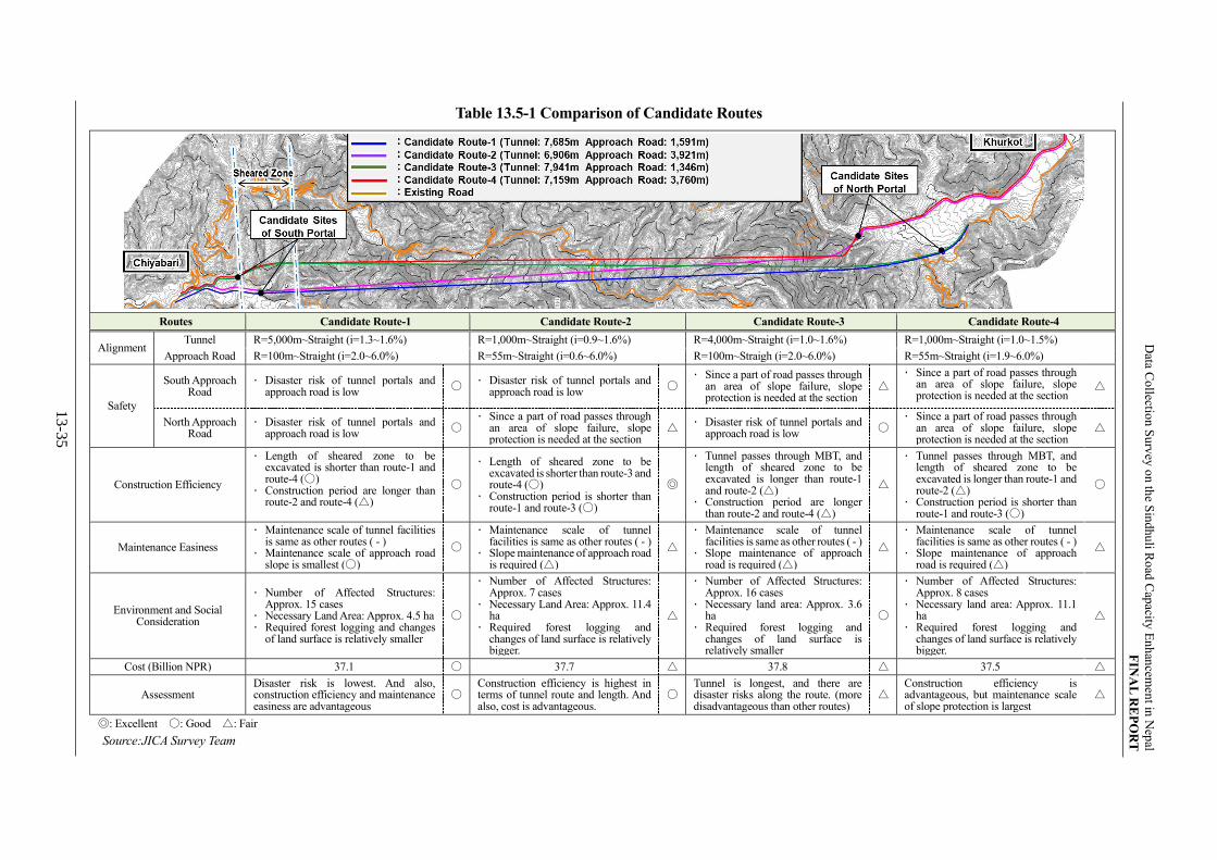
Data C
ollectio
n S
urv
ey o
n th
e Sin
dhu
li Ro
ad C
apacity
En
han
cemen
t in N
epal
FIN
AL
RE
PO
RT
13
-35
Table 13.5-1 Comparison of Candidate Routes
Routes Candidate Route-1 Candidate Route-2 Candidate Route-3 Candidate Route-4
Alignment Tunnel R=5,000m~Straight (i=1.3~1.6%) R=1,000m~Straight (i=0.9~1.6%) R=4,000m~Straight (i=1.0~1.6%) R=1,000m~Straight (i=1.0~1.5%)
Approach Road R=100m~Straight (i=2.0~6.0%) R=55m~Straight (i=0.6~6.0%) R=100m~Straigh (i=2.0~6.0%) R=55m~Straight (i=1.9~6.0%)
Safety
South Approach Road
· Disaster risk of tunnel portals and approach road is low
〇 · Disaster risk of tunnel portals and
approach road is low 〇
· Since a part of road passes through an area of slope failure, slope protection is needed at the section
△
· Since a part of road passes through an area of slope failure, slope protection is needed at the section
△
North Approach Road
· Disaster risk of tunnel portals and approach road is low
〇 · Since a part of road passes through
an area of slope failure, slope protection is needed at the section
△ · Disaster risk of tunnel portals and
approach road is low 〇
· Since a part of road passes through an area of slope failure, slope protection is needed at the section
△
Construction Efficiency
· Length of sheared zone to be excavated is shorter than route-1 and route-4 (〇)
· Construction period are longer than route-2 and route-4 (△)
〇
· Length of sheared zone to be excavated is shorter than route-3 and route-4 (〇)
· Construction period is shorter than route-1 and route-3 (〇)
◎
· Tunnel passes through MBT, and length of sheared zone to be excavated is longer than route-1 and route-2 (△)
· Construction period are longer than route-2 and route-4 (△)
△
· Tunnel passes through MBT, and length of sheared zone to be excavated is longer than route-1 and route-2 (△)
· Construction period is shorter than route-1 and route-3 (〇)
〇
Maintenance Easiness
· Maintenance scale of tunnel facilities is same as other routes ( - )
· Maintenance scale of approach road slope is smallest (〇)
〇
· Maintenance scale of tunnel facilities is same as other routes ( - )
· Slope maintenance of approach road is required (△)
△
· Maintenance scale of tunnel facilities is same as other routes ( - )
· Slope maintenance of approach road is required (△)
△
· Maintenance scale of tunnel facilities is same as other routes ( - )
· Slope maintenance of approach road is required (△)
△
Environment and Social Consideration
· Number of Affected Structures: Approx. 15 cases
· Necessary Land Area: Approx. 4.5 ha · Required forest logging and changes
of land surface is relatively smaller
〇
· Number of Affected Structures: Approx. 7 cases
· Necessary Land Area: Approx. 11.4 ha
· Required forest logging and changes of land surface is relatively bigger.
△
· Number of Affected Structures: Approx. 16 cases
· Necessary land area: Approx. 3.6 ha
· Required forest logging and changes of land surface is relatively smaller
〇
· Number of Affected Structures: Approx. 8 cases
· Necessary land area: Approx. 11.1 ha
· Required forest logging and changes of land surface is relatively bigger.
△
Cost (Billion NPR) 37.1 〇 37.7 △ 37.8 △ 37.5 △
Assessment Disaster risk is lowest. And also, construction efficiency and maintenance easiness are advantageous
〇 Construction efficiency is highest in terms of tunnel route and length. And also, cost is advantageous.
〇 Tunnel is longest, and there are disaster risks along the route. (more disadvantageous than other routes)
△ Construction efficiency is advantageous, but maintenance scale of slope protection is largest
△
◎: Excellent 〇: Good △: Fair
Source:JICA Survey Team

Data Collection Survey on the Sindhuli Road Capacity Enhancement in Nepal FINAL REPORT
13-36
13.6 STUDY ON TUNNEL STRUCTURE
13.6.1 Outline
Japan is one of the most advanced and experienced countries in the world in the field of tunneling. The
geology and geotechnical condition of Nepal is very similar to that of Japan. Therefore, the study on tunnel
structure under of the Survey is based upon the experiences in Japan and the Japanese Standards listed in
Table 13.6-1. These standards are applied to all the highway tunnels and national road tunnels in Japan,
and most of them have been constructed by New Austrian Tunneling Method (NATM), which is a
univera¥sally applied standard construction method of mountain tunnels. This method is applicable also
in to proposed tunnel at Chiyabari-Khurkot as geologically and topographically this section lies in a steep
mountainous and hilly area. However, as the tunnel section is assumed to encounter sheared zone between
MBT and MT at south portal area, provision of auxiliary method will be necessary to secure stability of
tunnel ground arch and the face during excavation.
Table 13.6-1 List of Applied Japanese Standards for Study on Tunnel Structure
Standard Issue Year
Standard Specifications for Tunneling-2016: Mountain Tunnel Japan Society of Civil Engineers 2016
Road Tunnel Technical Standards for Tunnel Structure Japan Road Association 2003
Road Tunnel Technical Standards for Tunnel Ventilation Japan Road Association 2008
Commentary on Road Structure Ordinance Japan Road Association 2021
Road Tunnel Technical Standards for Emergency Facilities Japan Road Association 2019
Design Guideline (Part3) Nippon Expressway Research Institute Company (NEXCO)
2016
Source:JICA Survey Team
13.6.2 Basic Conditions
Basic conditions applied to the study on tunnel structure are shown in Table 13.6-2.
Table 13.6-2 Basic Condition on Study on Tunnel Structure
Conditions Parameters Remarks
Design Speed 30km/h Tunnel Section
Number of Lanes 2 Single-tube tunnel with 2 lanes
Cross-section
Carriageway 3.50m Nepal Road Standard 2070
Shoulder 1.75m Commentary on Road Structure Ordinance
Inspection Gallery 0.75m Road Tunnel Technical Standards for Tunnel Structure
Median Strip 1.50m Nepal Road Standard 2070
Superelevation (%) 2.0% Nepal Road Standard 2070
Maximum Vertical Gradient (%) 3.0% Road Tunnel Technical Standards for Tunnel Structure and condition of Nagdhunga Tunnel
Vertical Clearance 5.0m Nepal Road Standard 2070
Source:JICA Survey Team

Data Collection Survey on the Sindhuli Road Capacity Enhancement in Nepal FINAL REPORT
13-37
13.6.3 Rock Classification Method and Standard Support Patterns of the Tunnel
Based on the site reconnaissance and the results of the geological survey conducted under the Survey, the
ground level of tunnel section is classified with reference to the index shown in Table 13.6-3. Also, the
support patterns for the tunneling shown in Table 13.6-4 and Table 13.6-5 are standardized based on that
ground levels. From the results in Table 13.4-1, the tunnel cross section is planned as 2 lanes with a rigid
median strip. Therefore, the width of inner section (approximately 13.5m) corresponds to large section
tunnel, and the support patterns shown in Table 13.6-5 should be applied.
Tunnel support types in this Study are mainly classified into 4 types to reflect the geotechnical condition
of the tunnel so far encountered. They are CI, CII, DI and DIII.
Type CI is applied to the ground where rock mass is partly weathered or altered, and discontinuous planes
are generally and relatively stable. Type CII is applied to the ground where rock mass is partly weathered
or altered and fractured. Type DI is applied to the ground where rock mass is sheared or weathered. Type
DIII is applied to sections near to tunnel poral where formation of ground arch is difficult.
Rock classification and support pattern for the tunnels of the candidate routes are shown in Table 13.6-6.
Table 13.6-3 Rock Mass Classification System
Rock
class Condition of rock mass RQD Stability of face Convergence
B
Rock is fresh and hard.
Discontinuous planes are
stable and the possibility of
loosening due to tunnel
excavation is very small.
60
to
90
The strength is significantly higher than
the expected load and only occasional
local spalling of rock fragment may
occur.
Convergence of tunnels is
negligible.
CI
Rock is partly weathered or
altered. Discontinuous
planes are generally
relatively stable
20
to
70
The strength is higher than the expected
load and the loosening is expected to be
local.
Convergence of tunnels is
usually within the elastic range.
C II
Rock is partly weathered or
altered and fractured. 20
to
70
Strength is not significantly higher than
the expected load, but is sufficient to
limit the elastic deformation. Rock
chunks along slippery discontinuous
planes tend to spall.
Convergence stops to increase
before the tunnel face has
advanced a distance of 2 D,
where D is the tunnel diameter.
Convergence of tunnels does not
exceed 50 mm.
D I
Rock is significantly
weathered and softened or
sheared.
< 20
Partial plastic displacement and elastic
deformation could occur. Or even if the
strength is high enough to limit the
elastic deformation, significant
loosening of ground along slippery
discontinuous planes could occur.
Where the strength is small and
the invert concrete is not placed
at an early stage, the convergence
could reach 30 to 60 mm and
does not stop to increase even if
the tunnel face has advanced
more than 2 D
D II
Rock is completely
weathered and partly
softened to soil, or heavily
sheared. < 20
The strength is low compared to the
expected load and large plastic
deformation as well as elastic
displacement could occur. In addition to
the low strength, significant loosening
of ground along slippery discontinuous
planes and large displacement could
occur.
Convergence of tunnels could
reach as far as to 60 to 200 mm
and does not stop to increase
even if the tunnel face has
advanced more than 2 D, if the
invert concrete is not placed at an
early stage

Data Collection Survey on the Sindhuli Road Capacity Enhancement in Nepal FINAL REPORT
13-38
Rock
class Condition of rock mass RQD Stability of face Convergence
DIII
It is tunnel portal section
where the overburden is
around 1.0 D to 2.0D.
-
It is difficult to form the ground arch
due to a thin overburden. -
E
Ground such as faults,
fractured zones and large
talus deposit.
-
Squeezing occurs and generates
occasional collapse in face area.
Large deformation could reach to
400mm.
Notes: RQD (Rock Quality Designation): Indicator of degree of rock crack. The total length of rod-like cores of more
than 10 cm included in the boring core length 1.0 m is indicated by percentage.
Source: JICA Survey Team (refer to Design Guideline -Part3-)
Table 13.6-4 Standard Support Patterns for Two-Lane Tunnels (Width of Inner Section 8.5-12.5m)
Ground class
Support pattern
Cut per
adva-nce (m)
Rock bolts Shotcrete Steel rib Lining thickness
(cm) Allowabl
e deformation (cm)
Excavation method Length
(m)
Spacing
Construc- tion range
Thickne-ss (cm)
Upper half size
Lower half size
Install-ation
Interval(m)
Arch & wall
Invert Periph-
eral
(m)
Longitu-
dinal
(m)
B B 2.0 3.0 1.5 2.0 Upper half
120 5 - - - 30 0 0
Full face
with micro
bench or top
heading cut
C I C I 1.5 3.0 1.5 1.5 Upper half 10 - - - 30 (40) 0
C II C II-a
1.2 3.0 1.5 1.2 Upper and
lower halves 10
- - - 30 (40) 0
C II-b H125 - 1.2
D I D I-a 1.0 3.0
1.2 1.0 Upper and
lower halves 15 H125 H125
1.0 30 45 0
D I-b 1.0 4.0 1.0
D II D II 1.0 or
less 4.0 1.2 1.0 or less
Upper and
lower halves 20 H150 H150
1.0
or less 30 50 10
Notes: The support patterns are divided into a and b as shown below. a: Standard support pattern generally used for all rock types b: Support pattern used in the initial design only when the tunnel excavation is expected to result in a larger
displacement in clay stone, black schist, mudstone, shale, tuff, or other rock types. Note that the values in ( ) for the invert are applied to tertiary mudstone, tuff, serpentinite, and other ground rocks, weathered crystalline schist, and sulfuric soil.
Source: Road Tunnel Technical Standards for Tunnel Structure
Table 13.6-5 Standard Support Patterns for Two-Lane Tunnels (Large Section Tunnel: Width of
Inner Section 12.5-14.0m)
Ground class
Support pattern
Cut per adva-
nce (m)
Rock bolts Shotcrete Steel rib Lining thickness
(cm) Allowable deformatio
n (cm)
Excavation method Length
(m)
Spacing Construc- tion range
Thickne-ss (cm)
Upper half size
Lower half size
Install-ation
Interval(m)
Arch & wall
Invert Periph-
eral
(m)
Longitu-
dinal
(m)
B B 2.0 4.0 1.5 2.0 上半 10 - - - 40 0 0 Full face
with micro
bench, top
heading cut,
center
diaphragm
method,
center drift
advancing
method
C I C I 1.5 4.0 1.2 1.5 Upper and
lower halves 15 - - - 40 (45) 0
C II C II 1.2 4.0 1.2 1.2 Upper and
lower halves 15 H150 - 1.2 40 (45) 0
D I D I 1.0 6.0 1.0 1.0 Upper and
lower halves 20 H150 H150 1.0 40 50 0
D II D II 1.0 or
less 6.0 1.0
1.0 or
less
Upper and
lower halves 25 H200 H200
1.0 or
less 40 50 10
出典: Road Tunnel Technical Standards for Tunnel Structure

Data Collection Survey on the Sindhuli Road Capacity Enhancement in Nepal FINAL REPORT
13-39
Table 13.6-6 List of Support Patterns Length of Candidate Routes
Routes Length of Support Patterns (m)
CI CII DI DIII DIIIp*
Candidate Route-1 4,360
(56.7%)
2,250
(29.3%)
100
(1.3%)
95
(1.2%)
880
(11.5%)
Candidate Route-2 3,865
(56.0%)
1,470
(21.3%)
100
(1.4%)
56
(0.8%)
1,410
(20.5%)
Candidate Route-3 4,560
(57.4%)
2,230
(28.1%)
100
(1.3%)
101
(1.3%)
950
(12.0%)
Candidate Route-4 3,995
(55.8%)
1,570
(21.9%)
100
(1.4%)
39
(0.1%)
1,455
(20.8%)
* DIIIp: DIII + Auxiliary Method (AGF method)
Source:JICA Survey Team
13.6.4 Tunnel Cross-Section
Based on the basic conditions shown in Table 13.6-2, typical tunnel cross-section is set. Typical tunnel
cross-section is shown in Figure 13.6-1.
Source:JICA Survey Team
Figure 13.6-1 Typical Tunnel Cross-Section (DI)

Data Collection Survey on the Sindhuli Road Capacity Enhancement in Nepal FINAL REPORT
13-40
13.6.5 Tunneling Method
13.6.5.1 Tunnel Driving Method
There are two tunnel excavation methods; drill & blasting (D&B) and mechanical excavation. D&B
method is generally applied in hard rock mass, and mechanical excavation is generally applied in middle
hard rock mass and soft rock mass.
Geology of the tunnels in the Study is assumed to consist mainly of middle hard rock or hard rock of gneiss,
schist, phyllite and granite and is generally classified as hard rock mass (qu>50 MPa). For this type of rock
mass, the Japanese standards for tunnel structure recommends D&B method. Therefore, D&B method is
recommended in the Study.
13.6.5.2 Excavation Method
Tunnel excavation method is classified as shown in Table 13.6-7. Since the tunnel routes passe through
MBT and MT around south portal area, ground condition of the section about 1 km from south portal
deems to be sheared zone where is located between MBT and MT. Therefore, auxiliary method for face
stabilization is required at the section, and the bench cut method is recommended in excavation method in
consideration of construction process of auxiliary method.
On the other hand, since the tunnel section other than sheared zone between MT and MBT is composed of
relatively stable and hard bedrock (gneiss, schist, phyllite, granite), the full face method or the full face
method with auxiliary bench is recommended.
Table 13.6-7 Classification and Characteristics of Standard Excavation Method
Excavation
Method Division of Section of Heading
Applicable
Ground Condition Advantages Disadvantages
Full Face
Method
Common excavation method
for small section tunnel
Very stable ground for large
section tunnel (A=30m2)
Unfit for good grounds
interspersed with poor ground
that may require the change of
the excavation method
Labor saving by mechanized
construction
Construction Management
including safety control is
easy because of the single-
face excavation.
Full tunnel length cannot
necessarily be excavated by
full face alone. Changing of
excavation method will be
adopted as required.
Fragment rocks from the top
of the tunnel may fall down
with increased energy &
additional safety measure are
required.
Full Face Method
with Auxiliary
Bench Cut
Comparatively stable ground,
but difficult using the Full Face
Method.
Full-face excavation is made
difficult during construction.
Presence of some poor ground
in fairly good ground.
Labor saving due to
mechanized construction
Construction management
including safety control is
easy because of the single-
face excavation.
Difficult to switch to other
excavation method when the
face does not stand up.
Bench
Cut
Method
Long
Bench
Cut
Ground is fairly stable, but Full-
face excavation is difficult.
Alternate excavation of top
heading and lower bench
reduces equipment and
manpower needs.
Alternate excavation system
elongates the construction
period.
Short
Bench
Cut
Applicable to various ground
such as softly ground, swelling
ground, and medium to hard
rock ground. (The most
fundamental and popular
method.)
Adaptable to change in the
ground condition.
Parallel excavation makes
difficult the balancing of
cycle time for top heading
and bench.
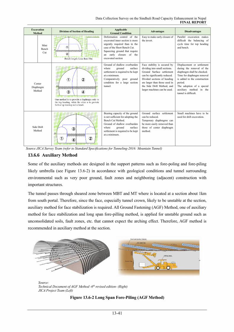
Data Collection Survey on the Sindhuli Road Capacity Enhancement in Nepal FINAL REPORT
13-41
Excavation
Method Division of Section of Heading
Applicable
Ground Condition Advantages Disadvantages
Mini
Bench
Cut
Deformation control of the
excavated inner section is more
urgently required than in the
case of the Short Bench Cut.
Squeezing ground that require
an early closure of the
excavated section
Easy to make early closure of
the invert.
Parallel excavation makes
difficult the balancing of
cycle time for top heading
and bench.
Center
Diaphragm
Method
Ground of shallow overburden
where ground surface
settlement is required to be kept
at a minimum.
Comparatively poor ground
condition for a large section
tunnel.
Face stability is secured by
dividing into small sections.
Ground Surface settlement
can be significantly reduced.
Divided sections of heading
are larger than those used in
the Side Drift Method, and
larger machines can be used.
Displacement or settlement
during the removal of the
diaphragm shall be checked.
Time for diaphragm removal
is added to the construction
period.
The adoption of a special
auxiliary method in the
tunnel is difficult.
Side Drift
Method
Bearing capacity of the ground
is not sufficient for adopting the
Bench Cut Method.
Ground of shallow overburden
where ground surface
settlement is required to be kept
at a minimum.
Ground surface settlement
can be reduced.
Temporary diaphragms can
be more easily removed than
those of center diaphragm
method.
Small machines have to be
used for drift excavation.
Source:JICA Survey Team (refer to Standard Specifications for Tunneling-2016: Mountain Tunnel)
13.6.6 Auxiliary Method
Some of the auxiliary methods are designed in the support patterns such as fore-poling and fore-piling
likely umbrella (see Figure 13.6-2) in accordance with geological conditions and tunnel surrounding
environmental such as very poor ground, fault zones and neighboring (adjacent) construction with
important structures.
The tunnel passes through sheared zone between MBT and MT where is located at a section about 1km
from south portal. Therefore, since the face, especially tunnel crown, likely to be unstable at the section,
auxiliary method for face stabilization is required. All Ground Fastening (AGF) Method, one of auxiliary
method for face stabilization and long span fore-pilling method, is applied for unstable ground such as
unconsolidated soils, fault zones, etc. that cannot expect the arching effect. Therefore, AGF method is
recommended in auxiliary method at the section.
Source: Technical Document of AGF Method -6th revised edition- (Right) JICA Project Team (Left)
Figure 13.6-2 Long Span Fore-Piling (AGF Method)

Data Collection Survey on the Sindhuli Road Capacity Enhancement in Nepal FINAL REPORT
13-42
13.6.7 Construction Planning and Temporary Facilities and Equipment for Construction
(1) Construction Plan
Construction plan of the tunnel such as excavation direction, excavation method and process are
recommended as follows;
Since length of the tunnel is over 7km, north and south portals are recommended in the portal where
excavation starts in terms of shortening construction period (see Figure 13.6-3),
Evacuation tunnel is excavated from south portal (excavation of the evacuation tunnel can be utilized
for pilot tunnel to investigate the ground condition of MBT, MT and sheared zone between both faults),
NATM and D&B method are recommended in both tunnel driving method and excavation method
based on expected rock condition at tunnel section (TMB expecting high speed excavation is
potentially applied for a section where is relatively stable and hard rock other than sheared zone
between MBT and MT (see Figure 13.6-4)).
Source:JICA Survey Team
Source: https://ugitec.co.jp/products/tbm/
Figure 13.6-3 Construction Plan (Excavation Direction) Figure 13.6-4 TBM (Open Type)
The sequence of tunnel excavation (D&B method) is shown in Figure 13.6-5.
Also, the guideline for preventive countermeasures against accidents from rock fall in the face of
mountain tunnel construction (18 Jan. 2018, Ministry of Hearth, Labor and Welfare, Japan), should be
followed/referred during the tunnel construction.

Data Collection Survey on the Sindhuli Road Capacity Enhancement in Nepal FINAL REPORT
13-43
Source:JICA Survey Team
Figure 13.6-5 Sequence of D&B Method
(2) Temporary Facilities and Equipment for Tunnel Construction
Major temporary facilities and equipment for tunnel construction are as follows.
Substation
Repair Station
Material Warehouse
Rest House
Intake Pomp/Water Pomp
Water Tunk
Explosive Handling Shop
Blasting Supplies Shop
Generator
Turbid Water Treatment Facility
Ventilation Facilities, Duct, Dust Collector
Material Yard
Batching Plant for Shotcrete
Batching Plant for Lining Concrete
Site Office
Detailed layout of the temporary facilities/equipment and detailed tunnel construction plan will be
considered in consideration of the result of the tunnel excavation plan, road construction plan and
influence on the noise caused by the construction.
As shown in Figure 13.6-3, since excavation of main tunnel from both portals is recommended in terms
of construction efficiency, construction yard should be planned near both portals. Candidate sites of
construction yard are shown in Figure 13.4-6.

Data Collection Survey on the Sindhuli Road Capacity Enhancement in Nepal FINAL REPORT
13-44
13.6.8 Facilities necessary for Tunnel
Table 13.6-8 lists the facilities to be installed in road tunnels (inside and outside) for securing safe and
smooth traffic flow.
Table 13.6-8 Facilities to be Installed Tunnel
Facilities Equipment
Tunnel
Ventilation
Tunnel Inside Jet Fan*/ CO meter/ VI meter/ AV meter
Tunnel Outside Local Control Panel
Tunnel
Lighting
Tunnel Inside Interior Lighting/ Entrance Lighting/ Emergency Lighting
Tunnel Outside Road Lighting/ Local control panel, etc.
Emergency
Facilities
Tunnel Inside
Emergency Telephone/ Push Button Alarm/ Fire Detector/ Fire
Extinguisher/ Fire Hydrant/ Guide Board, Hydrant/ Water Sprinkler System/
CCTV Camera, etc.
Tunnel Outside Local Control Panel/ Water Supply Pump/ Water Tank/ Pump Panel/
Emergency Information Board, etc.
Other
Facilities
Tunnel Inside -
Tunnel Outside Electrical Room/ Management Office/ Power supply system/ Back-up
Generator, etc.
*To install inside Outbound Tunnel.
Source:JICA Survey Team
(1) Ventilation Facilities
Ventilation in the tunnel forcibly discharges harmful substances discharged by the vehicle outside the
tunnel and secures safety and comfortability for driving inside the tunnel by keeping the concentration
of harmful substances in the tunnel below the control standards. And also, it is important to provide
better environment for the superintendents that undertake the tunnel maintenance work.
The necessity of tunnel ventilation and the detailed specification of ventilation equipment are
considered based on various elements such as tunnel cross-section, tunnel length, traffic volume in the
tunnel and natural environment around the tunnel. In case ventilation volume inside the tunnel by
natural wind is not enough to meet safe and comfortable condition inside the tunnel, mechanical
ventilation system must be necessary. Study for the necessity of mechanical ventilation system is
described in below.
The tunnel ventilation facilities should be planned in consideration of tunnel cross-section, the
difference in elevation at tunnel portals, traffic conditions and weather conditions. The tunnel
ventilation facility planning affects the safety and construction cost, and it is necessary to further
investigate and study tunnel ventilation facilities in the future. In this Study, the necessity of tunnel
ventilation facilities for the tunnels are estimated based on actual cases of Japan road tunnels in the
past. The figure which is shown in Figure 13.6-6 is used as one of indicator to determine the necessity

Data Collection Survey on the Sindhuli Road Capacity Enhancement in Nepal FINAL REPORT
13-45
of ventilation facilities easily. From Figure 13.6-6, mechanical ventilation deems to be required in the
tunnels.
※ 3,680 vehicles/day (2031)÷24 hours=154 vehicles/hour
Source: Prepared with reference to ”Road Tunnel Technical Standards
for Tunnel Ventilation” by JICA Study Team
Figure 13.6-6 Actual Cases of Japan Tunnels with/without Mechanical Ventilation
(2) Tunnel Lighting
Lighting inside the tunnel is very important to secure traffic safety. Tunnel lighting is composed of
Primary Lighting, Entrance Lighting and Emergency Lighting (in case of power cut). Detailed layout
and the specification are considered based on the following factors. In recent years, LED lighting which
meets the following factors is used as tunnel lighting in many countries including Japan. Therefore,
LED lighting is applied for design.
· High efficiency with long life
· Accommodating against high temperature, durability and humidity
· Appropriate luminescent color
· High luminous flux to meet the required high lighting level
· Easy maintenance
· Low running cost
1) Interior Lighting
Basic lighting is installed at regular intervals over the entire length of the tunnel to provide the
necessary brightness for the drivers so that they can see the obstacles ahead under constant speed.

Data Collection Survey on the Sindhuli Road Capacity Enhancement in Nepal FINAL REPORT
13-46
2) Entrance Lighting
Entrance lighting is installed to adjust the difference between outdoor brightness and brightness in
the tunnel. Therefore, it is necessary to set the luminance so that the influence of luminance can be
mitigated when change when the driver enters the tunnel.
3) Emergency Lighting during Power Failure
In case of a sudden loss of power, emergency lighting is required to prevent visual obscuration for
the drivers already running in the tunnel. Power shall be supplied from the UPS immediately as
uninterruptible power source.
4) Lighting outside the Tunnel Entrance
The street lamp at the exit of tunnel shall be installed adequately to guide the drivers coming up from
the tunnel, especially in nighttime. No street lamp at the exit road may cause the constriction of the
visual field of drivers and may lead to the accidents.
(3) Tunnel Emergency Equipment/Facilities
1) Tunnel Classification and Emergency Equipment/Facilities
Tunnel emergency equipment and facilities are to support the information transmission to road users
and road administrator, evacuation, self-extinguishment and fire fighter activities when accidents or
disasters occur inside the tunnel.
In Japanese Standards, Road Tunnel Technical Standards for Tunnel Ventilation and Design Guideline
(Part3), are determined by tunnel classification shown in Table 13.6-9. Also, tunnel classification is
classified to Class-AA, Class-A, Class-B, Class-C and Class-D according to traffic volume inside
tunnel and tunnel length as shown in Figure 13.6-7. According to this table, the higher the tunnel
classification, it is necessary to install various emergency equipment. Since the tunnels in the Study is
7,159m to 7,941m in length, tunnel class is Class-A.

Data Collection Survey on the Sindhuli Road Capacity Enhancement in Nepal FINAL REPORT
13-47
Table 13.6-9 Installation Standard of Emergency Facilities
Source: Prepared with reference to “Road Tunnel Technical Standards for Emergency Facilities” and “Design
Guideline (Part3)” by JICA Study Team

Data Collection Survey on the Sindhuli Road Capacity Enhancement in Nepal FINAL REPORT
13-48
※3,680 vehicles/day (2031)
Source: Road Tunnel Technical Standards for Emergency Facilities
Figure 13.6-7 Tunnel Classification
2) Emergency Telephone
Provision of Emergency Telephones as shown in Figure 13.6-8 are planned at both entrances to notify
the tunnel accidents or disasters to the tunnel administrator and at intervals of 200 m in the tunnel.
Emergency Telephone on wall Emergency Telephone at Entrance Emergency Telephone Box
Source:
https://radiate.jp/20130421/higashi-fushimi/
https://blogs.yahoo.co.jp/biwako_1164/59547680.html
https://travel.watch.impress.co.jp/img/trw/docs/1049/821/html/12.jpg.html
Figure 13.6-8 Emergency Telephone
3) Push Button Alarm
Provision of Push button alarm system as shown in Figure 13.6-9 are planned to be set at 1.2 to 1.5 m
above road surface and at intervals of 50 m to notify the tunnel accidents or disasters to the tunnel
administrator. This alarm system will connect with the emergency telephone and firefighting system.

Data Collection Survey on the Sindhuli Road Capacity Enhancement in Nepal FINAL REPORT
13-49
Push Button Alarm
with Fire Extinguisher & Fire Hydrant Push Button Alarm
Source:
https://car.watch.impress.co.jp/img/car/docs/685/703/html/049.jpg.html
https://www.iwasaki.co.jp/projects/examples/detail.php?EID=t34&cat=3
Figure 13.6-9 Push Button Alarm
4) Fire Detector
Fire Detector shown in Figure 13.6-10 reacts to the smoke generated by the fire in the tunnel and
detects the fire accident in the tunnel. It is planned at intervals of 50 m inside the tunnel. In many cases,
it functions as a switch for activating the emergency information board, firefighting facilities and the
ventilation facility with the reaction of the fire detector.
Source:
http://nexcokiyomi.hida-ch.com/index_7.html
http://www.pref.akita.jp/chuodo/new/newimg/h19.05.31new.html
Figure 13.6-10 Fire Detector
5) Emergency Information Board
Emergency alarm system as shown in Figure 13.6-11 sends accidents and disaster information to road
users by visual signals (alarm display) or audible alarms.
It is necessary to have adequate communication function to inform the road users of the disaster and
accident situation in the tunnel, and it is installed in an appropriate place not to interfere with fire
extinguishing activity and evacuation activities by road users.

Data Collection Survey on the Sindhuli Road Capacity Enhancement in Nepal FINAL REPORT
13-50
Emergency Information Board Control Panel
Source:
http://kitanihon-t.com/results/
http://www.iwate-shinkodenki.com/case/case25.html
Figure 13.6-11 Emergency Information Board
6) Fire Extinguishers
Fire extinguishers are shown in Figure 13.6-12. They are utilized for self-firefighting by the road users
and are planned at intervals of 50 m.
Source:
http://www.pref.yamanashi.jp/kanjo/kanri/manriki.html
https://car.watch.impress.co.jp/docs/news/688076.html
Figure 13.6-12 Fire Extinguishers
7) Fire Hydrants
Fire hydrants are as shown in Figure 13.6-13. They are utilized for self-firefighting by the road users
and are planned at every 200 m interval. At the same time, the hydrant for supporting firefighting
activities may be installed. In that case, the fire hydrant and the hydrant will be installed at same place.
Source:
http://asahisetsubi.co.jp/construction/463/
http://photozou.jp/photo/show/629359/116028160
Figure 13.6-13 Fire Hydrants

Data Collection Survey on the Sindhuli Road Capacity Enhancement in Nepal FINAL REPORT
13-51
8) Guide Board
Guide boards shown in Figure 13.6-14 are illuminated signs to inform the location of Tunnel portal to
road users. Guide board are to be set at intervals of 200 m.
Source:
https://www.iwasaki.co.jp/projects/examples/detail.php?EID=rhi07&cat=1
http://www.pref.yamanashi.jp/kanjo/kanri/manriki.html
Figure 13.6-14 Guide Board
9) Smoke Removal System and Evacuation Route
The tunnel ventilation system is planned for the purpose of both smoke removal and tunnel ventilation.
Jet fan will act to extract smoke in the event of fire in the tunnel.
Evacuation route facilities are evacuation tunnel, evacuation connection tunnel and evacuation port
and are planned to evacuate users in the tunnel to a safe space. Smoke removal system and evacuation
route are shown in Figure 13.6-15.
Since an evacuation tunnel and cross passages are planned, it is the basis of evacuation to escape to
tunnel portal or the evacuation tunnel in case of fire. A door is installed at the cross passages connecting
the evacuation tunnel and the main tunnel to prevent smoke from entering the evacuation tunnel.
Smoke Removal System (Jet Fan) Evacuation Route (Evacuation
ConnectionTunnel)
Source:
http://www.hanshin-exp.co.jp/company/skill/library/tech/post.html
https://radiate.jp/20081213/kitakan_opening_tochigi-ibaragi/
Figure 13.6-15 Smoke Removal System and Evacuation Route
10) Hydrant at Tunnel Portal
Hydrant at tunnel portal as shown in Figure 13.6-16 are planned at both tunnel portals to support the

Data Collection Survey on the Sindhuli Road Capacity Enhancement in Nepal FINAL REPORT
13-52
firefighting activity by firefighter.
Source:
http://daikitihanayama.web.fc2.com/2004Touring/yasya/Re/y3.html
http://www.pref.yamanashi.jp/kanjo/kanri/manriki.html
Figure 13.6-16 Hydrant at Tunnel Portal
11) Wireless Radio System
Coaxial cable as shown in Figure 13.6-17 are planned under the tunnel lighting system or the tunnel
center wall to allow tunnel staff, firefighter and police to use radios.
Source: https://car.watch.impress.co.jp/img/car/docs/685/703/html/048.jpg.html
Figure 13.6-17 Wireless Radio System
12) Radio Re-Broadcasting System and Loud Speaker System
Radio re-broadcasting system secure radio broadcast in tunnel by using lead antenna at tunnel entrance.
When an emergency in the tunnel occurs in environment where radio waves around the tunnel reach,
the system shall be used to transmit emergency information radio signals to car users in the tunnel. In
addition, the loud speaker system transmits the information on accident situation and evacuation to
tunnel users away from the vehicle by radio broadcasting with speakers installed in the tunnel. Radio
re-broadcasting system and loud speaker system are shown in Figure 13.6-18.
Guide Wire for AM Radio AM Aerial Wire Loud Speaker System
Source: https://travel.watch.impress.co.jp/img/trw/docs/1048/548/html/53.jpg.html
Figure 13.6-18 Radio Re-Broadcasting System and Loud Speaker System

Data Collection Survey on the Sindhuli Road Capacity Enhancement in Nepal FINAL REPORT
13-53
13) Monitor System
The monitor system (CCTV Camera) like the one shown in Figure 13.6-19 is designed based on the
tunnel plan and profile, focal length of cameras, and the size of objectives. The cameras will be installed
at tunnel wall and they are planned to be installed at 150-200 m intervals of tunnel. Also, they are
planned to be install at the emergency parking bay.
Source: http://www.densetsu-ndd.co.jp/construction/construction-329/
Figure 13.6-19 Monitor System
(4) Other Facilities
1) Emergency Parking Bay
Emergency parking bay is a facility that secures a safe and smooth traffic flow inside the tunnel by
providing a parking space for mechanically malfunctioned vehicles.
Based on the Design Guideline Part 4 issued by Nippon Expressway Research Institute Company
(NEXCO), emergency parking bay is installed in the tunnel at intervals of about 750 m. Proposed space
of the emergency parking bay is shown in Figure 13.6-20.
As for the location and installation number of the emergency parking bay, it is necessary to sufficiently
discuss and consider the necessity of installation of that and decide the details in the detailed design
stage.
Source:JICA Survey Team (Layout of Emergency Parking Bay)
https://radiate.jp/20140628/sagami_open/ (Photo)
Figure 13.6-20 Emergency Parking Bay
2) Evacuation Tunnel and Cross Passage
Evacuation tunnel and cross passage shown in Figure 13.6-21 are planned to evacuate tunnel users in
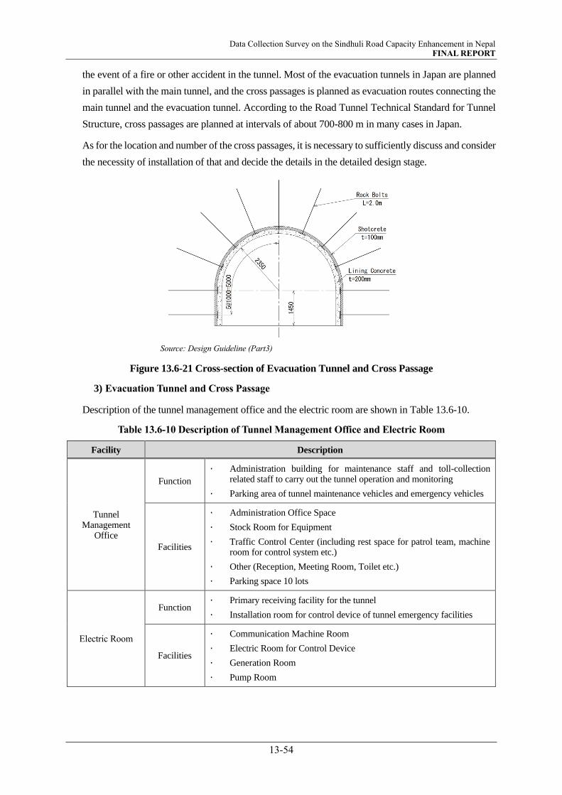
Data Collection Survey on the Sindhuli Road Capacity Enhancement in Nepal FINAL REPORT
13-54
the event of a fire or other accident in the tunnel. Most of the evacuation tunnels in Japan are planned
in parallel with the main tunnel, and the cross passages is planned as evacuation routes connecting the
main tunnel and the evacuation tunnel. According to the Road Tunnel Technical Standard for Tunnel
Structure, cross passages are planned at intervals of about 700-800 m in many cases in Japan.
As for the location and number of the cross passages, it is necessary to sufficiently discuss and consider
the necessity of installation of that and decide the details in the detailed design stage.
Source: Design Guideline (Part3)
Figure 13.6-21 Cross-section of Evacuation Tunnel and Cross Passage
3) Evacuation Tunnel and Cross Passage
Description of the tunnel management office and the electric room are shown in Table 13.6-10.
Table 13.6-10 Description of Tunnel Management Office and Electric Room
Facility Description
Tunnel Management
Office
Function
· Administration building for maintenance staff and toll-collection related staff to carry out the tunnel operation and monitoring
· Parking area of tunnel maintenance vehicles and emergency vehicles
Facilities
· Administration Office Space
· Stock Room for Equipment
· Traffic Control Center (including rest space for patrol team, machine room for control system etc.)
· Other (Reception, Meeting Room, Toilet etc.)
· Parking space 10 lots
Electric Room
Function · Primary receiving facility for the tunnel
· Installation room for control device of tunnel emergency facilities
Facilities
· Communication Machine Room
· Electric Room for Control Device
· Generation Room
· Pump Room

Data Collection Survey on the Sindhuli Road Capacity Enhancement in Nepal FINAL REPORT
13-55
13.6.9 Power Supply Condition
(1) DEMAND of ELECTRICITY
Tunnel projects require electricity for ventilation and lighting under both construction and operation.
1) Under Construction
In Japan, the electricity supply for construction sites is usually 3.3kV or 6.6kV and step-down at
construction yard to avoid loss under transition to 100~440V by transformers to supply electricity to
each construction equipment. Normally, three-phase altering current is used.
As it is assumed to excavate the tunnel from both portals, power receiving facility is needed on both
portals. In the details study, power receiving capacity is determined as a total of necessary power of
each equipment operating simultaneously. However, 800kVA for each portal is assumed referring to
the experience of similar tunnel projects in Japan without calculation of each equipment.
2) Under Operation
In detailed study, it is recommended to study which way of one portal receiving or both portal receiving
is economical. In case that transmission length become longer, voltage drop occurs and results in the
necessity of larger diameter of electric cable, which affect to space of cables in the tunnel cross section.
At this moment, 1,000kVA one-side receiving is assumed taking into consideration of the length of
7.6 km based on that a 5km tunnel with similar cross section area in Japan is receiving 600kVA in one
portal side.
(2) Power Procurement
As per the estimated power demand, information related to power procurement is surveyed. There
are three types of electric power supplier
NEA (Nepal Electricity Authority)
IPP (Independent Power Producer) *
VUCL (Vidhyut Utpadan Company Limited) *
* After the electricity act of 1992, the market has become unbundled at the generation point,
allowing private producers to participate in the market.
Transmission line consists of primary side (middle voltage) of 11kV and secondary side (low voltage) of
400/230V. Most of these transmission lines are built on overhead distribution facilities excluding leader
form substation. 11kV lines are pulled out from distribution substations (132/11kV, 66/11kV, 33/11kV)
and stretched around in cities with twig-like systems. Cable normally used for 11kV distribution lines is
three-phase wiring Aluminum Conductors Steel Reinforced with cross section of 100, 50, and 30mm2.
As shown in Figure 13.6-22, there are three 33/11kV substation along Sindhuli road at Khurkot, Sindhuli
and Bhima. From these substation, 11kV transmission lines are distributed. In the interview with a engineer
of NEA Sindhuli Distribution Center (SDC), the following information was obtained;
Sindhuli substation possess a 6/8 MVA transformer which enable to transmit electricity to four
routes

Data Collection Survey on the Sindhuli Road Capacity Enhancement in Nepal FINAL REPORT
13-56
If the tunnel project requires more than 6MVApower, it is needed to submit the request of suppling
power. Then, SDC will start to examine it.
In case that SDC cannot handle the request, SDC will ask Grid department / Province Division
Office to manage this request from tunnel project organization> The project organization should
wait for the study by System Planning Department of NEA.
On receiving side, it needs to set up a 33/11/0.4kVsubstation so as to be able to receive 33kVA
electricity.
Figure 13.6-23 is a request sheet in Nepal language to be submitted to SDC
Source:JICA Survey Team
Figure 13.6-22 Electric Power Facilities around Planned Tunnel

Data Collection Survey on the Sindhuli Road Capacity Enhancement in Nepal FINAL REPORT
13-57
Source:JICA Survey Team
Figure 13.6-23 Request Sheet of Power Supply
(3) Future Plan of Electricity Power Facilities
According to Figure 13.6-24 in JICA’s survey report1 which shows supply and demand of power from
2019, import of power from India is foreseen to be necessary in 2021 and the improvement of balance
of supply and demand in domestic market cannot be expected until 2030.
On the other hand, Figure 13.6-25 presents the transmission grid development plan of nationwide by
2035 and zone 4 including Sindhuli road by 2040.
1 Final Survey Report of Collecting and Confirming Information regarding Inter-city Power Distribution Development Plan in
Nepal, 2019 (JICA)

Data Collection Survey on the Sindhuli Road Capacity Enhancement in Nepal FINAL REPORT
13-58
Source:Final Survey Report of Collecting and Confirming Information regarding Inter-city Power Distribution
Development Plan in Nepal, 2019 (JICA)
Figure 13.6-24 Foreseen of Supply and Demand Balance of Power in Nepal
(a) Nationwide(2035)
(b) Zone-4 (2040) Source:Transmission System Development Plan of Nepal (Government of Nepal Ministry of energy, water
resources & irrigation, July 2018)
Figure 13.6-25 Transmission Line Plan

Data Collection Survey on the Sindhuli Road Capacity Enhancement in Nepal FINAL REPORT
14-1
CHAPTER 14 ROAD SAFETY
14.1 INTRODUCTION
Road safety crisis is a growing global epidemic. According to WHO (World Health Organization), every
year about 1.35 million people die globally from road-traffic accidents (RTAs) or more than 3,000 on a
daily basis, and 20 - 50 million are injured every year. More than half of all road traffic deaths are among
vulnerable road users. Pedestrians, cyclists, and riders of motorized 2- and 3-wheelers and their passengers
are collectively known as "vulnerable road users" and account for half of all road traffic deaths around the
world. Road traffic crashes are also a major cause of death among all age groups and the leading cause of
death for children and young adults aged 5–29 years. Countries around the world are adapting policies and
strategies with specific action plans to reduce fatalities and serious injuries. But implementation is yet to
gain sufficient momentum, particularly in low-income countries as the proportion of such mishaps is
higher in these countries; and Nepal is not an exception. Road safety is a shared responsibility. Engineering,
Education, and Enforcement (3Es) are considered as three key elements of road safety. Recently,
Emergency Response has been added to the elements as the response plays a vital role in the aftermath of
accidents.
14.2 KEY ELEMENTS of ROAD SAFETY
Road safety is a shared responsibility. Many countries/governments advocate 4Es 1 (Engineering,
Enforcement, Education, and Emergency Response) as the key elements for corresponding to Road Safety.
Source: JICA Survey Team
Figure 14.2-1 Key Elements (4Es) of Road Safety
• Engineering is used to establish speed limits that are appropriate to the primary purpose of the road;
provide a balance between mobility and safety for all roadway users; design roads that produce
desired speeds while meeting regulatory requirements; and introduce physical road geometries and
physical elements to create a road that induces drivers to travel at the desired speed.
1 Some speed management programs are considering other Es in their speed management plans. Jurisdictions sometimes consider
evaluation, environment, and equity when appropriate in a local community.

Data Collection Survey on the Sindhuli Road Capacity Enhancement in Nepal FINAL REPORT
14-2
• Enforcement encompasses the actions taken by authorities to ensure that drivers are complying with
the legal posted speed limit. While traditional manual police enforcement at spot locations is the more
commonly used strategy, automated speed enforcement is becoming more acceptable as a proven
method to reduce illegal speeding while allocating law enforcement resources to more critical matters.
• Education entails providing information to drivers about speeds and safety and increasing awareness
of engineering and enforcement measures to reduce speeding.
• Emergency services involve quick response of all necessary emergency personnel to a scene to
minimize the severity of a crash.
14.3 ROAD SAFETY AGENCY
Lead agency for road safety in Nepal is the MOPIT (Ministry of Physical Infrastructure and Transport).
MOPIT Minister chairs the National Road Safety Council (NRSC), which once or at the initial stage of
establishment used to be headed by the Secretary of the then Ministry of Labor and transport management.
However, this council was dormant since its establishment and never quite functioned. Since, the NRSC
is the option that most of the countries globally pursued to coordinate road-safety interventions, conferring
responsibilities to MOPIT was unanimously consented and endorsed on 31 January 2012. The functions
of the agency include coordination, legislation and monitoring and evaluation of road safety strategies.
14.4 ROAD SAFETY ACTION PLAN AND STRATEGIES
14.4.1 Road Safety Action Plan
The country`s Road Safety Action Plan 2013-2020 (RSAP 2013-2020) was formulated in 2013 by Ministry
of Physical Planning, Works and Transport Management (MPPWTM) in compliance to the mandate from
the UN Global Action. It obligates all stakeholders to follow this plan to improve and manage road-safety
in an integrated manner. It also sets out the activities that concerned agencies need to implement to achieve
the desired goals of reducing road traffic injuries and resultant economic losses in Nepal. This is the first
of its kind established in the country. RSAP for the next decade (2020-2030) is under formulation process
and is reported to be issued soon. The new RSAP will revise and update the current plan incorporating the
outcomes and lessons learned in the 2013-2020 period.
The RSAP incorporates interventions under the following five pillars to road-safety.
Pillar-1: Road safety management (consisting of 19 action plan targets)
Pillar-2: Safer roads and mobility (consisting of 26 action plan targets)
Pillar-3: Safer vehicles (consisting of 22 action plan targets)
Pillar-4: Safer road users (consisting of 16 action plan targets)
Pillar-5: Post-crash response (consisting of 11 action plan targets)
Only about half the plan targets were reported to be established/performed. This however is yet to be
authenticated.
14.4.2 Road Safety Strategies
Detailed formulation of the road safety strategies is one of the major activities proposed in the plan.
However, the plan tentatively proposes the followings.

Data Collection Survey on the Sindhuli Road Capacity Enhancement in Nepal FINAL REPORT
14-3
VISION
Safe road-infrastructures and services backed with effective post-crash response and conducive
environment resulting in little or no casualties from the RTAs
Mission
(i) To mitigate the loss of life, properties and economic loss from RTAs.
(ii) To complement the broader mission of the National Strategy on the Prevention and Control of
Violence, Injuries and Disabilities2
(iii) To meet the targets of the UN Decade of Action
(iv) To provide a common framework for stakeholder agencies to implement the various
interventions required to mitigate RTAs outcomes
14.5 ROAD SAFETY AUDIT
14.5.1 Audit Manual
Road Safety Audit (RSA) manual was prepared in 1997
by Traffic Engineering and safety Unit (TESU) 3 of the
DOR (Department of Roads). The manual is prepared
with an aim to raise road safety awareness amongst
highway engineers and others concerned. The manual
defines RSA as a systematic method of checking the
safety aspects of road schemes in order to detect potential
safety hazards before or even after the road is open to
traffic. The DOR`s policy mandates for a periodic road
safety audit of new major road construction and upgrading
to ensure safer roads and mobility. RSA is carried out by
a specialist or a team of specialist who are independent of
the design process. The manual applies for RSA for four
stages4;
i) Stage 1 Audit: Feasibility Study stage
ii) Stage 2 Audit: Preliminary Design stage
iii) Stage 3 Audit: Detailed Design stage (main audit)
iv) Stage 4 Audit: Pre-opening stage
However, according to DOR, the agency also has an experience of conducting post-construction audit
(audit of existing road). The audit was conducted for the section of Kalanki-Koteswor of the Ring Road in
a bid to control the increasing number of RTAs on the section. Following the audit the department has
2 National Strategies for Prevention and Control of Violence, Injuries and Disabilities in Nepal; GON 3 TESU has been restructured and renamed as Road Safety and Traffic Unit (RSTU) – as of November 2021. 4 The manual in Nepal mandates auditing at 4 stages, but Federal Highway Agency of USA recommends auditing in 5 stages –
the last one is the audit for post-construction stage (or even for existing road)
Figure 14.5-1 Road Safety Audit Manual

Data Collection Survey on the Sindhuli Road Capacity Enhancement in Nepal FINAL REPORT
14-4
decided to construct six over-head bridges at one kilometer interval apartment from the eight existing
bridges and three overhead existing bridges along the section.
14.5.2 Audit Flow
Source: JICA Survey Team
Figure 14.5-2 Steps in Road Safety Audit
14.6 ROAD SAFETY BUDGET
MOPIT`s fund for road safety is allocated in the national budget and possesses a road safety strategy which
is partially funded. Shows the budget allocated to MOPIT for Road Safety for the last three fiscal years. It
is apparent from the figures that budget allocated is in an increasing trend, which is evident that road safety
issue is attracting more attention.
Table 14.6-1 Budget Allocated for Road Safety for Past Three Fiscal Years
Fiscal Year 2019/20* 2020/21 2021/22
Budget (Million NPR) 97.9 220.7 500.0
Note: * actual expense, budget for FYs 2020/20 and 2021/22 are estimates
Source: Red Book 2078/79
14.7 ROAD SAFETY STATUS IN NEPAL
14.7.1 Road Safety Status
Nepal has one of the highest rates of road deaths in South Asia. According to the WHO, Total number of
deaths in Nepal for 2016 is estimated at 4,622. Fatalities per 100,000 population is 15.9. The fatality rate
is fairly in par with its neighboring countries. However, fatalities compared in terms of number of vehicles
registered in the country, Nepal ranks top with 40.0 persons per 10,000 vehicles. This is two times higher
than that of Bhutan (16.7), 3 times of India (13.0) and 5 times of Sri Lanka (7.1). The fatalities and serious
injuries are causing Nepal approximately 1,194 million US Dollar.
General facts compiled in reference to past research and monitoring about road safety in Nepal can be
summarized as followings;
About half the RTAs is recorded in Kathmandu Valley alone, where number of vehicles
registered account to almost half of the countries fleet ply.
The severity of RTA injuries in the Valley is under-reported.
Pedestrians are the most vulnerable groups
Accident prone areas are intersections in urban areas and black spots on highways (bridge
approaches, roadside built-up areas, intersections, sharp curves and high vertical grade sections)
in rural areas.
Project reference to RSTU for Audit
Project reports and plans sent to RSTU
RSTU studies plan and inspects site
RSTU holds meeting with designers
RSTU
undertakes audit RSTU prepares report and submits to DG/PM
Discuss/agree changes with
DG/PM
Provide feedback to designers
RSTU for Audit

Data Collection Survey on the Sindhuli Road Capacity Enhancement in Nepal FINAL REPORT
14-5
While motorbike accidents are significant in urban areas trucks and bus accidents dominate the
rural areas
One third of the accidents are reported to occur after sunset, when traffic is low
Absence of safety facilities, improper and sub-standard design, unsafe road and roadsides,
excessive vehicles that do not comply to the UN Vehicle Safety Regulations, imperfect rules and
regulations, road users` non-compliance to safety standards, poor emergency response service,
low-quality construction, lack of timely maintenance, lack of awareness (education), extreme
climate and terrain, driver negligence are the major causes responsible for the accidents.
From above, it is not an exaggeration to say that road safety strategies and practices in Nepal are at a
rudimentary stage. Despite of the establishment of the RSA plan and issuance of the RSA manual, targets
set for RTAs in Nepal are far from accomplishment. Nepal also advocates 4Es, yet the effort is yet to show
promising results. All four key elements of road safety need to be improved for reducing fatalities and
serious injuries in the country.
14.7.2 Safety Initiatives Adapted
Following steps have been taken by the government Formation of Road Safety Council, 2017.
• Mandating road safety audit in new road constructions and upgrading (Piloted in donor funded projects)
• Comprehensive driving license test
• Conduction of Road Safety Awareness campaigns among all stakeholders
• Revision of Nepal Road Design Standard
• Implementation of RSAP (RSAP 2013-2020)
• Crack down on road safety (limited on strategic roads)
• Promulgation of laws related to road safety (speed limit/drink-driving, drug-driving, use of helmet, seat
belt5 etc.)
• Establishment of Trauma Center (in Kathmandu)
• Vehicle fitness testing center (in Kathmandu)
14.8 ROAD SAFETY ISSUES
14.8.1 General Safety Issues in Nepal`s Highways
Nepal is a mountainous country. Most of its roads are constructed in the hills which encompasses various
safety issues that is indigenous to such roads. Nepal`s Road Safety Action Plan lists safety issues in Nepal`s
highways as follows.
Poor visibility at blind corners (no lighting, occurrence of haze and fogs)
Poor shoulders with insufficient width (uneven and partly collapsed)
Unforgiving side-drains
None or inadequate (non-robust) safety barriers
Improper layout of turnouts in single lane roads
5 As of November, 2021Seat belt law applies to drivers but not to front and rear seat occupants. The enforcement rate is ranked
5th in a total of 10. Helmet law applies to driver only. Pillion rider even children are not required to wear. Enforcement of helmet
law is high (8 out of 10). Drink-driving law enforcement is also high (8 out of 10).

Data Collection Survey on the Sindhuli Road Capacity Enhancement in Nepal FINAL REPORT
14-6
Sharp consecutive curves compounded with steep vertical grades
Lack of climbing lanes in steep hill areas
Potholes and sudden undulations due to lack of timely and adequate maintenance
Sub-standard and torn-out vehicles (especially buses and trucks) that are far away for complying to
UN`s safety vehicle regulations
Over-crowdedness (number of passengers exceeding allowable number)
Non-compliance to rules such as speed limits, wearing of helmets and seatbelts
Lack of safety awareness (drunken driving)
Lack of proper enforcement of law, rules and regulations
14.8.2 Road Safety Issues of the Sindhuli Road
Several trips were conducted to understand the road safety status of the Sindhuli Road. Site observation
with assistance from the visual image captured by the Drive Recorder were applied for the road safety
survey and Prompt List recommended by the Federal Highway Association Road Safety Audit for Existing
Road Audit Stage was referred for the purpose. Hereunder the safety status is briefly discussed with the
purpose to identify potential locations and items of safety issues and to provide simple recommendations.
Similar survey is recommended to be conducted during the succeeding stages. The recommendations
provided may be referred to for such surveys in the coming stages. However, it should be noted that then
the prompt list to be used should be selected in correspondence with the stage the survey is to be conducted.
For example, for the next survey stage, the PL for Planning Stage Audit should be referred.
(1) Road Alignment and Cross Section
1) Visibility, sight distance
Visibility and sight distance are often unsecured at sharp curves, particularly at hair-pin curves like in
Section II from Sta.44+0 to Sta.71+200, Section III from Sta. 80+300 to Sta.80+800, Sta. 85+800,
Sta.89+0 to Sta. 89+700 and between Sta.92+200 and Sta.93+500. But since the design speed is low,
this is not much of an issue as at the sharp curves on the ridges. This kind of curves exist more along
Section III and IV. At section IV there are curve mirrors (convex mirror) installed at most critical
curves. Some of the mirrors have been probably broken or stolen.
Recommendation: Installation of curve mirrors and warning sings
2) Design speed and Speed Limit
Design speeds set differs for each section, which are not high as regarded from the current role and
function of the road/sections. However, traffics, to be precise the daily/frequent users such as buses
and microbuses, tend to speed-off at higher velocity than the speed limit imposed on the sections. This
is made possible by three facts; i) the road was initially designed as a gravel road but later it was
asphalted, ii) the road is a 1.5 lane road that makes it easy to accelerate, especially at tangential sections,
iii) familiarity
Recommendation: increasing speed limit signs, pavement markings, rumble strips etc.
Data Collection Survey on the Sindhuli Road Capacity Enhancement in Nepal FINAL REPORT
14-7
3) Passing
Requires substantial reduction of speed. Frequent passing on tangential sections to overtake slow
vehicles. Turn outs are provided for passing of opposing vehicles but are not in full function as it is not
easily noticeable.
Recommendation: Increasing no takeover warning signs, installation of noticeable signs for use of
turnouts, widening of turnouts.
4) Cross section elements
Lane width is wider for a 1-lane road and narrow for 2-lane operation. Shoulder widths at both sides
are also insufficient. Cross-fall is elevated towards the side ditch (adverse superelevation at curves)
Recommendation: Widening to 2-lane road (conforming to Road Design Standard) securing of 1.5m
or wider shoulder
5) Drainage
No issues identified particularly with the drainage facilities except for the fact that the road is
superelevated towards the drains.
Recommendation: provision at other side of the curve to eliminate adverse superelevation
(2) Auxiliary Lanes
1) Tapers
Tapers are observed at turnouts and at ends of widening at curves only. There are no climbing lanes or
other form of additional lanes including at intersections.
Recommendation: extension of tapers for easy exit and entry at turnouts. This however applies if the
road will remain in the current state (1.5 lane wide). This will not be necessary if the road is widened
to 2-lanes, unless bus-bays, climbing lanes or other additional lanes are provided.
2) Lane width and shoulder widths
Auxiliary lanes are provided for several hundred meters at both the beginning point (Bardibas) and end
point (Dhulikhel). Taper and lane width are adequate, but shoulder width is narrow. Turnouts are
provided using the shoulders. Therefore, there is no shoulder at turnouts
Recommendation: Securing sufficient shoulder widths (conforming to standards)
3) Signs, Signages and Markings
Signs indicating turnouts and reduction of lanes at some locations are misplaced or unnoticeable due
to wearing (paint fading away, shape disturbed, direction absurd etc.). Signages were not confirmed.
Markings (center line and edge line) are provided. Zebra crossings and other markings were not
confirmed as well
Recommendation: Maintenance, repair, replace and new installment

Data Collection Survey on the Sindhuli Road Capacity Enhancement in Nepal FINAL REPORT
14-8
4) Turning Traffics
Very rare, but sometime traffics turn around at tangent sections, turnouts and/or at sections with open
space adjacent to the shoulder.
Recommendation: Provision of U-turn spaces at adequate intervals (3-5kms)
(3) Intersections and connecting roads
1) Locations and Configurations
Currently, exiting intersections are more a connecting point of two or more roads rather than like those
seen in urban areas. But development in and around intersections is progressing rapidly. Soon, the
connecting points will require to be converted into or planned as an intersection with appropriate
configuration. Current major connecting points are at Sta.0+0 (with E-W Highway at Bardibas), Sta.
18+500 (with Madan Bhandary Road), Sta.37+0 & Sta.38+0 (Sindhuli Bazar), Sta.74+280 (M-H
Highway), Sta.76+100 (Khurkot Bazar), Sta. 150+0 (Dhulikhel). Intersections at Sindhuli Bazar and
Khurkot Bazar consist of oblique legs.
Recommendation: New connecting points should be planned as an intersection from the beginning.
Also, for existing connecting points, relocation should be considered such that crossing roads intersect
at an angle of 90 degrees to the possible extent.
2) Visibility and sight distance
Currently, visibility and sight distance at the connecting roads are secured. But rapid development in
and around the intersections are anticipated to soon hinder visibility and sight distance. Especially
intersections mentioned above are of concern.
Recommendation: Secure sufficient right-of-way for future improvements of the intersections
3) Signage and markings
Signage and markings are sufficient for the current configuration of the connecting points but are
wearing.
Recommendations: Similar to those mentioned for auxiliary lanes.
4) Lightings and traffic signals
Lightings are provided in certain intersections but are not light enough. No intersection is equipped or
controlled by traffic signals (till date no chronic traffic congestion is evident)
Recommendations: Increasing lightings. Traffic signals may be desirable at Bardibas, intersection with
MB Highway and Dhulikhel.
(4) Signs and Lightings
1) General sign issues
Signs are provided along the entire stretch. Issues are as afore mentioned. Lightings are provided in a
selected area.

Data Collection Survey on the Sindhuli Road Capacity Enhancement in Nepal FINAL REPORT
14-9
Recommendation: for signs refer to those for intersections and connecting roads.
2) Sign legibility and supports
There are some signs that are not legible. Supports of existing signs are functional.
Recommendations: periodic maintenance (cleaning and replacing) of signs and supports
3) Lightings
Only confirmed at built-up areas.
Recommendations: Consideration for provision of lightings at black-spots (sharp curves, hair-pin
curves) and built-up areas desirable.
(5) Markings and Delineations
1) Centerline, edge lines, other markings
Markings are observed to have been placed recently. Being a 1.5 lane road, there is no centerline. But
edge lines are put almost throughout the entire stretch.
2) Guideposts and reflectors
Guideposts and reflectors to help guide and set specific boundaries are not found to be provided.
However, guard posts and guard blocks are provided at the valley side of the road. This functions both
as protection against falling down and as a guide for drivers. Section III has reflectors on these guard
posts.
Recommendation: Consideration for provision of reflectors
3) Curve warnings and delineators
Curve warnings are mostly provided by use of signs and curve mirrors. Curve mirrors provided are
seen vandalized.
Recommendations: replacement of vandalized curve mirrors.
(6) Barrier and Clear Zones
1) Barriers
Concrete blocks that function both as guidepost and barrier are provided at the valley side for guidance
and to stop out of control vehicles from falling. Provision of metal guard rails are limited. Concrete
blocks are provided throughout the stretch except at flat sections of section I. Barriers/guideposts at
Sections II and III are robust and installed at small intervals and are effective. But most sections in
Section IV only have guideposts, which are weak and installed in a wider interval.
Recommendations: consideration for replacement of guideposts at Section IV to barriers or guard
blocks
2) Footpath railings
Pedestrian is provided at built-up areas in Bardibas and Dhulikhel. Several hundred meters at Dhulikhel
is provided with railings.

Data Collection Survey on the Sindhuli Road Capacity Enhancement in Nepal FINAL REPORT
14-10
Recommendation: provision of railings at 4-lane section in Bardibas, consideration for extension
including Dhulikhel and installation at built-up area in combination with provision of footpath.
(7) Bridge and Culverts
1) Design features
Bridges also have 1.5-lane width only and is not equipped with a footpath.
Recommendation: Prioritizing and providing accordingly (longer bridge at or near built-up areas in
floodways of Section I and causeways at Khurkot, Dihi Phant Sta.81+100, and Sta 102+0)
(8) Floodways and Causeways
Floodways are frequently blocked by debris accumulated on top of it causing difficulty crossing it.
Sometimes the extent is so severe the traffics is severed until the deposit is removed.
Recommendations: maintenance to clear passage downstream of the floodway.
1) Ponding and flooding
Traffics are sometimes stuck in the floodway due to ponding and accumulation of debris.
Recommendations: consideration for provision of signals or manual gate to stop entry of vehicles until
safe passing is secured.
(9) Pavement
1) Pavement defects
No significant defects were observed.
2) Skid resistance
Sharp horizontal curves, steep grades, combination of grades and curves, and the approach to
intersections are susceptible to reduction of skid resistance.
Recommendations: identifying critical sections, measuring of skid resistance and repaving with thin
overlays or repaving using micro-surfacing
3) Ponding/Icing/Snow accumulation
Icing can occasionally occur during winter season at elevated sections of Section II and Section IV
(especially along the north face of the hills that are not exposed to the sunlight).
Recommendations: provision of warning signs (temporarily during cold season)
(10) Other Safety Issues
1) Headlight glare
In the absence of lightings, drivers use high beams. This causes overall reduction of visibility and
causing failures in detecting objects, pedestrians.
Recommendations: education to raise awareness of drivers

Data Collection Survey on the Sindhuli Road Capacity Enhancement in Nepal FINAL REPORT
14-11
2) Animal emergence
Rare but emergence of animals is confirmed, especially at nighttime mostly along the forest area in
Section II.
Recommendations: identifying frequent spotting areas and putting warning signs.
3) Rest areas
There are villages or built-up areas where the road users can rest. Namely, Sindhuli Bazaar, Khurkot,
Mulkot, Nepalthok, Bhakundebesi etc. However, these areas are mostly areas where meal and/or tea
are available. Rest area that includes gas station, service station, shops selling local products, and
information dissemination area (rest area like Michi no Eki in Japan) is not available.
Recommendations: consideration for provision of a rest area at least that includes restaurants and a gas
station.
4) Emergency Response
The earlier the victims of RTAs be carried and treated at a specialized medical facility (trauma center),
the better is their chances of survival. Currently, there is only one authorized trauma center in Nepal,
which is in Kathmandu. Most of the victims of RTAs along Sindhuli Road are treated at Kathmandu
University Hospital in Dhulikhel. The hospital currently does not have a trauma center but is under
preparation for its establishment.
Recommendations: Desirable to establish a hospital, if not a general medical facility at a couple of
locations.
14.9 ACKNOWLEDGEMENT AND RECOMMENDATION
The road safety survey results presented are not for the purpose of immediate actions to be taken. These
are intended for incorporation in the planning stage if/when the road is subject to improvement or
upgradation.
Also, the survey above has been conducted with reference to the prompt list of the FHWA, USA. Nepal`s
RSA manual also provides checklist that gives the safety features that need to be considered. However, the
lists only provide a very generalized summary of needs. As it is important that site circumstances and other
constraints be taken into consideration for a comprehensive RSA, it is suggested that prompt list of FHWA
or those applied by other international agencies be referred and applied accordingly in the subsequent
studies.
As DOR mandates performing Road Safety from as early as the Feasibility Study stage, it is recommended
that road safety aspects be checked, safety issues identified, and adequate measures incorporated in the
corresponding surveys/plans.


Data Collection Survey on the Sindhuli Road Capacity Enhancement in Nepal FINAL REPORT
15-1
CHAPTER 15 STUDY ON REST AREAS
15.1 INTRODUCTION
Pre-Feasibility Study (F/S) on rest areas on the Sindhuli Road was carried out in September 2019 under the
Project for Operation and Maintenance of the Sindhuli Road undertaken by JICA. This F/S report mainly
includes;
Current situation and potential sites for rest areas
Development plan
Recommendations
In Pre-F/S report, altogether 10 areas as shown in Figure 15.1-1 and Figure 15.1-2 are proposed as candidate
sites for roadside rest areas. These include the rest areas currently used by drivers.
This chapter provides updates of these candidates, based on findings from the site survey carried out under
this Survey.
Figure 15.1-1 Potential Rest Areas as of 2019 (Currently Used as Rest Area)

Data Collection Survey on the Sindhuli Road Capacity Enhancement in Nepal FINAL REPORT
15-2
Source: Technical Report (Draft) Pre F/S of Rest Area in Sindhuli Road
Figure 15.1-2 Potential Rest Areas as of 2019 (Newly Suggested)

Data Collection Survey on the Sindhuli Road Capacity Enhancement in Nepal FINAL REPORT
15-3
15.2 CURRENT SITUATION AND CANDIDATE SITES
15.2.1 Location Map
Location of rest areas that were surveyed in the F/S in 2019 are shown in Figure 15.2-1.
Source: JICA Survey Team
Figure 15.2-1 Location Map of Rest Areas
1. 37+700 Sindhuli Bazar
2. 43+600 Chiyabari
7. 76+00 Khurkot
5. 94+200 Mulkot
8. 138+800 Bhakundebesi
10. 151+800 Kavre Bhanjyang
6. 55+00 Selfie Danda
3. 82+100 Dihi Phant
4. 128+100 Landfill Area in
Roshi River
9. 140+200 Bhakundebesi

Data Collection Survey on the Sindhuli Road Capacity Enhancement in Nepal FINAL REPORT
15-4
15.2.2 Current Situation
Current situation of potential areas and observation and findings from the observation of the sites under this
Survey including is summarized in Table 15.2-1.
Table 15.2-1 Current Situation of Potential Areas
S.N Location Photo Observation / Findings
1. 37+700 Sindhuli Bazar
Approximate travel time
is 50 mins from
Bardibas and 4 hours 20
mins from KTM.
There are many
buildings and facilities
to rest.
2. 43+600 Chiyabari
Approximate travel time
is 1 hour from Bardibas
and 4 hours from KTM
There are many
buildings and facilities
to rest.
3. 55+00 Selfie Danda
Approximate travel time
is 1.5 hour from
Bardibas and 3.5 hours
from KTM
There are many street
vendors alongside the
road.
Here is popular spot for
selfie shots because of
beautiful scenery.
4. 76+00 Khurkot
Approximate travel time
is 2 hours from Bardibas
and 3 plus hours from
KTM
There are many
buildings and facilities
to rest.
5. 82+100 Dihi Phant
Approximate travel time
is 2 hours from Bardibas
and 3 hours from KTM
Although there are no
facilities to rest, enough
space for rest area along
the road is confirmed.

Data Collection Survey on the Sindhuli Road Capacity Enhancement in Nepal FINAL REPORT
15-5
S.N Location Photo Observation / Findings
6. 94+200 Mulkot
Approximate travel time
is 2.5 hour from
Bardibas and 2.5 hours
from KTM
There are some
restaurants and hotels.
Enough space for rest
area along the road is
confirmed.
7. 128+100 Landfill Area
in Roshi River
Approximate travel time
is 3 hours from Bardibas
and 2 hours from KTM
This area is developed
by landfill in the Roshi
River bank
Enough space for rest
area along the road is
confirmed.
8. 138+800 Bhakundebesi
Approximate travel time
is 3.5 hour from
Bardibas and 1.5 hours
from KTM
There are many
buildings and facilities
to rest.
9. 140+200 Bhakundebesi
Approximate travel time
is 3.5 hour from
Bardibas and 1.5 hours
from KTM
Enough space for rest
area along the road is
confirmed.
10. 151+800 Kavre
Bhanjyang
Approximate travel time
is 4 hour from Bardibas
and 1 hours from KTM
Limited space for rest
area along the road is
confirmed.
Source: JICA Survey Team

Data Collection Survey on the Sindhuli Road Capacity Enhancement in Nepal FINAL REPORT
15-6
15.3 DEVELOPMENT PLAN
15.3.1 Development Plan
In the Pre-F/S report, development plan is composed of main plan and sub plan by taking 2 stepwise measures
as illustrated in Figure 15.3-1.
Source: Technical Report (Draft) Pre F/S of Rest Area in Sindhuli Road
Figure 15.3-1 Development Plan
This plan was formulated based on the existing road condition (1.5 lane). However, looking ahead to the
future 2-lane improvement of Sindhuli Road that will accommodate all types of vehicles, following studies
and actions in addition to the plans above is deemed necessary.
Study on scale of facilities and parking lots
Study on required facilities, and operation & maintenance methods
Availability of land to be acquired
15.3.2 Necessary Procedures
Necessary procedures are summarized in the Pre-F/S report as shown in Table 15.3-1.

Data Collection Survey on the Sindhuli Road Capacity Enhancement in Nepal FINAL REPORT
15-7
Table 15.3-1 Necessary Procedures
Source: Technical Report (Draft) Pre F/S of Rest Area in Sindhuli Road
15.4 RECOMMENDATION
15.4.1 Installation of “Michi-No Eki “
In the Pre-F/S report, it is recommended to install “Michi-No-Eki” along Sindhuli Road. “Michi-no-Eki” is
a multi-purpose facility that serves not only for tourists but also for social and economic activities in the local
community. Refer to https://www.japan.travel/en/guide/michi-no-eki/.
After improvement of the Sindhuli Road, traffic volume will increase. This implies to more use of rest area
by the road users. In addition, there are touristic spots and recreational facilities alongside the Sindhuli Road.
Therefore, for both resting and information dissemination purposes, development of rest areas such as
“Michi-No-Eki” is rational. To make the facility more functional the rest area will require additional facilities.
The major facilities that are recommended are as listed below.
Counter where latest/immediate information on traffic condition and closures are provided
Maintenance Office of the Road
Administrative Information Desks
Police Box
Meeting Rooms for Community
Tenancy Spaces for Shops or Cafe Restaurants
Toilets
Fuel and Service Station
It is expected that rest areas that are equipped with the above-mentioned facilities and provide various
information will have higher demand than facilities with simple food serving purpose only. This type of
multi-functional facility will further contribute in raising the local economy.
15.4.2 Effective Land Utilization near Tunnel Portals
Alternative routes with a mountain tunnel are planned at Chiyabari-Khurkot section (Section II) as the
improvement measure for enhancement of road function. Since approach roads connecting to north portal of
Khurkot side are planned to pass through relatively flat farmland, it is possible to secure space to build a

Data Collection Survey on the Sindhuli Road Capacity Enhancement in Nepal FINAL REPORT
15-8
tunnel management office, toll gate for tunnel passage (subject to decision from the road authority), and even
Michi-No Eki (rest area). Figure 15.4-1 and Figure 15.4-2 show the candidate sites of the Michi-No Eki near
north portal.
A space of 17,000 m2 or more can be secured at this candidate site, and facilities such as police box,
community meeting room, local product store, restaurant, toilet, parking lots and gas station can be built. In
addition, since contrasting view of the nature and the artificial structure (tunnel portal, road) can be enjoyed
from the rest area, expectation for development as a recreational area is also high. Meanwhile, Sindhuli Gadhi,
one of the most historical places (forts) that is famous for the wars between the then Gorkha Army of Nepal
and the British troops is only about several kilometers. Therefore, the space can also accommodate a facility
for dissemination of the information.
Source: JICA Survey Team
Figure 15.4-1 Location Map of Candidate Sites of Rest Areas near Tunnel Portal
Candidate Site of Rest Area (P-1)
Candidate Site of Rest Area (P-2) Source: JICA Survey Team Source: JICA Survey Team
Figure 15.4-2 Photos of Candidate Sites of Rest Areas near Tunnel Portal

Data Collection Survey on the Sindhuli Road Capacity Enhancement in Nepal FINAL REPORT
16-1
CHAPTER 16 CONSTRUCTION PLANNING AND COST ESTIMATE
16.1 INTRODUCTION
Information and data related to the procurement of labor, construction materials, construction equipment,
etc. in order to implement the road function enhancement measures were collected and analyzed. The
estimated construction cost is based on the measures mentioned in Chapters 10 and 13 and tunneling of
Section II. The results are summarized hereunder.
The data and information described in this chapter are based on the analysis of available public materials,
and findings from field surveys, and interviews with related parties. A more specific procurement and
construction planning that is based on updated data obtained through detailed investigations and surveys
are suggested.
16.2 CONSTRUCTION PLAN
16.2.1 Procurement Plan
Procurement conditions for necessary laborers, construction materials and construction equipment for this
project are studied.
16.2.1.1 General Conditions
(1) Labor
As to the laborers engaging in this project, workers who do not need special skills such as ordinary
workers, security guards are readily procurable from around the site, while engineers and skilled workers
need to be procured from other urban cities such as Kathmandu. In addition, it is not difficult to procure
the workers form India as they can enter Nepal without a VISA. However, experienced foremen for the
specific construction such as tunneling, countermeasure against landslide, reinforcement earth method
and metal-road method for bridge works, which requires advanced technique and safety considerations
are not available in the country. These foremen need to be procured from a third country or Japan.
As a reference on this matter, the unit costs of various kinds of laborer allied in Kavrepalanchowk district
is presented in Table 16.2-1, which are published by DOR (Department of Roads).
(2) Construction Materials
Table 16.2-2 summarizes the information related to various kinds of construction materials, which were
obtained by interviewing with engineers in Nepal.
Natural material like stone, sand, aggregate etc., which will be extensively utilized in large amount in the
project, are easily available from the riverbeds of Sunkoshi River (75km~108km) and Roshi Khola
(108km~132km) as well as from the nearby local quarries. Other materials such as cement, rebar, etc,
should be procured from Kathmandu or Janakapur (90km from Sindhuli) and India if not sufficiently
available in Nepal market. However,the construction materials used in special work with little experience
are not distributed in Nepal, and thus needs to be procured from a third country including Japan.

Data Collection Survey on the Sindhuli Road Capacity Enhancement in Nepal FINAL REPORT
16-2
(3) Construction Equipment
Rental business of construction machines has been spreading in Nepal.
Basically, construction equipment for tunnel construction should be planned to procure from 3rd countries,
including from Japan for maintaining certain level of quality and maintenance services. On the other hand,
the procurement of general construction machines for the construction at open areas is easily available
locally on a rental basis. However, large size machines and special machines may need careful
judgement for reliable suppliers.
Table 16.2-3 summarizes the information related to various kinds of construction equipment obtained by
interviewing with the engineers in Nepal.
As a reference, results of interview to engineer who is currently involved in the Nagdhunga tunnel
construction project are as follows;
Nepalese sub-contractors own most of construction equipment for open area
Most of heavy construction machines for tunneling works are imported from Japan
Diesel fuel is imported by Nepal Oil Corporation from India.
Explosive produced by Nepalese army are available but imported from India considering quality
assurance.
Some parts of tunnel facilities may be able to import from subsidiary of European countries, which
industry locates in India.
Table 16.2-6 and Table 16.2-7 summarize the construction equipment (limited capacity). Procurement
rate of these equipment is published by DOR. This equipment is easily procurable in Nepal.
(4) Procurement from Other countries
Procurement route from Japan is as shown below. This is based on information gathered from reports of
previous Sindhuli Road Construction Plan and experiences of completed construction works.
This route pass through the highway roads in India, heavy and large size equipment can be transported.
However, the existing Sindhuli road is on narrow and difficult alignments. Detailed study of
transportation of each necessary equipment is inevitable.
The materials and construction equipment mobilized from India, other third countries and Japan are
transported by 40FT size trailer as shown in Figure 16.2-1. This is confirmed by interview with Japanese
logistics provider in India.
Dispatch from
Port in Japan
Sea transport to
Kolkata
Road transport to
Patna (India)
Road transport to
Birgunj (Nepal)
Arrive
KTM

Data Collection Survey on the Sindhuli Road Capacity Enhancement in Nepal FINAL REPORT
16-3
Source: JICA Survey Team
Figure 16.2-1 Semi-Trailer for Inland Transportation (reference)
Table 16.2-1 Labor Unit Price (Kavrepalanchok district)
All items increased in about 5% from 077/78 to 078/79.
Description
077/078
rate (NRP/Md.)
078/79
rate
(NRP/Md.)
1 Unskilled Labor 725.00 760.00
2 Unskilled Labor working in highlands 725.00 760.00
3 Porters (40 kg per / 4 fund) 725.00 760.00
4 Unskilled labor and porter's hero 725.00 760.00
5 Skilled workers:( carpenter, mason, painter, plumber,
electrician)
990.00 1040.00
6 Semi-skilled workers:(carpenter, mason, painter, plumber,
electrician, mechanics, light vehicle driver)
825.00 865.00
7 Heavy equipment operator 880.00 925.00
8 Survey helper, line man, camp helper, tape man, chain man,
cleaner
715.00 750.00
9 Guard, peon, Watchman 715.00 750.00
10 Road supervisor 770.00 810.00
11 lane man (Length worker) 605.00 635.00
12 Supervisor, Facilitators, Catalysts etc. (on wages)
Night watchman 715.00 750.00
Surveyor (like overseer) technician 1105.00 1160.00
Survey helper 715.00 750.00
Chain man, tape man, staff man, drill helper, truck helper,
sayas
855.00 900.00
Sweeper, Mehtar 570.00 600.00
Ordinary machine operator, wire binder 870.00 915.00
Welder assistant 745.00 780.00
Architect/ engineer 1325.00 1350.00
Sub- engineer, draft man, nasu (technical) 1105.00 1125.00
Assist. Sub-engineer, draft-man, buyer (technical) 880.00 955.00
Pitch sprayer 615.00 645.00
Pitch Boiler 615.00 645.00
13 Nursery Hero 585.00 700.00 Source: JICA Survey Team

Data Collection Survey on the Sindhuli Road Capacity Enhancement in Nepal FINAL REPORT
16-4
Table 16.2-2 Material Procurement (1/2)
Material Name
Procurement
Remarks Nepal India
Japan
or 3rd
country
Civil Works
Cement 〇 〇 Imported and domestic products are both
distributed
Bitumen Materials 〇 Imported products (generally distributed)
Stone 〇 Imported products (generally distributed)
Grable, Sand, Aggregate 〇 Available from quarries
Earth fill material 〇 Imported products (generally distributed)
Reinforcement bar 〇 〇 Imported and domestic products are both
distributed
Guiderail (steel) 〇 Imported products (generally distributed)
Concrete barrier 〇 Imported products (generally distributed)
Gabion with wire 〇 Imported products (generally distributed)
Wire mesh for gabion 〇 Imported products (generally distributed)
Restressed concrete strand (steel
wire)
〇 ◎ ◎: recommendation from quality
viewpoint
Bearing for bridge 〇 〇
Concrete pipe for drainage 〇 Imported products (generally distributed)
PVC pipe 〇 Imported products (generally distributed)
Nonwoven fabric 〇 〇 Imported products (generally distributed)
Diesel (Fuel) 〇 〇 Imported products (generally distributed)
Wooden panels for concrete form 〇 〇 〇 Imported and domestic products are both
distributed
Wooden scaffold material 〇 Imported products (generally distributed)
Steel scaffold material 〇 Quality assurance
Rock bolt materials 〇 ◎ ◎: recommendation from quality
viewpoint
High-strength network 〇 ◎ ◎: recommendation from quality
viewpoint
Precast-concrete products (Curb
stone, Drainage, etc.) 〇
Imported and domestic products are both
distributed
Concrete admixtures 〇 Imported products (generally distributed)
H shaped steel beam 〇 Quality assurance
Source: JICA Survey Team

Data Collection Survey on the Sindhuli Road Capacity Enhancement in Nepal FINAL REPORT
16-5
Table 16.2-3 Material Procurement (2/2)
Material Name
Procurement
Remarks Nepal India
Japan
or 3rd
country
Tunnel Civil Works
Steel support 〇 ◎ ◎: recommendation from quality
viewpoint
Rock bolt 〇 ◎ ◎: recommendation from quality
viewpoint
AGF material for fore piling
method 〇
AGF (all ground fastening) for
supplemental supporting.
Retardant fluid for backing
injection material 〇 ◎
◎: recommendation from quality
viewpoint
Water tight sheet 〇
Wire mesh for sprayed concrete 〇 〇 ◎ ◎: recommendation from quality
viewpoint
Tunnel Facility
Facilities for emergency
- Information System 〇
- Alarming system 〇
- Fire safety (fighting) equipment 〇
- evacuation guidance system 〇
- Others 〇
Ventilation (Jet fun etc.) 〇
Lighting (LED light) 〇
Electric supply 〇
Monitoring and control 〇
Telecommunication 〇
Source: JICA Survey Team

Data Collection Survey on the Sindhuli Road Capacity Enhancement in Nepal FINAL REPORT
16-6
Table 16.2-4 Equipment Procurement (1/2)
Equipment Name Specification
(Example)
Procurement
Nepal India Japan or 3rd
country
Civil Works
Bulldozer 4~21ton 〇
Ripper mounted bulldozer 21ton 〇 〇
Hydraulic Excavator
(Backhoe) 0.3~1.0m3 〇
Wheel loader 2.1m3 〇
Dump truck 4~10ton 〇
Track flat body /Trailer 10~20ton 〇
Truck crane ~30ton (25t
capacity) 〇
Vibrohammer 30~90kW 〇
Breaker 0.25~1.2m3 〇
Motor grader 3.1m 〇
Road roller 10~12ton 〇
Tire roller 3~20ton 〇
Vibration roller 3~4ton 〇
Concrete (Batching) plant 45m3/hr 〇 〇 〇
Water tanker 8ton 〇
Oil tanker 8ton 〇
Rough Terrain Crane <35 ton 〇 〇
Rough Terrain Crane 35ton< 〇
Sheet pile driver 〇
Borehole pile rig (with all
accessories) 〇
Electric generator 100-600kVA 〇 〇 ◎
◎ large size equipment is recommended to procure from quality viewpoint
Source: JICA Survey Team

Data Collection Survey on the Sindhuli Road Capacity Enhancement in Nepal FINAL REPORT
16-7
Table 16.2-5 Equipment Procurement (2/2)
Equipment Name Specification
(Example)
Procurement
Nepal India
Japan or
3rd
country
Tunnel Civil Works
Load header 65kW-4P, 200/110kW-4/8P 〇 ◎
Drill Jumbo 2 or 3 boom 〇
Giant breaker Hydraulic, 3t 〇 ◎
Concrete spray robot 25m3/hr 〇
Steel support installation equipment
(Elector)
〇
Excavator (backhoe) 0.6m3 〇 ◎
Wheel loader, side dump 2.3m3 〇
Wheel loader 1~5m3 〇 ◎
Tractor excavator 1~4m3 〇 ◎
Slide center for concreting final lining 〇
Stage for water tight sheet work 〇
Ventilation blower 500, 1000, 3,000m3/min 〇
Ventilation duct dia. 1,500mm 〇
Water treatment plant 50~200ton/hr 〇
Dust collector 〇
Concrete pump 90m3/hr 〇 〇
Concrete mixer track 3~10ton 〇 〇
Concrete finisher for pavement 〇
Concrete spreader for pavement 〇
Concrete traveler for pavement 〇
Belt conveyor for muck 〇
◎: recommendation from quality viewpoint
Source: JICA Survey Team

Data Collection Survey on the Sindhuli Road Capacity Enhancement in Nepal FINAL REPORT
16-8
Table 16.2-6 Rate of Plant and Machinery (1/2)
Equipment Name Capacity/Category
Asphalt Plant up to 10 Ton
Asphalt Paver 112kw/16.5Ton
Asphalt, Mobile Mini Hot-mix Plant 6.5 ton
Air Compressor 150 to 275cfm
Air Compressor (Portable) 110HP/412 CFM
Chipping Spreader 90kw/8.5ton
Crane Mobile 5+ to 40 ton
Cutter Concrete
Dozer Wheel 181 to 230 HP
Dozer Track 80 to 230 HP
Bitumen Distributor 4 to 6 KL
Bitumen Distributor(Truck Mounted) 202kw/8000Ltr
Mini Dumper 1 to 4 Cu. M.
Hydraulic Self Propelled Surface Top Hammer Drill 3 ton
Excavator Track up to 150 HP
Excavator Track 14 ton
Excavator + Breaker 111 to 150HP
Hydraulic Excavator with Breaker (racked) 14 ton
Hydraulic Excavator with Breaker (racked) 148 HP
Mini Excavator < 1.1 ton
Excavator, Wheeled 163hp/20.8Ton
Excavator, Long Reach 139hp/24.2Ton
Forklift Truck < 2.5 ton
Generator up to 50KVA
Motor Grader 90HP 135 HP 145 HP
Chip Spreader
JICA Survey Team Original Source: DOR Equipment Hire Rate

Data Collection Survey on the Sindhuli Road Capacity Enhancement in Nepal FINAL REPORT
16-9
Table 16.2-7 Rate of Plant and Machinery (2/2)
Equipment Name Capacity/Category
Loader Wheel 1.2 ~2.5 Cu.M
Multi-purpose loading machine (Load all) 55Kw
Backhoe Loader <90 HP
Skid Steer Loader with breaker 55 HP
Skid Steer Loader with fork lifter 55 HP
Water Pump (Engine) up to 6"
Water Pump (Elect.) 5, 7.5 HP
Pile Driver* 10 ton
Road Marking Machine 50 liters
Roller 3 Wheel up to 12 Ton
Roller Pneumatic up to 20 Ton
Roller Vib. Pedestrian (Double Drum) up to 0.6 ton
Roller Vib. Pedestrian 0.5 ton
Double Drum Vibratory Roller, Pedestrian (Walk Behind) up to 1 ton
Roller Vib. Sheep foot up to 10 ton
Roller Asphalt up to 7 ton
Roller Vib. Self-Prop (Soil Compactor) 10 ton
Roller Vib. Self-Prop. 3~11ton
Roller, Combination Vibratory 1.4 ton 1.6 ton
Spray Emulsion up to 1KL
Roller, Combination Vibratory up to 7 ton
Track flat bed up to 150 HP
Truck Tipper up to 150 HP
Truck Tipper From 150+ HP
Trailer Tractor 10 + to 25 ton
Transport Truck(15ton) 15 ton
Trailer Tractor Semi Low-Bed 40 ton
Water Tanker up to 8 KL
Tractor up to 85 HP
Compactor H/Towed Compactor H/Towed
Welding Generator 3 kVA
Source:JICA Survey Team Original Source: DOR Equipment Hire Rate
16.2.1.2 Main Construction Materials
(1) Stone, Sand and Aggregates
It is reasonable to assume the procurement of these materials from general market in Nepal. There are

Data Collection Survey on the Sindhuli Road Capacity Enhancement in Nepal FINAL REPORT
16-10
two types of origin, from quarries at hill and mountain areas using crushing
process of large size rocks and gravels and from riverbeds.
Annual Report of Department of Mines and Geology1 explains future
possibility of limitation of mining at riverbeds of large rivers flowing in
Terai and riverbeds of rivers and hills in Churia region to conserve the
natural environment as well as to a measure against curbing illegal
procurement. As a countermeasure for this situation, they surveyed
potential quarry sites in Mahabharata range where good quality material is
expected. Tinkanya-6/7 and Ranichuri-9 which locate near Sindhuli road
are introduced in Sindhuli District as one of 14 districts surveyed.
Table 16.2-8 Synopsis of the Areas for the Mining of Construction Materials in Sindhuli District
Source: JICA Survey Team
The different quarry site of Nepal has been identified by Department of Mines and Geology and Road
Construction and Maintenance Materials Study (RCMMS), Department of Road.
On the other hand, some quarries under operation were found at river sides or mountain sides along
Sindhuli road during site visiting in September 2021. (Figure 16.2-2)
Since it is not confirmed whether the operation is under authorized permission and the quality of outputs
satisfy the requirement as construction materials, it will be needed to investigate on these concerns.
According to a document regarding original Sindhuli road Section 3 construction project, they procured
materials form 8 quarries at river sides. Mining is allowed in January and February in each year and the
allowable amount of mining is determined by District Development Committees (DDCs) who provide
1 *Annual Report of Department of Mines and Geology No.12 DMG July 2020 (Ashadh, 2077 B.S.) (Table 16.2-8)

Data Collection Survey on the Sindhuli Road Capacity Enhancement in Nepal FINAL REPORT
16-11
licenses to the highest bidders to operate quarries on the riverbeds in annual basis.
The reference paper of Er. Buddhi Raj Joshi and Dr. Madhav Prasad Koirala2 explains a) summary of
Quarries, b) quality of output materials investigated as an example, c) environmental issue of quarry
development and operation. Regarding b), the different properties of stone aggregate of Kotre Quarry are
tested for the sustainability regarding quality of the aggregate such as the physical, mechanical and
chemical properties (Crushing value, Impact Value, LAA) as pavement materials and found that almost
of the demand of stone aggregate was fulfilled. However, regarding c), they advocate that the
engineering part of these quarry location, methods of extraction, environmental impact and many other
aspects should be regularized.
Even though the procurement depends on the market condition at the necessary time, it will be important
to develop the procurement plan taking into consideration of necessary amount, quality and effect of
environmental protection regulations.
2 Sustainable Stone Extraction for Using as Construction Material and Suitability Properties: Case Study of Kotre Quarry Of Nepal,
Er. Buddhi Raj Joshi and Dr. Madhav Prasad Koirala, Pokhara University. 2018

Data Collection Survey on the Sindhuli Road Capacity Enhancement in Nepal FINAL REPORT
16-12
Table 16.2-9 Quarry Sites of Nepal
Source: Department of Mines and Geology (DMG, FY 2066/67) and "Road Construction and Maintenance Materials Study
(RCMMS)"

Data Collection Survey on the Sindhuli Road Capacity Enhancement in Nepal FINAL REPORT
16-13
9/22 13:58 (Section 2) 9/24 13:43 (Section 3, 94km)
9/24 14:24 (Section 3, 98km) 9/25 10:48 (Section 4, 120km)
9/25 11:46(Section 4, 128km) 9/25 11:54 (Same operation with left site)
9/25 13:22(Section 4, 130km) 9/25 13:47(Section 4, 132km)
Source: JICA Survey Team
Figure 16.2-2 Example of Quarries along Sindhuli Road Section III to IV

Data Collection Survey on the Sindhuli Road Capacity Enhancement in Nepal FINAL REPORT
16-14
(2) Cement
According to the report of Nepal Rastra Bank Economic Research Department3, the cement and clinker
production has followed an upward trend in Nepal and 55 cement industries are in operation with an
annual capacity of 15 million metric tons in 2020. Figure 16.2-3 depicts the pattern of change in the
import of cement and clinker between 2014/15 and 2018/19. There has been a sharp decline in the import
of cement and clinker. The gap between the domestic demand and supply of cement has gradually
narrowed down.
Considering this situation, most of necessary cement is procurable inside Nepal. However, the report
pointed out that there is necessity to import from India due to the following reasons, so it will be inevitable
to confirm the market condition in the next study predicting the construction schedule;
1) Domestic cement industries have a limited ability to supply cement in bulk quantities as needed by large
scale projects if simultaneously undergoing. When cement supply consists of smaller batches,
considerable time gets wasted in the testing process which slows down the construction activities.
2) There are concerns about quality assurance of cement produced in Nepal industries.
In case importing from India, 50 kg bags are a basic unit (neither bulk lorry nor 1 ton bag).
Transportation route is as follows;
India (Railway or Track) ⇒Custom. Temporary Storage⇒Domestic Transportation in Nepal (200km
with track) ⇒ Storage at the construction site (normally 2 weeks)
The contractor needs daily procurement management, storage control and quality control.
*)Foreign Direct Investment in Cement Industry in Nepal -A Study on Socio-economic Impact- Nepal
Rastra Bank Economic Research Department Economic Development Division, May 2021
Figure 16.2-3 Import and production of cement and clinker in Nepal
Annual report of Department of Mines and Geology also describe the cement production industry.
1) Two decades ago there were two government owned cement companies(Hetauda Cement Industries
Ltd、Udayapur Cement Factory)covered domestic demand since the demand was small. After that
3 Foreign Direct Investment in Cement Industry in Nepal -A Study on Socio-economic Impact- Nepal Rastra Bank Economic Research
Department Economic Development Division, May 2021

Data Collection Survey on the Sindhuli Road Capacity Enhancement in Nepal FINAL REPORT
16-15
period, the domestic cement demand has increased with progress of infrastructure development and
Nepal was forced to have relied on the import from India. Then, Nepal government promoted the
private investment to cement industry in Nepal.
2) As a result. Currently 90% of domestic demand is covered by six domestic cement companies(Sivam,
Sona-pur, Maruti, Ghorahi, Rolpa, Bishal, Nigale etc cement industries Pvt. Ltd. )and the shortage
is covered by import from India.
3) To prepare for the future demand increase of cement, the potential limestone quarries were surveyed.
As a result, Kakurthakur Limestone Deposit (52.78 million ton reserve, Maruti Cement Pvt. Ltd.)
in Sindhuli district is introduced.
(3) Recycle of construction materials
In the road improvement project, it is necessary to dismantle existing structures such as retaining walls,
drainages and course ways along the road of 130km length excluding 30km tunnel.
Table 16.2-10 summarize the qualities of existing structure of Sindhuli road.
Table 16.2-10 Quantities of structure of original Sindhuli road development project
Section I II III IV Total
Length(km) 37.0 36.0 37.0 50.0 160.0
Earth work(1000m3) 146 1,000 686 1,026 2,858
Concrete(1000m3) 9 106 87 66 268
Gabion (1000m3) 36 122 120 28 306
Plum concrete retaining wall
(1000m2)
0 157 113 132 402
Drainage (1000Lm) 8 48 56 74 186
Simple pavement (1000m2) 14 170 180 289 653
Bridge(Nos) 9 1 0 5 15
Couse way(Nos) 5 3 12 19 39
Bridge:5 Steel bridges sand 10 Concrete bridges, total length is 1,030m
Course way:14 box types and 25 overflow types total length is 2,390m
Source:2017/11/1 Japan Road Conference (Presentation by Nippon Koei. Ltd.)
(a) Rainwater Drainage facility (b) Retaining wall
Source: JICA Survey Team
Figure 16.2-4 Example of existing structures to be dismantled

Data Collection Survey on the Sindhuli Road Capacity Enhancement in Nepal FINAL REPORT
16-16
It is not desirable from both environmental and economical viewpoints that the dismantled materials are
all disposed. In Japan, most of dismantled construction materials is recycled.
In general, dismantled concrete blocks are crushed into small pieces or particles and used as recycle
material after being separated from cement. The method of separating stiffened cement adhering to
aggregates are rubbing with heating method, screw triturating method and eccentric rotary method. Small
size plant is also available.
Table 16.2-11 Recycle of Construction Materials (Japan)
Original Material Name Usage
Dismantled
Construction
Material
Concrete blocks Recycle aggregates, Sub base/base course materials
Asphalt concrete blocks Subbase/base course materials, Recycle asphalt
Source: JICA Survey Team
According to the interview to local engineer in Nepal, stones used for retaining walls is recycled by
cleaning all mortal or concrete patching particles from the stones.
(4) Reuse of Tunnel muck
In case that that the area adjacent to tunnel is available as disposed area of muck by tunnel excavation,
it is lucky from the viewpoint of reducing transportation expense of muck.
On the other hand, it is more desirable to reuse muck as much as possible in other sections within the
project. In this project, reuse of muck for embankment of approach road to tunnel should be considered
to be realized.
As the first important condition, it is inevitable to grasp the possibility of slaking and its degree and to
confirm inclusion of heavy metals which may induce the long-term settlement (deformation) of
embankment.
Rock muck from tunnel excavation is usually larger size material, the normal compaction control
method for soil embankment cannot be applied. One method is to divide the excavated rocks into
smaller pieces less than one compaction layer thickness (e.g. 100mm) which are acceptable to apply a
normal embankment construction works, but this additional process results in decrease of construction
efficiency and effect of cost down due to increase of crushing cost.
From these considerations, it is usual to apply construction method regulation method, in which
machine and times of compaction are determine by test construction, so as to enable rock utilization
with soil with minimum process of treatment of rock muck. These conditions should be considered
in the construction plan in the design stage.
As a trial calculation, the followings are calculated;
・ Expected amount of muck: (110m2+20m2)×7,700m=100million m3 (Embankment volume will
increase by 1.15~1.40 times due to volume change rate to roughly 120 million m3)

Data Collection Survey on the Sindhuli Road Capacity Enhancement in Nepal FINAL REPORT
16-17
・ If used for approach road of 1,600m length, the cross section area is 750m2, which is similar to
embankment of the height of 15m.
16.2.2 Spoil Disposal Area
(1) Information by Interview
The following information is obtained by interview to an engineer related to Nagudunga tunnel project.
1) Agreement of landowner for private land or permission of government organization for public land
is required
2) No special limitation to dispose on farm land and river area exists on the presupposition that the
disposed materials do not contain hazardous material.
3) Tunnel muck of about 20 million m3 is planned to be disposed at the valley just across the western
portal to minimize the transportation distance of the muck and to avoid traffic generation on the
already congested highway.
The following information is obtained by interview to a Sindhuli Bardibas road project officer, Mr.
Rabindra Das;
1) Generally, Government of Nepal recommend disposal areal in the government land (like river
banks or barren land) and if government land are not available or not enough then private land near
riverbank shall also be utilized if environmental authorities allows/permits (like dumping and laying
top cultivable soil).
2) Need to obtain a permission of environmental government organization
3) In some cases, covering of the surface of disposed area is required so as to enable to use far land.
(2) Existing Study of Sindhuli Tunnel
The report of Sindhuli tunnel Feasibility study by Nepal consultant in
2018 plans following spoil disposal area.
The area of planned approach roads on both north and south portal
presents configuration of medium size rivers (Gwan Khola on south
portal, Abdheri Khola on north portal) which connect mountain stream
to large rivers (north Sunkoshi River). Therefore, the river improvement
enabling the water flow safely is planned as well as disposal area along
both sides of the riverbank.
It is predicted that the government of Nepal has accepted this idea of
disposal area development and it might be possible to adopt this idea in
this report.
As mentioned in the previous clause, tunnel muck should be used as embankment material for approach
roads as much as possible and remaining soils can be used to increase the elevation of land along the
approach roads. The clearing surface clearing soils prior to embankment work should be stored temporary
and recycled as surface soil for farmlands so that the farmers can continue the farming at the area.

Data Collection Survey on the Sindhuli Road Capacity Enhancement in Nepal FINAL REPORT
16-18
Planning of soil disposal areas proposed in the report is shown in Table 16.2-12. Their location and
photos are shown in Figure 16.2-5 and Figure 16.2-6.
Table 16.2-12 Disposal area plan in the FS report
North Portal(Khurkot) South Portal(Sindhuli Bazar)
Area (km2) 0.177 0.268
Disposal Capacity (m3) 575,000 875,000
Length of rivers to be improved (m) 1,455 2,485
Source: JICA Survey Team

Data Collection Survey on the Sindhuli Road Capacity Enhancement in Nepal FINAL REPORT
16-19
View to opposite direction form portal View to Portal direction
Source: JICA Survey Team
Figure 16.2-5 Planed Mock Disposal Area in Feasibility Study of Sindhuli Road Tunnel in Section2
(North portal)

Data Collection Survey on the Sindhuli Road Capacity Enhancement in Nepal FINAL REPORT
16-20
View to opposite direction form portal View to Portal direction
Source: JICA Survey Team
Figure 16.2-6 Planed Mock Disposal Area in Feasibility Study of Sindhuli Road Tunnel in Section2
(North portal)

Data Collection Survey on the Sindhuli Road Capacity Enhancement in Nepal FINAL REPORT
16-21
16.2.3 Camp Yard and Temporary Stock Yard
From Section I to south portal of planned tunnel in Section II, there are villages with large farmland scattered
along the Ratu River, Kamala River and Gwang River excluding 29km to 36km. From the north portal in
Section II to Section III, longer stretch run mountainside along Sunkoshi River and no usable land can be
found in these stretches. However, land use of riverbank (village and farmland, e.g. Figure 16.2-7) or land on
gentle slope locate every 5 km at maximum distance.
Therefore, it will not be difficult to find the lands for construction camp and temporary storage yards,
In front of both portals, there are enough areas to be utilized as temporary construction yard (10,000m2 for
each) considering the topography and current land use conditions.
The negotiation with landowners is necessary for these temporary uses of private lands.
Source: JICA Survey Team
Figure 16.2-7 Image of Camp Yard at Section III, 94km+000 (view from zigzag road at 93km+700)
16.2.4 Traffic Regulation and Safety Management during Construction
One of difficulties on road improvement construction is appropriate management of the existing traffic.
Thorough study on traffic regulation under construction works is needed. The traffic volume on the road
includes both common vehicles and construction vehicles including large size vehicles in some construction
works. The route of transportation to Section II and Section III up to the south portal is from Bardibas and
the route to up to north portal in Section II and Section III-IV is from Dhulikel.
The following situation should be considered.
(1) One-sided traffic regulation
1) In case of large size vehicle traffic
Considering the efficiency of equipment and material transportation, it is desirable to use larger size
vehicles as much as possible. Preliminary study on traffic regulation to grasp the overall predicted
conditions where and what kind of regulation will be necessary along the Sindhuli road for larger size
vehicles needs to be studied as well. In addition, since there are some locations where the current
alignment does not allow the large size vehicles passing though without any specific consideration, it

Data Collection Survey on the Sindhuli Road Capacity Enhancement in Nepal FINAL REPORT
16-22
will be necessary to study the necessity of road improvement or some temporary widening of road in the
earlier stage of the project.
2) In case that the centerline of alignment is kept as it is, the widening of the road should be executed in
both sides of the road. This work requires one-side traffic regulation during both cut slope mountain
side and installation of new retaining wall for valley side widening which are executed in different
construction schedule. Especially for cutting of mountain side slope, it is necessary to set temporary
walls between work area and one-side traffic lane to prevent from overflow of cut-downed rocks and
soils. Further, the width of work area should be determined considering the necessity of loading and
carrying out them.
3) Even flat area, the one-side traffic regulation is necessary during pavement work.
4) Flagmen or temporary signal equipment should be designated to control the movement of vehicles
and secure smooth and safe traffic.
Since traffic regulation on two-way direction road assume one-side traffic close and another lane is
allowed to use for one direction, change of traffic direction system is needed. In this case, clearance
time (duration of both direction signals are red) should be considered for one-side altering traffic
capacity. This is necessary time for the last vehicle which entered one-side traffic lane just before the
control signal turn from blue to red.
The allowable traffic capacity on this occasion is calculated as follows;
CT=L×(3,600/1,000)/V
CT: Clearance time(sec)
L: Length of construction area(m)、V:Vehicle speed(km/h)
Qk=Qko×g
Qk: Traffic capacity in case of one-side traffic(Nos/min)
Qko:Traffic capacity of one lane within multiple lanes(Nos/min)
g:Rate of possible running time in one cycle G/C
G:Possible running time of one direction in one cycle(=C/2-CT)
C: Duration of one cycle(sec)
Source: JICA Survey Team
Figure 16.2-8 Image of One-side Altering Traffic Section
Figure 16.2-8 presents an example of calculation assuming V=20km/hr. and Qko=20 vehicles / min as a
reference. For example, one direction traffic capacity is 4.0 vehicles/ min in case that the one-side traffic
Blue signal Red signal
One-side traffic section

Data Collection Survey on the Sindhuli Road Capacity Enhancement in Nepal FINAL REPORT
16-23
section is 300m and cycle time of 180 sec.
Table 16.2-13 Calculation Example of One-side Altering Traffic(-:failure)
Source: JICA Survey Team
(2) Fully Traffic Closing
It is assumed that fully traffic closing is forced to implement in some cases depending on contents of road
improvement construction and safety consideration. An example of the later one is the point with large
rock blocks on the slope which must be removed for cutting work.
In case that the duration of the work is long, it is necessary to set a detour avoiding the location including
temporary bridge to cross the rivers in some locations. There may be possibility to avoid long detour by
setting temporary piers or just simply widening valley side.
These rough planning should be carried out considering overall project schedule and order of
improvement locations.
Some reference information helpful to consider detour at the opposite bank of the river along the road are
presented in Figure 16.2-9.
1) 76km+200 Existing River Crossing Bridge which vehicle can pass through (Sunkoshi River)

Data Collection Survey on the Sindhuli Road Capacity Enhancement in Nepal FINAL REPORT
16-24
2) 96km+200 Existing River Crossing Bridge which vehicle can pass through (Sunkoshi River)
3) 108km+100 Existing River Crossing Bridge which vehicle can pass through (Sunkoshi River)

Data Collection Survey on the Sindhuli Road Capacity Enhancement in Nepal FINAL REPORT
16-25
4) 118km+600 Temporary road crossing river (Roshi Khola 108km+800~132km+200)
5) 120 km +600 Temporary road crossing river (Roshi Khola 108km+800~132 km +200)
Figure 16.2-9 Possibility of Crossing Rivers for Tenporary Traffic
16.2.5 Others
(1) Locations difficult to widening
Figure 16.2-10 shows photographs at Section IV 109 km +700, where a suspension pedestrian bridge
exists in direction perpendicular to the Sindhuli road. Since both main tower and anchorage locate very
close to the road, it is necessary to dismantle the structure or to find another route.
At this moment, the importance of this bridge is unknown, but the temporary out of service is inevitable
to improve the road. It may be necessary to consider that both pedestrians and vehicle traffic are to pass
a temporary road crossing Roshi Khola in dry season with small amount of river water flow.

Data Collection Survey on the Sindhuli Road Capacity Enhancement in Nepal FINAL REPORT
16-26
Source: JICA Survey Team
Figure 16.2-10 Location difficult to widen the road at Section 3 PK109+700
16.3 ESTIMATE OF TENTATIVE CONSTRUCTION COST
16.3.1 Outline of Each Section and General Effect to Construction cost
・Section I begins at Bardibas on the E-W Highway and go north direction on Siwalik hills, then reach
to Sindhuli Bazar. The total length is 37km. The elevation of the starting point is about 225m above sea
level. It increases gradually as the road goes further to the north and elevation of end point is about 500m.
Due to gentle vertical alignment on the flat terrain with relatively small difference of elevations between
starting and end points, no conspicuous large-scale earthwork consisting of high cuts/embankments will
be required.
→ Minimum construction cost is expected.
・Section Ⅱ runs from Sindhuli Bazar to Khurkot, which faces Sunkoshi River, passing though
Mahabharat Range. The total length is 36km. The elevation of both starting point and end point is both
500m and the highest point of Mahabharat Range is about 1350m above sea level. The first 7km of the
road runs on the Siwalik hills (elevation 500m~900m)and the remaining north stretch runs along
mountainous terrain with very steep slope, where many locations constructed with large scale cut and
embankment.
→29km within 36km is to be substituted by the new tunnel, the construction cost is largest among 4
sections. Remaining 7km also runs at steep slope, which require larger cost.
・Section III begins at Khurkot, where the elevation is about 500m. This section is approximately 36.8
km long and ends at Nepalthok. The elevation of starting and end points is about 500m and 550m

Data Collection Survey on the Sindhuli Road Capacity Enhancement in Nepal FINAL REPORT
16-27
respectively, and the highest point is at the elevation of 650m at PK89+800. The elevation change is
smaller than other sections, the road runs the quite steep hillsides on the right bank of Sunkoshi River.
Several villages exists along the road, where many slope failures and landslides have been occurring in
the past.
→The improvement of the road on steep hillsides along the river require the difficulty structure for
widening road resulting in large construction cost.
・Section IV connects Nepalthok and Dhulikel with total length of about 50km. The section passes first
22km along Roshi River and then after passing through a flat area in Bhakundebesi (PK137+100~
PK145+700) the road begins to ascend relatively steep hill gradually to about 1500m at Dhulikhel.
Large-scale cuts/fill are not prominent in this section except some specific locations.
→Longest section and partially runs steep slope, so the cost is not low
16.3.2 Related Items to Cost Estimate
(1) Transition of Labor and Material Cost of Construction Field
Due to the economic growth and promotion of infrastructure development in the last two decades, the
labor and material cost for construction has been increasing as shown in Figure 16.3-1. After the
earthquake in 2015, higher escalation was found due to demand for recovery construction of damaged
structures. Then, the values in 2019 and 2020 have dropped suddenly. This may be effect by COVID-19.
On the other hand, Figure 16.3-2 which summarizes the data of labor cost obtained from other documents.
In cost estimation, DOR unit cost data of FY2020/21 (2077/78) is basically used. When the macro unit
cost data of similar structure of road project in Nepal is adopted, escalation rates, 1.2 times for the data
of FY2016/17 and 1.05 times for the data of FY2019/20, are considered.
Source:https://nepalindata.com/data/
Figure 16.3-1 Transition of Labor and Material Cost of Construction Field

Data Collection Survey on the Sindhuli Road Capacity Enhancement in Nepal FINAL REPORT
16-28
Source:National Salary and Wage Rate Index
Figure 16.3-2 Transition of Labor Cost of Construction Field
16.3.3 Rough Construction Cost Estimate
(1) Assumptions on Cost Estimate
1) Road (Earth work, Breast and Retaining wall, Side ditch, slope protection, etc.):based on the
cost estimate data of similar projects in Nepal and DOR’s DDC rate (District Development
Committee rate4)of FY2077/78 (2020/21) for the representative cross sections in Chapter 10.
2) Bridge:based on the unit cost derived from cost estimate data of similar DOR projects in Nepal
3) Tunnel:based on the unit rate of a similar size tunnel in Japan and the each length of various
support patters depending on predicted ground condition of tunnel section, which is presented
on geological profile.
4) Corse way:based on assumed concrete volume and DDC rate
5) Pavement:based on assumed concrete volume and DDC rate assuming
(surface course t=50mm, binder course t=50mm, base course t=100mm and sub-base course
t=150mm, Width: 10m assumed for all sections)
6) Road furniture and ancillary facilities:based on the unit cost derived from cost estimate data of
similar DOR projects in Nepal
(2) Representative Cross Sections for Cost Estimate
Five cross sections for open section(Type-2,Type-3A、Type-3B、Type-4,Type-5) and Tunnel
section(Type-6)are supposed. The yellow line represents the existing cross section on open area cross
sections. In the cost estimate, dismantling work is considered prior to complete the final widened cross
section depicted by rigid lines.
(3) Locations where the alignment improved
The cost of the locations in Table 16.3-1 presents locations of study for alignment improvement and
alternative routes, which are studied in Chapter 10. The construction cost for alignment improvement is
4 NORMS for RATE ANALYSIS:
Standard Specifications for Road and Bridge Works (approved on BS 2058.3.15.), Ministry of Physical Infrastructure and Transport
Department of Roads
0
100
200
300
400
500
600
20
04
/05
20
05
/06
20
06
/07
20
07
/08
20
08
/09
20
09
/10
20
10
/11
20
11
/12
20
12
/13
20
13
/14
20
14
/15
20
15
/16
20
16
/17
20
17
/18
20
18
/19
20
19
/20
20
20
/21
Cost History of Construction Labourer

Data Collection Survey on the Sindhuli Road Capacity Enhancement in Nepal FINAL REPORT
16-29
reflected in the cost estimate in the next clause. For remaining sections, widening of the existing road is
applied for cost estimate.
Table 16.3-1 Locations of improvement of alignment
No. Section STA. No. Alternative Route
1 Ⅰ
2km+600 - 2km+900 ALT-1E
2 5km+200 - 5km+600 ALT-2B
3 Ⅱ 41km+800 - 43km+500 ALT-3A
4
Ⅲ
80km+200 - 80km+800 ALT-4B
5 85km+750 - 86km+050 ALT-5B
6 87km+650 - 94km+650 ALT-6D
7 96km+900 - 97km+250 ALT-7B
8 101km+900 - 105km+000 ALT-8A
9 106km+800 - 107km+800 ALT-9B
10 109km+400 - 110km+200 ALT-10A
11
Ⅳ
112km+000 - 113km+300 ALT-11A
12 113km+350 - 114km+900 ALT-12A
13 115km+300 - 117km+450 ALT-13A
14 123km+650 - 124km+800 ALT-14A
15 127km+600 - 128km+500 ALT-15A
Source: JICA Survey Team
(4) Results of Cost Estimation
Table 16.3-2 summarize the result of cost estimate. For each section;
⚫ Section Ⅰ: 3,900 million NRP
⚫ Section Ⅱ: 39,500 million NRP
⚫ Section Ⅲ: 21,300 million NRP
⚫ Section Ⅳ:11,400 million NRP
⚫ Total: 76,100 million NRP
Construction cost for tunnel Section Ⅱ consists of the followings;
・Tunnel including both main tunnel and evacuation tunnel (length 7,691m): 36,000 million NRP
・Approach road for both north and south portal (length 1,600m): 900 million NRP
Total: 36,900 million NRP
Others excluding tunnel relating stretch, total construction cost is expected 43,500 million NRP and 0.332
million NRP/m. For each section;
Section Ⅰ: 0.106 million NRP
Section Ⅱ: 0.382 million NRP
Section Ⅲ: 0.578 million NRP

Data Collection Survey on the Sindhuli Road Capacity Enhancement in Nepal FINAL REPORT
16-30
Section Ⅳ: 0.228 million NRP
These figures reflect the topographic conditions as described in clause of 16.2.1 and unit cost (NRP/m)
of Section Ⅲ is the highest among 4 sections.
If alternative route for No.6 in Table 16.3-1, which may reduce the total cost, is adopted, 4,300 million
NRP reduction is expected, but the future detailed study is necessary on this matter.
Table 16.3-2 Result of Cost Estimation
Section
Ⅰ Ⅱ Ⅲ Ⅳ Overall
Road
Improvem
ent
Road
Improvem
ent
Tunnel
Tunnel
Approa
ch
Road
Improveme
nt
Road
Improve
ment
Excludi
ng
tunnel
Tunnel TOTAL
Length
(km) 36.8 6.9 7.7 1.6 34.7 49.6 128.0 9.3 139.6
Cost
(million
NRP)
3,923 2,634 36,002 870 21,256 11,395 39,208 36,872 76,080
Cost/Length
(million
NRP/km)
107 382 4,676 544 613 228 306 - -
Exclusive of Design cost (F/S, DD), consulting services cost, O&M cost, contingency, land acquisition &
compensation cost, taxes, inflation etc. Source: JICA Survey Team

Data Collection Survey on the Sindhuli Road Capacity Enhancement in Nepal FINAL REPORT
17-1
CHAPTER 17 APPLICABILITY OF ADVANCED TECHNOLOGY
17.1 INTRODUCTION
This Chapter presents the prospects on the applicability of advanced technologies in the survey and
construction of long road tunnels and slope management (slope-stability) on the Sindhuli Road.
Information obtained from the on-going Naghdhunga Tunnel Construction Project with regards to the cut-
of edge technologies applied in the project and hearings conducted with Society of Consulting
Architectural & Engineering Firms (SCAEF) of Nepal on the slope management combined with the
findings from the studies conducted under this Survey is reflected. Applicability of such technologies to
the tunnel and the slopes of the Sindhuli road is evaluated from the following points.
i. Necessity for the introduction of advanced technologies with respect to the technical attainment
level of Nepal
ii. Necessity of technological transfer
iii. Sustainable Development of the transferred technologies
iv. Contribution for SDGs
v. Consistency to government policy (i-construction, Society5.0)
17.2 NECESSITY OF ADVANCED TECHNOLOGY
17.2.1 Perception for the capacity of Tunnelling and Slope Management in Nepal
There is no road tunnel with 2lanes or more or having a width (diameter) of over 10m excepting the cut
and covered tunnel (Kalanki underpass) before the Nagdhunga Tunnel Project started. But Nepal has
abundant experience on hydro-power tunnels. These tunnels are for conveyance of water and are about 3
to 5m in diameter. The exact statistics of the tunnels constructed till date is unknown as the data is not even
available with the Nepal Tunnel Association (NTA). However, there are reports of tunnel 10km long that
was constructed using the TBM. Apparently, there neither are existing railway tunnels nor plans for
construction of railway, subway tunnels.
Figure 17.2-1 show the diameter of tunnels for various purposes. It is apparent that road tunnels and hydro
tunnels differ significantly. Therefore, where the cut rock face of the tunnel is easy to stabilize in hydro-
tunnels, it becomes difficult in the road tunnels. This fundamental understanding on tunnel technology is
yet to be perceived by the tunnel and road engineers of Nepal. There are no engineers either in the DOR
(Department of Roads) or in consulting firms, or even contractors with experience of a large tunnels like
road tunnels.

Data Collection Survey on the Sindhuli Road Capacity Enhancement in Nepal FINAL REPORT
17-2
Source: JICA Survey Team
Figure 17.2-1 Comparison of Excavation Scale of Tunnel for Various Purpose
Management of slopes along highway is almost not practiced unless in the consequence of a failure. It
seems customary to construct a road and cut the hills in a slope that is considered to be stable (almost
vertical) without application of stabilizing measures. As a consequence, the slopes are vulnerable, and the
surface is frequently and easily washed away during torrential downpour that often results into temporary
disruption of traffics. Seldom and only in large scale failure areas application of wire nets and rock bolts
are observed. However, due to lack of timely and adequate maintenance and improper drainage, most of
them are prematurely unfunctional (damaged). Also, even slopes with apparent failure risk are seen to be
left unattended, which emphasizes that slope management that envisages possible disruptions is not yet in
normal practice. Despite, road slope management in the Sindhuli Road has been properly put into practice.
This is because of the continued assistance by Japan even after completion and handing over of the road
to the government of Nepal.
Source: JICA Survey Team
Figure 17.2-2 Collapse of Roadside Slope and Temporary Traffic at the Mid-Hill Highway

Data Collection Survey on the Sindhuli Road Capacity Enhancement in Nepal FINAL REPORT
17-3
Source: JICA Survey Team Source: JICA Survey Team
Figure 17.2-3 Outflowed Restraining (wire net and rock bolts) and Pilling Huge Rock Mass
17.2.2 Necessity of Advanced Technology for Long Road Tunnel
The construction of the Nagdhunga Tunnel is encountering difficulties due to heterogeneous and unstable
geological condition that are more sophisticated than the condition predicted during the detailed design,
which were based on results of vast geological investigation. In Nepal, the fundamental characteristics of
rock for tunnelling is metamorphic rock and this feature is similar along the roadside of the Sindhuli road,
especially at the tunneling area in Section II. The advanced geological survey and test and excavating
technic will be required to obtain correct information with regards to the geological conditions where
heterogeneous metamorphic rock sites are anticipated.
The necessity of advanced technology for the new Sindhuli road and the tunnel during the survey/study
stage, design stage, excavation and construction stage and post-construction operation stage is discussed
separately hereunder.
(1) Survey and Design Stage
The geological condition of Sindhuli road tunnel is mainly metamorphic rock. The proposed bypass
must traverse a very fragile fractured zone that is distributed over around 1km between the MBT and
the MT. In order to ensure safe and smooth construction, the importance of precise geological
information that matches with the actual condition of the ground is very high. Application of advanced
survey and investigation technologies (boring, exploration) is thus necessary. Beyond the fractured
zone, the distribution is qualitatively assumed from the results of ERT (Electric Resistivity
Tomography) as rock mainly consisting of granite and gneiss, which are both hard rocks. However,
from the laboratory test conducted on the samples extracted, these rocks are found porous and as such
it is anticipated to have joints. Since the overburden is very thick, it is physically not possible to obtain
accurate information and ascertain the condition by boring/exploration. This is the reason why advance
geophysical exploration technology is necessary to be applied.

Data Collection Survey on the Sindhuli Road Capacity Enhancement in Nepal FINAL REPORT
17-4
(2) Excavation and Construction Stage
The biggest and serious issue anticipated to be encountered during excavation of the tunnel is the
fractured zone distributed between the MBT (Main Boundary Thrust), MT (Mahabharat Thrust) and
its neighboring area at the south portal. One of the common auxiliary methods applied to reinforce
such poor geology is the AGF method (long pipe umbrella method re long pipe fore-piling method).
AGF method is extensively used in Japan for similar purpose. This is also adopted in the Nagdhunga
tunnel. Where the rocks are even more fractured and have risks of large deformation during excavation
due to high ground pressure, in Japan normally multiple support system is adopted. This is very much
likely during excavation of the tunnel proposed at Section II. Therefore, adoption of the above
technology is suggested.
On the other hand, at the portal on the north side (Khurkot side) where the tunnel alignment
underpasses the existing Sindhuli Road, the overburden is very shallow. Here, close observation and
strict subsidence control is suggested.
By and large, rock distribution along the tunnel is hard. But since the alignment runs deep inside (far
from the surface) with thick overburden and with the limited surveys/investigation under this survey,
the actual condition of the rock is unknown. Therefore, it is important to check the condition ahead
during excavation safety during cut face work. The proposed tunnel in Section II is relatively long.
Methods like forward drilling/exploration (prospect drilling) and probing device are suggested to be
included in the work cycle. Recently, various on-site visualization methods are broadly applied in such
cases in the developed countries including Japan.
(3) In Service Stage
As the tunnel length is relatively long, facilities like lighting, ventilation, emergency facilities will be
extensively required. As the two ends of the tunnel are far apart, in an unlikely even of disasters access
between the two portals becomes difficult. Therefore, it is important to correspond during the time of
an emergency in accordance with the pre-prepared program/manual. In addition to this, a system that
ensures the electrical rooms (facility control) provided at the two portals interlink and function
efficiently is developed for the safety of the users
17.2.3 Necessity of Advanced Technology for the Slope Management on Mountainous Road
As described in Section 17.2.1 slope management of mountainous roads is rarely implemented in Nepal.
Sustainable slope management of Section III, Section IV and the stretch between Section III and the north
portal of the Sindhuli Road is indispensable in order to maintain the road as a reliable disaster-resilient
logistics road. For this, a comprehensive slope management based on the theory of asset management that
contributes to effective slope maintenance that takes the results of the periodic and routine inspection into
consideration including control and adaptation concepts is necessary.

Data Collection Survey on the Sindhuli Road Capacity Enhancement in Nepal FINAL REPORT
17-5
17.3 APPLICABLE ADVANCE TECHNOLOGY FOR LONG TUNNELS
17.3.1 Technology of Survey and Design Stage
(1) Advanced High Quality Boring Method
Advanced high quality boring method, also commonly known as high quality sample extraction
method, is a method that enables almost 100% extraction of high-quality core even at fault disturbance
zones, fractured zones, landslide mass and cracked rocks.
This method requires special boring tools and high excavation management skills. The area where
borings are required has similar geological properties mention above. However, this type of method
(technology) is still not available in Nepal. This method is preferable but to apply this in Nepal,
materials and equipment such as tools and technical guidance on excavation management is
indispensable.
This technology is indispensable for the survey of fractured zone in Sindhuli south portal and
application is therefore preferable but in such case the equipment, tools and technical transfer are
required. The technical transfer is expected to enhance understanding and knowledge of engineers in
Nepal.
Source: JICA Survey Team
Figure 17.3-1 Comparison Core of Conventional Method (upper) and Advanced High Quality Boring Method (lower)
(2) Microtremor Array Observation Survey
Micrometer Array Observation Survey is one of the geophysical survey methods for shallow to deep
ground. This method catches many usual surface microtremor with plural high-sensitivity sensors and
provides the S-wave distribution on analysis. This survey applies the analysis of macro-condition in
deep rock ground and able to provide the information of deep rock condition where seismic prospecting
wave and resistivity electrical investigation could not reach likely Sindhuli road tunnel.

Data Collection Survey on the Sindhuli Road Capacity Enhancement in Nepal FINAL REPORT
17-6
Source: JICA Survey Team
Figure 17.3-2 Outline of Submarine Array Microtremor Observation Survey
17.3.2 Excavation and Construction Stage
(1) Multiple Support System
Multiple support system is a widely used construction method in Japan. It is used in the construction
of tunnels with extremely poor ground with major deformation of cutting face and diameter (internal
displacement).
This method applies the primary support which permits large deformation. It then applies the secondary
support and stabilizes the cut face after the ground stress has reduced. This method is applied where
umbrella methods likely AGF Method cannot correspond against the deformation. This is deemed
effective at the fractured zone at the south portal area of Sindhuli tunnel.
Source: JICA Survey Team
Figure 17.3-3 Outline of Multiple Support System
(2) Technology for deformation control at the crossing with shallow overburden
In Japan, tunnels are often constructed as renovations of existing roads, so they often intersect with
existing roads and structures with thin soil cover. Therefore, a monitoring system technology that is
linked with the cut face work has been established that constantly monitors the displacement of the

Data Collection Survey on the Sindhuli Road Capacity Enhancement in Nepal FINAL REPORT
17-7
crossing object and the subsidence control by the long steel pipe fore-piling method and the pipe-
roofing method.
From the proposed alignment of the bypass, there will be a situation where the north portal intersects
with the existing Sindhuli Road. The valley side of the road is supported by poor rigidity gabion
retaining wall, so subsidence and deformation control are required.
If the existing road is damaged due to excessive road surface subsidence or structural deformation, it
may take a long time to restore and resume traffic, so the application of this technology is
recommended.
Source: JICA Survey Team
Figure 17.3-4 Example of Technology for deformation control at the crossing road with shallow overburden
(3) Technology for Effective Tunnelling in Safety with ICT and AI Solution
There are many technological development points to called Society 5.0 and i-construction in Japan.
The trend of development is safety level up in cutting works with reducing the foreman and increasing
the working speed on standardization technology with ICT (Information and Communication
Technology) and AI solution. And Visualizing technology of deformation is developing point of Japan.
ICT and AI solution which is recommendable should be shown in below.
In recent years, most of the technological developments in the construction field in Japan are oriented
toward Society 5.0 and i-construction, and the development direction is to improve the safety of cut
face work and standardize and automate special cut face work using ICT and AI technology. The
mainstream is to reduce the number of facets and improve work speed by using technology. In addition,
technological development such as displacement visualization is a field in which Japan is prominently
advanced. The ICT and AI utilization technologies that are considered to be applicable to the Sindhuli
Road tunnels are shown below.
1) Probing Method in Front of Tunnel Facing
It is a technology to know the properties of the ground behind the cut face, which could cover about
several meters to 10 meters, by attaching a sensor to a rock drill of a drill jumbo and measuring the
drilling energy. In most cases, there are more than 100 blasting holes at a time. Since the measured

Data Collection Survey on the Sindhuli Road Capacity Enhancement in Nepal FINAL REPORT
17-8
data is immediately analyzed by AI and returned to the face work, sudden spring water and geological
defects can be grasped in advance, which leads to improvement of safety of face work and
improvement of work efficiency such as adjustment of drilling pattern.
Source: JICA Survey Team
Figure 17.3-5 Probing Method in Front of Tunnel Facing and Excavation Support System with Visualization of AI Solution
2) On-Site Visualization of Geological Information with Projection Mapping
Observing and understanding rock types, crack and joints, and bedrock strength at the face of a
mountain tunnel is an advanced technique that requires a high skill. In more cases, the face is covered
with shot-concrete immediately after blasting and shaving, so it is not possible to see the previous face
in the next work stage. This is an on-site visualization technology that utilizes the results of AI analysis
of the face forward exploration and face observation records described in a) and projects them onto the
actual face.
Source: JICA Survey Team
Figure 17.3-6 On-Site Visualization of the geological information on the cutting face
17.3.3 Operation Stage
(1) Facility Control
In a long and high-grade highway tunnel like the proposed 7km tunnel in the Sindhuli Road, many
facilities, especially emergency facilities, will be installed and operated in conjunction with each other.
Such conjunction of facilities is called control. Such controls are planned and operated at a high level
worldwide including Japan. In the case of the tunnel here also, cooperation with fire departments and
police, and daily management are considered to be management of both portals, and it is desirable to

Data Collection Survey on the Sindhuli Road Capacity Enhancement in Nepal FINAL REPORT
17-9
introduce facility control based on an international or the Japanese method.
(2) Jet Fan with Inverter Control for Ventilation System
One recommended item for individual equipment is the jet fan with inverter control. It is a facility
applied to control the movement of smoke in an emergency when a fire breaks out due to an accident
inside a tunnel. Normally, it is used to eliminate exhaust gas from vehicles like a general jet fan, but in
emergency operation, the jet fan operating speed is adjusted according to the smoke concentration to
be excluded, enabling effective operation. This type of jet fan can be expected to reduce operating costs
and maintenance costs during normal operation and is one of the things that should be introduced along
with facility control in the Sindhuli Road tunnel where many jet fans will be installed.
17.4 APPLICABLE ADVANCE TECHNOLOGY FOR SLOPE MANAGEMENT
17.4.1 Slope Management
In Japan, with the recognition that roadside slopes are also one of the road facilities, regular inspections
and inspection results are recorded and aggregated. This contributes to preparing long-term repair plans
that covers appropriate budget allocation and preparation of long list and short list of repair works which
helps implementation in line with the outcomes.
In Nepal, the most important point is to foster awareness that roadside slopes are also one of the road
facilities, and to build a system for proper management based on the awareness of risk management and
asset management. In that respect, it is desirable to introduce a management system that creates carte based
on regular inspections and manages slopes based on the data.
Source: JICA Survey Team
Figure 17.4-1 Example of slope management record in Japan
17.4.2 High Energy Absorption Net
It is not realistic to make the entire roadside slopes of the Sindhuli Road risk-free after its improvement in
view of the current budget constraint.
General slope countermeasures that can be applicable are shotcrete, concrete framework, rock bolt, ground
anchor, rockfall prevention ntes, rock shelters etc. The cost of these general countermeasures may be high
depending on the installation conditions.
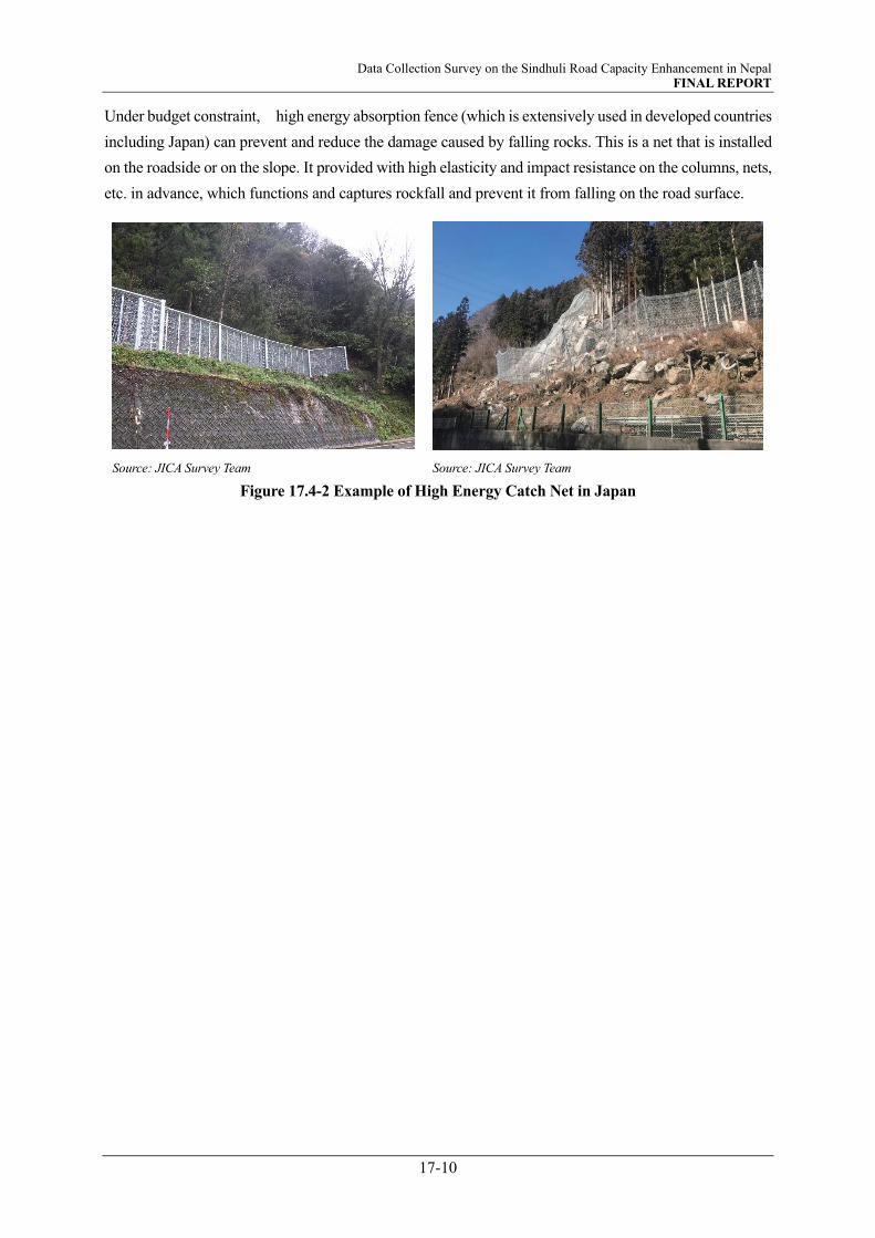
Data Collection Survey on the Sindhuli Road Capacity Enhancement in Nepal FINAL REPORT
17-10
Under budget constraint, high energy absorption fence (which is extensively used in developed countries
including Japan) can prevent and reduce the damage caused by falling rocks. This is a net that is installed
on the roadside or on the slope. It provided with high elasticity and impact resistance on the columns, nets,
etc. in advance, which functions and captures rockfall and prevent it from falling on the road surface.
Source: JICA Survey Team Source: JICA Survey Team
Figure 17.4-2 Example of High Energy Catch Net in Japan

Data Collection Survey on the Sindhuli Road Capacity Enhancement in Nepal FINAL REPORT
18-1
IMPROVEMENT EFFECT
18.1 INTRODUCTION
In this Survey, traffic demand forecast was simply conducted to grapes traffic demand and trend on the
Sindhuli Road based on population data and GDP growth rate. In order to quantitively study and evaluate
improvement effects that are deemed to be brought about by the capacity enhancement of the Sindhili
Road, traffic demand forecast based on wide area road network model is required, which is not included
in this survey due to lack of readily available data and other budgetary and timeframe constraints. Traffic
analysis including wide area road network is suggested for implementation in the succeeding project.
Therefore, this chapter provides improvement effects only in terms of travel time saving effect of Sindhuli
Road capacity enhancement using the results of future demand forecasts in 2041 explained in Chapter 8
and study results in Chapter 10 and 13.
18.2 TRAVEL TIME SAVING EFFECT OF THE PROJECT
18.2.1 Methodology
Improvement of the project road can play a very important role in strengthening the accessibility and
economic growth. A preliminary economic evaluation of travel time saving and travel cost saving were
carried for “With Project” and “Without Project” cases.
Source: JICA Survey Team
Figure 18.2-1 Workflow of TTC Saving Benefit
The travel time cost (TTC) is the cost lost by a vehicle when it travels. The TTC is normally calculated
based on the average labor productivity and income of the country. As the DOR (Department of Roads)
don’t configure official TTC for road projects in Nepal, the Survey Team adopted the TTC estimated in
the SD Road Project Survey. Basically, reduction in travel time is the main component in the derivation of
the TTC saving. The annual savings was calculated as the difference in travel time between the base road
network and with Sindhuli Road project. The unit TTC of vehicles is shown in Table 18.2-1. And the
Benefit Stream
Unit Travel Time Cost (TTC)
Traffic Assignment Result (per day)
Benefit Daily Savings of TTC
Yearly Benefit in 2041
“Without” Project
“With” Project
Summations of TTC
Summations of TTC

Data Collection Survey on the Sindhuli Road Capacity Enhancement in Nepal FINAL REPORT
18-2
average number of passengers and average Loading Weight of Heavy Truck are shown in Table 18.2-2,
Table 18.2-3 and Table 18.2-4 respectively.
Table 18.2-1 Unit Travel Time Cost, W/O Motorcycle
Source: SD Road Project Report (JICA)
Table 18.2-2 Average Number of Passengers by Type of Vehicle
Source: SD Road Project Report (JICA)
Table 18.2-3 Average Loading Weight of Heavy Truck on Weekday
Source: SD Road Project Report (JICA)
Classification NPR/veh.-min
Car & Taxi 8.6
Utility Pick up 13.3
Micro Bus 19.8
Mini Bus 45.4
Large Bus 48.2
Light Truck 4.9
Heavy Truck 6.3
Multi-axel Truck 6.9
Others 9.1
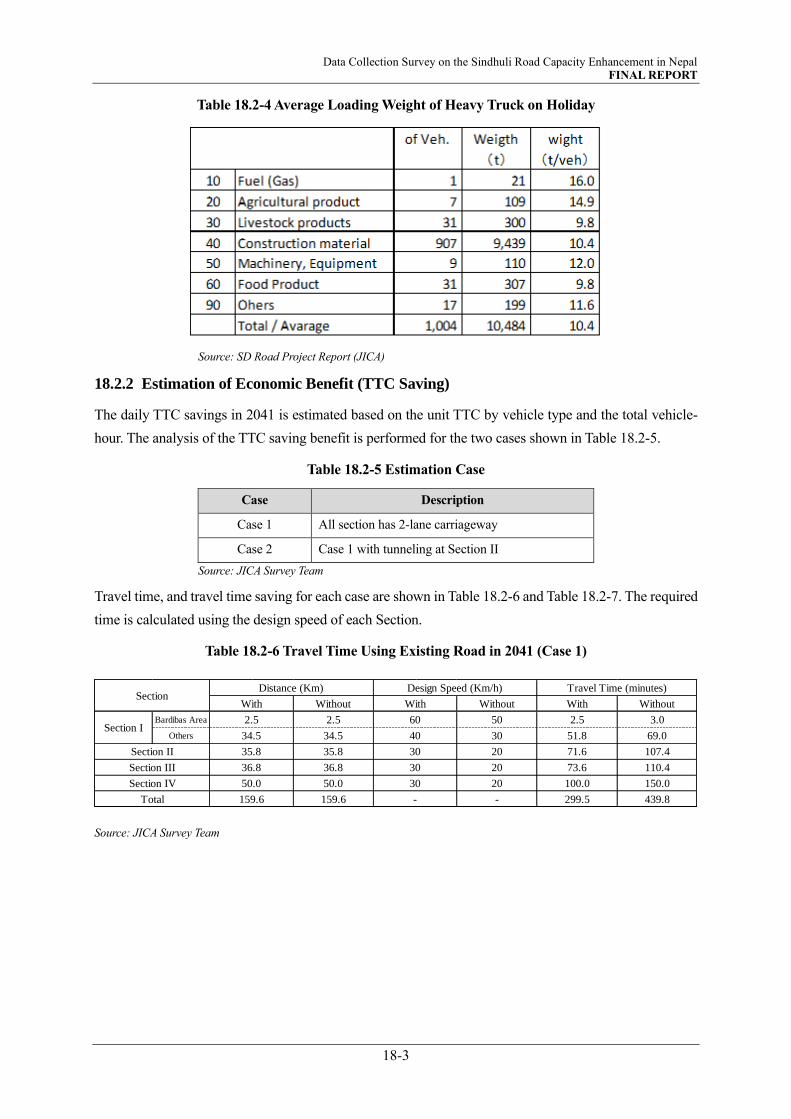
Data Collection Survey on the Sindhuli Road Capacity Enhancement in Nepal FINAL REPORT
18-3
Table 18.2-4 Average Loading Weight of Heavy Truck on Holiday
Source: SD Road Project Report (JICA)
18.2.2 Estimation of Economic Benefit (TTC Saving)
The daily TTC savings in 2041 is estimated based on the unit TTC by vehicle type and the total vehicle-
hour. The analysis of the TTC saving benefit is performed for the two cases shown in Table 18.2-5.
Table 18.2-5 Estimation Case
Case Description
Case 1 All section has 2-lane carriageway
Case 2 Case 1 with tunneling at Section II
Source: JICA Survey Team
Travel time, and travel time saving for each case are shown in Table 18.2-6 and Table 18.2-7. The required
time is calculated using the design speed of each Section.
Table 18.2-6 Travel Time Using Existing Road in 2041 (Case 1)
Source: JICA Survey Team
Without Without With Without
Bardibas Area 2.5 50 2.5 3.0
Others 34.5 30 51.8 69.0
35.8 20 71.6 107.4
36.8 20 73.6 110.4
50.0 20 100.0 150.0
159.6 - 299.5 439.8
Distance (Km)
With
159.6
Design Speed (Km/h)
With
60
40
30
30
30
-
2.5
34.5
35.8
36.8
50.0
Section II
Section III
Section IV
Total
Travel Time (minutes)
Section I
Section

Data Collection Survey on the Sindhuli Road Capacity Enhancement in Nepal FINAL REPORT
18-4
Table 18.2-7 Travel Time Using Existing Road and Tunnel in 2041 (Case2)
Source: JICA Survey Team
The calculation of the travel time saving is shortened time for using the Sindhuli Road before/after the
maintenance and the shortened time for switching from westbound route to Sindhuli road. In addition, the
travel speed between vehicle types is the same. The daily TTC saving by year is estimated based on the
unit TTC by vehicle type and the total vehicle-hour. The results of the TTC saving in each case are shown
in Table 18.2-8 and Table 18.2-9. As a result of the analysis, TTC saving is expected to be 2,585 million
NPR / year in Case 1, and 3,080 Million NPR / year in Case 2.
Table 18.2-8 TTC Saving Using Existing Road in 2041 (Case 1) (Million NPR / year)
Source: JICA Survey Team
Table 18.2-9 TTC Saving Using Existing Road and Tunnel in 2041 (Case 2) (Million NPR / year)
Source: JICA Survey Team
18.3 SUMMARY OF ESTIMATION RESULTS
Table 18.3-1 Summary of Estimation Results
Case Without Project
With Project
Case 1
(All section has 2-lane carriageway.)
Case 2
(Case 1 with tunneling at Section II)
Travel Time 439.8 minutes (7.3 hour) 299.5 minutes (5.0 hour) 260.3 minutes (4.3 hour)
Time Saving - 140.3 minutes(2.3 hour) 179.5 minutes(3.0 hour)
Cost Saving - 2,585 million NPR / year 3,080 million NPR / year
Source: JICA Survey Team
Without Without With Without
Bardibas Area 2.5 50 2.5 3.0
Others 34.5 30 51.8 69.0
Tunnel 7.7 Tunnel 30
Approach 1.6 Approach 30
Others 6.9 Others 30
36.8 20 73.6 110.4
50.0 20 100.0 150.0
159.6 - 260.3 439.8
35.8
Distance (Km)
With
2.5
34.5
Design Speed (Km/h)
With
60
40
32.420 107.4
36.8
50.0
140.0
30
30
-
Section II
Section I
Section III
Section IV
Total
Travel Time (minutes)Section
Bardibas Area 1.8 2.7 0.5 1.4 0.3 0.2 1.2 0.4 2.0 10.4
Others 28.3 46.8 23.0 40.8 0.0 11.2 37.7 0.0 6.7 194.6
58.7 97.2 47.7 84.7 0.0 23.3 78.3 0.1 14.0 403.9
76.2 191.3 57.3 166.4 0.0 23.0 79.0 1.6 40.1 634.9
125.7 275.6 62.7 249.0 0.0 30.1 121.6 0.0 0.6 865.3
46.7 169.8 155.4 56.0 26.4 2.7 19.8 0.0 0.0 476.8
337.4 783.3 346.6 598.3 26.7 90.5 337.6 2.2 63.5 2,585.9
Sindhuli Road
8. Heavy
Truck
9. Multi-
axel Truck
2. Car &
Taxi
3. Utility
Pick up
4. Micro
BusTotal
5. Mini
Bus
6. Large
Bus
7. Light
Truck10. Others
Section I
Section II
Section III
Section IV
Conversion from Westward Route
Total
Bardibas Area 1.8 2.7 0.5 1.4 0.3 0.2 1.2 0.4 2.0 10.4
Others 28.3 46.8 23.0 40.8 0.0 11.2 37.7 0.0 6.7 194.6
122.9 203.4 99.8 177.4 0.0 48.8 164.0 0.1 29.3 845.8
76.2 191.3 57.3 166.4 0.0 23.0 79.0 1.6 40.1 634.9
125.7 275.6 62.7 249.0 0.0 30.1 121.6 0.0 0.6 865.3
51.9 188.4 172.4 62.1 29.3 3.0 22.0 0.0 0.0 529.1
406.7 908.2 415.8 697.1 29.5 116.3 425.5 2.2 78.8 3,080.1
2. Car &
Taxi
8. Heavy
Truck
9. Multi-
axel Truck10. Others Total
3. Utility
Pick up
4. Micro
Bus
5. Mini
Bus
6. Large
Bus
7. Light
Truck
Section III
Section IV
Conversion from Westward Route
Total
Section I
Section IISindhuli Road

Data Collection Survey on the Sindhuli Road Capacity Enhancement in Nepal FINAL REPORT
19-1
CONCLUSION AND SUGGESTION
19.1 INTRODUCTION
This chapter discusses on pre-conditions for undertaking surveys and implementation of the project in
addition to suggestions and recommendations that need to be considered as a way forward in the
succeeding study stages.
19.2 PRE-CONDITIONS FOR IMPLEMENTATION OF THE PROJECT
Sindhuli Road is a 160km long national highway and is the shortest route connecting Kathmandu with the
East Terai regions and the northeast regions of the country. This Survey was carried out to understand the
current condition of the existing road and its operation, conduct traffic survey for future projection and
study the needs and possibility of capacity enhancement. The Survey finds and proposes measures for the
capacity enhancement, but there are some pre-conditions for undertaking the succeeding surveys/studies.
They are as discussed hereunder.
19.2.1 Capacity Enhancement of the Entire Stretch
One of the pre-conditions for undertaking the subsequent is the capacity enhancement that covers the entire
160km stretch of the Sindhuli Road.
The project aims to enhance the mobility and accessibility functions between Kathmandu and the eastern
regions including Terai. To realize this, simply widening the existing road to dual lane and improving
specific section only is not sufficient. A complete and comprehensive approach that include improvement
of the alignment, enhancing disaster-resilience and safety of the entire stretch is indispensable.
Besides, making a commitment by Nepal side to enhance the entire stretch of Sindhuli Road is one of the
important pre-condition to proceed the subsequent study for tunneling at Section II.
19.2.2 Timely Undertaking
In addition, the project is deemed to be of a huge size in terms of its cost and technology required. It`s
completion will also take substantial period - unless the scope is divided and undertaken simultaneously,
completion within the target period would be impossible, if not extremely challenging. The capacity
enhancement measures consist of various methods, from that which is technically and financially possible
for the GON to implement on its own to that which will require advanced technology for which
international assistance will be recommendable. Regardless of how the divisions of the demarcation will
be, it is important that the undertakings maintain harmony and consistency, such that the capacity of the
Sindhuli Road is realized in the prescribed target period.
19.2.3 Initiatives of Nepal Side for Project Implementation
The 5-year Strategic Plan of MOPIT sets out, among other objectives, widening of all roads under the
jurisdiction of the MOPIT / DOR to 2-lanes or more road. Narayanghat – Mugling Road, which is the only
section with narrower width was dualized in 2020. MH Highway and M-B Highway that connect to the
Sindhuli Road are being and will be constructed with 2 or more lanes. In February 2020, consultancy

Data Collection Survey on the Sindhuli Road Capacity Enhancement in Nepal FINAL REPORT
19-2
service for detailed design for improvement of Section III and Section IV was announced by the DOR for
under its own fund, but for reasons unclear was withdrawn in July of the same year. Budget for
maintenance of the Sindhuli Road is however allocated as indicated in the Red Book 2021/22.
It is thus apparent that the GON is very much aware of the importance and need of the Sindhuli Road.
However, as described in this report, there are budgetary and technical issues in the improving of the
Sindhuli Road. Nepal side is required to take necessary steps, such as specifically identifying and including
the project in the development plans, preparing implementation plans, allocating necessary budget etc. to
resolve these issues and realize the Sindhuli Road 2.0. This report is expected to serve as a material for
assisting Nepal side for consideration toward the realization of the Sindhuli Road 2.0.
19.3 RECOMMENDATIONS AND SUGGESTIONS
19.3.1 Reconsideration for Division of Sections
The findings of the study conducted under this Survey is compiled in sections that was demarcated during
the construction (4 sections, total length 160km). Conditions of capacity enhancement scopes may be better
interpreted in a different sectioning that is based on the topography, regional characteristics, traffic volume,
methods to be applied etc. In addition, the standard cross-section to be applied is suggested to take the
following points into consideration.
Consideration for road users other than traffic vehicles
Geometric conditions to be applied (Nepal`s Road Design Standard, Asian Highway Design Standard,
Consistency with M-H Highway and M-B Highway)
Topography and geology of the target area and its surroundings
Construction controls/constraints (detour during construction, traffic closures etc.)
Drainage, land use, ROW, etc
The study under this Survey was based on 1.0m resolution 3D satellite images with high-precision digital
elevation model (AW3D). However, there are limitations in accuracy such as the influence of tree height
and the inability to reproduce the current road. In addition, since the geology is at the reconnaissance level,
more detailed geological investigation such as borings/exploration and other physical tests should be
conducted, especially in places where landslides are a concern. Furthermore, the hydraulic and
hydrological data are also referred from preceding studies. The abnormal (extreme) weather that triggered
several landslides through the country including the target area needs to be taken into consideration.
Apart from those given above, following items are particularly important and needs to be considered in
the succeeding survey / study.
Level / standard of maintenance and cost are in trade-off relation. It is therefore necessary to scrutinize
the contents of the study scopes. In particular, since the design speed has immense influence on these
two factors, the design speed should be appropriately set following close and repeated discussion with
the DOR.

Data Collection Survey on the Sindhuli Road Capacity Enhancement in Nepal FINAL REPORT
19-3
This Survey adopts the design conditions/ criteria based on the Road Design Standard of Nepal. The
conditions.
Surveys and investigations conducted under this study at areas of landslide and slope failure sections
was limited to visual inspection and desk study. Appropriate assessment and reflection in the design
while referring to the field reconnaissance and international survey / investigation methods commonly
are deemed important in the succeeding study.
The estimated construction cost provided in Chapter 16 is tentative. It also does not include disaster
risk during construction. It is thus suggested that these risks are taken into consideration with proper
assessment and in close discussion with the DOR to set the necessary cost in the provisional sum.
Pavement design applied under this study is based on the number of heavy vehicles provided by the
traffic demand forecast. Condition of the roadbed or potential attraction to/from the on-going K-M
Fast Track are not considered. It is suggested that surveys/investigations required for the pavement
design including assumed traffic diversions to/from the K-M Fast Track, its toll fee etc. are taken into
consideration in the future traffic volume prediction and ultimately to the pavement design. In addition,
to ensure durability of the pavement, management of overloaded vehicles is also important.
Construction period estimated under this Survey may change depending on the construction plans,
such as utilizing the exiting road by imposing one way traffic or providing a detour etc., to be adopted.
Therefore, the Sindhuli Road 2.0 plan roadmap proposed in this survey needs to be revised based on
the results of the construction plan study conducted in the subsequent survey.
19.3.2 Tunneling at Section II
(1) Fractured Zones of Main Boundary Thrust and Mahabharat Thrust
As discussed in Chapter 13, it is understood that a band width of about 100 – 150m around MBT and
about 50m at MT at the south portal area are highly shattered fault zones. Under limited time due to
effect from the global pandemic, sufficient investigations were not able to be conducted. In future
surveys, it is therefore desirable that more detailed geological investigations (boring, elastic wave
exploration, etc.), be conducted to understand more accurately the location (section) and properties of
the fault zones for justifying the candidate routes and reflect it in the excavation method.
(2) Lane Operation Method of the Tunnel Section
Several lane operation methods of the tunnel section were compared, and their characteristics
summarized. There is a high possibility that the tunnel to be planned at Section II is expected to be a
lengthy tunnel. Therefore, in such case it is important to consider the optimal lane operation method in
consideration of the disaster risk, safety inside the tunnel including emergency facilities to be installed,
and disaster prevention system.
Therefore, it is suggested that the lane operation method of the tunnel section is discussed closely with
the DOR and decide the lane operation method considering not only the cost required for tunnel
construction but also the disaster risk and safety of the tunnel.

Data Collection Survey on the Sindhuli Road Capacity Enhancement in Nepal FINAL REPORT
19-4
(3) Excavation Method
The tunnel route crosses highly fractured zone at the MBT (Main Boundary Thrust) and the MT
(Mahabharat Thrust) at the south portal area. Since there is concern about destabilization of the face in
this section, it is important to consider the optimum excavation method and support structure based on
the results of future geological surveys.
In addition, at the stage of this survey, a AGF method is proposed as a measure to stabilize the face of
the section, but it is necessary to optimize the auxiliary method in the subsequent surveys/studies based
on the characteristics of the ground.
(4) Construction Planning of Tunnel
The tunneling at Section II is more than 7 km long. Excavation from both portals is recommended,
which is also the basis of cost estimation conducted under this Survey. This Survey proposes candidate
construction yard sites around the south and north portals. Necessary investigation and surveys are
suggested for formulating a concrete temporary equipment layout plan at these candidate sites. In
addition, as the rock classification assumed at most of the tunnel section is CI to CII there is a high
possibility for adoption of a blasting method using dynamites. Therefore, thorough confirmation of the
necessary procedures and processes for handling explosives is suggested to be considered and reflected
in the construction plan.
(5) Power Supply for Tunnel
Electricity of 1,600kVA is required during tunnel construction and 1,000kVA during operation. High
tension lines were identified at the target area. Power supply is thus considered possible, but plan for
provision of distribution line will be required. Nevertheless, for following reasons, power supply by
means of a power generator is suggested.
For corresponding to sudden power outage and other possible emergency situations,
Negotiations and procedures maybe sophisticated and lengthy and construction to lay distribution
lines for power may take time
To operate traffics inside the tunnel smoothly and safely, it is utterly important that the facilities inside
the tunnel is timely and adequately maintained. Proper education for transfer of technology, knowledge,
know-hows on maintenance and operation of the tunnel is therefore highly suggested.
19.3.3 Traffic Demand Forecast
Traffic demand forecasts conducted under this Survey takes into account only the socio-economic
framework of Nepal and traffic volume conducted by the research team. There are many developments
such as completion and opening of the K-M Fast Track, eastern section of M-H Highway and M-B
Highway, north-south corridors etc. On one hand, the completion of the K-M Fast Track will attract traffics
from the Sindhuli Road temporarily resulting to reduction of the volume currently plying there. However,
on the other hand, the significance of the Sindhuli Road is expected to rise with respect to the development
of other highways including growth of the country.
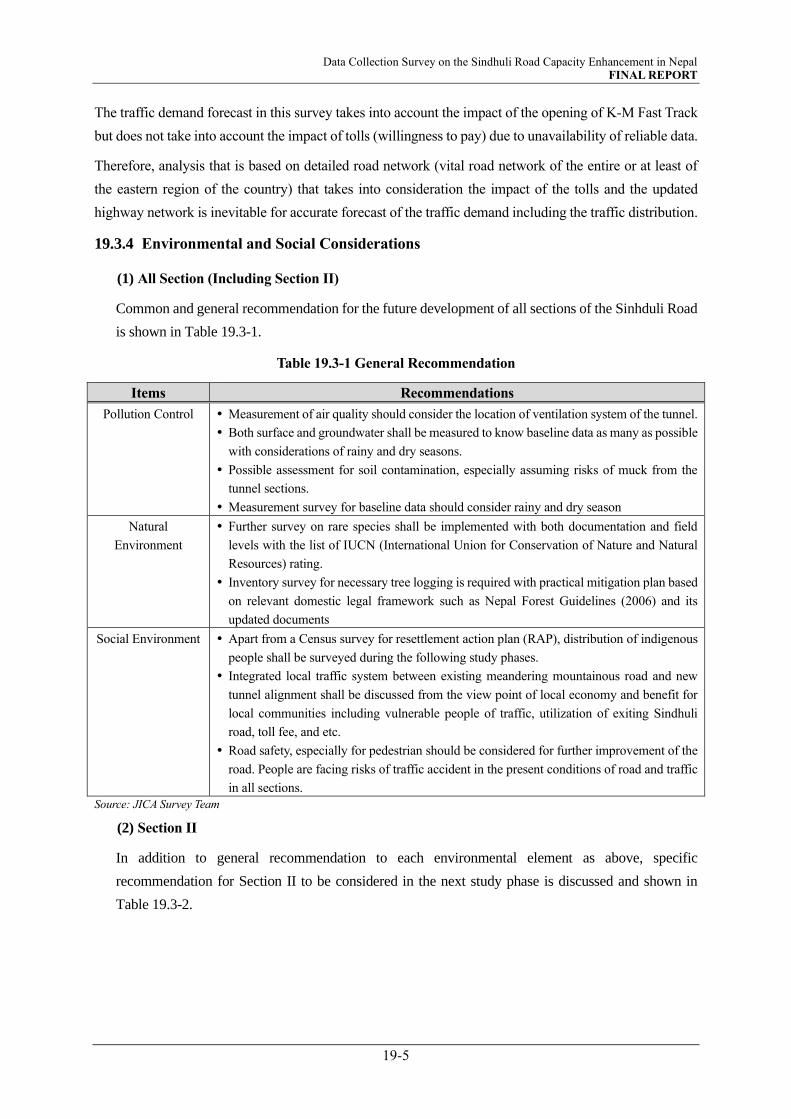
Data Collection Survey on the Sindhuli Road Capacity Enhancement in Nepal FINAL REPORT
19-5
The traffic demand forecast in this survey takes into account the impact of the opening of K-M Fast Track
but does not take into account the impact of tolls (willingness to pay) due to unavailability of reliable data.
Therefore, analysis that is based on detailed road network (vital road network of the entire or at least of
the eastern region of the country) that takes into consideration the impact of the tolls and the updated
highway network is inevitable for accurate forecast of the traffic demand including the traffic distribution.
19.3.4 Environmental and Social Considerations
(1) All Section (Including Section II)
Common and general recommendation for the future development of all sections of the Sinhduli Road
is shown in Table 19.3-1.
Table 19.3-1 General Recommendation
Items Recommendations
Pollution Control Measurement of air quality should consider the location of ventilation system of the tunnel.
Both surface and groundwater shall be measured to know baseline data as many as possible
with considerations of rainy and dry seasons.
Possible assessment for soil contamination, especially assuming risks of muck from the
tunnel sections.
Measurement survey for baseline data should consider rainy and dry season
Natural
Environment
Further survey on rare species shall be implemented with both documentation and field
levels with the list of IUCN (International Union for Conservation of Nature and Natural
Resources) rating.
Inventory survey for necessary tree logging is required with practical mitigation plan based
on relevant domestic legal framework such as Nepal Forest Guidelines (2006) and its
updated documents
Social Environment Apart from a Census survey for resettlement action plan (RAP), distribution of indigenous
people shall be surveyed during the following study phases.
Integrated local traffic system between existing meandering mountainous road and new
tunnel alignment shall be discussed from the view point of local economy and benefit for
local communities including vulnerable people of traffic, utilization of exiting Sindhuli
road, toll fee, and etc.
Road safety, especially for pedestrian should be considered for further improvement of the
road. People are facing risks of traffic accident in the present conditions of road and traffic
in all sections.
Source: JICA Survey Team
(2) Section II
In addition to general recommendation to each environmental element as above, specific
recommendation for Section II to be considered in the next study phase is discussed and shown in
Table 19.3-2.

Data Collection Survey on the Sindhuli Road Capacity Enhancement in Nepal FINAL REPORT
19-6
Table 19.3-2 The Other Recommendation for the Section II
Items Contents
Associated Facilities and
Cumulative Impact
It does not seem to be any qualified cases as associated facilities with the discussed
tunnel section at the moment of this survey. Cumulative impact, however, should be
surveyed and evaluated in the future survey period to avoid overlooking of such impact
including stabilization of slopes along the planned alignment.
Secondary/Indirect Impact Because the candidate sites of soil borrow pit, quarry, dumping site, camping site, etc.
have not fixed yet at the time of this survey, secondary impact caused by such project-
related facilities should be examined in detail during the following survey phases. Also,
indirect impact including socio-economical changes on bypassed area shall be assessed
with enough survey data in the following survey periods.
Special Considerations on
Tunnel Portals
Impact and rights on land around the tunnel portals shall be further discussed with
views of land ownership and protection zones of tunnel structures, such as land surface
rights and restriction of development in the future.
Considerations for Rainy
and Dry Season
Environmental items which may be affected by the rainy and dry season, such as
hydrology, water-use, air pollution, shall be considered carefully before commencement
of baseline surveys in the following survey periods to assess the impact correctly.
Impact on Socially
Vulnerable People
Impact on vulnerable people, such as vendors along the existing road which is bypassed
by the tunnel section, shall be assessed with care to avoid ignorance in mitigation and
monitoring measures. Also, other form of vulnerability, such as refugee of the last
earthquake, shall be confirmed and considered appropriately. Source: JICA Survey Team
19.3.5 Construction Planning and Cost Estimate
In the subsequent study of the projects, the followings items are suggested to be given considerations.
Study market condition of materials and equipment considering predicted construction schedule.
Reuse and/or disposal of tunnel muck and dismantled construction material based on the information in
this report after determining the final tunnel route and necessary approach roads.
Understanding the details of valley side retaining walls by obtaining calculation sheets including the
ground conditions. In some locations, inspection for the existing structure may be required. This work is
inevitable for the study and design of widening the existing road.
Studying the possibility to avoid dismantling of the existing structure as much as possible.
Efficient method for transportation of large-scale construction materials and equipment, especially
possible size of semi-trailer at the hair-pin curves.
Conduct investigations at the mountain side slope to study necessary slope protection measures.
Study other conceivable methods of enhancement measure and its construction cost. Especially, this survey
applies mountain bridge as improvement measures at certain hairpin curves. Considering possibilities for
alternatives that are cost-efficient are suggested(provision of turn outs etc.).
Conduct surveys to examine the status of application of recycled material (recycle method, quality
assurance etc.).
Scrutinization of construction cost estimate based on the more specific design.
Study of traffic management methods based on existing traffic and construction vehicles and machines.

Data Collection Survey on the Sindhuli Road Capacity Enhancement in Nepal FINAL REPORT
19-7
19.4 RECOMMENDATIONS
In addition to suggestions mentioned above, the followings are recommendations from the JICA Survey
Team for realizing and ensuring smooth implementation of the project.
Tentative Construction Cost
The result of this study estimates the total construction cost for capacity enhancement of the Sindhuli
Road that includes dualization of the entire section and tunneling at Section II is approximately 76.1
billion NPR. The construction cost for tunneling at Section II solely is about 36.9 billion NPR. It is
therefore important that the scale of the project is well understood and accepted by the GON,
including the MOF prior to moving forward for the implementation of the tunneling at Section II.
Specific and Indicative Plans
In particular, although MOPIT/DOR have positive opinions and are supportive with the capacity
enhancement of the Sindhuli Road, more specific plans indicating the time frame are required.
Therefore, it is necessary that Nepal side clarify the feasibility of dualization, which is a prerequisite
for the capacity enhancement.
Technical Aspects
The critical section is Section II where construction of the bypass that consists of about 8km long
tunnel is expected to take the longest period – about 8 years. It is therefore recommended that the
improvement of other sections be commenced in line with the study of the tunneling.
Provision of tunnels in some mountainous sections in Section III can have significant outcome and
might be advantageous in the long run. Study for examining the possibility of such provision is
recommended
The entire stretch of the Sindhuli Road was planned, designed and constructed under the grant aid
assistance from Japan. Local material and technology were extensively used, but many sections
consist of sophisticated technology that is unique to Japan. Widening at these sections needs
understanding the details of these technologies.
There are sections that can be undertaken by the GON on its own, both technically and financially.
These sections are recommended to be undertaken by the GON. This will help minimize the
investment and enhance awareness of ownership.
To ensure high benefit-cost ratio (BCR), adopting a sub-optimal solution that addresses capacity
enhancement of sections projected to have high BCR while widening other sections to the extent
sufficient for passing over of opposing vehicles or addition of turnouts progressively.