Centrifuges and Filters - IHI Asia Pacific Thailand
64
Centrifuges and Filters
-
Upload
khangminh22 -
Category
Documents
-
view
0 -
download
0
Transcript of Centrifuges and Filters - IHI Asia Pacific Thailand

Centrifuges and Filters

IHI Products in the CommunityCentrifuges and Filters

C e n t r i f u g e s a n d F i l t e r s3
Screw Decanter Centrifuge
PD Dehydrator
Belt Press Dehydrator
IHI-Leaf Filter
FUNDABAC Filter
Pilot Test
Guinard Centrifuge
Pilot Test
Screw Decanter Centrifuge
PD Dehydrator
Belt Press Dehydrator
IHI-Leaf Filter
FUNDABAC Filter
Guinard Centrifuge
p. 4
p. 18
p. 22
p. 30
p. 40
p. 50
p. 62
PD
DE
HY
DR
AT
OR
BE
LT P
RE
SS
D
EH
YD
RA
TO
RG
UIN
AR
DC
EN
TR
IFUG
EP
ILOT
TE
ST
IHI-LE
AF FILT
ER
FUN
DA
BA
C FILT
ER
SC
RE
W D
EC
AN
TE
RC
EN
TR
IFUG
E
IHI Products in the CommunityCentrifuges and Filters

Structure of the Screw Decanter Centrifuge1
Screw Decanter CentrifugeThe IHI Screw Decanter Centrifuge has been developed with our latest high speed rotation technology for use in every industry.From big to small, we offer a variety of models to meet your needs.
Liquid outletVibration isolator
Frame
Solid outlet
Belt coverMotor
Back drive
Feed pipeThe feed pipe is supported by the pipe holder and supplies slurry into the bowl from outside.
Inner screwThe inner screw consists of an inner drum and a screw blade welded onto the drum. The inner drum includes several liquid discharge ports. The top of the blade is provided with hardened material for excellent anti-wear.
BearingThe bearing supports the bowl with a structure of high accuracy which is enough to bear high-speed rotation.
CasingThe casing consistsof upper and lower casings, and is provided with outlets for solid matter and liquid.
Outer bowlThe outer bowl is a cylinder/cone combination, supported at both ends by the bearings. A separated liquid outlet is provided on the large-diameter side, and an outlet for solid matter on the small-diameter side. At the separated liquid outlet, the liquid level can be adjusted according to slurry being treated.
Gear boxThe gear box is an planetary gearing mechanism providing the bowl and screw with a rotation difference in the same direction.
Screw Decanter Centrifuge
To separate the slurry intosol id and l iquid, sett l ingp o n d s , w h i c h u s e t h especificdifference ingravity,have longbeenapplied. Ina structure that uses thisprinciple, as shown in thefigure, if you supply slurryfrom pipe A, solid mattersettles and separates intobowl B, which results inoutflowofsupernatant fluidfromweirC.
Then, a screw conveyorw i th a s l i gh t ro ta t i ona ldifference is installed in therotor.Thesolidpiledup inthe bowl is compelled tomovetotheright,whereitisdewateredanddischargedby theconveyor.Theslurryisconverted intoclear liquidand discharged from theoutletonthesideplate.
Rotating this device athigh speed (2000-6000rpm)helpsthesolidssettlefurtherbycentrifugalforce,and the sol ids rapidlyaccumulateontotheinnersurfaceofthebowl.
Whenslurryissupplied,theseparatedanddewateredsolidmatteriscontinuouslydischarged fromthesolidoutlet,and theseparatedliquid from theseparatedliquidoutlet.
Feed pipe
Slurry
Bowl
Solid
Supernatant fluid
Weir
SolidRotor
Side plate
Separated liquid
Screw
Slurry
Slurry
SolidRotor
Side plate
Separatedliquid
Outer bowl
Bearing box
Feed pipe
Slurry
Solid outletSeparated liquid outlet
Frame
Safety device
Gear boxCasing
Inner screw
Separated liquid
Solid
V-pulley
Principle of the Screw Decanter Centrifuge2
1
3
2
4
4C e n t r i f u g e s a n d F i l t e r s
SC
RE
W D
EC
AN
TE
RC
EN
TR
IFUG
EP
D D
EH
YD
RA
TO
RB
ELT
PR
ES
S
DE
HY
DR
AT
OR
GU
INA
RD
CE
NT
RIFU
GE
PILO
T T
ES
TIH
I-LEA
F FILTE
RFU
ND
AB
AC
FILTE
R

Features3
Quick TreatmentThroughcontinuousseparationanddehydration,alargeamountofslurrycanbetreatedquickly.
Optimal Performance by ApplicationWithawiderangeofpossibleselections;includingthebowl length,screwpitch,heightof theweirontheliquidsurfaceadjustmentplate,andscrewrotationspeed; theoptimalperformancecanbeobtainedforeverytypeofslurry.
Broad ApplicationsTheacceptableslurrysolidconcentrationrangeis0.1%to50%,whilesolidparticles inslurrywithcoarsenessrangingfromseveralmicronsto5mmcanbetreated.
Easy OperationLittleeffortisrequiredforthepre-operationpreparationsand post-operation cleaning, which raises workefficiencyandmakesoperationsverysimple.
Outstanding DurabilityPartsthatmaywearhavehighanti-wearperformancethroughtheuseofstrongsurface-hardeningoverlay.For slurry thatmaycauseextremewear, theuseof ultra-anti-wear chips can raise the anti-wearperformanceanotherlevel.
Anti-noiseAwideselectionofanti-noisemodelsandaccessoriesareavailable.
SafetyThesafetydeviceautomaticallystartsworkingin theeventofanoverloadduringoperationsoraparticlecaught inthescrew.Simultaneousalarmscannotifyoperatorsaboutanyproblems.
12
345
67
8
Applications4With its superior performance including a wide range of slurries that can be handled and large treatment volume through continuous operations, the IHI Screw Decanter Centrifuge is used in a large number of fi elds, centered around water treatment and manufacturing processes.
Food IndustrySteel Industry Chemical Industry
●Starch (Corn/potato /sweet potato)●Fish meal●Rendering●Yeast, Soy milk●Fruit juice, Beverages, Grains, Seasonings
●Resins (Vinyl chloride, Vinylidene chloride, Polyethylene, Polystyrene, ABS, Others)●Dyes, Pigments (Titanium oxide, Chrome yellow, Red iron oxide, others)●Fertilizers, Carbons, Medicines, Crystals (Sodium chloride, Sodium bicarbonate, Sodium sulfate decahydrate, Barium sulfate, Gypsum, Magnesium sulfate, Others)●Fluorescents for cathode-ray tube televisions●Toner polymers for copy machines●Electronics, semiconductors (Si, GaAs, SiO2, SiC, CMP)
●Pulverized coal●Fine ore●Slag●Clay●Kaolin●Plate solution●Iron powder●Copper powder●Glass powder●Waste oil●Calcium carbonate
ManufacturingProcesses
Sewage
Clean water
●Urban sewage, Housing complex sewage●Rural community wastewater
Muddy water,Turbid water
●Civil works, Tunnels●Dams, Stone crushing●Dredging●Cement
●Purified water●Industrial water
Industrialwastewater
●Food processing (Seafood processing, meat processing, agricultural product processing, brewing, confectionery production, bread making, etc.)●Livestock, Paper mill, Textile and dyeing, Chemical factory (Paints, chemicals, oils, fertilizers, printing, etc.)●Plating, Oil-bearing, Thermal power generation●Petroleum and gas factory, Steelworks, Metalworking industry, Machining industry, Wet type dust collection, General mining and manufacturing, Gypsum for desulfurization
Night soil
Garbage
●Night soil (human waste)●Septic tanks
●Incinerator wastewater●Garbage dumping site wastewater
Water treatment
Numerous ModelsTheproductsaremanufacturedatthenewestfacilitiesunderstrictqualitymanagementandhave receivedpraise forhighquality.FromMini-Decanters to theUltraLargetype,fromwastewatertoalltypesofslurryofmanufacturingprocess,theproductline-upincludesarichvarietyofmodelsthatcansuiteveryapplication.
C e n t r i f u g e s a n d F i l t e r s5
SC
RE
W D
EC
AN
TE
RC
EN
TR
IFUG
EP
D D
EH
YD
RA
TO
RB
ELT
PR
ES
S
DE
HY
DR
AT
OR
GU
INA
RD
CE
NT
RIFU
GE
PILO
T T
ES
TIH
I-LEA
F FILTE
RFU
ND
AB
AC
FILTE
R

HS-L Type
Slurry inlet
Rotation direction
A B
Cake outlet
C
Cake outletSeparated liquid outlet
Separated liquid outlet
Cake outlet
Rotation direction
Cake outletSeparated liquid outletA B
C
Slurry inlet
Separated liquid outlet
General-purpose type with high performanceOf all the Screw Decanter Centrifuges, the HS-L Type is the best for general purpose and is widely used in various fi elds.
Outline drawing (HS-204L, HS-205L, HS-255L)
Outline drawing (HS-324L or higher)
Screw Decanter Centrifuge
SC
RE
W D
EC
AN
TE
RC
EN
TR
IFUG
EP
D D
EH
YD
RA
TO
RB
ELT
PR
ES
S
DE
HY
DR
AT
OR
GU
INA
RD
CE
NT
RIFU
GE
PILO
T T
ES
TIH
I-LEA
F FILTE
RFU
ND
AB
AC
FILTE
R
6C e n t r i f u g e s a n d F i l t e r s

Specifications
Dehydration performance of sludge
Notes: 1.Normalcapacityisbasedonsettlingperformancestandardforstandardslurry(SSconcentration=1.5-2.5%). Treatmentvolumeisdifferentaccordingtotheslurryconditions(SSconcentration,viscosity,particlesize,orspecificgravity,etc.),whetherusing flocculantornot,anddesiredperformance(cakemoisturecontentratio,SSrecoveryratio). Furthermore,boththeamountofsolid(kg·DSS/h)andamountofslurry(m3/h)shouldbeconsideredwhenselectingthemodeltype.PleaseaskIHI aboutfeaturesorapplications. 2.Motoroutputforlargetypescanbealteredaccordingtoslurryconditions.
C:Cationic,A:Anionic,N:Nonionic
Thetreatmentvolumeandperformanceofcentrifugesaredifferentdependingonthepurposeofuse(clarification,dehydration,concentration,sorting,etc.),slurryconditions (SSconcentration, liquidviscosity, liquidandsolidspecificgravity,particlesizeofsolids,etc.),whetherusingflocculantornot,anddesiredperformance(SSrecoveryratio,cakemoisturecontentratio).
Performance
Cake moisture content ratio SS recovery ratio Flocculant additive rate (For sludge solids)
SC
RE
W D
EC
AN
TE
RC
EN
TR
IFUG
EP
D D
EH
YD
RA
TO
RB
ELT
PR
ES
S
DE
HY
DR
AT
OR
GU
INA
RD
CE
NT
RIFU
GE
PILO
T T
ES
TIH
I-LEA
F FILTE
RFU
ND
AB
AC
FILTE
R
C e n t r i f u g e s a n d F i l t e r s7
MD-10 0.6~0.9 2,000 2,000 1,260 940 420 250 2.2 ー HS-204L 1.0~1.5 2,000 3,500 1,500 1,030 560 390 3.7 ー HS-205L 1.5~2.5 2,000 3,500 1,635 1,060 560 410 3.7 ー HS-255L 2.5~3.5 2,000 3,500 1,870 1,380 560 390 3.7 ー HS-324L 3.0~4.0 2,000 3,500 2,100 1,440 700 1,030 11.0 ー HS-325L 4.0~6.0 2,000 3,500 2,300 1,440 700 1,160 15.0 ー HS-364L 3.0~5.0 2,000 3,500 2,150 1,890 830 1,200 15.0 ー HS-365L 5.0~8.0 2,000 3,500 2,380 1,950 830 1,440 22.0 ー HS-366L 8.0~12.0 2,000 3,000 2,690 1,950 830 1,700 30.0 ー HS-404L 4.0~6.0 2,000 3,500 2,520 2,000 870 1,970 22.0 ー HS-405L 7.0~10.0 2,000 3,500 2,780 2,000 870 2,260 30.0 ー HS-406L 10.0~15.0 2,000 3,000 3,120 2,000 870 2,820 30.0 ー HS-504L 6.0~10.0 2,000 3,500 3,050 2,380 1,040 3,435 30.0 ー HS-505L 10.0~16.0 2,000 3,500 3,400 2,380 1,040 3,840 45.0 ー HS-506L 16.0~23.0 2,000 3,000 3,830 2,380 1,040 4,350 55.0 ー HS-554L 8.0~12.0 2,000 3,000 3,500 2,700 1,080 4,070 45.0 0.40
HS-555L 13.0~19.0 2,000 3,000 3,860 2,700 1,080 4,750 55.0 0.40
HS-556L 19.0~28.0 2,000 3,000 4,330 3,000 1,080 5,150 55.0 0.40
HS-634L 10.0~15.0 2,000 3,000 3,980 3,000 1,330 5,850 55.0 0.75
HS-635L 17.0~25.0 2,000 3,000 4,390 3,000 1,330 6,500 75.0 0.75
HS-636L 25.0~37.0 2,000 2,600 4,920 3,000 1,330 7,200 90.0 0.75
HS-704L 13.0~19.0 2,000 2,600 4,430 3,350 1,480 8,100 75.0 0.75
HS-705L 20.0~31.0 2,000 2,600 4,880 3,350 1,480 8,900 90.0 0.75
HS-706L 31.0~47.0 2,000 2,600 5,470 3,500 1,480 10,500 110.0 0.75
HS-804L 17.0~25.0 2,000 2,600 5,060 3,500 1,790 11,700 90.0 0.75
HS-805L 27.0~40.0 2,000 2,600 5,740 3,500 1,790 12,900 110-132 0.75
HS-806L 40.0~60.0 2,000 2,600 6,420 3,500 1,790 15,100 132-160 0.75
HS-1005L 42.0~63.0 2,000 2,000 6,800 4,000 2,200 20,800 150-200 0.75
HS-1105L 51.0~76.0 2,000 2,000 7,500 4,200 2,300 25,000 180-250 0.75
Centrifugal force (G) Dimension (mm) Weight (kg)
Output (kW)
(㎥/h) Normal Maximum A B C Main drive motor Lube oil unit
Normal capacityType
Sewage 76~83% 95~99% 0.5~1.2% C
Night soil 80~85% 95~99% 0.6~1.6% C
General factory 82~88% 95~99% 0.8~2.0% C
Livestock 82~85% 95~99% 0.8~1.5% C
Plating sludge 70~85% 95~99% 0.2~0.5% A
Dye sludge 70~80% 95~99% 0.2~0.8% A, N
Paint factory supernatant sludge 75~85% 95~99% 0.5~0.5% N
Used paper sludge 60~75% 95~99% 0.1~1.0% A
Acid pickling sludge 70~80% 95~99% 0.2~0.5% A, N
Wet type dust collection sludge 60~75% 95~99% 0.3~0.5% A, N
Clean water sludge 70~80% 95~99% 0.1~0.5% A, N
Stone crushing sludge 30~50% 85~98% 0.0~0.4% A, N
Biological excess sludge
Types of sludge

IX-T TypeEnergy saving, low noise, less spaceDeveloped under the concept of "Gentle to the Earth", this is a light weight, low noise type slender-bodied decanter, requiring minimal installation space. It gives its best performance in the fi eld of sewage treatment.
Performance
Human waste treatment Rural community wastewater Garbage landfill wastewater Industrial
wastewater
High load treatment methodExcess + precipitated
Septic tank sludge
Human waste debris
removal
Activated excess sludge
Activated excess sludge
Flocculation sludge
Activated excess sludge
Flocculant additive rate (%/DS) 1.4~1.8 1.0~1.5 Without flocculants feed 1.0~1.5 1.0~1.5 1.5~2.0 1.0~1,5
Cake moisture content ratio (%) 83~85 80~85 70~80 84~85 84~85 84~85 84~85
SS recovery ratio (%) 95 or higher 95 or higher 50~70 95 or higher 95 or higher 95 or higher 95 or higher
Treatment volume(kg・DSS/h)
IX-18S 15 10 *2~3 10 10 15 10
IX-18T 30 25 *3~5 25 25 30 25
IX-25T 70 50 *7~9 50 50 70 50
IX-32T 140 110 *12~15 110 110 140 110
IX-36T 180 140 *16~20 140 140 180 140
IX-40T 220 170 *20~25 170 170 220 170
IX-50T 360 270 *30~38 270 270 360 270
Electricity regeneration systemFeatures
Light weight, small installation spaceWehavesucceeded inachieving30% lighterweightand40%lessinstallationspacecomparedtoourregulartypesbycreatinganoptimaldesignfortheshapeoftherotatingunit,andcasingsize.
Low noiseBymodifying theshapeof the rotatingpart'scover,whichhasbeenasourceofnoise,wehaverealized2to3dB(A)lessnoisecomparingwithournormalmachines.
Energy savingIX-TTypeadopts Inverters for themaindriveandbackdriveunits.ThiscanbringyouoptimalG-Forceandscrewspeedforyourslurrybyjustturning thedialon thecontrolpanel.Alsobyconnecting Inverters for themaindrivemotorandbackdrivemotor,thebackdrivemotoractsasgeneratorandsuppliesthepowertothemainmotor.
1
2
3
Energy-saving:Thebackdrivemotor installedasagearboxgenerateselectricity,whichisusedfordrivingthecentrifuge.
Inverter Inverter
Collected power
Back drive motor
Main drive motor
Centrifuge
Power supply
*Thetreatmentvolumeforhumanwastedebrisremovalisdisplayedinm3/h.
Screw Decanter Centrifuge
SC
RE
W D
EC
AN
TE
RC
EN
TR
IFUG
EP
D D
EH
YD
RA
TO
RB
ELT
PR
ES
S
DE
HY
DR
AT
OR
GU
INA
RD
CE
NT
RIFU
GE
PILO
T T
ES
TIH
I-LEA
F FILTE
RFU
ND
AB
AC
FILTE
R
8C e n t r i f u g e s a n d F i l t e r s

Back drive motor
Cake outletA
Separated liquid outlet
Main drive motor
Separated liquid outlet Cake outlet
B
C
Outline drawing
TypeNormal
capacity(㎥/h)
Centrifugal force(G)
Output (kW)
Weight (kg)
Dimension (mm)
Main drive motor
Back drive motor A B C
IX-18S 0.7~1 2,000 3.7 0.75 300 1,250 800 400
IX-18T 1.5~2 2,000 3.7 0.75 400 1,550 800 400
IX-25T 3.5~4.5 2.000 5.5 1.5 700 2,000 900 500
IX-32T 7~9 2,000 11 3.7 1,100 2,500 1,050 630
IX-36T 9~12 2,000 15 3.7 1,500 2,750 1,200 750
IX-40T 11~16 2,000 18.5 5.5 2,200 3,000 1,300 800
IX-50T 18~25 2,000 30 7.5 3,500 3,550 1,500 900
Specifications
1.Motoroutputcanbealteredaccordingtoslurryconditions.2.Thespecificationsmaybemodifiedwithoutadvancednotice.PleaseconfirmthedetailswithIHI.
SC
RE
W D
EC
AN
TE
RC
EN
TR
IFUG
EP
D D
EH
YD
RA
TO
RB
ELT
PR
ES
S
DE
HY
DR
AT
OR
GU
INA
RD
CE
NT
RIFU
GE
PILO
T T
ES
TIH
I-LEA
F FILTE
RFU
ND
AB
AC
FILTE
R
C e n t r i f u g e s a n d F i l t e r s9

HS-DP TypeEnergy saving with a deep pool-shaped rotor.The back drive system is fi tted as standard.
TypeNormal
capacity (㎥/h)
Centrifugal force(G)
Output (kW) Weight (kg) Dimension (mm)
Main drive motor
Back drive motor
Lube oilunit
withcommon
bedA B C1 C2
HS-40DP 1.5-2.5 2,000 3.7 0.75 - * 720 1,675 1,320 573 -HS-100DP 3-4 2,000 5.5 1.5 - * 890 1,865 1,500 600 -HS-120DP 4-6 2,000 7.5 1.5 - * 1,000 2,075 1,500 600 -HS-200DP 3-5 2,000 11 2.2 - 1,750 2,260 1,600 - 930
HS-300DP 5-8 2,000 11 2.2 - 1,900 2,460 1,600 - 930
HS-320DP 7-11 2,000 11 2.2 - 2,100 2,730 1,600 - 930
HS-340DP 4-6 2,000 11 3.7 - 2,000 2,580 1,950 - 986
HS-360DP 6-10 2,000 15 3.7 - 2,200 2,510 1,950 - 986
HS-380DP 9-14 2,000 18.5 3.7 - 2,400 2,810 1,950 - 986
HS-400DP 6-8 2,000 15 3.7 - 2,600 2,710 2,000 - 1,060
HS-500DP 8-12 2,000 18.5 3.7 - 3,000 2,970 2,000 - 1,060
HS-520DP 11-17 2,000 18.5 3.7 - 3,300 3,310 2,000 - 1,060
HS-600DP 9-13 2,000 22 5.5 - 4,500 3,280 2,300 - 1,260
HS-700DP 13-19 2,000 30 5.5 - 4,900 3,630 2,300 - 1,260
HS-720DP 18-27 2,000 30 5.5 - 5,500 4,030 2,300 - 1,260
HS-760DP 15-23 2,000 37 7.5 0.4 5,700 4,130 2,380 1,129 1,300
HS-800DP 20-30 2,000 55 7.5 0.75 11,600 4,785 3,065 1,390 1,720
Specifi cations
Center of centrifuge
Cake outlet
Back drive motor
Cake outlet(With companion flange)
Slurry inlet
C2 C
1
A BSeparated liquid outlet
Foundation bolt
Rotation direction
Main drive motor
Separated liquid outlet
Block-out box for foundation bolt
Outline drawing
1. Normalcapacityisbasedontheassumptionofdehydrationofmixedsludge(SSconcentration=1.5-2.5%),usingthestandardnitrogenremovalmethod. Treatmentvolume isdifferentaccordingtothetypeofsludge, theslurryconditions (SSconcentration,viscosity,particlesize,orspecificgravity,etc.), whetherusingflocculantornot,anddesiredperformance(cakemoisturecontentratio,SSrecoveryratio). PleaseaskIHIaboutfeaturesorapplications.2. Motoroutputcanbealteredaccordingtoslurryconditions.*=Incaseofnocommonbed
Screw Decanter Centrifuge
SC
RE
W D
EC
AN
TE
RC
EN
TR
IFUG
EP
D D
EH
YD
RA
TO
RB
ELT
PR
ES
S
DE
HY
DR
AT
OR
GU
INA
RD
CE
NT
RIFU
GE
PILO
T T
ES
TIH
I-LEA
F FILTE
RFU
ND
AB
AC
FILTE
R
10C e n t r i f u g e s a n d F i l t e r s

RS/RW TypeExclusive dehydrator for synthetic resinRS Type High Dehydration Resin Exclusive Screw DecanterIHI's original unique rotor reduces the water content of separated matter by 5-10% compared to the previous general purpose machines. RW Type Resin Washing Screw DecanterThrough the use of a unique mechanism, the product can be cleaned and dehydrated.
Type Normal capacity
(kg・DSS/h)
Centrifugal force (G)
Dimension(mm) Weight
(kg)
Output (kW)
For resin dehydration For resin dehydration and washing Normal Maximum Length Width Height Main drive
motorLube oil
unit
HS-204RS(HS-10RS) HS-204RW(HS-10RW) 800 2,000 3,500 1,500 1,030 560 390 5.5 -
HS-254RS HS-254RW 1,200 2,000 3,500 1,710 1,380 590 600 11 -
HS-324RS(HS-20RS) HS-324RW(HS-20RW) 2,000 2,000 3,500 2,100 1,440 700 850 22 -
HS-364RS HS-364RW 2,600 2,000 3,500 2,160 1,950 830 1,000 30 -
HS-404RS(HS-40RS) HS-404RW(HS-40RW) 3,200 2,000 3,500 2,520 2,000 870 1,730 45 -
HS-504RS(HS-60RS) HS-504RW(HS-60RW) 5,000 2,000 3,500 3,050 2,380 1,040 3,120 75 -
HS-554RS HS-554RW 6,000 2,000 3,000 3,500 2,700 1,080 3,700 90 0.4
HS-634RS(HS-80RS) HS-634RW(HS-80RW) 8,000 2,000 3,000 3,980 3,000 1,330 5,400 132 0.75
Specifications
Specifications
TypeNormal
capacity (kg・DSS/h)
Dimension (mm) Main drive motor (kW)
Weight (kg)
Length Width Height with common bed
HS-324GS 800-1200 2,170 1,600 912 11-15 1,430
HS-364GS 1.000-1,600 2,230 2,000 1,055 15-22 2,100
HS-404GS 1,300-1,900 2,616 2,000 1,062 18.5-30 2,600
HS-504GS 2.000-3,000 3,410 2,500 1,305 37-55 4,500
HS-554GS 2.400-3,600 3,675 2,700 1,305 45-75 5,700
HS-634GS 3,000-4.800 4,135 2,850 1,629 55-90 7,800
HS-704GS 4,000-5,500 4,385 2,920 1,629 55-110 9,500
HS-804GS 5,000-7.500 5,430 3,650 *1,780 75-132 *9,600
Note:Treatmentvolume is forgypsumbyproductwhenusinganashseparationmethoddesulfurizationsystemwithacoal-firedboiler orwhenusingadesulfurizationsystemwithaheavyoil-fueledboiler.Treatmentvolumeisdifferentdependingontheslurryconditions (SSconcentration,particlesize,flyash,etc.).PleaseaskIHIaboutfeaturesorapplications.*=Incaseofnocommonbed
1. Motoroutputmaybealteredaccordingtothecentrifugalforce,slurryconcentration,andtreatmentvolume.2. Toprovidevariabilityinthedifferentialspeedofthescrew,avariabledifferentialspeeddevicecanbeadded.3. Dependingontheinstallationconditions,anexplosionprotectionstructureandairtightstructurecanbeadded.4. Normalcapacityisapproximatetreatmentvolumeofchloroethyleneforgeneralpurpose.
GS TypeExhaust Gas DesulfurizerContinuous Centrifuge for Gypsum DehydrationThe tapered part of the machine consists of a primary dehydration part with an acute angle and a secondary dehydration part with an obtuse angle, enabling high dehydration.The use of anti-wear chips on the edges of screw blades and anti-wear ceramics on the inner outlet chamber, inner outlet, and solid outlet add considerable improvements for better durability.
SC
RE
W D
EC
AN
TE
RC
EN
TR
IFUG
EP
D D
EH
YD
RA
TO
RB
ELT
PR
ES
S
DE
HY
DR
AT
OR
GU
INA
RD
CE
NT
RIFU
GE
PILO
T T
ES
TIH
I-LEA
F FILTE
RFU
ND
AB
AC
FILTE
R
C e n t r i f u g e s a n d F i l t e r s11

MW TypeAnti-wear screw decanter for powerful treatment of muddy and turbid waterMW Type can be used for high wearing slurry, such as turbid water, muddy water or dredging slurry.
TypeNormal
capacity(㎥/h)
Normal centrifugal
force(G)
Dimension (mm) Weight (kg)Main drive
motor(kW)
Back drive motor (kW)
Lube oil unit(kW)A B C1 C2
withcommon
bed
HS-200MW 3-5 900-1300 1,550 1,320 570 730 850 3.7 1.5 -
HS-250MW 6-8 900-1300 1,810 1,500 600 860 1,100 5.5 2.2 -
HS-300MW 9-13 900-1300 2,460 1,600 700 930 1,900 15 3.7 -
HS-360MW 12-17 900-1300 2,500 1,950 830 1,060 2,400 22 5.5 -
HS-400MW 15-21 900-1300 2,970 2,000 870 1,060 3,000 30 7.5 -
HS-500MW 23-32 900-1300 3,630 2,300 1,040 1,260 4,900 45 11 -
HS-550MW 28-39 900-1300 4,080 2,300 1,080 1,300 5,700 55 15 0.4
HS-600MW 37-51 900-1300 4,500 3,050 1,390 1,720 11,600 75 18.5 0.75
HS-600MWC 55-75 900-1300 5,080 3,050 1,390 1,720 13,000 90 22 0.75
HS-800MW 60-80 900-1300 5,560 3,260 1,740 2,120 17,500 110 30 0.75
HS-800MWC 85-120 900-1300 6,240 3,260 1,740 2,120 20,000 132 37 0.75
Specifi cations
Note:Normalcapacityandnormalcentrifugalforcearetheexampleswhenthespecificgravityofbentonitemudisloweredwhentheundergroundcontinuouswallconstructionmethodisapplied.
Motoroutputcanbealteredaccordingtoslurryconditions.
Center of centrifuge
Cake outlet
Main drive motorBack drive motor
Cake outlet(With companion flange)
Slurry inlet
C2 C1
A BSeparated liquid outlet
Foundation bolt
Rotationdirection
Separated liquid outlet
Block-out box for foundation bolt
Outline drawing
Innerscrewwithultraanti-wearchip Ceramicliner
CeramicbushingFeatures
Greatly improves anti-wearperformance,whilethecompactsize al lows the instal lat ionspacetobesmaller.
Abrasiveslurrycanbeprocessedquicklyandathighvolume.
Byequippingavariabledifferentialspeeddevice,changes to theslurryconditioncanbehandledquickly.
1 2 3
12C e n t r i f u g e s a n d F i l t e r s
Screw Decanter Centrifuge
SC
RE
W D
EC
AN
TE
RC
EN
TR
IFUG
EP
D D
EH
YD
RA
TO
RB
ELT
PR
ES
S
DE
HY
DR
AT
OR
GU
INA
RD
CE
NT
RIFU
GE
PILO
T T
ES
TIH
I-LEA
F FILTE
RFU
ND
AB
AC
FILTE
R

LS TypeSanitary typeequipped with a washing deviceIHI's original CIP automatic washing device is fitted as standard.It is used in a wide range of fields, including food, medicines, and fine chemicals.
Features
Buffingfinishforwetparts
Automaticwashing inside thecasing
Automaticdischargingofrestliquidinsidetheouterbowl
Automaticwashingofoutersurfaceoftherotor
Reversewashingof the innerscrew1
4
2
5
3
TypeNormal
capacity(㎥/h)
Centrifugal force(G)
(MAX)
Output (kW) Weight (kg) Dimension (mm)
Main drive motor
Back drive motor
Lube oil unit
withcommon
bedA B C1 C2
HS-204LS 1.0-1.5 3,500 3.7 0.75 (0.4) *670 1,545 1,320 573 -
HS-205LS 1.5-2.5 3,500 3.7 0.75 (0.4) *720 1,675 1,320 573 -
HS-255LS 2.5-3.5 3,500 5.5 1.5 (0.4) *890 1,865 1,500 600 -
HS-324LS 3-4 3,500 11 2.2 (0.4) 1,750 2,260 1,600 - 930
HS-325LS 4-6 3,500 15 3.7 (0.4) 1,900 2,460 1,600 - 930
HS-365LS 5-8 3,500 22 5.5 (0.4) 2,200 2,510 1,950 - 986
HS-366LS 8-12 3,000 30 5.5 (0.4) 2,400 2,810 1,950 - 986
HS-405LS 7-10 3,500 30 5.5 (0.4) 3,000 2,970 2,000 - 1,060
HS-406LS 10-15 3,000 30 5.5 (0.4) 3,300 3,310 2,000 - 1,060
HS-505LS 10-16 3,500 45 7.5 (0.4) 4,900 3,630 2,300 - 1,260
HS-506LS 16-23 3,000 55 7.5 (0.4) 5,500 4,030 2,300 - 1,260
Specifications
*=Incaseofnocommonbed
A B
C1
C2
Outline drawing
C e n t r i f u g e s a n d F i l t e r s13
SC
RE
W D
EC
AN
TE
RC
EN
TR
IFUG
EP
D D
EH
YD
RA
TO
RB
ELT
PR
ES
S
DE
HY
DR
AT
OR
GU
INA
RD
CE
NT
RIFU
GE
PILO
T T
ES
TIH
I-LEA
F FILTE
RFU
ND
AB
AC
FILTE
R

TP TypeThree-phase separation of oil, water and solid matter in one step.One unit can perform three-phase separation of oil, water and solid matter.This greatly contributes to energy saving in processes and improved economic effi ciency.
Slurry
SolidLightliquid
Heavyliquid
Cross section diagram
Specifi cations
Light liquidoutlet
Center of centrifuge
Cake outlet
Main drive motorBack drive motor
Cake outlet(With companion flange)
Light liquid outlet
Slurry inlet
Rotation direction
C2 C
1
A B
Lube oil unit
Heavy liquid outlet
Heavy liquidoutlet
Foundation boltBlock-out box for foundation bolt
Outline drawing
TypeNormal
capacity (㎥/h)
Maximum centrifugal
force(G)
Dimension (mm) Weight (kg) Output (kW)
A B C1 C2with
common bedMain drive
motorLube oil
unit
HS-255TP (HS-25TP) 1.5-2.5 3,500 1,870 1,380 600 - *660 5.5 (0.4)
HS-324TP (HS-34TP) 2-3 3,500 2,100 1,440 700 930 1,350 11 (0.4)
HS-325TP (HS-35TP) 3-4 3,500 2,300 1,440 700 930 1,500 15 (0.4)
HS-365TP 4-5 3,500 2,390 1,950 830 1,050 2,000 22 (0.4)
HS-366TP 6-8 3,000 2,700 1,950 830 1,050 2,300 30 (0.4)
HS-405TP (HS-45TP) 5-7 3,500 2,780 2,000 870 1,060 2,900 30 (0.4)
HS-406TP (HS-46TP) 7-10 3,000 3,120 2,000 870 1,060 3,600 30 (0.4)
HS-505TP (HS-55TP) 7-11 3,500 3,400 2,380 1,040 1,260 5,000 45 (0.4)
HS-506TP (HS-56TP) 11-16 3,000 3,830 2,380 1,040 1,260 5,500 45 (0.4)1.Treatmentvolumeaboveisinthecaseofpresswaterforfishmeal,andcanbealteredaccordingtotheliquidtreated.2.Motoroutputcanbealteredaccordingtotheadoptedcentrifugalforce.*=Incaseofnocommonbed
14C e n t r i f u g e s a n d F i l t e r s
Screw Decanter Centrifuge
SC
RE
W D
EC
AN
TE
RC
EN
TR
IFUG
EP
D D
EH
YD
RA
TO
RB
ELT
PR
ES
S
DE
HY
DR
AT
OR
GU
INA
RD
CE
NT
RIFU
GE
PILO
T T
ES
TIH
I-LEA
F FILTE
RFU
ND
AB
AC
FILTE
R

HV TypeSealed and pressure-tightA pressure-tight and airtight decanter.It can be used for dehydration in various fields, including for hazardous materials such as solvents or poisonous substances.
TypeNormal
capacity (㎥/h)(1)
Centrifugal force(G)
(MAX)
Normal design
pressure
Normal design
temperature
Output (kW)(2) Dimension(3)
Weight(kg)(3)Main drive
motorBack drive
motor A B C
HS-206L-HV 2 3,000 0.1MPaG 120℃ 5.5 2.2 1,970 1,250 580 800
HS-256L-HV 3 3,000 0.1MPaG 120℃ 7.5 3.7 2,850 1,600 1,200 2,000
HS-366L-HV 10 3,000 0.1MPaG 120℃ 37 11 3,150 2,200 1,200 4,400
Specifications
Cake outletSeparatedliquid outlet
Slurry inlet
BA
C
Outline drawing
*Theimageshowsamodelwithincludedoptions.
Features
Non-contact shaft seal methodDueto thenon-contactgasseal, there isno lossofpower fromthesealandcontaminationwillnotoccur.Furthermore, thenon-contactsealensuresa long lifespan.Also,flushing liquid,necessaryformechanical typecontact sealmethodsand therefrigerationorcirculationequipmentneededfor itarenotrequired.Itusesanextremelylowamountofsealgasaswell.
Simple and compact designBecause itutilizesahorizontal format, itoffersahighdegreeof freedomwhenplanningplantequipmentlayout.
1
2
Original seal embedded structureByusinganoriginalsealembeddedstructure,thetotallengthhasbeenreducedtothelengthofourstandardmachinesandthroughthis,itispossibletooperateitwithhighcentrifugalforce.
3
Note1:Thenormalcapacitystandsonlyasaroughguide,andwilllargelychangedependingontheslurryconditionofyourplan.Note2:Motoroutputcanbealteredaccordingtoslurryconditions.Note3:Weightanddimensionmaydifferaccordingtospecifications.
C e n t r i f u g e s a n d F i l t e r s15
SC
RE
W D
EC
AN
TE
RC
EN
TR
IFUG
EP
D D
EH
YD
RA
TO
RB
ELT
PR
ES
S
DE
HY
DR
AT
OR
GU
INA
RD
CE
NT
RIFU
GE
PILO
T T
ES
TIH
I-LEA
F FILTE
RFU
ND
AB
AC
FILTE
R

Centrifugal Thickener ISC-H TypeEnergy-saving and thickeningwithout the need for fl occulantsBased on IHI's long-term centrifugal and dehydration technology research and our achievements, the ISC-H Type has been developed as a centrifugal thickener. Compared to the former methods, energy saving effi ciency is much greater for both power consumption and motor output.Incredible treatment performance can be achieved in a short period of time. The amount of concentration can be freely adjusted. The product is manufactured at the newest facilities under strict quality management for optimum reliability.
Applications
●Sewage and mini sewage water treatment plantRawsludge,mixturesludge,activatedexcesssludge,andothers(tertiarytreatmentsludge,etc.)
●Human waste treatmentActivatedexcesssludge,digestedsludge,mixturesludge(digestedsludge+activatedexcess sludge), septic tank sludge, andothers(tertiarytreatmentsludge,etc.)
●OthersVarious industrial wastewater treatmentsludge,drinkingwater treatment sludge,processliquid
Type
Normal capacity (m2/h) Maximum centrifugal
force(G)
Output (kW) Weight (kg) Dimension (mm)
Sewage excess sludge
Human waste excess sludge
Main drive motor
Back drive motor
Lube oil unit
withcommon
bedA B C1 C2
ISC-1H 1.5 1.2 2,000 2.2 0.75 - *720 1,675 1,320 573 -
ISC-2H 4 3 2,000 3.7 0.75 - *820 1,865 1,380 594 -
ISC-2HC 5.5 4 2,000 3.7 0.75 - *1,000 2,080 1,380 594 -
ISC-3H 6 5 2,000 5.5 1.5 - 1,900 2,135 1,600 707 929
ISC-3HC 9 7 2,000 7.5 1.5 - 2,100 2,400 1,600 707 929
ISC-4H 10 8 2,000 11 2.2 - 3,000 2,725 2,000 834 1,056
ISC-4HC 14 11 2,000 15 2.2 - 3,300 3,070 2,000 834 1,056
ISC-5H 16 12 2,000 18.5 3.7 - 5,200 3,450 2,300 1,031 1,256
ISC-5HC 22 17 2,000 22 3.7 - 5,500 3,880 2,300 1,031 1,256
ISC-6H 28 21 2,000 37 5.5 0.75 11,000 4,600 2,900 1,400 1,650
ISC-7H 36 27 2,000 45 7.5 0.75 *8,200 5,000 3,200 1,600 -
ISC-8H 50 38 2,000 75 11 0.75 *11,400 5,500 3,600 1,800 -
ISC-9H 70 50 2,000 110 15 0.75 *15,000 7,200 3,800 2,000 -
ISC-11H 110 80 2,000 150 22 0.75 *25,000 8,700 4,200 2,300 -
ISC-13H 170 130 1,800 250 30 1.5 *38,000 10,000 4,700 2,700 -
Specifi cations
1.Normalcapacityof sewageexcesssludge isunder theconditionsof:without flocculants feed,SSconcentration treatment=0.6-0.8%, thickenedsludgeconcentration=4% orhigher,SSrecoveryratio=90%orhigher.Treatmentvolumewillbe1.2timesasgreatwhenSSrecoveryratiois85%and1.3timeswhenSSrecoveryratiois80%.2.Normalcapacityofhumanwasteexcesssludge isunder theconditionsof: thesludge is treatedwithhigh load treatment,without flocculants feed,SSconcentrationof treatment matter=1.5-2.0%,thickenedsludgeconcentration=4-5%,SSrecoveryratio=90%orhigher.Treatmentvolumewillbe1.2timesasgreatwhenSSrecoveryratiois85%and1.3timeswhenSS recoveryratiois80%.3.Thepowerofthemainmotordriveandbackdrivemotoriswhentheinverterdriveisused.Itcanbealteredaccordingtothetypeofdrive,adoptedcentrifugalforce,andtreatmentvolume.*=Incaseofnocommonbed
Separatedliquid outlet
Slurry inlet
Anti-vibration rubberCommon bedFoundation bolt
Casing drain
AB
C1
C2
Concentrated liquid outlet
Outline drawing
16C e n t r i f u g e s a n d F i l t e r s
Screw Decanter Centrifuge
SC
RE
W D
EC
AN
TE
RC
EN
TR
IFUG
EP
D D
EH
YD
RA
TO
RB
ELT
PR
ES
S
DE
HY
DR
AT
OR
GU
INA
RD
CE
NT
RIFU
GE
PILO
T T
ES
TIH
I-LEA
F FILTE
RFU
ND
AB
AC
FILTE
R

(A) Lube oil unitThisdevicecontainsanoil tank,cooler,andfeedoilpumpinacompactpackagetoforciblylubricatebearings.
(B) Internal flocculant feed pipeThispipeisusedtofeedtheflocculantintothecentrifuge.The internal flocculant feedmethodcanbeuseddependingon theslurrycondition.
Increased Functionality, Increased EfficiencyScrew Decanter OptionsVarious peripheral devices are assembled to improve functionality and handle a wide range of slurry.
(C) Installation standTheunitandmotorcanbothrestonthis steel framedstandwith legs.Installationcanbeperformedeasily,and it isalsoconvenient forpipingtheseparated liquidand removingsolids.
(C) Noise-proof coverThis compact cover combines acommonbaseplateandnoise-proofbox. Itcanreducenoisebyabout5dB(A).
(E) Ultra-anti-wear chipsFor slurry that may cause extremewear, installingultra-anti-wearchipsmadeofcementedcarbideonto thebladesof the innerscrewcanfurtherimprovetheanti-wearperformance.
(F) Flexible jointsFlexiblejointscanbeinstalledtotheslurrysupply inlet,separated liquidoutlet, andsolidoutlet topreventdevicevibrationsfromtransferringtothepipes.
(D) Stellite chipsTheanti-wearperformancecanbeimprovedbyinstallingtheseontothebladesoftheinnerscrew.
(G) Skimming structureThiscansuppressfoamintheseparatedliquid.
C e n t r i f u g e s a n d F i l t e r s17
SC
RE
W D
EC
AN
TE
RC
EN
TR
IFUG
EP
D D
EH
YD
RA
TO
RB
ELT
PR
ES
S
DE
HY
DR
AT
OR
GU
INA
RD
CE
NT
RIFU
GE
PILO
T T
ES
TIH
I-LEA
F FILTE
RFU
ND
AB
AC
FILTE
R

PD Dehydrator
IHI develops the industry's largest model with a width of 2mBased on IHI's long-term fundamental technology research, the world's largest PD Dehydrator has been added to the lineup. The PD Dehydrator can treat large amounts of sludge, which has never been done by a single machine before, and it greatly contributes to smaller space, energy saving, and reduction in required accessories.
Equipped with a fi lter reversal mechanism (Note 2)
The fi lter can reverse rotation with a single switch. This makes maintenance and control simple.Note 2: For PD-250II Type to PD-1000II Type only.
Lower powerIHI's original new filter reduces the amount of power required to drive the fi lter.The total power for the dehydrator is also extremely small, which greatly contributes to energy saving.
Circular fl occulation tankThe flocculation tank is circular, so compared to rectangular tanks, there is efficient agitation without deposits for easy care.
Safety device uses torque limiter methods (Note 1)
When a massive load is placed on the filter, torque limiter methods protect the drive device.The torque limiter can easily be reset if the overload is removed. Unlike a Charpin system torque clutch, this method does not require complicated work, such as exchanging parts.Note 1: Excluding PD-250II Type.
Its basic principle is gravity fi ltration. Because of its low vibration, low noise, low odor and energy saving performance it is gentle for the environment and also your workplace.From general drainage to oil containing sludge at food factories or slaughterhouses etc., excellent performance is assured.
*PD stands for Piled Disc.
18 C e n t r i f u g e s a n d F i l t e r s
PD Dehydrator
SC
RE
W D
EC
AN
TE
RC
EN
TR
IFUG
EP
D D
EH
YD
RA
TO
RB
ELT
PR
ES
S
DE
HY
DR
AT
OR
GU
INA
RD
CE
NT
RIFU
GE
PILO
T T
ES
TIH
I-LEA
F FILTE
RFU
ND
AB
AC
FILTE
R

Oil-containing wastewater dehydrationFood manufacturers often see sludge with large amounts of oil, such as flotation scum or kitchen wastewater. The PD Dehydrator safely dehydrates this type of sludge without clogging. Using the basic principle of separation through filtering, sludge can be dehydrated without settling.
Less noise/vibration/odor/stenchThe rotation speed for the filter is extremely slow at less than 1 rpm, so there is hardly any vibration or noise. Also, since separation and dehydration is performed in an airtight box, there are no odors, stenches, or scattered liquids.
Easy to installThe flocculation tank and washing water pump are packaged with the main unit for easy installation. Since there is hardly any vibration, there is no need for special foundation work, either.
Separation and dehydration through gravity filtrationThe basic principle is gravity filtration.The action of gravity performs filtration, so there is no need for the power from pressurizers or vacuums.The piled disk assembly consists of spacers and many thin discs made from wire mesh and filter that are piled together.Mult iple cyl indrical f i l ters are inserted into the dehydration tank to maintain a large filtration bed area.The floc is captured on the filter as cake, while liquids run through the gaps between the thin discs, where the liquid is separated, collected, and expelled through the filtered liquid outlet.
Auto-renewal of the filtration surface through cake removalThe floc accumulated on the filter is automatically removed by gently rotating the filter, and then it is transferred in the direction of the dehydrated cake outlet.In this manner, the filter surface is constantly renewed, which guarantees a channel for the liquid and maintains an efficient filtration rate.
Dehydration through draining and consolidationThe filters are gently rotated in a fixed direction, the cake created from coagulated floc is transferred towards the cake outlet, and finally it is removed from the surface of the water and the water content of the cake is lowered through draining. The number of rotations for the filter near the cake outlet is significantly lower, which causes consolidation in the cake and further promotes dehydration.As a result, the cake that has been dehydrated through both draining and consolidation is pushed in the direction of the outlet.
Cleaning the filterFilters scrape clean the surfaces of other filters, constantly renewing the filter surfaces. In order to ensure cleanliness, pressurized water sprays the filters clean at fixed time intervals, thus removing clogs in the filter paths and maintaining filtration ability.
1 Features of the PD Dehydrator
2 Principle of PD Dehydrator
Upper filtration bed
Flocculated slurry
Dehydrated cake
Lower filtration bed
Dehydration tank Filtered liquid Flocculator
Bearing
Filtered liquid
Dehydration tank
DiscSpacer
Shaft
Liquid passage
Floc
Filtered liquid
Slurry
Flocculant
Easy & fully automatic operationOperations are fully automatic, requiring very little manpower. The control panel is a touch panel for easy operations that make setting and changing operating conditions easy.
Easy maintenanceThe filter is composed of stainless discs, and since filter cloths are not used, maintenance is easy.
Energy-savingThe filter rotates at slow speed, requiring only a touch of drive power.
Less cleaning waterThe filter constantly cleans itself to prevent clogging.Washing occurs intermittently, so little washing water is required.
C e n t r i f u g e s a n d F i l t e r s 19
SC
RE
W D
EC
AN
TE
RC
EN
TR
IFUG
EP
D D
EH
YD
RA
TO
RB
ELT
PR
ES
S
DE
HY
DR
AT
OR
GU
INA
RD
CE
NT
RIFU
GE
PILO
T T
ES
TIH
I-LEA
F FILTE
RFU
ND
AB
AC
FILTE
R

A
B
C D
Dehydration tank inspection doorFlocculation tank inspection door
Flocculation tankWashing water pump
Flocculation tank draine. Filtration liquid outletd. Washing water inlet
Cake outletinspection door
Washing water tank
f. Cake outlet
Flocculation mixer
a. Slurry inlet
b. Flocculant inlet 1
c. Flocculant inlet 2
Overall outline drawing
PD-250II - PD-2000II
Type Width(mm)
Dimension (mm) Output (kW)Weight
(ton)(when dry)
Washing water
(m3/day) (Note 1)A B C D Drive unit Mixer
Washing water pump
PD-250Ⅱ 250 2647 1035 1540 1845 0.4 0.2 1.1 2.00 1.0~1.5
PD-500Ⅱ 500 2647 1120 1540 1845 0.4 0.2 1.1 2.45 1.0~1.5
PD-750Ⅱ 750 2647 1230 1540 1930 0.6 0.4 2.2 2.85 2.0~2.5
PD-1000Ⅱ 1000 2647 1480 1540 1930 0.6 0.4 2.2 3.10 2.0~2.5
PD-1500Ⅱ 1500 2737 2400 1652 2150 1.15 0.75×2 3.0 5.40 3.5~4.0
PD-2000Ⅱ 2000 2737 2650 1652 2150 1.15 0.75×2 3.0 6.50 3.5~4.0
Overview of specifi cations
TypeSlurry inlet Flocculant
inlet 1Flocculant
inlet 2Washing water
inletFiltered liquid
outletFlange size of
cake outlet
a b c d e f
PD-250Ⅱ 25A Rc1/2 Rc1/2 Rc3/4 80A 318x264mm
PD-500Ⅱ 25A Rc1/2 Rc1/2 Rc3/4 100A 568x264mm
PD-750Ⅱ 40A Rc1/2 Rc1/2 Rc3/4 100A 818x264mm
PD-1000Ⅱ 40A Rc1/2 Rc1/2 Rc3/4 100A 1068x264mm
PD-1500Ⅱ 80A Rc1 Rc1 Rc3/4 100A 1584×264mm
PD-2000Ⅱ 80A Rc1 Rc1 Rc3/4 100A 2084×264mm
Connecting
Note 1: The volume of washing liquid is for six minutes every hour of ten hours in one day.
20 C e n t r i f u g e s a n d F i l t e r s
PD Dehydrator
SC
RE
W D
EC
AN
TE
RC
EN
TR
IFUG
EP
D D
EH
YD
RA
TO
RB
ELT
PR
ES
S
DE
HY
DR
AT
OR
GU
INA
RD
CE
NT
RIFU
GE
PILO
T T
ES
TIH
I-LEA
F FILTE
RFU
ND
AB
AC
FILTE
R

Field Sludge nameSS
concentration(%)
Solid treatment volume
(kg・DSS/h/m)
Polymer dosage per DSS
(%)
Cake moisture content ratio
(%)
SS recovery ratio(%)
SewageSewage mixed sludge 1.0~2.5 70~90 0.5~1.0 70~78 95 or higher
Sewage digested sludge 1.5~2.5 70~90 1.0~1.5 78~84 98 or higher
Night soil
Human waste septic tank sludge 0.5~1.0 70~110 1.0~1.5 78~83 98 or higher
Human waste excess sludge 1.0~2.0 60~90 1.0~1.5 80~85 95 or higher
Human waste mixed sludge(biological + precipitated) 1.0~2.0 50~70 1.0~1.5 80~85 95 or higher
Food
Packaged lunch factory mixed sludge (excess + flotation) 1.5~2.5 40~60 Anion: 0.5
Cation: 1.0 77~82 95 or higher
Packaged lunch factory excess sludge 1.5~2.5 40~60 Anion: 0.5Cation: 1.0 77~82 95 or higher
Confectionery excess sludge 1.5~2.0 60~70 Anion: 0.5Cation: 1.0 82~85 95 or higher
Drink factory excess sludge 1.5~2.0 40~60 1.5~2.0 82~85 95 or higher
Ham manufacturing factory mixed sludge (excess + flotation) 1.5 60 1.5~2.0 81~83 95 or higher
Pig manure excess sludge 1.5 60~70 1.0~1.5 83~85 95 or higher
Broiler machining factory excess sludge 1.5 60~70 Anion: 0.5Cation: 1.0 84~86 90 or higher
Slaughterhouse excess sludge 1.5~2.0 80~100 0.5 82~85 95 or higher
Slaughterhouse mixed sludge (excess + flotation) 2.7 100~120 Anion: 0.1
Cation: 0.5 71~78 95 or higher
Hotel kitchen wastewater flotation sludge 1.0~2.0 50~60 Anion: 0.5Cation: 1.0 72~85 95 or higher
Airport wastewater excess sludge 1.0 50~60 Anion: 0.5Cation: 1.0 85 95 or higher
Chemical
Chemical plant excess sludge 1.0~1.5 60 1.5 85 95 or higher
Detergent plant flotation sludge 0.8 40 Anion: 1.5Cation: 0.5 83~85 98 or higher
Performance is different depending on the sludge state. Please contact IHI for more information.
Treatment performance
Note) Inside the broken line is packaged
Washing water tank
Filtered liquid
Controlpanel
Flocculationtank
PD Dehydrator
Dehydratedcake
Conveyor belt
Flocculant
Polymer tank
Slurry
Washing water
M M
M
M
P
P
PSlurry tank
M
Flow sheet for PD Dehydrator facilities
C e n t r i f u g e s a n d F i l t e r s 21
SC
RE
W D
EC
AN
TE
RC
EN
TR
IFUG
EP
D D
EH
YD
RA
TO
RB
ELT
PR
ES
S
DE
HY
DR
AT
OR
GU
INA
RD
CE
NT
RIFU
GE
PILO
T T
ES
TIH
I-LEA
F FILTE
RFU
ND
AB
AC
FILTE
R

Belt Press Dehydrator
Cake removal blade
Cake removalblade
Dehydrated cake Tray
Tray
Meanderingcorrection unit
Meandering correction unit
Cake thicknessadjustment device
Washing device
Washing device
Drive unitFilter clothtension device
Filter clothtension device
Filteredliquid
Flocculator
Feed box
Upper filter cloth
Lower filter cloth
High pressure belt
Gravity dehydration section
Low
pre
ssur
e d
ehyd
ratio
n se
ctio
n
Slu
rry
sup
ply
High pressure dehydration section
The Belt Press Dehydrator has a simple structure. It has been developed by improving the former dehydrator with our long-term accumulated dehydration technology.It plays an active part not only in the fi eld of drainage (sewage/human waste) but in manufacturing processes.
Belt Press Dehydrator System Diagram1
Belt Press Dehydrator
22 C e n t r i f u g e s a n d F i l t e r s
SC
RE
W D
EC
AN
TE
RC
EN
TR
IFUG
EP
D D
EH
YD
RA
TO
RB
ELT
PR
ES
S
DE
HY
DR
AT
OR
GU
INA
RD
CE
NT
RIFU
GE
PILO
T T
ES
TIH
I-LEA
F FILTE
RFU
ND
AB
AC
FILTE
R

Porous plate dehydration roller High pressure dehydration section
Five Features for Improved Dehydration Efficiency2
1 High pressure dehydrationLow water content cakeThe dehydrator cons is ts o f a hydraulic cylinder and a special high pressure belt. Compared to previous dehydrators, cake with 5-10% lower water content is produced. The high pressure belt consists of long, narrow belts arranged in parallel, so there is uniform pressure for effective removal of filtered liquid.
2 Large diameter pressure rollerSmooth increase in pressureA large roller is used as the first high pressure dehydration roller. Guided by the filter cloths, sludge passes through smaller rollers for the best increase in pressure. This leads to reliable dehydration without requiring an unreasonable series of processes in the Gravity dehydration section, Low pressure dehydration section, and High pressure dehydration section. Therefore, even sludge that was difficult to dehydrate previously can be processed effectively.
3 Proper pressure roller arrangementMulti-level structure for compact designThe filter cloths lead from bottom to top, so the filtered liquid does not flow through the next dehydration roller, but instead the filtered liquid is reliably stripped away at each roller. Furthermore, the rollers are effectively arranged in multiple stories for a comparatively large dehydration surface using the fewest possible rollers in an exceedingly compact installation area.
4 Perforated rollerFour times more effective than single-sided dehydrationThe surface of the main dehydration roller is perforated, so the filtered liquid can be removed from both sides of the filter cloth for dehydration performance that is four times higher than single-sided dehydration. The perforated roller also prevents cake clogging, ensuring stable performance.
5 Effective dehydrationDrastic increase in dehydration performanceThe filtration and dehydration performance throughout the machine produces consistent Cake. As a result, the High pressure dehydration section works more effectively and many types of sludge in a wide range of applications can be treated.
Slurry supplypump
Flocculantfeed pump
Slurry tank
Clearwater
Clearwater
Valve unit local panel
Compressor
Washing water pumpStrainer
Oil pump unit
Flocculator
Control panel
Polymer tank
Flow sheet
1 2 3
4 5
C e n t r i f u g e s a n d F i l t e r s 23
SC
RE
W D
EC
AN
TE
RC
EN
TR
IFUG
EP
D D
EH
YD
RA
TO
RB
ELT
PR
ES
S
DE
HY
DR
AT
OR
GU
INA
RD
CE
NT
RIFU
GE
PILO
T T
ES
TIH
I-LEA
F FILTE
RFU
ND
AB
AC
FILTE
R

Types of slurrySS
concentration(%)
Flocculant additive rate
(%/DSS)
Cake moisture content
ratio
Treatment volume(kg・dss/h)
NI-M50 NI-M100 NI-M150 NI-M200 NI-M250 NI-M300
Human waste
treatment
Mixed sludge using the normal nitrogen removal method 2.0 1.2-1.6 80-82 35-45 70-85 140-170 180-220 230-280 270-330
Mixed sludge using the high load treatment method 2.0 1.0-1.4 79-81 35-45 70-85 140-170 180-220 230-280 270-330
Septic tank sludge 1.5 1.0-1.6 80-82 30-40 60-80 120-160 160-210 200-260 230-310
Urban sewage
Digested sludge 2.0-5.0 0.7-1.3 68-83 35-100 70-200 105-300 140-400 175-500 210-600
Mixed raw sludge 2.0-5.0 0.6-1.2 65-83 35-125 70-250 105-375 140-500 175-625 210-750
Garbage landfill
Activated excess sludge 1.5 1.2-1.6 81-83 30-35 60-70 120-140 160-180 200-230 230-270
Precipitated sludge 1.5 0.8-1.2 81-83 30-35 60-70 120-140 160-180 200-230 230-270
Paper manufacturing wastewater
Activated excess sludge 1.5-2.0 1.3-1.7 75-80 40-45 80-90 160-180 160-230 260-290 310-350
Precipitated sludge 5.0-8.0 0.3-0.5 65-70 100-120 200-240 390-470 520-620 650-780 780-940
Excess + precipitated mixed sludge 3.0 0.4-0.6 70-75 70-90 140-180 270-350 360-470 460-590 650-700
Industrialwastewater
Grit washing wastewater 45-50 0.04 30 1,000 2,000 3,900 5,200 6,500 7,800
Food factory active excess sludge 1.5 1.0-1.5 79-83 25-35 50-70 100-140 130-180 160-230 200-270
Metalworking plant precipitated sludge 1.5 0.5-1.0 78-82 30-35 60-70 120-140 160-180 200-230 230-270
Performance
( )L
W
Compressedair inlet CRc 14
Dehydration liquid outlet
H
/
Washing water inlet B
Slurry inlet A
TP
Operating oil pressure outletOperating oil inlet
Hydraulic connector D
/Rc 14 ×2
Outline drawing
Belt Press Dehydrator
24 C e n t r i f u g e s a n d F i l t e r s
SC
RE
W D
EC
AN
TE
RC
EN
TR
IFUG
EP
D D
EH
YD
RA
TO
RB
ELT
PR
ES
S
DE
HY
DR
AT
OR
GU
INA
RD
CE
NT
RIFU
GE
PILO
T T
ES
TIH
I-LEA
F FILTE
RFU
ND
AB
AC
FILTE
R

W L
H
3−Rc 1 4
Drain
Pipe connector
Pressuregauge
/
Rc 1 2/
Block-out box forfoundation bolt
L
W
E
H
NI-M50 NI-M100 NI-M150 NI-M200 NI-M250 NI-M300
Filter cloth
Filter cloth effective width m 0.5 1.0 1.5 2.0 2.5 3.0
Filter cloth width m 0.6 1.1 1.6 2.1 2.6 3.1
Filter cloth speed 0.5-5.0 0.5-5.0 0.5-5.0 0.5-5.0 0.5-5.0 0.5-5.0
Dimension
Width W mm 1,200 1,700 2,270 2,770 3,300 3,800Length L mm 3,100 3,100 4,470 4,470 4,540 4,540Height H mm 1,920 1,920 2,470 2,470 2,970 2,970
Output
Drive unit kW 0.75 1.5 1.5 1.5 2.2 2.2Hydraulic device kW 0.75 1.5 1.5 1.5 1.5 1.5Flocculator kW 0.4 0.4 0.4 0.4 0.4 0.4Feed mixer kW ̶ ̶ ̶ ̶ 0.2 0.2
Washing waterVolume ℓ/min 70 120 175 225 275 325
Pressure MPa(Pe) 0.5 0.5 0.5 0.5 0.5 0.5
Compressed air
Volume ℓ/min 60 60 120 120 120 120
Pressure MPa(Pe) 0.7 0.7 0.7 0.7 0.7 0.7
Weight / LoadProduct weight ton 2 3.5 7 9 14 17Operation load kN 25 39 79 98 152 182
Connection
Slurry inlet A 65A 65A 100A 100A 150A 150A
Washing water inlet B 25A 25A 40A 40A 65A 65A
Compressed air inlet C Rc1/4 Rc1/4 Rc1/4 Rc1/4 Rc1/4 Rc1/4
Hydraulic connector D Rc1/4 Rc1/4 Rc1/4 Rc1/4 Rc1/4 Rc1/4Normal treatment volume m3/h 1.5-2.5 3.5-4.5 7-9 9-11 11-14 13-17
NI-M50 NI-M100 NI-M150 NI-M200 NI-M250 NI-M300
Concrete foundation
Width W mm 1,435 1,935 2,505 3,005 3,530 4,030
Length L mm 2,795 2,795 3,795 3,795 3,790 3,790
Height H mm 200 200 200 200 200 200Wastewater outlet E mm 150 150 200 200 250 250
Width W mm 500
Length L mm 620
Height H mm 775
Oil tank capacity ℓ 40
Power kW 1.5
Weight kg 120
Oil pump unitThis is the oil pressure generation device that applies compressive force in the High pressure dehydration section. It is supplied as a separate unit.
Valve unit local panelThis device includes the electromagnetic valve for air pressure and oil pressure
operations, relay terminal limit switch for detecting positioning of the filter cloth, and others.
Notes:Normal treatment volume to the left is based on the assumption of dehydration (cake moisture content ratio=80-82%) of mixed sludge (SS concentration=2%) using the standard nitrogen removal method. Treatment volume differs according to the type of sludge, SS concentration, use of flocculants, or desired cake moisture content ratio. Please ask IHI about features, applications, or options.
Specifications
Foundation
Accessories
Notes:For use with AC 400 V.The specifications are different for use with AC 200 V.
C e n t r i f u g e s a n d F i l t e r s 25
SC
RE
W D
EC
AN
TE
RC
EN
TR
IFUG
EP
D D
EH
YD
RA
TO
RB
ELT
PR
ES
S
DE
HY
DR
AT
OR
GU
INA
RD
CE
NT
RIFU
GE
PILO
T T
ES
TIH
I-LEA
F FILTE
RFU
ND
AB
AC
FILTE
R

NI-M50 NI-M100 NI-M150 NI-M200 NI-M250 NI-M300
Dimension
Width W mm 1,600 2,200 2,650 3,150 3,980 4,480
Length L mm 3,610 3,610 5,170 5,170 5,340 5,340
Height H mm 2,320 2,320 3,040 3,040 3,540 3,540
Weight Cover weight kg 600 900 1,200 1,500 1,800 2,000
Connecting
Slurry inlet A 65A 65A 100A 100A 150A 150AWashing water inlet B 25A 25A 40A 40A 65A 65A
Compressed air inlet C Rc1/4 Rc1/4 Rc1/4 Rc1/4 Rc1/4 Rc1/4
Hydraulic connector D Rc1/4 Rc1/4 Rc1/4 Rc1/4 Rc1/4 Rc1/4
Exhaust duct 100A 100A 150A 150A 200A 200A
Concrete foundation
Width W mm 1,700 2,200 2,750 3,250 4,080 4,580
Length L mm 3,250 3,250 4,525 4,525 4,700 4,700
Height H mm 200 200 200 200 200 200
Wastewater outlet E φ
mm 150 150 200 200 250 250
Filtered liquid tray
Width W mm 1,760 2,300 2,750 3,250 4,080 4,580
Length L mm 3,250 3,250 4,625 4,625 4,820 4,820
Height H mm 800 800 800 800 1,000 1,000
Wastewater outlet E φ
mm 150A 150A 200A 200A 250A 250A
Weight kg 550 750 1,200 1,400 2,400 2,700
NI-M50 NI-M100 NI-M150 NI-M200 NI-M250 NI-M300
Effective volume ℓ 72 72 158 158 317 317
Mixer power kW 0.4 0.4 0.4 0.4 0.4 0.4
Rotations (50 Hz) min-1 48 - 192 48 - 192 48 - 192 48 - 192 48 - 192 48 - 192
Slurry inlet A 65A 65A 100A 100A 150A 150A
Valve unit local panel
F. Exhaust duct
A. Slurry inlet
C. Compressed air inlet
D. Hydraulic connector
B. Washing water inlet
Slurry inletWashing water inlet
L
WH
L
H
Slurry inlet A
Slurry inlet Flocculantoutlet
DrainA
2nd flocculant inlet G
Tank 1 Tank 2
Wastewater outlet E
W
Flocculator (single feed)This feeds the flocculant solution into the slurry in the Slurry supply pipe, mixes together this mixture, and forms fl ocs.
NI-M50 NI-M100 NI-M150 NI-M200 NI-M250 NI-M300
Effective volume ℓ 38+34 38+34 135+129 135+129 280+260 280+260
Mixer power kW 0.4 × 2 0.4 × 2 0.4 × 2 0.4 × 2 0.4 × 2 0.4 × 2
Rotations (50 Hz) min-1 48-192 48-192 48-192 48-192 48-192 48-192
Slurry inlet A 65A 65A 100A 100A 150A 150A
Flocculant inlet G 25A 25A 40A 40A 50A 50A
Flocculator (dual feed)This first mixes Cationic flocculant into the slurry, then it adds Anionic fl occulant to reduce the water content of the cake.A dual tank fl occulator is used for this method. The fi rst fl occulant is fed into the Slurry supply pipe, while the second fl occulant is fed into the Flocculator.
NI-M50 NI-M100 NI-M150 NI-M200 NI-M250 NI-M300
Width W mm 1,040 1,580 2,195 2,695 3,290 3,790
Length L mm 2,980 3,000 4,310 4,310 4,420 4,420
Height H mm 800 800 800 800 1,000 1,000
Wastewater outlet E 150A 150A 200A 200A 250A 250A
Weight kg 450 650 1,000 1,200 2,000 2,200
Filtered liquid trayThe filtered liquid and washing wastewater are collected in the concrete foundation with a standard configuration, but by installing a steel filtered liquid tray, a belt press can be installed.
Anti-odor coverThe Anti-odor cover is removed for delivery and must be reinstalled on location.
Options
Belt Press Dehydrator
26 C e n t r i f u g e s a n d F i l t e r s
SC
RE
W D
EC
AN
TE
RC
EN
TR
IFUG
EP
D D
EH
YD
RA
TO
RB
ELT
PR
ES
S
DE
HY
DR
AT
OR
GU
INA
RD
CE
NT
RIFU
GE
PILO
T T
ES
TIH
I-LEA
F FILTE
RFU
ND
AB
AC
FILTE
R

h
b
Drive side
d
Reverse drive side
Washing pipes(Removed)
a
c
Cak
e ou
tlet
sid
e
Slu
rry
sup
ply
sid
e
NI-M50 NI-M100 NI-M150 NI-M200 NI-M250 NI-M300
Drive side a mm 1,000 1,000 1,500 1,500 2,000 2,000
Reverse drive side b mm 1,200 1,200 1,500 1,500 1,500 1,500
Supply liquid side c mm 1,000 1,000 1,000 1,000 1,000 1,000
Cake outlet side d mm 1,000 1,000 1,000 1,000 1,000 1,000
Up h mm 390 580 660 860 960 1,240
Elevation weight ton 1 1.5 2.5 3.5 6 7
Grease centralized oilingA grease oiling board is installed, and the area between each bearing is connected with pipes so that oil can be easily delivered to each bearing. One grease oiling board is installed on each side of the belt press.
Side panelThis side-mounted control panel can be installed to the side of the belt press dehydrator.Switches are installed to perform start and stop operations. A separate control panel with control circuits and drive circuits must be installed.
Onboard drive wiringA relay terminal board is installed to the valve unit panel that can also perform onboard drive wiring to the drive unit and flocculator.
Washing water strainerIf there is a danger of suspended particles becoming mixed in the washing water, install a strainer to the washing water pipe.
Reserve concentration machineInstall this machine to increase the slurry concentration levels and increase treatment volume.
Control panelThe control panel combines the drive circuits for the drive unit, flocculator, and oil pump unit. It is located separately.If the drive circuits or control circuits for the slurry supply pump, flocculant feed pump, or washing water pump are required, please mention upon ordering that these should also be controlled.
Roller nylon coatingIn order to improve anti-corrosion performance, nylon coating can be applied to rollers. This not only improves anti-corrosion, but also anti-wear and appearance.
Foundation
C e n t r i f u g e s a n d F i l t e r s 27
SC
RE
W D
EC
AN
TE
RC
EN
TR
IFUG
EP
D D
EH
YD
RA
TO
RB
ELT
PR
ES
S
DE
HY
DR
AT
OR
GU
INA
RD
CE
NT
RIFU
GE
PILO
T T
ES
TIH
I-LEA
F FILTE
RFU
ND
AB
AC
FILTE
R

Features of IHI Filters
Fully automatedFiltration, washing and cake discharge operations can be fully automated.
Completely closedSince all operations can be performed in completely closed conditions, operations including solvents and dangerous substances can be processed in a safe and comfortable work environment. There is no contamination to the products from the outside.
Space savingA vertical structure does not require a large space for installation.
Suitable for high temperature, pressure and viscosity fi ltration (IHI-Leaf Filter only)
Filtration is possible under a high temperature of 400ºC, pressure of 4MPa (40Kg/cm2·G), and viscosity of 150Pa·s(150,000 c.P).
Rest Volume fi ltration (IHI-Leaf Filter only)
A unique fi lter mechanism for rest volume enables fi ltration leaving almost zero residual liquid.A single fi lter is enough for high-mix low-volume production lines.
Corrosion resistantDepending on the properties of the liquids to be processed, materials for liquid contact are selectable (stainless steel, titanium, hastelloy). The FUNDABAC Filter can use plastic filter elements, making it particularly suitable for corrosive liquids.
No movement (FUNDABAC Filter only)
Filtered cake can be removed completely by back blow or back washing. There are no drive units on the fi lter main body, which makes maintenance much easier.
12
34
5
6
7
●Synthetic resin(MMA, TDI, PVC, MDI, etc.)
●Terephthalic acid
●Epoxy resin
●Organic solvent
●Petroleum resin
●Adipic acid
●Plasticizers (e.g., DOP)
●Caprolactam
etc.
Petrochemicalindustry
●Surfactant
●Catalysts
●Decolorizing filtration with activated carbon
●Ethylene glycol
●Propylene glycol
●Polypropylene glycol
●Organic pigment
●Dye
etc.
●Sodium sulfate, sodium phosphate, other solutions
●Purification processes for cobalt, titanium and zinc, etc.
●Inorganic pigment
●Waste acid
●Agrichemical
●Titanium oxide
●Pesticide
●Nitrocellulos
etc.
●Fermented liquid
●Culture media
●Crystal slurry filtration, washing and drying
●Amino acid
●Glycerol filtration with activated charcoal
●Sorbose
●Sorbitol
●Enzyme
etc.
●Rosin
●Varnishes (acrylic resin)
●Natural resin
●Coating
●Lacquer
etc.
●Mineral oil filtration with bleaching earth
●Grinding oil
●Machining oil
●Rolling oil
●Waste oil
etc.●Carbohydrate solution(e.g., glucose)
●Tea
●Juice
●Wine
●Noodle sauce
●Soy sauce
●Vinegar
●Sodium alginate
●Dairy product
●Caramel
etc.
●Plant and animal oil filtration with bleaching earth
●Crude soy oil filtration for lecitin
●Nickel catalyst filtration for hardened oils and fatty acid
●Dewaxing
●Food oil filtration for purification
●Process for waste white earth
etc.
●Viscose
●Acetate dope
●Intermediary product for chemical fiber
●Mercerization
etc.
IHIFilters
Organic chemicalindustry
Inorganic chemicalindustry
Pharmaceuticalindustry Resins/Coatings
Mineral oil
Food industry
Oil and fat industry
Fiber industry
SC
RE
W D
EC
AN
TE
RC
EN
TR
IFUG
EP
D D
EH
YD
RA
TO
RB
ELT
PR
ES
S
DE
HY
DR
AT
OR
GU
INA
RD
CE
NT
RIFU
GE
PILO
T T
ES
T
IHI-Leaf Filter / FUNDABAC Filter
28 C e n t r i f u g e s a n d F i l t e r s
IHI-LE
AF FILT
ER
FUN
DA
BA
C FILT
ER

●Synthetic resin(MMA, TDI, PVC, MDI, etc.)
●Terephthalic acid
●Epoxy resin
●Organic solvent
●Petroleum resin
●Adipic acid
●Plasticizers (e.g., DOP)
●Caprolactam
etc.
Petrochemicalindustry
●Surfactant
●Catalysts
●Decolorizing filtration with activated carbon
●Ethylene glycol
●Propylene glycol
●Polypropylene glycol
●Organic pigment
●Dye
etc.
●Sodium sulfate, sodium phosphate, other solutions
●Purification processes for cobalt, titanium and zinc, etc.
●Inorganic pigment
●Waste acid
●Agrichemical
●Titanium oxide
●Pesticide
●Nitrocellulos
etc.
●Fermented liquid
●Culture media
●Crystal slurry filtration, washing and drying
●Amino acid
●Glycerol filtration with activated charcoal
●Sorbose
●Sorbitol
●Enzyme
etc.
●Rosin
●Varnishes (acrylic resin)
●Natural resin
●Coating
●Lacquer
etc.
●Mineral oil filtration with bleaching earth
●Grinding oil
●Machining oil
●Rolling oil
●Waste oil
etc.●Carbohydrate solution(e.g., glucose)
●Tea
●Juice
●Wine
●Noodle sauce
●Soy sauce
●Vinegar
●Sodium alginate
●Dairy product
●Caramel
etc.
●Plant and animal oil filtration with bleaching earth
●Crude soy oil filtration for lecitin
●Nickel catalyst filtration for hardened oils and fatty acid
●Dewaxing
●Food oil filtration for purification
●Process for waste white earth
etc.
●Viscose
●Acetate dope
●Intermediary product for chemical fiber
●Mercerization
etc.
IHIFilters
Organic chemicalindustry
Inorganic chemicalindustry
Pharmaceuticalindustry Resins/Coatings
Mineral oil
Food industry
Oil and fat industry
Fiber industry
Main Applications SC
RE
W D
EC
AN
TE
RC
EN
TR
IFUG
EP
D D
EH
YD
RA
TO
RB
ELT
PR
ES
S
DE
HY
DR
AT
OR
GU
INA
RD
C
EN
TR
IFUG
EP
ILOT
TE
ST
C e n t r i f u g e s a n d F i l t e r s 29
IHI-LE
AF FILT
ER
FUN
DA
BA
C FILT
ER

IHI-Leaf FilterThe IHI-Leaf Filter is a Horizontal Filter Leaf Pressure Filter with excellent fi ltration performance and a fully automatic operation. Residual liquid, the long-standing problem for a pressure fi lter, is also completely fi ltered by IHI's original Rest Volume Filtration system.
Motor
Motor support
V belt
Upper shaft seal
Distance ring
Filter leaf
Bracket
Vessel
Shaft
Rake
Lower shaft seal
Discharge valve
SC
RE
W D
EC
AN
TE
RC
EN
TR
IFUG
EP
D D
EH
YD
RA
TO
RB
ELT
PR
ES
S
DE
HY
DR
AT
OR
GU
INA
RD
C
EN
TR
IFUG
EP
ILOT
TE
ST
IHI-LE
AF FILT
ER
FUN
DA
BA
C FILT
ER
IHI-Leaf Filter
30 C e n t r i f u g e s a n d F i l t e r s

Structure of IHI-Leaf Filter1The upper part of the vessel for the CFR Type incorporates a mirror plate, and the lower part is formed in a reversed conical shape with a discharge valve at the end. An IHI-specialized pneumatic rubber seal or pneumatic ball valve is used as the discharge valve. The lower part of the vessel in the CFA Type incorporates a mirror plate with a slurry discharge outlet.Both CFR and CFA Types incorporate horizontal circular filter leaves, which are piled along a shaft (vertical hollow centered shaft) via distance rings. The distance rings adjusts the space between leaves. Cake is only deposited on the upper surfaces of the leaves and fi ltered liquid fl ows downward through the shaft. The disc plates have slightly concaved centers to facilitate the fl ow of the fi ltered liquid. The fi lter media are easily attached/detached with clamp rings. The filter media can be selected from filter fabrics made of Tefl on, polypropylene and polyester as well as from wire meshes made of anti-corrosion alloys such as stainless steel to meet the required application.The vessel is highly pressure resistant and it is possible to incorporate jackets to maintain temperature control if necessary.
Clamping bolt & nut
Clamping ring
Tape
Rope
Tape
Rope
Disc plate
20-mesh support screen
3-mesh support screenDisc plate
Filter screen or filter cloth
Filter Nest2When cake is discharged, the fi lter nest is rotated by a motor to detach cake on the leaves using centrifugal force. In the CFR model, cake is collected in dry form after being dropped through the discharge outlet. The CFA model collects cake as slurry, after it has been sprayed or rotated within liquid, inside the vessel. (In some cases, fi ltration surfaces on the inside of the fi lter may be washed in this operation.)
Shaft
Distance ring
Overfl ow plate
Filter leaf
Filter media lineup
Note: The allowable temperatures differ by type of liquid.
SC
RE
W D
EC
AN
TE
RC
EN
TR
IFUG
EP
D D
EH
YD
RA
TO
RB
ELT
PR
ES
S
DE
HY
DR
AT
OR
GU
INA
RD
C
EN
TR
IFUG
EP
ILOT
TE
ST
IHI-LE
AF FILT
ER
FUN
DA
BA
C FILT
ER
C e n t r i f u g e s a n d F i l t e r s 31
110 mesh - 1000 mesh (special: up to 3000 mesh)
Teflon medium 180
PP (Polypropylene) small - extra large 80
PE (Polyester) small - medium 100
PPS (Polyphenylene sulfide) small - large 150
Nominal allowabletemperature(°C)
Air permeability(cc/cm²·sec)Material
Filter mesh
Filter fabric

Filter shaft*Double oil seal is available.
Bearing sleeve
Seal flush hole
Shell cover
Packing gland
Oil seal
Oil seal
Guide pivot(Fixed shaft)
Filter shaft
Teflon sheet (Radial bearing)
*Triple oil seal is available.
Filtered liq
uid
Filtered liquid outlet
Shell cover
Packing gland
Carbon bush
Flange
Oil seal
Mechanical seal housing
Mechanical seal sleeve
Double mechanical seal
Oil sealTeflon sheet
Lantern ring
Filter shaft
O-ring
Filter vessel
Guide bush(Rotation shaft)
To filtered liquidoutlet
Filtered liquid
Oil seal housing
Filter leaf
Oil seal
Flushing
Gland packing + Oil seal
CFR Type with double oil seal
Mechanical type
CFA Type with triple oil seal
Packing glands, oil seals or mechanical seals can be installed if necessary, on the shaft at the top of the vessel. The sleeve assembly structure allows easy assembly and disassembly.
The CFR Type incorporates an oil seal for shaft sealing at the bottom of the fi lter. Tefl on sheet is also mounted as a lower bearing.
Seal fl ushing mechanism for the lower shaft: (for the CFR Type)
Seal life can be extended by supplying fl ushing liquid to the seal
part of the lower shaft while the fi lter nest is rotating.
Upper Shaft Seal
Lower Shaft Seal
3
4
Options
SC
RE
W D
EC
AN
TE
RC
EN
TR
IFUG
EP
D D
EH
YD
RA
TO
RB
ELT
PR
ES
S
DE
HY
DR
AT
OR
GU
INA
RD
C
EN
TR
IFUG
EP
ILOT
TE
ST
IHI-LE
AF FILT
ER
FUN
DA
BA
C FILT
ER
32 C e n t r i f u g e s a n d F i l t e r s
IHI-Leaf Filter

In addition to regular belt drive by motors, direct drive by an inverter, hydraulic motor drive, and air motor drive are also available. The hydraulic type drives multiple leaf fi lters by a single hydraulic unit, offering many advantages in fi lter maintenance and cost. The hydraulic, air and inverter drives allow arbitrary rotation speeds, facilitating cake repulping and cleaning of fi lter media.
Inverter drive Hydraulic motor drive
Inverter Drive/ Hydraulic Motor Drive/ Air Motor Drive5
Air motor drive Hydraulic unit
SC
RE
W D
EC
AN
TE
RC
EN
TR
IFUG
EP
D D
EH
YD
RA
TO
RB
ELT
PR
ES
S
DE
HY
DR
AT
OR
GU
INA
RD
C
EN
TR
IFUG
EP
ILOT
TE
ST
IHI-LE
AF FILT
ER
FUN
DA
BA
C FILT
ER
C e n t r i f u g e s a n d F i l t e r s 33

The IHI-Leaf Filter uses a pioneering system for unmanned automated operation, which can run with almost no human intervention for all processing stages. The unique control system enables anyone to operate the system easily.
Filter p
ump
Power supply
Compressed air
for instruments
Cyclone
Pipes and wires for instruments
Power lines
Filter (CFR Type)
airSteam
Raw liquid tank
Washing liquid tank
Precoat tank
Aid feeder
Filtered liquid tank
Compressed
The fi gure shows an operation example. Necessity of precoat, residual liquid filtration and cake washing is determined based on processes.
■ Program table
Process TimeOperation point (Valve & Equipment)
① ② ⑩ ⑪ ⑫ ⑬ ⑭ ⑮ ⑯ ⑰ ⑱ ⑲ ⑳ ㉑ ㉒ ㉓ ㉔ ㉕ ㉖ ㉗ ㉘ ㉙1. Rest ~2. Filling 6’ ● ● ● ●3. Precoat 12’ ● ● ● ● ●4. Precoat recovery 12’ ● ● ● ● ●5. Prefiltration 6’ ● ● ● ● ●6. Filtration ~ ● ● ● ● ●7. Rest Volume filtration ~ ● ● ● ● ●8. Emptying 6’ ● ● ●9. Filling (washing liquid) 6’ ● ● ● ● ●10. One-pass washing 12’ ● ● ● ●11. Recycle Washing 24’ ● ● ● ●12. Emptying 6’ ● ● ●13. Steam blowing 10’ ● ●14. Air blowing 10’ ● ● ●15. Drainage 2’ ● ●16. Pressure Release 1’ ● ●17. Open discharge valve 0.5’ ● ●18. Cake discharge A 0.5’ ● ● ●19. Cake discharge B 1’ ● ●20. Close discharge valve 0.5’ ●
Operation Process6
Aid feeder
Precoat tank Raw liquid tank Washing liquid tank
Filtered liquid tank
Cake hopper
Control panel
Filter pump
IHI-Leaf FilterCFR Type
Steam
Compressed air (N2)
Exhaust
Cyclone
23 24
20
1918 14
13 15 16 17 21 22
25
2627 28
29
1
10
1211
2
Operation fl ow
Note: The indicated time is approximate. Mark “●” in the table represents that the equipment is in operation.
SC
RE
W D
EC
AN
TE
RC
EN
TR
IFUG
EP
D D
EH
YD
RA
TO
RB
ELT
PR
ES
S
DE
HY
DR
AT
OR
GU
INA
RD
C
EN
TR
IFUG
EP
ILOT
TE
ST
IHI-LE
AF FILT
ER
FUN
DA
BA
C FILT
ER
34 C e n t r i f u g e s a n d F i l t e r s
IHI-Leaf Filter

1. Rest 2. Filling 3. Precoat 4. Precoat recovery 5. PrefiltrationThe filter is empty and ready for operation.
The filter is filled with precoat by pump. The air in the filter exits from the top.
The filtered liquid is returned to the precoat tank and circulated to form an aid layer on the leaves.
The raw liquid is filtered and a part of the filtered liquid is stored in the precoat tank for use in the next operation.
The filtered liquid is returned to the raw liquid tank and circulated by filtration until it is clear. Use of overflow is needed in principle to prevent solid components from precipitating.
The filtered clear liquid is removed from the system. Each leaf can hold cake up to 35 mm thick.
By adding pressurized air (N2) to the residual liquid in the filter, the liquid in the filter is sprayed from the top of the filter to thoroughly filter the liquid using all leaves.
The washing liquid passes through the cake layers, to wash the cake or extract the liquid. The first part of the washing liquid is sent to the filtered liquid tank.
When residual liquid filtration is not necessary, the liquid in the filter is discharged to the raw liquid tank using pressurized air (N2) from the top.
The filter can be filled with washing liquid when the filtered liquid outlet is open.
The filtered clear liquid is removed
6. FiltrationBy adding pressurized air (N2) to
7. Rest Volume filtrationWhen residual liquid filtration is
8. EmptyingThe filter can be filled with washing
9. Filling (washing liquid)The washing liquid passes through
10. One-pass washing
16. Pressure release 17. Open discharge valve 18. Cake discharge 19. Close discharge valve 20. Slurry discharge
[Cake discharge for the CFA Type]
Pressurized air (N2) in the filter is released.
Before discharging cake, the discharge valve is fully opened.
Cake on the leaves are spun off to the bottom by rotating the filter nest. The rotation is performed intermittently two to three times.
The discharge valve is closed, then the machine is ready for the first process. This flow of processes is repeated.
For the CFA Type, cake are dis-charged in a slurry form using showering or rotation within liquid.
11. Recycle washing 12. Emptying 13. Steam blowing 14. Air blowing 15. DrainageUnder air pressure (N2), any remaining liquid is drained from the machine.
After one-pass washing, the filtered washing liquid is returned to the washing liquid tank and circulated.
The washing liquid is discharged using pressurized air (N2). The washing liquid may be filtered using the residual liquid filtration.
Cake is dried by blowing steam. Cake is dried by blowing air (N2). Additional air (N2) blowing may be conducted after blowing steam to eliminate steam drainage.
SC
RE
W D
EC
AN
TE
RC
EN
TR
IFUG
EP
D D
EH
YD
RA
TO
RB
ELT
PR
ES
S
DE
HY
DR
AT
OR
GU
INA
RD
C
EN
TR
IFUG
EP
ILOT
TE
ST
IHI-LE
AF FILT
ER
FUN
DA
BA
C FILT
ER
C e n t r i f u g e s a n d F i l t e r s 35

Raw liquid tank
Filtered liquid tank
Filtered liquid
Filter pump
Air (N2)0.3MPa
0.15MPa
Initial step
Shower pipe
Overflow plate
When the raw liquid tank becomes empty, pressurized air (N2) is applied.
The residual liquid is supplied equally from shower pipes on the top of the filter.
The liquid is collected on the overflow plates, and then flows down to the lower leaves.
Continuous filtration is realized with all leaves immersed.
Residual liquid fi ltration system
1234567
V-1 → P-1 → V-3 → V-4 V-5
V-1 → P-1 → V-3 → V-4
V-1 → P-1 → V-3 → V-6
V-5 → V-2 V-6
V-7 → P-1 → V-3 → V-6 V-8
V-8 → P-1 → V-3 → V-6
V-8 → V-9 V-10
Filters are immersed in high concentration washing liquid.
Washing liquid (high concentration) is recovered.
The liquid is circulated at Low Level in the tank.
Liquid in the filters is discharged.
Filters are immersed by fresh washing liquid.
Filtered washing liquid is sent to the washing liquid tank.
Liquid in the filters is discharged.
Washing liquid filling I
Cake washing I
Circulation washing I
Liquid discharge I
Washing liquid filling II
Cake washing II
Liquid discharge II
RemarksStep Liquid flow
IHI-Leaf Filters, for both CFR and CFA Types, perform Rest volume filtration using all leaves. This enables filtration to be effi cient and thorough, as well as enabling different products to be processed easily with only one IHI-Leaf Filter.
(1) Residual liquid fi ltered quicklyFiltration is performed using the entire area of leaves, making the process effi cient and quicker. (The fi ltration speed, however, is slightly slower than the normal fi ltration.)
(2) Cake formed uniformlySince filtration is performed using all leaves, cake is formed uniformly.*The ultimate residual liquid only remains in dead space in the discharge valve in a small amount in pipes and pumps.
IHI-Leaf Filter employs upper sur face and hor izonta l leaf filtration, featuring good stability of f i l tered cake. A selection of cake washing methods are available. Cake washing may provide improved y ie ld and detoxifi cation of cake.
(Shower pipe)
Mechanism for Rest Volume Filtration
Mechanism for Cake Washing
7
8
Basics for cake washing
(1) One-pass washing
(5) Residual liquid fi ltration washing
(4) Counterfl ow multi-step washing
(3) Repulping washing
(2) Recycle washing
Filtered liquid tank
Low-concentration washing liquid tank
Washing liquid tank
V-10V-9
V-7 V-1
V-6
V-5V-8
V-2 V-3 V-4
P-1
Example of counterfl ow multi-step washing
SC
RE
W D
EC
AN
TE
RC
EN
TR
IFUG
EP
D D
EH
YD
RA
TO
RB
ELT
PR
ES
S
DE
HY
DR
AT
OR
GU
INA
RD
C
EN
TR
IFUG
EP
ILOT
TE
ST
IHI-LE
AF FILT
ER
FUN
DA
BA
C FILT
ER
36 C e n t r i f u g e s a n d F i l t e r s
IHI-Leaf Filter

In addition to filtration, IHI-Leaf Filter CFR Type can be used as a high efficiency shelf drier by installing a hot air generator or a vacuum generator. IHI-Leaf Filter will be helpful for the streamlining of production processes for crystallized or powdered products in chemical, pharmaceutical or food industries.
Crystallization tank
Washing liquid
Shelf drier
Paddle drier
Tumbler drier
Centrifuge
Wet powder
Separated liquid
IHI-Leaf Filter
Filter pump Filtered clarified liquid
Vacuum system
Coolant inlet
Coolant outlet
Gas condenser
Drain
SteamHot air generator
Mist separator
Washing liquid
Mechanisms for Filtration and Drying9
Filling Hot air dryingFiltration Rest volume filtration Cake washing Vacuum drying Cake dischargePrefiltration
(4) Maintains comfortable work environmentAll operations are performed in closed condition. This eliminates handling solid products which would be required if a fi lter and drier were installed separately. This maintains a safe and clean work environment even in the case of processing dangerous materials including toxic substances and solvents. There is no contamination to products during the process, which also improves the product quality.
(5) Small installation space requiredThe vertical structure requires a small installation space compared to parallel fi lter, separator and drier installation.
General solid-liquid separation and drying Filtration and cake drying with IHI-Leaf Filter
(1) Eliminates human intervention with fully automated operationThe entire operation can be fully automated including fi ltration, drying and cake discharge.
(2) Performs thorough Rest volume fi ltrationThorough filtration is possible using all leaves with special internal circulation.
(3) Performs washing and extraction for cakeHorizontal leaves and upper surface fi ltration assure that no cake have dropped off the leaves. Following fi ltration, cake washing or extraction can be performed effi ciently by using, for example, washing liquid.
SC
RE
W D
EC
AN
TE
RC
EN
TR
IFUG
EP
D D
EH
YD
RA
TO
RB
ELT
PR
ES
S
DE
HY
DR
AT
OR
GU
INA
RD
C
EN
TR
IFUG
EP
ILOT
TE
ST
IHI-LE
AF FILT
ER
FUN
DA
BA
C FILT
ER
C e n t r i f u g e s a n d F i l t e r s 37

Model nameFiltration
area(m²)
Leaf diameter
(mm)
Number of filter leaf
(pcs.)
Rotation speed
50Hz/60Hz(min-1)
Motor(kW)
Tank capacity
(m³)
Filled mass(ton)
Designedload(kN)
a(mm)
b(mm)
n(mm)
Cake outlet
C
Hoist capacity
(ton)
CFR2-4-50 2 400 18 510/610 5.5 0.45 1.450 60 2245 968 2350 200A 1
CFR3-6-50 3 600 12 406/490 7.5 0.65 2.4 100 2304 1226 2300 300A 1
CFR5-6-50 5 600 20 406/490 11 0.9 3.3 120 2744 1266 2600 300A 1
CFR7-8-50 7 800 16 330/400 11 1.25 3.95 150 2674 1347 2500 300A 1
CFR10-8-50 10 800 22 330/400 15 1.55 4.25 200 3032 1735 3200 400A 2
CFR15-10-50 15 1000 21 280/330 18.5 2.15 6.2 235 3178 1567 3000 400A 2
CFR20-10-50 20 1000 28 280/330 22 2.60 7.0 275 3598 1717 3400 400A 3
CFR25-10-50 25 1000 35 300/330 30 3.15 8.25 325 4055 1749 3800 400A 3
CFR30-10-50 30 1000 42 270/330 30 3.7 9.5 365 4602 2230 4400 400A 5
CFR45-12-50 45 1250 45 240/280 37 6.9 15.9 550 5520 3004 5050 500A 7.5
Specifi cations
n
a
b
Rotating direction of filter nest
FD
G
A
A
E
B
F
GD
C
B
E
Dimensions
CFR Type
Nozzle symbol Nozzle name
A Raw liquid inlet
B Filtered liquid outlet
C Cake outlet
D Overflow
E Compressed air inlet
F Pressure gauge port
G Peephole
SC
RE
W D
EC
AN
TE
RC
EN
TR
IFUG
EP
D D
EH
YD
RA
TO
RB
ELT
PR
ES
S
DE
HY
DR
AT
OR
GU
INA
RD
C
EN
TR
IFUG
EP
ILOT
TE
ST
IHI-LE
AF FILT
ER
FUN
DA
BA
C FILT
ER
38 C e n t r i f u g e s a n d F i l t e r s
IHI-Leaf Filter

Rotating direction of filter nest
FD
G
C
E
a
n
25°H A
B
FE G
G
B
C
H
A
D
b
Dimensions
Model nameFiltration
area(m²)
Leaf diameter
(mm)
Number of
filter leaf(pcs.)
Rotation speed
50Hz/60Hz(min-1)
Motor(kW)
Tank capacity
(m³)
Filled mass(ton)
Designed load(kN)
a(mm)
b(mm)
n(mm)
Hoist capacity
(ton)
CFA2-4-40 2 400 18 510/610 3.7 0.23 1.03 40 1816 1031 2200 1
CFA5-6-40 5 600 20 406/490 5.5 0.52 2.02 80 2252 1271 2500 1
CFA10-8-40 10 800 22 330/400 11 0.9 3.05 120 2433 1397 2600 2
CFA15-10-40 15 1000 21 250/300 15 1.3 4.6 220 2536 1517 2650 2
CFA20-10-40 20 1000 28 250/300 18.5 1.6 5.4 235 2906 1517 3050 3
CFA30-10-40 30 1000 42 250/300 22 2.3 6.9 275 3616 2117 3750 5
CFA40-10-30 40 1000 56 240/270 30 2.5 8.1 325 3949 2230 4050 5
CFA45-10-30 45 1000 63 240/270 30 2.8 8.8 345 4239 2230 4350 5
CFA55-12-40 55 1250 55 180/216 55 5.8 14.5 570 5081 2400 5100 7.5
CFA65-12-40 65 1250 65 180/216 55 6.7 16.6 670 5591 2400 5600 7.5
Nozzle symbol Nozzle name
A Raw liquid inlet
B Filtered liquid outlet
C Cake outlet
D Overflow
E Compressed air inlet
F Pressure gauge port
G Peephole
H Liquid discharge outlet
Specifications
CFA Type
SC
RE
W D
EC
AN
TE
RC
EN
TR
IFUG
EP
D D
EH
YD
RA
TO
RB
ELT
PR
ES
S
DE
HY
DR
AT
OR
GU
INA
RD
C
EN
TR
IFUG
EP
ILOT
TE
ST
IHI-LE
AF FILT
ER
FUN
DA
BA
C FILT
ER
C e n t r i f u g e s a n d F i l t e r s 39

MaterialAir
permeability(cc/cm²·sec)
Allowable temperature(nominal, ˚C)
PP5UU Polypropylene Small 80
PP20UU Polypropylene medium 80
PP30MU Polypropylene large 80
PP150MM Polypropylene extra large 80
PE5UU Polyester Small 100
PE20UU Polyester medium 100
PS5UU Polyphenylene sulfide Small 150
PS20UU Polyphenylene sulfide large 150
FUNDABAC FilterIHI's fully automatic FUNDABAC Filter is playing an active part in the manufacturing
process fields of chemicals, pharmaceuticals and medicines, food etc. Resin-made
parts can be used for the liquid contact components. Particularly when using highly
corrosive liquids or when avoiding metal contamination is required, we recommend the
FUNDABAC Filter.
Structure ofFUNDABAC Filter
1
FUNDABAC consists of three major parts: filter vessel, candles (fi lter elements) and register pipes. The fi lter vessel is made of stainless steel or carbon steel, with a rubber or titanium lining. The filter elements are made of synthetic resins such as reinforced polypropylene resin (PPR), polyvinylidene fl uoride resin (PVDF) or stainless steel, and the fi lter fabric is made of synthetic fi bers such as polyester, polypropylene, polyphenylene sulfide (PPS), nylon or Tefl on.
Overflow pipe
Shell cover
Filtrate outlet
Register
Candle(Filter element)
Filter Vessel
Cake Discharge outlet
Drain nozzle
Slurry inlet
Principle of Filtration2
FiltrationRaw liquid is pressurized and fed into the filter vessel using a pump. The fi ltered liquid is collected from the fi ltered liquid outlet for each register pipe at the top of the fi lter vessel.
Cake dischargeCake attached to candles (filter elements) is dried by air and collected in solid form from the bottom of the fi lter vessel using back blow. The cake can also be collected in slurry form using back washing.
Specifi cations for fi lter cloth
Note: Allowable temperatures are approximate values since they depend on liquid types.
Item
Name
FUNDABAC Filter
40 C e n t r i f u g e s a n d F i l t e r s
SC
RE
W D
EC
AN
TE
RC
EN
TR
IFUG
EP
D D
EH
YD
RA
TO
RB
ELT
PR
ES
S
DE
HY
DR
AT
OR
GU
INA
RD
CE
NT
RIFU
GE
PILO
T T
ES
TIH
I-LEA
F FILTE
RFU
ND
AB
AC
FILTE
R

Structure and Principle of Candle (Filter Element)3Candle pieces (2) are attached to a riser pipe (1) and hose-like filter fabric (3) is fixed to this by hose bands (5) at both ends. The hose bands, which are dedicated for FUNDABAC Filter, secure the filter fabric firmly. Fig.1 illustrates how filtration is performed.Raw liquid (A) pressurized and fed into the vessel by a pump is filtered with filter fabric (3) and flows into the candle pieces (2) through slots (4). The liquid flows downward (5) and converges on the riser pipe (1) and flows upward (6) and is collected into the register pipe (7). The filter cloth is tightly pressed against candle pieces (2) by pump pressure and cake (7) is formed on the filter fabric.Candle pieces (2) are designed to have sufficient strength against filtration pressure, and also for cake (7) to form uniformly over the filter fabric (* The profile of the candle piece is patented). The structure with the riser pipe (1) enables slurry (A) in the filter to be discharged without causing cake on the fabric to come off when air is applied during the process.Fig.2 illustrates cake being discharged.Cake (8) is detached using back blow air (B). Filter fabric (3) attached on the candle pieces makes a large movement, dropping dried cake efficiently. Alternatively, cake is discharged in slurry form by alternately applying reverse washing liquid and back blowing air (B).
(7) Register pipe
(5) Hose band
(2) Candle piece
(1) Riser pipe
(3) Filter cloth
(1) Riser pipe
(2) Candle piece
(7) Cake
(4) Slit
(6)
(5)
(2) Candle piece
(8) Cake
(3) Filter cloth
(A) Slurry
(B) Back blow air
(3) Filter cloth
Fig.1 Fig.2
C e n t r i f u g e s a n d F i l t e r s 41
SC
RE
W D
EC
AN
TE
RC
EN
TR
IFUG
EP
D D
EH
YD
RA
TO
RB
ELT
PR
ES
S
DE
HY
DR
AT
OR
GU
INA
RD
CE
NT
RIFU
GE
PILO
T T
ES
TIH
I-LEA
F FILTE
RFU
ND
AB
AC
FILTE
R

Cake
Compressed air
Back washing Back blow
Riser pipe
Reverse washing liquid
The reversed liquid rises by the air lift effect.
Compressed air
Large movement of filter cloth
Compressed air
Compressed air shortcuts.
Back washing liquid Compressed air
Small movement of filter cloth
Effects of Riser Pipe4
With the FUNDABAC Filter, liquid in the cake is led into the candle
with compressed air passing through the cake layers and, together
with liquid remaining in the candle, flows upward in the riser pipe
to exit from the fi lter. This enables cake to be uniformly dried over
candles and then discharged.
With conventional fi lters, compressed air passing through cake layers
will take shorter paths in the upper parts of candles, causing cake
on lower parts of the candles to fl ow off with the remaining fi ltered
liquid in the element. For this reason, dried cake discharge cannot be
expected.
With conventional filters, which do not incorporate riser pipes,
washing liquid reverse-fed into the element does not reach the top of
the element by itself. Compressed air will be used only to wash lower
parts of the element and will easily escape from upper parts, resulting
in poor washing performance.
With the FUNDABAC Filter, washing liquid is reverse-fed into the riser
pipe in an amount slightly more than the capacity of the riser pipe,
immediately followed by compressed air. The washing liquid rises
to the top of the element by the air lift effect, resulting in efficient
washing.
(For dried cake discharge, the profi les formed by the riser pipe and
special candle pieces cause the filter fabric to freely expand for
effective cake discharge.)
FUNDABAC Filter
FUNDABAC Filter
Conventional fi lter with circular candle
Conventional fi lter with circular candle
Drying
Reverse washing & back blow
42 C e n t r i f u g e s a n d F i l t e r s
FUNDABAC Filter
SC
RE
W D
EC
AN
TE
RC
EN
TR
IFUG
EP
D D
EH
YD
RA
TO
RB
ELT
PR
ES
S
DE
HY
DR
AT
OR
GU
INA
RD
CE
NT
RIFU
GE
PILO
T T
ES
TIH
I-LEA
F FILTE
RFU
ND
AB
AC
FILTE
R

G
C
E
A
B
B
A
F
EG
G
G
F
D
bI.D
a
c
d
Nozzle symbol Nozzle name
A Filtered liquid outlet
B Raw liquid inlet
C Overflow
D Discharge outlet
E Pressure gauge port
F Drain outlet
G Peephole
Model nameFiltration
area(m²)
Candle length(mm)
Number of candles(pcs.)
Equipment mass
(empty, ton)
Tank capacity
(m³)
Designed load(kN)
a b c dDischarge
outletD
Hoist capacity
(ton)
RZ4.5-14-12 4.5 1250 14 0.75 0.9 21 2517 750 1265 2665 300A 0.2
RZ6-14-16 6 1650 14 0.8 1.1 24 2917 750 1265 3050 300A 0.2
RZ9-27-12 9 1250 27 0.9 1.5 31 2758 950 1535 2865 300A 0.2
RZ15-36-16 15 1650 36 1.2 2.2 44 3187 1050 1535 3250 300A 0.2
RZ23-36-25 23 2500 36 1.3 3.0 55 4037 1050 1535 4110 400A 0.3
RZ35-54-25 35 2500 54 1.7 4.3 77 4262 1250 1585 4110 400A 0.3
RZ54-83-25 54 2500 83 2.8 6.8 123 4547 1550 1390 3810 400A 0.3
RZ83-128-25 83 2500 128 3.9 10.1 179 4932 1850 1565 3910 500A 1
RZ121-186-25 121 2500 186 5.5 15.1 262 5402 2200 1715 3910 500A 1.5
RZ171-264-25 171 2500 264 7.1 22.0 370 5872 2600 1815 3910 500A 1.5
Specifications5
Dimensions
Specifications
Note:
1. Major specifications and dimensions are subject to change without notice.
2. The values in the table are for the candle PP with designed pressure of 0.5MPaG and the vessel material of SUS304.
3. Designed load does not include those for discharge valves, other valves and pipes which may be attached to the filter main body.
C e n t r i f u g e s a n d F i l t e r s 43
SC
RE
W D
EC
AN
TE
RC
EN
TR
IFUG
EP
D D
EH
YD
RA
TO
RB
ELT
PR
ES
S
DE
HY
DR
AT
OR
GU
INA
RD
CE
NT
RIFU
GE
PILO
T T
ES
TIH
I-LEA
F FILTE
RFU
ND
AB
AC
FILTE
R

A B
21 3 4 5 6 7
Filling Prefiltration Filtration Emptying Air blowing A Air blowing B Drainage
Filtered liquid is returned to the raw liquid tank and circulated with filtration until it is clear. Use of overflow is needed in principle to prevent any solids from precipitating.
The filtered clear liquid is removed from the system. Each leaf can hold cake up to 20mm thick.
Cake on the filter fabric are dehydrated by air (N2) blow. Air blow is applied to each filtration line separately to reduce peak usage of water and electricity.
The washing liquid is discharged using pressurized air (N2).
Under air pressure (N2), any remaining liquid is drained from the machine.
The filter is filled with precoat by pump. The air in the filter exits from the top.
Operation Process6
P1
FUNDABAC Filter ①
②
⑨
⑩
⑪
⑭
⑬
③
④
⑤
⑥
⑧
⑦
⑫
Compressed air(N2)
Raw liquid tank
Filter pumpP-1
Filtered liquid tank
Reversewashing liquid
Operation fl ow
Operation of fi lter
44 C e n t r i f u g e s a n d F i l t e r s
FUNDABAC Filter
SC
RE
W D
EC
AN
TE
RC
EN
TR
IFUG
EP
D D
EH
YD
RA
TO
RB
ELT
PR
ES
S
DE
HY
DR
AT
OR
GU
INA
RD
CE
NT
RIFU
GE
PILO
T T
ES
TIH
I-LEA
F FILTE
RFU
ND
AB
AC
FILTE
R

A B
21 3 4 5 6 7
Filling Prefiltration Filtration Emptying Air blowing A Air blowing B Drainage
Filtered liquid is returned to the raw liquid tank and circulated with filtration until it is clear. Use of overflow is needed in principle to prevent any solids from precipitating.
The filtered clear liquid is removed from the system. Each leaf can hold cake up to 20mm thick.
Cake on the filter fabric are dehydrated by air (N2) blow. Air blow is applied to each filtration line separately to reduce peak usage of water and electricity.
The washing liquid is discharged using pressurized air (N2).
Under air pressure (N2), any remaining liquid is drained from the machine.
The filter is filled with precoat by pump. The air in the filter exits from the top.
A B A A BB
98 10 11 12 13 14
Pressure release Cake discharge A Back washing A Back blowing A Back washing B Back blowing BCake discharge B
Cake is discharged by opening the cake discharge valve at the bottom of the filter and applying back blow air (N2). The discharge operation is conducted with each register separately to reduce peak usage of water and electricity.
Pressurized air (N2) in the filter is released.
Filter fabric is reverse washed with washing liquid and air (N2). The reverse washing is conducted with each filtration line separately to reduce peak usage of water and electricity.
Process TimeOperation point (Valve & Equipment)
① ② ③ ④ ⑤ ⑥ ⑦ ⑧ ⑨ ⑩ ⑪ ⑫ ⑬ ⑭ P-1
1. Filling 10′ ● ● ● ●2. Prefiltration 3′ ● ● ● ● ● ● ●3. Filtration ~ ● ● ● ● ● ● ●4. Emptying 10′ ● ● ●5. Air blowing A 5′ ● ● ● ●6. Air blowing B 5′ ● ● ● ●7. Air blowing C 5′ ● ● ● ●8. Drainage 1′ ● ● ●9. Pressure Release 2′ ● ● ● ● ●10. Discharge valve opening 1′ ● ● ●11. Cake discharge IA 0.1′ ● ● ● ●12. Cake discharge IIA 0.1′ ● ● ●13. Cake discharge IB 0.1′ ● ● ● ●14. Cake discharge IIB 0.1′ ● ● ●15. Cake discharge IC 0.1′ ● ● ● ●16. Cake discharge IIC 0.1′ ● ● ●17. Discharge valve closing 1′18. Back washing A 0.1′ ● ● ●19. Back blowing A 0.1′ ● ● ●20. Back washing B 0.1′ ● ● ●21. Back blowing B 0.1′ ● ● ●22. Back washing C 0.1′ ● ●23. Back blowing C 0.1′ ● ● ●
Program table
Note: The processing time is approximate.
Operation of fi lter
* FUNDABAC is a registered trademark of DrM.
Mark “●” in the table represents that the equipment is in operation.
C e n t r i f u g e s a n d F i l t e r s 45
SC
RE
W D
EC
AN
TE
RC
EN
TR
IFUG
EP
D D
EH
YD
RA
TO
RB
ELT
PR
ES
S
DE
HY
DR
AT
OR
GU
INA
RD
CE
NT
RIFU
GE
PILO
T T
ES
TIH
I-LEA
F FILTE
RFU
ND
AB
AC
FILTE
R
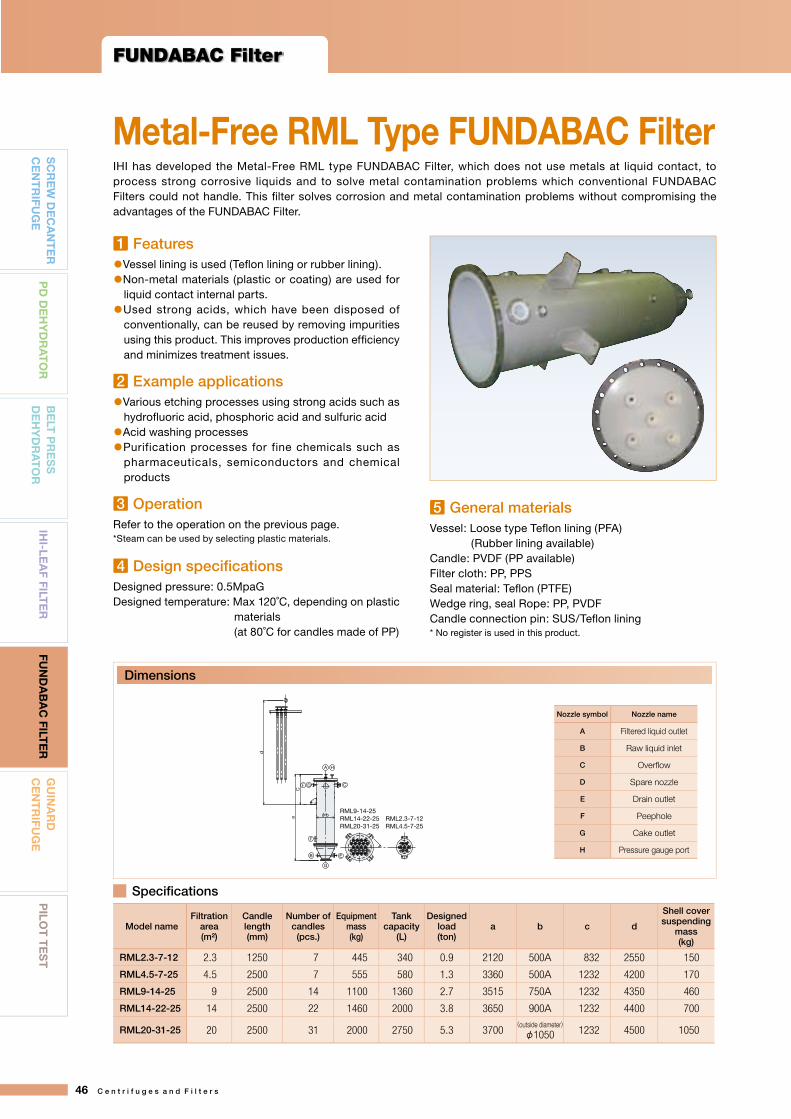
1 Features●Vessel lining is used (Tefl on lining or rubber lining).●Non-metal materials (plastic or coating) are used for liquid contact internal parts.●Used strong acids, which have been disposed of conventionally, can be reused by removing impurities using this product. This improves production effi ciency and minimizes treatment issues.
2 Example applications●Various etching processes using strong acids such as hydrofl uoric acid, phosphoric acid and sulfuric acid●Acid washing processes●Purification processes for fine chemicals such as pharmaceuticals, semiconductors and chemical products
3 OperationRefer to the operation on the previous page.*Steam can be used by selecting plastic materials.
4 Design specifi cationsDesigned pressure: 0.5MpaGDesigned temperature: Max 120˚C, depending on plastic materials (at 80˚C for candles made of PP)
Model nameFiltration
area(m²)
Candle length(mm)
Number of candles(pcs.)
Equipment mass(kg)
Tank capacity
(L)
Designed load(ton)
a b c d
Shell coversuspending
mass(kg)
RML2.3-7-12 2.3 1250 7 445 340 0.9 2120 500A 832 2550 150
RML4.5-7-25 4.5 2500 7 555 580 1.3 3360 500A 1232 4200 170
RML9-14-25 9 2500 14 1100 1360 2.7 3515 750A 1232 4350 460
RML14-22-25 14 2500 22 1460 2000 3.8 3650 900A 1232 4400 700
RML20-31-25 20 2500 31 2000 2750 5.3 3700(outside diameter)φ1050 1232 4500 1050
IHI has developed the Metal-Free RML type FUNDABAC Filter, which does not use metals at liquid contact, to process strong corrosive liquids and to solve metal contamination problems which conventional FUNDABAC Filters could not handle. This fi lter solves corrosion and metal contamination problems without compromising the advantages of the FUNDABAC Filter.
Metal-Free RML Type FUNDABAC Filter
5 General materials Vessel: Loose type Tefl on lining (PFA) (Rubber lining available)Candle: PVDF (PP available)Filter cloth: PP, PPSSeal material: Tefl on (PTFE)Wedge ring, seal Rope: PP, PVDFCandle connection pin: SUS/Tefl on lining* No register is used in this product.
CDF
A H
RML9-14-25RML14-22-25RML20-31-25
E
G
B
F
a bφ
C
d
RML2.3-7-12RML4.5-7-25
Dimensions
Specifi cations
Nozzle symbol Nozzle name
A Filtered liquid outlet
B Raw liquid inlet
C Overflow
D Spare nozzle
E Drain outlet
F Peephole
G Cake outlet
H Pressure gauge port
1
2
3
4
5
46 C e n t r i f u g e s a n d F i l t e r s
FUNDABAC Filter
SC
RE
W D
EC
AN
TE
RC
EN
TR
IFUG
EP
D D
EH
YD
RA
TO
RB
ELT
PR
ES
S
DE
HY
DR
AT
OR
GU
INA
RD
CE
NT
RIFU
GE
PILO
T T
ES
TIH
I-LEA
F FILTE
RFU
ND
AB
AC
FILTE
R

Modelname
Filtration area(m²)
Candlelength(mm)
Number of candles(pcs.)
Equipment mass
(empty, kg)
Tank capacity
(L)
Designed load(kN)
Filteredliquid outlet
A
Raw liquid inlet
B
OverflowC
Spare nozzle
D
Raw liquid discharge
outletE
Cake Outlet
F
PeepholeG
Pressure gauge portH
I(mm)
J(mm)
Hoist capacity
(ton)
R1.5-5-12 1.5 1250 5 350 320 10 25A×5 40A 40A 40A 15A 200A φ100×2 20A 1961 2438 0.5
R2-5-16 2.0 1650 5 400 400 11 25A×5 40A 40A 40A 15A 200A φ100×2 20A 2361 2838 0.5
R3-5-25 3.0 2500 5 540 590 13 25A×5 40A 40A 40A 15A 200A φ100×2 20A 3261 3632 0.5
Penta-Candle Specifications
728
φ675
350350
500A
G
HD
A G
H
D C
I
J
B
F
E
G1
G2
A
E C B
Dimensions
Main specifications
Note: 1. Main specifications and dimensions are subject to change without notice.2. The values in the table are for the candle PP with designed pressure of 0.5MPaG and the vessel material of SUS304.3. Designed load does not include those for discharge valves, other valves and pipes which may be attached to the filter main body.
Filtration plantIHI can provide a filtration plant as a system including not only the filter main body, but also tanks such as precoat tanks and body feed tanks, piping, platforms, control panels and meters. Based on reliable quality for applications and installation environments, IHI provides various sizes of filtration plants to meet customers' individual requirements.Examples include filtration for absorbing liquid of exhaust gas desulfurization, filtration for crude soy oil, decolorizing filtration for carbohydrate solutions with activated charcoal, nickel catalyst filtration, dewaxing, etc.
IHI will comprehensively coordinate optimized filtration plants for various processes to meet customers’ needs using IHI’s broad experience and advanced technologies.
Skid optionThe skid type provides a compact filtration plant installed on a common platform, which incorporates filters, pumps, tanks, pipes, valves, control panels and wiring for electricity and meters. Since most parts of construction can be completed in our factory, it provides a drastically reduced on-site construction period and labor, yet with excellent quality control and reduced cost. It enables customers to quickly start operation just by connecting the primary electricity and pipes for the raw liquid inlet, filtered liquid outlet and air (N2, steam).
Filtration Plant Design and Construction
C e n t r i f u g e s a n d F i l t e r s 47
SC
RE
W D
EC
AN
TE
RC
EN
TR
IFUG
EP
D D
EH
YD
RA
TO
RB
ELT
PR
ES
S
DE
HY
DR
AT
OR
GU
INA
RD
CE
NT
RIFU
GE
PILO
T T
ES
TIH
I-LEA
F FILTE
RFU
ND
AB
AC
FILTE
R

IHI has been providing products as a pioneer of filters and filtration plants to meet customers’ advanced needs. Peripheral and related equipment, which has been developed in response to customers’ needs, now spans a wide range. IHI is seeking the best way to fully exploit the fi lters’ capability and to achieve the best total performance of the systems.
Limit switch
Pneumatic rubber seal valve
Speed controller
Separation plate
Molded packing
Circuit for valve switching and process control
Full automatic control panelThis controls automated operation for filters with a predetermined program to activate equipment such as pumps and valves. IHI proudly provides easy operation and a reliable control mechanism with extremely low failure rates.
Full automatic fi lter aid feederThe filter aid feeder automatically measures and feeds aids in powder form. They are generally used for precoat or body feed.
Pneumatic rubber seal valveThis valve is used as a cake discharge valve. This was developed to withstand harsh conditions requiring a liquid seal during filtration while allowing solid matter to pass through upon cake discharge. It is a plate type valve, which holds only a small amount of residual liquid, allowing liquid to discharge completely. The valve has an assembly structure to ease maintenance.
Cake being discharged
Equipment to Support Filters
Leaf suspension jigSaves labor and time when assembling leaves into fi lter nests.
Spray nozzleHigh pressure spray nozzles can be installed in the fi lters to clean surfaces of filter media to remove clogging matter or prevent clog formation.
IHI-Leaf Filter Options1
48 C e n t r i f u g e s a n d F i l t e r s
IHI-Leaf Filter / FUNDABAC Filter
SC
RE
W D
EC
AN
TE
RC
EN
TR
IFUG
EP
D D
EH
YD
RA
TO
RB
ELT
PR
ES
S
DE
HY
DR
AT
OR
GU
INA
RD
CE
NT
RIFU
GE
PILO
T T
ES
TIH
I-LEA
F FILTE
RFU
ND
AB
AC
FILTE
R

Cake thickness detection switchEspecially useful for fi ltration for high density or varying concentration liquids, in which cake thickness control is difficult. When cake thickness exceeds a certain value, sensors installed near the filter fabric shall detect, enabling precise thickness con t ro l . A f te r cake d i scha rge , substances attached on the sensors are washed away by washing nozzles.
Spiral spray nozzleEffective for cleaning inside the filters, especially for upper parts of registers and candles.
Washing nozzle
Sensor
IHI-Leaf and FUNDABAC Filters provide fully automated continuous operation for 24 hours with one or two inspections per year by opening the fi lters. The vertical structure of the fi lters means they do not require a large space for installation and maintenance.
Filter vessel installation Filter nest assembly Shell cover assembly Piping and wiring
Nest assembly Vessel installation Completed assembly
Filter vessel installation Filter nest assembly Shell cover assembly Driving part assembly
Piping and wiring
Filter nest assembly Shell cover assembly
Installation and Maintenance for FUNDABAC Filters
Installation and Maintenance for IHI-Leaf Filters
FUNDABAC Filter Options
2
1
2
Easy Installation and Maintenance
C e n t r i f u g e s a n d F i l t e r s 49
SC
RE
W D
EC
AN
TE
RC
EN
TR
IFUG
EP
D D
EH
YD
RA
TO
RB
ELT
PR
ES
S
DE
HY
DR
AT
OR
GU
INA
RD
CE
NT
RIFU
GE
PILO
T T
ES
TIH
I-LEA
F FILTE
RFU
ND
AB
AC
FILTE
R

Guinard CentrifugeThe Guinard Centrifuge is a solid-liquid separator manufactured with IHI's high speed rotation
technology using the fully automatic and continuous centrifugal method. This machine is
suitable for dehydrating comparatively coarse solids such as crystallizations or synthetic resins,
and capable of washing separated solids with our original washing system.
1
Compact Size, Low Vibration, and Easy InstallationThe unit is vertical with a rational structure. The balanced rotating body means low vibration, and easy installation, in a small space.
Easy MaintenanceThe upper casing, basket, screen, etc., can be dismantled easily from above, which leads to easy maintenance.
A Variety of Models and Equipment for Various ApplicationsVarious models are available from the washing types (HL), and 2-stage washing types (HL2), to washing liquid separating types (HLS and HL2S). Furthermore, various options are available such as the basket washing mechanism, sealed type machine for treatment of combustible or hazardous materials such as solvents, concentrated discharging type, prevention of adhesion of solid material, etc.
Complete After-Sales ServiceIHI's service network perform an attentive and thorough after-sales service.
Continuous OperationAfter supplying slurry from the upper part of the centrifuge, the liquid contained in the slurry is separated through the slits of the screen when centrifugal force is applied. On the other hand, solid particles remain in the inner side of the screen, and are discharged to the lower section by the scraper. This principle enables the separation and dehydrating process to be operated continuously and automatically, without manpower.
Excellent DehydrationThe solid particles which remain in the inner side of the screen are continuously conveyed by the scraper, and form a thin accumulation. This thin accumulated layer of solid particles has less fi ltration resistance, and prevents clogging by IHI’s original taper-slit screen (TIS Type). This gives a high dehydration performance.
Outstanding Washing PerformanceDehydrating and washing of separated solids are performed simultaneously and continuously (HL Type). The washing solution is supplied to the whole circumference evenly from the unique washing device to the thin solid layer, enabling an excellent washing performance with a small amount of washing solution. Furthermore, the 2 types of washing liquid are used from the 2-stage washing pipe (HL2 Type), and the separated liquid and washing liquid can be collected separately (HLS Type and HL2S Type).
Characteristics of the IHI Guinard Centrifuge
Guinard Centrifuge
50 C e n t r i f u g e s a n d F i l t e r s
SC
RE
W D
EC
AN
TE
RC
EN
TR
IFUG
EP
D D
EH
YD
RA
TO
RB
ELT
PR
ES
S
DE
HY
DR
AT
OR
GU
INA
RD
CE
NT
RIFU
GE
PILO
T T
ES
TIH
I-LEA
F FILTE
RFU
ND
AB
AC
FILTE
R

Application2
GuinardCentrifuge
Food Chemical fertilizer
Inorganic chemical industry Organic chemical industry
●Urea●Sodium nitrate●Ammonium nitrate●Ammonium sulfate●Ammonium phosphate
etc
●Polyethylene●Expanded polystyrene (EPS)●ABS resin●Fumaric acid●Sodium glutamate●Polyvinyl chloride●Glycine●Terephthalic acid●Ion-exchange resin●Caprolactam●Bisphenol-A●Pentaerythritol●Nylon pellet●Poval, Eval
etc
●Potassium chloride●Sodium chloride●Sodium dichromate●Iron sulfate●Copper sulfate●Sodium carbonate●Sodium sulfate●Sodium thiosulfate●Sodium chlorate●Nickel sulfate ●Sodium hypochlorite
etc
●Apple juice●Corn fiber●Citric acid●Tartaric acid●Salt
●Sesame●Fruit juice●Wax●Seasoning●Aspirin
etc
Experiment data
Sodium chloride (NaCl)(Collected salt of sodium hypochlorite)
Polystyrene (synthetic resin)
Citric acid
Nylon pellets
C e n t r i f u g e s a n d F i l t e r s 51
SC
RE
W D
EC
AN
TE
RC
EN
TR
IFUG
EP
D D
EH
YD
RA
TO
RB
ELT
PR
ES
S
DE
HY
DR
AT
OR
GU
INA
RD
CE
NT
RIFU
GE
PILO
T T
ES
TIH
I-LEA
F FILTE
RFU
ND
AB
AC
FILTE
R
Model C30HLSTotal volume of crystal 1300kg/Hr
Concentration 35wt%Volume of separated liquid 1790ℓ/Hr
Particle size 100MESH ON 80%
Temperature 25℃
Washing water water (100ℓ/Hr)Centrifugal force 750G
Moisture ratio 3.0wt% or less
Material TITANIUM
Model C30HLTotal volume of crystal 1700kg/Hr
Concentration 30wt%Volume of separated liquid 1850ℓ/Hr
Particle size 80MESH ON 90%
Temperature 20~40℃
Washing water water (150ℓ/Hr)Centrifugal force 2000G
Moisture ratio 1.5wt%
Model C55HVolume of solids 4000kg/Hr
Concentration 30wt%Volume of separated liquid 9000ℓ/Hr (water)
Particle size 10~ 24MESH
Temperature Normal temperatureCentrifugal force 1000 ~ 1300G
Moisture ratio 0.2wt%
Model C30HLVolume of solids 2000kg/Hr
Concentration 50wt%Volume of separated liquid 2000ℓ/Hr
Particle size φ2mm
Temperature Normal temperatureCentrifugal force 1800G
Moisture ratio ̶

Structure and Principle3The GUINARD Centrifuge is composed of a cylindrical frame and a conical cover (upper and lower casings) mounted on the frame and equipped with a slurry feed inlet and a separated liquid outlet.A rotary conical basket is provided inside the casing, and a screen having a number of slits is set inside the basket. A scraper consisting of spiral blades built on the surface of a rotor rotates along the inner surface of the screen at a given relative speed with the necessary clearance maintained from the screen. This relative speed is controlled by the reduction gear.All the movements are effected by the motor mounted on the motor base through the V-belt.The slurry fed through the slurry feed inlet is spread in the form of a thin layer on the inner wall of the conical screen. The solid in the slurry is separated from the liquid while being scraped out and pushed downward by the rotation of the scraper, and falls down to the bottom of the frame. The separated liquid is passed through the slits of the screen by centrifugal force and discharged from the separated liquid outlet. When a washing liquid is to be used, it is supplied from the washing liquid inlet.
Basket
Screen
Scraper
Slurry feed inlet Washing liquid inlet MotorScreen
Machine drive unit
V-belt
Motor base
Lubricating oil inlet
Separated liquid out let
Upper casing
Lower casing
Basket
Scraper
Frame Torque limiting device
Solid outlet
Guinard Centrifuge
52 C e n t r i f u g e s a n d F i l t e r s
SC
RE
W D
EC
AN
TE
RC
EN
TR
IFUG
EP
D D
EH
YD
RA
TO
RB
ELT
PR
ES
S
DE
HY
DR
AT
OR
GU
INA
RD
CE
NT
RIFU
GE
PILO
T T
ES
TIH
I-LEA
F FILTE
RFU
ND
AB
AC
FILTE
R

Rotating Mechanism / Lubricating Oil Mechanism 4
Basket
Scraper
Gear
Lubricating oil outlet (upper)
Lubricating oil outlet (low
er)
Air-seal
Lubricating oil inlet
Unit name
Standard-speed rotating unit
High-speed rotating unit
Stationary unit
Support shaft
Lube oil unit
The rotating drive unit is built with the gear in the center.The motor rotation is transmitted through the V-pulley and V-belt as the basic revolution. On the other hand, a slightly faster revolution than the basic revolution is transmitted from the gear through the center shaft, to the scraper. This relative rotating mechanism scrapes out the solids on the inner screen evenly, by the scraper.The plunger pump attached to the rotating drive unit is a forced lubrication system which ensures safe lubrication with a small amount of lubricant.
Rotating drive
C e n t r i f u g e s a n d F i l t e r s 53
SC
RE
W D
EC
AN
TE
RC
EN
TR
IFUG
EP
D D
EH
YD
RA
TO
RB
ELT
PR
ES
S
DE
HY
DR
AT
OR
GU
INA
RD
CE
NT
RIFU
GE
PILO
T T
ES
TIH
I-LEA
F FILTE
RFU
ND
AB
AC
FILTE
R
C20 C30 C40 C55 Oil tank capacity(ℓ) 13 13 13 13
Flow rate of lubricating oil(ℓ/Hr) 5~6 6~9 9~12 12~15
Model

Screen5The screen is the important component for separating solids for the centrifugal separator. IHI provides a variety of screens for a multitude of applications.
Standard screens
TypePlate
thickness(mm)
Nominalslit dimensions
(mm)
Openingratio(%)
Material Cross-sectionalshape
TIS5007S 0.50 0.07×4.0 5.4
SUS316L-CSPTitanium
TIS5010 0.50 0.10×4.0 7.7
TIS5015 0.50 0.15×4.0 11.4
TIS5020 0.50 0.20×4.0 12.7
TIS5025 0.50 0.25×4.0 15.8
TIS8025 0.80 0.25×4.0 15.8 SUS304-CSP
KIP6030 0.60 0.30×3.0 18.0SUS316SUS316L
KIP6050 0.60 0.50×3.0 25.0
NIP7040 0.70 0.40×4.0 20.0
NIS3012 0.30 0.12×2.5 8.4SUS316SUS316LTitanium
NIS5025 0.50 0.25 dia. 6.0SUS316SUS316LTitanium
The Tyler Normal Screen Scale Sieves
Mesh(Sieve
designation/in)
Sieveopening
(mm)
Nominal wirediameter
(mm)
21/2 7.925 2.2353 6.680 1.778
31/2 5.613 1.6514 4.699 1.6515 3.962 1.1186 3.327 0.9147 2.794 0.8338 2.362 0.8139 1.981 0.83910 1.651 0.88912 1.397 0.71114 1.168 0.63516 0.991 0.59720 0.833 0.43724 0.701 0.35828 0.589 0.318̶̶ ̶̶ ̶̶32 0.495 0.30035 0.417 0.31042 0.351 0.25448 0.295 0.23460 0.246 0.17865 0.209 0.18380 0.175 0.142100 0.147 0.107115 0.124 0.097150 0.104 0.066170 0.088 0.061200 0.074 0.053250 0.061 0.041270 0.053 0.041325 0.043 0.036400 0.038 0.025
●Mounting of screen
1
2 3
Guinard Centrifuge
54 C e n t r i f u g e s a n d F i l t e r s
SC
RE
W D
EC
AN
TE
RC
EN
TR
IFUG
EP
D D
EH
YD
RA
TO
RB
ELT
PR
ES
S
DE
HY
DR
AT
OR
GU
INA
RD
CE
NT
RIFU
GE
PILO
T T
ES
TIH
I-LEA
F FILTE
RFU
ND
AB
AC
FILTE
R

Centrifuge Variations6
Feed slurry
Separatedsolids
Feed slurry
Washing liquid
Separated solids
Feed slurry
Separated liquid
Crystal or solid
Separated liquid and washing liquid
Washing liquid I
Washing liquid II
N Type (with short basket)
Large slurry feed inlet, ideal for coarse solid treatment.
HL Type (1-stage washing type)
1-stage washing. Washing is performed by spraying washing liquid at separated solids.
HL2 Type (2-stage washing type)
Used for 2-stage washing when further washing is required, or used when two types of washing liquids are required.
H Type (with tall basket)
Ideal for treatment of slurries of low concentration, viscous liquids.
HLS Type (Washing liquid separating type)
Washing liquid and separated liquid is separated when collecting.
HL2S Type (2-stage washing liquid separating type)
Used for 2-stage washing for further washing, or two types of washing liquids can be used. The separated liquid and washing liquids can all be collected separately.
C e n t r i f u g e s a n d F i l t e r s 55
SC
RE
W D
EC
AN
TE
RC
EN
TR
IFUG
EP
D D
EH
YD
RA
TO
RB
ELT
PR
ES
S
DE
HY
DR
AT
OR
GU
INA
RD
CE
NT
RIFU
GE
PILO
T T
ES
TIH
I-LEA
F FILTE
RFU
ND
AB
AC
FILTE
R

N, H, HL, HL2 Type
ModelDimensions(mm) Slurry
feed inlet
Separatedliquid
(outlet)
Washingliquid
(outlet)
Washingliquid I (inlet)
Washingliquid II (inlet)
a b c d e f g h A B C D E
C20
H 905 515 70 320 725 790 570 1300 25A 50A ̶ ̶ ̶HL 935 515 70 350 725 790 570 1300 25A 50A ̶ 15A ̶HLS 935 515 130 290 725 790 570 1300 25A 50A 50A 15A ̶
C30
N 1100 600 75 425 1000 980 735 1600 50A 65A ̶ ̶ ̶H 1155 600 75 480 1000 980 735 1600 50A 65A ̶ ̶ ̶HL 1180 600 75 505 1000 980 735 1600 50A 65A ̶ 15A ̶HLS 1185 600 155 430 1000 980 735 1600 50A 65A 65A 15A ̶HL2 1200 600 75 525 1000 980 735 1600 50A 65A ̶ 15A 15A
HL2S 1200 600 155 445 1000 980 735 1600 50A 65A 65A 15A 15A
C40
N 1300 680 115 505 1350 1325 1000 1900 50A 80A ̶ ̶ ̶H 1375 680 115 580 1350 1325 1000 1900 50A 80A ̶ ̶ ̶HL 1400 680 115 605 1350 1325 1000 1900 50A 80A ̶ 15A ̶HLS 1405 680 230 495 1350 1325 1000 1900 50A 80A 80A 15A ̶HL2 1460 680 115 665 1350 1325 1000 1900 50A 80A ̶ 15A 15A
HL2S 1460 680 230 550 1350 1325 1000 1900 50A 80A 80A 15A 15A
C55
N 1640 800 145 695 1570 1550 1200 2300 65A 200A ̶ ̶ ̶H 1835 800 145 890 1570 1550 1200 2300 65A 200A ̶ ̶ ̶HL 1835 800 145 890 1570 1550 1200 2300 65A 200A ̶ 15A ̶HLS 1835 800 275 760 1570 1550 1200 2300 65A 200A 200A 15A ̶HL2 1885 800 145 940 1570 1550 1200 2300 65A 200A ̶ 15A 15A
HL2S 1885 800 275 810 1570 1550 1200 2300 65A 200A 200A 15A 15A
Main dimensions
FGHJK
Rc1/4Rc1/2Rc1/4Rc1/4Rc1/4
Lubricating oil outlet (upper)Lubricating oil outlet (lower)Lubricating oil inletAir–seal inspection holeAir–seal inlet
J, K
F, G, H
F, JGH, K
a
e
g
f
cd
b
Slurry feed inlet (A)
Separated liquidoutlet (B)
Washing liquid I inlet (D)Washing liquid II inlet (E)
Washing Washingliquid I inlet (D)
Separated liquidoutlet (B)
Rotating drive unit
h (m
inim
um h
oist
ing
heig
ht)
(whe
n ov
erha
ulin
g)
Washing liquid II inlet (E)
Outline drawing
Guinard Centrifuge
56 C e n t r i f u g e s a n d F i l t e r s
SC
RE
W D
EC
AN
TE
RC
EN
TR
IFUG
EP
D D
EH
YD
RA
TO
RB
ELT
PR
ES
S
DE
HY
DR
AT
OR
GU
INA
RD
CE
NT
RIFU
GE
PILO
T T
ES
TIH
I-LEA
F FILTE
RFU
ND
AB
AC
FILTE
R

HLS, HL2S Type
Model
Specification
Basket Motor Weight ofequipment Drive unit Design
load
Amount oftreatment(reference
value)
Maximumcentrifugal
force
Utilities(reference
value)
Innerdiameter
(mm)(kW) (kg) Weight
(kg) (kN)Amount of
clarified liquid(㎥/hr)
(G) Air-seal(Lit/min)
C20H
200 2.2 190 40 5 1.0 1800 50~100HLHLS
C30
N
300 5.5 700 105 20 3.0 1800 100~200
HHLHLSHL2HL2S
C40
N
400 15 1350 195 35 5.5 1800 100~300
HHLHLSHL2HL2S
C55
N
550 30 2300 425 60 11 1500 200~500
HHLHLSHL2HL2S
Main dimensions
Slurry feed inlet (A)
Washing liquidoutlet (C)
J, K
F, G, H
Washing liquid I inlet (D)Washing liquidII inlet (E)
Washing liquid I inlet (D)
F, J
G
H, K
a
e
g
f
cd
b
Separated liquidoutlet (C)
Separated liquid outlet (B)
Washing liquid II inlet (E)
Separated liquid outlet (B)
Rotating drive unit
h (m
inim
um h
oist
ing
heig
ht)
(whe
n ov
erha
ulin
g)
FGHJK
Rc1/4Rc1/2Rc1/4Rc1/4Rc1/4
Lubricating oil outlet (upper)Lubricating oil outlet (lower)Lubricating oil inletAir–seal inspection holeAir–seal inlet
Outline drawing
Note:1) The treatment capacity of the unit mainly depends on the amount of separated liquid. The separated l iquid ( including washing l iquid) varies by the characteristics of the treated substance. Please use this as a reference for model selection.2) The centrifugal force (500G-1800G), and treatment capacity are determined by the test results and performances.3) Air-seal is necessary for reducing negative pressure. The values are for reference (normal), and may vary depending on the pressure balance of before/after separation.4) The standard material is SUS304. In addition, SUS316, SUS316L, hastelloy, or titanium can be used as a material for manufacturing, depending on the substance for treatment.5) Legend of types (example: C40HL)
C40: The Scales are indicated by types. The value indicates the inner diameter (unit: cm) of the bottom of basket.HL: Indicates the variations. In this case, th is indicates “high basket, 1-stage washing type”.S: Indicates variations. In this case, this indicates “washing liquid separated type”.
C e n t r i f u g e s a n d F i l t e r s 57
SC
RE
W D
EC
AN
TE
RC
EN
TR
IFUG
EP
D D
EH
YD
RA
TO
RB
ELT
PR
ES
S
DE
HY
DR
AT
OR
GU
INA
RD
CE
NT
RIFU
GE
PILO
T T
ES
TIH
I-LEA
F FILTE
RFU
ND
AB
AC
FILTE
R

Basket washingnozzle
Washingsolution
1 Fully-sealed typeA fully-sealed vertical separator, with a compact design. Ideal for explosive materials or hazardous solvents, etc. The fully-sealed type is designed for N2 gas seal nozzle, or pressure equalization nozzle, in order to seal the unit.Design pressure: max 5.0kPa (Pe)
2 Basket washingWhen performing continuous operation for a long period of time, slit clogging may occur from the outer side of the basket, depending on the characteristics of the slurry. The basket washing mechanism is designed for continuous and stable operation, by spraying the washing liquid intermittently, from the outside of the basket.
3 Crystal collectorThe discharge of separated solids is centralized for effective treatment of substances of high adherence. The solids are conveyed downwards by the scraper, and collected in the crystal collector. Inside the collector is a scraping blade, transferring the solids through a collector-shoot, and discharging through from a cylindrical discharge-shoot.
4 Anti-adhesion system (Oscillator plate, air cylinder drive)The intensively discharged solids are received by an oscillator plate (natural rubber, etc.), which is activated by an air cylinder. This forces the solids to drop off, and prevents adhesion or build-up of solids.Proven high performance for high adhesion by-product salt.
Distributor
Washing device
Washing liquid
Washingliquid
Crystal collector ShootSeparated solids
ScraperScreenBasket
slurryFeed
Separated liquid
Rubber sheet
Air cylinder(intermittent)
Basket
Scraper
Diffuser
Collector Separatedsolid
Increased Functionality and Effi ciencyGuinard Centrifuge OptionsVarious peripheral devices can be added to improve functionality and handle a wide range of products.
1 2
3 4
Guinard Centrifuge
58 C e n t r i f u g e s a n d F i l t e r s
SC
RE
W D
EC
AN
TE
RC
EN
TR
IFUG
EP
D D
EH
YD
RA
TO
RB
ELT
PR
ES
S
DE
HY
DR
AT
OR
GU
INA
RD
CE
NT
RIFU
GE
PILO
T T
ES
TIH
I-LEA
F FILTE
RFU
ND
AB
AC
FILTE
R

5 Defl ectorAdhesion of solids to the frame is reduced by changing the discharging direction of the solids discharged from the diffuser.
6 Hopper, air knockerReceives the discharged solids, and prevents the discharge failure of bridge-formed solids with an air knocker.
7 Preconcentration unitWhen solid concentration is diluted (less than 5% in general), preconcentration units are installed on the anterior section of the Guinard, to accelerate dehydration.
PurposeNo.N-1N-2N-3N-4
Slurry feed inlet
Concentrated liquid outlet
Separated liquid outlet
Overflow
PurposeNo.N-1N-2N-3
Slurry feed inlet
Concentrated liquid outlet
Low-concentrated liquid outlet
❶ Tamiclone (Hydroclone Separator)
Used when the difference in specifi c gravity between solid and liquid is small. A screen is installed inside to utilize the centrifugal force of the vortex for centrifugal filtration and concentration.
❷ Liquid cyclone
Used when the difference in specific gravity between solid and liquid is large. The centrifugal force of the vortex of liquid is utilized for centrifugal concentration.
5 6
7
1 2
C e n t r i f u g e s a n d F i l t e r s 59
SC
RE
W D
EC
AN
TE
RC
EN
TR
IFUG
EP
D D
EH
YD
RA
TO
RB
ELT
PR
ES
S
DE
HY
DR
AT
OR
GU
INA
RD
CE
NT
RIFU
GE
PILO
T T
ES
TIH
I-LEA
F FILTE
RFU
ND
AB
AC
FILTE
R

Example Flow7
Centrifugeunit
Rubber vibration insulator and installation guide
Rubber vibrationinsulator and
installation guide
Separated liquid
Limit switchof torque limiter
Air-seal
Conveyor
Basket washing
Hopper
Washing liquid(Clear fluid)
Control panel
Flow meter
Washing of solids
Feed slurry
Lube oilunit
Pressure switch
to control panelStand
Hopper
Chain block
Overflow
Liquid cyclone
Vapor dischargeduct
300 ∼
500m
m
Rubber vibration insulator
Stand
Separated Solids
Guinard Centrifuge
60 C e n t r i f u g e s a n d F i l t e r s
SC
RE
W D
EC
AN
TE
RC
EN
TR
IFUG
EP
D D
EH
YD
RA
TO
RB
ELT
PR
ES
S
DE
HY
DR
AT
OR
GU
INA
RD
CE
NT
RIFU
GE
PILO
T T
ES
TIH
I-LEA
F FILTE
RFU
ND
AB
AC
FILTE
R

(µm)1000
100
10
1
0.1
0.01
(*1)
FUN
DA
BA
C F
ilter
/IH
I-Le
af F
ilter
(*2)
(*3)
20MESH
35MESH
50MESH
300MESH
400MESH
635MESH
1000MESH
2400MESH
100MESH
150MESH200MESH
Ultr
afilt
ratio
n (U
F) r
ange
Cak
e fil
trat
ion
rang
eStr
ainer r
ange
Dec
ante
r ce
ntri
fug
e
Gui
nard
cen
trifu
ge
Prec
oat fi
ltrati
on ra
nge
Note 1) Filtration limit may vary by fi ltration aid.2) Separation limit may vary by specifi c gravity of the liquid to be fi ltered.3) MESH may vary by wire diameter and the values in the table are approximate.4) This table is provided as a reference only. For actual application, tests are conducted for confi rmation.
Application Scope forIHI Filters and Centrifuges
C e n t r i f u g e s a n d F i l t e r s 61
SC
RE
W D
EC
AN
TE
RC
EN
TR
IFUG
EP
D D
EH
YD
RA
TO
RB
ELT
PR
ES
S
DE
HY
DR
AT
OR
GU
INA
RD
CE
NT
RIFU
GE
PILO
T T
ES
TIH
I-LEA
F FILTE
RFU
ND
AB
AC
FILTE
R

Pilot Test
*Test equipment is also available.
Nutsche test equipment
(Filtration area: 0.001m²)
R0.3m2
FUNDABAC Filter test equipment
L1750mm×W1000mm×H1900mm
R0.06m2
FUNDABAC Filter test equipment
L692mm×W281mm×H685mm
CFR0.06m2
IHI-Leaf Filter test equipment
L1700mm×W1000mm×H1500mm
Pilot Test
IHI has a selection of pilot test machines available. Customers considering purchasing any of these machines are invited to try them out and confi rm the performance for themselves.
What is the Pilot Test?
Test Enquiry Form
Before performing tests, please send the below information to IHI.
1. Name
2. Company
3. Department/Division Name
4. Industry
5. Contact Information Postal Code
Address
Phone – –
6. E-mail
62 C e n t r i f u g e s a n d F i l t e r s
SC
RE
W D
EC
AN
TE
RC
EN
TR
IFUG
EP
D D
EH
YD
RA
TO
RB
ELT
PR
ES
S
DE
HY
DR
AT
OR
GU
INA
RD
CE
NT
RIFU
GE
PILO
T T
ES
TIH
I-LEA
F FILTE
RFU
ND
AB
AC
FILTE
R

Test Enquiry Data
Please answer the following questions to the best of your knowledge.
7. Raw Material
(1) Name of the raw material
(2) PH
(3) Operation temperature ℃
(4) Viscosity C.P.
8. Suspended Solid in the Raw Material
(1) Name of the solid
(2) Composition of the solid
(3) Concentration of solids included within the raw material
(4) Absolute specific gravity of the solid parts
(5) Bulk specific gravity of the solid parts
(6) Particle size and distribution of the solid parts
9. Liquid in the Raw Material
(1) Name of the liquid
(2) Specific gravity of the liquid
10. Treatment Conditions
(1) Treatment volume ㎥/h
kg・DSS/h
(2) Desired solid recovery rate %
(3) Desired moisture in the recovered solids wt%
11. Is It Possible to Use Additives Such As Filter Aids and High-Polymer Coagulants? Yes / No
12. Current Treatment Flow
(1) The type, manufacturer and model of the separator currently in use
(2) Problems with the separator currently in use
*1 We regret to inform you that we cannot conduct a test on our premises if your slurry is one with properties like the ones below. 1. Toxic slurry 2. Explosive slurry 3. Volatile slurry 4. Slurry that would be difficult for our company to dispose of*2 We regret to inform you that testing cannot be conducted under the following instances. 1. An instance where our company is in possession of many records, making it possible to predict performance with a high-degree of accuracy. 2. An instance where we have determined from the submitted data sheet, that it would be difficult for our machines to process your materials.
! Precautions
C e n t r i f u g e s a n d F i l t e r s 63
SC
RE
W D
EC
AN
TE
RC
EN
TR
IFUG
EP
D D
EH
YD
RA
TO
RB
ELT
PR
ES
S
DE
HY
DR
AT
OR
GU
INA
RD
CE
NT
RIFU
GE
PILO
T T
ES
TIH
I-LEA
F FILTE
RFU
ND
AB
AC
FILTE
R

Safety warning
Read and understand the operator’s manual before
using any of the machines featured in this catalog.
Product and contact information is correct as of March 2012.
Specifications are subject to change without notice to improve product performance or functionality.
Please note colors of actual products may appear different for reasons attributable to printing.
IHI Global Network
Americas NEW YORK IHI INC. 150 East 52nd Street, 24th Floor, New York, N.Y. 10022 U.S.A. TEL: +1-212-599-8100 FAX: +1-212-599-8111 HOUSTON IHI INC. Houston Office 2500 Citywest Blvd., Suite 300, Houston, TX 77042 U.S.A. TEL: +1-713-267-2397 FAX: +1-713-267-2267 RIO DE JANEIRO IHI do Brasil Representações Ltda. Rua da Quitanda 59, 5°andar, Centro Rio de Janeiro BRAZIL TEL: +55-21-3806-2150 FAX: 55-21-2220-5907
Asia-Pacific SEOUL IHI Seoul Liaison Office 23F, Seoul Finance Center B/D, 84, 1-ka, Taepyung-ro, Chung-ku, Seoul 100-768, KOREA TEL: +82-2-753-8605 FAX: +82-2-755-4772 BEIJING IHI Beijing Liaison Office Room 1901, China Resources Building, No. 8 Jianguomenbei Avenue, Beijing, P.C.100005, CHINA TEL: +86-10-8519-2586 FAX: +86-10-8519-2590 SHANGHAI IHI Shanghai Liaison Office 24th Floor, Hang Seng Bank Tower, 1000 Lujiazui Ring Road, Pudong New Area, Shanghai, 200120 CHINA TEL: +86-21-6841-1717 FAX: +86-21-6841-1919 IHI (Shanghai) Management Co., Ltd Room 021, 24th Floor, Hang Seng Bang Tower, 1000 Lujiazui Ring Road, Pudong New Area, Shanghai, 200120 CHINA TEL: +86-21-6841-1717 FAX: +86-21-6841-1919 SUZHOU IHI-Sullair Compression Technology (Suzhou) Co., Ltd. No.262, Changyang Street, Suzhou Industrial Park, Suzhou, Jiang Su, 215024, CHINA TEL: +86-512-8518-8500 FAX: +86-512-8518-8510 HONG KONG IHI (HK) Ltd. Room 2203, 22/F., Causeway Bay Plaza 2, 463-483 Lockhart Road, Causeway Bay, HONG KONG TEL: +852-2522-4093 FAX: +852-2845-2497 TAIPEI IHI Taipei Office Room 1202, Chia Hsin Building, No.96 Section 2, Chung Shan North Road, Taipei, TAIWAN TEL: +886-2-2542-5520 FAX: +886-2-2542-4362 HANOI IHI Hanoi Representative Office Unit 515, Sun Red River, 23 Phan Chu Trinh Street, Hoan Kiem District, Hanoi, VIETNAM TEL: +84-4-3934-5305 FAX: +84-4-3934-5303 BANGKOK IHI Bangkok Representative Office 11th Floor, Ramaland Building, 952 Rama IV Road, Suriyawongse, Bangrak, Bangkok 10500, THAILAND TEL: +66-2-236-3490 FAX: +66-2-236-7340 KUALA LUMPUR IHI Kuala Lumpur Office Letter Box No.52, 27th Floor, UBN Tower, 10 Jalan P.Ramlee 50250, Kuala Lumpur, MALAYSIA TEL: +60-3-2072-1255 FAX: +60-3-2072-1418 SINGAPORE IHI Singapore Branch 77 Robinson Road #14-03 Robinson 77, SINGAPORE 068896 TEL: +65-6515-6609 FAX: +65-6438-8006 IHI Marine Engineering (Singapore) Pte. Ltd. 27, Tanjong Kling Road, SINGAPORE 628052 TEL: +65-6268-7360 FAX: +65-6261-0794 JAKARTA IHI Jakarta Representative Office Mid Plaza Ⅱ, 17th Floor, Jl. Jendral Sudirman Kav.10-11 Jakarta 10220, INDONESIA TEL: +62-21-570-7701 FAX: +62-21-570-7705 SYDNEY IHI Engineering Australia Pty. Ltd. Suite 2201, Level 22, 111 Pacific Highway, North Sydney NSW 2060 AUSTRALIA TEL: +61-2-9923-9300 FAX: +61-2-9923-9333 NEW DELHI IHI New Delhi Liaison Office 15th Floor Dr. Gopal Das Bhawan, 28 Barakhamba Road New Delhi-110001, INDIA TEL: +91-11-2332-5095 FAX: +91-11-2332-2480
Europe LONDON IHI Europe Ltd. 2nd Floor, America House, 2 America Square, London EC3N 2LU, U.K. TEL: +44-20-7481-8180 FAX: +44-20-7481-4955 PARIS IHI Paris Office 17, Rue d'Orleans, 92200 Neuilly sur Seine, FRANCE TEL: +33-1-46-43-14-93 FAX: +33-1-46-37-78-69 MOSCOW IHI Moscow Representative Office Office E02-312, 2nd floor, 8, 4th Dobryninskiy Pereulok, Moscow 119049, RUSSIA TEL: +7-495-989-6001 FAX: +7-495-989-6005
Middle East ALGIERS IHI Algiers Officeand Africa Boulevard du 11 Decembre 1960, Lot No.12 Cooperative Essalam, Appartement No.02, 1er etage, El Biar, Alger, ALGERIA TEL: +213-21-92-43-99 FAX: +213-21-92-14-36 BAHRAIN IHI Bahrain Regional Office Manama Centre, Entrance 1, 2nd floor, Suite No.208, Government Road P. O. Box 5837, Manama, KINGDOM OF BAHRAIN TEL: +973-1721-2230 FAX: +973-1721-2201
Centrifuge & Filter Group, Sales Department, Rotating Machinery OperationsToyosu IHI Bldg., 1-1, Toyosu 3-chome, Koto-ku, Tokyo 135-8710 JAPANTEL: +81-3-6204-7330 FAX: +81-3-6204-8708URL : www.ihi.co.jp/separator/en/E-mail : [email protected] 40022-003-00-1203-3,000FXSS(CG387) Printed in Japan
This catalog is printed with environmentally-friendly vegetable inks that cause low environmental impact.