CEMENT INDUSTRY - UNIDO's Open Data Platform
89
UNITED NATIONS INDUSTRIAL DEVELOPMENT ORGANIZATION Vienna International Centre, P.O. Box 300, 1400 Vienna, Austria Tel: (+43-1) 26026-0 · www.unido.org · [email protected] OCCASION This publication has been made available to the public on the occasion of the 50 th anniversary of the United Nations Industrial Development Organisation. DISCLAIMER This document has been produced without formal United Nations editing. The designations employed and the presentation of the material in this document do not imply the expression of any opinion whatsoever on the part of the Secretariat of the United Nations Industrial Development Organization (UNIDO) concerning the legal status of any country, territory, city or area or of its authorities, or concerning the delimitation of its frontiers or boundaries, or its economic system or degree of development. Designations such as “developed”, “industrialized” and “developing” are intended for statistical convenience and do not necessarily express a judgment about the stage reached by a particular country or area in the development process. Mention of firm names or commercial products does not constitute an endorsement by UNIDO. FAIR USE POLICY Any part of this publication may be quoted and referenced for educational and research purposes without additional permission from UNIDO. However, those who make use of quoting and referencing this publication are requested to follow the Fair Use Policy of giving due credit to UNIDO. CONTACT Please contact [email protected] for further information concerning UNIDO publications. For more information about UNIDO, please visit us at www.unido.org
-
Upload
khangminh22 -
Category
Documents
-
view
3 -
download
0
Transcript of CEMENT INDUSTRY - UNIDO's Open Data Platform

UNITED NATIONS INDUSTRIAL DEVELOPMENT ORGANIZATION Vienna International Centre, P.O. Box 300, 1400 Vienna, Austria
Tel: (+43-1) 26026-0 · www.unido.org · [email protected]
OCCASION
This publication has been made available to the public on the occasion of the 50th
anniversary of the
United Nations Industrial Development Organisation.
DISCLAIMER
This document has been produced without formal United Nations editing. The designations
employed and the presentation of the material in this document do not imply the expression of any
opinion whatsoever on the part of the Secretariat of the United Nations Industrial Development
Organization (UNIDO) concerning the legal status of any country, territory, city or area or of its
authorities, or concerning the delimitation of its frontiers or boundaries, or its economic system or
degree of development. Designations such as “developed”, “industrialized” and “developing” are
intended for statistical convenience and do not necessarily express a judgment about the stage
reached by a particular country or area in the development process. Mention of firm names or
commercial products does not constitute an endorsement by UNIDO.
FAIR USE POLICY
Any part of this publication may be quoted and referenced for educational and research purposes
without additional permission from UNIDO. However, those who make use of quoting and
referencing this publication are requested to follow the Fair Use Policy of giving due credit to
UNIDO.
CONTACT
Please contact [email protected] for further information concerning UNIDO publications.
For more information about UNIDO, please visit us at www.unido.org


/^e>7UNI DO-Czechoslovakia Joint Programme for International Co-operation in the Field of Ceramics, Building Materials and Non-metallic Minerals Based Industries Pi I sen, Czechoslovakia
Distr.L IM ITED
JP/52/80 August 1930O RIG IN A L: English
Technical Workshop cn Energy Conservationin Silicate Industriesfor the Least Developed CountriesPilsen, Czechoslovakia October 1981
CEMENT INDUSTRY - REDUCING THE ENERGY REQUIREMENTS
IN TECHNOLOGICAL PROCESSES AND HEAT CONSUMING UNITS
by: Jiri Lahovskÿ
The views and opinions expressed in this paper are those of the author and do not necessarily reflect the views o f the secretariat o f UNIDO. This document has teen reproduced without formal editing.

iTECHNOLOGICAL PROCESSES OF PREPARATION OF THE RAW_MIX FOR PORTLAND CLINKER BURNING
Rotary kilns are the most important equipment in each cement plant and therefore an exceptional care is being taken when a designer selects the kiln for his project. The output of the kiln determine the capacity of the whole plant. The kiln consumes 80-100 *3b of all thermal- energy and 5—20 ^ of electric power needed for the cement manufacture.However, the selection of the thermal process can be affected by specific conditions of each individual plant. The crucial factor in this sense are physical and chemical properties of the raw mix components. From the point of view of the preparation of raw mix for its calcination in the cement kiln, we distinguish 4 basic technological processes which shall be described before the kilns are talked about.a) wet processb) semi-wet processc) dry processd) semi-dry process •Hereunder we give a brief description of different processes:Vet process of the raw nix preparationThe raw materials are either vashod. or ground along with water.The slurry (which must have a good degree of fluidity) is then stored in silos, homogenized, and on basis cf chemical analysis is corrected by the slurry from other silos until an adequate chemical composition is achieved. The slurry is then conveyed to a bin above the rotary kiln and with great accuracy fed into the kiln. Generally the slurry contains 33-^0 of water. Plastic raw materials occassionally require an increase in water content up to 50 in order to reach necessary fluidity. On the other hand the non—plastic raw materials sometimes settle for only 28-33 rh o f water.Semi-vet process of the raw' mix preparationThe slurry prepared by wet process undergoes a filtration aimed at reducing the water content in the slurry; this results in the economy on heat which wouJd have to be spent for evaporation of this unneccr,snry water.For slurry fit Lrntion the vacuum filters or press filters are used. The f i. 1 t*.*r cake is either fed into the rotary kiln, or for its

2
calcination on the grate it is sometimes necessary to thicken it by adding a certain amount of raw meal. This applies for the situation when the filter cake is not compact enough to provide granules formec in extrusion presses or other suitable presses, or on nodulizing discs. Moisture content of the raw mix particles that are fed into the kiln is 14-18 # of H20.Dry process of the raw mix preparation
Crushed raw materials are either first dried in a drier and then ground, or drying and grinding ara carried out simultaneously in a drying circuit mill. Individual components are fed into the mill by means of weigh feeders, or - in older plants - are batched by their volumes. Raw meal is then conveyed into the system of homogenizing and reserve silos where it is pneumatically or mechanically homogenized or possibly corrected and then it is routed and fed into the rotarv kiln. Chemical control is of course more exacting than in the wet process of preparation. Moisture content of the raw mix is less than 1 £ of H20.Semi-dry process of the raw mix preparation
Dry and homogenized raw meal prepared by dry process (see above) is moistened in a screw, on a nodulizing disc or possibly in a nodulizing drum. Moistened (or granulated) raw meal is in the form of irregular conglomerate pieces fed into the kiln, or (if granulated) onto a Lepol grate. Moisture content of the raw mix is 10-15 of H20.This process comprises also the preparation of the raw mix for the shaft kilns. However, since the raw materials for the shaft kilns have to contain pressed-in fuel (coke or anthracite) there are two alternatives:a) Preparation of "white meal"Raw meal prepared by dry process is weighed along with fuel that is ground down to a grain size of 1-8 mm. Such mix is thoroughly blended in a mixing screw, moistened to reach 1 1-1 ̂^ of water content, and granulated or compacted. Compressed pieces are fed into the shafe kiln.b) Preparation of "black meal"For preparation of blaclc meal the fuel in ground along with other components in the raw mill, all components being very precisely batched into the mill. "Black meal" is blended in homogoni ing

N t -
3 -
silos and prior to being fed into the kiln is moistened up to 11-14 5® of H20 and granulated or compacted.
Diagram of preparation of the slurry for the wet process of cement manufacture ___ __
Limestone extractionTransport Clay or marl
Conveyance to the kiln feedFeeding into the kiln
Diagram of preparation of the raw mix for the semi-wet process of cement*manufacture _ _____________
Slurry prepared by wet process (bin)
Primary crushing Extraction
StorageSecondary crushingi
Washing*Storage
Feeding into the millFeeding into the mill
Storage of slurry and blendingCorrection of chemical composition
Press filtrationBinGranulation or compactionFeeding of granules onto the Lopol grateor into the kiln
«. •« » H -
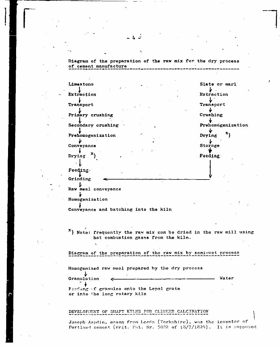
Diagram of the preparation of the raw mix for the dry process of cement manufacture
LimestonelExtraction Transport Primary crushing
iSecondary crushing*PrehomogenizationVConveyanceI xDrying )i
FeeGrinding ^ ---------- :-------------Raw meal conveyance
*HomogenizationConveyance and batching into the kiln
Slate or marl Extraction
l'TransportCrushing
IPrehomogenization Drying X )
VStorage*Feeding.
V
X ) Note: frequently the raw mix can be dried in the raw mill using hot combustion gases from the kiln.
Diagram of the preparation of the raw mix by semi-wet process
Homogenized raw meal prepared by the dry process*Granulation ^-------------------------------------Water
Feeding <f granules onto the Lepol grate or Into the long rotary kiln
DEVELOPMENT OF SHAFT FOR CLINKER CALCINATIONJoseph AspdJn, mason from Leeds (Yorkshire), was the Portland cement (hrit. Pat. Nr. 50E2 of l<J/7/lH 2h) .
\inventor of It is niippoycd

Fig. 1 - Remnants of the Aspdin kiln at Horthfleet

• 1_ K
\
\that his product nowadays could not be designated as "Portland" cement since it would not meet strict requirement of our current standards. Lime kilns, used by Joseph Aspdin in his original werks at Wakefield, did not provide the temperature needed for proper sintering of all the raw mix. According to nowadays criteria^\p^in>s product ground after the calcination should ba more precisely called "Roman" cement or "hydraulic lime". Also in another works at Northfleet, the remnants of which can be seen in Fig. 1, the kilns called dome kilns or bottle kilns were constructed. These kilns used to operate periodically, i.a. once the fuel was burnt the kiln had to be left to cool down and discharged completely. No wonder that fuel consumption was very high and amounted to 30-50.®o of the clinker weight.(see fig. 2)The shaft kilns that were being developed in Europe in the second half of* the last century used to ae filled with bricks made from cement raw mix, with intermittent layers of solid fuel (coke or anthracite). Once the fuel in the shaft was burnt out, the contents of the kiln was cooled down by opening the ports in the lovsr part of the kiln; the kiln was then emptied. The mass was with great difficulties separated into clinker andunderbumed residue. Large pieces were desintegrated by iron bars or mattocks.Back in 18^5 Isaac Charles Johnson proved positive effects of the raw mix calcination with transition into sintering and pointed out the importance of a precise maintaining of each component s share in the raw mix. His discoveries however were made practical use of ouch later. First an improvement in the shaft kilns was needed.It was not until 1872 that a kiln designed by Johnson was sot up in England. It was already using hot gases for raw bricks drying. (See t i g . 3)Great progress in clinker calcination was brought about by Dietsch kilns, so-called "desk kilns", (fig. h ) . These kilns had a pre-heating vertical shaft, sintering zone in the horizontal part, and a cooling shaft. Raw bricks were inserted into the upper part of the vertical shaft, and proceeded down the shaft to an almost horizontal desk. Sometimes it was necessary to push the bricks down with iron bars or rakes. The sintering process took place in the horizontal part called "desk11 or "bridge". From thi3 place the bricks were routed into the cooling shaft wnich broadened downwards. This proved to be advantageous since the flame for sintering was concentrated in the tapered upper part while broader space towards the bottom prevented burning-on. Clinker was being gradually withdrawn out of tlio shaft which resulted in an almost continuous flow of the mass through the kiln.Firing in the Dietsch kiln required great skill an experience since it was necessary to fill the calcining shaft in such a way that the

Dome kiln.
Fig. 2 - Dome kiln

I
Fig. 3 - Johnson kiln
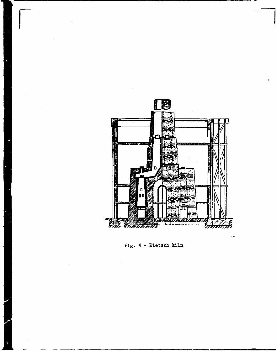

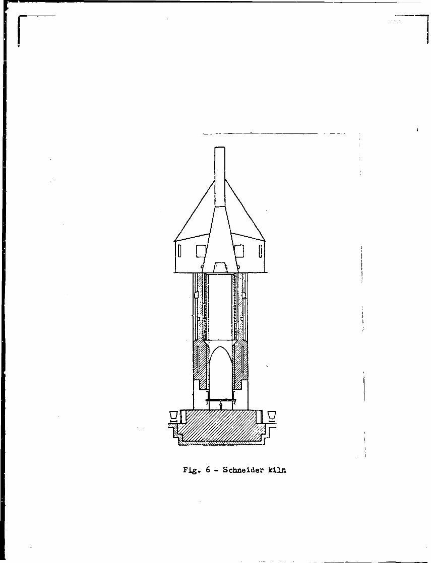
air could flow freely through the gaps between the bricks, and care had to be taken that the .cooling zone allow a steady passage of air. To counterweigh this, however, the kiln produced an excellent quality clinker since the raw mix remained in the calcining shaft for a sufficiently long time (2-3 hours) and the sintering process temperature was adequately high. Moreover the cooling was comparatively fast (in particular tfhen a fan was used to blow the cooling air^ which improves the quality of clinker.Another advantage of the Dietsch kiln was a lower fuel consumption (l9-25 $ of coke and anthracite of the clinker weight) , as well as a higher output (12-20 tpd). After implementation of the blown-in air, the output of twin kilns reached 30-40 tpd for which only 17 $ of the mix coke + anthracite was consumed (related to the weight of clinker).Another two kilns were competing with the Dietsch kiln; the Hauenschild kiln (designed 1869) and similar Schneider kiln (fig.Nr. 5 and 6) . These types featured a simpler service and maintenance in view of a lesser burning-on of clinker on the walls. The consumption of coke was approx. 17 The output was still quite low - 15-20 tpd.Schneider kiln gained such a popularity in Europe that e.g. in 1919 half of all clinker kilns in operation in Germany were of this design.The shell of the Schneider kiln consisted of two sheets and the space between them served for air cooling. Schneider used to place one layer of raw bricks onto the fireclay refractory lining and thus separated the refractory bricks from the hot clinker. Prior to each filling of the kiln with the layer of bricks, a bank of bricks was placed on the perimeter and thus the protective cuff was becoming longer and longer.The Dietsch kilns and other kilns of european design, particularly the Danish one (called also Aalborg or Schofer kiln) (fig. 7) wore constructed in the U.S. and La,tin America as well.
Automatic shaft kilns
Tho greatest progress in the design of shaft kilns was enabled by the invention of Hauens.child Jr. (1912), so-called "automatic shaft kilns". This denomination in not precise, since the kiln was not automatic in today s sense of the word; a continuous withdrawal of clinker was implemented and a gyratory grate was installed at tho

Fig. 3 - Hauenschild kiln
Fig» 6 - Schneider kiln

Fig. 7 - Schoefer kiln (called Aalborg kiln)

bottom of the shaft. In view of the fact that the grate which served for clinker crushing was almost continuously withdrawing clinker in the overall cross-section of the kiln, clinker was Sinking in the kiln evenly.This procedure was tested for the first time in 1912 in Beocin (todays Yugoslavia) and later at Ladce (today s Czechoslovakia).The production of horizontal gyratory grate was started in the German company Curt von Grueber in Berlin and as early as in 1917 the first kiln denominated as "automatic" went onstream at Blauenberg in Germany. New design of the kiln enabled an easy control, no more difficult manual rake-out was necessary, the quality of clinker improved and it was possible to maintain the sintering zone in the upper part of the kiln. Vith all these advantages the consumption of fuel vas considerably lower in comparison with then existing rotary kilns. The output of the "automatic" shaft kiln was only 30-40 tpd but after the improvements were implemented it reached 70 tpd or even more.The Hauenschild*s patented design was in its era an unprecedented success.The "automatic” shaft kilns with gyratory grate became rapidly widespread which can be evidenced by these figures:
Year Number of kilns installed1917 11919 481927 500
оAs can be seen from Fig. Nr. 8, the shaft kiln of Curt von Grueber Co. consisted of a vertical shaft which was a steel shell provided with refractory lining. The shaft was in the upper part closed with a steel sheet cover in the form of truncated cone with a Joophole.The cover was connected to the chimney. Compacted raw pellets with coke grit (or anthracite) , moistened to approx. 8-l4^ of 1120, were evenly distributed by means of a gyratory distributing disc. Lower part of the shaft contained the horizontal gyratory grate provided with numerous lugs by means of which the clinker was crushed and through the openings in the grate fell down; from under the grate it was discharged by thrcc-chaaibor closures (Grueber System) onto a conveyor. The air пессяг.агу for burning of fuel was blown into the space under the grate. The nir wan distributed through the holes in the grate along the overall cross-section of the shaft and rose upwards intensely c o o l i n g clinker and protecting grate from being damaged. Passing through the mass, the air became preheated; entering the sintering zone the nir was burning fuel since penetrated ( through, pores) even into the raw hrie.lco. Hot gases in

r
Fig. 8 - Automatic kiln of Curt von Grueber Co.

the upper layer served for raw bricks drying and were cooled down to approx. 120 °C.The development of the shaft kilns illustrates a progressive tendency towards smaller raw pellets. Instead of original bricks with dimensions upto 290 mm of length used in the old shaft kilns, the automatic shaft kilns processed smaller and smallerpallets and the latest granules do not exceed 30 mm. This trend is shown in Table Nr. 1 .Link between hourly outputs of the shaft kilns and the raw particle size _ _ _ _ _ _____________________
Table Nr. 1.
Brick(particle)dia.mm
Output of the kilnt/h
Depthoffire"m
Velocity of the passage of the massro/'h
Sinteringtime
h
Period
120 15 3,-0 0,60 5,00 1920-30
70 5,40 2,0 0,78 2,56 1930-^0
35 6,25 1,3 0,91 l.'O 1 9 b 0 - 5 0
25 7,30 1,0 1,09 0,91 1950-60
17 S , k 5 0,8 1,23 0,651960-80
10 10,70 0,6 1,56 0,39
Figures shown in Tabic Nr. 1. evidence that it was necessary to amend even the mechanical equipment in view of»the particle size. The machines producing bricks disappeared and were superseded by various briquetting presses and extrusion presses. After the World War II. the nodulizers became widespread, in particular nodulizing discs for forming of granules.Nodulizing discs were also being progressivoly improved. The best discs to produce granules for the .shaft kilns proved to bo the shallow discs (or throc-stngc discs) of the Loose-lie Company.These discs produce granules that are sufficiently porous and can

v - 9 -
better'withstand the thermal shock , i.e. do not explode at a rapid temperature rise.Fast calcination and a narrow sintering zone enabled to erect kilns with lower shaft. Optimum height to inner dia. ratio is generally 3-4 : 1 .The drag of the kiln rose during the 60 years of development from 500 nun of water column (4.900 Pa) to 1.600 mm of water column (15.690 Pa). This went hand in hand with a decrease in raw particle weight. This results in a greater likelihood that the air channels, so-called chimneys, could appear; these channels allow a substantial
part of air to leak. Therefore it is necessary to check during the calcination how the sintering zone behaves and to pack possible leaks, otherwise the percentage of the imperfectly calcined residue would be undesirably high.
«Regarding the grates, the most widely used was the gyratory grate (Curt von Grueber Co., Krupp - F.R.G.), however also the cylinder grates emerged (Mannstaedt or Stchmann Systems - Humboldt F.R.G.) and sliding grate Thiele (Pfeiffer Co. — F.R.G.).Modern shaft kiln can be seen in Fig. Nr. 9.Your attention can be drawn to the shape of the upper part of the shaft that broadens into a sort of a funnel. This concept improves the packing of kiln edges by the raw material. The sintering zone should ideally be placed within the funnel as it is shown in the figure.The shape as well as the size of the openings in the grate must be dimensioned according to the size of small granules, to prevent s*lf-discharge of the kiln through the grate s openings. For this purpose the Spohn/s con^^ate is most suitable (Fig. Nr. 10) .In order to improve the quality of clinker, Dr, Spohn pioneered in 1958 at Blauebern the technology of "black meal'1. Fuel is ground along with the raw materials, while in the "white meal" process the grains of solid fuel are only added prior to nodulizing.In the "black meal" process, the particles of ash are extremely fine and thus react perfectly with the raw mix.To complete the subject it is necessary to mention also some efforts to intensify tire burning process, e.g. by applying the oxygon-cnrichod air (02) amounting to approx. hO of 0?. (of the total amount of air). This is the so-called A-K process (Anselm- •
/


Fig. 10 - Spohn conical grate
/
- ib -
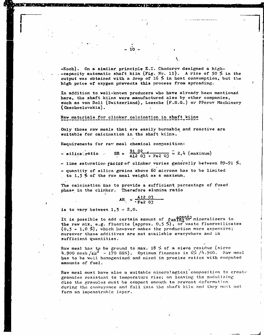
-Koch). On a similar principle E.X. Chodorov designed a high- -capacity automatic shaft kiln (Fig. Nr. ll). A rise of 50 in the output was obtained with a drop of 16 $ in heat consumption, but the high price of oxygen prevents this process from spreading.In addition to well-known producers who have already been mentioned here, the shaft kilns were manufactured also by other companies, such as von Roll (Switzerland), Loesche (F.R.G.) or Prerov Machinery (Czechoslovakia).Raw materials for clinker calcination in shaft kilns .
V
Only those raw meals that are easily burnable, and reactive are suitable for calcination in the shaft kilns.Requirements for rav meal chemical composition:
- silica /ratio SR = 'Fe2~03 * 2 >k (maxiraura)- lime saturation factor of clinker varies generally between 89-91 %•- quantity of silica grains above 60 microns has to be limited
to 1,5 $ of the raw meal weight as a maximum.The calcination has to provide a sufficient percentage of fused phase in the clinker. Therefore alumina ratio
AR A12 03 Fe2 03
is to vary between 1,5 - 2 ,0.It is possible to add certain amount of . mineralizers to ■the raw mix, e.g. fluorite (approx. 0,5 1°) , or waste fluorosilicates (0,5 - 1,0 io) , v/hich however makes the production more expensive; moreover these additives are not available everywhere and in sufficient quantities.Raw meal has be ground to max. 18 $ of a sieve residue (sieve4.900 mesh /csf - 170 BSS) . Optimum fineness is ( > [/4.900. Ilav meal has to be well homogenized and mixed in precise ratios with computed amounts of fuel.Raw meal must have also a stiitablc mineral ogical composition to create granules resistant to temperatui’c rise; on leaving the nodulizing disc the granules must be compact enough to prevent deformation during the conveyance and fall into the shaft kiln and they must not form an impenetrable layer.

Fig. 11 - Shaft kiln (E.I. Chodorov'a design) with intake of oxygen into the sintering zone

- 11 -
I
The occurrence of the mineral montmorillonitz in the raw meal is recommendable, vhile certain minerals of the illitg group should he avoided.Fuel for the automatic shaft kilns
For the automatic shaft kilns the homogenized raw meal is mixed with fine-grained fuel (l-8 mm) of a low volatile matter (max. 7 #) . i.e. coke, anthracite or kerosene coke; such mix is aftorwards moistened and nodulized.Advantages and shortcomings of the shaft kilns
In comparison with rotary kilns, the capital investment for the shaft kilns was 60 £ lower, their design was comparatively simpler and did not require much space.Heat consumption was. low and moreover the shaft kilns were using overwhelmingly coke of 1-8 mm which used to be a difficult waste for many years. The grindability of clinker was better which resulted in an economy on electric power needed for cement grinding.On the other hand even the largest shaft kilns were small units and to build a medium-sized plant it was necessary to gather them in batteries. The control and monitoring of the process of calcination was more difficult.The burner operator s work required great physical effort since clinker used to become burnt on the refractory lining. The burnt-on pieces had to be torn down by means of steel bars. Quality of clinker was generally lesser than quality of clinker produced in rotary kilns.Shaft kilns remain in operation even in the most advanced countries , however their share in the total cement production is on a decline. They are considered as an obsolete technology and shall be progressively superseded by dry rotary kilns with preheaters.
\

SHAFT KILNS FOR PORTLAND CLINKER CAIXINATION
Unitlid o s t leriodi- :al kilns
Dietsch duplox kiln
i’oriodi- ;al shaft kilns
Schneider Automatic shaft kilnsK-L In
with horizontal grate
withconograte
Specific heat consump. kcal/kkJ/kg
? 2300- -3500 9630- -14600
1200--16505024-6908
1700
7118
1200
5024
960 1 950 4019 3977
860
3600
Raw particles s^aP° 1 size mmdriod br icks dried bricks
290xl40x8(briquets compacts granules granulos
of blackmealMoisture content of, r.m.V.U.- Kin n.»rinl % 5 5 2 2 12 12 12Height of the shaft (less chimney) m 5,5 12 7 8-: 2 11,4 i 8,6 8,0Inner diameter of the shaft (less chimney)
upper part lower part
mm
1,54.0
- 1.82,5
2,5-3,:2,5-3,5
2.4 2,82.4 2,4
2,82,4
Fuel coal coal anthracite or mix
coke coko ooko anthra- : cite
70 £ anthracite 30^ coke
Electric power requirement of tne whole kiln group per 1 t clinker kWh/t 0 0 0 0 12 12-14 20Year of commissioning - 1840-60 1890-1910 1870-10 1910-20 1950-60 1967 1 9 6 8
Output tpd 2 17-20 8 15-20 l4o 18O 185Weight pf fuel to weight of clinker ratio ' 35-55 17-25
0 2426 17 13 13 12

DEVELOPMENT OF ROTARY KILNS
English engineer Frederic Ransome vas seeking to design a rotary kiln since as early as 1873* In 1885 he was awarded the Dritish Patent Nr. 5442 (Fig. Nr. 12) on the rotary kiln. His first kiln for gas firing was set up in 1887 in a small plant at Oregon but this plant was soon liquidated. Approximately at the same time his kiln: in East Kingston (N.Y.) belonging to Atlas P.C. Corporatic was being tested. After certain initial difficulties had been overcome the kiln operated satisfactorily. Ransome s original desi was for a gas-fired kiln, but then he switched to oil firing. He also amended the technology of cement manufacture for the rotary kilns. Based on operational experience, he got the raw meal ground more finely and moistened it.Another improvement of the rotary kiln was implemented by American engineers Harry and Seaman and Atlas Cement Corp. and their amended kiln of 1895 is considered to have been the first economically operating unit in the world. The size of the kilns poised on 0 6 ' x 60 ( 0 1,83 m x 18,3 m). The output reached 34,1 tpd (dry process) ar.d 23,8 tpd (slurry with 35 5» of H20) .After 1890 the rotary kiln appeared in Europe too. For example in I896 a rotary kiln 0 1,8 x 12 m was erected at Lollar bei Giess'e this kiln was producing 30 tpd and in 1899 was followed by another kiln at Hemmoor.Also the Panish company F.L. Smidth began to construct rotary kilns with pulverized coal firing, their output reaching 30-60 tpd.Even T.A. Edison was invited to cooperate on an improved design of rotary kiln, in particular regarding economy of operation (cuts in specific fuel consumption). Edison was clever in reolizin that the kiln dimensions, in particular kiln length, would have to be enlarged. In 1903 his kiln 0 2,5 x 45,7 m at Stewartsville was successfully commissioned. The output was 150 tpd in dry process (heat consumption 2000 keal/kg of clinker = 8.374 kJ/kg) and 135 tpd (2530 keal/kg of clinker = 10.366 kJ/kg) in wet process.Rotary kiln started gaining predominance over the shaft kilns and its dimensions were increasingly growing; soriours efforts were bcin, made to cut the fuel consumption, in particular by making a better use of the lieut contained in exit cases. This heat was recuperated either by built-in installations in the kiln, or by heat exchangers located behind the kiln.

View o f tfce loncitttii*
Jttem oy
12 - First rotary kiln for portland clinker burning (sketch from Bansome’s patent)

- Ik -
\
Raw materials wore either ground along with water - consequently a well fluid slurry was obtained - or wore dried, ground in a dry condition and fed into the kiln in the form of raw meal. In the former caso we speak of the vot process of production, in the latter of the dry one. In the initial stages of cement manufacture the wet process was more advantageous since the slurry was perfectly homogenized which was .not possible to achieve with the dry raw meal. The wet plants produced less dust, were simpler and the quality of cement was generally better. Particularly good results were obtained with chalks which were by their high natural water content and an easy wasfcebility, (with no grinding needed) predestined for the wet process. Easy service and lov/er consumption of the expensive electric power were equally advantageous.Development of long vet rotary kilns
Vet rotary kilns calcined the slurry whose water content enabled the sufficient fluidity for conveyance, homogenizing and feeding into the kiln. Vatcr content was mostly 33-38 in some cases (when plastic raw materials were used) exceeded 40 $> of 1120, rarely even 50 /0. Non-plastic raw materials and those ground along with fluxing agents sometimes require only 28-33 $ of K20.Thermal balances) shows that the bulk of heat in the wet kilns is consumed for evaporation of water from the slurry. In the short vet kilns however the greatest losses of heat were registered in the hot combustion gases (more than 45 Í). Therefore the designers first sought to increase the length of the kiln. While first rotary kilns had the dia. : length ratio 1 : 12, currently this ratio for the vet kiln is 1 : 33 up to 1 : 40. In order to feduce the temperature of exit gases, i.e. to make use of their heat, the enlarged kilns had built-in internal heat exchangers that enabled the heat transfer, sometimes serving also for other purposes (diminishing dust content, breakage of mud rings, helping the passage of mass through the kiln and formation of granules).Among internal heat exchangers in use in rotary kilns we can mention at least the mo3t widespread ones.a) Slurry preheaters located at the entrance to the kiln
Slurry preheaters with heat exchange compartments (Fig. Nr. 12 and 13). As the figures show, those preheaters are of two basic design?; of the F.L. Smidlh Company •- preheaters with transversa 1 and longitudinal ax'rangement of grates.Generally in the cement plants the preheaters with transversal arrangement of grate .are in use. They arc located 3-5 m from

Fig. 13 - Slurry preheater with heat exchange compartments-! ongitudinal arrangement of the grate of F.L. Smidth

Fig. 14 - Slurry preheater with heat exchange compartments- transversal arragement of the grate

- 15 -
the end of the kiln and consist of two circular grates built-in tranversally in the kiln. The spacing between the grates is 600 mm as a minimum. The space betwean the grates is divided into 6 radial sections. The kiln shell above these sections is provided with openings covered from outside by metal pockets. The sections are filled (approx, up to 50 £) with steel rings of approx. 100 mm of length.Slurry passes through' the openings in the diaphragm grate bar and gets in touch with the rings heated by the exit gases that flow in the opposite direction. Moreover, the rotation of the kiln brings the slurry into the flow of gases. Slurry temperature rises by 20-30 £ and water evaporates. Xn addition, nearly half of the dust carried by the exit gases is being intercepted.Preheaters necessarily increase the aerodynamical resistance by 25-50 mm of water column (i.e. 245-^90 Pa). Moreover an inexpert service of the kiln can cause the grates of the preheater to get clogged by the driev. slurry which results in a backward flow of slurry into the dust chamber. Therefore sometimes these preheaters are being removed at the expense of the thermal balance of the kiln.Sometimes chains are being suspended instead of the preheaters with heat exchange compartments.
b) Preheater in the drying zone of the kilnThe most widely used preheater and heat exchanger in this zone are chains, suspended either loosely (chain curtain) or in chain gai'land Long wet rotary kilns can have a chain zone that reaches 15-20 ^ of the kiln total length. >Properly designed chain zone is to help the passage of slurry (later granules) through the kiln, is to transfer maximum possible amount of heat from the gases ^o the slurry and thus reduce the temperature of gases at the end of the kiln, using the heat for evaporation of water from the slurry. It also has to prevent formation of mud rings in the central part of the kiln, in which the mass is in the form of plastic paste. Last but not least it has to help dedust the exit gases. Granules leaving the chain zone are to have 6-10 ‘fo of water content.
c) To accelerate the final drying and preheating of the granules, sped built-in metal .fixtures are used, made of ctbrusion-res.istant materials that can ulso withstand high temperature of exit gases (approx. 800 °C) . They are shown in Fig. Nr. I1» and 15)- These units are made of high resistant Cr-Ni Steel (25 7> Cr and 6 > N>)* are expensive and heavy and can be destroyed if an unskillful operator allows an excessive temperature rise.


I
Fig. 16 - Internal heat exchangers in the long wet rotary kilnX - l slurry preheater with heat ex
change compartmentsII - II chain zone (garlands)HI _ h i cross-shaped built-in instal
lation of the Giprocement design

Fig. 17 - Cross-section of the "sluriy calciner" of Miag Co.

-•16 -
Deeper in the kiln at the end of* the preheating zone the ceramic heat exchangers can be installed. These however are more frequently in the rotary lime kilns, while in the cement industry they are scarcer.External heat exchangers for wet process rotary kilns Concentrators (calciners) of slurry
In an effort to reduce specific consumption of heat in the short wet kilns in the 1930#s, the so-called "concentrators" (Krupp) or "calciners" (>iiag *) were in use.As can be seen from Fig. 16, the equipment consists of a horizontal drum the shell of which is formed by grate bars with gaps of 70 mm. The drum is filled with cast iron ring-shapod pieces. Hot exit gases leave the kiln at a temperature of approx. 600 °C. The drum rotates slowly (1-2,5 rpra). The slurry is fed into the drum from above and is evenly distributed. In the drum most of the water from the slurry evaporates and simultaneously the gases are cooled down to only 150 °C.First concentrators were set up in cement plants in England and Germany and soon spreaded all over the world. The wet kilns from the 1930*3 that had originally the specific heat consumption of 2.100-2.200 kcal/kg of clinker (8-792-9.211 kJ/kg), once the calcine were installed this figure dropped to 1.500-1.600 kcal/kg of clinker (6.280-6.700 kJ/kg). The output rose by 10-25 £.In addition to such reconstructions, new more modern units were being installed; their specific consumption was considerably lover - approx. 1.350 kcal/kg of clinker (5.652 kJ/kg), or even less (exceptionally 1.230 kcal/kg of clinker - 5-150 kJ/kg).Among the deficiencies of the equipment we can mention high emissions of dust, although current electrostatic precipitators enable a perfect dedusting of exit gases. As a matter of fact however, the long vet kilns wi'th a system of internal build-ins provide a simpler operation in comparison with wet kilns with concentrators, they have lesser maintenance requirements, do not consume so much electric power, and there is no danger of the influence of the false air which in the concentrators plays an important part. '
Polysins vertical chain drier
The PoJysius drier used to bo coupled to the vret rotary kilns

1
Fig. 18 - Polyaiua vertical chain drier

- .1 7 -
whose inner dia. : length ratio was approx. 1 : 20. Heat of the hot combustion gases was used for preheating of the slurry (Fig.Nr. 17).The drier consisted of two vertical concentric steel-sheet cylinders; the outer ono was thermally insulated and had at the bottom a discharge hopper that emptied into the rotary kiln.In between the cylinder shells, the chains were suspended from a steel structure that was rotating slowly. The slurry was fed and distributed evenly onto the chains. During the rotation of the structure the chains were hitting each other thus being cleaned up and the material fell onto a gyratory pan; from the pan it travelled to a movable chute and into the kiln.With the Polysius drier the output rose by 25 ana the consumption of fuel dropped by the equal percentage. Exit gases entering the drier had a temperature of 65O-76O °C and were cooled down to 140-200 °C; water content of the slurry was reduced from 35-^0 ^ down to 10 ?o of H20. The equipment required much maintenance.Drying of slurry in the atomizing drier
In some cases the kiln was combined with atomizing driers that were drying the slurry in the compartments in which the slurry was being atomized into the flow of hot exit gases. The output was raised by 30 £ and specific heat consumption was 12 £ lower. These results were obtained e.g. by the Danish Company Niro-Atomizer in cooperation with F.L, Smidth Company. (3oo Xig. 19)Clinker calcination in long wet rotary' kiln
In the wet process of production the kiln is fed with slurry with water content of 29-55 /«, most often 35-^0 $ of H20. From the technological point of view the wet process is the most versatile one. Although in recent years the wet process is giving way to the thermally more economical dry process with rotary kilns with dispersion heat exchangers, yet ;K) $ of the world production of clinker comes from the wet process.Long rotary kiln is a steel cylinder provided with refractory lining. It rotates generally at a speed of 1,1-1,2 rpm. Raw slurry is batched at one end of tlio kiln, while at the other end (in the kiln hood) the fuel is brought. The slurry proceeds slowly through tlio kiln towards the kiln hood which is enabled by a slight inclination of Lhe kiln (;i "'>) . The slurry is dried in tlio drying zone equipped with steel chains. Tlio chains absorb

1
>
Fig. 19 - Operational scheme of spray drying Niro-Atomizer Co.
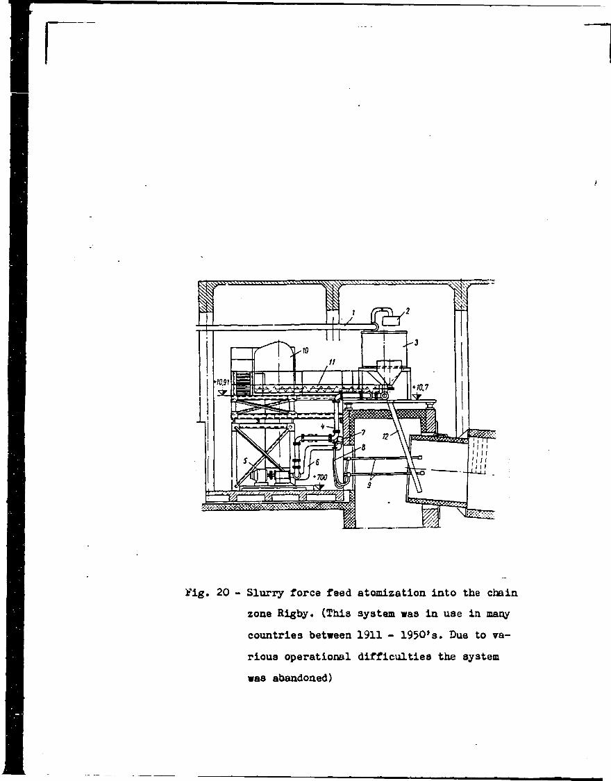
i'lg. 20 - Slurry force feed atomization into the chain zone Rigby* (This system was in use in many countries between 1911 - 1950’s. Due to various operational difficulties the system was abandoned)

>
Fig. 21 - Cross-section of the chain zone of long rotary kilns; chain garlands and chain curtain

/
— , o— xu —
\
the heat from the exit gases and transfer this heat to the slurry. Simultaneously the gases in the chain zone cool down to leave the kiln at 120-300 °C. The chain zone also serves for partial dedusting of the exit gases. On leaving the chain zone, the mass is already in the form of granules with residual moisture 6-10 of H20. The granules dry up very fast and proceed further into the calcining zone where (at 900 °C) the calcium carbonate decomposes. In the sintering zone at a maximum temperature of 1450 °C a number of chemical reactions take place, giving rise to tricalcium silicate, dicalcium silicate, tricalcium aluminate, tetracalcium aluminosilicate, magnesium oxide and approx. 0,5 of free lime. At the temperatures that occur in the sintering zone approx. 23-28 $ of the mass is in the form of melt and the mass sinters. The product of sintering called Portland clinker is quenched in a planetary, grate or drum cooler and leaves the cooler at 80-150 °C. As a coolant we use the air which is simultaneously heated to a high temperature (500-800 °C) and serves a s secondary air. Primary air enters the kiln along with the fuel and represents (when natural gas or fuel oil is used) only 5-15 of the total amount of air needed for firing; if a coal-fired kiln is concerned, this percentage is approx. 25
Long wet-kilns can be built up to the output ^.000 tpd.Temperatures and individual zones of the wet process rotary kiln can be seen from the following table.
Kiln zone Temperatureo,„mass xn oof burnt Gas tem
per, in °cEstimated length of the zone (in ^ from total effee live kiln length)zone
entryzoneend
zoneentry
zoneend
drying hO iuu 200 700 20
preheating 100 550 700 1250# 21
calcining .550 1100 1250 1500 33exotermic HOG i'i5C 1500 1750 13sintering l-’i50 1300 1750 950 8
cooling 1300 . 1100 950 800 5
Advan tnges of the wot proco?;;s of productionl) Preparation of perfectly homogcnjzed raw materials is cosier

‘.19 -
and therefore the requirements on the extraction, storage, andjoint batching of the raw material components are lesser.Additional correction of the composition and homogenization isvery simple. >
2 ) Mechanical equipment is not that sophisticated which means an easy maintenance and service.
3) If easily washable raw materials are used (soft marls, chalks and clays), the vet process enables to remove very.easilythe undesirable admixtures of the rocks, such as quartz sand, pebbles, flints, pieces of unweathered primary rocks, gypsum crystals etc.
%4) Vet grinding is easier than the dry one. Particular economy
on grinding is noticeable with Washable- chalks and soft marls, where no grinding at all is needed.
5) Porous, soft raw materials with high water content at extraction do not need any drying which would even in the dry process require the installation of driers with certain heat consumption for drying.
6) Very fine chalks that in the dry process cause an excessive amount of flue dust from the heat exchanger, are on the contrary suitable for the wet process; they form compact granules and this not only makes the firing easier but reduces the dust contentso that no electrostatic precipitators are needed.
>»7) Vet process of raw mix preparation does not require dedusting.8) In the vet process cement plant in the departments of raw mix
preparation and laboratory the numbers of servicemen and maintenance staff are substantially lower.
9) Vet process requires less capital investment both for mechanical equipment and civil works.
10) Hygienic conditions of work'in the vet plant are generally better which reflects in a lower accident rate etc.
11) Lower consumption of electric power is a considerable advantage of the wet process.
12) Vet rotary kilns produce a better quality clin'ce**. Even if the raw meal could be homogenized as perfectly as the slurry, the content of alkalies in clinker from dry kilns is 60 % higher
- 20 -
than that from the wet ones, since the absorption of alkalies in the raw meal in the dispersion heat exchanger is practically complete.13) Vet process can make use even of those raw materials for *
which the dry process is absolutely inadequate. They aree.g. sea oysters and other "salted" raw materials with elevated levels, of chlorides, further certain raw materials that are extremely fine already at extraction, raw materials with exceptionally high water content (often extracted from below water level), etc.
14) Refractory lining of the same quality in the sintering zoneof the wet kiln has a longer life (almost a double) . Therefore the wet kilns benefit from shorter downtimes than dry kilns with dispersion heat exchangers, with logical effects on the economy of operation.
15) An easy homogenization and correction of raw materials enable to process raw mixes of four and more components, with great fluctuations of chemical composition of individual components.
Drawbacks of the wet process
1) In comparison with the dry process with dispersion heat exchange the wet process always consumes more heat for the burning proper. The difference is so high that the increased cost of fuel, counterweighs all other advantages of the wet process.The world energy crisis with sharp rise in fuel prices has dealt a lethal blow to the wet process. It is believed that the long wet kilns are going to be used only under very special circumstances.
2) The wet process is not suitable for highly plastic raw materials that require exceptionally large amounts of water in order to reach normal fluidity of the slurry (often above 50 /o) ; thus the heat consumption (in contrast to the lower output) risesin view of the necessity to evaporate excessive water from the slurry.
3) Raw materials containing higher levels of bentonite arc less suitable for tho wot process since they can create in the kiln the so-called mud rings the removal of which is not easy.Also tliixotropic slurries can mean some problems during conveyance and storage in the silos. On the contrary, the slurries absolutely non-plastic (e.g. from limestone and slag) tend to liquation and sedimentation.

All these physical and chemical properties of the slurry can be anticipated and defined by laboratory procedures in analyzing the final raw material samples.k ) Also the consumption of non-return process water is rated among
the important disadvantages of the wet process. This kind of i water is in some areas of the world very scarce and can be used
only for agriculture..In some cases even (in certain regions of Mexico or Iraq or others) the official institutions do not
- authorize construction of wet process plants.
Semi-dry and serai-wet process of production
hepol process
For the semi-dry process the raw meal is moistened to 8-15 $ of H20 and nodulized. Similarly the semi-wet process uses raw particles obtained by filtration of the raw slurry' with granulation or compaction of filter cake with water content of 15-18 'fc. For the calcination of the raw meal prepared by semi-dry or semi-wet process it is possible to use either long rotary kilns with internal preheaters or short rotary kilns with grate calciners (Lepol System) which are the most economical as far as thermal consumption is concerned.
• /Rotary kilns with grate calciners (Lepol kilns)
It was in 1927 in Germany when Dr. Lellep was awarded the Patent Nr. h h 6 298 which remarkably influenced the development of kiln systems. Dr. Lellep made use of his vast experience regarding sintering of ores and applied his knowledge to calcination of cement clinker. Essentially lie suggested to calcine the nodulized raw mix on the grate by hot exit gases leaving the short rotary kiln. Partially calcined granules enter the rotary kiln in which they sinter. The patent was made use of by the Polysius Company which cailcd the kiln as "Lepol kiln". In 1929-31 the first kiln was installed by Polysius in Germany and shortly afterwards another one in Switzerland. Low heat consumption anci high output of the Lepol kiln promoted its rapid spreading in the period between the two Vorld Wars. As many as 53 kilns in 18 countries were operating in 1937. and 2 years later (in 1939) this figure roso to 120.

I22
After the Vorld Var H the design, department at Neubeckum implemented various constructional improvements. The so-called duplex conduction of exit gases through the calcining grate was developed thus making a better use of their heat; moreover it improved the calcining process on the grate and dedusting of gases
\ in the cold chamber (Fig. Nr.22 and 23 ). Vhile the kilns with the single conduction of gases featured thermal consumption of 1 .050-1.300 kcal/lcg of clinker (4.AOO-5-^0 kJ/kg) , this data for the kilns with duplex conduction of gases was below 900 kcal/kg of clinker (3.770 kJ/kg), and the the large units operated at even 7^0-780 kcal/kg of clinker (3*098-3.266 kJ/kg), which places this kiln still among the most economical in this field.The largest Lepol kilns produce 3-000 tpd of clinker. In the post-war period the leading manufacturers of the Lepol kilns became Polysius and Miag ir. F.R.G. , Zementanlagebau in G.D.R. and Aliis-Chalmers in the U.S.Good results in reducing the thermal consumption were obtained also thanks to a series of other technical improvements such as replacement of drum coolers with the grate ones, etc.In I960 as cany as 290 Lepol kilns were in operation. In the 1970 s there was a slowdown in their construction due to the competition with the kilns with dispersion heat exchangers, which apart from lesser maintenance requirements make use of the hot exit gases of 36O °C that serve for drying of raw meal in the mill or in a drier. \Clinker calcination in the Lepol kiln
Raw materials are conveyed to the Lepol kiln either in the form of homogenized raw meal with residual moisture of approx. 0,5 /" of H20 (a ), or as a filter cake with 15-17 $ of H20 (n) .In case of (a ) the raw meal is routed onto a nodulizing disc where it is moistened and where the meal forms granules of 0 10-15 mm with moisture content of 12-l4 $ of 1120. These granules are directed onto the calcining grate. Ve speak of a semi—dry preparation.In case of ( U ) i t is also necessary to convert the f i l t e r c a k e into grains with appropriate moisture content, geometrical shape and compactness. For solid cakes, obtained by pressure filtration, Die extrusion presses generally suffice. If tlio cakes are too soft,
Row mix fwdirtg
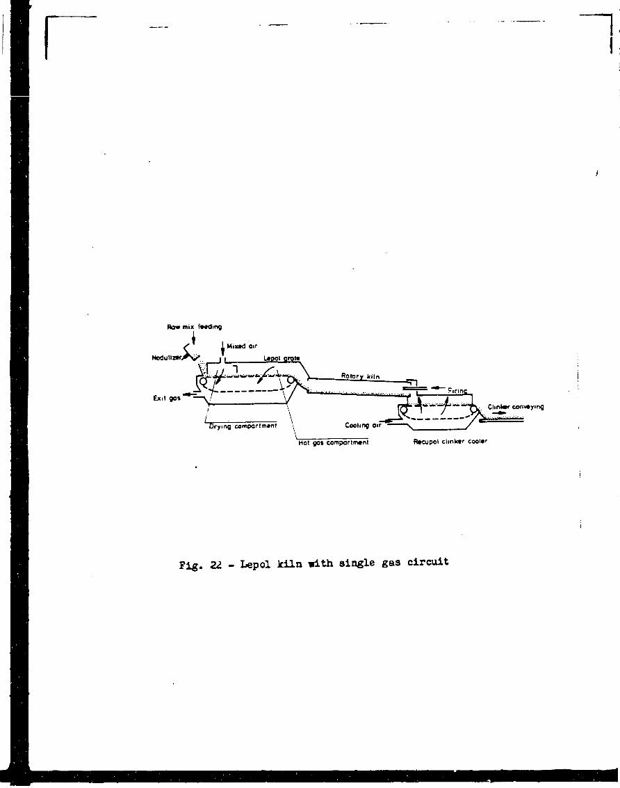
Fig. 22 - Lepol kiln with single gas circuit

Row mu feeding
first gas passegt
Fig. 23 - Lepol kiln with double gas circuit

- Vacuum diac filters for slurry filtration and filter cake feeding into the rotary kiln

9Fig. 25 - "Concentrator" of the kiag Co. for
moistened raw meal

A
it is sometimes necessary to add dry raw meal or precipitated dust, granulation following afterwards. These processes are particularly advantageous if the wet kilns under reconstruction use soft raw materials with high moisture content, e.g. chalks. In this case we speak of a semi-wet process of production. This process can be also resorted to if soft raw materials with elevated chloride content are to be used. A substantial part of chlorides is removed during filtration and the rest can be eliminated by means of the so-called by-pass which enables a derouting of a part of exit gases from the hot chamber of the calcining grate.Raw meal grains are fed onto the calcining grate. The space around the grate is lined and divided into a cold (drying) chamber and a hot chamber. The layer of granules (1^0-200 mm thick) is carried by the grate first into the drying chamber where it meets the . combustion gases (300 °C); on passing through the layer of moist granules the gases cool down to 90-120 ° C . Cases that passed through the layer of granules travel then through the gaps in the grate bars (of 8 mm of width). Dried and preheated granules then enter the hot chamber where they are calcined by hot gases from the kiln (1.100 °C).The clinker calcination process ends up in the short rotary kiln where the granules sinter. The Lepol kiln has the optimum length to inner dia. ratio of l4 : 1 . Owing to the thermal preparation of the raw materials on the grate, the final phase of burning in the rotary kiln is very intense which is testified by the specific output of the Lepol kiln which - at peak performance - reaches 2,2 t/m3 per day. The grate shifts at a speed of 25—50 m/hour, while the passage of material through tho kiln takes 80-100 minutes. Disintegrated granules that fall through the grate are conveyed by moans of a chain conveyor and elevator into a cooler, generally the grate cooler.Raw materials suitable for calcination on the Lepol calcining grate
The crucial point here is the nocossity to obtain the raw particles that are pei'fectlj' compact, can withstand temperature upsurge, and must bo abrasion-rc.jistant. More suitable for these purposes are the plastic raw materials containing the clay mineral monttnori- llonite. Therefore a maximum possible attention is to be paid to the selection of the raw material components, in particular regarding the sialit^Somponcnt (generally clay). The granules ore to be compact enough to avoid their deformation during conveyance from the nodulizer to tho grate, enabling an adequate permeability of tho layer of granules for tho hot gases* which is a precondition for a normal operation of not only the grate but of the kiln is a
I

\
V
2k -
whole. If the granules are too hard, with strength exceeding 1.500 g (at granule dia. of 15 mm), they are less porous and generally less resistant to the thermal shock of hot gases which results in their disintegration or explosion. On the other hand granules with strength below 600 g get plastically deformed.Also the way of formation is of great importance. Moreover the less plastic raw materials feature a low resistance to abrasion. If a maximum of 5 i of grains fall through the grate it is considered as operationally tolerable.In order to summarize the topic we can say that an extraordinary care has to be taken to select the raw materials and that their analysis deserve a special attention, all this being possible only in a close cooperation with the manufacturer of mechanical equipment.
Dry process of production
In cement plants that operate on the dry process of production, the old short kilns without the heat exchangers are today practically non-existent. Most of the kilns currently in use have dispersion heat exchangers, or they are long kilns with internal preheaters, or possibly with one- or tvo-stage exchangers; still there are plants using dry process kilns with waste heat boilers which were left over from older systems.Short rotary kiln with waste heat boiler
The waste heat boilers were being incorporated to rotary kilns in order to recuperate the. heat of hot exit gases whose temperature reached 700-1.000 °C (Fig. Nr.26 ). Of the total thermal consumption of 1.550-1.85O keal/kg of clinker (6.^90-7 *7^6 kJ/kg), approx. 550 keal/kg (2.302 kJ/kg) were used for production of electric power. This technology was used mainly in I 9 k 0 3 .*
Currently it is more economical to construct kilns with heat exchangers of a lower thermal consumption, and to procure electric power in the power plants where its production uses a lowcr-gradc fuel and is much more efficient.Dry long rotary kilns
Among the dry long rotary kilns wc generally reckon those whose inner dia. : length ratio is 1 : 30 or more. Modern kilns have this

Fig. 26 - Boiler using waste heat from the rotai*y kiln

SEMI-DRY AND SEMI-VET ROTARY KILNS AND SINTERING GRATE
UnitLong rot. cl In on granules
L e p o l K i l n Kilns with calcinera on moistened raw m.
Sintering grate Arupp- -Lurgi
conduction of gasesm d prch. single duplex 3 chambers
Specific heat consumption kca/lcglcJ/kg
1.180 h . 9b0
I .050*».*»00
85O3.560
7 60 3.180
1100-1200*>605-502/»
12 bO5192
Output of the kiln tpd 338 250 1*00 1.920 100-1000 3**0Specific output of the kiln in metric tons/day for 1 m3 t/m3/d 0,58 1,62 2,09 1,*»1 0,8-1 ,1 15 t/ra2
of grate/dMoisture content of raw mix 13 1*» 1 h 13 12-15 1*»_ . „ after- kiln Temperature of gases .' r after exchan, °C 250 9OO-950
1201000-1100
901120
120700 ,
2b0-*»002*»0
Temporaturo of raw mix into kiln °c. (granulos)20 76O 800 850 250 20
Percentage of apparent dissociation of raw meal entering kiln • * - *»0 **5 ' *»5 - - •Length : inner dia, ratio m/m 28:1 15:1 1*»:1 17:1 20:1 -Electric power requirements for clinker production (total kiln group)
kWh/t 9 9 13 17 18-19 25-DO
Fuel - coal oil oil heavy oil various cokeCooler type - planetary drum grate grate various -Kiln dimensions 0 x length n x m 3,*»x85 2 ,8/2;6xp6 3x36 *»,7x75 - 26 m2
Calcining grate size widthxlength mxm - 2 ,b2xl2,5 3x12,5 *4,76x37,5 - -Country/year Yugoslav.1958 Jordan
195**Jordan
1963Japan
1966FRG FRG' 1952
Manufacturer MI AG FRG
PolysiusFUG
PolysiusFRG
KawasakiJapan
Miag,KruppFUG
Krupp, Lurgi FRG
>
- 26 -
ratio 1:33 - 1:38. These kilns were developed in the U.S. since they were operationally reliable, required minimum service and maintenance and the consumption of electric power for the kiln drive (6-8 kWh/t of clinker) was absolutely the lowest of all kilns. Somewhat higher heat consumption in comparison with European kilns was (until the breakout of energy crisis) of secondary importance.In 1962-63 as many as 31^ these kilns were operating in the U.S. , and today they still provide 30 $ of the North America s production of clinker. In Europe and in other parts of the world however these kilns are very scarce, e.g. in F.R.G. they account only for 2 $ of the clinker production.Dry long kilns were originally constructed with no internal or external heat exchangers. Exit gases at the end of the kiln used to have a temperature of 700 °C or more and had to be efficiently cooled down - most frequently by injections of water - in order to be exhausted by a fan or dedusted.In the 1950 s the internal heat exchange system were becoming more widely used. First the systems of heat-resistant steel chains were implemented. Later the cross-shaped internal ceramic heat exchanger were tested in the calcining zone, later also the cross-shaped steel exchangers. Temperatures at the end of the kiln dropped to ^30- -530 °C and the heat consumption lessened to 950-1*170 keal/kg of clinker (3 * 977-'» .900 kJ/kg), according to the quality of design and workmanship of the exchangers. If the hot exit gases are used as a drying‘media in a drum drier, it is possible to remove as much as 13 /0 of the moisture from the raw mix.Tho incorporation of cyclone preheaters meant a significant progress in tho development of dry rotary kilns. This helped not only dedust partially the exit gases, but resulted in diminishing their temperature and reducing the specific heat consumption down to 850 keal/kg of clinker (3*559 kJ/kg).As a rule the following combinations are in use:1) Dry long kiln with two cyclone preheaters in parallel arrangement
(i.e. one-stage heat exchange).2) Dry long kiln with one preheater in the first stage and two
preheaters (smaller ones) in the second stage.3) Two-stage preheater of the F.L. Smidth Company consisting of
an outer cyclone preheater with lining and an inner cyclone preheater (Fig. Nr. 27).
\

- 27 -
1All these arrangements are interesting also from the point of view of conversion of the long wet rotary kilns to the long dry kilns.Long dry kilns were constructed for outputs of up to 3.000 tpd.In view of the fact that the heat exchange in the long kiln is far from being efficient, the specific output of these kilns is low and their dimensions are extreme. A kiln of even 5*000 tpd of clinker was designed; the shell of this giant kiln was computed to be 0 7«5 x 260 m.In comparison with the short kiln with dispersion counter-current heat exchanger, the long dry rotary kiln requires k 5 $ more cf capital investment.As regards the operational reliability, the long dry kilns are less sensitive to clogging caused by alkali salts, and their drag is low which reflects in the power requirement of the kiln exhaustor.
The Grudex System
This heat exchanger, constructed by Kennedy van Saun Co. in the cement plant at Coplay (Coplay Cement Corp. , Pa loses the meal to the pneumatic Fuller-Kynion pump which for es tl. ..sal through a spiral tube made of heat-resistant Cr-Ni steel. The spiral is located in a vertical tover provided with lining, through which the hot gases from the dry rotary kiln pass (Fig. Nr. 28 ). Raw meal is preheated to 700-760 °C. Tho Grudex heat exchanger contributed to an increase in output by 36 and to a drop in heat consumption by hh (specific heat consumption for clinker burning after reconstruction amounts to 1.090 keal/kg of clinker { k . 5 6 k kJ/lcg) .
Dry process of production with dispersion heat exchangers
Homogenized raw meal is continuously dosed into the shaft dispersion heat exchanger or into the four-stage cyclone preheater. Hot gases from the rotary kiln entering tho exchanger have a temperature of 1.050 °C and they pr^-hcat and partially calcine the raw meal.Raw meal enters the heat exchanger at kO °C and lcavos at 800 °C. Exit‘gases enter tho exchanger at 1.030 °C, transfer their heat to the raw meal and leave the exchanger at 3-̂ 0 °C. These gases are cooled and moisten in the conditioning tower and dusted off in the electrostatic precipitator. Preheated raw meal from the heat exchanger enters the short rotary kiln where the burning process

Fig. 27 - Two—stage cyclone heat exchanger ofF.L. Smidth Co.

I
I
IFig. ?8 - Grudex heat exchanger (Kennedy van Saun Co.)

' ¿r
J
Fig. 29 - Dispersion heat exchangersa) Humboldtb) Poly si изc) Vedagd) ltiag
1

Fig. 30 - Dispersion shaft counter-current heat exchanger of Prerov Machinery

1
I I I
Fig. 31 - Gros»-sectional view of the Krupp countercurrent heat exchanger

- 2 8 -
terminates. Clinker produced in the sintering: zone is cooled in the grate cooler.The preparation of the raw meal for the dry process of cement manufacture is considerably more complex, but the heat consumption in this case is low and therefore this process shall in the future prevail.Dry process kilns with dispersion heat exchangers can produce 300-5.000 tpd at calorific consumption of 960 kcal/kg of clinker (3.182 kJ/kg) - 720 kcal/kg of clinker (3.017 kJ/kg). The larger the kiln, the more economical operation.Dispersion heat exchangers are either cyclone heat exchangers of Humboldt, F.L. Smidth Co., Ishikawajima-Harima Co., or shaft counter-current heat exchangers - Prerov Machinery, Krupp, Zeraent- anlagebau Dessau, or they combine cyclones with turbulence shafts where the gases are routed into two channels - Polysius, Wedag, Kawasaki, UBE, Miag, Allis-Chalmer^.Some of the mentioned manufacturing companies were themselves the inventors of the systems, some of them build the systems with a license. Technical description of all systems of dispersion heat exchangers would go beyond the framework of this study. However it *is possible to say that generally all these companies are able to construct exchangers for the kiln of 3.000 tpd, some of them erected heat exchangers for over 4.000 tpd. In one project there is even a heat exchanger of over 5.000 tpd of clinker. As regards the specific heat consumption, all heat exchanger systems are capable of reaching the specific heat consumption of 800 kcal/kg of clinker (3.349 kJ/kg) or even lower. It depends also on the output of the kiln. Larger units have a lower thermal consumption as was found by G.A. Schroth for cyclone heat exchangers in 1973:
kiln output Specific heat consumptiontpd kcal/kg kJ/kg.
300 860 3.600400 830 3.559500 845 3.538600 835 3.496800 810 3.3911.000 800 3.3491.200 785 3.2871.400 770 3.2241.600 765 3.1821.800 765 3.2032.000 760 3.1822.500 750 3.1403.000 745 3.1193.500 740 3.0984 .000 7 30 3.056

DRY ROTARY KILN WITH DISPERSION HEAT EXCHANGERS
/
Short rotary kiln with dispersion heat exchanger
K1ID four-stago cyclone oxchancor,
Shaft counter-current exchanger Prerov Machinery, grate c
Specific heat consumption keal/kfkJ/kg
72 h3.031
7't03.098 «
Output of the kiln tpd I.53O 3.000
Specific output of the kiln in tons of clinker/day per 1 m3 of inner space of the kilr
t/m3/d 1,79 1,63
Moisture contont of raw meal * 0,5 0,5_ . „ after kill Temperature of cases aftar oxcl . °C
I .0503'»o
1.050350
Temperature of raw moal into the kiln °C 800 800
Percentage of apparent dissociation of the raw meal ^5Length to inner dia. ratio m/m 17, ') : 1 17,6 : 1Electric power requirements for tho whole kiln group kWh/t 17 -
Fuel - oil heavy fuel oilKiln dimensions - J», h x 68 5,6 x 90
Manufacturer , KHD - F.R.G. Prerov Machinery Chechoslovakia

Raw materials suitable for the dry process of production with kilns with dispersion heat exchangers
In preparing the technology for the dry process of production, special attention has to bo paid to tho total content of alkalies, sulphides, sulphates and chlorides both in the raw mix and in the fuel.General condition is that the alkali content in the raw mix must not exceed 1,5 Chloride content (expressed as Cl’) is not toexceed 0,04 £ and sulphur content of raw meal plus fuel, calculated in S03, may not exceed 1Dispersion heat exchangers are not very suitable for the raxv materials with elevated content of alkalies. Alkalies clog the gas ducts and exchangers, in particular when they are combined with sulphates and chlorides. Difficult problems in operation are frequent and sometimes even the kiln has to be shut down.Maximum caution has to be taken when raw materials from desert areas are used, since they generally contain dangerous levels of soluble alcalic salts (chlorides, carbonates, sulphates). This is true in particular for the Middle East countries, namely Egypt, Saudi Arabia, Iran, Kuvait, further certain regions in South America e.g. northern parts of Argentina etc.Kilns with dispersion preheaters and flash-calcining system
The Ishikawajima-IIarima Heavy Industries Co. (i.II.I.) developed a system of the-so-called flash chamber which is coupled to the lowFcr part of the heat exchanger. By means of conduction of larger amounts of heat into the exchanger the rate of calcination of the raw meal entering the kiln rose to 90 fo. Part of the hot air from tho grate cooler (temperature 6OO-65O °C) was used as the firing air. This system has been put into operation in the cement plant in Chichibu Cement Co. on the kiln 0 3,9 x 51 r.i with a K3ID heat exchanger. Specific output rose from 1,52*- t/m3/ /day to 3»38-i t/m3/doy. This s ystem enabled to build the cement producing unit of 7.700 tpd.Additional firing into the heat exchanger is a basis fox* a couple of recent systems. hue to the lesser amounts of fuel burnt .in tho rotary kiln, the life of refractory lining is longer, which was decisive particularly in large units. The transfer of calcining proccco into the heat exchanger made the burning pi'ocess

DRY ROTARY KILNS
D r y r 0 t a r y k i l n
Unit Short ShortLong lciln w ith pre
with wastelieatortnd c y c lo n e heat b o i l e r
S p e c i f i c heat consumption k e al/k f 2200 2000 950 850 1500-1850 x )
kJ/kfi 9211 837/1 3977 3559 6280- 77/»6
Output of the k i l n o f c l . tpd 35 15 0 630 1000 80-3300S p e c i f i c output o f the k i l n in n o t r ie tons of cl i.nkcr/day per 1 m3 of t/m3/d 1,02 0,868 0,6 0,7 0 , 8- 1,32inner space
fod raw m. £ 0,5 0,5 0,5 0,5 0,5iMoisture content raw nti int(]j tho k i l n 0,5 0,5 0,5 0,5 0,5
Temperature o f a f t e r k i l n °C 950 650 . Z»50 z»00 700-1000G0'5OS a f t e r cxch °c - - ■ 180
Temperature of raw, mix f> 40 40 40 40 40in to the r o t a r y k i l n c
Per conta.pa of apparentd i s s o c i a t i o n o f the raw m. <
j e n t e r i n s the k i l n
| Length to inner d ia . r a t i o m/a 12 : 1 21 : 1 hh : 1 38 :1 17-25 : 1jj E l e c t r i c power requirement j of tho whole k i l n proup kVh/t - 10 8 7 12-15
i k i l n dimensions ,0 x le n g th inxm 1,8 x 1 8 , 2 2 ,5-x '15,7 3 ,75/ 3,2»5 / 3,75 x l M
- variou s
Terr - 1887 1903 1963 1973 1930-80
*)Out of tills quantity 500-700 kcnl aro usod for production of electric power

Sf
• 32 - Sketch of the SF heat exchanger of theIahikawajIma-Harima Heavy Industries Co. Ltd
Fig

Fig. 33 - Flash-calciner system of the F. L. Smidth Co.

f
Fig. 34 - DD Flash-calciner System (Dual Combustion and Dénitration Calciner) of the Niheu
Cernent Co* Ltd

>
Fig. 35 - Fire box of the flash-calciner system KSV and NaSV of the Kawasaki Co.

Fig. 36 - Mitsubishi Fluidized Calciner sketch (FMC)

r- 3 2 -
easier and enabled to . design- kilns of* up to 10.000 tpd.Large number or tlio flash-calciner systems that have been developed so far does not allow their description individually in this work. Therefore we give at least a review of the main systems in the following table.
Systemdenomination
Inventor Manufacturer Max. output (actual or planned)
Licensee
SF Chichibu Cement Co. Ltd.Is hikawaj ima Karima Heavy In. Co. Ltd.
Ishikawa j ima Harima Heavy Industries Co. Ltd«
7.70C tpd FullCo.
mfc - Mitsubishi Mining and Cement Co. Ltd.
Mitsubishi nervy Indust. Co. Ltd. Mitsubishi Polysius
7.200 tpd
RSP Onoda Cement Co. Ltd.
Kawasaki Hea vyIndustries Co.
5.200 tpd Allis-ChalmorsCreuoot-LoircV/0 Lice:sintorg(USSR)
ICSVKawasaki Spouted Hod and Vortex Chamber
Kawasaki Heavy Indu.trios Co.
Kawasaki Heavy Industries Co.
2.500 tpd
NK3V 'New KSV)
— 11 — — M — h .500 tpd
i

Systemdénomination
Inventor Manufacturer%
Max. output (actual or planned)
Licensee
DDDual Combustion and De- nitration Calciner
Nihon Cement Co. Ltd.
Kobe Steel Ltd.
4.000 tpd
FLS F.L. Smidth Co. Ltd.
F.L. Smidth Co. Ltd.
4.300 tpd
GG MitsubishiHeavyIndustriesLtd.
MitsubishiHeavyIndustries Ltd.
4.400 tpd
S Sumitomo Cement co. Ltd.
Sumitomo Cement Co. Ltd.
4.500 tpd*
H HitachiZoscn
HitachiZosen
U UBE Industries Ltd.
Pyroclon Klockner-Humboldt-Deutz
Klbclcner-Humboidt-Deutz
3.200 tpd
Prepol B Polysius Polysius 4.200 tpdPrepol AT PolysiU3 PolysiusPrepol AS Polysi US Polysius 7.000 tpd
. / Partial pre-onlciiiing
In some cases it is more advantageous to embark on a more modest increase in the kiln output, e.g. by 10-15 since the capacities of

- 3** -
ether equipment do not allow a major rise, or in a given situation it may not be considered as reasonable to undertake a large-scale reconstruction incl. clinker coolers, conveyors, heat exchanger etc. In this case it is possible to withdraw the firing air needed for burning of fuel in the pre-calcining kiln and use it for an additional firing in a pre-elected place in the exchanger, or possibly in an adequate part of the gas duct between the kiln and the heat exchanger.Comparison of both pre-calcining systems
Partial pro-calcining Complete pre-calcinir
Calciningchamber
The burners are placed in the amended ga9 duct or in the lower part of the exchanger
Self-contained chamber with burners with the combustión air intake
Combustion terciary air
Conducted directly through the rotary kiln (so-called excessive air)
Conducted through an independent duct from the clinker cooler (rarely from another source)
Fuel share in . 30_50 ¿ the pre-calcining 1*5-65 £
Decarbonati on grade in /á 60-75 70-90
Usability up to 5.000 tpd 10.000 tpd
Design simpler more sophisticated
Usability of coolers
all kinds except for the planetary coolers

Н-'У ПОТАЩУ KILNS V.’ITM DISPERSION HEAT EXCHANGERS AND FLASH-CALCINER SYSTEM
.11
Uni tMFC
Ishlkawn- jirna Harina Il.Ind.
7503l40
SFMitsubishi Mi
ning C.
RSPOnoria + Kawasaki
KSVKawasakiHeavyIndustries
FLSF. L.Smid th
Specific heat consumption ' keal/kgkj/kg
7503i4o
7503l4o
1----1О О 1 «Л-3-11
fa1
76O3180
1[-ueput o“T the kiln tpd 7 2 0 0 77OO 3100 8300 41501 Specific output of the kiln t/тЗ/d 3.9 3,8 5,2 3,2 3,7i Tc xporaturo of gases after kiln ! after cxchang.
0c 1150390
1030з'ю
IO5O260
1100 3'* 0
1100380
| Temper. of rav:- n:oal into tho kiln °C 830 830 830 860 87O¡Temper, of gases after calcin.chamber °c 860 880 830 860 87O1j Percentage of apparent dissociation # " 90 93 88 91 90¡Temperature of second, air * °c 800 800 680 950 800...mount of fuel into the calcinor * 59 62 60 55 57Number of cnlciners - О
4m 2 1 2 1Calcincr diameter in 8,0 7,4 3,6 6,8 7,1j Type of heat exchanger - f o u r - s t a g o c y c l o n o t y p oSpeed of the kiln rpm 3,0 3,0 2,7 2,0 2,3Inclination of the kiln о /1,0 /1,0 /1,0 4,5 4,5|Kiln dimensions 0 x length rnxm 5,4 X 95 3,5x100 3,45/3,75V 7«î 6,2 х Ю 5 4,75x75Length to inner dia. ratio m/m 19,/* : 1 10, it : 1 23, /1 : 1 18,4 : 1 17.6 : 1!JYear of commissioning - 1975 1973 1978------- :- 1975------- ---- 1977—

- 36 -
Advantages of the dispersion heat exchangers with flash- -calciner system
1) Out of the total quantity of fuel, 60 $> is burnt in the calcining chamber which enables to achieve the calcination rate of approx. 85
2) The start-up time of the kiln is relatively short and the full operation begins between 5-20 hours.
3) Longer life of refractory lining (25-30 %>) due to a lower thermal load of the sintering zone, and due to a relatively smaller diameter of the kiln.
h ) Easier transport and erection of the rotary kiln in large units, since the kilns can have considerably smaller dimensions in comparison with conventional kilns with heat exchangers.
5) For the additional firing in the heat exchanger it is possible to use also coal or waste low-grade fuels, which helps save quality fuels with high calorific values.
6) Area needed for civil works is 25 /° lesser.7) Lower content of NOxin the exit gases, in particular in special
calcining chambers (DD, 5G) - it has been proved only 150-300 ppm at 10 of 02.
8) Clinker grain size is generally finer.8) Large units (above 3*000 tpd) reach the heat consumption of
730-790 kcal/kg clinker (3*056-3.308 kJ/kg).
Doficiencios
1) Older plants featured somewhat increased heat consumption(by 0-5 fi) ̂ nthe most recent units tho consumption is comparable to the conventional design without the flash-calciner system.
2) Slightly increased consunytion of oloctric power. It is estimated at an average of 1,5 kWh/t of clinker.
3) In spite of the fact that tho rotary kiln for tlio same output has a smaller diameter, tho system is more complex and economical effects can bo a c e n starting from tho output of 3-000 tpd,more evidently from h .500 tpd.

Fuels used for the production of Portland clinker in rotary kilns
In order to reach the sintering temperature in the burning zone of the rotary kiln it is necessary to heat the clinker up to 1.390-1.480 °C. The temperature of the flame is approx. 1.800 °C and can be obtained by combustion of a high-quality fuel and preheated air. In this respect the cement kilns differ from the lime ones.Gas.For a gas-fired kiln it is necessary to use gas which has a calorific value of at least 5*500 kcal/Nm3 (theoretically the lowest possible calorific value for gas firing is 4.350 kcal/Nm3 - 18.213 kj/kg). Average value for natural gases used in cement plants is 8.300 kcal/ /Nra3 i.e. 34.750 kJ/kg). Implementation of gas firing in the cement plants is simple and does ,not require much capital investment. Needed is only a duct for connection to the main gas line, relatively cheap reducing and measuring station, automatic de-pressurizing and a special burner. Once the burner is correctly tuned-up, the service demands little effort. Gas mixes easily with the primary air and the control is not very difficult either. In comparison with coal or oil firing it is necessary to tolerate a slight drop in output and an increase in specific heat consumption.Oil
Cement plante generally use the cheapest kind of oils, i.e. heavy duty fuel oil. These oils are transported to the plants in the tank trucks and are preheated. In contrast to gas firing, the oils require that storage tanks be built, and prior "to burning they must be heated to a higher temperature in order to reach a perfect atomisation of oil leaving the burner. It is necessary to reach the viscosity of 1,2 - 2° of Englcr, which corresponds to the temperature of those oils approx. 125-145 °C.Heavy fuel oils have calorific values of 9-400-9.800 keal/kg of oil (39.356 - 41.031 kJ/kg).Coal 1The quality and composition of coal deserves great attention, aswell as its preparation. Coal used for clinker burning-should be of uniform quality, of a calorific value above 6.000 keal/kg of dry coal (25.121 kJ/lcg). The minimum calorific valuo of dried coal should bo of 5.000 kcnl/kg of coal (20.934 kJ/lcg). With decreasing calorific value of coal the output of the kiln rapidly drops, tlic specific heat consumption rises and the quality of clinker deteriorates due to the excessive amounts of usii. Also the ash ring can

- 38 -
emerge.>
Coal is hot to be over-dried since then does not catch fire easily.Black coal should have 1-1,5 1° of moisture content.The content of volatile matter is to be daily checked, already on delivery of coal to the plant.' Optimum content of volatile matter is 18-25 and it pays off to maintain this content even by mixing two or three kinds of coal.Coals with high content of volatile matter provide the flame which is too broad and less hot. The coal also ignites at a small distance from the burner. On tho contrary the coal with low content of volatile matter burns with a concentrated short flame, but far from the burner. The situation can be to a certain extent improved by grinding the coal more finely.The fineness of coal is recommended to be of 12-16 'fo of sieve residue (sieve 0,035 i n 85 micr.)For estimation purposes the following formula can be used:$ of the sieve residue 0,085 - 0,6 x volatile matter $
Possibilities for burning of low-grade fuels in the cement rotary kilns
As it has already been explained, the sintering in the sintering zone requires a high-quality fuel. This conclusion however does not exclude a possibility if using fuels of low calorific values, provided they are suitably applied.In the dry process of production, the least suitable method is the mixing of fuel with the raw materials. Practical tests have proved that this process does not bring expected results, but on the contrary causes major problems.Tho more reasonable way is to bring the fuel by means of another burner (auxiliary one) in an adequate quantity (up to 20 >̂) . Thus for example garbage is burned in a cement plant in England, low-grade coals in Netherlands, Brazil and other countries.The dry process enables to burn low-grade solid, gaseous and liquid fuels in botveen tho rotary kiln and the heat exchanger, in an independent combustion chamber, tho hot gases being conducted into the heat exchanger. It is possible however to burn a sm H e r amount of fuel either directly in the exchanger or in the gas duct which connect:; the kiln to tho exchanger. This is already in use in u couple <>f kilns in tlie world. The combustion air is either

conducted by an Independent duct from thè cooler, or it is exhausted trough the kiln. This process is called the dry process with pre-calcining.
The pre-calcining means that the raw meal is thermally better prepared in the heat exchanger; thus in the kiln it is not necessary to b u m so much fuel. It results in an increase in the kiln outputs and longer life of refractories.
To conclude this chapter we have to point out that using of another fuel with its transport, storage and handling represents a more complex operation in the plant and it is necessary to consider a simpler and more efficient burning of fuel in other thermal units.
This consideration of course requires a more detailed study with regard to specific conditions of individual plants.
Bypass,- system
This system is in use in same case in the kiln groups with dispersion heat exchanger. It reduced the content of alkalies and chlorides in the clinker and the circuit of circulating salts inside the kiln by means of exhausting a part of the gasses (3-10*) out of the kiln.
These gases are then colled and the alkali-rich dust is removed.
Lessening of the content of alkalies in the exit gases prevent the excessive formation of alkali c coating in the lower part of the heat exchanger and the gas ducts.
Inplementation of the bypass-system results in an increase in heat consumption by 4 - 5 kcal/kg of clinker (17 - 21 kJ.kg” )̂ per each lià of the by-passed exit gases. Moreover a grater capital investiments is needed as well as the consumption of the electric power rises (by total of 2 kWh per 1 t of clinker).
The most usual arrangement of the bypass-system can be seen from i?‘ig. 37, 33 and 39.

38 - Preheater bypass-system where the dust of the bypass gas is directly precipitated in a separate dust collector

Fig. 39 - Preheater bypass-system with diverting of the al-'ali duat and with feed-back line for the diverted gas into the main exit gas duct

V
✓¿0 -
R E F E R E N C E S
1) Ahrends J., Ciezlinski V. - Technologia cementu, Warszawa 19552) Anselm W. - Der Schachtofen, Heidelberg 19523) Anselm W. - Die Zementherstellung, Wiesbaden 19^14) Bdrta R. - Cbemie a technologic cementu, ¿SAV Praha I96l/5) De Beus A.J. - Mind your chain dollar, Minerals Processing Oct.
19676) Blanks R.F. , Kennedy H.L. - The Technology of Cement and
Concrete, Vol. I., John Willey and Sons, Inc., New York 1955
7) Bogue R.H. - Chemistry of Portland Cement, New York I955tReinhold Publishing Corp.
8) Boynton R.S. - Chemistry and Technology of Lime and Limestone,Interscience Publishers 1966
9) Butt a kol. - Technologiya vyazushchikh vyeshchestv, Moscow 196510) Czernin V. - La Quimica del Cemento, Barcelona 196311) Dcsko - Naladka i teplotekhnicheskiye ispitaniya vrashchayush-
chikhsya pechey na ceraentnykh zavodakh, Moscow12) -Duda W. - Cement Data Book, Bauverlag GmbH Wiesbaden 197613) Jirku E. - Palenie slinku na sachtovych peciach, Horne Srnie14) Jung V.N. - Osnovy tekhnologii vyazushchikh vyeshchestv,
Moscow 195115) Hinterkeuser J. - Wirtschaftliche Ilerstellung von Zementklinker
durch Umtellung von Nass auf Trockenverfahren, Zement-Kalk-Gips, Wiesbaden 32, Nr. 12/1979 (More economic manufacture of cement clinker by conversion from wet to dry process)
16) Keil F. - Zement, Herstellung und Eigenschaften, Spri-ger VerlagBerlin-IIeidelberg-New York 1971
17) Kleczak A. - Moglichkeiten zur Verringerung des Brennstoffver-brauchs bei der' Zementlierctellung im Nas s v c r t a t i r a n (Possibilities 'of roducing fuel consumption in cement manufacture by the wet process), Zeinent-Kalk- -Gips 32 , Nr. 8/1979
18) Klihl H. - Der Baustoff Zement, VED Verlag fiir Eauwcsen, T3oriin1963 * '
19) KUhl H. - Zement-Chemic, Bond IX. Verlag Teclinik Berlin 1952

-« «
20) Lahovskÿ J. - Bilÿ cement, Praha 1970 (White cement)21 ) Lea F.M. - The Chemistry of Cement and Concrete, Edward
Arnold Publishers Ltd., London 1956 >22) Lurje J.S. - Portlandcement, Moscow 195923) Meade R.K. - Portland Cement, New York 19262 k ) Papadakis M., Venuat M. - Fabrication et Utilization des
Liants Hydrauliques, Eyrolles Paris25) Pastala A.L. - The application of precalciner technology
for the cement industry of developing country,World Cement Technology, 8, 1977 Nr. k
26) Plassraann E. - Beitrag zur Wârmewirtschaft von Nassdrehofen,Zement-Kalk-Gips 1957* Nr. 2
27) Peray K., Vaddel U.J. - The Rotary Cement Kiln, ChemicalPublishing Co.,Inc., New York 1972
28) Schoch K. - Die Mortel-Bindebaustoffe, Zement-Kalk-Gips,Berlin 1928
29) Seidel K. - Handbuch flir'das Zeraent Labor, Bauverlag GmbH,Wiesbaden 196^
30) Taggart A.F. - Handbook of Mineral Dressing, John Willey andSons Inc., New York 1967
31) Tereraeckij - Proyektirovaniye cenentnykh i asbestocementnykhzavodov, Moscow 1964
32) Vorobjev CH.S., Mazurov D.J. - Teploiolchnicheskiye raschetycementnykh pechoy i apparatov, Gosudarstvennove izdatelstvo, Moscow 1962
33) Vranka L., Horvàth J. - Vyrobné stroje a zariadenie silikdto-v6ho priemyslu, Bratislava 1963
34) Watson V., Craddock Q.L. - Cement Chemist^s and WorksManagers Handbook, Concrete Publication Ltd., London II. edition 1952
35) Weber P, - Heat Transfer in Rotary Kilns, Bauverlag GmbH,Wiesbaden
36) Witt J.C. - Portland Cement Technology, Now York 1966,2nd Edition, Chemical. Publishing Comp. Inc.,New York

Fig. 1 - Remnants of the Aspdin kiln at NorthfleetFig. 2 - Come kilnFig. 3 - Johnson kilnFig. 4 - Cietsch kilnFig. 5 - Hauenschild kilnFig. 6 » Schneider kilnFig. 7 - Schoefer kiln (called Aalborg kiln)Fig. 8 - Automatic kiln of Curt von Grueber Co.Fig. 9 - Modern shaft kiln Fig. 10 - Spohn conical grateFig. 11 - Shaft kiln (£.1. Chodorcv’s design) with intake
of _ 'ygen into the sintering zone Fig. 12 - First rotary kiln for portland clinker burning
(sketch from Ransome’s patent)Fig. 13 - Slurry preheater with heat exchange compartments-
- longitudinal arrangement of the grate of F.L. Smidth
Fig. 14 - Slurry preheater with heat exchange compartments-- transversal arragement of the grate
Fig. 15 » Preheater Gygi - HolderbankFig. 16 - Internal heat exchangers in the long wet rotary
kiln - I - I slurry preheater with heat exchange coapartments
II - II chain zone (garlands)III - III cross-shaped built-in installa
tion of the Giprocement design Fig. 17 - Cros3-section of the"slurry calciner" of Miag Co. Fig. 18 - Poly3ius vertical chain drier Fig. 19 - Operational of spray drying Niro-Atomizer Co.
m*

- 43 -
Fig, 20 - Slurry force feed stomozation into the chain zone Rigby. (This system was in use in many countries between 1911 - 1950* s. Due to varioue operational difficulties the system was abandoned)
Fig. 21 - Cross-section of the chain zone of long rotary kilns; chain garlands and chain curtain
Fig. 22 - Lepol kiln with single gas circuit Fig. 23 - Lepol kiln with double gas circuit Fig. 24 - Vacuum disc filters for slurry filtration and
filter cake feeding into the rotary kiln Fig. 25 - "Concentrator" of the Miag Co. for moiateded raw
mealFig. 26 - Boiler using waste heat from the rotary kiln Fig. 27 - Two-stage cyclone heat exchanger of F.L. Smidth Co. Fig. 28 - Grudex heat exchanger (Kennedy van Saune Co.)Fig. 29 - Dispersion heat exchangers
a) Humboldtb) Polysiusc) Vedagd) Miag
Fig. 30 - Dispersion shaft counter-current heat exchanger of Prerov Machinery
Fig. 31 - Crosa-sectional view if the Krupp counter-current heat exchanger
Fig. 32 - Sketch of the SF heat exchanger of the Ishikawajima- -Harima Heavy industries Co. Ltd
Fig. 33 - Flash-calciner system of the F.L. Smidth Co

- 44 -
Fig. 34 - DD Flash-calciner system (Dual Combustion andDenitration Cal ciner) of the Nihon Cement Co. Ltd
Fig. 35 - Firo box of the flash-cal ciner system KSV and NKSV of the Kawasaki Co.
Fig. 36 - Mitsubishi Fluidized Cal ciner sketch (MFC)Fig. 37 - Preheater bypass-system with cyclones for preli
minary dust collection and separate E-precipitator for the bypass gas
Fig. 38 - Preheater bypass-system where the dust of the bypass gas is directly precipitated in a separate dust collector
Fig. 39 - Preheater bypass-system with diverting of the alkali dust and wltn feed-back line for the diverted gas into the main exit gas duct

CONTENTS .----------------------------------------------------------------- PageTECHNOLOGICAL PROCESSES OF PREPARATION OF THE RAW MIX FOR PORTLAND CLINKER CALCINATION 1Vet process of the raw mix preparation - < ■ 1Semi-wet process of the raw mix preparation 1Dry process of the raw-mix preparation 2Semi-dry process of the raw mix preparation 2
DEVELOPMENT OF SHAFT KILNS FOR CLINKER CALCINATION k
Automatic shaft kilns 6
Link between hourly outputs of the shaft kilns and theraw particle size 8Raw materials for clinker calcination in shaft kilns 10Advantages and shortcomings of the shaft kilns 11
DEVELOPMENT OF ROTARY KILNS / 13Development of long wet rotary kilns 14External heat exchanger for wet process rotary kilns 16Concentrators (calciners) of slurry l6Polysius vertical chain drier 16Drying of slurry in the*-atomizing drier 17 'Clinker calcination in long wet rotary kiln 17Advantages of the wet procers of production 18Drawbacks of the wet process 20Semi-dry and semi-wet process of production 21Rotary kilns with grate calciners (Lepol kilns) 21Clinker calcination in the Lepol kiln 22 -Raw materials suitable for calcination on the Lepolcalcining grate 23Dry process of production - 2h
Short rotary kiln with waste heat boiler 2h
Dry long rotary kilns

PageThe Grudex System 27Dry process of* production with dispersion heat exchangers , 27
Haw materials suitable for dry process of production with kilns with dispersion heat exchangers 30
Kilns with dispersion preheaters and flash--calcining system 30
i Advantages of the dispersion heat exchangerswith flas-calciner system 36
» Deficiencies 36
Fuels used for the production of portland clinker in rotary kilns 37
Gas . 3 7Oil 37
Coal 37
Possibilities for burning of low-grade fuelsin the cement rotary kilns 38Bypass-system 39References 4°
>