Catalog FI01 2021
392
Siemens FI 01 · 2021 4 You can download all instructions, catalogs and certificates for SITRANS L free of charge: www.siemens.com/level 4/2 Product overview 4/2 Level Measurement Selector 4/9 Point level measurement 4/9 RF Capacitance switches 4/11 - Pointek CLS100 4/17 - Pointek CLS200 - Standard 4/33 - Pointek CLS200 - Digital 4/49 - Pointek CLS300 - Standard 4/63 - Pointek CLS300 - Digital 4/78 Vibrating switches 4/78 - SITRANS LVL100 4/85 - SITRANS LVL200 4/111 - SITRANS LVS100 4/115 - SITRANS LVS200 4/125 - SITRANS LVS300 4/133 Rotation paddle switches 4/133 - SITRANS LPS200 4/145 Ultrasonic non-contacting switch 4/145 Pointek ULS200 4/149 Continuous level measurement 4/149 Controllers 4/150 - SITRANS LT500 4/155 - SITRANS LUT400 series 4/163 - MultiRanger 200 HMI 4/168 - MultiRanger 100/200 4/172 - HydroRanger 200 HMI 4/176 - HydroRanger 200 4/180 Ultrasonic 4/182 Ultrasonic transmitters 4/182 - SITRANS LU150 4/187 - SITRANS LU180 4/192 - SITRANS Probe LU 4/197 - SITRANS Probe LU240 4/203 - The Probe 4/206 Ultrasonic transducers 4/207 - ST-H 4/210 - EchoMax XRS-5 4/214 - EchoMax XPS 4/222 Continuous level measurement (continued) 4/222 Accessories for level sensors 4/222 - EA aiming devices 4/224 - FMS mounting brackets 4/226 - TS-3 temperature sensor 4/228 Radar level transmitters 4/232 - SITRANS Probe LR 4/236 - SITRANS LR100 4/238 - SITRANS LR110 4/241 - SITRANS LR120 4/244 - SITRANS LR140 4/246 - SITRANS LR150 4/249 - SITRANS LR200 4/263 - SITRANS LR250 Horn Antenna 4/274 - SITRANS LR250 Polypropylene Lens Antenna 4/283 - SITRANS LR250 Flanged Encapsulated Antenna 4/293 - SITRANS LR250 Hygienic Encapsulated Antenna 4/319 - SITRANS LR460 4/325 - SITRANS LR560 4/331 Guided wave radar transmitters 4/332 - SITRANS LG series 4/375 Capacitance transmitters 4/375 - SITRANS LC300 4/390 Communication 4/390 SmartLinx module Level Measurement © Siemens 2020
-
Upload
khangminh22 -
Category
Documents
-
view
2 -
download
0
Transcript of Catalog FI01 2021

Level Measurement
© Siemens 2020
4/2 Product overview4/2 Level Measurement Selector
4/9 Point level measurement4/9 RF Capacitance switches4/11 - Pointek CLS1004/17 - Pointek CLS200 - Standard4/33 - Pointek CLS200 - Digital4/49 - Pointek CLS300 - Standard4/63 - Pointek CLS300 - Digital
4/78 Vibrating switches4/78 - SITRANS LVL1004/85 - SITRANS LVL2004/111 - SITRANS LVS1004/115 - SITRANS LVS2004/125 - SITRANS LVS300
4/133 Rotation paddle switches4/133 - SITRANS LPS200
4/145 Ultrasonic non-contacting switch4/145 Pointek ULS200
4/149 Continuous level measurement4/149 Controllers4/150 - SITRANS LT5004/155 - SITRANS LUT400 series4/163 - MultiRanger 200 HMI4/168 - MultiRanger 100/2004/172 - HydroRanger 200 HMI4/176 - HydroRanger 200
4/180 Ultrasonic4/182 Ultrasonic transmitters4/182 - SITRANS LU1504/187 - SITRANS LU1804/192 - SITRANS Probe LU4/197 - SITRANS Probe LU2404/203 - The Probe
4/206 Ultrasonic transducers4/207 - ST-H4/210 - EchoMax XRS-54/214 - EchoMax XPS
4
4444
4444444444
4
4
44
44
44
44
4/222 Continuous level measurement
(continued)
/222 Accessories for level sensors/222 - EA aiming devices/224 - FMS mounting brackets/226 - TS-3 temperature sensor
/228 Radar level transmitters/232 - SITRANS Probe LR/236 - SITRANS LR100/238 - SITRANS LR110/241 - SITRANS LR120/244 - SITRANS LR140/246 - SITRANS LR150/249 - SITRANS LR200/263 - SITRANS LR250 Horn Antenna/274 - SITRANS LR250 Polypropylene Lens
Antenna/283 - SITRANS LR250 Flanged Encapsulated
Antenna/293 - SITRANS LR250 Hygienic Encapsulated
Antenna/319 - SITRANS LR460/325 - SITRANS LR560
/331 Guided wave radar transmitters/332 - SITRANS LG series
/375 Capacitance transmitters/375 - SITRANS LC300
/390 Communication/390 SmartLinx module
Siemens FI 01 · 2021
You can download all instructions, catalogs and certificates for SITRANS L free of charge: www.siemens.com/level
4/2 Siemens FI 01 · 2021
Level measurementProduct overview
Level Measurement Selector
4
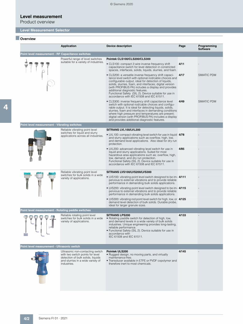
■ Overview
Application Device description Page Programming Software
Point level measurement - RF Capacitance switches
Powerful range of level switches suitable for a variety of industries.
Pointek CLS100/CLS200/CLS300
• CLS100: compact 2-wire inverse frequency shift capacitance switch for level detection in constricted spaces, interfaces, solids, liquids, slurries, and foam.
4/11 -
• CLS200: a versatile inverse frequency shift capaci-tance level switch with optional rod/cable choices and configurable output, ideal for detection of liquids, solids, slurries, foam, and interfaces; digital version (with PROFIBUS PA) includes a display and provides additional diagnostic features. Functional Safety (SIL 2). Device suitable for use in accordance with IEC 61508 and IEC 61511.
4/17 SIMATIC PDM
• CLS300: inverse frequency shift capacitance level switch with optional rod/cable choices and configu-rable output. It is ideal for detecting liquids, solids, slurries, foam and interfaces in demanding conditions where high pressure and temperatures are present; digital version (with PROFIBUS PA) includes a display and provides additional diagnostic features.
4/49 SIMATIC PDM
Point level measurement - Vibrating switches
Reliable vibrating point level switches for liquid and slurry applications across all industries.
SITRANS LVL100/LVL200
• LVL100: compact vibrating level switch for use in liquid and slurry applications such as overflow, high, low, and demand level applications. Also ideal for dry run protection.
4/78 -
• LVL200: advanced vibrating level switch for use in liquid and slurry applications. Suited for most hazardous area applications such as: overflow, high, low, demand, and dry run protection.Functional Safety (SIL 2). Device suitable for use in accordance with IEC 61508 and IEC 61511.
4/85 -
Reliable vibrating point level switches for bulk solids in a wide variety of applications.
SITRANS LVS100/LVS200/LVS300
• LVS100: vibrating point level switch designed to be im-pervious to external vibrations and to provide reliable performance in demanding bulk solids applications.
4/111 -
• LVS200: vibrating point level switch designed to be im-pervious to external vibrations and to provide reliable performance in demanding bulk solids applications.
4/115 -
• LVS300: vibrating rod point level switch for high, low, or demand level detection of bulk solids. Durable probe, ideal for larger granule sizes.
4/125
Point level measurement - Rotating paddle switches
Reliable rotating point level switches for bulk solids in a wide variety of applications.
SITRANS LPS200• Rotating paddle switch for detection of high, low,
and demand levels in a wide variety of bulk solids industries. Unique engineering provides long-lasting, reliable performance.
• Functional Safety (SIL 2). Device suitable for use in accordance with IEC 61508 and IEC 61511.
4/133 -
Point level measurement - Ultrasonic switch
Ultrasonic non-contacting switch with two switch points for level detection of bulk solids, liquids and slurries in a wide variety of industries.
Pointek ULS200• Rugged design, no moving parts, and virtually
maintenance-free.• Transducer available in ETFE or PVDF copolymer and
therefore inert to most chemicals.
4/145 -
© Siemens 2020

4/3Siemens FI 01 · 2021
■ Overview
Level measurementProduct overview
Level Measurement Selector
4
Continuous level measurement - Controllers
SITRANS LT500 is a versatile, single and multi-vessel level monitor/controller for virtually any application in a wide range of industries.
SITRANS LT500• Level, volume, and flow measurements in open
channels, differential control, extended pump control, and alarm functions.
• Easy to use HMI display with local four-button programming, menu-driven parameters, and wizard support for key applications.
4/150 -
The SITRANS LUT400 series con-trollers are compact, single point, long-range ultrasonic controllers for continuous level or volume measurement of liquids, slurries, and solids, and high accuracy monitoring of open channel flow.
SITRANS LUT420/430/440
In addition to industry leading 1 mm (0.04 inch) accuracy, each of the three models in the series are compatible with our full range of EchoMax transducers and offer varying degrees of pump, alarm, and other control functionality, all from a very compact and easy-to-use interface.• 1 mm accuracy. • HART communications. • Next Generation Sonic Intelligence.
4/155 SIMATIC PDM
Versatile short- to medium-range ultrasonic single- and dual-vessel level controller for virtually any application in a wide range of industries.
MultiRanger 100/200• Using non-contacting ultrasonic technology, the
controller measures the level in short to medium range applications up to 15 m (50 ft) of solids, liquids, or slurries
• Auto False-Echo Suppression of false echoes
4/168 SIMATIC PDM
Ultrasonic level controller for up to six pumps - control, differential control, and open channel flow monitoring.
HydroRanger 200• An economical, low-maintenance solution delivering
control efficiency and productivity needed to meet today’s exacting standards
• Auto False-Echo Suppression of false echoes
4/172 SIMATIC PDM
Application Device description Page Programming Software
© Siemens 2020

4/4 Siemens FI 01 · 2021
■ Overview
Level measurementProduct overview
Level Measurement Selector
4
Continuous level measurement - Ultrasonic transmitters
SITRANS LU150 and LU180 are short-range integrated ultrasonic level transmitters. These 2-wire, 4 to 20 mA loop powered transmit-ter are ideal for liquids, slurries, and bulk materials in open or closed vessels to 5 m (16.4 ft).
SITRANS LU150• LU150 is approved for general purpose applications.• Easy to install, program, and maintain.• Patented Sonic Intelligence echo processing.
4/182 -
SITRANS LU180• LU180 is approved for intrinsically safe applications.• Easy to install, program, and maintain.• Patented Sonic Intelligence echo processing.
4/187 -
2-wire loop powered ultrasonic transmitter for level, volume, and flow monitoring of liquids in open channels, storage vessels and simple process vessels.
SITRANS Probe LU• Continuous level measurement up to 12 m (40 ft)
range.• Sonic Intelligence signal processing. • Auto False-Echo Suppression.
4/192 SIMATIC PDM
Ultrasonic level transmitter with HART, 4 to 20 mA is ideal for level, volume, and volume flow measure-ments. It works with liquids, slurries, and bulk materials up to 12 meters (40 feet).
SITRANS Probe LU240• Continuous level measurement up to 12 m (40 ft)
range.• Next generation Process Intelligence signal
processing.• Auto False-Echo Suppression for fixed obstruction
avoidance.• Fast and easy configuration with quick start wizards.
4/197 SIMATIC PDM
Compact level transmitter with integrated transducer for accurate level measurement of liquid applications.
The Probe• A short-range integrated ultrasonic level transmitter,
ideal for liquids and slurries in open or closed vessels.• 3 wire system with mA output and alarm relay.
4/203 -
Continuous level measurement - Ultrasonic transducers
ST-H: ETFE or PVDF transducer for chemicals
XRS-5: Standard transducer for applications to 8 m (26 ft)
ST-H/EchoMax XRS-5
• ST-H: the narrow design of the ST-H allows the sensor to be mounted using a 2 inch connection
4/207 -
• XRS-5: narrow beam angle of only 10°, measuring range maximum 8 m (26 ft) for measurement of liquids, solids, and slurries
4/210 -
Transducers for liquids and bulk solids
XPS series: Hermetically sealed PVDF enclosure for chemical immunity
EchoMax XPS • XPS series offers versions for various distances up to
30 m (100 ft) and up to a maximum temperature of 95 °C (203 °F)
4/214 -
Application Device description Page Programming Software
© Siemens 2020

4/5Siemens FI 01 · 2021
■ Overview
Level measurementProduct overview
Level Measurement Selector
4
Continuous level measurement - Radar transmitters
2-wire, 6 GHz pulse radar level transmitter for continuous monitoring of liquids and slurries in storage vessels with nominal pressure and temperature, to a range of 20 m (66 ft).
SITRANS Probe LR• Uni-Construction polypropylene rod antenna standard • Process Intelligence signal processing • Auto False-Echo Suppression of false echoes
4/232 SIMATIC PDM
SITRANS LR100: a compact radar transmitter for continuous level measurement of liquids and slurries to a range of 8 m (26 ft).
SITRANS LR110: a compact radar transmitter for continuous level measurement of liquids, slurries, or solids to a range of 15 m (49.2 ft).
SITRANS LR100• Bluetooth connectivity for easy setup with
SITRANS mobile IQ• Chemically resistant PVDF enclosure• W band FMCW radar yields narrow beam with small
antenna for superior performance in short range applications
• 5 mm accuracy
4/236
SITRANS LR110• Bluetooth connectivity for easy setup with
SITRANS mobile IQ• Chemically resistant PVDF enclosure• W band FMCW radar yields narrow beam with small
antenna for superior performance in short range applications
• HART 7.0 or Modbus RTU communication for intelli-gent integration into your application
• 2 mm accuracy and zero near range distance yields optimum inventory management capability
4/238
Compact radar transmitter for continuous level measurement of liquids and solids to a range of 30 m (98.4 ft).
SITRANS LR120• Bluetooth connectivity for easy setup with
SITRANS mobile IQ• Chemically resistant PVDF enclosure• W band FMCW radar yields narrow beam with small
antenna for superior performance in short range appli-cations
• HART 7.0 or Modbus RTU (in preparation) communi-cation for intelligent integration into your application
• Submergence shield accessory prevents build up on sensor during flooding conditions
• 2 mm accuracy and zero near range distance yields optimum inventory management capability
4/241
SITRANS LR140: a 2 wire loop powered radar transmitter for continuous level measurement of liquids and slurries to a range of 8 m (26 ft).
SITRANS LR150: a compact radar transmitter for continuous level measurement of liquids, slurries, and solids to a range of 15 m (49.2 ft), with optional HMI.
SITRANS LR140• Bluetooth connectivity for easy setup with
SITRANS mobile IQ.• Chemically resistant PVDF sensor.• W band FMCW radar yields narrow beam with small
antenna for superior performance in short range applications.
4/244
SITRANS LR150• Bluetooth connectivity for easy setup with
SITRANS mobile IQ.• Optional HMI with pushbutton programming and local
diagnostic data.• Chemically resistant PVDF sensor.• W band FMCW radar yields narrow beam with small
antenna for superior performance in short range applications.
4/246
2-wire, 6 GHz pulse radar level transmitter for continuous monitor-ing of liquids and slurries in stor-age and process vessels including high temperature and pressure, to a range of 20 m (66 ft).
SITRANS LR200• Program without opening the lid, even in hazardous ar-
eas, using patented infrared IS handheld programmer • Special Uni-Construction hermetically sealed polypro-
pylene rod antenna has integrated threaded connec-tion
• Built-in alphanumeric display with support in four languages
4/249 SIMATIC PDMAMSSITRANS DTM
Application Device description Page Programming Software
© Siemens 2020

4/6 Siemens FI 01 · 2021
■ Overview
Level measurementProduct overview
Level Measurement Selector
4
2-wire, 25 GHz pulse radar level transmitter for continuous monitor-ing of liquids and slurries in storage and process vessels including high temperature and pressure, to a range of 20 m (66 ft); antenna designs ideal for small vessels, low dielectric media, food & beverages and corrosive/aggressive media.
SITRANS LR250• Simple operation using the graphical local user
interface (LUI) • Plug-and-play setup using the intuitive Quick Start
Wizard• 25 GHz high frequency allows for small horn antennas
and easy mounting in nozzles • Process Intelligence signal processing for improved
measurement reliability and Auto False-Echo Suppression of fixed obstructions
4/263 SIMATIC PDMAMSSITRANS DTM
4-wire, 24 GHz FMCW radar level transmitter with extremely high signal-to-noise ratio and advanced signal processing for continuous monitoring of solids up to 100 m (328 ft); ideal for measurement in extreme dust and high temperature applications
SITRANS LR460• Process Intelligence for advanced signal processing
and quick and easy adjustment • Self-guided Quick Start Wizard for plug and play
startup • 100 m (328 ft) range for long-range and difficult
applications
4/319 SIMATIC PDM
2-wire, 78 GHz FMCW radar level transmitter for continuous monitor-ing of solids and liquids to a range of 100 m (328 ft); easy to install, plug and play, virtually no mainte-nance
SITRANS LR560• Rugged stainless steel design • 78 GHz high frequency provides very narrow beam,
virtually no mounting nozzle noise, and optimal reflection from sloped solids
• Aimer option to direct beam to area of interest, such as draw point of cone
• Air purge connection is included for self-cleaning of extremely sticky solids
• Lens antenna is highly resistant to product buildup • Local display interface (LDI) allows local programming
and diagnostics
4/325 SIMATIC PDM
AMS
SITRANS DTM
Continuous level measurement - Guided wave radar transmitters
Guided wave radar transmitters for short- and medium-range level, level/interface, and volume mea-surement of liquids, slurries, and solids. The four LG models are unaffected by changes in process conditions, high temperatures and pressures, and provide a wide range of hygienic options.
SITRANS LG240/250/260/270• Measures accurately on materials
with dielectric (dK) as low as 1.4 • Guided wave radar measurement
for up to 2 mm (0.08 inch) accuracy • Measures level, level/interface, and volume of solids,
slurries, and liquids• 4 button programming for quick setup • Reliable level measurement on harsh applications with
pressure up to 400 bar g (40 000 kPa) and te-mperatures as high as 450 °C (842 °F)
4/332 SIMATIC PDM
SITRANS DTM
Continuous level measurement - Capacitance transmitters
For liquids and solids applications, ideal for standard industrial appli-cations in chemical, hydrocarbon processing, food and beverage, and mining, aggregate and cement industries.
SITRANS LC300• Sophisticated, but easy-to-adjust microprocessor
combined with field-proven probes • Active shield technology ensures measurements are
unaffected by vapors, product deposits, dust, and condensation
4/375 -
Communications
SmartLinx Module• Optional communication modules, SmartLinx, provide
direct digital connection to popular industrial fieldbus systems
4/390 -
Application Device description Page Programming Software
© Siemens 2020

4/7Siemens FI 01 · 2021
■ Overview
Level measurementProduct overview
Level Measurement Selector
4
preferred
condition dependent
Continuous Level
Conditions Ultrasonic Radar Guided Wave Radar
Capacitance Gravimetric Hydrostatic pressure
Measurement
Level
Interface (liquid/liquid)
Interface (liquid/solid)
Volume
Mass
Flow (open channel)
Level Applications
Changing density
Changing dielectric
Aggressive chemicals
Pressure/vacuum
High temperature
Cryogenic
Turbulence
Steam
Hydrocarbon vapors/solvents
Foam
Buildup
High viscosity
Dust
Solids powders
Solids granules/pellets < 25 mm (1 inch)
Solids > 25 mm (1 inch)
High angle of repose
© Siemens 2020

4/8 Siemens FI 01 · 2021
■ Overview
Level measurementProduct overview
Level Measurement Selector
4
preferred
condition dependent
Point Level
Conditions Vibration Capacitance Paddle Ultrasonic
Measurement
Level
Interface (liquid/liquid)
Interface (liquid/solid)
Volume
Mass
Flow (open channel)
Level Applications
Changing density
Changing dielectric
Aggressive chemicals
Pressure/vacuum
High temperature
Cryogenic
Turbulence
Steam
Hydrocarbon vapors/solvents
Foam
Buildup
High viscosity
Dust
Solids powders
Solids granules/pellets < 25 mm (1 inch)
Solids > 25 mm (1 inch)
High angle of repose
© Siemens 2020

4/9Siemens FI 01 · 2021
Level measurementPoint level measurement
RF Capacitance switches
Introduction
4
■ Overview
Introduction
Inverse frequency shift capacitance point level and material detection switches are designed to withstand the harsh environ-ments of high pressure and high temperature applications.
Inverse Frequency Technology
Siemens inverse frequency shift capacitance devices incorpo-rate a unique frequency-based approach to level measurement. The capacitance units monitor the effect of capacitance based on frequency change. The relationship between capacitance and frequency is inverse. Because small level changes result in a large frequency change, the result is excellent resolution and accuracy.
Principle of Operation
Inverse frequency shift capacitance devices require two compo-nents: a reference electrode of a variable capacitor and the measurement electrode. In capacitive level measurement, the environment (typically the vessel wall) acts as the reference electrode, while the probe supplies the measurement electrode. The dielectric is composed of the vessel contents and, if the measurement electrode is insulated, the insulating layer.
Inverse frequency shift capacitance operation
Capacitance is affected by the surface area of the electrodes, the separation distance between the electrodes and the dielec-tric constant of the vessel contents. The dielectric constant is the measure of a material’s ability to store energy. The relative di-electric constant of air (vacuum) is 1; all other materials have a higher value.
■ Mode of operation
Common Terms
Capacitance
The property of a system of conductors and dielectrics that per-mits the storage of electricity when a potential difference exists between the conductors. Its value is expressed as the ratio of a quantity of electricity to a potential difference and the unit is a Farad.
Capacitor
A device in a circuit that has the potential to store an electric charge. Typically a capacitor has two conductors or electrodes separated by a layer of a non-conducting material called a di-electric. With the conductors on opposite sides of the dielectric layer oppositely charged by a source of voltage, the electrical energy of the charged system is stored in the polarized dielec-tric.
Dielectric constant
The ability of a dielectric to store electrical potential energy un-der the influence of an electric field. This is measured by a ratio which compares the capacitance of a condenser with the mate-rial as dielectric to its capacitance with a vacuum/dry air as dielectric: the dielectric constant of air is 1.
Active shield
The portion of the probe isolated from the active measurement section. The sensor signal is connected to the active shield portion of the probe, eliminating the electrical potential differ-ence between the shield and the measurement section. So, the shield portion of the probe near the process connection is not affected by changes in vapor concentration, material buildup, dust, or condensation.
Operating principles
Internal vessel diameter
(Insulation)Probesleeve
Internalvessel wall
Probedia.
Dielectric = insulation (conductive contents)
Dielectric = contents plus insulation(non-conductive contents)
© Siemens 2020

4/10 Siemens FI 01 · 2021
Level measurementPoint level measurementRF Capacitance switches
Introduction
4
■ Technical specifications
Point Level Measurement
Criteria Pointek CLS100 Pointek CLS200 Pointek CLS300
Typical applications Liquids, slurries, powders, granules, applications in constricted spaces
Liquids, slurries, powders, granules, foam, food, and pharmaceuticals, -petrochemicals
Liquids, slurries, powders, granules, relatively high pressure, and temperature, hazardous areas
Max. length including sensor
100 mm (4 inch) Rod: 5.5 m (18 ft)Cable: up to 30 m (98 ft)
Rod: 1 m (40 inch)Cable: 25 m (82 ft)
Process temperature (Temperature ratings are pressure dependent. See Pressure/Temperature curves for respective product.)
• Stainless steel process connection:-30 ... +100 °C (22 ... +212 °F)
• Fully Synthetic (PPS process connection):-10 ... +100 °C (14 ... 212 °F)
• -40 ... +85 °C (-40 ... +185 °F)
• With thermal isolator: -40 ... +125 °C (-40 ... +257 °F)
• -40 ... +200 °C (-40 ... +392 °F)
• HT version: -40 ... +400 °C (-40 ... +752 °F)
Process pressure(Pressure ratings are temperature dependent.See Pressure/Temperature curves forrespective product.)
Up to 10 bar g (146 psi g) • Rod versions: Up to 25 bar g (365 psi g)
• Cable version: Up to 10 bar g (146 psi g)
Up to 35 bar g (511 psi g)
Output Stainless steel cable or enclosure version:• 4 ... 20/20 ... 4 mA,
2-wire current loop • Solid-state output
Fully-synthetic version (PPS)• Relay output
Standard: • 1 SPDT Form C relay,
solid-state switch
Digital:• Solid-state switch included
Standard: • 1 SPDT Form C relay,
solid-state switch
Digital: • Solid-state switch included
Communications Standard: • 3 LED indicators
Digital: • PROFIBUS PA;
SIMATIC PDM compatible
Standard: • 3 LED indicators
Digital: • PROFIBUS PA;
SIMATIC PDM compatible
PowerSpecifications
Standard: • 12 ... 33 V DC
Intrinsically Safe (Stainless steel version only):• 10 ... 30 V DC
Standard: • 12 ... 250 V AC/DC, 0 ... 60 Hz,
2 W max.
Digital:• Bus voltage:
12 ... 30 V DC, IS version:12 ... 24 V DC
• Current consumption:12.5 mA
Standard: • 12 ... 250 V AC/DC, 0 ... 60 Hz,
2 W max.
Digital:• Bus voltage:
12 ... 30 V DC, IS version: 12 ... 24 V DC
• Current consumption:12.5 mA
Approvals Stainless steel cable or enclosure version:
CE, CSA, FM, ATEX, RCM, Lloyds Register, WHG
Fully-synthetic version (PPS):
CSA, FM
CSA, FM, CE, ATEX, RCM, Lloyds Register, WHG, Vlarem II
CSA, FM, CE, ATEX, RCM, Lloyds Register, WHG, Vlarem II
© Siemens 2020

4/11Siemens FI 01 · 2021
Level measurementPoint level measurement
RF Capacitance switches
Pointek CLS100
4
■ Overview
Pointek CLS100 is a compact, 2-wire, inverse frequency shift ca-pacitance switch for level and material detection in constricted spaces, interfaces, solids, liquids, slurries, and foam; with the ability to tune out buildup on probe.
■ Benefits
• Easy installation with verification by built-in LED • Low maintenance with no moving parts • Sensitivity adjustment • Integrated cable or PBT enclosure versions available • Intrinsically Safe, Dust Ignition Proof, and General Purpose
options available
■ Application
Pointek CLS100’s short insertion length of 100 mm (4 inch) and versatility in various applications and in vessels or pipes makes it a good replacement for traditional capacitance sensors.
Its advanced tip-sensing technology provides accurate, repeat-able switchpoint performance. The PPS (Polyphenylene sulfide) probe [optional PVDF (Polyvinylidene Fluoride)] is chemically re-sistant with an effective process operating temperature range from -30 to +100 °C (-22 to +212 °F) (7ML5501), and -10 to +100 °C (14 to 212 °F) (7ML5610). The fully potted de-sign ensures reliability in a vibrating environment such as agi-tated tanks up to 4 g. When used with a SensGuard protection cover, the CLS100 is protected from shearing, impact, and abra-sion in tough primary processes.
The Pointek CLS100 is available in three versions. The integral cable version has a stainless steel process connection and probe options of PPS or PVDF. The fully synthetic version has a thermoplastic polyester enclosure with a PPS process connec-tion combined with a PPS probe. The standard enclosure version has a thermoplastic polyester enclosure with a stainless steel process connection in combination with a PPS or PVDF probe.• Key Applications: liquids, slurries, powders, granules, food
and pharmaceuticals, chemicals, hazardous areas
■ Configuration
Pointek CLS100 installation, dimensions in mm (inch)
Installation
Standpipes
Wall restriction
50 (2) min.
20 (0
.79)
max
.
≥ 50 (2)
50 (2
)
© Siemens 2020

4/12 Siemens FI 01 · 2021
Level measurementPoint level measurementRF Capacitance switches
Pointek CLS100
4
■ Technical specifications
1) When synthetic process connection version (7ML5610) is used in wet locations, switching voltage of the relay is limited to 35 V DC/16 V AC.
2) When operation is in areas classified as hazardous, observe restrictions according to relevant certificate. See also Pressure/Temperature curves on page 5/13.
3) For caustic materials, consult a local sales person for alternative O-rings. For more information, please visit http://www.automation.siemens.com/aspa_app.
4) When FFKM O-ring (Option A22) is selected, process temperature is restricted to -20 °C (-4 °F).
Stainless steel process connection(integral cable or enclosure version) (7ML5501)
Fully synthetic process connection(enclosure version only) (7ML5610)
Mode of operation
Measuring principle Inverse frequency shift capacitive leveldetection
Inverse frequency shift capacitive level detection
Input
Measured variable Change in picoFarad (pF)
Change in picoFarad (pF)
Output
Output signal• Alarm output 4 ... 20/20 ... 4 mA
2-wire loop 4 ... 20/20 ... 4 mA2-wire loop
• Switch output1) Solid-state: 30 V DC/30 V AC, max. 82 mA
Max. switching voltage: 60 V DC/30 V ACMax. switching current: 1 A
• Fail-safe mode Min. or max. Min. or max.
Accuracy
Repeatability 2 mm (0.08 inch) 2 mm (0.08 inch)
Rated operating conditions2)
Installation conditions• Location Indoor/outdoor Indoor/outdoor
Ambient conditions• Ambient temperature -30 ... +85 °C
(-22 ... +185 °F)-10 ... +85 °C(14 ... 185 °F)
• Storage temperature -40 ... +85 °C(-40 ... +185 °F)
-40 ... +85 °C(-40 ... +185 °F)
• Installation category I I• Pollution degree 4 4
Medium conditions• Relative dielectric
constant εr
Min. 1.5 Min. 1.5
• Process temperature -30 ... +100 °C(-22 ... +212 °F)
-10 ... +100 °C(14 ... 212 °F)
• Pressure (vessel) -1 ... +10 bar g(-14.6 ... +146 psi g), nominal2)
-1 ... +10 bar g(-14.6 ... +146 psi g), nominal
• Degree of protection - Enclosure version IP68/Type 4/NEMA 4 IP68/Type 4/NEMA 4- Integral cable version IP65/Type 4/NEMA 4 Not applicable
• Cable inlet ½" NPT (M20 x 1.5 optional)
½" NPT (M20 x 1.5 optional)
Design
Enclosure/Integral cable version
Fully synthetic version
Material • Body
(Enclosure version) Thermoplastic polyester Thermoplastic polyester
• Lid (Enclosure version) Transparent thermoplas-tic polycarbonate (PC)
Transparent thermoplas-tic polycarbonate (PC)
• Integrated cable body (Integral cable version)
316L stainless steel Not applicable
Sensor length (nominal) 100 mm (4 inch) 100 mm (4 inch)
Process connection material of probe/wetted parts3)
Connection: 316L stainless steel; Process seal: FKM (optional FFKM); Sensor: PPS (optional PVDF)4)
PPS process connection and PPS sensor (Uni-Construction)
Connection (Enclosure version)
Internal 5-point terminal block, ½" NPT wiring entrance, M20 x 1.5 optional
Removable internal 5-point terminal block,½" NPT wiring entrance, M20 x 1.5 optional
Connection (Integral cable version)
4 conductors, 1 m (3.3 ft), 0.5 mm² (22 AWG), shielded, polyester jacket
Not applicable
Process connection ¾" NPT [(Taper), ANSI/ASME B1.20.1]R 1" [(BSPT), EN 10226/PT (JIS-T), JIS B 0203]G 1" [(BSPP), EN ISO 228-1/PF (JIS-P), JIS B 0202]
¾" NPT [(Taper), ANSI/ASME B1.20.1]R 1" [(BSPT), EN 10226/PT (JIS-T), JIS B 0203]
Power supply
Standard 12 ... 33 V DC 12 ... 33 V DC
Intrinsically Safe 10 ... 30 V DC (Intrinsically Safe barrier required)
Not applicable
Certificates and approvals
• General: CE, CSA, FM, RCM
• Marine: Lloyds Register of Shipping, categories ENV1, ENV2, and ENV5 Dust Ignition Proof (barrier required): CSA/FM Class II and III, Div. 1, Groups E, F, G T4
• Intrinsically Safe (barrier required): CSA/FM Class I, II, and III, Div. 1, Groups A, B, C, D, E, F, G T4 ATEX II 1 GD 1/2GD EEx ia IIC T4 to T6 T107 °C
• Overfill protection: WHG (Germany)
• General: CSA, FM
Stainless steel process connection(integral cable or enclosure version) (7ML5501)
Fully synthetic process connection(enclosure version only) (7ML5610)
© Siemens 2020

4/13Siemens FI 01 · 2021
Level measurementPoint level measurement
RF Capacitance switches
Pointek CLS100
4
■ Selection and ordering data Article No. Article No.
1) Barrier or Intrinsically Safe power supply required for Intrinsically Safe protection.
1) See Temperature restriction on page 4/14.2) Available only with Approvals option C.
1) See Temperature restriction on page 4/14.
Pointek CLS100 RF Capacitance point level switch, stainless steel process connection
Detects level and interface in liquids, solids, slurries and foam. Compact, with 100 mm (4 inch) insertion, adaptable sensitivity, with the ability to tune out build-up on probe.
7ML5501-
0 7 7 7 7
Click on the Article No. for the online configuration in the PIA Life Cycle Portal.
Process Connection¾" NPT [(Taper), ANSI/ASME B1.20.1] AR 1" [(BSPT), EN 10226/PT (JIS-T), JIS B 0203] EG 1" [(BSPP), EN ISO 228-1/PF (JIS-P), JIS B 0202] J
ApprovalsGeneral Purpose: CE, CSA, FM, RCM ACSA/FM Class I, II, and III, Div. 1, Groups A, B, C, D, E, F, G T4; ATEX II 1 GD ½ GD EEx ia IIC T4 ... T6 T107 °C1)
C
CSA/FM Class II and III, Div. 1, Groups E, F, G1) G
Device versionIntegral cable version (PPS probe) 1Enclosure version (PPS probe), ½" NPT cable inlet 3Integral cable version with PVDF probe body 5Enclosure version with PVDF probe body (½" NPT cable inlet)
6
Enclosure version (PPS probe), M20 x 1.5 cable inlet
7
Enclosure version with PVDF probe body, M20 x 1.5 cable inlet
8
Overfill protectionNot required 0Required (WHG) 1
Further designs Order codePlease add "-Z" to Article No. and specify Order code(s).
Stainless steel tag [70 x 13 mm (2.75 x 0.5 inch)]: Measuring-point number/identification (max. 20 characters) specify in plain text
Y17
FFKM seal O-ring1)A22
Material inspection Certificate Type 3.1 per EN 10204
C12
INMETRO2)E34
Operating Instructions
Note: due to ATEX regulations one Quick start manual is included with every product. All literature is available to download for free, in a range of languages, at
http://www.siemens.com/processinstrumentation/documentation
Accessories Article No.
SensGuard, ¾" NPT (PPS). Only available for CLS100 with ¾" NPT thread.
7ML1830-1DL
SensGuard, R 1" (BSPT) (PPS). Only available for CLS100 with ¾" NPT thread.
7ML1830-1DM
Tag, stainless steel, 12 x 45 mm (0.47 x 1.77 inch), one text line, suitable for enclosures
7ML1930-1AC
Siemens Intrinsically Safe Barrier (DC powered), ATEX II 1 G EEx ia
7NG4124-0AA00
½" NPT General Purpose Cable Entry IP68/IP69KNEMA 6, -40 ... +80 °C (-40 ... +176 °F),Dust Ignition Proof, cable size 6 ... 12 mm(0.236 ... 0.472 inch)
7ML1830-1JA
M20 x 1.5 General Purpose Cable Entry IP68/IP69KNEMA 6, -40 ... +80 °C (-40 ... +176 °F),Dust Ignition Proof, cable size 7 ... 12 mm(0.275 ... 0.472 inch)
7ML1830-1JC
Pointek CLS100 RF Capacitance point level switch, PPS process connection
Detects level and interface in liquids, solids, slurries, and foam. Compact, with 100 mm (4 inch) insertion, adaptable sensitivity, with the ability to tune out build-up on probe.
7ML5610-
0 7 7 7 7
Click on the Article No. for the online configuration in the PIA Life Cycle Portal.
Process connection (PPS)¾" NPT [(Taper), ANSI/ASME B1.20.1] (PPS probe body)
A
R 1" [(BSPT), EN 10226/PT (JIS-T), JIS B 0203] (PPS probe body)
B
ApprovalsGeneral Purpose: CSA, FM D
Versions/OptionsEnclosure version, PPS process connection, ½" NPT cable inlet
1
Enclosure version, PPS process connection, M20 x 1.5
2
Overfill protectionNot required 0Required 1
Further designs Order code
Please add "-Z" to Article No. and specify Order code(s).
Stainless steel tag [70 x 13 mm (2.75 x 0.5 inch)]: Measuring-point number/identification (max. 20 characters) specify in plain text
Y17
Material inspection Certificate Type 3.1 per EN 10204
C12
Operating Instructions
Note: due to ATEX regulations one Quick start manual is included with every product. All literature is available to download for free, in a range of languages, at
http://www.siemens.com/processinstrumentation/documentation
Accessories Article No.
SensGuard, ¾" NPT (PPS). Only available for CLS100 with ¾" NPT thread.
7ML1830-1DL
SensGuard, R 1" (BSPT) (PPS). Only available for CLS100 with ¾" NPT thread.
7ML1830-1DM
Tag, stainless steel, 12 x 45 mm, (0.47 x 1.77 inch) one text line, suitable for enclosures
7ML1930-1AC
© Siemens 2020

4/14 Siemens FI 01 · 2021
Level measurementPoint level measurementRF Capacitance switches
Pointek CLS100
4
■ Options
Optional SensGuard, dimensions in mm (inch)
Optional SensGuardInternal thread ¾" NPT
Processconnection ¾" NPT
ProcessconnectionR 1" (BSPT)
32(1
.26)
70 (2
.75)
70 (2
.75)
91 (3
.6)
91 (3
.6)
32(1
.26)
© Siemens 2020

4/15Siemens FI 01 · 2021
Level measurementPoint level measurement
RF Capacitance switches
Pointek CLS100
4
■ Characteristic curves
Pointek CLS100 process pressure/temperature derating curves
■ Dimensional drawings
Pointek CLS100, dimensions in mm (inch)
Example:Permitted operating pressure = 10 bar (145 psi) at 75 °C
Permitted operating pressures P
Permitted operating temperature T
Atmospheric
Pressure/temperature curve CLS100Threaded process connections (7ML5501)
30 bar (435 psi)
20 bar (290 psi)
10 bar (145 psi)
-150 ºC (-238 ºF)
-1 bar (-14.5 psi)-100 ºC (-148 ºF)
-50 ºC (-58 ºF)
-29 ºC (-20 ºF)
0 ºC (32 ºF)
50 ºC (122 ºF)
RT 100 ºC (212 ºF)
150 ºC (302 ºF)
200 ºC (392 ºF)
-22 ºF(-30 ºC)
400 ºF(204 ºC)
300 ºF(149 ºC)
200 ºF(93 ºC)
100 ºF(38 ºC)
14 ºF(-10 ºC)
*Some G thread configurations deviate from this size.
Process connection
Ground lugTerminal block
LED (red)Output statusLED (yellow)
Sensor status
Process connection
LED (red)Output status
Cable relief
LED (yellow)Sensor status
Sensitivity trimpotPower LED (green)
Trimpot cap
Sensitivity trimpot
Power LED (green)Ground post
Enclosure versionIntegral cable version
Cable inlet ½" NPT(optional M20 x 1.5)
Cable Ø 5 (0.2)
72.5
(2.9
)
nom
inal
98 (3
.9)
120
(4.7
)
nom
inal
98 (3
.9)
36 (1.4) nominal*
80 (3.2)
65 (2
.6)
204
(8.0
)
120
(4.7
)50
(2
.0)
23
5
4
1
© Siemens 2020

4/16 Siemens FI 01 · 2021
Level measurementPoint level measurementRF Capacitance switches
Pointek CLS100
4
■ Circuit diagrams
Pointek CLS100 connections
2
3
5
4
1
Red
Black
White
White
Red
Black
White
White
Red
Black
White
White
Solid state switch, 30 V DC/AC(peak) 82 mA (max)
V supply
12 ... 33 V DC
When driving an inductive load (for example, an external relay), a protection diode must be connected in the correct polarity to prevent possible switch damage due to inductive spikes generated by switching the inductor (please refer to instruction manual). Intrinsically Safe Models - please follow local regulations and area classifications; refer to instruction manual for more details.
Note:
* Switch/relay normally open in unpowered state* Relay not available on Pointek CLS100 IS version (7ML5501)
mA current loop (+V or -V) mA current loop (+V or -V) groundSolid state switch/relay* Solid state switch/relay*
12 ... 33 V DC
Polarity as required fordesired operation
V supply
12 ... 33 V DC
Solid State Switch Version
4/20 mA Loop Alarm
LOW/HIGH Alarm
Enclosure and Fully Synthetic Version
Integral Cable Version - Non Intrinsically Safe only
Rmax = Vsupply - 10 V20 mA
Red wireBlack wireCable shieldWhite wireWhite wire
Terminal operations Cable equivalent
© Siemens 2020

4/17Siemens FI 01 · 2021
Level measurementPoint level measurement
RF Capacitance switches
Pointek CLS200 - Standard
4
■ Overview
Pointek CLS200 (standard version) is a versatile inverse fre-quency shift capacitance level and material detection switch with optional rod/cable choices and configurable output. CLS200 is ideal for detection of liquids, solids, slurries, foam, and interfaces and has the ability to tune out buildup on the probe.
■ Benefits
• Potted construction protects signal circuit from shock, vibration, humidity, and/or condensation
• High chemical resistance• Level detection independent of tank or pipe earth reference• Insensitive to product buildup due to high frequency
oscillation• 3 LED indicators for sensor status, output status, and power• Suitable for API 2350
■ Application
Pointek CLS200 standard version has 3 LED indicators with basic relay and solid-state switch alarms. Universal switch for solids/liquids and interface.
The power supply is galvanically isolated and accepts a wide range of voltages (12 to 250 V AC/DC). When used with thermal isolator, the stainless steel and PPS (PVDF optional) materials used in the probe construction provide a temperature rating up to 125 °C (257 °F) on the process wetted portion of the probe. The switch responds to any material with a dielectric constant of 1.5 or more by detecting a change in oscillating frequency, and it can be set to detect before contact or on contact with the probe. The CLS200 operates independently of the tank wall or pipe so it does not require an external reference electrode for level detection in a non-conductive vessel such as concrete or plastic (EMC regulations applicable in some regions).• Key Applications: liquids, slurries, powders, granules,
pressurized applications, hazardous areas
■ Configuration
Pointek CLS200 installation, dimensions in mm (inch)
Avoid areas where material build up occurs.
Keep unit out of path of falling material, or protect probe from falling material.
Install probe at least 50 (2) from tank wall.
Installation
Min. 50 (2)
© Siemens 2020

4/18 Siemens FI 01 · 2021
Level measurementPoint level measurementRF Capacitance switches
Pointek CLS200 - Standard
4
■ Technical specifications
1) When operation is in areas classified as hazardous, observe restrictions according to relevant certificate. See also Pressure/Temperature curves on page 5/34.
2) Thermal isolator is used if process connection temperature exceeds 85 °C (185 °F)
3) Pressure rating of process seal is temperature dependent. See Pressure/Temperature curves on page 5/34.
Mode of operation
Measuring principle Inverse frequency shift capacitive level detection
Input
Measured variable Change in picoFarad (pF)
Output
Output signal• Relay output 1 SPDT Form C relay
- Max. contact voltage • 30 V DC • 250 V AC
- Max. contact current • 5 A DC • 8 A AC
- Max. switching capacity 150 W DC
2 000 VA AC- Time delay (ON and/or OFF) 1 ... 60 s
• Solid-state output - Output Galvanically isolated- Protection Against reversed polarity (bipolar)- Max. switching voltage • 30 V DC
• 30 V peak AC - Max. load current 82 mA- Voltage drop < 1 V, typical at 50 mA- Time delay (pre or post switching) 1 ... 60 s
Rated operating conditions1)
Installation conditions • Location Indoor/outdoor
Ambient conditions • Ambient temperature -40 ... +85 °C (-40 ... +185 °F)2)
• Storage temperature -40 ... +85 °C (-40 ... +185 °F)• Installation category II• Pollution degree 4
Medium conditions Liquids, bulk solids, slurries and interfaces
• Relative dielectric constant εr Min. 1.5• Process temperature
- Without thermal isolator -40 ... +85 °C (-40 ... +185 °F)2)
- With thermal isolator -40 ... +125 °C (-40 ... +257 °F)• Process pressure (rod version) -1 ... +25 bar g (-14.6 ... +365 psi g)
(nominal)• Process pressure (cable version)3) -1 ... +10 bar g (-14.6 ... +150 psi g)
(nominal)• Process pressure (sliding coupling
version) -1 ... +10 bar g (-14.6 ... +150 psi g) (nominal)
Electromagnetic compatibility To comply with CE EMC regulations (where applicable); the CLS200 should be installed per the instruction manual.
Design
Material • Enclosure Epoxy-coated aluminum with gasket• Optional thermal isolator 316L stainless steel
Connection Removable terminal block, max. 2.5mm²
Degree of protection IP65/Type 4/NEMA 4 (optional IP68)
Cable inlet 2 x M20 x 1.5 thread (option: 2 x ½" NPT conduit entry including 1 plugged entry)
Power supply 12 ... 250 V AC/DC, 0 ... 60 Hz max. 2 W
Certificates and approvals
General Purpose CSA, FM, CE, RCM
Dust Ignition Proof ATEX II ½ D T100 °C
Flameproof Enclosure With IS Probe ATEX II 1 G EEx d[ia] IIC T6 ... T4ATEX II ½ D T100 °C
Dust Ignition Proof with IS Probe CSA/FM Class II, Div. 1, Groups E, F, G CSA/FM Class III T4
Explosion Proof Enclosure With IS Probe
CSA/FM Class I, Div. 1, Groups A, B, C, DCSA/FM Class II, Div. 1, Groups E, F, GCSA/FM Class III T4
Marine Lloyds Register of Shipping, Categories ENV1, ENV2, and ENV5
Overfill Protection WHG (Germany)VLAREM II
Others Pattern Approval (China), SIL
© Siemens 2020

4/19Siemens FI 01 · 2021
■ Technical specifications (continued)
Level measurementPoint level measurement
RF Capacitance switches
Pointek CLS200 - Standard
4
1) PFA coating (7ML5634 and 7ML5644) has 120 micron thickness2) For caustic materials, consult a local sales person for alternative O-rings. For more information, please visit http://www.automation.siemens.com/aspa_app.3) Thermal isolator is used if process connection temperature exceeds 85 °C (185 °F)
Design: Probe
Rod version Sanitary version Cable version Sliding Coupling version
Max. length 5 500 mm (216.53 inch) 5 500 mm (216.53 inch) • 30 000 mm (1 181.1 inch) liquids and slurries
• 5 000 mm (196.85 inch) solids (under loads)
5 500 mm (216.53 inch)
Process connection R ¾", 1", 1¼", 1½" [(BSPT), EN 10226/PT (JIS-T), JIS B 0203]
1½", 2" sanitary fitting clamp316L stainless steel
R ¾", 1", 1¼", 1½"[(BSPT), EN 10226/PT (JIS-T), JIS B 0203]
R ¾", 1", 1¼", 1½"[(BSPT), EN 10226/PT (JIS-T), JIS B 0203]
¾", 1", 1¼", 1½" NPT [(Taper), ANSI/ASME B1.20.1]
¾", 1", 1¼", 1½" NPT [(Taper), ANSI/ASME B1.20.1]
¾", 1", 1¼", 1½" NPT [(Taper), ANSI/ASME B1.20.1]
G ¾", 1", 1½" [(BSPP), EN ISO 228-1/PF (JIS-P), JIS B 0202]
G ¾", 1", 1½" [(BSPP), EN ISO 228-1/PF (JIS-P), JIS B 0202]
G ¾", 1", 1½"[(BSPP), EN ISO 228-1/PF (JIS-P), JIS B 0202]
316L stainless steelASME/EN flange
316L stainless steel ASME/EN flange
Extension material 316L stainless steeloptional PFA coated1)
316L stainless steel Fluoroethylene propylene (FEP) cable with stainless steel core
316L stainless steel
Sensor wetted parts PPS (optional PVDF) PPS (optional PVDF) PPS (optional PVDF) PPS (optional PVDF)
O-ring seal material FKM (optional FFKM)2) FKM (optional FFKM)2) FKM (optional FFKM)2) FKM (optional FFKM)2)
Thermal isolator3) Optional Optional Optional Optional
Extension User selected length User selected length Cable extension User selected length
© Siemens 2020

4/20 Siemens FI 01 · 2021
Level measurementPoint level measurementRF Capacitance switches
Pointek CLS200 - Standard
4
■ Selection and ordering data Article No. Article No.
1) Barrier or Intrinsically Safe power supply required for Intrinsically Safe protection.
2) Available with Approval options F, G, and H.
Pointek CLS200 RF Capacitance point level switch, rod design
Detects level and interface in liquids, solids, slurries, and foam. Adjustable, 5.5 m (18.04 ft), insertion, adaptable sensitivity, with the ability to tune out build-up on probe.
7ML5630-
7 7 7 7 7 - 7 7 7 0
Click on the Article No. for the online configuration in the PIA Life Cycle Portal.
Process connection
Threaded, 316L stainless steel¾" NPT [(Taper), ANSI/ASME B1.20.1] 0 A1" NPT [(Taper), ANSI/ASME B1.20.1] 0 B1¼" NPT [(Taper), ANSI/ASME B1.20.1] 0 C1½" NPT [(Taper), ANSI/ASME B1.20.1] 0 DR ¾" [(BSPT), EN 10226/PT (JIS-T), JIS B 0203] 1 AR 1" [(BSPT), EN 10226/PT (JIS-T), JIS B 0203] 1 BR 1½" [(BSPT), EN 10226/PT (JIS-T), JIS B 0203] 1 DG ¾" [(BSPP), EN SO 228-1/PF (JIS-P), JIS B 0202] 3 AG 1" [(BSPP), EN ISO 228-1/PF (JIS-P), JIS B 0202] 3 BG 1½" [(BSPP), EN ISO 228-1/PF (JIS-P), JIS B 0202]
3 D
Welded flange, 316L stainless steel, raised face1" ASME, 150 lb 5 A1" ASME, 300 lb 5 B1" ASME, 600 lb 5 C1½" ASME, 150 lb 5 D1½" ASME, 300 lb 5 E1½" ASME, 600 lb 5 F2" ASME, 150 lb 5 G2" ASME, 300 lb 5 H2" ASME, 600 lb 5 J3" ASME, 150 lb 5 K3" ASME, 300 lb 5 L3" ASME, 600 lb 5 M4" ASME, 150 lb 5 N4" ASME, 300 lb 5 P4" ASME, 600 lb 5 Q
Welded flange, 316L stainless steel, Type A flat facedDN 25, PN 16 6 ADN 25, PN 40 6 BDN 40, PN 16 6 CDN 40, PN 40 6 DDN 50, PN 16 6 EDN 50, PN 40 6 FDN 80, PN 16 6 GDN 80, PN 40 6 HDN 100, PN 16 6 JDN 100, PN 40 (Note: Flange bolting patterns and facings dimensionally correspond to the applicable ASME B16.5 or EN 1092-1 standard.)
6 K
Probe length
(length from flange face) (threaded lengths include process thread)
Note: No Y01 needed in Order code for standard lengthsCompact [threaded 120 mm (4.72 inch), Flanged 98 mm (3.86 inch)]
A
Extended rod, 250 mm (9.84 inch) BExtended rod, 350 mm (13.78 inch) CExtended rod, 500 mm (19.69 inch) DExtended rod, 750 mm (29.53 inch) EExtended rod, 1 000 mm (39.37 inch) FExtended rod, 1 250 mm (49.21 inch) GExtended rod, 1 350 mm (53.15 inch) HExtended rod, 1 500 mm (59.06 inch) JExtended rod, 1 750 mm (68.90 inch) KExtended rod, 2 000 mm (78.74 inch) L
Add Order code Y01 and plain text: "Insertion length ... mm"Extended rod, 210 ... 1 000 mm (8.27 ... 39.37 inch) MExtended rod, 1 001 ... 2 000 mm (39.41 ... 78.74 inch)
N
Extended rod, 2 001 ... 3 000 mm (78.78 ... 118.11 inch)
P
Extended rod, 3 001 ... 4 000 mm (118.15 ... 157.48 inch)
Q
Extended rod, 4 001 ... 5 000 mm (157.52 ... 196.85 inch)
R
Extended rod, 5 001 ... 5 500 mm (196.89 ... 216.53 inch)
S
Thermal isolatorWithout thermal isolator 0With thermal isolator [for process connection temperatures over 85 °C (185 °F)]
1
Remote mount electronics and mounting bracketWith 2 m (79 inch) of cable1)2) 2With 5 m (197 inch) of cable1)2) 3
Wetted sealsFKM 0FFKM [for process temperatures above -20 °C (-4 °F)]
1
Probe material316L stainless steel with PPS probe body 0316L stainless steel with PVDF probe body 1
ApprovalsDust Ignition Proof:CE, RCM, ATEX II 1/2 D T100 °C CFlameproof Enclosure with IS Probe: CE, RCM, ATEX II 1 G EEx d[ia] IIC T6 ... T4, ATEX II 1/2 D T100 °C
D
Flameproof Enclosure with IS Probe, with WHG approval:CE, RCM, ATEX II 1/2 G EEx d[ia] IIC T6 ... T4,ATEX II 1/2 D T100 °C
E
Dust Ignition Proof with IS Probe: CSA/FM Class II, Div. 1, Groups E, F, G, CSA/FM Class III T4
F
Explosion Proof Enclosure with IS Probe:CSA/FM Class I, Div. 1, Groups A, B, C, D, CSA/FM Class II, Div. 1, Groups E, F, G, CSA/FM Class III T4
G
General Purpose (CSA, FM) HGeneral Purpose (CE, RCM) JGeneral Purpose (CSA, FM, CE, RCM) with WHG approval
K
Enclosure and lidAluminum epoxy coated2 x ½" NPT via adapter - cable inlet, IP65 A2 x M20 x 1.5 cable inlet, IP65 B2 x ½" NPT via adapter - cable inlet, IP68 C2 x M20 x 1.5 cable inlet IP68 D
Pointek CLS200 RF Capacitance point level switch, rod design
Detects level and interface in liquids, solids, slurries, and foam. Adjustable, 5.5 m (18.04 ft), insertion, adaptable sensitivity, with the ability to tune out build-up on probe.
7ML5630-
7 7 7 7 7 - 7 7 7 0
© Siemens 2020

4/21Siemens FI 01 · 2021
■ Selection and ordering data Order code Article No.
Level measurementPoint level measurement
RF Capacitance switches
Pointek CLS200 - Standard
4
1) Available only with Approvals options C, D, E.
Further designs
Please add "-Z" to Article No. and specify Order code(s).
Total insertion length: enter the total insertion length in plain text description
Y01
Stainless steel tag [70 x 13 mm (2.75 x 0.5 inch)]: Measuring-point number/identification (max. 27 characters) specify in plain text
Y15
Manufacturer's test certificate: M to DIN 55350, Part 18 and ISO 9000
C11
Material inspection Certificate Type 3.1 per EN 10204
C12
SIL/IEC 61508 Declaration of Conformity [SIL 2 (overspill)]
C20
INMETRO1) E34
Operating Instructions
All literature is available to download for free, in a range of languages, at
http://www.siemens.com/processinstrumentation/documentation
Accessories See page 4/41
Pointek CLS200 RF Capacitance point level switch, cable design
Detects level and interface in liquids, solids, slurries, and foam. Cable extension options to 30 m (98.43 ft), adaptable sensitivity, with the ability to tune out build-up on probe.
7ML5631-
7 7 7 7 7 - 7 7 7 0
Click on the Article No. for the online configuration in the PIA Life Cycle Portal.
Process connection
Threaded, 316L stainless steel¾" NPT [(Taper), ANSI/ASME B1.20.1] 0 A1" NPT [(Taper), ANSI/ASME B1.20.1] 0 B1¼" NPT [(Taper), ANSI/ASME B1.20.1] 0 C1½" NPT [(Taper), ANSI/ASME B1.20.1] 0 DR ¾" [(BSPT), EN 10226/PT (JIS-T), JIS B 0203] 1 AR 1" [(BSPT), EN 10226/PT (JIS-T), JIS B 0203] 1 BR 1½" [(BSPT), EN 10226/PT (JIS-T), JIS B 0203] 1 DG ¾" [(BSPP), EN ISO 228-1/PF (JIS-P), JIS B 0202] 3 AG 1" [(BSPP), EN ISO 228-1/PF (JIS-P), JIS B 0202] 3 BG 1½" [(BSPP), EN ISO 228-1/PF (JIS-P), JIS B 0202]
3 D
Welded flange, 316L stainless steel, raised face1" ASME, 150 lb 5 A1" ASME, 300 lb 5 B1" ASME, 600 lb 5 C1½" ASME, 150 lb 5 D1½" ASME, 300 lb 5 E1½" ASME, 600 lb 5 F2" ASME, 150 lb 5 G2" ASME, 300 lb 5 H2" ASME, 600 lb 5 J3" ASME, 150 lb 5 K3" ASME, 300 lb 5 L3" ASME, 600 lb 5 M4" ASME, 150 lb 5 N4" ASME, 300 lb 5 P4" ASME, 600 lb 5 Q
Welded flange, 316L stainless steel, Type A flat facedDN 25, PN 16 6 ADN 25, PN 40 6 BDN 40, PN 16 6 CDN 40, PN 40 6 DDN 50, PN 16 6 EDN 50, PN 40 6 FDN 80, PN 16 6 GDN 80, PN 40 6 HDN 100, PN 16 6 JDN 100, PN 40 (Note: Flange bolting patterns and facings dimensionally correspond to the applicable ASME B16.5 or EN 1092-1 standard.)
6 K
© Siemens 2020

4/22 Siemens FI 01 · 2021
■ Selection and ordering data Article No. Order code
Level measurementPoint level measurementRF Capacitance switches
Pointek CLS200 - Standard
4
1) Sensor detached to allow customer to set desired cable length.2) Available with Approvals options F ... H.
1) Available only with Approvals options C, D, E.
Probe length
(length from flange face)(threaded lengths include process thread)
Note: No Y01 needed in Order code for standard lengthsExtended cable, 3 000 mm (118.11 inch), length can be determined by customer on assembly1)
A
Extended cable, 6 000 mm (236.22 inch), length can be determined by customer on assembly1)
B
Add Order code Y01 and plain text: "Insertion length ... mm"Extended cable, 500 ... 5 000 mm (19.69 ... 196.85 inch)
C
Extended cable, 5 001 ... 10 00 mm (196.89 ... 393.70 inch)
D
Extended cable, 10 001 ... 15 000 mm (393.74 ... 590.55 inch)
E
Extended cable, 15 001 ... 20 000 mm (590.59 ... 787.4 inch)
F
Extended cable, 20 001 ... 25 000 mm (787.44 ... 984.25 inch)
G
Extended cable, 25 001 ... 30 000 mm (984.29 ... 1 181.1 inch)
H
Thermal isolatorWithout thermal isolator 0With thermal isolator [for process connection temperatures over 85 °C (185 °F)]
1
Remote mount electronics and mounting bracketWith 2 m (79 inch) of cable2) 2With 5 m (197 inch) of cable2) 3
Wetted sealsFKM and PTFE 0FFKM and PTFE [for process temperatures above -20 °C ) (-4 °F)]
1
Probe materialFEP jacketed cable with PPS probe body 0FEP jacketed cable with PVDF probe body 1
ApprovalsDust Ignition Proof: CE, RCM, ATEX II 1/2 D T100 °C
C
Flameproof Enclosure with IS Probe: CE, RCM, ATEX II 1 G EEx d[ia] IIC T6 ... T4, ATEX II 1/2 D T100 °C
D
Flameproof Enclosure with IS Probe, with WHG approval: CE, RCM, ATEX II 1/2 G EEx d[ia] IIC T6 ... T4, ATEX II 1/2 D T100 °C
E
Dust Ignition Proof with IS Probe: CSA/FM Class II, Div. 1, Groups E, F, G, CSA/FM Class III T4
F
Explosion Proof Enclosure with IS Probe: CSA/FM Class I, Div. 1, Groups A, B, C, D, CSA/FM Class II, Div. 1, Groups E, F, G, CSA/FM Class III T4
G
General Purpose (CSA, FM) HGeneral Purpose (CE, RCM) JGeneral Purpose (CSA, FM, CE, RCM) with WHG approval
K
Enclosure and lidAluminum epoxy coated2 x ½" NPT via adapter - cable inlet, IP65 A2 x M20 x 1.5 cable inlet, IP65 B2 x ½" NPT via adapter - cable inlet, IP68 C2 x M20 x 1.5 cable inlet, IP68 D
Pointek CLS200 RF Capacitance point level switch, cable design
Detects level and interface in liquids, solids, slurries, and foam. Cable extension options to 30 m (98.43 ft), adaptable sensitivity, with the ability to tune out build-up on probe.
7ML5631-
7 7 7 7 7 - 7 7 7 0
Further designs
Please add "-Z" to Article No. and specify Order code(s).
Total insertion length: enter the total insertion length in plain text description
Y01
Stainless steel tag [70 x 13 mm (2.75 x 0.5 inch)]: Measuring-point number/identification (max. 27 characters) specify in plain text
Y15
Manufacturer's test certificate: M to DIN 55350, Part 18 and ISO 9000
C11
Material inspection Certificate Type 3.1 per EN 10204
C12
SIL/IEC 61508 Declaration of Conformity [SIL 2 (overspill)]
C20
INMETRO1) E34
Operating Instructions
All literature is available to download for free, in a range of languages, at
http://www.siemens.com/processinstrumentation/documentation
Accessories See page 4/41
© Siemens 2020

4/23Siemens FI 01 · 2021
Level measurementPoint level measurement
RF Capacitance switches
Pointek CLS200 - Standard
4
■ Selection and ordering data Article No. Article No.
1) Available only with Approvals options C, D, E.
Pointek CLS200 RF Capacitance point level switch, sanitary rod design
Detects level and interface in liquids, solids, slurries, and foam. Adjustable, 5.5 m (18.04 ft), insertion, adaptable sensitivity, with the ability to tune out build-up on probe.
7ML5632-
7 7 7 7 7 - 7 7 7 0
Click on the Article No. for the online configuration in the PIA Life Cycle Portal.
Process connection
Sanitary 316L stainless steel1" sanitary fitting clamp 8 A1½" sanitary fitting clamp 8 B2" sanitary fitting clamp 8 C2½" sanitary fitting clamp 8 D3" sanitary fitting clamp(Note: Sanitary connection dimensionally corresponds to the applicable ISO 2852 standard)
8 E
Probe length
(length from process connection face)
Note: No Y01 needed in Order code for standard lengthsCompact, 98 mm (3.86 inch) AExtended rod, 250 mm (9.84 inch) BExtended rod, 350 mm (13.78 inch) CExtended rod, 500 mm (19.69 inch) DExtended rod, 750 mm (29.53 inch) EExtended rod, 1 000 mm (39.37 inch) FExtended rod, 1 250 mm (49.21 inch) GExtended rod, 1 350 mm (53.15 inch) HExtended rod, 1 500 mm (59.06 inch) JExtended rod, 1 750 mm (68.90 inch) KExtended rod, 2 000 mm (78.74 inch) L
Add Order code Y01 and plain text: "Insertion length ... mm"Extended rod, 110 ... 350 mm (4.3 ... 13.78 inch) MExtended rod, 351 ... 1 000 mm (13.78 ... 39.37 inch)
N
Extended rod, 1 001 ... 2 000 mm (39.41 ... 78.74 inch)
P
Extended rod, 2 001 ... 3 000 mm (78.78 ... 118.11 inch)
Q
Extended rod, 3 001 ... 4 000 mm (118.15 ... 157.48 inch)
R
Extended rod, 4 001 ... 5 000 mm (157.52 ... 196.85 inch)
S
Extended rod, 5 001 ... 5 500 mm (196.89 ... 216.53 inch)
T
Thermal isolatorThermal isolator 0With thermal isolator [for process connection temperatures over 85 °C (185 °F)]
1
Remote mount electronics and mounting bracketRemote mount electronics and mounting bracket 2Remote mount electronics with 5 m (197 inch) of cable
3
Wetted sealsFKM 0FFKM [for process temperatures above -20 °C (-4 °F)]
1
Probe material316L stainless steel with PPS probe body 0316L stainless steel with PVDF probe body 1
ApprovalsDust Ignition Proof: CE, RCM, ATEX II ½ D T100 °C
C
Flameproof Enclosure with IS Probe:CE, RCM, ATEX II 1 G EEx d[ia] IIC T6 ... T4,ATEX II ½ D T100 °C
D
Flameproof Enclosure with IS Probe:CE, RCM, ATEX II 1 G EEx d[ia] IIC T6 ... T4, ATEX II ½ D T100 °C
E
Flameproof Enclosure with IS Probe, with WHG approval:CE, RCM, ATEX II ½ G EEx d[ia] IIC T6 ... T4, ATEX II ½ D T100 °C
F
Dust Ignition Proof with IS Probe:CSA/FM Class II, Div. 1, Groups E, F, G, CSA/FM Class III T4
G
General Purpose (CSA, FM) HGeneral Purpose (CE, RCM) JGeneral Purpose (CSA, FM, CE, RCM) with WHG approval
K
Enclosure and lid
Aluminum epoxy coated2 x ½" NPT via adapter - cable inlet, IP65 A2 x M20 x 1.5 cable inlet, IP65 B2 x ½" NPT via adapter - cable inlet, IP68 C2 x M20 x 1.5 cable inlet, IP68 D
Further designs Order code
Please add "-Z" to Article No. and specify Order code(s).
Total insertion length: enter the total insertion length in plain text description
Y01
Stainless steel tag [70 x 13 mm (2.75 x 0.5 inch)]: Measuring-point number/identification (max. 27 characters) specify in plain text
Y15
Manufacturer's test certificate: M to DIN 55350, Part 18 and ISO 9000
C11
Material inspection Certificate Type 3.1 per EN 10204
C12
SIL/IEC 61508 Declaration of Conformity [SIL 2 (overspill)]
C20
INMETRO1) E34
Operating Instructions
All literature is available to download for free, in a range of languages, at
http://www.siemens.com/processinstrumentation/documentation
Accessories See page 4/41
Pointek CLS200 RF Capacitance point level switch, sanitary rod design
Detects level and interface in liquids, solids, slurries, and foam. Adjustable, 5.5 m (18.04 ft), insertion, adaptable sensitivity, with the ability to tune out build-up on probe.
7ML5632-
7 7 7 7 7 - 7 7 7 0
© Siemens 2020

4/24 Siemens FI 01 · 2021
Level measurementPoint level measurementRF Capacitance switches
Pointek CLS200 - Standard
4
■ Selection and ordering data Article No. Article No.
1) Available with Approvals options F ... H.
1) Available only with Approval options C, D, E.
Pointek CLS200 RF Capacitance point level switch, sliding coupling design
Detects level and interface in liquids, solids, slurries, and foam. Adjustable, 5.5 m (18.04 ft), insertion, adaptable sensitivity, with the ability to tune out build-up on probe.
7ML5633-
7 7 7 7 7 - 7 7 7 0
Click on the Article No. for the online configuration in the PIA Life Cycle Portal.
Process connection
Threaded, 316L stainless steel¾" NPT [(Taper), ANSI/ASME B1.20.1] 0 A1" NPT [(Taper), ANSI/ASME B1.20.1] 0 B1¼" NPT [(Taper), ANSI/ASME B1.20.1] 0 C1½" NPT [(Taper), ANSI/ASME B1.20.1] 0 DR ¾" [(BSPT), EN 10226/PT (JIS-T), JIS B 0203] 1 AR 1" [(BSPT), EN 10226/PT (JIS-T), JIS B 0203] 1 BR 1½" [(BSPT), EN 10226/PT (JIS-T), JIS B 0203] 1 DG ¾" [(BSPP), EN ISO 228-1/PF (JIS-P), JIS B 0202] 3 AG 1" [(BSPP), EN ISO 228-1/PF (JIS-P), JIS B 0202] 3 BG 1½" [(BSPP), EN ISO 228-1/PF (JIS-P), JIS B 0202]
3 D
Probe length
(length from flange face)(threaded lengths include process thread)
Note: No Y01 needed in Order code for standard lengthsExtended rod, 350 mm (13.78 inch) CExtended rod, 500 mm (19.69 inch) DExtended rod, 750 mm (29.53 inch) EExtended rod, 1 000 mm (39.37 inch) FExtended rod, 1 250 mm (49.21 inch) GExtended rod, 1 350 mm (53.15 inch) HExtended rod, 1 500 mm (59.06 inch) JExtended rod, 1 750 mm (68.90 inch) KExtended rod, 2 000 mm (78.74 inch) L
Add Order code Y01 and plain text: "Insertion length ... mm"Extended rod, 350 ... 1 000 mm (13.78 ... 39.37 inch)
M
Extended rod, 1 001 ... 2 000 mm (39.41 ... 78.74 inch)
N
Extended rod, 2 001 ... 3 000 mm (78.78 ... 118.11 inch)
P
Extended rod, 3 001 ... 4 000 mm (118.15 ... 157.48 inch)
Q
Extended rod, 4 001 ... 5 000 mm (157.52 ... 196.85 inch)
R
Extended rod, 5 001 ... 5 500 mm (196.89 ... 216.53 inch)
S
Thermal isolatorWithout thermal isolator 0With thermal isolator [for process connection temperatures over 85 °C (185 °F)]
1
Remote mount electronics and mounting bracketWith 2 m (79 inch) of cable1) 2With 5 m (197 inch) of cable1) 3
Wetted sealsFKM and PTFE 0FFKM and PTFE [for process temperatures above -20 °C (-4 °F)]
1
Probe material316L stainless steel with PPS probe body 0316L stainless steel with PVDF probe body 1
ApprovalsDust Ignition Proof:CE, RCM, ATEX II 1/2 D T100 °C
C
Flameproof Enclosure with IS Probe:CE, RCM, ATEX II 1 G EEx d[ia] IIC T6 ... T4,ATEX II 1/2 D T100 °C
D
Flameproof Enclosure with IS Probe, with WHG approval:CE, RCM, ATEX II 1/2 G EEx d[ia] IIC T6 ... T4,ATEX II 1/2 D T100 °C
E
Dust Ignition Proof with IS Probe:CSA/FM Class II, Div. 1, Groups E, F, G CSA/FM Class III T4
F
Explosion Proof Enclosure with IS Probe:CSA/FM Class I, Div. 1, Groups A, B, C, DCSA/FM Class II, Div. 1, Groups E, F, GCSA/FM Class III T4
G
General Purpose (CSA, FM) HGeneral Purpose (CE, RCM) JGeneral Purpose (CSA, FM, CE, RCM) with WHG approval
K
Enclosure and lid
Aluminum epoxy coated2 x ½" NPT via adapter - cable inlet, IP65 A2 x M20 x 1.5 cable inlet, IP65 B2 x ½" NPT via adapter - cable inlet, IP68 C2 x M20 x 1.5 cable inlet, IP68 D
Further designs Order code
Please add "-Z" to Article No. and specify Order code(s).
Total insertion length: enter the total insertion length in plain text description
Y01
Stainless steel tag [70 x 13 mm (2.75 x 0.5 inch)]: Measuring-point number/identification (max. 27 characters) specify in plain text
Y15
Manufacturer's test certificate: M to DIN 55350, Part 18 and ISO 9000
C11
Material inspection Certificate Type 3.1 per EN 10204
C12
SIL/IEC 61508 Declaration of Conformity [SIL 2 (overspill)]
C20
INMETRO1) E34
Operating Instructions
All literature is available to download for free, in a range of languages, at
http://www.siemens.com/processinstrumentation/documentation
Accessories See page 4/41
Pointek CLS200 RF Capacitance point level switch, sliding coupling design
Detects level and interface in liquids, solids, slurries, and foam. Adjustable, 5.5 m (18.04 ft), insertion, adaptable sensitivity, with the ability to tune out build-up on probe.
7ML5633-
7 7 7 7 7 - 7 7 7 0
© Siemens 2020

4/25Siemens FI 01 · 2021
Level measurementPoint level measurement
RF Capacitance switches
Pointek CLS200 - Standard
4
■ Options
Optional SensGuard, dimensions in mm (inch)
■ Characteristic curves
Pointek CLS200 process pressure/temperature derating curves (7ML5633 and 7ML5643)
Optional SensGuardInternal thread ¾" NPT
Processconnection ¾" NPT
ProcessconnectionR 1" (BSPT)
32(1
.26)
70 (2
.75)
70 (2
.75)
91 (3
.6)
91 (3
.6)
32(1
.26)
Example:Permitted operating pressure = 10 bar (145 psi) at 75 °C
Permitted operating pressures P
Permitted operating temperature T
Atmospheric
Pressure/temperature curveCLS200 sliding couplingthreaded process connections(7ML5633 and 7ML5643)
30 bar (435 psi)
20 bar (290 psi)
10 bar (145 psi)
-150 ºC (-238 ºF)
-1 bar (-14.5 psi)-100 ºC (-148 ºF)
-50 ºC (-58 ºF)
-29 ºC (-20 ºF)
0 ºC (32 ºF)
50 ºC (122 ºF)
RT 100 ºC (212 ºF)
150 ºC (302 ºF)
200 ºC (392 ºF)
-40 ºF(-40 ºC)
400 ºF(204 ºC)
300 ºF(149 ºC)
200 ºF(93 ºC)
100 ºF(38 ºC)
14 ºF(-10 ºC)
© Siemens 2020

4/26 Siemens FI 01 · 2021
■ Characteristic curves (continued)
Level measurementPoint level measurementRF Capacitance switches
Pointek CLS200 - Standard
4
Pointek CLS200 process pressure/temperature derating curves (7ML5631 and 7ML5641)
Pointek CLS200 process pressure/temperature derating curves (7ML5630 or 7ML5640)
Permitted operating pressures P
Permitted operating temperature T
Atmospheric
Pressure/temperature curveCLS200 cableThreaded process connections(7ML5631 and 7ML5641)
30 bar (435 psi)
20 bar (290 psi)
10 bar (145 psi)
-150 ºC (-238 ºF)
-1 bar (-14.5 psi)-100 ºC (-148 ºF)
-50 ºC (-58 ºF)
-29 ºC (-20 ºF)
0 ºC (32 ºF)
50 ºC (122 ºF)
RT 100 ºC (212 ºF)
150 ºC (302 ºF)
200 ºC (392 ºF)
-40 ºF(-40 ºC)
400 ºF(204 ºC)
300 ºF(149 ºC)
200 ºF(93 ºC)
100 ºF(38 ºC)
14 ºF(-10 ºC)
Permitted operating pressures P
Permitted operating temperature T
Atmospheric
Pressure/temperature curveCLS200 compact and extended rodThreaded process connections(7ML5630 and 7ML5640)
30 bar (435 psi)
20 bar (290 psi)
40 bar (580 psi)
10 bar (145 psi)
-150 ºC (-238 ºF)
-1 bar (-14.5 psi)-100 ºC (-148 ºF)
-50 ºC (-58 ºF)
-29 ºC (-20 ºF)
0 ºC (32 ºF)
50 ºC (122 ºF)
RT 100 ºC (212 ºF)
150 ºC (302 ºF)
200 ºC (392 ºF)
-40 ºF(-40 ºC)
400 ºF(204 ºC)
300 ºF(149 ºC)
200 ºF(93 ºC)
100 ºF(38 ºC)
14 ºF(-10 ºC)
© Siemens 2020

4/27Siemens FI 01 · 2021
■ Characteristic curves (continued)
Level measurementPoint level measurement
RF Capacitance switches
Pointek CLS200 - Standard
4
Pointek CLS200 process pressure/temperature derating curves (7ML5632 and 7ML5642)
Pointek CLS200 process pressure/temperature derating curves (7ML5631 and 7ML5641)
Permitted operating pressures P
Permitted operating temperature T
Pressure/temperature curveCLS200 compact and extended sanitary typeSanitary process connections(7ML5632 and 7ML5642)
Atmospheric
30 bar (435 psi)
20 bar (290 psi)
10 bar (145 psi)
-150 ºC (-238 ºF)
-1 bar (-14.5 psi)-100 ºC (-148 ºF)
-50 ºC (-58 ºF)
-29 ºC (-20 ºF)
0 ºC (32 ºF)
50 ºC (122 ºF)
RT 100 ºC (212 ºF)
150 ºC (302 ºF)
200 ºC (392 ºF)
-40 ºF(-40 ºC)
400 ºF(204 ºC)
300 ºF(149 ºC)
200 ºF(93 ºC)
100 ºF(38 ºC)
14 ºF(-10 ºC)
The curve denotes the minimum allowable flange class for the shaded area below.1)
Permitted operating pressures P
Permitted operating temperature T
Pressure/temperature curveCLS200, cableASME flanged process connections(7ML5631 and 7ML5641)
Atmospheric
30 bar (435 psi)
20 bar (290 psi)
10 bar (145 psi)
-150 ºC (-238 ºF)
-1 bar (-14.5 psi)-100 ºC (-148 ºF)
-50 ºC (-58 ºF)
-29 ºC (-20 ºF)
0 ºC (32 ºF)
50 ºC (122 ºF)
RT 100 ºC (212 ºF)
150 ºC (302 ºF)
200 ºC (392 ºF)
250 ºC (482 ºF)
300 ºC (572 ºF)
350 ºC (662 ºF)
400 ºC (752 ºF)
-40 ºF(-40 ºC)
700 ºF(371 ºC)
600 ºF(315 ºC)
500 ºF(260 ºC)
400 ºF(204 ºC)
300 ºF(149 ºC)
200 ºF(93 ºC)
100 ºF(38 ºC)
14 ºF(-10 ºC)
ASME 150 lb1)
© Siemens 2020

4/28 Siemens FI 01 · 2021
■ Characteristic curves (continued)
Level measurementPoint level measurementRF Capacitance switches
Pointek CLS200 - Standard
4
Pointek CLS200 process pressure/temperature derating curves (7ML5630 and 7ML5640)
Pointek CLS200 process pressure/temperature derating curves (7ML5631 and 7ML5641)
The curve denotes the minimum allowable flange class for the shaded area below.1)
Permitted operating pressures P
Permitted operating temperature T
Pressure/temperature curveCLS200 compact and extended rodASME flanged process connections (7ML5630 and 7ML5640)
Atmospheric
30 bar (435 psi)
20 bar (290 psi)
50 bar (725 psi)
40 bar (580 psi)
10 bar (145 psi)
-150 ºC (-238 ºF)
-1 bar (-14.5 psi)-100 ºC (-148 ºF)
-50 ºC (-58 ºF)
-29 ºC (-20 ºF)
0 ºC (32 ºF)
50 ºC (122 ºF)
RT 100 ºC (212 ºF)
150 ºC (302 ºF)
200 ºC (392 ºF)
250 ºC (482 ºF)
300 ºC (572 ºF)
350 ºC (662 ºF)
400 ºC (752 ºF)
-40 ºF(-40 ºC)
700 ºF(371 ºC)
600 ºF(315 ºC)
500 ºF(260 ºC)
400 ºF(204 ºC)
300 ºF(149 ºC)
200 ºF(93 ºC)
100 ºF(38 ºC)
14 ºF(-10 ºC)
ASME 150 lb1)
ASME 300 lb1)
The curve denotes the minimum allowable flange class for the shaded area below.1)
Permitted operating pressures P
Permitted operating temperature T
Pressure/temperature curveCLS200 cableEN flanged process connections(7ML5631 and 7ML5641)
Atmospheric
30 bar (435 psi)
20 bar (290 psi)
10 bar (145 psi)
-150 ºC (-238 ºF)
-1 bar (-14.5 psi)-100 ºC (-148 ºF)
-50 ºC (-58 ºF)
-29 ºC (-20 ºF)
0 ºC (32 ºF)
50 ºC (122 ºF)
RT 100 ºC (212 ºF)
150 ºC (302 ºF)
200 ºC (392 ºF)
250 ºC (482 ºF)
300 ºC (572 ºF)
350 ºC (662 ºF)
400 ºC (752 ºF)
-40 ºF(-40 ºC)
700 ºF(371 ºC)
600 ºF(315 ºC)
500 ºF(260 ºC)
400 ºF(204 ºC)
300 ºF(149 ºC)
200 ºF(93 ºC)
100 ºF(38 ºC)
14 ºF(-10 ºC)
PN 161)
© Siemens 2020

4/29Siemens FI 01 · 2021
■ Characteristic curves (continued)
Level measurementPoint level measurement
RF Capacitance switches
Pointek CLS200 - Standard
4
Pointek CLS200 process pressure/temperature derating curves (7ML5630 and 7ML5640)
The curve denotes the minimum allowable flange class for the shaded area below.1)
Permitted Operating Pressures P
Permitted Operating Temperature T
Pressure/Temperature CurveCLS200 Compact and Extended RodEN Flanged Process Connections (7ML5630 and 7ML5640)
Atmospheric
30 bar (435 psi)
20 bar (290 psi)
50 bar (725 psi)
40 bar (580 psi)
10 bar (145 psi)
-150 ºC (-238 ºF)
-1 bar (-14.5 psi)-100 ºC (-148 ºF)
-50 ºC (-58 ºF)
-29 ºC (-20 ºF)
0 ºC (32 ºF)
50 ºC (122 ºF)
RT 100 ºC (212 ºF)
150 ºC (302 ºF)
200 ºC (392 ºF)
250 ºC (482 ºF)
300 ºC (572 ºF)
350 ºC (662 ºF)
400 ºC (752 ºF)
-40 ºF(-40 ºC)
700 ºF(371 ºC)
600 ºF(315 ºC)
500 ºF(260 ºC)
400 ºF(204 ºC)
300 ºF(149 ºC)
200 ºF(93 ºC)
100 ºF(38 ºC)
14 ºF(-10 ºC)
PN 401)
PN 161)
© Siemens 2020

4/30 Siemens FI 01 · 2021
Level measurementPoint level measurementRF Capacitance switches
Pointek CLS200 - Standard
4
■ Dimensional drawings
Pointek CLS200 threaded/sanitary process connection, dimensions in mm (inch)
Thermalisolator
316L stainless steel sanitary process connection
Sanitary compact versionSanitary fitting (7ML5632 and 7ML5642)
Min. insertion length = 500 (19.69)Max. insertion length = 30 000 (1 181)Applicable for liquids and solids applications. Cable can be shortened on site.
Min. insertion length = 200 (7.87)Max. insertion length = 5 500 (216)
Min. insertion length = 110 (4.3)Max. insertion length = 5 500 (216)
FEP insulated cable Ø6 (0.3)
316L stainless steel sensor weight
316L stainless steel extension
316L stainless steel sliding coupling
Y01
(inse
rtio
n le
ngth
)Y0
1 (in
sert
ion
leng
th)
Electronics/enclosure
PPS or optionalPVDF probe
PPS or optionalPVDF probe
PPS or optionalPVDF probe
PPS or optionalPVDF probe
Compact versionThreaded(7ML5630 and 7ML5640)
Sliding coupling versionThreaded (7ML5633 and 7ML5643)
Sanitary extended versionSanitary fitting (7ML5632 and 7ML5642)
Extended cable versionThreaded(7ML5631 and 7ML5641)
Extended rod versionThreaded(7ML5630 and 7ML5640)
Lid with window
2 cable entries½" NPT or M20 x 1.5
XP, lid without window
Y01
(inse
rtio
n le
ngth
)
PPS or optionalPVDF probe
PPS or optionalPVDF probe
316L stainless steel sanitary process connection
316L stainless steel extension
Y01
(inse
rtio
n le
ngth
)
Min. insertion length = 350 (13.82)Max. insertion length = 5 500 (216)
GP, DIP lid,without window
98
(3.8
)
Min
. 215
(8
.46)
84
(3.3
)
Ø20 (0.79)
Ø24 (0.95)
98
(3.8
)
Ø20 (0.79)
84
(3.3
)
120
(4.7
)22
(0
.87)
126
(4.9
6)
226
(8.9
0)
½" NPT: 150 (5.91)M20: 135 (5.32)
139
(5.4
7)
Ø20 (0.79)
84
(3.3
)
213
(8.3
9)
219
(8.6
2)
132
(5.2
0)
© Siemens 2020

4/31Siemens FI 01 · 2021
■ Dimensional drawings (continued)
Level measurementPoint level measurement
RF Capacitance switches
Pointek CLS200 - Standard
4
Pointek CLS200 flanged process connections, dimensions in mm (inch)
Thermalisolator
Min. insertion length = 500 (19.69)Max. insertion length = 30 000 (1 181)Applicable for liquids and solids applica-tions. Cable can be shortened on site.
Min. insertion length = 200 (7.87)Max. insertion length = 5 500 (216)
FEP insulated cable Ø6 (0.3)
316L stainless steel sensor weight
Y01
(inse
rtio
n le
ngth
)
PPS or optionalPVDF probe
PPS or optionalPVDF probe
PPS or optionalPVDF probe
Compact versionWelded Flange (7ML5630 and 7ML5640)Welded Flange, PFA coated(7ML5634 and 7ML5644)
Extended cable versionWelded Flange (7ML5631 and 7ML5641)
Extended rod versionWelded Flange (7ML5630 and 7ML5640)Welded Flange, PFA coated(7ML5634 and 7ML5644)
Lid with window
2 cable entries½" NPT or M20 x 1.5
XP, lid without window
Y01
(inse
rtio
n le
ngth
)
316L stainless steel extension (or PFA coated
Flange Class Facing thicknessFlange Facing (raised face)
Electronics/enclosure
Insertion length does not include any raised face/gasket face dimension (see Flange Facing Table above)
GP, DIP lid,without window
Ø20 (0.79)
84
(3.3
)
98
(3.8
)
148
(5.8
3)
236
(9.2
9) 249
(9.8
0)
½" NPT: 150 (5.91)M20: 135 (5.32)
161
(6.3
4)
Ø20 (0.79)
84
(3.3
)
2 (0.08)7 (0.28)2 (0.08)
PN16/40ASME 600/900ASME 150/300
154
(6.0
6)
242
(9.5
3)
© Siemens 2020

4/32 Siemens FI 01 · 2021
Level measurementPoint level measurementRF Capacitance switches
Pointek CLS200 - Standard
4
■ Circuit diagrams
Pointek CLS200 connections
White
White
Red (+)
Wiring: Pointek CLS200 Digital
Solid state switch:30 V DC/30 V AC (peak), 82 mA max.
Relay contact:8 A at 250 V AC, 2 000 VA5 A at 30 V DC, 150 W
WhiteBlack
Red
Sensor status
Output status
Power on
Delay
Trip point
Sensor
Reedcontact*
Power connection:24 V DC or PROFIBUS PA bus
(not polarity sensitive).
Black (-)
Orange (f)
Sensor
Test input
Alarm output solid-state switch
Wiring: Pointek CLS200 standard
Notes:Refer to the instruction manual or contact a Siemens representative for detailed wiring information.
Notes:Identification label is on underside of lid. Switch and potentiometer settings are for illustration purposes only (refer to operation/setup in manual).
-
All field wiring must have insulation suitable for at least 250 V.-Relay contact terminals are for use with equipment having no accessible live parts and wiring having insulation suitable for at least 250 V.
-
Maximum working voltage between adjacent relay contacts shall be 250 V.-Refer to the Instruction Manual or contact Siemens representative for detailed wiring information.
-
*Magnet activated sensor TestA magnet can be used to test the sensor without opening the lid of the Pointek CLS200 Digital version. Bring the magnet close to the test area indicated on the enclosure. The sensor test starts and finishes automatically after 10 seconds.
Power supply
12 to 250 V AC/DC
NC NO NO
Switch bank
GND
24 V DC/PROFIBUS PA
3 2 1
321
+-
K2
K4
K1
L3L1
S1P1
L2
K3
P2
OFF
(+)
(f)
© Siemens 2020

4/33Siemens FI 01 · 2021
Level measurementPoint level measurement
RF Capacitance switches
Pointek CLS200 - Digital
4
■ Overview
Pointek CLS200 (digital version) is a versatile inverse frequency shift capacitance level and material detection switch with optional rod/cable choices and configurable output. CLS200 is ideal for detection of liquids, solids, slurries, foam, and inter-faces and has the ability to tune out buildup on the probe. The digital version includes PROFIBUS PA, an LCD display, and advanced diagnostic features.
■ Benefits
• Potted construction protects signal circuit from shock, vibration, humidity, and/or condensation
• High chemical resistance• Level detection independent of tank or pipe earth reference • Insensitive to product buildup due to high frequency
oscillation• High sensitivity allows installation in a wide range of liquids,
solids or slurry applications• Integral LCD display allows for easy menu-driven setup• PROFIBUS PA communication (SIMATIC PDM compatible)
■ Application
Pointek CLS200 digital version provides an integral LCD display for stand-alone use, and also provides PROFIBUS PA communi-cation (Profile version 3.0, Class B) for connection to a network.
The power supply is galvanically isolated and accepts a wide range of voltages (12 to 30 V DC). When used with thermal isolator, the stainless steel and PPS (PVDF optional) materials used in the probe construction provide a temperature rating up to 125 °C (257 °F) on the process wetted portion of the probe. The switch responds to any material with a dielectric constant of 1.5 or more by detecting a change in oscillating frequency, and it can be set to detect before contact or on contact with the probe. The menu-driven setup allows precise control of the switch point signal damping and alarm functions.
When connected to the PROFIBUS network, advanced diagnos-tics and set up using SIMATIC PDM are possible.
The CLS200 operates independently of the tank wall or pipe so it does not require an external reference electrode for level detection in a non-conductive vessel such as concrete or plastic (EMC regulations applicable in some regions).• Key Applications: liquids, slurries, powders, granules,
pressurized applications, hazardous areas
■ Configuration
Pointek CLS200 installation, dimensions in mm (inch)
Avoid areas where material build up occurs.
Keep unit out of path of falling material, or protect probe from falling material.
Install probe at least 50 (2) from tank wall.
Installation
Min. 50 (2)
© Siemens 2020

4/34 Siemens FI 01 · 2021
Level measurementPoint level measurementRF Capacitance switches
Pointek CLS200 - Digital
4
■ Technical specifications
1) When operation is in areas classified as hazardous, observe restrictions according to relevant certificate. See also Pressure/Temperature curves on page 5/36.
2) Thermal isolator is used if process connection temperature exceeds 85 °C (185 °F)
3) Pressure rating of process seal is temperature dependent. See Pressure/Temperature curves on page 5/34.
4) Barrier or Intrinsically Safe power supply required for Intrinsically Safe protection
Mode of operation
Measuring principle Inverse frequency shift capacitive level detection
Input
Measured variable Change in picoFarad (pF)
Output
Output signal• Solid-state output
- Output Galvanically isolated- Protection Against reversed polarity (bipolar)- Max. switching voltage • 30 V (DC)
• 30 V peak (AC) - Max. load current 82 mA- Voltage drop < 1 V, typical at 50 mA- Time delay (ON and/or OFF) Programmable by user (0 ... 100 s)
• Fail-safe mode Min. or max.• Connection Removable terminal block
Rated operating conditions1)
Installation conditions• Location Indoor/outdoor
Ambient conditions• Ambient temperature -40 ... +85 °C (-40 ... +185 °F)2)
• Storage temperature -40 ... +85 °C (-40 ... +185 °F)• Installation category II• Pollution degree 4
Medium conditions Liquids, bulk solids, slurries, and interfaces
• Relative dielectric constant εr Min. 1.5• Process temperature
- Without thermal isolator -40 ... +85 °C (-40 ... +185 °F)2)
- With thermal isolator -40 ... +125 °C (-40 ... +257 °F)• Process pressure (rod version) -1 ... +25 bar g (-14.6 ... +365 psi g)
(nominal) • Process pressure (cable version)3) -1 ... +10 bar g (-14.6 ... +150 psi g)
(nominal) • Process pressure
(sliding coupling version) -1 ... +10 bar g (-14.6 ... +150 psi g) (nominal)
Design
Material • Enclosure Epoxy-coated aluminum with gasket• Optional thermal isolator 316L stainless steel
Connection Removable terminal block, max. 2.5 mm²
Degree of protection IP65/Type 4/NEMA 4 (optional IP68)
Cable inlet 2 x M20 x 1.5 thread (option: 2 x ½" NPT conduit entry including 1 plugged entry)
Electromagnetic compatibility To comply with CE EMC regulations (where applicable); the CLS200 should be installed per the instruction manual.
Power supply
Bus voltage Standard: 12 ... 30 V DC
Intrinsically Safe: 12 ... 24 V DC
Current consumption 12.5 mA
Certificates and approvals
General Purpose CSA, FM, CE, RCM
Dust Ignition Proof ATEX II 1/2 D T100 °C
Dust Ignition Proof with IS Probe CSA/FM Class II, Div. 1,Groups E, F, GCSA/FM Class III T4
Flameproof Enclosure with IS Probe ATEX II 1/2 G EEx d[ia] IIC T6 ... T4ATEX II ½ D T100 °C
Explosion Proof with IS Probe CSA/FM Class I, Div. 1,Groups A, B, C, DCSA/FM Class II, Div. 1, Groups E, F, GCSA/FM Class III T4
Intrinsically Safe4) ATEX II 1 G EEx ia IIC T6 ... T4ATEX II ½ D IP6X T100 °CCSA/FM Class I, Div. 1,Groups A, B, C, DCSA/FM Class II, Div. 1,Groups E, F, GCSA/FM Class III T4
Non-incendive CSA/FM Class I, Div. 2,Groups A, B, C, DCSA/FM Class II, Div. 2,Groups F, GCSA/FM Class III T4 or T6
Non-Sparking ATEX II 3 G Ex nA II T6 ... T4ATEX II 2 D IP6X T100 °C
Marine Lloyds Register of Shipping, Categories ENV1, ENV2, and ENV5
Others Pattern Approval (China)
Communication PROFIBUS PA (IEC 61158 CPF3 CP3/2) Bus physical layer: IEC 61158-2 MBP (IS) Device profile: PROFIBUS PA profile for Process Control Devices Version 3.0, Class B FISCO field device
© Siemens 2020

4/35Siemens FI 01 · 2021
■ Technical specifications (continued)
Level measurementPoint level measurement
RF Capacitance switches
Pointek CLS200 - Digital
4
1) 1PFA coating (7ML5634 and 7ML5644) has 120 micron thickness2) For caustic materials, consult a local sales person for alternative O-rings. For more information, please visit http://www.automation.siemens.com/aspa_app.3) Thermal isolator is used if process connection temperature exceeds 85 °C (185 °F).
Design: Probe
Rod version Sanitary version Cable version Sliding Coupling version
Max. length 5 500 mm (216.53 inch) 5 500 mm (216.53 inch) • 30 000 mm (1 181.1 inch) liquids and slurries
• 5 000 mm (196.85 inch) solids (under loads)
5 500 mm (216.53 inch)
Process connection R ¾", 1", 1¼", 1½" [(BSPT), EN 10226/PT (JIS-T), JIS B 0203]
¾", 1", 1¼", 1½" NPT [(Taper), ANSI/ASME B1.20.1]
G ¾", 1", 1½" [(BSPP), EN ISO 228-1/PF(JIS-P), JIS B 0202]316L stainless steelASME/EN flange
1½", 2" sanitary fitting clamp 316L stainless steel
R ¾", ", 1¼", 1½" [(BSPT), EN 10226/PT (JIS-T), JIS B 0203]
¾", 1", 1¼", 1½" NPT[(Taper), ANSI/ASME B1.20.1]
G ¾", 1", 1½" [(BSPP), EN ISO 228-1/PF(JIS-P), JIS B 0202]316L stainless steel ASME/EN flange
R ¾", 1", 1¼", 1½" [(BSPT), EN 10226/PT (JIS-T), JIS B 0203]
¾", 1", 1¼", 1½" NPT [(Taper), ANSI/ASME B1.20.1]
G ¾", 1", 1½" [(BSPP), EN ISO 228-1/PF(JIS-P), JIS B 0202]
Extension material 316L stainless steeloptional PFA coated1)
316L stainless steel Fluoroethylene propylene (FEP) cable with stainless steel core
316L stainless steel
Sensor wetted parts PPS (optional PVDF) PPS (optional PVDF) PPS (optional PVDF) PPS (optional PVDF)
O-ring seal material FKM (optional FFKM)2) FKM (optional FFKM)2) FKM (optional FFKM)2) FKM (optional FFKM)2)
Thermal isolator3) Optional Optional Optional Optional
Extension User selected length User selected length Cable extension User selected length
© Siemens 2020

4/36 Siemens FI 01 · 2021
Level measurementPoint level measurementRF Capacitance switches
Pointek CLS200 - Digital
4
■ Selection and ordering data Article No. Article No.
1) Barrier or Intrinsically Safe power supply required for Intrinsically Safe protection.
2) Available with Approvals options F, G, H, J, and K.
Pointek CLS200 RF Capacitance point level switch, digital, rod design
Detects level and interface in liquids, solids, slurries, and foam. Adjustable, 5.5 m (18.04 ft), insertion, adaptable sensitivity, with the ability to tune out build-up on probe. With display and digital communications.
7ML5640-
7 7 7 7 7 - 7 7 7 0
Click on the Article No. for the online configuration in the PIA Life Cycle Portal.
Process connection
Threaded, 316L stainless steel¾" NPT [(Taper), ANSI/ASME B1.20.1] 0 A1" NPT [(Taper), ANSI/ASME B1.20.1] 0 B1¼" NPT [(Taper), ANSI/ASME B1.20.1] 0 C1½" NPT [(Taper), ANSI/ASME B1.20.1] 0 DR ¾" [(BSPT), EN 10226/PT (JIS-T), JIS B 0203] 1 AR 1" [(BSPT), EN 10226/PT (JIS-T), JIS B 0203] 1 BR 1½" [(BSPT), EN 10226/PT (JIS-T), JIS B 0203] 1 DG ¾" [(BSPP), EN ISO 228-1/PF (JIS-P), JIS B 0202] 3 AG 1" [(BSPP), EN ISO 228-1/PF (JIS-P), JIS B 0202] 3 BG 1½" [(BSPP), EN ISO 228-1/PF (JIS-P), JIS B 0202]
3 D
Welded flange, 316L stainless steel, raised face1" ASME, 150 lb 5 A1" ASME, 300 lb 5 B1" ASME, 600 lb 5 C1½" ASME, 150 lb 5 D1½" ASME, 300 lb 5 E1½" ASME, 600 lb 5 F2" ASME, 150 lb 5 G2" ASME, 300 lb 5 H2" ASME, 600 lb 5 J3" ASME, 150 lb 5 K3" ASME, 300 lb 5 L3" ASME, 600 lb 5 M4" ASME, 150 lb 5 N4" ASME, 300 lb 5 P4" ASME, 600 lb 5 Q
Welded flange, 316L stainless steel, Type A flat facedDN 25, PN 16 6 ADN 25, PN 40 6 BDN 40, PN 16 6 CDN 40, PN 40 6 DDN 50, PN 16 6 EDN 50, PN 40 6 FDN 80, PN 16 6 GDN 80, PN 40 6 HDN 100, PN 16 6 JDN 100, PN 40(Note: flange bolting patterns and facings dimensionally correspond to the applicable ASME B16.5 or EN 1092-1 standard.)
6 K
Probe length
(length from flange face) (threaded lengths include process thread)
Note: No Y01 needed in Order code for standard lengthsCompact [threaded 120 mm (4.72 inch), Flanged 98 mm (3.86 inch)]
A
Extended rod, 250 mm (9.84 inch) BExtended rod, 350 mm (13.78 inch) CExtended rod, 500 mm (19.69 inch) DExtended rod, 750 mm (29.53 inch) EExtended rod, 1 000 mm (39.37 inch) FExtended rod, 1 250 mm (49.21 inch) GExtended rod, 1 350 mm (53.15 inch) HExtended rod, 1 500 mm (59.06 inch) JExtended rod, 1 750 mm (68.90 inch) KExtended rod, 2 000 mm (78.74 inch) L
Add Order code Y01 and plain text: "Insertion length ... mm"Extended rod, 210 ... 1 000 mm (8.27 ... 39.37 inch)
M
Extended rod, 1 001 ... 2 000 mm (39.41 ... 78.74 inch)
N
Extended rod, 2 001 ... 3 000 mm (78.78 ... 118.11 inch)
P
Extended rod, 3 001 ... 4 000 mm (118.15 ... 157.48 inch)
Q
Extended rod, 4 001 ... 5 000 mm (157.52 ... 196.85 inch)
R
Extended rod, 5 001 ... 5 500 mm (196.89 ... 216.53 inch)
S
Thermal isolatorWithout thermal isolator 0With thermal isolator [for process connection temperatures over 85 °C (185 °F)]
1
Remote mount electronics and mounting bracketWith 2 m (79 inch) of cable2) 2With 5 m (197 inch) of cable2) 3
Wetted sealsFKM 0FFKM [for process temperatures above -20 °C (-4 °F)]
1
Probe material316L stainless steel with PPS probe body 0316L stainless steel with PVDF probe body 1
ApprovalsNon-Sparking: CE, RCM, ATEX II 3 G Ex nA II T6 ... T4, ATEX II 2 D IP6X T100 °C
B
Dust Ignition Proof:CE, RCM, ATEX II ½ D T100 °C
C
Intrinsically Safe:1)
CE, RCM, ATEX II 1 G EEx ia IIC T6 ... T4, ATEX II ½ D IP6X T100 °C
D
Flameproof Enclosure with IS Probe:CE, RCM, ATEX II ½ G EEx d[ia] IIC T6 ... T4, ATEX II ½ D T100 °C
E
Non-incendive:CSA/FM Class I, Div. 2, Groups A, B, C, DCSA/FM Class II, Div. 2, Groups F, GCSA/FM Class III T4 or T6
F
Dust Ignition Proof with IS Probe:CSA/FM Class II, Div. 1, Groups E, F, GCSA/FM Class III T4
G
Intrinsically Safe:1)
CSA/FM Class I, Div. 1, Groups A, B, C, DCSA/FM Class II, Div. 1, Groups E, F, GCSA/FM Class III T4
H
Explosion Proof with IS Probe:CSA/FM Class I, Div. 1, Groups A, B, C, DCSA/FM Class II, Div. 1, Groups E, F, GCSA/FM Class III T4
J
General Purpose (CSA, FM) KGeneral Purpose (CE, RCM) L
Enclosure and lid
Aluminum epoxy coated2 x ½" NPT via adapter - cable inlet, IP65 A2 x M20 x 1.5 cable inlet, IP65 B2 x ½" NPT via adapter - cable inlet, IP68 C2 x M20 x 1.5 cable inlet, IP68 D
Pointek CLS200 RF Capacitance point level switch, digital, rod design
Detects level and interface in liquids, solids, slurries, and foam. Adjustable, 5.5 m (18.04 ft), insertion, adaptable sensitivity, with the ability to tune out build-up on probe. With display and digital communications.
7ML5640-
7 7 7 7 7 - 7 7 7 0
© Siemens 2020

4/37Siemens FI 01 · 2021
Level measurementPoint level measurement
RF Capacitance switches
Pointek CLS200 - Digital
4
■ Selection and ordering data Order code Article No.
1) Available only with Approvals options C and E.
Further designs
Please add "-Z" to Article No. and specify Order code(s).
Total insertion length: enter the total insertion length in plain text description
Y01
Stainless steel tag [70 x 13 mm (2.75 x 0.5 inch)]: Measuring-point number/identification (max. 27 characters) specify in plain text
Y15
Manufacturer's test certificate: M to DIN 55350, Part 18 and ISO 9000
C11
Material inspection certificate Type 3.1 per EN 10204
C12
INMETRO1) E34
Operating Instructions
All literature is available to download for free, in a range of languages, at
http://www.siemens.com/processinstrumentation/documentation
Accessories See page 4/41
Pointek CLS200 RF Capacitance point level switch, digital, cable design
Detects level and interface in liquids, solids, slurries, and foam. Cable extension options to 30 m (98.43 ft), adaptable sensitivity, with the ability to tune out build-up on probe. With display and digital communications.
7ML5641-
7 7 7 7 7 - 7 7 7 0
Click on the Article No. for the online configuration in the PIA Life Cycle Portal.
Process connection
Threaded, 316L stainless steel¾" NPT [(Taper), ANSI/ASME B1.20.1] 0 A1" NPT [(Taper), ANSI/ASME B1.20.1] 0 B1¼" NPT [(Taper), ANSI/ASME B1.20.1] 0 C1½" NPT [(Taper), ANSI/ASME B1.20.1] 0 DR ¾" [(BSPT), EN 10226/PT (JIS-T), JIS B 0203] 1 AR 1" [(BSPT), EN 10226/PT (JIS-T), JIS B 0203] 1 BR 1½" [(BSPT), EN 10226/PT (JIS-T), JIS B 0203] 1 DG ¾" [(BSPP), EN ISO 228-1/PF (JIS-P), JIS B 0202] 3 AG 1" [(BSPP), EN ISO 228-1/PF (JIS-P), JIS B 0202] 3 BG 1½" [(BSPP), EN ISO 228-1/PF (JIS-P), JIS B 0202] 3 D
Welded flange, 316L stainless steel, raised face1" ASME, 150 lb 5 A1" ASME, 300 lb 5 B1" ASME, 600 lb 5 C1½" ASME, 150 lb 5 D1½" ASME, 300 lb 5 E1½" ASME, 600 lb 5 F2" ASME, 150 lb 5 G2" ASME, 300 lb 5 H2" ASME, 600 lb 5 J3" ASME, 150 lb 5 K3" ASME, 300 lb 5 L3" ASME, 600 lb 5 M4" ASME, 150 lb 5 N4" ASME, 300 lb 5 P4" ASME, 600 lb 5 Q
Welded flange, 316L stainless steel, Type A flat facedDN 25, PN 16 6 ADN 25, PN 40 6 BDN 40, PN 16 6 CDN 40, PN 40 6 DDN 50, PN 16 6 EDN 50, PN 40 6 FDN 80, PN 16 6 GDN 80, PN 40 6 HDN 100, PN 16 6 JDN 100, PN 40 6 K(Note: flange bolting patterns and facings dimensionally correspond to the applicable ASME B16.5 or EN 1092-1 standard.)
© Siemens 2020

4/38 Siemens FI 01 · 2021
■ Selection and ordering data Article No. Article No.
Level measurementPoint level measurementRF Capacitance switches
Pointek CLS200 - Digital
4
1) Barrier or Intrinsically Safe power supply required for IntrinsicallySafe protection.
2) Available with Approvals options F, G, H, J, and K.
1) Available only with Approvals options C and E.
Probe length
(length from flange face) (threaded lengths include process thread)
Note: No Y01 needed in Order code for standard lengthsExtended cable, 3 000 mm (118.11 inch), length can be determined by customer on assembly
A
Extended cable, 6 000 mm (236.22 inch), length can be determined by customer on assembly
B
Add Order code Y01 and plain text: "Insertion length ... mm"Extended cable, 500 ... 5 000 mm (19.69 ... 196.85 inch)
C
Extended cable, 5 001 ... 10 000 mm (196.89 ... 393.70 inch)
D
Extended cable, 10 001 ... 15 000 mm (393.74 ... 590.55 inch)
E
Extended cable, 15 001 ... 20 000 mm (590.59 ... 787.40 inch)
F
Extended cable, 20 001 ... 25 000 mm (787.44 ... 984.25 inch)
G
Extended cable, 25 001 ... 30 000 mm (984.29 ... 1 181.10 inch)
H
Thermal isolatorWithout thermal isolator 0With thermal isolator [for process connection temperatures over 85 °C (185 °F)]
1
Remote mount electronics and mounting bracketWith 2 m (79 inch) of cable2) 2With 5 m (197 inch) of cable2) 3
Wetted sealsFKM and PTFE 0FFKM and PTFE [for process temperatures above -20 °C (-4 °F)]
1
Probe materialFEP jacketed cable with PPS probe body 0FEP jacketed cable with PVDF probe body 1
ApprovalsNon-Sparking: CE, RCM, ATEX II 3 G Ex nA II T6 ... T4, ATEX II 2 D IP6X T100 °C
B
Dust Ignition Proof:CE, RCM, ATEX II ½ D T100 °C
C
Intrinsically Safe:1)
CE, RCM, ATEX II 1 G EEx ia IIC T6 ... T4, ATEX II ½ D IP6X T100 °C
D
Flameproof Enclosure with IS Probe:CE, RCM, ATEX II ½ G EEx d[ia] IIC T6 ... T4, ATEX II ½ D T100 °C
E
Non-incendive:CSA/FM Class I, Div. 2, Groups A, B, C, DCSA/FM Class II, Div. 2, Groups F, GCSA/FM Class III T4 or T6
F
Dust Ignition Proof with IS Probe:CSA/FM Class II, Div. 1, Groups E, F, GCSA/FM Class III T4
G
Intrinsically Safe:1)
CSA/FM Class I, Div. 1, Groups A, B, C, DCSA/FM Class II, Div. 1, Groups E, F, GCSA/FM Class III T4
H
Explosion Proof with IS Probe:CSA/FM Class I, Div. 1, Groups A, B, C, DCSA/FM Class II, Div. 1, Groups E, F, GCSA/FM Class III T4
J
General Purpose (CSA, FM) KGeneral Purpose (CE, RCM) L
Pointek CLS200 RF Capacitance point level switch, digital, cable design
Detects level and interface in liquids, solids, slurries, and foam. Cable extension options to 30 m (98.43 ft), adaptable sensitivity, with the ability to tune out build-up on probe. With display and digital communications.
7ML5641-
7 7 7 7 7 - 7 7 7 0
Enclosure and lid
Aluminum epoxy coated2 x ½" NPT via adapter - cable inlet, IP65 A2 x M20 x 1.5 cable inlet, IP65 B2 x ½" NPT via adapter - cable inlet, IP68 C2 x M20 x 1.5 cable inlet, IP68 D
Further designs Order code
Please add "-Z" to Article No. and specify Order code(s).
Total insertion length: enter the total insertion length in plain text description
Y01
Stainless steel tag [70 x 13 mm (2.75 x 0.5 inch)]: Measuring-point number/identification (max. 27 characters) specify in plain text
Y15
Manufacturer's test certificate: M to DIN 55350, Part 18 and ISO 9000
C11
Material inspection Certificate Type 3.1 per EN 10204
C12
INMETRO1) E34
Operating Instructions
All literature is available to download for free, in a range of languages, at
http://www.siemens.com/processinstrumentation/documentation
Accessories See page 4/41
Pointek CLS200 RF Capacitance point level switch, digital, cable design
Detects level and interface in liquids, solids, slurries, and foam. Cable extension options to 30 m (98.43 ft), adaptable sensitivity, with the ability to tune out build-up on probe. With display and digital communications.
7ML5641-
7 7 7 7 7 - 7 7 7 0
© Siemens 2020

4/39Siemens FI 01 · 2021
■ Selection and ordering data Article No. Article No.
Level measurementPoint level measurement
RF Capacitance switches
Pointek CLS200 - Digital
4
1) Barrier or Intrinsically Safe power supply required for Intrinsically Safe protection.
2) Available with Approvals options F, G, H, J, and K.
1) Available only with Approvals options C and E.
Pointek CLS200 RF Capacitance point level switch, digital, sanitary rod design.
Detects level and interface in liquids, solids, slurries, and foam. Adjustable, 5.5 m (18.04 ft), insertion, adaptable sensitivity, with the ability to tune out build-up on probe. With display and digital communications.
7ML5642-
7 7 7 7 7 - 7 7 7 0
Click on the Article No. for the online configuration in the PIA Life Cycle Portal.
Process connection
Sanitary 316L stainless steel1" sanitary fitting clamp 8 A1½" sanitary fitting clamp 8 B2" sanitary fitting clamp 8 C2½" sanitary fitting clamp 8 D3" sanitary fitting clamp (Note: Sanitary connection dimensionally corresponds to the applicable ISO 2852 standard.)
8 E
Probe length
(length from process connection face)
Note: No Y01 needed in Order code for standard lengthsCompact, 98 mm (3.86 inch) AExtended rod, 250 mm (9.84 inch) BExtended rod, 350 mm (13.78 inch) CExtended rod, 500 mm (19.69 inch) DExtended rod, 750 mm (29.53 inch) EExtended rod, 1 000 mm (39.37 inch) FExtended rod, 1 250 mm (49.21 inch) GExtended rod, 1 350 mm (53.15 inch) HExtended rod, 1 500 mm (59.06 inch) JExtended rod, 1 750 mm (68.90 inch) KExtended rod, 2 000 mm (78.74 inch) L
Add Order code Y01 and plain text: "Insertion length ... mm"Extended rod, 110 ... 350 mm (4.3 ... 13.78 inch)
M
Extended rod, 351 ... 1 000 mm (13.82 ... 39.37 inch)
N
Extended rod, 1 001 ... 2 000 mm (39.41 ... 78.74 inch)
P
Extended rod, 2 001 ... 3 000 mm (78.78 ... 118.11 inch)
Q
Extended rod, 3 001 ... 4 000 mm (118.15 ... 157.48 inch)
R
Extended rod, 4 001 ... 5 000 mm (157.52 ... 196.85 inch)
S
Extended rod, 5 001 ... 5 500 mm (196.89 ... 216.53 inch)
T
Thermal isolatorWithout thermal isolator 0With thermal isolator [for process connection temperatures over 85 °C (185 °F)]
1
Remote mount electronics and mounting bracketWith 2 m (79 inch) of cable2) 2With 5 m (197 inch) of cable2) 3
Wetted sealsFKM 0FFKM [for process temperatures above -20 °C (-4 °F)]
1
Probe material316L stainless steel with PPS probe body 0316L stainless steel with PVDF probe body 1
ApprovalsNon-Sparking: CE, RCM, ATEX II 3 G Ex nA II T6 ... T4, ATEX II 2 D IP6X T100 °C
B
Dust Ignition Proof:CE, RCM, ATEX II ½ D T100 °C
C
Intrinsically Safe:1)
CE, RCM, ATEX II 1 G EEx ia IIC T6 ... T4, ATEX II ½ D IP6X T100 °C
D
Flameproof Enclosure with IS Probe:CE, RCM, ATEX II ½ G EEx d[ia] IIC T6 ... T4, ATEX II ½ D T100 °C
E
Non-incendive:CSA/FM Class I, Div. 2, Groups A, B, C, DCSA/FM Class II, Div. 2, Groups F, GCSA/FM Class III T4 or T6
F
Dust Ignition Proof with IS Probe:CSA/FM Class II, Div. 1, Groups E, F, GCSA/FM Class III T4
G
Intrinsically Safe:1)
CSA/FM Class I, Div. 1, Groups A, B, C, DCSA/FM Class II, Div. 1, Groups E, F, GCSA/FM Class III T4
H
Explosion Proof with IS Probe:CSA/FM Class I, Div. 1, Groups A, B, C, DCSA/FM Class II, Div. 1, Groups E, F, GCSA/FM Class III T4
J
General Purpose (CSA, FM) KGeneral Purpose (CE, RCM) L
Enclosure and lid
Aluminum epoxy coated2 x ½" NPT via adapter - cable inlet, IP65 A2 x M20 x 1.5 cable inlet, IP65 B2 x ½" NPT via adapter - cable inlet, IP68 C2 x M20 x 1.5 cable inlet, IP68 D
Further designs Order code
Please add "-Z" to Article No. and specify Order code(s).
Total insertion length: enter the total insertion length in plain text description
Y01
Stainless steel tag [70 x 13 mm (2.75 x 0.5 inch)]: Measuring-point number/identification (max. 27 characters) specify in plain text
Y15
Manufacturer's test certificate: M to DIN 55350, Part 18 and ISO 9000
C11
Material inspection Certificate Type 3.1 per EN 10204
C12
INMETRO1) E34
Operating Instructions
All literature is available to download for free, in a range of languages, at
http://www.siemens.com/processinstrumentation/documentation
Accessories See page 4/41
Pointek CLS200 RF Capacitance point level switch, digital, sanitary rod design.
Detects level and interface in liquids, solids, slurries, and foam. Adjustable, 5.5 m (18.04 ft), insertion, adaptable sensitivity, with the ability to tune out build-up on probe. With display and digital communications.
7ML5642-
7 7 7 7 7 - 7 7 7 0
© Siemens 2020

4/40 Siemens FI 01 · 2021
■ Selection and ordering data Article No. Article No.
Level measurementPoint level measurementRF Capacitance switches
Pointek CLS200 - Digital
4
1) Barrier or Intrinsically Safe power supply required for Intrinsically Safe protection.
2) Available with Approvals options F, G, H, J, and K.
1) Available only with Approvals options C and E.
Pointek CLS200 RF Capacitance point level switch, digital, sliding coupling design.
Detects level and interface in liquids, solids, slurries, and, foam. Adjustable, 5.5 m (18.04 ft), insertion, adaptable sensitivity, with the ability to tune out build-up on probe. With display and digital communications.
7ML5643-
7 7 7 7 7 - 7 7 7 0
Click on the Article No. for the online configuration in the PIA Life Cycle Portal.
Process connection
Threaded, 316L stainless steel¾" NPT [(Taper), ANSI/ASME B1.20.1] 0 A1" NPT [(Taper), ANSI/ASME B1.20.1] 0 B1¼" NPT [(Taper), ANSI/ASME B1.20.1] 0 C1½" NPT [(Taper), ANSI/ASME B1.20.1] 0 DR ¾" [(BSPT), EN 10226/PT (JIS-T), JIS B 0203] 1 AR 1" [(BSPT), EN 10226/PT (JIS-T), JIS B 0203] 1 BR 1½" [(BSPT), EN 10226/PT (JIS-T), JIS B 0203] 1 DG ¾" [(BSPP), EN ISO 228-1/PF (JIS-P), JIS B 0202] 3 AG 1" [(BSPP), EN ISO 228-1/PF (JIS-P), JIS B 0202] 3 BG 1½" [(BSPP), EN ISO 228-1/PF (JIS-P), JIS B 0202] 3 D
Probe length
(length from flange face) (threaded lengths include process thread)
Note: No Y01 needed in Order code for standard lengthsExtended rod, 350 mm (13.78 inch) CExtended rod, 500 mm (19.69 inch) DExtended rod, 750 mm (29.53 inch) EExtended rod, 1 000 mm (39.37 inch) FExtended rod, 1 250 mm (49.21 inch) GExtended rod, 1 350 mm (53.15 inch) HExtended rod, 1 500 mm (59.06 inch) JExtended rod, 1 750 mm (68.90 inch) KExtended rod, 2 000 mm (78.74 inch) L
Add Order code Y01 and plain text: "Insertion length ... mm"Extended rod, 350 ... 1 000 mm (13.82 ... 39.37 inch)
M
Extended rod, 1 001 ... 2 000 mm (39.41 ... 78.74 inch)
N
Extended rod, 2 001 ... 3 000 mm (78.78 ... 118.11 inch)
P
Extended rod, 3 001 ... 4 000 mm (118.15 ... 157.48 inch)
Q
Extended rod, 4 001 ... 5 000 mm (157.52 ... 196.85 inch)
R
Extended rod, 5 001 ... 5 500 mm (196.89 ... 216.53 inch)
S
Thermal isolatorWithout thermal isolator 0With thermal isolator [for process connection temperatures over 85 °C (185 °F)]
1
Remote mount electronics and mounting bracketWith 2 m (79 inch) of cable2) 2With 5 m (197 inch) of cable2) 3
Wetted sealsFKM and PTFE 0FFKM and PTFE [for process temperatures above -20 °C (-4 °F)]
1
Probe material316L stainless steel with PPS probe body 0316L stainless steel with PVDF probe body 1
ApprovalsNon-Sparking: CE, RCM, ATEX II 3 G Ex nA II T6 ... T4, ATEX II 2 D IP6X T100 °C
B
Dust Ignition Proof:CE, RCM, ATEX II 1/2 D T100 °C
C
Intrinsically Safe:1)
CE, RCM, ATEX II 1 G EEx ia IIC T6 ... T4, ATEX II 1/2 D IP6X T100 °C
D
Flameproof Enclosure with IS Probe:CE, RCM, ATEX II 1/2 G EEx d[ia] IIC T6 ... T4, ATEX II 1/2 D T100 °C
E
Non-incendive:CSA/FM Class I, Div. 2, Groups A, B, C, DCSA/FM Class II, Div. 2, Groups F, GCSA/FM Class III T4 or T6
F
Dust Ignition Proof with IS Probe:CSA/FM Class II, Div. 1, Groups E, F, GCSA/FM Class III T4
G
Intrinsically Safe:1)
CSA/FM Class I, Div. 1, Groups A, B, C, DCSA/FM Class II, Div. 1, Groups E, F, GCSA/FM Class III T4
H
Explosion Proof with IS Probe:CSA/FM Class I, Div. 1, Groups A, B, C, DCSA/FM Class II, Div. 1, Groups E, F, GCSA/FM Class III T4
J
General Purpose (CSA, FM) KGeneral Purpose (CE, RCM) L
Enclosure and lid
Aluminum epoxy coated2 x ½" NPT via adapter - cable inlet, IP65 A2 x M20 x 1.5 cable inlet, IP65 B2 x ½" NPT via adapter - cable inlet, IP68 C2 x M20 x 1.5 cable inlet, IP68 D
Further designs Order code
Please add "-Z" to Article No. and specify Order code(s).
Total insertion length: enter the total insertion length in plain text description
Y01
Stainless steel tag [70 x 13 mm (2.75 x 0.5 inch)]: Measuring-point number/identification (max. 27 characters) specify in plain text
Y15
Manufacturer's test certificate: M to DIN 55350, Part 18 and ISO 9000
C11
Material inspection Certificate Type 3.1 per EN 10204
C12
INMETRO1) E34
Operating Instructions
All literature is available to download for free, in a range of languages, at
http://www.siemens.com/processinstrumentation/documentation
Accessories See page 4/41
Pointek CLS200 RF Capacitance point level switch, digital, sliding coupling design.
Detects level and interface in liquids, solids, slurries, and, foam. Adjustable, 5.5 m (18.04 ft), insertion, adaptable sensitivity, with the ability to tune out build-up on probe. With display and digital communications.
7ML5643-
7 7 7 7 7 - 7 7 7 0
© Siemens 2020

4/41Siemens FI 01 · 2021
■ Selection and ordering data Article No.
Level measurementPoint level measurement
RF Capacitance switches
Pointek CLS200 - Digital
4
Accessories
SensGuard, ¾" NPT (PPS). Only available for CLS200 with ¾" NPT thread.
7ML1830-1DL
SensGuard, R 1" (BSPT) (PPS). Only available for CLS200 with ¾" NPT thread.
7ML1830-1DM
One metallic cable gland M20 x 1.5, -40 ... +80 °C (-40 ... +176 °F), Dust Ignition Proof, with integrated shield connection (available for PROFIBUS PA)
7ML1930-1AQ
General Purpose
½" NPT General Purpose Cable Entry IP68/IP69KNEMA 6, -40 ... +80 °C (-40 ... +176 °F),Dust Ignition Proof, cable size 6 ... 12 mm(0.236 ... 0.472 inch)
7ML1830-1JA
M20 x 1.5 General Purpose Cable Entry IP68/IP69KNEMA 6, -40 ... +80 °C (-40 ... +176 °F),Dust Ignition Proof, cable size 7 ... 12 mm(0.275 ... 0.472 inch)
7ML1830-1JC
Hazardous Locations
1/2" NPT EMC rated Cable Gland: Dust Ignition Proof, Flameproof Exd, and Increased Safety ATEX II 2 GD ExtD A21 (Zone 1, Zone 2, Zone 21, Zone 22, and in Gas Groups IIA, IIB and IIC) 60 ... +80 °C IP66, IP67, IP68, NEMA4X, cable sizes 5.5 ... 12 mm (0.216 ... 0.472 inch)
7ML1830-1JB
M20 EMC rated Cable Gland: Dust Ignition Proof, Flameproof Exd, and Increased Safety ATEX II 2 GD ExtD A21 (Zone 1, Zone 2, Zone 21, Zone 22 and in Gas Groups IIA, IIB and IIC) 60 ... +80 °C IP66, IP67, IP68, NEMA4X, cable sizes 5.5 ... 12 mm (0.216 ... 0.472 inch)
7ML1830-1JD
Blind threaded flanges are available. Customers interested in a custom designed device should consult a local sales person. For more information, please visit http://www.automation.siemens.com/aspa_app.
Pointek Specials See page 4/70
■ Options
Optional SensGuard, dimensions in mm (inch)
Optional SensGuardInternal thread ¾" NPT
Processconnection ¾" NPT
ProcessconnectionR 1" (BSPT)
32(1
.26)
70 (2
.75)
70 (2
.75)
91 (3
.6)
91 (3
.6)
32(1
.26)
© Siemens 2020

4/42 Siemens FI 01 · 2021
Level measurementPoint level measurementRF Capacitance switches
Pointek CLS200 - Digital
4
■ Characteristic curves
Pointek CLS200 process pressure/temperature derating curves (7ML5633 and 7ML5643)
Pointek CLS200 process pressure/temperature derating curves (7ML5631 and 7ML5641)
Example:Permitted operating pressure = 10 bar (145 psi) at 75 °C
Permitted operating pressures P
Permitted operating temperature T
Atmospheric
Pressure/temperature curveCLS200 sliding couplingthreaded process connections(7ML5633 and 7ML5643)
30 bar (435 psi)
20 bar (290 psi)
10 bar (145 psi)
-150 ºC (-238 ºF)
-1 bar (-14.5 psi)-100 ºC (-148 ºF)
-50 ºC (-58 ºF)
-29 ºC (-20 ºF)
0 ºC (32 ºF)
50 ºC (122 ºF)
RT 100 ºC (212 ºF)
150 ºC (302 ºF)
200 ºC (392 ºF)
-40 ºF(-40 ºC)
400 ºF(204 ºC)
300 ºF(149 ºC)
200 ºF(93 ºC)
100 ºF(38 ºC)
14 ºF(-10 ºC)
Permitted operating pressures P
Permitted operating temperature T
Atmospheric
Pressure/temperature curveCLS200 cableThreaded process connections(7ML5631 and 7ML5641)
30 bar (435 psi)
20 bar (290 psi)
10 bar (145 psi)
-150 ºC (-238 ºF)
-1 bar (-14.5 psi)-100 ºC (-148 ºF)
-50 ºC (-58 ºF)
-29 ºC (-20 ºF)
0 ºC (32 ºF)
50 ºC (122 ºF)
RT 100 ºC (212 ºF)
150 ºC (302 ºF)
200 ºC (392 ºF)
-40 ºF(-40 ºC)
400 ºF(204 ºC)
300 ºF(149 ºC)
200 ºF(93 ºC)
100 ºF(38 ºC)
14 ºF(-10 ºC)
© Siemens 2020

4/43Siemens FI 01 · 2021
■ Characteristic curves (continued)
Level measurementPoint level measurement
RF Capacitance switches
Pointek CLS200 - Digital
4
Pointek CLS200 process pressure/temperature derating curves (7ML5630 or 7ML5640)
Pointek CLS200 process pressure/temperature derating curves (7ML5632 and 7ML5642)
Permitted operating pressures P
Permitted operating temperature T
Atmospheric
Pressure/temperature curveCLS200 compact and extended rodThreaded process connections(7ML5630 and 7ML5640)
30 bar (435 psi)
20 bar (290 psi)
40 bar (580 psi)
10 bar (145 psi)
-150 ºC (-238 ºF)
-1 bar (-14.5 psi)-100 ºC (-148 ºF)
-50 ºC (-58 ºF)
-29 ºC (-20 ºF)
0 ºC (32 ºF)
50 ºC (122 ºF)
RT 100 ºC (212 ºF)
150 ºC (302 ºF)
200 ºC (392 ºF)
-40 ºF(-40 ºC)
400 ºF(204 ºC)
300 ºF(149 ºC)
200 ºF(93 ºC)
100 ºF(38 ºC)
14 ºF(-10 ºC)
Permitted operating pressures P
Permitted operating temperature T
Pressure/temperature curveCLS200 compact and extended sanitary typeSanitary process connections(7ML5632 and 7ML5642)
Atmospheric
30 bar (435 psi)
20 bar (290 psi)
10 bar (145 psi)
-150 ºC (-238 ºF)
-1 bar (-14.5 psi)-100 ºC (-148 ºF)
-50 ºC (-58 ºF)
-29 ºC (-20 ºF)
0 ºC (32 ºF)
50 ºC (122 ºF)
RT 100 ºC (212 ºF)
150 ºC (302 ºF)
200 ºC (392 ºF)
-40 ºF(-40 ºC)
400 ºF(204 ºC)
300 ºF(149 ºC)
200 ºF(93 ºC)
100 ºF(38 ºC)
14 ºF(-10 ºC)
© Siemens 2020

4/44 Siemens FI 01 · 2021
■ Characteristic curves (continued)
Level measurementPoint level measurementRF Capacitance switches
Pointek CLS200 - Digital
4
Pointek CLS200 process pressure/temperature derating curves (7ML5631 and 7ML5641)
Pointek CLS200 process pressure/temperature derating curves (7ML5630 and 7ML5640)
The curve denotes the minimum allowable flange class for the shaded area below.1)
Permitted operating pressures P
Permitted operating temperature T
Pressure/temperature curveCLS200, cableASME flanged process connections(7ML5631 and 7ML5641)
Atmospheric
30 bar (435 psi)
20 bar (290 psi)
10 bar (145 psi)
-150 ºC (-238 ºF)
-1 bar (-14.5 psi)-100 ºC (-148 ºF)
-50 ºC (-58 ºF)
-29 ºC (-20 ºF)
0 ºC (32 ºF)
50 ºC (122 ºF)
RT 100 ºC (212 ºF)
150 ºC (302 ºF)
200 ºC (392 ºF)
250 ºC (482 ºF)
300 ºC (572 ºF)
350 ºC (662 ºF)
400 ºC (752 ºF)
-40 ºF(-40 ºC)
700 ºF(371 ºC)
600 ºF(315 ºC)
500 ºF(260 ºC)
400 ºF(204 ºC)
300 ºF(149 ºC)
200 ºF(93 ºC)
100 ºF(38 ºC)
14 ºF(-10 ºC)
ASME 150 lb1)
The curve denotes the minimum allowable flange class for the shaded area below.1)
Permitted operating pressures P
Permitted operating temperature T
Pressure/temperature curveCLS200 compact and extended rodASME flanged process connections (7ML5630 and 7ML5640)
Atmospheric
30 bar (435 psi)
20 bar (290 psi)
50 bar (725 psi)
40 bar (580 psi)
10 bar (145 psi)
-150 ºC (-238 ºF)
-1 bar (-14.5 psi)-100 ºC (-148 ºF)
-50 ºC (-58 ºF)
-29 ºC (-20 ºF)
0 ºC (32 ºF)
50 ºC (122 ºF)
RT 100 ºC (212 ºF)
150 ºC (302 ºF)
200 ºC (392 ºF)
250 ºC (482 ºF)
300 ºC (572 ºF)
350 ºC (662 ºF)
400 ºC (752 ºF)
-40 ºF(-40 ºC)
700 ºF(371 ºC)
600 ºF(315 ºC)
500 ºF(260 ºC)
400 ºF(204 ºC)
300 ºF(149 ºC)
200 ºF(93 ºC)
100 ºF(38 ºC)
14 ºF(-10 ºC)
ASME 150 lb1)
ASME 300 lb1)
© Siemens 2020

4/45Siemens FI 01 · 2021
■ Characteristic curves (continued)
Level measurementPoint level measurement
RF Capacitance switches
Pointek CLS200 - Digital
4
Pointek CLS200 process pressure/temperature derating curves (7ML5631 and 7ML5641)
Pointek CLS200 process pressure/temperature derating curves (7ML5630 and 7ML5640)
The curve denotes the minimum allowable flange class for the shaded area below.1)
Permitted operating pressures P
Permitted operating temperature T
Pressure/temperature curveCLS200 cableEN flanged process connections(7ML5631 and 7ML5641)
Atmospheric
30 bar (435 psi)
20 bar (290 psi)
10 bar (145 psi)
-150 ºC (-238 ºF)
-1 bar (-14.5 psi)-100 ºC (-148 ºF)
-50 ºC (-58 ºF)
-29 ºC (-20 ºF)
0 ºC (32 ºF)
50 ºC (122 ºF)
RT 100 ºC (212 ºF)
150 ºC (302 ºF)
200 ºC (392 ºF)
250 ºC (482 ºF)
300 ºC (572 ºF)
350 ºC (662 ºF)
400 ºC (752 ºF)
-40 ºF(-40 ºC)
700 ºF(371 ºC)
600 ºF(315 ºC)
500 ºF(260 ºC)
400 ºF(204 ºC)
300 ºF(149 ºC)
200 ºF(93 ºC)
100 ºF(38 ºC)
14 ºF(-10 ºC)
PN 161)
The curve denotes the minimum allowable flange class for the shaded area below.1)
Permitted Operating Pressures P
Permitted Operating Temperature T
Pressure/Temperature CurveCLS200 Compact and Extended RodEN Flanged Process Connections (7ML5630 and 7ML5640)
Atmospheric
30 bar (435 psi)
20 bar (290 psi)
50 bar (725 psi)
40 bar (580 psi)
10 bar (145 psi)
-150 ºC (-238 ºF)
-1 bar (-14.5 psi)-100 ºC (-148 ºF)
-50 ºC (-58 ºF)
-29 ºC (-20 ºF)
0 ºC (32 ºF)
50 ºC (122 ºF)
RT 100 ºC (212 ºF)
150 ºC (302 ºF)
200 ºC (392 ºF)
250 ºC (482 ºF)
300 ºC (572 ºF)
350 ºC (662 ºF)
400 ºC (752 ºF)
-40 ºF(-40 ºC)
700 ºF(371 ºC)
600 ºF(315 ºC)
500 ºF(260 ºC)
400 ºF(204 ºC)
300 ºF(149 ºC)
200 ºF(93 ºC)
100 ºF(38 ºC)
14 ºF(-10 ºC)
PN 401)
PN 161)
© Siemens 2020

4/46 Siemens FI 01 · 2021
Level measurementPoint level measurementRF Capacitance switches
Pointek CLS200 - Digital
4
■ Dimensional drawings
Pointek CLS200 threaded/sanitary process connections, dimensions in mm (inch)
Thermalisolator
316L stainless steel sanitary process connection
Sanitary compact versionSanitary fitting (7ML5632 and 7ML5642)
Min. insertion length = 500 (19.69)Max. insertion length = 30 000 (1 181)Applicable for liquids and solids applications. Cable can be shortened on site.
Min. insertion length = 200 (7.87)Max. insertion length = 5 500 (216)
Min. insertion length = 110 (4.3)Max. insertion length = 5 500 (216)
FEP insulated cable Ø6 (0.3)
316L stainless steel sensor weight
316L stainless steel extension
316L stainless steel sliding coupling
Y01
(inse
rtio
n le
ngth
)Y0
1 (in
sert
ion
leng
th)
Electronics/enclosure
PPS or optionalPVDF probe
PPS or optionalPVDF probe
PPS or optionalPVDF probe
PPS or optionalPVDF probe
Compact versionThreaded(7ML5630 and 7ML5640)
Sliding coupling versionThreaded (7ML5633 and 7ML5643)
Sanitary extended versionSanitary fitting (7ML5632 and 7ML5642)
Extended cable versionThreaded(7ML5631 and 7ML5641)
Extended rod versionThreaded(7ML5630 and 7ML5640)
Lid with window
2 cable entries½" NPT or M20 x 1.5
XP, lid without window
Y01
(inse
rtio
n le
ngth
)
PPS or optionalPVDF probe
PPS or optionalPVDF probe
316L stainless steel sanitary process connection
316L stainless steel extension
Y01
(inse
rtio
n le
ngth
)
Min. insertion length = 350 (13.82)Max. insertion length = 5 500 (216)
GP, DIP lid,without window
98
(3.8
)
Min
. 215
(8
.46)
84
(3.3
)
Ø20 (0.79)
Ø24 (0.95)
98
(3.8
)
Ø20 (0.79)
84
(3.3
)
120
(4.7
)22
(0
.87)
126
(4.9
6)
226
(8.9
0)
½" NPT: 150 (5.91)M20: 135 (5.32)
139
(5.4
7)
Ø20 (0.79)
84
(3.3
)
213
(8.3
9)
219
(8.6
2)
132
(5.2
0)
© Siemens 2020

4/47Siemens FI 01 · 2021
■ Dimensional drawings (continued)
Level measurementPoint level measurement
RF Capacitance switches
Pointek CLS200 - Digital
4
Pointek CLS200 flanged process connections, dimensions in mm (inch)
Thermalisolator
Min. insertion length = 500 (19.69)Max. insertion length = 30 000 (1 181)Applicable for liquids and solids applica-tions. Cable can be shortened on site.
Min. insertion length = 200 (7.87)Max. insertion length = 5 500 (216)
FEP insulated cable Ø6 (0.3)
316L stainless steel sensor weight
Y01
(inse
rtio
n le
ngth
)
PPS or optionalPVDF probe
PPS or optionalPVDF probe
PPS or optionalPVDF probe
Compact versionWelded Flange (7ML5630 and 7ML5640)Welded Flange, PFA coated(7ML5634 and 7ML5644)
Extended cable versionWelded Flange (7ML5631 and 7ML5641)
Extended rod versionWelded Flange (7ML5630 and 7ML5640)Welded Flange, PFA coated(7ML5634 and 7ML5644)
Lid with window
2 cable entries½" NPT or M20 x 1.5
XP, lid without window
Y01
(inse
rtio
n le
ngth
)
316L stainless steel extension (or PFA coated
Flange Class Facing thicknessFlange Facing (raised face)
Electronics/enclosure
Insertion length does not include any raised face/gasket face dimension (see Flange Facing Table above)
GP, DIP lid,without window
Ø20 (0.79)
84
(3.3
)
98
(3.8
)
148
(5.8
3)
236
(9.2
9) 249
(9.8
0)
½" NPT: 150 (5.91)M20: 135 (5.32)
161
(6.3
4)
Ø20 (0.79)
84
(3.3
)
2 (0.08)7 (0.28)2 (0.08)
PN16/40ASME 600/900ASME 150/300
154
(6.0
6)
242
(9.5
3)
© Siemens 2020

4/48 Siemens FI 01 · 2021
Level measurementPoint level measurementRF Capacitance switches
Pointek CLS200 - Digital
4
■ Circuit diagrams
Pointek CLS200 connections
White
White
Red (+)
Wiring: Pointek CLS200 Digital
Solid state switch:30 V DC/30 V AC (peak), 82 mA max.
Relay contact:8 A at 250 V AC, 2 000 VA5 A at 30 V DC, 150 W
WhiteBlack
Red
Sensor status
Output status
Power on
Delay
Trip point
Sensor
Reedcontact*
Power connection:24 V DC or PROFIBUS PA bus
(not polarity sensitive).
Black (-)
Orange (f)
Sensor
Test input
Alarm output solid-state switch
Wiring: Pointek CLS200 standard
Notes:Refer to the instruction manual or contact a Siemens representative for detailed wiring information.
Notes:Identification label is on underside of lid. Switch and potentiometer settings are for illustration purposes only (refer to operation/setup in manual).
-
All field wiring must have insulation suitable for at least 250 V.-Relay contact terminals are for use with equipment having no accessible live parts and wiring having insulation suitable for at least 250 V.
-
Maximum working voltage between adjacent relay contacts shall be 250 V.-Refer to the Instruction Manual or contact Siemens representative for detailed wiring information.
-
*Magnet activated sensor TestA magnet can be used to test the sensor without opening the lid of the Pointek CLS200 Digital version. Bring the magnet close to the test area indicated on the enclosure. The sensor test starts and finishes automatically after 10 seconds.
Power supply
12 to 250 V AC/DC
NC NO NO
Switch bank
GND
24 V DC/PROFIBUS PA
3 2 1
321
+-
K2
K4
K1
L3L1
S1P1
L2
K3
P2
OFF
(+)
(f)
© Siemens 2020

4/49Siemens FI 01 · 2021
Level measurementPoint level measurement
RF Capacitance switches
Pointek CLS300 - Standard
4
■ Overview
Pointek CLS300 (standard version) is an inverse frequency shift capacitance level and material detection switch with optional rod/cable choices and configurable output. CLS300 is ideal for detecting liquids, solids, slurries, foam, and interfaces in demanding conditions where high pressure and temperatures are present and has the ability to tune out buildup on the probe.
■ Benefits
• Active-Shield technology so measurement is unaffected by material buildup or nozzle interference in active shield section
• Performs in extremely abrasive conditions because of solid rod construction
• Three LED indicators for adjustment control, output status, and power
• High-temperature version up to 400 °C (752 °F)
■ Application
Pointek CLS300 standard version has three LED indicators with basic relay and solid-state switch alarms.
The robust design of CLS300 makes it specifically applicable for heavy solids applications where abrasive materials occur as in the mining industry. The fully potted electronics are unaffected by condensation, dust or vibration.
Wetted parts are made of stainless steel with a PFA shield for high chemical resistance, and of ceramic and stainless steel for high temperature version. Materials with low or high dielectric constants can be accurately detected. The unique Active Shield suppresses interference from material buildup or long installa-tion nozzles.
The unique modular design of the Pointek CLS300 provides a wide range of configurations, process connections, extensions and approvals to meet the temperature and pressure require-ments of specific applications. The modular design makes ordering easier and reduces stocking requirements. A wide range of probe configurations are available, including rod and cable versions.• Key Applications: liquids, slurries, bulk solids, relatively high
pressure and temperature, hazardous areas, milling and mining applications
■ Configuration
Pointek CLS300 installation, dimensions in mm (inch)
Build up of material in active shield area does not affect switch operation.
Keep unit out of path of falling material, or protect probe from falling material.
Installation
Install probe at least 50 (2) from tank wall.Note angle of repose and adjust accordingly.
Min. 50 (2)
Min. 50 (2)
© Siemens 2020

4/50 Siemens FI 01 · 2021
Level measurementPoint level measurementRF Capacitance switches
Pointek CLS300 - Standard
4
■ Technical specifications
1) When operation is in areas classified as hazardous, observe restrictions according to relevant certificate. See also Pressure/Temperature curves starting on page 5/57.
2) Thermal isolator is used if process connection temperature exceeds 85 °C (185 °F).
3) Pressure rating of process seal is temperature dependent. See Pressure/Temperature curves starting on page 5/57.
1) Zirconium Oxide2) For caustic materials, consult a local sales person for alternative O-rings.
For more information, please visit http://www.automation.siemens.com/aspa_app.
Mode of operation
Measuring principle Inverse frequency shift capacitive level detection
Input
Measured variable Change in picoFarad (pF)
Output
Output signal • Relay output 1 SPDT Form C relay
- Max. contact voltage • 30 V DC • 250 V AC
- Max. contact current • 5 A (DC) • 8 A (AC)
- Max. switching capacity • 150 W (DC) • 2 000 VA (AC)
- Time delay (ON and/or OFF) 1 ... 60 s• Solid-state output
- Output Galvanically isolated- Protection Against reversed polarity (bipolar)- Max. switching voltage • 30 V (DC)
• 30 V peak (AC) - Max. load current 82 mA- Voltage drop < 1 V, typical at 50 mA- Time delay (pre or post switching) 1 ... 60 s
Accuracy
Resolution• Min. sensitivity (pF) 1 % change in actual capacitance• Max. temperature error 0.2 % of actual capacitance value
Rated operating conditions1)
Installation conditions • Location Indoor/outdoor
Ambient conditions • Ambient temperature -40 ... +85 °C (-40 ... +185 °F)2)
• Storage temperature -40 ... +85 °C (-40 ... +185 °F)
Medium conditions Liquids, bulk solids, slurries and interfaces, and applications with viscous materials
• Relative dielectric constant εr Min. 1.5• Process temperature
- Rod/Cable version -40 ... +200 °C (-40 ... +392 °F)2)
- High-temperature version -40 ... +400 °C (-40 ... +752 °F)• Process pressure3) -1 ... +35 bar g (-14.6 ... +511 psi g)
Design
Material (enclosure) Powder-coated aluminum with gasket
Degree of Protection Standard: Type 4/NEMA 4/IP65Optional: Type 4/NEMA 4/IP68
Cable inlet 2 x M20 x 1.5 thread (option: 2 x ½" NPT conduit entry including 1 plugged entry)
Controls and displays
Displays 3 LEDs, for probe status, output status and power supply
Potentiometers 2 potentiometers for time delay and sensitivity
Switches 5 DIP switches for delay on/off, fail-safe high/low, time delay test/adjust, high/low sensitivity, test delay settings
Power supply
Supply 12 ... 250 V AC/DC, 0 ... 60 Hz, galvanically isolated, 2 W
Certificates and approvals
General Purpose CSA, FM, CE, RCM
Flameproof Enclosure with IS Probe ATEX II ½ G EEx d[ia] IIC T6 ... T1ATEX II ½ D T100 °C
Dust Ignition Proof with IS Probe ATEX II ½ D T100 °CCSA/FM Class II, Div. 1,Groups E, F, GCSA/FM Class III T4
Explosion Proof Enclosure with IS Probe
CSA/FM Class I, Div. 1,Groups A, B, C, DCSA/FM Class II, Div. 1,Groups E, F, GCSA/FM Class III T4
Marine Lloyds Register of Shipping, Categories ENV1, ENV2, and ENV5
Overfill Protection WHG (Germany)VLAREM II (Belgium)
Others Pattern Approval (China)
Design: Probe
Rod version High Temperature version Cable version
Length Min. 250 mm (9.8 inch),max. 1 000 mm (40 inch)
Min. 250 mm (9.8 inch),max. 1 000 mm (40 inch)
Min. 1 000 mm (40 inch),max. 25 000 mm (984 inch)
Sensor wetted parts PFA (no insulation on active probe), 316L stainless steel, PEEK isolators
Ceramic (ZrO21)) isolators
(no insulation on active probe), 316L stainless steel
316 stainless steel, optional PFA, PEEK isolators
O-ring seal material FKM (optional FFKM)2) Graphite2) FKM (optional FFKM)2)
Thermal isolator Optional Standard Optional
Extension User selectable length User selectable length User selectable cable length
© Siemens 2020

4/51Siemens FI 01 · 2021
Level measurementPoint level measurement
RF Capacitance switches
Pointek CLS300 - Standard
4
■ Selection and ordering data Article No. Article No.
1) Available with Probe version options B ... D, F, G only [≥ 500 mm (19.69 inch)].
2) Available with Probe version options C, D, and G only [≥ 750 mm (29.53 inch)].
Pointek CLS300 RF Capacitance point level switch, rod design.
Detects level and interface in aggressive liquids, solids, slurries, and foam. Adjustable, 1 m (3.28 ft), insertion, adaptable sensitivity, with active shield to tune out build-up on probe.
7ML5650-
7 7 7 7 7 - 7 7 7 7
Click on the Article No. for the online configuration in the PIA Life Cycle Portal.
Process connection
Threaded, 316L stainless steel¾" NPT [(Taper), ANSI/ASME B1.20.1] 0 A1" NPT [(Taper), ANSI/ASME B1.20.1] 0 B1¼" NPT [(Taper), ANSI/ASME B1.20.1] 0 C1½" NPT [(Taper), ANSI/ASME B1.20.1] 0 DR ¾" [(BSPT), EN 10226/PT (JIS-T), JIS B 0203] 1 AR 1" [(BSPT), EN 10226/PT (JIS-T), JIS B 0203] 1 BR 1½" [(BSPT), EN 10226/PT (JIS-T), JIS B 0203] 1 DG ¾" [(BSPP), EN ISO 228-1/PF (JIS-P), JIS B 0202] 3 AG 1" [(BSPP), EN ISO 228-1/PF (JIS-P), JIS B 0202] 3 BG 1½" [(BSPP), EN ISO 228-1/PF (JIS-P), JIS B 0202] 3 D
Welded flange, 316L stainless steel, raised face1" ASME, 150 lb 5 A1" ASME, 300 lb 5 B1" ASME, 600 lb 5 C1½" ASME, 150 lb 5 D1½" ASME, 300 lb 5 E1½" ASME, 600 lb 5 F2" ASME, 150 lb 5 G2" ASME, 300 lb 5 H2" ASME, 600 lb 5 J3" ASME, 150 lb 5 K3" ASME, 300 lb 5 L3" ASME, 600 lb 5 M4" ASME, 150 lb 5 N4" ASME, 300 lb 5 P4" ASME, 600 lb 5 Q
Welded flange, 316L stainless steel, Type A flat facedDN 25, PN 16 6 ADN 25, PN 40 6 BDN 40, PN 16 6 CDN 40, PN 40 6 DDN 50, PN 16 6 EDN 50, PN 40 6 FDN 80, PN 16 6 GDN 80, PN 40 6 HDN 100, PN 16 6 JDN 100, PN 40 (Note: flange bolting patterns and facings dimen-sionally correspond to the applicable ASME B16.5 or EN 1092-1 standard.)
6 K
Probe length
(length from flange face) (threaded lengths include process thread)
Note: No Y01 needed in Order code for standard lengthsStandard version, rod 350 mm (13.78 inch) AExtended rod, length 500 mm (19.69 inch) BExtended rod, length 750 mm (29.53 inch) CExtended rod, length 1 000 mm (39.37 inch) D
Add Order code Y01 and plain text: "Insertion length ... mm"Extended rod, factory adjusted length 250 ... 499 mm (9.8 ... 19.65 inch)
E
Extended rod, factory adjusted length 500 ... 749 mm (19.69 ... 29.49 inch)
F
Extended rod, factory adjusted length 750 ... 999 mm (29.53 ... 39.3 inch)
G
Thermal isolatorWithout thermal isolator 0With thermal isolator [for process connection temperatures over 85 °C (185 °F)]
1
Wetted sealsFKM 0FFKM [for process temperatures above -20 °C (-4 °F)]
1
Probe material316L stainless steel with PFA lining and PEEK isolators
0
ApprovalsDust Ignition Proof with IS Probe: CE, RCM, ATEX II ½ D T100 °C
C
Flameproof Enclosure with IS Probe: CE, RCM, ATEX II ½ G EEx d[ia] IIC T6 ... T1, ATEX II ½ D T100 °C
D
Flameproof Enclosure with IS Probe, with WHG approval: CE, RCM, ATEX II ½ G EEx d[ia] IIC T6 ... T1, ATEX II ½ D T100 °C
E
Dust Ignition Proof with IS Probe: CSA/FM Class II, Div. 1, Groups E, F, G, CSA/FM Class III T4
F
Explosion Proof Enclosure with IS Probe: CSA/FM Class I, Div. 1, Groups A, B, C, D, CSA/FM Class II, Div. 1, Groups E, F, G, CSA/FM Class III T4
G
General Purpose (CSA, FM) HGeneral Purpose (CE, RCM) JGeneral Purpose with WHG approval (CSA, FM, CE, RCM)
K
Enclosure and lid
Aluminum epoxy coated2 x ½" NPT via adapter - cable inlet, IP65 A2 x M20 x 1.5 cable inlet, IP65 B2 x ½" NPT via adapter - cable inlet, IP68 C2 x M20 x 1.5 cable inlet, IP68 D
Active shield lengthStandard length - (125 mm threaded, 105 mm flanged)
0
Extended shield - (250 mm threaded, 230 mm flanged)1)
1
Extended shield - (400 mm threaded, 380 mm flanged)2)
2
Pointek CLS300 RF Capacitance point level switch, rod design.
Detects level and interface in aggressive liquids, solids, slurries, and foam. Adjustable, 1 m (3.28 ft), insertion, adaptable sensitivity, with active shield to tune out build-up on probe.
7ML5650-
7 7 7 7 7 - 7 7 7 7
© Siemens 2020

4/52 Siemens FI 01 · 2021
Level measurementPoint level measurementRF Capacitance switches
Pointek CLS300 - Standard
4
■ Selection and ordering data Order code Article No.
1) Available only with Approvals options C, D, E.
Further designs
Please add "-Z" to Article No. and specify Order code(s).
Total insertion length: enter the total insertion length in plain text description
Y01
Stainless steel tag [70 x 13 mm (2.75 x 0.5 inch)]: Measuring-point number/identification (max. 27 characters) specify in plain text
Y15
Manufacturer's test certificate: M to DIN 55350, Part 18 and to ISO 9000
C11
Material Inspection Certificate Type 3.1 per EN 10204
C12
INMETRO1) E34
Operating Instructions
All literature is available to download for free, in a range of languages, at
http://www.siemens.com/processinstrumentation/documentation.
Accessories See page 4/69
Pointek CLS300 RF Capacitance point level switch, cable design.
Detects level and interface in aggressive liquids, solids, slurries, and foam. Cable extension options to 25 m (82.02 ft), adaptable sensitivity, with active shield to tune out build-up on probe.
7ML5651-
7 7 7 7 7 - 7 7 7 7
Click on the Article No. for the online configuration in the PIA Life Cycle Portal.
Process connection
Threaded, 316L stainless steel1¼" NPT [(Taper), ANSI/ASME B1.20.1] 0 C1½" NPT [(Taper), ANSI/ASME B1.20.1] 0 DR 1½" [(BSPT), EN 10226/PT (JIS-T), JIS B 0203] 1 DG 1½" [(BSPP), EN ISO 228-1/PF (JIS-P), JIS B 0202] 3 D
Welded flange, 316L stainless steel, raised face1½" ASME, 150 lb 5 D1½" ASME, 300 lb 5 E1½" ASME, 600 lb 5 F2" ASME, 150 lb 5 G2" ASME, 300 lb 5 H2" ASME, 600 lb 5 J3" ASME, 150 lb 5 K3" ASME, 300 lb 5 L3" ASME, 600 lb 5 M4" ASME, 150 lb 5 N4" ASME, 300 lb 5 P4" ASME, 600 lb 5 Q
Welded flange, 316L stainless steel, Type A flat facedDN 40, PN 16 6 CDN 40, PN 40 6 DDN 50, PN 16 6 EDN 50, PN 40 6 FDN 80, PN 16 6 GDN 80, PN 40 6 HDN 100, PN 16 6 JDN 100, PN 40 (Note: Flange bolting patterns and facings dimensionally correspond to the applicable ASME B16.5 or EN 1092-1 standard.)
6 K
Probe length
(length from flange face) (threaded lengths include process thread)
Note: No Y01 needed in Order code for standard lengthsExtended cable, 3 000 mm (118.11 inch), length can be shortened by customer
A
Extended cable, 6 000 mm (236.22 inch), length can be shortened by customer
B
Add Order code Y01 and plain text: "Insertion length ... mm"Extended cable, 500 ... 1 000 mm (19.69 ... 39.37 inch)
E
Extended cable, 1 001 ... 5 000 mm (39.41 ... 196.85 inch)
F
Extended cable, 5 001 ... 10 000 mm (196.89 ... 393.70 inch)
G
Extended cable, 10 001 ... 15 000 mm (393.74 ... 590.55 inch)
H
Extended cable, 15 001 ... 20 000 mm (590.59 ... 787.40 inch)
J
Extended cable, 20 001 ... 25 000 mm (787.44 ... 984.25 inch)
K
© Siemens 2020

4/53Siemens FI 01 · 2021
■ Selection and ordering data Article No. Order code
Level measurementPoint level measurement
RF Capacitance switches
Pointek CLS300 - Standard
4
1) Available with Probe version options A, B, F ... K, only [≥ 1 000 mm (39.7 inch)].
1) Available only with Approvals options C, D, E.
Thermal isolatorWithout thermal isolator 0With thermal isolator [for process connection temperatures over 85 °C (185 °F)]
1
Wetted sealsFKM 0FFKM [for process temperatures above -20 °C (-4 °F)]
1
Probe materialBare 316L stainless steel cable, PEEK isolators and 316L stainless steel cable weight
0
PFA coated cable, PEEK isolators and 316L stainless steel cable weight
1
ApprovalsDust Ignition Proof with IS Probe: CE, RCM, ATEX II ½ D T100 °C
C
Flameproof Enclosure with IS Probe:CE, RCM, ATEX II ½ G EEx d[ia] IIC T6 ... T1, ATEX II ½ D T100 °C
D
Flameproof Enclosure with IS Probe, with WHG approval:CE, RCM, ATEX II ½ G EEx d[ia] IIC T6 ... T1, ATEX II ½ D T100 °C
E
Dust Ignition Proof with IS Probe:CSA/FM Class II, Div. 1, Groups E, F, G, CSA/FM Class III T4
F
Explosion Proof Enclosure with IS Probe: CSA/FM Class I, Div. 1, Groups A, B, C, D, CSA/FM Class II, Div. 1, Groups E, F, G, CSA/FM Class III T4
G
General Purpose (CSA, FM) HGeneral Purpose (CE, RCM) JGeneral Purpose with WHG approval (CSA, FM, CE, RCM)
K
Enclosure and lid
Aluminum epoxy coated2 x ½" NPT via adapter - cable inlet, IP65 A2 x M20 x 1.5 cable inlet, IP65 B2 x ½" NPT via adapter - cable inlet, IP68 C2 x M20 x 1.5 cable inlet, IP68 D
Active shield lengthStandard length - (125 mm threaded, 105 mm flanged)
0
Extended shield - (250 mm threaded, 230 mm flanged)
1
Extended shield - (400 mm threaded, 380 mm flanged)1)
2
Pointek CLS300 RF Capacitance point level switch, cable design.
Detects level and interface in aggressive liquids, solids, slurries, and foam. Cable extension options to 25 m (82.02 ft), adaptable sensitivity, with active shield to tune out build-up on probe.
7ML5651-
7 7 7 7 7 - 7 7 7 7
Further designs
Please add "-Z" to Article No. and specify Order code(s).
Total insertion length: enter the total insertion length in plain text description
Y01
Stainless steel tag [70 x 13 mm (2.75 x 0.5 inch)]: Measuring-point number/identification (max. 27 characters) specify in plain text
Y15
Manufacturer's test certificate: M to DIN 55350, Part 18 and to ISO 9000
C11
Material Inspection Certificate Type 3.1 per EN 10204
C12
INMETRO1) E34
Operating Instructions
All literature is available to download for free, in a range of languages, at
http://www.siemens.com/processinstrumentation/documentation.
Accessories See page 4/69
© Siemens 2020

4/54 Siemens FI 01 · 2021
■ Selection and ordering data Article No. Article No.
Level measurementPoint level measurementRF Capacitance switches
Pointek CLS300 - Standard
4
1) Available with Probe version options B ... D, F, G only [≥ 500 mm (19.69 inch)].
2) Available with Probe version options C, D, and G only [≥ 750 mm (29.53 inch)].
Pointek CLS300 RF Capacitance point level switch, high temperature design.
Detects level and interface in aggressive liquids, solids, slurries, and foam. Adjustable, 1 m (3.28 ft), insertion, adaptable sensitivity, with active shield to tune out build-up on probe.
7ML5652-
7 7 7 0 7 - 7 7 7 7
Click on the Article No. for the online configuration in the PIA Life Cycle Portal.
Process connection
Threaded, 316L stainless steel¾" NPT [(Taper), ANSI/ASME B1.20.1] 0 A1" NPT [(Taper), ANSI/ASME B1.20.1] 0 B1¼" NPT [(Taper), ANSI/ASME B1.20.1] 0 C1½" NPT [(Taper), ANSI/ASME B1.20.1] 0 DR ¾" [(BSPT), EN 10226/PT (JIS-T), JIS B 0203] 1 AR 1" [(BSPT), EN 10226/PT (JIS-T), JIS B 0203] 1 BR 1½" [(BSPT), EN 10226/PT (JIS-T), JIS B 0203] 1 DG ¾" [(BSPP), EN ISO 228-1/PF (JIS-P), JIS B 0202] 3 AG 1" [(BSPP), EN ISO 228-1/PF (JIS-P), JIS B 0202] 3 BG 1½" [(BSPP), EN ISO 228-1/PF (JIS-P), JIS B 0202] 3 D
Welded flange, 316L stainless steel, raised face1" ASME, 150 lb 5 A1" ASME, 300 lb 5 B1" ASME, 600 lb 5 C1½" ASME, 150 lb 5 D1½" ASME, 300 lb 5 E1½" ASME, 600 lb 5 F2" ASME, 150 lb 5 G2" ASME, 300 lb 5 H2" ASME, 600 lb 5 J3" ASME, 150 lb 5 K3" ASME, 300 lb 5 L3" ASME, 600 lb 5 M4" ASME, 150 lb 5 N4" ASME, 300 lb 5 P4" ASME, 600 lb 5 Q
Welded flange, 316L stainless steel, Type A flat facedDN 25, PN 16 6 ADN 25, PN 40 6 BDN 40, PN 16 6 CDN 40, PN 40 6 DDN 50, PN 16 6 EDN 50, PN 40 6 FDN 80, PN 16 6 GDN 80, PN 40 6 HDN 100, PN 16 6 JDN 100, PN 40 (Note: Flange bolting patterns and facings dimensionally correspond to the applicable ASME B16.5 or EN 1092-1 standard.)
6 K
Probe length
(length from flange face) (threaded lengths include process thread)
Note: No Y01 needed in Order code for standard lengthsStandard version rod, 350 mm (13.78 inch) AExtended rod, length 500 mm (19.69 inch) BExtended rod, length 750 mm (29.53 inch) CExtended rod, length 1 000 mm (39.37 inch) D
Add Order code Y01 and plain text: "Insertion length ... mm"Extended rod, factory adjusted length 250 ... 499 mm (9.8 ... 19.65 inch)
E
Extended rod, factory adjusted length 500 ... 749 mm (19.69 ... 29.49 inch)
F
Extended rod, factory adjusted length 750 ... 999 mm (29.53 ... 39.3 inch)
G
Wetted sealsGraphite 0
Probe material316L stainless steel with ceramic (ZrO2) isolators 0
ApprovalsDust Ignition Proof with IS Probe: CE, RCM, ATEX II ½ D T100 °C
C
Flameproof Enclosure with IS Probe: CE, RCM, ATEX II ½ G EEx d[ia] IIC T6 ... T1, ATEX II ½ D T100 °C
D
Flameproof Enclosure with IS Probe with WHG approval: CE, RCM, ATEX II ½ G EEx d[ia] IIC T6 ... T1, ATEX II ½ D T100 °C
E
Dust Ignition Proof with IS Probe: CSA/FM Class II, Div. 1, Groups E, F, G, CSA/FM Class III T4
F
Explosion Proof Enclosure with IS Probe: CSA/FM Class I, Div. 1, Groups A, B, C, D, CSA/FM Class II, Div. 1, Groups E, F, G, CSA/FM Class III T4
G
General Purpose (CSA, FM) HGeneral Purpose (CE, RCM) JGeneral Purpose with WHG approval (CSA, FM, CE, RCM)
K
Enclosure and lid
Aluminum epoxy coated2 x ½" NPT via adapter - cable inlet, IP65 A2 x M20 x 1.5 cable inlet, IP65 B2 x ½" NPT via adapter - cable inlet, IP68 C2 x M20 x 1.5 cable inlet, IP68 D
Active shield lengthStandard length - (125 mm threaded, 105 mm flanged)
0
Extended shield - (250 mm threaded, 230 mm flanged)1)
1
Extended shield - (400 mm threaded, 380 mm flanged)2)
2
Pointek CLS300 RF Capacitance point level switch, high temperature design.
Detects level and interface in aggressive liquids, solids, slurries, and foam. Adjustable, 1 m (3.28 ft), insertion, adaptable sensitivity, with active shield to tune out build-up on probe.
7ML5652-
7 7 7 0 7 - 7 7 7 7
© Siemens 2020

4/55Siemens FI 01 · 2021
■ Selection and ordering data Order code
Level measurementPoint level measurement
RF Capacitance switches
Pointek CLS300 - Standard
4
1) Not available with Probe length option B.2) Available only with Approvals options C, D, E.
Further designs
Please add "-Z" to Article No. and specify Order code(s).
Total insertion length: enter the total insertion length in plain text description1)
Y01
Stainless steel tag [70 x 13 mm (2.75 x 0.5 inch)]: Measuring-point number/identification (max. 27 characters) specify in plain text
Y15
Manufacturer's test certificate: M to DIN 55350, Part 18 and to ISO 9000
C11
Material Inspection Certificate Type 3.1 per EN 10204
C12
INMETRO2) E34
Operating Instructions
All literature is available to download for free, in a range of languages, at
http://www.siemens.com/processinstrumentation/documentation.
Accessories See page 4/69
© Siemens 2020

4/56 Siemens FI 01 · 2021
Level measurementPoint level measurementRF Capacitance switches
Pointek CLS300 - Standard
4
■ Characteristic curves
Pointek CLS300 process pressure/temperature derating curves (7ML5650, 7ML5651, 7ML5660, and 7ML5661 )
Pointek CLS300 process pressure/temperature derating curves (7ML5652 and 7ML5662)
Example:Permitted operating pressure = 30 bar (435 psi) at 75 °C
Permitted operating pressures P
Permitted operating temperature T
Pressure/temperature curveCLS300 extended rod and cable probesThreaded process connections(7ML5650, 7ML5651, 7ML5660 and 7ML5661)
Atmospheric
30 bar (435 psi)
20 bar (290 psi)
40 bar (580 psi)
10 bar (145 psi)
-150 ºC (-238 ºF)
-1 bar (-14.5 psi)-100 ºC (-148 ºF)
-50 ºC (-58 ºF)
-29 ºC (-20 ºF)
0 ºC (32 ºF)
50 ºC (122 ºF)
RT 100 ºC (212 ºF)
150 ºC (302 ºF)
200 ºC (392 ºF)
250 ºC (482 ºF)
300 ºC (572 ºF)
350 ºC (662 ºF)
400 ºC (752 ºF)
-40 ºF(-40 ºC)
700 ºF(371 ºC)
600 ºF(315 ºC)
500 ºF(260 ºC)
400 ºF(204 ºC)
300 ºF(149 ºC)
200 ºF(93 ºC)
100 ºF(38 ºC)
14 ºF(-10 ºC)
Permitted operating pressures P
Permitted operating temperature T
Pressure/temperature curveCLS300 high temperature rod probesThreaded process connections (7ML5652 and 7ML5662)
Atmospheric
30 bar (435 psi)
20 bar (290 psi)
40 bar (580 psi)
10 bar (145 psi)
-150 ºC (-238 ºF)
-1 bar (-14.5 psi)-100 ºC (-148 ºF)
-50 ºC (-58 ºF)
-29 ºC (-20 ºF)
0 ºC (32 ºF)
50 ºC (122 ºF)
RT 100 ºC (212 ºF)
150 ºC (302 ºF)
200 ºC (392 ºF)
250 ºC (482 ºF)
300 ºC (572 ºF)
350 ºC (662 ºF)
400 ºC (752 ºF)
-40 ºF(-40 ºC)
700 ºF(371 ºC)
600 ºF(315 ºC)
500 ºF(260 ºC)
400 ºF(204 ºC)
300 ºF(149 ºC)
200 ºF(93 ºC)
100 ºF(38 ºC)
14 ºF(-10 ºC)
© Siemens 2020

4/57Siemens FI 01 · 2021
■ Characteristic curves (continued)
Level measurementPoint level measurement
RF Capacitance switches
Pointek CLS300 - Standard
4
Pointek CLS300 process pressure/temperature derating curves (7ML5650, 7ML5651, 7ML5660, and 7ML5661)
The curve denotes the minimum allowable flange class for the shaded area below.1)
Permitted operating pressures P
Permitted operating temperature T
Pressure/temperature curveCLS300 extended rod and cable probesASME flanged process connections(7ML5650, 7ML5651, 7ML5660 and 7ML5661)
Atmospheric
30 bar (435 psi)
20 bar (290 psi)
40 bar (580 psi)
50 bar (725 psi)
10 bar (145 psi)
-150 ºC (-238 ºF)
-1 bar (-14.5 psi)-100 ºC (-148 ºF)
-50 ºC (-58 ºF)
-29 ºC (-20 ºF)
0 ºC (32 ºF)
50 ºC (122 ºF)
RT 100 ºC (212 ºF)
150 ºC (302 ºF)
200 ºC (392 ºF)
250 ºC (482 ºF)
300 ºC (572 ºF)
350 ºC (662 ºF)
400 ºC (752 ºF)
-40 ºF(-40 ºC)
700 ºF(371 ºC)
600 ºF(315 ºC)
500 ºF(260 ºC)
400 ºF(204 ºC)
300 ºF(149 ºC)
200 ºF(93 ºC)
100 ºF(38 ºC)
14 ºF(-10 ºC)
ASME 150 lb1)
ASME 300 lb1)
© Siemens 2020

4/58 Siemens FI 01 · 2021
■ Characteristic curves (continued)
Level measurementPoint level measurementRF Capacitance switches
Pointek CLS300 - Standard
4
Pointek CLS300 process pressure/temperature derating curves (7ML5652 and 7ML5662)
The curve denotes the minimum allowable flange class for the shaded area below.1)
Permitted operating pressures P
Permitted operating temperature T
Pressure/temperature curveCLS300 high temperature rod probesASME flanged process connections(7ML5652 and 7ML5662)
Atmospheric
30 bar (435 psi)
20 bar (290 psi)
40 bar (580 psi)
50 bar (725 psi)
60 bar (870 psi)
70 bar (1.015 psi)
80 bar (1.160 psi)
90 bar (1.305 psi)
10 bar (145 psi)
-150 ºC (-238 ºF)
-1 bar (-14.5 psi)-100 ºC (-148 ºF)
-50 ºC (-58 ºF)
-29 ºC (-20 ºF)
0 ºC (32 ºF)
50 ºC (122 ºF)
RT 100 ºC (212 ºF)
150 ºC (302 ºF)
200 ºC (392 ºF)
250 ºC (482 ºF)
300 ºC (572 ºF)
350 ºC (662 ºF)
400 ºC (752 ºF)
-40 ºF(-40 ºC)
700 ºF(371 ºC)
600 ºF(315 ºC)
500 ºF(260 ºC)
400 ºF(204 ºC)
300 ºF(149 ºC)
200 ºF(93 ºC)
100 ºF(38 ºC)
14 ºF(-10 ºC)
ASME 150 lb1)
ASME 300 lb1)
ASME 600 lb1)
© Siemens 2020

4/59Siemens FI 01 · 2021
■ Characteristic curves (continued)
Level measurementPoint level measurement
RF Capacitance switches
Pointek CLS300 - Standard
4
Pointek CLS300 process pressure/temperature derating curves (7ML5650, 7ML5651, 7ML5660, and 7ML5661)
Pointek CLS300 process pressure/temperature derating curves (7ML5652 and 7ML5662)
The curve denotes the minimum allowable flange class for the shaded area below.1)
Permitted operating pressures P
Permitted operating temperature T
Pressure/temperature curveCLS300 extended rod and cable probes EN flanged process connections(7ML5650, 7ML5651, 7ML5660 and 7ML5661)
Atmospheric
30 bar (435 psi)
20 bar (290 psi)
40 bar (580 psi)
50 bar (725 psi)
10 bar (145 psi)
-150 ºC (-238 ºF)
-1 bar (-14.5 psi)-100 ºC (-148 ºF)
-50 ºC (-58 ºF)
-29 ºC (-20 ºF)
0 ºC (32 ºF)
50 ºC (122 ºF)
RT 100 ºC (212 ºF)
150 ºC (302 ºF)
200 ºC (392 ºF)
250 ºC (482 ºF)
300 ºC (572 ºF)
350 ºC (662 ºF)
400 ºC (752 ºF)
-40 ºF(-40 ºC)
700 ºF(371 ºC)
600 ºF(315 ºC)
500 ºF(260 ºC)
400 ºF(204 ºC)
300 ºF(149 ºC)
200 ºF(93 ºC)
100 ºF(38 ºC)
14 ºF(-10 ºC)
PN 161)
PN 401)
The curve denotes the minimum allowable flange class for the shaded area below.1)
Permitted Operating Pressures P
Permitted Operating Temperature T
Pressure/Temperature CurveCLS300 High Temperature Rod ProbesEN Flanged Process Connections (7ML5652 and 7ML5662)
Atmospheric PN 161)
PN 401)
50 bar (725 psi)
40 bar (580 psi)
30 bar (435 psi)
20 bar (290 psi)
10 bar (145 psi)
-150 ºC (-238 ºF)
-1 bar (-14.5 psi)-100 ºC (-148 ºF)
-50 ºC (-58 ºF)
-29 ºC (-20 ºF)
0 ºC (32 ºF)
50 ºC (122 ºF)
RT 100 ºC (212 ºF)
150 ºC (302 ºF)
200 ºC (392 ºF)
250 ºC (482 ºF)
300 ºC (572 ºF)
350 ºC (662 ºF)
400 ºC (752 ºF)
-40 ºF(-40 ºC)
700 ºF(371 ºC)
600 ºF(315 ºC)
500 ºF(260 ºC)
400 ºF(204 ºC)
300 ºF(149 ºC)
200 ºF(93 ºC)
100 ºF(38 ºC)
14 ºF(-10 ºC)
© Siemens 2020

4/60 Siemens FI 01 · 2021
Level measurementPoint level measurementRF Capacitance switches
Pointek CLS300 - Standard
4
■ Dimensional drawings
Pointek CLS300 threaded process connections, dimensions in mm (inch)
Thermalisolator
Electronics/enclosure
Rod versionThreaded (7ML5650 and 7ML5660)
High temperature rod versionThreaded (7ML5652 and 7ML5662)
Cable version, non-insulatedThreaded (7ML5651 and 7ML5661)
Cable version, insulatedThreaded (7ML5651 and 7ML5661)
Lid with window
2 cable entries½" NPT or M20 x 1.5
XP, lid without window
Thermalisolator
Ceramicisolator(s)
Probe
Probe
Stainless steel weight
Stainless steel weight
Note:
Stainless steel cable
PFA insulated cable
LidLid clip
min
. = 5
00 (2
0)/m
ax. =
25
000
(984
)Y0
1 (in
sert
ion
leng
th)
Mea
surin
g le
ngth
min
. = 5
00 (2
0)/m
ax. =
25
000
(984
)Y0
1 (in
sert
ion
leng
th)
Mea
surin
g le
ngth
min
. = 2
50 (9
.8)/m
ax. =
1 0
00 (3
9.37
)Y0
1 (in
sert
ion
leng
th)
Mea
surin
g le
ngth
min
. = 2
50 (9
.8)/m
ax. =
1 0
00 (3
9.37
)Y0
1 (in
sert
ion
leng
th)
Mea
surin
g le
ngth
1) Extended Active Shield (Y02): standard length 125 (4.92). Optional active shield lengths: 250 (9.84) or 400 (15.75).
GP, DIP lid,without window
146
(5.7
5)23
4 (9
.21)
247
(9.7
2)
½" NPT: 150 (5.91)M20: 135 (5.32)
159
(6.2
6)Ø19 (0.75) Ø19 (0.75)
250
(9.8
4)
250
(9.8
4)
Ø10 (0.35)Ø6 (0.24)
Ø32 (1.26) Ø32 (1.26)
Y02
1)
Y02
1)
Y02
1)
Y02
1)
20 (0.79)
152
(5.9
8)
240
(9.4
5)
© Siemens 2020

4/61Siemens FI 01 · 2021
■ Dimensional drawings (continued)
Level measurementPoint level measurement
RF Capacitance switches
Pointek CLS300 - Standard
4
Pointek CLS300 flanged process connections, dimensions in mm (inch)
Electronics/enclosure
Rod versionWelded flange (7ML5650 and 7ML5660)
High temperature rod versionWelded flange (7ML5652 and 7ML5662)
Cable version, non-insulatedWelded flange (7ML5651 and 7ML5661)
Cable version, insulatedWelded flange (7ML5651 and 7ML5661)
Thermalisolator
Ceramicisolator(s)
Probe
Probe
Stainless steel weight
Stainless steel weight
Note:
Stainless steel cable
PFA insulated cable
LidLid clip
min
. = 5
00 (2
0)/m
ax. =
25
000
(984
)Y0
1 (in
sert
ion
leng
th)
Mea
surin
g le
ngth
min
. = 5
00 (2
0)/m
ax. =
25
000
(984
)Y0
1 (in
sert
ion
leng
th)
Mea
surin
g le
ngth
min
. = 2
50 (9
.8)/m
ax. =
1 0
00 (3
9.37
)Y0
1 (in
sert
ion
leng
th)
Mea
surin
g le
ngth
min
. = 2
50 (9
.8)/m
ax. =
1 0
00 (3
9.37
)Y0
1 (in
sert
ion
leng
th)
Mea
surin
g le
ngth
1) Extended Active Shield (Y02): standard length 105 (4.13). Optional active shield lengths: 230 (9.06) or 380 (14.96).
Flange Class Facing thicknessFlange Facing (raised face)
Insertion length does not include any raised face/gasket face dimension (see Flange Facing Table above)
Thermalisolator
Lid with window
2 cable entries½" NPT or M20 x 1.5
XP, lid without window
GP, DIP lid,without window
Ø 19 (0.75) Ø 19 (0.75)
250
(9.8
4)
250
(9.8
4)
Ø 10 (0.35)Ø 6 (0.24)
Ø 32 (1.26) Ø 32 (1.26)
Y02
1)
Y02
1)
Y02
1)
Y02
1)
2 (0.08)7 (0.28)2 (0.08)
PN16/40ASME 600/900ASME 150/300
168
(6.6
1)
257
(10.
12)
270
(10.
63)
½" NPT: 150 (5.91)M20: 135 (5.32)
181
(7.1
3)
174
(6.8
5)
263
(10.
35)
© Siemens 2020

4/62 Siemens FI 01 · 2021
Level measurementPoint level measurementRF Capacitance switches
Pointek CLS300 - Standard
4
■ Circuit diagrams
Pointek CLS300 connections
White
White
Red (+)
Wiring: Pointek CLS300 digital
Solid state switch:30 V DC/30 V AC (peak), 82 mA max.
Relay contact:8 A at 250 V AC, 2 000 VA5 A at 30 V DC, 150 W
WhiteBlack
Red
Sensor status
Output status
Power on
Delay
Trip point
Sensor
Reedcontact*
Power connection:24 V DC or PROFIBUS PA bus
(not polarity sensitive).
Black (-)
Orange (f)
Sensor
Test input
Alarm output solid-state switch
Wiring: Pointek CLS300 standard
Notes:Refer to the instruction manual or contact a Siemens representative for detailed wiring information.
Notes:Identification label is on underside of lid. Switch and potentiometer settings are for illustration purposes only (refer to operation/setup in manual).
-
All field wiring must have insulation suitable for at least 250 V.-Relay contact terminals are for use with equipment having no accessible live parts and wiring having insulation suitable for at least 250 V.
-
Maximum working voltage between adjacent relay contacts shall be 250 V.-Refer to the Instruction manual or contact Siemens representative for detailed wiring information.
-
*Magnet activated sensor testA magnet can be used to test the sensor without opening the lid of the Pointek CLS300 digital version. Bring the magnet close to the test area indicated on the enclosure. The sensor test starts and finishes automatically after 10 seconds.
Power supply
12 to 250 V AC/DC
NC NO NO
Switch bank
GND
24 V DC/PROFIBUS PA
3 2 1
321
+-
K2
K4
K1
L3L1
S1P1
L2
K3
P2
OFF
(+)
(f)
© Siemens 2020

4/63Siemens FI 01 · 2021
Level measurementPoint level measurement
RF Capacitance switches
Pointek CLS300 - Digital
4
■ Overview
Pointek CLS300 (digital version) is an inverse frequency shift capacitance level and material detection switch with optional rod/cable choices and configurable output. It is ideal for detect-ing liquids, solids, slurries, foam, and interfaces in demanding conditions where high pressure and temperatures are present and has the ability to tune out buildup on the probe. The digital version includes PROFIBUS PA, an LCD display, and advanced diagnostic features.
■ Benefits
• Active-Shield technology so measurement is unaffected by material buildup or nozzle interference in active shield section
• Performs in extremely abrasive conditions because of solid rod construction
• Push-button calibration, full-function diagnostics• High sensitivity allows installation in a wide range of liquids,
solids or slurry applications• Integral LCD display allows for easy menu-driven setup• PROFIBUS PA communication (SIMATIC PDM compatible)
■ Application
Pointek CLS300 digital version provides an integral LCD display for stand-alone use, with PROFIBUS PA communication (Profile version 3.0, Class B) when required. Solid-state switch alarm is standard.
The robust design of CLS300 makes it specifically applicable for heavy solids applications where abrasive materials occur as in the mining industry.
The fully potted electronics are unaffected by condensation, dust or vibration.
Wetted parts are made of stainless steel with a PFA shield for high chemical resistance, and of ceramic and stainless steel for high temperature version. Materials with low or high dielectric constants can be accurately detected. The unique Active Shield suppresses interference from material buildup or long installa-tion nozzles.
The unique modular design of the Pointek CLS300 provides a wide range of configurations, process connections, extensions and approvals to meet the temperature and pressure require-ments of specific applications. The modular design makes ordering easier and reduces stocking requirements. A wide range of probe configurations are available, including rod and cable versions. • Key Applications: liquids, slurries, bulk solids, relatively high
pressure and temperature, hazardous areas, milling and mining applications
■ Configuration
Pointek CLS300 installation, dimensions in mm (inch)
Build up of material in active shield area does not affect switch operation.
Keep unit out of path of falling material, or protect probe from falling material.
Installation
Install probe at least 50 (2) from tank wall.Note angle of repose and adjust accordingly.
Min. 50 (2)
Min. 50 (2)
© Siemens 2020

4/64 Siemens FI 01 · 2021
Level measurementPoint level measurementRF Capacitance switches
Pointek CLS300 - Digital
4
■ Technical specifications
1) When operation is in areas classified as hazardous, observe restrictions according to relevant certificate. See also Pressure/Temperature curves starting on page 5/57.
2) Thermal isolator is used if process connection temperature exceeds 85 °C (185 °F)
3) Pressure rating of process seal is temperature dependent. See Pressure/Temperature curves starting on page 5/57.
4) Barrier or Intrinsically Safe power supply required for Intrinsically Safe protection
1) Zirconium Oxide2) For caustic materials, consult a local sales person for alternative O-rings. For more information, please visit http://www.automation.siemens.com/aspa_app.
Mode of operation
Measuring principle Inverse frequency shift capacitive level detection
Input
Measured variable Change in picoFarad (pF)
Output
Solid-state output • Output Galvanically isolated• Protection Against reversed polarity (bipolar)• Max. switching voltage • 30 V (DC)
• 30 V peak (AC) • Max. load current 82 mA• Voltage drop < 1 V, typical at 50 mA• Time delay (pre or post switching) Programmable by user (0 ... 100 s)
Fail-safe mode Min. or max.
Connection Removable terminal block
Accuracy
Resolution• Min. sensitivity (pF) 1 % change in actual capacitance• Max. temperature error 0.2 % of actual capacitance value
Rated operating conditions1)
Installation conditions• Location Indoor/outdoor
Ambient conditions• Ambient temperature -40 ... +85 °C (-40 ... +185 °F)2)
• Storage temperature -40 ... +85 °C (-40 ... +185 °F)
Medium conditions Liquids, bulk solids, slurries, interfaces, and applications with viscous materials
• Relative dielectric constant εr Min. 1.5• Process temperature
- Rod/Cable version -40 ... +200 °C (-40 ... +392 °F)2)
- High Temperature version -40 ... +400 °C (-40 ... +752 °F)• Process pressure3) -1 ... +35 bar g (-14.6 ... +511 psi g)
Design
Material (enclosure) Powder-coated aluminum with gasket
Degree of protection Standard: Type 4/NEMA 4/IP65Optional: Type 4/NEMA 4/IP68
Cable inlet 2 x M20 x 1.5 thread (option: 2 x ½" NPT conduit entry including 1 plugged entry)
Controls and displays
Local display LCD
Configuration • Locally, using 3 button keypad (for standalone operation)
• Remotely, using SIMATIC PDM (for installation on a network)
Power supply
Bus voltage (at process connection) • Standard: 12 ... 30 V DC • Intrinsically Safe: 12 ... 24 V DC
Current consumption 12.5 mA
Certificates and approvals
General Purpose CSA, FM, CE, RCM
Dust Ignition Proof ATEX II 1/2 D, 2 D IP6X T100 °C
Flameproof Enclosure With IS Probe ATEX II 1/2 G EEx d[ia] IIC T6 ... T4ATEX II 1/2 D T100 °C
Dust Ignition Proof With IS Probe CSA/FM Class II, Div. 1, Groups E, F, GCSA/FM Class III T4
Intrinsically Safe4) ATEX II 1 G EEx ia IIC T6 ... T4ATEX II 1/2 D, 2 D IP6X T100 °C
CSA/FM Class I, Div. 1, Groups A, B, C, DCSA/FM Class II, Div. 1, Groups E, F, GCSA/FM Class III T4
Non-incendive CSA/FM Class I, Div. 2, Groups A, B, C, DCSA/FM Class II, Div. 2, Groups F, GCSA/FM Class III T4 or T6
Explosion Proof with IS Probe CSA/FM Class I, Div. 1, Groups A, B, C, DCSA/FM Class II, Div. 1, Groups E, F, GCSA/FM Class III T4
Marine Lloyds Register of Shipping, Categories ENV1, ENV2, and ENV5
Others Pattern Approval (China)
Communication PROFIBUS PA (IEC 61158 CPF3 CP3/2)
Bus physical layer: IEC 61158-2 MBP-(IS)
Device profile: PROFIBUS PA profile for Process Control Devices Version 3.0, Class B
FISCO field device
Design: Probe
Rod version High Temperature version Cable version
Length Min. 250 mm (9.8 inch),max. 1 000 mm (40 inch)
Min. 250 mm (9.8 inch),max. 1 000 mm (40 inch)
Min. 1 000 mm (40 inch),max. 25 000 mm (984 inch)
Sensor wetted parts PFA (no insulation on active probe), 316L stainless steel, PEEK isolators
Ceramic (ZrO21)) isolators
(no insulation on active probe), 316L stainless steel
316 stainless steel, optional PFA, PEEK isolators
O-ring seal material FKM (optional FFKM)2) Graphite2) FKM (optional FFKM)2)
Thermal isolator Optional Standard Optional
Extension User selectable length User selectable length User selectable cable length
© Siemens 2020

4/65Siemens FI 01 · 2021
Level measurementPoint level measurement
RF Capacitance switches
Pointek CLS300 - Digital
4
■ Selection and ordering data Article No. Article No.
1) Barrier or Intrinsically Safe power supply required for IntrinsicallySafe protection.
2) Available with Probe version options B ... D, F, G only [≥ 500 mm (19.69 inch)].
3) Available with Probe version options C, D, and G only [≥ 750 mm (29.53 inch)].
Pointek CLS300 RF Capacitance point level switch, digital, rod design.
Detects level and interface in aggressive liquids, solids, slurries, and foam. Adjustable, 1 m (3.28 ft), insertion, adaptable sensitivity, and active shield to tune out build-up on probe. With display and digital communications.
7ML5660-
7 7 7 7 7 - 7 7 7 7
Click on the Article No. for the online configuration in the PIA Life Cycle Portal.
Process connection
Threaded, 316L stainless steel¾" NPT [(Taper), ANSI/ASME B1.20.1] 0 A1" NPT [(Taper), ANSI/ASME B1.20.1] 0 B1¼" NPT [(Taper), ANSI/ASME B1.20.1] 0 C1½" NPT [(Taper), ANSI/ASME B1.20.1] 0 DR ¾" [(BSPT), EN 10226/PT (JIS-T), JIS B 0203] 1 AR 1" [(BSPT), EN 10226/PT (JIS-T), JIS B 0203] 1 BR 1½" [(BSPT), EN 10226/PT (JIS-T), JIS B 0203] 1 DG ¾" [(BSPP), EN ISO 228-1/PF (JIS-P), JIS B 0202] 3 AG 1" [(BSPP), EN ISO 228-1/PF (JIS-P), JIS B 0202] 3 BG 1½" [(BSPP), EN ISO 228-1/PF (JIS-P), JIS B 0202] 3 D
Welded flange, 316L stainless steel, raised face1" ASME, 150 lb 5 A1" ASME, 300 lb 5 B1" ASME, 600 lb 5 C1½" ASME, 150 lb 5 D1½" ASME, 300 lb 5 E1½" ASME, 600 lb 5 F2" ASME, 150 lb 5 G2" ASME, 300 lb 5 H2" ASME, 600 lb 5 J3" ASME, 150 lb 5 K3" ASME, 300 lb 5 L3" ASME, 600 lb 5 M4" ASME, 150 lb 5 N4" ASME, 300 lb 5 P4" ASME, 600 lb 5 Q
Welded flange, 316L stainless steel, Type A flat facedDN 25, PN 16 6 ADN 25, PN 40 6 BDN 40, PN 16 6 CDN 40, PN 40 6 DDN 50, PN 16 6 EDN 50, PN 40 6 FDN 80, PN 16 6 GDN 80, PN 40 6 HDN 100, PN 16 6 JDN 100, PN 40 (Note: Flange bolting patterns and facings dimensionally correspond to the applicable ASME B16.5 or EN 1092-1 standard.)
6 K
Probe length
(length from flange face) (threaded lengths include process thread)
Note: No Y01 needed in Order code for standard lengthsStandard version, rod 350 mm (13.78 inch) AExtended rod, length 500 mm (19.69 inch) BExtended rod, length 750 mm (29.53 inch) CExtended rod, length 1 000 mm (39.37 inch) D
Add Order code Y01 and plain text: "Insertion length ... mm"Extended rod, factory adjusted length 250 ... 499 mm (9.8 ... 19.65 inch)
E
Extended rod, factory adjusted length 500 ... 749 mm (19.69 ... 29.49 inch)
F
Extended rod, factory adjusted length 750 ... 999 mm (29.53 ... 39.3 inch)
G
Thermal isolatorWithout thermal isolator 0With thermal isolator [for process connection temperatures over 85 °C (185 °F)]
1
Wetted sealsFKM 0FFKM [for process temperatures above -20 °C (-4 °F)]
1
Probe material316L stainless steel with PFA lining and PEEK isolators
0
ApprovalsDust Ignition Proof:CE, RCM, ATEX II ½ D, 2 D IP6X T100 °C
B
Intrinsically Safe1) CE, RCM, ATEX II 1 G EEx ia IIC T6 ... T4, ATEX II ½ D, 2 D IP6X T100 °C
C
Flameproof Enclosure with IS Probe: CE, RCM, ATEX II ½ G EEx d[ia] IIC T6 ... T4, ATEX II ½D T100 °C
D
Dust Ignition Proof with IS Probe: CSA/FM Class II, Div. 1, Groups E, F, GCSA/FM Class III T4
E
Intrinsically Safe1)
CSA/FM Class I, Div. 1, Groups A, B, C, DCSA/FM Class II, Div. 1, Groups E, F, GCSA/FM Class III T4
F
Explosion Proof Enclosure with IS Probe:CSA/FM Class I, Div. 1, Groups A, B, C, DCSA/FM Class II, Div. 1, Groups E, F, GCSA/FM Class III T4
G
General Purpose (CSA, FM) HGeneral Purpose (CSA, FM, CE, RCM) J
Enclosure and Lid
Aluminum epoxy coated2 x ½" NPT via adapter - cable inlet, IP65 A2 x M20 x 1.5 cable inlet, IP65 B2 x ½" NPT via adapter - cable inlet, IP68 C2 x M20 x 1.5 cable inlet, IP68 D
Active shield lengthStandard length - (125 mm threaded, 105 mm flanged)
0
Extended shield - (250 mm threaded, 230 mm flanged)2)
1
Extended shield - (400 mm threaded, 380 mm flanged)3)
2
Pointek CLS300 RF Capacitance point level switch, digital, rod design.
Detects level and interface in aggressive liquids, solids, slurries, and foam. Adjustable, 1 m (3.28 ft), insertion, adaptable sensitivity, and active shield to tune out build-up on probe. With display and digital communications.
7ML5660-
7 7 7 7 7 - 7 7 7 7
© Siemens 2020

4/66 Siemens FI 01 · 2021
Level measurementPoint level measurementRF Capacitance switches
Pointek CLS300 - Digital
4
■ Selection and ordering data Order code Article No.
1) Available only with Approvals options B and D.
Further designs
Please add "-Z" to Article No. and specify Order code(s).
Total insertion length: enter the total insertion length in plain text description
Y01
Stainless steel tag [70 x 13 mm (2.75 x 0.5 inch)]: Measuring-point number/identification (max. 27 characters) specify in plain text
Y15
Manufacturer's test certificate: M to DIN 55350, Part 18 and to ISO 9000
C11
Material inspection Certificate Type 3.1 per EN 10204
C12
INMETRO1) E34
Operating Instructions
All literature is available to download for free, in a range of languages, at
http://www.siemens.com/processinstrumentation/documentation.
Accessories See page 4/69
Pointek CLS300 RF Capacitance point level switch, digital, cable design.
Detects level and interface in aggressive liquids, solids, slurries, and foam. Cable extension options to 25 m (82.02 ft), adaptable sensitivity, with active shield to tune out build-up on probe. With display and digital communications.
7ML5661-
7 7 7 7 7 - 7 7 7 7
Click on the Article No. for the online configuration in the PIA Life Cycle Portal.
Process connection
Threaded, 316L stainless steel1¼" NPT [(Taper), ANSI/ASME B1.20.1] 0 C1½" NPT [(Taper), ANSI/ASME B1.20.1] 0 DR 1½" [(BSPT), EN 10226/PT (JIS-T), JIS B 0203] 1 DG 1½" [(BSPP), EN ISO 228-1/PF (JIS-P), JIS B 0202] 3 D
Welded flange, 316L stainless steel, raised face1½" ASME, 150 lb 5 D1½" ASME, 300 lb 5 E1½" ASME, 600 lb 5 F2" ASME, 150 lb 5 G2" ASME, 300 lb 5 H2" ASME, 600 lb 5 J3" ASME, 150 lb 5 K3" ASME, 300 lb 5 L3" ASME, 600 lb 5 M4" ASME, 150 lb 5 N4" ASME, 300 lb 5 P4" ASME, 600 lb 5 Q
Welded flange, 316L stainless steel, Type A flat facedDN 40, PN 16 6 CDN 40, PN 40 6 DDN 50, PN 16 6 EDN 50, PN 40 6 FDN 80, PN 16 6 GDN 80, PN 40 6 HDN 100, PN 16 6 JDN 100, PN 40 (Note: Flange bolting patterns and facings dimensionally correspond to the applicable ASME B16.5 or EN 1092-1 standard.)
6 K
Probe length
(length from flange face) (threaded lengths include process thread)
Note: No Y01 needed in Order code for standard lengthsExtended cable, 3 000 mm (118.11 inch), length can be shortened by customer
A
Extended cable, 6 000 mm (236.22 inch), length can be shortened by customer
B
Add Order code Y01 and plain text: "Insertion length ... mm"Extended cable, 500 ... 1 000 mm (19.69 ... 39.37 inch)
E
Extended cable, 1 001 ... 5 000 mm (39.41 ... 196.85 inch)
F
Extended cable, 5 001 ... 10 000 mm (196.89 ... 393.70 inch)
G
Extended cable, 10 001 ... 15 000 mm (393.74 ... 590.55 inch)
H
Extended cable, 15 001 ... 20 000 mm (590.59 ... 787.40 inch)
J
Extended cable, 20 001 ... 25 000 mm (787.44 ... 984.25 inch)
K
© Siemens 2020

4/67Siemens FI 01 · 2021
■ Selection and ordering data Article No. Order code
Level measurementPoint level measurement
RF Capacitance switches
Pointek CLS300 - Digital
4
1) Barrier or Intrinsically Safe power supply required for Intrinsically Safe protection.
2) Available with Probe version options A, B, F ... K, only [≥ 1 000 mm (39.7 inch)].
1) Available only with Approvals options B and D.
Thermal isolatorWithout thermal isolator 0With thermal isolator [for process connection temperatures over 85 °C (185 °F)]
1
Wetted sealsFKM 0FFKM [for process temperatures above -20 °C (-4 °F)]
1
Probe materialBare 316L stainless steel cable, PEEK isolators and 316L stainless steel cable weight
0
PFA coated cable, PEEK isolators and 316L stainless steel cable weight
1
ApprovalsDust Ignition Proof: CE, RCM, ATEX II ½ D, 2 D IP6X T100 °C
B
Intrinsically Safe1) CE, RCM, ATEX II 1 G EEx ia IIC T6 ... T4, ATEX II ½ D, 2 D IP6X T100 °C
C
Flameproof Enclosure with IS Probe: CE, RCM, ATEX II ½ G EEx d[ia] IIC T6 ... T4, ATEX II ½ D T100 °C
D
Intrinsically Safe1)
CSA/FM Class I, Div. 1, Groups A, B, C, DCSA/FM Class II, Div. 1, Groups E, F, GCSA/FM Class III T4
F
Explosion Proof Enclosure with IS Probe:CSA/FM Class I, Div. 1, Groups A, B, C, DCSA/FM Class II, Div. 1, Groups E, F, GCSA/FM Class III T4
G
General Purpose (CSA, FM) HGeneral Purpose (CSA, FM, CE, RCM) J
Enclosure and Lid
Aluminum epoxy coated2 x ½" NPT via adapter - cable inlet, IP65 A2 x M20 x 1.5 cable inlet, IP65 B2 x ½" NPT via adapter - cable inlet, IP68 C2 x M20 x 1.5 cable inlet, IP68 D
Active shield lengthStandard length - (125 mm threaded, 105 mm flanged)
0
Extended shield - (250 mm threaded, 230 mm flanged)
1
Extended shield - (400 mm threaded, 380 mm flanged)2)
2
Pointek CLS300 RF Capacitance point level switch, digital, cable design.
Detects level and interface in aggressive liquids, solids, slurries, and foam. Cable extension options to 25 m (82.02 ft), adaptable sensitivity, with active shield to tune out build-up on probe. With display and digital communications.
7ML5661-
7 7 7 7 7 - 7 7 7 7
Further designs
Please add "-Z" to Article No. and specify Order code(s).
Total insertion length: enter the total insertion length in plain text description
Y01
Stainless steel tag [70 x 13 mm (2.75 x 0.5 inch)]: Measuring-point number/identification (max. 27 characters) specify in plain text
Y15
Manufacturer's test certificate: M to DIN 55350, Part 18 and to ISO 9000
C11
Material inspection Certificate Type 3.1 per EN 10204
C12
INMETRO1) E34
Operating Instructions
All literature is available to download for free, in a range of languages, at
http://www.siemens.com/processinstrumentation/documentation.
Accessories See page 4/69
© Siemens 2020

4/68 Siemens FI 01 · 2021
■ Selection and ordering data Article No. Article No.
Level measurementPoint level measurementRF Capacitance switches
Pointek CLS300 - Digital
4
1) Barrier or Intrinsically Safe power supply required for IntrinsicallySafe protection.
2) Available with Probe version options B ... D, F, G only [≥ 500 mm (19.69 inch)].
3) Available with Probe version options C, D, and G only [≥ 750 mm (29.53 inch)].
Pointek CLS300 RF Capacitance point level switch, digital, high temperature design.
Detects level and interface in aggressive liquids, solids, slurries, and foam. Adjustable, 1 m (3.28 ft), insertion, adaptable sensitivity, with active shield to tune out build-up on probe. With display and digital communications.
7ML5662-
7 7 7 0 7 - 7 7 7 7
Click on the Article No. for the online configuration in the PIA Life Cycle Portal.
Process connection
Threaded, 316L stainless steel¾" NPT [(Taper), ANSI/ASME B1.20.1] 0 A1" NPT [(Taper), ANSI/ASME B1.20.1] 0 B1¼" NPT [(Taper), ANSI/ASME B1.20.1] 0 C1½" NPT [(Taper), ANSI/ASME B1.20.1] 0 DR ¾" [(BSPT), EN 10226/PT (JIS-T), JIS B 0203] 1 AR 1" [(BSPT), EN 10226/PT (JIS-T), JIS B 0203] 1 BR 1½" [(BSPT), EN 10226/PT (JIS-T), JIS B 0203] 1 DG ¾" [(BSPP), EN ISO 228-1/PF (JIS-P), JIS B 0202] 3 AG 1" [(BSPP), EN ISO 228-1/PF (JIS-P), JIS B 0202] 3 BG 1½" [(BSPP), EN ISO 228-1/PF (JIS-P), JIS B 0202] 3 D
Welded flange, 316L stainless steel, raised face1" ASME, 150 lb 5 A1" ASME, 300 lb 5 B1" ASME, 600 lb 5 C1½" ASME, 150 lb 5 D1½" ASME, 300 lb 5 E1½" ASME, 600 lb 5 F2" ASME, 150 lb 5 G2" ASME, 300 lb 5 H2" ASME, 600 lb 5 J3" ASME, 150 lb 5 K3" ASME, 300 lb 5 L3" ASME, 600 lb 5 M4" ASME, 150 lb 5 N4" ASME, 300 lb 5 P4" ASME, 600 lb 5 Q
Welded flange, 316L stainless steel, Type A flat facedDN 25, PN 16 6 ADN 25, PN 40 6 BDN 40, PN 16 6 CDN 40, PN 40 6 DDN 50, PN 16 6 EDN 50, PN 40 6 FDN 80, PN 16 6 GDN 80, PN 40 6 HDN 100, PN 16 6 JDN 100, PN 40 (Note: Flange bolting patterns and facings dimensionally correspond to the applicable ASME B16.5 or EN 1092-1 standard.)
6 K
Probe length
(length from flange face) (threaded lengths include process thread)
Note: No Y01 needed in Order code for standard lengthsStandard version rod, 350 mm (13.78 inch) AExtended rod, length 500 mm (19.69 inch) BExtended rod, length 750 mm (29.53 inch) CExtended rod, length 1 000 mm (39.37 inch) D
Add Order code Y01 and plain text: "Insertion length ... mm"Extended rod, factory adjusted length 250 ... 499 mm (9.8 ... 19.65 inch)
E
Extended rod, factory adjusted length 500 ... 749 mm (19.69 ... 29.49 inch)
F
Extended rod, factory adjusted length 750 ... 999 mm (29.53 ... 39.3 inch)
G
Wetted sealsGraphite 0
Probe material316L stainless steel with ceramic (ZrO2)isolators 0
ApprovalsDust Ignition Proof CE, RCM, ATEX II ½ D, 2 D IP6X T100 °C
B
Intrinsically Safe1)
CE, RCM, ATEX II 1 G EEx ia IIC T6 ... T4, ATEX II ½ D, 2 D IP6X T100 °C
C
Flameproof Enclosure with IS Probe:CE, RCM, ATEX II ½ G EEx d[ia] IIC T6 ... T4, ATEX II ½ D T100 °C
D
Intrinsically Safe1)
CSA/FM Class I, Div. 1, Groups A, B, C, DCSA/FM Class II, Div. 1, Groups E, F, GCSA/FM Class III T4
F
Explosion Proof Enclosure with IS Probe:CSA/FM Class I, Div. 1, Groups A, B, C, DCSA/FM Class II, Div. 1, Groups E, F, GCSA/FM Class III T4
G
General Purpose (CSA, FM) HGeneral Purpose (CSA, FM, CE, RCM) J
Enclosure and Lid
Aluminum epoxy coated2 x ½" NPT via adapter - cable inlet, IP65 A2 x M20 x 1.5 cable inlet, IP65 B2 x ½" NPT via adapter - cable inlet, IP68 C2 x M20 x 1.5 cable inlet, IP68 D
Active shield lengthStandard length - (125 mm threaded, 105 mm flanged)
0
Extended shield - (250 mm threaded, 230 mm flanged)2)
1
Extended shield - (400 mm threaded, 380 mm flanged)3)
2
Pointek CLS300 RF Capacitance point level switch, digital, high temperature design.
Detects level and interface in aggressive liquids, solids, slurries, and foam. Adjustable, 1 m (3.28 ft), insertion, adaptable sensitivity, with active shield to tune out build-up on probe. With display and digital communications.
7ML5662-
7 7 7 0 7 - 7 7 7 7
© Siemens 2020

4/69Siemens FI 01 · 2021
Level measurementPoint level measurement
RF Capacitance switches
Pointek CLS300 - Digital
4
■ Selection and ordering data Order code Article No.
1) Available only with Approvals options B and D.
Further designs
Please add "-Z" to Article No. and specify Order code(s).
Total insertion length: enter the total insertion length in plain text description
Y01
Stainless steel tag [70 x 13 mm (2.75 x 0.5 inch)]: Measuring-point number/identification (max. 27 characters) specify in plain text
Y15
Manufacturer's test certificate: M to DIN 55350, Part 18 and to ISO 9000
C11
Material Inspection Certificate Type 3.1 per EN 10204
C12
INMETRO1) E34
Operating Instructions
All literature is available to download for free, in a range of languages, at
http://www.siemens.com/processinstrumentation/documentation.
Accessories See page 4/69
Accessories
One metallic cable gland M20 x 1.5, -40 ... +80 °C (-40 ... +176 °F) with integrated shield connection (available for PROFIBUS PA)
7ML1930-1AQ
General Purpose
½" NPT General Purpose Cable Entry IP68/IP69KNEMA 6, -40 ... +80 °C (-40 ... +176 °F),Dust Ignition Proof, cable size 6 ... 12 mm (0.236 ... 0.472 inch)
7ML1830-1JA
M20 x 1.5 General Purpose Cable Entry IP68/IP69KNEMA 6, -40 ... +80 °C (-40 ... +176 °F),Dust Ignition Proof, cable size 7 ... 12 mm (0.275 ... 0.472 inch)
7ML1830-1JC
Hazardous Locations
½" NPT EMC rated Cable Gland: Dust Ignition Proof, Flameproof Exd, and Increased Safety ATEX II 2 GD ExtD A21 (Zone 1, Zone 2, Zone 21, Zone 22, and in Gas Groups IIA, IIB and IIC) -60 ... +80 °C IP66, IP67, IP68, NEMA4X, cable sizes 5.5 ... 12 mm (0.216 ... 0.472 inch)
7ML1830-1JB
M20 EMC rated Cable Gland: Dust Ignition Proof, Flameproof Exd, and Increased Safety ATEX II 2 GD ExtD A21 (Zone 1, Zone 2, Zone 21,Zone 22, and in Gas Groups IIA, IIB and IIC) -60 ... +80 °C IP66, IP67, IP68, NEMA4X, cable sizes 5.5 ... 12 mm (0.216 ... 0.472 inch)
7ML1830-1JD
Blind threaded flanges are available. Customers interested in a custom designed device should consult a local sales person. For more infor-mation, please visit
http://www.automation.siemens.com/aspa_app.
© Siemens 2020

4/70 Siemens FI 01 · 2021
■ Selection and ordering data Article No. Article No.
Level measurementPoint level measurementRF Capacitance switches
Pointek CLS300 - Digital
4
1) Special flange sizes and facings are available. Please consult a local sales person for details.
2) Please consult a local sales person for part number and pricing3) For General Purpose approvals only4) To maintain approvals, qualified trained Siemens personnel required for
part replacement5) Customers interested in a custom designed device should consult a local
sales person. For more information, please visit http://www.automation.siemens.com/aspa_app.
Pointek Specials1)
CLS100 Polycarbonate Lid and Gasket, FKM
Kit, lid and gasket, CLS100 enclosure version A5E01163671
CLS100 Miscellaneous Parts
Custom length of cable is available only for 7ML5501-xxx1x and 7ML5501-xxx5x2)
CLS200 Gasket (IP65), Synprene
Spare gasket, enclosure version (IP65 versions only) A5E01163672
CLS200 Gasket (IP68), Silicone
Spare gasket, enclosure version (IP68 versions) A5E01163673
CLS200/CLS300/LC300 Blind Lid
Spare aluminum blind lid (for standard versions only)
A5E01163674
CLS200/CLS300 Lid with window
Spare aluminum lid with window A5E01163676
CLS200 Sensor Kit for cable units
Kit, sensor for cable units, PPS, standard, FKM A5E01163677
Kit, sensor for cable units, PPS, digital, FKM A5E01163678
Kit, sensor for cable units, PPS, standard, FFKM A5E01163679
Kit, sensor for cable units, PPS, digital, FFKM A5E01163680
Kit, sensor for cable units, PVDF, standard, FKM A5E01163681
Kit, sensor for cable units, PVDF, digital, FKM A5E01163682
Kit, sensor for cable units, PVDF, standard, FFKM A5E01163683
Kit, sensor for cable units, PVDF, digital, FFKM A5E01163684
CLS200 Mounting Bracket, 316L stainless steel
Spare mounting bracket, mounting hole 27 mm (1 inch)
A5E01163685
CLS200 PROFIBUS Connector (IP65)
Spare, PROFIBUS connector (IP65 versions only) A5E01163686
CLS200 Miscellaneous Parts
CLS200 with FFKM O-rings (any version)2)
CLS200 Electronics
Test magnet, digital version 7ML1830-1JE
Amplifier/power supply kit, standard version A5E03251681
Amplifier/power supply, digital version 7ML1830-1JF
LCD display, digital version 7ML1830-1JK
CLS300 Cable Extensions, 316L stainless steel
Kit, stainless steel cable extension, 1 m, adjustable by customer
A5E01163688
Kit, stainless steel cable extension, 3 m, adjustable by customer
A5E01163689
Kit, stainless steel cable extension, 5 m, adjustable by customer
A5E01163690
Kit, stainless steel cable extension, 10 m, adjustable by customer
A5E01163691
Kit, stainless steel cable extension, 15 m, adjustable by customer
A5E01163693
Kit, stainless steel cable extension, 20 m, adjustable by customer
A5E01163695
CLS300 Cable Extensions, 316 stainless steel with PFA coating
Kit, PFA cable extension, 1 m, adjustable by customer
A5E01163697
Kit, PFA cable extension, 3 m, adjustable by customer
A5E01163698
Kit, PFA cable extension, 5 m, adjustable by customer
A5E01163699
Kit, PFA cable extension, 10 m, adjustable by customer
A5E01163700
Kit, PFA cable extension, 15 m, adjustable by customer
A5E01163701
Kit, PFA cable extension, 20 m, adjustable by customer
A5E01163702
CLS300 Rod Kits, 316L stainless steel
Kit, stainless steel rod 180 mm (7.09 inch) to be used with CLS300 units only (with standard active shield). Insertion length after installation is 350 mm (13.78 inch).
A5E01163719
Kit, stainless steel rod 330 mm (12.99 inch) to be used with CLS300 units only (with standard active shield). Insertion length after installation is 500 mm (19.69 inch).
A5E01163720
Kit, stainless steel rod 580 mm (22.83 inch) to be used with CLS300 units only (with standard active shield). Insertion length after installation is 750 mm (29.53 inch).
A5E01163721
Kit, stainless steel rod 830 mm (32.68 inch) to be used with CLS300 units only (with standard active shield). Insertion length after installation is 1 000 mm (39.37 inch).
A5E01163722
Kit, stainless steel rod 1330 mm (52.36 inch) to be used with CLS300 units only (with standard active shield). Insertion length after installation is 1 500 mm (59.06 inch).2)
Kit, stainless steel rod 1830 mm (72.05 inch) to be used with CLS300 units only (with standard active shield). Insertion length after installation is 2 000 mm (78.74 inch).2)
Kit, stainless steel rod customized length up to 1 m2)
Kit, stainless steel rod customized length up to 2 m2)
CLS300 Electronics Kits with drivers (for rod or cable versions)
Kit, electronics with driver, standard CLS300. To be used in cable versions with length greater than 5 m.3)4)
A5E01163723
Kit, electronics with driver, digital CLS300. To be used in cable versions with length greater than 5 m.3)4)
A5E01163725
CLS300 Electronics Kits with drivers (for cable versions)
Kit, electronics with driver, standard CLS300. To be used in cable versions with length greater than 5 m.3)4)
A5E01163724
Kit, electronics with driver, digital CLS300. To be used in cable versions with length greater than 5 m.3)4)
A5E01163726
CLS300 Electronics
Test magnet, digital version 7ML1830-1JE
Amplifier/power supply kit, standard version A5E03251683
Amplifier/power supply, digital version 7ML1830-1JF
LCD display, digital version 7ML1830-1JK
CLS300 Weight Kit, 316L stainless steel
Kit, spare stainless steel weight. To be used in any cable version of CLS300.
A5E01163727
Pointek Specials1)
© Siemens 2020

4/71Siemens FI 01 · 2021
Level measurementPoint level measurement
RF Capacitance switches
Pointek CLS300 - Digital
4
■ Characteristic curves
Pointek CLS300 process pressure/temperature derating curves (7ML5650, 7ML5651, 7ML5660 and 7ML5661)
Pointek CLS300 process pressure/temperature derating curves (7ML5652 and 7ML5662)
Example:Permitted operating pressure = 30 bar (435 psi) at 75 °C
Permitted operating pressures P
Permitted operating temperature T
Pressure/temperature curveCLS300 extended rod and cable probesThreaded process connections(7ML5650, 7ML5651, 7ML5660 and 7ML5661)
Atmospheric
30 bar (435 psi)
20 bar (290 psi)
40 bar (580 psi)
10 bar (145 psi)
-150 ºC (-238 ºF)
-1 bar (-14.5 psi)-100 ºC (-148 ºF)
-50 ºC (-58 ºF)
-29 ºC (-20 ºF)
0 ºC (32 ºF)
50 ºC (122 ºF)
RT 100 ºC (212 ºF)
150 ºC (302 ºF)
200 ºC (392 ºF)
250 ºC (482 ºF)
300 ºC (572 ºF)
350 ºC (662 ºF)
400 ºC (752 ºF)
-40 ºF(-40 ºC)
700 ºF(371 ºC)
600 ºF(315 ºC)
500 ºF(260 ºC)
400 ºF(204 ºC)
300 ºF(149 ºC)
200 ºF(93 ºC)
100 ºF(38 ºC)
14 ºF(-10 ºC)
Permitted operating pressures P
Permitted operating temperature T
Pressure/temperature curveCLS300 high temperature rod probesThreaded process connections (7ML5652 and 7ML5662)
Atmospheric
30 bar (435 psi)
20 bar (290 psi)
40 bar (580 psi)
10 bar (145 psi)
-150 ºC (-238 ºF)
-1 bar (-14.5 psi)-100 ºC (-148 ºF)
-50 ºC (-58 ºF)
-29 ºC (-20 ºF)
0 ºC (32 ºF)
50 ºC (122 ºF)
RT 100 ºC (212 ºF)
150 ºC (302 ºF)
200 ºC (392 ºF)
250 ºC (482 ºF)
300 ºC (572 ºF)
350 ºC (662 ºF)
400 ºC (752 ºF)
-40 ºF(-40 ºC)
700 ºF(371 ºC)
600 ºF(315 ºC)
500 ºF(260 ºC)
400 ºF(204 ºC)
300 ºF(149 ºC)
200 ºF(93 ºC)
100 ºF(38 ºC)
14 ºF(-10 ºC)
© Siemens 2020

4/72 Siemens FI 01 · 2021
■ Characteristic curves (continued)
Level measurementPoint level measurementRF Capacitance switches
Pointek CLS300 - Digital
4
Pointek CLS300 process pressure/temperature derating curves (7ML5650, 7ML5651, 7ML5660, and 7ML5661)
The curve denotes the minimum allowable flange class for the shaded area below.1)
Permitted operating pressures P
Permitted operating temperature T
Pressure/temperature curveCLS300 extended rod and cable probesASME flanged process connections(7ML5650, 7ML5651, 7ML5660 and 7ML5661)
Atmospheric
30 bar (435 psi)
20 bar (290 psi)
40 bar (580 psi)
50 bar (725 psi)
10 bar (145 psi)
-150 ºC (-238 ºF)
-1 bar (-14.5 psi)-100 ºC (-148 ºF)
-50 ºC (-58 ºF)
-29 ºC (-20 ºF)
0 ºC (32 ºF)
50 ºC (122 ºF)
RT 100 ºC (212 ºF)
150 ºC (302 ºF)
200 ºC (392 ºF)
250 ºC (482 ºF)
300 ºC (572 ºF)
350 ºC (662 ºF)
400 ºC (752 ºF)
-40 ºF(-40 ºC)
700 ºF(371 ºC)
600 ºF(315 ºC)
500 ºF(260 ºC)
400 ºF(204 ºC)
300 ºF(149 ºC)
200 ºF(93 ºC)
100 ºF(38 ºC)
14 ºF(-10 ºC)
ASME 150 lb1)
ASME 300 lb1)
© Siemens 2020

4/73Siemens FI 01 · 2021
■ Characteristic curves (continued)
Level measurementPoint level measurement
RF Capacitance switches
Pointek CLS300 - Digital
4
Pointek CLS300 process pressure/temperature derating curves (7ML5652 and 7ML5662)
The curve denotes the minimum allowable flange class for the shaded area below.1)
Permitted operating pressures P
Permitted operating temperature T
Pressure/temperature curveCLS300 high temperature rod probesASME flanged process connections(7ML5652 and 7ML5662)
Atmospheric
30 bar (435 psi)
20 bar (290 psi)
40 bar (580 psi)
50 bar (725 psi)
60 bar (870 psi)
70 bar (1.015 psi)
80 bar (1.160 psi)
90 bar (1.305 psi)
10 bar (145 psi)
-150 ºC (-238 ºF)
-1 bar (-14.5 psi)-100 ºC (-148 ºF)
-50 ºC (-58 ºF)
-29 ºC (-20 ºF)
0 ºC (32 ºF)
50 ºC (122 ºF)
RT 100 ºC (212 ºF)
150 ºC (302 ºF)
200 ºC (392 ºF)
250 ºC (482 ºF)
300 ºC (572 ºF)
350 ºC (662 ºF)
400 ºC (752 ºF)
-40 ºF(-40 ºC)
700 ºF(371 ºC)
600 ºF(315 ºC)
500 ºF(260 ºC)
400 ºF(204 ºC)
300 ºF(149 ºC)
200 ºF(93 ºC)
100 ºF(38 ºC)
14 ºF(-10 ºC)
ASME 150 lb1)
ASME 300 lb1)
ASME 600 lb1)
© Siemens 2020

4/74 Siemens FI 01 · 2021
■ Characteristic curves (continued)
Level measurementPoint level measurementRF Capacitance switches
Pointek CLS300 - Digital
4
Pointek CLS300 process pressure/temperature derating curves (7ML5650, 7ML5651, 7ML5660 and 7ML5661)
Pointek CLS300 process pressure/temperature derating curves (7ML5652 and 7ML5662)
The curve denotes the minimum allowable flange class for the shaded area below.1)
Permitted operating pressures P
Permitted operating temperature T
Pressure/temperature curveCLS300 extended rod and cable probes EN flanged process connections(7ML5650, 7ML5651, 7ML5660 and 7ML5661)
Atmospheric
30 bar (435 psi)
20 bar (290 psi)
40 bar (580 psi)
50 bar (725 psi)
10 bar (145 psi)
-150 ºC (-238 ºF)
-1 bar (-14.5 psi)-100 ºC (-148 ºF)
-50 ºC (-58 ºF)
-29 ºC (-20 ºF)
0 ºC (32 ºF)
50 ºC (122 ºF)
RT 100 ºC (212 ºF)
150 ºC (302 ºF)
200 ºC (392 ºF)
250 ºC (482 ºF)
300 ºC (572 ºF)
350 ºC (662 ºF)
400 ºC (752 ºF)
-40 ºF(-40 ºC)
700 ºF(371 ºC)
600 ºF(315 ºC)
500 ºF(260 ºC)
400 ºF(204 ºC)
300 ºF(149 ºC)
200 ºF(93 ºC)
100 ºF(38 ºC)
14 ºF(-10 ºC)
PN 161)
PN 401)
The curve denotes the minimum allowable flange class for the shaded area below.1)
Permitted Operating Pressures P
Permitted Operating Temperature T
Pressure/Temperature CurveCLS300 High Temperature Rod ProbesEN Flanged Process Connections (7ML5652 and 7ML5662)
Atmospheric PN 161)
PN 401)
50 bar (725 psi)
40 bar (580 psi)
30 bar (435 psi)
20 bar (290 psi)
10 bar (145 psi)
-150 ºC (-238 ºF)
-1 bar (-14.5 psi)-100 ºC (-148 ºF)
-50 ºC (-58 ºF)
-29 ºC (-20 ºF)
0 ºC (32 ºF)
50 ºC (122 ºF)
RT 100 ºC (212 ºF)
150 ºC (302 ºF)
200 ºC (392 ºF)
250 ºC (482 ºF)
300 ºC (572 ºF)
350 ºC (662 ºF)
400 ºC (752 ºF)
-40 ºF(-40 ºC)
700 ºF(371 ºC)
600 ºF(315 ºC)
500 ºF(260 ºC)
400 ºF(204 ºC)
300 ºF(149 ºC)
200 ºF(93 ºC)
100 ºF(38 ºC)
14 ºF(-10 ºC)
© Siemens 2020

4/75Siemens FI 01 · 2021
Level measurementPoint level measurement
RF Capacitance switches
Pointek CLS300 - Digital
4
■ Dimensional drawings
Pointek CLS300 threaded process connections, dimensions in mm (inch)
Thermalisolator
Electronics/enclosure
Rod versionThreaded (7ML5650 and 7ML5660)
High temperature rod versionThreaded (7ML5652 and 7ML5662)
Cable version, non-insulatedThreaded (7ML5651 and 7ML5661)
Cable version, insulatedThreaded (7ML5651 and 7ML5661)
Lid with window
2 cable entries½" NPT or M20 x 1.5
XP, lid without window
Thermalisolator
Ceramicisolator(s)
Probe
Probe
Stainless steel weight
Stainless steel weight
Note:
Stainless steel cable
PFA insulated cable
LidLid clip
min
. = 5
00 (2
0)/m
ax. =
25
000
(984
)Y0
1 (in
sert
ion
leng
th)
Mea
surin
g le
ngth
min
. = 5
00 (2
0)/m
ax. =
25
000
(984
)Y0
1 (in
sert
ion
leng
th)
Mea
surin
g le
ngth
min
. = 2
50 (9
.8)/m
ax. =
1 0
00 (3
9.37
)Y0
1 (in
sert
ion
leng
th)
Mea
surin
g le
ngth
min
. = 2
50 (9
.8)/m
ax. =
1 0
00 (3
9.37
)Y0
1 (in
sert
ion
leng
th)
Mea
surin
g le
ngth
1) Extended Active Shield (Y02): standard length 125 (4.92). Optional active shield lengths: 250 (9.84) or 400 (15.75).
GP, DIP lid,without window
146
(5.7
5)23
4 (9
.21)
247
(9.7
2)
½" NPT: 150 (5.91)M20: 135 (5.32)
159
(6.2
6)Ø19 (0.75) Ø19 (0.75)
250
(9.8
4)
250
(9.8
4)
Ø10 (0.35)Ø6 (0.24)
Ø32 (1.26) Ø32 (1.26)
Y02
1)
Y02
1)
Y02
1)
Y02
1)
20 (0.79)
152
(5.9
8)
240
(9.4
5)
© Siemens 2020

4/76 Siemens FI 01 · 2021
■ Dimensional drawings (continued)
Level measurementPoint level measurementRF Capacitance switches
Pointek CLS300 - Digital
4
Pointek CLS300 flanged process connections, dimensions in mm (inch)
Electronics/enclosure
Rod versionWelded flange (7ML5650 and 7ML5660)
High temperature rod versionWelded flange (7ML5652 and 7ML5662)
Cable version, non-insulatedWelded flange (7ML5651 and 7ML5661)
Cable version, insulatedWelded flange (7ML5651 and 7ML5661)
Thermalisolator
Ceramicisolator(s)
Probe
Probe
Stainless steel weight
Stainless steel weight
Note:
Stainless steel cable
PFA insulated cable
LidLid clip
min
. = 5
00 (2
0)/m
ax. =
25
000
(984
)Y0
1 (in
sert
ion
leng
th)
Mea
surin
g le
ngth
min
. = 5
00 (2
0)/m
ax. =
25
000
(984
)Y0
1 (in
sert
ion
leng
th)
Mea
surin
g le
ngth
min
. = 2
50 (9
.8)/m
ax. =
1 0
00 (3
9.37
)Y0
1 (in
sert
ion
leng
th)
Mea
surin
g le
ngth
min
. = 2
50 (9
.8)/m
ax. =
1 0
00 (3
9.37
)Y0
1 (in
sert
ion
leng
th)
Mea
surin
g le
ngth
1) Extended Active Shield (Y02): standard length 105 (4.13). Optional active shield lengths: 230 (9.06) or 380 (14.96).
Flange Class Facing thicknessFlange Facing (raised face)
Insertion length does not include any raised face/gasket face dimension (see Flange Facing Table above)
Thermalisolator
Lid with window
2 cable entries½" NPT or M20 x 1.5
XP, lid without window
GP, DIP lid,without window
Ø 19 (0.75) Ø 19 (0.75)
250
(9.8
4)
250
(9.8
4)
Ø 10 (0.35)Ø 6 (0.24)
Ø 32 (1.26) Ø 32 (1.26)
Y02
1)
Y02
1)
Y02
1)
Y02
1)
2 (0.08)7 (0.28)2 (0.08)
PN16/40ASME 600/900ASME 150/300
168
(6.6
1)
257
(10.
12)
270
(10.
63)
½" NPT: 150 (5.91)M20: 135 (5.32)
181
(7.1
3)
174
(6.8
5)
263
(10.
35)
© Siemens 2020

4/77Siemens FI 01 · 2021
Level measurementPoint level measurement
RF Capacitance switches
Pointek CLS300 - Digital
4
■ Circuit diagrams
Pointek CLS300 connections
White
White
Red (+)
Wiring: Pointek CLS300 digital
Solid state switch:30 V DC/30 V AC (peak), 82 mA max.
Relay contact:8 A at 250 V AC, 2 000 VA5 A at 30 V DC, 150 W
WhiteBlack
Red
Sensor status
Output status
Power on
Delay
Trip point
Sensor
Reedcontact*
Power connection:24 V DC or PROFIBUS PA bus
(not polarity sensitive).
Black (-)
Orange (f)
Sensor
Test input
Alarm output solid-state switch
Wiring: Pointek CLS300 standard
Notes:Refer to the instruction manual or contact a Siemens representative for detailed wiring information.
Notes:Identification label is on underside of lid. Switch and potentiometer settings are for illustration purposes only (refer to operation/setup in manual).
-
All field wiring must have insulation suitable for at least 250 V.-Relay contact terminals are for use with equipment having no accessible live parts and wiring having insulation suitable for at least 250 V.
-
Maximum working voltage between adjacent relay contacts shall be 250 V.-Refer to the Instruction manual or contact Siemens representative for detailed wiring information.
-
*Magnet activated sensor testA magnet can be used to test the sensor without opening the lid of the Pointek CLS300 digital version. Bring the magnet close to the test area indicated on the enclosure. The sensor test starts and finishes automatically after 10 seconds.
Power supply
12 to 250 V AC/DC
NC NO NO
Switch bank
GND
24 V DC/PROFIBUS PA
3 2 1
321
+-
K2
K4
K1
L3L1
S1P1
L2
K3
P2
OFF
(+)
(f)
© Siemens 2020

4/78 Siemens FI 01 · 2021
Level measurementPoint level measurementVibrating switches
SITRANS LVL100
4
■ Overview
SITRANS LVL100 is a compact vibrating level switch for material detection in liquid and slurry applications such as overflow, high, low and demand applications, as well as pump protection. It is ideal for use in confined spaces.
■ Benefits
• Proven vibrating level switch technology for liquids • Compact insertion length of 40 mm (1.57 inch) for confined
space applications• Available starting at 1/2" threaded process connections• Fault monitoring for corrosion, loss of vibration, or line break to
the piezo drive • Integrated test function to confirm correct operation
■ Application
SITRANS LVL100 is a compact level switch designed for indus-trial use in all areas of process technology and can be used for material detection with liquids and slurries. With an insertion length of only 40 mm (1.57 inch), SITRANS LVL100 can be mounted in small pipes and confined space applications. It is virtually unaffected by the chemical and physical properties of the liquid. The LVL100 can be used in difficult conditions includ-ing turbulence, air bubbles, foam generation, buildup, or exter-nal vibration.
The tuning fork is piezoelectrically energized and vibrates at a mechanical resonance frequency of approximately 1 200 Hz. The vibration frequency changes when the tuning fork is cov-ered by the medium. This change is detected by the integrated oscillator and converted into a switching command. The integrated electronics evaluate the level signal and output a switching signal to connected devices.• Key Applications: for use in liquids and slurries, for level
measurement, overfill, and dry run protection
■ Configuration
SITRANS LVL100 installation, dimensions in mm (inch)
Switching point (recommended mounting
position, particularly for adhesive applications)
Switching point
Vertical mounting
Horizontal mounting
Switching point with
lower density
Switching point with
higher density
Switching point [approx. 13 (0.51)]
Horizontal mounting in viscous or adhesive applications
NOTE:Welded socket for flush mount optional.
Ensure cable gland faces downward to avoid water ingress.
Moisture protection
13 (0
.51)
30 (1.18)
13 (0
.51)
© Siemens 2020

4/79Siemens FI 01 · 2021
Level measurementPoint level measurement
Vibrating switches
SITRANS LVL100
4
■ Technical specifications
Mode of operation
Measuring principle Vibrating point level switch
Input
Measured variable High and low and demand
Output
Output options • Contactless electronic switch • Transistor output PNP
Measuring accuracy
Hysteresis Approx. 2 mm (0.08 inch) with vertical installation
Switching delay Approx. 500 ms (on/off)
Frequency Approx. 1 100 Hz
Rated operating conditions
Installation conditions • Location Indoor/outdoor
Ambient conditions• Ambient temperature -40 ... +70 °C (-40 ... +158 °F)• Storage temperature -40 … +80 °C (-40 … +176 °F)• Installation category III• Pollution degree 2
Medium conditions• Temperature
- Standard -40 ... +100 °C (-40 ... +212 °F)- High temperature option -40 ... +150 °C (-40 ... +302 °F)
• Pressure (vessel) -1 ... 64 bar g (-14.5 ... 928 psi g)• Density 0.7 ... 2.5 g/cm³
(0.025 ... 0.09 lb/in³)
Design
Material • Enclosure 316L and Plastic PEI• Tuning fork 316L (1.4404 or 1.4435)• Process connection (threaded) 316L (1.4404 or 1.4435)• Process seal Klingersil C-4400
Process connection • Pipe thread, cylindrical
(ISO 228 T1) G ½" A, G ¾" A, or G 1" A
• Pipe thread, tapered ½" NPT, ¾" NPT, or 1" NPT• Hygienic fittings Bolting DN 40 PN 40
Tri-clamp 1", 1½", 2" PN 10
Degree of protection IP65/Type 4/NEMA 4 (with DIN 43650 valve plug), IP66/67 or IP68 (with M12 connector)
Conduit entry 1 x M12 [IP66/IP67 or IP68 (0.2 bar)]
Weight (housing) 250 g (9 oz)
Power supply
Supply voltage 20 ... 253 V AC, 50/60 Hz20 ... 253 V DC
Power consumption Max. 0.5 W
Certificates and approvals • Overfill protection (WHG) • Shipping approvals
© Siemens 2020

4/80 Siemens FI 01 · 2021
Level measurementPoint level measurementVibrating switches
SITRANS LVL100
4
■ Selection and ordering data Article No. Order code
1) Available only with Electronics option 2.2) Available only with Process connection options A0, A2, A4, A6, C0, C2, D0,
and D1.3) Available only with Process connection options A1, A3, A5, and A7 ... B6,
C1, C3, and D2.4) Available only with Electrical connection/Protection options B and C.5) Available only with Process temperature options A and B.6) Available only with Shipping approval options DNV and GL.7) Available only with Electrical connection/Protection option B.
SITRANS LVL100 Vibrating point level switch.
Detects level and material in liquids and slurries. Compact, with 40 mm (1.6 inch) insertion.
7ML5745-
7 7 7 7 7 - 7 7 A 0
Click on the Article No. for the online configuration in the PIA Life Cycle Portal.
ApprovalsWithout approvals 1Shipping approvals5) 2Overfill protection (WHG)1) 3Canada/US for Ex-free area (including Ordinary Location Approval)7)
4
Process temperatureStandard -40 ... +100 °C (-40 ... +212 °F)2) AExtended -40 ... +150 °C (-40 ... +302 °F)2)6) BHygienic applications -40 ... +150 °C (-40 ... +302 °F)3)
C
Process connectionThread G¾" A PN 64/316L A 0Thread G¾" A PN 64/316L Ra < 0.8 µm A 1Thread ¾" NPT PN 64/316L A 2Thread ¾" NPT PN 64/316L Ra < 0.8 µm A 3Thread G1" A PN 64/316L A 4Thread G1" A PN 64/316L Ra < 0.8 µm A 5Thread 1" NPT PN 64/316L A 6Thread 1" NPT PN 64/316L Ra < 0.8 µm A 7Tri-Clamp 1" PN 16 DIN 32676/316L Ra < 0.8 µm A 8Tri-Clamp 1½" PN 16 DIN 32676/316L Ra < 0.8 µm B 0Tri-Clamp 2" PN 16 DIN 32676/316L Ra < 0.8 µm B 1Bolting DN 25 PN 40 DIN 11851/316L Ra < 0.8 µm B 2Bolting DN 40 PN 40 DIN 11851/316L Ra < 0.8 µm B 3Bolting DN 50 PN 25 DIN 11851/316L Ra < 0.8 µm B 4SMS DN 38 PN 6 316L Ra < 0.8 µm B 5Hygienic fitting with compression nut F40 PN 25/316L Ra < 0.8 µm
B 6
Thread G½" (DIN 3852-A) PN 64/316L C 0Thread G½" (DIN 3852-A) PN 64/316L Ra < 0.8 µm C 1Thread ½" NPT (ASME B1.20.1) PN 64/316L C 2Thread ½" NPT (ASME B1.20.1) PN 64/316L Ra < 0.8 µm
C 3
Thread R¾" PN 64, EN 10226-1/316L D 0R1 Thread R1 PN 64, EN 10226-1/316L D 1RF Thread R1 PN 64, EN 10226-1/316L (Ra < 0.8 µm)
D 2
ElectronicsContactless electronic switch 20 ... 250 V AC/DC4) 1Transistor output PNP 10 ... 35 V DC 2
Housing316L 1
Electrical connection/ProtectionM12 x 1/IP67 AAccording to ISO4400 including plug/IP65 BAccording to DIN 43650 incl. plug with QuickOn connection/IP65
C
M12 x 1 incl. 5 m cable/IP68 (0.2 bar) D
Further designs
Please add "-Z" to Article No. and specify Order code(s).
Cleaning including certificate (oil, grease and silicone free)
W01
Identification Label, foil laser marking Y16
Acceptance test Certificate 2.2 for material EN 10204
C15
3.1-Inspection Certificate for instrument with test data (EN 10204)
C25
Operating Instructions
All literature is available to download for free, in a range of languages, at
http://www.siemens.com/processinstrumentation/documentation.
Spare Parts Article No.
LVL100 Threaded Welded Socket
G¾" A/316L with FKM Seal 7ML1930-1EE
G1" A/316L with FKM Seal 7ML1930-1EF
M27 x 1.5/316L with FKM Seal 7ML1930-1EG
G¾" A/316L with EPDM Seal 7ML1930-1EH
G1" A/316L with EPDM Seal 7ML1930-1EJ
M27 x 1.5/316L with EPDM Seal 7ML1930-1EK
© Siemens 2020

4/81Siemens FI 01 · 2021
Level measurementPoint level measurement
Vibrating switches
SITRANS LVL100
4
■ Characteristic curves
SITRANS LVL100 ambient temperature/process temperature derating curves
Ambient temperature to process temperature dependency(high temperature version)
Ambient temperature to process temperature dependency(standard version)
Process temperature in °C (°F)
Am
bien
t tem
pera
ture
in °
C (°
F)
Process temperature in °C (°F)
Am
bien
t tem
pera
ture
in °
C (°
F)
0 ºC (32 ºF)
-20 ºC (-4 ºF)
20 ºC (68 ºF)
40 ºC (104 ºF)
60 ºC (140 ºF)
80 ºC (176 ºF)
100 ºC (212 ºF)
-40 ºC(-40 ºF)
0 ºC(32 ºF)
-40 ºC(-40 ºF)
50 ºC(122 ºF)
70 ºC(158 ºF)
0 ºC (32 ºF)
-20 ºC (-4 ºF)
20 ºC (68 ºF)
40 ºC (104 ºF)
60 ºC (140 ºF)
80 ºC (176 ºF)
100 ºC (212 ºF)
120 ºC (248 ºF)
140 ºC (284 ºF)
150 ºC (302 ºF)
-40 ºC(-40 ºF)
0 ºC(32 ºF)
-40 ºC(-40 ºF)
70 ºC(158 ºF)
© Siemens 2020

4/82 Siemens FI 01 · 2021
Level measurementPoint level measurementVibrating switches
SITRANS LVL100
4
■ Dimensional drawings
SITRANS LVL100, dimensions in mm (inch)
SITRANS LVL100 (standard) SITRANS LVL100 (extended high temperature)
SITRANS LVL100 (extended, high temperature)
Switching point
L =Length with G ¾" A, ¾" NPT: 66 (2.6)Length with G 1" A, 1" NPT: 69 (2.7)
Thread G ¾" A, G 1" A (DIN ISO 228/1),
¾" NPT or 1" NPT (valve plug DIN 43650)
Switching point
Tri-clamp (valve plug DIN 43650)
L =Length with G ¾" A, ¾" NPT: 66 (2.6)Length with G 1" A, 1" NPT: 69 (2.7)Length with Tri-clamp: 53 (2.1)
Bolting DIN 11851 (valve plug DIN 43650)
SMS 1145 (valve plug DIN 43650)
Switching point
L =Length with bolting: 53 (2.1)Length with SMS 1145: 53 (2)
SITRANS LVL100 (standard with M12 connector)
Switching point
L =Length with G ¾" A, ¾" NPT: 66 (2.6)Length with G 1" A, 1" NPT: 69 (2.7)
Switching point
L =Length with G ½" A, ½" NPT: 62 (2.4)
L =Length with G ½" A, ½" NPT: 62 (2.4)
Thread G ½" A (DIN ISO 228/1),
½" NPT (valve plug ISO 4400)
Thread G ¾", G 1" A (DIN ISO 228/1), ¾" NPT or 1" NPT (valve plug ISO 4400)
Switching point
Ø 31.7 (1.25)
Ø 21.3 (0.84)
Ø 31.7 (1.25)
Ø 21.3 (0.84)
Ø 21.3 (0.84)
Ø 31.7 (1.25)
Ø 31.7 (1.25)
Ø 31.7 (1.25)
36 (1.42)
27 (1.06)
35 (1.38)
158
(6.2
2)
SW 32 (1.26)
G ¾" A, ¾" NPTG 1" A, 1" NPT
L40
(1.57)
13 (0.51)
~ 88
(3.4
6)SW 32 (1.26)
G ¾" A, ¾" NPTG 1" A, 1" NPT
40 (1.57)L
13 (0.51)
~ 10
1 (3
.98)
13 (0.51)
L
40 (1
.57)
~ 11
5 (4
.53)
~ 10
5 (4
.13)
M12 x 1
158
(6.2
2)
L
40 (1.57)
13 (0.51)
G ¾" A, ¾" NPTG 1" A, 1" NPT
10 (0.39)
SW 32 (1.26)
L
L
M12 x 110 (0.39)
130
(5.1
4)
65 (1
.26)
38
(1.5
)
17 (0.67)
G½ A, ½" NPT
SW 32 (1.26)
36 (1.42)
27 (1.06)
35 (1.38)
156
(6.1
4)
SW 32 (1.26)
G ½" A, ½" NPT
L
11 (0.43)
Ø 17 (0.67)
38 (1.5)
11 (0.43)
© Siemens 2020

4/83Siemens FI 01 · 2021
Level measurementPoint level measurement
Vibrating switches
SITRANS LVL100
4
■ Options
SITRANS LVL100 welded socket, dimensions in mm (inch)
LVL100 threaded welded socket
29.5
(1
.16)
53 (2.09)
32
(1.2
6)
32 (1.26)
60 (2.36)
G1" G¾"
39 (1.54)
G¾" A/316L G1" A/316L
© Siemens 2020

4/84 Siemens FI 01 · 2021
Level measurementPoint level measurementVibrating switches
SITRANS LVL100
4
■ Circuit diagrams
SITRANS LVL100 connections
PE (protective ground)
Contactless electronic switch (valve plug DIN 43650)
Transistor PNP (M12 x 1 plug connection)
10 ... 55 V DC 10 ... 55 V DC
Transistor PNP (with valve plug DIN 43650)
10 ... 55 V DC 10 ... 55 V DC
PA (Potential equalization)
Max. Min.
Max. Min.Max. Min.
1 23
1 23
PE
L1 N L1 N
RL
RL
11 42
1 12 2
3 34 4
RL RL
2 23 3
1 23
1 23
PA
RL
RL
© Siemens 2020

4/85Siemens FI 01 · 2021
Level measurementPoint level measurement
Vibrating switches
SITRANS LVL200
4
■ Overview
SITRANS LVL200 is a standard vibrating level switch for material detection in liquid and slurry applications such as overflow, high, low, and demand applications, as well as pump protection. For use in SIL-2 applications.
■ Benefits
• Proven vibrating level switch technology for liquids • Compact insertion length of 40 mm (1.57 inch) for confined
space applications • Fault monitoring for corrosion, loss of vibration or line break to
the piezo drive • Functional Safety (SIL 2). Device suitable for use in
accordance with IEC 61508 and IEC 61511 • Hygienic process connections • Suitable for API 2350• Optional remote test signal conditioner
■ Application
SITRANS LVL200 is a level switch designed for industrial use in all areas of process technology and can be used with liquids and slurries. With a tuning fork insertion length of only 40 mm (1.57 inch), SITRANS LVL200 can be mounted in small pipes and applications with confined space. The LVL200 can be used to measure products with a minimum density of > 0.5 g/cm³ (0.018 lb/in³). The LVL200 can be used in difficult conditions including turbulence, air bubbles, foam generation, buildup, or external vibration.
SITRANS LVL200 continuously monitors faults via frequency evaluation, providing early detection of strong corrosion or damage on the tuning fork, loss of vibration, or a line break to the piezo drive.
The tuning fork is piezoelectrically energized and vibrates at its mechanical resonance frequency of approximately 1 200 Hz. The vibration frequency changes when the tuning fork is cov-ered by the medium. This change is detected by the integrated oscillator and converted into a switching command. The integrated electronics evaluate the level signal and output a switching signal, directly operating connected devices.
The optional signal conditioner provides a remote test feature to ensure continuous product reliability.• Key Applications: for use in liquids and slurries, for level
measurement, overfill, and dry run protection
■ Configuration
SITRANS LVL200 installation, dimensions in mm (inch)
NOTE:Welded socket for flush mount optional
Marked with screwed version on top,with flange versions directed to the flange holes
Switching point[approx. 27 (1.06)]
Mount away from fillingopenings or agitators.
Switching pointwith higher
density
Switching pointwith lower density
Switching point[approx.
13 (0.51)]
Switching point(recommended
mounting position,particularly for
adhesive applications)
Ensure cable gland faces downward to
avoid water ingress.
Moisture protection
Vertical mounting
Horizontal mounting
© Siemens 2020

4/86 Siemens FI 01 · 2021
Level measurementPoint level measurementVibrating switches
SITRANS LVL200
4
■ Technical specifications
Mode of operation
Measuring principle Vibrating point level switch
Input
Measured variable High and low and demand (via mode switch)
Output
Output options • Relay output (DPDT), 2 floating SPDTs
• Contactless electronic switch • 2-wire Namur signal output • Transistor (NPN/PNP) 10 ... 55 V DC• 8/16 mA
Measuring accuracy
Repeatability 0.1 mm (0.004 inch)
Hysteresis Approx. 2 mm (0.08 inch) with vertical installation
Switching delay • Standard, Extended: approx. 500 ms (on/off)
• High temperature: approx. 1 s (optionally adjustable at factory)
Frequency • Standard, Extended: Approx. 1 200 Hz
• High temperature: 1400 Hz
Rated operating conditions
Installation conditions• Location Indoor/outdoor
Ambient conditions• Ambient temperature -40 ... +70 °C (-40 ... +158 °F)• Storage temperature -40 … +80 °C (-40 … +176 °F)• Installation category III• Pollution degree 2
Medium conditions• Temperature
- LVL200S Standard -50 ... +150 °C (-58 ... +302 °F)- LVL200S High temperature option -50 ... +250 °C (-58 ... +482 °F)- LVL200E Standard: with 316L/
Alloy C22-50 ... +150 °C (-58 ... +302 °F)
- LVL200E High temperature optionwith 316L/Alloy C22
-50 ... +250 °C (-58 ... +482 °F)
- LVL200H High temperature -196 … +450 °C (-321 … +842 °F)
Pressure (vessel) • Standard, Extended: -1 ... 64 bar g (-14.5 ... 928 psi g)
• High temperature: instrument version up to 160 bar (2 320 psi g): -1 … 160 bar/-100 … 16 000 kPa (-14.5 … 2 320 psi g)
Note: The process pressure is dependent on configuration, including process fitting, e.g. flange
Density 0.7 ... 2.5 g/cm³ (0.025 ... 0.09 lb/in³); 0.5 ... 2.5 g/cm³ (0.018 ... 0.09 lb/in³) by switching over
Density optionally starts at 0.47 cm3 (0.017 lb/in3)
Design
Material • Enclosure • Aluminum die-cast AISi10Mg,
powder-coated, basis: Polyester• Stainless steel housing,
electropolished 316L• Stainless steel housing,
precision casting 316L• Plastic housing, plastic PBT
(Polyester)• Tuning fork 316L (1.4404 or 1.4435), Alloy C22• Extension tube
[ø 21.3 mm (0.839 inch)] 316L (1.4404 or 1.4435), Alloy C22
• Process connection: threaded • Standard, Extended: 316L (1.4404 or 1.4435), Alloy C22
• High temperature: Inconel 718• Process connection: flange 316L (1.4404 or 1.4435), 316L with
Alloy C22, ECTFE, or PFA coating• Process seal Klingersil C-4400
Process connection • Pipe thread, cylindrical (ISO 228 T1) G ¾" A, G 1" A• Pipe thread, tapered ¾" NPT, 1" NPT, 1½" NPT• Flanges DIN from DN 25, ASME from 1"• Hygienic fittings Bolting DN 40 PN 40, 1, 1½, 2, 2½"
Tri-Clamp PN 10, conus DN 25 PN 40, Tuchenhagen Varivent DN 50 PN 10, SMS
Degree of protection Type 4X/NEMA 4X/IP66/IP67
Conduit entry • 1 x M20 x 1.5 (cable: ø 5 ... 9 mm), 1 x blind stopper M20 x 1.5; attached 1 x M20 x 1.5 cable entry
• 1 x ½" NPT cable entry, 1 x blind stopper ½" NPT, 1 x ½" NPT cable entry
• 1x M12 x 1; 1 x blind stopper M20 x 1.5
Weight • Device weight
(dependent on process fitting) Approx. 0.8 ... 4 kg (0.18 ... 8.82 lb)
• Tube extension (extended version)
Approx. 920 g/m (10 oz/ft)
Power supply
Supply voltage• Relay DPDT 20 ... 253 V AC, 50/60 Hz,
20 ... 72 V DC• Contactless 20 ... 253 V AC, 50/60 Hz,
20 ... 253 V DC• 2-wire NAMUR
Operating voltage (characteristics according to standard) for connection to an amplifier according to NAMUR
IEC 60947-5-6, approx. 8.2 VOff-load voltage Uo approx. 8.2 VShort-circuit current IUapprox. 8.2 mA
Operating voltage 8/16 mA (via the signal conditioning instrument)• Non-Ex instrument 12 … 36 V DC• Ex-d instrument (ATEX, FM, CSA) 12 … 36 V DC• Ex-ia instrument (ATEX) 12 … 29 V DC• Ex-ia instrument (FM, CSA) 12 … 31 V DC
© Siemens 2020

4/87Siemens FI 01 · 2021
■ Technical specifications (continued)
Level measurementPoint level measurement
Vibrating switches
SITRANS LVL200
4
Power consumption • Standard, Extended: 1 ... 8 VA (AC), approx. 1.3 W (DC)
• High temperature: 3 VA (AC), 1 W (DC)
• Relay DPDT 1 ... 8 VA (AC), approx. 1.3 W (DC)• Contactless Domestic current requirement
approx. 3 mA (via load circuit)
Load current• Min. 10 mA• Max. 400 mA [with I > 300 mA the
ambient temperature can be max. 60 °C (140 °F)]
• Max. 4 A up to 40 ms (not WHG specified)
• 8/16 mA, two-wire output Output signal• Empty (uncovered)
- 8 mA• Full (covered)
- 16 mA• Fault message
- < 1.8 mA
Possible signal conditioning instruments: SITRANS SCSC, SITRANS TCSC
• 2-wire Namur Current consumption• Falling characteristics ≥ 2.6 mA
uncovered/≤ 0.6 mA covered• ≤ 0.6 mA uncovered/≥ 2.6 mA
covered • Failure message ≤ 0.6 mA
• Transistor (NPN/PNP)10 ... 55 V DC
Output• Floating transistor output,
permanently shortcircuit-proof
Load current• < 400 mA
Voltage loss• < 1 V
Switching voltage• < 55 V DC
Blocking current• < 10 μA
Certificates and approvals • CE, CSA • Overfill Protection WHG
and VLAREM II • FM (Non-Incendive) Class I, Div. 2,
Groups A, B, C, D • FM (Explosion-Proof) Class I, Div. 1,
Groups A, B, C, D; (Dust Ignition-Proof) Class II, III, Div. 1, Groups E, F, G1
• IECEx d IIC T6 ... T2 Ga/Gb EHEDG • ATEX II 1/2G, 2G EEx d IIC T6 • ATEX II 1G, 1/2G, 2G EEx ia IIC T6• Shipping approvals • BR-Ex d IIC T6 ... T2 • FDA, 3A, EHEDG• SIL/IEC61508 Declaration of Con-
formity [SIL-2 (min/max detection)]
Please see configuration section below for full list of approvals.
© Siemens 2020

4/88 Siemens FI 01 · 2021
Level measurementPoint level measurementVibrating switches
SITRANS LVL200
4
■ Selection and ordering data Article No. Article No.
SITRANS LVL200 Vibrating point level switch, standard design
Detects level and material in liquids and slurries. Short insertion. For hazardous applications.
7ML5746-
7 7 7 7 7 - 7 7 A 0 7 7 7
Click on the Article No. for the online configuration in the PIA Life Cycle Portal.
ElectronicsContactless electronic switch 20 ... 250 V AC/DC1)9)24)
1
Double relay (DPDT) 20 ... 72 V DC/20 ... 250 V AC24)
2
NAMUR signal9) 4Transistor (NPN/PNP) 10 ... 55 V DC1)25) 5Two-wire (8/16 mA) 12 ... 36 V DC27) 6
ApprovalsWithout approvals AOverfill protection (WHG)9) BATEX II 1G, ½G, 2G Ex ia IIC T66) WATEX II 1G, ½G, 2G Ex ia IIC T6 + WHG6)9) CATEX II ½G, 2G Ex d IIC T6 + WHG5)15) DATEX II 1G, ½G, 2G Ex ia IIC T6 + shipping approvals6)16)
E
ATEX II ½G, 2G Ex d IIC T6 + shipping approvals5)15)
F
ATEX II 1G, ½G, 2G Ex ia IIC T6 + ATEX II ½D IP6X T6)7)17)
G
IECEx Ex ia IIC T66)18) HShipping approvals16) KATEX II 3G Ex nA II T5 ... T1 X14)19) LFM (IS) Class I, II, III, Div. 1, Groups A, B, C, D, E, F, G6)20)
N
FM (XP) Class I, Div. 1, Groups A, B, C, D; (DIP) Class II, III, Div. 1, Groups E, F, G2)5)10)
P
FM (NI) Class I, Div. 2, Groups A, B, C, D21) QIECEx d IIC T6 ... T2 Ga/Gb5)15) RCSA (XP) Class I, II, III Div. 1, Groups A, B, C, D, E, F, G5)15)
S
CSA (NI) Class I, II, III, Div. 2, Groups A, B, C, D, E, F, G22)
T
BR-Ex d IIC T6 ... T25)23) UCSA (IS) Class I, II, III Div. 1, Groups A, B, C, D, E, F, G6)9)
V
ATEX II ½D, 2D ExtD A20/21, A21 IP6 T...19)26)
X
GOST-R/EAC + ATEX II 1G, ½G, 2G Ex ia IIC T6 + WHG9)26)
Z J 1 A
GOST-R/EAC + ATEX II ½G, Ex d IIC T2 ... T6 + WHG5)15)28)
Z J 1 B
GOST-R/EAC + ATEX II ½G, Ex d IIC T2 ... T6 + Ship approval5)15)28)
Z J 1 C
GOST-R/EAC + ATEX II 1G, ½G, 2G Ex ia IIC T6 + II ½D, 2D ExtD7)17)28)
Z J 1 D
GOST-R/EAC + ATEX II ½D, 2D ExtD A20/21, A21 IP6 T...17)26)
Z J 1 E
Process connectionThread G¾" A, PN 64/316L A 0 0Thread G¾" A, PN 64/316L Ra < 0.8 µm A 0 1Thread ¾" NPT, PN 64/316L A 0 2Thread ¾" NPT, PN 64/316L Ra < 0.8 µm A 0 3Thread ¾" NPT, PN 64/Alloy 400 (2.4360) A 0 4Thread G¾" A, PN 64/Alloy C22 (2.4602) A 0 5Thread ¾" NPT, PN 64/Alloy C22 (2.4602) A 0 6Thread G1" A, PN 64/316L A 0 7Thread G1" A, PN 64/316L ECTFE coated MB19824)
A 0 8
Thread G1" A, PN 64/316L PFA coated4) A 1 0Thread G1" A, PN 64/Alloy 400 (2.4360) A 1 1Thread G1" A, PN 64/316L Ra < 0.8 µm A 1 2Thread 1" NPT, PN 64/316L A 1 3Thread 1" NPT, PN 64/316L ECTFE coated MB19824)
A 1 4
Thread 1" NPT, PN 64/316L PFA-coated4) A 1 5Thread 1" NPT, PN 64/Alloy 400 (2.4360) A 1 6Thread 1" NPT, PN 64/316L Ra < 0.8 µm A 1 7Thread G1" A, PN 64/Alloy C22 (2.4602) A 1 8Thread G1" A, PN 64/Alloy C22 (2.4602) Ra < 0.3 µm
A 2 0
Thread G1½" A, PN 64/316L A 2 1Thread G1½" A, PN 64/316L Ra < 0.8 µm A 2 2Thread G1½" A, PN 64/Alloy C22 (2.4602) A 2 3Thread 1" NPT, PN 64/Alloy C22 (2.4602) A 2 4Thread 1½" NPT, PN 64/316L A 2 5Thread 1½" NPT, PN 64/316L Ra < 0.8 µm A 2 6Thread 1½" NPT, PN 64/Alloy C22 (2.4602) A 2 7Thread G2" A, PN 64/316L A 2 8Thread M27 x 1.5, PN 64/316L A 3 0Conus DN 25, PN 40/316L Ra < 0.3 µm A 3 1Conus DN 25, PN 40/316L Ra < 0.8 µm A 3 2Conus DN 25, PN 40/ECTFE (ZB3033)4) A 3 3Conus M52, PN 40/316L A 3 4Conus M52, PN 40/316L Ra < 0.3 µm A 3 5Conus M52, PN 40/316L Ra < 0.8 µm A 3 6Tri-Clamp 1", PN 16/316L Ra < 0.3 µm A 3 7Tri-Clamp 1", PN 16/Alloy C22 (2.4602) A 3 8Tri-Clamp 1", PN 16/316L Ra < 0.8 µm A 4 0Tri-Clamp 1½", PN 16/316L Ra < 0.3 µm A 4 1Tri-Clamp 1½", PN 16/Alloy C22 (2.4602) A 4 2Tri-Clamp 1½", PN 16/316L Ra < 0.8 µm A 4 3Tri-Clamp 2", PN 16/316L Ra < 0.3 µm A 4 4Tri-Clamp 2", PN 16/Alloy C22 (2.4602) A 4 5Tri-Clamp 2", PN 16/316L Ra < 0.8 µm A 4 6Tri-Clamp 2½", PN 10/316L Ra < 0.3 µm A 4 7Tri-Clamp 2½", PN 10/316L Ra < 0.8 µm A 4 8Tri-Clamp 3", PN 10/316L Ra < 0.3 µm A 5 0Tri-Clamp 3", PN 10/316L Ra < 0.8 µm A 5 1Bolting DN 32, PN 40 DIN11851/316L Ra < 0.3 µm
A 5 2
Bolting DN 32, PN 40 DIN11851/316L Ra < 0.8 µm
A 5 3
Bolting DN 25, PN 40 DIN11851/316L Ra < 0.3 µm
A 5 4
Bolting DN 25, PN 40 DIN11851/316L Ra < 0.8 µm
A 5 5
Bolting DN 40, PN 40 DIN11851/316L Ra < 0.3 µm
A 5 6
Bolting DN 40, PN 40 DIN11851/316L Ra < 0.8 µm
A 5 7
Bolting DN 40, PN 40 DIN11864-1 A/316L Ra < 0.8 µm ZB3052
A 5 8
Bolting DN 50, PN 25 DIN11851/316L Ra < 0.3 µm
A 6 0
Bolting DN 50, PN 25 DIN11851/316L Ra < 0.8 µm
A 6 1
Bolting DN 50, PN 25 DIN11864-1 A/316L Ra < 0.8 µm ZB3052
A 6 2
Hygienic w. compr. nut F40, PN 25/316L A 6 3Hygienic w. compr. nut F40, PN 25/316L Ra < 0.3 µm
A 6 4
Hygienic w. compr. nut F40, PN 25/316L Ra < 0.8 µm
A 6 5
Varivent N50-40/316L Ra < 0.3 µm A 6 6Varivent N50-40/316L Ra < 0.8 µm A 6 7Varivent N125/100/316L Ra < 0.8 µm A 6 8DRD flange, PN 40/316L ZB3007 A 7 0SMS DN 38/316L Ra < 0.8 µm4) A 7 1SMS DN 51, PN 6/316L Ra < 0.8 µm4) A 7 2Swagelok VCR screwing ZG2579, PN 64/316L
A 7 3
Neumo biocontrol size 25, PN 16/316L Ra < 0.8 µm
A 7 4
SITRANS LVL200 Vibrating point level switch, standard design
Detects level and material in liquids and slurries. Short insertion. For hazardous applications.
7ML5746-
7 7 7 7 7 - 7 7 A 0 7 7 7
© Siemens 2020

4/89Siemens FI 01 · 2021
■ Selection and ordering data Article No. Article No.
Level measurementPoint level measurement
Vibrating switches
SITRANS LVL200
4
Neumo biocontrol size 50, PN 16/316L Ra < 0.8 µm4)
A 7 5
Neumo biocontrol size 65, PN 16/316L Ra < 0.8 µm
A 7 6
Neumo biocontrol size 80, PN 16/316L Ra < 0.8 µm
A 7 7
SÜDMO DN 50, PN 10/316L Ra < 0.8 µm A 7 8Small flange DN 25, PN 1.5 DIN 28403/316L pol. Ra < 0.8 µm
A 8 0
Small flange DN 40, PN 1.5 DIN 28403/316L pol. Ra < 0.8 µm
A 8 1
Ingold connection, PN16/316L a < 0.8 µm (acc. to MB2523)
A 8 2
Ingold connection, PN 16/Alloy C22 (2.4602) Ra < 0.8 µm (acc. to MB6017)
A 8 3
Terminal DN 33.7 PN 40 DIN 11864-3-A-/316L BN2 Ra < 0.8 µm4)
A 8 4
Hygienic fl. DN 50 PN 16 DIN 11864-2-A-/316L Ra < 0.8 µm
A 8 5
Flange DN 25, PN 6 Form C, DIN 2501/316L A 8 6Flange DN 25, PN 6 Form C, DIN 2501/PFA4) A 8 7Flange DN 25, PN 40 Form C, DIN 2501/316L
A 8 8
Flange DN 25, PN 40 Form C, DIN 2501/Alloy C22 (2.4602)
B 0 0
Flange DN 25, PN 40 Form C, DIN 2501/ECTFE4)
B 0 1
Flange DN 25, PN 40 Form C, DIN 2501/PFA4)
B 0 2
Flange DN 25, PN 40 Form C, DIN 2501/Enamelled
B 0 3
Flange DN 25, PN 40 Form D, DIN 2501/316L
B 0 4
Flange DN 25, PN 40 Form F, DIN 2501/316L B 0 5Flange DN 25, PN 40 Form N, DIN 2501/316L
B 0 6
Flange DN 25, PN 40 Form N, DIN 2501/Alloy C22 (2.4602)
B 0 7
Flange DN 25, PN 40 Form N, DIN 2501/Alloy 400 (2.4360) solid
B 0 8
Flange DN 25, PN 40 V13, DIN 2501/316L B 1 0Flange DN 32, PN 40 Form C, DIN 2501/316L
B 1 1
Flange DN 32, PN 40 Form C, DIN 2501/ECTFE4)
B 1 2
Flange DN 40, PN 6 Form C, DIN 2501/316L B 1 3Flange DN 40, PN 6 Form C, DIN 2501/ECTFE4)
B 1 4
Flange DN 40, PN 40 Form C, DIN 2501/316L
B 1 5
Flange DN 40, PN 40 Form C, DIN 2501/Alloy C22 (2.4602)
B 1 6
Flange DN 40, PN 40 Form C, DIN 2501/ECTFE4)
B 1 7
Flange DN 40, PN 40 Form C, DIN 2501/PFA4)
B 1 8
Flange DN 40, PN 40 Form C, DIN 2501/Enamelled3)
B 2 0
Flange DN 40, PN 40 Form F, DIN 2501/316L B 2 1Flange DN 40, PN 40 Form N, DIN 2501/316L
B 2 2
Flange DN 40, PN 40 Form E, DIN 2501/316L
B 2 3
Flange DN 40, PN 40 V13, DIN 2501/316L B 2 4Flange DN 50, PN 40 Form C, DIN 2501/316L
B 2 5
Flange DN 50, PN 40 Form C, DIN 2501/Alloy C22 (2.4602)
B 2 6
Flange DN 50, PN 40 Form C, DIN 2501/ECTFE4)
B 2 7
Flange DN 50, PN 40 Form C, DIN 2501/ECTFE (ZB3108)4)
B 2 8
SITRANS LVL200 Vibrating point level switch, standard design
Detects level and material in liquids and slurries. Short insertion. For hazardous applications.
7ML5746-
7 7 7 7 7 - 7 7 A 0 7 7 7
Flange DN 50, PN 40 Form C, DIN 2501/PFA4)
B 3 0
Flange DN 50, PN 40 Form D, DIN 2501/316L
B 3 1
Flange DN 50, PN 40 Form D, DIN 2501/Alloy C22 (2.4602)
B 3 2
Flange DN 50, PN 40 Form F, DIN 2501/316L B 3 3Flange DN 50, PN 40 Form N, DIN 2501/316L
B 3 4
Flange DN 50, PN 40 Form N, DIN 2501/Alloy C22 (2.4602)
B 3 5
Flange DN 50, PN 40 Form E, DIN 2501/316L
B 3 6
Flange DN 50, PN 40 V13, DIN 2501/316L B 3 7Flange DN 50, PN 40 R13, DIN 2501/316L B 3 8Flange DN 50, PN 64 Form F, DIN 2501/316L B 4 0Flange DN 50, PN 64 Form N, DIN 2501/Alloy C22 (2.4602)
B 4 1
Flange DN 50, PN 64 Form C, DIN 2501/316L
B 4 2
Flange DN 50, PN 64 Form L, DIN 2501/316L B 4 3Flange DN 50, PN 100 Form E, DIN 2501/316L
B 4 4
Flange DN 50, PN 100 Form L, DIN 2501/316L
B 4 5
Flange DN 65, PN 40 Form C, DIN 2501/316L
B 4 6
Flange DN 65, PN 40 Form C, DIN 2501/Alloy C22 (2.4602)
B 4 7
Flange DN 65, PN 40 Form C, DIN 2501/ECTFE4)
B 4 8
Flange DN 65, PN 40 Form C, DIN 2501/PFA4)
B 5 0
Flange DN 65, PN 40 Form F, DIN 2501/316L B 5 1Flange DN 65, PN 64 Form E, DIN 2501/316L
B 5 2
Flange DN 80, PN 40 Form C, DIN 2501/316L
B 5 3
Flange DN 80, PN 40 Form C, DIN 2501/Alloy C22 (2.4602)
B 5 4
Flange DN 80, PN 40 Form C, DIN 2501/ECTFE4)
B 5 5
Flange DN 80, PN 40 Form C, DIN 2501/PFA4)
B 5 6
Flange DN 80, PN 40 Form C, DIN 2501/Enamelled3)
B 5 7
Flange DN 80, PN 40 Form F, DIN 2501/316L B 5 8Flange DN 80, PN 40 Form N, DIN 2501/316L
B 6 0
Flange DN 100, PN 16 Form C, DIN 2501/316L
B 6 2
Flange DN 100, PN 16 Form C, DIN 2501/Alloy C22 (2.4602)
B 6 3
Flange DN 100, PN 16 Form C, DIN 2501/ECTFE4)
B 6 4
Flange DN 100, PN 16 Form C, DIN 2501/PFA4)
B 6 5
Flange DN 100, PN 16 Form C, DIN 2501/Enamelled3)
B 6 6
Flange DN 100, PN 16 Form D, DIN 2501/316L
B 6 7
Flange DN 100, PN 16 Form F, DIN 2501/316L
B 6 8
Flange DN 100, PN 16 Form N, DIN 2501/316L
B 7 0
Flange DN 100, PN 40 Form C, DIN 2501/316L
B 7 1
Flange DN 100, PN 40 Form C, DIN 2501/ECTFE4)
B 7 2
Flange DN 100, PN 40 Form C, DIN 2501/PFA4)
B 7 3
SITRANS LVL200 Vibrating point level switch, standard design
Detects level and material in liquids and slurries. Short insertion. For hazardous applications.
7ML5746-
7 7 7 7 7 - 7 7 A 0 7 7 7
© Siemens 2020

4/90 Siemens FI 01 · 2021
■ Selection and ordering data Article No. Article No.
Level measurementPoint level measurementVibrating switches
SITRANS LVL200
4
Flange DN 100, PN 40 Form C, DIN 2501/Enamelled3)
B 7 4
Flange DN 100, PN 40 Form F, DIN 2501/316L
B 7 5
Flange DN 100, PN 40 Form N, DIN 2501/316L
B 7 6
Flange DN 100, PN 40 V13, DIN 2501/316L B 7 7Flange DN 100, PN 64 Form E, DIN 2501/316L
B 7 8
Flange DN 100, PN 100 Form E, DIN 2501/316L
B 8 0
Flange DN 100, PN 100 Form L, DIN 2501/316L
B 8 1
Flange DN 125, PN 16 Form F, DIN 2501/316L
B 8 2
Flange DN 125, PN 40 Form C, DIN 2501/316L
B 8 3
Flange DN 125, PN 40 Form N, DIN 2512/ 316L
B 8 4
Flange DN 150, PN 16 Form C, DIN 2501/316L
B 8 5
Flange DN 150, PN 16 Form C, DIN 2501/Alloy C22 (2.4602)
B 8 6
Flange DN 150, PN 16 Form C, DIN 2501/ECTFE4)
B 8 7
Flange DN 150, PN 16 Form C, DIN 2501/PFA4)
B 8 8
Flange DN 150, PN 16 Form D, DIN 2501/316L
C 0 0
Flange DN 150, PN 40 Form C, DIN 2501/316L
C 0 1
Flange DN 150, PN 40 Form C, DIN 2501/Alloy C22 (2.4602)
C 0 2
Flange DN 150, PN 40 Form F, DIN 2501/316L
C 0 3
Flange DN 150, PN 40 Form N, DIN 2512/316L
C 0 4
Flange DN 200, PN 10 Form C, DIN 2501/ECTFE4)
C 0 5
Flange DN 200, PN 16 Form C, DIN 2501/316L
C 0 6
Flange DN 25, PN 40 Form B1, EN 1092-1/316L
C 0 7
Flange DN 25, PN 40 Form B1, EN 1092-1/Alloy C22 (2.4602)
C 0 8
Flange DN 25, PN 40 Form B1, EN/316L/PFA4)
C 1 0
Flange DN 25, PN 40 Form B1, EN 1092-1/Enamelled3)
C 1 1
Flange DN 25, PN 40 Form B2, EN 1092-1/316L
C 1 2
Flange DN 25, PN 40 Form F, EN 1092-1/316L
C 1 3
Flange DN 25, PN 63 Form B1, EN 1092-1/316L
C 1 4
Flange DN 25, PN 100 Form B2, EN 1092-1/316L
C 1 5
Flange DN 40, PN 40 Form B1, EN/316L C 1 6Flange DN 40, PN 40 Form B1, EN 1092-1/PFA4)
C 1 7
Flange DN 40, PN 40 Form B2, EN/316L C 1 8Flange DN 50, PN 40 Form B1, EN/316L C 2 0Flange DN 50, PN 40 Form B1, EN 1092-1/Alloy C22 (2.4602)
C 2 1
Flange DN 50, PN 40 Form B1, EN 1092-1/Alloy 400 (2.4360) ZB2977
C 2 2
Flange DN 50, PN 40 Form B1, EN 1092-1/ECTFE4)
C 2 3
Flange DN 50, PN 40 Form B1, EN/316L/PFA4)
C 2 4
Flange DN 50, PN 40 Form B1, EN 1092-1/Enamelled3)
C 2 5
SITRANS LVL200 Vibrating point level switch, standard design
Detects level and material in liquids and slurries. Short insertion. For hazardous applications.
7ML5746-
7 7 7 7 7 - 7 7 A 0 7 7 7
Flange DN 50, PN 40 Form C, EN 1092-1/316L
C 2 6
Flange DN 50, PN 40 Form D, EN/316L C 2 7Flange DN 50, PN 40 Form D, EN 1092-1/Alloy C22 (2.4602)
C 2 8
Flange DN 50, PN 40 Form B2, EN 1092-1/316L
C 3 0
Flange DN 50, PN 40 Form E, EN 1092-1/316L
C 3 1
Flange DN 80, PN 40 Form B1, EN 1092-1/316L
C 3 2
Flange DN 80, PN 40 Form B1, EN 1092-1/Alloy C22 (2.4602)
C 3 3
Flange DN 80, PN 40 Form B1, EN 1092-1/ECTFE4)
C 3 4
Flange DN 80, PN 40 Form B1, EN 1092-1/Enamelled3)
C 3 5
Flange DN 80, PN 40 Form B2, EN 1092-1/316L
C 3 6
Flange DN 100, PN 16 Form B1, EN 1092-1/316L
C 3 7
Flange DN 100, PN 16 Form B1, EN 1092-1/Alloy C22 (2.4602)
C 3 8
Flange DN 100, PN 16 Form B1, EN 1092-1/Enamelled3)
C 4 0
Flange DN 100, PN 40 Form B1, EN 1092-1/316L
C 4 1
Flange DN 100, PN 40 Form B1, EN 1092-1/Enamelled3)
C 4 2
Flange DN 100, PN 40 Form C, EN 1092-1/316L
C 4 3
Flange DN 100, PN 63 Form B2, EN 1092-1/316L
C 4 4
Flange DN 150, PN 16 Form B1, EN 1092-1/316L
C 4 5
Flange DN 150, PN 16 Form B1, EN 1092-1/PFA4)
C 4 6
Flange DN 150, PN 40 Form B1, EN 1092-1/316L
C 4 7
Flange DN 150, PN 40 Form B1, EN 1092-1/ECTFE4)
C 4 8
Flange DN 150, PN 40 Form B2, EN 1092-1/316L
C 5 0
Flange 1" 150 lb ASME B16.5/316L C 5 1Flange 1" 150 lb RF, ASME B16.5/Alloy C22 (2.4602)
C 5 2
Flange 1" 150 lb RF, ASME B16.5/Alloy 400 (2.4360) ZB2977
C 5 3
Flange 1" 150 lb RF, ASME B16.5/ECTFE4) C 5 4Flange 1" 150 lb RF, ASME B16.5/PFA4) C 5 5Flange 1" 150 lb RF, ASME B16.5/Enamelled3
C 5 6
Flange 1" 300 lb RF, ASME B16.5/316L C 5 7Flange 1" 300 lb RF, ASME B16.5/ECTFE4) C 5 8Flange 1" 600 lb RF, ASME B16.5/316L C 6 0Flange 1½" 150 lb RF, ASME B16.5/316L C 6 1Flange 1½" 150 lb RF, ASME B16.5/Alloy C22 (2.4602)
C 6 2
Flange 1½" 150 lb RF, ASME B16.5/ECTFE4) C 6 3Flange 1½" 150 lb RF, ASME B16.5/PFA4) C 6 4Flange 1½" 150 lb RF, ASME B16.5 Enamelled3)
C 6 5
Flange 1½" 150 lb FF, ASME B16.5/ECTFE4) C 6 6Flange 1½" 300 lb RF, ASME B16.5/316L C 6 7Flange 1½" 300 lb RF, ASME B16.5/Alloy 400 (2.4360) ZB2977
C 6 8
Flange 1½" 300 lb RF, ASME B16.5/ECTFE3) C 7 0Flange 1½" 600 lb RF, ASME B16.5/316L C 7 1Flange 2" 150 lb RF, ASME B16.5/316L C 7 2Flange 2" 150 lb RF, ASME B16.5/Alloy C22 (2.4602)
C 7 3
SITRANS LVL200 Vibrating point level switch, standard design
Detects level and material in liquids and slurries. Short insertion. For hazardous applications.
7ML5746-
7 7 7 7 7 - 7 7 A 0 7 7 7
© Siemens 2020

4/91Siemens FI 01 · 2021
■ Selection and ordering data Article No. Article No.
Level measurementPoint level measurement
Vibrating switches
SITRANS LVL200
4
Flange 2" 150 lb RF, ASME B16.5/Alloy 400 (2.4360) ZB2977
C 7 4
Flange 2" 150 lb RF, ASME B16.5/ECTFE4) C 7 5Flange 2" 150 lb RF, ASME B16.5/PFA4) C 7 6Flange 2" 150 lb RF, ASME B16.5/Enamelled3)
C 7 7
Flange 2" 150 lb FF, ASME B16.5/316L C 7 8Flange 2" 150 lb FF, ASME B16.5/ECTF4) C 8 0Flange 2" 150 lb SG (small groove), ASME B16.5/316L
C 8 1
Flange 2" 300 lb RF, ASME B16.5/316L C 8 2Flange 2" 300 lb RF, ASME B16.5/Alloy C22 (2.4602)
C 8 3
Flange 2" 300 lb RF, ASME B16.5/ECTFE4) C 8 5Flange 2" 300 lb RF, ASME B16.5/PFA4) C 8 6Flange 2" 300 lb RF, ASME B16.5 Enamelled3)
C 8 7
Flange 2" 300 lb RJF, ASME B16.5/316L C 8 8Flange 2" 300 lb ST, ASME B16.5/316L D 0 0Flange 2" 300 lb LG (large groove), ASME B16.5/316L
D 0 1
Flange 2" 300 lb LT, ASME B16.5/316L D 0 2Flange 2" 600 lb RF, ASME B16.5/316L D 0 3Flange 2" 600 lb RF, ASME B16.5/Alloy 400 (2.4360) ZB2977
D 0 4
Flange 2" 600 lb RF, ASME B16.5/ECTFE4) D 0 5Flange 2" 600 lb RJF, ASME B16.5/316L D 0 6Flange 2" 600 lb LG, ASME B16.5/316L D 0 7Flange 2" 900 lb RJF, ASME B16.5/316L D 0 8Flange 2½" 150 lb RF, ASME B16.5/316L D 1 0Flange 2½" 300 lb RF, ASME B16.5/316L D 1 1Flange 3" 150 lb RF, ASME B16.5/316L D 1 2Flange 3" 150 lb RF, ASME B16.5/Alloy C22 (2.4602)
D 1 3
Flange 3" 150 lb RF, ASME B16.5/ECTFE4) D 1 4Flange 3" 150 lb RF, ASME B16.5/PFA4) D 1 5Flange 3" 150 lb RF, ASME B16.5/Enamelled3)
D 1 6
Flange 3" 150 lb FF, ASME B16.5/316L D 1 7Flange 3" 150 lb FF, ASME B16.5/ECTFE4) D 1 8Flange 3" 150 lb FF, ASME B16.5/PFA4) D 2 0Flange 3" 300 lb RF, ASME B16.5/316L D 2 1Flange 3" 300 lb RF, ASME B16.5/Alloy C22 (2.4602)
D 2 2
Flange 3" 300 lb RF, ASME B16.5/ECTFE4) D 2 3Flange 3" 300 lb RF, ASME B16.5/PFA4) D 2 4Flange 3" 300 lb RF, ASME B16.5/Enamelled3)
D 2 5
Flange 3" 600 lb RF, ASME B16.5/316L D 2 6Flange 3½" 150 lb RF, ASME B16.5/316L D 2 7Flange 3½" 150 lb RF, ASME B16.5/ECTFE4) D 2 8Flange 4" 150 lb RF, ASME B16.5/316L D 3 0Flange 4" 150 lb RF, ASME B16.5/Alloy C22 (2.4602)
D 3 1
Flange 4" 150 lb RF, ASME B16.5/ECTFE4) D 3 2Flange 4" 150 lb RF, ASME B16.5/PFA4) D 3 3Flange 4" 150 lb RF, ASME B16.5/Enamelled3)
D 3 4
Flange 4" 150 lb LT, ASME B16.5/316L D 3 5Flange 4" 300 lb RF, ASME B16.5/316L D 3 6Flange 4" 300 lb RF, ASME B16.5/Alloy C22 (2.4602)
D 3 7
Flange 4" 300 lb RF, ASME B16.5/ECTFE4) D 3 8Flange 4" 300 lb RJF, ASME B16.5/316L D 4 0Flange 4" 300 lb LG, ASME B16.5/316L D 4 1Flange 4" 300 lb LT, ASME B16.5/316L D 4 2Flange 4" 600 lb RF, ASME B16.5/316L D 4 3Flange 4" 600 lb RJF, ASME B16.5/316L D 4 4Flange 6" 150 lb RF, ASME B16.5/316L D 4 5
SITRANS LVL200 Vibrating point level switch, standard design
Detects level and material in liquids and slurries. Short insertion. For hazardous applications.
7ML5746-
7 7 7 7 7 - 7 7 A 0 7 7 7
Flange 6" 150 lb RF, ASME B16.5/Alloy C22 (2.4602)
D 4 6
Flange 6" 150 lb RF, ASME B16.5/ECTFE4) D 4 7Flange 6" 150 lb RF, ASME B16.5/PFA4) D 4 8Flange 6" 150 lb RJF, ASME B16.5/316L D 5 0Flange 6" 300 lb RF, ASME B16.5/316L D 5 1Flange 8" 150 lb RF, ASME B16.5/316L D 5 2Flange 8" 150 lb RF, ASME B16.5/ECTFE4) D 5 3Flange 1" BS.10 Table E/316L D 5 4Flange 1" BS.10 Table E/PFA4) D 5 5Flange 1½" BS.10 Table E/316L D 5 6Flange 3½" BS.10 Table E/316L D 5 7Flange 4" BS.10 Table E/ECTFE4) D 5 8Flange DN 40 10K, JIS/316L D 6 0Flange DN 50 10K, JIS/316L D 6 1Flange DN 80 10K, JIS/316L D 6 2Flange DN 100 10K, JIS/316L D 6 3Thread R1 PN 64, EN 10226-1/316L D 6 5Flange 2" 900 lb RF, ASME B16.5/316L D 7 0
Adapter/Process temperatureWithout adapter/-50 ... +150 °C (-58 ... +302 °F)
1
With adapter/-50 ... +200 °C (-58 ... +392 °F)13)
2
With adapter/-50 .... +250 °C (-58 ... +482 °F)
3
With gas-tight leadthrough/-50 ... +150 °C (-58 ... +302 °F)
4
With gas-tight leadthrough/-50 ... +250 °C (-58 ... +482 °F)
5
Housing/Cable entryAluminum IP66/IP67/M20 x 1.5 AAluminum IP66/IP67/½" NPT B316L stainless steel (electropolished) IP66/IP67/M20 x 1.5
C
316L stainless steel (electropolished) IP66/IP67/½" NPT
D
Plastic single chamber IP66/IP67/M20 x 1.5 EPlastic single chamber IP66/IP67/½" NPT FStainless steel chamber (precision casting) IP66/IP67/M20 x 1.5
G
Stainless steel chamber (precision casting) IP66/IP67/½" NPT
H
Aluminum IP66/IP67/M20 x 1.5 Special HARTING plug HAN 7D (bent) according to Tier One (ZB7555)11)
V
SITRANS LVL200 Vibrating point level switch, standard design
Detects level and material in liquids and slurries. Short insertion. For hazardous applications.
7ML5746-
7 7 7 7 7 - 7 7 A 0 7 7 7
© Siemens 2020

4/92 Siemens FI 01 · 2021
Level measurementPoint level measurementVibrating switches
SITRANS LVL200
4
■ Selection and ordering data Order code
1) Available only with Adapter/Process temperature options 1, 3, 4, and 5.2) Available only with Housing/Protection/Cable option B.3) Available only with Adapter/Process Temperature options 1, 2, and 4.4) Not available with Adapter/Process Temperature options 2, 3, and 5.5) Not available with Adapter/Process Temperature options 2, 4, and 5.6) Available only with Electronics options 4 and 6.7) Not available with ECTFE coated probe options.8) Listed Certificates are not available with all configurations please contact
factory for more information.9) Not available with Housing/Protection/Cable Option V.10)Not available with PFA and ECTFE coating options.11)Available only with Approval option A.12)Available only with Relay Electronic options and Non-hazardous
Approval options.13)Available only with Enamelled Process connection options.14)Available only with Electronic options 4, 5, and 6.15)Available only with Aluminum Housing/Protection/Cable options.16)Not available with Stainless Steel (electropolished)
Housing/Protection/Cable options and certain glands.17)Not available with Plastic and Stainless Steel (electropolished)
Housing/Protection/Cable options and certain glands.18)Not available with Housing/Protection/Cable options D, and V.19)Not available with Plastic Housing/Protection/Cable options and certain
glands.20)Not available with Housing/Protection/Cable options A, E, G, and V.21)Available only with Housing/Protection/Cable options B, D, F, and H.22)Not available with Housing/Protection/Cable options C and V.23)Available only with Housing/Protection/Cable options A, B, and H.24)Not available with Approval options C, E, G, H, L, N, V, W, J1A, J1D, and
J1E.25)Not available with Approval options C, E, G, H, N, V, W, J1A, J1D, and J1E.26)Available only with Electronic option 4.27)Not available with EAC approval options.28)Not available with Electronic option 6.
Further designs
Please add "-Z" to Article No. and specify Order code(s).
Switching status indication with colors red-green12)
A21
Cleaning including Certificate (oil, grease, and silicone free)
W01
Identification label (measurement loop) stainless steel: max. 40 characters, add in plain text. To add more than one line, use a coma ","" for line break.
Y17
Identification Label (measurement loop) foil: max. 40 characters add in plain text. To add more than one line, use a coma "," for line break.
Y18
NACE0175 to 3.1 Material Certificate for material (EN10204 NACE MR 0175)8) Note: not available with Process Connection and Rigid extension coatings PFA, ECTFE, and Enamel. NACE not available with Hygienic process connections.
D07
Material Inspection certificate 3.1 of EN 102048)
C05
2.2-Factory certificate for material (EN 10204)8)
C15
Functional Safety (SIL 2). Device suitable for use in accordance with IEC 61508and IEC 615118)
C20
Dye penetration test, results confirmed via a 3.1 certificate/instrument (EN 10204)8)
C13
X-ray test + 3.1 certificate/instrument8) C14
Positive material identification test + 3.1 certificate/instrument8)
C16
Roughness test + 3.1 certificate/instrument8) C18
3.1-Inspection Certificate for instrument with test data (EN 10204)8)
C25
Quality and test plan C26
Pressure test + 3.1 certificate/instrument8) C31
Helium leak test + 3.1 certificate/instrument8) C32
Ferrite measuring accuracy to DIN 32514-1 + 3.1 certificate/instrument8)
C60
Pressure test according to Norsok + 3.1 certificate/instrument8)
C61
Operating Instructions
All literature is available to download for free, in a range of languages, at
http://www.siemens.com/processinstrumentation/documentation
Spare Parts and Accessories Article No.
Electronics module SITRANS LVL200 Relay 7ML1830-1NC
Electronics module SITRANS LVL200 Contactless
7ML1930-6AA
NAMUR spare electronics module A5E35817107
SITRANS SCSC single channel signal conditioner and remote test
7ML5760-.....-....
SITRANS TCSC two channel signal conditioner and remote test
7ML5761-.....-....
LVL200 Threaded Welded Socket
• G¾" A/316L with FKM Seal 7ML1930-1EE
• G1" A/316L with FKM Seal 7ML1930-1EF
• M27 x 1.5/316L with FKM Seal 7ML1930-1EG
• G¾" A/316L with EPDM Seal 7ML1930-1EH
• G1" A/316L with EPDM Seal 7ML1930-1EJ
• M27 x 1.5/316L with EPDM Seal 7ML1930-1EK
© Siemens 2020

4/93Siemens FI 01 · 2021
■ Selection and ordering data Article No. Article No.
Level measurementPoint level measurement
Vibrating switches
SITRANS LVL200
4
SITRANS LVL200 Vibrating point level switch, rigid extension design
Detects level and material in liquids and slurries. Top mount, with extension options to 6 m (19.69 ft). Ideal for hazardous applications.
7ML5747-
7 7 7 7 7 - 7 7 7 7 7 7 7
Click on the Article No. for the online configuration in the PIA Life Cycle Portal.
ElectronicsContactless electronic switch 20 ... 250 V AC/DC1)9)14)
1
Double relay (DPDT) 20 ... 72 V DC/20 ... 250 V AC14)
2
NAMUR signal9) 4Transistor (NPN/PNP) 10 ... 55 V DC1)15) 5Two-wire (8/16 mA) 12 ... 36 V DC25) 6
ApprovalsWithout approvals AOverfill protection (WHG)9) BATEX II 1G, ½G, 2G Ex ia IIC T66) WATEX II 1G, ½G, 2G Ex ia IIC T6 + WHG6)9) CATEX II ½G, 2G Ex d IIC T6 + WHG5)7)16) DATEX II 1G, ½G, 2G Ex ia IIC T6 + shipping approvals6)17)
E
ATEX II ½G, 2G Ex d IIC T6 + shipping approvals5)7)16)
F
ATEX II 1G, ½G, 2G Ex ia IIC T6 + ATEX II ½D IP6X T6)8)18)
G
IECEx Ex ia IIC T66)19) HShipping approvals17) KATEX II 3G Ex nA II T5 ... T1 X LFM (IS) Class I, II, III, Div. 1, Groups A, B, C, D, E, F, G6)20)
N
FM (XP) Class I, Div. 1, Groups A, B, C, D; (DIP) Class II, III, Div. 1, Groups E, F, G2)5)
P
FM (NI) Class I, Div. 2, Groups A, B, C, D21) QIECEx d IIC T6 ... T2 Ga/Gb5)7)16) RCSA (XP) Class I, II, III Div. 1, Groups A, B, C, D, E, F, G2)5)7)
S
CSA (NI) Class I, II, III, Div. 2, Groups A, B, C, D, E, F, G22)
T
BR-Ex d IIC T6 ... T25)18) UCSA (IS) Class I, II, III Div. 1, Groups A, B, C, D, E, F, G6)9)
V
ATEX II ½D, 2D ExtD A20/21, A21 IP6 T...23)24)
X
GOST-R/EAC + ATEX II 1G, ½G, 2G Ex ia IIC T6 + WHG9)24)
Z J 1 A
GOST-R/EAC + ATEX II ½G, Ex d IIC T2 ... T6 + WHG5)7)16)26)
Z J 1 B
GOST-R/EAC + ATEX II ½G, Ex d IIC T2 ... T6 + Ship approval5)7)16)26)
Z J 1 C
GOST-R/EAC + ATEX II 1G, ½G, 2G Ex ia IIC T6 + II ½D, 2D ExtD18)24)
Z J 1 D
GOST-R/EAC + ATEX II ½D, 2D ExtD A20/21, A21 IP6 T...18)24)
Z J 1 E
NOTE:
When selecting a Process connection option, process connection coating must match the extension coating and the material and surface roughness type.
Process connectionThread G¾" A, PN 64/316L A 0 0Thread G¾" A, PN 64/316L Ra < 0.8 µm A 0 1Thread ¾" NPT, PN 64/316L A 0 2Thread ¾" NPT, PN 64/316L Ra < 0.8 µm A 0 3Thread ¾" NPT, PN 64/Alloy 400 (2.4360) A 0 4Thread G¾" A, PN 64/Alloy C22 (2.4602) A 0 5Thread ¾" NPT, PN 64/Alloy C22 (2.4602) A 0 6Thread G1" A, PN 64/316L A 0 7Thread G1" A, PN 64/316L ECTFE coated MB19824)
A 0 8
Thread G1" A, PN 64/316L PFA coated4) A 1 0Thread G1" A, PN 64/Alloy 400 (2.4360) A 1 1Thread G1" A, PN 64/316L Ra < 0.8 µm A 1 3
Thread 1" NPT, PN 64/316L A 1 4Thread 1" NPT, PN 64/316L ECTFE coated MB19824)
A 1 5
Thread 1" NPT, PN 64/316L PFA coated4) A 1 6Thread 1" NPT, PN 64/Alloy 400 (2.4360) A 1 7Thread 1" NPT, PN 64/316L Ra < 0.8 µm A 1 8Thread G1" A, PN 64/Alloy C22 (2.4602) A 2 0Thread G1½" A, PN 64/316L A 2 1Thread G1½" A, PN 64/316L Ra <0.8 µm A 2 2Thread G1½" A, PN 64/Alloy C22 (2.4602) A 2 3Thread 1" NPT, PN 64/Alloy C22 (2.4602) A 2 4Thread 1½" NPT, PN 64/316L A 2 5Thread 1½" NPT, PN 64/316L Ra < 0.8 µm A 2 6Thread 1½" NPT, PN 64/Alloy C22 (2.4602) A 2 7Thread G2" A, PN 64/316L A 2 8Thread M27 x 1.5 PN 64/316L A 3 0Cyl. socket/316Ti/1.4581 ECTFE coatedZB29844)
A 3 1
Conus DN 25 PN 40/316L Ra < 0.3 µm A 3 2Conus DN 25 PN 40/316L Ra < 0.8 µm A 3 3Conus DN 25 PN 40/ECTFE (ZB3033)4) A 3 4Conus M52 PN 40/316L A 3 5Conus M52 PN 40/316L Ra < 0.3 µm A 3 6Conus M52 PN 40/316L Ra < 0.8 µm A 3 7Tri-Clamp 1" PN 16/316L Ra < 0.3 µm A 3 8Tri-Clamp 1" PN 16/Alloy C22 (2.4602) A 4 0Tri-Clamp 1" PN 16/316L Ra < 0.8 µm A 4 1Tri-Clamp 1½" PN 16/316L Ra < 0.3 µm A 4 2Tri-Clamp 1½" PN 16/Alloy C22 (2.4602) A 4 3Tri-Clamp 1½" PN 16/316L Ra < 0.8 µm A 4 4Tri-Clamp 2" PN 16/316L Ra < 0.3 µm A 4 5Tri-Clamp 2" PN 16/Alloy C22 (2.4602) A 4 6Tri-Clamp 2" PN 16/316L Ra < 0.8 µm A 4 7Tri-Clamp 2½" PN 10/316L Ra < 0.3 µm A 4 8Tri-Clamp 2½" PN 10/316L Ra < 0.8 µm A 5 0Tri-Clamp 3" PN 10/316L Ra < 0.3 µm A 5 1Clamp 3" PN16 (ø91 mm) DIN32676, ISO2852/ 316L (Ra < 0.8 µm)
A 5 2
Bolting DN 32 PN 40 DIN 11851/316L Ra < 0.3 µm
A 5 3
Bolting DN 32 PN 40 DIN 11851/316L Ra < 0.8 µm
A 5 4
Bolting DN 25 PN 40 DIN 11851/316L Ra < 0.3 µm
A 5 5
Bolting DN 25 PN 40 DIN 11851/316L Ra < 0.8 µm
A 5 6
Bolting DN 40 PN 40 DIN 11851/316L Ra < 0.3 µm
A 5 7
Bolting DN 40 PN 40 DIN 11851/316L Ra < 0.8 µm
A 5 8
Bolting DN 40 PN 40 DIN 11864-1 A/316L Ra < 0.8 µm ZB3052
A 6 0
Bolting DN 50 PN 25 DIN 11851/316L Ra < 0.3 µm
A 6 1
Bolting DN 50 PN 25 DIN 11851/316L Ra < 0.8 µm
A 6 2
Bolting DN 50 PN 25 DIN 11864-1 A/316L Ra < 0.8 µm ZB3052
A 6 3
Hygienic w.compr.nut F40 PN 25/316L A 6 4Hygienic w.compr.nut F40 PN 25/316L Ra < 0.3 µm
A 6 5
Hygienic w.compr.nut F40 PN 25/316L Ra < 0.8 µm
A 6 6
Varivent N50-40/316L Ra < 0.3 µm A 6 7Varivent N50-40/316L Ra < 0.8 µm A 6 8Varivent N125/100/316L Ra < 0.8 µm A 7 0DRD flange PN 40/316L ZB3007 A 7 1SMS DN 38/316L Ra < 0.8 µm4) A 7 2SMS DN 51 PN 6/316L Ra < 0.8 µm4) A 7 3Swagelok VCR screwing ZG2579 PN 64/316L
A 7 4
SITRANS LVL200 Vibrating point level switch, rigid extension design
Detects level and material in liquids and slurries. Top mount, with extension options to 6 m (19.69 ft). Ideal for hazardous applications.
7ML5747-
7 7 7 7 7 - 7 7 7 7 7 7 7
© Siemens 2020

4/94 Siemens FI 01 · 2021
■ Selection and ordering data Article No. Article No.
Level measurementPoint level measurementVibrating switches
SITRANS LVL200
4
Neumo biocontrol size 25 PN 16/316L Ra < 0.8 µm
A 7 5
Neumo biocontrol size 50 PN 16/316L Ra < 0.8 µm
A 7 6
SÜDMO DN 50 PN 10/316L Ra < 0.8 µm A 8 0Small flange DN 25 PN 1.5 DIN 28403/316L pol. Ra < 0.8 µm
A 8 1
Small flange DN 40 PN 1.5 DIN 28403/316L pol. Ra < 0.8 µm
A 8 2
Ingold connection PN 16/316L Ra < 0.8 µm A 8 3Collar clamp connection DN 33,7 PN 40 Form A, DIN 11864-3/1.4435 (BN2, Ra < 0.8 µm)
A 8 4
Collar flange DN 50 PN 16 Form A, DIN 11864-2/316L (Ra < 0.8 µm)
A 8 5
Flange DN 25 PN 6 Form C, DIN 2501/316L A 8 6Flange DN 25 PN 6 Form C, DIN 2501/PFA4) A 8 7Flange DN 25 PN 40 Form C, DIN 2501/316L A 8 8Flange DN 25 PN 40 Form C, DIN 2501/Alloy C22 (2.4602) plated
B 0 0
Flange DN 25 PN 40 Form C, DIN 2501/ECTFE4)
B 0 1
Flange DN 25 PN 40 Form C, DIN 2501/PFA4)
B 0 2
Flange DN 25 PN 40 Form D, DIN 2501/316L B 0 3Flange DN 25 PN 40 Form F, DIN 2501/316L B 0 4Flange DN 25 PN 40 Form N, DIN 2501/316L B 0 5Flange DN 25 PN 40 Form N, DIN 2501/Alloy 400 (2.4360) solid
B 0 7
Flange DN 25 PN 40 V13, DIN 2501/316L B 0 8Flange DN 32 PN 40 Form C, DIN 2501/316L B 1 0Flange DN 32 PN 40 Form C, DIN 2501/ECTFE4)
B 1 1
Flange DN 40 PN 6 Form C, DIN 2501/316L B 1 2Flange DN 40 PN 6 Form C, DIN 2501/ECTFE4)
B 1 3
Flange DN 40 PN 40 Form C, DIN 2501/316L B 1 4Flange DN 40 PN 40 Form C, DIN 2501/Alloy C22 (2.4602) plated
B 1 5
Flange DN 40 PN 40 Form C, DIN 2501/ECTFE4)
B 1 6
Flange DN 40 PN 40 Form C, DIN 2501/PFA4)
B 1 7
Flange DN 40 PN 40 Form C, DIN 2501/Enamelled3)
B 1 8
Flange DN 40 PN 40 Form F, DIN 2501/316L B 2 0Flange DN 40 PN 40 Form N, DIN 2501/316L B 2 1Flange DN 40 PN 40 Form E, DIN 2501/316L B 2 2Flange DN 40 PN 40 V13, DIN 2501/316L B 2 3Flange DN 50 PN 40 Form C, DIN 2501/316L B 2 4Flange DN 50 PN 40 Form C, DIN 2501/Alloy C22 (2.4602) plated
B 2 5
Flange DN 50 PN 40 Form C, DIN 2501/ECTFE4)
B 2 6
Flange DN 50 PN 40 Form C, DIN 2501/ECTFE (ZB3108)4)
B 2 7
Flange DN 50 PN 40 Form C, DIN 2501/PFA4)
B 2 8
Flange DN 50 PN 40 Form D, DIN 2501/316L B 3 0Flange DN 50 PN 40 Form D, DIN 2501/Alloy C22 (2.4602)
B 3 1
Flange DN 50 PN 40 Form F, DIN 2501/316L B 3 2Flange DN 50 PN 40 Form N, DIN 2501/316L B 3 3Flange DN 50 PN 40 Form N, DIN 2501/Alloy C22 (2.4602) solid
B 3 4
Flange DN 50 PN 40 Form E, DIN 2501/316L B 3 5Flange DN 50 PN 40 V13, DIN 2501/316L B 3 6Flange DN 50 PN 40 R13, DIN 2501/316L B 3 7Flange DN 50 PN 64 Form F, DIN 2501/316L B 3 8Flange DN 50 PN 64 Form C, DIN 2501/316L B 4 1Flange DN 50 PN 64 Form L, DIN 2501/316L B 4 2
SITRANS LVL200 Vibrating point level switch, rigid extension design
Detects level and material in liquids and slurries. Top mount, with extension options to 6 m (19.69 ft). Ideal for hazardous applications.
7ML5747-
7 7 7 7 7 - 7 7 7 7 7 7 7
Flange DN 50 PN 100 Form E, DIN 2501/316L
B 4 3
Flange DN 50 PN 100 Form L, DIN 2501/316L
B 4 4
Flange DN 65 PN 40 Form C, DIN 2501/316L B 4 5Flange DN 65 PN 40 Form C, DIN 2501/ECTFE4)
B 4 7
Flange DN 65 PN 40 Form C, DIN 2501/PFA4)
B 4 8
Flange DN 65 PN 40 Form F, DIN 2501/316L B 5 0Flange DN 65 PN 64 Form E, DIN 2501/316L B 5 1Flange DN 80 PN 40 Form C, DIN 2501/316L B 5 2Flange DN 80 PN 40 Form C, DIN 2501/Alloy C22 (2.4602) plated
B 5 3
Flange DN 80 PN 40 Form C, DIN 2501/ECTFE4)
B 5 4
Flange DN 80 PN 40 Form C, DIN 2501/PFA4)
B 5 5
Flange DN 80 PN 40 Form F, DIN 2501/316L B 5 6Flange DN 80 PN 40 Form N, DIN 2501/316L B 5 7Flange DN 100 PN 16 Form C, DIN 2501/316L
B 6 0
Flange DN 100 PN 16 Form C, DIN 2501/Alloy C22 (2.4602) plated
B 6 1
Flange DN 100 PN 16 Form C, DIN 2501/ECTFE4)
B 6 2
Flange DN 100 PN 16 Form C, DIN 2501/PFA4)
B 6 3
Flange DN 100 PN 16 Form D, DIN 2501/316L
B 6 4
Flange DN 100 PN 16 Form F, DIN 2501/316L
B 6 5
Flange DN 100 PN 16 Form N, DIN 2501/316L
B 6 6
Flange DN 100 PN 40 Form C, DIN 2501/316L
B 6 7
Flange DN 100 PN 40 Form C, DIN 2501/ECTFE4)
B 6 8
Flange DN 100 PN 40 Form C, DIN 2501/PFA4)
B 7 0
Flange DN 100 PN 40 Form C, DIN 2501/Enamelled3)
B 7 1
Flange DN 100 PN 40 Form F, DIN 2501/316L
B 7 2
Flange DN 100 PN 40 Form N, DIN 2501/316L
B 7 3
Flange DN 100 PN 40 V13, DIN 2501/316L B 7 4Flange DN 100 PN 64 Form E, DIN 2501/316L
B 7 5
Flange DN 100 PN 100 Form E, DIN 2501/316L
B 7 6
Flange DN 100 PN 100 Form L, DIN 2501/316L
B 7 7
Flange DN 125 PN 16 Form F, DIN 2501/316L
B 7 8
Flange DN 125 PN 40 Form C, DIN 2501/316L
B 8 0
Flange DN 125 PN 40 Form N, DIN 2512/316L
B 8 1
Flange DN 150 PN 16 Form C, DIN 2501/316L
B 8 2
Flange DN 150 PN 16 Form C, DIN 2501/Alloy C22 (2.4602) plated
B 8 3
Flange DN 150 PN 16 Form C, DIN 2501/ECTFE4)
B 8 4
Flange DN 150 PN 16 Form C, DIN 2501/PFA4)
B 8 5
Flange DN 150 PN 16 Form D, DIN 2501/316L
B 8 6
Flange DN 150 PN 40 Form C, DIN 2501/316L
B 8 7
Flange DN 150 PN 40 Form C, DIN 2501/Alloy C22 (2.4602) plated
B 8 8
SITRANS LVL200 Vibrating point level switch, rigid extension design
Detects level and material in liquids and slurries. Top mount, with extension options to 6 m (19.69 ft). Ideal for hazardous applications.
7ML5747-
7 7 7 7 7 - 7 7 7 7 7 7 7
© Siemens 2020

4/95Siemens FI 01 · 2021
■ Selection and ordering data Article No. Article No.
Level measurementPoint level measurement
Vibrating switches
SITRANS LVL200
4
Flange DN 150 PN 40 Form F, DIN 2501/316L
C 0 0
Flange DN 150 PN 40 Form N, DIN 2512/316L
C 0 1
Flange DN 200 PN 10 Form C, DIN 2501/ECTFE4)
C 0 2
Flange DN 200 PN 16 Form C, DIN 2501/316L
C 0 3
Flange DN 25 PN 40 Form B1, EN 1092-1/316L
C 0 4
Flange DN 25 PN 40 Form B1, EN 1092-1/Alloy C22 (2.4602) plated
C 0 5
Flange DN 25 PN 40 Form B1, EN/316L/PFA4)
C 0 6
Flange DN 25 PN 40 Form B1, EN 1092-1/Enamelled3
C 0 7
Flange DN 25 PN 40 Form B2, EN 1092-1/316L
C 0 8
Flange DN 25 PN 40 Form F, EN 1092-1/316L
C 1 0
Flange DN 25 PN 63 Form B1, EN 1092-1/316L
C 1 1
Flange DN 25 PN 100 Form B2, EN 1092-1/316L
C 1 2
Flange DN 40 PN 40 Form B1, EN/316L C 1 3Flange DN 40 PN 40 Form B1, EN 1092-1/PFA4)
C 1 4
Flange DN 40 PN 40 Form B2, EN/316L C 1 5Flange DN 50 PN 40 Form B1, EN/316L C 1 6Flange DN 50 PN 40 Form B1, EN 1092-1/Alloy C22 (2.4602) plated
C 1 7
Flange DN 50 PN 40 Form B1,EN 1092-1/Alloy 400 (2.4360) ZB2977
C 1 8
Flange DN 50 PN 40 Form B1, EN 1092-1/ECTFE4)
C 2 0
Flange DN 50 PN 40 Form B1, EN/316L/PFA4)
C 2 1
Flange DN 50 PN 40 Form B1, EN 1092-1/Enamelled3)
C 2 2
Flange DN 50 PN 40 Form C, EN 1092-1/316L
C 2 3
Flange DN 50 PN 40 Form D, EN/316L C 2 4Flange DN 50 PN 40 Form B2, EN 1092-1/316L
C 2 6
Flange DN 50 PN 40 Form E, EN 1092-1/316L
C 2 7
Flange DN 80 PN 40 Form B1, EN 1092-1/316L
C 2 8
Flange DN 80 PN 40 Form B1, EN 1092-1/Alloy C22 (2.4602) plated
C 3 0
Flange DN 80 PN 40 Form B1, EN 1092-1/ECTFE4)
C 3 1
Flange DN 80 PN 40 Form B1, EN 1092-1/Enamelled3)
C 3 2
Flange DN 80 PN 40 Form B2, EN 1092-1/316L
C 3 3
Flange DN 100 PN 16 Form B1, EN 1092-1/316L
C 3 4
Flange DN 100 PN 16 Form B1, EN 1092-1/Alloy C22 (2.4602) plated
C 3 5
Flange DN 100 PN 16 Form B1, EN 1092-1/Enamelled3)
C 3 6
Flange DN 100 PN 40 Form B1, EN 1092-1/316L
C 3 7
Flange DN 100 PN 40 Form B1, EN 1092-1/Enamelled3)
C 3 8
Flange DN 100 PN 40 Form C, EN 1092-1/316L
C 4 0
Flange DN 100 PN 63 Form B2, EN 1092-1/316L
C 4 1
Flange DN 150 PN 16 Form B1, EN 1092-1/316L
C 4 2
Flange DN 150 PN 16 Form B1, EN 1092-1/PFA4)
C 4 3
SITRANS LVL200 Vibrating point level switch, rigid extension design
Detects level and material in liquids and slurries. Top mount, with extension options to 6 m (19.69 ft). Ideal for hazardous applications.
7ML5747-
7 7 7 7 7 - 7 7 7 7 7 7 7
Flange DN 150 PN 40 Form B1, EN 1092-1/316L
C 4 4
Flange DN 150 PN 40 Form B1, EN 1092-1/ECTFE4)
C 4 5
Flange DN 150 PN 40 Form B2, EN 1092-1/316L
C 4 6
Flange 1" 150 lb ASME B16.5/316L C 4 7Flange 1" 150 lb RF, ASME B16.5/Alloy C22 (2.4602) plated
C 4 8
Flange 1" 150 lb RF, ASME B16.5/Alloy 400 (2.4360) ZB2977
C 5 0
Flange 1" 150 lb RF, ASME B16.5/ECTFE4) C 5 1Flange 1" 150 lb RF, ASME B16.5/PFA4) C 5 2Flange 1" 150 lb RF, ASME B16.5/Enamelled3)
C 5 3
Flange 1" 300 lb RF, ASME B16.5/316L C 5 4Flange 1" 300 lb RF, ASME B16.5/ECTFE4) C 5 5Flange 1" 600 lb RF, ASME B16.5/316L C 5 6Flange 1½" 150 lb RF, ASME B16.5/316L C 5 7Flange 1½" 150 lb RF, ASME B16.5/Alloy C22 (2.4602) plated
C 5 8
Flange 1½" 150 lb RF, ASME B16.5/ECTFE4) C 6 0Flange 1½" 150 lb RF, ASME B16.5/PFA4) C 6 1Flange 1½" 150 lb RF, ASME B16.5 Enamelled3)
C 6 2
Flange 1½" 150 lb FF, ASME B16.5/ECTFE4) C 6 3Flange 1½" 300 lb RF, ASME B16.5/316L C 6 4Flange 1½" 300 lb RF, ASME B16.5/Alloy 400 (2.4360) ZB2977
C 6 5
Flange 1½" 300 lb RF, ASME B16.5/ECTFE4) C 6 6Flange 1½" 600 lb RF, ASME B16.5/316L C 6 7Flange 2" 150 lb RF, ASME B16.5/316L C 6 8Flange 2" 150 lb RF, ASME B16.5/Alloy C22 (2.4602) plated
C 7 0
Flange 2" 150 lb RF, ASME B16.5/Alloy 400 (2.4360) ZB2977
C 7 1
Flange 2" 150 lb RF, ASME B16.5/ECTFE4) C 7 2Flange 2" 150 lb RF, ASME B16.5/PFA4) C 7 3Flange 2" 150 lb RF, ASME B16.5/Enamelled3)
C 7 4
Flange 2" 150 lb FF, ASME B16.5/316L C 7 5Flange 2" 150 lb FF, ASME B16.5/ECTFE4) C 7 6Flange 2" 150 lb SG (small groove), ASME B16.5/316L
C 7 7
Flange 2" 300 lb RF, ASME B16.5/316L C 7 8Flange 2" 300 lb RF, ASME B16.5/Alloy C22 (2.4602) plated
C 8 0
Flange 2" 300 lb RF, ASME B16.5/ECTFE4) C 8 2Flange 2" 300 lb RF, ASME B16.5/PFA4) C 8 3Flange 2" 300 lb RJF, ASME B16.5/316L C 8 5Flange 2" 300 lb ST, ASME B16.5/316L C 8 6Flange 2" 300 lb LG (large groove), ASME B16.5/316L
C 8 7
Flange 2" 300 lb LT, ASME B16.5/316L C 8 8Flange 2" 600 lb RF, ASME B16.5/316L D 0 0Flange 2" 600 lb RF, ASME B16.5/Alloy 400 (2.4360) ZB2977
D 0 1
Flange 2" 600 lb RF, ASME B16.5/ECTFE4) D 0 2Flange 2" 600 lb RJF, ASME B16.5/316L D 0 3Flange 2" 600 lb LG, ASME B16.5/316L D 0 4Flange 2" 900 lb RJF, ASME B16.5/316L D 0 5Flange 2½" 150 lb RF, ASME B16.5/316L D 0 6Flange 2½" 300 lb RF, ASME B16.5/316L D 0 7Flange 3" 150 lb RF, ASME B16.5/316L D 0 8Flange 3" 150 lb RF, ASME B16.5/Alloy C22 (2.4602) plated
D 1 0
Flange 3" 150 lb RF, ASME B16.5/Alloy 400 (2.4360) ZB2977
D 1 1
Flange 3" 150 lb RF, ASME B16.5/ECTFE4) D 1 2Flange 3" 150 lb RF, ASME B16.5/PFA4) D 1 3
SITRANS LVL200 Vibrating point level switch, rigid extension design
Detects level and material in liquids and slurries. Top mount, with extension options to 6 m (19.69 ft). Ideal for hazardous applications.
7ML5747-
7 7 7 7 7 - 7 7 7 7 7 7 7
© Siemens 2020

4/96 Siemens FI 01 · 2021
■ Selection and ordering data Article No. Article No.
Level measurementPoint level measurementVibrating switches
SITRANS LVL200
4
Flange 3" 150 lb RF, ASME B16.5/Enamelled3)
D 1 4
Flange 3" 150 lb FF, ASME B16.5/316L D 1 5Flange 3" 150 lb FF, ASME B16.5/ECTFE4) D 1 6Flange 3" 150 lb FF, ASME B16.5/PFA4) D 1 7Flange 3" 300 lb RF, ASME B16.5/316L D 1 8Flange 3" 300 lb RF, ASME B16.5/Alloy C22 (2.4602) plated
D 2 0
Flange 3" 300 lb RF, ASME B16.5/ECTFE4) D 2 1Flange 3" 300 lb RF, ASME B16.5/PFA4) D 2 2Flange 3" 300 lb RF, ASME B16.5/Enamelled3)
D 2 3
Flange 3" 600 lb RF, ASME B16.5/316L D 2 4Flange 3½" 150 lb RF, ASME B16.5/316L D 2 5Flange 3½" 150 lb RF, ASME B16.5/ECTFE4) D 2 6Flange 4" 150 lb RF, ASME B16.5/316L D 2 7Flange 4" 150 lb RF, ASME B16.5/Alloy C22 (2.4602) plated
D 2 8
Flange 4" 150 lb RF, ASME B16.5/ECTFE4) D 3 0Flange 4" 150 lb RF, ASME B16.5/PFA4) D 3 1Flange 4" 150 lb RF, ASME B16.5/Enamelled3)
D 3 2
Flange 4" 150 lb LT, ASME B16.5/316L D 3 3Flange 4" 300 lb RF, ASME B16.5/316L D 3 4Flange 4" 300 lb RF, ASME B16.5/Alloy C22 (2.4602) plated
D 3 5
Flange 4" 300 lb RF, ASME B16.5/ECTFE4) D 3 6Flange 4" 300 lb RJF, ASME B16.5/316L D 3 7Flange 4" 300 lb LG, ASME B16.5/316L D 3 8Flange 4" 300 lb LT, ASME B16.5/316L D 4 0Flange 4" 600 lb RF, ASME B16.5/316L D 4 1Flange 4" 600 lb RJF, ASME B16.5/316L D 4 2Flange 5" 150 lb RF, ASME B16.5/316L D 4 3Flange 6" 150 lb RF, ASME B16.5/316L D 4 4Flange 6" 150 lb RF, ASME B16.5/Alloy C22 (2.4602) plated
D 4 5
Flange 6" 150 lb RF, ASME B16.5/ECTFE4) D 4 6Flange 6" 150 lb RF, ASME B16.5/PFA4) D 4 7Flange 6" 150 lb RJF, ASME B16.5/316L D 4 8Flange 6" 300 lb RF, ASME B16.5/316L D 5 0Flange 8" 150 lb RF, ASME B16.5/316L D 5 1Flange 8" 150 lb RF, ASME B16.5/ECTFE4) D 5 2Flange 1" BS.10 Table E/316L D 5 3Flange 1" BS.10 Table E/PFA4) D 5 4Flange 1½" BS.10 Table E/316L D 5 5Flange 3½" BS.10 Table E/316L D 5 6Flange 4" BS.10 Table E/ECTFE4) D 5 7Flange DN 40 10K, JIS/316L D 5 8Flange DN 50 10K, JIS/316L D 6 0Flange DN 80 10K, JIS/316L D 6 1Flange DN 100 10K, JIS/316L D 6 2Thread R1 PN 64, EN10226-1/316L11) D 6 5Flange 2" 900 lb RF, ASME B16.5/316L D 7 0Flange 4" 150 lb RF, ASME B16.5/Alloy C22 (2.4602) solid
D 7 1
Adapter/Process temperatureWithout adapter/-50 ... +150 °C 1With adapter/-50 ... +200 °C13) 2With adapter/-50 ... +250 °C 3With gas-tight leadthrough/-50 ... +150 °C 4With gas-tight leadthrough/-50 ... +250 °C 5
Housing/Cable entryAluminum IP66/IP67/M20 x 1.5 AAluminum IP66/IP67/½" NPT B316L stainless steel (electropolished) IP66/IP67/M20 x 1.5
C
316L stainless steel (electropolished) IP66/IP67/½" NPT
D
SITRANS LVL200 Vibrating point level switch, rigid extension design
Detects level and material in liquids and slurries. Top mount, with extension options to 6 m (19.69 ft). Ideal for hazardous applications.
7ML5747-
7 7 7 7 7 - 7 7 7 7 7 7 7
Plastic single chamber IP66/IP67/M20 x 1.5 EPlastic single chamber IP66/IP67/½" NPT FStainless steel chamber (precision casting) IP66/IP67/M20 x 1.5
G
Stainless steel chamber (precision casting) IP66/IP67/½" NPT
H
Aluminum IP66/IP67/M20 x 1.5 Special HARTING plug HAN 7D (bent) according to Tier One (ZB7555)
V
NOTE:
When selecting a Rigid Extension option, extension coating must match the process connection coating and the material and surface roughness type.
Rigid Extension 316L80 ... 500 mm A 0501 ... 1 000 mm A 11 001 ... 1 500 mm A 21 501 ... 2 000 mm A 32 001 ... 2 500 mm A 42 501 ... 3 000 mm A 53 001 ... 3 500 mm A 63 501 ... 4 000 mm A 7
Rigid Extension ECTFE coated80 ... 500 mm B 0501 ... 1 000 mm B 11 001 ... 1 500 mm B 21 501 ... 2 000 mm B 32 001 ... 2 500 mm B 42 501 ... 3 000 mm B 5
Rigid Extension PFA coated80 ... 500 mm C 0501 ... 1 000 mm C 11 001 ... 1 500 mm C 21 501 ... 2 000 mm C 32 001 ... 2 500 mm C 42 501 ... 3 000 mm C 53 001 ... 3 500 mm C 63 501 ... 4 000 mm C 7
Rigid Extension 316L Ra ≤ 0.8 μm80 ... 500 mm D 0501 ... 1 000 mm D 11 001 ... 1 500 mm D 21 501 ... 2 000 mm D 32 001 ... 2 500 mm D 42 501 ... 3 000 mm D 53 001 ... 3 500 mm D 63 501 ... 4 000 mm D 7
Rigid Extension 316L Ra ≤ 0.3 μm80 ... 500 mm E 0501 ... 1 000 mm E 11 001 ... 1 500 mm E 21 501 ... 2 000 mm E 32 001 ... 2 500 mm E 42 501 ... 3 000 mm E 53 001 ... 3 500 mm E 63 501 ... 4 000 mm E 7
Rigid Extension Enamelled version80 ... 250 mm F 0251 ... 500 mm F 1501 ... 750 mm F 2751 ... 1 000 mm F 31 001 ... 1 250 mm F 41 251 ... 1 500 mm F 5
SITRANS LVL200 Vibrating point level switch, rigid extension design
Detects level and material in liquids and slurries. Top mount, with extension options to 6 m (19.69 ft). Ideal for hazardous applications.
7ML5747-
7 7 7 7 7 - 7 7 7 7 7 7 7
© Siemens 2020

4/97Siemens FI 01 · 2021
■ Selection and ordering data Article No. Article No.
Level measurementPoint level measurement
Vibrating switches
SITRANS LVL200
4
1) Available only with Adapter/Process temperature options 1, 3, 4, and 5.2) Available only with Housing/Cable entry option B.3) Available only with Adapter/Process temperature options 1, 2, and 4.4) Not available with Adapter/Process temperature options 2, 3, and 5.5) Not available with Adapter/Process temperature options 2, 4, and 5.6) Available only with Electronics options 4 and 6.7) Available only with rigid extension options less than 3 001 mm.8) Listed Certificates are not available with all configurations please contact
factory for more information.9) Not available with Housing/Protection/Cable option V.10)Not available with PFA, ECTFE, and enamelled coating options.11)Available only with some 316L extensions.12)Available only with relay electronic options and non-hazardous
Approval options.13)Available only with Enamelled Process connection/Material options.14)Not available with Approval options C, E, G, H, L, N, V, and W.15)Not available with Approval options C, E, G, H, N, and V.16)Only available with Aluminum Housing/Protection/Cable options and
certain glands.17)Not available with Stainless Steel Electropolish Housing/Protection/Cable
options and certain glands.18)Not available with Plastic or Stainless Steel Electropolish Housing/
Protection/Cable options and certain glands.19)Not available with Housing/Protection/Cable options D and V.20)Not available with Housing/Protection/Cable options A, E, G, and V.21)Not available with some Housing/Protection/Cable gland options.22)Not available with Housing/Protection/Cable options A, C, and V.23)Not available with Plastic Housing/Protection/Cable options.24)Available only with Electronic option 4.25)Not available with FM approval options.
Rigid Extension Alloy C22 (2.4602)80 ... 500 mm G 0501 ... 1 000 mm G 11 001 ... 1 500 mm G 21 501 ... 2 000 mm G 32 001 ... 2 500 mm G 42 501 ... 3 000 mm G 53 001 ... 3 500 mm G 63 501 ... 4 000 mm G 7
Rigid Extension Alloy 400 (2.4360)80 ... 500 mm H 0501 ... 1 000 mm H 11 001 ... 1 500 mm H 21 501 ... 2 000 mm H 32 001 ... 2 500 mm H 42 501 ... 3 000 mm H 5
Further designs Order code
Please add "-Z" to Article No. and specify Order code(s).
Switching status indication with colors red-green12)
A21
Cleaning including Certificate (oil, grease, and silicone free)
W01
Enter the total insertion length in plain text description, max. 4 000 mm (157.48 inch)
Y01
Identification label (measurement loop) stainless steel: max. 40 characters, add in plain text. To add more than one line, use a coma "," for line break.
Y17
Identification label (measurement loop) foil: max. 40 characters add in plain text. To add more than one line, use a coma ", " for line break.
Y18
NACE0175 to 3.1 Material Certificate for material (EN 10204 NACE MR 0175)8) Note: not available with Process connection and Rigid extension coatings PFA, ECTFE, and Enamel. NACE not available with Hygienic process connections.
D07
Material Inspection certificate 3.1 of EN 10204 C05
2.2-Factory certificate for material (EN 10204)8) C15
Functional Safety (SIL 2). Device suitable for use in accordance with IEC 61508 and IEC 615118)
C20
Dye penetration test, results confirmed via a 3.1 certificate/instrument (EN 10204)8)
C13
X-ray test + 3.1 certificate/instrument8) C14
Positive material identification test + 3.1 certificate/instrument8)
C16
Roughness test + 3.1 certificate/instrument8) C18
3.1-Inspection Certificate for instrument with test data (EN 10204)
C25
Quality and test plan C26
Pressure test + 3.1 certificate/instrument8) C31
Helium leak test + 3.1 certificate/instrument8) C32
Ferrite measuring accuracy to DIN 32514-1 + 3.1 certificate/instrument8)
C60
Pressure test according to Norsok + 3.1 certificate/instrument8)
C61
Operating Instructions
All literature is available to download for free, in a range of languages, at
http://www.siemens.com/processinstrumentation/documentation
SITRANS LVL200 Vibrating point level switch, rigid extension design
Detects level and material in liquids and slurries. Top mount, with extension options to 6 m (19.69 ft). Ideal for hazardous applications.
7ML5747-
7 7 7 7 7 - 7 7 7 7 7 7 7
Spare Parts and Accessories
Electronics module SITRANS LVL200 Relay 7ML1830-1NC
Electronics module SITRANS LVL200 Contactless
7ML1930-6AA
NAMUR spare electronics module A5E35817107
SITRANS SCSC single channel signal conditioner and remote test
7ML5760-.....-....
SITRANS TCSC two channel signal conditioner and remote test
7ML5761-.....-....
Lock fitting, unpressurized, G1" A/316L 7ML1930-1DQ
Lock fitting, unpressurized, 1" NPT/316L 7ML1930-1DR
Lock fitting, unpressurized, G1 ... 1/2" A/316L 7ML1930-1DS
Lock fitting, unpressurized, 1 ... 1/2" NPT/316L 7ML1930-1DT
Lock fitting, -1 ... 16 bar, G1" A/316L 7ML1930-1DU
Lock fitting, -1 ... 16 bar, 1" NPT/316L 7ML1930-1DV
Lock fitting, -1 ... 16 bar, G1 1/2" A/316L 7ML1930-1DW
Lock fitting, -1 ... 16 bar, 1 1/2" NPT/316L 7ML1930-1DX
Lock fitting, -1 ... 64 bar, G1" A/316L 7ML1930-1EA
Lock fitting, -1 ... 64 bar, 1" NPT/316L 7ML1930-1EB
Lock fitting, -1 ... 64 bar, G1 1/2" A/316L 7ML1930-1EC
Lock fitting, -1 ... 64 bar, 1 1/2" NPT/316L 7ML1930-1ED
© Siemens 2020

4/98 Siemens FI 01 · 2021
■ Selection and ordering data Article No. Article No.
Level measurementPoint level measurementVibrating switches
SITRANS LVL200
4
SITRANS LVL200 Vibrating point level switch, high temperature and pressure design
Detects level and material in liquids and slurries in extreme environments. Extension options to 3 m (9.84 ft).
7ML5748-
7 7 7 7 7 - 7 7 7 7
Click on the Article No. for the online configuration in the PIA Life Cycle Portal.
Version/MaterialCompact version/Inconel 718 (2.4668)1)2) 1With tube extension/316L and Inconel 718 (2.4668)1)3)
2
With tube extension/Alloy C22 (2.4602) and Inconel 718 (2.4668)4)
3
ApprovalsWithout approvals AShip approval BOverfill protection WHG7) CATEX II ½G, 2G Ex d IIC T66)9) DATEX II 1G, ½G, 2G Ex ia IIC T65)9) FATEX II 1G, ½G, 2G Ex ia IIC T6 + ship approval5)9)10)
G
ATEX II 1G, ½G, 2G Ex ia IIC T6 + Overfill protection (WHG)6)7)9)
H
ATEX II ½G, 2G Ex d IIC T6 + Overfill protection (WHG)6)7)9)
J
FM (NI) Class I, Div. 2, Groups A, B, C, D T6 ... T19)11)
N
FM (NI) Class I, Div. 2, Groups A, B, C, D T6 ... T1 + Ship approval6)9)
P
FM (IS) Class I, Div. 1, Groups A, B, C, D Zone 0, 0/1, 1, AEx ia IIC T6 ... T1 Ga, Ga/Gb, Gb5)9)12)
Q
FM (XP) Class I, Div. 1, Groups A, B, C, D T6 ... T1, Zone 0/1, 1, AEx d IIC T6 ... T1 Ga/Gb, Gb6)9)
R
FM (XP) Class I, Div. 1, Groups A, B, C, D T6 ... T1, Zone 0/1, 1, AEx d IIC T6 ... T1 Ga/Gb, Gb + Ship approval6)9)
S
IEC Ex d IIC T66)9) EIEC Ex ia IIC T6 + Ship approval5)9)10) UIEC Ex ia IIC T65)9) T
CCSAUS (NI) Class I, Div. 2, Groups A, B , C, D, (DIP) Class II, III, Div. 1, Groups E, F, G6)9)
V
CCSAUS (NI) Class I, Div. 2, Groups A, B, C, D, (DIP) Class II, III, Div. 1, Groups E, F, G + Ship approval6)9)
W
CCSAUS (IS) Class I, II, III, Div. 1, Groups A, B, C, D, E, F, G5)9)12)
X
CCSAUS (IS) Class I, II, III, Div. 1, Groups A, B, C, D, E, F, G + Ship approval5)9)13)
Y
CCSAUS (XP) Class I, II, III, Div. 1, Groups A, B, C, D, E, F, G6)9)
K
CCSAUS (XP) Class I, II, III, Div. 1, Groups A, B, C, D, E, F, G + Ship approval6)9)
L
Process connectionThread G1 PN 100, DIN 3852-A/316L A 0Thread G1 PN 160, DIN 3852-A/Inconel 718 (2.4668)
A 1
Thread 1" NPT PN 100, ASME B1.20.1/316L A 2Thread 1" NPT PN 160, ASME B1.20.1/ Inconel 718 (2.4668)
A 3
Flange DN 50 PN 40 Form C, DIN 2501/316/316
A 4
Flange DN 50 PN 40 Form C, DIN 2501/316/316L, with Alloy C22 (2.4602) coating
A 5
Flange DN 50 PN 40 Form N, DIN 2501/316/316L
A 6
Flange DN 50 PN 40 Form V13, DIN 2501/316/316L
A 7
Flange DN 50 PN 40 Form V13, DIN 2501/Alloy C22 (2.4602) solid
A 8
Flange DN 50 PN 40 Form V13, DIN 2501/316/316L, with Alloy C22 (2.4602) coating
B 0
Flange DN 50 PN 64 Form E, DIN 2501/316/316L
B 1
Flange DN 50 PN 100 Form C, DIN 2501/316/316L
B 2
Flange DN 50 PN 100 Form F, DIN 2501/316/316L
B 3
Flange DN 50 PN 100 Form V13, DIN 2501/316/316L
B 4
Flange DN 50 PN 160 Form C, DIN 2501/316/316L
B 5
Flange DN 50 PN 160 Form F, DIN 2501/316/316L
B 6
Flange DN 65 PN 16 Form C, DIN 2501/316/316L
B 7
Flange DN 65 PN 40 Form C, DIN 2501/316/316L
B 8
Flange DN 65 PN 100 Form C, DIN 2501/316/316L
C 0
Flange DN 80 PN 40 Form C, DIN 2501/316/316L
C 1
Flange DN 80 PN 100 Form C, DIN 2501/316/316L
C 2
Flange DN 80 PN 160 Form F, DIN 2501/316/316L
C 3
Flange DN 80 PN 160 Form L, DIN 2501/316/316L
C 4
Flange DN 80 PN 250 Form L, DIN 2501/316/316L
C 5
Flange DN 80 PN 250 Form L, DIN 2501/Alloy C22 (2.4602) solid
C 6
Flange DN 100 PN 16 Form C, DIN 2501/316/316L
C 7
Flange DN 100 PN 40 Form C, DIN 2501/316/316L
C 8
Flange DN 100 PN 100 Form E, DIN 2501/316/316L
D 0
Flange DN 100 PN 160 Form L, DIN 2501/316/316L
D 1
Flange DN 125 PN 16 Form C, DIN 2501/316/316L
D 2
Flange DN 125 PN 40 Form C, DIN 2501/316/316L
D 3
Flange DN 150 PN 16 Form C, DIN 2501/316/316L
D 4
Flange DN 150 PN 16 Form C, DIN 2501/316/316L, with Alloy C22 (2.4602) coating
D 5
Flange DN 150 PN 40 Form C, DIN 2501/316/316L
D 6
Flange DN 150 PN 160 Form L, DIN 2501/316/316L
D 7
Flange DN 200 PN 16 Form C, DIN 2501/316/316L
D 8
Flange DN 200 PN 64 Form C, DIN 2501/316/316L
E 0
Flange DN 250 PN 16 Form C, DIN 2501/316/316L
E 1
Flange DN 250 PN 64 Form C, DIN 2501/316/316L
E 2
Flange DN 50 PN 40 Form B1, EN 1092-1/1.4435
E 3
Flange DN 50 PN 40 Form B1, EN 1092-1/316/316L
E 4
Flange DN 50 PN 40 Form B1, EN 1092-1/316/316L, with Alloy C22 (2.4602) coating
E 5
Flange DN 50 PN 40 Form B2, EN 1092-1/316/316L
E 6
Flange DN 50 PN 40 Form C, EN 1092-1/316/316L
E 7
Flange DN 50 PN 40 Form D, EN 1092-1/316/316L
E 8
SITRANS LVL200 Vibrating point level switch, high temperature and pressure design
Detects level and material in liquids and slurries in extreme environments. Extension options to 3 m (9.84 ft).
7ML5748-
7 7 7 7 7 - 7 7 7 7
© Siemens 2020

4/99Siemens FI 01 · 2021
■ Selection and ordering data Article No. Article No.
Level measurementPoint level measurement
Vibrating switches
SITRANS LVL200
4
Flange DN 50 PN 40 Form E, EN 1092-1/316/316L
F 0
Flange DN 50 PN 63 Form B2, EN 1092-1/316/316L
F 1
Flange DN 50 PN 63 Form B2, EN 1092-1/316/316L, with Alloy C22 (2.4602) coating
F 2
Flange DN 50 PN 63 Form C, EN 1092-1/316/316L
F 3
Flange DN 50 PN 63 Form D, EN 1092-1/316/316L
F 4
Flange DN 50 PN 100 Form B1, EN 1092-01/316/316L
F 5
Flange DN 50 PN 100 Form C, EN 1092-1/316/316L
F 6
Flange DN 50 PN 160 Form B1, EN 1092-1/316/316L
F 7
Flange DN 50 PN 160 Form B2, EN 1092-1/316/316L
F 8
Flange DN 50 PN 250 Form B1, EN 1092-1/316/316L
G 0
Flange DN 50 PN 250 Form B2, EN 1092-1/316/316L
G 1
Flange DN 65 PN 40 Form B1, EN 1092-1/316/316L
G 2
Flange DN 65 PN 63 Form C, EN 1092-1/316/316L
G 3
Flange DN 80 PN 40 Form B1, EN 1092-1/316/316L
G 4
Flange DN 80 PN 40 Form B2, EN 1092-1/316/316L
G 5
Flange DN 80 PN 40 Form C, EN 1092-1/316/316L
G 6
Flange DN 80 PN 40 Form D, EN 1092-1/316/316L
G 7
Flange DN 80 PN 63 Form B2, EN 1092-1/316/316L
G 8
Flange DN 80 PN 160 Form B2, EN 1092-1/316/316L
H 0
Flange DN 80 PN 250 Form B1, EN 1092-1/316/316L
H 1
Flange DN 100 PN 16 Form D, EN 1092-1/316/316L
H 2
Flange DN 100 PN 40 Form B1, EN 1092-1/316/316L
H 3
Flange DN 100 PN 40 Form B2, EN 1092-1/316/316L
H 4
Flange DN 100 PN 40 Form C, EN 1092-1/316/316L
H 5
Flange DN 100 PN 40 Form D, EN 1092-1/316/316L
H 6
Flange DN 100 PN 160 Form B2, EN 1092-1/316/316L
H 7
Flange DN 125 PN 63 Form C, EN 1092-1/316/316L
H 8
Flange DN 125 PN 160 Form B2, EN 1092-1/316/316L
K 0
Flange DN 150 PN 40 Form B1, EN 1092-1/316/316L
K 1
Flange DN 150 PN 40 Form C, EN 1092-1/316/316L
K 2
Flange DN 150 PN 40 Form D, EN 1092-1/316/316L
K 3
Flange DN 40 PN 100, GOST 12815-80.7/316/316L
K 4
Flange DN 50 PN 100, GOST 12815-80.7/316/316L
K 5
Flange DN 80 PN 100, GOST 12815-80.7/316/316L
K 6
Flange DN 100 PN 100, GOST 12815-80.7/316/316L
K 7
SITRANS LVL200 Vibrating point level switch, high temperature and pressure design
Detects level and material in liquids and slurries in extreme environments. Extension options to 3 m (9.84 ft).
7ML5748-
7 7 7 7 7 - 7 7 7 7
Flange 1½" 150 lb RJF, ASME B16.5/316/316L
K 8
Flange 1½" 300 lb RJF, ASME B16.5/316/316L
L 1
Flange 1½" 1 500 lb RJF, ASME B16.5/316/316L
L 2
Flange 2" 150 lb RF, ASME B16.5/316/316L L 3Flange 2" 150 lb RF, ASME B16.5/Alloy C22 (2.4602) solid
L 4
Flange 2" 300 lb RF, ASME B16.5/316/316L L 5Flange 2" 300 lb RF, ASME B16.5/Alloy C22 (2.4602) solid
L 6
Flange 2" 300 lb RF, ASME B16.5/316/316L, with Alloy C22 (2.4602) coating
L 7
Flange 2" 300 lb ST (small tongue), ASME B16.5/316/316L
L 8
Flange 2" 300 lb RJF, ASME B16.5/316/316L M 1Flange 2" 300 lb LM (large male), ASME B16.5/316/316L
M 2
Flange 2" 300 lb SG, ASME B16.5/316/316L M 3Flange 2" 300 lb LG, ASME B16.5/316/316L M 4Flange 2" 600 lb RF, ASME B16.5/316/316L M 5Flange 2" 600 lb RF, ASME B16.5/316/316L, with Alloy C22 (2.4602) coating
M 6
Flange 2" 600 lb RJF, ASME B16.5/316/316L M 7Flange 2" 900 lb RF, ASME B16.5/316/316L M 8Flange 2" 900 lb RJF, ASME B16.5/316/316L N 1Flange 2" 1 500 lb RF, ASME B16.5/316/16L N 2Flange 2" 1 500 lb RJF, ASME B16.5/316/316L
N 3
Flange 2" 1 500 lb LT, ASME B16.5/Alloy C22 (2.4602) solid
N 4
Flange 2" 1 500 lb LM, ASME B16.5/316/316L
N 5
Flange 2" 2 500 lb RJF, ASME B16.5/316/316L
N 6
Flange 2½" 150 lb RF, ASME B16.5/316/316L N 7Flange 2½" 300 lb RF, ASME B16.5/316/316L N 8Flange 2½" 600 lb RF, ASME B16.5/316/316L P 1Flange 2½" 900 lb RF, ASME B16.5/316/316L P 2Flange 2½" 2 500 lb RJF, ASME B16.5/316/316L
P 3
Flange 3" 150 lb RF, ASME B16.5/316/316L P 4Flange 3" 150 lb RF, ASME B16.5/Alloy C22 (2.4602) solid
P 5
Flange 3" 300 lb RF, ASME B16.5/316/316L P 6Flange 3" 300 lb RJF, ASME B16.5/316/316L P 7Flange 3" 300 lb LT, ASME B16.5/316/316L P 8Flange 3" 600 lb RF, ASME B16.5/316/316L R 1Flange 3" 600 lb RF, ASME B16.5/Alloy C22 (2.4602) solid
R 2
Flange 3" 600 lb RF, ASME B16.5/316/316L, with Alloy C22 (2.4602) coating
R 3
Flange 3" 600 lb RJF, ASME B16.5/316/316L R 4Flange 3" 900 lb RF, ASME B16.5/316/316L R 5Flange 3" 900 lb RJF, ASME B16.5/316/316L R 6Flange 3" 1 500 lb RF, ASME B16.5/316/316L R 7Flange 3" 1 500 lb RJF, ASME B16.5/316/316L
R 8
Flange 3" 2 500 lb RF, ASME B16.5/316/316L S 1Flange 3" 2 500 lb RJF, ASME B16.5/316/316L
S 2
Flange 4" 150 lb RF, ASME B16.5/316/316L S 3Flange 4" 150 lb RF, ASME B16.5/Alloy C22 (2.4602) solid
S 4
Flange 4" 150 lb RJF, ASME B16.5/316/316L S 5Flange 4" 300 lb RF, ASME B16.5/316/316L S 6Flange 4" 300 lb RF, ASME B16.5/Alloy C22 (2.4602) solid
S 7
SITRANS LVL200 Vibrating point level switch, high temperature and pressure design
Detects level and material in liquids and slurries in extreme environments. Extension options to 3 m (9.84 ft).
7ML5748-
7 7 7 7 7 - 7 7 7 7
© Siemens 2020
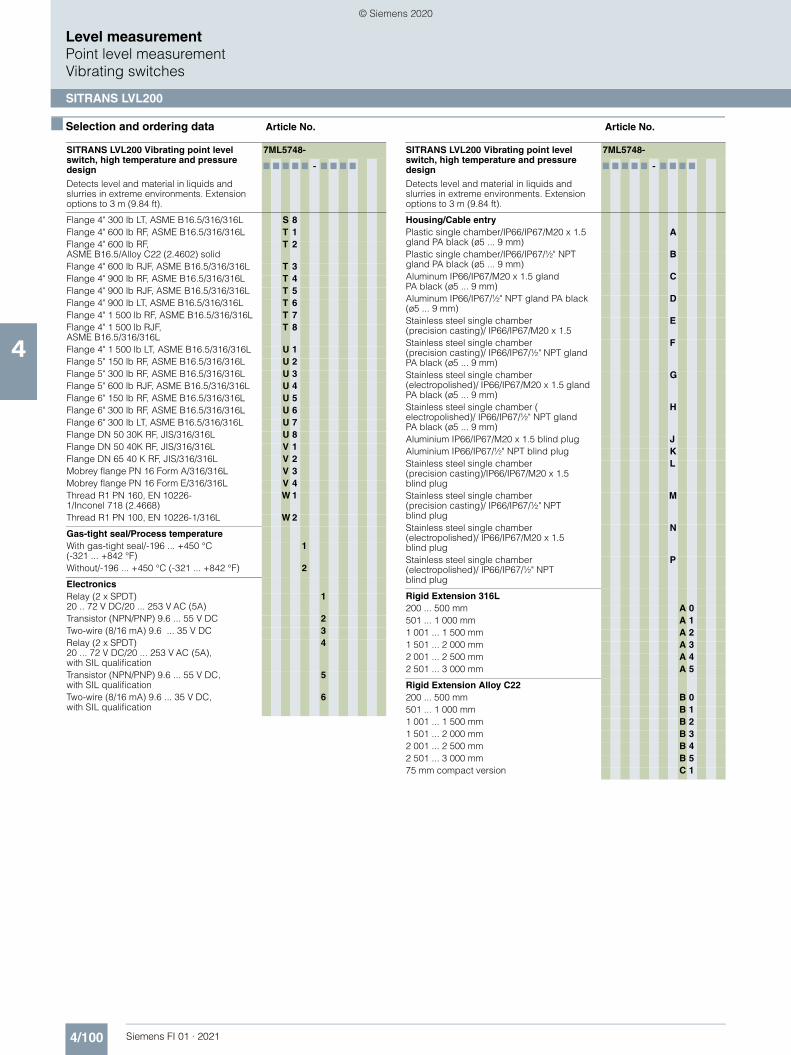
4/100 Siemens FI 01 · 2021
■ Selection and ordering data Article No. Article No.
Level measurementPoint level measurementVibrating switches
SITRANS LVL200
4
Flange 4" 300 lb LT, ASME B16.5/316/316L S 8Flange 4" 600 lb RF, ASME B16.5/316/316L T 1Flange 4" 600 lb RF, ASME B16.5/Alloy C22 (2.4602) solid
T 2
Flange 4" 600 lb RJF, ASME B16.5/316/316L T 3Flange 4" 900 lb RF, ASME B16.5/316/316L T 4Flange 4" 900 lb RJF, ASME B16.5/316/316L T 5Flange 4" 900 lb LT, ASME B16.5/316/316L T 6Flange 4" 1 500 lb RF, ASME B16.5/316/316L T 7Flange 4" 1 500 lb RJF, ASME B16.5/316/316L
T 8
Flange 4" 1 500 lb LT, ASME B16.5/316/316L U 1Flange 5" 150 lb RF, ASME B16.5/316/316L U 2Flange 5" 300 lb RF, ASME B16.5/316/316L U 3Flange 5" 600 lb RJF, ASME B16.5/316/316L U 4Flange 6" 150 lb RF, ASME B16.5/316/316L U 5Flange 6" 300 lb RF, ASME B16.5/316/316L U 6Flange 6" 300 lb LT, ASME B16.5/316/316L U 7Flange DN 50 30K RF, JIS/316/316L U 8Flange DN 50 40K RF, JIS/316/316L V 1Flange DN 65 40 K RF, JIS/316/316L V 2Mobrey flange PN 16 Form A/316/316L V 3Mobrey flange PN 16 Form E/316/316L V 4Thread R1 PN 160, EN 10226-1/Inconel 718 (2.4668)
W 1
Thread R1 PN 100, EN 10226-1/316L W 2
Gas-tight seal/Process temperatureWith gas-tight seal/-196 ... +450 °C (-321 ... +842 °F)
1
Without/-196 ... +450 °C (-321 ... +842 °F) 2
ElectronicsRelay (2 x SPDT) 20 .. 72 V DC/20 ... 253 V AC (5A)
1
Transistor (NPN/PNP) 9.6 ... 55 V DC 2Two-wire (8/16 mA) 9.6 ... 35 V DC 3Relay (2 x SPDT) 20 ... 72 V DC/20 ... 253 V AC (5A), with SIL qualification
4
Transistor (NPN/PNP) 9.6 ... 55 V DC, with SIL qualification
5
Two-wire (8/16 mA) 9.6 ... 35 V DC, with SIL qualification
6
SITRANS LVL200 Vibrating point level switch, high temperature and pressure design
Detects level and material in liquids and slurries in extreme environments. Extension options to 3 m (9.84 ft).
7ML5748-
7 7 7 7 7 - 7 7 7 7
Housing/Cable entryPlastic single chamber/IP66/IP67/M20 x 1.5 gland PA black (ø5 ... 9 mm)
A
Plastic single chamber/IP66/IP67/½" NPT gland PA black (ø5 ... 9 mm)
B
Aluminum IP66/IP67/M20 x 1.5 gland PA black (ø5 ... 9 mm)
C
Aluminum IP66/IP67/½" NPT gland PA black (ø5 ... 9 mm)
D
Stainless steel single chamber (precision casting)/ IP66/IP67/M20 x 1.5
E
Stainless steel single chamber (precision casting)/ IP66/IP67/½" NPT gland PA black (ø5 ... 9 mm)
F
Stainless steel single chamber (electropolished)/ IP66/IP67/M20 x 1.5 gland PA black (ø5 ... 9 mm)
G
Stainless steel single chamber (electropolished)/ IP66/IP67/½" NPT gland PA black (ø5 ... 9 mm)
H
Aluminium IP66/IP67/M20 x 1.5 blind plug JAluminium IP66/IP67/½" NPT blind plug KStainless steel single chamber (precision casting)/IP66/IP67/M20 x 1.5 blind plug
L
Stainless steel single chamber (precision casting)/ IP66/IP67/½" NPT blind plug
M
Stainless steel single chamber (electropolished)/ IP66/IP67/M20 x 1.5 blind plug
N
Stainless steel single chamber (electropolished)/ IP66/IP67/½" NPT blind plug
P
Rigid Extension 316L200 ... 500 mm A 0501 ... 1 000 mm A 11 001 ... 1 500 mm A 21 501 ... 2 000 mm A 32 001 ... 2 500 mm A 42 501 ... 3 000 mm A 5
Rigid Extension Alloy C22200 ... 500 mm B 0501 ... 1 000 mm B 11 001 ... 1 500 mm B 21 501 ... 2 000 mm B 32 001 ... 2 500 mm B 42 501 ... 3 000 mm B 575 mm compact version C 1
SITRANS LVL200 Vibrating point level switch, high temperature and pressure design
Detects level and material in liquids and slurries in extreme environments. Extension options to 3 m (9.84 ft).
7ML5748-
7 7 7 7 7 - 7 7 7 7
© Siemens 2020

4/101Siemens FI 01 · 2021
Level measurementPoint level measurement
Vibrating switches
SITRANS LVL200
4
■ Selection and ordering data Order code Article No.
1) Not available with Process Connection options A0 and A2.2) Available only with Rigid extension option C1.3) Available only with 316L Process Connection and Rigid extension options.4) Available only with Alloy C22 Rigid extension options.5) Available only with Electronic options 3 and 6.6) Available only with Housing/Cable entry options J, K, L, M.7) Available only with Electronic option 6.8) Available only with Electronic options 1, 2, and 4.9) Available only with Gas tight seal/Process temperature option 1. 10)Not available with Housing/Cable entry options G, H, N, P.11)Available only with Housing/Cable entry options J, K, L, M, N, P. 12)Not available with Housing/Cable entry options A and B.13)Not available with Housing/Cable entry options A, B, G, H, N, P.
Further designs
Please add "-Z" to Article No. and specify Order code(s).
Cleaning including Certificate(oil, grease, and silicone free).
W01
Enter the total insertion length in plain text description.
Y01
Identification label (measurement loop) stainless steel.
Y17
Identification Label (measurement loop) foil. Y18
Output switching delay (1 ... 60 s)/default is 1 s Y36
NACE0175 to 3.1 Material Certificate for material (EN 10204 NACE MR 0175) Note: not available with some Process connection options.
D07
Material Inspection 3.1-Inspection certificate for material (EN 10204)
C05
Acceptance test Certificate 2.2 for material (EN 10204)
C15
Dye penetration test, results confirmed via a 3.1 certificate/instrument (EN 10204)
C13
3.1-Inspection certificate for instrument with test data (EN 10204)
C25
Quality and test plan C26
Helium leak test + 3.1 certificate/instrument C32
Spare Parts and Accessories Article No.
SITRANS SCSC single channel signal conditioner and remote test
7ML5760-.....-....
SITRANS TCSC two channel signal conditioner and remote test
7ML5761-.....-....
Operating Instructions
All literature is available to download for free, in a range of languages, at
http://www.siemens.com/processinstrumentation/documentation
SITRANS SCSC, single channel, signal conditioner
Provides power and relay output for one LVL200 vibrating switch, 8/16 mA electronics design. Provides remote test of any LVL200 device.
7ML5760-
7 7 A 7 1 - 7 7 7 7
Click on the Article No. for the online configuration in the PIA Life Cycle Portal.
ApprovalsFor Ex-free area 1 AATEX II (1) G/D [Ex ia Ga/Da] IIC/IIIC, I (M1) [Ex ia Ma] I
1 D
ATEX II (1) G/D (Ex ia Ga/Da) IIC/IIIC, I (M1) (Ex ia Ma) I + WHG
1 E
IEC [Ex ia Ga] IIC, [Ex ia Da] IIIC, [Ex ia Ma] I 1 HIEC (Ex ia Ga) IIC, (Ex ia Da) IIIC, (Ex ia Ma) I + WHG
1 J
Ex-free area (incl. EAC approval) 2 A
SIL qualificationWithout 1With 2
VersionSingle-channel (8/16 mA) for level detection 1Single channel (8/16 mA), level detection with fail safe relay
2
Housing/cable entryPlastic/IP20 A
Terminal block connectionDetachable 2.5 mm²/ Ex sensor: 2 x blue; output and operating voltage: 2 x black
A
Detachable 2.5 mm²/ sensor: 2 x black; out-put and operating voltage: 2 x black
B
LanguageEnglish 0German 1
Operating Instructions
All literature is available to download for free, in a range of languages, at
http://www.siemens.com/processinstrumentation/documentation
© Siemens 2020

4/102 Siemens FI 01 · 2021
■ Selection and ordering data Article No. Article No.
Level measurementPoint level measurementVibrating switches
SITRANS LVL200
4
1) Available only with terminal block connection option B.2) Available only with terminal block connection option A.
■ Options
SITRANS LVL200 welded socket and lock fitting, dimensions in mm (inch)
SITRANS TCSC, dual channel, signal conditioner
Provides power and relay output for two LVL200 vibrating switch, 8/16 mA electronics design. Provides remote test of any LVL200 device.
7ML5761-
7 7 A 7 1 - 7 7 7 7
Click on the Article No. for the online configuration in the PIA Life Cycle Portal.
ApprovalsFor Ex-free area1) 1 AATEX II (1) G/D [Ex ia Ga/Da] IIC/IIIC, I (M1) [Ex ia Ma] I2)
1 D
ATEX II (1) G/D (Ex ia Ga/Da) IIC/IIIC, I (M1) (Ex ia Ma) I + WHG
1 E
IEC [Ex ia Ga] IIC, [Ex ia Da] IIIC, [Ex ia Ma] I2) 1 HIEC (Ex ia Ga) IIC, (Ex ia Da) IIIC, (Ex ia Ma) I + WHG
1 J
Ex-free area (incl. EAC approval) 2 A
SIL qualificationWithout 1With 2
VersionDouble-channel (8/16 mA) for level detection 1
Housing/cable entryPlastic/IP20 A
Terminal block connectionDetachable 2.5 mm²/ Ex sensor: 2 x blue; output and operating voltage: 2 x black
A
Detachable 2.5 mm²/ sensor: 2 x black; out-put and operating voltage: 2 x black
B
LanguageEnglish 0German 1
Operating Instructions
All literature is available to download for free, in a range of languages, at
http://www.siemens.com/processinstrumentation/documentation
SITRANS TCSC, dual channel, signal conditioner
Provides power and relay output for two LVL200 vibrating switch, 8/16 mA electronics design. Provides remote test of any LVL200 device.
7ML5761-
7 7 A 7 1 - 7 7 7 7
LVL200 extended64 bar
LVL200 threaded welded socket
LVL200 extended16 bar
LVL200 extendedunpressurized
Lock fitting
53 (2.09)
32
(1.2
6)
32 (1.26)
60 (2.36)
29.5
(1
.16)
39 (1.54)G1"
G¾"
G¾" A/316L G1" A/316L
© Siemens 2020

4/103Siemens FI 01 · 2021
■ Options (continued)
Level measurementPoint level measurement
Vibrating switches
SITRANS LVL200
4
SITRANS SCSC and SITRANS TCSC LVL Test Conditioners, dimensions in mm (inch)
SITRANS SCSC and SITRANS TCSC LVL Test Conditioner connections
SITRANS SCSC and TCSC LVL test conditioner
56
(2.2
0)
20(0.79)
113 (4.45)
108
(4.2
5)
46
(1.8
1)
92(3
.62)
52
(2.0
5)
Sensor circuit 8/16 mA Relay output
Fail safe relay/second relay output (optional) Voltage supply
Note: TCSC includes terminal 4 and 5 for second device.
1234
21
10 11 12
13 14 15
16 17
1
2
3
4
+ -
+ -
Open
© Siemens 2020

4/104 Siemens FI 01 · 2021
Level measurementPoint level measurementVibrating switches
SITRANS LVL200
4
■ Characteristic curves
SITRANS LVL200 process pressure/process temperature/ambient temperature derating curves
Process pressure with switch position 0.7 g/cm³ (mode switch)
Process pressure with switch position 0.5 g/cm³ (mode switch)
Process temperature in °C (°F)
Process temperature in °C (°F)
Process temperature in °C (°F)
Am
bien
t tem
pera
ture
in °
C (°
F)Temperature range with temperature adapter
Pro
cess
pre
ssur
e in
bar
(psi
g)
Pro
cess
pre
ssur
e in
bar
(psi
g)
Ambient/Process temperature
100 ºC (212 ºF)
150 ºC (302 ºF)
200 ºC (392 ºF)
250 ºC (482 ºF)
50 ºC (122 ºF)
-50 ºC (-58 ºF)
0 ºC(32 ºF) 0 ºC
(32 ºF)
0 ºC(32 ºF)
-40 ºC(-40 ºF)
40 ºC(104 ºF)
70 ºC(158 ºF)
100 ºC (212 ºF)
150 ºC (302 ºF)
200 ºC (392 ºF)
250 ºC (482 ºF)
50 ºC (122 ºF)
-50 ºC (-58 ºF)
20(290)
40(580)
64(928)
-1(-14.5)
0 ºC(32 ºF)
100 ºC (212 ºF)
150 ºC (302 ºF)
200 ºC (392 ºF)
250 ºC (482 ºF)
50 ºC (122 ºF)
-50 ºC (-58 ºF)
20(290)
40(580)
64(928)
-1(-14.5)
© Siemens 2020

4/105Siemens FI 01 · 2021
■ Characteristic curves (continued)
Level measurementPoint level measurement
Vibrating switches
SITRANS LVL200
4SITRANS LVL200 high temperature process temperature/process pressure curve, version up to 100 bar (1 450 psig)
SITRANS LVL200 high temperature pressure/temperature curve, version up to 160 bar (2 321 psig)
SITRANS LVL200 high temperature ambient temperature/process temperature
Pro
cess
pre
ssur
e
Process temperature
SITRANS LVL high temperatureprocess temperature/process pressure,version up to 100 bar (1 450 psig)
100 bar (1 450 psig)
64 bar (928 psig)
40 bar (580 psig)
-110 °C(-166 °F)
0 °C(32 °F)
-196 °C(-321 °F)
450 °C(842 °F)
200 °C(392 °F)
Process temperature
Pro
cess
pre
ssur
e
SITRANS LVL200 high temperaturepressure/temperature curve,version up to 160 bar (2 321 psig)
64 bar (928 psig)
40 bar (580 psig)
160 bar(2 321 psig)
450 °C(842 °F)
0 °C(32 °F)
-110 °C(-166 °F)
-196 °C(-321 °F)
SITRANS LVL100 high temperature ambient temperature/process temperature
Am
bien
t tem
pera
ture
Process temperature
70 °C(158 °F)
50 °C(122 °F)
-110 °C(-166 °F)
0 °C(32 °F)
-20 °C(-4 °F)
-40 °C(-40 °F)
250 °C(482 °F)
450 °C(842 °F)
-196 °C(-321 °F)
© Siemens 2020

4/106 Siemens FI 01 · 2021
Level measurementPoint level measurementVibrating switches
SITRANS LVL200
4
■ Dimensional drawings
SITRANS LVL200 housing, dimensions in mm (inch)
SITRANS LVL200 (standard), dimensions in mm (inch)
M20 x 1.5/½ NPT
M20 x 1.5/½ NPT
M20 x1.5
M20 x 1.5/½ NPT
M20 x 1.5/½ NPT
Stainless steel singlechamber
(electropolished)
SITRANS LVL200, housing
Stainless steel singlechamber
(precision casting)
Aluminumsingle chamber
125
(4.9
2)
~ 116(4.57)
ø 84(3.31)
119
(4.6
9)
~ 69 (2.72)
ø 80(3.15)
~ 59(2.32)
ø 77(3.03)
~ 69(2.72)
114
(4.4
9)
112
(4.4
1)
ø 77(3.03)
Temperature adapter
Bolting DN 40 Flange Gas-tight leadthrough
Cone DN 25Tri-clampThreaded
SITRANS LVL200 standard
SW 32 (G ¾" A, ¾" NPT)SW 41 (G 1" A, 1" NPT)
G ¾" A, ¾" NPTG 1" A, 1" NPT
18.5
(0
.73)
Ø33.7 (1.33)
178
(7.0
1)
53
(2.0
9)
55
(2.1
7)53 (2
.09)
34
(1.3
4)
19
(0.7
5)
50
(1.9
7)
57
(2.2
4)36
(1.4
2)
66
(2.6
0)
53
(2.0
9)
© Siemens 2020

4/107Siemens FI 01 · 2021
■ Dimensional drawings (continued)
Level measurementPoint level measurement
Vibrating switches
SITRANS LVL200
4
SITRANS LVL200 (extended), dimensions in mm (inch)
SITRANS LVL200 extended
Threaded Cone DN 25Tri-clamp
Bolting DN 40 Gas-tight leadthroughFlanged
Temperature adapter
Sensor length (L)316L, Alloy C22 (2.4602)
Enamelled
316L, ECTFE coated
316L, PFA coated
G ¾" A, ¾" NPTG 1" A, 1" NPT
18.5 (0.73)
SW 32 (G ¾" A, ¾" NPT)SW 41 (G 1" A, 1" NPT)
36(1.42)
57 (2.24)
50 (1.97)
19(0.75)
34 (1.34)
178 (7.01)
L LL
L L
80 ... 6 000 mm (3.15 ... 236.2 inch)
80 ... 1 500 mm (3.15 ... 59.06 inch)
80 ... 3 000 mm (3.15 ... 118.1 inch)
80 ... 4 000 mm (3.15 ... 157.5 inch)
© Siemens 2020

4/108 Siemens FI 01 · 2021
■ Dimensional drawings (continued)
Level measurementPoint level measurementVibrating switches
SITRANS LVL200
4
SITRANS LVL200 high temperature, compact version, dimensions in mm (inch)
ø 28.5(1.12)
ø 33.7(1.33)
ø 33.7(1.33)
ø 28.5(1.12)
Sealing surface
SITRANS LVL200 high temperature, compact version
74(2.91) 40
(1.57)
320(12.60)
G 1, 1 NPT
41
323(12.72)
DN50, PN40
74(2.91) 40
(1.57)
© Siemens 2020

4/109Siemens FI 01 · 2021
■ Dimensional drawings (continued)
Level measurementPoint level measurement
Vibrating switches
SITRANS LVL200
4
SITRANS LVL200 high temperature, tube version, dimensions in mm (inch)
SITRANS LVL200 high temperature, tube version
ø 33.7(1.33)
ø 28.5(1.12)
ø 28.5(1.12)
ø 21.3(0.84)
ø 33.7(1.33)
Sen
sor l
engt
h
Sen
sor l
engt
hSealing surface
DN50 PN40
323
(12.
72)
320
(12.
60)
85(3
.35)
40
(1.5
7)
85(3
.35)
40(1
.57)
G 1, 1 NPT
41
© Siemens 2020

4/110 Siemens FI 01 · 2021
Level measurementPoint level measurementVibrating switches
SITRANS LVL200
4
■ Circuit diagrams
SITRANS LVL200 connections
67
41
532
Relay output
Relay output
Voltage supply
Contactless
Relay (DPDT)
DCAC
Voltage supply
Amplifier according to NAMUR IEC 60947-5-6, approx. 8.2 V
NPN actionPNP action
Control lamp - fault indication (red)
Control lamp - switching status (yellow)Control lamp - operating status (green)
Mode switch for selecting the switching behavior (min./max.)
DIL switch for sensitivitybehavior (min./max.)
Test key
Ground terminal
Connector block
Connection terminals
Relay (DPDT)
Signal conditioning instrument
Control lamp
DIL switch for sensitivity adjustment
Ground terminal
Connection terminals
Processing system or PLC
Control lamp
DIL switch for characteristics reversal
DIL switch for sensitivity adjustment
Ground terminal
Connection terminals
DIL switch for mode adjustment
Control lamp
DIL switch for switching point adaptation
Ground terminal
Connection terminals
Control lamp
DIL switch for characteristics reversal
DIL switch for sensitivity adjustment
Ground terminal
Simulation key
Connection terminals
Control lamp
DIL switch for mode adjustment
DIL switch for switching point
Ground terminal
Connection terminals
Control lamp - fault indication (red)
Control lamp - Switching status (yellow)
Control lamp - Operating status (green)
Mode switch for selecting the switchingbehaviour (min./max.)DIL switch for sensitivity adjustment
Ground terminal
Connection terminals
Control lamp - fault indication (red)
Control lamp - Switching status (yellow)
Control lamp - Operating status (green)
Mode switch for selecting the switchingbehaviour (min./max.)
DIL switch for sensitivity adjustment
Ground terminal
Connection terminals
NL1–+
–+– +
N
21
–+
–+
NAMUR
SITRANS LVL200H 8/16 mA
SITRANS LVL200S, LVL200ETransistor (NPN/PNP)
SITRANS LVL200H, Transistor (NPN/PNP)
SITRANS LVL200S, LVL200E SITRANS LVL200H
SITRANS LVL200S, LVL200E 8/16 mA
L1
© Siemens 2020
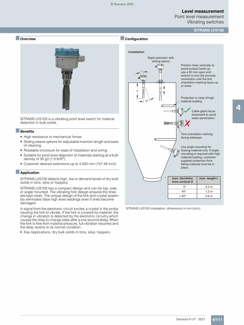
4/111Siemens FI 01 · 2021
Level measurementPoint level measurement
Vibrating switches
SITRANS LVS100
4
■ Overview
SITRANS LVS100 is a vibrating point level switch for material detection in bulk solids.
■ Benefits
• High resistance to mechanical forces • Sliding sleeve options for adjustable insertion length and ease
of cleaning • Rotatable enclosure for ease of installation and wiring • Suitable for point level detection of materials starting at a bulk
density of 30 g/l (1.9 lb/ft3) • Customer desired extensions up to 4 000 mm (157.48 inch)
■ Application
SITRANS LVS100 detects high, low or demand levels of dry bulk solids in bins, silos or hoppers.
SITRANS LVS100 has a compact design and can be top, side, or angle mounted. The vibrating fork design ensures the tines are kept clean. The unique design of the fork and crystal assem-bly eliminates false high level readings even if tines become damaged.
A signal from the electronic circuit excites a crystal in the probe causing the fork to vibrate. If the fork is covered by material, the change in vibration is detected by the electronic circuitry which causes the relay to change state after a one second delay. When the fork is free from material pressure, full vibration resumes and the relay reverts to its normal condition. • Key Applications: dry bulk solids in bins, silos, hoppers
■ Configuration
SITRANS LVS100 installation, dimensions in mm (inch)
max. deviation from vertical O
max. length L
0.6 m1.2 m4.0 m
Tine orientation marking facing sideways.
Cable gland faces downward to avoid water penetration.
Protection in case of high material loading.
Rigid extension with sliding sleeve
Position tines vertically to avoid product build-up: use a 50 mm open-end wrench to turn the process connection until the tine orientation marking faces up or down.
Installation
Use angle mounting for flowing material only. If angle mounting is required with high material loading, customer-supplied protection from falling material must be in place.
O
L
*
*
5°45°
> 45°
© Siemens 2020

4/112 Siemens FI 01 · 2021
Level measurementPoint level measurementVibrating switches
SITRANS LVS100
4
■ Technical specifications
Mode of Operation
Measuring principle Vibrating point level switch
Input
Measured variable High, low and demand
Measuring frequency 200 Hz
Output
Relays DPDT relay
Relay delay From loss of vibration: approximately 1 second
From resumption of vibration: approximately 1 ... 2 s
Signal delay Probe uncovered to covered: approximately 1 s
Probe covered to uncovered: approximately 1 ... 2 s
Relay fail-safe High or low, switch selectable
Alarm output Relay 8 A at 250 V AC, non-inductive
Relay 5 A at 30 V DC, non-inductive
Sensitivity High or low, switch selectable
Rated operating conditions
Installation conditions • Location Indoor/outdoor
Ambient conditions • Ambient temperature -40 ... +60 °C (-40 ... +140 °F)• Storage temperature -40 ... +80 °C (-40 ... +176 °F)• Installation category III• Pollution degree 2
Medium conditions • Process temperature -40 ... +150 °C (-40 ... +302 °F) • Max. threaded bushing temperature 80 °C (176 °F)• Max. enclosure surface temperature
(Category 2D) 90 °C (194 °F)
• Max. extension surface temperature (Category 1D)
150 °C (302 °F)
• Pressure (vessel) Max. 10 bar g (145 psi g) European Pressure Directive 2014/68/EU: Category 1
Minimum material density Approx. 30 g/l (1.9 lb/ft3)
Design
Material • Enclosure Epoxy coated aluminum
Process connection • Thread 1¼" NPT [(Taper), ANSI/ASME B1.20.1],R 1½" [(BSPT), EN 10226]
• Thread R 1½" [(BSPT), EN 10226], ½" NPT [(Taper),ANSI/ASME B1.20.1], sliding sleeve[min. length 500 mm (19.69 inch)]
• Thread material: stainless steel 304 (1.4301) or 316L (1.4404) depending on configuration
Tine material Stainless steel 316L (1.4404)
Degree of protection IP66/Type 4/NEMA 4
Conduit entry 2 x M20 x 1.5 or 2 x ½" NPT (For FM and CSA approved versions only.)
Weight Standard version, no extensions: approx. 1.7 kg (3.7 lb)
Power supply • 19 ... 230 V AC, +10 %, 50 ... 60 Hz, 8 VA
• 19 ... 40 V DC, +10 %, 1.5 W
Certificates and approvals • CSA/FM General Purpose • CE • CSA/FM Dust Ignition Proof • RCM• ATEX II 1/2 D • IECex
© Siemens 2020

4/113Siemens FI 01 · 2021
Level measurementPoint level measurement
Vibrating switches
SITRANS LVS100
4
■ Selection and ordering data Article No. Order code
1) Only available with the following configurations 7ML5735-2AA11-0AA0 or 7ML5735-2AB11-0AA0.
2) Not available with extension length options 11 and 12.3) Input voltage 2 not allowed with extension length 16, 17, 18 or 20.
1) Available only with Approval option A.
SITRANS LVS100 Vibrating fork point level switch
Level and material detection for dry bulk solids. Extension options to 4 m (13.12 ft).
7ML5735-
7 7 7 7 7 - 0 7 A 0
Click on the Article No. for the online configuration in the PIA Life Cycle Portal.
Input VoltageDPDT Relay: 19 ... 230 V AC, 19 ... 40 V DC 1DPDT Relay: 19 ... 230 V AC, 19 ... 40 V DC (stocked version)1)3)
2
Process temperatureUp to 150 °C (302 °F) AProcess connectionThreadedR 1½" [(BSPT), EN 10226] A1¼" NPT [(Taper), ANSI/ASME B1.20.1] BR 1½" [(BSPT), EN 10226] DIN 2999 thread, sliding sleeve [min. length 500 mm (19.69 inch)]2)
C
1½" NPT [(Taper), ANSI/ASME B1.20.1] , sliding sleeve [min. length 500 mm (19.69 inch)]2)
D
Extension length
Stainless steel 316L (1.4404)Standard length, 170 mm (6.69 inch) 1 1
Add Order code Y01 and plain text: "Insertion length ... mm"
Stainless steel 304 (1.4301)230 ... 500 mm (9.05 ... 19.69 inch) 1 2501 ... 1 000 mm (19.72 ... 39.37 inch) 1 31 001 ... 1 500 mm (39.41 ... 59.06 inch) 1 41 501 ... 2 000 mm (59.09 ... 78.74 inch) 1 52 001 ... 2 500 mm (78.78 ... 98.43 inch) 1 62 501 ... 3 000 mm (98.46 ... 118.11 inch) 1 73 001 ... 3 500 mm (118.15 ... 137.80 inch) 1 83 501 ... 4 000 mm (137.83 ... 157.48 inch) 2 0
ApprovalsCSA/FM General Purpose, CE, RCM ACSA/FM Class II, Div. 1, Groups E, F, G, Class III, ATEX II ½ D, RCM
B
IEC-Ex Ex t IIIC T-- Da/Db IP6X CEAC Ex ta/tb IIIC Da/Db D
Further Designs
Please add "-Z" to Art. No. and specify Order code(s).
Total insertion length: Enter the total insertion length in plain text description, max. (50 mm increments)
Y01
Signal bulb inserted in M20 cable gland1) A20
Factory test certificate - M to DIN 55350, Part 18 C11
Operating Instructions
All literature is available to download for free, in a range of languages, at
http://www.siemens.com/processinstrumentation/documentation
Spare Parts Article No.
Replacement Electronics Module LVS100 DPDT Relay (19 ... 253 V AC, 19 ... 55 V DC)
7ML1830-1NS
R 1½" [(BSPT), EN 10226] DIN 2999 thread, sliding sleeve
7ML1830-1NT
1½" NPT [(Taper), ANSI/ASME B1.20.1], sliding sleeve [min. length 500 mm (19.69 inch)]
7ML1830-1NU
© Siemens 2020

4/114 Siemens FI 01 · 2021
Level measurementPoint level measurementVibrating switches
SITRANS LVS100
4
■ Dimensional drawings
SITRANS LVS100, dimensions in mm (inch)
■ Circuit diagrams
SITRANS LVS100 connections
Tine orientation marking
Threaded bushing[max. temp.
80 °C (176 °F)]
Customer supplied process flange
Tine
125
(4.9
2):
Sta
ndar
d fo
rk
170
... 4
000
(6.6
9 ...
157
.48)
:C
usto
mer
spe
cifie
d rig
id
Zone 21(cat. 2)
Zone 20(cat. 1)
150
(5.9
1)120 (4.72)
75 (2
.95)
60 (2.36)
60
(2.3
6)
Universal voltage (DPDT relay)
AC: Terminal 1: LTerminal 2: N19 ... 230 V AC, +10 %, 50 ... 60 Hz, 8 VA
DC: Terminal 1: +Terminal 2: -19 ... 50 V DC, +10 %, 2 W
Alarm output
relayFSH/FSLadjustment
LED
Sensitivity adjustment:B = factory setting,A = decreased
8 7 6 5 4 3 2 1
© Siemens 2020

4/115Siemens FI 01 · 2021
Level measurementPoint level measurement
Vibrating switches
SITRANS LVS200
4
■ Overview
SITRANS LVS200 is a vibrating point level switch for high, low, or demand level detection of bulk solids.
■ Benefits
• High resistance to mechanical forces • Strong vibration resistance to high bulk material loads • Rotatable enclosure for convenient wiring • Suitable for low density material: standard version, 20 g/l
(1.3 lb/ft3); liquid/solid interface version, 50 g/l (3 lb/ft3) and low density option min. 5 g/l (0.3 lb/ft3)
• Customer desired extensions up to 20 000 mm (787 inch) • Optional detection of solids within liquid • Durable short fork option with 165 mm (6.5 inch) insertion
length
■ Application
The standard LVS200 detects high, low, or demand levels of dry bulk solids in bins, silos, or hoppers. The liquid/solid interface version can also detect settled solids within liquids or solids within confined spaces such as feed pipes. It is designed to ignore liquids in order to detect the interface between a solid and a liquid.
A pipe extension version is available with either the standard or liquid/solid interface electronics and fork, separated by a customer supplied 1 inch pipe.
SITRANS LVS200 has an optional 4 to 20 mA output for monitor-ing buildup on the fork to determine when preventative maintenance should be performed in sticky applications.
The LVS200 has a compact design and can be top, side or angle mounted. The vibrating fork design ensures the tines are kept clean. The unique design of the fork and crystal assembly elim-inates false high level readings even if tines become damaged.
A signal from the electronic circuit excites a crystal in the probe causing the fork to vibrate. If the fork is covered by material, the change in vibration is detected by the electronic circuitry which causes the relay to change state after a one second delay. When the fork is free from material pressure, full vibration resumes and the relay reverts to its normal condition.• Key Applications: dry bulk solids in bins, silos, hoppers or
settled solids within liquids (interface version)
© Siemens 2020

4/116 Siemens FI 01 · 2021
Level measurementPoint level measurementVibrating switches
SITRANS LVS200
4
■ Technical specifications
Mode of operation
Measuring principle Vibrating point level switch
Input
Measured variable High, low, and demand
Measuring frequency• Standard 125 Hz• Liquid/solid interface and short fork
version 350 Hz
Output
PNP Open collector: Permanent load max. 0.4 A, short-circuit and overload protectedTurn-on voltage: max. 50 V (reverse protection)
2-wire without contact Load current:• Min. 10 mA • Max. 500 mA permanent • Max. 2A < 200 ms • Max. 5A < 50 ms
Voltage drop on the electronic module: max. 7 V with closed electric circuit
Cut-off current with open electric circuit: max. 5 mA
Relays • Version with 1 relay SPDT relay• Version with 2 relays DPDT relay
Relay delay • From loss of vibration: approximately 1 second
• From resumption of vibration: approximately 1 ... 2 seconds
Signal delay • Probe uncovered to covered: approximately 1 second
• Probe covered to uncovered: approximately 1 ... 2 seconds
Relay fail-safe High or low, switch selectable
Alarm output • Relay 8 A at 250 V AC, non-inductive
• Relay 5 A at 30 V DC, non-inductive
mA output 8/16 mA or 4 ... 20 mA• Resolution 4 ... 20 mA ± 0.1 mA
Sensitivity High or low, switch selectable
Rated operating conditions
Installation conditions • Location Indoor/outdoor
Ambient conditions • Ambient temperature -40 ... +60 °C (-40 ... +140 °F)• Storage temperature -40 ... +80 °C (-40 ... +176 °F)• Installation category III• Pollution degree 2
Medium conditions • Process temperature • All except CSA Class II, Group G:
-40 ... +150 °C (-40 ... +302 °F) • CSA Class II, Group G:
-40 ... +140 °C (-40 ... +284 °F),CSA temperature code T3B
• Max. threaded bushing temperature 80 °C (176 °F)• Max. enclosure surface temperature
(Category 2D) 90 °C (194 °F)
• Max. extension surface temperature (Category 1D)
150 °C (302 °F)
• Pressure (vessel) Max. 30 bar g (435 psi g) European Pressure Directive 2014/68/EU: Category 1
• Minimum material density • Standard version: approx. 20 g/l (1.2 lb/ft3)
• Liquid/solid interface version: approx. 50 g/l (3 lb/ft3)
• Optional low density version: approx. 5 g/l (0.3 lb/ft3)
Design
Material • Enclosure Epoxy coated aluminum
Process connection • Thread 1½" NPT [(Taper), ANSI/ASME B1.20.1], R ½" [(BSPT), EN 10226], and flange options
• Optional sliding bushing with 2" NPT [(Taper), ANSI/ASME B1.20.1] or BSP thread
• Thread material: stainless steel 303 (1.4301)
Tine material Stainless steel 316L (1.4404), PTFE-coated tines are available upon special request
Degree of protection IP65/Type 4/NEMA 4
Conduit entry 2 x M20 x 1.5 or 2 x ½" NPT (For FM and CSA approved versions only.)
Weight • Standard version, no extensions: approx. 2.0 kg (4.4 lb)
• Solids/liquids version, no extensions: approx. 1.9 kg (4.2 lb)
Power supply • 19 ... 230 V AC, +10 %, 50 ... 60 Hz, 8 VA
• 19 ... 55 V DC, +10 %, 1.5 W
Certificates and approvals
• CSA/FM General Purpose • CE • CSA/FM Dust Ignition Proof • RCM• ATEX II 1/2 D • CSA/FM IS Class I, II, III Div. 1,
Groups A, B, C, D, E, F, G, FM Class I, Aex ia IIC, CSA Class I, Ex ia IIC, available only with power supply options 5 and 6
• ATEX II 1G and 1/2 G Eex ia IIC; ATEX II 1D and 1/2 D, available only with power supply option 5
© Siemens 2020

4/117Siemens FI 01 · 2021
Level measurementPoint level measurement
Vibrating switches
SITRANS LVS200
4
■ Selection and ordering data Article No. Article No.
1) Available with Approval options A ... D, G only.2) Available with Approval options D, E, F only.3) Available with Approval options B, D, G only.4) Available with configurations 7ML5731-7AA11-1BA0 or
7ML5731-7AB11-1AA0 only.5) Basic version is cost effective and offers fast delivery.6) Not available with extension length options 11, 12, 31, 32.7) Max. 6 bar (87 psi).8) Available with option extension length 11 ... 28.9) Available with option extension length 31 … 48.
SITRANS LVS200 Vibrating fork point level switch, standard design
Level and material detection in dry bulk solids. Extension options to 4 m (13.12 ft). With advanced testing, output, and durability options, including low bulk densities.
7ML5731-
7 7 7 7 7 - 7 7 A 0
Click on the Article No. for the online configuration in the PIA Life Cycle Portal.
Power supply19 ... 230 V AC, 19 ... 55 V DC, one relay output (SPDT)1)
1
19 ... 230 V AC, 19 ... 55 V DC, two relay outputs (DPDT)1)
2
18 ... 50 V DC PNP1) 319 ... 230 V AC/DC without contact, 2-wire loop powered1)
4
7 ... 9 V DC (requires NAMUR switch amplifier) NAMUR IEC 60947-5-6, 2-wire2)
5
8/16 mA or 4 ... 20 mA; 12.5 ... 35 V DC, 2-wire3) 619 ... 230 V AC, 19 ... 55 V DC, one relay output (SPDT) basic version4)5)
7
Process temperatureWithout temperature isolator AWith temperature isolator BSeparated enclosure - cable length 1.5 m (4.92 ft) [max. temperature process 150 °C (302 °F)/max. temperature electronics 60 °C (140 °F)]
C
Separated enclosure - cable length 4.0 m (13.12 ft) [max. temperature process150 °C (302 °F)/max. temperature electronics 60 °C (140 °F)]
D
Process connection
ThreadedR 1½" [(BSPT), EN 10226] A1½" NPT [(Taper), ANSI/ASME B1.20.1] BG 2" [(BSPP), EN ISO 228-1], sliding sleeve [min. length 500 mm (19.69 inch)]6)
C
2" NPT [(Taper), ANSI/ASME B1.20.1], sliding sleeve [min. length 500 mm (19.69 inch)]6)
D
FlangedDN 100 PN 6, EN 1092-1, flat face7) EDN 100 PN 16, EN 1092-1, flat face F2" ASME 150 lb B16.5, raised face G3" ASME 150 lb B16.5, raised face H4" ASME 150 lb B16.5, raised face J2" Tri-clamp (DN 50) ISO 2852 K
Extension length
Stainless steel 304 (1.4301)Standard length, 235 mm (9.25 inch) 1 1
Add Order code Y01 and plain text: "Insertion length ... mm"300 ... 500 mm (11.81 ... 19.69 inch) 1 2501 ... 750 mm (19.72 ... 29.53 inch) 1 3751 ... 1 000 mm (29.57 ... 39.37 inch) 1 41 001 ... 1 250 mm (39.41 ... 49.21 inch) 1 51 251 ... 1 500 mm (49.25 ... 59.06 inch) 1 61 501 ... 1 750 mm (59.09 ... 68.90 inch) 1 71 751 ... 2 000 mm (68.94 ... 78.74 inch) 1 82 001 ... 2 250 mm (78.78 ... 88.58 inch) 2 12 251 ... 2 500 mm (88.62 ... 98.43 inch) 2 22 501 ... 2 750 mm (98.46 ... 108.27 inch) 2 32 751 ... 3 000 mm (108.31 ... 118.11 inch) 2 43 001 ... 3 250 mm (118.15 ... 127.95 inch) 2 53 251 ... 3 500 mm (127.99 ... 137.80 inch) 2 63 501 ... 3 750 mm (137.83 ... 147.64 inch) 2 73 751 ... 4 000 mm (147.68 ... 157.48 inch) 2 8
Stainless steel 316L (1.4404)Standard length, 235 mm (9.25 inch) 3 1
Add Order code Y01 and plain text: "Insertion length ... mm"300 ... 500 mm (11.81 ... 19.69 inch) 3 2501 ... 750 mm (19.72 ... 29.53 inch) 3 3751 ... 1 000 mm (29.57 ... 39.37 inch) 3 41 001 ... 1 250 mm (39.41 ... 49.21 inch) 3 51 251 ... 1 500 mm (49.25 ... 59.06 inch) 3 61 501 ... 1 750 mm (59.09 ... 68.90 inch) 3 71 751 ... 2 000 mm (68.94 ... 78.74 inch) 3 82 001 ... 2 250 mm (78.78 ... 88.58 inch) 4 12 251 ... 2 500 mm (88.62 ... 98.43 inch) 4 22 501 ... 2 750 mm (98.46 ... 108.27 inch) 4 32 751 ... 3 000 mm (108.31 ... 118.11 inch) 4 43 001 ... 3 250 mm (118.15 ... 127.95 inch) 4 53 251 ... 3 500 mm (127.99 ... 137.80 inch) 4 63 501 ... 3 750 mm (137.83 ... 147.64 inch) 4 73 751 ... 4 000 mm (147.68 ... 157.48 inch) 4 8
Material process connection/extensionStainless steel threads 304 (1.4301), flanges 321 (1.4541), Tri-clamp 304 (1.4301)8)
1
Stainless steel 316L (1.4404)9) 2
ApprovalsCSA/FM Dust Ignition Proof, RCM AATEX II ½ D, RCM BCSA/FM General Purpose, RCM, CE CCE, RCM DCSA/FM IS Class I, II, III Div. 1, Groups A, B, C, D, E, F, G, FM Class I, Aex ia IIC, CSA Class I, Ex ia IIC, RCM
E
ATEX II 1G and ½G Eex ia IIC; ATEX II 1D and ½D, RCM
F
IEC-Ex t IIIC Da/Db GEAC Ex ta/tb IIIC Da/Db, Ex ta IIIC Da HEAC Ex Ga/Gb Ex ia IIC, 0Ex ia IIC Ga; Ex ta/tb IIIC Da/Db, Ex ta IIIC Da
J
SITRANS LVS200 Vibrating fork point level switch, standard design
Level and material detection in dry bulk solids. Extension options to 4 m (13.12 ft). With advanced testing, output, and durability options, including low bulk densities.
7ML5731-
7 7 7 7 7 - 7 7 A 0
© Siemens 2020

4/118 Siemens FI 01 · 2021
Level measurementPoint level measurementVibrating switches
SITRANS LVS200
4
■ Selection and ordering data Order code Article No.
1) Available only with power supply option 1 and Approval options C, D and with Process connection flange options E ... J.
2) Available with Approval option D only.3) K05 and G01 are not available together.
Further Designs
Please add "-Z" to Article No. and specify Order code(s).
Factory test certificate - M to DIN 55350, Part 18 C11
Total insertion length: Enter the total insertion length in plain text description, max. 4 000 mm (157.48 inch)
Y01
Stainless steel tag [100 x 45 mm (3.94 x 1.77 inch)]: Measuring-point number/identification (max. 27 characters); specify in plain text
Y14
Enhanced sensitivity > 5 g/l via electronics and increased insertion length of 25 mm (0.98 inch)3)
K05
Enhanced sensitivity < 5 g/l via electronics, increased insertion length of 25 mm (0.98 inch), and increased aluminum fork width1)3)
G01
Signal bulb inserted in M20 cable gland2) A20
NAMUR 8/16 mA switch amplifiers available, contact factory for pricing
Operating Instructions
All literature is available to download for free, in a range of languages, at
http://www.siemens.com/processinstrumentation/documentation
Spare Parts Article No.
Replacement Electronics Module (125 Hz) [19 ... 230 V AC, 19 ... 55 V DC, one relay output (SPDT)]
7ML1830-1KL
Replacement Electronics Module (125 Hz) [19 ... 230 V AC, 19 ... 55 V DC, two relay output (DPDT)]
A5E35525363
Sliding sleeve, 2" BSP (ISO 228) 7ML1830-1JM
Sliding sleeve, 2" NPT (ASME B1.20.1) 7ML1830-1JN
Namur Isolator switch amplifier relay output KFD2-SR2-Ex1.W
A5E35667901
SITRANS LVS200, standard, power supply 7, process temperature A, process connection A, extension length 11, material process connection/extension 1, and approval B
7ML5731-7AA11-1BA0
SITRANS LVS200, standard, power supply 7, process temperature A, process connection B, extension length 11, material process connection/extension 1, and approval A
7ML5731-7AB11-1AA0
SITRANS LVS200 Vibrating fork point level switch, short fork and interface design
Level and material detection in dry bulk solids or solids interface within a liquid. Extension options to 4 m (13.12 ft). With advanced testing, output, and durability options.
7ML5732-
7 7 7 7 7 - 7 7 A 0
Click on the Article No. for the online configuration in the PIA Life Cycle Portal.
Power supply19 ... 230 V AC, 19 ... 55 V DC, one relay output (SPDT)6)
1
19 ... 230 V AC, 19 ... 55 V DC, two relay outputs (DPDT)6)
2
18 ... 50 V DC PNP6) 319 ... 230 V AC/DC without contact, 2-wire loop powered6)
4
8/16 mA or 4 ... 20 mA; 12.5 ... 35 V DC, 2-wire1) 5
Process temperatureWithout temperature isolator AWith temperature isolator BSeparated enclosure - cable length 1.5 m (4.92 ft) [max. temperature process 150 °C (302 °F)/max. temperature electronics 60 °C (140 °F)]
C
Separated enclosure - cable length 4.0 m (13.12 ft) [max. temperature process 150 °C (302 °F)/max. temperature electronics 60 °C (140 °F)]
D
Process connection
ThreadedR 1½" [(BSPT), EN 10226] A1½" NPT [(Taper), ANSI/ASME B1.20.1] BG 2" [(BSPP), EN ISO 228-1], sliding sleeve [min. length 500 mm (19.69 inch)]2)
C
2" NPT [(Taper), ANSI/ASME B1.20.1], sliding sleeve [min. length 500 mm (19.69 inch)]2)
D
FlangedDN 100 PN 6, EN 1092-1, flat face3) EDN 100 PN 16, EN 1092-1, flat face F2" ASME 150 lb B16.5, raised face G3" ASME 150 lb B16.5, raised face H4" ASME 150 lb B16.5, raised face J2" Tri-clamp (DN 50) ISO 2852 K
Extension length
Stainless steel 304 (1.4301)Standard length, 165 mm (6.50 inch) 1 1
Add Order code Y01 and plain text: "Insertion length ... mm"200 ... 500 mm (7.87 ... 19.69 inch) 1 2501 ... 750 mm (19.72 ... 29.53 inch) 1 3751 ... 1 000 mm (29.57 ... 39.37 inch) 1 41 001 ... 1 250 mm (39.41 ... 49.21 inch) 1 51 251 ... 1 500 mm (49.25 ... 59.06 inch) 1 61 501 ... 1 750 mm (59.09 ... 68.90 inch) 1 71 751 ... 2 000 mm (68.94 ... 78.74 inch) 1 82 001 ... 2 250 mm (78.78 ... 88.58 inch) 2 12 251 ... 2 500 mm (88.62 ... 98.43 inch) 2 22 501 ... 2 750 mm (98.46 ... 108.27 inch) 2 32 751 ... 3 000 mm (108.31 ... 118.11 inch) 2 43 001 ... 3 250 mm (118.15 ... 127.95 inch) 2 53 251 ... 3 500 mm (127.99 ... 137.80 inch) 2 63 501 ... 3 750 mm (137.83 ... 147.64 inch) 2 73 751 ... 4 000 mm (147.68 ... 157.48 inch) 2 8
© Siemens 2020

4/119Siemens FI 01 · 2021
■ Selection and ordering data Article No. Article No.
Level measurementPoint level measurement
Vibrating switches
SITRANS LVS200
4
1) Available with Approval options B, D, E only.2) Not available with extension length options 11, 12, 31, 32.3) Max. 6 bar (87 psi).4) Available with extension length options 11 ... 28.5) Available with extension length options 31 … 48.6) Power supply options 1, 2, 3, 4 not allowed with Approvals
options F and H.
1) Available with Approval option D only.2) Available with power supply option 1 only.3) A20 not allowed with power supply options 4 or 5.4) G02 not allowed with process temperature options C or D.
Stainless steel 316L (1.4404)Standard length, 165 mm (6.50 inch) 3 1
Add Order code Y01 and plain text: "Insertion length ... mm"200 ... 500 mm (7.87 ... 19.69 inch) 3 2501 ... 750 mm (19.72 ... 29.53 inch) 3 3751 ... 1 000 mm (29.57 ... 39.37 inch) 3 41 001 ... 1 250 mm (39.41 ... 49.21 inch) 3 51 251 ... 1 500 mm (49.25 ... 59.06 inch) 3 61 501 ... 1 750 mm (59.09 ... 68.90 inch) 3 71 751 ... 2 000 mm (68.94 ... 78.74 inch) 3 82 001 ... 2 250 mm (78.78 ... 88.58 inch) 4 12 251 ... 2 500 mm (88.62 ... 98.43 inch) 4 22 501 ... 2 750 mm (98.46 ... 108.27 inch) 4 32 751 ... 3 000 mm (108.31 ... 118.11 inch) 4 43 001 ... 3 250 mm (118.15 ... 127.95 inch) 4 53 251 ... 3 500 mm (127.99 ... 137.80 inch) 4 63 501 ... 3 750 mm (137.83 ... 147.64 inch) 4 73 751 ... 4 000 mm (147.68 ... 157.48 inch) 4 8
Material process connection/extensionStainless steel threads 304 (1.4301), flanges 321 (1.4541), Tri-clamp 304 (1.4301)4)
1
Stainless steel 316L (1.4404)5) 2
ApprovalsCSA/FM Dust Ignition Proof, RCM AATEX II ½ D, RCM BCSA/FM General Purpose, RCM, CE CCE, RCM DIEC-Ex t IIIC Da/Db EATEX II 1G and ½G Eex ia IIC; ATEX II 1D and½D, CE, RCM
F
EAC Ex ta/tb IIIC Da/Db, Ex ta IIIC Da GEAC Ex Ga/Gb Ex ia IIC, 0Ex ia IIC Ga; Ex ta/tb IIIC Da/Db, Ex ta IIIC Da
H
SITRANS LVS200 Vibrating fork point level switch, short fork and interface design
Level and material detection in dry bulk solids or solids interface within a liquid. Extension options to 4 m (13.12 ft). With advanced testing, output, and durability options.
7ML5732-
7 7 7 7 7 - 7 7 A 0
Further Designs Order code
Please add "-Z" to Article No. and specify Order code(s).
Factory test certificate - M to DIN 55350, Part 18 C11
Total insertion length: Enter the total insertion length in plain text description, max. 4 000 mm (147.48 inch)
Y01
Stainless steel tag [100 x 45 mm (3.94 x 1.77 inch)]: Measuring-point number/identification (max. 27 characters); specify in plain text
Y14
Signal bulb inserted in M20 cable gland1)3) A20
Note: G02 must be ordered for solids/liquids interface detection.
Adjustable sensitivity (by potentiometer) for solids/liquids interface detection1)2)4)
G02
Operating Instructions
All literature is available to download for free, in a range of languages, at
http://www.siemens.com/processinstrumentation/documentation
Spare Parts Article No.
Replacement Electronics Module (125 Hz) [19 ... 230 V AC, 19 ... 55 V DC, two relay output (DPDT)]
A5E35525363
Replacement Electronics Module (350 Hz) [19 ... 230 V AC, 19 ... 55 V DC, one relay output (SPDT)]
7ML1830-1KM
Sliding sleeve, 2" BSP (ISO 228) 7ML1830-1JM
Sliding sleeve, 2" NPT (ASME B1.20.1) 7ML1830-1JN
© Siemens 2020

4/120 Siemens FI 01 · 2021
Level measurementPoint level measurementVibrating switches
SITRANS LVS200
4
■ Selection and ordering data Article No. Order code
1) Available with Approval options A, B, C, D, G only.2) Available with Approval options D, E, F, J and application type 1 only.3) Available with Approval options B, D, F, G, H only.4) Max. 6 bar (87 psi).
1) Available only with power supply option 1 and Approvals options C, D, and with Process connection flange options C … G.
2) Available with Approval options D only.3) Available with Power supply option 1 only and application type option 2.4) Not available with option K05.5) Available with Application type option 1 only.6) A20 not allowed with Power supply options 4, 5, and 6.
SITRANS LVS200 Vibrating fork point level switch, pipe extension design
Level and material detection in dry bulk solids. Requires customer supplied pipe extension with insertion to 3.8 m (12.47 ft). With advanced testing, output, and durability options.
7ML5733-
7 7 7 7 7 - 7 7 A 0
Click on the Article No. for the online configuration in the PIA Life Cycle Portal.
Power supply
19 ... 230 V AC, 19 ... 55 V DC, one relay output (SPDT)1)
1
19 ... 230 V AC, 19 ... 55 V DC, two relay outputs (DPDT)1)
2
18 ... 50 V DC PNP1) 3
19 ... 230 V AC/DC without contact, 2-wire loop powered1)
4
7 ... 9 V DC (requires NAMUR switch amplifier) NAMUR IEC 60947-5-6, 2-wire2)
5
8/16 mA or 4 ... 20 mA; 12.5 ... 35 V DC, 2-wire3) 6
Process temperature
Up to 150 °C (302 °F) A
Process connection
Threaded
R 1½" [(BSPT), EN 10226] A
1½" NPT [(Taper), ANSI/ASME B1.20.1] B
Flanged
DN 100 PN 6, EN 1092-1, flat face4) C
DN 100 PN 16, EN 1092-1, flat face D
2" ASME 150 lb B16.5, raised face E
3" ASME 150 lb B16.5, raised face F
4" ASME 150 lb B16.5, raised face G
2" Tri-clamp (DN 50) ISO 2852 K
Process connection material
Stainless steel threads 304 (1.4301), flanges 321(1.4541), Tri-clamp 304 (1.4301)
1
Stainless steel 316L (1.4404) 2
Extension length
Customer supplied 1" pipe extension Length: 300 ... 3 800 mm (11.81 ... 149.61 inch)
1
Application type
Dry bulk solids (125 Hz) 1
Liquids/solids interface (350 Hz) 2
Approvals
CSA/FM Dust Ignition Proof, RCM A
ATEX II ½D, RCM B
CSA/FM General Purpose, RCM, CE C
CE, RCM D
CSA/FM IS Class I, II, III Div. 1, Groups A, B, C, D, E, F, G, FM Class I, Aex ia IIC, CSA Class I, Ex ia IIC, RCM
E
ATEX II 1G and ½G Eex ia IIC; ATEX II 1D and ½D, RCM
F
IEC-Ex t IIIC Da/Db G
EAC Ex ta/tb IIIC Da/Db, Ex ta IIIC Da H
EAC Ex Ga/Gb Ex ia IIC, 0Ex ia IIC Ga; Ex ta/tb IIIC Da/Db, Ex ta IIIC Da
J
Further Designs
Please add "-Z" to Article No. and specify Order code(s).
Factory test certificate - M to DIN 55350, Part 18 C11
Total insertion length: Enter the total insertion length in plain text description, max. 3 800 mm (149.61 inch)
Y01
Stainless steel tag [100 x 45 mm (3.94 x 1.77 inch)]: Measuring-point number/identification (max. 27 characters); specify in plain text
Y14
Enhanced sensitivity > 5 g/l via electronics and increased insertion length of 25 mm (0.98 inch)5)
K05
Enhanced sensitivity < 5 g/l via electronics, increased insertion length of 25 mm (0.98 inch) and increased aluminum fork width1)4)5)
G01
Adjustable sensitivity (by potentiometer) for solids/liquids interface detection2)3)4)
G02
Signal bulb inserted in M20 cable gland2)6) A20
Operating Instructions
All literature is available to download for free, in a range of languages, at
http://www.siemens.com/processinstrumentation/documentation
Spare Parts Article No.
Replacement Electronics Module (125 Hz) [19 ... 230 V AC, 19 ... 55 V DC, one relay output (SPDT)]
7ML1830-1KL
Replacement Electronics Module (125 Hz) [19 ... 230 V AC, 19 ... 55 V DC, two relay output (DPDT)]
A5E35525363
Replacement Electronics Module (350 Hz) [19 ... 230 V AC, 19 ... 55 V DC, one relay output (SPDT)]
7ML1830-1KM
NAMUR Isolated switch amplifier Relay output KFD2-SR2-Ex1.W
A5E35667901
© Siemens 2020

4/121Siemens FI 01 · 2021
■ Selection and ordering data Article No. Article No.
Level measurementPoint level measurement
Vibrating switches
SITRANS LVS200
41) Available with Approval options A, B, C, D, G only.2) Available with Approval options D, E, and F only.
Not available for Application type option 2. 3) Available with Approval option D only.4) Max. 6 bar (87 psi).5) Not available with Application type option 2.6) Not available with Power supply option 5.7) Cable length is limited to 7 000 mm (275.59 inch).8) Available with Power supply options 1 … 4, and 6.
SITRANS LVS200 Vibrating fork point level switch, cable extended design
Level and material detection in dry bulk solids. Extension options to 20 m (65.62 ft). With advanced testing, output, and durability options. Measures bulk densities less than 5 g/l (0.3 lb/ft3).
7ML5734-
7 7 7 7 7 - 7 7 A 0
Click on the Article No. for the online configuration in the PIA Life Cycle Portal.
Power supply19 ... 230 V AC, 19 ... 55 V DC, one relay output (SPDT)1)
1
19 ... 230 V AC, 19 ... 55 V DC, two relay outputs (DPDT)1)
2
18 ... 50 V DC PNP1) 319 ... 230 V AC/DC without contact, 2-wire loop powered1)
4
7 ... 9 V DC (requires NAMUR switch amplifier) NAMUR IEC 60947-5-6, 2-wire2)5)
5
8/16 mA or 4 ... 20 mA; 12.5 ... 35 V DC, 2-wire3) 6
Process temperatureUp to 80 °C (176 °F) A
Process connection
ThreadedR 1½" [(BSPT), EN 10226] (1.4301/304) A1½" NPT [(Taper), ANSI/ASME B1.20.1] (1.4301/304)
B
FlangedDN 100 PN 6, EN 1092-1 (1.4541/321), flat face4) CDN 100 PN 16, EN 1092-1 (1.4541/321), flat face D2" ASME 150 lb B16.5 (1.4541/321), raised face E3" ASME 150 lb B16.5 (1.4541/321), raised face F4" ASME 150 lb B16.5 (1.4541/321), raised face G
Extension length750 ... 1 000 mm (29.5 ... 39.4 inch) [max. length 20 000 mm (787.4 inch), not with Power supply option 5 (max. 10 000 mm, 393.7 inch)]8)
1 0
Add Order code Y01 and plain text: "Insertion length ... mm"1 001 ... 2 000 mm (39.41 ... 78.74 inch) 1 12 001 ... 3 000 mm (78.78 ... 118.11 inch) 1 23 001 ... 4 000 mm (118.15 ... 157.48 inch) 1 34 001 ... 5 000 mm (157.52 ... 196.85 inch) 1 45 001 ... 6 000 mm (196.89 ... 236.22 inch) 1 56 001 ... 7 000 mm (236.26 ... 275.59 inch) 1 67 001 ... 8 000 mm (275.63 ... 314.96 inch)5) 1 78 001 ... 9 000 mm (315 ... 354.33 inch)5) 1 89 001 ... 10 000 mm (354.37 ... 393.70 inch)5) 2 010 001 ... 11 000 mm (393.74 ... 433.07 inch)5)6) 2 111 001 ... 12 000 mm (433.11 ... 472.44 inch)5)6) 2 212 001 ... 13 000 mm (472.48 ... 511.81 inch)5)6) 2 313 001 ... 14 000 mm (511.85 ... 551.18 inch)5)6) 2 414 001 ... 15 000 mm (551.22 ... 590.55 inch)5)6) 2 515 001 ... 16 000 mm (590.59 ... 629.92 inch)5)6) 2 616 001 ... 17 000 mm (629.96 ... 669.29 inch)5)6) 2 717 001 ... 18 000 mm (669.33 ... 708.66 inch)5)6) 2 818 001 ... 19 000 mm (708.70 ... 748.03 inch)5)6) 3 019 001 ... 20 000 mm (748.07 ... 787.40 inch)5)6) 3 1
Application typeDry bulk solids (125 Hz) 1Liquids/solids interface detection, short insertion or heavier materials (350 Hz)7)
2
ApprovalsCSA/FM Dust Ignition Proof, RCM AATEX II ½D, RCM BCSA/FM General Purpose, RCM, CE CCE, RCM DCSA/FM IS Class I, II, III Div. 1, Groups A, B, C, D, E, F, G, FM Class I, Aex ia IIC, CSA Class I, Ex ia IIC, RCM
E
ATEX II 1G and ½G Eex ia IIC; ATEX II 1D and ½D, RCM6)
F
IEC-Ex t IIIC Da/Db GEAC Ex ta/tb IIIC Da/Db, Ex ta IIIC Da HEAC Ex Ga/Gb Ex ia IIC, 0Ex ia IIC Ga; Ex ta/tb IIIC Da/Db, Ex ta IIIC Da
J
SITRANS LVS200 Vibrating fork point level switch, cable extended design
Level and material detection in dry bulk solids. Extension options to 20 m (65.62 ft). With advanced testing, output, and durability options. Measures bulk densities less than 5 g/l (0.3 lb/ft3).
7ML5734-
7 7 7 7 7 - 7 7 A 0
© Siemens 2020

4/122 Siemens FI 01 · 2021
Level measurementPoint level measurementVibrating switches
SITRANS LVS200
4
■ Selection and ordering data Order code Article No.
1) Available only with power supply option 1 and Approvals C, D, and with process connection flange options C … G.
2) Available with Approval options D only.3) Available with Power supply option 1 and Application type 2 option only.4) Not available with option K05.5) Available with Application type option 1 only.6) A20 not allowed with Power supply options 4, 5, or 6.
Further Designs
Please add "-Z" to Article No. and specify Order code(s).
Factory test certificate - M to DIN 55350, Part 18 C11
Enter the total insertion length in plain text description, max. 20 000 mm (787.40 inch)
Y01
Stainless steel tag [100 x 45 mm (3.94 x 1.77 inch)]: Measuring-point number/identification (max. 27 characters); specify in plain text
Y14
Enhanced sensitivity > 5 g/l via electronics and increased insertion length of 25 mm (0.98 inch)5)
K05
Enhanced sensitivity < 5 g/l via electronics and increased insertion length of 25 mm (0.98 inch) and increased aluminum fork width1)4)
G01
Adjustable sensitivity (by potentiometer) for solids/liquids interface detection2)3)4)
G02
Signal bulb inserted in M20 cable gland2)6) A20
Operating Instructions
All literature is available to download for free, in a range of languages, at
http://www.siemens.com/processinstrumentation/documentation
Spare Parts
Replacement Electronics Module (125 Hz) [19 ... 230 V AC, 19 ... 55 V DC, one relay output (SPDT)]
7ML1830-1KL
Replacement Electronics Module (125 Hz) [19 ... 230 V AC, 19 ... 55 V DC, two relay output (DPDT)]
A5E35525363
Replacement Electronics Module (350 Hz) [19 ... 230 V AC, 19 ... 55 V DC, one relay output (SPDT)]
7ML1830-1KM
NAMUR Isolated switch amplifier Relay output KFD2-SR2-Ex1.W
A5E35667901
© Siemens 2020

4/123Siemens FI 01 · 2021
Level measurementPoint level measurement
Vibrating switches
SITRANS LVS200
4
■ Dimensional drawings
SITRANS LVS200, dimensions in mm (inch)
View A-A
Tine orientation marking
Threaded bushing [max. temp. 80 °C
(176 °F)]
Optional sliding bushing*
Customer supplied process flange
100 (3.94) Solids/liquids
interface model 100 (3.94) Solids/liquids
interface model
TineTine
Thread lengthBSP: 20.5 (0.81)
NPT: 24 (0.94)
700
... 2
0 00
0 (2
7.56
... 7
87)*
*
170
(6.6
9):
Sta
ndar
d m
odel
Notes:* The clamping screws of the sliding bushing must be tightened to 10 Nm.** Cable version with liquids/solids interface model option length to 7 000 mm (275.59 inch)
Cable version with NAMUR electronics length to 10 000 mm (393.7 inch) tightened to 10 Nm.See manual for pipe extended version details. (Pipe is customer supplied.)
165 (6.5):230 (9.0): 300 ... 4 000 (11.81 ... 157):
Compact solids/ liquids interface modelCompact standard version
Customer-specified rigid extension
170
(6.6
9):
Sta
ndar
d m
odel
42 (1.67)
42 (1.67)
150
(5.9
1)
120 (4.72)
195
(7.6
8)15
5 (6
.1)
75
(2.9
5)
60 (2.36)
60
(2.3
6)
A A
© Siemens 2020

4/124 Siemens FI 01 · 2021
Level measurementPoint level measurementVibrating switches
SITRANS LVS200
4
■ Circuit diagrams
SITRANS LVS200 connections
Protective earth terminal
Alarm output relay
Sensitivity adjustment (B=factory setting, A=decreased sensitivity)
FSH/FSL adjustment
Approx. 7 ... 9 V DC,intrinsically safe(IEC 60947-5-6)
NAMUR IEC 60947-5-6 8/16 mA or 4 ... 20 mA2-wire
DCTerminal 1: +, terminal 2: -18 ... 50 V DC, +10 %, 1.5 W
ACTerminal 1: L, terminal 2: N19 ... 230 V AC, +10 %, 50 ... 60 Hz, 18 VA
DCTerminal 1: +, terminal 2: -19 ... 55 V DC, +10 %, 2 W
ACTerminal 1: L, terminal 2: N19 ... 230 V AC, +10 %, 50 ... 60 Hz, 1.5 VA
DCTerminal 1: +, terminal 2: -19 ... 230 V DC, +10 %, 1 W
DCterminal 1: +, terminal 2: -2.5 ... 36 V DC, + 0 %
Load
3-wire PNP
Signal output
Universal voltage (DPDT relay)
19 ... 230 V AC or+/- 19 ... 55 V DC
LED
L+PE
N-
-+PEN-
L+PE
37 9
BA
FSH
FSL
31 2 4 5
31 2 1 24 5 8
1 2
L+PE
N-
1 2
L+PE
N-
1 2
NL
© Siemens 2020
4/125Siemens FI 01 · 2021
Level measurementPoint level measurement
Vibrating switches
SITRANS LVS300
4
■ Overview
SITRANS LVS300 is a vibrating rod point level switch for high, low, or demand level detection of bulk solids.
■ Benefits
• High resistance to mechanical forces.• Adjustable sensitivity for varied applications including
build-up.• Rotatable enclosure for convenient wiring.• Suitable for low density material: standard version,
20 g/l (1.3 lb/ft3).• Customer desired extensions up to 4 000 mm (157 inch).• 160 mm (6.3 inch) insertion length.• Flexible, customer supplied, rods to 4 meters.• Process connections starting at 1 inch.
■ Application
The standard LVS300 detects high, low, or demand levels of dry bulk solids in bins, silos, or hoppers.
A pipe extension version is available, separated by a customer supplied 1 inch pipe.
The LVS300 has a compact design and can be top, side or angle mounted. The vibrating rod design ensures the product will not be impacted by bridging of traditional forks in applications with buildup potential. A durable probe design ensures the product will withstand heavier materials without damage or bending.
A signal from the electronic circuit excites a crystal in the probe causing the rod to vibrate. If the rod is covered by material, the change in vibration is detected by the electronic circuitry which causes the output to change state after a one second delay. When the probe is free from material, full vibration resumes and the relay reverts to its normal condition.• Key Applications: dry or bulk solids with buildup potential, in
bins, silos, or hoppers, such as lime, molding sand, milk powder, flour, salt, and plastic granules.
© Siemens 2020

4/126 Siemens FI 01 · 2021
Level measurementPoint level measurementVibrating switches
SITRANS LVS300
4
■ Technical specifications
Mode of operation
Measuring principle Vibrating point level switch
Input
Measured variable High, low, and demand
Measuring frequency• Standard 330 Hz
Output
PNP Open collector: Permanent load max. 0.4 A, short-circuit and over-load protected (reverse protection)
Relay DPDT relay
Signal delay • Probe uncovered to covered: approximately 1 second
• Probe covered to uncovered: approximately 1 ... 2 seconds
Relay fail-safe High or low, switch selectable
Alarm output • Relay 8 A at 250 V AC, non-inductive
• Relay 5 A at 30 V DC, non-inductive
Sensitivity Four sensitivity settings, switch selectable
Rated operating conditions
Installation conditions• Location Indoor/outdoor
Ambient conditions• Ambient temperature -40 ... +60 °C (-40 ... +140 °F)• Storage temperature -40 ... +80 °C (-40 ... +176 °F)• Installation category II• Pollution degree 2
Medium conditions• Process temperature -40 ... +150 °C (-40 ... +302 °F)• Pressure (vessel) Max. 16 bar g (232 psi g) European
Pressure Directive 2014/68/EU: Category 1
• Minimum material density Approx. 20 g/l (1.2 lb/ft3)
Design
Material• Enclosure Aluminum powder coat
Process connection • G 1", G 1 1/4", G 1 1/2" DIN 228; NPT 1", NPT 1 1/4", NPT 1 1/2" ANSI B 1.20.1
• Flange: according to selection 1.4541 (321) or 1.4404 (316L)
• Tri-clamp: stainless steel 1.4301 (304) or 1.4404 (316L)
• 2" (DN 50) ISO 2852
Probe material • Oscillator material: stainless steel 1.4404 (316L)
• Stainless steel 1.4301 (304)/1.4541 (321) or 1.4404 (316L) (process connection andtube extension)
Degree of protection IP67 (EN 60529), NEMA Type 4X
Conduit entry 2 x M20 x 1.5 or 2 x ½" NPT
Weight • Standard version: 1.3 kg (2.9 lb) +1.3 kg/m (+2.9 lb per 39.3 inch) extension
• Customer supplied pipe: 1.8 kg (4.0 lb) +1.3 kg/m (+2.9 lb per 39.3 inch) extension
Power supply • Relay DPDT 21 ... 230 V, 50 ... 60 Hz, ± 10 %* 22 VA, 22 ... 45 V DC, ± 10 %* 2W *incl. ± 10 % of EN 61010
• 3-wire PNP 20 ... 40 V DC, ± 10 %* *incl. ± 10 % of EN 61010
Certificates and approvals CE, ATEX, FM
© Siemens 2020

4/127Siemens FI 01 · 2021
Level measurementPoint level measurement
Vibrating switches
SITRANS LVS300
4
■ Selection and ordering data Article No. Order code
1) Max. 6 bar (87 psi).2) Available only with Approval option A.
SITRANS LVS300 Vibrating rod point level switch, compact design
Level and material detection in solids. Compact, with 160 mm (6.30 inch) insertion.
7ML5736-
7 7 7 7 7 - 7 7
Click on the Article No. for the online configuration in the PIA Life Cycle Portal.
Power supplyRelays DPDT 21 ... 230 V AC 22 ... 45 V DC 1PNP 20 ... 40 V DC 2
Process temperatureWithout temperature isolator [up to Tprocess = 150 °C (302 °F) at Tamb < 40 °C (104 °F)]
A
With temperature isolator [up to Tprocess = 150 °C (302 °F) at Tamb > 40 °C (104 °F)]
B
Process connection
ThreadedThread G 1½" (BSPP) EN ISO 228-1 AThread G 1¼" (BSPP) EN ISO 228-1 BThread G 1" (BSPP) EN ISO 228-1 CThread NPT 1½" (Taper) ANSI B1.20.1 DThread NPT 1¼" (Taper) ANSI B1.20.1 EThread NPT 1" (Taper) ANSI B1.20.1 FTri-clamp 2" (DN50) ISO 2852 G
FlangedFlange DN 100 PN6, EN1092-11) HFlange DN 100 PN16, EN1092-1 J2” ASME 150 lb B16.5 K3” ASME 150 lb B16.5 L4” ASME 150 lb B16.5 M
Extension lengthStandard length, 160 mm (6.3 inch) 1 1
Material process connection/extensionStainless steel threads 304 (1.4301), flanges 321 (1.4541), Tri-clamp 304 (1.4301)
1
Stainless steel 316 L (1.4404) 2
ApprovalsCE AATEX II 1/2D Ex ta/tb IIIC TI Da/Db IP6X B
FMUS and FMC General Purpose C
FMUS and FMC DIP Class II, III Div.1 Groups E, F, G D
Further designs
Please add "-Z" to Article No. and specify Order code(s).
Stainless steel tag [(70 mm x 13 mm (2.76 x 0.51 inch)]: Measuring-point number/identification (max. 27 characters) specify in plain text
Y14
Signal bulb inserted in M20 cable gland2) A20
Factory test certificate - M to DIN 55350, Part 18 C11
Operating Instructions
All literature is available to download for free, in a range of languages, at
https://intranet.entry.siemens.com
© Siemens 2020

4/128 Siemens FI 01 · 2021
Level measurementPoint level measurementVibrating switches
SITRANS LVS300
4
■ Selection and ordering data Article No. Order code
1) Max. 6 bar (87 psi).2) Available with extension length 12.3) Available with extension length 42.4) Available only with Approval option A.5) Available only with Approval options A and C.6) Available only with Process connection options A, D, H, J, K, L, M, not
available with extension length 12 and 42.7) Available only with Material Process connection/extension option 1.
SITRANS LVS300 Vibrating rod point level switch, pipe extended design
Level and material detection in solids. Extension options up to 4 m (13.12 ft).
7ML5737-
7 7 7 7 7 - 7 7
Click on the Article No. for the online configuration in the PIA Life Cycle Portal.
Power supplyRelays DPDT 21 ... 230 V AC 22 ... 45 V DC 1PNP 20 ... 40 V DC 2
Process temperatureWithout temperature isolator [up to Tprocess = 150 °C (302 °F) at Tamb < 40 °C (104 °F)]
A
With temperature isolator [up to Tprocess = 150 °C (302 °F) at Tamb > 40 °C (104 °F)]
B
Process connection
ThreadedThread G 1½" (BSPP) EN ISO 228-1 AThread G 1¼" (BSPP) EN ISO 228-1 BThread G 1" (BSPP) EN ISO 228-1 CThread NPT 1½" (Taper) ANSI B1.20.1 DThread NPT 1¼ " (Taper) ANSI B1.20.1 EThread NPT 1" (Taper) ANSI B1.20.1 FTri-clamp 2" (DN50) ISO 2852 G
FlangedFlange DN 100 PN6, EN1092-11) HFlange DN 100 PN16, EN1092-1 J2” ASME 150 lb B16.5 K3” ASME 150 lb B16.5 L4” ASME 150 lb B16.5 M
Extension length
Extension length Stainless steel threads 304 (1.4301), flanges 321 (1.4541)200 ... 500 mm (7.87 ... 19.69 inch) 1 2501 ... 750 mm (19.72 ... 29.53 inch) 1 3751 ... 1 000 mm (29.57 … 39.37 inch) 1 41 001 ... 1 250 mm (39.41 ... 49.21 inch) 1 51 251 ... 1 500 mm (49.25 ... 59.06 inch) 1 61 501 ... 1 750 mm (59.09 … 68.90 inch) 1 71 751 ... 2 000 mm (68.94 ... 78.74 inch) 1 82 001 ... 2 250 mm (78.78 ... 88.58 inch) 2 12 251 ... 2 500 mm (88.62 ... 98.43 inch) 2 22 501 ... 2 750 mm (98.46 ... 108.27 inch) 2 32 751 ... 3 000 mm (108.31 ... 118.11 inch) 2 43 001 ... 3 250 mm (118.15 ... 127.95 inch) 2 53 251 ... 3 500 mm (127.99 ... 137.80 inch) 2 63 501 ... 3 750 mm (137.83 ... 147.64 inch) 2 73 751 ... 4 000 mm (147.68 ... 157.48 inch) 2 8
Extension length Stainless steel 316 L (1.4404)200 ... 500 mm (7.87 ... 19.69 inch) 4 2501 ... 750 mm (19.72 ... 29.53 inch) 4 3751 ... 1 000 mm (29.57 … 39.37 inch) 4 41 001 ... 1 250 mm (39.41 ... 49.21 inch) 4 51 251 ... 1 500 mm (49.25 ... 59.06 inch) 4 61 501 ... 1 750 mm (59.09 … 68.90 inch) 4 71 751 ... 2 000 mm (68.94 ... 78.74 inch) 4 82 001 ... 2 250 mm (78.78 ... 88.58 inch) 5 12 251 ... 2 500 mm (88.62 ... 98.43 inch) 5 22 501 ... 2 750 mm (98.46 ... 108.27 inch) 5 32 751 ... 3 000 mm (108.31 ... 118.11 inch) 5 43 001 ... 3 250 mm (118.15 ... 127.95 inch) 5 53 251 ... 3 500 mm (127.99 ... 137.80 inch) 5 63 501 ... 3 750 mm (137.83 ... 147.64 inch) 5 73 751 ... 4 000 mm (147.68 ... 157.48 inch) 5 8
Material process connection/extensionStainless steel threads 304 (1.4301), flanges 321 (1.4541), Tri-clamp 304 (1.4301)2)
1
Stainless steel 316 L (1.4404)3) 2
ApprovalsCE AATEX II 1/2D Ex ta/tb IIIC T! Da/Db IP6X BFMUS and FMC General Purpose CFMUS and FMC DIP Class II, III Div.1, Groups E, F, G D
Further designs
Please add "-Z" to Article No. and specify Order code(s).
Enter the total insertion length in plain text description, max. 4 000 mm (157.48 inch)
Y01
Stainless steel tag [(70 mm x 13 mm (2.76 x 0.51 inch)]: Measuring-point number/identification (max. 27 characters) specify in plain text
Y14
Signal bulb inserted in M20 cable gland4) A20
Sliding sleeve, for application without overpressure max. 150 °C (302 °F), min. length 501 mm (19.72 inch)5)6)7)
P12
Sliding sleeve, for application with overpressure, max. 16 bar (232 psi), max. 150 °C (302 °F), min. length 501 mm (19.72 inch)6)
P13
Factory test certificate - M to DIN 55350, Part 18 C11
Operating Instructions
All literature is available to download for free, in a range of languages, at
http://www.siemens.com/processinstrumentation/documentation
Spare parts
Replacement Electronics Modules are available. Contact factory for pricing.
© Siemens 2020

4/129Siemens FI 01 · 2021
Level measurementPoint level measurement
Vibrating switches
SITRANS LVS300
4
■ Selection and ordering data Article No. Order code
1) Max. 6 bar (87 psi).2) Available only with Approval option A.
SITRANS LVS300 Vibrating rod point level switch, customer supplied tube
Level and material detection in solids. Requires flexible, customer supplied, pipe extensions with insertion to 4 m (13.12 ft).
7ML5738-
7 7 7 7 7 - 7 7
Click on the Article No. for the online configuration in the PIA Life Cycle Portal.
Power supplyRelays DPDT 21 ... 230 V AC 22 ... 45 V DC 1PNP 20 ... 40 V DC 2
Process temperatureWithout temperature isolator [up to Tprocess = 150 °C (302 °F) at Tamb < 40 °C (104 °F)]
A
Process connection
ThreadedThread G 1½" (BSPP) EN ISO 228-1 AThread NPT 1½" (Taper) ANSI B1.20.1 DTri-clamp 2" (DN50) ISO 2852 G
FlangedFlange DN 100 PN6, EN1092-11) HFlange DN 100 PN16, EN1092-1 J2” ASME 150 lb B16.5 K3” ASME 150 lb B16.5 L4” ASME 150 lb B16.5 M
Extension length1 500 mm (59 inch), adjustable cable length 1 14 000 mm (157 inch), adjustable cable length 1 2
Material process connection/extensionStainless steel threads 304 (1.4301), flanges 321 (1.4541), Tri-clamp 304 (1.4301)
1
Stainless steel 316 L (1.4404) 2
ApprovalsCE AATEX II 1/2D Ex ta/tb IIIC T! Da/Db IP6X BFMUS and FMC General Purpose CFMUS and FMC DIP Class II, III Div.1, Groups E, F, G D
Further designs
Please add "-Z" to Article No. and specify Order code(s).
Stainless steel tag [(70 mm x 13 mm (2.76 x 0.51 inch)]: Measuring-point number/identification (max. 27 characters) specify in plain text
Y14
Signal bulb inserted in M20 cable gland2) A20
Factory test certificate - M to DIN 55350, Part 18 C11
Operating Instructions
All literature is available to download for free, in a range of languages, at
http://www.siemens.com/processinstrumentation/documentation
Spare parts
Replacement Electronics Modules are available. Contact factory for pricing.
© Siemens 2020

4/130 Siemens FI 01 · 2021
Level measurementPoint level measurementVibrating switches
SITRANS LVS300
4
■ Dimensional drawings
SITRANS LVS300 enclosure, dimensions in mm (inch)
Ø120(Ø4.72)
127(5.0)
135(5.31)
© Siemens 2020

4/131Siemens FI 01 · 2021
■ Dimensional drawings
Level measurementPoint level measurement
Vibrating switches
SITRANS LVS300
4
SITRANS LVS300, dimensions in mm (inch)
1 2 3
3
2
1
Flange Temperature isolatorThread
Compact version
Approval Process connection
Thread on extension pipe
Approval Thread on extension pipe
Approval Process connection
Thread on extension pipe
Flange DNFlange ANSIFlange DN
Flange ANSIThread Flange
Pipe extension
Pipe extension - customer mounted
FlangeThread Temperature isolator
160(6.3)
175(6.89)
130(5.12)
Ø28(Ø1.1)
Tri-clamp
L=200..4 000(7.9..157)
Ø28(Ø1.1)
130(5.12)
L=1.500/4.000(59/157)
130(5.12)
Ø25.4(Ø1.00)
Ø40(Ø1.57)
Tri-clamp
Tri-clamp
CE, ATEX
FM
G 1½"
NPT 1½" NPT 1"
R 1"
CE, ATEX R 1"
NPT 1"
CE, ATEX
FM
FM
R 1"NPT 1"
NPT 1"
175(6.89)
© Siemens 2020

4/132 Siemens FI 01 · 2021
Level measurementPoint level measurementVibrating switches
SITRANS LVS300
4
■ Circuit diagrams
SITRANS LVS300 connections
Relay DPDT
Universal voltage
Signal outputPower supply
PNP
3-wire
Load
Power supply
Connectingterminals
Protectiveconductorterminal
742 85 931
PEL N
2 31
PE
© Siemens 2020

4/133Siemens FI 01 · 2021
Level measurementPoint level measurement
Rotation paddle switches
SITRANS LPS200
4
■ Overview
SITRANS LPS200 is a rotary paddle switch for point level and material detection in bulk solids.
■ Benefits
• Proven paddle switch technology for bulk solids • High integrity mechanical seal • Universal power supply options available• Unique friction clutch mechanism prevents damage from
falling material • Rotatable enclosure for convenient wiring • Optional paddles for use with low density materials • Small paddle makes for simple installation through existing
process connection • High temperature model and optional extension kit available • Optional fail-safe configuration detects loss of rotation • Functional Safety (SIL 2). Device suitable for use in -accor-
dance with IEC 61508 and IEC 61511
■ Application
The paddle switch technology detects full, empty, or demand conditions on materials such as grain, feed, cement, plastic granulate, and wood chips. The paddle switch can handle bulk densities as low as 15.06 g/l (0.94 lb/ft3) with the optional rectan-gular vane or 100 g/l (6.25 lb/ft3) with the standard measuring vane.
A low revolution geared motor with slip clutch drives a rotating measuring vane which senses the presence of material at the mounted level of the LPS200. As material comes into contact with the rotating paddle, rotation stops, which changes the microswitch state. When the paddle is no longer covered by material, rotation resumes and the relay reverts to its normal condition.
The LPS200 has a rugged design for use in harsh conditions in the solids industry. The sensitivity of the paddle can be adjusted for varying material properties like buildup on the vane.
The LPS200 comes in a variety of configurations including compact, extended and cable extension. It is equipped with a standard vane which is effective in most applications, but can be configured with a hinged or rectangular vane for increased sensitivity for light materials.• Key Applications: bulk solids such as grain, feed, cement,
plastic granulate, wood chips
■ Technical specifications
Mode of operation
Measuring principle Rotating point level switch
Input
Measured variable High and low and demand
Output
Output signal• Alarm output Microswitch 5 A at 250 V AC,
non-inductive
Microswitch SPDT contact 4 A at 30 V DC, non-inductive
• Pickup delay Standard (1 rpm model): approx. 1.3 seconds
Optional process applications (5 rpm model): approx. 0.26 seconds
Sensitivity Adjustable via reset force of spring or geometry of measuring vane
Rated operating conditions
Installation conditions• Location Indoor/outdoor
Ambient conditions• Ambient temperature -25 ... +60 °C (-13 ... +140 °F)• Storage temperature -40 ... +80 °C (-40 ... +176 °F)• Installation category III• Pollution degree 2
Medium conditions Bulk solids• Temperature
- Standard -25 ... +80 °C (-13 ... +176 °F)- Optional -25 ... +600 °C (-13 ... +1 112 °F)
Higher temperature version is available. Consult a local sales per-son for details. For more information, please visit http://www.automation.siemens.com/aspa_app.
• Pressure (vessel) - Standard Max. 0.5 bar g (7.25 psi g)- Optional Max. 10 bar g (145 psi g)
• Minimum material density - Standard measuring vane Can detect down to 100 g/l
(6.25 lb/ft3) - Optional measuring vane Can detect down to 15.06 g/l
(0.94 lb/ft3)
Design
Material • Enclosure Epoxy coated aluminum• Process connection, measuring
shaft and vane Stainless steel or aluminum
Process connection Thread NPT, BSP, and flange options
Degree of protection IP65/Type 4/NEMA 4
Conduit entry 2 x M20 x 1.5 or 2 x ½" NPT (For FM and CSA approved versions only)
Power supply
AC or DC versions 115 V AC, ± 15 %, 50 ... 60 Hz, 4 VA or 230 V AC, ± 15 %, 50 Hz, 6 VA,or 48 V AC, or 24 V AC, or 24 V DC, ± 15 %, 2.5 W
Universal voltage (DPDT replay) 24 V DC ± 15 % 50 ... 60 Hz, 22 ... 230 V AC, ± 10 %, max. 10 VA
Certificates and approvals • CSA/FM General Purpose • CE • CSA/FM Dust Ignition Proof • ATEX II 1/2 D • RCM• IECex
© Siemens 2020

4/134 Siemens FI 01 · 2021
Level measurementPoint level measurementRotation paddle switches
SITRANS LPS200
4
■ Selection and ordering data Article No. Article No.
SITRANS LPS200 Rotary paddle point level switch, compact design
Level detection in solids. Compact, side or top mount with extension options to 300 mm (11.81 inch).
7ML5725- Ord. code
7 7 7 7 7 - 7 7 7 0 7 7 7
Click on the Article No. for the online configuration in the PIA Life Cycle Portal.
Process temperatureUp to 80 °C (176 °F) 1Up to 150 °C (302 °F) 2Up to 250 °C (482 °F) 3Up to 600 °C (1 112 °F)1)2) 4Up to 80 °C (176 °F) basic version aluminum1)3)
5
Up to 80 °C (176 °F) basic version stainless steel1)4)
6
Power supply230 V AC, 1 rev/min. A230 V AC, 5 rev/min. C115 V AC, 1 rev/min. E115 V AC, 5 rev/min. G48 V AC, 1 rev/min. J24 V AC, 1 rev/min. K24 V DC, 1 rev/min. L24 V DC, 5 rev/min. N48 V AC, 5 rev/min. Z J 1 B24 V AC, 5 rev/min. Z J 1 EUniversal Voltage, 1 rev/min. Z J 2 AUniversal Voltage, 1 rev/min., fail-safe Z J 2 BUniversal Voltage, 5 rev/min. Z J 2 CUniversal Voltage, 5 rev/min. fail-safe Z J 2 D
Process connection
ThreadedG 1¼" [(BSPP), EN ISO 228-1] AG 1" [(BSPP), EN ISO 228-1] BG 1½" [(BSPP), EN ISO 228-1] C1" NPT [(Taper), ANSI/ASME B1.20.1] D1¼" NPT [(Taper), ANSI/ASME B1.20.1] E1½" NPT [(Taper), ANSI/ASME B1.20.1] F
FlangedDN 32 PN 6, EN 1092-1, flat face5) GDN 100 PN 6, EN 1092-1, flat face5) HDN 100 PN 16, EN 1092-1, flat face J2" ASME 150 lb B16.5, raised face K3" ASME 150 lb B16.5, raised face L4" ASME 150 lb B16.5, raised face M2" Tri-clamp (DN 50) ISO 28526) N
Process pressureUp to 0.5 bar (7.25 psi) 1Up to 5 bar (72.5 psi) 2Up to 10 bar (145 psi) 3
Process connection materialAluminum7) 1Stainless steel, threads 303 (1.4305), flanges 321 (1.4541), Tri-clamp 304 (1.4301)
2
Stainless steel 316L (1.4404)8) 3
Extension length100 mm (3.94 inch)9) 1150 mm (5.91 inch) 2200 mm (7.87 inch) 3250 mm (9.84 inch) 4300 mm (11.81 inch) 5
Measuring vaneBoot shaped, 35 x 106 mm (1.38 x 4.17 inch)10)
A
Hinged vane, 65 x 200 mm (2.56 x 7.87 inch)10)11)
B
Boot shaped, 28 x 98 mm (1.10 x 3.86 inch) CRectangular, 50 x 150 mm (1.97 x 5.91 inch)12)
D
Rectangular, 50 x 250 mm (1.97 x 9.84 inch)12)
E
Rectangular, 98 x 150 mm (3.86 x 5.91 inch)11)12)
F
Rectangular, 98 x 250 mm (3.86 x 9.84 inch)11)12)
G
Rectangular, 50 x 98 mm (1.97 x 3.86 inch)12)
H
ApprovalsCSA/FM Dust Ignition Proof, RCM AATEX II ½ D, RCM BCSA/FM General Purpose, RCM, CE CCE, RCM DIEC Ex ta/tb IIIC EEAC Ex ta/tb IIIC Da/Db F
SITRANS LPS200 Rotary paddle point level switch, compact design
Level detection in solids. Compact, side or top mount with extension options to 300 mm (11.81 inch).
7ML5725- Ord. code
7 7 7 7 7 - 7 7 7 0 7 7 7
© Siemens 2020

4/135Siemens FI 01 · 2021
Level measurementPoint level measurement
Rotation paddle switches
SITRANS LPS200
4
■ Selection and ordering data Order code Article No.
1) Available with approval options C and D only, up to 0.5 bar.2) Not available with process connections A, B, D, E, and G.3) Only available with the following configurations 7ML5725-5AC11-2AD0 or
7ML5725-5EE11-2AC0.4) Only available with the following configurations
7ML5725-6ZC12-2AB0 J2A or 7ML5725-6ZE12-2AA0 J2A.5) Available with process pressure options 1 and 2 only.6) Available with process temperature option 1 only.7) Available with process connection options A ... F only,
process pressure option 1 and process temperature options 1 and 5 only.8) Available with process connection options C, F, H … N and
Measuring vane options A and B.9) Available with measuring vane options A, C, D, E, H only.10)Add 16 mm (0.63 inch) to extension length.11)Available with extension lengths 2, 3, 4, 5.12)Available with process connection options H … M only.13)Available with approval option D only.14)Available with power supply options A, C, E, G, J, K, L, N, J1B, J1D, J1E,
J2A, J2C only.15)Available up to 250 °C (482 °F). This option does not automatically
implement a food conform design.16)Pendulum shaft 500 mm/1 000 mm/1 500 mm should be selected with
150 mm standard length 2 and vane A (35 x 106) to get to the desired lengths.
17)Available with Power supply options J2A and J2C only.18)Available with Approval options A, B, C, D, and E only. Approvals A and C
with FM only.
Further Designs
Please add "-Z" to Article No. and specify Order code(s).
Heating of enclosure13)14) A35
Signal bulb inserted in M20 cable gland13) A20
Food grade materials (in contact with process), according to 1935/2004/EC, with FDA conform shaft sealing15)
K01
Stainless steel tag [100 x 45 mm (3.94 x 1.77 inch)]: Measuring-point number/identification (max. 27 characters); specify in plain text
Y14
Functional Safety (SIL 2). Device suitable for use in accordance with IEC 61508 and IEC 6151117)18)
C20
Factory test certificate - M to DIN 55350, Part 18 C11
Operating Instructions
All literature is available to download for free, in a range of languages, at
http://www.siemens.com/processinstrumentation/documentation
Spare Parts
Replacement vane, boot shape, 35 x 106 mm (1.38 x 4.17 inch)
7ML1830-1KH
Hinged vane, 98 x 200 mm (3.86 x 7.87 inch) 7ML1830-1KJ
Rigid extension kit
(Includes spring coupling, rigid tube extension, and required pins)
Extension: 500, 400, 300 mm (19.7, 15.8, 11.8 inch)16)
7ML5711-0AA
Extension: 1 000, 900, 800, 700, 600 mm (39.4, 35.4, 31.5, 27.6, 23.6 inch)16)
7ML5711-1AA
Extension: 1 500, 1 400, 1 300, 1 200, 1 100 mm (59.1, 55.1, 51.2, 47.2, 43.3 inch)16)
7ML5711-2AA
Rope extension kit, 2 m (6.56 ft) 7ML1830-1KK
SITRANS LPS200, compact for up to 80 °C (176 °F), aluminum, with power supply E, process connection E, process pressure 1, process connection material 1, extension length 2, measuring vane A, and approval C
7ML5725-5EE11-2AC0
SITRANS LPS200, compact for up to 80 °C (176 °F), stainless steel, with power supply Z (J2A), process connection C, process pressure 1, process connection material 2, extension length 2, measuring vane A, and approval B
7ML5725-6ZC12-2AB0 J2A
SITRANS LPS200, compact for up to 80 °C (176 °F), stainless steel, with power supply Z (J2A), process connection E, process pressure 1, process connection material 2, extension length 2, measuring vane A, and approval A
7ML5725-6ZE12-2AA0 J2A
© Siemens 2020

4/136 Siemens FI 01 · 2021
■ Selection and ordering data Article No. Article No.
Level measurementPoint level measurementRotation paddle switches
SITRANS LPS200
4
SITRANS LPS200 Rotary paddle point level switch, shaft protected design
Level detection in aggressive solids. Compact, side or top mount, with enhanced shaft protection. Extension options to 300 mm (11.81 inch).
7ML5726- Ord. code
7 7 7 7 7 - 7 7 7 7 7 7 7
Click on the Article No. for the online configuration in the PIA Life Cycle Portal.
Process temperatureUp to 80 °C (176 °F) 1Up to 150 °C (302 °F) 2Up to 250 °C (482 °F) 3Up to 600 °C (1 112 °F)1)2) 4Up to 80 °C (176 °F) basic version3) 5
Power supply230 V AC, 1 rev/min. A230 V AC, 5 rev/min. C115 V AC, 1 rev/min. E115 V AC, 5 rev/min. G48 V AC, 1 rev/min. J24 V AC, 1 rev/min. K24 V DC, 1 rev/min. L24 V DC, 5 rev/min. N48 V AC, 5 rev/min. Z J 1 B24 V AC, 5 rev/min. Z J 1 EUniversal voltage, 1 rev/min. Z J 2 AUniversal voltage, 1 rev/min., fail-safe Z J 2 BUniversal voltage, 5 rev/min. Z J 2 CUniversal voltage, 5 rev/min., fail-safe Z J 2 D
Process connection
ThreadedG 1¼" [(BSPP), EN ISO 228-1] AG 1½" [(BSPP), EN ISO 228-1] B1¼" NPT [(Taper), ANSI/ASME B1.20.1] C1½" NPT [(Taper), ANSI/ASME B1.20.1] D
FlangedDN 32 PN 6, EN 1092-1, flat face4) EDN 100 PN 6, EN 1092-1, flat face4) FDN 100 PN 16, EN 1092-1, flat face G2" ASME 150 lb B16.5, raised face H3" ASME 150 lb B16.5, raised face J4" ASME 150 lb B16.5, raised face K2" Tri-clamp (DN 50) ISO 28525) L
Process pressureUp to 0.5 bar (7.25 psi) 1Up to 5 bar (72.5 psi) 2Up to 10 bar (145 psi) 3
Process connection materialAluminum6) 1Stainless steel, threads 303 (1.4305), flanges 321 (1.4541), Tri-clamp 304 (1.4301)18)
2
Stainless steel 316L (1.4404)7) 3
Extension length150 mm (5.91 inch)8) 1200 mm (7.87 inch) 2250 mm (9.84 inch) 3300 mm (11.81 inch) 4
Extension material (protection tube)Aluminum9) AStainless steel 303 (1.4305) BStainless steel 316L (1.4404)10) C
Measuring vane
Boot shaped, 35 x 106 mm (1.38 x 4.17 inch)11)
A
Hinged vane, 65 x 200 mm (2.56 x 7.87 inch)11)12)
B
Rectangular, 50 x 150 mm (1.97 x 5.91 inch)13)
D
Rectangular, 50 x 250 mm (1.97 x 9.84 inch)13)
E
Rectangular, 98 x 150 mm (3.86 x 5.91 inch)12)13)
F
Rectangular, 98 x 250 mm (3.86 x 9.84 inch)12)13)
G
Rectangular, 50 x 98 mm (1.97 x 3.86 inch)13)
H
Approvals
CSA/FM Dust Ignition Proof, RCM 1
ATEX II ½ D, RCM 2
CSA/FM General Purpose, RCM, CE 3
CE, RCM 4
IEC Ex ta/tb IIIC 5
EAC Ex ta/tb IIIC Da/Db 6
SITRANS LPS200 Rotary paddle point level switch, shaft protected design
Level detection in aggressive solids. Compact, side or top mount, with enhanced shaft protection. Extension options to 300 mm (11.81 inch).
7ML5726- Ord. code
7 7 7 7 7 - 7 7 7 7 7 7 7
© Siemens 2020

4/137Siemens FI 01 · 2021
Level measurementPoint level measurement
Rotation paddle switches
SITRANS LPS200
4
■ Selection and ordering data Order code Article No.
1) Available with approval options 3 and 4 only and up to max 0.5 bar.2) Not available with process connection options A, C, E.3) Only available with the following configurations 7ML5726-5ZB12-2BA2 J2A
or 7ML5726-5ZC12-2BA1 J2A.4) Available with process pressure options 1 and 2 only.5) Available with process temperature option 1 only.6) Available with process connection options A ... E only, available with
process pressure option 1 only, and process temperature option 1 only.7) Extension and vane will also change to 316L, only for
process connection options B, D, F … L and vane A.8) Available with measuring vane options A, D, E, H only.9) Available with process pressure option 1 and
process temperature option 1 only.10)Available with process connection options B, D, F … L and vane A.11)Add 16 mm (0.63 inch) to extension length.12)Available with extension length options 2 … 4 only.13)Available with process connection options F, G, H, J, K only.14)Available with approval option 4 only.15)Available with power supply options A, C, E, G, J, K, L, N, J1B, J1D, J1E,
J2A, J2C only.16)Available up to 250 °C (482 °F). This option does not automatically
implement a food conform design.17)Available with Power supply options J2A and J2C only.18)Available with Extension material Stainless steel, threads 303
option B only.19)Available with Approval options 1, 2, 3, 4, and 5 only. Approvals 1 and 3
with FM only.
Further Designs
Please add "-Z" to Article No. and specify Order code(s).
Heating of enclosure14)15) A35
Signal bulb inserted in M20 cable gland14) A20
Food grade materials (in contact with process), according to 1935/2004/EC, with FDA conform shaft sealing16)
K01
Stainless steel tag [100 x 45 mm (3.94 x 1.77 inch)]: Measuring-point number/identification (max. 27 characters); specify in plain text
Y14
Functional Safety (SIL 2). Device suitable for use in accordance with IEC 61508 and IEC 61511.17)19)
C20
Factory test certificate - M to DIN 55350, Part 18 C11
Operating Instructions
All literature is available to download for free, in a range of languages, at
http://www.siemens.com/processinstrumentation/documentation
Spare Parts
Replacement vane, boot shape, 35 x 106 mm (1.38 x 4.17 inch)
7ML1830-1KH
Hinged vane, 98 x 200 mm (3.86 x 7.87 inch) 7ML1830-1KJ
SITRANS LPS200, extended for up to 80 °C (176 °F), power supply Z (J2A), process connection B, process pressure 1, process connection material 2, extension length 2, extension material B, measuring vane A, and approval 2
7ML5726-5ZB12-2BA2 J2A
SITRANS LPS200, extended for up to 80 °C (176 °F), power supply Z (J2A), process connection C, process pressure 1, process connection material 2, extension length 2, extension material B, measuring vane A, and approval 1
7ML5726-5ZC12-2BA1 J2A
© Siemens 2020

4/138 Siemens FI 01 · 2021
■ Selection and ordering data Article No. Article No.
Level measurementPoint level measurementRotation paddle switches
SITRANS LPS200
4
SITRANS LPS200 Rotary paddle point level switch, cable extension design
Level detection in solids. Top mount, with extension options to 10 m (32.80 ft).
7ML5727- Ord. code
7 7 7 7 7 - 7 7 7 0 7 7 7
Click on the Article No. for the online configuration in the PIA Life Cycle Portal.
Process temperatureUp to 80 °C (176 °F) 1Up to 150 °C (302 °F) 2Up to 250 °C (482 °F) 3Up to 600 °C (1 112 °F)1)2) 4Up to 80 °C (176 °F) basic version3) 5
Power supply230 V AC, 1 rev/min. A230 V AC, 5 rev/min. C115 V AC, 1 rev/min. E115 V AC, 5 rev/min. G48 V AC, 1 rev/min. J24 V AC, 1 rev/min. K24 V DC, 1 rev/min. L24 V DC, 5 rev/min. N48 V AC, 5 rev/min. Z J 1 B24 V AC, 5 rev/min. Z J 1 EUniversal voltage, 1 rev/min. Z J 2 AUniversal voltage, 1 rev/min., fail-safe Z J 2 BUniversal voltage, 5 rev/min. Z J 2 CUniversal voltage, 5 rev/min., fail-safe Z J 2 D
Process connection
ThreadedG 1¼" [(BSPP), EN ISO 228-1] AG 1½" [(BSPP), EN ISO 228-1] B1¼" NPT [(Taper), ANSI/ASME B1.20.1] C1½" NPT [(Taper), ANSI/ASME B1.20.1] D
FlangedDN 32 PN 6, EN 1092-1, flat face4) EDN 100 PN 6, EN 1092-1, flat face4) FDN 100 PN 16, EN 1092-1, flat face G2" ASME 150 lb B16.5, raised face H3" ASME 150 lb B16.5, raised face J4" ASME 150 lb B16.5, raised face K
Process pressureUp to 0.5 bar (7.25 psi) 1Up to 5 bar (72.5 psi) 2Up to 10 bar (145 psi) 3
Process connection materialAluminum5) 1Stainless steel, threads 303 (1.4305), flanges 321 (1.4541)
2
Cable extension lengthStandard cable length, 2 000 mm (78.74 inch)
0
Add Order code Y01 and plain text: "Insertion length ... mm"500 ... 1 000 mm (19.69 ... 39.37 inch) 1Cable length 1 001 ... 2 000 mm (39.41 ... 78.74 inch)
2
Cable length 2 001 ... 3 000 mm (78.78 ... 118.11 inch)
3
Cable length 3 001 ... 4 000 mm (118.15 ... 157.48 inch)
4
Cable length 4 001 ... 5 000 mm (157.52 ... 196.85 inch)
5
Cable length 5 001 ... 6 000 mm (196.89 ... 236.22 inch)
6
Cable length 6 001 ... 7 000 mm (236.26 ... 275.59 inch)
7
Cable length 7 001 ... 10 000 mm (275.63 ... 393.70 inch)
8
Without extension12) 9 N 1 A
Measuring vaneBoot shaped, 35 x 106 mm (1.38 x 4.17 inch)6)
A
Hinged vane, 65 x 200 mm (2.56 x 7.87 inch)6)
B
Boot shaped, 28 x 98 mm (1.10 x 3.86 inch)7)
C
Rectangular, 50 x 150 mm (1.97 x 5.91 inch)7)
D
Rectangular, 50 x 250 mm (1.97 x 9.84 inch)7)
E
Rectangular, 98 x 150 mm (3.86 x 5.91 inch)7)
F
Rectangular, 50 x 98 mm (1.97 x 3.86 inch)7) G
ApprovalsCSA/FM Dust Ignition Proof, RCM AATEX II ½ D, RCM BCSA/FM General Purpose, RCM, CE CCE, RCM DIEC Ex ta/tb IIIC EEAC Ex ta/tb IIIC Da/Db F
SITRANS LPS200 Rotary paddle point level switch, cable extension design
Level detection in solids. Top mount, with extension options to 10 m (32.80 ft).
7ML5727- Ord. code
7 7 7 7 7 - 7 7 7 0 7 7 7
© Siemens 2020

4/139Siemens FI 01 · 2021
Level measurementPoint level measurement
Rotation paddle switches
SITRANS LPS200
4
■ Selection and ordering data Order code Article No.
1) Available with approval options C and D up to max. 0.5 bar.2) Not available with process connections A, C, E.3) Only available with the following configurations
7ML5727-5ZC12-0AA0 J2A or 7ML5727-5ZB12-0AB0 J2A.4) Available with process pressure options 1 and 2 only.5) Available with process connections A ... E only,
process pressure option 1 only and process temperature options 1 and 5 only.
6) Add 16 mm (0.63 inch) to extension length.7) Available with process connections F … K only.8) Available only for process temperature up to 80 °C (176 °F) and
process connection material 2.9) Available with approval option D.10)Available with power supply options A, C, E, G, J, K, L, N, J1B, J1D, J1E,
J2A, J2C only.11)Available up to 250 °C (482 °F). This option does not automatically
implement a food conform design (food conform gaps and radius).12)Not available with P01 and available with Approval D, mounting kit for rope
extension included.13)Available with Power supply options J2A and J2C only.14)Available with Approval options A, B, C, D, and E only. Approvals A and C
with FM only.
Further Designs
Please add "-Z" to Article No. and specify Order code(s).
Total insertion length: Y01
Stainless steel tag [100 x 45 mm (3.94 x 1.77 inch)]: Measuring-point number/identification (max. 27 characters); specify in plain text
Y14
Reinforced cable (max. 28 kN pulling force)8) P01
Heating of enclosure9)10) A35
Signal bulb inserted in M20 cable gland9) A20
Food grade materials (in contact with process), according to 1935/2004/EC, with FDA conform shaft sealing11)
K01
Functional Safety (SIL 2). Device suitable for use in accordance with IEC 61508 and IEC 61511.13)14)
C20
Factory test certificate - M to DIN 55350, Part 18 C11
Operating Instructions
All literature is available to download for free, in a range of languages, at
http://www.siemens.com/processinstrumentation/documentation
Spare Parts
Replacement vane, boot shape, 35 x 106 mm (1.38 x 4.17 inch)
7ML1830-1KH
Hinged vane, 98 x 200 mm (3.86 x 7.87 inch) 7ML1830-1KJ
SITRANS LPS200, cable extension for up to 80 °C (176 °F), power supply Z (J2A), process connection B, process pressure 1, process connection material 2, extension length 0, measuring vane A, and approval B
7ML5727-5ZB12-0AB0 J2A
SITRANS LPS200, cable extension for up to 80 °C (176 °F), power supply Z (J2A), process connection C, process pressure 1, process connection material 2, extension length 0, measuring vane A, and approval A
7ML5727-5ZC12-0AA0 J2A
© Siemens 2020

4/140 Siemens FI 01 · 2021
Level measurementPoint level measurementRotation paddle switches
SITRANS LPS200
4
■ Selection and ordering data Article No. Order code
1) Available with process pressure options 1 and 2 only.2) Available with Approval option D only.3) Available with Power supply options A ,C, E, G, J, K, L, N, J1B, J1D, J1E,
J2A, J2C only.4) This option does not automatically implement a food conform design.5) Available with Power supply options J2A and J2C only.6) Available with Approval options A, B, C, D, and E only. Approvals A and C
with FM only.
SITRANS LPS200 Rotary paddle point level switch, angled extension design
Level detection in aggressive applications. Bottom or side mount with enhanced shaft protection. Extension options to 300 mm (11.81 inch).
7ML5728- Ord. code
7 7 7 7 7 - 7 7 7 0 7 7 7
Click on the Article No. for the online configuration in the PIA Life Cycle Portal.
Process temperatureUp to 80 °C (176 °F) 1Up to 150 °C (302 °F) 2Up to 250 °C (482 °F) 3
Power supply230 V AC, 1 rev/min. A230 V AC, 5 rev/min. C115 V AC, 1 rev/min. E115 V AC, 5 rev/min. G48 V AC, 1 rev/min. J24 V AC, 1 rev/min. K24 V DC, 1 rev/min. L24 V DC, 5 rev/min. N48 V AC, 5 rev/min. Z J 1 B24 V AC, 5 rev/min. Z J 1 EUniversal voltage, 1 rev/min. Z J 2 AUniversal voltage, 1 rev/min., fail-safe Z J 2 BUniversal voltage, 5 rev/min. Z J 2 CUniversal voltage, 5 rev/min., fail-safe Z J 2 D
Process connection
FlangedDN 100 PN 6, EN 1092-1, flat face1) ADN 100 PN 16, EN 1092-1, flat face B4" ASME 150 lb B16.5, raised face C
Process pressureUp to 0.5 bar (7.25 psi) 1Up to 5 bar (72.5 psi) 2Up to 10 bar (145 psi) 3
Process connection materialStainless steel 303/321 (1.4305/1.4541) 1
Extension length125 mm (4.92 inch) 1150 mm (5.91 inch) 2200 mm (7.87 inch) 3250 mm (9.84 inch) 4300 mm (11.81 inch) 5
Measuring vaneRectangular vane, 50 x 98 mm (1.97 x 3.86 inch)
A
Rectangular vane, 50 x 150 mm (1.97 x 5.91 inch)
B
Rectangular vane, 50 x 250 mm (1.97 x 9.84 inch)
C
Rectangular vane, 98 x 150 mm (3.86 x 5.91 inch)
D
Rectangular vane, 98 x 250 mm (3.86 x 9.84 inch)
E
Hinged vane, 65 x 200 mm (2.56 x 7.87 inch) F
ApprovalsCSA/FM Dust Ignition Proof, RCM AATEX II ½ D, RCM BCSA/FM General Purpose, RCM, CE CCE, RCM DIEC Ex ta/tb IIIC EEAC Ex ta/tb IIIC Da/Db F
Further Designs
Please add "-Z" to Article No. and specify Order code(s).
Heating of enclosure2)3) A35
Signal bulb inserted in M20 cable gland2) A20
Food grade materials (in contact with process), according to 1935/2004/EC, with FDA conform shaft sealing4)
K01
Stainless steel tag [100 x 45 mm (3.94 x 1.77 inch)]: Measuring-point number/identification (max. 27 characters); specify in plain text
Y14
Functional Safety (SIL 2). Device suitable for use in accordance with IEC 61508 and IEC 61511.5)6)
C20
Factory test certificate - M to DIN 55350, Part 18 C11
Operating Instructions Article No.
All literature is available to download for free, in a range of languages, at
http://www.siemens.com/processinstrumentation/documentation
Spare Parts
Replacement vane, boot shape, 35 x 106 mm (1.38 x 4.17 inch)
7ML1830-1KH
Hinged vane, 98 x 200 mm (3.86 x 7.87 inch) 7ML1830-1KJ
© Siemens 2020

4/141Siemens FI 01 · 2021
■ Selection and ordering data Article No. Article No.
Level measurementPoint level measurement
Rotation paddle switches
SITRANS LPS200
4
SITRANS LPS200 Rotary paddle point level switch, rigid extension design
Level detection in solids. Top mount, with extension options to 4 m (13.12 ft).
7ML5730- Ord. code
7 7 7 7 7 - 7 7 7 7 7 7 7
Click on the Article No. for the online configuration in the PIA Life Cycle Portal.
Process temperatureUp to 80 °C (176 °F) 1Up to 150 °C (302 °F) 2Up to 250 °C (482 °F) 3Up to 600 °C (1 112 °F)1)2) 4
Power supply230 V AC, 1 rev/min. A230 V AC, 5 rev/min. C115 V AC, 1 rev/min. E115 V AC, 5 rev/min. G48 V AC, 1 rev/min. J24 V AC, 1 rev/min. K24 V DC, 1 rev/min. L24 V DC, 5 rev/min. N48 V AC, 5 rev/min. Z J 1 B24 V AC, 5 rev/min. Z J 1 EUniversal voltage, 1 rev/min. Z J 2 AUniversal voltage, 1 rev/min., fail-safe Z J 2 BUniversal voltage, 5 rev/min. Z J 2 CUniversal voltage, 5 rev/min., fail-safe Z J 2 D
Process connection
ThreadedG 1¼" [(BSPP), EN ISO 228-1] AG 1½" [(BSPP), EN ISO 228-1] B1¼" NPT [(Taper), ANSI/ASME B1.20.1] C1½" NPT [(Taper), ANSI/ASME B1.20.1] D
FlangedDN 32 PN 6, EN 1092-1, flat face3) EDN 100 PN 6, EN 1092-1, flat face3) FDN 100 PN 16, EN 1092-1, flat face G2" ASME 150 lb B16.5, raised face H3" ASME 150 lb B16.5, raised face J4" ASME 150 lb B16.5, raised face K2" Tri-clamp 2 (DN 50) ISO 28524) L
Process pressureUp to 0.5 bar (7.25 psi) 1Up to 5 bar (72.5 psi) 2Up to 10 bar (145 psi) 3
Process connection materialAluminum5) 1Stainless steel, threads 303 (1.4305), flanges 321 (1.4541), Tri-clamp 304 (1.4301)
2
Stainless steel 316L (1.4404)6) 3
Extension material (protection tube)Aluminum7)8) 0Stainless steel 303 (1.4305)9) 1Stainless steel 316L (1.4404)10)11)22) 2
Extension length
Aluminum250 ... 500 mm (9.84 ... 19.69 inch) A501 ... 750 mm (19.72 ... 29.53 inch) B751 ... 1 000 mm (29.57 ... 39.37 inch) C1 001 ... 1 250 mm (39.41 ... 42.21 inch) D1 251 ... 1 500 mm (49.25 ... 59.06 inch) E1 501 ... 1 750 mm (59.09 ... 68.90 inch) F1 751 ... 2 000 mm (68.94 ... 78.74 inch) G2 001 ... 2 250 mm (78.78 ... 88.58 inch) H2 251 ... 2 500 mm (88.62 ... 98.43 inch) J2 501 ... 2 750 mm (98.46 ... 108.27 inch) K2 751 ... 3 000 mm (108.31 ... 118.11 inch) L3 001 ... 3 250 mm (118.15 ... 127.95 inch) M3 251 ... 3 500 mm (127.99 ... 137.80 inch) N3 501 ... 3 750 mm (137.83 ... 147.64 inch) P3 751 ... 4 000 mm (147.67 ... 157.48 inch) Q
Stainless steel 303 (1.4305)250 ... 500 mm (9.84 ... 19.69 inch) R501 ... 750 mm (19.72 ... 29.53 inch) S751 ... 1 000 mm (29.57 ... 39.37 inch) T1 001 ... 1 500 mm (39.41 ... 59.05 inch) U1 501 ... 2 000 mm (59.09 ... 78.74 inch) V2 001 ... 2 500 mm (78.78 ... 98.42 inch) W2 501 ... 3 000 mm (98.46 ... 118.11 inch) X3 001 ... 4 000 mm (118.15 ... 157.48 inch) Y
Stainless steel 316L (1.4404)250 ... 500 mm (9.84 ... 19.69 inch) Z P 1 A501 ... 750 mm (19.72 ... 29.53 inch) Z P 1 B751 ... 1 000 mm (29.57 ... 39.37 inch) Z P 1 C1 001 ... 1 500 mm (39.41 ... 59.05 inch) Z P 1 D1 501 ... 2 000 mm (59.09 ... 78.74 inch) Z P 1 E2 001 ... 2 500 mm (78.78 ... 98.42 inch) Z P 1 F2 501 ... 3 000 mm (98.46 ... 118.11 inch) Z P 1 G3 001 ... 4 000 mm (118.5 ... 157.48 inch) Z P 1 H
Measuring vaneBoot shaped, 35 x 106 mm (1.34 x 4.17 inch)12)
A
Hinged vane, 65 x 200 mm (2.56 x 7.87 inch)12)
B
Rectangular, 50 x 150 mm (1.97 x 5.91 inch)13)
C
Rectangular, 50 x 250 mm (1.97 x 9.84 inch)13)
D
Rectangular, 98 x 150 mm (3.86 x 5.91 inch)13)
E
Rectangular, 98 x 250 mm (3.86 x 9.84 inch)13)
F
Rectangular, 50 x 98 mm (1.97 x 3.86 inch)13)
G
ApprovalsCSA/FM Dust Ignition Proof, RCM 1ATEX II ½ D, RCM 2CSA/FM General Purpose, RCM, CE 3CE, RCM 4IEC Ex ta/tb IIIC 5EAC Ex ta/tb IIIC Da/Db 6
SITRANS LPS200 Rotary paddle point level switch, rigid extension design
Level detection in solids. Top mount, with extension options to 4 m (13.12 ft).
7ML5730- Ord. code
7 7 7 7 7 - 7 7 7 7 7 7 7
© Siemens 2020

4/142 Siemens FI 01 · 2021
Level measurementPoint level measurementRotation paddle switches
SITRANS LPS200
4
■ Selection and ordering data Order code Article No.
1) Available with approval options 3 and 4, up to max 0.5 bar.2) Not available with process connections A, C, E.3) Available with process pressure options 1 and 2 only.4) Available with process temperature 1 only.5) Available with process connections A ... E only, with
process pressure option 1 and process temperature option 1 only.6) Available with process connection options B, D, F … L and
measuring vane option A.7) Available with process pressure 1 and process temperature 1 only.8) Available with extension length options A … Q only.9) Available with extension length options R … Y only.10)Available with process connection options B, D, F … L and
measuring vane A, process connection material 3. Available only with extension length options P1A … P1H only.
11)Only available with seal at tube end options P06 … P09.12)Add 16 mm (0.63 inch) to extension length.13)Available with process connections F, G, H, J, K only.14)Available with approval option 4 only.15)Available with power supply options A, C, E, G, J, K, L, N, J1B, J1D, J1E,
J2A, J2C only.16)Available when ordered with ingress protection seal options
P06 … P09 only.17)Available up to 250 °C (482 °F). This option does not automatically imple-
ment a food conform design.18)Available with process pressure option 1 only.19)Available up to 250 °C (482 °F).20)Available with Power supply options J2A and J2C only.21)Available with Approval options 1, 2, 3, 4, and 5 only. Approvals 1 and 3
with FM only.22)Internal probe construction is 1.4305, add seal option P09 to
prevent ingress.
Further Designs
Please add "-Z" to Article No. and specify Order code(s).
Total insertion length: Enter the total insertion length in plain text description, max. 4 000 mm (157.48 inch)
Y01
Stainless steel tag [100 x 45 mm (3.94 x 1.77 inch)]: Measuring-point number/identification (max. 27 characters); specify in plain text
Y14
Heating of enclosure14)15) A35
Signal bulb inserted in M20 cable gland14) A20
Food grade materials (in contact with process), according to 1935/2004/EC, with FDA conform shaft sealing16)17)
K01
Functional Safety (SIL 2). Device suitable for use in accordance with IEC 61508 and IEC 61511.20)21)
C20
Factory test certificate - M to DIN 55350, Part 18 C11
Optional end of shaft seal for stability and ingress protection
Max. temperature 80 °C (176 °F) P06
Max. temperature 150 °C (302 °F) P07
Max. temperature 250 °C (482 °F) P08
Max. temperature 600 °C (1 112 °F) P09
Sliding sleeve: standard, max. pressure 0.5 bar14)18)
P12
Sliding sleeve: pressure tight, for over-pressure application, dependent on pressure option ordered)19)
P13
Operating Instructions
All literature is available to download for free, in a range of languages, at
http://www.siemens.com/processinstrumentation/documentation
Spare Parts
Replacement vane, boot shape, 35 x 106 mm (1.38 x 4.17 inch)
7ML1830-1KH
Hinged vane, 98 x 200 mm (3.86 x 7.87 inch) 7ML1830-1KJ
© Siemens 2020

4/143Siemens FI 01 · 2021
Level measurementPoint level measurement
Rotation paddle switches
SITRANS LPS200
4
■ Dimensional drawings
SITRANS LPS200, dimensions in mm (inch)
L= Length
Angle option Rope option
Ropefixing
2 00
0 (7
8.74
) sta
ndar
d;C
an b
e sh
orte
ned
by th
e cu
stom
er;
tota
l len
gth
avai
labl
e 10
000
(393
.7)
Shaft protected option
HingedStandard
Measuring vanes
Thread lengthBSP: 20.5 (0.81)
NPT: 24 (0.94)
Process temperature-25 ... +80 °C
(-13 ... +176 °F)
Optionalprocessflange
Zone 20(Cat. 1)
Zone 21(Cat. 2)
Ambient temperature-25 ... +60 °C
(-13 ... +140 °F)
Hinged98 x 200 mm
Rectangular98 x 250 mm
Rectangular98 x 150 mm
Rectangular50 x 250 mm
Rectangular50 x 150 mm
Rectangular50 x 98 mm
Boot shaped28 x 98 mm
Boot shaped35 x 106 mm
Central(factory setting)Light
Spring adjustment
Covered up to 10 cm (3.93 inch)with material
Completely coveredwith material
Vane
2)Process temperature-25 ... +600 °C
(-13 ... +428 °F)
Thread lengthBSP: 20.5 (0.81)
NPT: 24 (0.94)
High temperature model: compact version
Rectangular vane optionsRectangular
Conduit connection M20 or ½" NPT
Standard model: compact version
NotesFor heavy material, only top mounting of paddle switch is recommended.Compact LPS200 is recommended for side mounting on bins for low or intermediate material levels.
For 35 x 106 mm boot shaped and 98 x 200 mm hinged measuring vanes, add 16 mm to extension length.
Foldtogether
to leadinto
mountinghole
Measuring vane
Spring adjustmentCentral
(factory setting)Light
125
... 3
00(4
.92
... 8
.46)
1.
For use with all approval options except CSA class II. See manual for more details.
2.
Zone 20(Cat. 1)
Zone 21(Cat. 2)
Ambient temperature-25 ... +60 °C
(-13 ... +140 °F)
Process temperature
150 g/l(9.4 lb/ft³)
150 g/l(9.4 lb/ft³)
250 g/l(15.6 lb/ft³)
60 g/l(3.7 lb/ft³)
40 g/l(2.5 lb/ft³)
50 g/l(3.1 lb/ft³)
50 g/l(3.1 lb/ft³)
30 g/l(1.9 lb/ft³)
30 g/l(1.9 lb/ft³)
20 g/l(1.2 lb/ft³)
70 g/l(4.4 lb/ft³)
30 g/l(1.9 lb/ft³)
80 g/l(5.0 lb/ft³)
50 g/l(3.1 lb/ft³)
25 g/l(1.6 lb/ft³)
25 g/l(1.6 lb/ft³)
15 g/l(0.9 lb/ft³)
15 g/l(0.9 lb/ft³)
15 g/l(0.9 lb/ft³)
15 g/l(0.9 lb/ft³)
35 g/l(2.2 lb/ft³)
150 g/l(9.4 lb/ft³)
150 g/l(9.4 lb/ft³)
100 g/l(6.2 lb/ft³)
300 g/l(18.7 lb/ft³)
300 g/l(18.7 lb/ft³)
300 g/l(18.7 lb/ft³)
200 g/l(12.5 lb/ft³)
500 g/l(31.2 lb/ft³)
500 g/l(31.2 lb/ft³)
120 g/l(7.5 lb/ft³)
100 g/l(6.2 lb/ft³)
50 (1.97)
50 (1.97)
BA98 (3.86)50 (1.97)
250 (9.84)150 (5.90)250 (9.84)
98 (3.86)98 (3.86)
150 (5.90)
B
A
200 (7.87)
98 (3
.86)
Min. 37 (1.46)
106 (4.17)
35 (1
.38)
1) L
1) L
A
100 (3.94)
150/250 °C (302/482 ºF)
200 (7.87)
600 °C (1 112 ºF)
400 (15.74)
300 (11.81)250 (9.84)200 (7.87)150 (5.91)
123
(4.8
4)
120 (4.72)
1) L
60 (2.36)
60 (2
.36)
75 (2.95)
A
350 °C(662 ºF)
300 (11.81)
© Siemens 2020

4/144 Siemens FI 01 · 2021
Level measurementPoint level measurementRotation paddle switches
SITRANS LPS200
4
■ Circuit diagrams
SITRANS LPS200 connections
7 6 15 28 7 6 15 4 29 10
SEC
SEC
SEC
SEC
SEC
SEC
10
3
20
6
60
20
6
2
0
0
30
10
3
1
10
3
20
6
60
20
6
2
0
0
30
10
3
1
Fail safe alarm switching and timing behaviour:If the vane is not covered, the rotating vane shaft will send pulses at 20 second intervals.In case of fault, the pulses are missed. After 30 seconds, the alarm relay will open.
Max. 4 mm2 (AWG12)
Max. 4 mm2 (AWG12)
Universal voltage (DPDT relay)*
Signal output Power Supply
Signal output DPDT
Alarm output**
Power Supply
With option Fail safe alarm (rotation control). Contact open when de-energised.
AC or DC version
Signal output: delay
Sensor covered -> freeFactory setting = 3 sec
Sensor covered -> coveredFactory setting = 1 sec
**
Power supply:
AC version:24 V or 48 V or 115 V or 230 V 50/60 Hz max. 4 VAAll voltages ± 10 %1)
Supply voltage as selected.External fuse: max 10 A, fast or slow, HBC, 250 V
DC version:24 V DC ± 15 %1) max. 2.5 WExternal fuse: not required
1) Including ±10% of EN 61010
Signal output:Micro switch, SPDT contactmax. 250 V AC, 5 A, non inductivemax. 30 V DC, 4 A, non inductiveExternal fuse: max 10 A, fast or slow, HBC, 250 V
* See manual for universal voltage with SIL.
L N PE+ -L N PE
+ -
© Siemens 2020

4/145Siemens FI 01 · 2021
Level measurementPoint level measurement
Ultrasonic non-contacting switch
Pointek ULS200
4
■ Benefits
• 2 switch outputs for high-high, high, low, and low-low level alarms or pump up/pump down control
• Integral temperature compensation• AC or DC power supply• Electronics provided with fail-safe function• Threaded and sanitary fitting clamp process connections• Polycarbonate enclosure, Type 6/NEMA 6/IP67• Easy, two-button programming
■ Application
The measuring range for bulk solids is max. 3 m (9.8 ft) and 5 m (16.4 ft) for liquids and slurries. Unlike invasive contacting devices, there is no material buildup on the sensor.
The level switch has a rugged design, combining the transducer and electronics in one durable device. It has no moving parts and is virtually maintenance-free.
The transducer, available in ETFE or PVDF copolymer, is inert to most chemicals. This means the device can be used in the chemical, petrochemical, water, and wastewater industries. A sanitary version of the ULS200, with an industry standard flange option, is easy to remove from the application for cleaning. It thus satisfies the prerequisites for use in the food, beverage, and pharmaceutical industries. The Pointek ULS200 delivers supe-rior performance while reducing maintenance, downtime, and equipment replacement costs.• Key Applications: liquids, slurries, fluid materials, plugged
chute detection, chemical industry
■ Design
Installation
The Pointek ULS200 should be mounted in an area that is within the temperature range specified and that is suitable to the enclo-sure rating and materials of construction. The cover should be accessible to allow programming, wiring and display viewing.
It is advisable to keep the Pointek ULS200 away from high voltage or current runs, contactors and SCR control drives.
Locate the Pointek ULS200 so that it has a clear sound path perpendicular to the material surface. The sound path should not intersect the fill path, rough walls, seams, rungs etc.
Mounting and Interconnection
The Pointek ULS200 is available in three thread types: 2" NPT, R 2" (BSPT), EN 10226 or PF2 and can be fitted with the optional 75 mm (3 inch) flange adapter for mating to 3" ASME, DN 65, PN 10, and JIS 10K 3B sized flanges.
Separate cables and conduit may be required to conform to standard instrumentation wiring or electrical codes.
■ Configuration
Pointek ULS200 mounting
Beam angle
Seams
Rungs
Pipe
Fill
Flat mounting and Beam angle
Parabolic mounting
12°
© Siemens 2020

4/146 Siemens FI 01 · 2021
Level measurementPoint level measurementUltrasonic non-contacting switch
Pointek ULS200
4
■ Technical specifications
Mode of operation
Measuring principle Ultrasonic level switch
Measuring range
Measuring range in liquids 0.25 ... 5 m (0.8 ... 16.4 ft)
Measuring range in bulk solids 0.25 ... 3 m (0.8 ... 9.8 ft)
Output
AC Version (relay) 2 SPDT Form C contacts, rated 5 A at 250 V AC or 30 V DC, resistive load; rated 1 A at 48 V DC resistive load
DC Version (relay) 2 SPDT Form C contacts, rated 5 A at30 V DC, resistive load; rated 1 A at 48 V DC resistive load
DC Version (transistor) 2 switches, rated max. 100 mA, 48 V DC
Accuracy
AC/DC version• Resolution 3 mm (0.1 inch)• Repeatability 0.25 % of measuring range
Rated operation conditions
Installation conditions • Location Indoors/outdoors• Beam angle 12°
Ambient conditions• Ambient temperature -40 ... +60 °C (-40 ... +140 °F)• Storage temperature -40 ... +60 °C (-40 ... +140 °F)• If mounted in metal threads -20 ... +60 °C (-5 ... +140 °F)
Medium conditions • Process pressure 0.5 bar (7.25 psi) max.
Design
Material Polycarbonate with gasket
Weight Approx. 1.5 kg (3.3 lb)
Transducer material PVDF or ETFE copolymer
Threaded mounting 2" NPT [(Taper), ANSI/ASME B1.20.1]R 2" [(BSPT), EN 10226]or G 2" [(BSPP), EN ISO 228-1]
• Optional flange adapter For 3" ASME, DN 65, PN 10, and JIS 10 K3B
Sanitary mounting 4" sanitary fitting clamp
Power supply
AC version 100 ... 230 V AC, ± 15 %, 50/60 Hz, max. 12 VA, 5 W
DC version 18 ... 30 V DC, 3 W
Displays and controls
Display LCD, three digits, 9 mm (0.35 inch) high, for display of distance between sensor face and material, multi-segment graphic for operating state
Memory EEPROM, non-volatile
Programming 2 keys
Electronics/enclosure Connection: terminal block, max. 2.5 mm2
(14 AWG) solid/1.5 mm2 (16 AWG) stranded
Degree of protection IP67/Type 6/NEMA 6
Cable inlet 2 x ½" NPT or 2 x PG 13.5
Certificates and approvals CE, CSA US/C, FM
© Siemens 2020

4/147Siemens FI 01 · 2021
Level measurementPoint level measurement
Ultrasonic non-contacting switch
Pointek ULS200
4
■ Selection and ordering data Article No.
1) Available with Enclosure/cable inlet option 2 only.2) Available with Approvals option K only.
■ Options
Pointek ULS200 optional flange adapter, dimensions in mm (inch)
Pointek ULS200 Ultrasonic point level switch
Non-contact, 5 m (16.4 ft) range, for bulk solids, liquids, and slurries.
7ML1510-
7 7 7 0 7
Click on the Article No. for the online configuration in the PIA Life Cycle Portal.
Power supply24 V DC, relay output 124 V DC, transistor output 2100 ... 230 V AC, relay output 3
ApprovalsCE, RCM, CSA Class I, II, Div. 21) JCE, RCM, CSAus/c, FM K
Transducer/Process connectionETFE, 2" NPT [(Taper), ANSI/ASME B1.20.1] AEFTE, R 2" [(BSPT), EN 10226] BEFTE, G 2" [(BSPP), EN ISO 228-1] CPVDF copolymer, 2" NPT [(Taper), ANSI/ASME B1.20.1]
E
PVDF copolymer, R 2" [(BSPT), EN 10226] FPVDF copolymer, G [(BSPP), EN ISO 228-1] GPVDF copolymer, 4" sanitary mounting2) J
Enclosure/cable inlet
Polycarbonate• Cable inlet PG 13.5 1• Cable inlet ½" NPT 2
Further designs Order code
Please add "-Z" to Article No. and specify Order code(s)
Stainless steel tag [69 x 50 mm (2.71 x 1.97 inch)]: Measuring-point number/identification (max. 27 characters) specify in plain text
Y15
Operating Instructions
All literature is available to download for free, in a range of languages, at
http://www.siemens.com/processinstrumentation/documentation
Accessories Article No.
Tag, stainless steel, 12 x 45 mm (0.47 x 1.77 inch), one text line, suitable for enclosures
7ML1930-1AC
Universal Box Bracket Mounting Kit 7ML1830-1BK
3" ASME, DN 65 PN 10, JIS 10K 3B ETFE Flange adapter for 2" NPT
7ML1830-1BT
3" ASME, DN 65 PN 10, JIS 10K 3B ETFE Flange adapter for 2" BSPT
7ML1830-1BU
2" BSP nylon plastic locknut 7ML1830-1DQ
2" NPT nylon plastic locknut 7ML1830-1DT
4" sanitary mounting clamp 7ML1830-1BR
Spare Parts
Polycarbonate Lid 7ML1830-1LG
190.2 (7.49)diameter
148.8 (5.86)bolt hole circle
diameter
Flange adapter for mating 2" NPT or 2" BSP process connections to 3" ASME, DN 65 PN 10 and JIS 10K 3B flanges
© Siemens 2020

4/148 Siemens FI 01 · 2021
Level measurementPoint level measurementUltrasonic non-contacting switch
Pointek ULS200
4
■ Dimensional drawings
Pointek ULS200, dimensions in mm (inch)
■ Circuit diagrams
Pointek ULS200 connections
Lid
Conduitconnection½" NPT or
PG 13.5
2" NPTR 2" BSPT
or PF2Transducer
Lid clip#8-32x3/8"
machine screw
Threaded
Sanitary
74 (2.9)
180 (7.1)
60 (2.35) 74 (2.9)
57(2.25)
22 (0.87)
180 (7.1)
74 (2.9)
Transistor output: DC version only
Two non-polarized transistor outputs aresuitable for connection to PLCs, DCSs,or customer supplied relays.
Two Form ‘C’ (SPDT) relays can switch external devices such as alarms, relays, contactors, PLCs, DCSs, etc.
Relay output
or18 ... 30 V DC
18 ... 30 V DC
100 ... 230 V AC50/60 Hz
431
N
8 975 6
1
+ -
+ -
2
1 2
2
431 8 975 62
L
© Siemens 2020

4/149Siemens FI 01 · 2021
Level measurementContinuous level measurement
Controllers
Introduction
4
■ Overview
After driving the market in ultrasonic level controllers for the past 40 years, Siemens has evolved its industry leading solutions to include control for 80 GHz radar sensors.
Siemens level controller portfolio provides high-accuracy open channel monitoring, flexible control for multiple-relay ultrasonics, and reliable controllers for long-range, high frequency radar.
■ Technical specifications
Controller Selection Guide
Criteria SITRANS LT500 SITRANS LUT400 HydroRanger 200 MultiRanger 100/200
Range Sensor dependent 0.3 ... 60 m (1 ... 196 ft), trans-ducer and application depen-dent
15 m (50 ft) transducer and application dependent
15 m (50 ft) transducer and application dependent
Typical applications Single or dual point, wet wells, reservoirs, flumes/weirs, chemical storage, liquid stor-age, hoppers, crusher bins, dry solids storage
Wet wells, reservoirs, flumes/weirs, chemical stor-age, liquid storage, hoppers, crusher bins, dry solids stor-age
Wet wells, flumes/weirs, bar screen control
Wet wells, flumes/weirs, bar screen control, hoppers, chemical storage, liquid stor-age, crusher bins, dry solids storage
Output 1, 3, 6 relays, two 4 ... 20 mA outputs (isolated)
4 ... 20 mA/HART3 relays
6 relays standard, two 4 ... 20 mA outputs (isolated)
1 relay (option on MultiRanger 100)
3 relays standard
6 relays (option)
Two 4 ... 20 mA outputs (isolated)
Communications Options: • HART
(additional 4 ... 20 mA out-put)
• PROFIBUS PA• PROFIBUS DP• Modbus RTU
HART 7.0, USB, SIMATIC PDM Built-in Modbus RTU/ASCII via RS 485
Options:• SIMATIC PDM• SmartLinx
(PROFIBUS DP, DeviceNet)
• Built-in Modbus RTU or ASCII via RS 485
• Options:• SIMATIC PDM• SmartLinx
(PROFIBUS DP, DeviceNet)
Power specifications AC version: 100 ... 230 V AC ± 15 %, 50/60 Hz, 36 VA/17 W
DC version: 12 ... 30 V DC, 20 W
AC version:100 ... 230 V AC ± 15 %, 50/60 Hz, 36 VA
Fuse: 5 x 20 mm,Slow Blow, 0.25 A, 250 V
DC version:10 … 32 V DC, 10 WFuse: 5 x 20 mm,Slow Blow, 1.6 A, 125 V
AC version:100 ... 230 V AC ± 15 %, 50/60 Hz, 36 VA/17 W
DC version:12 ... 30 V DC, 20 W
AC version:100 ... 230 V AC ± 15 %,50/60 Hz, 36 VA/17 W
DC version:12 ... 30 V DC, 20 W
Approvals CE, CSAUS/C, UL Listed, FM, RCM
CE, CSAUS/C, UL Listed, FM,RCM, LR, ABS, MCERTS
CE, CSAUS/C, UL Listed, FM, RCM, MCERTS
CE, CSAUS/C, UL Listed, FM, RCM
© Siemens 2020

4/150 Siemens FI 01 · 2021
Level measurementContinuous level measurementControllers
SITRANS LT500
4
■ Overview
SITRANS LT500 is a versatile, single and multi-vessel level mon-itor/controller for virtually any application in a wide range of in-dustries.
■ Benefits
• Easy to use HMI display with local four-button programming, menu-driven parameters, and Wizard support for key applica-tions.
• English, German, French, Spanish, Chinese, Italian, Portu-guese, Japanese, Danish, Dutch, Swedish, Finnish, Polish, and Russian texts on the HMI.
• Removable terminal blocks for ease of wiring.• Digital input for back-up level override from point level device.• Communication options for HART, Modbus RTU,
PROFIBUS PA, PROFIBUS DP and ProfiNet.• Single or dual point level monitoring.• Auto False-Echo Suppression for fixed obstruction avoidance.• Up to 6 independent programmable relays for pump control,
alarms, or remote totalization.• Level, volume, and flow measurements in open channels, dif-
ferential control, extended pump control, and alarm functions.• Wall and panel mounting options.
■ Application
SITRANS LT500 can be used with SITRANS LR110, LR120, Probe LU240 or any level device generating a mA signal. SITRANS LT500 offers true dual point monitoring and digital communications. SITRANS LT500 is low maintenance and economical. With its advanced control functions, it can operate pumps during lower cost time periods and manage pump ros-ters for efficiency.
SITRANS LT500 will monitor open channel flow and features ad-vanced relay alarming and pump control functions as well as volume conversion.• Key Applications: wet wells, flumes/weirs, bar screen control,
hoppers, chemical storage, liquid storage, crusher bins, dry solids storage
■ Design
SITRANS LT500 is available in wall or panel mounting options.
© Siemens 2020

4/151Siemens FI 01 · 2021
Level measurementContinuous level measurement
Controllers
SITRANS LT500
4
■ Technical specifications
Sensor input
Number of inputs 1 or 2
Terminal voltage Max. 26 V, Min. 18 V (0 ... 22.6 mA)
Wiring 2 conductor, twisted, shielded, 0.5 ... 0.75 mm² (22 ... 18 AWG)
Max. cable length 500 m (1 640.42 ft)
Sensor input communication • 4 ... 20 mA• HART protocol, for supported sen-
sors: SITRANS LR110, LR120, SITRANS Probe LU240
4 ... 20 mA sensor input• Resolution 0.025 % of full scale• Accuracy 0.1 % of full scale
HART sensor input Resolution and accuracy are depen-dent on connected sensor
Discrete input
Quantity 2 (1 additional available on optional HART communication card)
Switching threshold, low 0 ... 0.5 V DC
Switching threshold, high 10 ... 50 V DC
Input current Max. 3 mA
Bias voltage 24 V
Analog output
Quantity 2
Range 0 ... 20 mA or 4 ... 20 mA• Max. load 750 Ω• Resolution 0.1 % of range
Accuracy ±20 µA
Wiring 2 conductor, twisted, shielded, 0.5 ... 0.75 mm² (22 ... 18 AWG)
Relay output
Quantity Up to 6, 4 form A and 2 form C
Rating 5 A at 250 V AC, non-inductive
Rated operating conditions
Installation conditions• Location Indoor/outdoor• Installation category II• Pollution degree 4
Ambient conditions• Ambient temperature -20 ... +50 °C (-4 ... +122 °F)• Storage temperature -20 ... +50 °C (-4 ... +122 °F)
Design
Weight• Wall mount 1.22 kg (2.68 lb)• Panel mount 1.35 kg (2.97 lb)
Enclosure• Material Polycarbonate• Degree of protection
- Wall mount IP65/Type 4X/NEMA 4X- Wall mount IP54/Type 3/NEMA 3
Display and control
LCD display 60 x 40 mm (2.36 x 1.57 inch) LCD, 240 x 160 pixels resolution
Menu navigation 4 push button keys
Memory card 8 GB Industrial micro SD
Power supply
AC version 100 ... 230 V AC, ±15 %, 50/60 Hz, 36 VA (17 W)
DC version 12 ... 30 V DC (20 W)
Certificates and approvals • CE, RCM• FM, CCSAUS, CULUS
Communication
Service interface USB 2.0 mini A cable
Optional Fieldbus • HART, with Active/Passive 4 ... 20 mA
• Modbus RTU• PROFIBUS PA• PROFIBUS DP• ProfiNet
© Siemens 2020

4/152 Siemens FI 01 · 2021
Level measurementContinuous level measurementControllers
SITRANS LT500
4
■ Selection and ordering data Article No. Order code
SITRANS LT500
Continuous, non-contact, for liquids, slurries, and solids. Monitors level, volume, and vol-ume flow, for virtually any application in a wide range of process industries.
7ML60-
7 7 - 7 7 7 7 7 - 7 A A7
Click on the Article No. for the online configuration in the PIA Life Cycle Portal.
Product typeHydroRanger 0
MultiRanger 1
Feature setLevel, volume, and flow 3
Sensor input type4 ... 20 mA input(s) 0
Number of measurement points Single point version A
Dual point version B
Relay output1 relay (1 Form A), 250 V AC A
3 relays (2 Form A, 1 Form C), 250 V AC B
6 relays (4 Form A, 2 Form C), 250 V AC C
Mounting, enclosure designWall mount, standard enclosure 0
Wall mount, 4 entries, M20 cable glands included
1
Panel mount 2
Type of protectionNon Ex (general purpose) CCSAUS, FM, CE, RCM
0
Removable data storageIncluded, (8 GB micro SD) 1
Input voltage10 ... 30 V DC 2
100 ... 230 V AC 3
Further designs
Please add "-Z" to Article No. and specify Order code(s).
Stainless steel tag [13 x 45 mm (0.5 x 1.75 inch)]:Tag (device parameter, max. 32 characters) plate stainless steel 304/1.4301
Y15
Mass storageEnable mass storage function with SD card (Not available for USA)
Y80
CertificatesFactory test certificate - M to DIN 55350, Part 18
C19
Factory certificate 2.2 (EN 10204) - wetted parts
C14
Communication4 ... 20 mA, active output, with HART F01Modbus RTU F04PROFIBUS PA F05PROFIBUS DP F06ProfiNet F07
SpecialsSpecial design Y99
For customs, contact a local sales person. For more information please visit http://www.automation.sie-mens.com/aspa_app
Operating Instructions
All literature is available to download for free, in a range of languages, at http://www.siemens.com/processinstrumen-tation/documentation
Optional equipment Article No.
Tag, stainless steel, 12 x 45 mm, one text line, (max. 16 characters)
7ML1930-1AC
Barriers in a NEMA 4X/IP65 enclosure A5E50255823Barrier suitable for LR1xx & LU240 (STAHL: 9001/01-280-110-101)
A5E50113513
Sunshield, 304 Stainless steel 7ML1930-1GASITRANS RD100, loop powered display -see Chapter 7
7ML5741-.....-.
SITRANS RD150, remote digital display for 4 ... 20 mA and HART devices - see Chapter 7
7ML5742-.....-....
SITRANS RD200, universal input display with Modbus conversion - see Chapter 7
7ML5740-.....-..
SITRANS RD300, dual line display with total-izer and linearization curve and Modbus con-version - see Chapter 7
7ML5744-.....-..
Spare partsReplacement motherboard, single point, includes DC power module
A5E50113558
Replacement motherboard, dual point, includes DC power module
A5E50113557
Replacement motherboard, single point, includes AC power module
A5E50113542
Replacement motherboard, dual point, includes AC power module
A5E50113543
Replacement lid with 4 button HMI A5E50113559Replacement lid with 4 button HMI panel mount version
A5E50113560
Retrofit kit for wall mount to panel mount ver-sion
A5E50114010
Replacement SD card A5E50113554HART communications module A5E50113564PROFIBUS PA communications module A5E50113568Modbus RTU communications module A5E50113565PROFIBUS DP communications module A5E50113567ProfiNet communications module A5E50113569
© Siemens 2020

4/153Siemens FI 01 · 2021
Level measurementContinuous level measurement
Controllers
SITRANS LT500
4
■ Dimensional drawings
SITRANS LT500, dimensions in mm (inch)
Cable entry locationEnclosure
lidCableentry
Enclosurebase
Panel mount dimensions
Wall mount dimensions
131 (5.2)
15 (0.6)
6 (0.2)
87 (3.4)
161 (6.3)
15 (6)
240(9.4)
31(1.2)
94(3.7)
278(10.9)
198(7.8)
228(8.9)
Ø4.3 (0.17)
© Siemens 2020

4/154 Siemens FI 01 · 2021
Level measurementContinuous level measurementControllers
SITRANS LT500
4
■ Circuit diagrams
SITRANS LT500 connections
Note:1. Use 2-core copper wire, twisted, with shield, for expansion up to
365 m (1 200 ft). Route cable in grounded metal conduit, separate from other cables.
2. Verify that all system components are installed in accordance with instructions.
3. Connect all cable shields to the SITRANS LT500 shield connec-tions. Avoid differential ground potentials by not connecting cable shields to ground (earth) anywhere else.
4. Keep exposed conductors on shielded cables as short as possible to reduce noise on the line caused by stray transmissions and noise pickup.
Relays shown in released state
1
CA
CC
CB
33
32
35
34
BIAS
1
2
2
DISCRETINPUTS
mAOUTPUT
FIELDBUS
28
24
27
26
31
25
30
29
L1L2/N
INPUT POWER
INPUT POWER
100-230V
12-30 V
SHLD
SHLD
SHLD
SHLD
23
22
21
20
SHLD
RLY 6
RLY 5
RLY 4
RLY 3
RLY 2
RLY 1
SENSOR
19
15
18
14
17
13
16
12
11
10
9
8
7
6
5
4
3
22
1
SHLD
CD
© Siemens 2020

4/155Siemens FI 01 · 2021
Level measurementContinuous level measurement
Controllers
SITRANS LUT400 series
4
■ Overview
The SITRANS LUT400 series controllers are compact, single point, long-range ultrasonic controllers for continuous level or volume measurement of liquids, slurries, solids, and high accuracy monitoring of open channel flow.
■ Benefits
• Small 1/2 DIN enclosure [144 h x 144 d x 146 w mm (5.7 x 5.7 x 5.75 inch)] with standard universal mounting bracket for wall, pipe, and DIN rail, plus an optional panel mount
• Easy to use HMI display with local four-button programming, menu-driven parameters, and Wizard support for key applica-tions
• English, German, French, Spanish, Chinese, Italian, Portuguese, and Russian texts on the HMI.
• Level, Volume, OCM Flow monitoring • Three relays combined with a suite of pump, alarm, and relay
control features • HART Communications • EDDs for SIMATIC PDM, AMS Device Manager, and Field
Communicator 375/475, plus DTMs for FDTs (Field Device Tools)
• Web browser for local programming from an intuitive web-based interface
• Two discrete inputs for backup level override and pump interlock functions
• Echo profile and trend views from the local display • Patented digital receiver for improved performance in
electrically noisy applications (close proximity to VSDs) • Real time clock with daylight savings time, supporting an
integrated datalogger and energy saving algorithms for minimizing pump operation during high cost energy periods
• Removable terminal blocks for ease of wiring• MCERTS Certified for Open Channel Flow
■ Application
The SITRANS LUT400 comes in three different models, depend-ing on the application, level of performance and functionality required:• SITRANS LUT420 Level Controller: Level or volume measure-
ment of liquids, slurries, and solids, as well as basic pump control functions, and basic data logging capability
• SITRANS LUT430 Level, Pump and Flow Controller: Includes all features of the LUT420 plus a full suite of advanced pump control and alarm functionality, open channel flow monitoring, and basic flow data logging capability
• SITRANS LUT440 High Accuracy OCM: Our most featured, highest accuracy model. Includes all features of the LUT430, plus the industry’s best accuracy (± 1 mm within 3 m), full suite of advanced control functionality, and enhanced flow logging capability
• Key Applications: wet wells, reservoirs, flumes/weirs, chemi-cal storage, liquid storage, hoppers, crusher bins, dry solids storage
© Siemens 2020

4/156 Siemens FI 01 · 2021
Level measurementContinuous level measurementControllers
SITRANS LUT400 series
4
■ Technical specifications
Mode of Operation Ultrasonic level, volume, pump, and open channel flow
Measuring range 0.3 … 60 m (1 … 196 ft), transducer dependent
Input
Discrete 0 ... 50 V DC switching levelLogical 0 ≤ 10 V DCLogical 1 = 10 ... 50 V DCMax. 3 mA
Output
Transducer frequency 10 ... 52 kHz
Ultrasonic transducer Compatible transducers: All Echo-Max and ST-H series transducers
Relays • 1 SPDT Form C, NO or NC relay, rated 1A at 250 V AC, non-inductive and 3A at 30 V DC
• 2 SPST Form A, NO relays, rated 5A at 250 V AC, non-inductive and 3 A at 30 V DC
mA output 4 … 20 mA, isolated
Max. load 600 Ω max. in ACTIVE mode, 750 Ω max. in PASSIVE mode
Resolution 0.1 % of range
Accuracy
Error in measurement • Standard operation: ± 1 mm (0.04 inch) plus 0.17 % of measured distance
• High accuracy OCM: ± 1 mm (0.04 inch), within 3 m (9.84 ft) range
Resolution • Standard operation: 0.1 % of range or 2 mm (0.08 inch), whichever is greater
• High accuracy OCM: 0.6 mm (0.02 inch), within 3 m (9.84 ft) range
Temperature compensation • -40 ... +150 °C (-40 ... +300 °F) • Integral temperature sensor in
transducer • External TS-3 temperature sensor
(optional) • Programmable fixed temperature
values
Rated operating conditions
Installation conditions • Location Indoor/outdoor• Installation category II• Pollution degree 4
Ambient conditions• Ambient temperature (enclosure) -20 … +50 °C (-4 … +122 °F)• Storage temperature -20 … +50 °C (-4 … +122 °F)
Design
Weight• Enclosure with display lid 1.3 kg (2.87 lb)• Enclosure with blank lid 1.2 kg (2.65 lb)
Material (enclosure) Polycarbonate
Degree of protection• Enclosure with display or blank lid IP65/Type 4X/NEMA 4X• Enclosure with blank lid and knock-
out removedIP20
Remote display lid IP65/Type 3/NEMA 3
Cable
Transducer and mA output signal • Transducer, mA output:2 copper conductors, twisted,with foil shield/drain wire, 300 V0.5 … 0.75 mm² (22 … 18 AWG)
• Relay/power to be copperconductors per localrequirements to meet 250 V5 A contact rating
Max. separation betweentransducer and transceiver
365 m (1 200 ft)
Displays and controls 60 x 40 mm (2.36 x 1.57 inch) remov-able LCD, 240 x 160 pixels resolution,operational up to 5 m from enclosure base
Programming• Primary 4 Local push buttons• Secondary • PC running SIMATIC PDM
• PC running Emerson AMS DeviceManager
• PC running a web browser • PC running a Field Device Tool
(FDT) • Field Communicator 375/475
(FC375/FC475)
Memory • 512 kB flash EPROM • 1.5 MB flash for data logging
Power supply
AC version 100 ... 230 V AC ± 15 %,50/60 Hz, 36 VAFuse: 5 x 20 mm, Slow Blow,0.25 A, 250 V
DC version 10 … 32 V DC, 10 WFuse: 5 x 20 mm, Slow Blow,1.6 A, 125 V
Certificates and approvals
General CSAUS/C, CE, FM, UL listed, RCM, EAC, KCC, MCERTS certified for Open Channel Flow
Hazardous• Non-incendive
(Canada) CSA Class I, Div. 2, Groups A, B,C, D; Class II, Div. 2, Groups F, G;Class III
• Shipping Lloyd's Register, ABS
Communication HART 7.0, USB
© Siemens 2020

4/157Siemens FI 01 · 2021
■ Technical specifications (continued)
Level measurementContinuous level measurement
Controllers
SITRANS LUT400 series
4
SITRANS LUT420 SITRANS LUT430 SITRANS LUT440
Category Feature Level Controller Level, pump and flow con-troller
High accuracy OCM control-ler
Operations Level, space, and distance measurement
Open channel flow measurement
Volume conversion
Specifications Compatible with EchoMax and ST-H transducers
Standard accuracy: ± 1 mm + 0.17 % of measured distance
High accuracy: ± 1 mm within 3 meters
Mounting options: wall or panel, pipe, DIN-rail
Data logging and communications
HART communications
4 ... 20 mA output (active and passive)
Integrated datalogger for mea-surement value and alarms
Integrated datalogger for fixed rate flow logging
Integrated datalogger for variable rate flow logging triggered by changes in flow condition
Daily data logging for maxi-mum, minimum and average flow, daily totalized volume, and minimum and maximum temperature
Flow monitoring High accuracy open channel flow measurement
9 digit daily and running flow totalizers
High and low flowrate alarms
External totalizer and sampler control
MCERTS Class 1 Certification
MCERTS Class 2 Certification
Pump control Energy saving algorithms for pump control
Wall cling reduction
Pump run-on functionality
Pump start and power resumption delays
Alternate duty pump routines
Fixed duty and service ratio pump routines
Pumped volume totalizer
Submergence detection
Discrete input pump interlocks
Time to spill calculation
© Siemens 2020

4/158 Siemens FI 01 · 2021
Level measurementContinuous level measurementControllers
SITRANS LUT400 series
4
■ Selection and ordering data Article No. Article No.
SITRANS LUT420 and LUT430
Continuous, non-contact, 60 m (197 ft) range. Monitors level, volume, and volume flow in liquids, slurries, and solids. With high accuracy volume flow and built in data logging.
7ML5050-
0 7 7 7 7 - 7 7 7 0
Click on the Article No. for the online configuration in the PIA Life Cycle Portal.
Model
SITRANS LUT420 - Level controller A
SITRANS LUT430 - Level, Pump & Flow controller B
Enclosure display options
With display A
With remote panel mount display [Includes panel mount cable extension, 2.5 m (8.2 ft)]
B
No display (blank lid provided) C
Note: Enclosure includes back-plate for wall and pipe mounting, and an integrated clip for DIN-rail mounting. DIN-rail mounting for standard TS35 x 7.5 and TS35 x 15 mm DIN-rail to IEC 60715, EN 60715
Input voltage
100 ... 230 V AC ± 15 % 1
10 ... 32 V DC 2
Cable inlet
3 cable inlets, cable glands not supplied 1
3 cable inlets, 3 M20 plastic cable glands supplied 2
Number of measurement points
Single point system (includes one transducer input, one mA output, and one external temperature sensor input)
1
Communications and I/O
HART, 2 discrete inputs, 3 relays D
Approvals
General purpose CE, FM, CSAUS/C, UL, RCM, EAC, KCC
A
Hazardous locations CSA Class I, II, III, Div. 2, Groups A, B, C, D, F, G
C
Further designs Order code
Please add "-Z" to Article No. and specify Order code(s).
Manufacturer's test certificate M to DIN 55350, Part 18 and to ISO 9000
C11
Stainless steel tag [69 x 50 mm (2.71 x 1.97 inch)]: Measuring-point number/identification (max. 27 characters) specify in plain text
Y15
Namur NE43 failsafe setting - device preset to failsafe < 3.6 mA
N07
Operating Instructions
All literature is available to download for free, in a range of languages, at
http://www.siemens.com/processinstrumentation/documentation
Accessories
Tag, stainless steel, 12 x 45 mm (0.47 x 1.77 inch), one text line, suitable for enclosure
7ML1930-1AC
TS-3 Temperature Sensor - see TS-3 on page 4/226 7ML1813-...
Panel mount cable extension, 2.5 m (8.2 ft) 7ML1930-1GF
Qty 3 cable glands and retaining nuts 7ML1930-1GB
USB cable, 2 m (6.56 ft) - Standard USB-A to USB-mini B
7ML1930-1GD
Hart modem/USB (for use with a PC and SIMATIC PDM)
7MF4997-1DB
Sunshield, 304 stainless steel 7ML1930-1GE
SITRANS RD100, loop powered display - see Chapter 7
7ML5741-...
SITRANS RD150, remote digital display for 4 ... 20 mA and HART devices - see Chapter 7
7ML5742-.....-....
SITRANS RD200, universal input display with Modbus conversion - see Chapter 7
7ML5740-...
SITRANS RD300, dual line display with totalizer and linearization curve and Modbus conversion - see Chapter 7
7ML5744-...
SITRANS RD500 web, universal remote monitoring solution for instrumentation - see Chapter 7
7ML5750-...
Spare parts
Panel mount retrofit kit (convert standard unit with display to panel mount version)
7ML1830-1PA
Terminal block replacement kit (5 piece kit with one of each removable terminal)
7ML1830-1PB
Wall/Pipe mount plate 7ML1830-1PC
Enclosure (include blank label) 7ML1830-1PD
SITRANS LUT400 Lid (with Display) 7ML1830-1PE
SITRANS LUT400 Lid (blank) 7ML1830-1PF
Fuse - AC (0.25 A, 250 V, Slow Blow) 7ML1830-1PG
Fuse - DC (1.6 A, 125 V, Slow Blow) 7ML1830-1PH
Panel mount gasket and fastener kit 7ML1830-1PK
DIN-rail clip 7ML1830-1PL
LUT420, assembly, DC, board stack with cradle, general purpose
A5E42824483
LUT420, assembly, AC, board stack with cradle, general purpose
A5E42824562
LUT430, assembly, DC, board stack with cradle, general purpose
A5E42824564
LUT430, assembly, AC, board stack with cradle, general purpose
A5E42824568
LUT420, assembly, DC, board stack with cradle, hazardous
A5E42824561
LUT420, assembly, AC, board stack with cradle, hazardous
A5E42824563
LUT430, assembly, DC, board stack with cradle, hazardous
A5E42824565
LUT430, assembly, AC, board stack with cradle, hazardous
A5E42824570
© Siemens 2020

4/159Siemens FI 01 · 2021
■ Selection and ordering data Article No. Article No.
Level measurementContinuous level measurement
Controllers
SITRANS LUT400 series
4
1) Compatible with all EchoMax Transducers. High accuracy OCM performance with the use of an XRS-5 transducer and TS-3 temperature sensor (each sold separately).
SITRANS LUT440
Continuous, non-contact, 60 m (197 ft) range. Monitors level, volume, and volume flow in liquids, slurries, and solids. With high accuracy volume flow and built in data logging.
7ML5050-
0 7 7 7 7 - 7 7 7 0
Click on the Article No. for the online configuration in the PIA Life Cycle Portal.
Model
SITRANS LUT440 - High accuracy Open Channel Monitor1)
C
Enclosure display options
With display A
With remote panel mount display [includes panel mount cable extension, 2.5 m (8.2 ft)]
B
No display (blank lid provided) C
Note: Enclosure includes back-plate for wall and pipe mounting, and an integrated clip for DIN-rail mounting. DIN-rail mounting for standard TS35 x 7.5 and TS35 x 15 mm DIN-rail to IEC 60715, EN 60715
Input voltage
100 ... 230 V AC ± 15 % 1
10 ... 32 V DC 2
Cable inlet
3 cable inlets, cable glands not supplied 1
3 cable inlets, 3 M20 plastic cable glands supplied 2
Number of measurement points
Single point system (includes one transducer input, one mA output, and one external temperature sensor input)
1
Communications and I/O
HART, 2 discrete inputs, 3 relays D
Approvals
General purpose CE, FM, CSAUS/C, UL, RCM, EAC, KCC
A
Hazardous locations CSA Class I, II, III, Div. 2, Groups A, B, C, D, F, G
C
Further designs Order code
Please add "-Z" to Article No. and specify Order code(s).
Manufacturer's test certificate M to DIN 55350, Part 18 and to ISO 9000
C11
Stainless steel tag [69 x 50 mm (2.71 x 1.97 inch)]: Measuring-point number/identification (max. 27 characters) specify in plain text
Y15
Namur NE43 failsafe setting - device preset to failsafe < 3.6 mA
N07
Operating Instructions
All literature is available to download for free, in a range of languages, at
http://www.siemens.com/processinstrumentation/documentation
Accessories
Tag, stainless steel, 12 x 45 mm (0.47 x 1.77 inch), one text line, suitable for enclosure
7ML1930-1AC
TS-3 Temperature Sensor - see TS-3 on page 4/226 7ML1813-...
Panel mount cable extension 2.5 m (8.2 ft) 7ML1930-1GF
Qty 3 cable glands and retaining nuts 7ML1930-1GB
USB cable 2 m (6.56 ft) - Standard USB-A to USB-mini B
7ML1930-1GD
HART modem/USB (for use with PC and SIMATIC PDM)
7MF4997-1DB
Sunshield, 304 stainless steel 7ML1930-1GE
SITRANS RD100, loop powered display - see Chapter 7
7ML5741-...
SITRANS RD150, remote digital display for 4 ... 20 mA and HART devices - see Chapter 7
7ML5742-.....-....
SITRANS RD200, universal input display with Modbus conversion - see Chapter 7
7ML5740-...
SITRANS RD300, dual line display with totalizer and linearization curve and Modbus conversion - see Chapter 7
7ML5744-...
SITRANS RD500 web, universal remote monitoring solution for instrumentation - see Chapter 7
7ML5750-...
Spare parts
Panel mount retrofit kit (convert standard unit with display to panel mount version)
7ML1830-1PA
Terminal block replacement kit (5 piece kit with one of each removable terminal)
7ML1830-1PB
Wall/Pipe mount plate 7ML1830-1PC
Enclosure (include blank label) 7ML1830-1PD
SITRANS LUT400 Lid (with Display) 7ML1830-1PE
SITRANS LUT400 Lid (blank) 7ML1830-1PF
Fuse - AC (0.25 A, 250 V, Slow Blow) 7ML1830-1PG
Fuse - DC (1.6 A, 125 V, Slow Blow) 7ML1830-1PH
Panel mount gasket and fastener kit 7ML1830-1PK
DIN-rail clip 7ML1830-1PL
LUT440, assembly, DC, board stack with cradle, general purpose
A5E42847453
LUT440, assembly, AC, board stack with cradle, general purpose
A5E42847455
LUT440, assembly, DC, board stack with cradle, hazardous
A5E42847454
LUT440, assembly, AC, board stack with cradle, hazardous
A5E42847456
© Siemens 2020

4/160 Siemens FI 01 · 2021
Level measurementContinuous level measurementControllers
SITRANS LUT400 series
4
■ Dimensional drawings
SITRANS LUT400, dimensions in mm (inch)
SITRANS LUT400
Backmount
bracket
Enclosure
Cable entry (3 places)
190(7.5)
198(7.8)
98°
259(10.2)
45(1.2)
144(5.7)
34(1.34)
33(1.34)
22(0.87)
155(6.10)
146(5.75)
© Siemens 2020

4/161Siemens FI 01 · 2021
■ Dimensional drawings (continued)
Level measurementContinuous level measurement
Controllers
SITRANS LUT400 series
4
SITRANS LUT400, dimensions in mm (inch)
Cut-out
Note: Cut-out template
(printed to scale) shipped
with remote panel mount
model.
6.25 (0.25) rad.(4 places)
5.50 (0.22) dia.(4 places)
97.0
0 ±
1.00
(3.8
1 ±
0.04
)
1.80 ± 1.00(0.07 ± 0.04)
13.50 ± 1.00 (0.53 ± 0.04)
110.00 ± 1.00(4.33 ± 0.04)
125.
00 (4
.92)
125.00(4.92)
© Siemens 2020

4/162 Siemens FI 01 · 2021
Level measurementContinuous level measurementControllers
SITRANS LUT400 series
4
■ Circuit diagrams
SITRANS LUT400 connections
BR2032
0.25 A, 250 V
ACTPAS
1
1 2
1
1 2 3
L1 L2/N
LO1.6 A,125 V
310 - 2 V
12 3 14
RELAYS
RLY R YL RLY
WH
T
BK
SHLD
WH
T
BLKL
mA OUT/ ARTH
DI P YS AL
SERV CEI
BA TERYT
DC SYNSLOW B OWL
INPUTP W RO EDI CRETE I PUTSS NTRANSDUCERTS 3-
SLOW B W
1
NP TO E
I UP W R
C
22 23 24
6 97 081 42 53
21201918171615
12 13 14
© Siemens 2020

4/163Siemens FI 01 · 2021
Level measurementContinuous level measurement
Controllers
MultiRanger 200 HMI
4
■ Overview
MultiRanger 200 HMI is a versatile short to medium-range ultra-sonic single and multi-vessel level monitor/controller for virtually any application in a wide range of industries.
■ Benefits
• Easy to use HMI display with local four-button programming, menu-driven parameters, and Wizard support for key applications
• English, German, French, Spanish, Chinese, Italian, Portuguese, and Russian texts on the HMI
• Removable terminal blocks for ease of wiring• Digital input for back-up level override from point level device• Communication using built-in Modbus RTU via RS 485 and
SIMATIC PDM configuration software• Compatible with SmartLinx system: PROFIBUS DP, PROFINET
(cyclic access of process values only), DeviceNet, Modbus TCP/IP, and EtherNet/IP
• Single or dual point level monitoring• Auto False-Echo Suppression for fixed obstruction avoidance• Differential amplifier transceiver for common mode noise
reduction and improved signal-to-noise ratio• Level, volume, and flow measurements in open channels,
differential control, extended pump control, and alarm func-tions
• Wall and panel mounting options
■ Application
MultiRanger 200 HMI can be used with various materials, includ-ing, water, municipal waste, acids, woodchips, or on materials with high angles of repose. MultiRanger 200 HMI offers true dual point monitoring, digital communications with built-in Modbus RTU via RS 485, as well as compatibility with SIMATIC PDM, allowing PC configuration and set-up. MultiRanger 200 HMI fea-tures Sonic Intelligence advanced echo-processing software for increased reading reliability.
MultiRanger 200 HMI will monitor open channel flow and fea-tures more advanced relay alarming and pump control functions as well as volume conversion.
It is compatible with chemical-resistant EchoMax transducers that are approved for hostile environments.• Key Applications: wet wells, flumes/weirs, bar screen control,
hoppers, chemical storage, liquid storage, crusher bins, dry solids storage
■ Design
The MultiRanger 200 HMI is available in wall or panel mounting options.
© Siemens 2020

4/164 Siemens FI 01 · 2021
Level measurementContinuous level measurementControllers
MultiRanger 200 HMI
4
■ Technical specifications
1) Program range is defined as the empty distance to the face of the transducer plus any range extension
2) EMC performance available on request
Mode of Operation
Measuring principle Ultrasonic level measurement
Measuring range 0.3 ... 15 m (1 ... 50 ft)
Measuring points 1 or 2
Input
Analog 0 ... 20 mA or 4 ... 20 mA, from alternate device, scalable
Discrete 10 ... 50 V DC switching level Logical 0 ≤ 0.5 V DC Logical 1 = 10 ... 50 V DC max. 3 mA
Output
EchoMax transducer 44 kHz
Ultrasonic transducer Compatible transducers: ST-H and EchoMax series XPS-10, XPS-15/15F, and XRS-5
Relays Rating 5 A at 250 V AC, non-inductive
mA output 0 ... 20 mA or 4 ... 20 mA• Max. load 750 Ω, isolated• Resolution 0.1 % of range
Accuracy
Error in measurement 0.25 % of range or 6 mm (0.24 inch), whichever is greater
Resolution 0.1 % of measuring range1) or 2 mm (0.08 inch), whichever is greater
Temperature compensation • -50 ... +150 °C (-58 ... +302 °F)• Integral temperature sensor• External TS-3 temperature sensor
(optional)• Programmable fixed temperature
values
Rated operating conditions
Installation conditions• Location Indoor/outdoor• Installation category II• Pollution degree 4
Ambient conditions• Ambient temperature (housing) -20 ... +50 °C (-4 ... +122 °F)• Storage temperature -20 ... +50 °C (-4 ... +122 °F)
Design
Weight• Wall mount 1.22 kg (2.68 lb)• Panel mount 1.35 kg (2.97 lb)
Material (enclosure) Polycarbonate
Degree of protection (enclosure)• Wall mount IP65/Type 4X/NEMA 4X• Panel mount IP54/Type 3/NEMA 3
Electrical connection• Transducer and mA output signal 2-core copper conductor, twisted,
shielded, 0.5 ... 0.75 mm² (22 ... 18 AWG), Belden 8760 or equivalent is acceptable
• Max. separation between transducer and transceiver
365 m (1 200 ft)
Displays and controls 60 x 40 mm (2.36 x 1.57 inch) LCD 240 x 160 pixels resolution
Power supply
AC version 100 ... 230 V AC ± 15 %, 50/60 Hz, 36 VA (17 W)
DC version 12 ... 30 V DC (20 W)
Certificates and approvals • CE, RCM, EAC, KCC2)
• FM, CSAUS/C, UL• CSA Class I, Div. 2, Groups A, B, C,
and D, Class II, Div. 2, Groups F and G, Class III (wall mount only)
Communication • RS 232 with Modbus RTU or ASCII via RJ-11 connector
• RS 485 with Modbus RTU or ASCII via terminal strips
• Optional: SmartLinx cards for- PROFIBUS DP-V1, PROFINET
(cyclic access of process values only)
- DeviceNet, Modbus TCP/IP, EtherNet/IP
Mode of Operation
© Siemens 2020

4/165Siemens FI 01 · 2021
Level measurementContinuous level measurement
Controllers
MultiRanger 200 HMI
4
■ Selection and ordering data Article No. Order code
1) Available with Mounting/Enclosure design options D or E.2) SmartLinx PROFINET module is certified per standard V2.2.4.
MultiRanger 200 Ultrasonic level controller
Continuous, non-contact, 15 m (50 ft) range. Monitors level, volume, and open channel flow in liquids, slurries, and solids.
7ML5033-
7 7 7 7 7 - 7 7
Click on the Article No. for the online configuration in the PIA Life Cycle Portal.
VersionsMultiRanger 200, level, volume, flow, and differential measurements
2
Mounting, enclosure design4 button HMI, Wall mount, standard enclosure D4 button HMI, Wall mount, 4 entries, 4 M20 cable glands included
E
4 button HMI, Panel Mount F
Input voltage100 ... 230 V AC A12 ... 30 V DC B
Number of measurement points Single point version 0Dual point version 1
Data communications (SmartLinx)Without module 0SmartLinx PROFIBUS DP V0 module 2SmartLinx DeviceNet module 3SmartLinx PROFIBUS DP V1 module 4SmartLinx PROFINET module2) 5SmartLinx EtherNet/IP module 6SmartLinx Modbus TCP/IP moduleSee SmartLinx product page 4/348 for more information.
7
Output relays6 relays (4 Form A, 2 Form C), 250 V AC 2
ApprovalsGeneral Purpose CE, FM, CSAUS/C, UL listed, RCM, EAC, KCC
A
CSA Class I, Div. 2, Groups A, B, C, and D; Class II, Div. 2, Groups F and G; Class III1)
B
Further designs
Please add "-Z" to Article No. and specify Order code(s).
Stainless steel tag [69 x 50 mm (2.71 x 1.97 inch)]: Measuring-point number/identification (max. 27 characters) specify in plain text
Y15
Test Certificate: Manufacturer's test certificate M to DIN 55350, Part 18 and to ISO 9000
C11
Operating Instructions
All literature is available to download for free, in a range of languages, at
http://www.siemens.com/processinstrumentation/documentation
Optional equipment Article No.
Tag, stainless steel, 12 x 45 mm, one text line, suitable for enclosures
7ML1930-1AC
Sunshield, 304 Stainless steel 7ML1930-1GA
USB to RS 232 adapter 7ML1930-6AK
RS 232 to RJ11 COMMS adapter 7ML1830-1MC
SITRANS RD100, loop powered display - see Chapter 7
7ML5741-...
SITRANS RD150, remote digital display for 4 ... 20 mA and HART devices - see Chapter 7
7ML5742-.....-....
SITRANS RD200, universal input display with Modbus conversion - see Chapter 7
7ML5740-...
SITRANS RD300, dual line display with totalizer and linearization curve and Modbus conversion - see Chapter 7
7ML5744-...
SITRANS RD500 web, universal remote monitoring solution for instrumentation - see Chapter 7
7ML5750-...
Spare parts
Power Supply Board (100 ... 230 V AC) 7ML1830-1MD
Power Supply Board (12 ... 30 V DC) 7ML1830-1ME
Removable terminal blocks A5E38824197
Spare lid with HMI, MultiRanger 200 HMI/HydroRanger 200 HMI, wall
A5E35778738
Spare lid with HMI, MultiRanger 200 HMI/HydroRanger 200 HMI, panel
A5E35778740
SmartLinx DeviceNet module 7ML1830-1HT
SmartLinx PROFIBUS DP V1 module A5E35778741
Smartlinx PROFINET IO module 7ML1830-1PM
SmartLinx Modbus TCP/IP, EtherNet/IP module 7ML1830-1PN
© Siemens 2020

4/166 Siemens FI 01 · 2021
Level measurementContinuous level measurementControllers
MultiRanger 200 HMI
4
■ Dimensional drawings
MultiRanger 200 HMI, dimensions in mm (inch)
Panel mount dimensions
Wall mount dimensions
Lid screws (6)
Cable entry location Ø4.3 (0.17),
four mounting holes Enclosure
lid Cable entry
Enclosure base
198 (7.8)
278
(10.
9)
31(1.2)
94 (3.7)
15 (0.6)
240
(9.4
)
161 (6.3) 87 (3.4) 131 (5.2)15
(0.6)
6 (0.2)
228
(9.0
)
© Siemens 2020

4/167Siemens FI 01 · 2021
Level measurementContinuous level measurement
Controllers
MultiRanger 200 HMI
4
■ Circuit diagrams
MultiRanger 200 HMI connections
Note:1. Use 2-core copper wire, twisted, with shield, for expansion up to
365 m (1 200 ft). Route cable in grounded metal conduit, separate from other cables.
2. Verify that all system components are installed in accordance with instructions.
3. Connect all cable shields to the MultiRanger shield connections. Avoid differential ground potentials by not connecting cable shields to ground (earth) anywhere else.
4. Keep exposed conductors on shielded cables as short as possible to reduce noise on the line caused by stray transmissions and noise pickup.
Relays shown in released state
DC version
See note 1
DISCRETE INPUTS
SHIELD
mA INPUT
Relay 1
Relay 2
Relay 3
Relay 4
Relay 5
Relay 6
SHIELD
SYNC
4 ... 20 mAOUTPUTS
Or
COM
A
B
RS 485
TS-3
1
2-
+
-
+
L1L2/N
12 ... 30 V
TB2
TB3
TB1
TB1
- +
1
2
1
2
-
+
-
+
-
+-
+
© Siemens 2020

4/168 Siemens FI 01 · 2021
Level measurementContinuous level measurementControllers
MultiRanger 100/200
4
■ Overview
MultiRanger is a versatile short to medium-range ultrasonic single and multi-vessel level monitor/controller for virtually any application in a wide range of industries.
■ Benefits
• Digital input for back-up level override from point level device • Communication using built-in Modbus RTU via RS 485 • Compatible with SmartLinx communication options or
SIMATIC PDM via RS 485• Single or dual point level monitoring • Auto False-Echo Suppression for fixed obstruction avoidance • Differential amplifier transceiver for common mode noise
reduction and improved signal-to-noise ratio • MultiRanger 100: level measurements, simple pump control,
and level alarm functions • MultiRanger 200: level, volume, and flow measurements in
open channels, differential control, extended pump control, and alarm functions
• Wall and panel mounting options
■ Application
MultiRanger can be used on different materials, including fuel oil, municipal waste, acids, woodchips, or on materials with high angles of repose. MultiRanger offers true dual point monitoring, digital communications with built-in Modbus RTU via RS 485, as well as compatibility with SIMATIC PDM, allowing PC configura-tion and setup. MultiRanger features Sonic Intelligence advanced echo-processing software for increased reading reliability.
MultiRanger 100 offers cost-effective level alarming, as well as on/off and alternating pump control. MultiRanger 200 will monitor open channel flow and features more advanced relay alarming and pump control functions as well as volume conversion.
It is compatible with chemical-resistant EchoMax transducers that can be used in hostile environments at temperatures as high as 145 °C (293 °F).• Key Applications: wet wells, flumes/weirs, bar screen control,
hoppers, chemical storage, liquid storage, crusher bins, dry solids storage
■ Design
The MultiRanger is available in wall or panel mounting options.
© Siemens 2020

4/169Siemens FI 01 · 2021
Level measurementContinuous level measurement
Controllers
MultiRanger 100/200
4
■ Technical specifications
1) Program range is defined as the empty distance to the face of the transducer plus any range extension
2) EMC performance available on request
Mode of Operation
Measuring principle Ultrasonic level measurement
Measuring range 0.3 ... 15 m (1 ... 50 ft)
Measuring points 1 or 2
Input
Analog (MultiRanger 200 only) 0 ... 20 mA or 4 ... 20 mA, from alternate device, scalable
Discrete 10 ... 50 V DC switching levelLogical 0 ≤ 0.5 V DCLogical 1 = 10 ... 50 V DC Max. 3 mA
Output
EchoMax transducer 44 kHz
Ultrasonic transducer Compatible transducers: ST-H and EchoMax series XPS-10, XPS 15/15F, and XRS-5
Relays Rating 5 A at 250 V AC, non-inductive • Version with 1 relay
(MultiRanger 100 only) 1 SPST Form A
• Version with 3 relays 2 SPST Form A/1 SPDT Form C• Version with 6 relays 4 SPST Form A/2 SPDT Form C
mA output 0 ... 20 mA or 4 ... 20 mA• Max. load 750 Ω, isolated• Resolution 0.1 % of range
Accuracy
Error in measurement 0.25 % of range or 6 mm (0.24 inch), whichever is greater
Resolution 0.1 % of measuring range1)
or 2 mm (0.08 inch), whichever is greater
Temperature compensation • -50 ... +150 °C (-58 ... +302 °F) • Integral temperature sensor • External TS-3 temperature sensor
(optional) • Programmable fixed temperature
values
Rated operating conditions
Installation conditions• Location Indoor/outdoor• Installation category II• Pollution degree 4
Ambient conditions• Ambient temperature (housing) -20 ... +50 °C (-4 ... +122 °F)• Storage temperature -20 ... +50 °C (-4 ... +122 °F)
Design
Weight • Wall mount 1.37 kg (3.02 lb)• Panel mount 1.50 kg (3.31 lb)
Material (enclosure) Polycarbonate
Degree of protection (enclosure) • Wall mount IP65/Type 4X/NEMA 4X• Panel mount IP54/Type 3/NEMA 3
Electrical connection• Transducer and mA output signal 2-core copper conductor, twisted,
shielded, 0.5 ... 0.75 mm² (22 ... 18 AWG), Belden 8760 or equivalent is acceptable
• Max. separation between transducer and transceiver
365 m (1 200 ft)
Displays and controls 100 x 40 mm (4 x 1.5 inch) multi-block LCD with backlighting
Programming Programming using hand-held programmer, SIMATIC PDM or via PC with Dolphin Plus software
Power supply
AC version 100 ... 230 V AC ± 15 %, 50/60 Hz, 36 VA (17 W)
DC version 12 ... 30 V DC (20 W)
Certificates and approvals • CE, RCM, EAC, KCC2)
• Lloyd’s Register of Shipping • ABS Type Approval • FM, CSAUS/C, UL listed • CSA Class I, Div. 2, Groups A, B, C,
and D, Class II, Div. 2, Groups F and G, Class III (wall mount only), ATEX II 3D, EAC Ex
Communication • RS 232 with Modbus RTU or ASCII via RJ-11 connector
• RS 485 with Modbus RTU or ASCII via terminal strips
• Optional: SmartLinx cards for - PROFIBUS DP - DeviceNet
© Siemens 2020

4/170 Siemens FI 01 · 2021
Level measurementContinuous level measurementControllers
MultiRanger 100/200
4
■ Selection and ordering data Article No. Order code
1) For wall mount applications only.2) For standard enclosure wall mount, option A only.
MultiRanger 200 Ultrasonic level controller
Continuous, non-contact, 15 m (50 ft) range. Monitors level, volume, and open channel flow in liq-uids, slurries, and solids.
7ML5033-
7 7 7 7 7 - 7 7
Click on the Article No. for the online configuration in the PIA Life Cycle Portal.
VersionsMultiRanger 100, level measurement only 1MultiRanger 200, level, volume, flow, and differential measurements
2
Mounting, enclosure designWall mount, standard enclosure AWall mount, 4 entries, 4 M20 cable glands included BPanel mount (CE, CSAUS/C, FM, UL) C
Power supply100 ... 230 V AC A12 ... 30 V DC B
Number of measurement pointsSingle point version 0Dual point version 1
Communication (SmartLinx)Without module 0SmartLinx PROFIBUS DP module 2SmartLinx DeviceNet moduleSee SmartLinx product on page 4/348 for more information.
3
Output relays3 relays (2 Form A, 1 Form C), 250 V AC 16 relays (4 Form A, 2 Form C), 250 V AC 21 relay (1 Form A), 250 V AC (available on MultiRanger 100 model only)
3
ApprovalsGeneral Purpose CE, FM, CSAUS/C, UL listed, RCM, EAC, KCC
A
CSA Class I, Div. 2, Groups A, B, C, and D; Class II, Div. 2, Groups F and G; Class III1)
B
ATEX II 3D, EAC Ex2) C
Further designs
Please add "-Z" to Article No. and specify Order code(s).
Stainless steel tag [69 x 50 mm (2.71 x 1.97 inch)]: Measuring-point number/identification(max. 27 characters) specify in plain text
Y15
Operating Instructions
All literature is available to download for free, in a range of languages, at
http://www.siemens.com/processinstrumentation/documentation
Accessories Article No.
Handheld programmer A5E36563512
Tag, stainless steel, 12 x 45 mm (0.47 x 1.77 inch), one text line, suitable for enclosure
7ML1930-1AC
M20 cable gland kit (4 M20 cable glands, 4 M20 nuts, 4 washers)
7ML1930-1FV
Sunshield kit, 304 stainless steel 7ML1930-1GA
USB to RS 232 adapter 7ML1930-6AK
SITRANS RD100, loop powered display - see Chapter 7
7ML5741-...
SITRANS RD150, remote digital display for 4 ... 20 mA and HART devices - see Chapter 7
7ML5742-.....-....
SITRANS RD200, universal input display with Modbus conversion - see Chapter 7
7ML5740-...
SITRANS RD300, dual line display with totalizer and linearization curve and Modbus conversion - see Chapter 7
7ML5744-...
SITRANS RD500 web, universal remote monitoring solution for instrumentation - see Chapter 7
7ML5750-...
Spare parts
Power Supply Board (100 ... 230 V AC) 7ML1830-1MD
Power Supply Board (12 ... 30 V DC) 7ML1830-1ME
MultiRanger 100/200/ HydroRanger 200 display, non-HMI
7ML1830-1MF
Removable terminal blocks A5E38824197
© Siemens 2020

4/171Siemens FI 01 · 2021
Level measurementContinuous level measurement
Controllers
MultiRanger 100/200
4
■ Dimensional drawings
MultiRanger 100/200, dimensions in mm (inch)
■ Circuit diagrams
MultiRanger 100/200 connections
mA5
9P PX X X
6
0
7 8
1 20 0 0 0 0 0 0 0
3 4
C
Panel mount version
Wall mount version
Siemens recommends using a holepunch for drilling the holes.
Suitable location forconduit entrances
Mounting holes(accessed under lid)
Ø 4.3 (0.17) (x4)
Coverscrews(x6)
MountingholesØ 4.3 (0.17) (x4)
(provided by customer)Mounting screw
Housing
14.9(0.58)
15.2(0.6)
160.3 (6.325) 6.6(0.26)
Hand programmer
Article number: A5E36563512
278
(10.
94)
36(1.40)
97(3.82)198 (7.80)
130 (5.125)
227
(8.9
3)
240
(9.4
5)
91(3.58)
Note:1. Use 2-core copper wire, twisted, with shield, for expansion up to
365 m (1 200 ft). Route cable in grounded metal conduit, separate from other cables.
2. Verify that all system components are installed in accordance with instructions.
3. Connect all cable shields to the MultiRanger shield connections. Avoid differential ground potentials by not connecting cable shields to ground (earth) anywhere else.
4. Keep exposed conductors on shielded cables as short as possible to reduce noise on the line caused by stray transmissions and noise pickup.
Relays shown in released state
DC version
See note 1
DISCRETE INPUTS
SHIELD
mA INPUT
Relay 1
Relay 2
Relay 3
Relay 4
Relay 5
Relay 6
SHIELD
SYNC
4 ... 20 mAOUTPUTS
COM
A
B
RS 485
TS-3
1
2-
+
-
+
L1L2/N
12 ... 30 V
TB2
TB3
TB1
TB1
- +
1
2
1
2
-
+
-
+
-
+-
+
© Siemens 2020

4/172 Siemens FI 01 · 2021
Level measurementContinuous level measurementControllers
HydroRanger 200 HMI
4
■ Overview
HydroRanger 200 HMI is an ultrasonic level controller for up to six pumps and provides control, differential control, and open channel flow monitoring.
■ Benefits
• Easy to use HMI display with local four-button programming, menu-driven parameters, and Wizard support for key applications
• English, German, French, Spanish, Chinese, Italian, Portuguese, and Russian texts on the HMI
• Removable terminal blocks for ease of wiring• Monitors wet wells, weirs, and flumes• Communication using built-in Modbus RTU via RS 485 and
SIMATIC PDM configuration software• Compatible with SmartLinx system: PROFIBUS DP, PROFINET
(cyclic access of process values only), DeviceNet, Modbus TCP/IP, and EtherNet/IP
• Single or dual point level monitoring• 6 relays• Auto False-Echo Suppression for fixed obstruction avoidance• Anti-grease ring/tide mark buildup• Differential amplifier transceiver for common mode noise
rejection and improved signal-to-noise ratio• Wall and panel mounting options
■ Application
For water authorities, municipal water, and wastewater plants, Hy-droRanger 200 HMI is an economical, low-maintenance solution delivering control efficiency and productivity needed to meet to-day’s exacting standards. It offers single point monitoring with all models, and optional dual-point monitoring with 6 relay model. As well, it has digital communications with built-in Modbus RTU via RS 485.
The standard 6 relay HydroRanger 200 HMI will monitor open channel flow and features advanced relay alarming and pump control functions as well as volume conversion. It is compatible with SIMATIC PDM, allowing for PC configuration and set-up. Sonic Intelligence advanced echo-processing software provides increased reading reliability.
HydroRanger 200 HMI uses proven continuous ultrasonic echo ranging technology to monitor water and wastewater of any con-sistency up to 15 m (50 ft) in depth. Achievable resolution is 0.1 % with accuracy to 0.25 % of range. Unlike contacting devices, HydroRanger 200 HMI is immune to problems caused by suspended solids, harsh corrosives, grease or silt in the effluent, reducing downtime.• Key Applications: wet wells, flumes/weirs, bar screen control
■ Technical specifications
Mode of Operation
Measuring principle Ultrasonic level measurement
Measuring range 0.3 ... 15 m (1 ... 50 ft), transducer dependent
Measuring points 1 or 2
Input
Analog 0 ... 20 mA or 4 ... 20 mA, from alter-nate device, scalable (6 relay model)
Discrete 10 ... 50 V DC switching level Logical 0 ≤ 0.5 V DC Logical 1 = 10 ... 50 V DC max. 3 mA
Output
EchoMax transducer 44 kHz
Ultrasonic transducer Compatible transducers: ST-H and EchoMax series XPS-10, XPS-15/15F, and XRS-5
Relays1) Rating 5 A at 250 V AC, non-inductive• Model with 6 relays 4 SPST Form A/2 SPDT Form
mA output 0 ... 20 mA or 4 ... 20 mA• Max. load 750 Ω, isolated• Resolution 0.1 % of range
Accuracy
Error in measurement 0.25 % of range or 6 mm (0.24 inch), whichever is greater
Resolution 0.1 % of measuring range or 2 mm (0.08 inch), whichever is greater2)
Temperature compensation • -50 ... +150 °C (-58 ... +302 °F)• Integral temperature sensor in
transducer• External TS-3 temperature sensor
(optional)• Programmable fixed temperature
values
Rated operating conditions
Installation conditions• Location Indoor / outdoor• Installation category II• Pollution degree 4
Ambient conditions• Ambient temperature (enclosure) -20 ... +50 °C (-4 ... +122 °F)• Storage temperature -20 ... +50 °C (-4 ... +122 °F)
Design
Weight• Wall mount 1.22 kg (2.68 lb)• Panel mount 1.35 kg (2.97 lb)
Material (enclosure) Polycarbonate
Degree of protection (enclosure)• Wall mount IP65/Type 4X/NEMA 4X• Panel mount IP54/Type 3/NEMA 3
Cable• Transducer and mA output signal 2-core copper conductor, twisted,
shielded, 300 Vrms, 0.82 mm² (18 AWG), Belden 8 760 or equivalent is acceptable
• Max. separation between transducer and transceiver
365 m (1 200 ft)
Displays and controls 60 x 40 mm (2.36 x 1.57 inch) LCD 240 x 160 pixels resolution
Power supply3)
AC version 100 ... 230 V AC ± 15 %, 50/60 Hz, 36 VA (17 W)
DC version 12 ... 30 V DC (20 W)
© Siemens 2020

4/173Siemens FI 01 · 2021
■ Technical specifications (continued)
Level measurementContinuous level measurement
Controllers
HydroRanger 200 HMI
41) All relays certified for use with equipment that fails in a state at or under the rated maximums of the relays.
2) Program range is defined as the empty distance to the face of the transducer plus any range extension.
3) Maximum power consumption is listed4) EMC performance available upon request
■ Selection and ordering data Article No.
1) Available with Mounting/Enclosure design options 4 or 5.2) SmartLinx PROFINET module is certified per standard V2.2.4.
Certificates and approvals • CE, RCM, EAC, KCC4)
• FM, CSAUS/C, UL listed• CSAUS/C Class I, Div. 2, Groups A,
B, C and D, Class II, Div. 2, Groups F and G, Class III (wall mount only)
• MCERTS Class 2 approved for Open Channel Flow
Communication • RS 232 with Modbus RTU or ASCII via RJ-11 connector
• RS 485 with Modbus RTU or ASCII via terminal blocks
• Optional: SmartLinx cards for- PROFIBUS DPV1, PROFINET
(cyclic access of process values only)
- DeviceNet, Modbus TCP/IP, EtherNet/IP
HydroRanger 100/200 Ultrasonic level controller
Continuous, non-contact, 15 m (50 ft) range. Monitors level, volume, and open channel flow in liquids, slurries, and solids.
7ML5034-
7 7 7 7 7
Click on the Article No. for the online configuration in the PIA Life Cycle Portal.
Mounting, enclosure design4 button HMI, Wall mount, standard enclosure 44 button HMI, Wall mount, 4 entries, 4 M20 cable glands included
5
4 button HMI, Panel Mount 6
Input voltage100 ... 230 V AC A12 ... 30 V DC B
Number of measurement pointsSingle point model, 6 relays ADual point model, 6 relays B
Communication (SmartLinx)Without module 0SmartLinx PROFIBUS DP-V0 module 2SmartLinx DeviceNet module 3SmartLinx PROFIBUS DP-V1 module 4SmartLinx PROFINET module2) 5SmartLinx EtherNet/IP module 6SmartLinx Modbus TCP/IP moduleSee SmartLinx product page 4/348 for more information
7
ApprovalsGeneral Purpose CE, FM, CSAUS/C, UL listed, RCM, EAC, KCC
1
CSA Class I, Div. 2, Groups A, B, C, and D; Class II, Div. 2, Groups F and G; Class III1)
2
■ Selection and ordering data Order code
Further designs
Please add "-Z" to Article No. and specify Order code(s).
Stainless steel tag [69 x 50 mm (2.71 x 1.97 inch)]: Measuring-point number/identification (max. 27 characters), specify in plain text
Y15
Test Certificate: Manufacturer's test certificate M to DIN 55350, Part 18 and to ISO 9000
C11
Operating Instructions
All literature is available to download for free, in a range of languages, at
http://www.siemens.com/processinstrumentation/documentation.
Accessories Article No.
Tag, stainless steel, 12 x 45 mm (0.47 x 1.77 inch), one text line, suitable for enclosure
7ML1930-1AC
Sunshield kit, 304 stainless steel 7ML1930-1GA
USB to RS 232 adapter 7ML1930-6AK
RS 232 to RJ11 COMMS adapter 7ML1830-1MC
SITRANS RD100, loop powered display - see Chapter 7
7ML5741-...
SITRANS RD150, remote digital display for 4 ... 20 mA and HART devices - see Chapter 7
7ML5742-.....-....
SITRANS RD200, universal input display with Modbus conversion - see Chapter 7
7ML5740-...
SITRANS RD300, dual line display with totalizer and linearization curve and Modbus conversion - see Chapter 7
7ML5744-...
SITRANS RD500 web, universal remote monitoring solution for instrumentation - see Chapter 7
7ML5750-...
Spare parts
Power Supply Board (100 ... 230 V AC) 7ML1830-1MD
Power Supply Board (12 ... 30 V DC) 7ML1830-1ME
Removable terminal blocks A5E38824197
Spare lid with HMI, MultiRanger 200 HMI/HydroRanger 200 HMI, wall
A5E35778738
Spare lid with HMI, MultiRanger 200 HMI/HydroRanger 200 HMI, panel
A5E35778740
SmartLinx DeviceNet module 7ML1830-1HT
SmartLinx PROFIBUS DP-V1 module A5E35778741
Smartlinx PROFINET IO module 7ML1830-1PM
SmartLinx Modbus TCP/IP, EtherNet/IP module 7ML1830-1PN
© Siemens 2020

4/174 Siemens FI 01 · 2021
Level measurementContinuous level measurementControllers
HydroRanger 200 HMI
4
■ Dimensional drawings
HydroRanger 200 HMI, dimensions in mm (inch)
Panel mount dimensions
Wall mount dimensions
Lid screws (6)
Cable entry location Ø4.3 (0.17),
four mounting holes Enclosure
lid Cable entry
Enclosure base
198 (7.8)
278
(10.
9)
31(1.2)
94 (3.7)
15 (0.6)
240
(9.4
)
161 (6.3) 87 (3.4) 131 (5.2)15
(0.6)
6 (0.2)
228
(9.0
)
© Siemens 2020

4/175Siemens FI 01 · 2021
Level measurementContinuous level measurement
Controllers
HydroRanger 200 HMI
4
■ Circuit diagrams
HydroRanger 200 HMI connections
Note:1. Use 2-core copper wire, twisted, with shield, for expansion up to
365 m (1 200 ft). Route cable in grounded metal conduit, separate from other cables.
2. Verify that all system components are installed in accordance with instructions.
3. Connect all cable shields to the HydroRanger shield connections. Avoid differential ground potentials by not connecting cable shields to ground (earth) anywhere else.
4. Keep exposed conductors on shielded cables as short as possible to reduce noise on the line caused by stray transmissions and noise pickup.
Relays shown in released state
DC version
See note 1
DISCRETE INPUTS
SHIELD
mA INPUT
Relay 1
Relay 2
Relay 3
Relay 4
Relay 5
Relay 6
SHIELD
SYNC
4 ... 20 mAOUTPUTS
Or
COM
A
B
RS 485
TS-3
1
2-
+
-
+
L1L2/N
12 ... 30 V
TB2
TB3
TB1
TB1
- +
1
2
1
2
-
+
-
+
-
+-
+
© Siemens 2020

4/176 Siemens FI 01 · 2021
Level measurementContinuous level measurementControllers
HydroRanger 200
4
■ Overview
HydroRanger 200 is an ultrasonic level controller for up to six pumps and provides control, differential control, and open channel flow monitoring.
■ Benefits
• Monitors wet wells, weirs and flumes• Digital communications with built-in Modbus RTU via RS 485 • Compatible with SmartLinx communication options or
SIMATIC PDM via RS 485• Single or dual point level monitoring • 6 relay (standard), 1 or 3 relay (optional)• Auto False-Echo Suppression for fixed obstruction avoidance • Anti-grease ring/tide mark buildup• Differential amplifier transceiver for common mode noise
rejection and improved signal-to-noise ratio• Wall and panel mounting options
■ Application
For water authorities, municipal water, and wastewater plants, HydroRanger 200 is an economical, low-maintenance solution delivering control efficiency and productivity needed to meet to-day’s exacting standards. It offers single point monitoring with all models, and optional dual-point monitoring with 6 relay model. As well, it has digital communications with built-in Modbus RTU via RS 485.
The standard 6 relay HydroRanger 200 will monitor open chan-nel flow and features more advanced relay alarming and pump control functions as well as volume conversion. It is compatible with SIMATIC PDM, allowing for PC configuration and setup. Sonic Intelligence advanced echo-processing software pro-vides increased reading reliability. The optional 1 or 3 relay mod-els provide accurate level measurement functions only; these two models do not provide open channel flow, differential level measurement or volume conversion functions.
HydroRanger 200 uses proven continuous ultrasonic echo rang-ing technology to monitor water and wastewater of any consis-tency up to 15 m (50 ft) in depth. Achievable resolution is 0.1 % with accuracy to 0.25 % of range. Unlike contacting devices, HydroRanger 200 is immune to problems caused by suspended solids, harsh corrosives, grease or silt in the effluent, reducing downtime. • Key Applications: wet wells, flumes/weirs, bar screen control
© Siemens 2020

4/177Siemens FI 01 · 2021
Level measurementContinuous level measurement
Controllers
HydroRanger 200
4
■ Technical specifications
1) All relays certified for use with equipment that fails in a state at or under the rated maximums of the relays
2) This model is level control only; no open channel flow, differential level or volume conversion functions
3) Program range is defined as the empty distance to the face of the transducer plus any range extension
4) Maximum power consumption is listed5) EMC performance available upon request
Mode of Operation
Measuring principle Ultrasonic level measurement
Measuring range 0.3 ... 15 m (1 ... 50 ft), transducer dependent
Measuring points 1 or 2
Input
Analog 0 ... 20 mA or 4 ... 20 mA, from alter-nate device, scalable (6 relay model)
Discrete 10 ... 50 V DC switching levelLogical 0 ≤ 0.5 V DCLogical 1 = 10 ... 50 V DCMax. 3 mA
Output
EchoMax transducer 44 kHz
Ultrasonic transducer Compatible transducers: ST-H and EchoMax series XPS-10, XPS 15/15F, and XRS-5
Relays1) Rating 5 A at 250 V AC, non-inductive• Model with 1 relay2) 1 SPST Form A• Model with 3 relays2) 2 SPST Form A/1 SPDT Form C• Model with 6 relays 4 SPST Form A/2 SPDT Form C
mA output 0 ... 20 mA or 4 ... 20 mA• Max. load 750 Ω, isolated• Resolution 0.1 % of range
Accuracy
Error in measurement 0.25 % of range or 6 mm (0.24 inch), whichever is greater
Resolution 0.1 % of measuring range or 2 mm (0.08 inch), whichever is greater3)
Temperature compensation • -50 ... +150 °C (-58 ... +302 °F) • Integral temperature sensor in
transducer • External TS-3 temperature sensor
(optional) • Programmable fixed temperature
values
Rated operating conditions
Installation conditions• Location Indoor / outdoor• Installation category II• Pollution degree 4
Ambient conditions• Ambient temperature (enclosure) -20 ... +50 °C (-4 ... +122 °F)• Storage temperature -20 ... +50 °C (-4 ... +122 °F)
Design
Weight• Wall mount 1.37 kg (3.02 lb)• Panel mount 1.50 kg (3.31 lb)
Material (enclosure) Polycarbonate
Degree of protection (enclosure)• Wall mount IP65/Type 4X/NEMA 4X• Panel mount IP54/Type 3/NEMA 3
Cable• Transducer and mA output signal 2-core copper conductor, twisted,
shielded, 300 Vrms, 0.82 mm² (18 AWG), Belden 8 760 or equivalent is acceptable
• Max. separation between transducer and transceiver
365 m (1 200 ft)
Displays and controls 100 x 40 mm (4 x 1.5 inch) multi-block LCD with backlighting
Programming Programming using handheld programmer or via PC with SIMATIC PDM software
Power supply4)
AC version 100 ... 230 V AC ± 15 %, 50/60 Hz, 36 VA (17 W)
DC version 12 ... 30 V DC (20 W)
Certificates and approvals • CE, RCM, EAC, KCC5)
• Lloyd's Register of Shipping • ABS Type Approval • FM, CSAUS/C, UL listed • CSAUS/C Class I, Div. 2, Groups A,
B, C, and D, Class II, Div. 2, Groups F and G, Class III, EAC Ex (wall mount only)
• MCERTS Class 3 approved for Open Channel Flow
Communication • RS 232 with Modbus RTU or ASCII via RJ-11 connector
• RS 485 with Modbus RTU or ASCII via terminal blocks
• Optional: SmartLinx cards for - PROFIBUS DP - DeviceNet
© Siemens 2020

4/178 Siemens FI 01 · 2021
Level measurementContinuous level measurementControllers
HydroRanger 200
4
■ Selection and ordering data Article No. Order code
1) Available with approval option 1 only.2) This model is level control only; no open channel flow, differential level,
or volume conversion functions.
HydroRanger 100/200 Ultrasonic level controller
Continuous, non-contact, 15 m (50 ft) range. Monitors level, volume, and open channel flow in liquids, slurries, and solids.
7ML5034-
7 7 7 7 7
Click on the Article No. for the online configuration in the PIA Life Cycle Portal.
MountingWall mount, standard enclosure 1Wall mount, 4 entries, 4 M20 cable glands included 2Panel mount1) 3
Power supply100 ... 230 V AC A12 ... 30 V DC B
Number of measurement points Single point model, 6 relays ADual point model, 6 relays BSingle point model, level only, 1 relay2) CSingle point model, level only, 3 relays2) D
Communication (SmartLinx)Without module 0SmartLinx PROFIBUS DP module 2SmartLinx DeviceNet moduleSee SmartLinx product on page 4/348 for more information.
3
ApprovalsGeneral Purpose CE, FM, CSAUS/C, UL listed, RCM, EAC, KCC
1
CSA Class I, Div. 2, Groups A, B, C, and D; Class II, Div. 2, Groups F and G; Class III, EAC Ex (for wall mount applications only)
2
Further designs
Please add "-Z" to Article No. and specify Order code(s).
Stainless steel tag [69 x 50 mm (2.71 x 1.97 inch)]: Measuring-point number/identification (max. 27 characters) specify in plain text
Y15
Operating Instructions
All literature is available to download for free, in a range of languages, at
http://www.siemens.com/processinstrumentation/documentation
Accessories Article No.
Handheld programmer A5E36563512
Tag, stainless steel, 12 x 45 mm (0.47 x 1.77 inch), one text line, suitable for enclosure
7ML1930-1AC
Sunshield kit, 304 stainless steel 7ML1930-1GA
USB to RS 232 adapter 7ML1930-6AK
SITRANS RD100, loop powered display - see Chapter 7
7ML5741-...
SITRANS RD150, remote digital display for 4 ... 20 mA and HART devices - see Chapter 7
7ML5742-.....-....
SITRANS RD200, universal input display with Modbus conversion - see Chapter 7
7ML5740-...
SITRANS RD300, dual line display with totalizer and linearization curve and Modbus conversion - see Chapter 7
7ML5744-...
SITRANS RD500 web, universal remote monitoring solution for instrumentation - see Chapter 7
7ML5750-...
Spare parts
Power Supply Board (100 ... 230 V AC) 7ML1830-1MD
Power Supply Board (12 ... 30 V DC) 7ML1830-1ME
MultiRanger 100/200/HydroRanger 200 display, non-HMI
7ML1830-1MF
Removable terminal blocks A5E38824197
© Siemens 2020

4/179Siemens FI 01 · 2021
Level measurementContinuous level measurement
Controllers
HydroRanger 200
4
■ Dimensional drawings
HydroRanger 200, dimensions in mm (inch)
■ Circuit diagrams
HydroRanger 200 connections
mA5
9P PX X X
6
0
7 8
1 20 0 0 0 0 0 0 0
3 4
C
Panel mount version
Wall mount version
Siemens recommends using a holepunch for drilling the holes.
Suitable location forconduit entrances
Mounting holes(accessed under lid)
Ø 4.3 (0.17) (x4)
Coverscrews(x6)
MountingholesØ 4.3 (0.17) (x4)
(provided by customer)Mounting screw
Housing
14.9(0.58)
15.2(0.6)
160.3 (6.325) 6.6(0.26)
Hand programmer
Article number: A5E36563512
278
(10.
94)
36(1.40)
97(3.82)198 (7.80)
130 (5.125)
227
(8.9
3)
240
(9.4
5)
91(3.58)
Notes1. Use 2-core copper wire, twisted, with shield, for expansion up to
365 m (1 200 ft.). Route cable in grounded metal conduit, separate from other cables.
2. Verify that all system components are installed in accordance with instructions.
3. Connect all cable shields to the HydroRanger 200 shield connec-tions. Avoid differential ground potentials by not connecting cable shields to ground (earth) anywhere else.
4. Keep exposed conductors on shielded cables as short as possible to reduce noise on the line caused by stray transmissions and noise pickup.
Relays shown in released state
DC version
See note 1
DISCRETE INPUTS
SHIELD
mA INPUT
Relay 1
Relay 2
Relay 3
Relay 4
Relay 5
Relay 6
SHIELD
SYNC
4 ... 20 mAOUTPUTS
COM
A
B
RS 485
TS-3
1
2-
+
-
+
L1L2/N
12-30 V
TB2
TB3
TB1
TB1
- +
1
2
1
2
-
+
-
+
-
+-
+
© Siemens 2020

4/180 Siemens FI 01 · 2021
Level measurementContinuous level measurementUltrasonic
Introduction
4
■ Overview
Introduction
Ultrasonic measurement is based on the speed of sound. Sound can be used as a measurement tool because there is a measur-able time lapse between sound generation and the "hearing" of the sound. This time lapse is then converted into usable informa-tion. Ultrasonic sensing equipment generates a sound above 20 000 Hz and then interprets the time lapse of the returned echo. The transducer creates the sound and senses the echo and then a transceiver interprets the sound and converts it into information.
Siemens ultrasonic units include Sonic Intelligence, a signal pro-cessing technology. Using unique algorithms, Sonic Intelligence differentiates between true echoes from the material and false echoes from obstructions or electrical noise, providing intelligent processing of echo profiles.
Typical System
Ultrasonic level measurement requires two components: one to generate the sound and catch the echo (transducer) and one to interpret the data and derive a measurement (transceiver). Even though some ultrasonic instruments combine the components in one unit, the individual functionality remains distinct. The mea-surement output is communicated to the unit, PLCs or PCs for process control.
Principle of Operation
A piezoelectric crystal inside the transducer converts an electri-cal signal into sound energy, firing a burst into the air which travels to the target and then is reflected back to the transducer. The transducer then acts as a receiving device and converts the sonic energy back into an electrical signal contained in the transceiver. An electronic signal processor analyzes the return echo and calculates the distance between the transducer and the target. The time lapse between firing the sound burst and receiving the return echo is directly proportional to the distance between the transducer and the material in the vessel. This ba-sic principle lies at the heart of the ultrasonic measurement technology and is illustrated in the equation: Distance = (Velocity of Sound x Time)/2.
■ Mode of operation
Common Terms
Attenuation
Denotes a decrease in signal magnitude in transmission from one point to another. Attenuation may be expressed as a scalar ratio of the input magnitude to the output magnitude or in deci-bels.
Beam angle
The diameter of a conical boundary centered around the axis of transmission when the power (radiating perpendicular to the transducer face on the axis of transmission) is reduced by half (-3 dB).
Blanking distance
Specified zone extending downward from the transducer face in which received echoes are ignored by the transceiver. Blanking distance ignores echoes from ringing.
Echo confidence
The recognition of the validity of the echo as material level. A measure of echo reliability.
Ringing
The inherent nature of the transducer to continue vibrating after the transmit pulse has ceased; the decay of the transmit pulse.
Transducer/Transceiver
A transducer provides the initial ultrasonic pulse and receives its echo. An ultrasonic transducer amplifies the sound wave cre-ated by the piezoelectric crystal and transmits that sound wave to the face of the transducer while at the same time dampening the sound wave from the other sides of the crystal.
Transceivers analyze the echo from the transducer to determine the required measurement.
© Siemens 2020

4/181Siemens FI 01 · 2021
Level measurementContinuous level measurement
Ultrasonic
Introduction
4
■ Technical specifications
Ultrasonic Transmitter Selection Guide
Handheld programmer selection guide
Criteria SITRANSProbe LU
SITRANS Probe LU240
SITRANS LU150/LU180
Range 6 m (20 ft) or 12 m (40 ft)
0.2 ... 6 m (8 inch ... 20 ft)0.2 ... 12 m (8 inch ... 40 ft)
0.25 ... 5 m (0.8 ... 16.4 ft)
Typical applications Chemical storagevessels, filter beds, liquid storage vessels
Chemical storage vessels, filter beds, liquid storage vessels
Chemical storage vessels, filter beds, mud pits, liquid storage vessels, food applications
Output HART model:4 ... 20 mA/HARTPROFIBUS PA model: PROFIBUS
4 ... 20 mA/HART 4 ... 20 mA loop powered
Communications HART orPROFIBUS PA
Options:
SIMATIC PDM for remote configuration and diagnostics
HART, SIMATIC PDM
N/A
Power specifications HART: 4 ... 20 mA,24 V DC nominal, max. 550 Ω, 30 V DC
PROFIBUS PA: 12, 13, 15, or 20 mA, dependent on pro-gramming
HART: 4 ... 20 mA, 10.5 ... 30 V DC 12 ... 30 V DC, 0.1 A surge, max. 600 Ω in the loop at 24 V DC
Approvals CE, CSAUS/C, FM, RCM, ATEX, IECEx FM, CSAUS/C, CE, RCM
ATEX, IECEx, FM, INMETRO, NEPSI, SABS
CE, CSAUS/C, FM, ATEX, RCM, NEPSI, IECEx
mA5
9P PX X X
6
0
7 8
1 20 0 0 0 0 0 0 0
3 4
C
* Note: To order the IS version of this hand programmer, order 7ML5830-2AH.
A5E36563512 7ML5830-2AJ
SITRANS Probe LU PROFIBUSMultiRanger 100/200HydroRanger 200SITRANS Probe LU HART* SITRANS LU
© Siemens 2020

4/182 Siemens FI 01 · 2021
Level measurementContinuous level measurementUltrasonic transmitters
SITRANS LU150
4
■ Overview
SITRANS LU150 is a short-range integrated ultrasonic level transmitter. This general purpose, 2-wire, 4 to 20 mA loop pow-ered transmitter is ideal for liquids, slurries, and bulk materials in open or closed vessels to 5 m (16.4 ft).
■ Benefits
• Easy to install, program, and maintain• Accurate and reliable• Sanitary models available• Patented Sonic Intelligence echo processing• Integral temperature compensation
■ Application
The transducer is available in PVDF copolymer, making the device suitable for use in a wide variety of applications.
SITRANS LU150 is easy to install and maintain, and can be quickly removed for cleaning as required by the food, beverage and pharmaceutical industries.
The reliability of the level data is based on the Sonic Intelligence echo processing algorithms. A filter discriminates between the true echo and false echoes from acoustic or electrical noises and agitator blades in motion. The ultrasonic pulse propagation time to the material and back is temperature-compensated and converted into distance for display, analog output.• Key Applications: chemical storage vessels, filter beds, mud
pits, liquid storage vessels, food applications
■ Configuration
SITRANS LU150 mounting
12º
Pipe
Rungs
Seams
Fill
Beam Angle
© Siemens 2020

4/183Siemens FI 01 · 2021
Level measurementContinuous level measurement
Ultrasonic transmitters
SITRANS LU150
4
■ Technical specifications ■ Selection and ordering data Article No.
Mode of Operation
Measuring principle Ultrasonic level measurement
Input
Measuring range 0.25 ... 5 m (0.8 ... 16.4 ft)
Frequency 54 kHz
Output
mA 4 ... 20 mA• Span Proportional/ inversely proportional• Max. load 600 Ω in the loop at 24 V DC
Power supply
Supply voltage 12 ... 30 V DC, 0.1 A surge
Max. power consumption 0.75 W (25 mA at 24 V DC)
Certificates and approvals CE, CSAUS/C
Accuracy
Error in measurement 0.25 % of measuring range (in air)
Resolution 3 mm (0.125 inch)
Temperature compensation Built in
Echo processing Sonic Intelligence
Rated operation conditions
Beam angle 12°
Ambient temperature• Standard -30 ... +60 °C (-22 ... +140 °F)• Metallic mounting -20 ... +60 °C (-4 ... +140 °F)
Storage temperature• Standard -30 ... +60 °C (-22 ... +140 °F)• Metallic mounting -20 ... +60 °C (-4 ... +140 °F)
Max. static operating pressure Normal atmospheric pressure
Design
Weight 1.3 kg (2.9 lb)
Material• Electronics enclosure PBT• Transducer PVDF copolymer
Degree of protection IP68 / NEMA 6 / TYPE 6
Process connection • 2" NPT [(Taper), ANSI/ASME B1.20.1]
• R 2" [(BSPT), EN 10226]• G 2" [(BSPP), EN ISO 228-1]• 4" sanitary
Flange adapter 3" Universal, (fits DN 65, PN 10 and 3" ASME)
Cable inlet 1 inlet for M20, optional 1/2" NPT
SITRANS LU150 Ultrasonic level transmitter
Continuous, non-contact, 5 m (16.4 ft) range. Monitors level in liquids and slurries. Basic level performance.
7ML5201-
0 7 7 0
Click on the Article No. for the online configuration in the PIA Life Cycle Portal.
Transducer/Process connection (PVDF)PVDF copolymer, 2" NPT [(Taper), ANSI/ASME B1.20.1]
E
PVDF copolymer, R 2" [(BSPT), EN 10226] FPVDF copolymer, G 2" [(BSPP), EN ISO 228-1] GPVDF copolymer, 4" Sanitary mounting J
Cable inletM20 x 1.5 [General Purpose cable gland -20 ... +60 °C (-4 ... +140 °F) included]
B
1/2" NPT stainless steel entry (no cable gland included)
C
Further designs Order code
Please add "-Z" to Article No. and specify Order code(s).
Stainless steel tag [13 x 45 mm (0.5 x 1.75 inch)]: Measuring-point number/identification (max. 20 characters) specify in plain text
Y15
Test certificate: Manufacturer's test certificate M to DIN 55350, Part 18 and to ISO 9000
C11
Operating Instructions
All literature is available to download for free, in a range of languages, at
http://www.siemens.com/processinstrumentation/documentation
Accessories Article No.
Tag, stainless steel, 12 x 45 mm (0.47 x 1.77 inch), one text line
7ML1930-1AC
Universal Box Bracket Mounting kit 7ML1830-1BK
Sanitary 4" mounting clamp 7ML1830-1BR
3" ASME, DN 65 PN 10, JIS 10K 3B ETFE Flange adapter for 2" NPT
7ML1830-1BT
3" ASME, DN 65 PN 10, JIS 10K 3B ETFE Flange adapter for 2" BSPT
7ML1830-1BU
2" BSP nylon plastic locknut 7ML1830-1DQ
2" NPT nylon plastic locknut 7ML1830-1DT
Cable Gland - General Purpose -20 ... +60 °C (-4 ... +140 °F)
A5E34457564
© Siemens 2020

4/184 Siemens FI 01 · 2021
Level measurementContinuous level measurementUltrasonic transmitters
SITRANS LU150
4
■ Options
SITRANS LU150 optional flange adapter, dimensions in mm (inch)
SITRANS LU150
Optional flange adapter
The SITRANS LU150 can be fitted with the optional 75 (3) flange adapter for mating to 3" ANSI, DIN 65 PN10 and JIS 10K3B flanges.
SITRANS LU150, Flange Adapter
© Siemens 2020

4/185Siemens FI 01 · 2021
Level measurementContinuous level measurement
Ultrasonic transmitters
SITRANS LU150
4
■ Dimensional drawings
SITRANS LU150, dimensions in mm (inch)
Electronics
Mounting Thread
Sensor
SITRANS LU150, Threaded
160.6 (6.3)
234.6 (9.2)
91.5(3.6)
122.7 (4.8)
104.5 (4.1)
53 (2.0)
87 (3.4)
83.3 (3.2)
© Siemens 2020

4/186 Siemens FI 01 · 2021
■ Dimensional drawings (continued)
Level measurementContinuous level measurementUltrasonic transmitters
SITRANS LU150
4
SITRANS LU150, dimensions in mm (inch)
■ Circuit diagrams
SITRANS LU150 connections
Electronics
Mounting thread
Sensor
SITRANS LU150, Sanitary
239.2 (9.4)
73.0 (2.9)
12 ... 30 V DC
Loop instrumentation
R
Units
LOE/faultOperation status
'4' key
'20' key
Program mode Alphanumeric
Display
Threaded and Sanitary models
max
V Supply
+–+
–
1 2
–
SITRANS LU150
© Siemens 2020

4/187Siemens FI 01 · 2021
Level measurementContinuous level measurement
Ultrasonic transmitters
SITRANS LU180
4
■ Overview
SITRANS LU180 is a short-range integrated ultrasonic level transmitter. It is intrinsically safe (ATEX, CSA, FM, IECEx, NEPSI), 2 wire, 4 to 20 mA loop powered, ideal for liquids, slurries, and bulk materials in open or closed vessels to 5 meters (16.4 feet).
■ Benefits
• Easy to install, program, and maintain• Accurate and reliable• Sanitary models available• Patented Sonic Intelligence echo processing• Integral temperature compensation
■ Application
The transducer is available in PVDF copolymer, making the de-vice suitable for use in a wide variety of applications. SITRANS LU180 is easy to install and maintain, and can be quickly removed for cleaning as required by the food, beverage and pharmaceutical industries. The reliability of the level data is based on the Sonic Intelligence echo processing algorithms. A filter discriminates between the true echo and false echoes from acoustic or electrical noises and agitator blades in motion. The ultrasonic pulse propagation time to the material and back is temperature compensated and converted into distance for display, analog output.• Key Applications: chemical storage vessels, filter beds, mud
pits, liquid storage vessels, food applications
■ Configuration
SITRANS LU180 mounting
12º
Pipe
Rungs
Seams
Fill
Beam Angle
© Siemens 2020

4/188 Siemens FI 01 · 2021
Level measurementContinuous level measurementUltrasonic transmitters
SITRANS LU180
4
■ Technical specifications ■ Selection and ordering data Article No.
Mode of operation
Measuring principle Ultrasonic level measurement
Input
Measuring range 0.25 ... 5 m (0.8 ... 16.4 ft)
Frequency 54 kHz
Output
mA 4 ... 20 mA• Span Proportional/ inversely proportional• Max. load 600 Ω in the loop at 24 V DC
Power supply
Supply voltage 12 ... 30 V DC, 0.1 A surge
Max. power consumption 0.75 W (25 mA at 24 V DC)
Certificates and approvals CSA:
IS/ Class I, II, III, Div. 1, Groups: A, B, C, D, E, F, G T4
FM:
IS/ Class I, II, III, Div. 1, Groups: A, B, C, D, E, F, G T4
ATEX:
II 1G Ex ia IIC T4 Ga IECEx Ex ia IIC T4 GaNEPSI Ex ia IIC T4 Ga
Accuracy
Error in measurement 0.25 % of measuring range (in air)
Resolution 3 mm (0.125 inch)
Temperature compensation Built in
Echo processing Sonic Intelligence
Rated operation conditions
Beam angle 12°
Ambient temperature• Standard -40 ... +60 °C (-40 ... +140 °F)• Metallic mounting -20 ... +60 °C (-4 ... +140 °F)
Storage temperature• Standard -40 ... +60 °C (-40 ... +140 °F)• Metallic mounting -20 ... +60 °C (-4 ... +140 °F)
Max. static operating pressure Normal atmospheric pressure
Design
Weight 1.3 kg (2.9 lb)
Material• Electronics enclosure PBT• Transducer PVDF copolymer
Degree of protection IP68 / NEMA 6 / TYPE 6
Process connection • 2" NPT [(Taper), ANSI/ASME B1.20.1]
• R 2" [(BSPT), EN 10226]• G 2" [(BSPP), EN ISO 228-1]• 4" sanitary
Flange adapter 3" Universal (fits DN 65, PN 10 and 3" ASME)
Cable inlet 1 inlet for M20, optional 1/2" NPT
SITRANS LU180 Ultrasonic level transmitter
Continuous, non-contact, 5 m (16.4 ft) range. Monitors level in liquids and slurries. Basic level performance for intrinsically safe applications.
7ML5202-
0 7 7 0
Click on the Article No. for the online configuration in the PIA Life Cycle Portal.
Transducer/Process connectionPVDF copolymer, 2" NPT [(Taper), ANSI/ASME B1.20.1]
E
PVDF copolymer, R 2" [(BSPT), EN 10226] FPVDF copolymer, G 2" [(BSPP), EN ISO 228-1] GPVDF copolymer, 4" Sanitary mounting J
Cable inletM20 x 1.5 [General Purpose cable gland -20 ... +60 °C (-4 ... +140 °F) included]
B
1/2" NPT stainless steel entry (no cable gland included)
C
Further designs Order code
Please add "-Z" to Article No. and specify Order code(s).
Stainless steel tag [13 x 45 mm (0.5 x 1.75 inch)]: Measuring-point number/identification (max. 20 characters) specify in plain text
Y15
Test certificate: Manufacturer's test certificate M to DIN 55350, Part 18 and to ISO 9000
C11
Operating Instructions
All literature is available to download for free, in a range of languages, at
http://www.siemens.com/processinstrumentation/documentation.
Accessories Article No.
Tag, stainless steel, 12 x 45 mm (0.47 x 1.77 inch), one text line
7ML1930-1AC
Universal box bracket mounting kit 7ML1830-1BK
Sanitary 4" mounting clamp 7ML1830-1BR
3" ASME, DN 65 PN 10, JIS 10K 3B ETFE Flange adapter for 2" NPT
7ML1830-1BT
3" ASME, DN 65 PN 10, JIS 10K 3B ETFE Flange adapter for 2" BSPT
7ML1830-1BU
2" BSP nylon plastic locknut 7ML1830-1DQ
2" NPT nylon plastic locknut 7ML1830-1DT
Cable Gland, General Purpose -20 ... +60 °C (-4 ... +140 °F)
A5E34457564
© Siemens 2020

4/189Siemens FI 01 · 2021
Level measurementContinuous level measurement
Ultrasonic transmitters
SITRANS LU180
4
■ Options
SITRANS LU180 optional flange adapter, dimensions in mm (inch)
SITRANS LU180
Optional flange adapter
The SITRANS LU180 can be fitted with the optional 75 (3) flange adapter for mating to 3" ANSI, DIN 65 PN10 and JIS 10K3B flanges.
SITRANS LU180, Flange Adapter
© Siemens 2020

4/190 Siemens FI 01 · 2021
Level measurementContinuous level measurementUltrasonic transmitters
SITRANS LU180
4
■ Dimensional drawings
SITRANS LU180, dimensions in mm (inch)
Electronics
Mounting Thread
Sensor
SITRANS LU180, Threaded
160.6 (6.3)
234.6 (9.2)
91.5(3.6)
122.7 (4.8)
104.5 (4.1)
53 (2.0)
87 (3.4)
83.3 (3.2)
© Siemens 2020

4/191Siemens FI 01 · 2021
■ Dimensional drawings (continued)
Level measurementContinuous level measurement
Ultrasonic transmitters
SITRANS LU180
4
SITRANS LU180, dimensions in mm (inch)
■ Circuit diagrams
SITRANS LU180 connections
Electronics
Mounting thread
SITRANS LU180, Sanitary
Sensor
239.2 (9.4)
73.0 (2.9)
12 ... 30 V DC
Loop instrumentation
R
Units
LOE/faultOperation status
'4' key
'20' key
Program mode Alphanumeric
Display
SITRANS LU180, Threaded and sanitary models
max
V Supply
+–+
–
1 2
–
SITRANS LU180
© Siemens 2020

4/192 Siemens FI 01 · 2021
Level measurementContinuous level measurementUltrasonic transmitters
SITRANS Probe LU
4
■ Overview
SITRANS Probe LU is a 2-wire loop powered ultrasonic transmit-ter for level, volume and flow monitoring of liquids in open channels, storage vessels, and simple process vessels.
■ Benefits
• Continuous level measurement up to 12 m (40 ft) range • Easy installation and simple startup • Programming using infrared Intrinsically Safe handheld
programmer, SIMATIC PDM or HART Communicator • Communication using HART or PROFIBUS PA • ETFE or PVDF transducers for chemical compatibility • Sonic Intelligence signal processing • Auto False-Echo Suppression for fixed obstruction avoidance • Level to volume or level to flow conversion
■ Application
The SITRANS Probe LU is ideal for level monitoring in the water and wastewater industry, chemical storage vessels, and small bulk hoppers.
The range of SITRANS Probe LU is 6 or 12 m (20 or 40 ft). Using Sonic Intelligence, Auto False Echo Suppression for fixed obstruction avoidance, and accuracy of 0.15 % of range or 6 mm (0.25 inch), the Probe LU provides unmatched reliability.
The Probe LU offers two communications options: HART or PROFIBUS PA (Profile version 3.0, Class B).
The transducer on the Probe LU is available as ETFE or PVDF to suit the chemical conditions of your application. As well, for applications with varying material and process temperatures, the Probe LU incorporates an internal temperature sensor to compensate for temperature changes. • Key Applications: chemical storage vessels, filter beds, liquid
storage vessels
■ Configuration
SITRANS Probe LU mounting
Beam angle
Seams
Rungs
Pipe
FillFlat mounting and beam angle
Parabolic mounting
10°
© Siemens 2020

4/193Siemens FI 01 · 2021
Level measurementContinuous level measurement
Ultrasonic transmitters
SITRANS Probe LU
4
■ Technical specifications
Mode of operation
Measuring principle Ultrasonic level measurement
Typical application Level measurement in storage vessels and simple process vessels
Inputs
Measuring range• 6 m (20 ft) model 0.25 ... 6 m (10 inch ... 20 ft)• 12 m (40 ft) model 0.25 ... 12 m (10 inch ... 40 ft)
Frequency 54 kHz
Outputs
mA/HART• Range 4 ... 20 mA• Accuracy ± 0.02 mA
PROFIBUS PA Profile 3, Class B
Performance
Resolution ≤ 3 mm (0.12 inch)
Accuracy ± the greater of 0.15 % of range or 6 mm (0.24 inch)
Repeatability ≤ 3 mm (0.12 inch)
Blanking distance 0.25 m (10 inch)
Update time ≤ 5 s• 4/20 mA/HART version ≤ 5 s at 4 mA• PROFIBUS version ≤ 4 s at 15 mA current loop
Temperature compensation Built-in to compensate over temperature range
Beam angle 10°
Rated operating conditions
Ambient conditions • Location Indoor/outdoor• Ambient temperature -40 ... +80 °C (-40 ... +176 °F)• Storage temperature -40 ... +80 °C (-40 ... +176 °F)• Relative humidity/ingress protection Suitable for outdoor • Installation category I• Pollution degree 4
Medium conditions • Temperature at flange or threads -40 ... +85 °C (-40 ... +185 °F) • Pressure (vessel) 0.5 bar g (7.25 psi g)
Design
Material (enclosure) PBT (Polybutylene Terephthalate)
Degree of protection Type 4X/NEMA 4X, Type 6/NEMA 6/IP67/IP68 enclosure
Weight 2.1 kg (4.6 lb)
Cable inlet 2 x M20 x 1.5 cable gland or 2 x ½" NPT thread or 1 x M20 x 1.5 and 1 x ½" NPT
Material (transducer) Buna-N seal with ETFE (Ethylene Tetrafluoroethylene) or PVDF (Polyvinylidene Fluoride)
Process connection
Threaded connection 2" NPT [(Taper), ANSI/ASME B1.20.1]
R 2" [(BSPT), EN 10226]
or
G 2" [(BSPP), EN ISO 228-1]
Flange connection 3 inch (80 mm) universal flange
Other connection FMS 200 mounting bracket (see page 5/189) or customer supplied mount
Display and Controls
Interface Local: LCD display with bar graph
Remote: Available via HART or PROFIBUS PA
Configuration Using Siemens SIMATIC PDM (PC) or HART handheld communicator or Siemens infrared handheld programmer
Memory Non-volatile EEPROM
Power supply
4 ... 20 mA/HART Nominal 24 V DC with 550 Ω maxi-mum; maximum 30 V DC 4 ... 20 mA
PROFIBUS PA 12, 13, 15, or 20 mA depending on programming (General Purpose or Intrinsically Safe version)
per IEC 61158-2
Certificates and Approvals
General CSAUS/C, FM, CE, RCM
Marine (only applies to HART communication option)
• Lloyd’s Register of Shipping • ABS Type Approval
Hazardous• Intrinsically Safe (Europe) ATEX II 1G Ex ia IIC T4 Ga• Intrinsically Safe (USA/Canada) CSA/FM, Class I, Div. 1, Groups A, B,
C, D; Class II, Div. 1, Groups E, F, G; Class III T4
• Intrinsically Safe (International) SIR 13.0008X Ex ia IIC T4 Ga• Intrinsically Safe (Brazil) INMETRO Ex ia IIC T4 Ga• Non-incendive (USA) FM Class I, Div. 2, Groups A, B, C, D
T4
Handheld Programmer
Intrinsically Safe Siemens handheld programmer
Infrared receiver
• Approvals for handheld programmer ATEX II 1GD / IECEx SIR 09.0073
Ex ia IIC T4 Ga
Ex iaD 20 T135 °C
FM/CSA Class I, II, III, Div. 1, Groups A, B, C, D, E, F, G T6
Ambient temperature -20 ... 50 °C (-5 ... 122 °F)
Interface Proprietary infrared pulse signal
Power 3 V lithium battery (non-replaceable)
© Siemens 2020

4/194 Siemens FI 01 · 2021
Level measurementContinuous level measurementUltrasonic transmitters
SITRANS Probe LU
4
■ Selection and ordering data Article No. Order code
1) Available with Enclosure/Cable Inlet option 2 only.2) Available with Communication option 2 only.3) Available with Communication option 1 only.
SITRANS Probe LU Ultrasonic level transmitter
Continuous, non-contact, up to 12 m (40 ft) range. Monitors level and volume in liquids and slurries. With optional PROFIBUS PA.
7ML5221-
7 7 7 7 7
Click on the Article No. for the online configuration in the PIA Life Cycle Portal.
Enclosure/Cable InletPlastic (PBT), 1 x M20 x 1.5 and 1 x ½" NPT (no cable glands supplied)
0
Plastic (PBT), 2 x M20 x 1.5 (includes 1 general purpose cable gland: 7ML1930-1AM)
1
Plastic (PBT), 2 x ½" NPT (no cable glands supplied)
2
Range/Transducer material6 m (20 ft), ETFE A6 m (20 ft), PVDF Copolymer B12 m (40 ft), ETFE C12 m (40 ft), PVDF Copolymer D
Process connection2" NPT [(Taper), ANSI/ASME B1.20.1] AR 2" [(BSPT), EN 10226] BG 2" [(BSPP), EN ISO 228-1] C
Communication/Output4 ... 20 mA, HART 1PROFIBUS PA 2
ApprovalsGeneral Purpose, FM, CSAUS/C, CE, RCM, KCC 1Non-incendive, FM Class I, Div. 2, Groups A, B, C, D T51)
4
Intrinsically Safe, CSA/FM Class I, Div. 1, Groups A, B, C, D; Class II, Div. 1, Groups E, F, G; Class III T42)
5
Intrinsically Safe ATEX 1G/IECEx/INMETROEx ia IIC T4 Ga, RCM, KCC2)
6
Intrinsically Safe ATEX 1G/IECEx/INMETROEx ia IIC T4 Ga, RCM, KCC3)
7
Intrinsically safe, CSA/FM Class I, Div. 1, Groups A, B, C, D; Class II, Div. 1, Groups E, F, G; Class III T43)
8
Further designs
Please add "-Z" to Article No. and specify Order code(s).
Stainless steel tag [69 x 50 mm (2.71 x 1.97 inch)]: Measuring-point number/identification (max. 27 characters) specify in plain text
Y15
Operating Instructions for HART/mA device
All literature is available to download for free, in a range of languages, at
http://www.siemens.com/processinstrumentation/documentation.
Accessories Article No.
Handheld programmer, Intrinsically Safe, EEx ia 7ML5830-2AH
Handheld programmer, General Purpose approvals A5E36563512
Handheld programmer, Infrared, Intrinsically Safe, PROFIBUS PA
7ML5830-2AJ
HART modem/USB (for use with a PC and SIMATIC PDM)
7MF4997-1DB
2" BSP nylon plastic locknut 7ML1830-1DQ
2" NPT nylon plastic locknut 7ML1830-1DT
3" ASME, DN 65 PN 10, JIS 10K 3B ETFE Flange adapter for 2" NPT
7ML1830-1BT
3" ASME, DN 65 PN 10, JIS 10K 3B ETFE Flange adapter for 2" BSPT
7ML1830-1BU
One General Purpose polymeric cable gland M20 x 1.5, rated for -20 ... +80 °C (-4 ... +176 °F)
7ML1930-1AM
One metallic cable gland M20 x 1.5, rated -40 ... +80 °C (-40 ... +176 °F) for General Purpose or ATEX EEx e installations (available for HART only)
7ML1930-1AP
One metallic cable gland M20 x 1.5, rated -40 ... +80 °C (-40 ... +176 °F) with integrated shield connection (available for PROFIBUS PA)
7ML1930-1AQ
Universal box bracket, FMS-200 7ML1830-1BK
Probe LU rock guard and sunshield 7ML1930-1GH
SITRANS RD100, loop powered display -see Chapter 7
7ML5741-.....-.
SITRANS RD150, remote digital display for 4 ... 20 mA and HART devices - see Chapter 7
7ML5742-.....-....
SITRANS RD200, universal input display with Modbus conversion - see Chapter 7
7ML5740-.....-..
SITRANS RD300, dual line display with totalizer and linearization curve and Modbus conversion - see Chapter 7
7ML5744-.....-..
For applicable back up point level switch see point level measurement section.
Spare Parts
Plastic lid 7ML1830-1KB
© Siemens 2020

4/195Siemens FI 01 · 2021
Level measurementContinuous level measurement
Ultrasonic transmitters
SITRANS Probe LU
4
■ Options
SITRANS Probe LU optional flange adapter, dimensions in mm (inch) SITRANS Probe LU with optional mounting bracket
■ Dimensional drawings
SITRANS Probe LU, dimensions in mm (inch)
190.2 (7.49)Diameter
148.8 (5.86)Bolt hole circle
diameter
Flange adapter for mating 2" NPT or 2" BSP process connections to 3" ASME, DN 65 PN 10 and JIS 10K 3B flanges
SITRANS Probe LU with FMS 200 universal box bracket
7ML1830-1BK
Above model is shown without M20 cable glands or 1/2" NPT conduit connectors.Note:
Transducer
Mounting thread
Electronics
Hinged lid
139.
7 (5
.50)
130.1 (5.12)
198.
9 (7
.83)
51.1 (2.01)
21
(0.8
3)
54 (2.13)
© Siemens 2020

4/196 Siemens FI 01 · 2021
Level measurementContinuous level measurementUltrasonic transmitters
SITRANS Probe LU
4
■ Circuit diagrams
SITRANS Probe LU connections
HART model above is shown with M20 cable glands. 1/2" NPT threaded connection is also available.Note:-
DC terminal shall be supplied from an SELV source in accordance with IEC-1010-1 Annex H.-All field wiring must have insulation suitable for rated input voltages.-Separate cables and conduit may be required to conform to standard instrumentation wiring practices or electrical codes.-
Connect the wires to the terminals as shown:
the polarity is identified on the terminal block
Watertight gland
Lid screws
Cable
Terminals for loop current or PROFIBUS PA cable
© Siemens 2020

4/197Siemens FI 01 · 2021
Level measurementContinuous level measurement
Ultrasonic transmitters
SITRANS Probe LU240
4
■ Overview
SITRANS Probe LU240 ultrasonic level transmitter, ideal for level, volume, and volume flow measurements. It works with liquids, slurries, and bulk materials up to 12 m (40 ft).
■ Benefits
• Continuous level measurement up to 12 m (40 ft) range• Easy installation and simple startup• Programming using 4-button HMI or SIMATIC PDM• Communication using HART• ETFE or PVDF transducers for chemical compatibility• Process Intelligence signal processing• Auto False Echo Suppression for fixed obstruction avoidance• Low power and current startup
■ Application
SITRANS Probe LU240 is ideal for level monitoring in the water and wastewater industry, chemical storage vessels, and small bulk hoppers.
The range of SITRANS Probe LU240 is 3, 6, or 12 m (10, 20, or 40 ft). Probe LU240 provides unmatched reliability, using Process Intelligence, Auto False Echo Suppression for fixed obstruction avoidance, and accuracy of 0.15 % of range or 6 mm (0.25 inch) (on 6 m and 12 m models only).
SITRANS Probe LU240 offers HART communication on certain models and mA output on all models.
The transducer on the Probe LU240 is available as ETFE or PVDF to suit the chemical conditions of your application. As well, for applications with varying material and process temperatures, Probe LU240 incorporates an internal temperature sensor to compensate for temperature changes.• Key Applications: chemical storage vessels, filter beds, liquid
storage vessels
■ Configuration
SITRANS Probe LU240 mounting
Pipe
Seams
Pipe
Rungs
Seams
© Siemens 2020

4/198 Siemens FI 01 · 2021
Level measurementContinuous level measurementUltrasonic transmitters
SITRANS Probe LU240
4
■ Technical specifications
Mode of operation
Measuring principle Ultrasonic level measurement
Typical application Level measurement in storage vessels and simple process vessels
Inputs
Measuring range• 3 m (10 ft) 0.2 ... 3 m (8 inch ... 10 ft)• 6 m (20 ft) model 0.2 ... 6 m (8 inch ... 20 ft)• 12 m (40 ft) model 0.2 ... 12 m (8 inch ... 40 ft)
Frequency 54 kHz
Outputs
mA/HART• Range 4 ... 20 mA• Accuracy ± 0.02 mA• HART version 7• Startup current 3.6 mA• Fail-safe Programmable as high, low, or hold
(loss of echo) per NAMUR NE43
Performance
Resolution ≤ 3 mm (0.12 inch)
Accuracy
3 m (10 ft) 10 mm (0.39 inch)
6 m (20 ft), 12 m (40 ft) ± the greater of 0.15 % of range or 6 mm (0.25 inch) [valid from 0.25 m (0.82 ft)]
Non-repeatability ≤ 3 mm (0.12 inch)
Blanking distance 0.2 m (0.66 ft)
Update time ≤ 4 s
Temperature compensation Built-in to compensate over temperature range
Beam angle 10°
Rated operating conditions
Ambient conditions• Location Indoor/outdoor• Ambient temperature • Storage: -40 ... +85 °C
(-40 ... +185 °F) • Operating: -40 ... +80 °C
(-40 ... +176 °F)• Relative humidity/ingress protection Suitable for outdoor• Installation category I• Pollution degree 4
Medium conditions• Temperature at flange or threads -40 ... +85 °C (-40 ... +185 °F)• Pressure (vessel) 0.5 bar g (7.25 psi g)
Display -20 … +80 °C (-4 … +176 °F)
Design
Material (enclosure) PBT (Polybutylene Terephthalate)
Degree of protection Type 4X, Type 6, IP66, IP68
Weight 0.93 kg (2.1 lb)
Cable inlet 2 x M20 x 1.5 cable gland or 1 x ½" NPT thread
Material (transducer) ETFE (Ethylene Tetrafluoroethylene) or PVDF (Polyvinylidene Fluoride) Buna-N seal
Process connection
Threaded connection 2" NPT [(Taper), ASME B1.20.1]
R 2" [(BSPT), EN 10226]
or
G 2" [(BSPP), EN ISO 228-1]
Flange connection 3 inch (80 mm) universal flange
Other connection FMS 200 mounting bracket (see page 4/186) or customer supplied mount
Display and Controls
Interface Local: LCD display
Remote: Available via HART
Configuration 4-button HMI
Memory Non-volatile EEPROM, no battery required
Power supply
4 ... 20 mA/HART 10.5 ... 30 V DC
Certificates and Approvals
General FM, CCSAUS, CE, RCM, EAC, KC, VLAREM
Hazardous• Intrinsically Safe
- Europe ATEX II 1G Ex ia IIC T4 Ga- International IECEx SIR 18.0013X Ex ia IIC T4 Ga- USA/Canada FM/CCSAUS Class I, Div. 1,
Groups A, B, C, D, Class II, Div. 1, Groups E, F, G, Class III T4
- Brazil INMETRO Ex ia IIC T4 Ga- China NEPSI Ex ia IIC T4 Ga- South Africa SABS Ex ia IIC Tx Ga- Russia EAC Ex 1G Ex ia IIC T4 Ga- Korea KOSHA KSs Ex ia IIC T4
• Non-incendive
- USA FM, Class I, Div. 2, Groups A, B, C, D Tx
Marine Lloyd’s Register, American Bureau of Shipping (ABS), DNV GL, Bureau Veritas, CCS
Metrological MCERTS, CPA, Kazakhstan pattern approval
© Siemens 2020

4/199Siemens FI 01 · 2021
Level measurementContinuous level measurement
Ultrasonic transmitters
SITRANS Probe LU240
4
■ Selection and ordering data Article No. Order code
1) Available only with Electrical connections/cable entries option K only.2) Available only with order codes E31, E32, E33, and E34.3) Order codes E31, E32, E33, E34 only available with Type of protection
option C.4) Order codes E50, E51, E54, E53, E58 only available with
Communications option 0.5) Available only with Measurement range/wetted parts
options D, E, G, and H.6) Available only with Measurement range/wetted parts options B and C.
SITRANS Probe LU240 Ultrasonic level transmitter
Continuous, non-contact, up to 12 m (40 ft) range. Monitors level, volume, and volume flow (model dependent) in liquids, slurries, and solids. With easy to use quick start wizards.
7ML51-
1 7 - 7 7 7 0 7 - 4 7 7 7
Click on the Article No. for the online configuration in the PIA Life Cycle Portal.
CommunicationsHART (4 ... 20 mA) level, volume, volume flow5)
0
4 ... 20 mA level6) 7
Ingress protectionIP66, IP68, Type 4X, 6 1
Measurement range/wetted parts200 ... 3 000 mm (7.87 ... 118.11 inch), PVDF Copolymer
B
200 ... 3 000 mm (7.87 ... 118.11 inch), ETFE C200 ... 6 000 mm (7.87 ... 236.22 inch), PVDF Copolymer
D
200 … 6 000 mm (7.87 ... 236.22 inch), ETFE E200 … 12 000 mm (7.87 ... 472.44 inch), PVDF Copolymer
G
200 … 12 000 mm (7.87 ... 472.44 inch), ETFE
H
Process connection2" NPT [(Taper), ASME B1.20.1] DR 2" [(BSPT), EN 10226] EG 2” [(BSPP), EN ISO 228-1] F
Non-wetted partsPlastic (PBT/PC material) 7
Type of protectionNon-Ex (ordinary locations) cCSAUS, CE, KC, RCM, EAC
A
Non-Ex (ordinary locations) CCSAUS, FM, CE, KC, RCM, EAC1)
B
Ex i (ia) (Ex-Zone 0/Div. 1)/IS, FM NI (Class I, Div. 2)2)
C
Electrical connections/cable entries2 x M20 x 1.5 (one general purpose Polyam-ide cable gland and one Polyamide blocking plug provided)
F
1 x 1/2" NPT (no gland cable provided) K
For custom electrical connections/cable entries, contact a local sales person. For more information please visit: http://www.automation.sie-mens.com/aspa_app
Local HMIWithout display (blind lid of PBT/PC material) 0With display (blind lid of PBT/PC material) 1With display (clear lid of PC material) 3
Further designs
Please add "-Z" to Article No. and specify Order code(s).
Stainless steel tag [13 x 45 mm (0.5 x 1.75 inch)]: Measuring-point number/identification (max. 32 characters) specify in plain text
Y15
Certificates
Test certificate: Manufacturer's test certificate M to DIN 55350, Part 18 and ISO 9000
C11
Certificate EN 10204-2.2 C14
Approvals3)
ATEX, SABS, IECEx - 1G, EAC Ex, Ex ia IIC T4 Ga E31
FM non-incendive - Class I, Div. 2, Groups A, B, C, D T5 (Ta = 80 °C), T6 (Ta = 40 °C)1)
E32
NEPSI, KCs, IECEx - Ex ia IIC T4 Ga E33
CCSAUS, KCs, FM - Class I, II, III, Div. 1, Groups A, B, C, D, E, F, G, T4, INMETRO, IECEx - Ex ia IIC T4 Ga1)
E34
Marine approvals4)
DNV-GL Det Norske Veritas/Germanischer Lloyd E50
LR Lloyds Register E51
BV Bureau Veritas E52
ABS American Bureau of Shipping E53
China Classification Society (CCS) E58
For customs, contact a local sales person. For more information please visit
http://www.automation.siemens.com/aspa_app.
Operating Instructions
All literature is available to download for free, in a range of languages, at
http://www.siemens.com/processinstrumentation/documentation
Accessories Article No.
Tag, stainless steel, 12 x 45 mm, one text line (max. 16 characters)
7ML1930-1AC
Stainless steel FMS200 universal box bracket mounting kit
7ML1830-1BK
3" ASME/DIN Universal mounting adapter, 2" NPT, ETFE
7ML1830-1BT
3" ASME/DIN Universal mounting adapter, 2" BSP, ETFE
7ML1830-1BU
2" NPT nylon plastic locknut 7ML1830-1DT
2" BSP nylon plastic locknut 7ML1830-1DQ
Cable Gland Polyamide - General Purpose (-20 ... +60 °C)
A5E34457564
Spare Parts
Spare lid, clear A5E44267491
Spare lid, blind A5E44267497
Spare o-ring for lid A5E44267501
Spare segmented display and 4-button HMI A5E44809382
© Siemens 2020

4/200 Siemens FI 01 · 2021
Level measurementContinuous level measurementUltrasonic transmitters
SITRANS Probe LU240
4
■ Options
SITRANS Probe LU240 optional flange adapter, dimensions in mm (inch)
SITRANS Probe LU240 with optional FMS 200 universal box bracket
190(7.48)
24(0.94)
7ML1830-1BK
© Siemens 2020

4/201Siemens FI 01 · 2021
Level measurementContinuous level measurement
Ultrasonic transmitters
SITRANS Probe LU240
4
■ Dimensional drawings
SITRANS Probe LU240, dimensions in mm (inch)
113.4 (4.5)
231.4(9.1)
79.4 (3.1)
107.4(4.2)
Ø 51(2.0)
Ø108 (4.3)
64(2.5)
21(0.8)
© Siemens 2020

4/202 Siemens FI 01 · 2021
Level measurementContinuous level measurementUltrasonic transmitters
SITRANS Probe LU240
4
■ Circuit diagrams
SITRANS Probe LU240 connections
Female end of
display cable
Male end of display
cable
© Siemens 2020

4/203Siemens FI 01 · 2021
Level measurementContinuous level measurement
Ultrasonic transmitters
The Probe
4
■ Overview
The Probe is a short-range integrated ultrasonic level transmitter, ideal for liquids and slurries in open or closed vessels.
■ Benefits
• Easy to install, program, and maintain• Accurate and reliable• Sanitary models available • Sonic Intelligence echo processing • Integral temperature compensation
■ Application
The transducer is available in PVDF copolymer, making the de-vice suitable for use in a wide variety of applications. The Probe is easy to install and maintain, and can be quickly removed for cleaning as required by the food, beverage and pharmaceutical industries.
The reliability of the level data is based on the Sonic Intelligence echo processing algorithms. A filter discriminates between the true echo and false echoes from acoustic or electrical noises and agitator blades in motion. The ultrasonic pulse propagation time to the material and back is temperature-compensated and converted into distance for display, analog output and relay actuation.• Key Applications: chemical storage vessels, filter beds, mud
pits, liquid storage vessels, food applications
■ Configuration
The Probe mounting
Beam angle
Seams
Rungs
Pipe
Fill
Flat mounting and beam angle
Parabolic mounting
12°
© Siemens 2020

4/204 Siemens FI 01 · 2021
Level measurementContinuous level measurementUltrasonic transmitters
The Probe
4
■ Technical specifications ■ Selection and ordering data Article No.
3-wire version
Mode of operation
Measuring principle Ultrasonic level measurement
Input
Measuring range 0.25 ... 5 m (0.8 ... 16.4 ft)
Frequency 54 kHz
Output
mA 4 ... 20 mA• Span Proportional/
inversely proportional• Max. load 750 Ω at 24 V DC
Relay For level alarm or fault
Power supply
Supply voltage 18 ... 30 V DC, max. 0.2 A
Max. power consumption 5 W (200 mA at 24 V DC)
Certificates and approvals CE, RCM, CSAUS/C, FM
Accuracy
Error in measurement 0.25 % of measuring range (in air)
Resolution 3 mm (0.125 inch)
Temperature compensation Built in
Echo processing Sonic Intelligence
Rated operation conditions
Beam angle 12°
Ambient temperature • Standard -40 ... +60 °C (-40 ... +140 °F)• Metallic mounting -20 ... +60 °C (-4 ... +140 °F)
Storage temperature• Standard -40 ... +60 °C (-40 ... +140 °F)• Metallic mounting -20 ... +60 °C (-4 ... +140 °F)
Max. static operating pressure Normal atmospheric pressure
Degree of protection IP65
Design
Weight • Without flange adapter 1.5 kg (3.3 lb)• With flange adapter 1.7 kg (3.7 lb)
Material • Electronics enclosure PVC• Transducer PVDF copolymer
Degree of protection IP65
Process connection • 2" NPT [(Taper), ANSI/ASMEB1.20.1]
• R 2" [(BSPT), EN 10226] • G 2" [(BSPP), EN ISO 228-1]• 4" sanitary
Flange adapter 3" Universal (fits DN 65, PN 10 and 3" ASME)
Cable inlet 2 inlets for PG 16 or ½" NPT cable glands
The Probe Ultrasonic level transmitter
Continuous, non-contact, 5 m (16.4 ft) range. Monitors level for liquids and slurries. With 3-wire relay output.
7ML1201-
7 7 7 0 0
Click on the Article No. for the online configuration in the PIA Life Cycle Portal.
Measuring range5 m (16.40 ft) 1
Transducer/Process connectionPVDF copolymer, 2" NPT [(Taper), ANSI/ASME B1.20.1]
E
PVDF copolymer, R 2" [(BSPT), EN 10226] FPVDF copolymer, G 2" [(BSPP), EN ISO 228-1] GPVDF copolymer, 4" Sanitary mounting J
Model/Approval3-wire, 24 V DC, CE, RCM, CSA, FM E
Further designs Order code
Please add "-Z" to Article No. and specify Order code(s).
Acrylic coated, stainless steel tag [13 x 45 mm (0.5 x 1.75 inch)]: Measuring-point number/identification (max. 20 characters) specify in plain text
Y17
Operating Instructions
All literature is available to download for free, in a range of languages, at
http://www.siemens.com/processinstrumentation/documentation
Accessories Article No.
Universal Box Bracket Mounting kit 7ML1830-1BK
Sanitary 4" mounting clamp 7ML1830-1BR
3" ASME, DN 65 PN 10, JIS 10K 3B ETFE Flange adapter for 2" NPT
7ML1830-1BT
3" ASME, DN 65 PN 10, JIS 10K 3B ETFE Flange adapter for 2" BSPT
7ML1830-1BU
2" NPT nylon plastic locknut 7ML1830-1DT
2" BSP nylon plastic locknut 7ML1830-1DQ
Plastic M20 cable gland with metal locknut 7ML1930-1DB
SITRANS RD100, loop powered display -see Chapter 7
7ML5741-.....-.
SITRANS RD150, remote digital display for 4 ... 20 mA and HART devices - see Chapter 7
7ML5742-.....-....
SITRANS RD200, universal input display with Modbus conversion - see Chapter 7
7ML5740-.....-..
SITRANS RD300, dual line display with totalizer and linearization curve and Modbus conversion - see Chapter 7
7ML5744-.....-..
For applicable back up point level switch see point level measurement section.
© Siemens 2020

4/205Siemens FI 01 · 2021
Level measurementContinuous level measurement
Ultrasonic transmitters
The Probe
4
■ Options
The Probe optional flange adapter, dimensions in mm (inch)
The Probe with optional mounting bracket
■ Circuit diagrams
The Probe connections
■ Dimensional drawings
The Probe, dimensions in mm (inch)
190.2 (7.49)diameter
148.8 (5.86)bolt hole circle
diameter
Flange adapter for mating 2" NPT or 2" BSP process connections to 3" ANSI, DN 65 PN10, and JIS 10K 3B flanges
The Probe with FMS 200 mounting bracket
mA output: 4 ... 20 mA, non-isolated, 750 Ω max.
3 wire model(standard and sanitary models)
Units
LOE/faultOperation status
'4' key
'20' key
Program mode
Segment display
Display
Relays: dry contact, closedunpowered or alarm state
Connect to protective earth
Power supply
Mountingthread
Cable entry‘knock out’
MountingthreadTransducer
Electronics
Cable entry‘knock out’
Transducer
Processconnection
Electronics
Hinged lid
Sanitary model
Hinged lid
Standard model
53 (2.1) max.
84 (3.3) max.
53 (2.1) max.
84 (3.3) max.
74 (2.9
)
279
(11)
7 (0
.3)
61 (2.4)
87 (3.4) Ø
117 (4.6)
279
(11)
7 (0
.3)
74 (2.9
)
61 (2.4)
87 (3.4) Ø
117 (4.6)
© Siemens 2020

4/206 Siemens FI 01 · 2021
Level measurementContinuous level measurementUltrasonic transducers
4
■ Overview
Ultrasonic Transducers
Ultrasonic measuring systems are the cost-effective choice for monitoring and control in short- to long-range applications for liquids, slurries, and solids in a wide range of industries. Trans-ducers are impervious to dust, moisture, corrosion, vibration, flooding, and extreme temperature. They are easy to install and virtually maintenance-free. Choose from a wide selection of models designed for short or long range applications on liquids or solids.
■ Technical specifications
1) Max range is rated for measurement of liquids, recommended range for solids is 50 % of maximum. Application conditions such as extreme dust or angle of repose may reduce the usable maximum range. Consult a local sales person for more details.
EchoMax Transducers
Liquids Liquids and Solids
Standard
XRS-5 ST-H XPS-10 XPS-15 XPS-30
Max. range1) 8 m (26 ft) 10 m (33 ft) 10 m (33 ft) 15 m (50 ft) 30 m (100 ft)
Min. range 0.3 m (1 ft) 0.3 m (1 ft) 0.3 m (1 ft) 0.3 m (1 ft) 0.6 m (2 ft)
Max. temperature 65 °C (149 °F) 73 °C (164 °F) 95 °C (203 °F) 95 °C (203 °F) 95 °C (203 °F)
Min. temperature -20 °C (-4 °F) -40 °C (-40 °F) -40 °C (-40 °F) -40 °C (-40 °F) -40 °C (-40 °F)
Typical Applications Wet wells and open channels
Chemical storage and liquid tanks
Dusty solids and slurries Deep wet wells and solids
Powders, pellets and solids
Frequency 44 kHz 44 kHz 44 kHz 44 kHz 30 kHz
Beam angle (-3dB) 10° 12° 12° 6° 6°
Thread size R 1" [(BSPT), EN 10226]
1" NPT
1" and 2" NPT
R 2" [(BSPT), EN 10226]
2" [(BSPP), EN ISO 228-1]
R 1" [(BSPT), EN 10226]
1" NPT
R 1" [(BSPT), EN 10226]
1" NPT
R 1.5" [(BSPT), EN 10226]
Universal thread
1.5" NPT
Enclosure • PVDFCopolymer
• CSM • Option: Flange with
PTFE facing
• ETFE • Option: PVDF
• PVDF • Option: foam facing • Flange with PTFE facing
• PVDF • Option: foam facing • Flange with PTFE facing
• PVDF • Option: foam facing • Flange with PTFE facing
Compatible with:
SITRANS LUT400 • • • • •
HydroRanger 200 • • • •
MultiRanger 100/200 • • • •
© Siemens 2020

4/207Siemens FI 01 · 2021
Level measurementContinuous level measurement
Ultrasonic transducers
ST-H
4
■ Overview
ST-H transducers use ultrasonic technology to measure level in chemical storage and liquid tanks.
■ Benefits
• Can be mounted on a narrow standpipe • Immune to corrosive and harsh environments • Integral temperature sensor
■ Application
The narrow design of the ST-H allows the transducer to be mounted on a narrow standpipe. When mounted correctly, it is completely protected from the process and can even be used in harsh, corrosive environments.
During operation, the ultrasonic transducer emits acoustic pulses in a narrow beam perpendicular to the transducer face. The level transceiver measures the propagation time between pulse emission and reception of the echo to calculate the dis-tance from the transducer to the material. Variations in sound velocity due to changes in temperature within the permissible range are automatically compensated by the integral tempera-ture sensor.• Key Applications: chemical storage, liquid tanks
■ Technical specifications
1) Approximate shipping weight of transducer with standard cable length2) When measuring chemicals, check compatibility of ETFE or PVDF and
epoxy, or mount joint external to process.
Mode of operation
Measuring principle Ultrasonic transducer
Input
Measuring range 0.3 ... 10 m (1 ... 33 ft)
Output
Frequency 44 kHz
Beam angle 12°
Accuracy
Temperature compensation Compensated by integral temperature sensor
Rated operating conditions
Pressure Normal atmospheric pressure
Ambient conditions
Ambient temperature -20 ... +60 °C (-5 ... +140 °F) (ATEX approved model)
-40 ... +73 °C (-40 ... +163 °F) (CSA/FM approved model)
Storage temperature -20 ... +60 °C (-5 ... +140 °F)
Design
Weight1) 1.4 kg (3 lb)
Material (enclosure) Base and lid made of ETFE or PVDF (epoxy fitted joint)2)
Process connection 2" NPT [(Taper), ANSI/ASME B1.20.1], R 2" [(BSPT), EN 10226] or G 2" [(BSPP), EN ISO 228-1]
Degree of protection IP68
Cable connection 2-core shielded/twisted, 0.519 mm² (20 AWG), PVC sheath
Cable (max. length) 365 m (1 200 ft) with RG 62 A/U coaxial cable
Options
Flange adapter 3" Universal (fits DN 65, PN 10 and 3" ASME)
Certificates and approvals CE, CSA Class I, II, III, Div. 1, Groups A, B, C, D, E, F, G T3 (ETFE only), FM Class I, II, Div. 1, Groups C, D, E, F, G T4A, ATEX II 2G / INMETRO Ex mb IIC T5 Gb, RCM, KCC
© Siemens 2020

4/208 Siemens FI 01 · 2021
Level measurementContinuous level measurementUltrasonic transducers
ST-H
4
■ Selection and ordering data Article No. Order code
1) Available with Process connection options 0 ... 2 only.2) Available with Process connection options 3 ... 5 only.3) Not suitable for Ketone, Hexane, Ester or Ethyl Acetate atmospheres.
ST-H Ultrasonic level transducer
Continuous, non-contact, 0.3 m (1 ft) range, for liquids.
7ML1100-
7 7 A 7 0
Click on the Article No. for the online configuration in the PIA Life Cycle Portal.
Process connectionETFE, 2" NPT [(Taper), ANSI/ASME B1.20.1] 0ETFE, R 2" [(BSPT), EN 10226] 1ETFE, G 2" [(BSPP), EN ISO 228-1] 2PVDF copolymer, 2" NPT [(Taper), ANSI/ASME B1.20.1]
3
PVDF copolymer, R 2" [(BSPT), EN 10226] 4PVDF copolymer, G 2" [(BSPP), EN ISO 228-1] 5
Cable length5 m (16.40 ft) A10 m (32.81 ft) B30 m (98.43 ft) C50 m (164.04 ft) D100 m (328.08 ft) E
ApprovalsCE, FM Class I, II, Div. 1, Groups C ,D ,E ,F ,G T4A3) 2ATEX 2G/INMETRO Ex mb IIC T5 Gb, RCM, KCC CSA Class I, II, III, Div. 1, Groups A, B, C, D, E, F, G T31)
3
CE, ATEX 2G/INMETRO Ex mb IIC T5 Gb, RCM, KCC2)
4
Further designs
Please add "-Z" to Article No. and specify Order code(s).
Acrylic coated, stainless steel tag [13 x 45 mm (0.5 x 1.75 inch)]: Measuring-point number/identification (max. 16 characters) specify in plain text
Y17
Accessories Article No.
Universal box bracket, mounting kit 7ML1830-1BK
3" ASME, DN 65 PN 10, JIS 10K 3B ETFE flange adapter for 2" NPT
7ML1830-1BT
3" ASME, DN 65 PN 10, JIS 10K 3B ETFE flange adapter for 2" BSPT
7ML1830-1BU
Easy Aimer 2, aluminum, NPT with ¾" x 1" PVC coupling
7ML1830-1AQ
Easy Aimer 2, aluminum with M20 adapter and 1" and 1½" BSPT aluminum couplings
7ML1830-1AX
Easy Aimer 304, NPT with 1" stainless steel coupling 7ML1830-1AU
Easy Aimer 304, with M20 adapter and 1" and 1½" BSPT 304 stainless steel couplings
7ML1830-1GN
Plastic adapter 1" NPT 7ML1930-1FX
Plastic adapter 1" NPT/M20 7ML1830-1EF
Operating Instructions
All literature is available to download for free, in a range of languages, at
http://www.siemens.com/processinstrumentation/documentation
© Siemens 2020

4/209Siemens FI 01 · 2021
Level measurementContinuous level measurement
Ultrasonic transducers
ST-H
4
■ Dimensional drawings
ST-H ultrasonic transducer, dimensions in mm (inch)
■ Circuit diagrams
ST-H ultrasonic transducer connections
Flange Adapter Coupling
Siemens flange adapter
87 (3.4)Diameter
Mounting thread(process
connection)
Conduit thread
1" NPT
20.9
(0.8
2)82
(3.2
)
74 (2
.9)
119
(4.7
)
22(0
.87)
53 (2.1)
Direct connection
Coaxial extension
3 Terminal direct*
3 Terminal extension*
Black
Black
Black
White
White
White
White
Shield
Shield
Shield
Shield
* For SITRANS LUT400, MultiRanger 100/200, HydroRanger 200
© Siemens 2020

4/210 Siemens FI 01 · 2021
Level measurementContinuous level measurementUltrasonic transducers
EchoMax XRS-5
4
■ Overview
EchoMax XRS-5 ultrasonic transducer provides reliable, contin-uous level monitoring of liquids and slurries in narrow lift sta-tions/wet wells, flumes, weirs and filter beds using a beam angle of just 10° and a CSM rubber face.
■ Benefits
• Narrow beam angle of only 10° • Chemically resistant PVDF copolymer enclosure and CSM
rubber face • Measuring range: 8 m (26 ft) for measurement of liquids and
slurries • Fully submersible: IP68 degree of protection • Easy installation with 1" NPT or R 1" BSPT connection
■ Application
The XRS-5 is non-contacting with a measuring range from 0.3 to 8 m (1 to 26 ft). Advanced echo processing ensures reliable data even in conditions with obstructions, turbulence, and foam.
The hermetically sealed CSM rubber face and the PVDF copoly-mer enclosure are designed for maximum resistance to meth-ane, salt water, caustics, and harsh chemicals common to wastewater installations. With an IP68 degree of protection, this rugged sensor is fully submersible in the event of flood condi-tions. Use a submergence shield if full submergence is possible in the application. A submergence shield will maintain a high level reading output during submerged conditions.
The low-cost XRS-5 transducer is compatible with a full range of Siemens controllers, from a basic system for high/low alarm or simple pump control, up to advanced control systems with communications, telemetry and SCADA integration capabilities.• Key Applications: wet wells, flumes, weirs, filter beds
■ Technical specifications
Mode of operation
Measuring principle Ultrasonic transducer
Input
Measuring range 0.3 ... 8 m (1 ... 26 ft), dependent on application
Output
Frequency 44 kHz
Beam angle 10°
Accuracy
Temperature error Compensated by integral temperature sensor
Rated operating conditions
Vessel pressure Normal atmospheric pressure
Ambient Conditions• Ambient temperature -20 ... +65 °C (-4 ... +149 °F)• Storage temperature -20 ... +65 °C (-4 ... +149 °F)
Design
Weight (approximate shipping weight of sensor with standard cable length)
1.2 kg (2.6 lb)
Material (enclosure) PVDF copolymer enclosure and CSM face
Process connection 1" NPT [(Taper), ANSI/ASME B1.20.1] or R 1" [(BSPT), EN 10226]
Degree of protection IP65/IP68
Cable connection 2-core shielded/twisted, 0.5 mm2 (20 AWG), PVC sheath
Cable (max. length) • 365 m (1 200 ft) with RG 62 A/U coaxial cable
• 365 m (1 200 ft) with 2-core twisted pair, foil shield, 0.5 mm2
(20 AWG), PVC sheath, only for MultiRanger 100/200
Options
Flange version Factory flange with PTFE face for ASME, EN or JIS configuration
Submergence shield For applications with flooding possible
Certificates and approvals CE, RCM, KCC
CSA Class I, Div. 2, Groups A, B, C, D, Class II, Div. 1 Groups E, F, G
FM Class I, Zone 1, AEx m IIC, T6 Class II, III, Div. 1, Groups E, F, G T6
ATEX II 2GD / IECEx / INMETRO Ex mb IIC T6 Gb, Ex tb IIIC T85 °C Db
© Siemens 2020

4/211Siemens FI 01 · 2021
Level measurementContinuous level measurement
Ultrasonic transducers
EchoMax XRS-5
4
■ Selection and ordering data Article No. Order code
EchoMax XRS-5 Ultrasonic level transducer
Continuous, non-contact, 8 m (26 ft) range, for liq-uids and slurries.
7ML1106-
7 7 7 7 0 - 0 7
Click on the Article No. for the online configuration in the PIA Life Cycle Portal.
Process connection1" NPT [(Taper), ANSI/ASME B1.20.1] 1R 1" [(BSPT), EN 10226] 2
Cable length5 m (16.40 ft) A10 m (32.81 ft) B30 m (98.43 ft) C
FacingStandard (CSM rubber) APTFE (flange versions) B
ApprovalsCE, RCM, KCC, CSA Class I, Div. 2, Groups A, B, C, D, Class II, Div. 1, Groups E, F, G FM Class I, Zone 1, AEx m IIC, T6 Class II, III, Div. 1, Groups E, F, G T6 ATEX II 2GD/IECEx/ INMETRO Ex mb IIC T6 Gb, Ex tb IIIC T85 °C Db
2
Mounting flange (flush mount)None A3" ASME, 150 lb, flat faced B4" ASME, 150 lb, flat faced C6" ASME, 150 lb, flat faced DDN 80, PN 10/16, Type A, flat faced JDN 100, PN 10/16, Type A, flat faced KDN 150, PN 10/16, Type A, flat faced LJIS10K 3B style QJIS10K 4B style RJIS10K 6B style S
Note: flange bolting patterns and facings dimensionally correspond to the applicable ASME B16.5 or EN 1092-1, or JIS B 2220 standard.
Further designs
Please add "-Z" to Article No. and specify Order code(s).
Acrylic coated, stainless steel tag [13 x 45 mm (0.5 x 1.75 inch)]: Measuring-point number/identification (max. 16 characters) specify in plain text
Y17
Accessories Article No.
Tag, stainless steel with hole,12 x 45 mm (0.47 x 1.77 inch), one text line for fastening on sensors
7ML1930-1BJ
Submergence shield kit 7ML1830-1BH
Easy Aimer 2, aluminum, NPT with ¾" x 1" PVC coupling
7ML1830-1AQ
Easy Aimer 2, aluminum with M20 adapter and 1" and 1½" BSPT aluminum couplings
7ML1830-1AX
Easy Aimer 304, NPT with 1" stainless steel coupling 7ML1830-1AU
Easy Aimer 304, with M20 adapter and 1" and 1½" BSPT 304 stainless steel couplings
7ML1830-1GN
FMS-200 universal box bracket, mounting kit 7ML1830-1BK
FMS-210 channel bracket, wall mount 7ML1830-1BL
FMS-220 extended channel bracket, wall mount 7ML1830-1BM
FMS-310 channel bracket, floor mount 7ML1830-1BN
FMS-320 extended channel bracket, floor mount 7ML1830-1BP
FMS-350 bridge channel bracket, floor mount (see Mounting Brackets on page 4/186 for more information)
7ML1830-1BQ
1" NPT locknut, plastic 7ML1830-1DS
1" BSP locknut, plastic 7ML1830-1DR
1" BSP locknut, flanged, plastic 7ML1830-1DN
Plastic adapter 1" BSP - 20 mm 7ML1830-1EA
Plastic adapter 1" NPT 7ML1930-1FX
Plastic adapter 1" NPT/M20 7ML1830-1EF
Operating Instructions
All literature is available to download for free, in a range of languages, at
http://www.siemens.com/processinstrumentation/documentation
© Siemens 2020

4/212 Siemens FI 01 · 2021
■ Selection and ordering data Article No. Order code
Level measurementContinuous level measurementUltrasonic transducers
EchoMax XRS-5
4
EchoMax XRS-5C Ultrasonic level transducer
Continuous, non-contact, 8 m (26 ft) range, for liquids and slurries.
7ML1105-
7 7 7 7 1 - 0 7
Click on the Article No. for the online configuration in the PIA Life Cycle Portal.
Process connection1" NPT [(Taper), ANSI/ASME B1.20.1] 1
Cable length5 m (16.40 ft) A10 m (32.81 ft) B30 m (98.43 ft) C
FacingStandard (CSM rubber) APTFE (flange versions) B
ApprovalsCSA Class I Div. 1, Groups A, B, C, D; Class II Div. 1, Groups E, F, G; Class III
1
Mounting flange (flush mount)None A3" ASME, 150 lb, flat faced B4" ASME, 150 lb, flat faced C6" ASME, 150 lb, flat faced D
Note: flange bolting patterns and facings dimensionally correspond to the applicable ASME B16.5 or EN 1092-1, or JIS B 2220 standard.
Operating Instructions
All literature is available to download for free, in a range of languages, at
http://www.siemens.com/processinstrumentation/documentation
Further designs
Please add "-Z" to Article No. and specify Order code(s).
Acrylic coated, stainless steel tag [13 x 45 mm (0.5 x 1.75 inch)]: Measuring-point number/identification (max. 16 characters) specify in plain text
Y17
Accessories Article No.
Submergence shield kit 7ML1830-1BH
Easy Aimer 2, aluminum, NPT with ¾" x 1" PVC coupling
7ML1830-1AQ
Easy Aimer 304, NPT with 1" stainless steel coupling 7ML1830-1AU
FMS-200 universal box bracket, mounting kit 7ML1830-1BK
FMS-210 channel bracket, wall mount 7ML1830-1BL
FMS-220 extended channel bracket, wall mount 7ML1830-1BM
FMS-310 channel bracket, floor mount 7ML1830-1BN
FMS-320 extended channel bracket, floor mount 7ML1830-1BP
FMS-350 bridge channel bracket, floor mount (see Mounting Brackets on page 4/186 for more information)
7ML1830-1BQ
© Siemens 2020

4/213Siemens FI 01 · 2021
Level measurementContinuous level measurement
Ultrasonic transducers
EchoMax XRS-5
4
■ Dimensional drawings
XRS-5 ultrasonic transducer, dimensions in mm (inch)
■ Circuit diagrams
XRS-5 ultrasonic transducer connections
Non-metalliccoupling
Non-metalliccoupling
Non-metalliccoupling
Flexibleconduit
Steel channel
Rigid metalconduit
Flexible conduit transducer should not besubjected to wind, vibration or jarring.
Transducer with submergence shield, used inapplications where flooding is possible.
Plywood
Plywood mounting provides excellent isolation (must be rigid).
Submergenceshield
Submergence Shield(optional)
Standard
Mounting:Suspended Conduit
Bracket
Submersible
Transducer
Non-metalliccoupling
Rigid metalconduit
Flange (optional)
ANSI, DIN, or JIS
25(0
.98)
127
(5.0
)
124 (4.9)15
5 (6
.1)
89 (3.5)
127
(5.0
)
* For SITRANS LUT400, MultiRanger 100/200, HydroRanger 200
Direct connection
Coaxial extension
3 terminal direct*
Junction box
Extend cable using RG-62 A/U coax.
3 terminal extension*
Shield
BlackWhite
Shield
BlackWhite
Black/hotWhite/shield
Shield
BlackWhite
© Siemens 2020

4/214 Siemens FI 01 · 2021
Level measurementContinuous level measurementUltrasonic transducers
EchoMax XPS
4
■ Overview
EchoMax XPS transducers use ultrasonic technology to measure level in a wide range of liquids and solids.
■ Benefits
• Integral temperature compensation• Low ringing effect reduces blanking distance• Optional foam facing for dusty applications• Self-cleaning and low-maintenance• Chemically resistant• Hermetically sealed
■ Application
XPS transducers can be fully immersed, are resistant to steam and corrosive chemicals, and can be installed without flanges.
The XPS series offers versions for various measuring ranges up to 30 m (100 ft) and up to a max. temperature of 95 °C (203 °F).
During operation, the EchoMax transducers emit acoustic pulses in a narrow beam. The level monitor measures the prop-agation time between pulse emission and its reflection (echo) to calculate the distance.
© Siemens 2020

4/215Siemens FI 01 · 2021
Level measurementContinuous level measurement
Ultrasonic transducers
EchoMax XPS
4
■ Technical specifications
1) Max range is rated for measurement of liquids, recommended range for solids is 50 % of maximum. Application conditions such as extreme dust or angle of repose may reduce the usable maximum range. Consult a local sales person for more details.
Input XPS-10 XPS-15 (standard and F models) XPS-30
Measuring range1) 0.3 ... 10 m (1 ... 33 ft) Standard:
0.3 ... 15 m (1 ... 50 ft) XPS-15F:
0.45 ... 15 m (1.5 ... 50 ft)
0.6 ... 30 m (2 ... 100 ft)
Output
Frequency 44 kHz 44 kHz 30 kHz
Beam angle 12° 6° 6°
Environmental
Location Indoors/outdoors
Ambient temperature -40 ... +95 °C (-40 ... +203 °F) Standard:
-40 ... +95 °C (-40 ... +203 °F)
XPS-15F:
-20 ... +95 °C (-4 ... +203 °F)
-40 ... +95 °C (-40 ... +203 °F)
Storage temperature -40 ... +95 °C (-40 ... +203 °F) Standard:
-40 ... +95 °C (-40 ... +203 °F)
XPS-15F:
-20 ... +95 °C (-4 ... +203 °F)
-40 ... +95 °C (-40 ... +203 °F)
Pollution degree 4
Pressure 8 bar g (120 psi g)
Flanged:
0.5 bar g (7.25 psi g)
8 bar g (120 psi g)
Flanged:
0.5 bar g (7.25 psi g)
0.5 bar g (7.25 psi g)
Flanged:
0.5 bar g (7.25 psi g)
Design
Weight 0.8 kg (1.8 lb)
1.3 kg (2.8 lb)
Flanged:
2 kg (4.4 lb)
4.3 kg (9.5 lb)
Power supply Operation of transducer only with approved Siemens controllers
Material Standard: PVDF
Flanged: PVDF with CPVC flange
Option: PTFE face with CPVC flange
Standard: PVDF
Flanged: PVDF with CPVC flange
Option: PTFE face with CPVC flange
Standard: PVDF
Flanged: PVDF with CPVC flange
Option: PTFE face with CPVC flange
Color Blue Standard: Blue
XPS-15F: Gray
Blue
Process connection
1" NPT or 1" BSPT Standard: 1" NPT or 1" BSPT
XPS-15F: 1" NPT
1.5" universal thread (NPT or BSPT)
Degree of protection
IP66/68 IP66/68 IP66/68
Cable 2-wire twisted pair/braided and foil shielded 0.5 mm² (20 AWG) PVC jacket
Separation Max. 365 m (1 200 ft)
Certificates and approvals Standard:
CE, CSA, FM, ATEX, IECEx
Standard:
CE, CSA, FM, ATEX, IECEx
XPS-15F:
FM Class I, Div. 1, Groups A, B, C, and D, Class II Div. 1, Groups E, F, and G, Class III
CE, CSA, FM, ATEX, IECEx
© Siemens 2020

4/216 Siemens FI 01 · 2021
Level measurementContinuous level measurementUltrasonic transducers
EchoMax XPS
4
■ Selection and ordering data Article No. Order code
1) Not available with flanged versions.2) Available with flanged versions only.3) Valid with mounting thread and facing options 0 ... 2 only.
EchoMax XPS-10 Ultrasonic level transducer
Continuous, non-contact, 10 m (32.80 ft), for liquids and solids.
7ML1115-
7 7 7 7 0
Click on the Article No. for the online configuration in the PIA Life Cycle Portal.
Mounting thread and facing1" NPT [(Taper), ANSI/ASME B1.20.1] 01" NPT [(Taper), ANSI/ASME B1.20.1] with foam facing1)
1
1" NPT [(Taper), ANSI/ASME B1.20.1] with PTFE facing2)
2
R 1" [(BSPT), EN 10226] 3R 1" [(BSPT), EN 10226] with foam facing1) 4R 1" [(BSPT), EN 10226] with PTFE facing2) 5
Cable length5 m (16.40 ft) B10 m (32.81 ft) C30 m (98.43 ft) E50 m (164.04 ft) F100 m (328.08 ft) K
Mounting flangeNone A3" ASME, 150 lb, flat faced C4" ASME, 150 lb, flat faced D6" ASME, 150 lb, flat faced E8" ASME, 150 lb, flat faced FDN 80, PN 10/16, Type A, flat faced GDN 100, PN 10/16, Type A, flat faced JDN 150, PN 10/16, Type A, flat faced LJIS10K3B Style MJIS10K4B Style PJIS10K6B Style (Note: Flange bolting patterns and facings dimensionally correspond to the applicable ASME B16.5 or EN 1092-1, or JIS B 2220 standard.)
R
ApprovalsATEX 2GD Ex mb IIC T4 Gb, Ex tb IIIC T135 °C Db; IECEx SIR 13.0009X Ex mb IIC T4 Gb, Ex tb IIIC T135 °C Db; FM Class I, Div. 2, Groups A, B, C, D; Class II, Div. 1, Groups E, F, G; Class III
3
CSA Class I, Div. 1, Groups A, B, C, D, Class II, Div. 1, Groups E, F, G, Class III 3)
4
Further designs
Please add "-Z" to Article No. and specify Order code(s).
Stainless steel tag [69 x 50 mm (2.71 x 1.97 inch)]: Measuring point number/identification (max. 27 characters) specify in plain text
Y15
Operating Instructions
All literature is available to download for free, in a range of languages, at
http://www.siemens.com/processinstrumentation/documentation
Accessories Article No.
Tag, stainless steel with hole, 12 x 45 mm (0.47 x 1.77 inch), one text line for fastening on sensors
7ML1930-1BJ
Submergence shield kit 7ML1830-1BH
Easy Aimer 2, aluminum, NPT with ¾" x 1" PVC coupling
7ML1830-1AQ
Easy Aimer 2, aluminum with M20 adapter and 1" and 1½" BSPT aluminum couplings
7ML1830-1AX
Easy Aimer 304, NPT with 1" stainless steel coupling 7ML1830-1AU
Easy Aimer 304, with M20 adapter and 1" and 1½" BSPT 304 stainless steel couplings
7ML1830-1GN
Universal box bracket, mounting kit 7ML1830-1BK
Channel bracket, wall mount 7ML1830-1BL
Extended channel bracket, wall mount 7ML1830-1BM
Channel bracket, floor mount 7ML1830-1BN
Extended channel bracket, floor mount 7ML1830-1BP
Bridge channel bracket, floor mount(see Mounting Brackets on page 4/186 for more information)
7ML1830-1BQ
1" NPT locknut, plastic 7ML1830-1DS
1" BSP locknut, plastic 7ML1830-1DR
1" BSP locknut, flanged, plastic 7ML1830-1DN
Plastic adapter 1" BSP - 20 mm 7ML1830-1EA
Plastic adapter 1" NPT 7ML1930-1FX
Plastic adapter 1" NPT/M20 7ML1830-1EF
© Siemens 2020

4/217Siemens FI 01 · 2021
■ Selection and ordering data Article No. Order code
Level measurementContinuous level measurement
Ultrasonic transducers
EchoMax XPS
4
1) Not available with flanged versions.2) Available with flanged versions only.3) Available with mounting options 0 ... 2 only.
EchoMax XPS-15 Ultrasonic level transducer
Continuous, non-contact, 15 m (49.21 ft), for liquids and solids.
7ML1118-
7 7 7 7 0
Click on the Article No. for the online configuration in the PIA Life Cycle Portal.
Mounting thread and facing1" NPT [(Taper), ANSI/ASME B1.20.1] 01" NPT [(Taper), ANSI/ASME B1.20.1] with foam facing1)
1
1" NPT [(Taper), ANSI/ASME B1.20.1] with PTFE facing2)
2
R 1" [(BSPT), EN 10226] 3R 1" [(BSPT), EN 10226] with foam facing1) 4R 1" [(BSPT), EN 10226] with PTFE facing2) 5
Cable length5 m (16.40 ft) B10 m (32.81 ft) C30 m (98.43 ft) E50 m (164.04 ft) F100 m (328.08 ft) K
Mounting flangeNone A6" ASME, 150 lb, flat faced D8" ASME, 150 lb, flat faced EDN 150, PN 10/16, Type A, flat faced JDN 200, PN 10, Type A, flat faced KJIS10K 6B NJIS10K 8B(Note: Flange bolting patterns and facings dimensionally correspond to the applicable ASME B16.5 or EN 1092-1, or JIS B 2220 standard.)
P
ApprovalsATEX 2GD Ex mb IIC T4 Gb, Ex tb IIIC T135 °C Db; IECEx SIR 13.0009X Ex mb IIC T4 Gb, Ex tb IIIC T135 °C Db; FM Class I, Div. 2, Groups A, B, C, D; Class II, Div. 1, Groups E, F, G; Class III
3
CSA Class I, Div. 1, Groups A, B, C, D, Class II, Div. 1, Groups E, F, G, Class III 3)
4
Further designs
Please add "-Z" to Article No. and specify Order code(s).
Stainless steel tag [69 x 50 mm (2.71 x 1.97 inch)]: Measuring point number/ identification (max. 27 characters) specify in plain text
Y15
Operating Instructions
All literature is available to download for free, in a range of languages, at
http://www.siemens.com/processinstrumentation/documentation
Accessories Article No.
Tag, stainless steel with hole, 12 x 45 mm (0.47 x 1.77 inch), one text line for fastening on sensors
7ML1930-1BJ
Submergence shield kit 7ML1830-1BJ
Universal box bracket, mounting kit 7ML1830-1BK
Channel bracket, wall mount 7ML1830-1BL
Extended channel bracket, wall mount 7ML1830-1BM
Channel bracket, floor mount 7ML1830-1BN
Extended channel bracket, floor mount 7ML1830-1BP
Bridge channel bracket, floor mount (see Mounting Brackets on page 4/186 for more information)
7ML1830-1BQ
1" NPT locknut, plastic 7ML1830-1DS
1" BSP locknut, plastic 7ML1830-1DR
1" BSP locknut, flanged, plastic 7ML1830-1DN
Easy Aimer 2, aluminum, NPT with ¾" x 1" PVC coupling
7ML1830-1AQ
Easy Aimer 2, aluminum with M20 adapter and 1" and 1½" BSPT aluminum couplings
7ML1830-1AX
Easy Aimer 304, NPT with 1" stainless steel coupling 7ML1830-1AU
Easy Aimer 304, with M20 adapter and 1" and 1½" BSPT 304 stainless steel couplings
7ML1830-1GN
Plastic adapter 1" BSP - 20 mm 7ML1830-1EA
Plastic adapter 1" NPT 7ML1930-1FX
Plastic adapter 1" NPT/M20 7ML1830-1EF
© Siemens 2020

4/218 Siemens FI 01 · 2021
■ Selection and ordering data Article No. Order code
Level measurementContinuous level measurementUltrasonic transducers
EchoMax XPS
4
EchoMax XPS-15F Ultrasonic level transducer
Continuous, non-contact, 15 m (49.21 ft), for liquids and solids.
7ML1171-
7 7 7 7 0
Click on the Article No. for the online configuration in the PIA Life Cycle Portal.
Mounting thread and facing1" NPT [(Taper), ANSI/ASME B1.20.1] 1
Cable length5 m (16.40 ft) B10 m (32.81 ft) C30 m (98.43 ft) D50 m (164.04 ft) E100 m (328.08 ft) F
Mounting flange, flush mountNone A6" ASME, 150 lb, flat faced B8" ASME, 150 lb, flat faced(Note: Flange bolting patterns and facings dimen-sionally correspond to the applicable ASME B16.5, or EN 1092-1, or JIS B 2220 standard.)
C
ApprovalsFM Class I, Div. 1, Groups A, B, C, and D, Class II Div. 1, Groups E, F, and G, Class III
1
Further designs
Please add "-Z" to Article No. and specify Order code(s).
Stainless steel tag [69 x 50 mm (2.71 x 1.97 inch)]: Measuring point number/ identification (max. 27 characters) specify in plain text
Y15
Operating Instructions
All literature is available to download for free, in a range of languages, at
http://www.siemens.com/processinstrumentation/documentation
Accessories Article No.
Tag, stainless steel with hole, 12 x 45 mm (0.47 x 1.77 inch), one text line for fastening on sensors
7ML1930-1BJ
Submergence shield kit 7ML1830-1BJ
Universal box bracket, mounting kit 7ML1830-1BK
Channel bracket, wall mount 7ML1830-1BL
Extended channel bracket, wall mount 7ML1830-1BM
Channel bracket, floor mount 7ML1830-1BN
Extended channel bracket, floor mount 7ML1830-1BP
Bridge channel bracket, floor mount (see Mounting Brackets on page 4/186 for more information)
7ML1830-1BQ
1" NPT locknut, plastic 7ML1830-1DS
Easy Aimer 2, aluminum, NPT with ¾" x 1" PVC coupling
7ML1830-1AQ
Easy Aimer 304, NPT with 1" stainless steel coupling 7ML1830-1AU
© Siemens 2020

4/219Siemens FI 01 · 2021
■ Selection and ordering data Article No. Order code
Level measurementContinuous level measurement
Ultrasonic transducers
EchoMax XPS
4
1) Not available with flanged versions.2) Available with flanged versions only.
EchoMax XPS-30 Ultrasonic level transducer
Continuous, non-contact, 30 m (98.42 ft) for liquids and solids.
7ML1123-
7 7 7 7 0
Click on the Article No. for the online configuration in the PIA Life Cycle Portal.
Mounting thread and facing1½" universal thread 01½" universal thread, foam facing1) 11½" universal thread, PTFE facing2) 2
Cable length5 m (16.40 ft) B10 m (32.81 ft) C30 m (98.43 ft) E50 m (164.04 ft) F100 m (328.08 ft) K
Mounting flangeNone A6" ASME, 150 lb, flat faced D8" ASME, 150 lb, flat faced EDN 150, PN 10/16, Type A, flat faced JDN 200, PN 10, Type A, flat faced KJIS10K 6B NJIS10K 8B(Note: Flange bolting patterns and facings dimensionally correspond to the applicable ASME B16.5 or EN 1092-1, or JIS B 2220 standard.)
P
ApprovalsATEX 2G 1D Ex mb IIC T4 Gb, Ex ta IIIC T135 °C Da; IECEx SIR 13.0009X Ex mb IIC T4 Gb, Ex ta IIIC T135 °C Da
5
Further designs
Please add "-Z" to Article No. and specify Order code(s).
Stainless steel tag [69 x 50 mm (2.71 x 1.97 inch)]: measuring-point number/identification (max. 27 characters) specify in plain text
Y15
Operating Instructions
All literature is available to download for free, in a range of languages, at
http://www.siemens.com/processinstrumentation/documentation
Accessories Article No.
Tag, stainless steel with hole, 12 x 45 mm (0.47 x 1.77 inch), one text line for fastening on sensors
7ML1930-1BJ
1½" BSPT locknut, plastic 7ML1830-1DP
Easy Aimer 2, aluminum, NPT with 1½" galvanized coupling
7ML1830-1AN
Easy Aimer 304, NPT with 1½" stainless steel coupling
7ML1830-1AT
Easy Aimer 2, aluminum with M20 adapter and 1" and 1½" BSPT aluminum couplings
7ML1830-1AX
Easy Aimer 304, with M20 adapter and 1" and 1½" BSPT 304 stainless steel couplings
7ML1830-1GN
Adapter 1½" BSP 7ML1830-1EB
© Siemens 2020

4/220 Siemens FI 01 · 2021
■ Selection and ordering data Article No. Order code
Level measurementContinuous level measurementUltrasonic transducers
EchoMax XPS
4
1) Not available with flanged version.2) Available for flanged versions only.
EchoMax XPS-30C Ultrasonic level transducer
Continuous, non-contact, 30 m (98.42 ft) for liquids and solids.
7ML1155-
7 7 7 7 1
Click on the Article No. for the online configuration in the PIA Life Cycle Portal.
Mounting thread and facing1½" universal thread 01½" universal thread, foam facing1) 11½" universal thread, PTFE facing2) 2
Cable length5 m (16.40 ft) B10 m (32.81 ft) C30 m (98.43 ft) E50 m (164.04 ft) F100 m (328.08 ft) K
Mounting flangeNone A6" ASME, 150 lb, flat faced D8" ASME, 150 lb, flat faced EDN 150, PN 10/16, Type A, flat faced JDN 200, PN 10, Type A, flat faced KJIS10K 6B NJIS10K 8B(Note: Flange bolting patterns and facings dimensionally correspond to the applicable ASME B16.5 or EN 1092-1, or JIS B 2220 standard.)
P
ApprovalsCSA, Class I, Div. 2, Groups A, B, C, D; Class II, Div. 1, Groups E, F, G; Class III
4
Further designs
Please add "-Z" to Article No. and specify Order code(s).
Stainless steel tag [69 mm x 50 mm (2.71 x 1.97 inch)]: Measuring-point number/identification (max. 27 characters) specify in plain text
Y15
Operating Instructions
All literature is available to download for free, in a range of languages, at
http://www.siemens.com/processinstrumentation/documentation
Accessories Article No.
Easy Aimer 2, aluminum, NPT with 1½" galvanized coupling
7ML1830-1AN
Easy Aimer 304, NPT with 1½" stainless steel coupling
7ML1830-1AT
1½" BSPT locknut, plastic 7ML1830-1DP
Adapter 1½" BSP 7ML1830-1EB
© Siemens 2020

4/221Siemens FI 01 · 2021
Level measurementContinuous level measurement
Ultrasonic transducers
EchoMax XPS
4
■ Dimensional drawings
XPS ultrasonic transducer
■ Circuit diagrams
XPS ultrasonic transducer connections
Version
Dimension XPS-10 XPS-15 XPS-30
A 88 mm(3.464 inch)
121 mm(4.764 inch)
175 mm(6.890 inch)
B 122 mm(4.803 inch)
132 mm(5.197 inch)
198 mm(7.795 inch)
C According to ASME, DIN, and JIS
E 124 mm(4.882 inch)
158 mm(6.220 inch)
n/a
F 152 mm(5.984 inch)
198 mm(7.795 inch)
n/a
J 28 mm (1.1 inch) 28 mm (1.1 inch) 28 mm (1.1 inch)
Bonded flange
Submergence shieldStandard
Radiating face
E
F
BB
A
C
JDirect connection
Coaxial connection
3 terminal direct*
3 terminal extension*Black
White
Shield
BlackWhite
Shield
Black
White
Shield
WhiteShield
* For SITRANS LUT400, MultiRanger 100/200, HydroRanger 200
Mounting
Interconnection
Make particularly sure that the radiating face of the transducer is protected from damage. Mount the transducer so that it is above the maximum material level by at least the blanking value. On liquid applications, the transducer must be mounted so that the axis of transmission is perpendicular to the liquid surface. On solids applications, an Easy Aimer should be used to facilitate aiming the transducer. Consider the optional temperature sensor when mounting the transducer.
Do not route cable openly or near high voltage or current runs, contactors and SCR control drives. For optimum isolation against electrical noise, run cable separately in a grounded metal conduit. Seal all thread connections to prevent ingress of moisture.
© Siemens 2020

4/222 Siemens FI 01 · 2021
Level measurementContinuous level measurementAccessories for level sensors
EA aiming devices
4
■ Application
EA 304 aiming device
The Easy Aimer 304 flange is a stainless steel aiming device for alignment of Siemens level sensors used for level measurement of bulk solids.
The sensor must be mounted aimed towards the low level draw point in the silo. The sensor can be rotated through 360° and an-gled at 0 to 27° off vertical. It must be mounted using an access plate with welded studs or a flange in order to isolate the mount-ing holes from the pressurized environment. When installed properly, the EA 304 aiming device is capable of withstanding pressures up to 0.5 bar (Europe) or 15 psi (North America). It can even be used in corrosive and aggressive environments.
EA 2 aiming device
The Easy Aimer 2 flange is a cast aluminum aiming device for alignment of Siemens level sensors.
The flange has graduated adjustments and an adjustable inser-tion length. When used for applications with bulk solids, the sen-sor is mounted so that it is aimed towards the lower level draw point in the silo. The sensor can be rotated through 360° and an-gled at 0 to 20° off vertical. It must be mounted using an access plate with welded studs or a flange in order to isolate the mount-ing holes from the pressurized environment. When installed properly, the EA 2 aiming device is capable of withstanding pressures up to 0.5 bar (Europe) or 15 psi (North America). It can even be used in corrosive and aggressive environments.
■ Selection and ordering data Article No.
1) For use with XPS-30 transducers only.
Easy aimerUsed on solids applications to aim level sensors for optimal performance. Available in a 304 stainlesssteel model, or a cast aluminum model.
Easy Aimer 2, aluminum with M20 adapter and 1" and 1½" BSPT aluminum couplings
7ML1830-1AX
Easy Aimer 304, with M20 adapter and 1" and 1½" BSPT 304 stainless steel couplings
7ML1830-1GN
Easy Aimer 2, aluminum, BSPT conduit 7ML1830-1AL
Easy Aimer 2, aluminum, NPT with 1½" galvanized coupling1)
7ML1830-1AN
Easy Aimer 2, aluminum, NPT with 1" galvanized coupling
7ML1830-1AP
Easy Aimer 2, aluminum, NPT with ¾" x 1" PVC coupling
7ML1830-1AQ
Easy Aimer 304, BSPT conduit 7ML1830-1AS
Easy Aimer 304, NPT with 1½" stainless steel coupling1)
7ML1830-1AT
Easy Aimer 304, NPT with 1" stainless steel coupling 7ML1830-1AU
Operating Instructions
All literature is available to download for free, in a range of languages, at
http://www.siemens.com/processinstrumentation/documentation
© Siemens 2020

4/223Siemens FI 01 · 2021
Level measurementContinuous level measurement
Accessories for level sensors
EA aiming devices
4
■ Dimensional drawings
EA 304 aiming device, dimensions in mm (inch)
EA 2 aiming device, dimensions in mm (inch)
Ø127 (5)typical
Clamping screw (3 places)
Sensor
Ground screw
Coupling/adapter
Mounting hole - 3 places 11 (7/16) on 157 (6.2) bolt center diameter
Customer mounting plate (as required)
Customer gasket (as required)
Mounting block (lower socket)
Clamping plate (upper socket)
1" NPT or BSP
Max. 27°
178 (7)
10 (0
.38)
170
(6.7
)13
5 (5
.3)
nom
inal
Locknut
Conduit gland
¾” NPT or BSP conduit x 300 (12) long
Angle block
Sighting block
Mounting block
Customer gasket (as required)
Customer mounting plate (as required)Coupling/
Adapter
Angle block binding screw and clampSighting block binding screw and clamp
Ground screw
127 (5)Ø typical
Mounting hole - 3 places to suit M8 or ⅜ inch, 120° apart on 157 mm (6.2 inch) bolt center diameter
Sensor
Max. 20°
16(0.63)
178(7.0)
76 (3) nominal
E A S Y A IME R II
MILLT
RONICS
© Siemens 2020

4/224 Siemens FI 01 · 2021
Level measurementContinuous level measurementAccessories for level sensors
FMS mounting brackets
4
■ Application
Siemens mounting brackets permit simple, fast installation of ultrasonic transducers. These rugged, high quality mounting brackets are constructed of 304 (1.4301) stainless steel and are suitable for use indoors and outdoors. They adjust to fit almost any application, saving you the time and expense of building custom brackets. Each kit includes all mounting parts.
FMS-200universal box bracket system
Mounting of units with 1 inch or 2 inch threaded connection.
Distance from sensor to wall or beam: 20 ... 31 cm (8 ... 12 inch).
The unique box design also acts as a sun shield for transducers with 1 inch threaded connections.
FMS-210wall mounting set
Mounting of transducers with 1 inch threaded connection.
Distance from transducer to wall or beam: 12 ... 48 cm (5 ... 19 inch).
FMS-220extended wall mounting set
Mounting of transducers with 1 inch threaded connection.
Distance from transducer to wall or beam: 32 ... 98 cm (13 ... 39 inch).
FMS-310floor mounting set
Mounting of transducers with 1 inch threaded connection.
Distance from transducer to floor: 20 ... 48 cm (8 ... 19 inch).
Distance from mounting support: 5 ... 57 cm (2 ... 22 inch).
FMS-320extended floor mounting set
Mounting of transducers with 1 inch threaded connection.
Distance from transducer to floor: 20 ... 48 cm (8 ... 19 inch).
Distance from mounting support: 41 ... 108 cm (16 ... 43 inch).
FMS-350floor mounting set, bridge
Mounting of transducers with 1 inch threaded connection.
Distance from transducer to floor: 20 ... 48 cm (8 ... 19 inch), anywhere along the complete width of the bridge [166 cm (65 inch)].
This kit is particularly suitable for measurements on open chan-nels (OCM) by providing a very stable mount for the transducer above a flume or weir.
■ Integration
FMS mounting brackets
FMS-200Universal box bracket
FMS-210Channel bracket, wall mount
FMS-220Extended channel bracket, wall mount
FMS-310Channel bracket, floor mount
FMS-320Extended channel bracket, floor mount
FMS-350Bridge channel bracket, floor mount
© Siemens 2020

4/225Siemens FI 01 · 2021
Level measurementContinuous level measurement
Accessories for level sensors
FMS mounting brackets
4
■ Selection and ordering data Article No.
Mounting brackets for XPS-10 sensors
FMS-200 universal box bracket set 7ML1830-1BK
FMS-210 wall mounting set 7ML1830-1BL
FMS-220 extended wall mounting set 7ML1830-1BM
FMS-310 floor mounting set 7ML1830-1BN
FMS-320 extended floor mounting set 7ML1830-1BP
FMS-350 floor mounting set, bridge 7ML1830-1BQ
Additional Operating Instructions
FMS-200 7ML1998BK61
FMS-210 7ML19985BL61
FMS-220 7ML19985BM61
FMS-310 7ML19985BN61
FMS-320 7ML19985BP61
FMS-350 7ML19985BQ61
Note: The Operating Instructions should be ordered as a separate line item on the order.All literature is available to download for free, in a range of languages, at
http://www.siemens.com/processinstrumentation/documentation
© Siemens 2020

4/226 Siemens FI 01 · 2021
Level measurementContinuous level measurementAccessories for level sensors
TS-3 temperature sensor
4
■ Overview
The TS-3 temperature sensor provides an input signal for temperature compensation of specific Siemens ultrasonic level controllers.
■ Benefits
• Chemically resistant ETFE enclosure• Fast response time• Approved for use in potentially explosive atmospheres
■ Application
Temperature compensation is essential in applications where temperature variations of the sound medium are expected.
By installing the temperature sensor close to the sound path of the associated ultrasonic transducer, a signal representative of the sound medium’s ambient temperature is obtained. The temperature sensor should not be mounted in direct sunlight.
The TS-3 is used in conjunction with ultrasonic transducers that do not have an integral temperature sensor. It is also recom-mended in cases where the integral temperature sensor of the transducer cannot be used.
The following conditions are typical for use of the TS-3 sensor: where a fast reaction to temperature variations is required, where a flanged ultrasonic transducer is used, or where high tempera-tures are encountered.
The TS-3 is not compatible with devices using the TS-2 or LTS-1 temperature sensors. Refer to the associated controller manual for more details.• Key Applications: for use in applications where temperature
sensor measurement from transducer does not accurately represent vessel temperature. Used for applications requiring quick temperature response (open channel monitoring).
■ Design
TS-3 temperature sensor
Conduit (supplied by others)
Coupling (supplied by others)
Plate or wall
Flange or wall
Locknut (supplied by others)
Note: Clearance hole/ locknut Installation method is not suitable for pressure applications.
Clearance
Tapped
TS-3
© Siemens 2020

4/227Siemens FI 01 · 2021
Level measurementContinuous level measurement
Accessories for level sensors
TS-3 temperature sensor
4
■ Technical specifications
1) ETFE is a fluoropolymer inert to most chemicals. For exposure to specific environments, check the chemical compatibility charts before installing the TS-3 in your application.
■ Dimensional drawings
TS-3 temperature sensor, dimensions in mm (inch)
■ Selection and ordering data Article No.
Mode of operation
Measuring principle Temperature sensor
Input
Measuring range -40 ... +100 °C (-40 ... +212 °F)
Output
Response time• Forced circulation (temperature
variation: 63 %) 55 s
• Flange, forced circulation 90 s• Natural convection 150 s
Rated operating conditions
Installation instructions Mounted indoors/outdoors, but not exposed to direct sunlight
Pressure Max. 4 bar (60 psi/400 kPa)
Design
Material (enclosure) ETFE1)
Cable connection 2-core, 0.5 mm² (20 AWG), shielded, silicone sheath
Process connection ¾" NPT [(Taper), ANSI/ASME B1.20.1]
R ¾" [(BSPT), EN 10226], totally encapsulated
Certificates and approvals CE, IEC Ex, FM, CSA, ATEX
¾" NPT or BSP
(2 places)Hex hub
27 (1 1/16)
Cable
Refer to associated manual for terminal
block detail
SITRANS LUT400 only
BLK
SHLD
WHT
ORWHT
BLK
Connect direct or via customer junction box
76 (3.0)
136 (5.4)15
(0.6)15
(0.6)20
(0.8)
TS-3 Temperature sensor
Continuous, non-contact, sensor for use with ultrasonic level controllers.
7ML1813-
7 7 B 7
Click on the Article No. for the online configuration in the PIA Life Cycle Portal.
Cable length1 m (3.28 ft) 15 m (16.40 ft) 210 m (32.81 ft) 330 m (98.43 ft) 450 m (164.04 ft) 570 m (229.66 ft) 690 m (295.28 ft) 7
Process connection¾" NPT [(Taper), ANSI/ASME B1.20.1] AR ¾" [(BSPT), EN 10226] B
ApprovalsCSA, FM 3CE, ATEX, IEC Ex 4
Operating Instructions
All literature is available to download for free, in a range of languages, at
http://www.siemens.com/processinstrumentation/documentation
Accessories
¾" NPT locknut, aluminum 7ML1930-1BE
Tag, stainless steel with hole, 12 x 45 mm (0.47 x 1.77 inch) for fastening on sensors
7ML1930-1BJ
© Siemens 2020

4/228 Siemens FI 01 · 2021
Level measurementContinuous level measurementRadar level transmitters
Introduction
4
■ Overview
Radar measurement technology is non-contacting and low maintenance. Because microwaves require no carrier medium, they are virtually unaffected by the process atmosphere (vapor, pressure, dust, or temperature extremes). Siemens offers a vari-ety of models to meet the specific needs of your application.
SITRANS Probe LR is a 2-wire, 6 GHz pulse radar level transmit-ter for continuous monitoring of liquids and slurries in storage vessels with nominal pressure and temperature, to a range of 20 m (66 ft).
SITRANS LR100 is a 2 wire loop powered radar transmitter for continuous level measurement of liquids and slurries to a range of 8 m (26 ft).
SITRANS LR110 is a compact radar transmitter for continuous level measurement of liquids, slurries, and solids to a range of 15 m (49.2 ft).
SITRANS LR120 is a compact radar transmitter for continuous level measurement of liquids and solids to a range of 30 m (98.4 ft).
SITRANS LR140 is a 2 wire loop powered radar transmitter for continuous level measurement of liquids and slurries to a range of 8 m (26 ft).
SITRANS LR150 is a compact radar transmitter for continuous level measurement of liquids, slurries, and solids to a range of 15 m (49.2 ft), with optional HMI.
SITRANS LR200 is a 2-wire, 6 GHz pulse radar level transmitter for continuous monitoring of liquids and slurries in process ves-sels including high temperature, pressure, agitation, and turbulence, to a range of 20 m (65 ft).
SITRANS LR250 is a 2-wire, 25 GHz pulse radar level transmitter for continuous monitoring of liquids and slurries in storage and process vessels including high temperature and pressure, cor-rosive or aggressive materials, to a range of 20 m (66 ft). Ideal for small vessels and low dielectric media.
SITRANS LR460 is a 4-wire, 24 GHz FMCW radar level transmit-ter with extremely high signal to noise ratio and advanced signal processing for continuous monitoring of solids, up to 100 m (328 ft). It is ideal for measurement in extreme dust and high temperature applications.
SITRANS LR560 2-wire, 78 GHz FMCW radar level transmitter for continuous monitoring of solids and liquids, to a range of 100 m (328 ft). It is easy to install, plug and play, and there is virtually no maintenance.
Auto False-Echo Suppression
SITRANS LR instruments offer the unique advantage of Process Intelligence signal processing technology. This in-depth knowl-edge and experience is built into the software’s advanced algo-rithms to provide intelligent processing of echo profiles. The re-sult is repeatable, fast and reliable measurement.
A special feature of SITRANS radar devices is Auto False-Echo Suppression, an echo processing technique that automatically detects and suppresses false echoes from vessel obstructions. You can implement this feature using two parameters on the local interface or SIMATIC PDM communicating over HART or PROFIBUS PA.
Quick to configure – Quick Start Wizard via SIMATIC PDM guides you during setup
Local display interface – graphically displays echo profiles and diagnostic information (available with LR200, LR250, and LR560)
© Siemens 2020

4/229Siemens FI 01 · 2021
Level measurementContinuous level measurement
Radar level transmitters
Introduction
4
■ Mode of operation
Principle of Operation
Radar measurement technology measures the time of flight from the transmitted signal to the return signal. From this time, distance measurement and level are determined.
Unlike ultrasonic measurement, radar technology does not require a carrier medium and travels at the speed of light (300 000 000 m/s). Most industrial radar devices operate from 6 to 78 GHz.
Siemens offers pulse radar transmitters (SITRANS Probe LR, SITRANS LR200, SITRANS LR250) and FMCW (Frequency Modulated Continuous Wave) radar transmitters (SITRANS LR100, SITRANS LR110, SITRANS LR120, SITRANS LR140, SITRANS LR150, SITRANS LR460, SITRANS LR560).
Pulse radar emits a microwave pulse from the antenna at a fixed repetition rate that reflects off the interface between the two ma-terials with different dielectric constants (the atmosphere and the material being monitored).
The echo is detected by a receiver and the transmit time is used to calculate level.
Reflected echoes are digitally converted to an echo profile. The profile is analyzed to determine the distance from the material surface to the reference point on the instrument.
FMCW (Frequency Modulated Continuous Wave) radar devices send microwaves to the surface of the material. The wave frequency is modulated continuously. At the same time, the receiver is also receiving continuously and the difference in frequency between the transmitter and the receiver is directly proportional to the distance to the material.
Radar operation in a reactor vessel
Level (db)
Distance
Surface echo
Echo from agitator
© Siemens 2020

4/230 Siemens FI 01 · 2021
Level measurementContinuous level measurementRadar level transmitters
Introduction
4
■ Technical specifications
Radar Selection Guide
Criteria SITRANS Probe LR SITRANS LR200 SITRANS LR100 SITRANS LR110 SITRANS LR120
Typical industries Chemicals, petrochemi-cals, water/waste-water, drilling mud
Chemicals, petrochemi-cals, aluminum, wastewa-ter
Chemicals, petrochemi-cals, mining, food and beverage
Chemicals, petrochemi-cals, mining, food and beverage
Chemicals, petrochemi-cals, mining, food and beverage
Typical applications Liquids, storage vessels, wet wells, drilling mud tanks
Liquids, process vessels with agitators, buildup, high temperatures
Liquid storage vessels, non-intrusively through plastic tanks, chemicals, aggregates
Liquid storage vessels, non-intrusively through plastic tanks, chemicals, aggregates
Liquid storage vessels, non-intrusively through plastic tanks, chemicals, aggregates
Range 0.3 ... 20 m (1 ... 65 ft)
0.4 ... 20 m (1.3 ... 65 ft)
0 ... 8 m (0 ... 26 ft)
0 ... 15 m (0 ... 49.2 ft)
0 ... 30 m (0 ... 98.4 ft)
Frequency 6.3 GHz 6.3 GHz 80 GHz nominal 80 GHz nominal 80 GHz nominal
Performance accuracy 0.1 % of range or 10 mm (0.4 inch)
0.1 % of range or 10 mm (0.4 inch)
± 5 mm ± 2 mm ± 2 mm
Temperature Ambient: -40 ... +80 °C (-40 ... +176 °F)
Process: -40 ... +80 °C (-40 ... +176 °F)
Ambient: -40 ... +80 °C (-40 ... +176 °F)
Process: -40 ... +200 °C (-40 ... +392 °F), dependent on antenna type
Ambient:-40 ... +60 °C (-40 ... +140 °F)
Process: -40 ... +60 °C (-40 ... +140 °F)
Ambient:-40 ... +80 °C (-40 ... +176 °F)
Process: -40 ... +80 °C(-40 ... +176 °F)
Ambient: -40 ... +80 °C(-40 ... +176 °F)
Process: -40 ... +80 °C(-40 ... +176 °F)
Output/communications/remote configuration and diagnostics
• 4 ... 20 mA/HART • SIMATIC PDM
• 4 20 mA/HART • PROFIBUS PA • SIMATIC PDM • AMS • SITRANS DTM/FDT for
PACTware, Fieldcare,etc.
• 4 ... 20 mA • SITRANS mobile IQ
• 4 ... 20 mA/HART• Modbus RTU• SITRANS mobile IQ• SIMATIC PDM• AMS• SITRANS DTM/FDT for
PACTware, Fieldcare
• 4 ... 20 mA/HART• Modbus RTU• SITRANS mobile IQ• SIMATIC PDM• AMS• SITRANS DTM/FDT for
PACTware, Fieldcare
Power • 24 V DC nominal • Loop powered
• 24 V DC nominal • Loop powered
• 12 ... 35 V DC• Loop powered
HART: • 12 ... 35 V DC• Loop powered
Modbus: • 8 … 30 V DC• Loop powered
HART: • 12 ... 35 V DC• Loop powered
Modbus: • 12 ... 35 V DC• Loop powered
Approvals CE, RCM, Lloyds Register of Shipping, ABS,FCC, Industry Canada, RED
ATEX,CSA, FM, INMETRO, EAC, IECEx, ANZEx, TIIS
CE, RCM, Lloyds Register of Shipping, ABS, FCC, Industry Canada, RED
ATEX, CSA, FM, INMETRO, EAC, IECEx, ANZEx, TIIS, NEPSI
General Purpose CE, CSA, FM, RCM
Hazardous ATEX, IECEx, CE, CSA, FM, RCM
Hazardous ATEX, IECEx, CE, CSA, FM, RCM
© Siemens 2020

4/231Siemens FI 01 · 2021
■ Technical specifications (continued)
Level measurementContinuous level measurement
Radar level transmitters
Introduction
4
Criteria SITRANS LR140 SITRANS LR150 SITRANS LR250 SITRANS LR460 SITRANS LR560
Typical industries Chemicals, petrochemi-cals, mining, food and beverage
Chemicals, petrochemi-cals, mining, food and beverage
Chemicals, petrochemi-cals, oil and gas, mining, marine, food and bever-age, pharmaceutical
Cement, power genera-tion, food processing, mineral processing, mining
Cement, chemical, power generation, grain, food processing, mineral processing, mining
Typical applications Liquid storage vessels, non-intrusively through plastic tanks, chemicals, aggregates
Liquid storage vessels, non-intrusively through plastic tanks, chemicals, aggregates
Liquids, storage and pro-cess vessels with agita-tors, vaporous liquids, high temperatures, low dielectric media, crude oil produced water
Cement, fly ash, grain, coal, flour, plastics
Cement, fly ash, chemical fertilizer, grain, coal, flour, plastics, environmental water level monitoring
Range 8 m (26.2 ft) 15 m (49.2 ft) 50 mm (2 inch) from end of horn to 20 m (65 ft), horn dependent
100 m (328 ft) 40 m (131 ft) 100 m (328 ft)
Frequency 80 GHz nominal 80 GHz nominal K-band (25.0 GHz)
24 ... 25 GHz FMCW 78 ... 79 GHz
Performance accuracy 5 mm 2 mm ≤ 3 mm (0.118 inch) 0.25 % 5 mm (0.2 inch)
Temperature Ambient: -40 ... +60 °C (-40 ... +140 °F)
Process: -40 ... +60 °C (-40 ... +140 °F)
Ambient: -40 ... +70 °C (-40 ...+158 °F)
Process: -40 ... +80 °C (-40 ... +176 °F)
Ambient: -40 ... +80 °C (-40 ... +176 °F)Process: -40 ... +200 °C (-40 ... +392 °F), dependent on antenna type
Ambient: 65 °C (149 °F)
Process: 200 °C (392 °F)
Ambient: -40 ... +80 °C (-40 ... +176 °F)
Process: -40 ... +100 °C(-40 ... 212 °F)
Optional: 200 °C (392 °F)
Output/communications/remote configuration and diagnostics
• 4 ... 20 mA• SITRANS mobile IQ
• 4 ... 20 mA/HART• SITRANS mobile IQ• SIMATIC PDM• AMS• SITRANS DTM/FDT for
PACTware, Fieldcare
• 4 ... 20 mA/HART • PROFIBUS PA • FOUNDATION
Fieldbus • SIMATIC PDM • AMS • SITRANS
DTM/FDT for PACTware,Fieldcare, etc.
• 4 ... 20 mA/HART • PROFIBUS PA • SIMATIC PDM
• 4 ... 20 mA/HART • PROFIBUS PA • SIMATIC PDM • AMS • SITRANS
DTM/FDT for PACTware,Fieldcare, etc.
Power • 12 ... 35 V DC• Loop powered
HART: • 12 ... 35 V DC• Loop powered
• 24 V DC nominal • Loop powered
• 100 ... 230 V AC, ± 15 %, 50/60 Hz, 6 W
• 24 V DC, +25/-20 %, 6 W
• 24 V DC nominal • Loop powered
Approvals General purpose CE, CSA, FM, RCM
Hazardous ATEX, IECEx, CE, CSA, FM, RCM
CE, RCM, Lloyds Register of Shipping, ABS, BV, FCC, Industry Canada, RED
ATEX, CSA, FM, INMETRO, EAC, IECEx, TIIS, NEPSI
Functional safety SIL-2, EHEDG, 3-A, USP Class VI
CE, RCM, FCC, Industry Canada, RED
ATEX, CSA, FM, INMETRO, IECEx, EAC
CE, RCM, FCC, Industry Canada, RED
ATEX, CSA, FM, INMETRO, IECEx, NEPSI, EAC
© Siemens 2020

4/232 Siemens FI 01 · 2021
Level measurementContinuous level measurementRadar level transmitters
SITRANS Probe LR
4
■ Overview
SITRANS Probe LR is a 2-wire, 6 GHz pulse radar level transmit-ter for continuous monitoring of liquids and slurries in storage vessels with nominal pressure and temperature, to a range of 20 m (66 ft).
■ Benefits
• Uni-Construction polypropylene rod antenna standard• Easy installation and simple startup• Programming using infrared Intrinsically Safe handheld
programmer, SIMATIC PDM or HART handheld communicator• Communication using HART• Process Intelligence signal processing• Auto False-Echo Suppression of false echoes
■ Application
The Probe LR is ideal for applications with chemical vapors, temperature gradients, vacuum or pressure, such as simple chemical storage or water treatment vessels. SITRANS Probe LR has a range of 0.3 to 20 m (1 to 65 ft).
Probe LR is designed for safe and simple programming using the Intrinsically Safe handheld programmer without having to open the instrument’s lid. It has a standard Uni-Construction polypropylene rod antenna that offers excellent chemical resis-tance and is hermetically sealed. The Uni-Construction antenna includes an internal, integrated shield that eliminates vessel nozzle interference.
SITRANS Probe LR incorporates Process Intelligence signal processing. The Probe LR also has a high signal-to-noise ratio leading to improved reliability.
Startup is easy with as few as two parameters for basic opera-tion. Programming is simple using SIMATIC PDM, HART hand-held communicator or the Intrinsically Safe handheld program-mer.• Key Applications: chemical storage, wastewater wet well, and
drilling mud
■ Configuration
SITRANS Probe LR installation, dimensions in mm (inch)
ParabolicFlatConical
Mounting unit on vessel
Mounting on a manhole cover Mounting on a nozzle
Min. 300 mm (1 ft) for every 3 m (10 ft) of vessel wall
Installation
Beam angle 28°
Min
.10
(0.4
)Min. 100 (4) SITRANS Probe LR
shield length 100 (4) or 250 (10) standard
lengths
Note:Beam angle is the width of the cone where the energy density is half of the peak energy density.The peak energy density is directly in front of and in line with the rod antenna.
•
•
© Siemens 2020

4/233Siemens FI 01 · 2021
Level measurementContinuous level measurement
Radar level transmitters
SITRANS Probe LR
4
■ Technical specifications
Mode of operation
Measuring principle Pulse radar level measurement
Frequency C-band, approx. 6 GHz
Measuring range 0.3 ... 20 m (1.0 ... 65 ft)
Output
Analog output 4 ... 20 mA
Accuracy ± 0.02 mA
Span Proportional or inversely proportional
Communications HART
Performance (reference conditions)
Accuracy ± the greater of 0.1 % of range or 10 mm (0.4 inch)
• From end of antenna to 600 mm (23.62 inch)
40 mm (1.57 inch)
• Remainder of range 10 mm(0.4 inch) or 0.1 % of span (whichever is greater)
10 mm (0.4 inch) or 0.1 % of span (whichever is greater)
Influence of ambient temperature 0.003 %/K
Repeatability ± 5 mm (2 inch)
Fail-safe mA signal programmable as high, low or hold (LOE)
Rated operating conditions
Installation conditions • Location Indoor/outdoor
Ambient conditions (enclosure) • Ambient temperature -40 ... +80 °C (-40 ... +176 °F)• Storage temperature -40 ... +80 °C (-40 ... +176 °F)• Installation category I• Pollution degree 4
Medium conditions
Dielectric constant εr > 3.0
Vessel temperature -40 ... +80 °C (-40 ... +176 °F)
Vessel pressure 3 bar g (43.5 psi g)
Design
Enclosure • Body construction PBT (Polybutylene Terephthalate)• Lid construction PEI (Polyether Imide)• Cable inlet 2 x M20 x 1.5 or 2 x ½" NPT with
adapter
Degree of protection Type 4X/NEMA 4X, Type 6/NEMA 6, IP67, IP68
Weight 1.97 kg (4.35 lb)
Antenna • Material Polypropylene rod, hermetically
sealed construction• Dimensions Standard 100 mm (4 inch) shield for
maximum 100 mm (4 inch) nozzle or optional 250 mm (10 inch) long shield
Process connections 1½" NPT [(Taper), ANSI/ASME B1.20.1]R 1½" [(BSPT), EN 10226]G 1½" [(BSPP), EN ISO 228-1]
Power supply • Nominal 24 V DC with max. 550 Ω, maximum 30 V DC
• 4 ... 20 mA
Certificates and approvals
General CSAUS/C, CE, FM, RCM
Marine • Lloyd's Register of Shipping • ABS Type Approval
Radio FCC, Industry Canada, RED, RCM
Hazardous• Intrinsically Safe (Brazil) INMETRO Ex ia IIC T4 Ga• Intrinsically Safe (Canada) CSA Class I, Div. 1, Groups A, B, C,
D; Class II, Div. 1, Group G; Class III• Intrinsically Safe (Europe) ATEX II 1G EEx ia IIC T4• Intrinsically Safe (International) IECEx Ex ia IIC T4• Intrinsically Safe
(Russia/Kazakhstan) EAC Ex ia
• Intrinsically Safe (USA) FM Class I, Div. 1, Groups A, B, C, D; Class II, Div. 1, Groups E, F, G; Class III
Programming
Handheld programmer HART communicator 375
PC SIMATIC PDM
Intrinsically safe Siemens handheld programmer (optional)
Infrared receiver
• Approvals (handheld programmer) ATEX II 1G EEx ia IIC T4CSA and FM Class I, Div. 1, Groups A, B, C, D, T6 at max. ambient
Display (local) Multi-segment alphanumeric liquid crystal with bar graph (representing level) available in four languages
© Siemens 2020

4/234 Siemens FI 01 · 2021
Level measurementContinuous level measurementRadar level transmitters
SITRANS Probe LR
4
■ Selection and ordering data Article No. Order code
SITRANS Probe LR Radar level transmitter
Continuous, non-contact, 20 m (66 ft) range, for liquids and slurries.
7ML5430-
7 7 7 7 0
Click on the Article No. for the online configuration in the PIA Life Cycle Portal.
Enclosure/Cable inletPlastic, (PBT), 2 x ½" NPT 1Plastic, (PBT), 2 x M20 x 1.5 2
Antenna type/Material - (max. 3 bar and 80 °C)Polypropylene antenna1½" NPT [(Taper), ANSI/ASME B1.20.1], comes with integral 100 mm shield
A
R 1½" [(BSPT), EN 10226], comes with integral 100 mm shield
B
G 1½" [(BSPP), EN ISO 228-1], comes with integral 100 mm shield
C
1½" NPT [(Taper), ANSI/ASME B1.20.1], comes with integral 250 mm shield
D
R 1½" [(BSPT), EN 10226], comes with integral 250 mm shield
E
G 1½" [(BSPP), EN ISO 228-1], comes with integral 250 mm shield
F
ApprovalsGeneral Purpose, CE, RED, RCM AGeneral Purpose, CSAus/c, FM, FCC BCSA Class I, Div. 1, Groups A, B, C, D, Class II, Div. 1, Group G, Class III, FCC, Intrinsically Safe
C
FM, Class I, II and III, Div. 1, Groups A, B, C, D, E, F, G, FCC, Intrinsically Safe
D
IECEx Ex ia IIC T4; ATEX II 1G EEx ia IIC T4, RED, RCM, Intrinsically Safe; INMETRO Ex ia IIC T4 Ga; EAC
E
Communication/Output4 ... 20 mA, HART 1
Further designs
Please add "-Z" to Article No. and specify Order code(s).
Stainless steel tag [69 x 50 mm (2.71 x 1.97 inch)]: Measuring-point number/identification (max. 27 characters) specify in plain text
Y15
Manufacturer's test certificate:M to DIN 55350, Part 18 and to ISO 9000
C11
Operating Instructions
All literature is available to download for free, in a range of languages, at
http://www.siemens.com/processinstrumentation/documentation
Accessories Article No.
Handheld programmer, Intrinsically Safe, ATEX II 1G, Ex ia
7ML5830-2AH
HART modem/USB (for use with a PC and SIMATIC PDM)
7MF4997-1DB
One metallic cable gland M20 x 1.5, rated -40 ... +80 °C (-40 ... +176 °F)
7ML1930-1AP
SITRANS RD100, loop powered display -see Chapter 7
7ML5741-.....-.
SITRANS RD150, remote digital display for 4 ... 20 mA and HART devices - see Chapter 7
7ML5742-.....-....
SITRANS RD200, universal input display with Modbus conversion - see Chapter 7
7ML5740-.....-..
SITRANS RD300, dual line display with totalizer and linearization curve and Modbus conversion - see Chapter 7
7ML5744-.....-..
For applicable back up point level switch -see point level measurement section
Spare parts
Plastic lid 7ML1830-1KB
For applicable back up point level switch - see point level measurement section
© Siemens 2020

4/235Siemens FI 01 · 2021
Level measurementContinuous level measurement
Radar level transmitters
SITRANS Probe LR
4
■ Dimensional drawings
SITRANS Probe LR, dimensions in mm (inch)
■ Circuit diagrams
SITRANS Probe LR connections
Std
. 115
(4.5
)[O
ptio
nal 2
68 (1
0.5)
]
Std
.: 27
3 (1
0.8)
min
.O
ptio
n: 4
23 (1
6.7)
max
.
Std
.: 55
2 (2
1.7)
min
.O
ptio
n: 7
02 (2
7.6)
max
.
Inactive shield length(internal)
Standard: 100 (4)Optional: 250 (10)
Polypropylenerod antenna
Locking collarMounting thread1½" NPT,R 1½" BSPT,G 1½" BSPP
Enclosure/electronics
Lid screws
Lid
½" NPT cable entry(or alternatively M20 x 1.5)
103.
5(4
)
139(5.5)
129(5.1)
134
(5.3
)
23 (0.9)
Part number: 7ML5830-2AH
Hand Programmer
DC terminal shall be supplied from an SELV source in accordance with IEC-1010-1 Annex H.Notes:-
All field wiring must have insulation suitable for rated input voltages.-Use shielded twisted pair cable (14-22 AWG).-Separate cables and conduit may be required to conform to standard instrumentation wiring practices or electrical codes.-
Connect the wires to the terminals as shown: the polarity is identified on the terminal block.
Strain relief (or NPT cable inlet)
SITRANS Probe LR
© Siemens 2020

4/236 Siemens FI 01 · 2021
Level measurementContinuous level measurementRadar level transmitters
SITRANS LR100
4
■ Overview
SITRANS LR100 is a 2 wire loop powered radar transmitter for continuous level measurement of liquids and slurries to a range of 8 m (26 ft).
■ Benefits
• Bluetooth connectivity for easy setup with SITRANS mobile IQ• Chemically resistant PVDF enclosure• W band FMCW radar yields narrow beam with small antenna
for superior performance in short range applications• Approved for open air applications outside of a tank• Compact design fits in limited space installations
■ Application
SITRANS LR100 is a W band FMCW radar level transmitter, packaged in a hermetically sealed PVDF enclosure for years of trouble-free reliable measurement service.
4 to 20 mA loop powered, it provides accurate level measure-ment to ranges of 8 m (26 ft). Measurement is possible non-in-trusively through plastic vessel tops for easy installation. Programming is convenient using the Bluetooth connection and SITRANS mobile IQ application on your smart device.
■ Technical specifications
Mode of operation
Measuring principle W band FMCW radar
Measuring range 0 ... 8 m (0 ... 26 ft)
Frequency 80 GHz nominal
Beam angle 8°
Power Supply
Voltage 12 ... 35 V DC
Current 4 ... 20 mA
Accuracy ± 5 mm
Rated operating conditions
Vessel pressure -1 ... +3 bar (14.50 ... 43.51 psi g)
Ambient temperature -40 ... +60 °C (-40 ... +140 °F)
Process temperature -40 ... +60 °C (-40 ... +140 °F)
Storage temperature -40 ... +80 °C (-40 ... +176 °F)
Design
Weight 0.5 kg (1.1 lb), plus 0.1 kg/m (0.2 lb/ft) cable length
Material (enclosure) PVDF
Process connection 1-½" NPT, 1-½" BSPT, or 1-½" BSPP
Degree of protection IP66/IP68
Cable connection • 8 m (26 ft) long, 2 conductor, twisted with shield 18 AWG, PVC jacket
• 1" NPT or 1" BSPT threaded connection
Certificates and approvals Ordinary locations, CE, CFMUS, CCSAUS, RCM, FCC, Industry Canada
Programming
SITRANS mobile IQ App SITRANS mobile IQ is a Bluetooth app that provides an intuitive inter-face to quickly configure, set up and monitor SITRANS LR100 series. For more information: http://www.siemens.com/mobileIQ
© Siemens 2020

4/237Siemens FI 01 · 2021
Level measurementContinuous level measurement
Radar level transmitters
SITRANS LR100
4
■ Selection and ordering data Article No. ■ Dimensional drawings
SITRANS LR100, dimensions in mm (inch)
■ Circuit diagrams
SITRANS LR100 connections
SITRANS LR100 Radar level transmitter
Continuous, non-contact, 8 m (26 ft) range, for liquids and slurries, 8 m integrated cable connection
7ML530
7 - 1 B 7 0 6 - 0 A A 0
Click on the Article No. for the online configuration in the PIA Life Cycle Portal.
Process connection1-½" NPT [(Taper),ASME B1.20.1]/electrical connection 1" NPT
A
R 1-½" [(BSPT),EN 10226]/electrical connection 1" BSPT
B
G 1-½" [(BSPP),EN ISO 228-1]/electrical connection 1" BSPT
C
Further designs Order code
Please add "-Z" to Article No. and specify Order code(s).
Tag (device parameter, max. 32 characters) plate stainless steel 304/1.4301
Y15
Operating Instructions
All literature is available to download for free, in a range of languages, at
http://www.siemens.com/processinstrumentation/documentation
Accessories Article No.
Easy Aimer 2, aluminum, NPT with ¾" x 1" PVC coupling
7ML1830-1AQ
Easy Aimer 2, aluminum with M20 adapter and 1" and 1½" BSPT aluminum couplings
7ML1830-1AX
Easy Aimer 304, NPT with 1" stainless steel coupling
7ML1830-1AU
Easy Aimer 304, with M20 adapter and 1" and 1½" BSPT 304 stainless steel couplings
7ML1830-1GN
FMS-200 universal box bracket, mounting kit 7ML1830-1BK
FMS-210 channel bracket, wall mount 7ML1830-1BL
FMS-220 extended channel bracket, wall mount
7ML1830-1BM
FMS-310 channel bracket, floor mount 7ML1830-1BN
FMS-320 extended channel bracket, floor mount
7ML1830-1BP
FMS-350 bridge channel bracket, floor mount (see Mounting Brackets on page 4/186 for more information)
7ML1830-1BQ
1" NPT locknut, plastic 7ML1830-1DS
1" BSP locknut, plastic 7ML1830-1DR
Plastic adapter 1" BSP - 20 mm 7ML1830-1EA
Plastic adapter 1" NPT 7ML1930-1FX
Plastic adapter 1" NPT/M20 7ML1830-1EF
SIMATIC RTU3010C compact, remote data manager with alarming
6NH3112-0BA00-0XX0
SIMATIC RTU3030C compact, remote data manager with alarming
6NH3112-3BA00-0XX0
SITRANS RD100, loop powered display - see Chapter 7
7ML5741-.....-.
SITRANS RD150, remote digital display for 4 to 20 mA and HART devices - see Chapter 7
7ML5742-.....-....
SITRANS RD200, universal input display with Modbus conversion - see Chapter 7
7ML5740-.....-..
SITRANS RD300, dual line display with totalizer and linearization curve and Modbus conversion - see Chapter 7
7ML5744-.....-..
For applicable back up point level switch - see point level measurement section
76.0
35.7
23.3
132.2
(1.40)
(5.20)
(0.95)
(3.0)
1" NPT, 1" BSPT
1 1/2 NPTBSPTBSPP
12 ... 35 V DC4 ... 20 mALoop powered
WHTBLK
SHIELD+
© Siemens 2020

4/238 Siemens FI 01 · 2021
Level measurementContinuous level measurementRadar level transmitters
SITRANS LR110
4
■ Overview
SITRANS LR110 is a compact radar transmitter for continuous level measurement of liquids, slurries, or solids to a range of 15 m (49.2 ft).
■ Benefits
• Bluetooth connectivity for easy setup with SITRANS mobile IQ• Chemically resistant PVDF enclosure• HART 7.0 or Modbus RTU (in preparation) communication for
intelligent integration into your application• W band FMCW radar yields narrow beam with small antenna
for superior performance in short range applications• Approved for open air applications outside of a tank• 2 mm accuracy and zero near range distance yields optimum
inventory management capability• Compact design fits in limited space installations• Hazardous area variants available for safe use in explosive
gas or dust environments.
■ Application
SITRANS LR110 is a W band FMCW radar level transmitter, packaged in a hermetically sealed PVDF enclosure for years of trouble-free reliable measurement service.
4 to 20 mA loop powered with HART [optional 4-wire Modbus RTU (in preparation)], providing accurate level measurement to ranges of 15 m (49.2 ft). Measurement is possible non-intru-sively through plastic vessel tops for easy installation. Programming is convenient using the Bluetooth connection and SITRANS mobile IQ application on your smart device.
■ Technical specifications
Mode of operation
Measuring principle W band FMCW radar
Measuring range 0 ... 15 m (0 ... 49.2 ft)
Frequency 80 GHz nominal
Beam angle 8°
Power Supply
HART• Voltage 12 ... 35 V DC• Current 4 ... 20 mA
Modbus (in preparation)• Voltage 8 … 30 V DC• Current 38 mA at 8 V DC/17 mA at 30 V DC
Communications
4 ... 20 mA HART 7.0
Modbus (4-wire option) (in preparation)
RTU
Accuracy ± 2 mm (range 0.25 ... 015 m), ± 10 mm (range 0 ... 0.25 m)
Rated operating conditions
Vessel pressure -1 ... +3 bar (14.50 ... 43.51 psi g)
Ambient temperature -40 ... +80 °C (-40 ... +176 °F)
Process temperature -40 ... +80 °C (-40 ... +176 °F)
Storage temperature -40 ... +80 °C (-40 ... +176 °F)
Design
Weight 0.5 kg (1.1 lb), plus 0.1 kg/m (0.2 lb/ft) cable length
Material (enclosure) PVDF
Process connection 1-½" NPT, 1-½" BSPT or 1-½" BSPP
Degree of protection IP66/IP68
Cable connection 1" NPT or 1" BSPT threaded connection
• HART Length options: 5 ... 100 m (16.4 ... 328.1 ft), 2 conductor, twisted with shield 18 AWG, PVC jacket
• Modbus version (in preparation) Length options: 5 ... 100 m (16.4 ... 328.1 ft), 4 conductor, twisted pairs, 22 AWG, polyurethane jacket
Certificates and approvals CE, CFMUS, CCSAUS, ATEX, IECEx, RCM, FCC, Industry Canada, INMETRO, NEPSI, FDA/(EG)1935/2004
Programming
SITRANS mobile IQ App SITRANS mobile IQ is a Bluetooth app that provides an intuitive interface to quickly configure, set up and monitor SITRANS LR100 series. For more information: http://www.siemens.com/mobileIQ
SIMATIC PDM SIMATIC PDM allows for remote PC configuration and diagnostics (for installation on a network).
© Siemens 2020

4/239Siemens FI 01 · 2021
Level measurementContinuous level measurement
Radar level transmitters
SITRANS LR110
4
■ Selection and ordering data Article No. Order code
1) Must be ordered in combination with order codes E49, E25, E27, or E47.2) Cannot be ordered in combination with order codes E49, E25, E27, or E47.3) Available only with Order code E47.4) MASC approval is also included when ordered with Type of protection
option G.
SITRANS LR110 Radar level transmitter
Continuous, non-contact, 15 m (49.2 ft) range, for liquids, slurries, or solids, integrated cable connection
7ML531-
7 - 7 7 7 0 6 - 0 - A 0
Click on the Article No. for the online configuration in the PIA Life Cycle Portal.
CommunicationsHART (4 ... 20 mA) 0
Bluetooth functionDisabled 0Enabled 1
Cable length5 m A10 m B30 m C50 m D100 m E
Process connection1-½" NPT [(Taper), ASME B1.20.1]/electrical connection 1" NPT
A
R 1-½" [(BSPT), EN 10226]/electrical connection 1" BSPT
B
G 1-½” [(BSPP), EN ISO 228-1]/electrical connection 1" BSPT
C
Type of protectionNon Ex (ordinary locations/Class I, Div. 1) CE, CFMUS, CCSAUS, RCM2)
A
Ex i (ia) (Gas Ex-Zone 0/Class 1, Div. 1) Dust Ex-Zone 20, 21, Class II & III Div. 11)
B
Ex Zone 1, ½, Zone 21, 22, (Class I, Div. 2), Class II & III, Div. 2 via encapsulation 3)
G
Further designs
Please add "-Z" to Article No. and specify Order code(s).
Tag (device parameter, max. 32 characters) plate stainless steel 304/1.4301
Y15
CFMUS, CCSAUS, ATEX, IECEx E49
INMETRO4) E25
NEPSI E27
ATEX, IECEx E47
WHG and Vlaren E61
Operating Instructions
All literature is available to download for free, in a range of languages, at
http://www.siemens.com/processinstrumentation/documentation
Accessories Article No.
Easy Aimer 2, aluminum, NPT with ¾" x 1" PVC coupling
7ML1830-1AQ
Easy Aimer 2, aluminum with M20 adapter and 1" and 1½" BSPT aluminum couplings
7ML1830-1AX
Easy Aimer 304, NPT with 1" stainless steel coupling 7ML1830-1AU
Easy Aimer 304, with M20 adapter and 1" and 1½" BSPT 304 stainless steel couplings
7ML1830-1GN
FMS-200 universal box bracket, mounting kit 7ML1830-1BK
FMS-210 channel bracket, wall mount 7ML1830-1BL
FMS-220 extended channel bracket, wall mount 7ML1830-1BM
FMS-310 channel bracket, floor mount 7ML1830-1BN
FMS-320 extended channel bracket, floor mount 7ML1830-1BP
FMS-350 bridge channel bracket, floor mount (see Mounting Brackets on page 4/186 for more information)
7ML1830-1BQ
1" NPT locknut, plastic 7ML1830-1DS
1" BSP locknut, plastic 7ML1830-1DR
Plastic adapter 1" BSP - 20 mm 7ML1830-1EA
Plastic adapter 1" NPT 7ML1930-1FX
Plastic adapter 1" NPT/M20 7ML1830-1EF
SIMATIC RTU3010C compact, remote data manager with alarming
6NH3112-0BA00-0XX0
SIMATIC RTU3030C compact, remote data manager with alarming
6NH3112-3BA00-0XX0
Intrinsically Safe barrier 7NG4124-1AA00
SITRANS RD100, loop powered display - see Chapter 7
7ML5741-.....-.
SITRANS RD150, remote digital display for 4 to 20 mA and HART devices - see Chapter 7
7ML5742-.....-....
SITRANS RD200, universal input display with Modbus conversion - see Chapter 7
7ML5740-.....-..
SITRANS RD300, dual line display with totalizer and linearization curve and Modbus conversion - see Chapter 7
7ML5744-.....-..
For applicable back up point level switch - see point level measurement section
© Siemens 2020

4/240 Siemens FI 01 · 2021
Level measurementContinuous level measurementRadar level transmitters
SITRANS LR110
4
■ Dimensional drawings
SITRANS LR110, dimensions in mm (inch)
■ Circuit diagrams
SITRANS LR120 Connections
76.0
35.7
23.3
132.2
(1.40)
(5.20)
(0.95)
(3.0)
1" NPT, 1" BSPT
1 1/2 NPTBSPTBSPP
12 ... 35 V DC4 ... 20 mALoop powered
WHTBLK
SHIELD+
© Siemens 2020

4/241Siemens FI 01 · 2021
Level measurementContinuous level measurement
Radar level transmitters
SITRANS LR120
4
■ Overview
SITRANS LR120 is a compact radar transmitter for continuous level measurement of liquids and solids to a range of 30 m (98.4 ft).
■ Benefits
• Bluetooth connectivity for easy setup with SITRANS mobile IQ• Chemically resistant PVDF enclosure• HART 7.0 or Modbus RTU (in preparation) communication for
intelligent integration into your application• W band FMCW radar yields narrow beam with small antenna
for superior performance in applications with obstructions• Approved for open air applications outside of a tank• 2 mm accuracy and zero near range distance yields optimum
inventory management capability• Submergence shield accessory prevents build up on sensor
during flooding conditions• Hazardous area variants available for safe use in explosive
gas or dust environments
■ Application
SITRANS LR120 is a W band FMCW radar level transmitter, packaged in a hermetically sealed PVDF enclosure for years of trouble-free reliable measurement service.
4 to 20 mA loop powered with HART [optional 4-wire Modbus RTU (in preparation)], providing accurate level measurement to ranges of 30 m (98.4 ft). Its long range, narrow beam make LR120 suitable for wet wells with obstructions or solids level measurement, for example aggregates or plastic pellets. Programming is convenient using the Bluetooth connection and SITRANS mobile IQ application on your smart device.
■ Technical specifications
Mode of operation
Measuring principle W band FMCW radar
Measuring range 0 ... 30 m (0 ... 98.4 ft)
Frequency 80 GHz nominal
Beam angle 4°
Power Supply
HART• Voltage 12 ... 35 V DC• Current 4 ... 20 mA
Modbus (in preparation)• Voltage 8 … 30 V DC• Current 38 mA at 8 V DC/17 mA at 30 V DC
Communications
4 ... 20 mA HART 7.0
Modbus (4-wire option) (in preparation)
RTU
Accuracy ± 2 mm (range 0.25 ... 30 m), ± 10 mm (range 0 ... 0.25 m)
Rated operating conditions
Vessel pressure -1 ... +3 bar (14.50 ... 43.51 psi g)
Ambient temperature -40 ... +80 °C (-40 ... +176 °F)
Process temperature -40 ... +80 °C (-40 ... +176 °F)
Storage temperature -40 ... +80 °C (-40 ... +176 °F)
Design
Weight 0.7 kg (1.5 lb), plus 0.1 kg/m (0.2 lb/ft) cable length
Material • Enclosure PVDF• Submergence shield • Polypropylene
• Silicone O-ring
Degree of protection IP66/IP68
Cable connection 1" NPT or 1" BSPT threaded connection
• HART Length options: 5 ... 100 m (16.4 ... 328.1 ft), 2 conductor, twisted with shield 18 AWG, PVC jacket
• Modbus version (in preparation) Length options: 5 ... 100 m (16.4 ... 328.1 ft), 4 conductor, twisted pairs, 22 AWG, polyurethane jacket
Certificates and approvals CE, CFMUS, CCSAUS, ATEX, IECEx, RCM, FCC, Industry Canada, INMETRO, NEPSI, FDA/(EG)1935/2004
Programming
SITRANS mobile IQ app SITRANS mobile IQ is a Bluetooth app that provides an intuitive inter-face to quickly configure, set up and monitor SITRANS LR100 series. For more information: http://www.siemens.com/mobileIQ
SIMATIC PDM SIMATIC PDM allows for remote PC configuration and diagnostics (for installation on a network).
© Siemens 2020

4/242 Siemens FI 01 · 2021
Level measurementContinuous level measurementRadar level transmitters
SITRANS LR120
4
■ Selection and ordering data Article No. Order code
1) Must be ordered in combination with order codes E49, E25, E27, or E47.2) Not available in combination with order codes E49, E25, E27, or E47.3) Available only with Order code E47.4) MASC approval is also included when ordered with Type of protection
option G.
SITRANS LR120 Radar level transmitter
Continuous, non-contact, 30 m (98.4 ft) range, for liquids, slurries, and solids, integrated cable connection
7ML532-
7 - 7 7 A 0 6 - 0 7 7 0
Click on the Article No. for the online configuration in the PIA Life Cycle Portal.
CommunicationsHART (4 ... 20 mA) 0
Bluetooth functionDisabled 0Enabled 1
Cable length5 m A10 m B30 m C50 m D100 m E
Type of protectionNon Ex (ordinary locations) CFMUS, CCSAUS, CE, RCM2)
A
Ex i (ia) (Gas Ex-Zone 0/Class I, Div. 1) Dust Ex-Zone 20, 21, Class II & III Div. 11)
B
Ex Zone 1, ½, 2, Zone 21, 22, via encapsulation3)
G
Electrical connection of the cable entry1" BSPT H1" NPT P
Further designs
Please add "-Z" to Article No. and specify Order code(s).
Tag (device parameter, max. 32 characters) plate stainless steel 304/1.4301
Y15
CFMUS, CCSAUS, ATEX, IECEx E49
INMETRO4) E25
NEPSI E27
ATEX, IECEx E47
WHG and Vlarem E61
Operating Instructions
All literature is available to download for free, in a range of languages, at
http://www.siemens.com/processinstrumentation/documentation
Accessories Article No.
Submergence shield kit A5E49069764
Easy Aimer 2, aluminum, NPT with ¾" x 1" PVC coupling
7ML1830-1AQ
Easy Aimer 2, aluminum with M20 adapter and 1" and 1½" BSPT aluminum couplings
7ML1830-1AX
Easy Aimer 304, NPT with 1" stainless steel coupling 7ML1830-1AU
Easy Aimer 304, with M20 adapter and 1" and 1½" BSPT 304 stainless steel couplings
7ML1830-1GN
FMS-200 universal box bracket, mounting kit 7ML1830-1BK
FMS-210 channel bracket, wall mount 7ML1830-1BL
FMS-220 extended channel bracket, wall mount 7ML1830-1BM
FMS-310 channel bracket, floor mount 7ML1830-1BN
FMS-320 extended channel bracket, floor mount 7ML1830-1BP
FMS-350 bridge channel bracket, floor mount (see Mounting Brackets on page 4/186 for more information)
7ML1830-1BQ
1" NPT locknut, plastic 7ML1830-1DS
1" BSP locknut, plastic 7ML1830-1DR
Plastic adapter 1" BSP - 20 mm 7ML1830-1EA
Plastic adapter 1" NPT 7ML1930-1FX
Plastic adapter 1" NPT/M20 7ML1830-1EF
SIMATIC RTU3010C compact, remote data manager with alarming
6NH3112-0BA00-0XX0
SIMATIC RTU3030C compact, remote data manager with alarming
6NH3112-3BA00-0XX0
Intrinsically Safe barrier 7NG4124-1AA00
SITRANS RD100, loop powered display - see Chapter 7
7ML5741-.....-.
SITRANS RD150, remote digital display for 4 to 20 mA and HART devices - see Chapter 7
7ML5742-.....-....
SITRANS RD200, universal input display with Modbus conversion - see Chapter 7
7ML5740-.....-..
SITRANS RD300, dual line display with totalizer and linearization curve and Modbus conversion - see Chapter 7
7ML5744-.....-..
For applicable back up point level switch - see point level measurement section
© Siemens 2020

4/243Siemens FI 01 · 2021
Level measurementContinuous level measurement
Radar level transmitters
SITRANS LR120
4
■ Dimensional drawings
SITRANS LR120, dimensions in mm (inch)
SITRANS LR120 Submergence shield accessory, dimensions in mm (inch)
■ Circuit diagrams
SITRANS LR120 Connections
Ø76.0
Ø80.0
35.51" NPT/BSPT
(Ø3.15)
154
(1.4)
(6.0)
(Ø1.8)
35.5
122(4.8)
76(3.0)
(8.2)208
(1.4)
12 ... 35 V DC4 ... 20 mALoop powered
WHTBLK
SHIELD+
© Siemens 2020

4/244 Siemens FI 01 · 2021
Level measurementContinuous level measurementRadar level transmitters
SITRANS LR140
4
■ Overview
SITRANS LR140 is a 2 wire loop powered radar transmitter for continuous level measurement of liquids and slurries to a range of 8 m (26 ft).
■ Benefits
• Bluetooth connectivity for easy setup with SITRANS mobile IQ.
• Chemically resistant PVDF sensor.• W band FMCW radar yields narrow beam with small antenna
for superior performance in short range applications.• Approved for open air applications outside of a tank.• Compact design fits in limited space installations.
■ Application
SITRANS LR140 is a W band FMCW radar level transmitter, packaged in a chemically resistant enclosure with PVDF sensor for years of trouble-free reliable measurement service.
4 to 20 mA loop powered, it provides accurate level measure-ment to ranges of 8 m (26 ft). Measurement is possible, non-intrusively, through plastic vessel tops for easy installation. Programming is convenient using the Bluetooth connection and SITRANS mobile IQ application on your smart device.
■ Technical specifications
■ Technical specifications (continued)
■ Selection and ordering data Article No.
Mode of operation
Measuring principle W band FMCW radar
Measuring range 0 ... 8 m (0 ... 26 ft)
Frequency 80 GHz nominal
Beam angle 8°
Power Supply
Voltage 12 ... 35 V DC
Current 4 ... 20 mA
Accuracy ± 5 mm
Rated operating conditions
Vessel pressure -1 ... +3 bar (14.50 ... 43.51 psi g)
Ambient temperature -40 ... +60 °C (-40 ... +140 °F)
Process temperature -40 ... +60 °C (-40 ... +140 °F)
Storage temperature -40 ... +80 °C (-40 ... +176 °F)
Design
Weight 0.5 kg (1.1 lb), plus 0.1 kg/m (0.2 lb/ft) cable length
Material (sensor) PVDF
Material (enclosure) PBT
Process connection 1-½" NPT, 1-½" BSPT, or 1-½" BSPP
Degree of protection IP66/IP67
Certificates and approvals General Purpose, CE
Programming
SITRANS mobile IQ App SITRANS mobile IQ is a Bluetooth app that provides an intuitive inter-face to quickly configure, set up and monitor SITRANS LR100 series.
For more information:http://www.siemens.com/mobileIQ
SITRANS LR140 Radar level transmitter
Non-contact, 8 m (26.2 ft) range, for liquids and solids.
7ML533
7 - 1 A 7 0 7 - 4 A 7 0
Click on the Article No. for the online configuration in the PIA Life Cycle Portal.
Process connection1-½" NPT AR 1-½" (BSPT) BG 1-½” (BSPP) C
Electrical connections/Cable entryM20 F½" NPT K
Further designs Order code
Please add "-Z" to Article No. and specify Order code(s).
Tag (device parameter, max. 32 characters) plate stainless steel 304/1.4301
Y15
Operating Instructions
All literature is available to download for free, in a range of languages, at
http://www.siemens.com/processinstrumentation/documentation
Accessories Article No.
SIMATIC RTU3010C compact, remote data manager with alarming
6NH3112-0BA00-0XX0
SIMATIC RTU3030C compact, remote data manager with alarming
6NH3112-3BA00-0XX0
SITRANS RD100, loop powered display - see Chapter 7
7ML5741-.....-.
SITRANS RD150, remote digital display for 4 to 20 mA and HART devices - see Chapter 7
7ML5742-.....-....
SITRANS RD200, universal input display with Modbus conversion - see Chapter 7
7ML5740-.....-..
SITRANS RD300, dual line display with totalizer and linearization curve and Modbus conversion - see Chapter 7
7ML5744-.....-..
For applicable back up point level switch - see point level measurement section
© Siemens 2020

4/245Siemens FI 01 · 2021
Level measurementContinuous level measurement
Radar level transmitters
SITRANS LR140
4
■ Dimensional drawings
SITRANS LR140, dimensions in mm (inch)
■ Circuit diagrams
SITRANS LR140 connections
155.6(6.1)
24.6(1.0)
Thread 1-1½" NPT,BSPT, or BSPP
Vent
104(4.1)
125(4.9)
94(3.7)
58(2.3)
Voltage supply,signal output
© Siemens 2020

4/246 Siemens FI 01 · 2021
Level measurementContinuous level measurementRadar level transmitters
SITRANS LR150
4
■ Overview
SITRANS LR150 is a compact radar transmitter for continuous level measurement of liquids, slurries, and solids to a range of 15 m (49.2 ft).
■ Benefits
• Bluetooth connectivity for easy setup with SITRANS mobile IQ.
• Optional HMI with pushbutton programming and local diagnostic data.
• Chemically resistant PVDF sensor.• HART 7.0 communication for intelligent integration into your
application.• W band FMCW radar yields narrow beam with small antenna
for superior performance in short range applications.• Approved for open air applications outside of a tank.• 2 mm accuracy and zero near range distance yields optimum
inventory management capability.• Compact design fits in limited space installations.• Hazardous area variants available for safe use in explosive
gas or dust environments (pending).
■ Application
SITRANS LR150 is a W band FMCW radar level transmitter, with a chemically resistant PVDF sensor, for years of trouble-free, reliable measurement service.
4 to 20 mA loop powered with HART, providing accurate level measurement to ranges of 15 m (49.2 ft). Measurement is possible, non-intrusively, through plastic vessel tops for easy installation. Programming is convenient using the Bluetooth connection and SITRANS mobile IQ application on your smart device or locally with an optional HMI.
■ Technical specifications
Mode of operation
Measuring principle W band FMCW radar
Measuring range 0 ... 15 m (0 ... 49.2 ft)
Frequency 80 GHz nominal
Beam angle 8°
Power Supply
HART• Voltage 12 ... 35 V DC• Current 4 ... 20 mA
Communications
4 ... 20 mA HART 7.0
Accuracy ± 2 mm
Rated operating conditions
Vessel pressure -1 ... +3 bar (14.50 ... 43.51 psi g)
Ambient temperature -40 ... +70 °C (-40 ... +158 °F)
Process temperature -40 ... +70 °C (-40 ... +158 °F)
Storage temperature -40 ... +80 °C (-40 ... +176 °F)
Design
Weight 0.5 kg (1.1 lb)
Material (sensor) PVDF
Material (enclosure) PBT
Process connection 1-½" NPT, 1-½" BSPT or 1-½" BSPP
Degree of protection IP66/IP67
Cable inlet M20 or ½" NPT
Certificates and approvals CE
Programming
SITRANS mobile IQ App SITRANS mobile IQ is a Bluetooth app that provides an intuitive inter-face to quickly configure, set up and monitor SITRANS LR100 series (avail-able for Android, Apple and Windows devices).
For more information:http://www.siemens.com/mobileIQ
Optional HMI 4 button with display of variables and diagnostic data
SIMATIC PDM SIMATIC PDM allows for remote PC configuration and diagnostics (for installation on a network).
© Siemens 2020

4/247Siemens FI 01 · 2021
Level measurementContinuous level measurement
Radar level transmitters
SITRANS LR150
4
■ Selection and ordering data Article No. Order code
SITRANS LR150 Radar level transmitter
Non-contact, 15 m (49.2 ft) range, for liquids and solids.
7ML534
0 - 7 A 7 0 7 - 4 7 7 7
Click on the Article No. for the online configuration in the PIA Life Cycle Portal.
Bluetooth functionDisabled 0Enabled 1
Process connection1-½" NPT AR 1-½" (BSPT) BG 1-½” (BSPP) C
Type of protectionNon Ex (ordinary locations) A
Electrical connections/cable entryM20 F½" NPT K
Local HMIWithout display (closed lid of PBT/PC material)
0
With display (closed lid of PBT/PC material) 1With display (clear lid with plastic window of PC material)
3
Further designs
Please add "-Z" to Article No. and specify Order code(s).
Tag (device parameter, max. 32 characters) plate stainless steel 304/1.4301
Y15
Operating Instructions
All literature is available to download for free, in a range of languages, at
http://www.siemens.com/processinstrumentation/documentation
Accessories Article No.
SIMATIC RTU3030C compact, remote data man-ager with alarming
6NH3112-3BA00-0XX0
Intrinsically Safe barrier 7NG4124-1AA00
SITRANS RD100, loop powered display - see Chapter 7
7ML5741-.....-.
SITRANS RD150, remote digital display for 4 to 20 mA and HART devices - see Chapter 7
7ML5742-.....-....
SITRANS RD200, universal input display with Mod-bus conversion - see Chapter 7
7ML5740-.....-..
SITRANS RD300, dual line display with totalizer and linearization curve and Modbus conversion- see Chapter 7
7ML5744-.....-..
For applicable back up point level switch -see point level measurement section
© Siemens 2020

4/248 Siemens FI 01 · 2021
Level measurementContinuous level measurementRadar level transmitters
SITRANS LR150
4
■ Dimensional drawings
SITRANS LR150, dimensions in mm (inch)
■ Circuit diagrams
SITRANS LR150 connections
155.6(6.1)
24.6(1.0)
Thread 1-1½" NPT,BSPT, or BSPP
Vent
104(4.1)
125(4.9)
94(3.7)
58(2.3)
© Siemens 2020

4/249Siemens FI 01 · 2021
Level measurementContinuous level measurement
Radar level transmitters
SITRANS LR200
4
■ Overview
SITRANS LR200 is a 2-wire, 6 GHz pulse radar level transmitter for continuous monitoring of liquids and slurries in process vessels including high temperature, pressure, agitation, and turbulence to a range of 20 m (65 ft).
■ Benefits
• Graphical local user interface (LUI) makes operation simple with plug-and-play setup using the intuitive Quick Start Wizard
• LUI displays echo profiles for diagnostic support• Communication using HART or PROFIBUS PA• Process Intelligence signal processing for improved
measurement reliability and Auto False-Echo Suppression of fixed obstructions
• Programming using infrared Intrinsically Safe handheld programmer or SIMATIC PDM
■ Application
SITRANS LR200’s unique design allows safe and simple pro-gramming using the Intrinsically Safe handheld programmer without having to open the instrument’s lid. It also features a built-in alphanumeric display in four languages.
The SITRANS LR200 has a standard Uni-Construction polypro-pylene rod antenna that offers excellent chemical resistance and is hermetically sealed. The Uni-Construction antenna features an internal, integrated shield that eliminates vessel nozzle interference.
Startup is easy with as few as two parameters for basic opera-tion. Installation is simplified as the electronics are mounted on a rotating head that swivels, allowing the instrument to line up with conduit or wiring connections or simply to adjust the posi-tion for easy viewing. SITRANS LR200 features Process Intelli-gence signal-processing technology for superior reliability.• Key Applications: liquid process vessels with agitators,
vaporous liquids, high temperatures, asphalt
■ Configuration
SITRANS LR200 installation, dimensions in mm (inch)
ParabolicFlatConical
Mounting unit on vessel
Mounting unit on stilling well Mounting on a nozzle
Min. 300 mm (1 ft) for every 3 m (10 ft) of vessel wall.
Installation
Orient front or back of device toward stillpipe slots.
Beam angle Rod: 28°4" horn: 29°6" horn: 20°8" horn: 17°
Beam angle is the width of the cone where the energy density is half of the peak energy density.
Note:•
The peak energy density is directly in front of and in line with the rod antenna.
•
There is a signal transmitted outside of the beam angle; therefore false targets may be detected.
•
Min
. 10
(0.4
)
Beam angle for horn antenna dependent on horn size
•
© Siemens 2020

4/250 Siemens FI 01 · 2021
Level measurementContinuous level measurementRadar level transmitters
SITRANS LR200
4
■ Integration
Antenna configurations for SITRANS LR200
1) Maximum pressure 0.5 bar g at 60 °C (7.25 psi g at 140 °F)2) Not including extensions, includes SITRANS LR200 and smallest process
connection
Antenna types Flat Faced Flange with Rod Shielded Rod Horn (4", 6", 8" sizes available)
Connection type Flat faced flangenominal pipe sizes 50, 80, 100, 150 mm (2, 3, 4, 6 inch)
Threaded 2" NPT, R 2" (BSPT), G 2" (BSPP) or flat faced flange nominal pipe sizes 80, 100 mm (3, 4 inch)
Flat faced flange nominal pipe sizes 50, 80, 100, 150 mm (2, 3, 4, 6 inch)
Wetted parts PTFE PTFE, 316L stainless steel, FKM O-ring 316L stainless steel PTFE, FKM O-ring
Extensions 50 or 100 mm (2 or 4 inch) PTFE or UHMW-PE
100, 150, 200 or 250 mm (4, 6, 8 or 10 inch) standard shield length
Use waveguide for extensions to 6 m (20 ft) long
Dielectric constant > 3 > 3 > 3
Insertion length (max.) 41 cm (16.3 inch) Variable Variable with extension
Purging option (liquid or gas) No No Yes
Sliding waveguide option for digesters1)
Yes No Yes
Weight2) 6.5 kg (14.3 lb) 5.0 kg (11 lb) 7.5 kg (16.5 lb)
Horn with waveguideextension. Used for hightemperature isolation, longstandpipes, and clearingtank obstructions. Flat faced flange
connection with PTFE rod antenna.
Shielded rod antennawith a stainless steelshield eliminatesstandpipe interference.Various lengths available.
SITRANS LR200 with flange adapter for connection to optional antennas.
© Siemens 2020

4/251Siemens FI 01 · 2021
Level measurementContinuous level measurement
Radar level transmitters
SITRANS LR200
4
■ Technical specifications
Mode of operation
Measuring principle Radar level measurement
Frequency C-band, approx. 6 GHz
Measuring range 0.3 ... 20 m (1.0 ... 65 ft)
Output
Analog output 4 ... 20 mA
Accuracy ± 0.02 mA
Span Proportional or inversely proportional
Communications HART
Optional: PROFIBUS PA (Profile 3.0, Class B)
Fail-safe Programmable as high, low or hold (Loss of Echo)
Performance (according to reference conditions IEC60770-1)
From end of antenna to 600 mm 40 mm (1.57 inch)
Remainder of range 10 mm (0.4 inch) or 0.1 % of span (whichever is greater)
Rated operating conditions
Installation conditions• Location Indoor/outdoor
Ambient conditions (enclosure)• Ambient temperature -40 ... +80 °C (-40 ... +176 °F)• Storage temperature -40 ... +80 °C (-40 ... +176 °F)• Installation category I• Pollution degree 4
Medium conditions
Dielectric constant εr εr > 1.6 (for εr < 3, use stillpipe)
Vessel temperature and pressure Varies with connection type; see Pressure/Temperature curves for more information
Design
Enclosure • Material Aluminum, polyester powder coated• Cable inlet 2 x M20 x 1.5 or 2 x ½" NPT
Degree of protection Type 4X/NEMA 4X, Type 6/ NEMA 6, IP67, IP68
Weight < 2.82 kg (6.21 lb) (polypropylene rod antenna)
Display (local) Multi-segment alphanumeric liquid crystal with bar graph (representing level) available in four languages
Antenna • Material Polypropylene rod, hermetically
sealed construction, optional PTFE• Dimensions Standard 100 mm (4 inch) shield for
maximum 100 mm (4 inch) nozzle, or optional 250 mm (10 inch) long shield
• Optional rods and horn Refer to SITRANS LR200 Antennas for optional rods and horns
Process connections • Process connection 1½" NPT [(Taper), ANSI/ASME
B1.20.1]R 1½" [(BSPT), EN 10226],
or
G 1½" [(BSPP), EN ISO 228-1] (polypropylene rod antenna)
• Flange connection Refer to SITRANS LR200 Antennas for more connections
Power supply
4 ... 20 mA/HART• General Purpose, Non-incendive,
Intrinsically Safe Nominal 24 V DC (max. 30 V DC) with max. 550 Ω
• Flame proof, Increased safety, Explosion proof
Nominal 24 V DC (max. 30 V DC) with max. 250 Ω
PROFIBUS PA • 10.5 mA • Per IEC 61158-2
Certificates and approvals
General CSAUS/C, CE, FM, RCM
Marine • Lloyd’s Register of Shipping • ABS Type Approval
Radio FCC, Industry Canada, and European (RED), RCM
Hazardous • Intrinsically Safe (Brazil) INMETRO Ex ia IIC T4 Ga• Explosion Proof (Canada/USA) CSA/FM, Class I, Div. 1, Groups A, B,
C, D; Class II, Div. 1, Groups E, F, G; Class III, T4
• Intrinsically Safe (Canada/USA) CSA/FM, Class I, Div. 1, Groups A, B, C, D; Class II, Div. 1, Groups E, F, G; Class III, T4
• Non-incendive (USA) FM, Class I, Div. 2, Groups A, B, C, D, T5
• Flame Proof/Increased Safety (China)
NEPSI Ex d mb ia IIC T4/ Ex e mb ia IIC T4
• Flame Proof (Europe) ATEX II 1/2 G Ex d mb ia IIC T4 Ga/Gb
• Increased Safety (Europe) ATEX II 1/2 G Ex e mb ia IIC T4 Ga/Gb
• Intrinsically Safe (Europe) ATEX II 1G Ex ia IIC T4• Intrinsically Safe (International) IECEx Ex ia IIC T4• Intrinsically Safe
(Russia/Kazakhstan) EAC Ex ia
Programming
Intrinsically Safe Siemens handheld programmer
Infrared receiver
• Approvals for handheld programmer IS model:
ATEX II 1GD Ex ia IIC T4 GaEx iaD 20 T135 °C Ta = -20 ... +50 °CCSA/FM Class I, II, and III, Div. 1, Groups A, B, C, D, E, F, G, T6 Ta = +50 °C
Handheld communicator HART communicator 375
PC • SIMATIC PDM • AMS • SITRANS DTM (for connecting to
FDT such as PACTware or Fieldcare)
Display (local) Multi-segment alphanumeric liquid crystal with bar graph (representing level) available in four languages
© Siemens 2020

4/252 Siemens FI 01 · 2021
Level measurementContinuous level measurementRadar level transmitters
SITRANS LR200
4
■ Selection and ordering data Article No. Order code
1) Available with enclosure option 2 only.2) Available with enclosure option 3 only.3) Available with communication option 3 only.
1) Available with communication option 3 only.2) Product shipped with plastic cable gland, rated to -20 °C. If -40 °C rating
required, then metallic cable gland is recommended.
SITRANS LR200 Radar level transmitter with polypropylene rod
Continuous, non-contact, 20 m (66 ft) range, for liquids and slurries.
7ML5422-
7 7 7 7 0
Click on the Article No. for the online configuration in the PIA Life Cycle Portal.
Enclosure/Cable inlet
Aluminum, epoxy painted2 x ½" NPT 22 x M20 x 1.5 3
Polypropylene antenna type - (Max. 3 Bar pressure and 80 °C)1½" NPT [(Taper), ANSI/ASME B1.20.1], c/w integral 100 mm shield
A
R 1½" [(BSPT), EN 10226], c/w integral 100 mm shield
B
G 1½" [(BSPP), EN ISO 228-1], c/w integral 100 mm shield
C
1½" NPT [(Taper), ANSI/ASME B1.20.1], c/w integral 250 mm shield
D
R 1½" [(BSPT), EN 10226], c/w integral 250 mm shield
E
G 1½" [(BSPP), EN ISO 228-1], c/w integral 250 mm shield
F
ApprovalsGeneral Purpose, CE, RED, RCM AGeneral Purpose, CSA, FM, Industry Canada, FCC BIntrinsically Safe, CSA Class I, II, Div. 1,Groups A, B, C, D, E, F, G, Industry Canada
C
Intrinsically Safe, FM Class I, II, Div. 1,Groups A, B, C, D, E, F, G, FCC
D
Intrinsically Safe, IECEx/ATEX II 1G Ex ia IIC T4, INMETRO Ex ia IIC T4, CE, RED, RCM; EAC
E
Non incendive, FM Class I, Div. 2,Groups A, B, C, D, FCC1)
F
Increased Safety, ATEX II ½G Ex e mb ia IIC T4 Ga/Gb, CE, RED, RCM; EAC2)3)
G
Flame Proof, ATEX II ½G Ex d mb ia IIC T4 Ga/Gb, CE, RED, RCM; EAC3)
H
Explosion Proof, CSA/FM Class I, II, III, Groups A, B, C, D, E, F, G, Industry Canada, FCC1)3)
J
Communication/OutputPROFIBUS PA 24 ... 20 mA, HART, start-up at < 3.6 mA 3
Further designs
Please add "-Z" to Article No. and specify Order code(s).
Stainless steel tag [69 x 50 mm (2.71 x 1.97 inch)]: Measuring-point number/identification (max. 27 characters); specify in plain text
Y15
Manufacturer's test certificate: M to DIN 55350, Part 18 and to ISO 9000
C11
Namur NE43 compliant, device preset to failsafe < 3.6 mA1)
N07
Operating Instructions
All literature is available to download for free, in a range of languages, at
http://www.siemens.com/processinstrumentation/documentation
Accessories Article No.
Handheld programmer, Intrinsically safe, EEx ia 7ML1930-1BK
HART modem/USB (for use with a PC and SIMATIC PDM)
7MF4997-1DB
One metallic cable gland M20 x 1.5, rated -40 ... +80 °C (-40 ... +176 °F), HART2)
7ML1930-1AP
One metallic cable gland M20 x 1.5, rated -40 ... +80 °C (-40 ... +176 °F), PROFIBUS PA2)
7ML1930-1AQ
One general purpose polymeric cable gland M20 x 1.5, rated -20 ... + 80 °C (-40 ... +176 °F)
7ML1930-1AM
SITRANS RD100, loop powered display -see Chapter 7
7ML5741-.....-.
SITRANS RD150, remote digital display for 4 ... 20 mA and HART devices - see Chapter 7
7ML5742-.....-....
SITRANS RD200, universal input display with Modbus conversion - see Chapter 7
7ML5740-.....-..
SITRANS RD300, dual line display with totalizer and linearization curve and Modbus conversion - see Chapter 7
7ML5744-.....-..
For applicable back up point level switch - see point level measurement section
© Siemens 2020

4/253Siemens FI 01 · 2021
■ Selection and ordering data Article No. Article No.
Level measurementContinuous level measurement
Radar level transmitters
SITRANS LR200
4
1) Available with process connection options BA, CA, DA, GB, HB, JB, BC, CC, DC, GD, HD, JD, BE, CE, DE, MA, MC, ME only.
2) Available with enclosure option 2 only.3) Available with enclosure option 3 only.4) Available with communication option C only.
SITRANS LR200 Radar level transmitter with PTFE rod
Continuous, non-contact, 20 m (66 ft) range, for liquids and slurries.
7ML5423-
7 7 7 7 7 - 7 7 7 7
Click on the Article No. for the online configuration in the PIA Life Cycle Portal.
Antenna material (uses antenna adapter)PTFE, uses antenna adapter and additional process connection below
1
Process connection (refer to Pressure/Temperature curves, page 4/259)Flanges (316L stainless steel)DN 50 PN 16, Type A, flat faced A ADN 80 PN 16, Type A, flat faced B ADN 100 PN 16, Type A, flat faced C ADN 150 PN 16, Type A, flat faced D A2" ASME 150 lb, flat faced F B3" ASME 150 lb, flat faced G B4" ASME 150 lb, flat faced H B6" ASME 150 lb, flat faced J BDN 50 PN 40, flat faced A CDN 80 PN 40, flat faced B CDN 100 PN 40, flat faced C CDN 150 PN 40, flat faced D C2" ASME 300 lb, flat faced, available with Pressure rating option 1 only due to flange hole spacing
F D
3" ASME 300 lb, flat faced G D4" ASME 300 lb, flat faced H D6" ASME 300 lb, flat faced J DJIS DN 50 10K A EJIS DN 80 10K B EJIS DN 100 10K C EJIS DN 150 10K(Note: Flange bolting patterns and facings dimensionally correspond to the applicable ASME B16.5, or EN 1092-1, or JIS B 2220 standard.)
D E
Threaded connection (316L stainless steel)1½" NPT [(Taper), ANSI/ASME B1.20.1] L A2" NPT [(Taper), ANSI/ASME B1.20.1] M AR 1½" [(BSPT), EN 10226] L CR 2" [(BSPT), EN 10226] M CG 1½" [(BSPP), EN ISO 228-1] L EG 2" [(BSPP), EN ISO 228-1] M E
Antenna extensions or Inactive shield lengthNo antenna extension 050 mm (2 inch) extension, PTFE 1100 mm (4 inch) extension, PTFE 2100 mm (4 inch) extension, 316L stainless steel shield1)
3
150 mm (6 inch) extension, 316L stainless steel shield1)
4
200 mm (8 inch) extension, 316L stainless steel shield1)
5
250 mm (10 inch) extension, 316L stainless steel shield1)
6
Process seal/gasketIntegral Gasket, for flat faced flange process connections only, not for Antenna extension options 3 ... 6
0
FKM O-ring, not available for combination of flat faced flanges with Antenna extension options 0, 1 or 2
1
Enclosure/Cable inlet
Aluminum, Epoxy painted2 x ½" NPT 22 x M20 x 1.5 3
Communication/OutputPROFIBUS PA B4 ... 20 mA, HART, start-up at < 3.6 mA C
ApprovalsGeneral Purpose, CE, RED, RCM AGeneral Purpose, CSA, FM, Industry Canada, FCC BIntrinsically Safe, CSA Class I, II, Div. 1, Groups A, B, C, D, E, F, G, Industry Canada
C
Intrinsically Safe, FM Class I, II, Div. 1, Groups A, B, C, D, E, F, G, FCC
D
Intrinsically Safe, IECEx/ATEX II 1G Ex ia IIC T4, INMETRO Ex ia IIC T4, CE, RED, RCM; EAC
E
Non incendive, FM Class I, Div. 2, Groups A, B, C, D, FCC2)
F
Increased Safety, ATEX II ½G Ex e mb ia IIC T4 Ga/Gb, CE, RED, RCM; EAC3)4)
G
Flame Proof, ATEX II ½G Ex d mb ia IIC T4 Ga/Gb, CE, RED, RCM; EAC4)
H
Explosion Proof, CSA/FM Class I, II, III, Groups A, B, C, D, E, F, G, Industry Canada, FCC2)4)
J
Pressure ratingRating per Pressure/Temperature curves in manual 00.5 bar g (7.25 psi g) maximum 1
SITRANS LR200 Radar level transmitter with PTFE rod
Continuous, non-contact, 20 m (66 ft) range, for liquids and slurries.
7ML5423-
7 7 7 7 7 - 7 7 7 7
© Siemens 2020

4/254 Siemens FI 01 · 2021
■ Selection and ordering data Order code Article No
Level measurementContinuous level measurementRadar level transmitters
SITRANS LR200
4
Further designs
Please add "-Z" to Article No. and specify Order code(s).
Stainless steel tag [69 x 50 mm (2.71 x 1.97 inch)]: Measuring-point number/identification (max. 27 characters); specify in plain text
Y15
Manufacturer's test certificate: M to DIN 55350, Part 18 and to ISO 9000
C11
Material inspection Certificate Type 3.1 per EN 10204
C12
Namur NE43 compliant, device preset to failsafe < 3.6 mA3)
N07
Operating Instructions
All literature is available to download for free, in a range of languages, at
http://www.siemens.com/processinstrumentation/documentation
Accessories
Handheld programmer, Intrinsically safe, EEx ia 7ML1930-1BK
Antenna, rod, PTFE 7ML1830-1HC
Antenna extension, 50 mm (2 inch), PTFE 7ML1830-1CH
Antenna extension, 100 mm (4 inch), PTFE 7ML1830-1CG
HART modem / USB (for use with PC and SIMATIC PDM)
7MF4997-1DB
Metallic cable gland M20 x 1.5, rated -40 °C (-40 °F) ... 80 °C (176 °F), HART (two are required)
7ML1930-1AP
Metallic cable gland M20 x 1.5, rated -40 °C (-40 °F) ... 80 °C (176 °F), PROFIBUS PA (two required)
7ML1930-1AQ
One General Purpose polymeric cable gland M20 x 1.5, rating for -20 °C (-4°F) ... + 80 °C (176 °F)
7ML1930-1AM
SITRANS RD100, loop powered display -see Chapter 7
7ML5741-.....-.
SITRANS RD150, remote digital display for 4 ... 20 mA and HART devices - see Chapter 7
7ML5742-.....-....
SITRANS RD200, universal input display with Modbus conversion - see Chapter 7
7ML5740-.....-..
SITRANS RD300, dual line display with totalizer and linearization curve and Modbus conversion - see Chapter 7
7ML5744-.....-..
For applicable back up point level switch - see point level measurement section
© Siemens 2020

4/255Siemens FI 01 · 2021
■ Selection and ordering data Article No. Article No.
Level measurementContinuous level measurement
Radar level transmitters
SITRANS LR200
4
SITRANS LR200 Radar level transmitter with horn
Continuous, non-contact, 20 m (66 ft) range, for liquids and slurries.
7ML5425-
7 7 7 7 7 - 7 7 7 7
Click on the Article No. for the online configura-tion in the PIA Life Cycle Portal.
Antenna material (uses antenna adapter)316L stainless steel with PTFE cone emitter 0316L stainless steel with PTFE cone emitter and purge connection with 1/8" NPT inlet1)
1
Process connection (refer to Pressure/Temperature curves, page 4/259)Flanges (316L stainless steel)DN 50 PN 16 EN 1092-1 Type A flat faced1) A ADN 80 PN 16 EN 1092-1 Type A flat faced B ADN 100 PN 16 EN 1092-1 Type A flat faced C ADN 150 PN 16 EN 1092-1 Type A flat faced D ADN 200 PN 16 EN 1092-1 Type A flat faced E ADN 80 PN 10/16 DIN EN 1092-1 Type B1 raised face2)
B F
DN 100 PN 10/16 DIN EN 1092-1 Type B1 raised face3)
C F
DN 150 PN 10/16 DIN EN 1092-1 Type B1 raised face3)
D F
DN 200 PN 16 DIN EN 1092-1 Type B1 raised face3) E F2" ASME 150 lb, flat faced1) F B3" ASME 150 lb, flat faced G B4" ASME 150 lb, flat faced H B6" ASME 150 lb, flat faced J B8" ASME 150 lb, flat faced K BDN 50 PN 40, flat faced3) A CDN 80 PN 40, flat faced3) B CDN 100 PN 40, flat faced3) C CDN 80 PN 25/40 DIN EN 1092-1 Type B1 raised face3)
C G
DN 100 PN 25/40 DIN EN 1092-1 Type B1 raised face3)
D G
DN 150 PN 25/40 DIN EN 1092-1 Type B1 raised face3)
E G
2" ASME 300 lb, flat faced1)3) F D3" ASME 300 lb, flat faced3) G D4" ASME 300 lb, flat faced3) H DJIS DN 50 10K1) A EJIS DN 80 10K B EJIS DN 100 10K C EJIS DN 150 10K D EJIS DN 200 10K(Note: Flange bolting patterns and facings dimensionally correspond to the applicable ASME B16.5, or EN 1092-1, or JIS B 2220 standard.)
E E
Communication/OutputPROFIBUS PA 14 ... 20 mA, HART, start-up at < 3.6 mA 2
Process seal/gasketFKM (-40 ... +200 °C) 0
Enclosure/Cable inlet
Aluminum, Epoxy painted2 x ½" NPT 22 x M20 x 1.5 3
Horn size/Waveguide options80 mm (3 inch) horn3) B100 mm (4 inch) horn4) C150 mm (6 inch) horn D200 mm (8 inch) horn E100 mm (4 inch) horn with 100 mm (4 inch) waveguide extension4)
F
100 mm (4 inch) horn with 150 mm (6 inch) waveguide extension4)
G
100 mm (4 inch) horn with 200 mm (8 inch) waveguide extension4)
H
100 mm (4 inch) horn with 250 mm (10 inch) waveguide extension4)
J
150 mm (6 inch) horn with 100 mm (4 inch) waveguide extension
K
150 mm (6 inch) horn with 150 mm (6 inch) waveguide extension
L
150 mm (6 inch) horn with 200 mm (8 inch) waveguide extension
M
150 mm (6 inch) horn with 250 mm (10 inch) waveguide extension
N
200 mm (8 inch) horn with 100 mm (4 inch) waveguide extension
P
200 mm (8 inch) horn with 150 mm (6 inch) waveguide extension
Q
200 mm (8 inch) horn with 200 mm (8 inch) waveguide extension
R
200 mm (8 inch) horn with 250 mm (10 inch) waveguide extension
S
SITRANS LR200 Radar level transmitter with horn
Continuous, non-contact, 20 m (66 ft) range, for liquids and slurries.
7ML5425-
7 7 7 7 7 - 7 7 7 7
© Siemens 2020

4/256 Siemens FI 01 · 2021
■ Selection and ordering data Article No. Order code
Level measurementContinuous level measurementRadar level transmitters
SITRANS LR200
4
1) Available with pressure rating option 1 only.2) Available with Antenna Material options 0 and 1 only.3) For stillpipe applications only.4) Available with enclosure option 2 only.5) Available with enclosure option 3 only.6) Available with communication option 2 only.7) Available with Communication/Output option 2 only.
1) Available with communication option 2 only.2) Product shipped with plastic cable gland, rated to -20 °C.
If -40 °C rating required, then metallic cable gland is recommended.3) Available with enclosure option 2 only.
ApprovalsGeneral Purpose, CE, RED, RCM AGeneral Purpose, CSA, FM, Industry Canada, FCC BIntrinsically Safe, CSA Class I, II, Div. 1, Groups A, B, C, D, E, F, G, Industry Canada
C
Intrinsically Safe, FM Class I, II, Div. 1, Groups A, B, C, D, E, F, G, FCC
D
Intrinsically Safe, IECEx/ATEX II 1G Ex ia IIC T4, INMETRO Ex ia IIC T4, CE, RED, RCM; EAC
E
Non incendive, FM Class I, Div. 2, Groups A, B, C, D, FCC4)
F
Increased Safety, ATEX II ½G Ex e mb ia IIC T4 Ga/Gb, CE, RED, RCM; EAC5)6)
G
Flame Proof, ATEX II ½G Ex d mb ia IIC T4Ga/Gb, CE, RED, RCM; EAC7)
H
Explosion Proof, CSA/FM Class I, II, III, Groups A, B, C, D, E, F, G, Industry Canada, FCC5)7)
J
Pressure ratingRating per Pressure/Temperature curves in manual 00.5 bar g (7.25 psi g) maximum 1
SITRANS LR200 Radar level transmitter with horn
Continuous, non-contact, 20 m (66 ft) range, for liquids and slurries.
7ML5425-
7 7 7 7 7 - 7 7 7 7
Further designs
Please add "-Z" to Article No. and specify Order code(s).
Stainless steel tag [69 x 50 mm (2.71 x 1.97 inch)]: Measuring-point number/identification (max. 27 characters); specify in plain text
Y15
Manufacturer's test certificate: M to DIN 55350, Part 18 and to ISO 9000
C11
Material inspection Certificate Type 3.1 per EN 10204
C12
Namur NE43 compliant, device preset to failsafe < 3.6 mA1)
N07
Operating Instructions
All literature is available to download for free, in a range of languages, at
http://www.siemens.com/processinstrumentation/documentation
Accessories Article No.
Handheld programmer, Intrinsically safe, EEx ia 7ML1930-1BK
HART modem/USB (for use with a PC and SIMATIC PDM)
7MF4997-1DB
One metallic cable gland M20 x 1.5, rated -40 ... +80 °C (-40 ... +176 °F), HART2)
7ML1930-1AP
One metallic cable gland M20 x 1.5, rated -40 ... +80 °C (-40 ... +176 °F), PROFIBUS PA3)
7ML1930-1AQ
One general purpose polymeric cable gland M20 x 1.5, rated -40 ... +80 °C (-40 ... +176 °F)
7ML1930-1AM
SITRANS RD100, loop powered display -see Chapter 7
7ML5741-.....-.
SITRANS RD150, remote digital display for 4 ... 20 mA and HART devices - see Chapter 7
7ML5742-.....-....
SITRANS RD200, universal input display with Modbus conversion - see Chapter 7
7ML5740-.....-..
SITRANS RD300, dual line display with totalizer and linearization curve and Modbus conversion - see Chapter 7
7ML5744-.....-..
For applicable back up point level switch - see point level measurement section
© Siemens 2020

4/257Siemens FI 01 · 2021
■ Selection and ordering data Article No. Article No.
Level measurementContinuous level measurement
Radar level transmitters
SITRANS LR200
4
SITRANS LR200 Specials
SITRANS LR200 PROFIBUS PA aluminum enclosure kit with electronics and covers (7ML5422, 7ML5423, 7ML5424, 7ML5425), calibrated for use with standard rod antenna
SITRANS LR200 aluminum enclosure with board stack, LUI display, 5.8 GHz, M20 cable inlet, approval option E, with PROFIBUS PA communication, no process connection.
A5E01483420
SITRANS LR200 aluminum enclosure with board stack, LUI display, 5.8 GHz, M20 cable inlet, approval option A, with PROFIBUS PA communication, no process connection.
A5E01483440
SITRANS LR200 aluminum enclosure with board stack, LUI display, 6.3 GHz, M20 cable inlet, approval option C, with PROFIBUS PA communication, no process connection.
A5E01483456
SITRANS LR200 aluminum enclosure with board stack, LUI display, 6.3 GHz, NPT cable inlet, approval option C, with PROFIBUS PA communication, no process connection.
A5E01483547
SITRANS LR200 aluminum enclosure with board stack, LUI display, 5.8 GHz, NPT cable inlet, approval option E, with PROFIBUS PA communication, no process connection.
A5E01483559
SITRANS LR200 HART aluminum enclosure kit with electronics and covers (7ML5422, 7ML5423, 7ML5424, 7ML5425), calibrated for use with standard rod antenna
SITRANS LR200 aluminum enclosure with board stack, LUI display, 5.8 GHz, M20 cable inlet, approval option A, with HART communication start-up at < 3.6 mA, no process connection.
A5E02956419
SITRANS LR200 aluminum enclosure with board stack, LUI display, 5.8 GHz, M20 cable inlet, approval option E, with HART communication start-up at < 3.6 mA, no process connection.
A5E02956420
SITRANS LR200 aluminum enclosure with board stack, LUI display, 5.8 GHz, M20 cable inlet, approval option G, with HART communication start-up at < 3.6 mA, no process connection.
A5E02956421
SITRANS LR200 aluminum enclosure with board stack, LUI display, 5.8 GHz, M20 cable inlet, approval option H, with HART communication start-up at < 3.6 mA, no process connection.
A5E02956422
SITRANS LR200 aluminum enclosure with board stack, LUI display, 5.8 GHz, NPT cable inlet, approval option A, with HART communication start-up at < 3.6 mA, no process connection.
A5E03617085
SITRANS LR200 aluminum enclosure with board stack, LUI display, 6.3 GHz, NPT cable inlet, approval option B, with HART communication start-up at < 3.6 mA, no process connection.
A5E03617086
SITRANS LR200 aluminum enclosure with board stack, LUI display, 5.8 GHz, NPT cable inlet, approval option C, with HART communication start-up at < 3.6 mA, no process connection.
A5E03617087
SITRANS LR200 aluminum enclosure with board stack, LUI display, 6.3 GHz, NPT cable inlet, approval option E, with HART communication start-up at < 3.6 mA, no process connection.
A5E03617088
Sun shield for SITRANS LR200 enclosure, stainless steel
A5E39142556
SITRANS LR200 horn antenna kits with mounting screws (no emitter supplied)
80 mm (3 inch) horn antenna kit PBD-25500K02A
100 mm (4 inch) horn antenna kit PBD-25500K03A
150 mm (6 inch) horn antenna kit PBD-25500K05A
SITRANS LR200 Extension Kits for Horn Antenna with mounting screw
100 mm (4 inch) extension kit for horn antenna PBD-25501K0100A
150 mm (6 inch) extension kit for horn antenna PBD-25501K0150A
200 mm (8 inch) extension kit for horn antenna PBD-25501K0200A
250 mm (10 inch) extension kit for horn antenna PBD-25501K0250A
500 mm (20 inch) extension kit for horn antenna PBD-25501K0500A
1 000 mm (40 inch) extension kit for horn antenna PBD-25501K1000A
SITRANS LR200 flanged rod antenna kit with 316L stainless steel flat faced flanges
Flanged PTFE rod antenna kit, 2" ASME, 150 lb. See drawing 51003 on http://www.siemens.com/radar1)4)
PBD-51003K020AAAA
Flanged PTFE rod antenna kit, DN 50 PN16. See drawing 51003 on http://www.siemens.com/radar.1)4)
PBD-51003K050AJAA
Flanged PTFE rod antenna kit, JIS 10K DN 50. See drawing 51003 on http://www.siemens.com/radar.1)4)
PBD-51003K050AOAA
SITRANS LR200 PTFE rod antenna kit with 316L stainless steel 1½" pipe thread process connection
PTFE rod antenna kit, R 1½" (BSPT), EN 10226 316L stainless steel process connection, FKM O-ring. See drawing 51004 on http://www.siemens.com/radar.4)
PBD-51004K2AAA
PTFE rod antenna kit, 1½" G 316L stainless steel process connection, FKM O-ring. See drawing 51004 on http://www.siemens.com/radar.4)
PBD-51004K3AAA
© Siemens 2020

4/258 Siemens FI 01 · 2021
■ Selection and ordering data Article No. Article No.
Level measurementContinuous level measurementRadar level transmitters
SITRANS LR200
4
1) Available in flange sizes including ASME, DIN and JIS. Please consult a local sales person for details.
2) Available with no pressure rating. Please consult a local sales person for details.
3) Available in other shield lengths. Please consult a local sales person for details.
4) Available with Pressure rating. Please consult a local sales person for details.
Customers interested in a custom designed device should consult a local sales person. For more information, please visit http://www.automation.siemens.com/aspa_app.
SITRANS LR200 PTFE rod antenna kit with 316L stainless steel 2" pipe thread process connection
PTFE rod antenna kit, 2" NPT 316L stainless steel process connection, FKM O-ring.See drawing 51005 on http://www.siemens.com/radar.4)
PBD-51005K1AAA
PTFE rod antenna kit, R 2" (BSPT), EN 10226 316L stainless steel process connection, FKM O-ring. See drawing 51005 on http://www.siemens.com/radar.4)
PBD-51005K2AAA
PTFE rod antenna kit, 2" G 316L stainless steel process connection, FKM O-ring. See drawing 51005 on http://www.siemens.com/radar.4)
PBD-51005K3AAA
SITRANS LR200 PTFE rod antenna kit (100 mm shield) with 316L stainless steel 2" pipe thread process connection
PTFE rod antenna shielded kit, 2" NPT 316L stainless steel process connection, FKM O-ring, 100 mm 316L stainless steel shield.See drawing 51002 on http://www.siemens.com/radar.3)4)
PBD-51002K0100AAA
PTFE rod antenna shielded kit, R 2" (BSPT), EN 10226 316L stainless steel process connection, FKM O-ring, 100 mm 316L stainless steel shield. See drawing 51002 on http://www.siemens.com/radar.3)4)
PBD-51002K0100BAA
PTFE rod antenna shielded kit, 2" G 316L stainless steel process connection, FKM O-ring, 100 mm 316L stainless steel shield. See drawing 51002 on http://www.siemens.com/radar.3)4)
PBD-51002K0100CAA
SITRANS LR200 horn antenna kit with 316L stainless steel flat faced flange, with PTFE emitter (without waveguide)
Horn antenna kit, 2" ASME 316L stainless steel flange 3" horn, PTFE emitter 1)4)
PBD-51006K020AAAA
Horn antenna kit, 2" ASME 316L stainless steel flange 4" horn, PTFE emitter 1)2)
PBD-51006K020AABA
Horn antenna kit, 2" ASME 316L stainless steel flange 6" horn, PTFE emitter 1)2)
PBD-51006K020AACA
Horn antenna kit, 2 " ASME 316L stainless steel flange 8" horn, PTFE emitter 1)2)
PBD-51006K020AADA
Horn antenna kit, DN 50 PN 16 316L stainless steel flange 80 mm horn, PTFE emitter 1)2)
PBD-51006K050AJAA
Horn antenna kit, DN 50 PN 16 316L stainless steel flange 100 mm horn, PTFE emitter1)2)
PBD-51006K050AJBA
Horn antenna kit, DN 50 PN 16 316L stainless steel flange 150 mm horn, PTFE emitter1)2)
PBD-51006K050AJCA
Horn antenna kit, DN 50 PN 16 316L stainless steel flange 200 mm horn, PTFE emitter1)2)
PBD-51006K050AJDA
SITRANS LR200 PTFE flanged rod antenna kit with 316L stainless steel shield and 316L stainless steel flat faced flange
PTFE shielded rod antenna kit, flanged, 3" ASME 150 lb 316L stainless steel flange, 100 mm 316L stainless steel shield.1)4)
PBD-51014K0100AAA
PTFE shielded rod antenna kit, flanged, DN 80 PN 16 316L stainless steel flange, 100 mm 316L stainless steel shield.1)4)
PBD-51014K0100EJA
PTFE shielded rod antenna kit, flanged, 3" ASME 150 lb 316L stainless steel flange, 150 mm 316L stainless steel shield.1)4)
PBD-51014K0150AAA
PTFE shielded rod antenna kit, flanged, DN 80 PN 16 316L stainless steel flange, 150 mm 316L stainless steel shield.1)4)
PBD-51014K0150EJA
PTFE shielded rod antenna kit, flanged, 3" ASME 150 lb 316L stainless steel flange, 200 mm 316L stainless steel shield.1)4)
PBD-51014K0200AAA
PTFE shielded rod antenna kit, flanged, DN 80 PN 16 316L stainless steel flange, 200 mm 316L stainless steel shield.1)4)
PBD-51014K0200EJA
PTFE shielded rod antenna kit, flanged, 3" ASME 150 lb 316L stainless steel flange, 250 mm 316L stainless steel shield.1)4)
PBD-51014K0250AAA
PTFE shielded rod antenna kit, flanged, DN 80 PN 16 316L stainless steel flange, 250 mm 316L stainless steel shield.1)4)
PBD-51014K0250EJA
PTFE paste
Kit, PTFE paste, Tube, 250 mL PBD-51036065
Cable gland
One metallic cable gland M20 x 1.5, rated -40 ... +80 °C (-40 ... +176 °F), HART
7ML1930-1AP
One metallic cable gland M20 x 1.5, rated -40 ... +80 °C (-40 ... +176 °F), PROFIBUS PA
7ML1930-1AQ
© Siemens 2020

4/259Siemens FI 01 · 2021
Level measurementContinuous level measurement
Radar level transmitters
SITRANS LR200
4
■ Characteristic curves
SITRANS LR200 ambient/process flange surface temperature curve
Maximum flange and process temperatures versus allowable ambient temperature
Process flange surface temperature (°C)
Am
bien
t tem
pera
ture
(°C
)
PTFE rod/horn antenna
Polypropylene rod
90
80
70
60
50
40
30
20
10
00 20 40 60 80 100 120 140 160 180 200 220
67 °C
130 °C
© Siemens 2020

4/260 Siemens FI 01 · 2021
Level measurementContinuous level measurementRadar level transmitters
SITRANS LR200
4
■ Characteristic curves (continued)
SITRANS LR200 process pressure/temperature derating curves
(A) 22452 50 mm/2 inch nom.
(B) 22452 80 mm/3 inch nom.
(C) 22452 100 mm/4 inch nom.
(D) 22452 80 mm/3 inch nom.
(E) 22452 100 mm/4 inch nom.
(F) 22452 150 mm/6 inch nom.
(G) 22452 200 mm/8 inch nom.
(H) 1.5" and 2", thread connection
Pre
ssur
e (b
ar, g
auge
)
Temperature (°C)
PTFE rod antenna with integral gasket 150# and PN 16 sizes
flange series 22452, 316 stainless steel, flat face
Horn antenna and/or wave guide with PTFE emitter 150# and PN 16 sizes
flange series 22452, 316 stainless steel, flat face
Pre
ssur
e (b
ar, g
auge
)
Temperature (°C)
Threaded process1.5" & 2" NPT, BSP, & G
Pre
ssur
e (b
ar, g
auge
)
Temperature (°C)
(G)
(F)
(E)
(D)
16.0
14.0
12.0
10.0
8.0
6.0
4.0
2.0
0.0
(B)(A)
(C)
-40 -20 0 20 40 60 80 100 120 140 160 180 200
16.0
14.0
12.0
10.0
8.0
6.0
4.0
2.0
0.0-50 0 50 100 150 200
(H)
40.0
35.0
30.0
25.0
20.0
15.0
10.0
5.0
0.0-50 0 50 100 150 200
© Siemens 2020

4/261Siemens FI 01 · 2021
Level measurementContinuous level measurement
Radar level transmitters
SITRANS LR200
4
■ Dimensional drawings
SITRANS LR200, dimensions in mm (inch)
SITRANS LR200 with polypropyleneshielded rod antenna
Reference point
Reference point
Reference pointAISI 316,
2" NPT,R 2" (BSPT)
or G 2" (BSPP)
Nameplate
PTFE rod antenna, threaded
½" NPT cable entry (or alternatively M20 x 1.5 cable gland) Threaded cover
Horn
Flange
Locking ring
Nameplate
Enclosure/electronics
Horn antenna with flat faced flange
Overall Length (L):374 (14.7) plusshielded length
Shield Length (S.L.):min. 100 (4)(customer specified)
Antenna shield(inactive length)
AISI 316
Active antenna(PTFE)
Nameplate
Threaded connectionPTFE rod, external shield
PTFEantenna
AISI 316, 2" NPT,
R 2" (BSPT) or G 2" (BSPP)
Std. 296 (11.7) min.Option: 446 (17.6) max.
Std. 575 (22.6) min.Option: 725 (28.5) max.
Enclosure/electronics
Locking ring
Reference point
Mountingthread
Polypropylenerod antenna
Shield length (internal):Standard: 100 (4)Optional: 250 (10)
S.L.
325.1(12.79)
225.8(8.89)
200 (8)
150 (6)
100(4)
Ø80 (3) 131(5.16)
187 (7.4)
L
18(0.7)
187(7.4)
17(0.67)
187 (7.4)
412 (16.3)
165 (6.5)
158(6.1)
154(6)
© Siemens 2020

4/262 Siemens FI 01 · 2021
Level measurementContinuous level measurementRadar level transmitters
SITRANS LR200
4
■ Circuit diagrams
SITRANS LR200 connections
Part number: 7ML1930-1BK
Hand programmer
DC terminal shall be supplied from an SELV source in accordance with IEC 1010-1 Annex H.Notes:1.
All field wiring must have insulation suitable for rated input voltages.2.Use shielded twisted pair cable (14 ... 22 AWG) for HART version.3.Separate cables and conduit may be required to conform to standard instrumentation wiring practices or electrical codes.4.
Connect the wires to the terminals as shown: the
polarity is identified on the terminal block.
Shield for HART and PROFIBUS PA intrinsically safe versions only.
Gland may or may not be provided, depending on approval option.
© Siemens 2020

4/263Siemens FI 01 · 2021
Level measurementContinuous level measurement
Radar level transmitters
SITRANS LR250 Horn Antenna
4
■ Overview
SITRANS LR250 is a 2-wire, 25 GHz pulse radar level transmitter for continuous monitoring of liquids and slurries in storage and process vessels including high temperature and pressure, to a range of 20 m (66 ft).
■ Benefits
• Graphical local user interface (LUI) makes operation simple with plug-and-play setup using the intuitive Quick Start Wizard
• LUI displays echo profiles for diagnostic support • 25 GHz high frequency allows for small antennas for easy
mounting in nozzles • Insensitive to mounting location and obstructions, and less
sensitive to nozzle interference • Short blanking distance for improved minimum measuring
range to 50 mm (2 inch) from the end of the antenna • Communication using HART, PROFIBUS PA, or FOUNDATION
Fieldbus• Process Intelligence signal processing for improved measure-
ment reliability and Auto False-Echo Suppression of fixed obstructions
• Programming using infrared Intrinsically Safe handheld programmer or over a network using SIMATIC PDM, Emerson AMS, or Field Device Tools such as PACTware or Fieldcare via SITRANS DTM
• Functional Safety (SIL 2). Device suitable for use in accor-dance with IEC 61508 and IEC 61511
• 3 mm (0.118 inch) accuracy in accordance with IEC 60770-1 • Suitable for API 2350
■ Application
SITRANS LR250 includes a graphical local user interface (LUI) that improves setup and operation by including an intuitive Quick Start Wizard, and echo profile displays for diagnostic support. Startup is easy using the Quick Start wizard with a few parameters required for basic operation.
The 25 GHz frequency creates a narrow, focused beam allowing for smaller horn antenna options and decreasing sensitivity to obstructions.
SITRANS LR250’s unique design allows safe and simple programming using the Intrinsically Safe handheld programmer without saving to open the instrument’s lid.
SITRANS LR250 measures superbly on low dielectric media, and in small vessels, as well as tall and narrow vessels.• Key Applications: liquid bulk storage tanks, process vessels,
vaporous liquids, high temperatures, low dielectric media and applications with functional safety requirements
■ Configuration
SITRANS LR250 installation, dimensions in mm (inch)
Mounting on vessel
Mounting on stilling well
Mounting on a nozzle
Installation
Orient front or back of device toward stillpipe slots.
Orient front or back of device toward vent.
Use largest horn size
possible in pipe.
beam width:1.5 horn = 19°2.0 horn = 15°3.0 horn = 10°4.0 horn = 8°
Beam angle is the width of the cone where the energy density is half of the peak energy density.
Note:•
The peak energy density is directly in front of and in line with the horn antenna.
•
There is a signal transmitted outside of the beam angle; therefore false targets may be detected.
•
Min
. 10
(0.4
)
Mounting on bypass
• Use largest possible antenna.
19°
© Siemens 2020

4/264 Siemens FI 01 · 2021
Level measurementContinuous level measurementRadar level transmitters
SITRANS LR250 Horn Antenna
4
■ Technical specifications
Mode of operation
Measuring principle Radar level measurement
Frequency K-band (25.0 GHz)
Minimum measuring range 50 mm (2 inch) from end of antenna
Maximum measuring range 20 m (65 ft), antenna dependent
Output
HART Version 5.1• Analog output 4 ... 20 mA• Accuracy ± 0.02 mA• Fail-safe • Programmable as high low or hold
(loss of echo) • NE 43 programmable
PROFIBUS PA Profile 3.01• Function blocks 2 Analog Input (AI)
FOUNDATION Fieldbus H1• Functionality Basic or LAS• Version ITK 5.2.0• Function blocks 2 Analog Input (AI)
Performance (according to reference conditions IEC60770-1)
Maximum measured error 3 mm (0.118 inch)
Influence of ambient temperature < 0.003 %/K
Rated operating conditions
Installation conditions• Location Indoor/outdoor
Ambient conditions (enclosure)• Ambient temperature -40 ... +80 °C (-40 ... +176 °F)• Storage temperature -40 ... +80 °C (-40 ... +176 °F)• Installation category I• Pollution degree 4
Medium conditions
Dielectric constant εr > 1.6, antenna and application dependent
Process temperature -40 ... +200 °C (-40 ... +392 °F) (at process connection with FKM O-ring)
-20 ... +200 °C (-4 ... +392 °F) (at process connection with FFKM O-ring)
Process pressure Up to 40 bar g (580 psi g), process connection and temperature dependent.See Pressure/Temperature curves for more information
Design
Enclosure • Material Aluminum, polyester powder-coated• Cable inlet 2 x M20 x 1.5 or 2 x ½" NPT
Degree of protection Type 4X/NEMA 4X, Type 6/NEMA 6, IP67, IP68
Weight < 3 kg (6.6 lb) 3.75 mm (1½ inch) threaded connection with 1½" horn antenna
Display (local) Graphic local user interface including quick start wizard and echo profile display
Antenna • Material 316L stainless steel• Dimensions (nominal horn sizes) Standard 1.5 inch (40 mm), 2 inch
(48 mm), 3 inch (75 mm), 4 inch (95 mm) horn, and optional 100 mm (4 inch) horn extension
Process connections• Process connection 1½", 2" or 3" NPT [(Taper),
ANSI/ASME B1.20.1]
R 1½", 2" or 3" [(BSPT), EN 10226]
G 1½", 2" or 3" [(BSPP), EN ISO 228-1]• Flange connection 2", 3", 4" (ANSI 150, 300 lb),
50, 80, 100 mm (PN 16, 40, JIS 10K)
Power supply
4 ... 20 mA/HART Nominal 24 V DC (max. 30 V DC) with max. 550 Ω
PROFIBUS PA • 15 mA • Per IEC 61158-2
FOUNDATION Fieldbus • 20.0 mA • Per IEC 61158-2
Certificates and approvals
General CSAUS/C, CE, FM, RCM
Radio FCC, Industry Canada, RED, RCM
Hazardous • Explosion Proof (Brazil) INMETRO Ex d ia mb IIC T4 Ga/Gb,
Ex ia ta IIIC T100 °C Da• Increased Safety (Brazil) INMETRO Ex e ia mb IIC T4 Ga/Gb,
Ex ia ta IIIC T100 °C Da• Intrinsically Safe (Brazil) INMETRO Ex ia IIC T4 Ga, Ex ia ta
IIIC T100 °C Da• Explosion Proof (Canada/USA) CSA/FM Class I, Div. 1, Groups A, B,
C, D; Class II, Div. 1, Groups E, F, G; Class III T4
• Intrinsically Safe (Canada/USA) CSA/FM Class I, Div. 1, Groups A, B, C, D; Class II, Div. 1, Groups E, F, G; Class III T4
• Non-incendive (Canada/USA) CSA/FM Class I, Div. 2, Groups A, B, C, D T5
• Flame Proof/Increased Safety (China)
NEPSI Ex d ia mb IIC T4 Ga/Gb, Ex e ia mb IIC T4 Ga/Gb, Ex iaD tD A20 IP67 T100 ºC
• Intrinsically Safe (China) NEPSI Ex ia IIC T4 Ga, Ex iaD tD A20 IP67 T100 ºC
• Non-sparking (China) NEPSI Ex nA IIC T4 Gc• Intrinsically Safe (Europe) ATEX II 1G Ex ia IIC T4 Ga
ATEX II 1D Ex ia IIIC T100 °C Da• Non-sparking (Europe) ATEX II 3G Ex nA IIC T4 Gc• Flame Proof (International/Europe) IECEx/ATEX II 1/2 GD, 1D, 2D,
Ex d mb ia IIC T4 Ga/Gb, Ex ia ta IIC T100 °C Da
• Increased Safety (International/Europe)
IECEx/ATEX II 1/2 GD, 1D, 2D, Ex e mb ia IIC T4 Ga/Gb, Ex ia ta IIIC T100 °C Da
• Intrinsically Safe (International) IECEx/ATEX II 1 G Ex ia IIC T4 Ga, IECEX/ATEX II 1D Ex ia ta IIC T100 °C Da
• Explosion Proof (Russia/Kazakhstan)
EAC Ex d
• Increased Safety (Russia/Kazakhstan)
EAC Ex e
• Intrinsically Safe (Russia/Kazakhstan)
EAC Ex ia
• Marine • Lloyd's Register of Shipping• ABS Type Approval• Bureau Veritas
• Functional Safety SIL-2 suitable in accordance with IEC 61508/61511
Programming
Intrinsically Safe Siemens handheld programmer
Infrared receiver
• Approvals for handheld programmer IS model:ATEX II 1 GD Ex ia IIC T4 GaEx ia D 20 T135 °C Ta = -20 ... +50 °CCSA/FM Class I, II, III, Div. 1, Groups A, B, C, D, E, F, G, T6 Ta = +50 °CIECEx SIR 09.0073
Handheld communicator HART communicator 375/475
PC • SIMATIC PDM • Emerson AMS • SITRANS DTM (for connection into
FDT such as PACTware or Fieldcare)
Display (local) Graphic local user interface including quick start wizard and echo profile displays
© Siemens 2020

4/265Siemens FI 01 · 2021
Level measurementContinuous level measurement
Radar level transmitters
SITRANS LR250 Horn Antenna
4
■ Selection and ordering data Article No. Article No.
1) Available with process connection options AA ... HD and Antenna Versions A ... H only.
2) Available with process connection options JA ... MH and Antenna Versions J ... P only.
3) Not available with Antenna options B, C, D, F, G, H.4) Not available with Antenna options A and E.5) Available with Approval options A, B, C, D, K, and L.6) Available only with Communications option 2.7) Available with Process Connection and Antenna Material 0, 1, 2, and 3 only.
SITRANS LR250 Radar level transmitter
Continuous, non-contact, 20 m (66 ft) range, for liquids and slurries.
7ML5431-
7 7 7 7 0 - 7 7 7 7
Click on the Article No. for the online configuration in the PIA Life Cycle Portal.
Process Connection and Antenna Material316L (1.4435 or 1.4404) stainless steel, PTFE emitter, FKM seal1)
0
316L (1.4435 or 1.4404) stainless steel, PTFE emitter, FFKM seal1)
1
Process Connection Type
Threaded connection 316L1½" NPT (ASME B1.20.1) (tapered thread)3) A AR 1½" [(BSPT), EN 10226-1] (tapered thread)3) A BG 1½" [(BSPP), EN ISO 228-1] (parallel thread)3) A C2" NPT (ASME B1.20.1) (tapered thread)4) A DR 2" [(BSPT), EN 10226-1] (tapered thread)4) A EG 2" [(BSPP), EN ISO 228-1] (parallel thread)4) A F3" NPT (ASME B1.20.1) (tapered thread)4) A GR 3" [(BSPT), EN 10226-1] (tapered thread)4) A HG 3" [(BSPP), EN ISO 228-1] (parallel thread)4) A J
Flanged connection 316L2" Class 150 ASME B16.5, raised face4) B D3" Class 150 ASME B16.5, raised face4) B E4" Class 150 ASME B16.5, raised face4) B F2" Class 300 ASME B16.5, raised face4) C D3" Class 300 ASME B16.5, raised face4) C E4" Class 300 ASME B16.5, raised face4) C F50A 10K JIS B 2220 flat face4) F A80A 10K JIS B 2220 flat face4) F B100A 10K JIS B 2220 flat face4) F CDN 50 PN 16 EN 1092-1 Type B1 raised face4) G ADN 80 PN 16 EN 1092-1 Type B1 raised face4) G BDN 100 PN 16 EN 1092-1 Type B1 raised face4) G CDN 150 PN 16 EN 1092-1 Type B1 raised face4) G DDN 50 PN 40 EN 1092-1 Type B1 raised face4) H ADN 80 PN 40 EN 1092-1 Type B1 raised face4) H BDN 100 PN 40 EN 1092-1 Type B1 raised face4) H CDN 150 PN 40 EN 1092-1 Type B1 raised face4) H D
Communication/OutputPROFIBUS PA5) 14 ... 20 mA, HART, start-up at < 3.6 mA 2FOUNDATION Fieldbus5) 3
Enclosure/Cable inlet
Aluminum, Epoxy painted2 x ½" NPT 02 x M20 x 1.5 1
Antenna 1½" horn A2" horn (fits 2" ASME or DN 50 nozzles) B3" horn (fits 3" ASME or DN 80 nozzles) C4" horn (fits 4" ASME or DN 100 nozzles) D1½" horn with 100 mm extension E2" horn with 100 mm extension F3" horn with 100 mm extension G4" horn with 100 mm extension H
ApprovalsGeneral Purpose, CE, CSA, FM, FCC, RED, RCM AIntrinsically Safe: CSA/FM Class I, Div. 1, Groups A, B, C, D, Class II, Div. 1, Groups E, F, G, Class III T4 FCC, Industry Canada
B
Intrinsically Safe: IECEx/ATEX II 1 G Ex ia IIC T4 Ga, IECEx/ATEX II 1D Ex ia ta IIIC T100 °C Da, INMETRO Ex ia IIC T4 Ga, Ex ia ta IIIC T100 °C Da, CE, RED, RCM
C
Non-incendive: CSA/FM Class I, Div. 2, Groups A, B, C, D T5, FCC, Industry Canada
D
Non Sparking: ATEX II 3G Ex nA IIC T4 Gc, CE, RED, RCM
E
Increased Safety: IECEx/ATEX II 1/2 GD,1D, 2D Ex e mb ia IIC T4 Ga/Gb, Ex ia ta IIIC T100 °C Da, INMETRO Ex e ia mb IIC T4 Ga/Gb, Ex ia ta IIIC T100 °C Da, CE, RED, RCM6)
F
Flameproof: IECEx/ATEX II 1/2 GD 1D, 2D Ex d mb ia IIC T4 Ga/Gb, Ex ia ta IIIC T100 °C Da INMETRO Ex d ia mb IIC T4 Ga/Gb, Ex ia ta IIIC T100 °C Da, CE, RED, RCM6)
G
Explosion proof: CSA/FM Class I, II, and III, Div. 1, Groups A, B, C, D, E, F, G, FCC, Industry Canada6)
H
Non Sparking: NEPSI Ex nA IIC T4 Gc KIntrinsically Safe: NEPSI Ex ia IIC T4 Ga, Ex iaD tD A20 IP67 T100 °C
L
Flameproof: NEPSI Ex d ia mb IIC T4 Ga/Gb, Ex iaD tD A20 IP67 T100 °C6)
M
Increased Safety: NEPSI Ex e ia mb IIC T4 Ga/Gb, Ex iaD tD A20 IP67 T100 °C6)
N
Pressure ratingRating per Pressure/Temperature curves in manual 00.5 bar g (7.25 psi g) maximum7) 1
SITRANS LR250 Radar level transmitter
Continuous, non-contact, 20 m (66 ft) range, for liquids and slurries.
7ML5431-
7 7 7 7 0 - 7 7 7 7
© Siemens 2020

4/266 Siemens FI 01 · 2021
■ Selection and ordering data Order code Article No
Level measurementContinuous level measurementRadar level transmitters
SITRANS LR250 Horn Antenna
4
1) Available with enclosure option 1 only.2) To be used with communication options 1 and 3 only.
Connector has IP67 rating.3) Available with approval options A and B. Available with approval option C
for use on intrinsically safe applications only. Not rated for dust Ex.4) Available with enclosure option 0 only.5) Applicable to communication option 2 only.6) For use with communication options 1 and 3 only.
Further designs
Please add "-Z" to Article No. and specify Order code(s).
Plug M12 with mating Connector1)2)3) A50
Plug 7/8" with mating Connector2)3)4) A55
Stainless steel tag [69 x 50 mm (2.71 x 1.97 inch)]: Measuring-point number/identification(max. 27 characters); specify in plain text
Y15
Manufacturer's Test Certificate: M to DIN 55350, Part 18 and to ISO 9000
C11
Material inspection certificate 3.1 of EN 10204 C12
Functional Safety (SIL 2). Device suitable for use in accordance with IEC 61508 and IEC 615113)5)
C20
Namur NE43 compliant, device preset to failsafe < 3.6 mA5)
N07
Operating Instructions
All literature is available to download for free, in a range of languages, at
http://www.siemens.com/processinstrumentation/documentation
Accessories
Handheld programmer, Intrinsically safe, EEx ia 7ML1930-1BK
HART modem/USB(for use with a PC and SIMATIC PDM)
7MF4997-1DB
One metallic cable gland M20 x 1.5, rated -40 ... +80 °C (-40 ... +176 °F), HART (two are required)
7ML1930-1AP
One metallic cable gland M20 x 1.5, rated -40 ... +80 °C (-40 ... +176 °F), PROFIBUS PA and FOUNDATION Fieldbus (two are required)6)
7ML1930-1AQ
FDA approved FKM O-ring for 2" G (BSPP) process connections -28 ... +80 °C (-28 ... +176 °F)
7ML1830-3AN
SITRANS RD100, loop powered display -see Chapter 7
7ML5741-.....-.
SITRANS RD150, remote digital display for 4 ... 20 mA and HART devices - see Chapter 7
7ML5742-.....-....
SITRANS RD200, universal input display with Modbus conversion - see Chapter 7
7ML5740-.....-..
SITRANS RD300, dual line display with totalizer and linearization curve and Modbus conversion - see Chapter 7
7ML5744-.....-..
For applicable back up point level switch - see point level measurement section
© Siemens 2020

4/267Siemens FI 01 · 2021
■ Selection and ordering data Article No. Article No.
Level measurementContinuous level measurement
Radar level transmitters
SITRANS LR250 Horn Antenna
4
SITRANS LR250 Spare parts
For special requests please consult a local sales person. For more information, please visit http://www.automation.siemens.com/aspa_app.
SITRANS LR250 horn version enclosures (PROFIBUS PA models)
SITRANS LR250 horn version enclosure with board stack, NPT cable inlet, approval option A, with PROFIBUS PA communication, no process connection
A5E01156836
SITRANS LR250 horn version enclosure with board stack, M20 cable inlet, approval option A, with PROFIBUS PA communication, no process connection
A5E01156838
SITRANS LR250 horn version enclosure with board stack, M20 cable inlet, approval option B, with PROFIBUS PA communication, no process connection
A5E01156841
SITRANS LR250 horn version enclosure with board stack, NPT cable inlet, approval option C, with PROFIBUS PA communication, no process connection
A5E01156843
SITRANS LR250 horn version enclosure with board stack, M20 cable inlet, approval option C, with PROFIBUS PA communication, no process connection
A5E01156844
SITRANS LR250 horn version enclosure with board stack, NPT cable inlet, approval option D, with PROFIBUS communication, no process connection
A5E01156846
SITRANS LR250 horn version enclosure with board stack, M20 cable inlet, approval option D, with PROFIBUS PA communication, no process connection
A5E01156848
SITRANS LR250 horn version enclosures (FOUNDATION Fieldbus models)
SITRANS LR250 enclosure with board stack, NPT cable inlet, approval option B, with FOUNDATION Fieldbus communication, no process connection
A5E03769538
SITRANS LR250 enclosure with board stack, NPT cable inlet, approval option D, with FOUNDATION Fieldbus communication, no process connection
A5E03769539
SITRANS LR250 enclosure with board stack, M20 cable inlet, approval option E, with FOUNDATION Fieldbus communication, no process connection
A5E03769543
SITRANS LR250 horn version enclosure with board stack, M20 cable inlet, approval option C, with FOUNDATION Fieldbus communication, no process connection
A5E02654608
SITRANS LR250 horn version enclosure with board stack, NPT cable inlet, approval option A, with FOUNDATION Fieldbus communication, no process connection
A5E02653792
SITRANS LR250 horn version enclosure with board stack, M20 cable inlet, approval option A, with FOUNDATION Fieldbus communication, no process connection
A5E02653793
SITRANS LR250 horn version enclosure with board stack, NPT cable inlet, approval option C, with FOUNDATION Fieldbus communication, no process connection
A5E02654606
SITRANS LR250 horn version enclosures (< 3.6 mA start-up HART)
SITRANS LR250 horn version enclosure with board stack, M20 cable inlet, approval option A, with HART communication start-up at < 3.6 mA, no process connection
A5E02956317
SITRANS LR250 horn version enclosure with board stack, M20 cable inlet, approval option C, with HART communication start-up at < 3.6 mA, no process connection
A5E02956319
SITRANS LR250 horn version enclosure with board stack, M20 cable inlet, approval option E, with HART communication start-up at < 3.6 mA, no process connection
A5E02956320
SITRANS LR250 horn version enclosure with board stack, M20 cable inlet, approval option F, with HART communication start-up at < 3.6 mA, no process connection
A5E02956322
SITRANS LR250 horn version enclosure with board stack, M20 cable inlet, approval option G, with HART communication start-up at < 3.6 mA, no process connection
A5E02956323
LR250 horn version enclosure with board stack, NPT cable inlet, approval option A, with HART communicationstart-up at < 3.6 mA, no process connection
A5E03441096
LR250 horn version enclosure with board stack, NPT cable inlet, approval option B, with HART communicationstart-up at < 3.6 mA, no process connection
A5E03441097
LR250 horn version enclosure with board stack, NPT cable inlet, approval option H, with HART communicationstart-up at < 3.6 mA, no process connection
A5E03441099
Sun shield for SITRANS LR250 enclosure, stainless steel
A5E39142556
SITRANS LR250 horn antenna and extension kits
38 mm (1.5 inch) horn antenna kit, 1.5 inch Process Connections only
A5E01151539
100 mm (4 inch) horn antenna extension kit, 1.5 inch process connections only
A5E01151553
50 mm (2 inch) stainless steel 316L horn antenna kit A5E01151569
75 mm (3 inch) stainless steel 316L horn antenna kit A5E01151571
100 mm (4 inch) stainless steel 316L horn antenna kit A5E01151573
100 mm (4 inch) horn antenna extension kit, 50 mm (2 inch), 75 mm (3 inch), and 100 mm (4 inch) process connection
A5E01151577
5 Dupont 1Gr Polyback, PTFE grease kit A5E01151626
SITRANS LR250 lid with O-ring A5E02465410
Ex-proof plugs
Ex-proof plugs kit, 1/2" NPT, qty 5 A5E39979991
Ex-proof plugs kit, M20, qty 5 A5E39979992
© Siemens 2020

4/268 Siemens FI 01 · 2021
Level measurementContinuous level measurementRadar level transmitters
SITRANS LR250 Horn Antenna
4
■ Characteristic curves
SITRANS LR250 ambient/process flange surface temperature curve
Maximum flange and process temperatures versus allowable ambient temperature
Process flange surface temperature (°C)
Am
bien
t tem
pera
ture
(°C
) 90
80
70
60
50
40
30
20
10
00 20 40 60 80 100 120 140 160 180 200 220
130 °C
65 °C
© Siemens 2020

4/269Siemens FI 01 · 2021
Level measurementContinuous level measurement
Radar level transmitters
SITRANS LR250 Horn Antenna
4
■ Dimensional drawings
SITRANS LR250 Threaded Horn Antenna, dimensions in mm (inch)
20 m (65.6 ft)
20 m (65.6 ft)20 m (65.6 ft)10 m (32.8 ft)
159
(6.2
6)
90 (3.5)
167 (6.6)
28 (1
.1)*
196
(7.7
)
154 (6.1)
50 (2.0)
135 (5.3)
166 (6.55)
199 (7.85)
254 (10)
180 (7.09)
213 (8.39)
268 (10.55)
Measurement range
Beam angleAntenna O.D.AntennaType
Height to sensor reference point
1-1/2" threaded connection
2" threaded connection
3" threaded connection
Threaded Horn Antenna
Antenna O.D.
½" NPT cable entry (or alternatively, M20 cable gland)
Threaded cover
Enclosure/electronics
Retainingcollar
Horn
Process device tag
Antenna O.D.
Sensor referencepoint
8 degrees
10 degrees15 degrees
19 degrees1.5" horn2" horn
3" horn
4" horn
N/A
N/A
N/A
N/A N/A
See dimension table for height to sensor reference
point
*28 mm (1.1) for 1.5 inch and 2 inch, 42 mm (1.65) for 3 inch
94.8 (3.73)
74.8 (2.94)
47.8 (1.88)39.8 (1.57)
© Siemens 2020

4/270 Siemens FI 01 · 2021
■ Dimensional drawings (continued)
Level measurementContinuous level measurementRadar level transmitters
SITRANS LR250 Horn Antenna
4
SITRANS LR250 Threaded Horn Antenna with extension, dimensions in mm (inch)
20 m (65.6 ft)
20 m (65.6 ft)20 m (65.6 ft)10 m (32.8 ft)235 (9.3)
266 (10.47)
299 (11.77)
354 (13.94)
280 (11.02)
313 (12.32)
368 (14.49)
159
(6.2
6)
90 (3.5)
167 (6.6)
196
(7.7
)
154 (6.1)
50 (2.0)
28 (1
.1)*
Sensor referencepoint
½" NPT cable entry (or alternatively, M20 cable gland)
Threaded cover
Enclosure/electronics
Retainingcollar
Horn
Process device tag
Measurementrange
Beam angleAntenna O.D.AntennaType
Height to sensor reference point
1-1/2" threadedconnection
2" threadedconnection
3" threadedconnection
See dimension table for height to sensor reference
point Antenna
O.D.
AntennaO.D.
Threaded Horn Antenna with Extension
*28 mm (1.1) for 1.5 inch and 2 inch, 42 mm (1.65) for 3 inch
8 degrees
10 degrees15 degrees
19 degrees1.5" horn2" horn
3" horn
4" horn
N/A
N/A
N/A
N/A N/A
94.8 (3.73)
74.8 (2.94)
47.8 (1.88)39.8 (1.57)
© Siemens 2020

4/271Siemens FI 01 · 2021
■ Dimensional drawings (continued)
Level measurementContinuous level measurement
Radar level transmitters
SITRANS LR250 Horn Antenna
4
SITRANS LR250 Flanged Horn Antenna, dimensions in mm (inch)
50 (2)80 (3)
100 (4)
50 (2.0)
227
(8.9
4)
154 (6.1)
167(6.6)
90(3.5)
190(7.48)
20 m (65.6 ft)20 m (65.6 ft)20 m (65.6 ft)
hornO.D.
Horn
Flange
Enclosure/electronics
Name-plate
Retaining collar
Process connection tag
50 (2) nominal
80 (3) nominal
100 (4) nominal
½" NPT cable entry (or alternatively, M20 cable gland)
Threaded cover
8 degrees10 degrees
15 degrees
Measurement range
Beam angleHorn O.D.Nominal HornSize
Height to sensor reference pointStainless steel flange raised or
flat-facedOptional alloy flange
Flanged Horn
135.3 (5.32)
168.3 (6.62)
223.3 (8.79)
138.3 (5.44)171.3 (6.74)
226.3 (8.90)94.8 (3.73)
74.8 (2.94)47.8 (1.88)
135.3(5.32)
168.3(6.62)
223.3(8.79)
Sensor reference point
© Siemens 2020

4/272 Siemens FI 01 · 2021
■ Dimensional drawings (continued)
Level measurementContinuous level measurementRadar level transmitters
SITRANS LR250 Horn Antenna
4
SITRANS LR250 Flanged Horn Antenna with extension, dimensions in mm (inch)
50 (2)80 (3)
100 (4) 20 m (65.6 ft)20 m (65.6 ft)20 m (65.6 ft)
50 (2) nominal
80 (3) nominal
100 (4) nominal
50 (2.0)
227
(8.9
4)
154 (6.1)
167(6.6)
90(3.5)
190(7.48)
Measurement range
Beam angleHorn O.D.Nominal HornSize
Height to sensor reference pointStainless steel flange raised or
flat-facedOptional alloy flange
Retaining collar
235.3 (9.26)
268.3 (10.56)
323.3 (12.73)
238.3 (9.38)271.3 (10.68)
326.3 (12.85)94.8 (3.73)
74.8 (2.94)47.8 (1.88)
235.3(9.32) 268.3
(10.62)323.3(12.79)
Flanged Horn with Extension
Horn
Flange
Enclosure/electronics
Name-plate
Process connection tag
½" NPT cable entry (or alternatively, M20 cable gland)
Threaded cover
8 degrees10 degrees
15 degrees
Horn O.D.
Sensor reference point
© Siemens 2020

4/273Siemens FI 01 · 2021
Level measurementContinuous level measurement
Radar level transmitters
SITRANS LR250 Horn Antenna
4
■ Circuit diagrams
SITRANS LR250 connections
Part number: 7ML1930-1BK
Hand Programmer
DC terminal shall be supplied from a source providing electrical isolation between the input and output, to meet the applicable safety requirements of IEC 61010-1.
Notes:1.
All field wiring must have insulation suitable for rated input voltages.2.Use shielded twisted pair cable (14 ... 22 AWG) for HART version.3.Separate cables and conduit may be required to conform to standard instrumentation wiring practices or electrical codes.4.
Connect the wires to the terminals as shown: the
polarity is identified on the terminal block.
Gland may or may not be provided depending on
approval option.
Shield for HART, PROFIBUS PA , and FOUNDATION Fieldbus Intrinsically Safe versions only.
© Siemens 2020

4/274 Siemens FI 01 · 2021
Level measurementContinuous level measurementRadar level transmitters
SITRANS LR250 Polypropylene Lens Antenna
4
■ Overview
SITRANS LR250 Polypropylene lens antenna is a 25 GHz pulse radar level transmitter for continuous monitoring of liquids and slurries in storage and process vessels including corrosive materials to a range of 20 m (65.6 ft).
■ Benefits
• For use in chemical environments where aggressive and corrosive materials are present.
• Graphical local user interface (LUI) makes operation simple with plug-and-play setup using the intuitive Quick Start Wizard
• LUI displays echo profiles for diagnostic support• Communication using HART, PROFIBUS PA, or
FOUNDATION Fieldbus• Process Intelligence signal processing for improved
measurement reliability and Auto False-Echo Suppression of fixed obstructions
• Programming using infrared, Intrinsically Safe, handheld programmer or over a network using SIMATIC PDM, Emerson AMS, or Field Device Tools such as PACTware or Fieldcare via SITRANS DTM
• 3 mm (0.118 inch) accuracy in accordance with IEC 60770-1
■ Application
SITRANS LR250 includes a graphical local user interface (LUI) that improves setup and operation by including an intuitive Quick Start Wizard, and echo profile displays for diagnostic support. Startup is easy using the Quick Start wizard with a few parameters required for basic operation.
SITRANS LR250’s unique design allows safe and simple programming using the Intrinsically Safe handheld programmer without having to open the instrument’s lid.• Key Applications: liquid bulk storage tanks, process vessels
with agitators, vaporous liquids, corrosive and aggressive materials.
© Siemens 2020

4/275Siemens FI 01 · 2021
Level measurementContinuous level measurement
Radar level transmitters
SITRANS LR250 Polypropylene Lens Antenna
4
■ Configuration
SITRANS LR250 Polypropylene lens antenna installation
SITRANS LR250 Polypropylene lens antenna, mounting on a nozzle, dimensions in mm (inch)
Mounting on vessel
Installation of SITRANS LR250 Level Probing Radar
Beam angle is the width of the cone where the energy density is half of the peak energy density.
Note:•
The peak energy density isdirectly in front of and in linewith the antenna.
•
There is a signal transmitted outside of the beam angle; therefore false targets may be detected.
•
Polypropylenelens antenna
10º
500 (20) max.
500 (20) max.
500 (20) max.
A
A
B
B
80 (3)
100 (4)
150 (6)
© Siemens 2020

4/276 Siemens FI 01 · 2021
Level measurementContinuous level measurementRadar level transmitters
SITRANS LR250 Polypropylene Lens Antenna
4
■ Technical specifications
Mode of operation
Measuring principle Radar level measurement
Frequency K-band (25.0 GHz)
Minimum measuring range 50 mm (2 inch) from end of antenna
Maximum measuring range 20 m (66 ft)
Output
HART Version 5.1• Analog output 4 ... 20 mA• Accuracy ± 0.02 mA• Fail-safe • Programmable as high, low or,
hold (loss of echo)• NE 43 programmable
PROFIBUS PA Profile 3.1• Function blocks 2 Analog Input (AI)
FOUNDATION Fieldbus H1• Functionality Basic or LAS• Version ITK 5.2.0• Function blocks 2 Analog Input (AI)
Performance (according to reference conditions IEC 60770-1)
Maximum measured error • > 500 mm from sensor reference point: 3 mm (0.118 inch)
• < 500 mm from sensor reference point: 25 mm (1 inch)
Influence of ambient temperature < 0.003 %/K
Rated operating conditions
Installation conditions• Location Indoor/outdoor
Ambient conditions (enclosure)• Ambient temperature -40 ... +80 °C (-40 ... +176 °F)• Storage temperature -40 ... +80 °C (-40 ... +176 °F)• Installation category I• Pollution degree 4
Medium conditions
Dielectric constant εr > 1.6
Process temperature -40 ... +80 °C (-40 ... +176 °F) at process connection
Process pressure Up to 5 bar g (72 psi g) temperature dependent.
Design
Enclosure• Material Aluminum, polyester powder-coated• Cable inlet 2 x M20 x 1.5 or 2 x ½" NPT
Degree of protection Type 4X/NEMA 4X, Type 6/NEMA 6, IP67, IP68
Weight Polypropylene lens antenna with 3 inch (80 mm) polypropylene flange• Approximately 3.4 kg (7.5 lb)
Display (local) Graphic local user interface including quick start wizard and echo profile display
Polypropylene lens antenna• Materials • Polyester powder coated exterior
• 3 inch cast aluminum• Polypropylene lens• FKM seal
• Process connections
- Material Polypropylene- Dimensions Universal flange: 3 inch (80 mm),
4 inch (100 mm), 6 inch (150 mm)
Power supply
4 ... 20 mA/HART Nominal 24 V DC (max. 30 V DC) with max. 550 Ω
PROFIBUS PA • 15 mA• per IEC 61158-2
FOUNDATION Fieldbus • 20.0 mA• per IEC 61158-2
Certificates and approvals
General CSAUS/C, CE, FM, RCM
Radio FCC, Industry Canada, RED, RCM
Hazardous• Explosion Proof (Brazil) INMETRO Ex d ia mb IIC T4 Ga/Gb,
Ex ia ta IIIC T100 °C Da• Increased Safety (Brazil) INMETRO Ex e ia mb IIC T4 Ga/Gb,
Ex ia ta IIIC T100 °C Da• Intrinsically Safe (Brazil) INMETRO Ex ia IIC T4 Ga,
Ex ia ta IIIC T100 °C Da• Explosion Proof (Canada/USA) CSA/FM Class I, Div. 1,
Groups A, B, C, D; Class II, Div. 1, Groups E, F, G; Class III T4
• Intrinsically Safe (Canada/USA) CSA/FM Class I, Div. 1, Groups A, B, C, D; Class II, Div. 1, Groups E, F, G; Class III T4
• Non-incendive (Canada/USA) CSA/FM Class I, Div. 2, Groups A, B, C, D T5
• Flame Proof/Increased Safety (China)
Ex d ia mb IIC T4 Ga/Gb, Ex e ia mb IIC T4 Ga/Gb, Ex iaD 20 T90 IP67 DIP A20 TA90 ºC
• Intrinsically Safe (China) Ex ia IIC T4 Ga, Ex iaD 20 T90 IP67 DIP A20 TA90 ºC
• Non-sparking (China) NEPSI Ex nA IIC T4 Gc• Intrinsically Safe (Europe) ATEX II 1G Ex ia IIC T4 Ga,
ATEX II 1D Ex ia ta IIC T100 °C Da• Non-sparking/Energy Limited
(Europe)ATEX II 3G Ex nA IIC T4 Gc
• Flame Proof (International/Europe) IECEx/ATEX II ½ GD, 1D, 2D, Ex d mb ia IIC T4 Ga/Gb, Ex ia ta IIC T100 °C Da
• Increased Safety (International/Europe)
IECEx/ATEX II ½ GD, 1D, 2D, Ex e mb ia IIC T4 Ga/Gb, Ex ia ta IIIC T100 °C Da
• Intrinsically Safe (International) IECEx/ATEX II 1 G Ex ia IIC T4 Ga, IECEX/ATEX II 1D Ex ia ta IIC T100 °C Da
• Explosion Proof (Russia/Kazakhstan)
EAC Ex d
• Increased Safety (Russia/Kazakhstan)
EAC Ex e
• Intrinsically Safe (Russia/Kazakhstan)
EAC Ex ia
• Marine • Lloyd's Register of Shipping• ABS Type Approval• Bureau Veritas
Programming
Intrinsically Safe Siemens handheld programmer
Infrared receiver
• Approvals for handheld programmer IS model:ATEX II 1 GD Ex ia IIC T4 Ga, Ex ia D 20 T135 °C Ta = -20 ... +50 °C, CSA/FM Class I, II, III, Div. 1, Groups A, B, C, D, E, F, G, T6, Ta = +50 °C, IECEx SIR 09.0073
Handheld communicator HART communicator 375/475
PC • SIMATIC PDM• Emerson AMS• SITRANS DTM (for connection into
FDT, such as PACTware or Fieldcare)
Display (local) Graphic local user interface including quick start wizard and echo profile displays.
© Siemens 2020

4/277Siemens FI 01 · 2021
Level measurementContinuous level measurement
Radar level transmitters
SITRANS LR250 Polypropylene Lens Antenna
4
■ Selection and ordering data Article No. Order code
1) Available only with Process connection options QA ... QE and Antenna option S.
2) Available only with Communication option 2 and Process connection and antenna material option 4.
3) Available only with Process connection and Antenna material option 5 and Process connection type option QC.
4) Available only with Enclosure option 1.5) Available only with Communication options 1 and 3.6) Available only with Approval options A, B, C, and L.7) Available only with Enclosure option 0.8) Available only with Approval options A, B, C, D, E, K, and L.9) Product shipped with plastic cable gland, rated to -20 °C (-4 °F). If -40 °C
(-40 °F) rating required, then metallic cable gland is recommended.
SITRANS LR250 Radar level transmitter
Continuous, non-contact, 20 m (66 ft) range, for liquids and slurries.
7ML5431-
7 7 7 7 0 - 7 7 7 7
Click on the Article No. for the online configuration in the PIA Life Cycle Portal.
Process Connection and Antenna MaterialPainted aluminum 3" horn antenna1) 5
Process Connection Type
Engineered polymer flange connectionsWithout flange, without mounting bracket, no polypropylene lens
Q A
Without flange, with mounting bracket, no polypropylene lens
Q B
Universal polymeric flange, flat face, with polypropylene lens, FKM sealDN80 PN16, ANSI 3", 150 lb, DN80 PN16/10K Q CDN100 PN16, ANSI 4", 150 lb, DN100 PN16/10K Q DDN150 PN16, ANSI 6", 150 lb, DN150 PN16/10K Q E
Communication/OutputPROFIBUS PA 14 ... 20 mA, HART, start-up at < 3.6 mA 2FOUNDATION Fieldbus 3
Enclosure/Cable inlet
Aluminum, Epoxy painted2 x ½" NPT 02 x M20 x 1.5 1
Antenna3 inch (80 mm) polypropylene lens antenna S
ApprovalsGeneral Purpose, CE, CSA, FM, FCC, RED, RCM AIntrinsically Safe: CSA/FM Class I, Div. 1, Groups A, B, C, D, Class II, Div. 1, Groups E, F, G, Class III T4 FCC, Industry Canada
B
Intrinsically Safe: IECEx/ATEX II 1 G Ex ia IIC T4 Ga, IECEx/ATEX II 1D Ex ia ta IIIC T100 °C Da, INMETRO Ex ia IIC T4 Ga, Ex ia ta IIIC T100 oC Da, CE, RED, RCM
C
Non-incendive: CSA/FM Class I, Div. 2, Groups A, B, C, D T5, FCC, Industry Canada
D
Non Sparking: ATEX II 3G Ex nA IIC T4 Gc, CE, RED, RCM
E
Increased Safety: IECEx/ATEX II ½ GD,1D, 2D Ex e mb ia IIC T4 Ga/Gb, Ex ia ta IIIC T100 °C Da, INMETRO Ex e ia mb IIC T4 Ga/Gb, Ex ia ta IIIC T100 oCDa, CE, RED, RCM2)
F
Flameproof: IECEx/ATEX II ½ GD 1D, 2D Ex d mb ia IIC T4 Ga/Gb, Ex ia ta IIIC T100 °C Da, INMETRO Ex d ia mb IIC T4 Ga/Gb, Ex ia ta IIIC T100 oC Da, CE, RED, RCM2)
G
Explosion proof: CSA/FM Class I, II and III, Div. 1, Groups A, B, C, D, E, F, G, FCC, Industry Canada2)
H
Non Sparking: NEPSI Ex nA IIC T4 Gc KIntrinsically Safe: NEPSI Ex ia IIC T4 Ga, Ex iaD 20 T90 IP67 DIP A20 TA90 ºC
L
Flameproof: NEPSI Ex d ia mb IIC T4 Ga/Gb, Ex iaD 20 T90 IP67 DIP A20 TA90 ºC2)
M
Increased Safety: NEPSI Ex e ia mb IIC T4 Ga/Gb, Ex iaD 20 T90 IP67 DIP A20 TA90 ºC2)
N
Pressure rating
0.5 bar (7.25 psi g) max. 1
Rating per Pressure/Temperature curves in manual3) 2
Further designs
Please add "-Z" to Article No. and specify Order code(s).
Plug M12, incl. cable socket, IP684)5)6) A50
Plug 7/8", incl. cable socket, IP685)6)7) A55
Long tag (device parameter, max. 27 characters) plate stainless steel 304/1.4301
Y15
Factory test certificate - M to DIN 55350, Part 18 C11
Inspection certificate 3.1 (EN 10204) - material of pressure-containing and wetted parts
C12
Namur NE43 compliant: device preset to failsafe < 3.6 mA2)
N07
Operating Instructions
All literature is available to download for free, in a range of languages, at
http://www.siemens.com/processinstrumentation/documentation
Accessories Article No.
Mounting bracket suitable for wall or ceiling mounting, for aluminum painted horn versions only
A5E46342367
Polypropylene lens replacement kit, polypropylene lens antenna and polymeric flange versions
A5E46342366
One metallic cable gland M20 x 1.5, rated -40 ... +80 °C (-40 ... +176 °F), HART9)
7ML1930-1AP
One metallic cable gland M20 x 1.5, rated -40 ... +80 °C (-40 ... +176 °F), PROFIBUS PA and FOUNDATION Fieldbus
7ML1930-1AQ
Handheld programmer, Intrinsically safe, EEx ia 7ML1930-1BK
HART modem/USB (for use with a PC and SIMATIC PDM)
7MF4997-1DB
FDA approved FKM o-ring for 2" G (BSPP) process connections -28 ... +80 °C (-28 ... +176 °F)
7ML1830-3AN
SITRANS RD100, loop powered display -see Chapter 7
7ML5741-.....-.
SITRANS RD150, remote digital display for 4 ... 20 mA and HART devices - see Chapter 7
7ML5742-.....-....
SITRANS RD200, universal input display with Modbus conversion - see Chapter 7
7ML5740-.....-..
SITRANS RD300, dual line display with totalizer and linearization curve and Modbus conversion - see Chapter 7
7ML5744-.....-..
For applicable back up point level switch - see point level measurement section
© Siemens 2020

4/278 Siemens FI 01 · 2021
■ Selection and ordering data Article No. Article No.
Level measurementContinuous level measurementRadar level transmitters
SITRANS LR250 Polypropylene Lens Antenna
4
SITRANS LR250 Polypropylene Lens Antenna Specials
SITRANS LR250 threaded PVDF antenna version enclosures (PROFIBUS PA models)
SITRANS LR250 threaded PVDF antenna version enclosure with board stack, M20 cable inlet, approval option A, with PROFIBUS PA communication, no process connection
A5E03588171
SITRANS LR250 threaded PVDF antenna version enclosure with board stack, NPT cable inlet, approval option A, with PROFIBUS PA communication, no process connection
A5E03588253
SITRANS LR250 threaded PVDF antenna version enclosure with board stack, NPT cable inlet, approval option B, with PROFIBUS PA communication, no process connection
A5E03588512
SITRANS LR250 threaded PVDF antenna version enclosure with board stack, M20 cable inlet, approval option C, with PROFIBUS PA communication, no process connection
A5E03589260
SITRANS LR250 threaded PVDF antenna version enclosure with board stack, NPT cable inlet, approval option D, with PROFIBUS PA communication, no process connection
A5E03589262
SITRANS LR250 threaded PVDF antenna version enclosure with board stack, M20 cable inlet, approval option E, with PROFIBUS PA communication, no process connection
A5E03589264
SITRANS LR250 threaded PVDF antenna version enclosures (FOUNDATION Fieldbus models)
SITRANS LR250 enclosure with board stack, M20 cable inlet, approval option A, with FOUNDATION Fieldbus communication, no process connection
A5E03589266
SITRANS LR250 enclosure with board stack, NPT cable inlet, approval option A, with FOUNDATION Fieldbus communication, no process connection
A5E03589275
SITRANS LR250 enclosure with board stack, NPT cable inlet, approval option B, with FOUNDATION Fieldbus communication, no process connection
A5E03589277
SITRANS LR250 enclosure with board stack, M20 cable inlet, approval option C, with FOUNDATION Fieldbus communication, no process connection
A5E03589280
SITRANS LR250 enclosure with board stack, NPT cable inlet, approval option D, with FOUNDATION Fieldbus communication, no process connection
A5E03589281
SITRANS LR250 enclosure with board stack, M20 cable inlet, approval option E, with FOUNDATION Fieldbus communication, no process connection
A5E03589283
SITRANS LR250 threaded PVDF antenna version enclosures (< 3.6 mA start-up HART models)
SITRANS LR250 enclosure with board stack, M20 cable inlet, approval option A, with HART communication start-up at < 3.6 mA, no process connection
A5E03569747
SITRANS LR250 enclosure with board stack, NPT cable inlet, approval option A, with HART communication start-up at < 3.6 mA, no process connection
A5E03586807
SITRANS LR250 enclosure with board stack, NPT cable inlet, approval option B, with HART communication start-up at < 3.6 mA, no process connection
A5E03586854
SITRANS LR250 enclosure with board stack, M20 cable inlet, approval option C, with HART communication start-up at < 3.6 mA, no process connection
A5E03586887
SITRANS LR250 enclosure with board stack, NPT cable inlet, approval option D, with HART communication start-up at < 3.6 mA, no process connection
A5E03586961
SITRANS LR250 enclosure with board stack, M20 cable inlet, approval option E, with HART communication start-up at < 3.6 mA, no process connection
A5E03587012
SITRANS LR250 enclosure with board stack, M20 cable inlet, approval option F, with HART communication start-up at < 3.6 mA, no process connection
A5E03587132
SITRANS LR250 enclosure with board stack, M20 cable inlet, approval option G, with HART communication start-up at < 3.6 mA, no process connection
A5E03587223
SITRANS LR250 enclosure with board stack, NPT cable inlet, approval option H, with HART communication start-up at < 3.6 mA, no process connection
A5E03588125
SITRANS LR250 threaded PVDF antenna kits
Antenna kit 2" NPT threaded PVDF A5E03528941
Antenna kit 2" R (BSPT) threaded PVDF A5E03528943
Antenna kit 2" G (BSPP) threaded PVDF A5E03528947
Kit of hardware parts for LR250 threaded PVDF antenna: consists of O-rings, screws, wavewasher, and loctite
A5E03528948
Ex-proof plugs
Ex-proof plugs kit, 1/2" NPT, qty 5 A5E39979991
Ex-proof plugs kit, M20, qty 5 A5E39979992
© Siemens 2020

4/279Siemens FI 01 · 2021
Level measurementContinuous level measurement
Radar level transmitters
SITRANS LR250 Polypropylene Lens Antenna
4
■ Options
SITRANS LR250 Polypropylene lens antenna, wall/ceiling mount
■ Dimensional drawings
SITRANS LR250 Polypropylene lens antenna, dimensions in mm (inch)
236.50 (9.31)
234.44(9.23)
1/2" NPT cable entry (oralternatively, M20 cable gland)
Threaded cover
Polypropylene Flange
Bolt hole circlemin. Ø
Bolt hole circle max. Ø
Boltholeradius
Number ofslotted boltholes
Aluminumantenna
Producttag
Nominal pipesize
OD± 1
Bolt holeradius± 0.25
Numberof
slottedholes
B.C.D.max. for
slotted holes(bmax.)± 0.75
B.C.D.min. for
slotted holes(bmin.)± 0.75
50 (2.0)
(3.5)90
(6.6)167
(6.4)162
162(11.8)
4
6
3 8
8
8
200 160 150 R 9.5
R 9.5
R 11.5
175
240
191
242
229
285
© Siemens 2020

4/280 Siemens FI 01 · 2021
■ Dimensional drawings (continued)
Level measurementContinuous level measurementRadar level transmitters
SITRANS LR250 Polypropylene Lens Antenna
4
SITRANS LR250 Polypropylene lens antenna, dimensions in mm (inch)
Process connection tag
Polypropylenelens antenna
½" NPT or M20 cable entry
Threaded cover
90(3.5)
167(6.6)
162(6.4)
154(6.1)
50(2.0)
271(10.7)
ø110(4.3)
© Siemens 2020

4/281Siemens FI 01 · 2021
■ Dimensional drawings (continued)
Level measurementContinuous level measurement
Radar level transmitters
SITRANS LR250 Polypropylene Lens Antenna
4
SITRANS LR250 Polypropylene lens antenna with universal polymeric flange, dimensions in mm (inch)
Bolt holeradius± 0.25
Nominalpipe size
OD± 1
B.C.D. max. for
slotted holes (bmax.)± 0.75
B.C.D.min. for
slotted holes (bmin.)± 0.75
# ofslotted holes
Universal polymeric flange
Bolt hole circle min. Ø
Bolt hole circle max. Ø
Bolt hole radius
Number of slotted bolt holes
½" NPT or M20 cable entry
Threaded cover
7.87 (200) 6.30 (160) 5.91 (150) 0.37 (9.5)
6.89 (175)
9.45 (140)
17.52 (191)
9.53 (242)
9.00 (229)
11.22 (285)
0.37 (9.5)
0.45 (11.5)
Process connection tag
Polypropylene lens antenna
90(3.5)
167(6.6)
162(6.4)
154(6.1)
50(2.0)
289(11.4)
4 (100)
6 (150)
3 (80) 8
8
8
© Siemens 2020

4/282 Siemens FI 01 · 2021
Level measurementContinuous level measurementRadar level transmitters
SITRANS LR250 Polypropylene Lens Antenna
4
■ Circuit diagrams
SITRANS LR250 connections
Part number: 7ML1930-1BK
Hand Programmer
DC terminal shall be supplied from a source providing electrical isolation between the input and output, to meet the applicable safety requirements of IEC 61010-1.
Notes:1.
All field wiring must have insulation suitable for rated input voltages.2.Use shielded twisted pair cable (14 ... 22 AWG) for HART version.3.Separate cables and conduit may be required to conform to standard instrumentation wiring practices or electrical codes.4.
Connect the wires to the terminals as shown: the
polarity is identified on the terminal block.
Gland may or may not be provided depending on
approval option.
Shield for HART, PROFIBUS PA , and FOUNDATION Fieldbus Intrinsically Safe versions only.
© Siemens 2020

4/283Siemens FI 01 · 2021
Level measurementContinuous level measurement
Radar level transmitters
SITRANS LR250 Flanged Encapsulated Antenna
4
■ Overview
SITRANS LR250 with flanged encapsulated antenna is a 2-wire, 25 GHz pulse radar level transmitter for continuous monitoring of liquids and slurries in storage and process vessels including corrosives or aggressive materials, to a range of 20 m (66 ft) (antenna dependent).
■ Benefits
• Fully encapsulated horn antenna design with FDA approved TFM 1600 PTFE lens for use in chemical and sanitary environ-ments where aggressive and corrosive materials are used
• Cost effective replacement for transmitters made of exotic materials
• Graphical local user interface (LUI) makes operation simple with plug-and-play setup using the intuitive Quick Start Wizard
• LUI displays echo profiles for diagnostic support• 25 GHz high frequency and 50 mm (2 inch) process
connection/antenna allow for easy mounting• Insensitive to mounting location and obstructions, and less
sensitive to nozzle interference• Short blanking distance for improved minimum measuring
range to 50 mm (2 inch) from the end of the antenna• Communication using HART, PROFIBUS PA,
or FOUNDATION Fieldbus• Process Intelligence signal processing for improved
measurement reliability and Auto False-Echo Suppression of fixed obstructions
• Programming using infrared Intrinsically Safe handheld programmer or over a network using SIMATIC PDM, Emerson AMS, or Field Device Tools such as PACTware or Fieldcare via SITRANS DTM
• Functional Safety (SIL 2). Device suitable for use in accordance with IEC 61508 and IEC 61511
• Suitable for API 2350
■ Application
SITRANS LR250 includes a graphical local user interface (LUI) that improves setup and operation by including an intuitive Quick Start Wizard, and echo profile displays for diagnostic support. Startup is easy using Quick Start Wizard with a few parameters required for basic operation.
The 25 GHz frequency creates a narrow, focused beam allowing for smaller antenna options and decreasing sensitivity to obstructions.
SITRANS LR250's unique design allows safe and simple programming using the Intrinsically Safe handheld programmer without having to open the instrument's lid.
SITRANS LR250 measures superbly in small vessels and in tanks/vessels up to 20 m (66 ft) on materials with dk > 1.6.
• Key Applications: liquid bulk storage tanks, process vessels with agitators, vaporous liquids, temperatures to 170 °C (338 °F), corrosive and aggressive materials and applications where ease of cleaning is required such as food or fine chemicals
■ Configuration
SITRANS LR250 Flanged Encapsulated Antenna installation, dimensions in mm (inch)
Mounting on vessel
Mounting on stilling well
Mounting on a nozzle
Installation
Orient front or back of device toward stillpipe slots.
Orient front or back of device toward vent.
Beam angle is the width of the cone where the energy density is half of the peak energy density.
Note:•
The peak energy density is directly in front of and in line with the antenna.
•
There is a signal transmitted outside of the beam angle; therefore false targets may be detected.
•
Mounting on bypass
3"/DN 80/80Aor larger
500 (20) max. 500 (20) max. 500 (20) max. 500 (20) max.
*Reference conditions
12.8°
A
9.6° 2"/DN 50/50A
AØ 50 (2)Ø 80 (3)Ø 100 (4)Ø 150 (6)
B
B*
© Siemens 2020

4/284 Siemens FI 01 · 2021
Level measurementContinuous level measurementRadar level transmitters
SITRANS LR250 Flanged Encapsulated Antenna
4
■ Technical specifications
Mode of operation
Measuring principle Radar level measurement
Frequency K-band (25.0 GHz)
Minimum measuring range 50 mm (2 inch) from end of antenna
Maximum measuring range 20 m (66 ft)
Output
HART Version 5.1• Analog output 4 ... 20 mA• Accuracy ± 0.02 mA• Fail-safe • Programmable as high low or hold
(loss of echo)• NE 43 programmable
PROFIBUS PA Profile 3.01• Function blocks 2 Analog Input (AI)
FOUNDATION Fieldbus H1• Functionality Basic or LAS• Version ITK 5.2.0• Function blocks 2 Analog Input (AI)
Performance (according to reference conditions IEC60770-1)
Maximum measured error • > 500 mm from sensor reference point: 3 mm (0.118 inch)
• < 500 mm from sensor reference point: 25 mm (1 inch)
Influence of ambient temperature < 0.003 %/K
Rated operating conditions
Installation conditions• Location Indoor/outdoor
Ambient conditions (enclosure)• Ambient temperature -40 ... +80 °C (-40 ... +176 °F)• Storage temperature -40 ... +80 °C (-40 ... +176 °F)• Installation category I• Pollution degree 4
Medium conditions
Dielectric constant εr ≥ 1.6 (antenna dependent)
Process temperature -40 ... +170 °C (-40 ... +338 °F) at process connection
Process pressure See Pressure/Temperature curves for more information (page 4/233)
Design
Enclosure• Material Aluminum, polyester powder-coated• Cable inlet 2 x M20 x 1.5 or 2 x ½" NPT
Degree of protection Type 4X/NEMA 4X, Type 6/NEMA 6, IP67, IP68
Weight (dependent on process connection)
• Approx. 7 kg (15.43 lb) for 2" Class 150 ASME B16.5 raised face flange (smallest size)
• Approx. 17.7 kg (39.02 lb) for 6" Class 150 ASME B16.5 raised face flange (largest size)
Display (local) Graphic local user interface including quick start wizard and echo profile display
Antenna• Material Stainless Steel 316L (1.4435 or
1.4404) and TFM 1600 PTFE Lens (lens is the only wetted part)
• Dimensions (nominal sizes) 48 mm (2 inch), 80 mm (3 inch), 100 mm (4 inch), 150 mm (6 inch)
Process connections
Flanged connection Raised Face
• 2, 3, 4, 6" Class 150 ASME B16.5• 50A, 80A, 100A, 150A 10K JIS B
2220• DN 50, DN 80, DN 100 & DN 150
PN 10/16 EN 1092-1 type B1
Power supply
4 ... 20 mA/HART Nominal 24 V DC (max. 30 V DC) with max. 550 Ω
PROFIBUS PA • 15 mA• Per IEC 61158-2
FOUNDATION Fieldbus • 20.0 mA • Per IEC 61158-2
Certificates and approvals
General CSAUS/C, CE, FM, RCM
Radio FCC, Industry Canada, RED, RCM
Hazardous • Explosion Proof (Brazil) INMETRO Ex d ia mb IIC T4 Ga/Gb,
Ex ia ta IIIC T100 °C Da• Increased Safety (Brazil) INMETRO Ex e ia mb IIC T4 Ga/Gb,
Ex ia ta IIIC T100 °C Da• Intrinsically Safe (Brazil) INMETRO Ex ia IIC T4 Ga, Ex ia ta
IIIC T100 °C Da• Explosion Proof (Canada/USA) CSA/FM Class I, Div. 1, Groups A, B,
C, D; Class II, Div. 1, Groups E, F, G; Class III T4
• Intrinsically Safe (Canada/USA) CSA/FM Class I, Div. 1, Groups A, B, C, D; Class II, Div. 1, Groups E, F, G; Class III T4
• Non-incendive (Canada/USA) CSA/FM Class I, Div. 2, Groups A, B, C, D T5
• Flame Proof/Increased Safety (China)
NEPSI Ex d ia mb IIC T4 Ga/Gb, Ex e ia mb IIC T4 Ga/Gb, Ex iaD tD A20 IP67 T100 ºC
• Intrinsically Safe (China) NEPSI Ex ia IIC T4 Ga, Ex iaD tD A20 IP67 T100 ºC
• Non-sparking/Energy Limited (China)
NEPSI Ex nA IIC T4 Gc
• Intrinsically Safe (Europe) ATEX II 1G Ex ia IIC T4 Ga
ATEX II 1D Ex ia ta IIIC T100 °C Da• Non-sparking/Energy Limited
(Europe)ATEX II 3G Ex nA IIC T4 Gc
• Flame Proof (International/Europe) IECEx/ATEX II 1/2 GD, 1D, 2D Ex d mb ia IIC T4 Ga/Gb, Ex ia ta IIC T100 °C Da
• Increased Safety (International/Europe)
IECEx/ATEX II 1/2 GD, 1D, 2D, Ex e mb ia IIC T4 Ga/Gb, Ex ia ta IIIC T100 °C Da
• Intrinsically Safe (International) IECEx/ATEX II 1 G Ex ia IIC T4 Ga, IECEx/ATEX II 1D Ex ia ta IIIC T100 °C Da
• Explosion Proof (Russia/Kazakhstan)
EAC Ex d
• Increased Safety (Russia/Kazakhstan)
EAC Ex e
• Intrinsically Safe (Russia/Kazakhstan)
EAC Ex ia
• Marine • Lloyd’s Register of Shipping• ABS Type Approval• Bureau Veritas
• Functional Safety SIL-2 suitable in accordance with IEC 61508/61511
Programming
Intrinsically Safe Siemens handheld programmer
Infrared receiver
• Approvals for handheld-programmer
IS model: ATEX II 1 GD Ex ia IIC T4 Ga Ex ia D 20 T135 °C Ta = -20 ... +50 °C CSA/FM Class I, II, III, Div. 1, Groups A, B, C, D, E, F, G, T6 Ta = 50 °C IECEx SIR 09.0073
Handheld communicator HART communicator 375/475
PC • SIMATIC PDM • Emerson AMS • SITRANS DTM (for connection into
FDT such as PACTware or Fieldcare)
Display (local) Graphic local user interface including quick start wizard and echo profile displays
© Siemens 2020

4/285Siemens FI 01 · 2021
Level measurementContinuous level measurement
Radar level transmitters
SITRANS LR250 Flanged Encapsulated Antenna
4
■ Selection and ordering data Article No. Order code
1) Maximum range 10 m (32.8 ft), dk > 3 [20 m (66 ft)] and dk > 1.6 when mounted in stillpipe].
2) Applicable with communication option 2 only.
1) Available with enclosure option 1 only.2) Available with communication options 1 and 3 only.3) Available with approval options A, B, C, and L only.4) Available with enclosure option 0 only.5) Applicable with communication option 2 only.6) Available with approval options A, B, C, D, E, K, and L only.
SITRANS LR250 Radar level transmitter with encapsulated horn and PTFE lens
Continuous, non-contact, 20 m (66 ft) range, for liquids and slurries in the chemical industry.
7ML5432-
7 7 7 7 0 - 7 7 7 7
Click on the Article No. for the online configuration in the PIA Life Cycle Portal.
Process Connection MaterialStainless steel 1.4404/1.4435 0
Process Connection Type
Flanged Process Connection Types (stainless steel 1.4404/1.4435)2" Class 150 ASME B16.5 raised face1) B F3" Class 150 ASME B16.5 raised face B G4" Class 150 ASME B16.5 raised face B H6" Class 150 ASME B16.5 raised face B J50A 10K JIS B 2220 raised face1) F D80A 10K JIS B 2220 raised face F E100A 10K JIS B 2220 raised face F F150A 10K JIS B 2220 raised face F GDN 50 PN 10/16 EN 1092-1 type B1 raised face1) G ADN 80 PN 10/16 EN 1092-1 type B1 raised face G BDN 100 PN 10/16 EN 1092-1 type B1 raised face G CDN 150 PN 10/16 EN 1092-1 type B1 raised face G D
Communication/OutputPROFIBUS PA 14 ... 20 mA, HART, start-up at < 3.6 mA 2FOUNDATION Fieldbus 3
Enclosure/Cable inlet
Aluminum, Epoxy painted2 x ½" NPT 02 x M20 x 1.5 1
Antenna lens materialTFM 1600 PTFE Flush Lens A
ApprovalsGeneral Purpose, CE, CSA, FM, FCC, RED, RCM AIntrinsically Safe: CSA/FM Class I, Div. 1, Groups A, B, C, D, Class II, Div. 1, Groups E, F, G, Class III T4 FCC, Industry Canada
B
Intrinsically Safe: IECEx/ATEX II 1 G Ex ia IIC T4 Ga, IECEx/ATEX II 1D Ex ia ta IIIC T100 °C Da, INMETRO Ex ia IIC T4 Ga, Ex ia ta IIIC T100 oC Da, CE, RED, RCM
C
Non-incendive: CSA/FM Class I, Div. 2, Groups A, B, C, D T5, FCC, Industry Canada
D
Non Sparking: ATEX II 3G Ex nA IIC T4 Gc, CE, RED, RCM
E
Increased Safety: IECEx/ATEX II 1/2 GD,1D, 2D Ex e mb ia IIC T4 Ga/Gb, Ex ia ta IIIC T100 °C Da, INMETRO Ex e ia mb IIC T4 Ga/Gb, Ex ia ta IIIC T100 oC Da, CE, RED, RCM2)
F
Flameproof: IECEx/ATEX II 1/2 GD 1D, 2D Ex d mb ia IIC T4 Ga/Gb, Ex ia ta IIIC T100 °C Da, INMETRO Ex d ia mb IIC T4 Ga/Gb, Ex ia ta IIIC T100 oC Da, CE, RED, RCM2)
G
Explosion proof: CSA/FM Class I, II and III, Div. 1, Groups A, B, C, D, E, F, G, FCC, Industry Canada2)
H
Non Sparking: NEPSI Ex nA IIC T4 Gc KIntrinsically Safe: NEPSI Ex ia IIC T4 Ga, Ex iaD tD A20 IP67 T100 °C
L
Flameproof: NEPSI Ex d ia mb IIC T4 Ga/Gb, Ex iaD tD A20 IP67 T100 °C2)
M
Increased Safety: NEPSI Ex e ia mb IIC T4 Ga/Gb, Ex iaD tD A20 IP67 T100 °C2)
N
Pressure ratingRating per Pressure/Temperature curves in instruction manual
0
Further designs
Please add "-Z" to Article No. and specify Order code(s).
Plug M12 with mating Connector1)2)3) A50
Plug 7/8" with mating Connector2)3)4) A55
Stainless steel tag [69 x 50 mm (2.71 x 1.97 inch)]: Measuring-point number/identification (max. 27 characters); specify in plain text
Y15
Manufacturer's test certificate: M to DIN 55350, Part 18 and to ISO 9000
C11
Material inspection Certificate Type 3.1 per EN 10204
C12
Functional Safety (SIL 2). Device suitable for use in accordance with IEC 61508 and IEC 615115)6)
C20
Namur NE43 compliant, device preset to failsafe < 3.6 mA5)
N07
Operating Instructions
All literature is available to download for free, in a range of languages, at
http://www.siemens.com/processinstrumentation/documentation
Accessories Article No.
Handheld programmer, Intrinsically safe, EEx ia 7ML1930-1BK
HART modem/USB (for use with a PC and SIMATIC PDM)
7MF4997-1DB
One metallic cable gland M20 x 1.5, rated -40 ... +80 °C (-40 ... +176 °F), HART (2 are required)6)
7ML1930-1AP
One metallic cable gland M20 x 1.5, rated -40 ... +80 °C (-40 ... +176 °F), PROFIBUS PA and FOUNDATION Fieldbus (2 are required)2)
7ML1930-1AQ
SITRANS RD100, loop powered display -see Chapter 7
7ML5741-.....-.
SITRANS RD150, remote digital display for 4 ... 20 mA and HART devices - see Chapter 7
7ML5742-.....-....
SITRANS RD200, universal input display with Modbus conversion - see Chapter 7
7ML5740-.....-..
SITRANS RD300, dual line display with totalizer and linearization curve and Modbus conversion - see Chapter 7
7ML5744-.....-..
For applicable back up point level switch - see point level measurement section
© Siemens 2020

4/286 Siemens FI 01 · 2021
■ Selection and ordering data Article No. Article No.
Level measurementContinuous level measurementRadar level transmitters
SITRANS LR250 Flanged Encapsulated Antenna
4
SITRANS LR250 flanged encapsulated Specials
SITRANS LR250 flanged encapsulated antenna version enclosures (PROFIBUS PA models)
SITRANS LR250 flanged encapsulated antenna version (7ML5432) enclosure with board stack, M20 cable inlet, approval option A, with PROFIBUS PA communication, no process connection
A5E32462853
SITRANS LR250 flanged encapsulated antenna version (7ML5432) enclosure with board stack, NPT cable inlet, approval option A, with PROFIBUS PA communication, no process connection
A5E32462854
SITRANS LR250 flanged encapsulated antenna version (7ML5432) enclosure with board stack, NPT cable inlet, approval option B, with PROFIBUS PA communication, no process connection
A5E32462855
SITRANS LR250 flanged encapsulated antenna version (7ML5432) enclosure with board stack, M20 cable inlet, approval option C, with PROFIBUS PA communication, no process connection
A5E32462856
SITRANS LR250 flanged encapsulated antenna version (7ML5432) enclosure with board stack, NPT cable inlet, approval option D, with PROFIBUS PA communication, no process connection
A5E32462857
SITRANS LR250 flanged encapsulated antenna version (7ML5432) enclosure with board stack, M20 cable inlet, approval option E, with PROFIBUS PA communication, no process connection
A5E32462858
SITRANS LR250 flanged encapsulated antenna version enclosures (FOUNDATION Fieldbus models)
SITRANS LR250 flanged encapsulated antenna version (7ML5432) enclosure with board stack, M20 cable inlet, approval option A,with FOUNDATION Fieldbus communication, no process connection
A5E32462859
SITRANS LR250 flanged encapsulated antenna version (7ML5432) enclosure with board stack, NPT cable inlet, approval option A, with FOUNDATION Fieldbus communication, no process connection
A5E32462860
SITRANS LR250 flanged encapsulated antenna version (7ML5432) enclosure with board stack, NPT cable inlet, approval option B, with FOUNDATION Fieldbus communication, no process connection
A5E32462861
SITRANS LR250 flanged encapsulated antenna version (7ML5432) enclosure with board stack, M20 cable inlet, approval option C, with FOUNDATION Fieldbus communication, no process connection
A5E32462862
SITRANSLR250 flanged encapsulated antenna version (7ML5432) enclosure with board stack, NPT cable inlet, approval option D, with FOUNDATION Fieldbus communication, no process connection
A5E32462863
SITRANS LR250 flanged encapsulated antenna version (7ML5432) enclosure with board stack, M20 cable inlet, approval option E, with FOUNDATION Fieldbus communication, no process connection
A5E32462864
SITRANS LR250 flanged encapsulated antenna version enclosures (< 3.6 mA start-up HART models)
SITRANS LR250 flanged encapsulated antenna version (7ML5432) enclosure with board stack, M20 cable inlet, approval option A, with HART communication start-up at < 3.6 mA, no process connection
A5E32462865
SITRANS LR250 flanged encapsulated antenna version (7ML5432) enclosure with board stack, NPT cable inlet, approval option A, with HART communication start-up at < 3.6 mA, no process connection
A5E32462866
SITRANS LR250 flanged encapsulated antenna version (7ML5432) enclosure with board stack, NPT cable inlet, approval option B, with HART communication start-up at < 3.6 mA, no process connection
A5E32462867
SITRANS LR250 flanged encapsulated antenna version (7ML5432) enclosure with board stack, M20 cable inlet, approval option C, with HART communication start-up at < 3.6 mA, no process connection
A5E32462868
SITRANS LR250 flanged encapsulated antenna version (7ML5432) enclosure with board stack, NPT cable inlet, approval option D, with HART communication start-up at < 3.6 mA, no process connection
A5E32462869
SITRANS LR250 flanged encapsulated antenna version (7ML5432) enclosure with board stack, M20 cable inlet, approval option E, with HART communication start-up at < 3.6 mA, no process connection
A5E32462830
SITRANS LR250 flanged encapsulated antenna version (7ML5432) enclosure with board stack, M20 cable inlet, approval option F, with HART communication start-up at < 3.6 mA, no process connection
A5E32462831
SITRANS LR250 flanged encapsulated antenna version (7ML5432) enclosure with board stack, M20 cable inlet, approval option G, with HART communication start-up at < 3.6 mA, no process connection
A5E32462832
SITRANS LR250 flanged encapsulated antenna version (7ML5432) enclosure with board stack, NPT cable inlet, approval option H, with HART communication start-up at < 3.6 mA, no process connection
A5E32462833
© Siemens 2020

4/287Siemens FI 01 · 2021
■ Selection and ordering data Article No.
Level measurementContinuous level measurement
Radar level transmitters
SITRANS LR250 Flanged Encapsulated Antenna
4
SITRANS LR250 flanged encapsulated antenna lens kits
Replacement TFM 1600 Lens and Spring Washer Kit for 2 inch Class 150 ASME B16.5 raised faced
A5E32462817
Replacement TFM 1600 Lens and Spring Washer Kit for 3 inch Class 150 ASME B16.5 raised faced
A5E32462819
Replacement TFM 1600 Lens and Spring Washer Kit for 4 inch Class 150 ASME B16.5 raised faced
A5E32462820
Replacement TFM 1600 Lens and Spring Washer Kit for 6 inch Class 150 ASME B16.5 raised faced
A5E32462821
Replacement TFM 1600 Lens and Spring Washer Kit for 50A 10K JIS B 2220 raised Face
A5E32462822
Replacement TFM 1600 Lens and Spring Washer Kit for 80A 10K JIS B 2220 raised Face
A5E32462823
Replacement TFM 1600 Lens and Spring Washer Kit for 100A 10K JIS B 2220 raised Face
A5E32462824
Replacement TFM 1600 Lens and Spring Washer Kit for 150A 10K JIS B 2220 raised Face
A5E32462825
Replacement TFM 1600 Lens and Spring Washer Kit for DN50 PN10/16 EN 1092-1 type B1 raised face
A5E32462826
Replacement TFM 1600 Lens and Spring Washer Kit for DN80 PN10/16 EN 1092-1 type B1 raised face
A5E32462827
Replacement TFM 1600 Lens and Spring Washer Kit for DN100 PN10/16 EN 1092-1 type B1 raised face
A5E32462828
Replacement TFM 1600 Lens and Spring Washer Kit for DN150 PN10/16 EN 1092-1 type B1 raised face
A5E32462829
Ex-proof plugs
Ex-proof plugs kit, 1/2" NPT, qty 5 A5E39979991
Ex-proof plugs kit, M20, qty 5 A5E39979992
© Siemens 2020
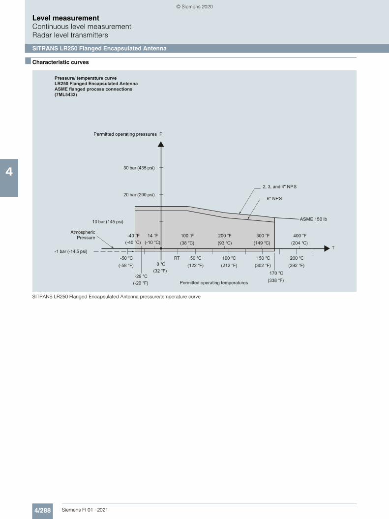
4/288 Siemens FI 01 · 2021
Level measurementContinuous level measurementRadar level transmitters
SITRANS LR250 Flanged Encapsulated Antenna
4
■ Characteristic curves
SITRANS LR250 Flanged Encapsulated Antenna pressure/temperature curve
Pressure/ temperature curveLR250 Flanged Encapsulated AntennaASME flanged process connections(7ML5432)
Permitted operating pressures
AtmosphericPressure
Permitted operating temperatures
2, 3, and 4" NPS
50 °C(122 °F)
10 bar (145 psi)
RT-50 °C(-58 °F)
-29 °C(-20 °F)
0 °C(32 °F)
20 bar (290 psi)
30 bar (435 psi)
100 °C(212 °F)
150 °C(302 °F)
200 °C(392 °F)
T-1 bar (-14.5 psi)
100 °F(38 °C)
14 °F(-10 °C)
-40 °F(-40 °C)
200 °F(93 °C)
300 °F(149 °C)
400 °F(204 °C)
P
ASME 150 lb
6" NPS
170 °C(338 °F)
© Siemens 2020

4/289Siemens FI 01 · 2021
■ Characteristic curves (continued)
Level measurementContinuous level measurement
Radar level transmitters
SITRANS LR250 Flanged Encapsulated Antenna
4
SITRANS LR250 Flanged Encapsulated Antenna pressure/temperature curve
SITRANS LR250 Flanged Encapsulated Antenna pressure/temperature curve
Pressure/ temperature curveLR250 Flanged Encapsulated AntennaEN 1092-1 flanged process connections(7ML5432)
Permitted operating temperatures
Permitted operating pressures
Atmosphericpressure
50 °C(122 °F)
10 bar (145 psi)
RT-50 °C(-58 °F)
-29 °C(-20 °F)
0 °C(32 °F)
20 bar (290 psi)
30 bar (435 psi)
100 °C(212 °F)
150 °C(302 °F)
200 °C(392 °F)
T-1 bar (-14.5 psi)
100 °F(38 °C)
14 °F(-10 °C)
-40 °F(-40 °C)
200 °F(93 °C)
300 °F(149 °C)
400 °F(204 °C)
P
PN 16
DN 50, DN 80
DN 100
DN 150
170 °C(338 °F)
(38 )
Pressure/ temperature curveLR250 Flanged Encapsulated AntennaJIS B 2220 flanged process connections(7ML5432)
Permitted operating temperatures
Permitted operating pressures
Atmosphericpressure
P
50 (122 )
10 bar (145 psi)
-50 (-58 )
-29 (-20 )
0 (32 )
20 bar (290 psi)
30 bar (435 psi)
100 (212 )
150
170 120
(302 )
(338 )(248 )
200 (392 )
-1 bar (-14.5 psi)
10K
150A
100A
50A, 80A
100 14 (-10 )
-40 (-40 )
200 (93 )
300 (149 )
400 (204 )
© Siemens 2020
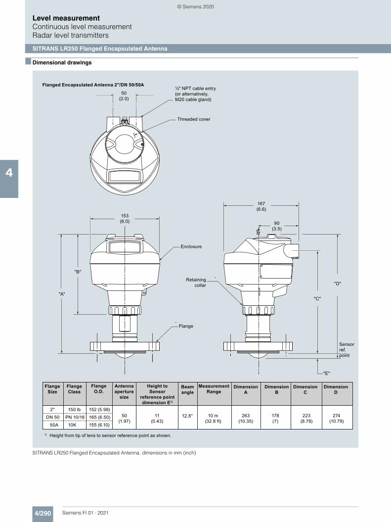
4/290 Siemens FI 01 · 2021
Level measurementContinuous level measurementRadar level transmitters
SITRANS LR250 Flanged Encapsulated Antenna
4
■ Dimensional drawings
SITRANS LR250 Flanged Encapsulated Antenna, dimensions in mm (inch)
see LR250_E_Installation.cdr for dim. values.
2"50
(1.97)10K
PN 10/16
150 lb
Beamangle
FlangeSize
Antennaaperture
size
Height to Sensor
reference pointdimension E1)
FlangeClass
DN 50
50A
FlangeO.D.
152 (5.98)
165 (6.50)
155 (6.10)
11(0.43)
12.8°
MeasurementRange
10 m(32.8 ft)
DimensionA
DimensionB
DimensionC
DimensionD
263(10.35)
178(7)
223(8.78)
274(10.79)
Flange
Enclosure
½" NPT cable entry (or alternatively, M20 cable gland)
Threaded cover
153(6.0)
50(2.0)
"A"
"B"
167(6.6)
90(3.5)
Retaining collar
"C"
"D"
"E"
Sensor ref. point
Flanged Encapsulated Antenna 2"/DN 50/50A
1) Height from tip of lens to sensor reference point as shown.
© Siemens 2020

4/291Siemens FI 01 · 2021
■ Dimensional drawings (continued)
Level measurementContinuous level measurement
Radar level transmitters
SITRANS LR250 Flanged Encapsulated Antenna
4
SITRANS LR250 Flanged Encapsulated Antenna, dimensions in mm (inch)
½" NPT cable entry (or alternatively, M20 cable gland)
Threaded cover
Flange
Enclosure
Retaining collar
Sensor ref. point
see LR250_E_Installation.cdr for dim. values.
3"75
(2.95)10KPN 10/16
150 lb
Beam angle
FlangeSize
Antennaaperture
size
Height to Sensor
reference pointdimension E1)
FlangeClass
DN 8080A
FlangeO.D.
190 (7.48)200 (7.87)185 (7.28)
15(0.59)
9.6°
MeasurementRange
20 m(65.6 ft)
DimensionA
DimensionB
DimensionC
DimensionD
328 (12.91)
178 (7)
288(11.34)
343 (13.54)
4"75
(2.95)10K
PN 10/16150 lb
DN 100100A
230 (9.06)220 (8.66)210 (8.27)
13(0.51)
9.6° 20 m(65.6 ft)
328(12.91)
178(7)
288(11.34)
343(13.50)
6"75
(2.95)10K
PN 10/16150 lb
DN 150150A
280 (11.02)285 (11.25)280 (11.02)
15(0.59)
9.6° 20 m(65.6 ft)
333(13.11)
178(7)
293(11.54)
348(13.70)
Flanged Encapsulated Antenna 3"/DN 50/80A or greater
1) Height from tip of lens to sensor reference point as shown.
153(6.0)
50(2.0)
"A"
"B"
167(6.6)
90(3.5)
"C"
"D"
"E"
© Siemens 2020

4/292 Siemens FI 01 · 2021
Level measurementContinuous level measurementRadar level transmitters
SITRANS LR250 Flanged Encapsulated Antenna
4
■ Circuit diagrams
SITRANS LR250 connections
Part number: 7ML1930-1BK
Hand Programmer
DC terminal shall be supplied from a source providing electrical isolation between the input and output, to meet the applicable safety requirements of IEC 61010-1.
Notes:1.
All field wiring must have insulation suitable for rated input voltages.2.Use shielded twisted pair cable (14 ... 22 AWG) for HART version.3.Separate cables and conduit may be required to conform to standard instrumentation wiring practices or electrical codes.4.
Connect the wires to the terminals as shown: the
polarity is identified on the terminal block.
Gland may or may not be provided depending on
approval option.
Shield for HART, PROFIBUS PA , and FOUNDATION Fieldbus Intrinsically Safe versions only.
© Siemens 2020

4/293Siemens FI 01 · 2021
Level measurementContinuous level measurement
Radar level transmitters
SITRANS LR250 Hygienic Encapsulated Antenna
4
■ Overview
The SITRANS LR250 Hygienic Encapsulated Antenna is a 2-wire 25 GHz pulse radar level transmitter with sanitary and hygienic approvals for continuous monitoring of liquids, slurries, and pastes within the food, beverage, chemical, and pharmaceutical industries to a range of 20 m (66 ft) (antenna dependent).
Picture shown with accessories sold separately.
■ Benefits
• Fully encapsulated horn antenna design with FDA approved and USP Class VI compliant, TFM 1600 PTFE lens
• < 0.8 μ Ra surface finish for maximum cleanability and hygiene requirements commonly required in sanitary environments
• Chemically resistant TFM 1600 PTFE lens is also suitable for aggressive or corrosive materials
• Approved device in accordance with 3-A, EHEDG EL Class I and/or EHEDG EL Aseptic Class I
• Cost effective replacement for transmitters made of exotic materials
• Graphical local user interface (LUI) makes operation simple with plug-and-play set-up using the intuitive Quick Start Wizard
• Industry standard process connections including ISO 2852, DIN 11851, DIN 11864-1, DIN 11864-2, DIN 11864-3, and Tuchenhagen Varivent Type F and N
• LUI displays echo profiles for diagnostic support• 25 GHz high frequency and 2 inch (50 mm) process
connection/antenna allow for easy mounting• Insensitive to mounting location and obstructions, and less
sensitive to nozzle interference• Communication using HART, PROFIBUS PA, or FOUNDATION
Fieldbus• Process Intelligence signal processing for improved
measurement reliability and Auto False-Echo Suppression of fixed obstructions
• Programming using infrared Intrinsically Safe handheld programmer or over a network using SIMATIC PDM, Emerson AMS, or Field Device Tools, such as PACTware or Fieldcare via SITRANS DTM.
• Functional Safety (SIL 2). Device suitable for use in accordance with IEC 61508 and IEC 61511
■ Application
SITRANS LR250 includes a graphical local user interface (LUI) that improves set-up and operation by including an intuitive Quick Start Wizard, and echo profile displays for diagnostic support. Startup is easy using the Quick Start wizard with few parameters required for basic operation.
The 25 GHz frequency creates a narrow, focused beam allowing for smaller antenna options and decreasing sensitivity to obstructions.
SITRANS LR250’s unique design allows safe and simple programming using the Intrinsically Safe handheld programmer without having to open the instrument’s lid.
SITRANS LR250 measures superbly in small vessels and in tanks/vessels up to 20 m (66 ft) on materials with dk > 1.6.• Key Applications: applications within the food, beverage,
chemical and pharmaceutical industries where sanitary, aseptic, or hygienic approvals are required or easy in-stall/clean flush antennas are preferable, such as ice cream, fruit juice, milk, beer, and pharmaceutical or chemical additives and ingredients.
■ Configuration
LR250 Hygienic Encapsulated Antenna, dimensions in mm (inch)
9.6°
Mounting on vessel Mounting on a nozzle
Installation
Beam angle is the width of the cone where the energy density is half of the peak energy density.
Note:•
The peak energy density is directly in front of and in line with the antenna.
•
There is a signal transmitted outside of the beam angle; therefore false targets may be detected.
•
3"/DN 80/80A or larger
Nozzles should be maximum l/d ratio 1:1 (Eg. 50 mm length, 50 mm diameter)
12.8°
l
d
© Siemens 2020

4/294 Siemens FI 01 · 2021
Level measurementContinuous level measurementRadar level transmitters
SITRANS LR250 Hygienic Encapsulated Antenna
4
■ Technical specifications
Mode of Operation
Measuring principle Radar level measurement
Frequency K-band (25.0 GHz)
Minimum measuring range 50 mm (2 inch) from end of antenna
Maximum measuring range 20 m (66 ft)
Output
HART Version 5.1• Analog output 4 ... 20 mA• Accuracy ± 0.02 mA• Fail-safe • Programmable as high low or hold
(loss of echo)• NE 43 programmable
PROFIBUS PA Profile 3.01• Function blocks 2 Analog Input (AI)
FOUNDATION Fieldbus H1• Functionality Basic or LAS• Version ITK 5.2.0• Function blocks 2 Analog Input (AI)
Performance (according to reference conditions IEC60770-1)
Maximum measured error • > 500 mm from sensor reference point: 3 mm (0.118 inch)
• < 500 mm from sensor reference point: 25 mm (1 inch)
Influence of ambient temperature < 0.003 %/K
Rated operating conditions
Installation conditions• Location Indoor/outdoor
Ambient conditions (enclosure)• Ambient temperature -40 ... +80 °C (-40 ... +176 °F)• Storage temperature -40 ... +80 °C (-40 ... +176 °F)• Installation category I• Pollution degree 4
Medium conditions
Dielectric constant εr ≥ 1.6 (antenna dependent)
Process temperature -40 ... +170 °C (-40 ... +338 °F) at process connection
Process pressure See Pressure/Temperature curves for more information
Design
Enclosure• Material Aluminum, polyester powder coated• Cable inlet 2 x M20 x 1.5 or 2 x ½" NPT
Degree of protection Type 4X/NEMA 4X, Type 6/NEMA 6, IP67, IP68
Weight (dependent on process connection)
• Approx. 4.7 kg (10.4 lb) for 2" ISO 2852 (smallest size)
• Approx. 7.9 kg (17.4 lb) for DN 100 DIN 11864-2 (largest size)
Display (local) Graphic local user interface including quick start wizard and echo profile display
Antenna• Material Stainless steel 316L (1.4435 or
1.4404) and TFM 1600 PTFE Lens (lens is the only wetted part)
• Lens surface finish (Ra) 0.8 μm
Process connections
Hygienic/Sanitary connections • 2", 3" & 4" Sanitary Clamp according to ISO 2852
• DN 50, DN 80 & DN 100 Aseptic/Hygienic threaded to DIN 11864-1 [Form A]
• DN 50, DN 80 & DN 100 Aseptic/Hygienic flanged to DIN 11864-2 [Form A]
• DN 50, DN 80 & DN 100 Aseptic/Hygienic Clamp according to DIN 11864-3 [Form A]
• DN 50, DN 80 & DN 100 Hygienic Union according to DIN 11851
• Type F (50 mm) & Type N (68 mm) Tuchenhagen Varivent
Power supply
4 ... 20 mA/HART Nominal 24 V DC (max. 30 V DC) with max. 550 Ω
PROFIBUS PA • 15 mA• Per IEC 61158-2
FOUNDATION Fieldbus • 20.0 mA• Per IEC 61158-2
Certificates and approvals
General CSAUS/C, CE, FM, RCM
Radio FCC, Industry Canada, RED, RCM
Hazardous• Explosion Proof (Brazil) INMETRO Ex d ia mb IIC T4 Ga/Gb,
Ex ia ta IIIC T100 °C Da• Increased Safety (Brazil) INMETRO Ex e ia mb IIC T4 Ga/Gb,
Ex ia ta IIIC T100 °C Da• Intrinsically Safe (Brazil) INMETRO Ex ia IIC T4 Ga, Ex ia ta
IIIC T100 °C Da• Explosion Proof (Canada/USA) CSA/FM Class I, Div. 1, Groups A, B,
C, D; Class II, Div. 1, Groups E, F, G; Class III T4
• Intrinsically Safe (Canada/USA) CSA/FM Class I, Div. 1, Groups A, B, C, D; Class II, Div. 1, Groups E, F, G; Class III T4
• Non-incendive (Canada/USA) CSA/FM Class I, Div. 2, Groups A, B, C, D T5
• Flame Proof/Increased Safety (China)
NEPSI Ex d ia mb IIC T4 Ga/Gb, Ex e ia mb IIC T4 Ga/Gb, Ex iaD tD A20 IP67 T100 ºC
• Intrinsically Safe (China) NEPSI Ex ia IIC T4 Ga, Ex iaD tD A20 IP67 T100 ºC
• Non-sparking (China) NEPSI Ex nA IIC T4 Gc• Intrinsically Safe (Europe) ATEX II 1G Ex ia IIC T4 Ga ATEX II 1D
Ex ia ta IIIC T100 °C Da• Non-sparking (Europe) ATEX II 3G Ex nA IIC T4 Gc• Flame Proof (International/Europe) IECEx/ATEX II 1/2 GD, 1D, 2D Ex d
mb ia IIC T4 Ga/Gb, Ex ia ta IIC T100 °C Da
• Increased Safety (International/Europe)
IECEx/ATEX II 1/2 GD, 1D, 2D, Ex e mb ia IIC T4 Ga/Gb, Ex ia ta IIIC T100 °C Da
• Intrinsically Safe (International) IECEx/ATEX II 1 G Ex ia IIC T4 Ga, IECEX/ATEX II 1D Ex ia ta IIIC T100 °C Da
• Explosion Proof (Russia/Kazakhstan)
EAC Ex d
• Increased Safety (Russia/Kazakhstan)
EAC Ex e
• Intrinsically Safe (Russia/Kazakhstan)
EAC Ex ia
Hygienic/Sanitary EHEDG EL Class I
EHEDG EL Aseptic Class I
© Siemens 2020

4/295Siemens FI 01 · 2021
■ Technical specifications (continued)
Level measurementContinuous level measurement
Radar level transmitters
SITRANS LR250 Hygienic Encapsulated Antenna
4
Programming
Intrinsically Safe Siemens handheld programmer
Infrared receiver
• Approvals for handheld programmer IS model: ATEX II 1 GD Ex ia IIC T4 Ga Ex ia D 20 T135 °C Ta = -20 ... +50 °C CSA/FM Class I, II, III, Div. 1, Groups A, B, C, D, E, F, G, T6 Ta = 50 °C IECEx SIR 09.0073
Handheld communicator HART communicator 375/475
PC • SIMATIC PDM• Emerson AMS• SITRANS DTM (for connection into
FDT, such as PACTware or Fieldcare)
Display (local) Graphic local user interface including quick start wizard and echo profile displays
© Siemens 2020
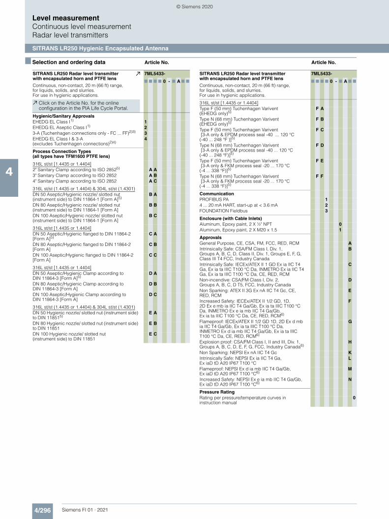
4/296 Siemens FI 01 · 2021
Level measurementContinuous level measurementRadar level transmitters
SITRANS LR250 Hygienic Encapsulated Antenna
4
■ Selection and ordering data Article No. Article No.
SITRANS LR250 Radar level transmitter with encapsulated horn and PTFE lens
Continuous, non-contact, 20 m (66 ft) range, for liquids, solids, and slurries. For use in hygienic applications.
7ML5433-
7 7 7 7 0 - 7 A 7 7
Click on the Article No. for the online configuration in the PIA Life Cycle Portal.
Hygienic/Sanitary ApprovalsEHEDG EL Class I1) 1EHEDG EL Aseptic Class I1) 23-A (Tuchenhagen connections only - FC ... FF)2)3) 3EHEDG EL Class I & 3-A (excludes Tuchenhagen connections)2)4)
4
Process Connection Types (all types have TFM1600 PTFE lens)
316L st/st [1.4435 or 1.4404]2" Sanitary Clamp according to ISO 28525) A A3" Sanitary Clamp according to ISO 2852 A B4" Sanitary Clamp according to ISO 2852 A C
316L st/st (1.4435 or 1.4404) & 304L st/st (1.4301)DN 50 Aseptic/Hygienic nozzle/ slotted nut (instrument side) to DIN 11864-1 [Form A]5)
B A
DN 80 Aseptic/Hygienic nozzle/ slotted nut (instrument side) to DIN 11864-1 [Form A]
B B
DN 100 Aseptic/Hygienic nozzle/ slotted nut (instrument side) to DIN 11864-1 [Form A]
B C
316L st/st [1.4435 or 1.4404]DN 50 Aseptic/Hygienic flanged to DIN 11864-2 [Form A]5)
C A
DN 80 Aseptic/Hygienic flanged to DIN 11864-2 [Form A]
C B
DN 100 Aseptic/Hygienic flanged to DIN 11864-2 [Form A]
C C
316L st/st [1.4435 or 1.4404]DN 50 Aseptic/Hygienic Clamp according to DIN 11864-3 [Form A]5)
D A
DN 80 Aseptic/Hygienic Clamp according to DIN 11864-3 [Form A]
D B
DN 100 Aseptic/Hygienic Clamp according to DIN 11864-3 [Form A]
D C
316L st/st (1.4435 or 1.4404) & 304L st/st (1.4301)DN 50 Hygienic nozzle/ slotted nut (instrument side) to DIN 118515)
E A
DN 80 Hygienic nozzle/ slotted nut (instrument side) to DIN 11851
E B
DN 100 Hygienic nozzle/ slotted nut (instrument side) to DIN 11851
E C
316L st/st [1.4435 or 1.4404]Type F (50 mm) Tuchenhagen Varivent (EHEDG only)5)
F A
Type N (68 mm) Tuchenhagen Varivent (EHEDG only)5)
F B
Type F (50 mm) Tuchenhagen Varivent [3-A only & EPDM process seal -40 ... 120 °C (-40 ... 248 °F )]5)
F C
Type N (68 mm) Tuchenhagen Varivent [3-A only & EPDM process seal -40 ... 120 °C (-40 ... 248 °F)]5)
F D
Type F (50 mm) Tuchenhagen Varivent [3-A only & FKM process seal -20 ... 170 °C(-4 ... 338 °F)]5)
F E
Type N (68 mm) Tuchenhagen Varivent [3-A only & FKM process seal -20 ... 170 °C (-4 ... 338 °F)]5)
F F
CommunicationPROFIBUS PA 14 ... 20 mA HART, start-up at < 3.6 mA 2FOUNDATION Fieldbus 3
Enclosure (with Cable Inlets)Aluminum, Epoxy paint, 2 X ½" NPT 0Aluminum, Epoxy paint, 2 X M20 x 1.5 1
ApprovalsGeneral Purpose, CE, CSA, FM, FCC, RED, RCM AIntrinsically Safe: CSA/FM Class I, Div. 1, Groups A, B, C, D, Class II, Div. 1, Groups E, F, G, Class III T4 FCC, Industry Canada
B
Intrinsically Safe: IECEx/ATEX II 1 GD Ex ia IIC T4 Ga, Ex ia ta IIIC T100 °C Da, INMETRO Ex ia IIC T4 Ga, Ex ia ta IIIC T100 °C Da, CE, RED, RCM
C
Non-incendive: CSA/FM Class I, Div. 2, Groups A, B, C, D T5, FCC, Industry Canada
D
Non Sparking: ATEX II 3G Ex nA IIC T4 Gc, CE, RED, RCM
E
Increased Safety: IECEx/ATEX II 1/2 GD, 1D, 2D Ex e mb ia IIC T4 Ga/Gb, Ex ia ta IIIC T100 °C Da, INMETRO Ex e ia mb IIC T4 Ga/Gb, Ex ia ta IIIC T100 °C Da, CE, RED, RCM6)
F
Flameproof: IECEx/ATEX II 1/2 GD 1D, 2D Ex d mb ia IIC T4 Ga/Gb, Ex ia ta IIIC T100 °C Da, INMETRO Ex d ia mb IIC T4 Ga/Gb, Ex ia ta IIIC T100 °C Da, CE, RED, RCM6)
G
Explosion proof: CSA/FM Class I, II and III, Div. 1, Groups A, B, C, D, E, F, G, FCC, Industry Canada6)
H
Non Sparking: NEPSI Ex nA IIC T4 Gc KIntrinsically Safe: NEPSI Ex ia IIC T4 Ga, Ex iaD tD A20 IP67 T100 °C
L
Flameproof: NEPSI Ex d ia mb IIC T4 Ga/Gb, Ex iaD tD A20 IP67 T100 °C6)
M
Increased Safety: NEPSI Ex e ia mb IIC T4 Ga/Gb, Ex iaD tD A20 IP67 T100 °C6)
N
Pressure RatingRating per pressure/temperature curves in instruction manual
0
SITRANS LR250 Radar level transmitter with encapsulated horn and PTFE lens
Continuous, non-contact, 20 m (66 ft) range, for liquids, solids, and slurries. For use in hygienic applications.
7ML5433-
7 7 7 7 0 - 7 A 7 7
© Siemens 2020

4/297Siemens FI 01 · 2021
■ Selection and ordering data Order code Article No
Level measurementContinuous level measurement
Radar level transmitters
SITRANS LR250 Hygienic Encapsulated Antenna
4
1) Available with Process connection options AA ... FB & FF only.2) Available with Approval options A, B, C, L only.3) Available with Process connections FC ... FF only.4) Available with Process connection options AA ... EC & FF only.5) Max. range 10 m (32.8 ft), dk > 3 [20 m (66 ft) and dk > 1.6 if installed in a
stillpipe].6) Applicable with Communication option 2 only.7) Available with Enclosure option 1 only.8) Available with Communication options 1 and 3 only.9) Available with Enclosure option 0 only.10)Available with Approval options A, B, C, D, E, K, L only.
Further designs
Please add "-Z" to Article No. and specify Order code(s).
Electrical Connection cable entry:
Plug M12 (IP 67 rating) with mating connector2)7)8) A50
Plug 7/8" (IP 67 rating) with mating Connector2)8)9) A55
Test Certificates
Manufacturer's Test Certificate M to DIN 55350, Part 18 and to ISO 9000
C11
Material inspection Certificate 3.1 of EN 10204 C12
Functional Safety
Functional Safety (SIL 2). Device suitable for use in accordance with IEC 61508 and IEC 615116)10)
C20
Namur
Namur NE43 compliant, device preset to failsafe < 3.6 mA6)
N07
Tagging
Stainless steel tag [69 mm x 50 mm (2.71 x 1.97 inch)]
Measuring-point number / identification (max. 27 characters) specify in plain text
Y15
Operating Instructions
All literature is available to download for free, in a range of languages, at
http://www.siemens.com/processinstrumentation/documentation
Accessories
Handheld programmer, Intrinsically safe, EEx ia (LUI enabled)
7ML1930-1BK
HART modem/USB(for use with a PC and SIMATIC PDM)
7MF4997-1DB
One metallic cable gland M20 x 1.5, rated -40 ... +80 °C (-40 ... +176 °F), HART (two are required)6)
7ML1930-1AP
One metallic cable gland M20 x 1.5, rated -40 ... +80 °C (-40 ... +176 °F), PROFIBUS PA and FOUNDATION Fieldbus (two are required)8)
7ML1930-1AQ
SITRANS RD100, loop powered display -see Chapter 7
7ML5741-.....-.
SITRANS RD150, remote digital display for 4 ... 20 mA and HART devices - see Chapter 7
7ML5742-.....-....
SITRANS RD200, universal input display with Modbus conversion - see Chapter 7
7ML5740-.....-..
SITRANS RD300, dual line display with totalizer and linearization curve and Modbus conversion - see Chapter 7
7ML5744-.....-..
For applicable back up point level switch - see point level measurement section
© Siemens 2020

4/298 Siemens FI 01 · 2021
■ Selection and ordering data Article No. Article No.
Level measurementContinuous level measurementRadar level transmitters
SITRANS LR250 Hygienic Encapsulated Antenna
4
SITRANS LR250 hygienic encapsulated Specials
11)Class II for low fat applications when EPDM seal used on DIN11851
For "Electronics Head only" follow the standard configuration and choose YY option on positions 9 and 10 of the full part number.
For example: 7ML5433-1YY20-1AA0 will order an electronics head for the following:
EHEDG EL Class 1 approval, 4 ... 20 mA HART, M20 cable entries, General purpose Haz Loc approval, pressure rating as per manual.
Spare Lens Kits (Lens and O-ring)
Kit, 2 inch, ISO 2852, HEA, Lens, silicone secondary O-ring
A5E32572731
Kit, 3 inch, ISO 2852, HEA, Lens, silicone secondary O-ring
A5E32572745
Kit, 4 inch, ISO 2852, HEA, Lens, silicone secondary O-ring
A5E32572747
Kit, DN 50, DIN 11851, HEA, Lens, silicone secondary O-ring
A5E32572758
Kit, DN 80, DIN 11851, HEA, Lens, silicone secondary O-ring
A5E32572770
Kit, DN 100, DIN 11851, HEA, Lens, silicone secondary O-ring
A5E32572772
Kit, DN 50, DIN 11864-1, HEA, Lens, silicone secondary O-ring
A5E32572773
Kit, DN 80, DIN 11864-1, HEA, Lens, silicone secondary O-ring
A5E32572779
Kit, DN 100, DIN 11864-1, HEA, Lens, silicone secondary O-ring
A5E32572782
Kit, DN 50, DIN 11864-2/3, HEA, Lens, silicone secondary O-ring
A5E32572785
Kit, DN 80, DIN11864-2/3, HEA, Lens, silicone secondary O-ring
A5E32572790
Kit, DN 100, DIN11864-2/3, HEA, Lens, silicone secondary O-ring
A5E32572791
Kit, Tuchenhagen, Type F, HEA, Lens, silicone secondary O-ring
A5E32572794
Kit, Tuchenhagen, Type N, HEA, Lens, silicone secondary O-ring
A5E32572795
Accessories (customer side process connection and FKM and EPDM seal for each size and type)
Kit DN50 DIN11864-1 GS Form A tank connection, EPDM Seal Class II
A5E32910638
Kit, DN80 DIN11864-1 GS Form A tank connection, EPDM Seal Class II
A5E32910649
Kit, DN100 DIN11864-1 GS Form A tank connection, EPDM Seal Class II
A5E32910657
Kit DN50 DIN11864-1 GS Form A tank connection, FKM Seal Class I
A5E32910658
Kit, DN80 DIN11864-1 GS Form A tank connection, FKM Seal Class I
A5E32910671
Kit, DN100 DIN11864-1 GS Form A tank connection, FKM Seal Class I
A5E32910681
Kit 2" ISO2852 tank connection, Clamp, Cleanable EPDM Seal Class II
A5E32910686
Kit 3" ISO2852 tank connection, Clamp, Cleanable EPDM Seal Class II
A5E32910697
Kit 4" ISO2852 tank connection, Clamp, Cleanable EPDM Seal Class II
A5E32910708
Kit 2" ISO2852 tank connection, Clamp, Cleanable FKM Seal
A5E32910718
Kit 3" ISO2852 tank connection, Clamp, Cleanable FKM Seal
A5E32910723
Kit 4" ISO2852 tank connection, Clamp, Cleanable FKM Seal
A5E32910734
Kit DN50 DIN11851 SC Tank connection, EPDM Seal Class II11)
A5E32910746
Kit DN80 DIN11851 SC Tank connection, EPDM Seal Class II11)
A5E32910771
Kit DN100 DIN11851 SC Tank connection, EPDM Seal Class II11)
A5E32910780
Kit DN50 DIN11851 SC Tank connection, FKM Seal Class II
A5E32910784
Kit DN80 DIN11851 SC Tank connection, FKM Seal Class II
A5E32910789
Kit DN100 DIN11851 SC Tank connection, FKM Seal Class II
A5E32910790
Kit DN50 DIN11864-2 Form A tank connection, M8 Hardware (nut/bolt/washer), EPDM Seal Class II
A5E32910791
Kit DN80 DIN11864-2 Form A tank connection, M10 Hardware (nut/bolt/washer), EPDM Seal Class II
A5E32910793
Kit DN100 DIN11864-2 Form A tank connection, M10 Hardware (nut/bolt/washer), EPDM Seal Class II
A5E32910799
Kit DN50 DIN11864-2 Form A tank connection, M8 Hardware (nut/bolt/washer), FKM Seal Class I
A5E32910805
Kit DN80 DIN11864-2 Form A tank connection, M10 Hardware (nut/bolt/washer), FKM Seal Class I
A5E32910809
Kit DN100 DIN11864-2 Form A tank connection, M10 Hardware (nut/bolt/washer), FKM Seal Class I
A5E32910812
Kit DN50 DIN11864-3 Form A tank connection, Clamp, EPDM Seal Class II
A5E32910813
Kit DN80 DIN11864-3 Form A tank connection, Clamp, EPDM Seal Class II
A5E32910814
Kit DN100 DIN11864-3 Form A tank connection, Clamp, EPDM Seal Class II
A5E32910815
Kit DN50 DIN11864-3 Form A tank connection, Clamp, FKM Seal Class I
A5E32910816
Kit DN80 DIN11864-3 Form A tank connection, Clamp, FKM Seal Class I
A5E32910817
Kit DN100 DIN11864-3 Form A tank connection, Clamp, FKM Seal Class I
A5E32910818
Kit Type F, Tuchenhagen, Clamp, EPDM Seal Class II (EHEDG only) - no tank connection
A5E33489537
Kit Type N, Tuchenhagen, Clamp, EPDM Seal Class II (EHEDG only) - no tank connection
A5E33489543
Kit Type F, Tuchenhagen, Clamp, FKM Seal Class I (EHEDG only) - no tank connection
A5E33489828
Kit Type N, Tuchenhagen, Clamp, FKM Seal Class I (EHEDG only) - no tank connection
A5E33489830
Ex-proof plugs
Ex-proof plugs kit, 1/2" NPT, qty 5 A5E39979991
Ex-proof plugs kit, M20, qty 5 A5E39979992
© Siemens 2020

4/299Siemens FI 01 · 2021
Level measurementContinuous level measurement
Radar level transmitters
SITRANS LR250 Hygienic Encapsulated Antenna
4
■ Characteristic curves
SITRANS LR250 Hygienic Encapsulated Antenna, process pressure/temperature rating curve
SITRANS LR250 Hygienic Encapsulated Antenna, process pressure/temperature rating curve
1
1
50°C(122°F)
10 bar (145 psi)
RT-50°C(-58°F)
-29°C 170°C(-20°F) (338°F)
0°C(32°F)
20 bar (290 psi)
30 bar (435 psi)
P
100°C(212°F)
150°C(302°F)
200°C(392°F)
T-1 bar (-14.5 psi)
100°F(38°C)
14°F(-10°C)
-40°F(-40°C)
200°F(93°C)
300°F(149°C)
400°F(204°C)
AtmosphericP Allowable operating pressuresT Allowable operating temperatures
DIN 11851 Sanitary/Hygienic nozzle/slotted nut: DN 50, DN 80, and DN 100DIN 11864-1 Aseptic/Hygienic nozzle/slotted nut: DN 50, DN 80, and DN 100
1
1
T50°C
(122°F)
10 bar (145 psi)
RT-50°C(-58°F)
-29°C170°C
(-20°F)(338°F)
0°C(32°F)
20 bar (290 psi)
30 bar (435 psi)
100°C(212°F)
150°C(302°F)
200°C(392°F)
-1 bar (-14.5 psi)
100°F(38°C)
14°F(-10°C)
-40°F(-40°C)
200°F(93°C)
300°F(149°C)
400°F(204°C)
P
AtmosphericP Allowable operating pressuresT Allowable operating temperatures
DIN 11864-2 Aseptic/Hygienic flanged: DN 50, DN 80, and DN 100
Note: For pressure applications, all attachment hardware must be suitably rated.
© Siemens 2020

4/300 Siemens FI 01 · 2021
■ Characteristic curves (continued)
Level measurementContinuous level measurementRadar level transmitters
SITRANS LR250 Hygienic Encapsulated Antenna
4
SITRANS LR250 Hygienic Encapsulated Antenna, process pressure/temperature rating curve
1
1
50°C(122°F)
10 bar (145 psi)
RT-50°C(-58°F)
-29°C 170°C(-20°F) (338°F)
0°C(32°F)
20 bar (290 psi)
30 bar (435 psi)
100°C(212°F)
150°C(302°F)
200°C(392°F)
-1 bar (-14.5 psi)
100°F(38°C)
14°F(-10°C)
-40°F(-40°C)
200°F(93°C)
300°F(149°C)
400°F(204°C)
P
T
DIN 11864-3 Aseptic/Hygienic clamp: DN 50, DN 80, and DN 100IS0 2852 Sanitary/Hygienic clamp: 2", 3", and 4"Tuchenhagen Varivent face seal clamp: Type N (68 mm) and Type F (50 mm)
Atmospheric
P Allowable operating pressures T Allowable operating temperatures
Note: For pressure applications, all clamps must be rated accordingly.
© Siemens 2020

4/301Siemens FI 01 · 2021
Level measurementContinuous level measurement
Radar level transmitters
SITRANS LR250 Hygienic Encapsulated Antenna
4
■ Dimensional drawings
SITRANS LR250 Hygienic Encapsulated Antenna (2" ISO 2852 sanitary clamp), dimensions in mm (inch)
1/2" NPT cable entry (or alternatively, M20 cable gland)
Threaded cover
Enclosure
Retaining collar
Sensorreferencepoint
Process connection
Hygienic encapsulated antenna (2" ISO 2852 sanitary clamp)
50.0(2.00)
153.0(6.02)
167.0(6.57)
178.0(7.01)
90.0(3.54)
Ø64.0(2.52)
225.7(8.89)
274.2(10.80)
11.0(0.43)
Ø44.0(1.73)
© Siemens 2020

4/302 Siemens FI 01 · 2021
■ Dimensional drawings (continued)
Level measurementContinuous level measurementRadar level transmitters
SITRANS LR250 Hygienic Encapsulated Antenna
4
SITRANS LR250 Hygienic Encapsulated Antenna (3" ISO 2852 sanitary clamp), dimensions in mm (inch)
1/2" NPT cable entry (or alternatively, M20 cable gland)
Threaded cover
Enclosure
Retaining collar
Process connection Sensor
referencepoint
Hygienic encapsulated antenna (3" ISO 2852 sanitary clamp)
50.0 (2.00)
153.0(6.02)
167.0(6.57)
178.0(7.01)
90.0(3.54)
Ø91.0(3.58)
343.2(13.51)
291.2(11.46)
14.5(0.57)Ø74.7
(2.94)
© Siemens 2020

4/303Siemens FI 01 · 2021
■ Dimensional drawings (continued)
Level measurementContinuous level measurement
Radar level transmitters
SITRANS LR250 Hygienic Encapsulated Antenna
4
SITRANS LR250 Hygienic Encapsulated Antenna (4" ISO 2852 sanitary clamp), dimensions in mm (inch)
1/2" NPT cable entry (or alternatively, M20 cable gland)
Threaded cover
Enclosure
Retaining collar
Process connection
Sensorreferencepoint
Hygienic encapsulated antenna (4" ISO 2852 sanitary clamp)
50.0 (2.00)
153.0(6.02)
167.0(6.57)
178.0(7.01)
90.0(3.54)
Ø119.0(4.69)
343.2(13.51)
291.2(11.46)
14.5(0.57)
Ø74.7(2.94)
© Siemens 2020

4/304 Siemens FI 01 · 2021
■ Dimensional drawings (continued)
Level measurementContinuous level measurementRadar level transmitters
SITRANS LR250 Hygienic Encapsulated Antenna
4
SITRANS LR250 Hygienic Encapsulated Antenna (DN 50 nozzle/slotted nut to DIN 11851), dimensions in mm (inch)
1/2" NPT cable entry (or alternatively, M20 cable gland)
Threaded cover
Enclosure
Retaining collar
Threaded nut
Sensorreferencepoint
Hygienic encapsulated antenna (DN 50 nozzle/slotted nut to DIN 11851)
Note: Cut out of process connection and placement of threaded nut are shown for illustrationpurposes only.
50.0 (2.00)
153.0(6.02)
178.0(7.01)
Ø57.6(2.27)
Ø44.0(1.73)
Ø63.7(2.51)
11.0(0.43)
274.2(10.80)
225.7(8.89)
167.0 (6.57)
90.0(3.54)
© Siemens 2020

4/305Siemens FI 01 · 2021
■ Dimensional drawings (continued)
Level measurementContinuous level measurement
Radar level transmitters
SITRANS LR250 Hygienic Encapsulated Antenna
4
SITRANS LR250 Hygienic Encapsulated Antenna (DN 80 nozzle/slotted nut to DIN 11851), dimensions in mm (inch)
1/2" NPT cable entry (or alternatively, M20 cable gland)
Threaded cover
Enclosure
Retaining collar
Threaded nut
Sensorreferencepoint
Hygienic encapsulated antenna (DN 80 nozzle/slotted nut to DIN 11851)
Note: Cut out of process connection and placement of threaded nut are shown for illustrationpurposes only.
50.0 (2.00)
153.0(6.02)
167.0(6.57)
178.0(7.01)
90.0(3.54)
Ø88.6(3.49)
343.2(13.51)
291.2(11.46)
14.5(0.57)
Ø74.7(2.94)
Ø94.7(3.73)
© Siemens 2020

4/306 Siemens FI 01 · 2021
■ Dimensional drawings (continued)
Level measurementContinuous level measurementRadar level transmitters
SITRANS LR250 Hygienic Encapsulated Antenna
4
SITRANS LR250 Hygienic Encapsulated Antenna (DN 100 nozzle/slotted nut to DIN 11851), dimensions in mm (inch)
1/2" NPT cable entry (or alternatively, M20 cable gland)
Threaded cover
Enclosure
Retaining collar
Threaded nut
Sensorreferencepoint
Note: Cut out of process connection and placement of threaded nut are shown for illustrationpurposes only.
Hygienic encapsulated antenna (DN 100 nozzle/slotted nut to DIN 11851)
50.0 (2.00)
153.0(6.02)
167.0(6.57)
178.0(7.01)
90.0(3.54)
Ø107.6(4.24)
343.2(13.51)
291.2(11.46)
14.5(0.57)
Ø74.7(2.94)
Ø113.7(4.48)
© Siemens 2020

4/307Siemens FI 01 · 2021
■ Dimensional drawings (continued)
Level measurementContinuous level measurement
Radar level transmitters
SITRANS LR250 Hygienic Encapsulated Antenna
4
SITRANS LR250 Hygienic Encapsulated Antenna (DN 50 aseptic clamp to DIN 11864-1), dimensions in mm (inch)
1/2" NPT cable entry (or alternatively, M20 cable gland)
Threaded cover
Enclosure
Retaining collar
Threaded nut
Sensorreferencepoint
Hygienic encapsulated antenna (DN 50 aseptic clamp to DIN 11864-1)
Note: Cut out of process connection and placement of threaded nut are shown for illustrationpurposes only.
50.0 (2.00)
153.0(6.02)
167.0 (6.57)
178.0(7.01)
90.0(3.54)
Ø66.9(2.63)
274.2(10.80)
225.7(8.89)
11.0(0.43)
Ø44.0(1.73)
Ø72.0(2.83)
© Siemens 2020

4/308 Siemens FI 01 · 2021
■ Dimensional drawings (continued)
Level measurementContinuous level measurementRadar level transmitters
SITRANS LR250 Hygienic Encapsulated Antenna
4
SITRANS LR250 Hygienic Encapsulated Antenna (DN 80 aseptic clamp to DIN 11864-1), dimensions in mm (inch)
1/2" NPT cable entry (or alternatively, M20 cable gland)
Threaded cover
Enclosure
Retaining collar
Threaded nut
Sensorreferencepoint
Note: Cut out of process connection and placement of threaded nut are shown for illustrationpurposes only.
Hygienic encapsulated antenna (DN 80 aseptic clamp to DIN 11864-1)
50.0 (2.00)
153.0(6.02)
167.0(6.57)
178.0(7.01)
90.0(3.54)
Ø98.9(3.89)
343.4(13.52)
291.3(11.47)
14.5(0.57)
Ø74.7(2.94)
Ø104.0(4.09)
© Siemens 2020

4/309Siemens FI 01 · 2021
■ Dimensional drawings (continued)
Level measurementContinuous level measurement
Radar level transmitters
SITRANS LR250 Hygienic Encapsulated Antenna
4
SITRANS LR250 Hygienic Encapsulated Antenna (DN 100 aseptic clamp to DIN 11864-1), dimensions in mm (inch)
1/2" NPT cable entry (or alternatively, M20 cable gland)
Threaded cover
Enclosure
Retaining collar
Threaded nut
Sensorreferencepoint
Note: Cut out of process connection and placement of threaded nut are shown for illustrationpurposes only.
Hygienic encapsulated antenna (DN 100 aseptic clamp to DIN 11864-1)
50.0 (2.00)
153.0(6.02)
167.0(6.57)
178.0(7.01)
90.0(3.54)
Ø118.9(4.68)
343.4(13.52)
291.3(11.47)
14.5(0.57)
Ø74.7(2.94)
Ø124.0(4.88)
© Siemens 2020

4/310 Siemens FI 01 · 2021
■ Dimensional drawings (continued)
Level measurementContinuous level measurementRadar level transmitters
SITRANS LR250 Hygienic Encapsulated Antenna
4
SITRANS LR250 Hygienic Encapsulated Antenna (DN 50 aseptic flange to DIN 11864-2), dimensions in mm (inch)
1/2" NPT cable entry (or alternatively, M20 cable gland)
Threaded cover
Enclosure
Retaining collar
Sensorreferencepoint
Flange
Note: Cut out of process connection and flange are shown for illustration purposes only.
Hygienic encapsulated antenna (DN 50 aseptic flange to DIN 11864-2)
50.0 (2.00)
153.0(6.02)
167.0 (6.57)
178.0 (7.01)
90.0 (3.54)
Ø63.0(2.48)
225.7 (8.89)
274.2 (10.80)
11.0 (0.43)
Ø44.0(1.73)
Ø94.5(3.72)
© Siemens 2020

4/311Siemens FI 01 · 2021
■ Dimensional drawings (continued)
Level measurementContinuous level measurement
Radar level transmitters
SITRANS LR250 Hygienic Encapsulated Antenna
4
SITRANS LR250 Hygienic Encapsulated Antenna (DN 80 aseptic flange to DIN 11864-2), dimensions in mm (inch)
1/2" NPT cable entry (or alternatively, M20 cable gland)
Threaded cover
Enclosure
Retaining collar
Sensor referencepoint
Flange
Hygienic encapsulated antenna (DN 80 aseptic flange to DIN 11864-2)
Note: Cut out of process connection and flange are shown for illustration purposes only.
50.0 (2.00)
153.0(6.02)
167.0 (6.57)
178.0 (7.01)
90.0 (3.54)
Ø133.0(5.24)
291.2 (11.46)
343.2 (13.51)
14.5 (0.57)
Ø74.7(2.94)Ø94.5(3.72)
© Siemens 2020

4/312 Siemens FI 01 · 2021
■ Dimensional drawings (continued)
Level measurementContinuous level measurementRadar level transmitters
SITRANS LR250 Hygienic Encapsulated Antenna
4
SITRANS LR250 Hygienic Encapsulated Antenna (DN 100 aseptic flange to DIN 11864-2), dimensions in mm (inch)
1/2" NPT cable entry (or alternatively, M20 cable gland)
Threaded cover
Enclosure
Retaining collar
Sensorreferencepoint
Flange
Hygienic encapsulated antenna (DN 100 aseptic flange to DIN 11864-2)
Note: The cut out of the process connection and the flange are shown for illustration purposes only.
50.0 (2.00)
153.0(6.02)
167.0 (6.57)
178.0 (7.01)
90.0 (3.54)
Ø159.0(6.26)
291.2 (11.46)
343.2 (13.51)
14.5 (0.57)
Ø74.7(2.94)
Ø113.5(4.47)
© Siemens 2020

4/313Siemens FI 01 · 2021
■ Dimensional drawings (continued)
Level measurementContinuous level measurement
Radar level transmitters
SITRANS LR250 Hygienic Encapsulated Antenna
4
SITRANS LR250 Hygienic Encapsulated Antenna (DN 50 aseptic clamp to DIN 11864-3), dimensions in mm (inch)
1/2" NPT cable entry (or alternatively, M20 cable gland)
Threaded cover
Enclosure
Retaining collar
Sensorreferencepoint
Process connection
Hygienic encapsulated antenna (DN 50 aseptic clamp to DIN 11864-3)
Note: Cut out of process connection is shown for illustration purposes only.
50.0 (2.00)
153.0(6.02)
167.0 (6.57)
178.0 (7.01)
90.0 (3.54)
225.2(8.87)
273.7 (10.78)
11.0 (0.43)
Ø44.0(1.73)
Ø77.5(3.05)
Ø63.0(2.48)
© Siemens 2020

4/314 Siemens FI 01 · 2021
■ Dimensional drawings (continued)
Level measurementContinuous level measurementRadar level transmitters
SITRANS LR250 Hygienic Encapsulated Antenna
4
SITRANS LR250 Hygienic Encapsulated Antenna (DN 80 aseptic clamp to DIN 11864-3), dimensions in mm (inch)
1/2" NPT cable entry (or alternatively, M20 cable gland)
Threaded cover
Enclosure
Retaining collar
Sensorreferencepoint
Process connection
Hygienic encapsulated antenna (DN 80 aseptic clamp to DIN 11864-3)
Note: Cut out of process connection is shown for illustration purposes only.
50.0 (2.00)
153.0(6.02)
167.0 (6.57)
178.0 (7.01)
90.0 (3.54)
Ø94.5(3.72)
291.2 (11.46)
343.2 (13.51)
14.5 (0.57)
Ø74.7(2.94)
Ø106.0(4.17)
© Siemens 2020

4/315Siemens FI 01 · 2021
■ Dimensional drawings (continued)
Level measurementContinuous level measurement
Radar level transmitters
SITRANS LR250 Hygienic Encapsulated Antenna
4
SITRANS LR250 Hygienic Encapsulated Antenna (DN 100 aseptic clamp to DIN 11864-3), dimensions in mm (inch)
1/2" NPT cable entry (or alternatively, M20 cable gland)
Threaded cover
Enclosure
Retaining collar
Sensorreferencepoint
Process connection
Hygienic encapsulated antenna (DN 100 aseptic clamp to DIN 11864-3)
Note: Cut out of process connection is shown for illustration purposes only.
50.0 (2.00)
153.0(6.02)
167.0 (6.57)
178.0 (7.01)
90.0 (3.54)
Ø113.5(4.47)
291.2 (11.46)
343.2 (13.51)
14.5 (0.57)
Ø74.7(2.94)
Ø130.0(5.12)
© Siemens 2020

4/316 Siemens FI 01 · 2021
■ Dimensional drawings (continued)
Level measurementContinuous level measurementRadar level transmitters
SITRANS LR250 Hygienic Encapsulated Antenna
4
SITRANS LR250 Hygienic Encapsulated Antenna (Tuchenhagen Type F), dimensions in mm (inch)
1/2" NPT cable entry (or alternatively, M20 cable gland)
Threaded cover
Enclosure
Retaining collar
Sensorreferencepoint
Process connection
Hygienic encapsulated antenna (Tuchenhagen Type F, 50 mm)
50.0(2.00)
153.0(6.02)
167.0(6.57)
178.0(7.01)
90.0(3.54)
Ø66.0(2.60)
232.7(9.16)
276.7(10.89)
6.5(0.26)
Ø50.0(2.00)
© Siemens 2020

4/317Siemens FI 01 · 2021
■ Dimensional drawings (continued)
Level measurementContinuous level measurement
Radar level transmitters
SITRANS LR250 Hygienic Encapsulated Antenna
4
SITRANS LR250 Hygienic Encapsulated Antenna (Tuchenhagen Type N), dimensions in mm (inch)
1/2" NPT cable entry (or alternatively, M20 cable gland)
Threaded cover
Enclosure
Retaining collar
Sensorreferencepoint
Process connection
Hygienic encapsulated antenna (Tuchenhagen Type N, 68 mm)
50.0(2.00)
153.0(6.02)
167.0(6.57)
178.0(7.01)
90.0(3.54)
Ø84.0(3.31)
225.5 (8.88)
274.2(10.80)
11.2(0.44)
Ø 68.0(2.68)
© Siemens 2020

4/318 Siemens FI 01 · 2021
Level measurementContinuous level measurementRadar level transmitters
SITRANS LR250 Hygienic Encapsulated Antenna
4
■ Circuit diagrams
SITRANS LR250 connections
Part number: 7ML1930-1BK
Hand Programmer
DC terminal shall be supplied from a source providing electrical isolation between the input and output, to meet the applicable safety requirements of IEC 61010-1.
Notes:1.
All field wiring must have insulation suitable for rated input voltages.2.Use shielded twisted pair cable (14 ... 22 AWG) for HART version.3.Separate cables and conduit may be required to conform to standard instrumentation wiring practices or electrical codes.4.
Connect the wires to the terminals as shown: the
polarity is identified on the terminal block.
Gland may or may not be provided depending on
approval option.
Shield for HART, PROFIBUS PA , and FOUNDATION Fieldbus Intrinsically Safe versions only.
© Siemens 2020

4/319Siemens FI 01 · 2021
Level measurementContinuous level measurement
Radar level transmitters
SITRANS LR460
4
■ Overview
The SITRANS LR460 is a 4-wire, 24 GHz FMCW radar level transmitter with extremely high signal-to-noise ratio and advanced signal processing for continuous monitoring of solids up to 100 m (328 ft). It is ideal for measurement in extreme dust and high temperature.
■ Benefits
• Process Intelligence for advanced signal processing and quick and easy adjustment
• Self-guided quick start wizard for plug and play startup• 24 GHz provides superior reflective properties on solids
surfaces• 100 m (328 ft) range for long-range and difficult applications• Easy Aimer optimizes signal quality on sloped surfaces • Programming using infrared Intrinsically Safe handheld
programmer or with SIMATIC PDM or HART handheld device
■ Application
SITRANS LR460 provides excellent results even during conditions of extreme dust. The integral Easy Aimer included on the SITRANS LR460 allows for easy positioning for optimum measurement on solids.
Process Intelligence onboard SITRANS LR460 means advanced signal processing is harnessed for reliable operation on both simple and difficult solids application.
SITRANS LR460 features a robust enclosure, flange and horn components. It is virtually unaffected by atmospheric or temperature conditions within the vessel.
An optional dust cap is available for sticky solids. Optional air purging is also available for extremely sticky applications.
Safe on-site local programming is simple using the Intrinsically Safe handheld programmer. SIMATIC PDM can be used for easy remote programming using HART or PROFIBUS PA.
The characteristics of 24 GHz and high signal-to-noise ratio contribute to exceptional signal reflection, regardless of the dielectric value of the medium.• Key Applications: long-range dusty applications, cement
powder, fly-ash, coal, flour, grain, plastics
■ Configuration
SITRANS LR460 installation, dimensions in mm (inch)
Beam angle
For best signal, always use largest horn size possible.Note:
Installation in mounting nozzle
Mounting unit on vessel Positioning with Easy Aimer
4 inch horn3 inch horn11°
10(0
.39)
8°
© Siemens 2020

4/320 Siemens FI 01 · 2021
Level measurementContinuous level measurementRadar level transmitters
SITRANS LR460
4
■ Technical specifications
Mode of operation
Measuring principle FMCW radar level measurement
Frequency 24.2 ... 25.2 GHz FMCW
Measuring range 0.35 ... 100 m (1.15 ... 328.08 ft)
Output
Analog output (HART)• Signal range Optically isolated• Load Max. 600 Ω• Fail-safe mA signal programmable as high,
low or hold (LOE)
Communication HART, optional PROFIBUS PA
Digital output Relay, NC or NO function, max. 50 V DC, max. 200 mA, rating 5 W
PROFIBUS PA protocol Layer 1 and 2, Class A, Profile 3.01
Performance (Reference conditions according to IEC 60770-1)
Non-linearity Greater of 25 mm (1 inch) or 0.25 % of span (including hysteresis and non-repeatability), over the full ambient temperature range
Non-repeatability ≤ 10 mm (0.4 inch)
Rated operating conditions
Amb. temperature for enclosure -40 ... +65 °C (-40 ... +149 °F)
Storage temperature -40 ... +65 °C (-40 ... +149 °F)
Location Indoor/outdoor
Installation category II
Pollution degree 4
Medium conditions
Dielectric constant εr > 1.4
Process temperature range -40 ... +200 °C (-40 ... +392 °F)
Vessel pressure 0.5 bar g (7.25 psi g) maximum
Design
Weight Approx. 6.1 kg (13.4 lb) with 3 inch universal flange
Materials • Enclosure Die-cast aluminum, painted• Degree of protection IP67/Type 4X/NEMA 4X/Type 6/
NEMA 6• Cable inlet 2 x M20 x 1.5 or ½" NPT
Process connections • Universal flanges, 304 stainless
steel, flat faced, with integral Easy Aimer
3 inch/80 mm, 4 inch/100 mm, 6 inch/150 mm (mates with flange EN 1092-1, ASME B16.5, or JIS B2238 bolt pattern), 0.5 bar g (7.25 psi g) max. pressure
Programming
Intrinsically Safe Siemens handheld programmer (ordered separately)
Infrared receiver
• Approvals for handheld programmer IS model: ATEX II 1G EEx ia IIC T4, CSA/FM Class I, Div. 1, Groups A, B, C, D T6 at max. ambient temperature of40 °C (104 °F)
Handheld communicator HART Communicator 375
PC SIMATIC PDM
Display (local) Alphanumeric LCD for readout and entry
Power supply 100 ... 230 V AC ± 15 % (50/60 Hz), 6 W (12 VA)
or
24 V DC +25/-20 %, 6 W (optional)
Certificates and approvals
General CSAUS/C, CE, FM, RCM
Radio European Radio (RED), Industry Canada, FCC, RCM
Hazardous Areas CSA/FM Class II, Div. 1, Groups E, F, and G, Class III
ATEX II 1D, 1/2 D, 2D T85 °C
INMETRO ExtD A20 IP67 T85 °C
EAC Ex DIP A20 Ta 85 °C IP67
Optional equipment
Dust cap PTFE
Air purge connection 1/8" NPT
© Siemens 2020

4/321Siemens FI 01 · 2021
Level measurementContinuous level measurement
Radar level transmitters
SITRANS LR460
4
■ Selection and ordering data Article No. Order code
1) Available with Purge option 0 only.
1) Product shipped with plastic cable gland, rated to -20 °C. If -40 °C ratingrequired, then metallic cable gland is recommended.
SITRANS LR460 Radar level transmitter with horn
Continuous, non-contact, 100 m (328 ft) range, for challenging solids applications.
7ML5426-
0 7 7 7 0 - 7 7 7 0
Click on the Article No. for the online configuration in the PIA Life Cycle Portal.
Process connection
Universal, flat faced, 0.5 bar g (7.25 psi g) maximum with integral Easy Aimer ball3 inch (80 mm) A4 inch (100 mm) B6 inch (150 mm) C
Antenna3" horn antenna, fits 80 mm (3 inch) nozzles A3" horn antenna, fits 80 mm (3 inch) nozzles with 100 mm extension
B
3" horn antenna, fits 80 mm (3 inch) nozzles with 200 mm extension
C
3" horn antenna, fits 80 mm (3 inch) nozzles with 500 mm extension1)
D
3" horn antenna, fits 80 mm (3 inch) nozzles with 1 000 mm extension1)
E
4" horn antenna, fits 100 mm (4 inch) nozzles F4" horn antenna, fits 100 mm (4 inch) nozzles with 100 mm extension
G
4" horn antenna, fits 100 mm (4 inch) nozzles with 200 mm extension
H
4" horn antenna, fits 100 mm (4 inch) nozzleswith 500 mm extension1)
J
4" horn antenna, fits 100 mm (4 inch) nozzles with 1 000 mm extension1)
K
Purge (self-cleaning) connectionNo purge connection 0Purge connection 1
Output/Communication4 ... 20 mA, HART 0PROFIBUS PA 1
Power supply/cable inlet
100 ... 230 V AC• 2 x M20 x 1.5 A• 2 x ½" NPT B
24 V DC• 2 x M20 x 1.5 C• 2 x ½" NPT D
ApprovalsGeneral Purpose, CSAUS/C, Industry Canada, FM, FCC, CE, RED, RCM
A
CSA/FM Class II, Div. 1, Groups E, F, and G, Class III
B
ATEX II ½ D T6, CE, RED C
Further designs
Please add "-Z" to Article No. and specify Order code(s).
Stainless steel tag [69 x 50 mm (2.71 x 1.97 inch)]: Measuring-point number/identification (max. 27 characters); specify in plain text
Y15
Manufacturer's test certificate: M to DIN 55350, Part 18 and to ISO 9000
C11
Operating Instructions
All literature is available to download for free, in a range of languages, at
http://www.siemens.com/processinstrumentation/documentation
Accessories Article No.
Handheld programmer, Infra-red, Intrinsically Safe, EEx ia
7ML5830-2AJ
Dust cap, PTFE, for 3 inch/80 mm horn 7ML1930-1BL
Dust cap, PTFE, for 4 inch/100 mm horn 7ML1930-1BM
HART modem/USB (for use with a PC and SIMATIC PDM)
7MF4997-1DB
One metallic cable gland M20 x 1.5, rated -40 ... +80 °C (-40 ... +176 °F), HART1)
7ML1930-1AP
One metallic cable gland M20 x 1.5, rated -40 ... +80 °C (-40 ... +176 °F), PROFIBUS PA1)
7ML1930-1AQ
SITRANS RD100, loop powered display -see Chapter 7
7ML5741-.....-.
SITRANS RD150, remote digital display for 4 ... 20 mA and HART devices - see Chapter 7
7ML5742-.....-....
SITRANS RD200, universal input display with Modbus conversion - see Chapter 7
7ML5740-.....-..
SITRANS RD300, dual line display with totalizer and linearization curve and Modbus conversion - see Chapter 7
7ML5744-.....-..
For applicable back up point level switch - see point level measurement section
© Siemens 2020

4/322 Siemens FI 01 · 2021
■ Selection and ordering data Article No. Article No.
Level measurementContinuous level measurementRadar level transmitters
SITRANS LR460
4
SITRANS LR460 Specials
1) Available with no pressure rating, 0.5 bar g maximum. Customers interested in a custom designed device should consult a local sales person. For more information, please visit http://www.automation.siemens.com/aspa_app.
Process connection part kits - non-pressure-rated
SITRANS LR460,100 mm extension for horn antenna, no purge1)
A5E01087872
SITRANS LR460, 200 mm extension for horn antenna, no purge1)
A5E01091262
SITRANS LR460,100 mm extension for horn antenna with purge1)
A5E01261979
SITRANS LR460, 200 mm extension for horn antenna with purge1)
A5E01261981
SITRANS LR460, horn 2", no purge, no emitter1) A5E02083905
SITRANS LR460, horn 3", no purge, no emitter1) A5E01623511
SITRANS LR460, horn 4", no purge, no emitter1) A5E01623512
SITRANS LR460, horn 2", with purge, no emitter1) A5E02083906
SITRANS LR460, horn 3", with purge, no emitter1) A5E01623513
SITRANS LR460, horn 4", with purge, no emitter1) A5E01623514
SITRANS LR460, 3" universal flat faced flange1) A5E02303897
SITRANS LR460, 4" universal flat faced flange1) A5E01259467
SITRANS LR460, 6" universal flat faced flange1) A5E01261834
SITRANS LR460 O-Rings for Easy Aimer1) A5E01261836
Kit, Emitter for LR4601) A5E02360694
Purge conversion kit - non-pressure-rated (no flange or extension included)
SITRANS LR460 purge conversion, 2" horn1) A5E02083914
SITRANS LR460 purge conversion, 3" horn1) A5E02083915
SITRANS LR460 purge conversion, 4" horn1) A5E02083916
Enclosure with electronics (LR460)
SITRANS LR460 enclosure with board stack, HART communication, AC power, M20 cable inlet, approval option A, no process connection
A5E02182085
SITRANS LR460 enclosure with board stack, PROFIBUS PA communication, AC power, M20 cable inlet, approval option A, no process connection
A5E02212422
SITRANS LR460 enclosure with board stack, HART communication, AC power, NPT cable inlet, approval option A, no process connection
A5E02212423
SITRANS LR460 enclosure with board stack, PROFIBUS PA communication, AC power, NPT cable inlet, approval option A, no process connection
A5E02212424
SITRANS LR460 enclosure with board stack, HART communication, DC power, M20 cable inlet, approval option A, no process connection
A5E02212425
SITRANS LR460 enclosure with board stack, PROFIBUS PA communication, DC power, M20 cable inlet, approval option A, no process connection
A5E02212426
SITRANS LR460 enclosure with board stack, HART communication, DC power, NPT cable inlet, approval option A, no process connection
A5E02212428
SITRANS LR460 enclosure with board stack, PROFIBUS PA communication, DC power, NPT cable inlet, approval option A, no process connection
A5E02212429
© Siemens 2020

4/323Siemens FI 01 · 2021
Level measurementContinuous level measurement
Radar level transmitters
SITRANS LR460
4
■ Dimensional drawings
SITRANS LR460, dimensions in mm (inch)
Connection cover
Electronics cover
Universal slotted flangeOptional horn extension(s)
Horn antenna
Referencepoint
Easy Aimer ball locking bolts
Purge connection
74.5(2.93)
97.5 (3.84)
SITRANS LR460 (7ML5426)
204 (8.0)
100/200/500/1 000(3.93/7.87/
19.68/39.37)
287 (11.29)
228 (8.97)285 (11.22)
© Siemens 2020

4/324 Siemens FI 01 · 2021
Level measurementContinuous level measurementRadar level transmitters
SITRANS LR460
4
■ Circuit diagrams
SITRANS LR460 connections
Part number: 7ML5830-2AJ
Hand programmerAC version
Recommended torque on terminal clamping screws, 0.5 ... 0.6 Nm Notes•
4 ... 20 mA, PROFIBUS PA, DC input circuits, 14 ... 20 AWG, shielded copper wire•AC input circuit, min. 14 AWG copper wire•All field wiring must have insulation suitable for at least 250 V •The equipment must be protected by a 15 A fuse or circuit breaker in the building installation•
DC version
Cable clamp
Earth terminal
Cable clamp
Earth terminal
Cable clamp
Earth terminal
Cable clamp
Earth terminal
SITRANS LR460HART HART
PROFIBUS PA PROFIBUS PA
© Siemens 2020

4/325Siemens FI 01 · 2021
Level measurementContinuous level measurement
Radar level transmitters
SITRANS LR560
4
■ Overview
SITRANS LR560 2-wire, 78 GHz FMCW radar level transmitter for continuous monitoring of solids and liquids to a range of 100 m (328 ft).
■ Benefits
• Rugged stainless steel design for industrial applications • 78 GHz high frequency provides very narrow beam, virtually
no mounting nozzle noise, and optimal reflection from sloped solids
• Aimer option to direct beam to area of interest, such as draw point of cone
• Lens antenna is highly resistant to product buildup • Air purge connection is included for self-cleaning of
extremely sticky solids • Local display interface (LDI) allows local programming and
diagnostics
■ Application
SITRANS LR560’s plug and play performance is ideal for most solids applications and long range liquid applications, including those with extreme dust and high temperatures to 200 ºC (392 ºF). Unique design allows safe and simple programming using the Intrinsically Safe handheld programmer without having to open the instrument’s lid. SITRANS LR560 includes an optional graphical local display interface (LDI) that improves setup and operation using an intuitive Quick Start Wizard, and echo profile display for diagnostic support. Startup is easy using the Quick Start wizard with a few parameters required for basic operation. SITRANS LR560 measures practically any solids material to a range of 100 m (328 ft).• Key Applications: cement powder, plastic powder/pellets,
grain, coal, wood powder, fly ash
■ Configuration
SITRANS LR560 installation, dimensions in mm (inch)
Installation
Note:• Beam angle is the width of the
cone where the energydensity is half of the peakenergy density
• The peak energy density is directly in front of and in line with the antenna
• There is signal transmittedoutside of the beam angle;therefore false targets may bedetected
Emissioncone
Aiming will assist in measuringmaterial in the cone
4°
© Siemens 2020

4/326 Siemens FI 01 · 2021
Level measurementContinuous level measurementRadar level transmitters
SITRANS LR560
4
■ Technical specifications
1) From sensor reference point2) Under severe EMI/EMC environments per IEC61326-1 or NAMUR NE21,
the device error may increase to a maximum of 25 mm (1 inch)3) Universal flange mates with EN 1092-1 (PN16)/ASME B16.5 (150 lb)/JIS
2220 (10K) bolt hole pattern.
Process temperature and pressure
Mode of operation
Measuring principle Radar level measurement
Frequency 78 GHz FMCW
Minimum detectable distance 400 mm (15.75 inch) from sensor reference point
Maximum measuring range1) • 40 m (131 ft) version • 100 m (328 ft) version
Output
Analog output 4 ... 20 mA
Communications • HART • Optional: PROFIBUS PA
Fail-safe • Programmable as high, low or hold (Loss of Echo)
• NE43 programmable
Performance (according to reference conditions IEC60770-1)
Maximum measured error (including hysteresis and non-repeatability)2)
5 mm (0.2 inch)
Rated operating conditions (according to reference conditions IEC60770-1)
Installation conditions • Location Indoor/outdoor
Ambient conditions (enclosure) • Ambient temperature -40 ... +80 °C (-40 ... +176 °F)• Storage temperature -40 ... +80 °C (-40 ... +176 °F)• Installation category I• Pollution degree 4
Medium conditions
Dielectric constant εr > 1.6
Process temperature and pressure See chart below
Design
Enclosure • Construction 316L/1.4404 stainless steel• Conduit entry M20 x 1.5, or ½" NPT via adapter• Purge inlet 1/8" NPT, 30 cfm at max. 100 psi• Lens material • 40 m version: PEI
• 100 m version: PEEK
Damage to lens could result from continuous purging/cleaning (due to abrasive solids). Recommended to purge/clean only a few seconds every hour.
• Degree of protection Type 4X/NEMA 4X, Type 6/NEMA 6, IP68
• Weight 3.15 kg (6.94 lb) including 3 inch flange
• Optional local display interface Graphic LCD, with bar graph representing level
Process connections • Universal flat-faced flanges3) • 3, 4, 6 inch/80, 100, 150 mm,
304 stainless steel • 3, 4, 6 inch/80, 100, 150 mm,
316L/1.4404 or 316L/1.4435 stainless steel
• Aimer flanges3) 3, 4, 6 inch/80, 100, 150 mm, polyure-thane powder-coated cast aluminum
Power supply
4 ... 20 mA/HART Nominal 24 V DC (max. 30 V DC) with max. 550 Ω
PROFIBUS PA 13.5 mA 9 ... 32 V DC, per IEC 61158-2
Certificates and approvals
General CSAUS/C, CE, FM
Radio Europe (RED), FCC, Industry Canada, RCM
Hazardous • Europe/International IECEx SIR 09.0149X
ATEX II 1D, 1/2D, 2DEx ta IIIC T139 ºC DaATEX II 3GEx nA II T4 GcEx nL IIC T4 Gc
• US/Canada FM/CSA Class II, Div. 1, Groups E, F, GClass III T4FM/CSA Class I, Div. 2,Groups A, B, C, D, T4
• China NEPSIEx nA II T4Ex nL IIC T4DIP A20 TA, T139 ºC
• Brazil INMETROEx na IIC T4 Gc Ex ta IIIC T139 ºC Da
Programming
Intrinsically Safe Siemens handheld programmer
Infrared receiver
• Approvals for handheld programmer
IS model:ATEX II 1GD Ex ia IIC T4 GaEx iaD 20 T135 °CTa = -20 ... +50 °CCSA/FM Class I, II, and III, Div. 1, Groups A, B, C, D, E, F, G, T6 Ta = 50 °C
Handheld communicator HART communicator 375/475
PC SIMATIC PDM, AMS, PACTware
Display (local) Graphic local user interface including quick start wizard and echo profile displays
Version Stainless steel-1 ... 0.5 bar-1 ... 3.0 bar
Aimer flange: -1 ... 0.5 bar
Aimer flange: -1 ... 3.0 bar
40 m -40 ... +100 °C (-40 ... +212 °F)
-40 ... +100 °C (-40 ... +212 °F)
-40 ... +100 °C (-40 ... +212 °F)
100 m -40 ... +200 °C (-40 ... +392 °F)
-40 ... +200 °C (-40 ... +392 °F)
-40 ... +120 °C (-40 ... +248 °F)
© Siemens 2020

4/327Siemens FI 01 · 2021
Level measurementContinuous level measurement
Radar level transmitters
SITRANS LR560
4
■ Selection and ordering data Article No. Order code
1) Rated to 120 ºC max. when used with Pressure rating option 1.
1) Available with Approval option A only.2) Available with Enclosure option B only.3) Available with Output/communication options B and C only.4) Only available with enclosure option A (NPT thread).5) Available with Pressure rating option 1 only.6) Available with Output/communication option A only.7) Product shipped with plastic cable gland, rated to -20 °C. If -40 °C rating
required, then metallic cable gland is recommended.
SITRANS LR560 Radar level transmitter with flush lens antenna
Continuous, non-contact, 100 m (328 ft) range, for general solids applications.
Order handheld programmer separately
7ML5440-
7 7 7 0 0 - 7 7 7 7
Click on the Article No. for the online configuration in the PIA Life Cycle Portal.
Measurement and process temperature range40 m (131 ft) max range, -40 ... +100 °C 0100 m (328 ft) max range, -40 ... +200 °C 1
Process connection
Universal flat-faced flange fits ANSI/DIN/JIS flanges80 mm/3 inch, 304 stainless steel A100 mm/4 inch, 304 stainless steel B150 mm/6 inch, 304 stainless steel C80 mm/3 inch, 316L stainless steel D100 mm/4 inch, 316L stainless steel E150 mm/6 inch, 316L stainless steel F80 mm/3 inch, painted aluminum, with integral aimer1)
G
100 mm/4 inch, painted aluminum, with integral aimer1)
H
150 mm/6 inch, painted aluminum, with integral aimer1)
J
Enclosure (with cable inlet)Stainless steel, 1 x ½" NPT AStainless steel, 1 x M20 x 1.5 (plastic gland included)
B
Pressure rating0.5 bar g (7.5 psi g) maximum 03 bar g (40 psi g) maximum 1
Output/communication4 ... 20 mA, HART APROFIBUS PA B
ApprovalsGeneral Purpose, FM, CSAUS/C, Industry Canada, FCC, CE, RED, RCM
A
CSA/FM Class I, Div. 2, Groups A, B, C, D, Class II, Div. 1, Groups E, F, G, Class III, Industry Canada, FCC
B
ATEX II 3G Ex nA/nL, 1D, ½D, 2D Ex ta, INMETRO, CE, RED, RCM
C
Local display interfaceWithout 1With 2
Further designs
Please add "-Z" to Article No. and specify Order code(s).
Plug M12 with mating connector1)2)3) A50
Plug 7/8" with mating connector1)3)4) A55
Stainless steel tag [69 x 50 mm (2.71 x 1.97 inch)]: Measuring-point number/identification (max. 27 characters); specify in plain text
Y15
Manufacturer's test certificate: M to DIN 55350, Part 18 and to ISO 9000
C11
Material inspection Certificate Type 3.1 per EN 102045)
C12
NAMUR NE43 compliant, device preset to failsafe < 3.6 mA6)
N07
Operating Instructions
All literature is available to download for free, in a range of languages, at
http://www.siemens.com/processinstrumentation/documentation
Accessories Article No.
Hand Programmer, Intrinsically safe 7ML1930-1BK
Local display interface 7ML1930-1FJ
Sun Shield Cover, 304 stainless steel 7ML1930-1FK
Housing lid with window 7ML1930-1FL
One metallic cable gland M20 x 1.5, rated -40 ... +80 °C (-40 ... +176 °F), HART7)
7ML1930-1AP
One metallic cable gland M20 x 1.5, rated -40 ... +80 °C (-40 ... +176 °F), PROFIBUS PA7)
7ML1930-1AQ
SITRANS RD100, loop powered display -see Chapter 7
7ML5741-.....-.
SITRANS RD150, remote digital display for 4 ... 20 mA and HART devices - see Chapter 7
7ML5742-.....-....
SITRANS RD200, universal input display with Modbus conversion - see Chapter 7
7ML5740-.....-..
SITRANS RD300, dual line display with totalizer and linearization curve and Modbus conversion - see Chapter 7
7ML5744-.....-..
For applicable back up point level switch - see point level measurement section
© Siemens 2020

4/328 Siemens FI 01 · 2021
■ Selection and ordering data Article No.
Level measurementContinuous level measurementRadar level transmitters
SITRANS LR560
4
SITRANS LR560 Specials
Customers interested in a custom designed device should consult a local sales person. For more information, please visit http://www.automation.siemens.com/aspa_app.
SITRANS LR560 Electronics Modules
SITRANS LR560 Electronics Module, HART, 100 m range, compatible with 7ML54401XX00XAXX, no enclosure or process connection included.
7ML18303-AC
SITRANS LR560 Electronics Module, PROFIBUS PA, 100 m range, compatible with 7ML54401XX00XBXX, no enclosure or process connection included.
7ML18303-AH
SITRANS LR560 Electronics Module, HART, 40 m range, compatible with 7ML54400XX00XAXX, no enclosure or process connection included.
7ML18303-AK
SITRANS LR560 Electronics Module, PROFIBUS PA, 40 m range, compatible with 7ML54400XX00XBXX, no enclosure or process connection included.
7ML18303-AL
SITRANS LR560 Miscellaneous Spare Kits
Kit, lid gasket, EPDM 7ML18303-AA
Kit, wrench for 4 inch and 6 inch Aimers 7ML18303-AB
Kit, O-rings for 3 inch Aimer 7ML18303-AD
Kit, O-rings for 4 inch Aimer 7ML18303-AE
Kit, O-rings for 6 inch Aimer 7ML18303-AF
Kit, lid screw and purge plug set with hex keys 7ML18303-AG
Kit, lid, no Window 7ML18303-AP
■ Options
SITRANS LR560 handheld programmer and sun shield cover
Article number:
Sun shield cover (304 stainless steel)
Article number:
Handheld programmer
7ML1930-1FK7ML1930-1BK
© Siemens 2020
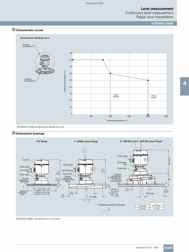
4/329Siemens FI 01 · 2021
Level measurementContinuous level measurement
Radar level transmitters
SITRANS LR560
4
■ Characteristic curves
SITRANS LR560 temperature derating curve
■ Dimensional drawings
SITRANS LR560, dimensions in mm (inch)
Process temperature (°C)
Am
bien
t tem
pera
ture
(°C
)
40 mversion 100 m
version
Temperature derating curve
Ambienttemperature
Processtemperature
90
70
80
60
50
40
30
20
10
050 250200150100
Cable gland
Grounding lug
Purge plug
Processconnection:
flat flange
Lid lock
Sensorreference
point
Flat flange 3” (DN80) aimer flange
Cable gland
Grounding lug
Purge plugProcess
connection:3” (DN80) aimer
flange
Cable gland
Groundinglug
Purge plug
Processconnection:
4” (DN100) and 6” (DN150)
aimer flange
4” (DN100) and 6” (DN150) aimer flange*
* C Spanner wrench included
5º max.10º max.
9.6(0.38)
166.1(6.54)
22.3(0.92)
166.
1(6.
54)
9.6(0.38)
53.2 (2.09)
3” (DN80): 200 (7.87)4” (DN100): 229 (9.02)
6” (DN150): 285 (11.22)
110 (4.33)
176(6.93)
110(4.33)
200(7.87)
4” (DN100): 229 (9.02)
6” (DN150): 285(11.22)
110(4.33)
A4” (DN100)6” (DN150) 60 (2.36)
A
© Siemens 2020

4/330 Siemens FI 01 · 2021
Level measurementContinuous level measurementRadar level transmitters
SITRANS LR560
4
■ Circuit diagrams
SITRANS LR560 connections
Notes:1. Depending on the approval rating, glands and plugs may be supplied with your instrument.2. DC terminal shall be supplied from a source providing electrical isolation between the input and output, to meet the applicable safety requirements of IEC 61010-1.3. All field wiring must have insulation suitable for rated input voltages.4. Use shielded twisted pair cable (14 ... 22 AWG) for HART version.5. Separate cables and conduit may be required to conform to standardinstrumentation wiring practices or electrical codes.
Cable shield (if used)
Cable gland(or NPT cable entry)
Connect the wiresto the terminals asshown: the polarityis identified on theterminal block.
© Siemens 2020

4/331Siemens FI 01 · 2021
Level measurementContinuous level measurement
Guided wave radar transmitters
Introduction
4
■ Overview
Introduction
Guided Wave Radar transmitters use TDR (time domain reflectometry).
Time Domain Reflectometry (TDR)
TDR uses pulses of electromagnetic (EM) energy to measure distances or levels. When a pulse reaches a dielectric disconti-nuity (created by media surface), part of the energy is reflected. The greater the dielectric difference, the greater the amplitude (strength) of the reflection.
The SITRANS LG includes a transmitter and waveguide that has a characteristic impedance in air and is used as a probe. When part of the probe is immersed in a material other than air, there is lower impedance due to the increase in the dielectric. When an EM pulse is sent down the probe and meets the dielectric discontinuity, a reflection is generated.
■ Mode of operation
Interface Detection
The SITRANS LG, is a transmitter capable of measuring both an upper level and an interface level. The upper liquid must have a dielectric constant between 1.6 and 10 and the two liquids have a difference in dielectric constants greater than 10. A typical ap-plication would be oil over water, with the upper layer of oil being non-conductive with a dielectric constant of approximately 2 and the lower layer of water being very conductive with a dielectric constant of approximately 80. This interface measurement can only be accomplished when the dielectric constant of the upper medium is lower than the dielectric constant of the lower medium.
24 V DC, 4 ... 20 mA loop powered
A small amount of energy continues down the probe in a low dielectric fluid.
Media dK > 1.4
Air: dK = 1
Transmit pulse
A reflection develops from the liquid surface.
Air: (dk = 1)
High dielectric medium(e.g. water: dk = 80)
Emulsion layer
Low dielectric medium(e.g. oil: dk = 2)
Interface Level
Signal
Upper Level
Signal
© Siemens 2020

4/332 Siemens FI 01 · 2021
Level measurementContinuous level measurementGuided wave radar transmitters
SITRANS LG series
4
■ Overview
The Siemens SITRANS LG series are guided wave radar trans-mitters for level, level/interface, and volume measurement of liquids and solids. The SITRANS LG product line can handle changes in process conditions, high temperatures and pressures, and steam.
■ Benefits
• High accuracy to +/- 2 mm• Advanced Diagnostics available for high degree of safety• Simple menu driven display offers ease of setup• Large range of options offers reliability in most continuous
level measurement applications• Ease of maintenance through module design and field
replaceable and adjustable probe options• Perfect solution for wide range of applications from storage to
interface with options for extreme pressure and temperature conditions
• Universally applicable in liquids, interface, slurries and solids• Highly immune to buildup using auto learn function• Ability to measure in loss of echo situations with probe end
tracking• Suitable for API 2350• Convenient access using USB and remote interface
accessories
■ Application
The SITRANS LG series comes in four different models, depend-ing on the applications, level of performance, and functionality required:• SITRANS LG240 offers configuration options for your hygienic
and corrosive application requirements• SITRANS LG250 Highly flexible solution for liquid level and
interface applications. Extremely versatile offering solutions for storage, separation of materials or difficult ammonia applications
• SITRANS LG260 Ideal for measuring level in medium range solids applications including; grains, plastics, and cement
• SITRANS LG270 offers configuration options for extreme conditions including high temperature and high pressure applications such as: harsh applications found in chemical, HPI and energy industries for example, LPG gas tanks, steam boilers and distillation columns
■ Configuration
SITRANS LG Series installation
Flange Metal sheet
Mounting socket If possible, avoid sockets, mount the sensor flush with the vessel top. If this is not possible, use short sockets with small diameter. Higher sockets or sockets with a bigger diameter can generally be used. They simply increase the upper blocking distance. Check if this is relevant for your measure-ment. In such cases, always carry out a false signal suppression after installation.
Installation in non-metal vessel
The guided microwave principle requires a metal surface on the process fitting. Therefore, use in plastic vessels etc. an instrument version with flange (from DN 50) or place a metal sheet, Ø > 200 mm (8 inch), beneath the process fitting when screwing it in.Make sure that the plate has direct contact with the process fitting
Socket must be installed flush
When welding the socket, make sure that the socket is flush to the vessel top.Before beginning the welding work, remove the electronics module from the sensor. By doing this, you avoid damage to the electron-ics through inductive coupling.
Inflowing medium
Do not mount the instruments in or above the filling stream. Make sure that you detect the product surface, not the inflowing product.
Mounting on nozzle
h)
d)
DN 40 ... DN 150d h
> DN 150 ... DN 200
<
<
150
100
© Siemens 2020

4/333Siemens FI 01 · 2021
Level measurementContinuous level measurement
Guided wave radar transmitters
SITRANS LG series
4
■ Configuration (continued)
SITRANS LG Remote Interface installation
Voltage supply/Signal output sensor
Sensor
Connection cable, sensor to LG Remote Interface
Connection of SITRANS LG Remote Interface to the sensor
Display and adjustment module
Connection of LG Remote Interface to the sensor and the PC
Voltage supply/Signal output sensor
Sensor
Connection cable, LG Remote Interface to sensor
LG Remote Interface
PC with DTM
Interface adapter
USB communicator
LG Remote Interface
© Siemens 2020

4/334 Siemens FI 01 · 2021
Level measurementContinuous level measurementGuided wave radar transmitters
SITRANS LG series
4
■ Technical specifications
Mode of operation
Measuring principle Guided wave radar measurement
Measuring range 300 ... 75 000 mm (11.81 ... 2 952.75 inch)
Output
mA analog output with HART digital signal
4 ... 20 mA/HART (SIL optional)
Output range• Analog Current: minimum 3.8 mA,
maximum 20.5 mA• Startup current ≤ 10 mA for 5 ms after switching on,
≤ 3.6 mA
Diagnostic alarm Failure signal current output (adjustable): last valid measured value, ≥ 21 mA, ≤ 3.6 mA
Digital communication HART Version 7 x and multidrop compatible
Modbus Modbus RTU, Modbus ASCII
PROFIBUS PA PROFIBUS PA profile 3.02
FOUNDATION Fieldbus FOUNDATION Fieldbus protocol Physical layer according to IEC 61158-2
Performance Process reference conditions according to DIN EN 61298-1
• Measuring cycle time < 500 ms • Step response time ≤ 3 s• Temperature Effects The measurement error from the
process conditions is in the specified pressure and temperature range of below 1 %
Non-linearity• Coaxial
• Single rod probes
• Interface models See manual for more details
Resolution and repeatability Accuracy +/- 2 mm (0.08 inch)
Accuracy• Coaxial/rod/cable probes +/- 2 mm (0.08 inch)• Interface models +/- 5 mm (0.197 inch)
Note: Typical deviation, Interface measurement. See manual for full explanation.
Rated operating conditions
Ambient temperature for enclosure -40 ... +80 °C (-40 ... +176 °F)
Storage temperature -40 … +80 °C (-40 … +176 °F)
LCD readable temperature range -40 ... +80 °C (-40 ... +176 °F) with display heated option
Location Indoor/outdoor
Installation category II
Pollution degree 2
Relative Humidity 20 ... 85 %
Medium conditions
Dielectric constant dK ≥ 1.4 (configuration dependent)
Note: for measurement below 1.4 use probe end tracking.
Process temperature range -196 ... +450 °C (-321 ... +842 °F)
Vessel pressure -1 … +400 bar (-100 … +40 000 kPa)
Design
Instrument weight (dependent on pro-cess fitting) - see manual for further details
Approx. 0.8 ... 8 kg (0.176 ... 17.64 lb)
Materials• Enclosure • Plastic housing plastic PBT
(Polyester)• Aluminum die-cast housing,
aluminum die-cast AISi10 mg, powder-coated- basis: polyester
• Stainless steel housing, precision casting 316L
• Stainless steel housing, electropolished 316L
• Degree of protection • Type 4/NEMA 4, IP65• Plastic housing IP66/IP67• Aluminum and stainless steel
housings are IP66/68• Cable inlet 2 x M20 x 1.5 or 2 x ½" NPT
Process connections • Pipe thread, cylindrical (ISO 228 T1) G¾" A, G1" A, G1½" A according to
DIN 3852-A• American pipe thread, conical
(ASME B1.20.1)¾" NPT, 1" NPT, 1½" NPT
• Flanged DIN from DN 25, ASME from 1"• Hygienic Hygienic fittings
Process seal instrument side FKM (SHS FPM 70C3 GLT), FFKM (Kalrez 6375), EPDM (A+P 70.10-02), silicone FEP coated (A+P FEPO-SEAL) or Borosilicate glass GPC 540
Second line of defense (glass seal) (optional)
Borosilicate glass GPC 540
Note: The second line of defense is a second level of the process separa-tion in the form of a gas-tight feedthrough in the lower part of the housing, preventing product from penetrating into the housing.
Programming
Local Four button, menu-driven data entry
Handheld communicator Hart communicator
PC SIMATIC PDM, AMS, PACTware
Power
2-wire Hart version 9.6 ... 35 V DC
4-wire versions 9.6 … 48 V DC, 20 … 42 V AC, 50/60 Hz, and 90 … 253 V AC, 50/60 Hz
Modbus 8 … 30 V DC
PROFIBUS PA 9 ... 32 V DC
FOUNDATION Fieldbus 9 ... 32 V DC
Note: see manual for specific power based on ordered options
Certificates and approvals
Hazardous approvals: ATEX, FM, CSA, IECexNote: other regional approvals are available
Hygienic approvals: EHEDG, FDA
Overfill protection WHG, Vlarem
Ship approval ABS, CCS, GL, BV, LR
© Siemens 2020

4/335Siemens FI 01 · 2021
Level measurementContinuous level measurement
Guided wave radar transmitters
SITRANS LG series
4
■ Technical specifications (continued)
SITRANS LG240 SITRANS LG250 SITRANS LG260 SITRANS LG270
Industries Food, Beverage and Pharmaceutical
Chemical/HPI/Power/General Cement, power generation, food, processing, mineral processing, mining
Chemical/HPI/Power/General
Applications Hygienic and corrosive applications
Liquids, storage and process vessels with agitators, vaporous liquids, interface
Cement, fly ash, grain, coal, flour, plastics
Aggressive applications in liquids, storage and process vessels with agitators, vaporous liquids, high temperatures and pressures, low dielectric media
Range 32 m 75 m 60 m 60 m
Performance ± 2 mm ± 2 mm ± 2 mm ± 2 mm
Temperature -40 … +150 °C(-40 ... +302 °F)
-40 … +200 °C(-40 ... +392 °F)
-40 … +200 °C (-40 ... +392 °F)
-196 … +450 °C (-320.8 ... +842 °F)
Process pressure
Standard version - -1 … +40 bar/-100 … +4 000 kPa (-14.5 … +580 psig), depend-ing on the process fitting
- -
With borosilicate glass lead-through
- -1 … +100 bar/-100 … +10 000 kPa (-14.5 … +1 450 psig), depend-ing on the process fitting
- -
Communications • 4 ... 20 mA/HART• Modbus: Modbus RTU,
Modbus ASCII• PROFIBUS PA• FOUNDATION Fieldbus• SIMATIC PDM• DTM/FDT for PACTware• Fieldcare
• 4 ... 20 mA/HART• Modbus: Modbus RTU,
Modbus ASCII• PROFIBUS PA• FOUNDATION Fieldbus• SIMATIC PDM• DTM/FDT for PACTware• Fieldcare
• 4 ... 20 mA/HART• Modbus: Modbus RTU,
Modbus ASCII• PROFIBUS PA• FOUNDATION Fieldbus• SIMATIC PDM• DTM/FDT for PACTware• Fieldcare
• 4 ... 20 mA/HART• Modbus: Modbus RTU,
Modbus ASCII• PROFIBUS PA• FOUNDATION Fieldbus• SIMATIC PDM• DTM/FDT for PACTware• Fieldcare
© Siemens 2020

4/336 Siemens FI 01 · 2021
Level measurementContinuous level measurementGuided wave radar transmitters
SITRANS LG series
4
■ Selection and ordering data Article No. Article No.
SITRANS LG240 Guided radar level transmitter
Continuous, contact, 32 m (105 ft) range. Monitors level and interface in aggressive liquids. Ideal for hygienic applications.
7ML5880- Ord. code
7 7 7 7 7 - 7 7 7 7 7 7 7
Click on the Article No. for the online configuration in the PIA Life Cycle Portal.
ApprovalsGeneral purpose (CSA, FM, CE) 0 AOverfill protection (WHG; VLAREM)11) 0 CATEX II 1G, ½G, 2G Ex ia IIC T614) 0 EATEX II 1G, ½G, 2G Ex ia IIC + Overfill (WHG; VLAREM)11)
0 F
ATEX II 1G, ½G 2G Ex ia IIC + ATEX II 1D, ½D, 2D IP6x1)15)17)
0 H
ATEX II ½G, 2G Ex d ia IIC T63)13)16) 0 JATEX II ½G, 2G Ex d ia IIC + ATEX II ½D, 2D IP6x3)13)16)17)
0 K
ATEX II 1D, ½D, 2D IP6x1)17)18) 0 NATEX II 1G, II ½G, II 2G Ex ia IIC T6 ... T1 Ga,Ga/Gb, Gb /IEC Ex ia IIC T6 ... T1 Ga, Ga/Gb, Gb1)14)
0 W
IEC Ex ia IIC T614) 0 PIEC Ex ia IIC T6 + IEC IP6x T tD1)15)17) 0 QIEC Ex d ia IIC T63)13)16) 0 RIEC Ex d ia IIC T6 + IEC IP6x T tD3)13)16) 0 SFM (NI) Class I, Div. 2, Groups A, B, C, D29)12)16)
1 A
FM (IS) Class I, II, III, Div. 1, Groups A, B, C, D, E, F, G9)15)
1 B
FM (XP-AIS) Class I, II, III, Div. 1, Groups A, B, C, D, E, F, G3)13)16)
1 C
CSA (NI) Class I, Div. 2, Groups A, B, C, D; (DIP) Class II, III, Div. 1, Groups E, F, G1)17)
1 E
CSA (IS) Class I, II, III, Div. 1, Groups A, B, C, D, E, F, G14)
1 F
CSA (XP-IS) Class I, II, III, Div. 1, Groups A, B, C, D, E, F, G3)13)16)
1 G
NEPSI Ex ia IIC T614) 2 ANEPSI Ex ia IIC T6 + DIP A20/21 TA T*1)15) 2 BNEPSI Ex d ia IIC T69)10)13)16) 2 CNEPSI Ex d ia IIC T6 + DIP A20/21 TA T*9)10)13)16)
2 D
NEPSI DIP A20/21 TA T*1)16) 2 GINMETRO Ex ia IIC T6 ... T114) 3 AINMETRO Ex t IIIC T* IP6X, Da, Da/Db, Da/Dc, Db + Ex ia IIC T6, Ga, Ga/Gb1)10)15)
3 B
INMETRO Ex d ia IIC T6 ... T19)10)13)16) 3 CINMETRO Ex t IIIC T* IP6X, Da, Da/Db, Da/Dc, Db + Ex d ia IIC T6 Ga/Gb9)10)13)16)
3 D
INMETRO Ex t IIIC T* IP6X, Da, Da/Db, Da/Dc, Db1)10)13)16)
3 G
Korea KC ex free area 6 AGOST-R/EAC 0 Ex ia IIC T1 ... T6 X14) 5 AGOST-R/EAC 0 Ex ia IIC T1 ... T6 X + Ex t IIIC T ... IP661)15)
5 B
GOST-R/EAC 1 Ex d ia IIC T1 ... T6 X9)10)13)16)
5 C
GOST-R/EAC 1 Ex d ia IIC T1 ... T6 X + Ex t IIIC T ... IP669)10)13)16)
5 D
Note: Version/Material, Process fitting/Material, and Length options are available only with options of corresponding type.
Probe version/MaterialProbe cable ø 4 mm (0.16 inch) with gravity weight/PFA17)
A
Probe exchangeable rod ø 8 mm (0.31 inch)/1.4435 (Basle standard)17)
B
Probe exchangeable rod ø 8 mm (0.31 inch)/ 1.4435 (Basle standard) can be autoclaved17)
C
Probe rod ø 10 mm (0.39 inch)/PFA17) DProbe exchangeable rod (ø 8 mm) /1.4435 (BN2), electropolished (Ra < 0.38 µm)17)
E
Process fitting/MaterialClamp 2" PN 16 (ø 64 mm) DIN 32676, ISO2852/1.4435 (BN2)
0 0
Clamp 2" PN 16 (ø 64 mm) DIN 32676, ISO2852/PTFE-TFM 1600
0 1
Clamp 2 1/2" PN 10 (ø 77.5 mm) DIN 32676, ISO2852/1.4435 (BN2)
0 2
Clamp 2 1/2" PN 10 (ø 77.5 mm) DIN 32676, ISO2852/PTFE-TFM 1600
0 3
Clamp 3" PN 10 (ø 91 mm) D N 32676, ISO2852/1.4435 (BN2)
0 4
Clamp 3" PN 10 (ø 91 mm) DIN 32676, ISO2852/PTFE-TFM 1600
0 5
Clamp 4" PN 6 (ø 119 mm) DIN 32676, ISO2852/1.4435(BN2)
0 6
Clamp 4" PN 6 (ø 119 mm) DIN 32676, ISO2852/PTFE-TFM 1600
0 7
Clamp 1½" PN 16 (ø 50.5 mm) DIN 32676, ISO2852/1.4435 (BN2)
4 0
Bolting DN 32, PN 40 DIN 11851/1.4435(BN2)
0 8
Bolting DN 32, PN 40 DIN 11851/PTFE-TFM 1600
1 0
Bolting DN 40, PN 40 DIN 11851/1.4435 (BN2)
1 1
Bolting DN 40, PN 40 DIN 11851/PTFE-TFM 1600
1 2
Bolting DN 50, PN 25 DIN 11851/1.4435(BN2)
1 3
Bolting DN 50, PN 25 DIN 11851/PTFE-TFM 1600
1 4
Bolting DN 65, PN 25 DIN 11851/PTFE-TFM 1600
1 5
Flange DN 25, PN 40 Form C, DIN 2501/PTFE-TFM 1600
2 0
Flange DN 40, PN 40 Form C, DIN 2501/PTFE-TFM 1600
2 1
Flange DN 50, PN 40 Form C, DIN 2501/PTFE-TFM 1600
2 2
Flange DN 50, PN 40 Form V13, DIN 2513/PTFE-TFM 1600
2 3
Flange DN 65, PN 40 Form C, DIN 2513/PTFE-TFM 1600
2 4
Flange DN 80, PN 40 Form C, DIN 2501/PTFE-TFM 1600
2 5
Flange DN 100, PN 16 Form C, DIN 2501/PTFE-TFM 1600
2 6
Flange DN 80, PN 40 EN 1092-1 Form B1/PTFE-TFM 1600
2 7
Flange DN 100, PN 40 EN 1092-1 Form B1/PTFE-TFM 1600
2 8
Flange 2" 150 lb RF, ASME B16.5/PTFE-TFM 1600
3 0
Flange 2" 300 lb RF, ASME B16.5/PTFE-TFM 1600
3 1
Flange 3" 150 lb RF, ASME B16.5/PTFE-TFM 1600
3 2
Flange 4" 150 lb RF, ASME B16.5/PTFE-TFM 1600
3 3
Note: The pressure limit for all PTFE coated versions is 16 bar (per manual).
SITRANS LG240 Guided radar level transmitter
Continuous, contact, 32 m (105 ft) range. Monitors level and interface in aggressive liquids. Ideal for hygienic applications.
7ML5880- Ord. code
7 7 7 7 7 - 7 7 7 7 7 7 7
© Siemens 2020

4/337Siemens FI 01 · 2021
■ Selection and ordering data Article No. Article No.
Level measurementContinuous level measurement
Guided wave radar transmitters
SITRANS LG series
4
ElectronicsTwo-wire 4 ... 20 mA/HART 0Four-wire Modbus3)13) 1Two-wire 4 ... 20 mA/HART with SIL qualification9)
2
Four-wire 4 ... 20 mA/HART; 90 ... 253 V AC; 50/60 Hz3)13)
3
Four-wire 4 ... 20 mA/HART; 9.6 ... 48 V DC; 20 ... 42 V AC3)13)
4
PROFIBUS PA9) 5FOUNDATION Fieldbus9) 6
Seal/Process temperatureWithout glass seal/-40 ... +150 °C (-40 ... +302 °F)2)
A
FFKM (Kalrez 6221)/-20 ... 150 °C(-4 ... +302 °F)4)
B
EPDM (Freudenberg 70 EPDM 291)/ -20 ... 130 °C (-4 ... +266 °F)4)
C
Housing/Protection/Cable
Note: for installation of remote display, 7ML5840, with LG two chamber housing options, contact PVC
Plastic IP66/IP67 M20 x 1.5/blind stopper APlastic IP66/IP67 1/2" NPT/blind stopper BAluminum/IP66/IP68 (0.2 bar) M20 x 1.5/blind stopper
C
Aluminum/IP66/IP68 (0.2 bar) 1/2" NPT/blind stopper
D
Aluminum double chamber/IP66/IP68 (0.2 bar) M20 x 1.5/blind stopper
E
Aluminum double chamber/IP66/IP68 (0.2 bar) 1/2" NPT/blind stopper
F
Stainless steel (precision casting) 316L/IP66/IP68 (0.2 bar) M20 x 1.5/blind stopper
G
Stainless steel (precision casting) 316L/IP66/IP68 (0.2 bar) 1/2" NPT/blind stopper
H
Stainless steel (electropolished) 316L/IP66/IP68 (0.2 bar) M20 x 1.5/blind stopper
J
Stainless steel (electropolished) 316L/IP66/IP68 (0.2 bar) 1/2" NPT/blind stopper
K
Stainless steel double chamber/IP66/IP68 (0.2 bar) M20 x 1.5/blind stopper
L
Stainless steel double chamber/IP66/IP68 (0.2 bar) 1/2" NPT/blind stopper
M
Aluminum/IP66/IP68 (0.2 bar) M20 x 1.5/cable gland stainless steel
N
Aluminum double chamber/IP66/IP68 (0.2 bar) M20 x 1.5/cable gland stainless steel
P
Stainless steel (precision casting) 316L/IP66/IP68 (0.2 bar) M20 x 1.5/cable gland stainless steel
Q
Stainless steel (electropolished) 316L/IP66/IP68 (0.2 bar) M20 x 1.5/cable gland stainless steel
R
Aluminum single chamber / IP66/IP68 (0.2 bar) M20 x 1.5/cable gland brass nickel-plated
W
Aluminum double chamber / IP66/IP68 (0.2 bar) M20 x 1.5/cable gland brass nickel-plated
X
SITRANS LG240 Guided radar level transmitter
Continuous, contact, 32 m (105 ft) range. Monitors level and interface in aggressive liquids. Ideal for hygienic applications.
7ML5880- Ord. code
7 7 7 7 7 - 7 7 7 7 7 7 7
Stainless steel single chamber (precision casting) / IP66/IP68 (0.2 bar) M20 x 1.5/ cable gland brass nickel-plated
Y
Stainless steel double chamber / IP66/IP68 (0.2 bar) M20 x 1.5/cable gland brass nickel-plated
S
Remote stainless steel single chamber housing, electropolished/IP66/IP67 with cable outlet IP68 (electronics separated by cable);M20 x 1.5/blind plug10)
Z Q 2 A
Remote plastic single chamber housing /IP66/IP67 with cable outlet IP68 (electronics separated by cable); M20 x 1.5/blind plug10)
Z Q 2 B
Lengths
Rod ø 8 mm (0.31 inch)/1.4435 (Basle standard 300 ... 4 000 mm)300 ... 1 000 mm (11.81 ... 39.37 inch)6)
0
1 001 ... 2 000 mm (39.41 ... 78.74 inch)6)
1
2 001 ... 3 000 mm (78.78 ... 118.11 inch)6)
2
3 001 ... 4 000 mm(118.15 ... 157.48 inch)6)
3
Rod ø 10 mm (0.24 inch)/PFA (300 ... 4 000 mm)300 mm (11.81 inch)6) 9 R 1 A500 mm (19.69 inch)6) 9 R 1 B300 ... 1 000 mm (11.81 ... 39.37 inch)6)
9 R 1 C
1 001 ... 5 000 mm (39.41 ... 78.74 inch)6)
9 R 1 D
2 001 ... 3 000 mm (78.78 ... 118.11 inch)6)
9 R 1 E
3 001 ... 4 000 mm(118.15 ... 157.48 inch)6)
9 R 1 F
Cable ø 4 mm (0.16 inch)/PFA (500 ... 32 000 mm)
500 mm (9.69 inch) 9 R 1 G
501 ... 1 000 mm (19.72 ... 39.37 inch) 9 R 1 H
1 001 ... 2 000 mm (39.41 ... 78.74 inch) 9 R 1 J
2 001 ... 4 000 mm (78.78 ... 157.40 inch) 9 R 1 K
4 001 ... 5 000 mm (157.52 ... 196.85 inch) 9 R 1 L
5 001 ... 10 000 mm (196.89 ... 393.70 inch) 9 R 1 M
10 001 ... 15 000 mm (393.74 ... 590.55 inch) 9 R 1 N
15 001 ... 20 000 mm (590.59 ... 787.40 inch) 9 R 1 P
20 001 ... 25 000 mm (787.44 ... 984.25 inch) 9 R 1 Q
25 001 ... 32 000 mm (984.29 ... 1 259.52 inch)
9 R 1 R
Exchange. rod ø 8 mm (0.31 inch)/1.4435 (BN2), electropolished (Ra < 0.38 µm)
300 ... 1 000 mm (11.81 ... 39.37 inch)6) 9 R 2 A
1 001 ... 2 000 mm (39.41 ... 78.74 inch)6) 9 R 2 B
2 001 ... 3 000 mm (78.78 ... 118.11 inch)6) 9 R 2 C
3 001 ... 4 000 mm (118.15 ... 157.48 inch)6) 9 R 2 D
SITRANS LG240 Guided radar level transmitter
Continuous, contact, 32 m (105 ft) range. Monitors level and interface in aggressive liquids. Ideal for hygienic applications.
7ML5880- Ord. code
7 7 7 7 7 - 7 7 7 7 7 7 7
© Siemens 2020

4/338 Siemens FI 01 · 2021
■ Selection and ordering data Order code Order code
Level measurementContinuous level measurementGuided wave radar transmitters
SITRANS LG series
4
Note: some configuration options are not available. For restriction information see the online PIA configuration tool.1) Some approvals are not available with Plastic and Stainless steel
(electropolished) Housing/Protection/Cable options and certain glands.2) Available only with Rod ø 10 mm/PFA and Cable ø 4 mm/PFA Length options.3) Available only with Supplementary electronic option A00 and
Indicating/adjustment module options E00, E01.4) Not available with Remote Housing/Protection/Cable options Q2A and Q2B.5) Not available with Electronic option 5.6) Not available with Y02.7) Available only with Electronic options 0, 2, and 6.8) Listed Certificates are not available with all configurations, please contact
factory for more information.9) Available only with Supplementary electronic option A00.10)Not available with Indicating/adjustment module option E02.11)Available only with Electronics options 0, 2, and 5.12)Some approvals are not available with Remote or Stainless steel
(electropolished) Housing/Protection/Cable options and certain glands.13)Available only with Double chamber, Metallic Housing/Protection/Cable
options and certain glands.14)Available only with Electronics options 0, 2, 5, 6.15)Available only with Electronics options 0 and 2.16)Available only with Electronics options 0 ... 4.17)Not available with some Seal/Process Temperature options.18)Available only with Electronic options 0, 2, 3, and 4.19)Available only with 316L Probes. NACE is not available with coated, plated,
or hygienic connections.
Note: Please consult manual for further detail.
Further designs (mandatory)
Please add "-Z" to Article No. and specify Order code(s).
Supplementary electronics
Without A00
Additional current output 4 ... 20 mA10) A01
Indicating/adjustment module
Without E00
Mounted E01
Laterally mounted E02
Language of display
German L00
English L01
French L02
Dutch L03
Italian L04
Spanish L05
Portuguese L06
Russian L07
Chinese L08
Japanese L09
Operating instructions
German M00
English M01
French M02
Spanish M03
Further designs (optional)
Please add "-Z" to Article No. and specify Order code(s).
Enter the total insertion length in plain text description
Y01
Enter the total length of rigid part (cable version only) range from 100 ... 1 000 mm
Y02
Cleaning included certificate: oil, grease and silicone free
W01
Remote electronic cable lengths: 2 m (6.6 ft). Only available with Housing options Q2A and Q2B
Y10
Remote electronic cable lengths: 5 m (16.4 ft). Only available with Housing options Q2A and Q2B
Y11
Remote electronic cable lengths: 10 m (32.8 ft). Only available with Housing options Q2A and Q2B
Y12
Identification label (measurement loop) stainless steel, 40 characters max, add in plain text. To add more than one line use a coma ""," for line break.
Y17
Identification Label (measurement loop) foil, 40 characters max, add in plain text. To add more than one line use a coma "," for line break.
Y18
Material Inspection certificate 3.1 of EN 10204
C05
3.1-Inspection Certificate for instrument (EN 10204)8)
C12
Inspection certificate 3.1 (EN 10204, NACE MR 0175) - material8)19)
Note: 316L probes include NACE MR 0175 and MR 0103, non 316L probes include MR 0175 only and plated flange designs are not available with NACE certificate.
D07
3.1-Inspection Certificate for instrument with test data (EN 10204)8)
C25
2.2-Factory certificate for material (EN 10204)8)
C15
Quality and test plan8) C26
Dye penetration test, results confirmed via a 3.1 certificate/instrument (EN10204)8)
C13
Further designs (optional)
Please add "-Z" to Article No. and specify Order code(s).
X-ray test + 3.1 certificate/instrument8) C14
Positive material identification test + 3.1 certificate/instrument8)
C16
Roughness test + 3.1 certificate/instrument8) C18
Pressure test + 3.1 certificate/instrument8) C31
Helium leak test + 3.1 certificate/instrument8) C32
Ferrite measuring accuracy to DIN 32514-1 + 3.1 certificate/instrument8)
C60
Pressure test according to Norsok + 3.1 certificate/instrument8)
C61
5 point calibration certificate (min. length 300 mm)8)
C62
Operating Instructions
All literature is available to download for free, in a range of languages, at
http://www.siemens.com/processinstrumentation/documentation
Accessories Article No.
SITRANS LG, GWR sensor Display Module A5E34143449
SITRANS LG, two-wire 4 ... 20 mA/HART electronic
A5E35637821
SITRANS LG, USB communicator A5E35192015
SITRANS LG, Mounting eye M12 x 20 PBD:51041448
SITRANS LG, Mounting spring PBD:51041449
Siemens Intrinsically Safe Barrier (DC powered), ATEX II 1 G EEx ia
7NG4124-0AA00
SITRANS RD100, loop powered display -see Chapter 7
7ML5741-.....-.
SITRANS RD150, remote digital display for 4 ... 20 mA and HART devices - see Chapter 7
7ML5742-.....-....
SITRANS RD200, universal input display with Modbus conversion - see Chapter 7
7ML5740-.....-..
SITRANS RD300, dual line display with totalizer and linearization curve and Modbus conversion - see Chapter 7
7ML5744-.....-..
For applicable back up point level switch - see point level measurement section
© Siemens 2020

4/339Siemens FI 01 · 2021
■ Selection and ordering data Article No. Article No.
Level measurementContinuous level measurement
Guided wave radar transmitters
SITRANS LG series
4
SITRANS LG250 Guided radar level transmitter
Continuous, contact, 75 m (246 ft) range. Monitors level and interface in liquids.
7ML5881- Ord. code
7 7 7 7 7 - 7 7 7 7 7 7 7
Click on the Article No. for the online configuration in the PIA Life Cycle Portal.
ApprovalsGeneral purpose (CSA, FM, CE) 0 AShipping approval4)6)7)8)13) 0 BOverfill protection (WHG; VLAREM)9)10)13) 0 CATEX II 1G, ½G, 2G Ex ia IIC T610)13) 0 EATEX II 1G, ½G, 2G Ex ia IIC + Overfill (WHG; VLAREM)10)13)
0 F
ATEX II 1G, ½G, 2G Ex ia IIC T6 + shipping approval4)6)7)8)13)
0 G
ATEX II 1G, ½G 2G Ex ia IIC + ATEX II 1D, ½D,2D IP6x1)13)
0 H
ATEX II ½G, 2G Ex d ia IIC T62)8)11)12)13) 0 JATEX II 1/2G, 2G Ex d ia IIC + ATEX II 1/2D, 2D IP6x2)8)11)12)13)
0 K
ATEX II 1/2G, 2G Ex d IIC T61)11)14) 0 LATEX II 1/2G, 2G Ex d IIC + ATEX II 1/2D, 2D IP6x1)11)13)14)
0 M
ATEX II 1D, 1/2D, 2D IP6x T1)13)14) 0 NATEX II 1G, II 1/2G, II 2G Ex ia IIC T6...T1 Ga, Ga/Gb, Gb /IEC Ex ia IIC T6...T1 Ga, Ga/Gb, Gb13)
0 W
ATEX II 1/2G, II 2G Ex db IIC T6 ... T1 Ga/Gb, Gb / IEC Ex db IIC T6 ... T1 Ga/Gb, Gb13)14)18)
1 K
ATEX II 1/2G, II 2G Ex d ia IIC T6 ... T1 Ga/Gb, Gb + Ship approval2)6)8)11)12)13)
7 A
ATEX II 1/2G, II 2G Ex db IIC T6 ... T1 Ga/Gb, Gb + Ship approval1)6)8)11)13)
7 B
ATEX II 1/2G, II 2G Ex db IIC T6 ... T1 Ga/Gb, Gb + Overfill protection (WHG, VLAREM)1)11)14)
7 P
IEC Ex ia IIC T610)13) 0 PIEC Ex ia IIC T6 + IEC IP6x T tD1)14)15) 0 QIEC Ex d ia IIC T62)8)11)12)13) 0 RIEC Ex d ia IIC T6 +IEC IP6x T tD2)8)11)12)13)15)
0 S
IEC Ex d IIC T61)11)14) 0 TIEC Ex d IIC T6 + IEC IP6x T tD1)11)14) 0 UIEC Ex db IIC T6...T1 Ga/Gb, Gb + Ship approval1)6)8)11)13)14)
7 C
IEC Ex ia IIC T6...T1 Ga, Ga/Gb, Gb + Ship approval6)8)13)16)
7 D
IEC Ex d ia IIC T6...T1 Ga/Gb, Gb + Ship approval2)6)8)11)13)15)
7 E
FM (NI) Class I, Div. 2, Groups A, B, C, D3)8)13)17)
1 A
FM (IS) Class I, II, III, Div. 1, Groups A, B, C, D, E, F5)8)13)
1 B
FM (XP-AIS) Class I, II, III, Div. 1, Groups A, B, C, D, E, F, G2)8)11)12)13)
1 C
FM (XP) Class I, Div. 1, Groups A, B, C, D2)11)13)14)
1 D
FM (NI) Class I, II, III, Div. 2, Groups A, B, C, D, F, G + Ship approval4)6)8)13)17)
7 F
FM (IS) Class I, II, III, Div. 1, Groups A, B, C, D, E, F, G + Ship approval6)8)13)16)
7 G
FM (XP-AIS) Class I, Div. 1, Groups A, B, C, D, + Ship approval6)8)11)13)16)
7 H
FM (XP) Class I, Div. 1, Groups A, B, C, D + Ship approval2)6)8)13)14)
7 J
CSA (NI) Class I, Div. 2, Groups A, B, C ,D (DIP) Class II, III, Div. 1, Groups E, F, G1)
1 E
CSA (IS) Class I, II, III, Div. 1, Groups A, B, C, D, E, F, G5)13)
1 F
CSA (XP-IS) Class I, II, III, Div. 1, Groups A, B, C, D, E, F, G2)8)11)12)13)
1 G
CSA (XP) Class I, II, III, Div. 1, Groups A, B, C, D, E, F, G8)13)14)18)
1 H
CSA (NI) Class I, II, III Div. 2, Groups A, B, C, D, F, G + Ship approval1)6)13)
7 K
CSA (IS) Class I, II, III, Div. 1, Groups A, B, C, D, E, F, G + Ship approval6)13)16)
7 L
CSA (XP-IS) Class I, II, III, Div. 1, Groups A, B, C, D, E, F, G + Ship approval6)8)11)32)
7 M
CSA (XP) Class I, II, III, Div. 1, Groups A, B, C, D, E, F, G + Ship approval6)8)13)14)18)
7 N
NEPSI Ex ia IIC T65)13) 2 ANEPSI Ex ia IIC T6 + DIP A20/21 TA T*1)13) 2 BNEPSI Ex d ia IIC T62)8)11)13) 2 C
NEPSI Ex d ia IIC T6 + DIP A20/21 TA T*2)8)11)13)
2 D
NEPSI Ex d IIC T61)11)13)14) 2 ENEPSI Ex d IIC T6 + DIP A20/21TA T1)11)13)14)
2 F
NEPSI DIP A20/21 TA T*1)13)14) 2 GINMETRO Ex ia IIC T6 ... T15)13) 3 AINMETRO Ex t IIIC T* IP6X, Da, Da/Db, Da/Dc, Db + Ex ia IIC T6, Ga, Ga/Gb1)11)13)
3 B
INMETRO Ex d ia IIC T6 ... T12)8)11)13) 3 CINMETRO Ex t IIIC T* IP6X, Da, Da/Db, Da/Dc, Db + Ex d ia IIC T6 Ga/Gb1)8)11)13)
3 D
INMETRO Ex d IIC T6 ... T11)11)13)14) 3 EINMETRO Ex t IIIC T* IP6X, Da, Da/Db, Da/Dc, Db + Ex d IIC T6 Ga/Gb1)11)13)14)
3 F
INMETRO Ex t IIIC T* IP6X, Da, Da/Db, Da/Dc, Db1)11)13)14)
3 G
KOSHA Ex d IIC T6 ... T1 – KE1)11)13)14) 4 AKorea KC ex free area 6 AGOST-R/EAC 0 Ex ia IIC T1 ... T6 X13) 5 AGOST-R/EAC 0 Ex ia IIC T1 ... T6 X + Ex t IIIC T ... IP661)13)
5 B
GOST-R/EAC 1 Ex d ia IIC T1 ... T6 X2)8)11)13) 5 CGOST-R/EAC 1 Ex d ia IIC T1 ... T6 X + Ex t IIIC T ... IP662)8)11)13)
5 D
GOST-R/EAC 1 Ex d IIC T1 ... T6 X1)11)13) 5 EGOST-R/EAC 0 Ex d IIC T1 ... T6 X + Ex t IIIC T ... IP661)11)13)
5 F
GOST-R/EAC Ex t IIIC T ... IP661)13) 5 G
Note: Version/Material, Process fitting/Material, and Length options are available only with options of corresponding type.
Probe version/MaterialProbe exchangeable cable ø 2 mm (0.08 inch) with gravity weight/31619)20)
A
Probe exchangeable cable ø 2 mm (0.08 inch) center weight/316L19)20)
B
SITRANS LG250 Guided radar level transmitter
Continuous, contact, 75 m (246 ft) range. Monitors level and interface in liquids.
7ML5881- Ord. code
7 7 7 7 7 - 7 7 7 7 7 7 7
© Siemens 2020

4/340 Siemens FI 01 · 2021
■ Selection and ordering data Article No. Article No.
Level measurementContinuous level measurementGuided wave radar transmitters
SITRANS LG series
4
Probe exchangeable cable ø 4 mm (0.16 inch) with gravity weight/316L9)19)20)
C
Probe exchangeable cable ø 4 mm (0.16 inch) with center weight/316L9)19)20)
D
Probe exchangeable rod ø 8 mm (0.31 inch)/316L9)19)
E
Probe exchangeable rod ø 12 mm (0.47 inch)/316L9)19)
F
Probe coax version ø 21.3 mm (0.84 inch) with single hole/316L9)19)20)
G
Probe coax version ø 21.3 mm (0.84 inch) with multiple hole/316L19)20)
H
Probe coax version ø 42.2 mm (1.66 inch) with multiple hole/316L9)19)20)
K
Probe exchangeable cable ø 4 mm (0.16 inch) with gravity weight/Alloy C22 (2.4602)9)
L
Probe exchangeable cable ø 4 mm (0.16 inch) with centre weight/Alloy C22 (2.4602)9)
M
Probe exchangeable rod ø 8 mm (0.31 inch)/Alloy C22 (2.4602)9)
N
Probe exchangeable rod ø 12 mm (0.47 inch)/Alloy C22 (2.4602)9)
P
Probe coax version ø 21.3 mm (0.84 inch) with multiple hole/Alloy C22 (2.4602)9)
Q
Probe coax version ø 42.2 mm (1.66 inch) with multiple hole/Alloy C22 (2.4602)9)
R
Probe exchangeable rod ø 8 mm (0.31 inch)/ Duplex (1.4462)9)
S
Exchangeable rod ø 12 mm (0.47 inch)/Alloy C22 and 400 (2.4360)9)
T
Exchangeable coated cable ø 4 mm with uncoated centering weight/PFA and 31621)24)30)35)36)
U
Process fitting/MaterialThread G 3/4" (DIN 3852-A) PN 6/316L 0 0Thread 3/4" NPT (ASME B1.20.1) PN 6/316L 0 1Thread G 3/4" (DIN 3852-A) PN 40/316L 0 2Thread 3/4" NPT (ASME B1.20.1) PN 40/316L 0 3Thread G 3/4" (DIN 3852-A) PN 100 / 316L22) 0 4Thread 3/4" NPT (ASME B1.20.1) PN 100/316L22)
0 5
Thread G 1" (DIN 3852-A) PN 40/316L 0 6Thread 1" NPT (ASME B1.20.1) PN 40/316L 0 7Thread G 1" (DIN 3852-A) PN 100/316L22) 0 8Thread 1" NPT (ASME B1.20.1) PN 100/316L22)
1 0
Thread G 1 1/2" (DIN 3852-A) PN 40/316L 1 1Thread 1 1/2" NPT (ASME B1.20.1) PN 40/316L
1 2
Thread G1 1/2" (DIN 3852-A) PN 100/316L22) 1 3Thread 1 1/2" NPT (ASME B1.20.1) PN 100/316L22)
1 4
Thread 2 NPT PN 40, ASME B1.20.1/316L23)24)
1 5
Flange DN 25 PN 40 Form C, DIN 2501/316L 2 0Flange DN 25 PN 40 Form F, DIN 2501/316L 2 1Flange DN 40 PN 40 Form C, DIN 2501/316L 2 2Flange DN 50 PN 40 Form C, DIN 2501/316L 2 3Flange DN 50 PN 40 Form V13, DIN 2513/316L
2 4
Flange DN 80 PN 40 Form C, DIN 2501/316L 2 5
SITRANS LG250 Guided radar level transmitter
Continuous, contact, 75 m (246 ft) range. Monitors level and interface in liquids.
7ML5881- Ord. code
7 7 7 7 7 - 7 7 7 7 7 7 7
Flange DN 80 PN 40 Form V13, DIN 2501/316L
2 6
Flange DN 100 PN 16 Form C, DIN 2501/316L
2 7
Flange DN 100 PN 16 Form V13, DIN 2501/316L
2 8
Flange DN 100 PN 40 Form C, DIN 2501 /316L
3 0
Flange DN 100 PN 40 Form V13, DIN 2513/316L
3 1
Flange DN 150 PN 16 Form C, DIN 2501/316L
3 2
Flange DN 50 PN 40 EN 1092-1 Form B1/316L 3 3Flange DN 80 PN 40 EN 1092-1 Form B1/316L 3 4Flange 1" 150 lb RF, ASME B16.5/316L 3 5Flange 1 1/2" 150 lb RF, ASME B16.5/316L 3 6Flange 2" 150 lb RF, ASME B16.5/316L 3 7Flange 2" 300 lb RF, ASME B16.5/316L 3 8Flange 3" 150 lb RF, ASME B16.5/316L 4 0Flange 3" 300 lb RF, ASME B16.5/316L 4 1Flange 4" 150 lb RF, ASME B16.5/316L 4 2Flange 4" 300 lb RF, ASME B16.5/316L 4 3Flange 6" 150 lb RF, ASME B16.5/316L 4 4Flange 6" 300 lb RF, ASME B16.5/316L 4 5Thread G 3/4" PN 40, DIN3852-A/Alloy C22 (2.4602)37)
4 6
Thread G 1" PN 40, DIN 3852-A/Alloy C22 (2.4602)37)
4 7
Thread G 1 1/2" PN 40, DIN 3852-A/Alloy C22 (2.4602)
4 8
Thread 1 1/2" NPT PN 40, ASME B1.20.1/Alloy C22 (2.4602)
5 0
Flange DN 50 PN 40 Form C, DIN 2501/ 316L with Alloy C22 (2.4602) coating
5 1
Flange DN 50 PN 40 Form B1, EN 1092-1/ 316L with Alloy C22 (2.4602) coating
5 2
Flange DN 80 PN 40 Form B1, EN 1092-1/ 316L with Alloy C22 (2.4602) coating
5 3
Flange DN 100 PN 40 Form B1, EN 1092-1/ 316L with Alloy C22 (2.4602) coating
5 4
Flange DN 150 PN 16 Form B1, EN 1092-1/ 316L with Alloy C22 (2.4602) coating
5 5
Flange DN 200 PN 16 Form B1, EN 1092-1/ 316L with Alloy C22 (2.4602) coating
5 6
Flange 2" 150 lb RF, ASME B16.5/316L with Alloy C22 (2.4602) coating
5 7
Flange 2" 300 lb RF, ASME B16.5/316L with Alloy C22 (2.4602) coating
5 8
Flange 3" 150 lb RF, ASME B16.5/316L with Alloy C22 (2.4602) coating
6 0
Flange 4" 150 lb RF, ASME B16.5/316L with Alloy C22 (2.4602) coating
6 1
Flange 4" 300 lb RF, ASME B16.5/316L with Alloy C22 (2.4602) coating
6 2
Flange 6" 150 lb RF, ASME B16.5/316L with Alloy C22 (2.4602) coating
6 3
Flange 6" 300 lb RF, ASME B16.5/316L with Alloy C22 (2.4602) coating
6 4
Thread G 3/4" (DIN 3852-A) PN 40/Duplex 1.4462
6 5
SITRANS LG250 Guided radar level transmitter
Continuous, contact, 75 m (246 ft) range. Monitors level and interface in liquids.
7ML5881- Ord. code
7 7 7 7 7 - 7 7 7 7 7 7 7
© Siemens 2020

4/341Siemens FI 01 · 2021
■ Selection and ordering data Article No. Article No.
Level measurementContinuous level measurement
Guided wave radar transmitters
SITRANS LG series
4
Flange DN 80 PN 40 Form F, DIN 2501/Duplex (1.4462)
6 6
Flange DN 50 PN 40 Form B1, EN 1092-1/ Duplex (1.4462)
6 7
Flange 1" 150 lb RF, ASME16.5/Duplex (1.4462)
6 8
Flange 1 1/2" 150 lb RF, ASME B16.5/Duplex (1.4462)
7 0
Flange 2" 150 lb RF, ASME B16.5/Duplex (1.4462)
7 1
Flange 2" 300 lb RF, ASME B16.5/Duplex (1.4462)
7 2
Flange 2" 600 lb RF, ASME B16.5/Duplex (1.4462)
7 3
Flange 3" 150 lb RF, ASME B16.5/Duplex (1.4462)
7 4
Flange 3" 300 lb RF, ASME B16.5/Duplex (1.4462)
7 5
Flange 4" 150 lb RF, ASME B16.5/Duplex (1.4462)
7 6
Flange 4" 150 lb FF, ASME B16.5/Duplex (1.4462)
7 7
Flange 4" 300 lb RF, ASME B16.5/Duplex (1.4462)
7 8
Flange 4" 600 lb RF, ASME B16.5/Duplex (1.4462)
8 0
Thread 1 1/2" NPT PN 40, ASME B1.20.1/Alloy 400 (2.4360)
8 1
Flange 2" 150 lb RF, ASME B16.5/Alloy 400 (2.4360)
8 2
Flange 2" 300 lb RF, ASME B16.5/Alloy 400 (2.4360) solid
8 3
Flange 3" 150 lb RF, ASME B16.5/Alloy 400 (2.4360)
8 4
Flange 3" 300 lb RF, ASME B16.5/Alloy 400 (2.4360)
8 5
Flange 3" 300 lb RJF, ASME B16.5/Alloy 400 (2.4360)
8 6
Flange 4" 150 lb RF, ASME B16.5/Alloy 400 (2.4360)
8 7
Flange 4" 300 lb RF, ASME B16.5/Alloy 400 (2.4360)
8 8
Flange DN 25 PN 40 Form C, DIN 2501/ Alloy C22 (2.4602) solid37)
9 0 L 1 A
Flange DN 25 PN 40 Form B1, EN 1092-1/ Alloy C22 (2.4602) solid37)
9 0 L 1 B
Flange DN 80 PN 40 Form B1, EN 1092-1/ Alloy C22 (2.4602) solid
9 0 L 1 C
Flange 1" 150 lb RF, ASME B16.5/Alloy C22 (2.4602) solid37)
9 0 L 1 D
Flange 1 1/2" 150 lb RF, ASME B16.5/Alloy C22 (2.4602) solid37)
9 0 L 1 E
Flange 1 1/2" 300 lb RF, ASME B16.5/Alloy C22 (2.4602) solid37)
9 0 L 1 F
Flange 2" 150 lb RF, ASME B16.5/Alloy C22 (2.4602) solid
9 0 L 1 G
Flange 2" 300 lb RF, ASME B16.5/Alloy C22 (2.4602) solid
9 0 L 1 H
Flange 2" 600 lb RF, ASME B16.5/Alloy C22 (2.4602) solid
9 0 L 1 J
Flange 2" 1 500 lb RJF, ASME B16.5/Alloy C22 (2.4602) solid
9 0 L 1 K
Flange 3" 150 lb RF, ASME B16.5/Alloy C22 (2.4602) solid
9 0 L 1 L
Flange 3" 300 lb RF, ASME B16.5/Alloy C22 (2.4602) solid
9 0 L 1 M
Flange 3" 300 lb RF, ASME B16.5/316L with Alloy C22 (2.4602) coating
9 0 L 1 N
SITRANS LG250 Guided radar level transmitter
Continuous, contact, 75 m (246 ft) range. Monitors level and interface in liquids.
7ML5881- Ord. code
7 7 7 7 7 - 7 7 7 7 7 7 7
Flange 4" 150 lb RF, ASME B16.5/Alloy C22 (2.4602) solid
9 0 L 1 P
Flange 4" 150 lb FF, ASME B16.5/Alloy C22 (2.4602) solid
9 0 L 1 Q
Flange 4" 300 lb RF, ASME B16.5/Alloy C22 (2.4602) solid
9 0 L 1 R
Flange 4" 300 lb RJF, ASME B16.5/Alloy C22 (2.4602) solid
9 0 L 1 S
Flange 4" 300 lb LT, ASME B16.5/Alloy C22 (2.4602) solid
9 0 L 1 T
Flange 4" 600 lb RJF, ASME B16.5/Alloy C22 (2.4602) solid
9 0 L 1 U
Flange 6" 150 lb RF, ASME B16.5/Alloy C22 (2.4602) solid
9 0 L 1 V
Flange 2 1/2" 600 lb RF, Masoneilan/Alloy C22 (2.4602) solid
9 0 L 1 W
Flange 2" 600 lb RF, ASME B16.5/316/316 L24) 9 0 L 1 XFlange 3" 600 lb RF, ASME B16.5/316/316L24)25)
9 0 L 1 Y
Flange 4" 600 lb RF, ASME B16.5/316/316L31)
9 0 L 2 A
Thread R1½ PN40, EN 10226-1/316L38) L 2 B
ElectronicsTwo-wire 4 ... 20 mA/HART 0Four-wire Modbus2)8)11) 1Two-wire 4 ... 20 mA/HART with SIL qualification9)10)
2
Four-wire 4 ... 20 mA/HART; 90 ... 253 V AC; 50/60Hz2)8)11)34)
3
Four-wire 4 ... 20 mA/HART; 9.6 ... 48 V DC; 20 ... 42 V AC2)8)11)34)
4
PROFIBUS PA5)8) 5FOUNDATION Fieldbus5)8) 6
Seal/Second line of defense/Process temperatureFKM (SHS FPM 70C3 GLT)/without glass seal/-40 ... +80 °C (-40 ... +176 °F)
A
FKM (SHS FPM 70C3 GLT)/without glass seal/ -40 ... +150 °C (-40 ... +302 °F)
B
FKM (SHS FPM 70C3 GLT)/with glass seal/-40 ... +150 °C (-40 … +302 °F)26)
C
FFKM (Kalrez 6375)/without/-20 ... 150 °C (-4 ... +302 °F)
D
FFKM (Kalrez 6375)/with/-20 ... +150 °C (-4 ... +302 °F)5)
E
FFKM (Kalrez 6375)/with glass seal/-20 ... +200 °C (-4 ... +392 °F)26)
F
EPDM (A+P 75.5/KW75F)/without glass seal/ -40 ... +80 °C (-40 ... +176 °F)
G
EPDM (A+P 75.5/KW75F)/without glass seal/ -40 ... +150 °C (-40 ... +302 °F)26)
H
EPDM (A+P 75.5/KW75F)/with glass seal/-40 ... +150 °C (-40 ... +302 °F)26)
J
Silicone FEP coated (A+P FEP-O-SEAL)/without glass seal/-40 ... +80 °C(-40 ... +176 °F)
K
Silicone FEP coated (A+P FEP-O-SEAL)/without glass seal/-40 ... +150 °C (-40 ... +302 °F)
L
Silicone FEP coated (A+P FEP-O-SEAL)/with glass seal/-40 ... +150 °C (-40 ... +302 °F)26)
M
With borosilicate glass lead through for volatile substances, e.g. ammonia/with glass seal/-60 ... +150 °C (-76 ... +302 °F)26)
N
FFKM (Kalrez 6375)/without glass seal/-20 … +200 °C (-4 ... +392 °F)
P
FKM (SHS FPM 70C3 GLT)/with glass seal/-40 ... 80 °C (-40 ... +176 °F)26)
Q
SITRANS LG250 Guided radar level transmitter
Continuous, contact, 75 m (246 ft) range. Monitors level and interface in liquids.
7ML5881- Ord. code
7 7 7 7 7 - 7 7 7 7 7 7 7
© Siemens 2020
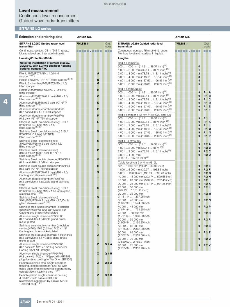
4/342 Siemens FI 01 · 2021
■ Selection and ordering data Article No. Article No.
Level measurementContinuous level measurementGuided wave radar transmitters
SITRANS LG series
4
Housing/Protection/Cable
Note: for installation of remote display, 7ML5840, with LG two chamber housing options, contact PVC
Plastic IP66/IP67 M20 x 1.5/blind stopper11)15)
A
Plastic IP66/IP67 1/2" NPT/blind stopper8)11) BPlastic 2-chamber/IP66/IP67/M20 x 1.5/blind stopper
G
Plastic 2-chamber/IP66/IP67 /1/2" NPT/blind stopper
H
Aluminum/IP66/IP68 (0.2 bar) M20 x 1.5/ Blind stopper8)11)
C
Aluminum/IP66/IP68 (0.2 bar) 1/2" NPT/Blind stopper8)11)
D
Aluminum double chamber/IP66/IP68 (0.2 bar) M20 x 1.5 / Blind stopper
E
Aluminum double chamber/IP66/IP68 (0.2 bar) 1/2" NPT/Blind stopper
F
Stainless Steel (precision casting) 316L/ IP66/IP68 (0.2 bar) M20 x 1.5/Blind stopper9)11)
L
Stainless Steel (precision casting) 316L/ IP66/IP68 (0.2 bar) 1/2" NPT/Blind stopper8)11)
M
Stainless Steel (electropolished) 316L/IP66/IP68 (0.2 bar) M20 x 1.5/Blind stopper8)11)
N
Stainless Steel (electropolished) 316L/IP66/IP68 (0.2 bar) 1/2" NPT/Blind stopper8)11)
P
Stainless Steel double chamber/IP66/IP68 (0.2 bar) M20 x 1.5/Blind stopper
Q
Stainless Steel double chamber/IP66/IP68 (0.2 bar) 1/2" NPT/Blind stopper
R
Aluminum/IP66/IP68 (0.2 bar) M20 x 1.5/ Cable gland stainless steel8)11)
S
Aluminum double chamber/IP66/IP68 (0.2 bar) M20 x 1.5/Cable gland stainless steel
T
Stainless Steel (precision casting) 316L/ IP66/IP68 (0.2 bar) M20 x 1.5/Cable gland stainless steel11)28)
U
Stainless Steel (electropolished) 316L/IP66/IP68 (0.2 bar) M20 x 1.5/Cable gland stainless steel11)28)
V
Stainless steel single chamber (precision casting)/IP66/IP68 (0.2 bar) M20 x 1.5/ Cable gland brass nickel-plated
W
Aluminum single chamber/IP66/IP68 (0.2 bar) M20 x 1.5/Cable gland brass nickel-plated
X
Stainless steel single chamber (precision casting)/IP66/ IP68 (0.2 bar) M20 x 1.5/ Cable gland brass nickel-plated
Y
Stainless steel double chamber / IP66/ IP68 (0.2 bar) M20 x 1.5 / Cable gland brass nickel-plated
J
Aluminum single chamber/IP66/IP68 (0.2 bar) with M20 x 1.5/Plug connector Harting HAN 7D (straight)
Z Q 1 A
Aluminum single chamber/IP66/IP68 (0.2 bar) with M20 x 1.5/Special HARTING plug (bent) according to Tier One (ZB7555)
Z Q 1 B
Remote stainless steel single chamber housing, electropolished/IP66/IP67 with cable outlet IP68 (electronics separated by cable); M20 x 1.5/blind plug11)27)
Z Q 2 A
Remote plastic single chamber housing /IP66/IP67 with cable outlet IP68 (electronics separated by cable); M20 x 1.5/blind plug11)27)
Z Q 2 B
SITRANS LG250 Guided radar level transmitter
Continuous, contact, 75 m (246 ft) range. Monitors level and interface in liquids.
7ML5881- Ord. code
7 7 7 7 7 - 7 7 7 7 7 7 7
Lengths
Rod ø 8 mm/316L300 ... 1 000 mm (11.81 ... 39.37 inch)29) 01 001 ... 2 000 mm (39.41 ... 78.74 inch)29) 12 001 ... 3 000 mm (78.78 ... 118.11 inch)29) 23 001 ... 4 000 mm (118.15 ... 157.48 inch)29) 34 001 ... 5 000 mm (157.52 ... 196.85 inch)29) 45 001 ... 6 000 mm (196.89 ... 236.22 inch)29) 5
Rod ø 8 mm/Duplex300 ... 1 000 mm (11.81 ... 39.37 inch)29) 9 R 1 A1 001 ... 2 000 mm (39.41 ... 78.74 inch)29) 9 R 1 B2 001 ... 3 000 mm (78.78 ... 118.11 inch)29) 9 R 1 C3 001 ... 4 000 mm (118.15 ... 157.48 inch)29) 9 R 1 D4 001 ... 5 000 mm (157.52 ... 196.85 inch)29) 9 R 1 E5 001 ... 6 000 mm (196.89 ... 236.22 inch)29) 9 R 1 F
Rod ø 8 mm or ø 12 mm /Alloy C22 and 400300 ... 1 000 mm (11.81 ... 39.37 inch)29) 9 R 1 J1 001 ... 2 000 mm (39.41 ... 78.74 inch)29) 9 R 1 K2 001 ... 3 000 mm (78.78 ... 118.11 inch)29) 9 R 1 L3 001 ... 4 000 mm (118.15 ... 157.48 inch)29) 9 R 1 M4 001 ... 5 000 mm (157.52 ... 196.85 inch)29) 9 R 1 N5 001 ... 6 000 mm (196.89 ... 236.22 inch)29) 9 R 1 P
Rod ø 12 mm/316L300 ... 1 000 mm (11.81 ... 39.37 inch)29) 9 R 2 A1 001 ... 2 000 mm (39.41 ... 78.74)29) 9 R 2 B2 001 ... 3 000 mm (78.78 ... 118.11 inch)29) 9 R 2 C3 001 ... 4 000 mm (118.15 ... 157.48 inch)29)
9 R 2 D
Cable lengths ø 2 or 4 mm/316L501 ... 1 000 mm (19.72 ... 39.37 inch) 9 R 2 E1 000 ... 5 000 mm (39.37 ... 196.85 inch) 9 R 2 F5 001 ... 10 000 mm (196.89 ... 393.70 inch) 9 R 2 G10 001 ... 15 000 mm (393.74 ... 590.55 inch) 9 R 2 H15 001 ... 20 000 mm (590.59 ... 787.40 inch) 9 R 2 J20 001 ... 25 000 mm (787.44 ... 984.25 inch) 9 R 2 K25 001 ... 30 000 mm (984.29 ... 1 181.10 inch)
9 R 2 L
30 001 ... 35 000 mm (1 181.14 ... 1 377.95 inch)
9 R 2 M
35 001 ... 40 000 mm (1 377.99 ... 1 574.80 inch)
9 R 2 N
40 001 ... 45 000 mm (1 574.84 ... 1 771.65 inch)
9 R 2 P
45 001 ... 50 000 mm (1 771.69 ... 1 968.50 inch)
9 R 2 Q
50 001 ... 55 000 mm (1 968.54 ... 2 165.35 inch)
9 R 2 R
55 001 ... 60 000 mm (2 165.39 ... 2 362.20 inch)
9 R 2 S
60 001 ... 65 000 mm (2 362.24 ... 2 559.06 inch)
9 R 2 T
65 001 ... 70 000 mm (2 559.09 ... 2 755.91 inch)
9 R 2 U
70 001 ... 75 000 mm (2 755.94 ... 2 952.76 inch)
9 R 2 V
SITRANS LG250 Guided radar level transmitter
Continuous, contact, 75 m (246 ft) range. Monitors level and interface in liquids.
7ML5881- Ord. code
7 7 7 7 7 - 7 7 7 7 7 7 7
© Siemens 2020

4/343Siemens FI 01 · 2021
■ Selection and ordering data Article No. Order code
Level measurementContinuous level measurement
Guided wave radar transmitters
SITRANS LG series
4
Cable Lengths ø 2 mm or ø 4 mm/Alloy C22501 ... 1 000 mm (19.72 ... 39.37 inch) 9 R 4 A1 001 ... 5 000 mm (39.41 ... 196.85 inch) 9 R 4 B5 001 ... 10 000 mm (196.89 ... 393.70 inch) 9 R 4 C10 001 ... 15 000 mm (393.74 ... 590.55 inch) 9 R 4 D15 001 ... 20 000 mm (590.59 ... 787.40 inch) 9 R 4 E20 001 ... 25 000 mm (787.44 ... 984.25 inch) 9 R 4 F25 001 ... 30 000 mm (984.29 ... 1 181.10 inch)
9 R 4 G
30 001 ... 35 000 mm (1 181.14 ... 1 377.95 inch)
9 R 4 H
35 001 ... 40 000 mm (1 377.99 ... 1 574.80 inch)
9 R 4 J
40 001 ... 45 000 mm (1 574.84 ... 1 771.65 inch)
9 R 4 K
45 001 ... 50 000 mm (1 771.69 ... 1 968.50 inch)
9 R 4 L
50 001 ... 55 000 mm (1 968.54 ... 2 165.35 inch)
9 R 4 M
55 001 ... 60 000 mm (2 165.39 ... 2 362.20 inch)
9 R 4 N
60 001 ... 65 000 mm (2 362.24 ... 2 559.06 inch)
9 R 4 P
65 001 ... 70 000 mm (2 559.09 ... 2 755.91 inch)
9 R 4 Q
70 001 ... 75 000 mm (2 755.94 ... 2 952.76 inch)
9 R 4 R
Coax ø 21.3 mm/316L300 ... 1 000 mm (11.81 ... 39.37 inch)29) 9 R 3 A1 001 ... 2 000 mm (39.41 ... 78.74 inch)29) 9 R 3 B2 001 ... 3 000 mm (78.78 ... 118.11 inch)29) 9 R 3 C3 001 ... 4 000 mm (118.15 ... 157.48 inch)29) 9 R 3 D
4 001 ... 5 000 mm (157.52 ... 196.85 inch)29) 9 R 3 E
5 001 … 6 000 mm (196.89 … 236.22 inch)29)
9 R 3 F
Coax ø 21.3 mm/Alloy C22300 ... 1 000 mm (11.81 ... 39.37 inch)29) 9 R 5 A1 001 ... 2 000 mm (39.41 ... 78.74 inch)29) 9 R 5 B2 001 ... 3 000 mm (78.78 ... 118.11 inch)29) 9 R 5 C3 001 ... 4 000 mm (118.15 ... 157.48 inch)29) 9 R 5 D4 001 ... 5 000 mm (157.52 ... 196.85 inch)29) 9 R 5 E5 001 ... 6 000 mm (196.89 ... 236.22 inch)29) 9 R 5 F
Coax ø 42.2 mm/316L300 ... 1 000 mm (11.81 ... 39.37 inch)29) 9 R 3 G1 001 ... 2 000 mm (39.41 ... 78.74 inch)29) 9 R 3 H2 001 ... 3 000 mm (78.78 ... 118.11 inch)29) 9 R 3 J3 001 ... 4 000 mm (118.15 ... 157.48 inch)29) 9 R 3 K4 001 ... 5 000 mm (157.52 … 196.85 inch)29) 9 R 3 L5 001 … 6 000 mm (196.89 … 236.22 inch)29)
9 R 3 M
Coax ø 42.2 mm/Alloy C22300 ... 1 000 mm (11.81 ... 39.37 inch)29) 9 R 5 G1 001 ... 2 000 mm (39.41 ... 78.74 inch)29) 9 R 5 H2 001 ... 3 000 mm (78.78 ... 118.11 inch)29) 9 R 5 J3 001 ... 4 000 mm (118.15 ... 157.48 inch)29) 9 R 5 K4 001 ... 5 000 mm (157.52 ... 196.85 inch)29) 9 R 5 L5 001 ... 6 000 mm (196.89 ... 236.22 inch)29) 9 R 5 M
Cable lengths ø 4 mm PFA300 ... 1 000 mm (12 ... 39.37 inch) 9 R 6 A1 001 ... 2 000 mm (39.41 ... 78.74 inch) 9 R 6 B2 001 ... 5 000 mm (78.77 ... 196.85 inch) 9 R 6 C5 001 ... 10 000 mm (196.89 ... 393.70 inch) 9 R 6 D10 001 ... 15 000 mm (393.74 ... 590.55 inch) 9 R 6 E15 001 ... 20 000 mm (590.59 ... 787.40 inch) 9 R 6 F20 001 ... 25 000 mm (787.44 ... 984.25 inch) 9 R 6 G25 001 ... 32 000 mm (984.29 ... 1 259.84 inch)
9 R 6 H
SITRANS LG250 Guided radar level transmitter
Continuous, contact, 75 m (246 ft) range. Monitors level and interface in liquids.
7ML5881- Ord. code
7 7 7 7 7 - 7 7 7 7 7 7 7
Further designs (mandatory)
Please add "-Z" to Article No. and specify Order code(s).
Supplementary electronics
Without A00
Additional current output 4 ... 20 mA11) A01
Dimensions centering weight (diameter/height)
Without B00
ø 40/30 mm B01
ø 45/30 mm (for 2 inch tubes) B02
ø 75/30 mm (for 3 inch tubes) B03
ø 95/30 mm (for 4 inch tubes) B04
ø 40 mm/30 mmø 1.57/1.18 inch (for 2 inch Schedule 160)
B05
ø 45 mm/30 mm (for 2 inch tubes)ø 1.77/1.18 inch (for 2 inch Schedule 40/80)
B06
ø 75 mm/30 mm (for 3 inch tubes)ø 2.95/1.18 inch (for 3 inch Schedule 10/40)
B07
ø 95 mm/30 mm (for 4 inch tubes) ø 3.74/1.18 inch (for 4 inch Schedule 80)
B08
Rod mounted
Without Rod, applicable for coax or cable probe types only
C00
Mounted C01
Not mounted C02
Indicating/adjustment module
Without E00
Mounted E01
Laterally mounted E02
Language of display
German L00
English L01
French L02
Dutch L03
Italian L04
Spanish L05
Portuguese L06
Russian L07
Chinese L08
Japanese L09
Operating instructions
German M00
English M01
French M02
Spanish M03
Further designs (optional)
Please add "-Z" to Article No. and specify Order code(s).
Enter the total insertion length in plain text description
Y01
Enter the total length of rigid part (cable version only) range from 100 ... 1 000 mm
Y02
Remote electronic cable lengths: 2 m (6.6 ft). Only available with Housing options Q2A and Q2B
Y10
Remote electronic cable lengths: 5 m (16.4 ft). Only available with Housing options Q2A and Q2B
Y11
© Siemens 2020

4/344 Siemens FI 01 · 2021
■ Selection and ordering data Order code
Level measurementContinuous level measurementGuided wave radar transmitters
SITRANS LG series
4
Remote electronic cable lengths: 10 m (32.8 ft). Only available with Housing options Q2A and Q2B
Y12
Identification Label (measurement loop) stainless steel, 40 characters max, add in plain text. To add more than one line use a coma "," for line break.
Y17
Identification Label (measurement loop) foil, 40 characters max, add in plain text. To add more than one line use a coma "," for line break.
Y18
Material Inspection certificate 3.1 of EN 10204 C05
3.1-Inspection Certificate for instrument (EN 10204)30)
C12
Inspection certificate 3.1 (EN 10204, NACE MR 0175) - material30)31)
Note: 316L probes include NACE MR 0175 and MR 0103, non 316L probes include MR 0175 only and plated flange designs are not available with NACE certificate.
D07
3.1-Inspection Certificate for instrument with test data (EN 10204)30)
C25
2.2-Factory certificate for material (EN 10204)30)
C15
Quality and test plan30) C26
Dye penetration test, results confirmed via a 3.1 certificate/instrument (EN10204)30)
C13
X-ray test + 3.1 certificate/instrument30) C14
Positive material identification test + 3.1 certificate/instrument30)
C16
Roughness test + 3.1 certificate/instrument30) C18
Pressure test + 3.1 certificate/instrument30) C31
Helium leak test + 3.1 certificate/instrument30) C32
Pressure test according to Norsok + 3.1 certificate/instrument30)
C61
5 point calibration certificate (min. length 500 mm)30)
C62
Pressure test (acc. to ASME B31.1), incl. 3.1 Inspection certificate30)
C63
Certificate suitable for tropical regions with, all attachment parts of metal (2.1 factory certificate)
C65
Operating Instructions
All literature is available to download for free, in a range of languages, at
http://www.siemens.com/processinstrumentation/documentation
Accessories Article No.
SITRANS LG, GWR sensor Display Module A5E34143449
SITRANS LG, two-wire 4 ... 20 mA/HART electronic
A5E35637821
SITRANS LG, USB communicator A5E35192015
SITRANS LG, Mounting eye M8 x 20 A5E36653574
SITRANS LG, Mounting eye M12 x 20 PBD:51041448
SITRANS LG, Mounting spring PBD:51041449
Siemens Intrinsically Safe Barrier (DC powered), ATEX II 1 G EEx ia
7NG4124-0AA00
SITRANS RD100, loop powered display -see Chapter 7
7ML5741-.....-.
SITRANS RD150, remote digital display for 4 ... 20 mA and HART devices - see Chapter 7
7ML5742-.....-....
SITRANS RD200, universal input display with Modbus conversion - see Chapter 7
7ML5740-.....-..
SITRANS RD300, dual line display with total-izer and linearization curve and Modbus conversion - see Chapter 7
7ML5744-.....-..
For applicable back up point level switch - see point level measurement section
Note: some configuration options are not available. For restriction information see the online PIA configuration tool.1) Not available with Plastic and Stainless steel (electropolished)
Housing/Protection/Cable options and certain glands.2) Available only with Metallic, Double chamber Housing/Protection/Cable
options and certain glands.3) Not available with Remote or Stainless steel (electropolished)
Housing/Protection/Cable options and certain glands.4) Not available with Stainless steel (electropolished)
Housing/Protection/Cable options and certain glands.5) Not available with certain glands.6) Not available with Version/Material option K, L, M, N, P, Q, R, S, T, and U.7) Not available with Length options 3, 4, 5, R2C, and R2D.8) Available only with Supplementary electronic option A00.9) Not available with Seal/Second line of defense/Process temperature option N.10)Not available with Housing/Protection/Cable option Q1B.11)Not available with Indicating/adjustment module option E02.12)Not available with Process fitting/Material options 00 and 01.13)Available only with Electronic options 0 ... 4.14)Available only with glass seal options.15)Available only with Seal/Second line of defense/Process temperature
options C, D, E, F, H, J, M, N, Q.16)Not Available with Housing/Protection/Cable options W, X, Y, J, Q1A, and
Q1B.17)Not Available with Seal/Second line of defense/Process temperature option
P.18)Available only with Single chamber, Aluminum and Stainless steel
(precision casting) Housing/Protection/Cable options.19)Available only with Dimensions centering weight option B00.20)Available only with Rod mounted option C00.21)Not available with Dimensions centering weight option B00.22)Available only with Seal/Second line of defense/Process temperature
option N.23)Not available with Version/Material options F, K, L, M, N, P, Q, R, S, and T.24)Not available with Seal/Process temperature options A, G, K, N, and Q.25)Available only with Version/Material options A ... K.26)Not available with Remote Housing/Protection/Cable options.27)Not available with some Seal/Process temperature options including glass.28)Not available with Supplementary electronics options.29)Not available with Y02.30)Listed Certificates are not available with all configurations, please contact
factory for more information.31)Available only with 316L Probes. NACE is not available with coated, plated,
or hygienic connections.32)Available only with Housing/Protection/Cable options E, F, N, Q, R, T.33)Available only with Housing/Protection/Cable options C, D, E, F, L, M, N, P,
Q, R, S, T, U, V, Q2A, and Q2B.34)Available only with Double chamber, Plastic and Metallic
Housing/Protection/Cable options and certain glands.35)Available only with Approvals options OA (CE only) and 1D. 36)Available only with ø 4 mm PFA Length options.37)Not available with Probe version/Material option P.38)Available only with Probe version/Material options G and H.
Note: Please consult manual for further details.
© Siemens 2020

4/345Siemens FI 01 · 2021
■ Selection and ordering data Article No. Article No.
Level measurementContinuous level measurement
Guided wave radar transmitters
SITRANS LG series
4
SITRANS LG260 Guided radar level transmitter
Continuous, contact, 60 m (197 ft) range. Monitors level in solids.
7ML5882- Ord. code
7 7 7 7 7 - 7 7 7 7 7 7 7
Click on the Article No. for the online configuration in the PIA Life Cycle Portal.
ApprovalsGeneral purpose (CSA, FM, CE)6) 0 AShipping approval4)5)7)8)9) 0 BOverfill protection (WHG; VLAREM)5)8) 0 CATEX II 1G, 1/2G, 2G Ex ia IIC T65)8) 0 EATEX II 1G, 1/2G, 2G Ex ia IIC + Overfill (WHG; VLAREM)5)8)
0 F
ATEX II 1G, 1/2G, 2G Ex ia IIC T6 + shipping approval4)5)7)8)9)10)
0 G
ATEX II 1G,1/2G,2G Ex ia IIC + II 1D,1/2D,1/3D, 2D IP661)5)8)
0 H
ATEX II 1/2G, 2G Ex d ia IIC T62)5)8)9)10) 0 JATEX II 1/2G, 2G Ex d ia IIC + shipping approval2)5)7)8)9)10)
0 L
ATEX II 1/2G, II 2G Ex db ia IIC T6 ... T1 Ga/Gb, Gb + II 1D, 1/2D, 1/3D, 2D Ext IIIC T* Da, Da/Db, Da/Dc, Db2)5)8)9)10)
0 M
ATEX II 1/2G, 2G Ex d IIC T61)8)10)11) 0 NATEX II 1G, II 1/2G, II 2G Ex ia IIC T6...T1 Ga, Ga/Gb, Gb /IEC Ex ia IIC T6...T1 Ga, Ga/Gb, Gb8)
0 W
ATEX II 1/2G, 2G Ex d IIC + shipping approval1)7)8)9)10)11)
0 Q
ATEX II 1/2G,2G Ex d IIC + II 1D, 1/2D, 1/3D, 2D IP661)8)10)11)
0 R
ATEX II 1D, 1/2D, 2D IP6x T 1)8)11) 0 SIEC Ex ia IIC T65)8) 0 TIEC Ex ia IIC T6...T1 Ga, Ga/Gb, Gb + Ex t IIIC T1)8)11)
0 U
IEC Ex d ia IIC T62)5)8)9)10) 1 AIEC Ex d ia IIC T6 + IEC IP6x T tD2)5)8)9)10) 1 BIEC Ex db IIC T6 ... T1 Ga/Gb, Gb1)8)10)11) 1 CIEC Ex db IIC T6 ... T1 Ga/Gb, Gb + IEC Ex t IIIC T8)10)11)19)
1 D
FM (NI) Class I, Div. 2, Groups A, B, C, D3)5)8)9)
1 F
FM (NI) Class I, Div. 2, Groups A, B, C, D + Ship approval3)5)7)8)9)10)
1 G
FM (IS) Class I, II, III, Div. 1, Groups A, B, C, D, E, F5)8)9)
1 H
FM (IS) Class I, II, III, Div. 1, Groups A, B, C, D, E, F, G + shipping approval4)5)7)8)9)10)
1 J
FM (XP-AIS) Class I, II, III, Div. 1, Groups A, B, C, D, E, F, G2)5)8)9)10)
1 K
FM (XP-AIS) Class I, II, III, Div. 1, Groups A, B, C, D, E, F, G + shipping approv-al2)5)7)8)9)10)
1 L
FM (XP) Class I, Div. 1, Groups A, B, C, D8)10)19)
1 M
CSA (NI) Class I, Div. 2, Groups A, B, C, D; (DIP) Class II, III, Div. 1, Groups E, F, G1)5)10)
1 N
CSA (IS) Class I, II, III, Div. 1, Groups A, B, C, D, E, F, G5)8)
1 P
CSA (XP-IS) Class I, II, III, Div. 1, Groups A, B, C, D, E, F, G2)5)8)9)10)
1 Q
CSA (XP) Class I, II, III, Div. 1, Groups A, B, C, D, E, F, G8)9)10)11)19)
1 R
NEPSI Ex ia IIC T65)8) 2 ANEPSI Ex ia IIC T6 + DIP A20/21 TA T*1)5)8) 2 BNERSI Ex d ia IIC T62)5)8)9)10) 2 CNEPSI Ex d ia IIC T6 + DIP A20/21 TA T*2)5)8)9)10)
2 D
NEPSI Ex d IIC T68)10)19) 2 ENEPSI Ex d IIC T6 + DIP A20/21 TA T*8)10)19) 2 FNEPSI DIP A20/21 TA T*1)8) 2 GINMETRO Ex ia IIC T6 ... T105)8) 3 A
INMETRO Ex t IIIC T* IP6X, Da, Da/Db, Da/Dc, Db + Ex ia IIC T6, Ga, Ga/Gb1)5)8)10)
3 B
INMETRO Ex d ia IIC T6 ... T12)5)8)9)10) 3 CINMETRO Ex t IIIC T* IP6X, Da, Da/Db, Da/Dc, Db + Ex d ia IIC T6 Ga/Gb2)5)8)9)10)
3 D
INMETRO Ex d IIC T6 ... T18)10)19) 3 EINMETRO Ex t IIIC T* IP6X, Da, Da/Db, Da/Dc, Db + Ex d IIC T6 Ga/Gb8)10)19)
3 F
INMETRO Ex t IIIC T* IP6X, Da, Da/Db, Da/Dc, Db1)5)8)10)
3 G
KOSHA Ex d IIC T6 ... T1 – KE8)10)19) 4 AKorea KC ex free area8) 6 AGOST-R/EAC 0 Ex ia IIC T1 ... T6 X8) 5 AGOST-R/EAC 0 Ex ia IIC T1 ... T6 X + Ex t IIIC T ... IP661)8)
5 B
GOST-R/EAC 1 Ex d ia IIC T1 ... T6 X2)8)9)10) 5 CGOST-R/EAC 1 Ex d ia IIC T1 ... T6 X + Ex t IIIC T ... IP662)8)9)10)
5 D
GOST-R/EAC 1 Ex d IIC T1 ... T6 X8)10)19) 5 EGOST-R/EAC 0 Ex d IIC T1 ... T6 X + Ex t IIIC T ... IP668)10)19)
5 F
GOST-R/EAC Ex t IIIC T ... IP661)8) 5 G
Note: Version/Material, Process fitting/Material, and Length options are available only with options of corresponding type.
Probe version/MaterialProbe exchangeable cable ø 4 mm (0.16 inch) with gravity weight/31613)14)
A
Probe exchangeable cable ø 6 mm (0.24 inch) with gravity weight/31613)14)
B
Probe exchangeable cable ø 6 mm (0.24 inch) with gravity weight/PA coated15)
C
Probe exchangeable cable ø 11 mm (0.43 inch) with gravity weight/PA coated15)
D
Probe exchangeable rod ø 16 mm (0.63 inch)/316L13)
E
Process fitting/MaterialThread G 3/4" (DIN 3852-A) PN 40/316L 0 0Thread 3/4" NPT (ASME B1.20.1) PN 40/316L 0 1Thread G 1" (DIN 3852-A) PN 40/316L 0 2Thread 1" NPT (ASME B1.20.1) PN 40/316L 0 3Thread G 1 1/2" (DIN 3852-A) PN 40/316L 0 4Thread 1 1/2" NPT (ASME B1.20.1) PN 40/316L
0 5
Thread G 2" (DIN 3852-A) PN 40/316L 0 6Flange DN 50 PN 40 Form C, DIN 2501/316L 1 0Flange DN 80 PN 40 Form C, DIN 2501/316L 1 2Flange DN 100 PN 16 Form C, DIN 2501/316L
1 3
Flange DN 100 PN 40 Form C, DIN 2501/316L
1 4
Flange DN 150 PN 16 Form C, DIN 2501/316L
1 5
Flange DN 50 PN 40 EN 1092-1 Form B1/316L
1 6
Flange DN 80 PN 40 EN 1092-1 Form B1/316L
1 7
Flange DN 100 PN 16 EN 1092-1 Form B1/316L
1 8
Flange 2" 150 lb RF, ASME B16.5/316L 3 0Flange 2" 300 lb RF, ASME B16.5/316L 3 2Flange 3" 150 lb RF, ASME B16.5/316L 3 3Flange 3" 300 lb RF, ASME B16.5/316L 3 4Flange 4" 150 lb RF, ASME B16.5/316L 3 5Flange 4" 300 lb RF, ASME B16.5/316L 3 6Flange 6" 150 lb RF, ASME B16.5/316L 3 7
SITRANS LG260 Guided radar level transmitter
Continuous, contact, 60 m (197 ft) range. Monitors level in solids.
7ML5882- Ord. code
7 7 7 7 7 - 7 7 7 7 7 7 7
© Siemens 2020

4/346 Siemens FI 01 · 2021
■ Selection and ordering data Article No. Article No.
Level measurementContinuous level measurementGuided wave radar transmitters
SITRANS LG series
4
ElectronicsTwo-wire 4 ... 20 mA/HART 0Four-wire Modbus2)9)10) 1Two-wire 4 ... 20 mA/HART with SIL qualification9)
2
Four-wire 4 ... 20 mA/HART; 90 ... 253 V AC; 50/60 Hz2)9)10)
3
Four-wire 4 ... 20 mA/HART; 9.6 ... 48 V DC; 20 ... 42 V AC2)9)10)
4
PROFIBUS PA9) 5FOUNDATION Fieldbus9) 6
Seal/Process temperatureFKM (SHS FPM 70C3 GLT)/-40 ... +80 °C (-40 ... +176 °F)16)
A
FKM (SHS FPM 70C3 GLT)/-40 ... +150 °C (-40 ... +302 °F)
B
FFKM (Kalrez 6375)/-20 ... +200 °C(-4 ... +392 °F)
C
EPDM (A+P 70.10-02)/-40 … +80 °C (-40 … +176 °F)16)
D
EPDM (A+P 70.10-02)/-40 ... +150 °C (-40 ... +392 °F)
E
Housing/Protection/Cable
Note: for installation of remote display, 7ML5840, with LG two chamber housing options, contact PVCPlastic IP66/IP67 M20 x 1.5/blind stopper9)10)
A
Plastic IP66/IP67 1/2" NPT/blind stopper9)10) BPlastic 2-chamber/IP66/IP67/M20 x 1.5/blind stopper
C
Plastic 2-chamber/IP66/IP67/ 1/2" NPT/blind stopper
D
Aluminum/IP66/IP68 (0.2 bar) M20 x 1.5/blind stopper9)10)
E
Aluminum/IP66/IP68 (0.2 bar) 1/2" NPT/blind stopper9)10)
F
Aluminum double chamber/IP66/IP68 (0.2 bar) M20 x 1.5/blind stopper
G
Aluminum double chamber/IP66/ IP68 (0.2 bar) 1/2" NPT/blind stopper
H
Stainless Steel (precision casting) 316L/IP66/IP68 (0.2 bar) M20 x 1.5/blind stopper9)10)
J
Stainless steel (precision casting) 316L/IP66/IP68 (0.2 bar) 1/2" NPT/blind stopper9)10)
K
Stainless steel (electropolished) 316L/IP66/IP68 (0.2 bar) M20 x 1.5/blind stopper9)10)
L
Stainless steel (electropolished) 316L/IP66/IP68 (0.2 bar) 1/2" NPT/blind stopper9)10)
M
Stainless steel double chamber/IP66/IP68 (0.2 bar) M20 x 1.5/blind stopper
N
Stainless steel double chamber/IP66/ IP68 (0.2 bar) 1/2" NPT/blind stopper
P
Aluminum/IP66/IP68 (0.2 bar) M20 x 1.5/cable gland stainless steel9)10)
Q
SITRANS LG260 Guided radar level transmitter
Continuous, contact, 60 m (197 ft) range. Monitors level in solids.
7ML5882- Ord. code
7 7 7 7 7 - 7 7 7 7 7 7 7
Aluminum double chamber/IP66/IP68 (0.2 bar) M20 x 1.5/cable gland stainless steel
R
Stainless steel (precision casting) 316L/ IP66/ IP68 (0.2 bar) M20 x 1.5/cable gland stainless steel9)10)
S
Stainless steel (electropolished) 316L/IP66/IP68 (0.2 bar) M20 x 1.5/cable gland stainless steel9)10)
T
Aluminum single chamber/IP66/IP68 (0.2 bar) M20 x 1.5/cable gland brass nickel-plated
W
Aluminum double chamber/IP66/IP68 (0.2 bar) M20 x 1.5/cable gland brass nickel-plated
X
Stainless steel single chamber (precision casting)/IP66/IP68 (0.2 bar) M20 x 1.5/cable gland brass nickel-plated
Y
Stainless steel double chamber/IP66/IP68 (0.2 bar) M20 x 1.5/cable gland brass nickel-plated
U
Remote stainless steel single chamber housing, electropolished/IP66/IP67 with cable outlet IP68 (electronics separated by cable); M20 x 1.5/blind plug10)
Z Q 2 A
Remote plastic single chamber housing /IP66/IP67 with cable outlet IP68 (electronics separated by cable); M20 x 1.5/blind plug10)
Z Q 2 B
Lengths
Rod ø 16 mm/316L500 mm (19.69 inch) 0501 ... 1 000 mm (19.72 ... 39.37 inch) 11 001 ... 2 000 mm (39.41 ... 78.74 inch) 22 001 ... 3 000 mm (78.78 ... 118.11 inch) 33 001 ... 4 000 mm (118.15 ... 157.48 inch) 44 001 ... 5 000 mm (157.52 ... 196.85 inch) 55 001 ... 6 000 mm (196.89 ... 236.22 inch) 6
Cable lengths ø 4 mm/316501 ... 1 000 mm (19.72 ... 39.37 inch) 9 R 2 E1 001 ... 5 000 mm (39.41 ... 196.85 inch) 9 R 2 F5 001 ... 10 000 mm (196.89 ... 393.70 inch) 9 R 2 G10 001 ... 15 000 mm (393.74 ... 590.55 inch) 9 R 2 H15 001 ... 20 000 mm (590.59 ... 787.40 inch) 9 R 2 J20 001 ... 25 000 mm (787.44 ... 984.25 inch) 9 R 2 K25 001 ... 30 000 mm (984.29 ... 1 181.10 inch)
9 R 2 L
30 001 ... 35 000 mm (1 181.14 ... 1 377.95 inch)
9 R 2 M
35 001 ... 40 000 mm (1 377.99 ... 1 574.80 inch)
9 R 2 N
40 001 ... 45 000 mm (1 574.84 ... 1 771.65 inch)
9 R 2 P
45 001 ... 50 000 mm (1 771.69 ... 1 968.50 inch)
9 R 2 Q
50 001 ... 55 000 mm (1 968.54 ... 2 165.35 inch)
9 R 2 R
55 001 ... 60 000 mm (2 165.39 ... 2 362.20 inch)
9 R 2 S
SITRANS LG260 Guided radar level transmitter
Continuous, contact, 60 m (197 ft) range. Monitors level in solids.
7ML5882- Ord. code
7 7 7 7 7 - 7 7 7 7 7 7 7
© Siemens 2020

4/347Siemens FI 01 · 2021
■ Selection and ordering data Article No. Order code
Level measurementContinuous level measurement
Guided wave radar transmitters
SITRANS LG series
4
Cable lengths ø 6 mm/316L500 mm (19.69 inch) 9 R 4 A501 ... 1 000 mm (19.72 ... 39.37 inch)
9 R 4 B
1 001 ... 5 000 mm (39.41 ... 196.85 inch)
9 R 4 C
5 001 ... 10 000 mm (196.89 ... 393.70 inch)
9 R 4 D
10 001 ... 15 000 mm (393.74 ... 590.55 inch)
9 R 4 E
15 001 ... 20 000 mm (590.59 ... 787.40 inch)
9 R 4 F
20 001 ... 25 000 mm (787.44 ... 984.25 inch)
9 R 4 G
25 001 ... 30 000 mm (984.29 ... 1 181.10 inch)
9 R 4 H
30 001 ... 35 000 mm (1 181.14 ... 1 377.95 inch)
9 R 4 J
35 001 ... 40 000 mm (1 377.99 ... 1 574.80 inch)
9 R 4 K
40 001 ... 45 000 mm (1 574.84 ... 1 771.65 inch)
9 R 4 L
45 001 ... 50 000 mm (1 771.69 ... 1 968.50 inch)
9 R 4 M
50 001 ... 55 000 mm (1 968.54 ... 2 165.35 inch)
9 R 4 N
55 001 ... 60 000 mm (2 165.39 ... 2 362.20 inch)
9 R 4 P
Cable lengths ø 6 mm or ø 11 mm/PA coated501 ... 1 000 mm (19.72 ... 39.37 inch)
9 R 6 A
1 001 ... 5 000 mm (39.41 ... 196.85 inch)
9 R 6 B
5 001 ... 10 000 mm (196.89 ... 393.70 inch)
9 R 6 C
10 001 ... 15 000 mm (393.74 ... 590.55 inch)
9 R 6 D
15 001 ... 20 000 mm (590.59 ... 787.40 inch)
9 R 6 E
20 001 ... 25 000 mm (787.44 ... 984.25 inch)
9 R 6 F
25 001 ... 30 000 mm (984.29 ... 1 181.10 inch)
9 R 6 G
30 001 ... 35 000 mm (1 181.14 ... 1 377.95 inch)
9 R 6 H
35 001 ... 40 000 mm (1 377.99 ... 1 574.80 inch)
9 R 6 J
40 001 ... 45 000 mm (1 574.84 ... 1 771.65 inch)
9 R 6 K
45 001 ... 50 000 mm (1 771.69 ... 1 968.50 inch)
9 R 6 L
50 001 ... 55 000 mm (1 968.54 ... 2 165.35 inch)
9 R 6 M
55 001 ... 65 000 mm (2 165.39 ... 2 559.06 inch)
9 R 6 N
SITRANS LG260 Guided radar level transmitter
Continuous, contact, 60 m (197 ft) range. Monitors level in solids.
7ML5882- Ord. code
7 7 7 7 7 - 7 7 7 7 7 7 7
Further designs (mandatory)
Please add "-Z" to Article No. and specify Order code(s).
Supplementary electronics
Without A00
Additional current output 4 ... 20 mA10) A01
Rod mounted
Without Rod, applicable for coax or cable probe types only
C00
Mounted C01
Not mounted C02
Indicating/adjustment module
Without E00
Mounted E01
Laterally mounted E02
Language of display
German L00
English L01
French L02
Dutch L03
Italian L04
Spanish L05
Portuguese L06
Russian L07
Chinese L08
Japanese L09
Operating instructions
German M00
English M01
French M02
Spanish M03
Further designs (optional)
Please add "-Z" to Article No. and specify Order code(s).
Enter the total insertion length in plain text description
Y01
Remote electronic cable lengths: 2 m (6.6 ft). Only available with Housing options Q2A and Q2B.
Y10
Remote electronic cable lengths: 5 m (16.4 ft). Only available with Housing options Q2A and Q2B.
Y11
Remote electronic cable lengths: 10 m (32.8 ft). Only available with Housing options Q2A and Q2B.
Y12
Identification Label (measurement loop) stainless steel, 40 characters max, add in plain text. To add more than one line use a coma "," for line break.
Y17
Identification Label (measurement loop) foil, 40 characters max, add in plain text. To add more than one line use a coma "," for line break.
Y18
© Siemens 2020
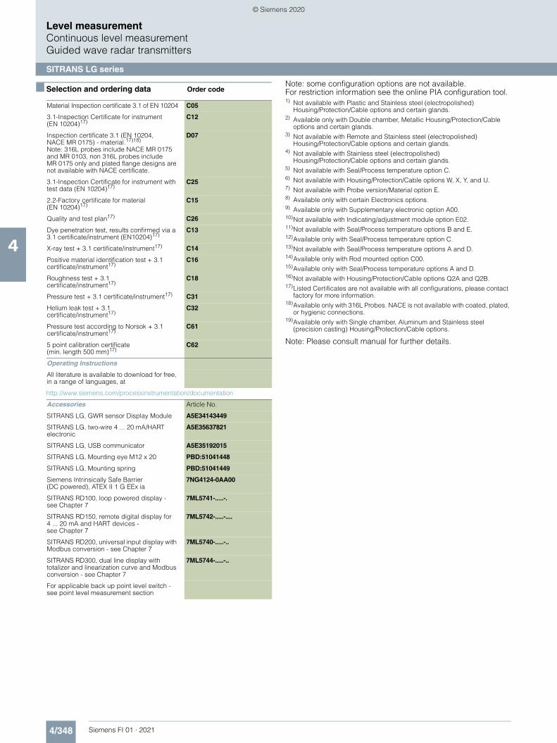
4/348 Siemens FI 01 · 2021
■ Selection and ordering data Order code
Level measurementContinuous level measurementGuided wave radar transmitters
SITRANS LG series
4
Material Inspection certificate 3.1 of EN 10204 C05
3.1-Inspection Certificate for instrument (EN 10204)17)
C12
Inspection certificate 3.1 (EN 10204, NACE MR 0175) - material.17)18)
Note: 316L probes include NACE MR 0175 and MR 0103, non 316L probes include MR 0175 only and plated flange designs are not available with NACE certificate.
D07
3.1-Inspection Certificate for instrument with test data (EN 10204)17)
C25
2.2-Factory certificate for material (EN 10204)17)
C15
Quality and test plan17) C26
Dye penetration test, results confirmed via a 3.1 certificate/instrument (EN10204)17)
C13
X-ray test + 3.1 certificate/instrument17) C14
Positive material identification test + 3.1 certificate/instrument17)
C16
Roughness test + 3.1 certificate/instrument17)
C18
Pressure test + 3.1 certificate/instrument17) C31
Helium leak test + 3.1 certificate/instrument17)
C32
Pressure test according to Norsok + 3.1 certificate/instrument17)
C61
5 point calibration certificate (min. length 500 mm)17)
C62
Operating Instructions
All literature is available to download for free, in a range of languages, at
http://www.siemens.com/processinstrumentation/documentation
Accessories Article No.
SITRANS LG, GWR sensor Display Module A5E34143449
SITRANS LG, two-wire 4 ... 20 mA/HART electronic
A5E35637821
SITRANS LG, USB communicator A5E35192015
SITRANS LG, Mounting eye M12 x 20 PBD:51041448
SITRANS LG, Mounting spring PBD:51041449
Siemens Intrinsically Safe Barrier (DC powered), ATEX II 1 G EEx ia
7NG4124-0AA00
SITRANS RD100, loop powered display -see Chapter 7
7ML5741-.....-.
SITRANS RD150, remote digital display for 4 ... 20 mA and HART devices - see Chapter 7
7ML5742-.....-....
SITRANS RD200, universal input display with Modbus conversion - see Chapter 7
7ML5740-.....-..
SITRANS RD300, dual line display with totalizer and linearization curve and Modbus conversion - see Chapter 7
7ML5744-.....-..
For applicable back up point level switch - see point level measurement section
Note: some configuration options are not available. For restriction information see the online PIA configuration tool.1) Not available with Plastic and Stainless steel (electropolished)
Housing/Protection/Cable options and certain glands.2) Available only with Double chamber, Metallic Housing/Protection/Cable
options and certain glands.3) Not available with Remote and Stainless steel (electropolished)
Housing/Protection/Cable options and certain glands.4) Not available with Stainless steel (electropolished)
Housing/Protection/Cable options and certain glands.5) Not available with Seal/Process temperature option C.6) Not available with Housing/Protection/Cable options W, X, Y, and U.7) Not available with Probe version/Material option E.8) Available only with certain Electronics options.9) Available only with Supplementary electronic option A00.10)Not available with Indicating/adjustment module option E02.11)Not available with Seal/Process temperature options B and E.12)Available only with Seal/Process temperature option C.13)Not available with Seal/Process temperature options A and D.14)Available only with Rod mounted option C00.15)Available only with Seal/Process temperature options A and D.16)Not available with Housing/Protection/Cable options Q2A and Q2B.17)Listed Certificates are not available with all configurations, please contact
factory for more information.18)Available only with 316L Probes. NACE is not available with coated, plated,
or hygienic connections.19)Available only with Single chamber, Aluminum and Stainless steel
(precision casting) Housing/Protection/Cable options.
Note: Please consult manual for further details.
© Siemens 2020

4/349Siemens FI 01 · 2021
■ Selection and ordering data Article No. Article No.
Level measurementContinuous level measurement
Guided wave radar transmitters
SITRANS LG series
4
SITRANS LG270 Guided radar level transmitter
Continuous, contact, 60 m (197 ft) range. Monitors level and interface in liquids in extreme environments.
7ML5883- Ord. code
7 7 7 7 7 - 7 7 7 7 7 7 7
Click on the Article No. for the online configuration in the PIA Life Cycle Portal.
ApprovalsGeneral purpose (CSA, FM, CE)32) 0 AShipping approval1)2)3)4)5) 0 BOverfill protection (WHG; VLAREM)2)3) 0 CATEX II 1G, 1/2G, 2G Ex ia IIC T62)32) 0 EATEX II 1G, 1/2G, 2G Ex ia IIC + Overfill (WHG; VLAREM)2)3)
0 F
ATEX II 1G, 1/2G, 2G Ex ia IIC T6 + shipping approval1)2)3)4)5)
0 G
ATEX II 1G,1/2G 2G Ex ia IIC + ATEX II 1D, 1/2D, 2D IP6x2)7)
0 H
ATEX II 1/2G, 2G Ex d ia IIC T62)5)6)8)32) 0 JATEX II 1/2G, 2G Ex d ia IIC + shipping approval1)2)3)5)6)8)
0 L
ATEX II 1/2G, 2G Ex d ia IIC + ATEX II 1/2D, 2D IP6x2)5)6)8)
0 M
ATEX II 1/2G, 2G Ex d IIC T66)7)32) 0 NATEX II 1G, II 1/2G, II 2G Ex ia IIC T6 ... T1 Ga, Ga/Gb, Gb /IEC Ex ia IIC T6 ... T1 Ga, Ga/Gb, Gb2)3)
0 W
ATEX II 1/2G, 2G Ex d IIC + ship approval1)2)3)5)6)7)
0 Q
ATEX II 1/2G, 2G Ex d IIC + ATEX II 1/2D, 2D IP6x2)6)7)
0 R
ATEX II 1D, 1/2D, 2D IP6x T2)7) 0 SATEX II 1/2G, II 2G Ex db IIC T6 ... T1 Ga/Gb, Gb + Overfill protection (WHG, VLAREM)6)7)32)
7 P
IEC Ex ia IIC T62) 0 TIEC Ex ia IIC T6 + IEC IP6x T tD2)7)32) 0 UIEC Ex d ia IIC T62)5)6)8)32) 1 AIEC Ex d ia IIC T6 + IEC IP6x T tD2)5)6)8) 1 BIEC Ex d IIC T63)6)7) 1 CIEC Ex d IIC T6 + IEC IP6x T tD2)3)6)7) 1 DIEC Ex db IIC T6 ... T1 Ga/Gb, Gb + Ship approval2)3)5)6)7)9)
7 C
IEC Ex ia IIC T6 ... T1 Ga, Ga/Gb, Gb + Ship approval2)9)12)
7 D
IEC Ex d ia IIC T6 ... T1 Ga/Gb, Gb + Ship approval2)5)6)8)9)
7 E
FM (NI) Class I, Div. 2, Groups A, B, C, D2)5)10)32)
1 F
FM (NI) Class I, Div. 2, Groups A, B, C, D + ship approval1)2)3)5)8)
1 G
FM (IS) Class I, II, III, Div. 1, Groups A, B, C, D, E, F2)5)32)
1 H
FM (IS) Class I, II, III, Div. 1, Groups A, B, C, D, E, F, G + ship approval1)2)3)4)5)
1 J
FM (XP-AIS) Class I, II, III, Div. 1, Groups A, B, C, D, E, F, G2)5)6)8)32)
1 K
FM (XP-AIS) Class I, II, III, Div. 1, Groups A, B, C, D, E, F, G + shipping approval1)2)3)5)6)8)
1 L
FM (XP) Class I, Div. 1, Groups A, B, C, D6)11)32)
1 M
CSA (NI) Class I, Div. 2, Groups A, B, C, D; (DIP) Class II, III, Div. 1, Groups E, F, G3)6)7)
1 N
CSA (IS) Class I, II, III, Div. 1, Groups A, B, C, D, E, F, G2)3)
1 P
CSA (XP-IS) Class I, II, III, Div. 1, Groups A, B, C, D, E, F, G2)3)5)6)8)
1 Q
CSA (XP) Class I, II, III, Div. 1, Groups A, B, C, D, E, F, G3)5)6)11)19)
1 R
CSA (NI) Class I, II, III Div. 2, Groups A, B, C, D, F, G + Ship approval2)3)6)7)9)
7 K
CSA (IS) Class I, II, III, Div. 1, Groups A, B, C, D, E, F, G + Ship approval2)6)9)12)
7 L
CSA (XP-IS) Class I, II, III, Div. 1, Groups A, B, C, D, E, F, G + Ship approval2)3)5)6)8)9)
7 M
NEPSI Ex ia IIC T62)3) 2 ANEPSI Ex ia IIC T6 + DIP A20/21 TA T*2)5)7) 2 BNERSI Ex d ia IIC T62)3)5)6)8) 2 CNEPSI Ex d ia IIC T6 + DIP A20/21 TA T* 2)3)5)6)8)
2 D
NEPSI Ex d IIC T62)3)6)11) 2 ENEPSI Ex d IIC T6 + DIP A20/21 TA T* 2)3)6)11)
2 F
NEPSI DIP A20/21 TA T*2)3)7) 2 GINMETRO Ex ia IIC T6 ... T12)32) 3 AINMETRO Ex t IIIC T* IP6X, Da, Da/Db, Da/Dc, Db + Ex ia IIC T6, Ga, Ga/Gb2)6)7)
3 B
INMETRO Ex d ia IIC T6 ... T12)5)6)8)32) 3 CINMETRO Ex t IIIC T* IP6X, Da, Da/Db, Da/Dc, Db + Ex d ia IIC T6 Ga/Gb2)5)68)
3 D
INMETRO Ex d IIC T6 ... T12)6)11)32) 3 EINMETRO Ex t IIIC T* IP6X, Da, Da/Db, Da/Dc, Db + Ex d IIC T6 Ga/Gb2)6)11)
3 F
INMETRO Ex t IIIC T* IP6X, Da, Da/Db, Da/Dc, Db2)6)7)
3 G
KOSHA Ex d IIC T6 ... T1 – KE2)3)6)11) 4 AKorea KC ex free area2)32) 6 AGOST-R/EAC 0 Ex ia IIC T1 ... T6 X2)3)13) 5 AGOST-R/EAC 0 Ex ia IIC T1 ... T6 X + Ex t IIIC T ... IP662)3)7)
5 B
GOST-R/EAC 1 Ex d ia IIC T1 ... T6 X2)3)5)6)8) 5 CGOST-R/EAC 1 Ex d ia IIC T1 ... T6 X + Ex t IIIC T ... IP662)3)5)6)8)
5 D
GOST-R/EAC 1 Ex d IIC T1 ... T6 X2)3)6)11) 5 EGOST-R/EAC 0 Ex d IIC T1 ... T6 X + Ex t IIIC T ... IP662)3)6)11)
5 F
GOST-R/EAC Ex t IIIC T ... IP662)3)14) 5 G
Note: Version/Material, Process fitting/Material, and Length options are available only with options of corresponding type.
Version/MaterialProbe exchangeable cable ø 2 mm (0.08 inch) with gravity weight/31615)16)17)
A
Probe exchangeable cable ø 2 mm (0.08 inch) center weight/316L15)17)18)
B
Probe exchangeable cable ø 4 mm (0.16 inch) with gravity weight/316L15)16)17)
C
Probe exchangeable cable ø 4 mm (0.16 inch) with center weight/316L15)17)18)
D
Probe exchangeable rod ø 16 mm (0.63 inch)/316L16)19)20)
E
Probe coax version ø 42.2 mm (1.66 inch) with multiple hole/316L16)17)20)
F
Probe coax version ø 42.2 mm (1.66 inch); multiple hole; reference distances/316L16)17)20)21)26)
G
Probe exchangeable cable ø 4 mm (0.16 inch) with gravity weight/Alloy C22 (2.4602)22)30)
H
Probe exchangeable rod ø 16 mm (0.63 inch)/Alloy C22 (2.4602)22)30)
J
Coax version ø 42.2 mm (1.66 inch) with multiple hole/Alloy C22 (2.4602)22)30)
K
Exchangeable rod, diameter 8 mm (0.32 inch)/316L19)23)
L
Coax ø 21.3 mm (0.838 inch) with multiple hole/316L23)
M
SITRANS LG270 Guided radar level transmitter
Continuous, contact, 60 m (197 ft) range. Monitors level and interface in liquids in extreme environments.
7ML5883- Ord. code
7 7 7 7 7 - 7 7 7 7 7 7 7
© Siemens 2020

4/350 Siemens FI 01 · 2021
■ Selection and ordering data Article No. Article No.
Level measurementContinuous level measurementGuided wave radar transmitters
SITRANS LG series
4
Process fitting/MaterialThread G 1 1/2" (DIN 3852-A) PN 400/316L20) 0 0Thread 1 1/2" NPT (ASME B1.20.1) PN 400/316L20)
0 1
Thread G1 1/2" PN 400, DIN 3852-A/Alloy C22 (2.4602)
0 2
Thread 1 1/2" NPT PN 400, ASME B1.20.1/ Alloy C22 (2.4602)
0 3
Flange DN 50 PN 40 Form C, DIN 2501/ 316L with Alloy C22 (2.4602) coating
0 4
Flange DN 80 PN 40 Form C, DIN 2501/ 316L with Alloy C22 (2.4602) coating
0 5
Flange DN 100 PN 16 Form C, DIN 2501/ 316L with Alloy C22 (2.4602) coating
0 6
Flange DN 50 PN 40 Form B1, EN 1092-1/ 316L with Alloy C22 (2.4602) coating
0 7
Flange DN 50 PN 63 Form B1, EN 1092-1/ 316L with Alloy C22
0 8
Flange DN 50 PN 40 Form C, DIN 2501/316L 1 0Flange DN 50 PN 40 form V13, DIN 2513/316L
1 1
Flange DN 65 PN 64 Form V13, DIN 2501/316L
1 2
Flange DN 80 PN 40 Form C, DIN 2501/316L 1 3Flange DN 80 PN 40 Form V13, DIN 2501/316L
1 4
Flange DN 80 PN 100 Form L, DIN 2501/316L20)
1 5
Flange DN 100 PN 16 Form C, DIN 2501/316L
1 6
Flange DN 100 PN 16 Form V13, DIN 2501/316L
1 7
Flange DN 100 PN 40 Form C, DIN 2501/316L
1 8
Flange DN 100 PN 40 Form V13, DIN 2513/316L
2 0
Flange DN 150 PN 16 Form C, DIN 2501/316L
2 1
Flange DN 50 PN 40 EN 1092-1 Form B1/316L
2 2
Flange DN 100 PN 160 GOST 12815-80.7/316L20)
2 3
Flange 2" 150 lb RF, ASME B16.5/316L with Alloy C22 (2.4602) coating
2 4
Flange 2" 300 lb RF, ASME B16.5/316L with Alloy C22 (2.4602) coating
2 5
Flange 2" 600 lb RF, ASME B16.5/316L with Alloy C22 (2.4602) coating
2 6
Flange 3" 150 lb RF, ASME B16.5/316L with Alloy C22 (2.4602) coating
2 7
Flange 3" 300 lb RF, ASME B16.5/316L with Alloy C22 (2.4602) coating
2 8
Flange DN 80 PN 160 Form C, DIN 2501/316L20)
6 0
Flange DN 80 PN 250 Form L, DIN 2501/316L20)
6 1
Flange DN 50 PN 160, EN 1092-1 Form B1/316L20)
6 2
Flange DN 50 PN 160, EN 1092-1 Form B2/316L20)
6 3
Flange DN 50 PN 32, EN 1092-1 Form B1/316L20)
6 4
Flange DN 65 PN 250, EN 1092-1 Form B1/316L20)
6 5
Flange DN 100 PN 160, EN 1092-1 Form B2/316L20)
6 6
Flange DN 80 PN 63, EN 1092-1 Form B2/316L
6 7
Flange 4" 600 lb RF, ASME B16.5/ 316L with Alloy C22 (2.4602) coating
6 8
SITRANS LG270 Guided radar level transmitter
Continuous, contact, 60 m (197 ft) range. Monitors level and interface in liquids in extreme environments.
7ML5883- Ord. code
7 7 7 7 7 - 7 7 7 7 7 7 7
Flange 2" 150 lb RF, ASME B16.5/316L 3 0Flange 2" 300 lb RF, ASME B16.5/316L 3 1Flange 2" 600 lb RF, ASME B16.5/316L 3 2Flange 2" 1 500 lb RF, ASME B16.5/316L 3 3Flange 3" 150 lb RF, ASME B16.5/316L 3 4Flange 3" 300 lb RF, ASME B16.5/316L 3 5Flange 3" 600 lb RF, ASME B16.5/316L 3 6Flange 3" 900 lb RF, ASME B16.5/316L 3 7Flange 3" 2 500 lb RF, ASME B16.5/316L 3 8Flange 3 1/2" 600 lb RF, ASME B16.5/316L 4 0Flange 4" 150 lb RF, ASME B16.5/316L 4 1Flange 4" 300 lb RF, ASME B16.5/316L 4 2Flange 4" 600 lb RF, ASME B16.5/316L 4 3Flange 6" 150 lb RF, ASME B16.5/316L 4 4Flange 6" 300 lb RF, ASME B16.5/316L 4 5Flange 6" 600 lb RF, ASME B16.5/316L 4 6Flange 2" 150 lb Fisher special return/316L 4 7Flange 3" 900 lb RJF, ASME B16.5/Alloy C22 (2.4602)
4 8
Flange 2" 900 lb RF, ASME B16.5/316L 5 0Flange 3" 1 500 lb RF, ASME B16.5/316L 5 1Flange 4" 900 lb RF, ASME B16.5/316L 5 2Flange 4" 1 500 lb RF, ASME B16.5/316L 5 3Flange 4" 2 500 lb RJF, ASME B16.5/316L20) 5 4Flange 4" 1500 lb RJF, ASME B16.5/316L20) 5 5Flange 3" 600 lb RF, ASME B16.5/316L with Alloy C22 (2.4602) coating
5 6
Flange 4" 150 lb RF, ASME B16.5/316L with Alloy C22 (2.4602) coating
5 7
Flange 4" 300 lb RF, ASME B16.5/316L with Alloy C22 (2.4602) coating
5 8
Flange 6" 150 lb RF, ASME B16.5/316L with Alloy C22 (2.4602) coating
7 0
Flange DN 50 PN 40 Form C, DIN 2501/Alloy C22 (2.4602) solid
7 1
Flange DN 100 PN 16 Form C, DIN 2501/C22 solid
7 2
Flange DN 100 PN 40 Form N, DIN 2501/Alloy C22 (2.4602) solid
7 3
Flange DN 50 PN 40 Form B1, EN 1092-1/Alloy C22 (2.4602) solid
7 4
Flange 2" 150 lb RF, ASME B16.5/Alloy C22 (2.4602) solid
7 5
Flange 2" 300 lb RF, ASME B16.5/Alloy C22 (2.4602) solid
7 6
Flange 2" 600 lb RF, ASME B16.5/Alloy C22 (2.4602) solid
7 7
Flange 2" 900 lb RJF, ASME B16.5/Alloy C22 (2.4602) solid
7 8
Flange 2" 1 500 lb RJF, ASME B16.5/ Alloy C22 (2.4602) solid
8 0
Flange 3" 150 lb RF, ASME B16.5/Alloy C22 (2.4602) solid
8 1
Flange 3" 300 lb RF, ASME B16.5/Alloy C22 (2.4602) solid
8 2
Flange 3" 600 lb RF, ASME B16.5/Alloy C22 (2.4602) solid
8 3
Flange 4" 150 lb RF, ASME B16.5/Alloy C22 (2.4602) solid
8 4
Flange 4" 300 lb RF, ASME B16.5/Alloy C22 (2.4602) solid
8 5
Flange 3" 600 lb RJF for R31, ASME B16.5/ Alloy C22 (2.4602) solid
8 6
SITRANS LG270 Guided radar level transmitter
Continuous, contact, 60 m (197 ft) range. Monitors level and interface in liquids in extreme environments.
7ML5883- Ord. code
7 7 7 7 7 - 7 7 7 7 7 7 7
© Siemens 2020

4/351Siemens FI 01 · 2021
■ Selection and ordering data Article No. Article No.
Level measurementContinuous level measurement
Guided wave radar transmitters
SITRANS LG series
4
Flange 2" 2 500 lb RJF, ASME B16.5/Alloy C22 (2.4602) solid
9 0 L 1 A
Flange 3" 1 500 lb RJF, ASME B16.5/Alloy C22 (2.4602) solid
9 0 L 1 B
Flange 3" 2 500 lb RJF, ASME B16.5/Alloy C22 (2.4602) solid
9 0 L 1 C
Flange 4" 600 lb RF, ASME B16.5/Alloy C22 (2.4602) solid
9 0 L 1 D
Flange 4" 600 lb RJF, ASME B16.5/Alloy C22 (2.4602) solid
9 0 L 1 E
Flange 4" 900 lb RF, ASME B16.5/Alloy C22 (2.4602) solid
9 0 L 1 F
Flange 4" 900 lb RJF, ASME B16.5/Alloy C22 (2.4602) massiv
9 0 L 1 G
Flange 4" 1 500 lb RJF, ASME B16.5/Alloy C22 (2.4602) solid
9 0 L 1 H
Flange 4" 2 500 lb RJF, ASME B16.5/Alloy C22 (2.4602) solid
9 0 L 1 J
Flange 8" 300 lb RF, ASME B16.5/Alloy C22 (2.4602) solid
9 0 L 1 K
Flange 3½" 600 lb Fisher type 249B and 259B/Alloy C22 (2.4602) solid
9 0 L 1 L
Flange 2½" 300 lb RF, ASME B16.5/316/316L 9 0 L 2 AFlange 2½" 600 lb RF, ASME B16.5/316/316L 9 0 L 2 BFlange DN 50 PN 40 Form D, EN 1092-1/316/316L24)
9 0 L 2 C
Flange 2½" 1 500 lb RF, ASME B16.5/316/316L
9 0 L 2 D
Flange 2" 600 lb RF, ASME B16.5/316L (Norsok)34)35)
9 0 L 2 E
Thread G 1" (DIN 3852-A) PN 100/316L 9 0 L 3 CThread 1" NPT, ASME B1.20.1/PN 100/316L 9 0 L 3 DThread G 1½" (DIN 3852-A) PN 100/316L 9 0 L 3 EThread 1½" NPT, ASME B1.20.1/PN 100/316L
9 0 L 3 F
Thread 2" NPT, ASME B1.20.1/PN 100/316L 9 0 L 3 GThread G ¾ PN100, DIN 3852-A/316L31) 9 0 L 3 HThread ¾ NPT PN100, ASME B1.20.1/3131) 9 0 L 3 J
ElectronicsTwo-wire 4 ... 20 mA/HART 0Four-wire Modbus5)6)8) 1Two-wire 4 ... 20 mA/HART with SIL qualification5)
2
Four-wire 4 ... 20 mA/HART; 90 ... 253 V AC; 50/60 Hz5)6)8)
3
Four-wire 4 ... 20 mA/HART; 9.6 ... 48 V DC; 20 ... 42 V AC5)6)8)
4
PROFIBUS PA5) 5FOUNDATION Fieldbus5) 6
Seal/Second line of defense/Process temperatureCeramic-graphite/with glass seal/ -196 ... +280 °C (-321 ... +536 °F)
A
Ceramic-graphite/with glass seal/-196 ... +450 °C (-321 ... +842 °F)
B
Ceramic-graphite/with glass seal/-196 ... +400 °C (-321 ... +752 °F)21)
C
PEEK-FFKM (Kalrez 6375) /with glass seal/ -20...+250 °C (-4 ... +482 °F)21)
D
SITRANS LG270 Guided radar level transmitter
Continuous, contact, 60 m (197 ft) range. Monitors level and interface in liquids in extreme environments.
7ML5883- Ord. code
7 7 7 7 7 - 7 7 7 7 7 7 7
Housing/Protection/Cable
Note: for installation of remote display, 7ML5840, with LG two chamber housing options, contact PVC
Plastic IP66/IP67 M20 x 1.5/blind stopper APlastic IP66/IP67 1/2" NPT/blind stopper BAluminum/IP66/IP68 (0.2 bar) M20 x 1.5/blind stopper
C
Aluminum/IP66/IP68 (0.2 bar) 1/2" NPT/blind stopper
D
Aluminum double chamber/IP66/IP68 (0.2 bar) M20 x 1.5/blind stopper
E
Aluminum double chamber/IP66/IP68 (0.2 bar) 1/2" NPT/blind stopper
F
Stainless steel (precision casting) 316L/IP66/IP68 (0.2 bar) M20 x 1.5/blind stopper
L
Stainless steel (precision casting) 316L/IP66/IP68 (0.2 bar) 1/2" NPT/blind stopper
M
Stainless steel (electropolished) 316L/IP66/IP68 (0.2 bar) M20 x 1.5/blind stopper
N
Stainless steel (electropolished) 316L/IP66/IP68 (0.2 bar) 1/2" NPT/blind stopper
P
Stainless steel double chamber/IP66/IP68 (0.2 bar) M20 x 1.5/blind stopper
Q
Stainless steel double chamber/IP66/IP68 (0.2 bar) 1/2" NPT/blind stopper
R
Aluminum/IP66/IP68 (0.2 bar) M20 x 1.5/cable gland stainless steel
S
Aluminum double chamber/IP66/IP68 (0.2 bar) M20 x 1.5/cable gland stainless steel
T
Stainless steel (precision casting) 316L/IP66/IP68 (0.2 bar) M20 x 1.5/cable gland stainless steel
U
Stainless steel (electropolished) 316L/IP66/IP68 (0.2 bar) M20 x 1.5/cable gland stainless steel
V
Aluminum single chamber/IP66/IP68 (0.2 bar) M20 x 1.5/cable gland brass nickel-plated
W
Aluminum double chamber/IP66/IP68 (0.2 bar) M20 x 1.5/cable gland brass nickel-plated
X
Stainless steel single chamber (precision casting)/IP66/IP68 (0.2 bar) M20 x 1.5/cable gland brass nickel-plated
Y
Stainless steel double chamber/IP66/IP68 (0.2 bar) M20 x 1.5/cable gland brass nickel-plated
J
Remote stainless steel single chamber housing, electropolished/IP66/IP67 with cable outlet IP68 (electronics separated by cable); M20 x 1.5/blind plug6)
Z Q 2 A
Remote plastic single chamber housing /IP66/IP67 with cable outlet IP68 (electronics separated by cable); M20 x 1.5/blind plug6)
Z Q 2 B
SITRANS LG270 Guided radar level transmitter
Continuous, contact, 60 m (197 ft) range. Monitors level and interface in liquids in extreme environments.
7ML5883- Ord. code
7 7 7 7 7 - 7 7 7 7 7 7 7
© Siemens 2020

4/352 Siemens FI 01 · 2021
■ Selection and ordering data Article No. Article No.
Level measurementContinuous level measurementGuided wave radar transmitters
SITRANS LG series
4
Lengths
Rod ø 16 mm/316L300 mm (11.81 inch)25) 0500 mm (19.69 inch)25) 1501 ... 1 000 mm (19.72 ... 39.37 inch)25) 21 001 ... 2 000 mm (39.41 ... 78.74 inch)25) 32 001 ... 3 000 mm (78.78 ... 118.11 inch)25) 43 001 ... 4 000 mm (118.15 ... 157.48 inch)25) 54 001 ... 5 000 mm (157.52 ... 196.85 inch)25) 65 001 ... 6 000 mm (196.89 ... 236.22 inch)25) 7
Rod ø 16 mm/C22501 ... 1 000 mm (19.72 ... 39.37 inch)25) 9 R 1 A1 001 ... 2 000 mm (39.41 ... 78.74 inch)25) 9 R 1 B2 001 ... 3 000 mm (78.78 ... 118.11 inch)25) 9 R 1 C3 001 ... 4 000 mm (118.15 ... 157.48 inch)25) 9 R 1 D4 001 ... 5 000 mm (157.52 ... 196.85 inch)25) 9 R 1 E5 001 ... 6 000 mm (196.89 ... 236.22 inch)25) 9 R 1 F
Rod ø 8 mm/316L300 ... 1 000 mm (11.81 ... 39.37 inch) 9 R 1 H1 001 ... 2 000 mm (39.41 ... 78.74 inch) 9 R 1 J2 001 ... 3 000 mm (78.78 ... 118.11 inch) 9 R 1 K3 001 ... 4 000 mm (118.15 ... 157.48 inch) 9 R 1 L4 001 ... 5 000 mm (157.52 ... 196.85 inch) 9 R 1 M5 001 ... 6 000 mm (196.89 ... 236.22 inch) 9 R 1 N
Cable lengths ø 2 or 4 mm/316L501 ... 1 000 mm (19.72 ... 39.37 inch)
9 R 2 E
1 000 ... 5 000 mm(39.37 ... 196.85 inch)
9 R 2 F
5 001 ... 10 000 mm(196.89 ... 393.70 inch)
9 R 2 G
10 001 ... 15 000 mm (393.74 ... 590.55 inch)
9 R 2 H
15 001 ... 20 000 mm (590.59 ... 787.40 inch)
9 R 2 J
20 001 ... 25 000 mm (787.44 ... 984.25 inch)
9 R 2 K
25 001 ... 30 000 mm (984.29 ... 1 181.10 inch)
9 R 2 L
30 001 ... 35 000 mm (1 181.14 ... 1 377.95 inch)
9 R 2 M
35 001 ... 40 000 mm (1 377.99 ... 1 574.80 inch)
9 R 2 N
40 001 ... 45 000 mm (1 574.84 ... 1 771.65 inch)
9 R 2 P
45 001 ... 50 000 mm (1 771.69 ... 1 968.50 inch)
9 R 2 Q
50 001 ... 55 000 mm (1 968.54 ... 2 165.35 inch)
9 R 2 R
55 001 ... 60 000 mm (2 165.39 ... 2 362.20 inch)
9 R 2 S
SITRANS LG270 Guided radar level transmitter
Continuous, contact, 60 m (197 ft) range. Monitors level and interface in liquids in extreme environments.
7ML5883- Ord. code
7 7 7 7 7 - 7 7 7 7 7 7 7
Cable lengths ø 4 mm/ C22501 ... 1 000 m(19.72 ... 39.37 inch)
9 R 4 A
1 000 ... 5 000 mm(39.37 ... 196.85 inch)
9 R 4 B
5 001 ... 10 000 mm(196.89 ... 393.70 inch)
9 R 4 C
10 001 ... 15 000 mm(393.74 ... 590.55 inch)
9 R 4 D
15 001 ... 20 000 mm(590.59 ... 787.40 inch)
9 R 4 E
20 001 ... 25 000 mm(787.44 ... 984.25 inch)
9 R 4 F
25 001 ... 30 000 mm (984.29 ... 1 181.10 inch)
9 R 4 G
30 001 ... 35 000 mm (1 181.14 ... 1 377.95 inch)
9 R 4 H
35 001 ... 40 000 mm(1 377.99 ... 1 574.80 inch)
9 R 4 J
40 001 ... 45 000 mm (1 574.84 ... 1 771.65 inch)
9 R 4 K
45 001 ... 50 000 mm (1 771.69 ... 1 968.50 inch)
9 R 4 L
50 001 ... 55 000 mm (1 968.54 ... 2 165.35 inch)
9 R 4 M
55 001 ... 60 000 mm (2 165.39 ... 2 362.20 inch)
9 R 4 N
Coax ø 42.2 mm/316L300 ... 1 000 mm (11.81 ... 39.37 inch)25) 9 R 3 G1 001 ... 2 000 mm (39.41 ... 78.74 inch)25)26)
9 R 3 H
2 001 ... 3 000 mm (78.78 ... 118.11 inch)25) 9 R 3 J3 001 ... 4 000 mm (118.15 ... 157.48 inch)25)
9 R 3 K
4 001 ... 5 000 mm (157.52 … 196.85 inch)25)
9 R 3 L
5 001 … 6 000 mm (196.89 … 236.22 inch)25)
9 R 3 M
Coax ø 42.2 mm/C22300 ... 1 000 mm (11.81 ... 39.37 inch)25) 9 R 3 Q1 001 ... 2 000 mm (39.41 ... 78.74 inch)25)26) 9 R 3 R2 001 ... 3 000 mm (78.78 ... 118.11 inch)25) 9 R 3 S3 001 ... 4 000 mm (118.15 ... 157.48 inch)25) 9 R 3 T4 001 ... 5 000 mm (157.52 ... 196.85 inch)25) 9 R 3 U5 001 ... 6 000 mm (196.89 ... 236.22 inch)25) 9 R 3 V
Coax ø 21.3 mm/316L300 ... 1 000 mm (11.81 ... 39.37 inch) 9 R 5 A1 001 ... 2 000 mm (39.41 ... 78.74 inch)
9 R 5 B
2 001 ... 3 000 mm (78.78 ... 118.11 inch)
9 R 5 C
3 001 ... 4 000 mm (118.15 ... 157.48 inch)
9 R 5 D
4 001 ... 5 000 mm (157.52 ... 196.85 inch)
9 R 5 E
5 001 ... 6 000 mm (196.89 ... 236.22 inch)
9 R 5 F
SITRANS LG270 Guided radar level transmitter
Continuous, contact, 60 m (197 ft) range. Monitors level and interface in liquids in extreme environments.
7ML5883- Ord. code
7 7 7 7 7 - 7 7 7 7 7 7 7
© Siemens 2020

4/353Siemens FI 01 · 2021
■ Selection and ordering data Order code Order code
Level measurementContinuous level measurement
Guided wave radar transmitters
SITRANS LG series
4
Further designs (mandatory)
Please add "-Z" to Article No. and specify Order code(s).
Supplementary electronics
Without A00
Additional current output 4 ... 20 mA6) A01
Dimensions centering weight (diameter/height)
Without B00
ø 40/30 mm B01
ø 45/30 mm (for 2 inch tubes) B02
ø 75/30 mm (for 3 inch tubes) B03
ø 95/30 mm (for 4 inch tubes) B04
ø 40 mm/30 mmø 1.57 inch/1.18 inch (for 2 inch Schedule 160)
B05
ø 45 mm/30 mm (for 2 inch tubes)ø 1.77 inch/1.18 inch (for 2 inch Schedule 40/80)
B06
ø 75 mm/30 mm (for 3 inch tubes)ø 2.95 inch/1.18 inch (for 3 inch Schedule 10/40)
B07
ø 95 mm/30 mm (for 4 inch tubes)ø 3.74 inch/1.18 inch (for 4 inch Schedule 80)
B08
Rod mounted
Without Rod, applicable for coax or cable probe types only
C00
Mounted C01
Not mounted C02
Indicating/adjustment module
Without E00
Mounted E01
Laterally mounted E02
Language of display
German L00
English L01
French L02
Dutch L03
Italian L04
Spanish L05
Portuguese L06
Russian L07
Chinese L08
Japanese L09
Operating instructions
German M00
English M01
French M02
Spanish M03
Further designs (optional)
Please add "-Z" to Article No. and specify Order code(s).
Enter the total insertion length in plain text description
Y01
Y02 rigid part is 100 mm, only applicablefor cable versions
Y02
Reference probe G length of reference distance = 260 mm/10.24 inches (note blanking 450 mm required with min. probe 1 000 mm)
Y05
Reference probe G length of reference distance = 500 mm/19.69 inches (note blanking 690 mm required with min. probe 1 250 mm)
Y06
Reference probe G length of reference distance = 750 mm/29.53 inches (note blanking 940 mm required with min. probe 1 500 mm)
Y07
Remote electronic cable lengths: 2 m (6.6 ft). Only available with Housing options Q2A and Q2B
Y10
Remote electronic cable lengths: 5 m (16.4 ft). Only available with Housing options Q2A and Q2B
Y11
Remote electronic cable lengths: 10 m (32.8 ft). Only available with Housing options Q2A and Q2B
Y12
Customer specific adjustment (unit value, 100 % distance from seal, 0 % distance from seal)
Y20
Cleaning included certificate: oil, grease and silicone free
W01
Identification Label (measurement loop) stainless steel, 40 characters max, add in plain text. To add more than one line use a coma "," for line break.
Y17
Identification Label (measurement loop) foil, 40 characters max, add in plain text. To add more than one line use a coma "," for line break.
Y18
Material Inspection certificate 3.1 of EN 10204 C05
3.1-Inspection Certificate for instrument (EN 10204)27)
C12
Inspection certificate 3.1 (EN 10204, NACE MR 0175) - material.27)
Note: 316L probes include NACE MR 0175 and MR 0103, non 316L probes include MR 0175 only and plated flange designs are not available with NACE certificate.
D07
3.1-Inspection Certificate for instrument with test data (EN 10204)27)
C25
2.2-Factory certificate for material (EN 10204)27)
C15
Quality and test plan27) C26
Dye penetration test, results confirmed via a 3.1 certificate/instrument (EN10204)27)
C13
X-ray test + 3.1 certificate/instrument27) C14
Positive material identification test + 3.1 certificate/instrument27)
C16
Roughness test + 3.1 certificate/instrument27)
C18
Pressure test + 3.1 certificate/instrument27) C31
Helium leak test + 3.1 certificate/instrument27)
C32
Pressure test according to Norsok + 3.1 certificate/instrument27)33)
C61
5 point calibration certificate (min. length 500 mm)27)
C62
Pressure test (acc. to ASME B31.1), incl. 3.1 Inspection certificate28)
C63
Certificate: Approval for steam boiler according to EN 12952-11, EN 12953-929)
C70
© Siemens 2020

4/354 Siemens FI 01 · 2021
■ Selection and ordering data Order code
Level measurementContinuous level measurementGuided wave radar transmitters
SITRANS LG series
4
Operating Instructions
All literature is available to download for free, in a range of languages, at
http://www.siemens.com/processinstrumentation/documentation
Accessories
SITRANS LG, GWR sensor Display Module A5E34143449
SITRANS LG, two-wire 4 ... 20 mA/HART electronic
A5E35637821
SITRANS LG, USB communicator A5E35192015
SITRANS LG, Mounting eye M12 x 20 PBD:51041448
SITRANS LG, Mounting spring PBD:51041449
Siemens Intrinsically Safe Barrier (DC powered), ATEX II 1 G EEx ia
7NG4124-0AA00
SITRANS RD100, loop powered display -see Chapter 7
7ML5741-.....-.
SITRANS RD150, remote digital display for 4 ... 20 mA and HART devices - see Chapter 7
7ML5742-.....-....
SITRANS RD200, universal input display with Modbus conversion - see Chapter 7
7ML5740-.....-..
SITRANS RD300, dual line display with totalizer and linearization curve and Modbus conversion - see Chapter 7
7ML5744-.....-..
For applicable back up point level switch - see point level measurement section
Note: some configuration options are not available. For restriction information see the online PIA configuration tool.1) Not available with Version/Material options E, F, G, J, and K.2) Available only with certain Electronic options.3) Not available with Seal/Process temperature option D.4) Not available with Stainless Steel (electropolished) Housing/
Protection/Cable options and certain glands.5) Available only with Supplementary electronic option A00.6) Not available with Indicating/adjusting module E02.7) Not available with Plastic and Stainless Steel (electropolished)
Housing/Protection/Cable options and certain glands.8) Available only with Double chamber, Metallic Housing/Protection/Cable
options and certain glands.9) Available only with Version/Material options A, B, C, D, and H.10)Not available with Remote and Stainless Steel (electropolished)
Housing/Protection/Cable options and certain glands.11)Available only with Single chamber, Aluminum and Stainless steel
(precision casting) Housing/Protection/Cable options.12)Available only with Housing/Protection/Cable options N, P, V, and Q2A.13)Not available with Housing/Protection/Cable options W, X, Y, and J.14)Available only with Housing/Protection/Cable options C, E, L, Q.15)Not available with Seal/Process temperature option C.16)Available only with Dimensions centering weight option B00.17)Available only with Rod mounted option C00.18)Not available with Dimensions centering weight option B00.19)Not available with Rod mounted option C00.20)Not available with Seal/Process temperature options C and D.21)Not available with Remote Housing/Protection/Cable options.22)Not available with Seal/Process temperature options B and D.23)Available only with Seal/Process temperature option D.24)Available only with Seal/Process temperature options A, B, and C.25)Not available with Order code Y02.26)Accuracy is application dependent, please consult factory.27)Listed Certificates are not available with all configurations, please contact
factory for more information.28)Available only with ASME Process fitting/Material options.29)Available with Version/Material options G, L, M and Electronic options
2 and 6.30)Available only with Alloy C22 Process fitting/Material options.31)Available only with Version/Material option M.32)Available only with some Version/Material options.33)Available only with Norsok Process fitting options.34)Available only with Seal/Second line of defense/Process temperature
options A and B.35)Available only with 316L probe Version/material options. Nace not
available with coated, plated, or hygienic connections.
Note: Please consult manual for further details.
© Siemens 2020

4/355Siemens FI 01 · 2021
■ Selection and ordering data Article No. Article No.
Level measurementContinuous level measurement
Guided wave radar transmitters
SITRANS LG series
4
1) Available only with Housing options 1 and 2.2) Available only with Housing option 0.3) Available only with Housing option 1.4) Available only with Mounting options B and D.5) Not available with Mounting option B.6) Shipping approval is only available with housing options 0 and 1.
SITRANS LG Remote Interface
Provides remote display and configuration for SITRANS LG series guided radar level transmitters.
7ML5840-
7 7 7 7 7 - 7 7 7 7 0
Click on the Article No. for the online configuration in the PIA Life Cycle Portal.
Note: for installation of remote display, 7ML5840, with LG two chamber housing options, contact PVC
ApprovalFor Ex-free area 0 AATEX II 1G, 2G, Ex ia IIC T6 Ga, Gb 0 CATEX II 2G, Ex d IIC T6 Gb1) 0 EIEC Ex ia IIC T6 Ga, Gb 0 FIEC Ex d IIC T6 Gb1) 0 G
CCSAUS (NI) Class I, Div. 2, Groups A, B, C, D; (DIP) Class II, III, Div. 1, Groups E, F, G
0 H
CCSAUS (IS) Class I, II, III, Div. 1, Groups A, B, C, D, E, F, G
0 J
CCSAUS (XP) Class I, Div. 1, Groups A, B, C, D1)
0 K
INMETRO Ex ia IIC T6 Ga, Gb 0 LINMETRO Ex d IIC T6 Gb1) 0 MShipping Approval (DNV/GL)6) 0 NATEX II 1G, 2G Ex ia IIC T6 Ga, Gb + Ship approval
0 P
ATEX II 2G Ex db IIC T6 Gb + Ship approval1)
0 Q
IEC Ex ia IIC T6 Ga, Gb + Ship approval 0 RIEC Ex db IIC T6 Gb + Ship approval1) 0 S
cCSAus (IS) Class I, II, III, Div. 1, Groups A, B, C, D, E, F, G + Ship approval
0 T
cCSAus (XP) Class I, Div. 1, Groups A, B, C, D + Ship approval1)
0 U
ElectronicsDigital (I²C communication) A
HousingPlastic2)4) 0Aluminum3)5) 1Stainless Steel (precision casting)3)5) 2
Housing protectionIP66/IP67 NEMA 4X 0IP66/IP68 NEMA 6P (0.2 bar) 1
Cable entryM20 x 1.5/ Blind plug 3½" NPT/ Blind plug 5
DisplayWithout AMounted B
MountingFor wall mounting with Aluminum or stainless steel housing
A
For carrier rail and wall mounting with plastic housing
B
For carrier rail with Aluminum or stainless steel housing
C
For tube mounting (29 ... 60 mm) including mounting material
D
CertificatesNone 03.1 Certificate/Instrument with test data 1Quality and Test plan 2
SITRANS LG Replacement Probes
For use with SITRANS LG series guided radar level transmitters.
7ML5841-
7 7 7 7 7 - 7 7 7 0
Click on the Article No. for the online configuration in the PIA Life Cycle Portal.
InstrumentLG2404) 0LG2506) 1LG2607) 2LG2709)10) 3
Probe Type3)
Exchangeable cable ø 2 mm with gravity weight/3161)11)
A A
Exchangeable cable ø 2 mm center weight/3162)11)
A C
Exchangeable cable ø 4 mm without weight/3161)11)
A D
Exchangeable cable ø 4 mm with gravity weight/3161)11)
A E
Exchangeable cable ø 4 mm with center weight/3162)11)
A G
Exchangeable cable ø 6 mm with gravity weight/3161)8)11)
A H
Exchangeable rod ø 8 mm/316L1) A PExchangeable rod ø 8 mm/1.4435 (acc. to Basle Standard)1)
A Q
Exchangeable rod ø 12 mm/316L1) A UExchangeable rod ø 16 mm/316L1) A WExchangeable coated cable ø4 mm with uncoated centering weight / PFA and 31611)12)
B A
Process fittingThread less than or equal to 1½ inch 0Thread greater than or equal to 2 inch 1Flange less than DN 50 or 2 inch 2Flange greater or equal to DN 50 or 2 inch or hygienic fitting (not for safety ingold 25 x 46 mm)
3
Dimension centering weightWithout 0ø 40 mm/30 mm 1ø 45 mm/30 mm (for 2 inch tubes) 2ø 75 mm/30 mm (for 3 inch tubes) 3ø 95 mm/30 mm (for 4 inch tubes) 4ø 1.57 inch/1.18 inch (for 2 inch Schedule 160)
5
ø 1.77 inch/1.18 inch (for 2 inch Schedule 40/80)
6
ø 2.95 inch/1.18 inch (for 3 inch Schedule 10/40)
7
ø 3.74 inch/1.18 inch (for 4 inch Schedule 80)
8
CertificatesWithout 02.2 Material certificate 13.1 Material certificate 2
© Siemens 2020

4/356 Siemens FI 01 · 2021
■ Selection and ordering data Article No. Article No.
Level measurementContinuous level measurementGuided wave radar transmitters
SITRANS LG series
4
1) Available only with Dimension centering weight option 0.2) Available only with Dimension centering weight options 1 ... 8.3) All Probe types are only available with corresponding Probe lengths.4) Not available with Probe type options AH, AQ, and AW.5) Available only with Process fitting options 2 and 3.6) Not available with Probe type options AQ and AW.7) Available only with Probe type options AE, AH, and AW.8) Not available with Process fitting option 2.9) Available only with Probe type options AA, AC, AE, AG, and AW.10)Available only with Process fitting options 0 and 3.11)Not available with certificate options 1 and 2.12)Available only with Dimension centering weight options 1 ... 4.
Lengths
Rod ø 8 mm 300 ... 1 000 mm (11.81 ... 39.37 inch) A A1 001 ... 2 000 mm (39.41 ... 78.74 inch) A B2 001 ... 3 000 mm (78.78 ... 118.11 inch) A C3 001 ... 4 000 mm (118.15 ... 157.48 inch) A D4 001 ... 5 000 mm (157.52 ... 196.85 inch) A E5 001 ... 6 000 mm (196.89 ... 236.22 inch) A F
Rod ø 12 mm300 ... 1 000 mm (11.81 ... 39.37 inch) A G1 001 ... 2 000 mm (39.41 ... 78.74 inch) A H2 001 ... 3 000 mm (78.78 ... 118.11 inch) A J3 001 ... 4 000 mm (118.15 ... 157.48 inch) A K4 001 ... 5 000 mm (157.52 ... 196.85 inch) A L5 001 ... 6 000 mm (196.89 ... 236.22 inch) A
M
Rod ø 16 mm300 ... 1 000 mm (11.81 ... 39.37 inch) A N1 001 ... 2 000 mm (39.41 ... 78.74 inch) A P2 001 ... 3 000 mm (78.78 ... 118.11 inch) A Q3 001 ... 4 000 mm (118.15 ... 157.48 inch) A R4 001 ... 5 000 mm (157.52 ... 196.85 inch) A S5 001 ... 6 000 mm (196.89 ... 236.22 inch) A T
Cable Lengths ø 2 mm and 4 mm/316501 ... 1 000 mm (19.72 ... 39.37 inch) A U1 001 ... 5 000 mm (39.41 ... 196.85 inch) A V5 000 ... 10 000 mm (196.85 ... 393.70 inch) A W10 001 ... 15 000 mm (393.74 ... 590.55 inch) A X15 001 ... 20 000 mm (590.59 ... 787.40 inch) A Y20 001 ... 25 000 mm (787.44 ... 984.25 inch) B A25 001 ... 30 000 mm (984.29 ... 1 181.10 inch)
B B
30 001 ... 35 000 mm (1 181.14 ... 1 377.95 inch)
B C
35 001 ... 40 000 mm (1 377.99 ... 1 574.80 inch)
B D
40 001 ... 45 000 mm (1 574.84 ... 1 771.65 inch)
B E
45 001 ... 50 000 mm (1 771.69 ... 1 968.50 inch)
B F
50 001 ... 55 000 mm (1 968.54 ... 2 165.35 inch)
B G
55 001 ... 60 000 mm (2 165.39 ... 2 362.20 inch)
B H
60 001 ... 65 000 mm (2 362.24 ... 2 559.06 inch)
B J
65 001 ... 70 000 mm (2 559.09 ... 2 755.91 inch)
B K
70 001 ... 75 000 mm (2 755.94 ... 2 952.76 inch)
B L
SITRANS LG Replacement Probes
For use with SITRANS LG series guided radar level transmitters.
7ML5841-
7 7 7 7 7 - 7 7 7 0
Cable Lengths ø 6 mm/316501 ... 1 000 mm (19.72 ... 39.37 inch) B M1 001 ... 5 000 mm (39.41 ... 196.85 inch) B N5 000 ... 10 000 mm (196.89 ... 393.70 inch) B P10 001 ... 15 000 mm (393.74 ... 590.55 inch) B Q15 001 ... 20 000 mm (590.59 ... 787.40 inch) B R20 001 ... 25 000 mm (787.44 ... 984.25 inch) B S25 001 ... 30 000 mm (984.29 ... 1 181.10 inch)
B T
30 001 ... 35 000 mm (1 181.14 ... 1 377.95 inch)
B U
35 001 ... 40 000 mm (1 377.99 ... 1 574.80 inch)
B V
40 001 ... 45 000 mm (1 574.84 ... 1 771.65 inch)
BW
45 001 ... 50 000 mm (1 771.69 ... 1 968.50 inch)
B X
50 001 ... 55 000 mm (1 968.54 ... 2 165.35 inch)
B Y
55 001 ... 60 000 mm (2 165.39 ... 2 362.20 inch)
C A
60 001 ... 65 000 mm (2 362.24 ... 2 559.06 inch)
C B
65 001 ... 70 000 mm (2 559.09 ... 2 755.91 inch)
C C
70 001 ... 75 000 mm (2 755.94 ... 2 952.76 inch)
C D
Cable Lengths ø 4 mm/316300 ... 1 000 mm (12 ... 39.37 inch) D A1 001 ... 2 000 mm (39.41 ... 78.74 inch) D B2 001 ... 5 000 mm (78.77 ... 196.85 inch) D C5 001 ... 10 000 mm (196.89 ... 393.70 inch) D D10 001 ... 15 000 mm (393.74 ... 590.55 inch) D E15 001 ... 20 000 mm (590.59 ... 787.40 inch) D F20 001 ... 25 000 mm (787.44 ... 984.25 inch) D G25 001 ... 32 000 mm (984.29 ... 1 259.84 inch)
D H
Further designs Order code
Please add "-Z" to Article No. and specify Order code(s).
Enter the total insertion length in plain text description
Y01
Total length: Enter the total length of rigid part (range 100 ... 1 000 mm LG270 limited to 100 mm) (cable versions only)
Y02
SITRANS LG Replacement Probes
For use with SITRANS LG series guided radar level transmitters.
7ML5841-
7 7 7 7 7 - 7 7 7 0
© Siemens 2020

4/357Siemens FI 01 · 2021
Level measurementContinuous level measurement
Guided wave radar transmitters
SITRANS LG series
4
■ Selection and ordering data Article No.
1) Available only with Version/Material options AA and AC.2) Available only with Version/Material options AB, AD, AE, AH and AJ.3) Available only with Version/Material options AE and AG.4) Available only with Tube Diameter option 1 and LG240.5) Available only with Tube Diameter options 2 and 3 and LG250.6) Available only with Tube Diameter option 1 and LG250.7) Available only with Tube diameter option 1 and LG260 or LG270.8) Available only with Tube Diameter options 2 and 3 and LG260 or LG270.
SITRANS LG Spacers
For use with SITRANS LG series guided radar level transmitters.
7ML5842-
7 7 7 7 - 0 0 A A 0
Click on the Article No. for the online configuration in the PIA Life Cycle Portal.
InstrumentLG2401) 0LG2502) 1LG2603) 2LG2703) 3
Version/MaterialCable ø 4 mm/ PFA4) A ARod ø 8 mm including fastening/ PEEK can be shortened5)
A B
Rod ø 10 mm/ PFA4) A CRod ø 12 mm including fastening/ PEEK can be shortened5)
A D
Rod ø 16 mm, cable with gravity weight, including fastening/ PEEK can be shortened5)7)
A E
Cable ø 2 mm including fastening/ PEEK and 316L
A F
Rod ø 16 mm including fastening/ 1.4568 (AISI 631) flexible8)
A G
Rod ø 8 mm including fastening/ PTFE can be shortened5)
A H
Rod ø 12 mm including fastening/ 1.4568 (AISI 631) flexible6)
A G
Tube diameter50 mm (2 inch) up to 100 mm (4 inch) 149.2 mm (1.9 inch) up to 56.3 mm (2.2 inch) 266.6 mm (2.6 inch) up to 84.9 mm (3.3 inch) 3
© Siemens 2020

4/358 Siemens FI 01 · 2021
Level measurementContinuous level measurementGuided wave radar transmitters
SITRANS LG series
4
■ Characteristic curves
SITRANS LG240, ambient temperature/process temperature curve
0 °C(32 °F)
-40 °C(-104 °F)
80 °C(176 °F)
150 °C(302 °F)-20 °C
(-68 °F)
SITRANS LG240,
AmbientTemperature
ProcessTemperature
MaximumPermissibleTemperature
Ambient temperature/process temperature, standard version
© Siemens 2020

4/359Siemens FI 01 · 2021
Level measurementContinuous level measurement
Guided wave radar transmitters
SITRANS LG series
4
■ Characteristic curves (continued)
SITRANS LG250, ambient temperature/process temperature curves
0 °C
0 °C
(32 °F)
(32 °F)
-40 °C
-40 °C
-40 °C
(-104 °F)
(-104 °F)
(-104 °F)
80 °C
80 °C
55 °C
(176 °F)
(176 °F)
(131 °F)
150 °C
200 °C150 °C
130 °C80 °C
65 °C
(302 °F)
(392 °F)(302 °F)
(266 °F)(176 °F)
(149 °F)
-20 °C(-68 °F)
SITRANS LG250,
SITRANS LG250,
AmbientTemperature
MaximumPermissibleTemperature
LimitedTemperatureRange
ProcessTemperature
AmbientTemperature
MaximumPermissibleTemperature
LimitedTemperatureRange
ProcessTemperature
Ambient temperature/process temperature, standard version
Ambient temperature/process temperature, temperature adapter version
© Siemens 2020

4/360 Siemens FI 01 · 2021
Level measurementContinuous level measurementGuided wave radar transmitters
SITRANS LG series
4
■ Characteristic curves (continued)
SITRANS LG260, maximum tensile load curves
2
2 2
1
4
4 4
2
6
6 6
14 14
3
8
8 8
16 16
4
10
10 10
18 18
5
12
12 12
20 20
6
0
0 0
00
0 0
05
5 5
510
10 10
1015
15 15
1520
20 20
2025
25 25
2530
30 30
30"A"
"C" "D"
"B"35
35 35
35
1
1 1
1
4
4 4
4
2
2 2
2
5
55
5
3
3 3
3
6
66
6
SITRANS LG260,
SITRANS LG260,
Maximum tensile load with cereals and plastic granules - cable: ø 4 mm (0.157 inch)
Maximum tensile load with sand and cement - cable: ø 4 mm (0.157 inch)
A. CerealsB. Plastic granules1. Tensile force in kN (the determined value must be multiplied with safety factor 2)2. Cable length in m3. Vessel diameter 12 m (39.37 ft)4. Vessel diameter 9 m (29.53 ft)5. Vessel diameter 6 m (19.69 ft)6. Vessel diameter 3 m (9.843 ft)
C. SandD. Cement1. Tensile force in kN (the determined value must be multiplied with safety factor 2)2. Cable length in m3. Vessel diameter 12 m (39.37 ft)4. Vessel diameter 9 m (29.53 ft)5. Vessel diameter 6 m (19.69 ft)6. Vessel diameter 3 m (9.843 ft)
© Siemens 2020

4/361Siemens FI 01 · 2021
Level measurementContinuous level measurement
Guided wave radar transmitters
SITRANS LG series
4
■ Characteristic curves (continued)
SITRANS LG260, ambient temperature/process temperature curves
0 °C
0 °C
(32 °F)
(32 °F)
-40 °C
-40 °C
-40 °C
(-104 °F)
(-104 °F)
(-104 °F)
80 °C
65 °C
80 °C
55 °C
(176 °F)
(149 °F)
(176 °F)
(131 °F)
150 °C
200 °C150 °C
130 °C(302 °F)
(392 °F)(302 °F)
(266 °F)
-20 °C(-68 °F)
AmbientTemperature
AmbientTemperature
MaximumPermissibleTemperature
MaximumPermissibleTemperature
LimitedTemperatureRange
LimitedTemperatureRange
ProcessTemperature
ProcessTemperature
SITRANS LG260, Ambient temperature/process temperature, temperature adapter versionCable version with ø 4 mm (0.157 inch)Cable version, PA coated with ø 6 mm (0.236 inch)
SITRANS LG260, Ambient temperature/process temperature, standard versionCable version with ø 4 mm (0.157 inch)Cable version, PA coated with ø 6 mm (0.236 inch)
© Siemens 2020

4/362 Siemens FI 01 · 2021
Level measurementContinuous level measurementGuided wave radar transmitters
SITRANS LG series
4
■ Characteristic curves (continued)
SITRANS LG260, ambient temperature/process temperature curves
0 °C(32 °F)
-40 °C
-40 °C
(-104 °F)
(-104 °F)
80 °C(176 °F)
150 °C(302 °F)
0 °C(32 °F)
-40 °C
-20 °C
(-104 °F)
(-68 °F)
80 °C
65 °C
(176 °F)
(149 °F)
200 °C170 °C(392 °F)(338 °F)
AmbientTemperature
ProcessTemperature
MaximumPermissibleTemperature
AmbientTemperature
MaximumPermissibleTemperature
LimitedTemperatureRange
ProcessTemperature
SITRANS LG260, Ambient temperature/process temperature, temperature adapter versionCable version with ø 6 mm (0.236 inch)Cable version, PA coated with ø 11 mm (0.433 inch)
SITRANS LG260, Ambient temperature/process temperature, standard versionCable version with ø 6 mm (0.236 inch)Cable version, PA coated with ø 11 mm (0.433 inch)
© Siemens 2020

4/363Siemens FI 01 · 2021
Level measurementContinuous level measurement
Guided wave radar transmitters
SITRANS LG series
4
■ Characteristic curves (continued)
SITRANS LG270, ambient temperature/process temperature curves
0 °C(32 °F)
-40 °C(-104 °F)
80 °C
65 °C
55 °C
-196 °C -80 °C
(176°F)
(149 °F)
(131 °F)
(-321 °F) (-112 °F)280 °C250 °C190 °C(536 °F)(482 °F)(374 °F)
0 °C(32 °F)
-40 °C(-104 °F)
80 °C
-196 °C -110 °C
35 °C
-20 °C220 °C 450 °C
(176 °F)
(-321 °F) (-230 °F)
(95 °F)
(-68 °F)(428 °F) (842 °F)
AmbientTemperature
MaximumPermissibleTemperature
LimitedTemperatureRange
ProcessTemperature
AmbientTemperature
MaximumPermissibleTemperature
LimitedTemperatureRange
ProcessTemperature
SITRANS LG270, Ambient temperature/process temperature ( -196 … +280 °C/-321 … +536 °F version)
SITRANS LG270, Ambient temperature/process temperature ( -196 … +450 °C/-321 … +842 °F version)
© Siemens 2020

4/364 Siemens FI 01 · 2021
Level measurementContinuous level measurementGuided wave radar transmitters
SITRANS LG series
4
■ Characteristic curves (continued)
SITRANS LG270, process pressure/process temperature curve
0 °C 100 °C 200 °C 300 °C 400 °C 450 °C(32 °F) (212 °F) (392 °F) (572 °F) (752 °F) (842 °F)
400 bar
380 bar
350 bar
320 bar300 bar
200 bar
100 bar
(5 800 psig)
(5 510 psig)
(5 070 psig)
(4 640 psig)(4 350 psig)
(2 900 psig)
(1 450 psig)
-200 °C -100 °C(-328 °F) (-148 °F)
ProcessTemperature
ProcessPressure
SITRANS LG270, Process pressure/process temperature ( -196 … +450 °C/-321 … +842 °F version)
© Siemens 2020

4/365Siemens FI 01 · 2021
Level measurementContinuous level measurement
Guided wave radar transmitters
SITRANS LG series
4
■ Dimensional drawings
SITRANS LG series, dimensions in mm (inch)
SITRANS LG Series plastic housing
SITRANS LG Series aluminum housing
SITRANS LG Series stainless steel housing
Single chamber version Double chamber
version
Double chamber version,
precision casting
Single chamber version,
precision casting
Single chamber version,
electropolished
Single chamber version
Double chamber version
Note: For integrated display and adjustment module the housing is 9 (0.35) higher for all housing options
M20 x 1.5/½" NPT
M16x1.5
M20 x 1.5/½" NPT
M20 x 1.5/½" NPT
M20x1.5
M16x1.5
M20 x 1.5/½" NPT
M20 x 1.5/½" NPT
M20 x 1.5/½" NPT
M20 x 1.5/½" NPT
M16x1.5
69 (2.72) Ø 77
(3.03)
114(4.49)
Ø 77 (3.03)
86 (3.39)
114(4.49)
116 (4.57)
Ø 84 (3.31)
120 (4.72)
91(3.58)
Ø 84 (3.31)
124(4.88)
59 (2.32)
Ø 80 (3.15)
112 (4.41)
69 (2.72) Ø 77
(3.03)
119 (4.69)
90(3.54) Ø 84
(3.31)
123 (4.84)
© Siemens 2020

4/366 Siemens FI 01 · 2021
Level measurementContinuous level measurementGuided wave radar transmitters
SITRANS LG series
4
■ Dimensional drawings (continued)
SITRANS LG240, dimensions in mm (inch)
Cable version Ø 4 (0.157), PFA coated Rod version Ø 10 (0.394), PFA coated
Autoclaved version Rod version Ø 8 (0.315), polished
Cable version with clamp
Cable version with bolting Rod version
with clamp
Cover with groove nut
Groove nut
Process fitting
Rod version with bolting
69.4
(2.7
3)
71.4
(2.8
1)
69.4
(2.7
3)
71.4
(2.8
1)
65.3
(2.5
7)
Note: Y01 = total insertion length
Ø 4(0.16)
115
(4.5
3)
Ø 4(0.16)
Ø 10(0.39)
70(2
.76)
Ø 54(2.13)
Ø w
DIN DN 25 DN 32 DN 40/ 1" 1½"
Ø w
DIN DN 50/ 2"
DIN DN 65/ 3"
Ø 50.5Ø 64Ø 91
112
(4.8
4)18
3(7
.20)
56(2
.02)
Ø 8(0.32)
500
... 3
2 00
0(1
9.68
... 1
2 59
8.42
)
300
... 4
000
(11.
81...
157
.48)
300
... 4
000
(11.
81...
157
.48)
300
... 4
000
(11.
81...
157
.48)
SITRANS LG240
70(2
.76)
Y02 Y02 Y02
© Siemens 2020

4/367Siemens FI 01 · 2021
Level measurementContinuous level measurement
Guided wave radar transmitters
SITRANS LG series
4
■ Dimensional drawings (continued)
SITRANS LG250, dimensions in mm (inch)
SITRANS LG250, dimensions in mm (inch)
500
... 7
5 00
0(1
9.68
... 2
952
.75)
Cable version with gravity weight
Cable version with centering weight
Rod version
Note: Y01 = total insertion length
SW 36 (1.42") (G3/4, 3/4" NPT)
SW 41 (1.61") (G1, 1" NPT)
SW 46 (1.81") (G1½, 1½" NPT)
G3/4, 3/4" NPT
G1, 1" NPT G1½, 1½" NPT
Ø 2 (0.08)
50(1
.97)
Ø 16 (0.63)
Ø 20(0.79)
46(1
.81)
22(0
.87)
Ø 4 (0.16)
100
(3.9
4)
96(3
.78)
22(0
.87)
Ø 4 (0.16)
100
(3.9
4)
Ø 16 (0.63)
Ø 20(0.79)
Ø 16 (0.63)
Ø 20(0.79)
Ø 2(0.079)
Ø 2 (0.08)
30 (1.1
8)
Ø 4(0.157)
30 (1.1
8)
SW 36 (1.42") (G3/4, 3/4" NPT)
SW 41 (1.61") (G1, 1" NPT)
SW 46 (1.81") (G1½, 1½" NPT)
G3/4, 3/4" NPT
G1, 1" NPT G1½, 1½" NPT
Ø 4 (0.16)
46(1
.81)
22(0
.87)
SW 36 (1.42") (G3/4, 3/4" NPT)
SW 41 (1.61") (G1, 1" NPT)
SW 46 (1.81") (G1½, 1½" NPT)
G3/4, 3/4" NPT
G1, 1" NPT G1½, 1½" NPT 22
(0.8
7)46
(1.8
1)
Ø 8(0.32)
51(2
.01)
30 (1.1
8)
SW 55 (2.17)
G1½, 1½" NPT
Ø 12(0.47)
500
... 7
5 00
0(1
9.68
... 2
952
.75)
500
... 7
5 00
0(1
9.68
... 2
952
.75)
300
... 6
000
(11.
81 ..
. 236
.22)
300
... 6
000
(11.
81 ..
. 236
.22)
SITRANS LG250
Y02
Y02
Y02
Coaxial version ø 21.3 (0.839)
Coaxial version ø 42.2 (1.661)
SITRANS LG250, coax version
Up
to 6
m (1
9.69
ft)
Up
to 6
m (1
9.69
ft)
ø 42.2(1.66)
ø 21.3(0.84)
Note: Y01 = total insertion length
46(1
.81)
SW 36 (1.42) (G¾, ¾" NPT)SW 41 (1.61) (G1, 1" NPT)SW 46 (1.81) (G1½, 1½" NPT)
G¾, ¾" NPT,G1, 1" NPT,G1½, 1½" NPT
51(2
.01)
22(0
.86)
SW 55(2.17)G1½, 1½" NPT
© Siemens 2020

4/368 Siemens FI 01 · 2021
Level measurementContinuous level measurementGuided wave radar transmitters
SITRANS LG series
4
■ Dimensional drawings (continued)
SITRANS LG260, dimensions in mm (inch)
Cable version Ø 4 (0.157)/ Ø 6 (0.236)- PA coated
Cable version Ø 6 (0.236)/ Ø 11 (0.433)- PA coated
Rod version Ø 16 (0.63)
Joint cable
Joint cable
Joint rod
Note: Y01 = total insertion length
SW 361.42
Ø 4(0.16)
G 3/4
Ø 22(0.79)
Ø 4(0.157)
150
(5.9
1)
22(0
.87)
46(1
.81)
Ø 6 (0.24)
G1½
SW 552.17
80(3
.15)
30(0
.24)
Ø 6 (0.24)
Ø 11(0.433)
150
(5.9
1)
Ø 11 (0.43)
SW 552.17
G1½
Ø 16(0.63)
30(0
.24)
80(3
.15)
500
... 6
5 00
0(1
9.68
... 2
559
.05)
500
... 6
5 00
0(1
9.68
... 2
559
.05)
300
... 6
000
(11.
81 ..
. 236
.22)
SITRANS LG260
Y02
Y02 Y02
Y02
© Siemens 2020

4/369Siemens FI 01 · 2021
Level measurementContinuous level measurement
Guided wave radar transmitters
SITRANS LG series
4
■ Dimensional drawings (continued)
SITRANS LG270, dimensions in mm (inch)
500
... 6
0 00
0(1
9.68
... 2
362
.20)
500
... 6
0 00
0(1
9.68
... 2
362
.20)
300
... 6
000
(11.
81 ..
. 236
.22)
500
... 6
000
(19.
68 ..
. 236
.22)
Cable version with gravity weight Cable version with centering weight
Rod version
Max. height of the vessel insulation Max. height of
the vessel insulation
Max. height of the vessel insulation
Note: Y01 = total insertion length
100
(3.9
4)
Ø 4 (0.16)
237
(9.3
3)
Ø 16 (0.63)
Ø 20 (0.79)
Ø 2 (0.08)
50(1
.97)
Ø 16 (0.63)
Ø 20 (0.79)
312
(12.
28)SW 60
(2.36)
G1½ 1½" NPT
Ø 4(0.16)
100
(3.9
4)35
(1.3
8)
Ø 16 (0.63)
Ø 20 (0.79)
Ø 4 (0.16)
Ø 2 / (0.08) 30 (1
.18)
45(1
.77)
237
(9.3
3)
Ø 2 (0.08)/
Ø 4 (0.16)
30 (1.1
8)
30 (1.1
8)
SW 60(2.36)
G1½ 1½" NPT
Ø 2 (0.08)/
Ø 4 (0.16)
35(1
.38)
312
(12.
28)
SW 60(2.36)
G1½ 1½" NPT
Ø 16 (0.63)
Ø 16 (0.63)
45(1
.77)
35(1
.38)
237
(9.3
3)
312
(12.
28)
500
... 6
0 00
0(1
9.68
... 2
362
.20)
500
... 6
0 00
0(1
9.68
... 2
362
.20)
SITRANS LG270
Y02 Y02Y02 Y02
© Siemens 2020

4/370 Siemens FI 01 · 2021
Level measurementContinuous level measurementGuided wave radar transmitters
SITRANS LG series
4
■ Dimensional drawings (continued)
SITRANS LG270, dimensions in mm (inch)
SITRANS LG USB Communicator, dimensions in mm (inch)
SITRANS LG270, coax versionTemperature version -196 … +280 °C (-321 … 536 °F)
Temperature version -196 … +450 °C (-321 … 842 °F)
Up
to 6
m (1
9.69
ft)
Up
to 6
m (1
9.69
ft)
Note: Y01 = total insertion length
237
(9.3
3)
SW 60(2.36)
G1½"/1½" NPT
312
(12.
28)
35(1
.38)
57(2
.24)
ø 66.3 (2.61)
9.7 (0.38)
TWIST
USBCommunicator
© Siemens 2020

4/371Siemens FI 01 · 2021
Level measurementContinuous level measurement
Guided wave radar transmitters
SITRANS LG series
4
■ Dimensional drawings (continued)
SITRANS LG remote interface, dimensions in mm (inch)
~ 75.2 (2.95)
SITRANS LG remote interface, aluminum housing
SITRANS LG remote interface, plastic housing
Ø 77 (3.03)
97 (3.82)
97 (3.82)
82 (3.23)
82 (3.23)
86 (3.39)
97 (3.82)
Ø 86 (3.39)
97(3.82)
82 (3.23)
82 (3.23)
87(3.43)
5(0.2)
6.5 (0.26)
~ 69 (2.72)
© Siemens 2020

4/372 Siemens FI 01 · 2021
Level measurementContinuous level measurementGuided wave radar transmitters
SITRANS LG series
4
■ Circuit diagrams
SITRANS LG series connections
SITRANS LG series connections
51 2+( ) (-) 76 8
4-20mA
51 2+( ) (-) 76 8
4-20mA
1 2+( ) (-)
4-20mA
2-wire HART electronic option, electronics and connection compartment, single chamber housing
Voltage supply, signal
output
For display and adjustment module or interface adapter
For external displayand adjustment unit
Ground terminal for connection of the cable screen
2-wire HART electronic option, electronics compartment, double chamber housing
For display and adjustment module or interface adapter
Internal connection to the connection
compartment
Internal connection to the plug connector for external displayand adjustment unit (optional)
2-wire HART electronic option, connection compartment, Ex-d-ia double chamber housing
Ground terminal for connection of the cable screen
Voltage supply, signal
output
Note: All 2-wire HART connections and electronics are also available with SIL qualification.
51 2+ +( ) (-) 76 8
++
51 2( ) (-) 76 8
4 ... 20mA
4 ... 20mA
PE
Act
ive
+
Pas
sive
+
Com
mon
IS G
ND
Power Supply
For display and adjustment module or interface adapter
4-wire HART electronic option, electronics compartment, double chamber housing
4-wire electronic option, connection compartment, double chamber housing with mains voltage
Function ground with installation according to CSA
Mass - output4…20 mA output (passive)4…20 mA output (active)
VoltageSupply
Internal connection to the connection compartment
© Siemens 2020

4/373Siemens FI 01 · 2021
Level measurementContinuous level measurement
Guided wave radar transmitters
SITRANS LG series
4
■ Circuit diagrams (continued)
SITRANS LG series connections
SITRANS LG series connections
LG series connections
I II
51 2+( ) (-) 76 8
4...20mA
1 2
++
( ) ( )(-) (-)7 8
4 ... 20mA 4 ... 20mA
+ +
Act
ive
+
Pas
sive
+
Com
mon
IS G
ND
Power Supply
/N++1 2
2
1Second current output (II) - Voltage supply and signal output (without HART)
First current output (I) - Voltage supply and signal output (HART)
Supplementary electronics Connection compartment with low voltage
Voltage supply
4 … 20 mA output (active)4 … 20 mA output (passive)Mass - output
Function ground with installationaccording to CSA
+
+
power supply
MODBUS
D0
D1
IS G
ND
USB
1 3 4 52 off on( )
( )
(-)
(-)
Modbus electronic option, connection compartment
USB interface
Slide switchfor integrated termination resistor (120 Ω)
Voltage supply
Modbussignal
Modbus electronic option, electronics compartment, double chamber housing For display and
adjustment module or interface adapter
Internal connection to the connection compartment
4 ... 20 mA
11
(+) 1 2 (-) 5 6 7 8
01234567
89
01234567
89
PROFIBUS electronic option, connection compartment, double chamber housing
Internal connection to the connection compartment
Contact pins for the display and adjustment module or interface adapter
Selection switch for bus address
PROFIBUS electronic option, electronics compartment, double chamber housing
Voltage supply, signal outputFor display and adjustment module or interface adapter
Ground terminal for connection of the cable screen
1
Bus
1
(+)1 2(-)
2
2
3
3
1 1
12
3
2
3
(+)1 2(-) 5 6 7 8
Bus
© Siemens 2020

4/374 Siemens FI 01 · 2021
Level measurementContinuous level measurementGuided wave radar transmitters
SITRANS LG series
4
■ Circuit diagrams (continued)
LG series connections
LG series connections
LG series connections
0
0
1 1 0123456789
0123456789
2
3
4
5
1
2
45
3
1
Bus
For display and adjustment module or interface adapterSelection switch for bus address
Voltage supply, signal output
PROFIBUS electronic option, electronics and connection compartment, single chamber housing
Ground terminal for connection of the cable screenFor external display and adjustment unit
(+)1 2(-) 5 6 7 8
0
1
0
1
Bus
1
2
3
4
1
2
3
4
5
5
Voltage supply, signal output
Contact pins for the display and adjustment module or interface adapter
Simulation switch ("1" = mode for simulation release)
For external display and adjustment unit
Ground terminal for connection of the cable screen
LG series, FOUNDATION Fieldbus electronic option, electronic and terminal compartment, single chamber housing
1 2( ) (-) 5+ 6 7 8
5
0
1
0
1
+ 6 7 8
Bus
1 2( ) (-)
0
1
0
1
Bus
1
2
3
2
3
11
2
3
4
1
1
2
3
4
Internal connection to the connection compartment
Contact pins for the display and adjustment module or interface adapter
Simulation switch ("on" = simulation mode)
Voltage supply, signal output
For display and adjustment module or interface adapter
For external display and adjustment unit
Ground terminal for connection of the cable screen
LG series, FOUNDATION Fieldbus electronic option, electronic compartment, double chamber housing
LG series, FOUNDATION Fieldbus electronic option, terminal compartment, double chamber housing
5 6 7 81 2( ) (-)+
+-
© Siemens 2020

4/375Siemens FI 01 · 2021
Level measurementContinuous level measurement
Capacitance transmitters
SITRANS LC300
4
■ Overview
SITRANS LC300 is an inverse frequency shift capacitance continuous level transmitter for liquid, interface, and solid applications. It is ideal for standard industrial applications in chemical, hydrocarbon processing, food and beverage, water, wastewater, mining, aggregate, and cement industries.
■ Benefits
• Active-Shield technology so measurement is unaffected by material buildup in active shield section
• Highly accurate and reliable PFA-lined probes • Integrated local LCD display • 2-wire (4 to 20 mA) current loop design • Current signaling according to NAMUR NE 43 • Push-button calibration and programming • Stilling well (ground tube) version for low dielectric media,
agitated materials, and non-metallic vessels
■ Application
SITRANS LC300 is a 2-wire level measurement instrument combining a sophisticated, yet easy-to-adjust microprocessor with field-proven probes. It is available in four versions: rod, rod with stilling well, cable with PFA insulation, and cable without PFA insulation.
Materials with low or high dielectric properties are accurately measured and Active-Shield technology helps in ignoring the effects of buildup or condensation near vessel nozzle.• Key Applications: conductive (dK ≥ 20) and non-conductive
(dK < 20) media including: liquids and solids in standard industrial processes, bulk solids applications involving dust, and chemical processes involving vapor
■ Configuration
SITRANS LC300 installation, dimensions in mm (inch)
Probe Applications
Rod version Conductive liquids, slurries or solids
Rod version with stilling well • Conductive liquids or slurries in non-conductive tanks
• Non-conductive liquids in non-conductive tanks
• Tanks with agitation or turbulent liquids
• Liquids with a dielectric constant below 2
• Non-linear tanks, such as parabolic or spherical tanks
• Interface measurements
Cable version Non-conductive solids or liquids
PFA coated cable version Conductive or sticky liquids, slurries or solids
Build up of material in active shield area does not affect switch operation.
Mounting on a bypass
Installation
Install probe at least 50 (2) from tank wall.Note angle of repose and adjust accordingly.
Min. 50 (2)
Min. 50 (2)
© Siemens 2020

4/376 Siemens FI 01 · 2021
Level measurementContinuous level measurementCapacitance transmitters
SITRANS LC300
4
■ Technical specifications
1) When operation is in areas classified as hazardous, observe restrictions according to relevant certificate. See also Pressure/Temperature curves on page 5/16.
2) Thermal isolator is used if process connection temperature exceeds 85 °C (185 °F)
3) Minimum voltage of 15 V DC is required for use at -40 °C (-40 °F)4) Not suitable for steam environments
Input
Measuring range 1.66 ... 3 300 pF
Span Min. 3.3 pF
Output
Loop current Continuous signal 4 ... 20 mA/20 ... 4 mA according to NAMUR 43
Accuracy (transmitter)
Temperature stability 0.25 % of actual capacitance value
Non-linearity and repeatability < 0.4 % of full scale and actual measurement value
Accuracy Deviation < 0.5 % of actual measurement value
Rated operating conditions1)
Ambient conditions • Ambient temperature -40 ... +85 °C (-40 ... +185 °F)2)3)
• Storage temperature -40 ... +85 °C (-40 ... +185 °F)• Installation category I• Pollution degree 4• Ingress protection Type 4/NEMA 4/IP65 (optional IP68)
Installation conditions• Location Indoor/outdoor• Process pressure -1 ... +35 bar g (-14.6 ... +511 psi g)• Process temperature -40 ... +200 ºC (-40 ... +392 ºF)4)
• Min. dielectric constant εr 1.5• Min. difference in dielectric constant
for interface measurement5
Design
Material• Enclosure Aluminum, epoxy-coated
Probe diameter• Rod version 19 mm (0.75 inch) with PFA jacket• Cable version 9 mm (0.35 inch) with PFA jacket,
6 mm (0.24 inch) without PFA jacket
Active shield length• Rod version Threaded: 120 mm (4.72 inch)
Flanged: 100 mm (3.94 inch)• Cable version Threaded: 125 mm (4.92 inch)
Flanged: 105 mm (4.13 inch)
Process connection of probe• Threaded rod mounting ¾",1",1¼", 1½" NPT
[(Taper), ANSI/ASME B1.20.1]
R ¾",1", 1½" [(BSPT), EN 10226/PT(JIS-T), JIS B 0203]
G ¾", 1", 1½" [(BSPP),EN ISO 228-1/PF (JIS-P), JIS B 0202]
• Threaded cable mounting 1½" NPT [(Taper), ANSI/ASME B1.20.1]R 1½" [(BSPT), EN 10226/PT (JIS-T), JIS B 0203] G 1½" [(BSPP),EN ISO 228-1/PF (JIS-P), JIS B 0202]
• Flange mounting 1 ... 4" ASME, DN 25 ... 100
Enclosure cable inlet 2 x ½" NPT or 2 x M20 x 1.5
Power supply 12 ... 30 V DC any polarity, 2-wire current loop circuit
User Interface
Display Local LCD, 4 digit, each 0 ... 9 and limited alpha characters
Safety
Measurement current signaling According to NAMUR NE 43, signal 3.8 ... 20.5 mA, fault ≤ 3.6 or ≥ 21 mA (22 mA)
Certificates and approvals
General CE, CSAUS/C, FM, RCM, KCC, EAC
Dust Ignition Proof (Intrinsically Safe probe circuit) • Canada/USA FM/CSA:
Class II, Div. 1, Groups E, F, GClass III T4
• Europe ATEX ½ D T100 °C
Flame Proof (Intrinsically Safe probe circuit) • Europe ATEX II ½ G EEx d [ia] IIC T6 ... T1
ATEX II ½ D T100 °C• Brazil Ex d [ia Ga] IIC T6 … T4 Gb Ex tb IIIC
T85 ºC … T100 °C Db IP65/IP68• Russia/Kazakhstan EAC Ex
Explosion Proof (Intrinsically Safe probe circuit) • Canada/USA Class I, Div. 1, Groups A, B, C, D
Class II, Div. 1, Groups E, F, GClass III T4
Marine ABS Type Approval, Lloyds Register
Overfill Protection AIB-Vincotte
Other Pattern Approval (AQSIQ, China), CRN, PED
Design: Probe
Rod version Stilling well version
Cable version
Length Min. 300 mm (12 inch),max. 5 000 mm (197 inch)
Min. 300 mm (12 inch),max. 5 000 mm (197 inch)
Min. 1 000 mm (40 inch),max. 25 000 mm (984 inch)
Sensor wetted parts
PFA, 316L stainless steel
PFA, 316L stainless steel
316L stainless steel or 316L stainless steel with PFA insulation
O-ring seal material
FKM or FFKM FKM or FFKM FKM or FFKM
Thermal isolator Optional Optional Optional
Options N/A N/A Mounting eye for PFA insulated cable version
© Siemens 2020

4/377Siemens FI 01 · 2021
Level measurementContinuous level measurement
Capacitance transmitters
SITRANS LC300
4
■ Selection and ordering data Article No. Article No.
1) Flange bolting patterns and facings dimensionally correspond to the applicable ASME B16.5 or EN 1092-1 standard.
2) Not available with FM approvals.
SITRANS LC300 Capacitance level transmitter, rod design
Continuous, contact, monitors level or interface in liquids or solids. Extension options up to 5 m (16.40 ft).
7ML5670-
7 7 7 7 7 - 7 7 7 0
Click on the Article No. for the online configuration in the PIA Life Cycle Portal.
Process connectionThreaded, 316L stainless steel¾" NPT [(Taper), ANSI/ASME B1.20.1] 0 A1" NPT [(Taper), ANSI/ASME B1.20.1] 0 B1¼" NPT [(Taper), ANSI/ASME B1.20.1] 0 C1½" NPT [(Taper), ANSI/ASME B1.20.1] 0 DR ¾" [(BSPT), EN 10226/PT (JIS-T), JIS B 0203] 1 AR 1" [(BSPT), EN 10226/PT (JIS-T), JIS B 0203] 1 BR 1½" [(BSPT), EN 10226/PT (JIS-T), JIS B 0203] 1 DG ¾" [(BSPP), EN ISO 228-1/PF (JIS-P), JIS B 0202] 3 AG 1" [(BSPP), EN ISO 228-1/PF (JIS-P), JIS B 0202] 3 BG 1½" [(BSPP), EN ISO 228-1/PF (JIS-P), JIS B 0202]
3 D
Welded flange, 316L stainless steel, raised face1)
1" ASME, 150 lb 5 A1" ASME, 300 lb 5 B1" ASME, 600 lb 5 C1½" ASME, 150 lb 5 D1½" ASME, 300 lb 5 E1½" ASME, 600 lb 5 F2" ASME, 150 lb 5 G2" ASME, 300 lb 5 H2" ASME, 600 lb 5 J3" ASME, 150 lb 5 K3" ASME, 300 lb 5 L3" ASME, 600 lb 5 M4" ASME, 150 lb 5 N4" ASME, 300 lb 5 P4" ASME, 600 lb 5 Q
Welded flange, 316L stainless steel, Type A flat faced1)
DN 25, PN 16 6 ADN 25, PN 40 6 BDN 40, PN 16 6 CDN 40, PN 40 6 DDN 50, PN 16 6 EDN 50, PN 40 6 FDN 80, PN 16 6 GDN 80, PN 40 6 HDN 100, PN 16 6 JDN 100, PN 40 6 K
Sanitary, hastelloy, duplex or other custom process connections available. Please contact a local sales person for details. For more information, please visit http://www.auto-mation.siemens.com/aspa_app.
Probe Length(from flange face or including process thread)
Add Order code Y01 and plain text: "Insertion length ... mm"300 ... 1 000 mm (11.81 ... 39.37 inch) A1 001 ... 2 000 mm (39.41 ... 78.74 inch) B2 001 ... 3 000 mm (78.78 ... 118.11 inch) C3 001 ... 4 000 mm (118.15 ... 157.48 inch) D4 001 ... 5 000 mm (157.52 ... 196.85 inch) E
Bent probes also available. Please contact a local sales person for details. For more information, please visit http://www.automation.siemens.com/aspa_app.
Thermal isolatorWithout thermal isolator 0With thermal isolator [for process connection temperatures over 85 °C (185 °F)]
1
Wetted sealsFKM 0FFKM [for process temperatures above -20 °C (4 °F)2)
1
Probe material19 mm (0.75 inch) diameter 316L stainless steel, PFA lined rod
0
ApprovalsGeneral Safety (CSA, FM, CE, RCM) ADust Ignition Proof With IS ProbeCE, RCM, ATEX II 1/2 D T100 °C
B
Flame Proof Enclosure With IS Probe CE, RCM, ATEX II 1/2 G EEx d [ia] IIC T6 ... T1, ATEX II 1/2 D T100 °C
C
Dust Ignition Proof With IS Probe CSA/FM Class II, Div. 1, Groups E, F, GCSA/FM Class III T4
D
Explosion Proof Enclosure With IS ProbeCSA/FM Class I, Div. 1, Groups A, B, C, DCSA/FM Class II, Div. 1, Groups E, F, GCSA/FM Class III T4
E
EnclosureAluminum epoxy coated 2 x ½" NPT via adapter - cable inlet, IP65
A
Aluminum epoxy coated 2 x M20 x 1.5 cable inlet, IP65
B
Aluminum epoxy coated 2 x ½" NPT via adapter - cable inlet, IP68
C
Aluminum epoxy coated 2 x M20 x 1.5 cable inlet, IP68
D
Stainless steel, contact local sales person for details. For more information, please visit
http://www.automation.siemens.com/aspa_app
SITRANS LC300 Capacitance level transmitter, rod design
Continuous, contact, monitors level or interface in liquids or solids. Extension options up to 5 m (16.40 ft).
7ML5670-
7 7 7 7 7 - 7 7 7 0
© Siemens 2020

4/378 Siemens FI 01 · 2021
■ Selection and ordering data Order code
Level measurementContinuous level measurementCapacitance transmitters
SITRANS LC300
4
1) Available only with Approvals options A and B.
Further designs
Please add "-Z" to Article No. and specify Order code(s).
Insertion length, specify in plain text: Y01: ... mm Y01
Stainless steel tag [70 x 13 mm (2.75 x 0.5 inch)]: Measuring-point number/identification (max. 27 characters) specify in plain text
Y15
Manufacturer's Test Certificate: M to DIN 55350, Part 18 and to ISO 9000
C11
Material inspection Certificate Type 3.1 per EN 10204
C12
INMETRO1) E34
Operating Instructions
All literature is available to download for free, in a range of languages, at
http://www.siemens.com/processinstrumentation/documentation
Accessories Article No.
Electronic transmitter kit (includes transmitter and driver)
7ML1830-1KN
SITRANS RD100, loop powered display -see Chapter 7
7ML5741-.....-.
SITRANS RD150, remote digital display for 4 ... 20 mA and HART devices - see Chapter 7
7ML5742-.....-....
SITRANS RD200, universal input display with Modbus conversion - see Chapter 7
7ML5740-.....-..
SITRANS RD300, dual line display with totalizer and linearization curve and Modbus conversion - see Chapter 7
7ML5744-.....-..
For applicable back up point level switch - see point level measurement section
© Siemens 2020

4/379Siemens FI 01 · 2021
■ Selection and ordering data Article No. Article No.
Level measurementContinuous level measurement
Capacitance transmitters
SITRANS LC300
4
1) Flange bolting patterns and facings dimensionally correspond to the applicable ASME B16.5 or EN 1092-1 standard.
2) Not available with FM approvals.
1) Available only with Approvals options A and B.
SITRANS LC300 Capacitance level transmitter, stilling well design
Continuous, contact, monitors level or interface in liquids. Extension options up to 5 m (16.40 ft).
7ML5671-
7 7 7 7 7 - 7 7 7 0
Click on the Article No. for the online configuration in the PIA Life Cycle Portal.
Process connectionThreaded, 316L stainless steel1½" NPT [(Taper), ANSI/ASME B1.20.1] 0 DR 1½" [(BSPT), EN 10226/PT (JIS-T), JIS B 0203] 1 DG 1½" [(BSPP), EN ISO 228-1/PF (JIS-P), JIS B 0202]
3 D
Welded flange, 316L stainless steel, raised face1)
1½" ASME, 150 lb 5 D1½" ASME, 300 lb 5 E1½" ASME, 600 lb 5 F2" ASME, 150 lb 5 G2" ASME, 300 lb 5 H2" ASME, 600 lb 5 J3" ASME, 150 lb 5 K3" ASME, 300 lb 5 L3" ASME, 600 lb 5 M4" ASME, 150 lb 5 N4" ASME, 300 lb 5 P4" ASME, 600 lb 5 Q
Welded flange, 316L stainless steel, Type A flat faced1)
DN 40, PN 16 6 CDN 40, PN 40 6 DDN 50, PN 16 6 EDN 50, PN 40 6 FDN 80, PN 16 6 GDN 80, PN 40 6 HDN 100, PN 16 6 JDN 100, PN 40 6 K
Sanitary, hastelloy, duplex or other custom process connections available.
Please contact a local sales person for details. For more information, please visit http://www.automation.siemens.com/aspa_app.
Probe Length (from flange face or including process thread)
Add Order code Y01 and plain text: "Insertion length ... mm"300 ... 1 000 mm (11.81 ... 39.37 inch) A1 001 ... 2 000 mm (39.41 ... 78.74 inch) B2 001 ... 3 000 mm (78.78 ... 118.11 inch) C3 001 ... 4 000 mm (118.15 ... 157.48 inch) D4 001 ... 5 000 mm (157.52 ... 196.85 inch) E
Thermal isolatorWithout thermal isolator 0With thermal isolator [for process connection temperatures over 85 °C (185 °F)]
1
Wetted sealsFKM 0FFKM [for process temperatures above -20 °C (4 °F)]2)
1
Probe material35 mm (1.38 inch) diameter stilling well, with 19 mm (0.75 inch) diameter 316L stainless steel, PFA lined rod with PTFE spacers
1
ApprovalsGeneral Safety (CSA, FM, CE, RCM) ADust Ignition Proof With IS ProbeCE, RCM, ATEX II 1/2 D T100 °C
B
Flame Proof Enclosure With IS ProbeCE, RCM, ATEX II 1/2 G EEx d [ia] IIC T6 ... T1, ATEX II 1/2 D T100 °C
C
Dust Ignition Proof With IS ProbeCSA/FM Class II, Div. 1, Groups E, F, G CSA/FM Class III T4
D
Explosion Proof Enclosure With IS ProbeCSA/FM Class I, Div. 1, Groups A, B, C, DCSA/FM Class II, Div. 1, Groups E, F, GCSA/FM Class III T4
E
EnclosureAluminum epoxy coated 2 x ½" NPT via adapter - cable inlet, IP65
A
Aluminum epoxy coated 2 x M20 x 1.5 cable inlet, IP65
B
Aluminum epoxy coated 2 x ½" NPT via adapter - cable inlet, IP68
C
Aluminum epoxy coated 2 x M20 x 1.5 cable inlet, IP68
D
Stainless steel, please contact a local sales person for details. For more information, please visit http://www.automation.siemens.com/aspa_app.
Further designs Order code
Please add "-Z" to Article No. and specify Order code(s).
Insertion length, specify in plain text: Y01: ... mm Y01
Stainless steel tag [70 x 13 mm (2.75 x 0.5 inch)]: Measuring-point number/identification(max. 27 characters) specify in plain text
Y15
Manufacturer's Test Certificate: M to DIN 55350, Part 18 and to ISO 9000
C11
Material inspection Certificate Type 3.1 per EN 10204
C12
INMMETRO1) E34
Operating Instructions
All literature is available to download for free, in a range of languages, at
http://www.siemens.com/processinstrumentation/documentation
Accessories Article No.
Electronic transmitter kit (includes transmitter and driver)
7ML1830-1KN
SITRANS RD100, loop powered display -see Chapter 7
7ML5741-.....-.
SITRANS RD150, remote digital display for 4 ... 20 mA and HART devices - see Chapter 7
7ML5742-.....-....
SITRANS RD200, universal input display with Modbus conversion - see Chapter 7
7ML5740-.....-..
SITRANS RD300, dual line display with totalizer and linearization curve and Modbus conversion - see Chapter 7
7ML5744-.....-..
For applicable back up point level switch - see point level measurement section
SITRANS LC300 Capacitance level transmitter, stilling well design
Continuous, contact, monitors level or interface in liquids. Extension options up to 5 m (16.40 ft).
7ML5671-
7 7 7 7 7 - 7 7 7 0
© Siemens 2020

4/380 Siemens FI 01 · 2021
■ Selection and ordering data Article No. Article No.
Level measurementContinuous level measurementCapacitance transmitters
SITRANS LC300
4
1) Flange bolting patterns and facings dimensionally correspond to the applicable ASME B16.5 or EN 1092-1 standard.
2) Cable lengths from 15 000 mm (590.55 inch) to 25 000 mm (984.25 inch) can be used in non-conductive media. Contact Factory for assistance.
3) Not available with FM approvals.
SITRANS LC300 Capacitance level transmitter, cable design
Continuous, contact, monitors level or interface in liquids or solids. Extension options up to 25 m (82.02 ft).
7ML5672-
7 7 7 7 7 - 7 7 7 0
Click on the Article No. for the online configuration in the PIA Life Cycle Portal.
Process connection
Threaded, 316L stainless steel1½" NPT [(Taper), ANSI/ASME B1.20.1] 0 DR 1½" [(BSPT), EN 10226/PT (JIS-T), JIS B 0203] 1 DG 1½" [(BSPP), EN ISO 228-1/PF (JIS-P), JIS B 0202]
3 D
Welded flange, 316L stainless steel, raised face1)
1½" ASME, 150 lb 5 D1½" ASME, 300 lb 5 E1½" ASME, 600 lb 5 F2" ASME, 150 lb 5 G2" ASME, 300 lb 5 H2" ASME, 600 lb 5 J3" ASME, 150 lb 5 K3" ASME, 300 lb 5 L3" ASME, 600 lb 5 M4" ASME, 150 lb 5 N4" ASME, 300 lb 5 P4" ASME, 600 lb 5 Q
Welded flange, 316L stainless steel, Type A flat faced1)
DN 40, PN 16 6 CDN 40, PN 40 6 DDN 50, PN 16 6 EDN 50, PN 40 6 FDN 80, PN 16 6 GDN 80, PN 40 6 HDN 100, PN 16 6 JDN 100, PN 40 6 K
Sanitary, hastelloy, duplex or other custom process connections available.
Please contact a local sales person for details. For more information, please visit http://www.automation.siemens.com/aspa_app.
Probe Length (from flange face or including process thread)
Add Order code Y01 and plain text: "Insertion length ... mm"1 000 ... 2 000 mm (39.37 ... 78.74 inch) A2 001 ... 4 000 mm (78.78 ... 157.48 inch) B4 001 ... 6 000 mm (157.52 ... 236.22 inch) C6 001 ... 8 000 mm (236.26 ... 314.96 inch) D8 001 ... 10 000 mm (315.00 ... 393.70 inch) E8 001 ... 10 000 mm (315.00 ... 393.70 inch) F12 001 ... 14 000 mm (472.48 ... 551.18 inch) G14 001 ... 16 000 mm (551.22 ... 629.92 inch)2) H16 001 ... 18 000 mm (629.96 ... 708.66 inch)2) J18 001 ... 20 000 mm (708.70 ... 787.40 inch)2) K20 001 ... 22 000 mm (787.44 ... 866.14 inch)2) L22 001 ... 24 000 mm (866.18 ... 944.88 inch)2) M24 001 ... 25 000 mm (944.92 ... 984.25 inch)2) N
Thermal isolatorWithout thermal isolator 0With thermal isolator [for process connection temperatures over 85 °C (185 °F)]
1
Wetted sealsFKM 0FFKM [for process temperatures above -20 °C (4 °F)]3)
1
Probe materialBare 316L stainless steel cable and 316L stainless steel cable weight, tinned copper crimp, PTFE backing ring, PEEK isolator and PFA lined active shield
0
ApprovalsGeneral Safety (CSA, FM, CE, RCM) ADust Ignition Proof With IS Probe CE, RCM, ATEX II 1/2 D T100 °C
B
Flame Proof Enclosure With IS Probe CE, RCM, ATEX II 1/2 G EEx d [ia] IIC T6 ... T1, ATEX II 1/2 D T100 °C
C
Dust Ignition Proof With IS ProbeCSA/FM Class II, Div. 1, Groups E, F, GCSA/FM Class III T4
D
Explosion Proof Enclosure With IS Probe CSA/FM Class I, Div. 1, Groups A, B, C, DCSA/FM Class II, Div. 1, Groups E, F, GCSA/FM Class III T4
E
EnclosureAluminum epoxy coated 2 x ½" NPT via adapter - cable inlet, IP65
A
Aluminum epoxy coated 2 x M20 x 1.5 cable inlet, IP65
B
Aluminum epoxy coated 2 x ½" NPT via adapter - cable inlet, IP68
C
Aluminum epoxy coated 2 x M20 x 1.5 cable inlet, IP68
D
Stainless steel, please contact a local sales person for details. For more information, please visit http://www.automation.siemens.com/aspa_app.
SITRANS LC300 Capacitance level transmitter, cable design
Continuous, contact, monitors level or interface in liquids or solids. Extension options up to 25 m (82.02 ft).
7ML5672-
7 7 7 7 7 - 7 7 7 0
© Siemens 2020

4/381Siemens FI 01 · 2021
■ Selection and ordering data Order code
Level measurementContinuous level measurement
Capacitance transmitters
SITRANS LC300
4
1) Available only with Approvals options A and B.
Further designs
Please add "-Z" to Article No. and specify Order code(s).
Insertion length, specify in plain text: Y01: ... mm Y01
Stainless steel tag [70 x 13 mm (2.75 x 0.5 inch)]: Measuring-point number/identification(max. 27 characters) specify in plain text
Y15
Manufacturer's Test Certificate: M to DIN 55350, Part 18 and to ISO 9000
C11
Material inspection Certificate Type 3.1 per EN 10204
C12
INMETRO1) E34
Operating Instructions
All literature is available to download for free, in a range of languages, at
http://www.siemens.com/processinstrumentation/documentation
Accessories Article No.
Electronic transmitter kit (includes transmitter and driver)
7ML1830-1KN
SITRANS RD100, loop powered display -see Chapter 7
7ML5741-.....-.
SITRANS RD150, remote digital display for 4 ... 20 mA and HART devices - see Chapter 7
7ML5742-.....-....
SITRANS RD200, universal input display with Modbus conversion - see Chapter 7
7ML5740-.....-..
SITRANS RD300, dual line display with totalizer and linearization curve and Modbus conversion - see Chapter 7
7ML5744-.....-..
For applicable back up point level switch - see point level measurement section
© Siemens 2020

4/382 Siemens FI 01 · 2021
■ Selection and ordering data Article No. Article No.
Level measurementContinuous level measurementCapacitance transmitters
SITRANS LC300
4
1) Flange bolting patterns and facings dimensionally correspond to the -applicable ASME B16.5 or EN 1092-1 standard.
2) Cable lengths from 15 000 mm (590.55 inch) to 25 000 mm (984.25 inch) can be used in non-conductive media. Contact Factory for assistance.
3) Not available with FM approvals.
SITRANS LC300 Capacitance level transmitter, PFA coated cable design
Continuous, contact, monitors level or interface in liquids or solids. Extension options up to 25 m (82.02 ft).
7ML5673-
7 7 7 7 7 - 7 7 7 7
Click on the Article No. for the online configuration in the PIA Life Cycle Portal.
Process connection
Threaded, 316L stainless steel1½" NPT [(Taper), ANSI/ASME B1.20.1] 0 DR 1½" [(BSPT), EN 10226/PT (JIS-T), JIS B 0203] 1 DG 1½" [(BSPP), EN ISO 228-1/PF (JIS-P), JIS B 0202]
3 D
Welded flange, 316L stainless steel, raised face1)
1½" ASME, 150 lb 5 D1½" ASME, 300 lb 5 E1½" ASME, 600 lb 5 F2" ASME, 150 lb 5 G2" ASME, 300 lb 5 H2" ASME, 600 lb 5 J3" ASME, 150 lb 5 K3" ASME, 300 lb 5 L3" ASME, 600 lb 5 M4" ASME, 150 lb 5 N4" ASME, 300 lb 5 P4" ASME, 600 lb 5 Q
Welded flange, 316L stainless steel, Type A flat faced1)
DN 40, PN 16 6 CDN 40, PN 40 6 DDN 50, PN 16 6 EDN 50, PN 40 6 FDN 80, PN 16 6 GDN 80, PN 40 6 HDN 100, PN 16 6 JDN 100, PN 40 6 K
Sanitary, hastelloy, duplex or other custom process connections available. Please contact a local sales person for details. For more information, please visit http://www.automation.siemens.com/aspa_app.
Probe Length (from flange face or including process thread)
Add Order code Y01 and plain text: "Insertion length ... mm"1 000 ... 2 000 mm (39.37 ... 78.74 inch) A2 001 ... 4 000 mm (78.78 ... 157.48 inch) B4 001 ... 6 000 mm (157.52 ... 236.22 inch) C6 001 ... 8 000 mm (236.26 ... 314.96 inch) D8 001 ... 10 000 mm (315.00 ... 393.70 inch) E10 001 ... 12 000 mm (393.74 ... 472.44 inch) F12 001 ... 14 000 mm (472.48 ... 551.18 inch) G14 001 ... 16 000 mm (551.22 ... 629.92 inch)2) H16 001 ... 18 000 mm (629.96 ... 708.66 inch)2) J18 001 ... 20 000 mm (708.70 ... 787.40 inch)2) K20 001 ... 22 000 mm (787.44 ... 866.14 inch)2) L22 001 ... 24 000 mm (866.18 ... 944.88 inch)2) M24 001 ... 25 000 mm (944.92 ... 984.25 inch)2) N
Thermal isolatorWithout thermal isolator 0With thermal isolator [for process connection temperatures over 85 °C (185 °F)]
1
Wetted sealsFKM 0FFKM [for process temperatures above -20 °C (-4 °F)]3)
1
Probe materialPFA coated cable and 316L stainless steel cable weight, PEEK isolator and PFA lined active shield
1
ApprovalsGeneral Safety (CSA, FM, CE, RCM) ADust Ignition Proof With IS ProbeCE, RCM, ATEX II 1/2 D T100 °C
B
Flame Proof Enclosure With IS Probe CE, RCM, ATEX II 1/2 G EEx d [ia] IIC T6 ... T1, ATEX II 1/2 D T100 °C
C
Dust Ignition Proof With IS ProbeCSA/FM Class II, Div. 1, Groups E, F, GCSA/FM Class III T4
D
Explosion Proof Enclosure With IS ProbeCSA/FM Class I, Div. 1, Groups A, B, C, DCSA/FM Class II, Div. 1, Groups E, F, GCSA/FM Class III T4
E
EnclosureAluminum epoxy coated 2 x ½" NPT via adapter - cable inlet, IP65
A
Aluminum epoxy coated 2 x M20 x 1.5 cable inlet, IP65
B
Aluminum epoxy coated 2 x ½" NPT via adapter - cable inlet, IP68
C
Aluminum epoxy coated 2 x M20 x 1.5 cable inlet, IP68
D
Stainless steel, please contact a local sales person for details. For more information, please visit http://www.automation.siemens.com/aspa_app.
Mounting eyeWithout Mounting eye 0With mounting eye 1
SITRANS LC300 Capacitance level transmitter, PFA coated cable design
Continuous, contact, monitors level or interface in liquids or solids. Extension options up to 25 m (82.02 ft).
7ML5673-
7 7 7 7 7 - 7 7 7 7
© Siemens 2020

4/383Siemens FI 01 · 2021
■ Selection and ordering data Article No. Article No.
Level measurementContinuous level measurement
Capacitance transmitters
SITRANS LC300
4
1) Available only with Approvals options A and B.Customers interested in a custom designed device should consult a local sales person. For more information, please visit http://www.automation.siemens.com/aspa_app.
Further designs
Please add "-Z" to Article No. and specify Order code(s).
Insertion length, specify in plain text: Y01: ... mm Y01
Stainless steel tag [70 x 13 mm (2.75 x 0.5 inch)]: Measuring-point number/identification(max. 27 characters) specify in plain text
Y15
Manufacturer's Test Certificate: M to DIN 55350, Part 18 and to ISO 9000
C11
Material inspection Certificate Type 3.1 per EN 10204
C12
INMETRO1) E34
Operating Instructions
All literature is available to download for free, in a range of languages, at
http://www.siemens.com/processinstrumentation/documentation
Accessories Article No.
Electronic transmitter kit (includes transmitter and driver)
7ML1830-1KN
SITRANS RD100, loop powered display -see Chapter 7
7ML5741-.....-.
SITRANS RD150, remote digital display for 4 ... 20 mA and HART devices - see Chapter 7
7ML5742-.....-....
SITRANS RD200, universal input display with Modbus conversion - see Chapter 7
7ML5740-.....-..
SITRANS RD300, dual line display with totalizer and linearization curve and Modbus conversion - see Chapter 7
7ML5744-.....-..
For applicable back up point level switch - see point level measurement section
LC300 Specials1)
LC300 Cable Extensions, 316L stainless steel
Kit, Stainless steel cable extension, 1 m, adjustable by customer
A5E01163688
Kit, Stainless steel cable extension, 3 m, adjustable by customer
A5E01163689
Kit, Stainless steel cable extension, 5 m, adjustable by customer
A5E01163690
Kit, Stainless steel cable extension, 10 m, adjustable by customer
A5E01163691
Kit, Stainless steel cable extension, 15 m, adjustable by customer
A5E01163693
Kit, Stainless steel cable extension, 20 m, adjustable by customer
A5E01163695
LC300 Cable Extensions, 316 stainless steel with PFA coating
Kit, PFA cable extension, 1 m A5E01163709
Kit, PFA cable extension, 3 m A5E01163710
Kit, PFA cable extension, 5 m A5E01163711
Kit, PFA cable extension, 10 m A5E01163712
Kit, PFA cable extension, 15 m A5E01163713
Kit, PFA cable extension, 20 m A5E01163714
LC300 Mounting Eye
Spare mounting eye (LC300 PFA versions only) A5E01163717
LC300 Weight Kit, 316L stainless steel
Kit, Spare stainless steel weight. To be used in any cable version of CLS300, or stainless steel cable version of LC300
A5E01163727
© Siemens 2020

4/384 Siemens FI 01 · 2021
Level measurementContinuous level measurementCapacitance transmitters
SITRANS LC300
4
■ Characteristic curves
SITRANS LC300 process pressure/temperature derating curves (7ML5670, 7ML5671, 7ML5672, and 7ML5673))
Example:Permitted operating pressure = 30 bar (435 psi) at 75 °C
Permitted operating pressures P
Permitted operating temperature T
Pressure/temperature curveLC300 standard, extended rod and cable probesThreaded process connections (7ML5670, 7ML5671, 7ML5672 and 7ML5673)
Atmospheric
30 bar (435 psi)
20 bar (290 psi)
40 bar (580 psi)
10 bar (145 psi)
-150 ºC (-238 ºF)
-1 bar (-14.5 psi)-100 ºC (-148 ºF)
-50 ºC (-58 ºF)
-29 ºC (-20 ºF)
0 ºC (32 ºF)
50 ºC (122 ºF)
RT 100 ºC (212 ºF)
150 ºC (302 ºF)
200 ºC (392 ºF)
250 ºC (482 ºF)
-40 ºF(-40 ºC)
500 ºF(260 ºC)
400 ºF(204 ºC)
300 ºF(149 ºC)
200 ºF(93 ºC)
100 ºF(38 ºC)
14 ºF(-10 ºC)
© Siemens 2020

4/385Siemens FI 01 · 2021
■ Characteristic curves (continued)
Level measurementContinuous level measurement
Capacitance transmitters
SITRANS LC300
4
SITRANS LC300 process pressure/temperature derating curves (7ML5670, 7ML5671, 7ML5672, and 7ML5673)
The curve denotes the minimum allowable flange class for the shaded area below.1)
Permitted operating pressures P
Permitted operating temperature T
Pressure/temperature curveLC300 standard, extended rod and cable probesASME flanged process connections (7ML5670, 7ML5671, 7ML5672 and 7ML5673)
Atmospheric
30 bar (435 psi)
20 bar (290 psi)
40 bar (580 psi)
50 bar (725 psi)
10 bar (145 psi)
-150 ºC (-238 ºF)
-1 bar (-14.5 psi)-100 ºC (-148 ºF)
-50 ºC (-58 ºF)
-29 ºC (-20 ºF)
0 ºC (32 ºF)
50 ºC (122 ºF)
RT 100 ºC (212 ºF)
150 ºC (302 ºF)
200 ºC (392 ºF)
250 ºC (482 ºF)
300 ºC (572 ºF)
350 ºC (662 ºF)
400 ºC (752 ºF)
-40 ºF(-40 ºC)
700 ºF(371 ºC)
600 ºF(315 ºC)
500 ºF(260 ºC)
400 ºF(204 ºC)
300 ºF(149 ºC)
200 ºF(93 ºC)
100 ºF(38 ºC)
14 ºF(-10 ºC)
70 bar (1.015 psi)
60 bar (870 psi)
80 bar (1.160 psi)
90 bar (1.305 psi)
ASME 1501)
ASME 3001)
ASME 6001)
© Siemens 2020

4/386 Siemens FI 01 · 2021
■ Characteristic curves (continued)
Level measurementContinuous level measurementCapacitance transmitters
SITRANS LC300
4
SITRANS LC300 process pressure/temperature derating curves (7ML5670, 7ML5671, 7ML5672, and 7ML5673)
The curve denotes the minimum allowable flange class for the shaded area below.1)
Permitted operating pressures P
Permitted operating temperature T
Pressure/temperature curveLC300 standard, extended rod and cable probesEN flanged process connections (7ML5670, 7ML5671, 7ML5672 and 7ML5673)
Atmospheric
30 bar (435 psi)
20 bar (290 psi)
40 bar (580 psi)
10 bar (145 psi)
-150 ºC (-238 ºF)
-1 bar (-14.5 psi)-100 ºC (-148 ºF)
-50 ºC (-58 ºF)
-29 ºC (-20 ºF)
0 ºC (32 ºF)
50 ºC (122 ºF)
RT 100 ºC (212 ºF)
150 ºC (302 ºF)
200 ºC (392 ºF)
250 ºC (482 ºF)
300 ºC (572 ºF)
350 ºC (662 ºF)
400 ºC (752 ºF)
-40 ºF(-40 ºC)
700 ºF(371 ºC)
600 ºF(315 ºC)
500 ºF(260 ºC)
400 ºF(204 ºC)
300 ºF(149 ºC)
200 ºF(93 ºC)
100 ºF(38 ºC)
14 ºF(-10 ºC)
PN 161)
PN 401)
© Siemens 2020

4/387Siemens FI 01 · 2021
Level measurementContinuous level measurement
Capacitance transmitters
SITRANS LC300
4
■ Dimensional drawings
SITRANS LC300 threaded process connections, dimensions in mm (inch)
Thermalisolator
Electronics/enclosure
Threaded (7ML5670) Threaded (7ML5671)
Cable version, non-insulatedThreaded (7ML5672)
Cable version, insulatedThreaded (7ML5673)
2 cable entries1/2" NPT or
M20 x 1.5
XP, lid without window
Stainless steel weight, actual
weight = (1.27 kg [2.80 lb])
Stainless steel weight (electrically
isolated but not PFA insulated), actual weight =
(2.15 kg [4.76 lb])
Stainless steel cable
PFA insulated cable
LidLid clip
min
. = 1
000
(40)
/ m
ax. =
25
000
(984
)Y0
1 (in
sert
ion
leng
th)
Mea
surin
g le
ngth
min
. = 1
000
(40)
/ m
ax. =
25
000
(984
)Y0
1 (in
sert
ion
leng
th)
Mea
surin
g le
ngth
min
. = 3
00 (1
4) /
max
. = 5
000
(197
)Y0
1 (in
sert
ion
leng
th)
Mea
surin
g le
ngth
min
. = 3
00 (1
4) /
max
. = 5
000
(197
)Y0
1 (in
sert
ion
leng
th)
Mea
surin
g le
ngth
Note:1) Rod version, threaded Y02 (including
process connection): shield length = 120 (4.7).
2) For non-conductive applications only. Non-insulated cable can be shortened on site. Weight is included in measuring length.
3) For liquid and solid applications. Insulated cable cannot be shortened. Weight is not included in measuring length.
4)For conductive materials, the measuring length includes the exposed PFA insulated cable only. Any fluid contact with the upper rod assembly will result in a short circuit and incorrect readings.
Mounting eye
See note 4
* = 30 (1.18) Inactive tip
PFA insulated
probe
PFA insulated
probe
Vent
Stainless steel stilling well
2) 3)
Ø34.5 (1.36)
Ø34.5 (1.36)
GP, DIP lid, without window
144
(5.6
7)
231
(9.0
9)
1/2" NPT: 150 (5.91)
M20: 135 (5.32)
Ø19 (0.75)
*
Ø35 (1.38)
250
(9.8
4)
350
(13.
78)
Ø9 (0.35)Ø6 (0.24)
Ø32 (1.26)
Y02
= 10
5 (4
.13)
Y02
= 10
5 (4
.13)
Y02
1)
Y02
1)
20 (0.79)
20 (0
.79)
Ø25 (0.98)
Ø12 (0.47)
350
(13.
78)
Ø9 (0.35)
20 (0.79)
Ø19 (0.75)
*
150
(5.9
1)
237
(9.3
3)
© Siemens 2020

4/388 Siemens FI 01 · 2021
■ Dimensional drawings (continued)
Level measurementContinuous level measurementCapacitance transmitters
SITRANS LC300
4
SITRANS LC300 flanged process connections, dimensions in mm (inch)
Electronics/enclosure
Welded Flange (7ML5670) Welded Flange (7ML5671)
Cable version, non-insulatedWelded Flange (7ML5672)
Cable version, insulatedWelded Flange (7ML5673)
Stainless steel weight
Stainless steel weight (electrically
isolated but not PFA insulated)
Stainless steel cable
PFA insulated cable
LidLid clip
min
. = 1
000
(40)
/ m
ax. =
25
000
(984
)Y0
1 (in
sert
ion
leng
th)
Mea
surin
g le
ngth
min
. = 1
000
(40)
/ m
ax. =
25
000
(984
)Y0
1 (in
sert
ion
leng
th)
Mea
surin
g le
ngth
min
. = 3
00 (1
4) /
max
. = 5
000
(197
)Y0
1 (in
sert
ion
leng
th)
Mea
surin
g le
ngth
min
. = 3
00 (1
4) /
max
. = 5
000
(197
)Y0
1 (in
sert
ion
leng
th)
Mea
surin
g le
ngth
Notes:1) Rod version, welded flange Y02: shield
length = 100 (3.9).2) For non-conductive applications only.
Non-insulated cable can be shortened on site. Weight is included in measuring length.
3) For liquid and solid applications. Insulated cable cannot be shortened. Weight is not included in measuring length.
4) For conductive materials, the measuring length includes the exposed PFA insulated cable only. Any fluid contact with the upper rod assembly will result in a short circuit and incorrect readings.
Mounting eye
See note 4
* = 30 (1.18) inactive tip
PFA insulated
probe
PFA insulated
probe
Vent
Stainless steel stilling well
2) 3)
Flange Class Facing thicknessFlange Facing (raised face)
Thermalisolator
2 cable entries½" NPT or M20 x 1.5
XP, lid without window
Ø34.5 (1.36)
Ø34.5 (1.36)
GP, DIP, lid, without window
Ø19 (0.75)
*
Ø35 (1.38)
250
(9.8
4)
350
(13.
78)
Ø9 (0.35)Ø6 (0.24)
Ø32 (1.26)
Y02
= 10
5 (4
.13)
Y02
= 10
5 (4
.13)
Y02
1)
Y02
1)
20 (0
.79)
Ø25 (0.98)
Ø12 (0.47)
350
(13.
78)
Ø9 (0.35)
Ø19 (0.75)
*
2 (0.08)7 (0.28)2 (0.08)
PN16/40ASME 600/900ASME 150/300
166
(6.5
4)
253
(9.9
6)
M20: 135 (5.32)1/2" NPT: 150 (5.91)
172
(6.7
7)
259
(10.
20)
© Siemens 2020

4/389Siemens FI 01 · 2021
Level measurementContinuous level measurement
Capacitance transmitters
SITRANS LC300
4
■ Circuit diagrams
SITRANS LC300 connections
white (S)black (O)
red (+)
Without safety barrierorange (S)black (O)
red (+)
With safety barrier
Menu / function selectorUp / + buttonDown / - button
4 ... 20 mA (2-wire) current loop measurement signal (not polarity sensitive)
For factory software update use only
© Siemens 2020

4/390 Siemens FI 01 · 2021
Level measurementCommunication
SmartLinx module
4
■ Overview
SmartLinx modules provide direct digital connection to popular industrial communications buses with true plug-and-play compatibility with products manufactured by Siemens.
■ Benefits
• Fast, easy installation • Direct connection: no additional installation required • Scaleable application layer allows for optimized network
bandwidth and memory requirements (for PROFIBUS DP-V0 and DeviceNet only)
• Modules available for PROFIBUS DP-V0, PROFIBUS DP-V1, PROFINET, DeviceNet, Modbus TCP/IP, and EtherNet/IP
■ Application
With the addition of a SmartLinx module, Siemens instruments can be connected to a variety of industrial communications networks.
They’re fast and easy to install, and can be added at any time. The module simply plugs into the socket on any SmartLinx enabled product. They require no secondary private buses or gateways and no separate wiring. There are no extra boxes to connect to your network so there’s a minimum load on engineering and maintenance staff.
SmartLinx provides all data from the instrument, including measurement and status, and allows changes to operation parameters to be done over the bus or telemetry link. The user can select which data in the application layer to transfer over the bus. This selection saves bandwidth and memory and optimizes data throughput and speeds up the network, enabling you to connect more instruments to your network.
Selecting a communications module: PROFIBUS DP-V0 versus PROFIBUS DP-V1
The PROFIBUS DP-V1 card was added to MultiRanger 200 HMI and HydroRanger 200 HMI to provide acyclic communication and SIMATIC PDM support over PROFIBUS and PROFINET. For backward compatibility, the PROFIBUS DP-V0 card can also be used with MultiRanger 200 HMI and HydroRanger 200 HMI.
MultiRanger 100/200, HydroRanger 200, BW500/L, and SF500 are compatible only with the PROFIBUS DP-V0 module.
■ Technical specifications
Module type PROFIBUS DP-V0
Interface RS 485 (PROFIBUS standard)
Transmission rate All valid PROFIBUS DP rates from 9 600 Kbps ... 12 Mbps
Slave address 0 ... 99
Connection Slave
SmartLinx module compatibility • MultiRanger 200 HMI• MultiRanger 100/200 • HydroRanger 200 HMI• HydroRanger 200 • Milltronics BW500, BW500/L• Milltronics SF500
Module type PROFIBUS DP-V1
Interface RS 485 (PROFIBUS standard)
Transmission rate All valid PROFIBUS DP rates from 9 600 Kbps ... 12 Mbps
Slave address 0 ... 99
Connection Slave
SmartLinx module compatibility • MultiRanger 200 HMI• HydroRanger 200 HMI
Module type PROFINET IO module
Interface RJ 45 female
Transmission rate 10/100 Mbits/s
Address IP address though dip switches or via DCP or DHCP
Connection Slave/server
SmartLinx module compatibility • MultiRanger 200 HMI• HydroRanger 200 HMI• Milltronics BW500, BW500/L• Milltronics SF500
Module type Modbus TCP/IP, EtherNet/IP
Interface RJ 45 female
Transmission rate 10/100 Mbits/s
Address IP address though dip switches or via DCP or DHCP
Connection Slave/server
SmartLinx module compatibility • MultiRanger 200 HMI• HydroRanger 200 HMI• Milltronics BW500, BW500/L• Milltronics SF500
Module type DeviceNet
Interface DeviceNet physical layer
Transmission rate 125, 250, 500
MAC address 0 ... 63
Connection Slave (group 2)
SmartLinx module compatibility • MultiRanger 200 HMI• MultiRanger 100/200 • HydroRanger 200 HMI• HydroRanger 200• Milltronics BW500, BW500/L• Milltronics SF500
© Siemens 2020

4/391Siemens FI 01 · 2021
Level measurementCommunication
SmartLinx module
4
■ Selection and ordering data Article No.
1) SmartLinx PROFINET module is certified per standard V2.2.4.
SmartLinx modules provide direct digital connection to popular industrial communications buses with true plug-and-play compatibility with products manufactured by Siemens.
SmartLinx PROFIBUS DP-V0 module 7ML1830-1HR
SmartLinx PROFIBUS DP-V1 module A5E35778741
SmartLinx DeviceNet module 7ML1830-1HT
Smartlinx PROFINET IO module1) 7ML1830-1PM
SmartLinx Modbus TCP/IP, EtherNet/IP module 7ML1830-1PN
Operating Instructions
All literature is available to download for free, in a range of languages, at
http://www.siemens.com/processinstrumentation/documentation
© Siemens 2020

4/392 Siemens FI 01 · 2021
Level measurementCommunication
Notes
4
© Siemens 2020