
Cambridge IGCSE Computer Science.pdf - WordPress.com
192
ENDORSED BY CAMBRIDGE \t .~ lnt~mational F.11aminarmns Cambridge IGCSE® Computer Science - ,.,,.,.__ ,ff David Watson Helen Williams /. HODDER 1 EDUCATION
-
Upload
khangminh22 -
Category
Documents
-
view
0 -
download
0
Transcript of Cambridge IGCSE Computer Science.pdf - WordPress.com
ENDORSED BY
~;~.~ CAMBRIDGE \t.~ lnt~mational F.11aminarmns
Cambridge
IGCSE® Computer
Science
-,.,,.,.__ ,ff David Watson
Helen Williams
/. HODDER 1 EDUCATION

Cambridge
IGCSE® Computer
Science

This page intentionally left blank

Computer Science
David Watson Helen Williams
i.7 HODDER EDUCATION AN HACHETTE UK COMPANY
Acknowledgements p. l tTCi.Stockphoto.com/Dcnn}~Bisogno 0 etc
t - top0 h - bottom.l - left 0 , - right 0 , - ccntn:
Computer hardw= ond 101iware brand nama mentioned in thi, ""°"•«protected by their rnp«ln'< tndenurlu 2nd :arcadmowkdged.
S..T.1.tchi>dcvdopcdbytheLifclongKinde<g•rtcnGroupattheMITMediaLab.Scchttp://,crnch.mit.edu
Every effort h:n'C been m•dc totrxc all copyright hold=. but if•ny have been in•dvatentlym"Crloohd the pubHsh= ,.;Ubc:plcascdtomakethcncce..uyarrangemcnnatthcfimopportunity.
Although every effort h .. been made to cnsun: that wd><ite addresses arc correct at time of going to press. Hodder Educationcannotbchddrc,pomiblefo,thccontentof2ny"''<b,itcmentionedinthi,book.ltis>0metimc,possiblcto find • n:located ,...,1, page by typing in the ,dd,a, of the home page foe • website in the URL window of you, broW>Cr.
Photo credits p. l Cl pcno- Fotolia; p. 15 Cl Dmitrydcsigner/Fotolia; p. 16 Ci.Stockphoto.com/K,d Yamashita; p.57 C RomanchudFotoli,: p.58 tC C Squa«od Studios/Pbotodisc/Getty lrrugcs. "'ClDmitriy Mclnikov - Fotolia.com. bCl Popovi Olga/ Fotoli•; p.59 C piufu.'C - FotoH• ; p.65 C Manfred Schmidt -Fotolia.com; p.67 Cl dja65 - Fotolia; p.68 C Komuntin Shcvt,ov - Fotolia; p.69 t Cl Miguel Nnarro/Stone/Gctty Image,. b C l'iero Cruciatti/At.my; p.73 Cl J,undesign/ Fotoli•; p.78 ond 79 C adiu - Fotolia; p.81 C Mykola M>zuryk- Fotolia; p.82 tCl Mauro Rodrigues/Fotolia, b CManin Dolun/Scknce Photo Libr-.ry; p.83 C Nornun Chan - Fotolia; p.85 C Studio 10 /Alamy; p.86 C Brcnn:rn
~tg,t.";;:t:_~:::.~~~~~~ ~Jt',t')~~~~~ ~!:t..:.!~t ;/~; {_;!<~;;'1'.a:::;_rF~! ....
H>ehctte UK', poHcy is to me p>p<r> that an: natucal, renewable 2nd =ydable products and made &om wood grown in susuinablefuccm.Thcloggingandmanuh.turingproccssc,:arc expc<tedtoconformtotheenvimnmenulrs,gulatiom ofthecountryoforigin.
On:len: plea,c contact ~int Ltd, 130 Milton P:uk, Abingdon, Oxon OXl4 4SB. Telephone: (44) 01235 827720.
~:t<:.ii:iJ!=.i,~.;:,.:;'~:;'.~:;;s.OO.MondaytoSatun:by. "itha H-hou,rncs,agc •mwcring,crvice.
II!) !GCSE i, the registered tcadcfilm of Cambridge International Examination,
C llivid Watson and Helen WiUiarm 2014
~:s;i,b~!:!~:;014 by
tn11:'~1U3~~rnpany
lmpr=ionnumbc,54321
Yeac201520142013
AU right, rac"'Cd. Apart from rny use pcrntitted under UK copyright law. no part of this publication may be reproduced or tcammitted in any form or by2ny mcan,, electronic or ma:lunic.t. including photocopring 2nd r,ccording. or held "ithin any information nonge and rctriev.d •J~t=. without pcnni,sion in wriring &om the publish«"' undcc licence fromtheCopyrightl.icensingAgencyLimited. Funhcrdctail,of.ruch~ccncc.(fucrcproy.,phicrcproduction)maybe obuinedfromthcCopyrightLicemingAgencyl.imited 0 s,,ffi-onHou>e 0 6--IOKirbyStrcct 0 LondonECIN8TS
CoverphotoCScannil-FotoHa
Thirdeditiontypactinll/13ptGalliardRomanbyAptaralnc.
Acrcaloguc:«cordfo,thi, titlcis:n .. ilablefromthcBritishl.ibr:uy
ISBN 978 1471809309
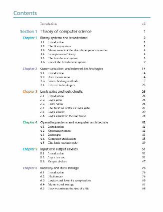
Contents
Introduction
Section 1 Theory of computer science
Chapter 1 Binary systems and hexadecimal 1.1 Introduction
1.2 111c binary system
1. 3 Measurement of the size of computer memories
1.4 Example use ofbinary
1.5 The hexadecimal system 1.6 Use of the hexadecimal system
Chapter 2 Communication and internet technologies 2.1 Introduction
2.2 Data transmission
2.3 Error-checking methods
2.4 lntcrnet technologies
Chapter 3 Logic gates and logic circuits 3 .1 Introduction
3 .2 Logic gates
3 .3 Truth tables
3.4 The fimction ofthe six logic gates
3.5 Logic circuits
3 .6 Logic circuits in the real world
Chapter 4 Operating systems and computer architecture 4.1 Introduction
4.2 Operating systems
4.3 Interrupts
4.4 Computer architecture
4 .5 The fetch-execute cycle
Chapter 5 Input and output devices 5.1 Introduction 5 .2 lnputdeviccs
5 .3 Outputdevices
Chapter 6 Memory and data storage 6.1 Introduction
6.2 File formats
6.3 Lossless and lossy file compression
6.4 Memory and storage 6.5 How to estimate the size ofa file
viii
14 14 14 17 22
26 26 26 26
27 29 38
42 42 42 43
45 49
51
51 51 67
76 76 76 80 81 88
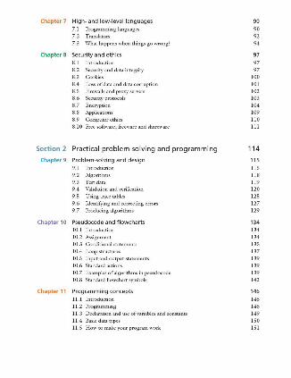
Chapter 7 High- and low-level languages 90 7.1 Programming languages 90 7.2 Translators 92 7.3 What happens when things go wrong? 94
Chapter 8 Security and ethics 97 8.1 Introduction 97 8.2 Security and data integrity 97 8.3 Cookies 100 8.4 Loss of data and data corruption 101 8.5 Firewallsandproxyservers 102 8.6 Security protocols 103 8.7 Encryption 104 8.8 Applications 109 8.9 Computer ethics 110 8.10 Freesoftware,freewareandshareware 111
Section 2 Practical problem-solving and programming 114
Chapter 9 Problem-solving and design 115 9.1 Introduction 115 9.2 Algorithms 118 9.3 Test data 119 9.4 Validation and \·erification 120
9.5 Using trace tables 125 9.6 Identifying and correcting errors 127
9.7 Producing algorithms 129
Chapter 10 Pseudocode and flowcharts 134 10. l Introduction 134 10.2 Assignment 134 10.3 Conditional statements 135 10.4 Loop structures 137 10.5 Input andoutputstatements 139 l 0.6 Standard actions 139 10.7 Exan1ples of algorithms in pseudocode 139 10.8 Standard flowchart symbols 142
Chapter 11 Programming concepts 11. l Introduction
11.2 Programming
11.3 Declaration and use of variables and constants
11.4 Basic data types
11.5 How to make your program work
146 146 146 149 150 151
Chapter 12 Data structures: arrays and using pre-release material 12.1 Introduction
12.2 Arrays
12.3 Using pre-release material
Chapter 13 Databases 13.1 Introduction
13.2 What are databases used for?
13.3 TI1e strucrnre ofa database
13.4 Practical use of a database
Index
163 163 163 168
169 169 169 169 171
178
I ntrod ucti on
A ims l11is textbook has been written to provide the knowledge, understanding and practical skills that a student would need for the Cambridge Internntional F.xaminations Computer Science I GCSE and GCE O Level courses.
The textbook is part of a package which includes a student CD-ROM. A teacher's CD-ROM is also available separately which includes additional guidance and other useful information ( see later in this introduction ).
This OC>Ok and accompanying student CD-ROM provide:
• practice end-of-chapter questions which include questions from past Cambridge International Examinations papers
• activities which gi\·e students additional guidance and practice • sample program solutions for programming activities • hints and tips where these provide additional help and knowledge.
Although this book has been written with the Cambridge lnter11atio11al F.xaminatiom syllabus in mind, it can still be used as a useful reference textbook for other GCSE computing courses. It is also a useful source of information for those srudcnts starting an A le\·el computer science course ~ especially at AS level.
Using the book 111c textbook contains 13 chapters. Although it is possible for some elements of the practical problem-solving chapters to be examined in Paper I (Theory of Computer Science ), and vice versa, the sections for the theory work are in Chapters 1 to 8 and the practical work in Chapters 9 to 13. The book has been split into Section 1 (TI1eory of computer science ) and Section 2 ( Practical problem-solving and programming) to follow the Cambridge International F.xaminatiom syllabus as closely as possible.
Activities are shown throughout the books as follows:
( Activity 1.1 ) Student CD-ROM TI1e accompanying student CD-ROM contains additional guidance to enhance the learning process in a number ofkeyareas in the textbook. The CD-ROM uses animation and verbal commentary wherever this is found helpful in the learning process. The CD-ROM includes sample program solutions for the programming activities.
Where book topics are included in the CD-ROM the following symbol is used: 0 Teacher's CD-ROM An additional teacher's CD-ROM is available to accompany this textbook. TI1is CD-ROM includes the following material:
• possible responses to sample examination and other guestions • each guesrion part suggests a level of difficulty • expected responses to the guesrions at that level are included • additional notes on why the responses meet the required level only

• answers to the end-of-chapter 'luestions in this textbook and to some of the activities where relevant
• program files in Python and Java for activities and end-of-chapter questions. • a scheme of work to help teacher's plan their r.110-year computer science course;
this scheme includes: • chapter numbers from the book • topic to be covered from the chapter • approximate time alkx:ation adllised to cover the topic • Cambridge lnten1ational F.xaminationssyllabus reference • relevant page numbers from the textbook • activities found in the textbook to help in the teaching process • any additional notes to help plan the lessons.
The teacher's CD-ROM has not been through the Cambridge endorsement process.
David W<Jtson and Helen Williams September 2014

This page intentionally left blank
G) Binary systems and hexadecimal
lnthischapteryouwilllearnabout:
e thebinarysystem • measurement of computer memories e thehexadecimal1ystem e howtoconvertnumbersbetweendifferentnumberbasesystems
1.1 Introduction As you progress through this book you will begin to realise how complex computer systems really are. By the time you reach Chapter 12 you should ha\·e a better understanding of the fundamentals behind computers themselves and the software that controls them.
Howe\'er, no matter how complex the system, the basic building block in all computers is the binary number system. This system is chosen since it consists of ls and Os only. Since computers contain millions and millions of tiny 'switches', which must be in the ON or OFF position, this lends itsclflogically to the binary system. A s,.vitch in the ON position can be represented by l; a switch in the OFF position can be represented by 0.
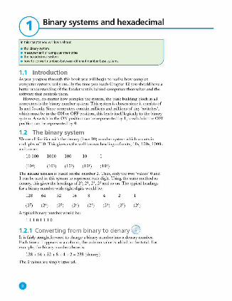
1.2 The binary system We arc all familiar with the dcnary (base 10 ) number system which counts in multiples of 10. This gives us the well -known headings of units, 10s, 100s, 1000s and soon:
10 OOO 1000 100 10
(104) ( 101 ) ( 102 ) ( 101 ) ( 100)
111c BINARY SYSI"EM is based on the number 2. Thus, only the two 'values' 0 and I can be used in this system to represent each digit. Using the same method as dcnary, thisgi\·cs the headings of 20, 21, 22, 23 and so on. The typical headings for a bi.nary number with eight digits would be:
128 64 32 16
A typical binary number would be:
111011 I 0
1.2.1 Converting from binary to denary @ It is fairly straightfonvard to change a binary number into a dcnary number. Each time a 1 appears in a column, the column value is added to the total. For example, the binary number above is:
128 + 64 + 32 + 8 + 4 + 2 - 238 (dcnary)
The O values arc simply ignored.
0
1.2
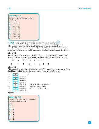
Activity 1.1 Convertthelollowingb.narynumber,; intodeoary:
a 00110011 b 01111111 c 10011001 d 01110100 e 11111111 f 00001111 g 10001111 h 11110000 i 01110000 j 11101110
1.2.2 Converting from denary to binary ® The reverse operation , converting from denary to binary, is slightly more complex. There are two basic ways of doing th is. The first method is 'trial and error' and the second method is more methodical and involves repetitive division.
Method l Consider the conversion of the dcnary number, 107, into binary. This method involves placing l s in the appropriate position so that the total equates to 107:
128 64 32 16
Method 2 This method involves successive division by 2. The remainders arc then read from BOTTOM to TOP to give the binary value. Again using 107, we get:
Figure 1.1
Activity 1.2
readlhe,emainde,lrombottomto toptogetlhebiM,ynumbef
0 1 1 0 1 0 1 1
Convertthelollowingdenarynumbersinto biMry{usingbothmethods)
• 41 b 67 ' 86 d 100 e 111 f 127 g 144 h 189 i 200 j 255
Th e binary system
•
1 BINARY SYSTEMS AND HEXADECIMAL
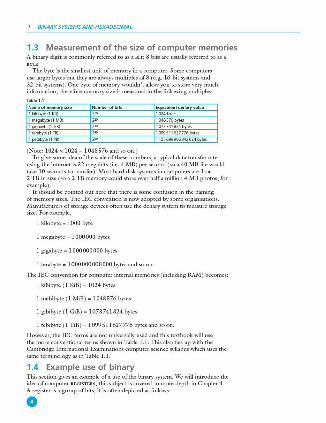
1.3 Measurement of the size of computer memories A binary digit is commonly referred to as a BIT; 8 bits are usually referred to as a
The byte is the smallest unit of memory in a computer. Some computers use larger bytes but they are always multiples of8 (e .g. 16-bit systems and 32 -bit systems). One byte of memory wouldn't allow you to store very much information; therefore memory size is measured in the following multiples:
1kiim,te(1KB)
(1MB)
e(1GB)
1terabvte(1Tl!)
1nPtabvte(1P!!)
(Note: 1024 x 1024 - I 048576 and so on.) To give some idea of the scale of these numbers, a typical data transfer rate
using the internet is 32 megabits (i.e. 4 MB ) per second (so a 40 i\1.B file would take 10 seconds to transfer ). Most hard disk systems in computers are 1 or 2 TB in size (so a 2 TB memory could store over half a million 4 MB photos, for example).
It should be pointed out here that there is some confusion in the naming of memory sizes. The IEC convention is now adopted by some organisations. Manufacturers of storage devices often use the de nary system to measure storage size. For example,
l kilobyte - 1000 byte
l megabyte - 1000000 bytes
I gigabyte - l 000000000 bytes
I terabyte - 1 OOO 000000 OOO bytes and so on.
111c ! EC convention for computer internal memories (including RAJ\1) becomes:
1 kibibytc ( l KiB ) - I 024 bytes
l mebibyte ( 1 MiB ) - I 048576 bytes
I gibibyte ( 1 GiB ) - l 073 741824 bytes
1 tebibyte ( 1 TiB ) - 1099511627776 bytes and so on.
H owe\·er, the IEC terms are not universally used and this textbook will use the more conventional terms shown in Table 1. 1. This also ties up with the Cambridge International E'l:aminations computer science syllabus which uses the same terminology as in Table 1. 1.
1.4 Example use of binary This section gives an example of a use of the binary system. \Ve will introduce the idea of computer REGISTERS; this subject is covered in more depth in Chapter 4. A register is a group ofbits; it is often depicted as follows:
0
1.5
Figur• 1.2
\\'hen computers (or microprocessors) are used to control devices (such as robots ), registers arc used as par t of the control system. The following example describes how registers can be used in controlling a simple device.
A robot vacuum cleaner has three wheels, A, Band C. A rotates on a spindle to allow for direction changes (as well as forward and bachvard movement); B and C are fixed to revolve around their ules to provide only forward and backward mo\·ement, and have an electric motor attached :
Figur• 1.3
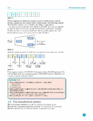
An 8-bit register is used to control the movement ofthe robot vacuum cleaner:
BdirPCtion C di rectioo fllfWards frnwards
Figur•1.4
If the register contains I O 1 0 1 0 l O this means 'motor Bis ON and motorCis ON t111d both motors are tuniing to produce FORiVARDS motion '. Effecti\·ely, the vacuum cleaner is moving forwards.
Activity 1.3 a What would be the effect jf the register contained the follov,iing ~alues7
1 10011000
b What would the register contain if only motor C was ON and the motors were turning in a BACKWARDS direction?
c What would the register contain if motor Band motor C were both ON but B was turning in a backwarddirectionandCwa1turninginalorwarddirection?
d What would be the effect jf the register contained the follov,iing? 11111111
1.5 The hexadecimal system The HEXADECIMAL SYSI"EM is very closely related to the binary system. H exadecimal (sometimes referred to as simply 'hex') is a base 16 system and therefore needs to use 16 different 'values' to represent each digit.
The hexadecimal system
•
1 BINARY SYSTEMS AND HEXADECIMAL
Because it is a system based on 16 different digits, the numbers Oto 9 and the letters A to F arc used to represent each hexadecimal (hex) digit. (A - 10, B - 11 ,C - 12 ,D - 13, E - 14 and F - 15. ) Using the same method asdcnary and binary, this gi\·cs the headings of 160, 161, 162, 163 and so on. The typical headings for a hexadecimal number with five digits would be:
65 536 4 096 256 16 l ( lfrl) (163 ) ( 162) ( 161) ( 160)
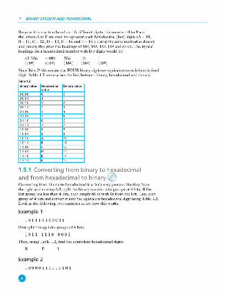
Since 16 - 24 this means that FOUR binary digits arc cciuivalcnt to each hexadecimal digit. Table 1.2 summarises the link between binary, hexadecimal and dcnary.
Binaryvalu• Denaryvalu•
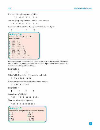
1.5.1 Converting from binary to hexadecimal and from hexadecimal to binary (v Co1wcrting from binary to hexadecimal is a fairly easy process. Starting from the right and moving left, split the binary number into groups of 4 bits. If the last group has less than 4 bits, then simply fill in with Os from the left. Take each group of4 bits and convert it into the cciuivalcnt hexadecimal digit using Table 1.2. Look at the following two examples to sec how this works.
Example 1
I O 1I111000 0 1
First split this up into groups of 4 bits:
101 1 111 0 0 0 0 I
TI1cn, using Table 1.2, find the CCJliivalcnt hexadecimal digits:
Example 2
100 0 0 I 111 111 0 l
0
1.5
First split this up into groups of4 bits:
I O OOO I 1111 1101
The left group only contains 2 bits, so add in two Os:
0 0 I O OOO I 1111 1101
Now use Table 1.2 to find the equivalent hexadecimal digits:
Activity 1.4 Convertthelollowingb4narynumbers into hexadecimal·
a 11000011 b 11110111 c 1001111111 d 10011101110 e 000111100001 f 100010011110 g 0010011111110 h 0111010011100 i 1111111101111101 j 00110011110101110
D
Con\'erting from hexadecimal to binary is also very straightforward . Using the data in Table 1.2 , simply take each hexadecimal digit and write down the 4-bit code which corresponds to the digit.
Example 3 A
Using Table 1.2 , find the 4 -bit code for each digit:
0 100 0 1 0 I 101 0
Put the groups together to form the binary number:
0 100 0 101 l O 1 0
Example 4
Again just use Table 1.2:
1011 l 111 0 00 0 100 0
Then put all the digits together:
10111111 0000 1000
Activity 1.5 Convertthelollowinghexadedmalnumbersintobinary· a 6C f BA6 b 59 g 9(( c AA h 40AA d AOO i DA47
J 1AB0
The hexadecimal system
0
1 BINARY SYSTEMS AND HEXADECIMAL
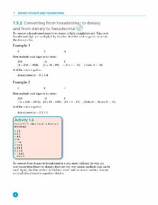
1.5.2 Converting from hexadecimal to denary and from denary to hexadecimal ® To con\'ert a hexadecimal number to denary is fairly straightforward. Take each hexadecimal digit and multiply it by its value . Add the totals together to obtain the dcnary\'aluc.
Example 1
A
First multiply each digit by its value:
256 16 (4 x 256 - 1024) (5 x 16 - 80) (10 x 1 - 10 ) (Note: A - 10)
Add the totals together:
denary number - 1 l 1 4
Example 2
First multiply each digit by its value:
256 16 (12 x 256 - 3072) (8 x 16 - 128 ) (15 x 1 - 15 ) (Note: C - 12 and F - 15 )
Add the totals together:
dcnary number - 3 2 1 5
Activity 1.6 Coovert the following heXildedmal number,; intodenary:
a 6B b9 C < 4A d FF e 1FF f AOl g BB4 h CAB i 12AE j A089
To con\'ert from denary to hexadecimal is a little more difficult. As with the cotwersion from binary to dcnary, there arc two very similar methods that can be used. Again, the first method is 'trial and error' and the second method is more methodical and im·olvcs repetitive division.
0
1.6 Use of the hexadecimal system
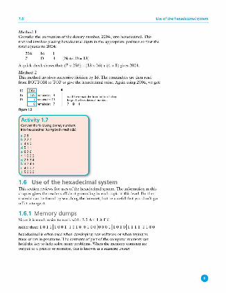
Method l Consider the conversion of the dcnary number, 2004, into hexadecimal. This method involves placing hexadecimal digits in the appropriate position so that the total eguatesto2004:
256 16 D (Note: D - 13 )
A quick check shows that: (7 x 256 ) + ( 13 x 16) + (4 x 1) gives 2004.
Method 2 This method involves successive division by 16. The remainders are then read from BOTTOM to TOP to gi\·e the hexadecimal value. Again using 2004, we get:
" ~""' 16 125 ,em.;nder : 4
16 7 ,emaamier: 13
0 ,em.;nder : 7
Figur•1.5
Activity 1. 7
1 rei>dtherem.;nderfmmbottomtotop togetthehexadecimalnOO'lber:
'0'
Convertthelollowingdenarynumbers intoheXddecimal{uloingbothmethods):
a 98 b 227 c 490 d 511 e 826 f 1000 g 2634 h 3743 i 4007 j SOOO
1.6 Use of t he hexadecimal system This section reviews five uses of the hexadecimal system. 111c information in this chapter gives the reader sufficient grounding in each topic at this le\'el. Further material can be found by searching the internet, but be careful that you don't go off at a tangent.
1.6.1 Memory dumps Since it is much easier to work with: B 5 A 4 I A F C
rather than: l O 1111001110 1 olo 10010001110101111111100
hexadecimal is often used when developing new software or when trying to trace errors in programs. The contents of part of the computer memory can hold the key to help solve many problems. When the memory contents are output to a printer or monitor, this is known as a MEMORY DUMP:
0
1 BINARY SYSTEMS AND HEXADECIMAL
1-·· ....... ··················1 009901'77 n 20 6D 65 6D 6F 12 79 20 64 75 6D 70 20 66 72 6F 6D 20 20 61
00990E9 E 74 797069636l6C2020636F6D707574657220206D85
00990EA5 6D 6F 72 H 20 73 69 6F 77 69 611 67 20 74 68 65 20 20 63 6 F 61!
00990EBC 746561?74 73206F66206l206ll756D62657220206F66
00990ED3 6C6F63 6l 74696F61173 2020696E2020696578202020
00990BIIA 6116F74 6l 74696F61120200000000000000000000000
Figu re 1.6
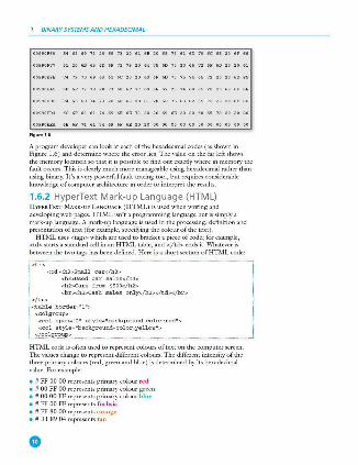
A program developer can look at each of the hexadecimal codes ( as shown in Figure 1.6) and determine where the error lies. The value on the far left shows the memory location so that it is possible to find out exactly where in memory tl1e fault occurs. This is clearly much more manageable using hexadecimal rather than using binary. It 's a very powerfid fault-tracing tool, but requires c.onsiderable knowledge of computer architecture in order to interpret tl1e results.
1.6.2 HyperText Mark-up Language (HTML) HYPERTEXT MARK·UP LANGUAGE (HTML) is used when writing and de\·eloping web pages. HTML isn't a progranuning language but is simply a mark-up language. A mark-up language is used in the processing, definition and presentation of text ( for example, specifying the colour of tl1e text ).
HTML uses <tags> which are used to bracket a piece of code; for exan1ple, <td> starts a standard cell in an HTML table, and </td> ends it. Whatever is berween tl1e two tags has been defined. H ere is a short section of HTML code:
<hJ :,Used car sales</hJ > <h2>Cars f rom $500</h2> <br><h2:>Cash sales only</h2></td></br>
HTML code is often used to represent colours of text on the computer screen. 1l1e values change to represent different colours. The different intensity of the three primary colours (red, green and blue) is determined by its hexadecimal value. For example:
• # FF 00 00 represents primary colour red • # 00 FF 00 represents primary colour green • # 00 00 FF represents primary colour blue • # FF 00 FF represents fuch sia • # FF 80 00 represents orange • # B 1 89 04 represents tan
1.6 Use of the hexadecimal system
and so on producing almost any colour the user wants. There are many websites available that allow a user to find the HTML code for the colour needed.
Activity 1.8 Usingtheinternet,findtheHTMLtodesforanumberofcolours Try entering HTML code into the computer and see how the colours and font types can be changed to good effect Make use of websites, ,;uch as www.html .arrl toproduce your own web pages With a little practice, you can import/embed images into your own design of web page using freely available software. Remember this is not a programming language. It is s.imply a mark-up language, so vecy little programmingskillisrequilrotouseHTML
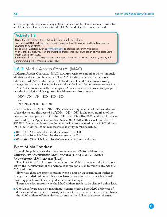
1.6.3 Media Access Control (MAC) A MEDIA ACCESS CoNTROL (MAC) ADDRFSS refers to a number which uniguely identifies a device on the internet. The MAC address refers to the network interface card (NIC) which is part of the device. The ,\1AC address is rarely changed so that a particular device can always be identified no matter where it is.
A MAC address is usually made up of 48 bits which are shown as six groups of hexadecimal digits (although 64-bit addresses are also known):
NN - NN - NN - DD - DD - DD
NN:NN:NN:DD:DD:DD
where the first half (NN - NN - NN) is the identity number of the manufacturer of the device and the second half (DD- DO - DO) is the serial number of the device. For example: 00 - l C - B3 - 4F - 25 - FE is the MAC address of a device produced by the Apple Corporation (code: 001 CB3 ) with a serial number of 4F25FE. Sometimes lower case hexadecimal letters are used in the MAC address: OO- lc-b3-4f-25 -fe. Other manufacturer identity numbers include:
• 00 - 14 - 22 which identifies devices made by Dell • 00 - 40 - 96 which identifies devices made by Cisco • 00 - AO - C9 which identifies devices made by Intel, and so on.
Types of MAC address It should be pointed out that there are mu types of MAC address: the UNIVERSALLY ADM IN ISTERED MAC ADDRESS (UAA) and the LocALLY
ADM INISTERED MAC ADDRESS (LAA).
The UAA is by far the most common type of MAC address and this is the one set by the manufacturer at the factory. It is rare for a user to want to change this MAC address.
H owever, there are some occasions when a user or an organisation wishes to change their MAC address. This is a relati\·ely easy task to carry out but it will cause big problems if the changed address isn't unique.
There are a fei.11 reasons why the MAC address needs to be changed using LAA:
• Certain software used on mainframe systems needs all the MAC addresses of devices to fall into a strict format; because of this, it may be necessary to change the MAC address of some devices to ensure they follow the correct format.
•
1 BINARY SYSTEMS AND HEXADECIMAL
• It may be necessary to bypass a MAC address filter on a router or a firewall; o nly ,\1AC addresses with a certain format are allowed through, otherwise the devices will be blocked.
• To get past certain types ofnen11ork restrictions it may be necessary to emulate unrestricted MAC addresses; hence it may require the MAC address to be changed on certain devices connected to the nen11ork.
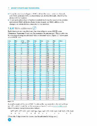
1.6.4 Web addresses @ Each character used on a keyboard has what is known as an ASCII CODE
(AM ERICAN STANDARD CODE FOR INFORMATION INTERCHANGE). These codes can be represented using hexadecimal values or decimal values. Figure 1.7 shows part of an ASCII table.
,. .... Char O« , .. Chu ,. , .. "'" " " <:SPACh " ., . " "' " " ' " " A " " " " " " . '" " .
SS ,, . " " ' " " ;e " s " .. 0 "'' " ' " ;s . " " ' '" " '" " ' " .. ' '" " ' " " " " G '" " '" '" n .. " '" .. . " " n " ' '"' " " >A " <A ' '"' SA
" '" ,s .. ' '" .. . .. K " " ' "" "' ' " " n ., M '"' " m
" " '" " " '" " " " ' " " 0 "' " .. "' 0 "" S> . "' " . " " ' ., S> Q m " S> ,, ' "' s, ' '" n S> a; ' .,
" ' m n s, " ' .. " '
,,. " '
" SS ' " SS " "' ,s
" " . " " ' "" " SS " ' " " w '" n w
'" '" . '" " ' '" ,. " " ' "' " ' "' " '" aA "' SA ' m >A
" '" " '" I m '" I
"' " " SC ' "' K
" " " so m " I ., " " " "" " " " ' " " m " <:OHETb
Figure 1.7
A good example of the use of ASCII codes is the representation ofa web address (or URL, which stands for uniform resource locator) such as www.hoddcr.co.uk which becomes (using hexadecimal 11alues):
%77 %77 %77 %2£ %68 %6F %64 %64 %65 %72 %2E %63 %6F %2E %75 %6B h d d k
(Note: the% sign is used to denote that hexadecin1al is being used.) •
1.6
Activity 1.9 Using the ASCII rnde table (Figure 1.7) convert the following URL~ into the equivalent hexadecimal:
a www.de.org.uk b www.de.org.uk/computer_sdence c httpsJ/INvwi.hodder.co.uk d www.HodderEducation.co.uk e http://www.ucles.ac.uk/computing.htm
Use of the hexadecimal system
Sometimes the hexadecimal addresses arc used in the address of files or web pages as a security feature. It takes longer to type in the URL using the hexadecimal codes, but it has the advantage that you are unlikely to fall into the trap of copying and pasting a 'fake' website address.
1.6.5 Assembly code and machine code Computer memory can be referred to directly using machine code or assembly code. This can have many advantages to program developers or when carrying out troubleshooting.
Machine code and assembly code are co\·ered in much more derail in Chapter 7; here we are simply interested in how hexadecimal fits into the picrnre.
Using hexadecimal makes it much easier, faster and less error prone to write code compared to binary. Using true machine code (which uses binary) is \·ery cumbersome and it takes a long time to kL-y in the values. It is also very easy to
mistype the digits in a 'sea of ls and Os'. Here is a simple example:
STO FFA4 (assembly code )
A5E4 FFA4 (machine code using hexadecimal \lalucs)
1010 01011110 0100 1111 1111 1010 0100 (machine code using binary)
,\lachine code and assembly code are examples of low-level languages and are used by software dL·velopers when producing, for example, computer games. As you will find in Chapter 7, although they look cumbersome, thL-y ha\·e many advantages at the development stage of software writing ( especially when trying to locate errors in the code).
Communication and internet technologies
2.1 Introduction When data is sent from one device to another, it is important to consider how that data is transmitted. It is also important to ensure that the data hasn't been changed in any way.
The internet has now become an integral part of all of our li\·es. This chapter will consider some of the important technologies going on in the background which support the internet.
2.2 Data transmission Data transmission can be either over a short distance ( for example, from computer to printer) or over longer distances (for example, over a telephone network). Essentiall y, three factors need to be considered when transmitting data ( each factor has to be agreed by both sender and receiver for this to work without error):
• the direction of the data transmission (i.e. in one direction only or in both directions)
• the method of transmission (how many bits arc sent at the same time ) • the method of synchronisation between the two devices.
2.2.1 Simplex, half-duplex and full-duplex © S IMPLEX DATA TRANSMISSION is in one direction only (i.e. from sender to receiver ). Example: data being sent from a computer to a printer.
HALF· DUPLEX DATA TRANSMISSION is in both directions but not at the same time (i.e. data can be sent from 'A' to 'B' or from 'B' to 'A' along the same line, but not at the same time). Example: a phone conversation between two people where only one person speaks a t a time .
FULL·DUPLEX DATA TRANSM ISSION is in bothdirectiom sim11/taneously (i.e. data can be sent from 'A' to ' B' and from 'B' to 'A' along the same line, both at the same time) . Example: broadband connection on a phone line.
2.2.2 Serial and parallel data transmission © SERIAL DATA TRANSMISSION is when data is sent, 011e bit at t1 time, over t1 single wireorcht1nnel (bits arc sent one after the other in a single stream).
Figure2.1
(Note: bits can be transmitted as simplex, half-duplex or full -duplex.)
•

2.2
This method of data transmission works well o\·er long distances. However, data is transmitted at a slower rate than parallel data transmission. Since only one wire or channel is used, there is no problem of data arri\'ing at its destination out of synchronisation.
An example of its use is sending data from a computer to a modem for transmission over a telephone line.
PARAILBL DATA TRANSMISSION is when sevem/ bits of dntt1 (umal/y 1 byte) are
sent down several wires 01' channels at the same time; one wire or channel is used to transmit each bit.
Data transmission
I -· I l -~-1 ~;,£~ Figur• 2.2 ... ;;::=,,p (Note: bits can be transmitted as simplex, half-duplex or full -duplex. ) •
This method of data transmission works very well o\·er short distances ( over longer distances, the bits can become 'skewed' - this means they will no longer be Figure 2.3 R;bbooronnector synchronised). I t is, howe\·er, a faster method of data transmission than serial.
An example of its use is when sending data to a printer from a computer using a ribbon connector.
Activity 2.1 Describewhatisme,mtby:
a serial, hatl-duplexdatatransmission b parallel,full-duplexdatatransmiOOn c serial,simplexdata trammission
A common use for serial data transmission is discussed in Section 2.2.4 (Universal Serial Bus (USB)).
Parallel data transmission is used in the internal electronics of the computer system. The pathways benveen the CPU and the memory all use this method of data transmission. Integrated circuits, buses and other internal components all use parallel data transmission because of the need for high speed data transfer. The use of8 -bit, 16-bit, 32-bit and 64-bit buses, for example, allow much faster data transmission rates than could be achieved with single channel serial data transfer. An internal clock is used to ensure the correct timing of data transfer; it is essentially synchronous in narnre (see Section 2.2.3 ) and the short distances between components mean that none of the issues described earlier have any real impact on the accuracy ofthe data.
Chapter 4 covers the internal architecrnre of computer systems (including the role of buses) and this should be read in conjunction with the information given above.
2.2.3 Asynchronous and synchronous data transmission AsYNCH RONOUS DATA T RANSMISSION refers to data being transmitted in an agreed bit pattern. Data bits ( ls and Os) arc grouped together and sent with CONTROL
2 COMMUNICATION AND INTERNET TECHNOLOGIES
1,tartbit 1, I O 1, 1, 1, 1, I O I O 1, 1, 1, I O 1, I O 1, IO I siopbit I cootrol bit Figu,.2.4
This means that the recei\·er of the data knows when the data starts and when it ends. This prevents data becoming mixed up; without these control bits, it would be in1possible to separate groups of data as they arrived.
SYNCHRONOUS DATA TRANSMISSION is a continuous stream of data (unlike asynchronous data which is sent in discrete groups). The data is accompanied by timing signals generated by an internal clock. This ensures that the sender and recei\'cr are synchronised with each other.
The recei\'ercounts how many bits ( l s and Os) were sent and then reassembles them into bytes of data. The timing must be \·ery accurate here since there arc no control bits sent in this type of data transmission. Howe\'er, it is a faster data transfer method than asynchronous and is therefore used where this is an important issue (for example, in network communications).
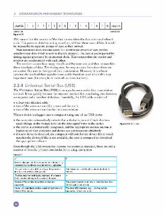
2.2.4 Universa l Seria l Bus (USB) 1l1e UNIVERSAL SERIAL Bus (USB) is an asynchronous serial data transmission method. It has quickly become the standard method for transferring data between a computer and a number of devices. Essentially, the USB cable consists of:
• a four-wire shielded cable • two of the wires arc used for power and the earth • two of the wires are used in the data transmission.
When a de\'ice is plugged into a computer using one of the USB ports:
• the computer automatically detects that a device is present (this is due to a small change in the \'oltagc level on the data signal wires in the cable ) Figu,. 2.5 use cable
• the de\'ice is automatically recognised, and the appropriate DEVICE DRIVER is loaded up so that computer and de\'ice can communicate effectively
• if a new device is detected, the computer will look for the de\'ice driver which matches the dt.·\'ice; if this is not available, the user is prompted to download the appropriate software.
Even though the USB system has become the industrial standard, there arc still a number ofbenefits ( / ) and drawbacks (x) to using this system:
Oevkespluggedintolhe«rnputera,reaotomabcally detected;de,,;ced,iv,,.-,a,reautomaticallyuploaded
Thero,mec!OfScanonlyfitonew~:thisp,'-"'enls Themaximumcablelenglhisp,esentlyabootS inror,ectconnectionsbeingmade metres
Thishasbecomethe indllSt,y,tan,fa,d;thismeans thatcoosidefablesuppo,tisava ilabletousers
Severaldiffe,entdatatransmissioo,atesare Thep,esenttransmissioo,ateislimitedtoJessthan supported 500megabil5Jll'fsecood
2.3
2.3 Error-checking methods Following data transmission, there is always the risk that the data has been corrupted or changed in some way. This can occur whether data is being transmitted over short distances or o\'er long distances.
Checking for errors is important since computers aren't able to check that text is correct; they can only recognise whether a word is in their built-in dictionary or not. Look at the following text:
Can you racd tihs?
' I cnduo't bvleicc taht I culod aulaclty uesdtannrd waht I was rdnaieg. Unisg the icndeblirc pweor of the hmuan mnid, aocdcrnig to rscccrah at Cmabridgc Uincrvtisy, it dseno't mttaer in waht oderr the ltercts in a wrod are, the olny irpoamtnt tihng is taht the frsit and lsat ltteer be in the rhgit pclae. The rsct can be a raotl mscs and you can sit!] racd it whoutit a pbocrlm.
Tihs is bucscac the huamn mnid dcos not racd crvcy lttccr by istlcf, but the wrod as a wlohc.
Aaznmig, huh? Yeah and I awlyas tghhuot slclinpg was ipmorantt! Sec if yuor fdrcins can racd tihs too'
(From an unknown source at Cambridge University)
Whilst you probably had little problem understanding this text, a computer would be unable to make any sense of it.
This is why error checking is such an important part of computer technology. This section considers a number of ways tliat can be used to check for errors so that you don't end up with text as shown in the example above!
A number of methods exist which can detect errors and, in some cases, actually correct tl1e error. The methods covered in tl1is section arc :
• parity checking • automatic repeat request (ARQ) • checksum • echo checking.
2.3.1 Par ity check ing @ PARITY C H ECKING is one method used to check whether data has been changed or corrupted following transmission from one device or medium to anotl1er device or medium.
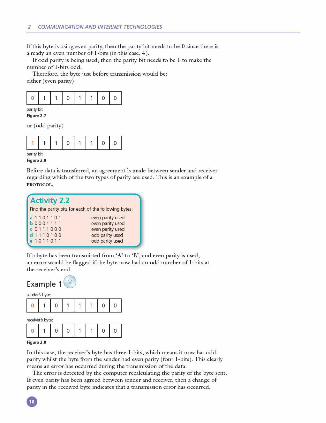
A byte of data, for example, is allocated a PARITY BIT. This is allocated before transmission takes place. Systems that use EVEN PARITY ha\·e an even number of 1-bits; systems that use ODD PARITY have an odd number of 1-bits. Consider tl1e following byte:
p,,<itybit Figur•2.6
Error<hecking methods
2 COMMUNICATION AND INTERNET TECHNOLOGIES
If this byte is using even parity, then the parity bit needs to be O since there is already an even number of I -bits (in this case, 4 ).
If odd parity is being used, then the parity bit needs to be I to make the number of I -bits odd.
Therefore, the byte just before transmission would be: either(even parity)
parjtybit
Rgu,.2.7
or (odd parity)
parjtybit
Rgu,.2.8
Before data is transferred, an agreement is made between sender and recei\·er regarding which of the two types of parity are used. This is an example of a
Activity 2.2 Findtheparitybitsloreadiolthelollowingbytes:
a 1101101 b 0001111 c 0111000 d 1110100
eveoparjtyused even parity used even parity used oddparjtyused odd parity used
If a byte has been transmitted from 'A' to 'B', and even parity is used, an error would be flagged if the byte now had an odd number of I-bits at the recei\'er'send.
Example 1@
Rgu,.2.9
In this case, the receiver's byte has three I -bits, which means it now has odd parity whilst the byte from the sender had even parity ( four I-bits). This clearly means an error has occurred during the transmission of the data.
The error is detected by the computer recalculating the parity of the byte sent. If c\'cn parity has been agreed between sender and recei\·er, then a change of parity in the received byte indicates that a transmission error has occurred.
2.3
Activity 2.3 Whichofthefollowingbyteshaveanerrorfollowingdatatransmission?
a 11101101 b 01001111 c 00111000 d 11110100
even parity used even parity used even parity used odd parity used odd parity used
In each case where an error occurs, can you work out which bit is incorrect?
Namrally, any of the bits in Example 1 could have been changed leading to
a transmission error. Therefore, e\·en though an error has been flagged , it is impossible to know exactly which bit is in error. (Your last answer in Activity 2.3 should have been 'NO' since there isn't enough information to determine which bit has been changed. )
0 One of the ways around this problem is to use PARITY BLOCKS. ln this method, a block of data is sent and the number of 1-bits are totalled horizontally and vertically (in other words, a parity check is done in both horizontal and vertical directions). As Example 2 shows, this method not only identifies that an error has occurred but also indicates where the error is.
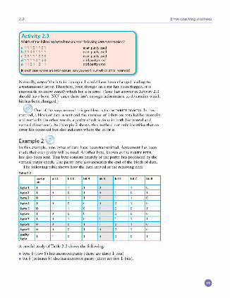
Example 2 @ In this example, nine b)'tes of data ha\·e been transmitted. Agreement has been made that even parity will be used. Another byte, known as the PARITY BITE,
has also been sent. This b)'te consists entirely of the parity bits produced by the \'ertical parity check. The parity b)'te also indicates the end of the block of data.
The following table shows how the data arri\·ed at the recei\'ing end:
byteB 0
byte9 0
parity
"'~ A carefid srudy of Table 2.2 shows the following:
• byte 8 (row 8 ) has incorrect parity (there are three 1-bits) • bit 5 (column 5 ) also has incorrect parity (there are five 1-bits).
Error<hecking methods
2 COMMUNICATION AND INTERNET TECHNOLOGIES
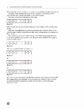
First of all, the table shows that an error has occurred following data transmission. Secondly, at the intersection of row 8 and column 5, the position of the
incorrect bit value (which caused the error) can be found. This means that byte 8 should have the value:
Figure2.10
which would also correct column 5 giving an even vertical parity ( now has four 1-bits).
This byte could therefore be corrected automatically as shown above, or an error message could be relayed back to the sender asking them to retransmit the block of data.
One final point: if two of the bits change value following data transmission, it may be impossible to locate the error using the above method. For example, using fa:ample l again:
Figu re2 .11
This byte could reach the destination as:
Figure2.12
Figu re2 .13
Figure2.14
All three are clearly incorrect; but they have retained even parity so this wouldn't have triggered an error message at the receiving end. Clearly we need to look at other methods to complement parity when it comes to error checking transmitted data.
2.3
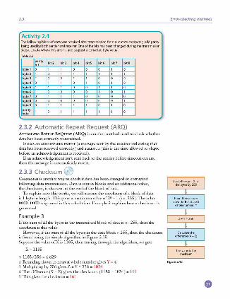
Activity 2.4 The following block of data was received after transmission from a remote computer; odd parity beingusedbybothsenderandreceiver.Oneofthebitshasbeeochangedduringthetransmission stage. LDG1tewherethiserrorisands.uggestamrrectedbyte value
byte1 0
byte2 1
byte3 1
byte4 0
bvt.5 1
bvte6 1
bvte7 0 bvte8 0
l bvte9 O
parity S,w
2.3.2 Automatic Repeat Request (ARO) Aurm,IATIC REPEAT REQuEIT (ARQ) is another method used to check whether data has been correctly transmitted.
It uses an ACKNOWLEDGEMENT (a message sent by the receiver indicating that data has been received correctly) and n1,rnour (this is the rime allowed to elapse before an acknowledgement is recei\·ed).
If an acknowledgement isn't sent back to the sender before rime out occurs, then the message is automatically resent.
2.3.3 Checksum ® CHECKSUM is another way to check if data has been changed or corrupted following data transmission. Data is sent in blocks and an additional value, the checksum, is also sent at the end of the bloc.k of data.
To explain how this works, we will assume the checksum of a block of data is I byte in length. This gives a maximum value of28 - 1 (i.e. 255 ). 111e value 0000 0000 is ignored in this calculation. Example 3 explains how a checksum is generated.
Example 3 If the sum of all the bytes in the transmitted block of data is<• 255, then the checksum is this value.
However, if the Slllll of all the brt:es in the data block> 255, then the checksum is found using the simple algorithm in Figure 2.15. Suppose the value ofX is 1185, then tracing through the algorithm , we get:
X - 1185
1 1185/256 - 4.629 2 Rounding down to nearest whole number gives Y - 4 3 Multiplying br 256 gives Z - Y • 256 - 1024 4 The difference (X - Z) gives the checksum: ( ll85 - 1024) - 161 5 This gives the checksum - 16 1
Error<hecking methods
Oividethesum,X.of thebyte,by2S6
Roondtheanswer downtothenea,est
wholenumbef.Y
Cakulatethe ciffereoce(X - Z)
Thi,valuei,the checksum
Figure 2.15
2 COMMUNICATION AND INTERNET TECHNOLOGIES
When a block of data is about to be transmitted, the checksum for the bytes is first of all calculated. This value is then transmitted with the block of data. At the recei\'ing end, the checksum is recalculated from the block of data received. This calculated value is then compared to the checksum transmitted. If they are the same value, then the data was transmitted without any errors; if the \'alues are different, then a request is sent for the data to be retransmitted.
Activity 2.5 Cakulate the chedsum for blocks of datawiththefollowingbytesums
, 148 b 905 c 14S0 d 4095
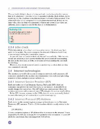
2.3.4 Echo check With ECHO CHECK, when data is sent to another device, this data is sent back again to the sender. The sender compares the two sets of data to check if any errors occurred during the transmission process.
As you will ha\'e no doubt worked out, this isn't \'ery reliable. If the two sets of data are different, it isn't known whether the error occurred when sending the data in the first place, or if the error occurred when sending the data back for checking!
H owe\·er, if no errors occurred then it is another way to check that the data was transmitted correctly.
2.4 Internet t echno logies TI1e internet is a world-,vide system of computer nenvorks and computers. All computers attached to the internet can communicate with each other providing a number of rules and protocols are adhered to.
2.4.1 Internet Service Provider (ISP) Each user makes use of an INTERNET SERVICE PROVIDER ( ISP); tl1ese are companies that pro\'ide the user with access to the internet. A monthly fee is usually charged for tills service. The ISP will set up a user account which will contain a username and a password; most ISPs also gi,·e the user an email address.
Before ISPs became crnrunon in the 1990s, internet access was usually limited to users who were part of a miiversity or a gO\·ernment agency.
2.4.2 Internet Protocol (IP) Address Each device on the internet is gi\'en a unique address known as tl1e INI"ERNIIT PROTOCOL ( IP) ADDRESS. This is a 32 -bit number which is usually written in the form:
109.108.158.1
A home computer is given an IP address when it connects to the internet. This is assigned by the ISP and is unique for that particular internet session. The only IP addresses tl1at remain fairly unchanged are web ser\'ers.
2.4
An I P address can be used instead of typing in the full URL. For example:
hnp://109. 108.158.1
would take you straight to the device corresponding to this address.
IP addresses and MAC add resses You will recall the term MEDIA ACCESS CONrROL (MAC) ADDRESS from Chapter l. This is a unigue number that identifies a device connected to the internet. So what is the difference between an IP address and a ,\.IAC address? The IP address gives the location of a device on the internet, whereas the MAC address identifies the device connected to the internet.
You can think of the IP address as the address of the house you live in ( it will have some unique way of identifying it, such as a JX)St or zip code). Using this example, the MAC address can be thought of as a way of uniquely identifying each person living in that house. It is possible to move house (so your IP address will change) but the same people will be living in the new house ( so their MAC addresses will remain unchanged).
2.4.3 HyperText Mark-up Language (HTML) H YPERTEXT MARK-UP LANGUAGE (H TML) is used when writing and de\·eloping web pages. HTML isn't a programming language but is simply a mark-up language. A mark-up language is used in the processing, definition and presentation of text (for example, specifying the colour of the text).
HTML uses <tags> which are used to bracket a piece of code; for example, <td> starts a standard cell in an H TML table, and </td> ends it. 'Nhatever is between the two tags has been defined. H ere is a short section of H TML code:
c:tr> c:td>c:hl>Small carc:/hJ> c:hl>Used car salesc:/hl> c:h2>Cars from $500c:/h2> c:br>c:h2>Cash sales onlyc:/h2>c:/td>c:/br>
c:/tr>
c:colgroup> c:col span•"2" style•"background-color,red"> c:col style•"background-color :yellow">
HTML st ructure and presentation \\'hen writing H TML code, it is very imixirtant to realise that there is a difference between the structure and the presentation.
Sr&ucruRE is the essential part of the H TML document; it includes the semantics (meaning) and strucrnral mark-up of the document.
PRESENTATION is the style of the document; i.e. how the document will look (or even sound ifit includes multin1edia elements).
These two features must be kept separate throughout the designing of a web page. At the end of the design process, the author should have an HTML document (which contains the structure and the actual content) and a separate css (CASCADING STYLE SH EIIT) file. The css file will contain t.·verything to control the acrnal presentation ofthe web page.
Internet technologies
•
2 COMMUNICATION AND INTERNET TECHNOLOGIES
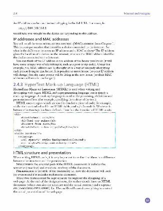
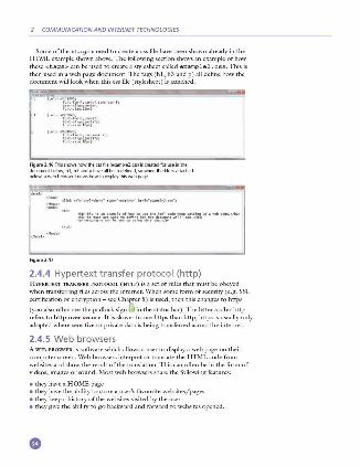
Some of the <tags> used to create a css file have been shown already in the HTML example shown abo\·e . The following section shows an example ofhow these <tags> can be used to create a stylesheet called example2 . css. This is then used in a web page document. The tags (hl, h3 and p ) all define how the document will look when this css file (stylesheet) is attached.
~r'"--"'"-"'f<;io,, ..... -r,.;.i~E,:1.,..,.-, ......
lcalo.aia!~uark (eolo"'f:r::~~ifji;;7rlf:
Figu,.2.16 Thisshow,:howlhecssfile (examp'el.css)isc,eatedfllf useinthe documentbelow;h1.h3andphaveall beendefined. sowhenthefileisattached below.awebbmwserknow,:howtodisplaythi,webpage
Figu,.2.17
2.4.4 Hypertext transfer protocol (http) HYPERTEXT TRANSFER PROTOCOL ( Hrrr ) is a se t of rules that must be obeyed when transferring files across the internet. \Vhen some form of security ( e.g. SSL
~;:~fi:i::~:: :::7~ti;~~~~:e s:~las ::l ~;l:s s~
1
::: :~:~ ~:: ~::~:s at:e~t1:::p
refers to http over i;; ecure. It is slower to use https than http; https is usually only adopted where sensit.i\·e or private data is being transferred across the .internet.
2.4.5 Web browsers A WBB BROWSBR is software which allows a user to display a web page on their computer screen . Web browsers interpret or translate the HTML code from websites and show the result of the translation. This can often be in the form of videos, images or sound . Most web browsers share the following features:
• they have a H OME page • they have the ability to store a user's fu\·ourite websites/pages • they keep a history of the websites vis ited by the user • they give the ability to go backward and forward to websites opened.
2.4
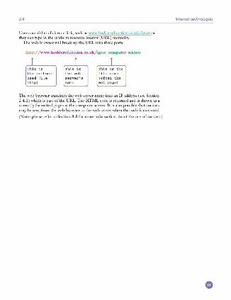
Users can either dick on a link, such as \.\'W'\','.hoddcreducation.co.uk/igcse or they can type in the uniform resource locator (URL) manually.
The web browser will break up the URL into three parts:
http://www.hoddereducation.eo.uk/igcsc_comp11ter_scien ce
the protocol used {i.e http)
(often the web page)
The web browser translates the web server name into an IP address (see Section 2.4.2) which is part ofthe URL. The HTML code is remrned and is shown as a correctly formatted page on the computer screen . It is also (X)SSible that cookies may be sent from the web browser to the web server when the code is executed.
(Note: please refer to Section 8 .3 for more information about the use of cookies.)
Internet technologies
•
® Logic gates and logic circuits
lnthischapteryouwilllearnabout:
e logk:gates e truthtilbles e logkdrcuit1 e useolBooleanalgebra
3.1 Introduction Electronic circuits in computers, many new memories and controlling devices are made up of thousands of LOGIC GATES. Logic gates take bi.nary inputs and produce a binary output. Several logic gates combined together form a LOG IC
CI RCUIT and these circuits are designed to carry out a specific function. The checking of the output from a logic gate or logic circuit is done using
a T RlITH TABLE.
This chapter will consider the function and role oflogic gates, logic circuits and truth tables. Also a number of possible applications of logic circuits will be considered. A reference to BooL EAN ALGEBRA will be made throughout the chapter, but this is really outside the scope of this textbook. H owever, Boolean algebra will be seen on many logic gate websites and is included here for completeness.
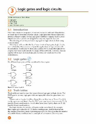
3.2 Logic gates ® Six different logic gates will be considered in this chapter:
----[>- =D-NOT gate ANO gate
=D- =D-0 R gate NANO gate
=D- =D-NOR gate XOR gate
Figu,.3.1 Logicgate,ymbols
3.3 Trut h ta bles Truth tables arc used to trace the output from a logic gate or logic circuit. The NOT gate is the only logic gate with one input; the other five gates ha\'c two inputs.
\\'hen constructing truth tables, all possible combinations of ls and Os which can be input arc considered. For the NOT gate (one input) there are only 21 (2 ) possible binary combinations. For all other gates (two inputs), there are 22 (4 ) possible binary combinations.
For logic circuits, the number of inputs can be more than 2; for example three inputs give a possible 23 (8 ) binary combinations. And for four inputs, the number of possible binary combinations is 2'4- (16). It is clear that the number of possible binary combinations is a multiple of the number 2 in C\'ery case.
3.4
To summarise in table form:
Ta ble 3.1Truthtablesla< two threeandtou,inputs
Inputs Inputs
I','---,~·~~ ~~-tC-' ~-t-'-----i
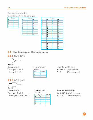
3.4 The function of the logic gates
3.4.1 NOT gate
A--[>-, Figur• 3.2
Description: The output, X, is l if:
the input, A, is 0
3.4.2 AND gate
Figur• 3.3
Description: The output, X, is 1 if:
both inputs, A and B, are 1
Truth table:
Input Output
A '
Truth table:
Inpu ts Output
' '
Inputs
The function of the logic gates
How to write this: X - NOT A (logic notation)
X - a (Boolean algebra)
How to write this: X - A AND B (logic notation)
X - a · b (Boolean algebra)
3 LOGIC GATES AND LOGIC CIRCUITS
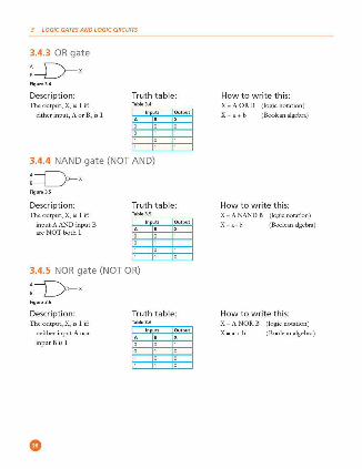
3.4.3 OR gate
Figu,.3.4
Descripti on: Truth table: TI1coutput, X, is 1 if:
either input, A or B, is 1
3.4.4 NAND gate (NOT AND)
:=O-x Figu,.3.5
Description: TI1coutput, X, is 1 if:
input A AND input B arc NOT both I
Truth table:
3.4.5 NOR gate (NOT OR)
Figu,.3.6
Descripti on: TI1coutput, X, is 1 if:
neither input A nor
input Bis 1
Truth table:
How to write this: X - A ORB (logic notation )
X - a+ b (Boolean algebra)
How to write this: X - A NAND B (logic notation)
X - ~ (Boolean algebra)
How to write this: X - A NOR B (logic notation )
X - a+D (Boolean algebra)
3.5 Logic circuits
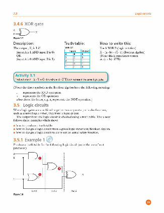
3.4.6 XOR gate
:=D-x Figur• 3.7
Descriptio n: Truth t a bl e: How t o w rite thi s: The output, X, is l if: X - A XOR B (logic notation)
(input A is 1 AND input BisO) OR (inputAisOANDinputBis 1)
Inputs Output 0 X
X -(a · 6 ) + (i · b) (Boolean algebra) (Note: this is sometimes wrinen as: (a+b) · ~)
Activity 3.1 FindoutwhyX:(a,D)+(ii,b)and(a+b},a--:--obothrepresentthesamelogk:gate
(Note: the three symbols in the Boolean algebra ha\·e the following meaning:
represents the AND operation + represents the OR operation a bar abo\·e the letter, e.g. ii, represents the NOT operation. )
3.5 Logic ci rcuits \\'hen logic gates are combined together to carry out a particular function, such as controlling a robot, they form a logic circuit.
The output from the logic circuit is checked using a truth table. There now follows three examples which show:
• how to produce a truth table • how to design a logic circuit from a gi\·en logic statement/Boolean algebra • how to design a logic circuit to carry out an actual safety function.
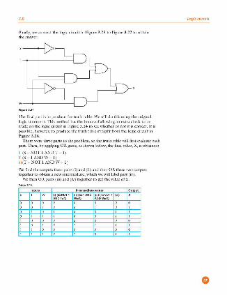
3.5.1 Example 1 ® Produce a truth table for the following logic circuit (note the use of • at
junctions):
Figur• 3.8
3 LOGIC GATES AND LOGIC CIRCUITS
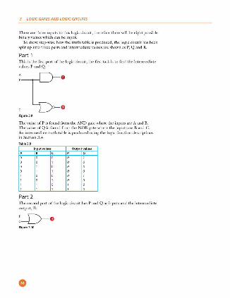
There arc three inputs to this logic circuit, therefore there will be eight possible binary values which can be input.
To show step-wise how the truth table is produced, the logic circuit has been split up into three parts and intermediate values arc shown as P, Q and R.
Part 1 This is the first part of the logic circuit; the first task is to find the intermediate valucs P andQ.
Figu,.3.9
TI1e value of P is found from the AND gate where the inputs arc A and B. TI1cvaluc ofQ is found from the NOR gate where the inputs arc B and C. An intermediate truth table is produced using the logic function descriptions in Section 3.4.
Input values OutputvaluH
Part 2 111c second part of the logic circuit has P and Q as inputs and the intermediate output, R:
Figu,.3.10
•
3.5
This produces the following intermediate truth table. (Note: even though there are only two inputs to the logic gate, we ha\·e generated eight binary values in part 1 and these must all be used in this second truth table. )
Inputs Output
Q "
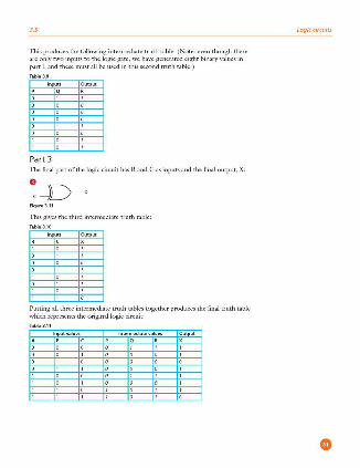
Part 3 The final part of the logic circuit has Rand C as inputs and the final output, X:
Figur• 3.11
This gi\·es the third intermediate truth table:
Inputs
Putting all three intermediate truth tables together produces the final truth table which represents the original logic circuit:
lnputvaluH
Logic circuits
3 LOGIC GATES AND LOGIC CIRCUITS
TI1e intermediate \'alues can be left out ofthe final truth table, but it is good practice to lea\'e them in until you become confident about producing the truth tables. The final truth table would then look like this:
lnputvalu.. Output
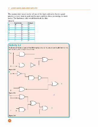
Activity 3.2 Producetruthtablesforeachofthefollowinglogiccircuit"i.Youareadvisedtosplitthemupinto intermediatepartstohelpeliminateerrors.
Figure3.12
3.5
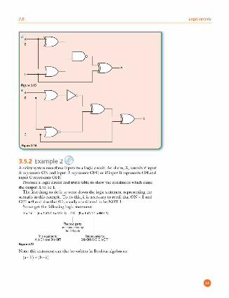
3.5.2 Examp le 2 e A safety system uses three inputs to a logic circuit. An alarm, X, sounds if input A represents ON and input B represents OFF; or if input B represents ON and inputCrepresentsOFF.
Produce a logic circuit and truth table to show the conditions which cause the output Xtobe 1.
The first thing to do is to write down the logic statement representing the scenario in this example. To do this, it is necessary to recall that ON - 1 and OFF - 0 and also that O is usually considered to be NOT 1.
So we get the following logic statement:
Figur• 3.17
(Aa1AND8aNOT1) OR (B•1ANDCaOOT1 )
I
Th,J.,.rn I moo~ct,,.., the OR gate
Note: this statement can also be written in Boolean algebra as:
1• · SJ. (b . ,)
Logic circuits
3 LOGIC GATES AND LOGIC CIRCUITS
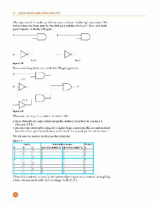
The logic circuit is made up of three parts as shown in the logic statement. \Ve will produce the logic gate for the first part and the third part. Then join both parts together with the OR gate.
Figure3.18
Now combining both parts with the OR gate gi\'es us:
Figure3.19
l11ere are two ways to produce the truth table:
• trace through the logic circuit using the method described in Example 1 (Section 3.5.1 )
• produce the truth table using the original logic statement; this second method has the advantage that it allows you to check that your logic circuit is correct.
We will use the second method in this example:
Inputs Output B (A:1 AND 8:NOT 1) (8:1 AND C=NOT 1) X
(Note: it is optional to leave in the intermediate values or to remm·e them giving a four-column truth table with headings: A, B, C, X. )
3.5
Activity 3.3 Orawthelogiccircuitsandcompletethetruthtableslorthefollowinglogicstatementsand Boolean algebra statements:
a X: 1 if{A: 1 ORB: 1)0R(A:OAN08 = 1) b Y = 1 if{A = OAND B = O)AND{B = 0 OR C = 1) c T = 1 if (switch K is ON or switch Lis ON) OR (switch K is ON and switch Mis OFF) OR (switch
Mis ON) d X:(a.b)+(b.c} a R = 1 if (switdi A is ON and switch 8 is ON) ANO (switch 8 is ON or switch C is OFF)
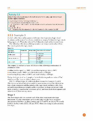
3.5.3 Example 3 A wind rnrbine has a safety system which uses three inputs to a logic circui t. A certain combination of conditions results in an output, X, from the logic circui t being cciual to 1. \Vhcn the value ofX - 1 then the wind mrbine is shut down.
The following table shows which parameters are being monitored and form the three inputs to the logic circuit.
Parameter d- ription
turbinespel'd
bearingtemperature T
\Mndvekx:ity
Binaryvalu• D-riptionofcondition
<a120kph
>120kph
The output, X, will ha\·e a value of l if any of the following combination of conditions occur:
• either mrbine speed< • 1000 rpm and bearing temperature> 80°C • or mrbine speed > I OOO rpm and wind velocity > 120 kph • or bearing temperamre <• 80°C and wind velocity> 120 kph.
Design the logic circuit and complete the truth table to produce a value ofX - 1 when any of the three conditions above occur.
This is a different type of problem to those covered in Examples l and 2. This time a real situation is g iven and it is necessary to convert the information into a logic statement and then produce the logic circuit and truth table. It is ad\~sable in problems as complex as this to produce the logic circuit and truth table separately (based on the conditions given) and then check them against each other to see ifthere are any errors.
Stage 1 The first thing to do is to convert each of the three statements into logic statements. Use the information given in the table and the three condition statements to find how the three parameters, S, T and W, are linked. We usually look for the key words AND, OR and NOT when converting actual statements into logic.
Logic circuits
•

3 LOGIC GATES AND LOGIC CIRCUITS
\\'e end up with the following three logic statements:
i turbine speed <• I 000 rpm and bearing temperature > 80°C logic statement: (S - NOT l AND T - 1) ii turbine speed > 1000 rpm and wind velocity> 120 kph logic statement: (S - 1 AND W - 1)
iii bearing temperature <• 80°C and wind velocity > 120 kph logic statement: (T - NOT 1 AND W - 1)
Stage 2 This now produces three intermediate logic circuits:
Figu,.3.20
ii !====O-Figu .. 3.21
Figu,.3.22
Each of the three original statements were joined together by the word OR. Thus we need to join all of the three intermediate logic circuits by two OR gates to get the final logic circuit.
We will start by joining (i) and (ii ) together using an OR gate :
Figu,.3.23
•
3.5
Finally, we connect the logic circuit in Figure 3.23 to Figure 3.22 to obtain theammrer:
Figur• 3.24
The final part is to produce the truth table. We will do this using the original logic statement. This method has the bonus of allowing an extra check to be made on the logic circuit in Figure 3 .24 to see whether or not it is correct. It is possible, howe\'er, to produce the truth table straight from the logic circuit in Figure 3.24.
There were three parts to the problem, so the truth table will first evaluate each part. Then, by applying OR gates, as shown below, the final value, X, is obtained :
i (S - NOTIANDT - 1) i i (S - 1 ANDW - 1) iil (T - NOT I ANDW - 1)
We find the outputs from parts (i) and (ii ) and then OR these two outputs together to obtain a new intermediate, which we will label part (iv).
We then OR parts (iii ) and (i\' ) together to get the \'alue ofX.
lnouts Outcut T (i)(S:NOT 1 (ii)(S:1AND (iiQ(T:NOT 1 (iv) X
ANDT:1) W:1) ANDW:1)
Logic circuits
3 LOGIC GATES AND LOGIC CIRCUITS
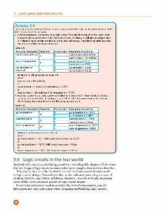
Activity 3.4 Twoscenariosaredesc:ribedbelow. lne.Khu11e,producethelogiccircuitandcompleteatruth tabletorepreseotthesc:enario ii Achemicalprocessisprotectedbyalogicdrcuit.Therearethreeinputstothelogiccircuit
representing key parameters in the chemical process. An alarm, X, will give an output value of1 dependingoncertainconditionsinthechemicalprocess. The following table describes theprocessconditionsbeingmonitored:
Puam•t..rdHcription Parametu Binarvvalu• o-riptionofcondition chemkalrea<lionrate O rea<lion,at e <40mol/llsec
process tem perature
Analarm,X,willgeneratethevalue 1 if: either reactionrate<40moWsec
concentration> 4 mol ANO temperature> 115°(
reaction rate>= 40 moWsec ANO temperature> 115°( b Apo1Nerstationhasasaletysystemcontrolledbyalogiccircuit. Threeinputstothelogic
circuit determine whether the output, S, is 1. When S = 1 the power !ilation shuts down. Thefollowingtabledescribestheconditionsbeingmonitored
Param.ierdHcription Parametu Binaryvalu• D-riptionofcondition gas temperature O astemperature <:160"(
reactor pressure
wate r temperature
Output,S,willgenerateavalueofl,if either
water temperature <:120"(
gas temperature> 160'C AND water temperature<= 120"C
gas temperature<= 160'CANDreactorpressure> 10bar
water temperature> 120°CANDreactorpressure> 10bar
3.6 Logic circuits in the real world Anybody with an electronics background who is reading this chapter will be aware that the design of logic circuits is considerably more complex than has been described.
This chapter has described in detail some of the fundamental theories used in logic circuit design. This will give the reader sufficient grounding to cover all existing ( l )GCSE and O level syllabuses. H owc\'cr, it is worth finally discussing some of the more advanced aspects oflogic circuit design.
Electronics companies need to consider the cost of components, case of fabrication and time constraints when designing and building logic circuits.

3.6
\\'e will mention two possible ways electronics companies can review logic circuit design:
1 One method is to use 'off-the-shelf' logic units and build up the logic circuit as a number of'building blocks'.
logic circuits in the real world
2 Another method im·olves simplif)ing the logic circuit as far as possible; this may be necessary where room is at a premium ( e.g. in building circuit boards for use in satellites to allow space exploration).
3.6.1 Using logic 'building blocks' One very common 'building block' is the NANO gate . It is possible to build up any logic gate, and therefore any logic circuit, by simply linking together a number ofNAND gates. For example, the AND, OR and NOT gates can be built from these gates as shown below:
The AND gate :
Figure3.25
The OR gate:
Figur• 3.26
The NOT gate:
Figur• 3.27
Activity 3.5 8ydrawingthetrutht<1bles,showthatthethreecircuitsabovecanbeusedtorepresentANO, OR and NOT gates.
3 LOGIC GATES AND LOGIC CIRCUITS
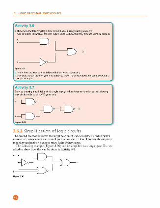
Activity 3.6 a Show how the following logic circuit could be built using NAND gates only.
Alsocompletetruthtablesforbothlogicdrcuit1toshowthattheyproduceidentic.aloutputs
Fig ure3.28
b Show how the XOR gate could be built from NAND gates only. c Complete a truth table for your final design to show it that it produces the !>ilme output as a
single XOR gate .
Activity 3. 7 Show by drawing a truth table which single logic gate has the s.ame function as the following logic circuit made up of NAND gates only.
Figu re3 .29
3.6.2 Simplification of logic circuits The second method invokes the simplification oflogic circuits. By reducing the number of components, the cost of production can be less. T his can also impro\·c reliability and make it easier to trace faults if they occur.
The following example ( Figure 3 .30) can be simplified to a single gate. You are asked to show how this can be done in Activity 3.8 .
Fig ure3.30
3.6
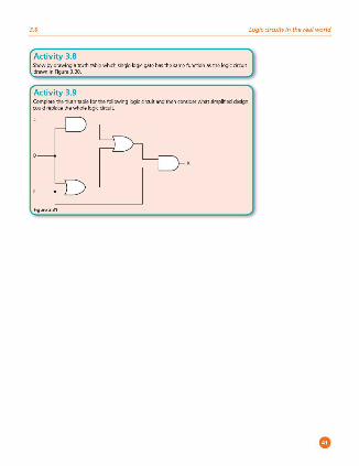
Activity 3.8 Show by drawing a truth table which single logic gate has the 'Hime function as the logic circuit drawninFigure3.30
Activity 3.9 Complete the truth tilble for the following logic circuit and then consider what s.implified design couldreplacethewholelogiccircuit
logic circuits in the real world
Operating systems and computer architecture
4.1 Introduction All modern computers ha\'e some form of operating system which users generally take for granted. The operating system makes it possible to communicate with the software and hardware that make up a typical computer system.
There are many ways of representing computer architecmre, but one of the more common ones is known as the von Neumann model which will be fully described in this chapter.
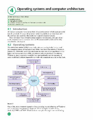
4.2 Operating systems 1l1e OPERATING SYSTEM (OS) is essentially software running in the background of a computer system. It manages many of the basic functions which are shown in Figure 4.1. Obviously not all operating systems carry out everything shown in the figure but it gives some idea of the importance and complexity of this software. Without it, most computers would be very user-unfriendly and the majority of users would find it almost impossible to work with computers on a day·to-day basis.
Figu,.4. 1
One of the most common examples of an operating system is known as Windows and is used on many personal computers. Other examples include: Linux, Android, UNIX and DOS. Windows is an example of a single-user multitasking

4.3
operating system - this means only one user can use the computer at a time but can h:we many applications open simultaneously. H ow operating systems actually work is beyond the scope of this textbook.
When a computer is first fXJWCred up, the initiating programs are loaded into memory from the ROM (read only memory) chip. These programs nm a checking procedure to make sure the hardware, processor, internal memory and bios ( basic input-output system) arc all functioning correctly. l fno errors are detected, then the operating system is loaded into memory.
It is worth mentioning here that simple de\'ices with embedded microprocessors don't always ha\·c an operating system. H ousehold items, such as cookers, microwa\·e ovens and washing machines only carry out single tasks which don't vary. The input is usually a button pressed or a touchsc.rcen option selected which activates a simple hardware function which doesn't need an operating system to control it.
Activity 4.1 Findouthowapplianceslittedwithmicroprocessorscanbecontrolledandi!Clivatedby web.enableddevicessuchassmartphones.
4.3 Interrupts and buffers An I NTERRUPT is a signal sent from a device or from software to the processor. This will cause the processor to temporarily stop what it is doing and service the interrupt. Interrupts can occur when, for example:
• a disk drive is ready to receive more data • an error has occurred, such as a paper jam in a printer • the user has pressed a key to interrupt the current process ~ an example could
be <CTRL><ALT><BREAK> keys pressed simultaneously • a software error has occurred ~ an example of this would be if an .exe file
couldn't be found to initiate the execution of a program.
Once the interrupt signal is received, the processor either carries on \vith what it was doing or stops to sef'lice the device/program that generated the intermpt.
Interrupts allow computers to carry out many tasks or to have several windows open at the same time. An example would be downloading a file from the internet at the same time as listening to some music from the computer library. vVhenever an interrupt is serviced, the status of the current task being run is sa\'ed. This is done using an INI"ERRUPT HANDLER and once the interrupt has been fully sef'liced, the status of the interrupted task is reinstated and it continues from the point prior to the intern1pt being sent.
BUFFERS arc used in computers as a temporary memory area. These are essential in modern computers since hardware devices operate at much slower speeds than the processor. !fit wasn't for buffers, processors would spend the majority of their time idle, waiting for the hardware device to complete its operation. Buffers are essentially filled from the processor or memory unit and whilst these are emptied to the hardware device, the processor carries on with other tasks. Buffers are used, for example, when streaming a video from the internet. This ensures that the video playback doesn't keep on stopping to wait for data from the internet.
Buffers and intermpts are often used together to allow standard computer functions to be carried out. These functions are often taken for granted by users
Interrupts and buffers
4 OPERATING SYSTEMS AND COMPUTER ARCHITECTURE
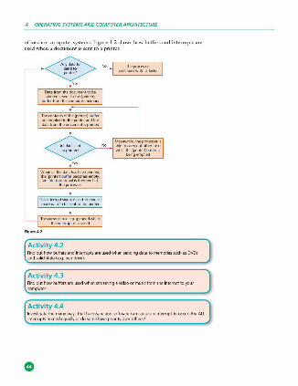
of modern computer systems. Figure 4.2 shows how buffers and interrupts are used when a docW11e.nt is sent to a printer.
Therurrenttaskissuspendedwhi!st theinterrupti,seiviced
Figu,.4.2
Activity 4.2
Meanwhife. theproc:es<Ofis abletocanyootothertask, wti.lethe{prfr,ter) buffer i,
befr,gempbed
Find out how buffers and interrupt, are used when sending data to memories ~has OVD1 andsolidstate(e.g . peodrive).
( Activity 4.3 F"'d o,< how ooffm ae .,s,d wh,a swamiog a ,idro o, mo,, fmm she ioS,m,s ro "'"' computer.
Activity 4.4 Investigate the many way; that hardware and software can cause an interrupt to occur. Are All interruptstreatedequallyordosomehavepriorityoverothers?
)

4.4
4.4 Computer architecture Very early computers were fed data whilst the machines were acrually running. They weren't able to store programs; consequently, thL-y weren't able to run without human intervention. ln about 1945, John von Neumann developed the idea of a stored program computer, often referred to as the VON NEUMANN ARCH ITBGnJRB concept. His idea was to hold programs and data in a memory. Data would then mo\·e between the memory unit and the processor.
There are many diagrams which show von Neumann architecture. Figures 4.3 and 4.4 show two different ways of representing this computer model. The first diagram is a fairly simple model whereas the second diagram goes into more detail.
Figure 4.3 shows the idea of how a processor and memory unit are linked together by connections known as BUSFS. This is a simple representation of von Neumann architecrnrc. These connections are described in Table 4.1.
>oc=
i~i..----. .. -•--.i M~ \!flit)
:Z,.~rus .+ Oatabus ..
Controlbus ...
Figur• 4.3
Table 4.1 describes the fimction of each of the three buses shown in Figure 4.3. Buses essentially move data around the computer and also send out control signals to make sure everything is properly synchronised.
lypeofbus o-riptionofbus rarriessignal,relatingtoaddres,es (seetat .. )belw'-""1theproces<0< and the memory
sendsdatabetweentheproces<0<. thememoryunitandtheinput/ outputde\,;ce,
:,~: si~',,;,,~:~_:: ~t~1 acti,,.;t>eswithintheromputer (examplesk,dude:the,eadand w,;tefunctions)
un ld ir•t ion• l (si(jl\alstravel in ooedirecl>ononly)
bl-cll ,-tional (datacantr..,ei ;n OOthdirectioo,)
unid ir•t iona l (si(jl\alslfavelin ooedirection only)
Computer architecture
4 OPERATING SYSTEMS AND COMPUTER ARCHITECTURE
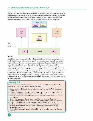
Figure 4.4 shows a slightly more detailed diagram of the \·on Neumann architecture. It brings to our attention another n<.·w concept in this computer model - the idea of ADDRESSES and REGISIBRS. Addresses indicate where the data is stored and registers are needed so that data can be manipulated within the computer.
Figu,. 4.4
An address is the location of where data can be found in a computer memory. Each address in the memory is unique. The addresses arcn 't actually shown in Figure 4.4, but they are contained in the part of the diagram labelled memory unit. T he actual function of the addresses is discussed in Section 4 .4. 1.
You will notice a number of items shown in the diagram known as registers: MAR, MDR, ALU, PC and C IR. TI1e.se arc a little more complex and their fimction will be fully described in the following pages. But essentially a register is simply a high-speed storage area within the computer. All data must be represented in a register before it can be processed. For example, iftwo numbers are to be added, both numbers must be stored in registers and the result of the addition must also be stored in a register.
Activity 4.5 Draw up a rnmmary table that show,; how buses. registers and addresses are all connected together.Thiscanbedonebydoingadesk-topexerdse
• Use a sheet of AO (flipchart size) paper and draw a large outline of the FIVE main components showninFigure4.4
• Cutcolouredarrowsoutolcardboardtoshowthebusesandplaceonthediagramyou·ve justdrawn;thedataandcontrolbuseswillbeeasytofit.
• However, you will need to do a little bit of thinking to decide how the address bus fits into your diagram
• CutthefiveregistersoutolcardboardandplacethemonthelargeAOoutline • Above the memory unit. place an example of some memory addresses and their contents • Cut out some 8-bit binary numbers representing your addresses and contents • Finally by moving data around you should be able to see how buses, addresses and registers
allinterconnect;yougetfurtherhelpindoingthisdesl::-topexercisewheoyouread Sectiom4.4.1to4.4.4
• TrytofindouthowsimpleoperationslikeadditioncanbeG1rriedoutusingyourdesk-top
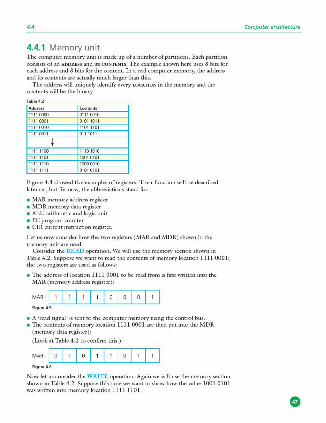
4.4
4.4.1 Memory unit The computer memory unit is made up of a number of partitions. Each partition consists of an ADDRESS and its CONTENTS. The example shown here uses 8 bits for each address and 8 bits for the content. In a real computer memory, the address and its contents are acmally much larger than this.
The address will uniciudy identify every LOCATION in the memory and the contents will be the binary.
Figure 4.4 showed five examples of registers. Their function will be described later on, but for now, the abbreviations stand for:
• MAR memory address register • MDRmemory data register • ALU ari thmetic and logic unit • PC program counter • CIR current instruction register.
Let us now consider how the two registers (,\.lAR.and MDR) shown in the memory unit arc used.
Consider the READ operation. \Ve will use the memory section shown in Table 4.2. Suppose we want to read the contents of memory location 1111 0001; the two registers arc used as follows:
• The address of location 1111 OOO 1 to be read from is first written into the MAR (memory address register ):
MAR I 1 I 1 I 1 I 1 I O I O I O I 1 I Figure4.5
• A 'read signal' is sent to the computer memory using the control bus. • 111c contents of memory location 1111 OOO I arc then put into the MD R
(memory data register ):
(Look at Table 4.2 to confirm this. )
MAR I O I 1 I O I 1 I 1 I O I 1 I 1 I Figu re 4.6
Now let us consider the \VRITE operation. Again we will use the memory section shown in T able 4.2. Suppose this time we want to show how the value 1001 0101 was wri tten into memory location 1111 1101.
Computer architecture
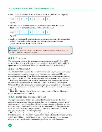
4 OPERATING SYSTEMS AND COMPUTER ARCHITECTURE
• The data to be stored is first written into the MDR (mcmory data register):
MAR I 1 I O I O I 1 I O I 1 I O I 1 I Figu re4.7
• This data has to be written into the memory location with the address 11 11 1101; so this address is now written into the MAR:
MAR I 1 I 1 I 1 I 1 I 1 I 1 I O I 1 I Figu re4.8
• Finally, a 'write signal' is sent to the computer memory using the control bus and this value will then be written into the correct memory location. (Again confirm this by looking at Table 4.2. )
Activity 4.6 Us.e your model uwted in Activity 4.S to show how the two operations, read and write, are carriedoutinthevonNeumilnnarc:hitecture
4.4.2 Processor TI1e PROCESSOR contains the ARITHMETIC AND LOGIC UN IT (ALU). The ALU allows arithmctic.(c .g. add, subtract, etc.) and logic (e .g. AND, OR, NOT, etc.) operations to be carried out. How this is used is explained in Section 4.5.
4.4.3 Control unit The CONTROL UN IT controls the operation of the memory, processor and input/ output devices. It contains the CURRENT INsrRUCrION REGisrER (CIR) and the PROGRAM COUNTER ( PC). The C l R contains the current instruction during processing. The PC contains the address of the next instruction to be executed.
Essentially, the control unit reads an instruction from memory (the address of the location where the instruction can be found is stored in the Program Counter (PC)). This instruction is then interpreted. During that process, signals arc generated along the control bus to tell the other components in the computer what to do.
H ow this all fits together with the other components of the von Neumann model is discussed in Section 4.5.
4.4.4 Input and output devices TI1e input and output devices arc discussed in Chapter 5 and arc the main method of entering data into and getting data out of computer systems. Input devices convert external data into a form the computer can understand and can then process ( e.g. keyboards, touchscreens and microphones). Output devices show the results of computer processing in a humanly understandable form (e.g . printers, monitors and loudspeakers).
H ow all of these five registers are used by a typical computer system can be found in Section 4.5 - the fetch-execute cycle . Again other textbooks and websites will all have different ways of showing how this cycle operates. The important thing is to get a good general understanding of how the cycle functions.
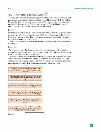
4.5
4.5 The fetch-execute cycle 0 To carry out a set of instructions, the processor first of all FETCH ES some data and instructions from memory and stores them in suitable registers. Both the address bus and the data bus are used in this process. Once this is done, each instruction needs to be decoded before finally being EXECU'IBD. This is all known as the H ITCH -EXECUTE CYCLE and is the last part of this puzzle.
Fet ch In the fetch-execute cycle, the next instruction is fetched from the memory address currently stored in the Program Counter (PC) and is then stored in the Current Instruction Register (CI R). 111c PC is then incremented (increased by 1) so that the next instruction can be processed.
This is then decoded so that each instruction can be interpreted in the next part of the cycle.
Execute The processor passes the decoded instruction as a set of control signals to the appropriate comix,nents within the computer system. This allows each instruction to be carried out in its logical sequence.
Figure 4.9 shows how the fetch-execute cycle is carried out in the von Neumann computer model. As with most aspects of computer science, there will be slight variations on this diagram if other textbooks or websites arc consulted. The main aim is to end up with a clear understanding of how this cycle works.
Thep,ogramcounte,(P()cootains!headdressolthe
memo:y 00000 °' 1:;: fe~~!Juctioo which has to
Thisadd,ee.sis!heoropledlmm!heKtothememo,y addr=register(MAR);!ht!sisdooellSO!lgtheaddr=
Theco!lteot,(instruction)atthememo,ykxatioo {address)rontaonedillMAAarethMcopH'dtemporarily
illlothememorydataregiste,(MOR)
Theronlel\ts(instructioos)oltheMDRa,elhencopied aodplacedintotherurrentinstructioo,egister(C IR)
Thevalueinthel'Cis!henincrementedbylsothatit oowpointsto!hene7,\~~who d!hastobe
Theinstructiooisfinallyderodedandlhenexecutedby sendingO<ltsigllals(vialhecOf\tfolbus)to!hevafious
romponentsollhecomputerS)'Stl'm
Figur• 4.9
The fetch~xecute cycle
•
4 OPERATING SYSTEMS AND COMPUTER ARCHITECTURE
Figure 4.9 shows the acrual stages that take place during the fetch-execute cycle, showing how each ofthe registers and buses are used in the process ( the first five boxes are part of the fetch cycle and the last box is part of the execute cycle).
Activity 4 . 7 • ltisv,,,orthtryingtodoadesk-topexert:isetocarryoutaseriesofinstructionsusingtheletch
execute cycle. Do 'iOme research and decide on four or five operations {add. subtract, etc .) and give the 8-bit binary codes. Then ue.ite a memory map as shown in Activity 4.5
• Once this is done, use the five registers you ueated in Activity4.S and news.bit binary valuestotraceouteXil(tlywhathappensasinstructionsareletchedandexecutedinyour rnmputermodel .
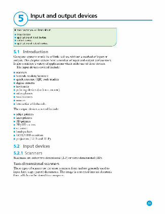
® Input and output devices
lnthischapteryouwinle.-imabout:
e inputdevices e applicationsolinputdevices e outputdevices e applicatioosoloutputdevices
5.1 Introduction Computer systems would be of little real use without a method of input or output. This chapter reviews how a number of input and output devices work. It also considers a variety of applications which make use of these dt.·vices.
The input devices covered include:
• scanners • barcode readers/scanners • quick response (QR) code readers • digital cameras • keyboards • pointing devices (such as a mouse ) • microphones • touchscrecns
• sensors • interacti\·c whiteboards.
The output devices covered include :
• inkjetprintcrs • laser printers • 3Dpri.ntcrs • 2D/ 3Dcutters • actuators • loudspeakers • LCD/ LED monitors • projectors (LCD and OLP).
5.2 Input devices
5.2.1 Scanners SCANNERS are ei ther two-dimensional (20 ) or three-dimensional (30).
Two-d imensio na l sca nne rs These types of scanner are the most common fonn and are generally used to input hard-copy (paper) documents. The image is converted into an electronic form which can be stored in a computer.
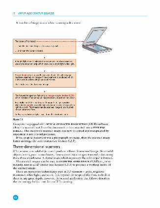
5 INP(JT AND OUTPUT DEVICES
A number of stages occur when scanning a document:
A bright licj>t lheo illuminates the document - modem scanners useatypeofxeooolampwhi<hprodocesaverybfqltwhitelight
A saoh.ad r1.<Nesacrossthedorumeotuntilthewholepage tlasbeenscanned.AAimageolthedorumentisproducedwhich isthensenttoaleosusingase<iesofmir,Ol'S
The!ensloruseslhedocur1entimage
The focused i,r.age now fa k onto a char~ couple device (CCD); whichronsis!sofam.mberofintegratedcirruitsetchedintosilicoo
(ssentiallytheCCDismadeupolthousarldsoflicj,k,eosilive eler1ents(or piHl1).fa<helementcreatesaneH'ctric<hargewhen
:;;t,t:1:~t!,-::,~':""' that the scanned iff age is now turned
Software produces a digital image Imm the electronic fofm
Figuftl5.1
Computers eciuipped with O PTICAL CHARACTER RECOGNITION (QCR) software allow the scanned text from the document to be converted into a TEXT FILE FORMAT. This means the scanned image can now be edited and manipulated by importing it into a word processor.
If the original document was a photograph or image, then the scanned image forms an image file such as JPEG (see Section 6.2.3 ).
Three-di mensio na l sca nne rs 30 scanners scan solid objects and produce a three -dimensional image. Since solid objects have x, y and z coordinates, these scanners take images at several points along these three coordinates. A digital image which represents the solid object is formed.
The scanned images can be used in COMPUTI!R AIDED DESIGN (CAD) or, more recently, sent to a 3D printer (see Section 5.3.3) to produce a working model of the scanned image.
There are numerous technologies used in 3D scanners - lasers, magnetic resonance, white light, and so on. It is beyond the scope of this book to look at these in any great depth; however, the second application that follows describes the technology behind one form of3D scanning.
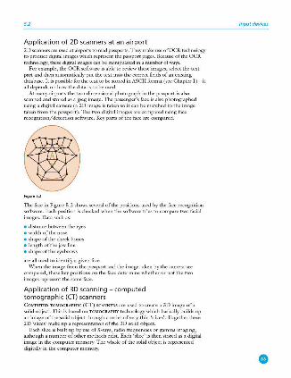
5.2
App li cat io n of 2D sca nners at an a irport 20 scanners arc used at airports to read passports. ThL-y make use of OCR technology to produce digital images which represent the passport pages. Because of the OCR technology, these digital images can be manipulated in a number of ways.
For example, the OCR software is able to review these images, selcc.t the text part and then automatically put the text into the correct fields of an existing database. It is possible for the text to be stored in ASCII format (see Chapter 1) - it all depends on how the data is to be used.
At many airports the two-dimensional photograph in the passport is also scanned and stored as a jpeg image. The passenger's face is also photographed using a digital camera (a 20 image is taken so it can be matched to the image taken from the passport). The two digital images are compared using face recognition/detection software. Key parts of the face are compared .
Figur•5.2
The face in Figure 5 .2 shows se\·eral of the positions used by the face recognition software. Each position is checked when the software tries to compare two facial images. Oatasuchas:
• distance between the eyes • width of the nose • shape of the cheek bones • length ofthe jaw line • shape of the eyebrows
are all used to identify a given face. \Vhen the image from the passport and the image taken by the camera are
compared, these key positions on the face determine whether or not the two images represent the same face.
Application of 3D scanning - computed tomographic (CT) sca nners Cm,IPUIBD TOMOGRAPHIC (CT) SCANNERS are used to create a 30 image of a solid object. This is based on TOMOGRAPHY technology which basically builds up an image of the solid object through a series oh·ery thin 'slices'. Together these 20 'slices' make up a representation of the 30 solid object.
Each slice is built up by use of X-rays, radio frequencies or gamma imaging; although a number of other methods exist. Each 'slice' is then stored as a digital image in the computer memory. The whole of the solid object is represented digitally in the computer memory.
Input devices
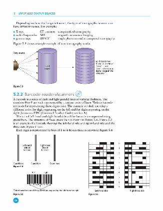
5 INP(JT AND OUTPUT DEVICES
Depending on how the image is formed, the type of tomographic scanner can have different names. For example :
• X-rays CT scanners computerised tomography • radio frequencies MRI magnetic resonance imaging • gamma rays SPECT single photon emission computed tomography.
Figure 5 .3 shows a simple example of how tomography works.
X·raysou,ce
Figure5.3
5.2.2 Barcode readers/scanners ®
~~~::Sm "sjice," - each "sjice"isstorl'dasa digital image;nthe
-"'~
A barcode is a series of dark and ligln parallel lines of \'arying thickness. 1l1e numbers O to 9 are each represented by a unique series oflines. Various barcode methods for representing these digits exist. The example we shall use adopts different codes for digits appearing on the left and for digits appearing on the right (known as UPC ( Universal Product Code ) \'ersion A).
The actual left-hand and right-hand sides of the barcode are separated using guard bars. The structure of these guard bars is shown in Figure 5.4. Figure 5.5 is an example of a barcode showing the left-hand side and right-hand side and the three sets of guard bars.
Each digit is represented by bars of 1 to 4 blocks thick as shown in Figure 5 .6.
Left.tland side of
Gu¥dbars Figu re5.4
"''""' Ri't!t;:'i"d
barcode
light
1111.IIIJJIJlmJ~IIII Thisshows lhe use ofthe guar<l barsseparntingtheleltlfomthe right.
Figure5.5 Figure 5.6
Right.tlandside

5.2
The barcode to represent the number 5 4 3 0 5 2 would therefore be as shown in Figure 5.7.
IIIJ I~ 11.11 ~ 1111,1 ~I~ I~ Ill Figur•5.7
Each digit is made up of two dark lines and two light lines. The width representing each digit is the same, thus the speed of scanning isn't important. The digits on the left ha\·e an odd number of dark elements and always begin with a light bar; the digits on the right have an even number of dark elements and always begin with a dark bar. This arrangement allows a barcode to be scanned in any direction.
Activity 5.1 • UsingthedatainFigureS.6,designthebarcodeslor
i 900340(threedigitsontheleh;threedigit5ontheright} ii 12576648(fourdigitsontheleft;lourdigitsontheright)
111 0588902918(fivedigitsontheleft;fiwdigit1ontheright). b Look at some barcodes on a variety of products and ..ee how Jllilny lit the above ~em;
lorthosethatdoo't,trytodrawupatables.imilartothatinFigure5.6toshowthe barrndeloreac:hdigit
So what happens when a barcodc is scanned?
• TI1c barcodc is first read by a red laser or red LE D ( LIGHT EMITTING DIODE).
• Light is reflected back off the barcodc; the dark areas reflect linlc or no light which allows the bars to be read.
• The reflected light is read by sensors (photoelectric cells). • As the laser or LED light is scanned across the barcodc, a pancrn is generated
which is converted into digital data - this allows the computer to understand the barcodc .
• For example: the digit '3' on the left generates the pattern L D D D D L D (where L - light and D - dark); this has the binary equivalent of O 1 1 1 1 0 1 (where L - O and D - 1).
Barcodc readers arc most commonly found at the checkout in supermarkets. There arc se\·eral other input and output devices at the checkout:
ln puUoutputdevice How it isused ke)1)ild tokey;nthenumbe,ofsameitemsbought;tokey inaw~t;tokey :::,=!:. uOOl'f the batcodeilit canootbe read by the barcode
speak'-" tomakeabeep;ngsoundf'!-lerytimeabatcodeisreadcorrectt,,;butalso tomakeanothersoundifthereisanermrwhen,eadin gthebarcode
p,inte, top,in toutareceiptr.temised list
m.,gne~c,tripe reade, to,ead the custome,"s crediVdebitcard
tos.elect itemsbytoucNnganic:oo(suchasfreshlruit\M\ichmaybesold loos.ewithoutpadaging)
Input devices
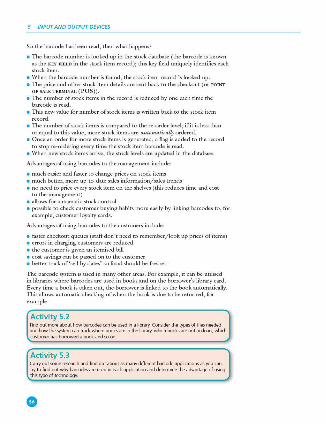
5 INP(JT AND OUTPUT DEVICES
So the barcode has been read, then what happens?
• The barcodc number is looked up in the stock database (the barcodc is known as the KEY FIELD in the stock item record); this key field uniquely identifies each stock item.
• \Vhen the barcodc number is found, the stock item record is looked up. • The price and other stock item details are sent back to the checkout ( or POINT
O F SALE TERMINAL (PQS)). • The number of stock items in the record is reduced by one each time the
barcodc is read. • This n,:,,11 value for number of stock items is written back to the stock item
record. • The number of stock items is compared to the re-order level; if it is less than
or equal to this value, more stock items arc automntical/y ordered. • Once an order for more stock items is generated, a flag is added to the record
to stop re-ordering every time the stock item barcode is read. • When new stock items arrive, the stock l,:,,•els are updated in the database .
Advantages of using bar codes to the management include:
• much easier and faster to change prices on stock items • much better, more up·to-date sales information/sales trends • no need to price e\'ery stock item on the shelves (this reduces time and cost
to the management) • allows for automatic stock control • possible to check customer buying habits more easily by linking barcodes to, for
example, customer loyalty cards.
Advantages of using bar codes to the customers include:
• faster checkout queues (staff don't need to remember/look up prices of items) • errors in charging customers are reduced • the customer is given an itemised bill • cost savings can be passed on to the customer • better track of'sell by dates' so food should be fresher.
TI1e barcode system is used in many other areas. For example, it can be utilised in libraries where barcodes arc used in books and on the borrower's library card. Every time a book is taken out, the borrower is linked to the book automatically. This allows automatic checking of when the book is due to be rernrned, for example .
Activity 5.2 FindoutmoreabouthowbarcodescanbeuIB!inalibrary.Considerthetypesollilesneeded and how the system can track where books are in the library, which books are out on loan, which cu1tomerha1borrowedabookandsoon.
Activity 5.3 Carryoutsomeres&1rchandlindoutaboutasmanydillerentbarcodeapplicationsasyoucan Try to find out why barrndes are used in each applic.ation and determine the advantage of using this type of technology.
5.2
5.2.3 Quick response (QR) codes @ Another type ofbarc.ode is the QUICK REsroNSE (QR) CODE. This is made up of a matrix of filled -in dark squares on a light background.
For example, the QR code in Figure 5.8 contains the message: ' computer science textbook - CIE syllabus'.
To make a comparison, normal barcodcs (as described in Section 5.2.2 ) can hold up to 30 digits; QR codes can hold over 7000 digits. This obviously gives greater scope for the storage of information.
Because of modern smart phones, which allow internet access on the mo\·e, QR codes can be scanned anywhere. This allows ad\·ertising of products on trains, buses, shopping malls and many other places. By using the built·in camera facility on modern phones and down.loading the appropriate application ( or app ), it is possible to read the QR code. The code may contain a website link or some form of advertising ( e.g. special offers on pizzas).
For example, the QR code in Figure 5.9 contains a phone number and an advertisement for free pizzas if ordered today. On scanning the QR code, the phone number and ad\·ertisement will appear on the mobile phone's screen. Advantages ofQRcodes include:
• there is no need for the user to write down or key in a website address; scanning the QR code does this automatically
• QR codes can store website addressesfURLs that appear in magazines, trains, buses or even on business cards, giving a very effective method of advertising.
5.2.4 Dig ital cameras Digital cameras ha\·e essentially replaced the more traditional camera that used film to record the photos. The film required de\·eloping and then printing before the photographer could see the result of their work. This made these cameras expensive to operate since it wasn't JX)Ssible to delete unwanted photographs.
Modern digital cameras simply link to a computer system via a USE port or by using Bluetooth (which enables wireless transfer of photographic files ).
These cameras are controlled by a microprocessor which can automatically carry out the following tasks:
• adjust the shutter speed • focus the image automatically • operate the flash automatically • adjust the aperture size • adjust the size ofthe image • remove 'red eye' when the flash has been used
and soon.
•
,·.l!J t ~ I!],,. Figure5.8
Figure5.9
Input devices
The photograph is captured when light passes through the lens onto a light- figuN 5.10 Digital came,a
sensitive cell. This cell is made up of tiny elements known as pixels. TI1e number of pi'l:els determines the size of the file used to store the photograph ( e.g. a 14-megapi'l:el camera will need 42 megabytes to store each raw (uncompressed) photograph). By reducing the resolution to , for example, a jpeg image, the
5 INP(JT AND OUTPUT DEVICES
storage reguirement is reduced to 4 megabytes (sec Section 6.2.3). The guality of the photograph also depends on many other factors, such as:
• the type of lens used • the lighting
and soon. ,\1obile phones have caught up with digital cameras as regards number of
pixels. The drawback is usually JXX>r lens quality and limited memory for the storage of photos. But this may all change in the next fe,11 years.
5.2.5 Keyboards KL,'boards are by far the most common method used for data entry. They are used as the input device on computers, tablets, mobile phones and many other electronic items.
The keyboard is connected to the computer either by using a USB connection or by wireless connection. In the case of tablets and mobile phones, the keyboard is often VIRTUAL or a type ofroucHSCREEN technology.
As expbincd in Chapter 1, each character otl a keyboard has an ASCII value. Each character pressed is crnwcrtcd into a digital signal, which the computer interprets.
Keyboards arc a relatively slow method of data entry and are also prone to errors. Bur they are probably still the easiest way to enter text into a computer. H owever, frcgucnt use of these devices can lead to injuries, such as RBPETITNE STRAIN INJURY (RSI) in the hands and wrists.
Ergonomic keyOOards can help to overcome this problem - these have the keys arranged differently as shown in Figure 5.12. They are also designed to give more support to the wrists and hands when doing a lot of typing.
5.2.6 Pointing devices l11e selection of an application often requires the user to 'click' on an icon. Selection of the icon is usually done with a POINI"ING DEVICE (such as a MOUSE or a TRACKERBAU.. ) or by using a touchscreen.
The mouse is probably still the most common JXJinting device and comes in various forms:
• the more traditional type ,vith a mechanical ball arrangement; connected to the computer through a USB JXJft
• the more modern type that use red LEDs to detect movement in the x-y direction; these arc a type of optical mouse
• mice that use either of tl1e above types of technology but use a wireless connection to the computer.
Whatever type of mouse is used it will rcguire an area of desk space to allow movement. They often reguire a mouse mat since some surfaces, such as paper, prevent the correct operation of the device. Depending on the type of computer, tl1e mouse is fitted witl1 one or two buttons to allow for selection and otl1er fimctions. Many designs of mouse have a scroll wheel to allow rapid movement up and down the screen.
Trackerballs are seen more often in an industrial environment - such as a control room. Because they don't need to move, the trackerball doesn't need any desk space or special surface. The operator is also less likely to suffer from injuries
Figure5.11Keyboard
Figure5.12E,gonomicke)O<lard
Figure5.13T,a<l<erbal l
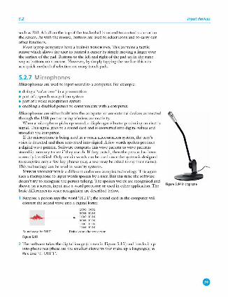
5.2
such as RS I. A ball on the top of the trackerball is moved to control a cursor on the screen. As with the mouse, buttons are used to select icons and to carry out otherfimctions.
Most laptop computers have a built-in T OUCH PAD. lbis contains a tactile sensor which allows the user to control a cursor by simply moving a finger over the surface of the pad. Buttons to the left and right of the pad act in the same way as buttons on a mouse. H owever, by simply tapping the surface this acts as a ciuick method of selection on many touch pads.
5.2.7 Microphones M icroph o n es are used to input sound to a computer. For example:
• doing a 'voice over' in a presentation • part of a speech recognition system • part of a voice recognition system • enabling a disabled person to communicate with a computer.
Microph o n es are either built into the computer or are external devices connected through the USB port or using wireless connectivity.
When a microphone picks up sound, a diaphragm vibrates producing an electric signal. This signal goes to a sound card and is converted into digital values and stored in the computer.
l fthe microphone is being used in a VOICE RBCOGN m ON system, the user's voice is detected and then converted into digital. A few words spoken produce a digital wave pattern. Software compares this wave pattern to wave patterns stored in memory to see if they match. If th<.,' match, then the person has been correctly identified. Only certain words can be used since the system is designed to recognise only a few key phrases (e.g. a user may be asked to say their name ). This technology can be used in security systems.
S PEEC H RECOGNITION is a different and more complex technology. This again uses a microphone to input words spoken by a user. But this time the software doesn't try to recognise the person talking. The spoken words are recognised and shown on a screen, input into a word processor or used in other application. The basic differences to voice recognition are described below.
1 Suppose a person says the word ' H UT'; the sound card in the computer will convert the sound wave into a digital form:
....._ _~ :::::::: D;gitalvalueaftercooversioo
Figure5.15
2 The software takes the digital image (shown in Figure 5.15 ) and breaks it up into phonemes (these are the smallest elements that make up a language); in this case ' H U H T'.
Input devices
Figure5 .1 4Microphone
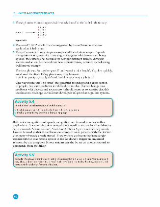
5 INP(JT AND OUTPUT DEVICES
3 These phonemes arc compared with words found in the built-in dictionary:
figuN5.1 6
4 The word ' H UT' would then be suggested by the software in whatever application is being run.
5 This, of course, is a very simple example and the whole concept of speech recognition is \·cry complex. In trying to recognise which words arc being spoken, the software has to take into account different dialects, different accents and so on. Just to indicate how difficult this is, consider the following well -known example:
The two phrases: 'recognise speech' and 'wreak a nice beach', if spoken quickly, arc almost identical. Using phonemes, they become: 'r eh k ao g nay z / s p iy eh' and 'r eh k / ay /nays/ b iy eh'
One way round this is to 'train' the computer to understand a cross-section of people; but some problems arc difficult to rcsol\-c. H uman beings have problems \\~th dialects and accents; so it should come as no surprise that this continues to challenge the software developers of speech recognition systems.
Activity 5.4 Oe,;cribehowspeechrecognitioncouldbeusedto:
ii teachlanguageskillstopeoplewhohavedifficultyinlearning b teachapersontosaywordsinaloll.'ignlanguage
Both voice recognition and speech recognition can be used in various other applications. For example, \'oicc recognition is used in cars to allow the dri\·cr to
say commands: 'make warmer', 'switch on GPS' or 'open window'. Key words have to be used so that the software can compare \·oicc patterns with the limited dictionary of words already stored. These systems arc becoming increasingly sophisticated so that normal speech in the car doesn't trigger an unwanted response by the computer. Newer systems can also be set up to only respond to
commands from the driver.
Activity 5.5 Coo1idertheplu'ieSandminu'ieSolulingvoicerecognitioninacar. lsitsaler?Forex.arnple,it may allow a driver to re~nd to an email while drMng etc. Try to develop this argument and drawavalidcondusionlromyourfindings
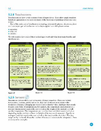
5.2 Input devices
5.2.8 Touchscreens Touchscreens are now a very common form of input device. TI1ey allow simple touch to launch an application or to carry out many ofthc functions of pointing devices such as a mouse.
One of the main uses of touchscrcen technology is in mobile phones. At present, there are three majOI" types oftouchscn:en technologies applied to mobile phone screens:
• capacitive • infra-red • resistive.
\Ve will consider how each of these technologies work and what their main benefits and drawbacks are.
• Thisismadeupofmanyla)"'"ol glassthatact likeacai,adror, creatingelec!ricfieldsbetweeothe glassplate,;inlayers.
- ~thetopgl.:ts,;layertltouched,
:.:!.:\:::~:' !ournedisde!e<minedbyan or.-bo.YdmicropmcesSO<
• Thisisaml'dlJmrosttedmok,gy. • Saeenvtlibililyi,good.....,,;n
strongSIK'llight • ltpe<mitsmuttf-lOI.Chcapabiity. • Thesaeenisve,ydurable;ittal::es
amajofimpac!tob<eaktheglass
Figure 5.17
5.2.9 Sensors ©
INFM-IIED(heatandoptkall
Hut-,en>itM!
-~:=~ - Need,awa,mobject
(e.g. finge,s)IOGl<f}' out an input operatioo
Optical
-::.t::1:.: - Usesao.,,,~of
Sl'O<OfS(in!heform
~:Z~~~oo ;:t'i!/1.e~cooolinate
• Bo!hsyrtem:sallowmutti-touchcapabiities • Theoplical,ystemalb.vstheuseofba,e
fi"9'-"',gkNedfinge"orastylusforinput • 8o!hsy;tem:shavegoodsc""-"1durabilily;it
!akeamajorirnpacttobreaktheglass
• ltisrelati,Plye,:peo<ivetedloology. • Heat-';ensi\Nesy;temonlyalowsb.arefingers
robeusedforinput(gk,,edfioger,orst~, tloo'twork)
• Bothsy;tem:s(oplicalaodheat-seositwe)ha.... taiflygoodscrerovisibil ityinrooogsonlig ht
figuN5.18
• Thismakesuseofaoupperlaye<ol polyester(afoonolplastic}and abonomla)'l'lolgla'5
• Whentl>etoppofye<terlajoer,S touched,thetoplayeraodthebonom layercompleteaci-cuit
• Signals are !hen sent out which are
~r~.t~ ... m,;:;.;:;;i!':tes ofw!ieretl>esc""-"1wastooc:hed
• ltisrelaWPlyinexpensivetedmology. • ltispossi,letousebarelingers,glo,,ed
fi"9'-"'ora,~"'IOG1ffY001aoinJ11l! operatioo
• Saerovislbilityispoorinmoog sunlight
• ltdoesn'tperm~rnulti-touchca~~ty.
·::;,mscr;: t~u;:~~ ~;:: !:en wea"outthJOOqltime
figuN5.19
SENSORS are devices which read or measure physical properties. 1l1esc can include temperature, pressure, acidity and so on. Real data is ANALOGUE in nature - this means it is constantly changing and doesn't have a discrete value. Analogue data usually reciuires some form of interpretation; for example, the temperature measurement on a mercury tl1ermomcter requires the user to look at tl1e height of the mercury to work out the temperature. The temperarnre can therefore have an infinite number of values depending on the precision of how the height oftl1e mercury is measured. Equally an analogue clock fuce requires the user to look at the hands on tl1e clock fucc. The area S\vept out by the hands allows tl1e number of hours and minutes to be interpreted. There are many other examples.
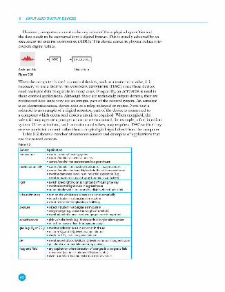
5 INP(JT AND OUTPUT DEVICES
H owever, computers cannot make any sense of these physical quantities and the data needs to be converted into a digital format. This is usually achieved by an ANALOGUE TO D IGITAL CONVERTI!R (ADC). This device converts physical values into discrete digital values.
AAalogoedata
Figu,.5.20
Oigitajdata
When the computer is used to control devices, such as a motor or a valve, it is necessary to USC a D IGITAL TO ANALOGUE CONVERTER (DAC) since these devices need analogue data to operate in many cases. Frequently, an AcrUATOR is used in these control applications. Although these arc technically output devices, tl1cy arc mentioned here since tl1cy arc an integral part of the control system . An actuator is an electromechanical device such as a relay, solenoid or motor. Note tl1at a solenoid is an cxan1plc of a digital actuator; part of the device is connected to
a computer which opens and closes a circuit as required. \Vhcn energised, tl1c solenoid may operate a plunger or armature to control, for example, a fuel injection system . Other actuators, such as motors and valves, may require a DAC so that they receive an electric current rather than a simple digital signal direct from the computer.
Table 5.2 shows a number of common sensors and examples of applications that use the nan1cd sensors.
Apn~cation
temperature • mntrnlacentulhea~ngsy,tem • mntrnVmooito< a chemical prnces, • mntrnVmooito< the temperature in a c,eenhouse
moisture/humidity • mntrnVmooito< the moisture fevel, in SO<l in a greenhouse • mntrnVmooito< the hooiiclity fevel, in the air in a g,reenhouse o mor,j\()(damfl"'-"Slevelsinanindustrialapplicatioo(e.g ..
mooit()(moi,tureinap,l'nt,prayboothinacarlactory)
li~t • switchstreeth~tingooatnightandoffduOOgtheday • mooi!()(/cootmlli<j,tlevelsinac,eenhouse • automatically switch on acar~headlightswhen itgetsdait
• tumoothewindscreenwiper,onaca,automatically • detectintrudefSinaburgla,alatmsystem • (OUntpeopleenteri~iWingabuiiding
• detectintrudefSinaburgla,alatmsystem • wei~thing,(e .g.checkthewei~tofavehide) • mooito,/cootmlaprocesswhefegaspressu,ei,important
• r,kkupnoiselevel,(e.g.footstep,)inab<.xglarala,msystem • detectthenoiseofliquidsdriW,nginapipe
gas(e.g . 0,()((02) • mooil()(polltrtionlevelsinafiveror intheair • measmeO,andCO,H'velsinagreenhouse • cheO::forC02 1eaksinapower,tation
pH • mooi!()(/cootmlac:idity/aik,-initylevel,in the SO<l in ~greenhouse • poUution/envimnmentalmooitoringinfivers
miKJrieticfield • anyilppicalionwt.eredetectiooofchangesinamagneticfield isrequired (e.g.inceUphor,e,.CDplayers.etc.)
• usedinanti·kldbrakingsystemsinmoto<vehide,
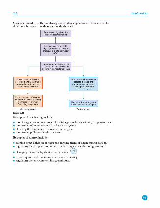
5.2
Sensors are used in both monitoring and control applications. 1l1cre is a subtle difference between how these two methods work:
SellSOl'SsendsiCJOalslothe miaopmcPSs.xk.omputer
Thesignals..-econvertedto digital(ifnecl'S"")')usingan analoguetodigitalcorwerte,
(AOC)
Thecomputerhnoanprocessor aoal)'5<-;lhedatareceiwdby
<hec:kingrtagainststoredvaiUl'S
Themicmprncesso<lcomputer hasnoeffectonwhatisbe;ng
monitored - itissimply 'watchong'thep«xes,
Theoutputlrnmthesystem affectsthenextsetofinputs
Monitoring system Cootfolsystem
Figur• 5.21
Examples of monitoring include:
• monitoring a patient in a hospital for vital signs such as heart rate, temperature, etc. • monitoring of intruders in a burglar alarm system • checking the temperature levels in a car engine • monitoring pollution levels in a river.
Examples of control include:
• turning street lights on at night and turning them off again during daylight • regulating the temperature in a central heating/ air conditioning system
• changing the traffic lights at a road junction © • operating anti -lock brakes on a car when necessary • regulating the environment in a greenhouse.
Input devices
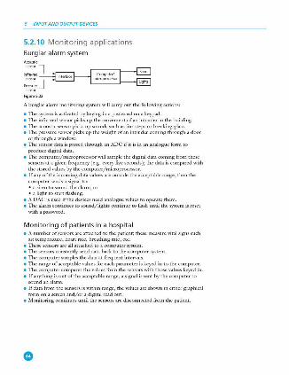
5 INP(JT AND OUTPUT DEVICES
5.2.10 Monitoring applications Burglar a larm system Aa,ustk
lnfra-<ed •o=
f'rp,;sure
Figu,.5.22
A burglar alarm monitoring system will carry out the following actions:
• The system is activated by keying in a password on a keypad. • The infra-red sensor picks up the movement of an intruder in the building. • The acoustic sensor picks up sounds such as footsteps or breaking glass. • The pressure sensor picks up the weight of an intruder coming through a door
or through a window. • The sensor data is passed through an ADC if it is in an analogue form to
produce digital data. • The computer/microprocessor will sample the digital data coming from these
sensors at a given frequency (e .g . every five seconds); the data is compared with the stored values by the computer/microprocessor.
• If any of the incoming data \'alues are outside the acceptable range, then the computer sends a signal to: • a siren to sound the alarm, or • a light to start flashing.
• A DAC is used ifthe devices need analogue values to operate them. • The alarm continues to sound/lights continue to flash until the system is reset
with a password.
Monitoring of patients in a hospital • A mm1ber of sensors arc attached to the patient; these measure vital signs such
as:temperan1re,heartrate, breathingrate,etc. • These sensors are all attached to a computer system. • The sensors constantly send data back to the computer system. • The computer san1ples the data at fre'luent intervals. • The range of acceptable \'alues for each parameter is keyed in to the computer. • The computer compares the \'alues from the sensors with those values keyed in. • If anything is out of the acceptable range, a signal is sent by the computer to
sound an alarm. • If data from the sensors is \vithin range, the values are shown in either graphical
form on a screen and/or a digital read out. • Monitoring continues until the sensors are disconnected from the patient.

5.2
5.2.11 Contro l applications
Control of street lighting
figu N5.23 figu N5.24
This next scciuence shows how a microprocessor is used to control the operation of a street lamp. The lamp is fitted with a light sensor which constantly sends data to the microprocessor. The data \'alue from the sensor changes according to
whether it is sunnr, cloudy, raining or it is night time etc.
• The light sensor sends data to the ADC interface. • lb.is digitises the data and sends it to the microprocessor. • The microprocessor samples the data every minute ( or at some other
frequency rate ). • If the data from the sensor< value stored in memory:
• a signal is sent from the microprocessor to the street lamp • and the lamp is switched on.
• The lamp sr:i.ys switched on for 30 minutes before the sensor readings are sampled again (this prevents the lamp flickering off and on during brief hcary cloud cover, for example ).
• If the data from the sensor >• value stored in memory: • a signal is sent from the microprocessor to the street lamp • and the lamp is switched off.
• 111c lamp stays switched off for 30 minutes before sensor readings arc sampled again (this prevents the lamp flickering off and on during hcary cloud cover, for example ).
Activity 5.6 Draw a flow diagram to ,;how the steps in how a mkroprocessor controls the switching off and on of a si-t lamp. Remember to include a method to stop the lamp switching on and off every few seconds
Anti-lock braking syste ms (o n cars) ANTI -LOCK BRAKING SYSTEMS (ABS) on cars use magnetic field sensors to stop the wheels locking up on the car if the brakes have been applied too sharply.
• When one of the car wheels rotates too slowly (i.e. it is locking up), a magnetic field sensor sends data to a microprocessor.
• 111c microprocessor checks the rotation speed of the other three wheels. • lfthcy arc different ( i.e. rotating faster), the microprocessor sends a signal to
the braking system :
Input devices
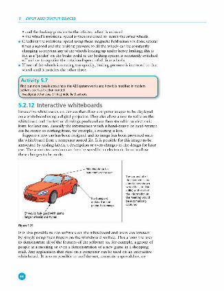
5 INP(JT AND OUTPUT DEVICES
• and the braking pressure to the affected wheel is reduced • the wheel's rotational speed is then increased to match the other wheels.
• Checking the rotational speed using these magnetic field sensors is done several times a second and the braking pressure to all the wheels can be constantly changing to prevent any of the wheels locking up under heavy braking; tills is felt as a 'judder' on the brake pedal as tl1e braking system is constantly switched off and on to equalise the rotational speed of all four wheels.
• If one of the wheels is rotating too quickly, braking pressure is increased to that wheel until it matches tl1e other three.
Activity 5. 7 Find out more details about how the ABS system works and how it is modified in modem systemssuchastractioncontrol lnvestigateotherusesofmagneticlieldseosor,;
5.2.12 Interactive whiteboards Interactive whiteboards are devices that allow computer images to be displayed on a whiteboard using a digital projector. They also allow a user to write on the wlllteboard and the text or drawings produced are then stored in an electronic form for later use. Basically the information wlllch is hand-drawn or hand-written can be stored so notlllng from, for example, a meeting is lost.
Suppose a new car has been designed and its image has been projected onto tl1e whiteboard from a computer-stored file. It is possible for this image to be annotated by adding labels, a description or even changes to the design for later use. The annotated version can then be saved in an electronic form to allow tl1ese changes to be made.
Itwouldlookg,oodwithsom~ klrguwhulscrodtyre.s
Figu,.5.25
w ~ shooldputo .sunroofontht.cor
Nobompus mokesth~ cor pronetodoioogt.
Thecarandallol thecommentsafld anootationsshown wouklbestored(in
~~l~~r:!':t!!I ;: theneetingwoold be automatically captured
It is also possible to nm software on the whiteboard and users can interact by simply using their fingers on the whiteboard surface. This allows tl1e user to demonstrate all of the features of the software to, for example, a group of people at a meeting or even a demonstration of a new game in a shopping mall. Any application that runs on a computer can be used on an interactive whiteboard. It is even possible to surf the net, annotate a spreadsheet or
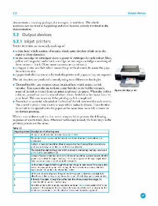
5.3
demonstrate a drawing package, for example, in real time. The whole audience can see what is happening and even become actively i1woked in the demonstration.
5.3 Output devices
5.3.1 lnkjet printers INKJET PRINTERS are essentially made up of:
• a print head which consists of nozzles which spray droplets of ink on to the paper to form characters
• an ink cartridge or cartridges; either a group of cartridges for each colour ( blue, yellow and magenta) and a black cartridge or one single cartridge containing all three colours+ black (Note: some systems use six colours.)
• a stepper motor and belt which moves the print head assembly across the page from side to side
• a paper feed which automatically feeds the printer with pages as they are reguircd.
The ink droplets arc produced currently using n\·o different technologies.
• Thermal bubble: tiny resistors create localised heat which makes the ink vaporise. 111is causes the ink to form a tiny bubble; as the bubble expands, some of the ink is ejected from the print head onto the paper. When the bubble collapses, a small vacuum is created which allows fresh ink to be drawn into the print head. This continues until the printing cyde is completed.
• Piezoelectric: a crystal is located at the back of the ink reservoir for each nozzle. The crystal is given a tiny electric charge which makes it vibrate. This vibration forces ink to be ejected onto the paper; at the same time more ink is drawn in for further printing.
\Vhen a user wishes to print a docwnent using an inkjet printer, the following sequence of events takes place. Whatever teclmology is used, the basic steps in the printing process are the same.
Sta<:1einprocHs DHaiptionofwhathapp•n•
l Thedatafromthedocumentissenttoa printe< oiv..-
~~~:drive, ensures thatthedataisin a fom\at that the chosen pmter can
Ached<:ismadebytheprinterclrivertoensurethatthed>osenprinte,isavai\ab!eto print(e.g.is j\busy.isitoffline.isitootofjnk.anclsooo)
The data is then sent to the printer anditisst"'edin a temp<><a,ymemorykoownas a printerbulf..- (sees.ectioo4.3)
Asheetolpape,isthenfedintothemainbodyoltheprinte,;asenso,detectswhether pape,isavailable in thepaperleedlfay - i/;tisoot ofpaper(orthepape,isjammed) then an errn, message is sent bad to the computer
Asthesheetofpaperisfedlhf~theprinte,.theprintheadma,eslfomsidetoside acr=thepaperpr;ntingthetextor;mage;thefoorinkcoloorsare'f)fayedintheir exi>damoontstop,oducetheoesi,edlinalrolou,
Attheendofeachfullpassoltheprinthead.thepape,isadvanc:edve,yslgltlyto allowthenextlinetobeprinted;thiscontinuesuntilthewholep;,gehasbeenprinted
tlthen>isJnOfedataintheprinte,buffe,.then!hewholeprocessfmmst.,.ge5is ,epeateduntilthebufferisfinaltyempty
Onc:etheprinterbufferisempty. theprinterseodsan interrupt (seeSection4.3)to!he processo,in!hecomputer;thisisa,equestlorJnOfedatatobesenttotheprinte,;the wt.oleprocesscontim,esuntilthewhaeolthedor:umenthasbeenprinted
Output devices
Figure5.261nkjetprinte,

5 INP(JT AND OUTPUT DEVICES
5.3.2 Laser printers LASER PRINTERS differ greatly from inkjet printers in the way they print pages. l11ey use dry powder ink rather than liCJuid ink and make use of the properties of static electricity to produce the text and images. Unlike inkjet printers, laser printers print the whole page in one go (inkjet printers print the page line byline).
Their advantage is the speed at which they can carry out large print jobs (e .g. 2000 leaflets) and the fact that they don't run out of ink halfway through.
The following table describes briefly the stages that occur when a document is printed using a laser printer:
SU •inproc .. s c .. c,iptionofwhathappe ns
1 Thedatafromthedocumentissenttoa ?"int0<dii""'
~~t::i diiver em<XPSltlatthe data isina lormatthatlhe chosenprinte< can
Acl>eckismadebytheprinte,drive<toensurettlatthed,osenprintefisavailableto print(e .9.isitbos,:isitoffline.isitoutofink.andsoon)
Thedataisthensenttolheprinte<anditisstoredinalemporarym<>mClfYkno.vnasa pnntefbuffN (refe<toSec!ion4 .3fllfmoredetails)
Thestartofthe printing procPSsk,vONes a princngdrum t,e;nggiltffia JX)SJttv, ~ : asthisdrumrotates.alaserbeamisscannedacrossitremcMngthepositivechargein ce,tainareas;thisleaves neg;,liYefy ch~go,d areaswhichexactlymatchthetexVim.,.ges olthepagetobeprinted
Thedrumisthenooatedwithpositivelyctlargedrotu(powderedink);sinc:ethetone, ispositivelycharged.itonlystidstolhenegatJVelychargedpa,tsoftheclrum
AnegativelyctlargedsheetofpaperisthenrolledOYe<!hedrum
The toner on the drum nowstids tolhe pape,to pmdoce an exactrnpyoflhe page senttolheprintef
Thepape,linallygoeslhmugh~luSl'IIM>ichisasetoll>eatedrolle,s;thel>eatmelts theinksothatitf,xPSpe,manentlytothepaper
Atthevef"jend.adischargelampr itreadytoprintthenextp.:,ge
alltheek>ctricchilfgefromthedrummaking
App li catio ns of inkjet and laser printe rs The choice of whether to use an inkjct printer or laser printer depends on which fcamres make it the most appropriate output device for the given application.
INKJET PRINTERS are best for one-off photos or where only a few pages of good quality, colour printing arc needed; the small ink cartridges or small paper trays would not be an issue with such applications.
LASER PRI NTERS produce high quality printouts and arc very fast when making multiple copies of a document; any application that needs high-volume printing (in colour or monochrome) would choose the laser printer ( for example, producing a large number of high quality flyers or ix,sters for ad\·crtising) - they have two advantages: they ha\·c large toner cartridges and large paper trays ( often holding more than a ream of paper).
Figure5.27Lue,printef
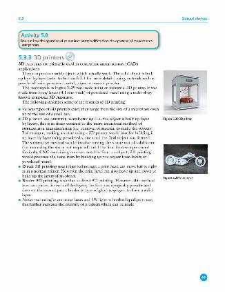
5.3
Activity 5.8 Find out how the operation of colour laser printers differ,; from the operation of monochrome laser printers
5.3.3 3D printers @ 30 PRINTERS are primarily used in COMPUTER·AIDBD DESIGN (CAD) applications.
They can produce solid objects which actually work. The solid object is built up layer by layer (refer to Section 5.2.l for more details ) using materials such as powdered resin, (X)Wdered metal, paper or ceramic powder.
The motorcycle in Figure 5.29 was made using an industrial 3D printer. It was made from many layers (0.1 mm thick) of powdered metal using a technology known as BINDER 30 PRINTING.
The following describes some of the features of 3D printing:
• Various types of 3D printers exist; they range from the size of a microwave oven up to the size of a small car.
• 30 printers use ADDITIVE manufacturing ( i.e. the object is built up layer by layer); this is in sharp contrast to the more traditional method of SUBTRACTI VE manufacturing (i.e. removal of material to make the object ). For example, making a statue using a 30 printer would involve building it up layer by layer using powdered stone until the final object was formed. The subtractive method would im·olve car\'ing the statue out of solid stone (i.e. remo\'ing the stone not required ) until the final item was produced. Similarly, CNC machining removes metal to form an object; 30 printing would produce the same item by building up the object from layers of powdered metal.
• Direct 30 printing uses inkjet technology; a print head can move left: to right as in a normal printer. H owever, the print head can also move up and down to build up the layers of an object.
• Binder 30 printing is similar to direct 30 printing. H owe\·er, this method uses two passes for each of the layers; the first pass sprays dry powder and then on the second pass a binder ( a type of glue ) is sprayed to form a solid layer.
• Newer technologies are using lasers and UV light to harden liquid polymers; this further increases the diversity of products which can be made.
Output devices
Figure5.283Dprinter
Figure5.29 Moto<cyde

5 INP(JT AND OUTPUT DEVICES
How to create a so lid object using a 3D printer l11crc arc a number of steps in the process of producing an object using these 30 printers. The steps arc summarised in Figure 5.30.
Adesignismadeusingrnmpuler·aideddesi(jl\(CAO)softwa,e
Thefiflilliseddrill<ingisimpo<tedintosomespec:ialsoftwarethat prep,aresitinalormatwhkhisunde,stoodbythe3Dprinter
The3Dprinterissetuptoallowthesolidobjecttobemade
The,ojidobjectisbuiltuplayerbylayer(oltenonly0.1m'll lhid); thiscantal<eseveralhours.dependingoothethid<nessolthe
laym. thematerialusedandthesizeofthefiflillobject
Theobjectis,ema,edfmmtheprinterandisthenp<epared;lor exampH'.someuseajeliy.lii::esupportwhid\needstobewashed awaybyimme"""1inwater.somerequi,etherema,alofexc=
plasticpowderandothersrequi"etheruttingawayoluro.ised material;inmanycases,tti;~~astobeleftto"ru,e"lora
Figu,.5.30
Uses of 3D printing 30 printing is regarded as being possibly the next ' industrial revolution' since it will change the manufacturing methods in many industries. The following list is just a glimpse into what we know can be made using these printers; in the years to come, this list will probably fill an entire book:
• prosthetic limbs made to exactly fit the recipient • items to all0\11 precision rcconstructi\·c surgery ( e.g. facial reconstruction
following an accident); the parts made by this technique arc more precise in their design since they arc made from exact scatUJing of the skull
• in aerospace, manufacturers arc looking at making wings and other parts using 30 technology; the bonus will be lightweight precision parts
• in fashion and art - 30 printing allows new creative ideas to be dc\·clopcd • making parts for items no longer in production, e.g. suspension parts for a
vintage car.
l11csc arc just a few ofthc exciting applications which make use of this new technology.
Activity 5.9 Do a search on the internet to find new and inno~ative 30 printer applications Have a class discussion on how these printers could herald the start of a new 'industrial reYOlution'
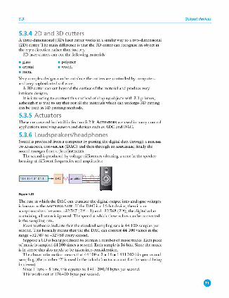
5.3
5.3.4 2D and 3D cutters A three-dimensional ( 3D) laser cutter works in a similar way to a two-dimensional (2D ) cutter. The main difference is that the 3D cutter can recognise an object in the x-y-z direction rather than just x-y.
3D laser cutters can cut the following materials:
• glass • polymer • crystal • wood. • metal
Very complex designs can be cut since the cutters are controlled by computers and \·cry sophisticated software.
A 3D cutter can cut beyond the surface of the material and produce \'cry intricate designs.
It is interesting to contrast this method of shaping objects with 3D printers, although it is true to say that not all the materials which can undergo 3D cutting can be used in 30 printing methods.
5.3.5 Actuators These arc co\·cred in detail in Section 5.2.9. AcruATORS arc used in many control applications invol\'ing sensors and d<:'lices such as ADC and DAC.
5.3.6 Loudspeakers/headphones Sound is produced from a computer by passing the digital data through a DIGITAL TO ANALOGUE CONVERTER (DAC) and then through an AM PLIFIER; finally the sound emerges from a (loud)sPBAKER.
The sound is produced by voltage differences \'ibrating a cone in the speaker housing at different freciuencies and amplitudes:
Figur•5.31
The rate at which the DAC can translate the digital output into analogue \'oltages is known as the SAMPLING RATE. lfthe DAC is a 16·bitde'lice, then it can accept numbers between +32767 (216 -1 ) and - 32768 (216); the digital value containing all zeros is ignored. The speed at which these w.lues can be converted is the sampling rate.
Most textbooks indicate that the standard sampling rate is 44 100 samples per second. This basically means that the the DAC can convert 44 100 \'alues in the range +32 767 to - 32 768 e\·ery second.
Suppose a CD is being produced to contain a number of music tracks. Each piece of music is sampled 44100 rimes a second. Each sample is 16 bits. Since the music is in stereo this also needs to be taken into consideration.
The abo\'e information means that 44 100 x 2 x 16 - 1411200 bits per second sampling (the number '2' is used in the calculation to account for the sound being in stereo).
Since l byte - 8 bits, this eciuates to l 411200/8 bytes per second. This works out at 176400 bytes per second.
Output devices
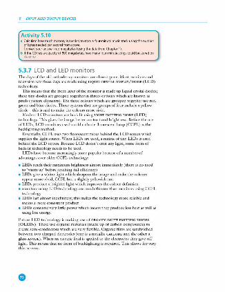
5 INP(JT AND OUTPUT DEVICES
Activity 5.10 a Calculate how much memory is needed to store a four-minute music track using the number
ofbytesneededpersecondfromabove Convert your answer into megabytes (using the data from Chapter 1)
b If the CO has a capacity of 800 megabytes, haw many lour-minute songs could be stored on the CO?
5.3.7 LCD and LED monitors 111c days of the old cathode-ray monitors arc almost gone. Most monitors and television sets these days arc made using LIQUID CRYSTAL DISPLAY/DIODE (LCD) technology.
This means that the front layer of the monitor is made up liquid crystal diodes; these tiny diodes arc grouped together in threes or fours which arc known as pixels (picture elements). The three colours which arc grouped together use red , green and blue diodes. Those systems that use groups of four include a yellow diode - this is said to make the colours more vivid.
Modern LCD monitors arc back lit using LIG HI" EMITTING D IODE (LED) technology. TI1is gives the image better contrast and brightness. Before the use of LEDs, LCD monitors used a cold cathode fluorescent lamp (CCFL) as the back.lighting method.
Essentially, CCFL uses two fluorescent tubes behind the LCD screen which supplies the light source. \Vhcn LEDs arc used, a matrix of tiny LEDs is used behind the LCD screen. Because LCD doesn't emit any light, some form of back-lit technology needs to be used.
LEDs ha\·c become increasingly more popular because of a number of advantages over older CCFL tcclmology:
• LEDs reach their maximum brigl1tncss almost immediately ( there is no need to 'warm up' before reaching full efficiency)
• LEDs give a whiter light which sharpens the image and make the colours appear more vivid; CCFL had a sliglnly ycllmvish tint
• LEDs produce a briglncr ligln which improves the colour definition • monitors using LED t eclmology arc much thinner than monitors using CCFL
technology • LEDs last almost indefinitely; this makes the technology more reliable and
means a more consistent product • LEDs consume very little power which means they produce less heat as well as
using less energy.
Furnrc LED technology is making USC of ORGAN IC LIG H T EM J'IT ING DIODES
(OLEDs). These use organic materials (made up of carbon compounds) to create semi-conductors which arc very flexibl e . Organic films arc sandwiched between two charged electrodes ( one is a metallic CATH ODE and the other a glass ANODE ) . \Vhcn an electric field is applied to the clcc.trodcs they gi\·c off light. This means that no form of backliglning is required. This allows for \·cry thin screens .
•
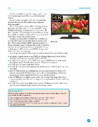
5.3
It also means that there is no longer a need to use LCD technology, since OLED is a self-contained system.
As can be seen in Figure 5 .32, OLEDs allow the screen to be curved. This ensures a good picmrc from any angle.
But the important aspect of the technology is how thin this makes the screen. It is now possible, using OLED technology, to bend screens to any shape. If this is adopted by mobile phone manufacturers, it will be possible to develop phones which can wrap around your wrist - much like a watch strap.
Imagine screens so thin that they can be folded up and placed in your pocket until th<.-y are needed. Or Figu N 5_32 how about using folding OLED displays attached to
fabrics creating 'smart' clothing (this could be used on outdoor survi\'al clothing where an integrated circuit, mobile phone, GPS receiver and OLED display could all be se\,~l into the clothing)?
Advantages of using OLED compared with existing LEDs and LCDs include:
• the plastic, organic layers of an OLED are thinner, lighter and more flexible than the crystal structures used in LEDs or LCDs
• the light-emitting layers of an OLED are lighter; OLED layers can be made from plastic rather than the glass used in LED and LCD screens
• OLEDs give a brighter light than LEDs • OLEDs do not reciuire backlighting like LCD screens - OLEDs generate their
own light • since OLEDs reciuire no back.lighting, they use much less power than LCD
screens (most of the LCD power is used todo the back.lighting); this is very important in battery-operated devices such as mobile phones
• since OLEDs are essentially plastics, they can be made into large, thin sheets (this means they could be used on large advertising boards in airports, subways, and so on)
• OLEDs have a very large field of view, about 170 degrees, which makes them ideal for use in television sets and for ad\·ertising screens.
Activity 5.11 Carry out some research into OLEO technology (then! all! numerous internet sites to help you} andanswerthefollowingquestions:
a Why all! inkjet printers helping to keep down the cost of OLED screens? b Howarediffell!ntcoloursgeoeratedusingOLEDtechnology? c Howisthebrightnessolthedisplaycontrolled? d OLEDs n!fresh 1000 timl'S faster than LCDs; why would this be an advantage? Where could it
beusedtogre;itellect?
Output devices
5 INP(JT AND OUTPUT DEVICES
LCD/LED screens are used on many hand-held devices with touchscrecns, such as mobile phones, tablets and game consoles. The technology behind such screens was discussed at great length in Section 5.2.8.
,\1odern LCD screens are very thin and very lightweight and are \·ery rcs1x:msive to touch. Obviously, the m.·w technologies described above will change the way we use these hand-held devices in the very near future.
5.3.8 Light projectors l11ere are two common types of light projector:
• digital light projectors (DLP) • LCD projectors.
Projectors are used to project computer output onto larger screens or even onto interactive whiteboards. They are often used in presentations and in multimedia applications.
The following two sections describe the basic differences behind these projector technologies.
Digital Light Projectors (D LP) l11e USC of millions of micro mirrors on a small DIGITA L LIGHT PROJBCT"OR (D LP) chip is key to how these devic.cs work.
The number of micro mirrors and the way they are arranged on the OLP chip determines the resolution of the digital image. When the micro mirrors tilt towards the light source, they are ON. When the micro mirrors tilt away from the light source, they are OFF. This creates a light or dark pi.'l:el on the projection screen. The micro mirrors can switch on or off several thousand times a second creating various gn.1' shades - typically 1024 grey shades can be produced (for example, if the mirror switc.hes on more often than it s,\~tches ?ff, it will produce a lighter shade of grey). This is known as the grey scale image.
A bright white light source ( e.g. from a xenon bulb) passes through a colour filter on its way to the OLP chip. The white light is split into the primary colours: red, green and blue - the DLP projector can create over 16 million different colours. l11e ON and OFF states of each micro mirror are linked with colours from the filter to produce the coloured image.
The whole concept is a little like reverse black and white photography. With OLP technology, the grey scales arc interpreted as colours rather than grey representing colours as used in photography.
5.3
LCD projectors These are older technology than DLP. Essentially a high-intensity beam oflight passes through an LCD display and then onto a screen. How this works in principle is described below.
• A powerful beam of white light is generated from a bulb or LED inside the projector body.
• TI1is beam oflight is then sent to a group of chromatic-coated mirrors; these reflect the light back at different wavelengths.
• When the white light hits these mirrors, the refh:cted light has wavelengths corresponding to red, green and blue light components.
• These three different coloured light components pass through three LCD screens; these screens show the image to be projected as millions of pixels in a grey scale .
• When the coloured light passes through the LCD screens, a red, green and blue \'ersion of the grey image emerges.
• 1l1ese images arc then combined using a special prism to produce a full colour image - this final image consists of millions of colours ( each shade of grey in the original image produces a different shade in each ofthe colour images).
• Finally the image passes through the projector lens onto a screen.
Output devices
® Memory and data storage
lnthischapteryouwilllearnabout:
e filelormatssuchasMIOl,MP3andjpeg e filernmpresskmtechniques • primary,secondaryandoff-linestorage e magnetic,optkalandsolid-st.-itemedia
6.1 Introduction There are many file formats used to store data, be this text, images or sound, in computer systems. This chapter will consider how file compression is used to sa\'e memory when storing different types of files.
All computer systems ha\·e primary memory and secondary memory storage. 111c main technologies used arc magnetic, optical and solid state . Storage devices which use each of these technologies will be described later in this chapter, together with a number of applications.
6.2 Fi le formats A number of different file formats are used in computer systems. We will look at the following ones:
• Musical Instrument Digital lntcrfu.cc (M I DI) • MP3 • MP4 • jpcg • text and number format.
6.2.1 Musica l Instrument Digit al Interface (MIDI) MUSI CAL I NSTRUMENT DIGITAL INTERPACE (i\UDI) is always associated with the storage of music files. H owever, M I D I files arc not music and don't contain any sounds; they arc \·cry different to, for example, MP3 files. MIDI is essentially a communications protocol that allows electronic musical instruments to interact with each other. The ,\1IDI protocol uses 8 -bit serial transmission with one start bit and one stop bit, and is therefore asynchronous (sec Section 2.2.3).
A MI D I file consists of a list of commands that instruct a device ( for example, an electronic organ, sound card in a computer or in a mobile phone) how to
produce a particular sound or musical note. Each MIDI command has a specific sequence of bytes. The first byte is the status byte - this informs the MIDI device what function to perform. Encoded in the status byte is the MIDI channel. MIDI operates on 16 different channels, which arc numbered Oto 15.
Examples of MIDI commands include:
• note on/off: this indicates that a key (on an electronic keyboard ) has been pressed/released to produce/stop producing a musical note
• kL-y pressure: this indicates how hard the key has been pressed ( this could indicate loudness of the music note or whether any vibrato has been used, and so on).
Two additional bytes arc required, a PITCH BITE, which tells the MID I device which note to play, and a VELOCITY BYIB, which tells the device how loud to play the note. \Vhcn music or sound is recorded on a computer system, these MIDI messages arc saved in a file which is recognised by the file extension .mid.
0
6.1
If this .mid file is played back through a musical instrument, such asan electronic keyboard, the music will be played back in an identical way to the original. The whole piece of music will have been stored as a series of commands but no actual musical notes. This makes it a \·cry versatile file structure, since the same file could be fed back through a different electronic instrument, such as an electric guitar, with different effects to the original. However, to play back through an instrument such as a guitar would need the use of SEQUENCER
SOFIWARE, since the MIDI files wouldn't be recognised in their 'raw' form. Both the electronic instruments and the computer need a MIDI interface to allow
them to 'talk' to each other. It was mentioned earlier that the M ID I operates on 16 channels. In fact the computer can send data out on all 16 MIDI channels at the same time. For example, 16 M I D I devices, each set up for a different MID I channel, could be connected to the computer. Each device could be playing a separate line in a song from the sequencer software, effectively creating an electronic orchestra. This implementation is being used more and more today in the recording studio, by major orchestras and in musical scores used in films.
Because MIDI files don't contain any audio tracks, their size, compared with an MP3 file, is considerably smaller. For example, a 10 megabyte MP3 file only requires about 10 kilobyte file size when using the M I D I format. This makes them ideal for devices where memory is an issue; for example, storing ring tones on a mobile phone.
6.2.2 MPEG-3 (MP3) and MPEG-4 (MP4) i\-I PEG-3 (MP 3) uses technology known as AU DIO COMPRESSION to convert music and other sounds into an MP3 file format. Essentially, this compression teclmology will reduce the size of a normal music file by about 90 per cent. For example, an 80 megabyte music CD can be reduced to 8 megabytes using MP3 technology.
MP3 files are used in MP3 players, computers or mobile phones. Files can be downloaded from the internet, or CDs can be converted to MP3 format. The CD files are converted using FI LE COMPRESSION software. \Vhilst the music quality can never match the 'foll' version found on a CD , the quality is satisfactory for most general purposes.
But how can the original music file be reduced by 90 per cent whilst still retaining most of the music quality? This is done using file compression algorithms which use PERCEPTUAL MUSIC SHAPING; this essentially removes sounds that the human ear can't hear properly. For example, if two sounds are played at the same time, only the louder one can be heard by the ear, so the softer sound is eliminated. This means that certain parts ofthe music. can be removed without affecting the quality too much.
MP3 files use what is known as a LOSSY FORMAT (see Section 6.3.2 ) since part of the original file is lost following the compression algorithm. This means that the original file can't be put back together again. H owe\·er, even the quality of ,\lP3 files can be different since it depends on the BIT RATE - this is the number of bits per second used when creating the file. Bit rates are roughly between 80 and 320 kilobits per second; usually 200 or higher gives a sound quality close to a normal CD.
MPEG-4 (MP 4) files are slightly different to MP3 files. This format allows the storage of multimedia files rather than just sound. Music, videos, photos and animation can all be stored in the MP4 format. Videos, for example, could be streamed over the internet using the M P4 format without losing any real discernable quality.
File formats
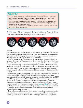
6 MEMORY AND DATA STORAGE
Activity 6.1 A CO is being used to store music Each minute's worth of recording takes up 12 megabytes
a TheCOcontainsninetrackswhicharethelollowinglength{inminutes):3,5,6,4,5,2, 7, 8, 8. How much memory would these nine tracks occupy on theC07
b If the CO was downloaded to a computer and then all the tracks were put through an MP3 compression algorithm, how much memory would the nine tracks now occupy {you may as.sumea90percentfilereductionsize)7
c Find the average size of each of the MP3 tracks, and then estimate how many MP3 files could be stored on an 800 megabyte CO.
6.2.3 Joint Photographic Experts Group (jpeg) files Look at the following fo·c photographs of the same car wheel:
Figu,.6. 1
TI1e resolution of the photographs is reduced from A to E. Photographs A and B arc very sharp whilst photograph Dis very fuzzy and Eis almost unrecognisable. This is the result of changing the number of PIXELS per centimetre used to store the image (that is, reducing the PicrURE RESOLu n oN).
\Vhcn a photographic file undergoes file compression, the size of the file is reduced. The trade -off for this reduc.ed file size is reduced quality of the image. One of the file formats used to reduce photographic file sizes is known as JPEG.
This is another example of lossy file compression. As with M P3 format, once the image is subjected to the jpeg compression algorithm, a new file is formed and the original file can no longer be constructed. Jpeg will reduce the RAW BITMAP image by a factor of between 5 and 15 depending on the guality of the original.
An image that is 2048 pixels wide and 1536 pixels high is egual to 2048 x 1536 pixels; in other words, 3 145 728 piJ:els. This is often referred to as a 3-megapixcl image (although it is obviously slightly larger). A raw bionap can often be referred to as a TIFF or BMl' image (file extension .TIP or .BJ\ilP). The file size ofthis in1,1ge is detemtined by the number of pixels. In the previous example, a 3-megapixel image would be 3 megapixels x 3 colours. 1n other words, 9 megab~'tes ( each pixel occupies 3 bytes because. it is made up of the tlm:e main colours: red, green and blue). TIFF and B,\ll' are the highest image guality because, rnilike jpeg, tl1<.-y are not in a compressed format.
The same image stored in jpeg format would probably occupy benveen 0.6 megabytes and 1. 8 megab)'tes.
Jpeg relies on certain properties of the human eye and, up to a ixiint, a certain amount of file compression can take place without any real loss of guality. The human eye is limited in its ability to detect very slight differences in brightness
•
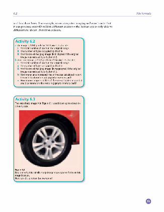
6.1
and in colour hues. For example, some computer imaging software boasts that it can produce o\·er 40 million different colours - the human eye is only able to
differentiate about 10 million colours.
Activity 6.2 a An image is 1200pixelsby1600pixels.Calculate:
I the total number of pixels in the original image II thenumberofbytesoccupiedbythislile Iii thelilesizeolthejpegimage(inkilobytes)iftheoriginal
imagewasreducedbyafactoro/8 b A second image is 3072 pixels by 2304 pixels. Cakulate:
I the total number of pixels in the original image Ii thenumberofbytesoccupiedbythislile Iii the file size of the jpeg image (in megabytes) if the original
imagewasreducedbyafactorofS Iv How many uncompres,;ed files of the size calculated in p;1rt
W) could be stored on a 4-gigabyte memory card? v Howmanyrnmpressedfilesofthesizecalculatedinp;irt(iii}
rnuld be stored oo the same 4-gigabyte memory card?
Activity 6.3 The very sharp image A in Figure 6.1 was blown up to about lix times its size:
Figur•6.2 Findoutwhythisiniliallysharpimagenowappearsluzzyatthi1 magnification Howcanthi1problembeovercome?
File formats
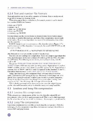
6 MEMORY AND DATA STORAGE
6.2.4 Text and number file formats Text and numbers can be stored in a number of formats. Text is usually stored in an ASCII format (see Section 1.6.4).
\Vhcn using spreadsheets or databases, for example, numbers can be stored in a number of different formats:
• real, e.g. 2.71678 • integer, e.g. 3 • date, e.g. 12/08/2016 • time, e.g. 19:45:50 • currency, e.g. R$ 15.50
It is important that the correct format is chosen if some form of processing is to be done. If number files undergo any form of file compression, then it tends to be lossless. Since it \'ery important that none of the information/data is lost (sec Section 6.3 ).
If ASCII format is used to store text on a file, then the table in Figure 1.7 is used to store each of the characters. For example, the word COi\1.PUTER would be stored as either:
67 79 77 80 85 84 69 82 or %43 %4F %40 %50 %55 %54 %45 %52
(the first code is in denary and the second in hexadecimal). Text files can also undergo file compression. These use complex algorithms that
work on redundancy or repeated sections of words (e.g. OU in yOUr, cOUntry or mOUntain). The following section shows , in \'ery simple terms, how this could work:
The phrase 'THIS SECTION SHOWS YOU HOW THIS WOULD \VORK' consists of35 memory units (ignoring spaces). Repeated words, such as 'THIS' could be put into a data dictionary and be replaced by 'l '. Repeated word sections, such as ' H O\V' and 'OU' could be replaced by the numbers '2' and '3'. Our phrase then becomes ' I SECTION S2S Y3 2 I W3LD WORK'.
Again, ignoring spaces, this compressed form now uses only 23 memory units. This is about a 33% sa\'ing in file size. Ob\'iously if whole pages are to be stored, then repeated words and word sections become even more numerous. Compression algorithms take many things into account when creating these compressed files - but this is outside the scope of this textbook.
This is clearly an example oflosslcss compression since the original phrase can be reformed if necessary using the data dictionary and compressed file.
6.3 Lossless and lossy file compression
6.3.1 Lossless file compression With LOSSLESS FILE COM PRESSION, all the data bits from the original file arc rcconstmctcd when the file is again uncompressed. This is particularly important for files where loss of any data would be disastrous - for example, a spreadsheet file.
6.3.2 Lossy file compression Lossy FILE COM PRESSION is very different to lossless file compression. With this technique, the file compression algorithm eliminates unnecessary bits of data as seen in M P3 and jpcg formats.
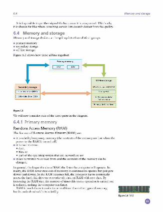
6.4
It is impossible to get the original file back once it is compressed. This is why it is chosen for files where removing certain bits doesn't detract from the quality.
6.4 Memory and storage Memory and storage devices can be split up into three distinct groups:
• primary memory • secondary storage • off-line storage.
Figure 6.3 shows how these all link together:
[ Se<ondarystorag• I j Harcf.diskdrive(HD0) ·1J _.
I So hd-stateO"ive(SSD) II ~
Figure 6.3
\Ve will now consider each of the three parts in the diagram.
6.4.1 Primary memory
Random Access M emory (RA M) The fcamrcs ofllANDOM AccBSS MEMORY (RAM) are:
Off-l ine sto rage
I DVDK:OandDVO.RAM I lllu-raydisk
I us~=~kf I I Removableha,dOO\le I
• it is volatilc/temix,rary memory (the contents of the memory are lost when the power to the RAM is turned off)
• it is used to store: • data, • filcs,or • part of the operating system that are currently in use
• it can be written to or read from and the contents of the memory can be changed.
In general, the larger the size ofRAt\1 the faster the computer will operate. In reality, the RM1 never mns out of memory; it continues to operate but just gets slower and slower. As the RAM becomes full, the processor has to continually access the hard disk drive to overwrite old data on RAM with new data. By increasing the RAt\1 size, the number of times this access operation is carried out is reduced, making the computer run faster.
RM1 is much faster to write to or read from than other types of memory; but its main drawback is its volatility.
Memory and storage
Figure6.4 RAM

6 MEMORY AND DATA STORAGE
Buffers were introduced in Chapter 4 (see Section 4.3). These often use RAt\1 since they need to be a fast memory and the data only needs to be held temporarily. As outlined earlier, buffers allow the processor to do other tasks while slower peripheral devices send data to and receive data from the computer.
There arc currently two types of RAt\1 technology:
• dynamic ram (DRAM ) • static RAM (SRAt\1 ).
Dyn am ic RAM (DRAM) Each DYNAM IC RAM (D RAA-I) chip consists of a number of transistors and capacitors. Each of these parts is tiny since a single RAt\1 chip will contain millions of transistors and capacitors. The function of each part is:
• capacitor - this holds the bits ofinfonnation (0 or 1) • transistor - this acts like a S\llitch; it allows tl1e chip control circuitry to read the
capacitor or change the capacitor's value.
This type of RAt\1 needs to be constantly REFRESH ED ( that is, the capacitor needs to be recharged every 15 microsecondsothcnvise it would lose its value). lfit wasn't refreshed, the capacitor's charge would leak away very guickly, leaving e\·erycapacitorwith the value 0.
DRAMs have a number of advantages over SRAi\1s:
• they are much less expensi\•e to manufacrnrc tl1an SRAM • they consume less JX>WCr than SRM1 • they have a higher storage capacity than SRAM.
St at ic RAM (SRAM) A big difference between SRAt\1 and DRAM is that this type of memory doesn't need to be constantly refreshed.
It makes use of'flip flops' which hold each bit of memory. SRAM is much faster than DRAt\l when it comes to data access (typically,
access rime for SRAM is 25 nanoseconds and for DRAM is 60 nanoseconds). DRAM is the most common type of RAM used in computers, but where
absolute speed is essential, then SRAM is tl1e preferred technology. For example, tl1e processor's MEMORY CACH E is tl1e high speed portion of the memory; it is effective because most programs access tl1e same data or instructions many times. By keeping as much of this information as JX)Ssible in SRAM, the computer avoids having to access the slower DRAM.
Read Only Memory (ROM) The main features of READ ONLY MEMORY (ROM) can be summarised as follows:
• they arc non-volatile/permanent memories ( tl1e contents of the memory remain even when tl1e power to the ROM is rnrncd oft)
• they are often used to store the start-up instructions when the computer is first switched on (for example, ROM might store the basic input/output system ( BIOS ))
• the data or contents of a ROM chip can only be read; they cannot be changed.
Figure6.5DRAM
Figure6.6SRAM
6.4
App licat io n \Ve will now consider an application, other than a computer, where both RAM. and ROM chips are used.
A remote-controlled toy car has a circuitry which contains both RAM and ROM chips. The remote control is a hand-held device.
We will consider the function of each type of memory independently:
• ROM • stores the factory settings such as remote control frequencies • stores the 'start-up' routines when the to)' car is first switched on • stores the set routines; for example, how the buttons on the hand-held device
control turning left, acceleration, stopping, and so on. • RAM
• the user may wish to program in their own routines; these new instructions would be stored in the RAM. chip
• the RAM. chip will store the data/instructions recei\·cd from the remote control unit.
Activity 6.4 Describe how ROM and RAM chips could be used in the following devices
a a microwave oven b arelrigerator c a remote-controlled model aeroplane; the movement of the aeroplane
isrnntrolledbyahand-helddevice
6.4.2 Secondary storage
Hard Disk Drives (HDD) HARD DISK DRIVES (HOD) are probably still the most common method used to store data on a computer.
Data is stored in a digital format on the magnetic surfaces of the disks ( or platters, as they arc frequently called). The hard disk drive will have a number of platters which can spin at about 7000 times a second . A number of read-write heads can access all of the surfaces in the disk drive. Normally each platter will ha\·e two surfaces which can be used to store the data. These read-write heads can move very quickly - typically tl1ey can move from the centre of the disk to the edge of the disk (and back again) 50 times a second.
Data is stored on the surface in sectors and tracks ( see Figure 6.8 on next page).
Memory and storage
A sector on a given track will contain a fixed number of bytes. Figur• 6.7 Unfortunately, hard disk drives have very slow data access when compared to,
for example, RAt\1. Many applications require the read-write heads to constantly seek for the correct blocks of data; this means a large number of head movements. The effects of LATENCY then become very significant. Luency is defined as the time it takes for a specific block of data on a data track to rotate around to the read- write head.
Users will sometimes notice the effect of latency when they see messages such as 'please wait' or, at its worst, 'not responding'.
6 MEMORY AND DATA STORAGE
Solid-state Drives (SSD) Latency is an issue in HDDs as described earlier. SOLID-STATE DRIVES (SSD) remove this issue considerably. They have no moving parts and all data is retrie\·ed at the same rate. They don't rely on magnetic properties; the most common type of solid-state storage devices store data by controlling the movement of electrons within NANO chips. The data is stored as Os and ls in millions of tiny transistors within the chip. This effectively produces a non-volatile rewritable memory.
H owever, a number of solid-state storage devices sometin1es use ELE,CI"RONICALLY ERASABLE PROGRAMMABLE READ-ONLY MEMORY (EEPROM) technology. The main difference is the use ofNORchips rather than NANO. This makes them faster in operation but devices using EE PROM are considerably more expensive than those that use NAND technology. Figu,..6.8
EEPROM also allows data to be read or erased in single bytes at a time. Use of NANO only allows blocks of data to be read or erased. This makes EE PROM technology more useful in certain applications where data needs to be accessed or erased in byte-sized chunks.
Because of the cost implications, the majority of solid-state storage devices use NANO technology. The two types arc usually distinguished by the terms FLASH
(use NANO) and EEPROM ( use NOR). So what are the main benefits ofusingSSD rather than HOD? The main
benefits of SSDs are summarised below:
• they are more reliable (no moving parts to go wrong) • they are considerably lighter (which makes them suitable for laptops) • they don't have to 'get up to speed' before they work properly • they have a lower power consumption • they run much cooler than HDDs (these last two points again make them very
suitable for laptop computers) • because they have no moving parts, they are \·cry thin • data access is considerably faster than HOD.
111c main drawback of SSD is the questionable longevity of the technology. Most solid state storage devices are conservati\·ely rated at only 20 GB write operations per day o\·er a three-year period - this is known as SSD endurance . For this reason, SSD teclmology is not used in servers, for example, where a huge number of write operations take place e\·ery day. H owever, this issue is being addressed by a mm1ber of manufacturers to improve the durability of these solid-state systems.
6.4.3 Off-line storage Off-line storage includes:
• CD/DVD/DVD-RAM (optical storage systems) • Blu-ray disks (optical storage systems) • USB flash memory/memory sticks/SD-XD cards (solid state storage systems) • removable/external hard disk drives (magnetic storage systems).
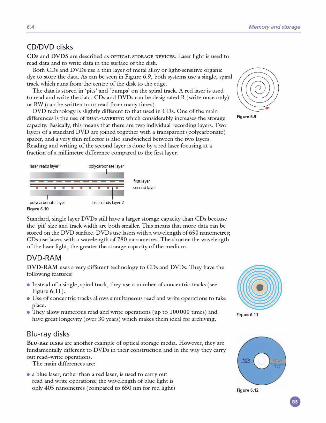
6.4
CD/DVD d isks CDs and DVDS are described as OPTICAL STORAGE DEVICES. Laser light is used to
read data and to write data in the surface ofthc disk.
Memory and storage
Both CDs and DVDs use a thin layer of metal alloy or light-scnsiti\·e organic (I) dye to store the data. As can be seen in Figure 6.9, both systems use a single, spiral track which runs from the centre of the disk to the edge.
The data is stored in 'pits' and 'bumps' on the spiral track. A red laser is used to read and write the data. CDs and DVDs can be designated R (write once only) or RW (can be writt~n t~ or rea_d from many times)._ . -
DVD technology is sliglnly different to that used m CDs. One of the mam differences is the use of DUAL-LAYERING which considerably increases the storage Figur• 6.9 capacity. Basically, this means that there are mu individual recording layers. Two layers of a standard DVD arc joined together with a transparent (ix,lycarbonatc ) spacer, and a very thin reflector is also sandwiched between the two layers. Reading and writing of the second layer is done by a red laser focusing at a fraction of a millimetre difference compared to the first layer.
polycarbonate lay'-" lase,readslayer2
Figur• 6.10
Standard, single layer DVDs still have a larger storage capacity than CDs because the 'pit' size and track width arc both smaller. This means that more data can be stored on the DVD surface. DVDs use lasers with a wa\·clcngth of650 nanometres; CDs use lasers with a wavelength of 780 nanometres. The shorter the wa\·clcngth of the laser light, the greater the storage capacity of the medium.
DVD-RA M DVD·RAA-1 uses a very different technology to CDs and DVDs. TI1cy ha\'c the following features:
• Instead of a single, spiral track, they use a number of concentric tracks (sec Figure 6 . 11 ).
• Use of concentric tracks allows simultaneous read and write operations to take place.
• TI1cyallow numerous read and write operations (up to 100000 times) and ha\'c great longevity ( o\'cr 30 years) which makes them ideal for archiving.
Blu-ray disks B LU·RAY DI SKS arc another example of optical storage media. H owever, they arc fundan1cntally different to DVDs in their construction and in the way they carry out read~writc operations.
The main differences arc:
• a blue laser, rather than a red laser, is used to carry out read and write operations; the wa\'clcngth of blue light is only 405 nanometres ( compared to 650 nm for red ligln)
Figure6. 11
Figur•6.12
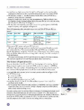
6 MEMORY AND DATA STORAGE
• using blue laser light means that the 'pits' and 'bumps' can be much smaller; consequently, Blu-ray can store up to fi\·c times more data than normal DVD
• Blu-rayuscs a single 1.1 mm thick polycarbonate disk; normal DVDs use a sandwich of two 0.6 mm thick disks
• using two sandwiched layers can cause BI REFRINGENCE (light is refracted into nvo separate beams causing reading errors); because Blu -ray uses only one layer, the disks don't suffer from birefringence
• Blu-ray disks automatically come witl1 a secure encryption system which helps to pn.·vcnt piracy and copyright infringement.
Table 6.1 summarises the main differences between CDs, DVDs and Blu-ray.
Disk type Wavelength of Trackpitch(distance laser light between tracks)
sin~1.2mm 1.60µm ....k,,-,rbooatelave,
two0.6mm 0.74µm nnlur,IOO(\atelay.,"
lllu·ray sin~l.lmm O.JOµm oolvca!booatelaye,
(Note: nm - JQ""9 metres and pm - JQ-6 metres. ) All these optical storage media arc used as back-up systems (for photos, music
and multimedia files ). This also means that CDs and DVDs can be used to transfer files between computers. Manufacturers often supply their software using CDs and DVDs. When the software is supplied in this way, the disk is usually in a read-only format.
The most common use of DVD and Blu-rayisthe supply ofmovics or games. 111c memory capacity of CDs isn't big enough to store most movics.
The fut ure of optica l med ia In recent times both the CD and DVD arc showing signs ofbecoming obsolete. Many computer systems now come with USB connectors only and no DVD or CD drive. The main method oftransfcrring files between devices has become tl1c flash memory. Many people now store all tl1cir music in the following ways:
• on hard disk drive systems (set up as sound systems as shown in Figure 6.13) • in i\11'3 format on:
• a computer/tablet • tl1cir mobile phone • a portable music player ( such as iPodlll)
• using tl1e 'cloud' to store all their files so they can access tl1cir music from anywhere in the world
• by ' streaming' their music from the internet; provided the user has an internet connection, they can access music tl1rough a laptop computer, mobile phone, tablet or any other receiving device.
It is also a similar story for movics where streaming is becoming increasingly more common. Many television sets are now set up as 'smart' TVs - this means it is now possible to stream movics or television programmes ON DEMAND witlmut the need for any DVD or Blu-ray players. In effect, the television set has become the central computer witl1 a link to the internet using wireless connection .
• Figure6.13
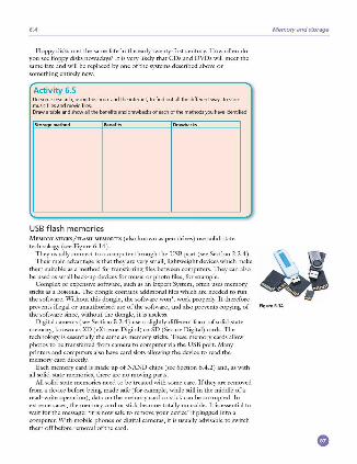
6.4
Floppy disks met the same fate in the early twenty-first century. H ow often do you see floppy disks nowadays? It is very likely that CDs and DVDs will meet the same fate and will be replaced by one of the systems described above or something entirely new.
Activity 6.5 Do some research, using this book and the internet, to find out all the dillerrot way,;. to store musiclilesandmovieliles Draw a table and show all the benefits and drav'ibac:k.l of each of the methods yoo have identified
USB fl as h me mo ries
Memory and storage
M EMORY STICKS/FLASH MEMORI ES (also known as pen drives ) use solid-state technology (see Figure 6.14 ).
They usually connect to a computer through the USB port (see Section 2.2.4 ). 4j" m?'!esi~i~:~1: :~:a:;:::~ ~~:\!~:f:~i1::r~1:~:~~~~1~::!~:,~:~~~;::i::n n;~:e \ ~-.' • , .. be used as small back-up devices for music or photo files, for example.
Complex or expensive software, such as an Expert System, often uses memory sticks as a DONG LE. 111c dongle contains additional files which arc needed to nm the software. \Vithout this dongle, the software won't work properly. It therefore prevents illegal or unauthorised use of the software, and also prevents copying of Figure 6.14 the software since, without the dongle, it is useless.
Digital cameras (see Section 5.2.4) use a slightly different form of solid-state memory, known as XD (cXtrcmc Digital) or SD (Secure Digital) cards. The technology is essentially the same as memory sticks. These memory cards allow photos to be tr.1.nsfcrred from camera to computer via the USB port. Many printers and computers also ha\·c card slots allowing the device to read the memory card directly.
Each memory card is made up ofNAND chips (see Section 6.4.2) and, as with all solid-state memories, there are no moving parts.
All solid-state memories need to be treated with some care. If they arc removed from a device before being made safe (for example, while still in the middle ofa read- write operation), data on the memory card or stick can be corrupted. In extreme cases, the memory card or stick become totally unusable. It is essential to wait for the message: 'it is now safe to rcmo\·e your device' if plugged into a computer. \Vith mobile phones or digital cameras, it is usually advisable to switch them offbcfore removal oftl1e card.
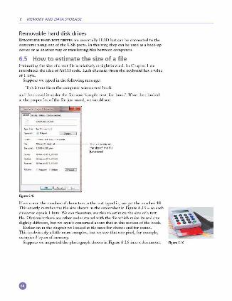
6 MEMORY AND DATA STORAGE
Removable hard disk drives REMOVABLE H ARD DISK DRIVES are essentially HDD but can be connected to the computer using one of the USB ixirts. In this way, they can be used as a back-up device or as another way of transferring files between computers.
6.5 How to estimate the size of a file Estimating the size ofa text file is rclati\·cly straightforward. In Chapter 1 we introduced the idea of ASCII code. Each character from the keyboard has a value ofl byte.
Suppose we typed in the following message:
This is text from the computer science text book
and then sa\·cd it under the filcnamc 'samplc_tcxt_ for_book'. If we then looked at the properties ofthc file just sa\'cd, we would sec:
IJ' __ .... _ .. _,..,.._ .. - ~
~n·-r-- _ ..J
just stored
Figu,.6.15
If we count the number of characters in the text t)'pcd in, we get the number 48. TI1is exactly matches the file size shown in the screcnshot in Figure 6.15 - so each character equals I byte. \Ve can therefore use tills to cstin1atc the size of a text file. Obviously tl1crc arc other codes stored with tl1c file which make its real size slightly different, but we aren't concerned about tl1at in tills section of the book.
Earlier on in the chapter we looked at file sizes for photos and for sound. TI1is is obviously a little more complex, but we saw that one pixel, for example, occupies 3 bytes of memory.
Suppose we imported the photograph shown in Figure 6.16 into a document. Figu,.6.16
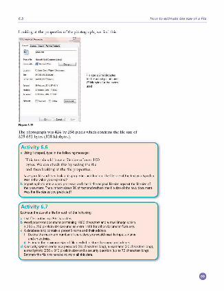
6.5
Looking at the properties of the photograph, we find this:
I '"-
~~-:--:· -- (i] -""Wmd ~ L.oc-.c C\- '°""'\'1-,"""-"•
---+-Filesizeis318kilobytl's ,.,,,.,.,.,,..,.,=,...., .. 1 lortheactualpictureand
~Jobytesf0<therodes
Fi gur• 6.17
The photograph was 424 by 256 pixels which confirms the file size of 325 632 bytes (3 18 kilobytes).
Activity 6.6 a UsingNotepad,typeinthefollowingme5Silge
This text should have a file size of over 100 bytes. We can check this by saving the file
How to estimate the size of a file
and then looking at the file properties.
Saveyourlileandtheolookatitspropertiesandfindoutthe lilesizeolthetextyoutypedin. Wasitthevalueyouexpected?
b lmportaphotointoawordprocessorandrnec:ktheoliginalfilesizeagainstthelilesizeol the document. Then import about 3K of text and recheck the file size of the new document Wasthefile,;izeasyoupredicted?
Activity 6. 7 Estimatethesizeolalileloreacholthelollowing
a Textfilernntaining256character.; b Word processor document containing 1000 character.; and a =all image which
is 256 >< 256 pixels in size (aswme an extra 14KB for other document fe;itures) c Adataba..eistornntainapernm'1nameandtheiraddress
I Decide the maximum number of characters you would need to input a name and an address .
Ii Estimate the maximum size of file needed to store the name and address . d Asecuritysystemrnntainsapassword{16diaracter.;long),ausername{20diarilderslong),
asmallphoto(2S6x640pixelsinsize}andasecurityquestion(upto72character.;long} Estimatethefilesizeneededtostoreall thisdata

0 High-and low-level languages
lnthischapteryouwilllearnabout:
e programminglanguages • high-levellanguages • low-levellanguages
• translators • compilers • interpreter,; • assemblers
7.1 Introduction People use many different languages to communicate with each other. In order for two people to understand each other they need to speak the same language or another person, an interpreter, is needed to translate from one language to
the other language. Programmers use many different programming languages to
communicate with computers. Computers only ' understand' their own machine code. A program needs to be translated into machine code before it can be ' understood' by a computer.
7.2 Programming languages
7.2 .1 What is a program? Programs are our way of telling a computer what to do, how to do it and when to do it. This enables a single computer to perform many different types of task. A computer can be used to stream videos, write reJX>rts, provide weather forecasts and many, many other jobs.
An example of a simple task that can be performed by a computer is the provision of a multiplication tables test. Figure 7. 1 shows a simple program to set this up and Figure 7 .2 shows an example of the test in use.
Figure7.2Proc_,am inuse
0
7.2
Activity 7.1 Find at least ten different tas.ks that computer programs perform in your school
A COMPurER PROGRAM is a list of instructions that enable a computer to perform a specific task. Computer programs can be written in high-k·vel languages or lowlevel languages, depending on the task to be performed and the computer to be used. Most programmers write programs in high-le\'el languages.
7.2.2 High-level languages High-level languages enable a programmer to focus on the problem to be solved and require no knowledge ofthe hardware and instruction set of the computer that will use the program. Many high-level programming languages are portable and can be used on different types of computer.
H igh-level languages are designed with programmers in mind; programming statements are easier to understand than those written in a low-level language. This means that programs written in a high-level language are easier to:
• read and understand as the language used is closer to human language • write in a shorter time • debug at the development stage • maintain once in use.
The following snippet of program to add two numbers together is a single program statement written in a typical high-le\·el language. It shows how easy it is to understand what is happening in a high-level language program:
::~~~::::;:;::::i.i:i.::~!~~~ii-:::::;:::~~i~~~~~:~:;.::: :··:··:··:··:··:··:··:··:··:··:··:··:··:··:··:··:··:··:··:··:··:··:··:··:··:··:··:··:··, There are many different high-level programming languages in use today including C++, Delphi, Java, Pascal, Python, Visual Basic and many more. Once a programmer has learnt the techni'lues of programming in any high-level language, these can be transferred to working in other high-level languages.
Activity 7 .2 High-level programming languages are x1id to be problem Dfieoted. What type of problems are the languages named above used for? Find out about five more high-level languages Name eadi programming language and find out what it is used for.
7.2.3 Low-leve l languages Low-level languages relate to the specific architecture and hardware of a particular type of computer. Low-level languages can refer to machine code, the binary instructions that a computer understands, or an assembly language that needs to be translated into machine code.
Assembly lang uages Fe,,11 programmers write programs in an assembly language. Those progranuncrs who do, do so for the following reasons:
• to make use of special hardware • to make use of special machine-dependent instructions • to write code that doesn't take up much space in primary memory • to write code that performs a task \·cry quickly.
Programming languages
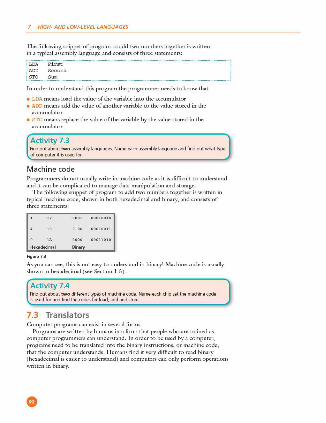
7 HIGH- AND LOW-LEVEL LANGUAGES
The following snippet of program to add two numbers together is written in a typical assembly language and consists of three statements:
In order to understand this program the programmer needs to know that
• LDA means load the value of the variable into the accumulator • ADD means add the value of another variable to the value stored in the
accumulator • STO means replace the value of the variable by the value stored in the
accumulator.
Activity 7 .3 Find out about two assembly languages. Name each assembly language and find out what type olcomputeriti1usedf0f.
Machine code Programmers do not usually write in machine code as it is difficult to understand and it can be complicated to manage data manipulation and storage.
The following snippet of program to add two numbers together is written in typical machine code, shown in both hexadecimal and binary, and consists of three statements:
I: : :::: :::::::: 1 0
Hnadec1mal Binary •
Figu,.7.3
As you can sec, this is not easy to understand in binary! Machine code is usually shown in hexadecimal (sec Section 1. 5).
Activity 7 .4 Find out about two different types of machine code. Name each chip set the machine rnde isusedlorandlindthecode1f0flo.-id,.-iddandstore
7.3 Translators Computer programs can exist in several forms.
Programs are written by humans in a form that people who arc trained as computer programmers can understand. In order to be used by a computer, programs need to be translated into the binary instructions, or machine code , that the computer understands. H umans find it very difficult to read binary (hexadecimal is easier to understand) and computers can only perform operations written in binary.
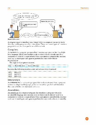
7.3
Figure 7.4T,amlatioo
A program must be translated into binary before a computer can use it; this is done by a utility program called a translator. There are several types of translator program in use; each one performs a different task.
Compilers A COMPILER is a computer program that translates a program written in a highlevel language ( HLL) into machine code so that it can be directly used by a computer to perform a required task. Once a program is compiled the machine code can be used again and again to perform the same task without recompilation.
The high-level program statement
!Sum :• FirstNumber + SecondNumber ···-·········-···-····-··· ·······-·-·-········-·-· -·······-·-·····-··--·····-·-·· becomes the following machine code instructions when translated
Interpreters An INTERPRETER is a computer program that reads a statement from a program written in a high-level language, performs the action specified and then docs the same with the next statement and so on.
Assemb lers An AS.SEMBLER is a computer program that translates a program written in an assembly language into machine code so that it can be directly used by a computer to perform a required task. Once a program is assembled the machine code can be used again and again to perform the same task without re -assembly.
Translators
7 HIGH- AND LOW-LEVEL LANGUAGES
The assembly language program statements
become the following machine code instructions when translated
i OOOl 00010010
· 0100 00010011
•oooo 00011010 ·------·-·-·-·-·-·-·-·-·-·-·-·-·-·-·-·-·-·-·-· ··· -····-···-·-·- ··· -····-···-·-·- ···--·---·-----·---·----·-·-···-· Table71Surrrnaryoftrans!atiooprograms
Compiler lnt .. preter
TransiatPSahi~levellanguage ExecutPSahi~levellaogoage T,aoslatesaJow.levellanguage program into ma.mine rnde program a statement at a ~me program into madline rode
Anexecutablefileolmachinerode Noexerutilblefileo/mad,;necode Anexl'CUtablefi eolmachinecode is produced is prOWCed is produced
One h"]h~evel lang~ statement One ho~-~vel language program One klw~evel langua.ge statement
~::::'.::;.:=;al ~ta!':;'~;~:=:.:~:~ ~.::;,:s1i;,,~~:,""" CompiledplO<Jfamsareused withoutthecompilPr
lnte,pretedpmgramsrannotbe usedwilhouttheinterp<ete,.
A compiled program is usually An interpreter is often used w+>en a An assembled program is llSUally distributedforgeneralllSI' program is being developed distributedlorgene,aluse
7.4 What happens when things go wrong? As programs are written by humans, they may contain errors. TI1ere are several different types of error. A SYNTAX ERROR is where a program statement doesn't obey the rules of the programming language. A program cannot be translated if it contains syntax errors. A LOG IC ERROR is where the program doesn't do what the programmer wanted it to do. Logic errors are found when a program is being run.
7.4.1 Syntax errors When a program is being compiled, if any syntax errors are found no translated program is produced. Instead, a list of all the errors in the whole program is produced. The programmer corrects these errors and recompiles the program.
\\'hen a program is being interpreted, the interpreter performs the actions specified by each statement until a syntax error is found. The programmer is then alerted to the place in the program where the error was found. The error is corrected by the programmer and the interpretation continues until the next error is found or the task is completed.
7.4.2 Logic errors When a program is being run, ifit doesn't do what it should do there is a logic error. TI1cse can be found by tracing what the program does and using test data with expected results - sec Chapter 9.
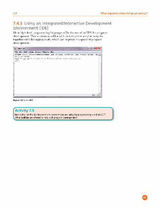
7.4 What happens when things go wrong?
7.4.3 Using an Integrated/Interactive Development Environment (IDE) ,\ilost high-level programming languages offer the use ofan IDE for program de\·elopmcnt. This contains an editor with an interpreter and/or compiler together with debugging tools, which can impro\·e the speed of program de\'elopmcnt.
&le16it-~ .... c.,t; .... w-n1-i,.;, Pyt .• on , . , . a 1~ , . , . a ,c<10. co,o.ne,, , -,. ,o >OH, 10,>s, n) [J<SC v . H aa ,a b>t [< •
;,, I .. . . . .- .. . 11 • • i .
Figur• 7.51'ythonlDE
Activity 7.5 Havealookatthedevelopmentenvironmentyouareusinglorprogramming What facilities are offered to help with program development?
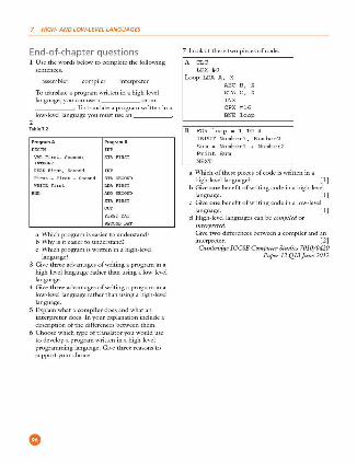
7 HIGH- AND LOW-LEVEL LANGUAGES
End-of-chapter questions l Use the words below to complete the following
assembler compiler interpreter
To translate a program written in a high-le\·el language, you can use a ___ or an ___ . To translate a program written in a low-level language you must use an ___ .
2 Ta ble7.2
Program A
RRADFi n t,Second
Fin t, - Fin t • Se cond
ProgramB
a \Vhich program is easier to understand? b Whyisiteasiertounderstand? c Which program is written in a high-k·vel
language? 3 Give three advantages of writing a program in a
high-level language rather than using a low-level language .
4 Give three advantages of writing a program in a low-le\'el language rather than using a high-level language.
5 Explain what a com piler docs and what an interpreter does. In your explanation include a description of the differences between them.
6 Choose which type of translator you would use to de\·elop a program written in a high-level programming language. Give three reasons to supportyourcl10ice .
•
7 Look at these two pieces of code:
A CLC LDX #0
Loop: LDA A, X ABC B, X STA C, X
CPX #16
BNE loop
B FOR loop • 1 TO 4 INPUT Number!, Number2 Sum - Number! + Number2 Print Sum
a Which of these pieces of code is written in a high-le\'el language? [l]
b Give o n e benefit of writing code in a high-level language. [l]
c Give o n e benefit of writing code in a low-level language. [l]
d H igh-level languages can be compiled or interpreted. Gi\·c t wo differences between a compiler and an interpreter. [2] Cambridge !GCSE Computer Studies 7010/0420
Paper 12 Ql3 June 2012
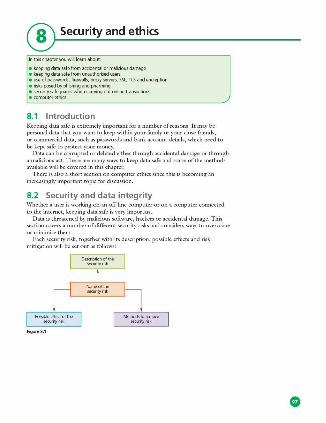
® Security and ethics
lnthischapteryouwinle.-imabout:
• keeping data safe from acddental or malkious damage • keepingdatasafelromunauthorisedusl'!'S • use of pa=rds, firewalls, proxy 51'rvers, SSL, ns and encryption e risksposedbyphishingandpharming • securitysafeguardswhenc,myingoutonlinetransactions e computerethics
8.1 Introduction Keeping data safe is extremely important for a number of reasons. It may be personal data that you want to keep within your family or your close friends, or commercial data, such as passwords and bank account details, which need to
be kept safe to protect your money. Data can be cormptcd or deleted either through accidental damage or through
a malicious act. There arc many ways to keep data safe and some of the methods available will be covered in this chapter.
There is also a short section on computer ethics since this is becoming an increasing])' important topic for discussion.
8.2 Security and data integrity \\'hether a user is working on an off-line computer or on a computer connected to the internet, keeping data safe is \·cry important.
Data is threatened by malicious software, hackers or accidental damage. This section co\·ers a number of different security risks and considers ways to overcome or minimise them.
Each security risk, together with its description, possible effects and risk mitigation will be set out as follows:
Possible effect of the sec..-;tyrisk
Figur• S.1
Oescriptiooofthe seru,;tyrisk
Name of the ,eru,;tyrisk
Methodsto,ema,e sec..-ityrisk
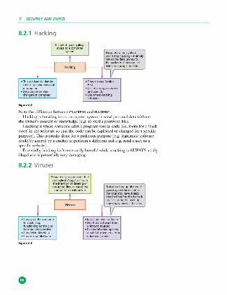
8 SECURITY AND ETHICS
8.2.1 Hacking
• Thiscanleadtoideobty
;~t;:.~ningpersooal
• Data can be deleted, changedorcorrnpted
Figu re8.2
Theactofgainingillegal iK:CPSSloacompute,
s,s=
Hacking
Note the difference between CRACKING and H ACKING.
H acking is breaking into a computer system to steal personal data without the owner's consent or knowledge (e .g. to steal a password file ).
Cracking is where someone edits a program source code ( i.e. looks for a 'back door' in the software so that the code can be exploited or changed for a specific purfXlse ). This is usually done for a malicious purpose ( e.g. legitimate software could be altered by a cracker to perform a different task e .g. send a user to a specific website).
Esscntiallr, hacking isn't necessarily harmfitl whilst cracking is ALWAYS totally illegal and is potentially very damaging.
8.2.2 Viruses
• Cancausethe~ter to crash.stop functiooingoormallyor
. ~~,:~\%~~· • Cancom1ptfiles/data
Figure8.3
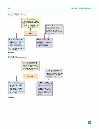
8.2
8.2.3 Phishing
Thecreatorsendsouta legitimate-looking email; as
soooastherecipientcltl,on
ali~n,!:i~~~::~71,
• Thecreatoroltheemail
~:,~"'~;!~ numbers Imm use" ~~visit the fake
• ThiscanH'adtofraudor identity theft
Figur• S.4
8.2.4 Pharming
bogus website
Phishing
Mahdouscode imtaHedona user",Mrddriveoroothe
,:f:::'tn"',i !':. :1: t'.:1
~
boguswebsotewithootthei, knowledge
• Thecreatorofthe malicious axle can gain
~~:c:~=~ ~;:.,"';.:.,:~~::1
• Thiscanieadtofraudor identity theft
Figur• S.5
Pharming
Security and data integrity
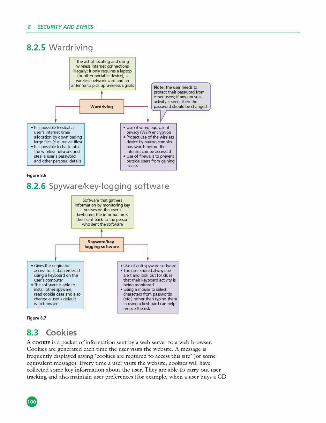
8 SECURITY AND ETHICS
8.2.5 Wardriving
·~!~:!!J~a alocationbydoo.vnloading largeMes(e .9.moviefiles)
·;;.:~::~k·~~~ steajause<'spassword andolhe,persooaldetaals
Figur• S.6
Wardriving
8.2.6 Spyware/key-logging software
Figur•S.7
Softwa<ethatgathm infom,atioobymooitorjngkey
pree,;esonlheuser's keyboard; theinfo,mabonis
the~n~~!"so~
Spyware/keyloggingsoftwar•
• Useolant~spywa<esoftware
·::;i'::i=~~~~:::. that thei, keyboardac~vityis beingmonito<ed
• Wngamousetoselect cha<acte"frompasswords (etc.)ratherthantypinglhem
;~~',;~~dcanhelp
8.3 Cookies AcooKII! is a packet of information sent by a web server to a web browser. Cookies are generated each time the user visits the website. A message is frequently displared sa)'lllg 'cookies are required to access this site' ( or some equivalent message). Every time a user visits the website , cookies will have collected some key information about the user. Ther are able to carry out user tracking and also maintain user preferences (for example, when a user buys a CD

8.4 Loss of data and data corruption
on a music website , the cookies will have remembered the user's previous buying habits and a message like this often follows: 'Customers who bought items in your Recent H istory also bought: YYYY').
Cookies aren't programs but are simply pieces of data. They can't actually perform any operations. 1l1cy only allow the detection of web pages viewed by a user on a particular website and store user preferences, as described above.
The information gathered by cookies forms an ANONYMOUS USER P ROFILE and doesn't contain personal information (such as credit card numbers or passwords). Because of the information they do collect, however, they are subject to privacy and security concerns.
8.4 Loss of data and data corruption Section 8.2 considered a number of security issues which could lead to loss of data or the corruption of data.
This section covers the potential impact on d ata caused by:
• accidental mal-operation • hardware malfunction • sofuvare malfimction
on a computer system. In each case:
• safeguards • recovery methods
to pre\·ent the loss or corruption of data arc considered.
Acddl'lltall=ofdata (forexample.lheaccidental
deletiooofali e)
~~(f.,~~\;.":~ disk drive)
Softwarelault(e.g inc:ompatiblesoltl'.•,.-e
imtalledonthesystem)
Incorrect computer operalion(e .g. inc:Offect shut<lownpmcedure0<
inc:Offectpmcedureforthe ,ema,al ola memorys~O:)
Figure 8.8
• Useofbad·upsin=dataislost0<conupted throoc,ianacridmtaloperatioo
• 'i.avedataonaregul,.-ba,is • Useofpasswordsanduse,idstorestrictacc5Sto
authorised users only
• Useofback·upsincasedataisi<><torcorrupted throociilhehardwa,efault
• UseofUPS(uninterruptablepowe,supply)to pteYl'fltpow..,i<><scausingha,dwaremaflunction
• 'i.avedataonaregu!arbasis • Useofpa,allelsystemsasback·uphardwMe
• Useolback·upsincasedataisi<><torcorrupted throoc,ilhesoftw,.-efault
• Savedataona,egu!arbasisincasethesottware suddenly"freezes"0<"aashes"whilsttheuseris workingooit
• Useofback·upsincasedataisi<><torcorrupted throoc,iv,rnngoperaboo
• Conecttrainingproceduressothatusers,.-eaware oltherorrectoperationofha,dware

8 SECURITY AND ETHICS
8.5 Firewalls and proxy servers A FIREWALL can be either software or hardware. It sits between the user's computer and an external network (e.g. the internet) and filters information in and out of the computer.
~ Figu,.8.9
Tasks carried out by a firewall include:
• examining the 'traffic' between the user's computer (or internal network) and a public network (e .g. the internet)
• checking whether incoming or outgoing data meets a given set of criteria • if the data fails the criteria, the firewall will block the 'traffic' and gi\·e the user
(or network manager) a warning that there may be a security issue • logging all incoming and outgoing 'traffic' to allow later interrogation by the
user (or network manager) • criteria can be set to prevent access to certain undesirable sites; the firewall can
keep a list of all undesirable IP addresses • helping to prevent viruses or hackers entering the user's computer ( or internal
network) • warning the user if some software on their system is trying to access an external
data source ( e.g. automatic software upgrade ); the user is gi\'cn the option of allowing it to go ahead or rcguesting that such access is denied.
TI1e firewall can be a hardware interface which is located somewhere between the computer ( or internal network external link) and the internet connection. It is often referred to in this case as a GATEWAY. Alternatively, the firewall can be software installed on a computer; in some cases, this is part of the operating system.
H owever, there arc certain circumstances where the firewall can't prevent potential harmful 'traffic':
• it cannot pre\'cnt indi\'iduals, on internal networks, using their own modems to bypass the firewall
• employee misconduct or carelessness can.not be controlled by firewalls ( for example, control of passwords or use of accounts)
• users on stand-alone computers can chose to disable the firewall , leaving their computer open to harmful 'traffic' from the internet.
All of these issues reguire management control or personal control ( on a single computer) to ensure that the firewall is allowed to do its job effccti\·cly.
PROXY SERVERS act as an intermediary between the user and a web server:
Webb<owse, Webb<owse,
I I :·:•I I l'::::1 ~1 response is filtered bad response to
prnxyse,ve,
Figu,.8.10

8.6
Functions of proxy servers include:
• allowing the internet 'traffic' to be filtered; they can block access to a website if necessary (s imilar type or reaction as a firewall )
• by using the fcamre known as a CACHE, they can speed up access to information from a website; when the website is first visited, the home page is stored on the proxy server; when the user next visits the website, it now goes through the proxy server cache instead, giving much faster access
• keeping the user's IP address secret - this clearly improves security • acting as a firC'.vall.
8.6 Security protocols \Ve will now consider two forms of security protocols when using the internet:
• Secure Sockets Layer (SSL) • Transport Layer Security (TLS).
SECURE SocKETs LAYER (SSL) is a type of protocol (a set of rules used by computers to communicate with each other across a network). This allows data to be sent and received securely over the internet.
When a user logs onto a website, SSL encrypts the data - only the user's computer and the web server are able to make sense of what is being transmitted. A user will know if SSL is being applied when they see https or the small padlock
e, in the stams bar at the top of the screen. So what happens when a user wants to access a secure website and receive and send data to it?
The use,"s web browse, sends a message so that it can comect wilhlherequiredwebsitewhKhi,securedbySSL
Thewebbrowserlhenrequeststhatthewebserve,ioentifiesitsett
ttthewebb<owse,canaulhenticatelhiscertificate.itsendsa message bad< to the web serve, to allow communicabon to begin
Oncethismessagei,,eceived.lhewebserverackno.Yledge,the webb<owse,.andtheSSL-el\CJ'll'tedtwo--waydatalfansferbegim
Figur• S.11
TRANSPORT LAYER SECURITY (TLS) is similar to SSL but is a more recent security system. Tl.S is a form of protcx:ol that ensures the security and privacy of data between devices and users when communicating m ·er the internet. It is essentially designed to provide encryption, authentication and data integrity in a more effective way than its predecessor SSL.
\Vhen a website and client (user ) communicate o\·er the internet, Tl.S is designed to pre\·e11t a third party hacking into this communication causing problems with data security.
Security protocols
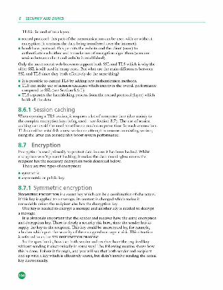
8 SECURITY AND ETHICS
TLS is formed of two layers:
• record protocol: this part of the communication can be used with or without encryption (it contains the data being transferred over the internet).
• handshake protocol: this permits the website and the client (user ) to authenticate each other and to make use of encryption algoriduns ( a secure session between client and website is established).
Only the most recent web browsers support both SSL and TLS which is why the older SSL is still used in many cases. But what arc die main differences between SSL and Tl...S since diey both cffccti\·cly do the same d1ing?
• It is ix,ssiblc to extend Tl.S by adding new aud1cntication methods. • Tl.5 can make use of SESSION CACHING which improves the overall performance
compared to SSL (sec Section 8.6.1 ). • Tl.5 separates the handshaking process from die record protocol ( layer) which
holds all the data.
8.6.1 Session caching When opening a Tl.S session, it requires a lot of computer time ( due mainly to
the complex encryption keys being used - sec Section 8.7). The use of session caching can avoid the need to utilise so much computer time for each connection. TI..S can either establish a new session or attempt to resume an existing session; using the latter can considerably boost system performance.
8. 7 Encryption Encryption is used primarily to protect data in case it has been hacked. Whilst encryption won't prevent hacking, it makes die data meaningless unless the recipient has the necessary decryption tools described below.
There are two types of encryption:
e svmmctric • a.symmetric or public key.
8.7.1 Symmetric encryption SYMMETRIC ENCRYPTION is a secret key which can be a combination of characters. If this key is applied to a message, its content is changed which makes it unreadable unless die recipient also has the decryption key.
One key is needed to encrypt a message and another key is needed to decrypt a message.
It is obviously imix,rtant that the sender and receiver have the same encryption and decryption key. 1l1crc is clearly a security risk here, since the sender has to supply the key to the recipient. 1l1is key could be intercepted by, for example, a hacker which puts die security of the encrypted message at risk. This sirnation is referred to as die KEY DISTRIBUTION PROBLEM.
So the question is, how can both sender and receiver have the required key without sending it electronically in some way? The following routine shows how this is done. Follow it through, and you will sec that both sender and recipient end up with a key which is effectively secret, but didn't involve sending the actual key electronically.
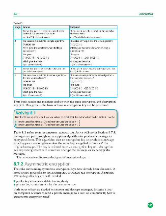
8.7
Stage Sender
Thesenderusesaoenayptklna"]Orithm(see Secbon8.73)andchoose<avalue
e.g . X•l{thisiskeptseael)
Thisvah;eofXisput;ntoa5'mplealgo,ithm
]X(MQQ1))
(M00rj,estheremainde<M1endividir,ga numberby11)
Hlisgives
7>(M0Dl1)•49(M0011)
wt>Khrj,esthevalu.e
S (ie.4remaindef5)
Hl<'sendernowsendslhevaluejustcakulated (i.e. S} totherecipient
Hlisnewvalueisputintothesamealgofilhm lhenewvalue,eplaces'7'
] X(MQQ11)
Hi s gives
3'(MOD11)•9(M0011)
wt.kht;j,,esthevalue
9(i.e.Oremaindef9)
Recipient
e.g.Ya4(thisisalsokeptsecrel}
Thevalc;eo!Yisputintothesamealgorilhm
]Y(M0011)
(MODgivestheremalr>derwhendividir,ga numbe,byll)
This gives
7•(MOO l1)•240l(MOD11)
whic:hgi,,....thevalue
3 (i.e.2l8remainde< 3)
TheredpH'ntnowsrodsthevaluejustcakulated (ie. 3)tothesende,
Thisnewvall1!'isputintolhesamealgorithm thenewvalJ erepl;,ces'7'
SY(M0011)
This gives
5'(M0011)a6lS(M0011)
which gives the value
9(i.e.56remainde,9)
Thus both sender and recipient end up with the same encryption and decryption key of9. This gives us the basis ofhow an encryption key can be generated.
Activity 8.1 Usethefollowingseoderandreceivervalue1tocheckthatthesystemdesaibedinTable8.lwofks
a sender u11.'S the value x= 3 and receiver uses thevaluey = S b senderusesthevaluex:7andreceiverusesthevaluey:6
Table 8.1 refers to an BNCRl'PTION ALGORITH M. As we will see in Section 8.7.3, messages are put through an encryption algorithm to produce a message in encrypted form. This algorithm uses an encryption key to produce a message which appears meaningless unless the same key is applied to 'unlock' the original message. The key is referred to as an encryption key or a decryption key depending whether it is used to encrypt the message or to decrypt the message.
The next section discusses the types of encryption keys.
8.7.2 Asymmetric encryption The risks surrounding symmetric encryption keys have already been discussed. A more secure method is to use ASYMMETRIC or PUBLIC KEY encryption. A PRNATB KEY and a public key are both needed:
• public key is made available to everybody • private key is only known by the computer user.
Both types of key are needed to encrypt and decrypt messages. Imagine a user on computer A wants to send a private message to a user on computer B; how is asymmetric encryption used?
Encryption

8 SECURITY AND ETHICS
Use,Aappliesasymmetrickeytoeouyptthemessage
The symmetric key is the~ ':'~Ate;irld""Bng lhe public key rooY.'f\
UserAs.endslhemessage"""'theintemet
UsefBdecryptsthe')'fffTll'trkkeybyapplyingthei"own private key
ThecJeroded,ymmetrickeyisnowusedtodeaypt lheffil""""9" sentbyuse,A
Figure8. 12
111c encryption keys arc often generated by using a H ASHING ALGORITHM . This is actually very different to an encryption algorithm. The hashing algorithm takes a message or a key and translates it into a string of characters usually shown in hex notation (the length of the string depends on the algorithm being used ). 1l1is essentially makes the message or key almost imJX>ssiblc to read ifit is somehow intercepted by, for example, a hacker. The same hashing algorithm has to be applied at both ends (sender and receiver) for the message or key to be understood.
In summary, the encryption algorithm converts messages using an encryption key into 'meaningless' text; the same key has to be used to decrypt the message. 1l1csc keys can, however, be intercepted which makes the encryption process less secure. To overcome this problem, a hashing algorithm is applied to the message or key, producing a string of characters which are virmally impossible to 'break' if intercepted. This considerably increases the security of the whole process when sending personal or sensitive data across, for example, the internet. The use of hashing and encryption is further discussed in Scction 8 .7.4.
An example ofa well -known hashing algorithm is ,\1D4 which generates a 128-bit string whenever a value is nm through it. For example, the following 16 -digit code:
1234 5678 9012 3456
would produce the following value when put through the MD4 hashing algorithm:
543FC7DDEAOCF5EAFS4279CBADCA180D
(Note: this contains 32 hexadecimal digits (i.e. 128 bits) - sec Section l.5. ) Strings which are 128 bits long gi\'e 3 x 1038 possible combinations which
makes them \·cry secure. Some newer systems use 256-bit strings which ha\·c 1 x 1077 possible combinations. Older systems employ strings which arc only 56 bits in length, which gives them only 7 x 1Ql6 possibilities - this has become rclati\•cly easy to break since modern computers arc so fast at number crunching!
But it is clear that the larger the key size, the more secure the encryption will be.
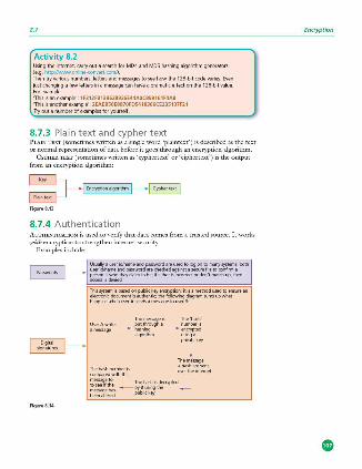
8.7
Activity 8.2 Using the internet, carry out a 51!arch for M04 and MOS hash ing algorithm generators (e.g. httpJMWW.online-convert.m m/) Then try various numbers, letters and messages to ,;ee how the 128-bit mde varies. Even just changing a few letters in a message can have a dramatic effect oo the 128-bit value For example 'Thi1isanex.ample': 1F312F8138628926E44AOC899161F4A8 'Thisisanotherexample': 2EAEB50E8870FD5418366CE235107F21 Tryout anumbi!rofex.amplesloryour,;ell .
8.7.3 Plain text and cypher text PLAIN IBXT (sometimes written as a single word 'plaintcxt') is described as the text or normal representation of data before it goes through an encryption algorithm.
CYPHER TEXT (sometimes written as 'cyphertext' or 'ciphcrtext') is the output from an encryption algorithm:
Figur• S.13
8.7.4 Authentication AurHENTICATION is used to verify that data comes from a trusted source. It works with encryption to strengthen internet security.
Examples include:
FigureS.14
Usualy auser,d/nameandpasswo,dareusedtologontomilllysystem,;both userodlnameillldp;rsswo,dare<hedrndaga;mtasenxeMetoronfirma =•~'~Jheyclaim to be; ifeitherisiocO<Tectordon"tmat<hup. then
Thissystemisbasedonpublickeyeoc:,yptioo;itisamethodusedtoens.ureill\ electmoicdocumeotisautheotic;thefoUowiogdia<1amsumsupwhat happeoswheouserAsendsam~touserB
The message is The"hash" User A writes pot through a number is
---- hashing ---- encrypted algorithm us,nga
private key
I :"~a:"'ar~ot over the internet
Encryption

8 SECURITY AND ETHICS
Rgu,.8.14contiooed
Biometric:sreliesontheooiquecharaclPristicsolhumanbeings; examplesindude
::.:'..~:,"""' o faa,recognition(sees.ectiooS.2.1) • YDkerecognition(seeSectionS.2.7)
Fingerprint sca ns lmagesoffinger,.-intsarecompa,ed"9"'nstp,eviouslyl scannedlingPrprintsstoredinadatabase;iftheymatch , • . thenaccessisallowed;thesystemcomparespattemsof 'ridges' and'valleys'whimarefairlyunique {amxacyis1in500)
Retina scans Retinae<:ansuseinfra-<edtoscantheuniquepattemof bloodvesselsintheretina(atthebad<oftheeye);itisa rathPrunpleasanttec:hnique,equi,;ngape,sontosit totallystillfot 10to 1Ssec:ondswh;lethescantakesplace; itisver'jsec\Xe,;ncenobodyhasyetfoundawayto duplicatethebloodv~lpattems {aa:,xaqis1in10milion)
8.7.5 Denial of service attacks A denia l o f service attack (DoS ) is an attempt at preventing users from accessing part of a network, notably an internet server. This is usually temporary but may be a very damaging act or a big breach of security. It doesn't just affect networks; an individual can also be a target for such an attack.
The attacker may be able to prevent a user from:
• accessing their emails • accessing websites/web pages • accessing on line services ( such as banking).
One method of attack is to flood the network with useless traffic. H ow does this cause the problem?
\\'hen a user types in or clicks on a URL of a website (using their web browser), a request is sent to the internet server which contains the website or web page. Obviously, the server can only handle a finite number of requests. So if it becomes o\·crloadcd by an attacker sending out thousands of requests, it won't be able to
service the user's legitimate request. This is effectively a denial of service. This can happen to a user's email account, for example, by an attacker sending
out many spam messages to their email account. Internet Service Providers ( ISPs) only allow a specific data quota for each user. Consequently, if the attacker sends out very large or many hundreds of emails to the user's account, it will quickly get clogged up and the user won't be able to receive legitimate emails.
An individual user or a website can guard against these attacks to some degree by:
• using an up-to-date malware/virus checker • setting up a firewall to restrict traffic to and from the internet server or user's
computer • applying email filters to manage or filter out unwanted traffic or spam emails.
Signs that a user can look out for to see if they arc a victim of one of these attacks include:
• slow network performance (opening files or accessing certain websites) • unavailability or inability to access particular websites • large amounts of spam mail reaching the user's email account.
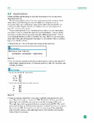
8.8
8.8 Applications Online banking and shopping arc all at risk from many of the security issues described earlier on.
We will now consider some of the ways banks protect their customers from online fraud. The following notes are in addition to safeguards such as encryption, SSL, virus sca1mers and many of the other ways described in the earlier part of this chapter and refer to additional features you might see as part ofa bank's security system.
\Vhcn a customer logs on to a banking website and carries out a transaction, encryption is used to protect the customer's personal details. H owever, banks carry out a number of other procedures to give additional protection. Not all of the methods described would be used by one bank. H owever, the notesgi\·e some idea of the type of safeguards that might be encountered when a customer logs on to a bank's website.
1 Many banks use a 10- or 12 -digit code uni'luc to the customer:
m HODDERBANK
Pleaseenteryou,unique12-digitrode
=== Figur•S.15
2 You may then be asked to input three random numbers from a four-digit PIN and/or three characters from a 10-charactcr password (this will vary from bank to bank,ofcoursc):
m HODDERBANK
Pleaseenterlhefolkw.ingdigitslrnmyo;xPIN ,•,,,, § 4111 digit
J'"digit
l'leaseenterlhelolk>wingcharacterslrnm)<}\lrpassword
,. , . .. Figure S.16
3 Some systems use a hand-held device into which the customer inserts their card. 111cy will be asked to enter their PIN. 111c device will then generate an eight-digit code which the customer types into the web page of the bank. lbis eight-digit code is generated from an internal clock and PIN. The bank's scn·cr and the time arc both synchronised with the hand-held device; the server also stores the PIN. The bank's server will therefore know if the eight-digit code entered is correct. Each eight-digit code is only valid for a few minutes before it has to be redone.
Appl/cations

8 SECURITY AND ETHICS
This system defeats hackers and spyware since the code will change e\·ery time the customer logs on to the bank's website.
Figure8.17
4 Some banking systems ask the customer to key in parts of their password using drop-down boxes. lllls is an attempt to defeat spywarejkey-logging software . Each of the requested characters from the password are entered by selecting a character from a drop-down me.nu using a mouse, thus eliminating the use of a keyboard .
m HODDERBANIC
Pleaseenterthelollowingcharactersfrom)'Ol#pa,,;wo<d
Figure8.18
5 Once all these stages have been passed, some systems then ask for personal data, such as: • 'You last logged into the system on 15th September 2015. Is that correct? ' • 'Your mobile phone number is: 9777 111 2222. ls that correct?' • '\<\'hat is your mother's maiden name?'
6 Assuming the customer successfully negotiates all of the security 'hurdles', they will be sent to a home page on the website. Once you arc there, it is imixirtant to only use the bank's navigation tools rather than the ones at the top of the screen. Otherwise you will be logged out of the system, and you will need to go through all the earlier st eps again.
8.9 Computer ethics C01,1PUTER ElHICS is a set of principles set out to regulate the use of computers. 1l1recfactorsarc considered :
• INTELLECTUAL PROPERTY RIGHTS - this covers, for example, copying of software without the permission of the owner
• PRIVACY ISSUES - this covers, for example, hacking or any illegal access to another person's personal data
• effect of computers on society - this cm·ers factors such as job losses, social impacts and so on .
Use of the internet has led to an increase in plagiarism - this is when a person takes another person's idea/work and claims it as their own. \Vhilst it is perfectly fine to quote anotl1er person's idea, it is essential that some acknowledgement is made so that the originator of tl1c idea is known to otl1crs. This can be done by a
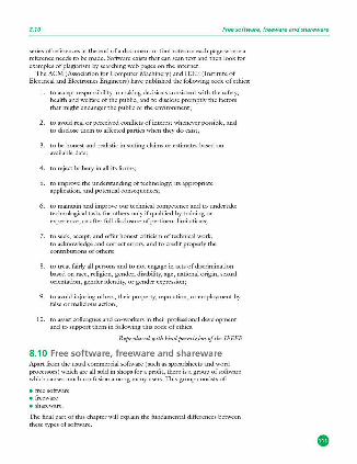
8.10 Free software, freeware and shareware
series of references at the end of a document or footnotes on each page where a reference needs to be made. Software exists that can scan text and then look for examples of plagiarism by searching web pages on the internet.
The ACM (Association for Computer Machinery) and I EEE (Institute of Electrical and Electronics Engineers) have published the following code of ethics:
I. to accept responsibility in making decisions consistent with the safety, health and welfare of the public, and to disclose promptly the factors that might endanger the public or the envirorunent;
2. to avoid real or perceived conflicts ofinterest whene\·er possible, and to disclose them to affected parties when they do exist;
3. to be honest and realistic in stating claims or estimates based on available data;
4. to reject bribery in all its forms;
5. to improve the understanding of technology; its appropriate application, and fX)tential consequences;
6. to maintain and impro\·e our technical competence and to undertake technological tasks for others only if ciualified by training or experience, or after full disclosure of pertinent limitations;
7. to seek, accept, and offer honest criticism of technical work, to acknowledge and correct errors, and to credit properly the contributions of others;
8. to treat fairly all persons and to not engage in acts of discrimination based on race, religion, gender, disability, age, national origin, sexual orientation, gender identity, or gender expression;
9. to avoid injuring others, their property, reputation, or employment by false or malicious action;
10. to assist colleagues and co-workers in their professional dL·velopment and to support them in following this code of ethics.
Reproduced with kind permission of the IEEEE
8.10 Free software, freeware and shareware Apart from the usual commercial software (such as spreadsheets and word processors) which are all sold in shops for a profit, there is a group of software whicl1 causes much confusion among many users. This group consists of:
• free software • freeware • shareware.
The final part of this chapter will explain the fundamental differences benveen thesetypesofsoftware.
8 SECURITY AND ETHICS
8.10.1 Free software Users ha\·e the freedom to run, copy, change or adapt free software. Examples include: F-six>t (photograph manager), Scribus (DTP ) and Abiword (word processor).
The originators of this type of software stress this is based on liberty and not price. This means that a user is guaranteed the freedom to study and modify the software source code in any way to suit their requirements.
Essentially a user is allowed to do the following:
• run the software for any legal purpose they wish • study the source code and modify it as necessary to meet their needs • pass the software (in either original or modified form ) on to friends, family
or colleagues.
A user of the software doesn't need to seek permission to do any of the above actions since it isn't protected by any copyright restrictions. Howe\·er, it is important to realise that there are certain rules that need to be obeyed. The user
• cannot add source code from another piece of software unless this is also described as free software
• cannot produce software which copies existing software subject to copyright laws • cannot adapt the software in such a way that it infringes copyright laws
protecting other software • may not use the source code to produce software which is deemed offensive by
third parties.
8.10.2 Freeware FREEWARE is software a user can download from the internet free of charge. Once it has been downloaded, there are no fees associated with using the software (examples include: Adobe, Skype or media plarers).
Unlike free software, freewarc is subject to copyright laws and users arc often reciuested to tick a box to say they understand and agree to the terms and conditions governing the software. This basically means that a user is not allowed to study or modify the source code in any way.
8.10.3 Shareware In this case, users are allowed to try out some software free of charge for a trial period. At the end of the trial period, the author of the software will request that you pay a fee if you like it. Once the fee is paid, a user is registered with the originator of the software and free updates and help are then provided. Very often, the trial version of the software is missing some ofthc features found in the foll version, and these don't become a\lailable until the fee is paid.
Obviously, this type of software is folly protected by copyright laws and a user must make sure they don't use the source code in any of their own software. Permission needs to be obtained before this software is copied and given to friends, family or colleagues.
8.10
Activity 8.3 A'iOftwarecompany offersasuiteolsharewareprograms {containir,gaspl&ldshei!I, wordprocessor,databaseanddrawingpackage) W"hatarethebenelitsto·
e thecompany • the customer
olollerir,gsoftwarepi!d.agesasshareware7
Free software, freeware and shareware
(Note: ethical issues arc raised as electronic communication continues to grow. Earlier in this chapter, issues such as hacking, \'iruses and other malware were considered. All of these put users at risk when using the internet or indeed any electronic de\'ice which transmits and receives data o\·er a live link ( e.g. mobile phones, tablets and other devices).
Many users are aware that computers can undergo hacking or virus attack ( and any of the other security issues outlined earlier) but don't seem to be aware that de\'ices such as mobile phones are also \llllnerablc to attack by hackers and other people intent on causing harm to users of electronic devices. )
p
0
- "-m Practical problem-solving \_!:_} and programming
Chapters
t 9 Problem-solving and design 11 5 10 Pseudocode and flowcharts 134 11 Programmingconcepts 146 12 Datastructures: arraysand using pre-release material 163 s 13 Databases 169
® Problem-solving and design
lnthischapteryouwinle.-imabout:
• computer systems and sub-systems • top-downdes.ign • structure diagrams • flowcharts •pseudorode • libraryroutines •sub-routines
e algolithms e standardmethodsofsolution e testdata e validationandverification e usingtracetables e identifyingandcorrectingerrors e producingalgorithms e theeffectivenessofasolution
9.1 Introduction In order to build a computer system that performs a specific task or sol\'cs a given problem, the task or problem has to be clearly defined, showing what is going to
be computed and how it is going to be computed . This chapter introduces the tools and techniques that are used to design a software solution that together with the associated computer hardware will form a computer system.
9.1.1 What is a computer syst em? A COMPlITER SYSTEM is made up of software, data, hardware, communications and people; each computer system can be divided up into a set of sub-systems. Each sub-system can be further divided into sub·systems and so on until each subsystem just performs a single action.
Computer systems can be very large or \·ery small or any size in between; most people interact with many different computer systems during their daily life without realising it. For example, when I wake up in the morning I use an app on my smart phone for mr alarm, I then check the weather forecast on mr computer before I drive to work. The alarm program is a very small computer system; when I check the weather forecast I obtain information from one of the largest
computer systems in the world.
Activity 9.1 ldeotjfyatleast fivecomputersystemsyoufrequentlyu~inyourdailylile.Seeilyoucandedde thesizeofeachsystem
9.1.2 Too ls a nd techni ques In order to understand how a computer system is built up and how it works, it is often divided up into sub-systems. This division can be shown using top-down design to produce structure diagrams that demonstrate the modular construction of the system. Each sub-system can be developed by a programmer as sub-routine or an existing library routine may be already available for use. H ow each sub-routine works can be shown by using flowcharts or pseudocode.

9 PROBLEM-SOLVING AND DESIGN
Top-down design ToP- DOWN DESIGN is the breaking down of a computer system into a set of sub-systems, then breaking each sub-system down into a set of smaller sub-systems, until each sub-system just performs a single action. TI1is is an effective way of designing a computer system to pro\'ide a solution to a problem, since each part of the problem is broken down into smaller more manageable problems. 111c process of breaking down into smaller sub-systems is called 'stepwise refinement'.
This structured approach works for the development of both large and small computer systems. \Vhen large computer systems arc being de\'clopcd this means that several programmers can work independently to develop and test different sub-systems for the same system at the same time. This reduces the development and testing time.
Structure diag rams In order to show top-down design in a diagrammatic form, structure diagrams can be used. The STRUcruRE DIAGRAM shows the design ofa computer system in a hierarchical way, with each level gi\'ing a more detailed breakdown of the system into sub-systems.
Alarm app for a smart phone Consider the alarm app computer system for a smart phone. This could be di\'idcd into three sub-systems, setting the alarm, checking for the alarm time, sounding the alarm. These sub-systems could then be further sub-divided; the structure diagram makes the process clearer.
FiguN9.1 Stn,cture diagramlor alannapp
Activity 9.2 Breakdownthe'checktime'sub-S)"item lromthesmartphooealarmappintofurther rnb-S)"items.
Activity 9.3 Drawastructurediagramlorcleaningyour teeth
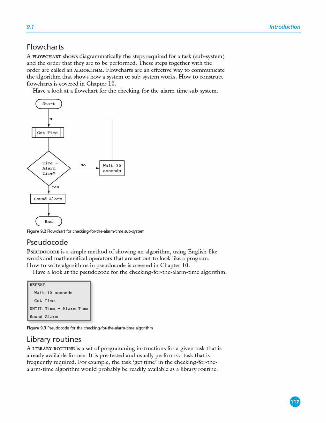
9.1
Flowcharts A FLOWCHART shows diagrammatically the steps required for a task (sub·system) and the order that they are to be performed. These steps together with the order are called an ALGORITH M. Flowcharts are an effective way to communicate the algorithm that shows how a system or sub-system works. H ow to construct flowcharts is cm·cred in Chapter 10.
H ave a look at a flowchart for the checking-for·thc -alarm-time sub-system.
Figure 9.2Flowchartlorched::fr,g-f0f-the...a!arm·timesub-system
Pseudocode PsBUDOCODE is a simple method of showing an algoritlun, using English-like words and mathematical operators that are set out to look like a program. H ow to write algorithms in pseudocodc is covered in Chapter 10.
H ave a look at the pseudocode for the checking-for-the-alarm-time algorithm.
Figur• 9.31'seudocodefllfthedieck;ng-fof-the-ala,m-timealgofithm
Library routines A LIBRARY ROUTINE is a set of programming instmcrions for a gi\·cn task that is already available for use. It is pre-tested and usually performs a task that is frequently required. For example, the task 'get time' in the checking-for-the alarm-time algorithm would probably be readily a'lllilable as a library routine.
Introduction
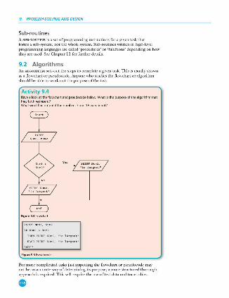
9 PROBLEM-SOLVING AND DESIGN
Sub-routines A SUB - RO urINB is a set of programming instructions for a given task that forms a sub-system, not the whole system. Sub-routines written in high-level programming languages are called 'procedures' or 'functions' depending on how they are used . See Chapter 11 for further details.
9.2 Algorithms An ALGORITHM sets out the steps to complete a given task. T his is usually shown as a flowchart or pseudocode . Anyone who studies the flowchart or algori thm should be able to work out the purpose of the task.
Activity 9.4 Have a look at the flo>Ndiart and pseudocode below. What is the purpose of the algorithm that they both represent? 'Nhatwouldbeoutputilthenumber17and 18were input?
• i o largeot •
Fig ure 9.4 Flowcha, t
l'"'ITT"-'· ""~ I ™~"'~ "-'· .,. ,.,~ ... RLS& PRINTNw.2, "h hrge&t"
Figu re9.5Pseudocode
For more complicated tasks just inspecting the flowchart or pseudocode may not be an accurate way of de termining its purpose; a more structured thorough approach is required . T his will reciuirc the use of test data and trace tables.
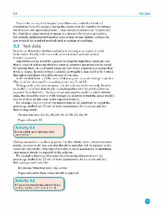
9.3
Some tasks arc required frequently and there are standard methods of completing them, for example, taking the square root of a number or sorting a list of names into alphabetical order. These standard solutions can be provided by a high-level programming language as a standard function or procedure, for example, mathematical fimctions such as max or min. Library routines are also available for standard methods such as sorting or searching.
9.3 Test data In order to determine whether a solution is working as it should, it needs to be tested. Usually before a whole system is tested each sub-system is tested separately.
Algorithms can be tested by a person working through them using any data that is required and seeing what the result is; computer programs can be tested by running them on a computer using any data that is required and seeing what result is output. In order to test a solution thoroughly it may need to be worked through several times with different sets of test data.
A SET OF 'IBST DATA is all the items of data required to work through a solution. The set of test data used in the activity above was 7 and 18.
Testing needs to be done to prove that the solution works correctly. In order to do this a set of test data should be used togetl1cr \vith tl1c result( s) that are expected from that data. The type of test data used to do this is called NORMAL
DATA, this should be used to work tl1rough tl1e solution to find the actual rcsult(s) and sec if these are the same as the expected result(s).
For example, here is a set of normal test data for an algorithm to record tl1c percentage marks from I O end-of-term examinations for a student and find their average mark:
Normal test data: 50, 50, 50, 50, 50, 50 50, 50, 50, 50
Expected result: 50
Activity 9.5 Provideanothersetoftestdataandits expected remit .
Testing also needs to be done to prove that tl1c solution does not give incorrect results. In order to do this, test data should be used that will be rejected as the values arc not suitable. This type of test data is called ERRONEOUS or ABNORMAL
TEST DATA; it should be rejected by the solution. For example erroneous/abnormal data for an algoritlm1 to record the
percentage marks from 10 end-of-term examinations for a student and find their average mark could be:
Erroneous/abnormal data: - 12, elc\·cn
Expected results: these values should be rejected
Activity 9.6 Provide some more erroneous/abnormal data lorthisalgorithmanditsexpectedresults.
Test data
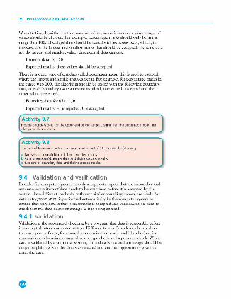
9 PROBLEM-SOLVING AND DESIGN
When testing algorithms with numerical values, sometimes only a given range of values should be allowed. For example, percentage marks should only be in the range O to 100. The algorithm should be tested with EXTREME DATA, which, in this case, are the largest and smallest marks that should be accepted. Extreme data are the largest and smallest values that normal data can take.
Extreme data: 0, 100
Expected results: these values should be accepted
l11crc is another type of test data called BOUNDARY DATA; this is used to establish where the largest and smallest values occur. For example, for percentage marks in the range Oto 100 , the algorithm should be tested with the following boundary data; at each boundary two values arc required, one value is accepted and the other value is rejected.
Boundary data for O is - 1, 0
Expected results: - 1 is rejected, 0 is accepted
Activity 9. 7 Provideboundarydatafortheupperendoltherange;as.sumethatthepm:entagemarbare alway:swholenumbers
Activity 9.8 The erid.ol-term examinations are now marked out of 20. Provide the following
il lwosetsofnormaldataandtheirexpectedresults b someerroneous/abnormaldataandtheirexpectedresults c twosetsofboundarydataandtheirexpectedresult1.
9.4 Validation and verification ln order for computer systems to only accept data inputs that arc reasonable and accurate, every item of data needs to be examined before it is accepted by the system. Two different methods, with very similar sounding names, are used. For data entry, VALlDATION is performed automatically by the computer system to ensure that only data is that is reasonable is accepted and VERIFICATION is used to check that the data docs not change as it is being entered.
9.4.1 Validation Validation is the automated checking by a program that data is reasonable before it is accepted into a computer system. Different types of check may be used on the sa.n1c piece of data; for example an examination mark could be checked for reasonableness by using a range check, a type check and a presence check. When data is validated by a computer system, if the data is rejected a message should be output explaining why the data was rejected and another opportunity given to enter the data.
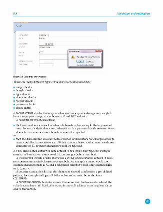
9.4
Cub
Figur•9.60ataentryemlf~
There are many different types of validation checks including:
• range checks • length checks • type checks • character checks • format checks • presence checks • check digits.
A RANGE CHECK checks that only numbers within a specified range are accepted. For example percentage marks between O and 100 inclusive.
A LENGTH CHECK checks either:
• that data contains an exact number of characters, for example that a password must be exactly eight characters in length so that passwords with se\·en or fewer characters or nine or more characters would be rejected
°' • that the data entered is a reasonable number of characters, for example a family name could be between two and 30 characters inclusive so that names with one character or 31 or more characters would be rejected.
A TYPE CHECK checks that the data entered is of a gi\·cn data type, for example number of brothers or sisters would be an integer (whole number).
A CHARAcrER CHECK checks that when a string of characters is entered it docs not contain any invalid characters or symbols, for example a name would not contain characters such as %, and a telephone number would only contain digits m (, ), a ,d ,.
A FORMAT CHECK checks that the characters entered conform to a pre-defined pattern, for exam ple in Figure 9 .6 the cub number must be in the form CUB9999.
A PRESENCE CHECK checks to ensure that some data has been entered and the value has not been left blank, for example an email address must be given for an online transaction.
Validation and verif ication
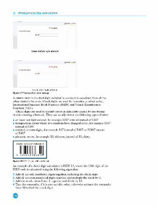
9 PROBLEM-SOLVING AND DESIGN
Sc,eenbefore login attempt
S<reen atterloginattempt Figu,.9.7Pfesenced\ed<:mo,me,,;age
A C H ECK DIGIT is the final digit included in a code; it is calculated from all the other digits in the code. Check digits are used for barcodes, product codes, International Standard Book Numbers ( ISBN) and Vehicle Identification Numbers (VIN).
Check digits are used to identify errors in data entry caused by mis-typing or mis-scanning a barcode. They can usually detect the following types of error:
• an incorrect digit entered, for example 5327 entered instead of5307 • transposition errors where rnro numbers have clianged order, for example 5037
insteadof5307 • omitted or extra digits, for example 537 instead of5307 or 53107 instead
of5307 • phonetic errors, for example 13, thirteen, instead of 30, thirty.
IS8N97B-0-340-983B2-9
, ll~!llmllllJIJIJIUII Figu,.9.8IS8N 13rndewithched<:digi t
An example ofa check digit calculation is ISBN 13, where the 13th digit of the ISBN code is calculated using the following algorithm.
1 Add all the odd numbered digits together, excluding the check digit. 2 Add all the even numbered digits together and multiply the result by 3. 3 Add the results from 1 and 2 together and divide by 10. 4 Take the remainder, ifit is zero use this value, otherwise subtract the remainder
from 10 to find the check digit.

9.4
A~ 9 7 8 0 3 4 0 9 8 3 8 2 @ ~/y '"°''';,;,
Ev• ndigits
Figure9.91S!lN
Using the ISBN above 9 7 8 0 3 4 0 9 8 3 8 2 wi thout its check digit:
1 9+8+3+0+8+8 - 36 2 3(7 + 0 +4+ 9 + 3 +2) - 75 3 (36 + 75 )/10 - 11 remainder l 4 10 ~ l - 9 the check digit.
To check that an ISBN 13 digit code is correct a similar process is followed.
1 Add all the odd numbered digits together, including the check digit. 2 Add all the e\·en number of digits together and multiply the result by 3. 3 Add the results from I and 2 together and divide by 10 . 4 The number is correct if the remainder is zero.
Using the ISBN above 9 7 8 0 3 4 0 9 8 3 8 2 9 with its check digit:
1 9+8+3+0+8+8+9 - 45 2 3(7+0+4+9+3+2 ) - 75 3 (45 + 75 )/ 10 - 12 remainder 0 4 Remainder is O therefore nwnber is correct.
Activity 9.9 a Find the (heck digit for the ISBN 978190612400. b AretheselSBNscorrect?
i 9718780171500 11 9781234567897
Activity 9.10 • Find an ISBN, then show that its chfil digil is correct • Working in pairs find two ISBNs each, copy one down with a transpmition error and the other
onecorrectly.Swapyour1S8Nsandseeilyoucanfindtheonewiththeerror. e lookatacorrectlSBN,canyouthinkolanerrorthatthissystemwillnotidentilyandexplain
withanexamplewhythisisthecase?
Activity 9.11 Find out about the modulo 11 check digit cakulation and how it is used for VlNs
( Activity 9.12 ~nd out how limit checks and consistency checks are used
Validation and verification
)

9 PROBLEM-SOLVING AND DESIGN
Activity 9.13 Which validation checks could you use for the following? You may decide that more than one validation check is required
a Entering a telephone number. b Entering a student's name c Entering a part number in the form XXX999, where X must be a letter and 9 must be a digit.
9.4.2 Verif ication Verification is checking that data has been accurately copied onto the computer or transferred from one part of a computer system to another.
Verification methods include:
• double entry • screen/visual check • parity check • checksum.
For DOUBLE ENTRY the data is entered twice, sometimes by different operators; the computer system compares both entries and outputs an error message requesting that the data is entered again if they are different.
Customer Information
Figure9.100oubleentry
A SCREEN/VISUAL CH ECK is a manual check completed by the user who is entering the data. When the data entry is complete the data is displayed on the screen and the user is asked to confirm that it is correct before continuing. The user either checks the data on the screen against a paper document that is being used as an input form or confirms from their own knowledge if the data is about them.
Parity cl1ecks and checksums are discussed in Sections 2.3.l and 2.3.3.
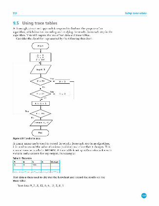
9.5
9.5 Using trace tables A thorough, strucmred approach is required to find out the purpose of an algorithm, which involves recording and srudying the results from each step in the algorithm. This will reguire the use of test data and trace tables.
Consider the algorithm represented by the following flowchart:
Figure 9.11Flowcharttotrace
A TRACE TABLE can be used to record the results from each step in an algorithm; it is used to record the value of an item (variable ) each time that it changes. This manual exercise is called a DRY RUN. A trace table is set up with a column for each variable and a column for any output. For example:
tH±£J Test data is then used to dry run the flowchart and record the results on the trace table.
Test data: 9 , 7, 3, 12, 6, 4, 15 , 2, 8, 5
Using trace tables
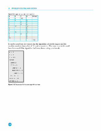
9 PROBLEM-SOLVING AND DESIGN
Table92Completedtfacetablefo,!Jow<ha,t
Output
It can be seen from the output that the algorithm selects the largest and the smallest numbers from a list of 10 positive numbers. The same trace table could have been used ifthc algori thm had been shown using pseudocodc.
Figure9.12 Psrudocodefo, thesamealgo<ithmtotface
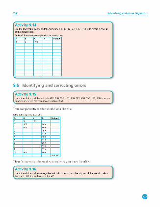
9.6
Activity 9.14 Usethetracetablebelowandthetestdata4,8, 19, 17, 3, 11,6, 1, 13,9torecordadryrun ofthep1.eUdocode
Table9.3Tracetableto~tefofthepseudocode
A B C X Output
9.6 Identifying and correcting errors
Activity 9.15
Identifying and correcting errors
Use a trace table and the test data 400,800,190,170,300,110,600,150,130, 900torec:ord anotherdryrunolthepseudoc:odeorllowc:hart.
Your completed trace table should look like this:
Ta ble 94 Completedtra,cetable
There is an error as the smallest number has not been identified .
Activity 9.16 Useatracetableandsomenegativetestdatatorec:ordanotherdryrunofthepseudcx:odeor flowchart. What error have you loondt
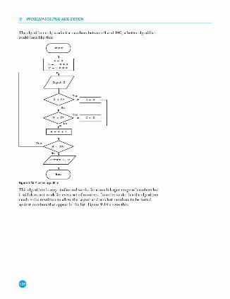
9 PROBLEM-SOLVING AND DESIGN
The algorithm only works for numbers between O and I 00; a better algorithm could look like this:
Figu..,9.13Abette,algor;thm
This algorithm is very similar and works for a much larger range of numbers but it still does not work for every set of numbers. In order to do this the algorithm needs to be rewritten to allow the largest and smallest numbers to be tested against numbers that appear in the list. Figure 9.14 shows this.
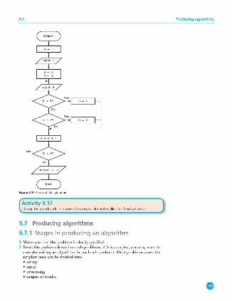
9.7
Figur•9.14Arruch be tteralgo<ithm
Activ ity 9.17 Change the pseudocode so it works for eV!'ry set of numbers like the flowchart above
9.7 Producing algorithms
9.7.1 Stages in producing an algorithm 1 Make sure that the problem is clearly specified. 2 Break the problem down into sub-problems; if it is complex, you may want to
consider writing an algorithm for each sub-problem. Most problems, even the simplest ones can be divided into: • sctup • input • processing • outputofresults.
Producing algorithms
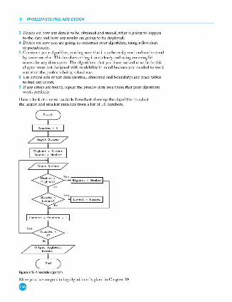
9 PROBLEM-SOLVING AND DESIGN
3 Decide on how any data is to be obtained and stored, what is going to happen to the data and how any results are going to be displayed.
4 Decide on how you arc going to construct your algorithm, using a flowchart or pscudocodc.
5 Construct your algorithm, making sure that it can be easily read and understood by someone else. This involves setting it out clearly and using meaningful names for any data stores. The algorithms that you have looked at so far in this chapter were not designed with readability in mind because you needed to work out what the problem being solved was.
6 Use several sets of test data ( normal, abnormal and boundary) and trace tables to find any errors.
7 If any errors arc found, repeat the process until you think that your algorithm works perfectly.
Ha\'c a look at a more readable flowchart showing the algorithm to select the largest and smallest numbers from a list of 10 numbers.
Figu,.9.15Areada<Jealgorithm
More practice on producing algorithms is given in Chapter 10.
0
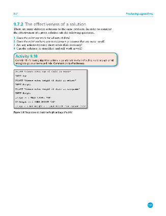
9.7
9.7.2 The effectiveness of a so luti on There are many different solutions to the same problem. ln order to consider the effectiveness of a gi\·en solution ask the following questions.
1 Does the solution work for all sets of data? 2 Does the solution have any unnecessary processes that are never used? 3 Arc any actions repeated more often than necessary? 4 Can the solution be simplified and still work as well?
Activity 9.1 8 Considerthelollowingalgorithmwritteninpseudocodetochl'<X ilachildisoldenooghortall enough to go on a theme park ride. Comment on its effectiveness
<Xrl'PITT'Pleaoeenterageofchildinyeara •
O\ll'PUT'Pleaoeenterheightofchildin ..,,treo•
INPUT Height
0\11'P!1I' ' Pl<1a oeenterweightofchildinkilograru, •
INPIJ'Flleight
IFA<Je.>- 5T!l&NOUTPUT ' 0K '
IFHeight>- lTll&NOUTPUf'OK'
IFAge<5A!ID11eight<lTIIIUf0UFPUT ' Youcannotride•
Figur•9.16Pseudocode to<hecktheheighta,nda.geofach;ld
Producing algorithms
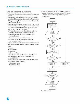
9 PROBLEM-SOLVING AND DESIGN
End-of-chapter questions l Name and describe the comixinents of a computer
system. 2 A computer S)'Stem is to be de\'eloped to provide
a modulo l l check digit for numbers from four to
20 digits in length. Provide a strucrnre diagram for this computer system.
3 A phone app is being developed to split the cost of a restaurant bill between a given number of people. It is being designed to work for up to 12 diners and for bills from $10 to $500 . a What \'alidation checks should be used for the
number of diners and the size of the bill? b Provide two sets of normal data and their
expected results. c Provide some abnormal/erroneous data. d Identify the boundary data required and
the expected results. 4 Explain what is meant by \'alidation and \·erification. 5 The follmving data is to be entered o nto an online
form:
• dateofbirth • password • phone number. For each item state , with reasons, the validation and verification checks that should be used.
6 Using ISBN 13: a Find the check digit for ISBN 978034098382 b Are these ISBNs correct?
9780521170653 9780596158086
7 1l1e following algorithm shown as a flowchart checks the sizes of a consignment of 10 parcels. The dimensions of each parcel are input in centimetres.
FiguN9.17 Howch..-t
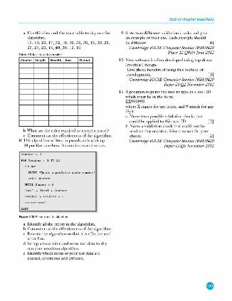
a Use this data and the trace table to dry run the algorithm. 15, 10, 20, 17, 32, 10, 30, 35, 30, 15, 30, 28, 25, 25, 20, 15, 40, 20, 12, 10
Table95Tracetableto~te
Counter Length Breadth Ar.a Output
b \Vhat are the rules required to accept a parcel? c Comment on the effectiveness of the algoritlm1.
8 This algorithm written in pseudocode adds up 10 positive numbers. It contains several errors.
PRINT ' l!nterapo,, itivewholenwsber'
Figure9.1BPseudococleforakjorithm
a Identify all the errors in tl1e algorithm. b Comment on the effectiveness of the algoritlm1. c Rewrite tl1e algorithm so tl1at it is effective and
error free. d Set up a trace table and some test data to dry
run your n.·written algorithm. e Identify which items of your test data are
normal, erroneous and extreme.
End-of-chapter questions
9 State two different validation checks and give an example of their use. Each example should be different. [4]
Cambridge [GCSE Computer Studies 7010/0420 Paper 12 Q9(b) June 2012
10 NC'.11 software is often dL·veloped using top-down (modular) design. Give tl1ree benefits of using this method of dC'.•elopment. [3]
Cambridge !GCSE Computer Studies 7010/0420 Paper 13 Q2 November 2012
11 A program requires the user to type in a user ID which must be in the form: XX999999 where X stands for any letter, and 9 stands for any digit. a Name two possible validation checks that
could be applied to this user ID. [2] b Name a validation chec.k that could not be
used on this occasion. Give a reason for your choice . [2] Cambridge [GCSE Computer Studies 7010/0420
Paper 13 Q5 November 2012
@ Pseudocode and flowcharts
lnthischapteryouwilllearnabout:
e thepseudocodelorassignment,using<• thepseudocodelOfconditionalstatements
IF ·- TIIEN - ELSE ·- ENDIF
CASE ·- OF - OTHERWISE ·- ENDCASE e thepseudocodelorloopstructures
FOR._TQ_NEXT
WHILE ·- DO ·- ENDWHILE e thepseudocodelOfinputandoutputstatement:5
INPUT and OU'JPUI
{e.g. READ and PRINT) e thepseudocodelorstandardactions
totalling(e.g. Sum .. SUlll + Number) counting(e.g.Count .. count+l}
• the standard llov,diart symbols for the above statements, commands and structures .)
10.1 Introduction Using pscudocodc is a clear and concise way to represent an algorithm. Data items to be processed by the algorithm arc given meaningful names in the same way that variables and constants are in a high-level programming language. Pseudocode is not bound by the strict syntax rules of a programming language. It does what its name sa)'Si it pretends to be programming code!
To ensure that pseudocode is easily understandable by others it is useful to be consistent in the way that it is written. The pseudocode in this book is written in the following way to help you understand the algorithms more easily:
• Courier New font is used throughout • all keywords (words used to describe a specific action (e .g. INPUT) are written
in capital letters • all names given to data items and sub-routines start with a capital letter • where conditional and loop statements arc used, repeated or selected statements
are indented by two spaces.
10.2 Assignment Values arc assigned to an itcm/\'ariable using the - operator. The 'lariable on the left of the - is assigned the w.lue of the expression on the right. 111c expression on the right can be a single \'alue or se\'cral \'alucs combined with mathematical operators.
Table10 1 Mathematicajope,ators
Operator
rrultiply
raisetothepowe,
() ()'()Up
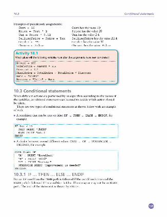
10.3
Examples of pseudocode assignments: Cost has the value 10
Price <- Cost * 2 Price has the value 20 Tax <- Price * 0 .12 Tax has the value 2.4 SellingPrice <-Price+ Tax SellingPricehasthevalue22.4 Gender <- "M" Gender has the value M Chosen <- False Chosen has the value False
Activity 10.1 W'hat values will the following variables have alter the aslignmeot:5 have been completed?
10.3 Conditional statements \Vhen different actions are performed by an algorithm according to the \'alues of the variables, conditional statements can be used to decide which action should be taken.
There are two types of conditional statement as shown below with an example of each.
• A condition that can be true or false: IF ·- THEN -· ELSE ... ENDIF, for example
• A choice between several different values: CASE ·- OF -· OTHERWISE . ENDCASE, for example
_,. "'""" o, "A" PRINT "Excellent"
: PRINT "Average" OTHERWISE PRINT "Improvement is needed"
ENDCASE
10.3.1 IF ... THEN ... ELSE ... ENDIF For an IF condition the THEN path is followed if the condition is true and the ELSE path is followed if the condition is false. There may or may not be an ELSE path. The end of the statement is shown by ENDIF.
Conditional statements
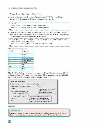
10 PSEUDOCODE AND FLOWCHARTS
A condition can be set up in different ways:
• Using a Boolean variable that can have the value TRUE or FALSE (see Section 11.4 for details of Boolean variables). For example
THEN PRINT "Your search was successful" ELSE PRINT "Your search was unsuccessful"
• Using comparison operators, as shown in Table 10.2. Comparisons arc made from left to right, for example A > 8 means is A greater than B. Comparisons can be simple or more complicated. For example
Table102Conva,isonq,e<al<ITT
Operator Comparison
l areate,lhan
1..-eate,thano,eaual lesslhaoorequaj notequaj
() I CJ"oup
1l1e algorithm below checks if a percentage mark is valid and a pass or a fail. 1l1is makes use of two IF statements. The second IF statement is part of the ELSE path of the first IF statement. This is called a nested IF.
IliPUTPercentageMa rk
IFP<,rcentagellark<OORPercentageMark>lOO
IFPe rce ntag eMa rk>4i
Figure10.1
Activity 10.2
;.1:h~== ;;: ;'."'t be
greate,lhanah\ll>dred
Thisisanesll'dIFstatementshown de,.-tybylhellSeofaserondlevei ofiodentation .The percMtagemark isontytestedifjtisintheror,ectraoge
Change the algorithm to check fora mark between O and 20 and a pass markol 10. Decide what normal. bo\lndary and erroneous data you will need to l\llly test yom algorithm
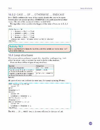
10.4
10.3.2 CASE ... OF .. . OTH ERWISE ... ENDCASE For a CASE condition the value of the variable decides the path to be taken. Several values arc usually specified. OTHERWISE is the path taken for all other values. The end of the statement is shown by ENDCASE.
The algoritlun below specifics what happens if the value of Choice is l , 2, 3 or 4.
CASE Choice OF 1 : Answer .. Numl + Num2
2 : Answer .. Numl - Num2
3 : Answer .. Numl * Num2
4 : Answer .. Numl I Num2
OTHERWISE PRINT "Please enter a valid choice"
Activity 10.3 Use a CASE statement to di~laythe day of the week ii the variable DAY has the value 1 to 7 and an error otherwise
10.4 Loop structures \\'hen some actions performed as part of an algoritlrn1 need repeating, this is called ' iteration'. Loop structures arc used to perform the iteration.
There arc three different types ofloop structure:
Operator
A ,epetitioo. where the numbe, of repeats is notknown.ttlatiscompletedatleastonce
Comparison
A ,epetitioo. where the numbe, of repeat, is WIIILE - · 00 ·- ENDWHILE
not known. ttlatmayneverbecompleted
All types ofloops can perform the same task, for example printing 10 stars.
FOR Counter .. 1 TO 10 · i
Counter .. Counter + 1
UNTIL Counter > 10 Counter .. o
WHILE Counter c: 10 DO
The FOR ... NEXT loop is the most efficient for this type of task.
!
I ! I ! :
Loop structures
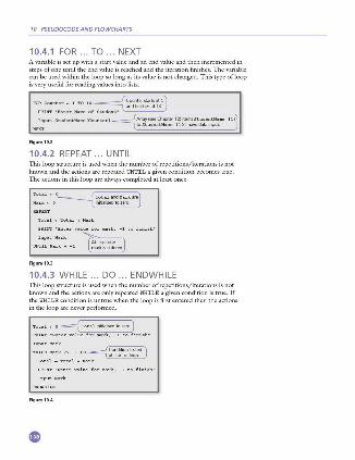
10 PSEUDOCODE AND FLOWCHARTS
10.4.1 FOR ... TO ... NEXT A variable is set up with a start value and an end value and then incremented in steps of one until the end value is reached and the iteration finishes. The variable can be used within the loop so long as its value is not changed. This type of loop is very useful forreadingvaluesintolists.
Figure10.2
10.4.2 REPEAT ... UNTIL l11is loop structure is used when the number of repetitions/iterations is not known and the actions arc repeated UNTIL a gi\·cn c.ondition becomes true. 111c actions in this loop are always completed at least once.
Totalo-0~
Mark..-0 ~
PRIN'T ' Rnter valuefor mark , - ltofiniah•
InputMa rk ~
UNTIL!lark - - 1 ~
Figure10.3
10.4.3 WHILE ... DO ... ENDWHILE This loop structure is used when the number of repetitions/iterations is not known and the actions arc only repeated WHILE a given condition is true. If the WHILE condition is untrue when the loop is first entered then the actions in the loop arc never performed.
To t alo-0~
PRIIIT ' Rnt e rvaluefor ...,rk , - ltofinioh•
Input Mark
Figure10.4
10.5
Activity 10.4 a Writepseudocodetoinput10pos.itivenumbersandfindthetotalandtheaverage b Writepseudorndetoinputpositivenumbers, - 1tolini~.andlindthetotalandtheaverage c Explainwhyyouchos.etheloop1tructuresloreachta1k
10.5 Input and output statements INPUT and OUTPUT are used for the entry of data and display of information. Sometimes READ can be used instead of INPUT; this is usually used for reading from files, which is not covered in this textbook. Frequently PRINT is used instead ofOUTPUT.
Input and output statements
INPUT is used for data entry. It is usually followed by a variable where the data input is stored, for example :
OUPUT/PRINT is used to display information ei ther on a screen or printed on paper. It is usually followed by a single value that is a string or a variable or a list of values separated by commas, for example :
10.6 Standard actions The ability to repeat actions is very important in the design of algorithms. When an algorithm is mrned into a program the same set of actions may be repeated many thousands of times, for example, keeping a running total of the value of goods sold in a supermarket.
i_R_u_n_n_i _n_~!.o,•l __ : __ Run_n.1.n.~T_o_,.-_1 __ , .. Y•.l_u_e_ ·· ·· · · · ·· ·· ·· · · · ·· ·· · · · ·· ·· ·: .: .. : : :: : .. :J Keeping a count of the number of times an action is performed is another standard action, for example:
Counting is also used to count down until a certain value is reached, for example the number of items in stock in a supermarket:
! Nl:l~e;:i_nStock_ .. Nu~errn.St_o_ck _ - .. 1 --····----·-·-·-- ·-·-·---· · ····--··· -·__]
10.7 Examples of algorithms in pseudocode
Exa mple 1 Tickets are sold for a concert at $20 each. If 10 rickets are bought then the discount is 10%; if20 rickets are bought the discount is 20%. No more than 25 rickets can be bought in a single transaction.
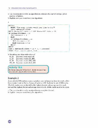
10 PSEUDOCODE AND FLOWCHARTS
a Use pseudocode to write an algoritlun to calculate the cost of buying a given number of tickets.
b Explain how you would test your algorithm.
b Would use test data with values of 0 , 26 Expected result rejected I , 25 Expected results 20,400 9, 10 Expected results 180, 180 19 , 20 Expected results 342, 320
Activity 10.5 ForthetestdatagiveninEXilmple1,identifythetypeoltest datausedandsuggesl'iOmemoretestdata
Example 2 A school with 600 srudents wants to produce some information from the results of the four standard tests in Maths, Science, English and IT. Each test isoutof lOO marks. The information output should be the highest, lowest and average mark for each test and the highest, lowest and average mark o;erall. All the marks need to be input.
a Use pseudocode to wri te an algorithm to complete this task. b Explain how you would test your algoritlun.
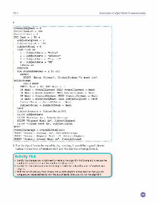
10.7
SubjectLowest .. 100 SubjectTotal .. o CASE Test OF
1 : SubjectName .. "Maths" : SubjectName .. "Science" : SubjectName .. "English"
4 : SubjectName .. "IT" OTHERWISE
FOR StudentNumber .. 1 TO 600 REPEAT
PRINT "Enter Student", StudentNumber,""s mark for",
UNTIL Mark c: 101 AND Mark > ~1 IF Mark c: OverallLowest THEN OverallLowest .. Mark IF Mark c: SubjectLowest THEN SubjectLowest ... Mark IF Mark > OverallHighest THEN OverallHighest .. Mark IF Mark > SubjectHighest THEN SubjectHighest .. Mark OverallTotal .. OverallTotal + Mark SubjectTotal ... SubjectTotal + Mark
NEXT
SubjectAverage .. SubjectTotal/600 PRINT SubjectName PRINT "Average is", SubjectAverage PRINT "Highest Mark is", SubjectHighest PRINT "Lowest Mark is " , SubjectLowest
; ov,,callAv,m,10 .. OverallTotal/2400 Average is", OverallAverage
•overall Highest Mark is", OverallHighest
Examples of algorithms in pseudocode
b For the algorithm to be tested by dry running, it would be a good idea to
reduce the number of students to 5 and the number of subjects to 2.
Activity 10.6 11 Identify the changes you would need to make to the algorithm for Example 2 to reduce the
numberofstudentsto5andthenumberofsubjectsto2 b ldeotilythetestdataneededtotestEXilmple2withthereducednumberolstudeotsand
subjects. c Withthe..etofdatayouhavechosen,setupandcompleteatracetablesothatyoucan
compare your expected results with the actual results when you dry run the algorithm
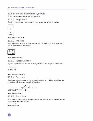
10 PSEUDOCODE AND FLOWCHARTS
10.8 Standard flowchart symbols Flowcharts are drawn using standard symOOls.
10.8.1 Begin/End Terminator symbols are used at the beginning and end of each flowchart.
Figure10.5lermonatofsymbols
10.8.2 Process Process symbols are used to show when values are assigned to an item/variable like an assignment in pseudocode.
Figu re 10.6 Proces,,)fflbol
10.8.3 Input/Output Input/Output symbols are used show input of data and output ofinformarion.
Figure10.7 1nput!Outputsymbol
10.8.4 Decision Decision symbols are used to decide which ac tion is to be taken next. These can be used for selection and repetition/iteration.
Figure10.8 0ecisionsymbol
10.8.5 Flow lines Flow lines are used to show the direction of flow which is usually, but not always, top to bottom and left to right.
Figu re 10.9Rowline
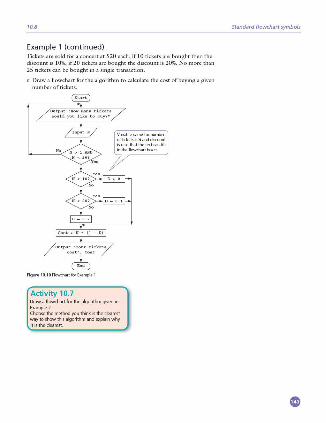
10.8
Exa mple 1 (co ntinued) Tickets arc sold for a concert at $20 each, iflO tickets are bought then the discount is I 0%, if 20 rickets are bought the discount is 20%. No more than 25 tickets can be bought in a single transaction.
c Draw a flowchart for the algorithm to calculate the cost ofbuying a given number of rickets.
Output •Yourticketo cost •, coot
Figur• 10.10Flowd>artforExampje1
Activity 10.7 Draw a flowchart for the algorithm given in Example 2. Choosethemethodyouthinkistheclearest way to show this algorithm and explain why it is the dearest
Standard flowchart symbols

10 PSEUDOCODE AND FLOWCHARTS
End-of-chapter questions l Show two ways of selecting diffen:nt actions using
pscudocode. 2 You have been asked to write the pscudocodc to
choose the correct routine from the menu shown below. a Decide which type of conditional statement you
a.re going to use:. b Explain your choice. c Write the psc:udocode. d Select your test dau and e.~plain why you chose
each value.
1 Set upnewAccOU'I\
2Mahchangestoan&.istjr.gAccount
4V;ewMy Orclers
6Alter..nE!<islingOrde,
Figu .. t0.11
3 Show three w.:iys a loop to :M:ld up fa·e numbers and print out the tota l can be sc:t up using pscudocode. E."tplain which lo:i,p is the most efficient to use:.
4 A sweet shop sc: lls 500 different sorts of sweets. Each sort of sweet is identified by a unique fourdigit code. All swt<'ts that start with a one ( I ) a.re chocolates, all sweets that start with a two (2) an: toffees, all sweets that surt with a three (3 ) an: jellies and all other sweets an: miscellaneous and can start with any other digit except zero. a Write an algorithm, using a flowchart, which
inputs the four-digit cock for all 500 items and outputs the number of chocobtes, toffees and jell ies.
b Explain how you would test your flowchart. c Decide the test data to use and complete a trace
table showing a dry run of your flowchart.
5 The temperature in an apartment must be kept between 18°C and 20"C. l fthe temperature reaches 22°C then the fun i.s switched on; if the temperature reaches 16°C then the he.:iter is switched on, otherwise: the fun and the heaters arc switched off. The following library routines an: available: • GctTempcrature • FanOn • FanOff • HcatcrOn • HcaterOff Write an algorithm, using pscudocodc or a flowchart, to keep the temperature at the right level.
6 Daniel lives in Italy and travels to Me,dco, India and New Zealand. The time differences arc:
Country
11ms, ifit is 10: 15 in Italy it will be 14:45 in India. a \\'rite an algorithm, using pscudocode or
otherwise:, which: • inputs the name of d1e country • inputs the time in I roly in hours (H ) and
mi.nutes (M) • calculates the time in the country input using
the data from the t.1blc • outputs the country and the time in hours
and minutes. [ 41 b Describe:, with examples, two sc:ts of test data
you would use: to test your algorithm. [21 Cambridge !GCSE Computer 5t,.die1 7010/0420
Paper JI Q/7 June 2011
7 A school is doing a check on the heights and weights of all its students. The school has I OOO snidcnts. Write an algorithm , using pscudocodc o r a flowchart,which • inputs the height and weight of all I OOO students • outputs the a,·cragc (mean ) height and weight • includes any necessary error traps for the input
ofhcight and weight. [51 Cnmbridge !GCSE Co,Hp11ter Studie1 7010/0420
Paper 11 Q l 7 November2010
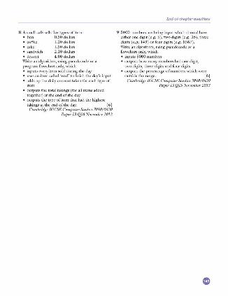
8 A small cafC: sells five types of item: • bun 0.50 dollars • coffee • cake • sandwich
1.20 dollars 1.50 dollars 2.10 dollars
• dessert 4.00 dollars Write an algorithm, using pseudocode or a program flowchart only, which • inputs every item sold during the day • uses an item called 'end' to finish the day's input • adds up the daily amount taken for each type of
item • outputs the total takings (for all items added
together) at the end of the day • outputs the type of item that had the highest
takings at the end of the day. [ 6] C11mlnidge !GCSE Computer Studies 7010/0420
P11per 13 Ql6 November 2012
End-of-chapter questions
9 5000 numbers are being input which should ha\·e either one digit ( e.g. 5 ), two digits ( e.g. 36), three digits (e.g . 149 ) or four digits (e .g. 8567). \Vrite an algorithm, using pseudocode or a flowchart only, which • inputs5000 numbers • outputs how many numbers had one digit,
two digits, three digits and four digits • outputs the percentage of numbers which were
outside the range. [6] C111nbridge IGCSE Computer Studies 7010/0420
P11per 13 QlS November2013
® Programming concepts
lnthischapteryouwilllearnabout:
e programming e dedarationanduseol
• variables •constants
• bask data types • integer • =I • char • string • Boolean
e howtouse • sequence • selection • repetition • totalling • counting
• useolpredelinedprocedurevfunctions
11.1 Introduction Chapters 9 and 10 ha\·e enabled you to de\·elop your computational thinking by writing algorithms to perform \'arious tasks. This chapter will show you how to put your computational thinking to the ultimate test by writing computer programs to perform tasks.
So far you ha\·e tested your algoritluns by dry running. Once you have written a program for your algorithm, and when there are no syntax errors (see Section 7.4. 1), you should then use a computer to nm the progr:1.m to complete the task you have specified. The computer will perform the task exactly as you ha\'e written it; you may need to make some changes before it works exactly as you intend it to.
11.2 Programming In Chapter 7 you learnt that programs could be written in high- or low-level languages then translated and run. This chapter will introduce you to the programming concepts required for practical use of a high-level language.
There are many high-lc\·el programming languages to choose from. For Cambridge !GCSE Computer Science any high-le\·el programming language may be used, howe\•e r if you plan to continue your studies with A Level Computer Science then one ofVisual Basic, Pascal/Delphi or Python is recommended.
,\1any programming languages are free to download and use. This chapter shows the use of programming and should be used in conjunction with learning the S)~ltax of an appropriate programming language.
Programs developed in this chapter will be illustrated using the following freely a\'ailable languages:
• Scratch: a good basic introduction to programming for beginners that is freely alfllilable from M IT. Scratch makes programming easy and fun to learn as it uses visual building blocks. It is useful as an introduction.
• JavaScript: a scripting language that works in any browser, no download needed. JavaScript works with the H TML (see Section 1.6.2 ).
• Python: a general purpose, open source programming language that promotes rapid program de\·elopment and readable code.
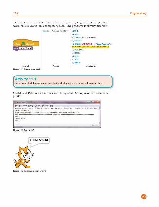
11.2
The traditional introduction to programming in any language is to display the words ' H ello \\'orld' on a computer screen. The programs look very different:
print {• HelloWorld • )
Python
Figure 11.1 Programs to display
Activity 11 .1
</TITLll >
<SCRIPT LA!!GOAGB - ' J " v"Script '>
docunent .writ e (' He lloWorld 'l
</SCRIPT>
</HEAD>
JavaScript
Have a look at all thre-e programs and dedde which program is the easiest to understand.
Scratch and Python work in their own Integrated Development Environments (ID Es).
·~·~- 1.,.0 (•1 . 1.0 · l><lhrl,~O.O,fl, sop >O lOll, 10, .. ,., , [MSC • • uoo !J H< (lo ~ U ! )] ;~ WUIJl
? ,..... ' GGP¥<i~h•' , 'ettdi<s' or " U«f>HU' !or ..,,e lofo<Nnloo.
»> - ------- USLUI.I ---- ---
>» I
Figur• 11.2Pythoo l0f
Hello World
Figur• 11 3Scratd\pro~amrunn;ng
Programming
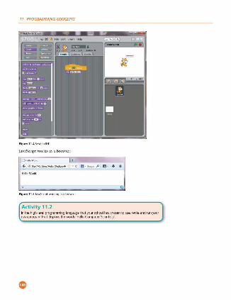
11 PROGRAMMING CONCEPTS
Fig u,. 11.4 ScratchlOE
JavaScript works in a browser.
O HelloWon:J
+ it RVIIOM..-.rtlod<to p/H C! • • Gooq,t JJ EJ• + _!_,
" Fig u,. 11.5 .lavaScriptworkinginabmwser
Activity 11.2 lnthehigh-levelprogrammi11glanguagethatyourschoolha1dios.entouse,writeandrunyour own program that displays the words 'Hello Computer Scientists'
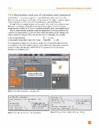
11.3 Declaration and use of variables and constants
11.3 Declaration and use of variables and constants A VARIABLE in a computer program is a named data store that contains a value that may change during the execution of the program. In order to make programs understandable to others, variables should be given meaningful names.
A CONSTANT in a computer program is a named data store that contains a value that does not change during the execution of the program. In order to make programs understandable to others, constants should be given meaningful names.
Not all programming languages explicitly differentiate between constants and \'ariables but programmers should be clear which data stores can be ch.,nged and which cannot be changed . There are several ways of doing this, for example :
• use of capital letters: • meaningful names tl1at begin with Const: ConstPi - 3 .142
It is considered good practice to declare at the start of a program the constants and variables to be used in that program. Declarations arc expected in programs written for the tasks specified in tl1e !GCSE Computer Science pre-release material(sccScction 1.2.3 ).
Figure 11.6Variableandcoostantdeda<abons;nScratc:h
varFirstVar,SecondVar;
con•tCon•tFirot - 500,SecondCon•t - lOO;
constConstFirot - 50;
constConstSe cond - 100;
assi(jl\edtl,e;rvalueswhen lheyarededaredbec:ause lheydonotc:haoge
Figure 11.7 Variableandcoostantdeda<alionsinJavaSaipt
Se condVar - JO ~ ariablesandronstants ConotFirot - 500 a<ededaredinl'ythonby :on• tSe cond - 100 assi(jl\ingvakles.
FirotVar,SecondVar - i0,30
ConotFirot,Con•tSecond - 500,100
Figure11.8Howtodedate variablesandcoostantsinl'ylhon
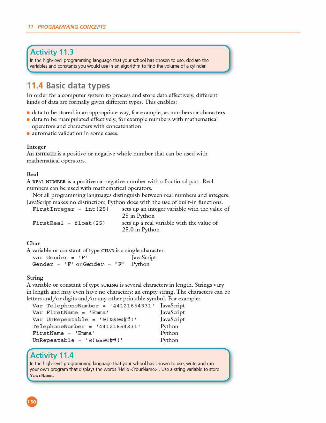
11 PROGRAMMING CONCEPTS
Activity 11 .3 lnthehigh-levelprogramminglanguagethatyourschoolhaschosentouse,dedarethe variables and constants you would use in an algorithm to find the volume of a cylinder.
11 .4 Basic data types In order for a computer system to process and store data effectively, different kinds of data arc formally given different types. This enables:
• data to be stored in an appropriate way, for example, as numbers or characters • data to be manipulated effectively, for example numbers with mathematical
operators and characters with concatenation • automatic validation in some cases.
Integer An I N"IBGER is a ix,siti\·c or negative whole number that can be used with mathematical operators.
Real A REAL NUMBER is a positive or negative number with a fractional part. Real numbers can be used with mathematical operators.
Not all programming languages distinguish between real numbers and integers. Ja\'aScript makes no distinction; Python docs with the use of built-in functions.
Firstlnteger • int (25) sets up an integer \'ariablc with the value of 25 in Python
FirstReal - float ( 25) sets up a real lfariablc with the \'aluc of 25.0 in Python
Char A lfariablc or constant oftypc CHAR is a single character.
var Gender - 'F' JavaScript Gender - 'F' or Gender - "F" Python
S t rin g A 'l:lriablc or constant oftypc STRING is sc\'cral characters in length. Strings \'ary in length and may even have no characters: an empty string. The characters can be letters and/or digits and/or any other printable symbol. For example:
Var TelephoneNumber - '44121654331' JavaScript Var FirstName - 'Emma' JavaScript Var UnRepeatable - ' @ ! &&@@## ! ' JavaScript TelephoneNumber - '44121654331' Python FirstName - 'Emma' Python UnRepeatable - ' @!&&@@##!' Python
Activity 11 .4 lnthehigh-levelprogramminglanguagethatyourschoolhaschosentouse,writeandrun your own program that dis.plays the words 'Hello <YourName>'. Use a string variable to store
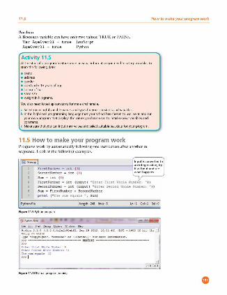
11.5 How to make your program work
Boolean A BOOLEAN variable can ha\·e only two values: TRUE or FAl..SE.
Var Age0ver21 - true JavaScript Age0ver21 - true Python
Activity 11 .5 At the start of a program to store ,;ome personal informatioo you need to set up variables to store thefollowingdat<1
• address
""'""" e over/undef 18yearsofage e rnlourofhair e shoesize e 'Neightinkilograms
You also need to set up coostants for male <1nd female
• Selectme.-minglulvariablenamesandtypesforyourrnnst<1ntsandvariable1 b lnthehigh-levelprogramminglanguagethatyourschoolhaschosrotouse,writeandrun
yourownprogramthatdisplaysthev<1luesyouhaveusedtoinitialiseyourvariablesand rnmtants
c Make sure that you un input new values <1nd select suitable test data for your program.
11.5 How to make your program work Programs work by automatically following one instruction after another in scguence . Look at the following examples.
Python file
1'1r,.tNumbcr • 1nt ( OJ
See ondNlllllher • 1nt ( 0 )
Sua • i.nt ( 0 1
l'"irscN\Utber • int (input( "Enter 1'"1:1;.,,; Whole Nw,,ber: " )) Second.Nl'IE.bcr - int (input ( ~tnter Second Whole NW!lber, " ) I .5um "' 1'1rso;Numbe r -t- Second.NU!tber
pr i nt (~Trie 9WR equal." ~, Sllll'I)
Figur• 11.9Pylhonprogram
rwe • copvr~qM", • creGi.:a • or •ucer.n (J" ror it.Ore •n rorr::.a cion. >>> rm-----·--- l!tslAAl ---- -----
~t.,r!l'frstllhahll.-...ce ~
~t,,,.~•c<mdllholc-•, ll Tl>es-cQUAl.s n >» I
Figure 11.1 0Pylhooprigamrunning
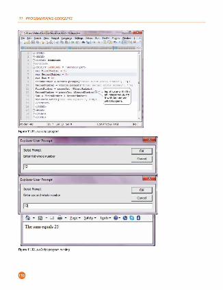
11 PROGRAMMING CONCEPTS
l;;;;;:.;,-·= 1 :::-;~. ~~--
0:J,.....Scr,pt">
:: ::c:~~u • O,
lluurw.l,U • "'-"<10,.,prciq,t( 'Enar Uut "?a<>l• ,i-.,r• , '' I: 5• c<AU&tM1r-"1.nc1c,w .prcq,( 'EntuHaon<1""°hnmat>u•,•• i ,
Figu,. 11.11 JavaS.Criptproc:,am
Explorer User Prompt - J 1-- I _: :1 ----112
Explorer User Prompt -.,;---1-- ~1 l!'IJ • Iii! • Gl oi • £age • ~fety - ,.,.,, . 8 · 0 0 0
The sum equals 25
Figu,. 11.12 JavaS.Criptpriqamroonk,g
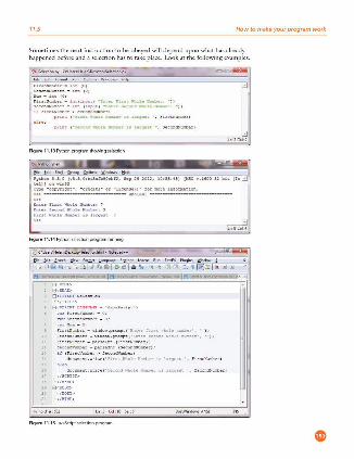
11.5 How to make your program work
Sometimes the next instruction to be obeyed will depend upon what has already happened before and a selection has to take place. Look at the following examples.
S • ccndN •= • u,t iO)
~-,· Nir.t t IO) ·nti .fll' "-Ci "E.D<u hnt. -.a.b -~
, eccnON=t>er • i n t. \ 1IlJl H i •un.u ~ 1111<>1- _, , " ))
Figur• 11.13Pythoopriqamshowin gs.election
Python S .S.O (vS.S.0:b!l! d'bnet>fl, S..p a lOU, 10:55 :H) [M5t: v . UOO S2 bit l l n • t.d)] on 111n32
ype: •copynQnt.•, •cre,nt.o• or • ucenoeo• ror aore 1nrorut.1on . >» UHiUU
~u~ n ut ll?loU - "' ~ ~t.,.,.,.,..... .... ole N.-,.<:3 Pint. Whole &u.t,,,,r h h~ot 7
Figure 11.14Pythooselectionprog,amrunning
fil<{di.:,C."h','~f,,,!!!dl.>"9<»<1•l.t!l-"'9>MoooR""T~FX. Pl"'l~ l'(n~ X
od f311il o o~l ~tafR l ~~ l • \r l t ~LCBtii / "'., 1 a!}!D l 'il !ii:i: _ :'
~SCHPT u.nz=>: • "Jn•Ser·p~" ~
va.r Hro c11unr,,,, - o :
va.r SecandRmber - O ;
FirotN<mt>er - vind<Y~ .pra,:pt( '~nt e c firot ><t.al e nu.,,t,e r' , S• condll"""'u _ ,,,_n<b,...prccpt ( '[r.tu .. c,on~"hah n=u• ,
Fir,tN<mt>er - p~r,ein t (firotN:mber)· se coooJ<U!lll:er - c,,,r oe incc aecon=n· H 1nroc11unr,,,, ;,,econ<lN.-..r/
docu.=nc .w: 1te{ 'firotWhaleNam>er,olaag,,,t
docu=nc .w: ite( 'Seccnd'1!>.olellemberi,lar1Jeot l' ~ / SCRIPT>-
20 </1'0DY>
</HTML>
Figur• 11.1 5laYaS.O-;ptselectioop<iqam
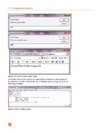
11 PROGRAMMING CONCEPTS
&plo,..., Usu Prompt -~f'roqt:
Erterl'ntwholerunber
po
&plon!':r Usl!r Prompt -I~
-~'. ~ I ~ C:\Usim\H~en\ DHkll p • C I e SO!querm X I X Goc.gle L • ~I SO!arch • I· More » Sign In ~ • Gi . lii1. ea 'ffl' . f•g• • ~foty • T2ol, • G· lliJ lll 0
Second Whole Number is largest 56
Figu,. 11.1 6JavaScr;pts.electionpmc_,amrunllOn9
Sometimes instructions need to be repeated several times so a final result can be obtained, this often im·olvcs the use of totalling and counting. Look at the following examples.
fi!.lditfg,m,tftl,n~'t(- l:l<IP
=r--.:t1~~)
~- • u:c (0) ..t,,h Co~nt ~ 5 :
Figu,. 11.17 Pylhoorepeti!ioopro~am
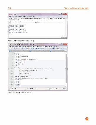
11.5 How to make your program work
Pythor. 3 . 3 . 0 lv3 . 3 . 0:bd3orh9Dtl>n, S e p 29 2012, 10:SS : •8 ) [ HSC T . 16JO 32bit i in _!
TYi>" • copyrl~"t", •credH• " o r "Hcen,el)• ror mo re 1nror=t1o n
»> ---- ------------ RL STM<T ---------------- ----
! n t ernWho leNwr.ber: ! nt eraWho leNwr.ber :7 !nt eraWho l e NUlf.ber : ! ! nt e r aWho l e NUlf.be r: 9 ! n t e r aWho le NUlf.be r: lJ
! : r ! ! iTen:mt>er,i, to
Figure 11.1 [email protected]
f ;i,, {di: ~•"h '{~ f"'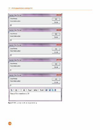
11 PROGRAMMING CONCEPTS
bplorerUnrPn>mpt -J;==-- ~
~
Explorer User Prompt -J;==-- ~
~
Explorer User Prompt - -1-- ~ ~ : ;·---
EicplorerUserPrompt -1-- ~ ~ : ;·---
Ei<plorerUserPrompt -1-- ~ ~ : :·---
O T fill T ~ -ii T ea;t " Saftty T T.11.ols T . .. 0 0 O
Sum offiH: numberli 1s 20
Figu re 11.20 Java5crip t ,epetitiooprogram runnmg
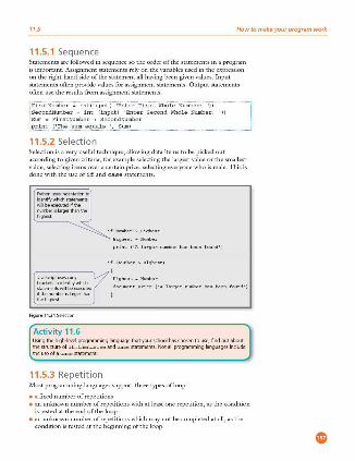
11.5 How to make your program work
11.5.1 Sequence Statements are followed in sequence so the order of the statements in a program is important. Assigrunent statements rely on the variables used in the expression on the right-hand side of the statement all having been given values. Input statements often provide values for assignment statements. Output statements often use the results from assignment statements.
'II
11.5.2 Selection Selection is a very useful technique, allowing data items to be picked out according to given criteria, for example selecting the largest value or the smallest value, selecting items over a certain price, selecting everyone who is male. This is done with the use of if and case statements.
JavaScript uses curly
~~!'n~ ~";:'~ :!~..i ifthenumbe,islafge,than lhehg)PSI
Figure 11.21 Selectioo
Activity 11.6
Bighe• t - Number
print('Ahrgernwaberhu beenfound• )
iflKuoiber>Highe• t)
Bighe• t - Numbe r
docu...,nt.write ( 'Alargernurberhasbeenfound')
Usingthehigh-levelprogrnmminglanguagethatyourschoolhaschosentouse,findoutabout the structure of if .. the n..el s e and case statements. Not all programming languages indude theuseofaca s e statement
11.5.3 Repetition Most programming languages support three types ofloop:
• a fixed number of repetitions • an unknown number of repetitions with at least one repetition, as the condition
is tested at the end of the loop • an unknown number of repetitions which may not be completed at all, as the
condition is tested at the beginning of the loop.
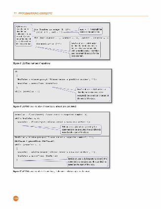
11 PROGRAMMING CONCEPTS
forCountarinrange(l,10), ~ .
print(• • •,end - ''l ~
for(varCounte r - l;Counter<- lO;Counter - Counter + l)
{ Jav"5criptUSl'5c,.fybfad::ets toioentilythestatementsto beexeruted;anewvariable -==--J withastartingvalue,coodibon
Figure 11.22 faednumberofrepetitioos
andincrementissetupfo,the looprounter
HewValue - window.pr001pt('Pleaoeenterapooitivenumber',
HewValue - p a ro e Plo.o.t(HewValue )
JavaSaiptusesrurfybradetsto ioentifythestatementstobe
exeruted;thecooditiooistestedat theendoltheloop
Figure11.23 Unknownro.Jmbef ol,epetiboos,atH'ast onerompleted
NewValue - float(input('Pleaoeenteranegativenumber•>>
NewVal u e - float( input('Pl<iao <i e nt e raliEGATIVEnumber'))
========={ Pythoousesindentabontoideoblythe ] statemeotstobeexeruted;the.cooditioni, testedatthe,tartoltheloop
NewVa ,><1 - wim10w.p~t('Peueenteranegativenumoer',
NewVal u <i - pane Float(N.,...Value);
NewVal u e - window.p~t(•Ple u eente raNl!GA.TIV&nwsber•,
NewVal u e - paneFloat (NewValue )
- - -======::::::lJavaSaiptusesrurfybradets.toioentilylhe l statementstobeexeruted;theconditioor, testedatthestartoftheloop
Figure11.24 Unkl\0Wflro.Jmbefol,epetiboos,statements inloopmayn..,e<beused
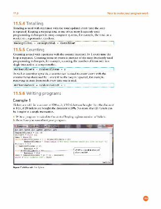
11.5 How to make your program work
11.5.4 Tota lling Totalling is used with repetition with the total updated e\·ery time the loop is repeated. K.:eping a rmrning total is one ofthe most frequently used programming techniques in many computer systems, for example, the total on a receipt at a supermarket checkout.
·--······-·-·-··-·· ····-······-······-··· -L~.'::.'::.'::.~.P.~.'!.::~:~.--~·-··-~.'::.7.~.~-~-~-~~~.:~---~----~?~.~.?.~.~-~-~.:?. ___ _
11.5.5 Counting Counting is used with repetition with the counter increased by 1 every time the loop is repeated. Counting items or events is another of the most frequently used programming techniques, for example, counting the number of items sold in a single transaction at a supermarket.
i NumberOfitems .. NumberOfitems + 1
As well as counting upwards, a counter can be used to count down with the counter being dee.ceased by I every time the loop is repeated, for example , removing an item from stock every time one is sold.
11.5.6 Writing programs
Exa mple 1 Tickets are sold for a concert at $20 each, if ! O tickets arc bought then the discount is 10%, if20 tickets are bought the discount is 20%. No more than 25 tickets can be bought in a single transaction.
a Write a program to calculate the cost of buying a given number of tickets. b Show how you would test your program.
!~uo tr1ekou• l.at (01 D10co,,..~e • Ue ot IOJ ,;01,: • U 0"-< ( 0 )
wt,Uc l<".zl>crOtr1cr«,t:1< l >e !>wu><,rO!'T1ckoe~•25 :
11".-1.0f llalr,tu • U aa t (u,put ' "*"' -"·"1' uenu -1e1 '""" Hlr<I u, DaV' '))
t ~-eOtTickcta < 10 :
:::":-e::.'.....~1:~;e!J"e~=~,!;~! ,e:o=,,=. =,.=_=,.= .. =_=.=, =~~ :~!! ~n~t1':bination of )
pnc.t l 'Yuctn.ocon• , co n 1
Figure 11.25Exampje1inl'ython
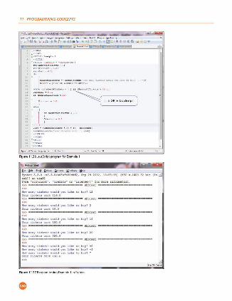
11 PROGRAMMING CONCEPTS
fk 1• s ..... - -1.nj- -.... _,,,""' ,_, ...... - l a iJ lilQ·,D~~ - ~ ;ll ~ j . ... t 1 l cDaJ r.a1~'iJ O O ~ l!j·j ..i :JI O ';> -~ --
...,,.rtl>Chc""t• • un•- -pr-,CI w- '-'.c <o0• ~ Uy<• L, k• ~ , , • ,
..,_, . ,,,,,.1., (..,_rtlfhe<C;o)
..,1J e <(l<'-.,<>n1o•ot• < l ) ll(,,_.,,,ruc.,to > 14 0,·
H , .. ...,, , «OC,:1'hU< 00) ~ ,-----.,,
~-.c-, - ~.O ~
··-
Ccot • N-.Ortlfhckoe, • ,O •
•~•• -~«•( · =•<•n• co c~,,
F1gu re 11.26 JavaSrnp tprigamfo, E~1
fltfditSl,o(_l~Qption,~ tioif
Pythcn3.3.0 lv3.3.0:bdSo fl, 9o.1>f2 . 3~29201:l, ~el.)J er. ll>nl2 ,.,...,., •co~·,r::.or.t•, •c,:e<IJ.:s• or •uct.~aeo• tor 110re 1nto,,..tic~. »> R!S?AA?
Youre1crusooo.2 u. o l> ------------------ R!Slr.RT -----~-----
lkw iu.ny cicb u ,u,ald you li b t o buy? 2 Your e,cttu coo c tO . O
- ...... ; i cUu """1.d YOU Uh <o b,iy? to """ - ny eict~~• ,mul.d you li b ~ o buy • - 1 lkw ... nyticbU,..,,,ld:fDaUtt.tobuy1 7 Y<lltt u ctt.uco• c UO , O
Figure11.27 Pmgram!P<lingfxamplel inl'ython
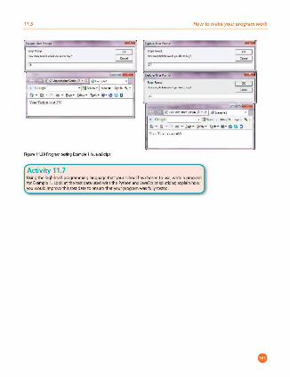
11.5
, .. ~ c,1- 1D<>tt, P • C · ~ 1
"('.o<-gl,: · !l lo>«h • t ...,.. . s.,. .. , .
a . g . i:;:i ,.. . t •!I' · }of•,- '2'11> · e · "' Q o
Figur• 11.28 Program tPStingExample 1 inJavaSaipt
Activity 11 . 7
How to make your program work
r2!lk ,Jlll -:.-w...o..-w, .... P• d 9 1, ..,.,, ~1 ><I X GoooglrL____:J{l>H" h· f Uo,e» Sion .. " ·
a - liiil - ..i • - f, .., . ,.My· ,~,., - e - li?l Iii o
Usingthehigh-levelprogramminglanguagethatyourschoolhaschosentouse,writeaprogram for Ex.ample 1. look at the test data used with the Python and Ja~aSuipt solutions; explain how you would improve this test data to ensure that your program was fully tested
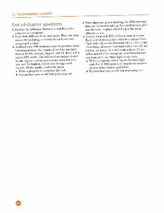
11 PROGRAMMING CONCEPTS
End-of-chapter questions l Explain the difference between a variable and a
constant in a program. 2 State four different basic data types. 11lustrateyour
answer by declaring a variable for each one and assigning it a value.
3 A school with 600 students wants to produce some information from the results of the four standard tests in Maths, Science, English and IT. Each test is out of l 00 marks. The information output should be the highest, lowest and average mark for each ttst and the highest, lowest and average mark O\'erall. All the marks need to be input. a Write: a program to complete: thiis task. b Explain how you would test your program.
4 Write three programs showing the diffe rent ways that can be used to add up five numben and print out the total. Explain which loop is the most
efficic:ntto usc. 5 A sweet shop sells 500 different sorts of sweets.
Each sort of s-,vcct is identified by a unique four· digit code. All sweets that start with a one ( 1) are chocolates, all s-,veets that start "~th a two (2) are
j:1~:s~~l :;~::~~hs:~:::;~i~i~:~;:!3Js :~d can start \\1th any other digit except zero. a Write a program, which inputs the four-digit
code for all 500 items and outputs the number of chocolates, toffeu and jellies.
b Explain how you would test your program .
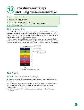
@ Data structures: arrays and using pre-release material
lnthischapteryouwillle.-imabout
e dedaratklnolone-dimensionalarrays e theuseolooe-dimensionalarrays e theuseolavariableasanindexinanarray • reading and 'Miting values in an array using a FOR _ TO ·- NEXT loop e usingpre-releasematerial
12.1 Introduction One of the advantages of using computer systems is their ability to accurately repeat the same tasks many times, for example, producing electricity bills or calculating exam scores. In order to do this, programs are written with loops for repetitions to work with lists of similar items.
These lists are identified by the use of a single name and each item in the list can be found by an index number showing the place in the list. This type of list is called a one-dimensional array. The items in the list are the elements of the array.
Figure12.1Ustorm>e-dimensiooala,,ay
12.2 Arrays
12.2.1 One-dimensional arrays In order to use a one-dimensional array in a computer program, you need to consider:
• what the array is going to be used for, so it can be gi\'en a meaningful name • how many items arc going to be stored, so the size of the array can be
determined • what sort of data is to be stored, so that the array can be the appropriate
data type.
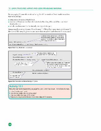
12 DATA STRUCTURES: ARRAYS AND USING PRE-RELEASE MATERIAL
For example, if a one-dimensional array for all the students' test marks in a class was to beset up:
• array name StudentMarkTest • number of items - number of students in the class, this could be a constant
NoStudents • whole numbers need to be stored, data type Integer.
Arrays usually start at element O or element 1. Often if an array starts at clement 0, the size of the array is given as one more than re'luired and clement O is not used.
Figure 12.2Alfif'jdeclaratiooinJavaSc:ript
~:fo':::::::1,:! ~~-e~l=r~t;;I positioo,1 to30them.mberofelements inthea,rayneedstobe31
Array declaration in Python
Listde<larationinPython
Figure 12.30eda@IDnofhstsaodarray;,nl'ylhoo
Activity 12.1 Usingthehigh-lewlprogramminglang\Jilgethatyourschoolhaschosen,lindootaboutarrays
ii ls the first element 1 or07 b Howdoyoudeclarethesizeofan.-may? c Canyoudeclarethetypeol thearr~? d Oeclareanarrayto'>lorethetestmarksloradassol3051udents
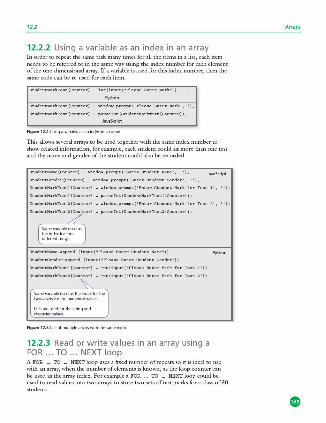
12.2
12.2.2 Using a variable as an index in an array In order to repeat the same task many times for all the items in a list, each item needs to be referred to in the same way using the index number for each element of the one -din1ensional array. !fa variable is used for this index number, then the same code can be re-used for each item.
StudentMarkTeot(Counter] - int(input( "P l eaoe EnterMark")).
Python
StudentMarkTeot(Counter] - winOOW.pro,apt('PleueEnterMark','');
StudentMa rkTeot(Counter] - p,,.uelnt(StudentMarkTeot[Counter));
JavaScript
Figure 12.4Us;ngav,.-iableasanir>dexinana1ray
This allows se\·eral arrays to be used together with the same index number to show related information, for example, each student could sit more than one test and the name and gender of the student could also be recorded.
StudentHa!Ml(Counter] - window.pr~t('EnterStudentHa...,•, JavaScript
StudentGender(Counter] - window.proq,t('EnterStudentGender', '');
StudentMarkTestl(Counter] - window.proq,t(•EnterStudentllarkforTestl',
StudentMarkTeotl(Counte r] - p a r oeint(StudentMarkTeo tl[Counte r]);
StudentMarkTest2(Counter] - window.proq,t{'EnterStudent!larkforTeot2',
StudentMarkTeo t2.7ter] - paroeint(StudentMarkTeot2(Counter]);
r;.:::.::a.:·.:"'_. ;;') l ~ferent,.-,ays J
StudentHa-.append ( input (• Plea0<1 EnterStudentHame"))
StudentGender.append(input("PleaoeEnterStudentGender•))
StudentMarkTeo tl(Counter] - int ( input( • PleaoelmterMarkforTeatl '))
StudentMarkTeot2(Cou~] - int ( input( • Pleaoe lmterMarkforTest2'))
( Sameva,,ablellSl'd. astheindexfor·"'1 1wo,.-,ay,fathem.<nencalvi1h;es
~=:'e,~:,the,tnngand
Figure 12.5Useolmultiple,.-rayswilhthe"'""' index
12.2.3 Read or write values in an array using a FOR ... TO ... NEXT loop
Python
A FOR •. TO ... NEXT loop uses a fixed number of repeats so it is ideal to use with an array, when the number of elements is known, as the loop counter can be used as the array index. For example a FOR ... TO ... NEXT loop could be used to read values into two arrays to store two sets of test marks for a class of 30 students.
Affays
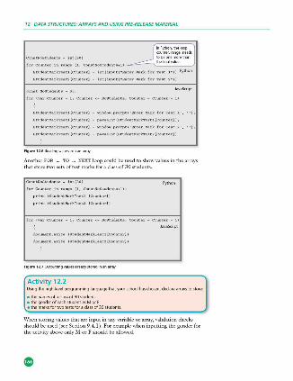
12 DATA STRUCTURES: ARRAYS AND USING PRE-RELEASE MATERIAL
__jt~§~~ for Counter in range (1, Cono tHoStudenta +U,-~-"--'.=-:=---'1
StudentMarkTe•tl[CounterJ - int(input( •EnterMarkforTe•tl')l Python
StudentMark'reat2[CounterJ - int(input('EnterMarkforTe at2'))
JavaS<ript
StudentMark'rea tl[CounterJ - window.proq,t('l!nt e rMarkforTestl',
StudentMark're•tl[CounterJ - paraelnt(StudentMarkTe otl[Counte r)l;
StudentMark'rest2[CounterJ - window.p~t('llnterMarkforTeat2',
StudentMarkTe•t2[CounterJ - p araeint(StudentMarkTeot2[Counter)l
Figu,.12.6Reading valuesintoanan~
Another FOR ... NEXT loop could be used to show \'alues in the arrays that store two sets of test marks for a class of 30 students.
Con a tlloStudent o - int(30)
forCounte rinra nge(l,ConstHoStudents+l),
print(Studentl!arkTe• tl(Counter])
print(Studentl!arkTe• t2 (Counter])
Figu,.12.7 UutputbngvaUesa~eadyslored,nana,;r~
Python
JavaScript
I Activity 12.2 Us.ingthehigh-lewlprogramminglanguagethat"jO.Urschoolhaschosen,dedarearraystostore
e thename1oladassof30students e thegenderofe;ichstudentasMorF e themarbfortwotestsloraclassof301tudents
When storing \'alues that arc input in any \'ariablc or array, \'ll.lidarion checks should be used (sec Section 9.4.1 ). For example when inputting the gender for the acti\'ity abo\'e only M or F should be allowed.
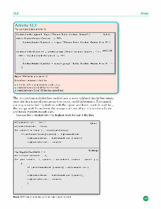
12.2
Activity 12.3 Theexamplesbelowte1tforM
StudentGender.append (input("PleaseEnte rStude ntGende r " )) Python
StudentGender(CounterJ - (input (•Plea oellnte rStude ntGende rMorF" ))
StudentGeniler[CounterJ - winilow.proq,t('llnterStuilentGende r', ''); JavaScript
"hile(StudentGender(Counte r] 1- 'M'l
StudentGender(CounterJ • .,inilo ... pro,apt('llnte rStude ntGende rMorF',
Figur• 12.8 Chec:kinglorgender"M"
Extendyourprogramtotestfor:
e bothMandFinyourstudentgeoderarray e marksbetweenOandSOlorthelir,;ttest e marksbetweenOand 100forthe1econdtest.
The two previous activities ha\·e enabled you to store validated data in four arrays; once this data is stored you can use it to extract useful information. For example you may want to find the students ,vith the highest and lowest mark for each test, the average mark for each test, the average mark overall and the number of male and female students in each class.
You can find a student with the highest mark for test I like this:
llighe• tMarkTe • tl - int(O)
llighe• tlndexTe• tl - int(O)
for Counter in range (l, Con•tNoStudentul),
if StudentMarkTestl(Counter] ~ llighe•tMarkTestl,
HighestMarkTestl - StudentMarkTestl(Counter)
Highe8tlndexTestl - Counter
varHighe• tMarkTestl - 0;
varHighe• tlndexTestl - 0;
if{StudentMarkTeotl[Counter)>HighestMarkTestl)
HighestMarkTestl - StudentMarkTe&tl(Counter);
HighestlndexTestl - Counter;
Figur• 12.9fmdingthestuden\w,thlhe t.,;,est,,..,.-kfortest1
Python
Affays
12 DATA STRUCTURES: ARRAYS AND USING PRE-RELEASE MATERIAL
Activity 12.4 Nowextendyourprogramaslollo=
ii Findthestudentswiththehighestmarksfortestsl and2 b Findthestudentswiththelov,,,estmarksfortestsl and 2. Hint:setyourlowestmarkvariables
to SO and 100. c Findtheaveragemarkloreachtest.Hint:usearunningtotalanddividebythenumberol
students at the end d Find the number of male and female students. Hint: count either males or females and
cakulatetheotherbytakingawayfrom30.
12.3 Using pre-rel ease material In order to answer practical questions based on pre -release material, you will need to practise the skills you ha\·c learnt so far. The pre -release material will arri\·c a few months before your examination; you can discuss it with your teacher and your fellow students.
You need to practise applying your skills to the tasks mentioned in the scenario, which is different for each examination series.
H ere is a check.list of useful things to do.
1 Read through the pre-release material several times. Check \\~th your teacher if there is anything at all that you do not understand.
2 For each task, write an algorithm using both pseudocode and a flowchart to
show what is required. 3 Choose sets of test data that you will need to use, and work out the expected
results. Remember to use normal, boundary and erroneous data. Be able to gi\'c reasons for your choice of test data.
4 Complete trace tables to test your pseudocodc and flowcharts. 1his will enable you to ensure that both the pscudocodc and the flowcharts work properly. It is a good idea to get another srndcnt to trace your algorithms as well.
5 Decide which works best for each task, pseudocodc or a flowchart, and why. 6 Before starting to write your program for each task:
• decide the variables, including any arrays, and constants you will need • decide the data types required for these • decide the meaningful names you will use • be able to explain your decisions.
7 If you arc asked to repeat the same thing many times, for example adding up totals, complete the task for one and check it works before repeating it many times.
8 \Vritc and test each task. You can use the same test data as you used for your pscudocodc and flowcharts.
( Activity 12.5 Work through the diecklist with the pre-release material for your examination )
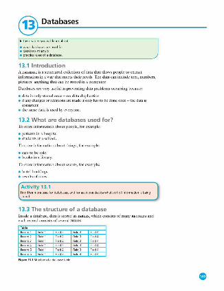
@ Databases
lnthischapteryouwillle.-imabout:
e whatdatabasesareusedlor • database ~tructure e practicalusesoladatabase.
13.1 Introduction A DATABASE is a structured collection of data that allows people to extract information in a way that meets their needs. 111c data can include text, numbers, pictures: anything that can be stored in a computer.
Databases are very usefol in preventing data problems occurring because:
• data is only stored once - no data duplication • if any changes or additions are made it only has to be done once - the data is
consistent • the same data is used by everyone.
13.2 What are databases used for? To store information about people, for example:
• patients in a hospital • students at a school.
To store information about things, for example:
• cars to be sold • books in a library.
To store information about events, for example:
• hotel bookings • resultsofraces.
Activity 13.1 Find fi vemoreuse1fordatabases,andforeachonedecidewhat1ort ofinlormationi1being Coed
13.3 The structure of a database Inside a database, data is stored in TA BLES , which consists of many RECORDS and each record consists of several FI BLDS.
Recotd1 Field l
Recotd2 Field l
Field l
Field l
Recotd5 Field l
Recotd6 Field l
Figur• 13.1 Struct .. e ofadatabasetabie

13 DATABASES
Tables contain data about one type of item, person or event, for example:
• a table of patients • a table of books • a table of doctor's appointments.
Each record within a table contains data about a single item, person or event, for example:
• Winnie Sing (a hospital patient) • !GCSE Computer Science (a book) • the 15:45 apixiintment on 27 January 2014.
Each field contains one specific piece of information about a single item, person or event, forexainple:
• For a hospital patient the fields could include: • first name • family name • date of admission • consultant • ward number • bed number.
• For a book the fields could include: • title • author • ISBN.
( Activity 13.2 Whatlieldswouldyouexpecttolindineachrecordloradoctor'sappointments7 )
In order to be sure that each record can be found easily and to prevent more than one copy of the same record being kept, each record includes a PRIMARY KEY field. Each primary key field in the table is uni'lue.
l'rimarvke Fieldl
l'rimarvke F"'ldl Primary key
Primary key l'rimaryke
l'rimaryke
Figu,. 13.25tructureofadatabasetab!eindtrlngaprimarykey
1l1e primary key can be a field that is already used, provided it is uni'lue, for example the ISBN in the book table, or a new field added to each record, for example, a uni'lue hospital number could be added to each hospital patient's record.
Sometimes, a primary h.-y can be formed by using nvo or more existing fields, for example, the doctor's appointments could have a primary key made from tl1e date and the tin1e of each appoinanent.
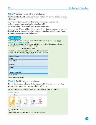
13.4
13.4 Practical use of a database As a Cambridge !GCSE Computer Science student you need to be able to do the following:
• define a single -table database from given data storage requirements • choose a suitable primary key for a database table • perform a query-by-example from given search criteria.
In order to do this you will need to use a relational database management system. The following case study shows how to set up a database with Microsoft Access and complete the tasks described above.
Cfbii@O Boy,;.-mdgirlsbetweentheagesolsevenandelevencanjoinacubscoutgroup. ~ eowikipediaorgfwil::i/CubScout)
Each cub scout group needs to keep records about its members. Most groups will keep the followinginformationabout&Khcubintheirgroup:
Toensu,eot.-rec:o,dsa,euptodate.pleaselilootalloflheinfom>abon beiow. W,thoutacompletedfomi.yoorchild1<illnotbeabletopartidpate
inmeetimpacti,,;ties
Figur•13.3Datacollectionform
13.4.1 Defining a database This section shows you how to define a single-table database from given data storage requirements and choose a suitable primary key.
Tocreatetherubscoutdatabase,openAccess,selecttheBlankdatabasetemplate
J:) 'iWl -o,uo«< .. _
'""""'"' l tmOiot<>
Figur•13.4!llankdatabase
andtypethelileoameCubScoutanddicktheCreatebutton
Practical use o f a da tabase
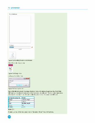
13 DATABASES
Ja,
lJ
FiguN13.5Creatir,gtherubscootdatab.ase
FiguN13.60esignView
andnamethetableCub.
FiguN13.7Namir,glhetable
Setupthelieldstomatc:hthedatacollectionlormandindudetheprimarykey.Eachfield will require a me<mingful name and a data type must be selected. The bas.ic: data types were introduced in Section 11.4. TheyareavailableinAccessbutthe names are different
Acces1alsohasotherdatatype1thatwillbeuseful:Date/TimeandCurrenc:y.
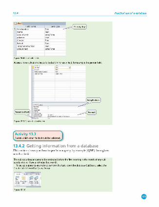
13.4
'i CubNumber Te•! l exl
Oat.1"lype
Date{Trme
Te lephoneNuribe r Te•t Dat e/Time
Figur• 13.8Cubtab!efields
Ac:cessallowsvalidationdieckstobebuiltinforeachlield,lorexamplethegenderlield
::::-=
~ Figur• 13.9Gend<.>rheldvalklatioo
=c.~· ~ ....,,En<oMfo,"'""'"'"''"' '".
Activity 13.3 O!!eidewhidiotherlieldsshouldbe validated.
13.4.2 Getting information from a database This section shows you how to perform a query-by-example (QBE) from given search criteria.
The cub scout leader wants to be reminded before the first me{'ting in the month of any cub scoutswhowillhaveabirthdaythatmonth
Tosetupaquery-by-exampletoperformthistask.openthedatabase CubScout, selectthe Create tab followed by Query Design
Figur• 13.10
Practical use of a database
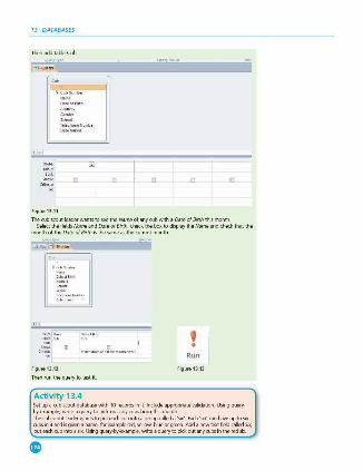
13 DATABASES
Theo add table Cub
Figure 13.11
The cub 'iCOul ledder wants to see the Name of any cub wilh a Date of Birth t his month. Select the fi~ds Name and Date of Birth, check the box to display the Name and check that the
montholtheDilteofBirthisthesamea1thecurrentmonth.
' . Run
Figure 13.12 Figure 13.13
Theorunthequerytotestit
Activity 13.4 Setupacub'iCOutdatabasewith 10recordsinit.lncludeappmpriate validation.Usingqllel)'by-example,writeaquerytopick outanycub1bomthismonth ThecubSCOlltle.lderwantstopute<Khcubintoagroupcalleda's.ix'.Each'lix'canhaveuptosix rub'i in it and isgiwn a name, for example red, yellow, blue or green. Add a newtextlieldcalled5i)(. put&Khrubintoasix.Usingquery-b)'-example,writeaquerytopkkoutanyrub'i intheredsix.

End-of-chapter questions 1 A database of students is to be set up with the following fields:
• Family name • Other names • Student I D • Date ofbirth • Date of entry to school • Currentclass • Current school year/grade • Email address.
a Select a data type for each field. b Which fields should be validated and which fields should be verified? c Decide the validation rules for those fields which should be \'alidated . d Which field would you choose for the primary key? e Choose a suitable format for the student ID. f Build a database with at least 10 records. Include all your validation checks.
Ensure there are at least three different classes and two different years/grades. g Set up and test QBEs to:
i Print Other names, Family name and Email address in alphabetical order of family name
ii Select all the students from a given class iiiSelect all the students for a year/grade and print Other names, Family name
and Data of birth, grouping the students by class.
End-of-chapter questions
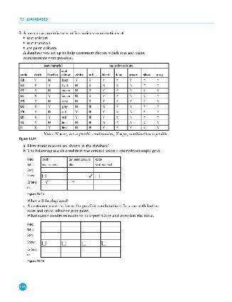
13 DATABASES
2 A motor car manufacturer offers various combinations of • scat colours • scat materials • car paint colours. A database was set up to help customers choose which scat and paint combinations were possible.
car paint colours
Notes: N - no, not t1 p01s1ble combmntwn, Y • yes, combinntwn is pomble. Figure13.14
a How many records arc shown in the database? b The following search condition was entered using a query-by-example grid:
carpa introlours rode
D D ./ D
FigureB.15
What will be displayed? c A customer wants to know the possible combinations for a car with leather
seats and cithcrsikcrorgrcypaint. What search condition needs to be input? Copy and complete the table.
FigureB.16
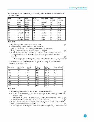
3 A database was set up to compare oil companies. A section of the database is shown below:
employe•
Gazjeti
Wa5fJPetrol
Figure 13.17
Europe
Europe
Profits (billion$)
Share price($)
a H owmanyfieldsarethereineachrecord? (1) b The following search condition was entered:
(No o f countries< 30 ) AND ( H ead office - "Americas") Using Code only, which records would be output? (2)
c What search condition is needed to find out which oil companies ha\'e a share price less than $50 or whose profits were greater than 8 billion dollars? (2)
Cambridge [GCSE Computer Studies 7010/0420 Paper 13 Ql2 June 2013
4 A database was set up to keep track of goods in a shop. A section of the database is shown below:
Figure 13.18
Number in ·-· Pric• of item($)
Value of stock($)
a H ow many records are shown in this section of database? (1) bi Using Item code only, what would be output if the following search was
carried out? (Number in stock < Re-order level ) AND ( Items ordered - "No") (2)
ii What usefol information does this search produce? [ 1] c Write a search condition to locate items costing more than $2.00 or which
ha\·e a stock value exceeding $300.00. (2) Cambridge [GCSE Computer Studies 7010/0420 Paper 13 Q9 November 2013
End-of-chapter questions
Index
A Abiword(wordprocessor),free
software112 acknowledgement 21 ACM(AssociationforComputer
Machinery),codeofethics 110-111
acoustidsoundsensor 62 actuators51,62,71 ADC(analoguetodigitalconverter) 62 additivemanufacturing 69 addressbus45 addresses,incomputermemory 45,47 AdobeReader(freeware) 112 airports,useofscanners 53 alarmapp,forasmartphone 116 algorithms
findingthepurpose118,125 flowcharts 117,118 identifying and correcting errors
127-129 producing 129--131 pseudocodellS,139-141 standardactions 139
ALUarithmeticandlogicunit 47,48 AND gate 26,27
made up of of NAND gates 39 Android 42 anonymoususerprofile 101 anti-lock braking systems 65-66 ARQ(automaticrepeatrequest) 21 arrays
name,sizeanddatatype 163-164 one-dimensional 163-164 readingorwritingvalues 165-167
ASCII code 12,53,58,88 assemblers 93-94 assemblycode,hexadecimal 13 assembly languages 91-92 assignment
inpseudocode134 statements 156
asymmetricencryption 105-107 asynchronousdatatransmission 15-16 audiocompression 77 authentication107
B back-lighting72 back-ups,regular101 barcode
checkdigit122 readers/scanners51,54-56
binary numbers convertingtodenary2-3 converting to hexadecimal 6-7
binder3Dprinting 69 biometrics 108 BIOS(basicinput-outputsystem) 43,82 birefringence86
bit(binarydigit)4 B1u·raydiscs85-86 BMP,rawbitmapimage 78 B0oleanal9ebra 26-29 Boolean variable 136,151 boundary data 119,169 browser
features24 security99,103-104 useofcookies25,100 useofHTML 24 useofJavaScript146,148
buffers43-44,82 burglaralarm,monitoringsystem 64 buses,function45 byte,smallestunitofcomputer
memory 4
C CAD(computeraideddesign)
52,69,70 CASE ... OF ... OTHERWISE ...
ENDCASE 137
cathode-ray monitors 72 CCD(chargecoupledevice) 52 CCFL(cold cathode fluorescent
lamp) 72 CD/DVD storage media 71-72,85,87 CHAR,datatype 150 characterchecks121 checkdigits121,122 checksum 17,21-22,124 OR current instruction register
47,48,49 clothing,'smart' 73 CNCmachining 69 comparison operators 136 compilers 93 computer architecture 45-48 computerethics 110-111 computermemory,sizeandunits 4 computer operation, incorrect 101 computer programs see programs computer systems
components 114 top-down design 114, 115-116
computers,effectonsociety 110 conditionalstatements 135-138 constants149,150 control,useofsensors63,65-66 controlbits15-16 controlbus45 controlunit48 cookies25,100-101 counting139,154-155,158 cracking98 CSS(cascadingstylesheet)file23-24 CT(computedtomography)scanners
S>-54
customerloyaltycards 56 cutters,2Dand3D 51, 71 cyphertext107
D DAC(digitaltoanalogueconverter)
62,71 data
analogueinnature61 location in computer memory 47 lossorcorruption101 safetyandsecurity97 storing 149, 165-167 types150-151,169,172
databits15-16 databus45 datacollectionform 171 dataentry,validationand
verification 120 data transmission
asynchronous 15-16 intemettechnologies 22-25 parallel15 rate4 serial14-15 simplex,half-duplexand
full-duplex14 synchronous16 viaUSB15,16,57,58,59,88
databases creating171-173 defining169,171 searching173-174 structure169-170
decisionsymbols 142 declaration,ofvariablesand
denary(base10)numbers 2 conversion to hexadecimal 8--9 converting to binary 3
denialofserviceattacks108 digital cameras 51,57-58
XDorSD(SecureDigital) cards87
digitallightprojectors(DLP) 74 digitalsignatures107 dongle87 DOS 42 doubleentry124 DRAM (dynamic RAM) 82 dryrun125,127,141,146 DVD-RAM 85
E echocheck22 EEPROM(electronicallyerasable
programmable read-only memory) 84
electroniccircuits26

encryption 104- 108 algorithm 105,106 secure86
erroneous/abnormal data 119, 169
checking 17-22 identifyingal'ldcorrectlng 127- 129 ,,,,., ..
extremedata 120
F F--spot (photograph manager), free
software112 face recognition53,108 fetch-executecycle 49-50 fields,inadatabase169- 170,172 file compression
algorithms 77,80 losslessandlossy77,78,80-81
file formats 76-80 filesize,estimatlng 88--89 fingerprintscans108 firewalls 102 flash memory 87
NANO technology 84 floppydisks87 flow lines 142 flowcharts 114,117, 142- 143, 169 FOR ... TO .. . NEXT loop 137- 138,
16S-167 formatchecks 121 ffeeware 11 2 fulkluplex data transmission 14
G games, on DVO and Blu-<ay 86 gassenSOf"62 gateway 102 gibibyte{GiB) 4 gigabyte(GB) 4
H hacking98 half--duplexdata transmlssion 14 hand•he lddevices, LCD/LEO screens 74 hardwarefault,causlngdatalossor
corruption 101 hashingalgorithms 106,107 HDD(harddlskdrlves) 83
removable 88 size 4
headphones 71 hexadecimal numbers
conversion to binary &-7 conversion todenary 8-9
hexadecimal system notation S-6 uses~13
high·level programming languages 91,93,14&-148
hospital patients databaserecordsl70 monitoring system 63, 64
HTML (hypertext mark-up language) hexadecimalcodes 10-11 and JavaScript 146 structureanclpl"esentation23-24 useforwebi:>a9es 23-25
http (hypertext transfer protocol) 24 https(httpoversecure)24, 103
paclloc.ksymbol 24, 99,103
I IDE(integrated/interactive
development environment) 95, 147,148
IEC(lnternationalElectrotechnical Commission)convention 4
IEEE(lnstituteofElectricaland Electronics Engineers),codeof ethics110-111
IF ... THEN ... ELSE ... ENDIF 135---136 ifstatements 156 Index number 163,165 infra-redsensor62 lnkjetprinters67,68 lnputdevices48,51 inputstatements 13g,156 inputloutputdevices,supermarket
checkouts55---56 input/output statements 139 inputloutputsymbols 142 integers 150,15 1, 152 intellectualpropertyrights110 interactive whiteboards 51, 66-67 internet technologies, data
transmission 22-25 interpreters93 interrupthandler43 interrupts43-44 IP(intemetprotocol)address
22- 23,25 ISBN (International Standard Book
Numbers),checkdigits 122-123 ISP(internetservice provider)22
denialofserviceattacks108
JavaScript arrays164,165,166,167 datatypes150-151 declarationofvariablesand
constants 149 display147,152 ex.ample program 159,160 loops158 repetition program 155,156, 158 selection program 153, 154, 156 works in a browser 146,148
JpegOolntPhotographk Experts Group)files 52, 53, 78-79
K keydistributlonproblem 104 key-logging software 100, 110 keyboard
ASCllchMacteu 12,58,88 as input device 48, 58 MIDI files 7&-77 vi rtual58
kibibyte {KIB) 4 kllobyte(KB)4
LAA (locally administered MAC address)11
laserprlnters68
Index
latency83,84 LCO(llquld crystaldisplay)technology
72,74,75 LCD/LEO monitors 51, 72- 74 LEO(llghtemlttlngdlode)
technology72 lengthchecks 121 libraries, barcodesystem 56 libraryroutlnes114,117- 118 lightprojectors(LCOandDLP)
66,74,75 light sensor 62 Linux 42 lists, Importance In programming 163 logic circuits
designing 33-35, 38 In puts and outputs 2&-29 off-the-shelf components 29, 39--40 lntherealworld 38-42 w fetyfunctlon35---3S simplifying 39,40-41 truthtables29-38
logicerror94 logic gates 26, 27-29 loo,,
structures137 types 157
loudspeakers51,71 low-level languages 91-92
M MAC(medlaaccesscontrol)addresses
11- 12,23 machlne code 13,92 magnetlcfleldsensor 62,65 magnetlcstoragesystems 83,84 manufacturing.subtractive 69 MAR memory address register 47-48 mathematkalfunctlons.stanclard
solutlom 119 M04 hashing algorithm 106, 107 MOR memory data register 47-48
INDEX
mebibyte(MiB) 4 megabyte(MB) 4 memory
devicesandmedia 81-88 primary 81-83 refreshing82
memory cache 82 memory cards 87 memory dumps 9-10 memory unit 47--48 microphones 51,59 microprocessors,embedded 43 MicrosoftAccess 171 MIDI (Musical Instrument Digital
lnterface)files76-77 mobile devices
cameras 58 flexible73 securityrisks113 touchscreentechnologies61
moisture/humidity sensor 62 monitorin9,useofsensors 63-64 motion sensor 62 mouse 51,58 movies
onDVDandBlu-ray 86 streaming 86
MPEG-3 (MP3) and MPEG-4 (MP4) files 77-78
MRl(magneticresonance imaging) 54
multimedia files, MPEG-4 (MP4) format 77
N
devicesandstoragesystems 86 MP3fileformat 77 streaming 86
NANDtechnology 26,28 as'buildingblock'39-40 insolid-statedevices84,87
nestedlF136 NIC(networkinterfacecard) 11
NOR chips 84 NOR gate 26,28 normal data 119,169 NOT gate 26,27
made up of NAND gates 39 number formats 80
0 off-linestorage84-88 OLED(organiclightemittingdiode)
72-73 onlinebanking,security109-110 opticalcharacterrecognition(OCR)
52,53 optical storage systems 85-86
OR gate 26,28 madeupofNANDgates 39
OS(operatingsystem) 42-43 output.statements 139,156 output devices 48,51,67-75
p padlocksymbol(https) 24,99, 103 parallel data transmission 15 parity,even and odd 17- 18 paritybit17 parity blocks 19 paritybyte19 paritycheck17-21,124 partitions,addressandcontents 47 Pascal/Delphi146 passwords
foranalarmsystem 64 authentication107 control102 forl5Paccount22 lengthcheck121 forpersonalbanking109-110 strong98 theft98,100 anduserid101
PCprogramcounter 47,48,49 pendrives87 perceptualmusicshaping 77 petabyte(PB)4 pH sensor 62 pharming 99 phishing99 photographic files
compression 78 wirelesstransfer 57
PIN,four<ligit109 piracy and copyright infringement,
preventing86,87 pitchbyte,in MIDI files 76 pixels78,88-89 plagiarism 110 plaintext,unencrypted107 pointing devices 51, 58--59 P05(pointofsale)terminal 56 pre-releasematerial,writingand
testing algorithms 169 presencechecks121 pressuresensor62 primarykeyfield 170,171 PRINT,output statement 139 printers51,67,68
3D 69-70 privacyissues110
see a/so security processsymbols 142 processor48 productcodes,checkdigits122 programming languages
90-92,146
programs definition and uses 90-91 examples 90,159 testing160-161
projectors see light projectors protocols18 proxyservers102-103 pseudocode114,117,126,
139-141,169 assignment 134-135 consistentpresentation134 operators134
publickeyencryption105-107 Python programming language 91,
146-147
Q
declaration of va riables and constants149-151
display147 example program 1S9, 160 IDE 95,147 listsandarrays164,165,166,167 loops158 program testing 160-161 repetition154-155,157,158 selection153
QBE(query-by-example) 173 QR(quickresponse)
R
code57 codereader51
RAM (random access memory) 81-82,83
rangechecks121 rawbitmapimage,TIFForBMP 78 READoperation 47 real numbers 150 records,inadatabase169-170 registers4-5,45,47 relational database management
system 171 REPEAT ... UNTIL loop structure
137,138 repetition157-158
program 154-156 repetitivestraininjury(RS1)58 resolution78
ROM (read only memory) 82, 83
running total 139,159
s safetysystem,logiccircuit 35-38 sampling rate 71 scanners51
2D 51-52,53 3D 52

Scratch programming language 146-147
declarationofvariables90,149 IDE 90,148
screenlvisualcheck124 Scribus(DTP),freesoftware 111 searching,libraryroutines118 security
anddataintegrity97-98 denialofserviceattacks 108 protocols103-104 risks98--100 useofpersonalquestions110
selection 153,157 sensors51,61--63 sequence,importance 157 sequencersoftware77 serialdatatransmission 14--15 sessioncaching104 shareware 112- 113 simplexdatatransmission 14 Skype(freeware) 112 software
onCDsandDVDs 86 development 9--10,13 fault101 free111 - 112
solenoid62 solid-state storage
offline84 requirescarefulhandling87
solution.effectiveness 131 sorting,libraryroutines 118 source code
editing98 infreewareandshareware 112
SPECT(singlephotonemission computed tomography) 54
speechrecognitionsystem5~0 spreadsheetfile,losslesscompression 80 spyware 100,110 SRAM (static RAM) 82 SSD(solid-statedrives) 84 SSL(securesocketslayer)103 standardactions,inalgorithm
design139 statements.order 157 statusbyte,inMIDlfiles 76
stepwiserefinement 116 stockcontrol,automatic 56 storage
media 81-88 secondary83-84
storagemedia,obsolescence 86-87 streetlighting,control65 STRINGtypevariableorconstant 150 structurediagrams 114,116 sub-routines 114,117,118 sub-systems 114,115,116,119 supermarkets,computerapplications
55---56,139,159 symmetricencryption 104--105 synchronousdatatransmission 16 syntaxerrors94,146
T tables,inadatabase169-170 tags, in HTML 10,23 tebibyte(TiB)4 temperature sensor 62 terabyte(TB)4 terminatorsymbols 142 testdata119--120,140,169 text,ASCllformat 80 text files
filecompression 80 formats 52,80
TIFF,rawbitmapimage 78 timeout 21 tomography 53-54 top-down design 114, 115--116 totalling 154-155, 159 touchpad,on laptop computers 58 touchscreentechnology 51, 58,61 tracetables12S-127 trackerball58--59 translator programs 92-94 transportlayersecurity(TLS)103- 104 truthtables26-29
forlogiccircuits29--38 TVs,'smart' 86 typechecks121
u UAA (universally administered MAC
address)11
Index
uniformresourcelocatorseeURL universalserialbusseeUSB UNIX 42 URL(uniformresourcelocator)
hexadecimal 13 1Paddress23 parts25 stored in QR code 57
USB(universalserialbus) data transmission method 15, 16,
57,58,S9,88 flash memories 81,84,87
user id/name 22,98,101,107
V validation
ofinput166 methods 120--124 inMicrosoftAccess 173 typesofchecks121
variable asanindexinanarray165 inacomputerprogram 149
velocitybyte,in MIDI files 76 verification124 VIN(vehicleidentificationnumber),
checkdigit122 viruses98 Visual Basic 146 voicerecognition5~0,108 vonNeumannarchitecture 45-46
w wardriving 100 web address see URL web browser see browser WEP(wiredequivalentprivacy)
encryption 100 WHILE ... DO ... ENDWHILE loop
structure137,138 Windows 42-43 wireless,passwordprotection 100 WRITE operation 47
X XOR gate 26,29