Building Mega Data Center from Heterogeneous Containers
10
Building Mega Data Center from Heterogeneous Containers Dan Li * , Mingwei Xu * , Hongze Zhao * , Xiaoming Fu † * Computer Science Department of Tsinghua University † Georg-August-University of Goettingen {tolidan,xmw}tsinghua.edu.cn, [email protected], [email protected] Abstract—Data center containers are regarded as the basic units to build mega data centers. In practice, heterogeneity exists among data center containers, because of technical innovation and vendor diversity. In this paper, we propose uFix, a scalable, flexible and modularized network architecture to interconnect heterogeneous data center containers. The inter-container con- nection rule in uFix is designed in such a way that it can flexibly scale to a huge number of servers with stable server/switch hardware settings. uFix allows modularized and fault-tolerant routing by completely decoupling inter-container routing from intra-container routing. We implement a software-based uFix stack on the Linux platform. Simulation and experiment results show that uFix enjoys high network capacity, gracefully handles server/switch failures, and brings light-weight CPU overhead onto data center servers. I. I NTRODUCTION Data center runs applications from on-line services such as Web mail, Web search, on-line games, to back-end infrastruc- tural computations including distributed file systems [1], [2], structured storage [3] and distributed execution engine [2], [4], [5]. Nowadays, companies or organizations build mega data centers containing tens of thousands of, or even hundreds of thousands of servers [6], [7]. The role of a data center network (DCN) is to interconnect a massive number of data center servers, and provide routing to upper-layer applications. A desired DCN architecture should have high scalability, high fault tolerance, rich network capacity, and low deployment cost. It has been observed that the tree architecture used in current data centers suffers from the problems of low bisec- tion bandwidth, poor scalability and single failure point [8], [11]. Consequently, in recent years there has been a growing interest in the community to design new DCN architectures. These efforts can be roughly divided into two categories. The first category is switch-centric, which puts primary network intelligence onto switches. Specifically, either a Clos network is designed to replace the Tree hierarchy of switches, such as in PortLand [12] and VL2 [13], or shortcut links are added on the tree to enhance the network capacity [14], [15]. In contrast, the second category is server-centric, which leverages the rapid growth of server hardware such as multi-core CPU The work is supported by the National Basic Research Program of China (973 Program) under Grant 2011CB302900 and 2009CB320501, and the National Natural Science Foundation of China (No.61170291, No.61133006). and multiple NIC ports to put the interconnection and routing intelligence onto servers. Switches are simply used as dummy crossbars or even completely eliminated. The latter category of architectures include DCell [8], FiConn [9], BCube [10], MDCube [18]. Containerized data centers are regarded as the basic units for building modern mega data centers. A containerized data center packs 1k∼4k servers as well as switches into a standard 20- or 40-feet shipping container. The container environment has the advantages in easy wiring, low cooling cost, high power density, etc. [10], [18]. In practice, heterogeneity can widely exist among data center containers. First, hardware innovation is rapid. It has been shown that data center owners usually incrementally purchase servers quarterly or yearly [16] to accommodate the service expansion. Hence, it is common that the containers bought at different times hold servers and switches with different hardware profiles. The heterogeneity can lie in the CPU capability, the memory space, the number of ports, etc. Second, there are a wide range of network architec- tures to build the data center containers. The containers bought from different vendors can use different network architectures for server connection inside. In this paper, we propose uFix, a scalable, flexible, and modularized network architecture to interconnect heteroge- neous data center containers. uFix requires that each server in containers reserves a NIC port for inter-container connection. Instead of using any strictly structured topology, the container interconnection in uFix is conducted in a flexible manner, so as to benefit smoothly incremental deployment of mega data centers. The connection rule is designed in such a way that with the growth of server population, we do not need to add any additional server hardware or switches, and there is no rewiring cost. uFix provides modularized and fault-tolerant routing to accommodate the interconnection topology. The uFix inter- container routing module is completely decoupled from the intra-container routing modules. Only light overhead is neces- sary for routing signaling and failure handling. The advantages of uFix routing scheme are twofold. First, data center owners can buy uFix containers from different vendors without modi- fying the intra-container routing modules. Second, the one-fit- all inter-container routing can be loaded onto servers without knowing the details of intra-container routing schemes.
-
Upload
khangminh22 -
Category
Documents
-
view
1 -
download
0
Transcript of Building Mega Data Center from Heterogeneous Containers

Building Mega Data Center from HeterogeneousContainers
Dan Li∗, Mingwei Xu∗, Hongze Zhao∗, Xiaoming Fu†
∗Computer Science Department of Tsinghua University †Georg-August-University of Goettingen{tolidan,xmw}tsinghua.edu.cn, [email protected], [email protected]
Abstract—Data center containers are regarded as the basicunits to build mega data centers. In practice, heterogeneity existsamong data center containers, because of technical innovationand vendor diversity. In this paper, we propose uFix, a scalable,flexible and modularized network architecture to interconnectheterogeneous data center containers. The inter-container con-nection rule in uFix is designed in such a way that it can flexiblyscale to a huge number of servers with stable server/switchhardware settings. uFix allows modularized and fault-tolerantrouting by completely decoupling inter-container routing fromintra-container routing. We implement a software-based uFixstack on the Linux platform. Simulation and experiment resultsshow that uFix enjoys high network capacity, gracefully handlesserver/switch failures, and brings light-weight CPU overheadonto data center servers.
I. INTRODUCTION
Data center runs applications from on-line services such asWeb mail, Web search, on-line games, to back-end infrastruc-tural computations including distributed file systems [1], [2],structured storage [3] and distributed execution engine [2], [4],[5]. Nowadays, companies or organizations build mega datacenters containing tens of thousands of, or even hundreds ofthousands of servers [6], [7]. The role of a data center network(DCN) is to interconnect a massive number of data centerservers, and provide routing to upper-layer applications. Adesired DCN architecture should have high scalability, highfault tolerance, rich network capacity, and low deploymentcost.
It has been observed that the tree architecture used incurrent data centers suffers from the problems of low bisec-tion bandwidth, poor scalability and single failure point [8],[11]. Consequently, in recent years there has been a growinginterest in the community to design new DCN architectures.These efforts can be roughly divided into two categories. Thefirst category is switch-centric, which puts primary networkintelligence onto switches. Specifically, either a Clos networkis designed to replace the Tree hierarchy of switches, such asin PortLand [12] and VL2 [13], or shortcut links are addedon the tree to enhance the network capacity [14], [15]. Incontrast, the second category is server-centric, which leveragesthe rapid growth of server hardware such as multi-core CPU
The work is supported by the National Basic Research Program of China(973 Program) under Grant 2011CB302900 and 2009CB320501, and theNational Natural Science Foundation of China (No.61170291, No.61133006).
and multiple NIC ports to put the interconnection and routingintelligence onto servers. Switches are simply used as dummycrossbars or even completely eliminated. The latter categoryof architectures include DCell [8], FiConn [9], BCube [10],MDCube [18].
Containerized data centers are regarded as the basic unitsfor building modern mega data centers. A containerized datacenter packs 1k∼4k servers as well as switches into a standard20- or 40-feet shipping container. The container environmenthas the advantages in easy wiring, low cooling cost, highpower density, etc. [10], [18]. In practice, heterogeneity canwidely exist among data center containers. First, hardwareinnovation is rapid. It has been shown that data center ownersusually incrementally purchase servers quarterly or yearly [16]to accommodate the service expansion. Hence, it is commonthat the containers bought at different times hold servers andswitches with different hardware profiles. The heterogeneitycan lie in the CPU capability, the memory space, the number ofports, etc. Second, there are a wide range of network architec-tures to build the data center containers. The containers boughtfrom different vendors can use different network architecturesfor server connection inside.
In this paper, we propose uFix, a scalable, flexible, andmodularized network architecture to interconnect heteroge-neous data center containers. uFix requires that each server incontainers reserves a NIC port for inter-container connection.Instead of using any strictly structured topology, the containerinterconnection in uFix is conducted in a flexible manner, soas to benefit smoothly incremental deployment of mega datacenters. The connection rule is designed in such a way thatwith the growth of server population, we do not need to addany additional server hardware or switches, and there is norewiring cost.
uFix provides modularized and fault-tolerant routing toaccommodate the interconnection topology. The uFix inter-container routing module is completely decoupled from theintra-container routing modules. Only light overhead is neces-sary for routing signaling and failure handling. The advantagesof uFix routing scheme are twofold. First, data center ownerscan buy uFix containers from different vendors without modi-fying the intra-container routing modules. Second, the one-fit-all inter-container routing can be loaded onto servers withoutknowing the details of intra-container routing schemes.

Fig. 1. A Fat-Tree architecture with 16 servers. It has three levels of 4-portswitches.
We implement a software-based uFix stack on the Linuxplatform. By large-scale simulations and real experiments ona test bed, we find that uFix enjoys high network capacity byits interconnection rule, gracefully responds to server/switchfailures, and adds little forwarding overhead to data centerservers.
The rest of this paper is organized as follows. Section IIdiscusses the related work and design goal of uFix. Section IIIpresents the interconnection rule of uFix. Section IV designsuFix routing and forwarding schemes. Section V describes theuFix implementation and evaluation. Section VI concludes thewhole paper.
II. RELATED WORK AND DESIGN GOAL
In this section, we introduce the related proposals on DCNarchitecture design, and discuss the design goals of uFix.
A. Related Work
As mentioned in the previous section, recently proposedDCN architectures can be divided into two categories, namely,switch-centric and server-centric. The former puts the inter-connection and routing intelligence on switches, while thelatter brings data center servers into the networking part andgets them involved in packet forwarding.
1) Switch-Centric Architecture: The switch-centric archi-tecture proposals either use a totally new switch infrastructureto replace the tree structure, or make enhancements upon thetree to improve the bisection bandwidth. PortLand [12] (Fig. 1)and VL2 [13] (Fig. 2) both use low-end, commodity switchesto form a three-layer Fat-Tree architecture. Each server stilluses one NIC port to connect an edge-level switch. The Fat-Tree infrastructure [11], which is in fact a Clos network, canprovide 1:1 oversubscription ratio to all servers in the network.The difference of VL2 from PortLand is that higher-speedswitches, e.g., those with 10GE ports, are used in higher levelsof the Clos network to reduce the wiring complexity.
Instead of completely giving up the traditional tree archi-tecture, the tree enhancement approaches add shortcut linksbesides the Tree links, either by 60Gbps wireless link [14], orby reconfigurable optical circuits [15]. The reasoning behindis that the full bisection bandwidth provided in many advancedDCN architectures is usually an overkill for mega data centers,since it is not actually required in the scale of entire datacenter.
Fig. 2. A VL2 architecture with 16 servers. 10Gb switches are used in thetop two levels.
2) Server-Centric Architecture: In server-centric DCN ar-chitectures, a server uses multiple NIC ports to join thenetworking infrastructure and participates in packet forward-ing. As demonstrated in Fig. 3, in DCell [8], a recursive,level-based structure is designed to connect servers via mini-switches and multiple server ports. DCell is highlighted byits excellent scalability, i.e., the number of servers supportedincreases double-exponentially with the number of server NICports. FiConn [9] goes one step further to limit the numberof server NIC ports as two, since most of current data centerservers have two built-in ports. The architecture is shown inFig. 4. Compared with DCell, FiConn not only eliminates thenecessity to add server NIC ports during data center expansion,but also reduces the wiring cost. The downside is that thenetwork capacity in FiConn is lower than DCell, and thenumber of server NIC ports is restricted to two.
Fig. 3. A DCell(4,1) architecture with 20 servers.
Fig. 4. A FiConn(4,2) architecture with 12 servers.
BCube [10] targets at building a data center container,typically with 1k∼4k servers. BCube is also a recursivestructure, which is shown in Fig. 5. Each server uses multipleports to connect different levels of switches. The link resourcein BCube is so rich that 1:1 oversubscription ratio is guar-anteed. MDCube [18] designs an architecture to interconnect

the BCube-based containers, as shown in Fig. 6. The inter-container connection and routing in MDCube are closelycoupled with the intra-container architecture, so as to providehigh bisection width and great fault tolerance.
Fig. 5. A BCube(4,1) architecture with 16 servers.
Fig. 6. An MDCube architecture with 36 servers.
B. Design Goals of uFixIt is envisioned that future mega data center is composed of
data center containers, because of the multi-facet advantagesof containerized data centers, including easier wiring, lowercooling cost, higher power density, etc [10], [18]. Data centercontainers are purchased periodically to accommodate theservice expansion. Due to the hardware innovation and vendordiversity, it is common that containers are heterogeneous, interms of both the server hardware configuration and the intra-container topology.
In this paper, we discuss how to build mega data centersfrom heterogeneous containers. We have the following designgoals for the uFix architecture.
Scalable Interconnection of Heterogeneous Data CenterContainers: uFix is designed for a mega data center, whichis expected to be composed of a large number of heteroge-neous containers. Note that after a data center container issealed, the hardware configurations on servers and switchesare relatively fixed. When the data center scales up, the datacenter owners are reluctant to open the containers and changethe server/switch hardware settings, such as adding NIC portsor CPU cores. For inter-container connection, a number ofNIC ports (from servers or switches) are exposed outside forwiring. Hence, uFix is expected to expand to large scale withstable physical settings on servers/switches in containers.
Support for Incremental Server Expansion: The datacenter size is usually incrementally expanded to accommodateservice growth. Though strictly structured topologies can pro-vide high network performance by fully leveraging the serv-er/switch configurations, they usually cannot smoothly handleincremental growth of data center scale. For example, the Fat-Tree structure composed of k-port switches can achieve 1:1oversubscription ratio when the number of servers is k3
4 . Butif the number of servers marginally exceeds this magic value,it is still an open issue how to connect them with networkperformance guarantee. In uFix, since the interconnection unitsare containers, we need to pay special attention to gracefullyembracing server expansion.
Decoupling Inter-container Architecture from Intra-container Architecture: We expect that data center ownerswill purchase containers at different times from differentvendors. Due to the rapid technical innovation, various inter-connection topologies and routing schemes can be used withinthese containers. An inter-container interconnection architec-ture will be operationally expensive if it needs to accommodatethe specific intra-container structures and routings. It is desir-able if a solution can regard every container as a black box, andcompletely decouple inter-container architecture from intra-container architectures. This kind of generic inter-containerarchitecture not only makes container interconnection easy, butalso benefits the independent development of intra-containertechnologies.
No existing DCN architectures can achieve all the designgoals above, since they focus on optimizing a homogeneous setof servers, by assuming that each server uses the same numberof NIC ports for interconnection and bears almost equivalentforwarding burden. The most related architecture with uFix isMDCube. However, the containers connected in MDCube areall BCube containers, and the inter-container architecture isclosely coupled with the intra-container BCube architecture.
III. UFIX INTERCONNECTION
In this section, we discuss how uFix connects the heteroge-neous data center containers to form mega data centers.
A. Interconnection Overview
A containerized data center packs servers and switchesinto a standard 20- or 40-feet shipping container, and offersnetworking, power, and cooling services to them. The serversinside a container, with a typical size of 1k∼4k, are usuallyhomogeneous so as to conduct easy interconnection whenmanufactured. Note that a specific network architecture usuallymatches certain server configuration. For example, server-centric data center architectures often require multiple NICports for interconnection, as well as high CPU capacity forservers to participate in packet forwarding. But for switch-centric architectures, the requirement on server hardware isrelatively low. Hence, if the servers have more than 4 ports andstrong CPU, BCube is a nice choice to achieve full bisectionbandwidth within the container. As for servers with limitedCPU capacity and NIC ports, tree or Fat-Tree can be used.

Fig. 7. A level-1 uFix domain constructed upon three containers. Container0 uses a Tree structure composed of 8 servers, Container 1 is a DCell1 with6 servers, and Container 2 is a FiConn1 with 12 servers. There are in total 5level-1 uFix links connecting the 3 uFix containers.
One possible way for interconnecting containers is to useexisting structured topologies such as Fat-Tree or BCube,treating each container as a unit. However, the aggregatebandwidth within a container is very large, and this kindof interconnection will make the inter-container bandwidthquite low, even using higher-speed switches for inter-containerconnection. Besides, this kind of interconnection requires addi-tional switches and brings in significant hardware investment.
Therefore, we turn to directly interconnecting the containersby the devices inside the containers. There are two designchoices, namely, switch based connection and server basedconnection. We choose server based interconnection for tworeasons. First, we can leverage the increasing NIC port densityon servers for network connection [10], [9], and do not requireadditional switches. Second, it is much easier to program onservers to load inter-container intelligence, especially becauselow-end switches are commonly used in current data centerdesign. Note that we can use the forwarding engine suchas ServerSwitch [19] on servers to offload the forwardingoverhead on server CPU.
In order to accomplish server based interconnection in uFix,it is required that in each container, a number (at least 2) ofservers with available NIC ports are reserved. We call theseservers uFix proxy candidates. Note that each uFix proxycandidate only needs to reserve one NIC port. If uFix iswidely accepted in future, this requirement can be regarded asa standard for manufacturing data center containers. The NICport reserved in the uFix proxy candidate for inter-containerconnection is called a uFix port, while the other ports on theserver are called container-specific ports.
B. Interconnection Algorithm
There are two challenges for inter-container connection inuFix. First, the server settings in a container are relativelystable after the container is manufactured, thus we need to
scale uFix with fixed uFix ports in a container. Second, it isdesirable for uFix to gracefully support incremental expansionof data center size. In other words, uFix data center can begradually built up in fine granularity, without breaking theinterconnection rule. It is difficult to use previously proposedstrictly structured topologies to achieve this goal.
We interconnect containers in uFix in a flexible way. Weiteratively define a level-l uFix domain as follows.
• A level-0 uFix domain is a container.• A level-l (l > 0) uFix domain comprises a number of
lower-level uFix domains, with the highest level of l−1.The process of connecting lower-level uFix domains to form
a level-l uFix domain is called a level-l uFix interconnection.The new links added during level-l uFix interconnection arecalled level-l uFix links. A server with a level-l uFix linkis called a level-l uFix proxy. For a level-l uFix proxy, thehighest-level uFix domain it belongs to before the level-luFix interconnection is called the designated domain of thelevel-l uFix proxy. Note that each uFix proxy has only onedesignated domain, but multiple uFix proxies can share thesame designated domain.
Now we describe the procedure of a level-l uFix intercon-nection. There are m lower-level uFix domains to connect,which we call pre-connecting uFix domains. They are denotedsequentially from 0 to m − 1, and the highest level amongthem is l − 1 (l > 0). Generally speaking, the new level-l uFix domain is formed by directly connecting part of theuFix proxy candidates in the m pre-connecting uFix domains.Suppose the total number of uFix proxy candidates in pre-connecting uFix domain i (0 ≤ i < m) is xi, and the numberof uFix proxy candidates in uFix domain i used for level-l uFix interconnection is ui (ui ≤ xi). We define level-luFix interconnection degree as g =
∑m−1i=0 ui∑m−1i=0 xi
. There are tworequirements.
m−1∑i=0
xi −m−1∑i=0
ui ≥ 2 (1)
ui ≥ m− 1, for any i (2)
Inequation (1) aims for higher-level extensibility of theresultant level-l uFix domain, for which we reserve at least twouFix proxy candidates. Hence, during the expansion of uFixscale, no additional server-side hardware, additional switches,or rewiring is required. It not only saves the building costof data centers, but also makes incremental deployment mucheasier. Inequation (2) guarantees that the pre-connecting uFixdomains can be connected as an intensive mesh if every uFixdomain is regarded as a virtual node. Here the intensive meshindicates that there is at least one level-l uFix link betweenevery two pre-connecting uFix domains. In this way, we canwell control the diameter of the resultant level-l uFix domain.If Inequation (2) cannot be satisfied, the m pre-connectinguFix domains will not be connected in the same level. Instead,a hierarchical solution is used. Note that each uFix proxy
candidate server will be used only once during the inter-container connection process, since it reserves only one NICport.
We can see a tradeoff for the setting of a level-l uFixinterconnection degree. On one hand, higher degree meansmore level-l uFix links, which brings greater inter-domainnetworking capacity and better fault tolerance in the resultantlevel-l uFix domain. On the other hand, smaller degree leavesmore uFix ports in the resultant level-l uFix domain forhigher-level interconnection. The data center owner has theflexibility to set the tradeoff by taking the wiring complexity,the inter-domain network capacity as well as the extensibilityfor higher-level connection into account.
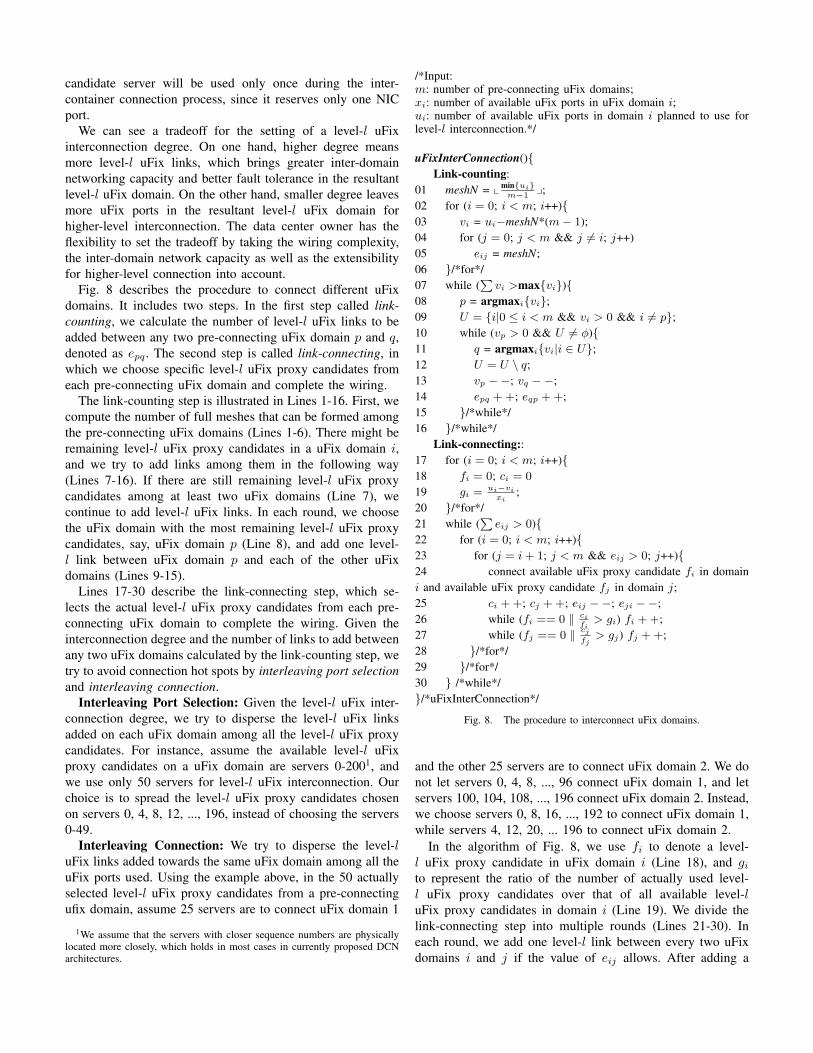
Fig. 8 describes the procedure to connect different uFixdomains. It includes two steps. In the first step called link-counting, we calculate the number of level-l uFix links to beadded between any two pre-connecting uFix domain p and q,denoted as epq . The second step is called link-connecting, inwhich we choose specific level-l uFix proxy candidates fromeach pre-connecting uFix domain and complete the wiring.
The link-counting step is illustrated in Lines 1-16. First, wecompute the number of full meshes that can be formed amongthe pre-connecting uFix domains (Lines 1-6). There might beremaining level-l uFix proxy candidates in a uFix domain i,and we try to add links among them in the following way(Lines 7-16). If there are still remaining level-l uFix proxycandidates among at least two uFix domains (Line 7), wecontinue to add level-l uFix links. In each round, we choosethe uFix domain with the most remaining level-l uFix proxycandidates, say, uFix domain p (Line 8), and add one level-l link between uFix domain p and each of the other uFixdomains (Lines 9-15).
Lines 17-30 describe the link-connecting step, which se-lects the actual level-l uFix proxy candidates from each pre-connecting uFix domain to complete the wiring. Given theinterconnection degree and the number of links to add betweenany two uFix domains calculated by the link-counting step, wetry to avoid connection hot spots by interleaving port selectionand interleaving connection.
Interleaving Port Selection: Given the level-l uFix inter-connection degree, we try to disperse the level-l uFix linksadded on each uFix domain among all the level-l uFix proxycandidates. For instance, assume the available level-l uFixproxy candidates on a uFix domain are servers 0-2001, andwe use only 50 servers for level-l uFix interconnection. Ourchoice is to spread the level-l uFix proxy candidates chosenon servers 0, 4, 8, 12, ..., 196, instead of choosing the servers0-49.
Interleaving Connection: We try to disperse the level-luFix links added towards the same uFix domain among all theuFix ports used. Using the example above, in the 50 actuallyselected level-l uFix proxy candidates from a pre-connectingufix domain, assume 25 servers are to connect uFix domain 1
1We assume that the servers with closer sequence numbers are physicallylocated more closely, which holds in most cases in currently proposed DCNarchitectures.
/*Input:m: number of pre-connecting uFix domains;xi: number of available uFix ports in uFix domain i;ui: number of available uFix ports in domain i planned to use forlevel-l interconnection.*/
uFixInterConnection(){Link-counting:
01 meshN = xmin{ui}m−1
y;02 for (i = 0; i < m; i++){03 vi = ui−meshN*(m− 1);04 for (j = 0; j < m && j ̸= i; j++)05 eij = meshN;06 }/*for*/07 while (
∑vi >max{vi}){
08 p = argmaxi{vi};09 U = {i|0 ≤ i < m && vi > 0 && i ̸= p};10 while (vp > 0 && U ̸= ϕ){11 q = argmaxi{vi|i ∈ U};12 U = U \ q;13 vp −−; vq −−;14 epq ++; eqp ++;15 }/*while*/16 }/*while*/
Link-connecting::17 for (i = 0; i < m; i++){18 fi = 0; ci = 0
19 gi =ui−vi
xi;
20 }/*for*/21 while (
∑eij > 0){
22 for (i = 0; i < m; i++){23 for (j = i+ 1; j < m && eij > 0; j++){24 connect available uFix proxy candidate fi in domaini and available uFix proxy candidate fj in domain j;25 ci ++; cj ++; eij −−; eji −−;26 while (fi == 0 ∥ ci
fi> gi) fi ++;
27 while (fj == 0 ∥ cjfj
> gj) fj ++;28 }/*for*/29 }/*for*/30 } /*while*/}/*uFixInterConnection*/
Fig. 8. The procedure to interconnect uFix domains.
and the other 25 servers are to connect uFix domain 2. We donot let servers 0, 4, 8, ..., 96 connect uFix domain 1, and letservers 100, 104, 108, ..., 196 connect uFix domain 2. Instead,we choose servers 0, 8, 16, ..., 192 to connect uFix domain 1,while servers 4, 12, 20, ... 196 to connect uFix domain 2.
In the algorithm of Fig. 8, we use fi to denote a level-l uFix proxy candidate in uFix domain i (Line 18), and gito represent the ratio of the number of actually used level-l uFix proxy candidates over that of all available level-luFix proxy candidates in domain i (Line 19). We divide thelink-connecting step into multiple rounds (Lines 21-30). Ineach round, we add one level-l link between every two uFixdomains i and j if the value of eij allows. After adding a

level-l link in a uFix domain i, we may skip a number of nextavailable level-l uFix proxy candidates based on the value ofgi (Lines 26-27).
Network Diameter: The primary limitation on the growthof server population in uFix comes from the network diameter,which is required to be low for sake of end-to-end delayrequirement of data center applications.
Theorem 1: If the highest diameter of a container is d0, thediameter of a level-l uFix domain, dl, is upper-bounded byd0 ∗ 2l + 2l − 1. Here the diameter represents the number ofhops.
Proof: We prove it by induction.For l = 0, the upper-bound certainly holds true.If the upper bound holds for any level-(l-1) uFix domain,
i.e., there is dl−1 ≤ d0 ∗ 2l−1 + 2l−1 − 1. Then, for a level-l uFix domain, any two servers can communicate with eachother in the following way: first, traversing its level-(l-1) uFixdomain to reach the uFix proxy with a level-l uFix link towardsthe destination level-(l-1) uFix domain; second, crossing thelevel-l uFix link; third, traversing the destination level-(l-1)uFix domain to arrive at the destination server. Hence, thereis dl ≤ 2 ∗ dl−1 + 1 ≤ d0 ∗ 2l + 2l − 1.
The data center containers are usually low-diameter struc-tures. For example, the diameter of Fat-Tree structure is 6,while that of a BCube(8,3) is 8. When building uFix, datacenter owners can intentionally control the uFix levels if net-work delay is a major concern, by setting the interconnectiondegree in the uFix interconnection of each level. For example,in a level-3 uFix network with d0 = 6, the maximum diameterof the network, d3, is 55. However, the actual number of hopsfor communication between two servers should be much lessthan d3 because of two reasons. First, the network diametersof many containers are less than d0. Second, the rich inter-container links guarantee that there are multiple paths betweentwo servers, hence the longest path is usually not used inpractice.
Wiring: The wiring is not an issue within containers. Weonly discuss inter-container links in uFix. We can put theselinks on top of the containers. Gigabit Ethernet copper wirescan be 100 meters long, which can connect tens of containers.It fits most cases for inter-container connection. Data centerowner has the flexibility for putting uFix links among uFixdomains. For instance, in Fig. 7, other than the interconnectionapproach shown in the figure, container 0 can also use ports[0,0] and [0,4] to connect container 2, while using ports [0,2]and [0,6] to connect container 1. In practice, this kind offlexibility can greatly reduce the wiring complexity comparedwith strictly structured topologies, which require hard wiringrules. When the uFix domain is large, we can intentionallychoose physically-close ports for inter-container connection.In case when the distance between containers is so far thatit exceeds the limit of copper wires, the optical fibres areintroduced. Note that during the extending process of uFix,no rewiring is required since uFix can connect uFix domainsof any levels. For example in Fig. 7, when we extend thelevel-1 uFix domain to higher-level uFix domains, we do not
Fig. 9. uFix routing and forwarding engine. It works below IP layer andabove container-specific forwarding layer.
need to change all the existing links. Instead, we only addslinks in the remaining uFix proxy servers which are selectedfor higher-level interconnection.
IV. UFIX ROUTING AND FORWARDING
In this section we design the routing and forwarding mech-anism in uFix, based on the container interconnection rulepresented in Section III.
A. Basic Idea
There are two key challenges to design uFix routing and for-warding mechanism. First, we need to decouple inter-containerarchitecture from intra-container architectures, which is one ofour design goals. Specifically, the inter-container routing andforwarding in uFix is carried on without understanding thesyntax and detail of intra-container architectures. Second, weneed to carefully address uFix proxy failures, since failuresare the norm instead of the exception in data centers. Tosome extent, the relationship between intra-container and inter-container routing/forwarding in uFix is analogous to intra-AS and inter-AS routing/forwarding in the Internet. We donot use BGP routing because in the Internet oriented rout-ing/forwarding framework, the inter-AS forwarding engine andintra-AS forwarding engine are the same, i.e., IP forwardingbased on longest-prefix matching. The inter-container routingscheme in uFix should assist in the inter-container forwardingscheme which is decoupled from intra-container forwarding.
We design a progressive routing and forwarding schemeupon the hierarchical uFix structure. The inter-container rout-ing and forwarding functionality is realized by a uFix routingand forwarding module inserted onto uFix servers, withoutupdates on intra-container routing modules. Fig. 9 illustratesthe routing and forwarding framework on a uFix server. TheuFix routing and forwarding module works below IP layerbut above the container-specific routing layer. In addition,uFix routing and forwarding module can directly send/receivepackets to/from the uFix port.
B. Route Signaling
We aggregate containers within a uFix domain into anIP segment. The IP segment shares an IP prefix as long aspossible and the uFix domain is uniquely mapped to the IPprefix. Besides, the IP segment of a lower-level uFix domainmust be the subset of that of the higher-level uFix domainit belongs to. In practice, a private IPv4 address space suchas 10.*.*.* has a space sized of approximately 16 million.

Even considering the address waste during IP segmentation,the space is sufficient for most data centers. For even largerdata centers, IPv6 address can be configured.
Each uFix proxy periodically sends an IP prefix exchangemessage to its physically neighboring (directly connected)uFix proxy. The message just advertises the IP prefix ofits designated domain. After a uFix proxy receives the IPprefix exchange message from its neighboring uFix proxy, itimmediately generates an IP prefix advertisement message andbroadcasts the message within its own designated domain. TheIP prefix advertisement message generated by a level-l uFixproxy i contains two items: the IP prefix of the designateddomain of its neighboring uFix proxy j, which is obtained bythe last received IP prefix exchange message from j, and theuFix proxy level of i, i.e., l. When broadcasting the IP prefixadvertisement message, a uFix proxy uses the broadcast IPaddress of its designated domain as the destination IP address,so servers beyond its designated domain will not receive thismessage.
Each server maintains a uFix proxy table, which is com-posed of the following fields: IP prefix, uFix level and uFixproxy set. When a server receives an IP prefix advertisementmessage, it updates the uFix proxy table as follows. If the IPprefix advertised in the message is not contained in the uFixproxy table, an entry for this IP prefix is added. Then, theuFix level field of this entry is filled with the uFix proxy levelin the message, and the source IP address of the message isadded into the uFix proxy set for this entry. But if the IP prefixadvertised in the message is already in the uFix proxy table,the uFix level field of the corresponding entry is updated, andsimilarly, the source IP address of the message is added intothe uFix proxy set.
We use Ul(s) to denote the level-l uFix domain a server sbelongs to. Fig. 10 illustrates an example of a uFix proxy tableon a certain server si, for which U0(si) is 10.1.1.0/24. Fromthe table, we can see that there are 4 level-1 uFix proxies inU0(si). The neighboring uFix proxies of two of them sharea designated domain of 10.1.0.0/24, while the neighboringuFix proxies of the other two share a designated domain of10.1.2.0/23. We can thus infer that there are in total threecontainers in U1(si), and the IP prefix of U1(si) is 10.1.0.0/22.In U1(si), there are 9 level-2 uFix proxies, connected to threelower-level uFix domains in U2(si). Similarly, there are 16level-3 uFix proxies in U2(si), connecting four other lower-level uFix domains in U3(si).
From the construction process, we can conclude that theuFix proxy table on a server s has the following character-istics. First, the IP prefixes of every two entries do not haveoverlapping space. Second, the combination of IP prefixes ofall entries in the uFix proxy table and that of U0(s) is justthe IP prefix of the highest-level uFix domain comprising s.Third, for a level-l entry from the uFix proxy table, the IPaddress of each uFix proxy in the proxy set lies within the IPprefix of a lower-level entry.
Fig. 10. The uFix proxy table on a server from the container with IP prefixof 10.1.1.0/24. The highest uFix domain level is 3.
C. Forwarding Procedure
uFix forwarding takes a progressive way. When a sourceserver ss initiates sending a packet to a destination server, theuFix forwarding module on it intercepts the packet. Assumethe destination IP address of the packet is sd. The uFixforwarding module first looks up the uFix proxy table to findthe entry whose IP prefix contains sd. We first discuss thecase when sd is beyond U0(ss). Based on the characteristicof uFix proxy table, the entry is unique and we assume itsuFix level is l. Typically, there are multiple uFix proxies inthe proxy set of this entry. To avoid out-of-order packets forthe same flow, we use a Hash function to map the five tupleof the packet to a uFix proxy in the proxy set, say, pl. Then,we use pl as the destination IP address and look up the uFixproxy table recursively as above until we finally get a uFixproxy within U0(ss), pc. We denote the inverse list of uFixproxies we get as P0 = {pc, ..., pl}. If sd is within U0(ss),we have P0 =NULL. By concatenating P0 and sd, we getPs = P0 ∪ {sd}. Next, ss adds a uFix routing field in thepacket to contain Ps and changes the destination IP addressof this packet to pc. After that, ss passes the packet down tothe container-specific routing layer (if any) or directly to theMAC layer.
When an intermediate server si receives a uFix packet, itforwards the packet based on the following scenarios.
Case 1: If si is not the entry server of U0(si), exit serverof U0(si) or the final destination server, the packet will beforwarded by the container-specific routing layer. In this case,the packet will not be delivered to the uFix forwarding module.
Case 2: If si is the entry server of U0(si), it will receivethe packet from its uFix port and the packet will be directlydelivered to the uFix forwarding module on si. If si isthe exit server of U0(si) or the final destination server, thepacket arrives at si via intra-container routing and it will alsobe delivered to the uFix forwarding module for upper-layerprocessing. In one sentence, whether si is the entry serverof U0(si), the exit server of U0(si), or the final destinationserver, the uFix forwarding module will receive the packet.
In this case, the uFix forwarding module on si extracts the

/*Function getPLFromTable(v) returns the uFix proxy list towardsserver v by looking up the uFix proxy table on s. If v is within thecontainer including s, the function returns NULL.*/
uFixFromUpLayer(s, pkt){01 dst = destination IP address of pkt;02 P0 = getPLFromTable(dst);03 Ps = P0∪ dst;04 pkt.uFixField = Ps;05 change destination IP address of pkt as Ps[0];06 pass pkt to lower layer;07 return;}/*uFixFromUpLayer*/
uFixFromDownLayer(s, pkt){01 P ′ = pkt.uFixField;02 if (P ′[0] == s){03 if (|P ′| == 1){04 deliver pkt to upper layer;05 return;06 }/*if*/07 else{08 remove P ′[0] from P ′;09 forward pkt via uFix port;10 return;11 }/*else*/12 }/*if*/13 P0 = getPLFromTable(P ′[0]);14 Ps = P0 ∪ P ′;15 pkt.uFixField = Ps;16 change destination IP address of pkt as Ps[0];17 pass pkt to lower layer;18 return;}/*uFixFromDownlayer*/
Fig. 11. uFix forwarding module on a server s. uFixFromUpLayer() processespackets passed from IP layer, and uFixFromDownLayer() is responsible forpackets delivered from lower container-specific layer or uFix port.
uFix routing field from the packet, gets the proxy list, P ′, andchecks the first item of P ′, namely, P ′[0].
Case 2.1: If P ′[0] = si and there is only one item in P ′,si must be the final destination server of the packet. Then sidelivers the packet to upper layers.
Case 2.2: If P ′[0] = si and there is more than one itemsin P ′, it indicates that si is the exit server (uFix proxy) ofU0(si). In this case, si removes P ′[0] from the proxy list, anddirectly forwards the packet to the neighboring uFix proxy viathe uFix port. Note that the outgoing packet does not have anycontainer-specific header.
Case 2.3: If P ′[0]! = si, it is an indication that si is theentry server of U0(si). In this case, si first recursively looksup the uFix proxy table to find the proxy list towards P ′[0],denoted as P0, just as the original source server of the packet,ss, does. si concatenates P0 and P ′ to get a new proxy listPi, and modifies the uFix routing field as Pi. Next, si changesthe destination IP address of the packet as the first item of Pi,and passes the packet down to the container-specific routinglayer (if any), or directly to the MAC layer.
Fig. 11 describes the procedure of uFix forwarding ona uFix server s for packet pkt, as presented above. u-FixFromUpLayer() processes packets passed from IP layer,
and uFixFromDownLayer() is responsible for packets deliv-ered from lower container-specific layer or uFix port.
D. Failure Handling
Failure is common in data centers since they are constructedupon commodity devices. We discuss the failure handling onuFix proxies for inter-container routing and forwarding.
IP prefix advertisement is a natural way to maintain the freshstates of uFix proxies. However, the frequency of sending IPprefix advertisement message is set relatively low to avoidbroadcast storm. Another naive solution is that every serveractively probes the uFix proxies in the uFix proxy table toupdate their states. Unfortunately this is also infeasible. Inmany cases, there are a large number of uFix proxies in theuFix proxy table, and this approach will cause considerableprobing overhead to the network. As a result, we choosean on-demand failure handling solution which is driven bytraffic demands. Hence each server does not need to probeand maintain the status of all uFix proxies. It works on a uFixserver s as follows.
If s is the source server or the entry server of a container,when it calls getPLFromTable(.) (refer to the algorithm ofFig. 11) to select the uFix proxy list towards server v forthe first packet of a flow, it selects the highest-level, say,level-l uFix proxy towards v, and triggers a probe to it. Ifreceiving no response from v, another level-l uFix proxy israndomly selected from the same uFix proxy set and probed.When a higher-level proxy is successfully probed, we beginto select the lower-level proxies. If all proxies in a uFix proxyset fail, the selection is backed off to the higher-level uFixproxy set to choose another uFix proxy. If all proxies in thehighest-level uFix proxy set fail, a uFix Route Error Messageis sent back to the source server to route for another roundfrom scratch. Since the round-trip time for probing betweendata center servers are usually in the orders of microseconds,the duration of on-demand failure handling on server s willbe affordable. A timeout threshold is also set to trigger thesending of uFix route error message.
During the transmission of the flow, server s also makesperiodical probes to the selected uFix proxies. If failurehappens during transmission, s makes another round of uFixproxy selection to switch the flow to a live path.
If s is the exit proxy of a container and it detects the failureof its uFix link or uFix neighboring server (this can be obtainedby keep-alive message between every two neighboring uFixproxies), it plays as if it is the entry proxy of the containerand conducts similar process as an entry proxy, so as to chooseanother uFix proxy for packet forwarding.
V. IMPLEMENTATION AND EVALUATION
In this section we present the implementation of uFix,as well as the evaluations on uFix performance by bothsimulations and experiments.

A. Implementation
We have implemented a software based uFix stack onLinux Platform. Note that container-specific routing protocolsmay need to parse the destination/source IP address of apacket to make corresponding forwarding decisions. Hence,we cannot add another packet header between IP header andcontainer-specific routing header. Otherwise, it will destroythe parsing of destination/source IP address on the container-specific routing module, which violates our design goal ofdecoupling inter-container architecture from intra-containerarchitecture. In our implementation, we overcome this problemby adding a special option type in the IP option header to carrythe uFix routing field.
We use a Linux NetFilter module to realize the uFixforwarding functionality, which is easy to be loaded into orunloaded from the system kernel. For packet forwarding, theuFix module intercepts packets from/to the uFix ports, looksup the uFix proxy table and modifies the uFix routing fieldin the IP option header. For packet sending/receiving, theuFix module also intercepts local outgoing/incoming packets,and adds/removes the uFix routing field before delivering thepacket to lower/higher layer. There are three major compo-nents in our implementation architecture, namely, uFix proxytable maintenance, uFix forwarding engine, and the packetsending/receiving part interacting with the TCP/IP stack.
B. Simulations
We conduct simulations to evaluate the uFix interconnectionand routing schemes.
Simulation Setting: We set the simulation environment asa level-1 uFix domain composed of 3 containers, namely, aBCube(8,2) with 512 servers, a DCell(4,2) with 420 servers,and a Tree architecture with 512 servers. The level-1 uFixinterconnection degree is set as a variable parameter. The datatransmission speed at all server NICs is 1Gbps. The speed ofall switch ports in BCube and DCell is 1Gbps. For switches inthe Tree, the lowest-level switches use 8 ports with 1Gbps toconnect servers, and use a 10Gbps port to connect upper-layerswitches. The ports of all higher-level switches in the Tree are10Gbps.
We generate all-to-all traffic pattern, in which each uFixserver sends packets to all other ones. Since uFix doesnot support full bisection bandwidth within the entire datacenter, we just use all-to-all communication to measure theperformance of the interconnection scheme as well as thefault-tolerant routing in uFix. We consider the metric ofAggregate Bottleneck Throughput (ABT), which is defined asthe throughput of the bottleneck flow multiplying the numberof all flows in the network. ABT is a good indication of thetask finish time for all-to-all communication with nearly equalamount of data to shuffle among servers.
Interleaving Port Selection and Interleaving Connecting:We first compare the ABTs with and without our interleavingport selection/interleaving connecting approach in uFix inter-connection scheme. Fig. 12 shows the simulation results. Wefind that interleaving port selection and interleaving connecting
20 40 60 800
50
100
150
200
250
300
350
400
Level−1 uFix interconnection degree(%)
Ag
gre
ga
te b
ott
len
eck t
hro
ug
hp
ut(
Gb
/s)
With inerleaving port selection / connecting
Without inerleaving port selection / connecting
Fig. 12. ABT with/without interleaving port selection and interleavingconnecting.
0 5 10 15 200
50
100
150
200
250
300
Server failure ratio(%)A
gg
reg
ate
bo
ttle
ne
ck t
hro
ug
hp
ut(
Gb
/s)
g=20%
g=40%
g=60%
g=80%
(a)
0 5 10 15 200
50
100
150
200
250
300
Switch failure ratio(%)
Ag
gre
ga
te b
ott
len
eck t
hro
ug
hp
ut(
Gb
/s)
g=20%
g=40%
g=60%
g=80%
(b)
Fig. 13. ABT against failures (g: level-1 uFix interconnection degree).(a) server failure; (b) switch failure.
can improve the ABT by 11.5∼53.3% in different settingsof level-1 uFix interconnection degrees. This is because byinterleaving port selection and interleaving connecting, trafficis spread more equivalently into different locations of a uFixdomain, which helps raise the bottleneck throughput. Anotherobservation is that higher level-1 uFix interconnection degreebrings higher ABT. It follows our expectation since more level-1 uFix links among servers are provided to carry the traffic.
Fault Tolerance: Then we evaluate the fault tolerant routingin uFix. The failure ratio (of servers and switches) is setfrom 0% to 20%. Fig. 13(a) and Fig. 13(b) show the resultsfor server failures and switch failures respectively. Graceful

0 200 400 600 800 10003
3.2
3.4
3.6
3.8
4
4.2
4.4
4.6
4.8
5
Traffic rate (Mbps)
CP
U o
ve
rhe
ad
(%)
Fig. 14. CPU overhead of uFix proxy against packet forwarding rates.
performance degradation is achieved in both types of failures.This is due to the multiple connections among containers andaccordingly the large number of paths between any pair ofservers. The performance degradation with switch failure iseven smoother, because server failure results in less flows inthe all-to-all traffic pattern. But in face of switch failure, therich connectivity in uFix ensures that there is always a pathfor the flow between two servers.
C. Experiments
We carry out experiments to study the packet forwardingspeed and uFix forwarding load, on a test bed composed of16 servers. Each server has one 2.8G Intel(R) Core(TM)2Duo CPU, 2GB DRAM, and two Realtek RTL8111/8168BPCI Express Gigabit Ethernet NICs. We install Ubuntu Linux9.10 (karmic) with kernel 2.6.31-14-generic on all servers. Theservers are divided into two parts. 4 servers are connected asa tree, and the other 12 servers form a FiConn1 network. Theswitches used in both Tree and FiConn are H3C S5100-24P-SIwith Gigabit Ethernet ports. A uFix link is added to connect aserver st from the tree and a server sf in the FiConn. Hence, stand sf are the two level-1 uFix proxies. Servers in the FiConnnetwork are installed with both FiConn and uFix stacks, whilethose in the tree are only equipped with uFix under TCP/IP.
We generate traffic from tree servers to FiConn servers,and measure the CPU load on the uFix proxy sf . The MTUis set as 6000 bytes. The traffic passing sf is tuned asdifferent rates. Fig. 14 shows the result. We can find the CPUutilization on sf is less than 5%, even when it forwards withthe speed close to 1Gbps. When the traffic rate increases,uFix consumes moderately more CPU power. It demonstratesthat the packet forwarding burden uFix brings is quite light-weighted, affordable on most data center servers. For uFixnetworks with larger scale, the CPU overhead will not be muchhigher, as long as the link rates are limited to 1Gbps. If weemploy the hardware-based server forwarding engines suchas ServerSwitch [19], the forwarding overhead will be evenlower.
VI. CONCLUSION
In this paper we proposed uFix, which aims to inter-connect heterogeneous data center containers to build mega
data centers. In uFix, the inter-container connection rule isdesigned in such a way that we do not need to update theserver/switch hardware within containers when the data centersize grows. In addition, it benefits the incremental deploymentof data centers by flexibly connecting the containers. The uFixrouting and forwarding intelligence is completely decoupledfrom the intra-container architectures, which makes the inter-container routing easy to deploy and helps the independentdevelopment of intra-container architectures. We have im-plemented a software based uFix stack on Linux platform.Our evaluation results show that uFix exposes high networkcapacity, gracefully handles server/switch failures, and bringsaffordable a forwarding overhead to data center servers.
REFERENCES
[1] S. Ghemawat, H. Gobio, and S. Leungm, “The Google File System”, InProceedings of ACM SOSP’03, 2003
[2] Hadoop, http://hadoop.apache.org/[3] F. Chang, etc., “Bigtable: A Distributed Storage System for Structured
Data”, In Proceedings of OSDI’06, Dec 2006[4] J. Dean and S. Ghemawat, “MapReduce: Simplified Data Processing on
Large Clusters”, In Proceedings of OSDI’04, 2004[5] M. Isard, M. Budiu, Y. Yu, etc., “Dryad: Distributed Data-Parallel
Programs from Sequential Building Blocks”, In Proceedings of ACMEuroSys’07, 2007.
[6] Google Data Center FAQ, http://www.datacenterknowledge.com/archives/2008/03/27/google-data-center-faq/, Mar 2008
[7] Yahoo Opens New Nebraska Data Center, http://www.datacenterknowledge.com/archives/2010/02/18/yahoo-opens-new-nebraska-data-center/, Feb 2010
[8] C. Guo, H. Wu, K. Tan, etc., “DCell: A Scalable and Fault-Tolerant Net-work Structure for Data Centers”, In Proceedings of ACM SIGCOMM’08,Aug 2008
[9] D. Li, C. Guo, H. Wu, etc., “Scalable and Cost-effective Interconnectionof Data Center Servers using Dual Server Ports”, IEEE/ACM Transactionson Networking, 19(1):102-114, 2011.
[10] C. Guo, G. Lu, D. Li, etc., “BCube: A High Performance, Server-centricNetwork Architecture for Modular Data Centers”, In Proceedings of ACMSIGCOMM’09, Aug 2009
[11] M. Al-Fares, A. Loukissas and A. Vahdat, “A Scalable, Commodity DataCenter Network Architecture”, In Proceedings of ACM SIGCOMM’08,Aug 2008
[12] R. Mysore, A. Pamboris, N. Farrington, etc., “PortLand: A ScalableFault-Tolerant Layer 2 Data Center Network Fabric”, In Proceedings ofACM SIGCOMM’09, Aug 2009
[13] A.Greenberg, J. Hamilton, N. Jain, etc., “VL2: A Scalable and FlexibleData Center Network”, In Proceedings of ACM SIGCOMM’09, Aug 2009
[14] S. Kandula, J. Padhye and P. Bahl, “Flyways To De-Congest Data CenterNetwork”, In Proceedings of HotNets’09 , Oct 2009
[15] G. Wang, D. Andersen, M. Kaminsky etc., “c-Through: Part-time Opticsin Data Centers”, In Proceedings of ACM SIGCOMM’10 , Aug 2010
[16] A. Greenberg, J. Hamilton, D. Maltz, etc., “The Cost of a Cloud:Research Problems in Data Center Networks”, In ACM SIGCOMMComputer Communication Review, 39(1):68-73, 2009
[17] Dell Powerage Servers. http://www.dell.com/content/products /catego-ry.aspx/servers
[18] H. Wu, G. Lu, D. Li, etc., “MDCube: A High Performance NetworkStructure for Modular Data Center Interconnection”, In Procedings ofACM SIGCOMM CoNEXT’09, Dec 2009
[19] G. Lu, C. Guo, Y. Li, etc., “ServerSwitch: A Programmable and HighPerformance Platform for Data Center Networks ”, In Proceedings ofNSDI’11.