BID FORM for BL601 – Memorial Stadium – Lighting ...
110
Page 1 of 2 BID FORM for BL601 – Memorial Stadium – Lighting Replacement (LED) – Lighting Design – Lighting Fixtures/Equipment – Installation Indiana University Bloomington Bloomington, Indiana IU 20220494 TO: The Trustees of Indiana University Bloomington, Indiana FROM: Bidder's Name Address City and State Phone Number Date FOR: Lighting Design – Lighting Fixtures/Equipment – Installation LUMP SUM BASE BID The undersigned Bidder, with a complete understanding of the Bidding Documents, hereby proposes to furnish Lighting Design – Lighting Fixtures/Equipment – Installation for the LUMP SUM BASE BID PRICE of: Dollars $ (written amount) (numerals) Vendor/Contractor Proposed Substantial Completion Date: LUMP SUM ALTERNATE #1 BID The undersigned Bidder, with a complete understanding of the Bidding Documents, hereby proposes to furnish Alternate #1 LIGHTING LEVEL OF 200 FOOT CANDLES for the LUMP SUM ALTERNATE BID PRICE of: Dollars $ (written amount) (numerals) LUMP SUM ALTERNATE #2 BID The undersigned Bidder, with a complete understanding of the Bidding Documents, hereby proposes to furnish Alternate #2 25-YEAR WARRANTY for the LUMP SUM ALTERNATE BID PRICE of: Dollars $ (written amount) (numerals)
-
Upload
khangminh22 -
Category
Documents
-
view
0 -
download
0
Transcript of BID FORM for BL601 – Memorial Stadium – Lighting ...

Page 1 of 2
BID FORM
for
BL601 – Memorial Stadium – Lighting Replacement (LED) –
Lighting Design – Lighting Fixtures/Equipment – Installation
Indiana University Bloomington Bloomington, Indiana
IU 20220494
TO: The Trustees of Indiana University Bloomington, Indiana
FROM: Bidder's Name
Address
City and State
Phone Number Date
FOR: Lighting Design – Lighting Fixtures/Equipment – Installation
LUMP SUM BASE BID
The undersigned Bidder, with a complete understanding of the Bidding Documents, hereby proposes to furnish Lighting Design – Lighting Fixtures/Equipment – Installation
for the LUMP SUM BASE BID PRICE of:
Dollars $
(written amount) (numerals)
Vendor/Contractor Proposed Substantial Completion Date:
LUMP SUM ALTERNATE #1 BID
The undersigned Bidder, with a complete understanding of the Bidding Documents, hereby proposes to furnish Alternate #1 LIGHTING LEVEL OF 200 FOOT CANDLES
for the LUMP SUM ALTERNATE BID PRICE of:
Dollars $
(written amount) (numerals)
LUMP SUM ALTERNATE #2 BID
The undersigned Bidder, with a complete understanding of the Bidding Documents, hereby proposes to furnish Alternate #2 25-YEAR WARRANTY
for the LUMP SUM ALTERNATE BID PRICE of:
Dollars $
(written amount) (numerals)

Page 2 of 2
LUMP SUM ALTERNATE #3 BID
The undersigned Bidder, with a complete understanding of the Bidding Documents, hereby proposes to furnish Alternate #3 LIGHTING CONTROLS
for the LUMP SUM ALTERNATE BID PRICE of:
Dollars $
(written amount) (numerals) LUMP SUM ALTERNATE #4 BID
The undersigned Bidder, with a complete understanding of the Bidding Documents, hereby proposes to furnish Alternate #3 SUBSTANTIAL COMPLETION DATE of 8/15/2022 for the LUMP SUM ALTERNATE BID PRICE of:
Dollars $
(written amount) (numerals) CONTRACTOR’S EQUIPMENT DELIVERY SCHEDULE
1. Delivery time for the equipment to be delivered to the project site will be no longer than ____ weeks from date of Contract Award or written Notice to Proceed.
TAX EXEMPTIONS
The undersigned Bidder has informed themselves of the tax exempt status of the Owner, as set forth in the Special conditions, and therefore, has not included these taxes in his Lump Sum Base Bid or Alternate prices.
SIGNATURES
Signature
Printed Name and Title
Company
Date

March 30, 2022
Re: Request for Quote IU Project 20220494 – BL601 Memorial Stadium Lighting Replacement (LED) –
Phase I – Sports Lighting Design, Equipment Purchase and installation.
Project Information:
Location: Memorial Stadium
701 E 17th Street
Bloomington, Indiana 47408
RFQ Due Date: 4/14/2022
Contract Award Date: 4/21/2022
Design/Installation
Substantial Completion
Date: 8/15/2022
RFQ Summary:
Indiana University is soliciting quotes from qualified stadium lighting manufacturers to design LED
lighting system, provide all required equipment and install new equipment for the “BL601 Memorial
Stadium Lighting Replacement (LED)”, Phase I. Phase II “Electrical Infrastructure” project will provide
power to new Phase I lighting system.
The project will require increasing the foot candle levels as listed in the performance specifications.
Existing poles and press box structure shall be reused. New supplemental pole locations to be installed
as required.
It is the goal of this solicitation to select a manufacturer that will be compatible with the owner and
other consultants providing successful design and construction. The owner reserves the right to select
the manufacturer that it deems to be in its best interest and reject any and all quotes.
Quotation Deliverables:
• Photometric calculations
• Lighting quantities
• New pole quantities
• Controls product information
• Product warranty
• Equipment delivery date based on a 4/20/2022 contract award date.
• Equipment Warranty/Service Agreement

• Completed Bid Form
Design Standards:
• Performance Specifications (Attachment 1)
• ESPN Venue Guide (Attachment 2)
• NCAA Best Lighting Practices – Lighting Summary 2017 Version 2 (Attachment 3)
• NCAA Best Lighting Practices – Intercollegiate Play 2007, 2011 L-1732-2 (Attachment 4)
Existing Drawings: AutoCAD drawings provided with this RFQ
Indiana University Team Lead:
Lynn Vornheder
Sr. Electrical Engineer
IU Engineering Servies
317-502-6776
Project Engineer:
David Jones
President/Sr. Electrical Engineer
Creative Engineering Solutions
317-748-5252
Scope of Work
Design Phase 1. Lighting representative shall provide a complete turnkey lighting design in compliance with design
standards and performance specifications listed above. Design shall meet minimum foot candle
requirements confirmed with manufacturer provided photometric calculations.
2. Lighting design shall include emergency egress photometrics. Select poles will be powered by the
stadium emergency power system.
3. Lighting design shall include all lights, light supports, poles, lighting controls, and pole length wire
harnesses. Provide electrical information such as voltage and amperage required.
4. Lighting supplier shall provide product data information to Project Engineer for all lights, controls,
and equipment.
5. Lighting design shall include all installation details required for installation of lights, controls,
electrical connections, and light supports.

Procurement/Installation Phase
1. Deliverables for Phase II Electrical Infrastructure design:
• Equipment table listing pole locations/heights with light fixture quantities and loads
• Lighting control relay schedule
• Drawings with pole locations
• List of all miscellaneous equipment requiring power
2. Demolition/removal of existing light fixtures, mounting devices, etc.
3. Installation of new lighting fixtures, controls, supports, poles, etc.
4. Installation of power wiring to the base of poles/supports. Power supply to base of poles/supports
by Phase II contractor.
5. Lighting supplier shall perform start-up and final punch of lighting system and controls.
Alternates
• Alternate #1 – Lighting Level
a. Base Bid: 150 Foot Candles
b. Alternate Bid: 200 Foot Candles
• Alternate #2 – Warranty
a. Base Bid: 5-year Warranty
b. Alternate Bid: 25-year Warranty
• Alternate #3 – Lighting Controls
a. Base Bid: Basic on/off controls.
b. Alternate Bid: On/Off control, dimming controls, basic lighting effects.
• Alternate #4 – Substantial Completion Date
a. Base Bid: Substantial Completion Date as proposed by vendor/contractor.
b. Alternate Bid: Substantial Completion date of 8/15/2022.
David L. Jones III, P.E.
President/Senior Electrical Engineer
DJones
Stamp

Attachment 1

265668 - 1
Creative Engineering Solutions
EXTERIOR ATHLETIC LIGHTING
SECTION: 265668 - EXTERIOR ATHLETIC LIGHTING
PART 1 - GENERAL
1.1
SUMMARY
A. Section includes lighting for the following outdoor sports venues:
1. Football field
1.2 DEFINITIONS
A. Substantial Completion: Substantial completion is the stage in the progress of the Work or
designated portion thereof is sufficiently complete in accordance with the Contract
Documents so that the owner can occupy or utilize the Work for its intended use.
B. Coefficient of Variation (CV): A statistical measure of the weighted average of all relevant
illumination values for the playing area, expressed as the ratio of the standard deviation for all
illuminance values to the mean illuminance value.
C. Fixture: See "Luminaire."
D. Illuminance: The metric most commonly used to evaluate lighting systems. It is the density of
luminous flux, or flow of light, reaching a surface divided by the area of that surface.
1. Horizontal Illuminance: Measurement in foot-candles, on a horizontal surface 36 inches
above ground unless otherwise indicated.
2. Target Illuminance: Average maintained illuminance level, calculated by multiplying
initial illuminance by LLF.
3. Vertical Illuminance: Measurement in foot-candles.
E. LC: Lighting Certified.
F. Light-Loss Factor (LLF): A factor used in calculating the level of illumination after a given period
of time and under given conditions. It takes into account temperature, dirt accumulation on
the luminaire, lamp depreciation, maintenance procedures, and atmospheric conditions. An
LLF includes a recoverable light-loss factor.
G. Luminaire: A complete lighting unit. Luminaires include lamps and the parts required to
distribute light, position and protect lamps, and connect lamps to power supply. Note that
"fixture" and "luminaire" may be used interchangeably and the "IES Lighting Handbook" uses
"luminaire" over "fixture."
H. Pole: Luminaire support structure, including tower used for large area illumination.
I. Uniformity Gradient (UG): The rate of change of illuminance on the playing field, expressed as

265668 - 2
Creative Engineering Solutions
EXTERIOR ATHLETIC LIGHTING
a ratio between the illuminances of adjacent measuring points on a uniform grid.
1.3 CODES AND STANDARDS
A. All materials and workmanship shall comply with all applicable Codes, Specifications, local
ordinances, industry standards, and utility company regulations.
B. In case of differences between building codes, specifications, state laws, local ordinances,
industry standards, utility company regulations, and Contract Documents, most stringent shall
govern. Contractor shall promptly notify Engineer in writing of such differences.
C. Non-Compliance: Should Contractor perform Work that does not comply with requirements of
applicable building codes, state laws, local ordinances, industry standards, and utility company
regulations, Contractor shall bear all costs related to correcting deficiencies.
D. Applicable codes and standards shall include all state laws, local ordinances, utility company
regulations and applicable requirements of following nationally accepted codes and standards.
E. Building codes (with all state and local amendments) shall include, but not limited to following:
1. National Electrical Code.
2. International Building Code.
3. International Fire Code.
F. These requirements shall be considered minimum and shall be exceeded when so indicated on
Drawings or herein specified.
G. Permits: Contractor shall pay for all building permits required by the Work, permits for opening
streets, and for connection to various utilities, including fees for electric meter installation and
other requirements necessary to carry out the Work.
H. Where streets or sidewalks are cut, they shall be repaired to at least as good a condition as they
were before, all at expense of this Contractor. Permits shall be posted in a prominent place at
building Site properly protected from weather and physical damage.
I. Industry Standards, Codes and Specifications
1. IEEE: Institute of Electrical and Electronics Engineers.
2. ASA: American Standards Association.
3. ASTM: American Society of Testing Materials.
4. IPCEA: Insulated Power Cable Engineers Association.
5. NBS: National Bureau of Standards.
6. NEMA: National Electric Manufacturers Association.
7. NFPA: National Fire Protection Association.
8. UL: Underwriters Laboratories.
9. NECA: National Electrical Contractors Association.
10. OSHA: Occupational Safety and Health Act.
J. All Work shall comply with current requirements of U.S. Department of Labor Occupational

265668 - 3
Creative Engineering Solutions
EXTERIOR ATHLETIC LIGHTING
Safety and Health Administration, entitles Occupational Safety and Health Standards; National
Consensus Standards and Established Federal Standards
1.4 DESIGN APPROVAL
A. All manufacturers must provide a complete submittal package for approval as outlined below:
1. Existing East poles (2 total at 141’ mounting height), West poles (2 total at 166’ mounting
height) and press box light banks (173’ mounting height) shall be reused for new design.
Provide additional poles as required.
2. Equipment Layout
a. Drawings showing field layouts with new and existing pole locations.
3. On Field Lighting Design
a. Outline of fields being lighted as well as pole locations referenced to the center of
the field (x & y), illuminance levels at grid spacing specified.
b. Pole height, number of fixtures per pole, horizontal and vertical aiming angles, as
well as luminaire information including wattage, lumens and optics.
c. Summary table showing the number and spacing of grid points, average,
minimum and maximum illuminance levels in foot candles (fc); uniformity
including maximum to minimum ratio.
4. Off Field Lighting Design
a. Lighting design drawing showing initial spill light levels along the boundary line
(defined on bid drawings) in foot candles. Light levels shall be taken at 30-foot
intervals along the boundary line. Readings shall be taken with the meter
orientation at both horizontal and aimed towards the most intense bank of lights.
5. Photometric Report
a. Provide first page of photometric report for all luminaire types being proposed
showing candela tabulations in accordance with IESNA LM-5-04 (IESNA Guide for
Photometric Measurements of Area and Sports Lighting Installations).
Illumination levels shall not to drop below desired target values in accordance to
IES RP-6-15, Page 2, Maintained Average Illuminance and shall be guaranteed for
the full warranty period.
6. Control & Monitoring System
a. Manufacturer of the control and monitoring system shall provide written
definition and schematics for automated control system.
7. Warranty

265668 - 4
Creative Engineering Solutions
EXTERIOR ATHLETIC LIGHTING
a. Provide written warranty information including all terms and conditions.
8. Product Information
a. Complete bill of material and current brochures/cut sheets for all products being
provided.
1.5 ACTION SUBMITTALS
A. Product Data: For each type of lighting product.
1. Arrange in order of luminaire designation.
2. Include data on features, accessories, and finishes.
3. Include physical description and dimensions of the luminaires.
4. Lamps, including life, output (lumens, CCT, and CRI), and energy-efficiency data.
5. Photometric data and adjustment factors based on laboratory tests, complying with IES
"Lighting Measurements Testing and Calculation Guides," of each lighting luminaire
type. The adjustment factors shall be for lamps and accessories identical to those
indicated for the luminaire as applied in this Project.
a. Testing Agency Certified Data: For indicated luminaires, photometric data
certified by a qualified independent testing agency. Photometric data for
remaining luminaires shall be certified by manufacturer.
b. Manufacturer Certified Data: Photometric data certified by manufacturer's
laboratory with a current accreditation under the NVLAP for Energy Efficient
Lighting Products.
6. Photoelectric relays.
7. Means of attaching luminaires to supports and indication that attachment is suitable for
components involved.
B. Shop Drawings: For nonstandard or custom luminaires.
1. Include plans, elevations, sections, and mounting and attachment details.
2. Include details of luminaire assemblies. Indicate dimensions, weights, loads, required
clearances, method of field assembly, components, and location and size of each field
connection.
3. Include diagrams for power, signal, and control wiring.
C. Product Schedule: For luminaires and lamps.
D. Delegated-Design Submittal: For exterior athletic lighting indicated to comply with
performance requirements and design criteria, including analysis data signed and sealed by
the qualified Indiana professional engineer responsible for their preparation.
1. Drawings and specifications for construction of lighting system. All documents shall be
stamped by an Indiana licensed engineer and architect as applicable.

265668 - 5
Creative Engineering Solutions
EXTERIOR ATHLETIC LIGHTING
2. Manufacturer's determination of LLF used in design calculations.
3. Lighting system design calculations for the following:
a. Target illuminance.
b. Point calculations of horizontal and vertical illuminance, CV, and UG at minimum
grid size and area.
c. Point calculations of horizontal and vertical illuminance in indicated areas of
concern for spill light.
d. Calculations of source intensity of luminaires observed at eye level from indicated
properties near the playing fields.
4. Electrical system design calculations for the following:
a. Short-circuit current calculations for rating of panelboards. Minimum SCCR is 22KA.
b. Total connected and estimated peak-demand electrical load, in kilowatts, of
lighting system.
c. Capacity of service required to supply lighting system.
5. Wiring requirements, including required conductors, cables, and wiring methods.
6. Structural analysis data and calculations used for pole selection.
a. Manufacturer Wind-Load Strength Certification: Submit certification that selected
total support system, including poles, complies with AASHTO LTS-6-M for location
of Project.
1.6 INFORMATIONAL SUBMITTALS
A. Coordination Drawings: Plans drawn to scale, on which the following items are shown and
coordinated with each other, using input from installers of the items involved:
1. Luminaires.
2. Luminaire support structures.
3. Limits of athletic fields.
4. Proposed underground utilities and structures.
5. Existing underground utilities and structures.
6. Athletic field support structures.
B. Qualification Data: For qualified manufacturer.
C. Welding certificates.
D. Product Certificates:
1. For support structures, including brackets, arms, appurtenances, bases, anchorages, and
foundations, from manufacturer.
E. Field quality-control reports.
F. Sample warranty.

265668 - 6
Creative Engineering Solutions
EXTERIOR ATHLETIC LIGHTING
G. All submittals shall be approved by engineer of record.
1.7 QUALITY ASSURANCE
A. Installer Qualifications: Manufacturer's authorized representative who is trained and approved
for installation of units required for this Project.
B. Manufacturer Qualifications: Manufacturer's responsibilities include fabricating sports lighting
and providing professional engineering services needed to assume engineering responsibility.
1. Engineering Responsibility: Preparation of delegated-design submittals and
comprehensive engineering analysis by a qualified professional engineer who is
additionally certified as an LC by the National Council on Qualifications for the Lighting
Professions.
C. Luminaire Photometric Data Testing Laboratory Qualifications: Luminaire manufacturers'
laboratory accredited under the NVLAP for Energy Efficient Lighting Products.
D. Luminaire Photometric Data Testing Laboratory Qualifications: Provided by an independent
agency, with the experience and capability to conduct the testing indicated, that is an NRTL as
defined by OSHA in 29 CFR 1910.7, accredited under the NVLAP for Energy Efficient Lighting
Products and complying with applicable IES testing standards.
E. Field Testing Agency Qualifications: An independent testing agency that is accredited under
the NVLAP for Energy Efficient Lighting Products, a member company of NETA, or an NRTL as
defined in 29 CFR 1910.7, with the experience and capability to conduct field testing according
to IES LM-5.
F. Field Testing Agency Qualifications: A qualified independent professional engineer not
associated with Contractor or lighting equipment manufacturer, who is additionally certified as
an LC by the National Council on Qualifications for the Lighting Professions.
G. Welding Qualifications: Qualify procedures and personnel according to the following:
1. AWS D1.1/D1.1M.
2. AWS D1.2/D1.2M.
1.8 WARRANTY
A. Special Warranty: Manufacturer's standard form in which manufacturer agrees to repair or
replace components of luminaires, lamps, and luminaire alignment products and to correct
misalignment that occurs subsequent to successful acceptance tests. Manufacturer may
exclude lightning damage, hail damage, vandalism, abuse, and unauthorized repairs and
alterations from special warranty coverage.
1. Luminaire Warranty: Luminaire and luminaire assembly shall be free from defects in
materials and workmanship for a period of 5 years (alternate #2: extended
warranty/service contract for 25 years including all parts and labor) from date of
Substantial Completion.

265668 - 7
Creative Engineering Solutions
EXTERIOR ATHLETIC LIGHTING
2. Maintenance:
a. Manufacturer shall monitor the performance of the lighting system, including
on/off status, hours of usage and luminaire outage for 5 years (alternate #2:
extended warranty/service contract for 25 years including all parts and labor)
from the date of equipment shipment. Parts and labor shall be covered such that
individual luminaire outages will be repaired when the usage of any field is
materially impacted.
3. Alignment Warranty: Accuracy of alignment of luminaires shall remain within specified
illuminance uniformity ratios for a period of at least 5 years (alternate #2: extended
warranty/service contract for 25 years including all parts and labor) from date of
successful completion of acceptance tests.
a. Realign luminaires that become misaligned during the warranty period.
b. Replace alignment products that fail within the warranty period.
c. Verify successful realignment of luminaires by retesting as specified in "Field
Quality Control" Article.
B. Warranty Period: 5 year(s) from date of Substantial Completion. Each manufacturer shall
supply a signed warranty covering the entire system for 5 years from substantial completion
date. Warranty shall guarantee specified light levels.
1. Manufacturer is responsible for removal and replacement of failed luminaires, including
all parts, labor, shipping, and equipment rental associated with maintenance.
2. Provide location of closest field office to stadium.
3. Manufacturer to provide with their quote the average response time a field technician
could be on site in the case of system malfunction.
C. Alternate #2: Provide extended warranty/service contract for a period of 25 years including all
parts and labor.
PART 2 - PRODUCTS
2.1 MANUFACTURERS
A. Manufacturers: Subject to compliance with requirements, provide products by one of the
following:
1. Musco.
2. Hubbell.
3. Cooper Lighting - Ephesus.
2.2 PERFORMANCE REQUIREMENTS
A. Facility Type: Intercollegiate.

265668 - 8
Creative Engineering Solutions
EXTERIOR ATHLETIC LIGHTING
B. Illumination Criteria:
1. All lighting designs shall comply with NCAA and ESPN Lighting Standards.
2. Minimum average target illuminance level for each lighted area for each sports venue
and for the indicated class of play according shall be 150 foot candles (alternate #1: 200
foot candles).
3. CV and maximum-to-minimum uniformity ratios for each lighted area equal to or less
than those listed in IES RP-6 for the indicated class of play.
4. UG levels within each lighted area equal to or less than those listed in IES RP-6 for the
indicated speed of sport.
C. Illumination Criteria per The ESPN Venue Design & Development Guide:
1. Base Bid
Measurement Grid/zone Coverage Target
Illumination
Levels
Recommended
Average
Illumination
MAX/MIN
Uniformity
Ratio
Horizontal Illumination Playing Surface
(72) 30’x30’ Grid Points
150 fc
175 fc 1.4:1
Vertical-Main Cameras Playing Surface
(72) 30’x30’ Grid Points
150 fc
175 fc 1.4:1
Vertical-Reverse
Cameras
Playing Surface
(72) 30’x30’ Grid Points
150 fc
175 fc 1.4:1
Vertical-High North and
South Endzone
Playing Surface
(72) 30’x30’ Grid Points
125 fc
150 fc 1.5:1
2. Alternate #1:
Measurement Grid/zone Coverage Target
Illumination
Levels
Recommended
Average
Illumination
MAX/MIN
Uniformity
Ratio
Horizontal Illumination Playing Surface
(72) 30’x30’ Grid Points
200 fc 200 fc 1.2:1
Vertical-Main Cameras Playing Surface
(72) 30’x30’ Grid Points
200 fc 200 fc 1.2:1
Vertical-Reverse
Cameras
Playing Surface
(72) 30’x30’ Grid Points
200 fc 200 fc 1.2:1
Vertical-High North and
South Endzone
Playing Surface
(72) 30’x30’ Grid Points
200 fc 175 fc 1.4:1
D. See attached camera locations provided by owner.
E. Illumination Calculations: Computer-analyzed point method complying with IES RP-6 to

265668 - 9
Creative Engineering Solutions
EXTERIOR ATHLETIC LIGHTING
optimize selection, location, and aiming of luminaires.
1. Grid Pattern Dimensions: For playing areas of each sport and areas of concern for spill-
light control, correlate and reference calculated parameters to the grid areas. Each grid
point represents the center of the grid area defined by the length and width of the grid
spacing.
2. Spill-Light Control: Minimize spill light for each playing area on adjacent and nearby
areas.
a. Calculate the horizontal and vertical illuminance due to spill light for points
spaced 20 feet apart in areas indicated on Drawings as "spill-light critical," to
ensure that design complies with the above limits.
3. Determine LLF according to IES RP-6 and manufacturer's test data.
a. Use LLD at 100 percent of rated lamp life. LLF shall be applied to initial
illumination to ensure that target illumination is achieved at 100 percent of lamp
life and shall include consideration of field factor.
b. LLF shall not be higher than 70 percent and may be lower when determined by
manufacturer after application of the ballast output and optical system output
according to IES RP-6.
4. Luminaire Placement: Luminaire clusters shall be outside the glare zones defined by
IES RP-6.
F. Football Fields:
1. IES RP-6: Class of Play I.
2. Speed of Sport: Fast Slow.
3. Grid Pattern Dimensions: 30 by 30 feet.
G. Lighting Control: Wireless:
1. Base bid: On/off control
2. Alternate #3: Entertainment Features: Show controller shall provide preprogrammed
light shows with option for customized scenes, plus custom preprogrammed light shows
set to music supplied by customer. Manufacturer-provided user interfaces include
touchscreens, pushbuttons, and/or other external control devices. No color changing
required in light show required.
H. Electric Power Distribution Requirements:
1. Electric Power: 480 V; three phase, 4W.
a. Include roughing-in of service indicated for nonsports improvements on Project
site.
b. Balance load between phases. Install wiring to balance three phases at each
support structure.

265668 - 10
Creative Engineering Solutions
EXTERIOR ATHLETIC LIGHTING
c. Include required overcurrent protective devices and individual lighting control for
each sports field or venue.
d. Include indicated feeder capacity and panelboard provisions for future lighted
sports field construction.
I. Maximum Total Load: See contract drawings.
1. Maximum Total Voltage Drop from Source to Load: 3 percent, including voltage drops in
branch circuit, subfeeder, and feeder.
2.3 LUMINAIRES AND LAMPS
A. Luminaires:
1. Rated/applied at 277V.
2. Listed and labeled, by an NRTL acceptable to authorities having jurisdiction, for
compliance with UL 1598 for installation in wet locations.
3. Doors, Frames, and Other Internal Access: Smooth operating, free from light leakage
under operating conditions, and arranged to permit relamping without using tools.
Arrange doors, frames, lenses, diffusers, and other pieces to prevent their accidental
falling during relamping and when secured in operating position. Doors shall be
removable for cleaning or replacing lens. Designed to disconnect ballast when door
opens.
4. Exposed Hardware: Stainless-steel latches, fasteners, and hinges.
5. Spill-Light Control Devices: Internal louvers and external baffles furnished by
manufacturer and designed for secure attachment to specific luminaire.
6. Luminaires: LED, rated as required for lighting levels requested.
2.4 SUPPORT STRUCTURES
A. Support Structures:
1. Galvanized steel poles and cross-arm assembly. Pole heights are as indicated on
drawings.
2. Non-approved technology:
a. Square static concrete poles will not be accepted.
b. Direct bury steel poles which utilize the extended portion of the steel shaft for
their foundation will not be accepted due to potential for internal and external
corrosive reaction to the soils and long term performance concerns.
c. Foundations designed with direct embedment steel components are not
recommended.
3. Lighting systems shall use concrete foundations.
a. Soil test borings required.

265668 - 11
Creative Engineering Solutions
EXTERIOR ATHLETIC LIGHTING
b. For a foundation using a pre-stressed concrete base embedded in concrete
backfill the concrete shall be air-entrained and have a minimum compressive
design strength at 28 days of 3,000 PSI. All piers and concrete backfill must bear
on and against firm undisturbed soil.
c. For anchor bolt foundations or foundations using a pre-stressed concrete base in
a suspended pier or re-enforced pier design pole erection may occur after 7 days
or after a concrete sample from the same batch achieves a certain strength.
d. Recommended foundation types direct buried pre-stressed concrete poles, direct
buried pre-stressed concrete base with a slip fit steel pole shaft, or poured-in-
place concrete foundation with anchor bolts and a base plate galvanized steel
pole.
4. Manufacturer will supply all drivers and supporting electrical equipment
5. All luminaires, visors , and cross-arm assemblies shall withstand 150 mph winds and
maintain luminaire aiming and alignment.
6. All support structure shall be designed and stamped by an Indiana licensed structural
engineer.
7. Existing Structural Parameters
a. Existing Support Structure Wind Load Strength: Existing poles and other support
structures, brackets, arms, bases, anchorage and foundations meet the 2012
edition of the IBC Building Code, wind speed of 115 MPH, exposure to category C
and an importance factor of 1.0.
b. Structural Design: The stress analysis and safety factor of the existing
poles conforms to AASHTO Standard Specifications for Structural Supports for
Highway Signs, Luminaires and Traffic Signals.
2.5 SURGE PROTECTIONS
A. Surge Protection: Comply with IU Electrical Design Standards Section 264300 "Surge Suppression
Sysem" and include surge suppressors with the following requirements:
1. Panelboard type.
2. Nonmodular, with digital indicator lights and one set of dry contacts.
2.6 LIGHTNING PROTECTION
A. Lightning Protection: Provide manufacturers recommended lighting protection system/devices.
2.7 GENERAL FINISH REQUIREMENTS
A. Protect mechanical finishes on exposed surfaces from damage by applying a strippable,
temporary protective covering before shipping.
B. Variations in finishes are unacceptable in the same piece. Variations in finishes of adjoining

265668 - 12
Creative Engineering Solutions
EXTERIOR ATHLETIC LIGHTING
components are acceptable if they are within the range of approved Samples and if they can
be and are assembled or installed to minimize contrast.
PART 3 - EXECUTION
3.1 EXAMINATION
A. Examine substrates, areas, and conditions, with Installer present, for compliance with
requirements for installation tolerances and other conditions affecting performance of the
Work.
1. Examine roughing-in for luminaire electrical and communications conduit to verify
actual locations of connections before pole or luminaire installation.
B. Examine foundations for suitable conditions where luminaires will be installed.
C. Proceed with installation only after unsatisfactory conditions have been corrected.
3.2 INSTALLATION
A. Comply with NECA 1.
B. Wiring Method: Install cables in raceways, except when cables are installed within boxes and
poles. Conceal raceways and cables.
1. Comply with IU Electrical Design Standards Section 260519 "Low-Voltage Electrical
Power Conductors and Cables" and Section 260533 "Raceways and Boxes for Electrical
Systems" for wiring connections and wiring methods.
C. Coordination layout and installation of luminaires with other construction.
D. Use web fabric slings (not chain or cable) to raise and set structural members. Protect
equipment during installation to prevent corrosion.
E. Install poles and other structural units level, plumb, and square.
F. Except for embedded structural members, grout void between pole base and foundation. Use
nonshrinking or expanding concrete grout firmly packed in entire void space. Use a short piece
of 1/2-inch- diameter pipe to make a drain hole through grout. Arrange to drain condensation
from interior of pole.
G. Install pole pads at all poles inside playing field boundaries and when located within 20 feet of
the field boundary.
H. Extend cast-in-place bolted base foundations 36 inches above grade, minimum.

265668 - 13
Creative Engineering Solutions
EXTERIOR ATHLETIC LIGHTING
3.3 FIELD QUALITY CONTROL
A. Testing Agency: Owner will engage a qualified testing agency to perform tests and inspections.
B. Perform the following tests and inspections:
1. After installing sports lighting system and after electrical circuits have been energized,
perform proof-of-performance field measurements and analysis for compliance with
requirements.
2. Playing and Other Designated Areas: Make field measurements at intersections of grids,
dimensioned and located as specified in "Performance Requirements" Article and as
described below:
a. Football Fields: Lighted area is 180 by 360 feet. Measure at least 72 points.
3. Make field measurements at established test points in areas of concern for spill light
and glare.
4. Perform analysis to demonstrate correlation of field measurements with specified
illumination quality and quantity values and corresponding computer-generated values
that were submitted with engineered design documents. Submit a report of the
analysis. For computer-generated values, use manufacturer's lamp lumens that are
adjusted to lamp age at time of field testing.
C. Correction of Illumination Deficiencies for Playing Areas: Make corrections to illumination
quality or quantity, measured in field quality-control tests, that varies from specified
illumination criteria by plus or minus 10 percent.
1. Add or replace luminaires; change mounting height and aiming; or install louvers,
shields, or baffles.
2. If luminaires are added or mounting height is changed, revise aiming and recalculate
and modify or replace support structures if indicated.
3. Do not replace luminaires with units of higher or lower wattage without Owner’s
representative approval.
4. Retest as specified above after repairs, adjustments, or replacements are made.
5. Report results in writing.
D. Correction of Excessive Illumination in Spill-Light-Critical Areas: If measurements indicate that
specified limits for spill light are exceeded, make corrections to illumination quantity,
measured in field quality-control tests, that reduce levels to within specified maximum values.
1. Replace luminaires; change mounting heights and revise aiming; or install louvers,
shields, or baffles.
2. Obtain Owner’s representative approval to replace luminaires with units of higher or
lower wattage.
3. If mounting height is changed, revise aiming and recalculate and modify or replace
support structures if indicated.
4. Retest as specified above after repairs, adjustments, or replacements are made.
5. Report results in writing.

265668 - 14
Creative Engineering Solutions
EXTERIOR ATHLETIC LIGHTING
E. Sports lighting will be considered defective if it does not pass tests and inspections.
F. Prepare test and inspection reports.
3.4 ADJUSTING
A. Adjust luminaires and supports to maintain orientation and aiming as recommended by
manufacturer.
END OF SECTION 265668

W101
W102
W103
W104
W105
W106
W107
W108
W109
W110
W111
W112
W113
W114
W115
W116
W117
W118
W119
W120
W121
W132
W199
W199A
W199C
W128
W128AW128B
W129
W122
W123
W124
W125
W130
W131
W199D
W199E
W199F
E101
E102
E103
E105
E106
E107
E108
E109
E110
E111
E113
E114
E115
E116
E117
E118
E119
E120
E121
E125
E126
E127
E128
E195
E122A
E122
E199E199A
E196
E199B
E194
W199B
W199G
N198
N101
N102
N199A
N103
N199B
N105
N104
N199U
N199C
N106
N199D N199E
N112
N199F
N114
N113
N199G
N115
N199H
N116
N117
N199T
N199S
N199K N199L
N111N108
N199R
N109
N199W
N110
N199V
N199Y
N107
S100
S101
S101A
S102
S102A
S104
S105
S105A
S105B
S109
S120
S124
S128
S130
S131
S131A
S132
S134
S160S170
S188
S189
S190
S191 S192
S193
S194
S195
S196
S197
S198
S199
S199A
S199B
S199C
S199D
S199E
S199F
S199G
S199H
S199J
S199KS199L
S199Z
S121
INDIANA UNIVERSITY
Report Generated:
MEMORIAL STADIUM
Building: BL601
Floor: 02
10/24/2021
garab
Callout
Hand Held or Cart Cameras on both east and west sidelines. height off the field varies from ~5' - 12'.
garab
Line
garab
Sticky Note
Hand Held Or Car Cameras often move along entire length of both sidelines
garab
Callout
Low End Zone Cameras on Platforms in each End Zone. On Platforms, generally Around 8-10' off the field.
garab
Line
End Zone Cameras on Platforms behind both north and South End Zones
garab
Callout
Camera Positioned on roof of NEZ "inside" the Video board structure. Height off of field -86'
garab
Callout
Camera Positioned on roof of SEZ "inside" the Video board structure. Height off of field -117'
garab
Callout
Camera sometimes Positioned in the corners of SEZ Terrace. Height off of field -43'
garab
Callout
Main Cameras Positioned on platforms at the TOP of the bleachers directly in front of the press box. Platforms located at the 50 year line and the North and South 35 yard lines. Height off of field -108'
garab
Line
Platform at top of stands in line with South 35 Yard Line
garab
Line
Platform at top of stands in line with North 35 Yard Line
garab
Callout
"Sky Cam" - FOr games with this camera, It can move over the entire playing field at varying heights

Attachment 2
PRACTICAL RECOMMENDATIONS & CONSIDERATIONS FOR STADIUM BROADCAST REQUIREMENTS

THE ESPN VENUE DESIGN & DEVELOPMENT GUIDE • VER. 1.0 • JUNE 20162
iStock.com/franckreporter
Copyright
This publication is protected under federal copyright law and all other applicable state, local and international laws. All rights reserved. No part of this publication may be reproduced, distributed, or transmitted in any form or by any means, without the prior permission of ESPN. Please note that content within this publication is based on the broadcast industry’s best practices and current guidelines. Although the author and ESPN have made every reasonable attempt to achieve complete accuracy of the content within this guide, they assume
no responsibility for errors, omissions or end use of the material provided. The ultimate responsibility of ensuring compliance with all applicable regulations, codes, standards or law rests with the end users. Your particular situation may not be exactly suited to the material provided or examples illustrated. Therefore, you should adjust the use of the information and recommendations accordingly. For additional information or permission requests, please contact ESPN directly.
ESPN Inc., ESPN Plaza, Bristol CT 06010 (Attn: Chris Calcinari/
College Football Group - Remote Production Operations)
ESPN Images
iStock.com/Tarik Kizilkaya iStock.com/maxkabakov
ESPN Images

THE ESPN VENUE DESIGN & DEVELOPMENT GUIDE • VER. 1.0 • JUNE 2016 3
Table of Contents
Forward . . . . . . . . . . . . . . . . . . . . . . . . . . . . . . . . . . . . . . . . . . . . . . . . 5Introduction . . . . . . . . . . . . . . . . . . . . . . . . . . . . . . . . . . . . . . . . . . . . . . 6
Chapter 1 Cameras 1.1 Camera Overview . . . . . . . . . . . . . . . . . . . . . . . . . . 7 1.2 Camera Complements . . . . . . . . . . . . . . . . . . . . . . . 9 1.3 Elevated Positions . . . . . . . . . . . . . . . . . . . . . . . . . . 10
1.4 Unobstructed Sightlines . . . . . . . . . . . . . . . . . . . . . . 10
1.5 Game Cameras . . . . . . . . . . . . . . . . . . . . . . . . . . . . 11
1.6 High End Zone Positions . . . . . . . . . . . . . . . . . . . . . 13
1.7 Slash Positions . . . . . . . . . . . . . . . . . . . . . . . . . . . . 14
1.8 All 22 Coverage . . . . . . . . . . . . . . . . . . . . . . . . . . . 14
1.9 Reverse 50 . . . . . . . . . . . . . . . . . . . . . . . . . . . . . . . 14 1.10 Beauty Camera . . . . . . . . . . . . . . . . . . . . . . . . . . . 14 1.11 Specialty Cameras . . . . . . . . . . . . . . . . . . . . . . . . 15
1.12 Field Level Positions . . . . . . . . . . . . . . . . . . . . . . 17
1.13 Hand-Held Cameras . . . . . . . . . . . . . . . . . . . . . . . 17
1.14 Sideline Vehicles . . . . . . . . . . . . . . . . . . . . . . . . . . . 18
1.15 Low End Zone Positions . . . . . . . . . . . . . . . . . . . . 19
1.16 Add’l Camera Considerations . . . . . . . . . . . . . . . . 20
1.17 Safety Considerations . . . . . . . . . . . . . . . . . . . . . . 21
1.18 Designated Interview Area . . . . . . . . . . . . . . . . . . . 22 1.19 Equipment Case Storage . . . . . . . . . . . . . . . . . . . . . . 22 1.20 Camera Location Power . . . . . . . . . . . . . . . . . . . . . . 22 1.21 Video Boards/Digital Displays . . . . . . . . . . . . . . . . 22
Chapter 2 Sightlines 2.1 Sightlines Overview . . . . . . . . . . . . . . . . . . . . . . . . . . . . 23
2.2 Key Sightline Definitions . . . . . . . . . . . . . . . . . . . . . . . . 24
2.3 Optimal Viewing Standards . . . . . . . . . . . . . . . . . . . . . . 25
2.4 Broadcast Positions/Seated Spectators . . . . . . . . . . . 26
Chapter 3 Broadcast Announce Booth 3.1 Broadcast Booth Overview . . . . . . . . . . . . . . . . . . . 27
3.2 Booth Location . . . . . . . . . . . . . . . . . . . . . . . . . . . . 28
3.3 Booth Layout/Dimensions . . . . . . . . . . . . . . . . . . . 28
3.4 Booth Lighting Grid . . . . . . . . . . . . . . . . . . . . . . . . . . 29
3.5 Booth Windows . . . . . . . . . . . . . . . . . . . . . . . . . . . . 30
3.6 Booth Acoustical Treatment . . . . . . . . . . . . . . . . . . . . . 31
3.7 Booth Countertop/Monitor Tray . . . . . . . . . . . . . . . . . 31
3.8 Booth Power Requirements . . . . . . . . . . . . . . . . . . . . . 32
3.9 Booth Voice And Data Requirements . . . . . . . . . . . . . . 32
3.10 Booth Environmental Requirements . . . . . . . . . . . 32
Chapter 4 Broadcast Compound 4.1 Compound Overview . . . . . . . . . . . . . . . . . . . . . 33
4.2 Compound Access . . . . . . . . . . . . . . . . . . . . . . . . . 34 4.3 Compound Surface Features . . . . . . . . . . . . . . . . . . . 34 4.4 Compound Amenities . . . . . . . . . . . . . . . . . . . . . . . 35 4.5 Compound Space Requirements . . . . . . . . . . . . . . . . 35 4.6 Alternate Compound . . . . . . . . . . . . . . . . . . . . . . . 37
Chapter 5 Location Power 5.1 Power Overview . . . . . . . . . . . . . . . . . . . . . . . . . . . . 38
5.2 Backup Power . . . . . . . . . . . . . . . . . . . . . . . . . . . . . 38 5.3 Generator/UPS Power . . . . . . . . . . . . . . . . . . . . . 38 5.4 Broadcast Compound Shore Power . . . . . . . . . . . . 40 5.5 Stadium Shore Power . . . . . . . . . . . . . . . . . . . . . . . 41
iStock.com/Suphakit73

THE ESPN VENUE DESIGN & DEVELOPMENT GUIDE • VER. 1.0 • JUNE 20164
Table of Contents
Chapter 6 Cabling 6.1 Cabling Overview . . . . . . . . . . . . . . . . . . . . . . . . . . 42
6.2 Cabling Enclosures . . . . . . . . . . . . . . . . . . . . . . . . . . 42
6.3 Cable Conduit (Broadcast) . . . . . . . . . .. . . . . . . . . . . . 43
6.4 Cabling Management . . . . . . . . . . . . . . . . . . . . . . . . . 44
6.5 Cabling Installation . . . . . . . . . . . . . . . . . . . . . . . . . . 45
6.6 Cable Types . . . . . . . . . . . . . . . . . . . . . . . . . . . . . . . 47
Chapter 7 Voice, Data & Internet 7.1 Voice, Data and Internet Overview . . . . . . . . . . . . . 51
7.2 Communication – TV Compound . . . . . . . . . . . . . . 51
7.3 Communication – Instant Replay . . . . . . . . . . . . . . . 52
7.4 Communication – Game Management . . . . . . . . . . . . 52
7.5 Communication – SID & Official Stats . . . . . . . . . . . . 53
7.6 Communication – Clock & Scoreboard . . . . . . . . . . . 53
7.7 Communication – Broadcast Booth . . . . . . . . . . . . . 54
7.8 Communication Enclosures . . . . . . . . . . . . . . . . . . . 54
7.9 Venue Transmission Support . . . . . . . . . . . . . . . . . . 54
Chapter 8 Lighting 8.1 Lighting Overview . . . . . . . . . . . . . . . . . . . . . . . . . . 56
8.2 Lighting Definitions . . . . . . . . . . . . . . . . . . . . . . . . . . 57
8.3 Lighting Thresholds . . . . . . . . . . . . . . . . . . . . . . . . . . 58
Chapter 9 Venue Safety 9.1 Safety Overview . . . . . . . . . . . . . . . . . . . . . . . . . . . 60
9.2 Working from Heights . . . . . . . . . . . . . . . . . . . . . . . 61 9.3 Slip and Trip Accidents . . . . . . . . . . . . . . . . . . . . . . 62 9.4 Noise Limits . . . . . . . . . . . . . . . . . . . . . . . . . . . . . . 64 9.5 Emergency Planning . . . . . . . . . . . . . . . . . . . . . . . . 65 9.6 Scaffolding Used For Camera Platforms . . . . . . . . 65 9.7 Stadium Security/Disorderly Fans . . . . . . . . . . . . . 66 9.8 Sideline Safety Concerns . . . . . . . . . . . . . . . . . . . . 66
Geber86
Acknowledgments . . . . . . . . . . . . . . . . . . . . . . . . . . . . . . . . . . . 67
Appendix A. Vendor Considerations/Contacts . . . . . . . . . . . . . . . . 68
B. Skycam Specs . . . . . . . . . . . . . . . . . . . . . . . . . . . . . . 71 C. Spidercam Specs . . . . . . . . . . . . . . . . . . . . . . . . . . . . 73 D. Nanawall Window Systems . . . . . . . . . . . . . . . . . . . . 75 E. Add’l Lighting: ESPN News/3 . . . . . . . . . . . . . . . . . . 77 F. Lighting Levels Worksheet . . . . . . . . . . . . . . . . . . . . . 78

THE ESPN VENUE DESIGN & DEVELOPMENT GUIDE • VER. 1.0 • JUNE 2016 5
This guide has been developed by ESPN’s lead venue design specialist along with support from the college football group. Its intended purpose is to provide a practical, easy-to-read set of guidelines/recommendations covering new construction, renovation and stadium broadcast requirements.
While the content in the chapters to follow is rather extensive, it cannot be expected to address or cover every situation you may encounter. A long list of factors, many of them acknowledged in this guide, will cause each project to be unique. The material examined should therefore function as an essential starting point and we recommend the engagement of additional industry specialists. These third party consultants can assist your lead architect, engineers and in-house representatives with developing a comprehensive plan covering a variety of broadcast essentials from the beginning of the project’s overall development.
Whether their scope of service to be provided includes design recommendations, technical drawings, space allocation review or RFP development; it is crucial to seek the guidance and support of competent firms who possess the relevant qualifications. The term competent is not used here as a complimentary descriptor, but rather in a legal sense. The chosen firms or persons must be highly qualified in order to help identify, mitigate and eliminate predictable conditions or design challenges that could well have a longlasting negative impact on the project. To assist in your search, this guide has assembled a list of potential firms (located in the appendix section) for your further review and consideration.
Whether your project calls for the integration ofbasic in-venue enhancements, partial renovationor is a complete stadium development, it is vital from the onset to also engage your broadcast rights holders. These vested partners will respectfully request that all necessary broadcast infrastructure be properly and fully addressed throughout the development, construction and roll-out phases of the project.
While the material to follow touches upon certain regulatory codes and standards, it is not intendedto serve as the definitive statement on these matters. The ultimate responsibility of ensuringcompliance with all federal, state, local regulations, codes or law rests with your design team andengaged project professionals.
For clarity, ESPN Productions, Inc., and its parent, subsidiaries, affiliated companies, officers, employees, author of this guide and authorized agents of each disclaim any and all liability arising out of or relating to the use of this guide.
Forward

6
Introduction
What defines the total fan experience? For many, it includes sleepy college towns, scenic tailgating, tradition-rich ceremonies and decades-long rivalries. Without a doubt, the electric atmosphere surrounding college football is unlike anything else in sport. At the center of it all, the venue and its design can either enhance or detract from these seasonal interactions. There are a variety of ways to measure the ultimate success of an upgrade, renovation or new stadium design beyond maximizing seating capacities, enhancing the in-stadium experience and luxury amenities. One vital aspect given high priority by ESPN is how well it will showcase the action on the field.
The material in the chapters to follow is meant to provide guidance to the collective team of venue management including technical specialists, project architects and pertinent collegiate authorities involved in the design and construction of football stadiums. We hope that it will serve to identify what the broadcast industry needs are, heighten the understanding of the importance of these essentials, and encourage that best practices are applied to the final venue design and daily operation.
The standards defined apply to all existing venues, new builds and modernization projects. While the information provided is comprehensive and based on our industry’s collective years of experience and research, it does not eliminate the need to seek expert advice from qualified broadcast consulting firms along with added input from all broadcast rights holders throughout all stages of planning and construction.
Undertaking projects of this sort requires a high level of skill, understanding and excellent communication between all relevant parties. On behalf of ESPN, we wish you and your collective team all the best in your building or renovating endeavor.
U N D E R TA K I N G P R O J E C T S O F T H I S S O R T R E Q U I R E S A H I G H L E V E L O F S K I L L
The ESPN Venue Design & Development GuidePractical Recommendations & Considerations For Stadium Broadcast Requirements

THE ESPN VENUE DESIGN & DEVELOPMENT GUIDE • VER. 1.0 • JUNE 2016 7
1.1 Camera OverviewComprehensive television coverage requires a sizeable number of dedicated camera positions and infrastructure located at different points around the stadium complex. For prime-time and major marquee match-ups, these requirements will increase dramatically. A variety of essential recommendations based on the industry’s current requirements including optimal location, height, angles to the field, work space and safety considerations (to highlight just a few) will be outlined in the sections to follow. The intent of this material is to not only provide information that will maximize a venue’s broadcast potential, but also safeguard against costly omissions too often seen in new construction and renovation projects. The minimum standards defined apply to all existing venues, new builds and modernization projects. The material to follow is intended as a guide only and does not eliminate the need to seek expert advice from qualified broadcast consulting firms (along with input from rights holders) throughout all stages of planning and construction.
One of many vital recurring topics addressed throughout this guide and in the chapter to follow is that of sightlines. All dedicated camera positions must provide sightlines free from any potential obstructions. Conceivable obstacles include other media, stadium structural features, window obstructions, PA speakers and fans (either seated or standing) extending their arms into the air or holding any object that blocks or impairs a camera’s line of sight.
We’ve emphasized this topic here because the subject of visual hindrances is not only imperative for broadcasters, but equally important to game officials. Instant replay staff rely on feeds provided from these same cameras to consult various angles prior to determining the accuracy of an initial call. Any visual blockage that precludes game officials from accessing clear and conclusive footage can certainly have a negative impact on the outcome of the game.
Cameras Chapter 1
“ T H E I N T E N T O F T H I S M AT E R I A L I S T O N O T O N LY P R O V I D E I N F O R M AT I O N T H AT W I L L M A X I M I Z E A V E N U E ’ S P R O D U C T I O N P O T E N T I A L , B U T A L S O S A F E G U A R D A G A I N S T C O S T LY O M I S S I O N S . . . ”
ESPN Images

THE ESPN VENUE DESIGN & DEVELOPMENT GUIDE • VER. 1.0 • JUNE 20168
Without question, the continuing success and growth of college football is necessitating new and innovative stadium design to heighten the in-venue experience for fans. These fresh initiatives have created a difficult challenge for designers to find the appropriate balance between facilitating these trends and maintaining the optimum coverage essentials for vested television partners. Ideally, new stadium and modernization projects will not only maintain but enhance ideal TV positions, while still offering ample preferred spectator amenities (i.e. luxury suites, premium club seating, etc.). It may be tempting for design teams to exclusively focus and support only new revenue opportunities by relocating traditional broadcast positions. Equivalent attention on telecast infrastructure along with the annual proceeds generated by rights deals should carry comparable consideration in the overall design plan. Studies of recently completed projects have revealed a disproportionate tendency toward displacing standard broadcast locations, which in turn has led to excessive elevations and severe angles to the field. These challenges have not only hindered the broadcaster’s ability to showcase the venue and the action on the field, but it has also had a direct negative impact on the quality of coverage supplied to instant replay officials. Ensuring optimum locations, ideal placements and required infrastructure are key priorities in maintaining healthy and mutually beneficial relationships for all parties. Detailed material covering these fundamentals will be addressed in greater detail beginning in the next section. During initial conversations with your design team, the importance of the venue’s overall orientation and its relationship to the sun (along with prevailing weather conditions) should never be overlooked. Proper care must be taken when planning the placement and positioning of the main coverage cameras and the impact the sun’s angle will have on broadcasters. Many college
games are played between early/late afternoons and into twilight. Primary cameras need to be protected from shooting directly into the sun and the associated resulting glare.
Later in this guide, attention will also be given to overall venue safety. As it pertains to cameras, it is imperative that all locations are safe, secure and in controlled areas without the possibility of interference from spectators.
NOTE: Even though new build or modernization initiatives
may not be all proportionate in size or scope, every project
should still pay special attention to the material that follows
should the occasion arise in the future.
iStock.com/Anthony Brown

THE ESPN VENUE DESIGN & DEVELOPMENT GUIDE • VER. 1.0 • JUNE 2016 9
1.2 Camera ComplementsIn order to maintain a consistent high level of coverage for both the guests in attendance (viewing on large video displays) and for fans watching at home, sufficient resources need to be incorporated into each project. Standard camera plans implemented during the regular season typically see a count varying between 8 and 20 units depending on the level of the respective telecast. Marquee match-ups, post-season play and championship coverage will feature several additional manned and unmanned positions beyond the standard placements to help enhance coverage and provide the highest possible viewing experience.
1 Left 25 Yard (Game) 5 Near Side Cart 10 Far Right Slash 15 Aerial Cable Camera “AS” Alternate Slash2 50 Yard (Game) 6 Near Side Hand-Held 11 RF/Wireless Hand-Held 16 Reverse 50 “OC” Talent On-Camera3 Right 25 Yard (Game) 7 Far Side Hand-Held 12 Far Side Cart 22 “All 22” Camera “PC” Play Clock4 High Left End Zone 8 Near Right Low End Zone 13 Jib/2nd Near Side Cart “BC” (Red) Beauty Camera “GC” Game Clock4A Alt. High Right End Zone 9 Near Left Low End Zone 14 Aerial (Airship or Plane) “BC” (Black) Alternate Beauty “AL” Alt. Low End Zone
TRADITIONAL BROADCAST CAMERA PLACEMENTS
COLOR LEGEND:
Standard locations utilized on most telecasts Additional locations utilized on higher level events Alternate locations for standard placements
1 0 1 02 0 2 03 0 3 04 0 4 05 0
1 01 0 2 02 0 3 03 0 4 04 0 5 0
1GC OC2
22
56
9
AL AL
8
10AS
AS AS
11
712
15
13BC BC
16
14
3
4 4A
Press Box/SuitesPC
NUMERICAL/LETTER KEY:
Cameron Cottrill

THE ESPN VENUE DESIGN & DEVELOPMENT GUIDE • VER. 1.0 • JUNE 20161 0
Note: Final camera placement may vary depending on the
game’s broadcast facility level along with the preference of
the incoming broadcast group. It is recommended to consult
with the director and network operations team in advance of
each telecast to confirm final facility level and placement.
1.3 Elevated PositionsElevated cameras (both manned and unmanned) are most often categorized as:
FIXED: A fixed camera position is normally mounted on
a tripod, “Hi-Hat” or camera seat and remains stationary
throughout the game.
NOTE: On some very infrequent occasions, a camera can
be moved from one fixed position to another fixed location
during a telecast. Specialty and point of view (POV) cameras
may be deployed on select telecasts. These can include:
blimps, airships, fixed wing aircraft, cabled aerial platforms
and robotic cameras. These units will be reviewed in greater
detail later in this chapter.
1.4 Unobstructed SightlinesAll elevated fixed camera positions must face away from the sun and provide sightlines free from any potential obstructions. As previously mentioned, conceivable obstacles include, other media, stadium structural features (post/columns/overhangs), window obstructions (frame/supports/mullions), PA speakers, electronic signage boards, as well as, fans (seated or standing) extending their arms into the air or holding objects that block or spoil a camera’s line of sight. When fans, workers, or other media are to be located directly in front (or below) any camera position, appropriate provisions must be addressed. A key specification in these instances is the height of the lens above the potential obstruction(s). To help achieve unobstructed sightlines, the center of the camera’s lens must possess a minimum height of 11’ above the seating tread of the first row positioned directly in front it. A height of 12’-14’ is optimal particularly when shallower seating rakes/angles are involved.
Figure above represents minimum lens height requirements when broadcast cameras are to be positioned directly or diagonally behind seating areas
5’ -
0”
11’ -
0”
MIN
IMUM
Todd Detwiler
THE ESPN VENUE DESIGN & DEVELOPMENT GUIDE • VER. 1.0 • JUNE 2016 1 1
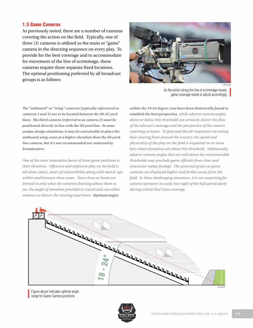
1.5 Game CamerasAs previously noted, there are a number of cameras covering the action on the field. Typically, one of three (3) cameras is utilized as the main or “game” camera in the directing sequence on every play. To provide for the best coverage and to accommodate for movement of the line of scrimmage, these cameras require three separate fixed locations. The optimal positioning preferred by all broadcast groups is as follows:
As the action along the line of scrimmage moves,game coverage needs to adjust accordingly.
The “outboard” or “wing” cameras (typically referenced as
cameras 1 and 3) are to be located between the 20-25 yard
lines. The third camera (referred to as camera 2) must be
positioned directly in line with the 50-yard line. In some
unique design situations, it may be conceivable to place the
outboard/wing cams at a higher elevation than the 50-yard
line camera, but it’s not recommended nor endorsed by
broadcasters.
One of the most imperative facets of these game positions is
their elevation. Offensive and defensive play on the field is
all about space, zones of responsibility along with match-ups
within and between these zones. Since those at home are
limited to only what the camera’s framing allows them to
see, the angle of elevation provided is crucial and can either
enhance or distort the viewing experience. Optimal angles
within the 19-24 degree zone have been historically found to
establish the best perspective, while adverse camera angles
above or below this threshold can seriously distort the flow
of the telecast’s coverage and the perspective of the viewers
watching at home. To fans and the all-important recruiting
base viewing from around the country, the speed and
physicality of the play on the field is impaired (or at times
lost) when elevations are above this threshold. Additionally,
adverse camera angles that are well above the recommended
thresholds may preclude game officials from clear and
conclusive replay footage. The potential grows as game
cameras are displaced higher and further away from the
field. In these challenging situations, it is not surprising for
camera operators to easily lose sight of the ball particularly
during critical Red Zone coverage.
19 -
24°
ESPN Images
Figure above indicates optimal angle range for Game Camera positions
Todd Detwiler

THE ESPN VENUE DESIGN & DEVELOPMENT GUIDE • VER. 1.0 • JUNE 20161 2
Three Camera Minimum Work Space Formula
8’ -
0”
18’ - 0”
Left 25-yard line (Camera 1) 50-yard line (Camera 2) Right 25-yard line (Camera 3)
Select screen shots above represent adverse camera angles above the recommended threshold. The viewing perspective is distorted and the flow, speed and physicality of the play is impaired.
Left 20-yard line (Camera 1) 50-yard line (Camera 2) Right 20-yard line (Camera 3)
Select screen shots above also depict adverse camera angles, this time well below the recommended threshold. The viewing perspective is again distorted and overall presentation is compromised.
The best wing or outboard game positions accommodate enough operating space for two working cameras (in-house video along with the main broadcast camera). When planning for appropriate working space, the best rule of thumb is to utilize a minimal work space formula of 6’ wide x 8’ deep per camera. If cameras are placed to close together, they cannot independently work (nor cross shoot) without interfering with the other camera. Using the formula provided, a total allotment of 6’ (to 12’) wide by 8’ deep is recommended.
Screen Shots Screen Shots
Single Camera Minimum Work Space Formula
8’ -
0”
6’ - 0”Todd Detwiler

THE ESPN VENUE DESIGN & DEVELOPMENT GUIDE • VER. 1.0 • JUNE 2016 1 3
The 50-yard line camera position should provide space for a minimum of three (3) (optimally four) working cameras (in-house video, other media or multiple broadcast cameras). A total allotment of 18’ (to 24’) wide by 8’ deep is recommended.
Provisions for these three fixed positions can be housed via multiple methods. Typically, they are supported in either assigned booths within the press box, on camera decks or individual pads built upon solid concrete foundations. To a smaller extent, camera seats, baskets or hi-hat mounting plates may also be utilized.
If main or game cameras are to be located inside the press box, openings to the field must allow lensing to freely move without interference from window sills, railings or mullions. A top priority during the planning phase is to identify andremove any potential obstruction that may impair the full operation of cameras or their operators. Often conventional or traditional windows and their required framework pose unique challenges. The support structure not only interrupts critical sightlines, but limits the positioning and full pan/tilt motion of cameras.
Some broadcasters, as well as design teams, prefera dedicated camera deck especially when projects face potential visual impairments or space limitations within the press box. The primary way leading into these placements should have a dedicated entrance and not accessed through adjacent spectator seating areas. The approach path should be flat (without stairs) and allow equipment cases to be easily transported by push carts for load-in. All positions should be placed on structurally solid foundations to help absorb and prevent adverse vibration during game activity. A non-slip finish with appropriate considerations for proper drainage must be provided to avoid the potential of standing water collecting during inclement weather.
NOTE: Additional material specifically addressing the
inclusion of camera seats, baskets or high hat mounting
plates can be best addressed by contacting ESPN
representatives directly.
1.6 High End Zone Positions In order to produce the highest-possible quality viewing experience, high end zone camera options should exist in either end of the stadium. This certainly holds true if the venue is to host championship contests, marquee games or other non-sporting events such as concerts.
Locations must be situated directly in the middle of the field exactly centered behind the goal posts. As with the main or “game” cameras, elevation is crucial. The height must allow the goal line (and end line) to be clear of any blockage from the cross bar. Optimally, (from the camera’s perspective) the goal line will appear to be positioned approximately 1-2 yards above the cross bar. An angle between 30-35 degrees is required to accomplish this preference.
NOTE: High end zone positions that are too shallow produce
camera movements that are quick and choppy when
covering side line to side line action. This distorts the flow
of the telecast’s coverage and the perspective of the viewers
watching at home.
ESPN

THE ESPN VENUE DESIGN & DEVELOPMENT GUIDE • VER. 1.0 • JUNE 20161 4
The best high end zone positions accommodate operating space for four (4) working cameras (in-house video, coaches’ cameras from both schools, and the main broadcast camera). Using the minimal work space formula provided (6’ wide x 8’ deep per camera), a total allotment of 24’ wide by 8’ deep is recommended. A non-slip finish along with proper drainage considerations previously described will apply to high end zone positions.
1.7 Slash Positions Ideally, a total of four (4) slash options located in each corner of the stadium should be incorporated into every project. This certainly holds true if the venue is to host championship contests, marquee games and other non-sporting events. At a minimum, two (2) slash alternatives located in the near and far corners (positions are referenced on camera map in section 1.2) need to be made available. If at all possible, all positions should be at the same or slightly lower elevation as the main game cameras. From the camera’s perspective, best placement forms an imaginary line (extending the diagonal length of the field’s rectangle shape) between the two opposite corners (front end zone pylon to front end zone pylon). Positions with orientation shading too far into the end zone will cause the goal post and its upright to become a visual obstacle for slash cameras when shooting across to the opposite sideline/team box. Slash locations should provide space for a minimal of one (1) (optimally two) working cameras (in-house video and broadcast). Applying the provided work space formula, a total allotment of 6’ (to 12’) wide by 8’ deep is recommended. A non-slip finish along with proper drainage considerations previously described will apply to all slash positions. 1.8 All 22 CoverageA favorite of TV analysts and coaches alike, the “All 22” perspective is designed to show what “all 22 players” on the field are doing on any given play. In most instances, it is comprised of two angles/positions - the first from high above the field
(centered at the 50) and a second view from the high end zone. Since we have already addressed space and location requirements for the high end zone, we will concentrate on the primary high 50 All-22 position.
The main 50-yard line game position should not be used for All 22 coverage. Nor should any space be allocated within the broadcast announce booth. The most suitable location is usually atop the press box roof, gantry or a dedicated camera pad on top of the seating bowl. Since both schools and broadcasters utilize this position, the space should provide for a minimal of three (3) (optimally four) working cameras (one for each school, broadcast and provisions for a “band cam”). A total work space allotment of 18’ (to 24’) wide by 8’ deep is recommended.
1.9 Reverse 50Prime-time, marquee games or championship match-ups, will certainly look to deploy additional production resources. One of the most often received requests is for an elevated reverse angle positioned directly in line with the opposite 50-yard line. If at all possible, this placement should be at the same or slightly higher elevation as the main game cameras. The space should provide for a minimal of one (1) (optimally two) working cameras (in-house video and broadcast). A total work space allotment of 6’ (to 12’) wide by 8’ deep is recommended. A non-slip finish along with proper drainage considerations previously described will apply to the reverse 50 position.
1.10 Beauty CameraA beauty camera will be utilized on most every level of telecast. This unmanned element most often consists of a hand-held (mounted on a tripod), robotic or other small POV (Point-of-View) camera. The placement (usually located in an elevated corner of the stadium), may vary from event to event based on the level of facilities and preference of the broadcast group. Since final assignment is often influenced by the need to capture the

THE ESPN VENUE DESIGN & DEVELOPMENT GUIDE • VER. 1.0 • JUNE 2016 1 5
venue’s individual characteristics and design, it is recommended to consult with the director and operations team in advance of each telecast regarding the beauty position.
If these positions are not pre-cabled, it is essential that easy and direct temporary cabling routes be available to safely and efficiently reach these areas from the TV compound.
1.11 Specialty Cameras
A. BLIMPS, AIR SHIPS AND FIXED WING AIRCRAFTGyro-stabilized camera mounts allow these units to provide a truly unique perspective high above the venue below. They are capable of shooting live action, as well as delivering stunning “beauty shots” of the stadium complex and surrounding area.
A pilot and camera operator working from within the aircraft take their cues from the broadcast director in the mobile unit via a two-way radio/communication link. A microwave/RF transmitter sends the camera’s signal from the blimp, airship or fixed wing plane to a ground receiver where it’s integrated into the telecast. The ground or “catch crew” (usually consisting of two people operating a small antenna dish mounted on a tripod) follow the flight plan of the craft capturing the wireless data and send the signal via cable to the mobile unit located within the TV compound.
The ground receive site (usually atop the press box or in an evaluated position in the TV compound) must have a clear unobstructed line of sight to the blimp, airship or fixed wing aircraft at all times.
Required cable specifics are addressed in Chapter 6 of this guide. If this position is not pre-cabled, it is essential that an easy and direct temporary cabling route be available to safely and efficiently reach this area from the TV compound.
Airships are a common sight in the skies abovesport venues providing outstanding visuals.
Multiple manufacturers operate specialized aerial cable camerasproviding a birds-eye view above the playing field.
B. AERIAL CABLED CAMERA SYSTEMSWhile not deployed on all telecasts, it is highly recommended that venues become familiar and address the necessary requirements for an aerial cabled camera tracking system. These systems operating above the action provide a bird’s-eye view of the exploits on the field. There are multiple manufacturers and companies who operate these specialized platforms. While there are unique differences between each, they essentially set up and operate in a similar manner. Cable suspended systems are comprised in some form of the following elements:
ESPN Images
ESPN Images

THE ESPN VENUE DESIGN & DEVELOPMENT GUIDE • VER. 1.0 • JUNE 20161 6
1) Low-tension custom hybrid cables secured to fixed points high atop each corner of the stadium. These four specialty braided Kevlar cables first pass through a pulling/redirect mechanism (affixed by temporary lifts or connected directly to the stadium’s infrastructure by either temporary box truss or permanently mounted brackets) then proceed on to one of four computer control reels/winches. In addition to providing the necessary framework for suspension and support, these cables transport video/data signals along with the necessary power distribution via integrated fiber optics and copper component strands.
2) The cables intersect above the field and attach to a gyro-stabilized transit platform forming the second system component. This platform or “spar” weighs roughly 45-60 pounds and is inclusive of an onboard HD camera (with wide angle lens), microphone, sensors for stabilization and pan/tilt motors for camera movement. This unit’s components function to provide a full 360° panoramic along with 180° tilt degree of coverage and maneuverability in three dimensions over the field.
3) Collectively the components connect to a centralized control center accounting for the third and final system element. A two-person team provides the camera flight and video control operating from proprietary computer workstations. A “pilot” (the one who flies the spar and monitors cable/reel adjustments in real time) and a camera operator (the one who controls the camera pan, tilt, zoom and focus) work in unison to control the overall system functionality. Work stations use custom software to control each aspect of the flight plan, including safety, motion, video, and obstacle avoidance.
The rigging approach for these aerial cabled systems are adaptable to almost any venue. Plans should be made for winch/reel placement, power
requirements and a central operating location in consultation with a qualified broadcast integrator and in direct dialog with the supplying vendor. General specifications have been included in the reference section of this guide.
To provide for an overall safe and efficient operation, the pilot and camera operator (along with any necessary support crew) working from the centralized control center need to have a clear unobstructed view of the entire field, all boundaries and the seating bowl itself. The best operating location to accommodate for this provision is within the press box. Ideally, a small auxiliary TV or radio booth situated on the same level and side of the press box as the announce booth/main game cameras is preferred. The auxiliary space should possess minimum measurements of 10’ wide x 12’ deep. Although slightly larger dimensions of 12’ wide x 16’ deep will certainly be beneficial.
C. PLAY CLOCK & GAME CLOCK CAMERASMost any level of broadcast today will connect to the venue’s game and play clocks via direct serial data connection(s) for inclusion into their telecasts. Permanent cabling infrastructure to support will be addressed in Chapter 6 and should be included within the project’s pre-planning phase. As a backup, most broadcasters deploy two (2) unmanned cameras (mounted on tripods) to shoot the game and play clock for manual integration. Provisions should be made to provide a location to accommodate this need. Where possible, it is highly desirable to setup auxiliary or backup play/game clocks for broadcasters. In some venues (where space is available) a small multipurpose room near the TV compound can best accommodate this request. If shooting backup displays is not a possibility, designated space near one of the game camera positions will be required. It is helpful if the shot orientation is as straight on as possible to the primary timing displays. In addition to mandated venue placements, additional timing displays positioned in elevated locales near the 50-yard line and along

THE ESPN VENUE DESIGN & DEVELOPMENT GUIDE • VER. 1.0 • JUNE 2016 1 7
stadium corners are beneficial to both fans and broadcasters alike. Game management timing mechanisms should be available as dedicated full-time displays and not disappear during in-stadium video segments or advertising presentations. If this position is not pre-cabled, it is essential that an easy and direct temporary cabling route be available to safely and efficiently reach this area from the TV compound.
1.12 Field Level PositionsOuter field perimeter work space (outside the playing surface boundaries) should be large enough to allow handheld cameras, steadicams, sideline vehicles and support personnel to efficiently operate without interfering with game operations.
Field level placements fall into two main categories:
Fixed: As with elevated fixed camera positions, these field placements are normally mounted on tripods and are built on either temporary platforms or within dedicated cut-outs (alcoves) incorporated into the seating bowl.
Mobile: All mobile on-field camera positions are “soft”, meaning they do not require a dedicated position or platform. These can include: hand-held (cabled or wireless RF) and sideline carts/jibs.
1.13 Hand-Held Cameras Depending on the level of the telecast, one (1) or two (2) hand-held cameras are normally utilized (three on select prime-time telecasts). As noted, these cameras do not require a dedicated position. Repositioning constantly throughout the broadcast, their primary responsibility is game coverage, color, player close-ups and are relied upon for crucial replay angles.
Principal assignment includes following the action - generally the ball most of the time. They often provide the definitive replay look: Was the ball caught or trapped? Was the player’s knee down? Did the ground cause the fumble? Optimal positioning preferred by all broadcast groups is created by a dedicated “buffer zone” located between the 6’ wide solid white boundary and an added dashed line marking a restrictive area between broadcast rights holders and other media. This is a concept successfully implemented in NFL venues. Where possible, this area should be clearly defined and separated with distinctive coloring marking the zone for broadcast cameras.
A dedicated TV “buffer zone” helps create a beneficial restrictivearea between broadcast rights holders and other media.
Hand-held cameras constantly reposition throughoutthe telecast and are relied upon for crucial coverage angles.
ESPN Images
ESPN Images

THE ESPN VENUE DESIGN & DEVELOPMENT GUIDE • VER. 1.0 • JUNE 20161 8
Sideline Cart - Principal assignments include game coverage, the quarterback, star player and of paramount importance - protecting the line of scrimmage/goal line. When allowed to be positioned properly, it is without question the most definitive look at the line of scrimmage and the plane of the goal line. Did the runner get across it? Was he stopped short? Did the ball pop out prior to crossing the line? Each question can be more easily answered if the sideline cart is able to be positioned appropriately. Any time the ball gets inside the 10-yard line, there should be an expectation for the cart camera to be parked on the goal line. In almost every instance, the cart is the most often reviewed angle by instant replay officials. As indicated in the drawing below, an unrestricted operating space of approximately 12’ (wide) between the team area and the seating wall (running the entire length of the field) should be provided on both the near and far sidelines.
1.14 Sideline Vehicles As with hand-held cams, camera vehicles are constantly repositioning throughout the broadcast.
NOTE: This open and unhindered operating space between the team box and the seating wall (running the
entire length of the field) should be provided on both the near and far sidelines.
Unrestricted operating space of approximately 12’wide should be available along both sidelines.
MINIMUM CLEARANCE12’ 12’
CFB Team
Todd Detwiler

THE ESPN VENUE DESIGN & DEVELOPMENT GUIDE • VER. 1.0 • JUNE 2016 1 9
1.15 Low End Zone PositionsOperating space for a minimum of two (2) low end zone positions (four is optimal) working in each end of the field is highly recommended. Purpose built cut-outs (alcoves) within the seat bowl or temporary portable platforms located in front of the seating area can accommodate these positions. From the camera’s perspective, best placement is between the yard line numbering (displayed on the field) and the hash marks. Equally important, they must be situated outside of the field goal net inclusive of any supporting structures and operating mechanisms. Locations with an orientation shading too far toward the goal post or placed behind a field goal net will cause visual obstructions for the camera.
NOTE: If plans only include two (2) low end zone options,
both are to be placed on the same side of the field as the
main or game cameras. If the venue is incorporating the
preferred four (4) stations, the alignment description is the
same as above with the two additional positions placed
on the opposite side of the goal posts. This ideal number
and placement will allow a great deal of flexibility. In-
house crews along with broadcast rights holders can work
simultaneously and it will also provide options for broadcast
directors to place one (1) low end zone camera “near” or
“far” (of the goal post) to assist with shooting back into the
near side line. When not in use, these locations can serve as
complementary or additional seating areas.
Cut-Out or Camera Alcoves - Positions must not have fan seating between camera and the playing field. The best elevation is 4’ – 5’ (placing the center of the camera’s lens at a minimum height of 9’) above the playing surface. A concrete slab foundation (like those recommended for elevated fix positions) can be utilized for these dedicated placements. The non-slip finish and same drainage considerations addressed earlier in this chapter apply equally to low end zone positions. When planning for appropriate work space, the following factors should be applied:
Using the minimal work space formula provided earlier (6’ wide x 8’ deep per camera); a total allotment of 12’ wide by 8’ deep is recommended. This will support two (2) cameras operating from each location (very beneficial if only two low end zone positions are available). Overall required work space can be reduced to 6’ wide x 8’ deep (per locale) if a total of four positions are available.
If a venue provides four (4) low end zone options, it may be likely that each will not be used during every telecast. Prior to each game, if confirmation is received that neither the broadcaster nor the in-house video crew will operate from one or either of the two “far” side positions, portable seating could be placed allowing this space to be utilized for single game or complimentary ticketing. The two (2) “near” positions should always be reserved for broadcast use.
Some venue designers (along with previousassociation publications) endorse a reduction of operating work space to 6’ wide x 4’ deep for the two “far” low end zone positions. This is an opinion that ESPN does not support or recommend.
Low end zone positions should offer a minimumlens height of 9’ above the playing surface.
ESPN Images

THE ESPN VENUE DESIGN & DEVELOPMENT GUIDE • VER. 1.0 • JUNE 20162 0
Temporary Platforms – Optimal positioning is directly behind the end line of the end zone (again, situated between the numbers and the hash marks). Platforms located further away from the field introduce frequent blockage/obstruction from media and non-participants crossing in front.
Temporary platforms allow for flexibility in that they can be moved to accommodate specific needs. It is recommended to consult with the broadcast rights holder in advance of each game to determine final placement. Some directors elect to have this camera closer to the hash marks while others prefer an orientation closer to the numbers. These essential advance conversations should include venue management, the broadcast operations team and the director to find a mutually agreeable location that addresses everyone’s interests including any safety considerations.
All temporary platforms (including scaffolding) need to be installed by a suitably licensed company or person and comply with all applicable health and safety guidelines. Essential working dimensions include a minimum recommended deck height of 36” and the aforementioned 6’ wide x 8’ deep work area. Temporary platforms should only accommodate a single working camera and
Temporary platforms allow for flexibility in that they canbe moved to accommodate specific needs.
operator. This is crucial to eliminate the potential of vibration or unnecessary movement caused by a second working operator during the telecast. During setup and knockdown, these temporary structures need to be durable enough to support the weight (and movement) of two technicians and equipment (approximately 800 pounds). Additional considerations include:
• Structure’s base needs to be solid and non-vibrating
• Structure’s surface should have a non-slip smooth finish
• Diagonal bracing to safeguard stability is highly
recommended
• Safe and stable access on to the structure (for operator &
equipment) needs to be provided
• A central steel eyebolt should also be planned to allow
the tripod to be secured to the base.
• Appropriate padding to the front and side of the
platform needs to be included.
• Platform height may vary depending upon placement
and working requirements.
1.16 Additional Camera ConsiderationsVenue management teams should be aware that facilities levels will vary according to the level of the event. On higher level and major telecasts, production teams may request nonstandard or unique situations not accounted for in the previously described sections. In these instances, requests will be made well in advance, fully reviewed with site management and must meet all necessary approvals prior to proceeding.
CFB Team
ESPN Images

THE ESPN VENUE DESIGN & DEVELOPMENT GUIDE • VER. 1.0 • JUNE 2016 2 1
1.17 Safety ConsiderationsWherever camera positions are located, safety considerations must be addressed. In Chapter 9 of this guide, we will visit health and safety concerns in greater detail. For now, elements pertaining to elevated and field positions are highlighted on the pages to follow. Additionally, ESPN’s Global Safety and Security team members are available to address any project or venue specific questions.
• If seated or standing patrons are to be located directly below any elevated positions, kick boards, drop-nets or other catch basin concepts, which prevent items from accidentally falling to areas below, are highly recommended.
B. SLIPPERY CONDITIONSExposed concrete slab foundations utilized for individual pads or camera decks may become slippery when wet or icy conditions are present (especially true with sealed or color hardened concrete areas). At the very least, these conditions offer challenges for safe setup/operation during the game and potentially pose a hazard if not treated with a slip resistant finish. There are a few ways to create non-slip surfaces that are examined in Chapter 9 (Section 9.2b) of this guide.
C. ACCESS TO POSITIONSAll camera positions must provide for a safe means of entry and egress (for both personnel and equipment) and meet all applicable state and federal safety standards (including provisions for stairs, ladders, and walkways). All field tunnel entrances should include sufficient height and width clearances to allow handling equipment (forklifts, scissor lifts, flatbeds) along with broadcast sideline vehicles proper access. Direct access with limited bend or steep ramp inclines is always desirable.
D. DRAINAGEA few times throughout this chapter, reference was made to “proper drainage.” Every permanent camera location should be substantially level and support the ability to withstand heavy rain without the risk of the camera operator, equipment or cables having to function in standing water. These positions often simply channel the water to the edge of the pavement (for run-off) or include some form of modest drain. Care must be taken not to over pitch these areas; the surface must be level enough for the camera and operator to function efficiently. These solid foundations should have
A. WORKING FROM HEIGHTSAny open or exposed side of a broadcast camera position (either permanent or temporary) which is four (4) feet or more above the lower level (30” in the state of California) must include state and federal compliant barriers or guard rails. We strongly encourage you to refer to federal and local codes for complete guard and barrier system compliance. As noted above, Chapter 9 does explore some regulatory requirements for these provisions in more detail.
• If barriers or guardrails are to be removed, lowered or otherwise altered to accommodate a camera position, appropriate fall restraint anchorage points (for both the operator and equipment) must be integrated. Please consult Chapter 9 (Section 9.1) for more details regarding suitable fall restraint information.
Appropriate Personal Protective Equipment(PPE) are addressed in Chapter 9 Section 9.2
iStock.com/Kali Nine LLC

THE ESPN VENUE DESIGN & DEVELOPMENT GUIDE • VER. 1.0 • JUNE 20162 2
a minimum 1% (1/8” per foot) up to a maximum of 2% (1/4” per foot) grade to the edge or drain. It is very important, that any grading slope away from the JBT (cable I/O box) or electrical outlets to prevent any potential damage or safety concern.
NOTE: Any fabricated drain inserted into a camera position
must take into account that most broadcasters will install (or
request the venue to install) an anchorage eyebolt near the
front of all concrete slab locations (approximately 12”- 18”
behind the front edge). As with temporary platforms, this
will allow the tripod to be safely secured to the foundation.
Consideration should to be given not to introduce potential
interference to the anchorage point from any drain
placement.
1.18 Designated Interview AreaWhere possible, a designated area should be provided in a secure off-field covered area where official statements or interviews may be safely conducted during inclement weather or other unforeseen delays. Any official or team representative interviewed will be subject to advance communication and regulations. Area should provide ease of access and close proximity to power and temporary cable drops.
1.19 Equipment Case StorageA dedicated space or suitable secure area situated near all camera positions should be allocated to safely store empty equipment cases during the telecast. It is advisable that this locale be as close to each camera location as possible to allow for easy access by the TV crew. In addition, it is important that provisions to lock and secure this area be made if at all possible.
1.20 Camera Location PowerWith the increased usage of fiber optic based technologies (which do not transport power over their glass strands) special consideration needs be given to power accommodations at each camera location. No less than one (1) dedicated 20 amp
(120 volt) circuit (individually terminated into a standard GFCI equipped quad box) should be provided for each operating position. In other words, if four (4) cameras are to be positioned at the main or game location, then four (4) dedicated 20 amp drops are suggested. If two (2) cameras are to operate from a low end zone position, then two (2) 20 amp services are recommended. Positioning of the quad box (with dual pair receptacles) should be placed at an appropriate height to eliminate the potential risk created by standing water.
1.21 Video Boards/Digital DisplaysMany facilities have or will install large HD format screens, scoreboards and electronically operated LED (or similar technology) message board systems. Full consideration must be given to ensure that optimal placements for these video displays do not present sightline challenges for broadcasters. The primary strength of digital displays is they are eye catching and interesting to the stadium fan base, a great advantage for advertisers and sponsors. However, displays positioned within any television camera’s field of view can be distracting and interfere with their standard operation. So their use should be subject to surface luminosity/brightness limits particularly during events televised at night. Prior to installation, it is highly recommended to have your broadcast rights holders review the final configuration and layout to help ensure the intended locations will not block or potentially interfere with optimal camera performance. Your rights holders would like to work together with your design team to find mutually beneficial and best solutions for all parties.

THE ESPN VENUE DESIGN & DEVELOPMENT GUIDE • VER. 1.0 • JUNE 2016 2 3
SightlinesChapter 2
2.1 Sightlines OverviewIf you’ve attended a sporting event at any level and had to strain to look around the back of the heads of those seated in front, you know firsthand how aggravating poor or limited sightlines can be. The quality of a seated spectator’s view is expressed in the industry as a “C-value.” The term refers to the vertical measurement of a person’s eye line (or line of sight) to see a predetermined focal point over the head of the person in front. For the purposes of this guidebook, the term sightline(s) pertains equally to ticketed fans, broadcast personnel and TV cameras alike. In broadcast reference, sightline applies to the capacity of the camera, broadcast talent and support personnel having a line of view completely free from any structural or physical obstruction including both seated and standing fans. Architects and project engineers who design stadiums have to carefully consider the way seating is laid out in order to maximize the venue’s capacity without compromising optimal “C-values” or required broadcast viewing standards. Sightlines have an interdependent relationship between patrons and broadcasters. The better the quality of the sightline, the more likely it is that fans will remain seated during an event and the potential for working limitations for broadcasters should therefore decrease. It is a given that during any contest, seated spectators will inevitably stand, raise their arms or high five those around them while experiencing the excitement of pivotal moments. If proper planning is not incorporated during pre-design, TV cameras operating behind these areas will be negatively affected.
“ F O R T H E P U R P O S E S O F T H I S G U I D E B O O K , T H E T E R M S I G H T L I N E P E R TA I N S E Q U A L LY T O T I C K E T E D F A N S ,B R O A D C A S T P E R S O N N E L A N D T V C A M E R A S A L I K E . ”
iStock.com/Luhuanfeng

THE ESPN VENUE DESIGN & DEVELOPMENT GUIDE • VER. 1.0 • JUNE 20162 4
C-VALUE RATING DESCRIPTION
6” (150 mm approx.) Excellent Can see extremely well over spectators in front
4.75” (120 mm approx.) Very Good Considered a quality line of sight. Optimal viewing standard to strive for
3.5” - 4” (90 -100 mm approx.) Reasonable - Good Can see well enough by tilting one’s head up and slightly backwards to see over those in front
2.5” - 3” (60 - 75 mm approx.) Limited - Fair Must look between heads of people in front to see adequately
Typical Industry C-Value For Seated Patrons
2.2 Key Sightline DefinitionsIn theory, the greater the C-Value, the better the sightline, which means a better view of the playing field. Unfortunately, it’s not a one-size-fits-all formula. There are a few other important components required to establish quality sightlines. To provide a better understanding, let’s take a quick look at some of these elements.
Angle of RakeThe “rake” (or angle) refers to the measurement of how gently or abruptly a seating area slopes downward towards the playing surface. This incline impacts how near or far a seat is away from the action. Angle of rake and C-Values have a direct correlation with each other. To achieve higher C-Values, the steeper the raking (or angle) of the stands must be. Conversely, the lower the C-value intended, the shallower the stands become.
Row Tread DepthThe part of the stairway or seated row that is actually stepped on is referred to as the “tread.” The depth of this trend is measured from the outer edge of the step to the vertical portion between steps. In addition to being a factor in formulating sightline calculations, a row’s depth plays a significant role in the comfort and safety of patrons.
Riser Heights The vertical section between each “tread” or the height of the step(s) between rows is the “riser.” For construction ease, designers often treat several seated rows as one; only adjusting riser heights slightly between each section. The difference may be slight - representing only a few inches, but the overall effect on sightlines can be quite significant.
Focal PointRefers to a spectator’s nearest point of interest on the playing field. Typically, in football the closest boundary marker/outer edge along the near sideline serves as the reference location for C-value calculation.

THE ESPN VENUE DESIGN & DEVELOPMENT GUIDE • VER. 1.0 • JUNE 2016 2 5
2.3 Optimal Viewing StandardsIdeally, architects would start by applying the 4.75” (120 mm approx.) C-Value standard described earlier to establish consistent optimal sightlines for patrons throughout all parts of the venue. Utilizing a universally recognized formula along with specialized software programs, design teams can then work out the required rake angles and riser heights to achieve the intended value.
That standard mathematical equation is:
NOTE: If you are working on a project with pre-existing seating and need to determine the current viewing
standards, your consultant can back-calculate the existing C-Value by rearranging the equation above and taking
into account existing measurements. In this instance the formula would be:
C = D (N+R) – R
D+T
N = (R+C) x (D+T) - R
D
N
T
C
N = riser (or step) height of each individual row of seatsR = vertical height between the person’s eye level and a point of focus on the fieldC = intended C-Value Standard to be appliedD = horizontal distance from individual position to the point of focus on the fieldT = depth of each individual row of seats
Todd Detwiler

THE ESPN VENUE DESIGN & DEVELOPMENT GUIDE • VER. 1.0 • JUNE 20162 6
The typical industry C-Value standards expressed in Section 2.1 will vary according to the sport or event as spectator’s focal points shift between activities. A C-value for a concert may differ considerably (since the focal point of the stage is much farther away) than a college football game even though the calculation is derived from the same seat. Achieving optimal or higher C-values is no easy matter. Extensive calculations are required from every seating section and may necessitate repetitive computations to address encountered design variables or safety interests. Considerations may include varying rakes and higher riser heights to deliver desired viewing standards. In some sectors of the venue, it may be problematic or impossible to consistently achieve optimal C-values. In these instances, it is necessary for designers to find workable compromises that attain reasonable solutions for all interested parties. Because of the complex nature of this process and expertise involved, ESPN recommends that your project design team seek and engage professional advice from competent firms or persons appropriately skilled in football venue design.
2.4 Broadcast Positions and Seated SpectatorsIt is equally important to mathematically calculate the quality of view from broadcast positions located directly or diagonally behind seating areas to ensure these sightlines are not affected by standing individuals. Unlike spectators, stationary or fixed cameras (mounted on tripods) cannot lean forward, adjust sideways or attempt to peer between the heads (or outstretched arms) of those standing to avoid having their working view blocked or impaired. The matter of visual limitations from these positions is not only crucial to broadcasters, but equally important to game officials. Instant replay is dependent on feeds and replays from these cameras in order to review various angles prior to determining the accuracy of an initial call. Any sightline impairment that precludes game officials from accessing clear and conclusive footage can certainly have a negative impact on the outcome of the game. In order to create acceptable viewing standards, a “super riser” will be necessary whenever camera positions are to be located behind fans, workers, or other media. Please reference Section 1.4 located within Chapter 1 for specific details and requirements.
ESPN Images

THE ESPN VENUE DESIGN & DEVELOPMENT GUIDE • VER. 1.0 • JUNE 2016 2 7
Broadcast Announce BoothChapter 3
3.1 Broadcast Booth OverviewA variety of essential design considerations, based on the industry’s “best practices” are outlined in the sections to follow. The guidelines defined apply to both new construction, renovation projects and existing venues. Understandably, the range of TV commentary positions dedicated to the broadcast rights holders will certainly vary depending on 1) institution’s size 2) yearly television exposure and 3) the overall scope of the new build or renovation.
At the very least, final planning should provide for one (1) fully equipped TV booth capable of handling all technical requirements of primary broadcast rights holder(s). In the development of the overall design, it is highly recommended that provisions for an auxiliary TV booth be incorporated. This supplementary booth can serve in multiple capacities (additional radio booth, VIP guest suite, aerial cable camera operating area … etc.) when secondary broadcast needs are not required.
In either case, both booths should offer clear unobstructed views of the entire playing surface, its boundary markers, team boxes, seating areas and scoreboard operations (particularly – play/game clocks and down & distance displays). To achieve this, the design team should ensure that broadcast booth’s sightlines are not adversely impacted by any of the following: 1. Stadium structural features2. Window obstructions (i.e. frame/supports/mullions)3. Low ceiling heights4 Dedicated camera positions (located between field of play and
booth)5. Suite/Club or other premium seating areas (or design
requirements to accommodate these zones)6. Seated or standing patrons (including their outstretched or
waving arms)
“ . . . B O O T H S S H O U L D O F F E R C L E A R U N O B S T R U C T E D V I E W S O FT H E E N T I R E P L AY I N G S U R F A C E , B O U N D A R Y M A R K E R S , T E A M B O X E S , S E AT I N G A R E A S A N D S C O R E B O A R D O P E R AT I O N S ”
iStock.com/Zig4photo

THE ESPN VENUE DESIGN & DEVELOPMENT GUIDE • VER. 1.0 • JUNE 20162 8
NOTE: For the purposes of this guide, the definition of the term “playing surface” includes the elevated/vertical
portions above the field. Any visual impairment that prevents broadcasters from seeing the full vertical range of kick-
offs, punts or long pass plays is considered an adverse sightline.
3.2 Booth LocationThe primary broadcast booth should be situated at or near the 50-yard line on the same level and side of the press box as the main camera positions. Ideally, the auxiliary TV booth should also be positioned in as near proximity to the 50-yard line as possible. Understandably, additional press box assignments (i.e. coaches, instant replay, game ops, VIP booths…etc.), along with other media seating priorities, will take on a higher sense of urgency than the auxiliary booth’s final position.
3.3 Booth Layout & DimensionsIt is normal industry practice to have as many as ten or more technicians, talent, support staff, as well as, camera(s) and technical components operating in the primary booth at any given time. It is imperative to manage the available space in the most practical and efficient method possible. In general, an unimpeded workflow is best achieved by
a continuous non-tiered (flat) floor orientation. A booth featuring a tiered design generally imposes workspace, lighting and on-cameras challenges for most broadcasters. The project design team should avoid a multi-level floor plan if at all possible. If the only means available is a multi-level design, then a minimum of a 10’ setback from the front opening to the higher elevated portion of the booth must be provided.
The primary booth’s floor plan should provide a minimum threshold of 18’ (wide) by 18’ (deep). The preferred dimensions of 20’- 24’ (wide) by 20’ (deep) is ideal.
NOTE: If one of the “game cameras” (Camera 2) is to be housed and operated within the broadcast booth, then the maximum 24’ width is highly recommended. The auxiliary booth can possess slightly smaller measurements of
14’ (wide) x 18’ (deep).
24” DEEP COUNTER 24” DEEP COUNTER
DROP DOWN ORREMOVABLE COUNTER
OPTIMAL DIMENSIONSWITHOUT CAMERA
OPTIMAL DIMENSIONSWITH GAME CAMERA
20’ - 0”
20’ -
0”
20’ -
0”
24’ - 0”
Todd Detwiler

THE ESPN VENUE DESIGN & DEVELOPMENT GUIDE • VER. 1.0 • JUNE 2016 2 9
A ceiling height of at least 10’ is strongly recommended. The contour of the booth should remain at a consistent height and not dip or slope at any point.
These recommended dimensions will allow broadcasters sufficient space to:
• Install necessary technical equipment• Mount temporary lighting instruments• Effectively manage on-camera segments (with
announcers standing in front of a backdrop or with their backs oriented towards the field)
• Comfortably accommodate up to (2-3) commentators, (1) on-camera guest, (1) stage manager, (1) camera operator, (1) audio technician, (1-2) spotters, (1) statistician and additional production support
NOTE: The auxiliary broadcast booth will feature the same
classification of personnel, but traditionally requires fewer
personnel. A range of 5-7 technicians, talent and support
staff may be present in the auxiliary booth during a game
telecast.
3.4 Booth Lighting GridIn most telecast applications, it is common to hang or support portable lighting fixtures from above. This method allows the broadcaster to avoid mounting lights on floor stands and thus maximizing the usable floor space. Therefore, it is essential that the broadcast booth’s design not be limited in height by a finished, suspended or sheet rock ceiling. To meet the requirements of this preferred practice, the design team should incorporate a permanently installed open pipe grid positioned toward the front half (closer to the front opening) of the announce booth. The grid should be installed to suspend 6”- 12” below the recommended 10’ ceiling height. This placement situates the grid to hang approximately 9’ - 9’ 6” above the finished floor. Final dimensions of the pipe grid formed will depend upon the overall booth’s dimensions.
The standard material universally recommended for this permanent grid installation is known as Schedule 40 pipe. This material is nothing more than standard steel plumbing pipe that is rated for structural applications. Aluminum pipe and EMT electrical conduit should not be considered as a substitute. The locking set bolts on standard lighting clamps can easily cut through or bend this type of material. Schedule 40 steel pipe is widely available at any number of plumbing and steel suppliers across the country. It is fairly easy to cut and thread while onsite to accommodate any desired dimension.
1) The most popular size of Schedule 40 pipe for
light grid applications is 1.5”. It has an OD
(outside diameter) of 1.90”.
2) Never use 2” Schedule 40 pipe! It has an OD of
2.375” and standard lighting clamps may not fit.
3) The pipe grid’s overall width and depth will be
dependent upon the booth’s ultimate size.
4) Black is the preferred color of schedule 40 for this
application.
It is also beneficial to consider mounting support brackets (outdoor rated schedule 40 pipe) outside and above the announce booth façade (running the full length of the booth’s width). This will allow for small antennas or other equipment to be affixed outside the booth. Final positioning should provide sufficient space away from the building to allow easy mounting of equipment (6” to 12”). Accessing the pipe should not present an unreasonable effort or pose a potential fall hazard to broadcast personnel. Additionally, the final placement should not introduce sight line limitations for those working inside the booth.
The lighting grid (and all materials) should be rated to meet or exceed all applicable codes and standards. Lighting instruments used today are very lightweight in nature and should not pose any issues or come close to exceeding noted load limits.

THE ESPN VENUE DESIGN & DEVELOPMENT GUIDE • VER. 1.0 • JUNE 20163 0
Typically, broadcasters utilize lighting fixtures (and necessary support) that carry a total load between 35- 80 lbs. (distributed evenly across the entire grid) during a standard telecast.
3.5 Booth WindowsAs a top priority, effective measures should be taken to eliminate the obstructed or impaired views often produced by conventional windows and their required framework. Traditional horizontal sliding windows or “sliders” pose challenges for broadcasters since the necessary hardware and framing are still readily visible even when individual panels are in their full open position. The supporting framework interrupts critical sightlines for working personnel and may limit the location and full panning motion of cameras operating in the booth. Vertical sliding window designs offer the same shortcomings.
There are a few workable options meeting these criteria which have been successfully installed in both NFL and collegiate venues in recent years. Two firms offering product lines for your design team’s consideration are: Nanawall System Inc. and Solar Innovations, Inc.
Available product lines include innovative stacking or folding systems which allow individual window panels to travel along a single (or multiple) track and secure into a stored position. Existing options can guide all panels in one direction (left or right) or allow end users to send half the panels left and the other half to the right. Certainly, a beneficial option for maximizing the booth’s working and storage space. For complete flexibility, available options allow panels to make a turn and store in the rear of the booth.
Some venues have incorporated mechanisms similar to that of an overhead garage door retracting upward while in use. This type of system is certainly advantageous for a “camera only” booth, but will interfere with the suspended pipe grid, lighting fixtures and robotic cameras featured in broadcast announce booths. Design considerations need to incorporate a solution that will easily operate in a large architectural opening, retract, fold or slide completely out of sight (leaving no visual impairment) and conveniently store out of the way.
After the window panels have been secured into their final destination, clean unobstructed views are achieved without mullions, frames and supporting hardware interrupting sightlines or normal camera operation. Systems can be designed to fit any opening size and are available in multiple finishes.
As previously stated, the preceding material offers suggestions on reasonable provisions. It is essential that your design team review all options thoroughly before making any final selections.
Figure above illustrates impaired views produced by traditional window framework
WJHW

THE ESPN VENUE DESIGN & DEVELOPMENT GUIDE • VER. 1.0 • JUNE 2016 3 1
3.6 Booth Acoustical TreatmentSince the announce booth should not feature a finished, suspended or sheet rock ceiling, it is necessary to treat the ceiling surface (above the permanently mounted pipe grid) with an acoustical spray application. This treatment is intended to dampen or flatten out echoing and unwanted noise reverberations. To further enhance optimal sound properties, the floor should be covered with an industrial grade carpet or rubberized finish to help quiet the room. Soft surfaces will absorb sound, while hard surfaces reflect and redirect sound. Any press box speakers located within the booth should be separately zoned and permit individual control. This will allow the volume to be adjusted or turned off during broadcasts. Additionally, main stadium PA speakers should not be located near or in the general vicinity of the primary booth.
3.7 Booth Countertop/Monitor Tray To accommodate workspace for monitors, technical equipment and to provide for a writing area for on-air talent (and their support personnel), the booth needs to include a built-in countertop. This working counter should be no less than 24” deep and run continuously against the opening overlooking the field of play.
Note: If one of the “game cameras” (Camera 2) is to be housed
and operated within the broadcast booth, then a 6’ section of
the counter (nearest the 50-yard line) needs to be hinged in
order to fold down (or easily removable) to allow the camera
to operate in the opening.
The height of the counter should be able to easily accommodate standard adjustable height drafting stools/chairs. Limiting the number of supports or legs beneath the counter is beneficial. Typically, this area serves as a work top for on-air talent and their support personnel. Additionally, it supports monitors, communication boxes, telestrators, computers and other technical devices. Including small pass-through holes (2” - 3” openings approximately 5’ - 6’ apart) along the countertop
will provide assistance with cable installation and helps to maximize operating space.
Over the years, other venue guides have included recommendations for permanent monitor trays to be positioned just outside and below the booth’s opening. While this provision may still have merit in select applications, it should be noted that large CRT monitors (that took up valuable counter space) have evolved into space-efficient flat screen displays. Fewer broadcasters find the need to outboard their monitors beyond the booth. A tray (or catch basin) still serves as an excellent preventive measure against objects falling from the announce booth causing potential injury to those below.
The design team should carefully review the
following considerations prior to implementing:
1) Only high quality materials rated for weather-
resistant, long lasting durability should be used
for the tray’s (or catch basin) construction.
2) Safety provisions to help safeguard monitors
or (other objects) from inadvertently becoming
dislodged need to be incorporated into the
design. Additionally, reaching over the
countertop’s depth and down to the tray’s
location should not present an unreasonable
effort or pose as a potential fall hazard to
broadcast personnel.
3) Final positioning of the tray (or catch basin)
needs to be carefully determined so the sightline
to the field of play is not negatively impacted
once broadcasters install monitors. Current
screen displays utilized range in size from 9”– 24”.
4) Tray (or catch basin) should retain a slight
angle so monitors can be positioned into a good
viewing angle. The most beneficial results are
achieved when the on-air talent can naturally
glance just slightly downward at the monitors
while calling the action.

THE ESPN VENUE DESIGN & DEVELOPMENT GUIDE • VER. 1.0 • JUNE 20163 2
3.8 Booth Power RequirementsThe incorporation of a circuit breaker panel (or sub-panel) within the booth is an essential element for broadcasters. In the event of a minor power interruption (due to a tripped breaker), having accessible means to quickly reset the breaker and resume normal operation in the shortest amount of time possible is indispensable.
Typical power guidelines for a standard announce booth include:
• Lighting Grid: No less than four (4) (six is ideal) - 20 amp (120 volt) circuits individually terminated into standard GFCI (Ground Fault Circuit Interrupters) equipped quad boxes. Positioning of quad box (with dual pair receptacles in each) above each quadrant of the light grid, will help to eliminate the need for extra extension cords.
• Under Countertop: No less than two (2) (three is ideal) - 20 amp (120 volt) circuits individually terminated into standard GFCI equipped outlets. Positioning of quad box (with dual pair receptacles in each) evenly spaced across the full length of the booth’s opening, helps to eliminate the need for extra extension cords.
NOTE:
1) The design team may also consider including a
single 30 amp (120 volt) breaker under the counter to
accommodate small portable heaters often utilized by
on-air talent. It may be best to color code the 30 amp
receptacle (in addition to standard labeling) for easy
identification.
2) Since the windows of the booth may remain open during
most telecasts (or after setup) and the possibility of
dampness or moisture entering the booth exists, GFCI
receptacles are strongly recommended.
Rear Of Booth: No less than two (2) (three is ideal) - 20 amp
(120 volt) circuits individually terminated into standard
GFCI equipped outlets is highly advisable.
3.9 Booth Voice And Data RequirementsComplete voice and data cabling requirements for the announce booth(s) can be found in Chapter 7 (Section 7.6) of this guide.
3.10 Booth Environmental RequirementsHeating, ventilation, and air-conditioning considerations need to be incorporated and rated to sufficiently cope with the working personnel and heat load of equipment noted above. The capacity of this system should create a comfortable working environment and be able to adjust to demands as necessary. Bear in mind, most broadcasters function during the game with the booth open and exposed to the outside elements. Standard thermostat and necessary controls should be located within the broadcast booth(s).
ESPN Images

THE ESPN VENUE DESIGN & DEVELOPMENT GUIDE • VER. 1.0 • JUNE 2016 3 3
Broadcast CompoundChapter 4
4.1 Compound OverviewThe TV compound is the central hub for all technical and production operations while broadcast crews are on site. The optimal placement for this area needs be situated in very close proximity to the stadium and as close as possible to the main power, cable and transmission interconnects. The maximum recommended distance (away from the stadium) should not exceed 500 feet.
While it’s true that fiber optic technology allows signals to be transmitted over considerable distances, as of this writing, not all mobile units in the industry (or their onboard equipment and cameras) are equipped to accommodate 100% fiber only venues without significant retrofitting or costly sub-rentals. Additionally, when an excessive distance between stadium and compound exists (and subsequently overt distances to the camera locations) the utilization of existing copper-based cable technology may lead to diminished signal quality.
Broadcast television deals are certainly a significant part of school and conference revenue. Along with this vital influx of capital, the exposure to large television audiences substantially heightens the exposure of institutions and their athletic programs to regional and national audiences. Despite these key deliverables, a current trend is having a negative impact on broadcasters with the relocation of TV compounds further and further away from advantageous locations. While we fully recognize the necessity of accommodating key donors, suite/premium seating and other vital venue stakeholders with desirable parking; the designers must also work to ensure equivalent consideration is provided to broadcast partners and their essential compound needs. Ensuring optimum compound placement and required infrastructure is a key priority in maintaining a healthy and mutually beneficial collaboration. The minimum standards defined herein apply to all existing venues, new builds and modernization projects. The material to follow is intended as a guide only and does not eliminate the need to seek
“ T H E T V C O M P O U N D I S T H E C E N T R A L H U B F O R A L L T E C H N I C A L A N D P R O D U C T I O N O P E R AT I O N S W H I L E B R O A D C A S T C R E W S A R E O N S I T E . ”
ESPN Images

THE ESPN VENUE DESIGN & DEVELOPMENT GUIDE • VER. 1.0 • JUNE 20163 4
expert advice from qualified broadcast consulting firms (along with input from broadcast rights holders) throughout all stages of planning and construction. To prevent undue congestion or possible interference with mutual event operations, this area should be located in a separate zone free and unencumbered by the venue’s other necessary functions ( i.e. - loading dock deliveries, team equipment transport, team bus arrivals or emergency service vehicle staging). Additionally, the TV compound should be reserved for the exclusive use of broadcast rights holders. The compound should be fenced off (by temporary or permanent means) to restrict access by the general public or non-broadcast entities. Broadcasters will require access for a limited number of service vehicles (i.e. fuel truck for generators) during the course of their stay. Considerations for these provisions should be made when planning the compound orientation and layout.
Space inside this designated area should be wide open offering ample room and ease of maneuverability to park all mobile units, production support vehicles and satellite uplink units required to undertake a telecast. Uplink trucks require an unobstructed view of the southern horizon. PLEASE NOTE: In the event that satellite uplink units cannot
be accommodated within the broadcast compound, venue
management will need to address an alternate location.
This substitute placement needs to be situated as close as
possible to the main broadcast compound to avoid any
diminished signal quality. As stated earlier, these units
require an unobstructed view of the southern horizon.
Venue management will then need to address the required
permanent cable route between these two locations. If
possible, ground level troughs (with easily removable
lightweight cover plates) or a cable bridge are the preferred
options.
4.2 Compound AccessDue to the size and limited maneuvering ability of vehicles occupying the compound, access to this area should be a straight, wide path that is easily navigated. Difficult turning radiuses, overtly winding turns, steep inclines, ramps or overhead obstructions that prevent ease of access should be avoided. Whenever possible, the compound should have more than one access and egress point.
Provisions to allow an ambulance, fire truck or other emergency service vehicle access to the broadcast compound (should the need arise) should be a part of the overall site plan.
4.3 Compound Surface FeaturesThe compound surface should have a solid foundation constructed of concrete or heavy asphalt base to withstand the weight and movement of large rigs. Today’s mobile units can weigh up to 80,000 pounds (40 tons). Final determination for the required thickness (cross section) needs to be made in consultation with your professional design team and take into account not only the surface material to be used, but existing soil conditions, intended substructure material and total traffic volume.
The overall plane of the area should be substantially level with a slight grade (or slope) to allow proper drainage. The end goal is to allow the area to withstand heavy rains without the risk of restricted vehicle movement and to help ensure that people, equipment, cases, or cable do not operate in standing water. Careful consideration must be given to the intended overall pitch. If it’s too steep, it will interfere with the required leveling and side expansion of today’s mobile units. Design consultants recommend a minimum 1% (1/8” per foot) up to a maximum of 2% (1/4” per foot) of grade. Mobile unit companies offer their own recommendation of 2” maximum differential (side to side) and a 4-5” variance (front to back).

THE ESPN VENUE DESIGN & DEVELOPMENT GUIDE • VER. 1.0 • JUNE 2016 3 5
NOTE: Asphalt Base - As asphalt ages, shrinkage occurs and
cracks will develop. Ongoing maintenance should address
any cracking and an asphalt or rubber-based material
should be used to seal any trouble areas. This will help
prevent any water from penetrating the underlying base
layers leading to larger concerns.
4.4 Compound AmenitiesThe size of facilities and working crews will vary from event to event. For prime-time, major or championship match-ups, requirements will increase dramatically. Adequate compound support and amenities to accommodate the needs of these working personnel should be provided.
NOTES:
1) Air conditioning units on mobile units produce a
considerable amount of heat exhaust. Access to a running
water supply will allow these units to be cooled by misting
the outside of the HVAC components.
2) To help support the large number of required personnel,
broadcasters may elect to supplement stadium restroom
facilities with portable units and hand wash basins.
3) On most regular season events, broadcasters will seek a
small (climate controlled) enclosed space within the stadium
complex to support on-site catering needs. A multipurpose
area that can accommodate 50-125 people for pre-event
needs will be necessary. Since a broadcast pre-game meal
is usually 4-5 hours prior to game time, we ask that venue
management make their best effort to accommodate this
request. Caterers and staff can have this area cleaned and
turned back around (for other media or designated purpose)
well before kick-time.
4.5 Compound Space RequirementsTypical compound space requirements for regular season telecasts are in the order of approximately 22,000 - 25,000 square feet (once all units are parked and staged in place). These measurements do not account for any maneuvering space required to safely deliver (back or pull-in) these vehicles into final assigned positions. A post parking allotment of 150’ x 150’ (square) or 200’ wide x 125’ deep (rectangle) can most often accommodate these obligations. Since larger match-ups, prime-time and post-season play will host more facilities and therefore require a larger overall footprint, it may be easier to portray these needs in an alternative manner. At a minimum, the broadcast compound should be sufficiently sized to accommodate the following:
A) Work lights with suitable illumination levels (no
less than 75-100 avg. lumens is recommended).
B) Waste containers, waste removal and general
cleaning services
C) Access to dedicated male and female restroom
facilities in very close proximity to the
compound (with ease of access) should be
provided. To accommodate the number of crew
members on most events, we recommend the
following fixture counts:
1) Women’s facility (2-3 toilets)
2) Men’s facility (2-3 urinals & 1 toilet)
3) Hand wash basins, soap and paper towel
dispensers should be provided in each
restroom.
NOTE: Both facilities should be accessible by
disabled parties, in accordance with ADA guidelines.
D) Access to a running water source (standard
water/hose bib connection(s) required –
see note 1)
E) Clearly marked emergency evacuation routes
F) Designated shelter in place location(s) (in the
event of inclement weather)
G) Sufficient space to accommodate temporary
food preparation and crew meal area (for large
events only)

THE ESPN VENUE DESIGN & DEVELOPMENT GUIDE • VER. 1.0 • JUNE 20163 6
DESCRIPTIONMOBILE UNITS GENERATOR UPLINK(S)
SUPPORT VEHICLES
PASSENGERVEHICLES
Working Measurements75’ x 25’
(Expanded)40’ x 20’
(Expanded)25’ x 15’
Dished Deployed 60’ x 25’
Regular Season (non-prime) 2 1 1-2 1 4
Prime-Time/Marquee Match-Up 2-3 1 2 1 4-6
Post-Season Conference Championship 2-4 1 2 1-2 6-8
0 25’ 50’ 100’
MOB
ILE
UNIT
GENERATOR
UPLINKUPLINK
SUPP
ORT
VEHI
CLE
BROADCASTSTORAGE
150'
150'
PASSENGERVEHICLES
MOB
ILE
UNIT
MOB
ILE
UNIT
UTILITY CARTSPORTABLERESTROOMS
NOTE: Sample compound layout provided above is for general reference purposes only. Facilities levels and vehicle
sizing (expanded vs. non-expandable mobile units) along with individual network requirements will ultimately
vary from event to event. Therefore, finalized compound layouts will have to adjust accordingly.
Populous

THE ESPN VENUE DESIGN & DEVELOPMENT GUIDE • VER. 1.0 • JUNE 2016 3 7
NOTES:
1) Vehicle dimensions noted do not account for space
between each vehicle to create a safe work area. At a
minimum, overall space considerations should account for
a 8’-10’ gap between all units and buildings. Not only will
this help to establish a safer compound for technicians and
sufficient room to perform routine vehicle maintenance,
it will also allow for more efficient access to storage
compartments underneath these units.
2) Overall dimensions described only apply to direct TV
broadcast support. If additional facilities are required for
game functions (i.e. score board/in-house video and their
production vehicles) or if local media uplinks/microwave
units are to be staged within the compound, additional
space requirements will need to be addressed. As previously
mentioned, the prevailing preference is to have a designated
TV compound for the exclusive use of broadcast rights
holders.
3) The power disconnect panel, main cable I/O box and fiber
transmission access points should be located within 50’-75’ of
mobile units.
4) As depicted in the compound drawing, an area for
motorized utility carts, portable restrooms and a section
(approximately 30’ x 40’) for dedicated empty case storage is
highly recommended.
5) If required, rigs transporting units noted may be taken to
a separate storage or marshaling area after park & power.
This area needs to be secured and located nearby in order to
retrieve units in a timely fashion post event.
6) If the compound is to be located in an enclosed or
underground (or Change to: semi-underground) area,
adequate ventilation must be provided. In consultation
with qualified consultants, planning for this type of an
arrangement needs to be fully compliant with all state/
federal regulatory agencies, as well as, all national/state
health and safety protocols.
4.6 Alternate Compound Major post-season coverage may necessitate provisions for a larger footprint. If your venue has aspirations to bid or host any major post season event, an alternate or auxiliary broadcast compound may be necessary.
Any alternative compound should be situated in close proximity to the main compound. The same provisions set forth for the main compound (including space, access, surface quality, ease of maneuverability and power) should be made available for this auxiliary site. Because the TV power disconnect panel, main cable I/O box and transmission access points may still be located within the main compound, necessary provisions to address required cable routes between these two locations must be provided. If possible, ground level troughs for cable (with removable cover plates) or a cable bridge are the preferred options.
Prior to any final development, it is highly advisable to consult with the appropriate broadcast rights holders to ensure adequate facilities are addressed and included in your planning.
ESPN Images
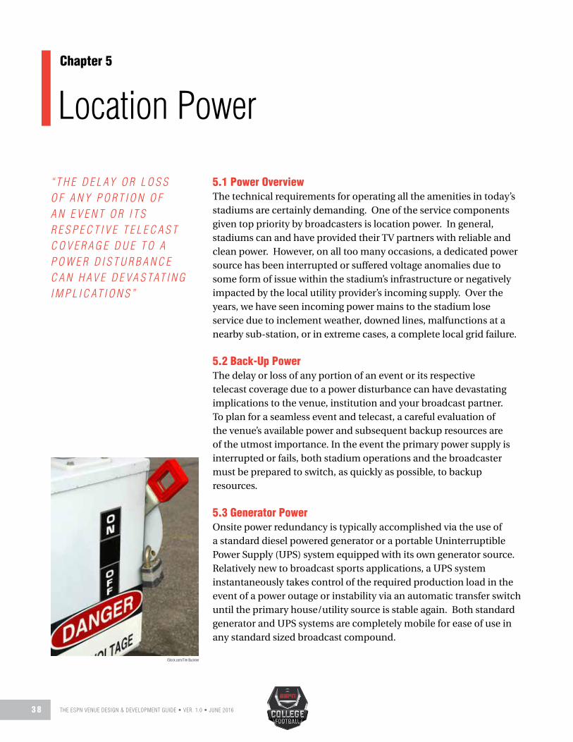
THE ESPN VENUE DESIGN & DEVELOPMENT GUIDE • VER. 1.0 • JUNE 20163 8
Location PowerChapter 5
5.1 Power OverviewThe technical requirements for operating all the amenities in today’s stadiums are certainly demanding. One of the service components given top priority by broadcasters is location power. In general, stadiums can and have provided their TV partners with reliable and clean power. However, on all too many occasions, a dedicated power source has been interrupted or suffered voltage anomalies due to some form of issue within the stadium’s infrastructure or negatively impacted by the local utility provider’s incoming supply. Over the years, we have seen incoming power mains to the stadium lose service due to inclement weather, downed lines, malfunctions at a nearby sub-station, or in extreme cases, a complete local grid failure.
5.2 Back-Up PowerThe delay or loss of any portion of an event or its respective telecast coverage due to a power disturbance can have devastating implications to the venue, institution and your broadcast partner. To plan for a seamless event and telecast, a careful evaluation of the venue’s available power and subsequent backup resources are of the utmost importance. In the event the primary power supply is interrupted or fails, both stadium operations and the broadcaster must be prepared to switch, as quickly as possible, to backup resources.
5.3 Generator PowerOnsite power redundancy is typically accomplished via the use of a standard diesel powered generator or a portable Uninterruptible Power Supply (UPS) system equipped with its own generator source. Relatively new to broadcast sports applications, a UPS system instantaneously takes control of the required production load in the event of a power outage or instability via an automatic transfer switch until the primary house/utility source is stable again. Both standard generator and UPS systems are completely mobile for ease of use in any standard sized broadcast compound.
“ T H E D E L AY O R L O S S O F A N Y P O R T I O N O F A N E V E N T O R I T S R E S P E C T I V E T E L E C A S T C O V E R A G E D U E T O A P O W E R D I S T U R B A N C E C A N H A V E D E V A S TAT I N G I M P L I C AT I O N S ”
iStock.com/Tim Buckner

THE ESPN VENUE DESIGN & DEVELOPMENT GUIDE • VER. 1.0 • JUNE 2016 3 9
Typical mobile unit powerinterconnect and monitoring panel
To ensure continuous operations, broadcasters may supply (at their own expense) either type of temporary power units at many (if not most) of their televised events. Typically, these vehicles are 12’ x 30’ or 12’ x 40’ in size. Sufficient access for refueling purposes should be considered when planning the TV compound layout. In addition, the 8’ - 10’ spacing between all compound vehicles and buildings addressed in Chapter 4 will apply equally to all generator placements. This practice will help establish an appropriate safe work area and allow required access to storage compartments underneath these units. As noted earlier in this guide, a broadcast compound situated in an enclosed or underground area must include
proper ventilation and support. Please reference Chapter 4 (Section 4.5) for more details. To ensure uninterrupted game operations and avoid unexpected event delays, it is highly recommended that venue management consider similar backup power measures. Backup means capable of supplying necessary power to key stadium functions (i.e. lights, scoreboard, game and play clock operations) for a minimum of three to four hours should be considered.
CAT Entertainment Services
CAT Entertainment Services
Illumination Dynamics

THE ESPN VENUE DESIGN & DEVELOPMENT GUIDE • VER. 1.0 • JUNE 20164 0
5.4 Broadcast Compound Shore Power A majority of the mobile units in the industry today require 400 amp 3 phase service at 208 volts. Please note, some trucks will utilize the full 400 amp service while others prefer splitting two (2) 200 amp services (1 - 200 amp service for technical/equipment power and 1- 200 amp service for environment control). Some mobile units (and other support vehicles) require only a single 200 amp 3 phase service (208v). Satellite uplinks can require anywhere from a single 200 amp single phase service (208v) to a 100 amp 3 phase service (208v).
With these figures in mind, the table below includes the minimum recommendation for dedicated power.
TV COMPOUND SHORE POWER400AMP
200AMP
100AMP
100AMP
20AMP
3 Phase 208v Services
3 Phase 208v Services
3 Phase 208v Services
1 Phase 208v Services
20 Amp Service
Regular Season (non-prime) 2 3 1 3 2
Prime-Time/Marquee Match-Up 3 3 2 3 2
Post-Season Conference Championship 3-4 3 2 3 6-8
NOTES:
1) Only qualified firms should be engaged to spec,
install, test and certify that all power provisions
meet or exceed local/federal codes and standards.
2) Overall power delivered and used within the TV
compound should be on a dedicated service and not
shared with any other venue requirements.
3) All terminal connections are to be housed in weather
resistant boxes/pedestals. Preferred enclosures are
constructed of stainless or cold rolled steel. Access
to the panels should include a weather sealed door
with drip shield.
4) Provisions for circuit breaker protection for all
branched circuits installed must be included.
5) All service connections to be provided on industry
standard twist-lock (Cam-Lok) non-interlocking
Crouse-Hinds E1016 series connectors.
6) Disconnect panels should be located within 50’ - 75’
of mobile units.
7) Grounding point(s) for TV units must be provided
near the disconnect panels.
8) The 20 amp services noted in the table above can
be placed in 120 volt duplex quad box receptacles
and contained within the panel enclosure. GFCI
protection for the 120V, 20 amp circuits must be
included.
9) Overall power described only applies to direct
TV broadcast support. If additional facilities are
required for venue functions (i.e. score board/
in-house video and their production vehicles)
or if local media uplinks/microwave units are to
be staged within the TV compound, additional
power requirements for their needs will have to be
addressed separately.
Compound electrical components and panels should be annually inspected.
iStock.com/Kadmy

THE ESPN VENUE DESIGN & DEVELOPMENT GUIDE • VER. 1.0 • JUNE 2016 4 1
5.5 Stadium Shore Power In addition to the previous stadium power accommodations referenced for cameras (Section 1.20) and the broadcast announce booth (Section 3.8), provisions for dedicated power on both sidelines should be included in the overall site plan. On most any level of telecast, broadcasters will need access to operate select audio and video equipment (i.e. wireless audio and video monitoring) at pre-determined locations along the sidelines. Requests for these accommodations should be made in advance of each event, fully reviewed with site management and must meet all necessary approvals prior to initial setup. Optimal locations are to be clearly outside of all game operational areas and allow for the use of a small portable table.
IN-VENUE POWER NOTES: Your project design team
should meet directly with contracted consultants to review
any requirements for 400/200 amp service connections.
Facilities with current or future plans to host concerts
or major entertainment events will require these higher
amperage levels. Broadcasters should not have any need for
service drops at these readings (within the seating bowl).
The 20 amp (120 volt) circuits indicated above, should
be terminated into standard GFCI equipped receptacles
and available on both the near and far sidelines. Ideally,
these drops will be placed inside weather proof enclosures
and not shared (or be on the same circuit) with any other
sideline support (i.e. player cooling/heating systems or
coach communication equipment). Final positioning for
these requirements should take into account and allow for
minimal extension cord use.
Sideline power requirements should include dedicated drops for broadcasters.
IN-VENUE SHORE POWER400AMP
200AMP
100AMP
20AMP
3 Phase 208v Services
3 Phase 208v Services
3 Phase 208v Services
120 Volt
Near Sideline See Note Below See Note Below - 2
Far Sideline See Note Below See Note Below - 2
Field/Tunnel Entrances (used for temporary studio sets) See Note Below See Note Below - 2
Camera Locations - - - Reviewed in Chapters 1/6
Announce Booth(s) - - - Reviewed in Chapter3
All temporary power placed outside the field of play along the sidelines will be matted and weather
proofed by broadcasters for added safety.
iStock.com/Oxford
iStock.com/Mark Hatfield

THE ESPN VENUE DESIGN & DEVELOPMENT GUIDE • VER. 1.0 • JUNE 20164 2
CablingChapter 6
6.1 Cabling OverviewIn the broadcast industry, permanent cabling provisions versus temporary cable installs (shown to lessen the potential for damage, service outages and trip hazards) are given top priority by broadcasters, as well as in-house video operations personnel. Today, venues are producing internal entertainment content for fans in attendance independently of on-site broadcasters. Recommendations and required infrastructure for both groups should therefore be project specific and planned on an individual basis. The material to follow is intended as a guide only and does not eliminate the need to seek expert advice from qualified broadcast integrators (along with input from rights holders) throughout all stages of planning, testing and installation.
As noted earlier in this guide, the TV compound is the central hub for all technical and production operations. As such, all broadcast connections should terminate within the TV compound. Optimally, all broadcast connections should be installed as “home-runs” (point to point). We strongly discourage the use of patch room(s) or any junctions between broadcast elements. It is important that facilities for cable connection be housed in weather resistant boxes/pedestals. Simple direct access between the TV compound, all camera placements, announce booth, game operations and other broadcast operation areas should be incorporated into the overall site plan. Preparations should include a full safety assessment of routes and the impact to the overall aesthetic properties of the venue. It is vital that only qualified broadcast consulting/integration firms are engaged to spec, install, test, label and certify that all provisions meet or exceed applicable local/federal codes and comply with broadcast rights holder’s recommendations.
6.2 Cabling Enclosures All terminal connections (mounting panels, plates, connectors and related hardware) are to be housed in weather resistant boxes/pedestals. These stainless or cold rolled steel enclosures (referred to in the industry as Job/Junction Box Television or “JBT”) are
“ R E C O M M E N D AT I O N S A N D R E Q U I R E D I N F R A S T R U C T U R E … S H O U L D T H E R E F O R E B E P R O J E C T S P E C I F I C A N D P L A N N E D O N A N I N D I V I D U A L B A S I S . ”
iStock.com/rolfbodmer

THE ESPN VENUE DESIGN & DEVELOPMENT GUIDE • VER. 1.0 • JUNE 2016 4 3
engineered for maximum flexibility in configuring cable installation and management. Their design specifically addresses the needs of professional broadcasters and the general audio/video marketplace. One firm offering complete product lines for your design team’s consideration is Bulloch Fabricating. Access to these panels should include weather sealed lockable doors with drip shields. Each JBT is to be appropriately labeled and that information is to be tracked in an overall cable management system (see Section 6.4 for more details). Final cable install and connection into each box must be neatly dressed and allow for a service loop (12’ x 15’) of excess cable. This will allow the front panels/bulkheads to be more easily removed for access and maintenance.
Provisions for one (1) 20 amp service (terminated in a 120 volt duplex receptacle with GFCI protection) needs to be provided immediately adjacent to each JBT location.
6.3 Cable Conduit (Broadcast) The general purpose of dedicated conduit for broadcasters is to provide a protective pathway and an efficient means of servicing required cabling. Additionally, it allows for an effective means for future installations, updating and necessary replacements. Improvements in cable technologies (along with the costly expense of repairing sensitive cable materials) have driven preferences for TV passageways to be primarily serviced by the combined use of lightweight steel electrical metallic tubing (EMT), rigid high density polyethylene (PE) and polyvinyl chloride (PVC) plastic conduits. EMT, also commonly referred to as thin wall, is the lightest weight steel conduit manufactured. Installers find it easy to alter or redirect as required while the material still maintains its essential protective properties. EMT is available in a variety of dimensions (2 ½”- 4”) and lengths (10’ and 20’). Your contracted broadcast consultant (along with a professional broadcast cable integrator) can assist with the selection of the appropriate EMT product based on its intended application. Regarding plastic raceways and their use in installations for TV, ESPN highly recommends the exclusive use of schedule 40 or 80 conduit. Despite its title, the word “schedule” has nothing to do with time. A conduit’s “schedule” has to do with the thickness of the walls. Although the inside dimensions of both are the same, schedule 80 pipe has a thicker outside diameter. It is found in many heavy industrial applications due to its impact resistance and is ideal for underground (and concrete encasements) installations.
Each conduit manufacturer (along with applicable codes) have specified diameter and capacity limits. Additionally, the required inside diameter of the conduit will be impacted by the method of cable installation. It is therefore necessary to discuss each project with a qualified broadcast consulting firm to determine its particular needs.
NOTE: One critical point to touch upon here: the
main I/O (Input/Output) panel placement within the
TV compound should be no further than 50’- 75’ from
the primary mobile unit parking location. Some
projects may opt for a broadcast interconnect room
verses multiple JBT pedestals at the TV compound.
On this point, there is no absolute right or wrong
approach. Interconnect rooms need to include one
(1) roll-up door (minimum of 10’ wide) along with a
single 3’ wide standard hinged door for ease of access.
Typical dimensions in the order of 16’ (20’ optimal)
wide x 15’ deep have been found to accommodate
most needs. Final sizing determination must take
into account any included provisions for other
media connections and the ultimate location of
the telecommunication demarcation point. Your
broadcast integration firm can address the overall
number, size and final location of all JBT boxes along
with inclusion of a interconnect room based on the
overall spec of the intended installation.

THE ESPN VENUE DESIGN & DEVELOPMENT GUIDE • VER. 1.0 • JUNE 20164 4
NOTE: Most broadcast conduit needs are met with 2”, 4” and
6” conduit banks. Additional information and application
specifics will be addressed later in this chapter.
The installation of cable through conduit is
primarily accomplished in two manners.
1) Pulling cable through conduit using a pull line
or rope.
2) Specialized equipment employing high volumes
of compressed air to install the cable. (Primarily
seen with fiber optics installs)
Curvature in conduit runs is a major deterrent
during cable install. Minor curving is unavoidable
due to layout, elevation and slight direction changes.
During planning and final conduit placement,
special attention needs to be given to the number
of sweeps, bends or offsets over the intended cable
distribution area. Additional information and
recommended limits will be addressed in Section 6.5.
NOTE: The consequences from striking gas or power
lines during conduit installation can be extremely
dangerous and potentially deadly. Before any
digging begins, it is essential that all underground
service lines (gas, water, power, etc.) in the project
vicinity are located, identified and well-marked. It
is recommended to contact the local “Call Before
You Dig” authority to ensure these provisions are
appropriately addressed.
6.4 Cabling ManagementProper cable management and the appropriate selection of conduit and cable trays (tailored to meet the specific requirements of any facility) will make permanent or temporary installations easier and more cost effective. Poor planning, sloppy install practices and inadequate labeling can lead to costly retrofitting, repairs in relative short order.
When designed and installed correctly, suitable cable management:
• Is more aesthetically pleasing• Supports larger weight load capacities• Preserves signal quality by avoiding cable stress
and sagging • Allows for easier and less costly expansion/
updating
During the planning, installation, and follow-up, the following items need to be addressed and integrated.
A. Industry standard mounting heights must be adhered to while taking into account the need to safely access components during install and ongoing maintenance.
B. All cable management components related to broadcast specific items should be easily and safely accessible by means of a small A-frame ladder and not require the need for any lift equipment.
C. It is essential that all requirements (including proper grounding) set forth by the National Electrical Code (NEC) (and any other applicable authority) are met and monitored.
D. Conduit and cable trays should not be overloaded or over-filled. They are to be managed within manufacturer-specified weight and spacing requirements. Additionally, in cases where there are more than three (3) cables located within a conduit (typical for broadcasting), the fill rate capacity should be no more than 40%.
E. All permanently installed cable needs to include a machine generated label (at each end) with designated location ID. All wall plates, racks or connection points, require laser engraved panel labeling. All labeling information is to be cataloged. All materials used for labeling should be sufficiently durable, weather resistant and suitable for the environment.

THE ESPN VENUE DESIGN & DEVELOPMENT GUIDE • VER. 1.0 • JUNE 2016 4 5
6.5 Cabling InstallationThe long established method of installing cable includes the use of a pull line attached to un-terminated cable stock (without connectors) and pulled into and through the conduit. Often, this method involves the use of specialized equipment in addition to required manpower to perform the actual pulling. It is essential that empty conduit be supplied with pre-installed pull line(s). The supplied product can consist of either a twisted rope or woven tape. The supplied line must be properly rated for maximum pulling tension. The stress of pulling cable through existing conduit will vary with the length of the route and the number of turns it has to make. The use of cable lubricants is strongly recommended. Cable lubricants reduce the amount of friction during a pull. This method requires sufficiently free clearance through the conduit and a lower volume fill.
In recent years the practice of pulling cable has been replaced (in select applications) with a newer method that utilizes compressed air to blow the cable into and through the conduit. This method requires specialized equipment producing high volumes of air. As with the standard pulling method, air-blowing techniques are also greatly affected by friction. As noted above, cable lubricants (along with pre-lubricated conduit) are strongly recommended. Regardless of which installation method is used, stress on cable during the install is of great concern. Exceeding the maximum allowable pulling tension (or the maximum allowable bending radius) can damage sensitive cable materials. Damage can be very expensive in terms interrupted service, repair and replacement costs. Additionally, it is extremely important (in both conduit and cable tray installs) that cables are not pulled on top of each other and never at a 90-degree angle. Improper install methods can lead to the cable’s protective outer jackets being cut or burned which may in turn expose sensitive inner components. These
ill-advised practices can lead to compromising the integrity of the install.
During cable installation into horizontal or vertical cable trays, it is very important that each cable be pulled separately and carefully laid into place. This independent cable isolation method will help avoid potential cable damage and the integrity loss addressed in the previous paragraph.
As noted earlier in this chapter, only qualified broadcast consulting/integration firms should be engaged to spec, install, test, label and certify all provisions meet or exceed local, state, federal code and any other authority or jurisdiction guidelines.
Permanent Installation – The cable route between the TV compound and primary stadium entry should be managed via a combination of dedicated conduit and cantilevered cable trays reserved exclusively for broadcast use. To preserve signal quality and avoid potential damage, conduit infrastructure supporting permanent installation should limit any curvature, turn, or bend (on a single pathway) to a maximum 90-degree adjustment in any direction. No more than two 90-degree adjustments (180-degree total) are to be positioned between any single pull points. This measured formula also applies to both horizontal bends and radius drops in cable trays.
iStock.com/chrisho

THE ESPN VENUE DESIGN & DEVELOPMENT GUIDE • VER. 1.0 • JUNE 20164 6
NOTE: All cables have a limiting factor surrounding
their “bend radius.” This measure simply denotes the
smallest radius a cable can be bent before excessive stress
or attenuation causes signal loss. This is of particular
importance with handling fiber-optic cabling and a primary
reason why the number and the severity of turns/bends are
restricted. In addition, your contracted broadcast consultant
(along with a professional broadcast cable integrator) can
assist with the appropriate Plenum and Riser rated products
and which classification will be required in order to be in
compliance with all applicable authorities and codes.
Temporary Installation Notes – Cable conduits are not recommended for temporary cable installs. There are no provisions for mechanical assistance that safely aids in this type of install. As such, all labor is performed manually. Temporary installs carry a much higher potential for cable or connector damage. Where cables are required to be routed between the TV compound and primary entry into the stadium; ground level troughs (with easily removable lightweight cover plates) or temporary cable ramps are the preferred options. These interlocking high weight bearing components protect cables and help to minimize potential trip hazards for workers, fans and other on-site support personnel. Standard ADA (Americans with Disabilities Act) and DDA (Disability Discrimination Act) compliant cable protectors are readily available for rental in most markets.
If conduit is the only means available to address temporary cable routing between the TV compound and the stadium, then 6” diameter (heavy duty) conduit must be provided. Please bear in mind that some types of broadcast cabling are equipped with large connectors making for a difficult pull and removal without a great deal of time, effort and the potential for costly damage. As noted above, permanent installations utilized raw or un-terminated stock which is more easily pulled through and the required connectors are attached afterwards. To preserve signal quality and avoid potential damage, the infrastructure supporting
temporary installation should limit any directional change (on a single pathway) to a maximum 45 degrees. Temporary cable installs via conduit must also address the following concerns:
• The first 24 inches of conduit (leaving any primary underground encasement) should be straight and contain no bends or turns.
• The maximum length of any temporary cable conduit shall be limited to 150 - 200 feet.
• A permanently affixed “draw string” (capable of high pulling tensions) must be included within each conduit.
• Complete separate accommodations for power and video/audio conduits must be provided.
• Any exposed conduit should include removable end caps to help provide water-tight and debris seal when not in use.
• Due to the overall dimension of broadcast cables with attached connectors; the number of required conduits may need to be double or triple the quantity of a permanent install.
A typical solution once temporary cable runs reach the stadium’s entry point is effectively managed by pre-installed J- shaped hooks. Mounted to the sidewall foundation (via sturdy fasteners), multiple hooks (approximately 4’ – 6’ apart) are required to support the necessary weight and to elevate the cables off the ground. The mounting height should be easily and safely accessible by the means of a small A-frame ladder and not require the need for any lift equipment during install or knockdown. Total weight considerations and available prefabricated cable support products for temporary cable installs can be best addressed in greater detail with your broadcast integrator or consultant.

THE ESPN VENUE DESIGN & DEVELOPMENT GUIDE • VER. 1.0 • JUNE 2016 4 7
6.6 Cable TypesBroadcast cable and its technical specifications continue to evolve along with advances in camera technology. The latest generation of high-resolution (high-frame rate) cameras provide incredible picture performance and unbelievable imagery. This progression has resulted in the need for a higher demand in cabling specifications to operate equipment at peak performance. Since most broadcasters will want to take advantage of this improved technology, there is a need to plan cable installations (along with retrofits or refreshes) with smart scalable solutions.
When you begin to consider current and potential future requirements, it can be a bit overwhelming; particularly with the current terms and technical jargon being tossed around. The following brief definitions are offered in hopes that it will help your design team more easily navigate their way through accessing current necessities.
SMPTE 311M – Fiber Optic and Copper Hybrid Cable (Society of Motion Picture and Television Engineers – “SMPTE”) This cable platform has become the preferred industry standard. This hybrid carries video signals (HD/SDI) between the camera and the associated camera control unit in the mobile unit over two single-mode optical fibers (thin glass filaments). This provides for both optimal redundancy and extended signal distance. Four separate copper electrical conducting elements support auxiliary needs and transport the necessary power to the camera. The cable’s outer sheath is Kevlar wrapped while the internal elements are individually housed in PE/PVC jackets to promote protection, strength and flexibility. SMPTE 311M is available in a three channel version which enables the operation of three separate cameras (per location) on a single cable run. This advantage promotes both ideal redundancy and cost efficiencies. ESPN highly recommends the use of 3-channel SMPTE cable over single channel configurations.
SMPTE 304M terminated with Lemo connectors are the industry standard. It is very important that all SMPTE cable terminations include a weather/debris cap.
Tactical Fiber Optic Cable - Extremely strong, lightweight, rugged fiber optic cable originally develop for use in military field operations which has been adapted for sports production. As with standard fiber optic cable, a video signal (HD/SDI) between the camera and the control unit is carried over an optical fiber. SMPTE 311m tactical cable (or TAC for short), is capable of high bandwidth signal carriage over significant distances. TAC cabling includes a layer of strong synthetic Kevlar yarn woven into fibers that help protect the glass filaments. An outer polyurethane jacket then adds an additional layer of protection. These cables are available in several assemblies for broadcast needs TAC-6, TAC-12, TAC-24…..etc. The related TAC number signifies the quantity of single-mode fibers included within each cable.
Sport remotes exclusively use single-mode fiber. “Multi-mode” fiber should never be specified or used in any broadcast application.
For all its many advantages, a major obstacle in broadcast applications is fiber optic’s inability to transport power between the TV compound and the camera location. Therefore, it is necessary to provide
permanent venue power immediately adjacent to each camera location utilizing TAC fiber. One (1) 20 amp service (per camera) terminated in a 120 volt duplex receptacle with GFCI protection is strongly recommended.
ST (Straight Tip) bayonet style connectors are the broadcast industry standard.
Triaxial Cable – Most often referred to as triax. Unlike the smaller lightweight fiber optic cable, triax is bulkier and substantially heavier polyethylene jackets and multiple braided metallic shields protect the copper conductors. These copper elements provide for both video signal (HD/SDI) and power transport between camera and the mobile unit. Triax is capable of carrying high bandwidth signals over shorter distances (fiber optic cable is capable of carrying much higher bandwidth capacities over significantly greater distances). Long the go to workhorse in the broadcast industry, triax is now giving way to the preferred SMPTE hybrid standard.
A wide variety of bayonet quick connect connectors are available for triax applications.

THE ESPN VENUE DESIGN & DEVELOPMENT GUIDE • VER. 1.0 • JUNE 20164 8
Coaxial Cable – Most often referred to as coax. A close relative to triax, coax primarily supports lower-frequency signals seen in video monitoring and audio signals. A polyethylene jacket and braided foil protect the cable’s copper center conductor.
A wide variety of BNC (Bayonet Neill Concelman) connectors are available for coax applications.
Audio/XLR Connections – An XLR connector is a style of electrical connector, primarily found on broadcast audio and lighting equipment. The connector is circular in design and will have between 3 and 7 pins depending upon the desired application. XLR connections are most commonly associated with “balanced audio” signals (3 pin), but are also commonly used for Intercom (4 pin), lighting control (4 and 5 pin), and low-voltage power supplies.
The term “balance audio” is in reference to the method of delivery. Typically, when two “balanced” devices are connected, the signal is delivered over three wires (a negative, positive and ground). The positive audio signal and the negative audio signal are identical, except for their polarities (which are reversed). The third conductor serves a common ground. In short, this process helps to eliminate or greatly reduce any potential noise from outside interferences (including electrical).
As with video cable, audio cable’s internal copper conductors have a flexible outer polyethylene shell while the internal elements are individually housed in PE inner jackets promoting additional protection, strength and flexibility. XLR connectors are available in male and female versions and can be customized to order in chassis or bulkhead mounted designs.
DT-12 (Dual Twisted) Audio Cable - Widely used by the mobile broadcast industry, “DT 12s” provide twelve balanced signal pairs. This rugged format primarily services broadcast intercom and audio applications. Thirty-seven multi-pin connectors (equipped with both male/female breakouts) are located at either end of the run. With the inclusion of XLR fan-outs (or direct-connect custom panels/wall plates) DT 12 cabling is more than capable of handling most microphone and communication needs throughout the stadium complex. Fiber optic cable also supports most audio, data and intercom needs very effectively. However, with its inability to transport power, broadcasters may be left without these vital services if any temporary power disruption occurs. DT-12’s copper elements provide reliable signal carriage along with the necessary power to operate required equipment making it an optimal backup option for broadcasters.
iStock.com/Barbara Henry

THE ESPN VENUE DESIGN & DEVELOPMENT GUIDE • VER. 1.0 • JUNE 2016 4 9
Source Location TriaxCable
SMPTE 3
Channel Cable
SM Fiber
Tac 6/12Cable
AudioDT 12
AudioXLR
(M- Male F-Female)
Coax5/10 Pair
CAT 5e/6Data
Game Camera (Cam 1) At or near left 20-25 yard line 2 2 1 1 6 6 - - 2M/2F 2M/2F - - 1 2
Game Camera (Cam 2) Mid Field at 50 2 2 1 1 6 6 - - 2M/2F 2M/2F - - 1 2
Game Camera (Cam 3) At or near right 20-25 yard line 2 2 1 1 6 6 - - 2M/2F 2M/2F - - 1 2
High End Zone Right (Cam 4) High End Zone Right 2 2 1 1 6 6 - - 2M/2F 2M/2F - - 1 2
High End Zone Left (Cam 4) High End Zone Left 2 2 1 1 6 6 - - 2M/2F 2M/2F - - 1 2
Slash Position(s) Near Side Positioned near side corner(s) - on an extended diagonal line through the playing field.
1 2 1 1 6 6 - - - - - - - -
Slash Position(s) Far Side Positioned far side corner(s) - on an extended diagonal line through the playing field.
1 2 1 1 6 6 - - - - - - - -
Reverse 50 Mid Field at reverse 50 1 2 1 1 6 6 - - - - - - - -
Field Level Box (Near Side Left 20) Left - Low End Zone/Near Side HH/Cart Camera
2 3 1 1 12 24 1 1 - - 5 5 2 3
Field Level Box (Near Side Right 20) Right - Low End Zone/Near Side HH/Jib
2 3 1 1 12 24 1 1 - - - - 2 3
Field Level Box (Far Side Left 20) Reverse Left Low End Zone/Far Side HH/Spare
2 3 1 1 12 24 - - 6M/6F 6M/6F 5 5 2 3
Field Level Box (Far Side Right 20) Reverse Right Low End Zone/Far Side HH
2 3 1 1 12 24 - - 6M/6F 6M/6F - - 2 3
Announce Booth Press Box 1 2 1 1 24 36 2 2 6M/6F 6M/6F 10 10 2 3
All 22 (Coaches Camera) On Camera Deck or Press Box Roof 1 2 - - 6 6 - - - - - - 1 2
Game/Play Clock Location TBD - Venue Specific 2 3 - - 6 6 - - - - - - - -
Beauty Camera Location TBD - Venue Specific 1 2 1 1 6 6 - - - - - - - -
Instant Replay Booth Press Box - - - - 12 12 - - 3M/3F 3M/3F 10 10 1 2
Aerial Cable Camera System Press Box - - - - 6 6 - - 2M/2F 2M/2F - - 1 2
Blimp Receive Press Box Roof/TV Compound - - - - 6 6 - - 2M/2F 2M/2F - - 1 2
Scoreboard Display/Timing Press Box - - - - 6 6 - - 3M/3F 3M/3F - - 1 2
Scoreboard Production Press Box - - - - 12 12 - - 6M/6F 6M/6F - - 1 2
Home SID Seat Press Box - - - - - - - - 2M/2F 2M/2F 5 5 1 2
Away SID Seat Press Box - - - - - - - - 2M/2F 2M/2F 5 5 1 2
Official Stats Press Box - - - - - - - - 3M/3F 3M/3F - - 1 2
Home/Press Conference Location TBD - Venue Specific 1 2 1 1 6 6 - - 4M/4F 4M/4F - - 1 2
Game Management Press Box - - - - 6 6 - - 4M/4F 4M/4F 5 5 2 3
Home/Visiting Radio Booth Location TBD - Venue Specific - - - - 12 12 - - 2M/2F 2M/2F - - 2 2
National Radio Booth Location TBD - Venue Specific - - 12 24 - - 2M/2F 2M/2F - - 2 2
Fiber Transmission Demarc Location TBD - Venue Specific - - - - 12 24 1 1 6M/6F 6M/6F - - 2 2
Uplink TV Compound/Aux Compound - - - - 12 24 1 1 6M/6F 6M/6F 5 5 2 2
Requ
ired
Reco
mm
ende
d
Requ
ired
Reco
mm
ende
d
Requ
ired
Reco
mm
ende
d
Requ
ired
Reco
mm
ende
d
Requ
ired
Reco
mm
ende
d
Requ
ired
Reco
mm
ende
d
Requ
ired
Reco
mm
ende
d

THE ESPN VENUE DESIGN & DEVELOPMENT GUIDE • VER. 1.0 • JUNE 20165 0
NOTES:
1) All cables need to be labeled (at both ends) with
designated location’s nomenclature. For example:
HI LT EZ - 1; Low Rt EZ - 2
2) In each location, cables, connectors, hardware and panels
are to be housed in weather resistant JBT boxes with drip
shields.
3) All SMPTE cable noted is 3-channel configuration. ESPN
highly promotes the use of this version of SMPTE cable
which economically supports three (3) separate camera
connections at each location drop. If single channel
SMPTE is to be deployed, each location indicated in the
table will require a minimum of two (2) separate SMPTE
cables.
4) Fiber noted is to be single mode terminated with
standard ST connectors.
5) Triax cable is to be fitted with standard King
Connectors.
6) Coax cable is to be fitted with standard King
Connectors.
7) Data cable to be punched down with industry standard
connectors.
8) To support fiber transport, the venue needs to incorporate
a 120 volt amp circuit (terminated into a quad box) at
each camera location noted above.
9) All of the on-field camera positions are “soft,”
meaning most do not require a dedicated position or
platform.
10) Two of the four field boxes noted to contain (1)
DT 12 and (12) XLR (6 males & 6 Female) cabled in
parallel.
11) Necessary provisions to address required cable routes
between TV compound and each location noted above
must be provided.
12) For temporary cable installation (required by
broadcasters to supplement permanent cable
infrastructure), provisions for ground level troughs (with
removable cover plates) and “J “ shaped hooks (to elevate
cables off the ground) should be provided.
13) Installation and final testing of all cable infrastructure to
be completed by industry certified professionals.
14) Overall cable described above applies to direct TV
broadcast support. If additional cable considerations
are required for in-venue requirements (i.e. score board/
in-house video) those options will need to be addressed
separately.
Rendering depicts standard JBT rackconnections for broadcast field placements.
Typical broadcast JBT field enclosure. Low profileflushmount options also available.
CFB Team
Bexel ESS

THE ESPN VENUE DESIGN & DEVELOPMENT GUIDE • VER. 1.0 • JUNE 2016 5 1
“ I T I S H I G H LY S U G G E S T E D T H AT A L L C O M M U N I C AT I O N P L AT F O R M S H A V E S O M E F O R M O F O N S I T E T E C H N I C A L S U P P O R T …A N D A L L O W F O R F U T U R E S C A L A B I L I T Y A N D E X P A N S I O N . ”
7.1 Voice, Data and Internet OverviewExisting venue communication capacities are under huge strains as fans use their mobile devices to send photos, texts, surf the web, and post social media content in ever increasing numbers. Optimizing a venue’s network resources is more important than ever as consumers’ avid demand for this access grows. An even more challenging situation occurs, if a facility opts to deliver specialized venue-specific content (in-house replays and advertising) to fans inside the stadium.
Media members and broadcasters alike require reliable voice, data and IT essentials while on site. It is highly suggested that all communication platforms have some form of on-site technical support (during setup and event hours) and allow for future scalability and expansion. This required technical framework will be comprised of industry standard cable, routers, switches, firewalls, and intrusion-prevention devices.
Understandably, firewall and protocols should be planned for and in place to protect the venue’s network against unauthorized traffic and control legitimate data. Optimally, any installed infrastructure should have the means to provide a Priority One quality of service (QOS) for approved affiliated media members and broadcast entities to connect directly to and bypass the larger network’s restrictive access. This “open access” can be password protected, limited in scope and include sufficient safeguards to keep the venue’s communication resources safe from unwanted cyber intrusions.
7.2 Communication Requirements – TV CompoundIn general, the broadcast compound location will require necessary infrastructure to support Plain Ordinary Telephone Service (“POTS”) lines and up to 1GB of high-speed bandwidth for Internet access including 802.11x Wi-Fi service or equivalent.
Voice, Data & InternetChapter 7
iStock.com/Milous

THE ESPN VENUE DESIGN & DEVELOPMENT GUIDE • VER. 1.0 • JUNE 20165 2
In order to accommodate the venue’s voice communication needs, your telco consultant will specify a standard PBX (Private Branch Exchange) or pure IP based system - VoIP (Voice over Internet Protocol) phone system for installation. It is extremely important that broadcasters have the ability to access and order phone lines independently of the in-house system. All too often, there are technical conflicts arising between the house system and the broadcaster’s onboard phone system. This will lead to communication challenges not only on site, but also between the venue and the broadcaster’s head-end. To avoid potential issues, the ability to order six to twelve (6-12) standard POTS circuits (per telecast) must be available (larger scale events may see this number double or triple). It is suggested to permanently install infrastructure to support a minimum of twenty to thirty (20-30) voice cable pairs. This additional capacity will support backup, repair challenges (with service carriers) and other media requirements.
These standard voice lines should be delivered over traditional twisted pair copper (or fiber optic wiring) to/from a local telephone company and the TV compound. Assigned voice lines should not require the need for extension dial (i.e. dial 8 or 9) to access an outside line or involve the use of an access code to dial long distance. There is no absolute requirement for terminating individual phone lines ordered to standard telephone jacks (RJ11). Final connection from the TV compound’s terminal block (or facility’s nearest telco closet) will be made directly to the mobile unit or uplink by a phone company representative or broadcast personnel.
NOTE: Today’s broadcast environments rely on faster
Internet pipelines more than ever. The speed of the service
provided not only impacts how team members access
information while on site, but it also affects the quality
of the experience they can deliver to the fans watching at
home. The old standard (DSL) technology provided by most
cable companies only a few years ago no longer supports the
needs of broadcasters today. As of this writing, IT framework
designed and installed for the TV compound needs to
support 1GB of high-speed bandwidth capacity with ample
room for future growth and expansion as IT capacities
expand. Primary broadcasters will be seeking multiple (and
independent) service connections up to the 300/20 Mbps
(download/upload) range. Required support for 100 Mbps
service connections will also still exist.
7.3 Communication Requirements - Instant Replay: Two (2) ring-down circuits (one primary/one back-up) need to be permanently installed between the TV compound and the Instant Replay Booth. A ring-down circuit provides a “Hot-Line” intercom between two phones. This circuit acts like a small version of a phone company’s central hub. It allows one phone to call another, but no dialing is necessary. The call is initiated by simply picking up the handset on the phone.
At a minimum, the venue needs to permanently install unshielded twisted pair (“UTP”) cable (enhanced CAT 6 24-guage cable is recommended) terminated on individual RJ11 modular jacks. The contracted instant replay service provider (or facility management) should include the required ring-down kit as part of their standard package.
Additionally, as noted on the broadcast cabling table in Section 6.6, one (1) TAC-12 Fiber is to be installed between the Instant Replay Room and the TV compound for independent camera and program feeds.
7.4 Communication Requirements - Game Management: In addition to permanently installed communication with the Instant Replay Booth, we strongly recommend two (2) ring-down circuits (one primary/one backup) to be pre-installed between the venue’s Game Operation Booth and the TV truck. This will allow for the mutual monitoring of potential weather, emergency and other venue safety concerns. The same provisions for CAT 6 twisted pair cable terminated on individual RJ11 modular jacks is required. If the

THE ESPN VENUE DESIGN & DEVELOPMENT GUIDE • VER. 1.0 • JUNE 2016 5 3
facility does not have access to an available ring-down kit ($100- $150 one-time purchase) please contact the broadcast rights holder in advance of each telecast.
Additionally, as noted on the broadcast cabling table in Section 6.6, one (1) TAC-6 Fiber should be installed between the Game Operations Booth and the TV compound for independent courtesy feeds or data sharing (i.e. weather monitoring).
7.5 Communication Requirement: Home/Away SID & Official Stats: As with game management, we strongly recommend pre-installing required wiring (same specs as instant replay and game management) to account for communication between the SID, official stats and the TV truck. One primary and one backup drop dedicated to each position. Broadcasters should supply the necessary ring-down kit to complete the communication loop.
NOTE: It is advisable to install an Ethernet connection (with
4 port hub) between the official stats position and the TV
truck to more easily facilitate separate required stats feeds.
7.6 Communication Requirements - Clock & Scoreboard Operation: Provisions for direct connection to the auxiliary output of the clock and scoreboard controller should be available to the TV compound. Termination of the ends to be compatible with the manufacturer’s (Daktronics, OES ...etc.) output and the input to broadcaster’s graphical scoring device. Usually, this is a very simple 9-pin serial interface cable connection between two serial ports (one male/one female end). We recommend the permanent installation of two (2) 9-pin serial interface cables (one primary/one backup). Additionally, it is advantageous if the output of the manufacturer’s system can also be tied (separately from above) to a VLAN (Virtual Local Area Network) connection. VLAN connections can then be made available to other parts of the venue (including the TV compound) if necessary. We recommend two (2) runs on CAT 6 twisted pair terminated on standard RJ 45 data jacks.
The inclusion of a single ring-down circuit pre-installed between scoreboard operations and the TV truck is advisable.
All voice, data and IT essentials should be designedto allow for future scalability and expansion.
It is highly suggested that all communication platforms haveonsite technical support during all setup and event days.
iStock.com/bjdizx iStock.com/bjdizx

THE ESPN VENUE DESIGN & DEVELOPMENT GUIDE • VER. 1.0 • JUNE 20165 4
7.7 Communication Requirements -Broadcast Announce Booth: Under the front working counter of the broadcast announce booth, provisions for the following should be provided:
• Two (2) wall mounted telephone outlets: One will be used as a standard phone line and the other will be connected to support emergency backup audio to the broadcaster’s main studio. Runs should be completely independent of the in-house system and easily terminated down in the TV compound’s demarcation. Wiring should consist of CAT 6 twisted pair terminated on standard RJ 11 jacks. Assigned voice lines should not require the need for extension dial (i.e. dial 8 or 9) to access an outside line or involve the use of an access code to dial long distance.
• Two (2) wall mounted data Ethernet connections: Data connections can support either in-house stats monitoring or hard link into the venue’s Internet gateway. Wiring should consist of CAT 6 twisted pair terminated on standard RJ 45 jacks.
Additional booth considerations include:
• One (1) ring-down circuit: The inclusion of a single ring-down circuit (mounted on the back wall) to the TV truck is advisable.
NOTES:
1) Internet connection to the broadcast booth should
support 100 Mbps minimum (150 Mbps optimal) speed.
2) It is recommended to visibly ID data, voice and ring-
down connections separately via color coding in addition
to standard labeling practices.
7.8 Communication Enclosures Communication connections are to be housed in heavy duty cabinets/pedestals. Only enclosures designed for use with telco equipment should be incorporated. All outdoor panels should be well suited for harsh environments and include weather sealed lockable front/rear access doors. Products come in a wide variety of styles and configurations. Your telecommunication consultant can address the overall number, size and final location based on the spec of the installation. A dedicated compound panel or cabinet may not be required if the telecommunication demarcation (demarc) servicing television is located within close proximity of the mobile units. Maximum distance between these two points should not be greater than 50’-75’ otherwise a standalone outdoor rated enclosure should be used.
7.9 Venue Transmission SupportThere are several means, but currently three primary methods of transmitting “backhaul” signals from a venue back to the broadcaster’s distribution point. Traditional satellite delivery via temporary C-Band/Ku-Band uplinks onsite, dedicated venue installations for fiber optic and IP (Internet Protocol) mediums. In TV terms, backhaul refers to the means of getting the video and audio content from the stadium back to the broadcaster’s main or final distribution center.
Typical uplink unit utilized bybroadcasters for back-haul paths
ESPN Images

THE ESPN VENUE DESIGN & DEVELOPMENT GUIDE • VER. 1.0 • JUNE 2016 5 5
In terms of uplinks, C-Band is more reliable under adverse weather conditions including heavy rain and snow than Ku-band. At the same time, C-Band uplinks require a larger footprint and their frequencies can be more congested and potentially vulnerable to interference. Full requirements for uplink truck support are addressed in Chapter 4 (Section 4.1) of this guide. There are certainly instances when standard uplink transmission is necessary (particularly when serving as the fully redundant backup path on larger or prime-time events), but with new video-compression standards evolving and the requirement to accommodate increased video, audio and data bandwidth loads, ESPN highly recommends venue management seek out other potential delivery providers for venue based interconnectivity.
As for fiber optic transport, current recommendations include two (2) on-site redundant in-bound/outbound service paths supporting all necessary encoding, decoding and video transmission capability for SD-SDI, HD-SDI, ASI, MPEG-2, MPEG-4 and JPEG 2000 formats. Additionally, uncompressed 720p and 1080p HD/SD circuits are highly advantageous. To support this initiative, venues should consider dual and diverse 10gb circuits to assist with approaching 1080p/60 format needs and beyond.
With the increased speed and reliability of Internet service, IP transport is fast becoming an alternative delivery method for broadcasters. In the not so distant future, IP transmission will continue its expansion and serve as a dependable backhaul backup on larger scale events and a primary source for smaller telecasts.
Your qualified broadcast consulting firm along with ESPN’s Remote Traffic Team will be able to introduce you to several providers (including Level 3, The Switch, AT&T … etc.) who can deliver and install both fiber and IP options for point-to-point and point-to-multipoint broadcast capabilities.
In-bound/outbound fiber servicepath monitoring display
In-bound/outbound fiber transmission connectionpanel accessed by broadcasters at select venues
iStock.com/Gareth Price GFX
J. La Chance

THE ESPN VENUE DESIGN & DEVELOPMENT GUIDE • VER. 1.0 • JUNE 20165 6
LightingChapter 8
“ W I T H T H E C O N S TA N T E V O L U T I O N O F C A M E R A T E C H N O L O G Y, W H AT W E R E S TA N D A R D L E V E L S O F L I G H T I N G O N LY A F E W Y E A R S A G O A R E N O L O N G E R A M P L E T O D AY. ”
8.1 Lighting OverviewThere are many essential features crucial to the design of stadium lighting systems, appropriate fixture selection, distribution manner, the quality, location and height of lighting stanchions are among the many fundamental elements to consider. The evaluation of these factors is a matter best managed between the venue and the detailed advice of its contractual specialist. This section of the guidebook will focus on the end results of these efforts.
With the constant evolution of camera technology, what were standard levels of lighting only a few years ago are no longer ample today. The latest generation of high-resolution/high-frame rate cameras provide incredible picture performance and unbelievable imagery. This progression has come with the need for a higher threshold of light to operate at peak performance. These developments could very well make for an interesting challenge for venues equipped with older lighting systems or designs. To avoid any potential issues, we advise that a technical evaluation of the lighting infrastructure plan be incorporated into a full case study. Part of this review should include luminary calculation sheets of projected levels along the playing surface and its boundaries. Readings must include, key measurement of horizontal/vertical illumination, uniformity and be provided in detailed worksheets.
The design team and venue management will undoubtedly find it advisable to work with a lighting design firm to ensure projected illumination levels provide for the minimum recommendation levels set forth later in this section. We highly recommend venues to be in compliance with the thresholds noted or agree to perform all necessary steps to meet these recommendations. For existing venues, these measures include: replacement of faulty or non-operable components, re-lamping, re-focusing of fixtures or the installation of temporary lighting enhancements. In any case, parties need to confirm lighting will meet or exceed recommendations and provide necessary field meter reading worksheets for verification.
iStock.com/Ermin Gutenberger

THE ESPN VENUE DESIGN & DEVELOPMENT GUIDE • VER. 1.0 • JUNE 2016 5 7
8.2 Lighting DefinitionsWhen you jump into the world of venue lighting, you can be overwhelmed with a slew of terms and technical jargon, especially if it’s your first time venturing into this realm. Below is a handy reference to some key lighting terminology that should be helpful while reviewing the remainder of this section.
Foot-candle (abbreviated fc) – Industry standard unit of measure of light intensity.
Illumination – Is the amount of light falling on the playing surface. It is often referred to as “lighting level.”
Horizontal Illumination – Is the level of light measured along a horizontal plain approximately three feet above the playing surface. The playing surface is divided into multiple grids or zones stretching across the entire field of play. Within each grid/zone, calculations of maximum, minimum and the maintained average level of illumination is measured.
Vertical Illumination – Is the level of light reaching the playing surface from the perspective of cameras both up top and at field level. This type of Illumination helps to show close up details of players, coaches and officials. The grids/zones used to review this type of illumination will vary according to a camera’s particular zone of coverage. Similar calculations and measurements are made as noted above (three feet above the playing surface), but these readings are primarily taken and recorded from the main game camera’s perspective (meter pointed toward the cameras on the press box side).
Uniformity – refers to the level of light change across an area/zone. Most often uniformity is expressed as a ratio. However, it may be easier to understand if it is referred to as a percentage of change between two adjacent or diagonal grids on the playing surface. Drastic variations in levels will create unique challenges for televised events.
Color Rendering – expressed as a rating from 0 to 100 on the Color Rendering Index (CRI), describes how a light source makes the color of an object appear to human eyes or a television camera. All things have a natural color. Team uniforms certainly run the full color gambit. Have you ever noticed how jerseys look under different lighting conditions? A jersey under the florescent lights in a locker room appears differently than the same jersey under direct sunlight on the field. In most applications, the higher the CRI rating on the index, the better its color rendering ability. As noted, the maximum rating is based on 100. A venue’s illumination plan should strive to achieve the best CRI rating possible which balances both spectators and broadcaster’s requirements while working within necessary fiscal parameters (a 65-70 CRI rating should represent the minimum target threshold). Project teams should work with your engaged lighting firm to find the most desirable plan that helps ensure any visual differences between what the human eye sees and the TV camera depicts are minimized.
Color Temperature - is a term used to describe the color of a given light. This term is always expressed in degrees Kelvin. Higher temps on the Kelvin scale are considered to be “cool” (more blue) while a lower temp is “warm” (more red). The broadcast industry has long considered 5600K (closest to ordinary daylight levels) to be the optimal standard. Traditional metal halide fixtures produce color temperatures around 4200k while LED fixtures can generate levels of 5600k or greater (newest LED models can be tuned between 4000k and 6500k). Understanding each project must work within necessary fiscal parameters, we request that the venue’s illumination plan strive to achieve a rating nearest to the preferred 5600k broadcast model as feasible. Your professional lighting consult should be able to present customizable options that can hopefully deliver the most suitably balanced solutions for all interested parties.
Note: Variations in color temperature
levels of more than 500K (from the
average value) will create challenges for
televised events and therefore should be
avoided.

THE ESPN VENUE DESIGN & DEVELOPMENT GUIDE • VER. 1.0 • JUNE 20165 8
8.3 Lighting ThresholdsThe tables to follow have been developed to provide a fresh look at the minimum requirements, recommendations and considerations fundamental to staging today’s telecast. These benchmarks have been produced in conjunction with the industry’s leading lighting design architects and consultants who specialize in this type of design.
Glare - Design of a venue’s lighting system along with the final layout, aiming pattern of fixture banks and the playing surface’s reflective properties should take in to account the potential for both direct and indirect glare. If not addressed properly, objectionable amounts of glare will have a negative impact on players, spectators and TV cameras alike. The broadcast equivalent of glare is termed “lens flare.” An experienced lighting vendor can assist your project team with the means, planning and accessories (glare shields) to help eliminate the potential for unacceptable glare.
Flicker - For years, sports venues have used metal halide lights to illuminate playing surfaces. A challenge in recent years for broadcasters has been the use of older style metal-halide lamps which produced excessive amounts of visible “flickering” (distracting flashing) especially with the increased use of super-slow motion/high frame rate cameras. As technology advancements with broadcast cameras continue to evolve, limitations on the maximum percentage of allowable flicker will likely increase. A knowledgeable lighting designer can assist your project team with the means, planning
and requirements to help set limits on flicker output (3 - 4% maximum limit is currently the optimal sensitivity level for broadcasters). Another viable option to eliminate an adverse flicker environment is with the installation of LED technology. While newer to outdoor venues, but making huge inroads, the inclusion of LED lighting has many advantages over traditional metal-halide fixtures including no visible flicker, longer life expectancy and energy savings. It is always advisable to consult with your professional lighting firm to weigh all options prior to making any final choices.
The industry basis for collecting measurements divides the playing surface along with the immediate perimeter (the 15’ extending from the field’s boundary line(s) towards the outer-wall) into 30’ x 30’ individual grids. This division creates an evaluation area consisting of 72 distinct grids across the field of play and an additional 40 grids within the adjacent perimeter for a total of 112 grid points.
iStock.com/Paulbr

THE ESPN VENUE DESIGN & DEVELOPMENT GUIDE • VER. 1.0 • JUNE 2016 5 9
TARGET RECOMMENDED MAX/MIN ILLUMINATION AVERAGE UNIFORMITY MEAUREMENT GRID/ZONE COVERAGE LEVELS ILLUMINATION RATIO
Horizontal Illumination Playing Surface 175 fc 200 fc 1.2:1 (72) 30’ x 30’ Grid Points
Vertical – Main Game Cameras Playing Surface 175 fc 200 fc 1.2:1 (72) 30’ x 30’ Grid Points
Vertical – Reverse Cameras Playing Surface 175 fc 200 fc 1.2:1 (72) 30’ x 30’ Grid Points
Vertical – High North & South End Zone Playing Surface 150 fc 175 fc 1.4:1 (72) 30’ x 30’ Grid Points
Broadcast Level 1 - denotes: venues consistently hosting prime-time appearances on ABC/ESPN/ESPN2’s to a full national TV audience.
TARGET RECOMMENDED MAX/MIN ILLUMINATION AVERAGE UNIFORMITY MEAUREMENT GRID/ZONE COVERAGE LEVELS ILLUMINATION RATIO
Horizontal Illumination Playing Surface 150 fc 175 fc 1.4:1 (72) 30’ x 30’ Grid Points
Vertical – Main Game Cameras Playing Surface 150 fc 175 fc 1.4:1 (72) 30’ x 30’ Grid Points
Vertical – Reverse Cameras Playing Surface 150 fc 175 fc 1.4:1 (72) 30’ x 30’ Grid Points
Vertical – High North & South End Zone Playing Surface 125 fc 150 fc 1.5:1 (72) 30’ x 30’ Grid Points
Broadcast Level 2 - denotes: venues consistently hosting prime-time appearances on ABC/ESPN/ESPN2 to a regional TV audience.
PLEASE NOTE: In some instances, only the required uniformity ratio and not the minimum foot-candle performance
spec has been specified. If proper uniformity ratios are achieved (between the field of play and the adjacent off-field
perimeters) illumination levels should remain within acceptable minimum thresholds. ESPN will be happy to work
with individual venues regarding any potential concerns or issues once projected reading worksheets and overall light
plans have been developed.
SPECIAL NOTE: For venues that fall into both telecast categories described, choose the game level that most often
applies. In most instances, we encourage the higher lighting threshold level to be applied. Additional lighting threshold
tables for venues exclusively hosting ESPN U, News and ESPN 3 events have been provided in the appendix section of
this manual.

THE ESPN VENUE DESIGN & DEVELOPMENT GUIDE • VER. 1.0 • JUNE 20166 0
Venue SafetyChapter 9
9.1 Safety OverviewThe venue authority (and any third party management) is responsible for providing a secure place of work and suitable environment for its staff, vendors, patrons and broadcast partners. As an event host, you must exercise practical care to see that the venue and all surrounding areas are reasonably safe. The information to follow is not intended to function as the definitive statement on all safety matters, codes or standards, but instead serve as a starting point to help identify best workplace practices. As emphasized throughout this guide, we strongly encourage the advice and engagement of industry specialists with the appropriate skills and experience to advise your team in all matters pertaining to venue safety.
Beginning during the design phase and reviewed annually thereafter, formal and informal risk assessments should be carried out. It is recommended that formal assessments be conducted by outside competent firms or persons with the appropriate skill and experience. Informal assessments should also be performed yearly by in-house teams to contribute their own expertise and working knowledge of the venue.
When covering events for broadcast, potential hazards can arise from any of the following:
• Manual handling of equipment during setup and knockdown • Trip hazards• Accessing broadcast camera positions• Working from heights• Adverse weather conditions• Noise levels• Disorderly fans
“ B E G I N N I N G D U R I N G T H E D E S I G N P H A S E A N D R E V I E W E D A N N U A L LY T H E R E A F T E R ,F O R M A L A N D I N F O R M A L R I S K A S S E S S M E N T S S H O U L D B E C A R R I E D O U T. ”
iStock.com/Craig Dingle

THE ESPN VENUE DESIGN & DEVELOPMENT GUIDE • VER. 1.0 • JUNE 2016 6 1
9.2 Working from HeightsAny fall carries with it a potential for serious injury. All work “at height” should be subject to detailed risk planning and assessment. A position should be considered “at height” if it can be reasonably determined that a person can be potentially hurt or injured by falling from it. Many venue management teams are unaware of their legal obligation when it comes to fall protection. For example, any open or exposed side of a broadcast position (including but not limited to: roof edge, vomitory, booth opening, platform, camera position or scaffold) that is four (4) feet or more above the level below (30” in the state of California) is considered a fall hazard and therefore governed under OSHA’s (Occupational Safety and Health Administration) “General Industry” guidelines.
These “General Industry” guidelines include provisions for the use of permanent or temporary guards, railing system, or an equivalent suitable barrier. Your industry specialist can review with your team the required standards in greater detail, but in general; a compliant barrier must be installed with a top railing between 39” and 42” and include a mid-rail at 21.” The top barrier must be able to withstand a force of 200 pounds applied in any direction (at any point along the structure). Elevated camera positions should be fitted with toe boards or some form of catch basin to prevent objects from falling on those located below. Additionally, for the safety of the operator and those situated in the adjacent area, all elevated positions of four (4’) or more are required by ESPN management to secure the camera tripod via a single point anchor. Most often, these anchorage points include a combination of appropriately rated eyebolt, turnbuckle and chain. The receiving hole for this anchorage point should be counter-sunk approximately 12-18 inches behind the front of the leading edge of the camera position. Eyebolts should be installed by a competent person who is knowledgeable about the intended application. TV crews generally supply their own turnbuckles and chain sets. It is highly
recommended that prior to starting any permanent installation of anchor points to consult with broadcasters to identify all required measures.
At camera locations, when fall protection is required, the first option should always be some form of OSHA compliant barrier. However, there are times when these might not be practical or feasible. It is acknowledged that installed barriers meeting height and safety requirements may obstruct sightlines. When dealing with broadcast positions, it is not uncommon to have an existing barrier in place during camera setup (protecting those installing the camera) and then remove or lower the barrier to allow for optimal sightlines and free unencumbered movement of the lens. While this approach eliminates the potential for interference or sightline concerns created, it will require the use of Personal Protective Equipment (or PPE) to reduce the risk of a fall exposure to workers. This form of fall prevention strategy requires the proper mix of PPEs, personnel training, and partnering with broadcasters regarding the facility’s potential fall hazards. The type of PPE to use will depend on the job application and specific hazard presented at that location.
Let’s address the distinction between two basic fall protection terms – “fall restraint” and “fall arrest.” The primary difference between arrest and restraint is an “arrest” occurs after a person falls. This form of protection stops a fall that has already occurred (preventing impact to a lower level). In “fall restraint,” a person is restrained from reaching a potential fall hazard. Typically, in these instances, the worker is fitted with a fixed-length lanyard and a body belt or full body harness. The lanyard acts as a leash, preventing the person from reaching the open or exposed hazard. We encourage your team to develop a comprehensive fall protection strategy and education program together with your industry specialist.

THE ESPN VENUE DESIGN & DEVELOPMENT GUIDE • VER. 1.0 • JUNE 20166 2
When or where compliant barriers are not feasible or present adverse sightline considerations and need to be temporarily removed during telecasts; provisions to support a “fall restraint” system must be provided. This includes a single anchorage point installed at least six (6) feet away from the exposed edge. The anchorage point should also be installed above the floor (four feet or more is preferred to minimize trip hazards) and centered directly behind the camera position. An anchorage point may be designed for a single user (5,000 lbs. rated) or two users (10,000 lbs. rated) as long as each user attaches with an appropriate fall protection lanyard and connector. ESPN recommends that all fall protection equipment be purchased through a certified specialist and is appropriately sizedand rated for the intended use.
Single point anchors are low cost and easy to use. As before, they should be installed by a competent person who is knowledgeable about the intended application. It is highly recommended that prior to starting any permanent installation to consult with broadcast associates to identify all required measures.
9.3 Slip and Trip Accidents Even the most benign accident can lead to a serious injury. In the workplace setting, most people may associate fall injuries with working from heights. Yet, according to the most recent surveys conducted by professional safety groups, the majority of fall-rated injuries occur as a result of same-level falls. It may be even more surprising to learn that slips, trips and falls cause an estimated 15 percent of all accidental deaths, second only to motor vehicle accidents. To minimize the potential risk and to ensure the safety and welfare of those on site, venue management must address both physical and human factors that can lead to these concerns.
A. Cable Routing
Venues without permanent cabling carry with them
a greater possibility for fall hazards resulting from
the need to install temporary or per event cable
runs. This heightened exposure can lead to potential
injuries and create greater liability exposure if not
planned and executed properly. Where temporary
cables are required to be routed between the TV
compound and primary entry into the stadium
(especially through public areas), ground level
troughs (with easily removable lightweight cover
plates) or temporary cable ramps are the preferred
options. These interlocking high weight bearing
components protect cables and help to minimize
potential trip hazards for workers, fans and other
onsite support personnel. Standard ADA (Americans
with Disabilities Act) and DDA (Disability
Discrimination Act) compliant cable protectors are
readily available for rental in most markets. (In some
instances, heavy duty industrial rubber matting may
also provide appropriate ground level protection
against trips, slips and falls in select applications).
A typical solution once temporary cable runs reach
the stadium’s entry point (from their underground
encasement) is effectively managed by pre-installed
J- shaped hooks. Mounted to the sidewall foundation
(via sturdy fasteners), multiple hooks (approximately
4’ – 6’ apart) are required to support the necessary
weight and to elevate the cables off the ground.
The mounting height should be easily and safely
accessible by the means of a small A-frame ladder and
not require the need for any lift equipment during
install or knockdown. The final phase involved in
temporary installs entails the delivery of cable and
its respective pre-terminated ends to all individual
camera positions and booths around the complex.
Poor planning or sloppy installation during this
phase of the process can introduce hazards for both
patrons and workers in relatively short order.
Note: Care should also be taken to avoid running
cable through declared “confined spaces” (includes
select types of vaults, manholes, culverts and tunnels)
that may not be suitable for non-certified personnel
to enter or work.
THE ESPN VENUE DESIGN & DEVELOPMENT GUIDE • VER. 1.0 • JUNE 2016 6 3
B. Slippery Conditions
Exposed concrete slab foundations utilized for camera
positions or decks can become slippery during inclement
weather, particularly when rain, ice or snowy conditions
are in the forecast. This especially holds true for color
hardened or sealed concrete surfaces. At the very least,
these conditions present challenges for safe setup/
operation and pose a potential hazard to broadcasters
if not treated with a slip-resistant finish.
There are multiple ways to create slip-resistant surfaces.
Two of the most common methods include texturing the
concrete itself (typically with a broom, trowel or other
hand tool) or by applying some sort of abrasive material
to the surface. There are several ways to accomplish
the latter: mix an appropriate gritty material into
the sealer before it’s applied, put down a textured slip
resistant paint, or by applying a gritty faced tape to
the surface. Where foot traffic tends to be heavy or in
broadcast application areas, abrasive grit material
offers the longest lasting non-slip surface option. We
highly suggest consulting with your general construction
contractor for the latest advice on suitable products.
C. Drainage
Special care must be taken to ensure proper drainage
is installed to deal with storm water run-off, provide
for snow removal and reduce the ability for ice to form
during colder months within the TV compound and all
camera locations. The primary objective is to ensure
that safe operating conditions exist at all these locations.
Chapter 4 of this guide spelled out required provisions
for the broadcast compound in detail (please reference
Section 4.3). Additionally, every permanent camera
location must also be equipped with similar drainage
provisions to withstand a heavy rain without the risk
of the camera operator, equipment or cables having to
operate in standing water. The final grading or pitch
for these positions should allow the water to channel to
the edge of the pavement (for run-off) or include some
form of modest floor drain. Care must be taken not to
over pitch these areas; the surface must be level enough
for the camera and operator to function efficiently. These
solid foundations should have a minimum 1% (1/8” per
foot) up to a maximum of 2% (1/4” per foot) grade to
the edge or drain. It is very important, that any grading
slope away from the JBT (cable I/O box) or electrical
outlets to prevent any potential damage or safety
concern.
Note: Any fabricated drain installed into camera
positions must take into account that most broadcasters
will install (or request the venue to install) an anchorage
eyebolt near the front of all concrete slab locations
(approximately 12”- 18” behind the front edge). As with
temporary platforms, this will allow the tripod to be
safely secured to the foundation. Consideration should
be given not to introduce potential interference to the
anchorage point from any drain placement.
D. Access To Positions
All walkways, stairways, catwalks, ramps or ladders
serving as entry or egress points to broadcast positions
must be designed in accordance with or to exceed OSHA
standards. If access requires climbing over a railing
or down into a position, the risk of slipping or falling
can be reduced by orienting a permanently installed
ladder system so that person only has to rotate 90
degrees to obtain access and by providing a handrail
that extends above the access edge. The handrail can be
designed to drop and stow once the operator has safely
descended into position. Additionally, an appropriate
fall protection anchorage point must be provided for the
operator to secure his/her PPE device to.
E. Equipment Case Storage
To minimize slip, trips and fall hazards and to provide
for a more secure and neat work area, a dedicated space
or suitable secure area situated near all camera positions
should be allocated to store empty equipment cases
during the telecast. It is advisable that this location be
as close to each camera location as possible to allow for
easy access by the TV crew. In addition, it is important
that provisions to lock and secure this area be made if at
all possible.

THE ESPN VENUE DESIGN & DEVELOPMENT GUIDE • VER. 1.0 • JUNE 20166 4
9.4 Noise LimitsUnlike other preventable work-related injuries, noise-induced hearing loss in workers may not be reported or usually even noticed when it occurs. One of the reasons is the damage usually accumulates over time. Its effects are realized long after the injury has happened. Unfortunately, hearing loss is permanent and irreversible. Many venue management teams are unaware of their legal obligation when it comes to protecting stadium workers from noise-induced hearing loss.
Limits surrounding noise exposure in the workplace falls under standards set by OSHA. These standards include both volume and length of exposure. According to OSHA, a worker may be exposed to 90 decibels (or dB) per eight-hour workday, but for every 5 dB increase in volume, the calculation for maximum exposure time must be cut in half.
Another agency administering work site safety, the National Institute for Occupational Safety and Health (NIOSH) recommends a lower exposure threshold equivalent to 85 dB for the same 8 hour period. Another important difference between the
agencies criteria exist in NIOSH utilization of a 3 dB exchange rate; in other words, for every increase of volume by 3 dB, the maximum exposure time is cut in half by the NIOSH standard.
To help reinforce this concept, we’ll review a couple of calculation examples. First, let’s start with OSHA allowance for 8 hours of permissible exposure limits (PEL) at 90 dB. Increase that level by just 5 dB (90 to 95) and the 8 hour maximum exposure time is cut in half to only 4 hours. If we increase the volume once more by an additional 5 dB (95 to 100) the four hour maximum is again cut in half to only 2 hours of exposure time. As noted above, NIOSH recommends limiting an 8 hour exposure to less than 85 dB. So if we take the same 100 dB model and re-calculate using NIOSH’s 3 dB exchange factor, the maximum exposure time is reduced to less than 15 minutes per day.
Leaf blowers measure between 70-75 dB; a chainsaw can be as loud as 110 dB; a rock concert can peak at 115-120 dB. Readings of cheering fans and bands in collegiate venues have been measured between 105-110 dB with occasional peaks above a 115 threshold. At these levels, it only takes between 1 and 15 minutes for that level of sound to cause potential damage. In 2014, Kansas City Chief fans proudly broke a Guinness World Record by achieving a noise level of 142.2 decibels in their stadium. By OSHA standards, a worker should only be exposed to this level of noise for approximately 24 seconds per day.
Where workers are expected to be exposed to noise levels of 85 dB or greater for 8 hours (as a time weighted average), a hearing conservation program which includes provisions for hearing protection should be implemented. When properly used, hearing protectors can reduce noise levels by 20 to 30 decibels and lower worker’s exposure below 85 dB where it will not cause hearing loss. There are several lower cost hearing protection options available including ear plugs (single and multiple use) and ear muffs.
Certified tech measuring in-game noise levels usingstandard digital db sound meter.
iStock.com/Bart Coenders

THE ESPN VENUE DESIGN & DEVELOPMENT GUIDE • VER. 1.0 • JUNE 2016 6 5
ESPN has an existing hearing protection program in use, which includes both education and distribution of hearing protection to all vendors and technicians working on televised event sites.
9.5 Emergency PlanningArchitects and design engineers need to ensure that final stadium plans are compliant with all applicable local and federal fire protection and safety standards. Venues should also establish a well-defined official emergency action plan which includes step-by-step guides outlining the course of action in the event of fires, evacuation, terrorism, threats of violence, and inclement weather scenarios. This strategy should contain information about the different levels of emergencies and outline the corresponding roles and responsibilities of management and workers alike. This blueprint should include specifications not only when the venue is fully-occupied, but during non-game day activities when workers and broadcasters may be onsite prepping the facility.
An effective emergency action plan should clearly identify protective actions to take during severe weather. Lightning is the most consistent and significant weather related hazard for outdoor events. There are approximately 60-70 fatalities and 10 times as many injuries from lightning strikes every year across the United States.
Appropriate safeguards should combine the use of an on site live (non-delayed) weathering monitoring system with lightning detection and identify specific criteria for suspending and resuming in-game activity. The policy should outline steadfast timeline standards for lightning suspension and a required evacuation timetable. Many venue managers continue to misinterpret existing recommendations provided by weather safety experts. The National Severe Storms Laboratory (NSSL) strongly recommends that all individuals should have left the game site and reached a safe structure or location by the time lightning is detected at a six-mile threshold.
9.6 Scaffolding Used For Camera Platforms Scaffolds used as camera platforms must comply with OSHA scaffold standards. They must be constructed, assembled and used in accordance with the manufacturer’s instructions. All permanent or temporary scaffolding must be assembled, maintained and inspected by a properly trained competent person or firm.
In order to achieve this measure, an evacuation of the venue must begin prior to six-mile detection. ESPN has adopted a policy that includes a mandatory withdraw and suspension of all exposed activities once lightning is detected at 8 miles. This allows sufficient time for all persons to reach a safe location by the time lightning reaches NSSL’s six-mile suspension recommendation. Professional safety organizations and national authorities endorse directives that suspend all activities completely until 30 minutes after the last lightning strike has been detected.
All applicable local/federal standards applying to venue ortemporary structures should be reviewed and applied.
iStock.com/Warchi

THE ESPN VENUE DESIGN & DEVELOPMENT GUIDE • VER. 1.0 • JUNE 20166 6
9.7 Stadium Security/Disorderly FansEach venue should have a comprehensive plan for both preventive measures and appropriate response to spectator aggression or violence. It is critical that venue managers be acquainted with their venue’s capabilities and workflows to better respond and then recover from incidents of aggression. Although there is no assurance of absolute 100% precautionary procedures in combating these threats, effective planning and management can reduce the risk to as low as reasonably practicable. Failure to prevent incidents can produce a variety of negative consequences including telecast interference and potential injury to spectators, broadcast technicians, venue workers and security personnel. Fans coming to your venue are entitled to have a good time, to be passionate and enthusiastic while cheering for their team. They just shouldn’t interfere with anyone else’s enjoyment of the game, or those working to provide broadcast coverage of the event. A truly effective plan attempts to achieve the right balance between the interests of all parties.
9.8 Sideline Safety ConcernsAll venues should develop and enforce a strict in-game sideline access policy. An effective planwould include provisions that limit the distribution of “field credentials” to only individuals or organizations that have a legitimate working function. Any non-team, media member, VIP or guest without a working capacity or valid need to be on the sidelines should be restricted to pre/post-game access privileges. The primary intent of this requirement is to provide for the safety/welfare of all persons, players, media members, support staffand game officials. This restriction will also help avoid any possible interference with game or broadcast operations.
This standing rule, along with the previously addressed requests for a broadcast rights holder’s “buffer Zone” (Chapter 1 - Section 1.13) and a clear unobstructed space for sideline vehicles to operate (Chapter 1 Section 1.14), will help ease the overcrowding and safety concerns that have steadily increased along the sidelines over the last several seasons.
Sideline overcrowding and safety concerns have steadilyincreased over the last several seasons.
Venues should have a comprehensive plan to address guest/workersafety and procedures to deal with disorderly patrons.
iStock.com/People Images iStock.com/Jay Stevens

THE ESPN VENUE DESIGN & DEVELOPMENT GUIDE • VER. 1.0 • JUNE 2016 6 7
Throughout the process of creating this guidebook, many individuals from the broadcast community have taken a break from their hectic schedules to offer special commentary and support following draft reviews of this manual. On behalf of ESPN, we wish to thank each for contributing their time, knowledge, and insight to this project. We would also like to personally thank our senior leadership, particularly Chris Calcinari for enabling our team to take the time to author and publish this guide. Without their support and contributions, this initiative would not have become a reality.
Finally, we would like to express our sincere gratitude to ESPN’s Content Edit Group (Kenneth Bowell/Joseph Frady/Ivery Johnson), ESPN’s Legal Department (Dave Soskin/Michele Kenausis/ Michael Civitello) and to the entire College Football Operations Team for their active participation and contributions. A special thank you to Jay Gleeson, Leigh Michaud and Taylor Morasutti for their extensive proof reading and support provided over the past several months of this project.
Photos and renderings featured in this guide have been licensed and commissioned by ESPN. All rights reserved. ESPN would like to credit the following parties for use of their images: Bexel, CAT Entertainment, ESPN Images, Illumination Dynamics, Populous, and Wrightson, Johnson, Haddon and Williams Inc., Cam Cottrill, iStock, and Todd Detwiler.
Acknowledgements
iStock.com/Geber86
iStock.com/lechatnoir iStock.com/Swell Photography iStock.com/David H. Lewis
ESPN Images

THE ESPN VENUE DESIGN & DEVELOPMENT GUIDE • VER. 1.0 • JUNE 20166 8
Appendix A. Vendor Considerations/Contacts
BROADCAST CONSULTING & DESIGN
Bexel ESSBurbank Headquarters2701 N Ontario StreetBurbank, CA 91504Site: www.bexel.com/bexel-ess
John [email protected](972) 870-2318
IdibriDallas Headquarters15508 Wright Brothers DriveAddison, Texas 75001 USASite: www.idibri.com
Ben [email protected](972) 239-1505
Wrightson, Johnson, Haddon & Williams, Inc. (WJHW)Dallas Headquarters3424 Midcourt Rd, Suite 124Carrollton, TX 75006Site: www.wjhw.com (972) 934-3700
Chris Williams (ext. 248)[email protected]
Jack McCallum (ext. 266)[email protected]
BROADCAST SYSTEM & CABLE INTEGRATORS
Bexel ESSBurbank Headquarters2701 N Ontario StreetBurbank, CA 91504Site: www.bexel.com/bexel-ess
John [email protected](972) 870-2318
Parsons TechnologiesMinneapolis Headquarters 5960 Main Street NEMinneapolis, MN 55432Site: www.parsonscorp.com
Troy [email protected](763) 528-2248
Pro Sound & Video1375 NE 123rd St Miami, FL 33161 Site: www.prosound.net
Rod [email protected] (305) 891-1000
R. Orange Inc.Engineering & Installations Services200 South Wilcox StreetSuite 412Castle Rock, Colorado 80104Site: www.rorangeinc.com
Dave [email protected](303) 517-3763
BROADCAST ANNOUNCE BOOTH WINDOW SYSTEMS
Nanawall SystemsSingle Track Sliding Window Systems100 Meadowcreek Drive #250 Corte Madera, CA 94925Site: www.nanawall.com
George WiedenhoferNational Sales [email protected](415) 380-2871

THE ESPN VENUE DESIGN & DEVELOPMENT GUIDE • VER. 1.0 • JUNE 2016 6 9
Solar InnovationsFolding, Sliding & Stacking Window Systems31 Roberts RoadPine Grove, PA 17963Site: www.solarinnovations.com
Josh [email protected] (570) 915-1500
BROADCAST CABLE/POWER ENCLOSURES
APX Enclosures, Inc.200 Oregon Street, Mercersburg, PA 17236Site: www.apx-enclosures.com
Lew [email protected](717) 328-9399
Bulloch Fabricating Inc.450 E Purnell StLewisville, TX 75057Site: www.bullochfab.com
Dean Peters [email protected](972) 221-6277
LIGHTING MANUFACTURES
Ephesus Lighting 125 East Jefferson ST Syracuse, NY 13202 Site: www.ephesuslighting.com
Angela [email protected](315) 849-2755
Michael [email protected](315) 569-2004
Musco Lighting100 1st Avenue West P.O. Box 808Oskaloosa, IA 52577Site: www.musco.com (800) 825-6020
Current, Powered By GE745 Atlantic AvenueBoston, MA 02111Site: WWW.CurrentbyGE.com
TEMPORARY LIGHTING
Musco Lighting100 1st Avenue West P.O. Box 808Oskaloosa, IA 52577Site: www.musco.com (800) 825-6020
LIGHTING DESIGNERS & CONSULTANTS
Henderson Engineering Inc.8345 Lenexa DriveSuite 300Lenexa, Kansas 66214Site: www.hei-eng.com
Michael Tran [email protected](913) 742-5775
Doug Weis [email protected](913) 742-5516
ME Engineers, Inc.14143 Denver West Pkwy, Suite 300Golden, Colorado 80401Site: [email protected]
Corey [email protected](303) 421-6655
Smith, Seckman Reid, Inc.2995 Sidco Dr. Nashville, TN 37204Site: www.ssr-inc.com
Scott Terry, [email protected]
Mike Rogers, [email protected](615) 383-1113

THE ESPN VENUE DESIGN & DEVELOPMENT GUIDE • VER. 1.0 • JUNE 20167 0
SECURITY/SAFETY
ESPN Security Safety & Health TeamESPN PlazaBristol, CT 06010
Gerald [email protected]
VENUE FIBER TRANSMISSION
AT&T Broadcast Video84 Deerfield LaneMeriden, CT 06450Site: www.business.att.com
Ron [email protected] (203) 317-5382
Level 3 Communications1 Penn Plaza, Ste. 5100New York, NY 10119Site: www.level3.com
Byars ColeAccounts Dir. [email protected] (212) 487- 0141
(Vyvx Specialists)
Mike Riccio(212) 487-0156 [email protected]
Jay Lebowitz(860) [email protected]
The Switch420 Lexington Ave, Suite 805New York, NY 10170 Site: www.theswitch.tv
David ShearerV. P. Sales(646) 560 [email protected]
Christian KneuerSr. Dir. of Sales(212) 239 [email protected]
ESPN REMOTE TRAFFIC TEAM
ESPN Remote Traffic TeamESPN PlazaRemote Production OperationsBristol, CT 06010
Bryan [email protected]
Adam [email protected]

THE ESPN VENUE DESIGN & DEVELOPMENT GUIDE • VER. 1.0 • JUNE 2016 7 1
Appendix B. Skycam Specs
In 2013, Kroenke Sports and Entertainment acquired SkyCam LLC, and began a significant investment in upgrading and expanding the SkyCam business. With KSE’s backing and commitment, Skycam has undergone a multimillion dollar expansion in the development and delivery of the new SkyCam “Wildcat System.”
Wildcat represents the Worlds’ best in engineering, automation, and broadcast technology, creating an advanced and flexible aerial camera system, so unique it has received its first of several US and World patents in 2015.
The 4 axis stabilized Wildcat system delivers amazing stabilization and image quality, while its open architecture allows for many different payload options to be flown safely in the space the system spans.
As the Global leader in aerial camera systems, SkyCam paved the way for safe and reliable operation with proprietary advanced software including line avoidance, obstacle avoidance and remote monitoring. In addition, the system has received engineering approval from the NFL, NCAA, UL, LADBS, and an independent lab certifying all safety ratings and factors. No safer system exists in the world.
Each system deployed undergoes a daily pre-deployment inspection, and is digitally logged on SkyCams proprietary monitoring and logistics software system, FlightDeck. SkyCam has an experienced engineering, operations, and management team, and is routinely requested to operate at the Worlds’ marquee events. We look forward to adding your event to our list.
WORLDS’ FIRST AERIAL CAMERA SYSTEM CONTINUES ITS LEGACY AS THE MOST ADVANCED AERIAL CAMERA SYSTEM.
SKYCAM LLC • 630 N. Freeway, Suite 350 • Fort Worth, TX 76102For Booking Information Call 817-984-6840 or [email protected]

THE ESPN VENUE DESIGN & DEVELOPMENT GUIDE • VER. 1.0 • JUNE 20167 2
SPECIFICATIONS
4-AXIS OPEN ARCHITECTURE SPARCAPABLE OF OPTIONAL PAYLOAD TYPES
Camera Head Endless 360° Pan, tilt with -100 look back, and 65 degree look up
Camera/Lens Cameras: HD Sony P1, Grass Valley LDX Compact. Lens: Fujinon 12x4.5, 18x5.5
Specialty cameras Ultra Motion/4KCameras/ 3D
Only Aerial Camera company to Successfully deploy 4K-Grass Valley LDX Compact, LMC Pico, and 5D stereoscopic 3D/multi camera payloads
Virtual Graphics VR and AR integrated through nCam. Live 1st and 10 positional data (yellow line) with SportVision and SMT
Spar Dimensions & Weight 48” tall and 18” wide. 45 lbs. with full camera and lens payload.
Speed Over 25 MPH
Power Embedded support cable, battery option available (8 hour)
Winch Size 18”x 24” x 18” 135 lbs. Requires only 5’x5’x5’ space to deploy. Smallest/ most flexible system in the world.
Winch & RCE Power Standard 5-wire US 208 3 Phase 30A. at winch location. RCE (Reel Control enclosure) measures 24”x24”x12” 100 lbs.
Engineering & Rigging Approved in all venues and insured to $10 million. No complicated rigging or seat kills; less than 150 lbs. tension pulley points, and boom lifts. Engineering Stamps Provided for Venues, UL 508A approved equipment.
Ownership & Manufacturing Owned and Operated by Kroenke Sports & Entertainment. 45,000 Square foot facility, dedicated engineering, and operations staff. Made with Pride in the USA.
Software & System Safety Closed loop system. Only product with software for collision avoidance, boundaries, obstacles, and line avoidance. E-stops located at each reel location and operator position. Watertight IP65 connections. System rain tested and designed for outdoor use.
Worldwide Safety and Logistics Online Portal for safety checks and alerts, venue and job logistics, planning and for crew, and event host.
Intellectual Property SkyCam has over 40 US and World Patents, Trademarks, and other Intellectual Property
SKYCAM LLC630 N. Freeway, Suite 350Fort Worth, TX 76102For Booking Information Call 817-984-6840or [email protected]

THE ESPN VENUE DESIGN & DEVELOPMENT GUIDE • VER. 1.0 • JUNE 2016 7 3
Appendix C. Spidercam Specs
phone: +1 201 842 0100 fax: +1 201 842 0101 mail: [email protected] web: www.spidercam.tv
spidercam US, inc. 70 commercial ave, unit c moonachie, NJ 07074 USA
QU
ALI
TY
The spidercam® SC250 was designed to work in large stadiums, studios or other big event areas but has surprised many clients with its agility and ability to also perform in much smaller areas.
All equipment is built to handle the demand-ing work of indoor and outdoor broad-casting including harsh weather conditions we sometimes have to cope with.
One of spidercam GmbHs main goals has al-ways been to provide the best possible pic-ture while maintaining the highest level of safety for performers, players and audience beneath the flying camera.
Certification: The requirements of the German TÜV were adhered to and were a major influence during the system’s design and initial construc-tion.
Annual inspection: To maintain the safety of the spidercam®, every spidercam® system under-goes a detailed, annual inspection by Spidercam GmbH engineers. All parts that are prone to abra-sion are changed at regular intervals in accord-ance with the maintenance and service schedule.
SAFE
TY
IDEA
spidercam® is a computerised cable camera system used for broadcast events and feature film produc-tions all around the world. It can move freely in a three dimensional area and delivers previously impossible pictures of sporting events, studio productions or concerts.
Dolly specs
Dimensions (l/w/h) 2/2/5.5ft
Weight 66lb
Power Li-ion batteries (6hrs runtime)
Speed 28fps / 19mph
Pan 360° endless at 120°/s
Tilt +100° / -110° at 120°/S
Data Transmission Optical (Fiber)
spidercam® SC250 overview

THE ESPN VENUE DESIGN & DEVELOPMENT GUIDE • VER. 1.0 • JUNE 20167 4
phone: +1 201 842 0100 fax: +1 201 842 0101 mail: [email protected] web: www.spidercam.tv
spidercam US, inc. 70 commercial ave, unit c moonachie, NJ 07074 USA
spidercam® SC250 requirements
Weight: 26.2kg [57,1lb] (without camera)
Power: 4 x Li-Ion batteries with runtime 6-8 h
Dimensions: L = 1.8m [5 -10”] / W = 0.6m [1’ -12”] / H = 0.6m [1’ -12”]
Speed: 9m/s [20mph]
Flight Area: 250 x 250m / 820” x 820”
Weight: 315kg [695lb] (each)
Power: 480VAC (-10% – +10%), 30A, 50Hz/60Hz, 3 Phase with ground and neut-ral. Our winches are equipped with 7H, IP44 CEE connectors. (IEC 230519)
Dimensions: L = 1.5m [4’ -11”] / W = 0.9m [2’-12”] / H = 0.9m [2’-12”]
Forces: 330m [1080”] of aramid composite cable per winch. The break and strain rating of the cable is 12,000N (maximum force in catenary cables is 1,200N)
Weight: 5kg [11lb] (each)
Dimensions: L = 0.3m [0’ -12”] / W = x 0.3m [0’ -12”] / H = x 0.3m [0’ -12”]
Forces: Designed to withstand a force of 10,000N (maximum force in system during operation is 1,200N)
Weight: 65kg [143.5lb]
Power: 110VAC-230VAC, 16A, 50Hz/60Hz, 1 Phase plus ground and neutral
Dimensions: L = 3m [9’ -10”] / W = x 2.5m [8’ -2”] / H = x 1.4m [4’ -7”]
DO
LLY
W
INC
HES
P
ULL
EYS
C
ON
TRO
L S
TAII
ON

NanaWall for Broadcast Booths
NanaWall Aluminum Framed Thermally Improved Single Track Sliding System HSW60
NanaWall Offers Choice of Folding, Sliding, and Frameless Opening Glass Wall Systems
• NanaWall Folding Systems are chains of bi-folding door panels
that fold-and-stack inward or outward to either side of the
opening. The stacked panels remain within the main opening.
• NanaWall Single Track Sliding Systems are individual top-hung
panels that can support virtually any shape and can be stacked
outside the opening in a variety of parking options.
Nana Wall Systems, Inc.
100 Meadowcreek Drive #250
Corte Madera, CA 94925
800 873 5673
415 383 3148
Fax 415 383 0312
nanawall.com
Panels Stack Outside of the Opening
THE ESPN VENUE DESIGN & DEVELOPMENT GUIDE • VER. 1.0 • JUNE 2016 7 5
Appendix D. Nanawall Window Systems

THE ESPN VENUE DESIGN & DEVELOPMENT GUIDE • VER. 1.0 • JUNE 20167 6
Trusted to be Included in Hundreds of Sports Venues
Installed at over 130 stadiums throughout North America,
NanaWall is the experienced leader in providing solutions for
stadium projects.
NANAWALL OPENING GLASS WALLS PROVIDE
Operable: The flexibility to open or close
Flexibility: A wide selection of systems and configurations
Privacy: Sound separation from the event without isolation
Safety: Impact resistance options
Protection: Off-season protection for interior spaces
Please contact NanaWall’s Dedicated Design Team [email protected]
800 873 5673
©2015 NANA WALL SYSTEMS, INC. Nana Wall Systems reserves the right to change specifications without notice. NanaWall and the NanaWall logo are trademarks of Nana Wall Systems Inc.
Nana Wall Systems, Inc.
100 Meadowcreek Drive #250
Corte Madera, CA 94925
800 873 5673
415 383 3148
Fax 415 383 0312
nanawall.com
NanaWall Aluminum Framed Thermally Improved Folding System SL70
Design Considerations
• Half height panels over the drink rail or full
height panels with the rail on the front or
behind.
• Operationally, do the requirements need
the panels stacked within the plane of the
opening or out of the plane of the opening.
• Material Choices
- All glass with no vertical sightlines
- Thin framed aluminum profiles for more temperate climates
- Thermally improved with sound controlled insulated glass for the harshest of conditions

THE ESPN VENUE DESIGN & DEVELOPMENT GUIDE • VER. 1.0 • JUNE 2016 7 7
Appendix E. Add’l Lighting: ESPN News/3
TARGET RECOMMENDED MAX/MIN ILLUMINATION AVERAGE UNIFORMITY MEAUREMENT GRID/ZONE COVERAGE LEVELS ILLUMINATION RATIO
Horizontal Illumination Playing Surface 125 fc 150 fc 1.5:1 (72) 30’ x 30’ Grid Points
Vertical – Main Game Cameras Playing Surface 125 fc 150 fc 1.5:1 (72) 30’ x 30’ Grid Points
Vertical – Reverse Cameras Playing Surface 125 fc 150 fc 1.5:1 (72) 30’ x 30’ Grid Points
Vertical – High North & South End Zone Playing Surface 100 fc 125 fc 1.7:1 (72) 30’ x 30’ Grid Points
PLEASE NOTE: In some instances, only the required uniformity ratio and not the minimum foot-candle performance
spec has been specified. If proper uniformity ratios are achieved (between the field of play and the adjacent off-field
perimeters) illumination levels should remain within acceptable minimum thresholds. ESPN will be happy to work
with individual venues regarding any potential concerns or issues once projected reading worksheets and overall light
plans have been developed.
Broadcast Level 3 – denotes: venues consistently hosting prime-time appearances to ESPN U full national audience.
TARGET RECOMMENDED MAX/MIN ILLUMINATION AVERAGE UNIFORMITY MEAUREMENT GRID/ZONE COVERAGE LEVELS ILLUMINATION RATIO
Horizontal Illumination Playing Surface 100 fc 125 fc 1.7:1 (72) 30’ x 30’ Grid Points
Vertical – Main Game Cameras Playing Surface 100 fc 125 fc 1.7:1 (72) 30’ x 30’ Grid Points
Vertical – Reverse Cameras Playing Surface 75 fc 100 fc 2:0:1 (72) 30’ x 30’ Grid Points
Broadcast Level 4 – denotes: venues primarily hosting digital platform telecasts (ESPN 3) and ESPN News telecasts.
PLEASE NOTE: For venues that fall into both telecast categories described, choose the game level that most often
applies. In most instances, we encourage the higher lighting threshold level to be applied.

THE ESPN VENUE DESIGN & DEVELOPMENT GUIDE • VER. 1.0 • JUNE 20167 8
Appendix F. Lighting Levels Worksheet
Lighting Performance Checklist: Football
Inspection must be completed by a qualified lighting technician using a light meter calibrated within the last 12 months.
Press “TAB” to navigate to cells to enter required data. Average light levels and uniformity values automatically calculate when data is entered from light readings at each point on the field.
Light Levels Taken In: ☐ Footcandles ☐ LuxDate of Inspection: ___________________________________ Inspected By: _____________________________________________College/Organization Name: ______________________________________________________ Seating Capacity: _______________ College/Organization Contact: ___________________________________________________________________________________Telephone: ______________________________ Email: ______________________________________________________________Facility Address: _____________________________________ City, State, Zip: ____________________________________________ Notes: Grid field as shown on the drawing below. Readings are taken in the middle of each square with light meter held 36 inches above ground, pointing up.
Number of grid points will vary depending on field size and layout.
To obtain average light level value:1. Record light level readings within each square2. Total all readings, divide by 72
To obtain uniformity ratio:1. Divide highest (maximum) light level reading by the lowest (minimum)
light level reading
Instructions – Horizontal Light Level Readings: Complete for all surveys.
If outdoors, click outside the field perimeter to select approximate pole locations on the layout below.
Field Orientation: (Please indicate field orientation in cells around diagram to the right.)
Horizontal Light Level and Field Survey Results:
Average light levels: ____________________
Uniformity: ____________________
(If outdoor) Quantity of poles: ____________________
Total # luminaires: ____________________
# luminaires operational: ____________________
Lamp wattage: ____________________
System voltage (if available): ____________________
Date lighting system installed: ____________________
Lighting manufacturer: ____________________
Date of last group relamp: ____________________
Annual hours of operation: ____________________
Light meter brand: ____________________
Model #: ____________________
Calibration date: ____________________Include facility photographs that may be helpful for camera or temporary lighting equipment locations, such as, end zones, press box, inside and outside facility, and overhead shot(s).
Take reading in center of grid area.
15'15'
30' x 30' grid

THE ESPN VENUE DESIGN & DEVELOPMENT GUIDE • VER. 1.0 • JUNE 2016 7 9
College/Organization Name: ____________________________________________________________________________________
Press Box Camera Vertical Light Level Readings:Complete only if televised levels apply.
Readings are taken in the middle of each square with light meter held 36 inches above the ground, pointing towards 50-yard line camera.
End Zone Camera Vertical Light Level Readings:Complete only if televised levels apply.
Readings are taken in the middle of each square with light meter held 36 inches above the ground, pointing towards end zone camera.
Field Orientation:
Field Orientation:
Press Box Camera Vertical Light Level Results:
Average light levels: ____________________
Uniformity: ____________________
End Zone Camera Vertical Light Level Results:
Average light levels: ____________________
Uniformity: ____________________

THE ESPN VENUE DESIGN & DEVELOPMENT GUIDE • VER. 1.0 • JUNE 20168 0
College/Organization Name: ____________________________________________________________________________________
Opposite Camera Vertical Light Level Readings:Complete only if televised levels apply.
Readings are taken in the middle of each square with light meter held 36 inches above the ground, pointing towards 50-yard line camera.
End Zone Camera Vertical Light Level Readings:Complete only if televised levels apply.
Readings are taken in the middle of each square with light meter held 36 inches above the ground, pointing towards end zone camera.
Field Orientation:
Field Orientation:
Opposite Camera Vertical Light Level Results:
Average light levels: ____________________
Uniformity: ____________________
End Zone Camera Vertical Light Level Results:
Average light levels: ____________________
Uniformity: ____________________

THE ESPN VENUE DESIGN & DEVELOPMENT GUIDE • VER. 1.0 • JUNE 2016 8 1
Notes

THE ESPN VENUE DESIGN & DEVELOPMENT GUIDE • VER. 1.0 • JUNE 20168 2
Notes

THE ESPN VENUE DESIGN & DEVELOPMENT GUIDE • VER. 1.0 • JUNE 2016 8 3
Notes

E S P N I N C . , E S P N P L A Z A , B R I S T O L C T 0 6 0 1 0

Attachment 3

Goals: 1. Quality TV Broadcasts: To establish best practices for lighting televised NCAA events, providing quality broadcasts within a reasonable budget. The light level expectations are applicable for both SD and HD broadcast.
2. Value-based Lighting System: To provide recommended best practices for lighting college level sporting events with considerations for quality lighting for player safety; reduced energy, maintenance and life-cycle costs;
and environmental sensitivity.
Considerations: 1. Size of facility, 2. Level of TV broadcast, 3. Validation of light levels, and 4. Cost consciousness.
Track Field
Horizontal Footcandles: 70 / 50 80 50 100 50 50 70 / 50 50 75 30 50 80 80*
Horizontal Uniformity: 2:1 / 2.5:1 2:1 2:1 2.5:1 2:1 2:1 2:1 / 2.5:1 2.5:1 1.7:1 3:1 3:1 2:1 2:1
Typical Seating: N/A N/A Under 5K N/A N/A N/A N/A N/A N/A N/A N/A N/A N/A
Pole position: 6+ poles N/A 4+ poles N/A 4+ poles 4+ poles 4+ poles N/A 4+ poles 4+ poles 4+ poles N/A N/A
Horizontal Footcandles: 100 / 70 80 75 100 75 75 100/70 75 75 75 75 80 80*
Horizontal Uniformity: 1.5:1 / 2:1 2:1 2:1 2:1 2:1 2:1 1.5:1 / 2:1 2:1 1.7:1 2:1 2:1 2:1 2:1
Camera #1 1st & 3rd Bases Center main side 50 yd line Center main side Center main side Center main side 1st & 3rd Bases Center main side High End Center main side Center main side Center main side Center main side
BaseballInfield / Outfield
Track & FieldSoccer
Volleyball / Beach
Volleyball
NCAA Best Lighting Practices
Intercollegiate Play
(no broadcast)
Basketball* Football Lacrosse Wrestling**SoftballInfield / Outfield
TennisSwimming /
Water PoloIce Hockey
Camera #1 1st & 3rd Bases Center main side 50 yd line Center main side Center main side Center main side 1st & 3rd Bases Center main side High End Center main side Center main side Center main side Center main side
Vertical Footcandles: 70 / 40 75 75 75 75 75 70 / 40 75 75 75 75 75 75
Vertical Uniformity: N/A 2:1 2:1 2:1 2:1 2:1 N/A 2:1 2:1 2:1 2:1 2:1 2:1
Camera #2 High Home Plate End End Zone End End End High Home Plate End Net N/A N/A End End
Vertical: 70 / 40 45 45 45 45 45 70 / 40 45 45 N/A N/A 45 45
Typical Seating: N/A N/A 5 - 25K N/A N/A N/A N/A N/A N/A N/A N/A N/A N/A
Pole position: 6+ poles N/A 6+ poles N/A 6+ poles 6+ poles 6+ poles N/A 4+ poles 6+ poles 6+ poles N/A N/A
Horizontal Footcandles: 100 100 100 100 100 100 100 100 100 100 100
Horizontal Uniformity: 1.7:1 1.7:1 1.7:1 1.7:1 1.7:1 1.7:1 1.7:1 1.7:1 1.7:1 1.7:1 1.7:1
Camera #1 Center main side 50 yd line Center main side Center main side Center main side Center main side High End Center main side Center main side Center main side Center main side
Vertical Footcandles: 100 100 100 100 100 100 100 100 100 100 100
Vertical Uniformity: 1.7:1 1.7:1 1.7:1 1.7:1 1.7:1 1.7:1 1.7:1 1.7:1 1.7:1 1.7:1 1.7:1
Camera #2 End End Zone End End End End Net N/A N/A End End
Vertical Footcandles: 60 60 60 60 60 60 60 N/A N/A 60 60
Typical Seating: N/A 25 - 45K N/A N/A N/A N/A N/A N/A N/A N/A N/A
Pole position: N/A 6+ poles N/A 6+ poles 6+ poles N/A 4+ poles 6+ poles 6+ poles N/A N/A
Horizontal Footcandles: 125 / 100 125 125 125 125 125 125 / 100 125 125 125 125 125 125
Horizontal Uniformity: 1.3:1 / 1.7:1 1.5:1 1.5:1 1.5:1 1.5:1 1.5:1 1.3:1 / 1.7:1 1.5:1 1.5:1 1.5:1 1.5:1 1.5:1 1.5:1
Camera #1 1st & 3rd Bases Center main side 50 yd line Center main side Center main side Center main side 1st & 3rd Bases Center main side High End Center main side Center main side Center main side Center main side
Regional Broadcast
Same as Regional Broadcast
Same as Regional Broadcast
National Broadcast
Camera #1 1st & 3rd Bases Center main side 50 yd line Center main side Center main side Center main side 1st & 3rd Bases Center main side High End Center main side Center main side Center main side Center main side
Vertical Footcandles: 90 / 50 125 125 125 125 125 90 / 50 125 125 125 125 125 125
Vertical Uniformity: N/A 1.5:1 1.5:1 1.5:1 1.5:1 1.5:1 N/A 1.5:1 1.5:1 1.5:1 1.5:1 1.5:1 1.5:1
Camera #2 High Home Plate End End Zone End End End High Home Plate End Net N/A N/A End End
Vertical Footcandles: 90 / 50 75 75 75 75 75 90 / 50 75 75 N/A N/A 75 75
Vertical Uniformity: N/A 2.5:1 2.5:1 2.5:1 2.5:1 2.5:1 N/A 2.5:1 1.7:1 N/A N/A 2.5:1 2.5:1
Typical Seating: N/A N/A 45K+ N/A N/A N/A N/A N/A N/A N/A N/A N/A N/A
Pole position: 6+ poles N/A 6+ poles N/A 6+ poles 6+ poles 6+ poles N/A 4+ poles 8+ poles 6+ poles N/A N/A
*Refer to NCAA Basketball
Championships Best Lighting Practices for
television broadcast located
under the Basketball link
**Competition is typically held at the
same venue as basketball or
volleyball
Notes: 1. All footcandle levels are target minimum averages
National Championship
Final Site
1. All footcandle levels are target minimum averages 2. New HID lighting system designs are recommended to use 0.7 Recoverable Light Loss Factor or Constant Illumination3. Lamp Characteristics a. LED - Recommended color temperature 4500 - 5700 degrees Kelvin b. LED - Minimum Color Redering Index (CRI) must be 75 c. HID - Minimum color temperature 4200 degrees Kelvin d. HID - Minimum Color Rendering Index (CRI) must be 654. Refer to the NCAA Broadcast Lighting Requirements for additional information5. Refer to sport and broadcast specific documents for design examples and verification forms6. Sports presentation should be considered for fan and TV enhancement for new LED systems7. NCAA's preferred Lighting Service provider is Musco Sports Lighting LLC
Contact NCAA at 317/917-6222 or www.NCAA.com with questions. jf
© 2006, 2010, 2017 National Collegiate Athletic Association - Approved by NCAA 12-14-17

Attachment 4

2007, 2011 National Collegiate Athletic Association L-1732-2
Best Lighting Practices: Football Standard Intercollegiate Play Summary: Following these recommended best practices will help ensure quality of light needed for the safety of participants and the enjoyment of spectators, as required. Typical stadium seating: under 5,000 seats Horizontal light levels: 50 footcandles Horizontal uniformity: 2.0:1 Grid spacing: 30 ft x 30 ft Recommended pole placement:
1. Special consideration for lighting placement is given to stadiums with customized roof mount potential. 2. Shaded areas indicate recommended pole location. All poles should be at least 45 feet from sideline. 3. On a 4-pole design, poles should be located between the 20-yard line and the goal line. 4. On a 6-pole design, setback of middle poles will depend on the presence of bleachers. 5. Pole placement and aiming angles shall be designed to minimize glare for players and spectators. 6. For new facilities or upgrades, it is recommended to consult a lighting professional for optimal pole placement.