
Basic Engineering Design Guide R-0
93
Authorized El Palito Refinery Expansion Project EPsCm - Phase Basic Engineering Design Guide Doc. No : EB020401-G00-FP14500P0001 TOYO Doc. No : ED-U00-PRS-INF-000-0002 -/0 Feb-08-2013 S.Io F.Kashani H.Matsumoto H.Semizu For Consortium Review Rev Issue Date Prepared Checked Approved Authorized Description FEED Doc. No. : 00-PMGM-BD-0001 FEED Latest Rev : E/9
-
Upload
independent -
Category
Documents
-
view
1 -
download
0
Transcript of Basic Engineering Design Guide R-0
Authorized
El Palito Refinery Expansion Project
EPsCm - Phase
Basic Engineering Design Guide Doc. No : EB020401-G00-FP14500P0001
TOYO Doc. No : ED-U00-PRS-INF-000-0002
-/0 Feb-08-2013 S.Io F.Kashani H.Matsumoto H.Semizu For Consortium Review
Rev Issue Date Prepared Checked
Approved
Authorized Description
FEED Doc. No. : 00-PMGM-BD-0001 FEED Latest Rev : E/9

El Palito Refinery Expansion Project
Phase II
Document Title Basic Engineering Design Guide
Document No. EB020401-G00-FP14500P0001 Page 2 of 93
Revision List ------------------------------------------------------------------------------------------------------------------------ Rev. No. Description ------------------------------------------------------------------------------------------------------------------------
-/0 For Consortium Review - Revised parts from FEED stage are marked as - Section 10, 11 and 12 have been re-arranged (substances are same as
previous version)
0

El Palito Refinery Expansion Project
Phase II
Document Title Basic Engineering Design Guide
Document No. EB020401-G00-FP14500P0001 Page 3 of 93
CONTENSTS
1. INTRODUCTION ............................................................................................................................ 8
2. GENERAL PROJECT SCOPE ....................................................................................................... 9
2.1. MAIN PROCESS UNITS SCOPE ............................................................................................ 9
2.2. PROJECT CONFIGURATION SCHEME ............................................................................... 12
3. ENGINEERING EXECUTION PROCEDURES ............................................................................. 13
3.1. PROJECT UNITS IDENTIFICATION ..................................................................................... 13
3.2. DRAWINGS AND DOCUMENTS PREPARATION ................................................................ 15
3.3. DOCUMENTS & DRAWINGS ISSUING AND REVISION ...................................................... 15
3.4. TECHNICAL DOCUMENTS IDENTIFICATION AND CODIFICATION .................................. 15
3.5. EQUIPMENT IDENTIFICATION AND NUMERATION ........................................................... 15
3.5.1. Mechanical Equipment ................................................................................................. 15
3.5.2. Electrical Equipment ..................................................................................................... 16
3.6. NEW LINES NUMERATION AND IDENTIFICATION SYSTEM ............................................. 17
3.7. STANDARD DRAWINGS AND SPECIFICATIONS FOR REVAMPING ................................ 18
3.7.1. Revamp philosophy for P&IDs (see attached example) ............................................. 18
3.7.2. Revamp symbology for equipment .............................................................................. 18
3.7.3. Revamp lines numbering system ................................................................................. 19
3.7.4. PID revamp symbology for existing PID ...................................................................... 20
3.7.5. Existing PID for identification of dismantling and modifications area ...................... 21
3.7.6. New PID for description of new or modified items and tie-ins location .................... 22
3.8. STANDARDS FOR UNITS INTEGRATION LINES ................................................................ 23
3.9. INSTRUMENT NUMERATION .............................................................................................. 24
3.9.1. Symbols and Instruments Identification ...................................................................... 24
3.9.2. Junction Boxes Identification ...................................................................................... 24
3.9.3. Instrument Wiring Identification ................................................................................... 24
4. REGULATIONS, INDUSTRY CODES AND STANDARDS .......................................................... 24
5. GEOGRAPHIC AND METEOROLOGICAL DATA ....................................................................... 25
6. UNITS OF MEASURE .................................................................................................................. 25
7. UTILITIES AND ELECTRICAL POWER INFORMATION ............................................................ 26
8. SAFETY AND ENVIRONMENTAL REQUIREMENTS ................................................................. 26
8.1. SIS (SAFETY INSTRUMENTED SYSTEMS) RELATED TO CHEMISTRY ........................... 26
8.2. SIS NOT RELATED TO CHEMISTRY ................................................................................... 26
8.3. FAST DEPRESSURIZATION ................................................................................................ 26
8.4. PUMP SHUTDOWN BY LOW LEVEL IN UPSTREAM VESSEL ........................................... 27

El Palito Refinery Expansion Project
Phase II
Document Title Basic Engineering Design Guide
Document No. EB020401-G00-FP14500P0001 Page 4 of 93
8.5. MINIMUM FLOW LINE BYPASS ON CENTRIFUGAL PUMPS WITH FLOW CONTROL ..... 27
8.6. AUTOMATIC ISOLATION VALVES BETWEEN PROCESS VESSEL AND PUMPS ............ 28
8.7. DRIVER FOR CRITICAL SERVICE PUMP ............................................................................ 28
8.8. HIGH LEVEL IN FEED DRUM, COMPRESSOR KO DRUM, SEPARATOR DRUM AT REACTION SECTION ..................................................................................................................... 28
8.9. COMPRESSOR ISOLATION CONSIDERRATIONS ............................................................. 29
8.10. BACK FLOW OVERPRESSURE CONTROL / MITIGATION ............................................. 29
8.11. FIRED HEATER ISOLATION CONSIDERATIONS ............................................................ 29
8.12. PUMP SEALS .................................................................................................................... 30
8.13. CONSTRAINTS DUE TO BENZENE HANDLING .............................................................. 30
8.14. CONSTRAINT DUE TO STREAMS CONTAINING H2S .................................................... 31
8.15. BATTERY LIMIT ISOLATION ............................................................................................ 31
9. DESIGN CONSIDERATIONS ...................................................................................................... 32
9.1. DESIGN PRESSURE AND TEMPERATURE ........................................................................ 32
9.1.1. Design pressure for individual equipment items ........................................................ 32
9.1.2. Shell and tube heat exchangers ................................................................................... 33
9.1.3. Design pressure for complete systems ....................................................................... 34
9.1.4. Fractionation tower and auxiliaries ............................................................................. 34
9.1.5. Exchangers, vessels and other equipment on the pump discharge ......................... 35
9.1.6. Process system similar to that of a reactor-recycle gas-loop .................................... 35
9.2. DESIGN TEMPERATURE ..................................................................................................... 35
9.3. EQUIPMENT STEAM PURGING ........................................................................................... 36
9.4. CYCLIC OPERATING CONDITIONS .................................................................................... 36
9.5. EQUIPMENT FLUSHING OR WASHING .............................................................................. 36
9.6. TRANSIENT OPERATING CONDITIONS ............................................................................. 37
9.7. CORROSION ALLOWANCE ................................................................................................. 37
9.7.1. Equipment Design Life ................................................................................................. 37
9.7.2. Pressure Retaining Equipment .................................................................................... 37
9.7.3. Internals ......................................................................................................................... 38
9.8. P&ID’S PREPARATION AND PRESENTATION ................................................................... 39
9.8.1. Equipment item number, service name and short specification ............................... 39
9.8.2. Representation of Equipment....................................................................................... 41
9.8.3. Instrumentation ............................................................................................................. 44
9.8.4. P&ID of Package Units by Vendor ................................................................................ 44
10. EQUIPMENT DESIGN BASIS................................................................................................... 45

El Palito Refinery Expansion Project
Phase II
Document Title Basic Engineering Design Guide
Document No. EB020401-G00-FP14500P0001 Page 5 of 93
10.1. VESSELS ........................................................................................................................... 45
10.1.1. Inside Diameter .......................................................................................................... 45
10.1.2. Required Length ........................................................................................................ 46
10.1.3. Nozzle and Flange...................................................................................................... 49
10.1.4. Miscellaneous ............................................................................................................ 51
10.2. TRAYS AND PACKING ..................................................................................................... 52
10.2.1. Selection of Tray or Packing ..................................................................................... 52
10.2.2. Hydraulics .................................................................................................................. 52
10.2.3. Material ....................................................................................................................... 52
10.3. SHELL AND TUBE HEAT EXCHANGERS ........................................................................ 53
10.3.1. Heat Exchanger Type ................................................................................................ 53
10.3.2. Process Specification ................................................................................................ 53
10.3.3. Reboiler ...................................................................................................................... 53
10.4. AIR FIN COOLER .............................................................................................................. 54
10.4.1. Process Specification ................................................................................................ 54
10.4.2. Selection of Water Cooler or Air Cooler ................................................................... 55
10.4.3. Miscellaneous ............................................................................................................ 55
10.5. HEATERS .......................................................................................................................... 56
10.5.1. General ....................................................................................................................... 56
10.5.2. Burners ....................................................................................................................... 57
10.5.3. Miscellaneous ............................................................................................................ 57
10.6. PUMPS .............................................................................................................................. 58
10.6.1. Process Specification ................................................................................................ 58
10.6.2. Pump Type ................................................................................................................. 58
10.6.3. Driver .......................................................................................................................... 58
10.6.4. Spare .......................................................................................................................... 59
10.6.5. Minimum Flow ............................................................................................................ 59
10.6.6. Miscellaneous ............................................................................................................ 60
10.7. COMPRESSORS ............................................................................................................... 61
10.7.1. Process Specification ................................................................................................ 61
10.7.2. Type ............................................................................................................................ 61
10.7.3. Driver .......................................................................................................................... 62
10.7.4. Spare .......................................................................................................................... 62
11. PIPING ...................................................................................................................................... 63
11.1. PIPING LAYOUTS ............................................................................................................. 63

El Palito Refinery Expansion Project
Phase II
Document Title Basic Engineering Design Guide
Document No. EB020401-G00-FP14500P0001 Page 6 of 93
11.1.1. General ....................................................................................................................... 63
11.2. DESIGN PRESSURE AND TEMPERATURES .................................................................. 65
11.3. DESIGN DETAILS ............................................................................................................. 65
11.3.1. Line and Connection Sizes ....................................................................................... 65
11.3.2. Material Specification Changes ................................................................................ 66
11.3.3. Flanges ....................................................................................................................... 66
11.3.4. Valves ......................................................................................................................... 67
11.3.5. Blinds.......................................................................................................................... 69
11.3.6. Sampling System ....................................................................................................... 69
11.3.7. Flame Arrestors ......................................................................................................... 69
11.3.8. Silencers ..................................................................................................................... 69
11.3.9. Battery Limit ............................................................................................................... 70
11.3.10. Block Valves around Equipment and Instrument .................................................... 71
11.3.11. Vents and Drains ....................................................................................................... 74
11.3.12. Purge Connection to Process Line ........................................................................... 81
11.3.13. Warming-up and pressure equalizing bypass of steam lines ................................. 82
11.3.14. Valve Size for Suction and Discharge Lines of Pumps ........................................... 82
11.3.15. Steam inlet line to steam turbine .............................................................................. 82
11.3.16. Pressure gauge for Pumps ....................................................................................... 82
11.3.17. Utility Stations ............................................................................................................ 82
11.3.18. Sampling Connections .............................................................................................. 82
11.3.19. Insulation and Steam Tracing ................................................................................... 83
11.3.20. Double Block Valve for On-stream Maintenance ..................................................... 83
11.4. LINE SIZING CRITERIA ..................................................................................................... 83
11.5. PIPING SERVICE IDENTIFICATION ................................................................................. 84
12. INSTRUMENTATION AND CONTROL ..................................................................................... 85
12.1. FLOW INSTRUMENTS ...................................................................................................... 86
12.2. LEVEL INSTRUMENTS ..................................................................................................... 87
12.3. PRESSURE INSTRUMENTS ............................................................................................. 88
12.4. TEMPERATURE INSTRUMENTS ...................................................................................... 88
12.5. CONTROL VALVES........................................................................................................... 89
12.6. PRESSURE RELIEF VALVES ........................................................................................... 90
12.7. ALARMS AND SHUTDOWN DEVICES ............................................................................. 90
12.8. INSTRUMENT AIR SUPPLY .............................................................................................. 91
12.9. INSTRUMENT ELECTRICAL POWER SUPPLY ............................................................... 91

El Palito Refinery Expansion Project
Phase II
Document Title Basic Engineering Design Guide
Document No. EB020401-G00-FP14500P0001 Page 7 of 93
13. CIVIL ENGINEERING DESIGN ................................................................................................. 92
13.1. MEASUREMENT UNIT AND LANGUAGE ........................................................................ 92
13.2. SITE PREPARATION AND EARTHWORK ........................................................................ 92
13.3. ROAD DESIGN AND CONSTRUCTION ............................................................................ 92
13.4. UNDERGROUND PIPING AND SURFACE DRAINAGE ................................................... 92
13.5. HVAC, PLUMBING AND SANITARY SERVICES .............................................................. 93
13.6. DESIGN AND CONSTRUCTION BASIS FOR STRUCTURES .......................................... 93
13.7. FIREPROOFING ................................................................................................................ 93
13.8. DIKE CAPACITY REQUIREMENT ..................................................................................... 93

El Palito Refinery Expansion Project
Phase II
Document Title Basic Engineering Design Guide
Document No. EB020401-G00-FP14500P0001 Page 8 of 93
1. INTRODUCTION
The Basic Engineering Design Guide is intended to provide Consortium with the technical information required to complete the “El Proyecto de Expansión Refinería El Palito (RELP)” Engineering Design Specifications, on a once-through basis, with minimum revisions and time delay. Consortium and PDVSA agreed to use FWI standards to prepare the Job Specification and Standard for the RELP expansion project. PDVSA and Consortium also agreed that Job Spec and Standards should be customized in order to comply with the Venezuelan law and regulations. During review of the job Specification and Standard for the RELP Expansion Project, if it is needed to add some PDVSA criteria as specific refinery requirements for obtaining a better design, the Consortium is willing to integrate these comments if after a discussion between PDVSA and Consortium is considered that the comments are not in contradiction with FWI standards. For the above mentioned reasons, PDVSA BEDG handed over to Consortium during the 1st Task Force Meeting held in Milan in December 2007 have been revised incorporating the design criteria agreed with PDVSA during the Engineering KOM, deleting the sections not related to the Process Design Basic and FEED phase (e.g. reference to Licensor documentation) and modifying the sections in contrast with FWI standards that shall be considered as a binding document for the development of the Project. The design consideration reported in this document shall be then read as supplementary information not included in the Job Specification/Standards issued for the RELP Project.

El Palito Refinery Expansion Project
Phase II
Document Title Basic Engineering Design Guide
Document No. EB020401-G00-FP14500P0001 Page 9 of 93
2. GENERAL PROJECT SCOPE
The project “Proyecto de Expansión Refinería El Palito (RELP)” is intended to adapt El Palito Refinery to new environmental regulations and for processing new heavy crude blend, by means of revamping existing units and installing new process plants associated with auxiliary units, utilities and offsites facilities.
2.1. MAIN PROCESS UNITS SCOPE El Palito Refinery Expansion Project is based on the installation and revamp of the following main process units:
• New Atmospheric and Vacuum Distillation Units:
The modification in the current Refinery’s crude blend feedstock density due to the change in its composition through adding more heavy/extra heavy crudes requires a new grass roots atmospheric and vacuum distillation units. The final Blend (22 °API) is known as Leona Crude which is a mixture between Mesa 30 and Merey 16. The maximum overall atmospheric distillation capacity shall be 140 kBPD.
• Revamp of Existing Atmospheric and Vacuum Distillation Units: Considering that the feedstock to RELP will be changed in a short time period, it is required to evaluate the feasibility to use the equipment in existing ADU/VDU to process 140 kBPD of a mixed crude of 28 oAPI case (blend of 4 crudes namely Zuata Sweet; Mesa 30; Merey 16 and Residual El Chaure)(Out of Consortium EPsCm Work Scope).
• Naphtha Complex:
Involves the installation of a new Naphtha Hydrotreating Unit to reduce the naphtha pool sulfur and nitrogen content from 50 wt ppm and 9 wt ppm to a maximum of 0.5 wt ppm for each, respectively. Also, a new Continuous Catalytic Reforming Unit to reformate the naphthas delivered by the hydrotreating unit, improving the RON number to 104.
0

El Palito Refinery Expansion Project
Phase II
Document Title Basic Engineering Design Guide
Document No. EB020401-G00-FP14500P0001 Page 10 of 93
• VGO Hydrotreating Unit:
The unit has been designed to process a blend of straight run VGO of 58000 BPSD (18.0 °API) from both New and Existing ADU/VDU with a sulfur content of 2.25 wt% and 2,634 wt ppm of nitrogen. It is expected a DVGO average production of 54,552(SOR)/50,976(EOR) BPSD of 24.68(SOR)/24.17(EOR) °API with a sulfur content of less than 200 wt ppm. The unit design per Licensor Basic Engineering Package suits to process a blend of cracked/straight run feedstock as original configuration.
• Diesel Hydrotreating Unit: This unit has been designed to process a blend of straight run gas oil of 45,000 BPSD (31.86 °API) from both New and Existing ADU/VDU with a sulfur content of 0.7676 wt% and a cetane index of 47.7 to produce an average of 46,512(SOR)/46,080(EOR) ULSD BPSD with a cetane number up to 51.0 and a sulfur content lower than 7.0 wt ppm. The unit design per Licensor Basic Engineering Package suits to process a blend of cracked/straight run feedstock as original configuration. Furthermore, to guarantee the proper functioning and reliability of these process units, El Palito Refinery Expansion Project RELP” includes the installation of new auxiliary units and utilities units, to supply the requirements of water, steam, air, nitrogen, gas and electricity under the conditions required. The utility units are out of Consortium EPsCm Work Scope. Finally new offsite facilities (flare system, intermediate storage tanks, fire protection unit, new dock, etc.) are provided, designed and constructed according to process, auxiliary and utilities plants requirements in order to guarantee a safety and environmental supported operation.
0
0

El Palito Refinery Expansion Project
Phase II
Document Title Basic Engineering Design Guide
Document No. EB020401-G00-FP14500P0001 Page 11 of 93
The major process and auxiliary units and their capacities are listed below. • New Atmospheric Distillation Unit 140,000 BPSD • New Vacuum Distillation Unit 105,000 BPSD • Existing Atmospheric Distillation Unit 140,000 BPSD • Existing Vacuum Distillation Unit 87,500 BPSD • LPG Unit(Treating+Fractionation) 1,750 BPSD(Note-1) • Naphtha Hydrotreating 24,500 BPSD • Continuous Catalyst Reformer 24,500 BPSD • Reformate Splitter 19,213 BPSD • Kerosene Treatment Unit (KTU) 14,450BPSD(Note-2) • VGO Hydrotreating 58,000 BPSD • Diesel Hydrotreating 45,000 BPSD • Hydrogen Production 55 MMSCFD x 2 trains • Hydrogen Recovery 38 MMSCFD • Sour Water Stripping 355 klb/hr x 3 trains(Note-3) • Amine Regeneration 606 klb/hr x 2 trains(Note-3) • Sulfur Recovery & TGT 125 TPD x 3 x50% SRU trains
+ 250TPD x 2 x 100%TGTU trains + 250TPD x 2 x 100% Incinerators + 250TPD x 1 x 100% Degassing Section
Notes:
1. LPG processing scheme is on HOLD. Final configuration to be confirmed by PDVSA.
2. Indicated figure is operating capacity. Design capacity to be defined by PDVSA.
3. Indicated figure is total operating capacity, Design Capacity of each train to be finalized with
PDVSA approval.
0

El Palito Refinery Expansion Project
Phase II
Document Title Basic Engineering Design Guide
Document No. EB020401-G00-FP14500P0001 Page 12 of 93
2.2. PROJECT CONFIGURATION SCHEME

El Palito Refinery Expansion Project
Phase II
Document Title Basic Engineering Design Guide
Document No. EB020401-G00-FP14500P0001 Page 13 of 93
3. ENGINEERING EXECUTION PROCEDURES 3.1. PROJECT UNITS IDENTIFICATION
The Units involved at the project scope “Proyecto de Expansión Refinería El Palito (RELP)” are classified according to the plant code assigned by the Refinery, and are numbered as follows: The codification mentioned below is actually used by PDVSA and involves 4 digits, that do not load the computer systems and allow the insertion of letters for codifications the different equipment of each unit; this also help the unit understanding.
Table 3.1: El Palito Refinery Units Codes
Process Units Plant Code ID code Atmospheric Distillation 1100 11 Vacuum Distillation 1200 12 Revamp of Existing Atmospheric Distillation (Out of Consortium EPsCm Work Scope) 100 10
Revamp of existing Vacuum Distillation (Out of Consortium EPsCm Work Scope) 6000 60
CCR Reaction 2100 21 CCR Catalyst Regeneration 2200 22 Naphtha Hydrotreating 2600 26 Reformate Splitter (Out of Consortium EPsCm Work Scope) 2700 27
Kerosene Treatment (Out of Consortium EPsCm Work Scope) 1500 15
VGO Hydrotreating 2800 28 Diesel Hydrotreating 2900 29 LPG Unit (Treating + Fractionation) 5100 51
Auxiliary Units Plant Code ID code
Hydrogen Production 3500 35 Hydrogen Recovery 3600 36 Amine Regeneration 3200 32 Sour Water Stripping 3300 33 Sulphur Recovery & Tail GasTreating 3400 34

El Palito Refinery Expansion Project
Phase II
Document Title Basic Engineering Design Guide
Document No. EB020401-G00-FP14500P0001 Page 14 of 93
Utilities Plant Code ID code
Raw Water Treatment / Desalination (Out of Consortium EPsCm Work Scope) 5300 53
BFW / Steam / Condensate (Out of Consortium EPsCm Work Scope) 5400 54
Cooling Water (Out of Consortium EPsCm Work Scope) 5500 55
Plant / Instrument Air (Out of Consortium EPsCm Work Scope) 5600 56
Fuel Gas 5700 57
Nitrogen (Out of Consortium EPsCm Work Scope) 5800 58
New Waste Water Treatment (Out of Consortium EPsCm Work Scope) 5900 59
Revamp of Existing Waste Water Treatment (Out of Consortium EPsCm Work Scope) 7250 72
Power Distribution 1900 19
Power Generation (Out of Consortium EPsCm Work Scope) 7800 78
Off Site Plant Code ID code
Interconnecting 9000 90 Flare System 9200 92 LPG-Storage Capacity Increase (Out of Consortium EPsCm Work Scope) XXXX XX
LPG Unit (Storage + Loading) 9300 93 Product Storage 9300 93 Module Offloading Jetty 9400 94 Shipping Facilities (Oil) 9500 95 Shipping Facilities (Storage & Tank Loading for Sulphur) 9600 96 Technical Buildings 9700 97 Control System 1800 18 Administrative Complex (Out of Consortium EPsCm Work Scope) XXXX AH
Social Club (Out of Consortium EPsCm Work Scope) XXXX A9
Fire Protection 9800 98 Site Preparation 9900 99
0
0

El Palito Refinery Expansion Project
Phase II
Document Title Basic Engineering Design Guide
Document No. EB020401-G00-FP14500P0001 Page 15 of 93
3.2. DRAWINGS AND DOCUMENTS PREPARATION
See Job Specification “00-FMGM-SP-0007” CAD Procedure
3.3. DOCUMENTS & DRAWINGS ISSUING AND REVISION Document will be issued for PDVSA’s review as per Coordination Procedure, “EB-020401-G00-GGL0100P0001”
3.4. TECHNICAL DOCUMENTS IDENTIFICATION AND CODIFICATION See Coordination Procedure “EB020401-G00-GGL0100P0001”
3.5. EQUIPMENT IDENTIFICATION AND NUMERATION 3.5.1. Mechanical Equipment
a. Identification Codes The mechanical equipment will be identified according to the codes usually used by El Palito Refinery. The detail is indicated at the following table:
Table 3.2 Mechanical Equipment Identification Codes
CODE EQUIPMENT B Boilers, Heaters, Burners, Dryers, Incinerators, Flares
D Fractionating Towers, Strippers, Absorbers, Reactors, Drums, Spheres, Pressure Vessels.
E Heat Exchangers, Air Coolers, Condensers, Cooling Towers.
G Pumps, Compressors, Blowers, Fan coolers, Exhaust Fans,
GT Turbine Driver
GE Engine Driver
GM Motor Driver
J Ejectors.
M Miscellaneous Equipment, Mixers, Agitators, Coalescers, Filters, Silos, Bins, Bag House, Rotary Valves,
N Electrical Generation.
S Solids Handling: Mills, Conveyors, Screeners, and Feeders.
T Tanks, Hoppers
X Package units.

El Palito Refinery Expansion Project
Phase II
Document Title Basic Engineering Design Guide
Document No. EB020401-G00-FP14500P0001 Page 16 of 93
b. Numeration
i. Equipment Numeration For the new mechanical equipment to be installed at the “Proyecto de Expansión Refinería El Palito (RELP)” the identification used actually in the refinery will be used:
ii. Driver Numeration
iii. Auxiliary Equipment Numeration Numeration of auxiliaries’ equipment shall follow the table 3.2.
iv. Tankage Numeration For the new intermediate and final storage tanks to be installed at the “Proyecto de Expansión Refinería El Palito (RELP)” the identification used actually in the refinery will be used:
3.5.2. Electrical Equipment See Job Specification 00-FELE-SP-0004
G-6003-A
Sequential Number Similar Equipment
Unit Identification Equipment Type(Pump)
GM-G2104
Mechanical Equipment Tag Number
Driver Type GM: Motor Driver GE: Engine Driver GT: Turbine Driver
Tank Volume (kBLS)
350X1
Sequential Number
0

El Palito Refinery Expansion Project
Phase II
Document Title Basic Engineering Design Guide
Document No. EB020401-G00-FP14500P0001 Page 17 of 93
3.6. NEW LINES NUMERATION AND IDENTIFICATION SYSTEM
The process lines codification in the new areas will become according to the following structure: For the Area Identification code See Section 3.1 Table El Palito Refinery Expansion Units Code.
Example of Line Numeration
Table 3.3 Heat Insulation Piping Codes
Item Designation HC Insulation – Heat Conservation
PP Personnel Protection
CC Cold Conservation
PS Insulated for Process Stabilization
ET Electrical Tracing
ST Steam Tracing
NI No Insulation
SJ Steam Jacket
A Acoustic Insulation
Notes: Numbering will start at 001. The line number changes aline number changes after control valves and main equipment. The number is different for the lines connected to equipment in parallel. Each type of fluid will have a separate numbering sequence. Drains and vents without permanent flows are neither identified nor listed. Design pressures and temperatures are shown on line list.
4”-P-6101-001-AA-1F-PP
Nominal Pipe Size (NPS)
Insulation Code (2 digits - letter) Material Specification Number Sequential Number (see also 3.7) P&ID Number referred to each unit P&ID Area Identification (Expansion Project Units-first two digitis) Line Service Code as per symbology P&ID
0

El Palito Refinery Expansion Project
Phase II
Document Title Basic Engineering Design Guide
Document No. EB020401-G00-FP14500P0001 Page 18 of 93
3.7. STANDARD DRAWINGS AND SPECIFICATIONS FOR REVAMPING 3.7.1. Revamp philosophy for P&IDs (see attached example)
Existing P&IDs shall be used to identify area of dismantling (Dismantling P&IDs) and area of modification of existing equipment or circuit, in case of small extent modifications. In order to avoid difficulty in representation of modifications, existing P&IDs shall not be used to represent large extent modifications. New P&IDs shall be used to describe new equipment, large extent modifications of existing equipment/circuits and new circuits through witness marker revamping. Existing area reused will be shown. Consortium will spread existing P&ID into separate P&IDs only if extended modification is required
3.7.2. Revamp symbology for equipment New items, modification of existing equipment or circuit and reusing of existing equipment to be modified, line, valve, instrument, shall be identified using the standard symbols presented on PDVSA standard drawings and specifications symbols and legends.The letter R (for revamping) will identify the drawings of existing and new P&ID’s (see attached examples). • For existing P&IDs (see attached standards) • For new P&IDs

El Palito Refinery Expansion Project
Phase II
Document Title Basic Engineering Design Guide
Document No. EB020401-G00-FP14500P0001 Page 19 of 93
3.7.3. Revamp lines numbering system
• Line, instrument, valve and equipment numbers, once deleted, shall not be re-used. • The symbol (N): new or (M): modified put beside a tag number, is identification for new or
modified line, instrument, valve, PSV and equipment. • Equipment numbering must follow section 3.4 “EQUIPMENT IDENTIFICATION AND
NUMBERING” • This will appear as such one corresponding lists and drawings. Example: Equipment, G-102 A (N), E-160 (M) Example: Line: P-1607-6"-B (N)
50°F – HC Where: P: Service 1607: Sequential Correlative Number 6": Line Diameter B: Piping Service Class 50°F: Operating Temperature HC: Insulation Code (according to Section 3.6, Table 3.3)
Example: Instruments, 10-TI-05 Where: 10: Unit Area Code TI: Instrument Identification in accordance with the standard ISA-S5.1 05: Instrument Identification Consecutive Numerical Code
Procedures to identify the lines on P&IDs: • Existing lines to be maintained shall keep their original identification • New lines shall be identified with the symbol (N) and tie-in identification (number, description,
location). • Concerning modification, a point (・) will define the witness marker revamping with brief
description if necessary.

El Palito Refinery Expansion Project
Phase II
Document Title Basic Engineering Design Guide
Document No. EB020401-G00-FP14500P0001 Page 20 of 93
3.7.4. PID revamp symbology for existing PID

El Palito Refinery Expansion Project
Phase II
Document Title Basic Engineering Design Guide
Document No. EB020401-G00-FP14500P0001 Page 21 of 93
3.7.5. Existing PID for identification of dismantling and modifications area

El Palito Refinery Expansion Project
Phase II
Document Title Basic Engineering Design Guide
Document No. EB020401-G00-FP14500P0001 Page 22 of 93
3.7.6. New PID for description of new or modified items and tie-ins location

El Palito Refinery Expansion Project
Phase II
Document Title Basic Engineering Design Guide
Document No. EB020401-G00-FP14500P0001 Page 23 of 93
3.8. STANDARDS FOR UNITS INTEGRATION LINES
The followings standards must be used to prepare the documents and Drawings for the integration. The interconnecting Lines in the revamped units should keep the original standard design. These lines should be shown in the interconnecting system diagram with both numbering and identification system separated with a battery limit line. Example:
Where: P: Service 16: P&ID Number 07: Sequential Correlative Number 6": Line Diameter B: Piping Class Specs 50°F: Operating Temperature HC: Insulation Code (according to Section 3.6, Table 3.3) XX: Unit Code (section 3.1)
Existing Units Diagrams(Atmospheric Distillation Unit)
B.L
To CCR Unit
Interconnecting System Diagrams New Units Diagram (CCR Unit)
From Crude Unit
CrudeUnit
B.L
CCRUnit
P-1607-6"-B-50°F-HC 6"-P-XX-16-07-B-HC

El Palito Refinery Expansion Project
Phase II
Document Title Basic Engineering Design Guide
Document No. EB020401-G00-FP14500P0001 Page 24 of 93
3.9. INSTRUMENT NUMERATION 3.9.1. Symbols and Instruments Identification
All symbols and instruments identification will be represented on symbology P&ID prepared by Consortium in accordance with the standard ISA S5.1 "Instrument Symbols and Identification" and following the normalized codification of the El Palito Refinery. Blocks of numbers will be reserved for Package Unit Instruments. The basic representation of symbols for instrumentation shall be accommodated by the detail engineering following final customer specifications and recommendations. Instruments Identification and loop numbering for the project will be as per document 00-FINS-SP-0001
3.9.2. Junction Boxes Identification Reference shall be made to the consortium job specification number 00-FINS-SP-0001 “INSTRUMENTATION SYMBOLS AND IDENTIFICATION.
3.9.3. Instrument Wiring Identification Reference shall be made to the CONSORTIUM Job Specification number 00-FINS-SP-0001 “INSTRUMENTATION SYMBOLS AND IDENTIFICATION.
4. REGULATIONS, INDUSTRY CODES AND STANDARDS Consortium and PDVSA agreed to use Consortium standard(mainly FWI’s) for the Project, but if it is needed to add some PDVSA criteria as specific refinery requirements for obtaining a better design it must be discussed between Consortium and PDVSA in order not to contradict FWI standards. Consortium will produce Job Specification and Standard customized for the Project needs based on the latest version of regulation(as of before 31/12/2011), industry codes and standard like ASME, API, ISA, IEC, ASTM, NACE, ANSI, NEMA, NFPA, etc. Consortium will also include those Venezuelan requirements that are mandatory for the Venezuelan Laws. The list of International Standards to be applied will be recalled in detail in each Job Specification/Standard issued for the project

El Palito Refinery Expansion Project
Phase II
Document Title Basic Engineering Design Guide
Document No. EB020401-G00-FP14500P0001 Page 25 of 93
5. GEOGRAPHIC AND METEOROLOGICAL DATA
See document EB020401-G00-FP14400P0001 (Basic Engineering Design Data)
6. UNITS OF MEASURE The specific units to be used on this project are listed below.
Table 6.1: Measure Units Description Units Description Units Temperature ºF Flow of steam Lb/h Pressure Psi Enthalpy BTU/lb Vacuum mmHg Heat duty/Power MMBTU/h, kW Mass Lb Transfer rate BTU/ft2. ºF.h Force Lbf Fouling resistance ft2. ºF.h/BTU Volume ft3 Viscosity CP Flow of Process fluid Equipment size mm (*)
• Liquid Pipe length mm (*) - Mass flow Lb/h Pipe diameter In - Volume flow US gpm Vessel nozzle sizes In • Gas - Mass flow Lb/h - Volume flow SCFM - SCFH
(*) For Engineering design and in Construction drawings, dimensional length will be shown in millimeters, except for mechanical drawings where dimensional lengths will be shown both in millimeters and ft-in (either of the two units to be shown in parenthesis as reference). While, in P&IDs, the dimensional length will be shown at least in ft-in. Additionally, the following unit of measure must be considered: • Unit Capacities BPSD • Millions MM • Miles M • Thousands k • Power for Rotating Equipment HP The normalized conditions for gas measurement are:
Standard: 760 mmHg, 60 ºF (15.5 ºC) (Sft3/min or SCFM) The normalized conditions for liquid specific gravity are: Standard: 760 mmHg, 60 oF (15.5 oC) (-)

El Palito Refinery Expansion Project
Phase II
Document Title Basic Engineering Design Guide
Document No. EB020401-G00-FP14500P0001 Page 26 of 93
7. UTILITIES AND ELECTRICAL POWER INFORMATION
See document EB020401-G00-FP14400P0001 (Basic Engineering Design Data)
8. SAFETY AND ENVIRONMENTAL REQUIREMENTS 8.1. SIS (SAFETY INSTRUMENTED SYSTEMS) RELATED TO CHEMISTRY
In case of risk due to chemical reactions, Licensor advises the SIL (Safety Integrity Level) in order to specify the corresponding SIS. For this unit, the SIS chemistry risk is: • Applicable and will be SIL: (as per ISA S84.01 or IEC 61508/61511). • Not applicable If applicable, a typical SIS configuration will be represented only for concerned loop(s) and close to the safety interlock corresponding to the loop, the following note will be indicated: This Safety Instrumented System (SIS) has to be in accordance with safety Integrity Level (SIL x) for this loop. Consortium and Owner shall make sure that the type and quality of the instrumentation supplied for the SIS, the redundancies which are possibly necessary for sensors and final elements, the logic system, and the on-site test frequency will be compatible with the SIL level which is specified.
8.2. SIS NOT RELATED TO CHEMISTRY The SIL and the corresponding SIS connected to equipment protection will be the responsibility of the Consortium and Owner. Licensor will show on the P&IDs a detailed configuration of the SIS.
8.3. FAST DEPRESSURIZATION Fire case: Normally considered for the reaction sections operating at a pressure equal or higher than 250 psig (17.2 barg), the depressurization to normally 100 psig (6.9 barg) or 50 per cent of the vessel design pressure shall be done manually from a push button. Above values of final pressure shall be reached in at least in 15 minutes. Runaway case: Considerations for the possibility of runaway in the reactor, –Consortium (based on the information provided by Licensor will specify depressurization device and the activation in accordance with the SIL value. The SIS corresponding to this depressurization shall be in accordance with the SIL value already specified for the risk of runaway

El Palito Refinery Expansion Project
Phase II
Document Title Basic Engineering Design Guide
Document No. EB020401-G00-FP14500P0001 Page 27 of 93
8.4. PUMP SHUTDOWN BY LOW LEVEL IN UPSTREAM VESSEL
Consortium will specify pump automatic shutdown by low level in upstream vessel for: • Feed pumps with elevated delta P higher than or equal 1015 psi (70 bar). • Sealless pumps. • Hot pumps handling flammable liquids, where flammable liquids are defined as:
1. Low-flash liquids (flash point below 100°F (38°C) 2. Combustible liquids with an operating temperature range starting from 15 °F (8 °C) below
the liquid flash point temperature and above • Pumps handling LPG. • Pumps handling toxic or carcinogenic compounds where Toxic materials is defined as a liquid,
vapour or solid with a total concentration of 5% wt or greater of materials with an Health Category rating of "2" or greater as per NFPA 704 "Standard System for the Identification of the Hazards of Materials for Emergency Response
• Pumps where the shutdown requirement has been specified by the Licensors. For all other cases, Consortium will check with the pump’s vendor if automatic shutdown is required.
8.5. MINIMUM FLOW LINE BYPASS ON CENTRIFUGAL PUMPS WITH FLOW CONTROL Consortium will provide minimum flow line with flow control for each centrifugal pump for the following cases:
- Multistage pumps with differential pressure higher than or equal to 508 psi (35 bar); - Large pumps with driver power higher than 160 kW;
The pump data sheet will specify the process flow without provision for the minimum flow, which will be specified by the pump’s vendor. For medium size pumps (i.e. below the limit specified above), Consortium will provide a minimum flow line with flow control, common for both centrifugal pumps, for the following cases:
- For process reason (turndown), the flowrate is lower than pump minimum flowrate. For small size pumps (i.e. driver power below 20 kW), Consortium will provide a minimum flow line with flow orifice, common for both centrifugal pumps, for the following cases:
- For process reason (turndown), the flowrate is lower than pump minimum flowrate. For pumps working in parallel minimum flow bypass shall be indicated for each pump. The pump data sheet will specify the process flow including provision for the minimum flow, to be confirmed by the pump’s vendor.
0
0
0

El Palito Refinery Expansion Project
Phase II
Document Title Basic Engineering Design Guide
Document No. EB020401-G00-FP14500P0001 Page 28 of 93
8.6. AUTOMATIC ISOLATION VALVES BETWEEN PROCESS VESSEL AND PUMPS
The followings valves closure shall result in the corresponding pump automatic shutdown. The valves shall be located as close as possible to the vessel nozzle (preferably on the nozzle flange itself) in order to allow an effective isolation in case of leakage in any point of the circuit downstream the process vessel inventory. These valves and associated actuation system shall be fire safe and shall be operated by a local push button (in safe location) and from control room. - A process vessel inventory over 283 ft3 (8 m3) of light ends (LPG). - A process vessel inventory over 283 ft3 (8 m3) and with a product above its auto ignition
temperature or at a temperature above 482 °F (250°C). - A process vessel inventory above 565 ft3 (16 m3) and a flammable product where flammable
liquids are defined as: 1. Low-flash liquids (flash point below 100°F (38°C) 2. Combustible liquids with an operating temperature range starting from 15 °F (8 °C) below
the liquid flash point temperature and above
8.7. DRIVER FOR CRITICAL SERVICE PUMP Motor will be applied as a rule taking into account reliable power supply from captive power generation system. However, steam turbine may also be applied in consideration of the overall steam balance. In the case the applied code so requires, diesel driver may be applied (e.g. fire water pumps).
8.8. HIGH LEVEL IN FEED DRUM, COMPRESSOR KO DRUM, SEPARATOR DRUM AT REACTION SECTION To avoid overfilling, an independent High High Level alarm (HHLA) via a Level Transmitter (LT) will be specified and connected to SIS. The level transmitter will be connected to the drum with independent nozzles of the others LT/LG nozzles. It shall be validated by a SIL Study when such high level shut down interlock will be applied.
0

El Palito Refinery Expansion Project
Phase II
Document Title Basic Engineering Design Guide
Document No. EB020401-G00-FP14500P0001 Page 29 of 93
8.9. COMPRESSOR ISOLATION CONSIDERRATIONS
To reduce the consequences of a fire in compressor area, remote activated isolation valves will be installed in the suction and discharge of any compressor with a power higher than or equal 150 kW and handling flammable or toxic gases. These valves and associated actuation system shall be fire safe and shall be operated by a local push button (in safe location) and from control room These valves closure shall result in the corresponding compressor automatic shutdown. The need of associated emergency depressurisation of the isolated compressor shall be investigated for each compressor through HAZOP and/or Vendor recommendation.
8.10. BACK FLOW OVERPRESSURE CONTROL / MITIGATION Following minimum devices will be considered at the pump discharge. Additional provisions to be defined in each case individually through HAZOP • Pressure lower than or equal to 580 psig (40 barg): one check valve • Pressure higher than 580 psig (40 barg) and smaller than 1160 psig (80 barg): two check
valves of different type (steam or shaft blow out resistant, preferably of the non-slamming type).
• Pressure higher than or equal 1160 psig (80 barg): two check valves of different type (stem or shaft blow out resistant, preferably of the non-slamming type) plus an automatic shut-off valve in case of low flow.
Additional provision could consist of either sizing PSV for backflow flowrate or providing redundant initiators activating closure of a dedicated ESD valve or the flow control valve on pump discharge.
8.11. FIRED HEATER ISOLATION CONSIDERATIONS In case of tube rupture in a fired heater and to minimize the consequences of a fire the following option can be considered depending on liquid/gas inventory and operating pressure: • A motor operated isolation valve will be installed at the inlet of the fired heater, if it is not
possible to shut down the feed flow.
• Feed stops and steam displacement of coils • A check valve or motor operated isolation valve shall be installed at the outlet of heaters that
operate above 1000 psig

El Palito Refinery Expansion Project
Phase II
Document Title Basic Engineering Design Guide
Document No. EB020401-G00-FP14500P0001 Page 30 of 93
8.12. PUMP SEALS
Unpressurized dual mechanical seals or sealless pumps shall be considered in the following cases: • LPG • Hydrocarbons above their auto ignition temperature or at a temperature higher than 482 °F.
(250°C) • Hazardous/Flammable fluid • Pump with operating pressure at stuffing box higher than or equal to 725 psig (50barg) Pressurized dual seals or sealles pumps shall be adopted for high toxicity or carcinogenic fluids). The criteria for liquids containing H2S is as follows: 1) H2S content in the liquid ≥ 500 ppm(wt) ・・・・・・・・・・・・・・・・・・・・・・・・・Toxic/Highly Toxic
(Dual pressurized seals is required per Arrangement 3 of API 682) 2) H2S content in the liquid ≥ 50 ppm(wt) and <500 ppm(wt) ・・・・・・・・・Hazardous
(Dual un-pressurized seals per Arrangement 2 of API 682) 3) H2S content in the liquid < 50 ppm(wt) ・・・・・・・・・・・・・・・・・・・・・・・・・・Mildly Hazardous
(Single Seals as per arrangement 1of API 682) For seal specifications, when a pressurized dual seal is selected, API Plan -53B shall be adopted, unless high temperature prevents its use. Final definition of the seal arrangement will be done during the EPsCm stage with the selected manufacturer.
8.13. CONSTRAINTS DUE TO BENZENE HANDLING Due to the benzene carcinogenetic knowledge, the following precautions shall be taken when applicable: • For all streams containing 0.5 per cent weight benzene or more and 25 per cent weight C7
through C9 aromatics or more, the following shall apply: Closed sampling Closed collection system with a below grade drum in an open pit receiving all
corresponding process part drains. For high benzene concentration, a threshold shall be agreed with PDVSA.
Pumps will be equipped with dual mechanical pressurized seals or pumps will be sealless if operating conditions allow it.
• Valve, flanges and joints shall be such as to satisfy the TWA (Time-Weighted Average) requirements exposure limit of 1 ppm for an 8-hour workday (OSHA’s requirement). The application of low emission vales & fittings to all CCR units shall be confirmed by PDVSA

El Palito Refinery Expansion Project
Phase II
Document Title Basic Engineering Design Guide
Document No. EB020401-G00-FP14500P0001 Page 31 of 93
during detailed engineering. All water streams saturated with aromatics shall be sent to a suitable processing or treating facility in order to minimize aromatic emissions to the environment.
8.14. CONSTRAINT DUE TO STREAMS CONTAINING H2S
When a process unit contains hydrocarbons or water streams with H2S content higher than or equal 10 wt ppm, the following precautions shall be taken to avoid H2S release to atmosphere: • Closed Loop Sample Connections. • Closed collection system with a below grade drum in an open pit receiving all corresponding
process part drains from where flashed H2S can be routed to flare. Consortium shall provide adequate H2S detection system in the process unit.
8.15. BATTERY LIMIT ISOLATION For flammable hydrocarbon liquid and gas services except flare service, double block valves, a check valve and spectacle blind in between block valves and two bleeder valves (one just after first block valve and the other before the second block valve ) shall be provided at each process unit battery limit. A single block valve, a spectacle blind and two bleeder valves (one at either side of spectacle blind) arrangement shall be provided for non-hazardous streams (i.e. utility streams). The following are standard practices for specifying battery limit isolation: • Battery limit isolation shall be specified for all process lines leaving the designed unit. • Process lines arriving at the designed unit, from facilities or process units outside scope of
design shall be specified with battery limit isolation. • Above isolation policies shall be applied to chemical and hydrogen lines entering or leaving
the designed unit. • A block valve (CSO) shall be specified between each unit independent flare header and the
main refinery flare header. To fulfil the CSO specification the valves shall have horizontal or downward directed stem.
Spectacle blinds shall normally be used for piping up to 12”. Spade (paddle blinds) shall be used for piping 14” and above.
0

El Palito Refinery Expansion Project
Phase II
Document Title Basic Engineering Design Guide
Document No. EB020401-G00-FP14500P0001 Page 32 of 93
9. DESIGN CONSIDERATIONS
As a general rule, while defining the scenarios (different from the normal operating one) for the selection of the design conditions of equipment, no double occurrence shall be considered. As an example, during steam out operations, system blocking-in and steam network at the design conditions, considered at the same time, is not deemed a credible scenario.
9.1. DESIGN PRESSURE AND TEMPERATURE 9.1.1. Design pressure for individual equipment items
Design pressure does not include the liquid static, as this will be added by the vessel design group based on the high level. Pressure drop across trays or vessel internals should be included if it is significant. Design pressure shall be selected among the below listed values, whichever is greater: • 51 psig (3.5 barg), same as minimum low pressure and acid flares design pressure. • Maximum flare back pressure if the vessel is directly connected to the high pressure flare
network • For maximum operating pressures less than 247 psig (17 barg), use the maximum operating
gage pressure + 25 psi (1.7 bar). • For maximum operating pressures between 247 psig (17 barg) and 1450 psig (100 barg),
use 110 per cent of the maximum operating gage pressure. • For maximum operating pressure between 1450 psig (100 barg) and above, use the
maximum operating pressure plus 145 psi (10bar). • Design pressure for atmospheric tanks and drums (normally vented to atmosphere) shall be
as per following.
Roof Type Design Pressure
Floating ATM
Cone Roof (for Water Service) ATM
Cone Roof (for Oil Service *1) 38mmH2Og / -25mmH2Og
Note:*1 breather valve to be installed.
• In case of nitrogen blanketing for tank roof type of Cone Roof/Cone Roof with Internal Floating, the design pressure shall be up to 200 mm H2Og /-25 mm H2Og

El Palito Refinery Expansion Project
Phase II
Document Title Basic Engineering Design Guide
Document No. EB020401-G00-FP14500P0001 Page 33 of 93
Full Vacuum shall be specified for equipment in the following cases: • Equipment that normally operates under vacuum conditions. Full Vacuum shall be specified
at the design temperature of the equipment. • Equipment subject to start up, shutdown and/or regeneration evacuation. Full Vacuum shall
be specified at the corresponding evacuation phase temperature. • Equipment subject to steam out. Full Vacuum shall be specified at ambient temperature. • Equipment, which normally operates liquid full and that, can be blocked in and cooled down.
Full Vacuum shall be specified at the equipment normal operating temperature. • Equipment containing fluid having a vapour pressure lower than atmospheric pressure at
ambient temperature. Full Vacuum shall be specified at ambient temperature. • Fractionators and associated equipment that can undergo a vacuum through the loss of heat
input. The temperature at which this full vacuum occurs must also be specified. Equipment normally operated under vacuum or frequently exposed to start-up or shut down evacuation shall be designed for full vacuum and for the highest pressure the equipment can experience in case of vacuum system failure.
9.1.2. Shell and tube heat exchangers ASME rules have to be followed for shell and tube heat exchangers where the design pressure of one side is considerably higher than the other one. According to these criteria the tube side design pressure cannot be under 10/13 of the shell side design pressure value. For high-pressure exchangers a maximum differential pressure of 725 psi should be considered. The updated API / ASME rule regarding the design pressure of low-pressure side compared to high-pressure side is now equal to the 10/13 rule as follows. When the design pressure of LP side is lower than 10/13 of the design pressure of HP side (according to code ASME Section VIII div. I) Or (10/12.5 per ASME Code Section VIII div. 2), the design pressure of LP side will be increased up to 10/13 of the design pressure of HP side (or 10/12.5) for the heat exchanger and the piping up to and including manual isolation valves on LP side, but not for the associated low pressure side piping system beyond the manual isolation valves. No specific safety device will be provided for tube rupture at FEED stage. However the low-pressure side piping is to be evaluated for overpressure by the detailed engineering contractor. The piping design pressure is to be up-rated if required or appropriate protection to be provided. Hydrostatic test pressure shall be as specified in ASME Code UG-99.

El Palito Refinery Expansion Project
Phase II
Document Title Basic Engineering Design Guide
Document No. EB020401-G00-FP14500P0001 Page 34 of 93
9.1.3. Design pressure for complete systems
When the same relief valve protects several equipment pieces, each one will be designed, at least, for the pressure imposed by the relief valve discharge conditions in case of emergency. For fractionating columns, the reference design pressure is taken at the column bottom. No isolation valves, or other devices that may restrict the flow, are allowed in between the protected equipment and the PSV location.
9.1.4. Fractionation tower and auxiliaries The design pressure of the overhead equipment shall be increased of the corresponding static head of the liquid column between the overhead accumulator and the overhead condenser, in order to account the case of condensation loss due to overhead system flooding. Example: Tower bottom design pressure: 250 psig x 1.1 = 275 psig Relief valve set pressure: 245 psig x 1.1 = 269.5 psig Reflux drum design pressure: 269.5 psig
Fig 9.1 Design Pressure of Tower and Auxiliaries
245
HLL
LLL
250
235
PSV Set Pressure=269.5 psig
Operating Pressure: psig

El Palito Refinery Expansion Project
Phase II
Document Title Basic Engineering Design Guide
Document No. EB020401-G00-FP14500P0001 Page 35 of 93
9.1.5. Exchangers, vessels and other equipment on the pump discharge
Equipment, which could have to bear a pump shut-off pressure because a closing valve (either control valve or block valve) must be designed for the following pressure: Design pressure = Suction Vessel Design Pressure + liquid height at vessel HLL at pump suction + 120 per cent of pump differential pressure. In case of steam turbine drive equipment the shut off pressure should be calculated based on maximum continuous speed of steam turbine, which is 105% of pump rated speed corresponding to 132% of pump differential pressure. The same Design pressure of pump discharge line shall be applied to the suction line of the pump up to and including the manual isolation valves on suction line or the automatic block valve (where foreseen), in order to protect the suction line in case of wrong switch over operation
9.1.6. Process system similar to that of a reactor-recycle gas-loop In this case, the recommendations given in the API Standard 521, last edition, Annex "B" and API Standard 520, last edition, Annex "B", will be followed.
9.2. DESIGN TEMPERATURE Design temperature shall be selected among the below listed values, whichever is greater: • Maximum operating temperature plus 27 °F, with a minimum of 176 °F, in the absence of any
other specific criteria. • For feed/effluent exchangers of reaction sections, the maximum operating temperature plus
45 °F, to take into account the operating temperature profile modification at low capacity. • For reaction sections, the loss of feed and air cooling (i.e. power failure) shall be considered in
order to evaluate the temperature profile due to the generated heat wave. The resulting maximum operating temperatures shall be selected as design temperatures of the involved equipment, if higher than any other temperature calculated as per the above criteria.
• In case of coolant failure, the cooler upstream maximum operating temperature shall be considered as the downstream equipment design temperature.
• In case of local air-cooler failure, the maximum outlet temperature, considering the residual natural draft cooling capacity, shall be considered as the downstream equipment design temperature.
It shall be observed that whenever heat exchanger is provided with bypass line on its hot side for process/maintenance purposes the maximum inlet temperature shall be considered as the downstream equipment design temperature.
0

El Palito Refinery Expansion Project
Phase II
Document Title Basic Engineering Design Guide
Document No. EB020401-G00-FP14500P0001 Page 36 of 93
The Minimum Metal Design Temperature (MMDT) shall be selected among the below listed values, whichever is lower as per ASME Section VIII, Division 1: • Minimum ambient temperature. • For operating temperatures below 32 °F, minimum operating temperature minus 9 °F. • For equipment containing LPG, the minimum operating temperature considering the
equipment depressurisation down to atmospheric pressure.
9.3. EQUIPMENT STEAM PURGING For equipment subjected to steam out, the following sentence will be specified on the data sheet: “Subject to steam out conditions”. The normal operating pressure and temperature of the steam shall be indicated as additional design conditions for the equipment. Steam out of large equipment should be performed using MP steam unless the equipment design conditions are heavily affected. For low design pressure and temperature equipment, due to economical reasons, the use of LP steam is recommended. The choice between the two steam levels shall be based on economic considerations.
9.4. CYCLIC OPERATING CONDITIONS For equipment exposed to pressure and temperature swings, the magnitude and frequency of these swings will be given on the specification sheet.
9.5. EQUIPMENT FLUSHING OR WASHING In some process units, equipment may be subject to flushing or washing operations prior to shutdown or maintenance (i.e. Vacuum units flushing with gas oil of residue circuits). For equipment involved in these kinds of operations, the same design conditions of the flushing/washing network shall be applied as additional design conditions, unless the equipment design conditions are heavily affected. In case of flushing/washing operations having a big impact on the equipment design conditions, a properly sized PSV shall be installed to protect all the equipment involved in such operations. The selection between the above-described solutions shall be based on economic considerations

El Palito Refinery Expansion Project
Phase II
Document Title Basic Engineering Design Guide
Document No. EB020401-G00-FP14500P0001 Page 37 of 93
9.6. TRANSIENT OPERATING CONDITIONS
In case of particular operating transient conditions, such as start-up, shutdown, catalyst activation, catalyst regeneration, etc., the maximum operating conditions shall be considered in order to identify any additional equipment design conditions as per the general criteria mentioned in the preceding paragraphs.
9.7. CORROSION ALLOWANCE 9.7.1. Equipment Design Life
The following design life may be applied to the unit design as a standard base: • Heavy Wall Reactors/Vessels: 30 years
(Including non-removable internals and catalyst bed support beams) • Reactor Removable Internals: 20 years • Columns & Vessels: 20 years • Exchangers: Shell, Channel, Tubesheets: 20 years • Exchanger Tubes Bundles: Carbon Steel and Low Alloy 5 years
High Alloy and Non-Ferrous 10 years • Furnace Tubes: 10 years • Piping: 10 years
9.7.2. Pressure Retaining Equipment The calculated corrosion allowance shall be based on the designed number of years in service (See Section 9.7.1). Metallurgy specified will be based upon that required for process considerations. The Contractor work scope shall include the Corrosion Control and Corrosion Inspection Programs. Corrosion allowance shall be specified as per the following general criteria: • A minimum CA of 1/8” (3 mm) for carbon steel in general non-corrosive environment such as
general hydrocarbon service. • In normal operation under Wet H2S Service, carbon steel shall have a CA of 1/4” (6 mm) for
most severe services and minimum CA of 1/8”(3mm) for other wet H2S services. • Minimum CA shall be 1/8” (3 mm) for low-alloyed steels (up to 2 1/4 % Cr included). • Minimum CA shall be 1/16” (1.5 mm) for low-alloyed steels (up to 9 % Cr included). This CA
may be extended, in accordance with PDVSA, to 1/8” (3 mm) for critical equipment (i.e. Reactors, HP Vessels and Furnaces).
• Minimum CA shall be 1/32” (0.75mm) for stainless steels.

El Palito Refinery Expansion Project
Phase II
Document Title Basic Engineering Design Guide
Document No. EB020401-G00-FP14500P0001 Page 38 of 93
For tubular heat exchangers, CA defined for tubes and shell sides, is applied to pressure retaining elements. • Tubesheet is concerned by CA on each side. • Tubes are not concerned by specified CA, whichever the side. If equipment is cladded or
weld overlayed, only undiluted thickness of clad weldings or weld overlay shall be considered as corrosion allowance.
9.7.3. Internals
a. "NON REMOVABLE INTERNALS" means: welded internals to vessels (support rings, support lugs, etc.)
b. "REMOVABLE INTERNALS" means: non welded internals to vessels (fractionation trays, distributor trays, mixing trays, catalyst support trays, support beams, inlet diffusors, outlet collectors, Quench pipes, thermocouples supports, etc.)
• Removable parts of carbon steel and low-alloyed steels (up to 9% Cr) internals shall have a minimum CA of one half of total vessel shell CA on each side in contact with the operating fluid.
• Fixed internals carbon steel and low alloyed steel (up to 9% Cr) made shall have the full corrosion allowance on each face (in total 2 times the designed CA of shell).
• In general, no corrosion allowance will be given for removable internals made of stainless steel (13 % Cr and above) and also for those non-ferrous high alloyed made. However, a corrosion allowance shall be specified for some internals exposed to severe conditions such as non-removable internals of reactor, catalyst bed support beams of reactor. These internals shall therefore have the CA, based on the reactor design life specified in paragraph “Equipment Design Life”, on each exposed surface.
• Tubular Heat Exchanger non-removable internals are not concerned by CA, whichever the side.
• No corrosion is considered for internals made with V wire screen or wire mesh.

El Palito Refinery Expansion Project
Phase II
Document Title Basic Engineering Design Guide
Document No. EB020401-G00-FP14500P0001 Page 39 of 93
9.8. P&ID’S PREPARATION AND PRESENTATION
In order to prepare diagrams (P&ID´S), symbols must be according to Instrumentation, Systems and Automation Society (I.S.A.) standard and 00-FINS-SP-0001 Rev.C02 are used for instrumentation symbols and identification.
9.8.1. Equipment item number, service name and short specification The following information is indicated as short specification. 1) Pump, Fan, Blower, Turbine and Compressor
Item No. Service Name Design Capacity gpm(Pump) SCFH(Compressor /Blower/Fan) Lb/h(Turbine) Head ft Rated Power HP Shut-off Pressure PSIG Material Insulation
2) Drum, Tower & Column
Item No. Service Name Size: ID x T-T (ft-in) x (ft-in) as typical Design/Operating Pressure PSIG Design/Operating Temperature OF Material Insulation
3) Heater and Air Fin Cooler
Item No. Service Name Type Design Heat Duty MMBTU/h Design/Operating Pressure PSIG Design/Operating Temperature OF Material Insulation

El Palito Refinery Expansion Project
Phase II
Document Title Basic Engineering Design Guide
Document No. EB020401-G00-FP14500P0001 Page 40 of 93
4) Shell & Tube Heat Exchangers
Item No. Service Name Type Design Heat Duty MMBTU/h Surface Area ft2 Design/Operating Pressure (Shell/Tube) PSIG Design/Operating Temperature (Shell/Tube) OF Material (Shell/Tube) Insulation
5) Tank
Item No. Service Name Size: ID x H (ft-in) x (ft-in) as typical Normal Capacity BARRELS Design/Operating Pressure PSIG Design/Operating Temperature OF Material Insulation
6) Others
Item No. Service Name Design/Operating Pressure PSIG Design/Operating Temperature OF Material Insulation

El Palito Refinery Expansion Project
Phase II
Document Title Basic Engineering Design Guide
Document No. EB020401-G00-FP14500P0001 Page 41 of 93
9.8.2. Representation of Equipment
The following information are to be shown on the P&IDs and UFDs, as minimum: 1) Heater
a. Equipment Tag b. Shape of Heater c. Radiation Coils d. Convection Coils, if any e. Connection Type (flange or welding) and Size f. Inlet and Outlet Manifold for Multi-Pass Heaters g. Decoking Nozzle Connection, if any h. All Attached Instruments i. Snuffing Steam Connection j. Stack Damper k. Flue Gas Sample Connection l. Fuel Gas System to Heater m. Heater Decoking System, if any
2) Tower / Vessel (Reactor & Drum) / Filter
a. Equipment Tag b. Shape of Tower and Vessel (including boot, if any) c. Trays or Packing (Typical Trays are shown on P&IDs for Tray Tower) d. Tray No. for Tray Tower e. Distributor Simple Representation or Indication, if any f. Mesh Blanket, if any g. Vortex Breaker, if any h. Manhole and its Size i. Skirt Height or Elevation of Vessels j. All Piping and their Sizes with Connection Type (flange or welding) k. All Attached instruments l. Vent and Drain Valves, if any m. Diameter and T-T Length of Tower and Vessel (including boot, if any) n. Slope Requirement for Horizontal Vessel, if required o. Relief Valves with Set Pressure and Size Indications, if any p. Steam-out System, if any

El Palito Refinery Expansion Project
Phase II
Document Title Basic Engineering Design Guide
Document No. EB020401-G00-FP14500P0001 Page 42 of 93
3) Heat Exchanger (Shell & Tube, Double Pipe, etc.)
a. Equipment Tag b. Shape of Exchanger for Kettle, Vertical, Double Pipe and Other Special Type c. Manhole and its Size, if any d. All Piping and their Sizes with Connection type (flange or welding)
Special cases as neutralization flanges shall be complemented by spectacle blinds and referred notes.
e. All Attached Instruments f. Vent and Drain Valves, if any g. Symmetrical Piping (clearly indicated) h. Relief Valves with Set Pressure and Size, if any
4) Air Fin Cooler
a. Equipment tag b. Type of Air Fin Cooler (forced or induced) c. Number of Bundles (to be shown in detail, if required) d. Number of Fans and Motors (to be shown in detail, if required) e. Louver, if any f. Inlet and Outlet Manifold with Size and Connection Type (flange or welding) g. Steam Coils, if any h. Vibration Switches, if any i. Variable Speed Motor Indication or Referred Note, if any j. Vent and Drain Valves, if any k. All Attached Instruments

El Palito Refinery Expansion Project
Phase II
Document Title Basic Engineering Design Guide
Document No. EB020401-G00-FP14500P0001 Page 43 of 93
5) Pump/Compressor/Blower
a. Equipment Tag b. Type of Pump, Compressor and Blower c. Type of Driver d. Connection Size and Rating of Suction and Discharge e. All Connection Size and Rating of Process Piping (utility lines are indicated on vendor's
P&ID. Only lines to tie-in with Vendor Scope are indicated on UFD.) Specific cases of flushing shall be indicated
f. All Instruments related to Main Process Fluid Control and Monitoring (other instruments are indicated on vendor's P&ID)
g. Relief Valves installed on Pumps and Compressors with Set Pressure and Size Indications
h. Vent and Drain Valves, if any (include the destination and special requirements for closed systems)
i. Simplified Representation of Seal System for Compressor, if any
6) Tanks a. Equipment Tag b. All Piping and their Sizes with Connection Type (flange or welding) c. All Attached Instruments d. Relief Valves with Set Pressure and Size Indications, if any e. Vent and Drain Valves

El Palito Refinery Expansion Project
Phase II
Document Title Basic Engineering Design Guide
Document No. EB020401-G00-FP14500P0001 Page 44 of 93
9.8.3. Instrumentation
The following information are to be shown on P&ID and UFDs a. Type of Instrument b. Instrument Nozzle Installed on Vessel with Size and Rating c. Heat Tracing Requirements d. Type of Control Valve (e.g. globe or butterfly) e. Air Failure Positions for Control Valves f. Limit Switch g. Tight Shut-off (TSO) Requirements for Control Valves h. Hand-Wheels for Control Valves i. Control Valve, Block Valve and Bypass Valve Size (including indication Locked Open/Close
as LO/LC, if any) j. Interlock and Linkage among Related Instrument and Equipment k. Set Pressure and Size of Pressure Safety Valves The instrument block valves will not be indicated in each P&ID, but the provision and size/specification shall be as per piping details prepared by Consortium (00-FPIP-SS-0001) and as per Instrument Job Specification 00-FINS-SP-0007 Symbols and Identification to be referred on GENERAL NOTES, SYMBOLS AND LEGEND, “EB020401-G00-DP20800P0001 to EB020401-G00-DP20800P0016”
9.8.4. P&ID of Package Units by Vendor Vendor’s Package P&IDs such as Compressors, Heaters, etc are used as one of process P&ID. On process P&ID, the simplified flow scheme of vendor’s portion and the drawing no. of Vendor’s P&ID is indicated on process P&ID to refer the P&ID easily. Connection of Process P&ID and Vendor P&ID should be one. Any duplicated indication on process and vendor P&ID shall be prohibited to avoid confusion.

El Palito Refinery Expansion Project
Phase II
Document Title Basic Engineering Design Guide
Document No. EB020401-G00-FP14500P0001 Page 45 of 93
10. EQUIPMENT DESIGN BASIS 10.1. VESSELS 10.1.1. Inside Diameter
For drums with a continuous vapor flow, the cross sectional area above the high liquid level must be large enough to limit the vapor velocity to the values given below.
𝑉𝑔 = 𝐾�𝜌𝐿 − 𝜌𝐺𝜌𝐺
Where: Vg: Allowable Gas Velocity (ft/sec) ρL: Liquid Density at Operating Condition (lb/ft3) ρG: Gas Density at Operating Condition (lb/ft3) K: Separation constant, as calculated from the values shown below a. For Vertical Separators & Scrubbers
WL/WG<0.1 K=0.35
0.1<WL/WG<1.0 K=0.25
1.0<WL/WG K=0.20
Where: WL: Liquid Mass Flowrate (lb/h) WG: Liquid Mass Flowrate (lb/h)
b. For Horizontal Separators
2.5<L/D<4.0(*1) K=0.40
4.0<L/D<6.0 K=0.50
6.0<L/D(*2) K=0.50(L/Lbase)0.05
(*1) Minimum Allowable L=7.5ft (*2) Maximum Allowable K=0.7 and Lbase/D=6.0
c. For the vessel without mist eliminator, use K as the above K multiplied by 0.8. For the vessel of critical services, use K as the above K multiplied by 0.5.
d. For hydrogen service (free hydrogen or mixture of hydrogen with hydrocarbons where the hydrogen partial pressure exceeds 75psia), use K=0.15.
0
0

El Palito Refinery Expansion Project
Phase II
Document Title Basic Engineering Design Guide
Document No. EB020401-G00-FP14500P0001 Page 46 of 93
10.1.2. Required Length
a. Between Inlet Nozzle C/L and High Liquid Level for Vertical Vessel For vertical separators, the distance between the inlet nozzle centerline and the high liquid level (HLL) should be 0.3 times the diameter (2 ft minimum).
b. Between Inlet Nozzle C/L (or Mist Eliminator) and Top Tangent Line for Vertical Vessel In case no mist eliminator is present, 0.6 times the diameter (4 ft minimum) should be allowed between the inlet center line and the top tangent line. In case a mist eliminator is present, allow for 0.6 times the diameter (3 ft minimum) to the bottom of the mist eliminator plus 1 ft from the top of the mist eliminator to the tangent line. Mist eliminators shall be at least 6 inches thick.
c. Between Top and High Liquid Level for Horizontal Vessel The vapor space in horizontal separators above the high liquid level (HLL) must be at least 0.2 times the diameter (1 ft minimum). If a mist eliminator is used, it shall be placed 18 inches above the high liquid level (HLL). High-high liquid level (HHLL, used for SIS) shall be 6” bellow the inlet for vertical separators or 6” below the top tangent line (or below the outlet mist eliminator, if present) for horizontal separators.
d. Between Bottom and Low Liquid Level for Horizontal Vessel Low-low liquid level (LLLL, used for SIS) shall be one foot above the vertical vessel bottom tangent and one foot above the bottom of horizontal vessels.
e. Reboiler Return Nozzle for Tower - 12” + Reboiler return nozzle nominal diameter between the nozzle bottom and the high liquid
level (HLL). - A tray spacing + 6” between the top of the nozzle and the bottom tray. - Orient the reboiler return nozzle parallel to the seal pan bellow the bottom tray downcomer, so
reboiler vapor does not impinge directly on seal pan overflow (this could entrain liquid to the bottom tray).

El Palito Refinery Expansion Project
Phase II
Document Title Basic Engineering Design Guide
Document No. EB020401-G00-FP14500P0001 Page 47 of 93
f. Surge and Hold-up Time
The minimum surge and hold-up times shown below shall be used for vessel sizing. Hold-up time is defined as the time from normal liquid level (NLL) to low limit of the level indicator (LLL), with no feed and normal flow out. Surge time is defined as the time from normal liquid level (NLL) to high limit of the level indicator (HLL), with normal feed and no flow out. The following table present the minimum surge & hold-up time for design, When only one figure is given, it corresponds to HLL-LLL , in the case of others criteria, contractors shall be used the most stringent.
Table 10.3 Minimum Surge and Hold-up Time in General
SERVICE MINIMUM SURGE
& HOLDUP TIME (Minutes)
General
To storage without pump 2
Feed to low head charge pump 2 & 5*1
Feed to high head multi-stage pump or fired heater 3 & 10*1
To further processing (based on product flow) 5*1 *1 If the vessel can be considered part of a closed loop system (like lean/rich amine), use minimum 7.5 minutes for the
storage vessel and 3 minutes for all other vessels.
Table 10.4 Minimum Surge and Hold-up Time for Feed Surge Drum
SERVICE MINIMUM SURGE
& HOLDUP TIME (Min.)
Feed Surge Drum (feed to unit)
Feed coming from more than two sources 5 & 15
One to two feed sources (upstream on flow control) 5 & 10

El Palito Refinery Expansion Project
Phase II
Document Title Basic Engineering Design Guide
Document No. EB020401-G00-FP14500P0001 Page 48 of 93
Table 10.5 Minimum Surge and Hold-up Time for Column
SERVICE MINIMUM SURGE
& HOLDUP TIME (Min.)
Column Bottoms
Shall be based on greater of :
product flow (based in General) or on flow to fired reboiler 3
Column Lateral Drawoff / Side Stripper
Shall be based on greater of :
On product flow 2
On reflux 5
Reflux Drums
Shall be based on greater of:
product flow (based in General) or on reflux 5
Steam Reboiler Condensate Pot 15 sec.*2 *2 Size Condensate Pot based on maximum condensate flow (max. Cv of condensate valve) and so that the tangent to
tangent elevation is:
For horizontal reboilers; 2’ + reboiler diameter
For vertical reboilers; 2’ + reboiler tube length
Note: For Vacuum Column Bottoms, the residence time (product + quench) will be based on 150 seconds from HLL
to LLL
Table 10.6 Minimum Surge and Hold-up Time for KO Drum
SERVICE MINIMUM SURGE
& HOLDUP TIME (Min.)
KO Drum
Based on 1% carryover for Compressor Suction KO Drum Fuel Gas KO Drum HLL to LLL based on 20 feet slug of liquid in inlet pipe
5
g. L/D Ratio
An optimum L/D ratio will be considered from a viewpoint of cost. In general, the L/D ratio should be as high as possible, complying at all times with the minimum diameter as set for the allowable gas velocity criteria. For reactors, L/D ratios up to 8 will be acceptable, in absence of other special consideration.

El Palito Refinery Expansion Project
Phase II
Document Title Basic Engineering Design Guide
Document No. EB020401-G00-FP14500P0001 Page 49 of 93
10.1.3. Nozzle and Flange
a. Inlet Nozzle Inlet nozzle should be equipped with a deflector device to spin the inlet to the separator, for better liquid degassing. A vane type inlet is a good choice for crude column applications. However, tangential-helical entrances are preferred for crude, vacuum and FCC tower feeds.
b. Outlet Nozzle The velocity at the liquid outlet shall be less than 3 ft/sec. For the inlet and vapor outlet, the velocity shall be based on:
𝑉𝑛𝑜𝑧𝑧𝑙𝑒 =80�𝜌𝑚
Where: ρm: vapour or vapour-liquid mixture density (lb/ft3)
c. For Instrument Thermowell nozzles on vessels shall be flanged and shall be 1½” minimum inside diameter. Alloy lined thermowell nozzles will be larger nominal diameter to ensure 1½” lining minimum inside diameter. For trayed columns, thermowell nozzles will be located in the downcomer area, rather than in the vapor space. For vessels constructed in accordance with a pressure vessel code, Class 150 flange rating as a minimum shall be specified, except for level instrumentation pipe columns and pressure relief valve connections which are specified with a Class 300 minimum flange rating.
d. Level Instrument
In general, nozzles on vessels shall be provided for the installation of external displacement (float) type level instruments, level switches and gauge glasses as follows: For controlled and viewed liquid level or for installations requiring multiple gauge glasses,
two flanged nozzles in minimum 2” with a minimum Class 300 flange rating shall be provided to install a 2” (use 3" for high pour point services like vacuum residue) pipe column for spans between vessel nozzles up to and including 15´-0". Multiple pipe columns shall be provided for spans greater than 15´-0". The external displacement type level instrument, level switches (including SIS switches) and gauge glasses shall be installed on the pipe column. Where concern for plugging exists

El Palito Refinery Expansion Project
Phase II
Document Title Basic Engineering Design Guide
Document No. EB020401-G00-FP14500P0001 Page 50 of 93
(high pour point materials, salt deposits, etc) or when only one level switch is provided, SIS switches will be installed direct to the vessel with the proper isolation facilities.
For horizontal vessels with a boot, the liquid interface boot bridle upper connection to the vessel is not to be combined with the bottom bridle connection on the drum section.
On the vessel inside at the top flanged connection, a baffle must be provided to minimize level fluctuations.
e. Drain and Vent
Vessels shall normally be provided with blind flanged drains and vents in accordance with the following table:
Table 10.1: Vent and Drain Size
VESSEL DIAMETER DRAIN SIZE VENT SIZE
9´-6" (2900 mm) and less 1-1/2" 1-1/2" Over 9´-6" through 14´-6" (4500 mm) 2" 1-1/2" Over 14´-6" through 19´-6" (6000 mm) 3” 2”
Over 19´-6" (6000 mm) 4” 3”
For services 1,500 psig and above, vents and drains will be provided with double globe valves and sized as per the table above.
Separate steam-out connections (MP or LP steam) are to be generally provided, according to: For vessels greater than 15,000 ft3 and no less than 13’-0” I.D., one 3" steam-out hard
piped connection with double block and bleed and a 6” blinded gate vent. For vessels greater than 5,000 ft3 and no less than 8’-0” I.D., one 2" steam-out hard piped
connection with double block and bleed and a 3” blinded gate vent. For vessels greater than 5,000 ft3 and less than 8’-0” I.D., one 2" steam-out hard piped
connection with double block and bleed and a 2” blinded gate vent. 2" nozzle with a gate and a blind and a 2" blinded gate vent, for all the rest.
Additionally, on horizontal vessels 10 feet or over in tangent length, a blanked off ventilation nozzle shall be provided on the top of the vessel near the end opposite the manway. The ventilation nozzle shall be sized as follows:

El Palito Refinery Expansion Project
Phase II
Document Title Basic Engineering Design Guide
Document No. EB020401-G00-FP14500P0001 Page 51 of 93
Table 10.2: Ventilation Nozzle
VESSEL TANGENT LENGTH NOZZLE SIZE
10´-0"(3100 mm) through 14´-6"(4500 mm) 4”
Over 14´-6"(4500 mm) through 24´-6"(7500 mm) 6”
Over 24´-6"(7500 mm) 8”
10.1.4. Miscellaneous
a. Skirt Height Required skirt heights above grade will be set by process conditions (e.g., pump NPSH). When skirt height is not influenced by process factors, it will be specified as “Minimum” on the equipment data sheet.
b. Liquid Drop Legs (Drawoff Boots) When required, liquid drop legs (drawoff boots) shall be provided on horizontal vessels as follows Drop leg diameter is based on comparison of water droplet settling velocity versus HC
droplet rising velocity. The minimum diameter will be 24" and the vessel diameter ratio to drop leg diameter shall be between 3 and 4.
Minimum length is 3 ft for level controller connections. If the vessel is lined, the drop leg shall be internally lined and welded to the vessel. If the
vessel is unlined, the drop leg shall be unlined and welded to the vessel.
c. Vortex Breaker All pump suctions from vessels and columns will be provided with Vortex Breakers.
d. Others Insulation, heat tracing, PWHT, hydrogen service (hydrogen partial pressure greater than 100 psia), sour wet service, and other special services, if required, shall be indicated on the vessel data sheet.

El Palito Refinery Expansion Project
Phase II
Document Title Basic Engineering Design Guide
Document No. EB020401-G00-FP14500P0001 Page 52 of 93
10.2. TRAYS AND PACKING 10.2.1. Selection of Tray or Packing
Valve trays shall be specified for fractionation services. Packing shall be used for specific services such as revamps of existing towers, new towers under 36 inches in diameter and internals modification with high economic incentives like vacuum towers. Even in this case, since towers diameter are determined by two factors, flooding limit and pressure drop, the diameter should be determined so that limits do not exceed for either two criteria and so using packing up to 36 inches diameter shall be asked for PDVSA approval. Whether packing for new towers larger than 36 inches can be applied in PDVSA clarification In case of selection of tray, Valve Trays will be normally specified. Trays will be numbered from bottom to top
10.2.2. Hydraulics a. Overdesign for Columns will correspond to 10 % of normal flow rates. b. Operating range for the trays will be at least 50 to 110 % of normal loads. c. Fractionator’s trays shall generally be designed for the same turndown as indicated for the
process units. However, in some services, the reflux rates and reboiler duties may not be turned down in proportion to the unit turndown when higher tray loadings are required to maintain desired efficiency.
d. Three pass trays shall not be specified e. Column diameters are estimated using calculation methods provided by the major packing
manufacturers. f. The following flooding limits for column sizing will be applied for all tray applications (valve, sieve
etc.): Jet Flooding Limit
・85% for all applications Down Comer Choke Flooding Factor:
・75% for high-pressure service (vapor density>2.5 lb/cf) and for column diameters under 36” ・80% for other applications.
10.2.3. Material a. 410 SS trays shall be specified except where corrosive conditions during normal operation
warrant the use of other alloy, unless material already specified by Licensors of relevant Units. b. 11-13 chromium alloy tray material is generally specified without corrosion allowance.
0

El Palito Refinery Expansion Project
Phase II
Document Title Basic Engineering Design Guide
Document No. EB020401-G00-FP14500P0001 Page 53 of 93
10.3. SHELL AND TUBE HEAT EXCHANGERS 10.3.1. Heat Exchanger Type
Unless impractical, shell and tube type exchanger shall be specified. Double-pipe or multiple-tube type heat exchanger will be specified where appropriate. For shell and tube heat exchangers, space for maintenance of the tube bundles shall be provided
10.3.2. Process Specification a. No overdesign will be considered for the heat exchangers, except:
Overhead condensers Greater of either 110 % of the estimated operating duty or the duty, increase of the corresponding reboiler.
Effluent cooler (or feed preheater) 10 % of cooler duty (or preheater duty) or 5 % of feed/effluent exchange duty, whichever is greater.
Reboiler 5 % of feed/bottom exchange or 10 % of reboiler duty, whichever is greater.
Bottom cooler 10 % of cooler duty or 5 % of feed/bottom exchange duty, whichever is greater.
b. The recommended normal cold end temperature approach is 18°F minimum. For reboilers, a temperature difference of at least 25°F shall be used between condensing steam and the process fluid.
c. Fouling factors for utility services shall be specified as per BEDD
10.3.3. Reboiler a. Horizontal thermosiphon reboilers are preferred. Once-through vertical thermosiphon reboilers
will not be used if the vapor flow is greater than 30 weight percent. Horizontal thermosiphon reboilers can be designed for vapor flow as high as 50 weight percent. When once-through thermosiphon reboilers are specified a chimney tray for the collection and disengagement of vapor-liquid stream from the bottom tray must be specified before feeding the reboiler.
b. Reboiler hydraulics shall be based upon a liquid level of 1’-0” above the tower bottom tangent line and a Safety Factor of 1.2-1.3 should be used for exchanger friction and line losses.

El Palito Refinery Expansion Project
Phase II
Document Title Basic Engineering Design Guide
Document No. EB020401-G00-FP14500P0001 Page 54 of 93
Beware of mean temperature difference suppression for pure fluids or low design MTD’s as a result of an increase in the boiling medium pressure (normal operating level in the column much higher than 1’-0”) and thus an increase in boiling temperature. The use of a flow restriction valve in the inlet of the reboiler is not allowed.
c. When steam is used as the heating medium, condensate control scheme shall be specified for low-pressure steam. For medium and high-pressure steam, condensate control scheme shall be considered as the preferred choice over steam flow control. For corrosive or fouling services, such as sour water stripper and amine regenerator reboilers, a steam desuperheater located downstream of the steam throttling valve (locate temperature sensing point 25 pipe diameters from injection point and control 20°F above saturation) and steam flow control with a condensate pot and associated condensate level control, shall be specified. When low pressure steam is used in a steam flow control scheme, the condensing pressure can fall to a level, which could compromise the ability for condensate removal. Therefore, care should be exercised in the condensate system hydraulic design. The difference in elevation from the reboiler condensate outlet flange to the condensate pot inlet shall be at least 2'-0" and the balance line shall be 1” in diameter.
10.4. AIR FIN COOLER 10.4.1. Process Specification
a. Dry bulb temperature to be used for air cooled exchanger sizing, is mentioned in document EB020401-G00-FP14400P0001 BEDD (Basic Engineering Design Data). Indicate the air design temperature.
b. Designer shall specify the process outlet temperature at a minimum of 27°F above the design dry bulb temperature. Indicate the preferred process outlet temperature if different.
c. An overdesign will be considered for the air coolers: Overhead air condensers
Greater of either 110 % of the estimated operating duty or the duty increase of the corresponding reboiler.
Reactor effluent air cooler 10 % of air cooler duty or 5 % of feed/effluent exchange duty, whichever is greater.
Bottom air cooler 10 % of air cooler duty or 5 % of feed/bottom exchange duty, whichever is greater.
0

El Palito Refinery Expansion Project
Phase II
Document Title Basic Engineering Design Guide
Document No. EB020401-G00-FP14500P0001 Page 55 of 93
10.4.2. Selection of Water Cooler or Air Cooler
a. Where process considerations allow, air cooled heat exchange is preferred over water-cooled heat exchange. If air cooling is preferred but process considerations require trim cooling, indicate the temperature breakpoint between air and water cooling.
b. Air cooling must be maximized, generally for cooling of the process fluids with temperature above 140oF. If further cooling is required, cooling water should be used and the temperature at the outlet of the air cooler can be reduced down to 130oF, according to designer judgment and practice.
c. Forced draft is preferred over induced draft fans
10.4.3. Miscellaneous a. In general, no temperature control device shall be installed on air coolers. When required to
help control the process fluid outlet temperature, the use of fan pitch shall be considered as the preferred temperature control device.
b. No winterizing is required.
c. Air-cooled heat exchangers handing a high pour point process fluid shall be equipped with heating coils under tube bundles

El Palito Refinery Expansion Project
Phase II
Document Title Basic Engineering Design Guide
Document No. EB020401-G00-FP14500P0001 Page 56 of 93
10.5. HEATERS 10.5.1. General
a. Heater efficiencies shall be based on an economic analysis. PDVSA resident engineer shall recommend waste heat recovery: Steam generation with as high as possible pressure level or Air preheat (in general, economics do not favour air preheat) If air preheats is selected, then recuperative (stationary) type air preheater shall be specified.
b. Oversizing will be considered as follows: To take into account the risk of undersizing of heat recovery systems (i.e. feed-effluent, feed-bottom), following oversizing is typically specified: Feed heater: 10 % of heater duty or 5 % of feed/effluent exchange duty, whichever is
greater. Reboiler: 5 % of feed/bottom exchange or 10 % of reboiler duty, whichever is greater.
c. For hydrocracking heaters a higher turndown could be considered based on Licensor recommendation.
d. For multipass heaters the following will be specified: Mixed phase: symmetrical arrangement of the passes and board temperature indicator on
each pass outlet. Liquid phase: flow control valve with a minimum flow stopper on each pass inlet and board
temperature indicator on each pass outlet. Vapour phase: symmetrical arrangement of the passes and board temperature indicator on
each pass outlet (except for box-type heaters: in this case see the manufacturer's recommendations).
e. Heater passes in services subject to coke formation (diesel and heavier products), shall have
automatic flow control with signal (and low flow alarm) to the control room. Pass control valves should have limit stops to maintain 25% of normal flow. Manifolds shall be sized so that the dynamic head in the manifold at the point of maximum velocity is not more than 5% of the individual pressure.

El Palito Refinery Expansion Project
Phase II
Document Title Basic Engineering Design Guide
Document No. EB020401-G00-FP14500P0001 Page 57 of 93
f. An automatic shutdown system shall be specified in the event of:
Low flow through the heater’s tubes. In case of multiple passes, the shutdown will be activated when there is low-low flow detected by 2 out of 3 voting in each heater pass to be confirmed by SIL verification study during detailed engineering.
High stack heater temperature. A check valve or motor operated isolation valve shall be installed at the outlet of heaters
that operate above 1000 psig.
Note: The before specifications do not apply to the Slurry Load Furnace.
g. Heaters in services subject to coke formation shall have precautions for steam-air decoking, including decoking pot. Consortium shall provide a complete design of this system.
10.5.2. Burners a. Heaters shall be designed for gas burning only. Precautions for oil burnings are not required. b. Burners shall be operable when excess air reaches a minimum of 15 percent. c. The pilot natural gas supply system shall be independent of the burner supply system.
10.5.3. Miscellaneous
In services subject to coke formation, skin thermocouples shall be specified.

El Palito Refinery Expansion Project
Phase II
Document Title Basic Engineering Design Guide
Document No. EB020401-G00-FP14500P0001 Page 58 of 93
10.6. PUMPS 10.6.1. Process Specification
a. 10 % oversizing will normally be specified. All centrifugal pumps shall normally be rated for 110 % of maximum process flow except for reflux and reboiler pumps, where 120 % shall be used.
b. The rated head is that required, at rated capacity, to overcome process pressure, line and equipment pressure losses, static head, control valve pressure drop, and contingency. The head contingency should be 5 psi for 10% differential head less than 5 psi; 10% differential head when it is larger than 5 psi but smaller than 50 psi; 50 psi for 10% differential head more than 50 psi.
c. In estimating the shutoff pressure of centrifugal pumps for initial setting of downstream equipment design conditions, reference to section 9 shall be made. The shutoff pressure shall be rechecked when the certified characteristic curves of the selected pumps are available.
d. Pump centreline is assumed to be 3 Ft above grade. Pump available NPSH shall be at least 2 ft greater than the required NPSH of the pump.
10.6.2. Pump Type a. Use of vertical pumps shall be avoided except following possible cases.
Sump pump; in sump pit or sump tank Sundyne Pump; Integrally geared pump for small capacity and high head application For the service of limited available NPSH; such as hot well pump of surface condenser Intake pumps Liquid Sulphur pumps installed in Sulphur pit.
b. Chemical injection pumps shall be of the reciprocating type and supplied by the vendors in
approved vendor list.
10.6.3. Driver a. Type of driver for critical service and extent of redundancy shall be as per Process/Licensor
requirement. b. Electrical motor drivers will be specified. For critical service, type of drive and extent of
redundancy to be defined process/Licensors requirement, drivers will be either steam turbines or electrical motors connected to the electrical emergency network.

El Palito Refinery Expansion Project
Phase II
Document Title Basic Engineering Design Guide
Document No. EB020401-G00-FP14500P0001 Page 59 of 93
10.6.4. Spare
a. Most process pump services shall be specified with installed spares. However, intermittent pump services may not be specified with installed spares. Spares in critical service (i.e. lube oil pumps, condensate circulation in steam generation systems) shall be automatic start, with the spare pump actuated by loss of discharge pressure or flow rate of the regular pump.
b. Continuous service process pump will be specified with full spare. c. Common spares can be specified whenever appropriate for metering pumps.
10.6.5. Minimum Flow
a. A minimum flow line shall be provided in all cases listed in Para 8.5 of this BEDG. b. In case minimum flow protection for a pump is required, two ARC valves - one per pump
(Yarway or equivalent) shall be specified for pipe diameters up to and including 6". For 8" and larger the arrangements described in section 8, shall be considered, with the exception of high head pump services, where ARC valves are the preferred choice, whatever the pipe diameter. The provision of ARC valve shall not be considered if in contrast with Licensor’s requirement (e.g. Licensor requirements as per P&IDs representation are binding) or Consortium operating experience. Unless otherwise specified per cent margin for motor selection should be in accordance with the following table as per Job specification 00-FMPC-SP-0002.
Table 10.4: MOTOR NAME PLATE POWER AND MARGIN FOR RATING
MOTOR NAMEPLATE RATING (HP) PERCENT OF RATED PUMP POWER <30 125
30 to 75 115
>75 110

El Palito Refinery Expansion Project
Phase II
Document Title Basic Engineering Design Guide
Document No. EB020401-G00-FP14500P0001 Page 60 of 93
10.6.6. Miscellaneous
a. Pumps in the process area shall be specified as per applicable API standard. However, pumps in non-hazardous area or utility areas or included in vendor packages may be specified to comply with ANSI or equivalent codes.
b. Specifications for pumps shall require unsheltered, outdoor installation c. Single mechanical pump seals shall be specified except for specific services such as high
temperature, dirty service, light hydrocarbon, and environmentally hazardous or toxic service. Refer to section 8.12 and 8.13 in this BEDG.
d. Water cooling is preferred over air cooling for turbine exhaust steam condensers e. Bearing temperature and vibration monitoring equipment shall be specified for most large size
rotating equipment f. A proper drain line shall be provided for the removal of liquid remaining in the line between the
check valve and the main stop valve g. A warm-up bypass shall be provided for pumps which will operate at or above 300ºF, or if the
process fluid will solidify or vaporize at ambient temperature under normal operating pressure. The bypass shall be sized for 2% of the normal flow or shall be 3/4” line min. The bypass shall have a block valve followed by RO(Restriction Orifice) and shall be installed around the pump discharge check and block valve unless otherwise indicated on P&ID.
0

El Palito Refinery Expansion Project
Phase II
Document Title Basic Engineering Design Guide
Document No. EB020401-G00-FP14500P0001 Page 61 of 93
10.7. COMPRESSORS 10.7.1. Process Specification
a. All other compressors shall normally be rated for 110 % of maximum process flow b. For some particular compressors services, overdesign will be specified as follows:
Make-up: minimum 10 % overcapacity Recycle: minimum 20 % overcapacity on gas Quench
10.7.2. Type a. Centrifugal compressors shall be specified conforming to API Standard 617 whenever suitable.
Axial compressors shall be specified conforming to applicable sections of API Standard 617 for large air blower services. Due to their high reliability, centrifugal and axial compressors shall not be spared, but a spare rotor shall be specified. Driver selection shall be evaluated for each application based upon process requirements, critical services, utilities and capital costs. Motor drivers will be preferred. Reciprocating compressor services shall be specified conforming to API Standard 618. Screw compressors shall be specified conforming to API Standard 619
b. Reciprocating compressors shall have manual-pneumatic suction valve unloaders for 0, 50 and full load capacity. Three-step unloading is considered a minimum. The process may require additional steps
c. Reciprocating compressor services shall be specified with sufficient spare capacity to permit maintenance of one machine while the plant remains on stream (in general 2 at 100% capacity shall be specified, unless economic reasons dictate 3 at 50% to be more convenient). Process gas temperature shall be limited to 250 °F (270°F max only with PDVSA approval) for services with non-lubricated cylinders above 1000 PSIG pressure and more than 300 HP/cylinder.
d. Screw compressors shall be specified in special instances when determined to be advantageous over alternate choices. Due to their high reliability, screw compressors shall not be spared, however a spare set of rotors shall be specified. Process gas temperature shall be limited to 320°F (340°F max only with PDVSA approval).
e. Air blowers and air compressors shall be specified in accordance with the refinery climatic conditions.

El Palito Refinery Expansion Project
Phase II
Document Title Basic Engineering Design Guide
Document No. EB020401-G00-FP14500P0001 Page 62 of 93
10.7.3. Driver
Electrical motor drivers will be specified. Critical service drivers will be either steam turbines or electrical motors connected to the electrical emergency network.
10.7.4. Spare
For compressor types other than centrifugal, sparing philosophy can be 2 × 100 %, 3 × 50 %, and 2 × 60 %.

El Palito Refinery Expansion Project
Phase II
Document Title Basic Engineering Design Guide
Document No. EB020401-G00-FP14500P0001 Page 63 of 93
11. PIPING
Piping design conditions, including temperature and pressure shall conform to the requirements of ASME B31.3
11.1. PIPING LAYOUTS 11.1.1. General
All piping shall be routed for the shortest and economical run. Layout shall be sufficient flexible to offset thermal effects, in order to avoid: Failure for excessive thermal expansion stress Flanged joint leakage Excessive loads to connected equipment
11.1.2. Support a. Generally all lines, inside battery limits of process units, shall be run on overhead pipe supports.
Exceptions are fire water lines and drain lines. New pipe racks shall have 15 percent of available width unused for future lines
b. Lines that cannot be run overhead shall be run on sleepers. Lines outside battery limits generally shall be run at grade on sleepers except in areas adjacent to units where vehicular and pedestrian access is required.
c. All piping over 3 inches nominal diameter with operating temperature 121° C (250°F) and over supported directly on concrete sleepers shall be provided with pipe shoes or saddles, with the bottom of the pipe 75 mm (3 inches) above the top of supporting concrete. Pipe shoes and saddles shall be of sufficient length to handle any possible line expansion.
d. Bare pipes shall rest directly on structural steel provided a smooth round steel bar (1/2 or 3/4 inch diameter) be welded on structural steel in order to minimize contact area and corrosion.
e. Where possible, all lines shall be run at levels that would enable them to be supported on structural steel at a common elevation.
f. All piping and accessories shall be arranged to facilitate support
0

El Palito Refinery Expansion Project
Phase II
Document Title Basic Engineering Design Guide
Document No. EB020401-G00-FP14500P0001 Page 64 of 93
11.1.3. Maintenance
a. Piping arrangement shall be planned for ease of equipment removal for inspection, servicing and/or maintenance
b. Piping and structures shall be arranged to permit mobile lifting equipment to approach process equipment and make lifts without obstruction
c. Maintenance areas shall be clear of piping insofar as possible. d. Control valves, relief valves, etc. shall be accessible from platforms or grade and grouped at
main operating levels. e. Where a drain valve is required, Bottom Of Pipe (BOP) shall be above ground or base level so a
plug can be easily installed and/or removed. A 100 mm (4 inches) minimum clearance is recommended.
f. Bottom of pipe inside the trench shall be minimum 200mm above the bottom of the trench. 50 mm min shall be kept from trench wall. When flange joints are provided minimum clearance shall be 150mm from bottom or edge of the trench to the edge of the flange
11.1.4. Miscellaneous a. Deflections over 1/2 inch are not permitted in all lines. b. All process and utility piping entering battery limits shall be provided with a block valve. Piping
leaving battery limits shall also be provided with block valve in accordance with the Battery Limit Isolation agreed between CON and PDVSA
c. Large, thin walled lines in non-–flammable service, such as cooling water lines, may be buried and continuously supported on sand cushions.
d. Buried pipe shall be externally coated, and provided with cathodic protection if required e. Piping insulated for “Hot Service” over 3 inches and larger nominal diameter shall not be
supported directly on structural steel or on a round smooth bar welded to structural steel, and shall be provided with pipe shoes or saddles, with the bottom of the pipe 100 mm (4 inches) above the top of supporting structural steel. Pipe shoes or saddles shall be sufficiently length to handle any possible line expansion
f. In process areas, specific elevations shall be selected for lines running north and south and other specific elevations for lines running east and west. These elevations shall be used throughout the unit, except where pockets must be avoided

El Palito Refinery Expansion Project
Phase II
Document Title Basic Engineering Design Guide
Document No. EB020401-G00-FP14500P0001 Page 65 of 93
11.2. DESIGN PRESSURE AND TEMPERATURES
a. The design pressures and temperatures to be used as a basis for the design of piping systems and the selection of standard piping material components shall be in accordance with the requirements of the ASME Code B31.3, with the maximum operating conditions shown on the applicable P&I Diagrams.
b. Piping shall be designed for the maximum expected severe coincidental of conditions of pressure and temperature during normal operation, reached on the basis of the following considerations: Design pressure of the equipment to which it is connected. Set pressure of the safety valve that protects the system. Discharge piping of a centrifugal pump not protected by a safety valve shall be designed at
pump shut-off pressure (see section 9 for details): All systems operating below atmospheric pressure, or connected to an equipment/system designed for full vacuum, shall be designed for full vacuum as well.
c. Particular care shall be given to the aboveground cooling water headers in case of circulation pumps stop and consequent back drainage of return headers. As alternative, vacuum breakers may be installed as required on the headers. All piping leaving the battery limits shall be designed for a closed valve at the battery limits of destination plant or off site installation.
d. The design pressure shall apply from the source to the last valve before entering equipment at a lower pressure.
11.3. DESIGN DETAILS 11.3.1. Line and Connection Sizes
Allowable pipe sizes in inches are: 1/2, 3/4, 1, 1 1/2, 2, 3, 4, 6, 8, 10, 12, 16, 20, 24 and larger, in 2-inch increments for interconnection piping, except for uncommon line size such as 26 inches and for other piping 6-inch increment for pipe size larger than 24 inches shall be observed. The requirement is observed to the practical extent. For some technical reason or nominated by Process Licensor, intermediate pipe size may as well be selected. In this case, Consortium should ask PDVSA for approval. In general, the minimum pipe sizes shall be as follows, 1/2 inch for utility lines 1 inch for process lines no size limitations for instrument connections and steam tracing lines 4 inches for underground sewer lines 1 1/2 inches for slurry lines and other than sewer underground lines.

El Palito Refinery Expansion Project
Phase II
Document Title Basic Engineering Design Guide
Document No. EB020401-G00-FP14500P0001 Page 66 of 93
11.3.2. Material Specification Changes
a. When a piping system of one material Line Spec is connected to a piping system of a higher rated material Line Spec, the connecting piping system shall be constructed of the higher rated material Line Spec up to and including the first valve in the connecting piping system. The higher rated material Line Spec shall be used up to and including the valve on the
bypass around equipment or pressure reducing valves. Block valves after the reducing valves shall be of the higher rated material Line Spec.
b. Where vessels have higher design ratings than the connecting lines, the valves at the vessels shall equal the pressure rating of the vessels if the valves are or can be normally closed during operation.
c. Drilled holes in orifice flanges shall be upward in gas or vapor lines, and lateral in liquid lines. Where these orientations are not applicable for spacing reasons, alternative orientation, as shown on Job Standard 00-FPIP-SS-0001, is acceptable.
11.3.3. Flanges The use of flanges in piping shall be limited to connections at flanged equipment, valves and appurtenances as indicated on P&I diagrams. Flanges shall also be provided in cases such as: Where frequent dismantling of piping is required. Where plastic, non–metallic or internally coated piping systems cannot be welded or
otherwise joined except by flanges. To provide clearance for dismantling of equipment such as pumps, compressors, reactors,
etc. Where it is not permitted to fabricate welding pipe. Where it is not feasible to weld piping sections of dissimilar materials, e.g. Carbon Steel to
Cast Iron, Carbon Steel to FRP, etc.

El Palito Refinery Expansion Project
Phase II
Document Title Basic Engineering Design Guide
Document No. EB020401-G00-FP14500P0001 Page 67 of 93
11.3.4. Valves
a. Valve Type Manually operated valves shall be selected based on their properties as described below. Valves shall be provided of the type and number shown on the P&I diagrams Gate Valves
Gate valves are used for services where throttling adjustment is not required during normal operation, generally. Gate valves are used for bypass lines for control valves at the diameter equal and bigger than 8”. Valve size for cooling water service is up to 8”.
Globe Valves Globe valves are used for lines requiring manual control, but globe valves in 3 inches and larger shall be used only when throttling is required. The following services will require globe valves: • By-pass lines for control valves (diameter up to 6”) • Where throttling is required globe valve in size 3 inches and larger shall be used. • Small bypass valve for main gate valve • In warm-up line on pumps discharge (refer to section 10 for provision details) • PSV bypass, where indicated on P&IDs if used as manual depressurisation lines. • Any other services as specified by Licensors on unit P&IDs. • Cooling water service (return line) for diameters up to 8”.
Needle Valves Needle Valves are used where manual control of a small quantity is required.
Check Valves • Check valves are provided on the discharge side of pumps and compressors. • Inert gas lines for seal, purging, vacuum break and pressurizing shall have a check
valve. • Utility lines leading to the process line shall have a check valve for each line. • However, utility lines, which are used only during shutdown maintenance, will each have
a spectacle blind with a check valve. • Silent no-slam and other requirements shall be indicated on P&ID, following licensor
requirement.
• Check valves shall be suitable for installation in horizontal or vertical lines where a reversal of flow may occur.
El Palito Refinery Expansion Project
Phase II
Document Title Basic Engineering Design Guide
Document No. EB020401-G00-FP14500P0001 Page 68 of 93
Butterfly Valves
Butterfly valves are used for the following gas and water services, taking into consideration its properties for less tight shut-off and lower differential pressure: • Liquid and gas services for low differential pressure • Cooling water, sea water, utility water, drinking water, demineralised water, and
desalinated water services for diameters at 10” and larger Ball Valves
Ball valves are applied for the tight shut-off services when operating temperature is within acceptable limits; • LPG service • Fuel gas service • In lieu of gate valves for services where solids may collect to prevent de-seating of the
wedge. Angle Valves
Angle valves are used for high differential pressure service. Electrical-motor operated Valves
Electrical-motor operated valves are applied at compressor suction and discharge. Face–to–face dimensions of gate, globe, check, ball, and plug valves shall be in accordance with ASME B16.10. Block valves shall in general be gate, ball, and butterfly or plug valves. Plug or ball valves shall be used (when operating temperature is within acceptable limits) in lieu of gate valves for services where solids may collect to prevent the seating of the wedge
b. Valve Arrange Double block valve and bleeder installations shall be provided as shown on the P&I
diagrams where necessary to avoid product contamination, or a hazardous condition. The valve for which bypasses are to be furnished shall be indicated on the applicable P&I
Diagrams. Integral valve bypass shall not be used unless absolutely required due to design limitations.
If used, it shall be globe valves only.

El Palito Refinery Expansion Project
Phase II
Document Title Basic Engineering Design Guide
Document No. EB020401-G00-FP14500P0001 Page 69 of 93
c. Miscellaneous
The bypass valve and the related bypass piping shall be of the same piping class as the principal valve.
Stem positions of all valves shall be indicated on the drawings, preferably not below the horizontal.
Pipelines containing hazardous solutions (i.e. acids, caustic, etc.) shall not have valve stems below the horizontal.
Manual gear actuators shall be supplied for gate and globe valves (which are operated more than four times a year), ball and plug valves, and fire–safe butterfly valves
11.3.5. Blinds
a. Blinds shall be supplied only to the extent required for normal operations and as shown on the P&I diagrams.
b. Blinds (spacers and spectacles) shall normally be installed on all process lines at battery limits and where required to facilitate testing, inspections or maintenance of equipment, in particular in case of vessel entry.
c. Show all spectacle blinds, steamout, sample connections, vents and drains, manual vents, all injection points such as chemicals, flushing oil etc.
11.3.6. Sampling System Sampling system details shall be in accordance with Licensors and Consortium standard for each unit. See also symbology P&ID for further details
11.3.7. Flame Arrestors Flame arrestors shall be provided for the following lines in order to prevent propagation of flame into equipment: Vent line from tanks containing inflammable material Off gas line connected to fire box to be incinerated.
11.3.8. Silencers Silencers are usually provided for following locations. Steam exhaust line to atmosphere Compressed air line exhausted to atmosphere Any non-hazardous process vent (i.e. Regeneration Loop vent in CCR unit) Evacuation or start-up ejectors discharge line

El Palito Refinery Expansion Project
Phase II
Document Title Basic Engineering Design Guide
Document No. EB020401-G00-FP14500P0001 Page 70 of 93
11.3.9. Battery Limit
See Job Specification 00-FMGM-SP-0001 The following instrumentation shall be installed at the Unit B.L, in addition to local pressure indication
Flowmeter
(Remote)
Pressure
(Remote)
Temperature
(Remote)
Steam Supply Lines X X X
BFW Supply Lines X X
Cooling Water Supply Lines X X
Cooling Water Return Lines X
Demineralized Water Supply Lines X
Fuel Gas Supply Lines X X X
Instrument Air Supply Lines X X X
Recovered Condensate
(on recovery pumps discharge line) X X X
Nitrogen
(only for the line connected as continuous process stream) X
0

El Palito Refinery Expansion Project
Phase II
Document Title Basic Engineering Design Guide
Document No. EB020401-G00-FP14500P0001 Page 71 of 93
11.3.10. Block Valves around Equipment and Instrument
i. Pumps, Turbine and Compressors Block valves shall be installed at the suction (inlet) and discharge (outlet) of pumps,
turbines and compressors, with the exception of submerged type pumps that have discharge valves but no suction valves.
The size of block valves shall be the same as the main line size. Air compressors and air blowers have no suction valves. For pumps on LPG service, block valve shall be of ball valve type.
ii. Cooling Water Heat Exchanger Cooling Water Heat Exchangers shall have block valves at the inlet and outlet of the cooling water line. The types of block valves shall be as follows,
Note:
1. For line size in 8” or smaller, use globe valve. For line size in 10” or larger use butterfly valve
2. Drain shall be seized 3/4” for lines in 8” or smaller and 1” for lines in 10” or larger. 3. For line size in 8” or smaller, use gate valve. For line size in 10” or large use butterfly
valve
Note 1
TW
CS
O 3/4"
1"
Grade 3/4"
Note 3
PG
Note 2
CWR
CWS

El Palito Refinery Expansion Project
Phase II
Document Title Basic Engineering Design Guide
Document No. EB020401-G00-FP14500P0001 Page 72 of 93
iii. Control Valves
a. Automatic control valves shall be furnished with block valves for isolation and a by-pass valve for hand control, except for the following cases:
Where a by-pass would involve a risk to safety Where manual control of the process cannot be mastered Where realization is not possible because of dampers and three-way valves Where control is used rarely or intermittently Where a control system can be repaired without plant shutdown Where specified on Licensor P&ID. Block valves shall have the same size of the main process line
b. Gate valves shall be used as block valves.
c. The block valves and by-pass valve for the control valve assembly shall be sized in accordance with the symbology EB020401-G00-DP20800P0016 Where piping is expanded after a control valve assembly (e.g., flashing condition), the block valve downstream of the control valve shall be equal to the expanded downstream piping.
d. Unless differently specified by Licensors on P&IDs or in valve data sheet, all the control valves without by-pass shall be specified with a hand wheel.
Note: In case that control valve without bypass is connected with interlock system, no hand wheel is provided.
Gate or Globe Valve
FC or FO 3/4" 3/4"
Reducer, if required
3/4 Reducer, if required
Without bypass
Hand Wheel
0
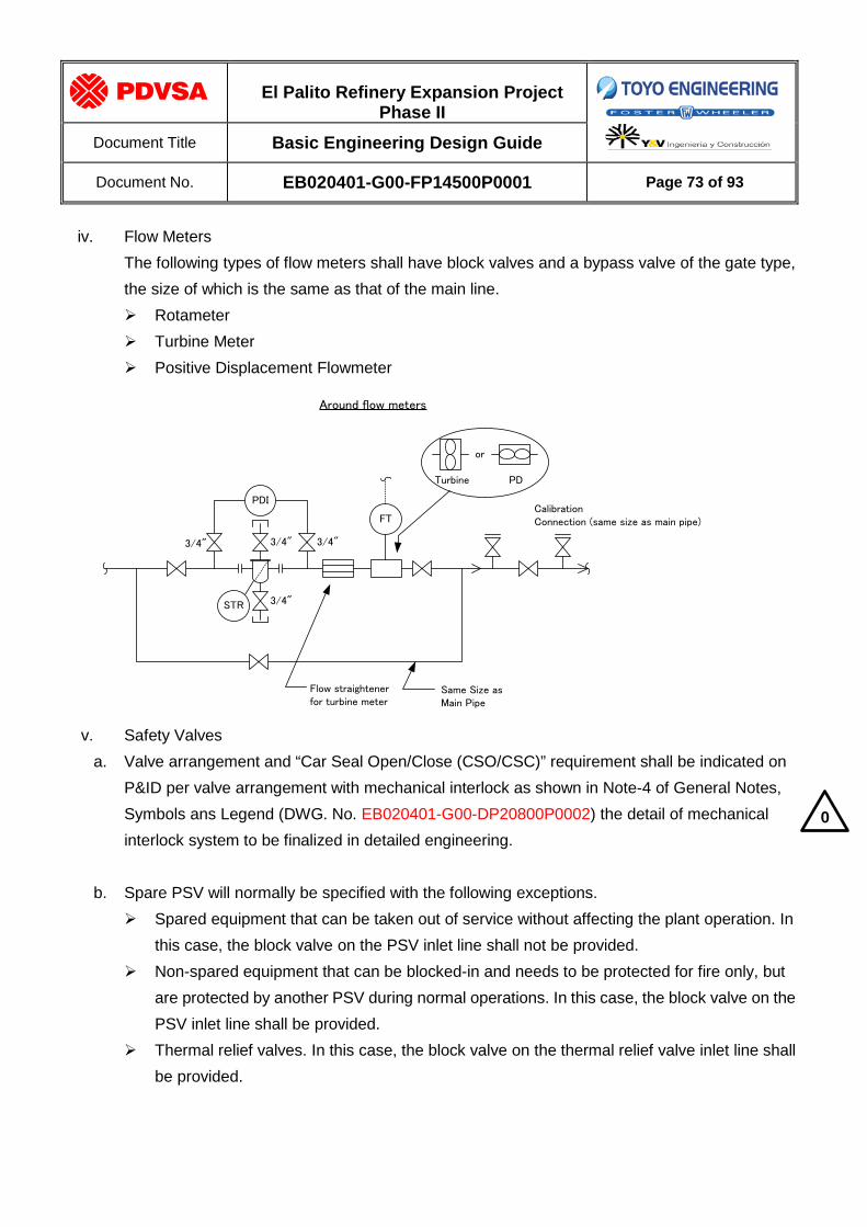
El Palito Refinery Expansion Project
Phase II
Document Title Basic Engineering Design Guide
Document No. EB020401-G00-FP14500P0001 Page 73 of 93
iv. Flow Meters
The following types of flow meters shall have block valves and a bypass valve of the gate type, the size of which is the same as that of the main line. Rotameter Turbine Meter Positive Displacement Flowmeter
PDI
FT
STR
3/4" 3/4" 3/4"
3/4"
CalibrationConnection (same size as main pipe)
or
Turbine PD
Flow straightenerfor turbine meter
Same Size asMain Pipe
Around flow meters
v. Safety Valves
a. Valve arrangement and “Car Seal Open/Close (CSO/CSC)” requirement shall be indicated on P&ID per valve arrangement with mechanical interlock as shown in Note-4 of General Notes, Symbols ans Legend (DWG. No. EB020401-G00-DP20800P0002) the detail of mechanical interlock system to be finalized in detailed engineering.
b. Spare PSV will normally be specified with the following exceptions. Spared equipment that can be taken out of service without affecting the plant operation. In
this case, the block valve on the PSV inlet line shall not be provided. Non-spared equipment that can be blocked-in and needs to be protected for fire only, but
are protected by another PSV during normal operations. In this case, the block valve on the PSV inlet line shall be provided.
Thermal relief valves. In this case, the block valve on the thermal relief valve inlet line shall be provided.
0

El Palito Refinery Expansion Project
Phase II
Document Title Basic Engineering Design Guide
Document No. EB020401-G00-FP14500P0001 Page 74 of 93
c. Isolating outlet block valve will not be specified if discharge is routed to atmosphere.
d. When two relieving devices are installed with block valves on the inlet and outlet piping, the
block valves shall be interlocked to ensure that the equipment being protected will never be isolated from the relieving device per valve arrangement with mechanical interlock as shown in Note 4 of General Notes, Symbols and Legend (DWG. No. EB020401-G00-DP20800P0002) the detail of mechanical interlock system to be finalized in detailed engineering.
e. The size of bypass lines shall be as follows,
Safety Valve Inlet Line Bypass Line
4” and smaller 1 1/2”
6” and larger 2”
11.3.11. Vents and Drains
Vents and drains are classified as either open or closed. a. Closed System
Closed vents and drains are connected to the flare system, blow down system, amine recovery system and sour water recovery system in order to minimize the release of explosive and toxic materials to the atmosphere. These vents and drains shall be applied for equipment where venting and draining is necessary during operation or when hazardous or flammable products are drained or vented during start-up and shutdown.
b. Open System
Open vents and drains, on the other hand, are exhausted to the atmosphere and recovered with oily sewer. This type of vent and drain is to be utilized during start-up and shutdown steam out operations or during normal operations in case non-hazardous or non-flammable products needs to vented or drained. For more details, refer to document EB020401-G00-DP14500T0006 Drainage Basic Design. In case of provision for vents and drains, their size and methods of installation are given according to the type of equipment, pressure rating and fluid services. For the types of equipment, towers, drums, heat exchangers, fin fan coolers pumps and piping are taken into consideration.
0
0

El Palito Refinery Expansion Project
Phase II
Document Title Basic Engineering Design Guide
Document No. EB020401-G00-FP14500P0001 Page 75 of 93
The classification of vent and drain is defined as follows;
Fl
are
Ligh
t Slo
p B
low
dow
n Sy
stem
Hea
vy S
lop
Blo
wdo
wn
Syst
em
Am
ine
Slo
p
Sou
r Wat
er S
lop
Oily
Sew
er
Che
mic
al S
ewer
Non
-Con
tam
inat
ed
Stro
m W
ater
Atm
osph
ere
Sur
ge P
ond
Light Hydrocarbons
(Hydrogen, Naphtha, Fuel Gas, Gas Oil) X X
X
(Note1,2)
Heavy Hydrocarbons
(LVGO, HVGO, AR, VR) X X
X
(Note1,2)
Steam X
Steam Condensate X X
(Note2)
Oily Water and Oily Contaminants X
(Note2)
Amine X X X
(Note3)
Chemical (Caustic / Acid) X
Sour Water X X
(Note3) X
Contaminated Strom Sewer X
Sour Water Slop System (Note4)
Note:
1. Slop blowdown header is routed via trenched pipe to Lighter or Heavy Slop Oil Drum
2. In principle, drain line from the vessel shall be connected to the Light or Heavy Slop Blowdown system. During the final
phase of steam-out, the steam condensate can be routed to the nearby oily sewer funnel.
3. Amine sump header is routed via trenched pipe to Amine Sump Drum. During the final phase of steam-out, the steam
condensate can be routed to the nearby oily sewer funnel.
4. To SWS Unit for Reprocessing
0

El Palito Refinery Expansion Project
Phase II
Document Title Basic Engineering Design Guide
Document No. EB020401-G00-FP14500P0001 Page 76 of 93
Vents and drains for equipment and piping are as follows,
a. Towers and Drums Vents shall be installed at the top of towers and drums. These vents can be installed on their associated piping which is the highest point. Location of vents shall be followed indication on P&ID. Vents at the top of drums shall be open vents, unless otherwise indicated on P&ID. Drains shall be installed at the bottom of towers and reboiler drains shall be connected to the tower drain piping. These drains can be installed on towers or their associated piping. Vents and drains shall be provided with blind flange in accordance with following: Minimum Size
See Table 10.1 in Section 10.1 VESSELS Note: The above size is applied unless otherwise indicated on P&ID or equipment data sheet
Installation Open System For 600# and lower Single Valve w/blind or cap
For 900# and higher Double Valve w/blind or cap
Closed System For all Rating Single Valve w/bleeder
Note: Bleeder for closed vent (or drain) can be utilized as open vent (or drain)
Typical Installation to refer to Piping detail Standard 00-FPIP-SS-0001
b. Heat Exchangers Vents shall be provided in the highest pocket of heat exchangers and/or inlet or outlet piping in order to prevent accumulation of non-condensable vapor and shall be open vents principally, unless otherwise indicated on P&ID. Drains shall be provided in the lowest pocket of heat exchangers and/or inlet or outlet line for drainage of liquid in the exchangers during shutdown and shall be open drains principally, unless otherwise indicated on P&ID. Minimum Size
Rating Vent Size Drain Size
Lower than 900# 3/4” 1”
900# and higher 1” 1”
Installation Open System For 600# and lower Single Valve w/blind or cap
For 900# and higher Double Valve w/blind or cap
Closed System For all Rating Single Valve w/bleeder
Note: Bleeder for closed vent (or drain) can be utilized as open vent (or drain)

El Palito Refinery Expansion Project
Phase II
Document Title Basic Engineering Design Guide
Document No. EB020401-G00-FP14500P0001 Page 77 of 93
c. Air Coolers
Vents shall be provided in the highest pocket of fin fan coolers in order to prevent accumulation of non-condensable vapor and shall be open vents principally, unless otherwise indicated on P&ID. Drains shall be provided in the lowest pocket of fin fan coolers for drainage of liquid in the exchangers during shutdown and shall be open drains, unless otherwise indicated on P&ID. Minimum Size
Vent Size: 1” Drain Size: 1-1/2” Installation
Open System For 600# and lower Single Valve w/blind or cap
For 900# and higher Double Valve w/blind or cap
Closed System For all Rating Single Valve w/bleeder
Note: Bleeder for closed vent (or drain) can be utilized as open vent (or drain)
d. Pumps
Vents shall be provided at pump discharge lines if pump casing vents are not provided. Open vents shall be applied in principle, unless otherwise indicated on P&ID. Drains shall be provided at pump casing. Drainage of liquid in discharge line shall be drained out through pump casing principle, unless otherwise indicated on P&ID. Minimum Size
Rating Vent Size Drain Size
Lower than 900# 3/4” 1”
900# and higher 1” 1”
Installation Open System For 600# and lower Single Valve w/blind or cap
For 900# and higher Double Valve w/blind or cap
Closed System For all Rating Single Valve w/bleeder
Note: Bleeder for closed vent (or drain) can be utilized as open vent (or drain)

El Palito Refinery Expansion Project
Phase II
Document Title Basic Engineering Design Guide
Document No. EB020401-G00-FP14500P0001 Page 78 of 93
Typical Installation is shown as follows,
B.V.
OS
NOTE 1
OS
Note: Refer to drain classification in general description of 11.3.11 Non-Hydrocarbon Drain for Pumps
600# and Lower 900# and Higher
B.V.
*: CS or OS or
NS *
B.V.
*: CS or OS or
NS *
El Palito Refinery Expansion Project
Phase II
Document Title Basic Engineering Design Guide
Document No. EB020401-G00-FP14500P0001 Page 79 of 93
e. Piping
Two types of vents are normally present: 1. Process Vent (e.g. they are operated during normal operations/maintenance) 2. Hydrostatic Test Vent Process vents are shown on P&ID while hydrostatic vents are not shown, however both will be indicated in the Isometric Drawings Process vents will be provided with valves, while hydrostatic vents will be sealed after testing with a welded cap. Process vents and drains shall be open, where necessary. Closed vents and drains are of special use during start-up, shutdown, etc. and their sizes shall be specified respectively on P&I Diagrams. The following general requirement shall be applied: Unless they serve as drains for large equipment (exchangers, etc.), process drains shall:
- Be minimum size and conform to individual Piping Materials and Job Specification 00-FPIP-SS-0001 “A/G PIPING STANDARDS”.
- Valved drains open to atmosphere in hydrocarbon, hydrogen, steam, or chemical service shall have a cap, plug, or blind flange on atmospheric side of valve. Socketweld end drain valves shall have a short pipe nipple with one end threaded and capped.
- Drains located below grade on underground lines shall consist of a thread-o-let, nipple, and valve.
High points of piping shall have vents as required for hydrostatic testing in accordance with the following: - Steam lines that require hydrostatic testing shall have NPS 1-threaded valves on
schedule 160 nipples welded in line. After initial test, nipple shall be cut to 3/4 inch in length and sealed with a weld cap
- Vents on other lines shall be minimum size, and conform to Piping Materials and Job Specification 00-FPIP-SS-0001 “A/G PIPING STANDARDS”
If possible, vent connections shall be located in accessible locations adjacent to platforms or structural members.
Piping systems shall have drain valves at all low points

El Palito Refinery Expansion Project
Phase II
Document Title Basic Engineering Design Guide
Document No. EB020401-G00-FP14500P0001 Page 80 of 93
Size and Installation shall be as follows,
Standard Vent Connection
Flange Class 600# AND LOWER 900# AND HIGHER
FOR PROCESS USE
FOR HYDROSTATIC TEST
Standard Drain Connection
Flange Class 600# AND LOWER 900# AND HIGHER
FOR PROCESS USE
Note: 1) Cap or Blind Flange as per Piping Class requirements 2) Screwed Cap shall be seal welded after hydrostatic test
NOTE1
NOTE1
NOTE2
3/4”
NOTE2
3/4”
NOTE1
NOTE1

El Palito Refinery Expansion Project
Phase II
Document Title Basic Engineering Design Guide
Document No. EB020401-G00-FP14500P0001 Page 81 of 93
11.3.12. Purge Connection to Process Line
For the utility line connection to the process line, valve arrangement shall be applied as follow
a. Fuel Gas Steam and Nitrogen
Note: Process spec to be shifted upstream of manual isolation valve if process side piping specification is rated higher than utility side piping specification
b. Flushing Oil
Note: Process spec to be shifted upstream of manual globe valve if process side piping specification is rated higher than utility side piping specification. Positive isolation through manual isolation valve shall be verified upstream in the FO supply line; if such valve is not present, an additional manual isolation valve shall be added upstream of the globe valve
min
process spec utility spec
FG
min
process spec utility spec
FO

El Palito Refinery Expansion Project
Phase II
Document Title Basic Engineering Design Guide
Document No. EB020401-G00-FP14500P0001 Page 82 of 93
11.3.13. Warming-up and pressure equalizing bypass of steam lines
For 12” and larger or 600# and higher for steam lines, provide 1” bypass with globe valve around B.L. valves for warming-up and pressure equalizing.
11.3.14. Valve Size for Suction and Discharge Lines of Pumps The size of valves installed in the suction and discharge lines of pumps shall be the same as the main line size.
11.3.15. Steam inlet line to steam turbine Spool piece for initial flushing is installed at steam inlet line to steam turbine. Warning-up line discharged to atmosphere to be foreseen.
11.3.16. Pressure gauge for Pumps Pressure gauges shall be provided at the discharge lines only for all centrifugal pumps.
11.3.17. Utility Stations a. Utility stations consisting of LP steam, plant air, nitrogen and utility water lines shall be
provided for the appropriate equipment and following points. All over the unit, with an approximate 30m span and close to heat exchangers, towers and vessels manholes with 10 meters or above elevation.
b. Connections between utility stations and equipment shall be done with temporary hose.
c. The size of each utility line shall be 1 inch, and the gate valve with hose connection
shall be provided for all services.
d. For LP steam, additional connection shall be supplied with screwed connection and permanent hose for fire abatement purposes.
11.3.18. Sampling Connections In principle, closed sampling system shall be provided, whose sample bypass shall be returned to process line and exhaust gas shall be vented to flare.
All sampling points shall be shown on P&ID.
0

El Palito Refinery Expansion Project
Phase II
Document Title Basic Engineering Design Guide
Document No. EB020401-G00-FP14500P0001 Page 83 of 93
11.3.19. Insulation and Steam Tracing
In principle, the lines and instruments of the following services shall have steam tracing. Gas line in which any condensing is prohibited. Liquid line with high pour point fluid.
11.3.20. Double Block Valve for On-stream Maintenance To ensure on-stream maintenance, double block valves should be applied for equipment and instrument which subject to on-stream maintenance for the following services, Toxic and H2S lethal service (Gas containing H2S in excess of 1%) Hydrocarbon and hydrogen service with ASME Rating Class 600# and higher Others (non-flammable) service with ASME Rating Class 900# and higher Note: Following subject to on-stream maintenance,
- All equipment that need to be isolated during operation - Control valve with bypass - Relief valve with a spare (inlet only) - Instrument that need to be isolated during operation (level, flow, pressure)
11.4. LINE SIZING CRITERIA
Lines sized by Licensors shall be checked with the requirements of PDVSA. Any resulting deviation shall be promptly transmitted to Licensors/PDVSA for concurrence. General recommendations are as follows,
a. Lines shall be sized for the most economical overall design and according to “PDVSA –Manual de Ingenieria de Diseño, Volumen 13-III, Section: Guidelines 90616.1.024- Dimensionamiento de Tuberias” and PDVSA-Manual de Ingenieria de Diseño, Volumen 13-III, Tuberias y Oleoductos, Section “L-TP-1.5 Calculos Hidraulicos de Tubería”.
b. Effects of line loss, pump characteristics, and heat exchanger and control valve pressure drops shall be considered. Final design shall be based on largest total pressure drop consistent with economy, ease of operation, and noise abatement and according to “PDVSA – Manual de Ingenieria de Diseño, Volumen 13-III, Tuberias y Oleoductos,
c. Section Guidelines 90616.1.024- Dimensionamiento de Tuberias” and PDVSA-Manual de Ingenieria de Diseño, Volumen 13-III, Section: L-TP-1.5 Calculos Hidráulicos de Tubería”.
d. Unless otherwise limited, maximum line velocity shall be governed by such factors as erosion and noise.
0

El Palito Refinery Expansion Project
Phase II
Document Title Basic Engineering Design Guide
Document No. EB020401-G00-FP14500P0001 Page 84 of 93
Velocities of fluids inside of pipe and pressure drop shall be according to: “PDVSA-Manual de Ingenieria de Diseño, Volumen 13-III, Tuberias y Oleoductos, Section: – Guidelines 90616.1.024- Dimensionamiento de Tuberias” and L-TP-1.5 Calculos Hidraulicos de Tubería”. Piping within process units will be sized based on the rated flow case. The sizing criteria based on the velocities and the pressure drop are as follows,
Service Velocity Pressure Drop
Pump Suction Lines Boiling Liquid < 0.3psi/100ft
Viscous Liquid(>30cP) < 0.3psi /100ft
Pump Discharge Lines 1 to 2 psi/100ft
Gravity Flow General 1 to 3 ft/sec
Self-venting 1 to 3 ft/sec
Vapor/Gas Transfer Lines Pressure Service 𝑉𝑚𝑎𝑥 = 100√𝑆𝑉
SV: Specific Volume 0.2 to 2 psi/100ft (to suit available)
Vacuum Service 𝑉𝑚𝑎𝑥 = 100√𝑆𝑉 SV: Specific Volume
less than 10% of absolute pressure
Column Overhead Lines
Vacuum Service less than 10% of absolute pressure
Atm/Moderate Pressure < 0.5 psi/100ft
Pressure > 200psi < 2.0 psi/100ft
Vertical Thermosyphon Reboiler < 3ft/sec < 0.5 ft-liquid/100ft
Utility Lines Header less than 5% of operating
gauge pressure
Branch
Compressor Suction and Discharge total pressure drop
less than 1% of absolute pressure
Relief Valve
(Note 1)
Inlet total pressure drop
less than 3% of set gauge pressure
Outlet (for Conventional Type)
Back Pressure less than 10% of
set gauge pressure
Outlet (for Balanced Type)
Back Pressure less than 30% of
set gauge pressure
Note: 1. Refer to document 92-FPRO-BD-0006 Flare System Design Basis Memorandum for
additional design criteria
11.5. PIPING SERVICE IDENTIFICATION See symbology P&ID

El Palito Refinery Expansion Project
Phase II
Document Title Basic Engineering Design Guide
Document No. EB020401-G00-FP14500P0001 Page 85 of 93
12. INSTRUMENTATION AND CONTROL a. Reference Documents for the Instrumentation design and installation are represented by the
CONSORTIUM Job Specifications, documents numbers: 00-FINS-SP-0001 ÷ 0018, EB020401-G00-FI11400T0001, EB020401-G00-FI14100T0001 and EB020401-G00-FI30100T001.
b. Control Systems and Instrumentation for the Atmospheric and Vacuum Distillation Revamp, including equipment package Instrumentations, shall be specified as 4 to 20 mA HART Protocol. For the new plants, the criteria defined by AIT RELP will be taken. Fieldbus protocol is to be applied to the practical max extent.
c. All the instruments shall be specified in agreement with the applicable area classification and resistant to marine atmosphere.
d. All the instrumentation, as far as possible, will have to be of repairable type; the equipment of disposable type will not have to be specified.
e. Project will contemplate a new control room that includes new facilities of this project. f. Designer shall specify continuous stream analyzers where required for process monitoring and
control. Designer shall describe his suggested control strategy to insure optimum and safe plant operations.
g. Designer shall describe his suggested Distributed Control System (DCS) to insure optimum and safe plant operations.
h. Additional control devices / systems will be specified based on a risk analysis of the control function and the location propose.
0
0

El Palito Refinery Expansion Project
Phase II
Document Title Basic Engineering Design Guide
Document No. EB020401-G00-FP14500P0001 Page 86 of 93
12.1. FLOW INSTRUMENTS
a. Calibration ranges for differential instruments for flow measurement shall be in inches of water. b. Use 300 # connection as a minimum on orifice plates flanges. c. Orifice plates will be fabricated in accordance with ISO-5167, generally 316 stainless steel as
minimum 304 Stainless Steel, Monel, Hastelloy or other suitable material will be used to resist the fluid corrosion and erosion properties.
d. The minimum rating will be 300# ANSI, and will be accordance with ANSI B16.5, ANSI B16.36, ANSI B 46.1 and ISO 5167. The flange thickness will not be less than 38 mm (1.5 in.) and the flange bore will match the internal diameter of the piping schedule. Spreader bolts (jack screws) will be provided in flanges, in diametrically opposing directions. For sour service, connections shall be in accordance with NACE Standard MR 0103-2005. The flow primary element sizing will be performed with a software program based on: ISO-5167/ASME SPINK precise calculation AGA 3 to 8
e. Glass tube rotameters shall not be used. On all applications, metal tube rotameters will be used. f. Rotameters will be installed with by-passes in order to facilitate maintenance without shutting
down the process. g. Other type of instruments, such as positive displacement, turbine type meters, electromagnetic,
vortex, ultrasonic, Coriolis may be used where the use thereof is strictly required by process conditions.
h. For low differential pressure drops, averaging type of pitot tubes may be used

El Palito Refinery Expansion Project
Phase II
Document Title Basic Engineering Design Guide
Document No. EB020401-G00-FP14500P0001 Page 87 of 93
12.2. LEVEL INSTRUMENTS
a. Use connection size 2”, 300 # as minimum on external displacement type level instrument. b. Level gauges will generally be of the reflex type, except in the following services, when
transparent gauge glasses will be specified: Interface between two liquids Colored liquids with specific gravities of 0.9 or higher Liquids containing gum, sediment or other solid particles which cling to the glass Glasses requiring mica shields Liquids not easily visible or tend to be opaque
c. Level indicators with magnetic coupling will not be used on applications where agitation is present into the vessel or where suspended solids are present in the process liquids.
d. Level bridles will be used for installation of multiple instruments on the same vessel. Level transmitter used for shutdown purposes will have separate vessel connections.
e. The preferred primary sensing element will be a differential pressure (d/p) cell operating on the hydrostatic head pressure principle. They will be complete with range elevation/suppression facilities.
f. Bubble type level applications using d/p cells may be used on sumps and corrosive fluid services. g. Displacers on process fluids operating at more than 400°F will be provided with cooling fins. h. External cage connection size will be NPS 2" 300# RF, unless the vessel connection specification
requires a higher rating. i. When the level measurement is wired to the SIS system, the transmitter will be independent of any
other level measuring device installed on the same vessel/tank/sump j. For special applications, nuclear or ultrasonic level instruments may be considered but with the
authorization of PDVSA

El Palito Refinery Expansion Project
Phase II
Document Title Basic Engineering Design Guide
Document No. EB020401-G00-FP14500P0001 Page 88 of 93
12.3. PRESSURE INSTRUMENTS
a. A local pressure gage shall be installed on top of each vessel. A board mounted temperature indicator shall be installed near the bottom of each vessel.
b. Pressure gauges installed above the process connection on hot fluids (steam, condensable gases, hot liquids) may be protected by a pigtail (siphon).
c. Pressure Instrument installed at pulsating services such as reciprocating equipment will be provided with snubbers to dampen the vibration and provide a real measurement.
d. All pressure instruments to be installed on slurry, viscous (>10cSt) fluids with suspended solids, toxic and corrosive services, will be provided with diaphragm seals. The diaphragm seal will be easily cleanable type. Where capillaries are required the capillary will be stainless steel complete with PVC covered stainless steel bendable armour.
e. The pressure instrument will be capable of withstanding an overpressure 1.5 times the maximum operating pressure, without producing any damage.
f. Wherever a pressure or temperature transmitter used for control is installed, provide a pressure gage or a local temperature indicator for calibration purposes. For critical services, a board mounted pressure or temperature indicator shall be supplied.
12.4. TEMPERATURE INSTRUMENTS a. When a signal is transmitted to DCS, the thermocouple/RTD shall be provided with a remote
temperature transmitter or multiplexer. b. Temperature measurement points for process monitoring and control shall be specified and
represented on the Piping and Instrument Diagram with item numbers. Thermowells for each heat exchanger shell shall be specified.
c. ISA type K thermocouples shall be specified for general services d. Thermowells in temperatures greater than 1100°F and those installed in large vacant spaces such
as radiant sections of furnaces, will be inserted from the top of the equipment rather than the side, in order to prevent sagging of the thermowell due to high temperatures.
e. Use class 150# flanges as a minimum for thermowells.
f. Head mounted transmitters shall normally be used. Separate transmitters shall be used when operating temperature is above 570 degF.
g. For process furnaces, each tube-surface temperature measurement shall be done by a main skin point, which signal go to DCS, and a reference skin point, which is available just on field.

El Palito Refinery Expansion Project
Phase II
Document Title Basic Engineering Design Guide
Document No. EB020401-G00-FP14500P0001 Page 89 of 93
12.5. CONTROL VALVES
a. Use 300 # connection as a minimum on control valves flanges. b. Control valves shall be sized such that the valve capacity is approximately 1.25 times the
maximum calculated flow capacity. c. Control valve sizing pressure drops will be determined as follows:
For flowrates less than 750 gpm and a system pressure drop (excluding the control valve) of less than 250 psi, the control valve sizing pressure drop shall be equal to 15 psi or 25 % of the total system pressure drop (including the control valve), whichever is greater.
For flow rates outside the above ranges, the control valve sizing pressure drop shall be equal to 25 psi or 20 % of the total system pressure drop (including the control valve), whichever is greater
d. Control valves will be sized for the minimum, normal and maximum operating conditions to ensure the valve will operate between 17 and 90 percent opening.
e. Valve trims will be selected to enable operation without any cavitation. f. In general the limit for noise generated by control valves shall be 85dBA or less, as measured at a
distance of 1 meter from the valve for continuous flow condition g. Valves used on emergency shut off service applications will be dedicated solely to that service
only and will not be used for normal process control purposes. h. The valve trim material will be 316 stainless steel as minimum required. Other materials will be
considered to suit the fluid erosion and corrosion properties. Stellited or harder trim material will be used on: Flashing fluids Fluids with entrained solids Pressure drops over 145 psig.
i. Pneumatic diaphragm or piston type actuator will be used to ensure that the valve: Operates correctly under all specified operating conditions. Withstands a pressure drop equal to the maximum upstream pressure. Speed of response complies with the process operational requirements.
j. The use of electro-hydraulic, electric, hydraulic or digital actuators will be considered only in cases where pneumatic diaphragms or piston actuators will not work correctly.
k. All control valves will be fitted with positioners.
0

El Palito Refinery Expansion Project
Phase II
Document Title Basic Engineering Design Guide
Document No. EB020401-G00-FP14500P0001 Page 90 of 93
12.6. PRESSURE RELIEF VALVES
a. The relief system shall be designed in accordance with API RP-520 and API RP-521. b. A single operating pressure relief valve (PSV) will be specified for each service unless:
Multiple valves are necessary because the required capacity cannot be provided in a single valve.
Dual valves are required in accordance with the American Society of Mechanical Engineers (ASME) boiler and pressure vessel code, section I.
c. For steam service governed by ASME Boiler and Pressure Vessel Code, Section I, the use of inlet or outlet block valves is not permitted. Isolating inlet and outlet block valves will normally not be specified for non-spared PSV. For spared valves, block valves should be CSC(inlet)/CSO(outlet) with mechanical interlock as shown in Note-4 of General Notes, Symbols and Legend(DWG. No. EB020401-G00-DP20800T0002) the detail of mechanical interlock system to be finalized in detailed engineering.
d. Pressure relief valves are normally installed at an elevation sufficient to slope the outlet line towards the main flare header without any pocket.
e. When two relieving devices are installed with block valves on the inlet and outlet piping, the block valves shall be interlocked to ensure that the equipment being protected will never be isolated from the relieving device.
f. Relief header shall be sized based on criteria included in document 92-FPRO-BD-0006 Flare System design Basis Memorandum:
g. Discharge piping on relieving devices venting to atmosphere will extend at least 3 meters above any platform or working area located within 24.5 ft /7.5m) meters radius of the point of discharge. The distance from a “working area” may be increased for the purpose of attenuation of exit noise, if necessary. Atmospheric vent piping will be square cut across the end.
12.7. ALARMS AND SHUTDOWN DEVICES a. Alarms and shutdown devices will be specified where required for process, safety or equipment
protection considerations. b. Shutdown device connections will be independent from instrument connections. c. All safety devices are connected to one specific system (SIS type).
0

El Palito Refinery Expansion Project
Phase II
Document Title Basic Engineering Design Guide
Document No. EB020401-G00-FP14500P0001 Page 91 of 93
12.8. INSTRUMENT AIR SUPPLY
a. The instrument air supply will be filtered and dried to a dew point of -85°F at 110 psig. In general, the quality of the instrument air will meet the requirements of ISA S7.3, Quality Standard for Instrument Air.
b. Air supply piping to locally mounted instruments and local panels will conform to the piping specification.
c. Instrument air system should have sufficient capacity for 20 minutes operation to execute safe shutdown .
12.9. INSTRUMENT ELECTRICAL POWER SUPPLY a. The preferred power supply for field instruments is 24 volts DC. b. Control systems such as DCS/SIS/F&G and other PLC systems, RTU systems, etc. will be
powered by 115 volts AC supplied from an un-interruptible power supply (UPS) system. c. The power system will be designed for 25% spare capacity. d. The main unregulated AC power supplies to instrumentation systems will be derived from the
essential services distribution system.

El Palito Refinery Expansion Project
Phase II
Document Title Basic Engineering Design Guide
Document No. EB020401-G00-FP14500P0001 Page 92 of 93
13. CIVIL ENGINEERING DESIGN 13.1. MEASUREMENT UNIT AND LANGUAGE
Unless otherwise noted, Metric System Unit shall be used, for drawings and Calculation Report.
Drawings Distances millimeters
Elevations meters
Loads kg or metric tons(t)
Pressures kg/cm2
Reinforcement bar diameter inches
Calculation Report Distances meters or millimeters
Elevations meters
Loads kg or metric tons(t)
Moments kg-m, kg-cm or t-m
Pressures kg/cm2 , kg/m2 or t/m2
Unit Weights kg/m3 or t/m3
Wind Speed km/h (kilometres/hour)
Reinforcement bar diameter inches
13.2. SITE PREPARATION AND EARTHWORK
Refer to the following Consortium Job Specification /documents: FCIV-SP-0001 for site preparation and earthwork 00-FCIV-SP-0004 Earthen dikes for storage tanks
13.3. ROAD DESIGN AND CONSTRUCTION Refer to the Consortium Job Specification 00-FCIV-SP-0002
13.4. UNDERGROUND PIPING AND SURFACE DRAINAGE Refer to the following Consortium Job Specification/documents: 00-FCIV-SP-0003 for underground piping and surface drainage 00-FCIV-SS-0001 for underground standard details

El Palito Refinery Expansion Project
Phase II
Document Title Basic Engineering Design Guide
Document No. EB020401-G00-FP14500P0001 Page 93 of 93
13.5. HVAC, PLUMBING AND SANITARY SERVICES
Refer to the following Consortium Job Specifications: 97-YMEC-SP-0006 for design basis 97-YMEC-SP-0007 for materials and construction 97-YMEC-SP-0008 for factory acceptance test 97-YMEC-SP-0009 for commissioning and performance test 97-YMEC-SP-0010 for field inspection and test
13.6. DESIGN AND CONSTRUCTION BASIS FOR STRUCTURES Refer to the following Consortium Job Specifications: 00-FSTC-SP-0001 for design loads and load combinations 00-FSTC-SP-0002 for design of blast resistant buildings 00-FSTC-SP-0003 for design of reinforced concrete structures and foundations 00-FSTC-SP-0004 for design of storage tank foundations 00-FSTC-SP-0005 for construction of reinforced concrete structures and durability 00-FSTC-SP-0006 for design of steel structures 00-FSTC-SP-0007 for fabrication and erection of steel structures AIG-2009-IF-155 Geotechnical Onshore Consolidation Study for the Expansion
Project of El Palito Refinery, Final Report (Rev. 1) 10-1209 Seismic Study associated to the Expansion Project of El Palito Refinery,
Final Report (version 1), CORAL 83, May 2010 AJ-YCIV-SP-0001 for design of bridges 97-TARQ-SP-0001 Design basis and facility description of buildings 97-TARQ-SP-0002 General requirement for design and engineering of buildings 97-TARQ-SP-0003 General requirements for materials and construction of buildings
13.7. FIREPROOFING Refer to the Consortium Job Specification 00-FSTC-SP-0008
13.8. DIKE CAPACITY REQUIREMENT In case of multiple tanks inside the dike, volumetric capacity of the dike area shall be not less 1_1/2 times (150%) of the sum of each tank capacity in accordance with the requirement in local regulation, LOPTYMAT.