Balsa Wood Bridge - ScholarWorks@CWU
59
Central Washington University Central Washington University ScholarWorks@CWU ScholarWorks@CWU All Undergraduate Projects Undergraduate Student Projects Spring 2021 Balsa Wood Bridge Balsa Wood Bridge Logan Bronemann Central Washington University, [email protected] Follow this and additional works at: https://digitalcommons.cwu.edu/undergradproj Part of the Mechanical Engineering Commons Recommended Citation Recommended Citation Bronemann, Logan, "Balsa Wood Bridge" (2021). All Undergraduate Projects. 162. https://digitalcommons.cwu.edu/undergradproj/162 This Undergraduate Project is brought to you for free and open access by the Undergraduate Student Projects at ScholarWorks@CWU. It has been accepted for inclusion in All Undergraduate Projects by an authorized administrator of ScholarWorks@CWU. For more information, please contact [email protected].
-
Upload
khangminh22 -
Category
Documents
-
view
0 -
download
0
Transcript of Balsa Wood Bridge - ScholarWorks@CWU

Central Washington University Central Washington University
ScholarWorks@CWU ScholarWorks@CWU
All Undergraduate Projects Undergraduate Student Projects
Spring 2021
Balsa Wood Bridge Balsa Wood Bridge
Logan Bronemann Central Washington University, [email protected]
Follow this and additional works at: https://digitalcommons.cwu.edu/undergradproj
Part of the Mechanical Engineering Commons
Recommended Citation Recommended Citation Bronemann, Logan, "Balsa Wood Bridge" (2021). All Undergraduate Projects. 162. https://digitalcommons.cwu.edu/undergradproj/162
This Undergraduate Project is brought to you for free and open access by the Undergraduate Student Projects at ScholarWorks@CWU. It has been accepted for inclusion in All Undergraduate Projects by an authorized administrator of ScholarWorks@CWU. For more information, please contact [email protected].

Balsa Wood Bridge
By
Logan Bronemann

2
Abstract: The objective of the project undertaken is to design and build an articulating bridge which can be raised and lowered constructed from only balsa wood. To meet the objective set forth for this project a series of requirements were set to determine the design parameters such as height, length, weight and more. Using these requirements, a series of analysis can be undertaken upon the bridge design and structure. These analyses consist of column buckling, tensile stress analysis, and compressive stress analysis. The analysis determined the dimensional requirements of the structural members to include a ½”x ½” lower support beam with varied cross sectional members being either 3/8” x 3/8” or ¼” x ¼”.These analyses allow for the demonstration of mechanical engineering principles both in design and construction methods. Work to date includes achieving construction of an articulating bridge with the ability to meet the 10 second locked raise requirement. The device constructed for this project delivered on the original objective as it is fully constructed from balsa wood while also allowing for articulation of the bridge in a vertical direction. These dimensions will allow for a load of 20 kilograms to be placed upon the structure as well as the ability to articulate vertically and remain in place for at least 10 seconds.

Contents 1. INTRODUCTION ...................................................................................................................... 6
a. Description .............................................................................................................................. 6
b. Motivation ............................................................................................................................... 6
c. Function Statement.................................................................................................................. 6
d. Requirements .......................................................................................................................... 6
e. Engineering Merit ................................................................................................................... 7
f. Scope of Effort......................................................................................................................... 7
g. Success Criteria ....................................................................................................................... 7
2. DESIGN & ANALYSIS ............................................................................................................. 8
g. Analysis................................................................................................................................... 8
i. Analysis 1 ............................................................................................................................ 8
ii. Analysis 2 ........................................................................................................................... 8
iii. Analysis 3 .......................................................................................................................... 8
iv. Analysis 4 .......................................................................................................................... 8
v. Analysis 5............................................................................................................................ 8
vi. Analysis 6 .......................................................................................................................... 9
vii. Analysis 7 ......................................................................................................................... 9
viii. Analysis 8 ........................................................................................................................ 9
viiii. Analysis 9 ....................................................................................................................... 9
X. Analysis 10 ......................................................................................................................... 9
Xi. Analysis 11........................................................................................................................ 9
h. Device: Parts, Shapes, and Conformation ............................................................................. 10
i. Device Assembly ................................................................................................................... 10
j. Technical Risk Analysis ........................................................................................................ 10
k. Failure Mode Analysis .......................................................................................................... 10
l. Operation Limits and Safety .................................................................................................. 10
3. METHODS & CONSTRUCTION ........................................................................................... 11
a. Methods ................................................................................................................................. 11
i. Process Decisions .............................................................................................................. 11
b. Construction .......................................................................................................................... 11
i. Description ......................................................................................................................... 11

4
ii. Drawing Tree, Drawing ID’s ............................................................................................ 12
iii. Parts ................................................................................................................................. 12
iv. Manufacturing Issues ....................................................................................................... 12
v. Discussion of Assembly .................................................................................................... 13
4. TESTING ..................................................................................................................................... 14
a. Introduction .......................................................................................................................... 14
b. Method/Approach ................................................................................................................ 14
c. Test Procedure ...................................................................................................................... 14
d. Deliverables........................................................................................................................... 14
5. BUDGET ..................................................................................................................................... 16
a. Parts ...................................................................................................................................... 16
b. Outsourcing ........................................................................................................................... 16
c. Labor ...................................................................................................................................... 16
d. Estimated Total Project Cost................................................................................................. 16
e. Funding Source...................................................................................................................... 16
6. Schedule .................................................................................................................................... 17
a. Design .................................................................................................................................... 17
b. Construction .......................................................................................................................... 17
c. Testing ................................................................................................................................... 17
7. Project Management ................................................................................................................ 19
a. Human Resources ................................................................................................................. 19
b. Physical Resources ................................................................................................................ 19
c. Soft Resources ....................................................................................................................... 19
d. Financial Resources ............................................................................................................... 19
8. DISCUSSION ............................................................................................................................... 20
a. Design .................................................................................................................................... 20
b. Construction .......................................................................................................................... 20
c. Testing ................................................................................................................................... 21
9. CONCLUSION ............................................................................................................................. 22
10. ACKNOWLEDGEMENTS ........................................................................................................... 23
References .................................................................................................................................... 24
APPENDIX A - Analysis ................................................................................................................... 25
Appendix A-1 – Reactions @ Points A and B .......................................................................... 25

5
Appendix A-2 – Force on Members and at Points .................................................................... 26
Appendix A-3 - Force on Members and at Points .................................................................... 27
Appendix A-4 – Member length ............................................................................................... 28
Appendix A-5 – Cross-section dimensions of material ............................................................ 29
APPENDIX B - Drawings ................................................................................................................. 38
Appendix B – Drawing Tree ...................................................................................................... 38
Drawing 20-001 ......................................................................................................................... 38
Appendix B – Drawing 20-002 .................................................................................................. 39
Appendix B-Drawing 20-003 ..................................................................................................... 40
Appendix B-Drawing 20-004 ..................................................................................................... 41
Appendix B – Drawing 10-001 .................................................................................................. 42
Appendix B – Drawing 10-002 .................................................................................................. 43
Appendix B – Drawing 10-003 .................................................................................................. 44
Appendix B – Drawing Tree ...................................................................................................... 44
APPENDIX C – Parts List and Costs ....................................................................................... 44
APPENDIX E - Schedule ................................................................................................................. 46
APPENDIX F – Expertise and Resources ........................................................................................ 47
....................................................................................................................................................... 47
APPENDIX G – Testing Report ....................................................................................................... 48
APPENDIX H – Resume .................................................................................................................. 57

6
1. INTRODUCTION
a. Description The intent of this project is to design and build an articulating bridge which can be raised
and lowered constructed from balsa wood. Bridges are intended to support large loads typically
to cross over into an area that would otherwise be inaccessible. In order to withstand these large
loads a bridge must be designed with toughness, areas of stress, and material in mind.
Engineering design can account for all of these aspects in order to design a bridge which will not
fail under the loads that may be placed on a bridge. By analyzing forces on the bridge, stresses
within the material, and load distribution between beam members an engineer can accurately
assess the strength of a bridge to determine if the bridge will be able to handle its working load.
b. Motivation This project was motivated by a need for a device that would function as a bridge resting
on abutments in order to meet predetermined specifications for loading force, weight, ability to
be traversed, as well as being able to articulate 50% of the bridge length vertically 280mm. This
motivation comes from the current state of the world surrounding the covid-19 pandemic in
which a project that could be built from home while socially distancing was required.
c. Function Statement The function of this bridge is threefold, first the bridge must span a divide while
supporting a load. Secondly the bridge must act as a means of passage for a moving structure
horizontally. And finally, the bridge must be able to be under a load while still maintaining its
rigidity.
d. Requirements For this Project a bridge is to be designed to meet specific requirements. These
requirements are as follows.
• will support at minimum between 18.9-20kg of mass.
This bridge must be within the specific dimensions as listed,
• overall length must be at minimum 400mm long
• House a 38mm wide road deck that extends the entire length of the bridge with no
openings except for an 8mm wide hole for loading
• The road deck must also be within 12mm of the abutment level either at the outside edge
of the abutment or the ends of the bridge (whichever is closer)
• The road deck may either be flat or have a smooth curve, if the deck is curved the
difference between the low point and high point may not exceed 25mm
• The bridge must allow passage of a rectangular object that is 32mm wide by 25mm in
height.
• the bridge also must be able to articulate in the vertical direction such that 50% of the
overall length of the bridge is raised a minimum of 200mm.
• While at rest the bridge should rest evenly on both abutments so that there is no gap
between the bridge and the abutments on both sides.
• Applying 10g of force to the lifting mechanism should allow for a 20lb piece of paper to
slip between the abutment and the bridge at minimum.

7
• The total weight of the structure must not exceed 85 grams.
e. Engineering Merit This project has engineering merit because it is a culmination of many different
principles of engineering and mathematics. While designing a bridge the requirement is to look
at what forces are being applied to which direction and locations, analyze the stresses placed on
individual components as well as the overall structure, determine material dimensions while
sticking to the previously mentioned weight and dimensional requirements of the project, and
finally designing a strong and durable device that will easily actuate the vertical motion of the
bridge without compromising the overall structure of the bridge itself. All of these factors lead to
a large engineering challenge.
f. Scope of Effort The scope of this project is to construct a truss which will be mirrored on both sides of
the bridge as well as to design and build a device that will actuate the articulating portion of the
bridge.
g. Success Criteria This project will be determined a success if the bridge matches required dimensions
while carrying a load and allowing passage to an over height structure.

8
2. DESIGN & ANALYSIS g. Analysis i. Analysis 1
This was the first analysis of the bridge structure design. The required load for success is
20kg roughly 200N of force. The reactions at points A and B are crucial to determining the rest
of the loads on each individual member of the bridge. Leading to the bigger picture once all
forces are determined for every point it will allow for analysis of stresses and ultimately
determining the thickness of each member of the bridge. This analysis brought forth the ability to
determine what forces the bridge must be able to support without failure leading to a design
parameter of how much force the bridge is required to hold. These calculations are detailed in
appendix A, green sheet A-1.
ii. Analysis 2
This analysis was to determine how forces are distributed among each member as well at
how joints will be loaded. This analysis brought forth the ability to accurately determine forces
across each member which in turn will allow for a more detailed stress analysis and lend the
ability to ultimately determine material thickness requirements in each member by assessing
failure points. The design parameter achieved from this analysis is exactly that, it is the
parameter of how much load each member is required to hold in order to not fail before meeting
the minimum failure load. These calculations can be found in appendix A, green sheet A-2 and
A-3. Because this bridge is a mirror image of itself by knowing the forces exerted on one side of
the bridge you also can determine the other side of the bridge.
iii. Analysis 3
Analysis 3 is shown in appendix A-4. This calculation was a straightforward calculation
of determining the overall length of each individual member associated with the bridge structure.
This calculation was essential as it met the dimensional requirements set forth in the
requirements section of the proposal. The bridge has met the length requirement of greater than
400mm as well as meeting the height requirement of 25mm.
iv. Analysis 4
Analysis 4 is documented in Appendix A-5. This calculation was the start of the more
crucial calculations that will determine the amount of weight the bridge structure will be able to
support without failure. Calculations for the lower beam dimensions are shown to be ½” x ¾” in
order to support the required load with a design factor of 1.5. this meets the requirement of being
able to support 20kg without failure.
v. Analysis 5
This analysis is documented in Appendix A-6. In order to determine the dimensions for
the internal members of the bridge stress analysis was required in order to accurately determine
the cross-sectional area and dimensions of the edge lengths. By using the stress equations shown
in appendix A-6 it was determined that a piece of balsa wood ¼” x ¼” was required in order to
properly support the required forces placed on the internal members.

9
vi. Analysis 6
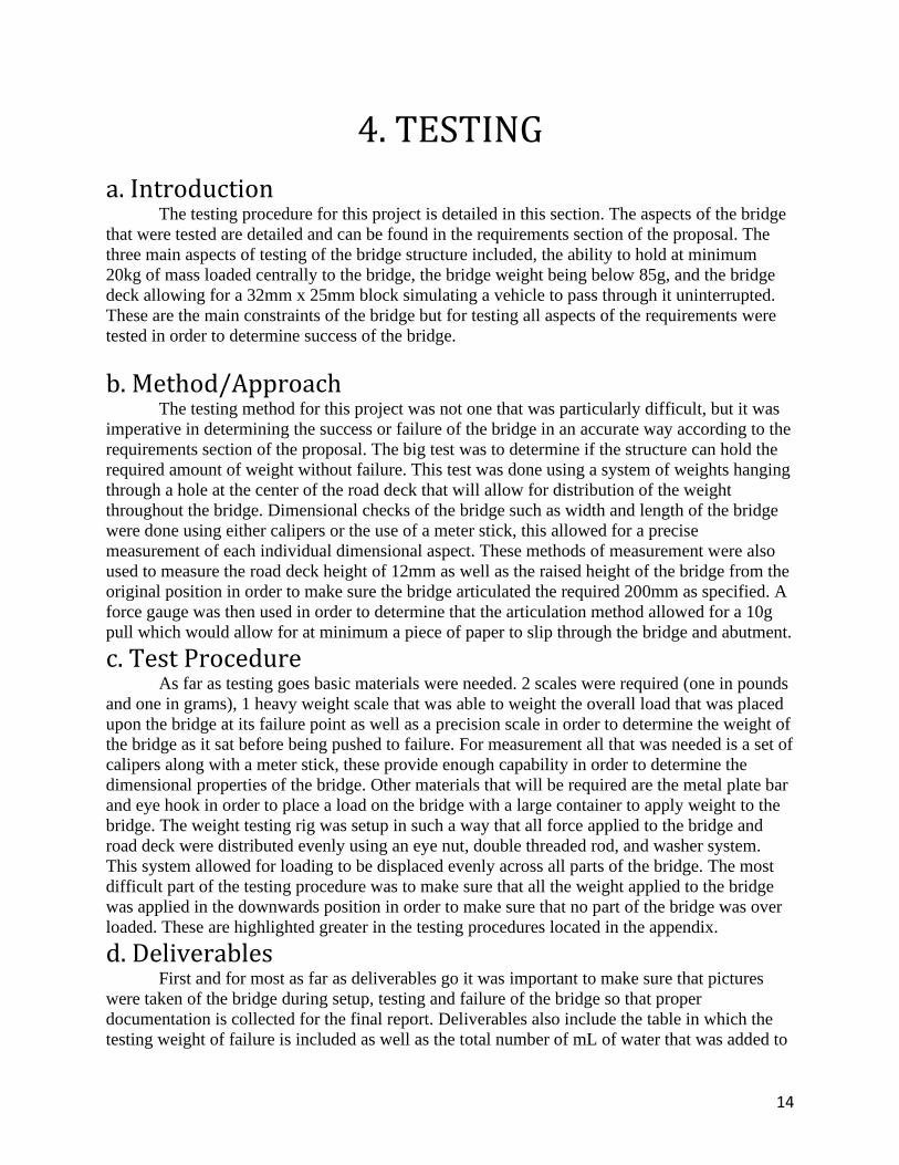
The calculations described here can be viewed in Appendix A-7. One of the requirements
of this bridge was that the overall mass of the structure would be no more than 85g in mass. This
calculation detailed in appendix A-7 was a complete calculation of the overall mass of the bridge
using the density of balsa wood and the volume of the individual members. this calculation
showed that the overall mass was 10g below the requirement listed in the proposal above.
vii. Analysis 7
This calculation was the final strength analysis of the bridge in order to determine what
sized columns would be needed in order to support the members that will be under compression.
This was also a calculation that was used to determine if the bridge would meet the requirement
of holding 20kg at minimum. These calculations can be found in appendix A-8.
viii. Analysis 8
The bridge has a requirement that says it must be able to articulate at least 50% of the
bridge to a height of 280mm. The first step in order to meet this requirement is to determine how
much force would be required to lift the bridge from a resting position. This information will
allow for the calculation of what kind of mechanism should be used in order to properly raise the
bridge to the required height.
viiii. Analysis 9
The bridge requirements states that the bridge must be able to articulate 280mm. The
design that was decided on for this articulation was to have a tower of one side of the bridge with
a small crank and a set of pulleys in order to wind up a string and pull the opposite end of the
bridge up. This calculation shows how much string will be required in order to complete this
operation. See appendix A-10
X. Analysis 10
The articulation design that was chosen for this bridge is one that requires a string at
some angle to pull in the x direction as well as the Y this means that the tension in the string is
going to be higher than the force that is actually required to lift the bridge. This calculation
shows the amount of tension that will be within the string at any given time while moving the
bridge up or down. See appendix A-11
Xi. Analysis 11
This analysis was done in order to determine the angle to which the bridge would sit
when fully raised to the required height. This allowed for a better understanding of how the
bridge would interact with the tower used to control the articulation components such as the
pulley and the axle. This was an analysis that would lead to the final analysis 12. The
calculations for this analysis can be found in appendix A-12.
Xii. Analysis 12
Once the bridge is in its fully retracted state the bridge will be under different loading as
the angle changes relative to the top of the tower. This means that more force will be required to
pull the bridge up than the force required to hold it up according to the calculations which will

10
allow for an easier time sustaining the upright position. This analysis can be found in appendix
A13.
h. Device: Parts, Shapes, and Conformation . The justification for the design of the bridge is based on an attempted to take a center
point load placed on the bridge and attempt to spread the forces evenly across all members
without placing to much stress at any one location. The loads can be found in appendix A, green
sheet A-2 and A-3. (more justification to come once more calculations have been done to
determine stresses in locations)
i. Device Assembly The device assembly addresses the problem at hand by taking individual components that
alone would not be able to support the minimum 20kg weight and assembling them in a way
which allows for a much larger forced to be applied on the structure. This includes adding
reinforced joint plates to reduce likelihood of breakages on glued joints, using stress analysis to
determine the required material cross-section at any given member and properly allowing
materials to bond.
j. Technical Risk Analysis With any project there is always some degree of technical risk associated with the project
at hand. In the case of this project the technical risks could involve things such as the articulating
portion of the bridge not properly operating to the design requirements such that it is not able to
raise the bridge to a satisfactory height in which case that entire assembly would have to be
replaces and redesigned causing a lot of time and project resource to be lost. There is also
technical risk associated with the bridge itself. If during analysis the bridge structure is
calculated to hold the required weight but in doing so the bridge exceeds the allowable weight
limit for the structure an almost full redesign would be required.
k. Failure Mode Analysis While preforming a failure mode analysis on the bridge the intent is to analyze as many
aspects of the bridge as possible in order to paint a full picture of what type of loads, stresses,
and strains will be placed on it in order to properly identify what material thickness and lengths
will be required in order to meet design specifications. In particular bending stress, shear stress,
normal stress, and moments in the material will play a big factor in determining where
components are most likely to fail. This analysis will improve the reliability of the structure by
reinforcing points that are most likely to fail.
l. Operation Limits and Safety As with any type of devices that has large loads placed upon it P.P.E. should always be
worn while in the area of the device. While constructing the bridge always use precaution while
cutting any materials and have all guards in place. Also, where actuation occurs for the moving
components of the bridge have a potential to pinch fingers or entangle hair so the structure
should not be touched while under load. During testing splintering may occur which requires
safety glasses to be worn at all times.

11
3. METHODS & CONSTRUCTION a. Methods For this project that is being undertaken, the original idea came from the need for a project that
will show engineering skill while still being able to be produced in the time of a pandemic such
as covid-19. This means that all of the design was done with little accessibility to CWU campus.
This will also be the case for construction of the project as campus will not be properly open by
the time the project needs to begin construction to stay on task. Limited access to the Hogue
building will be possible but under strict guidelines in order to maintain the safety of every
student. A few parts will be purchased such as the balsa wood members and glue for the wood
itself, but they will be modified and assembled into a bridge using home resources. The majority
of the parts for the articulation tower will be 3D printed using a personal printer, eliminating the
need for contact with others inside of the Hogue building. This limited access to Hogue has
created a unique situation where different and new methods for achieving goals had to be
established. This type of problem solving allowed for new methods and solutions to be used in
place of what would typically be thought of as the normal way to achieve a specific goal.
i. Process Decisions
One of the important things to do for any type of major project is to have a clear and
concise design decision process. In this section a detailed analysis of how the final design was
chosen and what factors lead to the decision of this design over a different design can be found.
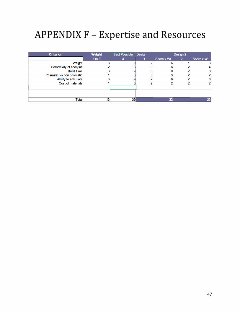
For this process a decision matrix was used in order to assess multiple different factors. This
decision matrix can be found in appendix F. Design 1 is a simpler design with a rectangular
shape and interior members going at 45 degrees. Design 2 was a more traditional bridge design
that may be seen in the real world more with a more curved shape arching above and more
reinforcement members on the interior. Both of these designs had potential to be chosen for this
project but in the end 1 had to be decided on over the others. The First and most important aspect
of this design was that the weight of the design meets the requirement. This is shown by the
weight section of the decision matrix. The weight of the number determines how important the
criteria is in the overall scheme of things. Design 1 came out on top for this category as it was
simply the smaller and more compact bridge design with less members required. This not only
allows for time to be cut off of the total assembly time, but it also allows for a lighter bridge in
order to meet the weight requirement set forth in the balsa wood bridge guidelines for success.
The other contributing factor to the design decision was to determine which bridge would allow
for the easiest mode of testing, because of design ones straight edges it will allow for the weight
system to sit easily upon the structure and provide a better test result than the other curved
structures. This type of logic can be followed throughout the entire decision matrix in order to
determine that the final design that was chosen was design 1.
b. Construction
i. Description
The construction of this bridge will occur in segments. This project consists of 9 parts
and 2 sub-assemblies. The first segment of construction is to assemble both sides of the truss
individually on non-stick wax paper. This will create the two main portions of the bridge. The
next portion of the build will be to connect these 2 trusses together using cross segments that will

12
allow the bridge to take form. Cross segments will be applied at the top and bottom of the bridge
in order to create a sturdy structure for the next process. Following this step, the road deck will
be installed creating a surface for the simulated car to cross as well as providing a place for the
load to be applied to the bridge itself. Lastly the bridge will need the articulation tower installed
in order to be able to move up and down, the articulation tower contains the only manufactured
part which is a pull that will convert vertically acting force into a vector force at an angle of 10
degrees. This pulley will be printed using an at home 3D printer.
ii. Drawing Tree, Drawing ID’s
iii. Parts
This project in particular has the benefit of having a material restriction which means that
most parts will be similar process for manufacturing. For the truss structure, the 3 different
dimension Members will be purchased in those dimensions at 3 feet in length. They will then be
required to be cut down into the appropriate lengths depending on the required length for that
Member location. The articulation tower is composed of 1/2” x 1/2” balsa wood segments which
will house the crank for articulation as well as the string and pulley that will be transferring the
force from vertical to a vector at 10 degrees. The only part manufactured in this process is the
pulley. This part will be manufactured using a 3D printing process.
iv. Manufacturing Issues
Issues with manufacturing have come from things such as the 3D printing process not
being able to accurately produce a part that small to any degree of accuracy. This could cause a
rough area between parts and within the rotation of parts and create unwanted friction within the
system. On the same note 3D printing also has the unfortunate side effect of being finicky while
printing and can have problems with parts not adhering to the print bed which creates many
problems while printing and usually leads to a failed print. Another manufacturing issue would
be the glue not creating a proper connection between members leading to a premature failure.
Balsa Wood Bridge
Truss Structure (Drawing 10-001)
1/2"x 3/4" Framework Members (Drawing 20-001)
3/8" Interior Members
1/4" Interior Members
(Drawing 20-002)
Road Deck
Articulation Tower
1" Balsa Wood Frame
Fishing LinePulley(Drawing 20-003)
Axle(Drawing 20-004)
Handle (Drawing 20-005)
Axle Mounts (20-006)
Ratchet Mechanism
(20-007)
Ratchet arm (20-008)

13
v. Discussion of Assembly
The Sub-assemblies are fairly basic only including 2 different sub-assemblies. The first sub assembly is going to be the truss itself, which is created using the construction method for 1 side of the truss and using connection beams to create the full truss structure. Once that is completed the truss requires a road deck which will be put in place after the two sides of the truss have been joined together. This whole sub assembly will be attached to the articulation tower via a pin which will allow for rotation as the towers string pulls the end of the bridge up. The articulation tower is constructed using 1/2” x 1/2” Balsa wood. At the top of this tower will be 2 pullies that will allow for force to be applied in the proper direction. The tower will also consist of a locking mechanism to keep the bridge in the upright position for extended periods of time. Because this design has been analyzed to such a large degree it will hold up relatively well to the benchmarks that were listed earlier in the proposal. Other benchmark bridges were not designed with such a heavy amount of analysis and because of this pound for pound this bridge should be far stronger. As far as cost goes compared to the benchmarks, the cost of balsa wood should not vary all that much and is most likely on par with the benchmarks set previously. This also applies to the manufacturing process as most of the process is just a matter of making simple cuts into stock balsa wood.
14
4. TESTING
a. Introduction The testing procedure for this project is detailed in this section. The aspects of the bridge
that were tested are detailed and can be found in the requirements section of the proposal. The
three main aspects of testing of the bridge structure included, the ability to hold at minimum
20kg of mass loaded centrally to the bridge, the bridge weight being below 85g, and the bridge
deck allowing for a 32mm x 25mm block simulating a vehicle to pass through it uninterrupted.
These are the main constraints of the bridge but for testing all aspects of the requirements were
tested in order to determine success of the bridge.
b. Method/Approach The testing method for this project was not one that was particularly difficult, but it was
imperative in determining the success or failure of the bridge in an accurate way according to the
requirements section of the proposal. The big test was to determine if the structure can hold the
required amount of weight without failure. This test was done using a system of weights hanging
through a hole at the center of the road deck that will allow for distribution of the weight
throughout the bridge. Dimensional checks of the bridge such as width and length of the bridge
were done using either calipers or the use of a meter stick, this allowed for a precise
measurement of each individual dimensional aspect. These methods of measurement were also
used to measure the road deck height of 12mm as well as the raised height of the bridge from the
original position in order to make sure the bridge articulated the required 200mm as specified. A
force gauge was then used in order to determine that the articulation method allowed for a 10g
pull which would allow for at minimum a piece of paper to slip through the bridge and abutment.
c. Test Procedure As far as testing goes basic materials were needed. 2 scales were required (one in pounds
and one in grams), 1 heavy weight scale that was able to weight the overall load that was placed
upon the bridge at its failure point as well as a precision scale in order to determine the weight of
the bridge as it sat before being pushed to failure. For measurement all that was needed is a set of
calipers along with a meter stick, these provide enough capability in order to determine the
dimensional properties of the bridge. Other materials that will be required are the metal plate bar
and eye hook in order to place a load on the bridge with a large container to apply weight to the
bridge. The weight testing rig was setup in such a way that all force applied to the bridge and
road deck were distributed evenly using an eye nut, double threaded rod, and washer system.
This system allowed for loading to be displaced evenly across all parts of the bridge. The most
difficult part of the testing procedure was to make sure that all the weight applied to the bridge
was applied in the downwards position in order to make sure that no part of the bridge was over
loaded. These are highlighted greater in the testing procedures located in the appendix.
d. Deliverables First and for most as far as deliverables go it was important to make sure that pictures
were taken of the bridge during setup, testing and failure of the bridge so that proper
documentation is collected for the final report. Deliverables also include the table in which the
testing weight of failure is included as well as the total number of mL of water that was added to

15
the weight reservoir in order to meet the testing standards. Testing uses a variety of setups and
measurement devices listed above. The bridge 10 second raise requirement has been performed
and is demonstrated in the TDR. The conducted test demonstrated that the bridge is capable of
sustained lift for the required 10 seconds outlined in the requirements.

16
5. BUDGET
a. Parts This project is to be composed a mostly easily accessible materials because the entirety of
the bridge structure is going to be made from balsa wood. This allows for easy procurement of
the materials listed in the parts and budget section in appendix C. For the most part amazon has
been used in order to order the specific sized balsa wood pieces and Jerrol’s was also a valuable
resource while attempting to collect all required materials. The Glue that will be used to
construct the bridge will be purchased from ace hardware along with any other instruments
required such as a knife and saw. After testing the budget was over the estimated value due to the
testing rig for failure being more costly than was originally anticipated. This led to being over
budget by about 50%. In the future for testing it would be ideal to order parts at the time of
estimation as prices and materials can change rapidly within the time from planning and the time
when testing actually takes place.
b. Outsourcing For this project most of the work should be done using all at homework. Due to the
nature of the project due to covid-19 outsourcing for parts for this particular project will not be
necessary. For any parts that may not be made of balsa wood a 3D printer will be used. 3D
printing will be used for parts that relate to the articulation portion of the bridge. This is possible
to be done from home without any type of outsourcing. In turn this allows for strict adherence to
the budget as well as low costs which allows for a personally funded project.
c. Labor The labor cost for this projects labor should be $0.00 as all of the labor will be done from
home without the use of any type of outsourcing. The use of an at home 3D printer allowed for a
lot of inexpensive parts to be produced without any outsourcing.
d. Estimated Total Project Cost As the articulation portion of the bridge has not been designed fully yet, the final cost
cannot be completely accurate but if the cost of the bridge structure shown in appendix C is
added to the estimated cost of the articulation components the estimated cost of project will be
about $85.00. as of now all parts and required materials have been acquired and a total budget of
around $50.00 has been spent meaning that the project is much below the budget anticipated.
e. Funding Source The cost of this project will be supported using funding from Logan Bronemann. This project is not going to be extremely expensive and can be fit into a personal budget.

17
6. Schedule
a. Design For the design portion of the schedule most things have been going according to plan for
the design phase. No major snags have been hit and it appears that the design is on track to be
completed by end of quarter.
b. Construction As Construction has begun on this project the schedule has progressed to the construction
phase as well. The schedule for construction is centered around creating the CAD modeled parts
that can be 3D printed first in order to determine what the construction process for the balsa
bridge section will entail in order to accurately produce the desired design. As of current the 3D
printed parts are completely printed and ready for assembly onto the articulation tower. The main
scheduling issue is that the prints can be unreliable at times as if one thing goes wrong during
printing it must be completely restarted. This has issue has been minimized by creating a printing
profile that has specific settings that allow for more accurate printing with the used material and
the part sizes. As far as the bridge itself goes the construction has begun by laying out the
materials and place to build but physical assembly has not yet begun. The main issue with
building the physical bridge was the necessity to have a proper space to dry as well as having the
necessary time left untouched. This means that a specific space needed to be allocated to the
building of this section of the project.
c. Testing Testing of the device has been totally and completely complete. All data has been
recorded and placed into the data collection sheet that was constructed in order to neatly and
precisely record the required data that was needed for the testing portion of this device. Testing
went for the most part according to plan, but this does not mean it did not have its fair share of
issues and difficulties along the way. The biggest issue that was faced while conducting testing
was the ability to properly secure the failure load testing rig. Parts that were supposed to arrive in
time for testing did not so substitutions to the design had to be made. Originally a specific nut
with a very flat like washer head was intended to be used to secure the rig to the top of the road
deck in order to distribute the weight, however this nut did not come in time for testing so an
alternate solution had to be made. The alternate solution was to use two small thin washers that
did not exceed 6mm were placed on top of the road deck and the road used to connect the bridge
to the loading system was placed through the road deck and through these 2 washers on the top
side of the road deck, a wing nut was then placed on top of these washers and the road was
threaded into the wing nut. This was essentially the same idea as before, but it was something
that had to be changed in order to conduct testing and remain on schedule. The other issue that
was encounter was with the grams scale that had to be ordered so that the overall weight of the
bridge could be tested. Originally a gram scale with a range of 0-100 grams was ordered as this
was the proper tool to measure a bridge that was at most supposed to weight 85 grams. The
shipping on this item was fairly fast but when the scale was received it was a scale that had a
minimum load of 100 grams which means it was not able to even detect a reading on the bridge
when it was placed on the scale. This required that a new scale be ordered for testing and the old
scale be sent back which put a bit of a time delay on the testing for the overall weight but all in
all test was able to remain on schedule. This just goes to show that while schedules are a

18
powerful tool for remaining on track for a project there will always be things that come up that
require schedule shifting and reorganization in order to remain on track for completion. Other
than these two small issues the remainder of testing was conducted according to schedule and
allowed for all testing to be conducted by the final testing date.

19
7. Project Management
a. Human Resources Human resources can make or break a project. For this particular project the human
resources will be limited due to the nature of the project in the worlds current condition but both
instructors for MET 489 are valuable resources for this project along with fellow classmates.
b. Physical Resources Physical resources will be used throughout this projects construction phase in order to
assemble a working product. Physical resources will include 3D Printer for printing pieces of the
articulation tower, knifes for cutting the balsa wood, and wood glue for securing the pieces of
balsa wood in place.
c. Soft Resources Soft resources will also be used in this project including software such as solidworks for
design processes, as well as Cura which is the slicing software that will be used for the 3D
printing process.
d. Financial Resources This project will not be on the expensive side seeing as the main component of the bridge will be balsa wood which is not particularly expensive. This project will be entirely funded by Logan Bronemann.

20
8. DISCUSSION
a. Design The design process for any major project is lengthy, extensive, and requires revision
constantly. This project was no different. Throughout the quarter many different designs were
considered for the truss assembly. The main concern was the weight factor of the bridge as
having a structure that is to complex would lead to the bridge being overweight and therefore not
meeting the requirements before the bridge was even able to be tested. The simple design that
was chosen was not random but rather encompassed different aspects of many design ideas into
something that was simple yet effective. Once the design was determined the analysis of the truss
system needed to begin in order to one by one make sure that this project would meet all of the
requirements listed in this report. Using truss analysis techniques allowed for overall loads as
well as joint loads and member loads to be determined within the bridge. This was the step that
was the basis of the whole project as knowing the forces within the structure was essentially half
the battle of the design process. Once the forces in every member were determined it became
possible to analyze the bridge members and determine what dimensions would be required in
order for the structure to meet the specifications. Column analysis was used for this as well as
looking at the bending stresses placed on members. once the structure members of the bridge had
been fully defined the articulation portion of the bridge was in need of a design. Because the
bridge was loaded in the center having the bridge articulation from the center of the bridge was
not an ideal solution to the problem at hand.
The problem at hand was to raise 50% of the bridge 200mm above its resting position. To
do this a tower was designed in order to apply a rotational force to an axle which will wind up a
string and pull from the opposite end of the bridge creating an articulation motion and raising the
bridge. Force applied to the bridge and tower were determined in order to make sure that no
components would be under too much stress while raising the bridge.
The problems that occurred within this project were subtle but present. The major
problem encountered was finding reliable and accurate material specs for balsa wood as there are
many different types of balsa wood and many different qualities. This proved to be one of the
biggest obstacles in the design process. Another problem that was encountered in this project
was simply the condition of the world at this moment being that all work related to the project
must be done at home without many University resources. This makes even small tasks a bit
more difficult. The design process was one that was tough, but it allowed for learning
environment that produces a valuable knowledge about what a project fully entails.
b. Construction Construction of this project is a detail-oriented undertaking in order to properly and efficiently construct the entire device in the 10-week time period. Many different challenges arise while undertaking such a large project. This project has obstacles during design, manufacturing and construction. The main concern at the start of the construction process was the 3D printing process and its ability to accurately produces parts of small sizes with any amount of precision. This concern ended up being a problem that had to be overcome in order to produce the parts required to raise the bridge and allow for articulation. The main issue with 3D printing small parts is creating a strong adhesion to the bed as well as stringing from the extruder. These problems occur because these parts are very small and has minimal surface

21
area to be able to adhere to the bed properly. This manufacturing process also ended up becoming increasingly more difficult as smaller and more precise parts were made and many tweaks to the slicer program had to be made in order to properly print the parts as intended. Many times, with small parts you will experience the part bending and curving as its printed because it has nothing keeping it grounded to the bed. This problem was overcome by adding a raft base to the part which creates a much larger surface area of material to be printed onto, allowing for much better adhesion to the bed. The second problem of stringing can be a large factor in part accuracy as if stringing occurs on the print then material that should have been added to the part layer has actually just been dragged around the part creating small hair like fibers that string off of the part. The material that was supposed to be creating a .25in hole for example has now been strung throughout the holes inside diameter which will in turn create large inaccuracies within the part itself. The main solution to this problem was to turn down the speed of the print in order to make sure that the layers are adhering to themselves and create a sort of “smoosh” between the extruder and the part as the layer is being added. This technique allows for much higher accuracy on part dimensions. As far as manufacturing of the bridge portion itself the most difficult part was creating an accurate enough cut using tools from home. Apartment living does not lend well to any manufacturing process involving wood as it becomes hard to use knives and cardboard to cut precise angles. This meant that many recuts were necessary in this process in order to make sure that parts fit together in an acceptable fashion for the project. Other than that the bridge portion itself was not necessarily difficult but it was time consuming and took up a majority of the project time.
c. Testing The testing process for the Balsa wood bridge project is a slow and methodical one in which fine details of the constructed device must be carefully examined in order to properly determine if the requirements stated in the above sections have been met. This process involved the use of many measurement tools such as scales, measuring sticks, calipers, as well as a complex failure system design in order to make sure that while testing the overall strength of the bridge that the weight is displaced evenly throughout all parts as to not over stress a specific area of the bridge. This process alone proved to be a difficult one as due to covid a device that can be used from home was required. The main issue with developing this rig was that in order to meet the 20kg weight requirement using water more than 5 gallons of water is needed to meet that weight so finding a vessel that could hold this much weight was difficult but achievable. Overall the bridge did end up meeting the minimum requirement but was not able to hold the amount of weight it was designed for. The road deck was not reinforced enough and caused the road deck to completely fail prematurely. This would mean that if the project was to be undertaken again it would be effective to design the bridge with more structural rigidity within the road deck itself. The only other requirement that was not able to be met was the minimum raise height as the design had interference between the tower and the bridge. This could have been resolved by creating a larger width differential between the tower and the bridge so that the 2 had very minimal contact with one another.

22
9. CONCLUSION In conclusion this testing report outlines the work done and the process followed throughout the journey of the “Balsa Wood Bridge: project. The successes and failure along the way and the steps taken to over come these milestones are all reflected in this document leading to the culmination of a years’ worth of work. This project helped to strengthen and exemplify the knowledge gained throughout the MET program at CWU. All in all, the results were successful and show not only the successes of the design work and the bridge as a whole but also the successes of the MET program as a whole at CWU. The takeaway from a design project of this scale is massive and the value is as well.

23
10. ACKNOWLEDGEMENTS Thank you to Professor Pringle and Dr. Choi for their hard work and dedication to all of the MET students at CWU. The level of care they give to each student is impressive and very much appreciated by all in the MET program.

24
References

25
APPENDIX A - Analysis Appendix A-1 – Reactions @ Points A and B

26
Appendix A-2 – Force on Members and at Points

27
Appendix A-3 - Force on Members and at Points

28
Appendix A-4 – Member length

29
Appendix A-5 – Cross-section dimensions of material

30
Appendix A-6 –
31
Appendix A-7 – Mass of structure calculation

32
Appendix A-8 – Column Pcr

33
Appendix A-9 – force required to lift bridge

34
Appendix A-10 – Length of string for lifting mechanism

35
Appendix A-11 – force across lifting string in tension

36
Appendix A-12 – raised bridge angle

37
Appendix A-13 – Force to hold bridge upright
38
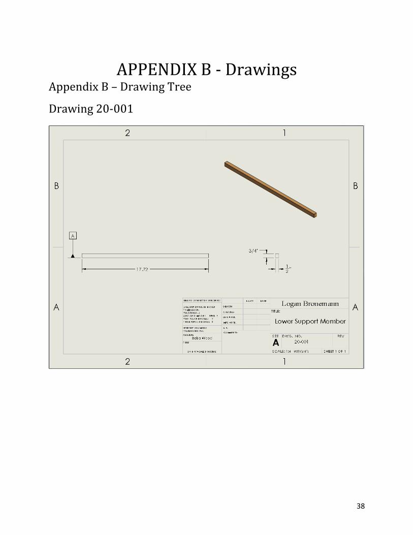
APPENDIX B - Drawings Appendix B – Drawing Tree
Drawing 20-001

39
Appendix B – Drawing 20-002

40
Appendix B-Drawing 20-003

41
Appendix B-Drawing 20-004

42
Appendix B – Drawing 10-001

43
Appendix B – Drawing 10-002

44
Appendix B – Drawing 10-003
Appendix B – Drawing Tree
Balsa Wood Bridge
Truss Structure (Drawing 10-001)
1/2"x 3/4" Framework Members (Drawing 20-001)
3/8" Interior Members
1/4" Interior Members
(Drawing 20-002)
Road Deck
Articulation Tower
1" Balsa Wood Frame
Fishing LinePulley(Drawing 20-003)
Axle(Drawing 20-004)
Handle (Drawing 20-005)
Axle Mounts (20-006)
Ratchet Mechanism
(20-007)
Ratchet arm (20-008)

45
APPENDIX C – Parts List and Costs
Part Number
Qty Part Description Source Cost Disposition
20-001 2 exterior members beam-1/2” x ¾” x36”
Amazon $20.00 Ordered 1/13
20-004 4 Interior Members 3/8” x 3/8” x36”
amazon $15.00 Order 1/13
20-002 4 Interior members 1/4”x1/4” x36”
amazon $15.00 Ordered 1/13
20-003 2 Pulley 3D Printed $0.50 Printed 1/20 20-004 1 Axle 3D Printed $0.50 Printed 1/20 20-005 1 Handle 3D Printed $0.25 Printed 1/20 20-006 2 Axle Supp orts 3D Printed $0.25 Printed 1/22 20-007 1 Ratchet 3D Printed $0.25 Printed 1/22 20-008 1 Ratchet Arm 3D Printed $0.25 Printed 1/22
APPENDIX D – Budget
Item Qty Description Cost Balsa wood saw 1 Small saw with teeth $15.00 Parchment paper 1 Non stick parchment paper $5.00 Glue 1 Sticks members together $7.00

46
APPENDIX E - Schedule
47
APPENDIX F – Expertise and Resources

48
APPENDIX G – Testing Report Testing Report 01: Appendix G1.1 Introduction: According to the outlined requirements from the engineering report the bridge must be able to articulate in the vertical direction and remain raised at the max raise height for at minimum 10 seconds without any outside assistance or force acting on the bridge. The predicted value was that the bridge will be able to remain in the upright position using only its own lifting mechanism for at least 15 seconds. This data will be collected using a simple stopwatch and the data collection sheet in order to determine if these criteria was met. This test is taking place on April 13 as seen in the gantt chant. Appendix G1.2 Methods and Approach: Testing for this requirement didn’t require any resource intensive type of testing as access to the internet allowed for a stopwatch and the data collection sheet was already prepared before hand allowing for ease of access while conducting the test. This test didn’t require an excess amount of data collection as the only data that needed to be collected was the length of time that the bridge was able to stay in the up right position on its own as well as a determination of if it met the requirement for the test. The main constraint of this testing was that the bridge would slip on the “non-slip” surface it was placed on making the bridge slightly torque to the side which would cause the need for a retest as everything needs to be in full operational condition but this would not prove to be a huge issue. The precision of this test was very high as it could easily be repeated multiple times as it does not cause any type of failure to the bridge. The accuracy of the test was also very high as the stopwatch used to record the data was able to record out to the hundredths of seconds which is far higher than the accuracy required for the test. Once this test was conducted the time that the bridge was held in the upright position was recorded and the data was then analyze to determine if the test was a success or failure by comparing it to the requirement of 10 seconds held without assistance. This data is show in the data collection table that was created to store the data of all conducted tests. Appendix G1.3 Test procedure: Summary This procedure documents the process of raising the bridge, using the locking mechanism and the time the bridge was able to stay in the upright position on its own accord. This test will determine if the bridge is able to meet the minimum requirement of 10 seconds held in the fully upright position. Following this summary is the testing information and the testing procedure.

49
Time: The test should be conducted by April 13th 4:00-5:00 PM. This test will be conducted at an off campus location. The time to setup should take no more than 10 minutes. Time to record should be approximately 10 minutes. Total test should be no more than 5 minutes and take down should be no more than 10 minutes. This time frame allows for a bit of flexibility as well if any extra time should be required. Place: The Verge Apartment complex, Ellensburg, WA. Required equipment includes:
• Camera
• Computer with Microsoft excel
• Stopwatch
• Bridge and raising tower
Risk: Main risk involved with this test is in the setup and takedown of the bridge, extra precaution should be taken in order to reduce physical damage to the structure will securing it in the proper testing position. The test procedure is as follows:
1. Collect equipment:
a. Camera from phone
b. All other materials should be in possession with data sheet pulled up in
excel on laptop
i. Excel sheet can be accessed by opening Microsoft excel from the
windows start menu
ii. Proceed to click “open” in the top left corner under “file”
iii. Click “Bridge failure spreadsheet”
c. Place laptop on table in convenient location
2. Place all materials on 1 of the tables being used for testing
3. Prepare the stopwatch for testing
4. Place counterweight that is attached to the articulation tower in a location that
allows for the string to be pulled tight as to keep tower in the upright position
while weight of bridge is placed upon it.
5. Assure that the bridge is in the fully lowered position before beginning test.
6. Using the handle on the raise tower turn clockwise as to begin to raise the
bridge. A clicking sound should be heard from the ratchet mechanism as it is
raised.
7. Raise the bridge so that it is in the fully raised position where the bridge can no
longer travel up, this is indicated via visual inspection as well as feedback from
the handle not turning anymore.
8. Assure that the ratchet mechanism is securely locked in place, so no slippage
occurs.
9. Release hands from bridge and start the stopwatch
10. Testing has begun, watch the bridge to make sure it remains in the upright
position and continue test until the stopwatch hits 15 seconds, or the bridge slips
out of position.

50
11. Record the Time the bridge was able to remain in the raised position in the 10
second raise column of the testing data chart.
12. Lower the bridge
a. Turn the white release handle counterclockwise as to release the ratchet
arm from the ratchet.
b. Allow gravity to slowly bring the bridge to a resting position.
13. Save the excel file
a. Navigate to the top left corner of the screen and click “File”
b. Under file proceed to click “save”
c. The document has been properly saved
14. Release tension in the counter weight by moving it closer to the bridge
15. Carefully take the bridge and move it to a safe storage location.
Appendix G1.4 Deliverables This test showed that the bridge was able to remain in the upright raised position for a total of 15 seconds without the help of any outside forces acting on it. This exceeds the requirement of remaining raised for 10 seconds by 150% making this a successful test beyond reasonable doubt. This test was fairly straight forward to test but provided valuable data about how the bridge performs according to the design set forth for the bridge. This test went according to plan and met the expectations perfectly. If the test was to be conducted again a better no slip surface would be the best way to improve future testing. Appendix G2.1 Introduction: The requirements of this project state that the bridge should be able to raise 50% of the bridge to 50% of the overall length of the bridge. This means that while the bridge is in the fully raised position the center point of the bridge should be at a height of 200mm as the overall length of the bridge is 400mm. Calculations were done to determine how tall the bridge raise tower would need to be in order to lift the bridge to this position. The predicted value for this test is that the bridge will be able to raise 200mm at the center point of the bridge. This data will be acquired using a ruler while the bridge is in the fully raised position to measure the height from the ground to the center point of the bridge. This test will be conducted on April 21st as shown on gantt chart below. Appendix G2.2 Methods and Approach: Testing for this requirement only required 2 resources which were Microsoft excel and a ruler. This was a very low cost test and didn’t require any of the testing budget to conduct as a ruler was already in possession prior to testing. To collect this data the bridge must be raised, a mark must be placed at the center point of the bridge and then

51
a ruler is held from the ground to this marked point to get a recordable data point which is then placed into the data collection chart on excel. The physical limitation of this test is that a ruler is only so accurate, this limitation should prove to be very impactful, but it is a limitation to keep in mind while conducting the test. Once the data is recorded it will be presented in a table generated in excel along with the rest of the testing data. Appendix G2.3 Test procedure: Summary This procedure documents the process of marking the center point of the bridge, raising the bridge, using the locking mechanism and measuring the height from the ground to the center point of the bridge to determine if it meets the minimum requirement of raising 50% of the bridge 50% of the overall length. Following this summary is the testing information and the testing procedure. Time: The test should be conducted by April 21th 4:00-4:45 PM. This test will be conducted at an off-campus location. The time to setup should take no more than 10 minutes. Time to record should be approximately 5 minutes. Total test should be no more than 5 minutes and takedown should be no more than 10 minutes. This time frame allows for a bit of flexibility as well if any extra time should be required. Place: The Verge Apartment complex, Ellensburg, WA. Required equipment includes:
• Camera
• Computer with Microsoft excel
• Marker/pencil
• ruler
• Bridge and raising tower
Risk: Main risk involved with this test is in the setup and takedown of the bridge, extra precaution should be taken in order to reduce physical damage to the structure will securing it in the proper testing position. The test procedure is as follows:
1. Collect equipment:
a. Camera from phone
b. All other materials should be in possession with data sheet pulled up in
excel on laptop
i. Excel sheet can be accessed by opening Microsoft excel from the
windows start menu
ii. Proceed to click “open” in the top left corner under “file”
iii. Click “Bridge failure spreadsheet”
c. Place laptop on table in convenient location
2. Place all materials on 1 of the tables being used for testing
3. Prepare the bridge for testing

52
a. Measure the overall length of the bridge (400mm)
b. Exactly half way between the two ends of the bridge place a small mark to
indicate the half way point (200mm from either end)
4. Place counterweight that is attached to the articulation tower in a location that
allows for the string to be pulled tight as to keep tower in the upright position
while weight of bridge is placed upon it.
5. Assure that the bridge is in the fully lowered position before beginning test.
6. Using the handle on the raise tower turn clockwise as to begin to raise the
bridge. A clicking sound should be heard from the ratchet mechanism as it is
raised.
7. Raise the bridge so that it is in the fully raised position where the bridge can no
longer travel up, this is indicated via visual inspection as well as feedback from
the handle not turning anymore.
8. Assure that the ratchet mechanism is securely locked in place, so no slippage
occurs.
9. Release hands from bridge so it is under its own weight completely
10. Take the ruler and firmly place the edge closer to the 1 inch mark firmly on the
ground surface
11. Using the ruler, measure from the firm ground surface to the previously marked
position on the center of the bridge.
12. Record this measurement under the 50% raise height section of the excel sheet
13. Lower the bridge
a. Turn the white release handle counterclockwise as to release the ratchet
arm from the ratchet.
b. Allow gravity to slowly bring the bridge to a resting position.
14. Save the excel file
a. Navigate to the top left corner of the screen and click “File”
b. Under file proceed to click “save”
c. The document has been properly saved
15. Release tension in the counterweight by moving it closer to the bridge
16. Carefully take the bridge and move it to a safe storage location.
Appendix G2.4 Deliverables This test showed that the bridge was unable to meet the requirement of allowing 50% of the bridge to raise 50% of the overall bridge length off the ground. The requirement states that the center point of the bridge must be 200mm off of the ground in order to be successful, the bridge was only able to raise the center point of the bridge a total of 152.4mm from the ground. The test was a failure do to a flaw in the design that did not allow enough room between the bridge and the tower which means that the road deck and sides would come into contact with the raise tower and not allow for full calculated retraction of the bridge. This problem could have been solved in the design phase by allowing for a gap between the 2 structure so that this interference would not occur.

53
Overall this test did not meet the requirement set forth in the project report but it did provide valuable information about how future designs could be improved. Appendix G3.1 Introduction: One requirement of the bridge was to be able to hold a weight of at minimum 18.9kg. To test this requirement a testing rig was set up in order to place a load upon the bridge to test its ability to meet this requirement. The predicted and calculated performance of this test was that the bridge would be able to hold at minimum 30kg of weight before failure occurred. This test had incremental weight increases applied to the bridge until failure occurred and because of this testing method a tally was kept for every 500mL of water that was added to the bridge so that data could be kept about the breaking point. Appendix G3.2 Methods and Approach: As far as testing goes the failure test described in this report was by far the most expensive of the tests conducted on this bridge. All in all, it required about $30.00 in testing materials in order to properly secure the loads in a safe way that wouldn’t cause unsafe conditions when testing. Other resources such as people were not used in this test and most of the resources need was simply the money to purchase the materials. The testing procedure for this particular requirement required that the weight be applied at the center of the bridge with the weight being applied in the directly downward position, this meant that the bridge would have a small whole through the road deck in which a rod could be placed through and secured to the top of the road deck weight would then be applied to the bottom side of the rod that was underneath the bridge. This created one limitation in the testing method and that was that the space in between the 2 ends of the bridge had a space limitation and that the weight being applied to the bridge had to be able to fit in between this gap. This was the main operational limitation but as far as accuracy of the test results its safe to say that the weight measured to be placed on the bridge is within 0.1 pounds of accuracy as this is how many decimal places the scale used is able to calculate. Using this data from the scale and the data from the recorded mL the testing will be recorded in a chart that has ascending mL values along with the corresponding weight in pounds next to these volume measurements. This data will then be confirmed at the end with a final weight check after failure occurs. This will be the final recorded failure weight of the bridge. Appendix G3.3 Test procedure: Summary

54
This procedure documents the process of recording, failing of the balsa wood bridge, and processing the results. The balsa wood bridge was designed in order to satisfy the requirements of the balsa wood bridge project correlating to MET489 senior project. The bridge is designed to fail at 30kg as this is the minimum bridge weight of 20 kilograms with a factor of safety of 1.5. Following this summary is the testing information and procedure. Time: The test should be conducted by April 23rd from 4:00pm to 6:00pm at an off-campus location. This allows for 30 minutes of equipment gathering and setup, 1 hour slowly and accurately add weight and fail the bridge, with 15 minutes of data recording and 15 minutes of clean up time. Place: The Verge Apartment complex, Ellensburg, WA. Required equipment includes:
• Camera
• Computer with Microsoft excel
• Pounds scale
• Water supply
• Two 5-gallon water jugs
• Container with ability to pour
• Duct tape
• scissors
• 2 tables of equal height (abutments)
• Rope able to hold 100 pounds
• Data sheet
• Safety glasses
• Drill with ½” hole bit
• 36mm square by 6mm thick steel plate w/ 6mm hole in center
• Steel rod with threaded ends
• 1 nut that fits threaded end of rod
Risk: Main risk involved with failure of a balsa wood bridge is the ability for pieces of wood to splinter and cause damage which is why safety glasses are required at all time. The other main risk is damage to surroundings or others if weight from load causes a violent break meaning bridge will be loaded only to no more than 100 pounds. The test procedure is as follows:
1. Collect equipment:
a. Camera from phone
b. All other materials should be in possession with data sheet pulled up in
excel on laptop
i. Excel sheet can be accessed by opening Microsoft excel from the
windows start menu
ii. Proceed to click “open” in the top left corner under “file”
iii. Click “Bridge failure spreadsheet”
c. Place laptop on table in convenient location

55
2. Place all materials on 1 of the tables being used for testing
3. Place safety goggles on so that they are securely on face and covering eyes
properly.
4. Take both two 5-gallon water jugs and place them side by side so that they are
touching
a. Place 1 end of the duct tape on 1 of the 5-gallon jugs and wrap the duct
tape around the other 5-gallon jug to secure them together.
b. Without cutting the tape continue to wrap around the 2 5-gallon jugs from
bottom to top securing the 2 jugs together firmly.
5. Take the drill and install the ½” drill bit into the chuck of the drill
a. Using this drill, drill out 4 concentric holes through the neck of both bottles
1 - ½” from the top of the bottle.
6. Using a tape measure, measure out 5 feet of rope
a. Using the scissors cut off 5 feet of the rope
7. Take the rope that has been cut and pull it through all 4 concentric holes that
have been drilled into the 5-gallon jugs.
a. Each end of the rope should have equal length from the jug to the tip of
the rope
8. place the pounds scale on hard even ground to receive best readings
a. collect the two 5-gallon jugs that have been duct taped together along with
the rope that has been pulled through and place them on the pounds scale
along with the 36mm square steel plate, the steel rod, and the nut.
b. record this weight as the passive weight on the bridge structure without
additional load.
9. Pull the 2 tables of equal high next to each other so that they are touching edge
to edge.
a. Measure out 400mm in length and separate each table so the gap
between the 2 is 400mm.
10. Place the bridge on both tables so that it spans the length of the gap between the
2 tables.
11. Place the 36mm square steel plate on the road deck so that the threaded hole is
centered with the hole in the center of the road deck.
a. From the underside of the bridge push the steel rod through the hole in the
center of the road deck as well as through the hole in the square plate.
i. Screw the nut onto the end of the steel rod in order to secure the
rod to the steel plate so that the rod is hanging from the steel plate.
12. Securing the two 5-gallon jugs to the rod using the eye nut and tie the rope to the
eye nut at the end of the rod.
13. Using the water supply at hand along with the pounds scale slowly measure out
1 pound of water into the separate pourable container.
a. Slowly and gently (to avoid impact forces) add this 1 pound of water into
the left side 5-gallon jug

56
b. Record that it was able to hold 1 gallon of water in the excel sheet and any
observations made on the bridge
i. Repeat step 13, 13a and 13b adding 1 pound additional but to the
right side 5-gallon jug.
c. Continue to repeat steps 13, 13a, 13b, and 13b(i) until bridge failure
occurs or bridge load weight is at 100lb
i. Bridge failure can be categorized as either a fracture in a member,
high amounts of bend so that the bridge cannot properly support
weight any longer, or anything that would prevent the bridge from
continuing to be loaded with a higher amount of weight
14. using the camera take pictures of the load on the bridge every 5lbs in order to
properly document the change in the bridges structure and see results at later
dates.
15. Once the bridge has failed and all loading data has been properly documented in
the excel sheet break down of test can begin
16. Start by saving the excel file
a. Navigate to the top left corner of the screen and click “File”
b. Under file proceed to click “save”
c. The document has been properly saved
17. Making sure to check for any possible safety hazards, disconnect the two 5-
gallon jugs from the metal rod in order enable the 5-gallon jug unit to move freely
a. Being careful to not strain any part of the body while maneuvering the
jugs, bring the 2 jugs to the nearest water disposal location such as a sink
or tub and dump out the water
b. These 2 jugs can now be disposed of as the test has been concluded.
18. Carefully remove bridge from the 400mm gap and surrounding areas as to
eliminate any hazards
a. Clear floor of any particles or wood scraps that may have been thrown to
the floor during failure
19. Return all equipment to its original location
Appendix G3.4 Deliverables The final test conducted on the bridge for failure testing was completed and the results of the bridge were recorded. All in all, the bridge was able to hold 19.0 kg. this is a far way from the predicted value of 30kg, but it was still able to meet the required value of 18.9kg minimum. This means that the test was successful in meeting to requirements set forth for this project. This test also exposed a weak point in the bridge as the actual calculated truss of the bridge looked prepared to hold much more weight, but the road deck was the failure point of the bridge. If the road deck had been better reinforced than the bridge may have been able to properly meet the calculated value of 30kg. All around the test was successful and shows that the bridge was able to meet the requirement set forth.

57
APPENDIX H – Resume

58
Objective Current Mechanical Engineering student at Central Washington University seeking an entry-level mechanical engineering position.
Education STEM Diploma | Mountlake Terrace High School 09/2013 – 06/2016 Graduated with STEM Honors, AP Physics, AP Biology, AP Calculus, AP History, member of the National Honor Society, National Science Fair award winner, Chosen to Present at the Edmonds Public Schools Foundation fundraising breakfast to encourage Corporate support of STEM. Varsity Football, Track and Field, young life, and member of FCLAA.
Bachelor of Mechanical Engineering Technology| Central
Washington University 09/2016 – Present Currently working on My Bachelor of Mechanical Engineering, Member of the National Honor Society, Dean’s List.
Experience Sales Associate| Mariner’s Team Store 2015 – 2018 Sales Associate, POS, customer service, key holder, inventory control.
Skills • Strong Technical ability
• Excellent Problem-Solving ability
• Team working Skills
• Excellent Time Management
• SolidWorks Certified
• Strong Communication skills
• Ability to work under pressure
• Skilled in 3-D printing
Activities I have a passion for Technology, the Sciences and Astronomy. I like to spend my free time experimenting with 3-D printing and reading up on new Technology. I enjoy Golfing, Movies, Hiking, Spending time with Friends & Family. I enjoy volunteering to help those in need, my favorite work is during the holidays procuring food, clothing and gifts to give to those in need.
LOGAN BRONEMANN
2833 Russet Rd, Brier WA 98036
425-772-1677