Ball_Plug_Valves.pdf - S-LOK
28
W e . s u p p o r t . t h e i n n o v a t i o n s . o f . c u s t o m e r s Leak - Proof Flow & Control Solution Partner The Best Partner for Value Creation
-
Upload
khangminh22 -
Category
Documents
-
view
1 -
download
0
Transcript of Ball_Plug_Valves.pdf - S-LOK

W e . s u p p o r t . t h e
i n n o v a t i o n s . o f . c u s t o m e r s
Leak - Proof Flow & ControlSolution Partner
The Best Partner
for Value Creation

2
Ball & Plug ValvesBall & Plug Valves IndexIndex
SBV, SFBV SERIESBall Valves 3~4SBV10
Series
5~9SBV30Series
10~13SBV60Series
14~17SFBV60Series
SDBV SERIESBall Valves forDIN Standard 22~24SDBV
Series
STBV SERIESTrunnion Ball Valves 18~21STBV
Series
SPV SERIESPlug Valves25~27SPV
Series

3
Ball ValvesBall ValvesSBV10SBV10
Features•Compact design with hexagon bar-stock for high integrity.•Working pressure up to 1000psig(69bar) at 100℉(38℃).•Low torque quarter turn actuation.•Size range of from 1/4″ to 1″ tubing and piping.•Various end connections : reliable S-LOK, NPT & ISO male & female.•Butterfly handle is available as option.
Applications•Water, Oil, Gas.•Petrochemical Plants.•Steel mils.•Heavy Vehicles.
Factory Test•Every valve is factory tested with Nitrogen@1000psig
(69bar) for leakage at the seat to a maximum allowableleak of 0.1sccm.
•The stem packing is tested for no detectable leakage.
Pressure-Temperature Ratings
1000900800700600500400300200100
70
60504030
2010
100 200 300 400 500℉
Pressure, psig Pressure, bar
Temperature0 50 100 150 200 250℃
SBV10Series For working pressure up to 1000 psig(69bar)

4
Ball ValvesBall Valves SBV10SBV10
S-6MS-4TF-4NS-10MS-6TF-6NS-12MS-8TF-8NS-16MS-10TF-12NS-12TS-16TF-16N
SBVA
SBVB
SBVC
SBVD
SBVE
BasicOrdering Number
Dimensions (mm)Orificemm(in) Cv End Connections
Inlet /Outlet
Item Description Material /ASTM SpecificationBrass
12345678910111213
BodyEnd ConnectorBallSeatInsertStemLower PackingUpper PackingGrandGrand WasherSpring WasherLock NutHandle
S316S316/A479, A276S316/A479, A276
Brass/B16Brass/B16
S316/A479, A276Reinforced PTFES316/A479, A276S316/A479, A276Reinforced PTFEReinforced PTFE
S304S304S304S304
S304 with PVC Coating
①② ③④⑤
⑥⑦⑧⑨⑩⑪⑫⑬
A
H
LL
Ordering Information and Dimensions
5.0
7.5
9.0
12.5
16.0
1.251.251.352.602.502.609.259.259.25
10.6010.6012.6512.6517.3517.35
6mm S-LOK1/4″ S-LOK1/4″ Female NPT
10mm S-LOK3/8″S-LOK3/8″ Female NPT
12mm S-LOK1/2″ S-LOK1/2″ Female NPT
16mm S-LOK5/8″S-LOK3/4″ Female NPT3/4″S-LOK
1″ S-LOK1″ Female NPT
797942909045989854
10810863
10713374
L H A B
31
40
42
51
55
55
78
78
96
96
17
22
27
32
38
Select valve ordering number, and applicable options.
SAFETY in VALVE SELECTIONThe selection of a valve for any application or system design must be considered to ensure safe performance. Valve function,valve rating,material compatibility, proper installation,operation and maintenance remain the sole responsibility of the system designer and the user.HANSUN ENGINEERING accepts no liability for any improper selection, installation, operation or maintenance.
B
•Ordering Information
End ConnectionDesignator
Inlet-Outlet SizeDesignator
Handle Designator
•Nil : Standard leverhandle
•BF: Optional butterflyhandle
BF4NF S6Body MaterialDesignator
•S6 : 316 Stainless Steel•BS: Brass
Series Designatorby Orifice Size
SBVA

5
Ball ValvesBall ValvesSBV30SBV30
Grade / ASTM Specification
Black Nylon17-4PH/A564
Brass/B16S316/A479, A276S316/A479, A276
PTFE/D1710 Brass/B16S316/A479, A276
PTFE/D1710 (standard)PFA (Option)
S316/A479, A276
Brass/B1617-4PH / A693S316 / A276
S316/A479, A276
S316(Fluorocarbon-coated)
1 Handle2 Set screw3 Packing bolt4 Upper grand5 Packing6 Lower grand
7 & 7-a Upper&Lower Ball seat
8 Ball stem9 Support rings
10 Side discs11 Panel nut12 Body 13 Packing spring 14 Packing grand
Features•Pressure rating up to 3000psig(206bar) @70℉(21℃).•Temperature rating from 50℉(10℃) to 150℉(65℃) with standard
PTFE seat and packing.•Choice of materials : Standard S316 and available in alloy 400 and Brass.•Vent to atmosphere available.•Every valve is 100% factory tested with the Nitrogen @1000psi (69bar).
DescriptionS316
•Pressure Rating with standard PTFE & PFA seat
ValveDesignator
Temperature RangePTFE PFA
SBV 1
SBV 2SBV 3SBV 4
2500psig(172bar)
Valve Body MaterialsBrass
50℉ to 150℉(10℃ to 65℃)
-65℉ to 150℉(-54℃ to 65℃)
Straight2-way
Angle2-way
Switching3-way
3000psig(206bar)2500psig(172bar)
2500psig(172bar)1500psig(103bar)
Technical Data
①②
③④⑤
⑥
⑦⑧
⑨⑩⑪
⑫
1. Handle with Arrow• indicates flow direction.• allows quick operation to open and close.2. Panel Mounting Nut
• allow easy installation.3. Variety of End Connections
• include fractional/metric S-LOK tube fittings,NPT female, ISO female threads.4. One-piece body
• reduces the number of potential leak points.5. Orifice
• is optimized design for minimum pressure drop.6. Packing Bolt
• allows easy packing adjustment with valve in-line.
①
②
③
④ ⑤
⑥
⑦
⑧
⑨⑩
7. PTFE Packing• is supported by top and bottom glands.8. Encapsulating Ball Seats
• virtually allow no dead volume.• are uniformly forced to form tight seals
against ball and body cavity.9. Support rings and discs
• retains the capsule packing and prevent cold flow.10. Integral Ball-Stem
• is machined from one piece bar stock.• is best suited to encapsulate ball seats.
⑦-a
Materials of construction
SBV30Series For working pressure up to 3000 psig(206bar)
⑭
⑬

6
Ball ValvesBall Valves SBV30SBV30
T1 Max.Panel Thick.
7.1
9.7
14.2
17.5
8.6
11.2
14.2
17.5
-24.624.627.227.220.629.732.829.730.525.426.226.2
-36.336.931.831.8
-44.244.244.239.6
-
21.325.625.628.128.120.630.032.830.431.225.426.225.426.238.838.931.831.831.849.849.849.839.639.6
42.751.151.156.156.141.159.965.560.762.550.852.350.852.377.578.063.563.563.599.699.699.679.279.2
1/16″ S-LOK1/8″ S-LOK3mm S-LOK1/4″ S-LOK6mm S-LOK1/8″ Female NPT1/4″ S-LOK3/8″ S-LOK6mm S-LOK8mm S-LOK1/8″ Female NPT1/4″ Female NPT1/4″ Male NPT1/4″ ISO Female Tapered3/8″ S-LOK10mm S-LOK1/4″ Female NPT3/8″ Female NPT3/8″ ISO Female Tapered1/2″ S-LOK3/4″ S-LOK12mm S-LOK1/2″ Female NPT1/2″ ISO Female Tapered
-0.150.150.350.350.30.90.90.90.90.70.750.750.752.02.01.71.51.54.63.84.63.53.5
0.10.20.20.60.60.51.41.51.41.51.20.91.20.96.06.03.02.62.6
12.06.4
12.06.36.3
SBV1
SBV2
SBV3
SBV4
0.052
0.093
0.125
0.187
0.281
0.4060.3750.406
1.3
2.4
3.2
4.8
7.1
10.39.5
10.3
S-1TS-2TS-3MS-4TS-6MF-2NS-4TS-6TS-6MS-8MF-2NF-4NM-4NF-4RS-6TS-10MF-4NF-6NF-6RS-8TS-12TS-12MF-8NF-8R
28.4
38.9
50.8
76.2
6.4
4.8
9.5
9.5
2.0
2.5
3.0
3.0
15.1
19.8
28.6
38.1
14.7
19.8
28.4
38.1
A L1 L2 H3 H2 H1 F T1 T2 G H WBasic
OrderingNumber
Dimensions (mm)End ConnectionsInlet Outlet
Ordering Information and DimensionsOrifice
mm inchCv
Inline Angle
34.5
39.6
52.6
61.7
All dimensions shown are for reference only and are subject to change. Dimensions with S-LOK nuts are in finger-tight position.Patterns : To order angle pattern, use-A as a suffix to the basic ordering number. Example : SBV1-S-4T-A-S6
•Flow RatePressure Drop to
Atomosphere (△p)in psi
AirSCFM
@70℉(21℃)
WaterUS GPM
@70℉(21℃)
Cv
1050
1001050
100
0.11.13.05.30.30.71.0
0.22.77.6
14.00.61.42.0
0.56.9
19.133.91.63.55.0
0.68.3
23.040.71.94.26.0
0.912.034.061.02.86.39.0
1.217.046.081.03.78.4
12.0
1.521.057.0
100.04.7
11.015.0
1.622.061.0
110.05.0
11.016.0
2.433.092.0
160.07.5
17.024.0
2.636.099.5
176.08.2
18.426.0
3.041.5
115.0203.0
9.521.230.0
6.083.0
230.0407.019.042.360.0
6.387.2
241.0427.019.944.563.0
6.488.6
245.0434.020.245.364.0
12.0166.0459.0814.037.984.9
120.0
◀ ◀F
◀ ◀
◀ ◀
◀◀
◀
◀
◀
◀◀
◀
HH1
H2
L2L1
A
◀ ◀T2 Min.Panel Thick.
G-PanelDrill Hole
◀◀ W
T1 Max.Panel Thick.
◀ ◀F
◀
◀
◀
◀
◀◀
◀H
H 3H2
◀ ◀
T2 Min.Panel Thick.
G-PanelDrill Hole
◀ B
Straight Pattern Angle Pattern
The Cv is for the straight pattern valves, Cvs of angle pattern valves are the same as those of 3-way valves.
SHUT OFF SHUT OFF
2-Way (Shut-Off Valve)

7
Ball ValvesBall ValvesSBV30SBV30
21.325.628.125.628.120.630.430.431.226.226.236.736.731.831.831.844.244.244.239.839.8
20.624.627.224.627.220.629.729.730.526.226.236.336.331.831.831.844.244.244.239.639.6
1/16″ S-LOK1/8″ S- LOK1/4″ S-LOK3mm S-LOK6mm S-LOK1/8″ Female NPT1/4″ S-LOK6mm S-LOK8mm S-LOK1/4″ Female NPT1/4″ ISO Female Tapered3/8″ S-LOK10mm S-LOK1/4″ Female NPT3/8″ Female NPT3/8″ ISO Female Tapered1/2″ S-LOK3/4″ S-LOK12mm S-LOK1/2″ Female NPT1/2″ ISO Female Tapered
Basic OrderingNumber
Orificemm inch
SBV1-3B
SBV2-3B
SBV3-3B
SBV4-3B
8.6
11.2
14.2
17.5
42.751.156.151.156.141.160.760.762.552.352.373.473.463.563.563.588.488.488.479.579.5
0.080.150.350.150.350.30.900.900.900.750.752.02.01.71.51.54.63.84.63.53.5
0.0520.0930.1250.0930.1250.125
0.187
0.281
0.4060.4060.3750.4060.406
1.32.43.22.43.23.2
4.8
7.1
10.310.39.5
10.310.3
S-1TS-2TS-4TS-3MS-6MF-2NS-4TS-6MS-8MF-4NF-4RS-6TS-10MF-4NF-6NF-6RS-8TS-12TS-12MF-8NF-8R
2.0
2.5
3.0
3.0
A L1 H1 H2 F T1 T2 G H WDimensions (mm)End Connections
Ordering Information and Dimensions
Cv
All dimensions shown are for reference only and are subject to change. Dimensions with S-LOK nuts are in finger-tight position.
28.7
38.9
50.8
76.2
15.1
19.8
28.6
38.1
34.5
39.6
52.6
61.7
14.7
19.8
28.4
38.1
3-Way switching Valves
◀ ◀
◀ ◀
◀ ◀
◀
◀
◀
◀◀ ◀
HH1
H2
L1
A
F
◀
◀
H1
◀ ◀W
T panel : 3.2mm(1/8inch)minimum panel thickness.
6.4
4.8
9.5
9.5
Cv
1050
1001050
100
WaterUS GPM
@70℉(21℃)
AirSCFM
@70℉(21℃)
•Flow RatePressure Drop to
Atomosphere (△p) in psi 0.080.92.44.30.30.60.8
0.152.05.7
10.10.41.01.5
0.304.2
11.520.30.92.13.0
0.354.8
13.423.71.12.53.5
0.7510.029.051.02.35.37.5
0.811.031.054.02.55.68.0
0.912.034.061.02.86.39.0
1.520.857.4
102.04.7
10.615.0
1.723.565.0
115.05.4
12.017.0
2.027.776.5
136.06.3
14.120.0
3.548.4
134.0237.011.124.735.0
3.852.6
145.0258.012.026.938.0
4.663.7
176.0312.014.532.546.0
T1 Max.Panel Thick.
◀
◀T2 Min.Panel Thick.
G-PanelDrill Hole

8
Ball ValvesBall Valves SBV30SBV30
SBV2-5W/7W Series Ball Valves
Ordering Number EndConnection Cv
SBV2-4W-F-2N 1/8 Female NPT 0.08
49.3(1.94)
24.6(0.97)
42.7(1.68)
11.2(0.44)
38.9(1.53)
4.8(3/16)
23.1(29/32)
0.06
0.08
1/2 Female NPT1/16 S-LOKTube Fitting1/8 S-LOKTube Fitting
SBV2-4W-F-8N
SBV2-6W-S-1TSBV2-6W-S-2T
Orifice Dimensions, mm(in.)mm1.67.11.31.6
in.0.0620.2810.0520.062
L39.4
(1.55)79.5
(3.13)
L119.8
(0.78)39.6
(1.56)
H43
(1.69)61.7
(2.43)
H111.1
(0.44)17.5
(0.69)
A38.8
(1.53)76.2(3.0)
T4.8
(0.19)9.7
(0.38)
D23.0
(0.91)38.1(1.5)
Technical Data
Features•Crossover of two streams•Machined stops provide positive port positioning.
Features• Flow can be switched from a single port to
multiple ports or from multiple ports to a single port.• 5way series valves have a spring-loaded detent
for exact port positioning.
Technical Data
T : Maximum panel thickness.D : Panel Hole
SBV2-4W/6W Series Ball Valves
T : Maximum panel thickness.D : Panel Hole
SBV2-4W-F-2NSBV2-4W-F-8N
SBV2-6W-S-1T / 2TSBV2-4W-F-2N-PFASBV2-4W-F-8N-PFA
SBV2-6W-1T-PFA / 2T-PFA
Ordering Number Temperature RangeSeatMaterial
Pressure Rating
PTFE
PFA
10°C to 65°C(50°F to 150°F)
-54°C to 65°C(-65°F to 150 °F)
2500150050025001500500
17210334.417210334.4
psig bar
SBV2-5W-F-2NSBV2-5W-F-2GSBV2-5W-F-8N
SBV2-7W-S-1T / 2TSBV2-5W-F-2N-PFASBV2-5W-F-2G-PFASBV2-5W-F-8N-PFA
SBV2-7W-1T-PFA / 2T-PFA
Ordering Number Temperature RangeSeatMaterial
Pressure Rating
PTFE
PFA
10°C to 65°C(50°F to 150°F)
-54°C to 65°C(-65°F to 150 °F)
25001500500
17210334.3
psig bar
1.6
Ordering Number EndConnection Cv
SBV2-5W-F-2NSBV2-5W-F-2G 1/8 F.NPT
1/8 F.PF 0.07
49.3(1.94)
24.6(0.97)
42.9(1.69)
24.6(0.97)
38.9(1.53)
4.1(5/32)
23.1(29/32)
0.05
0.07
1/2 Female NPT1/16 S-LOKTube Fitting1/8 S-LOKTube Fitting
SBV2-5W-F-8N
SBV2-7W-S-1T
SBV2-7W-S-2T
Orifice Dimensions, mm(in.)mm1.610.31.31.6
in.0.0620.4060.0520.062
L39.4
(1.55)79.5
(3.13)
L119.8
(0.78)39.6
(1.56)
H43
(1.69)61.7
(2.43)
H122.3
(0.88)17.5
(0.69)
11.2(0.44)
H211.1
(0.44)76.2(3.0)
A38.8
(1.53)76.2(3.0)
T4.1
(0.16)9.7
(0.38)
D23.0
(0.91)38.1(1.5)3.5
25001500500
17210334.3
9
Ball ValvesBall ValvesSBV30SBV30
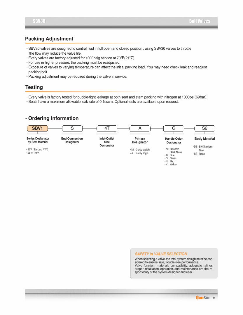
Packing Adjustment•SBV30 valves are designed to control fluid in full open and closed position ; using SBV30 valves to throttle
the flow may reduce the valve life. •Every valves are factory adjusted for 1000psig service at 70℉(21℃).•For use in higher pressure, the packing must be readjusted.•Exposure of valves to varying temperature can affect the initial packing load. You may need check leak and readjust
packing bolt.•Packing adjustment may be required during the valve in service.
Testing•Every valve is factory tested for bubble-tight leakage at both seat and stem packing with nitrogen at 1000psi(69bar).•Seats have a maximum allowable leak rate of 0.1sccm. Optional tests are available upon request.
SAFETY in VALVE SELECTIONWhen selecting a valve,the total system design must be con-sidered to ensure safe, trouble-free performance.Valve function, materials compatibility, adequate ratings,proper installation, operation, and maintenance are the re-sponsibility of the system designer and user.
Handle Color Designator
•Nil: StandardBlack Nylon
•B : Blue•G : Green•R : Red•Y : Yellow
•Ordering Information
End ConnectionDesignator
Inlet-OutletSize
Designator
Pattern Designator
•Nil : 2-way straight•A : 2-way angle
GA4TS S6
Body Material
•S6 : 316 StainlessSteel
•BS: Brass
Series Designatorby Seat Material
•SBV : Standard PTFE•SBVP : PFA
SBV1

10
Ball ValvesBall Valves SBV60SBV60
Item
Features•Pressure rating up to 10,000psig (689bar)@70℉(21℃).•Temperature rating from -22℉(-30℃)to 265℉(130℃)with PVDF seat or from -65℉(-54℃) to 500℉(260℃) with PEEK seat. •Robust body is best suited for high pressure application and allows various
pattern including : 2-way straight pattern, 3-way side port inlet, 3-way bottom port inlet.•Panel mounting and locking devices are available as options.•Blow out proof design with internally loaded stem.•Floating ball design ensures leak proof shut-off at high pressure.•Straight through flow path for minimum pressure drop.•Variety of end connections include reliable S-LOK tube fittings,
male/female NPT & ISO/BSP threads.•Handle with PVC Color coated allows easy and quick operation with low torque.•90 degree actuation.•Every valve is 100% factory tested with the nitrogen @1000psi (69bar).•Optional sour gas service to NACE MR 0175.
Operation•HANSUN SBV60 Series ball valves provide quick 1/4 turn on-off control of fluids in process, power and instrumentation applications.•All ports are suitable as inlets in full operation pressure of the valve.•A broad selection of valve body, seat, and seal materials provide a wide range of pressure and temperatures
at which the valve may be used.•Valves that have not been actuated for a period of time may have a higher actuation torque.
•End Seal : HNBR O-ring •Added Dise Spring •Seat : PEEK
① ②③ ④⑤
⑥
⑦⑧
⑨⑩
Description Grade /ASTM Specification12345678910
BodyEnd ConnectorBallEnd SealsSeatsStemStem PackingPinLock NutHandle
S316/A276, A479S316/A276, A479S316/A276, A479
Fluorocarbon FKM O-ringPCTFE, optional PEEK
S316/A276, A479PTFE/D1710Stainless Steel
Stainless Steel with WasherS304 with PVC Coating
※ Note : wetted parts are listed in orange color.Lubricant is Fluorocarbon based.
Materials of Construction
CNG / NGV Certifications
SBV60Series High Pressure Ball Valves
CertificatesSBVCSeries
ECE R110 ANSI NGV 3.1 - 2012 ISO 15500Certificate No. 110R-010333 126840AUT14 126840MECH103Classification Class 0 Manual valve Manual valveTemperature -40 to120°C (-40 to 248°F) -40 to120°C (-40 to 248°F) -40 to120°C (-40 to 248°F)
Working Pressure 260 bar @120°C 248 bar @120°C 260 bar @120°C
Valve Series

11
Ball ValvesBall ValvesSBV60SBV60
9295
1006572868484959195
10911111196
100117130116125
1/4″ S-LOK3/8″ S-LOK1/2″ S-LOK1/4″ Female NPT3/8″ Female NPT1/2″ Female NPT1/4″ Male NPT3/8″ Male NPT1/2″ Male NPT1/2″ Female NPT3/4″ Female NPT3/4″ Male NPT5/8″ S-LOK3/4″ S-LOK3/4″ Female NPT1″ Female NPT3/4″ S-LOK1″ S-LOK3/4″ Male NPT1″ Male NPT
BasicOrdering Number
Orificemm(inch)
SBV1H
SBV2H
SBV3H
S-4TS-6TS-8TF-4NF-6NF-8NM-4NM-6NM-8NF-8NF-12NM-12NS-10TS-12TF-12NF-16NS-12TS-16TM-12NM-16N
Dimensions (mm)End Connections
Ordering Information and Dimensions
Cv
All dimensions shown are for reference only and are subject to change. Dimensions with S-LOK nuts are in finger-tight position.
dmm
10.0(0.39)
12.7(0.50)
19.0(0.75)
1.23.7
7.5
3.77.27.5
10.1
30.019.030.019.030.0
4.87.1
10.0
7.19.7
10.0
12.7
20.015.820.015.820.0
A B L H H1 C S4647.55032.53643424247.545.547.554.555.555.5485058.5655862.5
4647.55032.53643424247.545.547.554.555.555.5485058.5655862.5
39
51
56
46.7
60.6
65.6
101
135
135
32
40
50
SBV60Series
10,000
8,000
6,000
4,000
2,000
0-54 0 50 100 150 200 230℃
psig bar
-65 32 122 212 302 392 446℉
689
551
413
275
137
0
SBV1H
SBV2H, 3HSBV60 2-wayPressure-TemperatureCurves for valves withPEEK seat
⇨
◀ ◀C
◀
◀
H
◀
◀
ød
◀ ◀◀◀
◀ ◀
A BL
◀ ◀C
◀
◀
H1
◀
◀
ød
◀ ◀◀◀
◀ ◀
A BL
◀
◀
Panel Thickness3/8″max.
with Panel Mounting
2-Way
◀
◀
S

12
Ball ValvesBall Valves SBV60SBV60
3-way2-way
PCTFE
PEEK
PCTFE
PEEK
6,000psig (413bar)
10,000psig (689bar)
5,000psig (344bar)
6,000psig (413bar)
-30℃to 180℃(-22℉ to 355℉ )-54℃to 230℃(-65℉ to 446℉)-23℃to 160℃(-9℉ to 320℉)-35℃ to 210℃(-31℉to 410℉)
101
135
135
39
51
56
10.0(0.39)
12.7(0.50)
19.0(0.75)
Dimensions mmA H H1 L S
1/4″ S-LOK3/8″ S-LOK1/2″ S-LOK1/4″ Female NPT3/8″ Female NPT1/2″ Female NPT1/2″ Female NPT3/4″ Female NPT5/8″ S-LOK3/4″ S-LOK3/4″ S-LOK1″ S-LOK3/4″ Female NPT1″ Female NPT
BasicOrdering Number
Orificemm(inch)
SBV1H-3*
SBV2H-3*
SBV3H-3*
S-4TS-6TS-8TF-4NF-6NF-8NF-8NF-12NS-10TS-12TS-12TS-16TF-12NF-16N
End Connections
Ordering Information and Dimensions
All dimensions shown are for reference only and are subject to change. Dimensions with S-LOK nuts are in finger-tight position.Ordering information :*“S”for side entry 3-way ordering i.e., SBV1H-3S-S-8T,*“B”for bottom entry 3-way ordering i.e., SBV1H-3B-S-8T
dmm4.87.1
10.0
12.7
15.820.0
51.553.055.836.740.245.549.755.265.565.570.076.656.760.8
Inlet & Outlet9295
1006572869195
111111117130116125
32
40
50
Handle Turn torque Table (N.m)Applied Working Pressures–psig(bar)
SBV1HSBV2HSBV3H
Valve Series 0(0 )0.30(0.22)1.20(0.88)1.70(1.25)
69(1000)0.35(0.25)1.50(1.10)1.80(1.32)
137(2000)0.40(0.29)1.70(1.25)1.90(1.40)
206(3000)0.40(0.29)1.70(1.25)2.00(1.47)
275(4000)0.40(0.29)1.80(1.32)2.10(1.55)
344(5000)0.40(0.29)1.90(1.40)2.20(1.62)
413(6000)0.45(0.33)2.00(1.47)2.30(1.69)
Technical Data-Pressure and Temperature Rating
ValveSeries
SBV1H
SBV2H
SBV3H
TemperatureRating
Pressure Rating@-54℃ to 21℃(-65℉ to 70℉)
Sealing MaterialsSeat Stem
PackingEndSeal
PTFE
PTFE
FKM
FKM
PCTFE
PEEK
PCTFE
PEEK
4,000psig (275bar)
6,000psig (413bar)
3,000psig (206bar)
4,000psig (275bar)
-30℃ to 180℃(-22℉to 355℉)-54℃ to 230℃(-65℉to 446℉ )-23℃to 160℃(-9℉ to 320℉)
-35℃ to 210℃(-31℉to 410℉)
ValveSeries
SBV1H
SBV2H
SBV3H
TemperatureRating
Pressure Rating@-54℃ to 21℃(-65℉ to 70℉)
Sealing MaterialsSeat Stem
PackingEndSeal
PTFE
PTFE
FKM
FKM
●The above pressure rating is for 2-way In-line pattern valves. 80% of the above rating shall be applicable to 2-way angle pattern valves and 3-way valves.●The rated pressure shown above is the maximum allowable pressure to the seat. If the system requires higher pressure to test, the valve must be in open position before and during test so as not to damage the seat.
●Pressure ratings of valves are sometimes limited to the maximum working pressure of pipe ends and tubing connected.The working pressure of tubing must be considered in the calculation of total system working pressure.
◀
◀A
◀
◀
S
◀
◀ dOutlet
◀
◀
H1
◀
◀
L Inlet
◀ ◀
d
Outlet
◀
◀
L Inlet
◀ ◀
d
◀
◀
H
◀
◀
H1
◀
◀dOutlet
Outlet
◀
◀ d
◀ ◀AIsolation
SIDE PORT INLET1/4 turn handle For flow switching
BOTTOM PORT INLET1/2 turn handleFor flow switching and isolation
3-Way

13
Ball ValvesBall ValvesSBV60SBV60
•Sour Gas ServiceIs provided to meet NACE Standard MR 0175.
Panel Mounting
•Every valve is factory tested for bubble-tight leakage at both seat and stem packing with nitrogen at 1000psi(69bar).•Hydraulic shell test is performed at 1.5 times the working pressure.•Seats have a maximum allowable leak rate of 0.1sccm.
optional tests are available upon request.
Testing
SAFETY in VALVE SELECTIONWhen selecting a valve, the total system design must be considered to ensure safe, trouble-free performance.Valve function, materials compatibility, adequate ratings, proper installation, operation, and maintenance are the responsibility of the systemdesigner and user.
•Ordering InformationSelection the applicable options from designators listed below.
※CNG / NGV Service•To order CNG / NGV Service, insert the designator“C”to the valve ordering number.•Material’s PEEK standard.
ex) SBVC1H-S-4T-S6
Screw hole panel mountingOrdering designator : PS
Locking nut panel mountingOrdering designator : PN
◀
◀L
◀◀L1
◀
◀
◀
◀
T
t
Valve SeriesSBV1HSBV2HSBV3H
34.0(1.33)36.0(1.42)40.0(1.57)
L L1 t T23.0(0.91)29.0(1.14)35.0(1.37)
4.0(0.15)5.0(0.20)6.0(0.23)
30.0(1.18)38.0(1.50)38.0(1.50)
Valve SeriesSBV1HSBV2HSBV3H
Panel Thickness30.0(1.18)38.0(1.50)38.0(1.50)
Panel Hole DrillMax. 4.0(0.157)Max. 4.0(0.157)Max. 4.0(0.157)
●Locking Nut
●Panel
Unit:mm(inch)•PN-Panel Mount Information •PS-Panel Mount InformationUnit:mm(inch)
End ConnectionDesignator
Inlet-Outlet SizeDesignator
Panel Mounting
•PN : Lock nut panelmounting
•PS : Screw hole panelmounting
Locking Device
•LD : Locking Device
Handle
•Nil : Standard leverhandle
•OH: Oval Handle(Applicable only forSBV1H)
SGOHLDPN4TSSeat MaterialDesignator
•Nil : Standard PCTFE•PK : PEEK
PKSour GasDesignator
•Nil : Without(Standard)•SG: Sour Gas Service
S6Body Material
•S6 : 316 Stainless Steel
Series Designatorby Orifice Size
SBV1H

14
Ball ValvesBall Valves SFBV60SFBV60
Features• Pressure rating up to 6,000psig (413bar)@70℉(21℃).•Temperature rating from -65℉(-54℃)to 350℉(177℃)with Standard PCTFE seat.•Free floating ball design provides seat wear compensation, therefore ensures leak proof shut-off at high pressure.•High flow in a compact design.•Panel mountable as standard.•Blow out proof design with internally loaded stem.•Micro-finished ball provides a positive seal.•Low operating torques and positive handle stops.•Handle indicates flow direction.•Straight through flow path for minimum pressure drop.•Bi-Directional flow.•Chevron packing standard for positive leak tight.•90 degree actuation.•Every valve is 100% factory tested with the nitrogen @1000psi (69bar).•Variety of end connections include reliable S-LOK tube fittings, Male/Female NPT &ISO/BSP threads.
Applications•Water•Oil•Gas•Petrochemical
Testing•Every valve is factory tested for bubble-tight leakage at both
seat and stem packing with nitrogen at 1000psi(69bar).•Seats have a maximum allowable leak rate of 0.1sccm.•Optional tests are available upon request.
Item Description Grade /ASTM Specification1234567891011121314
BodyEnd ConnectorBallSeatsRetainerRetainer SealEnd SealsStemStem PackingStem WasherPacking Bolt ①Lock NutSet ScrewHandle
①Molybdenum disulfide with hydrocarboncoating.※Note : wetted parts are listed in orange color.
Lubricant is Fluorocarbon based.
S316/A276, A479S316/A276, A479S316/A276, A479
PCTFE, optional PTFE, PEEKS316/A276, A479
PTFEPTFE
S316/A276, A479PTFES316
S316/A276, A479S316/A276, A479
Stainless SteelBlack Nylon standard
⑭⑬⑪⑧⑫⑨⑩
①
②⑤③④⑥⑦
Materials of Construction
SFBV60Series Forged High pressure Ball Valves
•CNG / NGV Valves added HNBR o-ring and added disc spring. •Seat Material’s PEEK standard
CNG / NGV Certifications
CertificatesValve Series
SFBVCSeries
ECE R110 ANSI NGV 3.1 - 2012 ISO 15500Certificate No. 110R-010333 126840AUT14 126840MECH103Classification Class 0 Manual valve Manual valveTemperature -40 to120°C (-40 to 248°F) -40 to120°C (-40 to 248°F) -40 to120°C (-40 to 248°F)
Working Pressure 260 bar @120°C 248 bar @120°C 260 bar @120°C

15
Ball ValvesBall ValvesSFBV60SFBV60
47.0(1.85)
78(3.07)
99(3.9)
9.4(0.37)
11.9(0.47)
17.8(0.70)
10.0(0.39)
10.7(0.42)
17.5(0.69)
23.2(0.91)
38.9(1.53)
44.2(1.74)
19(0.75)
25.6(1.01)
38.1(1.50)
16.3(0.64)
19.6(0.77)
22.9(0.90)
3.3(0.13)
6.4(0.25)
9.7(0.38)
1/16″S-LOK1/8″S-LOK1/8″Female NPT1/8″Male NPT1/4″S-LOK1/4″Male3mm S-LOK1/8″S-LOK1/4″S-LOK1/4″Male NPT1/4″Female NPT1/4″Female NPT1/4″Male NPT1/4″Male NPT1/4″Male NPT1/4″Female NPT3/8″S-LOK3/8″Male NPT6mm S-LOK8mm S-LOK10mmS-LOK3/8″Female NPT1/2″Female NPT1/2″S-LOK1/2″Male NPT3/4″S-LOK12mmS-LOK16mmS-LOK
1/4″S-LOK1/4″S-LOK
1/4″Female NPT3/8″S-LOK3/8″S-LOK
1.3(0.052)2.4(0.093)
4.2(0.165)
2.2(0.086)2.4(0.093)
4.8(0.189)
6.4(0.250)
4.8(0.189)6.4(0.250)
10.3(0.406)
9.5(0.375)10.3(0.406)
SFBV1
SFBV2
SFBV3
33.0(1.30)34.5(1.36)27.2(1.07)29.9(1.18)37.6(1.48)34.3(1.35)34.8(1.37)41.9(1.65)44.2(1.74)41.1(1.62)38.4(1.51)38.4(1.51)
41.1(1.62)
38.4(1.51)45.7(1.80)41.1(1.62)44.5(1.75)45.2(1.78)46.0(1.81)49.5(1.95)54.6(2.15)59.4(2.34)56.4(2.22)
59.2(2.33)
0.060.21
0.93
0.180.26
1.04
2.34
1.042.34
6.42
5.576.42
33.0(1.30)34.5(1.36)27.2(1.07)29.9(1.18)37.6(1.48)34.3(1.35)34.8(1.37)41.9(1.65)
44.2(1.74)
38.4(1.51)41.1(1.62)38.4(1.51)
45.7(1.80)
41.1(1.62)44.5(1.75)45.2(1.78)46.0(1.81)49.5(1.95)54.6(2.15)59.4(2.34)56.4(2.22)
59.2(2.33)
BasicOrdering Number
Orificemm(in.)
S-1TS-2TF-2NM-2NS-4TM-4NS-3MS-2TS-4TMS-4N4TFS-4N6TF-4NM-4NMF-4NMS-4N6TFS-4F6TS-6TM-6NS-6MS-8MS-10MF-6NF-8NS-8TM-8NS-12TS-12MS-16M
Dimensions mm(inch)End ConnectionsInlet Outlet
Ordering Information and Dimensions
Cv
Dimensions are for reference only and are subjet to change. Dimensions with S-LOK nuts are in finger-tight posion.
A B D E H C F d T
2-Way (Shut-Off Valve)
0.065.913.218.70.20.40.6
Cv
10501001050100
WaterUS GPM
@60℉(16℃)
AirSCFM
@70℉(21℃)
•Flow RatePressure Drop to
Atomosphere (△p) in psi 0.1817.739.656.00.61.31.8
0.2120.746.265.40.71.52.1
0.2625.657.280.90.81.82.6
0.9391.5204.7289.52.96.69.3
1.04102.4228.9323.73.37.410.4
2.34230.3515.0728.37.416.523.4
5.57548.21225.91733.717.639.455.7
6.42631.9
1413.01998.320.345.464.2
◀ ◀
◀
◀
◀
◀
◀ ◀
◀◀
◀
◀◀
◀
F(B:80, C:00)C
HD
E
A B
◀
◀◀
d-panelhole drill T-max panel
thickness
In-line pattern
*Flow rate calculated with 1000psig(69bar)inlet pressure.*To determine m2/hr multiply GPM by 0.227 and SCFM by 1.69

16
Ball ValvesBall Valves SFBV60SFBV60
T-max panelthickness
33.7(1.30)36.4(1.36)29.9(1.18)29.9(1.18)37.2(1.46)29.9(1.18)36.4(1.36)45.5(1.79)47.8(1.88)41.9(1.65)44.7(1.76)49.3(1.94)44.7(1.76)47.8(1.88)48.5(1.91)49.5(1.95)58.2(2.29)63.2(2.49)68.1(2.68)65.8(2.59)68.1(2.68)67.8(2.67)65.5(2.67)
1/16″ S-LOK1/8″ S-LOK1/8″ Female NPT1/8″ Male NPT1/4″ S-LOK1/4″ Male3mm S-LOK1/8″ S-LOK1/4″ S-LOK1/4″ Female NPT1/4″ Male NPT3/8″ S-LOK3/8″ Male NPT6mm S-LOK8mm S-LOK
10mm S-LOK3/8″ Female NPT1/2″ Female NPT1/2″ S-LOK1/2″ Male NPT3/4″ S-LOK
12mm S-LOK16mm S-LOK
A B E D H C F d TDimensions mm(inch)
SFBV1-3B
SFBV2-3B
SFBV3-3B
S-1TS-2TF-2NM-2NS-4TM-4NS-3MS-2TS-4TF-4NM-4NS-6TM-6NS-6MS-8MS-10MF-6NF-8NS-8TM-8NS-12TS-12MS-16M
0.060.21
0.63
0.180.210.700.87
0.87
0.700.87
3.62
3.463.62
1.3(0.052)2.4(0.093)
4.2(0.165)
2.2(0.086)2.4(0.093)4.8(0.189)5.0(0.196)
5.0(0.196)
4.8(0.189)5.0(0.196)
10.3(0.406)
9.5(0.375)10.3(0.406)
33.0(1.30)34.5(1.36)27.2(1.07)29.9(1.18)37.6(1.48)34.3(1.35)34.8(1.37)41.9(1.65)44.2(1.74)38.4(1.51)41.1(1.62)45.7(1.80)41.1(1.62)44.5(1.75)45.2(1.78)46.0(1.81)49.5(1.95)54.6(2.15)59.4(2.34)56.4(2.22)59.2(2.33)56.9(2.33)
8.5(0.33)
11.9(0.47)
17.8(0.70)
23.2(0.91)
38.9(1.53)
44.2(1.74)
18.0(0.71)
30(1.18)
38.1(1.50)
47.0(1.85)
78(3.07)
99(3.9)
16.3(0.64)
19.6(0.77)
22.9(0.90)
3.3(0.13)
6.4(0.25)
9.7(0.38)
0.065.913.218.70.20.40.6
0.1817.739.656.00.61.31.8
0.2120.746.265.40.71.52.1
0.6362.0138.7196.12.04.56.3
0.9391.5204.7289.52.96.69.3
2.34230.3515.0728.37.416.523.4
6.42631.9
1413.01998.320.345.464.2
0.8785.6191.5270.82.86.28.7
3.46340.6761.51077.010.924.534.6
3.62356.3796.71126.811.425.636.2
Pressure Drop toAtomosphere (△p) in psi
WaterUS GPM
@60℉(16℃)
AirSCFM
@70℉(21℃)
10501001050100
BasicOrdering Number
Orificemm(in.)
End ConnectionsInlet Outlet
Ordering Information and Dimensions
Cv
Dimensions are for reference only and are subjet to change. Dimensions with S-LOK nuts are in finger-tight posion.
3-Way (Switching Valve)
Cv•Flow Rate
◀ ◀
◀
◀
◀
◀
◀ ◀
◀◀
◀
◀◀
◀
FC
HD
E
A B
0.768.9154.1217.92.24.97.0
◀
◀
◀
d-panelhole drill
3-way ball valveSFBV 3-way Ball Valve is designed to switch media through the bottom port anddirect it to out of two outlet ports.
*Flow rate calculated with 1000psig(69bar)inlet pressure.*To determine m2/hr multiply GPM by 0.227 and SCFM by 1.69

17
Ball ValvesBall ValvesSFBV60SFBV60
6,000psig (413bar)
6,000psig (413bar)
1,500psig (103bar)
Technical Data-Pressure and Temperature Rating
PCTFE
PEEK
PTFE
-54℃to 177℃(-65℉to 350℉)
Temperature RatingPressure Rating@100℉(70℃)Seat Materials Pressure Rating@MaxTemperature
-54℃to 232℃(-65℉to 450℉)-54℃to 177℃(-65℉to 350℉)
1,000psig@350℉(69bar@177℃)700psig@450℉(48bar@232℃)250psig@350℉
(17.2bar@177℃)Caution Pressure Rating with 3-way side ports of as inlet : 150psig(10bar)
Ordering InformationSelection the applicable options from designators listed below.
SAFETY in VALVE SELECTIONWhen selecting a valve, the total system design must be considered to ensure safe, troble-free performance.Valve function, materials compatibility, adequate ratings, proper installation, operation, and maintenance are the responsibility of the systemdesigner and user.
Sour Gas Designator
•Nil : Without(Stand-ard)
•SG: Sour Gas
End ConnectionDesignator
Inlet-Outlet SizeDesignator
Seat Material Designator
•Nil : Standard PCTFE•PK : PEEK•TE : PTFE
SGPK4TS S6Body Material
•S6 : 316 Stainless Steel
Series Designatorby Orifice Size
SFBV1
※CNG / NGV Service•To order CNG / NGV Service, insert the designator “C”to the valve ordering number.•Seat Material’s PEEK standard.
ex) SFBVC1-S-4T-S6

18
Trunnion Ball ValvesTrunnion Ball Valves STBV 60, STBVCSTBV 60, STBVC
STBV60Series up to 6000psiSTBVCSeries CNG/NGV Valves up to 3770psi
Features
Testing
CNG / NGV Information
•The rated pressure shown above is the maximum allowable pressure to the seat. If the system requires higherpressure to test, the valve must be in open position before and during test so as not to damage the seat.
•Every valve is factory tested for bubble - tight leakage at both seat and stem packing with nitrogen at 1000psi(69bar).•Hydraulic shell test is performed at 1.5times the working pressur.•Seats have a maximum allowable leak rate of 0.1 SCCM.•Optional tests are available upon request.
•STBVC Series valve provides leak - tight integrity in both low and high pressure systems in CNG and NGV applications.Valves with peek seat and HNBR O-ring are compatible with CNG fluid.
Technical Data
PCTFE
PEEKPTFE
-17 to 121(0 to 250)
-17 to 232(0 to 450)
6,000psig (413bar)
6,000psig (413bar)1,500psig (103bar)
STBV60
ValveSeries
SeatMaterial Temperature Rating ℃ (℉) Pressure Rating
@38 ℃ (100℉)
Certificate No.ClassificationTemperature
Working PressureCertificate No.ClassificationTemperature
Working Pressure
110R-010333Class 0
-40 to 120℃ (-40 to 248℉)260 bar @ 120 ℃
110R-000184Class 0
-40 to -120℃ (-40 to 248℉)260 bar @ 38 ℃
126840AUT14Manual valve
-40 to 120℃ (-40 to 248℉)248 bar @ 120 ℃
110R-000184Manual valve
-40 to -120℃ (-40 to 248℉)260 bar @ 38 ℃
126840MECH103Manual valve
-40 to 120℃ (-40 to 248℉)260 bar @ 120 ℃
110R-000184Manual valve
-40 to -120℃ (-40 to 248℉)260 bar @ 38 ℃
STBVCSeries2-Way
STBVCSeries3-Way
ValveSeries Certificates ECE R110 ANSI NGV 3.1-2012 ISO 15500
•Working pressure up tp 6,000psi(413bar)@100℉(38℃).•Compact, maximum flow design.•Panel mountable as standard.•Handle indicates flow direction.•Low torque actuation.•2-way "Shut-up" and 3-way "Switching" type.•Various end connections : include S-LOK Tube Fittings, NPT / ISO male & female.•Optional sour gas service to NACE MR 0175.•Every valve is 100% factory tested.

19
Trunnion Ball ValvesTrunnion Ball ValvesSTBV 60, STBVCSTBV 60, STBVC
Materials of Construction
STBV60 & STBVC 2-Way STBV60 & STBVC 3-Way
*Service kits contain part
BodyStem*
Stem Support Ring*Stem Backup Ring*Stem Bearing*Stem O-Ring*Trunnion Ball*Ball O-Ring*Ball Backup Ring*Disc Spring*Seat*Seat Carrier*Seat Carrier Guide*Seat Carrier Backup Ring*Seat Carrier O-Ring*End Connector Packing*End ConnectorHandle*Set Screw *Stop PinLock NutSlip Ring*
S316 / A276 or A479 S316 / A276 or A479 - PEEK - PEEK - PTFE - PTFE PEEK FKM HNBR S316 / A276 or A479 FKM - HNBR - PTFE - PTFE - Alloy X-750 / AMS 5542
PCTFE, optional PTFE, PEEK PEEK S316 / A276 or A479 S316 / A276 or A479 PTFE FKM HNBR PTFE / D1710, Type 1 S316 / A276 or A479 Phenolic with brass insert S316 S316 S316 / A276 or A479 - PTFE - PTFE
123456789
10111213141516171819202122
Item DescriptionSTBV60 Series STBVC Series
2-Way 3-Way 2-Way 3-Way Grade/ASTM Specification

20
Trunnion Ball ValvesTrunnion Ball Valves STBV 60, STBVCSTBV 60, STBVC
Table of DimensionsSTBV60 & STBVC 2-Way STBV60 & STBVC 3-Way
STBV/
STBVC
F-2N 1/8” Female NPT 1.2 76.2 (3) 38.1 (1.5) F-4N 1/4” Female NPT 1 76.2 (3) 38.1 (1.5) - 1/4” Female NPT 1 99.8 (3.93) 50 (1.97) F-8N 1/2” Female NPT 1.2 108 (4.25) 54.1 (2.13) S-4T 1/4” S-LOK 1.6 105 (4.14) 52.6 (2.07) S-6T 3/8” S-LOK 1.4 112 (4.41) 55.6 (2.19) S-8T 1/2” S-LOK 1 117 (4.6) 58.4 (2.3) S-6M 6mm S-LOK 1.6 105 (4.14) 52.6 (2.07) S-8M 8mm S-LOK 1.5 105 (4.14) 52.6 (2.07) S-10M 10mm S-LOK 1.3 112 (4.41) 55.9 (2.2) S-12M 12mm S-LOK 1 117 (4.6) 58.4 (2.3)
F-2N 1/8” Female NPT 76.2 (3) 38.1 (1.5) F-4N 1/4” Female NPT 76.2 (3) 38.1 (1.5) - 1/4” Female NPT 99.8 (3.93) 50 (1.97) S-4T 1/4” S-LOK 105 (4.14) 52.6 (2.07) S-6T 3/8” S-LOK 0.75 112 (4.41) 55.6 (2.19) S-8T 1/2” S-LOK 117 (4.6) 58.4 (2.3) S-6M 6mm S-LOK 105 (4.14) 52.6 (2.07) S-8M 8mm S-LOK 105 (4.14) 52.6 (2.07) S-10M 10mm S-LOK 112 (4.41) 55.9 (2.2) S-12M 12mm S-LOK 117 (4.6) 58.4 (2.3)
STBV-3B/
STBVC-3B
2-Way Valve Orifice 4.75mm (0.187 in.) STBV60 Series End Connection Cv Dimensions mm(in.)
Ordering Numbers Inlet Outlet L L1
3-Way Valve Orifice 4.75mm (0.187 in.)

21
Trunnion Ball ValvesTrunnion Ball ValvesSTBV 60, STBVCSTBV 60, STBVC
Ordering Information•Selection of the applicable options from the designators are listed below.
•When selecting a valve, the total system design must be considered to ensure safe, trouble - free performance.•Valve function, materials compatibility, adequate ratings, proper installation, operation, and maintenance are the responsibility
of the system designer and user.
Service kits contain components of the same materials as new components.To order the service kit, selection of the applicable options from the designators are listed mark(*) of 19page.
Series Designator
STBV
End ConnectionDesignator
S
Inlet-Outlet SizeDesignator
4T
Seat Material Designator
PK
Handle MaterialDesignator•Nil: Nylon•MH:S316
•Nil : PCTFE for STBV60 Series (Standard)PEEK for STBVC (Standard)
•PK : PEEK•PC : PCTFE•TE : PTFE
•Nil : Without (Standard)•SG : Sour Gas
MH
Sour GasDesignator
SG
Body Material
•S6 : 316 Stainless Steel
S6
Series Designator
•STBV•STBVC
STBVC
Port wayDesignator
•Nil : 2-Way (Standard)•3B : 3-Way
3B
Service KitDesignator
SKIT
Handle OptionalDesignator
•Nil : Without (Standard)•WNH : With Nylon Handle•WMH : With Metal Handle
WNH
Body MaterialDesignator
•S6 : 316 Stainless Steel
S6
Safety in Valve Selection
Service Kit

22
Ball Valves for DIN StandardBall Valves for DIN Standard SDBVSDBV
Features• Pressure rating up to 500barg @ 21°C• Temperature rating from -20°C to 100°C with POM and FKM(Viton) standard.• Conforms to DIN standard.• Compact design with maximum orifice.• Variety of end connections such as DIN 2353 “L” & “S” series, Male & Female
DIN / ISO/ BSP and NPT threads.• Handle is only available in cast stainless steel standard.• Every valve is 100% factory tested with the Nitrogen @1,000psig (68barg)
• Every valve is factory tested with bubble-tight leakage test at both seat and stem packing with nitrogen at 1,000psig (69barg)• Hydraulic shell test is performed at 1.5 times the working pressure.• Seats have a maximum allowable leakage rate of 0.1 SCCM Optional tests are available upon request
Temperature Rating
Seals
Test
When selecting a valve, the total system design must be considered to ensure safe, trouble-free performance. Valve function, materials compatibility, adequate ratings, proper installation, operation, and maintenance are the responsibility of the system designer and user.
Safety in Valve Selection
Materials of Construction
Description Grade / Specification
1 Body2 End Connector3 Stem4 Stem Bearing PTFE5 Ball S316/A479 or A276 DIN 17440/145716 Ball Seats POM – MoS2 (Standard)7 Stem & End Seals Fluorocarbon FKM O-ring8 Locking Device Stainless Steel 9 Upper Washer Stainless Steel
10 Bolt Stainless Steel 11 Handle S316
S316/A479 or A276DIN 17440/14571
Materials Temperature RatingNBR -23 ℃ to 121 ℃FKM -23 ℃ to 200 ℃
EPDM -46 ℃ to 149 ℃
POM – MoS2 -30 ℃ to 100 ℃PTFE -54 ℃ to 65 ℃
Ball SeatsMaterials Temperature Rating
12 5 4
9 1110 8 7
6
3
SDBVSeries Ball Valves for DIN Standard

23
Ball Valves for DIN StandardBall Valves for DIN StandardSDBVSDBV
Tube connectionDIN 2353Light Series(L)Heavy Series(S)
Female ThreadBSPDIN / ISO 228 BSP
Female ThreadNPTASME / ANSI B1.20.1
L
R
DN
Tube
O.D
.
1
DN
ℓ1
T
DN
ℓ1T
Bh
H
h1
Table of Dimensions
Product Information
DIN 2353 Light(L) Tube SeriesBasic Ordering
NumberEnd Connections DN PB Weight
(kg)Dimensions (mm)
B H h h1 L ℓ ℓ1 RInlet & OutletSDBV1 – 6L 6MM 4 315 26 33 13.5 82 67 40 10 115 0.4SDBV1 – 8L 8MM 6 315 26 33 13.5 82 67 40 10 115 0.4SDBV1 – 10L 10MM 6 315 26 33 13.5 82 74 40 11 115 0.5SDBV2 – 12L 12MM 10 315 32 38 17.5 87 74 43 11 115 0.6SDBV3 – 15L 15MM 13 315 35 40 19 89 82 48 12 115 0.7SDBV3 – 18L 18MM 13 315 35 40 19 89 82 48 12 115 0.8SDBV4 – 22L 22MM 20 160 49 57 24.5 114 101 62 14 159 2.1SDBV5 – 28L 28MM 25 160 58 65 29.5 122 108 66.2 14 159 2.3SDBV5 – 35L 35MM 25 160 58 65 29.5 122 112 66.2 16 159 2.3
DIN 2353 Heavy (S) Tube SeriesBasic Ordering
NumberEnd Connections DN PB Weight
(kg)Dimensions (mm)
B H h h1 L ℓ ℓ1 RInlet & OutletSDBV1 – 8S 8MM 4 500 26 33 13.5 82 73 40 12 115 0.4SDBV1 – 10S 10MM 6 500 26 33 13.5 82 73 40 12 115 0.4SDBV2 – 12S 12MM 6 500 32 38 13.5 82 76 43 12 115 0.5SDBV2 – 14S 14MM 10 500 32 38 17.5 87 80 43 14 115 0.6SDBV3 – 16S 16MM 13 400 35 40 19 89 86 48 14 115 0.7SDBV3 – 20S 20MM 13 400 35 40 19 89 90 48 16 115 0.8SDBV4 – 25S 25MM 20 315 49 57 24.5 114 109 62 18 159 2.1SDBV5 – 30S 30MM 25 315 58 65 29.5 122 120 66.2 20 159 2.3SDBV5 – 38S 38MM 25 315 58 65 29.5 122 124 66.2 22 159 2.3

24
Ball Valves for DIN StandardBall Valves for DIN Standard SDBVSDBV
Product Information
Female DIN / ISO 228 / BSPBasic Ordering
NumberEnd Connections DN PB Weight
(kg)Dimensions (mm)
B H h h1 L ℓ ℓ1 RInlet & OutletSDBV1-F–2G PF 1/8 6 500 26 33 13.5 82 68.8 40 10 115 0.4SDBV1-F–4G PF 1/4 6 500 26 33 13.5 82 68.8 40 14 115 0.4SDBV2-F-6G PF 3/8 10 500 32 38 17.5 87 71.9 43 14 115 0.6SDBV3-F–8G PF 1/2 13 500 35 40 19 89 82.3 48 16.5 115 0.7SDBV4-F–12G PF 3/4 20 315 49 57 24.5 114 95.4 62 18 159 1.6SDBV5-F–16G PF 1 25 315 58 65 29.5 122 112.7 66.2 20 159 2.3SDBV6-F–20G PF1 1/4 32 315 75 82 37.5 165 121.6 68 22 260 4.36SDBV7-F–24G PF 1 1/2 38 315 95 99.1 47.5 182 130.2 85 24 260 6.8SDBV8-F–32G PF 2 50 315 115 115.2 57.5 198 140 100 26 260 9.44
Female NPT (ANSI/ASME B1.20.1)Basic Ordering
NumberEnd Connections DN PB Weight
(kg)Dimensions (mm)
B H h h1 L ℓ ℓ1 RInlet & OutletSDBV1-F–4N NPT 1/4 6 500 26 33 13.5 82 68.8 40 15 115 0.4SDBV2-F–6N NPT 3/8 10 500 32 38 17.5 87 78 43 15 115 0.6SDBV3-F–8N NPT 1/2 13 500 35 40 19 89 104 48 20.5 115 0.7SDBV4-F–12N NPT 3/4 20 315 49 57 24.5 114 102 62 21.5 159 1.6SDBV5-F–16N NPT 1 25 315 58 65 29.5 122 119 66.2 25.4 159 2.3SDBV6-F–20N NPT 1 1/4 32 315 75 82 37.5 165 - 68 - 260 -SDBV7-F–24N NPT 1 1/2 38 315 95 99.1 47.5 182 - 85 - 260 -SDBV8-F–32N NPT 2 50 315 115 115.2 57.5 198 - 100 - 260 -
• Hydraulic fluids, compressed air, lubricants, and fuel oil system.
Applications
• Is provided to meet NACE Standard MR0175.
Sour Gas Service
• Selection of the applicable options from the designators are listed below.
Ordering Information
Basic OrderingNumber
SDBV3
End Connection Designator
• F :Female Thread• M : Male Thread
F
Size Designator
4G
Ball SeatMaterial
Designator• Nil : Standard
POM-MoS2• TE : PTFE
TE
Stem & End Seal Material
Designator• Nil : Standard FKM• NB : NBR• EP : EPDM
NB
Locking Device
Designator• Nil : Without
(Standard)• LD : With
LD
Sour Gas Designator
• Nil : Without(Standard)
•SG : Sour Gas
SG
Material Designator
• S6 : S316• CS : Carbon Steel
S6

25
Plug ValvesPlug ValvesSPVSPV
Features• Pressure rating up 3,000psig(206barg) @70°F(21°C)• Temperature rating from -10 °F to 400°F(-23°C to 204°C) with PTFE
coated Viton Seal• Small and compact design• Easy maintenance and cleaning• Sizes available up to 1/2” tube and pipe• Body materials available in 316 stainless steel and brass
Material of Construction
Testing• Every valve is factory tested for shut off at 600psig (41barg)
• Wetted parts and lubricants listed in Red.
Component
S316/ A479 or A276
Valve Body MaterialsStainless Steel Brass
Grade/ASTM SpecificationBrass / B16
4. Handle5. Pin6. Snap ring
PTFE-coatedS316/ A479 or A276
PTFE-coatedViton Standard
PTFE-coatedBrass / B16
Pressure-Temperature Rating
• Differential pressure is limited to maximum 150 psig (10.3barg)when reverse flow occurs.
• Throttling reverse flow may damage O-ring.
SeriesPressure Rat-
ing TemperatureRating
Psig
ValveMaterial
Barg
Plug Orificemm (in.)
SPV1
SPV2
S316BrassS316Brass
3,000 206
2,000 137
-10 to 400 °F(-23 to 204 °C)
4.4 (.17)
7.2 (.28)
Optional O-ring Material
• PTFE - coated Viton is standard. Choose optional O-ring material for fluid compatibility and system temperatures.
O-ring material Temperature Range
Standard PTFE - coated Viton -20 to 400℉(-28 to 204℃)
PTFE - coated NBR -68 to 221℉(-20 to 105℃)
PTEF - coated EPDM -49 to 275℉(-45 to 135℃)
2
61
3
5
4
NylonS316/A276
Stainless Steel
3. O-ring
2. Plug
1. Body
SPVSeries Plug Valves

26
Plug ValvesPlug Valves SPVSPV
Ordering Information and Dimensions
Operation• S-LOK plug valves provide positive shut-off,
high flow capacity, and quick quarter-turn operation.• S-LOK plug valve provides flow throttling capability.
Product Information
Downstream Vent• S-LOK plug valves provide positive shut-off, high flow capacity,
and quick quarter-turn operation.• S-LOK plug valve provides flow throttling capability.
Open Condition Closed & Vent Condition
Basic OrderingNumber
End Connections Dimensions mm (inches)Inlet Outlet A B C D E F G H
SPV1
SPV2
S-2TS-4TS-6TS-6MM-2NM-4N
MS-4N4TMF-4NF-2NF-4NF-4RS-6TS-8TS-8M
S-10MS-12MM-8NF-6NF-8NF-8R
1/8 S-Lok1/4 S-Lok3/8 S-Lok6mm S-Lok1/8 M NPT1/4 M NPT
1/8 F NPT1/4 F NPT
1/4 F ISO tapered3/8 S-Lok1/2 S-Lok
8mm S-Lok10mm S-Lok12mm S-LOK
1/2 M NPT3/8 F NPT1/2 F NPT
1/2 ISO F Tapered
1/4 M NPT1/4 M NPT
1/4 S-Lok1/4 F NPT
50.5 (1.99)55.1 (2.17)58.2 (2.29)55.1 (2.17)38.9 (1.53)48.3 (1.90)51.2 (2.03)50.8 (2.00)45.2 (1.78)53.1 (2.09)56.1 (2.21)67.6 (2.66)73.2 (2.88)67.6 (2.66)68.1 (2.68)75.2 (2.96)67.1 (2.64)60.5 (2.38)73.2 (2.88)79.8 (3.14)
19.8(0.78)
47.8(1.88)
38.6(1.52)
29.0(1.14)
9.4(0.37)
11.7(0.46)
19.1(0.75)
28.4(1.12)
29.0(1.14)
63.2(2.49)
54.1(2.13)
38.1(1.50)
14.2(0.56)
16.8(0.66)
H
C
A
DF
G
E
B

27
Plug ValvesPlug ValvesSPVSPV
Flow Rate
Product Information
Ordering Information• Select the desired valve’s basic ordering number, option and body material.
Safe Valve Selection• The selection of a valve for any application or system design must be considered to ensure safe performance.
Valve function, valve rating, material compatibility, proper installation, operation and maintenance remain the sole responsibility of the system designer and the user. S-LOK accepts no liability for any improper selection, installation, operation or maintenance.
SPV1-M-4N EP VH S6
SeriesDesignator
O-ring Material Designator
Downstream Vent Option
Body MaterialDesignator
• Basic Ordering Number • Nil : PTFE-coated Viton• NB : PTFE-coated NBR• EP : PTFE-coated EPDM
• Nil : no vent• VH : Vent
• S6: S316• BS: Brass
Basic OrderingNumber
End Connections
Inlet Outlet
S-2TS-4TS-6TS-6MM-2NM-4N
MS-4N4TMF-4NF-2NF-4NF-4RS-6TS-8TS-8MS-10MS-12MM-8NF-6NF-8NF-8R
SPV1
SPV2
1/8 S-Lok1/4 S-Lok3/8 S-Lok6mm S-Lok1/8 M NPT1/4 M NPT
1/8 F NPT1/4 F NPT
1/4 F ISO tapered3/8 S-Lok1/2 S-Lok
8mm S-Lok10mm S-Lok12mm S-LOK
1/2 M NPT3/8 F NPT1/2 F NPT
1/2 ISO F Tapered
1/4 M NPT1/4 M NPT
1/4 S-Lok1/4 F NPT
0.11.61.11.6
1.0
0.91.01.2
0.9
6.44.4
6.4
4.82.44.3
2.7
0.3 (8.4)6.0 (169)4.1 (116)6.0 (169)
3.7 (104)
3.3 (93)3.7 (104)4.4 (124)
3.3 (93)
23.9 (676)16.4 (464)
23.9 (676)
17.9 (506)9.0 (254)16.0 (453)
10.1 (286)
0.8 (22)13 (368)8.9 (252)13 (368)
8.1 (229)
7.3 (206)8.1 (229)9.7 (274)
7.3 (206)
52.0 (1,470)35.7 (1,010)
52.0 (1,470)
39.0 (1,100)19.5 (552)34.9 (988)
21.9 (620)
1.1 (31)18 (509)
12.4 (351)18 (509)
11.3 (320)
101 (286)11.3 (320)13.5 (382)
10.1 (286)
72.3 (3,040)49.7 (1,400)
72.3 (2,040)
54.2 (1,530)27.1 (767)
48.6 (1,370)
30.5 (863)
0.1 (0.37)1.6 (6.0)1.1 (4.1)1.6 (6.0)
1.0 (3.7)
0.9 (3.4)1.0 (3.7)1.2 (4.5)
0.9 (3.4)
6.4 (24.2)4.4 (16.6)
6.4 (24.2)
4.8 (18.1)2.4 (9.0)4.3 (16.2)
2.7 (10.2)
0.2 (0.75)3.6 (13.6)2.5 (9.4)3.6 (13.6)
2.2 (8.3)
2.0 (7.5)2.2 (8.3)2.7 (10.2)
2.0 (7.5)
14.3 54.1)9.8 (37.0)
14.3(54.1)
10.7 40.4)5.4 (20.4)9.6 (36.3)
6.0 (22.7)
0.3 (1.1)5.1 (19.3)3.5 (13.2)5.1 (9.3)
3.2 (12.1)
2.8 (10.8)3.2 (12.1)3.8 (14.3)
2.8 (10.8)
20.2(76.4)13.9(52.6)
20.2(76.4)
15.2(57.5)7.6 (28.7)13.6 (51.4)
8.5 (32.1)
Cv
Pressure Drop in the Atmosphere, psi (bar)Air Flow, std ft3/min (L/min) Water Flow, US gal/min(L/min)
@70 °F (21 °C)1 (0.068) 5 (0.34) 10 (0.68) 1 (0.068) 5 (0.34) 10 (0.68)

27 Noksansandan361-ro, Gangseo-gu
(Songjeong-dong), Busan, Korea
Tel : +82-51-899-6700, Fax : +82-51-899-6799
E-Mail : [email protected]
Website : www.ehansun.co.kr, www.slok.co.kr
HanS
un Eng
inee
ring Co
., Ltd. Catalog
ue_B
all &
Plug Va
lves_201
703