UNIVERSIDAD AUTÓNOMA CHAPINGO DIVISIÓN DE CIENCIAS FORESTALES
Upload
khangminh22Category
view
0download
0
•
F~ClJLT~D DE INGENIER.I~ lJ_N_~_IVI_ DIVISIC>N DE EDUCACIC>N CONTINUA
A LOS ASISTENTES A LOS CURSOS
Las autoridades de la Facultad de Ingeniería, por conducto del jefe de la
División de Educación Continua, otorgan una constancia de asistencia a
quienes cumplan con los requisitos establecidos para cada curso.
El control de asistencia se llevará a cabo a través de la persona que le entregó
las notas. Las inasistencias serán computadas por las autoridades de la
División, con el fin de entregarle constancia solamente a los alumnos que
tengan un mínimo de 80% de asistencias.
Pedimos a l_os asistentes recoger su constancia el día de la clausura. Estas se . . .. retendrán por el periodo de un año,:_pasado este tiempo la DECFI no se hará
responsable de este documento.
Se recomienda a los asistentes ·participar · activament.; con sus ideas y
experiencias, pues los cursos que ofre~e la ,D.ivisiÓn están planeados para que
los profesores expongan una tesis, pero sobre todo, para que coordinen las
opiniones de todos los interesados, constituyendo verdaderos seminarios. ' ' '
Es muy importante que todos los asistentes llenen, y :entreguen su hoja de ) ' : ~. ' '1 ' ' . . ~ .
inscripción al .inicio del curso, información que __ servirá ·para integrar un
directorio de asistentes, que se entregará oportunamente.
Con el objeto de mejorar los servicios que la División de Educación Continua
ofrece, al final del curso "deberán entregar la evaluación a través de un
cuestionario diseñado para emitir juicios anónimos.
Se recomien-da llenar dicha evaluación conforme los profesores impartan sus
clases, a efecto de no llenar en la última sesión las evaluaciones y con esto
sean más fehacientes sus apreciaciones.
Atentamente División de Educación Continua.
PalaciO de Minería Calle de Tacuba 5 Primer piso Deleg Cuauhtémoc 06(X)Q Méx1co, D F. APDO. Postal M-2285 Teléfonos: 5512-8955 5512-5121 5521-7335 5521-1987 Fax 5510-0573 5521-4021 AL 25

~ ::¡ o z w ::¡ o -' ¡¡: w \ 1 -' -' '( < z u <>
(3
1 \ ¡;; o o. 1 \ )( w
PALACIO DE. MINERIA
"' /
" / PATIO PRINCIPAL
/ " / " "
PI .. ANTA BAJA
®
-\ 1 \ 1
1 ;,
1
~ H 1 ~~ r---..,,_
z-< § AUDITORIO
<t BQ
1
CALLE TACUBA
MEZZANINNE

~ i i
! ~
PALACIO DE MINERIA - - - - - - - - - - - - - - - - -11 11 11 11 1 11 11 11 11 11 1 11 11 11 - -
1
SALON DE ACTOS_,.! ]
ler. PISO
GUÍA DE LOCALIZACIÓN l. ACCESO
2. BIBLIOTECA HISTÓRICA
§@ •
C-4
3. LIBRERíA UNAM
4. CENlRO DE INFORMACIÓN Y DOCUMENTACIÓN "ING. BRUNO MASCANZONI"
5. PROGRAMA DE APOYO A LA TITULACIÓN
// 1 1 6. OFICINAS GENERALES
" / \ 1 "/ C-3 \t ,/, • 1\
/ ' 1 \ / ' 1 \
/ ' 1
7. ENTREGA DE MATERIAL Y CONlROL DE ASISTENCIA
8. SALA DE DESCANSO
SANITARIOS
1 ACADEMJA 0 INGEHIERIA • AULAS
CALLE TACUBA
DMSIÓN DE EDUCACIÓN CONTINUA DIVISIÓN DE EDUCACIÓN CONTINUA
' FACULTAD DE INGENIERIA U.N.A.M. CURSOS ABIERfOS

\,
Módulo IV REDES DIGITALES: actualidad y perspectivas
Temario
l. Introducción 1.1 Historias de las Redes Telefónicas 1.1.1 Objetivo 1.2 Modelo de Referencia OSI 1.2.1 Objetivo
2. Tecnología de Transporte 2.1 Modulación por Codificación de Pulsos PCM 2.1.1 Origen
3. Tecnologías LAN 3.1 Objetivo
4. Tecnologías W AN 4.1 Tipos de Conexiones 4.2 X.25
5. Conmutación de Paquetes 5.1 Introducción al Dir,ccionamiento 5.2 VLSM ,_,..__,
5.2.1 Variable Length Subnet Mask 5 .2.2 Máscara de Subred Variable 5.3 Sumarización 5.4 CIDR 5.4.1 Classless InterDomain Routing 5.5 Protocolos de Enrutamiento
6. VLANs y LAN Emulation 6.1 Virtual LAN 6 .1.1 Objetivos 6.2 Concentradores vs. Switches 6.2.1 Diferencias Técnicas y Económicas
7. VPN's y MPLS ¡ · 7.1 MPLS-VPN Architecture Overview
2

F.AC::ULT.AD DE INGENIER.I.A U_N_,A_I\II_ DIVISIC>N DE EDUCACIC>N C::C>NTINUA
"Tres décadas de orgullosa excelencia" 1971 - 2001
CURSOS ABIERTOS
DIPLOMADO INTERNACIONAL EN TELECOMUNICACIONES
MODULO IV: REDES DIGITALES: ACTUALIDAD Y PERSPECTIVAS
TEMA
TECNOLOGÍA DE TRANSPORTE
EXPOSITOR: ING. VICTOR OCTAVIO CID CASTILLO PALACIO DE MINERIA
JUNIO 2001
Pala:to de Mtneria . Calle de Tacl!ba 5 Pnmer ptsc Deleg Cuauhtémoc 06CXX) Méxtco, D F APDO Postal M·2285 Telefonos 5512-8955 5512-5121 5521-7335 5521-1987 Fax 551Q..OS73 5521-4021 AL 25

2. Tecnología de Transporte
- del 11 al 15 de junio de 2001
2

.. · . ..._ . ,. \
.. 3
•l

,, ~.
r.'
/,, )
'•
•• ·¡··
/
1
'> ,.,
/ 1
"'
-····
> ;.!.' h
/'''\\,' .¡ . ,, 'i ,,
;·¡ ' ' • • ' ¡ /
:·. t·,
... :~ j
' '
tk·l 11 ;d l"i dcjuniotk 2tHll .. 4

)
del JI al 15 de junio de 2001
• • • • • • • • • • • • • • • 5

•
' ,('
• • • • • • • •
\
'
• • • • • 6

Historia de Redes Telefónicas
Objetivos:
• Señalar puntos trascendentales de la historia de las redes telefónicas y de la redes de datos.
• Mencionar puntos importantes de la
digitalización de la voz.
7

Historia de Redes Telefónicas
De los años de 1876 a 1900:
•Aiexander Graham Bell· "Come here Mr. Watson, I want to see you!", Marzo 10 de 1876. •En 1877 la tienda de Charles Wi/liams hace los primeros teléfonos. •1878, Se funda el monopolio the Be// System a cargo de Theodore Vail. •En estas mismas fechas se desarrollan las primera tarjetas de conmutación manual.
• • • • • • • • • • • • • • • 8

Historia de Redes Telefónicas
•1879 La compañía Western Union cede todas sus patenetes y se forma American Be// Campan y.
• En los 1880 se instalaron los primeros circuitos metálicos.
•1882 Wetern Electric comienza a ser la primera suministradora de la~ Be// Companies.
•Automatica Strowger 1891 inventa el teléfono de marcado automático.
•1903 Bells enfrenta pequeñas compañías que se expanden en varios territorios.
9

Historia de Redes Telefónicas
De los años de 1901--1940
•La primera línea telefónica de costa a costa se tiende en 1915 de NY a San Francisco. • El gobierno se hace cargo de los servicios telefónicos en 1918. •En 1920 nace el Radio y Bell System se involucra en estos negocios. •Para 1930 la condiciones económicas del país hacen que los servicios telefónicos y largas distancias tengan reducciones en sus ventas.
. . ., . ., . . . . . . . . . .
t
10

Historia de Redes Telefónicas
.
De los años de 1940-A nuestros días
• La Segunda Guerra Mundial lleva a los ~~, Bell a realizar una serie de inovaciones : tecnológicas en cuestion telefónica.
•Los primeros teléfonos móviles se instalan en 1946.
•1947 se introduce a través de los Be// Labs el transistor y el curso de la historia cambió.
•1949 viene la primera propuesta de separación de la compañía Be// System.
•El teléfono Princess se introduce en 1963. •En los 60's se lanzan los primeros satélites de comunicaciones permitiendo dar servicio a millones de teléfonos.
11

Historia de Redes Telefónicas
•Para 1970 la FCC permite la·libre competencia entre compañías. •En 1983 se divide definitivamente la compañía Be// System en 7 unidades llamadas Baby Bells. •En 1995 se empieza a desarrollar voz sobre IP. •Para 1999 algunas compañías empiezan a tener tráfico de voz en redes IP.
• • • • • • • • • • • • • • • 12

Digitalización de la voz
Conversión Analógico/Digital '
· Como pasamos de una señal 1\ 1\ f\ 1\ 1\ 1\ 1\ /UlJ\ f\ \J V 1.1 V \! TTvV IJ1Jv
a una señal ? R=
•
Modulación por pulsos codificados
Pulse Code Modulation
PCM
• • • • • • • • • • • • • • • ' 13

Digitalización. de la voz
PCM
Es un método de conversión de señales analógicas a unos y ceros digitales, utilizado en la transmisión digital y consiste de tres pasos fundamentales:
. . . . . . . . . . . ,. . . . 14

Muestreo:
Se toman pequeñas muestras de voltaje en puntos discretos, a intervalos de 8
tiempo predeterminados
PAM
Digitalización de la voz
. . . . •· . . . . . . . . . . ' ' ' '
15

·. /
Cuantificación:
Cada muestra toma un valor de votaje cercano o próximo a los 256 niveles de amplitud.
Compresión con Ley A en Europa y con Ley ~ en Estados Unidos y Japón, para que puedan ser representadas las ondas en su totalidad.
Digitalización de la voz
127
86··
58
24··
o
-58
...
.1< ... ·······
1 ....
··············
-127
"" .....
···········
PAM
\
""-
PAM Red nivel de
ondeada al amplitud
m o más próxi
1/ 1/
l/
. . . . •· . . . . . . . . . . 16

Digitalización de la voz
Codificación:
Convierte los 256 niveles de votaje de amplitud posibles en códigos digitales binarios de 8 bits.
Voltaje Código
1 00000000
2 00000000
128 00001111
256 11111111
• • • • • • • • • • • • • • • ',
, . numenco
17

Modelo de Referencia
OSI
18

Modelo de Referencia OSI
Objetivo:
Definir el modelo de referencia OSI
19
Modelo de Referencia OSI
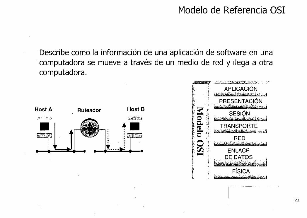
Describe como la información de una aplicación de software en una · computadora se mueve a través de un medio de red y llega a otra computadora.
Host A Ruteador Host B
20

Modelo de Referencia OSI
Capas superiores
Capas inferiores
. . . JRANSPORTE .. .. w+WHAtM§N&sf4ls:ueyz~
twmaupFj¡PwtfliHft.1.a ENLACE
•Desarrollado por ISO en 1984.
S
S,H
•Es un modelo conceptual de siete capas. •Cada capa tiene tareas específicas.
S=software H=hardware
21

Modelo de Referencia OSI
Protocolos
En el mundo de las redes de datos, un protocolo es un conjunto formal de reglas y convenios que determinan como las computadoras intercambian la información sobre un medio de redes.
•El modelo en si NO ES UN MÉTODO DE COMUNICACIÓN!. •La comunicación se hace utilizando:
~Protocolos LAN( capa 1 y 2) ~Protocolos WAN(capa 1,2 y 3) ~Protocolos de red( capas 5,6,7) ~Protocolos de ruteo.( capa 3)
.,
22

Interacción entre capas
Modelo de Referencia OSI
PRESENTACIÓN ijfijd#''zi4+-M4ititw;.4ib!.!i&úN141'*éuiWHfl"i
RED
. FÍSICA MMMieéi"i¡;¡~rüe>¡:j•tG!?!t&Nieail!Í
B
•Si una capa se quiere comunicar con otra, esta última da el servicio. •Los servicios de las capas adyacentes le ayudan con la capa pareja.
IJ 23

Modelo de Referencia OSI
Encapsulamiento Consiste en agregar datos que han sido pasados hacia abajo por una capa superior, utilizando los Headers y Trailers.
La Información de control consiste de peticiones específicas y de Instrucciones que son intercambiadas entre las capas parejas de OSI
HostA Ruteador Host B
T. .......... ....=
2~

Modelo de Referencia OSI
Formatos de la Información
FRAME Es la unidad de información que se manejan entre las capas enlace de datos. Consta de HEADER, datos de las capas superiores y posiblemente Trailer.
PACKET
Es la unidad de información que se manejan entre las capas de red cuando se usa el servicio orientado a conexión. Consta de HEADER, datos de las capas superiores y Posiblemente Trailer.
25

Modelo de Referencia OSI
DATAGRAM
Es la unidad de información que se manejan entre las capas de red cuando se usa el servicio no orientado a conexión. Consta de HEADER, datos de las capas superiores y Posiblemente Trailer.
SEGMENT Se refiere a la unidad de información cuya fuente y destino son las capas de transporte.
MESSAGE
Es la unidad de información que se manejan entre las capas superiores a las de red.
26

Modelo de Referencia OSI
Cell
Es la unidad de información de tamaño fijo que se manejan entre las capas de enlace de datos y son utilizadas en ambientes de redes switcheables como ATM .. Consta de HEADER y PAYLOAD.
-- 53 bytee-s--
5 bytes ' 48 bytes
27

Encapsulamiento
HostA
o
Modelo de Referencia OSI
--------------+
------------ -> !':J:ta -----------~
---------·
-------·
--.• ¡--.·-··"'-··-··.'· ... ·- ....... --.. -.... -·¡ ze..tF~;,;k,;:,_~~~ -~,.._,..;;-\;¿+~;•,.e"' ;/ .. ,..,,,.....,.;:!:
HEADERs o TRAILERs
c::=J !lrl\l
DATOS
TRAMA
e::
28

Encapsulamiento
HEADER o TRAILERs
. 1
Modelo de Referencia OSI
Enrrutador
DATOS
\
TRAMAs
..... 1 !....._......,¡
29

Encapsulamiento
[ ®wl ----- --~
I:_I@W##i ------ -~
-------~
-------~
-------~
-----+
L "··_ ¡ ............ ...,. ~· '· r r'r w ~n '·W'·vn
Modelo de Referencia OSI
Host 8 HEADERs o TRAILERs
1 1 L. .• ___ ,.J
DATOS
TRAMA
. 30

Modelo de Referencia OSI
Capa Física En ésta capa se define las especificaciones eléctricas, mecánicas, funcionales y de procedimiento para activar, mantener y desactivar el enlace físico de los sistemas de redes que se estén comunicando. Por ejemplo: •Relaciona propiedades físicas de la interfaz con el medio de transmisión. •Niveles de voltaje de bits así como tasa de transmisión. •Funciones entre los circuitos individuales de la interfaz y el medio de Tx. •Especifica la secuencia de eventos por la cual se intercambia un flujo de bits.
Capa 2
Capa 1
EIA-TIA 232 V.24 V.35 HSSI G703 EIA 530 X.21 bis SIP
31

Modelo de Referencia OSI
Capa de Enlace de Datos ¡ ; ' :1 . .!
Mientras la capa física proporciona solamente un servicio bruto de datos, la capa de enlace intenta hacer el enlace físico confiable.
•Notifica errores a las capas superiores cuando un error de transmisión a ocurrido.
•Maneja direccionamiento físico. •Define como están lo equipos físicamente conectados, ej. bus o anillo. •Sirve como moderador para el control de flujo.
Subcapa LLC
Subcapa MAC
t.:.LC: Logical Link Control: •Maneja la comunicación entre equipos sobre un solo enlace.
•Soporta servicios orientados y no orientados a conexión pedido por la capa superior.
MAC: Media Access Control •Maneja los protocolos de acceso al medio. •Define MAC address.
32

Modelo de Referencia OSI
Capa de Red
Proporciona los medios para transferencia de información entre sistemas finales a través de algún tipo de red de comunicación.
•Maneja direccionamiento lógico •Realiza funciones de ruteo para especificar la dirección destino y solicitar ciertas facilidades de la red. _
•Maneja varios enlaces a la vez •Los protocolos que se manejan en esta capa generalmente son protocolos de ruteo.
Capa3
BGP ·osPF link-state RIP
33

,-
Modelo de Referencia OSI
Capa de Transporte
•Intercambia datos entre sistemas finales. •El servicio de transporte orientado a conexión asegura que los datos lleguen libres de_ errores, en secuencia y sin pérdidas.
•Maneja el control de flujo entre sistemas finales. •Multiplexa los datos para que varias aplicaciones sean envíadas por un solo enlace físico.
•Establece rutas virtuales(circuitos virtuales), las cuales establece, las mantiene y termina.
•Checa errores y los restablece haciendo uso de la retransmisión.
Capa 4
Capa3
34

Modelo de Referencia OSI
Capa de Sesión
Controla el diálogo entre aplicaciones en los sistemas finales: •Establece, mantiene y termina la sesión de comunicación entre las capas de presentación.
•Consta de Petición de servicios y Respuesta de servicios solicitados por las aplicaciones que se estén corriendo en los diferentes equipos.
•Define si el diálogo es full-duplex o semi-duplex. •Agrupamiento marcando el flujo de datos. •Recuperación proporcionando un mecanismo de comprobación. •Casi no es utilizado en redes actuales.
Capa 5
Capa4
35

Capa de Presentación
1 \
Modelo de Referencia OSI
Define el formato de los datos que se van a intercambiar entre las aplicaciones y ofrece a los programas de aplicación un conjunto de servicios de conversión y codificación que son aplicados a la capa de aplicación asegurando que la información enviada por la capa de aplicación de un sistema sea entendida en el otro sistema. Ejemplos: MPEG,TIFF,JPEG,GIF ..
Capa 6
Capa 5
36

Modelo de Referencia OSI
Capa de Aplicación
Proporciona un medio a los programas de aplicación para que accedan al entorno OSI. •Es la capa más cercana al usuario final. •La capa de aplicación y el usuario interactúan directamente con el software de aplicación. Ejemplos: Transferencia de archivos Terminal virtuai(VTP) Protocolo de información de gestión común (CMIP)
Capa 7
<.:: Capa. 6 · · :~ '~ ''
\ 37

F.A.C::lJLT.A.D DE INGENIERI.A. lJ_N_.A._I\II_ DIVISIC>N DE EDUCACIC>N C::C>NTINUA
"Tres décadas de orgullosa excelencia" 1971 - 2001
CURSOS ABIERTOS
DIPLOMADO INTERNACIONAL EN
TELECOMUNICACIONES
MODULO IV: REDES DIGITALES: ACTUALIDAD Y PERSPECTIVAS
TEMA
TECNOLOGÍAS LAN
EXPOSITOR: ING. RODOLFO ARIAS VILLAVICENCIO PALACIO DE MINERIA
JUNIO 2001
Palac1o de M1neria . Calle de Tacuba 5 Pnmer p1so Deleg Cuauhtémoc Q6CX)Q Mtftx1co. O F APDO_ Postal M-2285 Telefonos 5512-8955 5512-5121 5521-7335 5521-1987 Fax 551().{)573 5521-4021 AL25

Tecnologías LAN
3. Tecnologías LAN
delll al15dejuniode2001
2

Tecnologías LAN
3

Tecnologías LAN
Objetivos
• Describir el modelo de referencia IEEE 802
• Describir las principales tecnologías LAN basadas en el --¡)modelo IEEE 802
.J 4

Tecnologías LAN
•Describir el modelo de referencia IEEE 802
•Describir las principales tecnologías LAN basadas en el modelo IEEE 802
.. 5

Tecnologías LAN
Arquitectura LAN 802 ¡·-·---------·-·-··-···-··-·-· ---·-----······¡ ~·-------------------·······-········-----···----------
11 1 :,· U.\. '¡ .. 1 1 ',, ;;:u!: a~er
1
1 ! Dala Link . 1 !
1
i"Y"' MAC 1
Sut1ayet 1
1 • ¡------- --·--·-1, ; j U:·
1
1 1 1' -~)·s!cal 1 loyor 1
! i ! 1
1 1 1 1 ¡ ! ¡ ¡ !---------------·-·····-···------'
OSII.i!'{c·r.
LLC 802.2: Define la aplicación fuente y destino Control de flujo Tipo de datagrama Transporta información de capas superiores.
6

DSAP SSAP
Tecnologías LAN
Formato LLC
2 Variable
Control Información
Octetos
DSAP: Destination Service Access Point SSAP: Source Service Access Point
7

(l
Campo de Control
• Define el tipo de trama que se transmite • Información
• Información de usuario •Supervisión
•Control de la conexión • N o numerada
Tecnologías LAN
• Establecimiento, mantenimiento y terminación de la sesión
•Control de Flujo
8

Tecnologías LAN
Campo de Control
O 1 ........... 7 8 9 ............. 15 Bits
1 o 1 N(S) IP/~ N(R) Frame I
O 1 2 3 4 5 6 7 8 9 ................. 15 Bits
11 O 1 S S 1 XXXX 1 P/F 1 N(R) 1 Frame S
O 1 2 3 4 5 6 7 Bits
11 1 1 M M IP/F IM M M 1 Frame U
9

Arquitectura LAN 802
Capas Superiores
LLC MAC
Física
í
Tecnologías LAN
MAC Define el formato de trama Direccionamiento fisico Detección y control de errores Control de acceso al medio Relacionado con la topología y medio de trans1nisión ·
10

Capa MAC
•Control ele acceso al medio •Direccionamiento físico
Tecnologías LAN
•Determina longitud máxima de datagrama, al interactuar con la capa física
• Detección ele errores •Control ele errores al interactuar con la subcapa LLC
11

Arquitectura LAN 802
Capas Superiores
LLC MAC
Física
Tecnologías LAN
Física Topología Distancias mínimas y máximas del medio de transmisión Código de línea
12

Capa Física
• Define topología • Define el medio de transmisión •Código de línea • Limites fisicos •Características eléctricas •Sincronía
Tecnologías LAN
13

Ethernet
e aracterísticas
Topología
CSMA/CD
Formato del frame
Implementación Física
Tecnologías LAN
14

e aracterísticas
• Extremadamente sencilla de implementar
•Técnica de acceso al medio tipo contención
• Red no determinística
•Bus lógico
•Tasas de transmisión de 10, 100 y 1000 Mbps
Tecnologías LAN
•Tamaño máximo de trama de 1518 bytes y mínimo de 64 bytes
• Diferentes medios de trasnmisión
•Es el tipo de red que tiene la mayor penetración en el mercado
15

Lógica
Física
Tecnologías LAN
Topología
•• ______ L ··-··------
••N ~ON r·----.... r-----.
'-.!..-~¡~~~~ ~~~~~¡ l~lY.nt: .----. ~-- ~ _......, -.~- . .¡"'-..,.·"_:.,--~¡ , \r:=~::a..:.".:,;_,._ ~ __ . , -,~..¿=- ..... ><;:-,_\ 1 ,
'"'""1 g_~ :--- .. ··-~o~· ·~ 1 ''·"''""'' l - ~ ~- - ~- /l-~- - .'r' - .J
·--...... _ . ~.... ~/- ,....-
'" r~~-ii -~ :.""·"· 3.,-, .. =' •¡ 1 ' 1
• • • • • • ¡ ''" '>" ,. r o~- \ "f" " • ~ •
1 -"~~~.:.:..¿~ .... , -'!''?•".,.lr'• Utt~..-~ ·~!~'rum!ll"
._ - - - - J
16

Tecnologías LAN
CSMA/CD Escuchar
No
Libre
Tx
No
Colisión
Back Off
17

Tecnologías LAN
.______ ________ __. .. ~
18

Tecnologías LAN
Algoritmo de Bakc Off
l. Selecciona un número aleatorio del rango O a 2n - 1 n =Número de colisiones detectadas para una transmisión determinada
2. Multiplica el número aleatorio x 51.2 ¡..ts 3. Incrementan hasta un valor de 1 O 4. Repite este valor 5 veces más 5. Si la colisión persiste manda un error de capas superiores
19

/
\
Tecnologías LAN
Formato del Frame
Data Link Header
6 6 2
Versión 2
802.3 Data Link Header LLC Header
Noven
SNAP Data Link Keader
FFFF Fcllcwed by Data
Data Link Header LLC Header
20

Implementación Física
Característica
Tasa de transmisión
jM~p~L~----~~----Método de señalización
Máxima longitud de
. c~~lei111L. -- -
Medio
Topología física
10
Ethernet Value
Baseband
500
50-ohm coax
. (t~i~k)
Bus
10Base5
10
Baseband
500
50-ohm cuax
~t~~~)-Bus
1
'·
10Base2
10
Baseband
185
50-ohm coax (thin)
Bus
r
Tecnologías LAN
Valores IEEE 802.3
10BaseT
10
Baseband
100
- - ----~---·-¡
Unshieldcd
1 twisted-p~ir___
Star
f" "t " - , ' L
10BaseF 100BaseT L
10 100
Baseband Baseband
2,000
Fiberoptic
PoinHopoint
100
Unshieldcd twistcd-pair
Bus
1
21

' /
10 Base 5
Coaxial grueso Manchester Bus lineal Max. Longitud de segmento 500 m # Max. de segmentos 5
Tecnologías LAN
Distancia mínima entre estaciones 2.5 m # Max. de nodos por segmento 200
22

10 Base 2
Coaxial delgado Manchester Bus lineal Max. Longitud de segmento 185 m # Max. de segmentos 5
Tecnologías LAN
Distancia mínima entre estaciones 0.5 m # Max. de nodos por segmento 3 70
23

UTP Manchester Estrella
/
10 Base T
Max. Longitud de segmento 100 m # Max. de segmentos 4
Tecnologías LAN
24

Evoluciones
•Fast Ethernet
•Gigabit Ethernet
•1 O Gigabit Ethernet
Tecnologías LAN
25

Características
Cable
Número de pares o hilos
Conector
Máxirm longitud del segmento
Máxima longitud de la red
·,.
Tecnologías LAN
Fast Ethernet
100BaseTX
UTP categoría 5, o STP Tipo 1 y 2
2 pares
Conector ISO 8877 (RJ-45)
100 metros
100BaseFX
Fibra multimodo 62.5/125 micron
2 hilos
Conector Duplex SCmediainterface (MIC) ST
400 metros
200 metros 0-~--~~~~~~-- --~- -~ ----
1 400 metros
1
100BaseT4
UTP categoría 3, 4, o 5
4 pares
Co!tector ISO 8877 (RJ-45) e
100 metros
200 metros
26

Autonegociación
1 OOBASE-TX full duplex
100BASE-T4
100BASE-TX
10BASE-T full duplex
10BASE-T
Tecnologías LAN
27

1 Gbps 10 Gbps
Gigabit Ethernet
MTU mínimo de 512 bytes X3 T 11 en capa fisica 8B10B
Tecnologías LAN
28

Token Ring 802.5
Carácterísticas
Topología
Token passing
Formato del frame
Funciones de supervisión
' ' \- --·
Tecnologías LAN
29

Tecnologías LAN
•Esquema de acceso al medio round-robin con opciones de prioridad y reservación
•Red tipo determiriística
• Velocidades de 4 y 16 Mbps
•Tamaño de trama de 4500 bytes como máximo
•Topología lógica tipo anillo
•Red de soporte para aplicaciones propietarias de IBIVI, COI110 SNA
30

Topología
Lógica
Física
.Br .. .
!
• ...
Tecnologías LAN
31
(r

Tecnologías LAN
Token Passing
•Uso de un frame especial llamado "token"
•Esquema Round Robin
•Opciones de prioridad y reservación para transmitir
32

rg EIDTB 1 ll'aiWnile y el Dl'l:i 3 mcibe la aama y la =pía
El DTE 1 pt•• el lutigo lihrc al oiguieore D11:
/
Tecnologías LAN
33

fi~J~ Lt!11yl !r. in a·pr2s
Formato del Frame
D.:IIaiC(Jrt~;Pall:j f-rarTI~!
_..
Token
~;~~~.: r ~;;~~ ~"~¿:.]···
Tecnologías LAN
.--
34

Tecnologías LAN
Funciones de Supervisión
Monitor Activo
Frames no reclamados
Generación del primer token
Estabilización del anillo
Monitor contention, selección del monitor activo
-' ' ' \ . ' ' j
35

Tecnologías LAN
Implementación Física
Tasa de transmisió
IBM Token Ring
4 ó 16 Mbps
lEE 802.5
4 ó 16 Mbps
-··n- ·----- - -· --· --··· . --- - - -- -- --- ·- -------· ---Dispositiv 260 (STP) 250 os por 72 (UTP)
--segmento-- ---------· -- ------ -----· ----··-Topo/og ía Estrella Estrella física ------ .. -~- --------- ------ .. -- -- --------- - - - - -----
Medio Par trenzado Par trenzado
Melado de acceso
Token passing Token passing
36

Características
Topología
Tipos de nodos
Arquitectura
Redundancia
Formato del frame
MAC
Tecnologías LAN
FDDI
37

e aracterísticas
• Red basada en fibra óptica.
•Utiliza un código 4B5B.
• Velocidad de datos de 1 OOMbps.
•Topología de anillo doble.
•Baja tasa de error (una en un billón).
•ConmutCJ.dores ópticos opcionales.
Tecnologías LAN
•Tamaño de paquete variable, máximo 4500 bytes.
• Eficiencia de un 80% con una frecuencia de 125 MHz
38

Topología
Lógica: Doble anillo
Física: Estrella y anillo
Tecnologías LAN
39

Tipos de N o dos DAS
PO SI so PI
• . . . so
··-········ --An An
illo primario · illo secundario PI 1//
//M ·sAY.
DAS
PO SI so' PI
DAC
M
/ "' s~s
Tecnologías LAN
DAS
PO SI so PI
SI
\( PO
\\ S ~SAS
40

Tecnologías LAN
Arquitectura FDDI
Capas Superiores
Enlace
Física
MODELO OSI
LLC ....................... !
MAC
PHY SMT
PMD
ESTÁNDAR FDDI
' ,~,
' \
41

Tecnologías LAN
•WRAP
• Estación bypass.- Aíslan una estación y pern1iten la operación continua del anillo.
• Dual Homing
42

Wrap, bypass <;1.1!1nr. •
r
\_
Tecnologías LAN
r>at callly!Jil~ &~lc'l 'l1ypa~.s~d cxmhg¡ra!Í:J<I.
43

Dual homing
i 1 1
. 1 1 1 1 ., 1 1
File Servers Routers
Tecnologías LAN
44

Tecnologías LAN
Formato de Trama FDDI 64 8 8 16 o 48 16 o 48 4500bytes 32 4 12
1 Preambulol SD FC 1 DA 1 SA 1 INFO 1 FCS
Formato de trama de Token
SD FC ED
8 8 8
Se define la longitud de las tramas en bits
45

1 .A espera el token
Fl 3. A agrega un token al fina
de la transmisión
Tecnologías LAN
Protocolo MAC de FDDI 0
2. A captura el token y transmite
la trama Fl con dirección
e
4. 8 captura el token y transmite trama F2
para D, y coloca otro token
46

5. e copia la trama Fl y la
deja pasar
7. A quita Fl del anillo y deja
pasar F2
Tecnologías LAN
6. D copia F2 y la deja pasar
8. B quita F2 del anillo y deja
pasar el token
47

-' \ '
Tecnologías LAN
Tecnologías Relacionadas
•CDDI
•FDDI 11
•FFOL
'
48

Tecnologías LAN
Características
Topología
De1nand priority
' ' ( ' 49

.'
Tecnologías LAN
e aracterísticas
Diseñada para implementarse sobre cableado UTP categoria 3 de la planta telefónica ya instalada
Soporte de los frames tipo Ethernet y Token Ring
Velocidad de 100 Mbps
Topología jerárquica
Muy poca penetración en el mercado
50

Topología
Física: Jerárquica, estrella
Lógica: Anillo
Cl1ent or Server PC
/
PC
• "'" PC
Tecnologías LAN
• '"'" PC
' \
Wori<stet<ln
• •n .. PC
E1hornot. Tokon Ring, FDOI.ATM, wm
51

¡
Tecnologías LAN
Demand Priority
Sistema centralizado del control de acceso al medio
Esquema de acceso tipo round-robin
Se requiere de una petición de transmisión, la cual entra en una de dos colas de espera:
Prioridad normal
Prioridad alta
52

802.1
•802.2
•802.3
•802.4
·802.5
•802.6
•802.7
•802.8
•802.9
•802.10
•802.11
•802.12
802.14
Resumen 802.x
Hiher Level Interface (HILI)
Logical Link Control (LLC)
CSMAICD (Ethernet)
Token Bus
Token Ring
Metropolitan Area Networks
Tecnologías LAN
Broadband Technical Advisory Grour (BBTAG)
Fiber Optic Technical Advisory Group (FOTAG)
lntegrated Service LAN (ISLAN) Interface
Estandar for lnteroperable LAN Security (SILS)
Wireless LAN (WLAN)
. Demand Priority (1 OOVGanyLAN)
Cable-TV Based Broadband Communication Network.
53

Tecnologías LAN
Gracias!
Rodolfo Arias Villavicencio
. . ... ' . ·- .. . ~ . · .. ' '
54

F.A.Cl..JLT.A.D DE INGE.NIE.R.I.A. l..J.N . .A..IVI. DIVISIC>N DE EDLJCA..CIC>N CONTINUA..
"Tres décadas de orgullosa excelencia" 1991 - 2001
CURSOS ABIERTOS
DIPLOMADO INTERNACIONAL EN
TELECOMUNICACIONES
MODULO IV: REDES DIGITALES: ACTUALIDAD Y PERSPECTIVAS
TEMA
TECNOLOGÍAS WAN
EXPOSITOR: ING. JAVIER SO LIS GONZALEZ PALACIO DE MINERIA
JUNIO 2001
Palac1o de M1nería Calle de Tacuba 5 Pnmer p1so Deleg Cuauhtémoc 06COO México, O F APDO. Postal M-2285 Teléfonos 5512-8955 5512-5121 5521-7335 5521-1987 Fax 5510-0573 5521-4021 AL25

z
• t ooz JP o1unr :1p e; t 1'~ t t tJP
l /
• • •
/ (
• • • • • • • • • •

~ ........ r ·. "'.. -. .
Tipos de Conexiones
• EIA/TIA-2320
• EIA/TIA-449
• V.35
• X.21
• 0.703
• EIA-530
• HSSI
• • • • • • • • • • • • • • 3

SDLC
• Creado por IBM a mediados de los 70's para uso sobre ambiente SNA.
• Primer protocolo orientado a bits y síncrono.
• Más eficiente, flexible y rápido.
• Predecesor de protocolos como HDLC, LAP, LAPB, IEEE 802.2
......... ·~· ... \~:~ .. ,.
5

·, \. i
SD.LC rfipos y Topologías
SDLC identifica dos tipos de nodos de red: • Primario
• Secundario
Las topologías son: • Point-to-point
• Multipoint
• ·Loop
• Hub go-ahead
• • • • • • • • • • • • • • 6
. . '

• • • •
For1nato de la ·rraina SDl.~C Fie!d ler.¡¡lll.
'in bytes
• •
1
1
1
1 l
•
1 or 2 1 or 2 \fartablo
Rooaivo $&'qi)OflC9
flUfrlbOJ
lrrlormabon lramt! 1011T.al
s .... d 1
Poli Í . li~9fl09
tln¡¡sl 1 nurnlxrr :
......... ·-·--···· "'"""""'''' __ ,. ~~~ ¡ ~""""" Poli ! .. .. , IÍilal tli.Jntber
' ¡ FIL'Io:.tJn P<lil 1 runctJor.
oooe ~mlill ' wJo '
• •
{)
o 1
1 t
•
2
• • • 7

i
• Comparte el formato de trama con SDLC.
• Soporta full-duplex y es síncrono.
• A diferencia de su predecesor, HDLC puede utilizar checksum de 32 bits.
• HDLC no soporta loop y go-ahead.
• SDLC soporta solo un modo de transmision, HDLC soporta 3 modos.
• • • • • • • • • • • • • • • 8
------------------------------~;~¡-···---~~' -.~----------------------------

--------------------------------~.~------------------------~
Jf-lD.LC Tipos
• NRM (Normal Response Mode).
• ARM (Asynchronous Response Mode) .
• ABM (Asynchronous Balanced Mode).
• • • •• • • • • • • • • • • • \ 9

¡'
\,
ppp
• Surgió cotno protocolo de transporte para IP.
• Esta compuesta por tres con1ponentes principales: - Método para encapsular datagramas multiprotocolo.
LCP (Link Control Protocol) para establecer y configurar la conexión a nivel enlace.
- NCP (Nenvork Control Protocols) para establecer y configurar diferentes protocolos de capa de red.
• • • • • •• • • • • • • • • 10

• • ••
Fil!ld lflt~lh. in ~(1$
Forrnato de la Tra1na PPP
:2 01 4
I_::J::: ~, .. : L::_l _ __:· __ _
• • • • • • • • 11

i
PPP LCP
LCP se realiza en cuatro etapas: • Establecimiento de la conexión y negociación de la configuración.
• Detenninación de la calidad del medio o enlace.
• Negociación a nivel protocolo de red.
• Fin de la conexión.
• • • • • • • • •• • • • • • 12

SL[P
• Originado por una implementación conocida como 3COM UNET TCP/IP.
• Define una forma de enviar paquetes de IP sobre líneas seriales en el estándar RS-232.
• Actualmente es utilizado para que computadoras remotas puedan accesar a redes (Dial-up ).
• • • • • • • • • • • • • • • ,.
\ ' ,_ 13

\~. ./
. ,. •;. "::~~~'
. '." \ ' ' . :: ;(:;;~ <(<''"'"''"'"
Car~1cterísticas en tra1nas SLIP
SLIP define dos caracteres especiales:
• END
• < ESC
No existe un "estándar" en la especificación de SLIP, por lo
que no hay un. tamaño de paquete máximo para este protocolo.
Sin embargo, se toma como norma e] utilizado por los drivers
Berkeley UNIX SLIP .
< 1 . . . . ., . . . . •• • • • • • 14

Defñciencias
Debido a que SLIP es un protocolo realmente sencillo que fue
diseñado hace tiempo no se tomaron en cuenta algunos puntos
como:
• Direccionatniento
• Tipo de identificación
• Detección y corrección de errores.
• Con1presi ón.
• • • • • • • • • • .. l •
1
• • • 15

\ /" ',
! \_
• Establecido por la CCITT en 1976
• Solo existía la infraestructura telefónica.
• Trata de n1ejorar la conmutación de Circuitos.
• Estándar solo para datos.
• Protocolo enfocado a tráfico de ráfagas
• Tecnología de conn1utación de paquetes
• 16

Relación X.25 con de capas del modelo de referencia OSI
/ Aplicación/
/Presentación/
Sesión ./
Transporte /
Red
X.25 Enlace
Físico
17

. Capa Física: Define las interfaces eléctricas y procedimientos para establecer la comunicación física entre el DTE y DCE
Capa de enlace:
Capa de red:
Define los procedimientos de control de flujo de información entre el DTE y DCE y es responsable de la corrección de errores.
Define los procedimientos de control para el intercambio de paquetes, en esta capa se establece la conexión virtual entre el punto fuente y el destino.
18

Arquitectura X.25
X.25 PLP
LAP-B
Física
-~ ' ·. . ; ·, 19

f ' \ )
Capa Física:
Para la capa física X.25 refiere a la recomendación X.21 bis de la CCITT que específica la forma para establecer, mantener y desconectar la trayectoria física entre DTE/DCE.
X.21 bis define dos estándares: V.24 (RS-232-C) para velocidades de transmisión menores a 20Kbps y V.35 para velocidades hasta 48Kbps.
. X.21 proporciona dos circuitos para transmisión de datos y dos circuitos de control, un circuito de señalización y un circuito de referencia.
20

Transmisión (T)
Control (C)
Recepción (R)
DTE Indicación (I) DCE
Señalización (S)
Tierra Física (G)
21 /

, Capa de enlace:
Las funciones de esta capa son las siguientes:
• Transferir los datos a través del enlace ele manera eficiente.
• Sincroniza el enlace para asegurar que el receptor y transmisor estén
en 1 ínea.
• Detecta errores de transmisión y realiza los procedimientos necesarios
para la recuperación.
• lclenti fica y reporta los errores a las capas superiores a las capas
superiores para la recuperación de datos.
• Informa a la capa ele red el status del enlace .
• • 22

Trama X.25
fi.;ld IO:.tl9iro. ir.!;p-:~ 1 Ül ' ----- ---- --,--------------r·------------·-·- ---r··------------------- ----~-- ---------- ---- -- .. ----1
1 :,:_L "~.,._ .L"~·::' _1. _ :: .. ____ j_'"' ____ ],,~ - .
_,.· f·rtf<:rrr lft1t~v) ir<~rn€1 1Qrma1
~-<- ~:;,:::~- --·: ·_- T---··--;,:~-~------·r·'-'i<!QU€1r>:e 1 f-'cll ¡ ,.,,,,..,.c., 1 O '"-"'"-'e' ' foní!l · nurnbl?!
___ __:.! -- !_
••••• '" •• " ... ,. '. < -· ......... ,. ~- • -~ ~ ~~- --- ~-- -- ---~. -·· ..... , ••
: 1, •
; J
r:.il f. na
/ 1
(
;:.ur,:;l10"! (1)(.]2
•'·
23

Tipos de tramas X.25
• Tramas de ltiformación: son utilizadas para la transferencias de paquetes. También lleva información de reconocimiento ( acknowlegment) p~1ra el control de flujo.
• Tramas de supervisión: realiza funciones de supervisión corno en reconocimiento de acknowlegment, retransmisión de tram:1s de información y responde a suspensiones temporales de transmisión.
• Tramas no numeradas: estas tramas realizan funciones de control y son utilizadas durante el establecimiento y la liberación del enlace .
• • 24

Tecnologías de Transporte
Proporciona sincronía a nivel 2.
Direccionan1iento físico.
Identifica el tipo d~ tratna (I, S, U).
Proporciona control de flujo y control de errores.
Transporta inforn1ación de capas superiores .
.e ¡A· . .,, • 25

' . ( -' -.... ___....
Formato del Frame LAP-B
AD~ CTRL ,
INFORMACION 1 CRC 1 F 1
1 1 1
•F: Bandera de inicio. • ADD: Dirección.
Variable
•CTRL: Identifican el tipo de trama y control de flujo. • INF: Datos e información de capas superiores.
2 1
•CRC: Chequeo de la trama y control de errores en combinación con el campo de controL
• F: Bandera final.
26

'• < ·,-, .. <!:•f'' ',7 ... _, - - ... •-~· .. ·. ~: ·--
.¡ . ~ ·, ·-¡ '·'t-,. '1 1 . ' '·' 'i"'. 1
!t l -~- t! e '··~
· • Integrated Services Digital Network
• Soporta aplicaciones de voz y no voz utilizando un conjunto de estándares
• Soporta aplicaciones conmutadas y no conmutadas
• Utiliza conexiones de 64 Kbps o múltiplos
• Implementa inteligencia en la red (SS7)
• Basado en una arquitectura de capas
(
27

Integración de Servicios
DI Telephon
1111111 ~'1 ---~o~o o o~o o o~ooo~ooowo 1111111 1111111 ~ o o o o o o o o o o o o o o H-----1 ISDN
1111111 1111111 Multiplexer
PBX
28

Agrupaciones Funcionales y Puntos de Referencia
S S En ~ @o
$S ET2~
R Al
TR2 T u '"" """
TRJ. ~
~ - lrs'..alacióc en do1reríEo e~: Clio::utc
D Agrupación Fumional.
® Punto de Referencia o Interfaz.
u V
-®- TL ~ TC
29

)
'" )
ISDN Estructura de Transmisión
-Canales B a 64 Kbps Canales D a 16 o 64 Kbps Canales Ha 384 (HO), 1536 (H11), o 1920 (H12) Kbps
3 conexiones diferentes en un canal B: • Circuitos-conmutados • Paquetes-conmutados • Semipermanentes
30

Tipos de Acceso
Acceso Básico: 2B + D 144 (196) Kbps
Acceso Primario 30 B + D 1984 Kbps
Estos accesos se refieren a la capa física
·. .i 31

Acceso Básico
Full duplex Código de línea Pseudotemario. 1 = OV. O= +750 m V o -750 m V Conector RJ45
Acceso Primario Configuración punto a punto 1.544 o 2.048 Mbps Código de línea 2B 1 Q. 1 O = + 3
11 = + 1 01 = -1 00 = -3
32

•
Tecnologías de Transporte
F Aoo[cTRL INFORMACION
16 8 o 16 Variable
/O /CIR 1 SAPJ 1 ·¡ TEI
'
1 2 3-8 9 10-16
Service Access Point Identifier (SAPI) Terminal Endpoint Iclentifier (TEI)
•
16 8
33

j
Servicios de la ISDN
•Servicios portadores
Modo circuito
Modo paquete
•Teleservicios
•Servicios suplementarios
34

•Uso. de circuitos virtuales.
•Utiliza las ventajas de los medios de transmisión digitales.
•Implementa identificadores de circuitos virtuales.
•Permite la conmutación de paquetes en la red a nivel 7.
•Implementa elmultiplexaje estadístico.
•No efectCúrcorrección de errores.
•No realiza control ele flujo .
• • 35

\ )
Frame Relay
~Alta veloCidad y bajo retardo.
•Soporte eficiente para tráficos o ráfagas.
• Flexibilidad.
• Eficiencia.
•Transporte de voz y datos.
•Conectividad.
•Simplicidad en gestión.
•Estándar.
36

LAP-F
F ADD Info FCS F -
"···· .
8 7 6 5 4 3 218 7 6 54 32 L
1 DLCIHO
' '" ' ¡ ' ) 37

LAP-F
• D LCI : Data Link Conection Identifier.
•C/R: Bit Comando Respuesta.
•EA: Extended Address (Dirección extendida).
• FECN: F orward Explicit Congestion N otification.
•BECN: Backward Explicit Congestion Notificatio.
• DE: Discard Elegibility.
•FCS: Frame Check Sequence.
38

Circuitos Virtuales
• Permanentes
•Conmutados
DLCI ,...-------- ---.. DLCI
l1T~
--~~-~· ·-· -·-1 2 ........ ·-~~-... -- ...... -- ...... - ...... -- . - ....... !)loo 2 2 . / ' ..
,: Fl!"ame Rala)' ·1 _ . .J NP--1vvm·k ~--/ ' . \ (i 2 ( ... ..... -- -- .. --- ... --- .... -- - ... - .. - ... -.. '¡3-6
1 } \ ~
") ! ' ) ' . 89 -4·- ··:· ·-.' ....... ' -·-- .. ---- ............ ,:¡. 52
-·.... -- --·· ·-··· ·· .. ··. .~··· ·-
[)TE
·.¡; ·-· ., -~ 1
39

Administración de Tráfico
AR~-___,
S
CIR, Be, Be
Be = AR*s CIR = Bc/T
T
40

Administración de Tráfico
S
/ ,_ ( ' '
T
41

. .r··- '\ .·
•Control de congestión explícita
Backward explicit congestion notification (BECN)
Foward explicit congestion notification (FECN)
Consolidated link-layer managment messagc (CLLM)
•Control de congestión implícita
Q.922
• .. -.. ·:.
·.
42

ATM
Integración de servicios. Escalabilidad. Independencia de velocidades. Circuitos virtuales. Calidad de Servicio (QoS)
JUtA l!n<tpolnlt
43

Modelo B-ISDN
L Management Plane / / Control Plane / UserPlane / .,
t'"" ;;--., ;:t '< " (\)
3 .., Higher Layers Higher Layers
1 3 ., ., ::>
;~ ~ '3 3 (\) o·::>
A TM Adapta! ion Laye;· 1 ::> ~ ~
ATM Layer 1 V Physical Layer V
44

Planos del B-ISDN RM
Control: Establece, mantiene y termina las conexiones.
Usuario: Transferencia de infonnación. Detección y corrección de errores.
Administración: Coordinación entre los demás planos y administración de los recursos del sistema.
45

·capaATM
•Toma ideas de X.25 y Frame Relay. •Circuitos virtuales (Conexiones virtuales)
-Misrno orden de Tx y Rx -Multiplexaje -Handshake
•No hay control de errores. • Introduce el concepto de celda.
46

Circuitos Virtuales
VPI: Virtual Path Identifier. VCI: Virtual Channel Identifier. VCC: Virtual Channel Connection. VPC: Virtual Path Connection.
47

Circuitos Virtuales
Transmission Medium
Identificadores de significado local. Si el VPC está formado solo se realiza el VCC.
48

vcc
Calidad de servicio. PVC o SVC. Canales meta-signaling.
49

CELDA
2 34567 8 1.2 34567 8
GFC VPI VPI
VPI VCI VPI VCI
VCI VCI
VCI PT fLF VCI PT pu HEC HEC
DATA DATA
User-to-Network Interface Network-to-Network Interface
50

CAPAAAL
A TM Adaptation Layer
Adaptar diferentes tipos de tráfico para ser transportados enATM. Se divide en dos subcapas:
Capa de Convergencia. Capa SAR (Segmentation and Reassambly).
(
51

Capa de Convergencia
Subcapa superior. Identifica el tipo de tráfico. Asigna clase de servicio basándose en tres características.
•Sincronía entre fuente y destino. • Velocidad variable o constante. • Modo de conexión.
sz;

Subcapa SAR
Segmenta y reensambla la información proveniente de la capa de convergencia. .
Realiza mecanismos de detección de errores.
53

i \ "--··
AALl
Higher Layer Frame User Information Information
47 Octets 47 Octets
es Sublay:er AALI-CS-PDU AALI-CS-PDU
SAR Sublayer \'-c_si'--\s_cj_~R_Cj_j_~_¡__----~ Bits : 1 3 3 1
AALI-SAR-PDU .--------------------·
A TM Layer ILA_TM __ He_a_de_._f ______ P_a--"-y_lo_a_d _______ --'
.. .. Octets 5 48
! .
54

AAL2
Hea9er .. .. Payload Trailer · .. .. SAR-PDU Payload 1 Ll 1 CRg
55

AAL 3/4 1 Higher layer Information
Header Payload ·
es sublayer User lnfonnation
Octets 1 2 < 65535 0-3 1 2
SAR sublayf,r jsT j SN ~ID jrnformation 1 u¡~ ...... jsT 1 SNjMiq lnformatiorj uj CRq
2 4 10 44 6. 10 2 4 10 44 6 10 bitsbits bits octets bits bits bitsbits bits octets bits bits
ATM layer Payload
56

AALS 1 Higher !ayer lnformation
CS Sublayer User Infonnation
Octets , O- 65535 · 0-47 1
SAR Sublayer SAR-PDU r SAR-PDU
48 Octets 48
A TM Layer lA TM l-leade1 Payload IATM Heade1
2 4
SAR-PDU
48
Payload
57

r
AAL
Type of Traffic CBR VBR ABR UBR RT NRT
Timing relationship Required Not Required between source and
destin:J.tion .•
Bit Rate Constant Variable
Connection Mode Connection Oriented Connectionles
AAL recommended AALI AAL2 AAL 3/4 AAL 3/4 1 AAL5
Class of Service A B e o
58

Tipos de Tráficos
CBR: Constant Bit Rate. ·vBR: Variable Bit Rate. ABR: A vailable Bit Rate. UBR: Unespicified Bit Rate.
.. ,,
59

CBR
Aplicaciones de tiempo real basadas en Circuit Switching Velocidad constante. . Aun si no hay nada que transmitir, el medio está dedicado. Sensibilidad en la variación de retardo entre trama y trama. Ejemplo: -.Telefonía.
Clase tipo A
60

VBR
VBR-rt y VBR-nrt. Aplicaciones orientadas a conexión. Relación de sincronía entre fuente y destino. Velocidad variable. Ejemplo de VBR-rt: Compresión de voz.
Clase B
61

' '- -- .
ABR
Aplicaciones orientadas a conexión. Velocidad variable. No necesita relación de sincronía. Aplicaciones generalmente de datos. Ejemplo: X.25 y Frame Relay.
Clase C
62

UBR
Trafico no orientado a conexión. No necesita relación de sincronía. Velocidad variable. Usado generalmente en datos. Ejemplo: Redes LAN.
Clase D
63

)
F.ACL.JLT.AD DE INGENIER.I.A L.J_N_.A_I\II_ DIVIs~néJiiMrs~Jn'of.i~~e\,Q"'fgfr-'ib~TINL.J.A
CURSOS ABIERTOS
DIPLOMADO INTERNACIONAL EN TELECOMUNICACIONES
MODULO IV: REDES DIGITALES: ACTUALIDAD Y PERSPECTIVAS
TEMA
CONMUTACIÓN DE PAQUETES
EXPOSITOR: ING. EDUARDO DIAZ GONZALEZ PALACIO DE MINERIA
JUNIO 2001
Pala::to de Mtnería . Calle de Tacuba 5 Pnmer ptsc Oe!eg. Cuauhtemoc 060Cl0 Méxtco, O F APDO. Postal M-2285 Teletones 5512-8955 5512-5121 5521-7335 5521-1987 Fax 5510-0573 5521-4021 AL25

. \
5. Conmutación de Paquetes
del 1 1 al 15 de junio de 2001
2

Introducción al Direccionamiento IP
'il
3

' '· '
Introducción al direccionamiento IP
172.16.0.1
10.13.0. 192.168.1.1 .
- Direccionamiento único permite la comunicación entre estaciones finales
- Elección de ruta basado en localidad
·Location is represented by an address
4

Dirección IP
Máscara
Direccionamiento IP
----------- -------¡ ..----------132 bitsr----------.
. . . -~. "'' ' ' ~- . '
•• • ' ,...., ? "' '
,d \l>-4_ ' ~ ( < • _...., • j L C ,~., ~;¡ L.::: .. l• n vt l t 1 ~- ¡ ~ í} • -·~ r ·l_S.~-·1 f
- .•• ~-- - _,_;':!t -· ~ '::_,
5

OJ~
-·-e
::3
, ~C
')
-·en
Q
-·
o'
128
::3
64
.-32
16
8 4 2 1
128 64
32
16
8 4 2 1
128 64
32
16
8 4 2 1 12
8 64
32
16 8 4 2 1
-· , .(\)
n n -· o ~ Q
/ -.,
1
3

o:J
m o~
o:J
S:
o m
-·
"X
-·C
..· "
. :S
S:U
• :S
" n
"
Q
n~
~3
en -·
, -·
3
, o
3"
3~
-· -·~
o Q
) Q
!!!
. o
-Q
-..,
o -0
Q
) -o
, :S
12
8 64
32
16 8
o 4 2
-· 1
, (\)
128
n 64
n
32
-· 16
o
8 ::3
r·~ --..
..
4 Q
~~
~ 2
3 1
: -·
C"'l
(\
) 12
8 ....
~1
::3
~
64
en¡
-+
32
o 16
8 H
4
" 2
N
1 ~
128
N
CJ1
64
32
16 8 4 2
w
.. 1
N

Clases de Direcciones IP
Clase A
Clase B:
Clase C:
Clase D:
Clase E:
8 bits 8·· bits 8 bits 8 bits . ji '
;.'1 ~ :"-~~ ,.,,.,", r' ~ : ! ~! ~·~~ (:;:] r ';_;lr;i~J. f .· l t1 , )'-. • ¡
- . :! - .::.~· ' ::
. 1 ~..... ) ' • • • ' • 1 •
~ - :;;.J r ,. '/ ( J fl ' 1 ;.. '~ r. .~ ., " t A' ¡: '• ~ ~¡ , ¡ P l 1 ... } .._.-, l - 1 ~ -,_• •• ~ ' <-. ::· ~" 1 ' ,1.. •• ·) •• ,· ~; • :: _;:_. '"'
Multicast
Reservada para
Investigación . .! •.
8

Clases de Direcciones IP "-
Bits: 1 8 9 1617 2425 32
Clase A:
Bits: 1 8 9 1617 2425 32
Clase B: Rango '1- '
¡, ' : : j 1
Bits: 1 8 9 1617' 2425.; 32
Clase C: Rango
Bits: 1 8 9 1617 2425 32
Clase D: r
( ' , __ ' 9

'
Determinación del Direccionamiento Disponible en
Network
una Dirección de Red
(Oil)~MC'\1'1'""00) CO ...... (Oil)~MN'l'"" N '1'"" '1'"" '1'"" '1'"" '1'"" '1'"" '1'""
101011 00 00010000 00000000 00000000 . 1 00000000 00000001 2 00000000 00000011 3
• • • • • • • • •
11111111 111111 01 65534 11111111 1111111 o 65535 11111111 11111111 65536
- 2
1 2!'!.2 = 216.2 = 655341 65534
10

Ejercicio
-~ . - ~· ~-- -. - . ~
_' .,.., - ~ ·-~~"'$:¡·. ' - .. .t,::> .. ~.~:·.~ ''l-, ' ·· •' - .., · '•1- • · '~ · ~•·- ,?!1;~- .-. -. : 1r' 1 ~I~-~~;~<:t 1
\' lt!..r=J:- .. ,'-.'):l\;~.~Á 0 J~¡,. -. ·. ,, tn[~~~:;. ..
13.52.100.1
128.63.2.1 00
200.33.137.165
192.100.183.2
148.233.64.16
256.241.201.1 o
. ., - "' . -
i 1
' " '
' !1
11

13.52.100.1
128.63.2.1 00
200.33.137.165
192.100.183.2
148.233.64.16
256.241.201.1 o
Respuestas
A
8
e
e 8
Inválida
13.0.0.0 0.52.1 00.1
128.63.0.0 0.0.2.1 00 1
200.33.137 .o 0.0.0.65
192.100.183.0 0.0.0.2
148.233.0.0 0.0.64.16
12

Direccionamiento sin Subredes
¡
172.16.0.1 172·16·0 ·2 172.16.0.3 172.16.255.253 172.16.255.
" J;t JC:J!~ A ...... .Q S . ~~ 1 i 1 ~ 172.16.0.0
· Red 172.16.0.0
1
i ' 13

Direccionamiento con Subredes
172.16.2.0
· Red 172.16.0.0
14

Dirección IP
Máscara de Default
Máscara de 8 bits de
Sub red
AAáscara de Subred
Network Host .. ,, '1: .
• ·' ¡ < • "'~~· - -H --""" /.., • • ~ • F ' ·v-.
' 1 > ' 1 ' .1 ~ f t ( : ' 1 f~ ~ 1 ' \
-·¡~ .. __ l."!¿: l. J_:·.(Jl ¡ \~)~' '·.·· ... ~ ~-·¡ ' ( l '
" - tt •
También escrita cómo "/16" donde 16 representn el número de 1 s en la máscara.
Network Subnet Host
También escrita cómo"/24" donde 24 representa el número de 1 s en la máscara.
15

Expresión Binaria de los Números Decimales
128 64 32 16 8 4 2 1
! ! ! ! ! ! ! ! 1 o o o o o o o - 11281 -1 1 o o o o o o - 11921 -1 1 1 o o o o o - 12241 -1 1 1 1 o o o o - 12401 -1 1 1 1 1 o o o - 12481 -1 1 1 1 1 . 1 o o - 12521 -1 1 1 1 1 1 1 o - 12541 -
1 1 1 1 1 1 1 1 - 12551 '; ; - '
16
~:-::...~-· ~~~':.-~ . -:-~· -~ :._:_ ~t;~.

Máscara de Red sin Subredes
Número de Red
Network Host
10101100 00010000 00000010 10100000
11111111 11111111 00000000 00000000
10101100 00010000 00000000 00000000
17

~áscara de Red con Subredes
, Número de Red
Network Subnet Host
10101100 00010000 00000010 10100000
11111111 11111111 11111111 00000000
10101100 00010000 0000001 o 00000000 ~·
CONoqoOCONoqo~ NO\Noqooqoi()IC) --NNNNN ......
· Número de red extendido por 8 bit.?
:·· : ?'• ;.... •
18

~áscara de Red con Subredes
Network Subnet
10101100 0010000 00000010
11111111 11111111 11111111
Host
10101100 0010000 00000010 10 00000
Número De Red
1 !'
· Número de Red extendida por 10 bits
i
O CON..,. lO ..,....,.101010 NNNNN
19

Ejemplo de Subred Clase B
Dirección Ip: 172.16.2.121 · Máscara de Red: 255.255.255.0
Network Network Subnet Host
172.16.2.121: 10101100 00010000 00000010 01111001
255.255.255.0: 11111111 11111111 11111111 00000000
Sub red: 101 O 1100 00010000 0000001 O 00000000
Broadcast: 10101100 00010000 00000010 11111111
·Dirección Sub red = 172 .16. 2. O ·Dirección de Host = 172.16.2.1-172.16.2.254 ·Dirección Broadcast = 172.16.2. 255 ·8 bits de Subred
20

Ejemplo de Subred Clase C .
Dirección IP: 192.168.5.121 Máscara de Red: 255. 255. 255. 248
Network
192.168.5.121: 1
255.255.255.248: 1
Subred: 1 Broadcast: 1
1000000
1111111
1000000 1000000
Network Network
10101000 00000101
11111111 11111111
10101000 00000101 10101000 00000101
·Dirección de Sub red = 192 .168. 5.120
Subnet
01111
11111
01111 01111
·Dirección de Host = 192.168.5.121-192.168.5.126 ·Dirección Broadcast= 192.168.5.127 ·5 bits de Subred
Host
001
000
000 .11
21

·VLSM ·CIDR . • Sumarización
22

Problemas con el Direccionamiento IP
· Agotamiento del direccionamiento IP · Crecimiento de las Tablas de Enrutamiento
23

'a.: \,. Soluciones
· Máscara de Subred; RFCs 950, 1812
· Direccionamiento Jerárquico
~ Sumarización de Rutas, RFC 1518
· Máscara de Sub red de Longitud Variable, RFC
1812
· Classless Interdomain Routing;
RFCs 1518, 1519, 2050
• Asignación de direcciones para Redes
Privadas, RFC 1918
· Network Address Translation, RFC 1631
24

~áscara de Subred
- Moviendo el límite de la máscara de red hacia la derecha, se crean subredes adicionales a expensas de tener un número de hosts reducidos en cada segmento
-La nueva máscara tendrá ls contiguos adicionales, indicando cuántos bits más ha sido extendida la porción de red · La formula- 2n, donde n es igual al número de bits
extendidos, indica el máximo número de subredes creadas
25

(
Planeación Jerárquica IP
·.¿un conmutador telefónico de México conoce cómo llegar a un teléfono específico en Monterrey? (01-8-118-8756)
26

Planeación Jerárquica IP
Larga ' Distancia
Ruta a 01 t (La combinación
01 indica 11 d d Central ama a e L l
1 d. t . oca argo 1s anc1a t
nacional
México
.¿un conmutador telefónico de México conoce cómo llegar a un teléfono específico en Monterrey? (01-8-118-8756)
27

Planeación Jerárquica IP
Larga Distancia Larga Distancia Nacional ________ ...,..Monterrey
Ruta a 01 t (La combinación ·
01 indica 11 d d Central ama a e L l
1 d. t . oca arga 1s anc1a t
nacional
México
Ruta a 8 (Código de área
que sumariza el área Monterrey)
.¿un conmutador telefónico de México conoce cómo llegar a un teléfono específico en Monterrey? (01-8-118-8756) ·'
28

Planeación Jerárquica IP
Larga Distancia Larga Distancia Nacional ________ _.Monterrey
Ruta a O 1 t Ruta a 8 1 (La combinación (Código de área +
01 indica e t 1 que sumariza llamada de
Len ra
1 el área Monterrey) 1 d. t . oca arga 1s anc1a t
nacional
México
Central Local Monterrey
Ruta a 118 (un prefijo
Que sumariza - , una pequena area en Monterrey)
.¿un conmutador telefónico de México conoce cómo llegar a un teléfono específico en Monterrey? (01-8-118-8756)
29

R / \
Planeación Jerárquica . IP ·
Larga Distancia Larga Distancia Nacional ________ ...,.Monterrey
Ruta a O 1 t Ruta a 8 1 {La combinación {Código de área +
Ruta a 118 {un prefijo
Que sumariza 01 indica e t 1 que sumariza
llamada de Len ra
1 el área Monterrey) 1 d. t . oca arga 1s anc1a t
nacional ·
- , Central Local una pequena area Monterrey en Monterrey)
¡ Ruta a 8756 (Número Destino)
México Monterrey
.¿un conmutador telefónico de México conoce cómo llegar a un teléfono específico en Monterrey? (01-8-118-8756)
30

Beneficios del Direccionamiento Jerárquico
- Reduce el número de direcciones en la tabla de enrutamiento
• Sumariza multiples direcciones en rutas sumari zadas
- Eficiente asignación de direcciones
• Asignación contigua de direcciones permite la utilización de todo el espacio de direccionamiento
31

r , ( ',
VLSM
Variable Length Subnet Mask Máscara de Subred Variable
32

¿Qué es Máscara de Subred Variable?
j' '
172.16.0.0/16
~
( ' ·~ 33

./ lQué es Máscara de Subred Variable?
172.16.1.0/24
172.16.0.0/16
172.16.2.Qj24
34

¿Qué es Máscara de Subred Variable?
172.16.14.32/27-'
172.16.1.0/24
' - :¡
:172.16.14.' 64/27. - ..
172.16.0.0/16
!i,-
172.'l 6.2.0/24 '/ . . . ' '.. .··.· ·. · .. ·.
' :1'72.16. 1'4.96/27 '' .
- La subred 172.16.14.0/24 está dividida en pequeñas subredes:
• La primera Subred con máscara (/27)
35

( ' '- ,.
lQué es Máscara de Subred Variable?
__________ _,.. ., -. -
(
172.16.14.32/27
_ ( 172.16.1.0/24
--····----,J·--· . , __ _
172.16.14. 64/27
172.16.0.0/16
172.16.2.0/24
172.16.14.140/30
- La subred 172.16.14.0/24 está dividida en pequeñas subredes: - • La primera Subred con máscara (/27)
· Una de estas no es utilizada en otra parte (/30)
. ' - '
36

Calculando VLSM
Dirección de Subred : 172.16.32.0/20 En Binario 101 011 OO. 00010000.00100000.00000000
37

\
Calculando VLSM
Dirección de Subred: 172.16.32.0/20 En Binario 10101100. 00010000.00100000.00000000
Dirección: 172.16.32.0/26 En Binario 10101100. 00010000. 0100 0.00000000
38

Calculando VLSM
Subnetted Address: 172.16.32.0/20 In Binary 101011 OO. 00010000.00100000.00000000
VLSM Address: 172.16.32.0/26 In Binary 101011 OO. 00010000.001 000.0 00000
1st subnet: 110101100 . 00010000 ¡.0010 ·1 oooo.oo ¡oooooo=172.16.32.0/26
Network Subnet VLSM Host subnet
39

' ~ 1 '
Calculando VLSM
Subnetted Address: 172.16.32.0/20 In Binary 101011 OO. 00010000.00100000.00000000
VLSM Address: 172.16.32.0/26 In Binary 101 011 OO. 00010000.001 000.0 00000
1st subnet: 000000=172.16.32.0/26 10101100 • 00010000 .0010 0000.00 2nd subnet: 000000=172.16.32.64/26 172 • 16 ;001o.·· 0000.01 . .
3~·d subnet: 000000=172.16.32.128/2'6 172 • 16 ;ó010 0000.10 4th subnet: 000000=172.16.32.192/26 172 • 16 .0010 0000.11 5th subnet: 000000=172.16.33.0/26 172 . 16 .0010 0001.00
Network Subnet VLSM Host Subnet
40

Ejemplo de VLSM
Derivada de la Subred 172.16.32.0/20
' 1 ' ) '-- <
1
41

' ,_
Ejemplo de VLSM
Derivada de la Subred 172.16.32.0/20 1
172.16.32.0/26
172.16.32.64/26
172.16.32.128/26
172.16.32.192/26
Máscara de 26 bits (62 hosts)
Í'
' \ ., " ., 1 ,, " :¡ ~l
42

Ejemplo de VLSM
Derivada de la Subred 172.16.32.0/20 1
Derivada de la subred 172.16.33.0/26
Máscara de 30 bits (2 hosts)
( ' i
172.16.32.0/26
172.16.32.64/26
172.16.32.128/26
172.16.32.192/26
Máscara de 26 bits (62 hosts)
43

/
Ejemplo de VLSM
Derivada de la Subred 172.16.32.0/20 1
17~U6.33.8/30
Derivada de la subred 172.16.33.0/26
Máscara de 30 bits (2 hosts)
172.16.32.0/26
172.16.32.64/26
172.16.32.128/26
172.16.32.192/26
Máscara de 26 bits (62 hosts)
44

, SUMARIZACION
;
' ' ' 45

'
lQue es la Sumarización?
172.16.25.0/24/ ( > ·''
\ )---,
172.16.26.0/24/---- .. • 1
(,
172.16.27. Tabla de Ruteo 172.16.25.0/24 172.16.26.0/24 172.16.27.0/24
46
¿Que es la Sumarización?
172.16.26.0/24 /r -.'· 1
172.16.27.
,- . ( \
Tabla de Ruteo l. 72.16.25.0/24 172.16.26.0/24 172.16.27.0/24
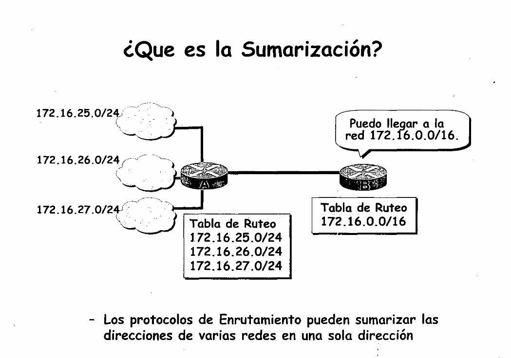
Puedo llegar a la red 172. f6.0.0/16.
Tabla de Ruteo 172.16.0.0/16
- Los protocolos de Enrutamiento pueden sumarizar las direcciones de varias redes en una sola dirección
47

' \
'
Sumarizando dentro de un Octeto
172.16.168.0/24 = 10101100 . ' 0001 0000 . . 10101 000 . 00000000
172.16.169.0/24 = 172 • 16 • 10101 001 . o 172.16.170.0/24 = 172 • 16 10101 010 . o 172.16.171.0/24 = 172 • 16 • 10101 011 . o 172.16.172.0/24 = 172 • 16 • 10101 100;. o 172.16.173.0/24 = 172 • 16 • 10101 101 . o 172.16.174.0/24 = 172 • 16 • 10101 110 . o
'
172.16.175.0/24 = 172 • 16 • 10101 111 . o Número de bits comunes = 21 Bits no Sumarizado: 172.16.168.0/21 comunes= 11
48

Sumarización de Direcciones en una Red VLSM
,• -- .. .-'
172.16.128.0/20
- --". ,.-('-
172.16.32.64/26 .
172.16.32.0/24 .Red··: ,., '· ' '
,.; ···' 1 •
----a.,CQrpórativa.
=Ci72.16.0.0/16 1
49
ú'

Consideraciones de Implementación
· Multiples direcciones IP deben tener los mismos bits de más alto orden
· Las decisiones de enrutamiento son basadas en la dirección completa
· Los protocolos de enrutamiento deben portar la longitud del prefijo (máscara de subred)
50

Sumarizando Rutas en Redes Discontiguas
172.16.5.0 255.255.255.0
j ( ,' ' "
' ' ·, '
' ~--···
192.168.14.16 255.255.255.240
RIPv1 Will Advertise .,.._,. Network 172.16.0.0 ... ...
172.16.6.0 255.255.255.0
~-~ -~.
_.,. ... -..../:· ,,
j',u··; .. ) \. . .·-.·
-..:;._ " .. ·' ' '
RIPv1 Will Advertise Network 172.16.0.0
- RIPvl e IGRP no anuncian las subredes, y por lo tanto no soportan redes discontiguas
- OSPF, EIGRP, y RIPv2 anuncian sub redes y por lo tanto soportan redes discontiguas
51

Be Careful When Summarizing Routes
. 72.16.5 ......
EIGRP Advertises 172.16.0.0/16
192.168.14.16 255.255.255.240
EIGRP Advertises 172.16.0.0/16
- EIGRP on both Router A and Router B advertise a summarized route to 172.16.0.0/16
- Router C receives two routes to 172.16.0.0/16
- Router A (or B or both) should be configured to not summarize
52

CIDR Classless InterDomain Routing
,r-- --
,_

• Classless Interdomain Routing
·Meca-nismo desarrollado para aliviar el agotamiento de direccionamiento y reducir el tamaño de la tabla de enrutamiento
·Bloques de direcciones clase C , asignadas a ISPs. Estos ISPs asignan subconjuntos de estas direcciones a sus clientes
· Los bloques son sumarizados en las tablas de enrutamiento
54

Ejemplo
t92.16S~9.o/24 . -
192.168.1 !t0/24
.'. j . ' ', ' ' ' ·.·_ ~. ':. ,._-. ' ·. , . ' ... ; "
192.168.8.0/21 . :· t' ' ." '
. 1,,··
-Redes de la 192.168.8.0/24 hasta la 192.168.15.0/24 son su marizadas por OC en un solo anuncio: 192. 168. 8. 0/21
i '
55

Protocolos de Enrutamiento
56

What Is Routing?
- Routing is the process of forwarding an iten1 from one location to another
- Routers ·forward traffic to a logical destination in a computer network
- Routers perform two major functions:
• Routing
- Leaming the logical topology of the network
• Switching
- Forwarding packets from an inbound interface toan outbound interface
57

Routing Requirements
- Is the protocol suite active on this device?
. - Is the destination network known to this device?
• Is there an entry in the routing table?
• Is the route currently available?
- Which outbound interface represents the best path?
• Lowest metric path is preferred
• Equallowest metric paths are shared
58

Routing Information
- Most of the necessary information is contained in the routing table
1 172.16.8.0 [1 00/118654] vi a 172.16.7 .9, 00:00:23, Seria lO
1 1'12.16.8.0 [100 /118654] via 172.16.7.9 00:00:23 Seria lO
•• How the route was learned (IGRP) -- Destination logical network or subnet -· Administrativa distance (trustworthiness factor) •• Metric value (reachability) -• Next-hop logical address (next router) -- Age of entry (in hours:minutes:seconds) -- Interface through which the route was learned
and through which the packetwillleave
( ', / 59

)
Administrative Distance
- Administrative distance is a selection method for IP routing protocols
- The lower the administrative distance, the more trusted the leaming mechanism
• Manually entered routes are preferred to dynamically leamed routes
• Routing protocols with sophisticated metrics are preferred over protocols with simple metric structures
~ ' .
60

Routing Decisions
- Routing protocols maintain a loop-free, single path to each destination network
- Routes are advertised with a reachability factor referred as a metric
- The path to the destination network is represented by the sum of the metrics associated with all intermediate links
- The routing process uses the n1etric value to selecta preferred path to each destination
• Multiple paths can be used if metric values are equal
) 61

Routers Forward Traffic
- Routing protocols maintain neighbor relationships with adjacent ( connected) routers
• Neighboring routers and routing protocols exchange frames containing either:
- Helio packets
- Routing update packets
• Routing tables contain routes learned from neighboring routers
- Routers forward traffic to the destination network by passing packets to the next-hop logical device (router) in the delivery path
62

. IGPs: RIP, IGRP, OSPF, EIGRP
IGP vs EGP
EGPs: BGP, EGP
Autonomous System 1 00 Autonomous System 200
• An autonomous system {AS) is a collection of networks under a a single technical administration
• IGPs operate within an autonomous system · • EGPs connect different autonomous systems
63

Classfull Routing Overview
"- Classfull routing protocols are a consequence of the distance vector method of ro u te calculation
• RIPvl
• IGRP
- Routing masks are not carried within the periodic routing updates
• Within a network, consistency of masks is assumed
64

Classful Routing Overview
- Classful routing protocols are a consequence of the distance vector method of ro u te calculation -
• RIPvl
• IGRP
- Routing masks are not carried within the periodic routing updates
• Within a network, consistency of masks is assumed
65

Classfull Subnetting Requirements
A Requirement for Only Two Host AddressesForced to Allocate 30
Host Addresses
192.168.5.129 /27
192.168.5.98/27
.. . 192.168.5.97 /27
-----....... ··¡¡¡¡¡ 192.168.5.33 /27 EO . E1 192.168.5.65 /27
- All router interfaces in the network must have the same subnet mask
- This approach may not·fully utilize available allocation of host addresses
66

Classless Routing Overview
- Classless routing protocols include the routing mask with the route advertisemeht
• OSPF
• EIGRP
• RIPv2
,. IS-IS
• BGP
- · Summary routes can be manually controlled within the network
67

Classless Subnetting Requirements
A Requirement for Only Two Host Addresses
VLSM Support Accommodates This
1
EO 192.168.5.33 /27
192.168.5.129/27
E1 192.168.5.65/27
- Router interfaces within the same network can have different subnet masks
• Variable-length subnet masking (VLSM) is supported
- This approach maximizes allocation of available host addresses
/ ., \ .·'
E8

\ '
Distance Vector Routing Update Traffic
Routing Table
All Routes
1
- In a distance vector environment, routing updates are propagated only to directly connected neighbors
69

Distance Vector Routing Protocols
9 -IGRP 520 • RIP 6-TeP 69 • TFTP 17 • UDP ... 53· DNS
~
.~ ~
Frame Payload e Frame
IP Protocol Packet Payload R
Header Header Number UDP Port Segment e
Header No. Payload
- Cisco routers support severa! distance vector routing protocols
• RIP
• IGRP
- Routing protocols rely on IP packets for delivery of routing inforrnation
70

Distance Vector p'~tocol Comparison Chart
Characteristic RIPv1 RIPv2 IGRP EIGRFf*
Count to infinity X X X Split liorizon X X X ·x Hold-down timer X X X Triggered updates with route poisoning X X X X
Load balancing-Equal paths X X X X Load balancing-Unequal paths X X VLSM support X X Routing algorithm 8-F 8-F 8-F DUAL Metric Hops Hops Comp Comp Hop count limit . 16 16 100 100 Scalability Med Med Large Large
** EIGRP is an advanced distance vector protocol
71

Link-State Routing Update Traffic
Routing Table
- In a link-state environment, link-state announcements are propagated to all devices in the routing domain
• Hierarchical design can limit the requirement to notify all devices
72

Link-State Protocol Comparison Chart
Characteristic
Hierarchical topology-Required Retains knowledge of all possible routes Route summarization-Manual Route summarization-Automatic Event-triggered announcements
Load balancing-Equal paths Load balancing-Unequal paths VLSM support Routing algorithm Metric Hop count limit Scalability
* For comparison purposes only, not a part of this cour~e ** EIGRP has sorne link-state features
OSPF
X X X
X
X
X Dijkstra
Cost 200 Large
IS-15* EIGRp**
X X X X X
X X X
X X X
X X IS-IS DUAL Cost Comp 1024 100
Vrylg Large
73

Convergence
• Convergence time is the time it takes for all routers to agree on the network topology after a change such as:
- N ew ro u tes being added
- Existing routes changing state • Convergence time is affected by:
- Update mechanism (hold-down timers)
- Size of the topology table
- Route calculation algorithm
- Media type
'· 74

' ' i . '·
RIP Convergence
Steps of convergence: 1. e detects link failure; sends Flash update, goes to D and 8
- Route is poisoned to B and D; removed from C's routing table 2. e sends a request to neighbors for alternate path
- 8roadcast for v1, multicast for v2 3. D reports no alternate path; 8 reports route with weaker metric
- Route via B immediately placed in routing table 4. e advertises route via 8 in periodic update to D
- No change to table because route is in hold-down 5. In D, E, and F, as hold-down timer expires, route is added to table
- New route propagated in periodic update eonvergence time at F: hold-down time plus two or three ~pdate intervals
1
75

IGRP Convergence
Steps of convergence: 1. e detects link failure; sends Flash update, goes to D and 8
- Route is poisoned to B and D; removed from _C's routing table 2. e sends query to neighbors for alternate route
- 8roadcast on all interfaces 3. e receives route with weaker metric from 8; poisoned route from D
- Route via B placed in routing table 4. e advertises route via 8 in Flash update to D and 8
- No change to table because route is in hold-down 5. In D, E, and F, as hold-down timer expires, route is added to table
- New route propagated in periodic update eonvergence time at F: hold-down time plus two or three Lipdate intehlals
76

EIGRP Convergence
Steps of convergence: 1. e detects link failure; has no FS, goes into active convergence
- No successor candídates present in topology database 2. e sends query to 8 cmd D to get logical successor
- Because no route with a lower feasible distance available 3. D's response indicates no logical successor 4. 8's response indicates FS with higher feasible distance 5. e accepts new path and distance, adds route via 8 to table 6. Sends Flash update about higher metric, goes to D and 8
- Only higher metric propagated in triggered update eonvergence time to F: approximately 2 seconds
77

· OSPF Convergence
Steps of convergence: 1. C detects link failure; sends lin.k-state advertisement, gces to D and B
- Topology change is detecteci, traffic forwarding suspended 2. All routers update topology database; copy LSA and flood to neighbors
- Al! devices have topological awareness 3. All routers run Dijkstra algorithm, generate new routing table
- Route via B in routing tables, traffic forwarding resumed Convergence time to F: approximately 6 seconds
. ' '-- _/ 78

Routing Updates
- Different ways to send route information
Routing Table
Routing Table
Distance Vector
Approach
Link-State
Approach
Full Table
1 Single Entry 1
79

Classfull and Classless Updates
RIPv1 network
172.16.2.0/24
=1 172.16.2.01
(
\_ t

Classfull and Classless Updates
. '
RIPv1 network
172.16.1.0/24
==l 172.16.2.01
.· '' 192.168.5.0/24
::=1172.1s.o.ol Routing table 172.16.0.0/16
81

Classfull and Classless Updates
RIPv1 network
172.16.2.0/24 ~ 172.16.1.0/24 ~~
==1 172._16.2.01
OSPF network
172.16.2.0/24 172.16.1.0/24
--=J 172.16.2.0/241
192.168.5.0/24
==!112.16.o.ol Routing table 172.16.0.0/16
82

Classfull and Classless Routing Updates
RIPv1 Network
172.16.2.0/24
==l 172.16.2.01
OSPF Network
172.16.2.0/24 172.16.1.0/24
--=d 172.16.2.0/241
~;¡ . 192.168.5.0/24
:3 1t2.1~.ó~ol
192.168.5.0/24
==J172.16.2.0/241
=1172.16.1.0/241 :
Routing Table 172.16.0.0/16
Routing Table 172.16.2.0/24 172.16.1.0/24
83

Routing Tables
- Entries are listed in an efficient search order
• Simplifies the search mechanism
- Multiple paths toa common destination can be listed
• Load balancing is enabled by default for IP
-- Displayed by the show ip route command
- En tries can be refreshed by the clear ip ro u te command
• Specify a single entry, use network number
• Specify all entries, use * as a wildcard character
{
\
/
84

< ( '
' )
Poner ej de tabla de enrutamiento
..
85

Routing Protocol Comparison Chart
** Characteristic RIPv1 RIPv2 IGRP EIGRP OSPF
Distance vector X X X X Link-state X
Classful (auto route summ.) X X X X Classless (VLSM support) X X X
Proprietary X X Scalability Small Small Me d. Large Large Convergence time Slow Slow Slow Fast Fast
** EIGRP is an advanced distance vector protocol
86
.. ' \._ ./
What Is OSPF?
- Has fast convergence
- Supports VLSM
- Processes updates efficiently
- Selects paths based on bandwidth
- Supports equal-cost multipath
87

OSPF in IP Packets
89- OSPF 6-TCP 17- UDP
.4~ Frame Payload
Frame IP Protocol Header
Header Number Packet Payload
'' OSPF is a link-state routing protocol
Relies on IP packets for delivery of routing information
- U ses protocol number 89
', '
e R e

OSPF Terminology
Interfaces ----.
89

OSPF Terminology
._Neighbors + .
90

OSPF Terminology
Cost = 6
91

OSPF Terminology
Area 1 Area O
Cost = 6
92

OSPF Terminology
Autonomous System
.,_Neighbors
+ Area 1
Area O
Cost = 6
93

OSPF Terminology .
Autonomous System
Area 1
Neighborship Databas e
Cost = 6
\
/
Area O
94

OSPF Terminology
Autonomous System
Area 1
Neighborship Databas e
N
Cost = 6
Topology Data base
.,_Neighbors
• Area O
95

OSPF Terminology
Autonomous System
Area 1
Neighborship Databas e
Cost = 6
Topology Data base
Area O
Routing Table
Lists Best Routes
96

Broadcast Multiaccess
Point-to-Point
NBMA
OSPF Topologies
X.25 ,; .. . Frame Reiay
97

OSPF Operation in a Broadcast Multiaccess Topology
afadjfjorqpoeru 39547439070713
Helio - - - - ...J.--------'
Neighborship
Routér ID- '::. . · · _ r _
Hello/déad intervals * Nelghbóts:~:· : :. ·. · .i ·-._ • :_
-A-·r·e--a· ID.· ·t~t;] · ' · ·_ .:., · : 1 - ., •
- .- • ·.;, '!. ·:. -''-{:•. ~-< ' . ·,··:.. . "''
Ro~ter.~ti,&~ity.·( .. v;.-- ., -_-._- · · · · -.
oR. iP address e - ••• 1 •• '
BDR IP address · Authenticatlon password* Stub area flag * ·
* Entry must match on neighboring routers
98

Neighborship (cont.)
afadjfjorqpoeru 39547439070713
Helio - - - - ...J---------'
Roúter ID;·<,_> · ·' ·. : ·
iieuo/deacf intervals * . ,.· . -,: .,. _, -.'t·':r._~-~~- ¡' . . J'
· .Neighbo~s;?' .. , · .. · · , ·· :·>· · ·-~: · '. ~ '; -.. ' ·~ ·-* .': ·'-.t~'' - ·--' •. . '¡ ·,
Ar~a-:1:~.~-~ .. ¡;t-·C:~:·-<: : .·_:~·, , ;· . ._~ ; :: . -Router ,pnonty) > ·:,· ·> .- : · .. ··· ..
oR:íR.éadd,ré~·s · '. · ~ ·· ·, : _( BóR<n~ ... á.ddtess · A~thentication password*:. Stubarea flag *
* Entry must match on neighboring routers
. ! . . • '-..._ '
99

-DRandBDR
- Bellos elect DR and BDR to represent segment - Each router then forms adjacency with DR and BDR
100

Electing the DR and BDR
P=1 P=1 P=O
- Helio packets exchanged via IP multicast - Router with highest OSPF priority elected
101

Exchange Process
172.16.5.1/24 172.1 EO ·
1 Down S tate 1
102

Exchange Process
1/24 172.16
1 po~n stélte 1 1 am router ID 172.16.5.1 and 1 see no one.
llnit Statel
103 -

Exchange Process
172.16.5.1/24 172.1
EO 1 Down Staté 1
1 am router ID 172.16.5.1 and 1 see no one.
l1nit ~tátel
1 am router ID 172.16.5.2, and 1 see 172.16.5.1.
104

'- ~. \
. :·
Exchange Process
.5.1/24 172.16.5.2/2
1 bown S tate 1 1 am router ID 172.16.5.1 and 1 see no one.
l1nit statel
1 a m router ID 172.16.5.2, and 1 see 172.16.5.1.-
Router A Neighbors List
172.16.5.2/24, int EO
1 Two-Way State 1
105

Discovering Routes
EO EO 172.16.5.1 .._ ____________ .... 172.16.5.3
1 Exstart S tate 1
1 will start exchange because 1 have router ID 172.16.5.1.
No, 1 will start exchange because 1 have a higher router ID.
106

Discovering Routes
EO 172.16.5.1 ..... ______________ .. 172.16.5.3
J Exsta'rt State 1
1 will start exchange because 1 have router ID 172.16.5.1.
No, 1 will start exéhange because 1 have a higher router ID. !iello
1 Exchange Stat3
Here is a summary of my link-state database.
Here is a summary of my link-state data base.'
107

EO 172.16.5.1
Discovering Routes (cont.)
Thanks for the information!
EO 172.16.5.3
100

EO 172.16.5.1
Discovering Routes (cont.)
Thanks for the information!
1 Lmidiilg StatéJ
EO 172.16.5.3
-~~ · 1 need the complete entry for network 172.16.6.0/24.
Here is the entry for network 172.16.6.0/24.
Thanks for the information!
109

EO 172.16.5.1
Discovering Routes (cont.)
Thanks for the information!
1 L..oading Staté 1
EO 172.16.5.3
1 need the complete entry for network 172.16.6.0/24.
Here is the entry for network 172.16.6.0/24.
Thanks for the information!
1 Full State 1 'Y
) 110

Choosing Routes
10.3.3.0/24
Cost=1
10.4.4.0/24
This is the best route to 1 0.3.3.0.
111

Maintaining Routing lnformation
Link-State Change
• Router A tells all OSPF DRs on 224.0.0.6
112

(
Mah:~taining Routing Information·
Link-State Changa
• Router A tells all OSPF DRs on 224.0.0.6
• DR tells others on 224.0.0.5
113

Maintaining Routing Information
Link-State Change
• Router A tells all OSPF DRs on 224.0.0.6
• DR tells others on 224.0.0.5
114

Maintaining Routing lnformation
Link-State Change
• LSU
x---~--
1 need to update my routing table .
• Router A tells all OSPF DRs on 224.0.0.6
• DR tells others on 224.0.0.5
115

Maintaining Routing Information (cont.)
Add to database
Send LSAck
Run SPF to calculate table
116

(
Maintaining Routing lnformation (cont.)
.. ;:·' ',¡. _>.
'. ~ f~~~) -.~~·:~: ,·::~ .. :.,,,;·~,. . c 3 ·1lstseq' #':,':'~·~. · · ·::~~:tHé·;§ahie1·' · ··->-· •
Ignore LSA 1 Ves ·t.ii. 5~L i · Ves
. ·'
N Add to database
Send LSAck
Run SPF to calculate table
1 . 1
117

Maintaining Routing Information (cont.)
Add to database
Send LSAck
Run SPF to calculate table
No
.:;::;~~~~-:~,. . ~· ls.s"eq:'~#, ..
'hi9~er.?; -... ·.,, .
No
Send LSU with newer
information to so urce
Ignore LSA 1
118

Maintaining Routing Information (cont.)
,'.· .
· _ls:~~tfyin.. . ·""'-'• : ; :"" link;;.state · ... · ·· ·c~ata6a~e? ···
' '<<; ' '~. ~, ' ..
Add to database
· Send LSAck
Run SPF to calculate new routin table
Ves
No . . . Send LSU . with newer·
information to so urce
- . . ~ .: ~·
Ignore LSA 1 Ves
119

OSPF Operation in a Point-to-Point Topology
Point-to-Point N eighborship
- Router dynamically detects its neighboring router using the Hello protocol
- No election: Adjacency is automatic as soon as the two routers can communicate
- OSPF packets are always sent as multicast 224.0.0.5
120

OSPF Operation in an NBMA Topology
- Single interface interconnects multiple sites
- NBMA topologies support multiple routers but without broadcasting capabilities
121

Frame Relay Topologies
Full Mesh
Partial Mesh
Star (Hub and Spoke)
122
DR Selection in NBMA Topology
- ··osPF considers NBMA to be like other broadcast media
- DR and BDR need to have full physical connectivity with all other routers
- DR and BDR need a list of neighbors
123

NBMA M o de N eighborship
- Usually a fully-meshed network
- DR/BDR elected
- Neighbors must be statically configured
- One IP subnet
- Stability of the network m ay be an issue
- Replicate LSA packets
- RFC 2328 compliant
124

Point-to-Multipoint Mode Neighborship
- Fully-meshed or partially-meshed topology
- No DR/BDR election
- Neighbors do rtot need to be statically configured
- One IP subnet · ·
- Replicate LSA packets
- RFC 2328 compliant
125

•
Ad acenciies Creation
l'oint-to-poi11t interfaces coming 11p: No election o/oLINK-3-lJI'DOWN: Interface Seriall, changed state to up OSI'F: Interface Scriall going llp ' OSI'F: Rcv helio from 192.168.0.11 arca O from Seriall 1 0.1.1.2 OSI'F: End of helio proccssing OSI'F: Build routcr LSA for area O, routcr ID 192.168.0.10 OSI'F: Rcv DBD from 192.168.0.11 on Seriall seq Ox20C4 opt Ox2 flag Ox71en 32 state INIT OSPF: 2 Way Commu11ication lo 192.168.0.11 011 Seriall, statc 2\V A Y OSPF: Send DBI> to 192.168.0.11 011 Scriall seq Oxi67F opt Ox2 flag Ox71cn 32 OSI'F: NBR Negotiation Done. We are the S LAVE OSI'F: Send I>BD lo 192.168.0.11 011 Serial! seq Ox20C4 opt Ox2 flag Ox2 len 72
Ethernet interface coming up: Election OSI'F: 2 Way Communication to 192.168.0.10 on EthernetO, state 2\VA Y OSI'F: end of Wait on interface K!hernetO OSI'F: DR/BI>R election on EthernetO OSPF: Elect BI>R 192.168.0.12 OSI'F: Elect DR 192.168.0.12
DR: 192.168.0.12 (Id) BDR: 192.168.0.12 (Id) OSI'F: Semii>BD lo 192.168.0.12 on FthernctO scq Ox546 opt Ox2 flag Ox71en 32 < ... > OSI'F: DR/HDR dcction on EthcrnctO OSI'F: Elect BDR 192.168.0.11 OSI'F: Elcct DR 192.168.0.12
DR: 192.168.0.12 (Id) HDR: 192:1(,8.0.11 (Id)
126

OSPF over N.BMA Topology Summary
Manual NBMA Fully meshed S ame configuration RFC
DRIBDR elected
Broadcast Fully meshed Automatic
Cisco S ame DRIBDR elected
Point-:to- Partial mesh S ame Automatic RFC
multipoint or star No DRIBDR ·
Point-to-Partial mesh
Manual multipoint S ame configuration Cisco
or star nonbroadcast No DRIBDR Partial mesh nt Point-to-point or star, using Automatic Cisco subinterface No DR/BDR
127

Issues with Maintaining a Large OSPF Network
1 am only receiving LSAs, no data.
My routing table is too big,
The SPF is running too often for me to route.
1 am running low on memory.
\
128

The Solution: OSPF Hierarchical Routing
Autonomous System
- Consists of areas and autonomous systems .
-:- Minimizes routing update traffic
129

OSPF Multi-Area Components
Routers LSAs Are as
Type 1 Area·O
Type 2
Area 1
Area 2
130

Types of OSPF Routers
Area 1 Backbone Area O Area 2
' { -- - )
, E~ternal - AS '-
131

Types of OSPF Routers
Area 1
Interna! Routers
Backbone Area O Area 2
132

Types of OSPF Routers
Area 1 Backbone Area O Area 2
~~ Interna! Routers
"
,J·E~
133

Types of OSPF Routers
Area 1
Interna! Routers
Backbone Area O
ABR and Backbone
, E. t ·1
) Router :. x~rna , AS
-..._
' '
Area 2
1}'1

Types of OSPF Routers
Area 1
Interna! Routers
Backbone Area O
ASBR and ABR and Backbone Backbone
Router j . • '> Router /. E~ternal · '\ AS ---
Area 2
135
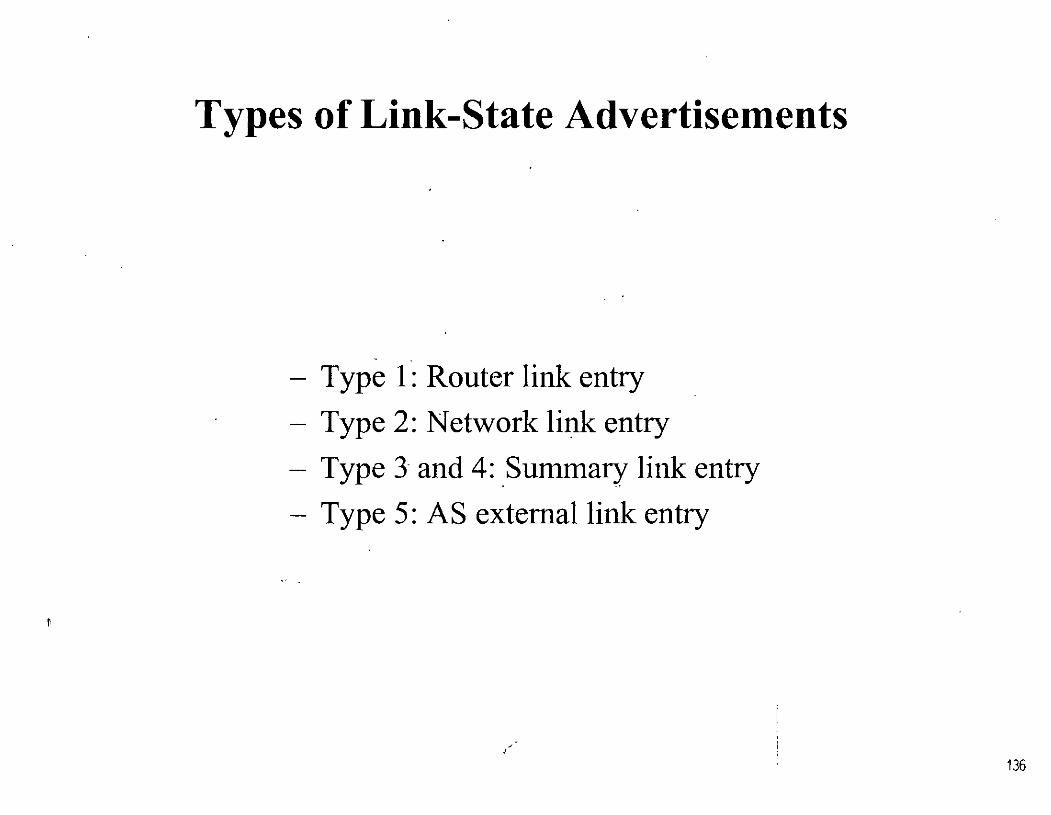
Types of Link-State Advertisements
- Type 1 : Router link entry
- Type 2: N etwork link entry
- Type 3 and 4: .Sun1mary link entry
- Type 5: AS extemal link entry
136

\:alculating Costs for Summary and AS Externa! Ro u tes
Area O
1785
137

Calculating Costs for Summary and AS External Ro u tes
Area 1 Area o -=lYI.
10 1785
133

Types of Areas
139

Types of Areas
Backbone Area O
lnterconnects areas;
accepts all LSAs.
140

•
Types of Areas
Backbone Area O
lnterconnects areas;
.· ac~ep.ts all LSAs.
141

Types of Areas
Backbone Area O
lnterconnects are as;
accepts all LSAs.
142

Forwarding''l>ackets in a Multi-Area Network
Area 50
To Destination Network
1 .... 1 -· ... .... 1 _ _.t To ABR1 To Backbone To ABR2
. ' 1
143

Flooding LSUs to Multiple Areas
Area 50 Stub
1.
1411

Flooding LSUs to Multiple Areas
Area 50 Stub
145

Flooding LSUs to Multiple Areas
,.,.__. ( ; ~ '
· ·RIP ... ··. . )
Type 5
146

' ,'
Flooding LSUs to Multiple Areas (cont.)
Routing Table
lntra-Area Ro u tes
lnter-Area Ro u tes
Externa! (Non-OSPF Routes)
147

Virtual Links Overview
Meeting the Backbone Area Requirements
Area O {Backbone)
Transit Are a
- Backbone center of communication - Virtuallinks provide path to backbone - A void configuring virtuallinks if possible
1
i
148

Meeting the Backbone Area Requirements (cont.)
it Area ·
• Link discontiguous backbone
- Merged networks
- Redundancy
- Point-to-point links
149

BGP Overview
IGPs: RIP, IGRP, OSPF, EIG
----=:L----.
,.
EGPs: BGP
• • . j
Autonomous System 65000 Autonomous System 65500
- An autonomous system (AS) is a collection of networks under a a single technical administration
- IGPs operate within an autonomous system
- EGPs connect different autonomous systems
150

BGP Is U sed Between Autonomous Systems
··.As<.' · ssooo·
BGP ' ' ' ,,
BGP ~ --··.As···:.:.,;_··,
65500 .· ..
BGP
. - BGP is used between autonomous systems
- Guarantees exchange of loop-free routing information
... 151

Scalable Routing Protocol Comparison
OSPF Interior LS Y es Cost
EIGRP Interior Advanced
DV r~o Composite
BGP Path vectors
Exterior Advanced No DV or attributes
152

When to Use BGP
. • BGP is most appropriate when at least one of the following conditions exist:
- An AS allows packets to transit through it to reach other autonomous systems ( for example, a serví ce provider)
- An AS has multiple connections to other autonomous systems
The flow of traffic entering and leaving your AS 1nust be manipulated
• And the effects ofBGP are well understood
153

How Big Is the Internet?
• A BGP router in the Internet has:
- A routing table that uses more than 30Mb
- Over 70,000 routes
- Over 6,500 AS numbers
154

' .
/
When Not to Use BGP
• BGP is not always appropriate. Don't use BGP ifyou have one ofthe following conditions:
A single connection to the Internet or other AS
Routing policy and route selection are not a concem for your AS
Lack of memory or processor power on BGP routers to handle constant updates
Limited understanding of route filtering and BGP path selection process
Low bandwidth between autonomous systems
• U se· static ro u tes instead
155

BGP Characteristics
. • BGP is a distance vector protocol with enhancements:
- Reliable updates-BGP runs on top of TCP (port 179)
- Incremental, triggered updates only
- Periodic keepalives to verify TCP connectivity
- Rich metrics (called path vectors or attributes)
Designed to scale to huge intemetworks
156

(
'
BGP Route Selection Decision Process
• Consider only (synchronized) routes with no AS Ioops anda valid next-hop, and then:
- Prefer highest weight (local to router)
Prefer highest local preference (global within AS)
- Prefer route ofiginated by the local router
- Prefer shortest AS-path
- Prefer lowest origin code (JGP < EGP < incomplete)
Prefer lowest MED ( from other AS)
- Prefer EBGP path over IBGP path
Prefer the path through the closest IGP neighbor
- Prefer the path with the lowest neighbor BGP router ID
157

BGP in IP Packets
179- BGP 6-TeP
23- Telnet 17- UDP
25- SMTP • IL ' ~ IL
1 Frame Payload
Frame • Packet Payload 1 IP Protocol Header
Header Number TCP Port" Segment Header No. Payload
• BGP is an advanced distance vector routing protocol
Relies on TCP for reliable session management
U ses port number 1 79
e R e
158

IGP Routing Protocol IP
' '
Tables
BGP Routing Protocol
- BGP has its own table, in addition to the IGP routing table
- Information can be exchanged between the two tables
159

Peers = Neighbors
.• AS65500' .·
·. '•, · .. :·.
.~ .
',•',
Neighbors
• Any two routers that have fonned a TCP connection in order to exchange BGP routing information are called peers or neighbors
\. 160

Internal BGP
. . . . .
• When BGP neighbors belong to the same AS
• Neighbors do not have to be directly connected ' 1
i '
161

External BGP
..__ _ __.. . . .· ·• ·.·L,::;:,,:~:· /i ·~:;·;· · .;·:.,~.,·~As ssóóo/
,- - . . . . . _· ~
• -_ • 1 ' • • •• -..__.....,
• When BGP neighbors be long. to different autonomous systems
• Neighbors should be directly connec~ed
162

Policy-Based Routing
• BGP allows administrators to define policies, or rules, for how data will flow through the autonomous systems
• BGP and associated tools cannot exprec;;s all routing policies
- BGP does not enable one AS to send traffic to a neighbor AS, intending that the traffic take a different ro u te from that taken by traffic originating in the neighbor AS
• However, BGP can support any policy conforming to (implementable by) the hop-by-hop routing paradigm
··--·
-··. - -
163

BGP Attributes
• BGP metrics are called path attributes
• Characteristics of attributes include:
- Well-known versus optional
- Mandatory versus discretionary
- Transitive versus nontransitive
- Partial
164

Well-known Attributes
• Well-known attributes
- Must be recognized by all compliant BGP implementations
- Are propagated to other neighbo~0
• Well-known mandatory attributes
- Must be present in all update messages
• Well-known discretionary attributes
- Could be present in update messages
165

Optional Attributes
• Optional attributes
- Recognized by sorne implementations ( could be prívate), expected not to be recognized by everyone
- Recogniz.ed optional attributes are propagated to other neighbors based on their meaning
• Optional transitive attributes
- If not recognized, are marked as partial and propagated to other neighbors
• Optional nontransitive attributes
- Discarded if not recognized
166
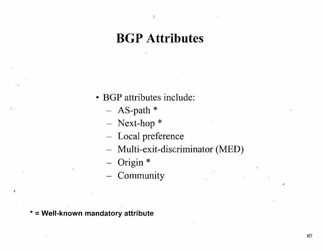
BGP Attributes
• BGP attributes include: AS-path *
- Next-hop *
- Local preference - Multi-exit-discriminator (MED)
- Origin * - Comtnunity
* = Well-known mandatory attribute
167

AS-Path Attribute
65000 . 1~2.168.2.0
• A list of autonomous systems that a ro u te has traversed
- For example, on Router B the path to 192.168.1.0 is the AS sequence 65500 64500
168

Next-Hop Attribute
' ',- -, ' ,,-
ÁS ssóoo.. . J -10.10.10.
_, ;:
''·
• Next-hop to reach a network
' ,
' ·~, ' ., -
- Router A advertises network 172.16.0.0 to Router B in EBGP, with a next hop of 10.10.1 0.3
- Router B advertises 172.16.0.0 in IBGP to Router C, keeping 10.10.10.3 as the next-hop address
169

Next-Hop on a Multiaccess Network
'> ':: -
.. ·~.:,;::·,~.'As s4~o'o ' > - ; ' • ' ·: ~.' - • ) • ................. , . ' . . . ' '
• In a multiaccess network
- Router B will advertise network 172.30.0.0 to Router A in EBGP, with a next hop of 1 O. 10.1 0.2, not 10.10.1 0.1
- This avoids an unnecessary hop
170

Next-Hop on an NBMA Network
" / . ~ >' >
• In an NBMA network
- By default, Router B will advertise network 172.30.0.0 to Router A in EBGP, with a next hop of 10.1 O. 1 0.2, not 10.10.10.1
- Can be overridden
171

Local Preference Attribute
· ,; As 65350 · .. ><·~·::'~;: , ... : 11:~·16.0 ~-'"" ,. AS~~52SO ',__~"· AS 65000 .
". :: ";·· .
. ' -~.. . "
.. , ... '' '1¡ ·' '¡·'
• - 1 • •
• Paths with highest preference value are most desirable
- Preference configured on routers
- Preference sent to intemal BGP neighbors only,
172

MED Attribute
i,. ,'
AS :65500- .·. · ___ .....___ · --. · · · · 11i20~o,o< ;: ·.. -..
' )' i ~··
· .1t2:16~b.o ·· :·;~.
As ssooo· ·
• Paths with lowest MED (also called the metric) value are most desirable
- MED configured on routers - MED sent to externa} BGP neighbors only
173

Origin Attribute
• IGP (i)
- network command • EGP (e)
- Redistributed from EGP • lncomplete (?)
- Redistributed from IGP or static
174

Community Attribute
- Communities are a means of tagging ro u tes to ensure consistent filtering or route-selection policy
- Any BGP router can tag routes in incoming and outgoing routing updates, or when doing redistribution
- Any BGP router can filter routes in incoming or outgoing updates, - or select preferred routes based on communities (the tag)
-By default, communities are stripped in outgoing BGP updates
175

Weight Attribute (Cisco Only)
65000· ·As·s52so·:,'. 172.2Q.O~O., ·,
·.·.·:'.AS '65500 ' ' " '
· ··."weight b:' 1 .. ~ .. :·A~ 6450((;
1 '• '
,- ';;,·' '.
• Paths with highest weight value are most desirable - Weight co11figured 011 routers, 011 a per-11eighbor basis - Weight 11ot se11t to a11y BGP neighbors
176

BGP Synchronization
• Synchronization rule: Do not use, or advertise to an external neighbor, a route learned by IBGP, until a matching route has been learned from an IGP
• Ensures consistency of information throughout the AS
• Avoids black holes within the AS
• Safe to tum off when all routers in the AS are running BGP
177

BGP Synchronization Example
• lf synchronization is on (the default) then:
• All routers in AS 65500 are running BGP; no IGP is running
- Routers A, C, and D would not use or advertise the route to 172.16.0.0 until they receive the mc1tching route via an IGP
- Router E would not hear about 172.16.0.0
• lf synchronization is off then:
- Routers A, e, and D would use and advertise the route they receive via IBGP; Router E would hear about 172.16.0.0
- lf Router E sends traffic for 172.16.0.0, Routers A, e, and D would route the packets correctly to Router B
178

BGP Message Types
• BGP defines the following message types: - Open
• Includes hold time and BGP router ID - Keepalive - Update
'
• Information for one path only ( could be to multiple networks) • Includes path attributes and networks
- Notification
• When error detected
• BGP connection closed after sent
17'

Route Selection Decision Process
• Consider only (synchronized) routes with no AS loops anda valid next-hop, and then:
- Prefer highest weight (local to router)
- Prefer highest local preference (global within AS)
- Prefer route originated by the local router
- Prefer shortest AS-path
- Prefer lowest origin code (IGP < EGP < incomplete)
- Prefer lowest MED (from other AS)
- Prefer EBGP path over IBGP path
- Prefer the path through the closest IGP neighbor
- Prefer oldest route for EBGP paths
- Prefer the path with the lowest neighbor BGP router JD
180

CIDR and Aggregate Addresses
···As 65o·oo ·.·.
192.168.0.0/16
. ~ '
AS 65~00. ···192:1ssd.oí24''!::::
' . ·.
_: . . :.:' . . · .. '
. ·. ·.·· ":Á~/g4500 . --..._.-, ·' ..
. .
·,.AS6~2·so · . .. 192.168.2.0/24
. ·,,. '
• Routes can be aggregated when passing through an AS
181

What Is Multihoming?
• Connecting to two or more ISPs to increase:
- Reliability-If one ISP fails, still connected
- Performance--Better paths to comrnon Internet destinations
182

Types of Multihoming
• Three common ways of configuring the connections are:
Default routes from all providers
- Customer routes and default routes from all providers
- Full routes from all providers
183

Default Ro u tes from All Providers
- Low memory and CPU usage
- Provider sends BGP default route
• Choice of provider decided by IGP n1etrics to reach default ro u te
- AS sends all of its ro u tes to provider
• Inbound path decided by Internet
184

Default Routes from All Providers Example
/ ~. ,' "'" ,
. ·: -:. :·- '/·\.· • •• . r • ,.,_ .. . . ------.../ .. · JS J?. -...... ------rf> '· ., · ... ···•',
C Chooses Lowest IGP Metric to Default
185
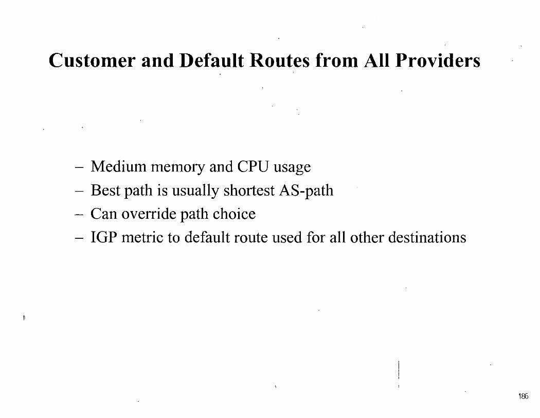
Customer and Default Routes from AH Providers
- Medium memory and CPU usage
- Best path is usually shortest AS-path
- Can override path choice
- IGP metric to default route used for all other destinations
185

Customer and Default Ro u tes from All Providers (con t.)
·· ''ÍSP .· , · · .h· . ( As stiooo · : ....
- e . ~ ,
. ~ . ;
C Chooses Shortest AS-Path
·,_ .-." . : ·:.- ,: -
72.16.o:oJt6 . · -..........:' >'- ~~;;.: ~ '"· ;.:: ··_f ~ '':~' '" ' '
'
187

Customer and Default Ro u tes from AH Providers (con t.)
----~/. ,:- ' ~ ' '
' ' ~ , ¡ ~- .. ; -. . "' ISP ,.
' ,.;.,;~~;65000; ,; ; 'i',:
. ·~. ' ' '
C Chooses Shortest AS-Path
----....../ ' ' ' ',
éu$tpmer · · As;'s4soo> .· .
< ",... • '
' ''~; , __ ,· -.
72.1(i.0.0/16; ,,, ' ' . - . - - "- . / ,·· ,-
:_: ,•'
1ffi

Full Routes from All Providers
- Higher memory and CPU usage
- Reach all destinations by best path
• U sually shortest AS-path
- Can still manually tune path choice
189

Full Routes from All Providers (cont.)
.. Áss4soo.· ·-. . . '
___.,..,..~/' :
· :):. '::, ÍSP .· .. ,:·· ( ·
C Chooses Shortest AS-path
... ·.·.;.\t~~r~:,.·_··~ ·~·.· .... . ·. ·,Ás '65~so . ·:.: ;~:·:
' , , ·"' 'r '··,t ;.,;.: ,'• :; .:, '
190

Gracias
';j.
191

FA.CULT.A.D DE DNGENIERB.A. U_N_A._IVI_
o 1 v 1 S.J.fi?Néc2!~ drru~JttMif t,Mi'it!~fil"fgfF_c¡M~ • • N u .A
CURSOS ABIERTOS
- .
DIPLOMADO INTERNACIONAL EN
TELECOMUNICACIONES
MODULO IV: REDES DIGITALES: ACTUALIDAD Y PERSPECTIVAS
TEMA
VLANs Y LAN Emulation
EXPOSITOR: ING. JAVIER LIMON GOMEZ PALACIO DE MINERIA
JUNIO 2001
Pala ero ae Mrneria . Calle ae Tacuoa 5 Pmner ~rso Deleg Cuauntémoc 06CXXJ Mexrco, O F ~ APDO Postal M-2285 Teidonos· 5512-8952 55i2-512i 55::?1-7335 5521-1937 Fa:- 5510..()573 5521-4021 AL25

• • • • • • • • •
VLANs
6~ VLANs~ y LA.N Em~ulation
del 11 al 15 de junio de 2001
• • • • • • 2

VLANs
• • • • • • • • • • • • • 3

Objetivos VLANs
v' Operación
v'Estándares
v' Consideraciones de diseño
• • • • • • • • • • • • • • • 4

Campus de Red Tradicional VLANs
• El bridge limita los dominios de colisiones
• • • • • • • • • • • • • 5

Interpretación de emisiones VLANs
Necesito saber la dirección MAC del servidor A
Server A " Multicast, broadcast y destinos desconocidos llegan a ser
eventos globales.
• • • • • • • • • • • • • • • 6

Emisiones de Broadcast VLANs
.. Server A
Los broadcasts pueden consumir el ancho de banda disponible
Cada dispositivo debe decodificar el frame de broadcast.
• 7

Solución: Regionalizar Tráfico VLANs
~: · f~=rt - 1, '.-/;
,,.~~
1 0.1.1. 1 0.1.2.0
10.1.3.0
Los broadcasts de LAN terminan en las interfaces del enrutador
• 8

Solución: Regionalizar Tráfico(Cont.) VLANs
<tlf. -~r. '""'";(!'~
~lj ......... -·~~
' ' '
Las VLANs limitan el tráfico de broadcast y separa el flujo de tráfico.
• • • • • • • • • • • • • • • 9

Carnpus Actual de J~edes VLANs :~-, '>~:' ~-?)·:~~~:'~~ . ' ... ,·.,_:_··
,, Los dispositivos de capa 3 interconectan los segmentos LAN, limitando los dominios de broadcast.
• • • • • • • • • • • • • • • 10

¿Qué es una VLAN ó Virtual LAN? VLANs
,, Una VLAN es un dominio de broadcast.
Una VLAN es una red conmutada, segmentada lógicamente de acuerdo a funciones, proyectos o aplicaciones independientemente de la localización física de los usuarios.
• • • • • • • • • • • • • • • 11

VLANs
Broadcast Domain 2
Broadcast Domain 1
Las VLANs y los routers limitan los broadcast al dominio ele origen _, ~ .
• • • • • • • • • • • • • • 12

;l~\·i·:1 f¡,;:l·;,r·J.PJ·Jdi'J ij·~·¡ '!J' ,.,..!¡:!}J·I'í·<·'!\·, :r']p;!!:·¡¡¡··r!¡ :r:l:;.• fj:'¡ '\/'¡ ;\ 1 ·¡ ---·.,.. ... •. -- - --- .. ... - - J .._ .. -., ..... ... - ..__ .. .._ - -- ... ; - ... -.
VLANs
..
Port-Based ,.....,-~~
,..._.,_~"
VLAJ1 1 VLAN2
VLAN3
Port-Driven
MAC-Based ~~~
t t , MAC '
1 ( MAC
'Addresses} Addresses·
VLAN1 VLAN2
MAC Address Driven (Layer 2)
La membresía dentro de la VLAN puede ser estática ó dinámica
13

' .. /
VLAN 1 000 000
- .. /·' . -- ~.
·,
VLAN3 l!llm!B
1!1
( VLAN2 lmllltm .1111 [1
''~~-- ---··
VLANs
/
• 14

Network Layer
Data Link Layer Broadcast Domains
Physical Layer LAN Switch
Human Layer
VLANs
/a"-192.20.21.o 192.20.24.0 192.30.20.0
\ \ ' ...... .... .... , ' ... / \ \ 1 \ \ ..-< ...... ;; <. \ / ...... 1 \ \ 1 \ .\- ... ' ' .... ..... \ ......... ,,../ ,... \ \ 1 y ... \ >" .... 1 \ ,, ...... 1 ....... 1 \
\~····~~\it\~·-Fioor #1 Floor #2 Floor #3
Todos los usuarios conectados en el mismo puerto del switch, pertenecen a la misma VLAN
• • • • • • • • • • • • • • • 15

l'ipos de J1=nlaces VLANs
Enlace de acceso
"' Un enlace de acceso es un enlace el cual es miembro de una sola VLAN
• • • • • • • • • • • • • • •

t' • \ -f. • . ~: ,, !.' •• ! 1
1·. ) " ·'· '\ l ,· ., . . ~: . . ~
., ~ ~! ( ·~
¡,j. \, 1 • · .. \'• ·,_.
Enlaces de troncal
111 11 . ~~ --- ' .¡, ,.....----.....
-:-:-~' :• ,', ;, r'
'· ~ ' . . .· ' : . . . ' .· ,.
•• •• • ••
• •• • • • • • • • • •• . . .. 1 .·:· .. •,. , .. , 1 / . ' '. / .. ~ - ' ~ -
-~···Y~~ •.•••.•••• ,>'··u~. ~,~. . lj'~.
SiEJJ BBJ
VLANs
Un enlace de troncal es capaz de transportar múltiples VLANs .
• • ·- • 17

VLANs
VLAN2 VLAN2
• Especil'icamente desarollado para multi-VLAN, cornunicacit'111 interna entre switches
• Dentro del encabezado de cada l"rame es el único luu:tr de idcnti l'icaci\'>11 ~
• Función de capa 2
• 18

Métodos de identicación de Vl.~ANs VLANs
Green
Fast Ethernet
RED VLAN RED VLAN "' Los paquetes cruzan ,, Packets traversing a shared backbone carry VLAN
identification within the packet header
VLAN ldentification Options: IEEE 802.1 Q (Frame tagging) Cisco ISL (lnter-Switch Link) Cisco 802.1 O (FDDI)
• • • • • • • • • • • • • • • 19

f• ¡·' r ;; .. ¡~'- ~\ ,r' ¡¡¡}'¡'/!l., ..... J· r:: ,_ \. ,·!: :' ;.• •' ~- fl ( ,, ~~ t' d ,, !: ,, •,1 h 'J \1 \{ ;¡ ::J J ·~ !~ .¡ ~~ ,., '! ,, f ... _.p ··~· .... '. ~~ ·.. ú . ·•· ,; :, '·. l ' ' •.•
VLANs
_:.......:: . ;----r---~· . • - '1"'
,-:-;~·-~ ~ J. l.· . .:.,¡ 1 ·. r, .··",
---~A1d t~-. /
---.-¡' .~"" n)'"T: 'j~ .... :< •··. '---V-LA-N-2-00-(P-o-rt-C-) ---••••••• 1
VLAN100
~~S'}---,------, Trunk Link ISL Frame
i . ~~· --- /
,---....· Frame 1----1"'•---·- , ------...
---· VLAN200 (Port B) VLAN200 (PortA)
Legend• Trunk Links
---- VLAN200 (Access Link)
ISL contiene la Información de las VLAN, así como los trames que circulan entre los switches, dentro de los enlaces de troncal
• 20

VLANs
El nombre oficial de IEEE 802.1 Q es Standard for Virtual Bridged Local Area Networks
::::-:-:-:-:·:-::: ........ ::: ..... ·:.: Ethernet
1 DA Data 1 FCS 1
~:~ : : : : : :( ::: ..... ·::: IEEE 802.3
DA Data , 1 FCS 1
. . . . •· . . . . . . . •· . 21

• •
Original Frame
( VLAN ID ancl
,.,:::::..._--..--.----------=::::..., TR Encapsulatlons are' 802.10, not
l.....JL-....l--1..-'---'--'-.1..-L-1--L-L-'--'-.1..-L....J 8112.1 p)
Token Ring Encapsulation Aag
IEEE802.IQ consta de:
2-bytes de etiqueta de indentificación del protocolo (TPID)
¡
''
i:'
¡! . ' .
i Con un valor fijo de Ox8100. Este valor TPID indica que el frame transporta 'la etiqueta de información 802.1 Q/802.1 p
2-bytes de etiqueta de control de información (TCI)
3 bit user priority
•
1 bit canonical format (CFI 1 ndicator)
12 bits VLAN ldentifier (VID)
••• • • • •• • • • • • • 22

Co&nprendiendo los Pat-rones de l'rá~1co VLANs
, La implementación de una red exitosa considera los patrones de tráfico
• • • • • • • • • • • • • • 23

·La Regla 80/20
80+% . Local Traffic
80+% Local Traffic
")'
VLAN3
\
VLANs
80+% Local Traffic
20% Remote Traffic
~ 80 porciento del tráfico es local y el 20 p.orciento es remoto
• • • • • • • • • • • • • • • 24

La N u e va llegla 20/80
20% Local Traffic
20% Local Traffic
VLANs
20% Local Traffic
80+% Remote Traffic
20 porciento del tráfico es local y el 80 porciento es remoto
• • • • • • • • • • ., .. 25

.Eunergen Patrones de Tráfñí~o VLANs
'* •
;
VLAN3
·· La regla 20/80 desafía la implementación de VLANs
• • • • • • • • • • • • • • • 26

Requeriunientos del (]it~nte
· ,, Rápida convergencia
o Trayectos definidos
fl Redundancia
o Escalabilidad
m Aplicaciones centralizadas
o La nueva regla 80/20
&- Soporte de multiprotocolos
,. Multicasting
VLANs
27

•
11:1 Modelo ~Jerárquico '. :-;·; ~ ',
•
.. . •.
•
Core Layer
• • • • • •
VLANs
• • • • 28

··~ <; .~ !¡ ;, . ... !. ,~_ ••
Punto de entrada a la red
Ancho de banda compartido
Servicios de capa 2
Filtros
Membresía de VLAN
• • '
VLANs
• 29

Capa de Distribución
~ Punto de agregación de accesos
" Acceso de servicios de Workgroup
{!> Definición de dominios de Broadcast
"' Ruteo lnterVLAN
o Traducción de medios
e Seguridad
• ' • >
> ' ¡ ~ •• :•: .
-·, '
. . . '.•;.
• • • • • • • • • • • • • • •
VLANs
30

I_Ja Capa de Co e VLANs .. _ ~-.~~tj;··~f:~~~~:~~~~:~ ~··k ~ ' ..
' . ;
Transporte rápido
·. No se procesa capa 3
Core Layer
• • • • • • • • • • • • • • 31 '· '

• •
. - ~·.'"'"
Core Layer Catalyst 55xx Catalyst 85xx Catalyst 65xx
• • • • •
VLANs
• • • • • • • • 32

lmplententación por Edificio
Switch Block
Mainframe Block Core
Block
Server Block
• • • • • • • • • • • • • • •
VLANs
.\2
33

Concentradores Vso Switches
Diferencias técnicas y económicas
• • • • •• • • • •• • • • • • •

¿Qué es un Concentrador?
• Un dispositivo con "n" puertos en el que todos los puertos es tan interconectados entre sí (en paralelo).
• Un concentrador repite en todos sus puertos lo que recibe en uno de ellos.
• Funciona con CSMA/CD.
• El concentrador es completamente acorde al desarrollo teórico de Ethernet.
¡----------35

Problen1as con los Concentradores Ethernet
• Los segmentos pueden soportar sólo 1024 estaciones MAC
• El protocolo fue diseñado para trabajar con tramas largas.
• El protocolo no funciona de forma óptima cuando trabaja con tramas cortas y tráfico elevado generado por las estaciones.
• Existen aplicaciones que consumen gran ancho de banda como la manipulación de gráficos, investigación genética, etc.
• • • • • • • • • • • • • • 36

• Puede requerirse la separación no solo para fines técnicos, sino políticos.
• Puede haber un ambiente mixto en el que se tenga la necesidad de utilizar más de un protocolo de capa 2.
• Casos de TELMEX.
• • • • • • • • • • • • • • • 37

Soluciones a los Problemas (p1·e s'vitches)
• Utilizar enrutadores para dividir el segmento.
• Microsegmentar las LANs para disminuir el tráfico.
• Utilizar "bridges".
• Utilizar Switches (a últimas fechas).
• • • • • • • • • • • • • • 38

~'1'"', . ~-,5 ... ·.,:: " . - ... :t< ' 1%:' j._¡¡ f.} ... ' J • •' -· "'. • • " . \ ~
Breve llistoria de los Switches
• 1973 Primera implementación funcional de Ethernet.
• 198110Base5.
• 1990 10BaseT comercial.
• Finales de los 80s, primeros bridges para dividir segmentos.
• 1991-Lanzamiento de Kalpana de los primeros switches y todas las monerías incluidas.
• 1995 Cisco adquiere Kalpana y Grand Junction Networks .
• • • . , . . . . . . . . . . 39

-Probieanas de los Concentradores
• Cuando se emplean concentradores el medio es compartido por todos los elementos conectados en el segmento.
• No se pueden realizar "loops" (aun cuando fueran deseables).
• El número de equipos que se pueden "poner en cascada" está limitado por el mismo protocolo Ethernet.
• • • • • • • • • • • • • • • 40

Problen1as de los Bridges
• Las primeras implementaciones comerciales descubrieron el "loop eterno".
• N o se puede establecer loop de ninguna forma.
• Un bridge es siempre más lento que un concentrador.
• • • • • • • • • • • • • • 41

Problemática·s de .Bridges (detalle)
Bn1tt1n Newton von Newman
Cmcertrad::lr
A B
orraultGat&w:ay
Jullota Fierro Podro Ftmz Jaime MaUlan
.01. ~~:~J ..:: -~ ' / 0813 ult Ga tew ay
Jullet3 Aerro P9 dro F9 rT1 z
• • • • • • • • • • • • • • • 42

Trama Ethernet Delimitador
Preambulo
de inicio 1
! 1
i
Dir. Dest. Oir. Orig. Longitud Control o tipo (opcional)
• Broadcast: Mal necesario.
• IP lo usa para la resolución ARP.
Datos PAD CRC
• En la antigüedad IPX lo empleaba casi para todo.
• Un broadcast es una dirección destino OxFFFF.
• Tan1bién existen direcciones Multicast.
• • • • • • • • • • • • • • 43

Conno Trabaja ARP en Concentradores
Ca1certracbr
[):¡1'3 ult Ga t9w ay J Ull 9ta A9 rro P9 dro F9 IT1 z
• • • • • • • • • • • • • • • 44

Diferencias a Detalle
• El concentrador repite el broadcast en todos sus puertos.
• Se puede considerar al concentrador como un dispositivo estúpido.
• El switch es en realidad un enrutador de capa 2.
• El switch es inteligente y tiene la capacidad de discernir en base al origen y destino de los paquetes que recibe.
• • • • • • • • • • • • • • 45

La tabla de ' 6ruteo'' de un bridge
• Se considera como una base de datos que aln1acena registros de tres variables.
• Las variables manejadas son: Dirección MAC
Puerto en el bridge en que se conoce a esa dirección MAC
Tietnpo transcurrido desde que se recibió el últitno paquete con dicha dirección MAC
• • • • • • • • • • • • • • • 46

Ejemplo de una tabla de bridge/s,vitch.
Dirección MAC Puerto Aging Time aa aa aa aa aa aa 1 2 bb bb bb bb bb bb 1 3 ce ce ce ce ce ce 1 10
dd dd dd dd dd dd '2 3 ee ee ee ee ee ee 3 130 1 1 1 1 1 1 1 1 1'1 1 1 4 24 22 22 22 22 22 22 5 15 33 33 33 33 33 33 5 12 44 44 44 44 44 44 6 289
. . . . . . . . . . . . •· . . 47

Modos de operación de bridges/switches • Store and Forward recibe la totalidad del paquete
Ethernet, lo verifica y posteriormente lo reenvía.
• Cut trough sólo lee los campos de dirección MA C origen Y. dirección MAC destino, empieza a transmitir el paquete inmediatamente después de que deduce a donde se dirige.
• Existen implementaciones híbridas, para el caso de Cisco es el "Fragment Free", trabaja con Cut Trough pero verifica la validez del paquete, si una estación en particular induce muchos errores, se cambia automáticantente a Store and Forward.
. !
48

.1. • ""'.-.,.......-'!:":
. '~>~!i;_c"fi
Objetivos de Span~rning .-free
• Evitar que los equipos hagan loops entre sí.
• Permitir establecer esquemas redundantes empleando "ruteo de capa 2".
• Que el protocolo sea lo más simple posible y a la vez configurable si el usuario así lo desea.
• • • • • • • • • • • • • • • 49

Una red que necesita Spanning rfree A
• • • • • • • • • • • • • • • 50

La n1isma red después de Spanning Tree A
• '
•
F - .
• • • • • • • • • • • • • • 51

') ,_<'
• • •
Diagrama de estados de Spanning rrree
• •·
N::l seleccion do como puerto raíz o esign a do
Listening ... .., ~ . .., ~ Exptr.~cron del ~ E1piracion del ~
Too o_,_,_ ¡ """'"'" ,_ .
• • • • • • • • • 52

' . '.
Factores que determinan la tecnología
• Aspectos técnicos.
• Aspectos económicos.
• Leyes del mercado.
• Ley de Moore.
• Ley de Metcalfe.
• Ley de la economía de escala .
• • • • • • • • • • •• • • • • 53

•
Distribución del mercado de switches 1998
50.00%
40.00%
30.00%
20.00%
10.00%
0.00%
1995
• • • • •
PARTICIPACION EN EL MERCADO
1996 1997
Reoporte anual
• • • • • •
32.67%
24.89%
1998
•
--cisco
--3com
__._ nortel net
--.cable! ron
-llf-Xyl~n
--.lntel
-e- RESTANTES
54

Precios llubs V so Switches 1998 HUBS
3com SuperStack 11 3com Superstack Bay Networks Bay Networks Bay Networks MODELO PS Hub 40 TP Hub 10 Cabletron SEHI 24 BayStack 106 BayStack 107 Hubstak 102
PRECIO EQUIPO $1,339.00 $2,099.00 $1,355.00 $1,499.00 $2,099.00 $1,399.00
PRECIO PUERTO $55.79 $87.46 $56.46 $124.92 $87.46 $58.29
SWITCH ES
Cabletron ELS100- Cabletron ELS10- Bay Networks 3com SuperStack Cisco WS-C1924-MODELO 24TX 26TX BayStack 303 11 Switch 1100 EN
PRECIO EQUIPO $2,995.00 $3,895.00 $1,625.00 $1 ,495.00 $1,525.00
PRECIO PUERTO $124.79 $144.26 $65.00 $57.50 $56.48
• • • • • • • • • • • • • • • 55

Caso práctico (objetivos)
• U na red debe aprovechar los recursos disponibles.
• Debe ser compatible con los equipos existentes.
• Se tienen que cumplir con ciertas limitantes políticas.
• Se debe buscar la mejor relación costo/beneficio.
• Se debe de apegar a las normas de redes en vigencia.
• Debe cumplir con la políticas de la compañía
• • • • • • • • • • • • • • • 56

Situación inicial
• • • • • • •
EnrlJ!ador de a e ces o Oseo 4500
oad_ centm_lada_ac_1
lnt!ir1!10ll t Etl~mttt 10 Bl QIT
C.llnt~xlon• t 10JBJUJ T )(
ln-ert!l•c f0r;f:Etll!'m.,t 100BJ r:iit~T )(
C~~ UTP
Cdlle 1/TP
•
CS.~ UTP
Czi:jc .IJ!P
• • • •
Con wrtdon~~ tdlll mlldiD t liT Pi1 'ftbi'J
Op1aa (10elcer ZI108Jil!IFXI
• •
'1
f. :i
CDnll liDOtl t 3 10 Mlpt Hi'i:fdupllilr
CDnoeninldor oon hrlae~l \lllr
Cbno1mhdor m~nhnulwr dO' 111111 Optu
01 nOI!Inhdor oo n tr.!not~lwr d(llft:lr.J 6ptoll
Ho.tJ CT
• 57

.Situación final
• • • • •
Enrutada- ~ distri bu:: ión ctl_neld:engo_00_1 meK:meK:
' ,. Switch IDF'1 t Dld_IJI!Int"Jata_..w.J 'oad_Oilln~jild ._..w_4
VLAN 1 VLÁN 2 MDF IDF 1
• • • • VLAN 3
IDF 2
• •
'eonollonoc '10Bie»T
VLAN 4 IDFJ
• . ,
Enrutador de d stribuci én ctl_~.rallejo_do_1 mex.me)(
:CDnodonec : 1DBaiJIIT
VLAN 5 Área
ASTRA • •
Hub CT
VLAN 6 Centro de
trabajo
58

¡ Muchísimas gracias por su atención !
Eduardo Díaz González
Ingeniero de proyectos [email protected]
• • • • • • • • • • • • • • 59

-
F.ACULT.AD DE INGENIERI.A U.N . .A.IVI. - - __ D_IVIS,~~éJ?ci~dh~Jntf.f~~eJ¡B"'fsfr-~~~1 N U A.
CUR_SOS ABIERTOS
DIPLOMADO INTERNACIONAL EN TELECOMUNICACIONES
MODULO IV: REDES DIGITALES: ACTUALIDAD Y PERSPECTIVAS
TEMA
VPN's y MPLS
EXPOSITOR: ING. PABLO DOMÍNGUEZ PEREZ PALACIO DE MINERIA
JUNIO 2001 .
Pa!ac1o ae Minería Caile de Tacu:Ja 5 Pnmer p1so De!eg Cuauhtemoc 06COO M€!x1co O..F APDO Postal M-2285 leléfonos 5512-8955 5512-5121 55::!1-7335 5521-1987 Fax 5510-0573 's5":!1-4021 AL 25

: ' ·¡.
del 11 al 15 de junio de 2001
MPLS-VPN·sprevidl-0699 :.:; 1999. Cisco Systems, lnc. . 1


• Concepts and goals
• Terminology
• Connection model
• Forwarding
• Mechanisms
• Topologies
• Scaling
• BGP-4 Enhancements Cap. Negotiation, MPLS, Route. Refresh; ORF . .
• Configuration Cuca Snnu
MPLS-VPN-sprevidl-0699 © 1999, Cisco Systems, lnc. 3

• An IP network infrastructure delivering prívate network services over a public i nfrastru ctu re ·
• Use a layer 3 backbone
• Scalability, easy provisioning
• Global as well as non-unique privatr~ address space
• QoS
• Controlled access
• Easy configuration for customers C1m SmEu
MPLS-VPN-s~ 0699 © 1999, Cisco Systems,lnc. 4

· • Private trunks over a TELCO/SP shared infrastructure • Leased/Dialup lines • FRIATM circuits • IP (GRE) tunnelling
• Transparency between provider and customer networks
• Optimal routing requires full mesh over over backbone .
CIUD Sllllll
MPLS.VPN-sprevidi-0699 © 1999, Cisco Systems. lnc. 5

• 8oth provider and customer network use same · network protocol
• CE and PE routers have a routing adjacency at each site
• All provider routers hold the full routing information about all customer networks
• Private addresses are not allowed
• May use the virtual router capability Multiple routing and forwarding tables based on Customer
Networks
MPLS-VPN-sf 0699 © 1999, Cisco Systems, lnc 6

· • S ame as Peer model BUT ! ! !
• Provider Edge routers receive and hold routing information only about VPNs directly connected
• Reduces the amount of routing information a PE router will store
• Routing information is proportional to the number of VPNs a router is attached to
• MPLS is used within the backbone to switch · packets {no need of full routing)
MPLS-VPN:Sprevidi-0699 © 1999, Cisco Systems, lnc. 7

• Concepts and goals
• Terminology
• Connection model
• Forwarding
• Mechanisms
• Topologies
• Scaling
• BGP-4 Enhancements Cap. Negotiation, MPLS, Route Refresh, ORF
• Configuration MPLS-VPN-sr .()699 © 1999, Cisco Systems, lnc. 8

• Provider N·etwork (P-Network) The backbone under control of a Service Provider
• Customer Network (C-Network) Network under customer control .
• CE router Customer Edge router. Part of the C-network and
interfaces toa PE router
MPLS-VP~...sprevldl-0699 © 1999, Cisco Systems, lnc.
Cnce SIITIII
9

• · Site Set of (sub)networks part of the C-network and co-located
A site is connected to the VPN backbone through one or more PE/CE links
• PE router Provider Edge router. Part of the P-Network and interfaces
toCE routers
• P router Provider (core) router, without knowledge of VPN
MPLS-VPN-sr ..{)699 © 1999, Cisco Systems, lnc.
C1m Sm111
10

. i 1
• Border router Provider Edge router interfacing to other provider networks
• Extended Community BGP attribute used to identify a Route-origin, Route-target
• Site of Origin ldentifier (SOO) · 64 bits identifying routers where the route has been
originated
MPLS-VPN-sprevldl-0699 © 1999, Cisco Systems, lnc. 11

• Route-Target 64 bits identifying routers that should receive the route
• Route Distinguisher Attributes of each route used to uniquely identify prefixes
among VPNs (64 bits)
VRF based (not VPN based)
• VPN-1Pv4 addresses Address including the 64 bits Route Distinguisher and the
32 bits IP address
MPLS-VPN-s1 .0699 © 1999, Cisco Systems, lnc.
Cuca SYIIIII
12

• VRF VPN Routing and Forwarding lnstance ·
Routing table and FIB table
Populated by routing protocol contexts
• VPN-Aware network A provider backbone where MPLS-VPN is deployéd
MPLS-VPN-sprevidi-0699 © 1999, C1sco Systems, lnc.
Cuco SYIHII
13

• Concepts and goals
• Terminology ' '.
• Connection model
• Forwardir-g
• Mechanisms
• Topologies
• Scaling
• BGP-4 Enhancements ·Cap. Negotiation, MPLS, Route Refresh, ORF
• Configuration CISCO Slllfll
MPLS-VPN-sr .0699 © 1999, Cisco Systems, lnc. 14

• A VPN is a collection of sites sharing a common routing information (routing table)
• A site can be part of different VPNs
• A VPN has to be seen as a community of interest (or Closed User Group)
• · Multiple Routing/Forwarding instances (VRF) on PE routers
MPLS·VPN-sprevld1..0699 © 1999, Cisco Systems, lnc. 15

e VPN-A
VPN-B
• A site belonging to different VPNs mayor MAY NOT be used as a transit point between VPNs · :
• lf two or more VPNs have a common site, address space must be unique among these VPNs·
MPLS-VPN-s· -0699 © 1999, Cisco Systems, lnc. 16

· • The VPN backbone is composed by MPLS LSRs • PE routers (edge LSRs)
• P routers (core LSRs)
• PE routers are faced to CE routers and distribute VPN information through 1·
MP-BGP to other PE routers VPN-1Pv4 addresses, Extended Community, Label
• P routers do not run BGP and do not have any VPN knowledge
MPLS-VPN-sprevldi-0699 © 1999, Cisco Syslems, lnc. . 17

• P routers (LSRs) are in the core of the MPLS cloud ~
' '
• PE routers use MPLS with the core and plain IP with CE routers . ·,
''
• P and PE routers share a common IGP '
• PE router are MP-iBGP fully meshed MPLS-VPN-s¡ -0699 © 1999, Cisco Systems, lnc. 18

--------- ·- .. -------------
• PE and CE routers exchange routing information through:
• EBGP, OSPF, RIPv2, Static routing
/
• CE router run standard routing software
MPLS-VPN-sprevldl~699 @ 1999, Cisco Systems,lnc.
CISCO SYIIIII
19

ckbpne IGP (OSPF, ISIS)
• PE routers maintain separata rou ng tables • The global routing table
With all PE and P routes Populated by the VPN backbone IGP (ISIS or OSPF)
• VRF (VPN Routing and Forwarding)
Routing and Forwarding table associated with one or more directly connected sites (CEs)
VRF are associated to (sub/virtual/tunnel)interfaces
Interfaces may share the same VRF if the connected sites may share the same routing information
MPLS-VPN-s ~699 © 1999, Cisco Systems, lnc. ·
C1m Smus
20

• Different site sharing the same routing information, may share the same VRF
-
• Interfaces connecting these sites will use the same VRF
• Sites belonging to the same VPN may share same VRF
MPLS-VPN-sprevldl-0699 © 1999, Cisco Systems, lnc.
Cnct S111111
21

VPN Backbone IGP
• The routes the PE receives from CE routers are installed in the appropriate VRF
• The routes the PE receives through the backbone IGP are installed in the global routing table
• By using separata VRFs, addresses need NOT to be unique among VPNs
MPLS-VPN-s -0699 © 1999, Cisco Systems, lnc. 22

• The Global Routing Table is populated by IGP protocols.
o In PE routers it may contain the BGP Internet routes {standard BGP-4 routes)
• BGP-4 {1Pv4) routes go into global routing table
• MP-BGP {VPN-1Pv4) routes go into VRFs
CISCI STITIII
MPLS-VPN-sprevidi~699 @ 1999, Cisco Systems,lnc. . 23
. . - . . ...• .. .
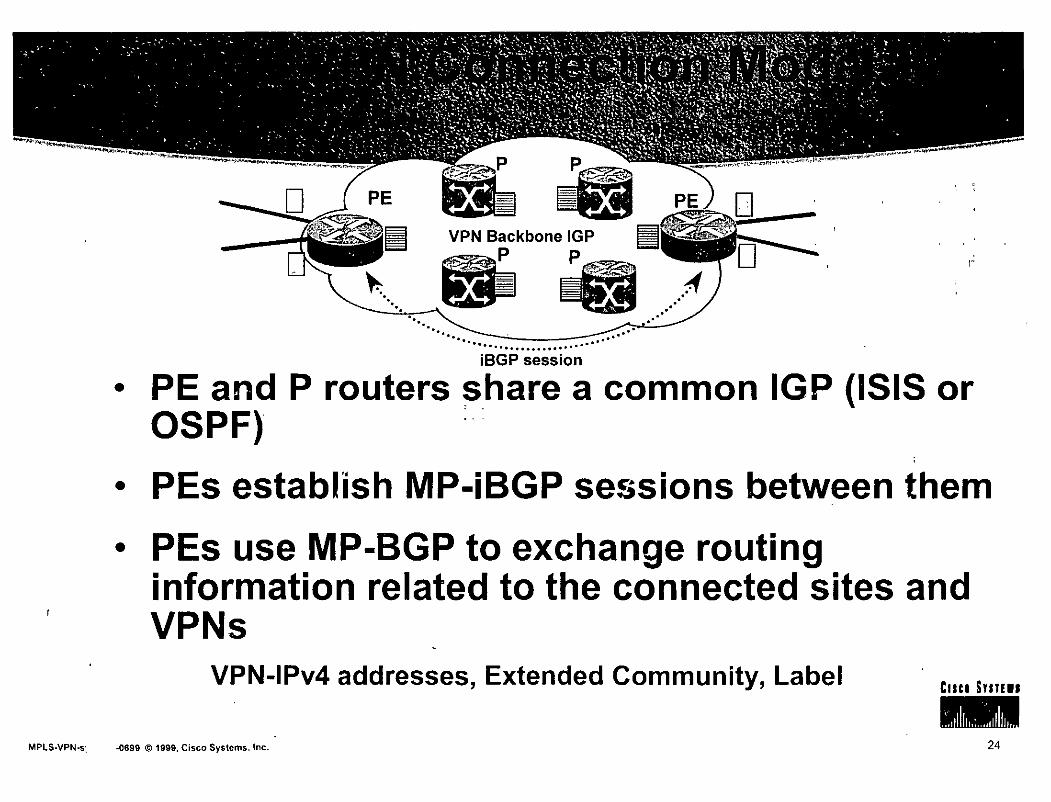
~-p ' " ' '
VPN Backbone IGP
~p
~~· 1"'
··.. - ----~~---... --::.--.......................... iBGP session
• PE and P routers share a common IGP (ISIS or OSPF) :.:
• PEs establlsh MP-iBGP sessions between them
• PEs use MP-BGP to exchange routing information related to the connected sites and VPNs
VPN-1Pv4 addresses, Extended Community, Label Cuu Sm111
MPLS-VPN-s·, -0699 © 1999, Cisco Systems, lnc. 24

• VPN-IPV4 address • Route Distinguisher
64 bits
Makes the 1Pv4 route globally unique
RD is configured in the PE for each VRF
RD. m ay or m ay not. be related to a site or a VPN
• 1Pv4 address (32bits)
• Extended Community attribute {64 bits) Site of Origin (500): identifies the originating site
Route-target (RT): identifies the set of sites the route has to be advertised to cuca su111s
MPLS-VPN-sprevldi~699 © 1999, Cisco Systems, lnc. 25

• Any other standard BGP attribute . Local Preference · MEO Next-hop AS PATH Standard Community •••
• A Label identifying: The outgoing interface
The VRF where a lookup has to be done (aggregate label)
The BGP label will be the second label in the label stack of packets travelling in the core
MPLS-VPN-s¡ ..()699 © 1999, Cisco Systems, lnc. 26.

• · BGP extended community attribute Structured, to support multiple applications
64 bits for increased range
• General form
• <16bits type>:<ASN>:<32 bit number>
Registered AS number
• <16bits type>:<IP address>:<16 bit number>
Registered IP address
MPLS-VPN-sprevldi-(1699 © 1999, Cisco Systems, lnc.
-. -·· .. .... . , ... _ . . .
CISCO Sllllll
27

• The Extended Community is used to:
• ldentify one or more routers where the route has been originated {site)
Site of Origin (500)
• Selects sites which should receive the route
Route-Target
MPLS-VPN-s¡ ..()699 !!> 1999, Cisco Systems, lnc.
1 '!
28

• The Label can be assigned only by the router which address is the Next-Hop attribute • PE routers re-write the Next-Hop with their own
address (loopback interface address) "Next-Hop-Self" BGP command towards iBGP neighbors Loopback addresses are advertised into the backbone IGP
• PE addresses used as BGP Next-Hop must be uniquely known in the backbone IGP
• No summarisation of loopback addresses in the e ore
MPLS-VPN-sprevidi..0699 © 1999, Cisco Systems. lnc. 29

BGP,RIPv2 update for Net1,Next-Hop=CE-1
VPN-1Pv4 update:
~ ·~
RD:Net1, Next-hop=PE-1 SOO=Site1, RT=Green, Label=(intCE1)
VPN-1Pv4 update is translated into 1Pv4 address (Net1) pul into VRF green since RT=Green and advertised to CE-2
• PE routers receive 1Pv4 updates (EBGP, RIPv2, Static)
• PE routers translate into VPN-1Pv4 Assign a 500 and RT based on configuration Re-write Next-Hop attribute Assign a label based on VRF and/or interface Send MP-iBGP update to all PE neighbors
MPLS-VPN--s -0699 © 1999, Cisco Systems, lnc. 30

BGP,OSPF, RIPv2 update for Net1 Next-Hop=CE-1
VPN-1Pv4 update: RD:Net1, Next-hop=PE-1 SOO=Site1, RT=Green, Label=(intCE1)
• Receiving PEs translate to 1Pv4
lnsert the route into the VRF identified by the . RT attribute (based on PE configuration)
VPN-1Pv4 update is translated into 1Pv4 address (Net1) pul into VRF green since RT=Green and advertised to.CE-2
i . ' .
• The label associated to the VPN-1Pv4 address will be set on packet forwarded towards the destination
CISCD SIITIII
MPLS-VPN-sprevidi-0699 ~ 1999, Cisco Systems, lnc. 31

• · Route distribution to sites is driven by the Site of Origin (SOO) and Route-target attributes
BGP Extended Community attribute
• A route is installed)n the site VRF . corresponding to the Route-target attribute
Driven by PE configuration
• A PE which conriects sites belonging to .. · multiple VPNs will install the route .into the site VRF if the Route-target attribute contains one or more VPNs to which the site is associated
MPLS-VPN..sr -Ofi99 © 1999, Cisco Systems, lnc
Cuu SY11111
32

• Concepts and goals
• Terminology
• Connection model
• Forwarding
• Mechanisms
• Topologies
• Scaling
• BGP-4 Enhancements . Cap. Negotiation, MPLS, Route Refresh, ORF
• Configuration Cuca Sm111
MPLS-VPN-sprevidi-0699 ® 1999, C1sco Systems, lnc. 33

• ·PE and P routers have BGP next-hop reachability through the backbone IGP
' .
• Labels are distributed through LDP {hop-by-hop) corresponding to BGP Next-Hops
• Label Stack is used for packet forwarding
• Top label indicates BGP Next-Hop (interior label)
• Second level label indicates outgoing inteñace or VRF (exterior label)
MPLS.VPN-s -0699 © 1999, Cisco Systems, lnc. 34

• MPLS nodes forward packets based on the top label
o P routers do not have BGP {nor VPN) knowledge No VPN routing information
No Internet routing information
CISCO SliTEII
MPLS-VPN-sprevidl~699 © 1999, Cisco Systems, lnc. 35

• The upstream LDP peer of the BGP next-hop (PE router) will pop the first level label
The penultimate hop will pop the label
• Requested through LDP
• The egress PE router will forward the packet. based on the second level label which gives the outgoing interface (and VPN)
MPLS.VPN-s1 -0699 © 1999, Cisco Systems, lnc.
Cuca Sunu
36

CE1
· P:rbuteré switch tlíe packetS .. 'based;onctlíe,IGP labei (label·
.t., ''·t' • *·f· •t'h •/ ta- k.) .,• ·., -H~i" • • ··-OO• op·o es e .. ~-·e,.·• ~ . ":. . . _,· . ; ~--' ' . "- ' - -.· ' .' .
packet
1 1
1
1
1 1
1
/
PE1
VPN Label
lrPI ~
· :gg_r:'re~eivé~-~fp~~i<et-: :··_.
\ \
-~~~§~~P. 1~ ci~rii~~ _site VRF;\ ·}, . 'B(;Piroute W.it~ Next•Hop and· .· " . i; ;¡ "·L.abel is found-·. · .. · ·
::B~P ·next-hCÍp (PE~) is ~eaclíabie --~ i . . through IGP route with -' .l.~ . ássociated labei · · · · ,"- ' . '- ' - . . ·-- - . ~
MPLS·VPN-sprevidl-0699 ~ 1999, Cisco Systems, lnc
\ \ \ \ \ \ \
\!
P1
Penultimate Hop ·Popping P2 is tlíe penultimate hop for the BGP next-hop P2 remove the top label This has been requested through LDP by PE2
\
IGP Labei(PE2)
\ \
\
VPN Label P2
~
. . ,...¡ • -- -
VPN Label
lrPI ~
1 1 1 1 1 1 ..
PE2
CE2
lrPI ~
CE3
37

• lngress PE receives normal IP Packets from CE router
• , PE router does "IP Longest Match" from VPN_B FIB , find iBGP next hop PE2 and impose a stack of labels: exterior Label T2 + Interior Label T8
MPLS-VPN-s .0699 © 1999, Cisco Systems, lnc. 38

• All Subsequent P routers do . Solely on Interior Label
• Egress PE router, removes Interior Label
• Egress PE uses Exterior Label to select which VPN/CE to forward the packet to. ·.
• Exterior Label is removed and packet routed toCE router MPLS-VPN-sprevidi..0699 © 1999, Cisco Systems, lnc.
Cuco S!m11
39

• Concepts and goals
• Terminology
• Connection model
• Forwarding
• Mechanisms
• Topologies
• Scaling
• BGP-4 Enhancements Cap. Negotiation, MPLS, Route Refresh, ORF
• Configuration Cuco Smr11
MPLS-VPN-s . ...0699 © 1999, Cisco Systems, lnc. 40

• VRF: VPN Routing and Forwarding lnstance
• VRF Routing Protocol Context
• VRF Routing Tables
• VRF CEF Forwarding Tables
Cuco Sm111
MPLS-VPN-sprevidi-0699 © 1999, Cisco Systems, lnc. 41

• VPN aware Routing Protocols
• Select/lnstall routes in appropriate routing table
• Per-instance router variables
• Not necessarily per-instance routing processes
• eBGP, OSPF, RIPv2, Static
Cuu Sm111
MPLS-VPN-s ,-0699 © 1999, Cisco Systems, lnc. 42

• VRF Routing table contains routes which should be available to a .Particular set of sites
• Analogous to standard lOS routing table, . supports the same. set of mechanisms
• Interfaces (sites) are assigned to:VRFs · ' One VRF per interface (sub-interface, tunnel or virtual-template)
Possible many interfaces per VRF
MPLS·VPN-sprevidi~699 © 1999, Cisco Systems, lnc. 43

Routing processes
Routing contexts
BGP
VRF Routing tables
VRF Forwarding tables
MPLS-VPN-s -0699 ~ 1999, Cisco Systems, lnc.
Routing processes run within specific routing contexts
• Populate specific VPN routing table and FIBs (VRF)
• Interfaces are assigned to VRFs
44

Logical view
Multihop MP-iBGP
p
• VRF
for site-1
Site-1 routes Site-2 routes
VRF for site-2
Site-1 routes Site-2 routes Site-3 routes
MPLS-VPN-sprevidi..0699 © 1999, Cisco Systems, lnc.
VRF for site-3
Site-2 routes Site-3 routes Site-4 routes
' ..
Site-3 routes Site-4 routes
'
VPN-B
Routi ng view
CIICt SUTIII
45

• Concepts and goals
• Terminology . : .
• Connection model
• Forwarding
• Mechanisms
• Topologies
• Scaling 1
ij
• BGP-4 Enhancements Cap. Negotiation, MPLS; Route Refresh, ORF
• Configu~ation MPLS-VPN~ i~699 © 1999, Cisco Systems, lnc. 46

• VPN-1Pv4 address are propagated together with the associated label in BGP Multiprotocol extension
• Extended Community attribute (route-target) is associated to each VPN-1Pv4 address, to populate the site VRF
MPLS.VPN-sprevldi~699 ~ 1999, Cisco Systems, lnc 47

• Each site has full routing knowledge of all other sites (of same VPN)
• Each CE announces his own address space
• MP-BGP VPN-1Pv4 updates are propagated between PEs
• Routing is optimal in the backbone
• Each route has the BGP Next;.Hop closest to the destination
• No site is used as central point for connectivity Cuu Srm••
MPLS-VPN-s, -0699 © 1999, Cisco Systems, lnc 48

VRF for slte-1
N1,NH=CE1 N2,NH=PE2 N3,NH=PE3
Routlng .Table on CE3
N1, PE3 : N2, PE3
Lócal VRF for site-3
N1,NH=PE1 N2,NH=PE2 N3,NH=CE3
VPN-1Pv4 updates exchanged between PEs
RD:N1, NH=PE1 ,Label=lntCE1, RT=Biue RD:N2, NH=PE2,Label=lntCE2, RT=Biue RD:N3, NH=PE3,Label=lntCE3, RT=Biue
Routing Table on CE1
N1: Local
EBGP/RIP/Static
N2, PE1 N3, PE1 N1
NH=CE1
EBGP/RIP/Static
VRF for slte-2
N1,NH=PE1 N2,NH=CE2 N3,NH=PE3
N2,NH=CE2
Routlng Table on CE2
N1,NH=PE2 N2,Local N3,NH=PE2
49
. -

• One central site has full routing knowledge of all other sites {of same VPN}
• Spoke-Sites
• Hub-Site is the central transit point between Spoke-Sites
• Use of central services at Hub-Site
MPLS·VPN-s 1~699 © 1999, Cisco Systems, lnc.
·> • 1 1 1
.•.. ·~¡
::¡:' :1
' ' t ' '. 1 ~ 1
• 1 ,,
: jt: .' .;
' '·:_¡j/ :· 1
.. :·
,'f, Cllci SYITEII
\ ;~ ' 50

VPN-1Pv4 update advertised by PE1 RD:N1, NH=PE1 ,Label=lntCE1, RT=Hub
lntCE1 VRF (lmport RT=Spoke) (Export RT=Hub) N1,NH=CE1 (exported) N2,NH=PE3 (imported) N3,NH=PE3 (imported
lntCE2 VRF ....._-1 (lmport RT=Spoke) r- (Export RT=Hub) E2 N1,NH=PE3 (imported)
N2,NH=CE2 (exported) N3,NH=PE3 (imported)
PE1
VPN-1Pv4 update advertif.ed by PE2 RD:N2, NH=PE2,Label=lfltCE2, RT=Hub
lntCE3-Hub VRF (lmport RT=Hub) N1,NH=PE1 N2,NH=PE2
lntCE3-Spoke VRF (Export RT=Spoke) N1,NH=CE3-Spoke N2,NH=CE3-Spoke N3,NH=CE3-Spoke
VPN-1Pv4 updates advertised by PE3 RD:N1, NH=PE3,Label=lntCE3-Spoke, RT=Spoke RD:N2, NH=PE3,Label=lntCE3-Spoke, RT=Spoke RD:N3, NH=PE3,Label=lntCE3-Spoke, RT=Spoke
• Routes are imported/exported into VRFs based on RT value of the VPN-1Pv4 updates
• PE.3 uses 2 (sub)interfaces with two different VRFs
'MPLS.VPN-sprevidi-0699 © 1999, Cisco Systems, lnc.
Cuca S111111
51

lntCE1 VRF (lmport RT=Spoke) (Export RT=Hub) N1 ,NH=CE1 (exported)
"':'::~--J N2,NH=PE3 (imported) .. N3,NH=PE3 (imported
~~
lntCE2VRF (lmport RT=Spoke) (Export RT=Hub) N1 ,NH=PE3 (imported) N2,NH=CE2 (exported) N3,NH=PE3 (imported)
lntCE3-Hub VRF -----..1 (lmport RT=Hub)
PE2
N1,NH=PE1 N2,NH=PE2
lntCE3-Spoke VRF (Export RT=Spoke)
__,__, N1 ,NH=CE3-Spoke t---~ N2,NH=CE3-Spoke
N3,NH=CE3-Spoke
BGP/RIPv2 ___-!
• Traffic from one spoke to another will travel across the hub site
• Hub site may host central services Security, NAT, centralised Internet access
MPLS-VPN-s )-0699 © 1999, Cisco Systems, lnc .. 52

•
•
illi~ ,. '
• 8 Y .
. _.,.. .. •' ..

• In a VPN, sites may need to have Internet connectivity
• Connectivity to the Internet means:
• Being able to reach Internet destinations
• Being able to be reachabje from any Internet source
• Security mechanism MUST be used as in ANY other kind of Internet connectivity
MPLS-VPN-~ Ji-(1699 © 1999, Cisco Systems, lnc. 54

• The Internet routing table is treated separately
• In the VPN backbone the Internet routes are in the Global routing table of PE routers
• Labels are not assigned to external (BGP) ro u tes
• P routers need not (and will not) run BGP
MPLS-VPN-sprevldi-0699 (!} 1999, Cisco Systems, lnc
--
55

• A default route is installed into the site VRF and pointing to a Internet Gateway
• The default route is NOT part of any VPN
• A single label is used for packets forwarded according to the default route
• The label is the IGP label corresponding to the IP address of the Internet gateway
Known in the IGP
MPLS-VPN-sprevldl-0699 © 1999, Cisco Systems, lnc. 56
• PE router originates CE routes for the Internet
• Customer (site) routes are known in the site VRF
Not in the global table
• The PE/CE interface is NOT known in the global table. However:
A static route for customer routes and pointing to the PE/CE interface is installed in the global table
• This static route is redistributed into BGP-4 global table and advertised to the Internet Gateway
• The Internet gateway knows customer routes and with _the PE address as next-hop cuce smfll
MPLS-VPN-!. J-0699 © 1999, Cisco Systems, lnc. 57

• The Internet Gateway specified in the default route {into the VRF) need NOT to be directly connected
• Different Internet gateways can be used for different VRFs
• Using default route for Internet routing does NOT allow any other default route for intraVPN routing
• As in any other routing scheme
MPLS-VPN-sprevidt-0699 © 1999, Cisco Systems, lnc. 58

Internet
PE-IG
MP-BGP
Site-2
MPLS-VPN~ .1-0699 @ 1999, Cisco Systems, lnc.
ip vrf VPN-A
rd 100:1
route-target bolh 100:1
1 Interface SeriaiO ip address 192.168.10.1 255.255.255.0
ip vrf forwarding VPN-A
1 Router bgp 100 no bgp default ipv4-unicast network 171.68.0.0 moísk 255.255.0.0 neighbor 192.168.1.1 remole 100 nelghbor 192.168.1.1 activate neighbor 192.168.1.1 next-hop-self neighbor 192.168.1.1 update-source lo~>pbackO 1 address-family ipv4 vrf VPN-A
1
neighbor 192.168.10.2 remole-as 65502 neighbor 192.168.10.2 activate exit-address-family
address-family vpnv4 neighbor 192.168.1.2 activate
exit-address-family
ip roule 171.68.0.0 255.255.0.0 SeriaiO ip route vrf VPN-A 0.0.0.0 0.0.0.0 192.168.1.1 global
59

IP packet D=cisco.com
Internet
MPLS-VPN-sprevidi~699 © 1999, Cisco Systems, lnc.
E
IP packet D=cisco.com
IP packet D=cisco.com
Sit~-2
Global Table and LFIB
192.168.1.1/32 Label=3 192.168.1.2/32 Labei=S
Site~2 VRF
0.0.0.0/0 192.168.1.1 (globul)
Site-1 routes Site-2 routes
60

• PE routers need not to hold the Internet table
• PE routers will use BGP-4 sessions to originate customer routes
• Packet forwarding is done with a single label identifying the ~nternet Gateway IP address
• More labels if Traffic Engineering is used .
MPLS-VPN•. 1-0699 © 1999, Cisco Systems, lnc.
Cnu S111111
61

• lf CE wishes to receive and announce routes from/to the Internet
• A dedicated BGP session is used over a separate (sub) interface
• The PE imports CE routes into the global routing table a.nd advertise them to the Internet
The interface is not part of any VPN and does not use any VRF
• Default route or Internet routes are exported to the CE
PE needs to have lnter11et routing table
MPLS-VPN-sprevldi-0699 ltl1999, Cisco Systems, lnc.
CIICI S!IT!II
62

• The PE uses separata (sub)interfaces with the CE
• One (sub)interface for VPN routing
associated to a VRF Can be a tunnel interface
• One (sub)interface for Internet routing
Associated to the global routing table
MPLS-VPN·. Ji~699 © 1999, Cisco Systems, lnc. 63

192.168.1.1
Internet
MP-BGP
Serial0.1
Site-2
MPLS-VPN-sprevidi-0699 © 1999, Cisco Systems, lnc.
·-· ~·- ·-.
route-target both 100:1 1 Interface Seria lO no ip address 1
Interface Serial0.1 ip address 192.168c20.1 255.255.255.0 ip vrf forwarding VPN-A 1 Interface Seríal0.2
ip address 171.68.10.1 255.255.255.0 1
Router bg p 100 , "' " no bgp default ipv4-unícast neíghbor 192.168:1.1 remole 100
neíghbor 192.1611.1.1 actívate
neíghbor 192.168.1.1 next-hop-self neighbor 192.168.1.1 update-source loopbackO neíghbor 171.68.10.2 remole 502 1 address-family ipv4 vrf VPN-A neíghbor 192.168.20.2 remole-as 502 neíghbor 192.168.20.2 actívate exít-address-family
address-famíly vpnv4 neighbor 192.168.1.2 actívate
exit-address-family
64

4~ IPpacket D=cisco.com
Internet PE-IG
MPLS-VPN• li-()699 © 1999, Cisco Systems, lnc.
IP packet D=cisco.com
Seria10.1
PE Global Table
Internet routes ---> 192.168.1.1 192.168.1.1, Label=3
CE routing table
Site-2 routes ----> Serial0.1 Network 171.68.0.0/16 Internet routes ---> Serial0.2
Site-2 Cuu Srmts
65

• Concepts and goals
• Terminology ' ' '
• Connection model
• Forwarding
• Mechanisms
• Topologies
· • Scaling
• BGP-4 Enhancements Cap. Negotiation, MPLS, Route Refresh, ORF
• Configuration Cuu SYm11
MPLS-VPN-sprevidl-0699 ® 1999, Cisco Systems, lnc. 66

• Existing BGP techniques can be used to scale the route distribution: route reflectors
• Each edge router needs only the information for the VPNs it supports
Directly connected VPNs
• RRs are used to distribute VPN routing information
MPLS~VPN~ Ji-0699 © 1999, Cisco Systems, lnc. 67

• Very highly scalable: lnitial VPN release: 1000 VPNs x 1000 sitesNPN = 1 ,000,000 sites
Architecture supports 1 00,000+ VPNs, 1 0,000,000+ sites
BGP "segmentation" through RRs is essential ! ! ! !
• Easy to add new sites configure the site on the PE connected to it
the network automagically does the rest
MPLS-VPN-sprevidi-0699 © 1999, Cisco Systems, lnc. i
'' ..
68

• Route Reflectors may be partitioned • Ea eh RR store routes for a set of VPNs
• Thus, no BGP router needs to store ALL VPNs information
• PEs will peer to RRs according to the VPNs they directly connect
MPLS-VPN-!. i-0699 © 1999, Cisco Systems, lnc. 69

• iBGP full mesh between PEs results in flooding all VPNs routes to all PEs
• Scaling problems when large amount of routes. In addition PEs need only routes for attached VRFs
• Therefore each PE will discard any VPN-1Pv4 route that hasn't a route-target configured to be imported in any of the attached VRFs
• This reduces significantly the amount of information each PE has to store
• Vol u me of BGP table is equivalent of vol u me of attached VRFs (nothing more)
MPLS-VPN-sprevldi-0699 © 1999, Cisco Systems, lnc. 70
' -. :' .. · . ·""""-·- ' .........

lmport RT=yellow VPN-1Pv4 update: +--+---1 RD:Net1, Next-hop=PE-X SOO=Site1, RT=Green, Labei=XVZ
MP-iBGP ses~¡jons VPN-1Pv4 update:
lmport RT=green RD:Net1, Next-hop=PE-X
..._-+----1 SOO=Site1, RT=Red, Labei=XVZ
• Each VRF has an import and export policy configurad
• Policies use route-target attribute (extended community)
• PE receives MP-iBGP updates for VPN-1Pv4 routes
• lf route-target is equal to any of the import values configured in the PE, the update is accepted
• Otherwise it is silently discarded
MPLS-VPN-~ Jl-0699 © 1999, Cisco Systems, lnc. 71

lmport RT=yellow
lmport RT=red 1
--- -·- -----------¡
2. PE issue a Route-Refresh to all neighbors in order to ask for re-transmission
1.-PE doesn't have red routes (previously filtered out)
.. ~
... ~
VPN-1Pv4 update: RD:Net1, Next-hop=PE-X SOO=Site1, RT=Green, Labei=XVZ
VPN-1Pv4 update: RD:Net1, Next-hop=PE-X SOO=Site1, RT=Red, Labei=XYZ
3. Neighbors re-send updates and "red".routetarget is now accepted
• Policy may change in the PE if VRF modifications are done
• New VRFs, removal of VRFs
• However, the PE may not have stored routing information which become useful after a change
• PE request a re-transmission of updates to neighbors • Route-Refresh
MPLS·VPN-sprevidi~699 © 1999, Cisco Systems, tnc. 72

.. VPN-1Pv4 update: 2. PE issue a ORF message to all neighbors in order not to receive red routes
~ RD:Net1, Next-hop=PE-X SOO=Site1, RT=Green, Labei=XYZ
VPN-1Pv4 update:
X RD: Net1, Next-hop=PE-X
1. PE doesn't need red routes
SOO=Site1, RT=Red, Labei=XYZ
3. Neighbors dynamically configure the outbound
1 filler and senc' updates accordingly
• PE router will discard update with unused route-target
• Optimisation requires these updates NOT to be sent
• Outbound Route Filter (ORF) allows a router to tell its neighbors which filter to use prior to propagate BGP updates
Cuu Smfll
MPLS-VPN~ Jl~699 © 1999, Cisco Systems, lnc. 73

• Concepts and goals
• Terminology
• Connection model
• Forwarding
• Mechanisms
• Topologies
• Scaling
• BGP-4 Enhancements Cap. Negotiation, MPLS, Route Refresh, ORF
• Configuration MPLS-VPN-sprevidi.0699 © 1999, Cisco Systems, lnc. 74
•• - '~.· • :•.. h'O. .•

• BGP attribute used to define
• 500 (Site of Origin ldentifier)
Routers where the route has been originated
• Route-target
Set of routers the route has to be exported to
• This enable the Closed User Group fu nctional ity
, • Set by PE routers in order to define import/export policies in a per siteNRF basis
MPLS·VPN-!.. Ji~699 @ 1999, Cisco Systems, lnc.
Cuce Srm••
75

Extended Community attribute Type code: TBD
Type Field: 2 bytes Value Field: 6 bytes
Types O through Ox7FFF inclusive are assignable by lANA. Types Ox8000. through OxFFFF inclusive are vendor-specific.
MPLS.VPN-sprevidi-0699 © 1999, Cisco Systems, lnc. 76
•• ~,_ - ••• _ -· _,. < -···. ..+ ·:.

• High order bit of the type field OxOO Administrator sub-field: 2 bytes (AS#)
Assigned Number sub-field: 4 bytes
• High order bit of the type field Ox01 >
Administrator sub-field: 4 bytes (IP address)
Assigned Number sub-field: 2 bytes
MPLS-VPNj> '"' ""'·~i~699 © 1999, Cisco Systems, lnc.
Cuco Sm111
77

• Router Origin Community
• ldentifies one or more routers that inject a set of routes (that carry this Community) into BG~
• The Type field for the Route Origin Community is Ox0001 or Ox01 01
• Similar to the Site of Origin (500)
Site of Origin will use a different cede
MPLS-VPN-sprevldi~699 © 1999, Cisco Systems, lnc.
CIICI S!IIEII
78

• Route Target Community
• ldentifies one or more routers that may receive a set of routes (that carry this Community) carried by BGP
• The Type field for the Route Target Community is Ox0002 or Ox01 02.
MPLS-VPN-"'""" ...,""Ji-0699 © 1999, Cisco Systems, lnc. ' ' 79

• Extension to the BGP protocol in order to carry routing information about other protocols • Multicast • MPLS • 1Pv6 • IPX • • • •
• Exchange of Multi-Protocol NLRI must be negotiated at session set up
BGP Capabilities negotiation
MPLS-VPN-sprevidi-0699 © 1999, Cisco Systems, lnc. 80

• New non-transitiva and optional BGP attributes
• MP REACH NLRI
"Carry the set of reachable destinations together with the nexthop information to be used for forwarding to these destinations" (RFC2283)
• MP UNREACH NLRI
Carry the set of unreachable desiinations
• Attribute contains one or more Triples Address Family lnformation (AFI) Next-Hop lnformation NLRI
MPLS.VPNr. Jl-0699 © 1999, Cisco Systems, lnc. 81

• Labelled VPN-IPV4 address appears in BGP NLRI
AFI = 1 - Sub-AFI = 128
• NLRI are encoded as one or more triples Length: totallength of Label + prefix (RO included)
Label: 24 bits
The LABEL field carries one or more labels (stack)
Prefix: RD (64 bits) + 1Pv4 prefix (32 bits)
MPLS~VPN-sprevldi-0699 © 1999, Cisco Systems, lnc.
,, . -.
82

• The label is assigned by the router originating the NLRI
i.e.: the router identified by the next-hop value
• The label ~s changed by the router that modifies the next-hop value
Typically the EBGP speaker
Or iBGP forwarder configured with next-hop-self
MPLS-VPN- di-Q699 © 1999, Cisco Systems, lnc. / 83

• Next-hop address must be of the same family of the NLRI
The next-hop will be a VPN-1Pv4 address with RD set to O
• BGP will consider two VPN-IPV4 comparable even with different labels
A withdrawn of a VPN-1Pv4 address will be considered for all NLRI corresponding to the VPN-IPV4 address, whatever are the different assigned labels
Cuco Sm111
MPLS-VPN-sprevldi~699 © 1999, Cisco Systems, lnc. 84

1 i! j !1
'' ' ,, ' ,¡ ' !' ,'
' ' ¡ 1 • ~·
• BGP routers establish BGP sessions through ' . ~
the OPEN message
• OPEN message contains optional p~rameters
• BGP session is terminated if OPEN parameters are not rec<;>gnised
• A new optional parameter: CAPABILITIES
Crm Sm11•
MPLS-VPN· Ji-0699 © 1999, Cisco Systems, lnc . ' 85

• A BGP router sends an OPEN message with CAPABILITIES parameter containing its capabilities:
Multiprotocol extension
Route Refresh
Co-operative Route Filtering
Multiple routes for same destination
•••
MPLS-VPN-sprev\di-0699 © 1999, Cisco Systems, lnc. 86

• BGP routers determine capabilities of their neighbors by looking at the capabilities parameters in the open message
• Unknown or unsupported capabilities may trigger the transmission of a NOTIFICATION message
"The decision to send the NOTIFICATION message and terminate peering is local to the speaker. Such peering should not be re-established automatically" draft-ietf-idr-bgp4-cap-neg-02
MPLS-VPN~ Jl-0699 © 1999, Cisco Systems,lnc. 87

• BGP routers use BGP-4 Multiprotocol Extension to carry label (label} mapping information
• Multiprotocol Extension capability ·
• Used to negotiate the Address Family ldentifier
AFI = 1
Sub-AFI = 128 for MPLS-VPN
MPLS-VPN-sprevldl.{l699 © 1999, Cisco Systems, lnc.
,·' •• • ... .... • 1 ~ -~·. • •• -
88

• New BGP Capability: Route Refresh
• Allows a router to request to any neighbor the re-transmission of BGP updates
• Useful when inbound policy has been ·modified
• Similar to Cisco "soft-reconfiguration"
without need to store any route ·
• BGP speakers may send •'Route-Refresh" message only to neighbors from which the . capability has been exchanged
MPLS.VPN- Ji~699 ~ 1999, Cisco Systems, lnc. 89

• When the inbound policy has been modified, the BGP speaker sends a Route-Refresh message to its neighbC?rs
• With AFI, Sub-AFI attributes
• Neighbors will re-transmit all routes for that particular AFI and Sub-A~I
Cuca SYIIEII
MPLS-VPN-sprevldl-0699 ~ 1999, Cisco Systems, lnc. 90

• In order to reduce amount of BGP traffic and CPU used to process updates, routers exchange filter configurations
• BGP spea~ers advertise to downstream neighbors, the outbound filter(s} they have to use
• Filters are described in ORF entries Outbound Route Filter
• ORF entries are part of the Route-Refresh message
Cuco SnHII
MPLS-VPN-. .di-0699 © 1999, Cisco Systems, lnc. 91

• ORF capability must be negotiated during session set-up
• Capability negotiation
• ORF capable BGP speaker will install ORFs per neighbor
• Each ORF will be defined by the upstream neighbor through route-refresh messages
MPLS-VPN-sprevldi..0699 @ 1999, Cisco Systems, lnc.
. • - ..... •.; j .
92

• ORF Entry
• AFI/Sub-AFI
Filter will apply only to selected address families
• ORF-Type
Determine the content of ORF-Value
NLRI is one ORF-Type
NLRI is used to match IP addresses (subnets)
MPLS-VPN-- Jl-0699 @ 1999, Cisco Systems, lnc.

• ORF Entry
• Action
ADD: Add an ORF entry to the current ORF
DELETE: Delete a previously received ORF entry
DELETE ALL: Delete all existing ORF entries
• Match
PERMIT: Pass routes that match 1the ORF entry
DENY: Do not pass routes that match the ORF entr}t
MPLS-VPN-sprevidi..0699 © 1999, Cisco Systems, lnc.
Cuco SmEII
94

• ORF Entry
• ORF-Value {for ORF-Type=NLRI) is <Scope,NLRI>
S cope
EXACT: Remote peer should consider routes equal to the NLRI specified in the ORF
REFIN.E: Remote peer should consider routes that are part of a subset of the NLRI specified in the ORF
NLRI: <length, prefix>
, • Multiple ORF entries will follow longest match ·
\ MPLS-VPN-1<~- - · '\)i-()699 © 1999, Cisco Systems, lnc.
1
Cnu SYm11
95

• ORF Entries are carried in BGP Route-Refresh messages
• AFI/Sub-AFI are encoded into the AFI/Sub-AFI field of the route refresh message
• ORF-Type is encoded after AFI/Sub-AFI field
• WHEN-TO-REFRESH field
• IMMEDIATE: apply the filter immediately
• DEFER: wait for subsequent route-refresh message
with same AFI/Sub-AFI and without any ORF entry or
with same AFI/Sub-AFI and with IMMEDIATE when-to-refresh field
• ORF-Type to be extended for Extended Communities
MPLS-VPN-sprevidi.0699 © 1999, Cisco Systems, lnc. 96
' . : :' -·· .

• Concepts and goals
• Terminology
• Connection model
• Forwarding
• Mechanisms
• Topologies
• Scaling
• BGP-4 Enhancements Cap. Negotiation, MPLS, Route Refresh, ORF
• Configuration \
MPLS.VPN~_ ,\-0699 © 1999, Cisco Systems, lnc. 97

• . VPN knowledge is on PE routers
• PE router have to be configurad for
• VRF and Route Distinguisher
• VRF import/export policies (based on Route-target)
• Routing protocol used with CEs
• MP-BGP between PE routers
• BGP for Internet routers With other PE routers
With CE routers
MPLS-VPN-sprevldi-0699 «:> 1999, Cisco Systems, lnc 98

• . RD is configurad on PE routers (for each VRF)
• VRFs are associated toROs in each PE
• Common (good) practica is to use the sam.~ RD for the same VPN in all PEs · ·
• But not mandatory
• VRF configuration command ip vrf <vrf-symbolic-name>
rd <route-distinguisher-value> route-target import <lmport route-target community> route-target export <lmport route-target community>
MPLS-VPN~"r" ''"'1.0699 © 1999, Cisco Systems,lnc.
Cuca Sm111
99

ip vrf site1 rd 100:1 route-target export 100:1 route-target import 100:1
ip vrf site2 rd 100:2 route-target export 100:2 route-target import 100:2 route-target import 100:1 route-target export 100:1
VRF for site-1 (100:1)
Site-1 routes Site-2 routes
MPLS.VPN-sprevidi-0699 © 1999, Cisco Systems, lnc.
VRF for site-2 (100:2)
Site-1 routes Site-2 routes Site-3 routes
VRF for site-3
(1 00:2)
Site-2 routes Site-3 routes Site-4 routes
ip vrfsite3 rd 100:2 route-target export 100:2 route-target import 100:2 route-target import 100:3 route-target export 100:3
ip vrf site-4 rd 100:3 route-target export 100:3 route-target import 100:3
VRF for site-4 · (100:3)
Site-3 routes Site-4 routes
100

• PE/CE may use BGP, RIPv2 or Static routes
• A routing context is used for each VRF
•. Routing contexts are defined within the · ro u ti ng protocol i nstance
Address-family router sub-command
Router rip version 2 address-family ipv4 vrf <vrf-symbolic-name> •••
any common router sub-command •••
MPLS-VPN-~. .ldi~699 © 1999, Cisco Systems, lnc.
Cuca Sm111

• BGP uses same "address-family" command Router BGP <asn>
•••
address-family ipv4 vrf <vrf-symbolic-name> •••
any common router BGP sub-command •••
• Static routes are configured per VRF ip ro u te vrf <vrf-symbolic-name> ...
MPLS-VPN-sprevidi-0699 © 1999, Cisco Systems, lnc. 102

' ~ . -
~i ... 1.~ .- '
• All show commands are VRF based ' .. - ·.
Show ip route vrf <vrf-symbolic-name> ...
Show ip protocol vrf <vrf-symbolic-name> '
Show ip cef <vrf-symbolic-name> ...
• • •
. . ~ . . .. ,
' . '
. . "
• PING and Telnet commands are VRF based
.1
telnet /vrf <vrf-symbolic-name>
ping vrf <vrf-symbolic-nanie>
MPLS-VPN-. .di-0699 ~ 1999, Cisco Systems, lnc.
Cnce S!IT!II

route-target export 100:1 route-target import 100:1
ip vñsite2 rd 100:2 route-target export 100:2 route-target import 100:2 route-target import 100:1 route-target export 100: l
inteñace Seria13/6 ip vñforwarding site1 ip address 192.168.61.6 255.255.255.0 encapsulation ppp ! inteñace Seria13/7 ip vñ forwarding site2 ip address 192.168.62.6 255.255.255.0 encapsulation ppp
MPLS-VPN-sprevldi.0699 © 1999, Cisco Systems,lnc.
for site-1 (100:1)
S ite-1 routes Site-2 routes
Multihop MP-iBGP
VRF for site-2 (100:2)
Site-1 routes Site-2 routes Site-3 routes
VRF for site-3 (100:2)
Site-2 routes Site-3 routes Site-4 routes
ip vrf site3 rd 100:2 route-target export 100:2
. route-target import 100:2 route-target import 100:3 route-target export 100:3
ip vrfsite-4 rd 100:3 route-target export 100:3 route-target import 100:3
inteñace Serial4/6 ip vñforwarding site3 . ip address 192.168.73.7 255.25S.255.0 encapsulation ppp ! inteñace Serial4/7 ip vrf forwarding site4 ip address 192.168.74.7 255.255.255.0
Site-3 rn,otad encapsulation ppp Slte-4 roulteJ._,. ____ .....;,.;.. ______ ..I
104

róuter bgp 100 no bgp default ípv4-unicast neíghbor 7.7.7.7 remote-as lOO neíghbor 7.7.7.7 update-source LoopO
address-famíly ipv4 vñ síte2 neighbor 192.168.62.2 remote-as 65502 neíghbor 192.168.62.2 actívate exít-address-family
address-family ípv4 vñ sítel ueighbor 192.168.61.1 remote-as 65501 neíghbor 192.168.61.1 actívate exít-address-family
.address-family vpnv4 neíghbor 7.7.7.7 actívate neíghbor 7.7.7.7 next-hop-self
exít-address-family
VRF for site-1 (100:1)
.. ·-~~_,;.:
MPLS-VPN-s:~! "::::i'i-0699 @ 1999, Cisco Systems, lnc.
Site-1 routes Site-2 routes
VRF for site-2 (100:2)
Site-1 routes Site-2 routes Site-3 routes
VRF for site-3 (100:2)
Site-2 routes Site-3 routes Site-4 routes
. J
router bgp lOO no bgp default ípv4-unicast neíghbor 6.6.6.6 remote-as lOO neíghbor ~,6.6.6,)-lpdate-!ou~ce,LoopO ! .· :'~· ·':J;~
address-faJ!l!ly ípv4 vñ síte4 neíghbor 19~.168. 7 4.4 re mote-as 65504 neíghbor 192.168.74.4 actívate exít-address-famíly
address-family ípv4 vñ síte3 . ncighbor 192~168~ 73:3 rernote-as 65503 neíghbor"192.168. 73.3 actív~te exít-address-family ! addre~~-ra~ily \.pnv4 · neíghbor 6.6.6.6 actívate neíghbor 6.6.6.6 next-hop-self
exít-address-famíly
Site-3 routes Site-4 routes
Cuu Smfll

• ·supports large scale VPN services ,, -· . .
• In creases value add by the VPN Service ·Provider
• Decreases Service Provider's cost of pro'vidhig .. :,., VPN services · ,, · · · · · _, "' .o ' • • · •
.
• Mechanisrns are, general enough to enable.VPN· Service Provider to slipport -a wide tange of VPN ... custome·rs · ' · · . . ~ :.· .. · . ··: :. . .' .: -
• See RFC2547 :~: ,' .
. >'
··' " .Cnce i;iil~s
' ' ~' ··-.~::.: -_
MPLS-VP~--sprevld~~-699 © 1999, Cisco Systems, lnc.
' ¡ . ~
Copyright © 2022 FDOKUMEN