Application for wastewater discharge licence for Crusheen ...
95
Clare County Council Application for wastewater discharge licence for Crusheen treatment plant Non-technical summary In accordance with Article 5 of Waste Water Discharge (Authorisation) Regulations, S.I. 684 of 2007 1 For inspection purposes only. Consent of copyright owner required for any other use. EPA Export 26-07-2013:14:18:36
-
Upload
khangminh22 -
Category
Documents
-
view
1 -
download
0
Transcript of Application for wastewater discharge licence for Crusheen ...

Clare County Council
Application for wastewater discharge
licence for Crusheen treatment plant
Non-technical summary
In accordance with Article 5 of Waste Water Discharge (Authorisation) Regulations, S.I. 684 of 2007
1
For
insp
ectio
n pur
pose
s only
.
Conse
nt of
copy
right
owne
r req
uired
for a
ny ot
her u
se.
EPA Export 26-07-2013:14:18:36
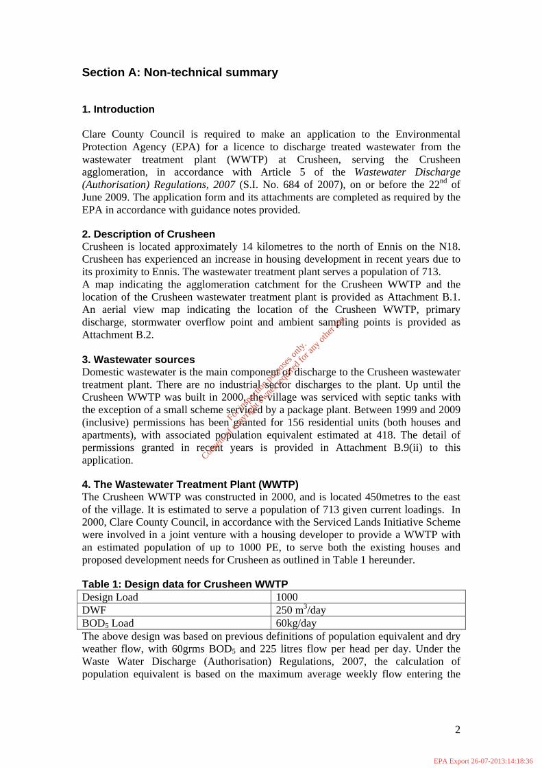
Section A: Non-technical summary 1. Introduction Clare County Council is required to make an application to the Environmental Protection Agency (EPA) for a licence to discharge treated wastewater from the wastewater treatment plant (WWTP) at Crusheen, serving the Crusheen agglomeration, in accordance with Article 5 of the Wastewater Discharge (Authorisation) Regulations, 2007 (S.I. No. 684 of 2007), on or before the 22nd of June 2009. The application form and its attachments are completed as required by the EPA in accordance with guidance notes provided. 2. Description of Crusheen Crusheen is located approximately 14 kilometres to the north of Ennis on the N18. Crusheen has experienced an increase in housing development in recent years due to its proximity to Ennis. The wastewater treatment plant serves a population of 713. A map indicating the agglomeration catchment for the Crusheen WWTP and the location of the Crusheen wastewater treatment plant is provided as Attachment B.1. An aerial view map indicating the location of the Crusheen WWTP, primary discharge, stormwater overflow point and ambient sampling points is provided as Attachment B.2. 3. Wastewater sources Domestic wastewater is the main component of discharge to the Crusheen wastewater treatment plant. There are no industrial sector discharges to the plant. Up until the Crusheen WWTP was built in 2000, the village was serviced with septic tanks with the exception of a small scheme serviced by a package plant. Between 1999 and 2009 (inclusive) permissions has been granted for 156 residential units (both houses and apartments), with associated population equivalent estimated at 418. The detail of permissions granted in recent years is provided in Attachment B.9(ii) to this application. 4. The Wastewater Treatment Plant (WWTP) The Crusheen WWTP was constructed in 2000, and is located 450metres to the east of the village. It is estimated to serve a population of 713 given current loadings. In 2000, Clare County Council, in accordance with the Serviced Lands Initiative Scheme were involved in a joint venture with a housing developer to provide a WWTP with an estimated population of up to 1000 PE, to serve both the existing houses and proposed development needs for Crusheen as outlined in Table 1 hereunder. Table 1: Design data for Crusheen WWTP Design Load 1000 DWF 250 m3/day BOD5 Load 60kg/day The above design was based on previous definitions of population equivalent and dry weather flow, with 60grms BOD5 and 225 litres flow per head per day. Under the Waste Water Discharge (Authorisation) Regulations, 2007, the calculation of population equivalent is based on the maximum average weekly flow entering the
2
For
insp
ectio
n pur
pose
s only
.
Conse
nt of
copy
right
owne
r req
uired
for a
ny ot
her u
se.
EPA Export 26-07-2013:14:18:36

wastewater works during the year and measurement of organic biodegradable load for this flow, allowing 60g of BOD5 per head of population. 5. Treatment Process Description Crusheen WWTP operates as an activated sludge process, and consists of the following elements:
Inlet Sump Inlet screening, fitted with screening removal and bypass Balance Tank Aeration tank Settlement tank with sludge collection hopper Sludge Holding Tank Administration control house
5. Inlet Sump Foul flows are directed initially to the inlet sump before being fed through the inlet screening process. During periods of heavy rainfall a storm water overflow facility from the Crusheen WWTP is provided at this point. The stormwater discharge is designated SW2 on the maps accompanying the application. Any such overflow discharges to the stream located to the east of the WWT P site. 5.2 Inlet Screening An Automatic Screening Conditioning Equipment, ACE 490, manufactured by Haigh Engineering, is fitted on the inlet line at Crusheen WWTP. The function of the system is to screen raw sewage, depositing inorganic material into a collecting bin, while allowing the filtered sewage to flow into the treatment plant. A screen bypass is provided to divert overflow directly to the balance tank. Inlet flow is monitored downstream of the screen. 5.3 Balance Tank A balance tank of 135m3 capacity is provided with a maximum inflow rate of 6 DWF. Solids in the tank are kept in suspension by means of an ABS mixer RW 3021 to prevent the tank becoming a primary settlement tank. Flow from the balance tank is pumped at a rate of 2 DWF to the treatment plant. 5.4 Aeration Basin. The aeration tank is constructed above ground, with a reactor volume of 145m3. This provides a retention time of 13.9 hours. The aeration system used is a Didier Disc Diffuser Nerox MP 340. The aerated effluent transfers via a baffled area to prevent surge overflow to the settlement tank. 5.5 Settlement Tank
3
For
insp
ectio
n pur
pose
s only
.
Conse
nt of
copy
right
owne
r req
uired
for a
ny ot
her u
se.
EPA Export 26-07-2013:14:18:36

The settlement tank is constructed above ground with 49m3 capacity and a retention time of 3 hours. The effluent passes (via a 150mm diameter pipe) from the aeration tank to the final settlement tank. The inlet pipe to the settlement chamber is laid under the tank in the center and rises up toward the top water level. The final settled effluent flows over a weir, located all around the periphery of the tank. A rotating bridge operates around the tank. The final clarified effluent discharges directly to a local stream located to the east of the WWTP. This stream drains to Inchicronan Lough situated to the south of Crusheen. A site layout map is provided as Attachment B.3 and the map indicating both the location of the treatment plant and the main discharge points to surface water is provided as Attachment B.2. The treated wastewater discharge is the primary discharge, and is designated SW1 on the maps accompanying the application. 5.6 Sludge Holding Tank Settled sludge is drawn by pipe from the central sludge hopper, back to the aeration tank or to the sludge holding tank where sludge can settle out further. Sludge is removed by tanker to Inagh WWTP for further processing. 5.8 Administration Control House The control room is housed in the administration building on site. The control room houses the main control panel for the treatment plant monitoring pumps and recording systems and basic office facilities provided therein. Daily record sheets with flow data and sludge handling details are maintained on site. In-process monitoring and final effluent monitoring is undertaken on a once per month basis at the plant, to provide appropriate control of the facility performance. The WWTP is manned by one part-time operative and an environmental technician on a part-time basis (Monday to Friday) and a part-time basis at the weekends. 6. Wastewater Flow volumes There is evidence of direct inflows from storm water in the flow data for the Crusheen WWTP. Flow records for the year 2008 and for the period January to March 2009 have been examined. The flows recorded are provided in Attachment E-1. Based on influent BOD measurement, this provides a population equivalent of 713. The total hydraulic load arriving at the Crusheen WWTP was calculated by measurement of the maximum average weekly load flow for March 2009, and this measurement was used to estimate the final population equivalent, based on the average influent BOD values for 2007/2008. The estimated maximum average weekly flow value arriving at the treatment works is 114m3 per day, with an average BOD of 369 mg O2/litre. The population equivalent for this loading is 713. This approach to estimation of population equivalent is in accordance with the definition provided in the Waste Water Discharge (Authorisation) Regulations, 2007 (“population equivalent” is a measurement of organic biodegradable load and a population equivalent of 1 (1 p.e.) means the organic biodegradable load having a five-day biochemical oxygen demand (BOD5) of 60g of oxygen per day; the load being calculated on the basis of the maximum average weekly load entering the waste water works during the year, excluding unusual situations such as those due to heavy rain). 7. Combined storm overflows A storm overflow facility is provided at the inlet sump delivering wastewater flow to the Crusheen treatment plant. The storm overflow facility discharges to a local stream
4
For
insp
ectio
n pur
pose
s only
.
Conse
nt of
copy
right
owne
r req
uired
for a
ny ot
her u
se.
EPA Export 26-07-2013:14:18:36

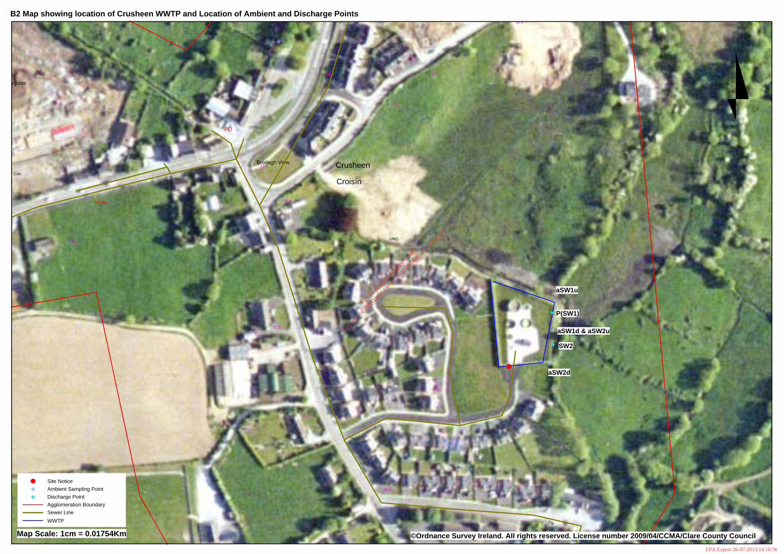
located to the east of the WWTP and drains in an easterly and then southerly direction towards Inchicronan Lough. The stormwater discharge is designated SW2 on the maps accompanying the application. No storm overflow was observed at the time of sampling, however samples of both upstream and downstream of the outfall point were taken during the preparation of this application and results of this exercise are set out in Table F.1 (ii) a of the application form. 8. Impact of emissions from the Crusheen WWTP on the receiving waters The impact of discharges from the Crusheen WWTP on the receiving waters is considered under a number of headings:
8.1 Description of receiving waters 8.2 Statutory Designations of the Receiving Waters 8.3 Assimilative capacity of the receiving waters 8.4 Total maximum nutrient load discharging to receiving waters 8.5 Monitoring undertaken on receiving waters 8.6 Impact of storm overflows
8.1 Description of receiving waters The outfall from Crusheen WWTP discharges to a local stream, which drains in an easterly and then southerly direction to Inchicronan Lough. This area includes several interconnected lakes and streams, where Inchicronan Lough is the largest lake in the area measuring 1.17 km2. Inchicronan Lough (Code 27-126) is situated to the south of Crusheen and to the east of Ballyline Lough (Code 27-63). Inchicronan Lough drains into the Millbrook River, which is included in the catchment of the River Fergus and of the Shannon River Basin. The Millbrook River is included in the EPA hydrometric and biological monitoring programs (Code 27M03). The catchment area of 18.24 hectacres is primarily well draining agricultural lands. There are no downstream abstractions of water for potable supplies or for agricultural purposes, with the exception of a small private well in Carrahill to the north-west of the lake. The most recent classification of trophic status for Inchicronan Lough is Mesotrophic as assigned in the report Lakes of County Clare Monitoring Report 2000-2001 carried out by TCD in November 2001. The river water quality downstream of Inchicronan Lough on the Millbrook River at Site No. 27M031100 is classified with a Q value of 4 in the most recent monitoring conducted in 2004 by the EPA The overall interim water quality status for the Inchicronan Catchment, which includes the area downstream of Crusheen WWTP, has been classified by the EPA as Good water quality status. 8.2 Statutory designations of Inchicronan Lough There are no sites designated as Special Areas of Conservation (SACs) and Special Protection Areas (SPAs) or Natural Heritage Areas (NHAs) in the vicinity of Inchicronan Lough. It is noted that a designated NHA Site (Code 000038) is proposed, which includes Inchicronan Lough, Inchicronan Island and the area immediately south of the lake. 8.3 Assimilative capacity of receiving waters The outfall from Crusheen WWTP discharges to a local stream, which drains in an easterly and then southerly direction to Inchicronan Lough. The impact of the discharge from the Crusheen WWTP on the receiving water was assessed in terms of
5
For
insp
ectio
n pur
pose
s only
.
Conse
nt of
copy
right
owne
r req
uired
for a
ny ot
her u
se.
EPA Export 26-07-2013:14:18:36

the impact on water quality on Inchicronan Lough rather than the local stream. In assessing the assimilative capacity of the receiving water reference is made to the Department of the Environment, Heritage and Local Government, National Urban Waste Water Study – Methodology for Receiving Water Capacity. Recent monitoring results indicate that Inchicronan Lough is classified as mesotrophic and when the criteria for calculating surface water ecological status and ecological potential as outlined in the Draft European Communities Environmental Objectives (Surface Waters) Regulations, 2008, then the water quality in Inchicronan Lough is considered to be Good to Moderate. In accordance with the above mentioned methodology, where the water quality in a lake is found to be currently of an acceptable standard (not in need of improvement), it is considered to have sufficient assimilative capacity for current discharges. Estimates of the volume, inflows to the lake and total nutrient loads to the lake are provided in Attachment A-8 to this application. 8.4 Total maximum nutrient load discharging to receiving Waters Analytical data for the wastewater discharge from the Crusheen WWTP is available on a bimonthly basis for several years, up to an including March 2009. The influent and effluent streams are monitored for biochemical oxygen demand (BOD), chemical oxygen demand (COD), and suspended solids (SS). Results for 2008 are used for this application. Table 2: Estimated nutrient load from Crusheen WWTP to Inchicrionan Lough
Average flow = 114m3/day; SS; suspended solids; BOD: biochemical oxygen demand; COD: chemical oxygen demand;
Date BOD (kg/day)
COD (kg/day)
SS (kg/day)
13/02/2008 11.4 18.0 7.9 29/05/2008 4.3 9.0 3.9 12/06/2008 2.3 7.8 1.4 01/07/2008 0.9 6.2 1.0 01/10/2008 2.5 4.4 1.6 10/12/2008 1.8 2.3 1.8 17/12/2008 1.4 2.9 0.7
Average 3.5 7.2 2.6
Flow data for the influent load to the plant are recorded daily. These flow records indicate the range of flow volumes through the system is 41 - 839 m3/day, with very high flow data been recorded during heavy rainfall episodes. The calculation of discharge load uses the average maximum flow data readings for January to March 2009 to present the typical discharge load from the facility. This approach takes account of the requirements of the Waste Water Discharge (Authorisation) Regulations, 2007 in relation to calculation of population equivalent, “population equivalent” is a measurement of organic biodegradable load and a population equivalent of 1 (1 p.e.) means the organic biodegradable load having a five-day - 16 - biochemical oxygen demand (BOD5) of 60g of oxygen per day; the load being calculated on the basis of the maximum average weekly load entering the waste water works during the year, excluding unusual situations such as those due to heavy rain” The discharge of the treated waste stream is used to assess the impact of the discharge on the receiving waters for biochemical oxygen demand (BOD) chemical oxygen
6
For
insp
ectio
n pur
pose
s only
.
Conse
nt of
copy
right
owne
r req
uired
for a
ny ot
her u
se.
EPA Export 26-07-2013:14:18:36

demand (COD) and suspended solids (SS) to waters. The nutrient discharge load is synopsised in Table 2 above, based on the estimated maximum flow readings and mean analytical values for the dates presented. 8.5 Monitoring undertaken on receiving waters There is no ongoing monitoring of Inchicronan Lough undertaken at present. The most recent monitoring data for Inchicronan lake is provided in Tables 3 and 4 below and is taken from reports titled Lakes of County Clare Monitoring Report 2000-2001 carried out by TCD in November 2001 and from the E.P.A. Water Quality in Ireland Report 2001-2003. The results indicate that Inchicronan Lough is classified as mesotrophic and in accordance with the Water Framework Directive, it is considered to be of Good Quality status. Table 3. Monitoring Data for Inchicronan Lough 2000/2001 Date 08/01/00 04/01/01 06/01/01 08/01/01 09/01/01 2000/2001 Parameter Units Mean Rainfall mm 78.3 107.3 63.4 96.0 56.1 80.23 Temp O C 10 15 13 No3N mg/l 0.04 0.30 0.2 0.05 0.06 0.13 TN mg/l 0.57 0.6 0.74 0.72 0.63 0.65 TDOC mg/l 6.6 7.8 10.1 8.6 8.28 TP µg/l 22.9 19.0 27.1 24 17.5 22.10 Chla µg/l 16 7.7 2.3 17.2 6.5 9.94 PH pH unit 8.21 8.07 8.15 7.99 7.76 8.04 Alk mg Caco3/l 147 122 142 127 135 134.60 Cond. in µS/cm 358 279 312 283 302 306.80 Colour in PtCo 26 47 31 39 28 34.20 Turb. in NTU 1.17 3.78 3.1 6.1 5.8 3.99 Lakes of County Clare Monitoring Report 2000-2001 carried out by TCD in November 2001 Table 4. EPA Monitoring Data for Inchicronan Lough -2003 No 295 Lake Inchicronan Location Co. Clare Sampling Agency L.A./ERTDI Year of Examination 2001 Sampling Frequency pa Four Surf Area km2 1.17 Tot.-P Chlorophyll ug/l Mean Max 17.2 Water Transp Min Mean
Trophic Status M Beneficial Uses None identified Recent Changes: Overal Status M EPA Water Quality in Ireland Report 2001-2003 Clare County Council, during the course of preparing the application for a discharge authorisation, under the Wastewater Discharge (Authorisation) Regulations 2007, (S.I No 684 of 2007) for the Crusheen WWTP, to the EPA assessed the Crusheen
7
For
insp
ectio
n pur
pose
s only
.
Conse
nt of
copy
right
owne
r req
uired
for a
ny ot
her u
se.
EPA Export 26-07-2013:14:18:36

agglomeration to identify any facility liable to generate substances listed in Annex X of the Water Framework Directive (2000/60/EC) or relevant pollutants listed in Annex VIII of the Water Framework Directive. Monitoring for these substances was undertaken in April 2009 and results on this monitoring do not indicate any substance on the list was present in the receiving waters both upstream and downstream of the discharges from the Crusheen WWTP (see Attachment F.1). No potential source of these pollutants has been identified in the sewer catchment, so it is unlikely that the discharge will contain the listed substances. Results from the survey will be collated and included in the licence application data as soon as may be on receipt of the results of the sampling exercise. In conclusion, there is no indication of significant deterioration in quality status of the receiving water in the vicinity of the discharge from the treatment plant or of the water quality in Inchicronan Lough. 8.6 Impact of storm overflows A storm overflow is located at the inlet sump to the Crusheen WWTP. During very heavy rainfall episodes there is potential for overflow from the system. Any such overflow discharges to a local stream located to the east of the WWTP site, which drains in an easterly and then southerly direction towards Inchicronan Lough. Sampling of this drain was undertaken on April 15th 2009, during the course of preparing the licence application. Results from the survey will be collated and included in the licence application data as soon as may be on receipt of the results of the sampling exercise. No complaints have arisen in connection with this overflow. 9. Proposed technology for improving emissions from WWTP There are no proposals for upgrading of the wastewater treatment facilities for the Crusheen WWTP. 10. Measures planned to monitor emissions into the environment Provisions for monitoring emissions from the wastewater treatment plant are in place at the Crusheen WWTP. A full time laboratory technician is employed to cater for the operational requirements in terms of monitoring at the Crusheen treatment plant. Monitoring of influent and effluent wastewater streams is undertaken on a monthly basis for the parameters biochemical oxygen demand (BOD), chemical oxygen demand (COD) and suspended solids (SS). Methods of analysis and sampling procedures are provided in Attachment E.2 of this application. Sampling is currently undertaken as grab sample for both the influent and effluent streams. ________________________________________________________________
8
For
insp
ectio
n pur
pose
s only
.
Conse
nt of
copy
right
owne
r req
uired
for a
ny ot
her u
se.
EPA Export 26-07-2013:14:18:36

Attachment A.2
Flow Diagram for Crusheen Waste Water Treatment Plant
For
insp
ectio
n pur
pose
s only
.
Conse
nt of
copy
right
owne
r req
uired
for a
ny ot
her u
se.
EPA Export 26-07-2013:14:18:36

Flow Diagram for Crusheen Waste Water Treatment Plant
Sludge Return
ACE Screen
Inlet Sump
Balance Tank
Clarifer
Aeration Tank
Sludge Holding
Tank Sludge removed off-site by tanker
Outlet weir to River
For
insp
ectio
n pur
pose
s only
.
Conse
nt of
copy
right
owne
r req
uired
for a
ny ot
her u
se.
EPA Export 26-07-2013:14:18:36

Attachment A.3
Assimilative Capacity of Inchicronan Lake
For
insp
ectio
n pur
pose
s only
.
Conse
nt of
copy
right
owne
r req
uired
for a
ny ot
her u
se.
EPA Export 26-07-2013:14:18:36

Assimilative Capacity of Inchicronan Lake
Volume of receiving waters = 7547900 m3
Surface area of lake = 1.17 km2
Mean Depth = 6.48 m
Catchment Area = 18.24 ha
Discharge volume from WWTP facility = 114 m3/day
Water Quality of receiving Water Mean 2000/2001 data (Report Lakes of County Clare Monitoring Report 2000-2001 carried out by TCD) Parameter Trophic Status Chla Chla TN TP (annual Max ) (Mean) (Mean) (Mean)
Mesotrophic 17.2 9.9 0.65 22.1
Ecological Status: Good-Moderate 10
Target Water Quality of receiving Water Parameter Trophic Status Chla TN TP Oligotrophic >2.5<8 n/a >5<10 Ecological Status: High-Good (5.8)
BOD Susp Solids COD Ammonia TP TN Average Daily load 3.5 2.6 7.2 ----No Data---- discharged from the Kilkishen WWTP as kg/day There are no proposals in place to increase the discharge from the plant.
For
insp
ectio
n pur
pose
s only
.
Conse
nt of
copy
right
owne
r req
uired
for a
ny ot
her u
se.
EPA Export 26-07-2013:14:18:36

CW
CR
CF
UND
31.9
35.9
37.9
40.4
UN
D
42.3
38.9
10K
v
27.4
CS
27.4
CR
School
29.3
CR
34.6
Inchicronan
CD
37.5
Crusheen
CW
Croisín
PO
37.5
32.5
36.8
Brodagh View
31.7
Moyglass
Burial Ground
34.4
Sports Ground
GS Sta
10Kv
CW
Area under Con.
CW
CF
Killaveinay
CW
40.1
CR
UND
38.0
CP
39.6
UND
(Cath)
CR
CF
CRUSHEEN
37.4
Church
UN
D
34.5
LevelCrossing
34.8
Pond
CF
CR
Cave
36.3
CR
CF
35.9
34.8
34.3
Giant's 38.3
CR
Grave
37.0
10Kv
©Ordnance Survey Ireland. All rights reserved. License number 2009/04/CCMA/Clare County Council Map Scale: 1cm = 0.04422Km
B1 Map showing Agglomeration Catchment served by Crusheen Waste Water Treatment Plant, and Location of WWTP
WWTPAgglomeration BoundarySewer LineSite Notice
Crusheen
een
II Y
•
HI.2m
hie ~C,---
.......• a
!--- .. • ~...--II
een
II Y
•
HI.2m
hie ~C,---
.......• a
!--- .. • ~...--II
For
insp
ectio
n pur
pose
s only
.
Conse
nt of
copy
right
owne
r req
uired
for a
ny ot
her u
se.
EPA Export 26-07-2013:14:18:36
CW
CR
CF
UND
31.9
35.9
37.9
38.9
CRCR
CD
37.5
Crusheen
CW
Croisín
PO
37.5
32.5
36.8
Brodagh View
31.7
yglass
GS Sta
10Kv
r Con.
SW2
P(SW1)
aSW2d
aSW1d & aSW2u
aSW1u
Map Scale: 1cm = 0.01754Km ©Ordnance Survey Ireland. All rights reserved. License number 2009/04/CCMA/Clare County Council
B2 Map showing location of Crusheen WWTP and Location of Ambient and Discharge Points
WWTPSewer LineAgglomeration BoundaryDischarge PointAmbient Sampling PointSite Notice
For
insp
ectio
n pur
pose
s only
.
Conse
nt of
copy
right
owne
r req
uired
for a
ny ot
her u
se.
EPA Export 26-07-2013:14:18:36

Attachment B.3
Crusheen WWTP Site Layout Plan
For
insp
ectio
n pur
pose
s only
.
Conse
nt of
copy
right
owne
r req
uired
for a
ny ot
her u
se.
EPA Export 26-07-2013:14:18:36

For
insp
ectio
n pur
pose
s only
.
Conse
nt of
copy
right
owne
r req
uired
for a
ny ot
her u
se.
EPA Export 26-07-2013:14:18:36

CW
CR
CF
UND
31.9
27.4
CR
School
29.3
CR
34.6
CD
CW
Croisín
32.5
36.8
31.7
34.4
und
Sta
UND
FiaFulacht
Fulacht
Enclosure
Fia
School
OLD RHO WWTP
Approximate Line of Rising main to public foul sewer
Public foul sewer
WWTP
B.4 Map showing location of the pumping Station and Old RHO WWTP in Crusheen
Scale: 1: 2500
Sewer Line
Pumping Station
Old Crusheen WWTP Site
For
insp
ectio
n pur
pose
s only
.
Conse
nt of
copy
right
owne
r req
uired
for a
ny ot
her u
se.
EPA Export 26-07-2013:14:18:37

Attachment B.6
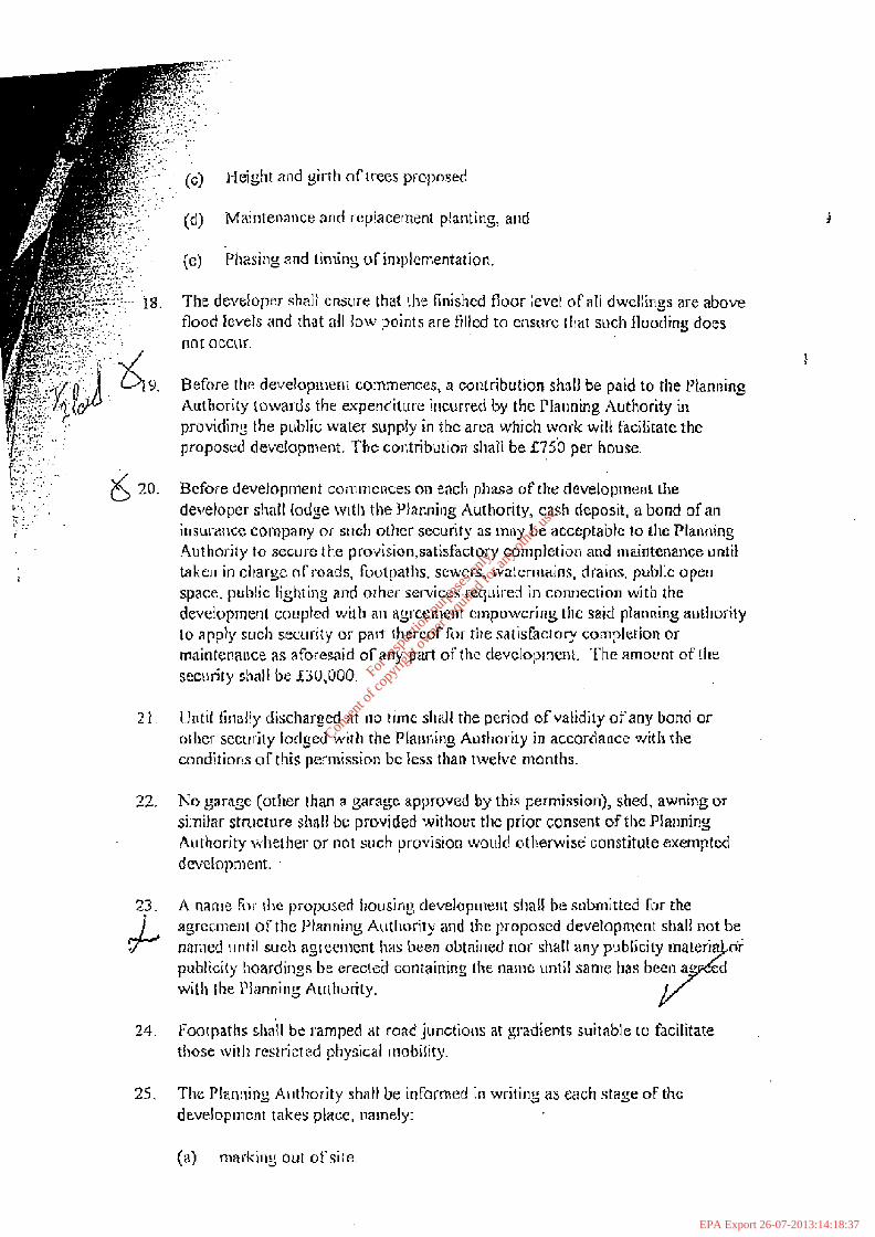
Conditions of Planning for Crusheen WWTP
For
insp
ectio
n pur
pose
s only
.
Conse
nt of
copy
right
owne
r req
uired
for a
ny ot
her u
se.
EPA Export 26-07-2013:14:18:37

. . .
CLARE COUNTY COUNCL
G o V E K N ~ T - E N ~ ~ (PLANNING AND DEVELOPXI ENT) ACTS, 1963 ICA?'IOK OF GRAN'T FOR PERMlSSION (SUBJECT TO
ONS)-UNUKK SECTION 2fi 01: THE ACT OF 1963, A$ AMENDED __e_C-C-------f---------------------.------------,------------------h-h----+-+--- - *
in Constnlction (Barefield) T,td., Referer~ce No. in Plnlln ir~g Rcgis tcr: P98/ 1672
Applicntiorl I-cccived:30/10/98
F~trther In To. reccivcd: 19/1/99, y*;$:,:; : , , t, x .<.:.%.*,; -., .. , , , 2/2/99, 1 1/3/99, 2 1/4/99 &
2 .'+ ; . . p;,; . .' .. , - , .-.-. 18/5/93 Rc 10/6/99
.<. C :. C: ,-,, - -... 2 " '
& . .. ~ ~ ~ l i c a l i o n of G n l v i n Consiruction (Barefield) T . t d , n f J o h n Gulvio , -.. .,;:,-. - ' , :!.: r re field, Enuis , Cu. Clare for permission L-.: r : , .' . , r - . ,.*- . '
\ L , -,:: ' , i to constn~ct 26 houses, sewage treatment pIant and ancillary sitc wol-ks ar Crusf~een,
\ , :- ' . ,-
Ca. Clnre In a~curdance with plans submitted on 10th Octobcr, I998 and further !: :,, !; , . ' ,-
: -. ' ,:. L . ,. . . i r ~ f ~ r ~ n t z t i o ~ ~ s~lbruirtcd on 19tI1 January, 1999 and 2nd Fcbntary, 1999, 1 I th March, . , - 1999, 2 1st .April, t ri99, 1 Slh May. 1999, as amended by letter submitted on 10th June, - * . . ! ' ...
l999 withdr~~ving applicaliol~ for two hn~rses on Sitcs 22 and 23. . ,
1; . . .. . -
A permission ltas becn gl-antsd T ~ I . the d c v e l o ~ ~ n ~ e n t described abovc, subject to b . ,
. . , . tllc fbllawir~g 33 cor~difiar~s:-
- , , , . 1. The roads and footpatlls sliall be ~onstnicted to the Planning Autliority's , , satisfaction in accordnncc with rile Recommendations for Site Development
Works for 31ousi11g Areas' of An Foras Forbartha, ( 1 934)
2. Rnad gradients, jurlc;~io~~ I-adii, camber and cross fall shall be in accordance with the "Recnm~ncnda~ioi~s for Site Development Works in Housing AI-asr of An Foras For-hat-I ha, except that t be ~ninimum longitudinal ~ r a d i e ~ ~ ~ shall be 11 150.
3 . Hydra~lls shaI! be provided by the developer as follows. -
(a) AIlhydranrsshallcon~plywithB.S.No. 750(1984)forUnder2roundFire Idydrarcts and shall be witably Iocated CJII a footpath, grass margin, etc., and fitled with a nominal 62.5mm male round threaded outla (see attached diayram).
Fir-e hydratits shal l be posilioned in suclt a way that; 1 . Area witllirl one nletre of hydrants is clear of all abstluction. 2. 7'he parking, luading 2nd unloading of vehicles is unlikely to obstnict the117. WIlcrc necessary, stlc11 dot~ble flanged distar~ce pieces shall be provided l a 1oci:ic thc isolating spindle ofthe h y d r a ~ ~ t within 1501nn1 below the C.I. st~rface box cover.
(b) Ourlct-s stmll be llot lnorc than 300nlm bclow finished grour~d level.
,.,. '
"
.'
ApplicatiOil rcccivecl~30JIO/98
Further Info. r('.('~jvcd: 19/1/99,2)2/99, 1113/99, 21/4/99 &I g/Sf99 & 10/6/99
Application of Galvin Const rue! iOIl (Barefield) Ltd., ofJa h n Gulvin,Barf,field, Ennis, Co. Clare for permissionto constl1Jct 26 houses, sewage treatment plant and ilncillary site works at Crusheen,Co. Clare i~dance with plans Sllbmilted on 30tb October, [998 and fu·rtherin(ormatiolJ submitted on 19th January, 1999 nod 2nd F"cbruary, 1999, I Ith March,1999,2 1st April, 1999, ISih May, 1999, as amended by letter ~ubmitted on JOtl1 June.[999 withdrawing appl;cation fOT two houses on Sites 22 <lnd 23.
A permlssion has becn gl'nntr.d fo,' the developmcnt desuibed abov~ subject to
the following 39 conditions:-
1. The roads and footpaths shall be I,;onstnlcted to the Planning Authority'ssatisfClction in accordance with the Recommendations for She nevelopmcntWorks for 'Hollsing Areas' or An Foras Forbartba, (1984)
2. Road gradients, jL1ll0liol1 radii, camber and cross fall shall be in accordance withthe "Recommendations for Site Development Works in Housing Areas' of AnFora:; Forhan ha, except that the minimum longitudinal gradient shall be t/150.
3. Hydrants shall be provided by the developer as follows. -
(a) All hydrants shall comply with B.S. No. 750 (1984) for Underground FireHydrants and shall be !;t1itably located on a footpath, grass margin, etc.,
. and fitted with a nominal 61.5mm male round threaded outlet (see attacheddiagram).
Fire hydrants shall be pm.itioned in such a way that:I. Area within one mdre of hydrants is clear of all obstruction.2. The parking, loading l1nd unloading of vehicles IS unlikely toobstruct them.Where necessary. such double flanged di~tance pieces shall be providedto lQc(~lc the isolating spindle of the hydrant within i SOmnl below theC.l.surface box cover.
(b) Outlets shall be not more th~Hl 300mm below finished ground level.
For
insp
ectio
n pur
pose
s only
.
Conse
nt of
copy
right
owne
r req
uired
for a
ny ot
her u
se.
EPA Export 26-07-2013:14:18:37

dicalor plates shall conform to B.S. 325 1 : 1976 and can be made of vitreous enanlelled nlild sreel cast iron alu~ninium alloy or plastic. TIle plates are of standard dimensions, ycliow in colour with the-letter T-I and the digits in black. The figure appearing on the top aperture denotes the t~omil~al size of the main in n>ilIitnetres and the lower one the distance in metres betweeu the indicator plate and the hydrant.
(d) Shalt be so s~laced that no bi~ilding is more than 1 50ft (45.72m) through free access from one and no1 more than 100m apart. The minimum distance bet~vee11 hydrant and building s t~a l l be 6m.
c:. . '. . *. 1,:.
7 .., ,. (e) Pipe sizes and general hydraulics shall be sucll that a discharge of 250 , , gallons per n i inute at 10 pounds per square inch is obtainable at each
hydrant (Confirmation of (e) shall be furnished.)
4. A sufficient number of suitably spaced and located road gullies shall be provided on the roads. The ~ u l l i e s shall be connected to the surface water disposal system. The Recomn~endations for Site Development Works for 'Housing Areas' of An Foras Forbartha, ( t 954), shall be taken into accoitrlt in the design of this system.
5 . All sr~rface water- fro111 roofs and paved areas sl~all be discharged to the surface water disposal syslein and [lo surface water shall be dischar~ed to a foul sewer or be permitted to flow onto thc public roadway or adjoining property.
6. Pitbiic lightins shall be l~rovided to facilitate each dwelling house when occupied and the developer shall switch o n the public lighting as dwellirlg ]louses are occr~pied and sliall maintain the public ljgl~titlg until taken in cliarge by the Council.
7. The public lighting shall be provided in accordance with a to be agreed. Before the developrncnt is commenced the shall be submitled to the Planning Authority for agreement.
8. The lighting columns for the public lighting system shall be constructed of 3.2mm ~ninirntln~ steel hot dip galvanised.
9. Electricity and telephone se~vices shall be laid underground. Provision shall be made for the underground installation of cable television service. l 'his work sllnll be carried out prior to road surfacing and junction boxes shall be provided by the developer.
10. Ail the main foul, surface water sewers and public water mains sllall be laid in roads or pitblic al~en spaces and no sewers or watermains other than individual housc coll~~ections shall be laid it] any private properly other than with the prior written consent of the Planning Authority.
11. Road gradients, junction radii, camber a ~ l d cross fall shall be i11 accordance with the Recom~neudations for Site Develop~nent Works in Housirlg Areas of An
4.
5.
6.
f57.
8.
9.
10.
11.
.Hydrant indicator plates shall conform to B.S. 3251: 1976 and Can bemade ofvitreoLls enamelled mild sleel cast iron aluminium alloy or plastic.The plates are of standard dimensions, yellow in colour with the-Jetter J-Iand the digits in black. The figure nppearing on the top aperture denotesthe nominal size ortbe main in millimetres and the lower one the distancein metres between the indicator plate and the hydrant.
(d) Shall be so spaced that no building is more than 150ft (45.72m) throughfree access from one and nol more than 100m apart. The minimumdistance between hydrant and building shall be 6m.
(e) Pipe sizes and general hydraulics shall be such that a discharge of250gallons per minute at 10 pounds per square inch is obtainable at eachhydrant (Confirmation of (e) shall be furnished.)
A sufficient number of suitably spaced and located road gullies shall be providedon the roads. The gullies shall be connected to the surface water disposalsystem. The Recommendations for Site Development Works for 'Housing Areas'of An Foras Forbartha, (1984), shall be taken into account in the ~esign of thissystem.
All surface water ii·om roofs and paved areas shall be discharged to the surfacewater disposal system and no surface water shall be discharged to a foul seweror be permitted to flow onto the public roadway or adjoining property.
Public lighting shall be provided to facilitate each dwelling house when occupiedand the developer shall switch on the public lighting as dwelling houses areoccupied and shall maintain the public lighting until taken in charge by theCouncil.
T.he public lighting shall be provided in accordance with a public ligh . Ig designto be agreed. Before the development is commenced the public lin ting designshctll be submitted to the Planning Authority for agreement.
The lighting columns for the public lighting system shall be constructed ofJ.2mm minimum steel hot dipgalvaniscd.
Electricity and telephone services shall be laid underground. Provision shall bemade for the underground installation of cable television service. This workshall be carried out prior to road surfacing and junction boxes shall be providedby the developer.
All the main foul, surface water sewers and public water mains shall be laid inroads or public open spaces and no sewers or watermains other than individualhouse connections shall be laid in any private properly other than with the priorwritten consent of the Planning Authority.
Road gradients, junction radii, camber and cross fall shall be in accordance withthe Recommendations for Site Development Works in Housing Areas of An
For
insp
ectio
n pur
pose
s only
.
Conse
nt of
copy
right
owne
r req
uired
for a
ny ot
her u
se.
EPA Export 26-07-2013:14:18:37
eight and girt11 of trees propnsed
(d) Mainter~ailce and replacement planting, a j ~ d
{el Pllasil~g and liming of inq,lcn~entation.
The developel- shall cnsrrre that I l~e finlshcd flour level of a11 dwcllin~s are above flood levels and that a41 low points are filled to ensrrre that such flooding does noc accur.
9. Before the develapolenr commences, a cotltribution shall be paid to the Pianning Authority fowards the exper1diiur.e incurred by the PIauning Authority in providin~ the piihli~ water supply in thc arca which work will facittate the proposed development. The co~~tribulion sliail be ~ 7 5 ' 0 per house
LG-; ,; ' - -. , 2 ) . -:-,;, . . - , ,.+,:: A . . -
& 20. Bcfore development cornmcnces a) each phase of the dcveloprnent the I,'.: ', ' , - . .- developer sl~afl Iadge with the Plannil~g Au~hority, cash deposit, a bond of an 2 :: . .. , . it~srrt-it~lcc cotnpany or sttch other security as may be acceptable to the Planiling
Authority to secure the provision,satisfacto con~pletioo and maintenance until take11 in charge of roads, footpaths, sewers, rvatcrn~ains, drains, public ope!] space. public lighting and other services required in connection with the devclopme~~t coupled with an agreement cmpowcrir~g the said planning a u ~ l ~ o r h y to ap$y such security or part thercof fur rile satisfacto~y ~ornpletion or maintet~ance as sfwesaid or any part or" the devcloptne~~t. .The amount of ille sectlrity shall be f 30,000.
2 1 . Until f i~~s l ly disd~arged at no tsmc sltall the perind of validiiy of any bond or other security lodged with the Planning Authori~y in accordance with the conditions of this permission bc less than twelve months.
22. KO garase (otIter than a garagc approved by this permissior~), shed. awning or similar s tnlcture shall be provided without the prior consent of the PImning Authority whether- or not stlelr provision ruould otherwise constitute exempted developn~ent. .
23. A name For the proposed housing develop~~~ent shaII be submitted Eor the ayccment of the Planning AutIlority and the proposed devetopmcnt sllall not be nanied 11nti1 such agr-eenlent has been obtained nor shatl any publicily huardin~s be erected containing the narnc uniil wit11 the Planning Arrrhority.
24. Footpaths slla'll bc lamped at road junctious at gradients sdtablc to facilitate those wit11 restricted physical mobility.
25. Tl~c PIan!ling A~ithority shall be inhrrned in writins as each s l a p of the dtve!opmcnt takes place, nan~eIy:
(a) markins our oi'site.
~, ' .:
~-;,."=,,".,
:"0.;"'" ~ .."
(c) Height and girth of trees proposed
(d) Mainten~llceand replacernent planting, and
(e) Phasing <tnd timing of implementation.
18. The developer shaH cnSllre that the finished floor level of <ltl dwellings are aboveflood kvels (lnd that nil low points are filled to enSllre tlmt such flooding doesnot occur. '
Before the developll1em commences, a contribution shall be paid to the PlanningAuthority towards the expenditure incurred by the Planning Authority inproviding the Pllhlil: water supply in the an.:a which work will facilitate theproPOSl.::U development. The contribulion shaH be £~5'O per house
6 20. Before development commence:; on eflch phase of the development thedeveloper shaH lodge with tile Planning Authority. cash deposit, a bond of aninsurance company or such otlmr security as may be acceptable to the PlanningAuthority to secure the provision,satisfactory completion and maintenance untiltaken in charge of roads, footpaths, sewers, watcrmains, drain:'>, public opellspace. public lighting and other servic~s rCCjuil"ed in connection witb thedevelopment coupled with an agreement empowering the said planning authorityto ;l pp}y such security or part thereof for rhe sat"lsfactory compldion ormaintenance ~s 3foresaid of any part of the development The amount of lhesecurity sball be £30,000.
21.
22.
23.
~
24.
25.
Until finLllly di:;charged (1t 110 time shall the period ofvalidity of any bond orother security lodged with the Plannil1g Authority in accordance with theconditions of this permission be Jess thall twelve months.
1\0 garage (other than a garage approved by thi.., permission), shed, awning orsimilar stmcH!re shall be provided without the prior consent oftbe PlanningAuthority ",,'helher or not such provision would otherwise constitute exempteddevclopment. .
A name for the proposed housing development shaH be submjtted [or theagreement of the Planning Authority and the proposed development shall not benamed IJntil such agreement has b~ell obtained nor shall any pllblicity materia orpublicity hoardings be erected containing the name until same ha~ beell a" edwith tbe Planning: Authority.
Footpaths shnil be ramped (It road junctions at gradients suitable w facilitatethose with res~rict cd physical Inobility.
The Planlling AI1thority shall be informed in writing as each .<it(lge of thedevelopment t<lkes place, namely:
(a) marking Out of si reo
For
insp
ectio
n pur
pose
s only
.
Conse
nt of
copy
right
owne
r req
uired
for a
ny ot
her u
se.
EPA Export 26-07-2013:14:18:37

(b) of road base.
(=) provision of pipework and ducting.
(d) nlarkirlg o u t of dwellings.
(e) surfacing of roacls and footpaths,
in ordcr that ins~~ect ion of the work in question may be carried out.
dries of rear yarden areas ab~rttirlg any road, footpath or pubiic space shall 7 - . , - . 1. . ?.- . . , be provided wilt1 a screen wall or fence in accordance with a scllerne to be 1,- :.:: , + ,
I"-:
agreed with the I1lanning Authority. This shall be agreed with the Planning ., - . L. .. ., . , . . Autl~ority before developrnent commences.
1 . b. - 27.. No dwelling shall be occupied until watermains, sewers and roadways are & provided to serve that dwelling in accordance with rhe specifications prescribed
by this perrnissioti.
28, All drains within or bounding the proposcd sitc shall be piped in pipes of a diameter to be agreed with the council and in a manner to permit the continued free flow ofwater and shall then bc backfilled.
Means of connectiilg to public watcr system sllall be asreed with the Planning Au t l~ority before developrnent commences.
Either a "Yield Right of Wayy" sign or a "$top" sign together with appropriate 6 30' road nral-kings shall be provided by *he developer ar his own expense at the junctian between the public road and the main access road to the proposed development. Details of (he sign atld road markings to be used shalt be agreed with the Planning Authority pt-ior to provision. '
All external finishes and colour schemes stiall be a p e d wit11 the Planning Autl~ori ty before development commenccs.
32. No llouse i n thc development s l ~ a l l be used for commercial overnight guest accon~rnodation without tile prior approval of the PIanning Authority, notwithstanding that any such use might be considered exempted development bu t for the provisions of this condition.
33. F~ill details of effluent treatment plant to be provided shall be lodged and ay-ccd wilt1 the Co~tnciJ before developl~lcrlt commences.
A
Prov~sion sIla!l be n~ade for cor~tlection of additional develop~nenr land into the treatment works. Details ofsan~e sllall be agreed with the Council before development commences.
27,.
~28,
i 30.
32.
.......oJ.) •
provision of road base.
provision of pipework and dueting,
marking out of dwellings.
(e) surfncing of roads and footpaths,
in order that inspection of the work in question may be carried out.
Boundaries of rear garden areas abt:tting <lny road, footpath or public space shallbe provided with a screen wall or fence in accordance with a scheme to beagreed with tbe Planning Authority. This shall be agreed with the PlanningAuthority before development commences.
No d\velling shall be occupied until watermains, sewers and roadways areprovided to serve that dwelling in accordance with the specifications prescribedby this permission,
All drains within or bounding the proposed site shaH be piped in pipes of adiameter to be agreed with the council and in a manner to permit the continuedfree flow ofwater and shall then be backfilled.
Means of connecting to public water system shall be agreed with the PlanningAuthority before development commences.
Either a "Yield Right of Way" sign or a "Stop" sign together with appropriateroad markings shall be provided by the developer at his own expense at thejunction between the public road and the main access road to the proposeddevelopment. Details of the sign and road markings to be used shall be agreedwith the Planning Authority prior to provision.
All external finishes and colour schemes slmll be agreed with the PhmningAuthority before development commences.
No bouse in the development shall be used for commercial overnight guestaccommodation without the prior approval of the Planning Authority,notwithstanding that any such use might be considered exempted developmentbut for the provisions of this condition.
Full details of effluent treatment plant to be provided shall be lodged andagreed with the Council before development commences.
ProVIsion shall be made for cOllnection of additional development land into thetreatment works. Details of same shall be agreed with the Council b.eforedevelopment commences.
J
For
insp
ectio
n pur
pose
s only
.
Conse
nt of
copy
right
owne
r req
uired
for a
ny ot
her u
se.
EPA Export 26-07-2013:14:18:37

Prior to comlnencement of development on site, the developer shall submit to the Co~incil a copy of a inaintenallce agreement drawn u p between the developer and the suppliers of the proposed foul emuent treatment. Copies of rnaintenancc iilspection and monitoring results shall be submitted to the Planning Authority at agreed t ime intervals.
8
Details of outL11I from effluent treatment system and provision of san~pling cl~arnber sl~all be lodged and agreed with the Cour~cil before development commences.
Existing hedgerowltrees between t11c develop~~let~t and land to the east shall be retained t~nless othet-tvise agreed with the Council.
Details of security to effluent treatment plant shall be asreed with the Council before develop~nent commences. '
The phasing u f the development shall be agreed with the Council before development commences. .
,. ,. ., 1 - . >:.+ ' > ,. ,, . , . . . .. , , , I - . .... . ., -
, . , , ,>. .:., . '
. ,
.- , , . . . .- .. , . SIGNED 0 1 1 bchrtlf o r CIm-t: C O ~ I I I ~ ~ Colrr~cil:
,',; , . .; -, . , , , ..,.. ,
,<. , , - . ,- 9 - . . . 2 -- ..: .. : '... . Stam Officsr, Pinnning Section, - . .. - .. . New Road, Esnis, Co. Clare.
-. m. . , ,
fi; . , -
!;. r., - g..- DATED: 14th J ~ l l y 1999. .. . .
, ~ , F, •
I ..•.• : •
Prior to commencement ofdevelopment on site, the developer shall submit to.' the Council a copy ofa maintenance agreement drawn up between the
developer and the suppliers of the proposed foul effluent treatment. Copies ofmaintenance inspection and monitoring results shall be submitted to thePlanning Authority at agreed time intervals. ,Details of outf.:1.11 from effiucnt treatment system and provision of samplingchamber shall be lodged and agreed with the Council before developmentcommences.
Existing hedgerow/trees between the development and land to the east shall beretained unless otherwise agreed with the Council.
Details of security to effluent treatment plant shall be agreed with the Councilbefore development commences.
The phasing of the development shaH be agreed with the Council beforedevelopment commences.
J
..I ~. ~ •
-r-\:.•••
f...
. ,. ".,
SIGNED 011 behalf of Clare County Council:
[IStaff Officer, Planning Section,New Road, Ennis, Co. Clare.
...;,.-
r::--:;.~ ..;- .;;".,.
DATED: t 4th J Illy 1999.
I
For
insp
ectio
n pur
pose
s only
.
Conse
nt of
copy
right
owne
r req
uired
for a
ny ot
her u
se.
EPA Export 26-07-2013:14:18:37

Attachment B.8 Newspaper Notice
For
insp
ectio
n pur
pose
s only
.
Conse
nt of
copy
right
owne
r req
uired
for a
ny ot
her u
se.
EPA Export 26-07-2013:14:18:37

Newspaper Notice APPLICATION TO THE ENVIRONMENTAL PROTECTION AGENCY FOR A WASTE WATER DISCHARGE LICENCE UNDER THE WASTE WATER
DISCHARGE (AUTHORISATION) REGULATIONS 2007. The applicant, Clare County Council, New Road, Ennis, County Clare, intends applying to the Environmental Protection Agency for a wastewater discharge licence under the above named regulation. The wastewater treatment plant associated with the application, Crusheen Wastewater Treatment Plant, is located at Crusheen, in the Townland of Crusheen, County Clare. The National Grid reference for the wastewater treatment plant is E139971; N187741. The Crusheen Wastewater Treatment Plant comprises preliminary screening, activated sludge treatment, clarifier tank, sludge holding tank with the sludge disposal off site. The final effluent from the domestic wastewater treatment plant discharges to a local stream located to the east of the wastewater treatment plant. The National Grid Reference for the Primary Discharge Point is E139997; N187757. Secondary emergency discharge may also take place from the stormwater overflow pipe at the inlet sump in the Townland of Crusheen, County Clare. The National Grid reference for the secondary discharge is E139998; N187732. A copy of the application for the waste water discharge licence and such further information relating to the application as may be furnished to the Agency in the course of the Agency’s consideration of the application, in such a format as may be determined by the Environmental Protection Agency, shall, as soon as is practicable after receipt by the Agency, be available for inspection or purchase at the headquarters of the Agency and at the principal office of Clare County Council, the relevant water services authority for this application. Submissions in relation to the application may be made to the Agency at its headquarters at the EPA, Office of Climate, Licensing and Resource Use, PO Box 3000, Johnstown Castle Estate, Wexford, Tel: 053 9160600 and Fax: 053 9160699. Signed: Clare County Council, Environment and Water Services, Áras Chontae an Chláir, New Road,
Ennis, Co. Clare. “Insertion in Clare Champion”: 12th June 2009
For
insp
ectio
n pur
pose
s only
.
Conse
nt of
copy
right
owne
r req
uired
for a
ny ot
her u
se.
EPA Export 26-07-2013:14:18:37

The applicant, Clare County Council, New Road, Ennis, County Clare, intendsapplying to the Environmental Protection Agency for a wastewater dischargeflCellCe under the above named regulation. The wastewater treatment plantassociated with the application, Corrofin Wastewater Treatment Plant islocated at Corrofin, in the Towniand of Ballykinncorra North, Corrofin, CountyClare. The National Grid reference for the wastewater treatment plant isE128820; N188545;
The Corrofin Wastewater Treatment Plant comprises of Preliminary screening,Imhoff Tank and Drying Beds. The final effluent from the domestic wastewatertreatment plants discharges via an outfall pipe from the wastewater treatmentfacility to the adjacent River Fergus. The National Grid Reference for the PrimaryDischarge POint at the end of the outfaft pipe is E128874; N188574.Asecondary emergency discharge may also take place from the stormwateroverflow pipe located on the collection system at CorrOOn Bridge in theTownland of Baunkyle, ,(orrOOn, County Clare. The National Grid referencefor the secondary discharge is E12861O; N188594.
The applicant Clare County Council, New Road, Ennis, County Clare, Intendsapplying to the Environmental Protection Agency for a wastewater dischargeficence under the above named regUlation. The wastewater treatmentplant associated with the application, Crtlsheen Wastewater TreatmentPlant is located atCtusheen, in the Townland of Crusheen, County Clare.The National Grid reference for the wastewater treatment plant isE139971; N187741.
Acopy of the dppIication for the waste water discharge licence and slKhfurther information relating to the application as may be furnished to theAgency in the CllUf5e of the Agency's consideration of the application, in sucha format as may be determined by the Environmental Protection Agency,shal, as soon as is practicable after receipt by the Agency, be available forinspection or purchase at the headquarters of the Agency and at the principaloffice of Clare County Council, the relevant water services authority forthis application.
Submissions in relation to the application may be made to the Agency atIts headquarters at the EPA, Office of Climate, Ucensing and Resource UsePO Box 3000, Johnstown Castle Estate, Wexford, Tel 053 9160600 andfax: 053 9160699.
APPUCAnoNS TO THE ENVIRONMENTALPROTECTION AGENCY FOR WASTE WATERDISCHARGE LICENCES UNDER THE WASTEWATER DISCHARGE (AUTHORlSA1l0N>REGULAnoNS 2007.
The Crusheen Wastewater Treatment Plant compri~s prefimlnary screening,actIVated slUdge treatment, danfier tank, sludge holding tank with the sludgedisposal off SIte. The final efftuent from the domestic wastewater treatmentplant discharges to a local stream located to the east of !he wastewater treatmentplant The National Grid Reference for the Primary Discharge Point ist139997; N187757
Secondary emergen<y discharge may also take place from the stolnlwaterOIIel1low pipe at the inlet sump in the Townland of Crusheen, County ClareThe NalJonal Grid reference for the secondary discharge isE139998; N187732
Acopy of the application for the waste water discharge licence and suchfurther information relating to the application as may be fumished to theAgertcy 111 the course 01 tht: Agency's consideration 01 the application, in sucha format as maybe determined by the .EnVironmental Protection Agency,shaH, as soon as IS practicable after recetpt by the Agency, be available forIllspectlon or purchase at the ~dquarters of the Agency and at the principaloffice of Clare County Council, the relevant water servICes authority forthis application
Submissions in relation to the application may be made to the Agency at itsheadquarters at the EPA, Office of Climate, Ucensing and Resource Use POBox 3000, Johnstown Castle Estate. Wexford, TeL 053 9160600 a~dFax: 053 9160699.
The applicant Clare County Council, New Road, Ennis, County Clare.Imends applying to the Environmental Protection Agency for a wastewaterdischarge fJCel1ce under the above named regulatioll.The wastewater treatment plant associated with the application, InaghWaste Water Treatment Plant, is located in the Townland of CarrowkeelWest, Inagh, County Clare. The Nati0l1al Grid reference for the wastewatertreatment plant is E120626; N181501.The IniJ9h Waste Water Treatment process comprises preliminary screeninQ.
CLARECounty Council
lathInisRDENCENTRE
Tel. 065-6827060for more info. or to arrange a
visit
Scrap VehicleDisposal Service
24 HR. RECOVERYContact:
Oliver Foudy Motors0868286071
Our usual largeselection ofbeclclingplants nowavailable.
RICHARD HAYESCornmarket Street,
EnnisFOR EXPERT REPAIR TO:
Washing Machines,Cookers, Tumble Dryers,
Fridges, Vacuum Cleaners, etc.Call out service
Tel. 065 68245880872544121
Telephone 065 6820254
O'GRADYBEDDING PLANTS17 College Park Ennis.
Offers Quality Childcare in afun and loving environment
Qualified and Dedicated staff
Creche· CarotinBUTTERFLY KISSES
CHILDCARE CENTRE
SPECIAL OFFER
200/0 OFFAU PLANTED BOWLS
FULL OF COLOUR
Offers available Fri., Sat. & Sun., 7.30 a.m. - 9.00 p.m.THIS MONTH ONLYat ".
54th Annual Exhibition ofKillaloe Apostolic Mission Work
will take place in the Scout Hall, Ennis, on Friday, June 12 at 3.00 p.p!.Continues Saturday June 13 from 2.00 to 6.00 p.m.
All Are Welcome
SEE ALSO GREAT EURO CRUNCHOFFERS AVAILABLE IN STORE
or why Dot try some of ourGREAT MEAT COMBINATION OFFERS
p..ices stading at ,UST (6
15 Market Place, Ennis Tel. 065 6823422
Customer Loyalty Club Members - Triple Points on allfresh Meat Purchases
Economy Roller Blinds* Selected Patio Door Verticals only ... €89* Wood Blinds - 20%
GreatValue inReadynt.ade Curtains
* Designer Fabrics only, per yd €10* 6' Wood Poles, only €25
Certificate I'Professle••COmpetence
DRIVERCPCOne DavTranspenCounes
Have Commenced In ClYbaun Hotel, Galwa,
SensationalValue at ...
Kieran RyanElectrical Repair CentreFor Guaranteed Repairs to allmakes of Washing Machines,
Cookers, Tumble Dryers,Dishwashers, Fridge/Freezers
LARGE SELECTION OFSPARE PARTS IN STOCK
Call out service to all areasTel. O6S 6829192
0862330773
• Relined, Rebuilt• Years of
Experience• Free Quotesand Surveys
TERENCE GALVINMobile 087 • 2564969
or 065 • 6822463
HOUSE TO RENTKilrush, 4 bed house torent. Ensuite and main
bathroom. Free Parkingfront and rear. Fully
furnished. Town centrecar park. €700 p.m.
Tel now 087-2196131
Phone Philip ColleranTV Services0868284151
• SOLID FUEL• SAND AND GRAVEL• CONCRETE BLOCKSWaste collection permit
WCP/lKl290/056
(091) 790044Fax: (091) 790288
E: [email protected]: www.coensteel.ie
"FREE TO AIR"SATELLITE SYSTEMS
~ NO MONTHLY BILL ~
@~~1~!~~.including BBC1, 2, 3, 4, lTV 1,2,3,4,
CM, More 4, E4, Five, Sky News, UTV, CNN,Film 4, True Movies 1&2, Kids
High Oef Box ~~incl BBC HD, lTV HD Extra t!f!!+all above channels
ALSO SKY PACKAGES
• •
Local Natural Flag-Stonesfor Floors and Patios
HOME ENERGY GRANT SCHEME
WE CAN SUPPLY AND INSTALLNEW Condensate Type Boilers and Heating controlsAnlC AND WALL INSULATION, BER,DRY LINING and EXTERNAL INSULATIONWe can assist with the Grant ApplicationCall (065) 6834368 Call or Text 086-8524100 I 087·9011909
The Computer Store, Barrack Street, EnnisPhone 0656821640 Mon - Sat
John RonghanPhone 065 6828086
WE TRADE ONLY FROM TIllS SHOPCLARE'SLEADING LA WNMOWER SHOP
lawn Mower Sale andaemonstraUon
At Our Hardware Shop,Commarket Street, Ennis
(on main Limerick-Galway road)On This Saturdav, June13th
from 11 a.m. - 6p.m.• Special discount on purchase during Demonstration Day.• All Lawnmowers serviced.• All Spare Parts stocked• Agents for Haylor, Draper, Mountfield, Empa Lawnmowers,Brush Cutters and Hedge Trimmers• Also a large selection of Secondhand Mowers,good trade-in offered on day ofsale• We stock Garden Ornaments, Flower and Vegetable Seeds,Fertilisers and Garden Trellis
• PC, Laptop, Software, accessories and supplies• Computer System Upgrades· Disk, memory etc• Internet and Broadband Setup• Antivirus and Internet Security• Computer System Repair· Maintenance
BALLYEA NATIONAL SCHOOLOPEN EVENING (Informal)
inThe New School
on Wednesday June 17th 7-9pmWe extend a warm invitation to all our friendsboth near and far to come along and view our
New School
THE COMPUTER STORE - is client focused andcommitted to customer satisfaction. With 40 years inthe IT Business we are ready to become your trustedprovider for:
P2 ~be ~lare ~bampion Frida
For
insp
ectio
n pur
pose
s only
.
Conse
nt of
copy
right
owne
r req
uired
for a
ny ot
her u
se.
EPA Export 26-07-2013:14:18:37

Attachment B.8 Site Notice
For
insp
ectio
n pur
pose
s only
.
Conse
nt of
copy
right
owne
r req
uired
for a
ny ot
her u
se.
EPA Export 26-07-2013:14:18:37

Site Notice APPLICATION TO THE ENVIRONMENTAL PROTECTION AGENCY FOR A WASTE WATER DISCHARGE LICENCE UNDER THE WASTE WATER
DISCHARGE (AUTHORISATION) REGULATIONS 2007. The applicant, Clare County Council, New Road, Ennis, County Clare, intends applying to the Environmental Protection Agency for a wastewater discharge licence under the above named regulation. The wastewater treatment plant associated with the application, Crusheen Wastewater Treatment Plant, is located at Crusheen, in the Townland of Crusheen, County Clare. The National Grid reference for the wastewater treatment plant is E139971; N187741. The Crusheen Wastewater Treatment Plant comprises preliminary screening, activated sludge treatment, clarifier tank, sludge holding tank with the sludge disposal off site. The final effluent from the domestic wastewater treatment plant discharges to a local stream located to the east of the wastewater treatment plant. The National Grid Reference for the Primary Discharge Point is E139997; N187757. Secondary emergency discharge may also take place from the stormwater overflow pipe at the inlet sump in the Townland of Crusheen, County Clare. The National Grid reference for the secondary discharge is E139998; N187732. A copy of the application for the waste water discharge licence and such further information relating to the application as may be furnished to the Agency in the course of the Agency’s consideration of the application, in such a format as may be determined by the Environmental Protection Agency, shall, as soon as is practicable after receipt by the Agency, be available for inspection or purchase at the headquarters of the Agency and at the principal office of Clare County Council, the relevant water services authority for this application. Submissions in relation to the application may be made to the Agency at its headquarters at the EPA, Office of Climate, Licensing and Resource Use, PO Box 3000, Johnstown Castle Estate, Wexford, Tel: 053 9160600 and Fax: 053 9160699. Signed: Clare County Council, Environment and Water Services, Áras Chontae an Chláir, New Road,
Ennis, Co. Clare. “Insertion in Clare Champion”: 12th June 2009
For
insp
ectio
n pur
pose
s only
.
Conse
nt of
copy
right
owne
r req
uired
for a
ny ot
her u
se.
EPA Export 26-07-2013:14:18:37

Attachment B.9(i)
Population Agglomeration:
For
insp
ectio
n pur
pose
s only
.
Conse
nt of
copy
right
owne
r req
uired
for a
ny ot
her u
se.
EPA Export 26-07-2013:14:18:37

Population Agglomeration for Crusheen WWTP Average maximum flow measurement during Jan – March 2009: 114m3 Mean BOD5 for period 2007/2008: 369 mg/l Population equivalent : 713 (using flow and mean BOD loading) Population equivalent: 516 (based on 225 litres/head/day)
For
insp
ectio
n pur
pose
s only
.
Conse
nt of
copy
right
owne
r req
uired
for a
ny ot
her u
se.
EPA Export 26-07-2013:14:18:37

Attachment B.9(ii)
Pending Development
For
insp
ectio
n pur
pose
s only
.
Conse
nt of
copy
right
owne
r req
uired
for a
ny ot
her u
se.
EPA Export 26-07-2013:14:18:37

Pending Development granted permission in the Crusheen catchment since 1999 Application Number Detail Population equivalent
arising @ 2.7 per house @1.5 per apartment unit
99/2633 18 houses 48.6
00812 2 houses 5.4
00/2651 18 houses 48.6
01/594 50 houses 135
02/18/05 49 houses 132.3
03/1798 1 house
1 apartment
2.7
1.5
03/2457 3 houses 8.1
04/1270 3 houses 8.1
05/85 1 house 2.7
05/176 4 houses 10.8
06/149 3 houses 8.1
06/2076 1 house 2.7
06/2424 I retail unit
2 apartments
3.0
Total 153 houses
3 apartments
413.1 +4.5
Combined total: 418
For
insp
ectio
n pur
pose
s only
.
Conse
nt of
copy
right
owne
r req
uired
for a
ny ot
her u
se.
EPA Export 26-07-2013:14:18:37
1
Attachment C.1
Description of Crusheen WWTP
For
insp
ectio
n pur
pose
s only
.
Conse
nt of
copy
right
owne
r req
uired
for a
ny ot
her u
se.
EPA Export 26-07-2013:14:18:37

2
The Crusheen WWTP was constructed in 2000, and is located 450metres to the east
of the village. It is estimated to serve a population of 713 given current loadings. In
2000, Clare County Council, in accordance with the Serviced Lands Initiative Scheme
were involved in a joint venture with a housing developer to provide a WWTP with
an estimated population of up to 1000 PE, to serve both the existing houses and
proposed development needs for Crusheen as outlined in Table 1 hereunder.
Table 1: Design data for Crusheen WWTP
Design Load 1000
DWF 250 m3/day
BOD5 Load 60kg/day
The above design was based on previous definitions of population equivalent and dry
weather flow, with 60grms BOD5 and 225 litres flow per head per day. Under the
Waste Water Discharge (Authorisation) Regulations, 2007, the calculation of
population equivalent is based on the maximum average weekly flow entering the
wastewater works during the year and measurement of organic biodegradable load for
this flow, allowing 60g of BOD5 per head of population.
Treatment Process Description Crusheen WWTP operates as an activated sludge process, and consists of the
following elements:
� Inlet Sump
� Inlet screening, fitted with screening removal and bypass
� Balance Tank
� Aeration tank
� Settlement tank with sludge collection hopper
� Sludge Holding Tank
� Administration control house 1. Inlet Sump Foul flows are directed initially to the inlet sump before being fed through the inlet
screening process. During periods of heavy rainfall a storm water overflow facility
from the Crusheen WWTP is provided at this point. The stormwater discharge is
designated SW2 on the maps accompanying the application. Any such overflow
discharges to the stream located to the east of the WWT P site.
2. Inlet Screening
An Automatic Screening Conditioning Equipment, ACE 490, manufactured by Haigh
Engineering, is fitted on the inlet line at Crusheen WWTP. The function of the system
is to screen raw sewage, depositing inorganic material into a collecting bin, while
allowing the filtered sewage to flow into the treatment plant. A screen bypass is
provided to divert overflow directly to the balance tank. Inlet flow is monitored
downstream of the screen. 3. Balance Tank A balance tank of 135m
3 capacity is provided with a maximum inflow rate of 6 DWF.
Solids in the tank are kept in suspension by means of an ABS mixer RW 3021 to
prevent the tank becoming a primary settlement tank. Flow from the balance tank is
pumped at a rate of 2 DWF to the treatment plant.
For
insp
ectio
n pur
pose
s only
.
Conse
nt of
copy
right
owne
r req
uired
for a
ny ot
her u
se.
EPA Export 26-07-2013:14:18:37

3
4. Aeration Basin.
The aeration tank is constructed above
ground, with a reactor volume of 145m3.
This provides a retention time of 13.9
hours. The aeration system used is a Didier
Disc Diffuser Nerox MP 340. The aerated
effluent transfers via a baffled area to
prevent surge overflow to the settlement
tank. 5. Settlement Tank The settlement tank is constructed above
ground with 49m3 capacity and a
retention time of 3 hours. The effluent
passes (via a 150mm diameter pipe)
from the aeration tank to the final
settlement tank. The inlet pipe to the
settlement chamber is laid under the tank
in the center and rises up toward the top
water level. The final settled effluent
flows over a weir, located all around the
periphery of the tank. A rotating bridge
operates around the tank. The final
clarified effluent discharges directly to a
local stream located to the east of the
WWTP. This stream drains to
Inchicronan Lough situated to the south of Crusheen. A site layout map is provided as
Attachment B.3 and the map indicating both the location of the treatment plant and
the main discharge points to surface water is provided as Attachment B.2. The treated
wastewater discharge is the primary discharge, and is designated SW1 on the maps
accompanying the application. 6. Sludge Holding Tank
Settled sludge is drawn by pipe from the central sludge hopper, back to the aeration
tank or to the sludge holding tank where sludge can settle out further. Sludge is
removed by tanker to Inagh WWTP for further processing. 7. Administration Control House The control room is housed in the administration building on site. The control room
houses the main control panel for the treatment plant monitoring pumps and recording
systems and basic office facilities provided therein. Daily record sheets with flow data
and sludge handling details are maintained on site. In-process monitoring and final
effluent monitoring is undertaken on a once per month basis at the plant, to provide
appropriate control of the facility performance. The WWTP is manned by one part-
time operative and an environmental technician on a part-time basis (Monday to
Friday) and a part-time basis at the weekends.
For
insp
ectio
n pur
pose
s only
.
Conse
nt of
copy
right
owne
r req
uired
for a
ny ot
her u
se.
EPA Export 26-07-2013:14:18:37

Attachment C.1.1 Stormwater Overflows
For
insp
ectio
n pur
pose
s only
.
Conse
nt of
copy
right
owne
r req
uired
for a
ny ot
her u
se.
EPA Export 26-07-2013:14:18:37

Stormwater Overflows A storm overflow facility is provided at the inlet sump delivering wastewater flow to the Crusheen treatment plant. The storm overflow facility discharges to a local stream located adjacent to the WWTP, which drains in an easterly and then southerly direction towards Inchicronan Lough. The stormwater discharge is designated SW2 on the maps accompanying the application. No storm overflow was observed at the time of sampling, however samples of both upstream and downstream of the discharge point were taken during the preparation of this application and results of this exercise are set out in Table F.1 (ii) a of the application form.
For
insp
ectio
n pur
pose
s only
.
Conse
nt of
copy
right
owne
r req
uired
for a
ny ot
her u
se.
EPA Export 26-07-2013:14:18:37

Attachment C.1.2
Flow Diagram for Crusheen Waste Water Treatment Plant
For
insp
ectio
n pur
pose
s only
.
Conse
nt of
copy
right
owne
r req
uired
for a
ny ot
her u
se.
EPA Export 26-07-2013:14:18:37

Flow Diagram for Crusheen Waste Water Treatment Plant
Sludge Return
ACE Screen
Inlet Sump
Balance Tank
Clarifer
Aeration Tank
Sludge Holding
Tank Sludge removed off-site by tanker
Outlet weir to River
For
insp
ectio
n pur
pose
s only
.
Conse
nt of
copy
right
owne
r req
uired
for a
ny ot
her u
se.
EPA Export 26-07-2013:14:18:37

Attachment C1.3
Flow Records
For
insp
ectio
n pur
pose
s only
.
Conse
nt of
copy
right
owne
r req
uired
for a
ny ot
her u
se.
EPA Export 26-07-2013:14:18:37

Flow volumes at Crusheen Wastewater Treatment Plant Table 1 Average Maximum Flow m3/day over the period January – March 2009
Date Flow m3/day Jan Weather Feb Weather March Weather
1 296 Wet 211 Very Wet 2 287 Dry 319 Wet 111 Dry 3 70 Dry 205 Wet 81 Dry 4 111 Wet 267 Wet 62 Dry 5 125 Wet 351 Wet 70 Dry 6 Wet 245 Wet 139 Wet 7 536 Very Wet 317 Wet 101 Dry 8 211 Wet 81 Dry 71 Dry 9 512 Wet 98 Dry 178 Wet 10 839 Very Wet 91 Dry 131 Wet 11 312 Wet 95 Dry 153 Wet 12 281 Wet 126 Dry 165 Wet 13 265 Wet 61 Dry 79 Wet 14 647 Wet 76 Dry 120 Wet 15 271 Wet 71 Dry 121 Wet 16 241 Wet 59 Dry 108 Dry 17 351 Wet Dry 94 Dry 18 412 Wet 129 Dry 41 Dry 19 515 Wet 65 Dry 131 Dry 20 624 Wet 71 Dry 69 Dry 21 453 Wet 68 Dry 74 Dry 22 427 Wet 65 Dry 63 Dry 23 81 Dry 41 Dry 66 Dry 24 45 Dry 51 Dry 58 Dry 25 93 Dry 81 Wet 102 Wet 26 145 Dry 56 Dry 61 Dry 27 181 Dry 61 Wet 80 Wet 28 221 Dry 71 Dry 101 Wet 29 71 Dry 61 Wet 73 Dry 30 73 Dry 218 Wet 31 137 Wet
Average Flow 285 120 101 Maximum Average Flow in dry period 114
78
78
Average maximum flow measurement during Jan – March 2009: 114m3 Mean BOD5 for period 2007/2008: 369 mg/l Population equivalent : 713 (using flow and mean BOD loading) Population equivalent: 516 (based on 225 litres/head/day)
For
insp
ectio
n pur
pose
s only
.
Conse
nt of
copy
right
owne
r req
uired
for a
ny ot
her u
se.
EPA Export 26-07-2013:14:18:37
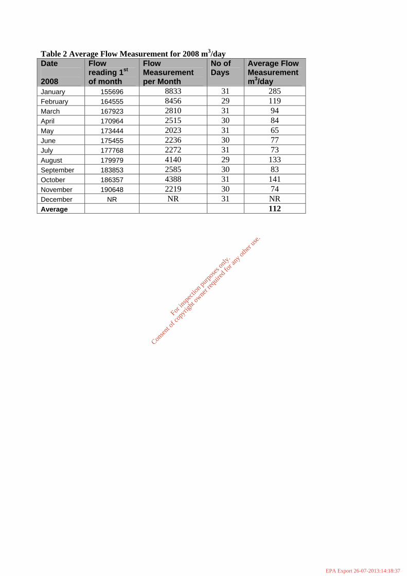
Table 2 Average Flow Measurement for 2008 m3/day Date 2008
Flow reading 1st of month
Flow Measurement per Month
No of Days
Average Flow Measurement m3/day
January 155696 8833 31 285 February 164555 8456 29 119 March 167923 2810 31 94 April 170964 2515 30 84 May 173444 2023 31 65 June 175455 2236 30 77 July 177768 2272 31 73 August 179979 4140 29 133 September 183853 2585 30 83 October 186357 4388 31 141 November 190648 2219 30 74 December NR NR 31 NR Average 112
For
insp
ectio
n pur
pose
s only
.
Conse
nt of
copy
right
owne
r req
uired
for a
ny ot
her u
se.
EPA Export 26-07-2013:14:18:37

Attachment C.1.4 Pumping Station Information
For
insp
ectio
n pur
pose
s only
.
Conse
nt of
copy
right
owne
r req
uired
for a
ny ot
her u
se.
EPA Export 26-07-2013:14:18:37
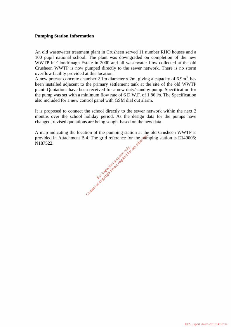
Pumping Station Information An old wastewater treatment plant in Crusheen served 11 number RHO houses and a 100 pupil national school. The plant was downgraded on completion of the new WWTP in Clondrinagh Estate in 2000 and all wastewater flow collected at the old Crusheen WWTP is now pumped directly to the sewer network. There is no storm overflow facility provided at this location. A new precast concrete chamber 2.1m diameter x 2m, giving a capacity of 6.9m3, has been installed adjacent to the primary settlement tank at the site of the old WWTP plant. Quotations have been received for a new duty/standby pump. Specification for the pump was set with a minimum flow rate of 6 D.W.F. of 1.86 l/s. The Specification also included for a new control panel with GSM dial out alarm. It is proposed to connect the school directly to the sewer network within the next 2 months over the school holiday period. As the design data for the pumps have changed, revised quotations are being sought based on the new data. A map indicating the location of the pumping station at the old Crusheen WWTP is provided in Attachment B.4. The grid reference for the pumping station is E140005; N187522.
For
insp
ectio
n pur
pose
s only
.
Conse
nt of
copy
right
owne
r req
uired
for a
ny ot
her u
se.
EPA Export 26-07-2013:14:18:37

Attachment C.2 Outfall Design and Construction
For
insp
ectio
n pur
pose
s only
.
Conse
nt of
copy
right
owne
r req
uired
for a
ny ot
her u
se.
EPA Export 26-07-2013:14:18:37

Outfall Design and Construction The effluent from the wastewater treatment plant discharges via an 225mm diameter concrete pipeline to a local stream located to the east of the WWTP which drains in an easterly and then southerly direction towards Inchicronan Lough. The treated wastewater discharge is the primary discharge, and is designated (P)SW1 on the maps accompanying the application, grid reference E…..; N…...
For
insp
ectio
n pur
pose
s only
.
Conse
nt of
copy
right
owne
r req
uired
for a
ny ot
her u
se.
EPA Export 26-07-2013:14:18:37

Attachment E.2
Sampling and Analysis Methodology
For
insp
ectio
n pur
pose
s only
.
Conse
nt of
copy
right
owne
r req
uired
for a
ny ot
her u
se.
EPA Export 26-07-2013:14:18:37
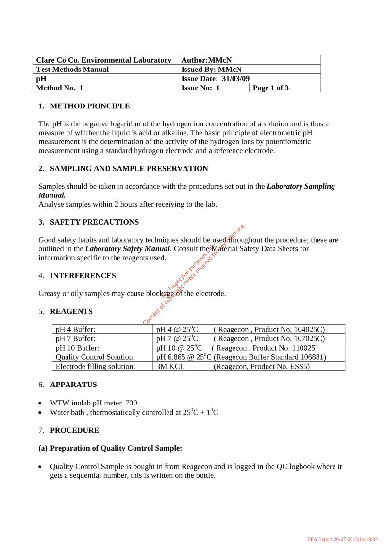
Clare Co.Co. Environmental Laboratory Author:MMcN Test Methods Manual Issued By: MMcN pH Issue Date: 31/03/09 Method No. 1 Issue No: 1 Page 1 of 3 1. METHOD PRINCIPLE The pH is the negative logarithm of the hydrogen ion concentration of a solution and is thus a measure of whither the liquid is acid or alkaline. The basic principle of electrometric pH measurement is the determination of the activity of the hydrogen ions by potentiometric measurement using a standard hydrogen electrode and a reference electrode. 2. SAMPLING AND SAMPLE PRESERVATION Samples should be taken in accordance with the procedures set out in the Laboratory Sampling Manual. Analyse samples within 2 hours after receiving to the lab. 3. SAFETY PRECAUTIONS Good safety habits and laboratory techniques should be used throughout the procedure; these are outlined in the Laboratory Safety Manual. Consult the Material Safety Data Sheets for information specific to the reagents used.
4. INTERFERENCES Greasy or oily samples may cause blockage of the electrode. 5. REAGENTS
pH 4 Buffer: pH 4 @ 25oC ( Reagecon , Product No. 104025C) pH 7 Buffer: pH 7 @ 25oC ( Reagecon , Product No. 107025C) pH 10 Buffer: pH 10 @ 25oC ( Reagecon , Product No. 110025) Quality Control Solution pH 6.865 @ 25oC (Reagecon Buffer Standard 106881) Electrode filling solution: 3M KCL (Reagecon, Product No. ESS5)
6. APPARATUS • WTW inolab pH meter 730 • Water bath , thermostatically controlled at 250C + 10C 7. PROCEDURE (a) Preparation of Quality Control Sample: • Quality Control Sample is bought in from Reagecon and is logged in the QC logbook where it
gets a sequential number, this is written on the bottle.
For
insp
ectio
n pur
pose
s only
.
Conse
nt of
copy
right
owne
r req
uired
for a
ny ot
her u
se.
EPA Export 26-07-2013:14:18:37

Clare Co.Co. Environmental laboratory Issue Date: 31/03/09 Issue No: 1 pH Method No: 1 Page 2 of 3 (b) Two Point Calibration: • Use two buffer solutions, pH 7 & pH 4 . The temperature the buffers should be 250C ± 10C
to minimize temperature correction errors. If necessary samples are placed in a 25oC waterbath to ensure that the correct temperature is achieved prior to measurement.
• Submerse the pH electrode in the first buffer solution pH 7 • Press the RUN ENTER key, the measured pH appears on the display • Set the nominal pH value of the buffer solution by pressing UP and DOWN arrow keys • Press the RUN ENTER key, the value of the asymmetery and the sensory symbol appear on
the display • Press the RUN ENTER key, SLOpe appears on the display. • Thoroughly rinse the electrode with distilled water • Submerse the electrode in the second buffer solution pH 4 • Press the RUN ENTER key, the second measure pH value appears on the display • Set the nominal pH value of the second buffer solution • Press the RUN ENTER key
The value of the slope(mV/pH) appears on the display. (Admissible range Slope = -50 to -62 mv/pH).
• The sensor symbol shows the evaluation of the electrode after the two point calibration • To return to measuring mode , Press the M key. • Record the slope value in the instrument logbook and on worksheet. (c) Measurement: • Select the measuring mode by selecting M • Rinse the pH electrode with purified water, blot dry and immerse into the first sample. • Press the M key until pH appears in the status display. • Activate the AR function by pressing AR (the current measured value is frozen) • Start the autoread function by pressing RUN ENTER, AR flashes on the display until a stable
value is reached, record in worksheet. • If necessary start the next autoread function by pressing RUN ENTER • A quality control sample must be run with each batch of analysis. (Reagecon Buffer Standard
6.865@ 250C) Record value of QC sample in worksheet and on QC chart and also record the temperature of QC sample.
• When measurement of samples is complete, rinse electrode in purified water, blot dry and store in 3 molar KCL solution.
8. METHOD DETECTION LIMIT/QUALITY CONTROL The method has no quantifiable detection limit however pH values of <2 and >12 units cannot be relied due to the nature of the sample matrix/electrode response.
For
insp
ectio
n pur
pose
s only
.
Conse
nt of
copy
right
owne
r req
uired
for a
ny ot
her u
se.
EPA Export 26-07-2013:14:18:37

Clare Co.Co. Environmental laboratory Issue Date: 31/03/09 Issue No: 1 pH Method No: 1 Page 3 of 3 The Quality Control Limits are shown below:
Quality Control Target
Lower Control Limit (LCL)
Lower Warning limit (LWL)
Upper Warning limit(UWL)
Upper Control Limit (UCL)
6.88 6.81
6.84 6.92 6.95
9. EXPRESSION OF RESULTS Report pH values to the nearest 0.1 pH unit, except the QC sample which must be reported to 2 decimal places. 10. REFERERENCES • Standard Methods for the Examination of Water and Wastewater, 21st edition, 2005. • Clare Co .Co. Laboratory Sampling Manual • Clare Co .Co. Laboratory Safety Manual • Clare Co.Co. Quality Manual • NS 30 A Manual for Analytical Quality Control for the Water Industry, Water Research Centre
1987 • WTW inoLab pH 730 operating manual.
For
insp
ectio
n pur
pose
s only
.
Conse
nt of
copy
right
owne
r req
uired
for a
ny ot
her u
se.
EPA Export 26-07-2013:14:18:37

Clare Co.Co. Environmental Laboratory Author: M.McN Test Method Manual Issued By: MMcN Chemical Oxygen Demand. High Range ( 20-1500 mg/L O2)
Low Range (10- 150 mg/l O2)
Issue Date: 17/02/09
Method No. 2 Issue No:1 Page 1of 4 1. METHOD PRINCIPLE The mg/L COD results are defined as the mg of O2 consumed per litre of sample under conditions of this procedure. In this procedure the sample is heated for 2hrs with a strong oxidising reagent, potassium dichromate. Oxidisable organic compounds react, reducing the dichromate ion to green chromic ion ( Cr3+). When the 10-150 mg/L method is used the amount of CR6+ remaining is determined. When the 20-1500 mg/L is used the amount of Cr3+ produced is determined. The COD reagent also contains silver and mercury ions. Silver is a catalyst and mercury is used to complex chloride interference’s.
2. SAMPLING AND SAMPLE PRESERVATION Samples should be taken in accordance with the procedures set out in the Laboratory Sampling Manual. Analyse samples as soon as possible after receipt to the lab, otherwise refrigerate and analyse within 48 hours. If this cannot be achieved preserve samples by acidification to pH < 2 with H2SO4 (2mls per litre), refrigerate and analyse within 28 days. 3. SAFETY PRECAUTIONS Good safety habits and laboratory techniques should be used throughout the procedure; these are outlined in the Laboratory Safety Manual. Vials contain sulphuric acid (86%), potassium dichromate silver and mercury. Consult Material Safety Data Sheet for information specific to the reagents used. Wear appropriate skin and eye protection. Vials are heated to 1500C so vials and digestion rack is very hot, take suitable precautions. 4. WASTE DISPOSAL Final samples contain mercury, silver and chromium at concentrations which are hazardous so all COD vials must be disposed of by sending to Shannon Environmental Services. The used vials are stored in the used delivery containers marked “waste” pending collection. 5 INTERFERENCES Chloride is the primary interference when determining COD concentration. Each COD vial contains mercuric sulphate which will eliminate chloride interference up to 2000 mg/L in the sample, if the sample contains greater than this it must be diluted.
For
insp
ectio
n pur
pose
s only
.
Conse
nt of
copy
right
owne
r req
uired
for a
ny ot
her u
se.
EPA Export 26-07-2013:14:18:37
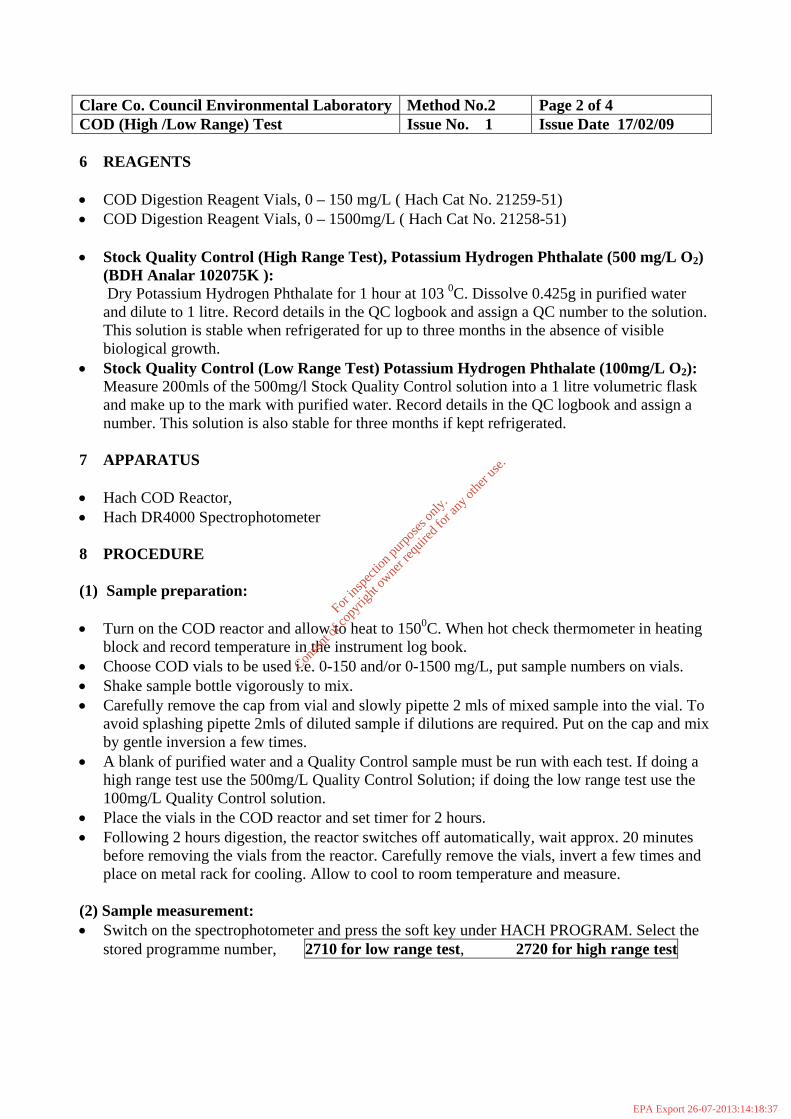
Clare Co. Council Environmental Laboratory Method No.2 Page 2 of 4 COD (High /Low Range) Test Issue No. 1 Issue Date 17/02/09 6 REAGENTS • COD Digestion Reagent Vials, 0 – 150 mg/L ( Hach Cat No. 21259-51) • COD Digestion Reagent Vials, 0 – 1500mg/L ( Hach Cat No. 21258-51) • Stock Quality Control (High Range Test), Potassium Hydrogen Phthalate (500 mg/L O2)
(BDH Analar 102075K ): Dry Potassium Hydrogen Phthalate for 1 hour at 103 0C. Dissolve 0.425g in purified water and dilute to 1 litre. Record details in the QC logbook and assign a QC number to the solution. This solution is stable when refrigerated for up to three months in the absence of visible biological growth.
• Stock Quality Control (Low Range Test) Potassium Hydrogen Phthalate (100mg/L O2): Measure 200mls of the 500mg/l Stock Quality Control solution into a 1 litre volumetric flask and make up to the mark with purified water. Record details in the QC logbook and assign a number. This solution is also stable for three months if kept refrigerated.
7 APPARATUS • Hach COD Reactor, • Hach DR4000 Spectrophotometer 8 PROCEDURE (1) Sample preparation: • Turn on the COD reactor and allow to heat to 1500C. When hot check thermometer in heating
block and record temperature in the instrument log book. • Choose COD vials to be used i.e. 0-150 and/or 0-1500 mg/L, put sample numbers on vials. • Shake sample bottle vigorously to mix. • Carefully remove the cap from vial and slowly pipette 2 mls of mixed sample into the vial. To
avoid splashing pipette 2mls of diluted sample if dilutions are required. Put on the cap and mix by gentle inversion a few times.
• A blank of purified water and a Quality Control sample must be run with each test. If doing a high range test use the 500mg/L Quality Control Solution; if doing the low range test use the 100mg/L Quality Control solution.
• Place the vials in the COD reactor and set timer for 2 hours. • Following 2 hours digestion, the reactor switches off automatically, wait approx. 20 minutes
before removing the vials from the reactor. Carefully remove the vials, invert a few times and place on metal rack for cooling. Allow to cool to room temperature and measure.
(2) Sample measurement: • Switch on the spectrophotometer and press the soft key under HACH PROGRAM. Select the
stored programme number, 2710 for low range test, 2720 for high range test
For
insp
ectio
n pur
pose
s only
.
Conse
nt of
copy
right
owne
r req
uired
for a
ny ot
her u
se.
EPA Export 26-07-2013:14:18:37

Clare Co. Council Environmental Laboratory Method No.2 Page 3 of 4 COD (High /Low Range) Test Issue No. 1 Issue Date 17/02/09 • Press {ENTER}. The wavelength is automatically selected. • Insert the test tube adapter into the sample cell module by sliding it under the thumbscrew and
into the alignment grooves. Fasten with the thumbscrew. • Clean the outside of the blank with a soft tissue. • Place the blank into the adapter with the Hach logo facing the front of the instrument. Close
the light shield. • Press the soft key under ZERO, the display will show: 0 mg/L COD. • Clean the outside of the sample vial with a soft tissue. Place the vial in the adapter with the
Hach logo facing the front of the instrument. Close the light shield. Results in mg/L COD will be displayed. Record results on the COD worksheet and record QC on worksheet and on relevant QC chart.
9 METHOD DETECTION LIMIT ( M.D.L.) & QUALITY CONTROL Low Range Test. Method Detection limit. M.D.L. mg/L O2
Quality Control Low Range test
mg/L O2
Lower Control Limit (LCL) mg/L O2
Lower Warning limit (LWL) mg/L O2
Upper Warning limit (UWL) mg/L O2
Upper Control Limit (UCL) mg/L O2
10 100 85 90 110 115 High Range Test:
Method Detection limit. M.D.L. Mg/L O2
Quality Control High Range test
mg/L O2
Lower Control Limit (LCL) mg/L O2
Lower Warning limit (LWL) mg/L O2
Upper Warning limit (UWL) mg/L O2
Upper Control Limit (UCL) mg/L O2
20 500 460
475 525 540
10. EXPRESSION OF RESULTS • Results are reported as mg/L O2. For the low range test results are reported to 1 decimal place,
for the high range test results that are in the range 20 – 1000 are reported to two significant figures and results > 1000 mg/L O2 are reported to three significant figures.
For
insp
ectio
n pur
pose
s only
.
Conse
nt of
copy
right
owne
r req
uired
for a
ny ot
her u
se.
EPA Export 26-07-2013:14:18:38

Clare Co. Council Environmental Laboratory Method No.2 Page 4 of 4 COD (High /Low Range) Test Issue No. 1 Issue Date 17/02/09 11. REFERENCES • Standard Methods for the Examination of Water and Wastewater, 21st edition. • Clare Co .Co. Laboratory Sampling Manual • Clare Co .Co. Laboratory Safety Manual • Clare Co.Co. Quality Manual • NS 30 A Manual for Analytical Quality Control for the Water Industry, Water Research Centre
1987
For
insp
ectio
n pur
pose
s only
.
Conse
nt of
copy
right
owne
r req
uired
for a
ny ot
her u
se.
EPA Export 26-07-2013:14:18:38

Clare Co.Council Environmental Laboratory Author:MMcN Test Method Manual Issued By: MMcN 5 day Biochemical Oxygen Demand Test Issue Date: 17/02/09 Method No. 3 Issue No: 1 Page 1 of 6 1. METHOD PRINCIPLE The method consists of filling with diluted and seeded sample, to overflowing , an airtight bottle of specified size and incubating it at 200C for 5 days. Dissolved oxygen is measured initially and after incubation and the BOD is computed from the difference between initial and final DO. A factor which must be borne in mind in obtaining and assessing B.O.D. results is nitrification. This is the oxidation of ammonia to nitrate by nitrifying bacteria and if the process is occurring under test conditions high oxygen uptake values will be recorded. For normal river waters the onset of nitrification conditions does not occur within the 5 day period but in the case of wastewaters containing nitrifying organisms this phenomenon will take place much more promptly and unless nitrification is inhibited the result is an apparently very high B.O.D. level. 2. SAMPLING AND SAMPLE PRESERVATION
Samples should be taken in accordance with the procedures set out in the Laboratory Sampling Manual. If analysis is begun within 2 hrs of collection cold storage is unnecessary if not, keep sample refrigerated before analysis. Analyse sample within 24h of collection. Warm chilled samples to 20oC + 30C . 3. SAFETY PRECAUTIONS Good safety habits and laboratory techniques should be used throughout the procedure; these are outlined in the Laboratory Safety Manual. 4. INTERFERENCES Samples containing caustic alkalinity or acidity must be neutralised to pH 6.5 to 7.5 with a solution of Sulphuric acid or Sodium hydroxide to pH 6.5 to 7.5 of such strength that the that the quantity of reagent does not dilute the sample by more than 0.5%. 5. REAGENTS • B.O.D. nutrient powder pillows ( Hach Prod.Code:14861-98) • Quality Control Solution : Glucose Glutamic Acid Standard Soln • Allythiourea (BDH analar,104622A) • TCMP ? • Seed ( diluted mixed liquor)
For
insp
ectio
n pur
pose
s only
.
Conse
nt of
copy
right
owne
r req
uired
for a
ny ot
her u
se.
EPA Export 26-07-2013:14:18:38

Clare Co. Council Environmental Laboratory Method No.3 Page 2 of 6 BOD Test Issue No. 1 Issue Date 17/02/09 6. APPARATUS • Incubator @ 20 0C + 10C • Incubation bottles, 250 to 300 mls capacity • Water bath , thermostatically controlled at 200C + 10C • Dissolved Oxygen Meter 7. PROCEDURE (A) Preparation of Quality Control solution: • Dry Glucose (BDH, Analar grade 10117Y) and reagent grade Glutamic acid (BDH
Biochemical 371064E) at 1030C for 1 hr. Allow to cool in a dessicator. • Dissolve 0.15g Glucose and 0.15g Glutamic acid distilled water and dilute to 1litre in a
volumetric flask. Mix well. Prepare fresh immediately before use. Store all Glucose/Glutamic mixtures at 40 C or lower. Record in the QC log book and assign a QC number
(B) Preparation of Reagents. • Source Water for Sample Dilution : A quantity of distilled water is aerated overnight, on the
day of the test 1 BOD nutrient powder pillow is added to 3 litres water. • Allylthiourea (Nitrification Inhibitor): This is used if analysing samples that require
nitrification inhibition e.g. Wastewater Treatment Plant samples. Dissolve 0.2g of Allythiourea (BDH analar,104622A) in 150 mls purified water and make up to 200mls in a volumetric flask. This solution is stable for up to two weeks if kept refrigerated. Record preparation in the back QC logbook.
• SEED (C) Preparation of Blanks, Samples & Quality Control: Samples both diluted and undiluted , dilution water blanks and Quality Control Samples should be treated in the same way. All samples must be brought to 200C + 30 C before D.O. measurement. Preparation of Dilution Water Quality Check Blanks:
• Two blanks must be run with each set of analysis, which contain nutrient, mineral and buffer solution but no seed or nitrification inhibitor , this serves as a check on quality of unseeded dilution water and cleanliness of incubation bottles. The DO uptake should should not exceed 0.2mg/L.
• for blank determination the prepared dilution water is treated as a sample. Place prepared dilution water into pre - labeled BOD bottles. Fill the BOD bottle to overflowing with sample. Remove any entrapped air bubbles by gently tapping the bottle.
• If using a nitrification inhibitor, add 1ml of Allythioura solution per 500 mls sample, two ATU blanks must be prepared and treated in the same way as the samples.
• Place the BOD bottles in the water-bath until ready for D.O. measurement.
For
insp
ectio
n pur
pose
s only
.
Conse
nt of
copy
right
owne
r req
uired
for a
ny ot
her u
se.
EPA Export 26-07-2013:14:18:38

Clare Co. Council Environmental Laboratory Method No.3 Page 3 of 6 BOD Test Issue No. 1 Issue Date 17/02/09 Preparation of Quality Control Samples:
• At least two QC samples must be run with each set of analysis, this is prepared by diluting the Glucose/Glutamic Standard solution by 50 with the dilution water in a volumetric flask or graduated cylinder. Place prepared QC sample into pre - labeled BOD bottles. Fill the BOD bottle to overflowing with sample. Remove any entrapped air bubbles by gently tapping the bottle.
• If using a nitrification inhibitor, add 1ml of Allythioura solution per 500 mls QC sample. • Place the BOD Bottle in the water- bath until ready for D.O. measurement.
Preparation of Samples:
• Some samples may require dilution , if the BOD is expected to be greater than 7mg/l O2 then the sample requires dilution . Make at least two dilutions of prepared sample estimated to produce a residual DO of at least 1.0 mg/L and a DO uptake of at least 2.0 mg/L.(Use dilution chart in Appendix 1 as reference).
• Prepare dilution by adding desired amount of sample to a 500 mls Class A Graduated Cylinder ( For dilution greater than 1:100 make a primary dilution first.
• Add X mls of seed and (nitrification inhibitor) solution per 500 mls diluted sample • Label BOD bottles with No. of sample, dilution and date. Shake vigorously and pour into BOD bottle (this is to ensure that sample is saturated with oxygen). • Fill the BOD bottle to overflowing with sample. Remove any entrapped air bubbles by
gently tapping the bottle. • Samples must be brought to 200C in a water-bath before DO measurement, after preparing
dilution measure initial DO within 30 min. (D) Calibration of Dissolved Oxygen Meter. NEW SECTION (E) Measurement of DO in Samples /Blanks and Quality Control Sample • Insert the funnel and stirrer into the BOD bottle to be measured, insert the electrode into the
bottle. Ensure that there are no air bubbles trapped on the electrode head. Allow the DO reading to stabilise, the sample when fully saturated at 200C should read between 8.8 to 9.2 mg/l. Record the DO1 for the blanks, QC and samples on the worksheet. Rinse the probe between sample measurement.
• Put the glass top on the bottle, ensure that no air bubbles are trapped. Seal with parafilm to prevent evaporation. Place the BOD bottle in the incubator for 5 days.
• After 5 days remove the BOD bottle from the incubator and record the DO5 remaining on the worksheet.
• Record samples with inhibition and without inhibition of separate worksheets. Samples with inhibitor added must be recorded as CBOD (Wastewater Treatment Plant Samples)
For
insp
ectio
n pur
pose
s only
.
Conse
nt of
copy
right
owne
r req
uired
for a
ny ot
her u
se.
EPA Export 26-07-2013:14:18:38
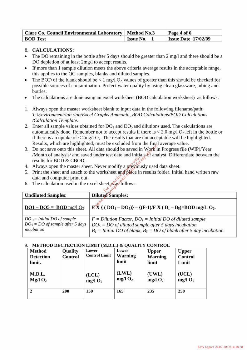
Clare Co. Council Environmental Laboratory Method No.3 Page 4 of 6 BOD Test Issue No. 1 Issue Date 17/02/09 8. CALCULATIONS: • The DO remaining in the bottle after 5 days should be greater than 2 mg/l and there should be a
DO depletion of at least 2mg/l to accept results. • If more than 1 sample dilution meets the above criteria average results in the acceptable range,
this applies to the QC samples, blanks and diluted samples. • The BOD of the blank should be < 1 mg/l O2, values of greater than this should be checked for
possible sources of contamination. Protect water quality by using clean glassware, tubing and bottles.
• The calculations are done using an excel worksheet (BOD calculation worksheet) as follows: 1. Always open the master worksheet blank to input data in the following filename/path:
T:\Environment/lab /lab/Excel Graphs Ammonia, BOD Calculations/BOD Calculations /Calculation Template.
2. Enter all sample values obtained for DO1 and DO5 and dilutions used. The calculations are automatically done. Remember not to accept results if there is < 2.0 mg/l O2 left in the bottle or if there is an uptake of < 2mg/l O2. The results that are not acceptable will be highlighted. Results, which are highlighted, must be excluded from the final average value.
3. Do not save onto this sheet. All data should be saved in Work in Progress file (WIP)/Year /Month of analysis/ and saved under test date and initials of analyst. Differentiate between the results for BOD & CBOD.
4. Always open the master sheet. Never modify a previously used data sheet. 5. Print the sheet and attach to the worksheet and place in results folder. Initial hand written raw
data and computer print out. 6. The calculation used in the excel sheet is as follows: Undiluted Samples: Diluted Samples: DO1 – DO5 = BOD mg/l O2
F X { ( DO1 – DO5)} – {(F-1)/F X ( B1 – B5)=BOD mg/L O2.
DO 1= Initial DO of sample DO5 = DO of sample after 5 days incubation
F = Dilution Factor, DO1 = Initial DO of diluted sample DO5 = DO of diluted sample after 5 days incubation BB1 = Initial DO of blank, B5 = DO of blank after 5 day incubation.
9. METHOD DECTECTION LIMIT (M.D.L.) & QUALITY CONTROL
Method Detection limit. M.D.L. Mg/l O2
Quality Control
Lower Control Limit (LCL) mg/l O2
Lower Warning limit (LWL) mg/l O2
Upper Warning limit (UWL) mg/l O2
Upper Control Limit (UCL) mg/l O2
2
200
150
165 235 250
For
insp
ectio
n pur
pose
s only
.
Conse
nt of
copy
right
owne
r req
uired
for a
ny ot
her u
se.
EPA Export 26-07-2013:14:18:38

Clare Co. Council Environmental Laboratory Method No.3 Page 5 of 6 BOD Test Issue No. 1 Issue Date 17/02/09 10. EXPRESSION OF RESULTS Results should be reported in accordance with the following table: Concentration Method of Reporting Example < 10 mg/l O2 Report to nearest integer 8.3 measured report as 8 10 – 1000 mg/l O2 Report to 2 significant figures 106.3 measured report as 110 > 1000 mg/l O2 Report to 3 significant figures 1244 measured, report as 1240
Note: If Nitrification is inhibited results should be reported as CBOD mg/l O2 otherwise report as BODmg/l O2
11. REFERERENCES
• Standard Methods for the Examination of Water and Wastewater, 21st Edition, 2005
APHA,.AWWA,WEF • Clare Co .Co. Laboratory Sampling Manual • Clare Co .Co. Laboratory Safety Manual • Clare Co.Co. Quality Manual
For
insp
ectio
n pur
pose
s only
.
Conse
nt of
copy
right
owne
r req
uired
for a
ny ot
her u
se.
EPA Export 26-07-2013:14:18:38
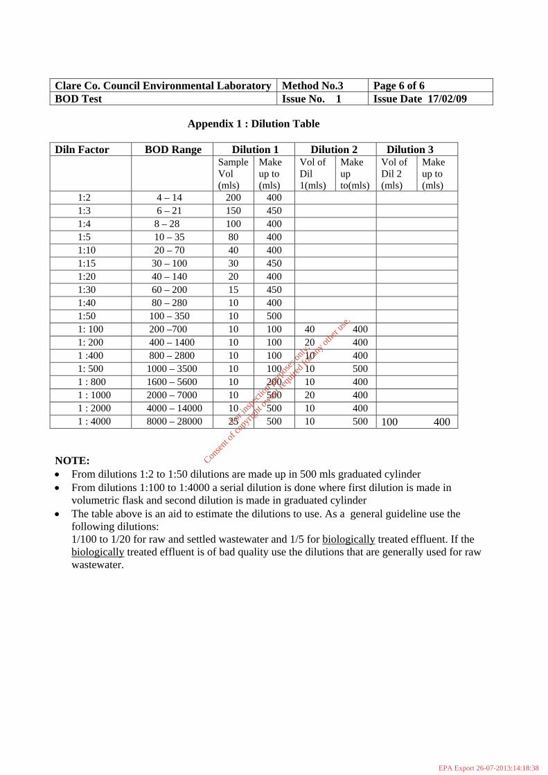
Clare Co. Council Environmental Laboratory Method No.3 Page 6 of 6 BOD Test Issue No. 1 Issue Date 17/02/09
Appendix 1 : Dilution Table Diln Factor BOD Range Dilution 1 Dilution 2 Dilution 3 Sample
Vol (mls)
Make up to (mls)
Vol of Dil 1(mls)
Make up to(mls)
Vol of Dil 2 (mls)
Make up to (mls)
1:2 4 – 14 200 400 1:3 6 – 21 150 450 1:4 8 – 28 100 400 1:5 10 – 35 80 400 1:10 20 – 70 40 400 1:15 30 – 100 30 450 1:20 40 – 140 20 400 1:30 60 – 200 15 450 1:40 80 – 280 10 400 1:50 100 – 350 10 500 1: 100 200 –700 10 100 40 400 1: 200 400 – 1400 10 100 20 400 1 :400 800 – 2800 10 100 10 400 1: 500 1000 – 3500 10 100 10 500 1 : 800 1600 – 5600 10 200 10 400 1 : 1000 2000 – 7000 10 500 20 400 1 : 2000 4000 – 14000 10 500 10 400 1 : 4000 8000 – 28000 25 500 10 500 100 400 NOTE: • From dilutions 1:2 to 1:50 dilutions are made up in 500 mls graduated cylinder • From dilutions 1:100 to 1:4000 a serial dilution is done where first dilution is made in
volumetric flask and second dilution is made in graduated cylinder • The table above is an aid to estimate the dilutions to use. As a general guideline use the
following dilutions: 1/100 to 1/20 for raw and settled wastewater and 1/5 for biologically treated effluent. If the biologically treated effluent is of bad quality use the dilutions that are generally used for raw wastewater.
For
insp
ectio
n pur
pose
s only
.
Conse
nt of
copy
right
owne
r req
uired
for a
ny ot
her u
se.
EPA Export 26-07-2013:14:18:38

10 Clare Co.Co. Environmental Laboratory Author: MMcN Test Methods Manual Issued By: MMcN Total Suspended Solids Issue Date : 17/02/09 Method No. 4 Page 1 of 3 Issue No 1 1. METHOD PRINCIPLE The procedure consists of filtering a well mixed sample through a weighed glass–fibre paper (grade GF/C with particle retention of 1.2um) and the residue on the filter is dried at 103 to 1050C. The increase in the weight of the filter represents the total suspended solids. 2. SAMPLING AND SAMPLE PRESERVATION Samples should be taken in accordance with the procedures set out in the Laboratory Sampling Manual. Samples must be refrigerated to minimize microbiological decomposition of solids and analyzed within 7 days.
3. SAFETY PRECAUTIONS Good safety habits and laboratory techniques should be used throughout the procedure; these are outlined in the Laboratory Safety Manual.
4. INTERFERENCES Exclude large floating particles if it is determined that their inclusion is not representative. For samples high in dissolved solids e.g. chloride, thoroughly wash the filter to ensure removal of the dissolved material. 5. REAGENTS Kaolin Quality Control Sample (200mg/L): Weigh 0.200g of Kaolin (Aldrich 22,883-4) dilute to 1litre in a volumetric flask with purified water. Mix well. Record in QC log book and assign number. 6. APPARATUS • 1 litre Buchner flask • GF/C Whatman filter papers (90mm) • Oven for operation at 103 to 105 oC • Analytical Balance • Dessicator
For
insp
ectio
n pur
pose
s only
.
Conse
nt of
copy
right
owne
r req
uired
for a
ny ot
her u
se.
EPA Export 26-07-2013:14:18:38

Clare Co. Council Environmental Laboratory Method No.4 Page 2 of 3 Total Suspended Solids. Issue No. 1 Issue Date 17/02/09 7. PROCEDURE (a) Preparation of GF/C Filter Papers • Insert numbered GF/C filter paper with wrinkled side up into filtration apparatus. • Apply vacuum and wash filter paper with 3 successive 20 mls portions of purified water.
Continue suction to remove all traces of water and discard washings. • Remove filter and dry in an oven at 103 to 1050C for 1 hour. • Cool in a dessicator to balance temperature and weigh, record of the worksheet. Store in
dessicator until needed. • A pre-weighed, numbered filter paper is required for each sample and QC sample.
(b) Sample Analysis • Prepare Quality Control Sample as above. At least one Quality Control sample must be run
with each batch of samples. Use 250mls of Quality Control sample per determination. • Place numbered pre-weighed filter paper on filter apparatus, wash with a small volume of
purified water to seat it. • Ensure sample is well mixed, pour a volume of the well-mixed sample onto the filter paper
(the volume chosen depends on the concentration of solids in the sample e.g. up to 500 mls can be filtered for samples of low suspended solids content and less than 100 mls samples are used if there is a high suspended solids content).
• Wash with three successive 10 ml volume of purified water and allow complete drainage between washings. Samples with high dissolved solids may require additional washings. Continue suction for about 5 minutes after filtration is complete.
• Record the volume filtered on the worksheet. • Carefully remove the filter from the apparatus place in the oven for 1 hour at 103 to 1050C. • Remove from oven, cool in dessicator and weigh, record final weight on worksheet and do
calculations below. Record value of QC sample on QC chart. 8. CALCULATIONS/RESULTS • The Total Suspended Solids is calculated as follows:
mg/L: Total Suspended Solids = ( A – B ) X 1,000,000 Sample Volume (ml)
A: Weight of filter plus dried residue (g) B: Weight of filter (g)
• Report results as mg/L SS to three significant figures.
For
insp
ectio
n pur
pose
s only
.
Conse
nt of
copy
right
owne
r req
uired
for a
ny ot
her u
se.
EPA Export 26-07-2013:14:18:38

Clare Co. Council Environmental Laboratory Method No.4 Page 3 of 3 Total Suspended Solids. Issue No. 1 Issue Date 17/02/09 9. METHOD DETECTION LIMIT (M.D.L.)/ QUALITY CONTROL
Method Detection
limit. M.D.L mg/l SS
2
Quality Contro
l Target mg/l SS 190
Lower Control Limit
(LCL) mg/l SS
175
Lower Warning
limit (LWL) mg/l SS
180
Upper Warning
limit (UWL) mg/l SS
200
Upper Control Limit (UCL) mg/l SS
205
10. REFERERENCES • Standard Methods for the Examination of Water and Wastewater, 21st edition. • Clare Co .Co. Laboratory Sampling Manual • Clare Co .Co. Laboratory Safety Manual • Clare Co.Co. Quality Manual • NS 30 A Manual for Analytical Quality Control for the Water Industry, Water Research Centre
1987
For
insp
ectio
n pur
pose
s only
.
Conse
nt of
copy
right
owne
r req
uired
for a
ny ot
her u
se.
EPA Export 26-07-2013:14:18:38

Attachment E.4
Crusheen WWTP Monitoring Results 2007/2008
For
insp
ectio
n pur
pose
s only
.
Conse
nt of
copy
right
owne
r req
uired
for a
ny ot
her u
se.
EPA Export 26-07-2013:14:18:38

Crusheen WWTP Monitoring Results 2007/2008 Date BOD COD Suspended Solids Influent Effluent Influent Effluent Influent Effluent 24/01/07 530 40 1900 115 404 281 22/02/07 532 99 1720 203 662 94 24/05/07 824 5 1374 22 3350 24 01/08/07 122 10 400 38 122 62 04/10/07 146 10 254 24 170 38 Date BOD COD Suspended Solids Influent Effluent Influent Effluent Influent Effluent 13/02/08 342 100 735 158 292 69 29/05/08 371 38 563 79 237 34 12/06/08 371 20 429 68 400 12 01/07/08 122 8 223 54 119 9 01/10/08 577 22 1443 39 886 14 10/12/08 290 16 568 20 293 16 17/12/08 198 12 452 25 174 6
For
insp
ectio
n pur
pose
s only
.
Conse
nt of
copy
right
owne
r req
uired
for a
ny ot
her u
se.
EPA Export 26-07-2013:14:18:38

Attachment E.5
Monitoring Data Storage and Reporting
For
insp
ectio
n pur
pose
s only
.
Conse
nt of
copy
right
owne
r req
uired
for a
ny ot
her u
se.
EPA Export 26-07-2013:14:18:38
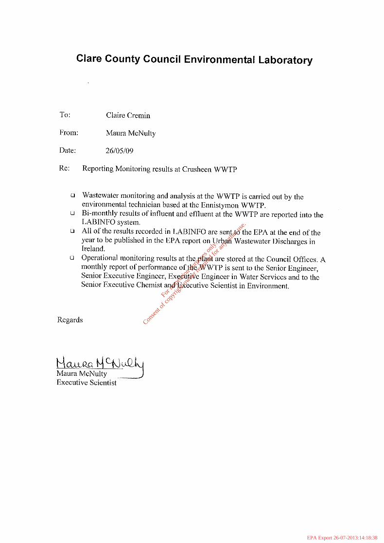
Clare County Council Environmental Laboratory
To: Claire Cremin
From: Maura McNulty
Date: 26/05/09
Re: Reporting Monitoring results at Crusheen WWTP
o Wastewater monitoring and analysis at the WWTP is earried out by theenvironmental technician based at the Ennistymon WWTP.
oBi-monthly results of influent and efnuent at the WWTP are reported into theLABINFO system.
o All of the results recorded in LABINFO are sent to the EPA at the end of theyear to be published in the EPA report on Urban Wastewater Diseharges inIreland.
o Operational monitoring results at the plant are stored at the Council Offices. Amonthly report of performance of the WWTP is sent to thc Senior Engineer,Senior Executive Engineer, Executive Enginecr in Watcr Services and to theSenior Executive Chemist and Executive Scientist in Environment.
Regards
~ ..Qg 1:E:N~&I'-lMaura McNulty ..-.-JExecutive Scientist
For
insp
ectio
n pur
pose
s only
.
Conse
nt of
copy
right
owne
r req
uired
for a
ny ot
her u
se.
EPA Export 26-07-2013:14:18:38

Attachment F1 Impact on Receiving Water
1
For
insp
ectio
n pur
pose
s only
.
Conse
nt of
copy
right
owne
r req
uired
for a
ny ot
her u
se.
EPA Export 26-07-2013:14:18:38

Impact of emissions from the Crusheen WWTP on the receiving waters The impact of discharges from the Crusheen WWTP on the receiving waters is considered under a number of headings:
(i) Description of receiving waters (ii) Statutory Designations of the Receiving Waters (iii) Assimilative capacity of the receiving waters (iv) Total maximum nutrient load discharging to receiving waters (v) Monitoring undertaken on receiving waters (vi) Impact of storm overflows
(i) Description of receiving waters The outfall from Crusheen WWTP discharges to a local stream, which drains in an easterly and then southerly direction to Inchicronan Lough. This area includes several interconnected lakes and streams, where Inchicronan Lough is the largest lake in the area measuring 1.17 km2. Inchicronan Lough (Code 27-126) is situated to the south of Crusheen and to the east of Ballyline Lough (Code 27-63). Inchicronan Lough drains into the Millbrook River, which is included in the catchment of the River Fergus and of the Shannon River Basin. The Millbrook River is included in the EPA hydrometric and biological monitoring programs (Code 27M03). The catchment area of 18.24 hectacres is primarily well draining agricultural lands. There are no downstream abstractions of water for potable supplies or for agricultural purposes, with the exception of a small private well in Carrahill to the north-west of the lake. The most recent classification of trophic status for Inchicronan Lough is Mesotrophic as assigned in the report Lakes of County Clare Monitoring Report 2000-2001 carried out by TCD in November 2001. The river water quality downstream of Inchicronan Lough on the Millbrook River at Site No. 27M031100 is classified with a Q value of 4 in the most recent monitoring conducted in 2004 by the EPA The overall interim water quality status for the Inchicronan Catchment, which includes the area downstream of Crusheen WWTP, has been classified by the EPA as Good water quality status. (ii) Statutory designations of Inchicronan Lough There are no sites designated as Special Areas of Conservation (SACs) and Special Protection Areas (SPAs) or Natural Heritage Areas (NHAs) in the vicinity of Inchicronan Lough. It is noted that a designated NHA Site (Code 000038) is proposed, which includes Inchicronan Lough, Inchicronan Island and the area immediately south of the lake. (iii) Assimilative capacity of receiving waters The outfall from Crusheen WWTP discharges to a local stream, which drains in an easterly and then southerly direction to Inchicronan Lough. The impact of the discharge from the Crusheen WWTP on the receiving water was assessed in terms of the impact on water quality on Inchicronan Lough rather than the local stream. In assessing the assimilative capacity of the receiving water reference is made to the Department of the Environment, Heritage and Local Government, National Urban Waste Water Study – Methodology for Receiving Water Capacity. Recent monitoring results indicate that Inchicronan Lough is classified as mesotrophic and when the criteria for calculating surface water ecological status and ecological potential as outlined in the Draft European Communities Environmental Objectives (Surface
2
For
insp
ectio
n pur
pose
s only
.
Conse
nt of
copy
right
owne
r req
uired
for a
ny ot
her u
se.
EPA Export 26-07-2013:14:18:38

Waters) Regulations, 2008, then the water quality in Inchicronan Lough is considered to be Good to Moderate. In accordance with the above mentioned methodology, where the water quality in a lake is found to be currently of an acceptable standard (not in need of improvement), it is considered to have sufficient assimilative capacity for current discharges. Estimates of the volume, inflows to the lake and total nutrient loads to the lake are provided in Attachment A-8 to this application. (iv) Total maximum nutrient load discharging to receiving Waters Analytical data for the wastewater discharge from the Crusheen WWTP is available on a bimonthly basis for several years, up to an including March 2009. The influent and effluent streams are monitored for biochemical oxygen demand (BOD), chemical oxygen demand (COD), and suspended solids (SS). Results for 2008 are used for this application. Table 2: Estimated nutrient load from Crusheen WWTP to Inchicrionan Lough
Average flow = 114m3/day; SS; suspended solids; BOD: biochemical oxygen demand; COD: chemical oxygen demand;
Date BOD (kg/day)
COD (kg/day)
SS (kg/day)
13/02/2008 11.4 18.0 7.9 29/05/2008 4.3 9.0 3.9 12/06/2008 2.3 7.8 1.4 01/07/2008 0.9 6.2 1.0 01/10/2008 2.5 4.4 1.6 10/12/2008 1.8 2.3 1.8 17/12/2008 1.4 2.9 0.7
Average 3.5 7.2 2.6
Flow data for the influent load to the plant are recorded daily. These flow records indicate the range of flow volumes through the system is 41 - 839 m3/day, with very high flow data been recorded during heavy rainfall episodes. The calculation of discharge load uses the average maximum flow data readings for January to March 2009 to present the typical discharge load from the facility. This approach takes account of the requirements of the Waste Water Discharge (Authorisation) Regulations, 2007 in relation to calculation of population equivalent, “population equivalent” is a measurement of organic biodegradable load and a population equivalent of 1 (1 p.e.) means the organic biodegradable load having a five-day - 16 - biochemical oxygen demand (BOD5) of 60g of oxygen per day; the load being calculated on the basis of the maximum average weekly load entering the waste water works during the year, excluding unusual situations such as those due to heavy rain” The discharge of the treated waste stream is used to assess the impact of the discharge on the receiving waters for biochemical oxygen demand (BOD) chemical oxygen demand (COD) and suspended solids (SS) to waters. The nutrient discharge load is synopsised in Table 2 above, based on the estimated maximum flow readings and mean analytical values for the dates presented.
3
For
insp
ectio
n pur
pose
s only
.
Conse
nt of
copy
right
owne
r req
uired
for a
ny ot
her u
se.
EPA Export 26-07-2013:14:18:38

(v) Monitoring undertaken on receiving waters There is no ongoing monitoring of Inchicronan Lough undertaken at present. The most recent monitoring data for Inchicronan lake is provided in Tables 3 and 4 below and is taken from reports titled Lakes of County Clare Monitoring Report 2000-2001 carried out by TCD in November 2001 and from the E.P.A. Water Quality in Ireland Report 2001-2003. The results indicate that Inchicronan Lough is classified as mesotrophic and in accordance with the Water Framework Directive, it is considered to be of Good Quality status. Table 3. Monitoring Data for Inchicronan Lough 2000/2001 Date 08/01/00 04/01/01 06/01/01 08/01/01 09/01/01 2000/2001 Parameter Units Mean Rainfall mm 78.3 107.3 63.4 96.0 56.1 80.23 Temp O C 10 15 13 No3N mg/l 0.04 0.30 0.2 0.05 0.06 0.13 TN mg/l 0.57 0.6 0.74 0.72 0.63 0.65 TDOC mg/l 6.6 7.8 10.1 8.6 8.28 TP µg/l 22.9 19.0 27.1 24 17.5 22.10 Chla µg/l 16 7.7 2.3 17.2 6.5 9.94 PH pH unit 8.21 8.07 8.15 7.99 7.76 8.04 Alk mg Caco3/l 147 122 142 127 135 134.60 Cond. in µS/cm 358 279 312 283 302 306.80 Colour in PtCo 26 47 31 39 28 34.20 Turb. in NTU 1.17 3.78 3.1 6.1 5.8 3.99 Lakes of County Clare Monitoring Report 2000-2001 carried out by TCD in November 2001 Table 4. EPA Monitoring Data for Inchicronan Lough -2003 No 295 Lake Inchicronan Location Co. Clare Sampling Agency L.A./ERTDI Year of Examination 2001 Sampling Frequency pa Four Surf Area km2 1.17 Tot.-P Chlorophyll ug/l Mean Max 17.2 Water Transp Min Mean
Trophic Status M Beneficial Uses None identified Recent Changes: Overal Status M EPA Water Quality in Ireland Report 2001-2003 Clare County Council, during the course of preparing the application for a discharge authorisation, under the Wastewater Discharge (Authorisation) Regulations 2007, (S.I No 684 of 2007) for the Crusheen WWTP, to the EPA assessed the Crusheen agglomeration to identify any facility liable to generate substances listed in Annex X of the Water Framework Directive (2000/60/EC) or relevant pollutants listed in Annex VIII of the Water Framework Directive. Monitoring for these substances was undertaken in April 2009 and results on this monitoring do not indicate any substance
4
For
insp
ectio
n pur
pose
s only
.
Conse
nt of
copy
right
owne
r req
uired
for a
ny ot
her u
se.
EPA Export 26-07-2013:14:18:38

on the list was present in the receiving waters both upstream and downstream of the discharges from the Crusheen WWTP (see Attachment F.1). No potential source of these pollutants has been identified in the sewer catchment, so it is unlikely that the discharge will contain the listed substances. Results from the survey will be collated and included in the licence application data as soon as may be on receipt of the results of the sampling exercise. In conclusion, there is no indication of significant deterioration in quality status of the receiving water in the vicinity of the discharge from the treatment plant or of the water quality in Inchicronan Lough. (vi) Impact of storm overflows A storm overflow is located at the inlet sump to the Crusheen WWTP. During very heavy rainfall episodes there is potential for overflow from the system. Any such overflow discharges to a local stream located to the east of the WWTP site, which drains in an easterly and then southerly direction towards Inchicronan Lough. Sampling of this drain was undertaken on April 15th 2009, during the course of preparing the licence application. Results from the survey will be collated and included in the licence application data as soon as may be on receipt of the results of the sampling exercise. No complaints have arisen in connection with this overflow.
5
For
insp
ectio
n pur
pose
s only
.
Conse
nt of
copy
right
owne
r req
uired
for a
ny ot
her u
se.
EPA Export 26-07-2013:14:18:38

Attachment F1.1
Assimilative Capacity of Inchicronan Lake
For
insp
ectio
n pur
pose
s only
.
Conse
nt of
copy
right
owne
r req
uired
for a
ny ot
her u
se.
EPA Export 26-07-2013:14:18:38

Assimilative Capacity of Inchicronan Lake
Volume of receiving waters = 7547900 m3
Surface area of lake = 1.17 km2
Mean Depth = 6.48 m
Catchment Area = 18.24 ha
Discharge volume from WWTP facility = 114 m3/day
Water Quality of receiving Water Mean 2000/2001 data (Report Lakes of County Clare Monitoring Report 2000-2001 carried out by TCD) Parameter Trophic Status Chla Chla TN TP (annual Max ) (Mean) (Mean) (Mean)
Mesotrophic 17.2 9.9 0.65 22.1
Ecological Status: Good-Moderate 10
Target Water Quality of receiving Water Parameter Trophic Status Chla TN TP Oligotrophic >2.5<8 n/a >5<10 Ecological Status: High-Good (5.8)
BOD Susp Solids COD Ammonia TP TN Average Daily load 3.5 2.6 7.2 ----No Data---- discharged from the Kilkishen WWTP as kg/day There are no proposals in place to increase the discharge from the plant.
For
insp
ectio
n pur
pose
s only
.
Conse
nt of
copy
right
owne
r req
uired
for a
ny ot
her u
se.
EPA Export 26-07-2013:14:18:38

ANNEX 1: TABLES/ATTACHMENTS
Standard forms are provided in this section for the recording and presentation of environmental monitoring results.
For
insp
ectio
n pur
pose
s only
.
Conse
nt of
copy
right
owne
r req
uired
for a
ny ot
her u
se.
EPA Export 26-07-2013:14:18:38

TABLE D.1(i)(a): EMISSIONS TO SURFACE/GROUND WATERS (Primary Discharge Point) Discharge Point Code: P (SW1)
Source of Emission: Crusheen Wastewater Treatment Plant
Location: Crusheen, Co. Clare
Grid Ref. (12 digit, 6E, 6N): E139997 ; N187757 ;
Name of receiving waters: Local Stream draining to Inchicronan Lough
River Basin District: Shannon International River Basin District
Designation of receiving waters: None
Flow rate in receiving waters: Not Known_____ m3.sec-1 Dry Weather Flow
Not Known_ m3.sec-1 95%ile flow
Emission Details:
(i) Volume emitted:
Normal/day 114m3 Maximum/day m3
Maximum rate/hour m3 Period of emission (avg) 60 min/hr 24 hr/day 365 day/yr
Dry Weather Flow m3/sec
For in
spec
tion p
urpo
ses o
nly.
Conse
nt of
copy
right
owne
r req
uired
for a
ny ot
her u
se.
EPA Export 26-07-2013:14:18:38
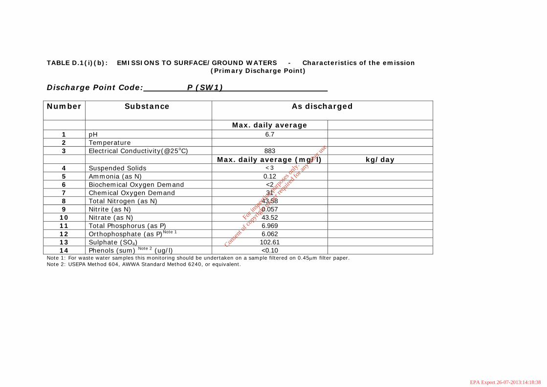
TABLE D.1(i)(b): EMISSIONS TO SURFACE/GROUND WATERS - Characteristics of the emission (Primary Discharge Point) Discharge Point Code: P (SW1) Number
Substance As discharged
Max. daily average 1 pH 6.7
2 Temperature
3 Electrical Conductivity(@25oC) 883
Max. daily average (mg/l) kg/day 4 Suspended Solids <3
5 Ammonia (as N) 0.12
6 Biochemical Oxygen Demand <2
7 Chemical Oxygen Demand 31 8 Total Nitrogen (as N) 43.58
9 Nitrite (as N) 0.057
10 Nitrate (as N) 43.52
11 Total Phosphorus (as P) 6.969
12 Orthophosphate (as P)Note 1 6.062
13 Sulphate (SO4) 102.61
14 Phenols (sum) Note 2 (ug/l) <0.10 Note 1: For waste water samples this monitoring should be undertaken on a sample filtered on 0.45μm filter paper. Note 2: USEPA Method 604, AWWA Standard Method 6240, or equivalent.
For
insp
ectio
n pur
pose
s only
.
Conse
nt of
copy
right
owne
r req
uired
for a
ny ot
her u
se.
EPA Export 26-07-2013:14:18:38

TABLE D.1(i)(c): DANGEROUS SUBSTANCE EMISSIONS TO SURFACE/GROUND WATERS Primary Discharge Point - Characteristics of the emission Discharge Point Code: P(SW1) Number
Substance As discharged
Max. daily average (μg/l)
kg/day kg/year
1 Atrazine <0.01 2 Dichloromethane <1 3 Simazine <0.01 4 Toluene <0.28 5 Tributyltin <0.02 6 Xylenes <1 7 Arsenic <0.96 8 Chromium <0.93 9 Copper 51
10 Cyanide <5 11 Fluoride 430 12 Lead 1.3 13 Nickel 1.2 14 Zinc 259.9 15 Boron <4.2 16 Cadmium <0.09 17 Mercury <0.2 18 Selenium 1 19 Barium <0.74
For
insp
ectio
n pur
pose
s only
.
Conse
nt of
copy
right
owne
r req
uired
for a
ny ot
her u
se.
EPA Export 26-07-2013:14:18:38

TABLE F.1(i)(a): SURFACE/GROUND WATER MONITORING (Primary Discharge Point – one table per upstream and downstream location) Discharge Point Code: P (SW1) MONITORING POINT CODE: aSW1u Parameter Results
(mg/lNote 1)
Sampling method
(grab, drift etc.)
Limit of Quantitation
Analysis method / technique
15/04/09 Date Date Date PH 7.3 Grab 0.01 Electrometry Temperature Electrical Conductivity (@25oC) 759
Grab 0.5 Spectrometry
Suspended Solids 3 Grab 3 Drying @104 C Ammonia (as N) 0.10 Grab 0.09 Colorimetry Biochemical Oxygen Demand <2 Grab 2 Electrometry Chemical Oxygen Demand 12 Grab 5 Colorimetry Dissolved Oxygen Grab Hardness (as CaCo3) 372 Grab 10 Colorimetry Total Nitrogen (as N) 1.44 Grab 1 Calculation Nitrite (as N) 0.008 Grab 0.003 Colorimetry Nitrate (as N) 1.43 Grab 0.09 Colorimetry Total Phosphorus (as P) 0.092 Grab 0.005 Colorimetry/Digestion Orthophosphate (as P) - unfiltered 0.030
Grab 0.006 Colorimetry
Sulphate (SO4) 37.41 Grab 2.11 Colorimetry Phenols (sum) Note 2 (ug/l) <0.10 Grab 0.1 GC-MS2 Note 1: Or other unit as appropriate – please specify. Note 2: USEPA Method 604, AWWA Standard Method 6240, or equivalent.
For
insp
ectio
n pur
pose
s only
.
Conse
nt of
copy
right
owne
r req
uired
for a
ny ot
her u
se.
EPA Export 26-07-2013:14:18:38

TABLE F.1(i)(b): SURFACE/GROUND WATER MONITORING (Dangerous Substances) (Primary Discharge Point - one table per upstream and downstream location) Discharge Point Code: P (SW1) MONITORING POINT CODE: aSW1u Parameter Results
(µg/l)
Sampling method
(grab, drift etc.)
Limit of Quantitation
Analysis method / technique
15/04/09 Date Date Date Atrazine <0.01 Grab 0.01 HPLC Dichloromethane <1 Grab 1 GC-MS 1 Simazine <0.01 Grab 0.01 HPLC Toluene <0.28 Grab 1 GC-MS 1 Tributyltin <0.02 Grab 0.02 GCMS Xylenes <1 Grab 1 GC-MS 1 Arsenic <0.96 Grab 0.96 ICPMS Chromium <0.93 Grab 0.93 ICPMS Copper 13 Grab 0.2 ICPMS Cyanide <5 Grab 5 Colorimetry Fluoride 190 Grab 0.09 Colorimetry Lead 0.6 Grab 0.38 ICPMS Nickel 0.7 Grab 0.47 ICPMS Zinc 19.9 Grab 4.6 ICPMS Boron <4.2 Grab 4.2 ICPMS Cadmium <0.09 Grab 0.09 ICPMS Mercury <0.2 Grab 0.2 ICPMS Selenium 2 Grab 0.74 ICPMS Barium 8.5 Grab 0.74 ICPMS
For
insp
ectio
n pur
pose
s only
.
Conse
nt of
copy
right
owne
r req
uired
for a
ny ot
her u
se.
EPA Export 26-07-2013:14:18:38

TABLE F.1(i)(a): SURFACE/GROUND WATER MONITORING (Primary Discharge Point – one table per upstream and downstream location) Discharge Point Code: P (SW1) MONITORING POINT CODE: aSW1d and aSW2u Parameter Results
(mg/lNote 1)
Sampling method
(grab, drift etc.)
Limit of Quantitation
Analysis method / technique
15/04/09 Date Date Date pH 7.6 Grab 0.01 Electrometry Temperature Electrical Conductivity (@25oC) 747
Grab 0.5 Spectrometry
Suspended Solids 4 Grab 3 Drying @104 C Ammonia (as N) 0.04 Grab 0.09 Colorimetry Biochemical Oxygen Demand <2 Grab 2 Electrometry Chemical Oxygen Demand 13 Grab 5 Colorimetry Dissolved Oxygen Grab Hardness (as CaCo3) 349 Grab 10 Colorimetry Total Nitrogen (as N) 1.92 Grab 1 Calculation Nitrite (as N) 0.019 Grab 0.003 Colorimetry Nitrate (as N) 1.34 Grab 0.09 Colorimetry
Total Phosphorus (as P) 0.093 Grab 0.005 Colorimetry/Digesti
on Orthophosphate (as P) - unfiltered 0.028
Grab 0.006 Colorimetry
Sulphate (SO4) 40.98 Grab 2.11 Colorimetry Phenols (sum) Note 2 (ug/l) <0.10 Grab 0.1 GC-MS2 Note 1: Or other unit as appropriate – please specify.
Note 2: USEPA Method 604, AWWA Standard Method 6240, or equivalent.
For in
spec
tion p
urpo
ses o
nly.
Conse
nt of
copy
right
owne
r req
uired
for a
ny ot
her u
se.
EPA Export 26-07-2013:14:18:38

TABLE F.1(i)(b): SURFACE/GROUND WATER MONITORING (Dangerous Substances) (Primary Discharge Point - one table per upstream and downstream location) Discharge Point Code: P (SW1) MONITORING POINT CODE: aSW1d and aSW2u Parameter Results
(µg/l)
Sampling method
(grab, drift etc.)
Limit of Quantitation
Analysis method / technique
15/04/09 Date Date Date Atrazine <0.01 Grab 0.01 HPLC Dichloromethane <1 Grab 1 GC-MS 1 Simazine <0.01 Grab 0.01 HPLC Toluene <0.28 Grab 1 GC-MS 1 Tributyltin <0.02 Grab 0.02 GCMS Xylenes <1 Grab 1 GC-MS 1 Arsenic <0.96 Grab 0.96 ICPMS Chromium <0.93 Grab 0.93 ICPMS Copper 10 Grab 0.2 ICPMS Cyanide <5 Grab 5 Colorimetry Fluoride 190 Grab 0.09 Colorimetry Lead 0.6 Grab 0.38 ICPMS Nickel <0.47 Grab 0.47 ICPMS Zinc 8.9 Grab 4.6 ICPMS Boron 127.3 Grab 4.2 ICPMS Cadmium <0.09 Grab 0.09 ICPMS Mercury <0.2 Grab 0.2 ICPMS Selenium 2 Grab 0.74 ICPMS Barium 8.8 Grab 0.74 ICPMS
For
insp
ectio
n pur
pose
s only
.
Conse
nt of
copy
right
owne
r req
uired
for a
ny ot
her u
se.
EPA Export 26-07-2013:14:18:38
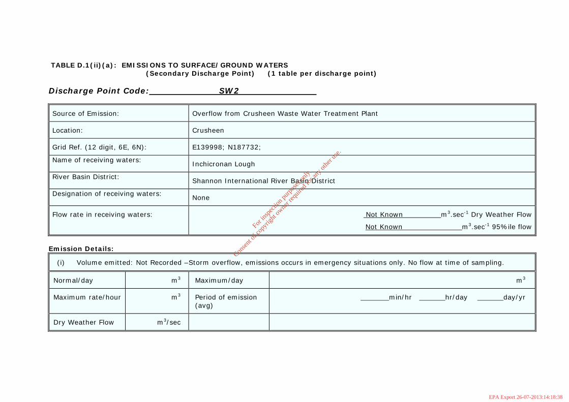
TABLE D.1(ii)(a): EMISSIONS TO SURFACE/GROUND WATERS (Secondary Discharge Point) (1 table per discharge point) Discharge Point Code: SW2
Source of Emission: Overflow from Crusheen Waste Water Treatment Plant
Location: Crusheen
Grid Ref. (12 digit, 6E, 6N): E139998; N187732;
Name of receiving waters: Inchicronan Lough
River Basin District: Shannon International River Basin District
Designation of receiving waters: None
Flow rate in receiving waters: Not Known m3.sec-1 Dry Weather Flow
Not Known m3.sec-1 95%ile flow
Emission Details:
(i) Volume emitted: Not Recorded –Storm overflow, emissions occurs in emergency situations only. No flow at time of sampling.
Normal/day m3 Maximum/day m3
Maximum rate/hour m3 Period of emission (avg)
min/hr hr/day day/yr
Dry Weather Flow m3/sec
For in
spec
tion p
urpo
ses o
nly.
Conse
nt of
copy
right
owne
r req
uired
for a
ny ot
her u
se.
EPA Export 26-07-2013:14:18:38
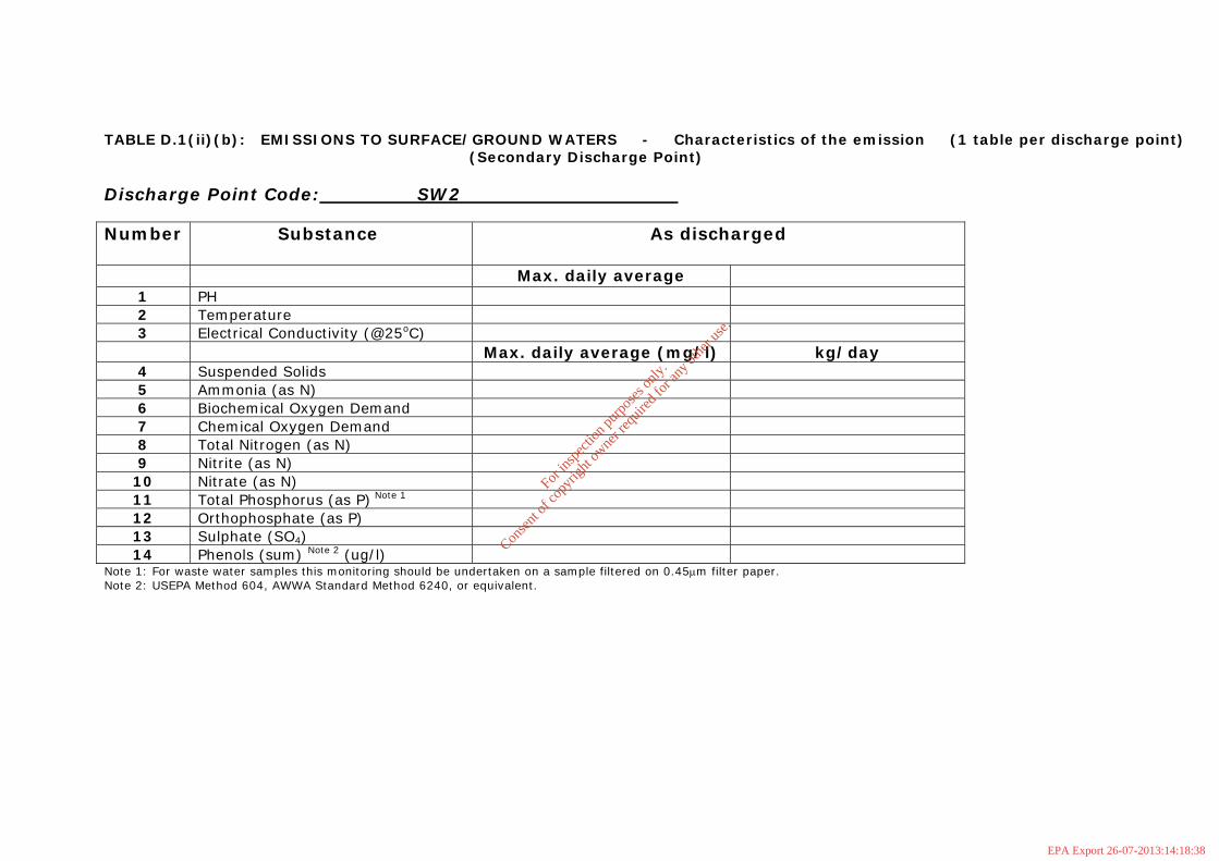
TABLE D.1(ii)(b): EMISSIONS TO SURFACE/GROUND WATERS - Characteristics of the emission (1 table per discharge point) (Secondary Discharge Point) Discharge Point Code: SW2 Number
Substance As discharged
Max. daily average 1 PH
2 Temperature 3 Electrical Conductivity (@25oC)
Max. daily average (mg/l) kg/day 4 Suspended Solids
5 Ammonia (as N)
6 Biochemical Oxygen Demand
7 Chemical Oxygen Demand
8 Total Nitrogen (as N)
9 Nitrite (as N)
10 Nitrate (as N)
11 Total Phosphorus (as P) Note 1
12 Orthophosphate (as P) 13 Sulphate (SO4)
14 Phenols (sum) Note 2 (ug/l) Note 1: For waste water samples this monitoring should be undertaken on a sample filtered on 0.45μm filter paper. Note 2: USEPA Method 604, AWWA Standard Method 6240, or equivalent.
For
insp
ectio
n pur
pose
s only
.
Conse
nt of
copy
right
owne
r req
uired
for a
ny ot
her u
se.
EPA Export 26-07-2013:14:18:38

TABLE D.1(ii)(c): DANGEROUS SUBSTANCE EMISSIONS TO SURFACE/GROUND WATERS Secondary Discharge Point - Characteristics of the emission (1 table per discharge point) Discharge Point Code: SW2 Number
Substance As discharged
Max. daily average (μg/l)
kg/day kg/year
1 Atrazine 2 Dichloromethane 3 Simazine 4 Toluene 5 Tributyltin 6 Xylenes 7 Arsenic 8 Chromium 9 Copper
10 Cyanide 11 Fluoride 12 Lead 13 Nickel 14 Zinc 15 Boron 16 Cadmium 17 Mercury 18 Selenium 19 Barium
For
insp
ectio
n pur
pose
s only
.
Conse
nt of
copy
right
owne
r req
uired
for a
ny ot
her u
se.
EPA Export 26-07-2013:14:18:38

TABLE F.1(ii)(a): SURFACE/GROUND WATER MONITORING - (1 table per discharge point upstream and downstream locations) (Secondary Discharge Point) Discharge Point Code: SW2 MONITORING POINT CODE: aSW2u and aSW1d Parameter Results
(mg/lNote 1)
Sampling method
(grab, drift etc.)
Limit of Quantitation
Analysis method / technique
15/04/09 Date Date Date pH 7.6 Grab 0.01 Electrometry Temperature Electrical Conductivity (@25oC) 747
Grab 0.5 Spectrometry
Suspended Solids 4 Grab 3 Drying @104 C Ammonia (as N) 0.04 Grab 0.09 Colorimetry Biochemical Oxygen Demand <2 Grab 2 Electrometry Chemical Oxygen Demand 13 Grab 5 Colorimetry Dissolved Oxygen Grab Hardness (as CaCo3) 349 Grab 10 Colorimetry Total Nitrogen (as N) 1.92 Grab 1 Calculation Nitrite (as N) 0.019 Grab 0.003 Colorimetry Nitrate (as N) 1.34 Grab 0.09 Colorimetry
Total Phosphorus (as P) 0.093 Grab 0.005 Colorimetry/Digesti
on Orthophosphate (as P) - unfiltered 0.028
Grab 0.006 Colorimetry
Sulphate (SO4) 40.98 Grab 2.11 Colorimetry Phenols (sum) Note 2 (ug/l) <0.10 Grab 0.1 GC-MS2 Note 1: Or other unit as appropriate – please specify. Note 2: USEPA Method 604, AWWA Standard Method 6240, or equivalent.
For
insp
ectio
n pur
pose
s only
.
Conse
nt of
copy
right
owne
r req
uired
for a
ny ot
her u
se.
EPA Export 26-07-2013:14:18:38

TABLE F.1(ii)(b): SURFACE/GROUND WATER MONITORING - (1 table per discharge point upstream and downstream locations) (Secondary Discharge Point) Discharge Point Code: SW2 MONITORING POINT CODE: aSW2u and aSW1d Parameter Results
(µg/l)
Sampling method
(grab, drift etc.)
Limit of Quantitation
Analysis method / technique
15/04/09 Date Date Date Atrazine <0.01 Grab 0.01 HPLC Dichloromethane <1 Grab 1 GC-MS 1 Simazine <0.01 Grab 0.01 HPLC Toluene <0.28 Grab 1 GC-MS 1 Tributyltin <0.02 Grab 0.02 GCMS Xylenes <1 Grab 1 GC-MS 1 Arsenic <0.96 Grab 0.96 ICPMS Chromium <0.93 Grab 0.93 ICPMS Copper 10 Grab 0.2 ICPMS Cyanide <5 Grab 5 Colorimetry Fluoride 190 Grab 0.09 Colorimetry Lead 0.6 Grab 0.38 ICPMS Nickel <0.47 Grab 0.47 ICPMS Zinc 8.9 Grab 4.6 ICPMS Boron 127.3 Grab 4.2 ICPMS Cadmium <0.09 Grab 0.09 ICPMS Mercury <0.2 Grab 0.2 ICPMS Selenium 2 Grab 0.74 ICPMS Barium 8.8 Grab 0.74 ICPMS
For
insp
ectio
n pur
pose
s only
.
Conse
nt of
copy
right
owne
r req
uired
for a
ny ot
her u
se.
EPA Export 26-07-2013:14:18:38

TABLE F.1(ii)(a): SURFACE/GROUND WATER MONITORING - (1 table per discharge point upstream and downstream locations) (Secondary Discharge Point) Discharge Point Code: SW2 MONITORING POINT CODE: aSW2d Parameter Results
(mg/lNote 1)
Sampling method
(grab, drift etc.)
Limit of Quantitation
Analysis method / technique
15/04/09 Date Date Date pH 7.7 Grab 0.01 Electrometry Temperature Electrical Conductivity (@25oC) 750
Grab 0.5 Spectrometry
Suspended Solids <3 Grab 3 Drying @104 C Ammonia (as N) 0.06 Grab 0.09 Colorimetry Biochemical Oxygen Demand <2 Grab 2 Electrometry Chemical Oxygen Demand 17 Grab 5 Colorimetry Dissolved Oxygen Grab Hardness (as CaCo3) 394 Grab 10 Colorimetry Total Nitrogen (as N) 2.01 Grab 1 Calculation Nitrite (as N) 0.016 Grab 0.003 Colorimetry Nitrate (as N) 1.43 Grab 0.09 Colorimetry
Total Phosphorus (as P) 0.035 Grab 0.005 Colorimetry/Digesti
on Orthophosphate (as P) - unfiltered 0.016
Grab 0.006 Colorimetry
Sulphate (SO4) 36.66 Grab 2.11 Colorimetry Phenols (sum) Note 2 (ug/l) <0.10 Grab 0.1 GC-MS2 Note 1: Or other unit as appropriate – please specify. Note 2: USEPA Method 604, AWWA Standard Method 6240, or equivalent.
For
insp
ectio
n pur
pose
s only
.
Conse
nt of
copy
right
owne
r req
uired
for a
ny ot
her u
se.
EPA Export 26-07-2013:14:18:39

TABLE F.1(ii)(b): SURFACE/GROUND WATER MONITORING - (1 table per discharge point upstream and downstream locations) (Secondary Discharge Point) Discharge Point Code: SW2 MONITORING POINT CODE: aSW2d Parameter Results
(µg/l)
Sampling method
(grab, drift etc.)
Limit of Quantitation
Analysis method / technique
15/04/09 Date Date Date Atrazine <0.01 Grab 0.01 HPLC Dichloromethane <1 Grab 1 GC-MS 1 Simazine <0.01 Grab 0.01 HPLC Toluene <0.28 Grab 1 GC-MS 1 Tributyltin <0.02 Grab 0.02 GCMS Xylenes <1 Grab 1 GC-MS 1 Arsenic <0.96 Grab 0.96 ICPMS Chromium <0.93 Grab 0.93 ICPMS Copper 5 Grab 0.2 ICPMS Cyanide <5 Grab 5 Colorimetry Fluoride 200 Grab 0.09 Colorimetry Lead 0.6 Grab 0.38 ICPMS Nickel <0.47 Grab 0.47 ICPMS Zinc <4.6 Grab 4.6 ICPMS Boron <4.2 Grab 4.2 ICPMS Cadmium <0.09 Grab 0.09 ICPMS Mercury <0.2 Grab 0.2 ICPMS Selenium 2 Grab 0.74 ICPMS Barium 10.9 Grab 0.74 ICPMS
For
insp
ectio
n pur
pose
s only
.
Conse
nt of
copy
right
owne
r req
uired
for a
ny ot
her u
se.
EPA Export 26-07-2013:14:18:39
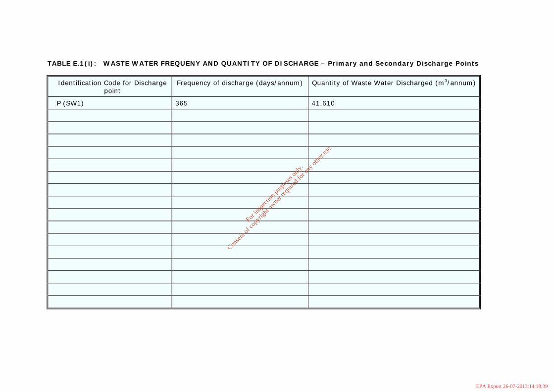
TABLE E.1(i): WASTE WATER FREQUENY AND QUANTITY OF DISCHARGE – Primary and Secondary Discharge Points
Identification Code for Discharge point
Frequency of discharge (days/annum) Quantity of Waste Water Discharged (m3/annum)
P (SW1) 365 41,610
For
insp
ectio
n pur
pose
s only
.
Conse
nt of
copy
right
owne
r req
uired
for a
ny ot
her u
se.
EPA Export 26-07-2013:14:18:39

TABLE E.1(ii): WASTE WATER FREQUENY AND QUANTITY OF DISCHARGE – Storm Water Overflows
Identification Code for Discharge point
Frequency of discharge (days/annum)
Quantity of Waste Water Discharged (m3/annum)
Complies with Definition of Storm Water Overflow
SW2 Discharge in emergency situation only
Not recorded Y
For
insp
ectio
n pur
pose
s only
.
Conse
nt of
copy
right
owne
r req
uired
for a
ny ot
her u
se.
EPA Export 26-07-2013:14:18:39

ANNEX 2: Check List For Regulation 16 Compliance Regulation 16 of the Waste Water Discharge (Authorisation) Regulations, 2007 (S.I. No. 684 of 2007) sets out the information which must, in all cases, accompany a discharge licence application. In order to ensure that the application fully complies with the legal requirements of Regulation 16 of the 2007 Regulations, all applicants should complete the following. In each case, refer to the attachment number(s) of your application which contain(s) the information requested in the appropriate sub-article. Regulation 16(1) In the case of an application for a waste water discharge licence, the
application shall -
Attachment Number
Checked by Applicant
(a) give the name, address, telefax number (if any) and telephone number of the applicant (and, if different, of the operator of any treatment plant concerned) and the address to which correspondence relating to the application should be sent and, if the operator is a body corporate, the address of its registered office or principal office,
Application Form
(b) give the name of the water services authority in whose functional area the relevant waste water discharge takes place or is to take place, if different from that of the applicant,
Application Form
(c) give the location or postal address (including where appropriate, the name of the townland or townlands) and the National Grid reference of the location of the waste water treatment plant and/or the waste water discharge point or points to which the application relates,
Application Form
(d) state the population equivalent of the agglomeration to which the application relates,
B9(i)
(e) specify the content and extent of the waste water discharge, the level of treatment provided, if any, and the flow and type of discharge,
C1 C1.1 C1.3
(f) give details of the receiving water body, including its protected area status, if any, and details of any sensitive areas or protected areas or both in the vicinity of the discharge point or points likely to be affected by the discharge concerned, and for discharges to ground provide details of groundwater protection schemes in place for the receiving water body and all associated hydrogeological and geological assessments related to the receiving water environment in the vicinity of the discharge.
F1 F1.1
ANNEX 2.doc ANNEX – Standard Forms
For
insp
ectio
n pur
pose
s only
.
Conse
nt of
copy
right
owne
r req
uired
for a
ny ot
her u
se.
EPA Export 26-07-2013:14:18:39

Regulation 16(1) continued…/
Attachment Number
Checked by Applicant
(g) identify monitoring and sampling points and indicate proposed arrangements for the monitoring of discharges and, if Regulation 17 does not apply, provide details of the likely environmental consequences of any such discharges,
B2 D2 E3
(h) in the case of an existing waste water treatment plant, specify the sampling data pertaining to the discharge based on the samples taken in the 12 months preceding the making of the application,
E4
(i) describe the existing or proposed measures, including emergency procedures, to prevent unintended waste water discharges and to minimise the impact on the environment of any such discharges,
C1.1
(j) give particulars of the nearest downstream drinking water abstraction point or points to the discharge point or points,
Not Applicable
(k) give details, and an assessment of the effects, of any existing or proposed emissions on the environment, including any environmental medium other than those into which the emissions are, or are to be made, and of proposed measures to prevent or eliminate or, where that is not practicable, to limit any pollution caused in such discharges,
F1 F1.1
(l) give detail of compliance with relevant monitoring requirements and treatment standards contained in any applicable Council Directives of Regulations,
F1
(m) give details of any work necessary to meet relevant effluent discharge standards and a timeframe and schedule for such work.
Not Applicable
(n) Any other information as may be stipulated by the Agency.
ANNEX 2.doc ANNEX – Standard Forms
For
insp
ectio
n pur
pose
s only
.
Conse
nt of
copy
right
owne
r req
uired
for a
ny ot
her u
se.
EPA Export 26-07-2013:14:18:39

Regulation 16(3) Without prejudice to Regulation 16 (1) and (2), an application for a licence shall be
accompanied by -
Attachment Number
Checked by the applicant
(a) a copy of the notice of intention to make an application given pursuant to Regulation 9,
B8
(b) where appropriate, a copy of the notice given to a relevant water services authority under Regulation 13,
Not Applicable
Such other particulars, drawings, maps, reports and supporting documentation as are necessary to identify and describe, as appropriate -
B1 B2 B3
(i) the point or points, including storm water overflows, from which a discharge or discharges take place or are to take place, and
B2
(c)
(ii) the point or points at which monitoring and sampling are undertaken or are to be undertaken,
B2
(d) such fee as is appropriate having regard to the provisions of Regulations 38 and 39. B9(iii) Regulation 16(4) An original application shall be accompanied by 2 copies of it and of all accompanying documents and particulars as required under Regulation 16(3) in hardcopy or in an electronic or other format as specified by the Agency.
Application Form
Regulation 16(5) For the purpose of paragraph (4), all or part of the 2 copies of the said application and associated documents and particulars may, with the agreement of the Agency.
Signed original. Attached 2 hardcopies of application provided or 2 CD versions of application (PDF files) provided. Attached 1 CD of geo-referenced digital files provided. Attached Regulation 17 Where a treatment plant associated with the relevant waste water works is or has been subject to the European Communities (Environmental Impact Assessment) Regulations 1989 to 2001, in addition to compliance with the requirements of Regulation 16, an application in respect of the relevant discharge shall be accompanied by a copy of an environmental impact statement and approval in accordance with the Act of 2000 in respect of the said development and may be submitted in an electronic or other format specified by the Agency
Not Applicable
EIA provided if applicable Not Applicable
2 hardcopies of EIS provided if applicable. Not Applicable
ANNEX 2.doc ANNEX – Standard Forms
For
insp
ectio
n pur
pose
s only
.
Conse
nt of
copy
right
owne
r req
uired
for a
ny ot
her u
se.
EPA Export 26-07-2013:14:18:39

2 CD versions of EIS, as PDF files, provided. Not Applicable
ANNEX 2.doc ANNEX – Standard Forms
For
insp
ectio
n pur
pose
s only
.
Conse
nt of
copy
right
owne
r req
uired
for a
ny ot
her u
se.
EPA Export 26-07-2013:14:18:39