
CertiKOS: An Extensible Architecture for Building ... - seltzer.com
Upload
khangminh22Category
view
4download
0
ANIMAL-FARM: An Extensible Frameworkfor Algorithm Visualization
Vom Fachbereich Elektrotechnik und Informatik
der Universitat Siegen
zur Erlangung des akademischen Grades
Doktor der Ingenieurwissenschaften
(Dr.-Ing.)
genehmigte Dissertation
von
Diplom-Informatiker Guido Roßling
geboren in Darmstadt
1. Gutachter: Prof. Dr. Bernd Freisleben
2. Gutachter: Prof. Dr. Mira Mezini
Tag der mundlichen Prufung: 11. April 2002

ii

Acknowledgments
The material presented in this thesis is based on my research during my time as a research assistantin the Parallel Systems Research Group at the Department of Electrical Engineering and ComputerScience at the University of Siegen, Germany.I would like to thank all collaboration partners who made this research enjoyable and productive.Apart from many discussion partners at conferences who offered insights or sparked ideas, I wantto thank some persons individually.First of all, I want to thank my academic mentor Bernd Freisleben who gave me the freedom neededfor developing this thesis. He also supported the incorporation of algorithm visualizations in theIntroduction to Computer Science course. Apart from giving hints on academic research techniquesand assisting me in writing papers, he has also graciously invested much financial support into thestressful year of 2000, when I was presenting my research status at six conferences.I also wish to thank my second advisor Mira Mezini for her advice in software engineering aspects.Her insights on developing adaptable software systems gave me a starting point for my explorationof dynamically configurable and extensible software.Several members at the department have helped developing ANIMAL-FARM and the ANIMAL sys-tem. Markus Schuler helped to design and implement the first ANIMAL prototype as his Mas-ter’s Thesis. Jens Brodowski and Andre Floper adapted parts of the graphical editing facilities tochanged Swing interfaces. Matthew Smith and Patrick Ahlbrecht also contributed to later stages ofthe development process by implementing add-ons. Andre Berten and Frank Katritzke proof-readdrafts of this thesis.Several researchers around the globe contributed ideas to the thesis. First of all, I want to thankTom Naps for many discussions and the productive cooperation in adapting algorithm visualiza-tion systems to pedagogical purposes. Stuart Hansen provided several animations generated fromstudent assignments, as well as hints on improving ANIMAL. Nils Faltin offered ideas on adaptingalgorithm visualizations to improve the success of teaching the underlying content.I thank my parents for their continuous support, without which I would not have been able tocome this far. Finally, grateful thanks go to my wife Annika and our son Fabian for their supportduring the development of this thesis and especially the finishing phase. Without them and theirinspiration, I would have found it much harder to take a step back during the writing process andallow phases of rest that helped firming up the content of the thesis.
iii

iv Zusammenfassung
Zusammenfassung
Die Visualisierung und Animation von Algorithmen ist in den letzten Jahren sowohl bei Lehrkraftenals auch bei Lernenden auf weltweit zunehmendes Interesse gestoßen. Dieses Interesse wird belegtdurch die wachsende Anzahl an wissenschaftlichen Publikationen, verfugbaren Animationssyste-men und die Anzahl frei erhaltlicher Animationen im World Wide Web. In ihrem Artikel von 1998geben Price, Baecker und Small die Zahl verfugbarer Animationssysteme als “uber 150” an [156].Seit dem Zeitpunkt der Publikation ist diese Zahl nochmal deutlich gestiegen.Diese Arbeit stellt ein Framework fur Algorithmenvisualisierung (AV) vor, das zahlreiche beson-dere Eigenschaften bietet, die es von aktuellen Animationssystemen abhebt. Hierzu zahlt insbeson-dere die sehr weitreichende Dynamik des Frameworks hinsichtlich seiner Zusammenstellung. Furdiesen Zweck wird die Verwendung dynamischer Lookup-Datenstrukturen konsequent auf die Ad-ministration sowohl von Komponenten als auch deren Attributen ausgedehnt. Als Ergebnis entstehtein Framework, das die Einfugung einzelner Komponenten zur Laufzeit durch dynamisches Ladenebenso unterstutzt wie die Entfernung von Komponenten und die Einfuhrung zusatzlicher “At-tribute”.Ein besonderes Konzept zur dynamischen Vermittlung nutzbarer Funktionalitaten durch eine Abar-beitung von Anfragen und Bereitstellung von Auswahlmoglichkeiten mittels einer sogenanntenHandler-Klasse findet im Framework weitreichenden Einsatz. Dieses Konzept kann auch in vielenanderen Softwarebereichen erfolgreich eingesetzt werden. Zusatzlich unterstutzt das Frameworkdie Verwendung ubersetzbarer GUI-Elemente auf Basis der Java Swing-Bibliothek, wobei gleich-zeitig die Erstellung der Komponenten vereinfacht wird. Da diese dynamischen Eigenschaftendes Frameworks fur viele Anwendungsgebiete interessant sind, werden sie im Rahmen der Arbeitzunachst abstrakt vorgestellt, bevor sie in den konkreten Anwendungszweck der Algorithmenvisu-alisierung eingebettet werden.Zu den besonderen Leistungen des Frameworks im Bereich der Algorithmenvisualisierung zahltinsbesondere die Unterstutzung fur flexible Ablaufkontrolle inklusive vollwertigem Ruckwartsab-spielen der Animationsinhalte. Zur Demonstration der Nutzbarkeit des Frameworks stellt die Ar-beit eine Umsetzung in einen konkreten Prototypen vor, der weitere Funktionsmerkmale beinhal-tet. Hierzu zahlen etwa die Unterstutzung mehrerer Generierungs- und Editierarten sowie eineeingebaute Skriptsprache mit Unterstutzung fur modulare Animationskomponenten. Die direkteUbersetzung von Animationsinhalten mit automatischer Anpassung der Positionen davon betrof-fener Objekte wird im Rahmen des Prototyps erstmals im Bereich der AV vorgestellt.Die Arbeit ist wie folgt strukturiert. Kapitel 2 gibt einen kurzen Uberblick uber die Geschichteder Algorithmenanimation. Basierend auf Price et al. [156] werden vier Rollen im Umgang mitAV-Systemen vorgestellt: Nutzer verwenden das System zum Betrachten und Interagieren mit derAnimation; Visualisierer erstellen die Animationen; Entwickler erstellen oder erweitern das Ani-mationssystem; Programmierer implementieren den zu animierenden Algorithmus, eventuell ohnedabei von einer geplanten Animation zu wissen. Einzelne Personen konnen dabei mehrere Rolleninnehaben. So wird beispielsweise der Visualisierer oftmals die Rolle des Nutzers annehmen, umsich von der Qualitat der erstellten Animation zu uberzeugen.Zusatzlich wird ein einfaches Klassifikationsschema fur Animationssysteme vorgestellt, das dieSysteme einteilt in themengebundene Systeme sowie anhand der Animationserstellungsart nachmanueller Eingabe, API-Programmierung, Skriptsprachenbefehlen oder logischen Beschreibungen.Die Verteilung der einzelnen Rollen sowie typische Starken und Schwachen der Ansatze werdendabei ebenfalls beleuchtet.

Zusammenfassung v
Basierend auf einer umfangreichen Betrachtung verfugbarer Applets und AV-Systemen sowie Lite-raturrecherchen werden Anforderungen an AV-Systeme formuliert. Die Anforderungen sind un-terteilt in allgemeine sowie von den einzelnen Nutzungsrollen ausgehende und werden unter Beruck-sichtigung der relevanten Publikationen in Kapitel 3 prasentiert. Aktuelle AV-Systeme realisierennur eine stark eingeschrankte Untermenge dieser Anforderungen. Andererseits macht es die stetigsteigende Erwartungshaltung hinsichtlich Funktionalitat in allen Softwarebereichen unwahrschein-lich, dass es ein “ideales” AV-System geben kann, das allen Wunschen gerecht werden kann. Dahersollte ein AV-System so flexibel gestaltet werden, dass Erganzungen und Erweiterungen der Funk-tionalitat so leicht wie moglich realisiert werden konnen.Aufgrund dieser Uberlegung prasentiert Kapitel 4 den Entwurf des ANIMAL-FARM Frameworksfur dynamisch erweiterbare und anpassbare AV-Systeme. Das Framework adressiert sowohl soft-waretechnische als auch AV-bezogene Anforderungen. Aus Sicht der Softwaretechnik ist insbeson-dere die abstrakte Beschreibung des Frameworks interessant, die auf dynamischen Laden undder intensiven Verwendung dynamischer Lookup-Strukturen beruht und damit eine dynamischeZusammenstellung und Erweiterbarkeit erlaubt. Hierzu zahlt auch die strikte Entkoppelung zweierzentraler Komponenten durch das Handler-Konzept, das eine sehr konsequente Ausdehnung desPrinzips der Trennung von Aufgabengebieten (engl. separation of concerns) erlaubt und als Ent-wurfsmuster (engl. design pattern) fur den Entwurf dynamisch anpassbarer Kommunikation dienenkann. Ein allgemeines Softwarepaket zur Ubersetzung von grafischen Elementen rundet den soft-waretechnischen Leistungsumfang des Frameworks ab.Aus AV-Sicht ist einer der entscheidenden Beitrage des Frameworks die effiziente Unterstutzungdes Zuruckspulens und sogar des flussigen Ruckwartsabspielens von Animationen. Auf dem FirstInternational Program Visualization Workshop im Jahr 2000 stellte ein Mitglied des Programmkomi-tees die Bedeutung des Zuruckspulens als “one of the most important ‘open questions’ in AV”heraus [2]. Das hier vorgestellte Framework beinhaltet diese Funktionalitat, wurde aber wenigerals ein halbes Jahr nach Publikation des Artikels fertiggestellt, was die Ausdruckskraft der ihmzugrundeliegenden Konzepte unterstreicht.Kapitel 5 stellt die erste Umsetzung des Frameworks vor: das ANIMAL System. ANIMAL ist dy-namisch erweiter- und anpassbar und komplett unabhangig von einem Verwendungskontext. Diemeisten denkbaren grafischen Inhalte im zweidimensionalen Raum konnen basierend auf den un-terstutzten Primitiven Punkt, Linienzug / Polygon, Text und Kreisbogen sowie den Animations-effekten fur das zeigen / verbergen, verschieben, rotieren sowie umfarben von Primitiven dargestelltwerden. In einigen Fallen mussen Primitive zur Reprasentation eines neuen Objekttyps kombiniertwerden.Die Erweiterbarkeit von ANIMAL unter Nutzung der Strukturen des ANIMAL-FARM Frameworkswird in Kapitel 6 diskutiert, indem unter anderem Listenelemente als neue Primitive vorgestelltwerden. Ein Listenelement besteht aus einem Text, zwei Polygonen sowie einer Menge von Li-nienzugen mit einer Pfeilspitze am Ende als Modellierung der Zeiger. Andere Beispielerweite-rungen im Kapitel umfassen einen Zoom Effekt, weitere Untertypen des allgemeinen Effekts zumVerschieben von Objekten, zusatzliche Import- und Export-Filter sowie die Hinzufugung weitererSprachenunterstutzung zur grafischen Benutzerschnittstelle.Die Evaluation von ANIMAL in Kapitel 7 zeigt, dass ANIMAL alle gestellten Anforderungen bis aufsieben unterstutzt. Sieben weitere Anforderungen werden nur teilweise angeboten, wahrend funfzusatzliche Anforderungen zwar erfullt werden, von ANIMAL als kontextunabhangiges Systemaber nicht garantiert werden konnen. Insgesamt erfullt ANIMAL mehr Anforderungen als irgendeinanderes aktuelles AV-System.

vi Zusammenfassung
Die wissenschaftlichen Hauptbeitrage dieser Arbeit liegen in verschiedenen Bereichen. Die inKapitel 3 zusammengetragenen Anforderungen resultieren aus einer sorgfaltigen Literaturrecherchesowie eigenen Uberlegungen. Sie sind umfangreicher als bisherige einschlagige Publikationen.Gleichzeitig werden die vier verschiedenen Nutzungsrollen in Betracht gezogen sowie allgemeineAnforderungen gestellt.Das Framework dehnt die Verwendung von Hashtabellen zur Speicherung von Werten konsequentauf die Anforderungen der dynamischen Erweiterbarkeit und Adaptivitat aus. Anstelle einfacherWerte wird Hashing zur Verwaltung der zu einem konkreten Zeitpunkt zur Verfugung stehendenKomponenten genutzt, was eine leichte Erganzung oder Entfernung von Komponenten begunstigt.Der Zustand der einzelnen Komponenten wird ebenfalls in einer dynamischen Struktur verwaltetanstelle einer festen Codierung in Form von Attributen. Hierdurch konnen Entwickler leicht weitereZustandsbeschreibungen einfugen, ohne den Quelltext des Frameworks oder des Gesamtsystemszu andern. Im Rahmen des Frameworks finden zusatzlich mehrere Entwurfsmuster Verwendung,indem etwa die zentralen Hashtabellen in einem Singleton [61, p. 217ff] verwaltet werden.Die bereits erwahnten Handler-Klassen dienen zu einer vollstandigen Entkoppelung von primarenKomponenten. Fur diese Vorgehensweise zur Vermittlung verfugbarer Funktionalitaten zwischenden entkoppelten Komponenten finden sich zahlreiche Anwendungsgebiete. Ein Hauptvorteil desAnsatzes ist dabei die stark vereinfachte Entwicklung von Erweiterungen der entkoppelten Kom-ponenten durch eine klare Trennung der Aufgabengebiete (engl. separation of concerns). Hand-ler agieren in diesem Sinn als ein spezielles Entwurfsmuster fur die bessere Unterstutzung vonerweiterbaren Systemen.Die Strategien fur die Erstellung dynamisch erweiterbarer Systeme werden im Rahmen der Arbeiterstmals auf den Entwurf eines Frameworks fur AV-Systeme ubertragen. Hier kann die verwen-dete Modellierung ihre volle Flexibilitat durch die von ihr unterstutzten Operationen herausstellen.Die strikte Trennung der Aufgabengebiete mittels des Handler-Konzepts ermoglicht dabei eine ein-fache und effiziente Unterstutzung des Ruckwartslaufs in Animationen. Gleichzeitig ermoglicht dieGrundstruktur des Frameworks die Ausdehnung des Ruckwartslaufs – sowohl in Form eines schritt-basierten Zuruckspulens als auch in dynamischem Ruckwartsabspielen – auf dynamisch eingebet-tete Erweiterungen von Animationseffekten und grafischen Objekte, ohne dass der Autor dieserKomponenten hierzu eine zusatzliche Implementierung leisten muss. Verglichen mit den meis-ten bisherigen AV-Systemen bietet das vorgestellte Framework “echtes” Ruckwartsspielen anstelleder Nutzung einer eingeschrankten Historie. Zusatzlich verfolgt das Framework eine deutlicheTrennung von Inhalten (engl. separation of concerns), die in ihrer Ausgestaltung eine sehr großeFlexibilitat erlaubt.Die im Rahmen des Frameworks vorgestellten Komponenten fur ubersetzbare GUI-Komponentenwerden zusatzlich auch fur die Unterstutzung von ubersetzbaren Animationen genutzt. Hierzu isteine relative Platzierung der Primitiven erforderlich, um den unterschiedlichen Abmessungen vonTexten in verschiedenen Sprachen Rechnung zu tragen.Die in ANIMAL eingebettete und im Rahmen dieser Arbeit vorgestellte Skriptsprache ANIMAL-SCRIPT bietet zusatzlich Unterstutzung fur modulare Animationskomponenten mit der Moglichkeitzum Datenaustausch. ANIMALSCRIPT-Animationen konnen manuell erstellt oder automatischgeneriert werden, wobei die Eingabedaten des Nutzers oder Visualisierers entsprechend beruck-sichtigt werden. In Kombination mit dem JHAVE-System [131, 181] unterstutzt ANIMALSCRIPT
ebenfalls interaktive Vorhersagen als didaktisch motiviertes Modell zur Verbesserung des Verstand-nisses.Teile dieser Arbeit wurden bereits als Konferenzbeitrage oder Journalartikel veroffentlicht. Die

Zusammenfassung vii
verschiedenen Techniken zur Generierung von Animationsinhalten fur Lehrzwecke wurden zuerstbei der SITE Konferenz 2000 prasentiert [173]. Ein Beitrag bei der SIGCSE Konferenz im Jahr2000 [174] erlauterte die Motivation fur die Verwendung von AV-Systemen in einer Vorlesung zurEinfuhrung in die Informatik. Der Beitrag stellte den damals aktuellen Stand des ANIMAL-Systemsvor. Zwei Beispielanimation zu Quicksort und der Verifikation von Algorithmen wurden detailiertbeschrieben, zusammen mit den im Einsatz von AV gewonnenen Erfahrungen.Auf der Basis zweier Konferenzposter [175, 183] und der sich daraus ergebenden Diskussionmit Konferenzteilnehmern wurde auf der ITiCSE 2000 [184] der Entwurf des ANIMAL-Systemsvorgestellt. Zu diesem Zeitpunkt bot ANIMAL nur eine grafische Schnittstelle zur Erzeugung vonAnimationen und eingeschrankte Unterstutzung von Zoomen und Export. Ein Beitrag beim FirstInternational Program Visualization Workshop im Anschluß an ITiCSE 2000 [177] und einemBeitrag zur SIGCSE 2001 [179] stellte die Skriptsprache ANIMALSCRIPT vor. Eine kurze Beschrei-bung der dynamischen Erweiterbarkeit von ANIMALSCRIPT befindet sich ebenfalls in dem letzt-genannten Beitrag.Die vier Nutzerrollen gemaß Price et al. [156] wurden zuerst in einer gleichzeitigen Veroffent-lichung in den Zeitschriften Informatik / Informatique [178] und Novatica [176] der Informatik-Dachorganisationen der Schweiz und Spaniens verwendet. Diese Artikel beschreiben auch weiter-fuhrende Merkmale von ANIMAL, wie etwa die Internationalisierung und die Strukturierung vonAnimationen.Drei weitere Publikationen befinden sich zur Zeit im Druck. Ein Artikel in der Aprilausgabe2002 des Journal of Visual Languages and Computing [180] umfasst die Unterstutzung der vierNutzerrollen sowie die grundlegenden Merkmale im Rahmen von ANIMAL. Ein Beitrag bei derITiCSE 2002 [181] prasentiert mehrere padagogische Anforderungen an AV-Systeme und erlautert,wie diese in der Kombination von JHAVE [131] mit ANIMAL umgesetzt werden. WesentlicheEntscheidungshilfen fur oder gegen konkrete Animationssysteme liefert der Beitrag bei der SECIII Konferenz [170].Weitere Publikationen befinden sich zur Zeit in Begutachtung fur den Second International Pro-gram Visualization Workshop. In [171] wird das ANIMAL-FARM Framework von Kapitel 4 vorge-stellt. Ausgewahlte aktuelle Forschungsvorhaben im AV-Bereich, die in [182] vorgestellt wer-den, sollen AV-System interaktiver machen und in die Richtung intelligenter Tutorensysteme wei-terfuhren. Die Entwicklung eines umfangreichen AV-Repositories wird in [40] vorgestellt.

viii Zusammenfassung

Contents
1 Introduction 1
2 Related Work 52.1 Introduction . . . . . . . . . . . . . . . . . . . . . . . . . . . . . . . . . . . . . . 52.2 A Short History of Algorithm Animation . . . . . . . . . . . . . . . . . . . . . . . 62.3 Animation User Roles . . . . . . . . . . . . . . . . . . . . . . . . . . . . . . . . . 72.4 Animation Generation Approaches . . . . . . . . . . . . . . . . . . . . . . . . . . 8
2.4.1 Topic-Specific Animation . . . . . . . . . . . . . . . . . . . . . . . . . . 82.4.2 Manual Generation in a GUI . . . . . . . . . . . . . . . . . . . . . . . . . 102.4.3 API-based Generation . . . . . . . . . . . . . . . . . . . . . . . . . . . . 122.4.4 Scripting-based Generation . . . . . . . . . . . . . . . . . . . . . . . . . . 132.4.5 Declarative Visualization Generation . . . . . . . . . . . . . . . . . . . . 142.4.6 Generation By Code Interpretation . . . . . . . . . . . . . . . . . . . . . . 15
2.5 Evaluation of Representative Tools . . . . . . . . . . . . . . . . . . . . . . . . . . 172.5.1 Algorithm Animation Applets on the WWW . . . . . . . . . . . . . . . . 182.5.2 Algorithm Animation Systems . . . . . . . . . . . . . . . . . . . . . . . . 29
2.6 Summary . . . . . . . . . . . . . . . . . . . . . . . . . . . . . . . . . . . . . . . 39
3 Requirements Analysis 433.1 Introduction . . . . . . . . . . . . . . . . . . . . . . . . . . . . . . . . . . . . . . 433.2 General Requirements . . . . . . . . . . . . . . . . . . . . . . . . . . . . . . . . 44
3.2.1 System Requirements . . . . . . . . . . . . . . . . . . . . . . . . . . . . 443.2.2 Development State and Performance . . . . . . . . . . . . . . . . . . . . . 463.2.3 Applicability . . . . . . . . . . . . . . . . . . . . . . . . . . . . . . . . . 47
3.3 User Requirements . . . . . . . . . . . . . . . . . . . . . . . . . . . . . . . . . . 483.3.1 Content Presentation . . . . . . . . . . . . . . . . . . . . . . . . . . . . . 483.3.2 Animation Display Controls . . . . . . . . . . . . . . . . . . . . . . . . . 503.3.3 User Interaction . . . . . . . . . . . . . . . . . . . . . . . . . . . . . . . . 503.3.4 Educational Support . . . . . . . . . . . . . . . . . . . . . . . . . . . . . 523.3.5 User Interface . . . . . . . . . . . . . . . . . . . . . . . . . . . . . . . . . 543.3.6 File Exchange . . . . . . . . . . . . . . . . . . . . . . . . . . . . . . . . . 553.3.7 Algorithm Understanding . . . . . . . . . . . . . . . . . . . . . . . . . . 563.3.8 Miscellaneous . . . . . . . . . . . . . . . . . . . . . . . . . . . . . . . . 57
3.4 Visualizer Requirements . . . . . . . . . . . . . . . . . . . . . . . . . . . . . . . 583.4.1 Applicability . . . . . . . . . . . . . . . . . . . . . . . . . . . . . . . . . 58
ix

x CONTENTS
3.4.2 Animation Display . . . . . . . . . . . . . . . . . . . . . . . . . . . . . . 603.4.3 Animation Generation . . . . . . . . . . . . . . . . . . . . . . . . . . . . 61
3.5 Developer Requirements . . . . . . . . . . . . . . . . . . . . . . . . . . . . . . . 633.6 Programmer Requirements . . . . . . . . . . . . . . . . . . . . . . . . . . . . . . 643.7 Summary . . . . . . . . . . . . . . . . . . . . . . . . . . . . . . . . . . . . . . . 64
4 The ANIMAL-FARM Algorithm Visualization Framework 674.1 Introduction . . . . . . . . . . . . . . . . . . . . . . . . . . . . . . . . . . . . . . 674.2 Concepts for Extensible Framework Design . . . . . . . . . . . . . . . . . . . . . 68
4.2.1 Using Properties to Model Object State . . . . . . . . . . . . . . . . . . . 684.2.2 Flexible Import and Export . . . . . . . . . . . . . . . . . . . . . . . . . . 754.2.3 Internationalization and GUI Creation Support . . . . . . . . . . . . . . . 784.2.4 Component Assembly and Administration . . . . . . . . . . . . . . . . . . 814.2.5 Decoupling Associated Objects Using Handlers . . . . . . . . . . . . . . . 834.2.6 Summary of Framework Extensibility and Adaptivity Approaches . . . . . 86
4.3 A Brief Framework Overview . . . . . . . . . . . . . . . . . . . . . . . . . . . . 884.4 Graphical Objects . . . . . . . . . . . . . . . . . . . . . . . . . . . . . . . . . . . 904.5 Animation Effects . . . . . . . . . . . . . . . . . . . . . . . . . . . . . . . . . . . 954.6 Graphical Object Handlers . . . . . . . . . . . . . . . . . . . . . . . . . . . . . . 984.7 Animation Representation . . . . . . . . . . . . . . . . . . . . . . . . . . . . . . 1024.8 Animation Player Front-end . . . . . . . . . . . . . . . . . . . . . . . . . . . . . 1064.9 Animation Import and Export . . . . . . . . . . . . . . . . . . . . . . . . . . . . . 1124.10 Summary . . . . . . . . . . . . . . . . . . . . . . . . . . . . . . . . . . . . . . . 112
5 The ANIMAL Animation System 1175.1 Introduction . . . . . . . . . . . . . . . . . . . . . . . . . . . . . . . . . . . . . . 1175.2 ANIMAL Architecture . . . . . . . . . . . . . . . . . . . . . . . . . . . . . . . . . 117
5.2.1 Graphical Primitives . . . . . . . . . . . . . . . . . . . . . . . . . . . . . 1185.2.2 Point Primitives . . . . . . . . . . . . . . . . . . . . . . . . . . . . . . . . 1215.2.3 Polyline and Polygon Primitives . . . . . . . . . . . . . . . . . . . . . . . 1235.2.4 Text Primitives . . . . . . . . . . . . . . . . . . . . . . . . . . . . . . . . 1245.2.5 Arc Primitives . . . . . . . . . . . . . . . . . . . . . . . . . . . . . . . . 125
5.3 Animation Effects . . . . . . . . . . . . . . . . . . . . . . . . . . . . . . . . . . . 1265.3.1 Show Effect . . . . . . . . . . . . . . . . . . . . . . . . . . . . . . . . . . 1295.3.2 Timed Show Effect . . . . . . . . . . . . . . . . . . . . . . . . . . . . . . 1305.3.3 Color Change Effect . . . . . . . . . . . . . . . . . . . . . . . . . . . . . 1305.3.4 Move Effect . . . . . . . . . . . . . . . . . . . . . . . . . . . . . . . . . . 1325.3.5 Rotate Effect . . . . . . . . . . . . . . . . . . . . . . . . . . . . . . . . . 133
5.4 Transformation Handlers . . . . . . . . . . . . . . . . . . . . . . . . . . . . . . . 1335.5 ANIMAL’s Animation Display GUI . . . . . . . . . . . . . . . . . . . . . . . . . 1355.6 ANIMAL’s Editing GUI . . . . . . . . . . . . . . . . . . . . . . . . . . . . . . . . 1385.7 Import and Export . . . . . . . . . . . . . . . . . . . . . . . . . . . . . . . . . . . 141
5.7.1 ANIMALSCRIPT . . . . . . . . . . . . . . . . . . . . . . . . . . . . . . . 1425.8 Summary . . . . . . . . . . . . . . . . . . . . . . . . . . . . . . . . . . . . . . . 144

CONTENTS xi
6 Extending ANIMAL Using ANIMAL-FARM 1476.1 Introduction . . . . . . . . . . . . . . . . . . . . . . . . . . . . . . . . . . . . . . 1476.2 Extending Graphical Primitives . . . . . . . . . . . . . . . . . . . . . . . . . . . . 148
6.2.1 Example Extension: Image Support . . . . . . . . . . . . . . . . . . . . . 1486.2.2 Example Extension: List Element Support . . . . . . . . . . . . . . . . . . 149
6.3 Extending Animation Effects . . . . . . . . . . . . . . . . . . . . . . . . . . . . . 1516.4 Extending Handler Capabilities . . . . . . . . . . . . . . . . . . . . . . . . . . . . 153
6.4.1 Implementing a New Handler . . . . . . . . . . . . . . . . . . . . . . . . 1536.4.2 Example Extension: Move Subtype Support . . . . . . . . . . . . . . . . . 154
6.5 Adding Language Support . . . . . . . . . . . . . . . . . . . . . . . . . . . . . . 1556.6 Extending Import and Export Facilities . . . . . . . . . . . . . . . . . . . . . . . . 156
6.6.1 Example Extension: Adding JSamba Import Facilities . . . . . . . . . . . 1566.6.2 Example Extension: Image and Video Export . . . . . . . . . . . . . . . . 157
6.7 Interactivity Support . . . . . . . . . . . . . . . . . . . . . . . . . . . . . . . . . 1576.8 Summary . . . . . . . . . . . . . . . . . . . . . . . . . . . . . . . . . . . . . . . 158
7 Evaluation 1597.1 Introduction . . . . . . . . . . . . . . . . . . . . . . . . . . . . . . . . . . . . . . 1597.2 Evaluation of ANIMAL’s Support for the Requirements . . . . . . . . . . . . . . . 160
7.2.1 System Requirements Evaluation . . . . . . . . . . . . . . . . . . . . . . 1607.2.2 Extensibility Requirements . . . . . . . . . . . . . . . . . . . . . . . . . . 1607.2.3 Development State and Performance . . . . . . . . . . . . . . . . . . . . . 1627.2.4 Applicability . . . . . . . . . . . . . . . . . . . . . . . . . . . . . . . . . 1637.2.5 Animation Generation . . . . . . . . . . . . . . . . . . . . . . . . . . . . 1637.2.6 Content Presentation . . . . . . . . . . . . . . . . . . . . . . . . . . . . . 1657.2.7 User Interface . . . . . . . . . . . . . . . . . . . . . . . . . . . . . . . . . 1657.2.8 Content Display and Controls . . . . . . . . . . . . . . . . . . . . . . . . 1667.2.9 User Interaction . . . . . . . . . . . . . . . . . . . . . . . . . . . . . . . . 1677.2.10 Educational Support . . . . . . . . . . . . . . . . . . . . . . . . . . . . . 1677.2.11 Algorithm Understanding Support . . . . . . . . . . . . . . . . . . . . . . 1687.2.12 File Exchange . . . . . . . . . . . . . . . . . . . . . . . . . . . . . . . . . 1697.2.13 Programmer Requirements . . . . . . . . . . . . . . . . . . . . . . . . . . 169
7.3 Summary . . . . . . . . . . . . . . . . . . . . . . . . . . . . . . . . . . . . . . . 169
8 Conclusions 171
A References 175A.1 Extension Listings . . . . . . . . . . . . . . . . . . . . . . . . . . . . . . . . . . 181


Chapter 1
Introduction
One central challenge in computer science lies in understanding the dynamics of algorithms anddata structures. This is of particular importance in two areas: computer science education andprogramming, especially concerning debugging. Understanding how and why an algorithm suchas Quicksort works is challenging for students and novice programmers. Finding a presentationthat allows learners to see how the intricate details of an implementation cooperate and interdependis usually difficult. Pinpointing the precise location of an implementation bug is difficult even foradvanced programmers. Both tasks are especially difficult if a static medium such as paper or anirreversible presentation technique such as writing on a blackboard is used.Software for instructing novices how to program and debug their code is increasingly used in com-puter science education. Algorithm Visualization (AV) systems are a special application of softwarevisualization, focusing on visualizing the dynamic behavior of software. The most common appli-cation areas of AV lie in education and debugging. The interest in AV from computer scienceeducation has steadily increased over the last years, as evidenced by the number of publications onthe topic. AV software visualizes the behavior of algorithms and data structures and thus mostlyfrees the user from having to manually trace the underlying implementation code.A large number of AV systems are already available, mainly from educational institutions. Theydiffer in a large number of ways, including the degree of interactivity, display strategy and the typeof supported input. The interactivity ranges from slide show-like displays without any interactiv-ity to full-fledged debuggers that let the user specify attribute values and invoke methods. Somedisplays may run automatically, possibly even without enabling the user to pause or slow down thedisplay. Other displays are triggered solely by user events such as pressing mouse buttons. A largevariety of different display control elements exist between the two extremes. Finally, the inputdata used by AV systems ranges from actual source code in a specific programming language tointeractive graphical editing using direct manipulation.The large variety of available systems presents a formidable challenge for users interested in em-ploying AV. The strengths, weaknesses and restrictions of a given system are usually not obvious atfirst glance. One drawback common to most current AV systems is the lack of support for easy cus-tomization of the system. Furthermore, it is highly unlikely that a given fixed system can meet alldemands of future applications. However, most systems cannot easily be extended with additionalfeatures.This thesis covers three main aspects for addressing these concerns. First, an extensive set ofrequirements for an “ideal” AV system is defined. These requirements also address different typesof interaction with AV systems including displaying and animation generation demands.
1

2 CHAPTER 1. INTRODUCTION
Second, we introduce a framework design for extensible and configurable systems. The frameworkconsequently uses dynamic loading for component acquisition and hashing for administrating thecomponents. Each hashed component acts as a Prototype [61, p. 127ff] and can be cloned foracquiring a new instance. The administration of components using hash tables allows easy additionand removal of individual components at run-time. By modeling the object state by propertiesinstead of fixed attributes, the framework also allows the introduction of new object properties atrun-time. The handler concept introduced in this thesis allows a very strict separation of concernsbetween two parties, with the negotiating handler fully decoupling the components. The frameworkalso provides a package for on-the-fly translation of arbitrary Swing-based GUI components. TheAV components of the framework support efficient animation rewinding and even reverse playing,which were considered “one of the most important ‘open questions’ in AV” in one of last year’smore prominent AV publications [2].Finally, we present a reference implementation prototype of the framework and analyze how it mea-sures against the set of requirements. The benefits of the framework design regarding extensibilityand adaptivity are emphasized by example extensions. As the prototype is extensible, requirementswhich are currently unsupported may be addressed by later extensions.This thesis is organized as follows. Chapter 2 introduces key terms used throughout this research,followed by an extensive examination of related AV systems. In chapter 3, we define and moti-vate a large set of AV system requirements. Where applicable, we also provide references to otherpublications that outline the rationale for a given requirement. Chapter 4 presents the design fordynamically extensible and configurable frameworks. The chapter introduces the consequent usageof dynamic data structures for supporting dynamic extensibility, as well as the handler concept use-ful for offering selective views of a given object’s functionality. The general-purpose frameworkdesign is then applied to AV with an emphasis on supporting the requirements discussed in chap-ter 3. In chapter 5, we present the implementation decisions taken in developing the prototypicalANIMAL AV system. The system is based on the framework introduced in chapter 4 and the set ofrequirements presented in chapter 3. Chapter 6 explores example extensions of the ANIMAL sys-tem. The features offered by ANIMAL are compared in chapter 7 with the requirements presentedin chapter 3. Chapter 8 concludes the thesis and outlines areas of further research.Parts of this thesis have been previously published in conference papers or journal articles. Thedifferent techniques for generating animation content for educational purposes were first presentedat the AACE SITE conference in 2000 [173]. A SIGCSE paper in 2000 [174] motivated the use ofadopting AV systems within an introductory computer science course. The primitives and effectssupported by ANIMAL were presented including example animation screen shots. Two exampleanimations, Quicksort and Introduction to Verification, were discussed in detail. The paper alsosummarized several of the lessons we learned during the course. Based on two conference posters[175, 183] and the discussion with conference participants, a publication at the ITiCSE conferencein 2000 [184] outlined the design of the ANIMAL AV system. It also presented the first rough setof requirements for AV systems. At this time, the system offered only manual generation within aGUI and very limited zooming and export facilities. A paper presented at the First InternationalProgram Visualization Workshop in 2000 (published in 2001) [177] and a SIGCSE paper [179]introduced the scripting language ANIMALSCRIPT, illustrating the main features and the generalstructure. A short description of how new features can be added dynamically was included in thepaper. The four usage roles described by Price et al. [156] were adopted by a joint publication in thejournals Informatik / Informatique [178] and Novatica [176] of the Swiss and Spanish ComputerSocieties, respectively. They also focused on additional functionality of the ANIMAL system, such

3
as internationalization and the labeling of animation steps.Three new publications are currently accepted for publication and in print. A journal article in theJournal of Visual Languages and Computing special issue on Software Visualization [180] presentsthe features that ANIMAL offers for the four roles defined by Price et al. in [156] and outlines thebasic features of ANIMAL. A paper at the ITiCSE 2002 conference [181] illustrates some of thepedagogical requirements for AV systems and how they are met by the combination of the JHAVEenvironment [131] and ANIMAL. Key decisions in adopting AV systems for teaching are presentedin a paper for the SEC III conference 2002 [170].Additionally, three publications are currently under review for publication in the Second Interna-tional Program Visualization Workshop. The ANIMAL-FARM framework is presented in [171]. Asecond paper presents current research issues in AV, which shall take AV systems further in thedirection of interactive intelligent tutoring [182]. Finally, the development of a comprehensive AVrepository is presented in [40].

4 CHAPTER 1. INTRODUCTION

Chapter 2
Related Work
2.1 Introduction
Algorithm visualization is a subtopic of software visualization. It focuses on the visualization ofthe higher level abstractions which describe software [156]. Algorithm animation is a variant ofAV that uses dynamic effects and transitions, rather than discrete scene images. Thus, it coversthe dynamic display of actual implementation code, pseudo code or other abstract views. In thefollowing, we will often refer to the field of AV as algorithm animation, or animation for short.The interest in algorithm animation research and application to education has grown over the lastyears, as indicated by the growing number of publications. A good recent overview of the field isgiven in the book by Stasko et al. [198]. The basic form of algorithm animation is shown in Fig-ure 2.1. The animation results from an “appropriate” transformation of the underlying algorithm.Various different types of transformation are examined in detail in later parts of this chapter.
appropriatetransformation
Algorithm
Animation
Figure 2.1: Base Form of Algorithm Animation Using an “Appropriate” Transformation
The term “animation” is understood differently by diverse researchers. Within the context of thiswork, animation always refers to a dynamic display of algorithmic behavior. The precise approachused for presenting the dynamics can choose from a set of options, including animated images orvideo streams. However, the focus is always taken to be on algorithms. Thus, special effects as usedin movies like Toy Story are not counted as animations. This chapter presents some of the historyof algorithm animation, the different roles taken by users of animation tools, and an overview ofthe different types of animation.We give a brief outline of the history of algorithm animation and then discuss the different rolesthat a person using an animation system can assume. After exploring the different approaches
5

6 CHAPTER 2. RELATED WORK
for generating algorithm animations, a large set of animation systems is briefly presented. Wefirst examine several Java applets ordered by their degree of interactivity. Full-fledged animationsystems are then examined ordered by the adopted generation type. The key findings of the chapterare summarized in the last section.
2.2 A Short History of Algorithm Animation
One main focus of algorithm animation is educational in nature: making algorithms easier to un-derstand and grasp. For an overview of how the field has evolved, we take a step back to previousdevelopments, many of which come from software engineering research. This research has led toa number of developments for addressing the problems of software complexity and comprehensi-bility. Examples include top-down design and stepwise refinement, as well as new concepts suchas object-oriented approaches to software design and development. For example, design patterns[61] help to reduce the complexity of software by providing a reusable class structure for certaincommon structures. Other regions of research and progress include the organization and manage-ment of development teams, integrated software development environments and computer-aidedsoftware engineering (CASE).Despite all these advances, the current appearance of programs usually does not contribute to mak-ing a program easily understandable. Baecker and Marcus [12] give an overview of various tech-niques for publishing C program code that help addressing this to a certain degree. Well-formattedcode is easier to read and follow than unindented code, and the addition of various layout techniquescan improve legibility even further. Comments following certain guidelines can be embedded intothe code and extracted by a tool to generate documentation. This approach is employed for ex-ample in Java, but has been used at least since 1984, when the WEB system by Knuth embeddeddocumentation into sources of the TEX typesetting system [106].Probably the first visual aid for understanding computer programs are flowcharts which were firstdemonstrated in 1947 by von Neumann and Goldstein [13]. Several later developments allowedautomatic generation from Fortran code, or embedding into source code. Nassi-Shneiderman dia-grams, introduced in 1973, present an alternative approach that counters the unstructured nature ofstandard flowcharts.All approaches described so far represent static visual displays of algorithms. The first dynamicdisplays go back to films by Knowlton [104, 105] that demonstrated a low-level list processinglanguage developed at Bell labs. The movies are attributed as being the first to use animationtechniques to portray program behavior and the first to address the visualization of dynamicallychanging data structures [13].Several more short films by other educators followed, including material by John Hopgood forhashing and syntax analysis and an animated PQ-tree data structure algorithm. Probably the mostinfluential film for algorithm animation is Sorting Out Sorting [14] by Baecker. Shown at many uni-versities all over the world, the movie introduces nine different internal sorting methods, includingan efficiency analysis. The movie is described in more detail in [11].The 1980s saw the wider availability of affordable personal workstations with bit-mapped displaysand graphical user interfaces. This advance allowed researchers to go beyond the prototypes andhighly specific animations of the previous decade and develop full-fledged algorithm animationsystems. The most important and well-known system of the time was the Brown Algorithm Sim-ulator and Animator (BALSA) by Brown [30], followed by BALSA-II in 1988. Due to the tight

2.3. ANIMATION USER ROLES 7
integration of BALSA with the teaching materials used, hundreds of undergraduates used the tool intheir course of study. Several later tools were inspired by aspects of BALSA.Since then, the number of animation systems has risen steadily. Price et al. [156] claim that by1998, more than 150 software visualization prototype systems and animations had been built. Thegrowing popularity of the Internet and especially the World-Wide Web has helped in spreadingthese tools and make users aware of the large number of offers available. The Complete Collectionof Algorithm Animations [33] lists all resources found by its creator in 1998. The reference bookby Stasko et al. [198] provides a good overview of the state of the art of the late 1990s.Today, various tools stray into hitherto unexplored areas of algorithm animation, including programauralization [28] and three-dimensional displays [29, 163]. Given the development speed in theyoung area of algorithm animation, it will be interesting to see what the state of art will be in tenyears. A good overview of the history of AV and general issues can be found in [198].
2.3 Animation User Roles
Price et al. [156] define four different roles in algorithm animation: programmer, software visual-ization software developer (or simply developer), visualizer and user. Programmer refers to theimplementer of the underlying algorithm to be animated, for example Quicksort. Developer refersto the implementer of the animation system, while the visualizer specifies the animation. Finally,the user views the resulting animation. Depending on the system, this may also include variousdegrees of interaction.Figure 2.2 shows the different roles and how they tie in with the algorithm, animation system andthe animation display. Note that in this context, the programmer may be unaware of animationplans by the visualizer. Therefore, many animation systems may not be able to provide services forthe programmer role.
Visualizer
User
DeveloperProgrammer
Algorithm
Animation
Animation System
Figure 2.2: Schematic View of User Roles
Each role has specific expectations of algorithm animation systems. Developers may be interestedin how easy it is to update or extend the system. They may also want to be able to adapt the systemto their preferences. Visualizers require flexible animation generation; different ways of generatinganimations may be required to address personal preferences or experience levels. Finally, users

8 CHAPTER 2. RELATED WORK
want to have a tool that runs smoothly, is easy to use and offers features such as video player-likecontrols.Many animation systems are geared for one or at most two different roles. In general, the later inthe development or display cycle of an animation a role appears, the more likely it is to be supportedby a given animation system. Thus, users located at the bottom rung of the generation process willusually find several features that allow for attractive animation display. Visualizers are also likely tofind features that help them in developing new animations, with the exception of some closed-shopsystems that can only display selected animations with fixed data sets.Developers are often not specially supported, due to the fact that most systems are simply shipped“as is” and are not meant to be extended or adapted at the client side. Finally, support for theprogrammer roles requires special care, as the programmer may not be aware of future animationplans. Thus, support for this role is usually limited to programs that work on interpreting theunderlying algorithm’s source code or extract debug data for interpretation.
2.4 Animation Generation Approaches
In this section, we discuss the approaches for generating animations. This classification is espe-cially important for the visualizer role responsible for generating animations, but may also haveconsequences on the other roles. Visualizers should choose an animation system that fits theirpersonal skills and preferences. Such systems may be easier or “more fun” to use, which maybe reflected in both the quantity and quality of the generated animations. The type of animationgeneration does not directly impact the features offered to the developer, programmer or user role.Therefore, the following sections focus on the support for the visualizer role, enabling them todetermine the base type of animation generation most appropriate to their situation.There are several different approaches for how animations can be generated by a visualizer. Oneapproach is using a graphical user interface, as included in most presentation tools such as Micro-soft PowerPointTM and StarOffice ImpressTM, or special generation tools such as MacromediaFlash. On the other end of the scale, some systems can automatically generate animations by in-terpreting source code or debug data. Between these extremes lie approaches that employ methodinvocations using a special visualization application programmer’s interface (API), use a collectionof ASCII-based commands (often also referred to as “scripting”), generate animations from dec-larations such as logical predicates, or explicitly encode animations for special topic areas. Thefollowing sections examine the different approaches for animation generation and characterize thedistribution of the four roles in each approach.
2.4.1 Topic-Specific Animation
Topic-specific animation systems offer special support for a limited number of applications. Thissupport is usually hard-coded, so that the system is restricted to the covered topics.Figure 2.3 shows the typical role distribution for topic-specific animation systems. The program-mer implements the original algorithm. The developer implements the complete tool including thegraphical user front-end for displaying the animation. The developer may use the implementationprovided by the programmer, or re-implement the algorithm. This alternative is indicated by adotted line connecting the original implementation and the animation system. The developer hasto adapt the algorithm so that it provides an animation while it is being executed. This is often

2.4. ANIMATION GENERATION APPROACHES 9
User role
Zoom
(empty)
Compare the elements
Programmer roleDeveloper roleVisualizer role
Figure 2.3: Role Distribution in Topic-Specific Systems
accomplished by adding special method invocations for generating the visualization. The origi-nal algorithm may also be split into separate units which are invoked in turn, each providing avisualization of special sub-aspects of the algorithm.The animation of the underlying algorithm is generated automatically. Thus, the visualizer role hasno direct part in the presentation. It may be possible to configure the appearance or behavior ofthe display, for example by setting the animation speed or zoom factor. However, these featurescan typically also be adjusted by the end user. Configurations by the visualizer may therefore bereadjusted by the user, weakening the role of the visualizer.The user interacts with the graphical front-end to see the animation. The amount of adjustablefeatures varies with each tool, but will usually include a “play” or “step” operation for displayingthe next step. Figure 2.3 also indicates some other possible features including pause, run, executeuntil end, or zooming.We select the image compression packages RLE, Quadtree and JPEG presented in [101] for illus-trating the typical strengths and weaknesses of topic-specific animations. Each of these packagesanimates a special approach for image compression using a fixed graphical front-end for visualiz-ing the embedded implementation code. Therefore, they cannot be used for other topics such as thecommon application area of sorting algorithms. Each system supports exactly one type of imagecompression algorithm: run-length encoding (RLE), Quadtree image segmentation and JPEG.The tools are very helpful in these application areas; however, they are also restricted to the embed-ded features. Several other approaches for image compression are missing. For example, the imagecompression algorithms employed in the popular GIF or PNG are not explained. The tools alsodo not support newer compression approaches such as Wavelets [35], fractal compression usingiterated function systems or weighted finite automata [41, 96]. Comparing the performance of thecovered algorithms is made more difficult due to their implementation in separate tools.These attributes are similar for most topic-specific systems. Developers of such specific systemspossess a precise knowledge of the animation content. Therefore, they can optimize the systemsto provide the best possible illustration of the topics as they perceive it. Note that in general, theperception of the most helpful or appropriate way of presentation may differ between the developer,visualizer and user. Most topic-specific animation systems do not give the user a chance to adaptthe display to his or her preferences.Topic-specific systems may often prevent visualizers from influencing the animation display. In an

10 CHAPTER 2. RELATED WORK
educational context, the visualizer role will typically be assumed by the educator, while the userswill be the students. The main advantage of topic-specific systems for visualizers is that they arefreed from having to generate the animation. Additionally, most topic-specific tools will allow theuser to change the input parameters, for example by providing a different image to be run throughthe compression algorithms in the packages described above. This allows users to experiment withdifferent data sets to get a better understanding of the algorithm’s behavior.The visualizer should carefully test the system before recommending it to his or her students. Apartfrom different perceptions of “good” presentation, there may also be fine but important differencesin the interpretation of the underlying algorithm. For example, there is a wide variety of waysfor choosing the pivot element in the Quicksort algorithm. If the approach used within the tool isnot identical to the one used by the visualizer in the educational context, the users may becomeconfused. Even worse, such small differences may go unnoticed by both visualizer and users. Inthis case, they may later find that they have developed different understandings of finer aspects ofthe covered topic. This may be especially harmful for the user in an examination context.
2.4.2 Manual Generation in a GUI
GUI-based generation is typically found in presentation tools such as Microsoft PowerPointTM
or StarOffice ImpressTM. Most presentation systems can also be used for algorithm animations,although they are not specialized for this usage. Figure 2.4 shows a typical distribution of the rolesin GUI-based animation generation.
User role
Zoom
Programmer roleVisualizer roleDeveloper role
Compare the elements
A
GraphicalEditor
Conceptual
Mapping
Figure 2.4: Role Distribution in GUI-Based Systems
The programmer implements the algorithm to be animated. The developer is responsible for im-plementing both the graphical editor and the user interface for displaying the animation. The taskof the visualizer is to perform a conceptual mapping that transforms the algorithm into a visualrepresentation. The GUI usually offers a set of graphical primitives and animation effects actingon them. The visualizer generates an animation by assembling a set of graphical primitives andtransforming them using the animation effects. The schematic system shown in Figure 2.4 offersthe basic graphic primitives line, rectangle, text and circle. It also offers moving, rotating, changing

2.4. ANIMATION GENERATION APPROACHES 11
the color and the visibility of graphical primitives, as shown from left to right. Finally, the user canuse the graphical front-end to view the animation.The graphical front-end used for displaying the animation may be the same as used for generatingthe animation. In the figure, the animation display contains the standard control elements includinga zoom operation. The graphical editor used for generating the animation may also be accessibleto the user.As an example of GUI-based animation generation, we consider manual generation using a standardpresentation tool such as Microsoft PowerPointTM or StarOffice ImpressTM. Several examplesof this can be found in the World-Wide Web, for example [158, 126, 22]. The decision to use apresentation tool is usually influenced by the fact that the tools are already being used for a slide-based presentation. Embedding animations in the same tool used throughout the presentation is themost “natural” approach. This also prevents possible problems regarding switching tasks during thepresentation or lack of memory. The latter is especially important when performing presentationson notebooks which usually have less RAM than full-fledged desktop computers.Most systems employing a graphical front-end for animation generation adhere to the WYSIWYGapproach – “what you see is what you get”. Thus, the visualizer will usually see a direct reflectionof his or her actions in the graphical display. This ability to immediately see the effects of anygiven action makes the approach very helpful, especially for novices or laypersons. The level ofabstraction expected of the visualizer is also lower than in most other approaches.The visualizer has a high degree of freedom in designing the animation, as the algorithm and theanimation are completely separated. Thus, he or she can choose any level of abstraction, and adaptthe graphical properties of the display and operations to his or her preferences. For example, amanually generated animation may gloss over some aspects of an algorithm and focus on the moresalient features, as perceived by the visualizer. Both the extent and the way in which this is usedmay differ between visualizer. For example, complex operations may be decomposed into theirbasic components and executed step by step.Another strength of GUI-based generation is that the visualizer can easily enhance the animationwith explanatory notes. As the animation is decoupled from actual implementation code, the expla-nation does not have to be embedded in the code, and can be arbitrarily terse or verbose, accordingto the visualizer’s interests.Finally, it is very easy for visualizers to illustrate the behavior of a given algorithm when certaincommon bugs are present. For example, invalid partitioning strategies for the Quicksort algorithmcan be presented, illustrating how sorting fails. The visualizer does not have to be concernedwith runtime considerations. Combining this approach with focusing strategies also enables thevisualizer to highlight the effect of typical coding mistakes. Infinite loops due to incorrect recursivecalls or loop conditions only impact the visualization. Incorrect pointer assignments also cannotcorrupt the actual algorithm. The commonly held opinion that one learns the most from mistakescan be tested by presenting such typical coding errors.Most graphical systems have a proprietary storage format, for example the format used by Mi-crosoft PowerPointTM. Import of and export to this format is usually supported in related tools.However, the format is usually ill suited for automatic generation. Part of this is due to the lackof freely available format documentation or the definition of the subcomponents. For practicalpurposes, this means that the visualizer usually has to generate the animation manually. There isoften no free API that the visualizer can use for generating the required format.Changing a single value of the algorithm’s input data may require editing the whole animationwithin the GUI. Thus, this type of animation generation is more suited to generating a prototype

12 CHAPTER 2. RELATED WORK
animation that serves as a guiding example. This animation may be shown and discussed within apresentation. The presence of only one animation of a given algorithm and the lack of support forquickly adapting the animation to different parameters may reduce the learning chance of the user.The time required to generate a full animation manually should not be underestimated by the visual-izer. The precise amount of time needed differs between reports. Our experience with the ANIMAL
system presented in chapter 5 indicates that visualizers already familiar with the given system re-quire roughly six hours for generating an “average” algorithm animation. This figure assumes thatthe visualizer has already decided on the presentation and thus can directly start generating theanimation. Interestingly enough, this time span corresponds to the required time for generating a“low-fidelity” animation using papers, pen and scissors, as reported by Hundhausen and Douglas[84].
2.4.3 API-based Generation
API-based generation involves method invocations using a special visualization application pro-grammer’s interface (API). The extent of support for primitive types and effects depends on theunderlying visualization API.
User role
Zoom
API Calls API Calls
Visualization API
Compare the elements
Visualizer roleDeveloper role
Programmer role
Figure 2.5: Role Distribution in API-based Systems
Figure 2.5 illustrates the different roles when using this generation approach. The programmer isresponsible for implementing the actual algorithm. The developer has to provide an appropriateimplementation of the visualization API, as well as a front-end for displaying the resulting anima-tion. The visualizer has to ensure that the appropriate API methods are invoked. The user interactswith the display front-end.API invocations can be implicit or explicit. The upper left section of the figure symbolizes implicitAPI method invocations. This may be supported by supplying a special class that incorporatesmethod invocations instead of a standard class. Note that this requires that the original implemen-tation expects appropriate objects which can be replaced by the visualizer with customized objects.An example of this approach is outlined in [138]. Implicit API invocation will in most cases still

2.4. ANIMATION GENERATION APPROACHES 13
require code modifications, but may be possible without touching the actual algorithm implementa-tion. Explicit invocations, on the other hand, modify the underlying implementation code by addingexplicit method invocations. This approach is shown in the upper middle of the figure.API-based generation has several advantages. Once the visualizer has implemented the appropriatemethod invocations, a new animation can be generated by simply invoking the algorithm. Illus-trating the behavior of the algorithm for different parameter values requires only passing in theappropriate parameters. Depending on the complexity of the algorithm, the visualizer may also beable to generate a new animation during a presentation. Users may also profit from this fact if theimplementation is available to them.A good visualization API may contain many methods that allow the visualizer to assemble theanimation easily. Finally, method invocations - whether implicit or explicit - are a “clean” way ofmodifying the underlying algorithm. Provided that the API method names and parameters are nottoo cryptic, the original algorithm may remain readable even when using explicit invocations.However, the API-based generation also has disadvantages. First of all, the algorithm to be ani-mated usually has to be implemented in the same programming language as the visualization API.There are a small number of exceptions, such as Java’s ability to invoke “native code” methodsusing the JINI interface. However, for most practical purposes, the visualizer has to settle for usingthe same programming language.API-based generation requires the visualizer to have a certain amount of programming skill in theAPI’s programming language. GUI-based generation, on the other hand, only requires that thevisualizer understands the algorithm and is able to “draw” it. Finally, API-based generation limitsthe visualizer to the methods provided in the API. The extent to which this is problematic dependson the extent of the API.
2.4.4 Scripting-based Generation
Scripting-based generation uses an intermediate format for representing the animation. Typically,this format consists of a set of text-based commands for generating or modifying graphical prim-itives. The title derives from the similarity of the output to a “program” written in a scriptinglanguage such as PHP [16] or Perl [208]. However, this should not be taken to imply the format isa full-fledged programming language capable of handling standard algorithms. Typically, the ex-pressiveness of the scripting language is strictly limited to animation purposes. Methods, variables,or loops are usually not supported.Figure 2.6 illustrates the distribution of roles in scripting-based generation. The programmer imple-ments an arbitrary algorithm or program. The visualizer is responsible for generating the animationin either of two ways. Firstly, he or she may substitute one or more parameter objects with specificobjects that produce scripting output, as illustrated in the top left part of the figure. Alternatively,he or she may add explicit method invocations or other statements that result in the generation ofscripting code within the algorithm. This output is analyzed by the scripting parser and displayedin the user front-end. Both parser and front-end have to be implemented by the developer. The usermerely interacts with the front-end for displaying the animation.Modifying an algorithm to generate scripting code is very similar to adding method invocations ina special visualization API, as described in section 2.4.3. Instead of reading the method documen-tation of a visualization API, the visualizer has to become familiar with the syntax of the scriptinglanguage. The scripting output can usually be stored in a file and loaded by the parser, allowing thevisualizer to store a set of animations. However, the compiler of the programming language can

14 CHAPTER 2. RELATED WORK
User role
Zoom
Scripting Code Scripting Code
Scripting Parser
Compare the elements
Programmer roleVisualizer roleDeveloper role
Figure 2.6: Role Distribution in Scripting-based Systems
only detect syntax errors concerning the invocation of the statements used for generating the script-ing code. Thus, a syntactically correct underlying algorithm may generate syntactically incorrectscripting code.Generating scripting code may be easier than figuring out appropriate API method invocations,depending on the visualizer’s programming skills and the extent of the API. Scripting offers theadvantage of storing animations to disk, so that visualizers can prepare a set of animations. Ifan animation using the requested parameter values is already available, it can be loaded directly;otherwise, the algorithm has to be invoked according to the parameters. One especially helpfulfeature of scripting based on stored scripting code is that the visualizer can fine-tune the animationby manually editing the stored code. Once the desired result is reached, this can be reinserted intothe implementation code for generating the animation. Thus, the visualizer may avoid having torecompile and execute the algorithm to determine the output. Depending on the characteristics ofthe algorithm, this can save a huge amount of time.
2.4.5 Declarative Visualization Generation
Declarative generation regards visualization as a mapping from a given program state to graphi-cal representations. It uses abstract mathematical expressions which can result in complex visualrepresentations. The declarative approach was introduced in [164] and is summarized in [163].Figure 2.7 illustrates the distribution of roles. The programmer develops the program code. Thevisualizer defines a mapping from program states to their graphical representation, and the userexamines the results of the visualization. The developer has to implement a system that analyzes themappings and generates the representation, as well as a front-end for displaying the animation. Theconceptual execution model updates the display whenever the program changes state in a relevantmanner. There may also be a special directive allowing the visualizer to deactivate the visualizationupdate [44].Declarative visualizations are usually also embedded into the code as abstract specifications, for

2.4. ANIMATION GENERATION APPROACHES 15
User role
Zoom
Programmer roleVisualizer roleDeveloper role
Compare the elements
A
GraphicalRepresentation
MappingState
Figure 2.7: Role Distribution in Declarative Visualization
example in a special comment notation. A special compilation or extraction mechanism is requiredfor mapping these abstract specifications into a computation. However, the developer also hasto provide the mechanism for extracting the specifications, as well as a front-end for displayingthe visualization itself. Thus, declarative visualization tends to shift part of the work required forgenerating visualizations from the visualizer to the developer.Mapping the program state to a graphical representation may be difficult for visualizers not schooledin mathematical reasoning. Declarative visualization system such as Pavane [165] and Leonardo[39] use predicates for specifying the mapping. Figuring out how to read the predicates and usethem appropriately may present an initial obstacle.
2.4.6 Generation By Code Interpretation
Some animation systems offer a direct visualization of algorithms from the underlying code. Thereare three main approaches for achieving this. The first approach relies on a debugger used forretrieving the current state of the program. The second approach preprocesses the underlying sourcecode and modifies it before sending it along to the compiler or interpreter. Alternatively, the codemay also be interpreted “as is”. The latter two approaches may require slight modifications to thecode, such as using a customized version of input and output methods.Figure 2.8 illustrates a typical role distribution for code interpretation-based animation. The pro-grammer implements the algorithms without regard to their visualization. The developer is respon-sible for implementing an appropriate technique for analyzing the code and interpreting it, as wellas a user front-end for displaying the animation. The user interacts with the front-end as usual.The visualizer role depends on the mode of generation. Systems that rely on debugger data, such asDDD [212] or Kami [205], need no modification of the actual source code. The only interaction forcustomizing the display is usually the addition or removal of breakpoints for retrieving the currentprogram state. If the breakpoints or a full session can be saved, as in DDD [212], the visualizer canpreselect them for the user. Otherwise, the user is responsible for the animation display.Systems that preprocess unmodified algorithm code, such as WinHIPE [128] and ZStep 95 [114],

16 CHAPTER 2. RELATED WORK
User role
Zoom
Programmer roleVisualizer roleDeveloper role
Compare the elements
Code Interpreter
Figure 2.8: Role Distribution in Code Interpretation Systems
do not require a visualizer. The user will typically be able to choose the amount of detail of thedisplay using a special control bar.The main strength of code interpretation-based animation is certainly the tight connection betweenthe code and its visualization. Errors in the graphical display are nearly impossible, apart fromthose caused by bugs in the code interpretation modules. Thus, the user always sees the actual im-plementation and can analyze the exhibited behavior. Changes to the implementation code will bereflected in the animation, once the code has been recompiled or reloaded for interpretation. Userscan easily change aspects of the programmer’s code to determine the actual effects this causes.The main weaknesses of the approach lie in its restricted expressiveness and level of abstraction,as well as a possibly severely restricted granularity control. The expressiveness of the animation isrestricted to the display of the actual code execution. Explanatory texts or cross-references cannoteasily be added, so that the code has to “speak for itself”. This is probably sufficient in manyapplications areas such as code debugging. However, certain aspects of the implementation maybe difficult to understand based on the implementation alone. For example, moderately advancedsorting algorithms such as Shellsort and Mergesort may confuse the user when only a display ofthe changed elements is presented.It is often very difficult, if not outright impossible, to change the level of abstraction. Users mayfind it very difficult to understand some algorithms containing very efficient implementations ofcomparatively “mundane” subtasks. For example, Dijkstra’s Shortest Path algorithm requires thedetermination of an unvisited node with minimum connection costs from the start node in eachloop iteration. It is comparatively easy to state this abstractly, as shown in the previous sentence. Astandard approach for determining the next node involves storing the connection costs in a priorityqueue which has to adapt to changed connection costs in each loop iteration. Visualizing thissegment of the algorithm may confuse users not yet familiar with Dijkstra’s algorithm and miximplementation details and algorithm issues.The user interface may provide only a limited selection of operations for adjusting the granularityof the display. For many educational applications, it might be preferable to take the result of a givenset of code lines for granted. In Dijkstra’s algorithm, it may be beneficial to assume that the nodehas been determined “somehow”, so that users can focus on the algorithm’s base idea. The usermight also want to skip lengthy initialization code and focus on the actual problem. In some cases,

2.5. EVALUATION OF REPRESENTATIVE TOOLS 17
this may be possible by setting or erasing breakpoints, as in DDD [212], or using special “showvalue” controls as in ZStep 95 [114]. If this operation is not supported, the user has to sit throughthe full initialization process.Finally, code interpretation-based animation is not suitable for all possible application areas. Ob-viously, it can only be used if an appropriate implementation of a given topic is available. Theprogramming language usually has to match the programming language used in the interpretationtool. Debugger-based tools may not have this restriction, but will usually require an executable filewhich may preclude the animation of programs implemented in interpreted programming languagessuch as Smalltalk or Lisp.
2.5 Evaluation of Representative Tools
Price et al. [156] state that more than 150 animations and authoring systems have been developed.However, this number stems from 1998. Since then, several new systems have been introduced,while others may have vanished. For example, several of the links valid in 1998 have becomeinvalid. On the other hand, systems newer than the summer of 1998 are not included in the count.The “Complete Collection of Algorithm Animations” (CCAA) [33] contains a set of linked Webpages enumerating the animations found by Peter Brummund in 1997/1998. Each animation ischaracterized by its title, author or institution of origin, the set of provided algorithms, specialrequirements and a short overview of what the animation offers. The site is organized by algorithmtypes on the one hand and site locations on the other hand. Adding a new animation would thusrequire changing at least two different explicitly encoded Web pages, one each for the algorithmand the site listing.Peters [151] presents a taxonomy for algorithm animation systems adapted from the taxonomy in-troduced by Price, Baecker and Small in [155, 156]. The appendix of the Master’s Thesis classifiesselected software into this modified taxonomy. The appendix is available on a CD-ROM and as acollection of Web pages.A topic with such wide-spread interest as software visualization and its subarea of algorithm anima-tion cannot fully be classified by static media. Hard-coded web pages as provided by Brummundare too cumbersome to maintain manually, and CD-ROM based approaches prevent the direct addi-tion of new links. Users interested in the field profit from a dynamic listing of available animationsoftware. In order to be easy to maintain, the listing must allow for easy updating and additionof elements. At the same time, it should also offer a certain amount of classification of the ani-mations, for example by topic. A full classification as employed by Price [156] or Peters [151] isprobably more than the average user requires. However, the user should be able to easily locatecertain animations or topics, such as “all sorting algorithms”.We have recently begun installing a new algorithm animation collection on the Internet [168] thataddresses these issues. Users can choose the types of animations they want to see by the followingcriteria: topic classification, for example “sorting”, language used in the animation (if any), anima-tion system, or all animations. The pages are dynamically generated by a set of PHP [16] scripts.The underlying data is extracted from a MySQL database [127]. The web pages therefore alwaysreflect the current state of the collected data, and do not require manual maintenance.Evaluating all algorithm animation systems or applets available on the Internet is beyond the scopeof this thesis. Instead, we constrain the discussion to some of the more relevant systems or applets.The main consideration of “relevance” here rests with the supported features of a given system or

18 CHAPTER 2. RELATED WORK
applet. Thus, the system chosen may not always be the most popular or well-known tool. Indeed,we will not be able to mention several tools that some reader might consider relevant. However, ourfocus in this evaluation lies not on a concrete tool’s qualities or shortcomings, but rather on typicalfeatures found in specific types of systems.In the remainder of the chapter, we introduce and evaluate some of the applets and animationsystems available on the Internet. The central difference between applets and systems is that theapplets presented are usually hard-coded for the given topic and possibly also a fixed input set,while animation systems are capable of handling a larger set of algorithms and animation topics.The requirements for an “ideal“ algorithm animation system stemming from evaluating other toolsare given in the next chapter.
2.5.1 Algorithm Animation Applets on the WWW
In this section, we examine typical algorithm animations presented as applets. As stated in theprevious section, the choice of concrete applets stems from the set of features they offer. Thus, theapplets presented may not be the most popular or publicized applets. Instead, we select “typical”representatives for a class of applets to discuss the typical attributes, starting with the least complexapplets. Whenever possible, a set of links to related applets is also given.Furthermore, applets are excluded whenever they can be recognized as display front-ends of anima-tion systems. Full-fledged animation systems are discussed in the following section. This section,on the other hand, focuses on hard-coded animations. Thus, practically all applets discussed in thissection belong to the category of topic-specific algorithm animation, as described in section 2.4.1.Note that this does not imply that the content of the applet is fixed to one parameter set or a singlealgorithm. For example, the user may be able to select a concrete sorting algorithm or customizethe input values.
Non-Interactive Applets
The simplest forms of algorithm animation applets are fully automatic with no special user inter-action. As a typical representative, we examine the illustration of Insertion Sort by Sekisita [190].Figure 2.9 shows a screen shot of this applet. The elements of the array are represented by col-ored bars separated by a small amount of space. The current insertion operation concerns the twohighlighted elements.
Figure 2.9: Insertion Sort Applet by Hiromasa Sekisita [190]

2.5. EVALUATION OF REPRESENTATIVE TOOLS 19
The animation uses blue for the array elements not affected by the current operation, and red forthe currently affected elements. Using blue for inactive and red for the currently active elementsis also common in several other applets. The grey values of the elements correspond to 39 for theblue elements, and 87 for the red elements. Color-blind users may find it very difficult to tell thetwo colors apart. This problem becomes even more relevant if a screen shot of the applet is printed.The colors in Figure 2.9 have been adapted to printing purposes by brightening the currently activearray elements to 204.The Insertion Sort applet does not support any user interaction: it starts immediately once the pageis loaded and continues until the values are sorted. Thus, if the user is inattentive when the pagestarts, he or she may miss parts of the animation. This can easily happen if the download of the pagetakes a certain while. The algorithm used by the applet is fixed and cannot be influenced by the user,although the same author also provides applets illustrating Bubble Sort [189] and Selection Sort[191]. The author also provides a special page which allows the user to choose the target algorithmto visualize [192]. The supported algorithms include Selection, Bubble, Insertion and Quicksort,Depth / Breadth First Search and Dijkstra’s Algorithm, the string searching algorithms Brute Force,KMP and Mischar Search, three tree traversal algorithms, Binary Search and Dictionary Search.There are many similar applets, mainly for illustrating sorting algorithms. One of the first suchJava-based applets was implemented by James Gosling and Kevin A. Smith of Sun Microsystems[70]. Included in the Java development kit distributions in the demo/applets folder, theseapplets have inspired many authors. Figure 2.10 shows an example screen shot illustrating threedifferent sorting algorithms running in parallel. Many educators have been using similar algorithmanimations for several years. However, most of these animations have never been published andthus remained bound to the context they were presented in.
Figure 2.10: Screen Shot of Gosling and Smith’s Applet for Sorting Algorithms [70]
Comparing Figure 2.9 and 2.10 shows both similarities and differences. Sekisita’s animation por-trays the array as a set of colored bars in horizontal orientation. Gosling and Smith’s implemen-tation, on the other hand, uses simple lines (often also called “sticks”) with vertical orientation.Sekisita highlights elements currently being exchanged by changing their color and lifting them upfrom the array’s base line. Gosling and Smith simply update the display with the changed state ofthe array. Sekisita’s applet starts automatically once the page is loaded, while Gosling and Smith’sapplet is started when the user clicks on it. Furthermore, Sekisita only presents a single sortingalgorithm on each page, while Gosling and Smith include three applets on their page: Bubble Sort,Bi-directional Bubble Sort and Quicksort.

20 CHAPTER 2. RELATED WORK
Finally, Gosling and Smith use two color lines to illustrate the low and high index of the search- in their own terms, the “high” and “low water mark” of the current sorting interval. The lowwater mark is colored in red, and the high water mark is in blue. For Bubble Sort, the role of thelines is exchanged: the blue line describes the value of the innermost loop variable, while the redline represents the value of the outer loop variable. The same problems with color perception asdescribed above apply to this selection. Again, the colors have been adapted for this printed thesis,with the blue line shown in a darker shade of grey than the red line. The standard array elementsare painted in black. Thus, the Bubble Sort algorithm shown in Figure 2.10 currently examinesthe fifth array element and has already finished sorting the largest five array elements. Note thatthe two special lines always have a fixed width, obscuring the actual array element’s value at thecurrent index.Many applets have been inspired by the freely available code of Gosling and Smith’s animation.For example, [69] contains a collection of fourteen sorting algorithm animations including the mostcommon sorting algorithms, including various variants of Merge Sort and Quicksort. Each algo-rithm is a separate applet that merely inserts a different sorting algorithm into Gosling and Smith’simplementation. Another example is provided by Andrew Kitchen [103], covering Bubble Sort,Quick Sort, Odd-Even Transposition Sort and Shear Sort. The web page also states the complexityclasses of the algorithms.
Figure 2.11: Shellsort Animation taken from [186]
Another popular presentation type for sorting algorithms uses 2D dot plots. Figure 2.11 shows anexample of this, provided by Robert Sedgewick [186]. Here, the x axis represents the array index,and the y axis the value of the element. The situation in Figure 2.11 illustrates a roughly sortedarray where most dots are set near to a diagonal line from the bottom left to the upper right corner.The associated applet offers a set of different increment sequences for Shell Sort and the relatedBrick Sort and Shakersort algorithms.The animations presented so far use different activation techniques for starting the animation. Someanimations start once the applet is loaded, others wait for the user to click on them, and Sedgewick’sanimation requires user inputs before it starts. However, none of them allow the user to control the

2.5. EVALUATION OF REPRESENTATIVE TOOLS 21
animation’s progress once the animation has been started. There is no pause, stop or single stepfacility. Thus, the user has to pay constant attention and be able to follow the algorithm at the paceset by the animation. Several other animations share this limitation, for example the animations forbreadth- [187] and depth-first search [188] by Hirosama Sekisita. Taisuke Fukuno’s animation ofthe Towers of Hanoi [60] shown in Figure 2.12 also runs until all eight disks are sorted and thenrestarts after a short delay. The disks possess different sizes and colors, with the smallest disk beingthe darkest. A counter at the bottom left keeps track of the current step number.
Figure 2.12: Towers of Hanoi Animation taken from [60]
Applets with some user control
There are many examples of applets which support elementary user controls. We focus on two tooutline the range of what we consider elementary controls. Firstly, Tanya Filipova’s animation ofa solution approach for the Traveling Salesman Problem [58] allows the user to generate a newgraph, run the animation or perform a single adaptation step. A sample image of this animation isshown in Figure 2.13.Gabrielle Ortmann’s Sorting Algorithm Demo [141] is similar to the sorting demonstration byGosling and Smith, but combines the different algorithms in a single applet. It also allows the userto toggle the animation speed between “fast” and “slow” and stop the animation. The algorithmsoffered include Insertion, Bubble, Bidirectional Bubble, Quick, and Shellsort.More refined applets give the user better control over the animation display. As an example, weregard the Bubble Sort animation provided by Alejo Hausner [73]. Figure 2.14 shows a screenshot of this applet. The animation uses a standard sticks view to portray the array elements andhighlights the currently regarded elements. In Figure 2.14, these elements are shown in a slightlybrighter shade of grey than the other array elements. The colors of the screen shot have beenimproved for printing purposes; color-blind users might find it difficult to tell the array elementsapart in the original animation.The user can control the animation by reinitialization, a run, pause and single step button. Addi-tionally, the animation speed is controllable by a slider. The two scrollbars on the left and right sideallow the user to adjust the animation’s zoom factor and scroll within the display. The applet offersthree different input sets: random, descending or almost sorted array elements. The name of thealgorithm and the number of events performed are shown at the top of the animation applet.Hausner also offers other comparable animation applets for Merge Sort [74] and Quicksort [75].The Merge Sort applet controls are identical to the Bubble sort applet. The Quicksort applet offersthree different types of display: random, sorted data in a sticks view as shown in Figure 2.14, and

22 CHAPTER 2. RELATED WORK
Figure 2.13: Traveling Salesman Problem Applet by Filipova [58]
Figure 2.14: Bubble Sort Screen Shot taken from [73]

2.5. EVALUATION OF REPRESENTATIVE TOOLS 23
random data with a dot plot similar to the one shown in Figure 2.11. Contrary to the other appletsby Hausner, this applet does not show the number of events.Sandeep Poonen [154] provides an applet that uses odometers to display the number of move andcomparison operations. The algorithms offered cover Insertion Sort, Selection Sort, Bubble Sort,Shaker Sort and Shellsort. The data is either random or in descending order. The user controls arelimited to single step, run (called “finish” in the applet) and pause.
Applets with accompanying extra information
Extra information can be placed in the embedding web page or encoded in the applet. For example,David Eck’s xSortLab [52] applet incorporates two lines of explanatory text at the bottom of theapplet. The applet allows the user to control the display speed. Apart from choosing between “go”and “step” mode, the animation can also be restarted. The user can select two different animationspeeds: normal and “fast”. Figure 2.15 shows a screen shot of the applet in action.
Figure 2.15: Quicksort Animation Screen Shot from Eck’s xSortLab applet [52]
The xSortLab applet contains three different visualization modes: the “visual mode” shown in Fig-ure 2.15, a “timed” mode which displays the elapsed time and a “log” which stores the statistics ofthe sorting algorithm after completion. The current number of comparisons and copying operationsare also given. Finally, the user can select the algorithm to watch, choosing between Bubble Sort,Selection Sort, Insertion Sort and Quicksort.John Morris provides various animations for his Programming Languages and System Designcourse [123]. The user can run the animation fully, stop it or perform a single step. The delaybetween animation steps can be chosen from a set of predefined delays. The web pages from which

24 CHAPTER 2. RELATED WORK
the applets are started contain a description of the algorithm including a complexity analysis. Figure2.16 shows a screen shot of a Radix Sort animation with the stop, run, step and skip buttons.
Figure 2.16: Radix Sort Animation Screen Shot from [9]
Some of the manually generated animation applets listed by Morris embed explanations directlyinto the animation, for example the applets for matrix chain multiplication [7], optimal binarysearch trees [124] and hashing [4]. The latter applet additionally allows the user to choose theprobing strategy between linear or quadratic probing with c=
�1, 2, 4 � .
Several of the applets provide a code view facility, either in the same window as the rest of theanimation or in a separate window. Examples of this include Huffman encoding and decoding [6],heaps [5], various sorting algorithms including Insertion Sort [8], Bin Sort [3], Quick Sort [203],Dijkstra’s shortest path algorithm [137] and some tree animations [136, 115]. The sorting appletsallow the user to choose the input data from a predefined list of ascending, descending or randomdata.Peter Brummund’s sorting algorithm animator [32] goes a step further by letting the user adjustthe graphical properties of the display. Color adjustments include the color of the foreground,background, sorted or inspected array elements and the highlight color. The number of blocks canbe typed in by the user. The properties of the data can be toggled between random, ascending anddescending order. Figure 2.17 shows a screen shot of the applet.The animation is controlled by a pause and stop button, together with a speed selection slider. Thenumber of comparisons and swap operations is given below the animation, as well as an optionalexplanation. The user can select the sorting algorithm from Bubble Sort, Insertion Sort, MergeSort, Selection Sort, Shellsort and Quicksort. The Java source code of the algorithm including

2.5. EVALUATION OF REPRESENTATIVE TOOLS 25
Figure 2.17: Bubble Sort Screen Shot taken from [32]
indentation and highlighting is also shown in the applet.Athanasios Papagelis provides animations of Prim’s [147] and Kruskal’s [146] algorithm for gener-ating the minimum spanning tree as well as for backtracking [145]. Figure 2.18 shows an examplescreen shot. The user can toggle between single step mode and a complete solution and may requesta new problem. The pseudo code of the algorithms is shown on a separate page. The algorithmsare described on the web page containing the applet. The backtracking animation also allows theuser to adjust the problem size between 4 and 16.
Applets with user input
Hans-Werner Lang provides several web pages for selected algorithms for his German course onalgorithms [109]. The animations can be divided into two groups. Shellsort, Quicksort and theTraveling Salesman Problem are animated automatically with very little user control except fortyping in the number of elements and selecting the ordering of the data. Figure 2.19 shows a screenshot of Quicksort, with the number of exchanges shown at the top.Some pages also contain a small selection of interactive “animations” prompting the user to se-lect the appropriate elements. These interactive applets cover the Warshall and Prim algorithms,Heapsort and the partitioning of Quicksort shown in Figure 2.20.There are several comparable applets that prompt the user for input data. For example, the Delaunaytriangulation applet by Daniel Mark Abrahams-Gessel [1] shows the triangulation process based onthe user’s mouse clicks within the canvas. However, it only provides a reset button and no othercontrols. Similarly, Connie Peng’s convex hull demonstration [150] uses user clicks as input toGraham’s Scan with only a pair of Clear and OK buttons. The VoroGlide applet by Christian Ickinget al. [87] also uses user clicks for Voronoi, Delaunay and convex hull calculation. However, it alsoallows the user to drag or remove individual points and directly updates the display.

26 CHAPTER 2. RELATED WORK
Figure 2.18: Screen Shot taken from Papagelis’ Kruskal animation [146]
Figure 2.19: Quicksort Screen Shot from Lang’s applet [109]

2.5. EVALUATION OF REPRESENTATIVE TOOLS 27
Figure 2.20: Partitioning in Quicksort as Illustrated in Lang’s applet [109]
Paul Chew’s Voronoi and Delaunay applet [37] determines both Voronoi diagrams and Delaunaytriangulations based on user clicks. It also shows the empty circles and the Delaunay or Voronoiedges. Geoff Leach’s Delaunay triangulation applet [112] illustrates the performance of three dif-ferent algorithms with different complexities. Some of the display properties are adjustable by theuser. User controls include start, stop, new problem and a toggle between automatic and “manual”stepping equivalent to single step modes. Figure 2.21 shows a screen shot of this applet.
Sandeep Mitra’s animations [121] cover various sorting algorithms including Bubble Sort andQuicksort. The animations show the array elements both as sticks and by their numerical val-ues. The user can control the animation display by adjusting the delay between steps and a setof controls also including going backwards in the animation. Some variant algorithms also let theuser provide customized input data. One of the applets [122] allows the user to select up to fourdifferent sorting algorithms which are then executed in a “race” against each other.
The merge sort demonstration by David Neto [135] illustrates the algorithm by showing the subtreesused in the merging process. The data may be in ascending, descending, “strange” (customized)order or be provided by the user. A “shuffle” button can also be used to modify the element ordering.The user controls include go, step, rewind, stop and a speed control. The animation also shows thedecisions made at each tree branching. Figure 2.22 shows a sample screen shot.
The sorting algorithms provided by Biliana Kaneva and Dominique Thiebaut [94] cover InsertionSort, Quicksort with four variants, Shellsort, Selection Sort, Heap Sort and Bubble Sort. Theinput data can be in random, ascending or descending order. The delay between animation stepsis adjustable, and the user can control the animation with a start, stop, resume and suspend button.The source code can optionally be shown with highlighting of the currently executed command.
The string-searching animation by Adriana Cassia Rosse de Almeida [43] allows the user to setboth search pattern and text to search. Furthermore, more than a single animation can be exe-cuted, including the Brute Force, KMP and Boyer-Moore algorithm. The user can adjust the delaybetween steps, but has no other control over the animation.

28 CHAPTER 2. RELATED WORK
Figure 2.21: Delaunay Triangulation Applet taken from [112]
Figure 2.22: Screen Shot of Neto’s Merge Sort Applet [135]

2.5. EVALUATION OF REPRESENTATIVE TOOLS 29
A limited number of applets incorporate the prediction of algorithm steps, for example [201], oreven simulating an algorithm, for example [54, 56]. Typically, these applets are generated by full-fledged AV systems, or following generation guidelines as in [55].
“Animations” incorporating user activity
Several of the animation applets provided by Tom Naps [132] may use preexisting data used inanother algorithm. For example, the data vector generated for one sorting algorithm may be reusedfor running a different sorting algorithm. The Boyer-Moore string searching algorithm also queriesthe user for both the searching pattern and the text to search. Most other animations do not allowthe user to specify input parameters. However, they offer a “quiz mode” which queries the userabout the current state of the display and the anticipated effect of the next transformation. The usercan typically control the zoom factor of the display and use a single step mode. Some animationsalso contain a link to external HTML documentation of the algorithms.The Heapsort animation by Nils Faltin and Tobias Gross [56] uses a didactical model for animationgeneration resulting from research by Faltin [55]. It allows the user to perform the execution ofHeapsort interactively by picking a pair of nodes and selecting the operation to perform from a listof primitives provided.The Towers of Hanoi animations by Friedrich Roschmann [166] and Romuald J. Zyłła [213] areboth implemented in JavaScript. Instead of performing an animation, they merely visualize thecurrent state and wait for the user to select the appropriate disk to move. The user can also adjustthe number of discs.Mathew Palakal offers visualizations of the data structures stack [143] and queue [142] as a part ofthe Personally Active Computing Exploration Resource (PACER) developed at Purdue University.The user can insert random elements to the data structure and remove them. The standard pointersinto the data structure - top of stack and front / rear for the queue - are also shown. The site containsmany other similar applets. More details on the PACER system are given in [144].
2.5.2 Algorithm Animation Systems
A large number of full-fledged animation systems has been developed over the last years. As wecannot cover all of them in this section, we will again focus on representative systems and brieflyoutline the properties of other related systems. We follow the separation of systems by animationgeneration approach as described in section 2.4: topic-specific systems, GUI-based generation,generation by API method invocations or scripting, declarative visualization and code interpreta-tion.
Topic-Specific Approaches
All animation systems presented in this category are limited to a specific topic area. Both users andvisualizers should be aware of this restriction, as it may imply that they have to use more than onesystem within their course. The presentation proceeds from the more limited to the more generalsystems.Probably one of the first widely known algorithm animations comes from Ronald Baecker and DaveSherman [14]: the movie Sorting Out Sorting. This movie was shown in many universities world-wide as an introduction to the covered sorting algorithms. It also contains a complexity analysis anda “race” in which multiple algorithms are executed at the same time. Another pair of older movies

30 CHAPTER 2. RELATED WORK
by Ken Knowlton [104, 105] illustrated operations on data structures in Bell Lab’s L programminglanguage. These movies are regarded as being probably the first to address the effects of operationson data structures by dynamically updating the stored elements [13].The choice of movies as the animation media implies that the user has a large degree of controlconcerning the display speed. Most standard video playing device are able to play the movie atnormal speed, as well as faster or slower, and may offer “freeze frames” and single frame stepping.Many video playing devices support playing the movie in reverse. Rewinding the movie is alsoeasy, although navigation to a certain scene within the movie is difficult to achieve.However, presenting the animation as a movie also means that the user cannot adjust any othersettings. Thus, the color of the movie cannot be adjusted, nor may the user select a target algorithmor provide a customized input set. In this aspect, the movie acts similarly to many of the animationapplets available on the World World Web. Both common sense and research studies agree that thedegree of user interaction should be higher than simply using a remote control to achieve learningbenefits. More on this will be said in chapter 3.Sami Khuri and Hsiu-Chin Hsu have developed a set of Java applications for animating CPUscheduling and page replacement algorithms [100] as well as image compression [101]. Each ofthese packages contains a graphical front-end that displays one algorithm at a time. Both packagesallow the user to select the algorithm from a list of supported algorithms.The scheduling and page replacement package supports the FIFO, Second Chance, Clock and LRUalgorithms, as defined in standard operating systems references such as [204]. The user can provideinput data by either typing in a sequence of page requests or clicking on a set of buttons representingone page request each. The animation places the previous state next to the current state. A tracebutton shows the effect of the next operation, while the run button executes all operations. The totalnumber of page faults is displayed during and at the end of the animation.The image compression package offers similar controls and illustrates the RLE, Quadtree and JPEGcompression algorithms. Both systems embed a set of explanations into the animations that helpthe user to understand what is currently happening. The image compression package also includesa step-by-step illustration of how JPEG compression works, which should prove helpful to the user.The EROSI system by Carlisle E. George [63] targets the visualization of recursion. Recursionis probably one of the most important basic concepts underlying many applications in ComputerScience. However, it is also notoriously difficult to understand for novices [64, 92]. This is atleast partially due to the danger of loosing track of context within multiple recursive calls. TheEROSI system visualizes only selected recursive methods. During method execution, it openssmall subwindows showing the new context for each new method invocation.The Bewegte Mathematik (“Animated Mathematics”) project by Stauff [200] is based on MicrosoftVisual Basic 5 and therefore restricted to Microsoft WindowsTM and MacOSTM. It containsa large selection of animations for illustrating diverse aspects of mathematics, especially the al-gorithmic components such as determining the area of an object. Alas, the system’s usability islimited due to the platform restrictions, the lack of an applet version and the fact that the whole toolis held in German.Ted Hung and Susan H. Rodger introduce two tools usable within an automata theory course in[86]. JFLAP is a package containing several tools for helping students understand topics of for-mal languages and automata theory. More specifically, it covers finite state automata, pushdownautomata, single or double band Turing machine as well as grammar and regular expression conver-sion. On starting the tool, the user can select one of the subtools, and may also use more than onetool at the same time. Each tool has an extensive documentation and facilities for both generating

2.5. EVALUATION OF REPRESENTATIVE TOOLS 31
and simulating the generated automata. [71] offers additional comments on using the program.The other system presented in [86] is called Pate and can be used for parsing and transforminggrammars. Pate shows the textual or graphical visualization of a derivation for a given grammar(restricted or unrestricted). With the textual visualization, a step-by-step derivation is displayedincluding the rules used at each step. In the graphical visualization, a parse tree for the derivation isshown with each node representing a symbol or a variable. Starting with a user-defined context-freegrammar, Pate performs the standard operations to transform the grammar into Chomsky normalform (CNF) [79]. A graphical representation shall aid the user in determining new productions inthe removal of unit and useless productions. Figure 2.23 shows a screen shot of Pate containingboth textual and graphical visualizations.
Figure 2.23: Pate Screen Shot taken from [162]
JELLRAP [95] is another system for animation in the field of formal languages and compiler con-struction. Its main focus lies in the parsing of strings with a variety of algorithms. It covers theLL(1), LL(2) and LR(1) algorithms. JELLRAP, Pate and JFLAP are all available on the WWW onSusan Rodger’s tool page [161].In a similar vein, Ganimal by Stephan Diehl, Andreas Kerren and Reinhard Wilhelm [47] focuseson interactive, web-based learning software for compiler design. The project currently offers anapplet illustrating the compilation of programs, as well as illustrations of Heapsort.William Yurcik and Larry Brumbaugh present a web-based little man computer simulator [210]used for animating the inner workings of a simple computer architecture. The user can control thesimulator with “step into” and “step over“ buttons. After setting breakpoints, the simulator can alsobe put into a “burst” mode which continues until the next HALT statement is reached.PILOT [24] is an interactive tool for learning and grading developed by Stina Bridgeman et al.The tool first generates a random problem for a limited set of application algorithms. The example

32 CHAPTER 2. RELATED WORK
discussed in [24] uses minimum spanning tree problems. The user then has to select the operationsthat he or she supposes represent the algorithm’s execution. In the example, the user has to decideon the next edge or node selected by the algorithm. The grading component of the systems displaysan evaluation of the user’s performance once the “Check” button has been pressed. PILOT alsoautomatically determines a grade for the user according to a built-in point table.Duane Jarc et al. have implemented a system that incorporates interactive prediction [90]. Similar inconcept to PILOT, the user has to select the next element touched by the algorithm. The system alsoincludes an animation unit that does not require any user input. However, a preliminary evaluationof the system indicates that the benefits of interactive prediction are not as good as hoped for.Several students seem to rely more on simply clicking elements and waiting for the system’s reply.As no grading component is installed and the process may be repeated as often as wanted, theeasiest way to “solve” any assignment is using trial-and-error. Whenever the system claims thatthe currently selected node is incorrect, the student can simply select another node. In this type ofusage, any learning effects would probably be accidentally. However, it is often very difficult if notimpossible to prevent users from abusing the system in this way.There are many more topic-specific algorithm animation systems than can be listed here. We there-fore constrain ourselves to a single sentence for pointing the reader to a few other systems ofinterest. Dershem and Vanderhyde [46] present a visualization of all methods of a given Java classthat can be invoked by entering input values into text fields and clicking on a button; it is thus nota true algorithm animation system. De Pauw et al. [149] present a visualization system for object-oriented programs showing critical operations and statistics from a program execution. StevenRobbins describes several applets for interactive network protocol simulations in [159]. Heath etal. [76] describe visualization approaches for performance evaluation and optimization of concur-rent programs. Achim Janser has implemented an interactive environment for teaching and learningcomputer graphics and image processing [89]; however, the system is only available in German andrestricted to MacOSTM and Microsoft WindowsTM .
GUI-based Systems
Compared to all other generation approaches, the number of GUI-based systems usable for algo-rithm animation is small. The key word here is usable - most of the systems actually used foranimations were not specifically designed for this purpose.Among the most often encountered tools for algorithm animation purposes are the presentationtools belonging to office packages. Typical examples include Microsoft PowerPointTM and Star-Office ImpressTM. The main reasons for using them for creating and using algorithm animationare threefold: they may already be used for generating and presenting course slides, they usuallyhave a broad installation base, and they are usable by both instructors and students.The fact that the visualizer may already be familiar with the tool is highly significant in this choice.On the one hand, the time required for being able to use the tool is reduced or even eliminated. Onthe other hand, the structure of the tools and their WYSIWYG approach of generation reduces thelevel of abstraction, seemingly making it easier to “get results”.However, the last argument may be highly misleading. While the visualizer is easily able to see theprogress the animation makes, manual generation is also very time-consuming! Hundhausen et al.[84] and our own experiences agree that manually generating an animation may well take severalhours using either standard artistic supplies such as pen, paper and scissors or a generic GUI-based tool. Part of the problem stems from the fact that the whole animation has to be assembled

2.5. EVALUATION OF REPRESENTATIVE TOOLS 33
manually. Even careful planning of the animation beforehand and heavy use of the clipboard facilityembedded in office presentation tools may not significantly speed up the process.Using standard presentation tools for algorithm animations has several advantages for the visual-izer. The main advantage, as outlined above, is the visualizer’s possible experience with the tool.Most importantly, though, visual generation with the mouse is something that most of today’s com-puter users have become used to. Therefore, the learning curve that visualizers have to master isparticularly gentle. This becomes most evident when switching from a GUI-based tool to a toolusing a different generation approach. Finally, presentation tools are also relatively easy to use bythe user. The presentation is usually regarded as a sequence of discrete slides. Therefore, the usercan usually navigate the animation in both directions, and may also jump directly to an interestingstate.Presentation tools also come with a set of typical disadvantages concerning algorithm anima-tion. First of all, they typically belong to an office system such as Microsoft OfficeTM or SunStarOfficeTM. This means that on the one hand, the cost for getting the program can be quite high.For the visualizer, this may not be an issue due to a possibly already existing installation. However,each user may also require an installation of the software. This is especially true if users are ex-pected to take on the visualizer role in the course of their work. Office packages have become veryextensive over the last years, regarding both the number of features offered and the amount of diskspace required for an installation. Even worse, the office system may not be available for the targetuser or visualizer platform. For example, there is no port of Microsoft OfficeTM to other operatingsystems than MacOSTM and Microsoft WindowsTM .However, the main disadvantage of presentation tools lies in their fixed state. Each tool has its ownset of offered features that the visualizer will usually be unable to extend or adapt to specific needs.Despite the ability to use diverse effects for inserting objects into an animation, the effects usablefor changing elements already presented may be severely limited. The tool will usually cater mostlyto presentation authors by offering fancy background motives or text fonts. The standard graphicalprimitives including lines are also supported. However, the tools are not designed for generatingelaborate drawings.To further compound the problem, presentation tools are unlikely to offer support for special primi-tive types such as arrays or linked lists. A typical animation topic such as sorting an array of integervalues thus requires the visualizer to draw the array including all array cells, element values andpossible pointers to cells. From the tool’s point of view, this merely represents a set of objectsthat happen to be close to each other, without semantic interpretation. Standard features such asgrouping all array elements may be helpful. However, this also forces the visualizer to undo thegrouping whenever an element is moved or otherwise changed. Typically, presentation tools willstart each new “slide” with a clean state, so that all relevant elements have to be copied from theprevious slide.An animation generated in a GUI-based tool does not have any connection to the algorithm itis supposed to present. On the one hand, this gives the visualizer a large amount of freedomin portraying the contents. On the other hand, this also means that the animation represents thevisualizer’s understanding of how the underlying algorithm behaves - which may differ from theactual behavior. Such errors can only be detected by the human viewer.Finally, perhaps the worst disadvantage of GUI-based systems is that the animations generatedcannot easily be reused. As the full animation is coded manually without a direct connection tothe algorithm, any change to the algorithm or the input values requires manual changes to theanimation. In extreme cases, changing a single input value may require changing all states of the

34 CHAPTER 2. RELATED WORK
animation, or even starting from scratch. This makes it very difficult for visualizers to provide a setof examples for the same topic.Presentation tools typically only support manual generation or importing of presentations in otherformats. The presence of a scripting language, such as Lingo for Macromedia Director, allowsat least a certain degree of automatic animation generation. However, the language used mustalso be simple enough to learn for visualizers. Embedding languages such as Microsoft VisualBasic for ApplicationsTM (VBA) into office components goes in this direction, but still requiresthe visualizer to learn a programming language.The addition of VBA has prompted some researchers to examine other office components for theirusefulness in algorithm animation. For example, Jukka Eskola and Jorma Tarhio [53] have built theexperimental Flopex system for dynamic visualizations in MicrosoftExcel. Flopex is a flowchartprogramming environment embedded in Microsoft Excel using a special interpreter written in VBA.The system can interact with the spreadsheet due to the access to the full Excel functionality andall cells and values in VBA.Flow charts are generated by copy and paste from predefined elements. These elements include flowlines, read, assign, and conditionals. The “program” can be run either continuously or step by step,and highlights the active cell in each step. The current value of all variables used in the program isshown in spreadsheet cells. Contrary to animations generated within presentation tools, the Flopexinterpreter actually executes the algorithm represented by the flowchart. While this prevents thevisualizer from employing abstractions, it also makes reuse easy, as the user can provide input datain one column of cells. However, the limitations regarding platform dependency and license costsfor presentation tools also apply to Flopex due to its dependence on Microsoft Excel. Furthermore,the usage of Flopex is limited by the features offered by the underlying flowchart interpreter.Jari Lavonen et al. have developed the icon oriented programming system Empirica Control for Mi-crosoft WindowsTM [111]. The system was designed to support teachers in technology educationat Finnish comprehensive schools. The system contains both the programming tool and an I/Ointerface. Example applications addressable by the system include the indication and control ofchanges in a physical environment. To this end, the interface provides access to eight independentopto-isolated digital output channels and two independent analog inputs. The paper illustratesseveral example programs using loops, conditionals, logical connectors and trigger events [111].The DANCE system by Stasko et al. [195] uses a graphical editor to generate method invocationsin the API-based animation tool TANGO [197]. The animation depends on run-time information.DANCE is supposed to ease the design of the animation and support program development withrapid prototyping. The generated animation commands can be manually fine-tuned and enrichedwith additional C source code. However, due to the underlying complex API, laypersons may findDANCE comparatively hard to pick up. This is especially the case if they are not familiar with thepath-transition paradigm [197] used in TANGO.Christopher Hundhausen and Sarah Douglas advocate a simplified graphical user interface for gen-erating “low fidelity” animations in [83]. “Low fidelity” here refers to rough and unpolished anima-tions similar to those built using simple art supplies. The system consists of two main components:the prototypical language SALSA for creating and presenting visualizations, and the interactive pro-gramming environment for the language, called ALVIS. Basically, the user is given a simple graph-ics editor window for sketching and cutting out visualization objects and a storyboard window inwhich these elements can be placed. The animation itself is specified either by direct manipulationof the elements or by typing in SALSA commands. Additionally, the control interface supportsreversing the display of the animation as well as a complete rewinding.

2.5. EVALUATION OF REPRESENTATIVE TOOLS 35
Systems with API-based Generation
In the Java visualizer class by Tom Naps [133], the visualizer declares a “visualizer” instance inthe code and invokes the object’s add method to generate a visualization. A special toString()method converts a given execution state to the appropriate String representation. The output canbe visualized in Naps’ GAIGS system. Naps claims that the benefits of this approach includeheightened student interest and better appreciation of object orientation and polymorphism, as thesame visualizer class is used in different classes. Students acting as visualizers have to determinethe key points in the algorithm where the state of the data structure is likely to change in a “relevant”way. The visualizers need not concern themselves with knowing the concrete API methods toinvoke. Therefore, this approach may prove to be easier to use for novices, and may lead to fastresults. A similar recent approach can be found in [97], which currently supports only arrays.Rasala [157] presents an animation technique for automatic array animation in C++. The visual-izer has to replace standard C++ arrays with a special template class and use the methods providedfor modifying the array. The added features of the array template include highlighting comparedelements and different views including bar, dot or line charts. Similarly, LaFollette et al. [108]describe an animation approach that hides the actual animation method invocations from the visu-alizer by replacing the standard primitive types with special self-animating C types. The resultingoutput can be examined in several different views including source code, parameters, global vari-ables, heap state, current operation, call stack and local variables. The user can run the animation,pause it or perform a single step. Currently, the system is limited to acyclic graph structures whichthe authors claim to be “sufficient for Computer Science I/II courses”.Dershem and Brummund [45] describe the architecture underlying the animation applet shownin Figure 2.17 on page 25. To generate the animation display, the user has to embed specificcommands to the algorithm implementation. Similarly, the Viz system by Domingue [48] records“history” events for playback. These events are embedded as method calls into the source code.Once the modified algorithm is executed, the history is recorded and used to generate one or moreviews. This approach is also used in the Internet Software Visualization Lab (ISVL) system [49]used for distance education, which also allows the user to annotate the recorded session.One of the first animation systems with API-based generation is Marc Brown’s Zeus [25], thesuccessor of the famous BALSA systems. Zeus allows the user to select different views, each ofwhich is presented in its own window. For example, a transcript view shows events as a symbolicexpression as the event is generated. Zeus incorporates the standard controls play, pause, step anda speed control, and also allows the user to store state snapshots.Zeus follows the interesting events approach introduced by Brown and Sedgewick which is sum-marized in [31]. Basically, this refers to annotating each part of the underlying algorithm with amethod invocation that generates an “appropriate” visualization of the current state during the exe-cution. Several other tools use this approach, for example the system by Merlini et al. [118]. Here,the API also supports array and binary tree structures and smooth transitions. It is also one of therelatively few systems that offer a “back” facility for stepping to the previous step.John Stasko developed the path-transition paradigm in his dissertation. Summarized in [197], thisparadigm performs each object transition along a path, which naturally leads to smooth and flexibletransitions by portraying the state of a transition at various intervals of the path. The first systemsincorporating this paradigm were Stasko’s TANGO and POLKA systems [197]. The Vivaldi project[140] follows a similar approach, but restricts each transition to changing exactly one attributeof one object. Thus, a diagonal move effect requires two transitions to modify the x and the y

36 CHAPTER 2. RELATED WORK
coordinate separately. The expressiveness is not limited by this approach, as multiple transitionscan be combined in a step.The extensive Catai system [36] requires the algorithm to be implemented according to certainspecifics, for example in C++ and using the LEDA library. It offers an efficient distributed in-teractive animation that can be integrated into the Web. To use the system, the visualizer has toextend the non-animated data structures of the underlying algorithm to animated data structures.The modified algorithm using the new data structures must then be placed in a special class. Somespecial methods for handling the graphical objects have to be defined by the visualizer.The first of the three algorithm animation tiers in McWhirter’s AlgorithmExplorer system [116]relies on a specification using an abstract data type. This abstraction maps to a set of API-basedmethods that realize the conceptual API. The Java Data Structures Library (JDSL) by Goodrich etal. also incorporates special facilities for visualizing data structures in Java, as introduced in [15].The only requirement is that visualizers replace their data structures by those provided in the JDSL.
Systems with Scripting-based Generation
The term “scripting” is sometimes confusing to novices in algorithm animation. Scripting usuallydoes not refer to full-fledged programming languages such as the scripting languages PHP [16]or Perl [208], but rather to a command-based notation for specifying visualization objects. Thistype of “scripting” languages often does not support variables, methods or higher constructs suchas loops or conditional statements.One of the most popular and widely used animation systems incorporating a scripting language isJSamba [196], a Java implementation of the visualization engine Samba used in Stasko’s POLKAsystem [197]. JSamba animations contain exactly one command or comment per line. The com-mands mostly use the standard names for defining or transforming objects, such as “triangle” or“move”. Each object must be given an unique identifier so that it can later be referenced for transi-tions. JSamba allows the user to zoom in and out of the display. To support this, object coordinatesare specified by floating-point values in the interval [0, 1] relative to the screen width and height.JSamba supports multiple views and smooth transitions. However, the visualizer cannot specify theduration or offset.Rodger and Pierson’s JAWAA [161, 152] is very similar to JSamba. There are some minor differ-ences regarding the names and parameters of some operations. JAWAA is specifically geared tosupport the common data structures array, stack, queue, graph and tree, as well as the standardgraphic primitives. In contrast to JSamba, the number of nodes of polygon lines is not limited -JSamba restricts the number of nodes to 8. JAWAA does not support multiple views or zooming.The JHAVE system by Tom Naps et al. [131] is a client-server environment for algorithm anima-tion. It uses either GAIGS or JSamba as its visualization agent. However, the JSamba scriptinglanguage has been extended to incorporate multiple-choice quizzes and links to external documen-tation. The most recent version of JHAVE [181] also incorporates the ANIMAL system developedin the course of this thesis and presented in chapter 5.
Declarative Systems
As described in section 2.4.5, declarative systems employ predicates that describe the state of thesystem. These predicates are usually placed in special comments inside the original source code,so that the code effectively remains the same if a standard compiler is used. A special compiler or

2.5. EVALUATION OF REPRESENTATIVE TOOLS 37
interpreter built into the declarative system is used to extract the actual predicates from the codeand uses them to map the current state into appropriate actions.Declarative systems are still rather uncommon, although there are also some newer developments.Probably the most visible declarative systems is Gruia-Catalin Roman’s PAVANE system [163].Animations are generated by predicates embedded into program code. Changes in the program statethat touch a defined predicate cause an update of the graphical display. Pavane has been appliedto a wide range of visualization problems including concurrent algorithms, rapid prototyping andcomputer architecture simulation. The authors claim that “competent” programmers are capable ofannotating finished programs within three to six hours of effort.Another, more recent system is Leonardo by Pierluigi Crescenzi et al. [44, 39]. Leonardo incorpo-rates the special logic programming language ALPHA which maps the concrete and abstract datastructures to the visualization. The integrated environment includes a special text editor for editingC and ALPHA code. The source code is translated by both a C and ALPHA compiler and linkedto generate the actual code. The virtual execution environment contains windows for text input andoutput, source code, input data and a control bar for controlling the behavior of the special virtualmachine. The system may use more than one view for the data. The virtual machine supportsfully reversible execution. ALPHA also contains special predicates for toggling the visualizationon or off. Specific operation subtypes can be passed as an integer, for example for synthesizing thedisplay of a rectangle [44]. Leonardo is currently only available for the MacOSTM platform.
Systems with Code Interpretation
Code interpretation-based systems can in principle be divided in two different subgroups: systemsthat rely on external data, such as generated by a debugger, and systems that work directly on thecode, possibly including some modifications. The most prominent representative of the first classis the GNU Data Display Debugger (DDD) by Andreas Zeller et al. [212]. DDD is a graphicalfront-end for debuggers such as DBX, XDB or Ladebug. Within the scope of this thesis, its mostinteresting feature is the graphical display of data structures within programs. Each element in adata structure is represented as a graph node; pointers between elements are represented by edges.The optional alias detection recognizes links to the same object and thus also allows the detectionof circular pointer structures.For visualization purposes, the user has to insert breakpoints into the code. Whenever a breakpointis encountered, the display is updated according to the current values of the watched variables. Adynamic animation can be generated by associating breakpoints with a continue statement. Apartfrom a graph display, the full functionality of GNUPLOT can be used to plot scalar, 1D or 2Darrays. The user can export the plot data and save the state of a session. To harness the full powerof DDD, the user has to be familiar with the basic operations of a debugger. This may causeproblems especially for programming novices.The Kami system by Minoru Terada [205] also relies on debugger data automatically extracted us-ing the GDB debugger and the Perl Expect package. It offers a play, stop, rewind and until modeand also allows the user to step over user-defined “trivial” methods. The animation is automatic andpassive without user interaction beyond the controls listed. Kami always highlights the currentlyexecuted line of code. Its most prominent feature is the use of the paper-slide metaphor for illus-trating method invocations. Based on a traditional form of children’s entertainment in Japan, a newslide is placed over the current activation frame when a method is invoked. Parts of the invokingslide still remain visible and highlight the context of the method invocation.

38 CHAPTER 2. RELATED WORK
A similar approach to illustrating method invocations is taken in the VisMod project by RicardoJimenez-Peris et al. [93]. In contrast to the previous two systems, VisMod is an integrated pro-gramming environment with code interpretation. VisMod pops up a window showing the returnresult of an invocation of a recursive method. However, as Jimenez-Peris and Patino-Martınezpoint out in [92], this is insufficient when a recursive program generates multiple calls. Typicalexamples of this category are Fibonacci and Ackermann numbers and most divide-and-conqueralgorithms including Quicksort. For this purpose, they propose to visualize the call tree annotatedwith the result(s) of the calculation.VisMod is one of several systems based on a functional programming environment. In [148], thesame authors propose to use visualization in text mode, including a visualization for list and graphstructures. The presentation includes the expression before and after evaluation, as well as theexpression or equation to be evaluated. Color unification of the variables and constructors in theexpressions is used for user guidance. Newly introduced right-hand side elements are shown in acommon color. The user can set breakpoints either on a function or equation level.The ZStep 95 project by Henry Lieberman et al. [114] offers comfortable controls for adjusting thedisplay of the animated code interpretation, including step over and back up operations. The execu-tion speed can also be adjusted. Stuart Watt has developed a similar system for code interpretation[209]. Both systems are targeted for the LISP programming language. Neither system focuses onalgorithm animation; however, the update of the graphical state display can be regarded as a (static)algorithm visualization.WinHIPE [207, 128, 129] provides a software visualization system for the functional programminglanguage Hope. The current evaluation state is presented as a series of static images shown after adelay, and can also be stored as bitmap files. Apart from the standard play and pause operations,the player for the static snapshots also allows the user to rewind the animation, go backwards oradjust the display speed. The images are based on rewriting rules. A new development supports thedynamic generation of HTML pages from a style sheet defining the page name, animation numberand image size.There are several similar systems for imperative programming languages, especially for Pascalwith its long tradition in university teaching. For example, Christopher Boroni et al. [20] describea program animator that uses a special execution virtual machine. After choosing a source file, theprogram can be displayed in a single step or continuous mode. The display can also be reversed.The environment also generates a “run time cost” on predefined operation weights. In a recentpublication, they describe how the extended system was integrated into a hypertextbook [21]. Formore information, the reader can also look up the URL listed in [68].The support for animating the behavior of object-oriented programs is also growing. For example,Dean Jerding et al. [91] present the GROOVE systems that shall help programmers in designingobject-oriented protocols in a graphical, animated manner. The well-known Jeliot [72] system byHaajanen et al. directly animates Java source code. Some minor modifications to the program codemay be necessary. The same is true for Steven Zeil’s AlgAE system [211].Jeliot 2000 [113] is not a newer version of Jeliot, but rather a modified re-implementation for adifferent target group, namely 10th grade high-school students. Accordingly, it places its mainemphasis on the basic programming elements: input/output, assignments, conditional and loopstructures. It is also limited to primitive types and arrays thereof. Animating the input and outputprocess requires the user to replace the standard Java methods with special classes for input andoutput handling included in the package.There are also several systems that perform code interpretation for specific tasks. For example,

2.6. SUMMARY 39
Javiva [206] focuses on the visualization and validation of student-written programs. To this end, itextracts pre- and postconditions as well as abstraction functions from special comments embeddedin Java source code. These conditions are used to generate an instrumented class file with “ap-propriate” validation method invocations. Whenever a condition is violated, the class informs theuser with a pop-up window. Optionally, the user can embed method invocations to the JDSL [15]described in the section on API-based generation.The GRASP programming environment (Graphical Representation of Algorithms, Structures andProcesses) [88] is a special software engineering tool. Besides syntax highlighting and code fold-ing, it also incorporates the display of control structure diagrams (CSDs) showing the context ofeach block inside the code. It can be used for a variety of languages including Ada95, C++, Javaand the hardware definition language VHDL.Finally, the PVaniM 2.0 system [199] provides both online and postmortem visualization support aswell as rudimentary I/O for long running, communication-intensive PVM applications. It providesthese features while using several techniques to keep system perturbation to a minimum. The onlinegraphical views provided by PVaniM 2.0 provide insight into message communication patterns, theamount of messages and bytes sent, host utilization, memory utilization, and host load information.
2.6 Summary
Algorithm animation as a special type of software visualization illustrates the dynamic behavior ofalgorithms. Researchers and educators have been interested in visualizing algorithmic operationsfor a long time. Starting with paper-based notations such as flowcharts, the field has evolved intoinstructional movies and computer-based animations. Today, a large selection of algorithm anima-tion systems is available. People interested in creating or using algorithm animation may have tospend much time in finding a system that fits both their skills and expectations. To address thisproblem, we have explored the different usage roles and animation generation approaches in thischapter. We have also discussed a large set of animation applets and full-fledged systems.Four roles can be associated with algorithm animation systems [156]. The programmer is respon-sible for implementing the algorithm. He or she need not be aware of any interest in visualizing thealgorithm. The developer designs, implements or refines an algorithm animation system. The visu-alizer combines the output from the two previous roles by mapping the algorithm to a visualizationin the chosen system. Finally, the user interacts with the animation generated by the visualizer. Thedegree of interaction depends on both the animation and the underlying system.Focusing on the visualizer role usually adopted by an educator, six different animation generationapproaches can be isolated. Apart from (semi-)automatic topic-specific systems, animations may begenerated using a graphical user interface, by API method invocations, using scripting commands,by declarative programming using predicates, or by code interpretation. The main characteristicsof these approaches are summarized in Table 2.1: the input type needed for generating an animation,the typical tasks of the developer and visualizer role, and the main benefits and drawbacks ofthe approach. The programmer is by definition independent of the algorithm animation. Theinteractions possible for the user depend on the animation display front-end of the system, noton the approach used for animation generation. Therefore, the programmer and user role are notincluded in the table.None of the generation approaches is inherently superior to the others. Rather, the circumstancesof the planned usage help in determining the most appropriate approach. For example, if algorithm

40 CHAPTER 2. RELATED WORK
Gen
erat
ion
Typ
eIn
put
type
Dev
elop
er’s
Task
Vis
ualiz
er’s
Task
Ben
efits
Dra
wba
cks
Topi
c-sp
ecifi
cal
gori
thm
pa-
ram
eter
s,ot
her
inpu
tval
ues
Impl
emen
tor
embe
dco
de,
and
map
code
tovi
sual
izat
ion.
—H
ighl
ysp
ecifi
c;al
low
ssp
e-ci
alen
hanc
emen
ts.
Pred
ic-
tions
fair
lyea
syto
embe
d.
Res
tric
ted
tofix
edco
ntex
t,us
ually
notr
eusa
ble
-di
ffer
-en
ttoo
lsne
eded
ford
iffe
rent
topi
car
eas.
GU
I-ba
sed
mou
sean
dke
yboa
rdPr
ovid
ea
grap
hica
lfr
ont-
end
for
editi
ng;
supp
ort
“app
ropr
i-at
e”pr
imiti
ves
and
effe
cts.
Man
ually
gene
rate
anim
atio
nsby
drag
&dr
opw
ithm
ouse
and
keyb
oard
.
Eas
yto
lear
n;m
ayfo
cus
onor
skip
aspe
cts;
may
embe
dex
plan
atio
nsan
dch
oose
ab-
stra
ctio
nle
vel;
may
pres
ent
effe
cts
ofse
lect
ed“b
ugs”
.
(Ver
y)tim
e-in
tens
ive
gene
r-at
ion;
usua
llyno
auto
ma-
tion
supp
ort;
anim
atio
non
lyva
lidfo
rgi
ven
valu
es;
may
cont
ain
(uni
nten
ded)
erro
rs.
API
invo
catio
nsm
etho
dca
llsIm
plem
ent
and
doc-
umen
tA
PI;
ensu
reap
prop
riat
em
appi
ngto
visu
aliz
atio
nop
er-
atio
ns.
Em
bed
API
calls
into
the
orig
inal
code
orus
esp
ecia
lob
ject
sw
ithem
bedd
edA
PIin
voca
tions
.
Eac
hin
voca
tion
gene
rate
sa
new
anim
atio
n;m
ayus
ear
bitr
ary
para
met
erva
lues
;co
deca
nbe
give
nto
stu-
dent
s;su
ppor
tsa
“cle
an”
embe
ddin
g.
Lan
guag
e(s)
fixed
byA
PI;
prog
ram
min
gsk
illre
quir
ed;
limite
dby
prov
ided
API
met
hods
;m
odif
ying
unde
r-ly
ing
code
may
alte
rbe
hav-
ior
and
redu
cele
gibi
lity.
Scri
ptin
gco
mm
ands
scri
ptin
gco
deIm
plem
ent
pars
er;
docu
men
tla
ngua
ge;
map
com
man
dsto
appr
opri
ate
visu
al-
izat
ion
oper
atio
ns.
Wri
teco
dem
anua
llyor
embe
dge
nera
tion
inal
gori
thm
,ex
plic
-itl
yor
impl
icitl
yus
-in
gsp
ecia
lobj
ects
.
Em
bedd
edco
mm
ands
gen-
erat
ean
imat
ion
inea
chin
-vo
catio
n;re
usab
leif
stor
edto
file;
allo
ws
man
ual
fine-
tuni
ng;
algo
rith
mim
ple-
men
tabl
ein
any
lang
uage
.
Som
epr
ogra
mm
ing
skill
sre
quir
ed;
limite
dby
com
-m
ands
prov
ided
insc
ript
ing
lang
uage
;co
deem
bedd
ing
may
affe
ctbe
havi
oran
dre
-du
cele
gibi
lity.
Dec
lara
tive
pred
icat
esIm
plem
ent
anal
yzer
for
pred
icat
eex
trac
-tio
n;m
appr
edic
ates
togr
aphi
cal
repr
e-se
ntat
ion.
Inse
rtth
epr
edic
ates
into
the
orig
inal
code
orsp
ecif
yse
para
tely
.
Eac
hin
voca
tion
gene
rate
san
anim
atio
n;us
ear
bitr
ary
para
met
erva
lues
;cl
ean
em-
bedd
ing;
may
allo
wus
er-
defin
edpr
edic
ates
.
Req
uire
sfa
mili
arity
with
mat
hem
atic
alre
ason
ing
(pre
dica
tes)
and
ago
oddo
c-um
enta
tion
ofpr
edic
ates
.
Cod
eIn
terp
reta
tion
sour
ceco
deor
exec
utab
lefil
ePr
ovid
eco
dean
a-ly
zer,
debu
gger
orin
terp
rete
r.
May
have
tode
fine
brea
kpoi
nts
orre
-pl
ace
som
em
etho
din
voca
tions
,es
p.fo
rst
anda
rdI/
O.
Tig
htco
nnec
tion
betw
een
code
and
anim
atio
n;im
me-
diat
eef
fect
ofm
odifi
edva
l-ue
s.
No
expl
anat
ions
orps
eudo
code
;lo
wab
stra
ctio
nle
vel;
usua
llylit
tlegr
anul
arity
cont
rol;
not
usef
ulfo
ral
lal
gori
thm
s.
Table 2.1: Typical Properties of Generation Approaches

2.6. SUMMARY 41
animations are limited to a single application area, a topic-specific systems may be the most ap-propriate choice. However, if several topics are covered, choosing a set of topic-specific systemsforces users to familiarize themselves with different systems over the length of a course. This maylead to confusion and diminished motivation. The key findings regarding the generation approachcan be summarized as follows:� GUI-based animation systems are probably the easiest to learn for algorithm animation
laypersons who want to generate their own animation. This is mostly due to the fact thatthese systems provide immediate feedback to any action taken. Also, most computer usershave gained sufficient familiarity with GUI-based systems from the window managers run-ning on their system, such as GNOME or KDE for Linux, or the graphical interface of thevarious Microsoft WindowsTM releases.
However, the generation is very time-consuming and usually can portray only a specific setof input values. Changing parameter values can only be addressed by generating a newanimation.� API-based generation may be easy to pick up for more experienced programmers used toinvoking methods in external libraries. The calls are directly embedded in the code, eitherby explicit invocation or by using self-animating data structures. Each new invocation of thecode generates a new animation. Thus, it is easy to portray the effect of changed parametervalues on the chosen algorithm.
While the embedding of additional method invocations is relatively “clean” from a program-ming point of view, it may affect the algorithm behavior due to side effects. Run-time mea-surements also become ineffective in instrumented code. Furthermore, the method invoca-tions may reduce the code legibility if the division between algorithm and animation codebecomes diffuse.� Scripting-based systems are conceptually close to API-based generation. Instead of methodinvocations in a special library, the visualizer generates scripting commands, typically bysending them to the standard output or to a file. The approach mainly shares the same benefitsand drawbacks as API-based generation. However, scripting generation is not as “clean” asmethod invocations due to infusing the code with output statements. On the other hand, thegeneration of the scripting code is independent of the programming language in which thealgorithm is implemented. Storing the generated code in a file allows the animation to bereused.� Declarative systems usually embed the predicates in special comments [163]. Thus, theyusually affect the code legibility less than scripting-based systems. In principle, each predi-cate could be mapped to a method invocation in an equivalent API. Thus, the approach alsoshares the same benefits as API-based generation. Some systems also allow the visualizerto define new predicates. However, the visualizer must have a certain skill in mathematicalreasoning to use these systems.� Code interpretation frees the visualizer from most tasks, except perhaps the setting of “appro-priate” breakpoints. These breakpoints can be similar to Marc Brown’s concept of interestingevents [26]. Some code modifications may be necessary if the source code is interpreted in afixed environment. The main benefit is the automatic tight connection to the actual algorithm

42 CHAPTER 2. RELATED WORK
execution; on the other hand, this closeness may also make abstract reasoning or focusingon the “main” parts of the algorithm more difficult. For example, skipping ahead in the codestill requires the execution of the actual code. This may take a long time, as in the case ofNP-hard problems [62].
Section 2.5 presented several systems for each generation type. The available systems can besplit into two categories: applets that illustrate a selected topic and full-fledged animation systems.The applets presented in section 2.5.1 were grouped according to the amount of user interactionand additional information presented. Simple non-interactive applets may not show the underlyingsource code or any textual description. More advanced applets let the user specify the input data andcontrol the animation, for example by adjusting the display speed or using a single step mode. Someapplets also contain additional information that explains the current state of the display. Section2.5.2 discussed a selection of full-fledged systems for each animation generation approach. Severalof the systems let the user specify at least some input data. They may also allow the generation ofnew animations by the visualizer.The large number of available tools makes the choice of an appropriate algorithm animation systemdifficult for both users and visualizers. Visualizers should try to determine the type of generationthat best fits their personal preferences and skills. However, depending on the chosen generationapproach, the number of remaining choices may still be large. Therefore, both visualizers and usersneed a set of requirements that each system can be checked against. The most appropriate systemfor their use can then be determined as the system that matches most of the requirements. Thefollowing chapter focuses on the generation of such a set of requirements.

Chapter 3
Requirements Analysis
3.1 Introduction
The large number of available algorithm animation systems makes finding an appropriate systemdifficult. Simply picking an arbitrary system may result in problems. For example, it may take awhile to figure out that the chosen system does not support all required operations. Evaluations ofavailable animation systems have to be constantly maintained to reflect the current state. Such listsare unlikely to be both up to date and complete. For example, the 21 pages devoted to an evalua-tion in section 2.5 contain only a small selection of the currently available applets and animationsystems.Therefore, we take a different approach in this chapter. Rather than trying to pinpoint the strengthsand weaknesses of selected systems, we explore the requirements for a hypothetical “ideal” algo-rithm animation system. Some of these requirements conflict with others, and may even contradicteach other. One standard requirements reference are the “ten commandments of algorithm anima-tion” by Gloor [67]:
1. Be consistent
2. Be interactive
3. Be clear and concise
4. Be forgiving to the user
5. Adapt to the knowledge level of the user
6. Emphasize the visual component
7. Keep the user interested
8. Incorporate both symbolic and iconic representations
9. Include analysis and comparisons
10. Include execution history
43

44 CHAPTER 3. REQUIREMENTS ANALYSIS
These “commandments” represent a mixture of demands on the different roles in algorithm ani-mation, as defined in section 2.3. We argue that all requirements represent the interest of the userrole. However, some of the requirements place demands on how the visualizer generates the ani-mation, notably requirements 1, 3, 6, 7 and 9. Additionally, the developer has to embed appropriatefunctionality in the system so that some requirements can be met by the visualizer. This mostlyconcerns requirements 2, 4, 5, 8, 10 and to a lesser extent requirements 6 and 9.The goal of this chapter is to provide the reader with a comprehensive set of requirements for ani-mation systems. The requirements are split into five categories. The first category contains generalrequirements applicable to all roles. The following four categories are dedicated to the requirementsfor one specific role each and are discussed in separate sections. Each requirement is described andmotivated. Not all requirements are equally important on an objective scale. Additionally, thereader may regard several requirements as less important according to his or her preferences. Mostrequirements are placed on functionality offered by the animation system, and thus address thework done by the developer. The chapter ends with a brief summary of the main requirements.
3.2 General Requirements
This section focuses on general requirements which are independent of the current role taken by theperson using a given system. Therefore, they apply to most or all of the different roles. Typically,the requirements are implicit for the developer role, as the developer can define the system to fit therequirements. They are usually of little or no concern to the programmer role. This is especiallytrue if the programmer is unaware of any visualization plans. The requirements can be split intothree categories: requirements regarding the machine the system is used on, development state andperformance of the animation system, and applicability of the animation system.
3.2.1 System Requirements
GR1. Operating system independence
Following the presentation of the Java language, this argument has gained a large following.The recognizable trend of many authors, including such illustrious firms as IBM, goes towardthe development of platform-independent software. The main rationale behind this trend isthe ability to reach the widest possible audience without having to port code to differentsystems.
Several programs are only available for selected operating systems. For example, WinHIPE[207, 128, 129] is only available for the Microsoft WindowsTM family. ZStep 95 [114] andLeonardo [44, 39] are only available for MacOSTM. Thus, users running the increasinglypopular Linux or other operating systems are excluded from using either of the tools.
A common statement regarding operating systems is that “most people run Microsoft Win-dowsTM”. This is used as a justification that it is unnecessary to use portable languages suchas Java or provide a port to other platforms. However, the argument does not consider thatmany universities use UNIX or MacOSTM on their computers. Arguably, university studentsor school pupils are among the primary clientele for algorithm animations. Thus, preventinga portion of them from using the tool is unwise. The press also periodically indicates thatseveral firms consider shifting to Linux for speed and cost considerations.

3.2. GENERAL REQUIREMENTS 45
GR2. Modest hard disk and RAM requirements
Hard disk capacity is comparatively “cheap” and new “off the shelf” computers are beingequipped with an increasing amount of memory. Thus, it is tempting to ignore the space andmemory requirements of tools. However, the amount of memory used is of importance tomany users in a variety of ways. For example, even large hard disks become filled due to thetendency of software to grow larger with each new release. Additionally, university campusesor firms often restrict the amount of space a given user can allocate. Buying additional disksor RAM modules once the capacity is exhausted may not be possible due to financial ororganizational reasons. Private users may also refrain from downloading sizable tools due tothe amount of time required.
GR3. No special hardware or additional component requirements
Depending on the features of a given tool, special hardware may be necessary. This includessupposedly “standard” hardware, such as CD-ROM or DVD drives. However, it may alsoconcern video decoder hardware or special graphics adapters, for example for 3D support.The developer should consider that each additional requirements may limit the number ofusers. For example, not all computers today are equipped with a CD-ROM drive. Thisconcerns older computers as well as some terminals found in university computing centers.It is questionable whether the interest of a given user is sufficiently high to invest the moneyin additional components, let alone buying a new computer.
GR4. Independence of an Internet connection
The obvious drawback of requiring an active Internet connection is that it directly limits theuser range to those who can access the Internet. Many universities allow their students to usethe Internet. However, this does not mean that the students also possess a private Internetconnection at home. Even if this is the case, using the system may result in costs for the userin the form of Internet connection or phone bills.
Finally, and perhaps most importantly, the system may be rendered unusable if the Internetconnection fails. In the simplest case, the user has no way to connect to the Internet. Forexample, he or she may be traveling, or have no modem or Ethernet plug. Problems at theclient or the system site, restrictive firewall policies and a variety of connection problemsmay also prevent system usage.
Some systems require a connection to the Internet due to their nature. For example, client-server systems naturally require a connection to the server component. If the server is notshipped to the user for technical, legal or other reasons, the system is only usable with anactive connection. In these cases, the developer has to take into account that users may beprevented from accessing the system due to the reasons given above. If the Internet connec-tion is not an essential part of the system, it should be added as an option which leaves (partof) the system functionality available if the connection fails. Otherwise, possible users ofthe system should be informed that an Internet connection is required. They can then decidewhether they want to download the system based on their connection situation.

46 CHAPTER 3. REQUIREMENTS ANALYSIS
3.2.2 Development State and Performance
GR5. System maintenance and stability
Many software developers offer clients access to pre-release versions of the software, com-monly called “beta software”. Users may associate “beta software” with many unknown orknown, but not yet fixed, bugs and lacking some of the expected features. Honesty and fair-ness to the client thus require that any piece of software that is not considered “finished”should mention that it is still “beta” or “under development”. Additionally, the user shouldbe able to determine whether the authors plan to maintain the system, so that bugs may befixed in a future release.
Ideally, the system should be available as Open Source. Other developers are then able todevelop additions or adaptations, as well as fixing known bugs.
GR6. Update policy
Similar to the previous requirement, a regular update policy can improve user confidence andsatisfaction with the software. “Regular” does not necessarily mean “scheduled”, so that nofixed dates for updates have to be given. A good update policy will mention that an updateis planned, possibly including a list of the bug fixes and additions. This allows users todetermine if problems or shortcomings in the tool will be fixed. Without such information,users may consider changing to a different tool if they cannot resolve their problems.
GR7. Total Cost of Ownership
One of the “buzzwords” in software development over the last years, total cost of owner-ship (TCO for short) addresses the sum of all costs associated with using a given system.This includes the cost of acquiring the system, the price of necessary additional components(GR3), the cost for the working time spent on developing content, and Internet connectionfees (GR4). Other cost factors may for example be the cost for acquiring an update, li-cense fees for software generated with the system or using an optional stand-alone “player”software. Finally, the user may have to invest money in additional documentation, demon-strations, tutorial material or simply in printing the digital manual. Comparatively “cheap”systems regarding the original price may have a high cost of ownership once the other costsare taken into account.
If possible, the user should be advised about additional costs. Thus, the system descriptionshould include a list of expected components with their associated price.
GR8. Sufficient system performance
The performance of the system depends on the underlying hardware. The term “sufficient”is at least partially subjective. However, the operations of the system, such as displaying thesequence of animation frames, should not fall below a certain threshold. For example, theillusion of smooth motion as in video clips requires a refresh rate of typically between 20and 32 frames per second. Users should be advised of minimum or typical requirements forstandard performance. For example, statement such as “requires an Intel Pentium III with atleast 700 MHz” help users in deciding whether an installation is useful. Such information isusually included in commercial software products, but often absent in shareware or freewareproducts.

3.2. GENERAL REQUIREMENTS 47
GR9. Easy downloading, installation and maintenance
A large amount of administrative tasks are placed on both university faculty and systemadministrators. Therefore, tool acquisition, installation and maintenance is one of the generalhindrances for adopting a tool. Even moderate effort may prevent effective use of the tool[21, 167].
Another consideration is the effect of updating the software. It is often unclear whetherthe update will modify, replace or simply ignore an existing installation. For example, theupdated version may be unable to access “old” files due to changes in formats. If the updatereplaces the previous version, those files may be lost. Whenever possible, the user shouldtherefore make a backup of the software before installing a new version or update.
3.2.3 Applicability
GR10. Flexible application area
As discussed in the previous chapter, software that focuses on a single topic may provide bet-ter support for its specific focus. However, this advantage also requires changing to anothersystem for exploring a different topic. Each system is likely to have its own specific userinterface. Therefore, both visualizers and users may have to learn using the system withoutbenefitting from their previous experience. The need to locate a set of systems for coveringthe range of topics covered adds to the complexity of system installation and maintenance(GR9) and may decrease the interest in using the systems.
GR11. Well-documented system goals
Khuri [98] points out that the intended goals of a system should be well-documented. Inhis article, he targets the developer of an algorithm animation system. However, users andvisualizers can also benefit from this. A documentation of development goals may outlinepossible application areas. It can also inform interested parties that the software may not beappropriate for the planned area of use.
GR12. Upward file format compatibility
New releases of software tend to add functionality in addition to fixing bugs. This addedfunctionality usually also impacts the file format. While the new release thus may have tomodify its save and load routines, it should still be able to process files written with older ver-sions. If this basic requirement is violated, all animations generated with a previous releasemay be rendered unusable after installing the update.
Note that the requirement does not prevent the author from adding to the file format or evenchanging the basic way animations are stored. Rather, it demands that the older parsingroutines are still supported. This may also contain the existence of the previous storageroutines, allowing the user to store an animation in a format that users of a previous releasecan process.
GR13. Downward file format compatibility
GR12 requires that users can still process files generated in an older release. However, itwould also be helpful if users of an older release could read animations generated in a newerrelease. Due to format changes and the possible use of features not present in their release,

48 CHAPTER 3. REQUIREMENTS ANALYSIS
some compromise in the quality of the animation may be unavoidable. However, the abilityto get at least a rough impression of the new animation is helpful and may also be a goodacquisition incentive.
3.3 User Requirements
This section examines the requirements that the user role places on an “ideal” algorithm animationtool. As described in section 2.3, user refers to the end user of an animation tool. Several userrequirements thus deal with interface decisions and the didactical structure of the animation. Thestructure of the animation is decided by the visualizer; however, some of the user expectations mayrequire tool support for specific operations.The requirements can be split in the following eight different categories, discussed in separatesubsections:� content presentation,� animation display controls,� user interaction,� educational support,� user interface considerations,� file exchange with other systems,� algorithm understanding support� and miscellaneous requirements.
3.3.1 Content Presentation
UR1. Embedded textual explanation of view
A common proverb in several languages holds that “a picture is worth more than 1,000words”, although the precise number of words differs between languages. Hundhausen [81]presents an evaluation of several cognitive science theories and empirical evidence that indi-cates that people remember pictures more easily and readily than text. However, stand-alonepictures may not be quite as helpful for understanding the content portrayed.
Several algorithm animation studies point out that one of the most important features of ananimation tool is the ability to embed a textual explanation [55, 2, 18, 21, 99, 134, 128].This is also supported by psychological research, as cited in [18]: text and graphics mustbe presented simultaneously and coordinated well. Anderson and Naps [2, 134] state thatthe presence of explanatory textual materials seems to “be a minimal requirement to achieveany level of understanding”. The underlying rationale is that the text is used to explain thegraphical display, especially the mapping between the underlying algorithm and its graphicalpresentation. Without this additional help, the users may be unable to fully understand thesignificance of what they see.

3.3. USER REQUIREMENTS 49
UR2. Embedded pseudocode with highlighting
The addition of pseudocode is one possible application of UR1. Several studies [82, 51, 32,201, 207, 38, 55, 174, 21, 110] consider pseudocode embedding important for understanding.Pseudocode offers a comparatively compact way of conveying the structure of an algorithmwithout focusing on the precise syntax of a programming language. Highlighting the cur-rently executed line of pseudocode guides the attention of the user. It may also improve themapping between the algorithm and the animation [55, 174].
Pseudocode simplifies the presentation of algorithms with long or intricate implementation.For example, it is comparatively easy to state Dijkstra’s algorithm in pseudocode by skippingover the details on how the next cheapest reachable node is selected. The actual implementa-tion, which may incorporate optimizations or special data structures such as a priority queue,may confuse students. However, the focus of the algorithm does not lie in the specific imple-mentation details!
UR3. Metaphors and Applications
In a similar vein as supporting pseudo code with highlighting, abstract views of an algo-rithm may help the user in getting a better understanding. These abstract views may be apseudocode version of the algorithm, “stories” [50] or metaphors built around the algorithm.One of the common metaphors is searching for a telephone number in a phone book, usuallyused to explain interpolation search. The actual choice of the abstraction depends on thepreferences and social environment of both visualizers and users.
The ability to present a “real world” example of the algorithm in action may increase userinterest. It also offers a different view of the algorithm which some users may find easier tograsp than the algorithmic presentation.
UR4. Linking to documentation
Layout considerations restrict the amount of documentation that can be embedded into ananimation. Thus, users may profit from a link to documentation that is presented in a separatewindow. There is usually no “best” way to provide a given material that works well for allusers. Empowering the user to choose the reading speed as well as the order of reading thematerial helps in addressing different needs. This may also include sidetracks unanticipatedby the visualizer. Hypertext documentation gives the control of reading and navigating thedocumentation to the user and is preferable to straight text [65, 2, 21, 99, 134, 167].
Note that the location of the documentation is also important. Documentation which onlyresides on a Web server requires an Internet connection, which may reduce usability for someusers - see GR4 and [167].
Anderson and Naps [2, 134] propose the addition of material in three different stages of in-teractivity. Static materials contain a non-changing hypertext material that is always present,regardless of the stage of execution of the algorithm. Algorithm-sensitive material changeswith respect to the execution of the algorithm, but is unaware of the actual data values af-fected by the operations. Dynamic material finally is fully aware of the current data, and thusmay incorporate this knowledge into the documentation.

50 CHAPTER 3. REQUIREMENTS ANALYSIS
3.3.2 Animation Display Controls
UR5. Full-fledged video player controls
A large number of studies stresses the importance of the animation control for the user.The standard controls should at least support pause and resume [25]. Tools that view ananimation as a slide show of connected steps should also support step functionalities. Otherrequirements often encountered include the ability to fast forward the animation either freely[67, 114] or to predefined “points of interest” [83, 99].
Some researchers also stress the importance of arbitrarily stepping backwards in the anima-tion to fixed “points of interest” [67, 83] or arbitrary points in the animation [118, 39, 55, 2,21, 113, 134, 128]. By the time users notice that they are confused or have lost track of theanimation, the appropriate point for regaining the train of thought is most probably passed.Therefore, the tool should support backtracking. Anderson and Naps [2] consider this es-sential for effectively using animations “to achieve any non-trivial level of understanding”.The article also points out that achieving this kind of backtracking is difficult in many cases.Hardly surprisingly, it is absent in most animation systems with dynamic displays. Naps[134] further points out that achieving the first two levels of Bloom’s taxonomy [19] requirea rewind facility.
UR6. Embedded breaks between steps
Some animation tools as well as general presentation tools such as Microsoft PowerPointTM
offer a “continuous” display more reminiscent of a slide show. While it may be temptingfor visualizers to incorporate this facility into their animations, breaks between steps can bevery relevant. The time needed for assimilating the animation content differs between users,as does the speed of comments given by an instructor [174]. One of the common points ofcritique in animations is that “the animation doesn’t wait for you to think” [2]. This mayeven be true if a pause button is provided, as the user may be too slow in pressing the button,leading to the problem of rewinding described in UR5.
Forcing the user to press a key or click on a button whenever the next step should be dis-played is also inadvisable, as it may easily lead to fatigue. Depending on the algorithm beinganimated, the animation may easily contain more than one hundred steps, each requiring aseparate key press or mouse click.
3.3.3 User Interaction
UR7. User interactivity support
Gloor [67] points out that the user should be active at least every 45 seconds. The simplestway to achieve this is by combining slide show modes with explicit play commands issuedby the user at his or her own speed. Anderson and Naps [2] propose that a greater degreeof interaction allowed by the instructional design of the tools ties in with a greater degreeof understanding. This also underscores the importance of embedded breaks between steps(UR6) combined with flexible controls (UR5) that prompt interactivity, if only on a mostlymechanic level.

3.3. USER REQUIREMENTS 51
UR8. Support role shift from user to visualizer
As a logical consequence of requirement UR7, the ultimate level of interactivity is letting theuser adopt the visualizer role. Several studies present convincing arguments that letting usersdesign their own animation is most effective for understanding [160, 194, 85, 2]. The centralissue then is the degree to which the animation system makes the design of a visualizationabstract. Both the level and quantity of programming needed for generating an animationshould be minimal to allow the user to focus on understanding the algorithm [2].
Note that this does not mean that the animation of a given algorithm has to be easy to modify.Rather, the animation tool should present some avenues for the user to become a visualizer,independent of any given animation. Thus, the user will generate a new animation, whichmay be used interactively by other users. Of course, educators acting as visualizers may alsoprovide a basic animation structure that has to be completed by the student users.
UR9. Input data generation or specification
Some animation systems allow the user to specify the input data by entering concrete values[71] or selecting the type of input from a predefined set [32]. Gloor stresses the importanceof enabling the user to specify input data by making it part of the second of his “ten com-mandments of algorithm animation” [67]. As he also points out, this functionality is lessimportant for users new to either the animation tool or the portrayed algorithm. For theseusers, a predefined set of inputs should be provided that illustrates the salient features of thealgorithm. The same argument is advocated by Khuri [99].
The user may find it difficult to fully design a “helpful” input. For example, novices to theQuicksort algorithm may find it difficult to figure out the correct type of data set to choosefor worst-case or best-case behavior. The input facilities for entering the data may alsooverwhelm the student due to the nature of the algorithm. For example, entering a completegraph as done in [71] for formal languages already requires a certain level of understanding.Anderson and Naps state that a “strategic” decision may be sufficient [2, 134]. In this case,users are restricted to predefined sets of input types that help them in deciding the criticalissues. In sorting algorithms, this selection could be restricted to random, in order, in reverseorder or almost in order.
UR10. Incorporate predictions and “quizzes”
A comparatively new development in algorithm animation is the inclusion of interactive pre-diction. The animation is stopped at specific breakpoints, and the user is prompted to predictwhat will happen in the next step. This prediction may incorporate clicking on specific areasof the screen. For example, a spanning tree algorithm animation may ask the user to selectthe next node or edge chosen by the algorithm [24, 55, 90].
Alternatively, a text prompt may appear that presents a “quiz” question and prompts theuser to provide an answer. These quizzes can cover a variety of types, such as true / false,multiple choice with one or more correct answers, or fill in the blanks [131]. The developerand visualizer may decide whether users get direct feedback regarding the correctness oftheir selected input.
Interactive prediction shall serve to sustain the concentration of the user. Studies by Byrneet al. [34] indicate a benefit of using prediction, although this benefit was not statistically

52 CHAPTER 3. REQUIREMENTS ANALYSIS
significant. Part of the unreliability may stem from the difficulty of the topic chosen for theexperiment. The structure and quality of both the prediction integration and the animationitself may also have affected the experiment. Finally, previous experience of the users mayhave impacted the results. In the study, strong users remained strong, while users who madelots of errors in the prediction seemed not to learn enough from it in time for the post-test.A recent study by Hundhausen [85] indicates that prediction can be a very effective wayof achieving significant improvement in understanding an algorithm as a problem-solvingrecipe. An upcoming dissertation by Hill [77] examines the instructional value of studentpredictions in tree animations.
However, the effectiveness of interactive prediction is still not fully evaluated. There may besignificant differences between predictions in pencil and paper form in a highly controlledlab setting, as opposed to the integration of interactions in an animation tool. There are onlyfew systems with fully integrated prediction, including JHAVE [131], the work by Jarc et al.[90], Bridgeman et al. [24], Miraftabi [120] and Faltin [54, 56, 55].
UR11. “Interesting” and “pathological” data incorporation
Animations with a predefined set of input values or supporting strategic input choices asdescribed in UR9 should also offer two special types of input. “Interesting” data refersto data that lets the user explore specific properties of the algorithm. For example, userslearning the Quicksort algorithm may find it interesting to see the algorithm’s behavior whencomparing two swap candidates which are equal to the pivot element. This ties in withthe distinction of whether Quicksort is stable. As this type of data will often not occur inrandomized generation and may also not be representative, some authors also refer to it as“cooked” data [27].
“Pathological” data, on the other hand, takes the algorithm to extreme behavior. Typically, italso illustrates the worst-case behavior of the algorithm, for example when sorting an arrayof identical values. Brown and Hershberger [27] mention that the use of pathological datahelped discover a subtle bug in the implementation of a polynomial decomposition algorithm.Other examples include selecting a single color bitmap for run length encoding [99].
UR12. Labeling of main steps
The third of the “ten commandments of algorithm animation” [67] includes a demand that im-portant logical algorithm steps should be accentuated in the animation. This can be achievedby annotation or by providing a special controller element that lists the steps and also acts asa hyperlink for jumping to a given step. A similar demand is given in [83, 99]. Incorporat-ing this display guides the user by highlighting the current step and may allow for a betterin-depth understanding of the algorithm [66].
3.3.4 Educational Support
UR13. Embedded analysis, complexity and comparison
The ninth of the “ten commandments of algorithm animation” demands an inclusion of ananalysis of the algorithm’s behavior [67]. This allows comparing the performance of differentalgorithms, possibly also running multiple algorithms in parallel [27]. A similar demand isformulated by Anderson and Naps [2] who place the ability to perform a complexity analysis

3.3. USER REQUIREMENTS 53
at the second-highest rung on their algorithm understanding scale. Note that the ability tofollow or even perform a complexity analysis also ties in with the highest level of Bloom’sunderstanding taxonomy [134].
The analysis should ideally incorporate the actual data used in the algorithm, for example byexplicitly stating the number of operations performed during the animation [67]. As a smallerrequirement, it should include the complexity class of the algorithm in big-O notation.
UR14. Faculty propagation
Perhaps the most important requirement in gaining user interest in a given tool is the propa-gation by faculty or other teaching staff. Bazik et al. [17] state that much of the success of theBALSA system was due to the tight integration with the other resources for the algorithmsand data structure course. Similarly, students are more likely to use algorithm animations ifthe teachers are enthusiastic about the tools themselves and propagate this interest. In somecases, even a recommendation or pointer to web resources by the teacher may be sufficientto prompt users to use the system.
UR15. Use of a visual layout notation
Certain visual layout notations such as grids or flowcharts may be helpful for novice users.For example, Mulholland and Watts [125] found using “fact cards” similar to spreadsheettables helpful. Part of the reason is ascribed to the lower level of syntactic detail comparedto using a “real” programming language such as Prolog. This may assist novice users incrossing the boundary from uncertainty into a confident use of the tool [125]. Similarly,Ben-Ari [18] argues that a secondary graphical notation including layout and typographymay be advantageous. However, this notation must also be learned by the user and may notbe obvious especially for novice users.
UR16. Adjustment of detail level
Both novice and advanced users may want to be able to adjust the amount of detail presentedin an animation. Some systems support this feature, for example by allowing the user toselect different views of the data. Anderson and Naps [2] postulate the adjustment of detailas the fifth of their eight levels on the instructional design scale. Similarly, adapting to theuser’s level of knowledge is the fifth of Gloor’s “ten commandments of algorithm animation”[67].
The level of detail may be arranged by hiding corresponding elements or offering multipleselectable views [27]. For example, [107] incorporates several different selectable viewswhich range from a basic display to detailed causality or communication views for distributedalgorithms. Typical other examples include portraying sorting algorithms as an array, a setof sticks, a dot plot or a hierarchical recursive call tree [2]. The Heapsort learning appletby Faltin and Gross [56] uses a bottom-up approach that illustrates the individual methodsseparately, and thus avoids swamping the user with details.

54 CHAPTER 3. REQUIREMENTS ANALYSIS
3.3.5 User Interface
UR17. General user interface considerations
A vast amount of different issues have to be taken into account when designing a user in-terface. Discussing the issues is far beyond the scope of this thesis. For example, the userinterface should be easy to use, self explanatory, consistent, prompting only for relevant in-teraction, flexible and supportive regarding the user’s tasks. An in-depth discussion of userinterface considerations can be found in a variety of Human-Computer Interaction (HCI)publications. A good starting point for novices to the topic is Faulkner’s book on the “essen-tials” of the field [57].
UR18. Internationalization in animations and user front-end
An aspect often overlooked by the predominantly English-speaking software developers isthe ability to translate content into the user’s native language. In the context of algorithmanimations, this concerns both the animation content and the graphical user interface. Forexample, many German students may be less willing to use a system which is held completelyin English. While we may regard this as regrettable, most users are likely to prefer a systemwhich is offered in their native language.
Translating the interface itself is possible by resource bundles containing the translated con-tent [80]. In effect, this is a requirement that the user places on the developer role. Offeringa localized animation, on the other hand, is a requirement placed on the visualizer who hasto prepare appropriate translations [178, 179]. However, this also requires special supportwithin the tool to either let the user choose from the list of encoded languages for eachloaded animation, or to adapt the language to the language used for the user interface. Thus,the developer role also has to provide support for animation translation.
UR19. Smooth transitions
Smooth transitions make it easier to perceive the currently performed operation [197]. Grad-ual change allows the eye more time to notice the changing elements. It also frees the userfrom trying to find the difference between one picture and its ancestor, possibly from theinternal representation in the user’s memory. Many authors agree that smooth transitions arehelpful, for example [27, 55, 2, 134]. On the other hand, applying smooth transitions to largedata sets may be impractical as the operations may take too long and may make the userimpatient.
Anderson and Naps [2] report that an informal study found that some users preferred smoothanimations, while others preferred discrete snapshots with breaks in between. It should benoted that the system underlying the study used smooth transitions without providing defaultbreaks between steps (UR6). It also offered no rewind facilities.
UR20. Color incorporation with “useful” settings
Colors can be very powerful for communicating information efficiently. Example applica-tions may use colors to encode the state of data structures, highlighting of activity, tyingmultiple views together, emphasizing patterns and providing a visible history [27].
However, human computer interaction research shows that not all color combinations areequally suited. Unreflected color choice or an abundance of colors may hinder rather than

3.3. USER REQUIREMENTS 55
help user understanding [57]. Additionally, about 8 per cent of men and 1 per cent of womenare color blind in varying degrees. Using color cues as the only means for conveying a certaininformation is therefore dangerous, especially if the brightness of the colors is similar. Thedeveloper of a system should pay attention to this fact and try to use colors that exhibita significant brightness difference. Note that apart from color blind users, the brightnessdifference is also decisive regarding the quality of grey scale printing of screen shots. Furtherhints about using colors are given in [57, 99].
UR21. Easy customization
Each user is likely to have his or her own set of preferences regarding the user interface.This mostly concerns the colors employed, as stated in UR20. For example, Brummund[32] presents an animation of different sorting algorithms that can be adjusted by settingdiverse color properties. Other areas of customization include the amount of informationpresented (see UR16) or its format. The work by Velazquez-Iturbide and Presa-Vazquez[207] supports templates that allow the user to specify the textual format of expression usedfor the animation.
3.3.6 File Exchange
UR22. Animation saving
This requirement is fulfilled by most systems incorporating graphical input. However, othersystems are also advised to support storing the full animation or parts thereof in an internalformat. The process of evaluating the input and building the animation may take a certainamount of time. In some cases, it may not be possible to recreate the precise animation con-tent, mostly if the algorithm incorporates random events. Systems incorporating generationby declaration, API method invocations or code interpretation can benefit the most from aninternal storage format. Scripting-based systems benefit less from this ability, as their contentis usually already fixed to disk.
An internal, efficient storage system allows quick retrieval of a given animation. This isespecially helpful if the animation is propagated over the WWW. A variety of compressionalgorithms can be used to further decrease the size of the file to be transmitted to the client.Java contains support for the gzip and zip compression algorithms popular with both UNIX
and Microsoft WindowsTM users.
UR23. Export facilities
Users are likely to appreciate the ability to export parts of the animation. Typical examplesof export include storing the display as an image in one or more popular formats [128].Video formats are obvious candidates for export, as they are able to appropriately conveythe dynamics of the animation. Other possible export formats include customized animationlanguages specified in the increasingly popular XML [78], as well as formats used by otheranimation systems.
Despite the presence of special libraries such as Apple’s Quicktime API [10], exports tovideo formats are still very uncommon. Similarly, some freely available APIs support imagegeneration. Alas, most animation systems do not even offer facilities for exporting anima-tions to other animation tools.

56 CHAPTER 3. REQUIREMENTS ANALYSIS
UR24. Import facilities
In a similar vein to UR23, users are likely to appreciate import filters. These filters can beused to load and possibly convert “legacy” animations. They also allow a user to access avariety of resources built by visualizers using other systems and incorporate them into thechosen system. Alas, import filters share the same fate as export filters, with most toolssupporting only their own format.
3.3.7 Algorithm Understanding
UR25. Focusing of attention
There are various techniques for focusing the user’s attention on the salient aspects of thealgorithm. Color usage has already been mentioned in UR20. Other possibilities includeshape analysis techniques [23], using only small data sets [51], incorporation of interactivepredications (UR10), highlighting the main steps of the algorithm (UR12) and shading out ofcurrently irrelevant elements [174]. Other techniques such as blinking may irritate the userand distract from the content [55]. Sound effects can also be used to get or direct the user’sattention [28].
UR26. Didactical structure of animation
The structure of the animation has a significant effect on the user’s chance of understandingthe topic [34]. Faltin [55] proposes a bottom-up approach that starts with an outline ofthe problem and known solutions. After comparing relevant algorithms, the data structuresused in the concrete algorithm selection are presented. This is followed by an introductionof the methods used by the algorithm and concluded with the actual implementation. Thepresentation could end with a discussion of the algorithm’s efficiency, as described in UR13.
UR27. Small data sets for introduction
To avoid confusing especially novice users, any animation should start with a small set ofdata. Some researchers claim that at most seven elements should be used or changed in eachstep [55]. This ties in with psychological research which shows that short-term memory canstore five words or shapes, six letters, seven colors and eight digits [99].
Starting with a small set of carefully chosen data makes focusing on the salient aspects ofan algorithm easier [51, 2]. Larger data sets may be necessary for illustrating key propertiesof algorithms [27]. Hashing animations operating on a small data set may have to resort to“cooked” data as described in UR11 to illustrate collision handling. Using a large, represen-tative data set offers a realistic view of hashing, but may initially confuse the user. To avoidthis confusion, the general principle should be introduced on a small data set, followed bythe larger data set that shows the typical behavior.
UR28. Loop shortening
The user should be able to skip the rest of a loop after understanding its operation. It is thusoften sufficient to perform only a few iterations of the loop fully and abbreviate or drop therest at the user’s discretion. Note that the user should be able to control when the rest isskipped, as the visualizer cannot predict the user’s level of understanding. Gloor hints at thiscapacity in the third, fifth and seventh of his “ten commandments of algorithm animation”

3.3. USER REQUIREMENTS 57
[67]. Several other researchers also include the requirement, for example [68, 55, 98, 205,210].
UR29. One “interesting event” per step
A single step in the animation should not be overburdened with operations. From the user’sperspective, each step should contain at most one “interesting” event per step [27, 55]. Notethat there may be intermediate steps which do not contain an “interesting event”. Thesesteps may focus on providing an explanation of what happened or is to happen, or show thepreparation of the next “event”.
The precise definition of what constitutes an “interesting event” varies between authors. Thestructuring approach advocated by Faltin [55] shows only interesting events. BALSA showsthe algorithm state at defined breakpoints [31]. In both cases, the visualizer defines whichelements are considered “interesting”.
UR30. Adjustable speed control
Gloor regards speed adjustability as an aspect of the fifth of his “ten commandments ofalgorithm animation” [67]. Several other reports also stress the importance of a speed control[65, 99, 205]. The most well-known veteran system of algorithm animation, BALSA byBrown and Sedgewick [31], already incorporated a speed control. Since then, speed controlhas been added to many systems that use a slide show approach of displaying the animation,such as JSamba [196]. Step-based systems that wait for a user action to show the next stepusually have less demand for a speed control.
3.3.8 Miscellaneous
UR31. “Graceful degradation”
GR8 discussed that the tool should offer “sufficient” performance. Gloor [65] also demandsthat the tool should degrade gracefully if running on a slower machine than anticipated. Thereare basically two alternatives for achieving this goal: leaving out intermediate image framesto “catch up”, or showing the full content, only slower.
The first approach may result in jerky, unpredictable behavior, but maintains a certain degreeof faith to the original timing constraints. The second approach ignores possible timingconstraints without leaving out anything. Watching the animation may become unbearable ifthe user’s computer is far too slow. While there is no easy solution to the dilemma, a goodtool should offer some way of addressing this issue.
UR32. Incorporation of a “history”
Some reports indicate that a history of the previous step or steps is required for algorithmunderstanding [51, 84]. Gloor has made the inclusion of a history the last of his “ten com-mandments of algorithm animation” [67]. One way of offering a history is by showing thecurrent and former value side by side [100, 101, 148].
UR33. Consistent presentation over diverse animations
A set of related animations should preferably be presented in a consistent way. Gloor makesthis demand the first of his “ten commandments of algorithm animation” [67]. Consistency

58 CHAPTER 3. REQUIREMENTS ANALYSIS
concerns both the visual presentation [98] and the control elements [65, 99]. Gloor [65] statesthat the advantages of using a consistent view of a family of related algorithms include easiergeneration and adaptation as well as better comparability. Using a customized presentationthat highlights the specific salient aspects of each algorithm in a family communicates itsintrinsic workings better [65]. However, it also forces the user to adjust to the differentnotation employed.
UR34. Clear mapping of code to animation
The easiest way to fulfill this requirement is by letting the user specify the mapping as de-scribed in UR8. Several other techniques have already been presented, such as includingtextual explanations (UR1), using pseudocode (UR2) or interactive predictions (UR10). AsKhuri [99] points out, finding an appropriate mapping is non-trivial and requires time, effort,careful thought and knowledge of the particular animation tool. Without providing a clearmapping, especially novice users may be unable to profit from the animation [98].
UR35. Restriction to meaningful user events
Interactive systems that allow the user to select elements or provide input as described inUR9 should detect faulty or meaningless inputs. Gloor [67] states that these types of inputshould be disregarded. Optionally, a dialog may alert the user that the input is incorrect ormeaningless.
One easy way of preventing meaningless interaction is by disabling control elements whichare inapplicable in the current situation. For example, a button for rewinding the animationis meaningless if the animation is already at the first step.
3.4 Visualizer Requirements
As described in section 2.3, animations are generated by visualizers. The design of the animationand especially the mapping from code to visualization is therefore the main task of visualizers. Inorder to provide the “best” possible animation, the animation tool has to support a set of specificoperations. Note that the importance visualizers place on the individual requirements may differaccording to their personal preferences and understanding of what constitutes a “good” animation.Some user requirements as well as most general requirements also apply to the visualizer. See Ta-ble 3.1 on page 66 for a detailed mapping. The visualizer requirements are split into the categoriesapplicability, animation display and animation generation.
3.4.1 Applicability
VR1. Focus on understanding the data structures and algorithmic steps
This should be the main focus of any educational algorithm animation. Part of the problemlies in enabling the user to understand the mapping between the algorithm and its visualiza-tion [81, 82, 51, 55, 2, 99]. Various ways for helping the user overcome this problem arelisted in the previous section and mapped in Table 3.1 on page 66. Slightly simplified, themore freedom the visualizer is granted in designing an animation, the better. However, visu-alizers should also check the user requirements in section 3.3. An animation tool that offers

3.4. VISUALIZER REQUIREMENTS 59
good support for generating animation, but is awkward to use for end users, may preventeven very good animations from being used.
VR2. Extensibility
As Khuri points out, no single animation tool will ever be universally superior across allkinds of users and tasks [99]. Despite this fact, there are a number of criteria that allow thevisualizer to determine which system is “better” for their application. One central aspect fordetermining this is the extensibility of the system. The developer cannot anticipate futureuses or application areas. Regular updates may address this issue somewhat; however, it isusually preferable if the visualizer can add extensions to the tool without having to downloada completely new release - see also GR9.
The extensions may be implemented by the visualizer who then assumes the developer role.Depending on the structure of extensions, they may also be made available for download byother programmers over the Internet. Some systems explicitly support extensions [36, 38,113, 178], though implementing them may require a deep knowledge of the target system[113].
VR3. Configurability
Similar to UR21, this requirement concerns the behavior and appearance of the tool’s userinterface. However, the focus lies more on the generation aspect. For example, the visualizermay be able to define the (textual) output format using a template [207], specify which inputdata is to be used [116], adjust color settings or delays between steps. Some of these settingsmay also be applicable to the user. If the system is extensible (VR2), the visualizer shouldalso be able to add or remove extensions from the configuration.
VR4. Internationalization in generation front-end
UR18 requires that animations and the user front-end for displaying animations shall betranslatable into the user’s native language. The same arguments apply to the interface usedby the visualizer for generating animations. See the discussion of UR18 on page 54 for moredetails.
VR5. Incorporation of several generation approaches
Each generation approach presented in section 2.4 has its particular strengths and weak-nesses. Visualizers are advised to determine the approach best suited to their targeted use ofanimations. For example, on the fly generation of animations effectively precludes manualgeneration in a graphical user interface. Another important consideration, however, lies inthe visualizer’s preferences, skills and prior experience. For example, API-based generationmay not be feasible for a visualizer without programming experience.
One important aspect is that expectations in a tool grow over time as the visualizer’s skill in-creases. Manual generation and direct code interpretation probably present the lowest initialhurdle for novice tool users. However, these approaches usually lack support for automaticgeneration and fine-tuning the display, respectively. The visualizer is therefore likely to ap-preciate a tool that “adapts” to his or her skill by providing increasingly more expressive andpowerful ways of generation.
For example, a visualizer could proceed in the following way in using a given tool. First, afew animations are generated manually to get acquainted with the features of the tool. After

60 CHAPTER 3. REQUIREMENTS ANALYSIS
a certain level of mastery in the tool is reached, the visualizer may be interested in using aquicker way of animation generation. One possible approach is using a scripting language[65]. The scripting language code can normally also be generated within program code.
The next step could therefore be the addition of appropriate output statements into the algo-rithm to be animated. Output statements of this kind can significantly lower the legibility ofthe underlying implementation. Therefore, the visualizer could shift to API-based generationby exchanging the output statements with appropriate API method invocations. Note that thisprogression requires a tool that can handle animation generation in a GUI, by scripting andby API invocations.
VR6. Educational use
The central consequence of this requirement is that the tool should be freely available (GR7)for both teacher and students. Therefore, a free “player” version of the tool should be avail-able for all major platforms (GR1), and the tool should be easy to download and install forthe students (GR9). One possible way to achieve this is by assembling all components ona CD that can be used as a shared resource by teachers and students [167]. In order to behelpful in teaching, the tool should also fulfill most of the user requirements. Otherwise, thestudents may be reluctant to use the tool.
3.4.2 Animation Display
VR7. Establishing own conventions
To allow users to compare different animations of related algorithms, the visualizer should beable to develop consistent views (UR33). This can entail an “appropriate” set of conventionsto denote different information [99]. For example, the shape, size, color or arrangement ofobjects may be used to convey information. It may also concern the division of screen space[99]. The tool should be prepared to support the visualizer in establishing such conventions.
VR8. Step skipping
The visualizer should be able to skip less interesting parts of the algorithm. This may concernrepetitive evaluations, for example of loops (UR28). Other application areas are lengthy ini-tializations or complex sub-operations that may distract from the main algorithm. Skippingthese segments may allow the visualizer to focus on the more salient aspects of the algorithmwithout boring or confusing the users.
Skipping is very easy to manage in some generation approaches, but may be problematic inother approaches. For example, manually generated animations by definition only presentwhat the visualizer has explicitly embedded. Code or step skipping is simply accomplishedby not entering the information. API- and scripting-based as well as declarative systemsmay offer special operations that turn off animation effects. Alternatively, the visualizer maysimply refrain from adding animation statements to the less interesting algorithm segments.Tools based on code interpretation may present problems if they offer no possibility for thevisualizer to exclude code segments or at least set breakpoints.

3.4. VISUALIZER REQUIREMENTS 61
VR9. Optional multiple views
As stated in UR16, multiple views may present different aspects of an algorithm [27, 107] oruse different visualizations of the same underlying data [2]. However, some authors also crit-icize the use of multiple views as possibly causing confusion due to an information overload[99].
VR10. Close link between system and lecture materials
Brown et al. [17] claim that the success of the BALSA system at Brown University wouldnot have been possible without a tight integration with the other resources for the algorithmsand data structure course. It is reasonable to assume that this also holds for other systems.The closer the link to the lecture materials, the more relevant the tool becomes for bothvisualizer and user [21, 167]. Anderson and Naps place this demand at the top level of theirinstructional design scale [2].
3.4.3 Animation Generation
VR11. Automatic ad-hoc generation
Several studies stress the importance of automatic generation support [48, 130, 110, 128,129]. Automatic generation frees the visualizer from the time-intensive task of explicit ani-mation generation and allows for a consistent presentation of animations of the same topic.Additionally, animations can be generated on demand and on the fly. For example, if anima-tions of Quicksort are generated automatically, the visualizer can respond to most questiontypes by showing an appropriate animation.
Note that only code interpretation offers “free” automatic generation. Most other generationapproaches require the visualizer to annotate the underlying algorithm with “appropriate”statements. The annotation may also be partially automatic, but this may result in unsatisfac-tory results. Manual generation approaches within a GUI typically do not support automaticgeneration.
VR12. Quick generation
Hundhausen and Douglas [84] state that the generation of a “high fidelity” animation oftextbook quality took “just over 33 hours”, most of which was allocated for graphics pro-gramming. As explained in Hundhausen’s dissertation [85], the system used for contentgeneration was JSamba. None of the students had previously worked with this system andtherefore had to spend a certain amount of time in getting familiar with the system. The lackof advanced features such as relative placement may also have played an important part inthe long generation process. See also VR14 for a discussion of relative placement.
From our experience, a duration of about six hours for manually generating an animationseems more typical. The amount depends on the visualizer’s experience, the ease of use ofthe tool and the degree to which automation is supported. By replacing manual generationwith scripting, we could reduce the time required by a factor of roughly 3. Part of this isprobably due to our familiarity with the underlying scripting language.

62 CHAPTER 3. REQUIREMENTS ANALYSIS
VR13. Reusable animation components or modules
Sometimes visualizers may have to provide a set of animations for the same general topic.As a typical application, the visualizer may generate multiple animations of the same sortingalgorithm that expose different aspects. For example, one animation each could illustratethe best, worst and average case. Additional animations could be used to illustrate specificalgorithmic behavior such as the sorting stability. The visualizer may also want to start theanimation with general comments about the sorting algorithm as described in UR1 and endit with a complexity analysis (UR13).
Generating basically the same start and end step sequence for each animation of a relatedtopic is irritating and time-consuming. It is possible to generate a “template” animationthat contains the standard start and end parts and use this to generate the other animations.However, it would be both “cleaner” from a programming point of view and easier if thevisualizer could simply generate animations representing the start and end part, respectively,and embed those into the finished animations. Note that this may also require the passing ofvariable values, if the actual number of comparisons and assignments in a given invocationis to be used for the complexity analysis.
VR14. Relative object placement
Relative placement allows the visualizer to place a new object at a certain distance fromanother object. Alternative placement strategies are automatic (determined by the tool) orby absolute coordinates. Automatic placement may result in unfortunate layouts and hascertain limitations. For example, optimal graph layout is NP-complete for most definitionsof “optimal” [62].
Absolute coordinates force the visualizer to specify fixed coordinates for each object. Insteadof fixed coordinates, normalized device coordinates can also be used [196]. This makesaligning objects very difficult for the visualizer. In some cases, placing two objects directlynext to each other may require keeping track of their location and calculating the targetpositions. This is awkward to do and also reduces code legibility.
Relative placement allows the visualizer to specify coordinates by giving a reference objectand an offset. The bounding box of the reference object can be used for precise placement[197]. More elaborate placement options may allow the reference to be an arbitrary nodeof a polygon or polyline or a user-defined location. The bounding box is also ill-suited foraligning text components, as the lower edge of the bounding box depends on the presence ofcharacters that extend beneath the text base line such as g, j, q, y. For this application,it would be preferable if the text’s base line could be used as an anchor point.
Both the ALVIS system [83] and DANCE [195] offer good support for relative placement.For example, ”right-of” and offsets based on edges of the bounding box of a given object canbe used.
VR15. Ease of learning
Most visualizers will not be interested in spending much time in becoming familiar with agiven tool. Note that the requirement of quick generation (VR12) does not necessary implythat the generation of the first animation is also quick and easy to achieve! As stated inVR5 and VR12, a tool that supports multiple approaches for generating animations may

3.5. DEVELOPER REQUIREMENTS 63
significantly lower the initial learning hurdle. The ease with which a tool can be learned alsodepends on the visualizer’s skill and previous experiences.
3.5 Developer Requirements
Developers of a system in our definition have only a small selection of requirements, as they canonly place requirements on an existing system. Therefore, the development process of the initialrelease can be disregarded. The only remaining requirements are those that provide extensions forthe system. Therefore, this section is restricted to systems that support extensibility (VR2).
DR1. Easy addition of components
In general, adding components should be as easy as possible. As perhaps the most impor-tant aspect, the amount of system code to touch should be minimal. In an extreme case,the developer may not have to touch any existing system code. This can be achieved by us-ing advanced software engineering technology concepts such as component-based software,aspects [102] or introspection.
The system should preferably offer support for registering new components in a single place.This cuts down on the likelihood of forgetting to register a new component in one place.It also makes testing experimental additions much easier and allows for quick removal ofdysfunctional units - see also VR2.
DR2. Extensibility documentation
DR1 states that it should be easy to add extensions by limiting the segments of code to touch.In addition, the location of the relevant code pieces must be well documented. Otherwise,external developers may have to go through the code line by line to determine the correctplace for extension registration.
A sad experience with some software systems is that the presence of documentation is notsufficient, as some references are barely understandable. Additionally, the documentationshould outline the general principle underlying the tool. In this way, developers stand a betterchance of understanding both where and how they can extend the system. For example, thetool Catai [36] provides a short overview of what has to be done to add new operations. Seealso Meyer [119] for a discussion of extensible system design.
DR3. Extension without detailed system knowledge
Even if the locations of code to touch are limited in number, the level of tool familiarityrequired for appropriate modification should be as low as possible. For example, [113] pro-vides a short overview of how Jeliot 2000 is implemented and how new animators can beadded. However, the authors also state that doing so requires detailed knowledge of theimplementation.

64 CHAPTER 3. REQUIREMENTS ANALYSIS
3.6 Programmer Requirements
As defined in section 2.3, programmers are responsible for implementing the original algorithm.They are not concerned with a possible animation. Thus, there is little that an animation tool canoffer to a programmer except for “standard” support from which any programmer can profit.
PR1. Code editing in an IDE
Integrated Development Environments (IDEs) are often used for implementation purposes.Examples include the well-known Turbo products by Borland, for example Turbo C++, andvarious environments for Java like Borland JBuilder or Symantec Visual Cafe. Typically, anIDE allows the programmer to write and edit the source code, compile and execute it. It mayalso include additional features such as debugging and generating user interfaces by drag anddrop.
Integrated environments that incorporate animation, for example Alice [42], Empirica Con-trol [111] and Leonardo [39], can significantly help both programmers and visualizers. Naps[134] states that animation as part of a programming environment is helpful for algorithmunderstanding in both the analysis and synthesis aspects of Bloom’s taxonomy [19].
PR2. Standard libraries support
Another feature that can assist programmers in developing algorithms is support for standardlibraries such as the C++ Standard Template Library (STL) [153] or LEDA [117]. Suchlibraries are usable independent of the actual visualization, and free the programmer fromhaving to reinvent the wheel. Note that this is only helpful if the system used by the visualizeris able to animate the data structures specified using the library. For example, the Catai [36]system supports the LEDA C++ library [117].
PR3. Programming environment testbed
This requirement needs the animation system to be extensible (VR2). In addition, theremust be a good documentation of how the system can be extended (DR2). Additionally,the system’s extensibility should not require a detailed knowledge of the “inner workings”or advanced programming and software engineering skills (DR3). If these requirementsare met, the system may be used as a test environment for programming. For example,an educator could ask the students to implement extensions. Provided that the system iseasy to customize (UR21), the educator may also remove some components and ask thestudents to re-implement them. Such assignments could be used in any programming orobject-orientation course once the students have reached a certain skill level in programming.
3.7 Summary
There are several ways for choosing an algorithm animation system. Basing the decision on recom-mendations by other users or the number of publications may cause frustration after extended use.For example, the chosen system may prove incapable of supporting all operations to be illustrated,without supporting the later addition of components. “Complete” lists of algorithm animations oranimation systems may be incomplete and out of date.In this chapter, we have explored an alternative approach. Based on the evaluation of a largebut incomplete set of animation systems in section 2.5, we have stated 69 requirements regarding

3.7. SUMMARY 65
algorithm animation systems. The requirements are split in five categories addressing 13 generalrequirements, and the specific requirements associated with each animation role: 35 user, 15visualizer, three developer and three programmer requirements. Many requirements also haveimplications for other roles. For example, several requirements placed by the user or visualizer setspecific implementation goals for the developer role. The complete list of requirements is includedin the appendix on page 175.Table 3.1 on the following page illustrates the roles touched by the individual requirements. Acheck mark “✔” is used to indicate that the requirement applies to the role. Parentheses indicatethat the relation is indirect, typically because the requirement depends on certain actions fromanother role. For example, UR9 requires support for input data specification. This is also aninteresting feature for the visualizer role, as users will profit more from generating their own inputthan from merely using predefined values, as discussed for example in [67, 2, 134]. However, thevisualizer cannot fulfill the requirement without specific system support provided by the developer.For example, the system - and thus also the developer - has to provide appropriate GUI elementsthat allow easy specification of the input values.The reader will probably regard some requirements as more important than others. We do notclaim that all requirements are equally relevant on an objective scale. Each reader may assign aslightly different importance to the different requirements. For example, the demand for platform-independent systems (GR1) may be regarded as irrelevant in a tightly controlled environment shar-ing the same operating system. However, several educational environments use some variant ofLinux or UNIX operating systems, while most students probably use Microsoft WindowsTM ontheir personal computers. In these cases, the requirement becomes highly relevant if the studentsshould also be able to use the system at home. Therefore, the reader should carefully study the re-quirements for all roles and decide on the relevance of each requirement in his or her environment.The implications of the requirements on the system design are discussed in the following chapter.

66 CHAPTER 3. REQUIREMENTS ANALYSIS
Req
uire
men
t
Use
r
Vis
ualiz
er
Dev
elop
er
Prog
ram
mer
GR1 ✔ ✔ (✔)GR2 ✔ ✔ (✔)GR3 ✔ ✔ (✔)GR4 ✔ ✔ (✔)GR5 ✔ ✔
GR6 ✔ ✔
GR7 ✔ ✔ (✔)GR8 ✔ ✔
GR9 ✔ ✔
GR10 ✔ ✔
GR11 ✔ ✔
GR12 ✔ ✔
GR13 ✔ ✔
UR1 ✔ ✔
UR2 ✔ ✔
UR3 ✔ ✔
UR4 ✔ ✔
UR5 ✔ ✔
UR6 ✔ ✔
UR7 ✔ ✔ ✔
UR8 ✔ (✔)UR9 ✔ (✔) ✔
UR10 ✔ ✔
UR11 ✔ (✔)UR12 ✔ ✔
UR13 ✔ (✔)UR14 ✔ ✔
UR15 ✔ ✔
UR16 ✔ ✔
UR17 ✔ ✔
UR18 ✔ ✔ ✔
UR19 ✔ ✔
UR20 ✔ ✔
UR21 ✔ ✔ ✔
UR22 ✔ ✔
Req
uire
men
t
Use
r
Vis
ualiz
er
Dev
elop
er
Prog
ram
mer
UR23 ✔ ✔
UR24 ✔ ✔
UR25 ✔ ✔
UR26 ✔ ✔
UR27 ✔ (✔)UR28 ✔ ✔
UR29 ✔ ✔
UR30 ✔ ✔
UR31 ✔ ✔ ✔
UR32 ✔ ✔ ✔
UR33 ✔ ✔
UR34 ✔ ✔
UR35 ✔ (✔)
VR1 ✔
VR2 ✔ ✔
VR3 ✔ ✔
VR4 ✔ ✔
VR5 ✔
VR6 ✔
VR7 ✔
VR8 ✔
VR9 ✔
VR10 ✔ ✔
VR11 ✔
VR12 ✔
VR13 ✔ ✔
VR14 ✔ ✔
VR15 ✔
DR1 ✔
DR2 ✔
DR3 ✔
PR1 ✔
PR2 ✔
PR3 ✔
Table 3.1: Requirements Overview

Chapter 4
The ANIMAL-FARM AlgorithmVisualization Framework
4.1 Introduction
A framework consists of a set of cooperating classes that together represent a reusable design for aspecific class of software [61]. In this chapter, we focus on motivating and describing a frameworkfor algorithm visualization. The framework defines the basic architecture of all AV systems builtusing it. In general, it will emphasize the ability to reuse the basic design rather than individualclasses or pieces of code.Developers of AV systems can use the framework presented in the course of this chapter. They thenhave to focus only on the implementation of the basic classes which are called from the framework.The framework includes fixed and ready-to-use components as well as abstract classes and inter-faces that have to be filled with content by the developers. All AV systems based on the frameworkwill therefore have the same core components and a similar structure of classes, making them easierto maintain and more consistent.Specifying a good framework structure is very difficult. Significant thought has to go into makingcertain that the framework can be reused easily on the basis of its merits regarding understandability,conciseness and easy applicability. The benefit of the framework is that it can make developing newconcrete implementations much easier.One central aspect in framework design is to make it as flexible, expressive and at the same timeextensible and adaptive as possible. Within the course of this research, we have specified a frame-work for AV systems that satisfies these requirements. This framework is called ANIMAL-FARM,an acronym for “Advanced Navigation and Interactive Modeling of Animations for Lectures -Framework for Animation Resource Management”. The framework title already hints towards someof the development goals. Additionally, one property of an animal farm is that it can house multipleanimals - and accordingly, the prototypical AV system built based on this framework, as describedin the next chapter, is called ANIMAL. This system also illustrates the expressiveness of the frame-work. The remainder of the chapter describes the components of the ANIMAL-FARM framework.Section 4.2 illustrates how frameworks can incorporate adaptivity and extensibility. Section 4.3presents an overview of the participating conceptual entities. Sections 4.4 to 4.9 introduce the com-ponents of the framework, including graphical objects, animation effects and displaying and editingfront-ends. Section 4.10 summarizes the main aspects of the framework.
67

68 CHAPTER 4. THE ANIMAL-FARM ALGORITHM VISUALIZATION FRAMEWORK
4.2 Concepts for Extensible Framework Design
We have to design a framework structure for AV systems that allows us to fulfill as many of therequirements in chapter 3 as possible. The requirements that have the greatest impact on the designof the framework are extensibility (VR2) and configurability (VR3). Related to the extensibilityrequirement are the developer requirements for easy addition of components (DR1) based on agood documentation (DR2). To support the generation of additions, the implementation processmust not require deep system knowledge (DR3).In the following, we will refer to additions as extensions. Our goal is the definition of a frameworkthat can be modified by programming extensions and by configuring the participating objects. Tomake the generation of extensions as easy for the developer as possible, we shall strive to makethe modification of existing code unnecessary wherever possible. As we will see, this goal can beachieved.In this section, we examine approaches that support extensibility and adaptivity on a frameworklevel. Providing these features within a framework shifts the burden of designing them from thedeveloper of a concrete system or extension thereof to the framework developer. Essentially, thismeans that a large investment of time and effort once saves much time for all later developmentsbased on the framework. The invested effort therefore pays off quickly.In the following subsections, we will regard one application area for extensibility and flexibilityeach. The areas we want to incorporate into an extensible framework concern the object staterepresentation (subsection 4.2.1), support for flexible import and export layers (subsection 4.2.2),internationalization and GUI element generation (subsection 4.2.3), dynamic component assemblyand administration (subsection 4.2.4) and decoupling objects for better reuse (subsection 4.2.5).Subsection 4.2.6 summarizes the key concepts and briefly evaluates their strengths and weaknesses.
4.2.1 Using Properties to Model Object State
One of the most basic design decisions to make for any framework or system is the representationof object state. Most object-oriented systems model object state by attributes. These are declaredand instantiated for each new object of a given class, so that each object has its own copy of theattribute. In some cases, a given attribute has to be shared by all objects of the same type. Javasupports this with the static keyword, which essentially states that a shared copy of the attributeis kept.The advantage of declaring attributes for modeling the object state are well-established: fast accessto the data and type checking [139]. However, modeling object state by a set of declared attributesalso has drawbacks. First of all, the user has to choose an appropriate access mode for each attribute.Java offers private, protected, public and default access for attributes or methods. The mode ischosen by placing the associated access modification keyword before the attribute or method name,with the following consequences:� private attributes or methods can only be accessed within the class, and are thus invisible
even to inheriting classes;� protected attributes or methods are visible within all classes of the package and subclassesregardless of the package they belong to;� public attributes or methods can be accessed by any class;

4.2. CONCEPTS FOR EXTENSIBLE FRAMEWORK DESIGN 69� default access is assumed when no keyword is given. It limits access to the package andtherefore also prevents access within subclasses placed in a different package.
System-wide public access has to be granted if an attribute has to be accessed in a different packagewithout an inheritance relationship between the providing and requesting class. The alternativesolution is to declare most, if not all, attributes as private to the class, and provide methods foraccessing or modifying the element’s value. Considered good practice in object-orientation [119],external attribute value changes are prevented, as any assignment must be performed by invokingthe special “set” method. Furthermore, the approach can be used to provide conditional access. Forexample, a method for setting the value may check the value subject to specific constraints and setit only if the constraints are met.Another concern in representing object state by attributes is that a new attribute may have to beintroduced whenever new capabilities are added to a class. For example, if users of a graphics tooldecide that circles also need a fill color which is not supported in the base system, a new colorattribute has to be added to the class representing circles. Following the modeling outlined above,two methods for read and write access may also be required. Thus, each change in the attributes ofa given class requires changing the implementation including a recompilation of the sources. Thesechanges may propagate to other methods, other classes or even different packages. For example,the declaration of a fill color and the appropriate access methods does not automatically affect howthe object is stored or displayed.The last, and in some cases most awkward, drawback of using attributes with a method pair forretrieving and setting the attribute is the large method interface of the class. As an example, weregard a system where most attributes are declared as private and are thus only accessible usingthe standard pair of access methods. This leads to very cumbersome invocations for initializing agiven object to non-standard values. There are three ways to deal with this situation: the invocationof relatively few methods with a large number of parameters, passing a special data container pa-rameter, or many subsequent invocations of access methods for setting one attribute each. All threeapproaches may be irritating and exhausting to a developer, especially if the method invocationorder is relevant. If some methods expect multiple parameters of the same type, the developer alsohas to figure out the meaning of each parameter, which may be challenging if the documentation issparse. In addition, some method invocations might be forgotten.Java offers a partial solution for this unsatisfactory situation by using properties. Java propertiesare instances of the java.util.Properties class that represents a specialized hash table for (key, value)pairs of type String. Basically, the state of a given object is no longer represented by a collectionof locally declared attributes, but rather by a property object. Property objects can also be loadedfrom and stored to a file.Instead of working directly on the value of locally declared attributes, operations change the valuesassociated with a given key in the property dictionary. The user may also provide conveniencemethods for setting or retrieving a given property. These methods have a very small interfaceconsisting of a single parameter or return value. The value is stored at the associated key bycopying or cloning the parameter, depending on the usage context.The java.lang.Properties class inherits the insertion and retrieval methods of its superclass java.util.-Hashtable that allow the usage of arbitrary objects as keys or values. However, the usage of theinherited methods is strongly discouraged. The presence of even a single non-String key or valuecauses invocations of the built-in storage support to fail. Attempts to retrieve a property valuewhich is not of String type returns the object’s String representation. This is usually generated by

70 CHAPTER 4. THE ANIMAL-FARM ALGORITHM VISUALIZATION FRAMEWORK
the toString() method inherited from the base class java.lang.Object. The default representationof any object is its class name followed by the “at” sign @ and the object’s hash code. Unless thetoString() method is overridden by the retrieved object, no information about the object values canbe extracted from the String representation.
color = theColor;
return color;− color: Color
+ getColor(): Color+ setColor(Color)
AttributedClass
− properties: Properties
+ setColor(Color)+ getColor(): Color
PropertiedClassString colorName =properties.getProperty("Color");
return ColorChoice.getNamedColor(
colorName);
props.put("Color",
ColorChoice.toString(theColor));
Figure 4.1: Modeling Attributes Using Properties with Customized Conversion Wrappers
This problem can be addressed by generating an appropriate String representation for each storedobject. Figure 4.1 illustrates how Color objects can be stored and retrieved. The upper part ofthe figure shows a “standard” implementation using a color attribute. The lower half illustrates theequivalent implementation using properties.The example assumes the presence of a ColorChoice class that converts instances of java.awt.Colorto their String representation and vice versa. The resulting String object may have any formatthat allows the extraction of the values. Some typical encoding examples for the color red thatallow for easy extraction of the values are textual (“red”) or using the color coordinate in theRGB color space, typically coded either in hexadecimal (“0xFF0000”) or decimal (“(255, 0,0)”). The method for decoding the color value has to know the format used to convert the Stringrepresentation back into a Color object.The framework provides an extension of the java.util.Properties class called XProperties whichprovides customized conversion methods for a variety of input types. The class is placed in thepackage animal.misc that contains support classes of the framework. Figure 4.2 shows the classdiagram of this class. The XProperties class contains a constant Point object representing thepoint of origin, used as the default return value for Point requests. Two class methods support theconversion of an integer array or segment thereof into a String. Another class method extracts aString array from a single String object using the element separator passed in the second parameter.These convenience methods are independent of the actual properties attribute and help in generatingappropriate entries. Additionally, all storage and retrieval methods perform appropriate runtimeexception checking and catch possible exceptions, as they may occur if a property value is cast to awrong type.XProperties allow the storage and extraction of boolean, double and int primitives, as well as Color,

4.2. CONCEPTS FOR EXTENSIBLE FRAMEWORK DESIGN 71
POINT_OF_ORIGIN: Point
+ arrayAsString(int[]): String
+ makeArrayFromString(String, String): String[]+ arrayAsString(int[], int, int): String
+ getBoolProperty(String): boolean+ getBoolProperty(String, boolean): boolean
+ put(String, boolean)
animal.misc.XProperties
+ getColorProperty(String, Color): Color + put(String, Color)+ put(String, double)+ getDoubleProperty(String): double
+ getDoubleProperty(String, double): double
+ getImageProperty(String): Image
+ put(String, String[])+ put(String, String)+ put(String, Point[])+ put(String, Point)+ put(String, int[])
+ put(String, Font)
+ put(String, int[], int, int)+ put(String, int)+ put(int, int)
+ getStringArrayProperty(String): String[]+ getStringArrayProperty(String, String): String[]
+ getPointProperty(String): Point+ getPointProperty(String, Point): Point+ getPointArrayProperty(String): Point[]
+ getIntProperty(String): int+ getIntProperty(String, int): int+ getIntArrayProperty(String): int[]
+ getFontProperty(String): Font+ getFontProperty(String, Font): Font
+ getElementsForPrefix(String): XProperties + getKeys(): String[]
java.util.Properties
Figure 4.2: Class Diagram of the Extended Property Support Class XProperties

72 CHAPTER 4. THE ANIMAL-FARM ALGORITHM VISUALIZATION FRAMEWORK
Font, Image and Point objects. Arrays with underlying type int, Point or String can also be insertedand retrieved. The set of keys can also be requested. Additionally, the getElementsForPrefix methodreturns a new XProperties instance which contains the set of all (key, value) pairs where the keystarts with the prefix passed as a parameter. This operation is helpful if properties belonging tothe same object or context are prefixed with a keyword followed by a separator. For example, Javacommonly employs dots as separators for system properties such as the java.compiler property thatallows setting the Java Just in Time Compiler.The attentive reader may be concerned that modeling the object state by properties violates twocentral tenets of object orientation: data hiding and encapsulation. However, we can reassure thereader that this is not the case. Rather, a system built using properties presents two different accessinterfaces: a compile-time interface for accessing the “known” parts of the object state, and adeveloper interface for accessing those parts of object state that were not anticipated at compiletime.Those attributes that the developer considers central to the propertied object would normally repre-sent the object state and be modeled as private attributes. A pair of get/set methods are then usuallyused for allowing access to the object state from other objects. The return value may also dependon the object having a certain consistent internal state. This type of method can still be providedafter changing the object state representation from attributes to properties. Where the old methodsimply returned the value of an attribute, it will instead retrieve and return the associated propertyfrom the hash table. This is in keeping with the concepts of data encapsulation and data hidingcentral to object-oriented systems: the user need not be aware how a given method is implemented,as long as it fulfills its promised contract [119]. This is also the main application of properties inJava, featured under the title of Java Beans, and widely used throughout the Swing API.Developers of extensions, on the other hand, need to be able to access parts of the object represen-tation that could not be anticipated when the application was originally built, or may simply nothave been considered. This access requires both retrieving and modifying the object’s state. In“classic” attribute-based systems, adding a new attribute requires code modification and recompi-lation. Properties, on the other hand, allow the easy addition of attributes by adding a new key tothe properties and providing it with the target value. This is also possible at run-time. The attributecan always be accessed through the properties object, even if there is no convenience method forretrieving or setting it. Other parts of the system can easily query whether the object offers a givenattribute by accessing the value.Java properties also support the installation of default values which are returned if a requested prop-erty is unknown. The default property object provides the values for keys which are not includedin the object’s properties. Property access calls may also specify a default value to be returned ifthe property currently has no assigned value. The default return value is null, which may causerun-time problems. Providing a non-null default value makes many run-time checks unnecessaryand also helps to prevent null pointer exceptions. Our specialized XProperties class always returnsa default non-null value, freeing the programmer from checking whether the requested property isknown.Figure 4.3 illustrates the support for default properties. The default properties object defaults isstored as a separate Properties object in object object1. When anObject requests a property, ob-ject1’s properties are consulted first, as shown in the upper part of the figure. If the requestedproperty key does not exist in object1, the internal default properties are consulted and the resultof this request is returned. This process is invisible to the requesting object. The requester thusalso has no way of detecting if the returned value comes from the object’s internal properties or the

4.2. CONCEPTS FOR EXTENSIBLE FRAMEWORK DESIGN 73
anObject object1 defaults
getProperty(...)
return value
getProperty(...)
getProperty(...)
return valuereturn value
Figure 4.3: Default Properties Interaction
default properties.
Listing 4.1: Behavior of Java Properties objects� �/ / I n s t a l l the d e f a u l t p r o p e r t i e s to be usedProper t i es d e f a u l t P r o p e r t i e s = new Proper t i es ( ) ;d e f a u l t P r o p e r t i e s . p u t ( ”a” , ”d” ) ;d e f a u l t P r o p e r t i e s . p u t ( ”b” , ”e” ) ;d e f a u l t P r o p e r t i e s . p u t ( ”c” , ” f ” ) ;
/ / Generate two p r o p e r t i e s ob jec ts w i th d e f a u l t p r o p e r t i e sProper t i es p1 = new Proper t i es ( d e f a u l t P r o p e r t i e s ) ;P rope r t i es p2 = new Proper t i es ( d e f a u l t P r o p e r t i e s ) ;
/ / ove rwr i t e the assoc ia t i on o f ” a ” i n ’ props ’p1.pu t ( ”a” , ”g” ) ;S y s t e m . e r r . p r i n t l n ( p1 .ge tProper ty ( ”a” ) ) ; / / ” g ”S y s t e m . e r r . p r i n t l n ( p2 .ge tProper ty ( ”a” ) ) ; / / ” d ” ( d e f a u l t )
/ / ove rwr i t e the assocat ion i n the d e f a u l t sd e f a u l t P r o p e r t i e s . p u t ( ”a” , ”h” ) ;S y s t e m . e r r . p r i n t l n ( p1 .ge tProper ty ( ”a” ) ) ; / / ” g ” : no e f f e c tS y s t e m . e r r . p r i n t l n ( p2 .ge tProper ty ( ”a” ) ) ; / / ” h ” ( d e f a u l t )
/ / remove the assocat ion o f ” a ” i n ’ p1 ’p1.remove ( ”a” ) ;S y s t e m . e r r . p r i n t l n ( p1 .ge tProper ty ( ”a” ) ) ; / / ” h ” ( d e f a u l t ! )� ��
Note that the default properties are stored in a separate properties object and not copied into theproperties table. Assigning a value to an entry thus does not affect the default properties object.

74 CHAPTER 4. THE ANIMAL-FARM ALGORITHM VISUALIZATION FRAMEWORK
Such assignments therefore also have no side effect if the default properties serve as defaults forseveral objects. Direct assignments to a default properties object shared by several properties updatethe association in the default properties. However, this is only noticeable if the changed propertyis requested and unavailable in the base properties table. Alas, neither of these effects is very welldocumented in the Java class documentation of properties: the developer has to read very carefullyto figure out the behavior. Listing 4.1 illustrates the behavior.The XProperties class remedies the disadvantages of properties by providing customized wrappersfor element conversion to and from String objects. A judicious use of properties instead of attributeshelps in keeping class interfaces lean and also makes the code more readable. In addition, it makesit far easier to let the computer generate parsing or exporting support for objects by allowing thestorage of the parsed entries into an XProperties object. Note that this may not be appropriate forstructured notations where the order of elements is relevant.Figure 4.4 shows two small support classes that provide additional functionality regarding editableobject properties. The class animal.main.PropertiedObject provides methods for getting and set-ting a private XProperties object. The setProperties method copies a reference to the underlyingXProperties object. Any assignments to the properties may therefore have side effects on otherobjects. The clonePropertiesFrom method offers a simple solution by inserting a clone of all prop-erties contained in the XProperties parameter into the local properties. The boolean parameterdetermines if the local properties reference shall be newly allocated before the cloned entries areinserted.
Cloneable
«interface»
− editor: Editor
+ clone(): Object+ getEditor(): Editor+ getSecondaryEditor(): Editor+ resetEditor()+ setDefaultEditor()+ setEditor(Editor)
animal.misc.EditableObject
− properties: XProperties
+ getProperties(): XProperties+ setProperties(XProperties)+ clonePropertiesFrom(PropertiedObject, boolean)
animal.main.PropertiedObject
animal.misc.XProperties
java.util.Properties
animal.editor.Editor
editor
properties
Figure 4.4: UML Class Diagram for Propertied and Editable Objects
The EditableObject class in package animal.misc extends the PropertiedObject class by adding areference to an editor object. The editor is used in GUI-based animation generation or editing.Its description is deferred to the concrete system, here part of the ANIMAL prototype presented in

4.2. CONCEPTS FOR EXTENSIBLE FRAMEWORK DESIGN 75
section 5.6. EditableObject instances can be cloned and provide methods for retrieving or settingthe given object’s editors. The secondary editor may represent different editing capabilities if theobject can be edited in two different contexts.Developers of a concrete AV system may consider graphical editing of the animation unnecessaryor even unwanted. The editors shown in Figure 4.4 are not explicitly referenced throughout theframework. Therefore, their implementation may be left open. If editing components are wanted,they are relatively easy to implement either in specific manually generated windows or using thestandard Java support for editing properties in the java.beans package, especially the PropertyEdi-tor classes.
4.2.2 Flexible Import and Export
One of the target areas for extensibility and adaptivity common to many systems is import andexport. Typically, each import or export format is represented by one class. Note that in somecases, a single class may act as the importer for several related formats, while other formats mayrequire multiple classes or even packages. Import usually works on a java.io.InputStream or aString object, depending on what is more adequate for the chosen format. Export usually requiresa String filename, as the concrete type of output stream may depend on the chosen format. Forexample, a java.io.OutputStream or subclass thereof is inapplicable if multiple files have to begenerated.Several of the requirements presented in chapter 3 stress the importance of the ability to importand export content. This concerns compatibilities between different releases of the system-specificproprietary format (GR12, GR13), the ability to save and export the actual content (UR22, UR23),and finally the ability to import foreign content into the framework (GR24).Resolving file format compatibilities is beyond the scope of a framework, as the proprietary storageformat used depends on the content type. However, the framework may be able to offer flexiblecomponents for importing and exporting content to a variety of formats. We therefore have toconsider how the framework can ease the task for developers of a concrete system.As an example, we investigate a system that can read and write its state to disk in six differentformats. We assume that the formats are sufficiently different to make implementing common readand write code unattractive. We regard three approaches for solving this problem: incorporatingread and write methods in each class, using the Visitor pattern [61, p. 331ff], or implementing aseparate class or set of classes for each format.In the first case, roughly a dozen methods per class have to be added for storing and retrievingthe data from disk in each of the formats. Once a new format is introduced, all classes have tobe touched by adding new storage and retrieval methods. Assuming that the number of formats issufficiently large - think for example of word processing systems and their large selection of importfilters -, the code for performing the actual operations represents a diminishing percentage of theclass code.The Visitor pattern [61, p. 331ff] offers a different approach that promises to eliminate code modi-fications on the underlying classes. The base visitor class declares a special visiting method foreach concrete class. In our example, this could be a method void storeXXX(XXX anXXX), whereXXX stands for the concrete class to store. A second visitor hierarchy can be used for loading thecontents, employing a set of XXX loadXXX() methods. The concrete classes now no longer need tobe adapted to a new storage format, as they can simply invoke the method reserved for them in thevisitor interface. The special accept(Visitor v) method is used for assigning the concrete visitor to

76 CHAPTER 4. THE ANIMAL-FARM ALGORITHM VISUALIZATION FRAMEWORK
employ, allowing for example the replacement of an ASCIIWriter by a XMLWriter.However, the Visitor pattern has one decisive disadvantage. If a new class is added to the classhierarchy - as would be expected in a dynamically extensible framework! -, an appropriate methodhas to be added to the Visitor base class, and implemented in all subclasses. Thus, instead ofmodifying each content class by adding for example image support when adding a new format, wenow have to modify each visitor class - both for loading and storing! - if a new “content” class isadded. Depending on the extent of the class hierarchy for storage and loading support on the onehand and the underlying content classes on the other hand, the situation may even be worse than itwas before. For this reason, Gamma et al.warn against using the Visitor pattern if the underlyingclass structure is likely to change often [61, p. 331ff].The third approach provides the storage and retrieval functionality in a separate set of classes.Storing or retrieving data is achieved by querying the attributes of the object to be stored in aformat-specific order and dumping them to disk in the target format. Storing the attributes of agiven object may require one method invocation for each attribute. Retrieving an object’s statefrom disk also requires one method invocation for each attribute to be set.The introduction of a new data exchange format in this approach no longer requires modificationsto the original classes. However, it will result in a large number of method invocations, making iteasy to forget one or more of them. The legibility of the code is reduced due to the large number oflines of code required to parse and initialize a moderately complex object, for example possessingtwenty different attributes.What can the framework do to counter these problems? First of all, the framework can define apair of small open interfaces for importing and exporting content. Typically, import operations willwork either on an input stream or come from a memory buffer that can be treated as having Stringformat. The latter is for example the case when the content to be imported was typed in or pastedinto a text field and shall be parsed from there.If more than a single import filter is possible, there must be some way of determining the correctone. We want to keep the framework as open for extensions as possible. This also concerns theimport and export components. Therefore, we have to anticipate that more than one filter each forimport and export will be present. One practical decision support comes from the file extensions.However, there could be multiple different formats that have the same extensions, or formats with-out a default file extension. In this case, the user of the system shall be able to specify the correctimport filter by selecting the appropriate MIME type.We therefore have to slightly adapt the class javax.swing.JFileChooser by adding one special filefilter for each known format specification. Each format specification shall consist of the defaultextension, a short description and the MIME type of the format. We introduce a new interface forthis purpose, called FormatSpecification, that gathers these elements.The abstract Importer class now has to offer only a small selection of methods. First of all, it mustbe able to store references to known concrete importers. These elements, which can be regardedas instances of the Prototype pattern [61, p. 117ff], have to be retrievable by either their MIMEtype or the associated file extension. In addition, the importer shall be able to provide a list of allformat names it can handle, as there may be instances where one filter handles multiple input types.For example, the gv application on UNIX-based systems such as Linux is able to handle (at least)Postscript (.ps), Encapsulated Postscript (.eps), compressed Postscript (.ps.gz) and compressedEncapsulated Postscript (.eps.gz). Instead of forcing developers to write four separate wrapperclasses, an implementor of this functionality shall be able to act as a filter for all four types.Figure 4.5 illustrates the structure of the import layer in the framework. Apart from an initialization

4.2. CONCEPTS FOR EXTENSIBLE FRAMEWORK DESIGN 77
SomeImporter ExternalPackage
+ getDefaultExtension(): String+ getFormatDescription(): String+ getMIMEType(): String
FormatSpecification
+ init()
+ getImporterFor(String): Importer+ getImporterForExtension(String): Importer
+ getContent(): Object+ importFrom(String): Object+ importFrom(InputStream, String): Object
+ getFormatNames(): String[]
Importer
...
Figure 4.5: Import Layer Structure in the Framework
method that may be needed by some formats, the main work is performed within two methods. TheimportFrom(String) method tries to open an input stream on the String value passed in and invokesthe abstract importFrom(java.io.InputStream, String) method. Here, the first parameter is a filestream which may be used for reading. The second parameter can be a filename or the actualcontent, depending on the input type. The result of the import operation is returned by the methods,but can also be queried later with the getContent method. Concrete subclasses of the abstract importframework class may add additional methods or even delegate parts of the import process to otherpackages.
Figure 4.6 illustrates the structure of the export layer in the framework. Except for exchangingimport with export, the export layer structure of the framework looks much as the import layer.The two methods for importing content from a String or an InputStream and a String have beenmerged into the method exportTo(String) which returns a boolean value. Concrete subclasses haveto open the appropriate stream or writer on the desired output and return a boolean value indicatingsuccess or failure.
The reason for not passing in a Stream to write on is that the different types of conceivable outputare too different to subsume them under a stream class. For example, the output might be piped,or result in a set of files. The latter is for example the case if the chosen export format is an imageformat such as BMP, which may require the generation of multiple output files if dynamic content isto be stored. In this case, a sequence of files sharing the same basic output name must be generated.Having only a reference to one preopened stream instance is insufficient for this application case.
The FormatSpecification class covering the format name, default extension and MIME type, allowsincorporating all import formats as special file filters for a customized javax.swing.JFileChooser.For example, if an importer for the MIME type text/plain is chosen, only files with the extension

78 CHAPTER 4. THE ANIMAL-FARM ALGORITHM VISUALIZATION FRAMEWORK
+ getDefaultExtension(): String+ getFormatDescription(): String+ getMIMEType(): String
FormatSpecification
SomeExporter ExternalPackage
+ exportTo(String): boolean+ init()+ setContent(Object)
Exporter
+ getExporterForExtension(String): Exporter+ getExporterFor(String): Exporter
+ getFormatNames(): String[]
...
Figure 4.6: Export Layer Structure in the Framework
txt are shown in the file chooser.At the same time, multiple different filters may have to use the same extension. For example,this may be the case if multiple different XML formats have to be parsed separately. Instead ofhard-coding the association between an extension and a concrete filter, an implementing systemmay retrieve the class names associated with a given MIME type from a configuration file and usereflection to dynamically load in the associated class. This class can then act as a Prototype [61,p. 127ff] for all later instantiations of the particular format handler. Thus, the number and types ofsupported import filters can be configured at least before starting the system by adding or droppingentries of the configuration file. The same applies to the export layer.Note that implementing systems or concrete frameworks will have to adapt the method interface bychanging the return type of getContent and the importFrom methods, as well as the concrete Im-porter subtype to return from the getImporterFor methods, and accordingly for the export support.
4.2.3 Internationalization and GUI Creation Support
Two further related issues provide very interesting avenues for flexible and adaptive frameworkdesign: GUI component creation and internationalization in the GUI front-end. Two of the require-ments placed in chapter 3 concern internationalization: UR18 demands support for translating thecontent and the user front-end, and VR4 for the generation front-end.Java is in principle prepared for handling GUI component internationalization issues. However,the developer has to do all the work, as the extent of support in Java is limited to the inclusionof several classes in the Java API. java.util.ResourceBundle and its subclasses bundle a set of re-sources as pairs of key and value. java.util.Locale models the different locales on the earth, repre-sented by their country code, language and possibly also application- or vendor-specific variants.

4.2. CONCEPTS FOR EXTENSIBLE FRAMEWORK DESIGN 79
java.util.MessageFormat, java.util.DateFormat and java.util.NumberFormat provide different for-mat options for entries depending on the chosen locale. For example, the notation for ChristmasEve in Germany is 24. Dezember 2002, while the US-English notation is December 24, 2002.The first and easiest application of these classes is to use a set of ResourceBundle elements forstoring one language version each of all translatable messages. The current locale can then be usedto determine the bundle from which a concrete message has to be retrieved. The disadvantage ofthis approach is that if a requested message is not present in the bundle, a java.util.MissingResour-ceException runtime exception is thrown. The resource bundle class also offers the retrieval of allpossible keys in the form of an enumeration object.The question we have to decide now is how a general framework can provide the best possiblesupport for developers. On the one hand, we need support for internationalization in the GUI front-end, and on the other hand, provisions have to be taken for supporting content translation. Thebasic classes provided by Java support addressing these issues. However, most of the work is stillleft to the developer, as there is no systematic support. The example in [80] illustrates this problem,including much code for performing the translation to a single additional language.From a design point of view, it would be best if we had two main participants for solving thisproblem. One participant should be able to translate a given message, possibly after modifying themessage text by including current values. This is important for messages such as “Could not loadxxx: file does not exist”. Here, we have to be able to use one message as the template from whichruntime messages containing a concrete replacement of the placeholder value xxx can be generatedon demand. Note that the developer cannot anticipate the concrete replacement value.The second participant shall provide support for the easy generation of Swing-based GUI com-ponents. Currently, the standard construction of many Swing components is cumbersome. Forexample, generating a javax.swing.JButton with all features requires four method invocations. Thebutton is first generated together with its label and image icon. The tool tip text, mnemonic andaction listener have to be added separately in one method invocation each. This process is alwaysthe same for buttons with these attributes.When we try to provide internationalization for the button, the number of method invocations in-creases even further, as we have to update the label and tool tip text, and possibly also the mnemonicand icon. We therefore need a class that makes the generation of common GUI components includ-ing internationalization support as simple as possible - ideally, each component shall be generatedwith a single method invocation. This class requires the support class for text translation to be ableto update the text components after internationalization.
+ getCurrentLocale(): Locale+ getResourceBundle(): ExtendedResourceBundle+ setLocale(Locale)
+ translateMessage(String): String+ translateMessage(String, Object[]): String+ translateMessage(String, Object[], boolean): String
translator.Translator
+ getKeys(): String[]+ getMessage(String): String+ getMessage(String, boolean): String+ printProperties()+ printProperties(java.io.PrintStream)
translator.ExtendedResourceBundle
Figure 4.7: Class Structure of the Translator Class
Figure 4.7 shows the framework classes we provide to solve the first problem of translating mes-sages. We have decided to provided an extended version of resource bundle support in a new

80 CHAPTER 4. THE ANIMAL-FARM ALGORITHM VISUALIZATION FRAMEWORK
class, called ExtendedResourceBundle. As the purpose of this class is the translation of content,we have placed it into the new package translator. ExtendedResourceBundle offers accessing allkeys present in a resource bundle as a String array and catches the possible runtime exception whentranslating a given message. An optional boolean parameter generates a warning if the requestedmessage does not exist. Of course, this warning is also translated into the language determinedby the current locale. To test the completeness of a given language resource bundle, two furthermethods allow printing the contents to System.out or a given java.io.PrintStream object.Based on the ExtendedResourceBundle class, we can specify the behavior for a class that offerstranslatable messages. We call this class simply Translator and also place it in the translator pack-age. The class shall act as a Singleton [61, p. 1287ff] by providing only class methods insteadof instance-specific methods. The class can therefore be used from everywhere without having tomaintain references to concrete instances. The class must allow querying and setting the current lo-cale. Additionally, it must access the underlying ExtendedResourceBundle to retrieve the translatedcontent.The translation process is performed within three methods sharing the same name translateMes-sage. The String parameter passed in is the ID of the message to translate, not its concrete content.The optional Object[] parameter represents arguments to be included in the translated content. Inthe motivating example above, this is the concrete file name for the placeholder xxx. Finally, theboolean parameter determines whether a warning shall be generated if the translation process fails.This is typically the case if the message ID is not present in the keys of the current resource bundle.The first two translateMessage methods always map into the third method by providing defaultvalues for the missing arguments. The translation process is performed by requesting the targetmessage from the ExtendedResourceBundle. If the result is not null, the message format for thecurrent locale is applied to the returned message, incorporating the parameter values stored in theObject array. As defined in class java.util.MessageFormat, the process replaces all occurrences ofnumbers placed in curly braces by the object at the given position in the parameter array. Thus, thecorrect representation of the message “Could not load xxx: file does not exist” is “Could not load�0 � : file does not exist”. The developer only has to make sure that the array passed contains (at
least) one element, namely the file name at index 0.The setLocale method of the Translator class switches the current locale. Apart from storing thecurrent locale within the Translator, the ExtendedResourceBundle is also requested to locate theassociated language resource bundle. Each new interaction with the Translator class will nowprovide texts translated into the chosen language, provided that the target resource exists. The twoclasses shown in Figure 4.7 therefore address the problem of translating message texts well.Based on the classes Translator and ExtendedResourceBundle, we can now design the more chal-lenging class for supporting translatable GUI elements. To allow easy reuse, the method interfaceof the class shall be kept as simple as possible. Additionally, one method invocation shall be enoughfor generation of a new GUI element. Finally, a single method invocation shall cause the translationof all elements generated within the class.To achieve this goal, we propose a class TranslatableGUIElement. Most of the class methods allowthe generation of translatable GUI elements. To make sure that all components are translatable, theyare registered in an internal hash table. When a translation of the components is requested, an iter-ator translates each registered component according to its type. For example, a javax.swing.JLabelcan only have a text entry, while javax.swing.JButton instances may have to translate their text, tooltip entry, mnemonic and possibly also the icon shown.Table 4.1 lists the capabilities of the methods supported by the TranslatableGUIElement class. We

4.2. CONCEPTS FOR EXTENSIBLE FRAMEWORK DESIGN 81
refrain from including the UML diagram as this is too large to fit on the page due to a cascadedmethod interface that allows dropping several of the generation parameters. Note that some meth-ods can also be customized further with parameters. For example, the programmer can provide aminimum, maximum and start value for JSlider elements.
Type Translatable Components
translator.ExtendedAction label, icon name, tool tip, name of method to invoketranslator.ExtendedActionButton label, tool tip, mnemonicjavax.swing.JButton label, icon name, tool tip, mnemonicjavax.swing.JCheckBox label, icon name, tool tip, mnemonicjavax.swing.JComboBox tool tipjavax.swing.JLabel textjavax.swing.JList tool tipjavax.swing.JMenu label, tool tip, mnemonicjavax.swing.JMenuItem label, tool tip, mnemonicjavax.swing.JRadioButton label, icon name, tool tip, mnemonicjavax.swing.JSlider tool tipjavax.swing.JTextField tool tip, default text
Table 4.1: Internationalization Support for GUI Elements in translator.TranslatableGUIElement
The table includes two special classes we provide: ExtendedAction and ExtendedActionButton.Based on the javax.swing.Action class [80], these provide translatable buttons with built-in actionlisteners. The comparatively simple approach followed by the Action elements causes a directinvocation of the Action instance’s actionPerformed method, which then has to be adapted by thedeveloper. In contrast, the new classes directly invoke a target method passed by name. Note thatthis method name is also parameterizable and may thus change if the locale has changed.The classes in the translator package are easily reusable in other projects. They provide full-fledged support for translating messages and even GUI elements on demand and on the fly. Forexample, the developer could provide a (translatable) Language menu containing the (also trans-latable) language choices as ExtendedAction elements. If the user clicks on one of these elements,the setLocale method of class Translator is invoked to change the current locale. This will alsocall the translateGUIElements method in the TranslatableGUIElement class and cause an updateof all GUI elements generated using the class. Thus, translating the whole interface of a givenapplication requires only one mouse click to perform, and only a few lines of code to embed! Ofcourse, the developer also has to make sure that the appropriate language resources are available,as the translation process will fail otherwise.
4.2.4 Component Assembly and Administration
Achieving maximum flexibility in an extensible framework requires minimizing the number of“hard-wired” extensible objects. Thus, a concrete system may contain only a small selection of“fixed” elements which are explicitly referenced in the code, and add other extension componentsat the user’s discretion. The decision which components shall be loaded can be encoded in a

82 CHAPTER 4. THE ANIMAL-FARM ALGORITHM VISUALIZATION FRAMEWORK
configuration file.
This configuration file can in principle be in straightforward line-based ASCII format, or be avail-able as a XML or property resource file, or come in a variety of other formats. For easy modificationby users, we use the ASCII notation. Replacing the format by another one is a simple matter ofrewriting the parsing method that retrieves the entries stored in the file.
One possible concern with keeping a configuration file is that editing its content may render thesystem unstable by adding unwanted or removing needed components. However, developers alsoneed the possibility to experiment with new extensions. To resolve this dilemma, the frameworklooks for the resource file first in the directory where the system was started. If the file is not presentthere, the entries of the CLASSPATH and finally the distribution jar file are searched.
Thus, developers can experiment with new features by simply starting the AV system in a differentdirectory. Note that this requires no code duplication or copying of the jar file. Classes which arepresent in the jar file but not configured for use act as if they did not exist. One possible applicationof this fact could be assigning students to programming tasks such as “implement the followingextension filter” by giving them access to the jar file with a configuration where the extension filteris excised.
Another application area of adaptive and extensible systems is the support for changing the con-figuration of the system at run-time. The framework therefore requires a special component thatsupports the insertion of new elements. An example screen shot of such a ComponentConfigureris shown in Figure 4.8. The screen shot was taken from the prototypical implementation of theframework presented in the next chapter. It therefore represents a certain configuration. For ourdiscussion of component assembly and configuration, we can ignore the actual values shown inFigure 4.8 and focus on the existence and degree of support of the presented component.
Figure 4.8: ComponentConfigurer Window for Adding Extensions on the Fly

4.2. CONCEPTS FOR EXTENSIBLE FRAMEWORK DESIGN 83
Several entries are grayed out in each configuration tab. These are the core components withoutwhich the system may not run smoothly. They cannot be removed by changing the configurationdynamically. Other components can be removed by deselecting them in the ComponentConfigurer.In general, the framework should allow the dynamic addition and removal of all component typesshown as tabs in Figure 4.8.The general approach for adding a new component can always be essentially the same:
1. retrieve the class name of the class to add; for example from the text field in Figure 4.8 or asan entry in the configuration file;
2. if necessary, prepare the class name for component look-up by prepending the associatedpackage name;
3. ask the default java.lang.ClassLoader object to locate the class definition for the given nameby searching the entries of the CLASSPATH. If this does not work, cancel the addition;
4. try to instantiate the loaded class without performing any cast operation. The result is eitheran exception, in which case the addition process is canceled, or a new instance of the class;
5. test whether the object is of the expected type and conforms to the expected interfaces; if so,cast the reference accordingly and store it appropriately;
6. finally, add the object to the “appropriate” places in the running system.
The last operation obviously depends on the type of object loaded. For example, loading a newprimitive class requires adding an appropriate entry to the tool bar for generating new primitiveinstances. Whenever a new instance of the loaded primitive is requested, the prototypical instanceis cloned and returned. Removing a given component requires only the removal of the prototypefrom the storage.The last enumeration item but one does not specify how and where the newly loaded object shallbe stored. Similarly to the expressiveness gained by representing object state by properties, weadvocate storing the instance in a hash table as a Prototype [61, p. 127ff]. This is the logicalextensions of the application of hash tables for efficient look-up of dynamic values to dynamiccomponents. It is inspired by the usage of hashing and properties in GUI assembly and Java beans.Using hash tables for storing each component as a Prototype consequently allows for maximumflexibility. Individual components can easily be added to the hash table and mapped to concreteinstances by cloning the Prototypes. For this end, the hash key of each component must eitherbe known or located in the enumeration of all keys stored in the hash table. Removing a givencomponent from the system is achieved by simply deleting its entry from the hash table.
4.2.5 Decoupling Associated Objects Using Handlers
Handlers are used for decoupling components that have a different focus, where one componentoffers services which can be selected and requested by the other component. For example, think ofa graphical object and a transformation on it. The graphical object, for example a point, does notneed to be aware why a change in location is performed, as long as it properly adjusts its location.Handlers provide the communication between these two separate elements. They offer a set ofpossible operations applicable to the first component to the second component. In this section, we

84 CHAPTER 4. THE ANIMAL-FARM ALGORITHM VISUALIZATION FRAMEWORK
will call the component which offers services and updates its internal state to perform operationsActualModel. The second component which requests a list of possible operations and requests anupdate of the ActualModel’s state is called Modifier. Once a specific operation is chosen and theModifier has determined the target state to assume, the handler invokes appropriate methods on theassociated ActualModel that cause the desired effect.Handler instances are always tied to a ActualModel type and therefore Singletons [61, p. 127ff].They effectively decouple the ActualModel and Modifier instances. To provide dynamic extensi-bility without code modification, we also introduce handler extensions, which allow adding newcapabilities to a system even at run-time. Handler extensions are stored in a dynamic look-up struc-ture along with the type covered. For example, the class name of the covered type can be used asthe key for storing the handler extension in a hash table. As there may be more than a single handlerextension for a given type, they are stored in a vector. When users request an operation on a giventype, the vector associated with the given type name is retrieved and iterated until the appropriatehandler extensions has been located and executed.
+ getType(): String
HandlerExtension
+ getMethods(ActualModel, Object): Vector+ addExtensionMethodsFor(ActualModel, Object, Vector)
+ insertHandlerExtension(HandlerExtension)+ propertyChange(ActualModel, PropertyChangeEvent)
Handler
Modifieroperationssupported
Change()property−
ActualModel
currentstate
"appropriate"invocations
Figure 4.9: Abstract Schematic Handler Structure
Figure 4.9 shows an abstract view of the communicating parties in the handler concept. The Ac-tualModel class in Figure 4.9 is the current point in our example. The Modifier role is taken onby the transformation on the point. The name of the handler has not been changed. As outlined inFigure 4.9, the handler provides the Modifier with a set of possible operations to perform on theActualModel instance. This set of operations will often depend on the current state of the model,indicated by a dashed line.Once the Modifier has decided on a concrete operation - for example, by querying the user fora choice -, it requests appropriate actions on the ActualModel by sending a java.beans.Property-ChangeEvent to the handler. This event encodes the name of the operation as well as the currentand target value of the property to change, as explained in detail in section 4.6. The handler is thenresponsible for mapping the requested operation to the actual model, or possibly veto the change.There are many possible areas where this concept can be of interest. Some examples include
Adaptive GUI components The Modifier represents the user who selects GUI operations. TheActualModel is the actually generated or modified GUI. Finally, the handler is the agent thatoffers a set of possible operations to the user and adjusts the actual GUI when needed.
Sandbox In this application, unwanted and possibly critical operations can be prevented fromaccessing the underlying object by being caught in the handler. The Modifier role in thisexample is the agent who requests operations, for example an application running inside the

4.2. CONCEPTS FOR EXTENSIBLE FRAMEWORK DESIGN 85
sandbox. The ActualModel role is taken on by the object outside the sandbox, which onlyreceives requests if the handler allows the operation.
Personalized Shops The Modifier is the Web interface of a given e-shop, offering different waresto a target audience. The ActualModel contains the wares offered by the shop, or alterna-tively the known information about the clients. The handler can then customize offers forclients based both on the type of client (preferred, occasional customer, first time, ��� ) andthe concrete attributes of the client, such as the client ID. It can thus offer both general dis-counts for long-time clients, and special offers that are thought to be of interest to a specificclient according to the information gathered so far.
Web Services Here, the requesting application takes the role of the Modifier. The Web Serviceis represented by the ActualModel. The handler as a go-between can provide a descriptionof the features offered by the different Web Service types and instances available and nego-tiate priority access. For example, the service description can be coded in the Web ServiceDescription Language (WSDL).
Consistency The Modifier role is assumed by the agent requesting an operation. The handler cancheck whether the operation is admissible based on the type and current state of the underly-ing ActualModel instance. If the operation is admissible, it may be forwarded. Alternatively,it can also be stored (“cached”) locally and forwarded only after the Modifier sends a “com-mit” signal. In this case, the handler can also act as a caching transaction control or policychecker.
Filtering Proxy As a last example, the handler may act as a filtering proxy which shows only se-lected operations based on the value of the ActualModel. Here, the Modifier role is typicallyassumed by a user requesting an operation, and the ActualModel is a service or application.The filtering may be applied to the service type - for example, no FTP access - or based onthe current state of the instance - for example, no access to pages containing sexual material.In this case, the filtering proxy can also serve as either a privacy guard or children filter.
The handler concept is one of the most important parts of the framework, underscoring the flexi-bility of the framework regarding adaptivity and extensibility. The concept is also far-reaching.However, it is difficult to classify handlers and handler extensions as design patterns. Each concretehandler and handler extension is implemented as a Singleton [61, p. 127], as they are tied toa specific primitive type, not instance. The method invocation sequencing of passing both themethod name gathered by getMethods and the effect mapping within propertyChange is typical forthe Chain of Responsibility pattern [61, p. 223ff].In some respects, handlers also act as a variation of the Bridge pattern [61, p. 151], althoughthe underlying problem is not one of bridging between an abstraction and an implementation asintended by the pattern. There are additional similarities to the general ideas underlying the Adapter[61, p. 139] pattern, although the focus here is not on inheritance, but rather dealing with codedecoupling and support for unanticipated extensions.The Facade pattern [61, p. 185] offers a unified interface to a set of interfaces in a subsystem. Ina way, this is also what handlers do, as they offer a uniform way of determining and performinganimation effects appropriate to the given primitive type. However, the match is again not quiteaccurate. There are also similarities between our handler concept and the Mediator pattern [61, p.

86 CHAPTER 4. THE ANIMAL-FARM ALGORITHM VISUALIZATION FRAMEWORK
273], but also enough differences to show that they are not the same. The main difference here isthe dynamic maintenance of the extensions which are not anticipated in the Mediator pattern.As handlers and handler extensions are stored in a static hash table and looked up when needed,new extensions can easily be added or removed at run-time, without risking the stability of thesystem.
4.2.6 Summary of Framework Extensibility and Adaptivity Approaches
The goal of this section was the introduction of components for a highly flexible and dynami-cally extensible framework. We have placed special attention on specifying components in such away that the implementation of extensions can be achieved without modifying existing system orframework code. The only exception to this rule are adaptations of the return types of the hand-ler concept, which are necessary for supporting compile-time type checking and thus preventingcasting and possible run-time exceptions.In general, the approach we proposed in the section allows developers the implementation of ex-tensions without deep system knowledge. Part of this is due to the fact that no existing code hasto be modified. The dynamic configuration and addition or removal further helps in implementingextensions without having to read and analyze all existing classes in a given package.In the following paragraphs, we briefly recap the key aspects of this section and outline strengthsand weaknesses of the individual components.� Properties offer a highly flexible approach for modeling object state. Basically, “fixed” at-
tributes are replaced by a properties object that stores all values in a look-up structure. Thestandard pair of access and setting methods for individual “attributes” can still be provided,but now works on the associated properties entry.
In general, properties can make the class interface leaner by not requiring the get / set methodpair, and also provide a good central point of data encapsulation in each object. Developerscan easily add or remove attributes even at run-time by inserting or removing a new key andassociated value into the properties look-up structure. The support for default values enablesconsistent behavior even for incomplete data.
As any other approach, properties also have disadvantages. First, the developer cannot seewhat “attributes” are covered as easily as with attributes. Note that from a data encapsulationand information hiding point of view, this is actually an advantage! Additionally, retrievingelements from the properties always returns a String object which has to be transformedin the appropriate type. The final disadvantage or liability is that extracting elements fromproperties, even using our support class XProperties, does not offer real type checking aswould be the case with declared attributes. In the interest of extensibility and in view of thegained flexibility, however, we think that this disadvantage is acceptable, as we also makesure to prevent run-time errors due to incorrect casting.
The main advantages of using properties are the great amount of additional freedom gainedfor dynamic ad-hoc addition or removal of elements and attributes thereof. A special supportclass specified in the framework addresses the disadvantage of having to transform entriesfrom String to the desired type and vice versa by offering this functionality. Additionally,the base properties-based class in our framework supports flexible cloning of the propertiesvalues for new instances based on the Prototype pattern [61, p. 127ff].

4.2. CONCEPTS FOR EXTENSIBLE FRAMEWORK DESIGN 87� Content import and export can typically be achieved in three different ways. First, the codefor reading and writing a given object can be embedded in the class code. Second, the Visitorpattern [61, p. 331ff] can be used for supporting diverse formats. Finally, the import andexport code can be placed in separate classes or even packages.
In the context of a dynamically extensible system, the first two choices are practically unus-able. Embedded import and export code in the class results in continuously growing classsize, with the actual modeled content representing a shrinking percentage of the full classcode. Additionally, each newly introduced import or export filter requires modifications tothe implementation code of all classes.
Similarly, the introduction of a new element on a Visitor-based import and export layer isproblematic for dynamically extensible systems. Each addition requires a new method tobe declared and implemented in the Visitor and all subclasses - a direct violation of ourrequirement of code modification-free extensions.
Placing the import and export code in a separate class or package thereof is the safest ap-proach for dynamically extensible systems. Based on the Importer and Exporter classesdefined by the framework, new filters can easily be implemented. The FormatSpecificationinterface defines the properties of the filter, essentially its default extension, a short descrip-tion and the MIME type. Both extension and MIME type can be used for customizing theJFileChooser class used for file selection in Java. Additionally, the correct filter can belooked up based on the extension or MIME type. The import and export support is thus veryflexible and allows for easy reuse.� The internationalization components provided by the framework extend the translation ser-vices supported by Java. Base Java offers a set of classes that can be used for translatingcontent. However, the developer has to implement the actual translation process manually.For this end, the framework extends the underlying modeling object for translatable texts inthe ExtendedResourceBundle class.
Content translation is achieved by a single method invocation in the Translator class. Themethod parameter is the ID of the message to translate. Additional parameters to be insertedinto the message can also be passed in.
Finally, the TranslatableGUIElement class provides internationalization support for Swing-based GUI elements. A single method invocation is sufficient for generating supported Swingcomponents, in some cases even along with action listeners. The translation support coversdisplayed texts, tool tips, mnemonics, and where applicable, also the names of icons or mes-sages to invoke on activation.� The dynamic assembly of components used in the framework is based on a configuration fileon the one hand, and dynamic configuration in a special window on the other hand. Theconfiguration file can have different formats; for pragmatic reasons, we have decided to usea straight line-based ASCII notation. To allow reusing the distribution jar file in a varietyof configurations, the framework looks for the configuration file first in the directory whereJava was started, followed by the entries of the CLASSPATH and finally the jar file itself.
There can be many different configurations of the same system, based on the directory wherethe configuration file resides on the one hand, and on the dynamic configuration on the other

88 CHAPTER 4. THE ANIMAL-FARM ALGORITHM VISUALIZATION FRAMEWORK
hand. This allows developers to experiment with new features, as well as assigning program-ming tasks to learners by simply “removing” the implemented component in question fromthe configuration.
As described in section 4.2.4, adding a new component is very simple, stressing the exten-sibility of the system. All possible run-time exceptions due to dynamic loading are caughtand lead to the removal of the component in question. Thus, the only run-time exceptionsand errors possible are those caused by the code, not by the dynamic assembly. The sameerrors and exceptions would therefore occur if the components were “hard-wired” into theframework or concrete system.
The performance of the system also does not suffer measurably from the dynamic assembly,as cloning the requested elements is easy and efficient to achieve. The very slight overheadin running time incurred by the dynamic nature of the framework is easily acceptable whenone considers the added expressiveness regarding dynamic assembly and extension imple-mentation.� The handler concept decouples two components that depend on each other for performingcertain services. In the scenario, component A provides some services to component B. B canselect the target service to execute and request it from A. The handler interacts between thesetwo classes by providing the set of applicable services to B, based on the type of servicerequested and the current state of A. Once a service is selected, the handler executes theappropriate method invocations on component A.
Handler extensions can be provided easily by implementing a new class and adding it dy-namically. The extensions are examined whenever the standard extension for a given typecannot handle a request.
Handlers are usable in many different application areas. They improve reusability due to thestrict separation of concerns they provide. Implementing individual component extensions isalso easier due to the cleaner focus of each component.
Combining the flexibility of the dynamic loading used for most central components in the ANIMAL
framework with the power of the handler therefore yields a highly expressive, reusable and easilyextensible framework. In fact, apart from the software engineering approach, this is to our knowl-edge the first published general-purpose framework for AV systems, as well as the first AV systemthat is explicitly geared for extensibility without intimate system knowledge, and more importantly,also requires no code modification.
4.3 A Brief Framework Overview
To specify an AV framework, we first have to define the participating entities. We regard bothalgorithm visualizations and animations, in the following abbreviated as “animations”. It is easyto see that there must be at least two central components: graphical objects such as text or lines,and animation effects that modify the appearance of the objects over time. We will therefore adaptthese two components for the framework.Assuming that a visualization cannot be stopped or even rewound, these two components are suf-ficient. We could even skip the separation between animation effects and graphical objects and

4.3. A BRIEF FRAMEWORK OVERVIEW 89
replace the effects by explicit operations on the graphical objects. This approach is clearly insuffi-cient if we plan to develop a general-purpose animation system that has no advance knowledge ofthe contents to present. Furthermore, an essentially stateless animation system built from cascadedor sequenced invocations of animation effects is too inflexible to allow advanced features such asanimation rewinding. However, this facility is required for a deeper understanding of the animationcontent, as stated in UR5 and several research papers, for example [118, 39, 55, 2, 21, 113, 134,128].We therefore have to incorporate a model of the animation content into our framework that repre-sents the current animation execution state and also allows accessing previous or future animationstates. To avoid the problem of having inadequate settings for memory used for undoing executedsteps, we strive to find a solution that allows unlimited undo without excessive memory require-ments for “large” animations. However, efficient rewinding represents a formidable challenge inAV systems.If a given object transformation can only be modeled within either the graphical primitive it changesor the animation effect, developers will always be forced to touch existing (but possibly foreign)code when they prepare an extension. However, we do not want to force developers to read andunderstand the whole code of the system they want to modify. We are even less interested inforcing them to modify this code by finding just the right place to plug in their added functionalityand basically hope that no side-effects will occur!The framework shall therefore plug handlers between animation effects and graphical objects, asdescribed in section 4.2.5. The responsibility of the handler will be to negotiate the services an-imation effects request from graphical objects by mapping them into a sequence of “appropriate”method invocations in the graphical object. Section 4.6 examines the adaptation of the handlers tothe AV context in detail and outlines the advantages offered by the approach.In addition, the ANIMAL-FARM framework offers a simple, efficient and elegant solution to theproblem of efficient rewinding and context-free reverse playing, which was stated to be “one of themost important ”open questions” in AV” as late as 2001 [2]. Briefly, forward playing is performedby initializing each primitive to the state to assume at the start of the current animation step. Theprimitive is then successively transformed by the animator (acting via the associated handler), basedon the start time and the percentage stage of animation effect completion. For reverse playing, wemodify the current time to lie in the future after initializing the animator. Instead of going forwardin time, we step backwards until we reach the original start time, which marks the start of the stepand therefore the end of the reverse execution. Accordingly, the animator requests modifications ofthe primitive that represent a move backwards in time.The animation model contains three participating classes. The animation structure is encoded inan Animation instance. Apart from fall-back copies during animation import or export, this classacts as a Singleton [61, p. 217ff]. The Animation instance stores references to all primitives andanimators, as well as the animation structure segmented in individual animation steps. The linksconnecting subsequent animation steps are modeled in Link objects. Apart from a link to the nextstep, Link instances also specify the operation to perform for advancing a step, for example a timeddelay or waiting for a specific user interaction. Links may also be labeled, with each label actingas hyperlinks to the associated animation step. Finally, the current dynamic state of the animationis encoded in an AnimationState object.Now the framework has four conceptual components: graphical objects, animation effects, handlersthat act as negotiators between the graphical objects and the effects, and an animation model. Twomore key components are obviously missing: facilities for displaying the animation and for editing

90 CHAPTER 4. THE ANIMAL-FARM ALGORITHM VISUALIZATION FRAMEWORK
its contents. The animation can be displayed by requesting each visible graphical object to paintitself on a canvas for each state of the algorithm. Consecutive states therefore have to incorporatethe changes or fragments thereof requested by the animation effects, for example by moving orrecoloring a given graphical object. The editing GUI front-end shall allow the editing of bothgraphical primitives, for example by modifying their initial color, and the animation effects, forexample by introducing different timing specifications or changing the type of effect to perform.As this functionality is currently not supported in most AV systems and might not be wanted, weprovide only an interface for docking editing components. The interface may be left danglingwithout risking the stability of the framework.In addition, the framework shall provide support for importing and exporting the animation. Wetherefore introduce two additional components for animation import and export. Several of theframework entities represent areas for extension (“hotspots”) by developers. This concerns anima-tion effects, handlers and graphical objects, as well as import and export facilities. Other areas,such as the GUI components, can be configured and extended to a lesser degree, as several of therequirements place implicit constraints on the design. For example, the control elements to supportin the AVPlayerGUI component are basically fixed by requirement UR5 and UR12.Figure 4.10 on the next page provides a high-level overview of the central components of the AN-IMAL-FARM framework: import and export layer, a drawing and editing front-end, and the centralanimation representation consisting of primitives, animation effect and handlers that negotiate be-tween the two other class types. The optional editing framework component is included in thefigure for completeness. As several AV systems may not want such a feature, we have not includedit as mandatory in the framework. However, the EditableObject class has prepared the neededfunctionality for adding editing using direct manipulation.The design of the framework places several research challenges. Apart from the general difficultyof defining a reusable framework, we also have to support dynamic extensibility without codemodification. Users and visualizers shall be able to add and remove extension components atrun-time using a configuration window. This goal has far-reaching consequences on the designapproach taken, as it concerns most of the framework components. On the AV side, we have tosupport efficient rewinding and reverse playing on a scale hitherto not shown in general-purposeAV systems. Additionally, flexible and extensible import and export filters have to be introducedincluding the support for magnification both in the display and in appropriate storage formats.
4.4 Graphical Objects
The supported graphical objects are one of the central components of AV systems. They modelthe different types of entities that can be used for displaying the actual animation content, and thushave a large impact on the system’s appearance and expressiveness.The following issues have to be taken into account when designing the support for graphical objects:
Flexible The graphical objects should strive not to fix any context or place specific demands ontheir environment.
Widely applicable As demanded by requirement GR10, the application area and concrete topicused in a special instance of the framework shall be left open. Restrictions preventing reuseor fixing the context of usage to a certain topic area limit the applicability of the frameworkand therefore make it less attractive to use.

4.4. GRAPHICAL OBJECTS 91
Main Animation Window
Animation Effects
Graphical PrimitivesGraphicObjectHandler
Drawing Window
Animation Overview
goto (10,10)
scale 2.5move (10,20)
<?XML?><animation>
<object>
File XMLDatabase
Image Video
goto (10,10)
scale 2.5move (10,20)
<?XML?><animation>
<object>
File XML
VideoImage
Database
Animation Window
Animation Labels
animationcontent
imported
contentanimationexport
displayedit
File Edit Help
0 errors were found.Animation loaded in���������������������������������������
−−Step 1 −−show 1−5, 7−9−− Step 2 −−move 1−3 via 6rotate 7−9 for 90 de
SzSpd
Step
Labels:Introduction (1)Initialization (5)Partitioning (9)Left recursion (16)
Figure 4.10: Abstract Overview of the ANIMAL-FARM Framework Components

92 CHAPTER 4. THE ANIMAL-FARM ALGORITHM VISUALIZATION FRAMEWORK
Extensible Developers must be able to develop new graphical objects with ease. The concreteimplementation of the framework shall be able to embed new objects even while it is running,without requiring a complete recompilation. Ideally, no source code of available classes shallhave to be changed.
Easy to implement additions The developer shall find implementing new graphical objects aseasy to do as possible (see DR1 and DR3). Thus, the knowledge of implementation detailsrequired for providing an implementation should be kept as small and shallow as possible.At the same time, adding new primitives must be easy for the visualizer (VR2).
Separation of concerns Both reuse and extension programming are hindered if each instance ofa new graphical object has to address a large number of issues. To be usable for animationpurposes, graphical objects must be able to change over time. Packing this evolution processinto the graphical object implementation results in large classes and less likelihood of reuse.We therefore have to decide on an approach that allows for a strict separation of concernsbetween animation effects and graphical objects. This will also make it easier to provideextensions without touching much if any existing class code.
Configurable As demanded by requirement VR3, certain aspects of the graphical object shall beconfigurable. This concerns the graphical representation, for example the color used for theobject’s outline.
Designed for reuse Apart from a clear separation of concerns as discussed above, composingavailable graphical objects into a new composite object must be easy. The amount of codingto be performed should be as low as possible to allow for effective reuse.
In the remainder of this section, we will discuss the modeling of graphical objects used within theANIMAL-FARM framework. The discussion will show how the different demands are incorporatedinto the design.The first design decision concerns the amount of knowledge that a generic graphical object shallhave. The central issue in designing the graphical object is defining which entities shall be respon-sible for animating a given graphical object. As stated in the framework overview in section 4.3,we separate the animation into three concerns: determining the state to assume for the current pointin time, mapping this state into operations on the affected graphical objects, and finally renderingthe (updated) graphical objects the display front-end. The graphical objects only have to provideappropriate methods for updating the state, such as changing the color. The main part of the actualwork in animating the object is shifted to the other two participating entities: the animation effecton the one hand and the handler on the other hand. These are described in more detail in section4.5 and 4.6, respectively.This separation of concerns makes reusing the graphical objects much easier, as developers can fo-cus on implementing a graphical object without worrying about how it can be animated. In essence,this is similar to the task assumed by the programmer AV role, who implements an algorithm with-out knowing or worrying about later animations.To make the extension of animation effects independent from the supported graphical objects, wedecouple the classes using handlers. The animation effect shall not have direct access to the graphi-cal primitive, but only refer to it by its ID. For the ID, we propose to use numerical values generatedby a self-incrementing Singleton [61, p. 87ff] method, so that each allocated ID will be unique. By

4.4. GRAPHICAL OBJECTS 93
not referencing concrete object instances, the development and compilation of extensions for bothareas are decoupled.
animal.misc.EditableObject
animal.main.PropertiedObject animal.misc.XProperties
− num: int
+ getNum(boolean): int
+ getBoundingBox(): Rectangle
animal.graphics.GraphicObject
+ paint(Graphics)+ setColor(Color)+ setDepth(int)+ setLocation(int, int)+ setNum(int)+ translate(int, int)
+ getColor(): Color+ getDepth(): int+ getLocation(): Point
Figure 4.11: Architecture of Graphical Objects in the Framework
Offering the widest possible applicability of the available graphical objects means that we haveto constrain the framework to offering primitive types. Primitives are simple conceptual graphicalentities that can serve as building blocks for more complex entities. Typical primitives for buildinga graphical system are points, polylines, texts and arcs. The framework specifies the base classfor the primitives. The degree of additional support for each primitive is left to the developers ofa concrete implementation. For the rest of this chapter, we will therefore replace the somewhatimprecise term graphical object by graphical primitive or simply primitive.Figure 4.11 shows the class structure of the proposed graphical object base class in our framework.As mentioned above, the graphical primitive has a private numeric ID field with a pair of methodsfor reading and modifying the value. When a graphical object is cloned, for example by a copy andpaste operation in an editing GUI, the clone retains the same numeric ID as the original object. Insome cases, this ID duplication may be wanted, as we will see in section 4.7. In all other cases, anew ID can be assigned explicitly by invoking the setNum method, or generated automatically byinvoking getNum(true).Apart from a unique numeric ID, all generic primitives share some other characteristics: color,

94 CHAPTER 4. THE ANIMAL-FARM ALGORITHM VISUALIZATION FRAMEWORK
depth, location and a bounding box, plus the standard methods for moving the element (also calledtranslating) and displaying it using the standard Java paint method. Note that the interpretationof the color may differ between different primitives. In general, the most “basic” color should beused, for example by picking an object outline rather than its (optional) fill color.
The depth information is used for resolving the display of overlapping objects. The depth acts as az coordinate in three-dimensional space, with the z axis vanishing into the monitor. Therefore, thegreater the value of the depth information, the “deeper” the primitive. Primitives are painted fromthe background to the front in the reverse order of depth, so that primitives with a lower depth valuemay partially or fully overlap and thus occlude primitives with a higher depth value.
The location of a given primitive is represented by a point. By convention, it is the upper leftcorner of the object. The bounding box is the smallest rectangle that fully encloses the primitive. Itis needed for determining if a given mouse click within the display or editing front-end could referto the given primitive. It is also used for precise primitive placement based on the relation to otherprimitives (“relative placement”).
The translate method moves the primitive to the target coordinate passed in. For some primitives,this can be achieved by simply adapting the primitive’s location. In other cases, special adaptationsmay be necessary. Finally, the paint method uses the standard Java interface for rendering thecurrent state of the primitive on the display, typically a drawing canvas. There is no adequategeneric implementation for either of these methods. Therefore, they are declared abstract to forceconcrete primitives to provide an adequate implementation.
All primitives in the ANIMAL-FARM AV framework are subclasses of the abstract GraphicObjectclass, which itself is a subclass of EditableObject. This means that all primitives have defaultfacilities for editing their state, and by default use properties for modeling their state, as shown inFigure 4.4 on page 74.
A short reflection shows that the primitive base class is not tied to a specific usage context, and cer-tainly not restricted to AV applications. It is flexible enough to be applicable to diverse applicationareas. Also, the interface of the base class as shown in Figure 4.11 is so lean that it is very easyto implement extensions. The strict separation of concerns we propagate has removed all tracesof animation purposes from the primitive implementation. In fact, the primitive could easily beused in any graphics context such as drawing programs or even games without having to changeanything about its structure.
The appearance of the primitives can be configured by invoking their access methods, such assetColor. More importantly, the underlying properties also allow far-reaching configurability, asthe insertion of new property values is as easy as modifying an existing entry. Of course, the paintmethod has to be modified to take the new properties into account when rendering the primitive.
In effect, the primitive base class GraphicObject acts as a Template pattern [61, p. 325ff]. Concreteprimitives may also belong to the Composite pattern if they combine multiple primitives for addedfunctionality [61, p. 163ff]. The design goals we placed at the start of this section - flexible, widelyapplicable, extensible, easy to implement, configurable and designed for reuse by using a strictseparation of concerns - are fulfilled well by the chosen structure. The primitive base class, rootedas it is on editable propertied objects, can be reused in a large variety of different contexts. It thusrepresents a large but easy to use “hotspot” for future extensions.

4.5. ANIMATION EFFECTS 95
4.5 Animation Effects
In section 4.4, we have seen that the graphical objects or “primitives” of the ANIMAL-FARM frame-work are designed to represent only a “static” view without any provision for animation. Theframework therefore needs another set of classes for addressing the dynamical aspects of anima-tions. For this purpose, we add two more types: animation effects (“animators”) and graphicalobject handlers (“handlers”). In this section, we focus on the functionality desired from animators.To avoid confusing the reader, we will first define some key terms used throughout the remainderof this thesis. An animation effect represents a family of related operations on generic objects. Theimplementation of a given animation effect is called animator.Animation effect subtypes represent one concrete instance of animation effects. Finally, animationeffects and effect subtypes may possess a timing specification consisting of an offset and a duration.The offset specifies the delay before the animation effect starts, while the duration specifies howmany intermediate steps are used for generating a smooth display.We use a short example to illustrate these distinctions. A typical animation effect is the (generic)move effect on selected primitives. A concrete animation subeffect could be move the first node,if “first node” is a valid concept for the selected primitives. A timed instance of this subeffectmay specify both the offset – after 100ms – and the duration – within 500ms – of the underlyingtransformation.Before we can start developing the structure of animator objects, we have to consider what wewant to achieve. The design of the base animator class shall address the same requirements as forprimitives. Thus, the animator must be flexible and widely applicable by not containing any specialcontext, as achieved by a design geared for reuse. Developers shall find it easy to implementextensions and configure the available animators.The separation of concerns underlying the concept of primitives can also be found in the animators.Here, we abstract in three different ways:
Decoupling from primitives The animator shall be fully decoupled from the primitives it workson, as it would otherwise have to import fixed class names. Dynamically loading of newprimitives at run-time holds no advantage without this decoupling, as the primitives cannotbe referred to. However, for performance reasons, we also do not want to perform a dynamiclookup and type cast for each primitive selected in a given animator.
Instead, the animator will simply work on the primitives’ IDs. When necessary, the currentstate of the animation can be used for mapping this numeric ID to the actual underlyingprimitives. This way, the animator is unaware of the possible types of primitives it couldwork on, and therefore can easily animate primitives it knows nothing about. This especiallyincludes primitive types that were not known at compile-time or even during system start-up.
Thus, the animator has to be defined just once and will then be able to handle arbitraryprimitives, allowing for great flexibility in usage and animator reuse.
Animation effect timing All applicable animators shall possess a timing specification consistingof the offset and duration of their operation, as defined above. The timing information shallbe specifiable both using real and virtual time units to address differences in processingpower of the underlying hardware, as demanded by requirement UR19. As this may not beappropriate for all animators, we separate the animators in two base classes, with the secondclass adding the timing handling.

96 CHAPTER 4. THE ANIMAL-FARM ALGORITHM VISUALIZATION FRAMEWORK
Genericity As stated above, each animation effect realized in an animator class shall represent afamily of related effects. Thus, the animator encoding the Move animation effect shall beable to provide all possible applications of moving primitive or parts thereof. Obviously, theanimator cannot anticipate all move types possible for primitives whose conception and im-plementation may still lie in the future. Therefore, the animator can only focus on represent-ing the behavior of the animation effect over time, without actually modifying the underlyingprimitives. For example, the Move animation effect will focus on interpolating the point toreach at a given point in time, without trying to actually modify the selected primitives.
Separating the three aspects of decoupling, timing and genericity from the animator by shiftingthem outside of the animator class improves the chances for reuse of individual animators, and alsomakes implementing extensions much easier. However, we have to specify how animation effectsare supposed to work. For example, how can a generic ColorChanger animator determine whatcolor properties may be changed, if there is no direct access to the selected primitives? The answeris simple: the decision of which animation effect subtypes are applicable for a given primitive isshifted from the animator class to a handler, as introduced in section 4.2.5.We decide to use a handler as a separate class for two reasons: first, the primitive as such is focusedon its “static” appearance and therefore does not have to know the different ways in which this couldbe changed. Second, if the information were embedded in the primitive, providing a new animationeffect would also require modifying the code of several primitives. This runs counter to our conceptof code modification-free extension and reuse. Section 4.2.5 discusses the functionality offered byhandlers and illustrates the benefits of this approach.For our current discussion of animation effects, we will assume that we can request a list of allpossible animation effect subtypes of the current animation effect for each affected primitive. Theprocess of generating this list is described in section 4.6. The animator is then responsible formerging these subtype lists by building an intersection and presenting this to the visualizer forselecting the appropriate effect.Finally, we have to define how animators can be executed to actually achieve animation in thevisual front-end. We split this process into three segments: initialization, action, and finishingthe execution. The initialization is responsible for setting up the animator. Timed animators thatincorporate a duration, an offset or both must know the start time of the association execution todetermine when their own execution can begin. Therefore, the initialization requires the currenttiming information, specified by real and virtual time. Additionally, the animator may depend onthe current state of the animation, for example due to dynamic elements that have to adapt to thecurrent situation. In some cases, the primitive will have to be accessed indirectly to retrieve thestart value for the animator.The action part of the animator performance is performed in a loop. During each loop iteration, thecurrent time is determined. The animator then determines what its target state shall be. For example,a ColorChanger effect may determine an interpolated intermediate color based on the percentagestage of its execution and the start and target color. The type of the determined value dependson the animator: ColorChanger animators will use a java.awt.Color to represent the current state,while Move animators will use a java.awt.Point that represents the location to assume. Note thatthe calculation of this state is independent of the actual primitives on which the effect works. Theresulting value of the calculation is passed along to the appropriate handler object, which is thenresponsible for mapping this into the appropriate operations on each primitive. See the discussionin section 4.6 for more details on handlers.

4.5. ANIMATION EFFECTS 97
The execute operation lets the animator assume the final state of execution. It is reached whenthe animator is fully executed. It can also be invoked directly to get a static view of the end ofthe animation step instead of a dynamic display. Additionally, it can mark the animation effect as“finished” to allow the concrete AV system to skip it during the next loop iterations.
+ setFinished(boolean)
+ setStep(int)+ setObjectNums(int[])
+ init(AnimationState, long, int)+ hasFinished(): boolean
+ getObjectNums(): int[]+ execute()+ action(long, int)
animal.animator.Animator
+ isShow(): boolean+ setShow(boolean)
animal.animator.Show
+ copyTimingFrom(TimedAnimator)
+ getOffset(): int+ getDuration(): int
+ getProperty(double): Object+ setDuration(int)+ setOffset(int)
animal.animator.TimedAnimator
animal.misc.EditableObject
animal.main.PropertiedObject animal.misc.XProperties
+ getTemporaryObjects(): int[]
Figure 4.12: Architecture of the Framework Animation Effect Classes
Figure 4.12 shows the structure of the animators in the ANIMAL-FARM AV framework. The basicanimator class Animator extends the EditableObject class presented in section 4.2.1 and thus pre-pares facilities for editing the properties. Apart from the already described methods action, executeand init, the animator can be assigned to a certain animation step. Steps represent administrativeunits for segmenting animations; they are described in more detail in section 4.7.The object nums array stores the numeric identification of the primitives modified by the animator,while the temporary objects array contains primitives that steer the execution without being visiblethemselves. For example, moving requires a line or arc along which the primitives are moved. Thenumeric ID of this line or arc is stored in the temporary objects array. Finally, the hasFinishedmethod allows determining if the animator has already finished its execution and can therefore beremoved from the display update scheduler.Two example subclasses of the animator base class are included in Figure 4.12. A Show animator,as shown, requires only a pair of additional methods for determining if the selected primitives shallbe shown or hidden. The TimedAnimator class adds methods for assigning and retrieving the timing

98 CHAPTER 4. THE ANIMAL-FARM ALGORITHM VISUALIZATION FRAMEWORK
information containing both the offset and duration. The copyTimingFrom method can be used totransfer timing information from one timed animator to another.The abstract getProperty(double) method is responsible for calculating the concrete value to assumefor the current point in time needed for smooth transitions UR19. The current time is passed as adouble value and represents the execution state of the animator in the normalized interval [0.0,1.0]. 0.0 refers to the start of the animator, while 1.0 represents the end of the animator execu-tion. The returned value represents the target state to assume for the current point of execution; itstype depends on the actual animation effect, as explained above.Animators have two central hotspots: they can extend the Animator or the TimedAnimator class,depending on whether the animator shall possess a duration and offset. To implement an extension,the developer only has to implement the inherited abstract action and getProperty methods. Inmany cases, however, the developer may also want to overwrite the execute method that by defaultsimply sets the animator state to “finished”.Note that animators only specify the animation effect subtype by name and possibly add timing in-formation for the execution. They do not work directly on any primitive object. This is done by thehandlers we examine in section 4.6. The primitives on which the animator works are present onlyby their numeric IDs. Therefore, implementing a new animator without also modifying or extend-ing at least one handler instance will only produce results if the animator works without primitives,for example by linking to external documentation or tests (see UR4 and UR10, respectively).Implementing a new animator is used for introducing a completely new animation effect group,such as the family of all conceivable rotation types. To implement a new subeffect of an alreadyavailable animator, such as move nodes x y z where x, y, z are node indexes, the developer insteadhas to implement a handler extension, as described in section 4.6. Animators have a very widefocus and are thus very well suited for reuse in many different contexts, as they do not actuallyperform operations that might clash with planned areas of use. Animators and TimedAnimators actas Template pattern instances [61, p. 325ff], just as the primitives themselves.
4.6 Graphical Object Handlers
We have already described the representation of primitives and animators in our algorithm visual-ization framework. As the reader will have noticed, there is no direct connection between primitivesand animators. Instead of a direct link, we use a handler for this connection, as described in section4.2.5 to further support reuse and extensibility.Without the negotiating intermediate handler class, animators and primitives have to communicatedirectly. This means that the functionality the framework currently lacks would have to be placed ineither or both of these classes. The tasks left are the determination of the animation effect subtypesavailable for a given animator and the mapping of a given animation effect to a modification of theprimitive that reflects the animation effect intent.If the determination of the offered animation subtypes for all primitives is placed in the primitiveor the animator class, the introduction of a new animation subtype must always result in one oftwo alternative situations: touching the code of the class or introducing a new class that is onlyslightly different from the other one. Both solutions are inelegant, and the first solution is alsohighly error-prone due to possible bugs introduced in established class code.To illustrate the problem, let us assume that there is a Move animator that can move whole objects,and a polyline graphical object that represents a sequence of linked line segments. The developer

4.6. GRAPHICAL OBJECT HANDLERS 99
now wants to introduce a new move effect subtype that only moves the first node of a polyline.We first regard the choice that the code for providing this new effect subtype is placed insidethe animator code. Adding the appropriate code to the Move implementation may easily lead tobugs: the new effect subtype may only be used if all primitives selected for the Move animator arepolyline (or possibly polygon) instances. If the developer forgets to place an appropriate conditionalstatement before the code, runtime errors due to invalid casts of for example text primitives topolyline instances may result.Even if the conditional is added, consider how bloated the implementation code of the animatorwill become if the developer adds more subeffects. For example, moving multiple selected nodesof a polyline or changing the radius of an arc are very easy to conceive. The net result of just afew such additions will be a class code that becomes hopelessly tangled in casts and conditions,obscuring the clear and simple design of the animator structure.Even worse, consider what happens if a new primitive is added and shall be provided with the“standard” effect. In this case, the developer has to touch all animator implementations to manuallyinsert the code for handling the primitive! This is about as far removed from our intention of easyreuse and clear legibility as one can be.Moving the generation of possible animation effects to the primitive does not improve the situation.The formerly clear and lean code of the primitive that was able to focus on representing the graphi-cal properties of a “static” primitive is suddenly swamped with conditional statements. In this case,the code has to check which animator type requests the list of possible animation effects.Developers of a new primitive have to embed the “appropriate” code for all currently availableanimators that shall be supported directly into the new class’ code. Again, this reduces legibility,makes maintenance more difficult, and increases the likelihood of bugs or inconsistent treatmentsbetween primitives.If a new animator is introduced instead, all primitive implementations have to be adapted. Thismay introduce bugs and side effects into previously well-tested and stable code. And of course, italso runs completely counter to our interest in reusability, legibility and simplicity.The logical consequence of this dilemma is the introduction of a handler. In this context, the handlerinstance has three main tasks: listing the supported animation effect subtypes for a given primitive,mapping a concrete animation subtype at a specified state to operations on the underlying primitive,and maintaining its own extensions. Each handler instance is tied to one primitive type instead ofa given primitive instance. It thus acts as a Singleton [61, p. 217ff]. Note that this also means thata concrete instance of the primitive has to be passed as a parameter for both determining the list ofpossible animation subeffects and actually modifying the underlying primitive.Figure 4.13 on the next page shows the two participating classes GraphicObjectHandler and Graphic-ObjectHandlerExtension. They were adapted from the handler classes presented in Figure 4.9 onpage 84 by replacing the classes AbstractModel and Modifier with the actual participating classesGraphicObject and Animator. As discussed in section 4.2.5, the handler extension class adds onlya method that helps determining the primitive type to which it is associated. As stated above, theprimitive instance to work on has to be passed to both methods, as the realization of handlers asSingletons provides no tie to concrete instances.We will start our discussion of the handler usage with the first task. The scenario contains ananimation effect which acts on a set of selected primitives and has to determine which animationeffect subtypes are appropriate for this given set. To achieve this, the animator has to access thegetMethods method in the handler associated with each of the selected primitive. Note that thedecision which animation effects are possible may depend on the current state of the underlying

100 CHAPTER 4. THE ANIMAL-FARM ALGORITHM VISUALIZATION FRAMEWORK
animal.graphics.GraphicObjectHandlerExtension
+ getType(): String
animal.graphics.GraphicObjectHandler
+ getMethods(GraphicObject, Object): Vector+ addExtensionMethodsFor(GraphicObject, Object, Vector)
+ insertHandlerExtension(GraphicObjectHandlerExtension)+ propertyChange(GraphicObject, PropertyChangeEvent)
Figure 4.13: Handlers and Handler Extensions in the ANIMAL-FARM Framework
object. For example, changing the fill color of a polyline may be possible, but has no visible effect.The animator contacts the underlying primitive which determines its associated handler and invokesgetMethods. This method receives two parameters: the current primitive for which the possibleanimation subeffects shall be determined, and an object that specifies the animation type. Forexample, a java.awt.Point object may represent both the underlying animator (Move) and the chosentarget point to assume. In Figure 4.14, this second parameter is called o, as nothing more aboutthe parameter is known a priori. Each invocation of getMethods returns a list of subeffect names.After gathering this list, the animator performs an intersection on the names to determine the set ofanimation subeffects that all selected primitives can perform.In some cases, this set may be empty or contain only one element; in other cases, it may contain alarge number of elements. The size of the result set is likely to become smaller the more differentprimitive types are involved, as each primitive adds effect subtypes specific to its type. For example,the option to move the second node is only relevant for primitives that are defined by more than onenode, such as polylines, as opposed to text, point or arc components. The visualizer can select oneof the elements in the result set as the target subeffect, or remove selected primitives to get a largerresult set.The second handler scenario deals with mapping a requested effect to appropriate operations onthe underlying primitives that result in the wanted visual display. At each discrete step during theexecution of the animation effect, the animator determines the current property of the effect. In ourmove effect example, this property represents the point along the move line to be reached “now”.As the method represents a change of one or more properties, we name the associated methodpropertyChange.Each primitive then has to be updated to this new state. Again, this is performed by contacting thehandler associated with the primitive type and asking it to invoke the appropriate methods on theprimitive. From the primitive’s point of view, this is a “static” change, not a dynamic animation:there is no visible difference between handler-based and visualizer-based requests, as they mightbe issued when editing the properties of an existing object. Furthermore, as each given handlerinstance deals with exactly one primitive type, the mapping is typically very easy to perform. Figure

4.6. GRAPHICAL OBJECT HANDLERS 101
aPrimitiveanAnimator aHandler
appropriate calls
return namesreturn names
propertyChange(p, e)
intersection()
setObjectNums()
getMethods(this, o)
getHandler()
action(f,t)
Figure 4.14: Cooperation between Animator, Primitive and GraphicObjectHandler Instances
4.14 illustrates the scenario.Finally, the last handler scenario covers the maintenance of handler extensions. The additionalindirection offered by the handler so far has improved reuse and the legibility of the code. Now letus assume that the capabilities of the handler itself shall be improved by adding a new animationsubeffect for a given primitive. In this case, the developer will normally still have to modify existingcode, with all the bad consequences this may have. While this modification is not as critical as themodifications previously undertaken in the primitive or animator class were, it is still unwanted.The framework therefore adds a new class: handler extensions. The handler extension base classextends the standard handler class by adding a type information which can be retrieved by a get-Type() method. Extensions are added to the global repository of available handler instances by aspecial method. The type of the handler extension determines the association with a concrete prim-itive. At the end of the getMethods invocation, a special method is invoked that checks whetherthe repository of handler extensions offers additional subeffects. Figure 4.15 illustrates this pro-cess. Accordingly, the propertyChange method checks whether the repository contains a handlerextension capable of handling a concrete request if the “standard” handler for the given type cannothandle it.The insertHandlerExtension method adds the extension passed in to the repository. The addExten-sionMethodsFor method checks the repository for extensions whose type information matches theGraphicObject instance passed in. It will then invoke getMethods for all matching extensions. Allsubeffect names resulting from these invocations are added to the java.util.Vector instance passedas the third argument. This vector is the same vector that was filled by the “basic” handlers withinthe getMethods invocation.The net result of the operation matches the Chain of Responsibility pattern [61, p. 223ff]: invokinggetMethods on a given handler will return the set of all appropriate subeffect names, whether theybelong to the basic handler or any of the possible handler extensions. Note that the Object argumentencodes the type and possibly further properties of the animator. For example, Move effects mayuse a Point object, while ColorChanger animators are likely to use a Color object.Mapping the animation effect to the underlying primitive object works similarly. First, the handler

102 CHAPTER 4. THE ANIMAL-FARM ALGORITHM VISUALIZATION FRAMEWORK
handlerExtensionAaHandler handlerExtensionB
Vector v = new Vector()
determine animator type
fill v with subeffect names
addExtensionMethodsFor(p, o, v)
determine extension handlers for p
v.addAll(v2)
list of subeffect names
Vector v2 = getMethods(p, o)
v.addAll(v2)
Vector v2 = getMethods(p, o)
return v
getMethods(p, o)
list of subeffect names
Figure 4.15: Incorporating Dynamically Added Handler Extensions
checks whether it is able to perform the requested concrete subeffect passed in as the “propertyname” in the PropertyChangeEvent argument. If so, the new value of the changed property isextracted from the event object and appropriate method invocations are performed on the primitivepassed as the first argument. If the handler does not know how to treat the subeffect, the effect ispassed along the Chain of Responsibility until it reaches the appropriate handler extension that iscapable of handling the effect, or the end of the chain is reached and the effect is skipped.
4.7 Animation Representation
We have now described three of the central components of our framework: graphical objects(“primitives”), animation effects (“animators”) and graphical object handlers and their extensions(“handlers”). We have illustrated how each of these components is structured and why they allsupport reuse and allow easy extensibility. The handlers act as a negotiating interface betweenprimitives and animators and allow the separation of concerns for primitives which only have toprovide a “static” representation of the object. Animators can focus on modeling one abstract ani-mation effect family each, with both the responsibility for determining the concrete subeffect typesfor the selected elements and the mapping of the subeffect into appropriate actions deferred to thehandler.The structure presented is highly expressive, but also very flexible and context-free. However,the combination of the three class types only allows the modeling of a set of unlinked animationeffects, as the structuring element that binds these isolated effects into a coherent whole has not yetbeen presented. In this section, we focus on defining an appropriate animation representation thatperforms this task.The animation representation has to address some of the requirements discussed in chapter 3. Apartfrom providing an appropriate model for generic animation content, this especially concerns the

4.7. ANIMATION REPRESENTATION 103
following requirements: labeling of steps (UR12) with the labels acting as hyperlinks, breaks be-tween steps (UR6) and the possibility for skipping individual animation steps (UR8). In addition,the flexible animation controls required by UR5 which also include reverse playing have to be keptin mind. While the animation representation is not responsible for actually displaying the animation- independent of direction -, it has to be prepared to address this issue.Generally, animations can be structured into animation steps. Each animation step can contain anarbitrary number of animators which execute simultaneously or consecutively, depending on thespecified timing. Requirement UR6 demands the possibility to place breaks between consecutivesteps. On the other hand, having a mandatory break between consecutive steps is disadvantageous,as this makes slide show-like presentations or subsequences thereof difficult if not impossible.Therefore, the animation representation has to let the visualizer decide whether there shall be abreak between two given consecutive steps. In general, there are two possible types of transitionsbetween steps: a timed and an event-based transition. The timed transition starts displaying the nextstep after a specified delay has passed, with a zero delay resulting in immediate execution. Event-based transitions are usually triggered by user events, typically clicking on a “play / continue”button. However, other types of event-based transitions are also conceivable. For example, the nextstep may be shown only after the user has selected an arbitrary or a specific (“correct”) element,performed a special operation, finished a test or answered an interactive prediction (UR10).In addition to defining transitions between steps, the visualizer must also be able to provide labelsfor arbitrary animation steps. As stated in UR12, these labels can be gathered in a list and providean overview of the animation structure. In addition they also act as hyperlinks: clicking on oneof the labels in the list shall directly set the animation display to the associated step. Note thatthis requires facilities for moving backwards in the animation, as well as skipping animation steps(UR8).Due to the different functions required from animation steps, we introduce a new class for mod-eling the animation steps. The new class may represent either the step itself, or the link betweenconsecutive steps. The first approach is at first glance an obvious choice. Here, each step objectcontains the list of animators to be performed in the step, and also models the transition of the step.However, this modeling makes operations such as copying animators from one step to another orexchanging the order of steps more difficult. Note that the step itself is basically stateless: only thetransition to the next step and the step label contain semantics.We therefore model the transitions themselves in the new class, called Link. Links extend Ed-itableObject and thus represent editable objects with built-in properties. Each Link instance isaware of its successor and the number of the animation step it represents. In addition, it stores theoptional label belonging to the step where the transition starts.A transition mode is used to describe how the user can reach the next animation step. As explainedabove, there are two default types of behavior: waiting for the user to activate a navigation buttonsuch as “play”, or waiting for a specified amount of time. The transition mode is modeled as aninteger value to allow for future extensions. The optional delay between steps as well as otherconceivable transition information is placed in the properties.We represent the link to the next animation step by an integer number instead of a Link reference.This makes merging two or more animations far easier, as we can easily provide a look-up tablethat translates the original animation step numbers to appropriately adapted values. Additionally,importing from and exporting to “flat” formats such as ASCII-based notations is easier if the nextstep to assume is encoded numerically.Figure 4.16 shows a schematic structure of an animation illustrating the use of links. Each box

104 CHAPTER 4. THE ANIMAL-FARM ALGORITHM VISUALIZATION FRAMEWORK
∆t=500ms presskey
presskey
Animation start Animation end
Start
Figure 4.16: Example Animation Structure
represents an animation step, and the horizontal lines represent the step transitions encoded in Linkinstances. The example animation contains four steps with a total of seven animators on threeprimitives. The first step shows a rectangle and a filled circle. The step is labeled Start, as shownon the link connecting it to the next step. The transition between the first steps shall be performedautomatically after a time of 500ms, unless the user explicitly halts or pauses the animation. Thesecond animation steps changes the fill color of the rectangle and moves the circle. We use shadingand dashes to illustrate the dynamic effects of the step. The third animation step is reached afterthe user has pressed a key. It moves two of the rectangle nodes, thereby shrinking the rectangle,and hides the circle. After another key press, the fourth animation step is reached, which hides therectangle and introduces a new rectangle at the bottom.
animal.misc.EditableObject
+ setMode(int)+ setNextStep(int)+ setStep(int)
+ getMode(): int+ getLinkLabel(): String
+ getNextStep(): int+ getStep(): int+ setLinkLabel(String)
animal.main.Link
Figure 4.17: Structure of Link Objects for Modeling the Transitions between Animation Steps
Figure 4.17 shows the structure of the Link framework class. The modeling of the transition be-tween steps provides support for step labeling as demanded by UR12. Note that further supportis required in the animation display front-end to use the labels as hyperlinks; here, we can only

4.7. ANIMATION REPRESENTATION 105
support their addition to links. Link objects also enable the visualizer to specify different transitiontypes between steps (UR6).We now have to define how we assemble the individual animation steps segmented by link objectsinto a coherent animation. We have to take into account that the representation shall offer supportfor skipping animation steps (UR8) and a variety of flexible animation controls including reverseplaying (UR5).For efficiency reasons and to support easier reuse of animators, links and primitives, we advocateplacing all instances of the three types into one private vector each. Thus, the animation repre-sentation class shall contain three vectors. The main operations needed by the animation concernthe insertion, deletion and retrieval of animators, primitives and links. Remember that animatorscannot directly access individual primitives, as they only store their numeric ID. We therefore haveto add a method for accessing a single primitive based on its numeric ID.As the animation class as presented has a fixed connection to all animators, primitives and links, weneed only one instance of it at run-time. Therefore, the animation class is basically an instance ofthe Singleton pattern [61, p. 127ff]. We say “basically”, as there may be special cases when havingtwo instances of the class for a few moments may be useful. For example, when importing a newanimation, it makes sense to hold a reference to the current animation until the new animation hasbeen successfully imported. In case of import problems, we can then easily revert to the previousanimation; if the import was successful, we can discard the previous animation. Similarly, thegeneration of a subset of the animation as a new animation object may be helpful when exportingparts of the current animation.The animation structure as presented so far represents only a static view of the animation, as itis completely stateless. We therefore introduce a second animation representation instance, calledAnimationState. Animation states are responsible for representing a given state of animation exe-cution. Contrary to animations, there may be multiple animation states at the same. To accuratelyrepresent the current state of the animation, the animation state object has to know the currentanimation step.Similarly to its namesake, the State pattern [61, p. 305ff], the behavior of the primitives andanimators depends on the current state of animation execution. The State object in the pattern andthe AnimationState objects in the framework can be shared and co-exist without problems. Theencapsulation of the dynamic aspects of the animation outside the main animation class makesit far easier to support advanced navigation controls that work in both directions, as a commonfall-back point - the initial state of all primitives – is always preserved in the Animation Singleton.To allow for easy navigation through the animation steps, as requested by requirements UR5 andUR8, the animation state also has to be aware of the next and previous animation step, as well as thefirst and last animation step. Similarly to the Animation class, the animation state also holds onevector each for the set of current primitives and animators, as well as for the set of all primitives.The important aspect here is the word current: the vector of current animators holds only theanimators to be executed in the current step. More importantly, the vector of current primitivescontains clones of the primitives being animated in the current step.The last aspect is central for the built-in support for reverse execution requested by requirementUR5. Most of the few AV systems that offer reverse execution to some degree do so by keeping anundo stack. The problem with this approach is that the developer of a system cannot anticipate howmuch memory has to be reserved for the undo stack. Note that the visualizer or user can also notspecify the stack size, as this depends on the current animation and the user’s interaction with it.Additionally, the undo stack fills very quickly if all intermediate animation states are also stored.

106 CHAPTER 4. THE ANIMAL-FARM ALGORITHM VISUALIZATION FRAMEWORK
java.util.Vector
+ deleteAnimator(Animator)+ deleteGraphicObject(int)+ deleteStep(int)# getAnimators(): Vector+ getGraphicObject(int): GraphicObject+ getGraphicObjects(): Vector+ getLink(int): Link+ insertAnimators(Animator)+ insertGraphicObjects(GraphicVector)+ insertLink(Link)
animal.main.Animation
+ setStep(int, boolean): boolean
animal.main.AnimationState
+ getCloneByNum(int): GraphicObject+ getAnimation(): Animation
+ getStep(): int
+ getFirstRealStep(): int+ getLastStep(): int+ getNextStep(): int+ getPrevStep(): int
# reset()
− allAnimators: Vector− allGraphicObjects: Vector− allLinks: Vector − nowObjects: Vector
− allObjectClones: Vector− nowAnimators: Vector
nowObjects
allObjectClones
nowAnimators
allGraphicObjects
allAnimators
allLinks
Figure 4.18: Animation Representation in the ANIMAL-FARM Framework
Pedagogically, there is a large difference between supporting stepping back (rewinding) and playingin reverse [2, 134, 181]. Stepping back simply returns the animation to the start of the previous step.Therefore, users have no visible clues to the effects performed within the step. Instead, they haveto figure out the difference between the current and previous step by comparing the displays, whichmay easily lead to overlooking critical aspects. Playing in reverse, on the other hand, performs thesame animation effect as playing the animation step in forward mode - only backwards. Thus, ifan object moves over a certain time span to the right during the animation step, playing the stepbackwards will show the object moving to the left – and thus in reverse – over the same time span.Detecting the difference between successive steps is therefore much easier if playing in reverse issupported.The described approach for setting the animation steps offers important functionality for two centraldidactic AV requirements: the ability to rewind the animation and even play it in reverse (seeUR5), and the associated ability to skip animation steps (UR8). Note that the Animation andAnimationState classes do not provide support for dynamically performing the animation step. TheAnimationState class only ensures the correct creation of primitives clones for the start or end of agiven selected step. The actual dynamic execution of the animation effects that results in a smoothtransitions on the display is only of interest in the AV player front-end, which we examine in thenext section.
4.8 Animation Player Front-end
The ANIMAL-FARM algorithm visualization framework is not limited to specifying the componentsneeded for assembling visualizations. Apart from the components already described - primitives,animators, handlers and the animation representation -, the framework also includes a prototypicaldefinition of the animation display front-end. The reason for including this specification lies in

4.8. ANIMATION PLAYER FRONT-END 107
the fact that all concrete systems based on the framework shall be able to address a large selectionof the requirements introduced in chapter 3. Accomplishing this is not trivial, and the developermay often find that decisions early in the implementation process block the way to achieving somegoals. For example, flexible reverse playing and rewinding support require careful considerationsand considerable effort in tailoring the components so that they interact precisely as needed. Thisis also part of the reason why most current AV systems offer only restricted rewinding or reverseplaying, if at all.In this section, we analyze the individual requirements that are important for an abstract animationplaying front-end. We strive to support as many of them as possible inside the framework to makethe work for the developers of a concrete application easier, and give them interesting and importantfunctionality “for free”.We start our discussion with a few relatively easy requirements. The first issue we have to addressis the independence of an Internet connection (GR4). As discussed in chapter 3, some AV systemsrequire an Internet connection for executing operations on the central server. Requiring an activenetwork connection may allow easy system updates, especially if part of the content is worked on atthe server side, instead of just providing fixed code. However, we have to acknowledge that not allusers may have an Internet connection. This is especially the case for applications of learning onthe move, whether in trains or on a plane. Even in settings with free Internet access, we have to takepossible network failures into account. In many countries, maintaining an Internet connection bydial-up also entails costs for phone calls, apart from fees gathered by the Internet access provider.Restricting the system to an Internet connection may thus limit the number of possible users, eitherdue to technical or monetary considerations.Luckily, the framework as described in this chapter does not require an Internet connection torun. There are only two places in the framework that actually profit from an Internet connection:downloading animations from the Internet, and acquiring new extensions and bug fixes. However,neither of these operations is essential to running the program. An inability or unwillingness to dialin to the Internet while applications based on the framework are running therefore has no adverseeffects.Another important consideration concerns the system performance (GR8), which must at least be“sufficient”. As can be seen from the quotation marks, sufficiency is at least partially subjective.We can state that the performance of the framework depends largely on the performance of theinstalled Java runtime environment, as is the case for most Java-based software. This concernsmostly two areas: a shortage of free memory and just in time compilation.The amount of memory available to the Java virtual machine has an impact on the performance.The Java virtual machine has an upper limit on the amount of RAM it can allocate. This limit canbe modified by start-up parameters. It is important to know that the Java virtual machine will notallocate more memory than this limit states – even if much more free memory is available.Just as the other central components of the framework, the content display front-end shall alsobe flexible in its application area (GR10). Offering highly specific operations with a special AVapplication in mind reduces the chances for reuse, as the application may not be usable for all AVcontents. The front-end will therefore have to strive for a mostly “implementation-neutral” appeal.One of the special features we required in chapter 3 is the ability to link to external content, typicallyin HTML format (UR4). The same application is used in many of today’s tools when activating thebuilt-in help function. Typically, the documentation is presented in HTML or the Microsoft Win-dowsTM help format. Some of today’s programs also connect to the Internet for selected features;this is for example the case with several Microsoft applications. Therefore, adding links to external

108 CHAPTER 4. THE ANIMAL-FARM ALGORITHM VISUALIZATION FRAMEWORK
documentation shall be supported, although the program must also be able to continue working ifno Internet connection is available.One of the most prominent feature of the framework is the incorporation of extensions (VR2).Here, provisions shall be taken that allow the integration of extensions even while the program isrunning. Section 4.2 already explained how extensions can be added and removed on the fly.Another important aspect in the flexibility of our framework is the ability to play animations inboth directions using a variety of controls. In keeping with requirement UR5 and in partial supportof the requirement for repeated user interaction (UR7), we want to support the following controloperations, as shown in Figure 4.19:
Star
t of
anim
atio
n
Prev
ious
ste
p
Paus
e
Play
Slid
esho
w
Nex
t ste
p
End
of
anim
atio
n
Rev
erse
slid
esho
w
Play
ste
p ba
ckw
ards
Figure 4.19: Example Control Tool Bar
1. jump to start of the animation,
2. jump to the beginning of the previous step, without a limitation on how often this can bedone,
3. perform a reverse slide show mode, which respects all timed links and inserts a configurabletime delay between steps which would normally wait for a user event,
4. play the current step in reverse to allow following the performed operation in reverse mode,
5. pause the animation,
6. play the current animation step and succeeding steps provided they are linked by timed tran-sitions,
7. perform a slide show mode by stringing together all steps, respecting all defined delays be-tween steps and treating event-based links as if they had a (configurable) fixed delay,
8. jump to the start of the next step,
9. and jump to the end of the animation.
We can state that supporting reverse playing is easily accomplished within our framework. Our de-sign of the animator, primitive and handler components as well as the animation representation hasbeen optimized to allow for smooth reverse playing and rewinding. Skipping ahead or backwardsin the animation (fast forward and rewinding) are very easy to do.Achieving a slide show mode is also easy if we assume that we can play the current animation stepin the appropriate direction. Adding the slide show functionality then only requires checking the

4.8. ANIMATION PLAYER FRONT-END 109
link object that connects the current step to its successor for the transition mode. If the mode isset to a timed delay, or to user interaction-based events beyond clicking “play”, execution proceedsnormally. Otherwise, the visualizer-defined event is ignored and a predefined, user-configurabledefault delay is performed. The animation can then continue with the next step. The same processapplies to a reverse slide show, if one replaces the (forward) playing with backward execution andthe next step with the previous one.One of the additional required features concerns the support for step labels that act as hyperlinks(UR12). We have already shown that the Link objects of the framework allow the addition of labels.Each link is also aware of the animation step it connects to its successor, as described in section4.7. Therefore, the animation display GUI only has to offer a small component that can gather alldefined labels in a list and waits for user selections. If a user clicks on an element in the list, thetarget step to assume can be extracted easily from the underlying Link object. The framework canthen simply invoke the setStep method of the AnimationState class to reset the animation to theassociated step, as described in section 4.7.The adjustment of detail level as required by UR16 cannot be achieved in a generic framework.The only partial support for detail adjustment possible for the framework is zooming the displaycanvas. As the primitives are painted on a graphical context, this can be achieved easily by scalingthe underlying context before rendering it on the screen.There are two main components in the animation display front-end specified by the framework.The animation window contains the slide rulers for controlling the display speed (UR30) and mag-nification (UR16), the animation control tool bar shown in Figure 4.19, a text field and a third slideruler for controlling the current animation step by entering its number or dragging the ruler (UR5,VR8) and finally the animation canvas on which the primitives are painted.The second component of the display front-end that can be fully defined in the framework is theanimation structure view which presents those labels which are present in the current animation ina list view and listens to user clicks. All of these entities including the canvas and the animationwindow itself are instances of the Singleton pattern [61, p. 127ff].We will now look at the process of reverse animation playing in more detail. In general, theexecution of smooth reverse playing is mostly the same as for smooth forward playing. Therefore,we will first briefly examine how smooth forward playing is performed.Instead of starting with a vector of primitives which are iteratively transformed by each animatorworking on them, we keep the original primitives separate from their animated clones. Even irre-versible animators that destroy the primitive structure, such as scaling an object with a factor of 0in either direction, can thus be reversed easily. Compared to the standard approach of keeping theprevious instances on an undo stack, our approach allows for unlimited reversibility.Cloning primitives requires additional memory for each generated clone. This memory can inprinciple be freed once a new set of clones is requested. However, Java does not support explicitmemory deallocation by developers, so that both user and visualizer are at the mercy of the garbagecollector. However, note that each cloning operation will at most clone as many primitives as arepresent in the whole animation. The amount of memory required for cloning thus depends on apredictable value – the number of primitives used within the animation for the worst case scenario–, instead of a highly dynamic and unpredictable value depending on the precise timing and contentof the stored animation effects. Our approach therefore normally consumes far less memory thanan elaborate undo stack that stores all intermediate dynamic states of the last few animation steps,for example as images. Additionally, the highly improved functionality makes the consumption ofmemory highly worthwhile.

110 CHAPTER 4. THE ANIMAL-FARM ALGORITHM VISUALIZATION FRAMEWORK
The first operation to perform when executing a timed animator is determining the current systemtime and display frame number (“ticks”). Ticks refer to the number of frames already displayedand are a useful virtual time measurement, as they adapt to the processing power of the currentsystem. All animators are then initialized with the current animation state and time. Note that theanimation state also contains the current state of the objects. The initialization also sets the starttime and ticks for the animator.We then enter a loop that is performed until all animators for the current step are finished. The bodyof this loop is shown in Figure 4.20. First, the current point in time is determined. For each activeanimator, we then invoke the action method with the current time as a parameter. The net effect ofthis invocation is that each animator determines the target state to assume for the current point intime based on the current time and its execution start, as passed by the initialization method. Fortimed animators, the getProperty method as described in section 4.5 is used to determine the targetstate, and an appropriate PropertyChangeEvent object is sent to each primitive.
AnimationWindow anAnimator aGraphicalObject AnimationCanvas
aHandler
property−Change(g, e)
appropriateinvocations
p = getProperty(factor)
propertyChange(...)
getHandler()
hasFinished()
repaintNow()
paint(graphics)
factor = ticks − start − offsetduration
timedetermine
ticks++;
action(time, ticks)
Figure 4.20: Timed Animator Execution
The event is directly forwarded to the Singleton handlers for the underlying primitive types byadding the current primitive. The generic handlers map the PropertyChangeEvent into a set ofinvocations that cause the appropriate transformation of the primitive.After performing this operation, each animator is checked for its finish status. If finished, it isremoved from the queue of current animators. In any case, execution proceeds with the next an-imator. Once all animators have been executed, the time is incremented. The animation windowinvokes the standard Java repaint method which causes all primitives to paint themselves in theirnew state on the animation canvas. The loop over the animators continues until all animators havefinished executing. The animation step is then set to the start of the next step.

4.8. ANIMATION PLAYER FRONT-END 111
This approach is flexible enough to be used after a small modification to also address reverse play-ing. In effect, there are only three places where we have to alter the code slightly to achieve fullydynamic reverse playing: in the initialization, the action invocation and the changing of the anima-tion step at the end of the execution.The initialization of all currently active animators for forward execution consists of two activities,as outline above: determining the current system time and display frame number (or “ticks”), andinitializing each animator with the current animation state and the current time information. Forreverse execution, we also initialize all animators with the current animation state and current time.However, we conceptually have to treat the “current” time – which marks the execution start ofthe step – as if it lay in the past. To do so, we determine the duration of the current step as themaximum of the sum of all offset and duration pairs of contained animators. This value is added tothe current time value. The new value represents the moment in time when the current step wouldfinish executing if we started it in forward playing mode “now”.We now have two pieces of timing information: the actual time, which we take to be the start of theanimation step in forward mode, and the modified time, which represents the end of the animationstep in forward mode. Therefore, we will use the actual time for the animator initialization, butstart the execution of the action method with the modified (“end”) time. The main execution loopis performed backwards by replacing the time increment by a time decrement, so that the executionof the animators starts with their end state and successively approaches their initial state. Thenet effect of this is a fluent reverse execution which can even handle the reversion of destructiveanimators, such as scaling a primitive with a factor of zero.
t [ticks] t [ticks]
forward execution
80%
60%
40%
20%
"now
" =
0%
= s
tart
100%
= e
nd
80%
60%
40%
20%
"now
" =
100
% =
end
"now
" +
ste
p le
ngth
= 0
% =
sta
rt
reverse execution
Figure 4.21: Treating Reverse Execution in the ANIMAL-FARM Framework
Figure 4.21 illustrates this process. The left side of the Figure shows how forward execution pro-ceeds. The current time (“now”) is used as the reference point for the start of the current animationstep. The execution proceeds over multiple intermediate stages until all of the step is executed (andthus 100% of the execution is reached). For simplicity reasons, the figure only shows the 20%,40%, 60% and 80% stages.The right side of Figure 4.21 shows the same process for reverse execution. The current timealso serves as the start point of the animation step. However, the animators start executing at theend of the animation step, determined from the start time of the step and the duration of the step.Therefore, the timing information passed along to the individual animators is initialized to the timeresulting from adding the step duration to the start time of the step. After 20% of the reverse stepexecution, the animation state will be the same as after 80% of forward execution, as the internalexecution time is diminished in each loop iteration. Thus, after 100% of the reverse step executionis performed, the animation has gone back far enough in time to end up at the start of the step.

112 CHAPTER 4. THE ANIMAL-FARM ALGORITHM VISUALIZATION FRAMEWORK
In a different vein, we can also enable the user to modify the display speed by providing a slideruler. The value of the slide ruler represents the amount of time to be added to the current timeafter each loop iteration. We only have to replace the increment operator for forward playing byadding the chosen value to the current time. For reverse playing, we replace the decrement operatorwith a subtraction of the chosen value. Thus, adjusting the display speed as required in UR30 istrivial to achieve in our framework. This feature can also be used to address the issue of gracefuldegradation (UR31) on slow or fast machines by dragging the slide ruler appropriately to speed upor slow down the interpretation process.
4.9 Animation Import and Export
As stated in section 4.2.2, the AV framework has to adapt the import and export layer classesslightly to offer properly typed methods. However, this is easily accomplished by replacing theObject parameters and return types by type Animation, as shown in Figure 4.22 and 4.23 for theimport and export layer, respectively. No other additions or modifications to the import and exportlayer are necessary. The abstract framework components are placed in a dashed box.
+ init()
+ getImporterFor(String): Importer+ getImporterForExtension(String): Importer
+ getContent(): Object+ importFrom(String): Object+ importFrom(InputStream, String): Object
+ getFormatNames(): String[]
Importer
+ getDefaultExtension(): String+ getFormatDescription(): String+ getMIMEType(): String
FormatSpecification
SomeImporter ExternalPackage
+ init()
+ getImporterFor(String): AnimationImporter+ getImporterForExtension(String): AnimationImporter
+ getAnimation(): Animation+ importFrom(String): Animation+ importFrom(InputStream, String): Animation
+ getFormatNames(): String[]
animal.exchange.AnimationImporter
...
Figure 4.22: Import Layer Structure
4.10 Summary
The main goal of this chapter was developing a reusable, dynamically extensible framework forAV. This challenging task can be split into three different research areas: specifying componentsfor a dynamically extensible framework (of arbitrary content), defining a solid framework struc-ture for AV, and embedding useful relevant AV features into the framework. We will regard theachievements in these three segments in the order given.

4.10. SUMMARY 113
+ exportTo(String): boolean+ init()+ setContent(Object)
Exporter
+ getExporterForExtension(String): Exporter+ getExporterFor(String): Exporter
+ getFormatNames(): String[]
+ getDefaultExtension(): String+ getFormatDescription(): String+ getMIMEType(): String
FormatSpecification
+ exportTo(String): boolean+ init()+ setAnimation(Animation)
+ getExporterForExtension(String): AnimationExporter+ getExporterFor(String): AnimationExporter
+ getFormatNames(): String[]
animal.exchange.AnimationExporter
SomeExporter ExternalPackage
...
Figure 4.23: Export Layer Structure
The incorporation of properties for representing the state of the participating entities allows dy-namic adaptation and extension, as new keys and values can easily be inserted into the properties.At the same time, data hiding and encapsulation purposes are still met by the changed represen-tation of object state. As a further bonus, the properties can provide default values, replacing thestandard “zero” or null value returned when accessing “uninitialized” attributes by the specifieddefault value. Properties can easily be shared between objects, but can also be cloned to provide aseparate copy of each entry to the participating entities.The flexible MIME type-based import and export layer offer simple facilities for supporting anarbitrary number of different import and export filters. This is especially of interest when the actualfile filters are added or removed dynamically.To achieve maximum applicability of our framework, we have also included support for the trans-lation of messages and even the whole GUI into a set of different languages. The only constraint ofthis support is the number of language resource files present. In theory, our framework can supportan unlimited number of languages and allow fast switching by a single mouse click. However, thisdepends on (other) users and developers helping us translate the language resource files. As theseare encoded in a line-based ASCII notation as used by Java properties, this task is easy to achieveif time-consuming, provided that one has enough familiarity with the target language.As an added bonus, the TranslatableGUIElement class for generating translatable GUI componentsalso makes the generation process much easier by internalizing most of the otherwise necessarymethod invocations. It also offers dynamic elements such as Action buttons that can directly invokea method by name, as specified in the configuration file. Changing the language used in the GUImay therefore also automatically change the association of some buttons to specific methods.The framework and concrete subsystems are assembled dynamically using dynamic loading. Mostentities loaded in this way are stored as Prototypes [61, p. 127ff] in a dynamic look-up structure.Thus, adding or removing new entities is very easy. As outlined in this chapter, implementingextensions typically requires neither source code modifications nor deep system knowledge. At

114 CHAPTER 4. THE ANIMAL-FARM ALGORITHM VISUALIZATION FRAMEWORK
run-time, the system can be reconfigured using the ComponentConfigurer component, both byadding and removing components. Components that are marked as “core” cannot be removed so asnot to endanger the system’s stability.The dynamic configuration of the framework during a session depends on a configuration file listingthe individual classes to be made available for the user or visualizer. The configuration can beentered manually by editing the ASCII-based configuration file, or dynamically using a specialGUI component.The configuration file is searched in the directory where the system is started first, followed by theentries of the CLASSPATH and the distribution jar file. Therefore, users can keep multiple copies ofthe configuration file representing different interests or views in separate directories. The concretesystem will then look slightly differently depending on the directory it is started in. Note that allusers can use the same jar file, even if their configurations vary. Of course, additional extensionsthat lie outside the jar distribution have to be placed inside the CLASSPATH so Java is able tolocate them. Using the same jar file is especially helpful in a network setting. Here, the jar filecan be provided as a shared network resource, together with the default configuration file. Userswho want to modify their local configuration can then copy only the configuration file and modifyit accordingly.The introduction of handlers as agents for negotiating services between two entities adds even moreflexibility to the system. As each handler or handler extension is linked to a fixed type, they arerepresented by Singletons [61, p. 217ff]. Within the course of the framework, the handlers areplaced between primitives and animators. Animators can query the handler for the set of concreteanimation effect subtypes applicable to a given primitive or set thereof. The handler generates thereturned list from its own knowledge about the underlying primitive class, as well as from the prim-itive’s state. When the animator has to perform an effect, it resolves the current timing informationand sends the concrete effect and the animator’s previous and current state to the handler. Thehandler then examines the data passed in and invokes the appropriate methods on the primitive.Handler extensions are lightweight classes that act in the same way as the “fixed” standard handlers,but are maintained as Singleton instances in a dynamic look-up structure. The “standard” handlersare required for animating a given primitive, and are thus automatically loaded in whenever a newprimitive is added to the system at start-up or during run-time. Extension handlers can be addedand removed at any time and are automatically included in the animation effect resolution process.The framework thus offers a very strict separation of concerns, especially regarding handlers. Sev-eral advantages spring from this approach. Firstly, it is very easy to develop new entities, whetherprimitives, animators, handlers or handler extensions. The developer can focus on one aspect dur-ing the development. For example, implementing a new primitive requires absolutely no knowledgeabout animation. The animators completely abstract from the underlying types. Finally, the handlerinstances are tied to a specific primitive class and act as Prototypes [61, p. 117ff]. Implementinga handler or extension thereof on a known primitive is therefore also simple, as only one specialclass has to be kept in mind.As can be seen, the specified framework is reusable and employs an open and lean class structure.As such, developing a concrete system on the basis of the framework design is not difficult. Theframework contains hotspots for extensibility in nearly all areas. In fact, there are only two areaswhere extensions are not planned: in the animation representation and the display components.These central components should not be subject to arbitrary change, as this may have catastrophicconsequences for the concrete system. Of course, the developers of a concrete system based on theframework can add further extensions facilities to their own system.

4.10. SUMMARY 115
Two base classes are employed widely throughout the framework: PropertiedObject and Editable-Object. The former represents an object whose state is represented by properties, with the addedfacility for cloning the properties from another object. The latter adds editing capabilities to Prop-ertiedObject instances. The editing process has to be implemented by the developer of the concretesystem to take individual preferences and system-specific demands into account. One exampleimplementation may follow the Java Beans approach for editing properties.Animations in the framework consist of a set of animation steps. Each animation step may con-tain an arbitrary number of animation effects. Steps are linked by Link objects which encodethe transition between steps. For example, the transition may be performed automatically after avisualizer-set delay, or wait for a specific user event. Links can also be labeled. These labels aregathered in a list, where each label acts as a hyperlink to the associated step, updating the displayaccordingly.The usage of an AnimationState object that provides clones of the primitives present in the currentanimation state offers advanced rewind and reverse playing functionality. Even in 2001, experts inthe field of AV stated that “currently no AV has rewind” capabilities, and considered an “efficientrewind one of the most important ‘open questions’ in AV” [2]. We submit that less than a year haspassed between this published statement and the finishing of our framework that offers full-fledgedrewinding including dynamic reverse playing.Graphical Objects (“primitives”) as used within the framework offer a clean separation of con-cerns. They are only aware of their current state and thus see themselves as “static” entities. Meth-ods for retrieving and especially changing their status allow changing the way the primitives aredisplayed. Each primitive also implements the paint(java.awt.Graphics) method for rendering it-self on a graphical context, typically a canvas. As no knowledge about the dynamic behavior duringthe animation is encoded in the primitives, they are highly reusable and could for example easilybe transported into a straightforward non-animating drawing program.Animation effects (“animators”) represent one general animation effect each. For example, a singleanimator is responsible for all translation (move) transformations. The animator has to be able tostore timing information such as the current time, start time of the effect execution, duration andoffset from the start of the animation step. Based on this information, the animator has to determineits current state during each point in its execution.This state only represents the value to be assumed by the animated primitives, and is thus com-pletely independent of the actual animation subeffect. For example, if the animator represents amove effect on a line, it is only responsible for calculating the point on the line reached at thecurrent time. The animator does not modify the animated primitives.Handler prototypes introduce a powerful general concept for service negotiation. Within the frame-work, they are used for two operations: determining the list of animation subeffects possible foreach primitive type and mapping property changes to primitives. For example, a handler can in-form a Move effect that the selected primitive can offer three different move effect types: movingthe whole object, only the first node, or only the second node. The animator gathers this informa-tion from all handlers and then builds an intersection to determine the subeffect types applicable toall selected primitives. The visualizer can then select from these types.When performing an animator, the animator determines its current state as defined above. Thisstate, together with the primitive worked on, the concrete subeffect and the previous state, is thensent along to the handlers of each animated primitive. The handlers extract the information andmap it to the specific method invocations that achieve the requested effect. Additionally, handlerscan forward requests to extension handlers which can be added dynamically for further animation

116 CHAPTER 4. THE ANIMAL-FARM ALGORITHM VISUALIZATION FRAMEWORK
effect functionalities.The display features the ANIMAL-FARM AV framework offers go beyond what most other compa-rable systems can offer. On the one hand, ANIMAL-FARM offers the same functionality as we areused from video playback devices, including fast forward and reverse, dynamic reverse playing,jumping to the start and end of the animation and a slide show mode that strings all animationsteps together. Additionally, the user can adjust the display speed and magnification as well as thepercentage of the animation show using sliders. Finally, the optional labels of individual animationsteps provide a “table of contents” view of the animation structure [66] and act as hyperlinks fordirectly jumping to the associated animation steps.

Chapter 5
The ANIMAL Animation System
5.1 Introduction
In chapter 2, we have explored a large selection of currently available animation systems and ap-plets. The evaluation yielded an elaborate set of 69 requirements for an “ideal” AV system inchapter 3. Based on some of the requirements, we have introduced a framework for an extensibleand configurable AV system in chapter 4.The framework fixes some aspects of extensible AV systems, but leaves others open to the indi-vidual developer. For example, the basic components of the target system are fixed, including theprincipal components. However, the precise implementation details are deliberately left vague toallow for personal design decisions. In this chapter, we present the prototypical extensible AV sys-tem ANIMAL built on the proposed framework. We also highlight which design decisions were leftopen for the individual components, and what decisions were taken and why.As explained in section 4.1, ANIMAL is an acronym for Advanced Navigation and InteractiveModeling of Animations for Lectures. The name expansion indicates that ANIMAL is specifi-cally geared to be usable within lectures and other educational settings. As ANIMAL is built onthe ANIMAL-FARM AV system framework, we can focus on the more salient design issues in thischapter. Our presentation of ANIMAL follows the structure of the previous chapter in describingthe individual components.Section 5.2 describes the general architecture of ANIMAL. Section 5.2.1 presents the graphicalprimitives supported by ANIMAL, followed by a discussion of the animation effects in section5.3. Section 5.4 presents the coordination of the graphical primitives and animation effects usingtransformation handlers. ANIMAL’s graphical front-end for displaying and editing animations ispresented in sections 5.5 and 5.6, respectively. Finally, section 5.7 describes the import and exportlayer implementations. Section 5.8 summarizes the chapter.
5.2 ANIMAL Architecture
ANIMAL consists of a core program, an import layer, a graphical generation and editing component,a graphical front-end for animation presentations and an export layer. The core program coversthe main animation window and other base classes, as well as the currently available graphicalprimitives and animation effects. The import layer contains a set of import filter components whichare loaded on demand, allowing for dynamic addition or removal. The same applies to the export
117

118 CHAPTER 5. THE ANIMAL ANIMATION SYSTEM
layer components. The graphical generation and editing front-end allows adjusting the properties ofthe currently loaded animation, as well as adding, modifying or removing both graphical primitivesand animation effects. Finally, the animation playing front-end offers flexible controls for viewingand rewinding the animation.The ComponentConfigurer introduced in Figure 4.8 on page 82 is used for dynamically assemblingthe individual components usable during a given ANIMAL session. It contains a tabbed pane witha set of tabs each addressing one area of extensibility or “hotspot”. In most cases, the user of thesystem can simply enter the name of the component in the text field shown at the top and pressReturn. ANIMAL then determines the “real” class name of the component from the user input andthe currently active tab and tries to load the associated class. If loading was successful, the class isdynamically inserted into ANIMAL’s runtime environment, added to the list of components shownon the associated tab, and can be used immediately. Thus, adding new components is very easy toachieve if the name of the component is known.The ComponentConfigurer shown in Figure 4.8 on page 82 can also be used for removing exten-sions by unchecking the box placed before the component’s name. Note that this is only possiblefor extensions; core components are selected but grayed out to prevent their removal. Further con-figurations can be performed in the ANIMAL Preferences window, as well as in the individual editorwindows. The last value settings used for a given primitive, effect or step are always treated as thedefault values for the next instance of the same type. Configuring individual elements is thereforealso easy.
5.2.1 Graphical Primitives
The framework includes a precise definition of the graphical primitive base class. Section 4.4 speci-fied the super class for all primitives and the set of operations offered therein. However, Figure 4.11on page 93 specified only a single data attribute for all graphical primitives, namely the numericidentification. Obviously, more information is needed for actually encoding the primitive represen-tation. Even the methods presented in the framework, such as getColor(), require an appropriateunderlying data representation.As described in section 4.2.1, we have decided to encode the basic representation of graphicalprimitives, such as color, font and depth information, as properties. Where necessary for efficiencyreasons, we use direct encoding with attributes for selected properties. This is especially the casefor object nodes, for example in a polygon object, which have to be referenced often. The typeconversion required by using properties may introduce an unacceptable delay if a large set of trans-formations is performed, as is likely in larger animations.All ANIMAL graphical primitives are placed in the package animal.graphics and extend the ab-stract class PTGraphicObject, where PT stands for Portable Toolkit. As shown in Figure 5.1,PTGraphicObject instances extend the framework class GraphicObject shown in Figure 4.11 onpage 93. They are therefore editable and propertied. In this and the following figures involving theframework, the framework components are placed in a dashed box if present. Implementors of spe-cific framework components are linked to their ancestor by standard inheritance arrows. Note thatin keeping with standard UML notation, methods inherited from the framework are not repeated inthe implementing subclass.The class attribute registeredHandlers is a hash table used for mapping animation effects to inter-mediate handler agents. The functionality of handlers was already introduced in section 4.6. Theactual mapping is described in more detail in section 5.4. The private num adopted from the frame-
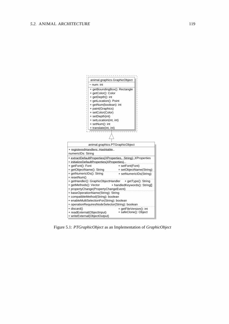
5.2. ANIMAL ARCHITECTURE 119
+ extractDefaultProperties(XProperties, String): XProperties+ initializeDefaultProperties(XProperties)
+ setFont(Font)+ setObjectName(String)+ getObjectName(): String
+ getFont(): Font
+ operationRequiresNodeSelector(String): boolean+ enableMultiSelectionFor(String): boolean+ compatibleMethod(String): boolean+ baseOperationName(String): String
+ getNumericIDs(): String + setNumericIDs(String)+ resetNum()
+ propertyChange(PropertyChangeEvent)+ handledKeywords(): String[]+ getMethods(): Vector
+ getHandler(): GraphicObjectHandler + getType(): String
numericIDs: String
+ safeClone(): Object+ writeExternal(ObjectOutput)
animal.graphics.PTGraphicObject
+ registeredHandlers: Hashtable
+ readExternal(ObjectInput)+ discard() + getFileVersion(): int
− num: int
+ getNum(boolean): int
+ getBoundingBox(): Rectangle
animal.graphics.GraphicObject
+ paint(Graphics)+ setColor(Color)+ setDepth(int)+ setLocation(int, int)+ setNum(): int+ translate(int, int)
+ getColor(): Color+ getDepth(): int+ getLocation(): Point
Figure 5.1: PTGraphicObject as an Implementation of GraphicObject

120 CHAPTER 5. THE ANIMAL ANIMATION SYSTEM
work has a unique value for each graphical primitive and thus acts as a reference for the object.The numericIDs attribute is a convenience storage object that prevents multiple conversions of thenumeric object ID to String objects.For better readability, the large interface of class PTGraphicObject has been segmented using dot-ted lines. The first segment contains the two class methods extractDefaultProperties and initial-izeDefaultProperties. They are used to initialize the current graphical primitive from a set of prede-fined properties. The object properties are extracted from a set of general properties. This processemploys the getElementsForPrefix method of class XProperties as described in section 4.2.1.The second segment contains several convenience methods for setting and retrieving attributes com-monly found in most primitives. The framework already provides methods for accessing and settingthe color and depth. ANIMAL’s PTGraphicObject adds methods for retrieving and modifying thefont and object name. Note that the precise interpretation of the color depends on the object’s type.ANIMAL chooses the most basic color for the getColor method. Therefore, the method will returnthe outline color for a polygon rather than its fill color.The depth of a primitive is used for resolving overlapping primitives. It acts like the z coordinatein three-dimensional geometry, with higher values indicating a position further to the background.Note that negative values represent positions in front of the display and are regarded as illegal.The font property is applicable to all graphical primitives that may contain a text component andcovers the complete font information including font name, size and style. Finally, the object nameis an optional String assigned to the primitive for easier reference. The primitive’s num attributeis sufficient for uniquely accessing the object, but only allows for natural number “names” whichmay be difficult to remember.The third segment lists the methods for accessing the primitive’s numerical identity. The frameworkprovides the methods getNum and setNum, as introduced in section 4.4. ANIMAL adds the methodresetNum for resetting a given object’s number to 0. The boolean parameter of getNum indicateswhether a new unique number shall be assigned before returning the current numeric ID. To preventcareless use, a new unique identification is only assigned if resetNum has been invoked. This is anecessary safety measure as the animation effects presented in section 5.3 all work on the numericIDs of the primitives and are not updated automatically if a new number has been assigned. Themethods for accessing the String representation of a set of numeric IDs are convenience facilitieswhich are mostly used by animation effects.The fourth segment offers methods required for performing animation effects on the graphicalprimitives. They are discussed in more detail in section 5.4. The following segment offers gen-eral methods needed within the GUI-based animation editing. They are discussed in section 5.6focusing on GUI-based generation and editing.The methods paint and translate taken from the framework are abstract, as they cannot be fullyspecified for abstract generic primitives. The paint method is responsible for displaying a givenprimitive’s current state on the graphic output context, while translate adjusts the primitive’s loca-tion. Note that translate is invoked internally from setLocation.The final segment of methods deals with object versioning. It also includes support for the java.io.Ex-ternalizable mechanism. Although externalization has been deprecated, the support is still presentto allow the parsing of older animation files. See section 5.7 for a discussion of export and importhandling.The method interface of PTGraphicObject is relatively large for an object-oriented design. This isdue to the different interests that have to be covered within the base class: convenience propertyaccess and setting, animation effect interface as well as storage and retrieval facilities.

5.2. ANIMAL ARCHITECTURE 121
Note that the framework class GraphicObject is a subclass of EditableObject, which again extendsPropertiedObject, as described in section 4.2.1 and 4.4. Therefore, all subclasses of PTGraphicOb-ject also inherit the methods and attributes of the classes PropertiedObject and EditableObject.They can thus access an internal state representation using properties and have a link to graphicaleditors. Furthermore, each subclass has a class attribute representing the default properties for allobjects of the given type.
animal.graphics.GraphicObject
animal.misc.EditableObject
animal.graphics.PTGraphicObject
animal.graphics.PTPoint animal.graphics.PTPolyline
animal.graphics.PTTextanimal.graphics.PTArc
animal.main.PropertiedObject animal.misc.XProperties
java.lang.Cloneable
nodes
textComponent
properties
Figure 5.2: Inheritance Structure of the Graphical Primitives in ANIMAL
The inheritance structure of the graphical primitives provided by ANIMAL is shown in Figure 5.2.The individual subclasses shown are discussed in the following subsections.
5.2.2 Point Primitives
The PTPoint class represents a single point as a special instance of a PTGraphicObject. Pointsare the smallest geometric unit. A PTPoint object occupies exactly one pixel on the display and istherefore practically invisible. However, points are needed for assembling more complex objectssuch as polygons. They are also needed for specifying the center of a rotation effect. We do notprovide example screen shots of ANIMAL PTPoint instances, as their nature prevents them frombeing very interesting or surprising to look at.Figure 5.3 shows the added methods provided by the class. Note that for efficiency reasons, thelocation of a point instance is represented by a double array. The location is also stored in theproperties and included in the class DefaultProperties. For a list of methods inherited from thebase class PTGraphicObject, please refer to Figure 5.1 on page 119 and Figure 4.11 on page 93.The methods placed above the first dotted line represent property setting or accessing. The standard

122 CHAPTER 5. THE ANIMAL ANIMATION SYSTEM
animal.misc.XProperties
animal.graphics.PTPoint
+ DefaultProperties: XProperties
+ getW(): int+ getX(): int+ getY(): int+ set(double, double, double)+ setPoint(Point)
+ setW(int)
+ scale(double, double)+ rotate(double, Point)+ rotate(double)
+ shear(double, double)
+ setX(int)+ setY(int)
+ toPoint(): Point+ toString(): String
+ clone(): Object
animal.graphics.PTGraphicObject
− coords: double[]
Figure 5.3: Class Diagram for Point Primitives in ANIMAL
graphic operation translate inherited from the GraphicObject framework class is implemented inPTPoint. In addition, PTPoint provides support for rotating, scaling and shearing point primitives.The last set of methods cover the conversion of a point to a java.awt.Point or String representation,as well as a secure clone operation that prevents unwanted side effects such as duplicated referencesto primitive properties.ANIMAL point primitives are specified using double precision homogenous coordinates [59]. Notethat although double precision coordinates are used for points, only integer coordinates are actuallyretrievable. This is due to the basic graphic operations in Java, which are based on integer pixelcoordinates.Homogenous coordinates represent a two-dimensional coordinate by three values labeled x, y andw. For w 1, (x � y) represent the coordinates of the point. For w � 1, the value of w representsa scaling factor applied to the x � y coordinates. Note that a value of w 0 is invalid. Figure 5.4summarizes the interpretation of homogenous coordinates.��
xyw
�������xwyw1
������xwyw �
Figure 5.4: Interpretation of Homogenous Coordinates
The advantage of using homogeneous coordinates lies in the consistent representation of graphicaloperations [59]. Standard operations such as rotate are implemented using matrix multiplications.However, this is not possible for translations which add to the value of the x, y coordinates. Usinghomogeneous coordinates, this addition can be achieved by multiplying the w entry with the target

5.2. ANIMAL ARCHITECTURE 123
summand while assuming that w 1. Although there are faster ways to represent the graphicaloperations, matrix multiplications allow for easy accumulation of effects.
5.2.3 Polyline and Polygon Primitives
ANIMAL’s polyline or polygon primitives consist of a vector of nodes linked by edges. Figure 5.5shows the class diagram of the PTPolyline class that represents both polyline and polygon objects.Note that each node is represented by a PTPoint primitive. PTPolyline primitives also implementthe animal.animator.MoveBase interface, and can thus be used as the base object for arbitrary moveeffects.The main difference between a polyline and a polygon is that the polygon is closed, that is, its lastnode is equal to the first node. Additionally, only polygons may be filled and possess a fill color.Polylines, on the other hand, may possess a forward or backward arrow that points away at a rightangle from the last or first node, respectively.
+ DefaultProperties: XProperties− nodes(): Vector
+ addNode(PTPoint)
+ getDifferentNodesCount(): int
+ getNode(int): Point+ getNodes(): Vector + getNodeCount(): int
+ removeNode(int)+ setNodes(Vector)+ setNode(int, Point)
+ getFillColor(): Color + setFillColor(Color)+ hasBwArrow(): boolean
+ setFilled(boolean)
+ rotate(double) + rotate(double, Point)+ shear(double, double)+ scale(double, double)
+ translate(boolean[], int, int) + translate(int, int, int)
+ toPolygon(): Polygon+ getPointAtLength(int): Point
+ getLength(): int+ useAsMoveBase()
animal.graphics.PTPolygon
+ setBwArrow(boolean)
+ isClosed(): boolean+ hasFwArrow(): boolean + setFwArrow(boolean)
+ setClosed(boolean)+ isFilled(): boolean
animal.graphics.PTPoint
animal.graphics.PTGraphicObjectanimal.animator.MoveBase
+ getLength(): int+ getPointAtLength(int): Point+ useAsMoveBase()
nodes
Figure 5.5: Class Diagram of Polyline / Polygon Primitives in ANIMAL
ANIMAL places no upper bound on the number of nodes used for a polyline object. A polylinemust consist of at least two nodes and thus represent a simple line to be valid. A polyline with onlyone node is simply a point and has to be represented as such.The first set of methods available for polyline or polygon primitives support the adjustment ofnodes. Apart from setting and retrieving a node at a certain index, ANIMAL also allows adding asingle node and setting or retrieving the set of nodes using a java.lang.Vector of PTPoint entries. Inaddition, the getDifferentNodesCount method can be used to query the nodes of a polygon primitive.

124 CHAPTER 5. THE ANIMAL ANIMATION SYSTEM
For polylines, the return value is equal to the return value of the getNodesCount method. However,the implementation of polygons in ANIMAL sets the last node of a polygon identical to its firstnode. The two methods will therefore have different results for polygon objects.The methods for querying and setting display properties are shown in the second method segment.PTPolyline instances provide methods for retrieving and setting the fill color of a polygon, as wellas testing or setting the existence of pointers at the start or end of a polyline. The closed property isimportant for the distinction between polyline and polygon primitives. The filled property is onlymeaningful for closed polylines, that is, polygons.The methods for querying and setting the display state access the internal properties of the object.They could be removed from the class without losing expressiveness. However, this may causeproblems for developers who wish to access a given value and would have to resort to guessing theassociated key. Note that neither of these methods is applicable to all instances of PTPolyline: thefill color is only meaningful for closed polyline instances (and thus polygons), while the forwardand backward arrows are only meaningful for “open” polylines.The implementation of the translate transformation as the third set of offered methods is almosttrivial. The standard translate(int, int) method inherited from PTGraphicObject translates all nodesof the structure at the same time. The special translate(boolean[], int, int) is used to translate asubset of nodes at the same time, instead of all nodes. Only those nodes where the boolean arrayat the node index contains true are translated. The translate(int, int, int) method translates only thenode at the index passed as the first argument. All translation requests are mapped directly to theset of PTPoint nodes and executed within that class. The other transformation methods behave asexpected. They perform the requested transformation by mapping the request to the set of nodes.The final set of methods offers a conversion to a java.awt.Polygon representation as well as methodsneeded for animation effects. The getLength method returns the geometric length of the object.getPointAtLength returns the point on the object reached after traversing it for a specified length.The useAsMoveBase method opens the object, activates the forward and deactivates the backwardarrow.
5.2.4 Text Primitives
The PTText class represents text objects consisting of a single line of text. Figure 5.6 shows theUML class diagram for this class. PTText instances share a DefaultProperties object and the es-capeText method. The method is used to escape unsafe text elements such as the single or doublequotation marks. The text and font information is stored in the internal properties representation.All other inherited methods from either the framework or the PTGraphicObject class therefore pro-vide only a short-hand notation for accessing the value from the properties. The relevant methodsfrom the PTGraphicObject class include accessing or setting the text color, font and depth proper-ties. PTText adds methods for retrieving and setting the text component, as well as for performingthe graphical transformations rotate, scale and shear.A special problem occurs when implementing the scale and rotate operations. Standard Java’sjava.awt.Graphics class does not support scaling or rotating text entries. Text scaling could inprinciple be accomplished by adapting the font size. However, this implementation only works iftwo conditions are met: first, the x and y scale factor must be identical, and second, the chosenfont must be available in the calculated size. As the scaling factor is a double value, the resultingfont size is highly likely to be a non-natural value. However, Java only allocates fonts with anatural font size, so certain compromises have to be made. Additionally, rotating the text is not

5.2. ANIMAL ARCHITECTURE 125
animal.graphics.PTGraphicObject
+ DefaultProperties: XProperties
+ escapeText(String): String
animal.graphics.PTText
+ getText(): String+ rotate(double)+ rotate(double, Point)+ scale(double, double)+ setText(String)
Figure 5.6: UML Inheritance Diagram for the PTText Class
easily accomplished due to lack of direct support. We have therefore decided to use the scaling androtation support in Java’s java.awt.Graphics2D class available in current JDKs.For maximum portability, ANIMAL only supports the three font families SansSerif, Serif andMonospaced. These font names are substituted with a system-specific font, typically Helveticaor Arial for fonts without serifs (SansSerif), Times Roman or Times New Roman for Serif fonts,and Courier or Dialog for Monospaced fonts. ANIMAL does not support the inclusion ofsystem-specific fonts such as Helvetica, as such fonts may not be present on a given client sys-tem. In those cases, the display of texts has to revert to a common basis, which typically results inproblems for the layout. The generic fall-back font is a plain 16-point SansSerif font.
5.2.5 Arc Primitives
The PTArc class represents an arbitrary arc component with an optional text entry. Arcs coverarbitrary circles and ellipses, as well as segments thereof. Figure 5.7 shows the class diagram forPTArc components. PTArc primitives implement the animal.animator.MoveBase interface, and canthus be used as the base object for arbitrary move effects.Most of the explanations for PTPolyline objects also apply to PTArc instances. The large set ofaccess and set methods shown in the diagram maps requests to the local properties of either the arcitself or its text subcomponent. If present, the text is centered on the arc’s center.The access methods are basically unnecessary but allow developers easier access to the properties.A closed arc is also called a pie wedge. The setCircle method allows switching from a circlerepresentation to an ellipse. The difference between these is that circles use an integer as theradius, while ellipses have a x and y radius represented as a point.Closed arcs may possess a fill color, while open arcs may exhibit the forward or backward arrowsalready described for polyline objects. The angle and start angle determine the shape of the arc inconjunction with its orientation. The orientation may be clockwise or counterclockwise and can bedetermined or set using the isClockwise and setClockwise methods, respectively.The second set of methods addresses animation effects on arcs. The getLength method returnsthe length of the arc. The getPointAtAngle method returns a point on the arc at the given angle.isAngleInside determines if a given angle is part of the arc, while useAsMoveBase opens the arcand installs a single forward arrow. The rotate methods allow the rotation of an arc component

126 CHAPTER 5. THE ANIMAL ANIMATION SYSTEM
around the point of origin or the passed point. The translate method is also implemented but notshown in the diagram as it was inherited from the superclass.
+ DefaultProperties: XProperties− textComponent: PTText
animal.graphics.PTArc
+ getArcAngle(): int + setArcAngle(int)+ setCenter(Point)+ getCenter(): Point+ setFillColor(Color)
+ getRadiusPoint(): Point+ setRadius(int)+ setRadius(Point)
+ getRadius(): int+ getFillColor(): Color
+ getStartAngle(): int + setStartAngle(int)+ getTextColor(): Color+ getTextComponent(): PTText
+ setTextColor(Color)
+ hasBwArrow(): boolean+ hasFwArrow(): boolean
+ setBwArrow(boolean)
+ isCircle(): boolean+ isClockwise(): boolean+ isClosed(): boolean+ isFilled(): boolean
+ setClockwise(boolean)+ setClosed(boolean)+ setFilled(boolean)
+ scale(double, double)+ rotate(double)+ isAngleInside(int): boolean+ getLength(): int + getPointAtAngle(int): Point
+ useAsMoveBase()+ rotate(double, Point)
+ setText(String)
+ setFwArrow(boolean)+ setCircle(boolean)
animal.graphics.PTGraphicObject
animal.graphics.PTText
animal.animator.MoveBase
+ getLength() : int+ getPointAtLength(int): Point+ useAsMoveBase()
Figure 5.7: UML Inheritance Diagram for the PTArc Class
5.3 Animation Effects
All ANIMAL animation effects or “animators” are placed in the animal.animator package and ex-tend the abstract class animal.animator.Animator. Animation effects that allow offset and durationspecification instead extend the abstract class animal.animator.TimedAnimator, which is a subclassof animal.animator.Animator. The UML class diagram for the Animator class in relation to theframework is shown in Figure 5.8. Note that the framework class has been placed in a dashed box,as it was directly extended for added functionality within the prototype system. Animator is a sub-class of EditableObject and therefore also of PropertiedObject. It contains three static attributesand a large collection of methods.The DefaultProperties class attribute represents the properties used as default properties for all ani-mator instances. On initializing a new animator, this attribute is declared as the default property set.As outlined in section 4.2.1, this has the effect of providing a common base for all animators as afall-back position. The infoFrame attribute is an extension for adapting ANIMAL to integration intoJHAVE and is described in section 6.7. The class attribute registeredHandlers is a hash table used

5.3. ANIMATION EFFECTS 127
+ setInfoFrame(InfoFrameInterface)
+ printIDs(int[]): String
+ extractDefaultProperties(XProperties, String): XProperties+ initializeDefaultProperties(XProperties)+ getInfoFrame(): InfoFrameInterface
animal.animator.Animator
+ getAnimatorName(): String+ getSpecialObjectNums(): int[]
+ setObjectNums(int[])
+ readExternal(ObjectInput)+ writeExternal(ObjectOutput)
+ getFileVersion(): int+ scavenge(boolean[])+ toString(int)
+ getStep() + getType(): String+ handledKeywords(): String[]+ isChangingAnimator(): boolean
+ discard()
+ DefaultProperties: XProperties+ infoFrame: InfoFrameInterface+ registeredHandlers: Hashtable
+ init(AnimationState, long, int)+ hasFinished(): boolean
+ execute()+ action(long, int)
Animator
+ getObjectNums(): int[]
+ setFinished(boolean)
+ setStep(int)+ setObjectNums(int[])
+ getTemporaryObjects(): int[]
Figure 5.8: Architecture of the Animator Base Class Animator

128 CHAPTER 5. THE ANIMAL ANIMATION SYSTEM
for mapping animation effects to intermediate agents called “handlers”. This process is describedin more detail in section 5.4.
For better readability, the large interface of class Animator has been segmented using dotted lines.The first segment contains the two class methods extractDefaultProperties and initializeDefault-Properties used for accessing the DefaultProperties class attribute described above. The get-InfoFrame and setInfoFrame methods are used for retrieving or assigning the infoFrame. Pleaserefer to section 6.7 for more information about the infoFrame.
The second block of methods provides read access to the basic properties of the current anima-tion effect: name, setting the array of objects on which the effect works, the array of specialobjects used by the animator, and the animation step in which the animator is placed. The typeof the animator is used for extracting the animator’s properties from the global dictionary using thegetElementsForPrefix method of class animal.misc.XProperties, as described in section 4.2.1. ThehandledKeywords are required for dynamically adding, removing and looking up animation effects.Finally, the isChangingAnimator returns true if the animator modifies the objects it works on. TheprintIDs method provides a convenience access to a String representation of the numeric IDs of theanimated objects.
The final segment of methods deals with object versioning. It also includes support for the java.io.Ex-ternalizable mechanism. Although externalization has been deprecated, the support is still presentto allow the parsing of older animation files.
The method interface of Animator is relatively large for an object-oriented design. This is dueto the different interests that have to be covered within the base class: convenience property ac-cess and setting, animation effect interface as well as storage and retrieval facilities. Note thatall subclasses of Animator also inherit the methods and attributes of the classes PropertiedObjectand EditableObject. They can therefore access an internal state representation using properties andhave a link to graphical editors. Furthermore, each subclass has a class attribute representing thedefault properties for all objects of the given type.
The abstract class TimedAnimator, shown in Figure 4.12 on page 97, provides the basic function-ality for timed animation effects. The class method copyTimingFrom for easy transferal of timinginformation has already been defined in the framework, as well as methods for accessing and set-ting the duration and offset of the current timed animation effect can be retrieved and set. ThegetMethod method allows the determination of the concrete subtype of the animation effect. Mostanimation effects provide more than only one type of effect. For example, a move effect may movethe whole object or only parts thereof, depending on the underlying type of the object.
The getStartTimeOrTicks methods can be used to retrieve the start time of the animation effect.The isUnitIsTicks and setUnitIsTicks method pair is used for resolving whether the underlying basetime unit is milliseconds or internal ticks corresponding to displayed image frames. The abstractgetProperty method is the main method for resolving timing information. It must determine andreturn the state of the animation effect at the current point in time. This is then used to determinethe state of each affected graphical primitive.
The inheritance structure of the animators provided by ANIMAL is shown in Figure 5.9. The Showeffect is currently the only available animation effect which does not use any timing information.The PTGraphicObject reference belongs to an array of the primitives on which the effect works.As the array is transient, the reference has been omitted from Figure 5.8.

5.3. ANIMATION EFFECTS 129
animal.animator.Animator
animal.animator.TimedAnimator animal.animator.Show
animal.main.AnimationStateanimal.graphics.PTGraphicObject
animal.animator.ColorChanger
animal.animator.Move animal.animator.Rotate
animal.animator.MoveBase
animal.animator.TimedShow
animal.animator.Rotation
Figure 5.9: Inheritance Diagram for ANIMAL Animation Effects
5.3.1 Show Effect
The Show effect implemented in class animal.animator.Show is arguably the simplest animator. Itssole task is modifying the visibility of graphical primitives according to the method used. Figure5.10 shows ANIMAL’s Show animator in relation to the framework. Apart from the methods inher-ited from animal.animator.Animator, the class has a private boolean attribute that determines thevisibility of the selected primitives, with true for visible and false for hidden. The value of thisattribute can be retrieved by invoking isShow and set by setShow.
animal.animator.Animator
− show: boolean
+ isShow: boolean+ setShow(boolean)
animal.animator.Show
Figure 5.10: Inheritance Diagram for Show Animators
Figure 5.11 presents a small example of the Show effect. In the first step, a coordinate axis witha mathematical function is displayed by invoking the Show effect with the object numbers, whichwe assume to be 1, 2 and 3. In the second step, two of the three primitives are hidden by a secondShow effect that has been set to hide mode by invoking setShow(false). Finally, the third stepshows the objects again by adding another Show effect. The boxes around the diagrams are insertedto show the boundary of each step.

130 CHAPTER 5. THE ANIMAL ANIMATION SYSTEM
hide 1 3show 1 2 3 show 1 3
Figure 5.11: Example Show Effect
5.3.2 Timed Show Effect
Figure 5.12 shows the structure of the TimedShow animator in relation to the framework. Just asthe Show animator, the simple structure of the requires only two additional methods for setting andretrieving the visibility state of the selected primitives beyond those introduced in the frameworksuper classes animal.animator.Animator and animal.animator.TimedAnimator.
animal.animator.TimedAnimator
animal.animator.TimedShow
− show: boolean
+ isShow: boolean+ setShow(boolean)
Figure 5.12: Inheritance Diagram for TimedShow Animators
For an example of the TimedShow effect, please refer to Figure 5.11. Note that the default Timed-Show effect offers no fading, so that the duration has no visible effect. Thus, there is only onedifference between a Show and a TimedShow animator: the Show animator is always executed atthe start of the animation step, while the TimedShow animator is only executed when its start timehas been reached. This fact can be used for building animation steps that show a number of itemswhich appear one after another, as commonly done in Microsoft PowerPointTM presentations.
5.3.3 Color Change Effect
Figure 5.13 illustrates the relationship between the color changer animator in the framework andin ANIMAL. To present a good interpolation of intermediate color values for non-instantaneouscolor change effects, the original colors of all object must be stored. Alternatively, the visualizermay also use a common start color for all animated primitives. Another pair of methods is used forretrieving and setting the target color.The color interpolation is achieved by calculating the intermediate color that bisects the line con-necting the start and target color at the current execution point for each animated object. Figure

5.3. ANIMATION EFFECTS 131
5.14 illustrates this process for a change from black to white for an arbitrary color property. Thefigure includes the interpolated color values for the following animator execution states, with thedouble precision timing given in parentheses: 0%, equal to the animation effect start (0.0), 20%(0.2), 50% (0.5), 85% (0.85) and 100%, equal to the animation effect end (1.0). The marked colorsare returned by the getProperty method defined on page 98.
animal.animator.TimedAnimator
animal.animator.ColorChanger
− originalColor: Color[ ]
+ getColor(): Color+ setColor(Color)+ setOriginalColor(Color)
Figure 5.13: Inheritance Diagram for ColorChanger Animators
1.0
0.00.2
0.5
0.85 B
R
G
1.0
(0, 0, 0)(51, 51, 51)
(127, 127, 127)
0.85
0.5
0.2
0.0
(217, 217, 217)(255, 255, 255)
Color Changing
Figure 5.14: Color Interpolation in the ColorChanger Animator
Figure 5.15 shows an example color change application grabbed from ANIMAL. The color of thetext embedded in the box changes over time from black to white, assuming appropriate grey shadesduring the operation.
t=0 t=0.2 t=0.5 t=0.85 t=1.0
Figure 5.15: Example Color Interpolation in the ColorChanger Animator

132 CHAPTER 5. THE ANIMAL ANIMATION SYSTEM
5.3.4 Move Effect
Figure 5.16 illustrates the Move animator in ANIMAL. Apart from declaring the animator as atimed animator, the only information needed are the length of the underlying move base and itsnumeric ID. ANIMAL’s Move animator offers a fluent interpolation of move points for animatorspossessing a duration. This is achieved by calculating the intermediate move points along the movebase object once for the current execution point. Figure 5.17 illustrates this process for a movealong a polyline. The figure includes the interpolated points for the following animator executionstates, with the double precision timing given in parentheses: 0%, equal to the animation effect start(0.0), 20% (0.2), 50% (0.5), 85% (0.85) and 100%, equal to the animation effect end (1.0). Themarked points on the polyline in Figure 5.17 are also the returned value of invoking the getPropertymethod for the associated values, as defined on page 98.
animal.animator.MoveBase
animal.animator.TimedAnimator
− length: int
+ setMoveBaseNum(int)+ getMoveBaseNum(): int− moveBase: MoveBase
animal.animator.Move
+ getLength(): int+ getPointAtLength(int): Point+ useAsMoveBase()
Figure 5.16: Inheritance Diagram for Move Animators
The MoveBase interface is responsible for determining the point on the underlying move base at agiven point in time. For this end, the execution state of the effect measured in the interval � 0 � 1 � ismultiplied with the length of the move base, as retrieved by getLength. The rounded result valueis then inside the interval � 0 � getLength � and used for determining the target point. Note that thisapproach is not limited to using lines as a move base; the developer can easily also implement thefunctionality for arc components. This is done in ANIMAL, so that moves can be accomplishedalong polylines or arcs.
0.0 0.2
0.5
0.85 1.0
Move Path
Figure 5.17: Timing of Move Animators
Figure 5.18 shows an example move application that moves a square along the path shown in Figure5.17.

5.4. TRANSFORMATION HANDLERS 133
t=0 t=0.2 t=0.5 t=0.85 t=1.0
Figure 5.18: Example Move Animator
5.3.5 Rotate Effect
Figure 5.19 illustrates the Rotate animator in ANIMAL. We added methods for setting and retriev-ing the center point and the rotation angle. The rotation itself is encapsulated in a Rotation objectthat allows accessing the rotation angle and center. ANIMAL’s rotate animator offers a fluent inter-polation of rotation angles for animators possessing a duration. This is achieved by calculating theintermediate rotation angles along the circle spanning the full rotation angle once for the currentexecution point.
animal.animator.TimedAnimator
− center: Point
+ getCenterNum(): int+ getDegrees(): int+ setCenterNum(int)+ setDegrees(int)
animal.animator.Rotate animal.graphics.Rotation
+ getAngle(): double+ getCenter(): PTPoint
Figure 5.19: Inheritance Diagram for Rotate Animators
Figure 5.20 illustrates this process for a move along a polyline. The figure includes the interpolatedpoints for the following animator execution states, with the double precision timing given in paren-theses: 0%, equal to the animation effect start (0.0), 20% (0.2), 50% (0.5), 85% (0.85) and 100%,equal to the animation effect end (1.0). The marked angles and thus also the associated points onthe angle are returned by the getProperty method for the associated values, as defined on page 98.Figure 5.21 shows an example rotate application that rotates an arrow on its end point along theangle shown in Figure 5.20.
5.4 Transformation Handlers
As stated in section 4.6, transformation handlers act as agents for negotiation between primitivesand animation effects. The primitives provide a straightforward implementation of the underlyinggraphical element. This especially includes methods for accessing the state using properties, the

134 CHAPTER 5. THE ANIMAL ANIMATION SYSTEM
0.0
0.2
0.5
1.0
0.85
Rotation Angle
Figure 5.20: Timing Resolution for Rotate Animators
t=0 t=0.2 t=0.5 t=0.85 t=1.0
Figure 5.21: Example of Rotate Animators
determination of the primitive’s location and bounding box, and the paint method for displayingthe primitive on the graphics context. Additionally, they provide at least the translate method forchanging the location, and may also offer the other basic transformations scale and rotate.Animation effects model the execution of generic animation effects. They can retrieve and set theaffected object and may possess a timing specification containing both an offset from the associatedanimation step’s start and a duration. The core functionality is wrapped in one method each forinitializing, performing and finishing the effect, respectively. Section 5.3 examined the animationeffects in more detail. From the handler’s point of view, it is sufficient to know that the animationeffect can determine the percentage state of its execution and retrieve the appropriate intermediatevalue, such as a target color or move location.The transformation handler is responsible for two central aspects of performing animation effects.Firstly, it is responsible for determining the list of concrete transformation subtypes available fora given primitive and a given animator. Secondly, it maps the given effect to a set of primitivetransformations for each affected primitive.The first task is achieved within the getMethods(PTGraphicObject, Object) method present in allhandlers. Given a concrete instance of the handled object type and an effect-parameterizing object,the handler returns a vector of possible animation effect subtypes, as shown in Figure 4.14 onpage 101. Note that the list of available effects can depend on the properties of the primitive. Forexample, if the nodes of a polygon can be moved individually, the set of possible method namesdepends on the number of nodes of the primitive. By passing the primitive as a parameter, suchproperties can be determined easily.The mapping of animation effects to primitive method calls is performed in the propertyChange(PT-GraphicObject, PropertyChangeEvent) method. Given the primitive on which to work and the

5.5. ANIMAL’S ANIMATION DISPLAY GUI 135
transformation encoded as a java.beans.PropertyChangeEvent, a set of method invocations onthe primitive are performed that result in the execution of the animation effect. The Property-ChangeEvent encodes the name of the animation effect subtype, as well as the current and targetvalue of the target object state. The precise data stored in the target state depends on the animationeffect. For example, Move effects encode the point reached at the current transformation time.The transformation handlers as defined in section 4.6 are perfectly up to the task set them. We havenot found it necessary to provide any extension or customization within the course of implementingthe prototypical AV system, apart from filling in the actual transformation types possible for eachelement. Therefore, we will not delve into the implementation code for handlers.ANIMAL also faithfully follows the animation representation structure described in section 4.7using a single Animation object modeling the animation built on the interaction of animators, prim-itives and primitive handlers. The animal.main.Link class represents the links between successiveanimation steps.In the following sections, we will examine the GUI front-end offered by ANIMAL for displayingand editing animations.
5.5 ANIMAL’s Animation Display GUI
ANIMAL’s animation display GUI is by definition the most “visible” component for users. Wehave therefore taken special care to offer relevant and helpful features for users and visualizersemploying the display GUI for testing their animations.
Figure 5.22: ANIMAL’s Main AV Frame
Figure 5.22 shows the main ANIMAL frame. The numbers placed in colored squares are not partof the frame; they were inserted here for better referencing of features. Similar numbering willappear in most other GUI components under consideration. The menu bar (1) contains a File menuwith the usual operations for loading, storing or creating a new animation. The Edit menu is usedfor showing or hiding the individual elements for the display and editing GUI. Options provides acentral access for configuring ANIMAL, including switching between two- and three-button mousetypes. The Language menu contains a list of localized GUI front-ends available for the installed

136 CHAPTER 5. THE ANIMAL ANIMATION SYSTEM
system. By default, it contains English and German language support. Finally, the Help menuoffers the usual access to the built-in help facilities.The tool bar below the menu also contains buttons for the most common file operations: newanimation (2), load (3), reload (4), enter scripting code (5), save (6) and save as (7) which storesthe animation under a different file name. The text area (8) below the tool bar lists status messagesfor ANIMAL, especially the load and save status.Figure 5.23 shows the animation display window used in ANIMAL. The top of the window containsa pair of sliders for controlling the display speed (1) and magnification (3), as well as two buttonsfor resetting the values to 100% (2, 4). The main part of the display is taken up by the animationcanvas (5) which presents the animation at the chosen speed and magnification scale. The animationshown in the screen shot is a joint effort of four students of the University of Wisconsin Parksidein animating a branch-and-bound dynamic knapsack algorithm. The display has been scaled toslightly less than 50% to fit the window on the page, causing some font artifacts.The bottom part of the animation window contains the central animation control bar (6) and theanimation step controls (7, 8). The text field (7) can be used for entering an arbitrary animation stepnumber. If the animation step exists, the animation jumps to it; otherwise, it remains at the currentstep and resets the displayed value. The slider (8) displays the percentage of the animation currentlyshown and can also be used for fast-forwarding or rewinding the animation. Both components (7, 8)are squeezed due to the page constraints, as the images used in the control tool bar are not resizable.
1
2
3
4
5
68
7
Figure 5.23: ANIMAL’s Animation Window
Figure 5.24 shows the animation control tool bar included in the animation window shown in Figure5.23. The buttons, from left to right, carry the following meaning, in keeping with Figure 4.19 onpage 108:

5.5. ANIMAL’S ANIMATION DISPLAY GUI 137
1 2 3 4 5 6 7 8 9
Figure 5.24: ANIMAL’s Control Tool Bar
1. jump to the start of the animation,
2. jump to the start of the previous animation step,
3. play the animation in reverse slide show mode. The timing delay between successive steps isrespected if present; otherwise, the delay set in the configuration is used,
4. play the current animation step backwards by employing all timing information for anima-tors,
5. pause the animation, especially relevant when employing either slide show mode,
6. play the current animation step by employing all timing information for animators,
7. play the animation in slide show mode, respecting all defined delays between subsequentsteps and using the configured default delay otherwise,
8. jump to the start of the next animation step,
9. jump to the end of the animation.
Finally, Figure 5.25 shows the implementation of the Animation Structure View in ANIMAL. As thestructure represents an animation time line, we call the window Time Line Window. All availablestep labels are gathered and displayed in a list inside the window, along with the associated stepnumber. If the user clicks on an entry in this list, the animation jumps to the associated step. Notethat it does not matter if the current animation step lies before or after the selected labeled step,as ANIMAL can easily handle reverse animation playing. If the selected labeled animation step isidentical to the current animation step, no effect will be visible.
Figure 5.25: ANIMAL’s Implementation of the Animation Structure View

138 CHAPTER 5. THE ANIMAL ANIMATION SYSTEM
5.6 ANIMAL’s Editing GUI
For our prototypical AV system, we have decided to support GUI-based animation generation andediting. This feature is relatively uncommon for AV systems, especially when combined with othergeneration or editing approaches, as demanded by requirement VR5. Therefore, adding such afront-end is a good exercise and also adds a special flavor to our prototype.The editing front-end of ANIMAL consists of four windows: the drawing window for generatingprimitives, the animation overview for managing animation effects and animation steps, the MainAV window shown in Figure 5.23 on page 136 and the Animation Structure View shown in Fig-ure 5.25 on the page before. As the latter two windows have already been described, we focus onthe drawing window and the animation overview.
8
11
14
17
20
23 24
22
19
16
1312
15
18
6
1 2 54
7
3
9 10
21
25
Figure 5.26: ANIMAL’s Drawing Window GUI
Figure 5.26 shows the drawing window used by ANIMAL. The top button row offers access tospecific editors for the currently supported primitives point (1), polyline / polygon (2), text (3), thelist element extension (4) described in section 6.2.2, and arc elements (5) including circles, ellipsesand segments thereof. The grid control (6) toggles the display width of the grid between the valuesnone, 5, 10, 20, 25 and 50, measured in screen pixels. The main canvas (7) is populated by theprimitives visible at the current animation step, as well as the optional grid. The canvas uses dragand drop for each primitive. Drag points for dragging the full object are placed at the middle of

5.6. ANIMAL’S EDITING GUI 139
each line. Editing points for moving individual primitive nodes are placed at each node and alloweasy manipulation of node locations.The first button row contains two buttons for toggling grid lock mode (8) and the display of tem-porary objects, such as move base primitives (9). Grid locking automatically adjusts primitivelocations selected by user actions to the closest intersection of grid lines. The refresh button (10)causes a redraw.The second row starts with the select objects button (11) used for toggling the usage mode fromgeneration to editing. The remaining two buttons toggle the selection of multiple objects (12) andthe editing mode (13). The latter, if active, pops up special editor window for the currently selectedprimitive or primitives. Figure 5.27 shows an example editor for arc primitives.
Figure 5.27: Arc Primitive Editor Window
The buttons (14, 15) offer undo and redo operations. Button (16) deletes the currently selectedprimitive or primitives. If at least one of the selected primitives is used in an animation effect, theuser will be prompted to confirm the deletion. The hare (17) offers a cloning operation that is veryuseful if a set of similar objects has to be generated. The cloned object is placed slightly belowand to the right of the original object. The disk button (18) is used to write the modified animationcontent back to the animation and all associated windows. It can be used to update the animationwindow, as this is not performed by default for performance reasons during the editing process.Button (19) runs the current animation step in the animation window, opening the window first ifnecessary.The buttons (20) - (22) let the user select the current animation step to be edited, by going back-wards (20) or forward (22) or by entering the target step number (21). The selection list (23) offersfive different magnification scales for drawing: 50%, 71%, 100%, 141% and 200%. The generalconfiguration menu that also allows adjusting the canvas background is activated by a button (24).Finally, the status line (25) describes the actions currently possible.The Animation Overview window shown in Figure 5.28 is used for generating and editing thestructure of the animation. It thus contains buttons for adding new animation effects (1-5) andanimation steps (8, 9). The animation effect buttons shown are, from left to right, Show (1), Move(2), Rotate (3), Color Change (4) and Timed Show (5). The main canvas of the window containstwo different types of entries: animation steps (6) and animation effects (7). Double clicking onan element brings up the associated editor. The right mouse button can also be used to activate acontext menu. The maintenance buttons at the bottom row allow inserting a new animation step

140 CHAPTER 5. THE ANIMAL ANIMATION SYSTEM
Figure 5.28: ANIMAL’s Animation Overview GUI
before (“prepending”, 8) or after the current step (“appending”, 9), refreshing the display (10) anddeleting the selected element (11). If the element to be deleted is an animation step with at leastone animation effect, the user has to confirm the deletion before it is performed.
Figure 5.29: ANIMAL’s Move Options GUI Editor
Figure 5.29 shows an example editor window for the Move effect. The name of the animationeffect and the current animation step are shown at the top of the window, along with the selectedanimation objects. The currently selected animation subeffect method translate #2 translates onlythe second node of a polyline or polygon primitive. The list of possible subeffects is generated bythe transformation handlers of the selected object(s), as described in section 5.4. The two radio

5.7. IMPORT AND EXPORT 141
buttons at the middle of the window toggle between real time (ms) and virtual frame-based time(ticks). The total duration and offset of the animation effect using the current time unit can bespecified in the two adjacent text fields. Finally, the temporary object used as the move base isshown, along with the standard trio of window buttons OK, Apply and Cancel. OK acts as Applyby applying any changes to the animation, but additionally also closes the editor window.
5.7 Import and Export
The import and export facilities offered by ANIMAL closely follow the specification of the frame-work in section 4.9. The standard Java file selector with adapted filter selections is used for queryingthe input or output file name and the target format. The appropriate import or export filters is theninstantiated and initialized by dynamic loading according to the configuration and accessed usingits MIME type.
Exporting can be configured to the user’s tastes. The exact degree of configurability depends on thechosen target output format. Figure 5.30 shows the standard export mode choice dialog. The usercan choose between exporting the complete animation or only those steps selected in the list at thebottom. Dynamic export as opposed to static snapshots contains the full dynamics of the animationeffects. If the export format is static, a sequence of appropriate elements may be generated, forexample resulting in a set of images written for a single animation step. The magnification canbe adjusted similarly to the drawing window to 50%, 71%, 100%, 141% or 200%, as well as tothe magnification used in the animation canvas. The selection list at the center right also allowsthe entry of arbitrary percentage values. Keep in mind that the precise export capabilities and thevisual quality of the output depend on the target format and the export filter implementation, ratherthan on ANIMAL’s display capabilities.
Figure 5.30: ANIMAL’s Export Mode Chooser Window

142 CHAPTER 5. THE ANIMAL ANIMATION SYSTEM
5.7.1 ANIMALSCRIPT
As a special elaborate case of an import filter, we regard the support for the built-in scripting lan-guage ANIMALSCRIPT. ANIMALSCRIPT animations are specified in a simple ASCII-based format.Each line of a valid ANIMALSCRIPT animation contains exactly one command or comment.ANIMALSCRIPT is extensible and thus allows easy adaptation and extension if desired featuresare not provided. The concrete extent of the features supported by ANIMALSCRIPT is retrieved atstart-up from a configuration file and used to dynamically build the whole parser component for thescripting language. This process is the same as described in section 4.2.Apart from supporting the base primitives provided by ANIMAL, ANIMALSCRIPT also supportslinked list elements, arrays and source code embedding including highlighting and indentation.Modular ANIMALSCRIPT files can be dynamically included using a special embed command.To make full use of the possibility of placing runtime information into a reusable module, ANI-MALSCRIPT allows the declaration of variables which can be placed in text components and arereplaced by their current value at load time.All coordinates used for specifying primitives or animator parameters can be relative to other,previously defined locations. One application area where this is important is the internationalizationof animation content offered in ANIMALSCRIPT. Here, the whole animation may be translatedinto the target language chosen by the user. Provided that internationalization is embedded in theanimation file and that all primitives use relative placement, the screen layout will still be fine, evenif the length of the components differs between languages.ANIMALSCRIPT provides facilities for performing interactive predictions (UR10). Currently, thefeature is employed only in conjunction with the JHAVE system [131, 181]. ANIMALSCRIPT canbe configured easily, as all components are loaded dynamically based on a configuration file. Theconfiguration file is first looked for in the current directory, followed by the CLASSPATH entries,the jar file containing the ANIMAL distribution and the ANIMAL home page. Therefore, users andvisualizers can easily switch between different ANIMALSCRIPT configurations by simply changingthe directory from which ANIMAL is started.ANIMALSCRIPT is simple to use but powerful. ANIMALSCRIPT input is typically a simple ASCIIfile consisting of a number of lines. Each line may contain either a comment marked by a hashmark #, or exactly one ANIMALSCRIPT command. The first word of each command line is thekeyword; this must always be unique to allow both easy parsing and dynamic extension.ANIMALSCRIPT commands typically have a number of parameters, some of which may be op-tional. The syntax of ANIMALSCRIPT is defined by a set of extended Backus-Naur rules using []for optional parameters and
� � for elements that may be repeated an arbitrary number of times.Further details about the syntax of ANIMALSCRIPT can be found in [179, 178, 177] and on theANIMAL Home Page [169].ANIMALSCRIPT provides some extended functionality that offers more comfortable access to ”hid-den” features of ANIMAL. The simplest extended command is the group / ungroup directive whichtells ANIMALSCRIPT to group all object IDs passed in as one object for the next steps, and thusfrees the user from much typing.List linking allows the user to set or clear the pointers of list elements with a single command.In keeping with pointer semantics, the user only has to specify the target object by its ID, anddoes not have to worry about the exact location of the pointer. This takes a lot of administrativebook-keeping from the user, compared to other systems where the precise target location must begiven.

5.7. IMPORT AND EXPORT 143
ANIMALSCRIPT provides full array support for both vertical and horizontal alignments. This in-cludes the installation and moving of array index pointers with an optional label as well as the putand swap operations. As the last two operations may have an effect on the width of the array cellsfollowing the first affected element, the layout of the array is updated, possibly including movingexisting array pointers. Thus, sorting an array using ANIMALSCRIPT is very easy to do, as it con-sists mostly of a sequence of arraySwap and movePointer commands for changing the elementsand moving the (optional) index pointers.ANIMALSCRIPT also provides full source code embedding. For this purpose, the user declaresa codeGroup with some formatting options, such as the font to be used, and gives the upper leftcorner. Individual code lines or code line elements can then be added to the code group, includingan optional indentation depth. The code is laid out dynamically. Source code highlighting is easilyaccomplished by commands that allow the user to highlight a given line or line segment as eitherthe current command or the current context.All elements may be positioned in one of the following ways:� using absolute coordinates such as (10, 20),� relative to an edge of another object’s bounding box,� relative to an arbitrary node of a given (polyline) object,� relative to the baseline of a given text,� or relative to the last location used.
One of the most helpful features of ANIMALSCRIPT during animation development is the echocommand. This command can be used to print the location of objects (usually the upper left corner)or their bounding box. It can also be used to print the numerical IDs of grouped objects, or show theIDs of all currently visible objects. For assertions, echo can print the current value, and it can alsoprint out any given text to the standard output. Thus, echo is a very powerful help during animationdevelopment in pinpointing the precise reason why something did not go the way it was supposedto. Of course, echo can also be turned off.In order to address the widest possible target audience with animations, all ANIMALSCRIPT textentries may be given either as a literal string or as localized text. The localization can be embeddedin the file or stored in separate language resource files. Embedded localized text is placed in paren-theses (), and each component is prefixed with the language code followed by a colon, for exampleas (de: ”Ja” en: ”Yes” fr: ”Oui”). On loading the animation, ANIMALSCRIPT prompts the userfor the language to be used for the animation’s display, and will layout all components accordingly.Due to the possibility of using relative coordinates, it is usually sufficient to generate one animationwith multiple languages embedded. Additional extended features of ANIMALSCRIPT include as-sertion checking, block charts, variables and stop-and-think questions as used in the JHAVE [131]system now also using ANIMALSCRIPT.While ANIMALSCRIPT already provides many helpful features for animation generation, users arebound to find some features they consider necessary or at least helpful which are not yet covered inthe extended ANIMALSCRIPT functionality. For this purpose, we have designed ANIMALSCRIPT
in a way that allows easy extensions by other programmers.Adding new graphic primitives or animation effects requires a certain knowledge of Java and pro-gramming in general. ANIMALSCRIPT comes with an extensive set of parsing support methods, so

144 CHAPTER 5. THE ANIMAL ANIMATION SYSTEM
that parsing the input data is comparatively easy to accomplish. This includes support for parsingkeywords, optional parameters, comments, color specification, absolute or relative coordinates andlocalized texts. Usually, each element in a new command definition requires one method call in theparsing support class. The ANIMALSCRIPT components can also be configured dynamically usingthe ComponentConfigurer shown in Figure 4.8 on page 82.The auxiliary animalscript.sourcerer API generates the parser code from a given extended Backus-Naur-Form. Using this API, programmers of ANIMALSCRIPT therefore only have to program theactual graphical and display operations.
5.8 Summary
Both graphical primitives and animation effects in ANIMAL employ properties for modeling mostof the object state. One exception to this rule are the numeric identification of graphical primitivesand the internal representation of primitive locations. Both are accessed very often in a typical ses-sion, including mathematical operations in the context of location transformations. Converting thelocation between Point and String format for each access introduces an significant but completelyunnecessary overhead. Recall that the location of every visible primitive must be accessed at leastonce for each paint invocation that updates the graphical display.The graphical primitives supported by ANIMAL are point, polyline / polygon, text and arc. Thevisualizer can toggle between polylines and polygons by inverting the value of the closed property.Contrary to some other systems as JSamba [196], polylines are not restricted in the number of nodesthey have, apart from requiring at least two nodes to form a valid line. Polygons can be filled withany color, while polylines may posses arrows at either or both ends. Text primitives are restricted tothe three Java system font families Serif, SansSerif and Monospaced to avoid portability problemsarising when specific fonts such as Arial are not installed on the user’s system. Finally, arcs maybe elliptical or circular. If closed as a pie wedge, they may also be filled; open arcs may possessforward or backward arrows. Additionally, a text can be placed inside the arc and, if present, isautomatically aligned on the arc’s center.All graphical primitives have a color, depth, name, numeric ID, location and bounding box thatcompletely encloses the primitive. They are also required to implement the translate(int, int)method that moves the object by the offset � ∆x � ∆y � . The paint method is invoked for generat-ing the display of a given primitive.ANIMAL animators are separated into timed and untimed animators. The only untimed animator iscurrently the Show animator for toggling the visibility of the chosen objects. All animators take anarbitrary non-empty set of objects as target objects. Timed effects specify the animator’s durationand offset from the animation step, using either real time measured in milliseconds or virtual timemeasured by the number of frames to display. Base ANIMAL provides the timed animation effectsTimedShow, Move, Rotate and ColorChange.With the exception of TimedShow, the intermediate state of the animated objects is interpolated foreach frame. For this purpose, ANIMAL employs three methods within each animator, as well as aseparate handler agent that maps the operations to the underlying primitives. The init(Animation-State, long, double) method initializes the animator and sets the start time to the time passed in asthe current system time and frame number. The action(long, double) method determines the targetstate of the primitives during the execution of the animator and forwards this state to the handler.Finally, the execute() method is invoked when the animation effect has finished. It displays the final

5.8. SUMMARY 145
state of the animator and removes the animator from the list of animators to examine.All animators are completely independent of the graphical primitives on which they work. Theirflexibility thus allows for easy reuse and recombination. The coordination of animators and primi-tives is the responsibility of the handler agents.Handlers provide two methods, called getMethods and propertyChange. The getMethods(PTGra-phicObject, Object) method receives the concrete primitive on which an effect is to take placeand an object that represents the animation effect parameters. Based on this second object, themethod builds a vector of appropriate animation effect subtypes. This generation may also takespecific properties of the primitive into account. For example, if a Move effect is requested, thevector returned may include the following move targets: full object, single specific node, or set ofnodes. The latter two subtypes require the knowledge of the node count encoded in the primitive.Animation effects receive a vector of animation subtypes for each object on which they work.The vectors are pruned by building an intersection. The resulting elements represent the possibleanimation subtypes applicable to the selected objects.The propertyChange(PTGraphicObject, java.beans.PropertyChangeEvent) method receives the cur-rent and target state of the animation effect, as well as the animation subtype, in the Property-ChangeEvent parameter. Based on the animation subtype, the new state is examined and mappedinto a set of method invocations on the primitive passed in so that the primitive’s display is adaptedto the requested effect.ANIMAL thus employs a strict separation of concerns. The graphical primitive classes representonly the current state of the underlying primitive including display capability in the paint method.However, they have no knowledge about animation per se. The animators, on the other hand, onlydetermine appropriate animation subtypes on a String base, and can interpolate intermediate ani-mation states. However, they do not possess any knowledge of the primitives on which they work.Finally, the handlers may not need to access the current concrete primitive instance in most caseswhen determining the possible animation effects. Exceptions are animation effects which dependon the current state of the primitive, for example the number of nodes or whether the underly-ing object is closed. Mapping the requested animation effect onto the primitive requires one ormore primitive method invocations that typically require little if any knowledge of implementationdetails.The front-end used by ANIMAL for displaying the animation consists of the main AV frame, ananimation window and a structure view of the animation. Apart from the usual file operations, themain AV frame centrally controls the visibility of the other windows and provides international-ization for all GUI components. The animation’s structure or “time line” is shown in a separatewindow. Clicking on a labeled step shown in this window updates the display to the associatedanimation step. The animation window offers facilities for changing the display speed and mag-nification on a percentage scale. Additionally, the video player-like control incorporates playing,stepping and displaying in a slide show mode for both animation directions, as well as jumping tothe animation start or end.The animation generation and editing front-end contains a drawing window for generating primi-tives with full drag and drop support, grid control, cloning, redo and undo. The animation effectsand steps are controlled in a separate animation overview window. Alternatively to visual gener-ation in the GUI, the animation may be specified using the built-in animation scripting languageANIMALSCRIPT. This language incorporates special features such as relative placement, anima-tion content internationalization and debugging. Special subtypes such as arrays and list elementsare also embedded in ANIMALSCRIPT, together with the typical operations used on the data types.

146 CHAPTER 5. THE ANIMAL ANIMATION SYSTEM
The import and export capabilities of ANIMAL are built from independent components that act asa file filter for one format each. The concrete selected filter instance is determined from the MIMEtype of the input and loaded dynamically. Export capabilities currently include the file formatspecified by ANIMAL, ANIMALSCRIPT and image or XML export. If the user request exportingthe animation with full dynamics, a set of images is stored for each animated step, instead of asingle snapshot showing the start of the step.The main contributions of the ANIMAL AV system prototype can thus be summed up as follows.ANIMAL is dynamically extensible and uses the concepts of the underlying framework to configureseveral component types at start-up or even while the system is running. This concerns primitives,animators, import and export filters, and ANIMALSCRIPT components. ANIMAL also presentsa (for AV systems) highly unusual combination of multiple generation and editing approaches,namely visually using the GUI front-end, by scripting in ANIMALSCRIPT, and by API invocationsin a separate API that is nearing completion. Thanks to the highly expressive framework base,ANIMAL is to our knowledge also the only general-purpose AV system that can handle randomaccess navigation through any animation, including rewinding and dynamic reverse playing.All GUI components can be dynamically translated on demand and on the fly by a single menu itemselection, thanks to the powerful operations provided by the underlying framework, as describedin section 4.2.3. The import and export filter interface is kept deliberately open for later additions.It may also be used to add another animation generation approach by writing a code interpretation“import filter” that translates code of a certain programming language into ANIMALSCRIPT or di-rectly into ANIMAL animation primitives and effects. An example project of this type was recentlyperformed in a Compiler Construction course at the University of Zittau / Gorlitz, Germany; alas,the results have not been published.ANIMALSCRIPT offers the standard features visualizers can find in other AV scripting language,but also several advanced commands. Among these are the echo command that is very helpfulfor debugging the code, powerful relative placement directives, internationalization support for theanimation code, and interactive prediction. Variables and loadable modules are also offered andallow for example the extraction of common front- and back-ends for sorting algorithms includingplaceholders for the actual number of calculation steps performed.The display front-end of ANIMAL offers dynamic adjustments of the display speed and magnifi-cation, hyperlink labels that illustrate the animation structure with the ability to directly jump tocertain animation steps, and full-fledged video player controls. A slider for adjusting the currentanimation step as an execution percentage state can also be used for a “fast forward” navigation.For visualizers who are not yet satisfied with the extended features offered by ANIMAL and fordevelopers interested in implementing extensions, we discuss example ANIMAL extensions in thenext chapter.

Chapter 6
Extending ANIMAL UsingANIMAL-FARM
6.1 Introduction
We have already discussed how the ANIMAL-FARM framework presented in chapter 4 supports thedynamic addition and removal of components. The ANIMAL system built on the framework there-fore also supports the integration of new components at run-time, as well as their removal. Notethat there is a difference between extensions of the ANIMAL system and the framework: the formertype of extensions provides added functionality for a concrete system, while the latter type modifiesthe framework. Here, we are concerned with extensions to the concrete implementation prototypeto better illustrate how easily new extensions can be developed. The design and implementationprocess does not require modifying any existing code (DR1) or intimate system knowledge (DR3).The developed extensions can be added or removed using the ComponentConfigurer introduced inFigure 4.8 on page 82.We have already discussed the individual components that make up the ANIMAL AV system. Only asmall number of components are tightly connected and explicitly referred to. These classes mainlyaddress the core animation modeling and GUI interactions. Other components are loaded dynam-ically and instantiated at run-time. This especially concerns the graphical primitives, animationeffects and import / export layers. This dynamic embedding is performed both at start-up and whenthe user alters the system settings while it is running. Thus, ANIMAL is dynamically extensible.However, the fact that components can be added or removed at run-time does not state how easilythis can be achieved. This concerns both the developer and the user or visualizer who wants toembed components. In this chapter, we discuss some example extensions that cover the range ofextensibility provided by ANIMAL. Where necessary, some implementation details will also beprovided. A precise implementation guideline is available online [169].The chapter is organized as follows. In section 6.2, we discuss two example extensions for graphicalprimitives. Extended animation effects are address in section 6.3. Adding sub-effects to alreadyimplemented effects requires the extension of object handlers. This process is illustrated in section6.4. Section 6.5 shows how a new language support can be installed for the whole ANIMAL GUI.Additional animation import and export filter implementations are discussed in section 6.6. Section6.7 discusses additions for interactivity added within the course of embedding ANIMAL to theJHAVE system. Section 6.8 summarizes the chapter.
147

148 CHAPTER 6. EXTENDING ANIMAL USING ANIMAL-FARM
6.2 Extending Graphical Primitives
There are two principal types of extensions for graphical primitives applicable to AV systems. Thefirst type, and probably the more obvious one, provides a fully new primitive that is not connectedto the other available primitives. Alternatively, an aggregate primitive that combines multiple otherprimitives with modified or extended semantics can be introduced.In this section, we discuss one example each for both approaches. For the completely new primi-tive, we address embedding support for images. The aggregate extension presented here describessupport for list elements as they are used throughout computer science.
6.2.1 Example Extension: Image Support
In order to develop a completely new primitive, a set of standardized steps has to be followed,which can be summarized as follows:
1. determine and define the properties of the primitive,
2. decide which properties if any should be modeled as attributes for performance reasons,
3. implement the basic functionality for displaying the primitive, including the abstract methodsinherited from the framework,
4. implement a handler object for the new primitive,
5. optionally implement a graphical editor component for visual adjustment of the displayableproperties,
6. optionally provide classes for im- and exporting of the new primitive, as the new primitivecannot be saved and loaded otherwise,
7. and finally embed the new primitive into ANIMAL using ANIMAL’s ComponentConfigurercomponent.
To illustrate these steps, we regard the Image primitive extension. Images can be a great boonto many application areas in algorithm animation. For example, geometric algorithms may benefitfrom embedded images in appropriate format, rather than hand-drawn objects based on the standardprimitives. The accompanying explanation of the visual content of the animation may also employimages, for example by presenting a scanned flow-chart of the algorithmic structure.First, we have to define the properties of images. Images possess a location inherited from theframework. In keeping with the standard usage, we pick the upper left corner of the image asits location. The image source is described by its URL and an internal javax.swing.ImageIcon forrendering it on the graphical context. Additionally, the width and height of the image are important.We will treat width, height and URL as properties, and store the ImageIcon and location as attributesfor efficiency reasons.The basic functionality to be implemented is easy to accomplish. The inherited getLocation methodsimply returns the location of the image, while getBoundingBox returns a rectangle using the lo-cation as the upper left and the location plus (width, height) as the lower right corner. translate is

6.2. EXTENDING GRAPHICAL PRIMITIVES 149
implemented by modifying the location of the image. Displaying within the paint method is per-formed by using the special drawImage method of the java.awt.Graphics class. Scale and rotatecan be achieved within the java.awt.Graphics2D environment introduced by JDK 1.2.The ImageHandler class responsible for handling the animation effects for image primitives is veryeasy to implement. Details on the process are given in section 6.4 which focuses on implementinghandler extensions. Implementing the graphical editor is straightforward using the provided basicfunctionality residing in class animal.editor.GraphicEditor. This includes support for editing theprimitive name and depth, as well as adding the three standard buttons OK, Apply and Cancel tothe bottom of the displayed frame. Appropriate elements for entering the URL of the image toembed and its width and height are easy to define. The main task left is then to make sure that thecommunication flow between the GUI elements and the underlying primitive is maintained.The implementation of import and export filters for image primitives is discussed in more detail insection 6.6. In the near future, the developer will be able to make the extension available using aspecial platform for World-Wide Web-based ANIMAL distribution, the J-Updater package imple-mented by Matthew Smith [193]. For this end, a 20 � 20 GIF image representing the new primitivemust also be provided. As the J-Updater project is not fully finished yet, the user currently hasto download extensions manually. Independently of how the extensions have been acquired, endusers, typically adopting the user or visualizer role, can easily embed the functionality by start-ing the ComponentConfigurer and typing in the base name of the extension, that is, Image. Theextension is then instantly usable.
6.2.2 Example Extension: List Element Support
List elements are commonly encountered in computer science applications and especially introduc-tory programming courses. Many authors use a similar notation for list elements that shows twoboxes, one containing the value of the list element and the other the pointers. List elements thuscan be generated as an aggregation of available primitives. Instead of doing this manually for eachinstance, we examine how we can implement a list element support extension.Figure 6.1 shows an example list element with two pointers. As shown, it can be assembled fromtwo filled polygons, a possibly empty set of polylines with a forward arrow and a text entry. InANIMAL terms, the resulting elements are mostly instances of animal.graphics.PTPolyline withappropriate values for the closed, filled and fwArrow properties. The color of the box outline andthe fill color of the polygons should be adjustable, requiring access to the respective properties. Dueto the visual appearance, we have decided to call the extension animal.graphics.PTBoxPointer.
PTPolyline: closed, filled,color, fillColornrPointers,
pointerPosition
PTText; Font, color, size, style
PTPolyline: not closed, fwArrow
Element
Figure 6.1: Schematic View of List Element Primitives and Specific Components

150 CHAPTER 6. EXTENDING ANIMAL USING ANIMAL-FARM
We have decided that the text element and all pointers shall share the same color to provide a“cleaner” look and feel. Thus, only the color property of the animal.graphics.PTText componentis accessible, and not the color properties of the individual pointers. In addition to the color, thetext entry itself together with the font name, style and size shall be specifiable. Finally, assemblingthe object requires properties that describe the pointer position and the number of pointers. Wehave decided to support the five pointer positions none, top, left, right and bottom, with Figure 6.1showing the commonly assumed bottom position. The number of pointers in the example is 2 anddictates the size of the array storing the pointers in the code, as well as the dimension of the pointerbox on the display.Implementing the extension is comparatively easy based on these definitions. Basically, we declarethe aggregated primitives and implement the basic operations from the framework. For example, thepaint method implementation simply invokes the paint method of all components in the appropriateorder. The bounding box is generated by building a union over the bounding boxes of all elements.The location of the object is the upper left corner of the topmost box. Note that this is not necessarilythe same as the upper left corner of the list element’s bounding box, depending on the position ofthe pointers.One small issue lies in initializing the layout for the new primitive. We proceed as follows. First weplace the text at a small offset from the location in such a way that the upper left corner of the textlies slightly below and to the right of the target upper left corner of the complete primitive. Thisis accomplished by determining the display properties of the text using the java.awt.FontMetricsobject for the chosen font and determining the dimensions of the given text. The text baseline isthen placed at the location plus a slight offset and a vertical distance equal to the font’s maximumascent.After the text component is placed, the text box is wrapped around the text, based on the text’swidth and height. The lower box starts at the lower left of the text box and has a sufficient heightto contain all pointers. Finally, the individual pointer start points are calculated and the pointersdrawn to the target location. If the pointer box is not placed at the bottom position, the calculationof the pointer box is adapted appropriately. The whole object can be translated by translating theobject’s location and re-initializing the object.One implementation issue has to be resolved when dealing with aggregate primitive types: the ques-tion of separate or shared properties. Normally, the 3 � n primitives encapsulated by the new primi-tive type will each have their own properties object. However, this makes it much more difficult forthe new primitive to gain and maintain control over the display of the subcomponents, for exam-ple by preventing the modification of the closed attribute for the two polygon boxes. On the otherhand, if we simply share the same properties object in all primitives, all animal.graphics.PTPolylineprimitives used in the list element will receive the same color when looking up the associated prop-erty.We already prepared for such problems when we developed the graphical editor interfaces. Asupplementary class animal.misc.PropertyNameMapper is used for mapping lookup requests ac-cording to the rules built into animal.main.PropertiedObject instances. Listing A.10 on page 190shows the code of the name mapper.The approach taken is as follows. When a polyline tries to determine its color, it will normally ac-cess it through the properties object using the special access key, in this example “Polyline.color”.The property name mapping mechanism is employed by rerouting direct property access through amapKey(String) invocation, where the parameter represents the original request key. If the internalhash table of the mapper does not list an entry for the passed parameter, the parameter is returned

6.3. EXTENDING ANIMATION EFFECTS 151
unchanged; otherwise, the associated entry is returned.
Name Mapping Rules: Text Box
Key ValuePolyline.color BoxPointer.colorPolyline.fillColor BoxPointer.fillColor
Name Mapping Rules: Pointer Area Box
Key ValuePolyline.color BoxPointer.pointerAreaColorPolyline.fillColor BoxPointer.pointerAreaFillColor
Properties Values
Key ValueBoxPointer.color redBoxPointer.fillColor greenBoxPointer.pointerAreaColor blueBoxPointer.pointerAreaFillColor black
Table 6.1: PropertyNameMapper Example Usage
Table 6.1 shows a small example. The two tables on the top contain the mapping for the text boxand the pointer area box, respectively. Thus, the color of a list element’s text box is stored in theproperty BoxPointer.color, and the fill color of the pointer area box is stored as BoxPointer.pointer-AreaFillColor. When one of the components requests a specific property, the actual property key touse is looked up in the table associated with the object. Thus, the list element will have a red text boxfilled with green, and a blue pointer area box filled with black. The property name mapper instancesfor the text element, text box and pointer area box, as well as the pointer instances are declared andassigned within the BoxPointer instance that also assigns its properties object as shared.After these considerations, implementing the class code for list elements in the BoxPointer classis easy. The same goes for the visual editor, where the main concern is that requests are alwaysperformed on the shared properties instance. Import and export implementations are deferred tosection 6.6 on extending import and export layers.The only thing that remains to be done except for packaging and configuration using the Com-ponentConfigurer is implementing a BoxPointerHandler. As with the image handler, this is notdifficult if carefully done. See section 6.4 for more details on implementing this and other han-dlers.Additionally, the primitive offers extended animation subeffects for the move animator. Apart frommoving the full object, it is also possible to move the main object body without modifying thepointer positions and moving individual pointer target positions. The former operation is neededwhen illustrating operations such as inserting elements into a list or removing them, while the latteroperation is used for “linking” elements. Instead of performing a straightforward translate, theeffect is restricted to the associated target primitive or primitives. Listing A.3 on page 183 containsthe code for the handler that illustrates this situation.
6.3 Extending Animation Effects
Similarly to graphical primitives, animation effect extensions can be divided in two groups: thosethat provide a fully new animator, and others that provide only modified or extended subeffects.

152 CHAPTER 6. EXTENDING ANIMAL USING ANIMAL-FARM
The first type requires the implementation of a new animation effect, while the latter can be accom-plished by providing handler extensions, as discussed in section 6.4. Here, we instead focus on theformer aspect of implementing a completely new animation effect.As an example, we regard the Zoom animation effect. Primitives can be scaled using the Scaleanimator. However, this operation only applies to the currently selected primitives. The Zoomeffect operates on the display and is therefore independent of the visible primitives. It enables thevisualizer to guide and focus the user’s focus by setting the magnification and also defining theupper left corner of the currently visible animation content. A similar operation is available inJSamba [196].Zoom effects require the target magnification and the upper left corner of the target display. Theseparameters can be queried in a simple GUI editor. The Zoom effect benefits from the fact that theanimation window already employs a scroll pane for displaying the animation content. The currentmagnification factor is also modifiable by the user in a slide ruler using a pair of get/set methods.Implementing an animation effect typically proceeds along the following steps:
1. determine the effect properties and whether they should be represented by attributes,
2. implement the animation effect initialization method init,
3. implement the execute method for performing the operations needed when the execution hasfinished,
4. implement code for generating the intermediate execution stage display in the action andgetProperty methods,
5. implement a GUI editor for querying and adjusting the properties,
6. implement import and export facilities (see section 6.6 for more details),
7. embed the new animation effect using the ComponentConfigurer component.
For the Zoom animator, we decide to represent the upper left corner of the display by a PTPointprimitive that is generated in the same way as other primitives. The advantage of using such apoint instead of absolute coordinates is that it is easier to specify the desired location, both visuallyand using scripting notation with relative placement. The timing specification is inherited from thesuper class animal.animator.TimedAnimator. Finally, the target magnification is represented by aninteger value specifying the percentage of the current display magnification, with 100 representingthe current magnification (100%).The animator initialization invokes the inherited initialization method. As the magnification canbe adjusted by the user, the current magnification is stored to serve as a basis for determiningthe target magnification. The execute method used for showing the final state of the animationeffect execution determines the target magnification by multiplying the original magnification withthe zoom factor. This value is then passed to the animation window component as the currentmagnification. After that, the inherited execute method is invoked to perform additional operationssuch as removing the animator from the list of scheduled animation effects.The action method requests the desired zoom factor for the current point in time from the getProp-erty method. This factor is then assigned to the animation window component. The getPropertymethod performs a straightforward calculation for determining the target magnification. Assuming

6.4. EXTENDING HANDLER CAPABILITIES 153
that the zoom factor at the start of the animator is zoomstart and that zoomtarget is the target zoomfactor, the current zoom factor for any point in time during the animator execution is determined as
zoomnow zoomstart �! zoomtarget " zoomstart #%$ timenow
timetotal
where timenow and timetotal represent the current execution stage and the total duration of the ani-mator, respectively.The implementation of a GUI editor for querying the target upper left corner of the display is verystraightforward. Note that the required entries for picking the target point and setting the timingare already inherited from the editor for timed animation effects. Similarly, it is easy to implementimport and export facilities for Zoom effects. This topic will be discussed in section 6.6. Afterthe extension has been successfully compiled and copied to an appropriate location in the CLASS-PATH, the user or visualizer can activate the animation effect within the ComponentConfigurercomponent.
6.4 Extending Handler Capabilities
The primitive handlers are used for determining the specific animation effects supported by a givenprimitive. They also map a given effect to appropriate primitive invocations, as discussed in sec-tion 4.6. Extending the handlers offered by ANIMAL can be accomplished in two different ways:implementing a new handler, or adding an extension handler.We still have to define the handlers for the PTImage and PTBoxPointer primitives introduced insections 6.2.1 and 6.2.2, respectively. Remember that a primitive handler as specified by the frame-work contains the two methods getMethods and propertyChange. The former is responsible forconstructing and returning a java.util.Vector instance of appropriate animation effect names for theprimitive. The propertyChange method examines the java.beans.PropertyChangeEvent passed as aparameter and has to invoke appropriate methods on the primitive for generating the visual displaythat fits the desired effect.
6.4.1 Implementing a New Handler
The ImageHandler class that provides the handler for image primitives is very easy to implement.We focus on the main ideas of the implementation here. The complete code is included in appendixA.1 as Listings A.1 - A.2.The getMethods(Object) method returns the names of the supported methods. We regard onlytwo different parameter types in this extension: java.awt.Point representing a Move effects andjava.lang.Boolean for Show / TimedShow effects. For move effects, the sole entry of the returnedvector is translate, the standard move method. TimedShow animators offer both show and hide.The primitive passed in as a parameter can be ignored within this method. Other handlers mayhave to examine the primitive to determine the appropriate animation effects, as we will see withthe BoxPointerHandler.The handler’s propertyChange analyzes the information encoded in the java.beans.PropertyChange-Event parameter and determines appropriate actions. Note that the support for show and hide effectsdoes not have to be encoded explicitly, as this is performed internally within the ANIMAL frame-work by adding or removing the primitives from the vector of objects scheduled for drawing.

154 CHAPTER 6. EXTENDING ANIMAL USING ANIMAL-FARM
The same process has to be performed for the BoxPointerHandler class. Listings A.3 - A.5 onpage 185 show the processing performed for Move effects. Apart from simply moving the wholeobject with the translate method, we also have to manage the pointers (called ”tips” within ANI-MAL). The setTip method sets the position of the first pointer without moving the rest of the listelement. The translateWithFixedTip method performs the opposite operation: it moves the wholeobject except for the target position of the first pointer. Both operations are sufficient for singly-linked lists. However, list elements with more than a single pointer need more flexible support.This will be examined in the next section. Additionally, the color properties shown in Figure 6.1on page 149 can be adjusted by a ColorChanger animator.The implementation of the propertyChange method is also relatively easy. The show / hide effectsagain are deferred to the super class, and the straightforward translate effect is also a matter of aboutfive lines of code. The diverse operations for changing the color of the individual subcomponentscan use the code of the respective primitives after a slight adaptation.
6.4.2 Example Extension: Move Subtype Support
In some cases, the developer may not wish to implement a full-fledged new animation effect, butrather add new subeffects to an existing animator. For example, polylines can be moved both as awhole object and on an individual node basis. This is even more important for list elements, wherethe visualizer must be able to move each pointer individually. Additionally, it should be possibleto move the whole list element except for selected pointers. If these requirements are not met, thebehavior of the list element is too restricted to provide full list element support.The needed features for selecting individual nodes of a list element are already provided for poly-lines and can easily be reused for list elements. However, the code for offering the additionalmethods for moving or fixing selected pointers as well as for performing the actual operation hasto be implemented.For this end, developers can take either of two different solution approaches. First, they can modifythe implementation of the underlying primitive handler by adding appropriate lines of code to thehandler. This has adverse effects on reuse and may also affect system stability. Alternatively,they can implement a handler extension which acts for all purposes like the real handler, but isembedded dynamically based on the current configuration and can therefore also be removed easilyif problems occur.Based on the implementation of the standard list element handler starting in Listing A.3 on page183f, Listings A.6 - A.9 on pages 186-189 contain the code for an extended list element han-dler. The getMethods method inherited from the super class contains additional methods for mov-ing the whole list element except for individual pointers (translateWithFixedTip #, translateWith-FixedTips...) as well as for moving selected pointers (setTip #, setTips...). The method names thatend with ellipsis (...) cause a special NodeSelector window to pop up for selecting the precisenodes. The ellipsis in the method name is then replaced by the chosen node numbers. Otherwise,the number following the hash mark character # is the number of the selected pointer. Examplemethod names could therefore be setTips 1 3 for setting the first and third pointer, or translate-WithFixedTips 2 4 for moving the full list element without changing the position of the second andfourth pointer.The property change handling is similar to the code used within the standard list element handler.First, the graphical primitive passed in is validated as an instance of the list element class PTBox-Pointer and cast to the appropriate type. Then a cascaded conditional check for the chosen method

6.5. ADDING LANGUAGE SUPPORT 155
name is performed. If the method name contains a hash mark #, the integer following it representsthe node number to work on. The move distance is calculated from the values encoded in the Prop-ertyChangeEvent. The appropriate primitive method for setting the pointer or moving the objectwithout the pointer can then be invoked.Supporting the animation of multiple pointers at the same time is slightly more challenging. Here,a java.util.StringTokenizer is used for extracting the numbers passed by the method name. Notethat the editing process replaces method names such as setTips... with a concrete name like setTips1 3 after prompting the visualizer for the nodes. A boolean array sized according to the number ofpointers is used for representing the nodes to modify. The individual array elements are initializedto false and thus “no modification”. The concrete elements to modify are determined by the String-Tokenizer. After the array is initialized, the appropriate methods are invoked, based on the type ofanimation method. Note that the method does not end with else super.propertyChange(ptgo, e), asthis would lead to a Stack overflow due to tailless recursion.
6.5 Adding Language Support
Adding a new language support for the GUI components is easy. The user or visualizer simplydownloads a language support pack from the ANIMAL home page [169] and uses the Component-Configurer component to embed it in ANIMAL. The translation texts are stored in ASCII filesnamed AnimalResources.ll CT, where ll stands for the language code and CT for the country codein upper case. Thus, the US-English texts are stored in AnimalResources.en US, German resides inAnimalResources.de DE and Spanish would be stored in AnimalResources.es SP.
Listing 6.1: Example Definitions from the US-English Language Support File� �About=About AnimalAnimAuthor=Animation Author :AnimInfo=About t h i s AnimationAnimSize=Animation Size :An imTi t le =Animation T i t l e :about.iconName= H e l p . g i fa b o u t . l a b e l =About Animalabout.mnemonic=aa b o u t . t a r g e t C a l l =showAboutDialogabou t . t oo lT i pTe x t =Shows in fo rma t i on about AnimalanimBGColor=animat ion background c o l o ranimBGColorOption=Animation Background :animInfo.iconName = H e l p . g i fa n i m I n f o . l a b e l =About t h i s v i s u a l i z a t i o nanimInfo.mnemonic=va n i m I n f o . t a r g e t C a l l =showAnimInfoDialoga n i m I n f o . t o o l T i p T e x t=Show i n f o about the cu r ren t animat ion� ��
The format of the resource files is a simple sequence of one key=value pair on each line. Listing6.1 shows an example selection of the US-English texts for ANIMAL. If the chosen language is notsupported, it is still easy to provide support. The developer simply has to copy the English resourcefile and replace the values - only the values, not the keys! - with the appropriate translation. After

156 CHAPTER 6. EXTENDING ANIMAL USING ANIMAL-FARM
adding the language file via the ComponentConfigurer, the new language is instantly availablewithin the Language menu of the main ANIMAL window.The entries of the file can be classified in four categories according to their target area of use: simplelabels, standard GUI elements such as radio buttons, menu items and button labels. The simplelabels, such as AnimAuthor in Listing 6.1, provide only the straightforward translation. StandardGUI element entries usually also include a tool tip text that provides a short description. Menuitems and buttons may also contain an icon and a method to invoke upon activation. The icon andmethod are specified by name, as can be seen with the entries about.iconName and about.targetCallin Listing 6.1, respectively.
6.6 Extending Import and Export Facilities
The possible extensions for import and export facilities can be grouped in two aspects: provi-ding a completely new import or export format, or adding to an existing format. Completely newimport or export formats have to be developed from scratch using ANIMAL’s support classes andembedded using the ComponentConfigurer. Additions to an existing format only have to be placedin an appropriate directory where the Java runtime environment can locate them. They are usedautomatically if the primitive they handle is encountered.
6.6.1 Example Extension: Adding JSamba Import Facilities
JSamba [197] employs a scripting language for specifying animation content. Providing an importfilter for JSamba and other scripting-based animation formats requires the following operations:
1. implement components that handle the parsing of the scripting code,
2. map the parsed primitives and animation effects to ANIMAL primitives and effects “as closelyas possible”,
3. insert the generated elements into the animation.
ANIMAL comes with an extensive support component for parsing ASCII-based scripting languagesthat place at most one command on a line of input. The developer can use this class to generatea parser with comparatively little effort, or use the sourcerer component that builds a parser froman extended Backus-Naur-Form specification. The output of this parser is a properties object thatstores the parsed values, and can be used for building ANIMAL components.Mapping the primitives and animation effects to ANIMAL is typically easy to achieve. In somecases, compromises may be necessary. For example, ANIMAL does not support rounded edgesin polygons. While this is a possible area for future extensions, animations that employ roundededges can currently only be rendered approximately. Once the current command has been mappedinto an ANIMAL representation, the objects can be inserted with a single straightforward methodinvocation.Implementing import facilities for new primitives or animators in an existing format is even eas-ier. The developer can adapt the implementation of the new filter to those already present for thegiven format. The same support classes for parsing ASCII-based input can be used. For example,parsing support for Image primitives or Zoom effects is very straightforward to implement after thedeveloper has defined the precise structure of the file format. The new classes are then placed in the

6.7. INTERACTIVITY SUPPORT 157
appropriate directory in the CLASSPATH. For example, an ImageImporter class for core ANIMAL
would be placed in the directory animal.exchange.animalascii if the ASCII-based ANIMAL formatis used.
6.6.2 Example Extension: Image and Video Export
As an interesting application of the flexible export facilities in ANIMAL, we provide both image andvideo exporting. To keep ANIMAL’s code small, both facilities rely on external APIs for performingthe file stream handling. Image generation is highly flexible: the user or visualizer can select anarbitrary set of steps for export and decide between a static snapshot of the step start or a “dynamic”export which saves all intermediate frames as individual images. The latter can for example be usedfor generating animated GIFs using other freely available tools. Additionally, the output imagescan be scaled to the canvas display magnification or any user-specified magnification. The actualexporting is accomplished by drawing the requested animation steps at the chosen magnificationand passing the resulting image to the export library. We have chosen JIMI [202] for this purpose,as it is both easy to handle and flexible. Due to the straightforward implementation, the completesource code for image exporting is only 6615 Bytes long.Video export currently uses Apple’s Quicktime for Java API [10]. The export follows the samebasic approach, except that the animation display images are now drawn on a QTCanvas objectinstead of the ANIMAL animation window. The total size of the Quicktime generation filter isroughly 13 kB. However, due to the use of native libraries within the Quicktime for Java library,video export is currently limited to MacOSTM and Microsoft WindowsTM .
6.7 Interactivity Support
Within the course of a cooperation with Tom Naps at the University of Wisconsin Oshkosh, AN-IMAL was adapted to fit the Visualizer interface of Naps’ JHAVE system. Part of this adaptationcovers the support for interactive prediction using multiple choice quizzes and dynamic HTML-based documentation, as described in [2].
Figure 6.2: Interactive Prediction: Fill in the Blanks Question

158 CHAPTER 6. EXTENDING ANIMAL USING ANIMAL-FARM
The added components are gathered in an InfoFrame as shown in Figure 6.2. Here, the user isprompted to predict the next position of the pivot element in a Quicksort animation. Adaptivedocumentation [134] is also supported and can be shown in the InfoFrame. For layout reasons, thisis not included in Figure 6.2. All interactive elements are available in ANIMALSCRIPT, includingdynamically adapting documentation that can change the document URL to update the contents.More details on this can be found in [131], although this does not yet cover the incorporation ofANIMAL. A paper that describes the incorporation of interactivity into ANIMAL is currently inprint [181].
6.8 Summary
In this chapter, we have outlined some extension possibilities for ANIMAL. The dynamic loadingof independent components widely employed throughout ANIMAL allows easy plugging in and un-plugging of extensions. Developing extensions is usually relatively easy, largely independent of thecontent of the extension. In general, implementation difficulties stem more from the implementedcontent than from the environment as fixed by the framework.Typical extensions areas include new graphical primitives such as images and list elements, anima-tion effects such as zoom and special animation effect methods, such as moving only selected nodesof a given primitive. Graphical primitive handlers acting as agents between the associated primi-tives and effects thereon can also be extended by an external class. Thus, no code modification isnecessary.ANIMAL’s GUI can be translated on the fly by selecting the target language from the main AVwindow. Adding a new language is another configuration operation performed within the Compo-nentConfigurer. Providing a new language requires only the translation of an ASCII-based resourcefile and configuring the component.Extending the set of import and export filters provided by ANIMAL is performed by implementingthe filters using the prepared support classes for ASCII parsing and object storage. The new objectsare then added to ANIMAL using the ComponentConfigurer. As example filters, we have brieflytouched on importing JSamba [197] and exporting animations in image or Quicktime video format.As we have seen, the large goals of making ANIMAL both extensible and configurable along thelines of the proposed framework were achieved. In the next chapter, we examine how ANIMAL
measures up against the requirements placed in chapter 3.

Chapter 7
Evaluation
7.1 Introduction
In this chapter, we evaluate the features offered by the ANIMAL-FARM framework introduced inchapter 4 and its prototype ANIMAL. To do so, we revisit the requirements defined in chapter 3 anddiscuss the extent of their realization in our system.For evaluation purposes, we offer two different views of the requirements. First, we examine thestate of support for individual requirements independent of the user role placing the requirement.This mapping is then performed within a table that summarizes the findings and maps them againstthe different requirements.The requirements can be divided into the following 13 different areas, each of which is evaluatedin a separate section:� required environment including special hardware or operating system demands,� extensibility and configurability,� development state and performance,� applicability,� content generation,� content presentation,� user interface considerations,� display controls,� user interaction,� educational support,� algorithm understanding support,� file exchange,� and programmer requirements.
159

160 CHAPTER 7. EVALUATION
7.2 Evaluation of ANIMAL’s Support for the Requirements
In this section and its subsections, we evaluate the degree to which ANIMAL measures up againstthe requirements of chapter 3. The section is structured into individual subsections that addressone segment of related requirements each. We also provide a table overview that maps the currentimplementation state of ANIMAL against the different user roles.
7.2.1 System Requirements Evaluation
System requirements define the target platform needed for running a piece of software - in ourcase, an AV system. The foremost system requirements as discussed in section 3.2.1 are operationsystem independence (GR1) and modest hard disk and RAM requirements (GR2). Additionally,the system should not require special additional hardware or software libraries (GR3), and be ableto run without an Internet connection (GR4).Today, the main criterion for platform independence is usually no longer the actual hardware butrather the operating system. On the one hand, several operating systems are available for differ-ent hardware platforms - for example, Linux -, and on the other hand, there is no longer a uniquemapping from hardware to the operating system even for “exotic” hardware. Therefore, the mainquestion to ask is whether the given system is independent of the operating system it runs under.Most AV systems which are freely available today are implemented in Java. Provided that a suf-ficiently recent Java runtime environment is available for the target system, any Java-based AVsystem is basically platform independent. However, the platform independence can only be guar-anteed if no special hardware or additional, possibly platform-dependent, software components arerequired.ANIMAL is written in standard Java and thus fulfills GR1. The base system also does not requireany special hardware of external libraries, in accordance with GR3. Optional extensions, such asimage and Quicktime video export, require special libraries, which may introduce platform depen-dence due to native code. This is actually the case with the Quicktime library, which is currentlylimited to Windows and MacOS. If this library were needed to run ANIMAL, GR3 would be vi-olated; however, its absence only prevents accessing an optional extension without restricting thebasic functionality.The standard ANIMAL distribution is sufficiently small to fit on a single 1.44 MB floppy, leavingenough space for an archive of all currently available ANIMAL animations. The RAM requirementsare dictated by Java and are typically 32 MB or more on most modern computers. Thus, GR2 thatdemands modest hard disk and RAM requirements is fulfilled.In contrast to some AV systems such as Jeliot [72], ANIMAL works on a computer without Internetaccess, as demanded in GR4. If an Internet connection is present, the user may log in to theANIMAL repository and download animations and extension packages. As ANIMAL is free, it canbe acquired and used by both teachers and learners. Its lean size of less than one megabyte alsomakes it highly usable for both faculty and students (VR6).
7.2.2 Extensibility Requirements
Apart from the system requirements regarded in section 7.2.1, extensibility (VR2) places the mostfar-reaching restrictions on a system’s architectural design. In chapter 3, we have isolated the fol-lowing requirements that address extensibility: easy addition of components (DR1), the presence of

7.2. EVALUATION OF ANIMAL’S SUPPORT FOR THE REQUIREMENTS 161
documentation (DR2) that illustrates how extensions can be implemented without detailed systemknowledge (DR3), and support for configuring the system’s components (VR3).We address all of these requirements in the ANIMAL-FARM AV framework presented in chapter 4.An extensive documentation of how extensions can be generated is included in this thesis and alsoprovided on the Internet [168]. The most challenging aspect regarding extensibility is making theprovision of extensions not only possible but also easy - especially since we have set ourselves thegoal of making source code modifications unnecessary.As we have seen in chapter 4, this ambitious goal is achieved by the AV framework presented inthis thesis. How did we manage to do it? Let us briefly summarize the main techniques, to furtherensure that the goal has been met.Within the framework design, we have consequently adapted the approach of representing objectstate in a dynamic data structure to extensible system design. Usually, this approach is found inlibraries of adaptable GUI components, such as Java Swing. We have extended this approach asfollows. The framework contains only a very small number of “fixed” central classes that providethe basic frame for the system. Most of these classes are abstract. Concrete instances are embeddedin the system by dynamic loading, based on a configuration that can be passed in at start-up, or isfixed to disk in the form of a configuration file. To provide maximum flexibility, the configurationfile is always looked for in the “current” directory, that is the directory where the application wasstarted, before the CLASSPATH entries are searched. Therefore, there can in principle be as manydifferent configurations as there are directories in the given file system.The dynamically loaded classes are checked for conformance to the given target interface or class.If this check is passed and the attempt to instantiate the class using Java’s reflection support alsoleads to no error, the new object is entered to a hash table. The entries of the hash table arePrototypes [61, p. 127ff] for future instances of the given class. The class name serves as thelookup key. Using hash tables for storing prototypes has the advantage that adding and removingcomponents is very easy. To add a component, the system simply follows the same approach asdescribed at the start of this paragraph: load the appropriate class definition, check its interface,and insert an instance of the class in the hash table, if all tests were passed. Removing a componentis achieved by simply removing its key from the hash table.The framework goes one step further by representing object state by properties instead of fixedattributes. The rationale behind this is threefold: first, properties allow the insertion and therefore“declaration” of new keys at run-time. Second, default values for all properties keys can be in-stalled, with the default value being returning when the currently requested key has no associatedvalue. Finally, mapping shared state-defining attributes is easier to accomplish using properties, asaccess restrictions need not be circumvented or rendered ineffective by making everything “public”or having default access.From the extensibility point of view, the first two points are the most interesting. They effectivelymean that if developers of a new extension require attributes not declared in existing classes, theycan “declare” them by inserting an appropriate value in the chosen element. Note that this requiresno source code modification - not even the presence of the actual source code is needed for suc-cessful compilation! Thus, our chosen approach offers new, innovative and interesting venues intoadaptive software construction.So far, we have illustrated that developing extensions without touching existing code is possible inour framework and the systems built on it. However, this does not mean that the development isnecessarily easy. In order to also achieve this goal, the framework introduces another new concept:a handler class that acts as a negotiating agent between two other classes. Within the AV area, the

162 CHAPTER 7. EVALUATION
target classes are the graphical primitives on the one hand, and the animation effects on the otherhand. The handler completely decouples these two classes, despite their seeming dependence oneach other. It does so by acting as a Singleton [61, p. 1287ff] that handles the specific operationsfor one type of primitive.An animation effect essentially needs to be able to perform two different types of operation onprimitives. First, it has to query the status of the primitive to determine the concrete animationsubeffects applicable to the primitive. Second, it has to invoke appropriate methods in the primitiveinstance that cause the primitive to adapt to the desired outcome of the animation effect.The handler cuts this direct connection between the animation effect and the primitive. The anima-tion effect contacts the primitive only via the handler. Thus, the handler generates and returns thelist of applicable animation subeffects, and also determines and invokes the set of primitive methodsneeded for representing the effect. Both operations may require querying the state of the underlyingprimitive. For example, if a Move animation effect can also move single polyline nodes, the handlerhas to query the given polyline instance to determine how many nodes it has in order to generatethe list of all applicable animation subeffects. However, this type of access is uncritical from theobject-orientation point of view. The handler is a Singleton specially adapted for the primitive, andthus may have to change if the primitive changes. Preferably, developers should implement exten-sion handlers for such operations. Following our basic approach of maximum flexibility, these arealso added and maintained dynamically in a hash table, allowing for easy addition and removal.Finally, we have to justify the claim that adding and removing components is easy, independent ofhow difficult or easy their implementation might have been. For this end, the framework providesthe ComponentConfigurer component described in section 5.2. This component offers an easy wayfor adding and removing extensions while the system is running. It thus fulfills the requirementsfor easy component addition (DR1) and configurability (VR3). To sum up, we can therefore statethat the requirements VR3, DR1, DR2 and DR3 are fulfilled very well by our framework.
7.2.3 Development State and Performance
Another issue of paramount importance for the target audience is the development state of thesystem. An “alpha” or “beta” version of a system is often unacceptable for many target usage areasdue to likely changes in later versions and known but yet unresolved bugs. In general, the systemshould be well-maintained and stable (GR5) and, ideally, have a fixed update policy for plannedversions (GR6). From the user’s and visualizer’s point of view, the total cost of ownership shouldalso be small (GR7). Cheap but well-implemented software with sufficient performance (GR8)also has benefits for the developer, who is more likely to be interested in developing extensions ona good basis. Finally, all four roles are likely to appreciate a simple and straightforward download,installation and easy maintenance of the software (GR9).ANIMAL’s official release is tested for stability over several weeks before it is made publicly avail-able. As with any other large piece of software, we cannot guarantee the absence of bugs. However,we have ascertained the stability and document known bugs on the tool’s web page including up-dates when the bug has been resolved. Thus, ANIMAL can be taken to fulfill GR5 and GR6.Currently, ANIMAL is given away for free, and thus has an almost zero TCO value, as requestedby GR7. Certain costs for the time needed for getting acquainted with ANIMAL can be assessed.However, these costs could not be avoided by any system, no matter how “intuitive” the interfacemight claim to be. ANIMAL is also not especially resource-hungry, running on all current com-puters with ease. The computer on which large parts of ANIMAL’s newer components have been

7.2. EVALUATION OF ANIMAL’S SUPPORT FOR THE REQUIREMENTS 163
developed is a 300 MHz Intel Pentium II notebook running SuSE Linux (release 6.1 to 7.3). AN-IMAL runs smoothly on this computer; most components do not take a noticeable amount of time.The main exceptions to this rule are the elaborate parsing methods required for resolving relativeplacement or internationalization within ANIMALSCRIPT animation input. In all other areas, thesystem performance is more than sufficient for the performance requirement (GR8).Finally, the newest release of ANIMAL has simplified the process of downloading and installingANIMAL even further. After navigating to the system home page [168], the user has to fill outa small form and can then download a Java archive file that contains the full distribution. Thisjar can be invoked either manually or - under Microsoft WindowsTM - by double clicking itwith the mouse. The latter approach assumes that the file type has been appropriately associatedwith the Java runtime environment; otherwise, the CLASSPATH variable used by Java has to beupdated. Maintaining the installed system is also easy, as the maintainer has to do nothing atall. The configuration files that steer the start-up component determination and initialization aresearched first in the current directory, then in the CLASSPATH and finally in the jar file of thedistribution. If a user should ruin his local installation, he or she can simply change to a differentdirectory and restart ANIMAL “from scratch”. Thus, GR9 is also satisfied by ANIMAL.
7.2.4 Applicability
After the more technical aspects discussed in the previous sections, we will now focus briefly onthe breadth of applicability offered by ANIMAL. As stated in GR10, the application area shouldnot be restricted to certain topic areas, and the system goals should be well-documented (GR11).Again, ANIMAL measures up well against these requirements.First, ANIMAL is not focused on a single topic area, such as graphs or sorting algorithms. Instead,both its primitives and animation effects are generic to allow arbitrary content to be displayed. Thefree placement of components and the support of the most relevant graphical primitives also allowsANIMAL to break out of the bounds of its original algorithm animation content and act as a small-scale alternative to full-fledged presentation tools such as Microsoft PowerPointTM and StarOfficeImpressTM. For example, the animations generated by students within ANIMAL’s graphical front-end include applications from Marketing, Economics, Physics and Mendel’s Laws from Genealogy- topics that might as well have been presented in professional presentation tools. The applicationarea is therefore flexible enough to meet the associated requirement of free applicability (GR10).The goals of the system – providing easy-to-use, portable and flexible support for AV while incor-porating modern software engineering techniques – are well-documented within this thesis. Thus,the requirement GR11 that demands well-documented system goals is also met.
7.2.5 Animation Generation
Chapter 3 defines seven requirements regarding the generation of animation content. Firstly, theuser shall be able to specify or generate the input data used by the algorithm (UR9). ANIMAL doesnot directly support this requirement, as it is completely context-free. It thus has no easy way ofdetermining what input types and values might be required. In principle, the order of the algorithmparameters, names and types can be described in a XML-based notation. However, this approachreaches its limit if only subaspects of an intricate method invocation sequence are to be illustrated.For example, illustrating the Ford-Fulkerson algorithm for maximum flow in a network as describedfor example in [185] requires the initialization of a matrix and, depending on the realization, a set

164 CHAPTER 7. EVALUATION
of other method invocations. This is difficult to describe abstractly without causing undue difficultyto the person generating the specification. Instead of this approach, ANIMAL delegates the parsingand incorporation of input parameter data to the (possibly external) subcomponents that generatethe animation content. For example, the JHAVE system [131] offers special input provision facil-ities for the algorithms it handles. The ANIMAL Sorting Algorithms Demo applet [172] shows anANIMAL-specific animation generation applet that generates ANIMALSCRIPT animations of sev-eral popular sorting algorithms according to the element and color settings chosen by the user. Theapplet illustrates one approach how ANIMAL can show animations generated from user input byshifting the context knowledge needed for querying the parameter from the AV system to context-specific generation wrappers.
A second generation requirement is that several generation approaches (VR5) shall be offered tobetter adjust to the visualizer’s skills and preferences. As described in previous chapters, ANI-MAL currently offers three generation approaches: visually using the mouse with drag and drop, byscripting using ANIMALSCRIPT, and by API invocations. Additionally, by adding input filter ap-plications as done for sorting algorithms [172], topic-specific animation families may be generated,and animations may also be extracted from filtered code interpretation. Thus, VR5 is very welladdressed by ANIMAL. The requirement of automatic ad-hoc generation (VR11) can also be metby the prototypical implementation. Note that automatic generation nearly always implies contextknowledge of either the specific topic area or the underlying interpreted programming language.
The visual front-end for generating and editing animation content is easy to pick up, as shown inchapter 5.6. We have also tried to make the scripting and API front-end as easy to learn as possibleby choosing a straightforward notation. One part of making a system easy to learn (VR15) lies inobject placement. For visual generation, including a grid with user-adjustable width is enough forplacing objects. Programmed animation generation approaches such as scripting and API invoca-tions benefit greatly from relative object placement (VR14). In the absence of relative placement,the visualizer has to calculate the screen positions of all primitives manually. This is both time-consuming and likely to lead to incorrect placement. Relative placement, on the other hand, allowsplacing one object at a certain distance from a reference object, independent of where this referenceobject resides. ANIMALSCRIPT and the generator API address the requirement VR14 by offeringflexible relative object placement based on the reference object’s bounding box, previously definedlocations, the last position used or individual nodes of a polyline or polygon.
One aspect that a purely graphical front-end cannot easily achieve is quick generation of anima-tion content, as demanded by VR12. ANIMAL therefore incorporates the scripting language AN-IMALSCRIPT and the animation generation API for quick generation of animation content. Notethat “quick” here refers to the time needed by an experienced visualizer for generating animationcontent. The time needed to familiarize oneself with the animation system has to be taken intoaccount separately. ANIMAL keeps this initial learning time moderately short by providing easy-to-use components.
ANIMALSCRIPT also offers an optional component that allows the embedding of other ANIMAL-SCRIPT files to an existing animation. Thus, a library of reusable animation components may bebuilt (VR13). A typical application of this component is to extract the introduction and summarysections of animations for a given sorting algorithm and dynamically linking them from the gener-ated concrete sorting applications.

7.2. EVALUATION OF ANIMAL’S SUPPORT FOR THE REQUIREMENTS 165
7.2.6 Content Presentation
We isolated four user requirements regarding the content presentation capabilities of an AV systemin chapter 3: embedding of textual explanations (UR1), pseudo code (UR2), abstract views (UR3),and linking to (possibly external) documentation (UR4).Embedding a textual explanation of the display is easy to do in systems based on visual genera-tion. ANIMAL’s editing front-end thus offers full support for arbitrary textual components. ANI-MALSCRIPT and the generator API also support placing explanatory elements, textual or otherwise.The ability to use relative placement again is useful for adding elements next to the entries they aresupposed to explain. UR1 is therefore fulfilled by ANIMAL in all generation and display front-ends.Pseudo code addition can be a powerful assistance in focusing on the contents of a given algorithm.For example, it can be used for abstracting or simplifying parts of the code. ANIMAL’s graphicalfront-end for animation generation and editing views pseudocode as standard text and thereforesupports embedding, indentation and highlighting.ANIMALSCRIPT and the generator API offer special support for code and pseudo code. The codeis specified as members of a code group, with each line containing one or more text elements with avisualizer-specified indentation level. The line or element to highlight can be chosen with a singlecommand. Three different types of color highlighting are supported: unhighlight, highlight andcontext highlight. The latter can be used if the context of the current command is to be highlighted,typically the enclosing block or method invocation. ANIMAL therefore satisfies the requirementUR2 for pseudocode embedding.The simplest type of abstract algorithm views is pseudocode, which we have already determinedto be supported by ANIMAL. Other, more elaborate abstract views include metaphors or “stories”[50]. While no special support for abstract views is incorporated in ANIMAL, the visualizer canassemble such elements using the graphical primitives ANIMAL provides within the GUI front-end, ANIMALSCRIPT and the generator API. We therefore argue that requirement UR3 is at leastpartially supported by ANIMAL.Sometimes, the layout prevents the inclusion of explanatory notes into the main animation body. Inother cases, the visualizer may want to separate the description from the actual content. One goodway of doing this is by placing the documentation in a separate window. The documentation may bein HTML format and thus allow the user to browse through it at will. Refined documentations maybe adaptive to the current state of the display, and for example include concrete values lifted fromthe current animation into the documentation, as described in [2]. Based on the cooperation withTom Naps, author of the JHAVE environment [131], ANIMAL also incorporates links to externaldocumentation in the InfoFrame component, and thus fulfills UR4.
7.2.7 User Interface
We have already shown that ANIMAL is highly flexible and easy to customize in the previoussections and chapters, as demanded by requirement UR21. ANIMAL’s graphical front-end employsthe standard user interface considerations regarding clearness, orderliness, consistency, and forcinginteraction only where necessary, as requested by UR17. Note that ANIMAL does not enforcesensible color choices, as this would restrict the creativity of the visualizer and possibly also therange of applicability. By making the last color chosen the default color for future operations,helpful color choices are made easier, in keeping with UR20.ANIMAL also offers both smooth and static transitions. The visualizer may specify the base offset

166 CHAPTER 7. EVALUATION
and duration for each effect. Note that a duration of 0 equals an instantaneous transformation. Totake different hardware performance and user perceptions into account, the user can also adjustthe animation speed between the theoretical value of 0% and 1000% (10 times the original speed).Primitive transitions with a duration are performed smoothly, provided that the hardware is suffi-ciently fast to perform them on time. This is noticeably more often the case if virtual frame-basedtime is used than when using real time on a millisecond basis. Even reverse execution of effects isperformed smoothly. Requirement UR19 is therefore fulfilled.Finally, both animations and the user front-end employed by ANIMAL are fully translatable on anad-hoc basis. Currently, content translation is limited to animations generated in ANIMALSCRIPT
or using the generator API. The target language for the animation is chosen on loading the anima-tion to allow for placement resolution. The GUI front-end can be translated at any time by selectingthe appropriate entry from the Language menu of ANIMAL’s main window. Note that both transla-tion types depend on the presence of appropriate language resources. Thus, many ANIMALSCRIPT
animations may not be translatable due to a lack of language resource files. As this could easily beremedied by providing appropriate files, requirements UR18 and VR4 are fully satisfied.
7.2.8 Content Display and Controls
The controls for animation content display have to be highly flexible to allow the highest degreeof comfort for users and visualizers. Users especially need to be able to pause and rewind theanimation to be able to achieve meaningful understanding [2, 134]. The minimum requirementstherefore are support for play, pause, stop and rewind. ANIMAL goes beyond this by adding a staticstep forward / backward facility.Typically, ANIMAL animation steps are linked by an user interaction event rather than a fixed timedelay. Thus, they offer a natural pause between segments of content, contrary to some other systemssuch as JAWAA [161, 152] or JSamba [196, 197]. The user can employ these breaks for gatheringthoughts, rethinking what was shown, and assimilating the content, as stated in requirement UR6.The slide show mode, on the other hand, links all originally unlinked animation steps into one largeprocession that can be started and paused with one mouse click each. The slide show mode is alsoemployed in other systems such as JAWAA [161, 152] and JSamba [196, 197]. However, to ourknowledge, ANIMAL is the only current general AV system that offers a play, step and slide showmode for both directions, as well as a jump to the start or end of the animation.Additionally, the speed of the animation can be adjusted between 0% and 1000% of the originalspeed, as discussed in section 7.2.7. Finally, the display may be scaled between 0% and 500%of its original size. Thus, ANIMAL exceeds the requirements of video player controls (UR5) andadjustable speed (UR30). The speed controls also allow graceful degradation (UR31) if the currentmachine is slower or faster than anticipated by the animation’s author.At the user’s discretion, individual animation steps may be skipped, due to the built-in structuredview of the algorithm (UR12) and the slide rule for adjusting the current animation step. Addi-tionally, the visualizer may decide to skip less interesting aspects of the underlying algorithm whendeveloping the animation. As ANIMAL is not based on code interpretation, arbitrarily long “jumps”in the display are possible, as demanded by VR8.ANIMAL does not provide direct support for displaying a “history” of previous states. However,given enough screen space, the previous state can be shown next to the current state, as employedin other tools [100, 101, 148]. Additionally, the flexible access controls allow going back to theprevious step for looking up the last state, as well as replaying the current step with smooth motions

7.2. EVALUATION OF ANIMAL’S SUPPORT FOR THE REQUIREMENTS 167
to easily detect changes. Requirement UR32 is therefore at least partially satisfied.ANIMAL currently does not support fixed visualizer conventions, such as the size of elements, sim-ilar to style sheets in Web context. At the present stage of development, only one set of propertiesis stored that reflects the last chosen settings for elements of the given type. However, we plan toprovide an extension that offers style sheet-like capabilities in a later release. Requirement VR7 istherefore mostly unsupported at the current stage of development. Multiple views (VR9) are alsocurrently unsupported, but planned for a later extension.Finally, we are working on embedding ANIMAL into several courses at various universities, includ-ing the University of Siegen, Germany, where ANIMAL was originally developed, the DarmstadtUniversity of Technology, Germany, and the University of Wisconsin, Oshkosh. We hope to ulti-mately be able to duplicate the close relation to the lecture materials for a given course that wasimportant for the success of the BALSA system. Currently, the associated requirement (VR10) isnot yet fulfilled, but we have made significant progress in that direction. For this end, we count onour current positive experiences in faculty propagation, as demanded by UR14.
7.2.9 User Interaction
One segment of the user interaction (UR7) is using the controls that steer the animation. Thisactivity, including the selection of labeled animation steps that act as hyperlinks, has already beendiscussed in section 7.2.8. In general, the simplest form of user interaction is requesting mouseclicks or other actions for advancing to the next animation step. As described in section 7.2.7, thisis done in ANIMAL at the visualizer’s discretion. A more advanced degree of interaction lies in thearea of interactive predictions. Here, ANIMAL in combination with the JHAVE environment offersflexible interactive prediction including a “for real” mode that deactivates the animation controlsuntil an answer has been submitted. Both UR7 and UR10 are therefore addressed by ANIMAL.We have also outlined before how the user may specify input data and perform a role shift tovisualizer, as described in requirements UR8 and UR9. Note that the choice of appropriate datadepends on both context and algorithm and can therefore not be performed automatically by ageneric system. Of course, any type of interesting or pathological input data for any given algorithmcan be used within ANIMAL; however, the data and the resulting animation effects have to bespecified by the visualizer. Requirement UR11 is therefore supported to the degree possible for ageneric AV system.
7.2.10 Educational Support
Many AV systems are not able to embed any type of meaningful complexity analysis into theircontent. If a complexity analysis is embedded, it is usually restricted either to an abstract proof withno connection to the animation content, or limited to a fixed input set. Based on ANIMALSCRIPT’smodular animation components, ANIMAL offers a middle-way solution. The basic introductorycomments as well as the efficiency and complexity analysis of a given algorithm can be externalizedto a separate file and shared by all animation instances of the given algorithm. ANIMALSCRIPT
supports value assignments to String-based variables, which can be replaced by their value at thetime of reading. From a practical point of view, the visualizer may set a given variable to thenumber of comparisons, assignments, swaps or any other value. The variable can then be used inthe externalized animation module that discusses the efficiency of the algorithm in general, thusinserting the actual value of the given invocation. This can be used as a foundation for embedding

168 CHAPTER 7. EVALUATION
efficiency analysis even in a generic, context-unaware AV system (UR13).
ANIMAL currently does not support specific visual layout notations, for example “fact cards” asdescribed in [125] (UR15), or the adjustment of the level of detail shown (UR16). Note that bothrequirements are very difficult to achieve for a generic system that is by definition unaware of thedisplayed primitives’ semantics.
7.2.11 Algorithm Understanding Support
Several issues must be addressed to reach optimal support for algorithm understanding. First,the speed of the display must be adjustable to the user’s preferences (UR30). The presentationof related issues should be consistent over separate animations (UR33); for example, the arrayunderlying most sorting algorithms should always be displayed in the same way. As we have seenbefore, ANIMAL offers flexible controls for adjusting the display speed. The precise presentationof the animation content is not enforced by ANIMAL to avoid restricting visualizers unnecessarily.However, the primitives offered by ANIMAL and especially ANIMALSCRIPT are well-suited forconsistent presentation. The requirement UR30 is therefore fully met and UR33 is at least partiallyfulfilled.
Two related issues that ANIMAL can handle to a certain extent are the clear mapping of code toanimation components (UR34) and focusing of user attention (UR25). ANIMAL supports diverseapproaches for explaining the mapping of the underlying code to the animation content: textualexplanations (UR1), pseudo code including indentation support and highlighting (UR2), using ex-ternal documentation (UR4) and interactive predictions (UR10). Similarly, color and especiallyhighlighting techniques can be used for focusing the user’s attention (UR25). However, the vi-sualizer is not forced to employ any of these techniques. As ANIMAL is completely unaware ofthe context in which it is used, it also cannot provide automatic support for these features. Therequirements UR25 and UR34 are therefore fulfilled only partially by ANIMAL. However, we canargue that a generic system cannot fulfill them to a greater degree than ANIMAL does. In a similarvein, ANIMAL offers a good selection of features for focusing on the understanding of algorithmsand data structures (VR1), without enforcing adherence.
In the same vein, the requirements for a didactical structure of the animation (UR26) and the us-age of small data sets for introducing new topics (UR27) are supported by ANIMAL, but cannot beenforced. The same goes for loop shortening (UR28), which is easy to do both in the visual genera-tion front-end and using ANIMALSCRIPT or the API. Restricting the animation content to allowingonly meaningful user events (UR35) and including at most one interesting event per animation step(UR29) can also not be enforced by a generic AV system such as ANIMAL.
At first glance, it might appear that ANIMAL is ill suited for supporting understanding of the algo-rithmic content. However, this is actually not the case. ANIMAL offers rich features for supportingthe understanding of algorithms; however, it is up to the visualizer to use or ignore them. This isdue to the fact that as a context-unaware system, no support can be provided for specific algorithms.In fact, as ANIMAL allows for greater design freedom in assembling the animation content, we canargue that ANIMAL allows better algorithm understanding than topic-specific tools if the visualizerworks well.

7.3. SUMMARY 169
7.2.12 File Exchange
File exchange between different applications is an import feature, but rather uncommon in AV sys-tems. In general, the visualizer should be able to store the animation content at any time (UR22),and users should also be able to load and store animations at their discretion. ANIMAL offers flex-ible export and import facilities for this purpose, as required by UR23 and UR24, respectively.Apart from the internal animation format in compressed and plain text format, ANIMAL also offersexporting to XML, various image formats and Quicktime videos. The latter two options require spe-cial external libraries. Note that Quicktime support is currently limited to Microsoft WindowsTM
and MacOSTM.Another related issue for file exchange is format compatibility. On the one hand, the current systemrelease must be able to parse the content of previous releases (GR12). This is achieved in manysystems, for example office products such as Sun StarOffice. Of even more interest is the facilityto parse code produced by later releases of the software than is currently being used. ANIMAL
addresses both issues by maintaining a version number for each primitive and effect. Depending onthe version number, the appropriate set of attributes is parsed. In general, additions to the format arealways added at the end of the line containing the element. Thus, requirements GR12 and GR13are addressed by ANIMAL.
7.2.13 Programmer Requirements
Currently, ANIMAL does not address the programmer requirements for code editing in an IDE(PR1) and standard library support (PR2). ANIMAL can serve as a small-scale programming envi-ronment testbed (PR3) where the programmers implement graphical primitives or effects. In thisfunction, it can also be used to introduce the dynamic loading and reconfiguration options.
7.3 Summary
In this chapter, we have evaluated the degree to which ANIMAL fulfills the requirements we definedin chapter 3. The discussion was split into different areas depending on the target focus of theindividual requirements.As we have seen, ANIMAL currently fulfills 62 of the 69 requirements. Seven requirements areonly partially fulfilled, including support for abstract views (UR3), input data specification (UR9),automatic ad-hoc generation (VR11) and a close link to lecture materials (VR10). Five otherrequirements are supported but cannot be enforced by a generic system such as ANIMAL: didacticalanimation structure (UR26), small data sets for introductions (UR27), loop shortening (UR28),restricting user events (UR35) and placing at most one “interesting event” in each step (UR29).ANIMAL currently does not address the following requirements: visual layout support (UR15),adjustment of detail level (UR16), visualizer animation conventions (VR7) and multiple views(VR9). The programmer requirements for an IDE (PR1), standard libraries support (PR2) andacting as a programming testbed (PR3) are also not fulfilled.While ANIMAL is therefore not yet “perfect”, it offers a large selection of highly relevant andinnovative features for AV systems. The main focus area of extensibility and configurability is notfound in most other comparable systems.

170 CHAPTER 7. EVALUATION

Chapter 8
Conclusions
Algorithm visualization and its subfield of algorithm animation have become more popular withteachers and instructors all over the world over the last few years. This is evidenced both by thenumber of publications on the topic and the number of algorithm animations available on the WorldWide Web. In 1998, Price et al. estimated the number of available animation systems at more than150 [156]. Since then, the number of systems and individual applets has risen further.In chapter 2, we have provided a short history of algorithm animation and introduced the fouruser roles user, visualizer, developer and programmer. The user is the end-user of the AV sys-tem, focused on watching and possibly interacting with the animation specified by the visualizer.The implementor of the AV system is the developer, while the programmer wrote the animatedalgorithm - perhaps without knowing about it being targeted for animation. Individuals may alsoassume multiple roles. For example, the visualizer will typically also assume the user role to checkthe quality of the generated animation.We have examined a large selection of algorithm visualization applets and systems in section 2.5.Based on our findings in this evaluation and literature research, we have formulated requirementsthat different user roles place on algorithm visualization (AV) systems. The individual requirementswere discussed with their justification and related references in chapter 3. Most current AV systemscan only address a very limited number of these requirements. AV systems, as any other piece ofsoftware, have to address rising expectations regarding functionality over time. It is unlikely thatthere will ever be a “perfect” AV system that satisfies all conceivable wishes of the target audience.Thus, we have to settle for a flexible AV system that allows the incorporation of changes andadditions (“extensions”). Embedding new functionality must also be as easy as possible.We have presented a framework for a dynamically extensible and adaptable AV system in chap-ter 4. The framework uses dynamic loading and reflection to achieve dynamic extensibility. Forthis end, we have consequently adapted the well-known dynamic data structure hash table for dy-namic administration of system components. The chosen approach shows good performance anda very high degree of flexibility. The handler concept introduced in the same chapter enables aclean decoupling of graphical objects and animation effects. It further enhances data hiding andencapsulation, and can be applied to a large set of advanced topic areas.The framework uses properties for representing object state, rather than the standard attributes.In this way, we open the door wide for dynamic extensibility and adaptivity. The insertion of new“attributes” as key and value pairs in a given object’s properties is simple for any developer familiarwith Java. The specialized support classes for propertied objects also reduce the disadvantage oflosing static type-checking inherent in employing a dynamic data structure for state representation.
171

172 CHAPTER 8. CONCLUSIONS
To ease the work of system developers and provide a boon for the users, the framework also sup-ports internationalization of GUI elements. In fact, the support package added for this end makesgenerating a translatable GUI element easier than generating it in the standard way using the SwingAPI! Translating all GUI elements is achieved with a single method invocation, which may forexample result from a menu selection.On the AV side, the presented framework offers fully reversible animation playing. As late as2001, an efficient rewind was considered “one of the most important ‘open questions’ in AV” bya member of the First International Program Visualization Workshop program committee [2]. Wesubmit that our solution to this problem was finished less than a year after the mentioned workshop,illustrating the power and expressiveness of the concepts underlying our work.We have also introduced the ANIMAL AV system, the first prototypical implementation of theframework. ANIMAL is dynamically extensible and configurable and allows animation generationand editing without context awareness. Based on the primitive types point, polyline / polygon, textand arc and the animation effects (timed) show, move, rotate and change color, nearly all typesof two-dimensional displays can be achieved. In many cases, two or more primitives have to becombined to form a new entity.ANIMAL uses handlers to mediate between the primitives and the effect, allowing for a very cleanseparation of concerns. Primitives focus only on their state representation and graphical rendition.Animation effects focus only on determining their current state depending on the current executiontime - without any awareness of the underlying animated primitives or even the specific animationmethod chosen.As one of the example extensions presented in chapter 6, we have built list element support based ona text element, two polygons, and a set of polylines with a tip at the end. Other example extensionspresented include a zoom effect, new move effect subtypes, additional import and export facilities,and adding a new language for the graphical front-end.As shown in our evaluation in chapter 7, ANIMAL fulfills all but seven of the 69 requirementsintroduced. Additionally, seven of the supported requirements are only partially supported, andfive further requirements cannot be checked and enforced by a generic AV system unaware of thetopic content. In total, ANIMAL addresses a larger number of requirements than any other currentAV system that we are aware of.The main research contributions of this thesis lie in diverse areas. We have presented a moreextensive set of requirements based on our own research and reference literature than publishedbefore in this field. The requirements take the different interaction roles into account and thusprovide four specific and one general perspective to requirements.We have also defined an extensible AV framework that contains a large set of hotspots for future ex-tensions. The proposed framework offers “real” reverse playing, as opposed to replaying a recordedhistory. The very strict separation of concerns of the components allows for easy customization anddynamic extension. Especially the incorporation of the negotiating handler components with dy-namic extensibility allows for very flexible and adaptable usage. At the same time, developingextensions is very easy due to the tight focus that allows the developer to focus on a single aspectof the whole system in each component.The components of the system are gathered at start-up or while the system is running, based on aconfiguration file and runtime configuration support. The configuration file is retrieved from thedirectory where the system is started, allowing for a different system to be used in each directory ofa file system. If the directory does not contain a configuration file, the CLASSPATH are searched,followed by the distribution jar file.

173
We have also examined techniques for building GUI front-end components that can be translatedby a single mouse click. Based on this research, we have introduced internationalization issues toalgorithm animation, using relative object placement to account for different dimensions of contentin varying languages.The embedded extensible scripting language ANIMALSCRIPT allows for modular animation de-sign and also supports automatic generation of animation content based on input data specifiedby the user or visualizer. In conjunction with the JHAVE AV system by Naps et al. [131], AN-IMALSCRIPT also supports interesting features such as interactive predictions, as presented in apaper awaiting publication in mid-2002 [181].The dynamic display capabilities of the ANIMAL-FARM framework include modifying the displayspeed and magnification, entering the target animation step, dragging a slider for fast-forwardingbetween 0% and 100% of the animation content, and a full-fledged video player control bar. Themain feature of the video player capabilities is the unlimited capability for reverse playing, whetherby jumping to the associated step or playing the step in reverse with full dynamics.Individual animation steps can be labeled. The labels are gathered in a list and outline the structureof the animation. They also act as hyperlinks to the associated steps. Again, it does not matter ifa selected label links to previous states of the current animation, as ANIMAL can easily rewind theanimation to the selected state.The ANIMAL-FARM framework and the implementation prototype ANIMAL are more extensivethan most comparable systems. However, there are still several areas of future research to follow.In general, the research topics can be grouped in four areas: software engineering, AV, evaluation,and educational aspects.On the software engineering side, the main weakness of the framework at the moment is its lackof a formal evaluation. While our experience in using the system shows that it is highly expres-sive and adaptable, it would be preferable to actually determine the degree to which the systemcan be adapted to different needs. Similarly, a careful assessment of the framework might locatelimitations that are not obvious at first glance, as is the case with most of today’s software systems.Another interesting application of the framework comes in the form of the J-Updater package[193]. This package shall support the downloading of new additions to the system both outside andduring run-time. Due to the extensive support for dynamic component addition and removal alreadyembedded in the framework, the dynamic update should not prove to be too difficult. However, thework on this is not yet finished.One application that partly belongs to software engineering and partly to AV is interactive AV gen-eration and controlling by the user. Here, the user shall be able to enter parameters for the executionof a given algorithm and then see an animation based on the provided values. The challenge here isthe specification and implementation of a front-end for querying parameter values for an arbitraryalgorithm. Implementing a component that prompts for values for a specific algorithm or class ofalgorithms, such as sorting algorithms, is relatively easy. The task becomes much more challengingif there shall be only one component that is capable of handling all types of algorithms.We speculate that a verbose language definition for specifying the parameters and possible condi-tions placed on them is necessary. For example, how can we address the effective input of a matrix,as needed for most graph algorithms? What about special properties and interdependencies? Asimple property would be that negative values are forbidden for invocations of the faculty function.Implementing the same condition for a matrix used for Dijkstra’s Shortest Paths algorithm is morechallenging. In some cases, special combinations of parameter values may be inappropriate, for ex-ample for sorting algorithms that require an array and the length of the array passed as parameters.

174 CHAPTER 8. CONCLUSIONS
In this case, the length of the array could of course be determined from the input values - but howcan this condition be specified? Of course, there are even more complex examples, and it is as yetcompletely unclear how far one could pursue this topic area.There are also several unresolved AV research areas. Of course, foremost of them are the require-ments not yet supported by either the framework or the system, such as the incorporation of multipleanimation windows, style sheets, and the adjustment of detail level. Additionally, more advancedtypes of interaction could be supported. This starts with interactive predictions that actually providea didactically motivating answer, such as outlining reasons why a given answer might have beenincorrect, or links to further resources. More advanced interaction types could query the user forinteracting with the current animation state, for example by selecting one displayed primitive. De-pending on which object is selected by the user, the animation could branch in different directions,or simply remain in the current step until the “correct” element is selected.Another interesting application is the addition of a code interpretation system as an import filter.For example, Jeliot 2000 [113] could be used as a front end for analyzing Java code. Instead ofproviding its own graphical rendition of the underlying algorithm, an ANIMAL animation could beprovided. As we have not yet managed to enter a cooperation with interested parties possessingcode interpretation-based AV systems, we could not pursue this area. However, the concept seemsplausible enough that it should be possible to perform this type of cooperation. In fact, the mainproblem will likely be adapting the code interpretation-based AV system to actually generatedANIMAL animation code as output, instead of a graphical rendition of the current algorithm state.Two further related areas of future work concern an applet front-end for ANIMAL. Due to the largenumber of animations already available on [168], this applet should also incorporate the ability toload a compressed archive of all registered animations once. The user could then select the currentanimation to view from the list of archive entries and interact with the animation. Once a givenanimation is over, the user shall also be able to select another animation without having to restartthe applet.There are several areas in the framework that would profit from an extensive evaluation. Thisconcerns the usage of ANIMAL as an AV system compared to other AV systems. Other aspects areas the learning effect to be gained from interactive predictions with didactical feedback as motivedabove. A working group led by the author and Tom Naps at the ITiCSE 2002 conference willevaluate techniques for improving the educational impact of AV. We speculate that other interestingareas of evaluation will come from this working group.Finally, there is still no extensive AV repository geared for educational purposes. The “standard”collection of algorithm animations [33] lists the visualizations only by site and algorithm, and alsodoes not incorporate newer entries. The repository prototype we have set up at [168] is still far fromcomplete, but already offers more information about a single animation than other repositories. Thisincludes a description of the animation content including screen shots and a classification of theinteraction type, as well as bibliographic data. A team of eight AV experts including the author ofthis thesis are currently working on building an even more extensive AV repository to be availablein summer 2002. The URL will probably be http://www.algoanim.net; the concrete URLwill also be given on [168].

Appendix A
References
Algorithm Animation System Requirements PageGR1: Operating system independence . . . . . . . . . . . . . . . . . . . . . . . . . . . 44GR2: Modest hard disk and RAM requirements . . . . . . . . . . . . . . . . . . . . . . 45GR3: No special hardware or additional component requirements . . . . . . . . . . . . . 45GR4: Independence of an Internet connection . . . . . . . . . . . . . . . . . . . . . . . 45GR5: System maintenance and stability . . . . . . . . . . . . . . . . . . . . . . . . . . 46GR6: Update policy . . . . . . . . . . . . . . . . . . . . . . . . . . . . . . . . . . . . . 46GR7: Total Cost of Ownership . . . . . . . . . . . . . . . . . . . . . . . . . . . . . . . 46GR8: Sufficient system performance . . . . . . . . . . . . . . . . . . . . . . . . . . . . 46GR9: Easy downloading, installation and maintenance . . . . . . . . . . . . . . . . . . 47GR10: Flexible application area . . . . . . . . . . . . . . . . . . . . . . . . . . . . . . 47GR11: Well-documented system goals . . . . . . . . . . . . . . . . . . . . . . . . . . . 47GR12: Upward file format compatibility . . . . . . . . . . . . . . . . . . . . . . . . . . 47GR13: Downward file format compatibility . . . . . . . . . . . . . . . . . . . . . . . . 47UR1: Embedded textual explanation of view . . . . . . . . . . . . . . . . . . . . . . . . 48UR2: Embedded pseudocode with highlighting . . . . . . . . . . . . . . . . . . . . . . 49UR3: Metaphors and Applications . . . . . . . . . . . . . . . . . . . . . . . . . . . . . 49UR4: Linking to documentation . . . . . . . . . . . . . . . . . . . . . . . . . . . . . . 49UR5: Full-fledged video player controls . . . . . . . . . . . . . . . . . . . . . . . . . . 50UR6: Embedded breaks between steps . . . . . . . . . . . . . . . . . . . . . . . . . . . 50UR7: User interactivity support . . . . . . . . . . . . . . . . . . . . . . . . . . . . . . . 50UR8: Support role shift from user to visualizer . . . . . . . . . . . . . . . . . . . . . . 51UR9: Input data generation or specification . . . . . . . . . . . . . . . . . . . . . . . . 51UR10: Incorporate predictions and “quizzes” . . . . . . . . . . . . . . . . . . . . . . . 51UR11: “Interesting” and “pathological” data incorporation . . . . . . . . . . . . . . . . 52UR12: Labeling of main steps . . . . . . . . . . . . . . . . . . . . . . . . . . . . . . . 52UR13: Embedded analysis, complexity and comparison . . . . . . . . . . . . . . . . . . 52UR14: Faculty propagation . . . . . . . . . . . . . . . . . . . . . . . . . . . . . . . . . 53UR15: Use of a visual layout notation . . . . . . . . . . . . . . . . . . . . . . . . . . . 53UR16: Adjustment of detail level . . . . . . . . . . . . . . . . . . . . . . . . . . . . . . 53UR17: General user interface considerations . . . . . . . . . . . . . . . . . . . . . . . . 54UR18: Internationalization in animations and user front-end . . . . . . . . . . . . . . . 54UR19: Smooth transitions . . . . . . . . . . . . . . . . . . . . . . . . . . . . . . . . . 54
175

176 APPENDIX A. REFERENCES
UR20: Color incorporation with “useful” settings . . . . . . . . . . . . . . . . . . . . . 54UR21: Easy customization . . . . . . . . . . . . . . . . . . . . . . . . . . . . . . . . . 55UR22: Animation saving . . . . . . . . . . . . . . . . . . . . . . . . . . . . . . . . . . 55UR23: Export facilities . . . . . . . . . . . . . . . . . . . . . . . . . . . . . . . . . . . 55UR24: Import facilities . . . . . . . . . . . . . . . . . . . . . . . . . . . . . . . . . . . 56UR25: Focusing of attention . . . . . . . . . . . . . . . . . . . . . . . . . . . . . . . . 56UR26: Didactical structure of animation . . . . . . . . . . . . . . . . . . . . . . . . . . 56UR27: Small data sets for introduction . . . . . . . . . . . . . . . . . . . . . . . . . . . 56UR28: Loop shortening . . . . . . . . . . . . . . . . . . . . . . . . . . . . . . . . . . . 56UR29: One “interesting event” per step . . . . . . . . . . . . . . . . . . . . . . . . . . 57UR30: Adjustable speed control . . . . . . . . . . . . . . . . . . . . . . . . . . . . . . 57UR31: “Graceful degradation” . . . . . . . . . . . . . . . . . . . . . . . . . . . . . . . 57UR32: Incorporation of a “history” . . . . . . . . . . . . . . . . . . . . . . . . . . . . . 57UR33: Consistent presentation over diverse animations . . . . . . . . . . . . . . . . . . 57UR34: Clear mapping of code to animation . . . . . . . . . . . . . . . . . . . . . . . . 58UR35: Restriction to meaningful user events . . . . . . . . . . . . . . . . . . . . . . . . 58VR1: Focus on understanding the data structures and algorithmic steps . . . . . . . . . . 58VR2: Extensibility . . . . . . . . . . . . . . . . . . . . . . . . . . . . . . . . . . . . . 59VR3: Configurability . . . . . . . . . . . . . . . . . . . . . . . . . . . . . . . . . . . . 59VR4: Internationalization in generation front-end . . . . . . . . . . . . . . . . . . . . . 59VR5: Incorporation of several generation approaches . . . . . . . . . . . . . . . . . . . 59VR6: Educational use . . . . . . . . . . . . . . . . . . . . . . . . . . . . . . . . . . . . 60VR7: Establishing own conventions . . . . . . . . . . . . . . . . . . . . . . . . . . . . 60VR8: Step skipping . . . . . . . . . . . . . . . . . . . . . . . . . . . . . . . . . . . . . 60VR9: Optional multiple views . . . . . . . . . . . . . . . . . . . . . . . . . . . . . . . 61VR10: Close link between system and lecture materials . . . . . . . . . . . . . . . . . . 61VR11: Automatic ad-hoc generation . . . . . . . . . . . . . . . . . . . . . . . . . . . . 61VR12: Quick generation . . . . . . . . . . . . . . . . . . . . . . . . . . . . . . . . . . 61VR13: Reusable animation components or modules . . . . . . . . . . . . . . . . . . . . 62VR14: Relative object placement . . . . . . . . . . . . . . . . . . . . . . . . . . . . . . 62VR15: Ease of learning . . . . . . . . . . . . . . . . . . . . . . . . . . . . . . . . . . . 62DR1: Easy addition of components . . . . . . . . . . . . . . . . . . . . . . . . . . . . . 63DR2: Extensibility documentation . . . . . . . . . . . . . . . . . . . . . . . . . . . . . 63DR3: Extension without detailed system knowledge . . . . . . . . . . . . . . . . . . . . 63PR1: Code editing in an IDE . . . . . . . . . . . . . . . . . . . . . . . . . . . . . . . . 64PR2: Standard libraries support . . . . . . . . . . . . . . . . . . . . . . . . . . . . . . . 64PR3: Programming environment testbed . . . . . . . . . . . . . . . . . . . . . . . . . . 64

List of Tables
2.1 Typical Properties of Generation Approaches . . . . . . . . . . . . . . . . . . . . 40
3.1 Requirements Overview . . . . . . . . . . . . . . . . . . . . . . . . . . . . . . . 66
4.1 Internationalization Support for GUI Elements in translator.TranslatableGUIElement 81
6.1 PropertyNameMapper Example Usage . . . . . . . . . . . . . . . . . . . . . . . . 151
177

178 LIST OF TABLES

List of Figures
2.1 Base Form of Algorithm Animation Using an “Appropriate” Transformation . . . . 52.2 Schematic View of User Roles . . . . . . . . . . . . . . . . . . . . . . . . . . . . 72.3 Role Distribution in Topic-Specific Systems . . . . . . . . . . . . . . . . . . . . . 92.4 Role Distribution in GUI-Based Systems . . . . . . . . . . . . . . . . . . . . . . . 102.5 Role Distribution in API-based Systems . . . . . . . . . . . . . . . . . . . . . . . 122.6 Role Distribution in Scripting-based Systems . . . . . . . . . . . . . . . . . . . . 142.7 Role Distribution in Declarative Visualization . . . . . . . . . . . . . . . . . . . . 152.8 Role Distribution in Code Interpretation Systems . . . . . . . . . . . . . . . . . . 162.9 Insertion Sort Applet by Hiromasa Sekisita [190] . . . . . . . . . . . . . . . . . . 182.10 Screen Shot of Gosling and Smith’s Applet for Sorting Algorithms [70] . . . . . . 192.11 Shellsort Animation taken from [186] . . . . . . . . . . . . . . . . . . . . . . . . 202.12 Towers of Hanoi Animation taken from [60] . . . . . . . . . . . . . . . . . . . . . 212.13 Traveling Salesman Problem Applet by Filipova [58] . . . . . . . . . . . . . . . . 222.14 Bubble Sort Screen Shot taken from [73] . . . . . . . . . . . . . . . . . . . . . . . 222.15 Quicksort Animation Screen Shot from Eck’s xSortLab applet [52] . . . . . . . . . 232.16 Radix Sort Animation Screen Shot from [9] . . . . . . . . . . . . . . . . . . . . . 242.17 Bubble Sort Screen Shot taken from [32] . . . . . . . . . . . . . . . . . . . . . . . 252.18 Screen Shot taken from Papagelis’ Kruskal animation [146] . . . . . . . . . . . . . 262.19 Quicksort Screen Shot from Lang’s applet [109] . . . . . . . . . . . . . . . . . . . 262.20 Partitioning in Quicksort as Illustrated in Lang’s applet [109] . . . . . . . . . . . . 272.21 Delaunay Triangulation Applet taken from [112] . . . . . . . . . . . . . . . . . . 282.22 Screen Shot of Neto’s Merge Sort Applet [135] . . . . . . . . . . . . . . . . . . . 282.23 Pate Screen Shot taken from [162] . . . . . . . . . . . . . . . . . . . . . . . . . . 31
4.1 Modeling Attributes Using Properties with Customized Conversion Wrappers . . . 704.2 Class Diagram of the Extended Property Support Class XProperties . . . . . . . . 714.3 Default Properties Interaction . . . . . . . . . . . . . . . . . . . . . . . . . . . . . 734.4 UML Class Diagram for Propertied and Editable Objects . . . . . . . . . . . . . . 744.5 Import Layer Structure in the Framework . . . . . . . . . . . . . . . . . . . . . . 774.6 Export Layer Structure in the Framework . . . . . . . . . . . . . . . . . . . . . . 784.7 Class Structure of the Translator Class . . . . . . . . . . . . . . . . . . . . . . . . 794.8 ComponentConfigurer Window for Adding Extensions on the Fly . . . . . . . . . 824.9 Abstract Schematic Handler Structure . . . . . . . . . . . . . . . . . . . . . . . . 844.10 Abstract Overview of the ANIMAL-FARM Framework Components . . . . . . . . 914.11 Architecture of Graphical Objects in the Framework . . . . . . . . . . . . . . . . . 934.12 Architecture of the Framework Animation Effect Classes . . . . . . . . . . . . . . 97
179

180 LIST OF FIGURES
4.13 Handlers and Handler Extensions in the ANIMAL-FARM Framework . . . . . . . . 1004.14 Cooperation between Animator, Primitive and GraphicObjectHandler Instances . . 1014.15 Incorporating Dynamically Added Handler Extensions . . . . . . . . . . . . . . . 1024.16 Example Animation Structure . . . . . . . . . . . . . . . . . . . . . . . . . . . . 1044.17 Structure of Link Objects for Modeling the Transitions between Animation Steps . 1044.18 Animation Representation in the ANIMAL-FARM Framework . . . . . . . . . . . . 1064.19 Example Control Tool Bar . . . . . . . . . . . . . . . . . . . . . . . . . . . . . . 1084.20 Timed Animator Execution . . . . . . . . . . . . . . . . . . . . . . . . . . . . . . 1104.21 Treating Reverse Execution in the ANIMAL-FARM Framework . . . . . . . . . . . 1114.22 Import Layer Structure . . . . . . . . . . . . . . . . . . . . . . . . . . . . . . . . 1124.23 Export Layer Structure . . . . . . . . . . . . . . . . . . . . . . . . . . . . . . . . 113
5.1 PTGraphicObject as an Implementation of GraphicObject . . . . . . . . . . . . . 1195.2 Inheritance Structure of the Graphical Primitives in ANIMAL . . . . . . . . . . . . 1215.3 Class Diagram for Point Primitives in ANIMAL . . . . . . . . . . . . . . . . . . . 1225.4 Interpretation of Homogenous Coordinates . . . . . . . . . . . . . . . . . . . . . . 1225.5 Class Diagram of Polyline / Polygon Primitives in ANIMAL . . . . . . . . . . . . . 1235.6 UML Inheritance Diagram for the PTText Class . . . . . . . . . . . . . . . . . . . 1255.7 UML Inheritance Diagram for the PTArc Class . . . . . . . . . . . . . . . . . . . 1265.8 Architecture of the Animator Base Class Animator . . . . . . . . . . . . . . . . . 1275.9 Inheritance Diagram for ANIMAL Animation Effects . . . . . . . . . . . . . . . . 1295.10 Inheritance Diagram for Show Animators . . . . . . . . . . . . . . . . . . . . . . 1295.11 Example Show Effect . . . . . . . . . . . . . . . . . . . . . . . . . . . . . . . . . 1305.12 Inheritance Diagram for TimedShow Animators . . . . . . . . . . . . . . . . . . . 1305.13 Inheritance Diagram for ColorChanger Animators . . . . . . . . . . . . . . . . . 1315.14 Color Interpolation in the ColorChanger Animator . . . . . . . . . . . . . . . . . 1315.15 Example Color Interpolation in the ColorChanger Animator . . . . . . . . . . . . 1315.16 Inheritance Diagram for Move Animators . . . . . . . . . . . . . . . . . . . . . . 1325.17 Timing of Move Animators . . . . . . . . . . . . . . . . . . . . . . . . . . . . . . 1325.18 Example Move Animator . . . . . . . . . . . . . . . . . . . . . . . . . . . . . . . 1335.19 Inheritance Diagram for Rotate Animators . . . . . . . . . . . . . . . . . . . . . . 1335.20 Timing Resolution for Rotate Animators . . . . . . . . . . . . . . . . . . . . . . . 1345.21 Example of Rotate Animators . . . . . . . . . . . . . . . . . . . . . . . . . . . . 1345.22 ANIMAL’s Main AV Frame . . . . . . . . . . . . . . . . . . . . . . . . . . . . . . 1355.23 ANIMAL’s Animation Window . . . . . . . . . . . . . . . . . . . . . . . . . . . . 1365.24 ANIMAL’s Control Tool Bar . . . . . . . . . . . . . . . . . . . . . . . . . . . . . 1375.25 ANIMAL’s Implementation of the Animation Structure View . . . . . . . . . . . . 1375.26 ANIMAL’s Drawing Window GUI . . . . . . . . . . . . . . . . . . . . . . . . . . 1385.27 Arc Primitive Editor Window . . . . . . . . . . . . . . . . . . . . . . . . . . . . . 1395.28 ANIMAL’s Animation Overview GUI . . . . . . . . . . . . . . . . . . . . . . . . . 1405.29 ANIMAL’s Move Options GUI Editor . . . . . . . . . . . . . . . . . . . . . . . . 1405.30 ANIMAL’s Export Mode Chooser Window . . . . . . . . . . . . . . . . . . . . . . 141
6.1 Schematic View of List Element Primitives and Specific Components . . . . . . . 1496.2 Interactive Prediction: Fill in the Blanks Question . . . . . . . . . . . . . . . . . . 157

A.1. EXTENSION LISTINGS 181
A.1 Extension Listings
Listing A.1: ImageHandler Implementation, Part 1� �package an ima l .g raph i cs ;
import j a v a . a w t . P o i n t ; / / f o r ”Move ” animator
import java.beans.PropertyChangeEvent ;
import j a v a . u t i l . V e c t o r ; / / f o r ” getMethods ( Object o ) ”
import animal.misc.MSMath ; / / used f o r p o i n t d i f f e r e n c e
/ &'&& Provides the opera t ions t h a t can be performed on images.& & @author Guido Roessl ing ( [email protected] )& @version 1.0 2001 * 11 * 15& /public class ImageHandler extends GraphicObjectHandler+
/ &'&& Generates a Vector o f e f f e c t types f o r the p r i m i t i v e .& The under ly ing animat ion e f f e c t i s cha rac te r i zed by& the second parameter , which may also encode re levan t& i n f o r m a t i o n .& We may also have to examine the p r o p e r t i e s o f the& p r i m i t i v e , which i s t h e r e f o r e passed i n as a parameter .& & @param ptgo the g raph i ca l p r i m i t i v e t h a t i s used i n& the animat ion e f f e c t . The parameter i s c u r r e n t l y not& used f o r images , but may be needed i n the f u t u r e .& @param ob j the ob jec t t h a t cha rac te r i zes the type& of animat ion e f f e c t f o r which the vec tor o f e f f e c t s& has to be generated.& /public Vector getMethods ( PTGraphicObject ptgo , Object ob j )+
Vector r e s u l t = new Vector ( ) ; / / generate r e s u l t con ta ine r
i f ( ob j instanceof Poin t ) / / an imat ion types f o r Moveresu l t .addElement ( ” t r a n s l a t e ” ) ; / / move whole image
i f ( ob j instanceof Boolean )+/ / an imat ion types f o r Show and TimedShowresu l t .addElement ( ”show” ) ; / / show imageresu l t .addElement ( ” h i d e ” ) ; / / h ide image,� ��

182 LIST OF FIGURES
Listing A.2: ImageHandler Implementation, Part 2� �/ / add extension methods prov ided i n o ther c lassesaddExtensionMethodsFor ( ptgo , ob j , r e s u l t ) ;
/ / r e t u r n the vec tor o f method namesreturn r e s u l t ;,
/ &'&& Change a p r i m i t i v e proper ty to perform the des i red e f f e c t .& To do so , examine the PropertyChangeEvent passed i n f o r& the animat ion e f f e c t name and the o ld and new va lue . Then& perform a set o f app rop r i a te method invoca t i ons on the& p r i m i t i v e passed as the f i r s t parameter .& & @param ptgo the g raph i ca l p r i m i t i v e to be animated& @param e the PropertyChangeEvent t h a t encodes the& animat ion sube f fec t name , o ld and new va lue .& /public void propertyChange ( PTGraphicObject ptgo ,
PropertyChangeEvent e )+/ / on ly works i f the passed ob jec t i s a PTImage !i f ( ptgo ! = nul l && ptgo instanceof PTImage )
+PTImage image = ( PTImage ) ptgo ;
S t r i n g what = e.getPropertyName ( ) ; / / r e t r i e v e name
i f ( what.equalsIgnoreCase ( ” t r a n s l a t e ” ) )+
/ / move/ / moving i s always r e l a t i v e ! Determine d i f f e r e n c e/ / between the l a s t and cu r ren t p o s i t i o n and use t h i s .Poin t o ld = ( Po in t ) e.getOldValue ( ) ;Po in t now = ( Po in t ) e.getNewValue ( ) ;Po in t d i f f = MSMath.d i f f (now , o ld ) ;
/ / move by ( new.x * o l d . x , new.y * o l d . y )image . t rans la te ( d i f f . x , d i f f . y ) ;,
else / / de fer to super c lass ; a lso handles show / hide !super.propertyChange ( ptgo , e ) ;,,,� ��

A.1. EXTENSION LISTINGS 183
Listing A.3: BoxPointerHandler Implementation, Part 1� �package an ima l .g raph i cs ;
import j ava .aw t .Co lo r ; / / f o r ” ColorChanger ” animatorimport j a v a . a w t . P o i n t ; / / f o r ”Move ” animator
import java.beans.PropertyChangeEvent ;
import j a v a . u t i l . V e c t o r ; / / f o r ” getMethods ( Object o ) ”
import animal.misc.MSMath ;
/ &'&& Provides opera t ions t h a t can be performed on l i s t e lements.& & @author Guido Roessl ing ( [email protected] )& @version 1.0 2001 * 11 * 15& /public class BoxPointerHandler extends GraphicObjectHandler+
/ &'&& Generates a Vector o f e f f e c t types f o r the p r i m i t i v e .& The under ly ing animat ion e f f e c t i s cha rac te r i zed by& the second parameter , which may also encode re levan t& i n f o r m a t i o n .& We may also have to examine the p r o p e r t i e s o f the& p r i m i t i v e , which i s t h e r e f o r e passed i n as a parameter .& & @param ptgo the g raph i ca l p r i m i t i v e t h a t used i n& the animat ion e f f e c t . This must be examined to o f f e r& approp r i a te methods f o r t r a n s l a t i n g i n d i v i d u a l po in te rs& ( ” t i p s ” ) .& @param ob j the ob jec t t h a t cha rac te r i zes the type& of animat ion e f f e c t f o r which the vec tor o f e f f e c t s& has to be generated.& /public Vector getMethods ( PTGraphicObject ptgo , Object ob j )+
Vector r e s u l t = new Vector ( ) ; / / generate outpu t
/ / p r i m i t i v e must be l i s t element f o r t h i s c lass !i f ( ptgo == nul l -.- ! ( ptgo instanceof PTBoxPointer ) )
return new Vector ( ) ; / / r e t u r n empty method set
/ / dec la re and cast l o c a l l i s t elementPTBoxPointer boxPointer = ( PTBoxPointer ) ptgo ;� ��

184 LIST OF FIGURES
Listing A.4: BoxPointerHandler Implementation, Part 2� �i f ( ob j instanceof Poin t )
+/ / Move animator subtypes
resu l t .addElement ( ” t r a n s l a t e ” ) ; / / move whole element
/ / add methods depending on number o f po in te rsi f ( boxPo in te r .ge tPo in te rs ( ) ! = nul l )
+/ / determine number o f po in te rsi n t nrPo in te rs = boxPo in te r .ge tPo in te rs ( ) . leng th ;i f ( n rPo in te rs ) 0 )
+resu l t .addElement ( ” s e t T i p ” ) ; / / se t the t i p/ / a lso , move the whole element except f o r t i presu l t .addElement ( ” t r a n s l a t e W i t h F i x e d T i p ” ) ;,,,
i f ( ob j instanceof Color )+
/ / ColorChanger animator/ / enumerate a l l s e t t a b l e c o l o r p r o p e r t i e sresu l t .addElement ( ” t e x t box frame & p o i n t e r c o l o r ” ) ;resu l t .addElement ( ” f i l l C o l o r ” ) ;resu l t .addElement ( ” p o i n t e r box frame c o l o r ” ) ;resu l t .addElement ( ” p o i n t e r background c o l o r ” ) ;resu l t .addElement ( ” c o l o r ” ) ;resu l t .addElement ( ” t e x t c o l o r ” ) ;,
i f ( ob j instanceof Boolean )+
/ / Show or TimedShowresu l t .addElement ( ”show” ) ; / / show whole elementresu l t .addElement ( ” h i d e ” ) ; / / h ide whole element,
/ / add extension methods from other c lassesaddExtensionMethodsFor ( ptgo , ob j , r e s u l t ) ;
return r e s u l t ; / / r e t u r n a l l determined methods,/ &'&& Transform the requested proper ty change i n method c a l l s& & @param ptgo the g raph i ca l p r i m i t i v e to modify& @param e the PropertyChangeEvent t h a t encodes& the in fo rma t i on which proper ty has to change how& /public void propertyChange ( PTGraphicObject ptgo ,
PropertyChangeEvent e )+/ / on ly works i f the passed ob jec t i s a PTBoxPointer !i f ( ptgo ! = nul l ptgo instanceof PTBoxPointer )
+PTBoxPointer boxPointer = ( PTBoxPointer ) ptgo ; / / castS t r i n g what = e.getPropertyName ( ) ; / / r e t r i e v e proper ty� ��

A.1. EXTENSION LISTINGS 185
Listing A.5: BoxPointerHandler Implementation, Part 3� �i f ( newValue ! = nul l && newValue instanceof Poin t )
+/ / must be Move animator !Poin t o ld = ( Po in t ) e.getOldValue ( ) ; / / o ld p o s i t i o nPoin t now = ( Po in t ) e.getNewValue ( ) ; / / new posPoin t d i f f = MSMath.d i f f (now , o ld ) ; / / d i f f e r e n c e
i f ( what.equalsIgnoreCase ( ” s e t T i p ” ) )+
/ / ( f i r s t ) t i pi f ( boxPo in te r .ge tPo in te rs ( ) ! = nul l )
boxPo in te r . se tT ip ( 0 ,MSMath.sum( boxPo in te r .ge tT ip ( 0 ) ,
d i f f ) ) ; / / f i r s t t i p,else i f ( what.equalsIgnoreCase ( ” t r a n s l a t e ” ) )
b o x P o i n t e r . t r a n s l a t e ( d i f f . x , d i f f . y ) ; / / whole elemelse i f ( what.equalsIgnoreCase ( ” t r a n s l a t e W i t h F i x e d T i p ” ) )boxPo in te r . t r ans la teWi thF i xed T ip s ( d i f f . x , d i f f . y ) ;,
else i f ( newVal ! = nul l && newVal instanceof Color )+
Color c o l o r = ( Color ) e.getNewValue ( ) ;i f ( what.equalsIgnoreCase ( ” t e x t box frame & p o i n t e r c o l o r ” ) )
boxPo in te r . se tCo lo r ( c o l o r ) ;else i f ( what.equalsIgnoreCase ( ” f i l l C o l o r ” ) )
b o x P o i n t e r . s e t B o x F i l l C o l o r ( c o l o r ) ;else i f ( what.equalsIgnoreCase ( ” p o i n t e r box frame c o l o r ” ) )
boxPo in te r . se tPo in te rA reaCo lor ( c o l o r ) ;else i f ( what.equalsIgnoreCase ( ” p o i n t e r background c o l o r ” )-/- what.equalsIgnoreCase ( ” c o l o r ” ) )
b o x P o i n t e r . s e t P o i n t e r A r e a F i l l C o l o r ( newVal ) ;else i f ( what.equalsIgnoreCase ( ” t e x t c o l o r ” ) )
boxPo in te r . se tTex tCo lor ( c o l o r ) ;,else / / handle by superc lass , i n c l . Show / TimedShow !
super.propertyChange ( ptgo , e ) ;,,,� ��

186 LIST OF FIGURES
Listing A.6: Extension Handler for Moving Multiple List Element Pointers, Part 1� �package an ima l .g raph i cs ;
import j a v a . a w t . P o i n t ; / / f o r ”Move ” animator
import java.beans.PropertyChangeEvent ;
import j a v a . u t i l . S t r i n g T o k e n i z e r ; / / to separate m u l t i p l e nodesimport j a v a . u t i l . V e c t o r ; / / f o r ” getMethods ( Object o ) ”
import animal.misc.MSMath ; / / used f o r p o i n t d i f f e r e n c e
/ &'&& Perform animators on l i s t elements wi th m u l t i p l e po in te rs& & @author Guido Roessl ing ( [email protected] )& @version 1.0 2001 * 11 * 27& /public class BoxPo in te rMoveMul t ip lePo in ters
extends GraphicObjectHandlerExtension / / extens ion !+/ &'&& Create a new extension and assign the approp r i a te type& /public BoxPo in te rMoveMul t ip lePoin te rs ( )+
type = PTBoxPointer.TYPE LABEL ; / / handles l i s t elements,/ &'&& Generates a Vector o f e f f e c t types f o r the p r i m i t i v e .& The under ly ing animat ion e f f e c t i s cha rac te r i zed by& the second parameter , which may also encode re levan t& i n f o r m a t i o n .& We may also have to examine the p r o p e r t i e s o f the& p r i m i t i v e , which i s t h e r e f o r e passed i n as a parameter .& & @param ptgo the g raph i ca l p r i m i t i v e t h a t used i n& the animat ion e f f e c t . This must be examined to o f f e r& approp r i a te methods f o r t r a n s l a t i n g i n d i v i d u a l po in te rs& ( ” t i p s ” ) .& @param ob j the ob jec t t h a t cha rac te r i zes the type& of animat ion e f f e c t f o r which the vec tor o f e f f e c t s& has to be generated.& /public Vector getMethods ( PTGraphicObject ptgo , Object ob j )+
/ / i f p r i m i t i v e n u l l or no l i s t element , r e t u r n ” no th ing ”i f ( ptgo == nul l -.- ! ( ptgo instanceof PTBoxPointer ) )
return r e s u l t ;� ��
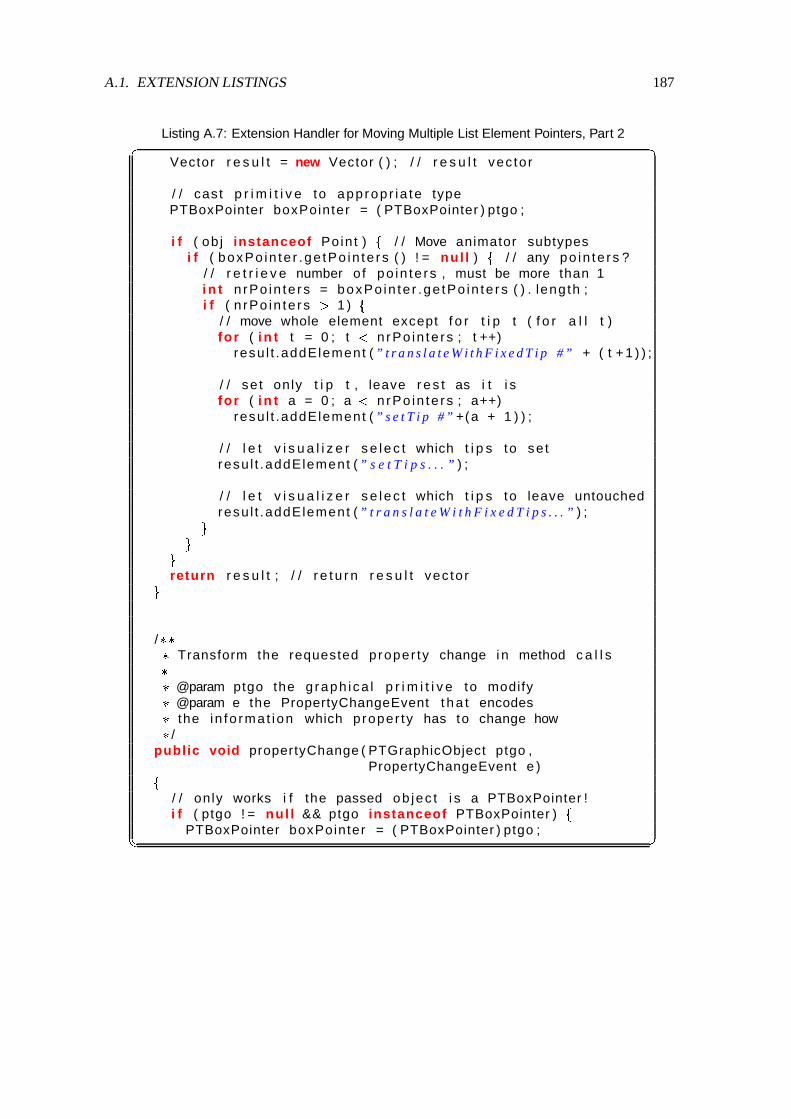
A.1. EXTENSION LISTINGS 187
Listing A.7: Extension Handler for Moving Multiple List Element Pointers, Part 2� �Vector r e s u l t = new Vector ( ) ; / / r e s u l t vec tor
/ / cast p r i m i t i v e to app rop r i a te typePTBoxPointer boxPointer = ( PTBoxPointer ) ptgo ;
i f ( ob j instanceof Poin t )+
/ / Move animator subtypesi f ( boxPo in te r .ge tPo in te rs ( ) ! = nul l )
+/ / any po in te rs ?
/ / r e t r i e v e number o f po in te rs , must be more than 1i n t nrPo in te rs = boxPo in te r .ge tPo in te rs ( ) . leng th ;i f ( n rPo in te rs ) 1 )
+/ / move whole element except f o r t i p t ( f o r a l l t )for ( i n t t = 0 ; t ( nrPo in te rs ; t ++)
resu l t .addElement ( ” t r a n s l a t e W i t h F i x e d T i p #” + ( t + 1 ) ) ;
/ / se t only t i p t , leave r e s t as i t i sfor ( i n t a = 0 ; a ( nrPo in te rs ; a++)
resu l t .addElement ( ” s e t T i p #” +(a + 1 ) ) ;
/ / l e t v i s u a l i z e r s e l e c t which t i p s to se tresu l t .addElement ( ” s e t T i p s . . . ” ) ;
/ / l e t v i s u a l i z e r s e l e c t which t i p s to leave untouchedresu l t .addElement ( ” t r a n s l a t e W i t h F i x e d T i p s . . . ” ) ;,,,
return r e s u l t ; / / r e t u r n r e s u l t vec tor,/ &'&& Transform the requested proper ty change i n method c a l l s& & @param ptgo the g raph i ca l p r i m i t i v e to modify& @param e the PropertyChangeEvent t h a t encodes& the in fo rma t i on which proper ty has to change how& /public void propertyChange ( PTGraphicObject ptgo ,
PropertyChangeEvent e )+/ / on ly works i f the passed ob jec t i s a PTBoxPointer !i f ( ptgo ! = nul l && ptgo instanceof PTBoxPointer )
+PTBoxPointer boxPointer = ( PTBoxPointer ) ptgo ;� ��

188 LIST OF FIGURES
Listing A.8: Extension Handler for Moving Multiple List Element Pointers, Part 3� �/ / r e t r i e v e t a r g e t method nameS t r i n g what = e.getPropertyName ( ) ;
/ / check i f move e f f e c t ( e lse not our problem here ! )i f ( e.getNewValue ( ) instanceof Poin t )
+Poin t o ld = ( Po in t ) e.getOldValue ( ) ; / / o ld p o s i t i o nPoin t now = ( Po in t ) e.getNewValue ( ) ; / / new p o s i t i o nPoin t d i f f = MSMath.d i f f (now , o ld ) ; / / d i f f e r e n c ei f ( wha t . s ta r t sWi th ( ” t r a n s l a t e W i t h F i x e d T i p #” ) )
+/ / determine s i n g l e f i x e d node numberi n t num = I n t e g e r . p a r s e I n t ( wha t . subs t r i ng ( 2 3 ) ) ;
/ / b u i l d app rop r i a te mapboolean [ ] map = new boolean [
boxPo in te r .ge tPo in te rCount ( ) ] ;/ / mark node f o r movemap[num * 1] = true ;
/ / move l i s t element accord ing to chosen mapboxPo in te r . t r ans la teWi th F i xedT i ps (map , d i f f . x ,
d i f f . y ) ;,else i f ( wha t . s ta r t sWi th ( ” s e t T i p #” ) )
+/ / determine s i n g l e t a r g e t node to movei n t num = I n t e g e r . p a r s e I n t ( wha t . subs t r i ng ( 8 ) ) ;
/ / move the se lec ted nodeboxPo in te r . se tT ip (num * 1 ,
MSMath.sum ( boxPo in te r .ge tT ip (num * 1 ) ,d i f f ) ) ;,
else i f ( wha t . s ta r t sWi th ( ” s e t T i p s ” )-/- wha t . s ta r t sWi th ( ” t r a n s l a t e W i t h F i x e d T i p s ” ) )+
/ / ac t on m u l t i p l e nodes at the same time/ / move nodes , or move element w i th f i x e d nodes?boolean setTipsMode = wha t . s ta r t sWi th ( ” s e t T i p s ” ) ;
/ / determine se lec ted nodesStr ingToken izer s t r i ngTok = new Str ingToken izer (
wha t . subs t r i ng ( ( setTipsMode ) ?7 : 2 2 ) ) ;
i n t nodeCount = boxPo in te r .ge tPo in te rCount ( ) ;
/ / b u i l d map f o r nodesboolean [ ] map = new boolean [ nodeCount ] ;i n t currentNode = 0 ;� ��

A.1. EXTENSION LISTINGS 189
Listing A.9: Extension Handler for Moving Multiple List Element Pointers, Part 4� �/ / i t e r a t e over parameter to e x t r a c t nodeswhile ( str ingTok.hasMoreTokens ( ) )
+/ / parse cu r ren t node numbercurrentNode = I n t e g e r . p a r s e I n t ( s t r ingTok.nex tToken ( ) ) ;i f ( currentNode ) 0 && currentNode ( = nodeCount )
map [ currentNode * 1] = true ; / / s e l e c t f o r opera t ion,i f ( boxPo in te r .ge tPo in te rs ( ) ! = nul l )
+i f ( setTipsMode )
+/ / se t only t i p s , leave ob jec t
i n t a ;for ( a = 0 ; a ( boxPo in te r .ge tPo in te rs ( ) . leng th ; a++)
i f ( map [ a ] ) / / i f marked , se t i t !boxPo in te r . se tT ip ( a ,
MSMath.sum( boxPo in te r .ge tT ip ( a ) ,d i f f ) ) ;,
else / / move ob jec t except f o r mapped nodesboxPo in te r . t r ans la teWi th F i xed T ips (map , d i f f . x ,
d i f f . y ) ;,,,,,� ��

190 LIST OF FIGURES
Listing A.10: PropertyNameMapper Implementation, Part 1� �package animal .misc ;
import j a v a . i o . P r i n t S t r e a m ; / / f o r s ta tus p r i n t i n g
import j a v a . u t i l . P r o p e r t i e s ; / / f o r i n t e r n a l lookup
/ &'&& Perform proper ty lookup i n shared p r o p e r t i e s& & @author Guido Roessl ing ( [email protected] )& @version 1.0 2001 * 11 * 30& /public class PropertyNameMapper+
/ &'&& ” forward ” mapping of key to value& /pr ivate Proper t i es mapping = new Proper t i es ( ) ;
/ &'&& ” reverse ” mapping of value to key& /pr ivate Proper t i es reverseMapping = new Proper t i es ( ) ;
/ &'&& I n s e r t a new mapping of key to mappedKey& & @param key the o r i g i n a l key& @param mappedKey the ac tua l key used f o r lookup& /public void inser tMapping ( S t r i n g key , S t r i n g mappedKey)+
mapping.put ( key , mappedKey ) ;reverseMapping.put (mappedKey , key ) ;,
/ &'&& Ret r ieve an element a t the key passed i n ” forward ” lookup& & @param key the access key& @return the proper ty name at the key , e lse the key i t s e l f& /public S t r i n g lookupMapping ( S t r i n g key )+
i f ( mapping.containsKey ( key ) )return mapping.getProper ty ( key ) ;
elsereturn key ;,� ��

A.1. EXTENSION LISTINGS 191
Listing A.11: PropertyNameMapper Implementation, Part 2� �/ &'&& Ret r ieve an element a t the key passed i n ” reverse ” lookup& & @param key the access key& @return the proper ty name at the key , e lse the key i t s e l f& /public S t r i n g lookupReverseMapping ( S t r i n g key )+
i f ( reverseMapping.containsKey ( key ) )return reverseMapping.getProper ty ( key ) ;
elsereturn key ;,
/ &'&& Remove the se lec ted en t r y from both mappings& & @param key the key to remove& /public void removeMapping ( S t r i n g key )+
i f ( mapping.containsKey ( key ) )+
S t r i n g value = lookupMapping ( key ) ;reverseMapping.remove ( value ) ;mapping.remove ( key ) ;,,
/ &'&& P r i n t the s ta tus o f the cu r ren t proper ty mapping& & @param out the Pr intStream to which to p r i n t& @see j a v a . i o . P r i n t S t r e a m& /public void pr in tMapping ( Pr in tStream out )+
o u t . p r i n t l n ( ” s t r a i g h t mapping : ” ) ;m a p p i n g . l i s t ( out ) ;o u t . p r i n t l n ( ” r e v e r s e mapping : ” ) ;r eve rseMapp ing . l i s t ( out ) ;,,� ��

192 LIST OF FIGURES

Bibliography
[1] Daniel Mark Abrahams-Gessel. Delaunay Triangulations From Hulls. WWW: http://www.cs.dartmouth.edu/˜gessel/Java/CGApp.html, 1996.
[2] Jay Martin Anderson and Thomas L. Naps. A Context for the Assessment of Algorithm Visu-alization System as Pedagogical Tools. First International Program Visualization Workshop,Porvoo, Finland. University of Joensuu Press, pages 121–130, July 2001.
[3] Woi L. Ang. Bin Sort. WWW: http://ciips.ee.uwa.edu.au/˜morris/Year2/PLDS210/binsort.html, 1998.
[4] Woi L. Ang. Building Hash Tables. WWW: http://ciips.ee.uwa.edu.au/˜morris/Year2/PLDS210/hash_tables.html, 1998.
[5] Woi L. Ang. Data Structures and Algorithms: Heap. WWW: http://ciips.ee.uwa.edu.au/˜morris/Year2/PLDS210/heaps.html, 1998.
[6] Woi L. Ang. Huffman Encoding & Decoding Animation. WWW: http://ciips.ee.uwa.edu.au/˜morris/Year2/PLDS210/huffman.html, 1998.
[7] Woi L. Ang. Matrix Chain Multiplication. WWW: http://ciips.ee.uwa.edu.au/˜morris/Year2/PLDS210/mat_chain.html, 1998.
[8] Woi L. Ang. Quick Sort. WWW: http://ciips.ee.uwa.edu.au/˜morris/Year2/PLDS210/qsort.html, 1998.
[9] Woi L. Ang. Radix Sort. WWW: http://ciips.ee.uwa.edu.au/˜morris/Year2/PLDS210/radixsort.html, 1998.
[10] Apple Computers, Inc. Quicktime for Java API. WWW: http://developer.apple.com/quicktime/qtjava/index.html, 2001.
[11] Ronald Baecker. Sorting Out Sorting: A Case Study of Software Visualization for TeachingComputer Science. In John Stasko, John Domingue, Marc H. Brown, and Blaine A. Price,editors, Software Visualization, pages 369–381. MIT Press, 1998.
[12] Ronald Baecker and Aaron Marcus. Printing and Publishing C Programs. In John Stasko,John Domingue, Marc H. Brown, and Blaine A. Price, editors, Software Visualization, chap-ter 4, pages 45–62. MIT Press, 1998.
193

194 BIBLIOGRAPHY
[13] Ronald Baecker and Blaine Price. The Early History of Software Visualization. In JohnStasko, John Domingue, Marc H. Brown, and Blaine A. Price, editors, Software Visualiza-tion, chapter 2, pages 29–34. MIT Press, 1998.
[14] Ronald Baecker and Dave Sherman. Sorting out Sorting. 30 minute color film, DynamicGraphics Project, University of Toronto (excerpted and “reprinted” in SIGGRAPH VideoReview 7, 1983), 1981. Distributed by Morgan Kaufman Publishers.
[15] Ryan S. Baker, Michael Boilen, Michael T. Goodrich, Roberto Tamassia, and B. AaronStibel. Testers and Visualizers for Teaching Data Structures. 30th ACM SIGCSE TechnicalSymposium on Computer Science Education (SIGCSE ’99), New Orleans, Louisiana, pages261–265, March 1999.
[16] Stig Sæther Bakken, Alexander Aulbach, Egon Schmid, Jim Winstead, Lars Torben Wilson,Rasmus Lerdorf, Zeev Suraski, and Andrei Zmievski. PHP Manual, 2000. WWW: http://snaps.php.net/manual/.
[17] John Bazik, Roberto Tamassia, Steven P. Reiss, and Andries van Dam. Software Visual-ization in Teaching at Brown University. In John Stasko, John Domingue, Marc H. Brown,and Blaine A. Price, editors, Software Visualization, chapter 25, pages 382–398. MIT Press,1998.
[18] Mordechai Ben-Ari. Program Visualization in Theory and Practice. Informatik / Informa-tique, Special Issue on Visualization of Software, pages 8–11, April 2001.
[19] Benjamin S. Bloom and David R. Krathwohl. Taxonomy of Educational Objectives; theClassification of Educational Goals, Handbook I: Cognitive Domain. Addison-Wesley,1956.
[20] Christopher M. Boroni, Frances W. Goosey, Michael T. Grinder, and Rockford J. Ross. AParadigm Shift! The Internet, the Web, Browsers, Java, and the Future of Computer Sci-ence Education. 29th ACM SIGCSE Technical Symposium on Computer Science Education(SIGCSE ’98), Atlanta, Georgia, pages 145–152, May 1998.
[21] Christopher M. Boroni, Frances W. Goosey, Michael T. Grinder, and Rockford J. Ross. En-gaging Students with Active Learning Resources: Hypertextbooks for the Web. 32nd ACMSIGCSE Technical Symposium on Computer Science Education (SIGCSE 2001), Charlotte,North Carolina, pages 65–69, February 2001.
[22] Alyce Brady. Introduction to Programming in C++ Extra Notes. WWW: http://max.cs.kzoo.edu/CS110W01/extraSlides.shtml, February 2001. Contains Power-point animations for Selection Sort, Insertion Sort and Merge Sort.
[23] Beatrix Braune and Reinhard Wilhelm. Focusing in Algorithm Explanation. IEEE Transac-tions on Visualization and Computer Graphics, 6(1):1–7, January 2000.
[24] Stina Bridgeman, Michael T. Goodrich, Stephen G. Kobourov, and Roberto Tamassia. PI-LOT: An Interactive Tool for Learning and Grading. 31st ACM SIGCSE Technical Sympo-sium on Computer Science Education (SIGCSE 2000), Austin, Texas, pages 139–143, March2000.

BIBLIOGRAPHY 195
[25] Marc H. Brown. Zeus: A System for Algorithm Animation and Multi-View Editing. Pro-ceedings of the 1991 IEEE Workshop on Visual Languages, Kobe, Japan, pages 4–9, October1991.
[26] Marc H. Brown. A Taxonomy of Algorithm Animation Displays. In John Stasko, JohnDomingue, Marc H. Brown, and Blaine A. Price, editors, Software Visualization, chapter 3,pages 35–42. MIT Press, 1998.
[27] Marc H. Brown and John Hershberger. Fundamental Techniques for Algorithm AnimationDisplays. In John Stasko, John Domingue, Marc H. Brown, and Blaine A. Price, editors,Software Visualization, chapter 7, pages 81–102. MIT Press, 1998.
[28] Marc H. Brown and John Hershberger. Program Auralization. In John Stasko, JohnDomingue, Marc H. Brown, and Blaine A. Price, editors, Software Visualization, chapter 10,pages 137–144. MIT Press, 1998.
[29] Marc H. Brown and Marc A. Najork. Algorithm Animation Using Interactive 3D Graphics.In John Stasko, John Domingue, Marc H. Brown, and Blaine A. Price, editors, SoftwareVisualization, chapter 9, pages 119–136. MIT Press, 1998.
[30] Marc H. Brown and Robert Sedgewick. A System for Algorithm Animation Structures.ACM SIGGRAPH ’84 Proceedings, Minneapolis, Minnesota, pages 177–186, July 1984.
[31] Marc H. Brown and Robert Sedgewick. Interesting Events. In John Stasko, John Domingue,Marc H. Brown, and Blaine A. Price, editors, Software Visualization, chapter 12, pages 155–172. MIT Press, 1998.
[32] Peter Brummund. Colossians 3:17. WWW: http://www.cs.hope.edu/˜alganim/animator/Animator.html, 1997.
[33] Peter Brummund. The Complete Collection of Algorithm Animations, 1998. WWW:http://cs.hope.edu/˜alganim/ccaa/.
[34] Michael D. Byrne, Richard Catrambone, and John Stasko. Do Algorithm Animations AidLearning? Technical report, Georgia Tech, August 1996. Available as Technical Report GIT-GVU-96-18 from http://www.cc.gatech.edu/gvu/softviz/empir/empir.html.
[35] Philippe M. Cassereau. Wavelet-based Image Coding. In Andrew B. Watson, editor, DigitalImages and Human Vision, chapter 2, pages 13–21. MIT Press, 1993.
[36] Giuseppe Cattaneo, Umberto Ferraro, Giuseppe F. Italiano, and Vittorio Scarano. Concur-rent Algorithms and Data Types Animation over the Internet. Proceedings of the 15th IFIPWorld Computer Congress, Vienna, Austria, 1998. Online at http://wonderland.dia.unisa.it/catai/.
[37] Paul Chew. Voronoi/Delaunay Applet. WWW: http://www.cs.cornell.edu/Info/People/chew/Delaunay.html, 1997.

196 BIBLIOGRAPHY
[38] Arturo I. Concepcion, Nathan Leach, and Allan Knight. Algorithma 99: An Experimentin Reusability & Component Based Software Engineering. 31st ACM SIGCSE TechnicalSymposium on Computer Science Education (SIGCSE 2000), Austin, Texas, pages 162–166,March 2000.
[39] Pierluigi Crescenzi, Camil Demetrescu, Irene Finocchi, and Rossella Petreschi. ReversibleExecution and Visualization of Programs with LEONARDO. Journal of Visual Languagesand Computing, 11(2):125–150, April 2000.
[40] Pierluigi Crescenzi, Nils Faltin, Rudolf Fleischer, Chris Hundhausen, Stefan Naher, GuidoRoessling, John Stasko, and Erkki Sutinen. The Algorithm Animation Repository. Proceed-ings of the Second International Program Visualization Workshop, Arhus, Denmark, page(submitted for review), June 2002.
[41] Karel Culik II and Jarkko Kari. Digital Images and Formal Languages. In GrzegorzRozenberg and Arto Salomaa, editors, Handbook of Formal Languages, volume 3 - Be-yond Words, chapter 10. Springer, 1997. ftp://ftp.cs.sc.edu/pub/culik/handbook.tar.gz.
[42] Wanda Dann, Stephen Cooper, and Randy Pausch. Making the Connection: ProgrammingWith Animated Small World. 5th Annual ACM SIGCSE/SIGCUE Conference on Innovationand Technology in Computer Science Education (ITiCSE 2000), Helsinki, Finland, pages41–44, July 2000.
[43] Adriana Cassia Rosse de Almeida. String Matching Algorithm Animation Applet. WWW:http://www.dcc.ufmg.br/˜cassia/smaa/english/, (no date given).
[44] Camil Demetrescu and Irene Finocchi. Smooth Animation of Algorithms in a DeclarativeFramework. Proceedings of the 1999 IEEE Symposium on Visual Languages (VL99), pages280–287, 1999.
[45] Herbert L. Dershem and Peter Brummund. Tools for Web-based Sorting Animations. 29th
ACM SIGCSE Technical Symposium on Computer Science Education (SIGCSE ’98), Atlanta,Georgia, pages 222–226, May 1998.
[46] Herbert L. Dershem and James Vanderhyde. Java Class Visualization for Teaching Object-Oriented Concepts. 29th ACM SIGCSE Technical Symposium on Computer Science Educa-tion (SIGCSE ’98), Atlanta, Georgia, pages 53–57, May 1998.
[47] Stephan Diehl, Andreas Kerren, and Reinhard Wilhelm. Ganimal. WWW: http://rw4.cs.uni-sb.de/˜ganimal/, 2000.
[48] John Domingue. Viz. WWW: http://kmi.open.ac.uk/sv/viz/viz.html,1997.
[49] John Domingue and Paul Mulholland. Staging Software Visualizations on the Web. IEEESymposium on Visual Languages (VL ’97), Capri, Italy, pages 368–375, 1997.
[50] Sarah A. Douglas, Christopher D. Hundhausen, and Donna McKeown. Toward Empirically-Based Software Visualization Languages. 1995 IEEE Symposium on Visual Languages,pages 342–349, 1995.

BIBLIOGRAPHY 197
[51] Sarah A. Douglas, Donna McKeown, and Christopher D. Hundhausen. Exploring HumanVisualization of Computer Algorithms. Proceedings of Graphics Interface ’96, Toronto,Canada, pages 9–16, 1996.
[52] David Eck. The xSortLab Applet. WWW: http://math.hws.edu/TMCM/java/xSortLab/index.html, 1997.
[53] Jukka Eskola and Jorma Tarhio. Animation of Flowcharts with Excel. First InternationalProgram Visualization Workshop, Porvoo, Finland. University of Joensuu Press, pages 59–68, July 2001.
[54] Nils Faltin. Designing Courseware on Algorithms for Active Learning with Virtual BoardGames. 4th Annual ACM SIGCSE/SIGCUE Conference on Innovation and Technology inComputer Science Education (ITiCSE ’99), Cracow, Poland, pages 135–138, June 1999.
[55] Nils Faltin. Aktives Lernen von Algorithmen mit interaktiven Visualisierungen. Tagungs-band ”Informatiktage 2000” der Gesellschaft fur Informatik, pages 121–137, 2000.
[56] Nils Faltin and Tobias Gross. Das Lernprogramm Heapsort-SALA 2.0. WWW: http://OLLI.informatik.uni-oldenburg.de/heapsort_SALA, 2000.
[57] Christine Faulkner. The Essence of Human-Computer Interaction. Prentice Hall, 1998.
[58] Tanya V. Filipova. Travelling Salesman Problem Animation. WWW: http://nuweb.jinr.dubna.su/˜filipova/tsp.html, 1996.
[59] James Foley, Andries van Dam, Steven Feiner, and John Hughes. Computer Graphics.Addison-Wesley, 2 edition, 1995.
[60] Taisuke Fukuno. Hanoi Applet. WWW: http://sariel.miyako.co.jp/˜uni/Hanoi.html, 1998.
[61] Erich Gamma, Richard Helm, Ralph Johnson, and John Vlissides. Design Patterns. Elementsof Reusable Object-Oriented Software. Addison-Wesley, 1995.
[62] Michael R. Garey and David S. Johnson. Computers and Intractability: a Guide to theTheory of NP-Completeness. Freeman, 1979.
[63] Carlisle E. George. EROSI - Visualizing Recursion and Discovering New Errors. 31st ACMSIGCSE Technical Symposium on Computer Science Education (SIGCSE 2000), Austin,Texas, pages 305–309, March 2000.
[64] David Ginat. Misleading Intuition in Algorithmic Problem Solving. 32nd ACM SIGCSETechnical Symposium on Computer Science Education (SIGCSE 2001), Charlotte, NorthCarolina, pages 21–25, February 2001.
[65] Peter A. Gloor. AACE - Algorithm Animation for Computer Science Education. Proceed-ings of the 1992 IEEE Workshop on Visual Languages, pages 25–31, 1992.
[66] Peter A. Gloor. Animated Algorithms. In John Stasko, John Domingue, Marc H. Brown,and Blaine A. Price, editors, Software Visualization, chapter 27, pages 409–416. MIT Press,1998.

198 BIBLIOGRAPHY
[67] Peter A. Gloor. User Interface Issues For Algorithm Animation. In John Stasko, JohnDomingue, Marc H. Brown, and Blaine A. Price, editors, Software Visualization, chapter 11,pages 145–152. MIT Press, 1998.
[68] Frances Goosey and Chris Boroni. WebLab Program Animator. WWW:http://www.cs.montana.edu/webworks/webworks-home/projects/program_animator/program_animator.html, 1997.
[69] James Gosling, Jason Harrison, and Jim Boritz. Sorting Algorithms Demo. WWW: http://www.cs.ubc.ca/spider/harrison/Java/sorting-demo.html, 2001.
[70] James Gosling and Kevin A. Smith. The Sorting Algorithm Demo (1.1). WWW: http://java.sun.com/applets/jdk/1.1/demo/SortDemo/index.html, 1996.
[71] Eric Gramond and Susan H. Rodger. Using JFLAP to Interact with Theorems in AutomataTheory. 30th ACM SIGCSE Technical Symposium on Computer Science Education (SIGCSE’99), New Orleans, Louisiana, pages 336–340, March 1999.
[72] J. Haajanen, M. Pesonius, E. Sutinen, J. Tarhio, T. Terasvirta, and P. Vanninen. Animationof User Algorithms on the Web. IEEE Symposium on Visual Languages, pages 360–367,1997.
[73] Alejo Hausner. Bubble Sort. WWW: http://www.cs.princeton.edu/˜ah/alg_anim/version1/BubbleSort.html, 1996.
[74] Alejo Hausner. Merge sort. WWW: http://www.cs.princeton.edu/˜ah/alg_anim/version1/MergeSort.html, 1996.
[75] Alejo Hausner. Quicksort. WWW: http://www.cs.princeton.edu/˜ah/alg_anim/version1/QuickSort.html, 1996.
[76] Michael T. Heath, Allen D. Malony, and Diane T. Rover. Visualization for Parallel Per-formance Evaluation and Optimization. In John Stasko, John Domingue, Marc H. Brown,and Blaine A. Price, editors, Software Visualization, chapter 23, pages 347–365. MIT Press,1998.
[77] Thomas G. Hill. Assessing the Instructional Value of Student Predictions in TreeAnimations. Doctoral Consortium at the 32nd ACM SIGCSE Technical Symposiumon Computer Science Education (SIGCSE 2001), Charlotte, North Carolina, page vii,2001. WWW: http://duke.csc.villanova.edu/docConsortium/DC01/participants/hill.html.
[78] Steven Holzner. Inside XML. New Riders Publishing, 2000.
[79] John E. Hopcroft, Rajeev Motwani, and Jeffrey D. Ullman. Introduction to Automata Theory,Languages, and Computation. Addison-Wesley, 2nd edition, 2000.
[80] Cay S. Horstmann and Gary Cornell. Core JAVA 2 - Advanced Features. Prentice Hall, 2000.
[81] Christopher D. Hundhausen. The Search for an Empiricial and Theoretical Foundationfor Algorithm Visualization. Available online at http://lilt.ics.hawaii.edu/˜hundhaus/writings/, 1993.

BIBLIOGRAPHY 199
[82] Christopher D. Hundhausen. Toward the Development of Highly Interactive Software Visu-alization Systems: A User-Centered Approach. International Workshop on Software Visual-ization, SIGCHI ’94, Boston, MA, 1994.
[83] Christopher D. Hundhausen and Sarah Douglas. SALSA and ALVIS: A Language and Sys-tem for Constructing and Presenting Low Fidelity Algorithm Visualizations. IEEE Sympo-sium on Visual Languages, Los Alamitos, California, pages 67–68, 2000.
[84] Christopher D. Hundhausen and Sarah Douglas. Using Visualizations to Learn Algorithms:Should Students Construct Their Own, or View an Expert’s? IEEE Symposium on VisualLanguages, Los Alamitos, California, pages 21–28, 2000.
[85] Christopher David Hundhausen. Toward Effective Algorithm Visualization Artifacts: De-signing for Participation and Communication in an Undergraduate Algorithms Course. PhDthesis, University of Oregon, 1999. Unpublished Doctoral Dissertation, available as techni-cal report CIS-TR-99-07 (June 1999) in Department of Computer and Information Science,University of Oregon, Eugene.
[86] Ted Hung and Susan H. Rodger. Increasing Visualization and Interaction in the AutomataTheory Course. 31st ACM SIGCSE Technical Symposium on Computer Science Education(SIGCSE 2000), Austin, Texas, pages 6–10, March 2000.
[87] Christian Icking, Rolf Klein, Peter Kollner, and Lihong Ma. VoroGlide 2.0. WWW: http://wwwpi6.fernuni-hagen.de/Geometrie-Labor/VoroGlide/, 1996.
[88] James H. Cross II, T. Dean Hendrix, Karl S. Mathias, and Larry A. Barowski. SoftwareVisualization and Measurement in Software Engineering Education: An Experience Report.29th ASEE/IEEE Frontiers in Education Conference, San Juan, Puerto Rico, pages 12b15–10, November 1999.
[89] Achim Janser. Entwurf, Implementierung und Evaluierung des interaktiven Lehr- undLernsystems ViACoBi fur die Visualisierung von Algorithmen der Computegraphik undBildverarbeitung. PhD thesis, Gerhard-Mercator-Universitat Duisburg, 1998. Ab-stract online at http://www.informatik.uni-duisburg.de/Info2/Janser/Janser.html.
[90] Duane Jarc, Michael B. Feldman, and Rachelle S. Heller. Assessing the Benefits of Inter-active Prediction Using Web-based Algorithm Animation Courseware. 31st ACM SIGCSETechnical Symposium on Computer Science Education (SIGCSE 2000), Austin, Texas, pages377–381, March 2000.
[91] Dean Jerding and John T. Stasko. Visualization of Object-Oriented Programs. WWW:http://www.cc.gatech.edu/gvu/softviz/ooviz/ooviz.html, 1998.
[92] Ricardo Jimenez-Peris and Marta Patino-Martınez. Visualizing Recursion and DynamicMemory. First International Program Visualization Workshop, Porvoo, Finland. Universityof Joensuu Press, pages 111–120, July 2001.
[93] Ricardo Jimenez-Peris, Marta Patino-Martınez, and J. Pacios-Martınez. VisMod: ABeginner-Friendly Programming Environment. Proceedings of the 1999 ACM Symposiumon Applied Computing, San Antonio, Texas, pages 115–120, 1999.

200 BIBLIOGRAPHY
[94] Biliana Kaneva and Dominique Thiebaut. Sorting Algorithms. WWW: http://cs.smith.edu/˜thiebaut/java/sort/demo.html, 1997.
[95] Alex Karweit and Robyn Geer. JELLRAP 1.0. WWW: http://www.cs.duke.edu/˜rodger/tools/jellrap/index.html, 1997.
[96] Frank Katritzke. Refinements of Data Compression Using Weighted Finite Automata. PhDthesis, University of Siegen, Germany, 2001.
[97] Charles F. Keleman and Eugene R. Turk. Visual Active Scaffolding. First InternationalProgram Visualization Workshop, Porvoo, Finland. University of Joensuu Press, pages 179–192, July 2001.
[98] Sami Khuri. Designing Effective Algorithm Visualizations. First International ProgramVisualization Workshop, Porvoo, Finland. University of Joensuu Press, pages 1–12, February2001.
[99] Sami Khuri. A User-Centered Approach for Designing Algorithm Visualizations. Informatik/ Informatique, Special Issue on Visualization of Software, pages 12–16, April 2001.
[100] Sami Khuri and Hsiu-Chin Hsu. Visualizing the CPU Scheduler and Page ReplacementAlgorithms. 30th ACM SIGCSE Technical Symposium on Computer Science Education(SIGCSE ’99), New Orleans, Louisiana, pages 227–231, March 1999.
[101] Sami Khuri and Hsiu-Chin Hsu. Interactive Packages for Learning Image CompressionAlgorithms. 5th Annual ACM SIGCSE/SIGCUE Conference on Innovation and Technologyin Computer Science Education (ITiCSE 2000), Helsinki, Finland, pages 73–76, 2000.
[102] Gregor Kiczales, John Lamping, Anurag Mendhekar, Chris Maeda, Cristina Videira Lopes,Jean-Marc Loingtier, and John Irwin. Aspect-Oriented Programming. In M. Aksit andS. Matsuoka, editors, ECOOP ’97 European Conference on Object-Oriented Programming,Jyvaskyla, Finland, pages 200–242. Springer-Verlag Berlin Heidelberg, June 1997.
[103] Andrew Kitchen. Sorting Algorithms. WWW: http://www.cs.rit.edu/˜atk/Java/Sorting/sorting.html, (no date given).
[104] Ken Knowlton. L6: Bell Telephone Laboratories Low-Level Linked List Language. 16minute black-and-white film, Murray Hill, N. J., 1966.
[105] Ken Knowlton. L6: Part II. An Example of L6 Programming. 30 minute black-and-whitefilm, Murray Hill, N. J., 1966.
[106] Donald E. Knuth. The TEXBook. Addison-Wesley, May 1986.
[107] Boris Koldehofen, Marina Papatriantafilou, and Philippas Tsigas. Distributed AlgorithmsViisualisation for Educational Purposes. 4th Annual ACM SIGCSE/SIGCUE Conference onInnovation and Technology in Computer Science Education (ITiCSE ’99), Cracow, Poland,pages 103–106, June 1999.
[108] Paul LaFollette, James Korsh, and Raghvinder Sangwan. A Visual Interface for EffortlessAnimation of C/C++ Programs. Journal of Visual Languages and Computing, 11(1):27–48,February 2000.

BIBLIOGRAPHY 201
[109] Hans-Werner Lang. Algorithmen. WWW: http://www.iti.fh-flens- burg.de/lang/algorithmen/algo.htm, 2001.
[110] Matti Lattu, Veijo Meisalo, and Jorma Tarhio. On Using a Visualization Tool as a Demon-stration Aid. First International Program Visualization Workshop, Porvoo, Finland. Univer-sity of Joensuu Press, pages 141–162, July 2001.
[111] Jari M. Lavonen, Veijo P. Meisalo, and Matti P. Lattu. Visual Programming: Basic Struc-tures Made Easy. First International Program Visualization Workshop, Porvoo, Finland.University of Joensuu Press, pages 163–178, July 2001.
[112] Geoff Leach. Delauney Triangulation. WWW: http://goanna.cs.rmit.edu.au/˜gl/research/comp_geom/delaunay/delaunay.html, 1996.
[113] Ronit Ben-Bassat Levy, Mordechai Ben-Ari, and Pekka A. Uronen. An Extended Experi-ment with Jeliot 2000. First International Program Visualization Workshop, Porvoo, Fin-land. University of Joensuu Press, pages 131–140, July 2001.
[114] Henry Lieberman and Christopher Fry. ZStep 95: A Reversible, Animated Source CodeStepper. In John Stasko, John Domingue, Marc H. Brown, and Blaine A. Price, editors,Software Visualization, chapter 19, pages 277–292. MIT Press, 1998.
[115] Linda Luo, Mervyn Ng, and Woi L. Ang. Red Black Tree. WWW: http://ciips.ee.uwa.edu.au/˜morris/Year2/PLDS210/red_black.html, 1998.
[116] J. D. McWhirter. AlgorithmExplorer: A Student-Centered Algorithm Animation System.In Proceedings of the IEEE Symposium on Visual Languages, pages 174–181, Washington,September 1996. IEEE Computer Society Press.
[117] Kurt Mehlhorn and Stefan Naher. LEDA: A Platform for Combinatorial and GeometricComputing. Cambridge University Press, 2000.
[118] D. Merlini, S. Petruzzi, R. Sprugnoli, and M. C. Verri. A System for Algorithms’ Animation.Proceedings of IEEE Multimedia Systems 1999, Florence, Italy, pages 1033–1034, 1999.
[119] Bertrand Meyer. Object-oriented Software Construction. Prentice Hall, 1997.
[120] Ramin Miraftabi. Intelligent Agents in Program Visualizations: A Case Study with Seal.First International Program Visualization Workshop, Porvoo, Finland. University of JoensuuPress, pages 53–58, July 2001.
[121] Sandeep Mitra. Java Sorting Animation Page - Bubble Sort. WWW: http://www.cs.brockport.edu/cs/javasort.html, 1999.
[122] Sandeep Mitra. Java Sorting Animation Page - Racing Sorts Page! WWW:http://www.cs.brockport.edu/cs/java/apps/sorters/race_sorters/sortchoiceinp.html, 1999.
[123] John Morris. Data Structures and Algorithms. WWW: http://ciips.ee.uwa.edu.au/˜morris/Year2/PLDS210/index.html, 1998.

202 BIBLIOGRAPHY
[124] John Morris and Woi L. Ang. Optimal Binary Search Tree. WWW: http://ciips.ee.uwa.edu.au/˜morris/Year2/PLDS210/opt_bin.html, 1998.
[125] Paul Mulholland and Stuart Watt. Learning by Building: A Visual Modelling Language forPsychology Students. Journal of Visual Languages and Computing, 11(5):481–504, October2000.
[126] David R. Musser. Advanced programming - rensselaer csci-6090. WWW: http://www.cs.rpi.edu/˜musser/ap/index_16.html, December 2000. Contains a binarytree searching, insertion and deletion animation in Powerpoint.
[127] MySQL Group. MySQL Reference Manual, 2001. WWW: www.mysql.com.
[128] Fernando Naharro-Berrocal, Cristobal Pajera-Flores, and J. Angel Velazquez-Iturbide. Foun-dations for the Automatic Construction of Animations and their Application to FunctionalPrograms. First International Program Visualization Workshop, Porvoo, Finland. Universityof Joensuu Press, pages 29–40, July 2001.
[129] Fernando Naharro-Berrocal, Cristobal Pareja-Flores, J. Angel Velazquez-Iturbide, and Mar-garita Martınez-Santamarta. Automatic Web Publishing of Algorithm Animations. Infor-matik / Informatique, Special Issue on Visualization of Software, pages 41–45, April 2001.
[130] Fernando Naharro-Berrocal, Cristobal Pareja-Flores, and Jose Angel Velazquez-Iturbide.Automatic Generation of Algorithm Animations in a Programming Environment. 30th
ASEE/IEEE Frontiers in Education Conference, Kansas City, Missouri, pages S2C 6–12,October 2000.
[131] Thomas Naps, James Eagan, and Laura Norton. JHAVE: An Environment to Actively En-gage Students in Web-based Algorithm Visualizations. 31st ACM SIGCSE Technical Sympo-sium on Computer Science Education (SIGCSE 2000), Austin, Texas, pages 109–113, March2000.
[132] Thomas L. Naps. Algorithm visualizations for CMSC34 - Algos and Data Structures.WWW: http://gaigs.cmsc.lawrence.edu/cmsc34/AVClient.html, 1998.
[133] Thomas L. Naps. A Java Visualizer Class: Incorporating Algorithm Visualisations into Stu-dents’ Programs. 3rd Annual ACM SIGCSE/SIGCUE Conference on Integrating Technologyinto Computer Science Education, Dublin, Ireland (ITiCSE ’98), pages 181–184, September1998.
[134] Thomas L. Naps. Incorporating Algorithm Visualization into Educational Theory: A Chal-lenge for the Future. Informatik / Informatique, Special Issue on Visualization of Software,pages 17–21, April 2001.
[135] David Neto. MergeSort demo with comparison bounds. WWW: http://www.cs.toronto.edu/˜neto/teaching/238/16/mergesort.html, 1996.
[136] Mervyn Ng. Minimum Spanning Tree Animation. WWW: http://ciips.ee.uwa.edu.au/˜morris/Year2/PLDS210/mst.html, 1998.

BIBLIOGRAPHY 203
[137] Mervyn Ng and Woi L. Ang. Dijkstra’s Algorithm. WWW: http://ciips.ee.uwa.edu.au/˜morris/Year2/PLDS210/dijkstra.html, 1998.
[138] Dung Nguyen and Stephen B. Wong. Design Patterns for Sorting. 32nd ACM SIGCSETechnical Symposium on Computer Science Education (SIGCSE 2001), Charlotte, NorthCarolina, pages 263–267, 2001.
[139] James Noble. Basic Relationship Patterns. Proceedings of the 2nd European Conference onPattern Languages of Programming (EuroPLoP ’97), Munich, Germany, 1997.
[140] Rainer Oechsle and Dieter Jahn. Visualisierung von ausgewahlten Lehrinhalten derInformatik - Beispielanimationen aus dem Projekt Vivaldi. Tagungsband GI-Workshop Soft-warevisualisierung (SV 2000), page ??, 2000. Published as Technical Report A01/00, FR6.2 Informatik, Universitat des Saarlandes.
[141] Gabriele Ortmann. The Sorting Algorithm Demo (1.1). WWW: http://archiv.informatik.fh-augsburg.de/informatik/projekte/meile/emiel/sort/bin/sort.html, 2001.
[142] Mathew Palakal. Graphical Linear Queue Demo. WWW: http://www.cs.iupui.edu/cgi-bin/cgiwrap/pacer/build_applet_page.cgi?topic=datastructs&subtopic=queue&spec=LinearQueue, 1997.
[143] Mathew Palakal. Graphical Stack Demo. WWW: http://www.cs.iupui.edu/cgi-bin/cgiwrap/pacer/build_applet_page.cgi?topic=datastructs&subtopic=stack&spec=StackDemo, 1997.
[144] Mathew J. Palakal, Frederick W. Meyers, and Carla L. Boyd. An Interactive Learning En-vironment for Breadth-First CS Curriculum. 29th ACM SIGCSE Technical Symposium onComputer Science Education (SIGCSE ’98), Atlanta, Georgia, pages 1–6, May 1998.
[145] Athanasios Papagelis. Backtracking. WWW: http://students.ceid.upatras.gr/˜papagel/project/kef5_8.htm, 1998.
[146] Athanasios Papagelis. Minimum Genetic Tree Animation: Kruskal Algorithm. WWW:http://students.ceid.upatras.gr/˜papagel/project/kruskal.htm,1998.
[147] Athanasios Papagelis. Minimum Genetic Tree Animation: Prim Algorithm. WWW: http://students.ceid.upatras.gr/˜papagel/project/prim.htm, 1998.
[148] Marta Patino-Martınez and Ricardo Jimenez-Peris. Visual Debugging of Functional Pro-grams. First International Program Visualization Workshop, Porvoo, Finland. University ofJoensuu Press, pages 101–110, July 2001.
[149] Wim De Pauw, Doug Kimelman, and John Vlissides. Visualizing Object-Oriented SoftwareExecution. In John Stasko, John Domingue, Marc H. Brown, and Blaine A. Price, editors,Software Visualization, chapter 22, pages 239–346. MIT Press, 1998.
[150] Connie Peng. Convex Hull Demo. WWW: http://www.cs.umd.edu/˜peng/cmsc754/animated/convexhull_anim.html, (no date given).

204 BIBLIOGRAPHY
[151] Frank Peters. Visualisierung von Algorithmen - Systematik und Bestandsaufnahme. Mas-ter’s thesis, Carl von Ossietzky-Universitat Oldenburg, 2001. Available online at http://www-cg-hci.informatik.uni-oldenburg.de/˜da/peters/Kalvin.
[152] W. Pierson and S. H. Rodger. Web-based Animation of Data Structures Using JAWAA.29th ACM SIGCSE Technical Symposium on Computer Science Education (SIGCSE ’98),Atlanta, Georgia, pages 267–271, 1998.
[153] P. J. Plauger, Alexander A. Stepanov, Meng Lee, and David R. Musser, editors. The C++Standard Template Library. Prentice Hall, 2000.
[154] Sandeep Poonen. Animation of Sort Algorithms. WWW: http://blackcat.brynmawr.edu/˜spoonen/JavaProject/sorter.html, 1998.
[155] B. A. Price, R. M. Baecker, and I. S. Small. A Principled Taxonomy of Software Visualiza-tion. Journal of Visual Languages and Computing, 4(3):211–264, 1993.
[156] Blaine Price, Ronald Baecker, and Ian Small. An Introduction to Software Visualization.In John Stasko, John Domingue, Marc H. Brown, and Blaine A. Price, editors, SoftwareVisualization, chapter 1, pages 3–27. MIT Press, 1998.
[157] Robert Rasala. Automatic Array Algorithm Animation in C++. 30th ACM SIGCSE TechnicalSymposium on Computer Science Education (SIGCSE ’99), New Orleans, Louisiana, pages257–260, March 1999.
[158] Ken Rebman. PowerPoint info. WWW: http://piglet.uccs.edu/˜haefner/math511/tools/presentations/presentations.htm, June 1999. Contains aPowerpoint animation of Pascal’s Triangle.
[159] Steven Robbins. The JOTSA Animation Environment. Proceedings of the 31st AnnualHawaii International Conference on Systems Sciences, pages 655–664, 1998.
[160] Susan Rodger. Integrating Animations into Courses. 1st Annual ACM SIGCSE/SIGCUEConference on Integrating Technology into Computer Science Education (ITiCSE ’96),Barcelona, Spain, pages 72–74, June 1996.
[161] Susan Rodger. JAWAA and Other Resources, 1997. Available at http://www.cs.duke.edu/˜rodger/tools/tools.html.
[162] Susan H. Rodger. Pate. WWW: http://www.cs.duke.edu/˜rodger/tools/pateweb/, 2000.
[163] Gruia-Catalin Roman. Declarative Visualization. In John Stasko, John Domingue, Marc H.Brown, and Blaine A. Price, editors, Software Visualization, chapter 13, pages 173–186.MIT Press, 1998.
[164] Gruia-Catalin Roman and K. Cox. A Declarative Approach to Visualizing Concurrent Com-putations. Computer, 22(10):25–36, October 1989.
[165] Gruia-Catalin Roman, K. Cox, C. Wilcox, and J. Plun. Pavane: A System for DeclarativeVisualization of Concurrent Computation. Journal of Visual Languages and Computing,3(1):161–193, January 1992.

BIBLIOGRAPHY 205
[166] Friedrich Roschmann. The Towers from Hanoi in JavaScript! WWW: http://privat.schlund.de/R/RoschmannFriedrich/, 1996.
[167] Rockford J. Ross. Hypertextbooks for the Web. First International Program VisualizationWorkshop, Porvoo, Finland. University of Joensuu Press, pages 221–233, July 2001.
[168] Guido Roßling. Algorithm Animation Repository. WWW: http://www.animal.ahrgr.de/en/AnimList.html, 2001.
[169] Guido Roßling. ANIMAL Home Page. WWW: http://www.animal.ahrgr.de,2001.
[170] Guido Roßling. Key Decisions in Adopting Algorithm Animations for Teaching. OpenIFIP-GI Conference on Social, Ethical and Cognitive Issues of Informatics and Informationand Communication Technologies (SEC III), Dortmund, Germany, page (accepted and inprint), July 2002.
[171] Guido Roßling. ANIMAL-FARM: An Extensible Framework for Algorithm Animation. Sec-ond International Program Visualization Workshop, Arhus, Denmark, page (submitted andunder review), June 2002.
[172] Guido Roßling and Jens Falk. ANIMAL sorting algorithms demo applet. WWW: http://www.animal.ahrgr.de/sortDemoApplet.html, December 2001.
[173] Guido Roßling and Bernd Freisleben. Approaches for Generating Animations for Lectures.Proceedings of the 11th Society for Information Technology and Teacher Education Confer-ence, pages 809–814, February 2000.
[174] Guido Roßling and Bernd Freisleben. Experiences In Using Animations in IntroductoryComputer Science Lectures. 31st ACM SIGCSE Technical Symposium on Computer ScienceEducation (SIGCSE 2000), Austin, Texas, pages 134–138, March 2000.
[175] Guido Roßling and Bernd Freisleben. Flexible Generation of Animations Using ANIMAL.International Conference on Mathematics / Science Education & Technology, page 432,February 2000.
[176] Guido Roßling and Bernd Freisleben. Generacion de visualizaciones de software usandoANIMALSCRIPT. Novatica, 1(150):38–42, April 2001.
[177] Guido Roßling and Bernd Freisleben. Program Visualization Using ANIMALSCRIPT. FirstInternational Program Visualization Workshop, Porvoo, Finland. University of JoensuuPress, pages 41–52, July 2001.
[178] Guido Roßling and Bernd Freisleben. Software Visualization Generation Using ANIMAL-SCRIPT. Informatik / Informatique, Special Issue on Visualization of Software, 8(2):35–40,April 2001.
[179] Guido Roßling and Bernd Freisleben. ANIMALSCRIPT: An Extensible Scripting Languagefor Algorithm Animation. 32nd ACM SIGCSE Technical Symposium on Computer ScienceEducation (SIGCSE 2001), Charlotte, North Carolina, pages 70–74, February 2001.

206 BIBLIOGRAPHY
[180] Guido Roßling and Bernd Freisleben. ANIMAL: A System for Supporting Multiple Roles inAlgorithm Animation. Journal of Visual Languages and Computing, 13(2):(in print), April2002.
[181] Guido Roßling and Thomas L. Naps. A Testbed for Pedagogical Requirements in AlgorithmVisualizations. 7th Annual ACM SIGCSE/SIGCUE Conference on Innovation and Technol-ogy in Computer Science Education (ITiCSE 2002), Arhus, Denmark, page (accepted and inprint), June 2002.
[182] Guido Roßling and Thomas L. Naps. Towards Intelligent Tutoring in Algorithm Visualiza-tion. Second International Program Visualization Workshop, Arhus, Denmark, page (sub-mitted and under review), June 2002.
[183] Guido Roßling, Markus Schuler, and Bernd Freisleben. ANIMAL: A New Interactive Mod-eler for Animations in Lectures. 31st ACM SIGCSE Technical Symposium on ComputerScience Education (SIGCSE 2000), Austin, Texas, page 437, March 2000.
[184] Guido Roßling, Markus Schuler, and Bernd Freisleben. The ANIMAL Algorithm Anima-tion Tool. 5th Annual ACM SIGCSE/SIGCUE Conference on Innovation and Technology inComputer Science Education (ITiCSE 2000), Helsinki, Finland, pages 37–40, July 2000.
[185] Robert Sedgewick. Algorithms in Java, Parts 1–4. Addison-Wesley, Reading, MA, USA,1998.
[186] Robert D. Sedgewick. Shellsort Animations. WWW: http://www.cs.princeton.edu/˜rs/shell/animate.html, 1996.
[187] Hiromasa Sekisita. Breadth-First Search Animation. WWW: http://al.ei.tuat.ac.jp/˜sekisita/graph2-e.html.
[188] Hiromasa Sekisita. Depth-First Search Animation. WWW: http://al.ei.tuat.ac.jp/˜sekisita/graph-e.html.
[189] Hiromasa Sekisita. Example of an Algorithm Animation: Bubble Sort. WWW: http://al.ei.tuat.ac.jp/˜sekisita/bsort-e.html.
[190] Hiromasa Sekisita. Example of an Algorithm Animation: Insertion Sort. WWW: http://al.ei.tuat.ac.jp/˜sekisita/isort-e.html.
[191] Hiromasa Sekisita. Example of an Algorithm Animation: Selection Sort. WWW: http://al.ei.tuat.ac.jp/˜sekisita/ssort-e.html.
[192] Hiromasa Sekisita. My Algorithm Animation System. WWW: http://al.ei.tuat.ac.jp/˜sekisita/aas/index.html.
[193] Matthew Smith. J-Updater – A Generic Java-based Software Updater. Technical report, De-partment of Electrical Engineering and Computer Science, University of Siegen, Germany,October 2001.
[194] John Stasko. Using Student-built Algorithm Animations as Learning Aids. 28th ACMSIGCSE Technical Symposium on Computer Science Education (SIGCSE ’97), San Jose,California, pages 25–29, February 1997.

BIBLIOGRAPHY 207
[195] John Stasko. Building Software Visualizations through Direct Manipulation and Demonstra-tion. In John Stasko, John Domingue, Marc H. Brown, and Blaine A. Price, editors, SoftwareVisualization, chapter 14, pages 187–203. MIT Press, 1998.
[196] John Stasko. Samba Algorithm Animation System, 1998. Available at http://www.cc.gatech.edu/gvu/softviz/algoanim/samba.html.
[197] John Stasko. Smooth Continuous Animation for Portraying Algorithms and Processes. InJohn Stasko, John Domingue, Marc H. Brown, and Blaine A. Price, editors, Software Visu-alization, chapter 8, pages 103–118. MIT Press, 1998.
[198] John Stasko, John Domingue, Marc H. Brown, and Blaine A. Price, editors. Software Visu-alization: Programming as a Multimedia Experience. MIT Press, 1998.
[199] John T. Stasko. PVaniM 2.0 Visualization Package. WWW: http://www.cc.gatech.edu/gvu/softviz/parviz/pvanimOL/pvanimOL.html, (no date given).
[200] Stauff. Bewegte Mathematik. WWW: http://www.muenster.de/˜stauff/bmru.htm, (no date given).
[201] Linda Stern, Harald Søndergaard, and Lee Naish. A Strategy for Managing Content Com-plexity in Algorithm Animation. 4th Annual ACM SIGCSE/SIGCUE Conference on Inno-vation and Technology in Computer Science Education (ITiCSE’99), Cracow, Poland, pages127–130, September 1999.
[202] Sun Microsystems, Inc. Jimi Software Development Kit. WWW: java.sun.com/products/jimi, February 2000.
[203] Chien Wei Tan. Quick Sort. WWW: http://ciips.ee.uwa.edu.au/˜morris/Year2/PLDS210/Java/q_sort/tqs_new.html, 1998.
[204] Andrew S. Tanenbaum. Modern Operating Systems. Prentice Hall, 2 edition, 2001.
[205] Minoru Terada. Animating C Programs in Paper-Slide-Show. First International ProgramVisualization Workshop, Porvoo, Finland. University of Joensuu Press, pages 79–88, July2001.
[206] Joseph A. Turner and Joseph L. Zachary. Javiva: A Tool for Visualizing and ValidatingStudent-Written Java Programs. 32nd ACM SIGCSE Technical Symposium on ComputerScience Education (SIGCSE 2001), Charlotte, North Carolina, pages 45–49, February 2001.
[207] Jose Angel Velazquez-Iturbide and Antonio Presa-Vazquez. Customization of Visualiza-tions in a Functional Programming Environment. 29th ASEE/IEEE Frontiers in EducationConference, San Juan, Puerto Rico, pages 12b3 22–28, November 1999.
[208] Larry Wall, Tom Christiansen, and Jon Orwant. Programming Perl. O’Reilly, 3rd edition,2000.
[209] Stuart N. K. Watt. Froglet: A Source-Level Stepper for Lisp. Technical Report KMI-TR-10,Human Cognition Research Laboratory, The Open University, UK, 1994.

208 BIBLIOGRAPHY
[210] William Yurcik and Larry Brumbaugh. A Web-Based Little Man Computer Simulator. 32nd
ACM SIGCSE Technical Symposium on Computer Science Education (SIGCSE 2001), Char-lotte, North Carolina, pages 204–208, 2001.
[211] Steven J. Zeil. ALGAE v2.0 - Sorting Demo. WWW: http://www.cs.odu.edu/˜zeil/AlgAE/WeissJavaSort/sortdemo.html, 2000.
[212] Andreas Zeller. Animating Data Structures in DDD. First International Program Visualiza-tion Workshop, Porvoo, Finland. University of Joensuu Press, pages 69–78, July 2001.
[213] Romuald J. Zyłła. Tower of Hanoi in JS. WWW: http://chemeng.p.lodz.pl/zylla/games/hf.html, 1999.
Copyright © 2022 FDOKUMEN