Airbag(s) Arming and Disarming - GimmeManuals.com
4477
Airbag(s) Arming and Disarming
-
Upload
khangminh22 -
Category
Documents
-
view
1 -
download
0
Transcript of Airbag(s) Arming and Disarming - GimmeManuals.com

Airbag(s) Arming and Disarming

Air Bag(s) Arming and Disarming: Service and Repair Airbag(s) Arming and Disarming

CAUTION: *
Work must be started 90 seconds after the ignition switch is turned to the "LOCK" position and thenegative (-) terminal cable is disconnected from the battery. (The SRS is equipped with a back-uppower source so that if work is started within 90 seconds of disconnecting the negative (-) terminalcable of the battery, the SRS may be deployed.)
* When the negative (-) terminal cable is disconnected from the battery, the memory of the clockand audio system will be canceled. So before starting work, make a record of the contentsmemorized in the audio memory system. When work is finished, reset the audio systems as beforeand adjust the clock. To avoid erasing the memory of each memory system, never use a backuppower supply from outside the vehicle.
* Before repairs, remove the airbag sensor if shocks are likely to be applied to the sensor duringrepairs.
* Do not expose the steering wheel pad, front passenger airbag assembly, side airbag assembly,airbag sensor assembly, front airbag sensor side airbag sensor assembly or door side airbagsensor directly to hot air or flames.
AIR BAG SYSTEM DISARMING
The Air Bag/Supplemental Restraint System (SRS) incorporates a backup energy source thatmaintains sufficient deployment voltage for up to 90 seconds after the ignition is turned Off and thebattery has been disconnected. Before disconnecting battery, note radio station settings, since allvehicle memory will be lost. Never use a backup power source from outside the vehicle.
1. Turn ignition to Lock, then disconnect battery ground cable. 2. Wait at least 90 seconds afterdisconnection before beginning service or diagnostic procedures.
AIR BAG SYSTEM ARMING
1. Ensure ignition is in Lock position. 2. Connect battery ground cable. 3. Wait at least 10 secondsbefore turning ignition from Lock position. 4. Turn ignition to ACC or On position and ensure SRSlamp lights, then goes off after approximately six seconds. If lamp remains lit, an SRS
condition is indicated. Refer to Restraint Systems, Air Bag Systems, Testing And Inspection. See:Restraint Systems/Air Bag Systems/Testing and Inspection

Page 464
SFI System

Page 3106
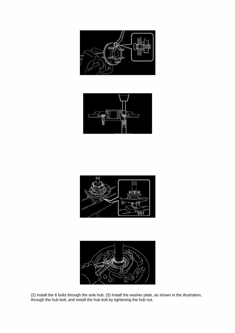
(2) Install the 6 bolts through the axle hub. (3) Install the washer plate, as shown in the illustration,through the hub bolt, and install the hub bolt by tightening the hub nut.

21. INSTALL REAR AXLE HUB & BEARING ASSY LH
a. Position the backing plate on the rear axle bearing, and install the 4 parking brake plates ontothe rear axle housing bolts using 2 socket
wrenches and a press.
22. INSTALL REAR AXLE SHAFT LH WASHER
a. Install the rear axle shaft plate washer onto the rear axle shaft.
23. INSTALL REAR AXLE BEARING RETAINER INNER LH
a. Install a new rear axle bearing retainer inner onto the rear axle shaft.
24. INSTALL REAR AXLE SHAFT LH
a. Using SST and a press, install the rear axle shaft onto the rear axle bearing.
SST 09521-25011
25. INSTALL REAR AXLE SHAFT LH SNAP RING
a. Using a snap ring expander, install a new snap ring.

Page 800
b. Install the grommet, a new lock washer and the nut.
Torque: 6.9 Nm (70 kgf-cm, 61 inch lbs.)
c. Install the manual valve lever shaft onto the groove and turn it 2 notches counterclockwise to theneutral position. d. Align the neutral basic line with the switch groove and tighten the adjusting bolt.
Torque: 13 Nm (130 kgf-cm, 9 ft. lbs.)
e. Bend the tabs of the lock washer.
HINT: Bend at least 2 of the lock washer tabs.
5. CONNECT PARK/NEUTRAL POSITION SWITCH CONNECTOR 6. CONNECT CABLE TONEGATIVE BATTERY TERMINAL
Torque: 3.9 Nm (40 kgf-cm, 35 inch lbs.)
7. INSPECT PARK/NEUTRAL POSITION SWITCH ASSY 8. ADJUST PARK/NEUTRAL POSITIONSWITCH ASSY 9. ADJUST SHIFT LEVER POSITION
10. INSPECT SHIFT LEVER POSITION

Specifications

Clutch Fluid: Specifications

Fluid type: ................................................................................................................................................................ SAE J1703 or FMVSS No.116 DOT 3

Page 704

(d) Turn the scan tool ON by pressing the "ON" button.

(e) Press "ENTER" after the start up screen appears.
(e) Select "1: DIAGNOSIS from the "APPLICATION SELECT menu.
(f) Select "1: OBD/MOBD" from the "FUNCTION SELECT FOR NORTH AMERICA" menu.

Specifications

Compression Check: Specifications

Compression pressure......................................................................................................................................................1230 kPa (12.5 kgf/cm2, 178 psi) Minimum pressure.................................................................................................................................................. 880kPa (9.0 kgf/cm2, 128 psi) or more Difference between each cylinder................................................................................................................................. 68 kPa (0.7kgf/cm2, 10 psi) or less

Page 1013

Brake Bleeding: Service and Repair W/o VSC

BRAKE FLUID (W/O VSC)
BLEEDING
HINT: If any work is done on the brake system or if air in the brake lines is suspected, bleed the airfrom the system.
NOTICE: Immediately wash off any brake fluid that comes into contact with any painted surfaces.
1. FILL RESERVOIR WITH BRAKE FLUID Fluid: SAE J1703 or FMVSS No.116 DOT3
2. BLEED MASTER CYLINDER
HINT: If the master cylinder has been disassembled or if the reservoir becomes empty, bleed theair from the master cylinder.
a. Using SST, disconnect the brake lines from the master cylinder.
SST 09023-00101
b. Slowly depress the brake pedal and hold it there.
c. Block the outer holes with your fingers, and release the brake pedal. d. Repeat b. and c. 3 or 4times.

Page 2271

c. Connect the air switching valve connector. d. Connect the vacuum hose.

9. INSTALL INTAKE PIPE INSULATOR
a. Install 2 new gaskets onto the cylinder head and air switching valve. b. Install the intake pipeinsulator with the 4 nuts.
Torque: 20 N.m (204 Kgf.cm, 15 ft.lbf)
10. CONNECT AIR INJECTION SYSTEM NO.1 HOSE
a. Connect the air injection system No.1 hose to the air switching valve.
11. INSTALL EXHAUST MANIFOLD HEAT INSULATOR NO.1

Page 2893
See Figures 8 and 9 for examples of liquid observed within the connector/Junction Block.
9. Replace the Engine Room Main Wire Harness and Junction Block No. 1.
10. Reconnect the battery.
11. Confirm proper operation of vehicle.
12. Repair is complete.

Page 174

Relay Box: Connector Views
Engine Room R/B, J/B - Engine Compartment Left

Service and Repair

Fuel Pressure Release: Service and Repair

PRECAUTION
1. PRECAUTION
a. Before working on the fuel system, disconnect the cable from the negative battery terminal. b.Do not work on the fuel system near fire. Never smoke during the work. c. Keep rubber and leatherparts away from gasoline.
2. DISCHARGE FUEL PRESSURE
CAUTION: -
Before removing fuel system parts, take precautions to prevent gasoline spillage.
- As some pressure remains in the fuel line even after taking precautions to prevent gasolinespillage, use a shop rag to prevent gasoline splashes when disconnecting the fuel line.
a. Disconnect the cable from the negative battery terminal. b. Remove the engine relay blockcover.
c. Remove the circuit opening relay. d. Connect the cable to the negative battery terminal.
Torque: 3.9 N.m (40 kgf.cm, 35 in.lbf)
e. Start the engine. f.
Turn the ignition switch to ON after the engine stops.
HINT: DTC P0171 (system to lean) may be present.
g. Crank the engine again, and check that the engine stops. h. Remove the fuel tank cap, anddischarge the pressure in the fuel tank completely. i.
Install the circuit opening relay.
3. FUEL SYSTEM
a. When disconnecting the high-pressure fuel line, a large amount of gasoline will splash. So takethe following precautions.

Page 9
I: Indicates a wiring Splice Point (Codes are "E" for the Engine Room, "I" for the Instrument Panel,and "B" for the Body).
The Location of splice Point I5 is indicated by the shaded section.
J: Indicates a shielded cable.
K: Indicates the pin number of the connector. The numbering system is different for female andmale connectors.
L: Indicates a ground point.
The first letter of the code for each ground point(s) indicates the component's location, e.g, "E" forthe Engine Compartment, "I" for the Instrument Panel and Surrounding area, and "B" for the Body

and Surrounding area.
N: Explains the system outline.
SYSTEM OUTLINE
Current is applied at all times through the STOP fuse to TERMINAL 2 of the stop light SW. Whenthe ignition SW is turned on, current flows from the GAUGE fuse to TERMINAL 8 of the light failuresensor, and also flows through the rear lights warning light to TERMINAL 4 of the light failuresensor.
STOP LIGHT DISCONNECTION WARNING When the ignition SW is turned on and the brakepedal is pressed (Stop light SW on), if the stop light circuit is open, the current flowing fromTERMINAL 7 of the light failure sensor to TERMINALS 1, 2 changes, so the light failure sensordetects the disconnection and the warning circuit of the light failure sensor is activated.
As a result, the current flows from TERMINAL 4 of the light failure sensor to TERMINAL 11 toGROUND and turns the rear lights warning light on. By pressing the brake pedal, the currentflowing to TERMINAL 8 of the light failure sensor keeps the warning circuit on and holds thewarning light on until the ignition SW is turned off.

Page 535

Transmission Position Switch/Sensor: Service and Repair

PARK/NEUTRAL POSITION SWITCH ASSY
REPLACEMENT
1. DISCONNECT CABLE FROM NEGATIVE BATTERY TERMINAL 2. DISCONNECTPARK/NEUTRAL POSITION SWITCH CONNECTOR
3. REMOVE PARK/NEUTRAL POSITION SWITCH ASSY
a. Using a screwdriver, unstake the lock washer. b. Remove the nut, lock washer and grommet. c.Remove the bolt and park/neutral position switch.
4. INSTALL PARK/NEUTRAL POSITION SWITCH ASSY
a. Install the park/neutral position switch onto the manual valve lever shaft and provisionally tightenthe adjusting bolt.

Locations
A/C - Ge

Page 2316

Fuel Pressure: Testing and Inspection

ON-VEHICLE INSPECTION
1. CHECK FUEL PUMP
a. Connect the hand-held tester to the DLC3. b. Turn the ignition switch to ON.
NOTE: Do not start the engine.
c. Turn the hand-held tester ON. d. Select the following menu items: DIAGNOSIS / ENHANCEDOBD II / ACTIVE TEST / FUEL PUMP / SPD. e. Check the fuel operation by operating it with thehand-held tester.
If the fuel pump does not operate, replace the fuel pump.
2. CHECK FUEL PRESSURE
a. Discharge the fuel system pressure. b. Using a voltmeter, measure the battery voltage.
Standard: 9.0 to 14 V
c. Disconnect the cable from the negative battery terminal. d. Remove the fuel pipe clamp. e.Disconnect the fuel hose.
f. Install SST into the vehicle.
SST 09268- 41048 (09268- 41500, 90467- 13001, 95336- 08070), 09268- 45014 (09268- 41200,09268-41220, 09268-41250, 90467-13001)
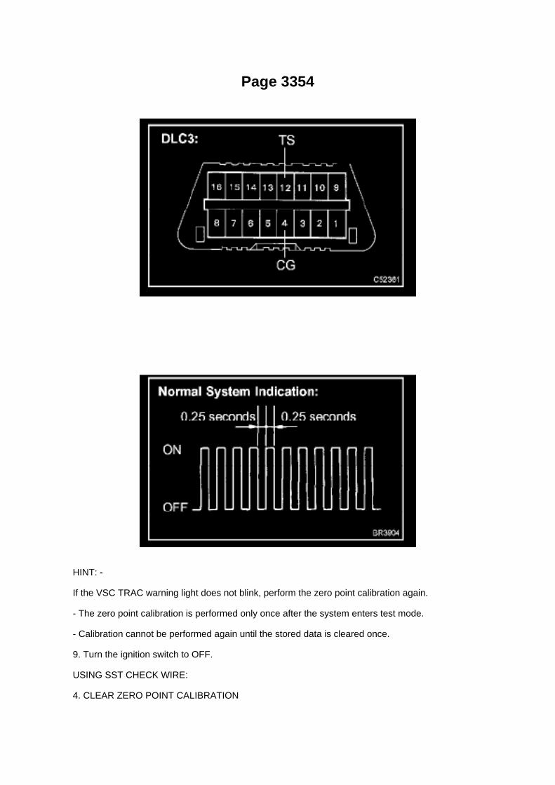
Page 3354
HINT: -
If the VSC TRAC warning light does not blink, perform the zero point calibration again.
- The zero point calibration is performed only once after the system enters test mode.
- Calibration cannot be performed again until the stored data is cleared once.
9. Turn the ignition switch to OFF.
USING SST CHECK WIRE:
4. CLEAR ZERO POINT CALIBRATION

HINT: After replacing the yaw rate and deceleration sensor, be sure to clear the zero pointcalibration data in the skid control ECU and perform zero point calibration.
a. Turn the ignition switch to the ON position.
b. Using SST, connect and disconnect terminals TS and CG of the DLC3 4 times or more within 8seconds.
SST 09843-18040
c. Check that the warning light blinks in a normal system indication pattern. d. Remove the SSTfrom the terminals of the DLC3. e. Perform zero point calibration of the yaw rate and decelerationsensor using a check wire (refer to step 5).
5. PERFORM ZERO POINT CALIBRATION OF YAW RATE SENSOR AND DECELERATIONSENSOR
HINT: After replacing the skid control ECU and/or yaw rate and deceleration sensor, be sure toperform yaw rate sensor and deceleration sensor zero point calibration.
NOTE: -
While obtaining the zero point, do not vibrate the vehicle by tilting, moving or shaking it and keep itstationary. (Do not start the engine.)
- Be sure to do this on a level surface (with an inclination less than 1 degree).
a. Procedures for test mode:
1. Turn the ignition switch to OFF. 2. Check that the steering wheel is in the straight ahead position.3. A/T: Check that the shift lever is in the P position and apply the parking brake.
M/T: Check that the shift lever is in neutral and apply the parking brake.

Page 581
SFI System

Page 1228

h. Tighten the bolts in the order shown in the illustration.

Torque:
12 Nm (122 kgf-cm, 9 ft. lbs.) for bolt A 16 Nm (158 kgf-cm, 11 ft. lbs.) for bolts except bolt A
i. Check that each timing mark is set in the position shown in the illustration.
j. Install the timing chain onto the camshaft timing gear, with the paint mark aligned with the timingmark on the camshaft timing gear.
k. Align the No.2 camshaft straight pin and camshaft timing gear straight pin hole. Then install thecamshaft timing gear onto the No.2 camshaft.
NOTICE: If the straight pin and straight pin hole are difficult to align, slightly rotate the No.2camshaft to the left and right using the hexagonal lobe of the camshaft. Then attempt to align themagain.

Page 2246
Transmission Position Switch/Sensor: Adjustments
PARK/NEUTRAL POSITION SWITCH ASSY
ADJUSTMENT
1. INSPECT PARK/NEUTRAL POSITION SWITCH ASSY
a. Apply the parking brake and turn the ignition switch to ON. b. Depress the brake pedal andcheck that the engine starts only when the shift lever is set in the N or P position and that it doesnot start in any
other positions.
c. Check that the back-up light comes on and the reverse warning buzzer sounds only when theshift lever is set in the R position and not in other
positions. If any failure is found, check the park/neutral position switch for continuity.
2. ADJUST PARK/NEUTRAL POSITION SWITCH ASSY
a. Loosen the bolt of the park/neutral position switch and set the shift lever to the N position. b.Align the groove and the neutral basic line. c. Hold the switch in position and tighten the bolt.
Torque: 13 Nm (130 kgf-cm, 9 ft. lbs.)
d. After making an adjustment, perform the inspection described in step 1.

Page 1458
2. After connecting the fuel tube connector, check that the fuel tube connector and pipe aresecurely connected by pulling them.

Page 56
Trailer Towing Relay: Diagrams

Towing Converter Relay Part 1

Page 2628
Knock Control Sensor (2TR-FE) Part 1

Page 162
SYMPTOM SIMULATION
HINT: The most difficult case in troubleshooting is when no problem symptoms occur. In suchcases, a thorough customer problem analysis must be carried out. A simulation of the same orsimilar conditions and environment in which the problem occurred in the customer's vehicle shouldbe carried out. No matter how much skill or experience a technician has, troubleshooting withoutconfirming the problem symptoms will lead to important repairs being overlooked and mistakes ordelays.
For example: With a problem that only occurs when the engine is cold or occurs as a result ofvibration caused by the road during driving, the problem can never be determined if the symptomsare being checked on a stationary vehicle or a vehicle with a warmed-up engine. Vibration, heat orwater penetration (moisture) is difficult to reproduce. The symptom simulation tests below areeffective substitutes for the conditions and can be applied on a stationary vehicle.
Important points in the symptom simulation test: In the symptom simulation test, the problemsymptoms as well as the problem area or parts must be confirmed. First, narrow down the possibleproblem circuits according to the symptoms. Then, connect the tester and carry out the symptomsimulation test, judging whether the circuit being tested is defective or normal. Also, confirm theproblem symptoms at the same time. Refer to the problem symptoms table for each system to

narrow down the possible causes.
1. VIBRATION METHOD: When vibration seems to be the major cause.
a. PART AND SENSOR
1. Apply slight vibration with a finger to the part of the sensor considered to be the cause of theproblem and check whether or not the
malfunction occurs.
HINT: Applying strong vibration to relays may open relays.
b. CONNECTORS
1. Slightly shake the connector vertically and horizontally.
c. WIRE HARNESS
1. Slightly shake the wire harness vertically and horizontally.
The connector joint and fulcrum of the vibration are the major areas that should be checkedthoroughly.

Page 3193

Shift Solenoid: Diagrams

The shift solenoid identification and location in the valve body is contained in the valve bodyservice and repair procedures and overhaul articles for most models.

Page 2735
When using Techstream Lite, select Generic J2534 Interface. Then click Next.
E. Confirm the following:
^ PC is connected to VIM.
^ VIM is connected to DLC3 connector.
^ Ignition is ON and engine is OFF or "READY" OFF (hybrid vehicles).

Page 2141

Part 2

a. Write VIN using the hand-held tester.
Vehicle Reprogramming
VEHICLE REPROGRAMMING
Beginning with some 2001 models and expanding to all models by 2007, Toyota/Scion and Lexusvehicles are equipped with flash reprogrammable Powertrain Control Modules (PCM).Reprogramming should only be performed if a Technical Service Bulletin or Service Campaignprovides direction to do so.

Page 408
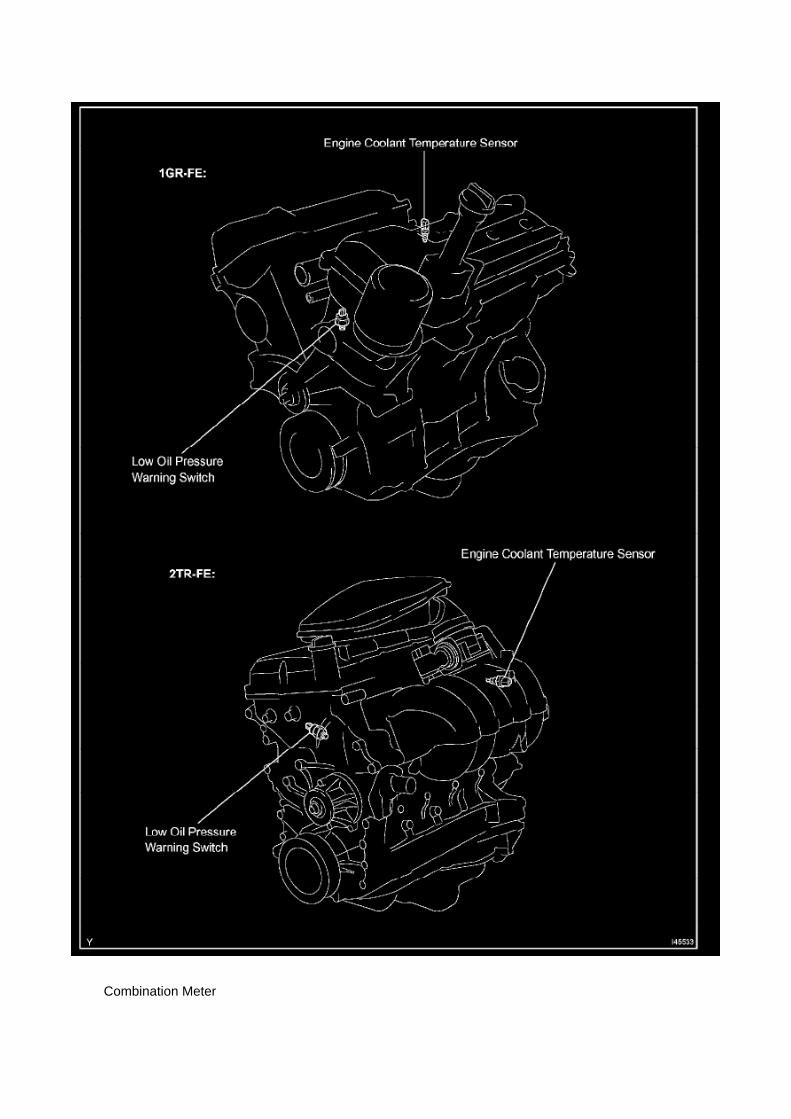
Combination Meter

Page 3288
b. Using SST, connect each brake line to the correct position of the brake actuator, as shown in theillustration.
SST 09023-00101 Torque: 15.2 Nm (155 kgf-cm, 11 ft. lbs.)

c. Connect the brake actuator connector. d. Lock the connector lock lever.
NOTICE: Make sure that the lever is locked securely.
8. INSTALL AIR INJECTION CONTROL DRIVER (2TR-FE ENGINE TYPE)
a. Install the air injection control driver with the 2 bolts.
Torque: 10 Nm (102 kgf-cm, 7 ft. lbs.)
b. Connect the 2 connectors.
9. FILL RESERVOIR WITH BRAKE FLUID
10. BLEED MASTER CYLINDER
SST 09023-00101
11. BLEED BRAKE LINE 12. CHECK FLUID LEVEL IN RESERVOIR 13. CHECK FOR BRAKEFLUID LEAKAGE 14. CONNECT CABLE TO NEGATIVE BATTERY TERMINAL
Torque: 3.9 Nm (40 kgf-cm, 35 inch lbs.)
15. CHECK BRAKE ACTUATOR WITH HAND-HELD TESTER

Page 3021
18. Inspect and adjust the clutch pedal sub-assembly.
A. Lift the floor carpet.
B. Check that the pedal height is correct.
Pedal height from asphalt sheet: 168.5 to 178.5 mm (6.634 to 7.028 in.)
C. Adjust the pedal height.
a. Loosen the lock nut and turn the stopper bolt until the height is correct.
b. Tighten the lock nut.
Torque: 25 N.m (250 kgf.cm, 18 ft.lbf)
D. Check that the pedal free play and push rod play are correct.

a. Depress the pedal until the clutch resistance begins to be felt.
Pedal free play: 5.0 to 15.0 mm (0.197 to 0.591 in.)
b. Gently depress the pedal until the resistance begins to increase a little.
E. Adjust the pedal free play and push rod free play.
a. Loosen the lock nut and turn the push rod until the free play and push rod play are correct.
b. Tighten the lock nut.
Torque: 11.8 N.m (120 kgf.cm, 9 ft.lbf)
c. After adjusting the pedal free play, check the pedal height.
19. Install the driver's side Junction Block.

Page 2221

Oxygen Sensor: Service and Repair Heated Oxygen Sensor

REPLACEMENT
1. DISCONNECT CABLE FROM NEGATIVE BATTERY TERMINAL 2. REMOVE HEATEDOXYGEN SENSOR
a. Disconnect the heated oxygen sensor connector. b. Disconnect the wire harness clamp. (4WDDRIVE TYPE)
c. Using SST, remove the heated oxygen sensor.
SST 09224-00010
3. INSTALL HEATED OXYGEN SENSOR
a. Using SST, install the heated oxygen sensor.

Page 1020

Page 2619
Crankshaft Position Sensor: Testing and Inspection
INSPECT CRANKSHAFT POSITION SENSOR
Check the resistance.
Using an ohmmeter, measure the resistance between the terminals.
HINT: Cold and Hot mean the temperature of the coils themselves. Cold is from -10 to 50°C (14 to122°F) and Hot is from 50 to 100°C (122 to 212° F).
If the result is not as specified, replace the camshaft position sensor.

Page 791
Steering Angle Sensor: Locations

ABS With EBD & BA & TRAC & VSC SYSTEM

Page 1050

The "Current Flow Chart", describes which parts each power source (fuses, fusible links, and circuitbreakers) transmits current to. In the Power Source circuit diagram, the conditions when batterypower is supplied to each system are explained. Since all System Circuit diagrams start from thepower source, the power source system must be fully understood.

Page 2397

Page 603
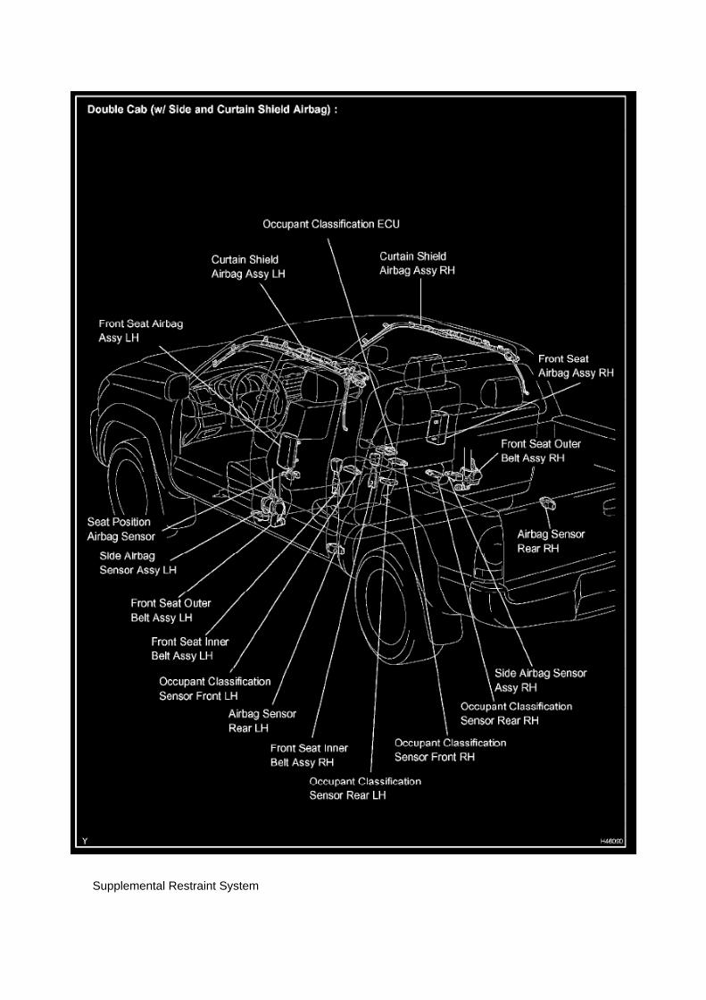
Supplemental Restraint System

Page 3020

16. Install the NEW clutch pedal sub-assembly.

A. Install the clutch pedal onto the clutch support with the bolt and nut.
Torque: 34 N.m (347 kgf.cm, 25 ft.lbf)
HINT
Install the bolt from the left side of the vehicle.
B. Apply MP grease to the clutch pedal sub-assembly where the clevis sub-assembly contacts theclutch pedal.
NOTE:
Failure to apply grease to the clevis and clutch pedal sub-assemblies could cause the noise toreturn.
C. Tighten the bolt to the instrument panel reinforcement assembly.
Torque: 8 N.m (82 kgf.cm, 6 ft.lbf)
17. Install the turnover (compression) spring.
A. Apply MP grease to the contact surface of the spring holder, clutch pedal, and spring.
B. Install the spring onto the clutch pedal and spring holder.

Locations
A/C - Ge

Page 2393

Page 1517
1. Remove coolant and any foreign material on rubber points "A," "B," and "C."
2. Check that points "A," "B " and "C" are not deformed, cracked, or swollen.
3. Check that points "C" and "D" are not stuck together.
4. Apply engine coolant to points "B" and "C" before using the radiator cap tester.
^ Radiator Cap Tester: Snap-On/Sun P/N SVTS262A (or equivalent)
5. Before installing the radiator cap tester, use the applicable radiator cap adaptor provided in thefollowing SST kits in conjunction with the radiator cap tester:
^ SST P/N 09230-00030-01 (09231-10080-01) or 09230-00020-01 (09231-10060-01) or09230-00050-01(09231-10110-01

6. When using the radiator cap tester, tilt it more than 30 degrees.
7. Pump the radiator cap tester several times, and check the maximum pressure.
Pumping speed: 1 pump/second
HINT:
Stop pumping when the valve opens and read the gauge. The gauge must be within the standardvalues listed below when the pressure valve opens. The cap is considered OK when the pressureholds steady or falls very slowly, but holds within the standard values listed below for one minute.
Specification:
If the maximum pressure is less than the minimum standard value, replace the radiator capsub-assembly.
Type: Compact Cap, 88 kPa

Page 369
Coolant Temperature Sensor/Switch (For Computer): Testing and Inspection
INSPECT E.F.I. ENGINE COOLANT TEMPERATURE SENSOR
a. Check the resistance.
1. Using an ohmmeter, measure the resistance between the terminals.
NOTE: If checking the engine coolant temperature sensor in water, be careful not to allow water tointrude into the terminals. After checking, wipe the water off the engine coolant temperature sensor.

If the result is not as specified, replace the engine coolant temperature sensor.

Page 1876
Step 1 - 3

Page 2248
b. Install the grommet, a new lock washer and the nut.
Torque: 6.9 Nm (70 kgf-cm, 61 inch lbs.)
c. Install the manual valve lever shaft onto the groove and turn it 2 notches counterclockwise to theneutral position. d. Align the neutral basic line with the switch groove and tighten the adjusting bolt.
Torque: 13 Nm (130 kgf-cm, 9 ft. lbs.)
e. Bend the tabs of the lock washer.
HINT: Bend at least 2 of the lock washer tabs.
5. CONNECT PARK/NEUTRAL POSITION SWITCH CONNECTOR 6. CONNECT CABLE TONEGATIVE BATTERY TERMINAL
Torque: 3.9 Nm (40 kgf-cm, 35 inch lbs.)
7. INSPECT PARK/NEUTRAL POSITION SWITCH ASSY 8. ADJUST PARK/NEUTRAL POSITIONSWITCH ASSY 9. ADJUST SHIFT LEVER POSITION
10. INSPECT SHIFT LEVER POSITION

Page 1423


Page 19

b. HANDLING CONNECTORS

1. When disconnecting a connector, first squeeze the mating halves tightly together to release thelock, then press the lock claw and separate the
connector.
2. When disconnecting a connector, do not pull on the harnesses. Grasp the connector directly andseparate it. 3. Before connecting the connector, check that there are no deformed, damaged, looseor missing terminals. 4. When connecting a connector, press firmly until you hear the lock closewith a "click" sound. 5. If checking the connector with a TOYOTA electrical tester, check it from thebackside (harness side) of the connector using a mini test lead.
NOTE: -
As a waterproof connector cannot be checked from the backside, check by connecting asub-harness.
- Do not damage the terminals by moving the inserted tester needle.
c. CHECKING CONNECTORS
1. Checking when the connector is connected: Squeeze the connector together to confirm that it isfully inserted and locked.
2. Checking when the connector is disconnected: Check by pulling the wire harness lightly from thebackside of the connector. Look for
unlatched terminals, missing terminals, loose crimps or broken conductor wires. Check visually forcorrosion, metallic or foreign objects and water; and bent, rusted, overheated, contaminated, anddeformed terminals.
NOTE: When testing a gold-plated female terminal, always use a gold-plated male terminal.

Page 167
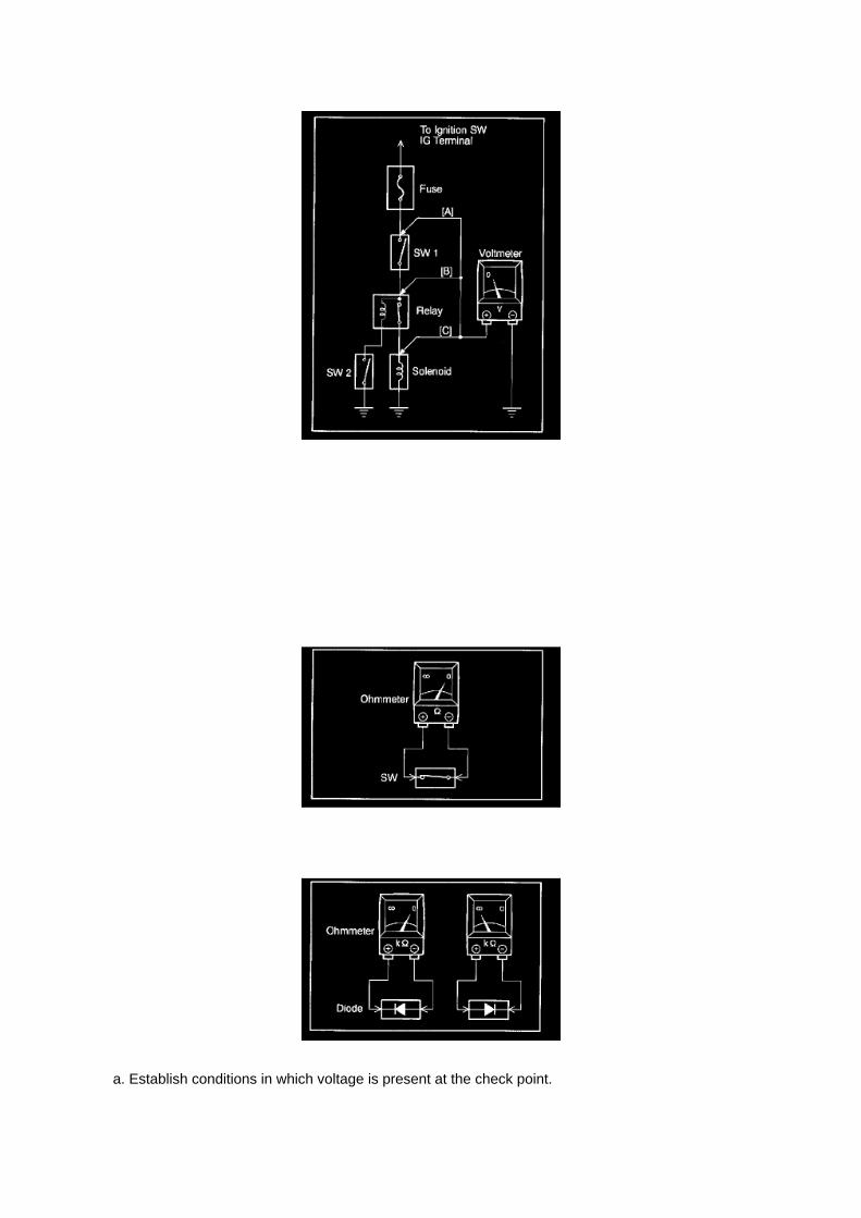
a. Establish conditions in which voltage is present at the check point.

Example: [A] - Ignition SW on [B] - Ignition SW and SW 1 on [C] - Ignition SW, SW 1 and Relay on(SW 2 off)
b. Using a voltmeter, connect the negative lead to a good ground point or negative battery terminal,and the positive lead to the connector or
component terminal. This check can be done with a test light instead of a voltmeter.
Continuity and Resistance Check
CONTINUITY AND RESISTANCE CHECK
a. Disconnect the battery terminal or wire so there is no voltage between the check points.
b. Contact the two leads of an ohmmeter to each of the check points.

Locations

Transmission Speed Sensor: Locations

He - Wi

Page 2807
Required Tools & Equipment
Important Information
^ 100,000 Mile Maintenance Interval - Inspection only; ATF-WS does NOT require any flushing orchanging during the life of the vehicle.
^ The use of Genuine Toyota ATF-WS is recommended.
^ The use of additives or aftermarket fluids that are considered compatible or substitutes may resultin shift concerns and damage to the internal transmission components.
^ ATF-WS is NOT compatible with T-IV or Dexron ATF.
^ Containers storing Toyota ATF-WS should ALWAYS be sealed - If exposed to the atmosphere,ATF-WS may absorb moisture and potentially cause shift concerns if used in operation.
^ One time use only.
^ When performing repairs on ATF-WS equipped transaxles, it is important to use only new, cleanATF-WS when refilling the ATM.
^ ATF-WS equipped ATMs may use the overflow type procedure - Any fluid drained from theoverflow plug should be discarded following proper local regulations and never reused. Failure todo so could result in shift concerns and damage to the internal transmission components.

Locations

Parking Brake Warning Switch: Locations
Ha - Op

Page 482

a. Apply a light coat of engine oil to the O-ring of the crankshaft position sensor.

b. Install the camshaft position sensor with the bolt.
Torque: 8.5 N.m (87 kgf.cm, 75 in.lbf)
NOTE: Make sure that the O-ring is not cracked or jammed when installing.
c. Connect the crankshaft position sensor connector and the 2 wire harness clamps.
8. INSTALL IDLE PULLEY ASSEMBLY W/BRACKET (W/ AIR CONDITIONING)

Page 239

Part 1

Page 1129

a. Establish conditions in which voltage is present at the check point.

Example: [A] - Ignition SW on [B] - Ignition SW and SW 1 on [C] - Ignition SW, SW 1 and Relay on(SW 2 off)
b. Using a voltmeter, connect the negative lead to a good ground point or negative battery terminal,and the positive lead to the connector or
component terminal. This check can be done with a test light instead of a voltmeter.
Continuity and Resistance Check
CONTINUITY AND RESISTANCE CHECK
a. Disconnect the battery terminal or wire so there is no voltage between the check points.
b. Contact the two leads of an ohmmeter to each of the check points.

Specifications

Balance Shaft: Specifications

BALANCE SHAFT THRUST CLEARANCE
a. Using a dial indicator, measure the thrust clearance while moving the balance shaft back andforth.
Standard thrust clearance: 0.07 to 0.13 mm (0.0027 to 0.0051 inch) Maximum thrust clearance:0.20 mm (0.0079 inch)

Page 740

Supplemental Restraint System

Page 1060

1. Disconnect connectors A and C and measure the resistance between terminals 1 and 2 ofconnector A and the body ground.

HINT: Measure the resistance while lightly shaking the wire harness vertically and horizontally.
If your results match the examples above, a short circuit exists between terminal 1 of connector Aand terminal 1 of connector C.
2. Disconnect connector B and measure the resistance between terminal 1 of connector A and thebody ground, and terminal 1 of connector B2
and the body ground. If your results match the examples above, a short circuit exists betweenterminal 1 of connector B2 and terminal 1 of connector C.
Check and Replace ECU
CHECK AND REPLACE ECU
NOTE:
- The connector should not be disconnected from the ECU. Perform the inspection from thebackside of the connector on the wire harness side.
- When no measuring condition is specified, perform the inspection with the engine stopped andthe ignition switch ON.
- Check that the connectors are fully seated. Check for loose, corroded or broken wires.
a. First check the ECU ground circuit. If it is faulty, repair it.
If it is normal, the ECU could be faulty. Replace the ECU with a normal functioning one and check ifthe symptoms occur. If the trouble symptoms stop, replace the ECU.
1. Measure the resistance between the ECU ground terminal and body ground.
Standard: Below 1 Ohms

Page 2945

11. Install the clutch pedal bushes.

A. Apply MP grease to the two (2) NEW bushes.
B. Install the two (2) bushes onto the clutch pedal.
12. Install the clutch pedal pad.
13. Install the clutch pedal spring holder.
A. Apply MP grease to the contact surface of the clutch pedal spring holder.
B. Install the clutch pedal spring holder.
14. Remove the clevis sub-assembly.
A. Measure length "A" of the clutch master cylinder.
a. Measure length "A" between the lock nut and the thread end with a ruler.
b. Record length "A".

Page 3279

f. Check the master cylinder solenoid operation.

Page 1344
Combination Meter

Locations
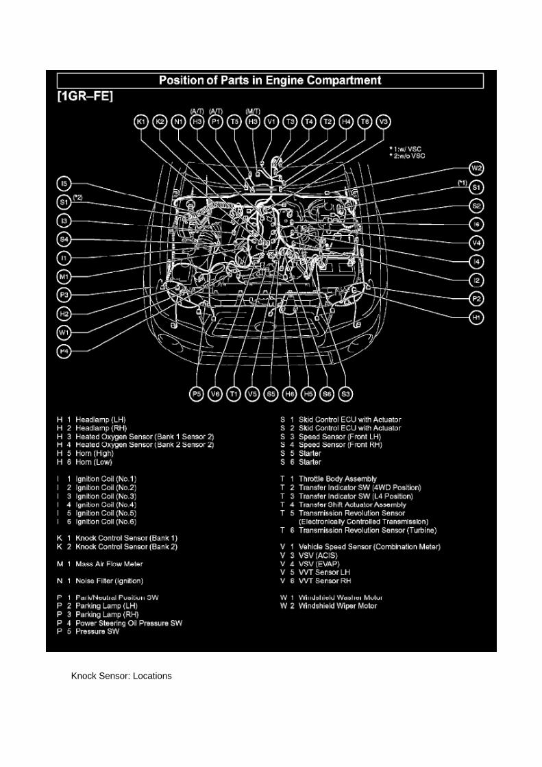
Knock Sensor: Locations

He - Wi

Service and Repair

Fuel Pressure Release: Service and Repair

PRECAUTION
1. PRECAUTION
a. Before working on the fuel system, disconnect the cable from the negative battery terminal. b.Do not work on the fuel system near fire. Never smoke during the work. c. Keep rubber and leatherparts away from gasoline.
2. DISCHARGE FUEL PRESSURE
CAUTION: -
Before removing fuel system parts, take precautions to prevent gasoline spillage.
- As some pressure remains in the fuel line even after taking precautions to prevent gasolinespillage, use a shop rag to prevent gasoline splashes when disconnecting the fuel line.
a. Disconnect the cable from the negative battery terminal. b. Remove the engine relay blockcover.
c. Remove the circuit opening relay. d. Connect the cable to the negative battery terminal.
Torque: 3.9 N.m (40 kgf.cm, 35 in.lbf)
e. Start the engine. f.
Turn the ignition switch to ON after the engine stops.
HINT: DTC P0171 (system to lean) may be present.
g. Crank the engine again, and check that the engine stops. h. Remove the fuel tank cap, anddischarge the pressure in the fuel tank completely. i.
Install the circuit opening relay.
3. FUEL SYSTEM
a. When disconnecting the high-pressure fuel line, a large amount of gasoline will splash. So takethe following precautions.

Electrical Specifications

Fuel Injector: Electrical Specifications

Resistance.............................................................................................................................................................................11.6 to 12.4 Ohm at 20°C (68°F)

Page 857

4WD

If the toe-in is not within the specified range, adjust it at the rack ends.
4. ADJUST TOE-IN
a. Remove the rack boot set clips. b. Loosen the tie rod end lock nuts. c. Turn the right and left rackends uniformly to adjust the toe-in.
HINT: Try to adjust the toe-in to the middle of the specified range.
d. Make sure that the lengths of the right and left rack ends are the same. e. Torque the tie rod endlock nuts.
Torque: 55.5 Nm (566 kgf-cm, 41 ft. lbs.)
f. Place the boots on the seats and install the clips.
HINT: Make sure that the boots are not twisted.
5. CHECK TURNING ANGLE
a. Turn the steering wheel fully, and measure the turning angle.
Wheel turning angle

Page 2798
Shift Interlock Solenoid: Testing and Inspection
KEY INTER LOCK SOLENOID
INSPECTION
1. INSPECT KEY INTER LOCK SOLENOID
a. Disconnect the solenoid connector. b. Connect KLS+
(4) terminal to the battery positive (+) terminal, and KLS- (3) terminal to the battery negative (-)terminal, and apply about 12V between KLS+ and KLS terminals. Check that operation noise canbe
heard from the solenoid.
If the solenoid does not operate, replace the solenoid.

Page 95

Page 910

Assenmacher Specialty Tools 1-800-525-2943

Page 1975
Step 13 - 15
INSPECTION PROCEDURE

Check For an Open In One Side of Can Sub Bus Line
CHECK FOR AN OPEN IN ONE SIDE OF CAN SUB BUS LINE
CIRCUIT DESCRIPTION

Locations

Page 428
Brake Light Switch: Testing and Inspection
INSPECT STOP LAMP SWITCH ASSEMBLY
a. Check the resistance.
1. Measure the resistance using an ohmmeter, and check the results in accordance with thevalue(s) in the table.
If the result is not as specified, replace the stop lamp switch

Page 3232
Step 4
INSPECTION PROCEDURE
ABS Warning Light Circuit (Does Not Light Up)
ABS WARNING LIGHT CIRCUIT (DOES NOT LIGHT UP)
CIRCUIT DESCRIPTION
If the ECU detects trouble, it lights the ABS warning light while at the same time prohibiting ABScontrol. At this time, the ECU records a DTC in the memory. Connecting terminals TC and CG ofthe DLC3 causes the ECU to display 2-digit DTCs by flashing the ABS warning light.

Page 1161

HINT: Troubleshoot each trouble symptom in accordance with the table.

Capacity Specifications

Refrigerant Oil: Capacity Specifications

Toyota gives the following formula for refrigerant oil replacement:
Standard: Oil capacity inside new compressor {150 + 15 cc (5.1 + 0.5 fl. oz.)} - Remaining oilamount in removed compressor assy = Oil amount to be removed before installation

Page 580

He - Wi

Page 799

Transmission Position Switch/Sensor: Service and Repair

PARK/NEUTRAL POSITION SWITCH ASSY
REPLACEMENT
1. DISCONNECT CABLE FROM NEGATIVE BATTERY TERMINAL 2. DISCONNECTPARK/NEUTRAL POSITION SWITCH CONNECTOR
3. REMOVE PARK/NEUTRAL POSITION SWITCH ASSY
a. Using a screwdriver, unstake the lock washer. b. Remove the nut, lock washer and grommet. c.Remove the bolt and park/neutral position switch.
4. INSTALL PARK/NEUTRAL POSITION SWITCH ASSY
a. Install the park/neutral position switch onto the manual valve lever shaft and provisionally tightenthe adjusting bolt.

Page 2472

Fuel Injector: Testing and Inspection

INSPECT FUEL INJECTOR ASSEMBLY
a. Check the resistance.
1. Using an ohmmeter, measure the resistance between the terminals.
Resistance: 11.6 to 12.4 Ohm at 20°C (68°F)
If the result is not as specified, replace the fuel injector.
b. Check the injection volume.
CAUTION: This test involves high-pressure fuel and electricity, therefore, safety precautions shouldbe taken. Perform this test in a safe area and avoid any sparks and flames. Do not smoke.
1. Discharge the fuel system pressure. 2. Remove the fuel hose from the fuel pressure pulsationdamper. 3. Remove the fuel hose from the fuel pipe. 4. Separate the pressure regulator.
NOTE: Do not separate the fuel hose No.2.
5. Assemble SST as shown in the illustration.
SST 09268- 41048 (09268- 41091, 09268- 41110, 09268- 41120, 09268- 41500, 95336- 08070,90467-13001)
6. Connect SST to the fuel pipe.

Page 643

NOTE:

Make sure to view the male end of the connector in the proper orientation as shown in theillustration.
(b) If the connector wires are correctly installed, installation of the wire seat jumper is NOTREQUIRED, proceed to section "VI. SSC
COMPLETION LABEL INSTALLATION".
(c) If the connector wires were NOT correctly installed, proceed to step "B. INSTALL THE WIRESEAT JUMPER".
B. INSTALL THE WIRE SEAT JUMPER
1. RECORD THE RADIO STATION PRESETS

Page 2390


Page 2301
Required SSTs
Repair Procedure
1. Using the Diagnostic Tester, check for diagnostic trouble codes (DTCs).
If DTCs P043E, P043F, P2401, P2402, and P2419 are ALL present, refer to the TechnicalInformation System (TIS):
2005 model year Tacoma Repair Manual:
^ Diagnostics: SFI System (2TR-FE): EVAP Inspection Procedure
^ Diagnostics: SFI System (1GR-FE): EVAP Inspection Procedure
2006 model year Tacoma Repair Manual:
^ 1GR-FE Engine Control System: SFI System: EVAP System
^ 2TR-FE Engine Control System: SFI System: EVAP System
2. Replace the charcoal canister assembly if the EVAP pump module is diagnosed in the EVAPInspection Procedure as the suspected area.
3. Using the Diagnostic Tester, clear all DTCs.

4. Perform the Automatic EVAP System Check and verify that NO pending DTCs set.
NOTE:
If the Automatic EVAP System Check fails to run, perform the following:
^ Turn the ignition key OFF.
^ Turn the Diagnostic Tester OFF.
^ Turn the ignition key ON and the Diagnostic Tester ON and restart the Automatic EVAP SystemCheck.

Locations

Locations

Specifications

Spark Plug: Specifications

SPARK PLUG TYPE:
DENSO ........................................................................................................................................................................................................... SK2OHR11 NGK ..................................................................................................................................................................................................................ILFR6C11
Correct electrode gap for new sparkplug.......................................................................................................................... 1.0 to 1.1 mm(0.039 to 0.043 in.)
Torque.....................................................................................................................................................................................18 N.m (184 kgf.cm, 13 ft.lbf)

Page 2733
^ Power Supply Mode is used to maintain battery voltage at 13.5 volts while flash reprogrammingthe vehicle.
^ For details on how to use the GR8 Battery Diagnostic Station, refer to the located on TIS,Diagnostics - Tools & Equipment - Battery Diagnostics.

3. Click the appropriate calibration ID and reprogram the vehicle's ECU with Techstream.
A. After reviewing the procedures outlined in the selected TSB, click the appropriate calibration IDlink by matching the vehicle's current
calibration ID to the Previous Calibration ID in the Calibration Identification Chart.
NOTE
^ Calibration files are embedded as live links in the service bulletin.
^ Some vehicles require special preparation - please review the selected TSB carefully.
B. Click Open to load calibration file information.
Techstream pulls calibration files as needed to ensure the latest calibration file is used. Do NOTsave calibrations locally on the hard drive or other media.
NOTICE
Errors during the flash reprogramming process can permanently damage the vehicle ECU.Minimize the risk by following the steps below.
^ Battery voltage MUST NOT FALL BELOW 11.4 volts during reprogramming. Confirm batteryvoltage is higher than 11.4 volts, but be sure voltage DOES NOT RISE ABOVE 16.0 volts duringreprogramming.
^ Turn OFF all vehicle accessories (e.g. audio system, A/C, interior lights, DRL, etc.). Do NOT addto or significantly change the vehicle's electrical

Engine Controls - A/F And O2 Sensor Identification
Oxygen Sensor: Technical Service Bulletins Engine Controls - A/F And O2 Sensor Identification
T-SB-0398-09
December 23, 2009
Engine Bank 1 and Bank 2 A/F and 02 Identification

Service Category Engine/Hybrid System
Section Engine Control
Market USA
Applicability
TSB SUPERSESSION NOTICE
The information contained in this TSB supersedes TSB No. EG034-07.
^ Applicability has been updated to include 2009 - 2010 model year vehicles and 2006 - 2010model year Highlander HV.
TSB No. EG034-07 is Obsolete and any printed versions should be discarded. Be sure to reviewthe entire content of this service bulletin before proceeding.
Introduction
This service bulletin provides information on the proper identification of engine bank 1 and enginebank 2 for correct A/F sensor and oxygen sensor replacement.
This bulletin contains information that identifies engine bank 1 and engine bank 2 on the followingengines: 1AZ-FE, 2AZ-FE, 2AZ-FE (PZEV), 1GR-FE, 2GR-FE, 2JZ-GE, 1MZ-FE, 3MZ-FE,1UR-FE, 3UR-FE, 2UZ-FE 5VZ-FE and 1ZZ-FE.
^ Bank 1 (B1) refers to the bank that includes cylinder No. 1.
^ Bank 2 (B2) refers to the bank opposite bank 1.
^ Sensor 1 (S1) refers to the sensor that is located before the catalytic converters.
^ Sensor 2 (S2) refers to the sensor that is located after the catalytic converters.
Warranty Information

A/T - World Standard Automatic Transmission Fluid
Fluid - A/T: Technical Service Bulletins A/T - World Standard Automatic Transmission Fluid
T-SB-0006-11
January 6, 2011
World Standard Automatic Transmission Fluid
Service Category Drivetrain
Section Automatic Transmission/Transaxle
Market USA

Applicability
TSB SUPERSESSION NOTICE
The information contained in this TSB supersedes TSB No. TC010-07.
Applicability has been updated to include 2009 - 2011 model year Toyota vehicles.
TSB No. TC010-07 is Obsolete and any printed versions should be discarded. Be sure to reviewthe entire content of this service bulletin before proceeding.
Introduction
World Standard (WS) Automatic Transmission Fluid (ATF) was introduced to reduce maintenancecosts and increase the mileage between scheduled maintenance checks. Here are some importanttips when working with ATF-WS in Toyota vehicles requiring its use.
Warranty Information

Page 2118

3. Start the engine and warm it up to normal operating temperatures before test-driving.

4. Perform a thorough test drive with several accelerations from a stop with "light throttle"application until proper transmission shifting is verified.
Reset Procedure 2
1. Disconnect the negative battery cable for 5 minutes.
2. Reconnect battery cable.
3. Start the engine and warm it up to normal operating temperatures before test-driving.
4. Perform a thorough test drive with several accelerations from a stop with "light throttle"application until proper transmission shifting is verified.

System Diagnosis
Air/Fuel Mixture: Testing and Inspection
INSPECT CO/HC
HINT: This inspection is for checking whether the CO/HC concentration in the emission gas whileidling complies with the regulations.
a. Start the engine. b. Keep the engine speed at 2,500 rpm for approximately 180 seconds. c.Insert the CO/HC meter testing probe at least 40 cm (1.3 ft.) into the tailpipe while idling. d.Immediately check the CO/HC concentration while idling and/or at 2,500 rpm.
HINT: When performing the 2 mode (2,500 rpm and idle) test, follow the applicable localregulations.
If the CO/HC concentration does not comply with the regulations, troubleshoot in the order givenbelow. (1) Check the A/F sensor and heated oxygen sensor operation.
(2) See the table for possible causes, then inspect and correct the applicable parts if necessary.

Page 2372

Page 1469

Spark Plug: Application and ID

SPARK PLUG TYPE:
DENSO ........................................................................................................................................................................................................... SK2OHR11 NGK ..................................................................................................................................................................................................................ILFR6C11
Correct electrode gap for new sparkplug.......................................................................................................................... 1.0 to 1.1 mm(0.039 to 0.043 in.)
Torque.....................................................................................................................................................................................18 N.m (184 kgf.cm, 13 ft.lbf)

Steering/Suspension - Vehicle Pull Repair Supplement
Alignment: Technical Service Bulletins Steering/Suspension - Vehicle Pull Repair Supplement
T-SB-0391-08
December 24, 2008
Repair Manual Supplement: Vehicle Pulling to One Side
Service Category Suspension
Section Alignment/Handling Diagnoses
Market USA
Applicability
TSB SUPERSESSION NOTICE
The information contained in this TSB supersedes the following TSBs:
^ 5T005-O1: Applicability has been updated to include 2008 - 2009 model year Toyota vehicles.
^ SU001-08: Applicability has been updated to include all 2002 - 2009 model year vehicles.
TSB Nos. ST005-01 and SU001-08 are Obsolete and any printed versions should be discarded. Besure to review the entire content of this service bulletin before proceeding.
Introduction
This bulletin contains general vehicle pulling diagnosis and repair procedures along with specificinformation to help correct pulling complaints.

This information supplements Repair Manual procedures when the symptoms are:
^ The driver holds the steering wheel without exerting steering effort while driving straight aheadthe vehicle drifts to the right or the left.
^ While driving straight ahead the driver has to steer either to the right or the left to maintainstraight driving.

Locations

Transmission Speed Sensor: Locations

He - Wi

Page 1142
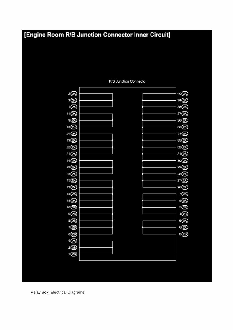
Relay Box: Electrical Diagrams

Engine Room R/B Junction Connector Inner Circuit

Page 3001
D. Cut the felt padding on the backside of the floor carpet without cutting the carpet using thecarpet knife adjusted only to the depth of the felt padding. Cut the felt padding in the shape shownbelow.
5. Replace the front floor pad.

A. Clean all residue from the backside of the carpet where the floor pad was located.
B. Attach the NEW front floor pad to the backside of the floor carpet.
C. Confirm that the square raised section on the foam pad is in the same position as the original toensure proper alignment.

Page 1328
Required SSTs
Repair Procedure
1. Verify leak exists from the crankshaft seal area.
2. Remove the accessory belt.
3. Remove the crankshaft pulley.
4. Remove the front oil seal.
5. Install the timing chain cover oil seal.
A. Apply MP grease to the lip of the NEW oil seal.
B. Place the oil seal into the correct location in the seal recess of the timing chain cover.
C. Install the SST into the crankshaft and lightly tighten until the seal is fully seated in the timingchain cover. Do NOT over tighten.

Page 2065

Applicable Vehicles

Page 2887
2. Print out the Freeze Frame Data for P0705 to allow easy review of data values. Note the valuesof the following parameters in the Data List:
^ Neutral Position SW Signal
^ Shift SW Status (R Range)
^ Shift SW Status (D Range)
^ Shift SW Status (4 or D)
^ Shift SW Status (3 Range)
^ Shift SW Status (2 Range)
^ Shift SW Status (L Range)
^ Stop Light Switch

Page 2213

He - Wi

Engine Controls - Techstream(R) ECU Re-Flash
Procedure
PROM - Programmable Read Only Memory: All Technical Service Bulletins Engine Controls -Techstream(R) ECU Re-Flash Procedure
T-SB-0064-10
February 4, 2010
Techstream ECU Flash Reprogramming Procedure
Service Category Engine/Hybrid System
Section Engine Control
Market USA
Applicability
TSB SUPERSESSION NOTICE
The information contained in this TSB supersedes TSB No. SS002-07.
^ Applicability has been updated to include 2009 - 2011 model year Toyota vehicles.
^ A new section, Techstream Preparation, has been added.
^ Techstream Lite has been added as an option in Required Tools & Materials.
^ Process Overview and Operation Procedure sections have been updated.
TSB No. SS002-07 is Obsolete and any printed versions should be discarded. Be sure to reviewthe entire content of this service bulletin before proceeding.
Introduction
Flash reprogramming allows the ECU software to be updated without replacing the ECU. Flashcalibration updates for specific vehicle models/ECUs are released as field-fix procedures describedin individual service bulletins. This bulletin details the Techstream ECU flash reprogramming

process and outlines use of the Technical Information System (TIS) and the Calibration UpdateWizard (CUW). Flash calibration updates can only be applied to the vehicle/ECU combination forwhich they are intended. ECUs have internal security that will not allow them to be programmedwith another ECU's information.
ECU
Electronic Control Unit (ECU) is a Toyota term used to describe integrated computerized devicesresponsible for managing the operation of a system or subsystem. For the purposes of this bulletin,the term "ECU" is used as a generic label for the following SAE J1930 standard references:
^ Powertrain Control Module (PCM)

Page 1041
Driver Side J/B - Lower Finish Panel
Details

On-Vehicle Inspection
Throttle Body: Testing and Inspection On-Vehicle Inspection
INSPECT THROTTLE W/MOTOR BODY ASSEMBLY
a. Listen to the throttle control motor operating sounds.
1. Turn the ignition switch to ON. 2. When pressing the accelerator pedal, listen to the runningsounds of the motor. Make sure no friction noises come from the motor.
If friction noises exist, check the throttle body, wire harness and ECM.
b. Inspect the throttle position sensor.
1. Connect the hand-held tester to the DLC3. 2. Turn the ignition switch to ON. 3. Turn thehand-held tester ON. 4. Select the following menu items: DIAGNOSIS / ENHANCED OBD II /DATA LIST / ALL / THROTTLE POS. 5. Depress the accelerator pedal.When the throttle valve isfully opened, check that the THROTTLE POS value is within the specified range.
Standard: 60% or more
NOTE: When checking the standard throttle valve opening percentage, the transmission should bein the neutral position.
If the result is not as specified, check the throttle body, wire harness and ECM.
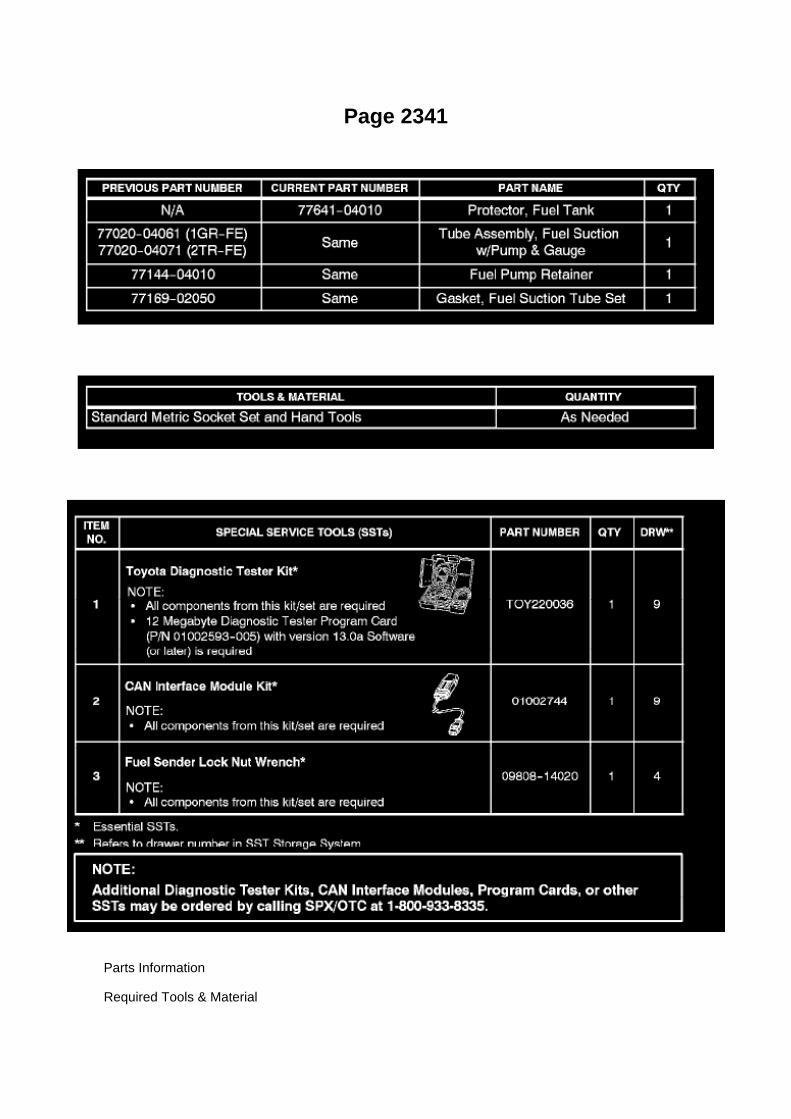
Page 2341
Parts Information
Required Tools & Material

Required SSTs
Repair Procedure
1. Using the Diagnostic Tester, check for Diagnostic Trouble Codes (DTCs). If DTC P0456 orP0445, and P0441 are present, check for an EVAP leak on top of the fuel suction platesub-assembly. Refer to the Technical Information System (TIS), 2005 model year Tacoma RepairManual: Diagnostics: SFI System (1GR-FE) / (2TR-FE): EVAP Inspection Procedure.
If NO EVAP leaks are detected at the fuel suction plate sub-assembly, this TSB does NOT apply.Please refer to the normal diagnostic procedure provided in the Repair Manual.
2. To correct the fuel suction plate sub-assembly, replace the fuel suction with pump and gaugetube assembly, retainer ring and gasket set according to TIS, 2005 model year Tacoma RepairManual: Fuel: Fuel Pump Assy: Removal & Installation And Disassembly & Reassembly (Tacoma).
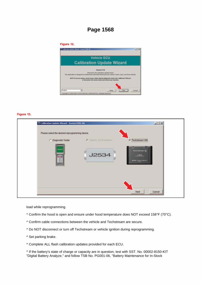
Page 1568
load while reprogramming.
^ Confirm the hood is open and ensure under hood temperature does NOT exceed 158°F (70°C).
^ Confirm cable connections between the vehicle and Techstream are secure.
^ Do NOT disconnect or turn off Techstream or vehicle ignition during reprogramming.
^ Set parking brake.
^ Complete ALL flash calibration updates provided for each ECU.
^ If the battery's state of charge or capacity are in question, test with SST. No. 00002-8150-KIT"Digital Battery Analyze," and follow TSB No. PG001-06, "Battery Maintenance for In-Stock

Vehicles & Pre-Delivery" or the appropriate "Maintenance for HV & Auxiliary Batteries" servicebulletin.
^ The GR8 Battery Diagnostic Station MUST be used in Power Supply Mode to maintain batteryvoltage at 13.5 volts while flash reprogramming the vehicle. For details on how to use the GR8Battery Diagnostic Station, refer to the GR8 Instruction Manual located on TIS, Diagnostics - Tools& Equipment - Battery Diagnostics.
3C. Click Next to start the calibration update process.
D. When using TIS Techstream select Techstream VIM as the desired programming device. Thenclick Next.

Page 721
are involved. As always, consult Dealer Daily/TIS to confirm VIN eligibility and to assure the SSC isapplicable. This will verify the vehicle is affected and has not already been completed prior todealer shipment or by another dealer. TMS warranty will not reimburse dealers for repairsconducted on vehicles that are not affected or were completed by another dealer.
III. Preparation
A. PARTS
B. TOOLS
^ Standard hand tools
^ Scan tool
IV. Background
On certain 2005 Model Year Tacoma Regular Cab (no rear seat) vehicles equipped with a frontbench seat, the Seat Position and Seatbelt Buckle Sensor Wire Harness Connector pins arepositioned incorrectly due to a wire harness manufacturing process error. In this condition, the seatposition and seatbelt buckle sensor may not function as designed, which, if the vehicle is involvedin a crash, could result in improper occupant restraint. In the worst case, this may lead to anincreased possibility of injury. Please note that even in this condition, the affected vehicles continueto comply with all applicable federal motor vehicle safety standards.
V. Work Procedure
A. INSPECT THE FRONT BENCH SEAT FLOOR WIRE HARNESS CONNECTOR WIRES
1. LOCATE THE BENCH SEAT FLOOR WIRE HARNESS

Page 2777
NOTE
On some models, DTCs may set as a result of reprogramming. If DTCs are present, clear codesand run the Health Check again. Troubleshoot any remaining Current, Pending, or History codes.Permanent codes will not be cleared using Techstream. Permanent codes do not illuminate the MILand do not require troubleshooting. They will clear during normal driving once the Universal TripDrive Pattern is performed.
4. Attach the Authorized Modifications Label.
A. Using a permanent marker or ball point pen complete the Authorized Modifications Label andattach to the vehicle. The Authorized
Modifications Label is available through the MDC P/N 00451-00001-LBL.
B. Attach the label under the hood in the location determined by the specific TSB or Campaign.
NOTE
Wait 60 - 90 seconds for ink to set before handling.

Page 2125
Step 4 - 5

Page 3005

7. Remove the clutch pedal shaft collar.

8. Using needle-nose pliers, remove the No. 1 cushion from the clutch pedal.
9. Install the clutch pedal No. 1 cushion on the NEW clutch pedal sub-assembly.
NOTE:
Install parts on the NEW clutch pedal sub-assembly BEFORE installing in the vehicle.
10. Install the clutch pedal shaft collar.
A. Apply MP grease to the clutch pedal shaft collar.
B. Install the clutch pedal shaft collar onto the clutch pedal.

Locations

Brake Lamp Relay: Locations
Engine Room R/B, J/B - Engine Compartment Left

Page 716
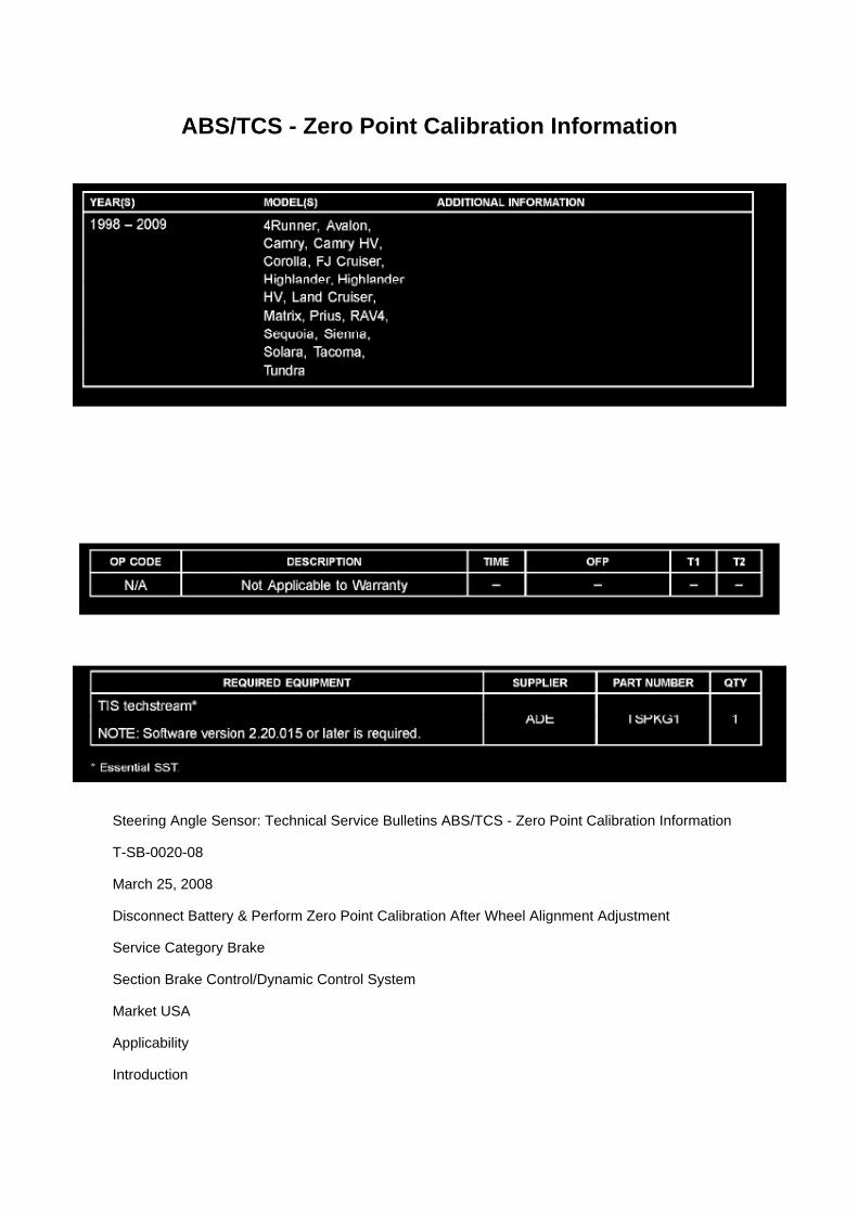
ABS/TCS - Zero Point Calibration Information
Steering Angle Sensor: Technical Service Bulletins ABS/TCS - Zero Point Calibration Information
T-SB-0020-08
March 25, 2008
Disconnect Battery & Perform Zero Point Calibration After Wheel Alignment Adjustment
Service Category Brake
Section Brake Control/Dynamic Control System
Market USA
Applicability
Introduction

The purpose of this TSB is to provide information on when and how to perform the zero pointcalibration on vehicles equipped with Vehicle Stability Control (VSC). Momentarily disconnectingthe battery is a necessary step for performing the zero point calibration.
Warranty Information
Required Tools & Equipment
^ Additional TIS techstream units may be ordered by calling Approved Dealer Equipment (ADE).
^ The Toyota Diagnostic Tester and CAN Interface Module may also be used to perform theservice procedures listed in this bulletin.
Preliminary Information
Perform this procedure if any of these repairs have been performed on the vehicle:
^ Wheel alignment has been adjusted.
^ Any chassis components have been removed/installed or replaced.

Page 1939

- Rx: Reception from each ECU (sensor).

- Tx: Transmission to each ECU (sensor).

Page 2987
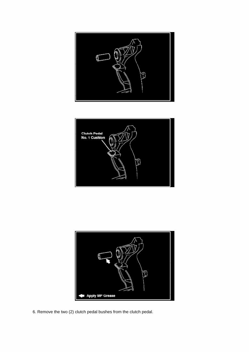
6. Remove the two (2) clutch pedal bushes from the clutch pedal.

7. Remove the clutch pedal shaft collar.
8. Using needle-nose pliers, remove the No. 1 cushion from the clutch pedal.
9. Install the clutch pedal No. 1 cushion on the NEW clutch pedal sub-assembly.
NOTE:
Install parts on the NEW clutch pedal sub-assembly BEFORE installing in the vehicle.
10. Install the clutch pedal shaft collar.
A. Apply MP grease to the clutch pedal shaft collar.
B. Install the clutch pedal shaft collar onto the clutch pedal.

Page 1026

Engine Room R/B, J/B - Engine Compartment Left

Page 226
Step 9
INSPECTION PROCEDURE

Page 2477

g. Remove the 2 bolts, then remove the fuel delivery pipe together with the fuel injectors.

NOTE: Be careful not to drop the fuel injectors when removing the fuel delivery pipe.
h. Remove the 2 delivery pipe No.1 spacers. i.
Remove the 4 injector vibration insulators.
j. Using a screwdriver, remove the 4 spacers.
11. REMOVE FUEL INJECTOR ASSEMBLY
a. Pull the 4 fuel injectors out of the fuel delivery pipe.
12. INSTALL FUEL INJECTOR ASSEMBLY
a. Apply a light coat of gasoline or spindle oil to new O-rings, then install one onto each fuelinjector.

Locations
A/C - Ge

Page 70
ABS With EBD System

Locations
Camshaft Position Sensor: Locations

A/C - Ge
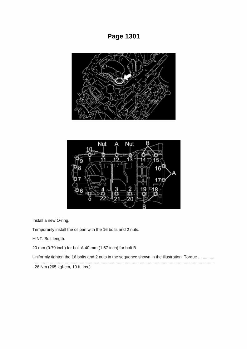
Page 1301
Install a new O-ring.
Temporarily install the oil pan with the 16 bolts and 2 nuts.
HINT: Bolt length:
20 mm (0.79 inch) for bolt A 40 mm (1.57 inch) for bolt B
Uniformly tighten the 16 bolts and 2 nuts in the sequence shown in the illustration. Torque ............................................................................................................................................................................. 26 Nm (265 kgf-cm, 19 ft. lbs.)

Locations

Oxygen Sensor Relay: Locations
Engine Room R/B, J/B - Engine Compartment Left

Page 2977
Install the bolt from the left side of the vehicle.
B. Tighten the bolt to the instrument panel reinforcement assembly.

Torque: 8 N.m (82 kgf.cm, 6 ft.lbf)
15. Install the turnover (compression) spring.
A. Apply MP grease to the contact surface of the spring holder, clutch pedal, and spring.
B. Install the spring onto the clutch pedal and spring holder.

Page 2484
b. Install the fuel pressure regulator with the 3 bolts.
Torque: 8.5 N.m (87 kgf.cm, 75 in.lbf)
c. Install the harness clamp bracket with the bolt.
Torque: 8.2 N.m (84 kgf.cm, 73 in.lbf)
d. Connect the engine wire harness clamp. e. Connect the VSV connector. f.
Connect the throttle w/ motor body connectors.
7. CONNECT FUEL HOSE NO.2 8. INSTALL INTAKE AIR CONNECTOR 9. CONNECT CABLETO NEGATIVE BATTERY TERMINAL
Torque: 3.9 N.m (40 kgf.cm, 35 in.lbf)
10. CHECK FOR FUEL LEAKAGE
Testing and Inspection
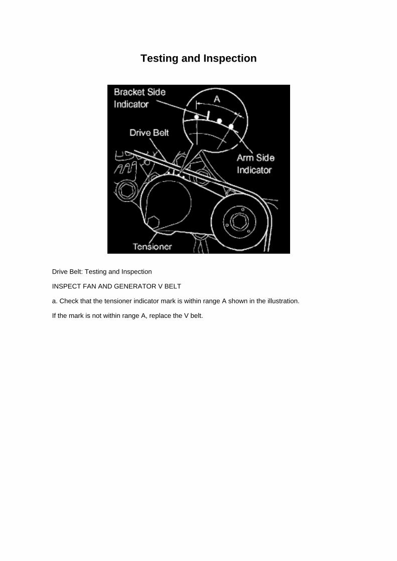
Drive Belt: Testing and Inspection
INSPECT FAN AND GENERATOR V BELT
a. Check that the tensioner indicator mark is within range A shown in the illustration.
If the mark is not within range A, replace the V belt.

Page 2208

Page 2045
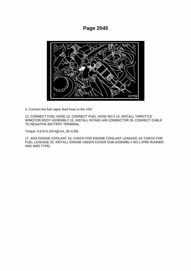
o. Connect the fuel vapor feed hose to the VSV.
12. CONNECT FUEL HOSE 13. CONNECT FUEL HOSE NO.2 14. INSTALL THROTTLEW/MOTOR BODY ASSEMBLY 15. INSTALL INTAKE AIR CONNECTOR 16. CONNECT CABLETO NEGATIVE BATTERY TERMINAL
Torque: 3.9 N.m (40 kgf.cm, 35 in.lbf)
17. ADD ENGINE COOLANT 18. CHECK FOR ENGINE COOLANT LEAKAGE 19. CHECK FORFUEL LEAKAGE 20. INSTALL ENGINE UNDER COVER SUB-ASSEMBLY NO.1 (PRE RUNNERAND 4WD TYPE)

Page 3252
10. INSTALL SENSOR BRACKET
a. Install the bracket with the bolt.
Torque: 12.5 Nm (127 kgf-cm, 9 ft. lbs.)
b. Install the wire harness clamp.
11. INSTALL COWL SIDE TRIM BOARD LH 12. INSTALL FRONT DOOR SCUFF PLATE LH 13.INSTALL FRONT FLOOR FOOTREST 14. INSTALL FRONT SEAT ASSEMBLY (BENCH SEATTYPE) 15. INSTALL FRONT SEAT ASSEMBLY LH (SEPARATE SEAT TYPE) 16. CONNECTCABLE TO NEGATIVE BATTERY TERMINAL
Torque: 3.9 Nm (40 kgf-cm, 35 inch lbs.)
17. CHECK ABS SENSOR SIGNAL
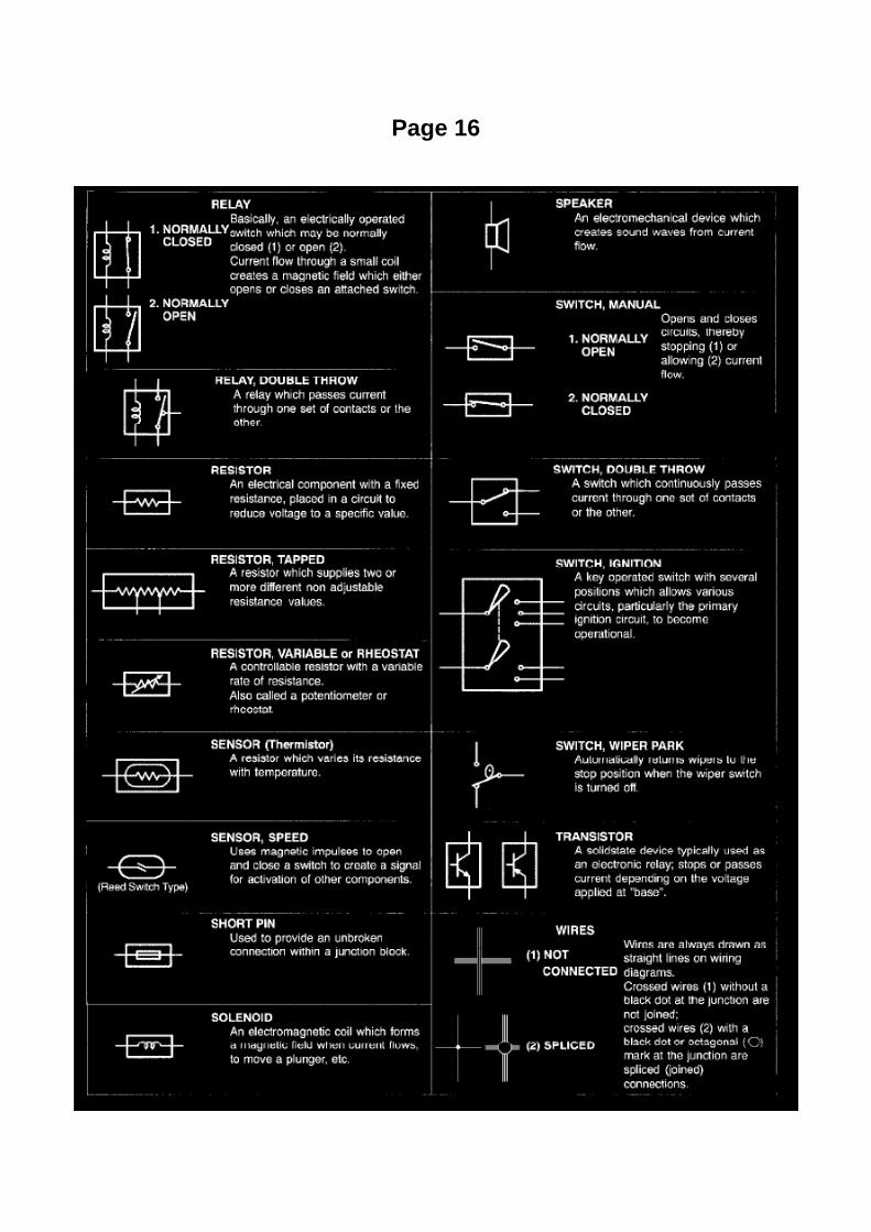
Page 16

Glossary Of Terms And Sysmbols Part 2

ABS W/EBD System
Electronic Brake Control Module: Testing and Inspection ABS W/EBD System
Terminals Of Control Module / Pinouts - Terminals Of ECU

Page 2039
Knock Sensor: Testing and Inspection
INSPECT KNOCK SENSOR
a. Check the resistance.
1. Using an ohmmeter, measure the resistance between the terminals.
If the result is not as specified, replace the knock sensor.

Page 3125
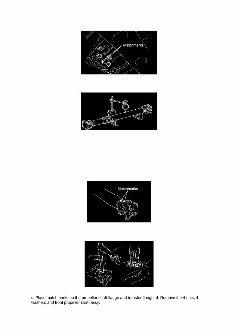
c. Place matchmarks on the propeller shaft flange and transfer flange. d. Remove the 4 nuts, 4washers and front propeller shaft assy.

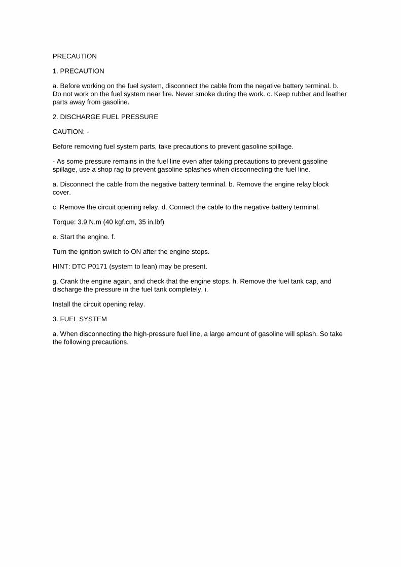
2. INSPECT PROPELLER SHAFT
a. Using a dial indicator, check the propeller shaft runout.
Maximum runout: 0.6 mm (0.024 inch) If the shaft runout is greater than the maximum, replace thepropeller shaft.
3. INSPECT PROPELLER SHAFT UNIVERSAL JOINT SPIDER BEARING
a. Check the spider bearings for wear and damage. b. Check each spider bearing's axial play byturning the yoke while holding the shaft tightly.
Maximum bearing axial play: 0 to 0.05 mm (0 to 0.002 inch) If the bearing axial play is greater thanthe maximum, replace the spider bearing.
4. REMOVE PROPELLER SHAFT UNIVERSAL JOINT SPIDER BEARING
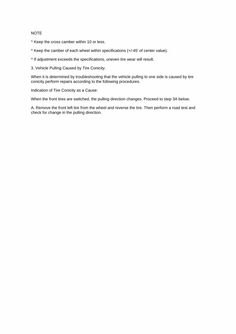
a. Place matchmarks on the flange yoke and sleeve yoke.
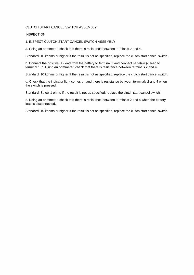
b. Using a brass bar and a hammer, slightly tap in the spider bearing outer races. c. Using needlenose pliers, remove the 4 snap rings from the grooves.

Locations

A/C - Fo

Page 1339

12. CHECK FOR ENGINE COOLANT LEAKAGE 13. CHECK FOR ENGINE OIL LEAKAGE 14.INSTALL ENGINE UNDER COVER SUB-ASSEMBLY NO.1 (PRE RUNNER AND 4WD TYPE)

a. Install the engine under cover No.1 with the 4 bolts.
Torque: 30 Nm (306 kgf-cm, 22 ft. lbs.)

Page 2112
Engine Control Module: Technical Service Bulletins Engine Controls - Entering VIN WhenReplacing PCM/ECM
ENGINE EG045-04
Title: ENTERING VIN DURING ECM (PCM) REPLACEMENT AND/OR DTC P0630
Models: All '04 - '06 Models
October 14, 2004
TSB REVISION NOTICE:
^ June 3, 2005: Content has been updated to include 2004 and 2006 model year vehicles.Highlander HV has been added to step 4 of the VIN Write Procedure. Step 3 of the VIN ReadProcedure has been clarified to include Prius and Highlander HV vehicles.
^ January 24, 2005: Step 4 has been clarified to include Prius vehicles. Previous versions of thisTSB should be discarded.
Introduction
All 2005 and subsequent model year Toyota and Scion vehicles have the VIN (VehicleIdentification Number) stored in the Electronic Control Module (ECM) (SAE term: PowertrainControl Module/PCM) non-volatile memory. The VIN is accessible on the data stream using theToyota Diagnostic Tester and can also be written to a new ECM (PCM) using a VIN Read/Write"utility.
Service ECMs (supply parts) are shipped without the VIN; therefore, as part of the ECM (PCM)replacement procedure, the VIN must be written to the replacement ECM (PCM) using theDiagnostic Tester utility function.
For most 2005 model year vehicles, failure to write the VIN to the ECM (PCM) will result in a M.I.L."ON" condition and set DTC P0630: VIN Not Programmed or Mismatch - ECM (PCM). The fivemodels listed below do not support DTC P0630.
^ Corolla
^ ECHO
^ Matrix
^ Scion xA
^ Scion xB
It is very important to remember to enter the VIN on these vehicles. Vehicles with missing VINs aresubject to failing some state and local vehicle emissions Inspection and Maintenance programs.

NOTE:
2004 model year vehicles which have been flash reprogrammed may contain updated 2005 modelyear OBD II logic. These vehicles will require VIN entry into the ECM (PCM) after reprogramming.
Applicable Vehicles
^ 2004 model year vehicles that have been flash reprogrammed.
^ All 2005 - 2006 model year vehicles.
Warranty Information

Page 1679
A/F and 02 Sensor Identification

Specifications
Piston Ring: Specifications
PISTON RING END GAP
Standard end gap
Maximum end gap

Page 530

He - Wi

Page 3370

c. Insert the stop lamp switch until the body comes into contact with the cushion.

NOTICE: -
When inserting the stop lamp switch, support the pedal from behind so that the pedal is not pushedin.
- Take care not to depress the pedal during the operation.
d. Make a quarter turn clockwise to install the stop lamp switch.
NOTICE: The turning torque for installing the stop lamp switch:
Torque: 1.5 Nm (15 kgf-cm, 13 inch lbs.) or less
HINT: Due to the inverse screw structure, turning the stop lamp switch clockwise will cause it tobecome loose and eventually detach from the adjuster.
e. Connect the stop lamp switch connector to the stop lamp switch. f.
Check the protrusion of the rod. Protrusion of the rod: 1.5 to 2.5 mm (0.059 to 0.098 inch)

Page 1866
5. Write the VIN in accordance with the Diagnostic Tester display.
6. Compare the VIN displayed on the Diagnostic Tester with the VIN on the instrument panel. Ifthese are not the same, write the VIN again after turning the ignition switch OFF.

VIN Read Procedure
1. Connect the Diagnostic Tester to DLC3.
2. Turn the ignition switch and Diagnostic Tester switch ON.
3. All vehicles except Prius and Highlander HV:
Select from the Diagnostic Tester menus: DIAGNOSIS, ENHANCED OBDII, VIN, and VIN READ.
Prius and Highlander HV vehicles:
Select from the Diagnostic Tester menus: DIAGNOSIS, OBD/MOBD, HV ECU, VIN, and VINREAD.
4. Check the VIN displayed on the Diagnostic Tester.
HINT: For further explanations, refer to the Technical Information System (TIS), appropriate modelrepair manual: Diagnostics: SF1 System: Registration.

Service and Repair

Fuel Pressure Release: Service and Repair
PRECAUTION
1. PRECAUTION
a. Before working on the fuel system, disconnect the cable from the negative battery terminal. b.Do not work on the fuel system near fire. Never smoke during the work. c. Keep rubber and leatherparts away from gasoline.
2. DISCHARGE FUEL PRESSURE
CAUTION: -
Before removing fuel system parts, take precautions to prevent gasoline spillage.
- As some pressure remains in the fuel line even after taking precautions to prevent gasolinespillage, use a shop rag to prevent gasoline splashes when disconnecting the fuel line.
a. Disconnect the cable from the negative battery terminal. b. Remove the engine relay blockcover.
c. Remove the circuit opening relay. d. Connect the cable to the negative battery terminal.
Torque: 3.9 N.m (40 kgf.cm, 35 in.lbf)
e. Start the engine. f.
Turn the ignition switch to ON after the engine stops.
HINT: DTC P0171 (system to lean) may be present.
g. Crank the engine again, and check that the engine stops. h. Remove the fuel tank cap, anddischarge the pressure in the fuel tank completely. i.
Install the circuit opening relay.
3. FUEL SYSTEM
a. When disconnecting the high-pressure fuel line, a large amount of gasoline will splash. So takethe following precautions.

Page 670

NOTE:

Make sure to view the male end of the connector in the proper orientation as shown in theillustration.
(b) If the connector wires are correctly installed, installation of the wire seat jumper is NOTREQUIRED, proceed to section "VI. SSC
COMPLETION LABEL INSTALLATION".
(c) If the connector wires were NOT correctly installed, proceed to step "B. INSTALL THE WIRESEAT JUMPER".
B. INSTALL THE WIRE SEAT JUMPER
1. RECORD THE RADIO STATION PRESETS

Page 36

[B] : For Waterproof Type Connector

HINT: Terminal retainer color is different according to connector body.
Example:
Terminal Retainer : Connector Body
Black or White : Gray
Black or White : Dark Gray
Gray or White : Black
"Case 1" Type where terminal retainer is pulled up to the temporary lock position (Pull Type).
Insert the special tool into the terminal retainer access hole (A Mark) and pull the terminal retainerup to the temporary lock position.
HINT: The needle insertion position varies according to the connector's shape (Number ofterminals etc.), so check the position before inserting it.
"Case 2" Type which cannot be pulled as far as Power Lock insert the tool straight into the accesshole of terminal retainer as shown.

Locations
Camshaft Position Sensor: Locations

A/C - Ge

Page 1052

Glossary Of Terms And Sysmbols Part 1

Page 2241

Ac - Ya

Page 843

When it is determined by troubleshooting that the vehicle pulling to one side is caused by wheelalignment perform repairs according to the following procedure.
NOTE
^ Keep the cross camber within 10 or less.
^ Keep the camber of each wheel within specifications (+/-45' of center value).
^ If adjustment exceeds the specifications, uneven tire wear will result.
3. Vehicle Pulling Caused by Tire Conicity.
When it is determined by troubleshooting that the vehicle pulling to one side is caused by tireconicity perform repairs according to the following procedures.
Indication of Tire Conicity as a Cause:
When the front tires are switched, the pulling direction changes. Proceed to step 3A below.
A. Remove the front left tire from the wheel and reverse the tire. Then perform a road test andcheck for change in the pulling direction.

Page 3244

Step 2 - 3

INSPECTION PROCEDURE
CHECK FOR INTERMITTENT PROBLEMS
HINT: A momentary interruption (open circuit) in the connectors and/ or wire harness between thesensors and ECUs can be detected through the ECU data monitor function of the hand-held tester.
a. Turn the ignition switch off and connect the hand-held tester to the DLC3.

Specifications
Water Pump: Specifications
Install a new gasket, then install the water pump with the 10 bolts.
Torque:
21 Nm (214 kgf-cm, 15 ft. lbs.) for bolt A 9 Nm (92 kgf-cm, 80 inch lbs.) for bolt B

Page 1106
I: Indicates a wiring Splice Point (Codes are "E" for the Engine Room, "I" for the Instrument Panel,and "B" for the Body).
The Location of splice Point I5 is indicated by the shaded section.
J: Indicates a shielded cable.
K: Indicates the pin number of the connector. The numbering system is different for female andmale connectors.
L: Indicates a ground point.
The first letter of the code for each ground point(s) indicates the component's location, e.g, "E" forthe Engine Compartment, "I" for the Instrument Panel and Surrounding area, and "B" for the Body

and Surrounding area.
N: Explains the system outline.
SYSTEM OUTLINE
Current is applied at all times through the STOP fuse to TERMINAL 2 of the stop light SW. Whenthe ignition SW is turned on, current flows from the GAUGE fuse to TERMINAL 8 of the light failuresensor, and also flows through the rear lights warning light to TERMINAL 4 of the light failuresensor.
STOP LIGHT DISCONNECTION WARNING When the ignition SW is turned on and the brakepedal is pressed (Stop light SW on), if the stop light circuit is open, the current flowing fromTERMINAL 7 of the light failure sensor to TERMINALS 1, 2 changes, so the light failure sensordetects the disconnection and the warning circuit of the light failure sensor is activated.
As a result, the current flows from TERMINAL 4 of the light failure sensor to TERMINAL 11 toGROUND and turns the rear lights warning light on. By pressing the brake pedal, the currentflowing to TERMINAL 8 of the light failure sensor keeps the warning circuit on and holds thewarning light on until the ignition SW is turned off.

Page 2226

He - Wi

Page 938
Parts Information
Required Tools & Material

Required SSTs
Repair Procedure
1. Using the Diagnostic Tester, check for Diagnostic Trouble Codes (DTCs). If DTC P0456 orP0445, and P0441 are present, check for an EVAP leak on top of the fuel suction platesub-assembly. Refer to the Technical Information System (TIS), 2005 model year Tacoma RepairManual: Diagnostics: SFI System (1GR-FE) / (2TR-FE): EVAP Inspection Procedure.
If NO EVAP leaks are detected at the fuel suction plate sub-assembly, this TSB does NOT apply.Please refer to the normal diagnostic procedure provided in the Repair Manual.
2. To correct the fuel suction plate sub-assembly, replace the fuel suction with pump and gaugetube assembly, retainer ring and gasket set according to TIS, 2005 model year Tacoma RepairManual: Fuel: Fuel Pump Assy: Removal & Installation And Disassembly & Reassembly (Tacoma).

Page 762

Clutch Switch: Service and Repair Clutch Start Cancel Switch Assy
CLUTCH START CANCEL SWITCH ASSEMBLY
INSPECTION
1. INSPECT CLUTCH START CANCEL SWITCH ASSEMBLY
a. Using an ohmmeter, check that there is resistance between terminals 2 and 4.
Standard: 10 kohms or higher If the result is not as specified, replace the clutch start cancel switch.
b. Connect the positive (+) lead from the battery to terminal 3 and connect negative (-) lead toterminal 1. c. Using an ohmmeter, check that there is resistance between terminals 2 and 4.
Standard: 10 kohms or higher If the result is not as specified, replace the clutch start cancel switch.
d. Check that the indicator light comes on and there is resistance between terminals 2 and 4 whenthe switch is pressed.
Standard: Below 1 ohms If the result is not as specified, replace the clutch start cancel switch.
e. Using an ohmmeter, check that there is resistance between terminals 2 and 4 when the batterylead is disconnected.
Standard: 10 kohms or higher If the result is not as specified, replace the clutch start cancel switch.

Locations

Knock Sensor: Locations

He - Wi

Specifications

Page 43
Terminals Of Control Module / Pinouts - Check Transponder Key ECU Assy Part 1

Page 2063
A/F and 02 Sensor Identification

Page 3127

5. INSTALL PROPELLER SHAFT UNIVERSAL JOINT SPIDER BEARING

a. Apply MP grease No.2 to a new spider and spider bearing. b. Fit the spider into the flange yoke.
c. Measure dimension A between the snap ring grooves. d. Insert the thrust washer and spiderbearing into the spider journal portion, and then measure dimension B of the universal joint.
NOTICE: When measuring dimension B. fix the spider and spider bearings in a vise and hold themfirmly together.
e. Select snap rings to make dimensions A and B the same.
Snap Ring Type
NOTICE: ^
Use new snap rings.
^ If possible, use snap rings of the same thickness for both edges.

Page 1884
Oscilloscope Waveforms

Page 1222

b. Place paint marks on the timing chain plates that align with timing marks of the camshaft timinggear.

c. Hold the hexagonal lobe of the No.2 camshaft with an adjustable wrench.
NOTICE: Be careful not to damage the camshaft oil delivery pipe.
d. Loosen the bolt.
e. Using 10 mm socket hexagon wrench, remove the head straight screw plug.
f. Insert a screwdriver into the service hole of the chain tensioner to hold the stopper plate of thechain tensioner lifted up.
HINT: Lifting up the stopper plate of the chain tensioner unlocks the plunger.

Page 1737
SFI System

Page 388

Combination Meter

Page 115
Headlamp Dimmer Relay: Testing and Inspection
INSPECT HEADLAMP DIMMER RELAY
a. Check the resistance.

1. Using an ohmmeter, measure the resistance between the terminals.
If the result is not as specified, replace the headlamp dimmer relay.

Page 2817

Ha - Op

Page 2957

2. REMOVE CLUTCH HOUSING COVER NO.1 (RA60/RA60F TRANSMISSION)

a. Remove the 3 bolts and clutch housing cover No.1.
3. DISCONNECT CLUTCH RELEASE CYLINDER TO FLEXIBLE HOSE TUBE
a. Using SST, disconnect the flexible hose tube.
SST 09023-00101
b. Remove the bolt and clutch line bracket.
HINT: Use a container to catch the fluid.
4. REMOVE CLUTCH RELEASE CYLINDER ASSY
a. Remove the 2 bolts and pull out the clutch release cylinder.
5. REMOVE CLUTCH RELEASE CYLINDER KIT
a. Remove the boot from the cylinder body.

Locations

Knock Sensor: Locations

He - Wi

Page 1116
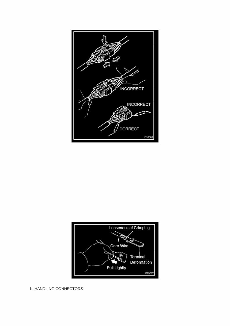
b. HANDLING CONNECTORS

1. When disconnecting a connector, first squeeze the mating halves tightly together to release thelock, then press the lock claw and separate the
connector.
2. When disconnecting a connector, do not pull on the harnesses. Grasp the connector directly andseparate it. 3. Before connecting the connector, check that there are no deformed, damaged, looseor missing terminals. 4. When connecting a connector, press firmly until you hear the lock closewith a "click" sound. 5. If checking the connector with a TOYOTA electrical tester, check it from thebackside (harness side) of the connector using a mini test lead.
NOTE: -
As a waterproof connector cannot be checked from the backside, check by connecting asub-harness.
- Do not damage the terminals by moving the inserted tester needle.
c. CHECKING CONNECTORS
1. Checking when the connector is connected: Squeeze the connector together to confirm that it isfully inserted and locked.
2. Checking when the connector is disconnected: Check by pulling the wire harness lightly from thebackside of the connector. Look for
unlatched terminals, missing terminals, loose crimps or broken conductor wires. Check visually forcorrosion, metallic or foreign objects and water; and bent, rusted, overheated, contaminated, anddeformed terminals.
NOTE: When testing a gold-plated female terminal, always use a gold-plated male terminal.

Page 362
Yaw Rate Sensor: Service and Repair
YAW RATE SENSOR (W/ VSC)
REPLACEMENT
1. DISCONNECT CABLE FROM NEGATIVE BATTERY TERMINAL 2. REMOVE FRONT SEATASSEMBLY (BENCH SEAT TYPE) 3. REMOVE FRONT SEAT ASSEMBLY LH (SEPARATESEAT TYPE) 4. REMOVE FRONT FLOOR FOOTREST 5. REMOVE FRONT DOOR SCUFFPLATE LH 6. REMOVE COWL SIDE TRIM BOARD LH 7. REMOVE SENSOR BRACKET
a. Turn up the floor carpet.
b. Remove the wire harness clamp. c. Remove the bolt and bracket.
8. REMOVE YAW RATE SENSOR
a. Disconnect the yaw rate sensor connector. b. Remove the 2 bolts and yaw rate sensor.
9. INSTALL YAW RATE SENSOR
a. Install the yaw rate sensor with the 2 bolts.
Torque: 12.5 Nm (127 kgf-cm, 9 ft. lbs.)
NOTICE: Make sure that the sensor is at the correct angle when installing.
b. Connect the yaw rate sensor connector.

Page 588

k. Disconnect the 3 connectors. l.

Remove the nut shown in the illustration.
m. Disconnect the engine wire harness from the relay block.
n. Remove the 5 bolts and 2 nuts, then remove the intake manifold.
9. REMOVE KNOCK CONTROL SENSOR
a. Disconnect the knock control sensor connector. b. Remove the bolt, then remove the knockcontrol sensor.
10. INSTALL KNOCK CONTROL SENSOR
a. Install the knock control sensor with the bolt.
Torque: 20 N.m (204 kgf.cm, 15 ft.lbf)
NOTE: Make sure that the knock sensor is at the correct angle when installing.
b. Connect the knock control sensor connector.
11. INSTALL INTAKE MANIFOLD

Page 3267
Terminals Of Control Module / Pinouts - Terminal Inspection

Page 1223

g. While keeping the stopper plate of the chain tensioner lifted up, slightly rotate the hexagonal lobeof the No.2 camshaft clockwise with an

adjustable wrench so the plunger of the chain tensioner is pushed.
HINT: When the No.2 camshaft is slightly rotated clockwise, the plunger is pushed.
NOTICE: Be careful not to damage the camshaft oil delivery pipe.
h. Keeping the adjustable wrench installed, remove the screwdriver with the plunger pushed in.
NOTICE: Do not move the adjustable wrench.
HINT: Removing the screwdriver lifts down the stopper plate and locks the plunger.
i. Insert a 3.0 mm (0.118 inch) diameter bar into the hole of the stopper plate with the stopper plateof the chain tensioner lifted down and locked.
HINT: If a 3.0 mm (0.118 inch) diameter bar cannot be inserted into the hole of the stopper plate,rotate the No.2 camshaft slightly to the left and right. Then a 3.0 mm (0.118 inch) diameter bar canbe inserted easily.
j. Secure the 3.0 mm (0.118 inch) diameter tear with tape.
k. Remove the bolt, then remove the camshaft timing gear.

Locations
A/C - Ge

Page 1444
g. Wipe off any spilt gasoline. h. Connect the cable to the negative battery terminal.
Torque: 3.9 N.m (40 kgf.cm, 35 in.lbf)
i. Connect the hand-held tester to the DLC3.
j. Turn the ignition switch to ON.
k. Turn the hand-held tester ON. l.
Select the following menu items: DIAGNOSIS / ENHANCED OBD II / ACTIVE TEST / FUEL PUMP/ SPD / ON.
m. Measure the fuel pressure.
Standard: 281 to 287 kPa (2.87 to 2.93 kgf/sq.cm, 40.8 to 41.7 psi)
- If the pressure is too high, replace the fuel pressure regulator.
- If the pressure is too low, check the connection between the fuel hose and fuel pump.
n. Disconnect the hand-held tester from the DLC3. o. Start the engine. p. Measure the fuelpressure while the engine idles.
Standard: 281 to 287 kPa (2.87 to 2.93 kgf/sq.cm, 40.8 to 41.7 psi)
q. Stop the engine. r.
Check that the fuel pressure does not change for 5 minutes.
Standard: 147 kPa (1.5 kgf/sq.cm, 21 psi)
If the pressure is not as specified, check the fuel pump, pressure regulator and/or injector.
s. Discharge the fuel system pressure. t.
Disconnect the cable from the negative battery terminal.

u. Remove SST while being careful to prevent gasoline splashes. v. Connect the fuel hose. w.Install the fuel pipe clamp. x. Connect the cable to the negative battery terminal.
Torque: 3.9 N.m (40 kgf.cm, 35 in.lbf)
3. CHECK FOR FUEL LEAKAGE

Page 679

(c) Confirm that the scan tool displays the data shown below and in the illustration.
^ "D SEAT POSITIFORWARD"
(Driver's seat is in the forward position).
^ "D BUCKLE SW.....SET"
(Driver's seat belt buckle switch is set/buckled).
3. TEST RESULTS
(a) If ALL four test results are OK the vehicle has been repaired, proceed to step "4. REMOVE THESCAN TOOL.
(b) In the UNLIKELY event that the test results are NG, refer to the troubleshooting flowchartlocated in section "VII. APPENDIX".
4. REMOVE THE SCAN TOOL
(a) Turn the scan tool OFF by pressing the "EXIT and "# " button simultaneously.
(b) Turn the ignition switch "OFF".
(c) Disconnect the scan tool from the DLC3 connector.
VI. SSC Completion Label Installation
After completing the repair and before returning the vehicle to the owner, an SSC completion label,which is enclosed in the owner's notification letter, must be affixed to the left front door hinge post,near the check strap.
(a) The label is to be filled out as follows:
^ Write in SSC 50I.
^ Write in date of repair.
^ Write in your dealer code.
(b) Additional SSC completion labels, in sheets of 50 (P/N 00410-01917), may be ordered throughthe non-parts system on a 1450 order form or
through the TDN system.
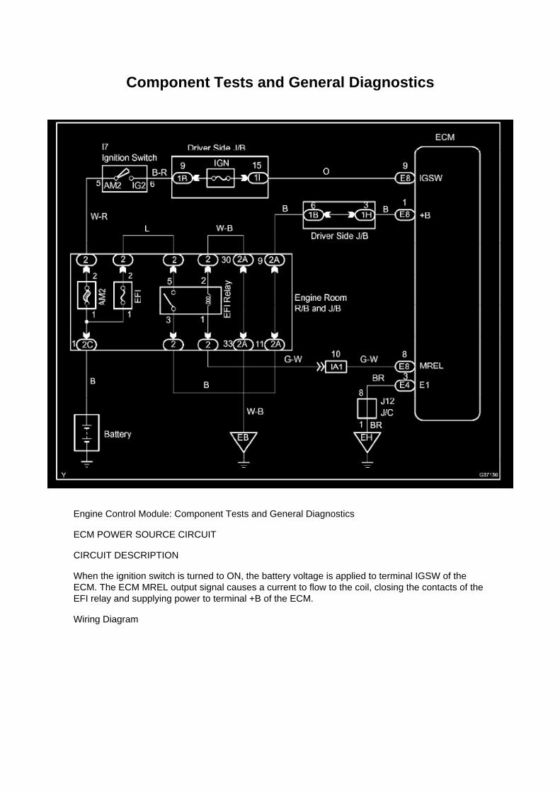
Component Tests and General Diagnostics
Engine Control Module: Component Tests and General Diagnostics
ECM POWER SOURCE CIRCUIT
CIRCUIT DESCRIPTION
When the ignition switch is turned to ON, the battery voltage is applied to terminal IGSW of theECM. The ECM MREL output signal causes a current to flow to the coil, closing the contacts of theEFI relay and supplying power to terminal +B of the ECM.
Wiring Diagram
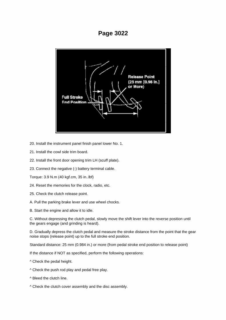
Page 3022
20. Install the instrument panel finish panel lower No. 1.
21. Install the cowl side trim board.
22. Install the front door opening trim LH (scuff plate).
23. Connect the negative (-) battery terminal cable.
Torque: 3.9 N.m (40 kgf.cm, 35 in..lbf)
24. Reset the memories for the clock, radio, etc.
25. Check the clutch release point.
A. Pull the parking brake lever and use wheel chocks.
B. Start the engine and allow it to idle.
C. Without depressing the clutch pedal, slowly move the shift lever into the reverse position untilthe gears engage (and grinding is heard).
D. Gradually depress the clutch pedal and measure the stroke distance from the point that the gearnoise stops (release point) up to the full stroke end position.
Standard distance: 25 mm (0.984 in.) or more (from pedal stroke end position to release point)
If the distance if NOT as specified, perform the following operations:
^ Check the pedal height.
^ Check the push rod play and pedal free play.
^ Bleed the clutch line.
^ Check the clutch cover assembly and the disc assembly.

Page 1822
Camshaft Position Sensor: Testing and Inspection
INSPECT CAMSHAFT POSITION SENSOR
Check the resistance.
Using an ohmmeter, measure the resistance between the terminals.
HINT: Cold and Hot mean the temperature of the coils themselves. Cold is from -10 to 50°C (14 to122°F) and Hot is from 50 to 100°C (122 to 212° F).
If the result is not as specified, replace the camshaft position sensor.

Page 1420

Page 3236

ABS Light: Testing and Inspection ABS With EBD & BA & TRAC & VSC System

ABS Warning Light Circuit (Remains On)
ABS WARNING LIGHT CIRCUIT (REMAINS ON)
CIRCUIT DESCRIPTION
If any of the following is detected, the ABS warning light remains ON.
1. The skid control ECU connectors are disconnected from the skid control ECU. 2. There is amalfunction in the skid control ECU internal circuit. 3. There is an open in the harness between thecombination meter and skid control ECU.
HINT: Use of the hand-held tester may not be possible when there is a malfunction in the skidcontrol ECU.

Page 3332
c. While observing the screen, gently jiggle the connector or wire harness between the ECU andsensors, or between ECUs.
OK: OPEN-screen display does not change.

Page 677

2. VERIFY THE REPAIR

(Test # 1)
(a) Move the bench seat to the rearmost position.
(b) Buckle the driver's seat belt.
(c) Confirm that the scan tool displays the data shown below and in the illustration.
^ "D SEAT POSITIOBKWARD" (Driver's seat is in the backward position).
^ "D BUCKLE SW SET"
(Driver's seat belt buckle switch is set/buckled).
(Test # 2)
(a) Leave the bench seat in the rearmost position.
(b) Unbuckle the driver's seat belt.
(c) Confirm that the scan tool displays the data shown below and in the illustration.
^ "D SEAT POSITIOBKWARD"

Page 1864
Engine Control Module: Technical Service Bulletins Engine Controls - Entering VIN WhenReplacing PCM/ECM
ENGINE EG045-04
Title: ENTERING VIN DURING ECM (PCM) REPLACEMENT AND/OR DTC P0630
Models: All '04 - '06 Models
October 14, 2004
TSB REVISION NOTICE:
^ June 3, 2005: Content has been updated to include 2004 and 2006 model year vehicles.Highlander HV has been added to step 4 of the VIN Write Procedure. Step 3 of the VIN ReadProcedure has been clarified to include Prius and Highlander HV vehicles.
^ January 24, 2005: Step 4 has been clarified to include Prius vehicles. Previous versions of thisTSB should be discarded.
Introduction
All 2005 and subsequent model year Toyota and Scion vehicles have the VIN (VehicleIdentification Number) stored in the Electronic Control Module (ECM) (SAE term: PowertrainControl Module/PCM) non-volatile memory. The VIN is accessible on the data stream using theToyota Diagnostic Tester and can also be written to a new ECM (PCM) using a VIN Read/Write"utility.
Service ECMs (supply parts) are shipped without the VIN; therefore, as part of the ECM (PCM)replacement procedure, the VIN must be written to the replacement ECM (PCM) using theDiagnostic Tester utility function.
For most 2005 model year vehicles, failure to write the VIN to the ECM (PCM) will result in a M.I.L."ON" condition and set DTC P0630: VIN Not Programmed or Mismatch - ECM (PCM). The fivemodels listed below do not support DTC P0630.
^ Corolla
^ ECHO
^ Matrix
^ Scion xA
^ Scion xB
It is very important to remember to enter the VIN on these vehicles. Vehicles with missing VINs aresubject to failing some state and local vehicle emissions Inspection and Maintenance programs.

NOTE:
2004 model year vehicles which have been flash reprogrammed may contain updated 2005 modelyear OBD II logic. These vehicles will require VIN entry into the ECM (PCM) after reprogramming.
Applicable Vehicles
^ 2004 model year vehicles that have been flash reprogrammed.
^ All 2005 - 2006 model year vehicles.
Warranty Information

Capacity Specifications

Engine Oil: Capacity Specifications
OIL CAPACITY (drain and refill):
With filter: ............................................................................................................................................................................ 5.8 L (6.1 US qt., 5.1 Imp. qt.) Without filter: ....................................................................................................................................................................... 5.1 L (5.4 US qt., 4.5 Imp.qt.)

Page 1470

Spark Plug: Testing and Inspection

INSPECT SPARK PLUG
a. Clean the spark plugs.
Air pressure: Below 588 kPa (6.0 kgf/sq.cm, 85 psi) Duration: 20 seconds or less
b. Check the spark plug for any damage on its thread and insulator.
If damaged, replace the spark plug.
Recommended spark plug: SK20HR11 (DENSO made) ILFR6C11 (NGK made)
c. Check the spark plug electrode gap.
1. Using a spark plug gap gauge, measure the electrode gap.
Electrode gap: 1.0 to 1.1 mm (0.039 to 0.043 in.) Maximum electrode gap: 1.3 mm (0.051 in.)
If the result is greater than the maximum, replace the spark plug.

Locations
Crankshaft Position Sensor: Locations

A/C - Ge

Page 1991
Wiring Diagram
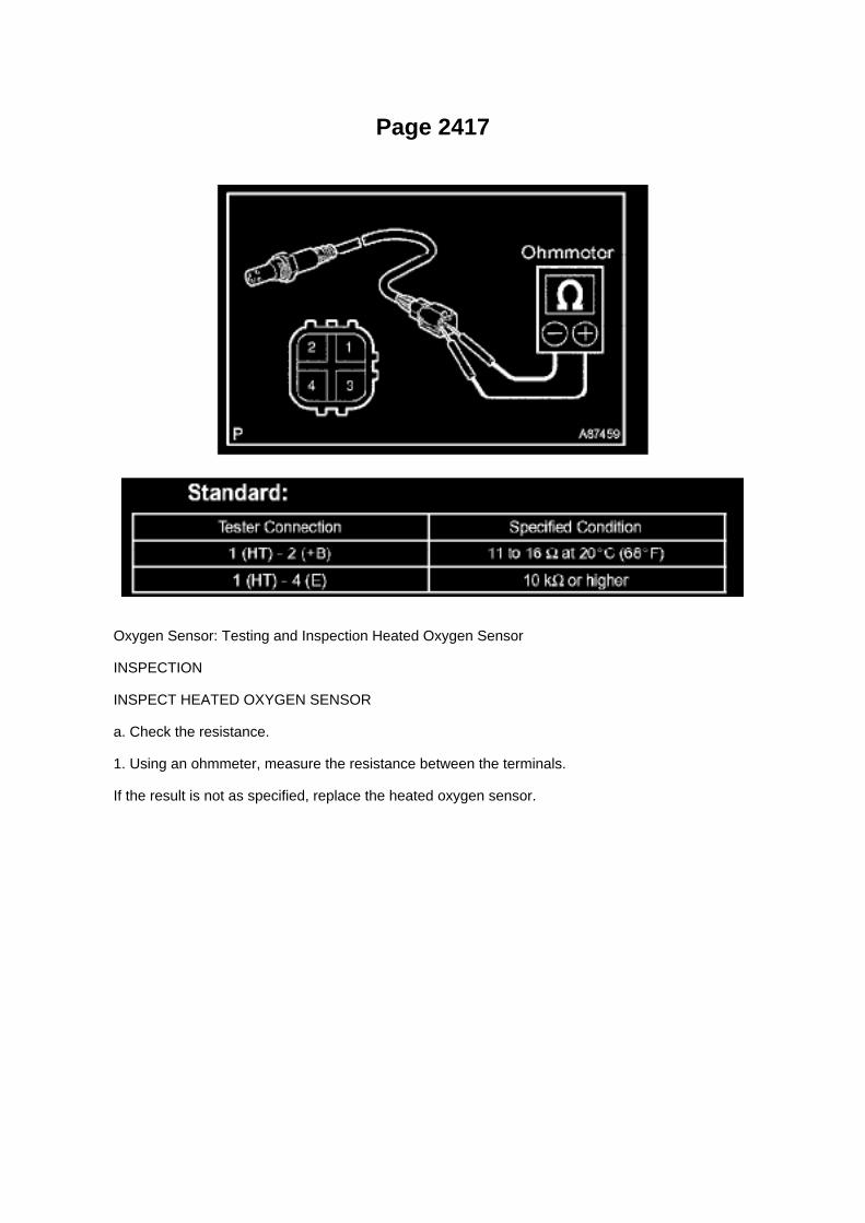
Page 2417
Oxygen Sensor: Testing and Inspection Heated Oxygen Sensor
INSPECTION
INSPECT HEATED OXYGEN SENSOR
a. Check the resistance.
1. Using an ohmmeter, measure the resistance between the terminals.
If the result is not as specified, replace the heated oxygen sensor.

Page 153
Steps 7 - 8
General Information
GENERAL INFORMATION A large number of ECU controlled systems are used in the TOYOTATACOMA. In general, ECU controlled systems are considered to be very intricate, requiring a highlevel of technical knowledge to troubleshoot. However, most problem checking procedures onlyinvolve inspecting the ECU controlled system's circuits one by one. An adequate understanding ofthe system and a basic knowledge of electricity is enough to perform effective troubleshooting,accurate diagnoses and necessary repairs.
FOR USING OBD II SCAN TOOL OR HAND-HELD TESTER
- Before using the scan tool or tester, the scan tool's instruction book or tester's operator manualshould be read thoroughly.
- If the scan tool or tester cannot communicate with the ECU controlled systems when you haveconnected the cable of the tester to the DLC3 with the ignition switch and tester turned ON, there isa problem on the vehicle side or tester side.
1. If communication is normal when the tester is connected to another vehicle, inspect thediagnosis data link line (Bus(+)line) or ECU power circuit
of the vehicle.
2. If communication is still impossible when the tester is connected to another vehicle, the problemis probably in the tester itself. Perform the Self
Test procedures outlined in the tester Operator's manual.
Basic Inspection
BASIC INSPECTION
a. RESISTANCE MEASURING CONDITION OF ELECTRONIC PARTS

1. Unless stated, all resistance measurements should be made at an ambient temperature of 20°C(68°F). Resistance measurements may be
outside the specifications if measured at high temperatures, i.e. immediately after the vehicle hasbeen running. Measurements should be made after the engine has cooled down.

Page 517

He - Wi

Page 1545
5. REMOVE EXHAUST PIPE ASSEMBLY FRONT
a. Remove the 2 bolts and 2 compression springs. b. Remove the exhaust pipe front from theexhaust pipe support. c. Remove the gasket from the exhaust manifold.
6. INSTALL EXHAUST PIPE ASSEMBLY FRONT
a. Check the free length.
(1) Using vernier calipers, measure the free length of the compression spring.
Minimum: 40.5 mm (1.594 inch) If the free length is less than the minimum, replace thecompression spring.
b. Using a wooden block and plastic-faced hammer, tap in a new gasket until it is flush with theexhaust manifold.

NOTICE: -
Make sure that the gasket is in the correct angle when installing.
- Do not reuse the removed gasket.
- Never push a new gasket into the exhaust manifold by installing the exhaust pipe front into theexhaust manifold.
c. Install the exhaust pipe front into the exhaust pipe sup port. d. Tighten the 2 bolts and 2compression springs.
Torque: 43 Nm (438 kgf-cm, 32 ft. lbs.)
7. INSTALL EXHAUST PIPE ASSEMBLY TAIL
a. Install a new gasket onto the exhaust pipe front. b. Install the exhaust pipe tail onto the 4exhaust pipe supports. c. Tighten the 2 bolts and 2 nuts.
Torque: 48 Nm (489 kgf-cm, 35 ft. lbs.)
8. INSTALL OXYGEN SENSOR
SST 09224-00010
9. INSTALL AIR FUEL RATIO SENSOR
SST 09224-00010
10. CONNECT CABLE TO NEGATIVE BATTERY TERMINAL
Torque: 3.9 Nm (40 kgf-cm, 35 inch lbs.)
11. CHECK FOR EXHAUST GAS LEAKAGE

Page 111
Fog/Driving Lamp Relay: Testing and Inspection
INSPECT FOG LAMP RELAY
a. Check the resistance.
1. Using an ohmmeter, measure the resistance between the terminals.
If the result is not as specified, replace the fog lamp relay.

Page 1130
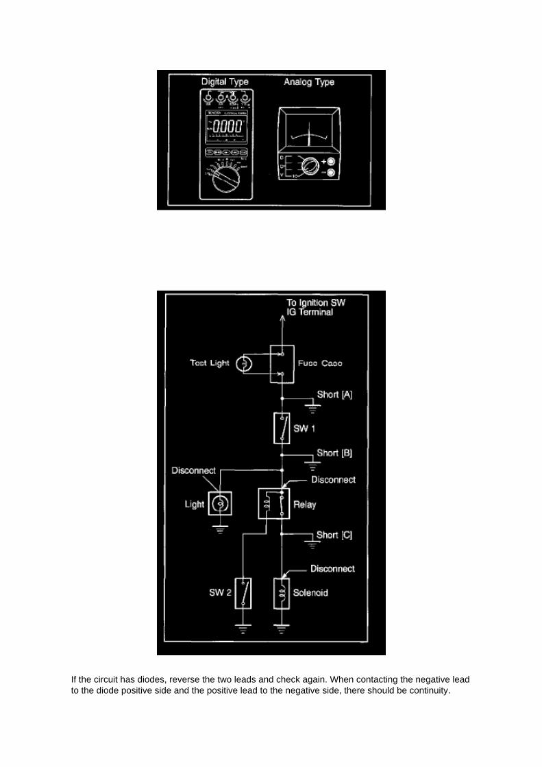
If the circuit has diodes, reverse the two leads and check again. When contacting the negative leadto the diode positive side and the positive lead to the negative side, there should be continuity.

When contacting the two leads in reverse, there should be no continuity.
c. Use a volt/ohmmeter with high impedance (10 kOhms/V minimum) for troubleshooting of theelectrical circuit.
Finding A Short Circuit
FINDING A SHORT CIRCUIT
a. Remove the blown fuse and disconnect all loads of the fuse.
b. Connect a test light in place of the fuse.
c. Establish conditions in which the test light comes on.
Example: [A] - Ignition SW on [B] - Ignition SW and SW 1 on [C] - Ignition SW, SW 1 and Relay on(Connect the Relay) and SW 2 off (or Disconnect SW 2)
d. Disconnect and reconnect the connectors while watching the test light.
The short lies between the connector where the test light slays lit and the connector where the lightgoes out.
e. Find the exact location of the short by lightly shaking the problem wire along the body.

Page 3270

Terminals Of Control Module / Pinouts - Terminal Inspection

Page 1146

Instrument Panel J/B No. 1 Inner Circuit

Locations
SFI System

Page 1362


Page 1051

Abbreviations

Page 705

(g) Select "NEW VEHICLE" from the "VEHICLE SELECT" menu.

(h) Go through the options and select the following information.
^ MODEL YEAR-2005
^ MODEL SELECTION - Tacoma
^ ENGINE TYPE - 2TR-FE (4-cylinder)
(i) Once these options are selected, a vehicle confirmation screen (shown in the illustration) will bedisplayed.
(j) Review the vehicle selection.
(k) Press "YES to confirm the selection.
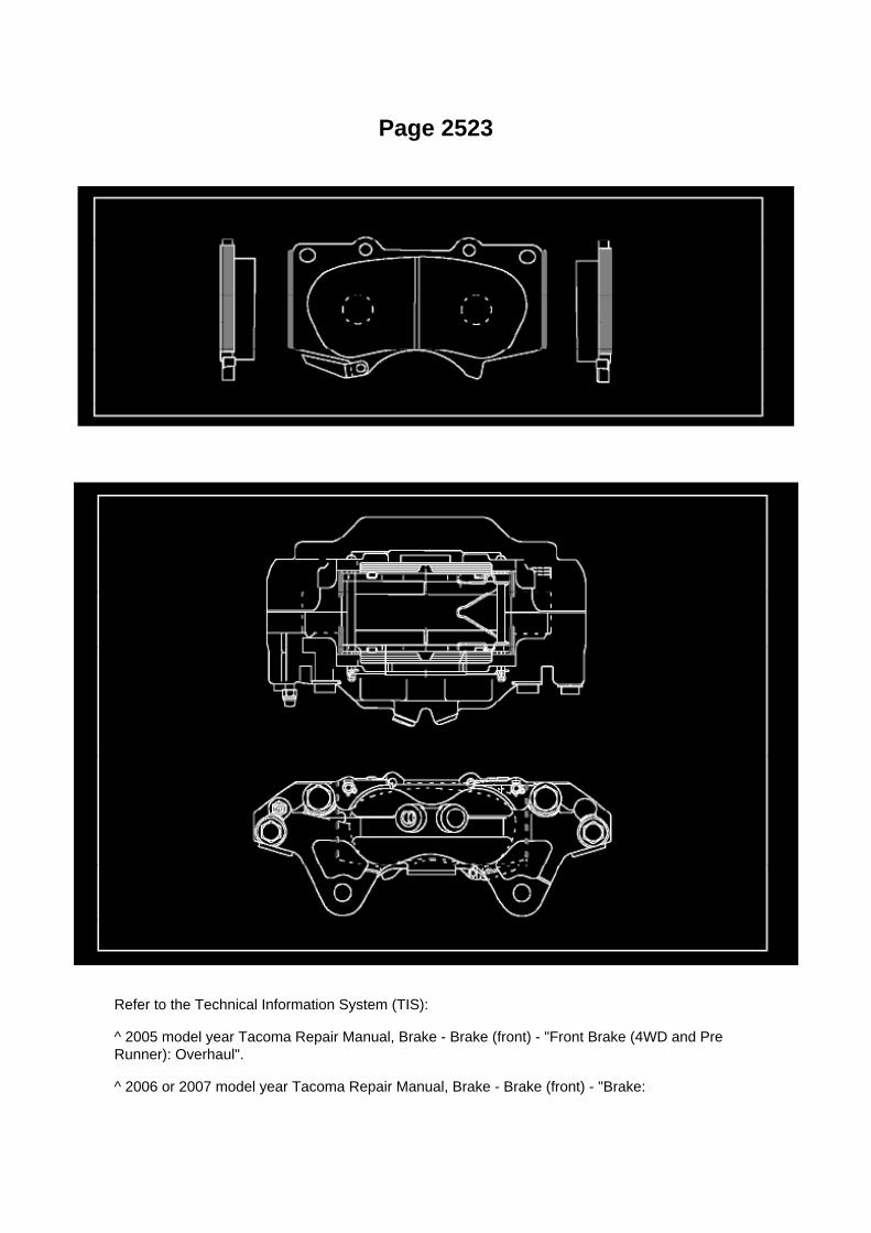
Page 2523
Refer to the Technical Information System (TIS):
^ 2005 model year Tacoma Repair Manual, Brake - Brake (front) - "Front Brake (4WD and PreRunner): Overhaul".
^ 2006 or 2007 model year Tacoma Repair Manual, Brake - Brake (front) - "Brake:

Front Brake (for 4WD and Pre -Runner): Removal".
3. Apply NEW grease on the brake pads as shown in red below.
4. Apply grease to the brake caliper as shown in red below.
5. Install the front brake pads and front rotors. Refer to TIS:
^ 2005 model year Tacoma Repair Manual, Brake - Brake (front) - "Front Brake (4WD and PreRunner): Overhaul".
^ 2006 or 2007 model year Tacoma Repair Manual, Brake - Brake (front) - "Brake: Front Brake (for4WD and Pre -Runner): Installation".
6. Road test the vehicle to confirm the front brake noise is NO longer present.

Page 703

5. RECONNECT THE NEGATIVE BATTERY CABLE

6. REPROGRAM THE RADIO STATION PRESETS AND SET THE CLOCK TO THEAPPROPRIATE TIME
C. VERIFY THE REPAIR USING THE SCAN TOOL
1. PREPARE THE SCAN TOOL
(a) Remove the DLC3 connector cover.
(b) Connect the scan tool to the DLC3 connector.
(c) Turn the ignition switch to the "ON" position.

Page 2311

8. INSTALL CHARCOAL CANISTER ASSEMBLY

a. Connect the fuel tank vent hose.
1. Align the fuel tank vent hose connector with the pipe, then push in the fuel tank vent connectoruntil the retainer makes a "click" sound to
connect the fuel tank vent hose to the charcoal canister.
NOTE: -
Check that there are no scratches or foreign objects on the disconnected parts of the fuel tank ventconnector and pipe before performing the work.
- After connecting the fuel tank vent hose, check that the fuel tank vent hose is securely connectedby pulling the quick connector.
b. Install the charcoal canister with the bolt and 2 nuts.
Torque: 20 N.m (204 Kgf.cm, 15 ft.lbf)
c. Connect the EVAP tube. d. Connect the connector.
9. INSTALL CHARCOAL CANISTER FILTER NO.2
10. INSTALL FUEL TANK ASSEMBLY 11. CONNECT FUEL TANK MAIN TUBE AND FUEL TANKRETURN TUBE 12. REMOVE FUEL TANK PROTECTOR SUB-ASSEMBLY NO.1 (OFF ROADPACKAGE) 13. CONNECT CABLE TO NEGATIVE BATTERY TERMINAL
Torque: 3.9 N.m (40 Kgf.cm, 35 in.lbf)
14. CHECK FOR FUEL LEAKAGE

Locations

Page 208

J. When Cal 1 has completed the update process turn ignition OFF for a minimum of 10 seconds.Then click Next.

K. Turn ignition to the ON position. Then click Start.
L. Do NOT disturb the vehicle during flash reprogramming.
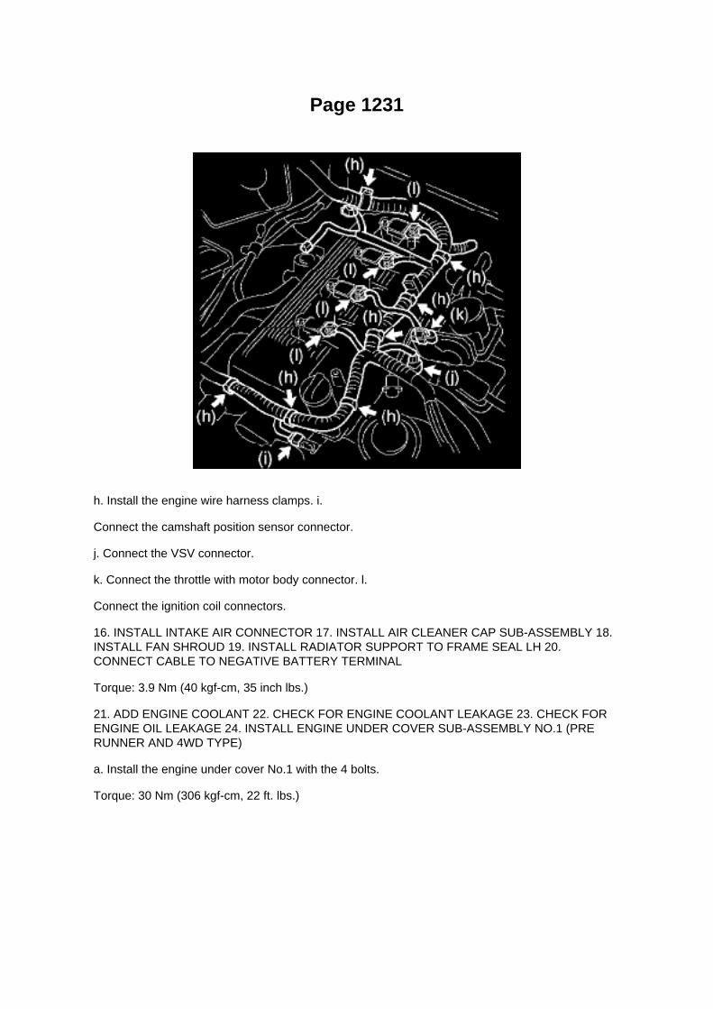
Page 1231
h. Install the engine wire harness clamps. i.
Connect the camshaft position sensor connector.
j. Connect the VSV connector.
k. Connect the throttle with motor body connector. l.
Connect the ignition coil connectors.
16. INSTALL INTAKE AIR CONNECTOR 17. INSTALL AIR CLEANER CAP SUB-ASSEMBLY 18.INSTALL FAN SHROUD 19. INSTALL RADIATOR SUPPORT TO FRAME SEAL LH 20.CONNECT CABLE TO NEGATIVE BATTERY TERMINAL
Torque: 3.9 Nm (40 kgf-cm, 35 inch lbs.)
21. ADD ENGINE COOLANT 22. CHECK FOR ENGINE COOLANT LEAKAGE 23. CHECK FORENGINE OIL LEAKAGE 24. INSTALL ENGINE UNDER COVER SUB-ASSEMBLY NO.1 (PRERUNNER AND 4WD TYPE)
a. Install the engine under cover No.1 with the 4 bolts.
Torque: 30 Nm (306 kgf-cm, 22 ft. lbs.)

Locations

Engine Room R/B, J/B - Engine Compartment Left

Page 2627
SFI System

Page 1843
Cruise Control System

Page 3052

Refer to Reset Procedure 2 for the vehicles with Electronically Controlled AutomaticTransmissions:

Reset Procedure 1
1. Connect the Toyota Diagnostic Tester to the vehicle.
2. Reset the ECM (PCM). Refer to the procedures below.

Page 1509
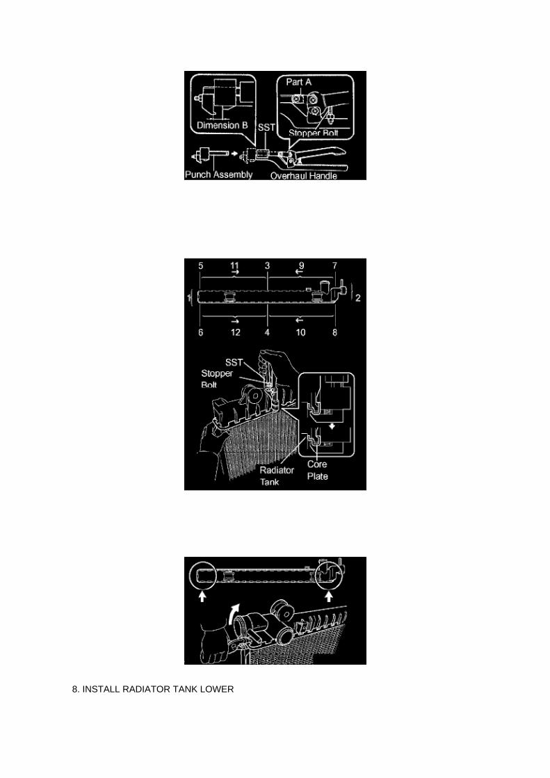
8. INSTALL RADIATOR TANK LOWER

HINT: Perform the same procedures as for the radiator tank upper.
9. ASSEMBLE SST
SST 09230-01010 (09231-01010, 09231-01020) a. Install the punch assembly into the overhaulhandle by inserting it into the hole in part A as shown in the illustration. b. While gripping thehandle, adjust the stopper bolt so that dimension B is as shown in the illustration.
Dimension B: 8.4 mm (0.331 inch)
10. CAULK CORE PLATE
a. Gently press SST against the core plate in the order shown in the illustration. After repeating thisa few times, fully caulk the core plate by
gripping the handle until stopped by the stopper bolt. SST 09230-01010 (09231-01010,09231-01020)
HINT: Do not tap the portions indicated in the illustration or the oil cooler using SST. Use pliers or asimilar tool. Be careful not to dam age the core plate.

Page 626
Safing Sensor: Service and Repair
Air Bag Sensor Assy Center
AIR BAG SENSOR ASSEMBLY CENTER
REPLACEMENT

1. PRECAUTION
Refer to Air Bag Systems; Service Precautions.
2. DISCONNECT CABLE FROM NEGATIVE BATTERY TERMINAL
Wait for at least 90 seconds after disconnecting the cable to prevent the airbag from working.
3. REMOVE CONSOLE UPPER REAR PANEL SUB-ASSEMBLY (AUTOMATICTRANSMISSION,SEPARATE SEAT TYPE) 4. REMOVE CONSOLE UPPER REAR PANELSUB-ASSEMBLY (MANUAL TRANSMISSION, SEPARATE SEAT TYPE) 5. REMOVE CONSOLEBOX ASSEMBLY REAR (SEPARATE SEAT TYPE) 6. REMOVE INSTRUMENT PANEL CUPHOLDER TRAY (AUTOMATIC TRANSMISSION, SEPARATE SEAT TYPE) 7. REMOVECONSOLE BOX FRONT (AUTOMATIC TRANSMISSION, SEPARATE SEAT TYPE) 8. REMOVECONSOLE BOX FRONT (MANUAL TRANSMISSION, SEPARATE SEAT TYPE)

Air-Fuel Ratio (A/F) Sensor
Oxygen Sensor: Testing and Inspection Air-Fuel Ratio (A/F) Sensor
INSPECTION
INSPECT AIR FUEL RATIO SENSOR
a. Check the resistance.
1. Using an ohmmeter, measure the resistance between the terminals.
If the result is not as specified, replace the air fuel ratio sensor.

Page 3095

(2) Install the 6 bolts through the axle hub. (3) Install the washer plate, as shown in the illustration,through the hub bolt, and install the hub bolt by tightening the hub nut.

21. INSTALL REAR AXLE HUB & BEARING ASSY LH
a. Position the backing plate on the rear axle bearing, and install the 4 parking brake plates ontothe rear axle housing bolts using 2 socket
wrenches and a press.
22. INSTALL REAR AXLE SHAFT LH WASHER
a. Install the rear axle shaft plate washer onto the rear axle shaft.
23. INSTALL REAR AXLE BEARING RETAINER INNER LH
a. Install a new rear axle bearing retainer inner onto the rear axle shaft.
24. INSTALL REAR AXLE SHAFT LH
a. Using SST and a press, install the rear axle shaft onto the rear axle bearing.
SST 09521-25011
25. INSTALL REAR AXLE SHAFT LH SNAP RING
a. Using a snap ring expander, install a new snap ring.

Page 1066
Diagnostic Trouble Code Chart
Use Diagnostic Trouble Codes (DTCs) (from the DTC checks) in the table to determine the troublearea and proper inspection procedure. The Supplemental Restraint System (SRS) DTC chart isshown as an example.
Problem Symptoms Table

PROBLEM SYMPTOMS TABLE

Specifications

Wheel Fastener: Specifications

Wheel Fastener ............................................................................................................................................................... 113 Nm (1,152 kgf-cm, 83 ft. lbs.)

Page 62
28. REMOVE INSTRUMENT CLUSTER FINISH PANEL SUB-ASSEMBLY CENTER 29. REMOVEGLOVE COMPARTMENT DOOR ASSEMBLY 30. REMOVE INSTRUMENT PANEL FINISHPANEL SUB-ASSEMBLY LOWER RH 31. REMOVE INSTRUMENT PANEL LOWER LH 32.REMOVE INSTRUMENT COVER SUB-ASSEMBLY LOWER 33. REMOVE INSTRUMENT SIDEPANEL RH 34. DISCONNECT PASSENGER AIRBAG CONNECTOR 35. REMOVEINSTRUMENT PANEL SUB-ASSEMBLY W/PASSENGER AIRBAG ASSEMBLY
36. REMOVE TOWING CONVERTER RELAY
a. Disconnect the connector. b. Remove the bolt and towing converter relay.
37. INSTALL TOWING CONVERTER RELAY
a. Install the towing converter relay with the bolt.
Torque: 7.0 N.m (71 kgf.cm, 62 in.lbf)
b. Connect the connector.
38. INSTALL INSTRUMENT PANEL SUB-ASSEMBLY W/PASSENGER AIRBAG ASSEMBLY 39.CONNECT PASSENGER AIRBAG CONNECTOR 40. INSTALL INSTRUMENT SIDE PANEL RH41. INSTALL INSTRUMENT COVER SUB-ASSEMBLY LOWER 42. INSTALL INSTRUMENTPANEL LOWER LH 43. INSTALL INSTRUMENT PANEL FINISH PANEL SUB-ASSEMBLYLOWER RH 44. INSTALL GLOVE COMPARTMENT DOOR ASSEMBLY 45. INSTALLINSTRUMENT CLUSTER FINISH PANEL SUB-ASSEMBLY CENTER 46. INSTALLCOMBINATION METER ASSEMBLY 47. INSTALL INSTRUMENT CLUSTER FINISH PANELSUB-ASSEMBLY 48. INSTALL INSTRUMENT PANEL FINISH PANEL LOWER NO.1 49.CONNECT HOOD LOCK CONTROL LEVER SUB-ASSEMBLY 50. INSTALL RADIO RECEIVERASSEMBLY W/ BRACKET 51. INSTALL AIR CONDITIONING CONTROL ASSEMBLY 52.INSTALL CONSOLE BOX FRONT (MANUAL TRANSMISSION, BENCH SEAT TYPE 53. INSTALLCONSOLE BOX FRONT (AUTOMATIC TRANSMISSION, BENCH SEAT TYPE) 54. INSTALLCONSOLE BOX FRONT (MANUAL TRANSMISSION, SEPARATE SEAT TYPE) 55. INSTALLCONSOLE BOX FRONT (AUTOMATIC TRANSMISSION, SEPARATE SEAT TYPE) 56. INSTALLINSTRUMENT PANEL CUP HOLDER TRAY (AUTOMATIC TRANSMISSION, SEPARATE SEATTYPE) 57. INSTALL CONSOLE BOX ASSEMBLY REAR (SEPARATE SEAT TYPE) 58. INSTALLCONSOLE UPPER REAR PANEL SUB-ASSEMBLY (MANUAL TRANSMISSION, SEPARATESEAT TYPE) 59. INSTALL CONSOLE UPPER REAR PANEL SUB-ASSEMBLY (AUTOMATICTRANSMISSION,SEPARATE SEAT TYPE)

Page 2080
SST 09224-00010
Torque: 44 N.m (449 Kgf.cm, 33 ft.lbf) 40 N.m (408 Kgf.cm, 30 ft.lbf) with SST
NOTE: Use a torque wrench with a fulcrum length of 300 mm (11.81 in.).
b. Connect the wire harness clamp. (4WD DRIVE TYPE) c. Connect the oxygen sensor connector.
4. CONNECT CABLE TO NEGATIVE BATTERY TERMINAL
Torque: 3.9 N.m (40 Kgf.cm, 35 in.lbf)

Service and Repair

Evaporative Canister Filter: Service and Repair
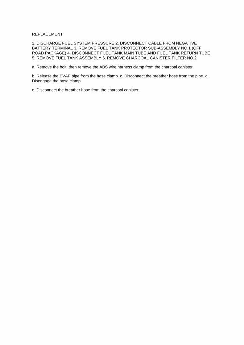
REPLACEMENT
1. DISCHARGE FUEL SYSTEM PRESSURE 2. DISCONNECT CABLE FROM NEGATIVEBATTERY TERMINAL 3. REMOVE FUEL TANK PROTECTOR SUB-ASSEMBLY NO.1 (OFFROAD PACKAGE) 4. DISCONNECT FUEL TANK MAIN TUBE AND FUEL TANK RETURN TUBE5. REMOVE FUEL TANK ASSEMBLY 6. REMOVE CHARCOAL CANISTER FILTER NO.2
a. Remove the bolt, then remove the ABS wire harness clamp from the charcoal canister.
b. Release the EVAP pipe from the hose clamp. c. Disconnect the breather hose from the pipe. d.Disengage the hose clamp.
e. Disconnect the breather hose from the charcoal canister.

Page 3257
ABS With EBD & BA & TRAC & VSC SYSTEM

W/ VSC
Brake Bleeding: Service and Repair W/ VSC
BRAKE FLUID (W/ VSC)
BLEEDING
NOTICE: -
Immediately wash off any brake fluid that comes into contact with any painted surfaces.
- Depressing the brake pedal with the reservoir cap removed will cause the fluid to spray.
HINT: -
If any work is done on the brake system or if air in the brake lines is suspected, bleed the air fromthe system.
- When bleeding, maintain the amount of fluid in the reservoir between the Min. and Max. lines.
1. FILL RESERVOIR WITH BRAKE FLUID
Fluid: SAE J1703 or FMVSS NO.116 DOT3
2. BLEED BRAKE BOOSTER W/ACCUMULATOR PUMP ASSEMBLY
HINT: If the brake master cylinder is disassembled, the brake line is disconnected from the brakemaster cylinder or if the reservoir becomes empty, bleed the brake master cylinder.
a. Turn the ignition switch to ON, and wait until the pump motor has stopped.
HINT: Pump operating sound can be heard.
b. Turn the ignition switch to OFF, and depress the brake pedal more than 20 times.
HINT: When pressure in the accumulator is released, the reaction force becomes lighter and thestroke becomes longer.
c. Repeat a. and b. 5 times. d. Turn the ignition switch to ON, and check that the pump stops afterapproximately 8 to 14 seconds.
NOTICE: If the pump does not stop, repeat step c. again.

3. BLEED BRAKE LINE
a. Turn the ignition switch to ON, and wait until the pump motor has stopped.
HINT: Pump operating sound can be heard.
b. Front brake line.
(1) Connect the vinyl tube to the brake caliper. (2) Depress the brake pedal several times, thenloosen the bleeder plug with the pedal held down. (3) At the point when the fluid stops coming out,tighten the bleeder plug, then release the brake pedal. (4) Repeat (2) and (3) until all the air in thefluid has been bled out.
Torque: 11 Nm (112 kgf-cm, 8 ft. lbs.)
(5) Repeat the above procedures to bleed the other brake line.

Page 219

A/C - Fo

Page 452

Headlamp Dimmer Switch: Testing and Inspection
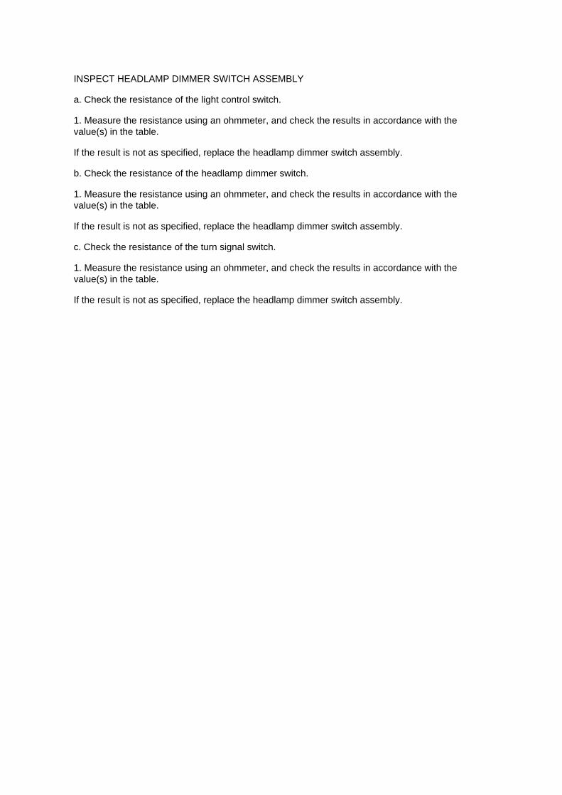
INSPECT HEADLAMP DIMMER SWITCH ASSEMBLY
a. Check the resistance of the light control switch.
1. Measure the resistance using an ohmmeter, and check the results in accordance with thevalue(s) in the table.
If the result is not as specified, replace the headlamp dimmer switch assembly.
b. Check the resistance of the headlamp dimmer switch.
1. Measure the resistance using an ohmmeter, and check the results in accordance with thevalue(s) in the table.
If the result is not as specified, replace the headlamp dimmer switch assembly.
c. Check the resistance of the turn signal switch.
1. Measure the resistance using an ohmmeter, and check the results in accordance with thevalue(s) in the table.
If the result is not as specified, replace the headlamp dimmer switch assembly.

Locations

Differential Lock Switch: Locations
A/C - Fo

Locations
Crankshaft Position Sensor: Locations

A/C - Ge

Page 3141
^ Torque the bolts to the specification found in the applicable Repair Manual.
NOTE
In most applications there will be 1 black torque converter bolt, be sure to install this bolt first to aidin aligning the torque converter to the flywheel assembly.

Page 1124
SYMPTOM SIMULATION
HINT: The most difficult case in troubleshooting is when no problem symptoms occur. In suchcases, a thorough customer problem analysis must be carried out. A simulation of the same orsimilar conditions and environment in which the problem occurred in the customer's vehicle shouldbe carried out. No matter how much skill or experience a technician has, troubleshooting withoutconfirming the problem symptoms will lead to important repairs being overlooked and mistakes ordelays.
For example: With a problem that only occurs when the engine is cold or occurs as a result ofvibration caused by the road during driving, the problem can never be determined if the symptomsare being checked on a stationary vehicle or a vehicle with a warmed-up engine. Vibration, heat orwater penetration (moisture) is difficult to reproduce. The symptom simulation tests below areeffective substitutes for the conditions and can be applied on a stationary vehicle.
Important points in the symptom simulation test: In the symptom simulation test, the problemsymptoms as well as the problem area or parts must be confirmed. First, narrow down the possibleproblem circuits according to the symptoms. Then, connect the tester and carry out the symptomsimulation test, judging whether the circuit being tested is defective or normal. Also, confirm theproblem symptoms at the same time. Refer to the problem symptoms table for each system to

narrow down the possible causes.
1. VIBRATION METHOD: When vibration seems to be the major cause.
a. PART AND SENSOR
1. Apply slight vibration with a finger to the part of the sensor considered to be the cause of theproblem and check whether or not the
malfunction occurs.
HINT: Applying strong vibration to relays may open relays.
b. CONNECTORS
1. Slightly shake the connector vertically and horizontally.
c. WIRE HARNESS
1. Slightly shake the wire harness vertically and horizontally.
The connector joint and fulcrum of the vibration are the major areas that should be checkedthoroughly.

Page 993

Engine Oil: Fluid Type Specifications

GRADE .................................................................................................................................... API SLEnergy-Conserving or ILSAC multigrade engine oil VISCOSITY ...................................................................................................................................................................................................... SAE5W-30

Page 2205
A/F and 02 Sensor Identification

Page 1889

9. INSTALL ECM

Torque: 5 N.m (51 kgf.cm, 44 in.lbf)
10. INSTALL INSTRUMENT PANEL FINISH PANEL SUB-ASSEMBLY LOWER RH 11. INSTALLGLOVE COMPARTMENT DOOR ASSEMBLY 12. CONNECT CABLE TO NEGATIVE BATTERYTERMINAL
Torque: 3.9 N.m (40 kgf.cm, 35 in.lbf)

Page 2854

17. INSTALL INDICATOR LAMP WIRE SUB-ASSY

a. Install the bulb into the indicator lamp wire sub-assembly. b. Install the indicator lamp wiresub-assembly.
18. INSTALL POSITION INDICATOR HOUSING UPPER
a. Install the slide cover and position indicator housing sub-assembly onto the shift lever guidehousing.
HINT: Firmly make the claws fit.
19. INSTALL FLOOR SHIFT ASSY
a. Install the floor shift with the 4 bolts.
Torque: 14 Nm (143 kgf-cm, 10 ft. lbs.)
b. Connect the 2 clamps and 2 connectors.
20. CONNECT TRANSMISSION CONTROL CABLE ASSY
a. CABLE TYPE:
(1) Connect the transmission control cable with the clip to floor shift assy. (2) Install thetransmission control cable onto the floor shift assy.

Restraints - OCS System Initialization

Seat Occupant Sensor: Technical Service Bulletins Restraints - OCS System Initialization

COLLISION REPAIR INFORMATION FOR THE COLLISION REPAIR PROFESSIONAL
TITLE: SRS OCCUPANT CLASSIFICATION SYSTEM INITIALIZATION
SECTION: ELECTRICAL BULLETIN # 177
MODELS: ALL EQUIPPED TOYOTA LEXUS and SCION MODELS
DATE: MARCH 2010
Models equipped with a Supplemental Restraint System (SRS) Occupant Classification System(OCS) will enable or disable the passenger front and side airbags based on seat occupancypassenger weight and seat belt latch engagement.
If an equipped vehicle sustains collision damage or if the front passenger seat or any of the OCScomponents are serviced the SRS Malfunction Indicator Light (MIL) may illuminate setting aDiagnostic Trouble Code (DTC).
NOTE:
It is necessary to diagnose and repair the root cause of a SRS or OCS DTC before initializing theOCS system. If SRS and OCS DTC's are not cleared the system may not operate properly.
Be sure to check and clear DTC's and perform OCS initialization per repair manual instructionswith a Techstream Special Service Tool (SST) or capable diagnostic tester.
Any of the following conditions could set a DTC illuminate the SRS MIL or cause the PASSENGERAIRBAG light to indicate incorrectly regardless of occupancy:
^ The OCS Electronic Control Unit (ECU) is replaced
^ Accessories such as a seatback tray are installed on the passenger seat
^ The passenger seat is removed and replaced or reinstalled
^ The vehicle is involved in an accident or collision
Model-specific repair manuals can be accessed through the Technical Information System (TIS)www.techinfo.toyota.com

Page 2009
Step 9 - 10

Capacity Specifications

Fluid - A/T: Capacity Specifications

Drain and Fill: 4 speed .................................................................................................................................................................... Up to 2.1 US. qt. (2.0 L)
Drain and Fill: 5 speed .................................................................................................................................................................... Up to 3.2 US. qt. (3.0 L)

Page 2197
o. Connect the fuel vapor feed hose to the VSV.
12. CONNECT FUEL HOSE 13. CONNECT FUEL HOSE NO.2 14. INSTALL THROTTLEW/MOTOR BODY ASSEMBLY 15. INSTALL INTAKE AIR CONNECTOR 16. CONNECT CABLETO NEGATIVE BATTERY TERMINAL
Torque: 3.9 N.m (40 kgf.cm, 35 in.lbf)
17. ADD ENGINE COOLANT 18. CHECK FOR ENGINE COOLANT LEAKAGE 19. CHECK FORFUEL LEAKAGE 20. INSTALL ENGINE UNDER COVER SUB-ASSEMBLY NO.1 (PRE RUNNERAND 4WD TYPE)

Page 2212
A/C - Ge

Page 1745
Ignition Switch: Testing and Inspection
INSPECT IGNITION OR STARTER SWITCH ASSEMBLY
a. Check the resistance.
1. Using an ohmmeter, measure the resistance between the terminals.
If the result is not as specified, replace the ignition or starter switch.

Engine Controls - A/F And O2 Sensor Identification
Oxygen Sensor: Technical Service Bulletins Engine Controls - A/F And O2 Sensor Identification
T-SB-0398-09
December 23, 2009
Engine Bank 1 and Bank 2 A/F and 02 Identification

Service Category Engine/Hybrid System
Section Engine Control
Market USA
Applicability
TSB SUPERSESSION NOTICE
The information contained in this TSB supersedes TSB No. EG034-07.
^ Applicability has been updated to include 2009 - 2010 model year vehicles and 2006 - 2010model year Highlander HV.
TSB No. EG034-07 is Obsolete and any printed versions should be discarded. Be sure to reviewthe entire content of this service bulletin before proceeding.
Introduction
This service bulletin provides information on the proper identification of engine bank 1 and enginebank 2 for correct A/F sensor and oxygen sensor replacement.
This bulletin contains information that identifies engine bank 1 and engine bank 2 on the followingengines: 1AZ-FE, 2AZ-FE, 2AZ-FE (PZEV), 1GR-FE, 2GR-FE, 2JZ-GE, 1MZ-FE, 3MZ-FE,1UR-FE, 3UR-FE, 2UZ-FE 5VZ-FE and 1ZZ-FE.
^ Bank 1 (B1) refers to the bank that includes cylinder No. 1.
^ Bank 2 (B2) refers to the bank opposite bank 1.
^ Sensor 1 (S1) refers to the sensor that is located before the catalytic converters.
^ Sensor 2 (S2) refers to the sensor that is located after the catalytic converters.
Warranty Information

Page 516
A/C - Ge

Page 1318

d. Using several steps, uniformly install and tighten the 10 bolts in the sequence shown in theillustration.
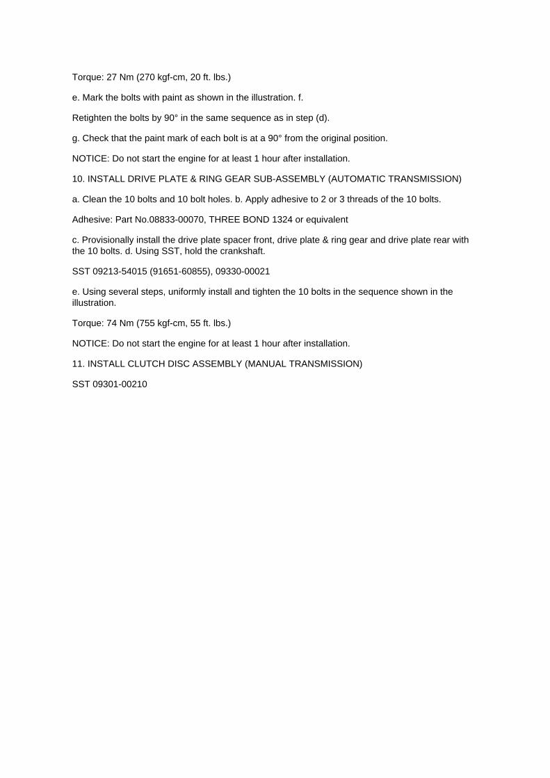
Torque: 27 Nm (270 kgf-cm, 20 ft. lbs.)
e. Mark the bolts with paint as shown in the illustration. f.
Retighten the bolts by 90° in the same sequence as in step (d).
g. Check that the paint mark of each bolt is at a 90° from the original position.
NOTICE: Do not start the engine for at least 1 hour after installation.
10. INSTALL DRIVE PLATE & RING GEAR SUB-ASSEMBLY (AUTOMATIC TRANSMISSION)
a. Clean the 10 bolts and 10 bolt holes. b. Apply adhesive to 2 or 3 threads of the 10 bolts.
Adhesive: Part No.08833-00070, THREE BOND 1324 or equivalent
c. Provisionally install the drive plate spacer front, drive plate & ring gear and drive plate rear withthe 10 bolts. d. Using SST, hold the crankshaft.
SST 09213-54015 (91651-60855), 09330-00021
e. Using several steps, uniformly install and tighten the 10 bolts in the sequence shown in theillustration.
Torque: 74 Nm (755 kgf-cm, 55 ft. lbs.)
NOTICE: Do not start the engine for at least 1 hour after installation.
11. INSTALL CLUTCH DISC ASSEMBLY (MANUAL TRANSMISSION)
SST 09301-00210

Removal and Installation
Engine Control Module: Service and Repair Removal and Installation

REPLACEMENT
NOTE: Perform REGISTRATION (VIN registration) when replacing the ECM.
1. DISCONNECT CABLE FROM NEGATIVE BATTERY TERMINAL 2. REMOVE GLOVECOMPARTMENT DOOR ASSEMBLY 3. REMOVE INSTRUMENT PANEL FINISH PANELSUB-ASSEMBLY LOWER RH 4. REMOVE ECM
a. Disconnect the 4 connectors. b. Remove the 2 bolts and nut, then remove the ECM.
5. REMOVE ECM BRACKET
a. Remove the 3 screws, then remove the ECM bracket.
6. REMOVE ECM BRACKET NO.2
a. Remove the 2 screws, then remove the ECM bracket No.2.
7. INSTALL ECM BRACKET NO.2
Torque: 3 N.m (32 kgf.cm, 28 in.lbf)
8. INSTALL ECM BRACKET
Torque: 3 N.m (32 kgf.cm, 28 in.lbf)

Page 2970

3. Remove the cowl side trim board LH.
A. Remove the clip.
B. Disengage the 2 clips and remove the cowl side trim board.
4. Cut the carpet felt backing (padding).
A. Turn over the left front portion of the floor carpet.
B. Mark the position where the foam front floor pad is located before removing.
NOTE:
^ Color of previous front floor pad (P/N 58571-04060): Cream Yellow
^ Color of NEW front floor pad (P/N 58571-04070): Black
C. Remove the foam front floor pad from the backside of the floor carpet.

Air-Fuel Ratio Sensor

Oxygen Sensor: Service and Repair Air-Fuel Ratio Sensor

REPLACEMENT
1. DISCONNECT CABLE FROM NEGATIVE BATTERY TERMINAL 2. REMOVE AIR FUEL RATIOSENSOR
a. Disconnect the air fuel ratio sensor connector. b. Disconnect the wire harness clamp.
c. Using SST, remove the air fuel ratio sensor.
SST 09224-00010
3. INSTALL AIR FUEL RATIO SENSOR
a. Using SST, install the air fuel ratio sensor.
SST 09224-00010
Torque: 44 N.m (449 Kgf.cm, 33 ft.lbf) 40 N.m (408 Kgf.cm, 30 ft.lbf) with SST
NOTE: Use a torque wrench with a fulcrum length of 300 mm (11.81in.).

Page 1833

Crankshaft Position Sensor: Service and Repair

REPLACEMENT
1. DISCONNECT CABLE FROM NEGATIVE BATTERY TERMINAL 2. REMOVE ENGINE UNDERCOVER SUB-ASSEMBLY NO.1 (PRE RUNNER AND 4WD TYPE) 3. REMOVE FAN ANDGENERATOR BELT (W/ AIR CONDITIONING) 4. REMOVE COMPRESSOR AND MAGNETICCLUTCH (W/ AIR CONDITIONING) 5. REMOVE IDLE PULLEY ASSEMBLY W/BRACKET (W/ AIRCONDITIONING)
a. Remove the 5 bolts, then remove the idle pulley with bracket.
6. REMOVE CRANKSHAFT POSITION SENSOR
a. Disconnect the crankshaft position sensor connector and the 2 wire harness clamps.
b. Remove the bolt, then remove the crankshaft position sensor.
7. INSTALL CRANKSHAFT POSITION SENSOR

Page 2054

Step 1 - 4

INSPECTION PROCEDURE

Page 1557

A/C - Fo

Page 2459

2. Pinch the retainer as illustrated, then pull the fuel tube connector out of the pipe.
3. If the fuel tube connector and pipe are stuck, pinch the pipe and push and pull the fuel tubeconnector to release it.
NOTE: Never use any tools.
4. After disconnecting the fuel tube, check the sealing surface of the pipe for dirt and mud.
If dirty, wipe it with a shop rag.
5. Cover the disconnected fuel tube connector and pipe with a vinyl bag to prevent damage and theintrusion of foreign objects.
d. Take the following precautions when installing the fuel tube connector.
1. Align the fuel tube connector with the pipe, then push in the fuel tube connector until the retainermakes a "click" sound.

Page 213
5. Write the VIN in accordance with the Diagnostic Tester display.
6. Compare the VIN displayed on the Diagnostic Tester with the VIN on the instrument panel. Ifthese are not the same, write the VIN again after turning the ignition switch OFF.

VIN Read Procedure
1. Connect the Diagnostic Tester to DLC3.
2. Turn the ignition switch and Diagnostic Tester switch ON.
3. All vehicles except Prius and Highlander HV:
Select from the Diagnostic Tester menus: DIAGNOSIS, ENHANCED OBDII, VIN, and VIN READ.
Prius and Highlander HV vehicles:
Select from the Diagnostic Tester menus: DIAGNOSIS, OBD/MOBD, HV ECU, VIN, and VINREAD.
4. Check the VIN displayed on the Diagnostic Tester.
HINT: For further explanations, refer to the Technical Information System (TIS), appropriate modelrepair manual: Diagnostics: SF1 System: Registration.

Page 2594
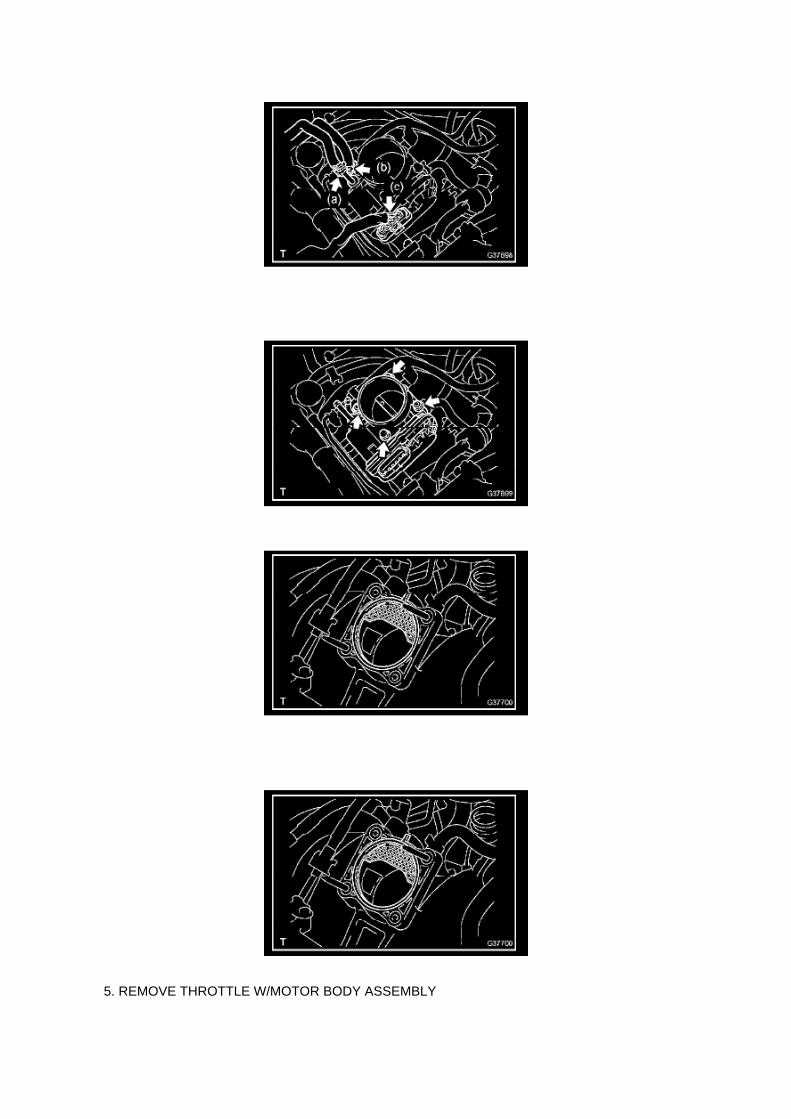
5. REMOVE THROTTLE W/MOTOR BODY ASSEMBLY

a. Disconnect the water bypass hose. b. Disconnect the water bypass hose No.2. c. Disconnect thethrottle motor connector.
d. Remove the 2 bolts and 2 nuts, then remove the throttle w/ motor body.
e. Remove the gasket from the intake manifold.
6. INSTALL THROTTLE W/MOTOR BODY ASSEMBLY
a. Install a new gasket onto the intake manifold.

Page 1982

CAN Communication System Check Sheet

Description of On-Board Diagnostics
FAIL-SAFE FUNCTION
a. When communication fails in any of the CAN bus lines (communication lines) due to a shortcircuit or any other causes, the fail-safe function,
which is specified for each system, operates to prevent the system from malfunctioning.
b. This function operates for each system when communication is impossible.
HINT:

Engine - Crankshaft Oil Seal Leak
Front Crankshaft Seal: All Technical Service Bulletins Engine - Crankshaft Oil Seal Leak
ENGINE EG025-07
Title: EG025-07
Models: '05 - '07 Tacoma (2TR-FE)
May 10, 2007
Introduction
Some Tacoma vehicles equipped with the 2TR-FE engine may exhibit an oil leak from thecrankshaft seal on the front timing cover. A new crankshaft pulley, oil seal, and SST (to install theseal) have been created to help address this condition. Follow the procedure below to replace thecrankshaft oil seal and pulley.
Applicable Vehicles
^ 2005 - 2007 model year Tacoma vehicles equipped with the 2TR-FE engine.
Parts Information
Warranty Information
Applicable Warranty*: This repair is covered under the Toyota Powertrain Warranty. This warrantyis in effect for 60 months or 60,000 miles, whichever occurs first, from the vehicle's in-service date.
* Warranty application is limited to correction of a problem based upon a customer's specificcomplaint.
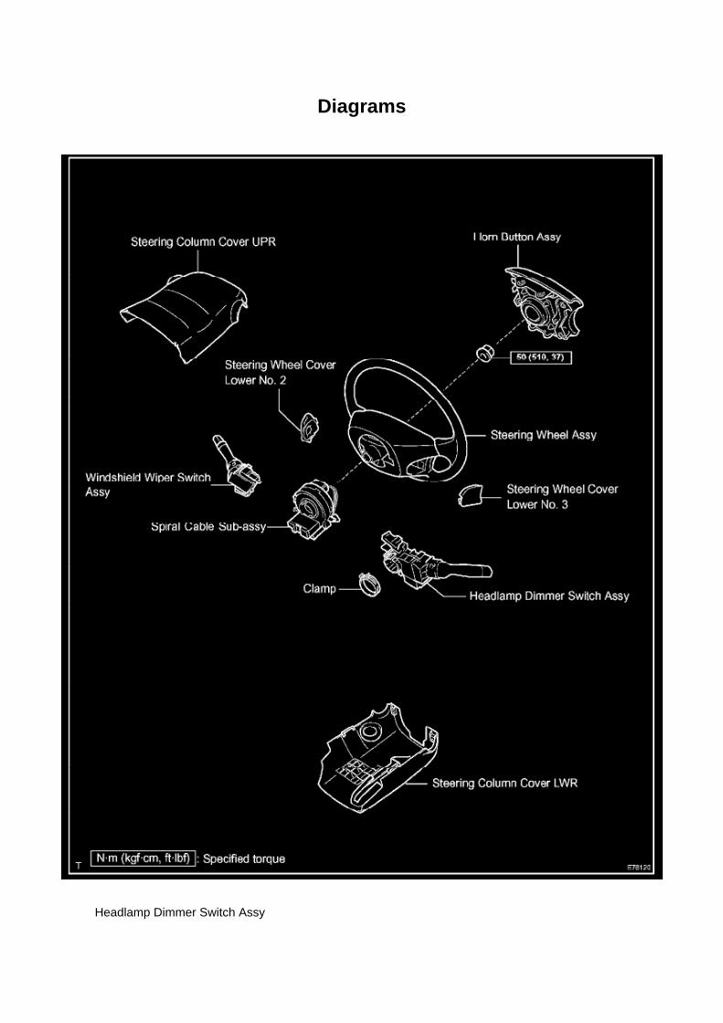
Diagrams
Headlamp Dimmer Switch Assy

Page 199

Mongoose MFC Software and Driver MUST be installed before Mongoose MFC selection will beavailable.

See TIS - Diagnostics - Scantool page for additional information.
^ If using TIS Techstream select TIS Techstream VIM (this is the default).
4. Click OK.
Operation Procedure
1. Verify the vehicle's applicability for recalibration and locate desired calibration file.
A. Connect Techstream and establish a vehicle connection.
B. Click the Health Check button on the System Select tab.

Page 644
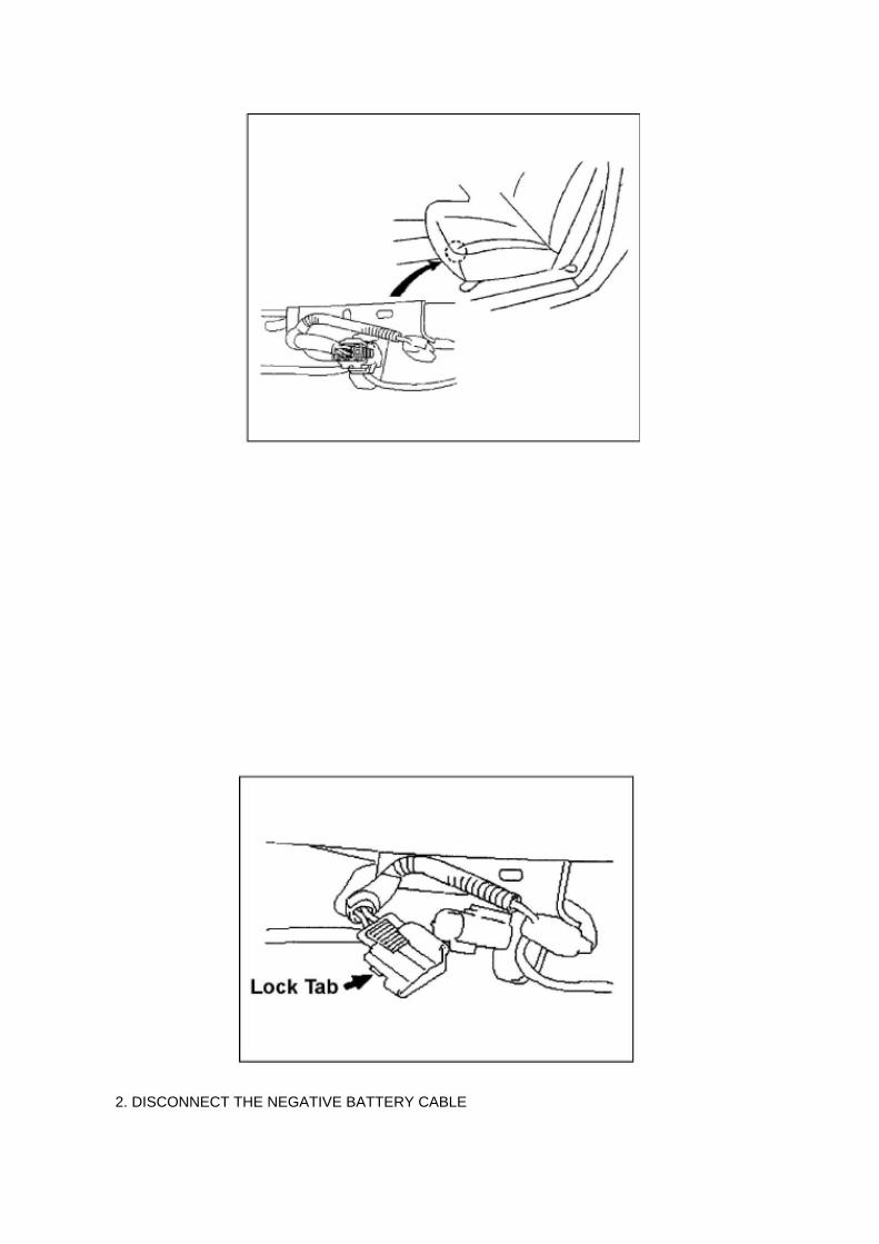
2. DISCONNECT THE NEGATIVE BATTERY CABLE

3. LOCATE THE BENCH SEAT FLOOR WIRE HARNESS
(c) Slide the bench seat to the rearmost position.
(d) Locate the floor wire harness and connector under the seat on the driver's side, closest to thefront edge of the seat cushion.
4. INSTALL THE WIRE SEAT JUMPER
NOTE:
DO NOT install the wire seat jumper on a vehicle which is NOT on the VIN list!
(a) Push the lock tab on the connector and pull to remove the female portion of the connector.
(b) Before installing the wire seat jumper to the vehicle, attach the Warning Label (shown in theillustration) onto the corrugated tubing, next to the
Part Number Label.
NOTE:
^ Attach the Warning Label in a similar manner to the Part Number Label, making sure not coverthe information printed on it.
^ DO NOT remove the Part Number Label or cover it with the Warning Label.
^ A small supply of labels were sent with the Service Manager Package. Additional labels can beordered from the Material Distribution Center (p/n 00410-92017).

Page 1411
k. Install a new gasket, then install the water by-pass pipe No.1 with the 2 nuts.
Torque: 18 Nm (178 kgf-cm, 13 ft. lbs.)
56. INSTALL OIL PAN SUB-ASSEMBLY 57. INSTALL OIL STRAINER SUB-ASSEMBLY 58.INSTALL OIL PAN SUB-ASSEMBLY NO.2 59. INSTALL OIL LEVEL GAGE SUB-ASSEMBLY 60.INSTALL CRANKSHAFT PULLEY
SST 09213-54015 (91651-60855), 09330-00021
61. INSTALL CYLINDER HEAD COVER SUB-ASSEMBLY 62. INSTALL INTAKE MANIFOLD TOHEAD GASKET NO.1 63. INSTALL CAMSHAFT POSITION SENSOR 64. INSTALLCRANKSHAFT POSITION SENSOR 65. INSTALL IDLE PULLEY ASSEMBLY W/BRACKET (W/AIR CONDITIONING) 66. INSTALL IDLER PULLEY SUB-ASSEMBLY NO.1 67. INSTALLV-RIBBED BELT TENSIONER ASSEMBLY 68. INSTALL GENERATOR ASSEMBLY 69. INSTALLINTAKE AIR CONNECTOR 70. INSTALL REAR END PLATE
a. Install the rear end plate with the 2 bolts.
Torque: 18 Nm (178 kgf-cm, 13 ft. lbs.)
71. INSTALL DRIVE PLATE & RING GEAR SUB-ASSEMBLY (AUTOMATIC TRANSMISSION)
SST 09213-54015 (91651-60855), 09330-00021
72. INSTALL FLYWHEEL SUB-ASSEMBLY (MANUAL TRANSMISSION)
SST 09213-54015 (9165-60855), 09330-00021
73. INSTALL CLUTCH DISC ASSEMBLY (MANUAL TRANSMISSION) 74. INSTALL CLUTCHCOVER ASSEMBLY (MANUAL TRANSMISSION) 75. INSTALL ENGINE ASSEMBLY 76.INSTALL AUTOMATIC TRANSMISSION ASSEMBLY 77. INSTALL MANUAL TRANSMISSIONUNIT ASSEMBLY 78. INSTALL EXHAUST PIPE ASSEMBLY FRONT 79. INSTALL EXHAUSTPIPE ASSEMBLY TAIL 80. CONNECT ENGINE WIRE 81. CONNECT AIR INJECTION SYSTEMNO.1 HOSE 82. CONNECT FUEL VAPOR FEED HOSE ASSEMBLY 83. CONNECT FUEL HOSENO.2 84. CONNECT FUEL HOSE 85. INSTALL WATER HOSE SUB-ASSEMBLY 86. INSTALLRADIATOR HOSE INLET 87. INSTALL COMPRESSOR AND MAGNETIC CLUTCH (W/ AIRCONDITIONING) 88. INSTALL RADIATOR HOSE NO.2 89. INSTALL VANE PUMP ASSEMBLY90. INSTALL AIR CLEANER CASE

a. Install the air cleaner case with the 3 bolts.
Torque: 12 Nm (122 kgf-cm, 9 ft. lbs.)
91. INSTALL AIR CLEANER FILTER ELEMENT SUB-ASSEMBLY 92. INSTALL AIR CLEANERCAP SUB-ASSEMBLY 93. INSTALL FAN SHROUD 94. INSTALL RADIATOR SUPPORT TOFRAME SEAL LH 95. INSTALL BATTERY TRAY 96. INSTALL BATTERY 97. ADD ENGINE OIL98. ADD ENGINE COOLANT 99. CHECK ENGINE OIL LEVEL
100. CHECK FOR FUEL LEAKAGE 101. CHECK FOR ENGINE COOLANT LEAKAGE

Page 1731
SFI System

Page 554

He - Wi

Recall - Floor Mat/Accelerator Pedal Interferance
Technical Service Bulletin # SSC90L Date: 091001

VSC TRAC Warning Light Circuit (Remains On)

Traction Control Indicator Lamp: Testing and Inspection VSC TRAC Warning Light Circuit(Remains On)

VSC TRAC WARNING LIGHT CIRCUIT (REMAINS ON)
CIRCUIT DESCRIPTION
When the skid control ECU stores DTCs, the VSC and TRAC functions are deactivated, the VSCTRAC warning light comes on in the combination meter.

Page 3356

Yaw Rate Sensor: Service and Repair
YAW RATE SENSOR (W/ VSC)
REPLACEMENT
1. DISCONNECT CABLE FROM NEGATIVE BATTERY TERMINAL 2. REMOVE FRONT SEATASSEMBLY (BENCH SEAT TYPE) 3. REMOVE FRONT SEAT ASSEMBLY LH (SEPARATESEAT TYPE) 4. REMOVE FRONT FLOOR FOOTREST 5. REMOVE FRONT DOOR SCUFFPLATE LH 6. REMOVE COWL SIDE TRIM BOARD LH 7. REMOVE SENSOR BRACKET
a. Turn up the floor carpet.
b. Remove the wire harness clamp. c. Remove the bolt and bracket.
8. REMOVE YAW RATE SENSOR
a. Disconnect the yaw rate sensor connector. b. Remove the 2 bolts and yaw rate sensor.
9. INSTALL YAW RATE SENSOR
a. Install the yaw rate sensor with the 2 bolts.
Torque: 12.5 Nm (127 kgf-cm, 9 ft. lbs.)
NOTICE: Make sure that the sensor is at the correct angle when installing.
b. Connect the yaw rate sensor connector.

Page 1994

Step 1 - 2

Page 295
Terminals of Control Module/Pinouts - Check Driver J/B Assy (Multiplex Network Body ECU) Part 1

A/C - Condenser Line Bolt Installation
Hose/Line HVAC: Technical Service Bulletins A/C - Condenser Line Bolt Installation
T-SB-0071-08
May 22, 2008
HVAC Condenser Line Bolts
Service Category Vehicle Interior
Section Heating/Air Conditioning
Market USA
Applicability

Introduction
To minimize cross threading of the condenser during assembly the condenser line bolts have beenchanged to tapered bolts. The tapered condenser line bolts have an increased torque specification.Refer to the table below for the proper torque specifications for the condenser line bolts.
Production Change Information
This TSB applies to vehicles produced BEFORE the Production Change Effective VINs shown.
Parts Information
Warranty Information

Page 76
Terminals Of Control Module / Pinouts Part 2

Locations

Parking Brake Warning Switch: Locations
Ha - Op
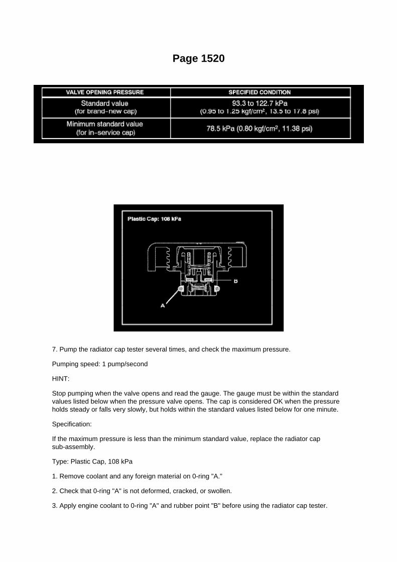
Page 1520
7. Pump the radiator cap tester several times, and check the maximum pressure.
Pumping speed: 1 pump/second
HINT:
Stop pumping when the valve opens and read the gauge. The gauge must be within the standardvalues listed below when the pressure valve opens. The cap is considered OK when the pressureholds steady or falls very slowly, but holds within the standard values listed below for one minute.
Specification:
If the maximum pressure is less than the minimum standard value, replace the radiator capsub-assembly.
Type: Plastic Cap, 108 kPa
1. Remove coolant and any foreign material on 0-ring "A."
2. Check that 0-ring "A" is not deformed, cracked, or swollen.
3. Apply engine coolant to 0-ring "A" and rubber point "B" before using the radiator cap tester.

^ Radiator Cap Tester: Snap-On/Sun P/N SVTS262A (or equivalent)
4. Before installing the radiator cap tester, use the applicable radiator cap adaptor provided in thefollowing SST kits in conjunction with the radiator cap tester:
^ SST P/N 09230-00030-01 (09231-10080-01) or 09230-00020-01 (09231-10060-01) or09230-00050-01(09231-10110-01

Recall 09V388000: Floor Mat/Accelerator Interference

Accelerator Pedal: Recalls Recall 09V388000: Floor Mat/Accelerator Interference

VEHICLE MAKE/MODEL: MODEL YEAR(S): Lexus/ES350 2007-2010 Lexus/IS 2006-2010Toyota/Avalon 2005-2010 Toyota/Camry 2007-2010 Toyota/Prius 2004-2009 Toyota/Tacoma2005-2010 Toyota/Tundra 2007-2010 MANUFACTURER: Toyota Motor Corporation
MFR'S REPORT DATE: October 05, 2009
NHTSA CAMPAIGN ID NUMBER: 09V388000
NHTSA Action Number: N/A COMPONENT: Vehicle Speed Control: Accelerator Pedal
POTENTIAL NUMBER OF UNITS AFFECTED: 3800000
SUMMARY: Toyota is recalling certain model year 2004-2010 passenger vehicles. The acceleratorpedal can get stuck in the wide open position due to its being trapped by an unsecured orincompatible driver's floor mat.
CONSEQUENCE: A stuck open accelerator pedal may result in very high vehicle speeds andmake it difficult to stop the vehicle, which could cause a crash, serious injury or death.
REMEDY: Toyota will notify owners of affected vehicles to remove any driver's floor mat and notreplace it with any other floor mat pending the development of model-specific remedies. Toyota willmail a second notification to owners of affected vehicles notifying them of the free remedies whenthey are available. The first notice is expected to be mailed during October 2009 and Toyota willadvise NHTSA of the estimated date when the remedies will be available. Owners may contactToyota at 1-800-331-4331, Lexus at 1-800-255-3987.
NOTES: Owners may also contact The National Highway Traffic Safety Administration's VehicleSafety Hotline at 1-888-327-4236 (TTY 1-800-424-9153), or go to http://www.safercar.gov.

Page 1890

Engine Control Module: Service and Repair Control Module Programming and Relearning
Precaution
PRECAUTION
1. INITIALIZATION
NOTE: Perform the REGISTRATION (VIN registration) when replacing the ECM.
2. FOR USING HAND-HELD TESTER
CAUTION: Observe the following items for safety reasons: -
Read its instruction books before using the tester.
- Prevent the tester cable from being caught on the pedals, shift lever and steering wheel whendriving with the tester connected to the vehicle.
- When driving the vehicle for testing purposes using the tester, two persons are required. One isfor driving the vehicle, and the other operates the tester.
Registration
REGISTRATION
NOTE: The Vehicle Identification Number (VIN) must be input into the replacement ECM.
HINT: The VIN is in the form of a 17-digit alphanumeric vehicle identification number. A hand-heldtester is required to resister the VIN.
1. DESCRIPTION
This registration section consists of three parts, Input Instructions, Read VIN and Write VIN. a.Input Instructions: Explains the general VIN input instructions using a hand-held tester. b. ReadVIN: Explains the VIN reading process in a flowchart. This process allows the VIN stored in theECM to be read, in order to confirm
that the two VINs, provided with the vehicle and stored in the vehicle's ECM, are the same.
c. Write VIN: Explains the VIN writing process in a flowchart. This process allows the VIN to beinput into the ECM. If the ECM is changed, or
the VIN and VIN do not match, the VIN can be registered, or overwritten in the ECM by followingthis procedure.
2. INPUT INSTRUCTIONS
a. Hand-held tester
1. The arrow buttons (UP, DOWN, RIGHT and LEFT) and numerical buttons (0 to 9) are used, inorder to input the VIN.
b. Cursor Operation
1. To move the cursor around the tester screen, press the RIGHT and LEFT buttons.
c. Alphabetical Character Input
1. Press the UP and DOWN buttons to select the desired alphabetical character. 2. After selection,the cursor should move.
d. Numeric Character Input

1. Press the numerical button corresponding to the number that you want to input. 2. After input,the cursor should move.
HINT: Numerical characters can be selected by using the UP and DOWN buttons.
e. Correction
1. When correcting the input character(s), put the cursor onto the character using the RIGHT orLEFT buttons. 2. Select or input the correct character using the UP/DOWN buttons, or thenumerical buttons.
f. Finishing Input Operation 1. Make sure that the input VIN matches the vehicle VIN after input. 2.Press the ENTER button on the tester.
3. READ VIN (Vehicle Identification Number)

Page 974

Required Tools & Equipment

ATF Level Inspection Temperature Range Table

Page 255
SFI System

Page 3320

Wiring Diagram

Page 1951

Step 1 - 2

Page 3132

d. Clamp the propeller shaft in a vise between aluminum plates. e. Using SST, push the spiderbearing out of the propeller shaft.

SST 09332-25010
HINT: Sufficiently raise the part indicated by (A) so that it does not come into contact with thespider bearing.
f. Clamp the removed spider bearing outer race in a vise and tap the propeller shaft to remove thespider bearing.
NOTICE: Do not tap the shaft tube.
HINT: Remove the spider bearing from the opposite side of the spider using the same procedure.
g. Separate the propeller w/ center bearing shaft assy.
h. Reinstall the 2 removed spider bearings onto the spider and clamp the spider bearings in a vise.i.
Using SST, push the bearing out of the yoke. SST 09332-25010
HINT: Sufficiently raise the part indicated by (A) so that it does not come into contact with thebearing.
j. Clamp the outer bearing race in a vise and tap off the yoke with a hammer.
k. Remove the spider.

Page 2027

a. Check the harness side connector (S9) of the steering angle sensor.
1. Disconnect the connector (S9) from the steering angle sensor. 2. Measure the resistanceaccording to the value(s) in the table.
5. YAW RATE SENSOR

Page 2106
Then click Next.
F. Verify correct current calibration and new calibration information. Then click Next.
NOTE
^ The total number of calibration IDs in the calibration file corresponds to the number ofreprogrammable processors in the ECU.

^ Each calibration file may contain up to three separate calibrations.

Page 500

(w/ AIR CONDITIONING)

i. Engage the engine wire harness clamp.
j. Connect the VSV connector.
k. Connect the ventilation hose No.3.
l. Connect the water bypass hose No.2.
m. Install the clamp bracket with the bolt.
Torque: 19 N.m (194 kgf.cm, 14 in.lbf)
n. Connect the vacuum hose.

Specifications
Pressure Plate: Specifications
Tighten the 6 bolts, in the order shown in the illustration, starting with the bolt located near theknock pin on the top. Torque ................................................................................................................................................................................. 19 Nm (195 kgf-cm, 14 ft. lbs.)

Page 294
Terminals of Control Module/Pinouts - Check Power Window Regulator Master Switch (ACCESSCAB)

Page 1940
Information Bus: Symptom Related Diagnostic Procedures
Symptom Index
PROBLEM SYMPTOMS TABLE
1. COMMUNICATION STOP MODE TABLE
a. Complete "CHECK CAN BUS LINE" to confirm that there is no malfunction in the CAN bus line.Select "BUS CHECK" on the hand-held
tester via the CAN VIM.
b. Check the communication stop mode of the ECUs or sensors not displayed among the following:"ENGINE", "ABS/VSC/TRAC", "YAW
/DECELERATE" or "STEERING SENSOR".
NOTE: If 2 or more ECUs or sensors are not displayed on the hand-held tester via the CAN VIM,perform troubleshooting for the communication stop mode of each un-displayed ECU or sensor.

(Either side of the CAN sub bus lines may be open)
2. DTC COMBINATION TABLE
a. Perform troubleshooting according to the combination of DTCs output.
HINT: -
Previous CAN communication system DTCs may be the cause if CAN communication systemDTCs are output and all ECUs and sensors connected to the CAN communication system aredisplayed on` the hand-held tester's "BUS CHECK" screen via the CAN VIM.
- U0073/94, U0123/62, U0124/95, U0126/63 and U0100/65 are the DTCs in the CANcommunication system.
- *2 ... U0100/65 is output if no power is supplied to the ECM.
- The table shows combinations of these DTCs.
- ... DTCs that are being output.
- ... DTCs that are not being output.
- SKID CONTROL ECU COMMUNICATION STOP MODE:
- STEERING ANGLE SENSOR COMMUNICATION STOP MODE:
- YAW RATE SENSOR COMMUNICATION STOP MODE:
- ECM COMMUNICATION STOP MODE: replace ECM.
Skid Control ECU Communication Stop Mode
SKID CONTROL ECU COMMUNICATION STOP MODE

Page 2614

Camshaft Position Sensor: Service and Repair

REPLACEMENT
1. DISCONNECT CABLE FROM NEGATIVE BATTERY TERMINAL 2. REMOVE CAMSHAFTPOSITION SENSOR
a. Disconnect the camshaft position sensor connector. b. Remove the bolt, then remove thecamshaft position sensor.
3. INSTALL CAMSHAFT POSITION SENSOR
a. Apply a light coat of engine oil to the O-ring of the camshaft position sensor.
b. Install the camshaft position sensor with the bolt.
Torque: 8.5 N.m (87 kgf.cm, 75 in.lbf)
NOTE: Make sure that the O-ring is not cracked or jammed when installing.
c. Connect the camshaft position sensor connector.
4. CONNECT CABLE TO NEGATIVE BATTERY TERMINAL
Torque: 3.9 N.m (40 kgf.cm, 35 in.lbf)

Page 3024
f. Check the clutch release point.
(1) Pull the parking brake lever and use wheel chocks. (2) Start the engine and allow it to idle. (3)Without depressing the clutch pedal, slowly move the shift lever into the reverse position until thegears engage. (4) Gradually depress the clutch pedal and measure the stroke distance from thepoint that the gear noise stops (release point) up to the full
stroke end position.
Standard distance: 25 mm (0.984 inch) or more (From pedal stroke end position to release point) Ifthe distance is not as specified, perform the following operations. ^
Check the pedal height.
^ Check the push rod play and pedal free play.
^ Bleed the clutch line.
^ Check the clutch cover assy and disc assy.

Page 3323
b. Turn the ignition switch on. Follow the on-screen directions on the hand-held tester to display theDATA LIST and select areas which should be
monitored for momentary interruptions.
HINT: A momentary interruption (open circuit) cannot be detected for 3 seconds after the ignitionswitch is turned on (initial check).
HINT: -
If the hand-held tester status remains open, check the continuity between the ECU and thesensors, or between ECUs.
- The OPEN display on the hand-held tester remains on for 1 second after the harness signalchanges from momentary interruption (open circuit) to normal condition.
c. While observing the screen, gently jiggle the connector or wire harness between the ECU andsensors, or between ECUs.
OK: OPEN-screen display does not change.
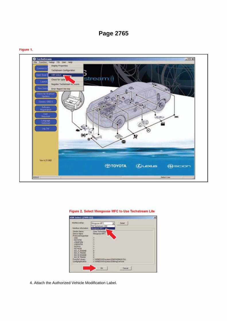
Page 2765
4. Attach the Authorized Vehicle Modification Label.

Modifications to ECU calibrations MUST be recorded and properly displayed on the vehicle usingthe Authorized Modification Label.
Techstream Preparation
Selecting the TIS Techstream VIM or the Mongoose MFC VIM.
Techstream software requires a VIM selection before you can use the Mongoose MFC VIM.
If using TIS Techstream no changes are needed.
Perform the following:
1. Select Setup from the Techstream Main Menu screen.
2. Select VIM Select from the Setup drop down menu.
3. Select the correct Interface Setup from the drop down list.
^ If using Techstream Lite select Mongoose MFC.
NOTE

Page 54

Engine Room R/B, J/B - Engine Compartment Left
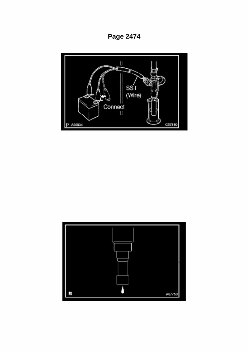
Page 2474

13. Connect SST (wire) to the injector and the battery for 15 seconds, and measure the injectionvolume with a graduated cylinder. Test each
injector 2 or 3 times.
SST 09842-30080
Volume: 71 to 86 cu.cm (4.3 to 5.2 cu in.) per 15 seconds Difference between each injector: 15cu.cm (0.9 cu in.) or less
If the injection volume is not as specified, replace the injector.
c. Check the leakage.
1. In the condition above, disconnect the tester probes of SST (wire) from the battery and check thefuel leakage from the injector.
Fuel drop: 1 drop or less in 12 minutes

Page 880

2. Pinch the retainer as illustrated, then pull the fuel tube connector out of the pipe.

3. If the fuel tube connector and pipe are stuck, pinch the pipe and push and pull the fuel tubeconnector to release it.
NOTE: Never use any tools.
4. After disconnecting the fuel tube, check the sealing surface of the pipe for dirt and mud.
If dirty, wipe it with a shop rag.
5. Cover the disconnected fuel tube connector and pipe with a vinyl bag to prevent damage and theintrusion of foreign objects.
d. Take the following precautions when installing the fuel tube connector.
1. Align the fuel tube connector with the pipe, then push in the fuel tube connector until the retainermakes a "click" sound.

Page 3126

d. Using SST, push the spider bearing out of the propeller shaft.

SST 09332-25010
HINT: Sufficiently raise the part indicated by (A) so that it does not come into contact with thespider bearing.
e. Clamp the spider bearing outer race in a vise and tap off the propeller shaft with a hammer.
HINT: Remove the bearing on opposite side in the same procedure.
NOTICE: Do not tap the shaft.
f. Install the 2 removed spider bearing outer races onto the spider, and clamp them in a vise.
g. Using SST, push the bearing out of the yoke.
SST 09332-25010
HINT: Sufficiently raise the part indicated by (A) so that it does not come into contact with thebearing.
h. Clamp the outer bearing race in a vise and tap off the flange yoke with a hammer. i.
Remove the spider.

Page 2941
Components
Repair Procedure

1. Record all radio presets before starting.
2. Disconnect the negative (-) battery terminal cable.
3. Remove the clutch pedal sub-assembly.

Page 2848
Shifter A/T: Service and Repair

FLOOR SHIFT ASSY

Page 1490
is pink, premixed ethylene glycol concentration is approximately 50 % and freezing temperature is-35°C (-31°F)) is recommended.
NOTICE: Do not substitute plain water for engine coolant.
e. Check the coolant level inside the radiator by squeezing the inlet and outlet radiator hosesseveral times by hand. If the coolant level goes
down, add coolant.
f. Install the radiator cap securely.
g. Slowly pour coolant into the radiator reservoir until it reaches the FULL line.
h. Warm up the engine until the cooling fan operates.
- Set the air conditioning as follows while warming up the engine.
i. Squeeze the inlet and outlet radiator hoses several times by hand while warning up the engine.
j. Stop the engine and wait until the coolant cools down.
k. Remove the radiator cap and check the coolant level inside the radiator. l.
If the coolant level is below the full level, perform the steps from (d) through
k. and repeat the operation until the coolant level remains at the full level. m. Check the coolantlevel inside the radiator reservoir tank again. If it is below the full level, add coolant. n. Install theengine under cover No.1 with the 4 bolts. (PRE RUNNER AND 4WD TYPE)
Torque: 30 Nm (306 kgf-cm, 22 ft. lbs.)
3. CHECK FOR ENGINE COOLANT LEAKAGE

Page 238

a. Read VIN using a hand-held tester.

4. WRITE VIN

Page 3237
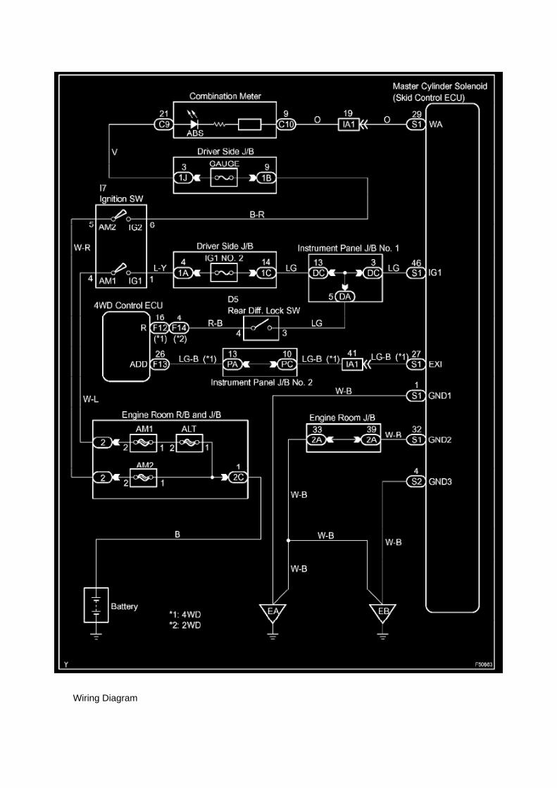
Wiring Diagram

Page 3342
ABS With EBD & BA & TRAC & VSC SYSTEM

Locations
Oil Pressure Sender: Locations

A/C - Ge

Page 1028
Driver Side J/B - Lower Finish Panel
Details

Locations

Key Reminder Switch: Locations
Ha - Op

Page 2503
Parts Information
Required Tools & Material

Required SSTs
Repair Procedure
1. Using the Diagnostic Tester, check for Diagnostic Trouble Codes (DTCs). If DTC P0456 orP0445, and P0441 are present, check for an EVAP leak on top of the fuel suction platesub-assembly. Refer to the Technical Information System (TIS), 2005 model year Tacoma RepairManual: Diagnostics: SFI System (1GR-FE) / (2TR-FE): EVAP Inspection Procedure.
If NO EVAP leaks are detected at the fuel suction plate sub-assembly, this TSB does NOT apply.Please refer to the normal diagnostic procedure provided in the Repair Manual.
2. To correct the fuel suction plate sub-assembly, replace the fuel suction with pump and gaugetube assembly, retainer ring and gasket set according to TIS, 2005 model year Tacoma RepairManual: Fuel: Fuel Pump Assy: Removal & Installation And Disassembly & Reassembly (Tacoma).

Page 1706
b. Install the grommet, a new lock washer and the nut.
Torque: 6.9 Nm (70 kgf-cm, 61 inch lbs.)
c. Install the manual valve lever shaft onto the groove and turn it 2 notches counterclockwise to theneutral position. d. Align the neutral basic line with the switch groove and tighten the adjusting bolt.
Torque: 13 Nm (130 kgf-cm, 9 ft. lbs.)
e. Bend the tabs of the lock washer.
HINT: Bend at least 2 of the lock washer tabs.
5. CONNECT PARK/NEUTRAL POSITION SWITCH CONNECTOR 6. CONNECT CABLE TONEGATIVE BATTERY TERMINAL
Torque: 3.9 Nm (40 kgf-cm, 35 inch lbs.)
7. INSPECT PARK/NEUTRAL POSITION SWITCH ASSY 8. ADJUST PARK/NEUTRAL POSITIONSWITCH ASSY 9. ADJUST SHIFT LEVER POSITION
10. INSPECT SHIFT LEVER POSITION

Page 3000
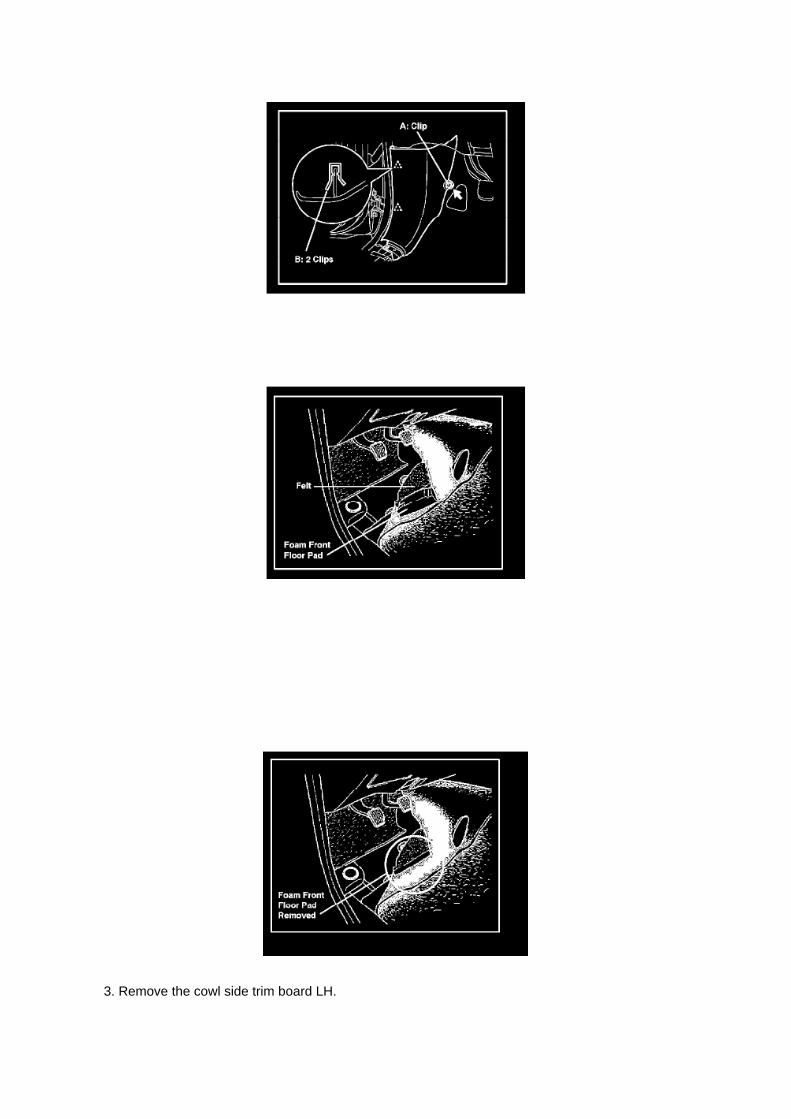
3. Remove the cowl side trim board LH.

A. Remove the clip.
B. Disengage the 2 clips and remove the cowl side trim board.
4. Cut the carpet felt backing (padding).
A. Turn over the left front portion of the floor carpet.
B. Mark the position where the foam front floor pad is located before removing.
NOTE:
^ Color of previous front floor pad (P/N 58571-04060): Cream Yellow
^ Color of NEW front floor pad (P/N 58571-04070): Black
C. Remove the foam front floor pad from the backside of the floor carpet.

Page 1922
Diagnostic Trouble Code Chart
Use Diagnostic Trouble Codes (DTCs) (from the DTC checks) in the table to determine the troublearea and proper inspection procedure. The Supplemental Restraint System (SRS) DTC chart isshown as an example.
Problem Symptoms Table

PROBLEM SYMPTOMS TABLE

Page 3122
d. Inspect the axle shaft deviation.
(1) Using a dial indicator, check the distortion of the surface of the axle shaft.
Maximum: 0.05 mm (0.0020 inch) If the deviation exceeds the maximum, replace the bearing.

Locations

A/C - Fo

Engine - Cylinder Head Cover Baffle Precautions
Valve Cover: Technical Service Bulletins Engine - Cylinder Head Cover Baffle Precautions
T-SB-0038-08
April 16, 2008

Cylinder Head Cover Baffle Precautions
Service Category General
Section Maintenance
Market USA
Applicability
Introduction
To prevent damaging the baffle located inside the cylinder head cover care must be taken whenadding engine oil. The baffle is designed to deflect oil and should not be used to support the weightof oil fill devices. Rough treatment or the weight of this equipment can place unnecessary stress onthe baffle and damage it. Follow the precautions below to avoid damaging the baffle when addingengine oil.
Warranty Information
Oil Filling Precautions

Page 1840
ABS With EBD System

Page 1398

Page 932

3. Install the fuel tank protector cover on top of the fuel suction plate sub-assembly as shown in theillustration.

Page 186
Instrument Panel J/B No. 2 Inner Circuit

Page 3329
Step 1 - 2

Page 209

M. Turn ignition OFF for a minimum of 10 seconds. Then click Next.

N. Turn ignition to the ON position. Then click Next.
0. Confirm all calibrations were updated as specified in the service bulletin. Then click Finish.

Page 570

a. Apply a light coat of engine oil to the O-ring of the crankshaft position sensor.

b. Install the camshaft position sensor with the bolt.
Torque: 8.5 N.m (87 kgf.cm, 75 in.lbf)
NOTE: Make sure that the O-ring is not cracked or jammed when installing.
c. Connect the crankshaft position sensor connector and the 2 wire harness clamps.
8. INSTALL IDLE PULLEY ASSEMBLY W/BRACKET (W/ AIR CONDITIONING)

Page 1923
Problem Symptoms Table
The suspected circuits or parts for each problem symptom are shown in the table . Use this table totroubleshoot when, during a DTC check, a "Normal" code is displayed but the problem is stilloccurring. Numbers in the table show the inspection order in which the circuits or parts should bechecked.
HINT: In some cases, the problem is not detected by the diagnostic system even though a problemsymptom is present. It is possible that the problem is occurring outside the detection range of thediagnostic system, or that the problem is occurring in a completely different system.

Locations
A/C - Ge

Page 1255
e. Subtract the piston pin diameter measurement from the bushing inside diameter measurement.
Standard oil clearance: 0.005 to 0.011 mm (0.0002 to 0.0004 inch) Maximum oil clearance: 0.025mm (0.0010 inch) If the oil clearance is greater than the maximum, replace the bushing. Ifnecessary, replace the connecting rod and piston pin as a set.

System Diagnosis
Idle Speed: Testing and Inspection
INSPECT ENGINE IDLING SPEED

a. When using a hand-held tester:
(1) Connect the hand-held tester to the DLC3. (2) Turn the ignition switch to ON. (3) Turn thehand-held tester ON. (4) Start the engine and warm it up. (5) Select the following menu items:DIAGNOSIS / ENHANCED OBD II / DATA LIST / PRIMARY / ENGINE SPD.
Idling speed: 600 to 700 rpm
NOTICE: -
Turn all electrical systems OFF.
- When checking the idling speed, the transmission is in the neutral position.
HINT: Refer to the hand-held tester operator's manual for further in formation regarding theselection of DATA LIST.
b. When not using a hand-held tester:
(1) Turn the ignition switch to ON. (2) Start the engine and warm it up. (3) Install SST onto terminal9 (TAC) of the DLC3. Connect a tachometer, then measure the engine idling speed. SST09843-18030 Idling speed: 600 to 700 rpm
NOTICE: -
Turn all electrical systems OFF.
- When checking the idling speed, the transmission should be in the neutral position.

Specifications

Axle Nut: Specifications

Hub Nut ........................................................................................................................................................................ 235 Nm (2,396 kgf-cm, 173 ft. lbs.)

Page 1687

He - Wi

M/T - Clutch Pedal Squeaking Noise
Technical Service Bulletin # TC004-06 Date: 060614
M/T - Clutch Pedal Squeaking Noise
TRANSMISSION & CLUTCH TC004-06
June 14, 2006
Title: CLUTCH PEDAL SQUEAK NOISE
Models: '05 - '06 Tacoma
Introduction
Some customers may complain about a "squeak" or "creak" noise when depressing or releasingthe clutch pedal. The clutch master cylinder clevis assembly has been improved to eliminate thiscondition.
Applicable Vehicles: ^
2005 - 2006 model year Tacoma vehicles equipped with manual transmission and producedBEFORE the Production Change Effective VIN shown below.
Production Change Information

Parts Information
Required Tools & Material
Warranty Information
Applicable Warranty:
This repair is covered under the Toyota Comprehensive Warranty. This warranty is in effect for 36months or 36,000 miles, whichever occurs first, from the vehicle's in-service date.
* Warranty application is limited to correction of a problem based upon a customer's specificcomplaint.

Locations

Fuel Pump Relay: Locations
Engine Room R/B, J/B - Engine Compartment Left

Page 1611

Main Relay (Computer/Fuel System): Testing and Inspection

INSPECT E.F.I. CIRCUIT OPENING RELAY ASSEMBLY
a. Check the resistance.
1. Using an ohmmeter, measure the resistance between the terminals.
If the result is not as specified, replace the E.F.I. circuit opening relay assembly.
INSPECT EFI RELAY
a. Check the resistance.
1. Using an ohmmeter, measure the resistance between the terminals.
If the result is not as specified, replace the E.F.I. ECU relay.

Page 1143

Driver Side J/B Inner Circuit

Page 1919

normally or lead to repairs not pertinent to the problem. Follow the procedures listed in theflowchart in the correct order.
Steps 4 - 6
- A flowchart showing how to proceed with troubleshooting using the DTC check is shown.Directions from the flowchart will indicate how to proceed either to DTC troubleshooting or to thetroubleshooting of each problem symptom.
Symptom Simulation

Page 3181

Ac - Ya

Page 177
Driver Side J/B - Lower Finish Panel

Page 1761
o. Connect the fuel vapor feed hose to the VSV.
12. CONNECT FUEL HOSE 13. CONNECT FUEL HOSE NO.2 14. INSTALL THROTTLEW/MOTOR BODY ASSEMBLY 15. INSTALL INTAKE AIR CONNECTOR 16. CONNECT CABLETO NEGATIVE BATTERY TERMINAL
Torque: 3.9 N.m (40 kgf.cm, 35 in.lbf)
17. ADD ENGINE COOLANT 18. CHECK FOR ENGINE COOLANT LEAKAGE 19. CHECK FORFUEL LEAKAGE 20. INSTALL ENGINE UNDER COVER SUB-ASSEMBLY NO.1 (PRE RUNNERAND 4WD TYPE)

Locations

Oxygen Sensor Relay: Locations
Engine Room R/B, J/B - Engine Compartment Left

Page 1369

b. Using SST, loosen the crankshaft pulley bolt.

SST 09213-54015 (91651-60855), 09330-00021
HINT: Loosen the crankshaft pulley bolt until only 2 or 3 threads are still installed in the crankshaft.
c. Using SST, remove the crankshaft pulley and crankshaft pulley bolt.
SST 09950-50013 (09951-05010, 09952-05010, 09953-05010, 09954-05021)
44. REMOVE OIL LEVEL GAGE SUB-ASSEMBLY
45. REMOVE OIL PAN SUB-ASSEMBLY NO.2
a. Remove the 18 bolts and 2 nuts.
b. Insert the blade of SST between the pans. Cut through the applied sealer and remove the oilpan.
SST 09032-00100
NOTICE: Be careful not to damage the contact surface of the oil pans.

ABS/TCS - Zero Point Calibration Information
Yaw Rate Sensor: Technical Service Bulletins ABS/TCS - Zero Point Calibration Information
T-SB-0020-08
March 25, 2008
Disconnect Battery & Perform Zero Point Calibration After Wheel Alignment Adjustment
Service Category Brake
Section Brake Control/Dynamic Control System
Market USA
Applicability
Introduction
The purpose of this TSB is to provide information on when and how to perform the zero pointcalibration on vehicles equipped with Vehicle Stability Control (VSC). Momentarily disconnectingthe battery is a necessary step for performing the zero point calibration.
Warranty Information
Required Tools & Equipment
^ Additional TIS techstream units may be ordered by calling Approved Dealer Equipment (ADE).
^ The Toyota Diagnostic Tester and CAN Interface Module may also be used to perform theservice procedures listed in this bulletin.
Preliminary Information
Perform this procedure if any of these repairs have been performed on the vehicle:
^ Wheel alignment has been adjusted.
^ Any chassis components have been removed/installed or replaced.

Page 101
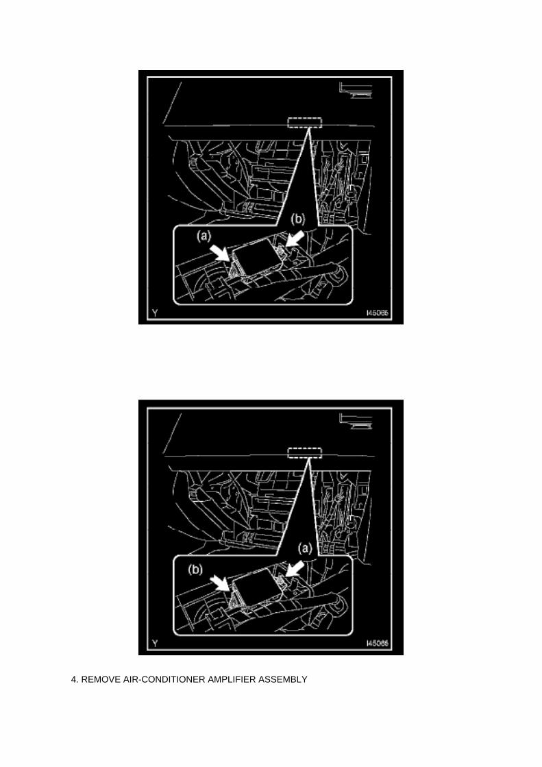
4. REMOVE AIR-CONDITIONER AMPLIFIER ASSEMBLY

a. Disconnect the connector. b. Remove the nut and the air-conditioner amplifier assembly.
5. INSTALL AIR-CONDITIONER AMPLIFIER ASSEMBLY
a. Install the air-conditioner amplifier assembly with the nut.
Torque: 7.0 N.m (71 kgf.cm, 62 in.lbf)
b. Connect the connector.
6. INSTALL INSTRUMENT PANEL FINISH PANEL SUB-ASSEMBLY LOWER RH 7. INSTALLGLOVE COMPARTMENT DOOR ASSEMBLY 8. CONNECT CABLE TO NEGATIVE BATTERYTERMINAL
Torque: 3.9 N.m (40 kgf.cm, 35 in.lbf)

Recall 05V302000: Seat Belt Position Sensor Defect

Seat Belt Buckle Switch: All Technical Service Bulletins Recall 05V302000: Seat Belt PositionSensor Defect
MAKE/MODELS: MODEL/BUILD YEARS: Toyota/Tacoma 2005 MANUFACTURER: Toyota MotorNorth America, Inc. NHTSA CAMPAIGN ID NUMBER: 05V302000 RECALL DATE: June 27, 2005
COMPONENT: Air Bags
POTENTIAL NUMBER OF UNITS AFFECTED: 11592
SUMMARY: On certain regular cab pickup trucks equipped with a bench seat, the seat position andseat belt buckle sensor connector pins are incorrectly positioned due to a wire harnessmanufacturing process error.
CONSEQUENCE: In this condition, the seat position and seat belt buckle sensor may not functionas designed, affecting the adaptive air bag deployment, which if the vehicle is involved in a crash,could result in improper occupant restraint.
REMEDY: Dealers will inspect the seat position and seat belt fastening condition sensor connector.An additional sub-wire harness will be installed to correct the connector pin manufacturing error, ifnecessary. The recall is expected to begin during late July 2005. Owners should contact Toyota at1-800-431-4331.
NOTES: Customers can also contact The National Highway Traffic Safety Administration's VehicleSafety Hotline at 1-888-327-4236 (TTY 1-800-424-9153), or go to http://www.safercar.gov.

Page 1988
Step 3
INSPECTION PROCEDURE
Yaw Rate Sensor Communication Stop Mode
YAW RATE SENSOR COMMUNICATION STOP MODE
MODE DESCRIPTION

Page 166
Circuit Inspection

Voltage Check
VOLTAGE CHECK

Page 2003

Step 15 - 17

INSPECTION PROCEDURE
Check CAN Bus Line For Short to GND
CHECK CAN BUS LINE FOR SHORT TO GND
CIRCUIT DESCRIPTION
A short to GND is suspected in the CAN bus line when there is continuity between terminals 4 (CG)and 6 (CANH) or terminals 4 (CG) and 14 (CANL) of the DLC3.
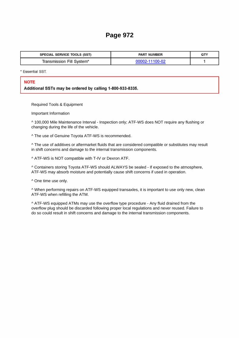
Page 972
Required Tools & Equipment
Important Information
^ 100,000 Mile Maintenance Interval - Inspection only; ATF-WS does NOT require any flushing orchanging during the life of the vehicle.
^ The use of Genuine Toyota ATF-WS is recommended.
^ The use of additives or aftermarket fluids that are considered compatible or substitutes may resultin shift concerns and damage to the internal transmission components.
^ ATF-WS is NOT compatible with T-IV or Dexron ATF.
^ Containers storing Toyota ATF-WS should ALWAYS be sealed - If exposed to the atmosphere,ATF-WS may absorb moisture and potentially cause shift concerns if used in operation.
^ One time use only.
^ When performing repairs on ATF-WS equipped transaxles, it is important to use only new, cleanATF-WS when refilling the ATM.
^ ATF-WS equipped ATMs may use the overflow type procedure - Any fluid drained from theoverflow plug should be discarded following proper local regulations and never reused. Failure todo so could result in shift concerns and damage to the internal transmission components.

Page 3023

Clutch Pedal Assembly: Adjustments

CLUTCH PEDAL SUB-ASSY
ADJUSTMENT
1. INSPECT AND ADJUST CLUTCH PEDAL SUB-ASSY
a. Lift the floor carpet.
b. Check that the pedal height is correct.
Pedal height from asphalt sheet: 168.5 to 178.5 mm (6.634 to 7.028 inch)
c. Adjust the pedal height.
(1) Loosen the lock nut and turn the stopper bolt until the height is correct. Tighten the lock nut.
Torque: 25 Nm (250 kgf-cm, 18 ft. lbs.)
d. Check that the pedal free play and push rod play are correct.
(1) Depress the pedal until the clutch resistance begins to be felt.
Pedal free play: 5.0 to 15.0 mm (0.197 to 0.591 inch)
(2) Gently depress the pedal until the resistance begins to increase a little.
Push rod play at pedal top: 1.0 to 5.0 mm (0.039 to 0.197 inch)
e. Adjust the pedal free play and push rod play.
(1) Loosen the lock nut and turn the push rod until the free play and push rod play are correct. (2)Tighten the lock nut. (3) After adjusting the pedal free play, check the pedal height. (4) Connect theair duct and install the lower finish panel.

Page 732

(c) Confirm that the scan tool displays the data shown below and in the illustration.

^ "D SEAT POSITIFORWARD"
(Driver's seat is in the forward position).
^ "D BUCKLE SW.....SET"
(Driver's seat belt buckle switch is set/buckled).
3. TEST RESULTS
(a) If ALL four test results are OK the vehicle has been repaired, proceed to step "4. REMOVE THESCAN TOOL.
(b) In the UNLIKELY event that the test results are NG, refer to the troubleshooting flowchartlocated in section "VII. APPENDIX".
4. REMOVE THE SCAN TOOL
(a) Turn the scan tool OFF by pressing the "EXIT and "# " button simultaneously.
(b) Turn the ignition switch "OFF".
(c) Disconnect the scan tool from the DLC3 connector.
VI. SSC Completion Label Installation
After completing the repair and before returning the vehicle to the owner, an SSC completion label,which is enclosed in the owner's notification letter, must be affixed to the left front door hinge post,near the check strap.
(a) The label is to be filled out as follows:
^ Write in SSC 50I.
^ Write in date of repair.
^ Write in your dealer code.
(b) Additional SSC completion labels, in sheets of 50 (P/N 00410-01917), may be ordered throughthe non-parts system on a 1450 order form or
through the TDN system.

Page 2644

Camshaft Position Sensor: Service and Repair

REPLACEMENT
1. DISCONNECT CABLE FROM NEGATIVE BATTERY TERMINAL 2. REMOVE CAMSHAFTPOSITION SENSOR
a. Disconnect the camshaft position sensor connector. b. Remove the bolt, then remove thecamshaft position sensor.
3. INSTALL CAMSHAFT POSITION SENSOR
a. Apply a light coat of engine oil to the O-ring of the camshaft position sensor.
b. Install the camshaft position sensor with the bolt.
Torque: 8.5 N.m (87 kgf.cm, 75 in.lbf)
NOTE: Make sure that the O-ring is not cracked or jammed when installing.
c. Connect the camshaft position sensor connector.
4. CONNECT CABLE TO NEGATIVE BATTERY TERMINAL
Torque: 3.9 N.m (40 kgf.cm, 35 in.lbf)

Page 1615
SFI System

Page 1105
Example: (1) Indicates Relay Block No.1

C: ( ) is used to indicate different wiring and connector, etc. when the vehicle model, engine type,or specification is different.
D: Indicates related system.
E: Indicates the wiring harness and wiring harness connector. The wiring harness with maleterminal is shown with arrows.
Outside numerals are pin numbers.
The first letter of the code for each wiring harness and wiring harness connector(s) indicates thecomponent's location, e.g, "E" for the Engine Compartment, "I" for the Instrument Panel andSurrounding area, and "B" for the Body and Surrounding area.
When more than one code has the first and second letters in common, followed by numbers (e.g,IH1, IH2), this indicates the same type of wiring harness and wiring harness connector.
F: Represents a part (all parts are shown in sky blue). The code is the same as the code used inparts position.
G: Junction Block (The number in the circle is the J/B No. and the connector code is shown besideit). Junction Blocks are shaded to clearly separate
them from other parts.
H: Indicates the wiring color.
Wire colors are indicated by an alphabetical code. B = Black L = Blue R = Red P = Pink O =Orange W = White V = Violet G = Green Y = Yellow BR = Brown SB = Sky Blue LG = Light GreenGR = Gray
The first letter indicates the basic wire color and the second letter indicates the color of the stripe.

Locations

Air Flow Meter/Sensor: Locations

He - Wi

Page 2973

B. Remove the cowl side trim board.

C. Remove the instrument panel finish panel lower No. 1.
D. Remove the driver's side Junction Block.
E. Remove the turnover (compression) spring.
F. Remove the bolt attached to the instrument panel reinforcement assembly.

Page 3307

Repair Procedure

1. Disconnect the cable from the negative (-) battery terminal for MORE THAN two (2) seconds.
2. Reconnect the cable to the negative (-) battery terminal.
3. Perform the applicable zero point calibration of the yaw rate sensor and/or the steering anglesensor.
HINT Refer to the applicable TSB or Repair Manual for the zero point calibration procedure.
4. Re-initialize all applicable systems available on the vehicle (power window sunroof power liftdoor etc.).
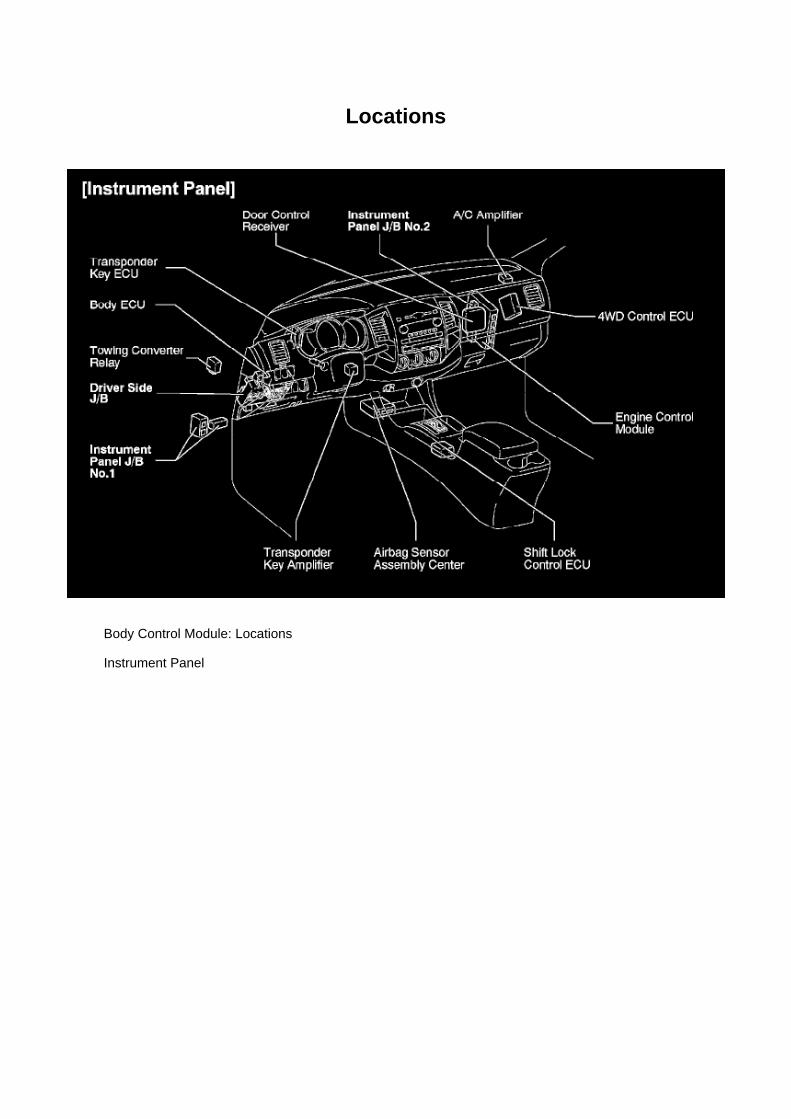
Locations
Body Control Module: Locations
Instrument Panel

Locations
Engine Room R/B No. 2 - Engine Compartment Left

Page 625

Safing Sensor: Testing and Inspection

AIRBAG SENSOR ASSEMBLY CENTER (VEHICLE NOT INVOLVED IN COLLISION)
a. Perform a diagnostic system check.
Refer to Air Bag Systems; Testing and Inspection.
AIRBAG SENSOR ASSEMBLY CENTER (VEHICLE INVOLVED IN COLLISION AND AIRBAG ISNOT DEPLOYED)
a. Perform a diagnostic system check.
Refer to Air Bag Systems; Testing and Inspection.
AIRBAG SENSOR ASSEMBLY CENTER (VEHICLE INVOLVED IN COLLISION AND AIRBAG ISDEPLOYED)
a. Replace the airbag sensor assembly center.
CAUTION: For removal and installation procedures of the airbag sensor assembly center, see"Replacement" and be sure to follow the correct procedure.
HINT: The airbag sensor assembly center should be replaced after any of the airbags hasdeployed, as it has been subjected to an impact.

Page 943

Oil Filter: Tools and Equipment

Toyota Oil Filter Wrench Set
AST tool# TOY 300
This set includes our tool numbers TOY640, TOY730, and M0219. With the TOY300 you haveevery gas engine Toyota/Lexus model covered between 1980 and 2009.
- Covers all Toyota and Lexus vehicles 1980-2009, based on factory filters.
Contact AST for pricing.
Assenmacher Specialty Tools 1-800-525-2943
This Kit Contains the Following Tools:
TOY 640 - Toyota Oil Filter Wrench

Page 2620

Crankshaft Position Sensor: Service and Repair

REPLACEMENT
1. DISCONNECT CABLE FROM NEGATIVE BATTERY TERMINAL 2. REMOVE ENGINE UNDERCOVER SUB-ASSEMBLY NO.1 (PRE RUNNER AND 4WD TYPE) 3. REMOVE FAN ANDGENERATOR BELT (W/ AIR CONDITIONING) 4. REMOVE COMPRESSOR AND MAGNETICCLUTCH (W/ AIR CONDITIONING) 5. REMOVE IDLE PULLEY ASSEMBLY W/BRACKET (W/ AIRCONDITIONING)
a. Remove the 5 bolts, then remove the idle pulley with bracket.
6. REMOVE CRANKSHAFT POSITION SENSOR
a. Disconnect the crankshaft position sensor connector and the 2 wire harness clamps.
b. Remove the bolt, then remove the crankshaft position sensor.
7. INSTALL CRANKSHAFT POSITION SENSOR

Page 3315
Step 1 - 2

Page 1427

Tip clearance

If the tip clearance is greater than the maximum, replace the timing chain cover.
7. INSPECT ROTOR BODY CLEARANCE
a. Check the body clearance.
(1) Using a feeler gauge, measure the clearance between the timing chain cover and driven rotor,as shown in the illustration.
Body clearance
If the body clearance is greater than the maximum, replace the timing chain cover.
8. INSPECT ROTOR SIDE CLEARANCE
a. Check the side clearance.
(1) Using a feeler gauge and precision straight edge, measure the clearance between the rotorsand precision straight edge, as shown in the
illustration.
Side clearance
If the side clearance is greater than the maximum, replace the timing chain cover.
9. INSTALL OIL PUMP ROTOR SET
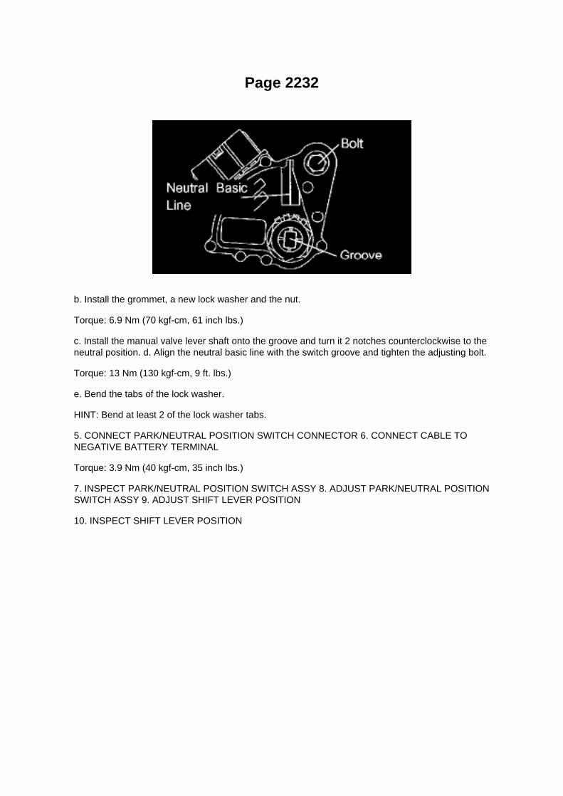
Page 2232
b. Install the grommet, a new lock washer and the nut.
Torque: 6.9 Nm (70 kgf-cm, 61 inch lbs.)
c. Install the manual valve lever shaft onto the groove and turn it 2 notches counterclockwise to theneutral position. d. Align the neutral basic line with the switch groove and tighten the adjusting bolt.
Torque: 13 Nm (130 kgf-cm, 9 ft. lbs.)
e. Bend the tabs of the lock washer.
HINT: Bend at least 2 of the lock washer tabs.
5. CONNECT PARK/NEUTRAL POSITION SWITCH CONNECTOR 6. CONNECT CABLE TONEGATIVE BATTERY TERMINAL
Torque: 3.9 Nm (40 kgf-cm, 35 inch lbs.)
7. INSPECT PARK/NEUTRAL POSITION SWITCH ASSY 8. ADJUST PARK/NEUTRAL POSITIONSWITCH ASSY 9. ADJUST SHIFT LEVER POSITION
10. INSPECT SHIFT LEVER POSITION

Page 709

(c) Confirm that the scan tool displays the data shown below and in the illustration.

^ "D SEAT POSITIFORWARD"
(Driver's seat is in the forward position).
^ "D BUCKLE SW.....SET"
(Driver's seat belt buckle switch is set/buckled).
3. TEST RESULTS
(a) If ALL four test results are OK the vehicle has been repaired, proceed to step "4. REMOVE THESCAN TOOL.
(b) In the UNLIKELY event that the test results are NG, refer to the troubleshooting flowchartlocated in section "VII. APPENDIX".
4. REMOVE THE SCAN TOOL
(a) Turn the scan tool OFF by pressing the "EXIT and "# " button simultaneously.
(b) Turn the ignition switch "OFF".
(c) Disconnect the scan tool from the DLC3 connector.
VI. SSC Completion Label Installation
After completing the repair and before returning the vehicle to the owner, an SSC completion label,which is enclosed in the owner's notification letter, must be affixed to the left front door hinge post,near the check strap.
(a) The label is to be filled out as follows:
^ Write in SSC 50I.
^ Write in date of repair.
^ Write in your dealer code.
(b) Additional SSC completion labels, in sheets of 50 (P/N 00410-01917), may be ordered throughthe non-parts system on a 1450 order form or
through the TDN system.

Page 1954
Step 1 - 2

Specifications

Fuel Pressure: Specifications

Fuel Pressure
At Idle.............................................................................................................................................281to 287 kPa (2.87 to 2.93 kgf/sq.cm, 40.8 to 41.7 psi)
After Engine Stopped for 5Min..............................................................................................................................................147kPa (1.5 kgf/sq.cm, 21 psi)

Page 2103
^ Power Supply Mode is used to maintain battery voltage at 13.5 volts while flash reprogrammingthe vehicle.
^ For details on how to use the GR8 Battery Diagnostic Station, refer to the located on TIS,Diagnostics - Tools & Equipment - Battery Diagnostics.
3. Click the appropriate calibration ID and reprogram the vehicle's ECU with Techstream.
A. After reviewing the procedures outlined in the selected TSB, click the appropriate calibration IDlink by matching the vehicle's current
calibration ID to the Previous Calibration ID in the Calibration Identification Chart.
NOTE
^ Calibration files are embedded as live links in the service bulletin.
^ Some vehicles require special preparation - please review the selected TSB carefully.
B. Click Open to load calibration file information.
Techstream pulls calibration files as needed to ensure the latest calibration file is used. Do NOTsave calibrations locally on the hard drive or other media.
NOTICE
Errors during the flash reprogramming process can permanently damage the vehicle ECU.Minimize the risk by following the steps below.
^ Battery voltage MUST NOT FALL BELOW 11.4 volts during reprogramming. Confirm batteryvoltage is higher than 11.4 volts, but be sure voltage DOES NOT RISE ABOVE 16.0 volts duringreprogramming.
^ Turn OFF all vehicle accessories (e.g. audio system, A/C, interior lights, DRL, etc.). Do NOT addto or significantly change the vehicle's electrical

Page 3042

Pressure Plate: Service and Repair

CLUTCH UNIT (R155/R155F)
COMPONENTS
OVERHAUL
1. REMOVE MANUAL TRANSMISSION UNIT ASSY (R155 TRANSMISSION) 2. REMOVEMANUAL TRANSMISSION UNIT ASSY (R155F TRANSMISSION)
3. REMOVE CLUTCH RELEASE FORK SUB-ASSY
a. Remove the clutch release fork together with the clutch release bearing from the transmissionassy.
4. REMOVE CLUTCH RELEASE BEARING ASSY
a. Remove the clutch release bearing assy from the clutch release fork.
5. REMOVE RELEASE FORK SUPPORT
a. Remove the release fork support from the transaxle assy.
6. REMOVE RELEASE BEARING HUB CLIP

Page 99
Engine Coolant Temperature Sensor Signal
A Changes in accordance with the engine coolant temperature
WAVEFORM 2:
Engine Speed Signal

HINT: The wavelength becomes shorter as the engine rpm increases.

Page 600

Po - Ya

Page 480
Crankshaft Position Sensor: Testing and Inspection
INSPECT CRANKSHAFT POSITION SENSOR
Check the resistance.
Using an ohmmeter, measure the resistance between the terminals.
HINT: Cold and Hot mean the temperature of the coils themselves. Cold is from -10 to 50°C (14 to122°F) and Hot is from 50 to 100°C (122 to 212° F).
If the result is not as specified, replace the camshaft position sensor.

Page 1125

2. HEAT METHOD: If the problem seems to occur when the area in question is heated.

a. Heat the component that is the possible cause of the malfunction with a hair dryer or similardevice. Check if the malfunction occurs.
NOTE: -
Do not heat to more than 60°C (140°F). Exceeding this temperature may damage components.
- Do not apply heat directly to the parts in the ECU.
3. WATER SPRINKLING METHOD: When the malfunction seems to occur on a rainy day or inhigh-humidity.
a. Sprinkle water onto the vehicle and check if the malfunction occurs.
NOTE: -
Never sprinkle water directly into the engine compartment. Indirectly change the temperature andhumidity by applying water spray onto the front of the radiator.
- Never apply water directly onto the electronic components.
HINT: If the vehicle has or had a water leakage problem, the leakage may have damaged the ECUor connections. Look for evidence of corrosion or shorts. Proceed with caution during water tests.
4. HIGH ELECTRICAL LOAD METHOD: When a malfunction seems to occur when electrical loadis excessive.
a. Turn on the heater blower, headlamps, rear window defogger and all other electrical loads.Check if the malfunction reoccurs.
Diagnostic Trouble Code Chart
DIAGNOSTIC TROUBLE CODE CHART

Locations

Vehicle Speed Sensor: Locations

He - Wi

Page 2126
Step 6 - 8

Page 264

A/C - Fo

Page 3009
17. Install the driver's side Junction Block.
18. Install the instrument panel finish panel lower No. 1.
19. Install the cowl side trim board.
20. Install the front door opening trim LH (scuff plate).
21. Connect the negative (-) battery terminal cable.
Torque: 3.9 N.m (40 kgf.cm, 35 in.lbf)
22. Reset the clock and radio presets.
23. Check the clutch release point.
A. Pull the parking brake lever and use wheel chocks.
B. Start the engine and allow it to idle.
C. Without depressing the clutch pedal, slowly move the shift lever into the reverse position untilthe gears engage (and grinding is heard).
D. Gradually depress the clutch pedal and measure the stroke distance from the point that the gearnoise stops (release point) up to the full stroke end position.
Standard distance: 25 mm (0.984 in.) or more (from pedal stroke end position to release point)
If the distance if NOT as specified, perform the following operations:
^ Check the pedal height.
^ Check the push rod play and pedal free play.

^ Bleed the clutch line.
^ Check the clutch cover assembly and the disc assembly.

Page 1045
Example: (1) Indicates Relay Block No.1
C: ( ) is used to indicate different wiring and connector, etc. when the vehicle model, engine type,or specification is different.
D: Indicates related system.
E: Indicates the wiring harness and wiring harness connector. The wiring harness with maleterminal is shown with arrows.
Outside numerals are pin numbers.
The first letter of the code for each wiring harness and wiring harness connector(s) indicates thecomponent's location, e.g, "E" for the Engine Compartment, "I" for the Instrument Panel andSurrounding area, and "B" for the Body and Surrounding area.
When more than one code has the first and second letters in common, followed by numbers (e.g,IH1, IH2), this indicates the same type of wiring harness and wiring harness connector.
F: Represents a part (all parts are shown in sky blue). The code is the same as the code used inparts position.
G: Junction Block (The number in the circle is the J/B No. and the connector code is shown besideit). Junction Blocks are shaded to clearly separate
them from other parts.
H: Indicates the wiring color.
Wire colors are indicated by an alphabetical code. B = Black L = Blue R = Red P = Pink O =Orange W = White V = Violet G = Green Y = Yellow BR = Brown SB = Sky Blue LG = Light GreenGR = Gray
The first letter indicates the basic wire color and the second letter indicates the color of the stripe.

Page 619

5. REMOVE SEAT POSITION AIR BAG SENSOR

a. Disconnect the connector from the seat position airbag sensor. b. Using a torx(R) socket wrench(T30), remove the torx(R) screw and the seat position airbag sensor.
6. INSTALL SEAT POSITION AIR BAG SENSOR
a. Check that the ignition switch is OFF. b. Check that the cable is disconnected from the batterynegative (-) terminal.
CAUTION: After disconnecting the cable from the terminal, wait for at least 90 seconds beforestarting the operation.
NOTE: -
Installation of the connector is done with the sensor assembly installed. Make sure the sensorassembly is installed to the specified torque.
- If the sensor assembly has been dropped, or there are cracks, dents or other defects in the case,bracket or connector, replace the sensor assembly with a new one.
- When installing the sensor assembly, make sure that the SRS wiring does not interfere with anyother parts and is not pinched between other parts.
- After installation, shake the sensor assembly to check that it is not loose.
c. Using a torx(R) socket wrench (T30), tighten the torx(R)screw to install the seat position airbagsensor.
Torque: 8.0 N.m (82 kgf.cm, 71 in.lbf)
d. Make sure that the clearance between the seat position airbag sensor and the seat rail is within0.6mm (0.023 in.) and 2 mm (0.079 in.). e. Check that there is no slack in the installation parts ofthe seat position airbag sensor. f.
Connect the connector to the seat position airbag sensor.
7. INSTALL FRONT SEAT ASSEMBLY LH 8. INSTALL SEAT TRACK COVER LH 9. CONNECTCABLE TO NEGATIVE BATTERY TERMINAL
Torque: 3.9 N.m (40 kgf.cm, 35 in.lbf)
10. INSPECT SRS WARNING LIGHT
Bench Seat Type

Page 1076

Fuse Block: Connector Views
Engine Room R/B, J/B - Engine Compartment Left

Specifications

Compression Check: Specifications

Compression pressure......................................................................................................................................................1230 kPa (12.5 kgf/cm2, 178 psi) Minimum pressure.................................................................................................................................................. 880kPa (9.0 kgf/cm2, 128 psi) or more Difference between each cylinder................................................................................................................................. 68 kPa (0.7kgf/cm2, 10 psi) or less

Page 3097

46. INSTALL REAR WHEEL

Torque: 113 Nm (1,152 kgf-cm, 83 ft. lbs.)
47. INSPECT PARKING BRAKE PEDAL TRAVEL (AUTOMATIC TRANSAXLE) 48. INSPECTPARKING BRAKE LEVER TRAVEL (MANUAL TRANSAXLE) 49. ADJUST PARKING BRAKEPEDAL TRAVEL (AUTOMATIC TRANSAXLE) 50. ADJUST PARKING BRAKE LEVER TRAVEL(MANUAL TRANSAXLE) 51. CHECK ABS SENSOR SIGNAL (W/ VSC) 52. CHECK ABSSENSOR SIGNAL (W/O VSC)

Page 377

12. INSTALL DRIVER SIDE JUNCTION BLOCK

a. Install the driver side junction block assembly with the 2 nuts.
Torque: 8.0 N.m (82 kgf.cm, 71 in.lbf)
b. Install the bracket with the 2 bolts.
Torque:8.0 N.m (82 kgf.cm, 71 in.lbf)
13. INSTALL INSTRUMENT PANEL FINISH PANEL LOWER NO.1 14. CONNECT HOOD LOCKCONTROL LEVER SUB-ASSEMBLY 15. INSTALL INSTRUMENT PANEL UNDER TRAY (A/TTRANSMISSION) 16. INSTALL INSTRUMENT PANEL HOLE COVER (M/T TRANSMISSION) 17.INSTALL COWL SIDE TRIM BOARD LH 18. INSTALL FRONT DOOR SCUFF PLATE LH 19.INSTALL FRONT FLOOR FOOTREST
20. CONNECT CABLE TO NEGATIVE BATTERY TERMINAL
Torque: 3.9 N.m (40 kgf.cm, 35 in.lbf)

Page 2719
Ce - Ya

Page 1364

Page 2446
SFI System

Page 3338
ABS With EBD & BA & TRAC & VSC SYSTEM

Page 2665

Knock Control Sensor (2TR-FE) Part 3

Diagram Information and Instructions
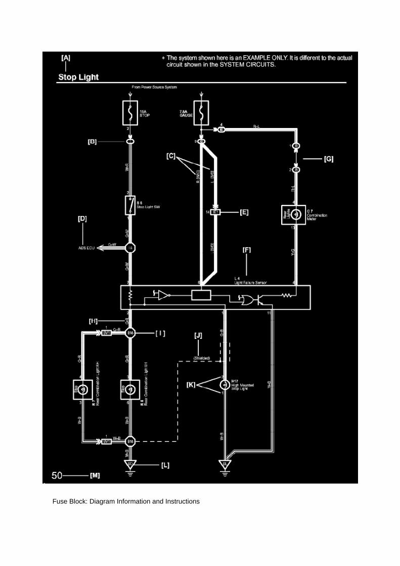
Fuse Block: Diagram Information and Instructions

Key to Diagrams
A: System Title
B: Indicates a Relay Block. No shading is used and only the Relay Block No. is shown todistinguish it from the J/B
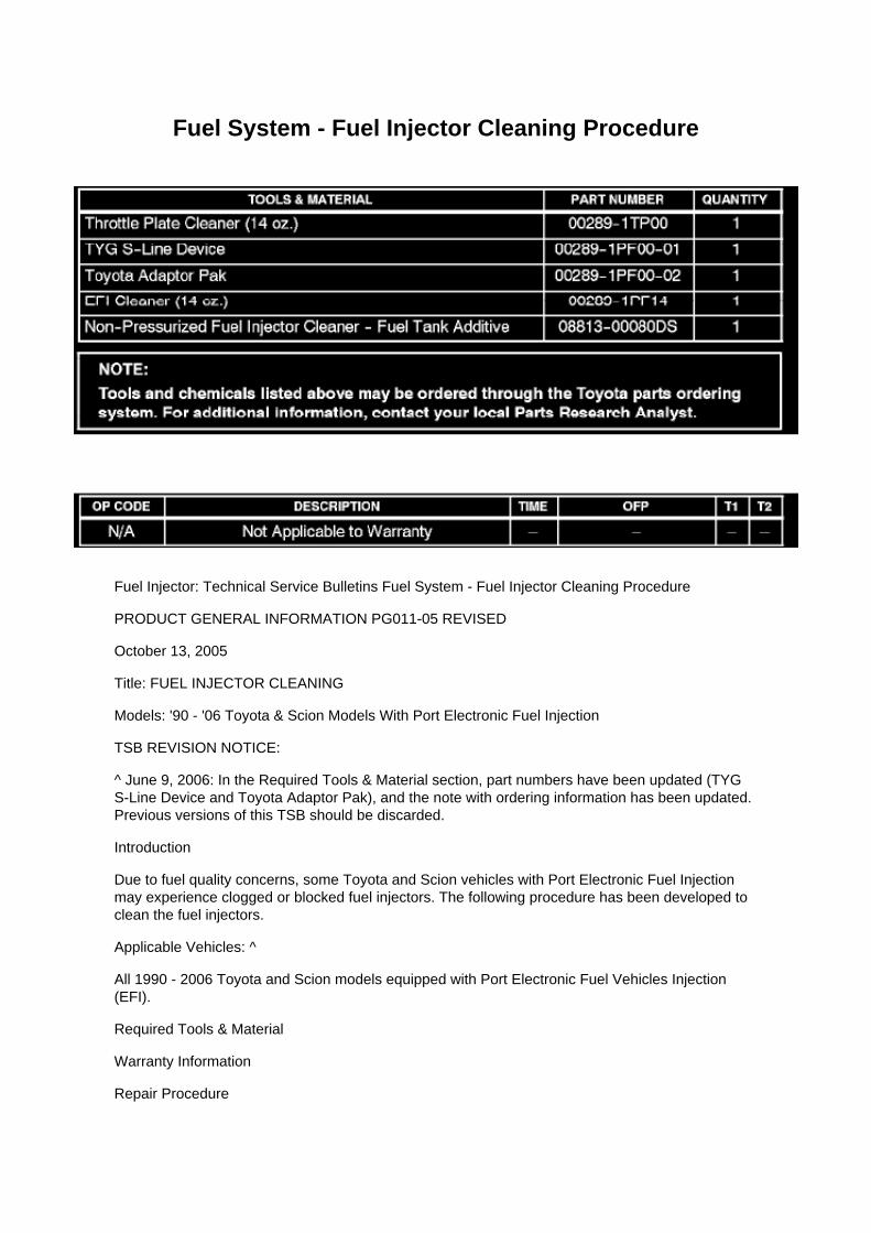
Fuel System - Fuel Injector Cleaning Procedure
Fuel Injector: Technical Service Bulletins Fuel System - Fuel Injector Cleaning Procedure
PRODUCT GENERAL INFORMATION PG011-05 REVISED
October 13, 2005
Title: FUEL INJECTOR CLEANING
Models: '90 - '06 Toyota & Scion Models With Port Electronic Fuel Injection
TSB REVISION NOTICE:
^ June 9, 2006: In the Required Tools & Material section, part numbers have been updated (TYGS-Line Device and Toyota Adaptor Pak), and the note with ordering information has been updated.Previous versions of this TSB should be discarded.
Introduction
Due to fuel quality concerns, some Toyota and Scion vehicles with Port Electronic Fuel Injectionmay experience clogged or blocked fuel injectors. The following procedure has been developed toclean the fuel injectors.
Applicable Vehicles: ^
All 1990 - 2006 Toyota and Scion models equipped with Port Electronic Fuel Vehicles Injection(EFI).
Required Tools & Material
Warranty Information
Repair Procedure

1. If the fuel injector nozzles are visibly blocked or if the injectors do NOT pass the fuel injectorvolume test, complete the fuel injector power flush using the following instructions:
A. Before an injector cleaning is performed, it is recommended that the following items be cleanedwith Toyota Throttle Plate Cleaner (P/N 00289-1TP00):
^ Idle air control device
^ Throttle plate (both sides if possible)
^ Throttle body
B. Bring the engine to operating temperature.
C. Disconnect the fuel pump electrical connector.

Testing and Inspection
Hazard Warning Switch: Testing and Inspection
INSPECT HAZARD WARNING SIGNAL SWITCH ASSEMBLY
a. Check the resistance.
1. Measure the resistance using an ohmmeter, and check the results in accordance with thevalue(s) in the table.
If the result is not as specified, replace the hazard warning signal switch assembly.
b. Check the illumination operation.
1. Connect the battery positive (+) lead to terminal 11 and the battery negative (-) lead to terminal10, then check that the illumination comes on.
Standard: Illumination comes on.
If the illumination does not come on, replace the bulb.

Page 1134
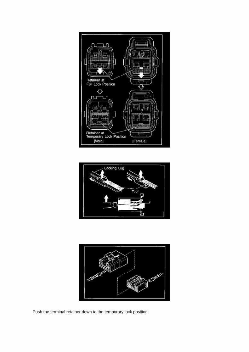
Push the terminal retainer down to the temporary lock position.

c. Release the locking lug from terminal and pull the terminal out from rear.
4. INSTALL TERMINAL TO CONNECTOR
a. Insert the terminal.
HINT: 1. Make sure the terminal is positioned correctly. 2. Insert the terminal until the locking luglocks firmly. 3. Insert the terminal with terminal retainer in the temporary lock position.

Page 602

Supplemental Restraint System

Page 3281

HINT: -
ON: Activate SFLH, depress the brake pedal, and then check that the left front wheel rotates.
- OFF: Deactivate SFLH, depress the brake pedal, and then check that the front left wheel does notrotate.
(1) Select "SFLH" on the hand-held tester. (2) Turn the "SFLH" on by the hand-held tester, thendepress the brake pedal with stable force. (3) When the solenoid is on, check the left front wheel byrotating it by hand. If the left front wheel stops, replace the brake master cylinder.
HINT: -
To protect the solenoid, hand-held tester turns off automatically 2 seconds after every solenoid hasbeen turned on.
- When rotating the wheel fast, the fail-safe function is activated and judgement cannot be madeproperly. So rotate the wheel as slowly as possible.
NOTICE: When operating it continuously, set the interval of more than 20 seconds.
(4) When the solenoid is off, depress the brake pedal again and check that the left front wheel doesnot rotate by hand.
If the left front wheel rotates, replace the brake master cylinder.
l. Inspect front ABS solenoid (SFRR) operation.
HINT: -
ON: Depress the brake pedal, activate SFRR and SFRH, and then check that the right front wheelrotates.
- OFF: Deactivate SFRR and SFRH, depress the brake pedal, and then check that the right frontwheel does not rotate.
(1) Select "SFRR & SFRH" on the hand-held tester. (2) Depress the brake pedal with stable force,then turn the "SFRR & SFRH" on simultaneously by the hand-held tester. (3) When the solenoidsare on, check the right front wheel by rotating it by hand.
If the right front wheel stops, replace the brake master cylinder.
HINT: -
To protect the solenoids, hand-held tester turns off automatically 2 seconds after every solenoidhas been turned on.
- When rotating the wheel fast, the fail-safe function is activated and judgement cannot be madeproperly. So rotate the wheel as slowly as possible.
NOTICE: When operating it continuously, set the interval of more than 20 seconds.
(4) When the solenoids are off, depress the brake pedal again and check that the right front wheeldoes not rotate by hand.
If the right front wheel rotates, replace the brake master cylinder.
m. Inspect front ABS solenoid (SFLR) operation.
HINT: -

ON: Depress the brake pedal, activate SFLR and SFLH, and then check that the left front wheelrotates.
- OFF: Deactivate SFLR and SFLH, depress the brake pedal, and then check that the left frontwheel does not rotate.
(1) Select "SFLR & SFLH" on the hand-held tester. (2) Depress the brake pedal with stable force,then turn the "SFLR & SFLH" on simultaneously by the hand-held tester. (3) When the solenoidsare on, check the left front wheel by rotating it by hand.
If the left front wheel stops, replace the brake master cylinder.
HINT: -
To protect the solenoids, hand-held tester turns off automatically 2 seconds after every solenoidhas been turned on.
- When rotating the wheel fast, the fail-safe function is activated and judgement cannot be madeproperly. So rotate the wheel as slowly as possible.
NOTICE: When operating it continuously, set the interval of more than 20 seconds. (4) When thesolenoids are off, depress the brake pedal again and check that the left front wheel does not rotateby hand.
If the left front wheel rotates, replace the brake master cylinder.
n. Inspect rear VSC solenoid (SREC) operation.
HINT: -
ON: Depress the brake pedal, activate SREC. Release the brake pedal and check that the rearwheels do not rotate.
- OFF: Deactivate SREC and check that the rear wheels rotate.
(1) Select "SRMF (SMCF, SA3)" on the hand-held tester. (2) Depress the brake pedal with stableforce, then turn the "SRMF (SMCF, SA3)" on by the handheld tester.

Page 1809
SFI System

Page 854
6 Of 6

Page 316
Ce - Ya

Page 1273
WARNING
Use care when inserting oil fill devices into the head cover. Forcefully inserting oil fill devices orfunnels into the oil fill hole may result in baffle damage during the oil fill process. If the baffle DOESbecome damaged, repair it to prevent any additional engine damage from occurring.

Page 1085
Driver Side J/B Inner Circuit

Page 1121
2. Disconnect the ECU connector. Check the ground terminals (on the ECU side and wire harnessside) for evidence of bending, corrosion or
foreign material. Lastly check the contact pressure of the female terminals.
Customer Problem Analysis
CUSTOMER PROBLEM ANALYSIS
HINT:
- In troubleshooting, the problem symptoms must be confirmed accurately. Preconceptions shouldbe discarded in order to give an accurate judgement. To clearly understand what the problemsymptoms are, it is extremely important to ask the customer about the problem and the conditionsat the time it occurred.
- As much information as possible should be gathered for reference. Even past problems that seemunrelated may also help in some cases. In the Diagnostic Section, a customer problem analysistable is provided for each system.
- 5 items are important points in the problem analysis:
Important Points with Customer Problem Analysis -
What .......................................................................................................................................................................... Vehicle model, system name
- When .................................................................................................................................................................. Date, time, occurrence frequency
- Where ............................................................................................................................................................................................ Road conditions
- Under what conditions? ............................................................................................. Runningconditions, driving conditions, weather conditions

- How did it happen? ................................................................................................................................................................... Problem symptoms

Page 638

Page 2129

Terminals Of ECM / Pinouts Part 2

Page 1575
NOTE
On some models, DTCs may set as a result of reprogramming. If DTCs are present, clear codesand run the Health Check again. Troubleshoot any remaining Current, Pending, or History codes.Permanent codes will not be cleared using Techstream. Permanent codes do not illuminate the MILand do not require troubleshooting. They will clear during normal driving once the Universal TripDrive Pattern is performed.
4. Attach the Authorized Modifications Label.
A. Using a permanent marker or ball point pen complete the Authorized Modifications Label andattach to the vehicle. The Authorized
Modifications Label is available through the MDC P/N 00451-00001-LBL.
B. Attach the label under the hood in the location determined by the specific TSB or Campaign.
NOTE
Wait 60 - 90 seconds for ink to set before handling.
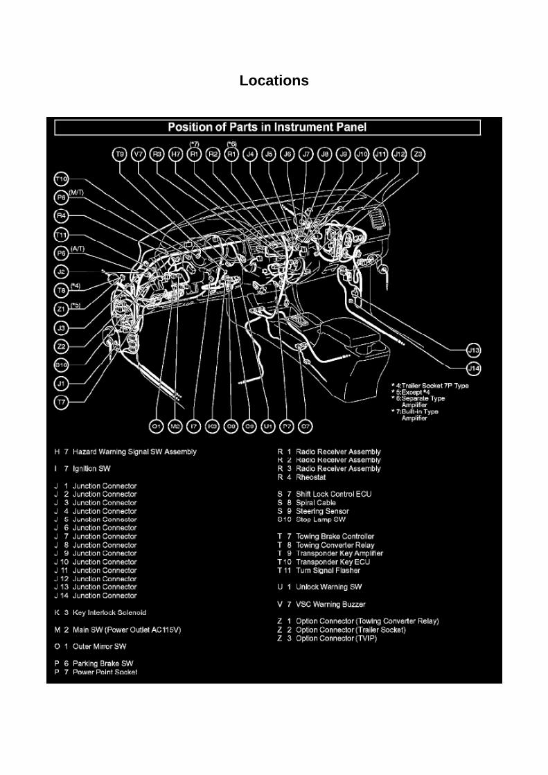
Locations

Ha - Op

Page 1738
Crankshaft Position Sensor: Testing and Inspection
INSPECT CRANKSHAFT POSITION SENSOR
Check the resistance.
Using an ohmmeter, measure the resistance between the terminals.
HINT: Cold and Hot mean the temperature of the coils themselves. Cold is from -10 to 50°C (14 to122°F) and Hot is from 50 to 100°C (122 to 212° F).
If the result is not as specified, replace the camshaft position sensor.

Page 3025
Clutch Pedal Assembly: Service and Repair

CLUTCH PEDAL SUB-ASSY
COMPONENTS
REPLACEMENT
1. REMOVE CLUTCH MASTER CYLINDER ASSY

Page 1108

Example: Splice point "I5" is on the Cowl Wire Harness and is described.
How to Read Connector List
HOW TO READ CONNECTOR LIST
A: Indicates connector to be connected to a part. (The numeral indicates the pin No.)
B: Junction Connector
Indicates a connector which is connected to a short terminal.
Junction connector in this include a short terminal which is connected to a number of wireharnesses. Always perform inspection with the short terminal installed. (When installing the wireharnesses, the harnesses can be connected to any position within the short terminal grouping.Accordingly, in other vehicles, the same position in the short terminal may be connected to a wireharness from a different part.) Wire harness sharing the same short terminal grouping have thesame color.
C: Parts Code
The first letter of the code is taken from the first letter of part, and the numbers indicates its order inparts which start with the same letter.
D: Connector Color
Connectors not indicated are milky white in color.

Page 2437
Parts Information
Required Tools & Material

Required SSTs
Repair Procedure
1. Using the Diagnostic Tester, check for Diagnostic Trouble Codes (DTCs). If DTC P0456 orP0445, and P0441 are present, check for an EVAP leak on top of the fuel suction platesub-assembly. Refer to the Technical Information System (TIS), 2005 model year Tacoma RepairManual: Diagnostics: SFI System (1GR-FE) / (2TR-FE): EVAP Inspection Procedure.
If NO EVAP leaks are detected at the fuel suction plate sub-assembly, this TSB does NOT apply.Please refer to the normal diagnostic procedure provided in the Repair Manual.
2. To correct the fuel suction plate sub-assembly, replace the fuel suction with pump and gaugetube assembly, retainer ring and gasket set according to TIS, 2005 model year Tacoma RepairManual: Fuel: Fuel Pump Assy: Removal & Installation And Disassembly & Reassembly (Tacoma).

Page 1877
Step 4 - 5

Page 1793

Spark Plug: Testing and Inspection

INSPECT SPARK PLUG
a. Clean the spark plugs.
Air pressure: Below 588 kPa (6.0 kgf/sq.cm, 85 psi) Duration: 20 seconds or less
b. Check the spark plug for any damage on its thread and insulator.
If damaged, replace the spark plug.
Recommended spark plug: SK20HR11 (DENSO made) ILFR6C11 (NGK made)
c. Check the spark plug electrode gap.
1. Using a spark plug gap gauge, measure the electrode gap.
Electrode gap: 1.0 to 1.1 mm (0.039 to 0.043 in.) Maximum electrode gap: 1.3 mm (0.051 in.)
If the result is greater than the maximum, replace the spark plug.

Page 2130

Terminals Of ECM / Pinouts Part 3

Page 1109
How to Read Ground Points

HOW TO READ GROUND POINTS
The ground points circuit diagram shows the connections from all major parts to the respectiveground points. When troubleshooting a faulty ground point, checking the system circuits which usea common ground may help you identify the problem ground quickly. The relationship betweenground points(EA, IB and IC is shown) can also be checked this way.
How to Read Power Source
HOW TO READ POWER SOURCE

Page 1641
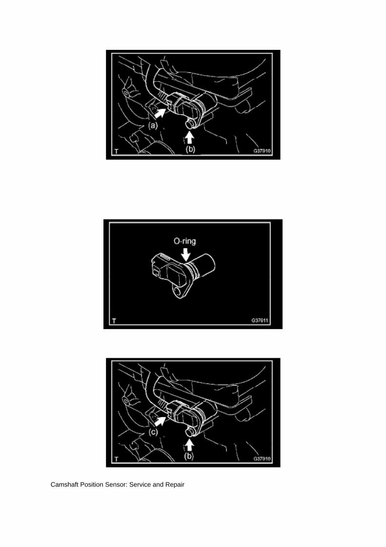
Camshaft Position Sensor: Service and Repair

REPLACEMENT
1. DISCONNECT CABLE FROM NEGATIVE BATTERY TERMINAL 2. REMOVE CAMSHAFTPOSITION SENSOR
a. Disconnect the camshaft position sensor connector. b. Remove the bolt, then remove thecamshaft position sensor.
3. INSTALL CAMSHAFT POSITION SENSOR
a. Apply a light coat of engine oil to the O-ring of the camshaft position sensor.
b. Install the camshaft position sensor with the bolt.
Torque: 8.5 N.m (87 kgf.cm, 75 in.lbf)
NOTE: Make sure that the O-ring is not cracked or jammed when installing.
c. Connect the camshaft position sensor connector.
4. CONNECT CABLE TO NEGATIVE BATTERY TERMINAL
Torque: 3.9 N.m (40 kgf.cm, 35 in.lbf)

Locations

Switch: Locations
Po - Ya

Page 2160
SFI System

Page 3211
b. Install the grommet, a new lock washer and the nut.
Torque: 6.9 Nm (70 kgf-cm, 61 inch lbs.)
c. Install the manual valve lever shaft onto the groove and turn it 2 notches counterclockwise to theneutral position. d. Align the neutral basic line with the switch groove and tighten the adjusting bolt.
Torque: 13 Nm (130 kgf-cm, 9 ft. lbs.)
e. Bend the tabs of the lock washer.
HINT: Bend at least 2 of the lock washer tabs.
5. CONNECT PARK/NEUTRAL POSITION SWITCH CONNECTOR 6. CONNECT CABLE TONEGATIVE BATTERY TERMINAL
Torque: 3.9 Nm (40 kgf-cm, 35 inch lbs.)
7. INSPECT PARK/NEUTRAL POSITION SWITCH ASSY 8. ADJUST PARK/NEUTRAL POSITIONSWITCH ASSY 9. ADJUST SHIFT LEVER POSITION
10. INSPECT SHIFT LEVER POSITION

Page 2447

Air Flow Meter/Sensor: Testing and Inspection

INSPECT INTAKE AIR FLOW METER SUB-ASSEMBLY
a. Check the operation.
1. Apply battery voltage across terminals 1 (+B) and 2 (E2G). 2. Using a voltmeter, connect thepositive (+) tester prove to terminal 3 (VG) and the negative (-) tester prove to terminal 2 (E2G). 3.Blow air into the mass air flow meter and check that the voltage fluctuates.
If the voltage does not fluctuate, replace the mass air flow meter.
b. Check the resistance.
1. Using an ohmmeter, measure the resistance between the terminals.
If the result is not as specified, replace the mass air flow meter.

Locations

Timing Component Alignment Marks: Locations

Timing Mark Locations

Page 1963
Step 3 - 4

Locations
Power Door Lock Switch: Locations

Power Door Lock Control System

Page 2100
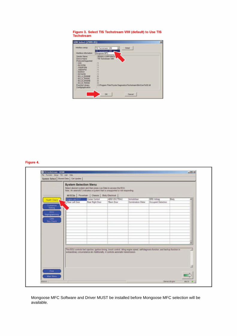
Mongoose MFC Software and Driver MUST be installed before Mongoose MFC selection will beavailable.

See TIS - Diagnostics - Scantool page for additional information.
^ If using TIS Techstream select TIS Techstream VIM (this is the default).
4. Click OK.
Operation Procedure
1. Verify the vehicle's applicability for recalibration and locate desired calibration file.
A. Connect Techstream and establish a vehicle connection.
B. Click the Health Check button on the System Select tab.

Page 693
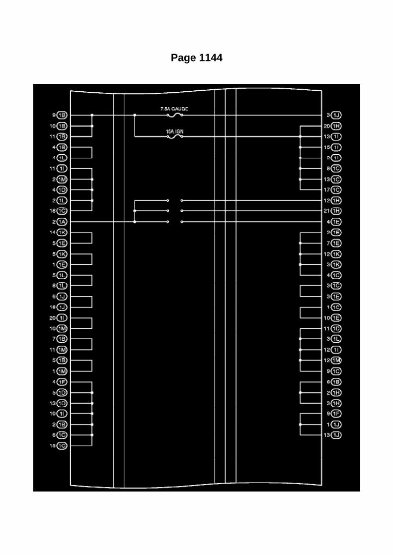
Page 1144

Driver Side J/B Inner Circuit

Page 1267

2. Pinch the retainer as illustrated, then pull the fuel tube connector out of the pipe.

3. If the fuel tube connector and pipe are stuck, pinch the pipe and push and pull the fuel tubeconnector to release it.
NOTE: Never use any tools.
4. After disconnecting the fuel tube, check the sealing surface of the pipe for dirt and mud.
If dirty, wipe it with a shop rag.
5. Cover the disconnected fuel tube connector and pipe with a vinyl bag to prevent damage and theintrusion of foreign objects.
d. Take the following precautions when installing the fuel tube connector.
1. Align the fuel tube connector with the pipe, then push in the fuel tube connector until the retainermakes a "click" sound.

Page 3264
ABS With EBD & BA & TRAC & VSC SYSTEM

Specifications

Axle Nut: Specifications

Hub Nut ........................................................................................................................................................................ 235 Nm (2,396 kgf-cm, 173 ft. lbs.)

Page 1445
a. Connect the hand-held tester to the DLC3. b. Turn the ignition switch to ON.
NOTE: Do not start the engine.
c. Turn the hand-held tester ON. d. Select the following menu items: DIAGNOSIS / ENHANCEDOBD II / ACTIVE TEST / FUEL PUMP / SPD / ON. e. Check that there are no leakage in the fuelsystem.

Page 1852

Mongoose MFC Software and Driver MUST be installed before Mongoose MFC selection will beavailable.

See TIS - Diagnostics - Scantool page for additional information.
^ If using TIS Techstream select TIS Techstream VIM (this is the default).
4. Click OK.
Operation Procedure
1. Verify the vehicle's applicability for recalibration and locate desired calibration file.
A. Connect Techstream and establish a vehicle connection.
B. Click the Health Check button on the System Select tab.

Page 1219
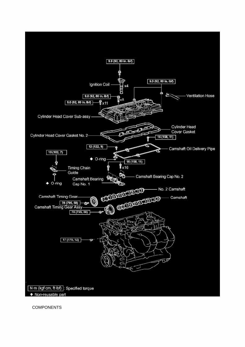
COMPONENTS

REPLACEMENT
1. DISCONNECT CABLE FROM NEGATIVE BATTERY TERMINAL 2. REMOVE ENGINE UNDERCOVER SUB-ASSEMBLY NO.1 (PRE RUNNER AND 4WD TYPE)
a. Remove the 4 bolts, then remove the engine under cover No.1.
3. DRAIN ENGINE COOLANT 4. REMOVE RADIATOR SUPPORT TO FRAME SEAL LH 5.REMOVE FAN SHROUD 6. REMOVE AIR CLEANER CAP SUB-ASSEMBLY

Page 2186

He - Wi

Component Inspection
Variable Valve Timing Actuator: Testing and Inspection Component Inspection
INSPECT CAMSHAFT TIMING OIL CONTROL VALVE ASSEMBLY

a. Check the resistance.
1. Using an ohmmeter, measure the resistance between the terminals.
If the result is not as specified, replace the camshaft timing oil control valve.
b. Check the operation.
1. Apply battery voltage across the terminals, and check that the spool valve operates.
NOTE: Check that the spool valve is not stuck.
HINT: The spool valve may not return if foreign objects are caught in it. This may cause subtlepressure leakage to the advance side, and a DTC may be set.

Page 908
Drive Belt: Service and Repair

FAN AND GENERATOR V BELT (2TR-FE)
REPLACEMENT
1. REMOVE FAN AND GENERATOR V BELT
a. Turning the hexagonal bolt on the V-ribbed belt tensioner clockwise, loosen and then remove theV belt.
2. INSTALL FAN AND GENERATOR V BELT
a. Provisionally install the V belt onto each pulley.
NOTICE: Install the V belt onto each pulley and finally install the V belt onto the V-ribbed belttensioner.
b. Turn the hexagonal bolt on the V-ribbed belt tensioner clockwise and install the V belt onto theV-ribbed belt tensioner pulley.
3. INSPECT FAN AND GENERATOR V BELT

Page 1974
Step 9 - 12

Page 2583

He - Wi

Page 374
Clutch Switch Assy

Specifications

Spark Plug: Specifications

SPARK PLUG TYPE:
DENSO ........................................................................................................................................................................................................... SK2OHR11 NGK ..................................................................................................................................................................................................................ILFR6C11
Correct electrode gap for new sparkplug.......................................................................................................................... 1.0 to 1.1 mm(0.039 to 0.043 in.)
Torque.....................................................................................................................................................................................18 N.m (184 kgf.cm, 13 ft.lbf)

Locations

He - Wi

Page 206
^ Figure 17 shows an example of the update procedure for a two-processor ECU.
G. Turn ignition OFF. Then click Next.
H. Confirm the following:

^ Ignition is ON and engine is OFF or "READY" OFF (hybrid vehicles).
^ Hood is open.
^ All accessories are OFF.
^ Battery voltage is above 11.4 volts.
NOTICE
Verify the vehicle is connected to a battery charger before continuing - If battery voltage falls below11.4 volts, ECU damage may occur.

Page 2175
SFI System

Page 587

d. Disconnect the water bypass hose No.2.

e. Disconnect the ventilation hose No.3.
f. Disconnect the VSV connector.
g. Disengage the engine wire harness clamp. h. Disconnect the compressor magnetic clutchconnector.
(w/ AIR CONDITIONING)
i. Disengage the wire harness clamp.
j. Remove the bolt and harness clamp bracket.

Page 492
Knock Control Sensor (2TR-FE) Part 1

Page 426
ABS With EBD System

Page 3015

A. Remove the front door opening trim LH (scuff plate).

B. Remove the cowl side trim board.
C. Remove the instrument panel finish panel lower No. 1.
D. Remove the driver's side Junction Block.
E. Remove the turnover (compression) spring.

Fuel/Emissions - MIL ON/DTC's P0456/P0445 and P0441
Set
Fuel Pump Mounting Gasket: All Technical Service Bulletins Fuel/Emissions - MIL ON/DTC'sP0456/P0445 and P0441 Set
ENGINE EG037-05 REVISED
Title: M.I.L. "ON" DTC P0456 OR P0455, AND P0441
Models: '05 Tacoma
September 1, 2005
TSB REVISION NOTICE:
^ September 16, 2005: The Applicable VDS has been updated in Applicable Vehicles. Previousversions of this TSB should be discarded.
Introduction
Some 2005 model year Tacoma vehicles may exhibit a M.I.L. "ON" condition with one or more ofthe following DTCs: P0456 or P0455, and P0441 (EVAP Emission Control System). Follow thesteps in this bulletin to correct this condition.

Applicable Vehicles
^ 2005 model year Tacoma vehicles (except D-Cab Short Bed), with the following VehicleDescription Section VDS) information shown below.
Warranty Information
Applicable Warranty*: This repair is covered under the Toyota Powertrain Warranty. This warrantyis in effect for 60 months or 60,000 miles, whichever occurs first, from the vehicle's in-service date.
* Warranty application is limited to correction of a problem based upon a customer's specificcomplaint.

Page 1356


Service and Repair

Clutch Slave Cylinder: Service and Repair
CLUTCH RELEASE CYLINDER ASSY
COMPONENTS
OVERHAUL
1. DRAIN CLUTCH FLUID

Replacement

Timing Cover: Service and Repair Replacement
TIMING CHAIN COVER SUB-ASSEMBLY (2TR-FE)

Locations

A/C - Fo

Page 848

Repair Procedure

1. Disconnect the cable from the negative (-) battery terminal for MORE THAN two (2) seconds.
2. Reconnect the cable to the negative (-) battery terminal.
3. Perform the applicable zero point calibration of the yaw rate sensor and/or the steering anglesensor.
HINT Refer to the applicable TSB or Repair Manual for the zero point calibration procedure.
4. Re-initialize all applicable systems available on the vehicle (power window sunroof power liftdoor etc.).

Page 3032
SFI System

Specifications

Intake Manifold: Specifications

Intake Manifold ................................................................................................................................................................... 25 Nm (255 kgf-cm, 18 ft. lbs.)
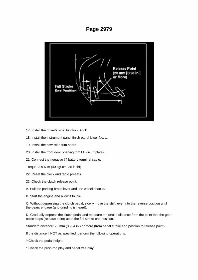
Page 2979
17. Install the driver's side Junction Block.
18. Install the instrument panel finish panel lower No. 1.
19. Install the cowl side trim board.
20. Install the front door opening trim LH (scuff plate).
21. Connect the negative (-) battery terminal cable.
Torque: 3.9 N.m (40 kgf.cm, 35 in.lbf)
22. Reset the clock and radio presets.
23. Check the clutch release point.
A. Pull the parking brake lever and use wheel chocks.
B. Start the engine and allow it to idle.
C. Without depressing the clutch pedal, slowly move the shift lever into the reverse position untilthe gears engage (and grinding is heard).
D. Gradually depress the clutch pedal and measure the stroke distance from the point that the gearnoise stops (release point) up to the full stroke end position.
Standard distance: 25 mm (0.984 in.) or more (from pedal stroke end position to release point)
If the distance if NOT as specified, perform the following operations:
^ Check the pedal height.
^ Check the push rod play and pedal free play.

^ Bleed the clutch line.
^ Check the clutch cover assembly and the disc assembly.

Page 2178

a. Apply a light coat of engine oil to the O-ring of the crankshaft position sensor.

b. Install the camshaft position sensor with the bolt.
Torque: 8.5 N.m (87 kgf.cm, 75 in.lbf)
NOTE: Make sure that the O-ring is not cracked or jammed when installing.
c. Connect the crankshaft position sensor connector and the 2 wire harness clamps.
8. INSTALL IDLE PULLEY ASSEMBLY W/BRACKET (W/ AIR CONDITIONING)

Component Inspection
Variable Valve Timing Actuator: Testing and Inspection Component Inspection
INSPECT CAMSHAFT TIMING OIL CONTROL VALVE ASSEMBLY

a. Check the resistance.
1. Using an ohmmeter, measure the resistance between the terminals.
If the result is not as specified, replace the camshaft timing oil control valve.
b. Check the operation.
1. Apply battery voltage across the terminals, and check that the spool valve operates.
NOTE: Check that the spool valve is not stuck.
HINT: The spool valve may not return if foreign objects are caught in it. This may cause subtlepressure leakage to the advance side, and a DTC may be set.

Page 1964
Step 5 - 6

Page 3256
ABS With EBD System

Page 1894

Flash reprogramming may be accomplished using one of the following methods: -

Toyota/Lexus factory scantool
- Vetronix Mastertech
- J2534 Compatible Vehicle Interface (Toyota validated and approved)
REPROGRAMMING WITH SCANTOOL
Toyota/Scion/Lexus ECMs can be reprogrammed using either the Toyota/Lexus factory scantool,or the Vetronix Mastertech scantool. The ECM reprogramming function is only available with theauthentic Toyota factory scantool software which runs on either of the above mentioned scantools.Scantool software version requirements are specified in applicable Technical Service Bulletin(TSB)/Service Communication (SC) documents.
The Toyota/Lexus factory scantool and/or authentic factory software program cards can bepurchased through the official Toyota and Lexus Special Service Tool provider, SPX Corp. Toorder, call (800) 933-8335 and request either: -
P/N 01001271 for the Toyota/Lexus factory scantool including factory software program card
- P/N 01002593-005 for the "stand alone" program card
Program cards are provided with the latest production version software available at time ofpurchase.
Vehicle recalibration using a scantool requires use of the following: -
Personal Computer running a Microsoft Windows 2000 or Windows XP operating system
- Toyota Diagnostic Tester or Vetronix Mastertech Scantool with Toyota factory software
- Toyota/Lexus factory scantool program card
- PC Interface Cable (P/N 01001090) to transfer data from PC to scantool
- Calibration CD (00456-REPRG-001)
REPROGRAMMING WITH J2534 INTERFACE
Toyota/Scion/Lexus ECMs that can be reprogrammed with a scantool can also be reprogrammedusing a Toyota validated J2534-1 interface. Vehicle recalibration requires the use of the following: -
Toyota validated J2534 interface
- Toyota Calibration Update Wizard software (available on calibration CD)
- Personal Computer running Microsoft Windows 2000/XP or later operating system
- Calibration CD (00456-REPRG-001)
Toyota strongly recommends USING ONLY VALIDATED INTERFACE DEVICES that appear onthis list.
Validated J2534 Devices Toyota works closely with J2534 interface manufacturers to ensure thattheir hardware works safely and efficiently with their products. Every device listed on this page hasbeen thoroughly tested and validated on Toyota, Scion and Lexus vehicles.
It is important to understand that only the specific devices, firmware, DLLs and APIs listed herehave been tested by Toyota. Toyota does not recommend use of any other J2534 device, firmware,DLL or API that is not listed here. Changes to J2534 hardware/software is outside of Toyota's

control; in some cases, changes made to device hardware/software can negatively impactreprogramming performance. Toyota makes every effort to continue to work with J2534 interfacemanufacturers to ensure continued product compatibility as the respective products evolve.
Requirement for device:
Supplier Device Name Version (Firmware* / DLL* / API*)
Drew Technologies CarDAQ Plus (01.08.06 / 01.08.06 / 04.04)
Actia PassThru+ XS (02.01 / 02.01 / 04.04)
Vetronix Corporation ES6510 Flasher (06.12 / 04.23 / 04.04)
EASE Diagnostics Universal Reprogrammer (JPI1_11b / 1.3.0.13 / 04.04)
Snap-On Pass Thru Pro (02.01 / 02.01 / 04.04)
Blue Streak Electronics Inc. BSE-2534 Global Programmer (01.21 / 02.27 / 04.04)
* Original validated firmware/DLL versions may be superceded by the device manufacturer.Contact the device manufacturer if you are unable to find the versions listed above.
Support OS:
OS Name and Version: Windows 2000 SP2 or later Windows XP Pro SP1 or later
For more information about the J2534 devices listed above, contact the vendors. To reportcompatibility problems with listed hardware/software, please contact the device manufacturer.
For more information about Toyota vehicle reprogramming CDs or to report problems runningToyota's Calibration Update Wizard software, please

Page 339

Ha - Op

Page 30
Problem Symptoms Table
The suspected circuits or parts for each problem symptom are shown in the table . Use this table totroubleshoot when, during a DTC check, a "Normal" code is displayed but the problem is stilloccurring. Numbers in the table show the inspection order in which the circuits or parts should bechecked.
HINT: In some cases, the problem is not detected by the diagnostic system even though a problemsymptom is present. It is possible that the problem is occurring outside the detection range of thediagnostic system, or that the problem is occurring in a completely different system.

Page 2651

a. Apply a light coat of engine oil to the O-ring of the crankshaft position sensor.

b. Install the camshaft position sensor with the bolt.
Torque: 8.5 N.m (87 kgf.cm, 75 in.lbf)
NOTE: Make sure that the O-ring is not cracked or jammed when installing.
c. Connect the crankshaft position sensor connector and the 2 wire harness clamps.
8. INSTALL IDLE PULLEY ASSEMBLY W/BRACKET (W/ AIR CONDITIONING)

Locations
SFI System

Page 2119
Engine Control Module: Locations
Instrument Panel

Page 1688
SFI System

Page 1859
^ Figure 17 shows an example of the update procedure for a two-processor ECU.
G. Turn ignition OFF. Then click Next.
H. Confirm the following:

^ Ignition is ON and engine is OFF or "READY" OFF (hybrid vehicles).
^ Hood is open.
^ All accessories are OFF.
^ Battery voltage is above 11.4 volts.
NOTICE
Verify the vehicle is connected to a battery charger before continuing - If battery voltage falls below11.4 volts, ECU damage may occur.

Page 2559
9. REMOVE FUEL TANK TO FILLER PIPE HOSE
a. Loosen the clamp bolt, then remove the fuel tank to filler pipe hose.
10. REMOVE FUEL TANK PROTECTOR NO.1
a. Remove the 4 clips, then remove the fuel tank protector.
11. INSTALL FUEL TANK PROTECTOR NO.1
a. Install the fuel tank protector with the 4 clips.
12. INSTALL FUEL TANK TO FILLER PIPE HOSE
a. Install the fuel tank onto the filler pipe hose, then tighten the pipe clamp bolt.

13. INSTALL FUEL SUCTION W/ PUMP & GAUGE TUBE ASSEMBLY
a. Install a new gasket onto the fuel tank. b. Set the fuel pump assembly in the fuel tank.
NOTE: Be careful not to bend the arm of the sender gauge.

Page 2049

Main Relay (Computer/Fuel System): Testing and Inspection

INSPECT E.F.I. CIRCUIT OPENING RELAY ASSEMBLY
a. Check the resistance.
1. Using an ohmmeter, measure the resistance between the terminals.
If the result is not as specified, replace the E.F.I. circuit opening relay assembly.
INSPECT EFI RELAY
a. Check the resistance.
1. Using an ohmmeter, measure the resistance between the terminals.
If the result is not as specified, replace the E.F.I. ECU relay.
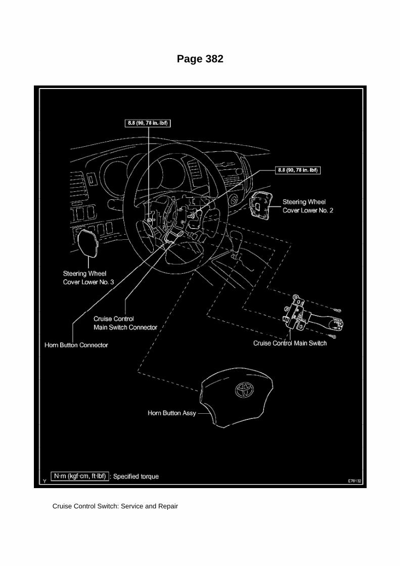
Page 382
Cruise Control Switch: Service and Repair

Cruise Control Main Switch
CRUISE CONTROL MAIN SWITCH
REPLACEMENT
1. PRECAUTION
Refer to Air Bag Systems; Service Precautions.
2. DISCONNECT CABLE FROM NEGATIVE BATTERY TERMINAL
Wait for at least 90 seconds after disconnecting the cable to prevent the airbag from working.
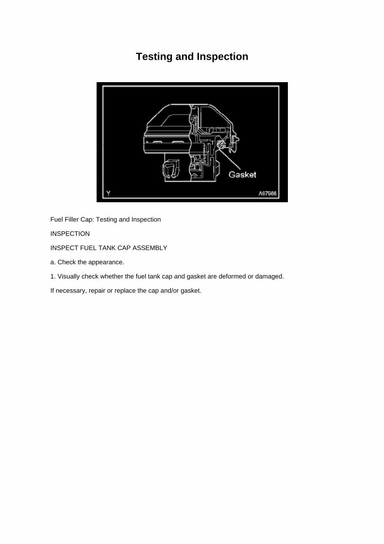
Testing and Inspection
Fuel Filler Cap: Testing and Inspection
INSPECTION
INSPECT FUEL TANK CAP ASSEMBLY
a. Check the appearance.
1. Visually check whether the fuel tank cap and gasket are deformed or damaged.
If necessary, repair or replace the cap and/or gasket.

Page 2061


Page 55

Ha - Op

Page 2958

b. Remove the push rod from the cylinder body.
c. Using compressed air, remove the piston together with the spring from the cylinder.
NOTICE: Be careful not to damage the inside of the cylinder body.
d. Remove the bleeder plug cap from the bleeder plug.
6. REMOVE RELEASE CYLINDER BLEEDER PLUG 7. INSTALL RELEASE CYLINDERBLEEDER PLUG
Torque: 11 Nm (110 kgf-cm, 8.0 ft. lbs.)
8. INSTALL CLUTCH RELEASE CYLINDER KIT
a. Install the bleeder plug cap onto the bleeder plug. b. Install the spring onto the cylinder body.
c. Apply lithium soap base glycol grease to the portions shown in the illustration. d. Install thepiston onto the cylinder body.
NOTICE: Be careful not to damage the inside of the cylinder body.
e. Install the push rod into the cylinder body. f.
Install the boot onto the cylinder body.
9. INSTALL CLUTCH RELEASE CYLINDER ASSY
a. Install the clutch release cylinder with the 2 bolts.
Torque: 12 Nm (120 kgf-cm, 8.7 ft. lbs.)

Page 1851
4. Attach the Authorized Vehicle Modification Label.

Modifications to ECU calibrations MUST be recorded and properly displayed on the vehicle usingthe Authorized Modification Label.
Techstream Preparation
Selecting the TIS Techstream VIM or the Mongoose MFC VIM.
Techstream software requires a VIM selection before you can use the Mongoose MFC VIM.
If using TIS Techstream no changes are needed.
Perform the following:
1. Select Setup from the Techstream Main Menu screen.
2. Select VIM Select from the Setup drop down menu.
3. Select the correct Interface Setup from the drop down list.
^ If using Techstream Lite select Mongoose MFC.
NOTE

Engine Controls - Techstream(R) ECU Re-Flash
Procedure
PROM - Programmable Read Only Memory: All Technical Service Bulletins Engine Controls -Techstream(R) ECU Re-Flash Procedure
T-SB-0064-10
February 4, 2010
Techstream ECU Flash Reprogramming Procedure
Service Category Engine/Hybrid System
Section Engine Control
Market USA
Applicability
TSB SUPERSESSION NOTICE
The information contained in this TSB supersedes TSB No. SS002-07.
^ Applicability has been updated to include 2009 - 2011 model year Toyota vehicles.
^ A new section, Techstream Preparation, has been added.
^ Techstream Lite has been added as an option in Required Tools & Materials.
^ Process Overview and Operation Procedure sections have been updated.
TSB No. SS002-07 is Obsolete and any printed versions should be discarded. Be sure to reviewthe entire content of this service bulletin before proceeding.
Introduction
Flash reprogramming allows the ECU software to be updated without replacing the ECU. Flashcalibration updates for specific vehicle models/ECUs are released as field-fix procedures describedin individual service bulletins. This bulletin details the Techstream ECU flash reprogramming

process and outlines use of the Technical Information System (TIS) and the Calibration UpdateWizard (CUW). Flash calibration updates can only be applied to the vehicle/ECU combination forwhich they are intended. ECUs have internal security that will not allow them to be programmedwith another ECU's information.
ECU
Electronic Control Unit (ECU) is a Toyota term used to describe integrated computerized devicesresponsible for managing the operation of a system or subsystem. For the purposes of this bulletin,the term "ECU" is used as a generic label for the following SAE J1930 standard references:
^ Powertrain Control Module (PCM)

Page 1881

Terminals Of ECM / Pinouts Part 2
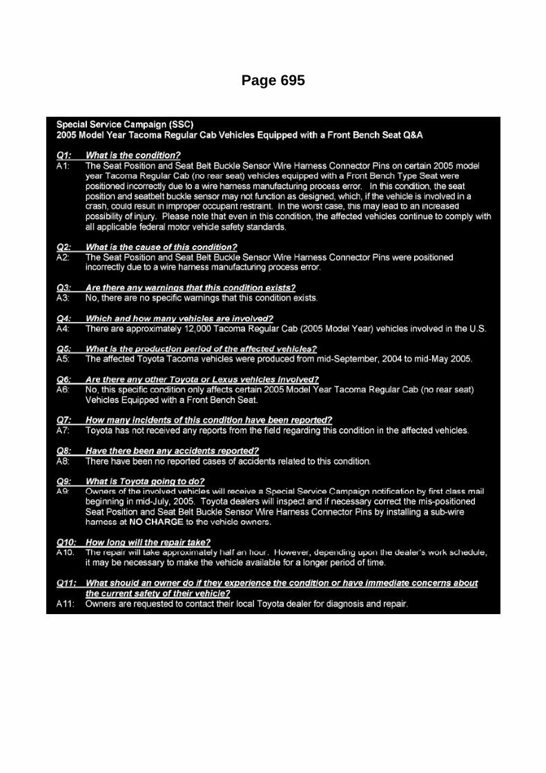
Page 695

Page 61
Trailer Towing Relay: Service and Repair
TOWING CONVERTER RELAY
REPLACEMENT
1. TABLE OF BOLT, SCREW AND NUT
HINT: All bolts, screws and nuts relevant to installing and removing the instrument panel are shownalong with their alphabetic codes in the table.
2. DISCONNECT CABLE FROM NEGATIVE BATTERY TERMINAL
Wait for at least 90 seconds after disconnecting the cable to prevent the airbag from working.
3. REMOVE FRONT FLOOR FOOTREST 4. REMOVE FRONT DOOR SCUFF PLATE LH 5.REMOVE FRONT DOOR SCUFF PLATE RH 6. REMOVE COWL SIDE TRIM BOARD LH 7.REMOVE COWL SIDE TRIM BOARD RH 8. SEPARATE FRONT DOOR OPENING TRIMWEATHERSTRIP LH 9. SEPARATE FRONT DOOR OPENING TRIM WEATHERSTRIP RH
10. REMOVE FRONT PILLAR GARNISH LH 11. REMOVE FRONT PILLAR GARNISH RH 12.REMOVE INSTRUMENT PANEL UNDER TRAY (PEDAL TYPE PARKING BRAKE) 13. REMOVEINSTRUMENT PANEL HOLE COVER (LEVER TYPE PARKING BRAKE) 14. REMOVECONSOLE UPPER REAR PANEL SUB-ASSEMBLY (AUTOMATIC TRANSMISSION,SEPARATESEAT TYPE) 15. REMOVE CONSOLE UPPER REAR PANEL SUB-ASSEMBLY (MANUALTRANSMISSION, SEPARATE SEAT TYPE) 16. REMOVE CONSOLE BOX ASSEMBLY REAR(SEPARATE SEAT TYPE) 17. REMOVE INSTRUMENT PANEL CUP HOLDER TRAY

(AUTOMATIC TRANSMISSION, SEPARATE SEAT TYPE) 18. REMOVE CONSOLE BOX FRONT(AUTOMATIC TRANSMISSION, SEPARATE SEAT TYPE) 19. REMOVE CONSOLE BOX FRONT(MANUAL TRANSMISSION, SEPARATE SEAT TYPE) 20. REMOVE CONSOLE BOX FRONT(AUTOMATIC TRANSMISSION, BENCH SEAT TYPE) 20. REMOVE CONSOLE BOX FRONT(AUTOMATIC TRANSMISSION, BENCH SEAT TYPE) 21. REMOVE CONSOLE BOX FRONT(MANUAL TRANSMISSION, BENCH SEAT TYPE) 22. REMOVE AIR CONDITIONING CONTROLASSEMBLY 23. REMOVE RADIO RECEIVER ASSEMBLY W/ BRACKET 24. SEPARATE HOODLOCK CONTROL LEVER SUB-ASSEMBLY 25. REMOVE INSTRUMENT PANEL FINISH PANELLOWER NO.1 26. REMOVE INSTRUMENT CLUSTER FINISH PANEL SUB-ASSEMBLY 27.REMOVE COMBINATION METER ASSEMBLY

Page 2354

Component Tests and General Diagnostics

Air Bag Control Module: Component Tests and General Diagnostics

AIRBAG SENSOR ASSEMBLY CENTER (VEHICLE NOT INVOLVED IN COLLISION)
a. Perform a diagnostic system check.
Refer to Air Bag Systems; Testing and Inspection.
AIRBAG SENSOR ASSEMBLY CENTER (VEHICLE INVOLVED IN COLLISION AND AIRBAG ISNOT DEPLOYED)
a. Perform a diagnostic system check.
Refer to Air Bag Systems; Testing and Inspection.
AIRBAG SENSOR ASSEMBLY CENTER (VEHICLE INVOLVED IN COLLISION AND AIRBAG ISDEPLOYED)
a. Replace the airbag sensor assembly center.
CAUTION: For removal and installation procedures of the airbag sensor assembly center, see"Replacement" and be sure to follow the correct procedure.
HINT: The airbag sensor assembly center should be replaced after any of the airbags hasdeployed, as it has been subjected to an impact.

Page 965

Coolant: Fluid Type Specifications

Coolant type:
In order to avoid technical problems, only use "Toyota Super Long Life Coolant" or similar highquality ethylene glycol based non-silicate, non-amine, non-nitrite, and non-borate coolant withlong-life hybrid organic acid technology.
Do not use plain water alone.

Page 1755
Knock Sensor: Testing and Inspection
INSPECT KNOCK SENSOR
a. Check the resistance.
1. Using an ohmmeter, measure the resistance between the terminals.
If the result is not as specified, replace the knock sensor.

Page 1834

a. Apply a light coat of engine oil to the O-ring of the crankshaft position sensor.

b. Install the camshaft position sensor with the bolt.
Torque: 8.5 N.m (87 kgf.cm, 75 in.lbf)
NOTE: Make sure that the O-ring is not cracked or jammed when installing.
c. Connect the crankshaft position sensor connector and the 2 wire harness clamps.
8. INSTALL IDLE PULLEY ASSEMBLY W/BRACKET (W/ AIR CONDITIONING)

Page 2656
Ignition Switch: Testing and Inspection
INSPECT IGNITION OR STARTER SWITCH ASSEMBLY
a. Check the resistance.
1. Using an ohmmeter, measure the resistance between the terminals.
If the result is not as specified, replace the ignition or starter switch.

Page 663

Page 3003

B. Remove the cowl side trim board.

C. Remove the instrument panel finish panel lower No. 1.
D. Remove the driver's side Junction Block.
E. Remove the turnover (compression) spring.
F. Remove the bolt attached to the instrument panel reinforcement assembly.

Page 2011
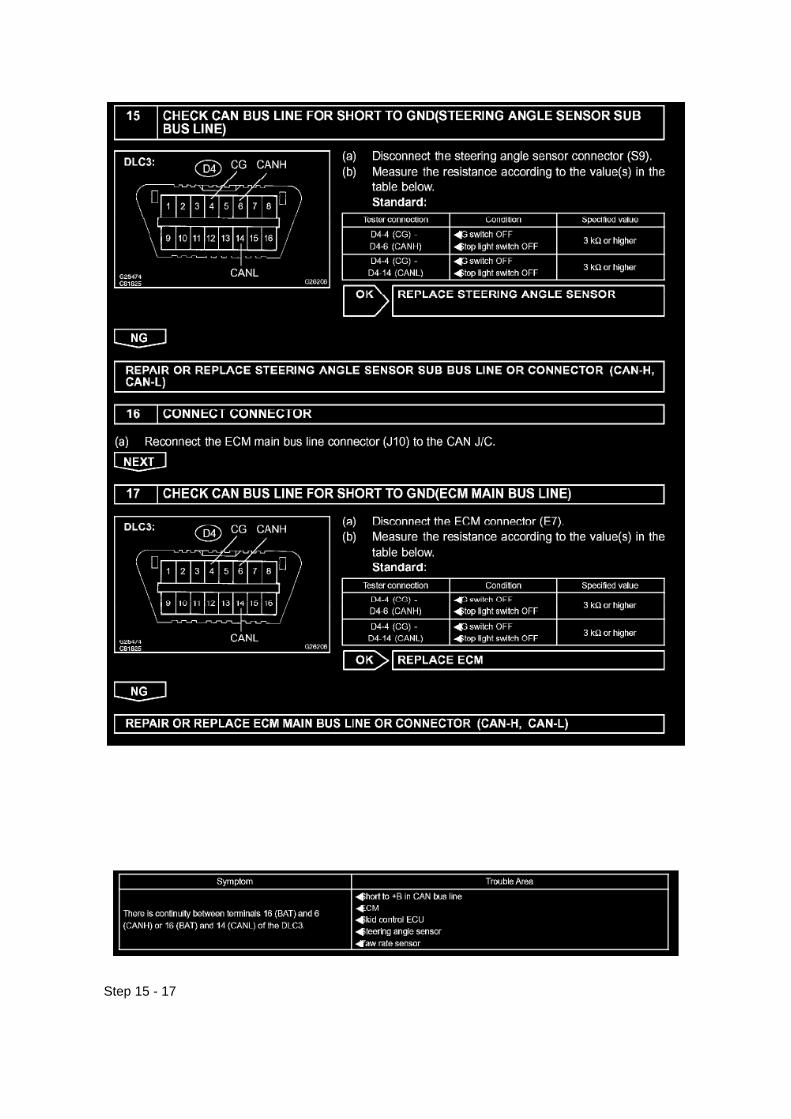
Step 15 - 17

INSPECTION PROCEDURE
Check Can Bus Line For Short to +B
CHECK CAN BUS LINE FOR SHORT TO +B
CIRCUIT DESCRIPTION
A short to +B is suspected in the CAN bus line when there is continuity between terminals 16 (BAT)and 6 (CANH) or terminals 16 (BAT) and 14

Page 1033

Driver Side J/B Part 1

Page 1226

f. When the camshaft timing gear reaches the most advanced position, release the air pressure onthe retard side path, then release the air pressure on the advance side path.

NOTICE: If the air pressure on the advance side path is released first, the camshaft timing gearassembly occasionally shifts in the retard direction abruptly. This may damage the lock pin. Be sureto release the air pressure on the retard side path first.
g. Remove the fringe bolt of the camshaft timing gear.
NOTICE: Be sure not to remove the other 3 bolts.
12. INSTALL CAMSHAFT TIMING GEAR ASSEMBLY
a. Put the camshaft timing gear and camshaft together by aligning the key groove and straight pin.b. Gently press the gear against the camshaft, and turn the gear. Push further at the position wherethe pin fits into the groove.
CAUTION: Be sure not to turn the camshaft timing gear to the retard angle side (to the right angle).
c. Check that there is no clearance between the gear's fringe and the camshaft. d. Tighten thefringe bolt with the camshaft timing gear fixed.
Torque: 78 Nm (795 kgf-cm, 58 ft. lbs.)
e. Check that the camshaft timing gear can move to the retard angle side (the right angle), and islocked in the extreme retard position.
13. INSTALL CAMSHAFT

Page 23

1. Disconnect connectors A and C and measure the resistance between terminals 1 and 2 ofconnector A and the body ground.

HINT: Measure the resistance while lightly shaking the wire harness vertically and horizontally.
If your results match the examples above, a short circuit exists between terminal 1 of connector Aand terminal 1 of connector C.
2. Disconnect connector B and measure the resistance between terminal 1 of connector A and thebody ground, and terminal 1 of connector B2
and the body ground. If your results match the examples above, a short circuit exists betweenterminal 1 of connector B2 and terminal 1 of connector C.
Check and Replace ECU
CHECK AND REPLACE ECU
NOTE:
- The connector should not be disconnected from the ECU. Perform the inspection from thebackside of the connector on the wire harness side.
- When no measuring condition is specified, perform the inspection with the engine stopped andthe ignition switch ON.
- Check that the connectors are fully seated. Check for loose, corroded or broken wires.
a. First check the ECU ground circuit. If it is faulty, repair it.
If it is normal, the ECU could be faulty. Replace the ECU with a normal functioning one and check ifthe symptoms occur. If the trouble symptoms stop, replace the ECU.
1. Measure the resistance between the ECU ground terminal and body ground.
Standard: Below 1 Ohms

On-Vehicle Inspection
Clutch Switch: Testing and Inspection On-Vehicle Inspection
CLUTCH START SWITCH ASSEMBLY
ON-VEHICLE INSPECTION
1. CHECK CLUTCH START SYSTEM
a. Check that the engine does not start when the clutch pedal is released. b. Check that the enginestarts when the clutch pedal is fully depressed.
If necessary, replace the clutch start switch assembly.

Service and Repair

Air Injection Control Valve: Service and Repair

REPLACEMENT
1. DISCONNECT CABLE FROM NEGATIVE BATTERY TERMINAL 2. REMOVE INTAKE AIRCONNECTOR 3. REMOVE AIR CLEANER CAP SUB-ASSEMBLY
a. Disconnect the mass air flow meter connector. b. Disconnect the wire harness clamp. c. Loosenthe hose clamp bolt, then disconnect the air cleaner hose No.1. d. Disconnect the 2 air cleanerclamps. e. Remove the air cleaner cap together with the air cleaner hose No.1.
4. REMOVE EXHAUST MANIFOLD HEAT INSULATOR NO.1
a. Remove the 5 bolts, then remove the exhaust manifold heat insulator No.1.
5. DISCONNECT AIR INJECTION SYSTEM NO.1 HOSE
a. Disconnect the air injection system No.1 hose from the air switching valve.
6. REMOVE INTAKE PIPE INSULATOR

Page 2850

COMPONENTS

OVERHAUL
1. REMOVE SHIFT LEVER KNOB SUB-ASSY 2. REMOVE CONSOLE UPPER REAR PANELSUB-ASSY 3. REMOVE CONSOLE BOX ASSY REAR 4. REMOVE INSTRUMENT PANEL CUPHOLDER TRAY 5. REMOVE CONSOLE BOX FRONT

Page 216

Refer to Reset Procedure 2 for the vehicles with Electronically Controlled AutomaticTransmissions:

Reset Procedure 1
1. Connect the Toyota Diagnostic Tester to the vehicle.
2. Reset the ECM (PCM). Refer to the procedures below.

Page 2231

Transmission Position Switch/Sensor: Service and Repair

PARK/NEUTRAL POSITION SWITCH ASSY
REPLACEMENT
1. DISCONNECT CABLE FROM NEGATIVE BATTERY TERMINAL 2. DISCONNECTPARK/NEUTRAL POSITION SWITCH CONNECTOR
3. REMOVE PARK/NEUTRAL POSITION SWITCH ASSY
a. Using a screwdriver, unstake the lock washer. b. Remove the nut, lock washer and grommet. c.Remove the bolt and park/neutral position switch.
4. INSTALL PARK/NEUTRAL POSITION SWITCH ASSY
a. Install the park/neutral position switch onto the manual valve lever shaft and provisionally tightenthe adjusting bolt.

Page 720

II. Identification of Affected Vehicles

A. AFFECTED VIN RANGE
NOTE:
This SSC only involves certain 2005 Model Year Tacoma Regular-Cab vehicles equipped with afront bench seat. Not all vehicles in the VIN range

Page 636

Page 777

He - Wi

Page 1593

Terminals Of ECM / Pinouts Part 2

Page 2870
b. Install the grommet, a new lock washer and the nut.
Torque: 6.9 Nm (70 kgf-cm, 61 inch lbs.)
c. Install the manual valve lever shaft onto the groove and turn it 2 notches counterclockwise to theneutral position. d. Align the neutral basic line with the switch groove and tighten the adjusting bolt.
Torque: 13 Nm (130 kgf-cm, 9 ft. lbs.)
e. Bend the tabs of the lock washer.
HINT: Bend at least 2 of the lock washer tabs.
5. CONNECT PARK/NEUTRAL POSITION SWITCH CONNECTOR 6. CONNECT CABLE TONEGATIVE BATTERY TERMINAL
Torque: 3.9 Nm (40 kgf-cm, 35 inch lbs.)
7. INSPECT PARK/NEUTRAL POSITION SWITCH ASSY 8. ADJUST PARK/NEUTRAL POSITIONSWITCH ASSY 9. ADJUST SHIFT LEVER POSITION
10. INSPECT SHIFT LEVER POSITION

Page 1579
Engine Control Module: Technical Service Bulletins Engine/Transmission Controls - Resetting ECMMemory
TRANSMISSION & CLUTCH TC002-03 REVISED
Title: ECM RESET MEMORY FUNCTION
Models: '00 - '05 All Models
June 10, 2003
TSB REVISION NOTICE:
^ December 20, 2004: Applicable Vehicles section has been updated - 2004 and 2005 model yearsadded, models and model years updated for various models; and Reset Procedure 2 has beenrevised.
^ January 16, 2004: Tundra vehicles were added to the Applicable Vehicles chart.
^ December 17, 2003: T-100 vehicles were removed from the Applicable Vehicles chart.
Previous versions of this TSB should be discarded.
Introduction

Whenever an automatic transmission is replaced, overhauled or individual components arereplaced, use this procedure to clear Engine Control Module (ECM, SAE term: Powertrain ControlModule, PCM) "Learned Values" to minimize subsequent performance concerns.
CAUTION:
Failure to follow the procedure below may lengthen the time to readjust the ECM "Learned Values,"potentially resulting in performance concerns.
Required SSTs
Warranty Information
Applicable Vehicles

Locations
Shift Interlock Control Module: Locations
Instrument Panel

Page 107
ABS With EBD & BA & TRAC & VSC SYSTEM

Page 2143

contact Toyota.

OBTAINING A CALIBRATION CD
The Calibration CD is compatible with the above mentioned scantools and J2534 interfaces. ACalibration CD contains all of the most current vehicle calibration files, applicable TSBs, theCalibration Update Wizard application software for a Windows PC, and instructions for use.
Calibration CDs can be ordered through the Toyota Material Distribution Center; order P/N00456-REPRG-001.
IMPORTANT NOTICE
It is possible to permanently damage a vehicle controller during the flash reprogramming process.It is especially important to understand that once started, the reprogramming process must not beinterrupted, reprogramming devices must not be disconnected and PCs must not be allowed to gointo standby, hibernation or similar power management modes. The information provided herein isintended expressly for use by qualified professional automobile technicians. To prevent damage toyour customer's vehicle and ensure safe service practice, read these materials completely andthoroughly before servicing the vehicle and be sure to follow all instructions.

Locations

Air Flow Meter/Sensor: Locations

He - Wi
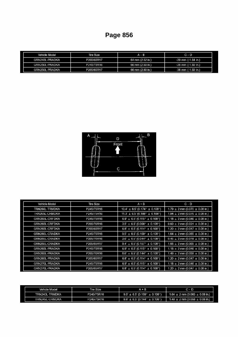
Page 856

4WD
Measuring points: A: Ground clearance of front wheel center B: Ground clearance of adjustmentcam bolt center (front side) C: Ground clearance of rear wheel center D: Ground clearance of rearleaf spring front side bush center
NOTICE: Before inspecting the wheel alignment, adjust the vehicle height to the specified value.
Bounce the vehicle up and down at the corners to stabilize the suspension before inspecting thevehicle height.
3. INSPECT TOE-IN
Toe-in
PRE RUNNER
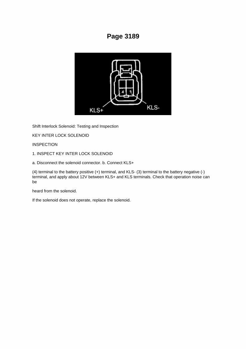
Page 3189
Shift Interlock Solenoid: Testing and Inspection
KEY INTER LOCK SOLENOID
INSPECTION
1. INSPECT KEY INTER LOCK SOLENOID
a. Disconnect the solenoid connector. b. Connect KLS+
(4) terminal to the battery positive (+) terminal, and KLS- (3) terminal to the battery negative (-)terminal, and apply about 12V between KLS+ and KLS terminals. Check that operation noise canbe
heard from the solenoid.
If the solenoid does not operate, replace the solenoid.

Page 1978

Step 4 - 7

Page 3105

a. Grind the rear axle bearing inner race surface using a grinder, and then chisel them out with achisel. b. Remove the rear axle shaft oil seal from the rear axle shaft.
19. INSPECT REAR AXLE SHAFT LH
a. Using a dial indicator, measure the runout of the shaft and flange.
Maximum runout:
Shaft runout: 1.5 mm (0.0591 inch) Flange runout: 0.05 mm (0.0020 inch)
If the rear axle shaft or flange is damaged or worn, or the runout is greater than the maximum,replace the rear axle shaft.
20. INSTALL REAR AXLE HUB BOLT
a. 2WD:
(1) Install a new deflector gasket and deflector onto the rear axle shaft.
HINT: Make sure that the deflector and deflector gasket are installed in the correct direction shownin the illustration.
(2) Install the 5 bolts through the axle hub. (3) Install a washer plate, as shown in the illustration,through the hub bolt, and install the hub bolt by tightening the hub nut.
b. 4WD and PRE RUNNER:
(1) Install a new deflector gasket and deflector onto the rear axle shaft.
HINT: Align the 2 notches.

Page 3093

13. REMOVE REAR AXLE SHAFT LH

a. Using SST and press, remove the rear axle shaft.
SST 09521-25011, 09521-25021
14. REMOVE REAR AXLE BEARING RETAINER INNER LH
a. Remove the rear axle bearing retainer inner from the rear axle bearing.
15. REMOVE REAR AXLE SHAFT LH WASHER
a. Remove the rear axle shaft washer from the rear axle bearing.
16. REMOVE REAR AXLE HUB & BEARING ASSY LH
a. Attach the 4 nuts to the rear axle housing bolts. b. Using a hammer, remove the 4 rear axlehousing bolts and rear axle bearing.
NOTICE: Do not reuse the nuts previously removed from the vehicle.
17. REMOVE REAR AXLE HUB BOLT
a. 2WD: Using SST, remove the 5 hub bolts.
SST 09650-17011
b. Remove the deflector and deflector gasket from the rear axle shaft.
c. 4WD and PRE RUNNER: Using SST, remove the 6 hub bolts.
SST 09650-17011
d. Remove the deflector and deflector gasket from the rear axle shaft.
18. REMOVE REAR AXLE BEARING OIL SEAL

Page 667

II. Identification of Affected Vehicles

A. AFFECTED VIN RANGE
NOTE:
This SSC only involves certain 2005 Model Year Tacoma Regular-Cab vehicles equipped with afront bench seat. Not all vehicles in the VIN range

Page 627
9. REMOVE CONSOLE BOX FRONT (AUTOMATIC TRANSMISSION, BENCH SEAT TYPE)
10. REMOVE CONSOLE BOX FRONT (MANUAL TRANSMISSION, BENCH SEAT TYPE)
11. REMOVE AIR BAG SENSOR ASSEMBLY CENTER
a. Disconnect the holder (with connectors) from the airbag sensor assembly center. b. Remove the3 bolts and the airbag sensor assembly center.
12. INSPECT AIR BAG SENSOR ASSEMBLY CENTER
13. INSTALL AIR BAG SENSOR ASSEMBLY CENTER
a. Check that the ignition switch is turned to OFF. b. Check that the cable is disconnected from thebattery negative terminal.
CAUTION: After removing the terminal, wait for at least 90 seconds before starting the operation.
c. Provisionally install the air bag sensor assembly center with the 3 bolts.
NOTE: -
If the airbag sensor assembly center has been dropped, or there are any cracks, dents or otherdefects in the case, bracket or connector, replace it with a new one.
- When installing the airbag sensor assembly center, make sure that the SRS wiring dose notinterfere with any other parts and that it is not pinched between other parts.
d. Tighten the 3 bolts to the specified torque.
Torque: 17.5 N.m (179 kgf.cm, 13 ft.lbf)
e. Check that there is no slack in the installation parts of the airbag sensor assembly center. f.
Connect the holder (with connectors) to the airbag sensor assembly center.
g. Check that the waterproof sheet is properly set.

14. INSTALL CONSOLE BOX FRONT (MANUAL TRANSMISSION, BENCH SEAT TYPE) 15.INSTALL CONSOLE BOX FRONT (AUTOMATIC TRANSMISSION, BENCH SEAT TYPE) 16.INSTALL CONSOLE BOX FRONT (MANUAL TRANSMISSION, SEPARATE SEAT TYPE) 17.INSTALL CONSOLE BOX FRONT (AUTOMATIC TRANSMISSION, SEPARATE SEAT TYPE) 18.INSTALL INSTRUMENT PANEL CUP HOLDER TRAY (AUTOMATIC TRANSMISSION,SEPARATE SEAT TYPE) 19. INSTALL CONSOLE BOX ASSEMBLY REAR (SEPARATE SEATTYPE) 20. INSTALL CONSOLE UPPER REAR PANEL SUB-ASSEMBLY (MANUALTRANSMISSION, SEPARATE SEAT TYPE) 21. INSTALL CONSOLE UPPER REAR PANELSUB-ASSEMBLY (AUTOMATIC TRANSMISSION,SEPARATE SEAT TYPE) 22. CONNECTCABLE TO NEGATIVE BATTERY TERMINAL
Torque: 3.9 N.m (40 kgf.cm, 35 in.lbf)
23. INSPECT SRS WARNING LIGHT
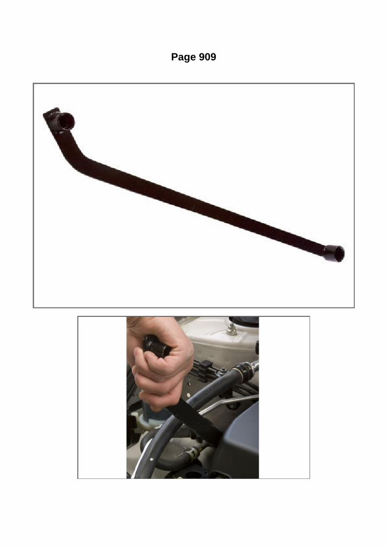
Page 909
Drive Belt: Tools and Equipment
Toyota Serpentine Belt Wrench
AST tool# TOY 1914
The TOY 1914 is a Toyota serpentine belt wrench that is equipped with 14mm and 19mm, 12 pointsecured attachments. Applications: 1998-2005 Corolla, 2004 Matrix, 2008 Highlander V6 (NonHybrid), 2002 RAV4 and 4.7L/5.7L V8 used in Tundra and Sequoia through 2008.
- Lightweight and Slim design
- Equipped with 14mm and 19mm, 12 point securing attachments
- Works on most Toyota applications (except Hybrids)
Contact AST for pricing.

Page 3234

Step 1

Locations

Fuel Pump Relay: Locations
Engine Room R/B, J/B - Engine Compartment Left

Page 2204
Engine Bank Identification

Page 1921

2. HEAT METHOD: If the problem seems to occur when the area in question is heated.

a. Heat the component that is the possible cause of the malfunction with a hair dryer or similardevice. Check if the malfunction occurs.
NOTE: -
Do not heat to more than 60°C (140°F). Exceeding this temperature may damage components.
- Do not apply heat directly to the parts in the ECU.
3. WATER SPRINKLING METHOD: When the malfunction seems to occur on a rainy day or inhigh-humidity.
a. Sprinkle water onto the vehicle and check if the malfunction occurs.
NOTE: -
Never sprinkle water directly into the engine compartment. Indirectly change the temperature andhumidity by applying water spray onto the front of the radiator.
- Never apply water directly onto the electronic components.
HINT: If the vehicle has or had a water leakage problem, the leakage may have damaged the ECUor connections. Look for evidence of corrosion or shorts. Proceed with caution during water tests.
4. HIGH ELECTRICAL LOAD METHOD: When a malfunction seems to occur when electrical loadis excessive.
a. Turn on the heater blower, headlamps, rear window defogger and all other electrical loads.Check if the malfunction reoccurs.
Diagnostic Trouble Code Chart
DIAGNOSTIC TROUBLE CODE CHART
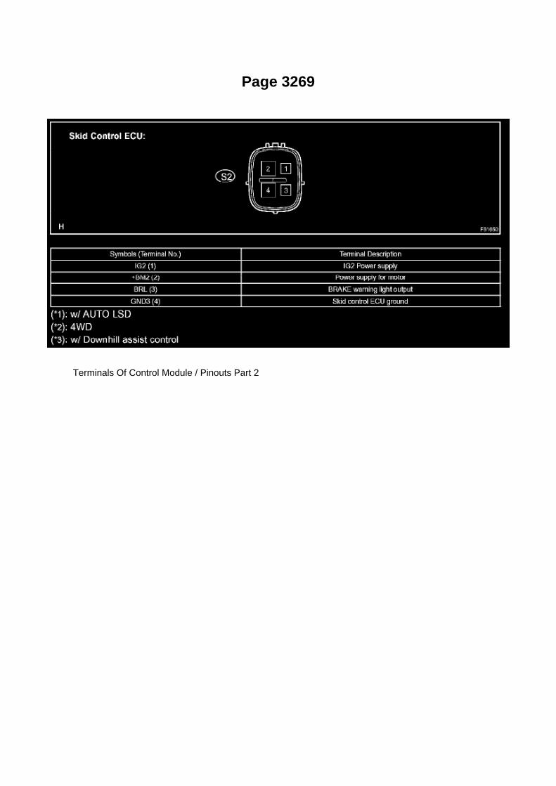
Page 3269
Terminals Of Control Module / Pinouts Part 2

Locations
Door Switch: Locations
Ac - Ou

Page 1598
Oscilloscope Waveforms
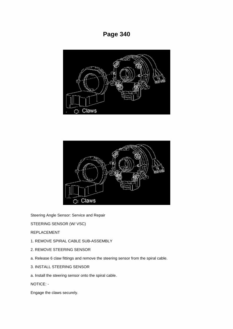
Page 340
Steering Angle Sensor: Service and Repair
STEERING SENSOR (W/ VSC)
REPLACEMENT
1. REMOVE SPIRAL CABLE SUB-ASSEMBLY
2. REMOVE STEERING SENSOR
a. Release 6 claw fittings and remove the steering sensor from the spiral cable.
3. INSTALL STEERING SENSOR
a. Install the steering sensor onto the spiral cable.
NOTICE: -
Engage the claws securely.

- Be careful not to damage the claws.
4. INSTALL SPIRAL CABLE SUB-ASSEMBLY

Page 2134
Oscilloscope Waveforms

Page 1660

He - Wi

Page 3314
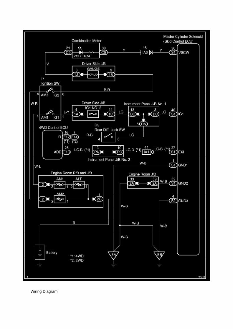
Wiring Diagram

Engine, A/T Controls - Torque Converter Lock-Up
Shudder
PROM - Programmable Read Only Memory: Customer Interest Engine, A/T Controls - TorqueConverter Lock-Up Shudder
T-SB-0096-09
March 20, 2009
Torque Converter Flex Lockup Shudder
Service Category Drivetrain
Section Automatic Transmission/Transaxle
Market USA
Applicability
The information contained in this TSB supersedes TSB No. T-SB-0048-09.
^ The following sections have been updated to include information for 2005 - 2007 model yearTacoma vehicles:
^ Applicability
^ Warranty Information
^ Parts Information
^ Calibration Information
TSB No. T-SB-0048-09 is Obsolete and any printed versions should be discarded. Be sure toreview the entire content of this service bulletin before proceeding.
Introduction
Some customers with 4 cylinder (2TR-FE) and A340 (4-speed) automatic transmission equippedTacoma vehicles may experience an intermittent shudder or vibration. This condition lasts forapproximately one second and occurs when lightly accelerating after an upshift into 3rd or 4th gearwith the torque converter assembly in Flex Lockup. This vibration is commonly described as feelinglike driving over "rumble strips" or on a "washboard" road. The Engine Control Module/ECM (SAEterm: Powertrain Control Module/PCM) logic has been revised to prevent the learning of anincorrect value during certain driving conditions. Use the following repair procedure to addresscustomer concerns.
Production Change Information
This TSB applies to vehicles produced BEFORE the Production Change Effective VIN shown.

Page 172

Push the terminal retainer down to the temporary lock position.

c. Release the locking lug from terminal and pull the terminal out from rear.
4. INSTALL TERMINAL TO CONNECTOR
a. Insert the terminal.
HINT: 1. Make sure the terminal is positioned correctly. 2. Insert the terminal until the locking luglocks firmly. 3. Insert the terminal with terminal retainer in the temporary lock position.

Page 498

k. Disconnect the 3 connectors. l.
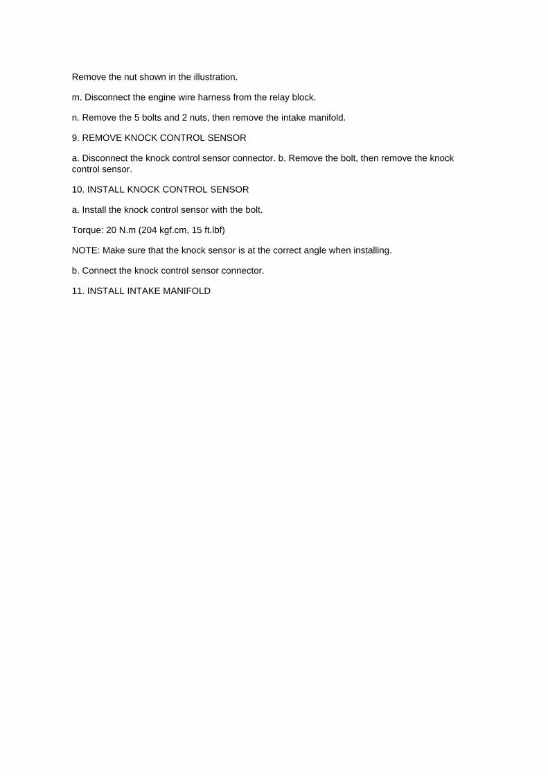
Remove the nut shown in the illustration.
m. Disconnect the engine wire harness from the relay block.
n. Remove the 5 bolts and 2 nuts, then remove the intake manifold.
9. REMOVE KNOCK CONTROL SENSOR
a. Disconnect the knock control sensor connector. b. Remove the bolt, then remove the knockcontrol sensor.
10. INSTALL KNOCK CONTROL SENSOR
a. Install the knock control sensor with the bolt.
Torque: 20 N.m (204 kgf.cm, 15 ft.lbf)
NOTE: Make sure that the knock sensor is at the correct angle when installing.
b. Connect the knock control sensor connector.
11. INSTALL INTAKE MANIFOLD

Page 2370

Page 1400

Page 3302
d. Connect the 3 connectors.
39. INSTALL MASTER CYLINDER PUSH ROD CLEVIS 40. INSTALL DRIVER SIDE JUNCTIONBLOCK
Torque: 8.0 Nm (82 kgf-cm, 71 inch lbs.)
41. INSTALL INSTRUMENT PANEL FINISH PANEL LOWER NO.1 42. INSTALL INSTRUMENTPANEL UNDER TRAY (AUTOMATIC TRANSAXLE) 43. INSTALL INSTRUMENT PANEL HOLECOVER (MANUAL TRANSAXLE) 44. INSTALL COWL SIDE TRIM BOARD LH 45. INSTALLFRONT DOOR SCUFF PLATE LH 46. INSTALL FRONT FLOOR FOOTREST 47. CONNECTCABLE TO NEGATIVE BATTERY TERMINAL
Torque: 3.9 Nm (40 kgf-cm, 35 inch lbs.)
48. CHECK BRAKE PEDAL HEIGHT 49. CHECK PEDAL FREE PLAY 50. CHECK PEDALRESERVE DISTANCE 51. FILL RESERVOIR WITH BRAKE FLUID 52. BLEED BRAKEBOOSTER W/ ACCUMULATOR PUMP ASSEMBLY 53. BLEED BRAKE LINE 54. BLEEDMASTER CYLINDER SOLENOID 55. CHECK FLUID LEVEL IN RESERVOIR 56. CHECK FORBRAKE FLUID LEAKAGE 57. CHECK BRAKE MASTER CYLINDER OPERATION
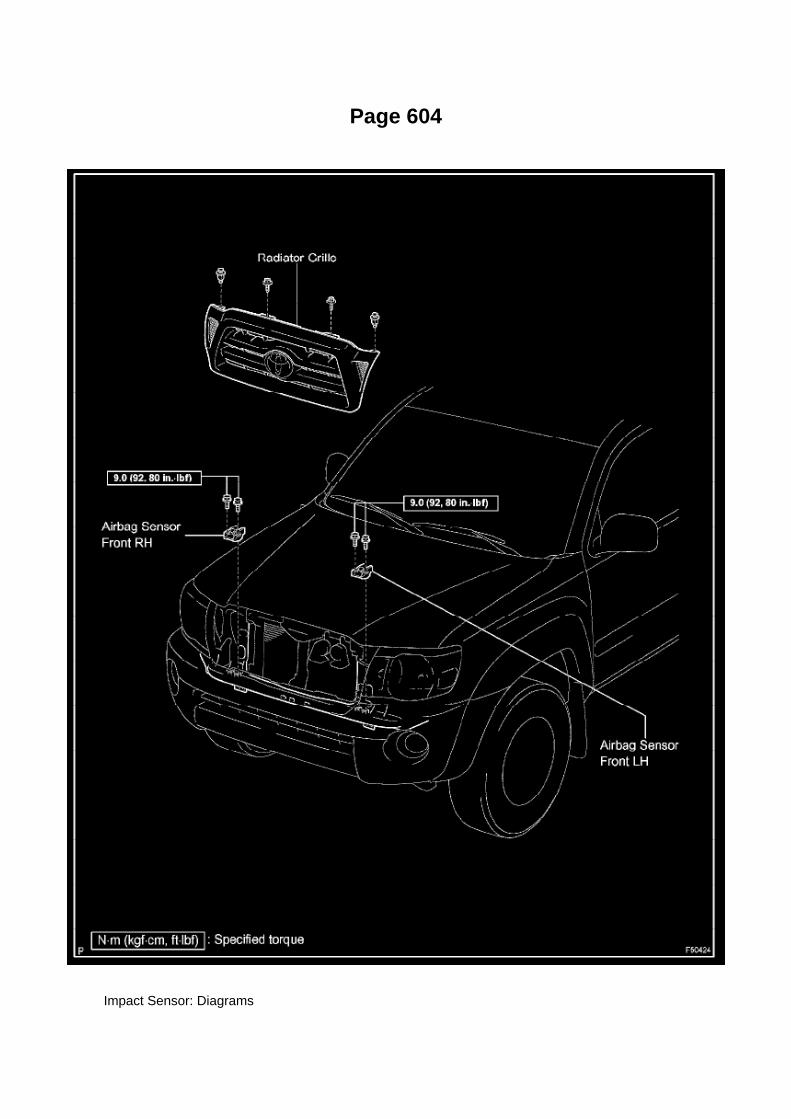
Page 604
Impact Sensor: Diagrams

Airbag Front LH Sensor

Page 2688

Shift Solenoid: Diagrams

The shift solenoid identification and location in the valve body is contained in the valve bodyservice and repair procedures and overhaul articles for most models.

Page 50
Fr - Si

Page 526
SST 09224-00010
Torque: 44 N.m (449 Kgf.cm, 33 ft.lbf) 40 N.m (408 Kgf.cm, 30 ft.lbf) with SST
NOTE: Use a torque wrench with a fulcrum length of 300 mm (11.81 in.).
b. Connect the wire harness clamp. (4WD DRIVE TYPE) c. Connect the oxygen sensor connector.
4. CONNECT CABLE TO NEGATIVE BATTERY TERMINAL
Torque: 3.9 N.m (40 Kgf.cm, 35 in.lbf)

Locations
Impact Sensor: Locations

A/C - Ge

Page 3103

9. SEPARATE REAR BRAKE TUBE NO.8

a. Using SST, separate the brake tube, and use a container to catch the brake fluid as it flows out.
SST 09023-00101
10. REMOVE REAR AXLE SHAFT W/ BACKING PLATE
a. Remove the 4 nuts and rear axle shaft w/ backing plate. b. Remove the O-ring.
11. REMOVE REAR AXLE SHAFT LH OIL SEAL
a. Using SST, remove the oil seal.
SST 09308-00010
12. REMOVE REAR AXLE SHAFT LH SNAP RING
a. Using a snap ring expander, remove the snap ring.

Fuel/Emissions - MIL ON/DTC's P0456/P0445 and P0441
Set
Fuel Pump Mounting Gasket: Customer Interest Fuel/Emissions - MIL ON/DTC's P0456/P0445 andP0441 Set
ENGINE EG037-05 REVISED
Title: M.I.L. "ON" DTC P0456 OR P0455, AND P0441
Models: '05 Tacoma
September 1, 2005
TSB REVISION NOTICE:
^ September 16, 2005: The Applicable VDS has been updated in Applicable Vehicles. Previousversions of this TSB should be discarded.
Introduction
Some 2005 model year Tacoma vehicles may exhibit a M.I.L. "ON" condition with one or more ofthe following DTCs: P0456 or P0455, and P0441 (EVAP Emission Control System). Follow thesteps in this bulletin to correct this condition.

Applicable Vehicles
^ 2005 model year Tacoma vehicles (except D-Cab Short Bed), with the following VehicleDescription Section VDS) information shown below.
Warranty Information
Applicable Warranty*: This repair is covered under the Toyota Powertrain Warranty. This warrantyis in effect for 60 months or 60,000 miles, whichever occurs first, from the vehicle's in-service date.
* Warranty application is limited to correction of a problem based upon a customer's specificcomplaint.

Page 2670

a. Install a new gasket onto the intake manifold. b. Install the intake manifold with the 5 bolts and 2nuts.

Torque: 25 N.m (255 kgf.cm, 18 ft.lbf)
c. Connect the engine wire harness to the relay block. d. Install the nut shown in the illustration.
Torque: 10 N.m (102 kgf.cm, 7 ft.lbf)
e. Connect the 3 connectors.
f. Install the harness clamp bracket with the bolt.
Torque: 8.2 N.m (84 kgf.cm, 73 in.lbf)
g. Engage the wire harness clamp. h. Connect the compressor magnetic clutch connector.

Page 2931

11. Install the clutch pedal bushes.

A. Apply MP grease to the two (2) NEW bushes.
B. Install the two (2) bushes onto the clutch pedal.
12. Install the clutch pedal pad.
13. Install the clutch pedal spring holder.
A. Apply MP grease to the contact surface of the clutch pedal spring holder.
B. Install the clutch pedal spring holder.
14. Remove the clevis sub-assembly.
A. Measure length "A" of the clutch master cylinder.
a. Measure length "A" between the lock nut and the thread end with a ruler.
b. Record length "A".

Page 2544

3. Install the fuel tank protector cover on top of the fuel suction plate sub-assembly as shown in theillustration.

Page 3215

He - Wi

Page 2322

1. Discharge the fuel system pressure (step 2). 2. Disconnect the fuel tank main tube. 3. Drain thefuel remaining in the fuel tank main tube. 4. Cover the disconnected fuel tank main tube (fuel tube

joint and fuel tube connector) with a vinyl bag to prevent damage and the intrusion
of foreign objects.
b. Take the following precautions when installing the fuel injector.
1. Do not reuse the O-ring. 2. Do not damage a new O-ring when installing it onto the fuel injector.3. Before installing a new O-ring, apply gasoline or spindle oil.
NOTE: Do not use engine oil, gear oil or brake oil.
4. Install the fuel injector into the fuel delivery pipe and cylinder head as illustrated.
HINT: Apply gasoline or spindle oil to the contact surface of the fuel delivery pipe and fuel injectorbefore installing the fuel injector.
c. Take the following precautions when disconnecting the fuel tube connector.
HINT: The structure of the fuel tube connector is as shown in the illustration.
1. Check the fuel tube connector and pipe for dirt and mud before removing the fuel tubeconnector.
If dirty, wipe it with a shop rag.

Page 1083

Driver Side J/B Inner Circuit

Page 1683
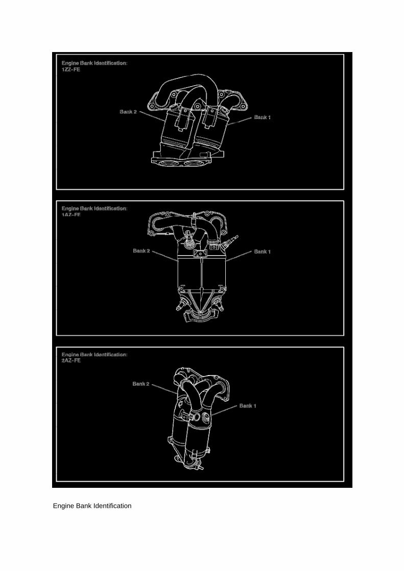
Engine Bank Identification

Engine Controls - A/F And O2 Sensor Identification
Oxygen Sensor: Technical Service Bulletins Engine Controls - A/F And O2 Sensor Identification
T-SB-0398-09
December 23, 2009
Engine Bank 1 and Bank 2 A/F and 02 Identification
Service Category Engine/Hybrid System
Section Engine Control
Market USA
Applicability
TSB SUPERSESSION NOTICE
The information contained in this TSB supersedes TSB No. EG034-07.
^ Applicability has been updated to include 2009 - 2010 model year vehicles and 2006 - 2010model year Highlander HV.
TSB No. EG034-07 is Obsolete and any printed versions should be discarded. Be sure to reviewthe entire content of this service bulletin before proceeding.
Introduction
This service bulletin provides information on the proper identification of engine bank 1 and enginebank 2 for correct A/F sensor and oxygen sensor replacement.
This bulletin contains information that identifies engine bank 1 and engine bank 2 on the followingengines: 1AZ-FE, 2AZ-FE, 2AZ-FE (PZEV), 1GR-FE, 2GR-FE, 2JZ-GE, 1MZ-FE, 3MZ-FE,1UR-FE, 3UR-FE, 2UZ-FE 5VZ-FE and 1ZZ-FE.
^ Bank 1 (B1) refers to the bank that includes cylinder No. 1.
^ Bank 2 (B2) refers to the bank opposite bank 1.
^ Sensor 1 (S1) refers to the sensor that is located before the catalytic converters.
^ Sensor 2 (S2) refers to the sensor that is located after the catalytic converters.
Warranty Information

Page 2557
f. Disconnect the fuel pump connector.
g. Disconnect the fuel tank vent hose.
1. Pinch the retainer and pull the fuel tank vent hose connector out of the charcoal canister todisconnect the fuel tank vent hose from the
charcoal canister.
NOTE: -
Remove any dirt and foreign objects from the fuel tank vent hose connector before performing thiswork.
- Do not allow any scratches of foreign objects on the parts when disconnecting, as the fuel tankvent hose connector has the O-ring that seals the pipe.
- Perform this work by hand. Do not use any tools.
- Do not forcibly bend, twist or turn the nylon tube.
- Protect the disconnected part by covering it with a vinyl bag after disconnecting the fuel tank venthose.
- If the fuel tank vent connector and pipe are stuck, push and pull to release them.
h. Remove the fuel tank assembly.
6. REMOVE FUEL TANK MAIN TUBE AND FUEL TANK RETURN TUBE

Page 1377

66. INSTALL CHAIN TENSIONER SLIPPER
a. Install the tensioner slipper with the bolt.
Torque: 21 Nm (214 kgf-cm, 15 ft. lbs.)
67. INSTALL CHAIN TENSIONER ASSEMBLY NO.1
a. Install a new gasket and the chain tensioner with the bolt and nut.
Torque: 10 Nm (102 kgf-cm, 7 ft. lbs.)
68. INSTALL TIMING CHAIN GUIDE
a. Install a new O-ring and the chain guide with the 2 bolts.
Torque: 10 Nm (102 kgf-cm, 7 ft. lbs.)
70. INSTALL OIL PAN SUB-ASSEMBLY
a. Apply continuous beads of seal packing to the places shown in the illustration.
Seal packing: Part No.08826-00080 or equivalent Seal width: 2 to 3 mm (0.079 to 0.118 inch)
NOTICE:

Page 1695

Oxygen Sensor: Service and Repair Heated Oxygen Sensor

REPLACEMENT
1. DISCONNECT CABLE FROM NEGATIVE BATTERY TERMINAL 2. REMOVE HEATEDOXYGEN SENSOR
a. Disconnect the heated oxygen sensor connector. b. Disconnect the wire harness clamp. (4WDDRIVE TYPE)
c. Using SST, remove the heated oxygen sensor.
SST 09224-00010
3. INSTALL HEATED OXYGEN SENSOR
a. Using SST, install the heated oxygen sensor.

Page 2593

Throttle Body: Service and Repair

REPLACEMENT
1. DISCONNECT CABLE FROM NEGATIVE BATTERY TERMINAL 2. REMOVE ENGINE UNDERCOVER SUB-ASSEMBLY NO.1 (PRE RUNNER AND 4WD TYPE) 3. DRAIN ENGINE COOLANT4. REMOVE INTAKE AIR CONNECTOR
a. Disconnect the pressure sensor connector. b. Disengage the wire harness clamp. c. Disconnectthe vacuum hose.
d. Disconnect the ventilation hose No.2.
e. Disconnect the vacuum hose.
f. Loosen the 2 hose clamp bolts.
g. Remove the 3 bolts, then remove the intake air connector.

Page 1821
SFI System

Page 3091
COMPONENTS

REPLACEMENT
1. DISCONNECT CABLE FROM NEGATIVE BATTERY TERMINAL 2. REMOVE REAR WHEEL 3.DRAIN BRAKE FLUID 4. REMOVE REAR BRAKE DRUM SUB-ASSY 5. REMOVE FRONTBRAKE SHOE
SST 09921-00010, 09718-00010
6. REMOVE REAR BRAKE SHOE
SST 09718-00010
7. REMOVE SPEED SENSOR REAR LH 8. SEPARATE PARKING BRAKE CABLE ASSY NO.3

Locations

Page 2006
Step 3 - 4

Page 674

(d) Turn the scan tool ON by pressing the "ON" button.

(e) Press "ENTER" after the start up screen appears.
(e) Select "1: DIAGNOSIS from the "APPLICATION SELECT menu.
(f) Select "1: OBD/MOBD" from the "FUNCTION SELECT FOR NORTH AMERICA" menu.

Clutch Start Switch Assy
Clutch Switch: Service and Repair Clutch Start Switch Assy
Inspection
CLUTCH START SWITCH ASSEMBLY
ON-VEHICLE INSPECTION
1. CHECK CLUTCH START SYSTEM

a. Check that the engine does not start when the clutch pedal is released. b. Check that the enginestarts when the clutch pedal is fully depressed.
If necessary, replace the clutch start switch assembly.
Replacement
CLUTCH START SWITCH ASSEMBLY
REPLACEMENT
1. REMOVE CLUTCH START SWITCH ASSEMBLY
a. Disconnect the clutch start switch assembly connector. b. Remove the nut and clutch start switchassembly from the clutch pedal support.
2. INSTALL CLUTCH START SWITCH ASSEMBLY
a. Install the clutch start switch assembly with the nut.
Torque: 16 Nm (160 kgf-cm, 12 ft. lbs.)
b. Connect the clutch start switch assembly connector.
3. INSPECT CLUTCH START SWITCH ASSEMBLY

Page 849
Alignment: Specifications

1 Of 6

Page 1140
Instrument Panel J/B No. 1 - Left Kick Panel

Page 2934
18. Inspect and adjust the clutch pedal sub-assembly.
A. Lift the floor carpet.
B. Check that the pedal height is correct.
Pedal height from asphalt sheet: 168.5 to 178.5 mm (6.634 to 7.028 in.)
C. Adjust the pedal height.
a. Loosen the lock nut and turn the stopper bolt until the height is correct.
b. Tighten the lock nut.
Torque: 25 N.m (250 kgf.cm, 18 ft.lbf)
D. Check that the pedal free play and push rod play are correct.
a. Depress the pedal until the clutch resistance begins to be felt.
Pedal free play: 5.0 to 15.0 mm (0.197 to 0.591 in.)
b. Gently depress the pedal until the resistance begins to increase a little.
E. Adjust the pedal free play and push rod free play.
a. Loosen the lock nut and turn the push rod until the free play and push rod play are correct.
b. Tighten the lock nut.
Torque: 11.8 N.m (120 kgf.cm, 9 ft.lbf)
c. After adjusting the pedal free play, check the pedal height.
19. Install the driver's side Junction Block.

Page 2740

M. Turn ignition OFF for a minimum of 10 seconds. Then click Next.

N. Turn ignition to the ON position. Then click Next.
0. Confirm all calibrations were updated as specified in the service bulletin. Then click Finish.

Page 223
Step 1 - 3

Page 881
2. After connecting the fuel tube connector, check that the fuel tube connector and pipe aresecurely connected by pulling them.

Page 1296

Oil Filter: Tools and Equipment

Toyota Oil Filter Wrench Set
AST tool# TOY 300
This set includes our tool numbers TOY640, TOY730, and M0219. With the TOY300 you haveevery gas engine Toyota/Lexus model covered between 1980 and 2009.
- Covers all Toyota and Lexus vehicles 1980-2009, based on factory filters.
Contact AST for pricing.
Assenmacher Specialty Tools 1-800-525-2943
This Kit Contains the Following Tools:
TOY 640 - Toyota Oil Filter Wrench

Service and Repair

Fuel Pressure Release: Service and Repair

PRECAUTION
1. PRECAUTION
a. Before working on the fuel system, disconnect the cable from the negative battery terminal. b.Do not work on the fuel system near fire. Never smoke during the work. c. Keep rubber and leatherparts away from gasoline.
2. DISCHARGE FUEL PRESSURE
CAUTION: -
Before removing fuel system parts, take precautions to prevent gasoline spillage.
- As some pressure remains in the fuel line even after taking precautions to prevent gasolinespillage, use a shop rag to prevent gasoline splashes when disconnecting the fuel line.
a. Disconnect the cable from the negative battery terminal. b. Remove the engine relay blockcover.
c. Remove the circuit opening relay. d. Connect the cable to the negative battery terminal.
Torque: 3.9 N.m (40 kgf.cm, 35 in.lbf)
e. Start the engine. f.
Turn the ignition switch to ON after the engine stops.
HINT: DTC P0171 (system to lean) may be present.
g. Crank the engine again, and check that the engine stops. h. Remove the fuel tank cap, anddischarge the pressure in the fuel tank completely. i.
Install the circuit opening relay.
3. FUEL SYSTEM
a. When disconnecting the high-pressure fuel line, a large amount of gasoline will splash. So takethe following precautions.

Fuel/Emissions - MIL ON/DTC's P0456/P0445 and P0441
Set
Fuel Pump Pickup Filter: All Technical Service Bulletins Fuel/Emissions - MIL ON/DTC'sP0456/P0445 and P0441 Set
ENGINE EG037-05 REVISED
Title: M.I.L. "ON" DTC P0456 OR P0455, AND P0441
Models: '05 Tacoma
September 1, 2005
TSB REVISION NOTICE:
^ September 16, 2005: The Applicable VDS has been updated in Applicable Vehicles. Previousversions of this TSB should be discarded.
Introduction
Some 2005 model year Tacoma vehicles may exhibit a M.I.L. "ON" condition with one or more ofthe following DTCs: P0456 or P0455, and P0441 (EVAP Emission Control System). Follow thesteps in this bulletin to correct this condition.

Applicable Vehicles
^ 2005 model year Tacoma vehicles (except D-Cab Short Bed), with the following VehicleDescription Section VDS) information shown below.
Warranty Information
Applicable Warranty*: This repair is covered under the Toyota Powertrain Warranty. This warrantyis in effect for 60 months or 60,000 miles, whichever occurs first, from the vehicle's in-service date.
* Warranty application is limited to correction of a problem based upon a customer's specificcomplaint.

Page 1571
^ Figure 17 shows an example of the update procedure for a two-processor ECU.
G. Turn ignition OFF. Then click Next.
H. Confirm the following:

^ Ignition is ON and engine is OFF or "READY" OFF (hybrid vehicles).
^ Hood is open.
^ All accessories are OFF.
^ Battery voltage is above 11.4 volts.
NOTICE
Verify the vehicle is connected to a battery charger before continuing - If battery voltage falls below11.4 volts, ECU damage may occur.

Page 74
Terminals Of Control Module / Pinouts - Terminal Inspection

Page 1780

2. Pinch the retainer as illustrated, then pull the fuel tube connector out of the pipe.

3. If the fuel tube connector and pipe are stuck, pinch the pipe and push and pull the fuel tubeconnector to release it.
NOTE: Never use any tools.
4. After disconnecting the fuel tube, check the sealing surface of the pipe for dirt and mud.
If dirty, wipe it with a shop rag.
5. Cover the disconnected fuel tube connector and pipe with a vinyl bag to prevent damage and theintrusion of foreign objects.
d. Take the following precautions when installing the fuel tube connector.
1. Align the fuel tube connector with the pipe, then push in the fuel tube connector until the retainermakes a "click" sound.

Page 17
Accessory Delay Module: Diagnostic Aids
Steps 1 - 6

Page 515

Oxygen Sensor: Locations

He - Wi

Page 1757

d. Disconnect the water bypass hose No.2.

e. Disconnect the ventilation hose No.3.
f. Disconnect the VSV connector.
g. Disengage the engine wire harness clamp. h. Disconnect the compressor magnetic clutchconnector.
(w/ AIR CONDITIONING)
i. Disengage the wire harness clamp.
j. Remove the bolt and harness clamp bracket.

Page 407
Ce - Ya

Page 2055

HINT: Troubleshoot each trouble symptom in accordance with the table.

Page 2891
G. Review Snapshot after completing test to confirm if abnormal readings are observed.
H. Does the Neutral Position SW Signal show "ON" at any time when in Reverse or Drive?
^ If YES - Go to next step (7.1).
^ If NO - Go to step 8.
NOTE
Neutral Position SW Signal can show "ON" either with Stop Lamp Switch "ON" or "OFF".

I. Does the Neutral Position SW Signal change based on brake pedal input (Stop Lamp Switch"ON" or "OFF") when in Reverse or Drive?
^ If YES - Ground through Stop Lamp Circuit confirmed. Go to step 9.
^ If NO - TSB does NOT apply. Refer to the applicable model year Tacoma Repair Manual fordiagnostics for DTC P0705.
8. Inspect connector DD and Junction Block No. 1 for liquid contamination or corrosion.
A. Disconnect battery.
B. Locate connector DD and Junction Block No. 1.
C. Remove the left front kick panel.

Page 2749
5. Check for the Authorized Modifications Label affixed to the vehicle in the location shown inFigure 2. Confirm if the ECM (PCM) calibration has
been updated using Techstream Health Check. If the calibration ID listed is NOT the latest ECM(PCM) calibration - go to step 6.
6. Flash Reprogram the ECM (PCM).
NOTE
^ The GR8 Battery Diagnostic Station MUST be used in Power Supply Mode to maintain batteryvoltage at 13.5 volts while flash reprogramming the vehicle.
^ For details on how to use the GR8 Battery Diagnostic Station, refer to the located on theTechnical Information System (TIS), Diagnostics - Battery
Follow the procedures outlined in TSB No. SS002-07, "Techstream ECU Flash ReprogrammingProcedure", and flash the ECM (PCM) with the NEW calibration file update.
7. Start the engine and warm it up to normal operating temperature before test driving.
8. Test drive the vehicle to confirm proper vehicle operation.

9. Install the Authorized Modifications Label.
A. Using a permanent marker enter the following information on the label:
^ ECM part number [Refer to the Parts Information section for the CURRENT PART NUMBER]
^ Calibration ID(s) [Refer to the Calibration Identification Chart for the NEW CALIBRATION ID]
^ Dealer Code
^ Repair Date
^ Change Authority [This TSB number]
B. Affix the Authorized Modifications Label to the vehicle at the location shown in Figure 2. TheAuthorized Modifications Label is available
through the MDC P/N 00451-00001-LBL.

Page 1115
Steps 7 - 8
General Information
GENERAL INFORMATION A large number of ECU controlled systems are used in the TOYOTATACOMA. In general, ECU controlled systems are considered to be very intricate, requiring a highlevel of technical knowledge to troubleshoot. However, most problem checking procedures onlyinvolve inspecting the ECU controlled system's circuits one by one. An adequate understanding ofthe system and a basic knowledge of electricity is enough to perform effective troubleshooting,accurate diagnoses and necessary repairs.
FOR USING OBD II SCAN TOOL OR HAND-HELD TESTER
- Before using the scan tool or tester, the scan tool's instruction book or tester's operator manualshould be read thoroughly.
- If the scan tool or tester cannot communicate with the ECU controlled systems when you haveconnected the cable of the tester to the DLC3 with the ignition switch and tester turned ON, there isa problem on the vehicle side or tester side.
1. If communication is normal when the tester is connected to another vehicle, inspect thediagnosis data link line (Bus(+)line) or ECU power circuit
of the vehicle.
2. If communication is still impossible when the tester is connected to another vehicle, the problemis probably in the tester itself. Perform the Self
Test procedures outlined in the tester Operator's manual.
Basic Inspection
BASIC INSPECTION
a. RESISTANCE MEASURING CONDITION OF ELECTRONIC PARTS

1. Unless stated, all resistance measurements should be made at an ambient temperature of 20°C(68°F). Resistance measurements may be
outside the specifications if measured at high temperatures, i.e. immediately after the vehicle hasbeen running. Measurements should be made after the engine has cooled down.

Locations
SFI System

Locations

Vehicle Speed Sensor: Locations

He - Wi

Page 1635

Air Flow Meter/Sensor: Testing and Inspection

INSPECT INTAKE AIR FLOW METER SUB-ASSEMBLY
a. Check the operation.
1. Apply battery voltage across terminals 1 (+B) and 2 (E2G). 2. Using a voltmeter, connect thepositive (+) tester prove to terminal 3 (VG) and the negative (-) tester prove to terminal 2 (E2G). 3.Blow air into the mass air flow meter and check that the voltage fluctuates.
If the voltage does not fluctuate, replace the mass air flow meter.
b. Check the resistance.
1. Using an ohmmeter, measure the resistance between the terminals.
If the result is not as specified, replace the mass air flow meter.

Page 1501

a. Loosen the 4 nuts shown in the illustration. b. Remove the fan and generator V belt.

c. Disconnect the radiator reserve tank hose from the radiator.
d. Disconnect the oil cooler inlet and outlet hoses from the fan shroud. (AUTOMATICTRANSMISSION)
e. Remove the 2 bolts shown in the illustration.
f. Remove the 4 nuts, then remove the fan shroud and fan with fluid coupling together.
NOTICE: Make sure that the fan shroud and fan with fluid coupling do not make any contact withthe radiator when they are removed.

Page 2470

Fuel Injector Assy (2TR-FE)

Specifications

Locations
A/C - Ge
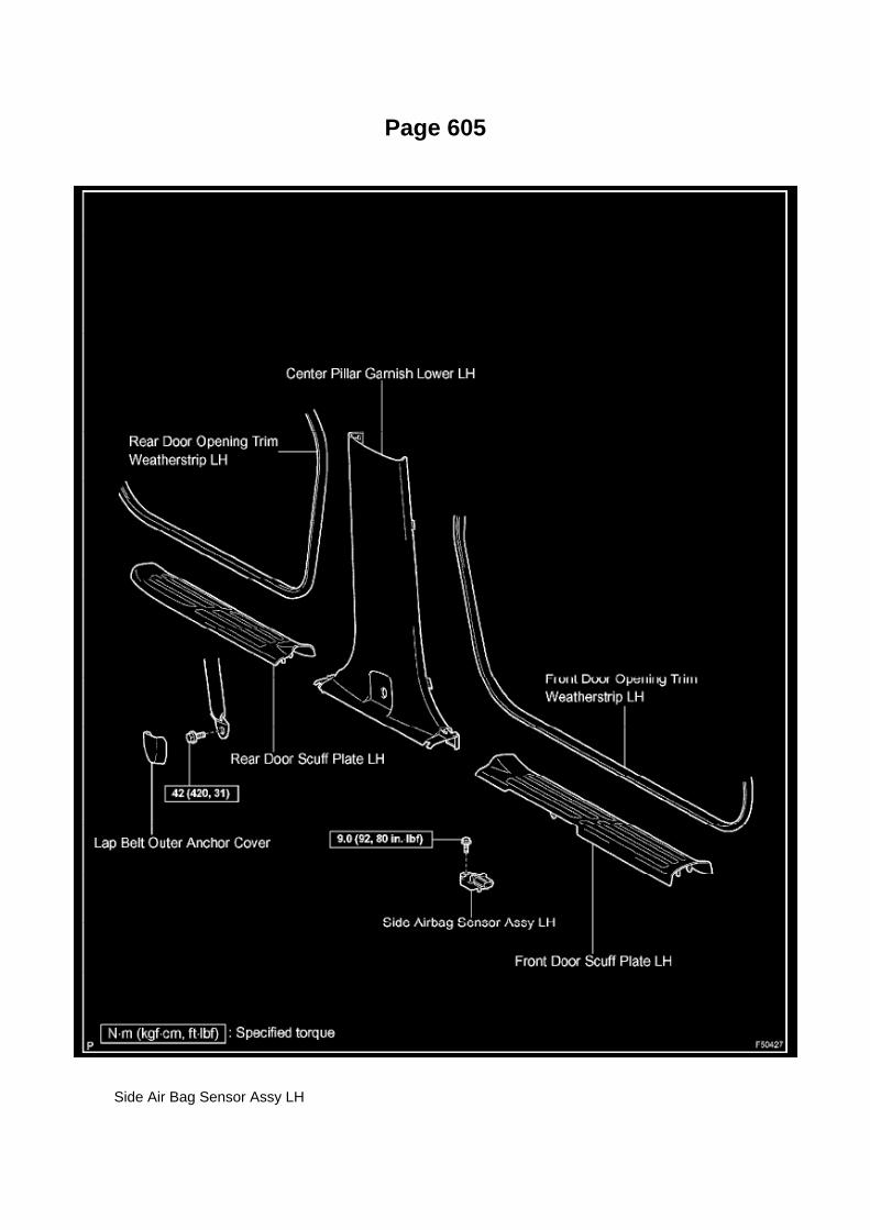
Page 605
Side Air Bag Sensor Assy LH

System Description
Information Bus: Description and Operation System Description
System Diagram
HINT:
- The skid control ECU stores DTCs and performs DTC communication by receiving informationfrom the steering angle sensor and yaw rate sensor. These sensors cannot store DTCs or performDTC communication.
- The ECM uses the CAN communication system to perform DTC communication instead of theconventional serial communication line (SIL).
SYSTEM DESCRIPTION
1. BRIEF DESCRIPTION
a. CAN (Controller Area Network) is a serial data communication system for real time application. Itis an in-vehicle multiplex communication
system which has a high communication speed (500 kbps) and a function to detect malfunctions.
b. The CAN performs communication based on differential voltage by pairing the CANH bus lineand CANL bus line. c. This vehicle uses the CAN communication system for communicationbetween the components in the ABS with EBD & BA & TRAC & VSC

system.
d. The CAN has two resistors of 120 ohm that are necessary for communication with the main busline.
2. DEFINITION OF TERMS
a. Main bus line
1. The main bus line is a wire harness between the two terminus circuits on the bus(communication line). This is the main bus in the CAN
communication system.
b. Sub bus line
1. The sub bus line is a wire harness which diverges from the main bus line to an ECU or sensor.
c. Terminus circuit
1. The terminus circuit is a circuit which is placed to convert communication current of the CANcommunication into bus voltage. It consists
of a resistor and condenser. Two terminus circuits are necessary for a bus.
d. CAN J/C
1. The CAN J/C is a junction designed for CAN communication, which stores a terminus circuit.

Page 1138
Driver Side J/B - Lower Finish Panel

Page 26

normally or lead to repairs not pertinent to the problem. Follow the procedures listed in theflowchart in the correct order.
Steps 4 - 6
- A flowchart showing how to proceed with troubleshooting using the DTC check is shown.Directions from the flowchart will indicate how to proceed either to DTC troubleshooting or to thetroubleshooting of each problem symptom.
Symptom Simulation
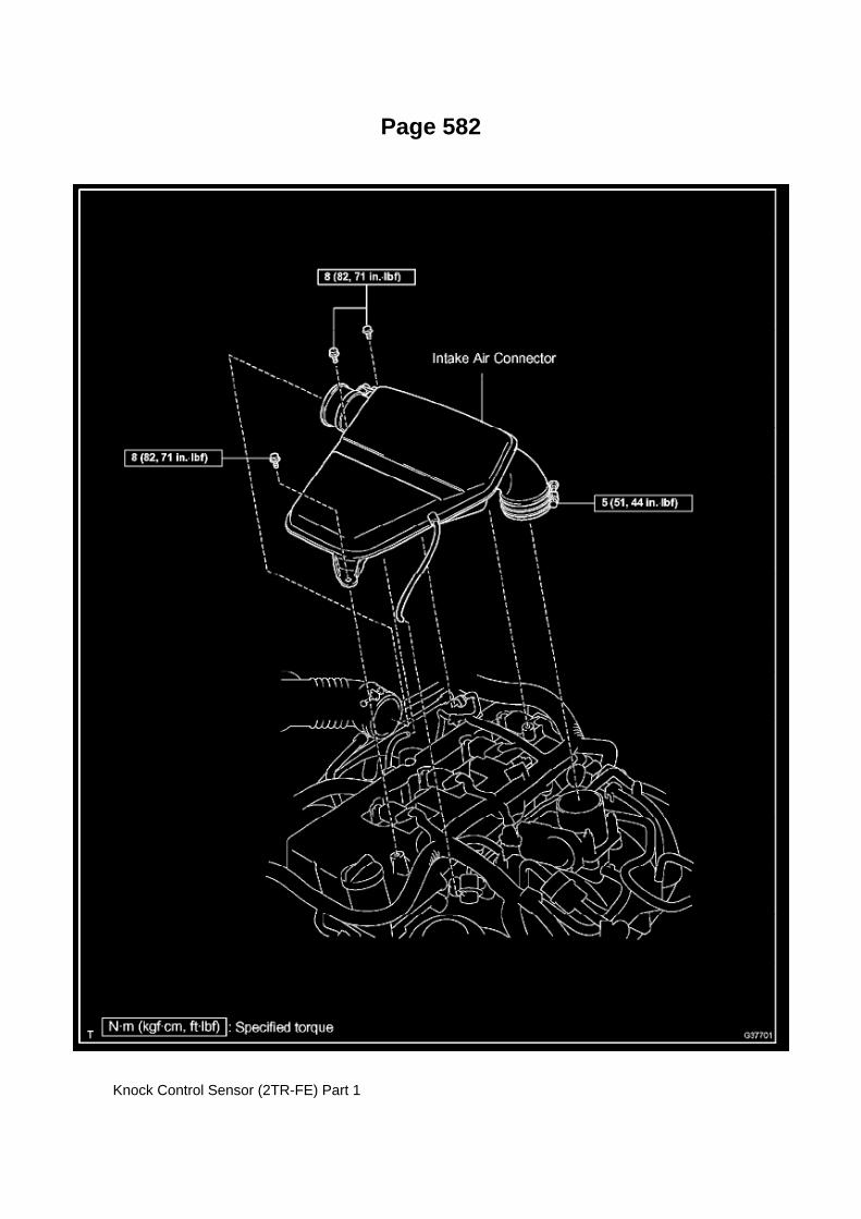
Page 582
Knock Control Sensor (2TR-FE) Part 1

Page 3019
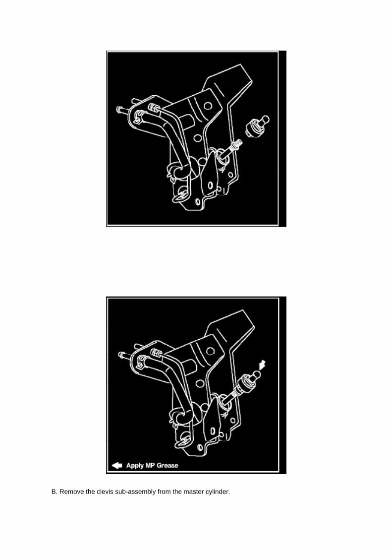
B. Remove the clevis sub-assembly from the master cylinder.

a. Loosen the lock nut.
b. Rotate and remove the clevis sub-assembly.
15. Install the NEW clevis sub-assembly.
A. Rotate the lock nut to match length "A".
B. Rotate and install the NEW clevis sub-assembly to contact the lock nut.
C. Tighten the lock nut and torque to specification.
Torque: 11.8 N.m (120 kgf.cm, 8.7 ft.lbf)
D. Apply MP grease to the ball end of the clevis sub-assembly where it will contact the clutchpedal.

Locations
Power Seat Control Module: Locations
Seat (Separate Seat)

Page 1607

contact Toyota.

OBTAINING A CALIBRATION CD
The Calibration CD is compatible with the above mentioned scantools and J2534 interfaces. ACalibration CD contains all of the most current vehicle calibration files, applicable TSBs, theCalibration Update Wizard application software for a Windows PC, and instructions for use.
Calibration CDs can be ordered through the Toyota Material Distribution Center; order P/N00456-REPRG-001.
IMPORTANT NOTICE
It is possible to permanently damage a vehicle controller during the flash reprogramming process.It is especially important to understand that once started, the reprogramming process must not beinterrupted, reprogramming devices must not be disconnected and PCs must not be allowed to gointo standby, hibernation or similar power management modes. The information provided herein isintended expressly for use by qualified professional automobile technicians. To prevent damage toyour customer's vehicle and ensure safe service practice, read these materials completely andthoroughly before servicing the vehicle and be sure to follow all instructions.

Page 607
Seat Position Air Bag Sensor (Separate Seat Type)

Page 1092

Engine Room R/B, J/B - Engine Compartment Left

Page 1357


Page 1891

a. Read VIN using a hand-held tester.

4. WRITE VIN

Page 1082

Fuse Block: Electrical Diagrams

Engine Room R/B Junction Connector Inner Circuit

Page 60
Trailer Towing Relay: Testing and Inspection
INSPECT TOWING CONVERTER RELAY
a. Measure the voltage and check the results in accordance with the value(s) in the table.
INSPECT TOWING CONVERTER RELAY

a. Check the resistance.
1. Using an ohmmeter, measure the resistance between the terminals.
If the result is not as specified, replace the towing converter relay.

Page 1981

Information Bus: Testing and Inspection

Page 3300

f. Install the 2 new plugs.

34. INSTALL BRAKE ACTUATOR TUBE NO.1
a. Using SST, install the brake actuator tube No.1.
SST 09023-00101 Torque:
15.2 Nm (155 kgf-cm, 11 ft. lbs.) for use without SST 14 Nm (143 kgf-cm, 10 ft. lbs.) for use withSST
HINT: -
Use a torque wrench with a fulcrum length of 250 mm (9 84 inch)
- This torque value is effective when SST is parallel to a torque wrench.
35. INSTALL BRAKE ACTUATOR HOSE
a. Using needle-nose pliers, install the brake actuator hose and 2 clips.
36. INSTALL BRAKE MASTER CYLINDER RESERVOIR SUB-ASSEMBLY
a. Install the cap. b. Apply lithium soap base glycol grease to the 3 new grommets. c. Install the 3grommets to the master cylinder body.
NOTICE: Be careful of the size of each grommets.
d. Install the master cylinder reservoir.
e. Using a pin punch and hammer, install a new pin onto the master cylinder reservoir.

Page 1409

NOTICE: -
Remove any oil from the contact surface.
- Install the chain cover within 3 minutes and tighten the bolts within 15 minutes of applying sealpacking.
- Do not start the engine for at least 4 hours after installation.
e. Align the oil pump's drive rotor spline and the crankshaft as shown in the illustration. Install thespline and chain cover onto the crankshaft. f.
Loosely install the timing chain cover with the 19 bolts and 2 nuts, but do not tighten the bolts andnuts yet.

Page 2851
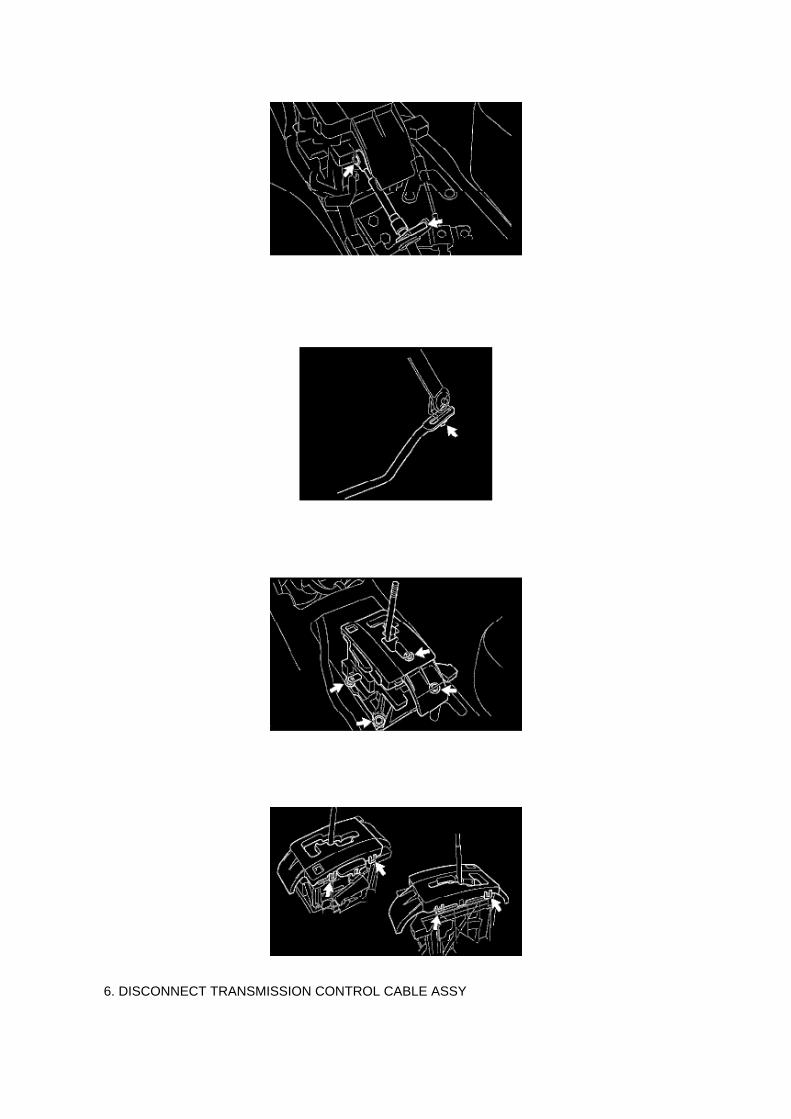
6. DISCONNECT TRANSMISSION CONTROL CABLE ASSY

a. CABLE TYPE:
(1) Disconnect the transmission control cable assy from the shift lever assy. (2) Remove the clipand disconnect the transmission control cable.
7. SEPARATE FLOOR SHIFT GEAR SHIFTING ROD SUB-ASSY
a. ROD TYPE:
(1) Remove the nut, then separate the floor shift gear shifting rod.
8. REMOVE FLOOR SHIFT ASSY
a. Disconnect the 2 connectors and 2 clamps. b. Remove the 4 bolts and floor shift assy.
9. REMOVE POSITION INDICATOR HOUSING UPPER
a. Release the 4 claws with a screwdriver and remove the position indicator housing and slidecover.

Page 3309
Steering Angle Sensor: Service and Repair
STEERING SENSOR (W/ VSC)
REPLACEMENT
1. REMOVE SPIRAL CABLE SUB-ASSEMBLY
2. REMOVE STEERING SENSOR
a. Release 6 claw fittings and remove the steering sensor from the spiral cable.
3. INSTALL STEERING SENSOR
a. Install the steering sensor onto the spiral cable.
NOTICE: -
Engage the claws securely.

- Be careful not to damage the claws.
4. INSTALL SPIRAL CABLE SUB-ASSEMBLY

Page 2928

A. Remove the front door opening trim LH (scuff plate).

B. Remove the cowl side trim board.
C. Remove the instrument panel finish panel lower No. 1.
D. Remove the driver's side Junction Block.
E. Remove the turnover (compression) spring.

Page 1058

a. For an open circuit in the wire harness in Fig. 1, perform a resistance check (step b) or a voltagecheck (step c).

b. Check the resistance.
1. Disconnect connectors A and C and measure the resistance between them.
HINT: Measure the resistance while lightly shaking the wire harness vertically and horizontally.
If your results match the examples above, an open circuit exists between terminal 1 of connector Aand terminal 1 of connector C.
2. Disconnect connectors B and measure the resistance between the connectors.
If your results match the examples above, an open circuit exists between terminal 1 of connectorB2 and terminal 1 of connector C.

Page 840

When the cross camber or caster of the front wheel alignment is large it can cause vehicle pulling.

If the cross camber or caster is within the specified range (30' or less), noticeable vehicle pullingwill not occur due to side-to-side differences in camber or caster.
NOTE
On a flat road, if the cross camber or caster is 30' or less and the steering wheel is held withoutexerting steering effort for 109 yards (100 m) when driving at 62 mph (100 km/h), thealignment-induced drift distance is approximately 1.64 feet (0.5 m).
2. Relationship Between Tire Characteristics and Vehicle Pulling to One Side
When radial tires are rotating they have the characteristic of generating force in the lateral directionbetween the tire and the road surface. This lateral force is comprised of two factors:
^ Ply-steer which changes direction according to the rotation direction of the tires.
^ Conicity which is generated in a fixed direction regardless of the tire rotation direction. If theselateral forces are too strong vehicle pulling will
occur.
A. Ply-Steer
Lateral force due to ply-steer is produced by the construction of the belts inside the tire tread. Withradial tires the wire of the belt is slanted as shown in the illustration below. Thus it is in the lateraldirection that tire tread easily changes shape (stretches) and lateral force is generated between thetire and the road surface in the lateral direction.
Lateral force from ply-steer prevents vehicle drift caused by road slant, so in many cases lateralforce to the left is provided to compensate for road slant to the right.
B. Conicity
Conicity is lateral force resulting from uneven formation of the left and right sides of the tire. Thedirection the lateral force is exerted depends on the hardness of the side walls and the difference inheight between the left/right sides of the tire.
NOTE
^ In the case of vehicle pulling caused by tires, the lateral force which is exerted as a result ofconicity has the greatest effect. On a flat road,

Testing and Inspection
Headlamp Relay: Testing and Inspection
INSPECT HEADLAMP RELAY
a. Check the resistance.
1. Using an ohmmeter, measure the resistance between the terminals.
If the result is not as specified, replace the headlamp relay.

Page 2460
2. After connecting the fuel tube connector, check that the fuel tube connector and pipe aresecurely connected by pulling them.

Page 491
SFI System

Fuel/Emissions - MIL ON/DTC's P0456/P0445 and P0441
Set
Fuel Pump Pickup Filter: All Technical Service Bulletins Fuel/Emissions - MIL ON/DTC'sP0456/P0445 and P0441 Set
ENGINE EG037-05 REVISED
Title: M.I.L. "ON" DTC P0456 OR P0455, AND P0441
Models: '05 Tacoma
September 1, 2005
TSB REVISION NOTICE:
^ September 16, 2005: The Applicable VDS has been updated in Applicable Vehicles. Previousversions of this TSB should be discarded.
Introduction
Some 2005 model year Tacoma vehicles may exhibit a M.I.L. "ON" condition with one or more ofthe following DTCs: P0456 or P0455, and P0441 (EVAP Emission Control System). Follow thesteps in this bulletin to correct this condition.

Applicable Vehicles
^ 2005 model year Tacoma vehicles (except D-Cab Short Bed), with the following VehicleDescription Section VDS) information shown below.
Warranty Information
Applicable Warranty*: This repair is covered under the Toyota Powertrain Warranty. This warrantyis in effect for 60 months or 60,000 miles, whichever occurs first, from the vehicle's in-service date.
* Warranty application is limited to correction of a problem based upon a customer's specificcomplaint.

Specifications
Water Pump: Specifications
Install a new gasket, then install the water pump with the 10 bolts.
Torque:
21 Nm (214 kgf-cm, 15 ft. lbs.) for bolt A 9 Nm (92 kgf-cm, 80 inch lbs.) for bolt B

Page 867
g. Wipe off any spilt gasoline. h. Connect the cable to the negative battery terminal.
Torque: 3.9 N.m (40 kgf.cm, 35 in.lbf)
i. Connect the hand-held tester to the DLC3.
j. Turn the ignition switch to ON.
k. Turn the hand-held tester ON. l.
Select the following menu items: DIAGNOSIS / ENHANCED OBD II / ACTIVE TEST / FUEL PUMP/ SPD / ON.
m. Measure the fuel pressure.
Standard: 281 to 287 kPa (2.87 to 2.93 kgf/sq.cm, 40.8 to 41.7 psi)
- If the pressure is too high, replace the fuel pressure regulator.
- If the pressure is too low, check the connection between the fuel hose and fuel pump.
n. Disconnect the hand-held tester from the DLC3. o. Start the engine. p. Measure the fuelpressure while the engine idles.
Standard: 281 to 287 kPa (2.87 to 2.93 kgf/sq.cm, 40.8 to 41.7 psi)
q. Stop the engine. r.
Check that the fuel pressure does not change for 5 minutes.
Standard: 147 kPa (1.5 kgf/sq.cm, 21 psi)
If the pressure is not as specified, check the fuel pump, pressure regulator and/or injector.
s. Discharge the fuel system pressure. t.
Disconnect the cable from the negative battery terminal.

u. Remove SST while being careful to prevent gasoline splashes. v. Connect the fuel hose. w.Install the fuel pipe clamp. x. Connect the cable to the negative battery terminal.
Torque: 3.9 N.m (40 kgf.cm, 35 in.lbf)
3. CHECK FOR FUEL LEAKAGE

Capacity Specifications

Coolant: Capacity Specifications

Total Cooling System Capacity M/T :................................................................................................................................ 8.7 L (9.1 US qt.,7.6 Imp. qt.)
Total Cooling System Capacity A/T :................................................................................................................................. 8.6 L (9.1 US qt.,7.6 Imp. qt.)

Page 2161

Air Flow Meter/Sensor: Testing and Inspection

INSPECT INTAKE AIR FLOW METER SUB-ASSEMBLY
a. Check the operation.
1. Apply battery voltage across terminals 1 (+B) and 2 (E2G). 2. Using a voltmeter, connect thepositive (+) tester prove to terminal 3 (VG) and the negative (-) tester prove to terminal 2 (E2G). 3.Blow air into the mass air flow meter and check that the voltage fluctuates.
If the voltage does not fluctuate, replace the mass air flow meter.
b. Check the resistance.
1. Using an ohmmeter, measure the resistance between the terminals.
If the result is not as specified, replace the mass air flow meter.

Page 2768

NOTE

Only Toyota Certified Technicians and above may access calibration files.
2. Connect the GR8 Battery Diagnostic Station.
A. Connect the GR8 Battery Diagnostic Station to the vehicle and turn it ON.
B. Select Power Supply Mode by following the screen flow below.
NOTICE
^ ECU damage may occur if the correct battery charger and mode setting are NOT used.

Page 1916

1. Disconnect connectors A and C and measure the resistance between terminals 1 and 2 ofconnector A and the body ground.

HINT: Measure the resistance while lightly shaking the wire harness vertically and horizontally.
If your results match the examples above, a short circuit exists between terminal 1 of connector Aand terminal 1 of connector C.
2. Disconnect connector B and measure the resistance between terminal 1 of connector A and thebody ground, and terminal 1 of connector B2
and the body ground. If your results match the examples above, a short circuit exists betweenterminal 1 of connector B2 and terminal 1 of connector C.
Check and Replace ECU
CHECK AND REPLACE ECU
NOTE:
- The connector should not be disconnected from the ECU. Perform the inspection from thebackside of the connector on the wire harness side.
- When no measuring condition is specified, perform the inspection with the engine stopped andthe ignition switch ON.
- Check that the connectors are fully seated. Check for loose, corroded or broken wires.
a. First check the ECU ground circuit. If it is faulty, repair it.
If it is normal, the ECU could be faulty. Replace the ECU with a normal functioning one and check ifthe symptoms occur. If the trouble symptoms stop, replace the ECU.
1. Measure the resistance between the ECU ground terminal and body ground.
Standard: Below 1 Ohms

Page 3017

6. Remove the two (2) clutch pedal bushes from the clutch pedal.

7. Remove the clutch pedal shaft collar.
8. Using needle-nose pliers, remove the No. 1 cushion from the clutch pedal.
9. Install the clutch pedal No. 1 cushion on the NEW clutch pedal sub-assembly.
NOTE:
Install parts on the NEW clutch pedal sub-assembly BEFORE installing in the vehicle.
10. Install the clutch pedal shaft collar.
A. Apply MP grease to the clutch pedal shaft collar.
B. Install the clutch pedal shaft collar onto the clutch pedal.

Capacity Specifications

Fluid - Differential: Capacity Specifications

DIFFERENTIAL OIL CAPACITY:
2WD Models (except Prerunner)............................................................................................................................................... 3.3 L(3.5 qt., 2.9 Imp. qt.)
4WD models and Prerunner Front (4WD models): ................................................................................................................................................................. 1.5 L (1.6 qt., 1.3 Imp. qt.) Rear: ........................................................................................................................................................................................... 2.8 L (3.0 qt., 2.5 Imp. qt.)
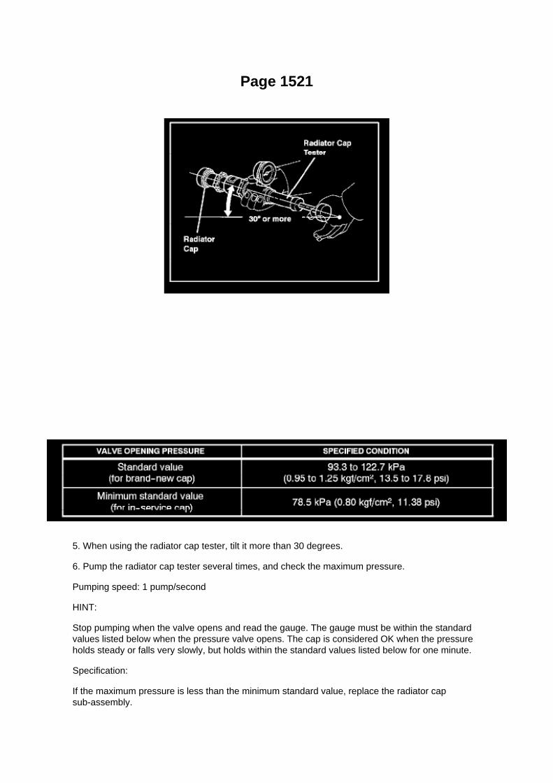
Page 1521
5. When using the radiator cap tester, tilt it more than 30 degrees.
6. Pump the radiator cap tester several times, and check the maximum pressure.
Pumping speed: 1 pump/second
HINT:
Stop pumping when the valve opens and read the gauge. The gauge must be within the standardvalues listed below when the pressure valve opens. The cap is considered OK when the pressureholds steady or falls very slowly, but holds within the standard values listed below for one minute.
Specification:
If the maximum pressure is less than the minimum standard value, replace the radiator capsub-assembly.

Page 2510
Parts Information
Required Tools & Material

Required SSTs
Repair Procedure
1. Using the Diagnostic Tester, check for Diagnostic Trouble Codes (DTCs). If DTC P0456 orP0445, and P0441 are present, check for an EVAP leak on top of the fuel suction platesub-assembly. Refer to the Technical Information System (TIS), 2005 model year Tacoma RepairManual: Diagnostics: SFI System (1GR-FE) / (2TR-FE): EVAP Inspection Procedure.
If NO EVAP leaks are detected at the fuel suction plate sub-assembly, this TSB does NOT apply.Please refer to the normal diagnostic procedure provided in the Repair Manual.
2. To correct the fuel suction plate sub-assembly, replace the fuel suction with pump and gaugetube assembly, retainer ring and gasket set according to TIS, 2005 model year Tacoma RepairManual: Fuel: Fuel Pump Assy: Removal & Installation And Disassembly & Reassembly (Tacoma).
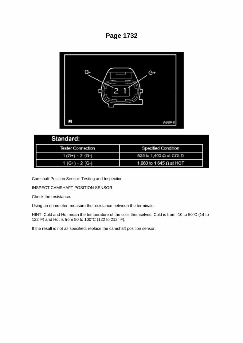
Page 1732
Camshaft Position Sensor: Testing and Inspection
INSPECT CAMSHAFT POSITION SENSOR
Check the resistance.
Using an ohmmeter, measure the resistance between the terminals.
HINT: Cold and Hot mean the temperature of the coils themselves. Cold is from -10 to 50°C (14 to122°F) and Hot is from 50 to 100°C (122 to 212° F).
If the result is not as specified, replace the camshaft position sensor.

Specifications
Engine Oil Pressure: Specifications
Oil pressure

Page 499

a. Install a new gasket onto the intake manifold. b. Install the intake manifold with the 5 bolts and 2nuts.

Torque: 25 N.m (255 kgf.cm, 18 ft.lbf)
c. Connect the engine wire harness to the relay block. d. Install the nut shown in the illustration.
Torque: 10 N.m (102 kgf.cm, 7 ft.lbf)
e. Connect the 3 connectors.
f. Install the harness clamp bracket with the bolt.
Torque: 8.2 N.m (84 kgf.cm, 73 in.lbf)
g. Engage the wire harness clamp. h. Connect the compressor magnetic clutch connector.

Page 1426

1. REMOVE OIL PUMP RELIEF VALVE

a. Using a 27 mm socket wrench, remove the relief valve plug and gasket. b. Remove the valvespring and oil pump relief valve.
2. REMOVE OIL PUMP COVER
a. Remove the 7 bolts and oil pump cover.
3. REMOVE OIL PUMP ROTOR SET
a. Remove the oil pump rotor set from the timing chain cover.
4. INSPECT OIL PUMP RELIEF VALVE
a. Coat the relief valve with engine oil and drop it into the relief valve hole. b. Check that the reliefvalve falls in smoothly by its own weight.
If it does not, replace the relief valve. If necessary, replace the timing chain cover.
5. INSPECT OIL PUMP ROTOR SET
a. Install the rotors to the timing chain cover with the rotors' marks facing outward. Check that therotors revolves smoothly.
6. INSPECT ROTOR TIP CLEARANCE
a. Check the tip clearance.
(1) Using a feeler gauge, measure the clearance between the drive and driven rotor tips, as shownin the illustration.

Page 2705

Transmission Position Switch/Sensor: Service and Repair
PARK/NEUTRAL POSITION SWITCH ASSY
REPLACEMENT
1. DISCONNECT CABLE FROM NEGATIVE BATTERY TERMINAL 2. DISCONNECTPARK/NEUTRAL POSITION SWITCH CONNECTOR
3. REMOVE PARK/NEUTRAL POSITION SWITCH ASSY
a. Using a screwdriver, unstake the lock washer. b. Remove the nut, lock washer and grommet. c.Remove the bolt and park/neutral position switch.
4. INSTALL PARK/NEUTRAL POSITION SWITCH ASSY
a. Install the park/neutral position switch onto the manual valve lever shaft and provisionally tightenthe adjusting bolt.

Locations

Page 3372

Brake Pedal Assy: Service and Repair
BRAKE PEDAL SUB-ASSEMBLY

Locations

Transmission Speed Sensor: Locations

He - Wi

Page 2075
Oxygen Sensor: Testing and Inspection Heated Oxygen Sensor
INSPECTION
INSPECT HEATED OXYGEN SENSOR
a. Check the resistance.
1. Using an ohmmeter, measure the resistance between the terminals.
If the result is not as specified, replace the heated oxygen sensor.

Page 237

Engine Control Module: Service and Repair Control Module Programming and Relearning

Precaution
PRECAUTION
1. INITIALIZATION
NOTE: Perform the REGISTRATION (VIN registration) when replacing the ECM.
2. FOR USING HAND-HELD TESTER
CAUTION: Observe the following items for safety reasons: -
Read its instruction books before using the tester.
- Prevent the tester cable from being caught on the pedals, shift lever and steering wheel whendriving with the tester connected to the vehicle.
- When driving the vehicle for testing purposes using the tester, two persons are required. One isfor driving the vehicle, and the other operates the tester.
Registration
REGISTRATION
NOTE: The Vehicle Identification Number (VIN) must be input into the replacement ECM.
HINT: The VIN is in the form of a 17-digit alphanumeric vehicle identification number. A hand-heldtester is required to resister the VIN.
1. DESCRIPTION
This registration section consists of three parts, Input Instructions, Read VIN and Write VIN. a.Input Instructions: Explains the general VIN input instructions using a hand-held tester. b. ReadVIN: Explains the VIN reading process in a flowchart. This process allows the VIN stored in theECM to be read, in order to confirm
that the two VINs, provided with the vehicle and stored in the vehicle's ECM, are the same.
c. Write VIN: Explains the VIN writing process in a flowchart. This process allows the VIN to beinput into the ECM. If the ECM is changed, or
the VIN and VIN do not match, the VIN can be registered, or overwritten in the ECM by followingthis procedure.
2. INPUT INSTRUCTIONS
a. Hand-held tester
1. The arrow buttons (UP, DOWN, RIGHT and LEFT) and numerical buttons (0 to 9) are used, inorder to input the VIN.
b. Cursor Operation
1. To move the cursor around the tester screen, press the RIGHT and LEFT buttons.
c. Alphabetical Character Input
1. Press the UP and DOWN buttons to select the desired alphabetical character. 2. After selection,the cursor should move.
d. Numeric Character Input

1. Press the numerical button corresponding to the number that you want to input. 2. After input,the cursor should move.
HINT: Numerical characters can be selected by using the UP and DOWN buttons.
e. Correction
1. When correcting the input character(s), put the cursor onto the character using the RIGHT orLEFT buttons. 2. Select or input the correct character using the UP/DOWN buttons, or thenumerical buttons.
f. Finishing Input Operation 1. Make sure that the input VIN matches the vehicle VIN after input. 2.Press the ENTER button on the tester.
3. READ VIN (Vehicle Identification Number)

Page 2430
Parts Information
Required Tools & Material

Required SSTs
Repair Procedure
1. Using the Diagnostic Tester, check for Diagnostic Trouble Codes (DTCs). If DTC P0456 orP0445, and P0441 are present, check for an EVAP leak on top of the fuel suction platesub-assembly. Refer to the Technical Information System (TIS), 2005 model year Tacoma RepairManual: Diagnostics: SFI System (1GR-FE) / (2TR-FE): EVAP Inspection Procedure.
If NO EVAP leaks are detected at the fuel suction plate sub-assembly, this TSB does NOT apply.Please refer to the normal diagnostic procedure provided in the Repair Manual.
2. To correct the fuel suction plate sub-assembly, replace the fuel suction with pump and gaugetube assembly, retainer ring and gasket set according to TIS, 2005 model year Tacoma RepairManual: Fuel: Fuel Pump Assy: Removal & Installation And Disassembly & Reassembly (Tacoma).

Page 210
NOTE
On some models, DTCs may set as a result of reprogramming. If DTCs are present, clear codesand run the Health Check again. Troubleshoot any remaining Current, Pending, or History codes.Permanent codes will not be cleared using Techstream. Permanent codes do not illuminate the MILand do not require troubleshooting. They will clear during normal driving once the Universal TripDrive Pattern is performed.
4. Attach the Authorized Modifications Label.
A. Using a permanent marker or ball point pen complete the Authorized Modifications Label andattach to the vehicle. The Authorized
Modifications Label is available through the MDC P/N 00451-00001-LBL.
B. Attach the label under the hood in the location determined by the specific TSB or Campaign.
NOTE
Wait 60 - 90 seconds for ink to set before handling.

Page 1094
Driver Side J/B - Lower Finish Panel
Details

Page 24
2. Disconnect the ECU connector. Check the ground terminals (on the ECU side and wire harnessside) for evidence of bending, corrosion or
foreign material. Lastly check the contact pressure of the female terminals.
Customer Problem Analysis
CUSTOMER PROBLEM ANALYSIS
HINT:
- In troubleshooting, the problem symptoms must be confirmed accurately. Preconceptions shouldbe discarded in order to give an accurate judgement. To clearly understand what the problemsymptoms are, it is extremely important to ask the customer about the problem and the conditionsat the time it occurred.
- As much information as possible should be gathered for reference. Even past problems that seemunrelated may also help in some cases. In the Diagnostic Section, a customer problem analysistable is provided for each system.
- 5 items are important points in the problem analysis:
Important Points with Customer Problem Analysis -
What .......................................................................................................................................................................... Vehicle model, system name
- When .................................................................................................................................................................. Date, time, occurrence frequency
- Where ............................................................................................................................................................................................ Road conditions
- Under what conditions? ............................................................................................. Runningconditions, driving conditions, weather conditions

- How did it happen? ................................................................................................................................................................... Problem symptoms

Page 469
SFI System

Page 2635

a. Install a new gasket onto the intake manifold. b. Install the intake manifold with the 5 bolts and 2nuts.

Torque: 25 N.m (255 kgf.cm, 18 ft.lbf)
c. Connect the engine wire harness to the relay block. d. Install the nut shown in the illustration.
Torque: 10 N.m (102 kgf.cm, 7 ft.lbf)
e. Connect the 3 connectors.
f. Install the harness clamp bracket with the bolt.
Torque: 8.2 N.m (84 kgf.cm, 73 in.lbf)
g. Engage the wire harness clamp. h. Connect the compressor magnetic clutch connector.

Page 2023

Step 12
INSPECTION PROCEDURE
Scan Tool Testing and Procedures
BUS CHECK
HINT: The ECUs and sensors that are properly connected to the CAN communication system canbe displayed using the hand-held tester via the CAN VIM.
a. Select "BUS CHECK" from the "OBD/MOBD MENU" screen.

Page 904


Page 3239
Step 3

M/T - Clutch Pedal Squeaking Noise
Technical Service Bulletin # TC004-06 Date: 060614
M/T - Clutch Pedal Squeaking Noise
TRANSMISSION & CLUTCH TC004-06
June 14, 2006
Title: CLUTCH PEDAL SQUEAK NOISE
Models: '05 - '06 Tacoma
Introduction
Some customers may complain about a "squeak" or "creak" noise when depressing or releasingthe clutch pedal. The clutch master cylinder clevis assembly has been improved to eliminate thiscondition.
Applicable Vehicles: ^
2005 - 2006 model year Tacoma vehicles equipped with manual transmission and producedBEFORE the Production Change Effective VIN shown below.
Production Change Information

Parts Information
Required Tools & Material
Warranty Information
Applicable Warranty:
This repair is covered under the Toyota Comprehensive Warranty. This warranty is in effect for 36months or 36,000 miles, whichever occurs first, from the vehicle's in-service date.
* Warranty application is limited to correction of a problem based upon a customer's specificcomplaint.

Page 2264
Ce - Ya

Page 1844
CAN Communication System

Diagrams
Windshield Wiper Switch Assy

Brakes - Front Brake Noise When Applied Backing Up
Brake Pad: All Technical Service Bulletins Brakes - Front Brake Noise When Applied Backing Up
BRAKES BR005-07 REVISED
Title: FRONT BRAKE NOISE IN REVERSE
Models: '05 - '07 Tacoma 4X4 & PreRunner
August 30, 2007
TSB REVISION NOTICE:
^ September 12, 2007: The description in the Warranty Information table and steps 2 and 5 in theRepair Procedure have been updated.
Previous versions of this TSB should be discarded.
Introduction Some customers may experience front brake noise when driving the vehicle in reverseand applying the brake pedal. The noise will typically occur when backing out of a parking spaceafter the vehicle has been stopped for an extended period of time. Updated front brake rotors andbrake pad shim grease are now available to improve this condition.
Applicable Vehicles
^ 2005 - 2007 model year Tacoma 4x4 and PreRunner vehicles.
Parts Information
Warranty Information

Applicable Warranty*: This repair is covered under the Toyota Comprehensive Warranty. Thiswarranty is in effect for 36 months or 36,000 miles, whichever occurs first, from the vehicle'sin-service date.
* Warranty application is limited to correction of a problem based upon a customer's specificcomplaint.
Repair Procedure
1. Conduct a road test to confirm the noise condition. The noise typically occurs when backing outof a parking spot in reverse.
2. Remove the front brake pads and front rotors.

Locations
Relay Box: Locations
Engine Room R/B No. 2 - Engine Compartment Left

Page 3002

6. Cut the dash panel insulator.

7. Return the carpet to its former position.
8. Go to Repair Procedure B, "Clutch Pedal Replacement."
Repair Procedure B
Clutch Pedal Replacement
1. Record all radio presets before starting.
2. Disconnect the negative (-) battery terminal cable.
3. Remove the clutch pedal sub-assembly.
NOTE:
Steps 3A - 3B can be skipped if Repair Procedure A was just performed.
A. Remove the front door opening trim LH (scuff plate).

Page 3317
Step 4 - 5

Page 501
o. Connect the fuel vapor feed hose to the VSV.
12. CONNECT FUEL HOSE 13. CONNECT FUEL HOSE NO.2 14. INSTALL THROTTLEW/MOTOR BODY ASSEMBLY 15. INSTALL INTAKE AIR CONNECTOR 16. CONNECT CABLETO NEGATIVE BATTERY TERMINAL
Torque: 3.9 N.m (40 kgf.cm, 35 in.lbf)
17. ADD ENGINE COOLANT 18. CHECK FOR ENGINE COOLANT LEAKAGE 19. CHECK FORFUEL LEAKAGE 20. INSTALL ENGINE UNDER COVER SUB-ASSEMBLY NO.1 (PRE RUNNERAND 4WD TYPE)

Page 1934

3. COMPONENTS WHICH COMMUNICATE THROUGH THE CAN COMMUNICATION SYSTEM

a. Skid Control ECU b. Steering Angle Sensor c. Yaw Rate Sensor d. ECM
4. DIAGNOSTIC CODES FOR THE CAN COMMUNICATION SYSTEM
a. DTCs for the CAN communication system are as follows:
U0073/94, U0123/62, U0124/95, U0126/63, U0100/65
5. REMARKS FOR TROUBLESHOOTING
a. Trouble in the CAN bus (communication line) can be checked from the DLC3 (except a wirebreak in lines other than the DLC3 sub bus line). b. The CAN communication system cannot detecttrouble in the DLC3 sub bus line even though the DLC3 is also connected to the CAN
communication system.
6. HOW TO DISTINGUISH THE J/C CONNECTOR
a. In the CAN communication system, all connectors connected to the CAN J/C are the sameshape. The connectors connected to the CAN J/C
can be distinguished by the colors of the bus lines and the connecting side of the connector.
HINT: See "TERMINALS OF ECU" for bus line colors or the type of connecting surface.

Page 512


Locations
Intake Air Temperature Sensor: Locations

SFI System
The Intake Air Temperature (IAT) Sensor is installed in the Mass Air Flow (MAF) Meter.

Front
Wheel Speed Sensor: Service and Repair Front
SPEED SENSOR FRONT LH
REPLACEMENT
HINT: The replacement procedures for the RH side are the same as those for the LH side.
1. DISCONNECT CABLE FROM NEGATIVE BATTERY TERMINAL 2. REMOVE FRONT WHEEL
3. REMOVE SPEED SENSOR FRONT LH
a. Disconnect the speed sensor connector. b. Remove the bolt and front speed sensor.
NOTICE: -
Do not attach any foreign matter to the sensor tip.
- Ensure that no foreign matter enters the sensor installation part.
4. INSTALL SPEED SENSOR FRONT LH
a. Install the front speed sensor with the bolt.
Torque: 8.3 Nm (85 kgf-cm, 73 inch lbs.)
NOTICE: Make sure that the sensor tip is clean.

b. Connect the speed sensor connector.
5. INSTALL FRONT WHEEL
Torque: 113 Nm (1,152 kgf-cm, 83 ft. lbs.)
6. CONNECT CABLE TO NEGATIVE BATTERY TERMINAL
Torque: 3.9 Nm (40 kgf-cm, 35 inch lbs.)
7. CHECK ABS SENSOR SIGNAL

Page 2016
Step 7 - 8
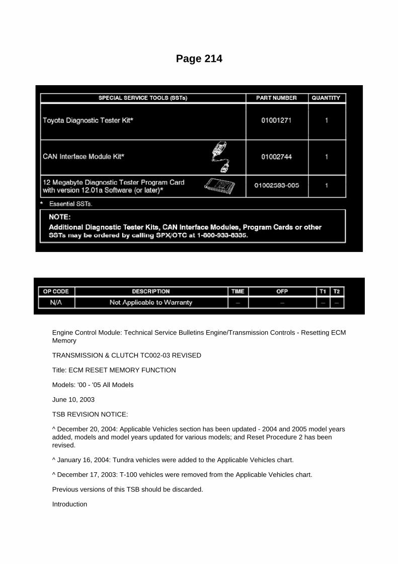
Page 214
Engine Control Module: Technical Service Bulletins Engine/Transmission Controls - Resetting ECMMemory
TRANSMISSION & CLUTCH TC002-03 REVISED
Title: ECM RESET MEMORY FUNCTION
Models: '00 - '05 All Models
June 10, 2003
TSB REVISION NOTICE:
^ December 20, 2004: Applicable Vehicles section has been updated - 2004 and 2005 model yearsadded, models and model years updated for various models; and Reset Procedure 2 has beenrevised.
^ January 16, 2004: Tundra vehicles were added to the Applicable Vehicles chart.
^ December 17, 2003: T-100 vehicles were removed from the Applicable Vehicles chart.
Previous versions of this TSB should be discarded.
Introduction

Whenever an automatic transmission is replaced, overhauled or individual components arereplaced, use this procedure to clear Engine Control Module (ECM, SAE term: Powertrain ControlModule, PCM) "Learned Values" to minimize subsequent performance concerns.
CAUTION:
Failure to follow the procedure below may lengthen the time to readjust the ECM "Learned Values,"potentially resulting in performance concerns.
Required SSTs
Warranty Information
Applicable Vehicles

Page 832
Wiper Switch: Service and Repair
Windshield Wiper Switch Assy
WINDSHIELD WIPER SWITCH ASSEMBLY
REPLACEMENT
1. DISCONNECT CABLE FROM NEGATIVE BATTERY TERMINAL
Wait for at least 90 seconds after disconnecting the cable to prevent the airbag from working.
2. REMOVE STEERING COLUMN COVER LWR 3. REMOVE STEERING COLUMN COVER UPR

Page 3365

3. BLEED BRAKE LINE

a. Connect the vinyl tube to the bleeder plug. b. Depress the brake pedal several times, thenloosen the bleeder plug with the pedal held down. c. At the point where the fluid stops coming out,tighten the bleeder plug, then release the brake pedal. d. Repeat b. and c. until all the air in thefluid has been bled out. e. Repeat the above procedure to bleed the air out of the brake line foreach wheel.
Torque: 11 Nm (112 kgf-cm, 8 ft. lbs.)
4. CHECK FLUID LEVEL IN RESERVOIR
a. Check the fluid level and add fluid if necessary.
Fluid: SAE J1703 or FMVSS No.116 DOT3

Page 3130
Drive/Propeller Shaft: Service and Repair Rear (W/ Center Bearing Shaft Assy)
PROPELLER W/ CENTER BEARING SHAFT ASSY (4WD ACCESS CAB AND DOUBLE CABTYPE)

COMPONENTS
OVERHAUL
1. REMOVE PROPELLER W/ CENTER BEARING SHAFT ASSY
a. Place matchmarks on the propeller shaft flange and differential. b. Remove the 4 nuts, 4 bolts, 4washers and front propeller shaft assy.

Page 2438

3. Install the fuel tank protector cover on top of the fuel suction plate sub-assembly as shown in theillustration.

Page 1063

normally or lead to repairs not pertinent to the problem. Follow the procedures listed in theflowchart in the correct order.
Steps 4 - 6
- A flowchart showing how to proceed with troubleshooting using the DTC check is shown.Directions from the flowchart will indicate how to proceed either to DTC troubleshooting or to thetroubleshooting of each problem symptom.
Symptom Simulation

Page 1148
Instrument Panel J/B No. 2 Inner Circuit

Page 1766

Fuel Pressure: Testing and Inspection

ON-VEHICLE INSPECTION
1. CHECK FUEL PUMP
a. Connect the hand-held tester to the DLC3. b. Turn the ignition switch to ON.
NOTE: Do not start the engine.
c. Turn the hand-held tester ON. d. Select the following menu items: DIAGNOSIS / ENHANCEDOBD II / ACTIVE TEST / FUEL PUMP / SPD. e. Check the fuel operation by operating it with thehand-held tester.
If the fuel pump does not operate, replace the fuel pump.
2. CHECK FUEL PRESSURE
a. Discharge the fuel system pressure. b. Using a voltmeter, measure the battery voltage.
Standard: 9.0 to 14 V
c. Disconnect the cable from the negative battery terminal. d. Remove the fuel pipe clamp. e.Disconnect the fuel hose.
f. Install SST into the vehicle.
SST 09268- 41048 (09268- 41500, 90467- 13001, 95336- 08070), 09268- 45014 (09268- 41200,09268-41220, 09268-41250, 90467-13001)

Page 3249

Ac - Ya
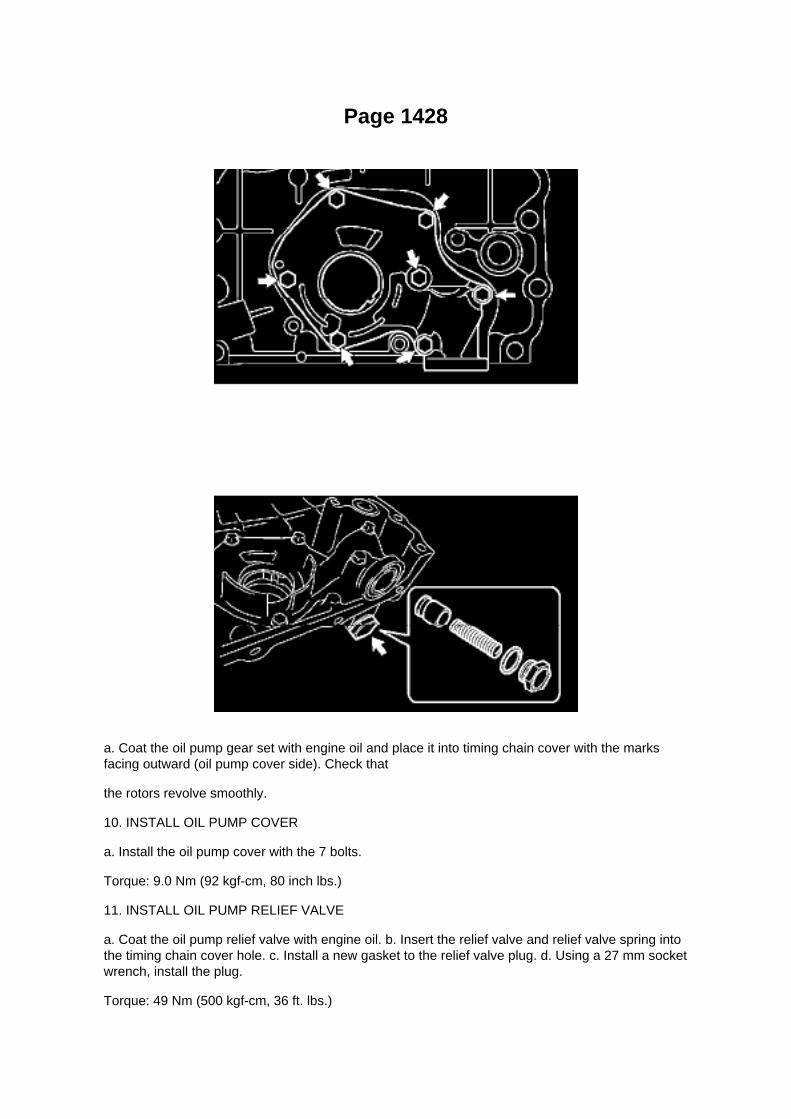
Page 1428
a. Coat the oil pump gear set with engine oil and place it into timing chain cover with the marksfacing outward (oil pump cover side). Check that
the rotors revolve smoothly.
10. INSTALL OIL PUMP COVER
a. Install the oil pump cover with the 7 bolts.
Torque: 9.0 Nm (92 kgf-cm, 80 inch lbs.)
11. INSTALL OIL PUMP RELIEF VALVE
a. Coat the oil pump relief valve with engine oil. b. Insert the relief valve and relief valve spring intothe timing chain cover hole. c. Install a new gasket to the relief valve plug. d. Using a 27 mm socketwrench, install the plug.
Torque: 49 Nm (500 kgf-cm, 36 ft. lbs.)

Page 2192

Knock Sensor: Service and Repair

REPLACEMENT
1. DISCONNECT CABLE FROM NEGATIVE BATTERY TERMINAL 2. REMOVE ENGINE UNDERCOVER SUB-ASSEMBLY NO.1 (PRE RUNNER AND 4WD TYPE) 3. DRAIN ENGINE COOLANT4. REMOVE INTAKE AIR CONNECTOR 5. REMOVE THROTTLE W/MOTOR BODY ASSEMBLY6. DISCONNECT FUEL HOSE 7. DISCONNECT FUEL HOSE NO.2 8. REMOVE INTAKEMANIFOLD
a. Disconnect the fuel vapor feed hose from the VSV.
b. Disconnect the vacuum hose.
c. Remove the bolt, then remove the clamp bracket.

Page 158

1. Disconnect connectors A and C and measure the resistance between terminals 1 and 2 ofconnector A and the body ground.

HINT: Measure the resistance while lightly shaking the wire harness vertically and horizontally.
If your results match the examples above, a short circuit exists between terminal 1 of connector Aand terminal 1 of connector C.
2. Disconnect connector B and measure the resistance between terminal 1 of connector A and thebody ground, and terminal 1 of connector B2
and the body ground. If your results match the examples above, a short circuit exists betweenterminal 1 of connector B2 and terminal 1 of connector C.
Check and Replace ECU
CHECK AND REPLACE ECU
NOTE:
- The connector should not be disconnected from the ECU. Perform the inspection from thebackside of the connector on the wire harness side.
- When no measuring condition is specified, perform the inspection with the engine stopped andthe ignition switch ON.
- Check that the connectors are fully seated. Check for loose, corroded or broken wires.
a. First check the ECU ground circuit. If it is faulty, repair it.
If it is normal, the ECU could be faulty. Replace the ECU with a normal functioning one and check ifthe symptoms occur. If the trouble symptoms stop, replace the ECU.
1. Measure the resistance between the ECU ground terminal and body ground.
Standard: Below 1 Ohms

Page 915
f. Remove the nut, then remove the charcoal canister filter No.2.
7. INSTALL CHARCOAL CANISTER FILTER NO.2
a. Install the charcoal canister filter No.2 with the nut.
Torque: 20 N.m (204 Kgf.cm, 15 ft.lbf)
a. Connect the breather hose to the charcoal canister. b. Engage the clamp. c. Connect thebreather hose to the pipe. d. Connect the EVAP pipe to the clamp. e. Install the ABS wire harnessclamp with the bolt.
Torque: 14 N.m (142 Kgf.cm, 10 ft.lbf)
8. INSTALL FUEL TANK ASSEMBLY 9. CONNECT FUEL TANK MAIN TUBE AND FUEL TANKRETURN TUBE
10. REMOVE FUEL TANK PROTECTOR SUB-ASSEMBLY NO.1 (OFF ROAD PACKAGE) 11.CONNECT CABLE TO NEGATIVE BATTERY TERMINAL
Torque: 3.9 N.m (40 Kgf.cm, 35 in.lbf)
12. CHECK FOR FUEL LEAKAGE

Page 2913

HINT: After assembling the input shaft bearing to the hub, make sure that it rotates smoothly.

b. Install 4 new bolts.
Torque: 27 Nm (270 kgf-cm, 20 ft. lbs.)
c. Mark each bolt with paint as shown in the illustration. d. Retighten each bolt by 90°. e. Checkthat the mark on each bolt is at a 90° angle from its original position.
16. INSPECT CLUTCH RELEASE BEARING ASSY
a. Turn the release bearing by hand while applying force in the axial direction.
HINT: The bearing is permanently lubricated and requires no cleaning or lubrication.
If necessary, replace the release bearing assy.
17. INSTALL CLUTCH DISC ASSY
a. Insert SST into the clutch disc assy, then insert them into the flywheel sub-assembly.
SST 09301-00210
NOTICE: Take care not to insert clutch disc assy in the wrong orientation.
18. INSTALL CLUTCH COVER ASSY

Page 2116
Refer to Reset Procedure 1 for the vehicles with Electronically Controlled AutomaticTransmissions:

Page 2036
Knock Control Sensor (2TR-FE) Part 1

Page 672

(c) Connect the male portion of the wire seat jumper to the female portion of the floor wire harness,as shown in the illustration.

(d) Push and pull the connectors to confirm that they are locked in place.
(e) Insert the wire seat jumper connector clip into the slotted hole on the seat bracket.
(f) Connect the female portion of the wire seat jumper to the male portion of the floor wire harness,as shown in the illustration.
(g) Push and pull the connectors to confirm that they are locked in place.
(h) Confirm that the wire seat jumper is correctly routed.

Page 2728
^ Engine Control Module (ECM)
^ Transmission Control Module (TCM)
^ Or any other Toyota specific control unit
Warranty Information
Parts Information
Required Tools & Equipment
NOTE
Additional SSTs may be ordered by calling 1-800-933-8335.
Process Overview
Techstream ECU flash reprogramming is a 4-step process:

1. Verify the vehicle's applicability for recalibration and locate desired calibration file by performingthe Techstream Health Check function.
NOTE
Techstream will automatically search TIS for the appropriate service bulletin using the currentCalibration ID from the vehicle. Calibration file links can be found embedded in the correspondingservice bulletin.
2. Connect the GR8 Battery Diagnostic Station using "Power Supply Mode" only.
The GR8 Battery Diagnostic Station includes a Power Supply Mode to help maintain batteryvoltage at 13.5 volts during ECU reprogramming.
ECU damage may occur if the correct battery charger mode setting is NOT used.
3. Locate appropriate calibration ID and reprogram the vehicle ECU with Techstream.
Techstream uses the Calibration Update Wizard (CUW) application to open calibration files andfacilitate the ECU flash reprogramming process.

Page 156
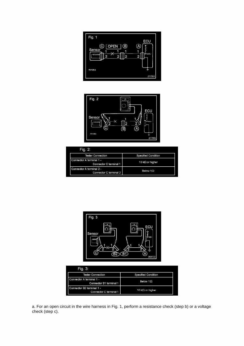
a. For an open circuit in the wire harness in Fig. 1, perform a resistance check (step b) or a voltagecheck (step c).

b. Check the resistance.
1. Disconnect connectors A and C and measure the resistance between them.
HINT: Measure the resistance while lightly shaking the wire harness vertically and horizontally.
If your results match the examples above, an open circuit exists between terminal 1 of connector Aand terminal 1 of connector C.
2. Disconnect connectors B and measure the resistance between the connectors.
If your results match the examples above, an open circuit exists between terminal 1 of connectorB2 and terminal 1 of connector C.

Page 1959
Step 11 - 14

Page 2109

J. When Cal 1 has completed the update process turn ignition OFF for a minimum of 10 seconds.Then click Next.

K. Turn ignition to the ON position. Then click Start.
L. Do NOT disturb the vehicle during flash reprogramming.

Page 2953
b. Connect the clutch start switch connector.
12. CONNECT DRIVER SIDE JUNCTION BLOCK 13. INSTALL INSTRUMENT PANEL FINISHPANEL LOWER NO.1 14. INSTALL COWL SIDE TRIM BOARD LH 15. INSTALL FRONT DOORSCUFF PLATE LH
16. CONNECT CLUTCH MASTER CYLINDER TO FLEXIBLE HOSE TUBE
a. Using SST, connect the flexible hose tube. SST 09023-00101
Torque: 15 Nm (155 kgf-cm, 11 ft. lbs.)
17. CONNECT CLUTCH RESERVOIR TUBE 18. BLEED BRAKE LINE (W/O VSC) 19. BLEEDCLUTCH PIPE LINE 20. INSPECT AND ADJUST CLUTCH PEDAL SUB-ASSY 21. CHECKBRAKE FLUID LEAKAGE (W/O VSC) 22. CHECK FOR CLUTCH FLUID LEAKAGE 23. CHECKFLUID LEVEL IN RESERVOIR

Locations
A/C - Ge

Page 861
(3) As shown in the chart, read the distance from the marked point to 0 point, and adjust the frontand/or rear adjusting cams accordingly.
Toe adjust cam: (Shorter) 2.8 Camber adjust cam: (Shorter) 1.5

Page 3331
a. Turn the ignition switch off and connect the hand-held tester to the DLC3.
b. Turn the ignition switch on. Follow the on-screen directions on the hand-held tester to display theDATA LIST and select areas which should be
monitored for momentary interruptions.

HINT: A momentary interruption (open circuit) cannot be detected for 3 seconds after the ignitionswitch is turned on (initial check).
HINT: -
If the hand-held tester status remains open, check the continuity between the ECU and thesensors, or between ECUs.
- The OPEN display on the hand-held tester remains on for 1 second after the harness signalchanges from momentary interruption (open circuit) to normal condition.

Page 2571
SFI System

Page 381
Cruise Control Main Switch
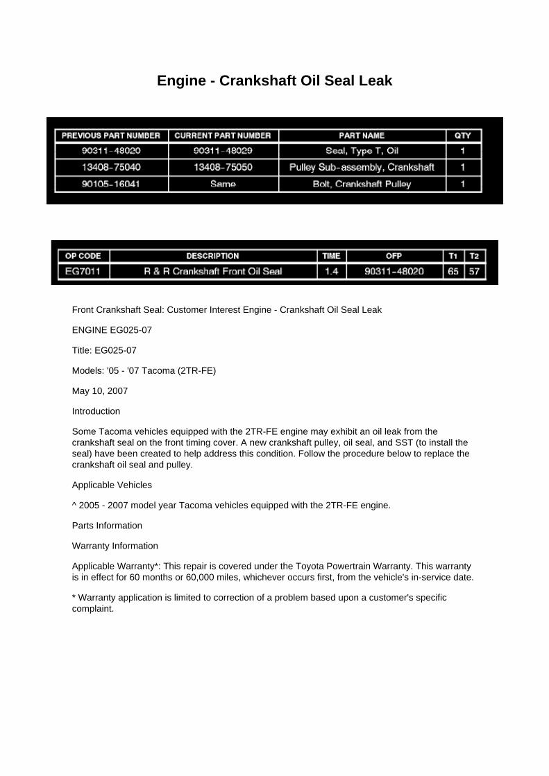
Engine - Crankshaft Oil Seal Leak
Front Crankshaft Seal: Customer Interest Engine - Crankshaft Oil Seal Leak
ENGINE EG025-07
Title: EG025-07
Models: '05 - '07 Tacoma (2TR-FE)
May 10, 2007
Introduction
Some Tacoma vehicles equipped with the 2TR-FE engine may exhibit an oil leak from thecrankshaft seal on the front timing cover. A new crankshaft pulley, oil seal, and SST (to install theseal) have been created to help address this condition. Follow the procedure below to replace thecrankshaft oil seal and pulley.
Applicable Vehicles
^ 2005 - 2007 model year Tacoma vehicles equipped with the 2TR-FE engine.
Parts Information
Warranty Information
Applicable Warranty*: This repair is covered under the Toyota Powertrain Warranty. This warrantyis in effect for 60 months or 60,000 miles, whichever occurs first, from the vehicle's in-service date.
* Warranty application is limited to correction of a problem based upon a customer's specificcomplaint.

Page 10
Diagram Legend
Diagram Legend
O: Indicates values or explains the function for reference during troubleshooting.
P: Indicates the reference showing the position on the vehicle of the parts in the system circuit.Example: Part L4 (Light Failure Sensor) * The letter in the code is from the first letter of the part,and the number indicates its order in parts starting with that letter.
Q: Indicates the reference showing the position on the vehicle of Relay Block Connectors in thesystem circuit.
Example: Connector "1" is described and is installed on the left side of the instrument panel.

R: Indicates the reference showing the position on the vehicle of J/B and Wire Harness in thesystem circuit.
Example: Connector "3C" connects the Instrument Panel Wire and J/B No.3. It is described and isinstalled on the instrument panel left side.
S: Indicates the reference describing the wiring harness and wiring harness connector (the femalewiring harness is shown first, followed by the male wiring harness).
Example: Connector "IE1" connects the floor wire (female) and Instrument panel wire (male). It isdescribed and is installed on the left side kick panel.
T: Indicates the reference showing the position of the ground points on the vehicle.
Example: Ground point "BO" is described and is installed on the back panel center.
U: Indicates the reference showing the position of the splice points on the vehicle.

Page 1704
Transmission Position Switch/Sensor: Adjustments
PARK/NEUTRAL POSITION SWITCH ASSY
ADJUSTMENT
1. INSPECT PARK/NEUTRAL POSITION SWITCH ASSY
a. Apply the parking brake and turn the ignition switch to ON. b. Depress the brake pedal andcheck that the engine starts only when the shift lever is set in the N or P position and that it doesnot start in any
other positions.
c. Check that the back-up light comes on and the reverse warning buzzer sounds only when theshift lever is set in the R position and not in other
positions. If any failure is found, check the park/neutral position switch for continuity.
2. ADJUST PARK/NEUTRAL POSITION SWITCH ASSY
a. Loosen the bolt of the park/neutral position switch and set the shift lever to the N position. b.Align the groove and the neutral basic line. c. Hold the switch in position and tighten the bolt.
Torque: 13 Nm (130 kgf-cm, 9 ft. lbs.)
d. After making an adjustment, perform the inspection described in step 1.

Page 1329
^ SST P/N 09223-75010-01
6. Remove the crankshaft bolt and SST.
7. Install the NEW crankshaft pulley.
A. Align the set key of the crankshaft with the key groove of the pulley, and slide on the pulley.

B. Temporarily install the NEW crankshaft pulley bolt onto the crankshaft.
C. Using the SSTs, hold the crankshaft pulley, and tighten the crankshaft pulley bolt.
^ SST P/N 09213-54015-01 (91651-60855-01), 09330-00021
Torque: 260 N.m (2,651 kgf.cm, 192 ft.lbf)
8. Reinstall the accessory belt.

Page 184

Instrument Panel J/B No. 1 Inner Circuit

Page 866

Fuel Pressure: Testing and Inspection

ON-VEHICLE INSPECTION
1. CHECK FUEL PUMP
a. Connect the hand-held tester to the DLC3. b. Turn the ignition switch to ON.
NOTE: Do not start the engine.
c. Turn the hand-held tester ON. d. Select the following menu items: DIAGNOSIS / ENHANCEDOBD II / ACTIVE TEST / FUEL PUMP / SPD. e. Check the fuel operation by operating it with thehand-held tester.
If the fuel pump does not operate, replace the fuel pump.
2. CHECK FUEL PRESSURE
a. Discharge the fuel system pressure. b. Using a voltmeter, measure the battery voltage.
Standard: 9.0 to 14 V
c. Disconnect the cable from the negative battery terminal. d. Remove the fuel pipe clamp. e.Disconnect the fuel hose.
f. Install SST into the vehicle.
SST 09268- 41048 (09268- 41500, 90467- 13001, 95336- 08070), 09268- 45014 (09268- 41200,09268-41220, 09268-41250, 90467-13001)

Locations

A/C - Fo

Page 1424
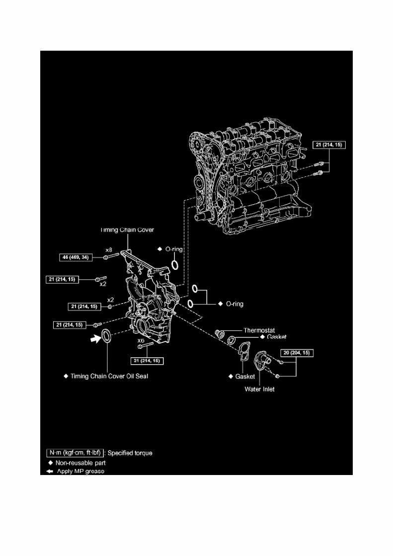

Specifications

Compression Check: Specifications

Compression pressure......................................................................................................................................................1230 kPa (12.5 kgf/cm2, 178 psi) Minimum pressure.................................................................................................................................................. 880kPa (9.0 kgf/cm2, 128 psi) or more Difference between each cylinder................................................................................................................................. 68 kPa (0.7kgf/cm2, 10 psi) or less

Page 154

b. HANDLING CONNECTORS
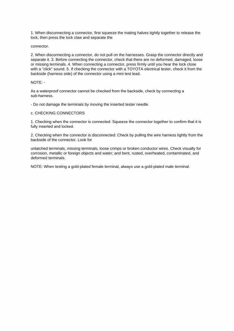
1. When disconnecting a connector, first squeeze the mating halves tightly together to release thelock, then press the lock claw and separate the
connector.
2. When disconnecting a connector, do not pull on the harnesses. Grasp the connector directly andseparate it. 3. Before connecting the connector, check that there are no deformed, damaged, looseor missing terminals. 4. When connecting a connector, press firmly until you hear the lock closewith a "click" sound. 5. If checking the connector with a TOYOTA electrical tester, check it from thebackside (harness side) of the connector using a mini test lead.
NOTE: -
As a waterproof connector cannot be checked from the backside, check by connecting asub-harness.
- Do not damage the terminals by moving the inserted tester needle.
c. CHECKING CONNECTORS
1. Checking when the connector is connected: Squeeze the connector together to confirm that it isfully inserted and locked.
2. Checking when the connector is disconnected: Check by pulling the wire harness lightly from thebackside of the connector. Look for
unlatched terminals, missing terminals, loose crimps or broken conductor wires. Check visually forcorrosion, metallic or foreign objects and water; and bent, rusted, overheated, contaminated, anddeformed terminals.
NOTE: When testing a gold-plated female terminal, always use a gold-plated male terminal.

Page 3241
Step 6 - 7
INSPECTION PROCEDURE
ABS Warning Light Circuit (Does Not Light Up)
ABS WARNING LIGHT CIRCUIT (DOES NOT LIGHT UP)

CIRCUIT DESCRIPTION
If the ECU detects trouble, it illuminates the ABS warning light while at the same time prohibitingABS control. At this time, the ECU records a DTC in its memory.
Connecting terminals TC and CG of the DLC3 causes the ECU to display 2-digit DTCs by blinkingthe ABS warning light.

Page 1014

3. BLEED BRAKE LINE

a. Connect the vinyl tube to the bleeder plug. b. Depress the brake pedal several times, thenloosen the bleeder plug with the pedal held down. c. At the point where the fluid stops coming out,tighten the bleeder plug, then release the brake pedal. d. Repeat b. and c. until all the air in thefluid has been bled out. e. Repeat the above procedure to bleed the air out of the brake line foreach wheel.
Torque: 11 Nm (112 kgf-cm, 8 ft. lbs.)
4. CHECK FLUID LEVEL IN RESERVOIR
a. Check the fluid level and add fluid if necessary.
Fluid: SAE J1703 or FMVSS No.116 DOT3

Page 2272
a. Install the exhaust manifold heat insulator No.1 with the 5 bolts.
Torque: 12 N.m (122 Kgf.cm, 9 ft.lbf)
12. INSTALL AIR CLEANER CAP SUB-ASSEMBLY
a. Install the air cleaner cap together with the air cleaner hose No.1. b. Connect the 2 air cleanerclamps. c. Tighten the hose clamp bolt, then connect the air cleaner hose No.1. d. Connect thewire harness clamp. e. Connect the mass air flow meter connector.
13. INSTALL INTAKE AIR CONNECTOR 14. CONNECT CABLE FROM NEGATIVE BATTERYTERMINAL
Torque: 3.9 N.m (40 Kgf.cm, 35 in.lbf)

Page 2041

d. Disconnect the water bypass hose No.2.

e. Disconnect the ventilation hose No.3.
f. Disconnect the VSV connector.
g. Disengage the engine wire harness clamp. h. Disconnect the compressor magnetic clutchconnector.
(w/ AIR CONDITIONING)
i. Disengage the wire harness clamp.
j. Remove the bolt and harness clamp bracket.

Page 1950
Wiring Diagram

Page 1072

"Case 1" Raise the terminal retainer up to the temporary lock position.

"Case 2" Open the secondary locking device.

Page 826
4. REMOVE WINDSHIELD WIPER SWITCH ASSEMBLY
a. Disconnect the 2 connectors. b. Using a screwdriver wrapped with protective tape, disengagethe claw and remove the windshield wiper switch assembly.
NOTE: The claw will break if pressed too hard.
5. INSTALL WINDSHIELD WIPER SWITCH ASSEMBLY
a. Engage the claw and install the windshield wiper switch assembly. b. Connect the 2 connectors.

6. CONNECT CABLE TO NEGATIVE BATTERY TERMINAL
Torque: 3.9 N.m (40 kgf.cm, 35 in.lbf)
7. INSTALL STEERING COLUMN COVER UPR 8. INSTALL STEERING COLUMN COVER LWR

Page 242

contact Toyota.

OBTAINING A CALIBRATION CD
The Calibration CD is compatible with the above mentioned scantools and J2534 interfaces. ACalibration CD contains all of the most current vehicle calibration files, applicable TSBs, theCalibration Update Wizard application software for a Windows PC, and instructions for use.
Calibration CDs can be ordered through the Toyota Material Distribution Center; order P/N00456-REPRG-001.
IMPORTANT NOTICE
It is possible to permanently damage a vehicle controller during the flash reprogramming process.It is especially important to understand that once started, the reprogramming process must not beinterrupted, reprogramming devices must not be disconnected and PCs must not be allowed to gointo standby, hibernation or similar power management modes. The information provided herein isintended expressly for use by qualified professional automobile technicians. To prevent damage toyour customer's vehicle and ensure safe service practice, read these materials completely andthoroughly before servicing the vehicle and be sure to follow all instructions.

Page 241

Flash reprogramming may be accomplished using one of the following methods: -

Toyota/Lexus factory scantool
- Vetronix Mastertech
- J2534 Compatible Vehicle Interface (Toyota validated and approved)
REPROGRAMMING WITH SCANTOOL
Toyota/Scion/Lexus ECMs can be reprogrammed using either the Toyota/Lexus factory scantool,or the Vetronix Mastertech scantool. The ECM reprogramming function is only available with theauthentic Toyota factory scantool software which runs on either of the above mentioned scantools.Scantool software version requirements are specified in applicable Technical Service Bulletin(TSB)/Service Communication (SC) documents.
The Toyota/Lexus factory scantool and/or authentic factory software program cards can bepurchased through the official Toyota and Lexus Special Service Tool provider, SPX Corp. Toorder, call (800) 933-8335 and request either: -
P/N 01001271 for the Toyota/Lexus factory scantool including factory software program card
- P/N 01002593-005 for the "stand alone" program card
Program cards are provided with the latest production version software available at time ofpurchase.
Vehicle recalibration using a scantool requires use of the following: -
Personal Computer running a Microsoft Windows 2000 or Windows XP operating system
- Toyota Diagnostic Tester or Vetronix Mastertech Scantool with Toyota factory software
- Toyota/Lexus factory scantool program card
- PC Interface Cable (P/N 01001090) to transfer data from PC to scantool
- Calibration CD (00456-REPRG-001)
REPROGRAMMING WITH J2534 INTERFACE
Toyota/Scion/Lexus ECMs that can be reprogrammed with a scantool can also be reprogrammedusing a Toyota validated J2534-1 interface. Vehicle recalibration requires the use of the following: -
Toyota validated J2534 interface
- Toyota Calibration Update Wizard software (available on calibration CD)
- Personal Computer running Microsoft Windows 2000/XP or later operating system
- Calibration CD (00456-REPRG-001)
Toyota strongly recommends USING ONLY VALIDATED INTERFACE DEVICES that appear onthis list.
Validated J2534 Devices Toyota works closely with J2534 interface manufacturers to ensure thattheir hardware works safely and efficiently with their products. Every device listed on this page hasbeen thoroughly tested and validated on Toyota, Scion and Lexus vehicles.
It is important to understand that only the specific devices, firmware, DLLs and APIs listed herehave been tested by Toyota. Toyota does not recommend use of any other J2534 device, firmware,DLL or API that is not listed here. Changes to J2534 hardware/software is outside of Toyota's

control; in some cases, changes made to device hardware/software can negatively impactreprogramming performance. Toyota makes every effort to continue to work with J2534 interfacemanufacturers to ensure continued product compatibility as the respective products evolve.
Requirement for device:
Supplier Device Name Version (Firmware* / DLL* / API*)
Drew Technologies CarDAQ Plus (01.08.06 / 01.08.06 / 04.04)
Actia PassThru+ XS (02.01 / 02.01 / 04.04)
Vetronix Corporation ES6510 Flasher (06.12 / 04.23 / 04.04)
EASE Diagnostics Universal Reprogrammer (JPI1_11b / 1.3.0.13 / 04.04)
Snap-On Pass Thru Pro (02.01 / 02.01 / 04.04)
Blue Streak Electronics Inc. BSE-2534 Global Programmer (01.21 / 02.27 / 04.04)
* Original validated firmware/DLL versions may be superceded by the device manufacturer.Contact the device manufacturer if you are unable to find the versions listed above.
Support OS:
OS Name and Version: Windows 2000 SP2 or later Windows XP Pro SP1 or later
For more information about the J2534 devices listed above, contact the vendors. To reportcompatibility problems with listed hardware/software, please contact the device manufacturer.
For more information about Toyota vehicle reprogramming CDs or to report problems runningToyota's Calibration Update Wizard software, please

Page 2010

Step 11 - 14

Page 1845
Data Link Connector: Description and Operation
DLC3 (Data Link Connector 3)
The vehicle's ECM uses the ISO 15765-4 for communication protocol. The terminal arrangement ofthe DLC3 complies with SAE J1962 and matches the ISO 15765-4 format.
HINT: The DLC3 is the interface prepared for reading various data from the vehicle's ECM. Afterconnecting the cable of a handheld tester, turn the ignition switch to ON and turn the tester ON.
If a communication failure message is displayed on the tester screen (on the tester: UNABLE TOCONNECT TO VEHICLE), a problem exists in either the vehicle or tester. In order to identify thelocation of the problem, connect the tester to another vehicle.
If communication is normal: Inspect the DLC3 on the original vehicle.
If communication is impossible: The problem is probably with the tester itself. Consult the ServiceDepartment listed in the instruction manual.

Page 57

Towing Converter Relay Part 2
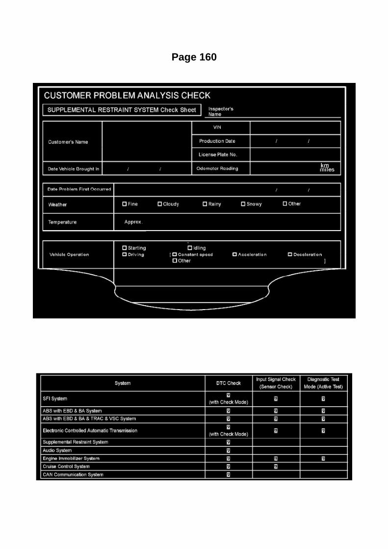
Page 160

(Sample ) Supplemental Restraint System check sheet
Symptom Confirmation and Diagnostic Trouble Code
SYMPTOM CONFIRMATION AND DIAGNOSTIC TROUBLE CODE
HINT:
The diagnostic system in the TOYOTA TACOMA has various functions. -
The first function is the Diagnostic Trouble Code (DTC) check. A DTC is a code stored in the ECUmemory whenever a malfunction in the signal circuits to the ECU occurs. In a DTC check, aprevious malfunction's DTC can be checked by a technician during troubleshooting.
- Another function is the Input Signal Check, which checks if the signals from various switches aresent to the ECU correctly. By using these functions, the problem areas can be narrowed down andtroubleshooting is more effective. Diagnostic functions are incorporated in the above systems in theTOYOTA TACOMA:
- In the DTC check, it is very important to determine whether the problem indicated by the DTC is:1) still occurring, or 2) occurred in the past but has since returned to normal. In addition, the DTCshould be compared to the problem symptom to see if they are related. For this reason, DTCsshould be checked before and after confirmation of symptoms (i.e., whether or not problemsymptoms exist) to determine current system conditions, as shown in the flowchart. Never skip theDTC check. Failing to check DTCs may, depending on the case, result in unnecessarytroubleshooting for systems operating

Page 1131
CAUTION: a. Do not open the cover or the case of the ECU unless absolutely necessary. (If the ICterminals are touched, the IC may be destroyed by static
electricity.)
b. When replacing the internal mechanism (ECU part) of the digital meter, be careful that no part ofyour body or clothing comes in contact with
the terminals of leads from the IC, etc. of the replacement part (spare part).
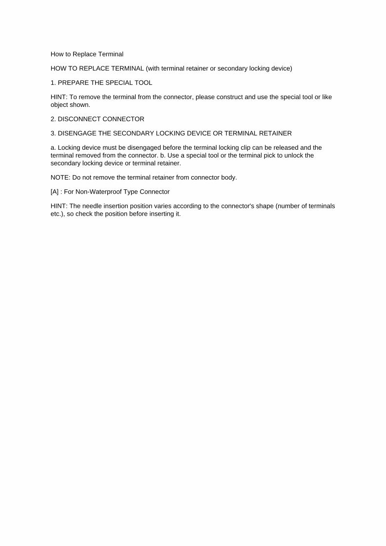
How to Replace Terminal
HOW TO REPLACE TERMINAL (with terminal retainer or secondary locking device)
1. PREPARE THE SPECIAL TOOL
HINT: To remove the terminal from the connector, please construct and use the special tool or likeobject shown.
2. DISCONNECT CONNECTOR
3. DISENGAGE THE SECONDARY LOCKING DEVICE OR TERMINAL RETAINER
a. Locking device must be disengaged before the terminal locking clip can be released and theterminal removed from the connector. b. Use a special tool or the terminal pick to unlock thesecondary locking device or terminal retainer.
NOTE: Do not remove the terminal retainer from connector body.
[A] : For Non-Waterproof Type Connector
HINT: The needle insertion position varies according to the connector's shape (number of terminalsetc.), so check the position before inserting it.
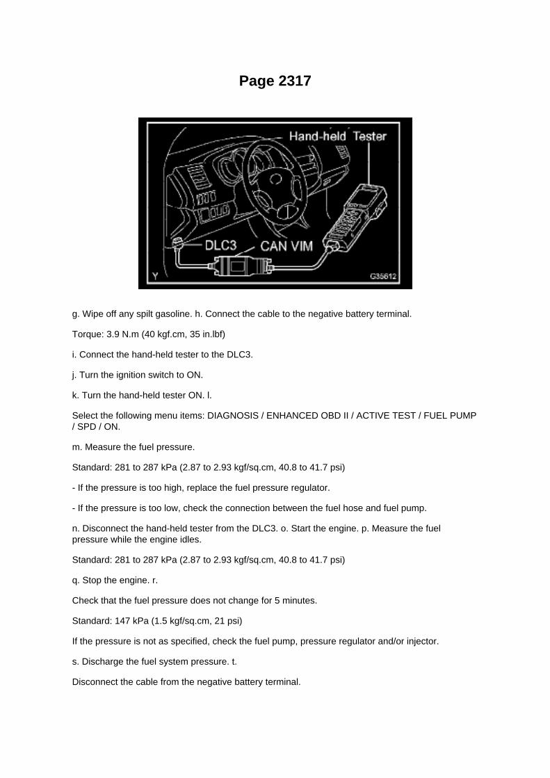
Page 2317
g. Wipe off any spilt gasoline. h. Connect the cable to the negative battery terminal.
Torque: 3.9 N.m (40 kgf.cm, 35 in.lbf)
i. Connect the hand-held tester to the DLC3.
j. Turn the ignition switch to ON.
k. Turn the hand-held tester ON. l.
Select the following menu items: DIAGNOSIS / ENHANCED OBD II / ACTIVE TEST / FUEL PUMP/ SPD / ON.
m. Measure the fuel pressure.
Standard: 281 to 287 kPa (2.87 to 2.93 kgf/sq.cm, 40.8 to 41.7 psi)
- If the pressure is too high, replace the fuel pressure regulator.
- If the pressure is too low, check the connection between the fuel hose and fuel pump.
n. Disconnect the hand-held tester from the DLC3. o. Start the engine. p. Measure the fuelpressure while the engine idles.
Standard: 281 to 287 kPa (2.87 to 2.93 kgf/sq.cm, 40.8 to 41.7 psi)
q. Stop the engine. r.
Check that the fuel pressure does not change for 5 minutes.
Standard: 147 kPa (1.5 kgf/sq.cm, 21 psi)
If the pressure is not as specified, check the fuel pump, pressure regulator and/or injector.
s. Discharge the fuel system pressure. t.
Disconnect the cable from the negative battery terminal.

u. Remove SST while being careful to prevent gasoline splashes. v. Connect the fuel hose. w.Install the fuel pipe clamp. x. Connect the cable to the negative battery terminal.
Torque: 3.9 N.m (40 kgf.cm, 35 in.lbf)
3. CHECK FOR FUEL LEAKAGE

Page 1566

NOTE

Only Toyota Certified Technicians and above may access calibration files.
2. Connect the GR8 Battery Diagnostic Station.
A. Connect the GR8 Battery Diagnostic Station to the vehicle and turn it ON.
B. Select Power Supply Mode by following the screen flow below.
NOTICE
^ ECU damage may occur if the correct battery charger and mode setting are NOT used.

Page 1942
Step 1 - 2
INSPECTION PROCEDURE
Check CAN Bus Line
CHECK CAN BUS LINE
CIRCUIT DESCRIPTION

When any DTC of the CAN communication system is output, first measure the resistance betweenthe terminals` of the DLC3 and the yaw rate sensor connector to specify the trouble area.

Page 1601

9. INSTALL ECM

Torque: 5 N.m (51 kgf.cm, 44 in.lbf)
10. INSTALL INSTRUMENT PANEL FINISH PANEL SUB-ASSEMBLY LOWER RH 11. INSTALLGLOVE COMPARTMENT DOOR ASSEMBLY 12. CONNECT CABLE TO NEGATIVE BATTERYTERMINAL
Torque: 3.9 N.m (40 kgf.cm, 35 in.lbf)

Page 2189

Knock Control Sensor (2TR-FE) Part 2

Page 2840
Shift Interlock Solenoid: Testing and Inspection
KEY INTER LOCK SOLENOID
INSPECTION
1. INSPECT KEY INTER LOCK SOLENOID
a. Disconnect the solenoid connector. b. Connect KLS+
(4) terminal to the battery positive (+) terminal, and KLS- (3) terminal to the battery negative (-)terminal, and apply about 12V between KLS+ and KLS terminals. Check that operation noise canbe
heard from the solenoid.
If the solenoid does not operate, replace the solenoid.

Page 511

Applicable Vehicles

Page 1913

3. Checking the contact pressure of the terminal: Prepare a spare male terminal. Insert it into afemale terminal, and check for good tension when

inserting and after full engagement.
d. REPAIR METHOD OF CONNECTOR TERMINAL
1. If there is any dirt on the terminal, clean the contact point using an air gun or shop rag. Neverpolish the contact point using sandpaper as the
platings may come off.
2. If there is abnormal contact pressure, replace the female terminal. If the male terminal isgold-plated (gold color), use a gold-plated female
terminal; if it is silver-plated (silver color), use a silver-plated female terminal.
3. Damaged, deformed, or corroded terminals should be replaced. If the terminal will not lock intothe housing, the housing may have to be
replaced.
e. HANDLING OF WIRE HARNESS
1. If removing a wire harness, check the wiring and clamping before proceeding so that it can berestored in the same way. 2. Never twist, pull or slacken the wire harness more than necessary. 3.Never make the wire harness come into contact with a high temperature part, or rotating, moving,vibrating or sharp-edged parts. Avoid panel
edges, screw tips and similar sharp items.
4. When installing parts, never pinch the wire harness. 5. Never cut or break the cover of the wireharness. If it is cut or broken, replace it or securely repair it with vinyl tape.
Check Open Circuit
CHECK OPEN CIRCUIT

Page 741

Supplemental Restraint System

Page 823

Windshield Washer Switch: Testing and Inspection

INSPECT WINDSHIELD WIPER SWITCH ASSEMBLY
a. Check the resistance.
1. Measure the resistance and check the results in accordance with the value(s) in the table below.
Standard:
If the result is not as specified, replace the windshield wiper switch assembly.
b. Check the intermittent operation.
1. Connect the voltmeter positive terminal to terminal 3 (+1) of the E7 connector and the voltmeternegative terminal to terminal 2 (EW) of the
E11 connector.
2. Connect the battery positive (+) lead to terminal 2 (+B) of the E7 connector and the batterynegative (-) lead to terminals 2 (EW) of the E11
connector and 1 (+S) of the E7 connector.
3. Turn the wiper switch to the INT position. 4. Connect the battery positive (+) lead to terminal1(+S) of the E7 connector for 5 seconds.
5. Connect the battery negative lead to terminal 1 (+S) of the E7 connector. Operate theintermittent wiper relay and check the voltage between
terminals 3 (+1) of the E7 connector and 2 (EW) of the E11 connector.

Page 1099

Engine Room R/B, J/B - Engine Compartment Left

Page 3364

Brake Bleeding: Service and Repair W/o VSC

BRAKE FLUID (W/O VSC)
BLEEDING
HINT: If any work is done on the brake system or if air in the brake lines is suspected, bleed the airfrom the system.
NOTICE: Immediately wash off any brake fluid that comes into contact with any painted surfaces.
1. FILL RESERVOIR WITH BRAKE FLUID Fluid: SAE J1703 or FMVSS No.116 DOT3
2. BLEED MASTER CYLINDER
HINT: If the master cylinder has been disassembled or if the reservoir becomes empty, bleed theair from the master cylinder.
a. Using SST, disconnect the brake lines from the master cylinder.
SST 09023-00101
b. Slowly depress the brake pedal and hold it there.
c. Block the outer holes with your fingers, and release the brake pedal. d. Repeat b. and c. 3 or 4times.

Page 1649
SFI System

Page 1663
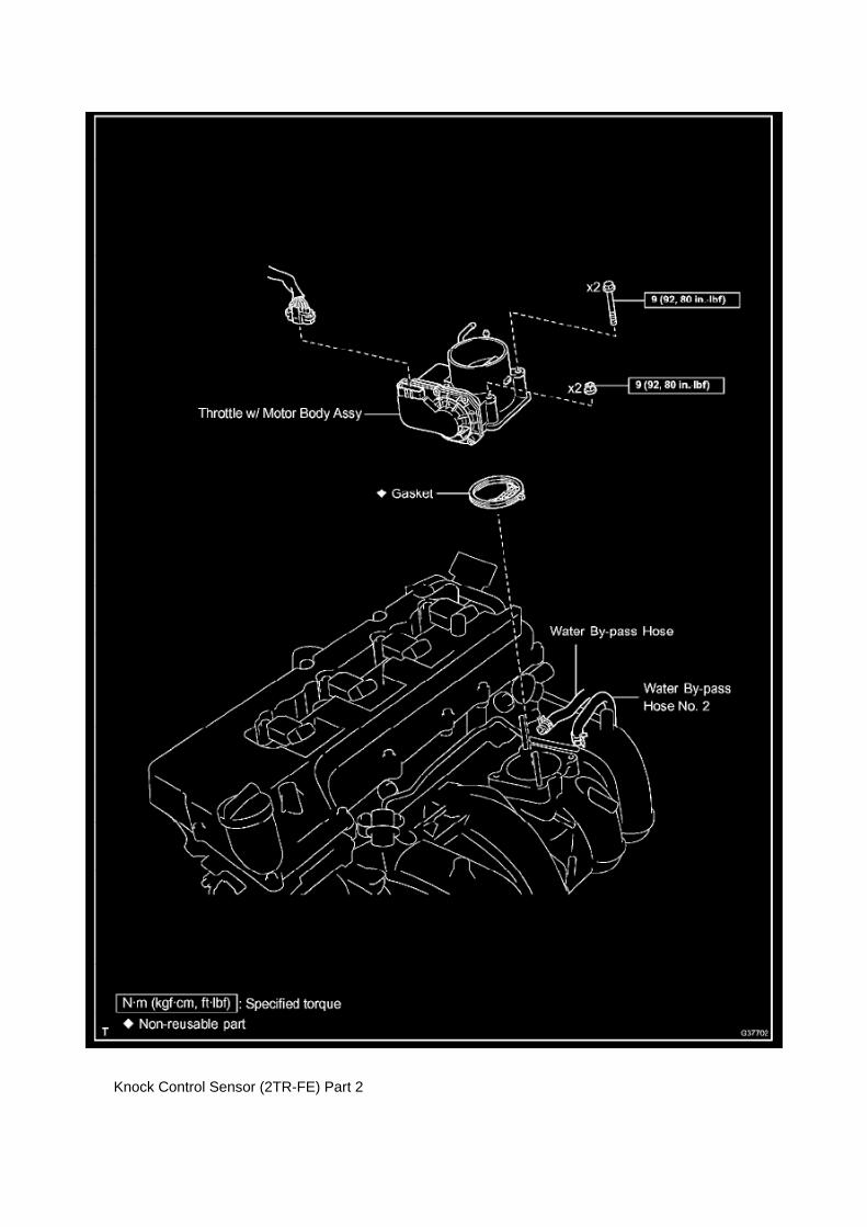
Knock Control Sensor (2TR-FE) Part 2

Page 2676

Spark Plug: Application and ID

SPARK PLUG TYPE:
DENSO ........................................................................................................................................................................................................... SK2OHR11 NGK ..................................................................................................................................................................................................................ILFR6C11
Correct electrode gap for new sparkplug.......................................................................................................................... 1.0 to 1.1 mm(0.039 to 0.043 in.)
Torque.....................................................................................................................................................................................18 N.m (184 kgf.cm, 13 ft.lbf)

Page 3296

19. REMOVE MASTER CYLINDER PUSH ROD CLEVIS

a. Loosen the lock nut on the brake master cylinder side, and then remove the rod operatingadapter and lock nut. b. Loosen the lock nut on the rod operating adapter, and then remove thepush rod clevis and lock nut.
20. REMOVE MASTER CYLINDER BOOT
21. REMOVE PISTON
a. Which pressing in the piston with a screwdriver, use a pin or equivalent to push the C-ring fromthe hole in the master cylinder body. Then
remove the snap ring with another screwdriver.
b. Remove the piston by pulling it straight out, not at an angle.
NOTICE: -
If the piston is pulled out at an angle, there is a possibility that the cylinder bore could be damaged.
- Be careful not to damage the rubber lips on the piston when reassembling.
22. REMOVE MASTER CYLINDER SOLENOID
a. Remove the 6 bolts. b. Remove the master cylinder solenoid and the gasket.
23. REMOVE BRAKE BOOSTER ACCUMULATOR ASSEMBLY
a. Place the brake booster w/ accumulator pump assembly in a vise with a cloth. b. Using a socketwrench (17 mm), remove the brake booster accumulator. c. Remove the brake boosteraccumulator pipe, compression spring and O-ring.
24. INSPECT BRAKE BOOSTER PUMP ASSEMBLY

Page 2769
^ Power Supply Mode is used to maintain battery voltage at 13.5 volts while flash reprogrammingthe vehicle.
^ For details on how to use the GR8 Battery Diagnostic Station, refer to the located on TIS,Diagnostics - Tools & Equipment - Battery Diagnostics.

3. Click the appropriate calibration ID and reprogram the vehicle's ECU with Techstream.
A. After reviewing the procedures outlined in the selected TSB, click the appropriate calibration IDlink by matching the vehicle's current
calibration ID to the Previous Calibration ID in the Calibration Identification Chart.
NOTE
^ Calibration files are embedded as live links in the service bulletin.
^ Some vehicles require special preparation - please review the selected TSB carefully.
B. Click Open to load calibration file information.
Techstream pulls calibration files as needed to ensure the latest calibration file is used. Do NOTsave calibrations locally on the hard drive or other media.
NOTICE
Errors during the flash reprogramming process can permanently damage the vehicle ECU.Minimize the risk by following the steps below.
^ Battery voltage MUST NOT FALL BELOW 11.4 volts during reprogramming. Confirm batteryvoltage is higher than 11.4 volts, but be sure voltage DOES NOT RISE ABOVE 16.0 volts duringreprogramming.
^ Turn OFF all vehicle accessories (e.g. audio system, A/C, interior lights, DRL, etc.). Do NOT addto or significantly change the vehicle's electrical

Recall - Seat Belt Sensor Wire Harness Modification
Technical Service Bulletin # SSC50I Date: 050701

Specifications

Valve Clearance: Specifications

The 2TR-FE engine uses a hydraulic valve lash adjuster assembly. Adjustment is not required.

Page 742

Supplemental Restraint System

Page 2662
SFI System

Page 3322

Step 2 - 3

INSPECTION PROCEDURE
CHECK FOR INTERMITTENT PROBLEMS
HINT: A momentary interruption (open circuit) in the connectors and/ or wire harness between thesensors and ECUs can be detected through the ECU data monitor function of the hand-held tester.
a. Turn the ignition switch off and connect the hand-held tester to the DLC3.

Page 1920
SYMPTOM SIMULATION
HINT: The most difficult case in troubleshooting is when no problem symptoms occur. In suchcases, a thorough customer problem analysis must be carried out. A simulation of the same orsimilar conditions and environment in which the problem occurred in the customer's vehicle shouldbe carried out. No matter how much skill or experience a technician has, troubleshooting withoutconfirming the problem symptoms will lead to important repairs being overlooked and mistakes ordelays.
For example: With a problem that only occurs when the engine is cold or occurs as a result ofvibration caused by the road during driving, the problem can never be determined if the symptomsare being checked on a stationary vehicle or a vehicle with a warmed-up engine. Vibration, heat orwater penetration (moisture) is difficult to reproduce. The symptom simulation tests below areeffective substitutes for the conditions and can be applied on a stationary vehicle.
Important points in the symptom simulation test: In the symptom simulation test, the problemsymptoms as well as the problem area or parts must be confirmed. First, narrow down the possibleproblem circuits according to the symptoms. Then, connect the tester and carry out the symptomsimulation test, judging whether the circuit being tested is defective or normal. Also, confirm theproblem symptoms at the same time. Refer to the problem symptoms table for each system to
narrow down the possible causes.
1. VIBRATION METHOD: When vibration seems to be the major cause.
a. PART AND SENSOR
1. Apply slight vibration with a finger to the part of the sensor considered to be the cause of theproblem and check whether or not the
malfunction occurs.
HINT: Applying strong vibration to relays may open relays.
b. CONNECTORS
1. Slightly shake the connector vertically and horizontally.
c. WIRE HARNESS
1. Slightly shake the wire harness vertically and horizontally.
The connector joint and fulcrum of the vibration are the major areas that should be checkedthoroughly.

Service and Repair

Fuel Pressure Release: Service and Repair

PRECAUTION
1. PRECAUTION
a. Before working on the fuel system, disconnect the cable from the negative battery terminal. b.Do not work on the fuel system near fire. Never smoke during the work. c. Keep rubber and leatherparts away from gasoline.
2. DISCHARGE FUEL PRESSURE
CAUTION: -
Before removing fuel system parts, take precautions to prevent gasoline spillage.
- As some pressure remains in the fuel line even after taking precautions to prevent gasolinespillage, use a shop rag to prevent gasoline splashes when disconnecting the fuel line.
a. Disconnect the cable from the negative battery terminal. b. Remove the engine relay blockcover.
c. Remove the circuit opening relay. d. Connect the cable to the negative battery terminal.
Torque: 3.9 N.m (40 kgf.cm, 35 in.lbf)
e. Start the engine. f.
Turn the ignition switch to ON after the engine stops.
HINT: DTC P0171 (system to lean) may be present.
g. Crank the engine again, and check that the engine stops. h. Remove the fuel tank cap, anddischarge the pressure in the fuel tank completely. i.
Install the circuit opening relay.
3. FUEL SYSTEM
a. When disconnecting the high-pressure fuel line, a large amount of gasoline will splash. So takethe following precautions.
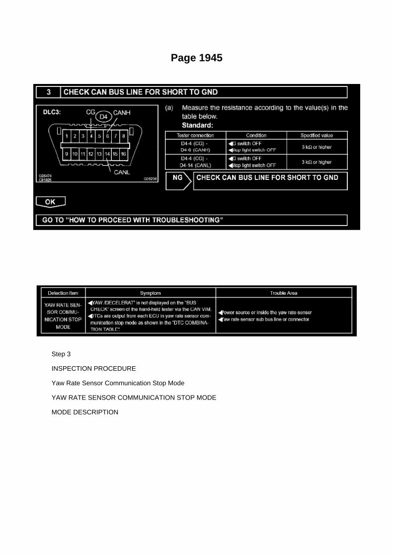
Page 1945
Step 3
INSPECTION PROCEDURE
Yaw Rate Sensor Communication Stop Mode
YAW RATE SENSOR COMMUNICATION STOP MODE
MODE DESCRIPTION

Page 510
Oxygen Sensor: Technical Service Bulletins Engine Controls - Bank 1/Bank 2 O2 Sensoridentification
ENGINE EG034-07
Title: ENGINE BANK 1 AND BANK 2 A/F AND O2 IDENTIFICATION
Models: '93 - '08 Applicable Models
June 28, 2007
The information contained in this TSB supercedes TSB No. EG037-04. TSB No. EG037-04 is nowobsolete and should be discarded.
Introduction
This service bulletin provides information on the proper identification of engine bank 1 and enginebank 2 for correct A/F sensor and oxygen sensor replacement.
This bulletin contains information that identifies engine bank 1 and engine bank 2 on the followingengines: 1AZ-FE, 2AZ-FE, 2AZ-FE (PZEV), 1GR-FE, 2GR-FE, 2GR-FSE, 2JZ-GE, 1MZ-FE,3MZ-FE, 1UR-FSE, 3UR-FE, 2UZ-FE, 3UZ-FE, 5VZ-FE, and 1ZZ-FE.
^ Bank 1 (B1) refers to the bank that includes cylinder No. 1.

^ Bank 2 (B2) refers to the bank opposite bank 1.
^ Sensor 1 (S1) refers to the sensor that is located before the catalytic converters.
^ Sensor 2 (S2) refers to the sensor that is located after the catalytic converters.
Warranty Information

Locations
A/C - Ge

Locations

Ha - Op

Page 151

Glossary Of Terms And Sysmbols Part 2

Page 555
SFI System

Page 203
load while reprogramming.
^ Confirm the hood is open and ensure under hood temperature does NOT exceed 158°F (70°C).
^ Confirm cable connections between the vehicle and Techstream are secure.
^ Do NOT disconnect or turn off Techstream or vehicle ignition during reprogramming.
^ Set parking brake.
^ Complete ALL flash calibration updates provided for each ECU.
^ If the battery's state of charge or capacity are in question, test with SST. No. 00002-8150-KIT"Digital Battery Analyze," and follow TSB No. PG001-06, "Battery Maintenance for In-Stock

Vehicles & Pre-Delivery" or the appropriate "Maintenance for HV & Auxiliary Batteries" servicebulletin.
^ The GR8 Battery Diagnostic Station MUST be used in Power Supply Mode to maintain batteryvoltage at 13.5 volts while flash reprogramming the vehicle. For details on how to use the GR8Battery Diagnostic Station, refer to the GR8 Instruction Manual located on TIS, Diagnostics - Tools& Equipment - Battery Diagnostics.
3C. Click Next to start the calibration update process.
D. When using TIS Techstream select Techstream VIM as the desired programming device. Thenclick Next.

Page 771

He - Wi

System Diagnosis
Air/Fuel Mixture: Testing and Inspection
INSPECT CO/HC
HINT: This inspection is for checking whether the CO/HC concentration in the emission gas whileidling complies with the regulations.
a. Start the engine. b. Keep the engine speed at 2,500 rpm for approximately 180 seconds. c.Insert the CO/HC meter testing probe at least 40 cm (1.3 ft.) into the tailpipe while idling. d.Immediately check the CO/HC concentration while idling and/or at 2,500 rpm.
HINT: When performing the 2 mode (2,500 rpm and idle) test, follow the applicable localregulations.
If the CO/HC concentration does not comply with the regulations, troubleshoot in the order givenbelow. (1) Check the A/F sensor and heated oxygen sensor operation.
(2) See the table for possible causes, then inspect and correct the applicable parts if necessary.

Page 2985

A. Remove the front door opening trim LH (scuff plate).

B. Remove the cowl side trim board.
C. Remove the instrument panel finish panel lower No. 1.
D. Remove the driver's side Junction Block.
E. Remove the turnover (compression) spring.

Locations
Crankshaft Position Sensor: Locations

A/C - Ge

Page 3283

- To protect the solenoid, hand-held tester turns off automatically 2 seconds after every solenoidhas been turned on.

- When rotating the wheel fast, the fail-safe function is activated and judgement cannot be madeproperly. So rotate the wheel as slowly as possible.
NOTICE: When operating it continuously, set the interval of more than 20 seconds. (4) When thesolenoid is off, depress the brake pedal again and check that the left rear wheel does not rotate byhand.
If the left rear wheel rotates, replace the brake master cylinder.
r. Inspect rear ABS solenoid (SRRR) operation.
HINT: -
ON: Depress the brake pedal, activate SRRR and SRRH, and then check that the right rear wheelrotates.
- OFF: Deactivate SRRR and SRRH, depress the brake pedal, and then check that the right rearwheel does not rotate.
(1) Select "SRH & SRR" on the hand-held tester. (2) Depress the brake pedal with stable force,then turn the "SRH & SRR" on simultaneously by the hand-held tester. (3) When the solenoids areon, check the right rear wheel by rotating it by hand. If the right rear wheel stops, replace the brakemaster cylinder.
HINT: -
To protect the solenoids, hand-held tester turns off automatically 2 seconds after every solenoidhas been turned on.
- When rotating the wheel fast, the fail-safe function is activated and judgement cannot be madeproperly. So rotate the wheel as slowly as possible.
NOTICE: When operating it continuously, set the interval of more than 20 seconds.
(4) When the solenoids are off, depress the brake pedal again and check that the right rear wheeldoes not rotate by hand. If the right rear wheel rotates, replace the brake master cylinder.
s. Inspect rear ABS solenoid (SRLR) operation.
HINT: -
ON: Depress the brake pedal, activate SRLR and SRLH, and then check that the left rear wheelrotates.
- OFF: Deactivate SRLR and SRLH, depress the brake pedal, and then check that the left rearwheel does not rotate.
(1) Select "SRLR & SRLH" on the hand-held tester. (2) Depress the brake pedal with stable force,then turn the "SRLR & SRLH" on simultaneously by the hand-held tester. (3) When the solenoidsare on, check the left rear wheel by rotating it by hand. If the left rear wheel stops, replace the brakemaster cylinder.
HINT: -
To protect the solenoids, hand-held tester turns off automatically 2 seconds after every solenoidhas been turned on.
- When rotating the wheel fast, the fail-safe function is activated and judgement cannot be madeproperly. So rotate the wheel as slowly as possible.

NOTICE: When operating it continuously, set the interval of more than 20 seconds. (4) When thesolenoids are off, depress the brake pedal again and check that the left rear wheel does not rotateby hand.
If the left rear wheel rotates, replace the brake master cylinder.
t. Lower the vehicle.
u. Disconnect the hand-held tester.

On-Vehicle Inspection
Clutch Switch: Testing and Inspection On-Vehicle Inspection
CLUTCH START SWITCH ASSEMBLY
ON-VEHICLE INSPECTION
1. CHECK CLUTCH START SYSTEM
a. Check that the engine does not start when the clutch pedal is released. b. Check that the enginestarts when the clutch pedal is fully depressed.
If necessary, replace the clutch start switch assembly.

Page 2099
4. Attach the Authorized Vehicle Modification Label.
Modifications to ECU calibrations MUST be recorded and properly displayed on the vehicle usingthe Authorized Modification Label.
Techstream Preparation
Selecting the TIS Techstream VIM or the Mongoose MFC VIM.
Techstream software requires a VIM selection before you can use the Mongoose MFC VIM.
If using TIS Techstream no changes are needed.
Perform the following:
1. Select Setup from the Techstream Main Menu screen.
2. Select VIM Select from the Setup drop down menu.
3. Select the correct Interface Setup from the drop down list.
^ If using Techstream Lite select Mongoose MFC.
NOTE

Locations
Camshaft Position Sensor: Locations

A/C - Ge

Page 1421
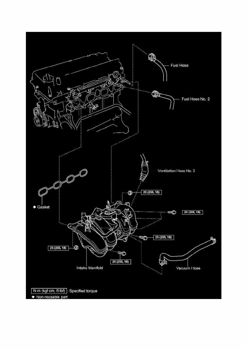

Page 2773
^ Figure 17 shows an example of the update procedure for a two-processor ECU.
G. Turn ignition OFF. Then click Next.
H. Confirm the following:

^ Ignition is ON and engine is OFF or "READY" OFF (hybrid vehicles).
^ Hood is open.
^ All accessories are OFF.
^ Battery voltage is above 11.4 volts.
NOTICE
Verify the vehicle is connected to a battery charger before continuing - If battery voltage falls below11.4 volts, ECU damage may occur.

Page 2042

k. Disconnect the 3 connectors. l.

Remove the nut shown in the illustration.
m. Disconnect the engine wire harness from the relay block.
n. Remove the 5 bolts and 2 nuts, then remove the intake manifold.
9. REMOVE KNOCK CONTROL SENSOR
a. Disconnect the knock control sensor connector. b. Remove the bolt, then remove the knockcontrol sensor.
10. INSTALL KNOCK CONTROL SENSOR
a. Install the knock control sensor with the bolt.
Torque: 20 N.m (204 kgf.cm, 15 ft.lbf)
NOTE: Make sure that the knock sensor is at the correct angle when installing.
b. Connect the knock control sensor connector.
11. INSTALL INTAKE MANIFOLD

Page 1597

Oscilloscope Waveforms
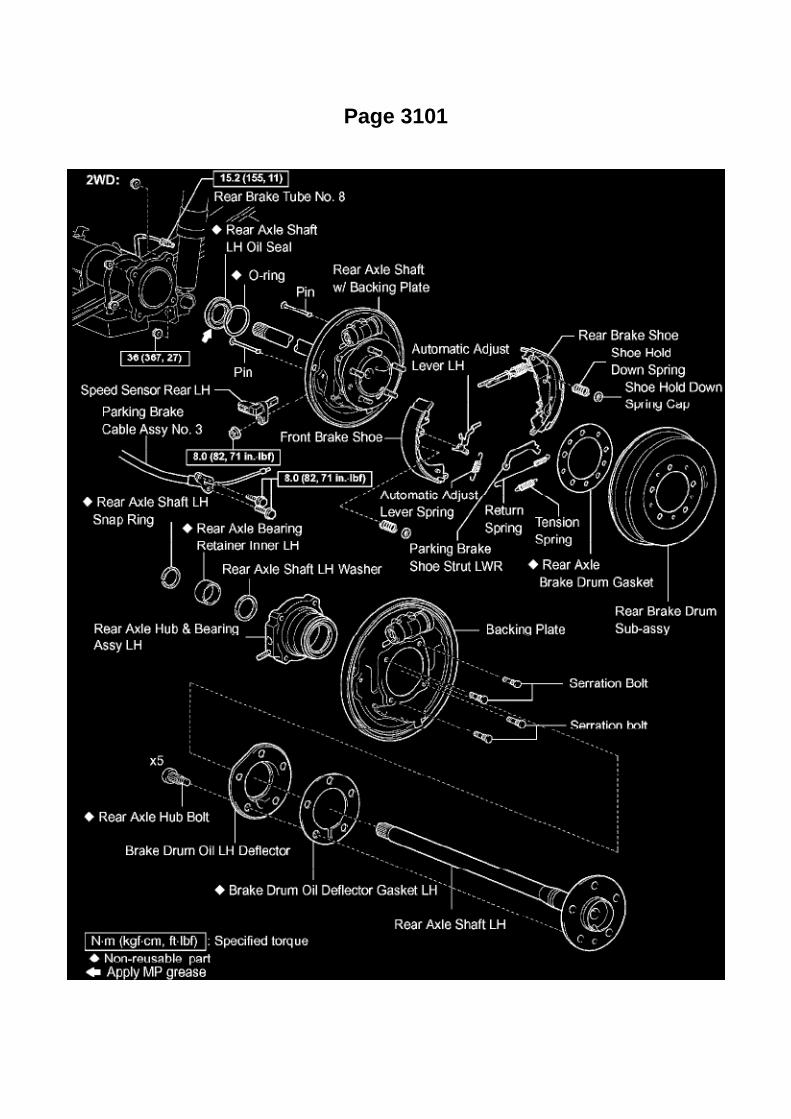
Page 3101

Wheel Bearing: Service and Repair
REAR AXLE SHAFT LH

Locations

Power Window Switch: Locations
Po - Ya

Page 3284

Hydraulic Control Assembly - Antilock Brakes: Testing and Inspection Brake Actuator Assembly(w/o VSC)

BRAKE ACTUATOR ASSEMBLY (W/O VSC)
ON-VEHICLE INSPECTION
1. CONNECT HAND-HELD TESTER:
a. Connect the hand-held tester to the DLC3. b. Start the engine and allow it to idle. c. SelectACTIVE TEST mode on the hand-held tester.
HINT: Refer to the hand-held tester operator manual for further details.
2. INSPECT ACTUATOR MOTOR OPERATION
a. With the motor relay ON, check the actuator motor operation noise. b. Turn the motor relay OFF.c. Depress the brake pedal and hold it for about 15 seconds. Check that the brake pedal cannot bede pressed. d. With the motor relay ON, check that the pedal does not pulsate.
NOTICE: Do not keep the motor relay ON for more than 5 seconds continuously. When operating itcontinuously, allow intervals of more than 20 seconds.
e. Turn the motor relay OFF and release the brake pedal.
3. INSPECT RIGHT FRONT WHEEL OPERATION
NOTICE: Never turn ON any solenoids other than those described below.
a. With the brake pedal depressed, perform the following operations. b. Turn SFRH and SFRRsolenoids ON simultaneously, and check that the pedal cannot be depressed.
NOTICE: Do not keep the solenoids ON for more than 2 seconds continuously. When operatingthem continuously, allow intervals of more than 20 seconds.
c. Turn SFRH and SFRR solenoids OFF simultaneously, and check that the pedal can bedepressed. d. Turn the motor relay ON, and check that the pedal returns.
NOTICE: Do not keep the motor relay ON for more than 5 seconds continuously. When operating itcontinuously, allow intervals of more than 20 seconds.
e. Turn the motor relay OFF and release the brake pedal.
4. INSPECT OTHER WHEEL OPERATION
a. Check the solenoids of the other wheels using the same procedures as above.
HINT:
Left front wheel: SFLH, SFLR Right rear wheel: SRRH, SRRR Left rear wheel: SRLH, SRLR

Page 1375

Timing Chain: Service and Repair Part 2
Replacement Continued
60. INSTALL CHAIN TENSIONER ASSEMBLY NO.2
a. Install the chain tensioner with the nut.
Torque: 18 Nm (185 kgf-cm, 13 ft. lbs.)
NOTICE: Assemble the chain tensioner with the 3.0 mm (0.118 inch) diameter bar installed, thenremove the bar after assembly. When doing this, avoid pushing the vibration damper against thechain.
61. INSTALL CHAIN VIBRATION DAMPER NO.3
a. Install the chain vibration damper No.3 with the 2 bolts.
Torque: 18 Nm (185 kgf-cm, 13 ft. lbs.)
62. INSTALL CHAIN VIBRATION DAMPER NO.2
a. Install the chain vibration damper with the bolt.
Torque: 27 Nm (270 kgf-cm, 20 ft. lbs.)
b. Remove the pin from the chain tensioner and release the plunger.
63. INSTALL CRANKSHAFT TIMING GEAR OR SPROCKET
a. Install the timing sprocket as shown in the illustration.

Page 1624

Main Relay (Computer/Fuel System): Testing and Inspection

INSPECT E.F.I. CIRCUIT OPENING RELAY ASSEMBLY
a. Check the resistance.
1. Using an ohmmeter, measure the resistance between the terminals.
If the result is not as specified, replace the E.F.I. circuit opening relay assembly.
INSPECT EFI RELAY
a. Check the resistance.
1. Using an ohmmeter, measure the resistance between the terminals.
If the result is not as specified, replace the E.F.I. ECU relay.

Testing and Inspection
Drive Belt: Testing and Inspection
INSPECT FAN AND GENERATOR V BELT
a. Check that the tensioner indicator mark is within range A shown in the illustration.
If the mark is not within range A, replace the V belt.

Engine Controls - A/F And O2 Sensor Identification
Oxygen Sensor: Technical Service Bulletins Engine Controls - A/F And O2 Sensor Identification
T-SB-0398-09
December 23, 2009
Engine Bank 1 and Bank 2 A/F and 02 Identification

Service Category Engine/Hybrid System
Section Engine Control
Market USA
Applicability
TSB SUPERSESSION NOTICE
The information contained in this TSB supersedes TSB No. EG034-07.
^ Applicability has been updated to include 2009 - 2010 model year vehicles and 2006 - 2010model year Highlander HV.
TSB No. EG034-07 is Obsolete and any printed versions should be discarded. Be sure to reviewthe entire content of this service bulletin before proceeding.
Introduction
This service bulletin provides information on the proper identification of engine bank 1 and enginebank 2 for correct A/F sensor and oxygen sensor replacement.
This bulletin contains information that identifies engine bank 1 and engine bank 2 on the followingengines: 1AZ-FE, 2AZ-FE, 2AZ-FE (PZEV), 1GR-FE, 2GR-FE, 2JZ-GE, 1MZ-FE, 3MZ-FE,1UR-FE, 3UR-FE, 2UZ-FE 5VZ-FE and 1ZZ-FE.
^ Bank 1 (B1) refers to the bank that includes cylinder No. 1.
^ Bank 2 (B2) refers to the bank opposite bank 1.
^ Sensor 1 (S1) refers to the sensor that is located before the catalytic converters.
^ Sensor 2 (S2) refers to the sensor that is located after the catalytic converters.
Warranty Information

Page 3268

Electronic Brake Control Module: Testing and Inspection ABS W/EBD, BA, TRAC & VSC Systems
Terminals Of Control Module / Pinouts Part 1

Page 944

TOY 730 - 73mm Toyota Oil Filter Wrench

M 0219 - 74mm Oil Filter Wrench

Page 1573

J. When Cal 1 has completed the update process turn ignition OFF for a minimum of 10 seconds.Then click Next.

K. Turn ignition to the ON position. Then click Start.
L. Do NOT disturb the vehicle during flash reprogramming.

Page 839

Warranty Information

NOTE
OP Code 044184 and the above combination codes apply to all models with the EXCEPTION ofCombo E for the MR2 Spyder model.
APPLICABLE WARRANTY
^ This repair is covered under the Toyota Comprehensive Warranty. This warranty is in effect for12 months or 20,000 miles, whichever occurs first,
from the vehicle's in-service date.
^ Warranty application is limited to correction of a problem based upon a customer's specificcomplaint.
Contents
This bulletin is divided into the following sections:
^ Wheel Alignment and Tire Characteristics
^ Repair Procedure Flow Chart
^ Repair Procedure
^ Important Notice
^ Troubleshooting
^ Vehicle Pulling Caused by Wheel Alignment
^ Vehicle Pulling Caused by Tire Conicity Camber Adjustment Method
Wheel Alignment & Tire Characteristics
1. Relationship Between Wheel Alignment and Vehicle Pulling to One Side

Page 723

NOTE:

Make sure to view the male end of the connector in the proper orientation as shown in theillustration.
(b) If the connector wires are correctly installed, installation of the wire seat jumper is NOTREQUIRED, proceed to section "VI. SSC
COMPLETION LABEL INSTALLATION".
(c) If the connector wires were NOT correctly installed, proceed to step "B. INSTALL THE WIRESEAT JUMPER".
B. INSTALL THE WIRE SEAT JUMPER
1. RECORD THE RADIO STATION PRESETS

Air-Fuel Ratio Sensor

Oxygen Sensor: Service and Repair Air-Fuel Ratio Sensor
REPLACEMENT
1. DISCONNECT CABLE FROM NEGATIVE BATTERY TERMINAL 2. REMOVE AIR FUEL RATIOSENSOR
a. Disconnect the air fuel ratio sensor connector. b. Disconnect the wire harness clamp.
c. Using SST, remove the air fuel ratio sensor.
SST 09224-00010
3. INSTALL AIR FUEL RATIO SENSOR
a. Using SST, install the air fuel ratio sensor.
SST 09224-00010
Torque: 44 N.m (449 Kgf.cm, 33 ft.lbf) 40 N.m (408 Kgf.cm, 30 ft.lbf) with SST
NOTE: Use a torque wrench with a fulcrum length of 300 mm (11.81in.).

Page 1405

COMPONENTS
REPLACEMENT
1. REMOVE HOOD SUB-ASSEMBLY 2. DISCHARGE FUEL SYSTEM PRESSURE 3. REMOVEENGINE UNDER COVER SUB-ASSEMBLY NO.1 (PRE RUNNER AND 4WD TYPE)
a. Remove the 4 bolts, then remove the engine under cover No.1.
4. REMOVE ENGINE UNDER COVER SUB-ASSEMBLY NO.2 (PRE RUNNER AND 4WD TYPE,REGULAR CAB)
a. Remove the 4 bolts, then remove the engine under cover No.2.
5. DRAIN ENGINE OIL 6. DRAIN ENGINE COOLANT 7. REMOVE BATTERY 8. REMOVEBATTERY TRAY 9. REMOVE RADIATOR SUPPORT TO FRAME SEAL LH
10. REMOVE FAN SHROUD

Specifications

Power Steering Fluid: Specifications

P/S Fluid Type: ............................................................................................................................................................................... ATF DEXRON II or III

Locations

Refrigerant Pressure Sensor / Switch: Locations

He - Wi

Service and Repair

Evaporative Canister Filter: Service and Repair

REPLACEMENT
1. DISCHARGE FUEL SYSTEM PRESSURE 2. DISCONNECT CABLE FROM NEGATIVEBATTERY TERMINAL 3. REMOVE FUEL TANK PROTECTOR SUB-ASSEMBLY NO.1 (OFFROAD PACKAGE) 4. DISCONNECT FUEL TANK MAIN TUBE AND FUEL TANK RETURN TUBE5. REMOVE FUEL TANK ASSEMBLY 6. REMOVE CHARCOAL CANISTER FILTER NO.2
a. Remove the bolt, then remove the ABS wire harness clamp from the charcoal canister.
b. Release the EVAP pipe from the hose clamp. c. Disconnect the breather hose from the pipe. d.Disengage the hose clamp.
e. Disconnect the breather hose from the charcoal canister.

Page 2527
SFI System

Page 185
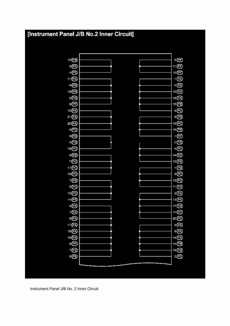
Instrument Panel J/B No. 2 Inner Circuit

Page 694

Page 2167

Camshaft Position Sensor: Service and Repair

REPLACEMENT
1. DISCONNECT CABLE FROM NEGATIVE BATTERY TERMINAL 2. REMOVE CAMSHAFTPOSITION SENSOR
a. Disconnect the camshaft position sensor connector. b. Remove the bolt, then remove thecamshaft position sensor.
3. INSTALL CAMSHAFT POSITION SENSOR
a. Apply a light coat of engine oil to the O-ring of the camshaft position sensor.
b. Install the camshaft position sensor with the bolt.
Torque: 8.5 N.m (87 kgf.cm, 75 in.lbf)
NOTE: Make sure that the O-ring is not cracked or jammed when installing.
c. Connect the camshaft position sensor connector.
4. CONNECT CABLE TO NEGATIVE BATTERY TERMINAL
Torque: 3.9 N.m (40 kgf.cm, 35 in.lbf)
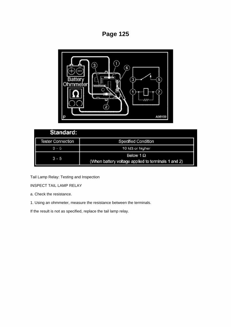
Page 125
Tail Lamp Relay: Testing and Inspection
INSPECT TAIL LAMP RELAY
a. Check the resistance.
1. Using an ohmmeter, measure the resistance between the terminals.
If the result is not as specified, replace the tail lamp relay.

Page 2668

d. Disconnect the water bypass hose No.2.

e. Disconnect the ventilation hose No.3.
f. Disconnect the VSV connector.
g. Disengage the engine wire harness clamp. h. Disconnect the compressor magnetic clutchconnector.
(w/ AIR CONDITIONING)
i. Disengage the wire harness clamp.
j. Remove the bolt and harness clamp bracket.

Page 20
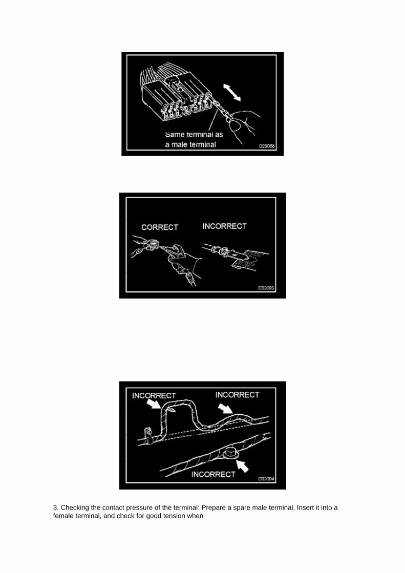
3. Checking the contact pressure of the terminal: Prepare a spare male terminal. Insert it into afemale terminal, and check for good tension when

inserting and after full engagement.
d. REPAIR METHOD OF CONNECTOR TERMINAL
1. If there is any dirt on the terminal, clean the contact point using an air gun or shop rag. Neverpolish the contact point using sandpaper as the
platings may come off.
2. If there is abnormal contact pressure, replace the female terminal. If the male terminal isgold-plated (gold color), use a gold-plated female
terminal; if it is silver-plated (silver color), use a silver-plated female terminal.
3. Damaged, deformed, or corroded terminals should be replaced. If the terminal will not lock intothe housing, the housing may have to be
replaced.
e. HANDLING OF WIRE HARNESS
1. If removing a wire harness, check the wiring and clamping before proceeding so that it can berestored in the same way. 2. Never twist, pull or slacken the wire harness more than necessary. 3.Never make the wire harness come into contact with a high temperature part, or rotating, moving,vibrating or sharp-edged parts. Avoid panel
edges, screw tips and similar sharp items.
4. When installing parts, never pinch the wire harness. 5. Never cut or break the cover of the wireharness. If it is cut or broken, replace it or securely repair it with vinyl tape.
Check Open Circuit
CHECK OPEN CIRCUIT

Page 2030

b. Do not use a bypass wire between the connectors.

NOTE: If you use a bypass wire, the characteristic of the twisted wire harness will be lost.
4. CONNECTOR HANDLING
a. When inserting tester probes into a connector, insert them from the back of the connector.
b. If it is impossible to check resistance from the back of the connector, use a repair wire to checkit.

Page 1893

Part 2

a. Write VIN using the hand-held tester.
Vehicle Reprogramming
VEHICLE REPROGRAMMING
Beginning with some 2001 models and expanding to all models by 2007, Toyota/Scion and Lexusvehicles are equipped with flash reprogrammable Powertrain Control Modules (PCM).Reprogramming should only be performed if a Technical Service Bulletin or Service Campaignprovides direction to do so.

Page 1979

Step 8 - 11

Page 1924
Circuit Inspection

Voltage Check
VOLTAGE CHECK

Page 1869

Refer to Reset Procedure 2 for the vehicles with Electronically Controlled AutomaticTransmissions:

Reset Procedure 1
1. Connect the Toyota Diagnostic Tester to the vehicle.
2. Reset the ECM (PCM). Refer to the procedures below.

Page 831
c. Check the operation
1. Turn the wiper switch off. 2. Connect the battery positive lead to terminal 2 (+B) of the E7connector and the battery negative lead to terminals 1 (+S) of the E7 connector
and 2 (EW) of the E11 connector.
3. Connect the voltmeter positive terminal to terminal 3 (+1) of the E7 connector and the voltmeternegative terminal to terminal 2 (EW) of the
E11 connector.Turn the washer switch on and off, and check the voltage between terminals 3 (+1)of the E7 connector and 2 (EW) of the E11 connector.

Page 2396

Page 813
Ce - Ya

Page 2060

Applicable Vehicles

Page 2537

3. Install the fuel tank protector cover on top of the fuel suction plate sub-assembly as shown in theillustration.

Page 1413

Timing Cover: Service and Repair Overhaul
TIMING CHAIN COVER SUB-ASSEMBLY (2TR-FE)

Page 58

Towing Converter Relay Part 3

Page 2828

He - Wi
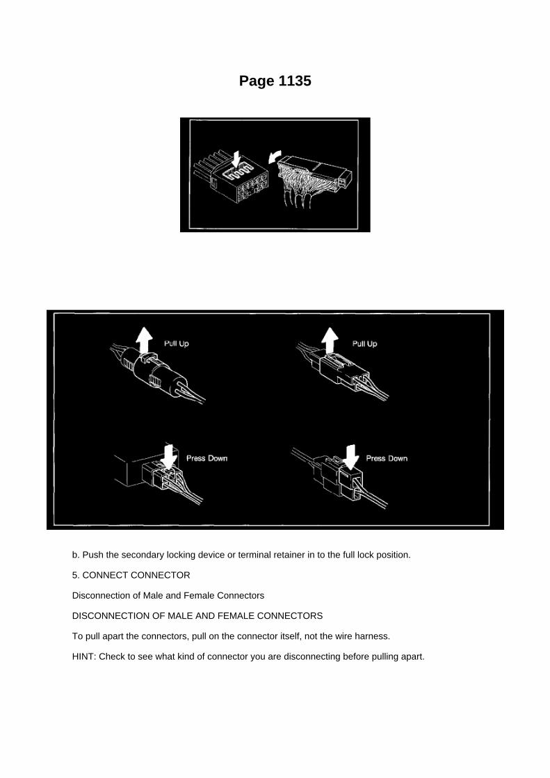
Page 1135
b. Push the secondary locking device or terminal retainer in to the full lock position.
5. CONNECT CONNECTOR
Disconnection of Male and Female Connectors
DISCONNECTION OF MALE AND FEMALE CONNECTORS
To pull apart the connectors, pull on the connector itself, not the wire harness.
HINT: Check to see what kind of connector you are disconnecting before pulling apart.

Page 1067
Problem Symptoms Table
The suspected circuits or parts for each problem symptom are shown in the table . Use this table totroubleshoot when, during a DTC check, a "Normal" code is displayed but the problem is stilloccurring. Numbers in the table show the inspection order in which the circuits or parts should bechecked.
HINT: In some cases, the problem is not detected by the diagnostic system even though a problemsymptom is present. It is possible that the problem is occurring outside the detection range of thediagnostic system, or that the problem is occurring in a completely different system.

Page 514
A/F and 02 Sensor Identification

Locations

Page 1482
10. INSTALL V-RIBBED BELT TENSIONER ASSEMBLY
a. Provisionally install the V-ribbed belt tensioner with bolts A and B. b. Tighten bolt B.
Torque: 40 Nm (408 kgf-cm, 30 ft. lbs.)
c. Tighten bolt A.
Torque: 21 Nm (214 kgf-cm, 16 ft. lbs.)
d. Check that the bolt holes of the V-ribbed belt tensioner and timing chain cover are aligned, andinstall bolt C.
e. Tighten bolt C.
Torque: 43 Nm (434 kgf-cm, 32 ft. lbs.)
11. INSTALL GENERATOR ASSEMBLY 12. INSTALL FAN SHROUD 13. INSTALL RADIATORSUPPORT TO FRAME SEAL LH 14. CONNECT CABLE TO NEGATIVE BATTERY TERMINAL
Torque: 3.9 Nm (40 kgf-cm, 35 inch lbs.)
15. ADD ENGINE COOLANT 16. CHECK FOR ENGINE COOLANT LEAKAGE 17. INSTALLENGINE UNDER COVER SUB-ASSEMBLY NO.1 (PRE RUNNER AND 4WD TYPE)
a. Install the engine under cover No.1 with the 4 bolts.
Torque: 30 Nm (306 kgf-cm, 22 ft. lbs.)

Page 2560
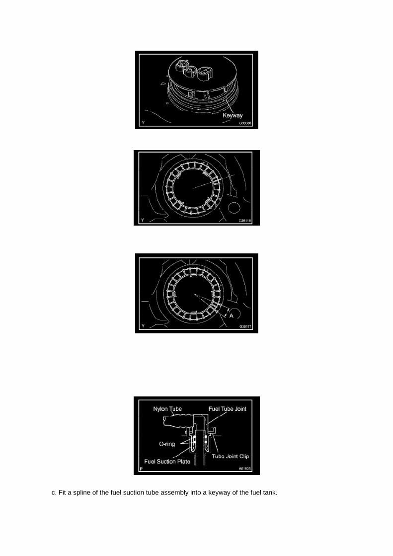
c. Fit a spline of the fuel suction tube assembly into a keyway of the fuel tank.

d. Install a new retainer.
1. Align the mark on a new retainer with the rib on the fuel tank as shown in the illustration.
2. Using SST, turn the retainer 740° to 780° clockwise (more than 2 turns), and position the markon the retainer within range A to install it.
SST 09808-14020 (09808-01410, 09808-01420, 09808-01430)
HINT: The ribs on the retainer can be fitted into the tip of the SST.
14. INSTALL FUEL TANK MAIN TUBE AND FUEL TANK RETURN TUBE
a. Install the fuel tank main tube and return tube with the 2 joint clips.
NOTE: -
Check that there are no scratches or foreign objects around the connected part of the fuel tube jointand plug before performing this work.

Page 3169
b. Install the grommet, a new lock washer and the nut.
Torque: 6.9 Nm (70 kgf-cm, 61 inch lbs.)
c. Install the manual valve lever shaft onto the groove and turn it 2 notches counterclockwise to theneutral position. d. Align the neutral basic line with the switch groove and tighten the adjusting bolt.
Torque: 13 Nm (130 kgf-cm, 9 ft. lbs.)
e. Bend the tabs of the lock washer.
HINT: Bend at least 2 of the lock washer tabs.
5. CONNECT PARK/NEUTRAL POSITION SWITCH CONNECTOR 6. CONNECT CABLE TONEGATIVE BATTERY TERMINAL
Torque: 3.9 Nm (40 kgf-cm, 35 inch lbs.)
7. INSPECT PARK/NEUTRAL POSITION SWITCH ASSY 8. ADJUST PARK/NEUTRAL POSITIONSWITCH ASSY 9. ADJUST SHIFT LEVER POSITION
10. INSPECT SHIFT LEVER POSITION

Page 2706
b. Install the grommet, a new lock washer and the nut.
Torque: 6.9 Nm (70 kgf-cm, 61 inch lbs.)
c. Install the manual valve lever shaft onto the groove and turn it 2 notches counterclockwise to theneutral position. d. Align the neutral basic line with the switch groove and tighten the adjusting bolt.
Torque: 13 Nm (130 kgf-cm, 9 ft. lbs.)
e. Bend the tabs of the lock washer.
HINT: Bend at least 2 of the lock washer tabs.
5. CONNECT PARK/NEUTRAL POSITION SWITCH CONNECTOR 6. CONNECT CABLE TONEGATIVE BATTERY TERMINAL
Torque: 3.9 Nm (40 kgf-cm, 35 inch lbs.)
7. INSPECT PARK/NEUTRAL POSITION SWITCH ASSY 8. ADJUST PARK/NEUTRAL POSITIONSWITCH ASSY 9. ADJUST SHIFT LEVER POSITION
10. INSPECT SHIFT LEVER POSITION

Page 1406
11. REMOVE AIR CLEANER CAP SUB-ASSEMBLY 12. REMOVE AIR CLEANER FILTERELEMENT SUB-ASSEMBLY 13. REMOVE AIR CLEANER CASE
a. Remove the 3 bolts, then remove the air cleaner case.
14. SEPARATE VANE PUMP ASSEMBLY 15. REMOVE RADIATOR HOSE NO.2 16. SEPARATECOMPRESSOR AND MAGNETIC CLUTCH (W/ AIR CONDITIONING) 17. REMOVE RADIATORHOSE INLET 18. SEPARATE WATER HOSE SUB-ASSEMBLY 19. DISCONNECT FUEL HOSE20. DISCONNECT FUEL HOSE NO.2 21. SEPARATE FUEL VAPOR FEED HOSE ASSEMBLY22. DISCONNECT AIR INJECTION SYSTEM NO.1 HOSE 23. DISCONNECT ENGINE WIRE 24.REMOVE EXHAUST PIPE ASSEMBLY TAIL 25. REMOVE EXHAUST PIPE ASSEMBLY FRONT26. REMOVE MANUAL TRANSMISSION UNIT ASSEMBLY 27. REMOVE AUTOMATICTRANSMISSION ASSEMBLY 28. REMOVE ENGINE ASSEMBLY 29. REMOVE CLUTCH COVERASSEMBLY (MANUAL TRANSMISSION) 30. REMOVE CLUTCH DISC ASSEMBLY (MANUALTRANSMISSION) 31. REMOVE FLYWHEEL SUB-ASSEMBLY (MANUAL TRANSMISSION)
SST 09213-54015 (91651-60855), 09330-00021
32. REMOVE DRIVE PLATE & RING GEAR SUB-ASSEMBLY (AUTOMATIC TRANSMISSION)
SST 09213-54015 (91651-60855), 09330-00021
33. REMOVE REAR END PLATE
a. Remove the 2 bolts, then remove the rear end plate.
34. REMOVE INTAKE AIR CONNECTOR 35. REMOVE GENERATOR ASSEMBLY 36. REMOVEV-RIBBED BELT TENSIONER ASSEMBLY 37. REMOVE IDLER PULLEY SUB-ASSEMBLY NO.138. REMOVE IDLE PULLEY ASSEMBLY W/BRACKET (W/ AIR CONDITIONING) 39. REMOVECRANKSHAFT POSITION SENSOR 40. REMOVE CAMSHAFT POSITION SENSOR 41.REMOVE INTAKE MANIFOLD TO HEAD GASKET NO.1 42. REMOVE CYLINDER HEAD COVERSUB-ASSEMBLY 43. REMOVE CRANKSHAFT PULLEY
SST 09213-54015 (91651-60855), 09330-00021, 09950-50013 (09951-05010, 09952-05010,09953-05010, 09954-05021)
44. REMOVE OIL LEVEL GAGE SUB-ASSEMBLY 45. REMOVE OIL PAN SUB-ASSEMBLY NO.2
SST 09032-00100

46. REMOVE OIL STRAINER SUB-ASSEMBLY 47. REMOVE OIL PAN SUB-ASSEMBLY
48. REMOVE TIMING CHAIN COVER
a. Remove the 2 nuts, then separate the water by-pass pipe No.1.

Page 1910
Information Bus: Diagnostic Aids
Steps 1 - 6

Page 931
Parts Information
Required Tools & Material

Required SSTs
Repair Procedure
1. Using the Diagnostic Tester, check for Diagnostic Trouble Codes (DTCs). If DTC P0456 orP0445, and P0441 are present, check for an EVAP leak on top of the fuel suction platesub-assembly. Refer to the Technical Information System (TIS), 2005 model year Tacoma RepairManual: Diagnostics: SFI System (1GR-FE) / (2TR-FE): EVAP Inspection Procedure.
If NO EVAP leaks are detected at the fuel suction plate sub-assembly, this TSB does NOT apply.Please refer to the normal diagnostic procedure provided in the Repair Manual.
2. To correct the fuel suction plate sub-assembly, replace the fuel suction with pump and gaugetube assembly, retainer ring and gasket set according to TIS, 2005 model year Tacoma RepairManual: Fuel: Fuel Pump Assy: Removal & Installation And Disassembly & Reassembly (Tacoma).

Page 1059

c. Check the voltage.

1. In a circuit in which voltage is applied to the ECU connector terminal, an open circuit can bechecked by conducting a voltage check.
FIG 4: With each connector still connected, measure the voltage between the body ground andthese terminals (in this order): 1) terminal 1 of connector A at the ECU 5 V output terminal, 2)terminal 1 of connector B, and 3) terminal 1 of connector C.
2. Example results:
If your results match the examples above, an open circuit exists in the wire harness betweenterminal 1 of connector B and terminal 1 of connector C.
Check Short Circuit
CHECK SHORT CIRCUIT
a. If the wire harness is ground shorted (Fig. 5), locate the section by conducting a resistancecheck with the body ground.
b. Check the resistance with the body ground.

M/T - Grinding/Hard to Engage 4WD Low
Clutch Pedal Assembly: All Technical Service Bulletins M/T - Grinding/Hard to Engage 4WD Low
TRANSMISSION & CLUTCH TC006-06
Title: CLUTCH PEDAL FEEL IMPROVEMENT
Models: '05 - '06 Tacoma
July 26, 2006
Introduction
Some customers may complain about one of the following conditions:
^ Grinding during shifting
^ Difficulty in engaging or releasing 4WD low
^ Uncomfortable foot or leg position with clutch pedal fully depressed
The clutch pedal assembly and the carpeting have been changed to improve the clutch pedal feeland operation.
Applicable Vehicles
^ 2005 - 2006 model year Tacoma vehicles equipped with manual transmission produced BEFOREthe Production Change Effective VINs shown below.

Production Change Information
Parts Information
Warranty Information
Applicable Warranty*: This repair is covered under the Toyota Comprehensive Warranty. Thiswarranty is in effect for 36 months or 36,000 miles, whichever occurs first, from the vehicle'sin-service date.
* Warranty application is limited to correction of a problem based upon a customer's specificcomplaint.

Page 1254

If the clearance is not as specified, replace the piston.

- PISTON PIN OIL CLEARANCE a. Using a caliper gauge, measure the inside diameter of thepiston pin hole.
Piston pin hole inside diameter: 22.001 to 22.010 mm (0.8662 to 0.8665 inch)
b. Using a micrometer, measure the piston pin diameter.
Piston pin diameter: 21.997 to 22.006 mm (0.8660 to 0.8664 inch)
c. Using a caliper gauge, measure the inside diameter of the connecting rod bushing.
Bushing inside diameter: 22.005 to 22.014 mm (0.8663 to 0.8667 inch)
d. Subtract the piston pin diameter measurement from the piton pin hole diameter measurement.
Standard oil clearance: 0.001 to 0.007 mm (0.00004 to 0.00028 inch) Maximum oil clearance:0.010 mm (0.0004 inch)
HINT: If the oil clearance is greater than the maximum, replace the piston and piston pin as a set.

Diagram Information and Instructions

Relay Box: Diagram Information and Instructions

Key to Diagrams
A: System Title
B: Indicates a Relay Block. No shading is used and only the Relay Block No. is shown todistinguish it from the J/B
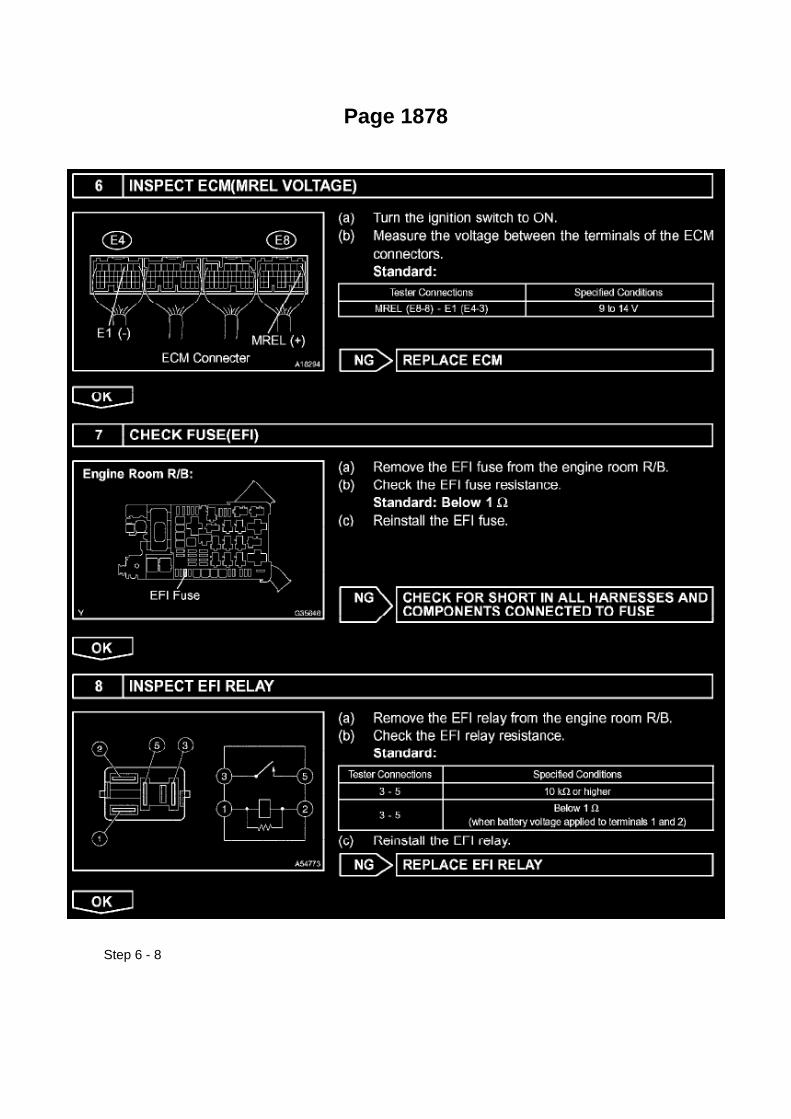
Page 1878
Step 6 - 8

Locations
Camshaft Position Sensor: Locations

A/C - Ge

Locations

Ha - Op

Page 3121

Drive/Propeller Shaft: Component Tests and General Diagnostics

DRIVE SHAFT, PROPELLER SHAFT, AXLE
ON-VEHICLE INSPECTION
1. INSPECT FRONT AXLE HUB BEARING
a. Remove the front wheel. b. 4WD: Remove the front axle hub grease cap. c. Remove the frontdisc brake caliper. d. Remove the front disc. e. Inspect the axle hub backlash.
(1) Using a dial indicator, check the backlash near the center of the axle hub.
Maximum: 0.05 mm (0.0020 inch) If the backlash exceeds the maximum, replace the bearing.
f. Inspect the axle hub deviation.
(1) Using a dial indicator, check the distortion of the surface of the axle hub.
Maximum: 0.05 mm (0.0020 inch) If the deviation exceeds the maximum, replace the bearing.
2. INSPECT REAR AXLE HUB BEARING
a. Remove the rear wheel. b. Remove the rear brake drum. c. Inspect the axle shaft backlash.
(1) Using a dial indicator, check the backlash near the center of the axle shaft.
Maximum: 0.05 mm (0.0020 inch) If the backlash exceeds the maximum, replace the bearing.

Page 545

Ac - Ya

Page 445
Fog/Driving Lamp Switch: Testing and Inspection
INSPECT FRONT FOG LAMP SWITCH
a. Check the resistance.
1. Measure the resistance using an ohmmeter, and check the results in accordance with thevalue(s) in the table.
If the result is not as specified, replace the front fog lamp switch assembly.
b. Check the illumination operation.
1. Connect the battery positive (+) lead to terminal 1 and the battery negative (-) lead to terminal 2,then check that the illumination comes on.
Standard: Illumination comes on.
If the illumination does not come on, replace the bulb.

Page 3078

10. REMOVE REAR DRIVE PINION FRONT TAPERED ROLLER BEARING

a. Using SST, remove the front bearing.
SST 09556-22010
b. Using SST, remove the front bearing outer race.
SST 09308-00010
c. Using a screwdriver, bend the oil storage ring and remove it.
11. REMOVE REAR DIFFERENTIAL DRIVE PINION BEARING SPACER 12. INSTALL REARDIFFERENTIAL DRIVE PINION BEARING SPACER
a. Install a new rear differential drive pinion bearing spacer.
13. INSTALL REAR DRIVE PINION FRONT TAPERED ROLLER BEARING
a. Using a brass bar and a hammer, install a new oil storage ring. b. Using SST and a hammer,install the front bearing outer race. c. Install the front bearing.
SST 09316-60011 (09316-00011, 09316-00021)
14. INSTALL REAR DIFFERENTIAL DRIVE PINION OIL SLINGER (W/ DIFF. LOCK)
15. INSTALL REAR DIFFERENTIAL CARRIER OIL SEAL
a. Using SST and a hammer, install a new oil seal.
SST 09554-30011 Oil seal drive in depth: 0.5 to 0.5 mm (-0.0197 to 0.0197 inch)
b. Coat oil seal lip with MP grease.
16. INSTALL REAR DRIVE PINION COMPANION FLANGE SUB-ASSY REAR
a. Using SST, install the companion flange. b. Coat the threads of a new nut with hypoid gear oilLSD.
SST 09950-30012 (09951-03010, 09953-03010, 09954-03010, 09955-03030, 09956-03030)

Page 2038
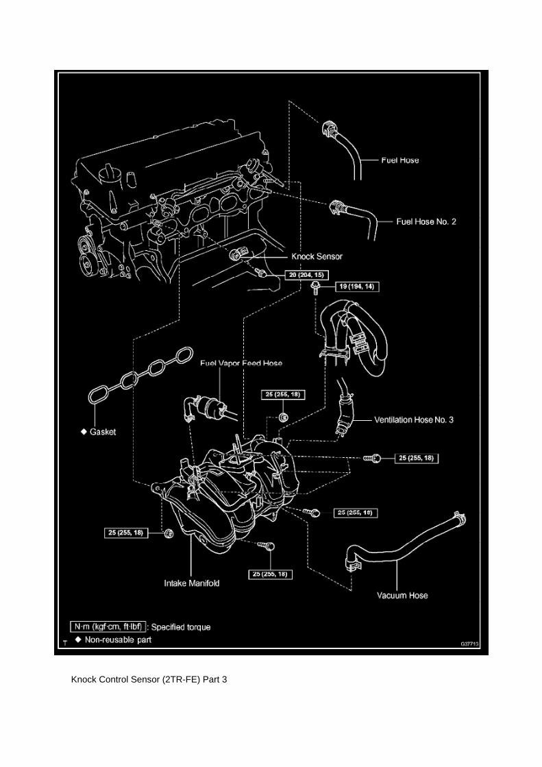
Knock Control Sensor (2TR-FE) Part 3

Service and Repair

Low Tire Pressure Indicator: Service and Repair

Tire Pressure Warning Light:
When the light comes on low tire inflation pressure is detected. Adjust tire pressure including thespare if it is equipped with a TPMS transmitter.
The light should go off within a few minutes after the tire pressure is adjusted.
Rotating tires may require the system to be initialized if the front and rear tires have differentpressure specifications.

Page 1605

Part 2

a. Write VIN using the hand-held tester.
Vehicle Reprogramming
VEHICLE REPROGRAMMING
Beginning with some 2001 models and expanding to all models by 2007, Toyota/Scion and Lexusvehicles are equipped with flash reprogrammable Powertrain Control Modules (PCM).Reprogramming should only be performed if a Technical Service Bulletin or Service Campaignprovides direction to do so.
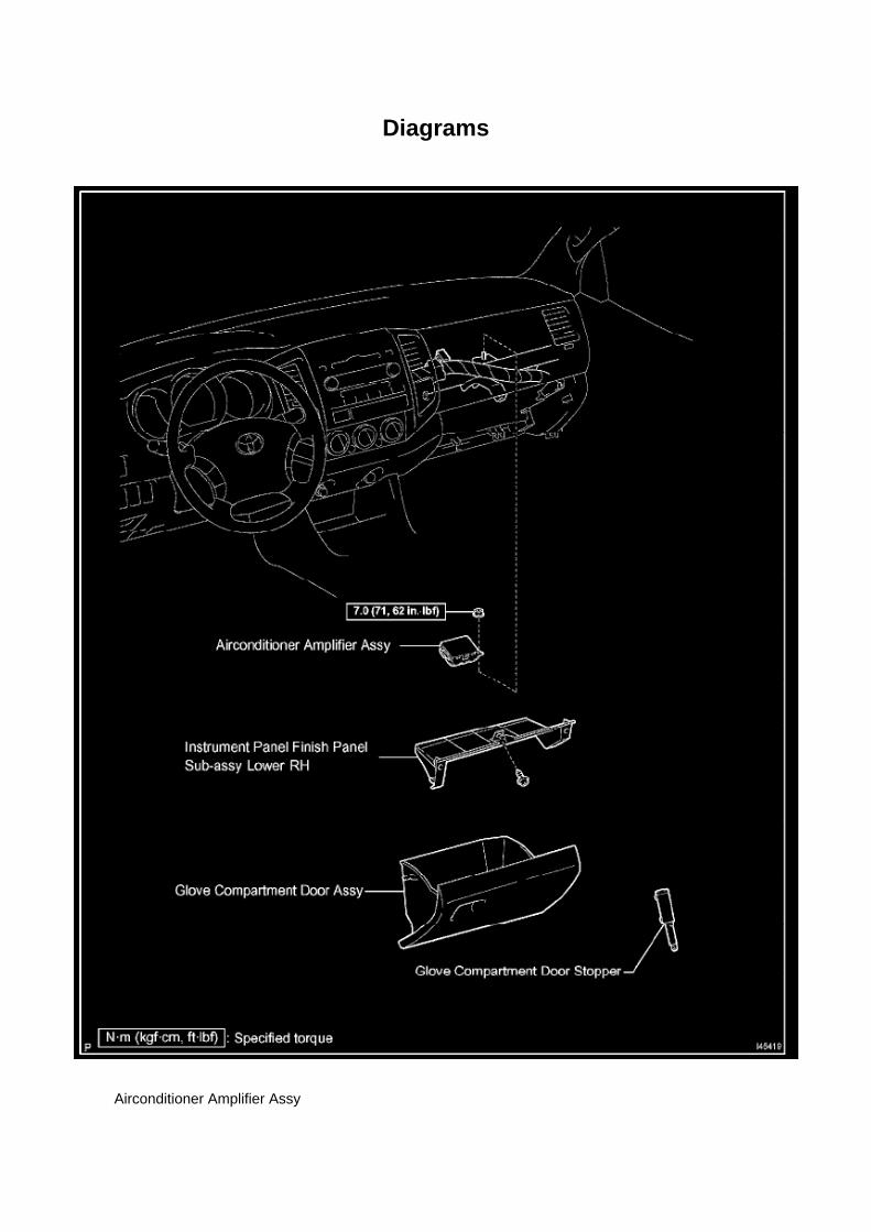
Diagrams
Airconditioner Amplifier Assy

Page 1792

Spark Plug: Application and ID

SPARK PLUG TYPE:
DENSO ........................................................................................................................................................................................................... SK2OHR11 NGK ..................................................................................................................................................................................................................ILFR6C11
Correct electrode gap for new sparkplug.......................................................................................................................... 1.0 to 1.1 mm(0.039 to 0.043 in.)
Torque.....................................................................................................................................................................................18 N.m (184 kgf.cm, 13 ft.lbf)

Page 1021

a. The activation prevention mechanism is built into the connector for the squib circuit of the SRS.As explained in the troubleshooting section, insert

a piece of paper that is the same thickness as male terminal between the terminal and the shortspring to release it (refer to the illustrations).
CAUTION: Never release the activation prevention mechanism on the squib connector even wheninspecting with the squib disconnected.
NOTE: -
Do not release the activation prevention mechanism unless specially directed to do so by thetroubleshooting procedure.
- To prevent the terminal and the short spring from being damaged, always use a piece of paperthat is the same thickness as the male terminal.

Page 2888
3. Is the Neutral Position SW Signal value "ON" or "OFF" in the Freeze Frame Data?
NOTE
In Figure 3, transmission is not in any gear position on this vehicle.
^ If the Neutral Position SW Signal is "OFF" - This TSB does NOT apply.
Refer to the applicable model year Tacoma Repair Manual for diagnostics for DTC P0705. If theNeutral Position SW Signal is "ON" - Go to step 4.

Page 2844

Shift Solenoid: Diagrams

The shift solenoid identification and location in the valve body is contained in the valve bodyservice and repair procedures and overhaul articles for most models.

Page 707

2. VERIFY THE REPAIR

(Test # 1)
(a) Move the bench seat to the rearmost position.
(b) Buckle the driver's seat belt.
(c) Confirm that the scan tool displays the data shown below and in the illustration.
^ "D SEAT POSITIOBKWARD" (Driver's seat is in the backward position).
^ "D BUCKLE SW SET"
(Driver's seat belt buckle switch is set/buckled).
(Test # 2)
(a) Leave the bench seat in the rearmost position.
(b) Unbuckle the driver's seat belt.
(c) Confirm that the scan tool displays the data shown below and in the illustration.
^ "D SEAT POSITIOBKWARD"

Page 1412

102. CHECK FOR OIL LEAKAGE 103. CHECK FOR EXHAUST GAS LEAKAGE 104. INSTALLENGINE UNDER COVER SUB-ASSEMBLY NO.1 (PRE RUNNER AND 4WD TYPE)

a. Install the engine under cover No.1 with the 4 bolts.
Torque: 30 Nm (306 kgf-cm, 22 ft. lbs.)
105. INSTALL ENGINE UNDER COVER SUB-ASSEMBLY NO.2 (PRE RUNNER AND 4WDTYPE, REGULAR CAB)
a. Install the engine under cover No.2 with the 4 bolts.
Torque: 30 Nm (306 kgf-cm, 22 ft. lbs.)
106. INSTALL HOOD SUB-ASSEMBLY

Page 841
if the steering wheel is held without exerting steering effort for 109 yards (100 m) when traveling at62 mph (100 km/h), the vehicle may drift as much as 5 feet (1.5 m).
^ When vehicle pulling is due to conicity, the amount of drift can be reduced and the direction ofdrift can be changed by changing the location of the tire or reversing the tire when installing it onthe wheel.
Repair Procedure Flow Chart

Repair Procedure
IMPORTANT NOTICE
Before repairing vehicle pulling to one side, it is necessary to clearly identify the cause of thepulling condition. Frequently, the cause of the vehicle pulling to one side is diagnosed as wheelalignment. However, the actual cause may be lateral force generated by the tires. Performingwheel alignment when tire force is the cause could result in the wheel alignment being set at avalue outside of specifications. This would then cause other problems such as uneven tire wear;etc.
1. Troubleshooting
First determine whether vehicle pulling to one side is caused by a wheel alignment problem or tirecharacteristics, then decide which repairs to make.
A. Perform the following checks and correct as necessary.
(1) Check tires for size, wear and for proper inflation pressure.
(2) Check whether the vehicle is noticeably tilted backward/forward or left/right.
NOTE
Tilting of the vehicle produces a left-right difference in the camber and caster and can causevehicle pulling to one side.
(3) Check brakes for dragging.
B. Confirm problem symptoms.

Locations

Switch: Locations
Po - Ya
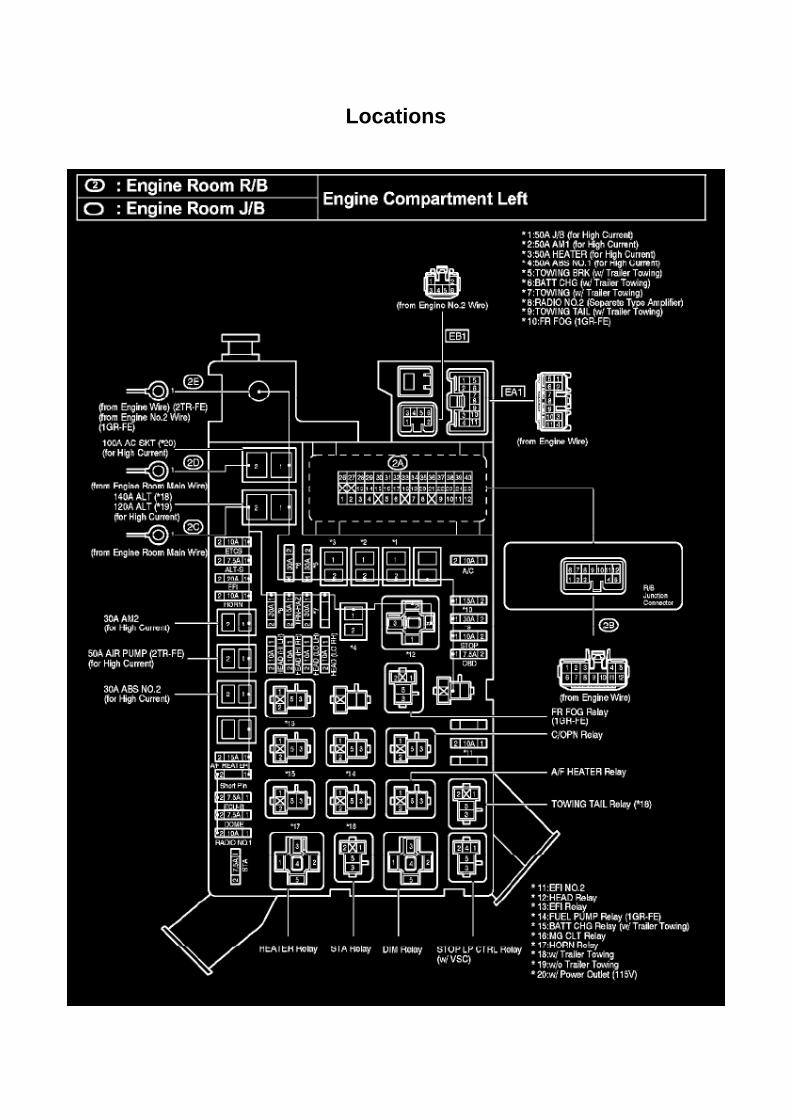
Locations

Oxygen Sensor Relay: Locations
Engine Room R/B, J/B - Engine Compartment Left

Locations
Air Bag Control Module: Locations
Instrument Panel

Page 2357


Page 1027
Driver Side J/B - Lower Finish Panel

Page 1724

He - Wi

Locations

Traction Control Switch: Locations
A/C - Fo
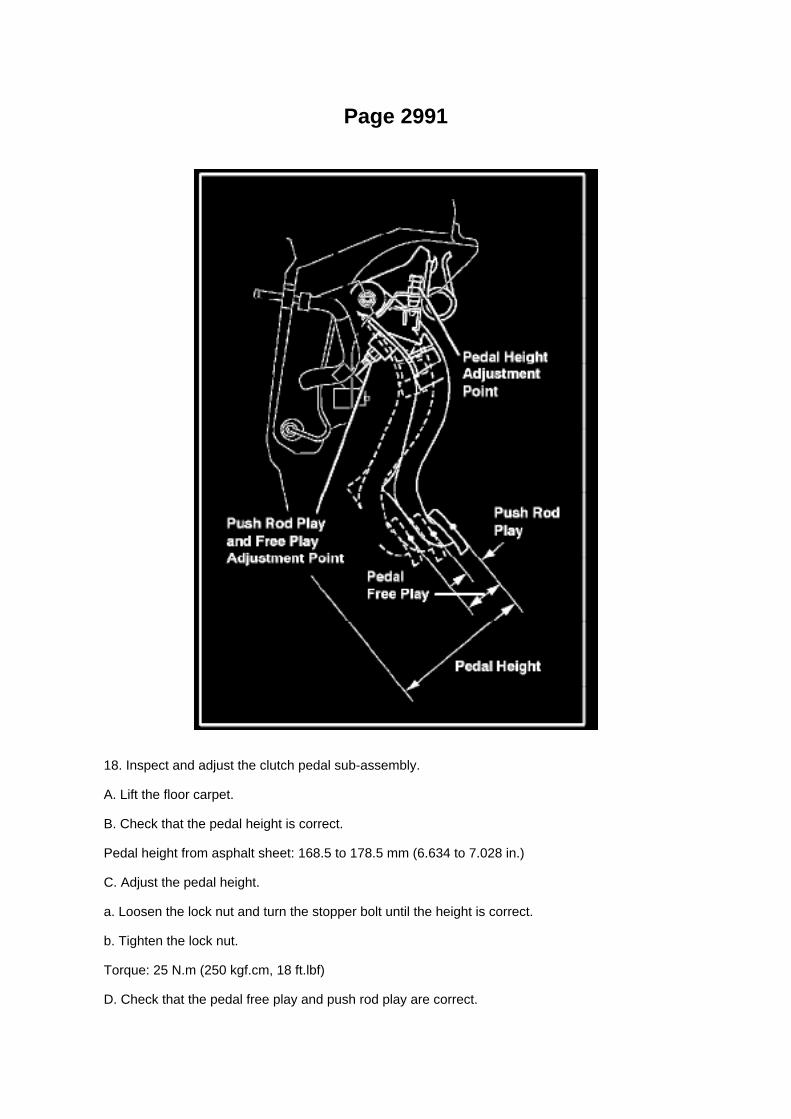
Page 2991
18. Inspect and adjust the clutch pedal sub-assembly.
A. Lift the floor carpet.
B. Check that the pedal height is correct.
Pedal height from asphalt sheet: 168.5 to 178.5 mm (6.634 to 7.028 in.)
C. Adjust the pedal height.
a. Loosen the lock nut and turn the stopper bolt until the height is correct.
b. Tighten the lock nut.
Torque: 25 N.m (250 kgf.cm, 18 ft.lbf)
D. Check that the pedal free play and push rod play are correct.

a. Depress the pedal until the clutch resistance begins to be felt.
Pedal free play: 5.0 to 15.0 mm (0.197 to 0.591 in.)
b. Gently depress the pedal until the resistance begins to increase a little.
E. Adjust the pedal free play and push rod free play.
a. Loosen the lock nut and turn the push rod until the free play and push rod play are correct.
b. Tighten the lock nut.
Torque: 11.8 N.m (120 kgf.cm, 9 ft.lbf)
c. After adjusting the pedal free play, check the pedal height.
19. Install the driver's side Junction Block.

Page 2998

Required Tools & Material

Components

Page 1682


Testing and Inspection
Compressor Clutch Relay: Testing and Inspection
INSPECT MAGNET-CLUTCH RELAY
a. Check the resistance.
1. Using an ohmmeter, measure the resistance between the terminals.
If the result is not as specified, replace the relay.

Tools and Equipment
Valve Spring: Tools and Equipment
Valve Spring Depressor
AST tool# TOY 160
Valve Spring Depressor used for Toyota Engines.
- Made of Aluminum
toyota valve springs depressor Contact AST for pricing.
Assenmacher Specialty Tools 1-800-525-2943

Page 2187
SFI System

Page 3038

Clutch Switch: Service and Repair Clutch Start Cancel Switch Assy

CLUTCH START CANCEL SWITCH ASSEMBLY
INSPECTION
1. INSPECT CLUTCH START CANCEL SWITCH ASSEMBLY
a. Using an ohmmeter, check that there is resistance between terminals 2 and 4.
Standard: 10 kohms or higher If the result is not as specified, replace the clutch start cancel switch.
b. Connect the positive (+) lead from the battery to terminal 3 and connect negative (-) lead toterminal 1. c. Using an ohmmeter, check that there is resistance between terminals 2 and 4.
Standard: 10 kohms or higher If the result is not as specified, replace the clutch start cancel switch.
d. Check that the indicator light comes on and there is resistance between terminals 2 and 4 whenthe switch is pressed.
Standard: Below 1 ohms If the result is not as specified, replace the clutch start cancel switch.
e. Using an ohmmeter, check that there is resistance between terminals 2 and 4 when the batterylead is disconnected.
Standard: 10 kohms or higher If the result is not as specified, replace the clutch start cancel switch.

Page 534
Transmission Position Switch/Sensor: Adjustments
PARK/NEUTRAL POSITION SWITCH ASSY
ADJUSTMENT
1. INSPECT PARK/NEUTRAL POSITION SWITCH ASSY
a. Apply the parking brake and turn the ignition switch to ON. b. Depress the brake pedal andcheck that the engine starts only when the shift lever is set in the N or P position and that it doesnot start in any
other positions.
c. Check that the back-up light comes on and the reverse warning buzzer sounds only when theshift lever is set in the R position and not in other
positions. If any failure is found, check the park/neutral position switch for continuity.
2. ADJUST PARK/NEUTRAL POSITION SWITCH ASSY
a. Loosen the bolt of the park/neutral position switch and set the shift lever to the N position. b.Align the groove and the neutral basic line. c. Hold the switch in position and tighten the bolt.
Torque: 13 Nm (130 kgf-cm, 9 ft. lbs.)
d. After making an adjustment, perform the inspection described in step 1.

Air-Fuel Ratio (A/F) Sensor
Oxygen Sensor: Testing and Inspection Air-Fuel Ratio (A/F) Sensor
INSPECTION
INSPECT AIR FUEL RATIO SENSOR
a. Check the resistance.
1. Using an ohmmeter, measure the resistance between the terminals.
If the result is not as specified, replace the air fuel ratio sensor.

ABS/TCS - Zero Point Calibration Information
Steering Angle Sensor: Technical Service Bulletins ABS/TCS - Zero Point Calibration Information
T-SB-0020-08
March 25, 2008
Disconnect Battery & Perform Zero Point Calibration After Wheel Alignment Adjustment
Service Category Brake
Section Brake Control/Dynamic Control System
Market USA
Applicability
Introduction

The purpose of this TSB is to provide information on when and how to perform the zero pointcalibration on vehicles equipped with Vehicle Stability Control (VSC). Momentarily disconnectingthe battery is a necessary step for performing the zero point calibration.
Warranty Information
Required Tools & Equipment
^ Additional TIS techstream units may be ordered by calling Approved Dealer Equipment (ADE).
^ The Toyota Diagnostic Tester and CAN Interface Module may also be used to perform theservice procedures listed in this bulletin.
Preliminary Information
Perform this procedure if any of these repairs have been performed on the vehicle:
^ Wheel alignment has been adjusted.
^ Any chassis components have been removed/installed or replaced.

Page 1537
10. INSTALL V-RIBBED BELT TENSIONER ASSEMBLY
a. Provisionally install the V-ribbed belt tensioner with bolts A and B. b. Tighten bolt B.
Torque: 40 Nm (408 kgf-cm, 30 ft. lbs.)
c. Tighten bolt A.
Torque: 21 Nm (214 kgf-cm, 16 ft. lbs.)
d. Check that the bolt holes of the V-ribbed belt tensioner and timing chain cover are aligned, andinstall bolt C.
e. Tighten bolt C.
Torque: 43 Nm (434 kgf-cm, 32 ft. lbs.)
11. INSTALL GENERATOR ASSEMBLY 12. INSTALL FAN SHROUD 13. INSTALL RADIATORSUPPORT TO FRAME SEAL LH 14. CONNECT CABLE TO NEGATIVE BATTERY TERMINAL
Torque: 3.9 Nm (40 kgf-cm, 35 inch lbs.)
15. ADD ENGINE COOLANT 16. CHECK FOR ENGINE COOLANT LEAKAGE 17. INSTALLENGINE UNDER COVER SUB-ASSEMBLY NO.1 (PRE RUNNER AND 4WD TYPE)
a. Install the engine under cover No.1 with the 4 bolts.
Torque: 30 Nm (306 kgf-cm, 22 ft. lbs.)

Page 2944

6. Remove the two (2) clutch pedal bushes from the clutch pedal.

7. Remove the clutch pedal shaft collar.
8. Using needle-nose pliers, remove the No. 1 cushion from the clutch pedal.
9. Install the clutch pedal No. 1 cushion on the NEW clutch pedal sub-assembly.
NOTE:
Install parts on the NEW clutch pedal sub-assembly BEFORE installing in the vehicle.
10. Install the clutch pedal shaft collar.
A. Apply MP grease to the clutch pedal shaft collar.
B. Install the clutch pedal shaft collar onto the clutch pedal.

Page 1955
Step 3 - 4
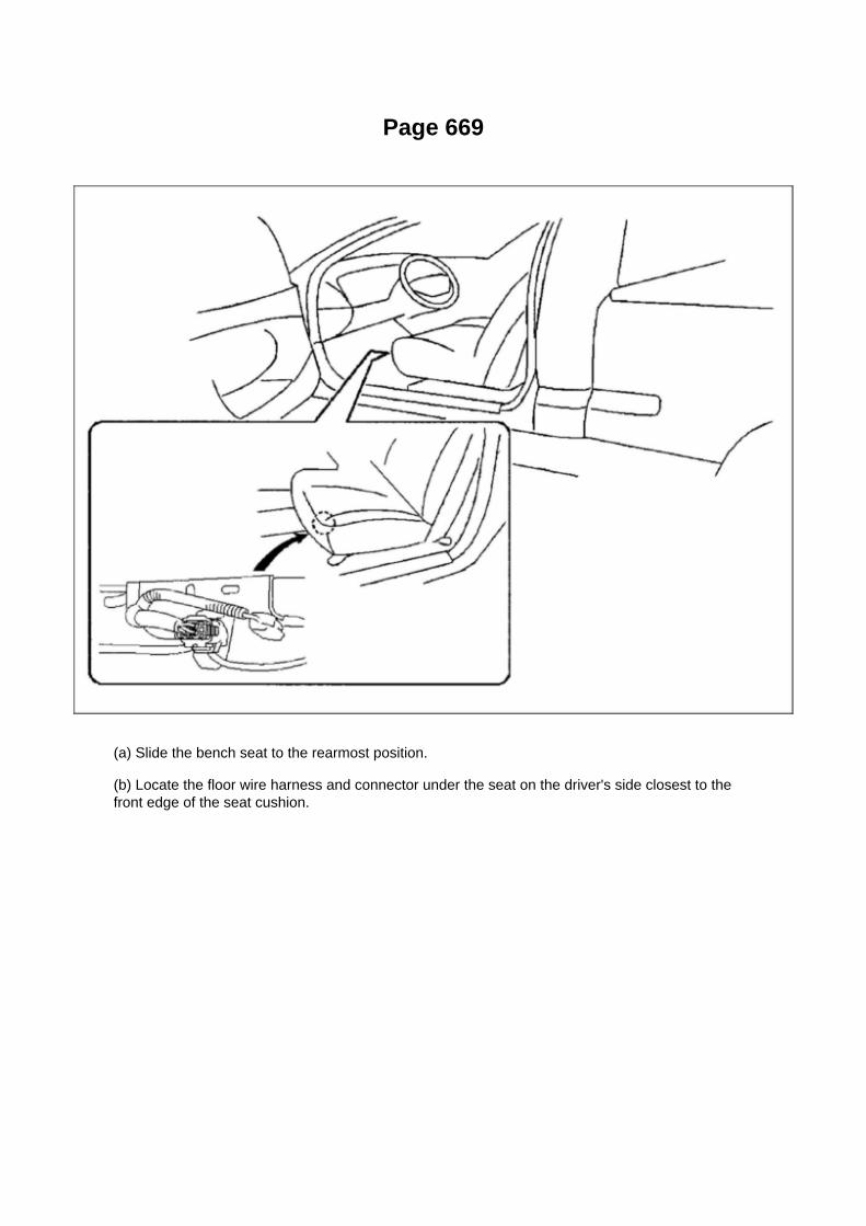
Page 669
(a) Slide the bench seat to the rearmost position.
(b) Locate the floor wire harness and connector under the seat on the driver's side closest to thefront edge of the seat cushion.

Page 1360

Locations

Air Flow Meter/Sensor: Locations

He - Wi
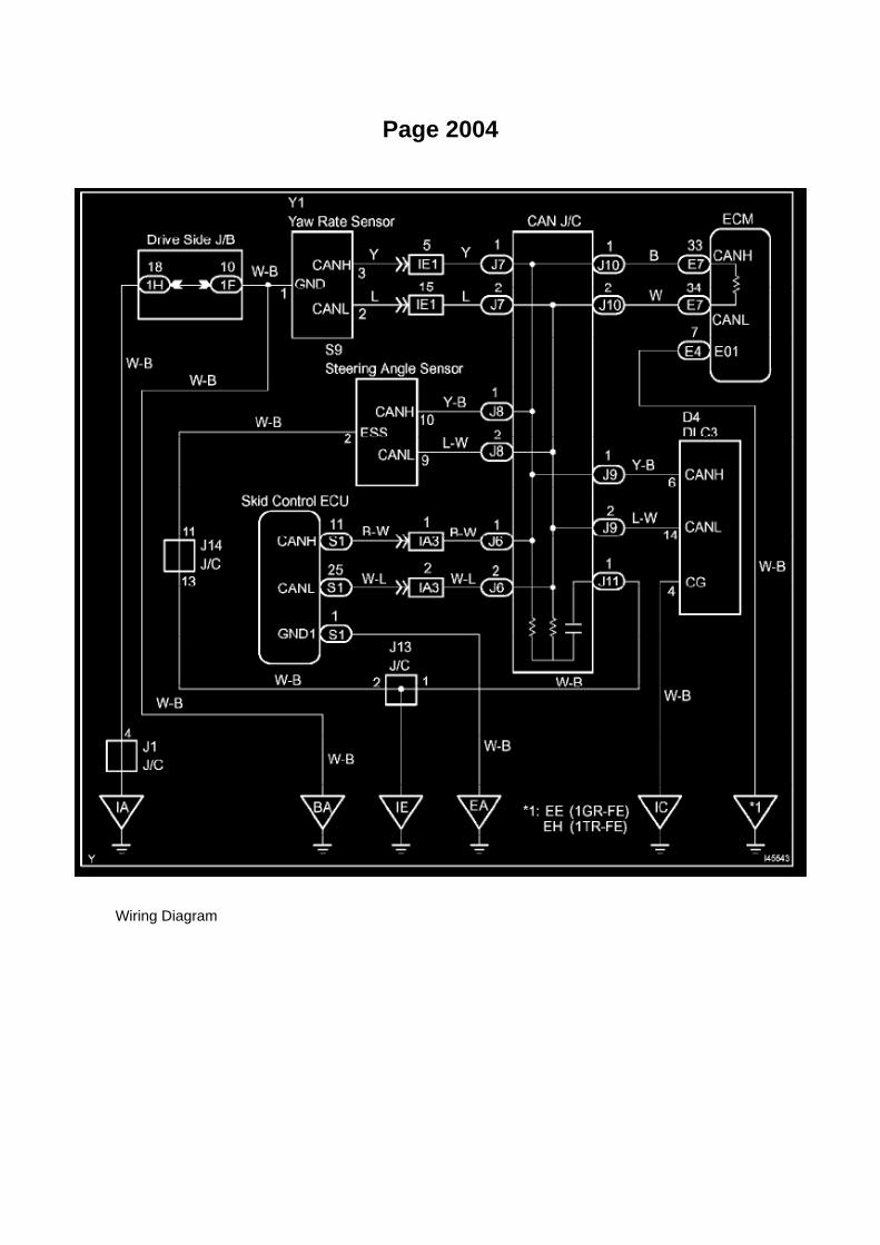
Page 2004
Wiring Diagram

Page 745
Occupant Detection ECU

Page 152
Relay Box: Diagnostic Aids
Steps 1 - 6

Page 950
Repair Procedure
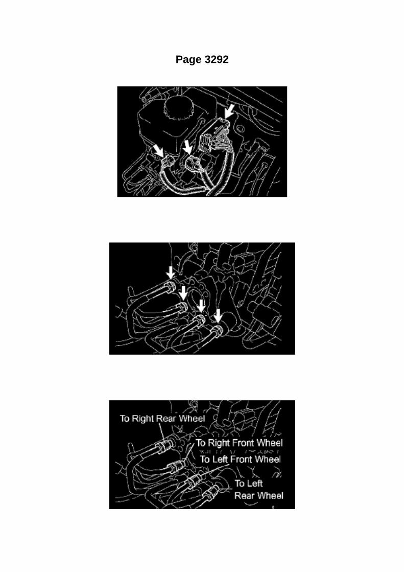
Page 3292

- As high pressure is applied to the brake actuator tube No.1, never deform it.
- Do not turn the ignition switch to ON until the work is completed.
1. DISCONNECT CABLE FROM NEGATIVE BATTERY TERMINAL 2. DRAIN BRAKE FLUID
NOTICE: Immediately wash off any brake fluid off immediately that comes into contact with apainted surface.
3. REMOVE FRONT FLOOR FOOTREST 4. REMOVE FRONT DOOR SCUFF PLATE LH 5.REMOVE COWL SIDE TRIM BOARD LH 6. REMOVE INSTRUMENT PANEL UNDER TRAY(AUTOMATIC TRANSAXLE) 7. REMOVE INSTRUMENT PANEL HOLE COVER (MANUALTRANSAXLE) 8. REMOVE INSTRUMENT PANEL FINISH PANEL LOWER NO.1 9. SEPARATEDRIVER SIDE JUNCTION BLOCK
10. SEPARATE MASTER CYLINDER PUSH ROD CLEVIS
11. REMOVE BRAKE MASTER CYLINDER ASSEMBLY
a. Disconnect the 3 connectors from the brake master cylinder.
b. Using SST, disconnect the 4 brake lines from the brake master cylinder.
SST 09023-00101
c. Use tags or labels to identify the place to reconnect each line.

Page 1639
SFI System

Initial Inspection and Diagnostic Overview

Information Bus: Initial Inspection and Diagnostic Overview

Page 1337
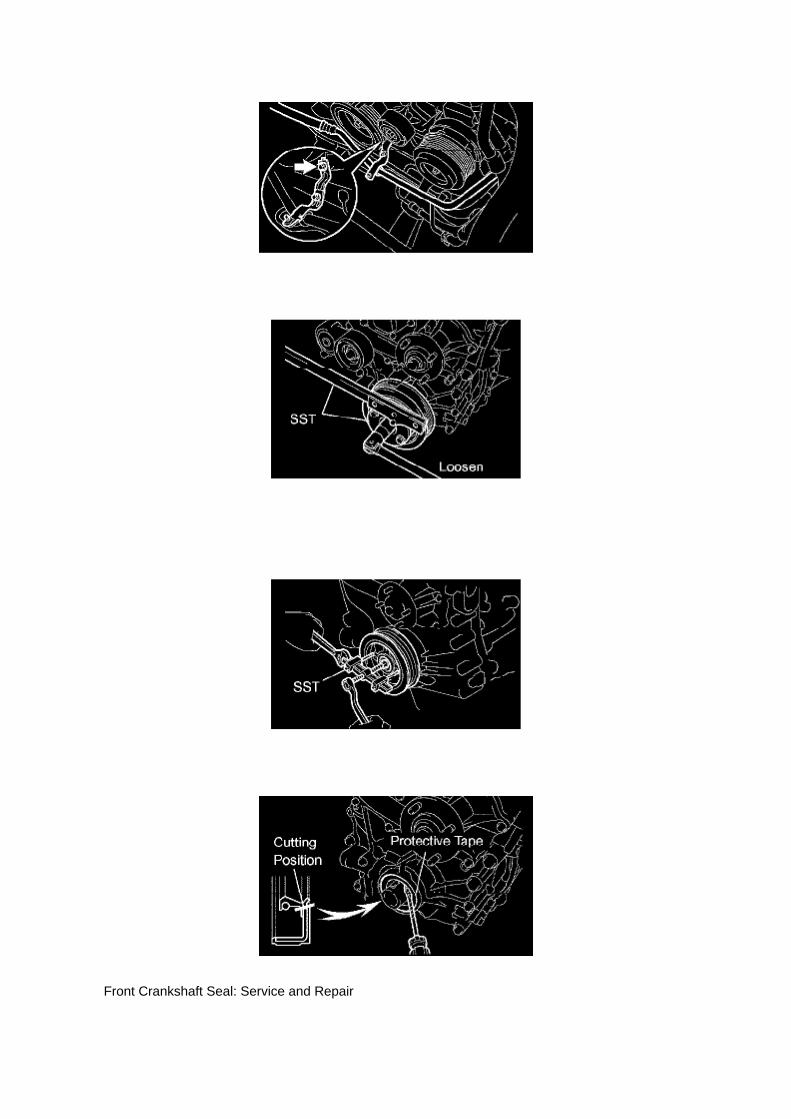
Front Crankshaft Seal: Service and Repair
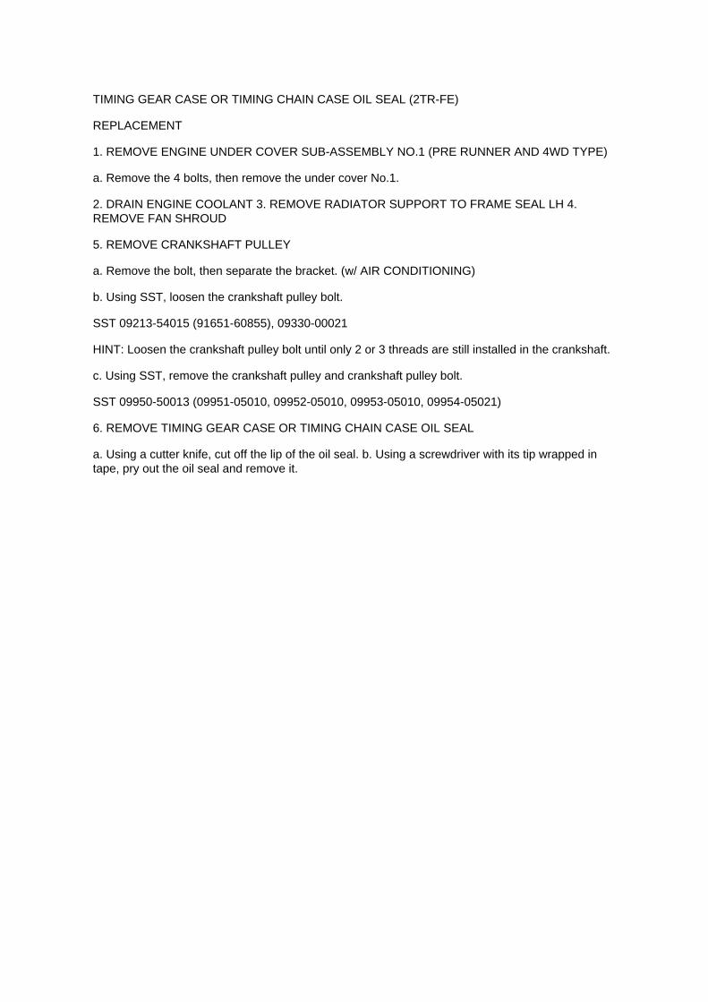
TIMING GEAR CASE OR TIMING CHAIN CASE OIL SEAL (2TR-FE)
REPLACEMENT
1. REMOVE ENGINE UNDER COVER SUB-ASSEMBLY NO.1 (PRE RUNNER AND 4WD TYPE)
a. Remove the 4 bolts, then remove the under cover No.1.
2. DRAIN ENGINE COOLANT 3. REMOVE RADIATOR SUPPORT TO FRAME SEAL LH 4.REMOVE FAN SHROUD
5. REMOVE CRANKSHAFT PULLEY
a. Remove the bolt, then separate the bracket. (w/ AIR CONDITIONING)
b. Using SST, loosen the crankshaft pulley bolt.
SST 09213-54015 (91651-60855), 09330-00021
HINT: Loosen the crankshaft pulley bolt until only 2 or 3 threads are still installed in the crankshaft.
c. Using SST, remove the crankshaft pulley and crankshaft pulley bolt.
SST 09950-50013 (09951-05010, 09952-05010, 09953-05010, 09954-05021)
6. REMOVE TIMING GEAR CASE OR TIMING CHAIN CASE OIL SEAL
a. Using a cutter knife, cut off the lip of the oil seal. b. Using a screwdriver with its tip wrapped intape, pry out the oil seal and remove it.

Page 524
b. Connect the wire harness clamp. c. Connect the air fuel ratio sensor connector.
4. CONNECT CABLE TO NEGATIVE BATTERY TERMINAL
Torque: 3.9 N.m (40 Kgf.cm, 35 in.lbf)

Locations
A/C - Ge

Page 665

Page 1640
Camshaft Position Sensor: Testing and Inspection
INSPECT CAMSHAFT POSITION SENSOR
Check the resistance.
Using an ohmmeter, measure the resistance between the terminals.
HINT: Cold and Hot mean the temperature of the coils themselves. Cold is from -10 to 50°C (14 to122°F) and Hot is from 50 to 100°C (122 to 212° F).
If the result is not as specified, replace the camshaft position sensor.
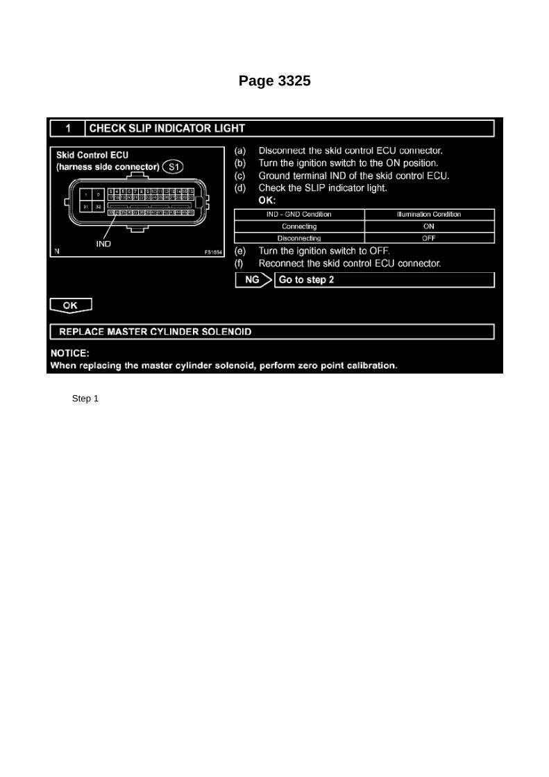
Page 3325
Step 1

Testing and Inspection
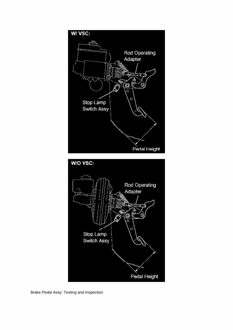
Brake Pedal Assy: Testing and Inspection

BRAKE PEDAL SUB-ASSEMBLY
ON-VEHICLE INSPECTION
1. CHECK BRAKE PEDAL HEIGHT
a. Check the brake pedal height.
Pedal height from dash panel: 158.1 to 168.1 mm (6.224 to 6.618 inch)
NOTICE: Do not adjust the pedal height. Doing so by changing the push rod length will structurallychange the pedal ratio.
If the pedal height is incorrect, adjust the rod operating adapter length.

Locations
Acceleration/Deceleration Sensor: Locations
Ac - Ou

Page 724

2. DISCONNECT THE NEGATIVE BATTERY CABLE

3. LOCATE THE BENCH SEAT FLOOR WIRE HARNESS
(c) Slide the bench seat to the rearmost position.
(d) Locate the floor wire harness and connector under the seat on the driver's side, closest to thefront edge of the seat cushion.
4. INSTALL THE WIRE SEAT JUMPER
NOTE:
DO NOT install the wire seat jumper on a vehicle which is NOT on the VIN list!
(a) Push the lock tab on the connector and pull to remove the female portion of the connector.
(b) Before installing the wire seat jumper to the vehicle, attach the Warning Label (shown in theillustration) onto the corrugated tubing, next to the
Part Number Label.
NOTE:
^ Attach the Warning Label in a similar manner to the Part Number Label, making sure not coverthe information printed on it.
^ DO NOT remove the Part Number Label or cover it with the Warning Label.
^ A small supply of labels were sent with the Service Manager Package. Additional labels can beordered from the Material Distribution Center (p/n 00410-92017).

Restraints - OCS System Initialization

Seat Occupant Classification Module - Air Bag: Technical Service Bulletins Restraints - OCSSystem Initialization

COLLISION REPAIR INFORMATION FOR THE COLLISION REPAIR PROFESSIONAL
TITLE: SRS OCCUPANT CLASSIFICATION SYSTEM INITIALIZATION
SECTION: ELECTRICAL BULLETIN # 177
MODELS: ALL EQUIPPED TOYOTA LEXUS and SCION MODELS
DATE: MARCH 2010
Models equipped with a Supplemental Restraint System (SRS) Occupant Classification System(OCS) will enable or disable the passenger front and side airbags based on seat occupancypassenger weight and seat belt latch engagement.
If an equipped vehicle sustains collision damage or if the front passenger seat or any of the OCScomponents are serviced the SRS Malfunction Indicator Light (MIL) may illuminate setting aDiagnostic Trouble Code (DTC).
NOTE:
It is necessary to diagnose and repair the root cause of a SRS or OCS DTC before initializing theOCS system. If SRS and OCS DTC's are not cleared the system may not operate properly.
Be sure to check and clear DTC's and perform OCS initialization per repair manual instructionswith a Techstream Special Service Tool (SST) or capable diagnostic tester.
Any of the following conditions could set a DTC illuminate the SRS MIL or cause the PASSENGERAIRBAG light to indicate incorrectly regardless of occupancy:
^ The OCS Electronic Control Unit (ECU) is replaced
^ Accessories such as a seatback tray are installed on the passenger seat
^ The passenger seat is removed and replaced or reinstalled
^ The vehicle is involved in an accident or collision
Model-specific repair manuals can be accessed through the Technical Information System (TIS)www.techinfo.toyota.com

Page 287

Ha - Op

Page 494

Knock Control Sensor (2TR-FE) Part 3

Recall 09V388000: Floor Mat/Accelerator Interference

Accelerator Pedal: All Technical Service Bulletins Recall 09V388000: Floor Mat/AcceleratorInterference

VEHICLE MAKE/MODEL: MODEL YEAR(S): Lexus/ES350 2007-2010 Lexus/IS 2006-2010Toyota/Avalon 2005-2010 Toyota/Camry 2007-2010 Toyota/Prius 2004-2009 Toyota/Tacoma2005-2010 Toyota/Tundra 2007-2010 MANUFACTURER: Toyota Motor Corporation
MFR'S REPORT DATE: October 05, 2009
NHTSA CAMPAIGN ID NUMBER: 09V388000
NHTSA Action Number: N/A COMPONENT: Vehicle Speed Control: Accelerator Pedal
POTENTIAL NUMBER OF UNITS AFFECTED: 3800000
SUMMARY: Toyota is recalling certain model year 2004-2010 passenger vehicles. The acceleratorpedal can get stuck in the wide open position due to its being trapped by an unsecured orincompatible driver's floor mat.
CONSEQUENCE: A stuck open accelerator pedal may result in very high vehicle speeds andmake it difficult to stop the vehicle, which could cause a crash, serious injury or death.
REMEDY: Toyota will notify owners of affected vehicles to remove any driver's floor mat and notreplace it with any other floor mat pending the development of model-specific remedies. Toyota willmail a second notification to owners of affected vehicles notifying them of the free remedies whenthey are available. The first notice is expected to be mailed during October 2009 and Toyota willadvise NHTSA of the estimated date when the remedies will be available. Owners may contactToyota at 1-800-331-4331, Lexus at 1-800-255-3987.
NOTES: Owners may also contact The National Highway Traffic Safety Administration's VehicleSafety Hotline at 1-888-327-4236 (TTY 1-800-424-9153), or go to http://www.safercar.gov.

Page 1389

NOTICE: Remove any oil from the contact surface. Install the chain cover within 3 minutes andtighten the bolts within 15 minutes of applying seal packing. Do not start the engine for at least 4hours after installation.
Align the oil pump's drive rotor spline and the crankshaft as shown in the illustration. Install thespline and chain cover onto the crankshaft. Loosely install the timing chain cover with the 19 boltsand 2 nuts, but do not tighten the bolts and nuts yet.

Page 1686
A/C - Ge

Page 3007
Install the bolt from the left side of the vehicle.
B. Tighten the bolt to the instrument panel reinforcement assembly.

Torque: 8 N.m (82 kgf.cm, 6 ft.lbf)
15. Install the turnover (compression) spring.
A. Apply MP grease to the contact surface of the spring holder, clutch pedal, and spring.
B. Install the spring onto the clutch pedal and spring holder.
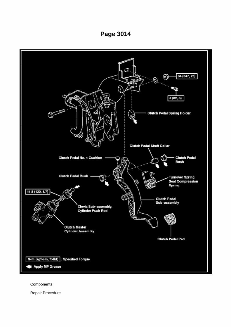
Page 3014
Components
Repair Procedure

1. Record all radio presets before starting.
2. Disconnect the negative (-) battery terminal cable.
3. Remove the clutch pedal sub-assembly.

Page 609

Impact Sensor: Testing and Inspection

AIRBAG SENSOR FRONT (VEHICLE NOT INVOLVED IN COLLISION)
a. Perform a diagnostic system check.
Refer to Air Bag Systems; Testing and Inspection.
AIRBAG SENSOR FRONT (VEHICLE INVOLVED IN COLLISION AND AIRBAG IS NOTDEPLOYED)
a. Perform a diagnostic system check.
Refer to Air Bag Systems; Testing and Inspection.
b. When the front bumper of the vehicle or its periphery is damaged, check if there is any damageto the airbag sensor front. If there are any airbag
sensor front defects as mentioned below, replace the airbag sensor front with a new one: -
Cracks, dents or chips in the case.
- Cracks or other damage to the connector.
- Peeling off of the label or damage to the serial number.
CAUTION: For removal and installation procedures of the airbag sensor front, see "Replacement"and be sure to follow the correct procedure.
AIRBAG SENSOR FRONT (VEHICLE INVOLVED IN COLLISION AND AIRBAG IS DEPLOYED)
a. Replace the airbag sensor front.
CAUTION: For removal and installation procedures of the airbag sensor front, see "Replacement"and be sure to follow the correct procedure.
HINT: The airbag sensor front on the impacted side should be replaced after the horn buttonassembly or instrument panel passenger airbag assembly has deployed.
SIDE AIRBAG SENSOR ASSEMBLY (VEHICLE NOT INVOLVED IN COLLISION)
a. Perform a diagnostic system check.
Refer to Air Bag Systems; Testing and Inspection.
SIDE AIRBAG SENSOR ASSEMBLY (VEHICLE INVOLVED IN COLLISION AND AIRBAG IS NOTDEPLOYED)
a. Perform a diagnostic system check.
Refer to Air Bag Systems; Testing and Inspection.
b. When the center pillar of the vehicle or its periphery is damaged, check if there is any damage tothe side airbag sensor assembly. If there are any
defects as mentioned below, replace the side airbag sensor assembly with a new one: -
Cracks, dents or chips in the case.
- Cracks or other damage to the connector.
- Peeling off of the label or damage to the serial number.
CAUTION: For removal and installation procedures of the side airbag sensor assembly, see"Replacement" and be sure to follow the correct procedure.
SIDE AIRBAG SENSOR ASSEMBLY (VEHICLE INVOLVED IN COLLISION AND AIRBAG ISDEPLOYED)
a. Replace the side airbag sensor assembly.
CAUTION: For removal and installation procedures of the side airbag sensor assembly, see"Replacement" and be sure to follow the correct procedure.
HINT: The side airbag sensor assembly on the impacted side should be replaced after the frontseat airbag assembly and curtain shield airbag assembly have deployed.
AIRBAG SENSOR REAR (VEHICLE NOT INVOLVED IN COLLISION)
a. Perform a diagnostic system check.
Refer to Air Bag Systems; Testing and Inspection.
AIRBAG SENSOR REAR (VEHICLE INVOLVED IN COLLISION AND AIRBAG IS NOTDEPLOYED)
a. Perform a diagnostic system check.
Refer to Air Bag Systems; Testing and Inspection.
b. When the quarter panel of the vehicle or its periphery is damaged, check if there is any damageto the airbag sensor rear. If there are any defects as
mentioned below, replace the airbag sensor rear with a new one: -
Cracks, dents or chips in the case.
- Cracks or other damage to the connector.
- Peeling off of the label or damage to the serial number.

Service and Repair
Vehicle Lifting: Service and Repair

VEHICLE LIFT AND SUPPORT LOCATIONS
1. NOTE ABOUT VEHICLE CONDITION WHEN JACKING UP VEHICLE
a. The vehicle must be unloaded before jacking up the vehicle. Never jack up/lift up a heavilyloaded vehicle. b. When removing heavy equipment such as the engine and transmission, thecenter of gravity of the vehicle may shift. To stabilize the vehicle:
place a balance weight in a location where it will not roll or shift; or use a mission jack to hold thejacking support.
2. NOTE FOR USING 4 POST LIFT
a. Follow the safety procedures outlined in its instruction manual. b. Use precautionary measuresto prevent the free wheel beam from damaging tires or wheels. c. Use wheel chocks to secure thevehicle.

Page 1853
C. Choose desired ECU group(s) in the Health Check dialog box.
D. Click Next.
E. Click Continue to view Health Check results.

F. Available calibration updates are indicated by a link in the Cal. Update? column. Click the link toaccess the appropriate service bulletin on TIS.
NOTE
^ Note any DTCs stored in Systems that will be flash reprogrammed.
^ Clicking the link will automatically launch TIS and perform a calibration search.
G. Log in to TIS. (If already logged in skip this step.)
H. To review the TSB and access the calibration file click the service bulletin link in the DocumentTitle column of the Calibration Search Result
portlet.

Page 1197

SST 09718-00010, 09921-00010

10. CHECK REAR DRUM BRAKE INSTALLATION 11. INSTALL REAR BRAKE DRUM SUB-ASSY12. ADJUST REAR DRUM BRAKE SHOE CLEARANCE 13. INSTALL REAR WHEEL
Torque: 113 Nm (1,152 kgf-cm, 83 ft. lbs.)
14. INSPECT PARKING BRAKE PEDAL TRAVEL (AUTOMATIC TRANSAXLE) 15. INSPECTPARKING BRAKE LEVER TRAVEL (MANUAL TRANSAXLE) 16. ADJUST PARKING BRAKEPEDAL TRAVEL (AUTOMATIC TRANSAXLE) 17. ADJUST PARKING BRAKE LEVER TRAVEL(MANUAL TRANSAXLE)

Page 2511

3. Install the fuel tank protector cover on top of the fuel suction plate sub-assembly as shown in theillustration.

Page 2230
Transmission Position Switch/Sensor: Adjustments
PARK/NEUTRAL POSITION SWITCH ASSY
ADJUSTMENT
1. INSPECT PARK/NEUTRAL POSITION SWITCH ASSY
a. Apply the parking brake and turn the ignition switch to ON. b. Depress the brake pedal andcheck that the engine starts only when the shift lever is set in the N or P position and that it doesnot start in any
other positions.
c. Check that the back-up light comes on and the reverse warning buzzer sounds only when theshift lever is set in the R position and not in other
positions. If any failure is found, check the park/neutral position switch for continuity.
2. ADJUST PARK/NEUTRAL POSITION SWITCH ASSY
a. Loosen the bolt of the park/neutral position switch and set the shift lever to the N position. b.Align the groove and the neutral basic line. c. Hold the switch in position and tighten the bolt.
Torque: 13 Nm (130 kgf-cm, 9 ft. lbs.)
d. After making an adjustment, perform the inspection described in step 1.

Page 3136
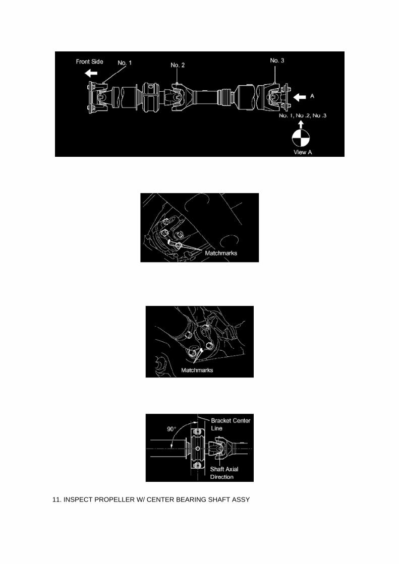
11. INSPECT PROPELLER W/ CENTER BEARING SHAFT ASSY

HINT: When replacing the spider bearing, make sure that the grease fitting assembly hole is facingin the direction shown in the illustration.
12. INSTALL PROPELLER W/ CENTER BEARING SHAFT ASSY
a. Align the matchmarks on the yoke and transfer flange. b. Install the propeller shaft assy with the4 nuts and 4 washers.
Torque: 88 Nm (899 kgf-cm, 65 ft. lbs.)
c. Align the matchmarks on the yoke and differential flange. d. Install the propeller shaft assy withthe 4 bolts, 4 nuts and 4 washers.
Torque: 88 Nm (899 kgf-cm, 65 ft. lbs.)
e. Provisionally install the center support bearing No.1 with 2 mounting bolts.
HINT: Make sure the bearing is installed with the drain hole facing downwards.
f. Torque the 2 bolts. Torque: 36 Nm (369 kgf-cm, 27 ft. lbs.)
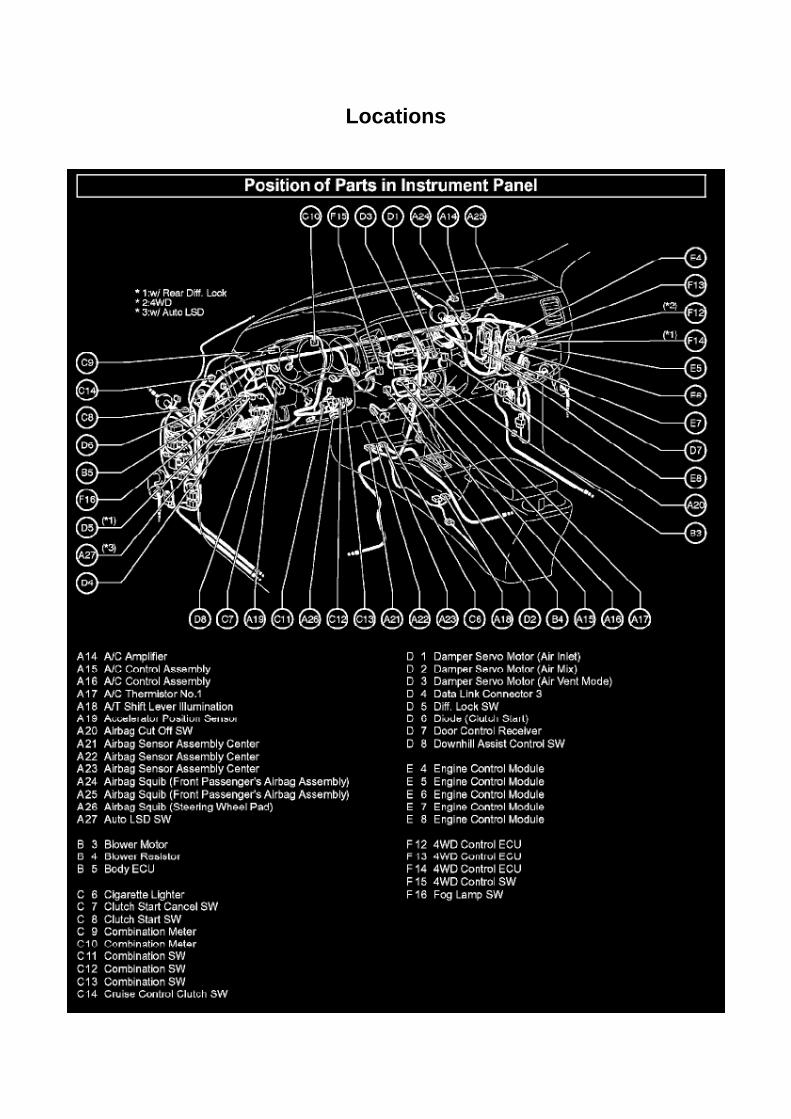
Locations

Clutch Switch: Locations
A/C - Fo

Page 409
Key Reminder Warning System

Page 3238
Step 1 - 2

Page 139
Driver Side J/B - Lower Finish Panel
Details
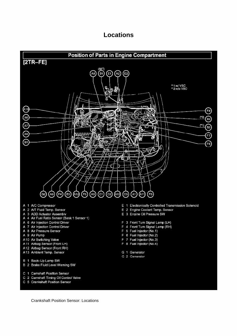
Locations
Crankshaft Position Sensor: Locations

A/C - Ge

Page 2911

7. REMOVE CLUTCH RELEASE FORK BOOT

8. REMOVE CLUTCH COVER ASSY
a. Align the matchmark on the clutch cover assy with the one on the flywheel sub-assembly. b.Loosen each set bolt one turn at a time until the spring tension is released. c. Remove the 6 boltsand clutch cover assy.
NOTICE: Do not drop the clutch disc assy.
9. REMOVE CLUTCH DISC ASSY
NOTICE: Keep the lining part of the clutch disc assy, pressure plate and surface of the flywheelsub-assy free from oil and foreign matter.
10. INSPECT CLUTCH DISC ASSY
a. Using vernier calipers, measure the rivet head depth.
Maximum rivet depth: 0.3 mm (0.012 inch) If necessary, replace the clutch disc assy.
b. Install the clutch disc assy onto the transaxle assy.
NOTICE: Take care not to insert the clutch disc assy in the wrong orientation.
c. Using a dial indicator, check the clutch disc assy runout.
Minimum runout: 0.8 mm (0.031 inch) If necessary, replace the clutch disc assy.
11. INSPECT CLUTCH COVER ASSY

Page 544

Po - Ya

Locations
A/C - Ge

Page 2946

B. Remove the clevis sub-assembly from the master cylinder.

a. Loosen the lock nut.
b. Rotate and remove the clevis sub-assembly.
15. Install the NEW clevis sub-assembly.
A. Rotate the lock nut to match length "A".
B. Rotate and install the NEW clevis sub-assembly to contact the lock nut.
C. Tighten the lock nut and torque to specification.
Torque: 11.8 N.m (120 kgf.cm, 8.7 ft.lbf)
D. Apply MP grease to the ball end of the clevis sub-assembly where it will contact the clutchpedal.

Page 1054
Fuse Block: Diagnostic Aids
Steps 1 - 6
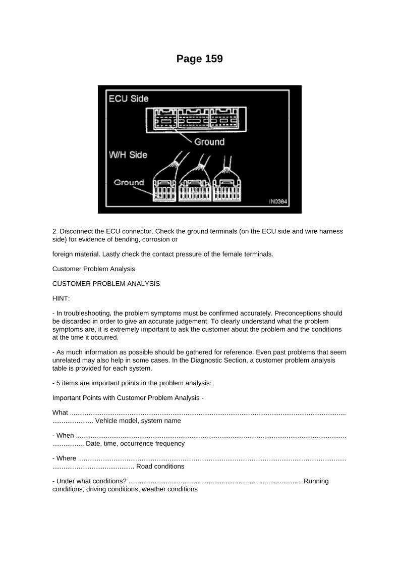
Page 159
2. Disconnect the ECU connector. Check the ground terminals (on the ECU side and wire harnessside) for evidence of bending, corrosion or
foreign material. Lastly check the contact pressure of the female terminals.
Customer Problem Analysis
CUSTOMER PROBLEM ANALYSIS
HINT:
- In troubleshooting, the problem symptoms must be confirmed accurately. Preconceptions shouldbe discarded in order to give an accurate judgement. To clearly understand what the problemsymptoms are, it is extremely important to ask the customer about the problem and the conditionsat the time it occurred.
- As much information as possible should be gathered for reference. Even past problems that seemunrelated may also help in some cases. In the Diagnostic Section, a customer problem analysistable is provided for each system.
- 5 items are important points in the problem analysis:
Important Points with Customer Problem Analysis -
What .......................................................................................................................................................................... Vehicle model, system name
- When .................................................................................................................................................................. Date, time, occurrence frequency
- Where ............................................................................................................................................................................................ Road conditions
- Under what conditions? ............................................................................................. Runningconditions, driving conditions, weather conditions

- How did it happen? ................................................................................................................................................................... Problem symptoms

Page 2736
Then click Next.
F. Verify correct current calibration and new calibration information. Then click Next.
NOTE
^ The total number of calibration IDs in the calibration file corresponds to the number ofreprogrammable processors in the ECU.

^ Each calibration file may contain up to three separate calibrations.

Page 2093

A/C - Fo

Page 1507

COMPONENTS
OVERHAUL
1. REMOVE RADIATOR DRAIN COCK
a. Remove the drain cock plug. b. Remove the O-ring from the drain cock plug.
2. ASSEMBLE SST
SST 09230-01010 (09231-01010, 09231-01030) a. Engage the claw with the overhaul handle byinserting it into the hole in part A as shown in the illustration. b. While gripping the handle, adjustdimension B to between 0.2 and 0.3 mm, using the stopper bolt.
Dimension B: 0.2 to 0.3 mm (0.008 to 0.012 inch)
NOTICE: If the stopper bolt can not be adjusted, the claw may be damaged.

Page 2562

NOTE: -

Check that there are no scratches or foreign objects around the connected part of the fuel tubeconnector and pipe before performing this work.
- After connecting the fuel tube connector, check that the fuel tube connector and pipe are securelyconnected by pulling them.
b. Install the fuel pipe clamp.
17. REMOVE FUEL TANK PROTECTOR SUB-ASSEMBLY NO.1 (W/ OFF ROAD PACKAGE)
a. Install the fuel tank protector LWR with the 4 nuts.
Torque: 20 N.m (204 kgf.cm, 15 ft.lbf)
18. ADD FUEL 19. CONNECT CABLE TO NEGATIVE BATTERY TERMINAL
Torque: 3.9 N.m (40 kgf.cm, 35 in.lbf)
20. CHECK FOR FUEL LEAKAGE

Page 1214
Compression Check: Testing and Inspection
INSPECT COMPRESSION
a. Warm up the engine, then stop it. b. Remove the intake air connector. c. Remove the ignitioncoils. d. Remove the spark plugs. e. Disconnect the fuel injector connector.
f. Inspect the compression. (1) Insert a compression gauge into the plug hole. (2) Crank the engine,then measure the compression pressure. Compression pressure: 1230 kPa (12.5 kgf/cm2, 178 psi)Minimum pressure: 880 kPa (9.0 kgf/cm2, 128 psi) or more Difference between each cylinder: 68kPa (0.7 kgf/cm2, 10 psi) or less
NOTICE: -
Use a fully-charged battery so the engine speed can be increased to 250 rpm or more.
- Inspect the other cylinders in the same way.
- Measure the compression pressure in as short a time as possible.
(3) If the compression pressure is low, pour a small amount of engine oil into the cylinder block,then measure it again.
HINT: -
If the compression pressure increases after adding the engine oil, the piston rings may be worn.
- If the compression pressure does not change after pouring engine oil, defects may be occurringaround the valves.

Page 1797
Compression Check: Testing and Inspection
INSPECT COMPRESSION
a. Warm up the engine, then stop it. b. Remove the intake air connector. c. Remove the ignitioncoils. d. Remove the spark plugs. e. Disconnect the fuel injector connector.
f. Inspect the compression. (1) Insert a compression gauge into the plug hole. (2) Crank the engine,then measure the compression pressure. Compression pressure: 1230 kPa (12.5 kgf/cm2, 178 psi)Minimum pressure: 880 kPa (9.0 kgf/cm2, 128 psi) or more Difference between each cylinder: 68kPa (0.7 kgf/cm2, 10 psi) or less
NOTICE: -
Use a fully-charged battery so the engine speed can be increased to 250 rpm or more.
- Inspect the other cylinders in the same way.
- Measure the compression pressure in as short a time as possible.
(3) If the compression pressure is low, pour a small amount of engine oil into the cylinder block,then measure it again.
HINT: -
If the compression pressure increases after adding the engine oil, the piston rings may be worn.
- If the compression pressure does not change after pouring engine oil, defects may be occurringaround the valves.

Page 1892

Part 1

Page 3203

Ha - Op

Page 401

5. Check that the magnet clutch is turned off when disconnecting terminals 1 and 2 (that areconnected in the prior step).

Standard: Terminals 1 and 2 connected: magnet clutch is ON Terminals 1 and 2 disconnected:magnet clutch is OFF
Replace the pressure switch if the magnet clutch operates normally. Inspect and repair the wireharness between the pressure switch and the ECM.

Page 140

Engine Compartment

Instrument Panel
Locations
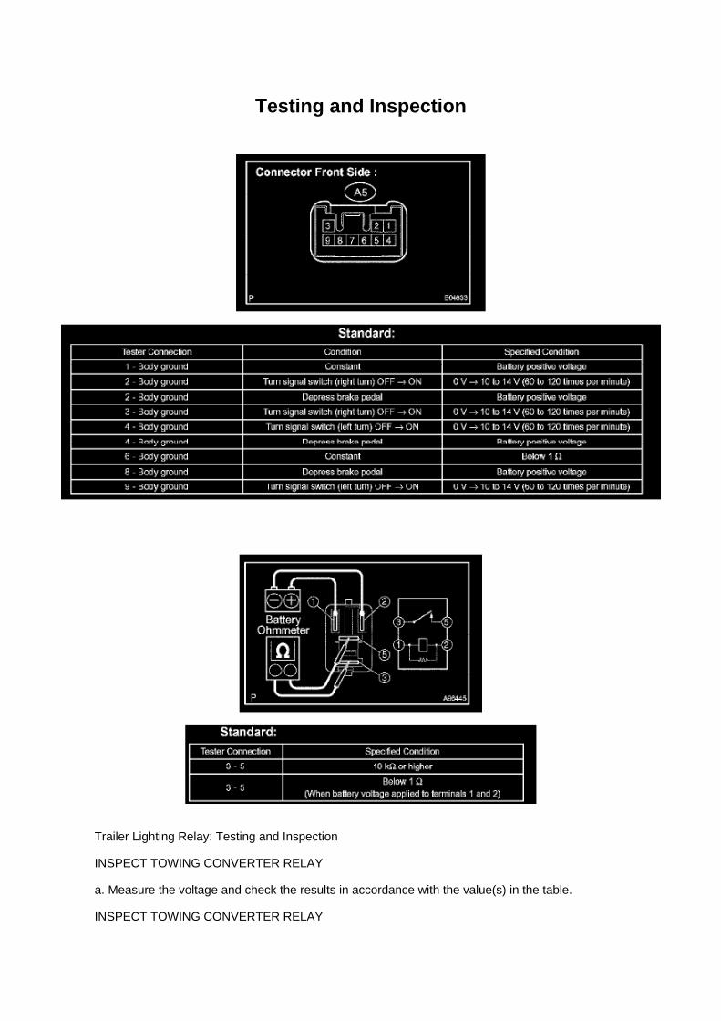
Testing and Inspection
Trailer Lighting Relay: Testing and Inspection
INSPECT TOWING CONVERTER RELAY
a. Measure the voltage and check the results in accordance with the value(s) in the table.
INSPECT TOWING CONVERTER RELAY

a. Check the resistance.
1. Using an ohmmeter, measure the resistance between the terminals.
If the result is not as specified, replace the towing converter relay.

Page 2465

D. Start the engine. After the engine has stalled, turn the ignition switch OFF.

E. Disable the fuel return line by blocking the line or installing the appropriate plug in the returnoutlet, if applicable.
NOTE:
Do NOT clamp plastic lines.
F. Install the device adapter to the fuel line and then secure the swivel fitting on the end of thehose.
G. Make sure the ball valve on the device is turned OFF (valve handle is crosswise to device).Screw the can of EFI cleaner (P/N 00289-1PF14) onto the device can adapter.
H. Open the valve on the device, start the vehicle, and allow it to run until the engine stalls.
I. Turn the ball valve OFF and remove the empty can.
J. Place a shop towel over the can adapter and slowly open the ball valve to depressurize thesystem.
K. Remove supply and return line adapters, reconnect vehicle fuel supply and return lines(replacing any fuel line gaskets and seals), and connect the fuel pump electrical connector.
L. Before starting the vehicle, pressurize the fuel system and check for leaks.
Run the engine for 4 - 5 minutes, and then snap the throttle several times to dislodge any carbonthat may remain in the system.
2. Add 1 can of Toyota Non-Pressurized Fuel Injector Cleaner Fuel Tank Additive (P/N08813-0080DS) to the fuel tank.
3. Road test the vehicle to verify normal operation.

Page 3068

Ac - Ya

Page 225
Step 6 - 8

Specifications

Connecting Rod Bearing: Specifications

Connecting Rod Oil Clearance
Standard oil clearance................................................................................................................................... 0.024 to 0.049mm (0.0009 to 0.0019 inch) Maximum oil clearance ............................................................................................................................................................... 0.066 mm (0.0026 inch)

Page 272
9. REMOVE CONSOLE BOX FRONT (AUTOMATIC TRANSMISSION, BENCH SEAT TYPE)
10. REMOVE CONSOLE BOX FRONT (MANUAL TRANSMISSION, BENCH SEAT TYPE)
11. REMOVE AIR BAG SENSOR ASSEMBLY CENTER
a. Disconnect the holder (with connectors) from the airbag sensor assembly center. b. Remove the3 bolts and the airbag sensor assembly center.
12. INSPECT AIR BAG SENSOR ASSEMBLY CENTER
13. INSTALL AIR BAG SENSOR ASSEMBLY CENTER
a. Check that the ignition switch is turned to OFF. b. Check that the cable is disconnected from thebattery negative terminal.
CAUTION: After removing the terminal, wait for at least 90 seconds before starting the operation.
c. Provisionally install the air bag sensor assembly center with the 3 bolts.
NOTE: -
If the airbag sensor assembly center has been dropped, or there are any cracks, dents or otherdefects in the case, bracket or connector, replace it with a new one.
- When installing the airbag sensor assembly center, make sure that the SRS wiring dose notinterfere with any other parts and that it is not pinched between other parts.
d. Tighten the 3 bolts to the specified torque.
Torque: 17.5 N.m (179 kgf.cm, 13 ft.lbf)
e. Check that there is no slack in the installation parts of the airbag sensor assembly center. f.
Connect the holder (with connectors) to the airbag sensor assembly center.
g. Check that the waterproof sheet is properly set.

14. INSTALL CONSOLE BOX FRONT (MANUAL TRANSMISSION, BENCH SEAT TYPE) 15.INSTALL CONSOLE BOX FRONT (AUTOMATIC TRANSMISSION, BENCH SEAT TYPE) 16.INSTALL CONSOLE BOX FRONT (MANUAL TRANSMISSION, SEPARATE SEAT TYPE) 17.INSTALL CONSOLE BOX FRONT (AUTOMATIC TRANSMISSION, SEPARATE SEAT TYPE) 18.INSTALL INSTRUMENT PANEL CUP HOLDER TRAY (AUTOMATIC TRANSMISSION,SEPARATE SEAT TYPE) 19. INSTALL CONSOLE BOX ASSEMBLY REAR (SEPARATE SEATTYPE) 20. INSTALL CONSOLE UPPER REAR PANEL SUB-ASSEMBLY (MANUALTRANSMISSION, SEPARATE SEAT TYPE) 21. INSTALL CONSOLE UPPER REAR PANELSUB-ASSEMBLY (AUTOMATIC TRANSMISSION,SEPARATE SEAT TYPE) 22. CONNECTCABLE TO NEGATIVE BATTERY TERMINAL
Torque: 3.9 N.m (40 kgf.cm, 35 in.lbf)
23. INSPECT SRS WARNING LIGHT

Page 921

2. Pinch the retainer as illustrated, then pull the fuel tube connector out of the pipe.

3. If the fuel tube connector and pipe are stuck, pinch the pipe and push and pull the fuel tubeconnector to release it.
NOTE: Never use any tools.
4. After disconnecting the fuel tube, check the sealing surface of the pipe for dirt and mud.
If dirty, wipe it with a shop rag.
5. Cover the disconnected fuel tube connector and pipe with a vinyl bag to prevent damage and theintrusion of foreign objects.
d. Take the following precautions when installing the fuel tube connector.
1. Align the fuel tube connector with the pipe, then push in the fuel tube connector until the retainermakes a "click" sound.

Page 3243
Step 1

Page 1180

13. REMOVE REAR AXLE SHAFT LH

a. Using SST and press, remove the rear axle shaft.
SST 09521-25011, 09521-25021
14. REMOVE REAR AXLE BEARING RETAINER INNER LH
a. Remove the rear axle bearing retainer inner from the rear axle bearing.
15. REMOVE REAR AXLE SHAFT LH WASHER
a. Remove the rear axle shaft washer from the rear axle bearing.
16. REMOVE REAR AXLE HUB & BEARING ASSY LH
a. Attach the 4 nuts to the rear axle housing bolts. b. Using a hammer, remove the 4 rear axlehousing bolts and rear axle bearing.
NOTICE: Do not reuse the nuts previously removed from the vehicle.
17. REMOVE REAR AXLE HUB BOLT
a. 2WD: Using SST, remove the 5 hub bolts.
SST 09650-17011
b. Remove the deflector and deflector gasket from the rear axle shaft.
c. 4WD and PRE RUNNER: Using SST, remove the 6 hub bolts.
SST 09650-17011
d. Remove the deflector and deflector gasket from the rear axle shaft.
18. REMOVE REAR AXLE BEARING OIL SEAL

Page 3369
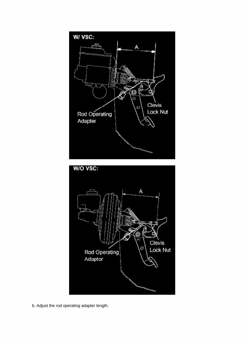
b. Adjust the rod operating adapter length.

(1) Remove the clip and clevis pin. (2) Loosen the clevis lock nut. (3) Adjust the rod operatingadapter length by turning the pedal push rod clevis. Rod operating adapter length A:
214 to 224 mm (8.425 to 8.818 inch) for w/ VSC 212 to 222 mm (8.346 to 8.740 inch) for w/o VSC
(4) Tighten the clevis lock nut.
Torque: 25.5 Nm (260 kgf-cm, 19 ft. lbs.)
(5) Install the clip and clevis pin. -
If the pedal height is incorrect even when the rod operating adapter is adjusted, check that there isno damage in the brake pedal, brake pedal lever, brake pedal bracket or dash panel.
- Even if there is damage, there is no problem if the reserve distance is within the standard value.
- If necessary, replace the parts.
2. CHECK AND ADJUST STOP LAMP SWITCH
HINT: If the pedal height is incorrect, check and adjust the stop lamp switch.
a. Disconnect the stop lamp switch connector from the stop lamp switch. b. Turn the stop lampswitch counterclockwise, and remove the stop lamp switch.

Page 2494
a. Connect the hand-held tester to the DLC3. b. Turn the ignition switch to ON.
NOTE: Do not start the engine.
c. Turn the hand-held tester ON. d. Select the following menu items: DIAGNOSIS / ENHANCEDOBD II / ACTIVE TEST / FUEL PUMP / SPD / ON. e. Check that there are no leakage in the fuelsystem.

Page 471

Camshaft Position Sensor: Service and Repair

REPLACEMENT
1. DISCONNECT CABLE FROM NEGATIVE BATTERY TERMINAL 2. REMOVE CAMSHAFTPOSITION SENSOR
a. Disconnect the camshaft position sensor connector. b. Remove the bolt, then remove thecamshaft position sensor.
3. INSTALL CAMSHAFT POSITION SENSOR
a. Apply a light coat of engine oil to the O-ring of the camshaft position sensor.
b. Install the camshaft position sensor with the bolt.
Torque: 8.5 N.m (87 kgf.cm, 75 in.lbf)
NOTE: Make sure that the O-ring is not cracked or jammed when installing.
c. Connect the camshaft position sensor connector.
4. CONNECT CABLE TO NEGATIVE BATTERY TERMINAL
Torque: 3.9 N.m (40 kgf.cm, 35 in.lbf)

Page 2369
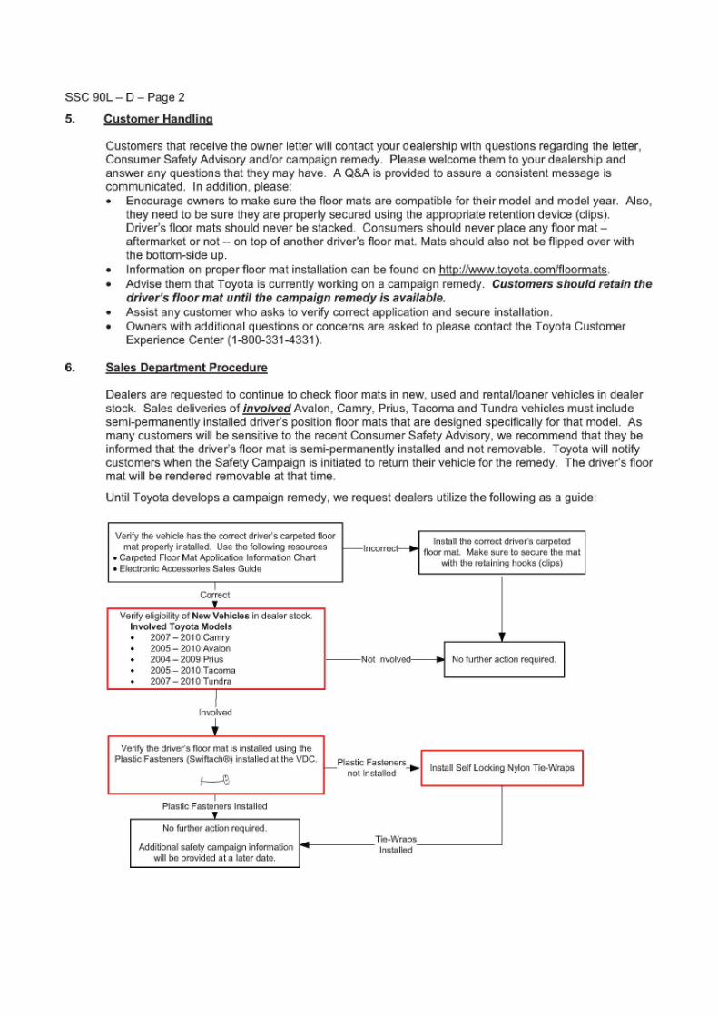

Page 3008
16. Inspect and adjust the clutch pedal sub-assembly.
A. Lift the floor carpet.
B. Check that the pedal height is correct.
Pedal height from asphalt sheet: 168.5 to 178.5 mm (6.634 to 7.028 in.)
C. Adjust the pedal height.
a. Loosen the lock nut and turn the stopper bolt until the height is correct.
b. Tighten the lock nut.
Torque: 25 N.m

(250 kgf.cm, 18 ft.lbf)
D. Check that the pedal free play and push rod play are correct.
a. Depress the pedal until pedal to push rod contact occurs (push rod free play).
b. Gently depress the pedal until the resistance begins to increase a little (pedal free play).
Pedal free play: 5.0 to 15.0 mm (0.197 to 0.591 in.)
E. Adjust the pedal and push rod free play.
a. Loosen the lock nut and turn the push rod until the pedal and push rod play are correct.
b. Tighten the lock nut.
Torque: 11.8 N.m (120 kgf.cm, 9 ft.lbf)
c. After adjusting the pedal free play, check the pedal height.

Page 1585
CAN Communication System

Locations
Camshaft Position Sensor: Locations

A/C - Ge

Page 953
A/C Clamp Remover for removing special air condition line clamps. Applicable: 1998 and newerToyota models with the new style A/C clamps. Comparable to Toyota Tool numbers 09870-00015and 09870-00025.
- Made in USA
- Fits both Toyota AC Clamps, used on high and low pressure lines.
- Applicable to: 1998 and newer Toyota models
- Stainless Steel release pins
- Identification and Instructions are laser marked on the handle
Contact AST for pricing.
Assenmacher Specialty Tools 1-800-525-2943

Page 3054
Continuously Variable Transmission/Transaxle: Technical Service Bulletins A/T, M/T - AlignmentPin Service Precaution
T-SB-0053-08
May 8, 2008
Alignment Pin Installation during Transmission/Transaxle Assembly Installation
Service Category Drivetrain
Section Automatic Transmission/Transaxle

Market USA
Applicability
Introduction
The purpose of this TSB is to provide information regarding the installation of alignment pins duringtransmission/transaxle assembly installation. Missing alignment pins may result in incorrectalignment and failure of the transmission/transaxle assembly. Use the information below wheninstalling a transmission/transaxle assembly.
Parts Information
Warranty Information
Repair Procedure
1. Inspect the rear side of the engine block assembly for 2 alignment pins.
^ If there are less than 2 alignment pins present one may have been removed with thetransmission/transaxle assembly. Check the removed assembly for the missing alignment pins. Goto step 2.

Locations
A/C - Ge

Page 3357
10. INSTALL SENSOR BRACKET
a. Install the bracket with the bolt.
Torque: 12.5 Nm (127 kgf-cm, 9 ft. lbs.)
b. Install the wire harness clamp.
11. INSTALL COWL SIDE TRIM BOARD LH 12. INSTALL FRONT DOOR SCUFF PLATE LH 13.INSTALL FRONT FLOOR FOOTREST 14. INSTALL FRONT SEAT ASSEMBLY (BENCH SEATTYPE) 15. INSTALL FRONT SEAT ASSEMBLY LH (SEPARATE SEAT TYPE) 16. CONNECTCABLE TO NEGATIVE BATTERY TERMINAL
Torque: 3.9 Nm (40 kgf-cm, 35 inch lbs.)
17. PERFORM YAW RATE SENSOR ZERO POINT CALIBRATION See: Testing andInspection/Component Tests and General Diagnostics/ABS
W/EBD & BA & TRAC & VSC System/Calibration
18. CHECK VSC SENSOR SIGNAL

Page 1378
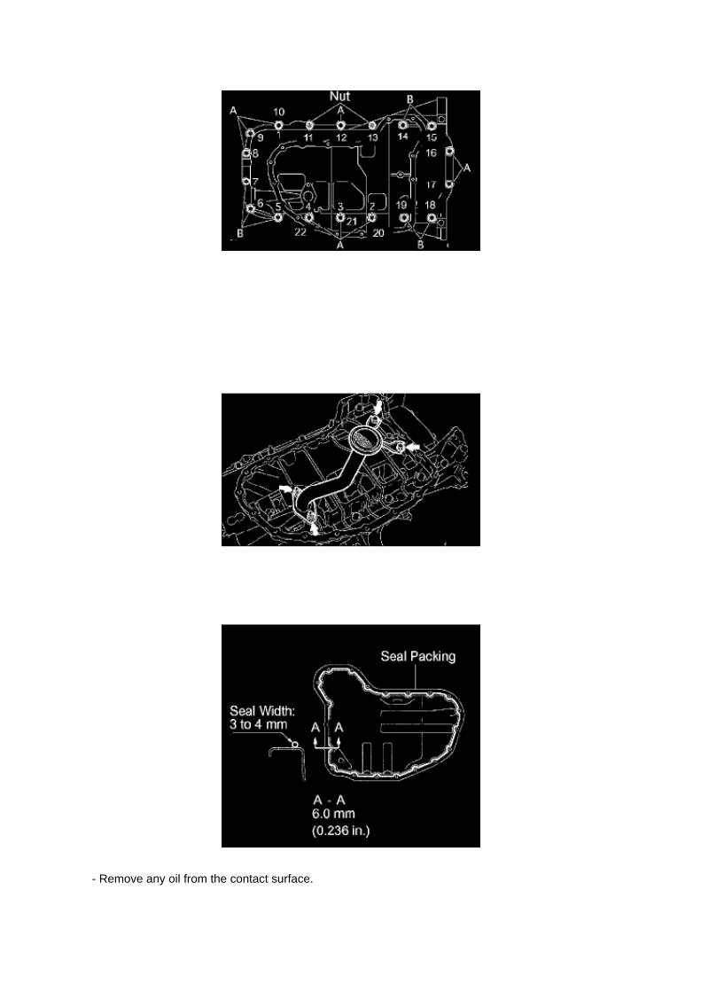
- Remove any oil from the contact surface.

- Install the crankcase within 3 minutes of applying the seal packing.
- Do not start the engine for at least 2 hours after installation.
b. Loosely install the oil pan with the 16 bolts and 2 nuts.
HINT: Bolt length:
20 mm (0.79 inch) for bolt A 40 mm (1.57 inch) for bolt B
c. Uniformly tighten the 16 bolts and 2 nuts in the sequence shown in the illustration.
Torque: 26 Nm (265 kgf-cm, 19 ft. lbs.)
71. INSTALL OIL STRAINER SUB-ASSEMBLY
a. Install a new gasket and the oil strainer with the 2 bolts and 2 nuts.
Torque: 26 Nm (265 kgf-cm, 19 ft. lbs.)
72. INSTALL OIL PAN SUB-ASSEMBLY NO.2
a. Apply continuous beads of seal packing to the places shown in the illustration.
Seal packing: Part No.08826-00080 or equivalent Seal width: 3 to 4 mm (0.118 to O.157 inch)
NOTICE: -
Remove any oil from the contact surface.
- Install the crankcase within 3 minutes of applying the seal packing.
- Do not start the engine for at least 2 hours after installation.

Page 2000
Step 7 - 8

Page 2210
A/F and 02 Sensor Identification

Locations

A/C - Fo

Page 1084

Driver Side J/B Inner Circuit

Page 673

5. RECONNECT THE NEGATIVE BATTERY CABLE
6. REPROGRAM THE RADIO STATION PRESETS AND SET THE CLOCK TO THEAPPROPRIATE TIME
C. VERIFY THE REPAIR USING THE SCAN TOOL
1. PREPARE THE SCAN TOOL
(a) Remove the DLC3 connector cover.
(b) Connect the scan tool to the DLC3 connector.
(c) Turn the ignition switch to the "ON" position.

Page 1391
Install a new gasket, then install the water by-pass pipe No.1 with the 2 nuts.
Torque ....................................................................................................................................................................... 18 Nm (178 kgf-cm, 13 ft. lbs.)

Removal and Installation

Engine Control Module: Service and Repair Removal and Installation

REPLACEMENT
NOTE: Perform REGISTRATION (VIN registration) when replacing the ECM.
1. DISCONNECT CABLE FROM NEGATIVE BATTERY TERMINAL 2. REMOVE GLOVECOMPARTMENT DOOR ASSEMBLY 3. REMOVE INSTRUMENT PANEL FINISH PANELSUB-ASSEMBLY LOWER RH 4. REMOVE ECM
a. Disconnect the 4 connectors. b. Remove the 2 bolts and nut, then remove the ECM.
5. REMOVE ECM BRACKET
a. Remove the 3 screws, then remove the ECM bracket.
6. REMOVE ECM BRACKET NO.2
a. Remove the 2 screws, then remove the ECM bracket No.2.
7. INSTALL ECM BRACKET NO.2
Torque: 3 N.m (32 kgf.cm, 28 in.lbf)
8. INSTALL ECM BRACKET
Torque: 3 N.m (32 kgf.cm, 28 in.lbf)

Page 1590
Step 6 - 8

Page 1767
g. Wipe off any spilt gasoline. h. Connect the cable to the negative battery terminal.
Torque: 3.9 N.m (40 kgf.cm, 35 in.lbf)
i. Connect the hand-held tester to the DLC3.
j. Turn the ignition switch to ON.
k. Turn the hand-held tester ON. l.
Select the following menu items: DIAGNOSIS / ENHANCED OBD II / ACTIVE TEST / FUEL PUMP/ SPD / ON.
m. Measure the fuel pressure.
Standard: 281 to 287 kPa (2.87 to 2.93 kgf/sq.cm, 40.8 to 41.7 psi)
- If the pressure is too high, replace the fuel pressure regulator.
- If the pressure is too low, check the connection between the fuel hose and fuel pump.
n. Disconnect the hand-held tester from the DLC3. o. Start the engine. p. Measure the fuelpressure while the engine idles.
Standard: 281 to 287 kPa (2.87 to 2.93 kgf/sq.cm, 40.8 to 41.7 psi)
q. Stop the engine. r.
Check that the fuel pressure does not change for 5 minutes.
Standard: 147 kPa (1.5 kgf/sq.cm, 21 psi)
If the pressure is not as specified, check the fuel pump, pressure regulator and/or injector.
s. Discharge the fuel system pressure. t.
Disconnect the cable from the negative battery terminal.

u. Remove SST while being careful to prevent gasoline splashes. v. Connect the fuel hose. w.Install the fuel pipe clamp. x. Connect the cable to the negative battery terminal.
Torque: 3.9 N.m (40 kgf.cm, 35 in.lbf)
3. CHECK FOR FUEL LEAKAGE

Page 1861

J. When Cal 1 has completed the update process turn ignition OFF for a minimum of 10 seconds.Then click Next.

K. Turn ignition to the ON position. Then click Start.
L. Do NOT disturb the vehicle during flash reprogramming.

Page 1716
Ce - Ya
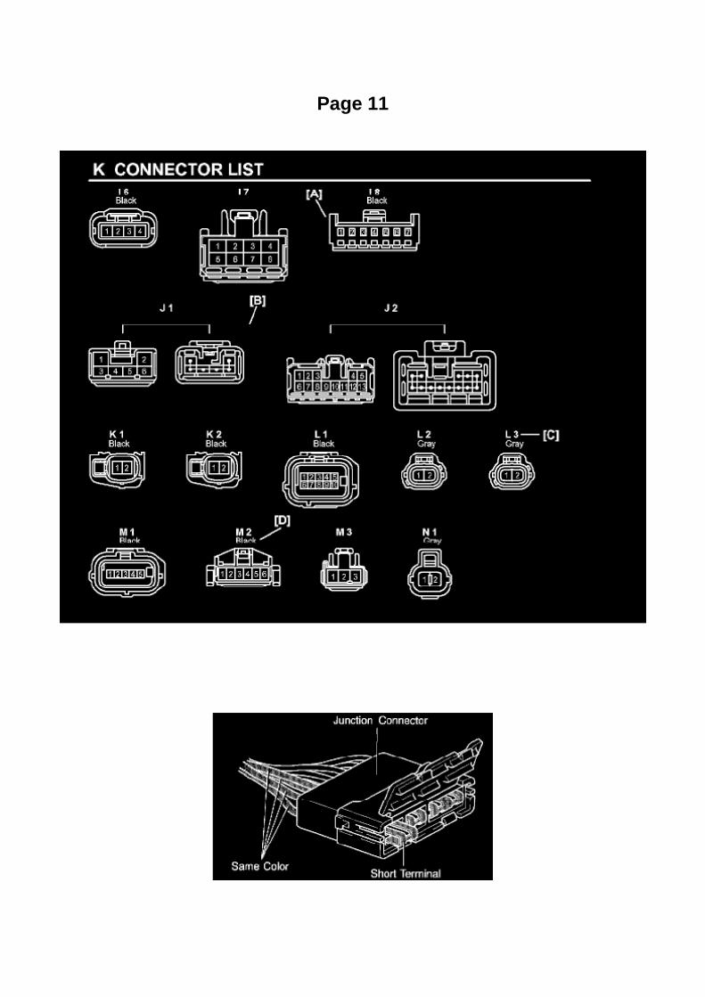
Page 11

Example: Splice point "I5" is on the Cowl Wire Harness and is described.
How to Read Connector List
HOW TO READ CONNECTOR LIST
A: Indicates connector to be connected to a part. (The numeral indicates the pin No.)
B: Junction Connector
Indicates a connector which is connected to a short terminal.
Junction connector in this include a short terminal which is connected to a number of wireharnesses. Always perform inspection with the short terminal installed. (When installing the wireharnesses, the harnesses can be connected to any position within the short terminal grouping.Accordingly, in other vehicles, the same position in the short terminal may be connected to a wireharness from a different part.) Wire harness sharing the same short terminal grouping have thesame color.
C: Parts Code
The first letter of the code is taken from the first letter of part, and the numbers indicates its order inparts which start with the same letter.
D: Connector Color
Connectors not indicated are milky white in color.

Page 640

II. Identification of Affected Vehicles

A. AFFECTED VIN RANGE
NOTE:
This SSC only involves certain 2005 Model Year Tacoma Regular-Cab vehicles equipped with afront bench seat. Not all vehicles in the VIN range

Page 1381

119. ENGINE UNDER COVER SUB-ASSEMBLY NO.2 (PRE RUNNER AND 4WD TYPE,REGULAR CAB)

a. Install the engine under cover No.2 with the 4 bolts.
Torque: 30 Nm (306 kgf-cm, 22 ft. lbs.)
120. INSTALL HOOD SUB-ASSEMBLY

Page 2263

Ac - Ya

Page 1961
Wiring Diagram

Page 1865
Required SSTs
VIN Write Procedure
To write a VIN to a replacement ECM (PCM), use the following process:

1. Confirm the VIN. It is located on the front left of the instrument panel.
2. Connect the Diagnostic Tester to DLC3.
3. Turn the ignition switch and Diagnostic Tester switch ON.
4. All vehicles except Prius and Highlander HV:
Select from the Diagnostic Tester menus: DIAGNOSIS, ENHANCED OBDII, VIN, and VIN WRITE.
Prius and Highlander HV vehicles:
Select from the Diagnostic Tester menus: DIAGNOSIS, OBD/MOBD, HV ECU, VIN, and VINWRITE.

Page 2179

a. Using several steps, uniformly install and tighten the 5 bolts in the sequence shown in theillustration.

Torque: 21 N.m (214 kgf.cm, 16 ft.lbf) for bolt A 43 N.m (438 kgf.cm, 32 ft.lbf) for bolt B, C
9. INSTALL COMPRESSOR AND MAGNETIC CLUTCH (W/ AIR CONDITIONING)
10. INSTALL FAN AND GENERATOR BELT (W/ AIR CONDITIONING) 11. INSTALL ENGINEUNDER COVER SUB-ASSEMBLY NO.1 (PRE RUNNER AND 4WD TYPE)
12. CONNECT CABLE TO NEGATIVE BATTERY TERMINAL
Torque: 3.9 N.m (40 kgf.cm, 35 in.lbf)

Page 2949
20. Install the instrument panel finish panel lower No. 1.
21. Install the cowl side trim board.
22. Install the front door opening trim LH (scuff plate).
23. Connect the negative (-) battery terminal cable.
Torque: 3.9 N.m (40 kgf.cm, 35 in..lbf)
24. Reset the memories for the clock, radio, etc.
25. Check the clutch release point.
A. Pull the parking brake lever and use wheel chocks.
B. Start the engine and allow it to idle.
C. Without depressing the clutch pedal, slowly move the shift lever into the reverse position untilthe gears engage (and grinding is heard).
D. Gradually depress the clutch pedal and measure the stroke distance from the point that the gearnoise stops (release point) up to the full stroke end position.
Standard distance: 25 mm (0.984 in.) or more (from pedal stroke end position to release point)
If the distance if NOT as specified, perform the following operations:
^ Check the pedal height.
^ Check the push rod play and pedal free play.
^ Bleed the clutch line.
^ Check the clutch cover assembly and the disc assembly.

Page 2084
SFI System

Page 618

Impact Sensor: Service and Repair Seat Position Airbag Sensor

Separate Seat Type
Seat Position Air Bag Sensor (Separate Seat Type)
REPLACEMENT
1. PRECAUTION
Refer to Air Bag Systems; Service Precautions.
2. DISCONNECT CABLE FROM NEGATIVE BATTERY TERMINAL
Wait for at least 90 seconds after disconnecting the cable to prevent the airbag from working.
3. REMOVE SEAT TRACK COVER LH 4. REMOVE FRONT SEAT ASSEMBLY LH

Page 1666

Knock Sensor: Service and Repair

REPLACEMENT
1. DISCONNECT CABLE FROM NEGATIVE BATTERY TERMINAL 2. REMOVE ENGINE UNDERCOVER SUB-ASSEMBLY NO.1 (PRE RUNNER AND 4WD TYPE) 3. DRAIN ENGINE COOLANT4. REMOVE INTAKE AIR CONNECTOR 5. REMOVE THROTTLE W/MOTOR BODY ASSEMBLY6. DISCONNECT FUEL HOSE 7. DISCONNECT FUEL HOSE NO.2 8. REMOVE INTAKEMANIFOLD
a. Disconnect the fuel vapor feed hose from the VSV.
b. Disconnect the vacuum hose.
c. Remove the bolt, then remove the clamp bracket.

Page 3109
Wheel Bearing: Tools and Equipment
Wheel Bearing Nut Socket
AST tool# TOY 185
For R and R of wheel bearing nut located on inboard side of wheel hub. Applicable: Newer Toyotatrucks and SUV's (2wd only).
- Made in USA
Contact AST for pricing.
Assenmacher Specialty Tools 1-800-525-2943

Page 2026

2. DLC3

a. Check the DLC3.
1. Measure the resistance according to the value(s) in the table.
3. SKID CONTROL ECU
a. Check the skid control ECU harness side connector (S1).
1. Disconnect the connector (S1) from the skid control ECU. 2. Measure the resistance accordingto the value(s) in the table.
4. STEERING ANGLE SENSOR

Page 317

Acceleration/Deceleration Sensor: Service and Repair
DECELERATION SENSOR (W/O VSC FOR 4WD AND PRE RUNNER)
REPLACEMENT
1. DISCONNECT CABLE FROM NEGATIVE BATTERY TERMINAL 2. REMOVE FRONT SEATASSEMBLY (BENCH SEAT TYPE) 3. REMOVE FRONT SEAT ASSEMBLY LH (SEPARATESEAT TYPE) 4. REMOVE FRONT FLOOR FOOTREST 5. REMOVE FRONT DOOR SCUFFPLATE LH 6. REMOVE COWL SIDE TRIM BOARD LH 7. REMOVE SENSOR BRACKET
a. Turn up the floor carpet.
b. Remove the wire harness clamp. c. Remove the bolt and bracket.
8. REMOVE DECELERATION SENSOR
a. Disconnect the deceleration sensor connector. b. Remove the 2 bolts and deceleration sensor.
9. INSTALL DECELERATION SENSOR
a. Install the deceleration sensor with the 2 bolts.
Torque: 12.5 Nm (127 kgf-cm, 9 ft. lbs.)
NOTICE: Make sure the sensor is at the correct angle when installing.
b. Connect the deceleration sensor connector.

Recall 05V302000: Seat Belt Position Sensor Defect

Seat Belt Buckle Switch: Recalls Recall 05V302000: Seat Belt Position Sensor Defect

MAKE/MODELS: MODEL/BUILD YEARS: Toyota/Tacoma 2005 MANUFACTURER: Toyota MotorNorth America, Inc. NHTSA CAMPAIGN ID NUMBER: 05V302000 RECALL DATE: June 27, 2005
COMPONENT: Air Bags
POTENTIAL NUMBER OF UNITS AFFECTED: 11592
SUMMARY: On certain regular cab pickup trucks equipped with a bench seat, the seat position andseat belt buckle sensor connector pins are incorrectly positioned due to a wire harnessmanufacturing process error.
CONSEQUENCE: In this condition, the seat position and seat belt buckle sensor may not functionas designed, affecting the adaptive air bag deployment, which if the vehicle is involved in a crash,could result in improper occupant restraint.
REMEDY: Dealers will inspect the seat position and seat belt fastening condition sensor connector.An additional sub-wire harness will be installed to correct the connector pin manufacturing error, ifnecessary. The recall is expected to begin during late July 2005. Owners should contact Toyota at1-800-431-4331.
NOTES: Customers can also contact The National Highway Traffic Safety Administration's VehicleSafety Hotline at 1-888-327-4236 (TTY 1-800-424-9153), or go to http://www.safercar.gov.

Locations

Air Flow Meter/Sensor: Locations

He - Wi

Page 1169
3. NOTE FOR USING JACK AND SAFETY STAND
a. Work in a flat area using wheel chocks at all times. b. Use a safety stand with a rubberattachment. c. Apply the jack and rigid rack to the specified location on the vehicle. d. When jackingup the front wheels, release the parking brake and place wheel chocks only behind the rearwheels. When jacking up the rear

wheels, place wheel chocks only in front of the front wheels.
e. The jack should not be used without the rigid rack. f.
When jacking up only the front wheels or only the rear wheels, place wheel chocks on both sides ofthe wheels touching the ground.
g. When lowering the vehicle with its front wheels jacked up, release the parking brake and placewheel chocks only in front of the rear wheels.
When lowering a vehicle with its rear wheels jacked up, place wheel chocks only behind the frontwheels.
4. NOTE FOR USING SWING ARM TYPE LIFT
a. Follow safety procedures outlined in its instruction manual. b. Use a swing arm equipped with arubber attachment. c. Set in the vehicle so as to make its center of gravity as close as possible tothe center of the lift. (L becomes short.) d. Place the vehicle horizontally by adjusting the height ofthe cradle, and match the groove of the cradle and the safety stand support location
accurately.
e. Be sure to lock the swing arms before lifting and during work (if equipped with arm locks). f.
Lift the vehicle up off the ground. Stand at a safe distance and shake the vehicle to check itsstability.

Page 1359

Page 973
Fluid - A/T: Technical Service Bulletins A/T - Fluid Level Inspection/Temperature Ranges
T-SB-0129-08
July 9, 2008
Automatic Transmission/Transaxle Fluid Level Inspection Temperature Ranges

Service Category Drivetrain
Section Automatic Transmission/Transaxle
Market USA
Applicability
Introduction
For vehicles equipped with a transmission requiring the use of the overflow type automatictransmission fluid (ATF) inspection process the ATF must be within a specific temperature rangefor accurate fluid level inspection. Inspecting the ATF outside of the specified temperature rangemay result in incorrect ATF fluid levels and could lead to shift quality M.l.L. "ON" and/ortransmission damage issues. Please see the information in this bulletin for updated ATF levelinspection temperature ranges.
HINT
For additional information including animations and video illustrations, please see the TechnicalTraining course E076: "Toyota ATF Level Inspection".
NOTE
Please see TSB No.TC010-07, "World Standard Automatic Transmission Fluid"; for important tipswhen working with ATF WS.
Warranty Information
Parts Information

Page 2968

Required Tools & Material

Components

Page 1926

If the circuit has diodes, reverse the two leads and check again. When contacting the negative leadto the diode positive side and the positive lead to the negative side, there should be continuity.

When contacting the two leads in reverse, there should be no continuity.
c. Use a volt/ohmmeter with high impedance (10 kOhms/V minimum) for troubleshooting of theelectrical circuit.
Finding A Short Circuit
FINDING A SHORT CIRCUIT
a. Remove the blown fuse and disconnect all loads of the fuse.
b. Connect a test light in place of the fuse.
c. Establish conditions in which the test light comes on.
Example: [A] - Ignition SW on [B] - Ignition SW and SW 1 on [C] - Ignition SW, SW 1 and Relay on(Connect the Relay) and SW 2 off (or Disconnect SW 2)
d. Disconnect and reconnect the connectors while watching the test light.
The short lies between the connector where the test light slays lit and the connector where the lightgoes out.
e. Find the exact location of the short by lightly shaking the problem wire along the body.

Page 1756

Knock Sensor: Service and Repair

REPLACEMENT
1. DISCONNECT CABLE FROM NEGATIVE BATTERY TERMINAL 2. REMOVE ENGINE UNDERCOVER SUB-ASSEMBLY NO.1 (PRE RUNNER AND 4WD TYPE) 3. DRAIN ENGINE COOLANT4. REMOVE INTAKE AIR CONNECTOR 5. REMOVE THROTTLE W/MOTOR BODY ASSEMBLY6. DISCONNECT FUEL HOSE 7. DISCONNECT FUEL HOSE NO.2 8. REMOVE INTAKEMANIFOLD
a. Disconnect the fuel vapor feed hose from the VSV.
b. Disconnect the vacuum hose.
c. Remove the bolt, then remove the clamp bracket.

Page 3152
Fluid - M/T: Testing and Inspection
MANUAL TRANSAXLE OIL
ON-VEHICLE INSPECTION
1. CHECK TRANSMISSION OIL
a. Park the vehicle in a level place. b. Remove the transmission filler plug and gasket. c. Check thatthe oil surface is within 5 mm (0.20 inch) of the lowest point of the transmission filler plug opening.
NOTICE: -
Problems may occur when the oil level is too high or low.
- After replacing the oil, drive the vehicle and check the oil level again.
d. Check for oil leakage when the oil level is low. e. Install the transmission filler plug and a newgasket.
Torque: 37 Nm (377 kgf-cm, 27 ft. lbs.)

Page 2014
Step 3 - 4

Rear
Drive/Propeller Shaft: Service and Repair Rear
PROPELLER SHAFT ASSY (4WD REGULAR CAB TYPE)

COMPONENTS
OVERHAUL
1. REMOVE PROPELLER SHAFT
a. Place matchmarks on the propeller shaft flange and differential flange. b. Remove the 4 nuts, 4bolts, 4 washers and front propeller shaft assy.

Page 360
HINT: -
If the VSC TRAC warning light does not blink, perform the zero point calibration again.
- The zero point calibration is performed only once after the system enters test mode.
- Calibration cannot be performed again until the stored data is cleared once.
9. Turn the ignition switch to OFF.
USING SST CHECK WIRE:
4. CLEAR ZERO POINT CALIBRATION

HINT: After replacing the yaw rate and deceleration sensor, be sure to clear the zero pointcalibration data in the skid control ECU and perform zero point calibration.
a. Turn the ignition switch to the ON position.
b. Using SST, connect and disconnect terminals TS and CG of the DLC3 4 times or more within 8seconds.
SST 09843-18040
c. Check that the warning light blinks in a normal system indication pattern. d. Remove the SSTfrom the terminals of the DLC3. e. Perform zero point calibration of the yaw rate and decelerationsensor using a check wire (refer to step 5).
5. PERFORM ZERO POINT CALIBRATION OF YAW RATE SENSOR AND DECELERATIONSENSOR
HINT: After replacing the skid control ECU and/or yaw rate and deceleration sensor, be sure toperform yaw rate sensor and deceleration sensor zero point calibration.
NOTE: -
While obtaining the zero point, do not vibrate the vehicle by tilting, moving or shaking it and keep itstationary. (Do not start the engine.)
- Be sure to do this on a level surface (with an inclination less than 1 degree).
a. Procedures for test mode:
1. Turn the ignition switch to OFF. 2. Check that the steering wheel is in the straight ahead position.3. A/T: Check that the shift lever is in the P position and apply the parking brake.
M/T: Check that the shift lever is in neutral and apply the parking brake.

Page 2836

Ha - Op

Specifications

Clutch Fluid: Specifications

Fluid type: ................................................................................................................................................................ SAE J1703 or FMVSS No.116 DOT 3

Page 307

Ac - Ya

Page 2176
Crankshaft Position Sensor: Testing and Inspection
INSPECT CRANKSHAFT POSITION SENSOR
Check the resistance.
Using an ohmmeter, measure the resistance between the terminals.
HINT: Cold and Hot mean the temperature of the coils themselves. Cold is from -10 to 50°C (14 to122°F) and Hot is from 50 to 100°C (122 to 212° F).
If the result is not as specified, replace the camshaft position sensor.

Page 2151
SFI System

Page 1039

Engine Room R/B, J/B - Engine Compartment Left

Page 1998
Step 3 - 4

Page 2853
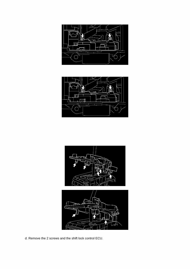
d. Remove the 2 screws and the shift lock control ECU.

14. INSTALL SHIFT LOCK CONTROL ECU SUB-ASSY
a. Install the shift lock control ECU with the 2 screws. b. Install the spring and shift lock release link.c. Install the shift lever guide housing . d. Install the lever lock and new shift lever nut.
15. INSTALL POSITION INDICATOR HOUSING LOWER
a. Install the position indicator housing lower.
HINT: Firmly make the claws fit.
16. INSTALL SHIFT LOCK RELEASE BUTTON

Page 2648
SFI System

Page 1990

Step 1 - 2

INSPECTION PROCEDURE
Steering Angle Sensor Communication Stop Mode
STEERING ANGLE SENSOR COMMUNICATION STOP MODE
MODE DESCRIPTION

Component Tests and General Diagnostics
Engine Control Module: Component Tests and General Diagnostics
ECM POWER SOURCE CIRCUIT
CIRCUIT DESCRIPTION
When the ignition switch is turned to ON, the battery voltage is applied to terminal IGSW of theECM. The ECM MREL output signal causes a current to flow to the coil, closing the contacts of theEFI relay and supplying power to terminal +B of the ECM.
Wiring Diagram
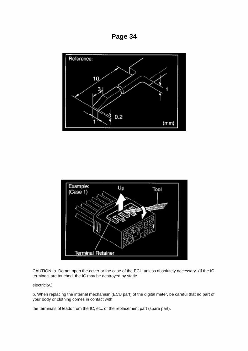
Page 34
CAUTION: a. Do not open the cover or the case of the ECU unless absolutely necessary. (If the ICterminals are touched, the IC may be destroyed by static
electricity.)
b. When replacing the internal mechanism (ECU part) of the digital meter, be careful that no part ofyour body or clothing comes in contact with
the terminals of leads from the IC, etc. of the replacement part (spare part).

How to Replace Terminal
HOW TO REPLACE TERMINAL (with terminal retainer or secondary locking device)
1. PREPARE THE SPECIAL TOOL
HINT: To remove the terminal from the connector, please construct and use the special tool or likeobject shown.
2. DISCONNECT CONNECTOR
3. DISENGAGE THE SECONDARY LOCKING DEVICE OR TERMINAL RETAINER
a. Locking device must be disengaged before the terminal locking clip can be released and theterminal removed from the connector. b. Use a special tool or the terminal pick to unlock thesecondary locking device or terminal retainer.
NOTE: Do not remove the terminal retainer from connector body.
[A] : For Non-Waterproof Type Connector
HINT: The needle insertion position varies according to the connector's shape (number of terminalsetc.), so check the position before inserting it.

Page 977

Fluid - A/T: Fluid Type Specifications

Change Automatic Transmission Fluid Only As Necessary.
Generally, it is necessary to change automatic transmission fluid only if your vehicle is driven underone of the Special Operating Conditions listed under one of the Scheduled Maintenance Guide orOwners Manual Supplement.
When changing the automatic transmission fluid, use only "Toyota Genuine ATF Type T-IV" (ATFJWS3309 or NWS6500) to aid in assuring optimum transmission performance.
Notice: Using automatic transmission fluid other than "Toyota Genuine ATF Type T-IV" may causedeterioration in shift quality, locking up of your transmission accompanied by vibration, andultimately damage the automatic transmission of your vehicle.

Page 3262

He - Wi

Page 1705

Transmission Position Switch/Sensor: Service and Repair

PARK/NEUTRAL POSITION SWITCH ASSY
REPLACEMENT
1. DISCONNECT CABLE FROM NEGATIVE BATTERY TERMINAL 2. DISCONNECTPARK/NEUTRAL POSITION SWITCH CONNECTOR
3. REMOVE PARK/NEUTRAL POSITION SWITCH ASSY
a. Using a screwdriver, unstake the lock washer. b. Remove the nut, lock washer and grommet. c.Remove the bolt and park/neutral position switch.
4. INSTALL PARK/NEUTRAL POSITION SWITCH ASSY
a. Install the park/neutral position switch onto the manual valve lever shaft and provisionally tightenthe adjusting bolt.

Locations

Oxygen Sensor Relay: Locations
Engine Room R/B, J/B - Engine Compartment Left

Page 205
Then click Next.
F. Verify correct current calibration and new calibration information. Then click Next.
NOTE
^ The total number of calibration IDs in the calibration file corresponds to the number ofreprogrammable processors in the ECU.

^ Each calibration file may contain up to three separate calibrations.

Locations

Knock Sensor: Locations

He - Wi

Page 1221
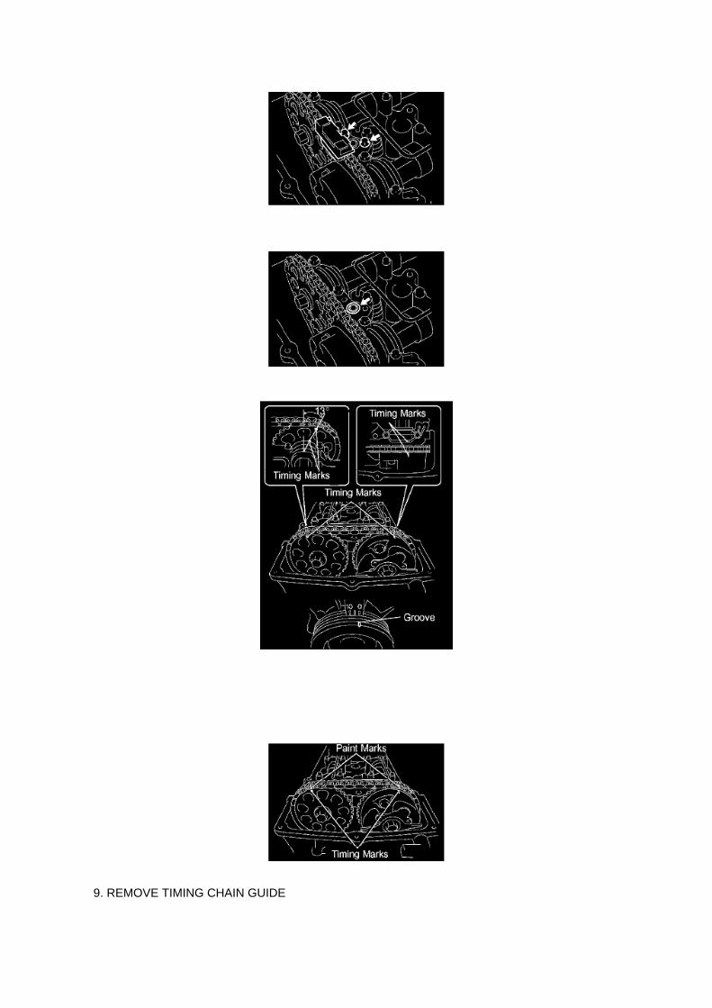
9. REMOVE TIMING CHAIN GUIDE

a. Remove the 2 bolts, then remove the timing chain guide.
b. Remove the O-ring.
10. REMOVE CAMSHAFT
a. Set the No.1 cylinder to the TDC/compression.
(1) Turn the crankshaft pulley clockwise and align its timing mark notch with the timing mark "0". (2)Check that the timing marks of the camshaft timing gear are located as illustrated.
HINT: If not, turn the crankshaft to align the marks.

Service and Repair

Low Tire Pressure Indicator: Service and Repair

Tire Pressure Warning Light:
When the light comes on low tire inflation pressure is detected. Adjust tire pressure including thespare if it is equipped with a TPMS transmitter.
The light should go off within a few minutes after the tire pressure is adjusted.
Rotating tires may require the system to be initialized if the front and rear tires have differentpressure specifications.

Page 699
(a) Slide the bench seat to the rearmost position.
(b) Locate the floor wire harness and connector under the seat on the driver's side closest to thefront edge of the seat cushion.

Page 1365


Page 746

Seat Occupant Sensor: Testing and Inspection

OCCUPANT CLASSIFICATION ECU (VEHICLE NOT INVOLVED IN COLLISION)
a. Perform a diagnostic system check.
Refer to Air Bag Systems; Testing and Inspection.
OCCUPANT CLASSIFICATION ECU (VEHICLE INVOLVED IN COLLISION)
a. Perform a diagnostic system check.
Refer to Air Bag Systems; Testing and Inspection.
b. Even if the airbag was not deployed, perform a visual check for damage to the occupantclassification ECU. If there are any defects as mentioned
below, replace the occupant classification ECU with a new one: -
Cracks, dents or chips in the case.
- Cracks or other damage to the connector.
CAUTION: For removal and installation procedures of the occupant classification ECU, see"Replacement" and be sure to follow the correct procedure.
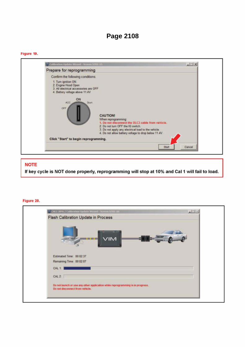
Page 2108
Then click Start.
I. Do NOT disturb the vehicle during flash reprogramming.
NOTE
^ ECU flash reprogramming may take anywhere from 3 - 30 minutes per calibration file.
^ Reprogramming time will vary depending on model and ECU communication protocol. Vehiclesusing CAN communication protocol will reprogram much faster (2 - 7 minutes).
NOTE
^ If vehicle requires only ONE calibration update, then proceed to step N in this bulletin.
^ If vehicle requires a SECOND calibration update, then continue as follows:
^ For serial communication vehicles, go to step J.
^ For CAN communication vehicles, go to step L.

Specifications

Fuel Pressure: Specifications

Fuel Pressure
At Idle.............................................................................................................................................281to 287 kPa (2.87 to 2.93 kgf/sq.cm, 40.8 to 41.7 psi)
After Engine Stopped for 5Min..............................................................................................................................................147kPa (1.5 kgf/sq.cm, 21 psi)

Page 383

3. REMOVE STEERING WHEEL COVER LOWER NO.2 4. REMOVE STEERING WHEEL COVERLOWER NO.3 5. REMOVE HORN BUTTON ASSEMBLY

6. REMOVE CRUISE CONTROL MAIN SWITCH
a. Disconnect the connector and remove the 2 screws.
b. Remove the cruise control main switch from the steering wheel.
7. INSTALL CRUISE CONTROL MAIN SWITCH
a. Install the cruise control main switch with the 2 screws and connect the connector.
8. INSTALL HORN BUTTON ASSEMBLY 9. INSTALL STEERING WHEEL COVER LOWER NO.3
10. INSTALL STEERING WHEEL COVER LOWER NO.2 11. CONNECT CABLE TO NEGATIVEBATTERY TERMINAL
Torque: 3.9 N.m (40 kgf.cm, 35 in.lbf)
12. INSPECT HORN BUTTON ASSEMBLY 13. INSPECT SRS WARNING LIGHT

Page 2504

3. Install the fuel tank protector cover on top of the fuel suction plate sub-assembly as shown in theillustration.

Page 2868
Transmission Position Switch/Sensor: Adjustments
PARK/NEUTRAL POSITION SWITCH ASSY
ADJUSTMENT
1. INSPECT PARK/NEUTRAL POSITION SWITCH ASSY
a. Apply the parking brake and turn the ignition switch to ON. b. Depress the brake pedal andcheck that the engine starts only when the shift lever is set in the N or P position and that it doesnot start in any
other positions.
c. Check that the back-up light comes on and the reverse warning buzzer sounds only when theshift lever is set in the R position and not in other
positions. If any failure is found, check the park/neutral position switch for continuity.
2. ADJUST PARK/NEUTRAL POSITION SWITCH ASSY
a. Loosen the bolt of the park/neutral position switch and set the shift lever to the N position. b.Align the groove and the neutral basic line. c. Hold the switch in position and tighten the bolt.
Torque: 13 Nm (130 kgf-cm, 9 ft. lbs.)
d. After making an adjustment, perform the inspection described in step 1.

Page 1860

Then click Start.
I. Do NOT disturb the vehicle during flash reprogramming.
NOTE
^ ECU flash reprogramming may take anywhere from 3 - 30 minutes per calibration file.
^ Reprogramming time will vary depending on model and ECU communication protocol. Vehiclesusing CAN communication protocol will reprogram much faster (2 - 7 minutes).
NOTE
^ If vehicle requires only ONE calibration update, then proceed to step N in this bulletin.
^ If vehicle requires a SECOND calibration update, then continue as follows:
^ For serial communication vehicles, go to step J.
^ For CAN communication vehicles, go to step L.

Page 1985
Step 1 - 2
INSPECTION PROCEDURE
Check CAN Bus Line
CHECK CAN BUS LINE
CIRCUIT DESCRIPTION

When any DTC of the CAN communication system is output, first measure the resistance betweenthe terminals` of the DLC3 and the yaw rate sensor connector to specify the trouble area.

Page 2536
Parts Information
Required Tools & Material

Required SSTs
Repair Procedure
1. Using the Diagnostic Tester, check for Diagnostic Trouble Codes (DTCs). If DTC P0456 orP0445, and P0441 are present, check for an EVAP leak on top of the fuel suction platesub-assembly. Refer to the Technical Information System (TIS), 2005 model year Tacoma RepairManual: Diagnostics: SFI System (1GR-FE) / (2TR-FE): EVAP Inspection Procedure.
If NO EVAP leaks are detected at the fuel suction plate sub-assembly, this TSB does NOT apply.Please refer to the normal diagnostic procedure provided in the Repair Manual.
2. To correct the fuel suction plate sub-assembly, replace the fuel suction with pump and gaugetube assembly, retainer ring and gasket set according to TIS, 2005 model year Tacoma RepairManual: Fuel: Fuel Pump Assy: Removal & Installation And Disassembly & Reassembly (Tacoma).

Page 1297

TOY 730 - 73mm Toyota Oil Filter Wrench

M 0219 - 74mm Oil Filter Wrench

Page 2823

Transmission Position Switch/Sensor: Service and Repair

PARK/NEUTRAL POSITION SWITCH ASSY
REPLACEMENT
1. DISCONNECT CABLE FROM NEGATIVE BATTERY TERMINAL 2. DISCONNECTPARK/NEUTRAL POSITION SWITCH CONNECTOR
3. REMOVE PARK/NEUTRAL POSITION SWITCH ASSY
a. Using a screwdriver, unstake the lock washer. b. Remove the nut, lock washer and grommet. c.Remove the bolt and park/neutral position switch.
4. INSTALL PARK/NEUTRAL POSITION SWITCH ASSY
a. Install the park/neutral position switch onto the manual valve lever shaft and provisionally tightenthe adjusting bolt.

Page 438

Ac - Ya

Page 1414


Page 150

Glossary Of Terms And Sysmbols Part 1

Page 3351
ABS With EBD & BA & TRAC & VSC SYSTEM

Page 783
Steering Angle Sensor: Locations

ABS With EBD & BA & TRAC & VSC SYSTEM

Page 1435
Variable Valve Timing Actuator: Testing and Inspection On-Vehicle Inspection
INSPECT CAMSHAFT TIMING OIL CONTROL VALVE ASSEMBLY
a. Check the operation.
1. Connect the hand-held tester to the DLC3. 2. Turn the ignition switch to ON. 3. Turn thehand-held tester ON. 4. Start the engine and warm it up. 5. Select the following menu items:DIAGNOSIS / ENHANCED OBD II / ACTIVE TEST / VVT CTRL B1.
6. Operate the OCV using the hand-held tester, then check the engine speed.
If the operation is not as specified, check the camshaft timing oil control valve, wire harness andECM.

Page 1126
Diagnostic Trouble Code Chart
Use Diagnostic Trouble Codes (DTCs) (from the DTC checks) in the table to determine the troublearea and proper inspection procedure. The Supplemental Restraint System (SRS) DTC chart isshown as an example.
Problem Symptoms Table

PROBLEM SYMPTOMS TABLE

Locations

He - Wi

Page 8
Example: (1) Indicates Relay Block No.1

C: ( ) is used to indicate different wiring and connector, etc. when the vehicle model, engine type,or specification is different.
D: Indicates related system.
E: Indicates the wiring harness and wiring harness connector. The wiring harness with maleterminal is shown with arrows.
Outside numerals are pin numbers.
The first letter of the code for each wiring harness and wiring harness connector(s) indicates thecomponent's location, e.g, "E" for the Engine Compartment, "I" for the Instrument Panel andSurrounding area, and "B" for the Body and Surrounding area.
When more than one code has the first and second letters in common, followed by numbers (e.g,IH1, IH2), this indicates the same type of wiring harness and wiring harness connector.
F: Represents a part (all parts are shown in sky blue). The code is the same as the code used inparts position.
G: Junction Block (The number in the circle is the J/B No. and the connector code is shown besideit). Junction Blocks are shaded to clearly separate
them from other parts.
H: Indicates the wiring color.
Wire colors are indicated by an alphabetical code. B = Black L = Blue R = Red P = Pink O =Orange W = White V = Violet G = Green Y = Yellow BR = Brown SB = Sky Blue LG = Light GreenGR = Gray
The first letter indicates the basic wire color and the second letter indicates the color of the stripe.

Page 3018

11. Install the clutch pedal bushes.

A. Apply MP grease to the two (2) NEW bushes.
B. Install the two (2) bushes onto the clutch pedal.
12. Install the clutch pedal pad.
13. Install the clutch pedal spring holder.
A. Apply MP grease to the contact surface of the clutch pedal spring holder.
B. Install the clutch pedal spring holder.
14. Remove the clevis sub-assembly.
A. Measure length "A" of the clutch master cylinder.
a. Measure length "A" between the lock nut and the thread end with a ruler.
b. Record length "A".

Page 224
Step 4 - 5

Page 483

a. Using several steps, uniformly install and tighten the 5 bolts in the sequence shown in theillustration.

Torque: 21 N.m (214 kgf.cm, 16 ft.lbf) for bolt A 43 N.m (438 kgf.cm, 32 ft.lbf) for bolt B, C
9. INSTALL COMPRESSOR AND MAGNETIC CLUTCH (W/ AIR CONDITIONING)
10. INSTALL FAN AND GENERATOR BELT (W/ AIR CONDITIONING) 11. INSTALL ENGINEUNDER COVER SUB-ASSEMBLY NO.1 (PRE RUNNER AND 4WD TYPE)
12. CONNECT CABLE TO NEGATIVE BATTERY TERMINAL
Torque: 3.9 N.m (40 kgf.cm, 35 in.lbf)
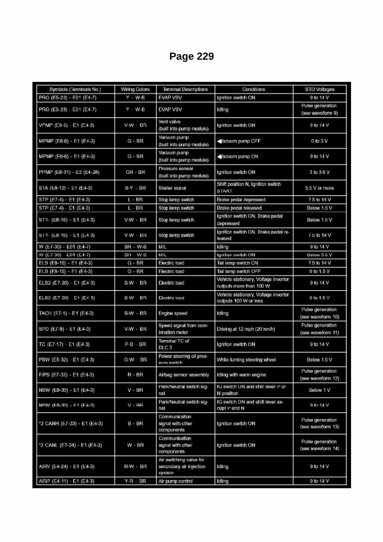
Page 229

Terminals Of ECM / Pinouts Part 3

Locations

Switch: Locations
Po - Ya

Locations
Crankshaft Position Sensor: Locations

A/C - Ge

Page 3352
Yaw Rate Sensor: Testing and Inspection
CALIBRATION
1. DESCRIPTION
a. After replacing the VSC relevant components or performing "Front wheel alignment adjustment",clearing and reading the sensor calibration
data are necessary.

b. Follow the chart to perform calibration.
USING HAND-HELD TESTER:
2. CLEAR ZERO POINT CALIBRATION
HINT: After replacing the yaw rate and deceleration sensor, be sure to clear the zero pointcalibration data in the skid control ECU and perform zero point calibration.
a. Connect the hand-held tester to the DLC3. b. Turn the ignition switch to the ON position. c.Operate the hand-held tester to erase the DTCs. d. Perform zero point calibration of the yaw rateand deceleration sensor using the hand-held tester (refer to step 3).
3. PERFORM ZERO POINT CALIBRATION OF YAW RATE SENSOR AND DECELERATIONSENSOR
HINT: After replacing the yaw rate and deceleration sensor, be sure to clear the zero pointcalibration data in the skid control ECU and perform zero point calibration.
NOTE: -
While obtaining the zero point, do not vibrate the vehicle by tilting, moving or shaking it and keep itstationary. (Do not start the engine.)
- Be sure to do this on a level surface (with an inclination of less than 1 degree).
a. Procedures for test mode.
1. Turn the ignition switch to OFF. 2. Check that the steering wheel is in the straight ahead position.

Page 37

Push the terminal retainer down to the temporary lock position.

c. Release the locking lug from terminal and pull the terminal out from rear.
4. INSTALL TERMINAL TO CONNECTOR
a. Insert the terminal.
HINT: 1. Make sure the terminal is positioned correctly. 2. Insert the terminal until the locking luglocks firmly. 3. Insert the terminal with terminal retainer in the temporary lock position.

Page 3376

c. Install the brake pedal with the bolt and nut onto the brake pedal support.

Torque: 34.3 Nm (350 kgf-cm, 25 ft. lbs.)
20. INSTALL STOP LAMP SWITCH ASSEMBLY
a. Insert the stop lamp switch until the body comes into contact with the cushion.
NOTICE: When inserting the stop lamp switch, support the pedal from behind so that the pedal isnot pushed in.
b. Make a quarter turn clockwise to install the stop lamp switch.
NOTICE: The turning torque for installing the stop lamp switch:
Torque: 1.5 Nm (15 kgf-cm, 13 inch lbs.) or less
HINT: Due to the inverse screw structure, turning the stop lamp switch clockwise will cause it tobecome loose and eventually detach from the adjuster.
c. Check the protrusion of the rod.
Protrusion of the rod: 1.5 to 2.5 mm (0.059 to 0.098 inch)
21. INSTALL BRAKE PEDAL RETURN SPRING
a. Apply lithium soap base glycol grease to the inner surface of the hole on the brake pedal supportand brake pedal. b. Install the return spring onto the brake pedal support and brake pedal.
22. INSTALL BRAKE PEDAL SUPPORT SUB-ASSEMBLY
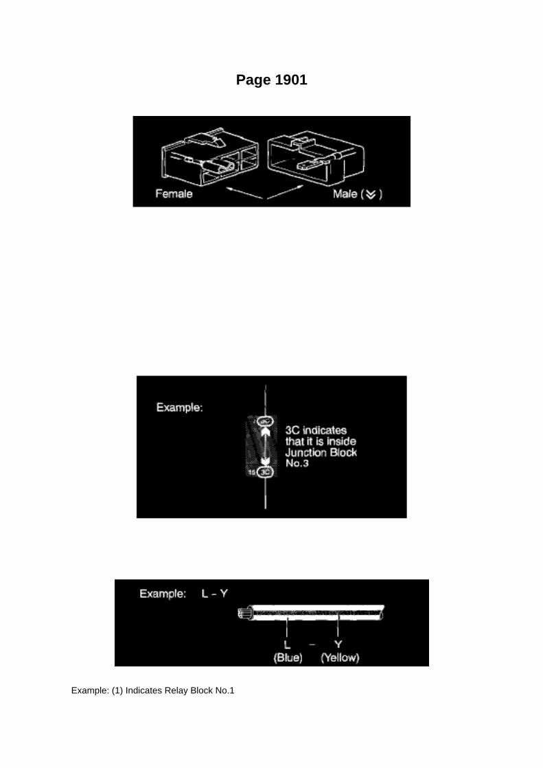
Page 1901
Example: (1) Indicates Relay Block No.1

C: ( ) is used to indicate different wiring and connector, etc. when the vehicle model, engine type,or specification is different.
D: Indicates related system.
E: Indicates the wiring harness and wiring harness connector. The wiring harness with maleterminal is shown with arrows.
Outside numerals are pin numbers.
The first letter of the code for each wiring harness and wiring harness connector(s) indicates thecomponent's location, e.g, "E" for the Engine Compartment, "I" for the Instrument Panel andSurrounding area, and "B" for the Body and Surrounding area.
When more than one code has the first and second letters in common, followed by numbers (e.g,IH1, IH2), this indicates the same type of wiring harness and wiring harness connector.
F: Represents a part (all parts are shown in sky blue). The code is the same as the code used inparts position.
G: Junction Block (The number in the circle is the J/B No. and the connector code is shown besideit). Junction Blocks are shaded to clearly separate
them from other parts.
H: Indicates the wiring color.
Wire colors are indicated by an alphabetical code. B = Black L = Blue R = Red P = Pink O =Orange W = White V = Violet G = Green Y = Yellow BR = Brown SB = Sky Blue LG = Light GreenGR = Gray
The first letter indicates the basic wire color and the second letter indicates the color of the stripe.

Locations

Power Steering Pressure Switch: Locations

He - Wi

Page 259
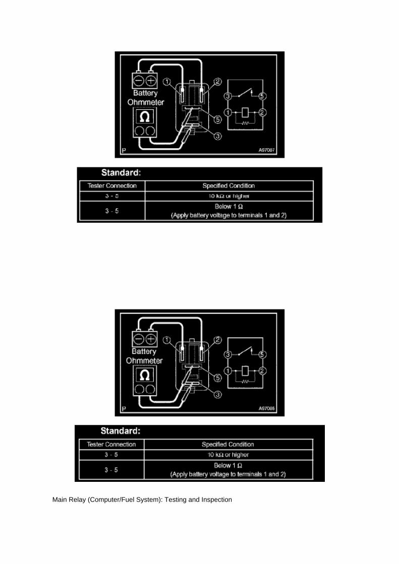
Main Relay (Computer/Fuel System): Testing and Inspection

INSPECT E.F.I. CIRCUIT OPENING RELAY ASSEMBLY
a. Check the resistance.
1. Using an ohmmeter, measure the resistance between the terminals.
If the result is not as specified, replace the E.F.I. circuit opening relay assembly.
INSPECT EFI RELAY
a. Check the resistance.
1. Using an ohmmeter, measure the resistance between the terminals.
If the result is not as specified, replace the E.F.I. ECU relay.

Page 1029

Engine Compartment

Instrument Panel
Locations

Page 2543
Parts Information
Required Tools & Material

Required SSTs
Repair Procedure
1. Using the Diagnostic Tester, check for Diagnostic Trouble Codes (DTCs). If DTC P0456 orP0445, and P0441 are present, check for an EVAP leak on top of the fuel suction platesub-assembly. Refer to the Technical Information System (TIS), 2005 model year Tacoma RepairManual: Diagnostics: SFI System (1GR-FE) / (2TR-FE): EVAP Inspection Procedure.
If NO EVAP leaks are detected at the fuel suction plate sub-assembly, this TSB does NOT apply.Please refer to the normal diagnostic procedure provided in the Repair Manual.
2. To correct the fuel suction plate sub-assembly, replace the fuel suction with pump and gaugetube assembly, retainer ring and gasket set according to TIS, 2005 model year Tacoma RepairManual: Fuel: Fuel Pump Assy: Removal & Installation And Disassembly & Reassembly (Tacoma).

Air-Fuel Ratio Sensor

Oxygen Sensor: Service and Repair Air-Fuel Ratio Sensor

REPLACEMENT
1. DISCONNECT CABLE FROM NEGATIVE BATTERY TERMINAL 2. REMOVE AIR FUEL RATIOSENSOR
a. Disconnect the air fuel ratio sensor connector. b. Disconnect the wire harness clamp.
c. Using SST, remove the air fuel ratio sensor.
SST 09224-00010
3. INSTALL AIR FUEL RATIO SENSOR
a. Using SST, install the air fuel ratio sensor.
SST 09224-00010
Torque: 44 N.m (449 Kgf.cm, 33 ft.lbf) 40 N.m (408 Kgf.cm, 30 ft.lbf) with SST
NOTE: Use a torque wrench with a fulcrum length of 300 mm (11.81in.).

Page 2755
Warranty Information
APPLICABLE WARRANTY
^ This repair is covered under the Toyota Federal Emission Warranty. This warranty is in effect for96 months or 80,000 miles, whichever occurs first,
from the vehicle's in-service date.

^ Warranty application is limited to correction of a problem based upon a customer's specificcomplaint.
Parts Information
NOTE
^ The ECM (PCM) should NOT be replaced as part of the repair procedure.
^ Authorized Modification Labels may be ordered in packages of 25 from the Materials DistributionCenter (MDC) through Dealer Daily - Dealer
Support Materials Orders.
Calibration Information

Locations

He - Wi

Page 400

Refrigerant Pressure Sensor / Switch: Testing and Inspection

INSPECT PRESSURE SWITCH
HINT: -
The pressure switch is installed onto the air conditioning pipe on the high pressure side.
- The switch detects a drop in refrigerant pressure, such as from refrigerant leakage, and turns themagnet clutch off(*1) to prevent damage to the compressor.
- The switch detects abnormally high pressure in the air conditioning cycle and turns the magnetclutch off (*1) to prevent damage to parts in the air conditioning cycle.
(*1): The ECM turns the magnet clutch on or off upon receiving the signal from the pressure switch.
- As the pressure switch operates when there is a malfunction with the refrigerant pressure, itsfunction cannot be inspected on-vehicle. Follow the procedures below to inspect it.
a. Inspect refrigerant pressure in the air conditioning cycle. b. Read the manifold gauge pressurewhen the conditions below are established.
Test conditions: -
Engine is running at 1,500 rpm
- Blower speed control knob is in HI position
- Temperature control knob is in COOL position
- Air conditioning switch is ON
- Recirculation
- Doors fully open
Standard: Pressure on high pressure side: 1.37 to 1.57 MPa (13.9 to 16.0 kgf.sq.cm 198 to 228psi)
HINT: -
If the refrigerant pressure is not within the standard range,inspect and repair the air conditioningcycle.
- Proceed to step (b) if the refrigerant pressure is within the specified range.
- If the refrigerant pressure is below 196 kPa (2.0 kgf.sq.cm,28 psi), the refrigerant amount in theair conditioning cycle may have decreased significantly for reasons such as a gas leakage.
c. Check the air conditioning operation.
1. Disconnect the pressure switch connector. 2. Connect terminals 1 and 2 of the pressure switchconnector on the vehicle wire harness side using a service wire. 3. Start the engine. 4. Turn the airconditioning switch on and check that the magnet clutch is turned on.

Page 3028
14. INSTALL CLUTCH PEDAL SUB-ASSY
a. Install the clutch pedal onto the clutch pedal support with the bolt and nut.
Torque: 34 Nm (347 kgf-cm, 25 ft. lbs.)
HINT: Install the bolt from the left side of the vehicle.
15. INSTALL TURN OVER SPRING SEAT COMPRESSION SPRING
a. Apply MP grease to the contact surfaces of the spring holder, clutch pedal and spring. b. Installthe spring onto the clutch pedal and spring holder.
16. INSTALL CLUTCH MASTER CYLINDER ASSY 17. BLEED BRAKE LINE (W/O VSC) 18.BLEED CLUTCH PIPE LINE 19. INSPECT AND ADJUST CLUTCH PEDAL SUB-ASSY 20.

CHECK BRAKE FLUID LEAKAGE (W/O VSC) 21. CHECK FOR CLUTCH FLUID LEAKAGE 22.CHECK FLUID LEVEL IN RESERVOIR

Page 2948
18. Inspect and adjust the clutch pedal sub-assembly.
A. Lift the floor carpet.
B. Check that the pedal height is correct.
Pedal height from asphalt sheet: 168.5 to 178.5 mm (6.634 to 7.028 in.)
C. Adjust the pedal height.
a. Loosen the lock nut and turn the stopper bolt until the height is correct.
b. Tighten the lock nut.
Torque: 25 N.m (250 kgf.cm, 18 ft.lbf)
D. Check that the pedal free play and push rod play are correct.

a. Depress the pedal until the clutch resistance begins to be felt.
Pedal free play: 5.0 to 15.0 mm (0.197 to 0.591 in.)
b. Gently depress the pedal until the resistance begins to increase a little.
E. Adjust the pedal free play and push rod free play.
a. Loosen the lock nut and turn the push rod until the free play and push rod play are correct.
b. Tighten the lock nut.
Torque: 11.8 N.m (120 kgf.cm, 9 ft.lbf)
c. After adjusting the pedal free play, check the pedal height.
19. Install the driver's side Junction Block.

Page 1996
Wiring Diagram

Page 1754

Knock Control Sensor (2TR-FE) Part 3

Locations
Electronic Brake Control Module: Locations
Engine Compartment

Page 2070
A/C - Ge

Page 2407

Applicable Vehicles

Engine Controls - Techstream(R) ECU Re-Flash
Procedure
Engine Control Module: Technical Service Bulletins Engine Controls - Techstream(R) ECURe-Flash Procedure
T-SB-0064-10
February 4, 2010
Techstream ECU Flash Reprogramming Procedure
Service Category Engine/Hybrid System
Section Engine Control
Market USA
Applicability
TSB SUPERSESSION NOTICE
The information contained in this TSB supersedes TSB No. SS002-07.
^ Applicability has been updated to include 2009 - 2011 model year Toyota vehicles.
^ A new section, Techstream Preparation, has been added.
^ Techstream Lite has been added as an option in Required Tools & Materials.
^ Process Overview and Operation Procedure sections have been updated.
TSB No. SS002-07 is Obsolete and any printed versions should be discarded. Be sure to reviewthe entire content of this service bulletin before proceeding.
Introduction
Flash reprogramming allows the ECU software to be updated without replacing the ECU. Flashcalibration updates for specific vehicle models/ECUs are released as field-fix procedures describedin individual service bulletins. This bulletin details the Techstream ECU flash reprogramming

process and outlines use of the Technical Information System (TIS) and the Calibration UpdateWizard (CUW). Flash calibration updates can only be applied to the vehicle/ECU combination forwhich they are intended. ECUs have internal security that will not allow them to be programmedwith another ECU's information.
ECU
Electronic Control Unit (ECU) is a Toyota term used to describe integrated computerized devicesresponsible for managing the operation of a system or subsystem. For the purposes of this bulletin,the term "ECU" is used as a generic label for the following SAE J1930 standard references:
^ Powertrain Control Module (PCM)

Page 3373
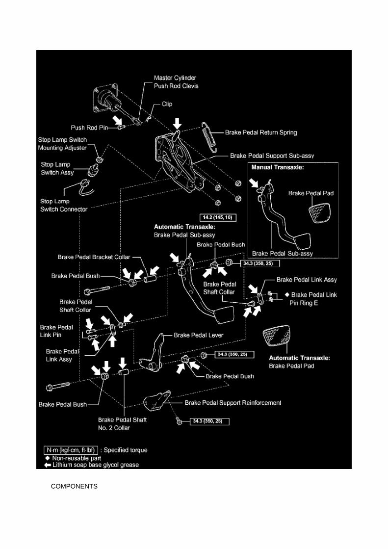
COMPONENTS

REPLACEMENT
1. DISCONNECT CABLE FROM NEGATIVE BATTERY TERMINAL 2. REMOVE FRONT FLOORFOOTREST 3. REMOVE FRONT DOOR SCUFF PLATE LH 4. REMOVE COWL SIDE TRIMBOARD LH 5. REMOVE INSTRUMENT PANEL UNDER TRAY (AUTOMATIC TRANSAXLE) 6.REMOVE INSTRUMENT PANEL HOLE COVER (MANUAL TRANSAXLE)

Page 2008
Step 7 - 8
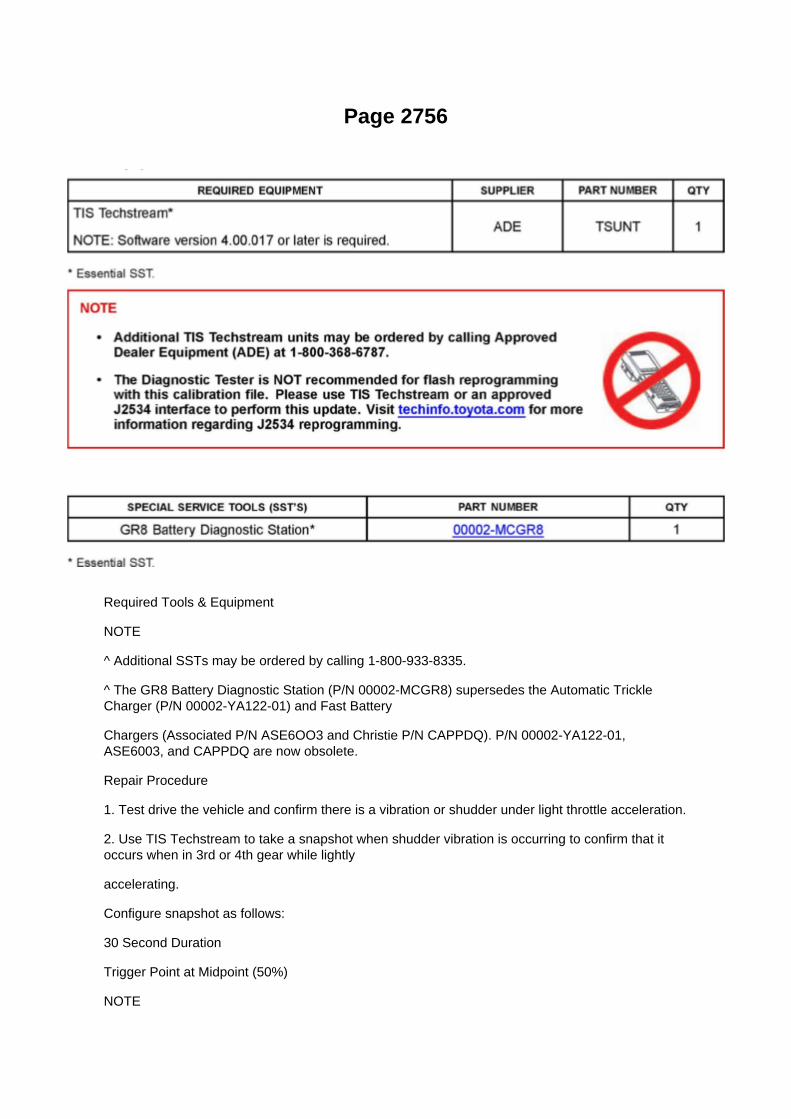
Page 2756
Required Tools & Equipment
NOTE
^ Additional SSTs may be ordered by calling 1-800-933-8335.
^ The GR8 Battery Diagnostic Station (P/N 00002-MCGR8) supersedes the Automatic TrickleCharger (P/N 00002-YA122-01) and Fast Battery
Chargers (Associated P/N ASE6OO3 and Christie P/N CAPPDQ). P/N 00002-YA122-01,ASE6003, and CAPPDQ are now obsolete.
Repair Procedure
1. Test drive the vehicle and confirm there is a vibration or shudder under light throttle acceleration.
2. Use TIS Techstream to take a snapshot when shudder vibration is occurring to confirm that itoccurs when in 3rd or 4th gear while lightly
accelerating.
Configure snapshot as follows:
30 Second Duration
Trigger Point at Midpoint (50%)
NOTE

Refer to the University of Toyota online training class P901C "Techstream InDepth" for informationabout taking snapshots and graphing snapshots on Techstream.

Capacity Specifications

Refrigerant: Capacity Specifications

Refrigerant Capacity..............................................................................................................................................................600 ± 30 g (21.16 ± 1.06 oz.)

Page 1957
Step 7 - 8

Page 2969

Repair Procedure Identification

Refer to the table below to determine which parts/modifications need to be performed.
Repair Procedure A
Carpet Modification
1. Remove the front door scuff plate LH. Disengage the 9 claws and remove the front door scuffplate.
2. Remove the front floor footrest. Disengage the 2 clips and remove the front floor footrest.

Page 1474
Compression Check: Testing and Inspection
INSPECT COMPRESSION
a. Warm up the engine, then stop it. b. Remove the intake air connector. c. Remove the ignitioncoils. d. Remove the spark plugs. e. Disconnect the fuel injector connector.
f. Inspect the compression. (1) Insert a compression gauge into the plug hole. (2) Crank the engine,then measure the compression pressure. Compression pressure: 1230 kPa (12.5 kgf/cm2, 178 psi)Minimum pressure: 880 kPa (9.0 kgf/cm2, 128 psi) or more Difference between each cylinder: 68kPa (0.7 kgf/cm2, 10 psi) or less
NOTICE: -
Use a fully-charged battery so the engine speed can be increased to 250 rpm or more.
- Inspect the other cylinders in the same way.
- Measure the compression pressure in as short a time as possible.
(3) If the compression pressure is low, pour a small amount of engine oil into the cylinder block,then measure it again.
HINT: -
If the compression pressure increases after adding the engine oil, the piston rings may be worn.
- If the compression pressure does not change after pouring engine oil, defects may be occurringaround the valves.

Page 733


Page 1225

NOTICE: Prevent foreign objects from getting into the engine compartment with a shop rag.

11. REMOVE CAMSHAFT TIMING GEAR ASSEMBLY
a. Clamp the camshaft in a vise, then check that the camshaft timing gear does not rotate.
NOTICE: Do not damage the camshaft by clamping it in a vise too tightly.
b. Cover the 4 oil paths of the cam journal with vinyl tape as shown in the illustration.
HINT: One of the 2 grooves located on the cam journal is for retarding cam timing (upper) and theother is for advancing cam timing (lower). Each groove has 2 oil paths. Plug one of the 2 oil pathsfor each groove with a piece of rubber before wrapping the cam journal with the tape.
c. Puncture the tape covering the advance side path and retard side path on the opposite side.
d. Apply air pressure at approximately 200 kPa (2.0 kgf/cm2, 29 psi) into the 2 paths (the advanceside path and retard side path) from the 2
punctures.
NOTICE: When applying air pressure, cover the paths with a shop rag to prevent oil splashes.
e. Confirm that the camshaft timing gear revolves in the advance direction when reducing the airpressure on the retard side path.
HINT: The lock pin is released and the camshaft timing gear revolves in the advance direction.

Page 879

1. Discharge the fuel system pressure (step 2). 2. Disconnect the fuel tank main tube. 3. Drain thefuel remaining in the fuel tank main tube. 4. Cover the disconnected fuel tank main tube (fuel tube

joint and fuel tube connector) with a vinyl bag to prevent damage and the intrusion
of foreign objects.
b. Take the following precautions when installing the fuel injector.
1. Do not reuse the O-ring. 2. Do not damage a new O-ring when installing it onto the fuel injector.3. Before installing a new O-ring, apply gasoline or spindle oil.
NOTE: Do not use engine oil, gear oil or brake oil.
4. Install the fuel injector into the fuel delivery pipe and cylinder head as illustrated.
HINT: Apply gasoline or spindle oil to the contact surface of the fuel delivery pipe and fuel injectorbefore installing the fuel injector.
c. Take the following precautions when disconnecting the fuel tube connector.
HINT: The structure of the fuel tube connector is as shown in the illustration.
1. Check the fuel tube connector and pipe for dirt and mud before removing the fuel tubeconnector.
If dirty, wipe it with a shop rag.

Page 2729
4. Attach the Authorized Vehicle Modification Label.

Modifications to ECU calibrations MUST be recorded and properly displayed on the vehicle usingthe Authorized Modification Label.
Techstream Preparation
Selecting the TIS Techstream VIM or the Mongoose MFC VIM.
Techstream software requires a VIM selection before you can use the Mongoose MFC VIM.
If using TIS Techstream no changes are needed.
Perform the following:
1. Select Setup from the Techstream Main Menu screen.
2. Select VIM Select from the Setup drop down menu.
3. Select the correct Interface Setup from the drop down list.
^ If using Techstream Lite select Mongoose MFC.
NOTE

Recall - Seat Belt Sensor Wire Harness Modification
Technical Service Bulletin # SSC50I Date: 050701

Page 518
SFI System

Page 2584
SFI System

Page 702

(c) Connect the male portion of the wire seat jumper to the female portion of the floor wire harness,as shown in the illustration.

(d) Push and pull the connectors to confirm that they are locked in place.
(e) Insert the wire seat jumper connector clip into the slotted hole on the seat bracket.
(f) Connect the female portion of the wire seat jumper to the male portion of the floor wire harness,as shown in the illustration.
(g) Push and pull the connectors to confirm that they are locked in place.
(h) Confirm that the wire seat jumper is correctly routed.

Page 147
How to Read Ground Points

HOW TO READ GROUND POINTS
The ground points circuit diagram shows the connections from all major parts to the respectiveground points. When troubleshooting a faulty ground point, checking the system circuits which usea common ground may help you identify the problem ground quickly. The relationship betweenground points(EA, IB and IC is shown) can also be checked this way.
How to Read Power Source
HOW TO READ POWER SOURCE

Page 2071

He - Wi

Specifications

Piston: Specifications

- PISTON DIAMETER a. Using a micrometer, measure the piston diameter at right angles to thepiston center line, the indicated distance from the piston end.
- PISTON OIL CLEARANCE a. Measure the cylinder bore diameter in the thrust directions. b.Subtract the piston diameter measurement from the cylinder bore diameter measurement.
Standard oil clearance: 0.019 to 0.052 mm (0.0007 to 0.0020 inch) If the oil clearance is greaterthan the standard, replace all the pistons and rebore all the cylinders. If necessary, replace thecylinder block.
HINT: -
Bore all the cylinders for the O/S piston outside diameter.
- Replace all the piston rings with ones to match the O/S pistons.
c. If the oil clearance is greater than the standard.
(1) Prepare 4 new O/S pistons. O/S 0.50 piston diameter: 95.441 to 95.451 mm (3.7575 to 3.7579inch) (2) Using a micrometer, measure the piston diameter at right angles to the piston center line,the indicated distance from the piston end. Distance: 9.3 mm (0.366 inch) (3) Calculate the amounteach cylinder is to be rebored as follows: Size to be rebored = P + C - H P = Piston diameter C =Piston clearance: 0.019 to 0.052 mm (0.0007 to 0.0020 inch) H = Allowance for honing: 0.02 mm(0.0008 inch) or less (4) Bore and hone the cylinders to calculated dimensions. Maximum honing:0.02 mm (0.0008 inch)
NOTICE: Excess honing will destroy the finished roundness.
- RING GROOVE CLEARANCE a. Using a feeler gauge, measure the clearance between a newpiston ring and the wall of the ring groove.
Ring groove clearance

Page 1419

Page 892

Spark Plug: Application and ID

SPARK PLUG TYPE:
DENSO ........................................................................................................................................................................................................... SK2OHR11 NGK ..................................................................................................................................................................................................................ILFR6C11
Correct electrode gap for new sparkplug.......................................................................................................................... 1.0 to 1.1 mm(0.039 to 0.043 in.)
Torque.....................................................................................................................................................................................18 N.m (184 kgf.cm, 13 ft.lbf)

Page 3006

11. Install the clutch pedal bushes.

A. Apply MP grease to the 2 NEW bushes.
B. Install the 2 bushes onto the clutch pedal.
12. Install the clutch pedal pad.
13. Install the clutch pedal spring holder.
A. Apply MP grease to the contact surface of the clutch pedal spring holder.
B. Install the clutch pedal spring holder.
14. Install the NEW clutch pedal sub-assembly.
A. Install the clutch pedal onto the clutch support with the bolt and nut.
Torque: 34 N.m (347 kgf.cm, 25 ft.lbf)
HINT:

Page 33

If the circuit has diodes, reverse the two leads and check again. When contacting the negative leadto the diode positive side and the positive lead to the negative side, there should be continuity.

When contacting the two leads in reverse, there should be no continuity.
c. Use a volt/ohmmeter with high impedance (10 kOhms/V minimum) for troubleshooting of theelectrical circuit.
Finding A Short Circuit
FINDING A SHORT CIRCUIT
a. Remove the blown fuse and disconnect all loads of the fuse.
b. Connect a test light in place of the fuse.
c. Establish conditions in which the test light comes on.
Example: [A] - Ignition SW on [B] - Ignition SW and SW 1 on [C] - Ignition SW, SW 1 and Relay on(Connect the Relay) and SW 2 off (or Disconnect SW 2)
d. Disconnect and reconnect the connectors while watching the test light.
The short lies between the connector where the test light slays lit and the connector where the lightgoes out.
e. Find the exact location of the short by lightly shaking the problem wire along the body.

Diagram Information and Instructions

Accessory Delay Module: Diagram Information and Instructions

Key to Diagrams
A: System Title
B: Indicates a Relay Block. No shading is used and only the Relay Block No. is shown todistinguish it from the J/B

Page 470
Camshaft Position Sensor: Testing and Inspection
INSPECT CAMSHAFT POSITION SENSOR
Check the resistance.
Using an ohmmeter, measure the resistance between the terminals.
HINT: Cold and Hot mean the temperature of the coils themselves. Cold is from -10 to 50°C (14 to122°F) and Hot is from 50 to 100°C (122 to 212° F).
If the result is not as specified, replace the camshaft position sensor.

Page 2734
load while reprogramming.
^ Confirm the hood is open and ensure under hood temperature does NOT exceed 158°F (70°C).
^ Confirm cable connections between the vehicle and Techstream are secure.
^ Do NOT disconnect or turn off Techstream or vehicle ignition during reprogramming.
^ Set parking brake.
^ Complete ALL flash calibration updates provided for each ECU.
^ If the battery's state of charge or capacity are in question, test with SST. No. 00002-8150-KIT"Digital Battery Analyze," and follow TSB No. PG001-06, "Battery Maintenance for In-Stock

Vehicles & Pre-Delivery" or the appropriate "Maintenance for HV & Auxiliary Batteries" servicebulletin.
^ The GR8 Battery Diagnostic Station MUST be used in Power Supply Mode to maintain batteryvoltage at 13.5 volts while flash reprogramming the vehicle. For details on how to use the GR8Battery Diagnostic Station, refer to the GR8 Instruction Manual located on TIS, Diagnostics - Tools& Equipment - Battery Diagnostics.
3C. Click Next to start the calibration update process.
D. When using TIS Techstream select Techstream VIM as the desired programming device. Thenclick Next.

Page 738
Seat Occupant Sensor: Locations
Fr - Si

Page 1053

Glossary Of Terms And Sysmbols Part 2

Page 2105
When using Techstream Lite, select Generic J2534 Interface. Then click Next.
E. Confirm the following:
^ PC is connected to VIM.
^ VIM is connected to DLC3 connector.
^ Ignition is ON and engine is OFF or "READY" OFF (hybrid vehicles).

Page 2473

SST 09268-41048 (09268-41500, 90467-13001)
7. Install the pressure regulator onto SST (union) with the 2 bolts.
Torque: 8.5 N.m (87 kgf.cm, 75 in.lbf)
SST 09268-41048 (09268-41091)
NOTE: Make sure that the O-ring is installed onto the pressure regulator.
8. Install the O-ring onto the injector. 9. Assemble SST as shown in the illustration.
SST 09268-41048 (09268-41110, 09268-41310)
10. Put the injector into a graduated cylinder.
CAUTION: Install a suitable vinyl tube onto the injector to contain any gasoline spray.
11. Make sure that SST is installed as shown in the illustration. 12. Operate the fuel pump.

Page 920

1. Discharge the fuel system pressure (step 2). 2. Disconnect the fuel tank main tube. 3. Drain thefuel remaining in the fuel tank main tube. 4. Cover the disconnected fuel tank main tube (fuel tube
joint and fuel tube connector) with a vinyl bag to prevent damage and the intrusion
of foreign objects.
b. Take the following precautions when installing the fuel injector.
1. Do not reuse the O-ring. 2. Do not damage a new O-ring when installing it onto the fuel injector.3. Before installing a new O-ring, apply gasoline or spindle oil.
NOTE: Do not use engine oil, gear oil or brake oil.
4. Install the fuel injector into the fuel delivery pipe and cylinder head as illustrated.
HINT: Apply gasoline or spindle oil to the contact surface of the fuel delivery pipe and fuel injectorbefore installing the fuel injector.
c. Take the following precautions when disconnecting the fuel tube connector.
HINT: The structure of the fuel tube connector is as shown in the illustration.
1. Check the fuel tube connector and pipe for dirt and mud before removing the fuel tubeconnector.
If dirty, wipe it with a shop rag.

Page 2445

He - Wi

Page 1132

"Case 1" Raise the terminal retainer up to the temporary lock position.

"Case 2" Open the secondary locking device.

Page 3142
Flex Plate: Specifications
Driveplate ............................................................................................................................................................................ 74 Nm (755 kgf-cm, 55 ft. lbs.)

Page 2984
Components
Repair Procedure

1. Record all radio presets before starting.
2. Disconnect the negative (-) battery terminal cable.
3. Remove the clutch pedal sub-assembly.

System Diagnosis
Idle Speed: Testing and Inspection
INSPECT ENGINE IDLING SPEED
a. When using a hand-held tester:
(1) Connect the hand-held tester to the DLC3. (2) Turn the ignition switch to ON. (3) Turn thehand-held tester ON. (4) Start the engine and warm it up. (5) Select the following menu items:DIAGNOSIS / ENHANCED OBD II / DATA LIST / PRIMARY / ENGINE SPD.
Idling speed: 600 to 700 rpm
NOTICE: -
Turn all electrical systems OFF.
- When checking the idling speed, the transmission is in the neutral position.
HINT: Refer to the hand-held tester operator's manual for further in formation regarding theselection of DATA LIST.
b. When not using a hand-held tester:
(1) Turn the ignition switch to ON. (2) Start the engine and warm it up. (3) Install SST onto terminal9 (TAC) of the DLC3. Connect a tachometer, then measure the engine idling speed. SST09843-18030 Idling speed: 600 to 700 rpm
NOTICE: -
Turn all electrical systems OFF.
- When checking the idling speed, the transmission should be in the neutral position.

Page 2137

9. INSTALL ECM

Torque: 5 N.m (51 kgf.cm, 44 in.lbf)
10. INSTALL INSTRUMENT PANEL FINISH PANEL SUB-ASSEMBLY LOWER RH 11. INSTALLGLOVE COMPARTMENT DOOR ASSEMBLY 12. CONNECT CABLE TO NEGATIVE BATTERYTERMINAL
Torque: 3.9 N.m (40 kgf.cm, 35 in.lbf)

Locations

Transmission Speed Sensor: Locations

He - Wi

Page 231
Oscilloscope Waveforms

Page 767
Ignition Switch: Service and Repair
IGNITION OR STARTER SWITCH ASSEMBLY
REPLACEMENT
1. DISCONNECT CABLE FROM NEGATIVE BATTERY TERMINAL
2. REMOVE STEERING COLUMN COVER LWR
a. Remove the 2 screws. b. Disengage the 2 claws and remove the steering column cover LWR.
3. REMOVE IGNITION OR STARTER SWITCH ASSEMBLY

a. Disconnect the connector. b. Disengage the 2 clamps, then remove the ignition or starter switch.
4. INSTALL IGNITION OR STARTER SWITCH ASSEMBLY 5. INSTALL STEERING COLUMNCOVER LWR 6. CONNECT CABLE TO NEGATIVE BATTERY TERMINAL
Torque: 3.9 N.m (40 kgf.cm, 35 in.lbf)

Page 146
Example: Splice point "I5" is on the Cowl Wire Harness and is described.
How to Read Connector List
HOW TO READ CONNECTOR LIST
A: Indicates connector to be connected to a part. (The numeral indicates the pin No.)
B: Junction Connector
Indicates a connector which is connected to a short terminal.
Junction connector in this include a short terminal which is connected to a number of wireharnesses. Always perform inspection with the short terminal installed. (When installing the wireharnesses, the harnesses can be connected to any position within the short terminal grouping.Accordingly, in other vehicles, the same position in the short terminal may be connected to a wireharness from a different part.) Wire harness sharing the same short terminal grouping have thesame color.
C: Parts Code
The first letter of the code is taken from the first letter of part, and the numbers indicates its order inparts which start with the same letter.
D: Connector Color
Connectors not indicated are milky white in color.

Page 3092

9. SEPARATE REAR BRAKE TUBE NO.8

a. Using SST, separate the brake tube, and use a container to catch the brake fluid as it flows out.
SST 09023-00101
10. REMOVE REAR AXLE SHAFT W/ BACKING PLATE
a. Remove the 4 nuts and rear axle shaft W/ backing plate. b. Remove the O-ring.
11. REMOVE REAR AXLE SHAFT LH OIL SEAL
a. Using SST, remove the oil seal.
SST 09308-00010
12. REMOVE REAR AXLE SHAFT LH SNAP RING
a. Using a snap ring expander, remove the snap ring.

Locations

Air Flow Meter/Sensor: Locations

He - Wi

Page 1768
a. Connect the hand-held tester to the DLC3. b. Turn the ignition switch to ON.
NOTE: Do not start the engine.
c. Turn the hand-held tester ON. d. Select the following menu items: DIAGNOSIS / ENHANCEDOBD II / ACTIVE TEST / FUEL PUMP / SPD / ON. e. Check that there are no leakage in the fuelsystem.

Page 2124
Step 1 - 3

Page 2195

a. Install a new gasket onto the intake manifold. b. Install the intake manifold with the 5 bolts and 2nuts.

Torque: 25 N.m (255 kgf.cm, 18 ft.lbf)
c. Connect the engine wire harness to the relay block. d. Install the nut shown in the illustration.
Torque: 10 N.m (102 kgf.cm, 7 ft.lbf)
e. Connect the 3 connectors.
f. Install the harness clamp bracket with the bolt.
Torque: 8.2 N.m (84 kgf.cm, 73 in.lbf)
g. Engage the wire harness clamp. h. Connect the compressor magnetic clutch connector.

Page 1376

64. INSTALL CHAIN VIBRATION DAMPER NO.1

a. Install the vibration damper with the bolt and nut.
Torque: 21 Nm (214 kgf-cm, 15 ft. lbs.)
65. INSTALL CHAIN SUB-ASSEMBLY
a. As shown in the illustration, install the chain onto the sprocket and gear with the painted marksaligned with the timing marks on the sprocket
and gear.
HINT: -
The camshaft mark plate is orange.
- The crankshaft mark plate is yellow.
b. Use a rope to tie the chain of the crankshaft timing sprocket. Tie the rope near the sprocket.
NOTICE: After the chain tensioner has been installed, the rope must be removed.
HINT: The rope is tied to prevent gear jumping.

Locations
SFI System

Page 1385


Page 2222
SST 09224-00010
Torque: 44 N.m (449 Kgf.cm, 33 ft.lbf) 40 N.m (408 Kgf.cm, 30 ft.lbf) with SST
NOTE: Use a torque wrench with a fulcrum length of 300 mm (11.81 in.).
b. Connect the wire harness clamp. (4WD DRIVE TYPE) c. Connect the oxygen sensor connector.
4. CONNECT CABLE TO NEGATIVE BATTERY TERMINAL
Torque: 3.9 N.m (40 Kgf.cm, 35 in.lbf)

Specifications

Spark Plug: Specifications

SPARK PLUG TYPE:
DENSO ........................................................................................................................................................................................................... SK2OHR11 NGK ..................................................................................................................................................................................................................ILFR6C11
Correct electrode gap for new sparkplug.......................................................................................................................... 1.0 to 1.1 mm(0.039 to 0.043 in.)
Torque.....................................................................................................................................................................................18 N.m (184 kgf.cm, 13 ft.lbf)

Page 178
Instrument Panel J/B No. 1 - Left Kick Panel

Locations
Intake Air Temperature Sensor: Locations

SFI System
The Intake Air Temperature (IAT) Sensor is installed in the Mass Air Flow (MAF) Meter.

Page 100
Control Module HVAC: Service and Repair

Airconditioner Amplifier Assy
AIR-CONDITIONER AMPLIFIER ASSEMBLY
REPLACEMENT
1. DISCONNECT CABLE FROM NEGATIVE BATTERY TERMINAL
Wait for at least 90 seconds after disconnecting the cable to prevent the airbag from working.
2. REMOVE GLOVE COMPARTMENT DOOR ASSEMBLY 3. REMOVE INSTRUMENT PANELFINISH PANEL SUB-ASSEMBLY LOWER RH

Page 2951
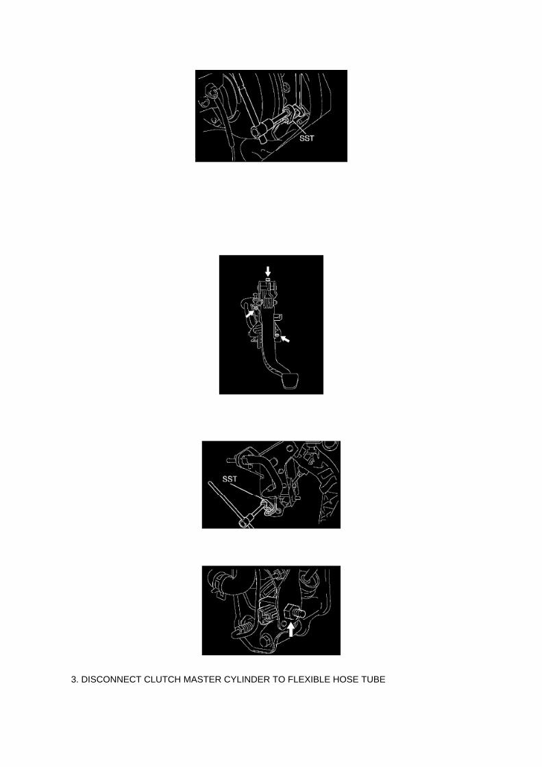
3. DISCONNECT CLUTCH MASTER CYLINDER TO FLEXIBLE HOSE TUBE

a. Using SST, disconnect the flexible hose tube. SST 09023-00101
4. REMOVE FRONT DOOR SCUFF PLATE LH 5. REMOVE COWL SIDE TRIM BOARD LH 6.REMOVE INSTRUMENT PANEL FINISH PANEL LOWER NO.1 7. SEPARATE DRIVER SIDEJUNCTION BLOCK 8. REMOVE CLUTCH PEDAL W/CLUTCH MASTER CYLINDER
a. Disconnect the clutch start switch connector.
b. Remove the 2 nuts and bolt, then remove the clutch pedal w/clutch master cylinder.
9. REMOVE CLUTCH MASTER CYLINDER ASSY
a. Disconnect the clutch reservoir tube.
b. Using SST, disconnect the 2 way tube from the clutch master cylinder.
SST 09023-00101
c. Remove the nut and clutch start switch from the clutch pedal support.

Page 652

(c) Confirm that the scan tool displays the data shown below and in the illustration.

^ "D SEAT POSITIFORWARD"
(Driver's seat is in the forward position).
^ "D BUCKLE SW.....SET"
(Driver's seat belt buckle switch is set/buckled).
3. TEST RESULTS
(a) If ALL four test results are OK the vehicle has been repaired, proceed to step "4. REMOVE THESCAN TOOL.
(b) In the UNLIKELY event that the test results are NG, refer to the troubleshooting flowchartlocated in section "VII. APPENDIX".
4. REMOVE THE SCAN TOOL
(a) Turn the scan tool OFF by pressing the "EXIT and "# " button simultaneously.
(b) Turn the ignition switch "OFF".
(c) Disconnect the scan tool from the DLC3 connector.
VI. SSC Completion Label Installation
After completing the repair and before returning the vehicle to the owner, an SSC completion label,which is enclosed in the owner's notification letter, must be affixed to the left front door hinge post,near the check strap.
(a) The label is to be filled out as follows:
^ Write in SSC 50I.
^ Write in date of repair.
^ Write in your dealer code.
(b) Additional SSC completion labels, in sheets of 50 (P/N 00410-01917), may be ordered throughthe non-parts system on a 1450 order form or
through the TDN system.

Page 1902
I: Indicates a wiring Splice Point (Codes are "E" for the Engine Room, "I" for the Instrument Panel,and "B" for the Body).
The Location of splice Point I5 is indicated by the shaded section.
J: Indicates a shielded cable.
K: Indicates the pin number of the connector. The numbering system is different for female andmale connectors.
L: Indicates a ground point.
The first letter of the code for each ground point(s) indicates the component's location, e.g, "E" forthe Engine Compartment, "I" for the Instrument Panel and Surrounding area, and "B" for the Body

and Surrounding area.
N: Explains the system outline.
SYSTEM OUTLINE
Current is applied at all times through the STOP fuse to TERMINAL 2 of the stop light SW. Whenthe ignition SW is turned on, current flows from the GAUGE fuse to TERMINAL 8 of the light failuresensor, and also flows through the rear lights warning light to TERMINAL 4 of the light failuresensor.
STOP LIGHT DISCONNECTION WARNING When the ignition SW is turned on and the brakepedal is pressed (Stop light SW on), if the stop light circuit is open, the current flowing fromTERMINAL 7 of the light failure sensor to TERMINALS 1, 2 changes, so the light failure sensordetects the disconnection and the warning circuit of the light failure sensor is activated.
As a result, the current flows from TERMINAL 4 of the light failure sensor to TERMINAL 11 toGROUND and turns the rear lights warning light on. By pressing the brake pedal, the currentflowing to TERMINAL 8 of the light failure sensor keeps the warning circuit on and holds thewarning light on until the ignition SW is turned off.

Page 2188
Knock Control Sensor (2TR-FE) Part 1

Page 2629

Knock Control Sensor (2TR-FE) Part 2

Page 710


Page 1070

If the circuit has diodes, reverse the two leads and check again. When contacting the negative leadto the diode positive side and the positive lead to the negative side, there should be continuity.

When contacting the two leads in reverse, there should be no continuity.
c. Use a volt/ohmmeter with high impedance (10 kOhms/V minimum) for troubleshooting of theelectrical circuit.
Finding A Short Circuit
FINDING A SHORT CIRCUIT
a. Remove the blown fuse and disconnect all loads of the fuse.
b. Connect a test light in place of the fuse.
c. Establish conditions in which the test light comes on.
Example: [A] - Ignition SW on [B] - Ignition SW and SW 1 on [C] - Ignition SW, SW 1 and Relay on(Connect the Relay) and SW 2 off (or Disconnect SW 2)
d. Disconnect and reconnect the connectors while watching the test light.
The short lies between the connector where the test light slays lit and the connector where the lightgoes out.
e. Find the exact location of the short by lightly shaking the problem wire along the body.

Page 1119
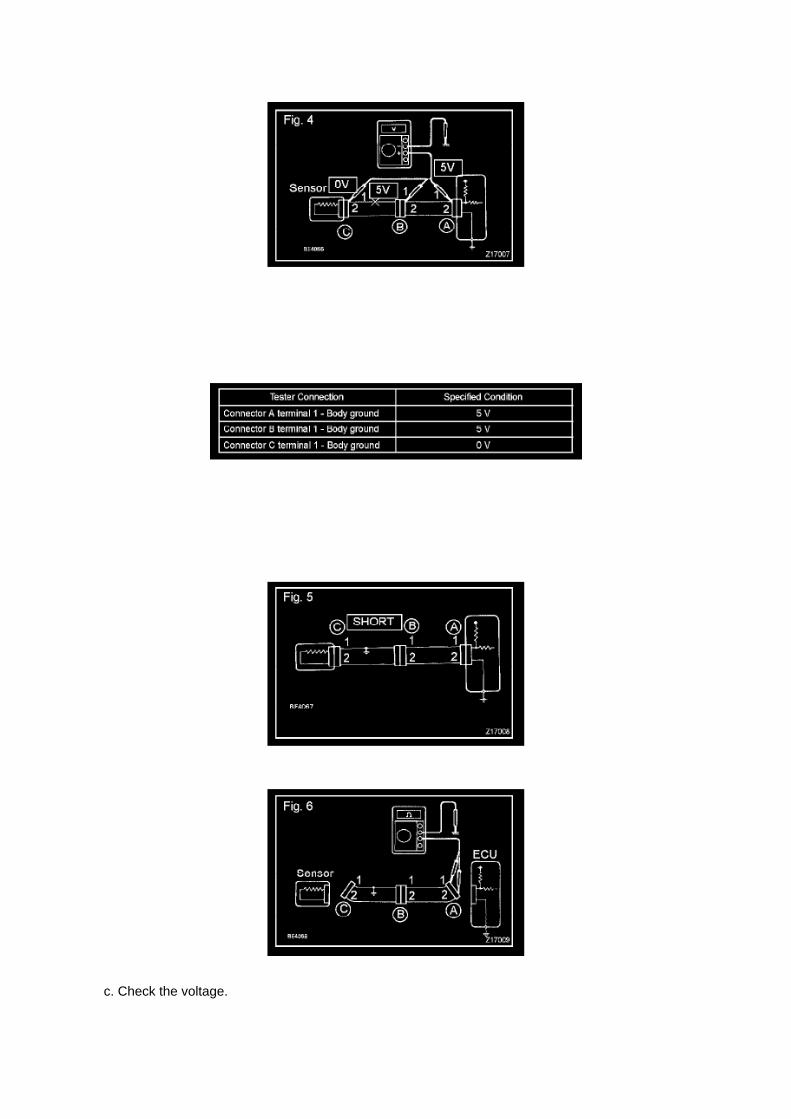
c. Check the voltage.

1. In a circuit in which voltage is applied to the ECU connector terminal, an open circuit can bechecked by conducting a voltage check.
FIG 4: With each connector still connected, measure the voltage between the body ground andthese terminals (in this order): 1) terminal 1 of connector A at the ECU 5 V output terminal, 2)terminal 1 of connector B, and 3) terminal 1 of connector C.
2. Example results:
If your results match the examples above, an open circuit exists in the wire harness betweenterminal 1 of connector B and terminal 1 of connector C.
Check Short Circuit
CHECK SHORT CIRCUIT
a. If the wire harness is ground shorted (Fig. 5), locate the section by conducting a resistancecheck with the body ground.
b. Check the resistance with the body ground.

Page 567
SFI System

Page 2552
Fuel Tank: Locations

Fuel Tank Assy

Page 2770
load while reprogramming.
^ Confirm the hood is open and ensure under hood temperature does NOT exceed 158°F (70°C).
^ Confirm cable connections between the vehicle and Techstream are secure.
^ Do NOT disconnect or turn off Techstream or vehicle ignition during reprogramming.
^ Set parking brake.
^ Complete ALL flash calibration updates provided for each ECU.
^ If the battery's state of charge or capacity are in question, test with SST. No. 00002-8150-KIT"Digital Battery Analyze," and follow TSB No. PG001-06, "Battery Maintenance for In-Stock

Vehicles & Pre-Delivery" or the appropriate "Maintenance for HV & Auxiliary Batteries" servicebulletin.
^ The GR8 Battery Diagnostic Station MUST be used in Power Supply Mode to maintain batteryvoltage at 13.5 volts while flash reprogramming the vehicle. For details on how to use the GR8Battery Diagnostic Station, refer to the GR8 Instruction Manual located on TIS, Diagnostics - Tools& Equipment - Battery Diagnostics.
3C. Click Next to start the calibration update process.
D. When using TIS Techstream select Techstream VIM as the desired programming device. Thenclick Next.

Page 3363

g. Repeat step (f) until all the air in the brake fluid is bled out. h. When the air is completely bled outof the brake fluid through the bleeder plug, tighten the bleeder plug.

Torque: 11 Nm (112 kgf-cm, 8 ft. lbs.)
i. Repeat the above procedures to bleed the other brake line.
j. Turn the ignition switch to OFF.
k. Turn the ignition switch to ON.
(1) Clear DTC.
5. CHECK FLUID LEVEL IN RESERVOIR
a. Turn the ignition switch to OFF, and depress the brake pedal more than 20 times (until the pedalreaction feels light and pedal stroke becomes
longer), and adjust the fluid level to the MAX level.
b. When the ignition switch is turned to the ON, brake fluid is sent to the accumulator and the fluidlevel decreases by approximately 5 mm from
the level when the ignition switch is off (normal).

Page 1113

Glossary Of Terms And Sysmbols Part 2

Page 1781
2. After connecting the fuel tube connector, check that the fuel tube connector and pipe aresecurely connected by pulling them.
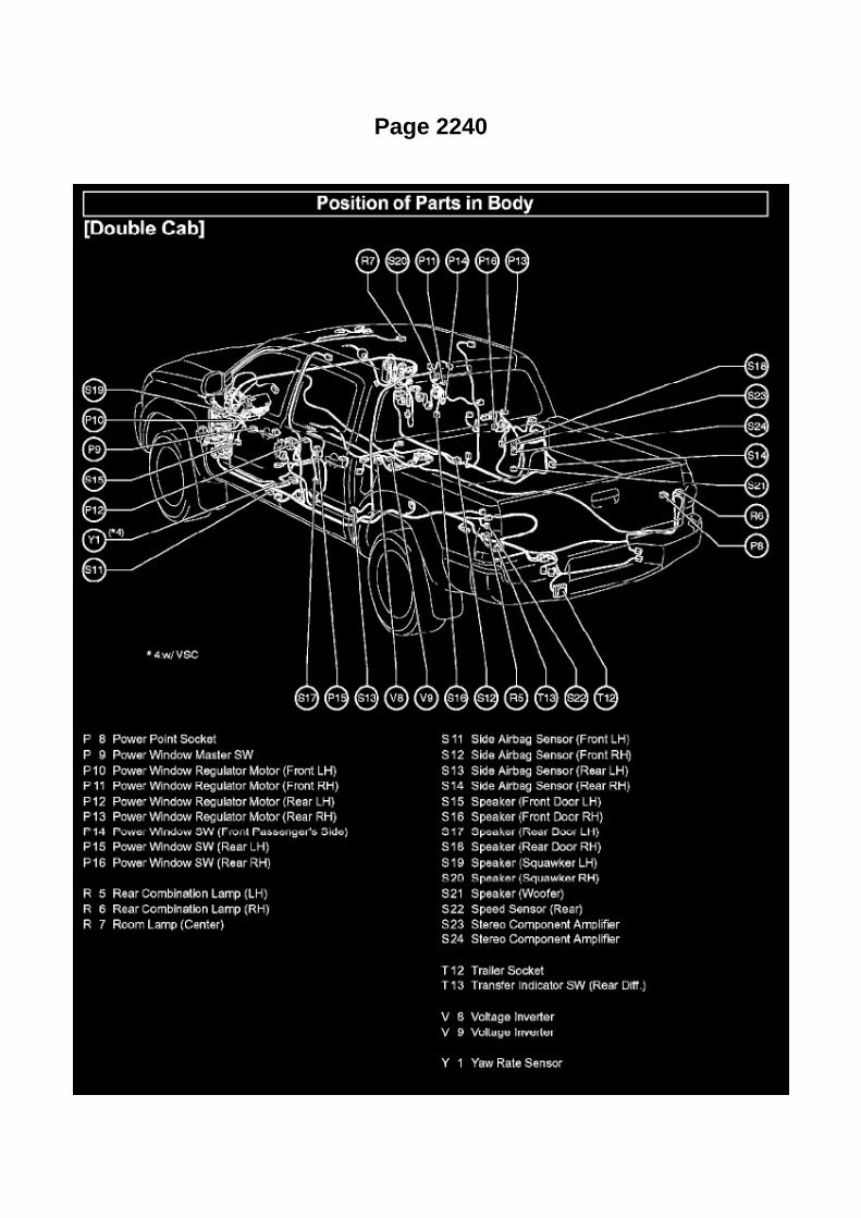
Page 2240

Po - Ya

Page 1958
Step 9 - 10

Page 3173

He - Wi
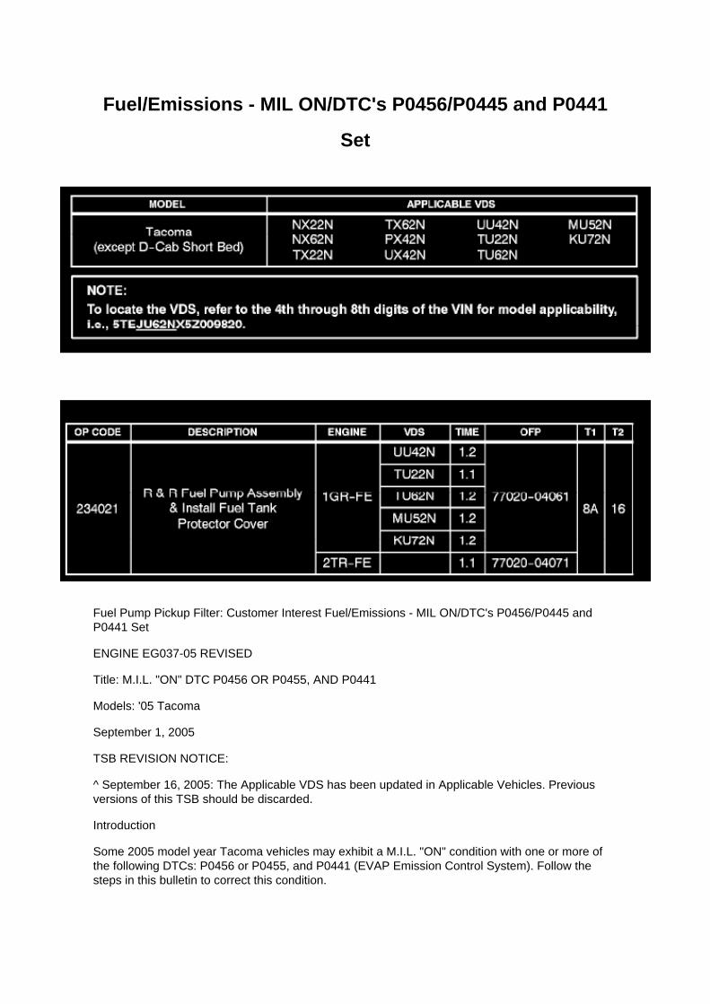
Fuel/Emissions - MIL ON/DTC's P0456/P0445 and P0441
Set
Fuel Pump Pickup Filter: Customer Interest Fuel/Emissions - MIL ON/DTC's P0456/P0445 andP0441 Set
ENGINE EG037-05 REVISED
Title: M.I.L. "ON" DTC P0456 OR P0455, AND P0441
Models: '05 Tacoma
September 1, 2005
TSB REVISION NOTICE:
^ September 16, 2005: The Applicable VDS has been updated in Applicable Vehicles. Previousversions of this TSB should be discarded.
Introduction
Some 2005 model year Tacoma vehicles may exhibit a M.I.L. "ON" condition with one or more ofthe following DTCs: P0456 or P0455, and P0441 (EVAP Emission Control System). Follow thesteps in this bulletin to correct this condition.

Applicable Vehicles
^ 2005 model year Tacoma vehicles (except D-Cab Short Bed), with the following VehicleDescription Section VDS) information shown below.
Warranty Information
Applicable Warranty*: This repair is covered under the Toyota Powertrain Warranty. This warrantyis in effect for 60 months or 60,000 miles, whichever occurs first, from the vehicle's in-service date.
* Warranty application is limited to correction of a problem based upon a customer's specificcomplaint.

Component Tests and General Diagnostics
Control Module HVAC: Component Tests and General Diagnostics
INSPECT AIR-CONDITIONER AMPLIFIER ASSEMBLY
a. Disconnect the connector from the air-conditioner amplifier assembly and inspect the connectoron the wire harness side, as shown in the table.
If the results are not as specified, inspect the circuits connected to the other parts.

Page 265
Air Bag Sensor Assy Center

Page 1317

7. REMOVE ENGINE REAR OIL SEAL

a. Using a cutter knife, cut off the lip of the oil seal. b. Using a screwdriver with its tip wrapped intape, pry out the oil seal and remove it.
NOTICE: Check the crankshaft for damage after removing the oil seal. If damaged, smooth thesurface with 400-grit sandpaper.
8. INSTALL ENGINE REAR OIL SEAL
a. Apply a light coat of MP grease to the lip of a new oil seal.
NOTICE: Keep the lip free of foreign objects.
b. Using SST and a hammer, tap the oil seal in until its surface is flush with the rear oil seal retaineredge.
SST 09223-15030, 09950-70010 (09951-07150)
NOTICE: -
Do not tap the oil seal in at an angle.
- Wipe any extra grease off the crankshaft.
9. INSTALL FLYWHEEL SUB-ASSEMBLY (MANUAL TRANSMISSION)
a. Clean the 10 bolts and 10 bolt holes. b. Apply adhesive to 2 or 3 threads of the 10 bolts.Adhesive: Part No.08833-00070, THREE BOND 1324 or equivalent c. Using SST, hold thecrankshaft.
SST 09213-54015 (91651-60855), 09330-00021

Page 168

If the circuit has diodes, reverse the two leads and check again. When contacting the negative leadto the diode positive side and the positive lead to the negative side, there should be continuity.

When contacting the two leads in reverse, there should be no continuity.
c. Use a volt/ohmmeter with high impedance (10 kOhms/V minimum) for troubleshooting of theelectrical circuit.
Finding A Short Circuit
FINDING A SHORT CIRCUIT
a. Remove the blown fuse and disconnect all loads of the fuse.
b. Connect a test light in place of the fuse.
c. Establish conditions in which the test light comes on.
Example: [A] - Ignition SW on [B] - Ignition SW and SW 1 on [C] - Ignition SW, SW 1 and Relay on(Connect the Relay) and SW 2 off (or Disconnect SW 2)
d. Disconnect and reconnect the connectors while watching the test light.
The short lies between the connector where the test light slays lit and the connector where the lightgoes out.
e. Find the exact location of the short by lightly shaking the problem wire along the body.

Page 1653

a. Using several steps, uniformly install and tighten the 5 bolts in the sequence shown in theillustration.

Torque: 21 N.m (214 kgf.cm, 16 ft.lbf) for bolt A 43 N.m (438 kgf.cm, 32 ft.lbf) for bolt B, C
9. INSTALL COMPRESSOR AND MAGNETIC CLUTCH (W/ AIR CONDITIONING)
10. INSTALL FAN AND GENERATOR BELT (W/ AIR CONDITIONING) 11. INSTALL ENGINEUNDER COVER SUB-ASSEMBLY NO.1 (PRE RUNNER AND 4WD TYPE)
12. CONNECT CABLE TO NEGATIVE BATTERY TERMINAL
Torque: 3.9 N.m (40 kgf.cm, 35 in.lbf)
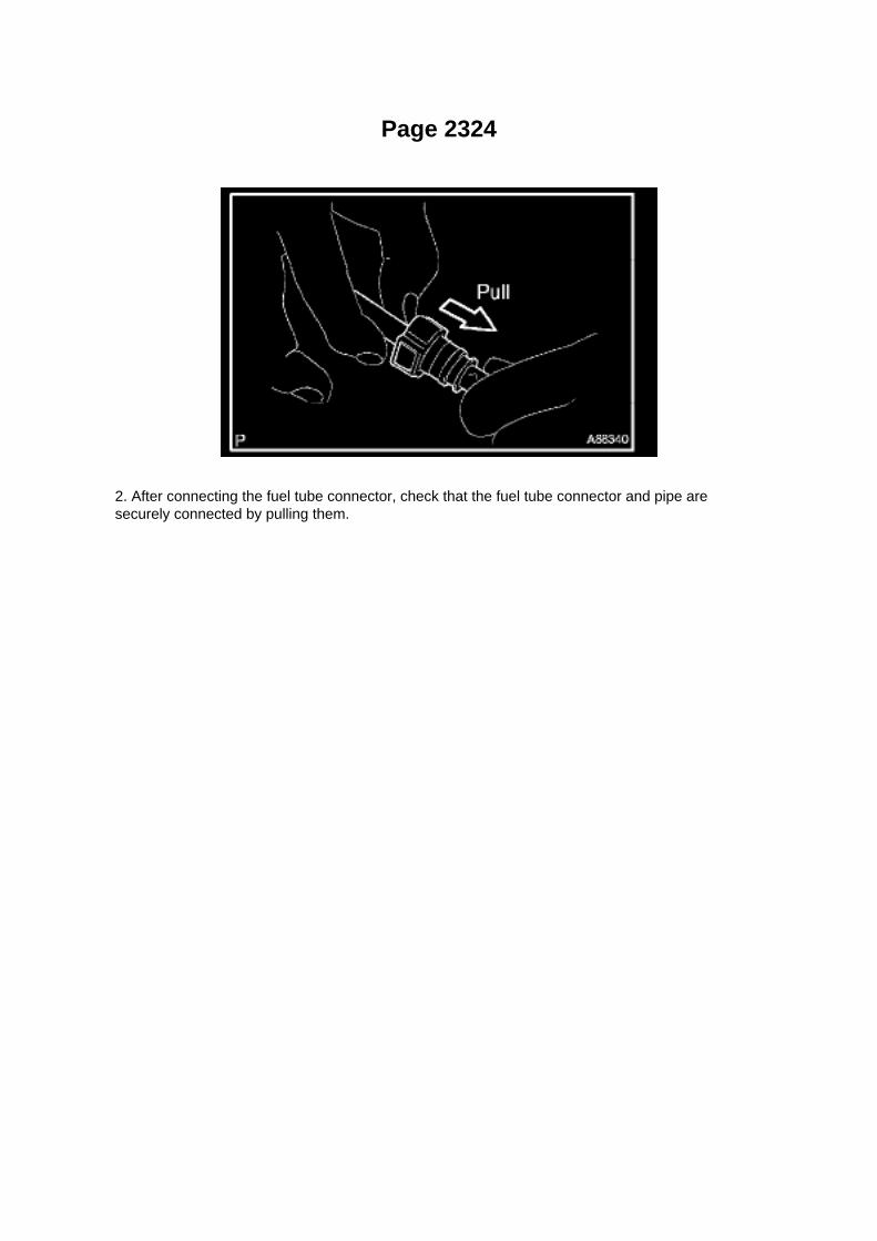
Page 2324
2. After connecting the fuel tube connector, check that the fuel tube connector and pipe aresecurely connected by pulling them.

Page 2493
g. Wipe off any spilt gasoline. h. Connect the cable to the negative battery terminal.
Torque: 3.9 N.m (40 kgf.cm, 35 in.lbf)
i. Connect the hand-held tester to the DLC3.
j. Turn the ignition switch to ON.
k. Turn the hand-held tester ON. l.
Select the following menu items: DIAGNOSIS / ENHANCED OBD II / ACTIVE TEST / FUEL PUMP/ SPD / ON.
m. Measure the fuel pressure.
Standard: 281 to 287 kPa (2.87 to 2.93 kgf/sq.cm, 40.8 to 41.7 psi)
- If the pressure is too high, replace the fuel pressure regulator.
- If the pressure is too low, check the connection between the fuel hose and fuel pump.
n. Disconnect the hand-held tester from the DLC3. o. Start the engine. p. Measure the fuelpressure while the engine idles.
Standard: 281 to 287 kPa (2.87 to 2.93 kgf/sq.cm, 40.8 to 41.7 psi)
q. Stop the engine. r.
Check that the fuel pressure does not change for 5 minutes.
Standard: 147 kPa (1.5 kgf/sq.cm, 21 psi)
If the pressure is not as specified, check the fuel pump, pressure regulator and/or injector.
s. Discharge the fuel system pressure. t.
Disconnect the cable from the negative battery terminal.

u. Remove SST while being careful to prevent gasoline splashes. v. Connect the fuel hose. w.Install the fuel pipe clamp. x. Connect the cable to the negative battery terminal.
Torque: 3.9 N.m (40 kgf.cm, 35 in.lbf)
3. CHECK FOR FUEL LEAKAGE

Page 31
Circuit Inspection

Voltage Check
VOLTAGE CHECK

Page 844

By performing this operation, it can be checked whether the left or right tire exerts a stronger lateralforce. Either tire can be reversed. Shown here is an example of the left tire reversed.
If Vehicle Pull Is Eliminated: Repair Is Now Complete.
The lateral force generated by the left and right front tires is virtually the same so the lateral force isneutralized and the vehicle travels straight ahead. The repair operation is now completed.
B. Rotate the larger lateral force front tire with the rear tire and check the change in the vehiclepulling.
NOTE
By shifting the front tire with the larger lateral force to the rear, the vehicle pulling level is usuallyreduced.
If Vehicle Is Still Pulling: Go to step 3C.
If Vehicle Pull Is Eliminated: Repair Is Now Complete.
C. Adjust cross camber to eliminate vehicle pulling.
HINT
If the tires are placed in the positions they were in during tire rotation when the least amount ofvehicle pulling occurred, wheel alignment can be performed with a minimal amount of adjustment.
NOTE
^ Keep the cross camber within 10 or less.
^ Keep the camber of each wheel within specifications (+/-45' of center value).
^ If adjustment exceeds the specifications, uneven tire wear will result.
4. Camber Adjustment Method.
^ After the camber has been adjusted, inspect the toe-in.

Page 641
are involved. As always, consult Dealer Daily/TIS to confirm VIN eligibility and to assure the SSC isapplicable. This will verify the vehicle is affected and has not already been completed prior todealer shipment or by another dealer. TMS warranty will not reimburse dealers for repairsconducted on vehicles that are not affected or were completed by another dealer.
III. Preparation
A. PARTS
B. TOOLS
^ Standard hand tools
^ Scan tool
IV. Background
On certain 2005 Model Year Tacoma Regular Cab (no rear seat) vehicles equipped with a frontbench seat, the Seat Position and Seatbelt Buckle Sensor Wire Harness Connector pins arepositioned incorrectly due to a wire harness manufacturing process error. In this condition, the seatposition and seatbelt buckle sensor may not function as designed, which, if the vehicle is involvedin a crash, could result in improper occupant restraint. In the worst case, this may lead to anincreased possibility of injury. Please note that even in this condition, the affected vehicles continueto comply with all applicable federal motor vehicle safety standards.
V. Work Procedure
A. INSPECT THE FRONT BENCH SEAT FLOOR WIRE HARNESS CONNECTOR WIRES
1. LOCATE THE BENCH SEAT FLOOR WIRE HARNESS

Page 227

Engine Control Module: Pinout Values and Diagnostic Parameters

Terminals Of ECM / Pinouts Part 1

Page 2021

Step 4 - 7

Page 2978
16. Inspect and adjust the clutch pedal sub-assembly.
A. Lift the floor carpet.
B. Check that the pedal height is correct.
Pedal height from asphalt sheet: 168.5 to 178.5 mm (6.634 to 7.028 in.)
C. Adjust the pedal height.
a. Loosen the lock nut and turn the stopper bolt until the height is correct.
b. Tighten the lock nut.
Torque: 25 N.m

(250 kgf.cm, 18 ft.lbf)
D. Check that the pedal free play and push rod play are correct.
a. Depress the pedal until pedal to push rod contact occurs (push rod free play).
b. Gently depress the pedal until the resistance begins to increase a little (pedal free play).
Pedal free play: 5.0 to 15.0 mm (0.197 to 0.591 in.)
E. Adjust the pedal and push rod free play.
a. Loosen the lock nut and turn the push rod until the pedal and push rod play are correct.
b. Tighten the lock nut.
Torque: 11.8 N.m (120 kgf.cm, 9 ft.lbf)
c. After adjusting the pedal free play, check the pedal height.

Locations
Cruise Control System

Page 356

Repair Procedure

1. Disconnect the cable from the negative (-) battery terminal for MORE THAN two (2) seconds.
2. Reconnect the cable to the negative (-) battery terminal.
3. Perform the applicable zero point calibration of the yaw rate sensor and/or the steering anglesensor.
HINT Refer to the applicable TSB or Repair Manual for the zero point calibration procedure.
4. Re-initialize all applicable systems available on the vehicle (power window sunroof power liftdoor etc.).

Page 1589
Step 4 - 5
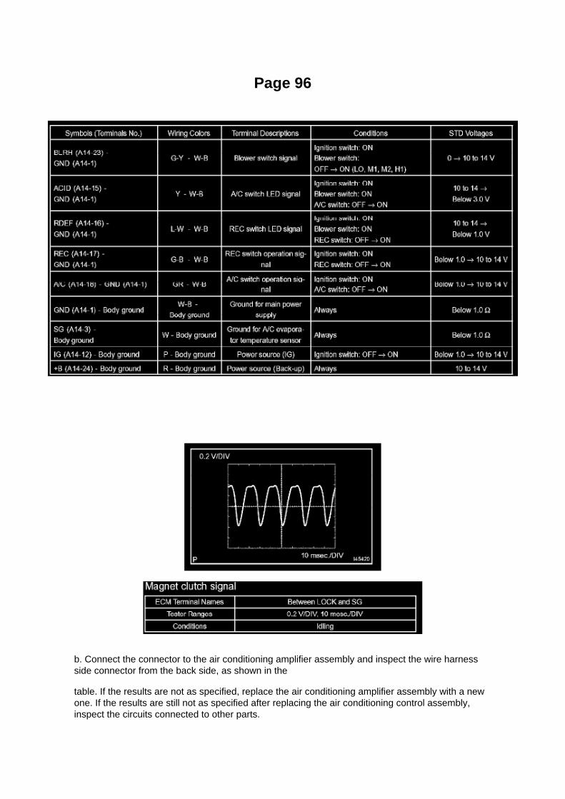
Page 96
b. Connect the connector to the air conditioning amplifier assembly and inspect the wire harnessside connector from the back side, as shown in the
table. If the results are not as specified, replace the air conditioning amplifier assembly with a newone. If the results are still not as specified after replacing the air conditioning control assembly,inspect the circuits connected to other parts.

WAVEFORM 1:
HINT: The wavelength becomes shorter as the engine rpm increases.

Page 1404


Page 2035
SFI System

Page 1372

c. Remove the bolt, nut, chain tensioner and gasket.

51. REMOVE CHAIN TENSIONER SLIPPER
a. Remove the bolt and tensioner slipper.
52. REMOVE CHAIN VIBRATION DAMPER NO.1
a. Remove the 2 bolts and vibration damper.
53. REMOVE CHAIN SUB-ASSEMBLY
54. REMOVE CRANKSHAFT TIMING GEAR OR SPROCKET
a. Remove the crankshaft timing gear from the crankshaft.
55. REMOVE CHAIN VIBRATION DAMPER NO.2

Page 1594

Terminals Of ECM / Pinouts Part 3

Page 2710

He - Wi

Page 1992

Step 1 - 2

INSPECTION PROCEDURE
Check CAN Main Bus Line For Disconnection
CHECK CAN MAIN BUS LINE FOR DISCONNECTION
CIRCUIT DESCRIPTION
The CAN main bus line and DLC3 sub bus line may have a disconnection when the resistancebetween terminals 6 (CANH) and 14 (CANL) of the DLC3 is more than 69 ohm.

Page 1201
3. NOTE FOR USING JACK AND SAFETY STAND
a. Work in a flat area using wheel chocks at all times. b. Use a safety stand with a rubberattachment. c. Apply the jack and rigid rack to the specified location on the vehicle. d. When jackingup the front wheels, release the parking brake and place wheel chocks only behind the rearwheels. When jacking up the rear

wheels, place wheel chocks only in front of the front wheels.
e. The jack should not be used without the rigid rack. f.
When jacking up only the front wheels or only the rear wheels, place wheel chocks on both sides ofthe wheels touching the ground.
g. When lowering the vehicle with its front wheels jacked up, release the parking brake and placewheel chocks only in front of the rear wheels.
When lowering a vehicle with its rear wheels jacked up, place wheel chocks only behind the frontwheels.
4. NOTE FOR USING SWING ARM TYPE LIFT
a. Follow safety procedures outlined in its instruction manual. b. Use a swing arm equipped with arubber attachment. c. Set in the vehicle so as to make its center of gravity as close as possible tothe center of the lift. (L becomes short.) d. Place the vehicle horizontally by adjusting the height ofthe cradle, and match the groove of the cradle and the safety stand support location
accurately.
e. Be sure to lock the swing arms before lifting and during work (if equipped with arm locks). f.
Lift the vehicle up off the ground. Stand at a safe distance and shake the vehicle to check itsstability.

Page 1576
Engine Control Module: Technical Service Bulletins Engine Controls - Entering VIN WhenReplacing PCM/ECM
ENGINE EG045-04
Title: ENTERING VIN DURING ECM (PCM) REPLACEMENT AND/OR DTC P0630
Models: All '04 - '06 Models
October 14, 2004
TSB REVISION NOTICE:
^ June 3, 2005: Content has been updated to include 2004 and 2006 model year vehicles.Highlander HV has been added to step 4 of the VIN Write Procedure. Step 3 of the VIN ReadProcedure has been clarified to include Prius and Highlander HV vehicles.
^ January 24, 2005: Step 4 has been clarified to include Prius vehicles. Previous versions of thisTSB should be discarded.
Introduction
All 2005 and subsequent model year Toyota and Scion vehicles have the VIN (VehicleIdentification Number) stored in the Electronic Control Module (ECM) (SAE term: PowertrainControl Module/PCM) non-volatile memory. The VIN is accessible on the data stream using theToyota Diagnostic Tester and can also be written to a new ECM (PCM) using a VIN Read/Write"utility.
Service ECMs (supply parts) are shipped without the VIN; therefore, as part of the ECM (PCM)replacement procedure, the VIN must be written to the replacement ECM (PCM) using theDiagnostic Tester utility function.
For most 2005 model year vehicles, failure to write the VIN to the ECM (PCM) will result in a M.I.L."ON" condition and set DTC P0630: VIN Not Programmed or Mismatch - ECM (PCM). The fivemodels listed below do not support DTC P0630.
^ Corolla
^ ECHO
^ Matrix
^ Scion xA
^ Scion xB
It is very important to remember to enter the VIN on these vehicles. Vehicles with missing VINs aresubject to failing some state and local vehicle emissions Inspection and Maintenance programs.

NOTE:
2004 model year vehicles which have been flash reprogrammed may contain updated 2005 modelyear OBD II logic. These vehicles will require VIN entry into the ECM (PCM) after reprogramming.
Applicable Vehicles
^ 2004 model year vehicles that have been flash reprogrammed.
^ All 2005 - 2006 model year vehicles.
Warranty Information

Page 218
Engine Control Module: Locations
Instrument Panel

Page 1049
How to Read Ground Points

HOW TO READ GROUND POINTS
The ground points circuit diagram shows the connections from all major parts to the respectiveground points. When troubleshooting a faulty ground point, checking the system circuits which usea common ground may help you identify the problem ground quickly. The relationship betweenground points(EA, IB and IC is shown) can also be checked this way.
How to Read Power Source
HOW TO READ POWER SOURCE

Page 1500

COMPONENTS

REPLACEMENT
1. DISCONNECT CABLE FROM NEGATIVE BATTERY TERMINAL 2. REMOVE ENGINE UNDERCOVER SUB-ASSEMBLY NO.1 (PRE RUNNER AND 4WD TYPE)
a. Remove the 4 bolts, then remove the engine under cover No.1.
3. DRAIN ENGINE COOLANT
4. REMOVE RADIATOR SUPPORT TO FRAME SEAL LH
a. Disengage the 9 clips, then remove the radiator support to frame seal LH.
5. REMOVE FAN SHROUD

Page 1536
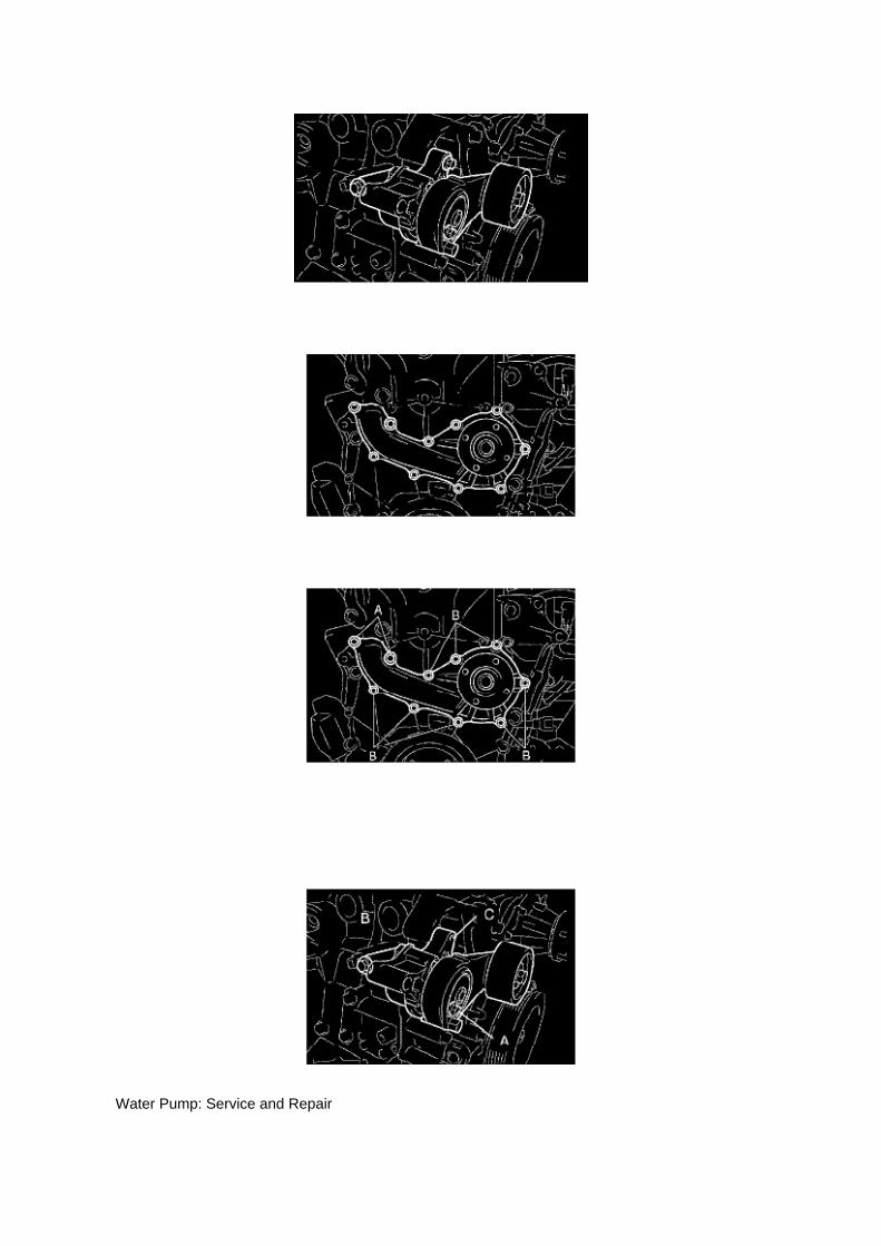
Water Pump: Service and Repair
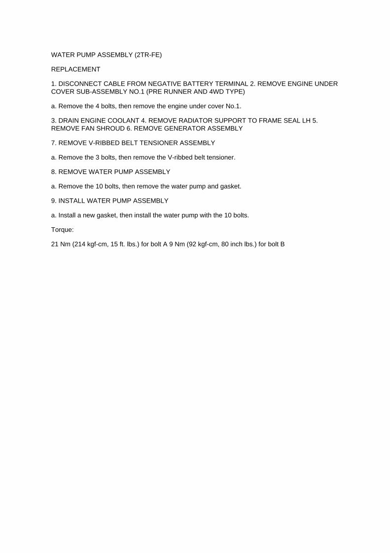
WATER PUMP ASSEMBLY (2TR-FE)
REPLACEMENT
1. DISCONNECT CABLE FROM NEGATIVE BATTERY TERMINAL 2. REMOVE ENGINE UNDERCOVER SUB-ASSEMBLY NO.1 (PRE RUNNER AND 4WD TYPE)
a. Remove the 4 bolts, then remove the engine under cover No.1.
3. DRAIN ENGINE COOLANT 4. REMOVE RADIATOR SUPPORT TO FRAME SEAL LH 5.REMOVE FAN SHROUD 6. REMOVE GENERATOR ASSEMBLY
7. REMOVE V-RIBBED BELT TENSIONER ASSEMBLY
a. Remove the 3 bolts, then remove the V-ribbed belt tensioner.
8. REMOVE WATER PUMP ASSEMBLY
a. Remove the 10 bolts, then remove the water pump and gasket.
9. INSTALL WATER PUMP ASSEMBLY
a. Install a new gasket, then install the water pump with the 10 bolts.
Torque:
21 Nm (214 kgf-cm, 15 ft. lbs.) for bolt A 9 Nm (92 kgf-cm, 80 inch lbs.) for bolt B

Page 1177

Wheel Bearing: Service and Repair
REAR AXLE SHAFT LH

Page 1319

12. INSTALL CLUTCH COVER ASSEMBLY (MANUAL TRANSMISSION) 13. INSTALL MANUALTRANSMISSION UNIT ASSEMBLY 14. INSTALL AUTOMATIC TRANSMISSION ASSEMBLY 15.

CHECK FOR ENGINE OIL LEAKAGE

Page 144
I: Indicates a wiring Splice Point (Codes are "E" for the Engine Room, "I" for the Instrument Panel,and "B" for the Body).
The Location of splice Point I5 is indicated by the shaded section.
J: Indicates a shielded cable.
K: Indicates the pin number of the connector. The numbering system is different for female andmale connectors.
L: Indicates a ground point.
The first letter of the code for each ground point(s) indicates the component's location, e.g, "E" forthe Engine Compartment, "I" for the Instrument Panel and Surrounding area, and "B" for the Body

and Surrounding area.
N: Explains the system outline.
SYSTEM OUTLINE
Current is applied at all times through the STOP fuse to TERMINAL 2 of the stop light SW. Whenthe ignition SW is turned on, current flows from the GAUGE fuse to TERMINAL 8 of the light failuresensor, and also flows through the rear lights warning light to TERMINAL 4 of the light failuresensor.
STOP LIGHT DISCONNECTION WARNING When the ignition SW is turned on and the brakepedal is pressed (Stop light SW on), if the stop light circuit is open, the current flowing fromTERMINAL 7 of the light failure sensor to TERMINALS 1, 2 changes, so the light failure sensordetects the disconnection and the warning circuit of the light failure sensor is activated.
As a result, the current flows from TERMINAL 4 of the light failure sensor to TERMINAL 11 toGROUND and turns the rear lights warning light on. By pressing the brake pedal, the currentflowing to TERMINAL 8 of the light failure sensor keeps the warning circuit on and holds thewarning light on until the ignition SW is turned off.

Page 1725
SFI System
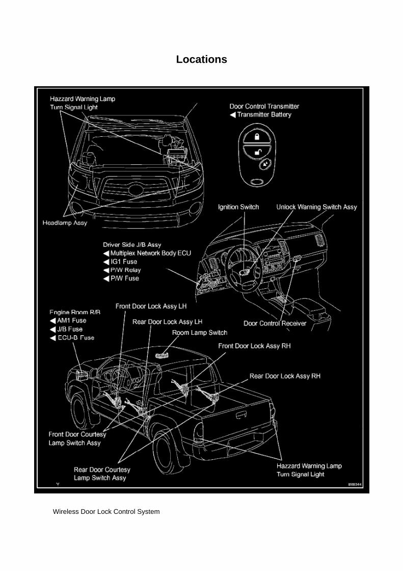
Locations
Wireless Door Lock Control System

Page 148

The "Current Flow Chart", describes which parts each power source (fuses, fusible links, and circuitbreakers) transmits current to. In the Power Source circuit diagram, the conditions when batterypower is supplied to each system are explained. Since all System Circuit diagrams start from thepower source, the power source system must be fully understood.
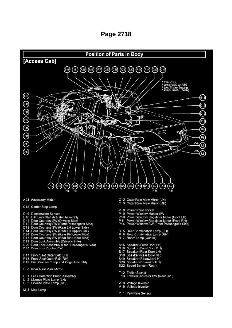
Page 2718

Ac - Ya

Page 1918
(Sample ) Supplemental Restraint System check sheet
Symptom Confirmation and Diagnostic Trouble Code
SYMPTOM CONFIRMATION AND DIAGNOSTIC TROUBLE CODE
HINT:
The diagnostic system in the TOYOTA TACOMA has various functions. -
The first function is the Diagnostic Trouble Code (DTC) check. A DTC is a code stored in the ECUmemory whenever a malfunction in the signal circuits to the ECU occurs. In a DTC check, aprevious malfunction's DTC can be checked by a technician during troubleshooting.
- Another function is the Input Signal Check, which checks if the signals from various switches aresent to the ECU correctly. By using these functions, the problem areas can be narrowed down andtroubleshooting is more effective. Diagnostic functions are incorporated in the above systems in theTOYOTA TACOMA:
- In the DTC check, it is very important to determine whether the problem indicated by the DTC is:1) still occurring, or 2) occurred in the past but has since returned to normal. In addition, the DTCshould be compared to the problem symptom to see if they are related. For this reason, DTCsshould be checked before and after confirmation of symptoms (i.e., whether or not problemsymptoms exist) to determine current system conditions, as shown in the flowchart. Never skip theDTC check. Failing to check DTCs may, depending on the case, result in unnecessarytroubleshooting for systems operating

A/T - Torque Converter Bolt Installation Precautions
Flex Plate: Specifications
Driveplate ............................................................................................................................................................................ 74 Nm (755 kgf-cm, 55 ft. lbs.)

Page 2203


Page 1677


Page 198
4. Attach the Authorized Vehicle Modification Label.

Modifications to ECU calibrations MUST be recorded and properly displayed on the vehicle usingthe Authorized Modification Label.
Techstream Preparation
Selecting the TIS Techstream VIM or the Mongoose MFC VIM.
Techstream software requires a VIM selection before you can use the Mongoose MFC VIM.
If using TIS Techstream no changes are needed.
Perform the following:
1. Select Setup from the Techstream Main Menu screen.
2. Select VIM Select from the Setup drop down menu.
3. Select the correct Interface Setup from the drop down list.
^ If using Techstream Lite select Mongoose MFC.
NOTE

Page 2776
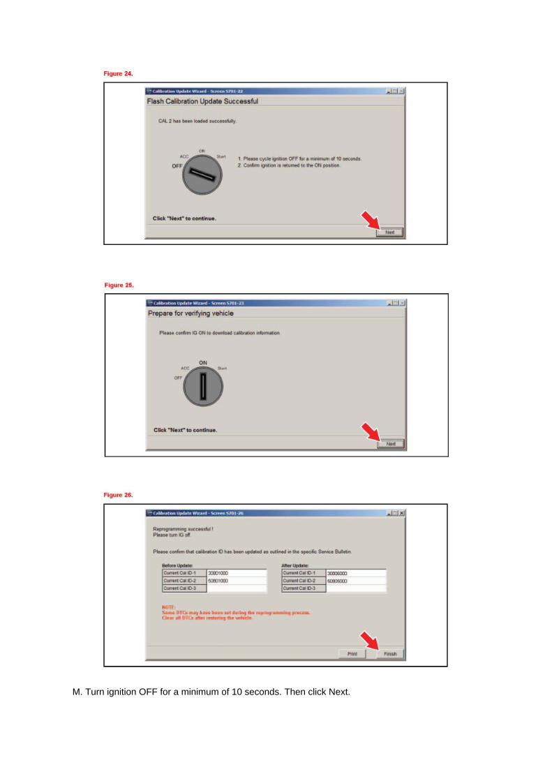
M. Turn ignition OFF for a minimum of 10 seconds. Then click Next.

N. Turn ignition to the ON position. Then click Next.
0. Confirm all calibrations were updated as specified in the service bulletin. Then click Finish.

Page 1952

Step 3
INSPECTION PROCEDURE
Check CAN Bus Lines For Short Circuit
CHECK CAN BUS LINES FOR SHORT CIRCUIT
CIRCUIT DESCRIPTION
The CAN bus lines are considered to be shorted when the resistance between terminals 6 (CANH)and 14 (CANL) of the DLC3 is below 54 ohm.

Page 2005
Step 1 - 2

Electrical - SRS And HV Wiring Repairs
Battery System, Hybrid Drive: Technical Service Bulletins Electrical - SRS And HV Wiring Repairs
TITLE: SRS & HV WIRING REPAIRS
SECTION: ELECTRICAL
BULLETIN # 156
MODELS: ALL TOYOTA LEXUS and SCION MODELS
DATE: AUGUST 2007
There are no approved repairs to Supplemental Restraint System (SRS) or High Voltage (HV)wiring or connectors. SRS system wiring and connectors are color coded yellow and HV wiring isorange however vehicle-specific wiring diagrams are the best source for identifying wiring in thesecircuits. Wiring diagrams are available through the Technical Information System (TIS)www.techinfo.toyota.com.
If SRS or HV wiring or connectors are suspected of damage they should be inspected thoroughly.Damaged wiring and/or connectors require replacement of the affected harness. Follow allprecautions and procedures outlined in model-specific repair manuals for replacing SRS wiring orcomponents. Only Certified Hybrid Service Technicians are qualified to replace HV system wiringand components.

Service and Repair

Shift Cable: Service and Repair

TRANSMISSION CONTROL CABLE ASSY (ATM)
REPLACEMENT
1. REMOVE SHIFT LEVER KNOB SUB-ASSY 2. REMOVE CONSOLE UPPER REAR PANELSUB-ASSY 3. REMOVE CONSOLE BOX ASSY REAR 4. REMOVE INSTRUMENT PANEL CUPHOLDER TRAY 5. REMOVE CONSOLE BOX FRONT 6. REMOVE VOLTAGE INVERTER ASSY(W/ VOLTAGE INVERTER)
7. REMOVE TRANSMISSION CONTROL CABLE ASSY
a. Disconnect the transmission control cable assy from the shift lever assy. b. Remove the clip anddisconnect the transmission control cable.
c. Remove the 2 nuts and disconnect the transmission control cable assy from the body.
d. Remove the nut and disconnect the transmission control cable assy from the body.
e. Remove the clip and transmission control cable bracket. f.
Remove the nut and transmission control cable assy.
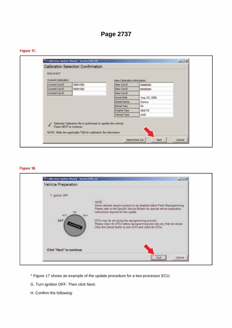
Page 2737
^ Figure 17 shows an example of the update procedure for a two-processor ECU.
G. Turn ignition OFF. Then click Next.
H. Confirm the following:

^ Ignition is ON and engine is OFF or "READY" OFF (hybrid vehicles).
^ Hood is open.
^ All accessories are OFF.
^ Battery voltage is above 11.4 volts.
NOTICE
Verify the vehicle is connected to a battery charger before continuing - If battery voltage falls below11.4 volts, ECU damage may occur.

Page 2947

16. Install the NEW clutch pedal sub-assembly.

A. Install the clutch pedal onto the clutch support with the bolt and nut.
Torque: 34 N.m (347 kgf.cm, 25 ft.lbf)
HINT
Install the bolt from the left side of the vehicle.
B. Apply MP grease to the clutch pedal sub-assembly where the clevis sub-assembly contacts theclutch pedal.
NOTE:
Failure to apply grease to the clevis and clutch pedal sub-assemblies could cause the noise toreturn.
C. Tighten the bolt to the instrument panel reinforcement assembly.
Torque: 8 N.m (82 kgf.cm, 6 ft.lbf)
17. Install the turnover (compression) spring.
A. Apply MP grease to the contact surface of the spring holder, clutch pedal, and spring.
B. Install the spring onto the clutch pedal and spring holder.

Page 701

2. DISCONNECT THE NEGATIVE BATTERY CABLE
3. LOCATE THE BENCH SEAT FLOOR WIRE HARNESS
(c) Slide the bench seat to the rearmost position.
(d) Locate the floor wire harness and connector under the seat on the driver's side, closest to thefront edge of the seat cushion.
4. INSTALL THE WIRE SEAT JUMPER
NOTE:
DO NOT install the wire seat jumper on a vehicle which is NOT on the VIN list!
(a) Push the lock tab on the connector and pull to remove the female portion of the connector.
(b) Before installing the wire seat jumper to the vehicle, attach the Warning Label (shown in theillustration) onto the corrugated tubing, next to the
Part Number Label.
NOTE:
^ Attach the Warning Label in a similar manner to the Part Number Label, making sure not coverthe information printed on it.
^ DO NOT remove the Part Number Label or cover it with the Warning Label.
^ A small supply of labels were sent with the Service Manager Package. Additional labels can beordered from the Material Distribution Center (p/n 00410-92017).

Page 1508

3. UNCAULK CORE PLATE
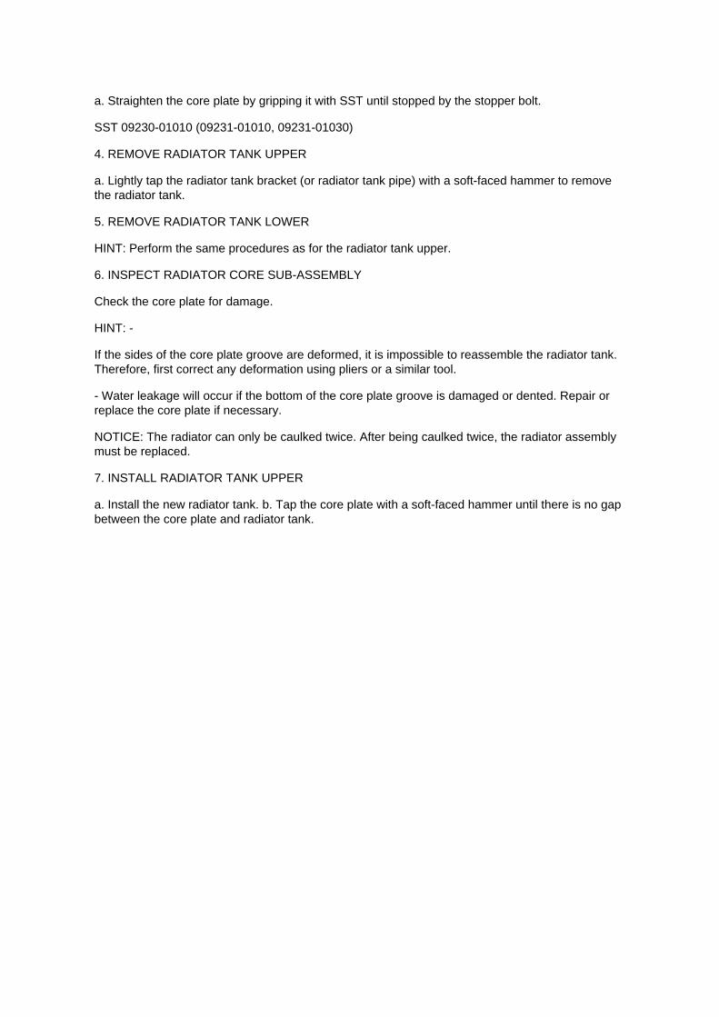
a. Straighten the core plate by gripping it with SST until stopped by the stopper bolt.
SST 09230-01010 (09231-01010, 09231-01030)
4. REMOVE RADIATOR TANK UPPER
a. Lightly tap the radiator tank bracket (or radiator tank pipe) with a soft-faced hammer to removethe radiator tank.
5. REMOVE RADIATOR TANK LOWER
HINT: Perform the same procedures as for the radiator tank upper.
6. INSPECT RADIATOR CORE SUB-ASSEMBLY
Check the core plate for damage.
HINT: -
If the sides of the core plate groove are deformed, it is impossible to reassemble the radiator tank.Therefore, first correct any deformation using pliers or a similar tool.
- Water leakage will occur if the bottom of the core plate groove is damaged or dented. Repair orreplace the core plate if necessary.
NOTICE: The radiator can only be caulked twice. After being caulked twice, the radiator assemblymust be replaced.
7. INSTALL RADIATOR TANK UPPER
a. Install the new radiator tank. b. Tap the core plate with a soft-faced hammer until there is no gapbetween the core plate and radiator tank.

Page 344
ABS With EBD & BA & TRAC & VSC SYSTEM

Page 2808
Fluid - A/T: Technical Service Bulletins A/T - Fluid Level Inspection/Temperature Ranges
T-SB-0129-08
July 9, 2008
Automatic Transmission/Transaxle Fluid Level Inspection Temperature Ranges

Service Category Drivetrain
Section Automatic Transmission/Transaxle
Market USA
Applicability
Introduction
For vehicles equipped with a transmission requiring the use of the overflow type automatictransmission fluid (ATF) inspection process the ATF must be within a specific temperature rangefor accurate fluid level inspection. Inspecting the ATF outside of the specified temperature rangemay result in incorrect ATF fluid levels and could lead to shift quality M.l.L. "ON" and/ortransmission damage issues. Please see the information in this bulletin for updated ATF levelinspection temperature ranges.
HINT
For additional information including animations and video illustrations, please see the TechnicalTraining course E076: "Toyota ATF Level Inspection".
NOTE
Please see TSB No.TC010-07, "World Standard Automatic Transmission Fluid"; for important tipswhen working with ATF WS.
Warranty Information
Parts Information

Locations
SFI System

Recall - Floor Mat/Accelerator Pedal Interferance
Technical Service Bulletin # SSC90L Date: 091001

Locations
SFI System

M/T - Clutch Pedal Squeaking Noise
Technical Service Bulletin # TC004-06 Date: 060614
M/T - Clutch Pedal Squeaking Noise
TRANSMISSION & CLUTCH TC004-06
June 14, 2006
Title: CLUTCH PEDAL SQUEAK NOISE
Models: '05 - '06 Tacoma
Introduction
Some customers may complain about a "squeak" or "creak" noise when depressing or releasingthe clutch pedal. The clutch master cylinder clevis assembly has been improved to eliminate thiscondition.
Applicable Vehicles: ^
2005 - 2006 model year Tacoma vehicles equipped with manual transmission and producedBEFORE the Production Change Effective VIN shown below.
Production Change Information

Parts Information
Required Tools & Material
Warranty Information
Applicable Warranty:
This repair is covered under the Toyota Comprehensive Warranty. This warranty is in effect for 36months or 36,000 miles, whichever occurs first, from the vehicle's in-service date.
* Warranty application is limited to correction of a problem based upon a customer's specificcomplaint.

Page 784
CAN Communication System

Page 1595

Terminals Of ECM / Pinouts Part 4

Oscilloscope Waveforms

Page 2631
Knock Sensor: Testing and Inspection
INSPECT KNOCK SENSOR
a. Check the resistance.
1. Using an ohmmeter, measure the resistance between the terminals.
If the result is not as specified, replace the knock sensor.

Page 988

Fluid - Differential: Fluid Type Specifications

OIL TYPE w/o Limited Slip :.....................................................................................................................................................Hypoid gear oil API GL-5 OIL TYPE w/ Limited Slip :............................................................................................................................... Hypoid gear oil forlimited slip API GL-5
RECOMMENDED OIL VISCOSITY: Front: ............................................................................................................................................................................................................... SAE 75W-90 Rear:Above -18°C (0°F): .................................................................................................................................................................................................. SAE 90 Below -18°C (0°F): ............................................................................................................................................................................. SAE 80W or80W-90

Page 1839
SFI System

Page 2561

- Check that the fuel tube joint is securely inserted to the end.

- Check that the tube joint clips are on the collar of the fuel tube joint.
- After installing the tube joint clip, check that the fuel tank main tube and return tube can be pulledout.
15. INSTALL FUEL TANK ASSEMBLY
a. Set the fuel tank assembly onto the mission jack. b. Connect the fuel tank vent hose.
1. Align the fuel tank vent connector with the pipe, then push in the fuel tank vent connector untilthe retainer makes a click sound to connect
the fuel tank vent hose to the fuel suction plate.
NOTE: -
Check that there are no scratches or foreign objects around the connected part of the fuel tank ventconnector and plug before performing this work.
- After connecting the fuel tank vent hose, check that the fuel tank vent hose is securely connectedby pulling the quick connector.
c. Connect the fuel pump connector. d. Connect the fuel tank to filler pipe hose. e. Install the 2 fueltank bands.
1. Install the 2 fuel tank bands with the 2 pins and 2 clips. 2. Install the 2 fuel tank bands with the 2bolts.
Torque: 62 N.m (632 kgf.cm, 46 ft.lbf)
f. Connect the fuel tank breather tube. 1. Align the fuel tube connector with the pipe, then push thefuel tube connector in until the retainer makes a click sound to connect the fuel
tank vent breather tube.
NOTE: -
Check that there are no scratches or foreign objects around the connected part of the fuel tubeconnector and pipe before performing this work.
- After connecting the fuel tank breather tube, check that the fuel pump tube is securely connectedby pulling the fuel tube connector and pipe.
2. Install the checker onto the pipe.
g. Tighten the clamp bolt.
16. CONNECT FUEL TANK MAIN TUBE AND FUEL TANK RETURN TUBE
a. Connect the fuel tank main tube and return tube.
1. Align the fuel tube connector with the pipe, then push the fuel tube connector in until the retainermakes a click sound to connect the fuel
tank main tube and return tube.

Page 700

NOTE:

Make sure to view the male end of the connector in the proper orientation as shown in theillustration.
(b) If the connector wires are correctly installed, installation of the wire seat jumper is NOTREQUIRED, proceed to section "VI. SSC
COMPLETION LABEL INSTALLATION".
(c) If the connector wires were NOT correctly installed, proceed to step "B. INSTALL THE WIRESEAT JUMPER".
B. INSTALL THE WIRE SEAT JUMPER
1. RECORD THE RADIO STATION PRESETS

Page 1676
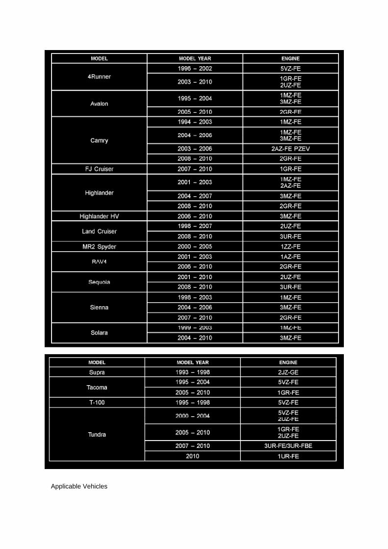
Applicable Vehicles

Page 1112

Glossary Of Terms And Sysmbols Part 1

Page 2767
C. Choose desired ECU group(s) in the Health Check dialog box.
D. Click Next.
E. Click Continue to view Health Check results.

F. Available calibration updates are indicated by a link in the Cal. Update? column. Click the link toaccess the appropriate service bulletin on TIS.
NOTE
^ Note any DTCs stored in Systems that will be flash reprogrammed.
^ Clicking the link will automatically launch TIS and perform a calibration search.
G. Log in to TIS. (If already logged in skip this step.)
H. To review the TSB and access the calibration file click the service bulletin link in the DocumentTitle column of the Calibration Search Result
portlet.

Page 2431
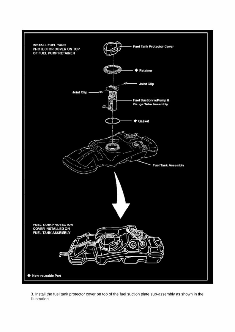
3. Install the fuel tank protector cover on top of the fuel suction plate sub-assembly as shown in theillustration.

Page 3242

Wiring Diagram

Page 322
ABS With EBD System

Page 1443
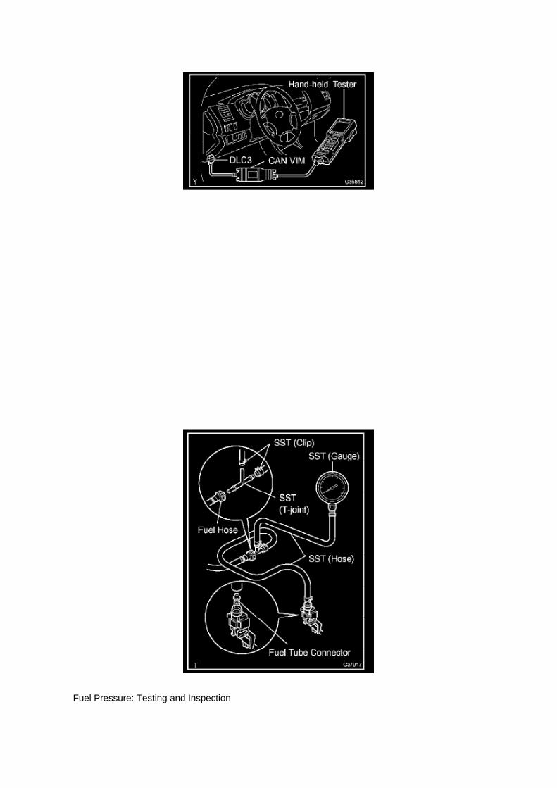
Fuel Pressure: Testing and Inspection

ON-VEHICLE INSPECTION
1. CHECK FUEL PUMP
a. Connect the hand-held tester to the DLC3. b. Turn the ignition switch to ON.
NOTE: Do not start the engine.
c. Turn the hand-held tester ON. d. Select the following menu items: DIAGNOSIS / ENHANCEDOBD II / ACTIVE TEST / FUEL PUMP / SPD. e. Check the fuel operation by operating it with thehand-held tester.
If the fuel pump does not operate, replace the fuel pump.
2. CHECK FUEL PRESSURE
a. Discharge the fuel system pressure. b. Using a voltmeter, measure the battery voltage.
Standard: 9.0 to 14 V
c. Disconnect the cable from the negative battery terminal. d. Remove the fuel pipe clamp. e.Disconnect the fuel hose.
f. Install SST into the vehicle.
SST 09268- 41048 (09268- 41500, 90467- 13001, 95336- 08070), 09268- 45014 (09268- 41200,09268-41220, 09268-41250, 90467-13001)

Page 180

Relay Box: Electrical Diagrams

Engine Room R/B Junction Connector Inner Circuit

Page 730

2. VERIFY THE REPAIR

(Test # 1)
(a) Move the bench seat to the rearmost position.
(b) Buckle the driver's seat belt.
(c) Confirm that the scan tool displays the data shown below and in the illustration.
^ "D SEAT POSITIOBKWARD" (Driver's seat is in the backward position).
^ "D BUCKLE SW SET"
(Driver's seat belt buckle switch is set/buckled).
(Test # 2)
(a) Leave the bench seat in the rearmost position.
(b) Unbuckle the driver's seat belt.
(c) Confirm that the scan tool displays the data shown below and in the illustration.
^ "D SEAT POSITIOBKWARD"

Page 1237
Variable Valve Timing Actuator: Testing and Inspection On-Vehicle Inspection
INSPECT CAMSHAFT TIMING OIL CONTROL VALVE ASSEMBLY
a. Check the operation.
1. Connect the hand-held tester to the DLC3. 2. Turn the ignition switch to ON. 3. Turn thehand-held tester ON. 4. Start the engine and warm it up. 5. Select the following menu items:DIAGNOSIS / ENHANCED OBD II / ACTIVE TEST / VVT CTRL B1.
6. Operate the OCV using the hand-held tester, then check the engine speed.
If the operation is not as specified, check the camshaft timing oil control valve, wire harness andECM.

Locations
A/C - Ge

Page 332
ABS With EBD System

Page 197
^ Engine Control Module (ECM)
^ Transmission Control Module (TCM)
^ Or any other Toyota specific control unit
Warranty Information
Parts Information
Required Tools & Equipment
NOTE
Additional SSTs may be ordered by calling 1-800-933-8335.
Process Overview
Techstream ECU flash reprogramming is a 4-step process:

1. Verify the vehicle's applicability for recalibration and locate desired calibration file by performingthe Techstream Health Check function.
NOTE
Techstream will automatically search TIS for the appropriate service bulletin using the currentCalibration ID from the vehicle. Calibration file links can be found embedded in the correspondingservice bulletin.
2. Connect the GR8 Battery Diagnostic Station using "Power Supply Mode" only.
The GR8 Battery Diagnostic Station includes a Power Supply Mode to help maintain batteryvoltage at 13.5 volts during ECU reprogramming.
ECU damage may occur if the correct battery charger mode setting is NOT used.
3. Locate appropriate calibration ID and reprogram the vehicle ECU with Techstream.
Techstream uses the Calibration Update Wizard (CUW) application to open calibration files andfacilitate the ECU flash reprogramming process.

Page 1503

7. INSTALL RADIATOR ASSEMBLY

a. Install the radiator with the 4 bolts.
Torque: 18 Nm (184 kgf-cm, 13 ft. lbs.)
b. Connect the oil cooler inlet and outlet hoses. (AUTOMATIC TRANSMISSION)
c. Connect the radiator hose NO.2.
d. Connect the radiator hose inlet.
8. INSTALL FAN SHROUD
a. Install the fan pulley.

Page 1133

[B] : For Waterproof Type Connector
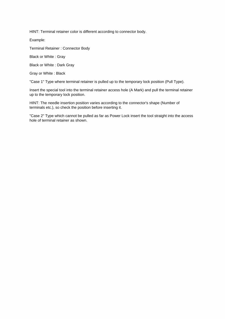
HINT: Terminal retainer color is different according to connector body.
Example:
Terminal Retainer : Connector Body
Black or White : Gray
Black or White : Dark Gray
Gray or White : Black
"Case 1" Type where terminal retainer is pulled up to the temporary lock position (Pull Type).
Insert the special tool into the terminal retainer access hole (A Mark) and pull the terminal retainerup to the temporary lock position.
HINT: The needle insertion position varies according to the connector's shape (Number ofterminals etc.), so check the position before inserting it.
"Case 2" Type which cannot be pulled as far as Power Lock insert the tool straight into the accesshole of terminal retainer as shown.

Page 2479
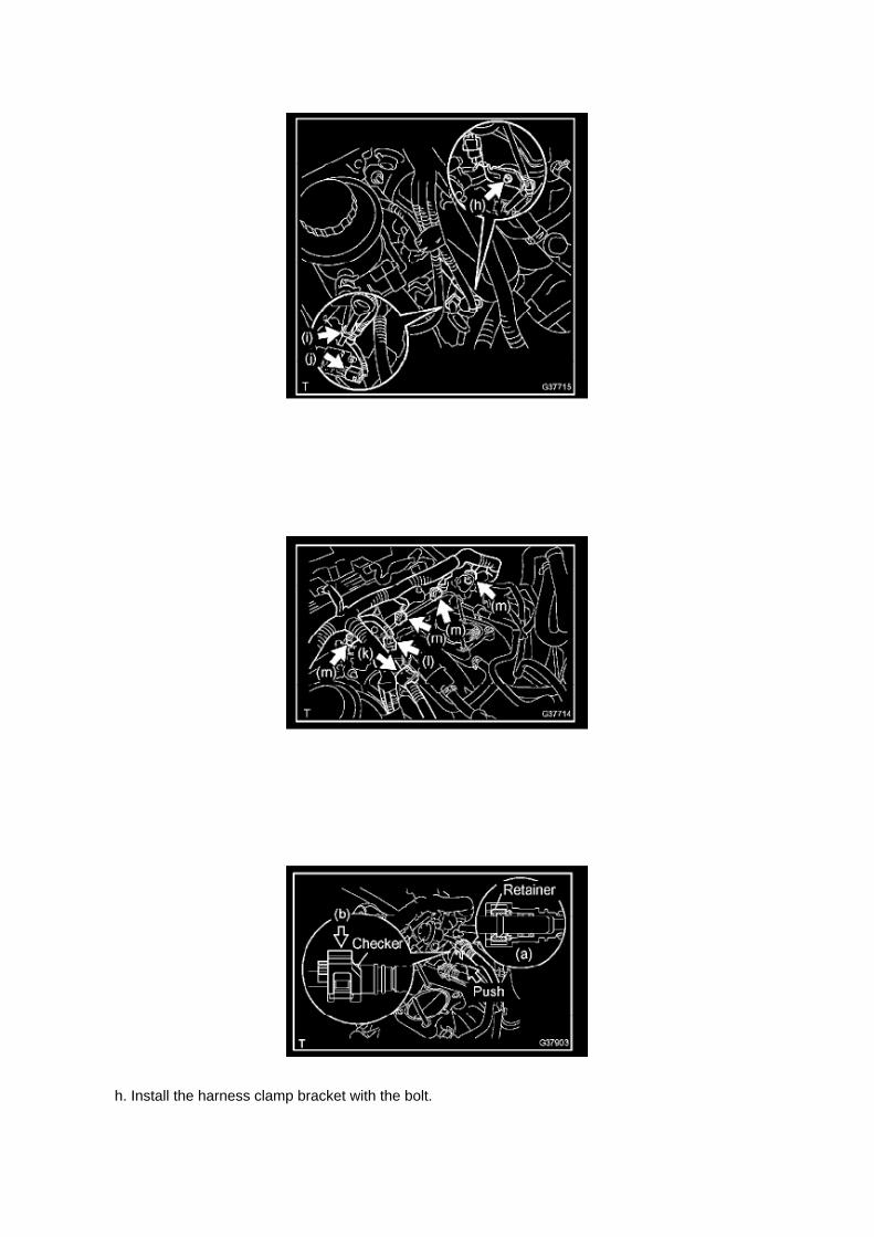
h. Install the harness clamp bracket with the bolt.

Torque: 8.2 N.m (84 kgf.cm, 73 in.lbf)
i. Connect the wire harness clamp.
j. Connect the compressor magnetic clutch connector. (w/ AIR CONDITIONING)
k. Connect the engine wire harness clamp. l.
Connect the VSV connector.
m. Connect the 4 injector connectors.
14. INSTALL FUEL PRESSURE PULSATION DAMPER ASSEMBLY 15. CONNECT FUEL HOSE
a. Align the fuel hose connector with the pipe stem, and insert the fuel hose until the retainermakes a click sound. b. Push down the checker of the fuel hose.
NOTE: -
Check that there are no scratches or foreign objects around the disconnected parts of the fuel hoseconnector and pipe before performing this work.
- After connecting the fuel hose, check that the fuel hose is securely connected by pulling the fuelhose connector and pipe.
c. Push the fuel hose down until the checker of the fuel hose makes a "click" sound.

Page 2013
Step 1 - 2

Page 2142

Flash reprogramming may be accomplished using one of the following methods: -

Toyota/Lexus factory scantool
- Vetronix Mastertech
- J2534 Compatible Vehicle Interface (Toyota validated and approved)
REPROGRAMMING WITH SCANTOOL
Toyota/Scion/Lexus ECMs can be reprogrammed using either the Toyota/Lexus factory scantool,or the Vetronix Mastertech scantool. The ECM reprogramming function is only available with theauthentic Toyota factory scantool software which runs on either of the above mentioned scantools.Scantool software version requirements are specified in applicable Technical Service Bulletin(TSB)/Service Communication (SC) documents.
The Toyota/Lexus factory scantool and/or authentic factory software program cards can bepurchased through the official Toyota and Lexus Special Service Tool provider, SPX Corp. Toorder, call (800) 933-8335 and request either: -
P/N 01001271 for the Toyota/Lexus factory scantool including factory software program card
- P/N 01002593-005 for the "stand alone" program card
Program cards are provided with the latest production version software available at time ofpurchase.
Vehicle recalibration using a scantool requires use of the following: -
Personal Computer running a Microsoft Windows 2000 or Windows XP operating system
- Toyota Diagnostic Tester or Vetronix Mastertech Scantool with Toyota factory software
- Toyota/Lexus factory scantool program card
- PC Interface Cable (P/N 01001090) to transfer data from PC to scantool
- Calibration CD (00456-REPRG-001)
REPROGRAMMING WITH J2534 INTERFACE
Toyota/Scion/Lexus ECMs that can be reprogrammed with a scantool can also be reprogrammedusing a Toyota validated J2534-1 interface. Vehicle recalibration requires the use of the following: -
Toyota validated J2534 interface
- Toyota Calibration Update Wizard software (available on calibration CD)
- Personal Computer running Microsoft Windows 2000/XP or later operating system
- Calibration CD (00456-REPRG-001)
Toyota strongly recommends USING ONLY VALIDATED INTERFACE DEVICES that appear onthis list.
Validated J2534 Devices Toyota works closely with J2534 interface manufacturers to ensure thattheir hardware works safely and efficiently with their products. Every device listed on this page hasbeen thoroughly tested and validated on Toyota, Scion and Lexus vehicles.
It is important to understand that only the specific devices, firmware, DLLs and APIs listed herehave been tested by Toyota. Toyota does not recommend use of any other J2534 device, firmware,DLL or API that is not listed here. Changes to J2534 hardware/software is outside of Toyota's

control; in some cases, changes made to device hardware/software can negatively impactreprogramming performance. Toyota makes every effort to continue to work with J2534 interfacemanufacturers to ensure continued product compatibility as the respective products evolve.
Requirement for device:
Supplier Device Name Version (Firmware* / DLL* / API*)
Drew Technologies CarDAQ Plus (01.08.06 / 01.08.06 / 04.04)
Actia PassThru+ XS (02.01 / 02.01 / 04.04)
Vetronix Corporation ES6510 Flasher (06.12 / 04.23 / 04.04)
EASE Diagnostics Universal Reprogrammer (JPI1_11b / 1.3.0.13 / 04.04)
Snap-On Pass Thru Pro (02.01 / 02.01 / 04.04)
Blue Streak Electronics Inc. BSE-2534 Global Programmer (01.21 / 02.27 / 04.04)
* Original validated firmware/DLL versions may be superceded by the device manufacturer.Contact the device manufacturer if you are unable to find the versions listed above.
Support OS:
OS Name and Version: Windows 2000 SP2 or later Windows XP Pro SP1 or later
For more information about the J2534 devices listed above, contact the vendors. To reportcompatibility problems with listed hardware/software, please contact the device manufacturer.
For more information about Toyota vehicle reprogramming CDs or to report problems runningToyota's Calibration Update Wizard software, please

Page 1266

1. Discharge the fuel system pressure (step 2). 2. Disconnect the fuel tank main tube. 3. Drain thefuel remaining in the fuel tank main tube. 4. Cover the disconnected fuel tank main tube (fuel tube

joint and fuel tube connector) with a vinyl bag to prevent damage and the intrusion
of foreign objects.
b. Take the following precautions when installing the fuel injector.
1. Do not reuse the O-ring. 2. Do not damage a new O-ring when installing it onto the fuel injector.3. Before installing a new O-ring, apply gasoline or spindle oil.
NOTE: Do not use engine oil, gear oil or brake oil.
4. Install the fuel injector into the fuel delivery pipe and cylinder head as illustrated.
HINT: Apply gasoline or spindle oil to the contact surface of the fuel delivery pipe and fuel injectorbefore installing the fuel injector.
c. Take the following precautions when disconnecting the fuel tube connector.
HINT: The structure of the fuel tube connector is as shown in the illustration.
1. Check the fuel tube connector and pipe for dirt and mud before removing the fuel tubeconnector.
If dirty, wipe it with a shop rag.

Page 569

Crankshaft Position Sensor: Service and Repair
REPLACEMENT
1. DISCONNECT CABLE FROM NEGATIVE BATTERY TERMINAL 2. REMOVE ENGINE UNDERCOVER SUB-ASSEMBLY NO.1 (PRE RUNNER AND 4WD TYPE) 3. REMOVE FAN ANDGENERATOR BELT (W/ AIR CONDITIONING) 4. REMOVE COMPRESSOR AND MAGNETICCLUTCH (W/ AIR CONDITIONING) 5. REMOVE IDLE PULLEY ASSEMBLY W/BRACKET (W/ AIRCONDITIONING)
a. Remove the 5 bolts, then remove the idle pulley with bracket.
6. REMOVE CRANKSHAFT POSITION SENSOR
a. Disconnect the crankshaft position sensor connector and the 2 wire harness clamps.
b. Remove the bolt, then remove the crankshaft position sensor.
7. INSTALL CRANKSHAFT POSITION SENSOR

Page 2757
3. Use Data List and the graphing functions of the Snapshot feature to confirm the following dataparameters when the shudder occurs:
^ Vehicle Speed
^ Engine Speed
^ Lock Up
Shift Status
^ If Lock Up is "OFF" and vehicle has just shifted into 3rd or 4th gear when shudder/vibrationoccurs - This TSB applies - Go to step 4.

^ If shudder/vibration occurs in 2nd gear, or when Lock Up is "ON - This TSB does NOT apply.Continue diagnosis per Repair Manual.
4. Disconnect the battery for at least 10 minutes, and then test drive the vehicle again.Shudder/vibration should be eliminated.
^ If shudder/vibration is eliminated - Go to step 5.
^ If shudder/vibration is still present - This TSB does NOT apply. Continue diagnosis per RepairManual.

Page 2990

16. Install the NEW clutch pedal sub-assembly.

A. Install the clutch pedal onto the clutch support with the bolt and nut.
Torque: 34 N.m (347 kgf.cm, 25 ft.lbf)
HINT
Install the bolt from the left side of the vehicle.
B. Apply MP grease to the clutch pedal sub-assembly where the clevis sub-assembly contacts theclutch pedal.
NOTE:
Failure to apply grease to the clevis and clutch pedal sub-assemblies could cause the noise toreturn.
C. Tighten the bolt to the instrument panel reinforcement assembly.
Torque: 8 N.m (82 kgf.cm, 6 ft.lbf)
17. Install the turnover (compression) spring.
A. Apply MP grease to the contact surface of the spring holder, clutch pedal, and spring.
B. Install the spring onto the clutch pedal and spring holder.
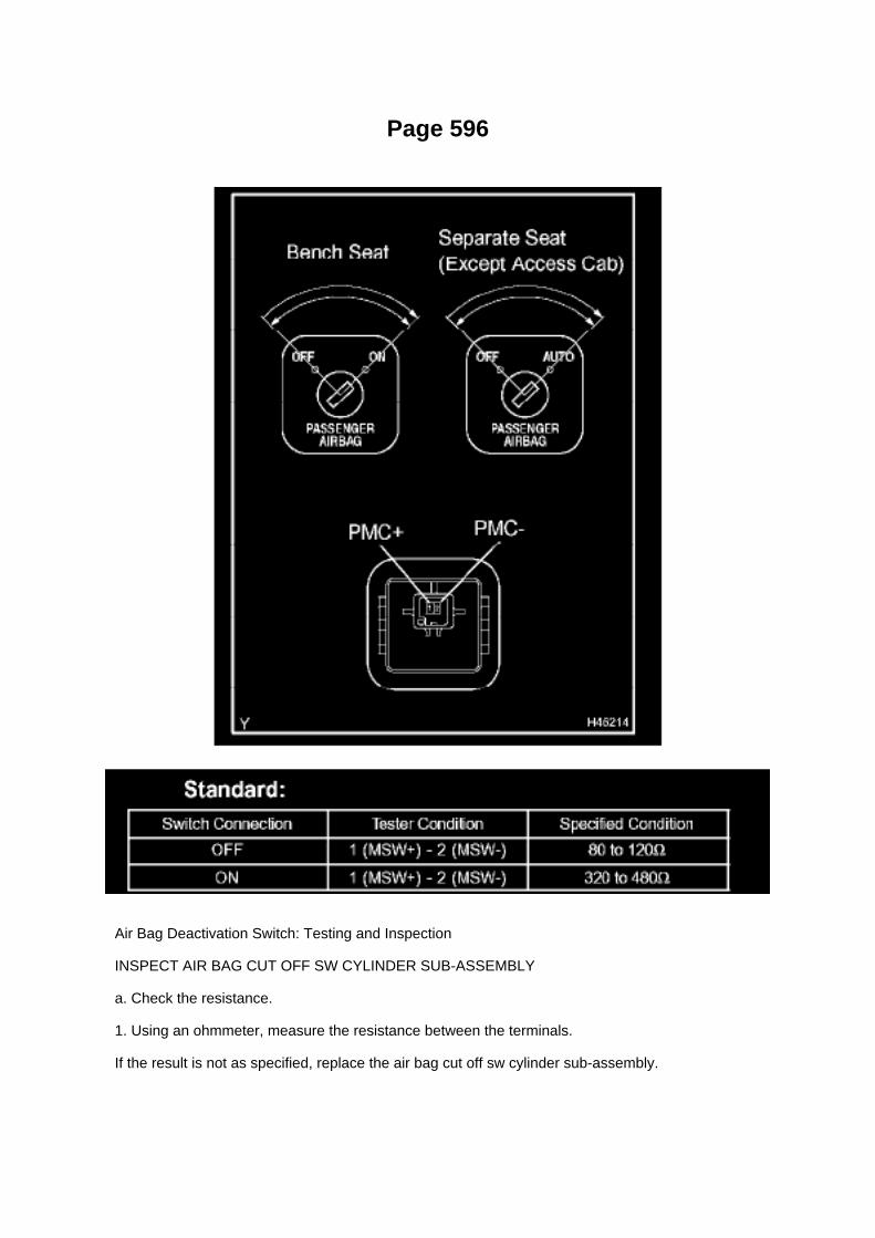
Page 596
Air Bag Deactivation Switch: Testing and Inspection
INSPECT AIR BAG CUT OFF SW CYLINDER SUB-ASSEMBLY
a. Check the resistance.
1. Using an ohmmeter, measure the resistance between the terminals.
If the result is not as specified, replace the air bag cut off sw cylinder sub-assembly.

Page 830

Wiper Switch: Testing and Inspection

INSPECT WINDSHIELD WIPER SWITCH ASSEMBLY
a. Check the resistance.
1. Measure the resistance and check the results in accordance with the value(s) in the table below.
Standard:
If the result is not as specified, replace the windshield wiper switch assembly.
b. Check the intermittent operation.
1. Connect the voltmeter positive terminal to terminal 3 (+1) of the E7 connector and the voltmeternegative terminal to terminal 2 (EW) of the
E11 connector.
2. Connect the battery positive (+) lead to terminal 2 (+B) of the E7 connector and the batterynegative (-) lead to terminals 2 (EW) of the E11
connector and 1 (+S) of the E7 connector.
3. Turn the wiper switch to the INT position. 4. Connect the battery positive (+) lead to terminal1(+S) of the E7 connector for 5 seconds.
5. Connect the battery negative lead to terminal 1 (+S) of the E7 connector. Operate theintermittent wiper relay and check the voltage between
terminals 3 (+1) of the E7 connector and 2 (EW) of the E11 connector.

Page 1917
2. Disconnect the ECU connector. Check the ground terminals (on the ECU side and wire harnessside) for evidence of bending, corrosion or
foreign material. Lastly check the contact pressure of the female terminals.
Customer Problem Analysis
CUSTOMER PROBLEM ANALYSIS
HINT:
- In troubleshooting, the problem symptoms must be confirmed accurately. Preconceptions shouldbe discarded in order to give an accurate judgement. To clearly understand what the problemsymptoms are, it is extremely important to ask the customer about the problem and the conditionsat the time it occurred.
- As much information as possible should be gathered for reference. Even past problems that seemunrelated may also help in some cases. In the Diagnostic Section, a customer problem analysistable is provided for each system.
- 5 items are important points in the problem analysis:
Important Points with Customer Problem Analysis -
What .......................................................................................................................................................................... Vehicle model, system name
- When .................................................................................................................................................................. Date, time, occurrence frequency
- Where ............................................................................................................................................................................................ Road conditions
- Under what conditions? ............................................................................................. Runningconditions, driving conditions, weather conditions

- How did it happen? ................................................................................................................................................................... Problem symptoms

W/ VSC
Brake Bleeding: Service and Repair W/ VSC
BRAKE FLUID (W/ VSC)
BLEEDING
NOTICE: -
Immediately wash off any brake fluid that comes into contact with any painted surfaces.
- Depressing the brake pedal with the reservoir cap removed will cause the fluid to spray.
HINT: -
If any work is done on the brake system or if air in the brake lines is suspected, bleed the air fromthe system.
- When bleeding, maintain the amount of fluid in the reservoir between the Min. and Max. lines.
1. FILL RESERVOIR WITH BRAKE FLUID
Fluid: SAE J1703 or FMVSS NO.116 DOT3
2. BLEED BRAKE BOOSTER W/ACCUMULATOR PUMP ASSEMBLY
HINT: If the brake master cylinder is disassembled, the brake line is disconnected from the brakemaster cylinder or if the reservoir becomes empty, bleed the brake master cylinder.
a. Turn the ignition switch to ON, and wait until the pump motor has stopped.
HINT: Pump operating sound can be heard.
b. Turn the ignition switch to OFF, and depress the brake pedal more than 20 times.
HINT: When pressure in the accumulator is released, the reaction force becomes lighter and thestroke becomes longer.
c. Repeat a. and b. 5 times. d. Turn the ignition switch to ON, and check that the pump stops afterapproximately 8 to 14 seconds.
NOTICE: If the pump does not stop, repeat step c. again.
3. BLEED BRAKE LINE
a. Turn the ignition switch to ON, and wait until the pump motor has stopped.
HINT: Pump operating sound can be heard.
b. Front brake line.
(1) Connect the vinyl tube to the brake caliper. (2) Depress the brake pedal several times, thenloosen the bleeder plug with the pedal held down. (3) At the point when the fluid stops coming out,tighten the bleeder plug, then release the brake pedal. (4) Repeat (2) and (3) until all the air in thefluid has been bled out.
Torque: 11 Nm (112 kgf-cm, 8 ft. lbs.)
(5) Repeat the above procedures to bleed the other brake line.

Page 453

Headlamp Dimmer Switch: Service and Repair

HEADLAMP DIMMER SWITCH ASSEMBLY
REPLACEMENT
1. PRECAUTION
Refer to Air Bag Systems; Service Precautions.
2. DISCONNECT CABLE FROM NEGATIVE BATTERY TERMINAL
Wait for at least 90 seconds after disconnecting the cable to prevent the airbag from working.
3. PLACE FRONT WHEELS FACING STRAIGHT AHEAD 4. REMOVE STEERING WHEELCOVER LOWER NO.2 5. REMOVE STEERING WHEEL COVER LOWER NO.3 6. REMOVEHORN BUTTON ASSEMBLY 7. REMOVE STEERING WHEEL ASSEMBLY
SST 09950-50013 (09951-05010, 09952-05010, 09953-05020, 09954-05021)
8. REMOVE STEERING COLUMN COVER LWR 9. REMOVE STEERING COLUMN COVER UPR
10. REMOVE SPIRAL CABLE SUB-ASSEMBLY 11. REMOVE WINDSHIELD WIPER SWITCHASSEMBLY
12. REMOVE HEADLAMP DIMMER SWITCH ASSEMBLY
a. Disconnect the connector. b. Remove the headlamp dimmer switch assembly as shown in theillustration.
c. Disengage the 2 claws and remove the headlamp dimmer switch assembly.

Page 3026

2. REMOVE TURN OVER SPRING SEAT COMPRESSION SPRING

a. Remove the compression spring.
3. REMOVE CLUTCH PEDAL SUB-ASSY
a. Remove the bolt and nut. b. Remove the clutch pedal from the clutch pedal support.
4. REMOVE CLUTCH PEDAL SPRING HOLDER
a. Remove the clutch pedal spring holder from the clutch pedal support.
5. REMOVE CLUTCH PEDAL PAD
6. REMOVE CLUTCH PEDAL BUSH
a. Remove the 2 bushes from the clutch pedal.

Page 1101
Driver Side J/B - Lower Finish Panel
Details

Page 3168

Transmission Position Switch/Sensor: Service and Repair

PARK/NEUTRAL POSITION SWITCH ASSY
REPLACEMENT
1. DISCONNECT CABLE FROM NEGATIVE BATTERY TERMINAL 2. DISCONNECTPARK/NEUTRAL POSITION SWITCH CONNECTOR
3. REMOVE PARK/NEUTRAL POSITION SWITCH ASSY
a. Using a screwdriver, unstake the lock washer. b. Remove the nut, lock washer and grommet. c.Remove the bolt and park/neutral position switch.
4. INSTALL PARK/NEUTRAL POSITION SWITCH ASSY
a. Install the park/neutral position switch onto the manual valve lever shaft and provisionally tightenthe adjusting bolt.

Engine Controls - Techstream(R) ECU Re-Flash
Procedure
Engine Control Module: Technical Service Bulletins Engine Controls - Techstream(R) ECURe-Flash Procedure
T-SB-0064-10
February 4, 2010
Techstream ECU Flash Reprogramming Procedure
Service Category Engine/Hybrid System
Section Engine Control
Market USA
Applicability
TSB SUPERSESSION NOTICE
The information contained in this TSB supersedes TSB No. SS002-07.
^ Applicability has been updated to include 2009 - 2011 model year Toyota vehicles.
^ A new section, Techstream Preparation, has been added.
^ Techstream Lite has been added as an option in Required Tools & Materials.
^ Process Overview and Operation Procedure sections have been updated.
TSB No. SS002-07 is Obsolete and any printed versions should be discarded. Be sure to reviewthe entire content of this service bulletin before proceeding.
Introduction
Flash reprogramming allows the ECU software to be updated without replacing the ECU. Flashcalibration updates for specific vehicle models/ECUs are released as field-fix procedures describedin individual service bulletins. This bulletin details the Techstream ECU flash reprogramming

process and outlines use of the Technical Information System (TIS) and the Calibration UpdateWizard (CUW). Flash calibration updates can only be applied to the vehicle/ECU combination forwhich they are intended. ECUs have internal security that will not allow them to be programmedwith another ECU's information.
ECU
Electronic Control Unit (ECU) is a Toyota term used to describe integrated computerized devicesresponsible for managing the operation of a system or subsystem. For the purposes of this bulletin,the term "ECU" is used as a generic label for the following SAE J1930 standard references:
^ Powertrain Control Module (PCM)
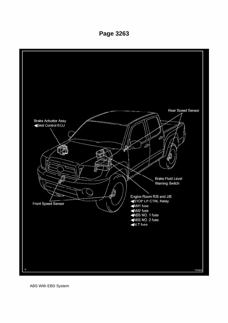
Page 3263
ABS With EBD System

Page 2890

Trigger point at Start (0%)
C. Select Data Graph Display.
Select the following Data Parameters for display on the line graphs:
^ Shift SW Status (R Range)
^ Shift SW Status (D Range)
^ Neutral Position SW Signal
^ Stop Light Switch
7. Duplication test procedure.
The following inspection procedure can be performed with the vehicle on the lift or while driving thevehicle. If driving, select an area with NO traffic since extensive stopping and shifting between thePark, Neutral, Reverse, and Drive positions is required with the brake pressed and released in allgear positions.
A. Clear all stored DTCs using Techstream.
B. Start the vehicle.
C. Start Snapshot.
D. Shift between Park, Reverse, Neutral, and Drive positions.
E. Ensure engagement in all gear positions selected.
F. Press and release brake pedal when in all gear positions (this can be performed multiple times).
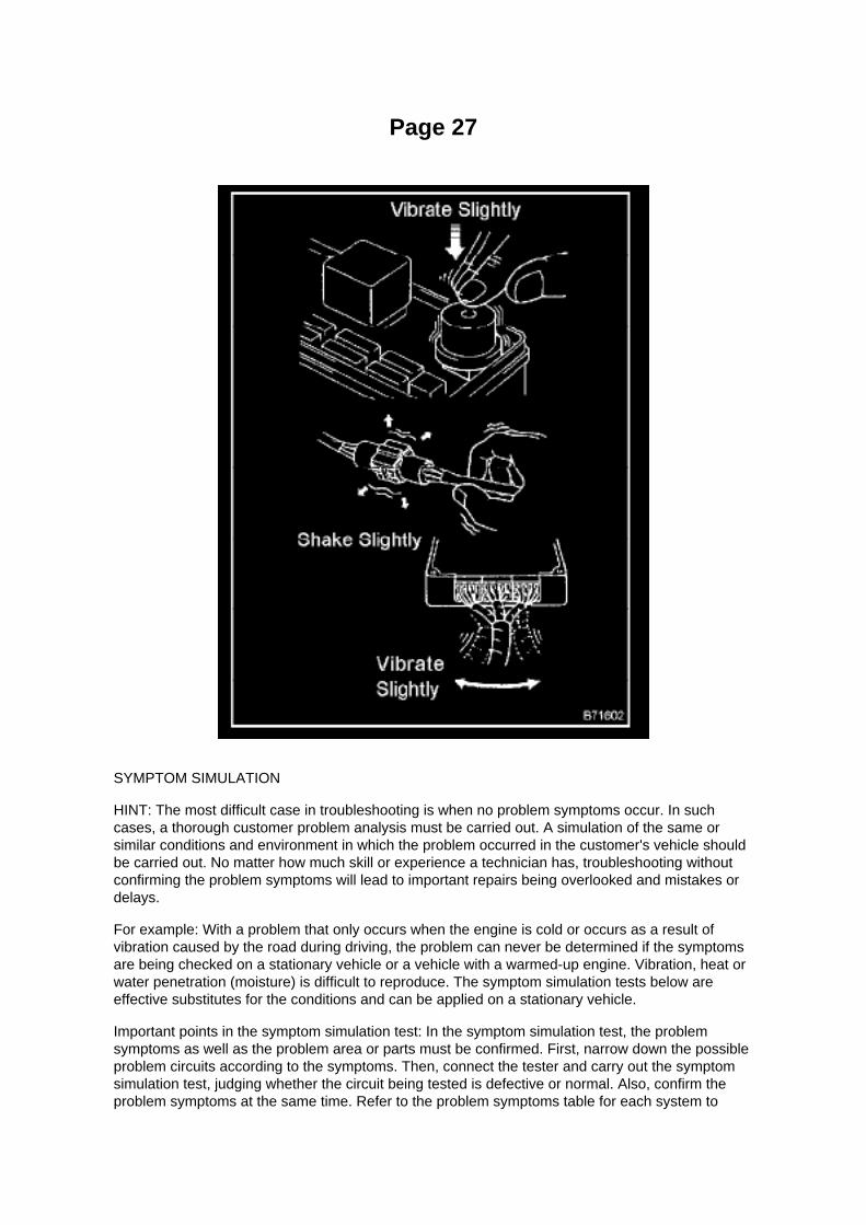
Page 27
SYMPTOM SIMULATION
HINT: The most difficult case in troubleshooting is when no problem symptoms occur. In suchcases, a thorough customer problem analysis must be carried out. A simulation of the same orsimilar conditions and environment in which the problem occurred in the customer's vehicle shouldbe carried out. No matter how much skill or experience a technician has, troubleshooting withoutconfirming the problem symptoms will lead to important repairs being overlooked and mistakes ordelays.
For example: With a problem that only occurs when the engine is cold or occurs as a result ofvibration caused by the road during driving, the problem can never be determined if the symptomsare being checked on a stationary vehicle or a vehicle with a warmed-up engine. Vibration, heat orwater penetration (moisture) is difficult to reproduce. The symptom simulation tests below areeffective substitutes for the conditions and can be applied on a stationary vehicle.
Important points in the symptom simulation test: In the symptom simulation test, the problemsymptoms as well as the problem area or parts must be confirmed. First, narrow down the possibleproblem circuits according to the symptoms. Then, connect the tester and carry out the symptomsimulation test, judging whether the circuit being tested is defective or normal. Also, confirm theproblem symptoms at the same time. Refer to the problem symptoms table for each system to

narrow down the possible causes.
1. VIBRATION METHOD: When vibration seems to be the major cause.
a. PART AND SENSOR
1. Apply slight vibration with a finger to the part of the sensor considered to be the cause of theproblem and check whether or not the
malfunction occurs.
HINT: Applying strong vibration to relays may open relays.
b. CONNECTORS
1. Slightly shake the connector vertically and horizontally.
c. WIRE HARNESS
1. Slightly shake the wire harness vertically and horizontally.
The connector joint and fulcrum of the vibration are the major areas that should be checkedthoroughly.

Page 2555
Fuel Tank: Service and Repair
Removal & Installation and Disassembly & Reassembly
1. DISCHARGE FUEL SYSTEM PRESSURE 2. DISCONNECT CABLE FROM NEGATIVEBATTERY TERMINAL 3. REMOVE FUEL TANK PROTECTOR SUB-ASSEMBLY NO.1 (W/ OFFROAD PACKAGE)
a. Remove the 4 nuts, then remove the fuel tank protector.
4. DISCONNECT FUEL TANK MAIN TUBE AND FUEL TANK RETURN TUBE
a. Remove the fuel pipe clamp.
b. Disconnect the fuel tank main tube and fuel tank return tube.
1. Pinch the retainer as illustrated, then pull the fuel tube connectors out of the pipes.
NOTE: -
Remove any dirt and foreign objects from the fuel tube connector before performing this work.
- Do not allow any scratches or foreign objects on the parts when disconnecting, as the fuel tubeconnector has the O-ring that seals the pipe.
- Perform this work by hand. Do not use any tools.
- Do not forcibly bend, twist or turn the nylon tube.
- Protect the disconnected part by covering it with a vinyl bag after disconnecting the fuel tube.
- If the fuel tube connector and pipe are stuck, push and pull to release them.
5. REMOVE FUEL TANK ASSEMBLY

Page 1694
b. Connect the wire harness clamp. c. Connect the air fuel ratio sensor connector.
4. CONNECT CABLE TO NEGATIVE BATTERY TERMINAL
Torque: 3.9 N.m (40 Kgf.cm, 35 in.lbf)

Page 3261

He - Wi

Page 1181
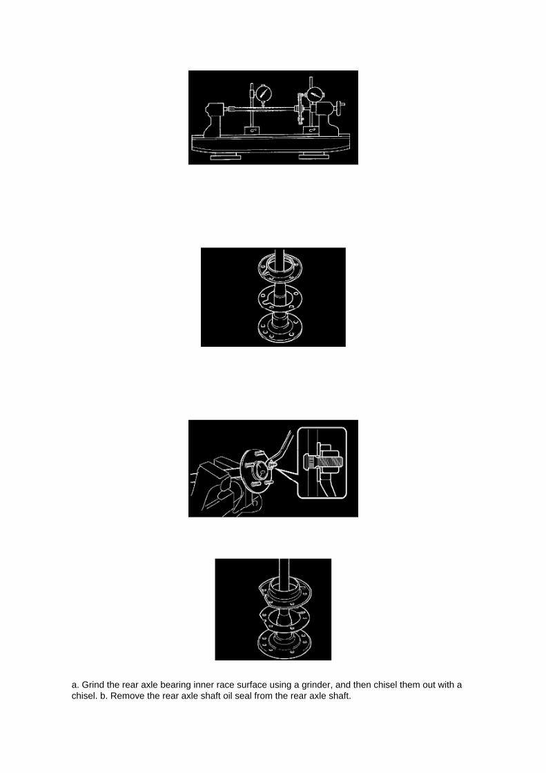
a. Grind the rear axle bearing inner race surface using a grinder, and then chisel them out with achisel. b. Remove the rear axle shaft oil seal from the rear axle shaft.

19. INSPECT REAR AXLE SHAFT LH
a. Using a dial indicator, measure the runout of the shaft and flange.
Maximum runout:
Shaft runout: 1.5 mm (0.0591 inch) Flange runout: 0.05 mm (0.0020 inch)
If the rear axle shaft or flange is damaged or worn, or the runout is greater than the maximum,replace the rear axle shaft.
20. INSTALL REAR AXLE HUB BOLT
a. 2WD:
(1) Install a new deflector gasket and deflector onto the rear axle shaft.
HINT: Make sure that the deflector and deflector gasket are installed in the correct direction shownin the illustration.
(2) Install the 5 bolts through the axle hub. (3) Install a washer plate, as shown in the illustration,through the hub bolt, and install the hub bolt by tightening the hub nut.
b. 4WD and PRE RUNNER:
(1) Install a new deflector gasket and deflector onto the rear axle shaft.
HINT: Align the 2 notches.

Locations

Ha - Op

Page 2771
When using Techstream Lite, select Generic J2534 Interface. Then click Next.
E. Confirm the following:
^ PC is connected to VIM.
^ VIM is connected to DLC3 connector.
^ Ignition is ON and engine is OFF or "READY" OFF (hybrid vehicles).

Page 1095

Engine Compartment

Instrument Panel
Locations

Page 1962
Step 1 - 2

Locations
Camshaft Position Sensor: Locations

A/C - Ge
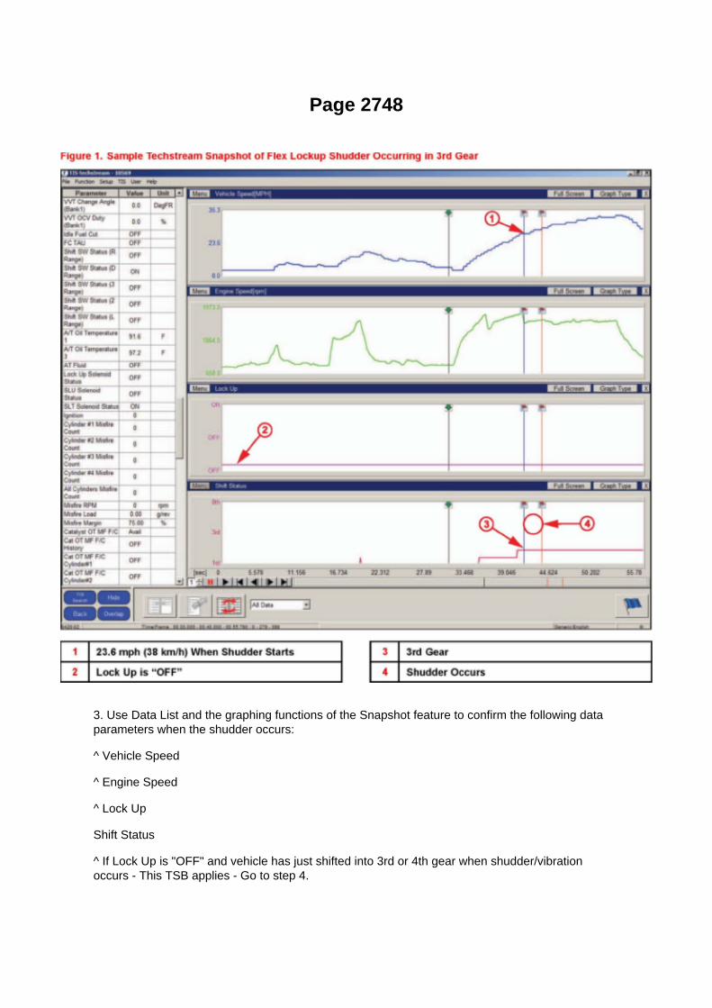
Page 2748
3. Use Data List and the graphing functions of the Snapshot feature to confirm the following dataparameters when the shudder occurs:
^ Vehicle Speed
^ Engine Speed
^ Lock Up
Shift Status
^ If Lock Up is "OFF" and vehicle has just shifted into 3rd or 4th gear when shudder/vibrationoccurs - This TSB applies - Go to step 4.

^ If shudder/vibration occurs in 2nd gear, or when Lock Up is "ON - This TSB does NOT apply.Continue diagnosis per Repair Manual.
4. Disconnect the battery for at least 10 minutes, and then test drive the vehicle again.Shudder/vibration should be eliminated.
^ If shudder/vibration is eliminated - Go to step 5.
^ If shudder/vibration is still present - This TSB does NOT apply. Continue diagnosis per RepairManual.

Page 2037

Knock Control Sensor (2TR-FE) Part 2

Page 1980
Step 12
INSPECTION PROCEDURE

Page 1944
Step 1 - 2

Page 207

Then click Start.
I. Do NOT disturb the vehicle during flash reprogramming.
NOTE
^ ECU flash reprogramming may take anywhere from 3 - 30 minutes per calibration file.
^ Reprogramming time will vary depending on model and ECU communication protocol. Vehiclesusing CAN communication protocol will reprogram much faster (2 - 7 minutes).
NOTE
^ If vehicle requires only ONE calibration update, then proceed to step N in this bulletin.
^ If vehicle requires a SECOND calibration update, then continue as follows:
^ For serial communication vehicles, go to step J.
^ For CAN communication vehicles, go to step L.

Page 2088

He - Wi

Page 2914
a. Align the matchmarks on the clutch cover assy and flywheel sub-assy. b. Tighten the 6 bolts, inthe order shown in the illustration, starting with the bolt located near the knock pin on the top.
Torque: 19 Nm (195 kgf-cm, 14 ft. lbs.)
HINT: ^
Following the order in the illustration, uniformly tighten the bolts.

^ Move SST up and down, right and left gently after checking that the disc is in the center, andtighten the bolts.
19. INSPECT AND ADJUST CLUTCH COVER ASSY
a. Using a dial indicator with roller instrument, check the diaphragm spring tip alignment.
Maximum non-alignment: 0.5 mm (0.020 inch) If the alignment is not as specified, adjust thediaphragm spring tip alignment using SST. SST 09333-00013
20. INSTALL RELEASE FORK SUPPORT
a. Install the release fork support onto the transaxle assy.
Torque: 47 Nm (479 kgf-cm, 35 ft. lbs.)
21. INSTALL RELEASE BEARING HUB CLIP
22. INSTALL CLUTCH RELEASE FORK SUB-ASSY
a. Apply release hub grease to the release fork and release bearing assy contact surfaces, releasefork and push rod contact surface and release
fork pivot point. Sealant: Part No.08887-01806, RELEASE HUB GREASE or equivalent
b. Install the release fork onto the release bearing assy.
23. INSTALL CLUTCH RELEASE BEARING ASSY
a. Apply clutch spline grease to the input shaft spline.
Sealant: Part No.08887-01706, CLUTCH SPLINE GREASE or equivalent
b. Install the bearing onto the release fork, and then install them onto the transaxle assy.
NOTICE: After installation, move the fork forward and backward to check that the release bearingslides smoothly.
24. INSTALL CLUTCH RELEASE FORK BOOT 25. INSTALL MANUAL TRANSMISSION UNITASSY (R155 TRANSMISSION) 26. INSTALL MANUAL TRANSMISSION UNIT ASSY (R155FTRANSMISSION)

Page 3282

(3) Release the brake pedal when the solenoid is on, and check that the rear wheels do not rotateby hand.

If the rear wheels rotate, replace the brake master cylinder.
HINT: -
To protect the solenoids, hand-held tester turns off automatically 2 seconds after every solenoidhas been turned on.
- When rotating the wheels fast, the fail-safe function is activated and judgement cannot be madeproperly. So rotate the wheels as slowly as possible.
NOTICE: When operating it continuously, set the interval of more than 20 seconds.
(4) When the solenoid is off, check the rear wheels by rotating them by hand. If the rear wheelsstop, replace the brake master cylinder.
o. Inspect rear VSC solenoid (STR) operation.
HINT: -
ON: Activate STR and SREC, then check that the rear wheels do not rotate.
- OFF: Deactivate STR and SREC. Reactivate SREC and check that the rear wheels rotate.
(1) Select "SRMR (SMCR, STR)" on the hand-held tester. (2) Turn the "SRMR (SMCR, STR) onsimultaneously by the hand-held tester. (3) When the solenoids are on, check that the rear wheelsdo not rotate by hand.
If the rear wheels rotate, replace the brake master cylinder.
HINT: -
To protect the solenoids, hand-held tester turns off automatically 2 seconds after every solenoidhas been turned on.
- When rotating the wheels fast, the fail-safe function is activated and judgement cannot be madeproperly. So rotate the wheels as slowly as possible.
NOTICE: When operating it continuously, set the interval of more than 20 seconds.
(4) When the solenoids are off, check the rear wheels by rotating them by hand. If the rear wheelsstop, replace the brake master cylinder. (5) When the "SRMF (SREC)" is off, depress the brakepedal again and check that the rear wheels do not rotate by hand. If the rear wheels rotate, replacethe brake master cylinder.
p. Inspect rear ABS solenoid (SRRH) operation.
HINT: -
ON: Activate SRRH, depress the brake pedal, and then check that the right rear wheel rotates.
- OFF: Deactivate SRRH, depress the brake pedal, and then check that the right rear wheel doesnot rotate.
(1) Select "SRRH" on the hand-held tester. (2) Turn the "SRRH" on by the hand-held tester, thendepress the brake pedal with stable force. (3) When the solenoid is on, check the right rear wheelby rotating it by hand. If the right rear wheel stops, replace the brake master cylinder.
HINT: -

To protect the solenoids, hand-held tester turns off automatically 2 seconds after every solenoidhas been turned on.
- When rotating the wheel fast, the fail-safe function is activated and judgement cannot be madeproperly. So rotate the wheel as slowly as possible.
NOTICE: When operating it continuously, set the interval of more than 20 seconds. (4) When thesolenoid is off, depress the brake pedal again and check that the right rear wheel does not rotateby hand.
If the right rear wheel rotates, replace the brake master cylinder.
q. Inspect front ABS solenoid (SRLH) operation.
HINT: -
ON: Activate SRLH, depress the brake pedal, and then check that the left rear wheel rotates.
- OFF: Deactivate SRLH, depress the brake pedal, and then check that the left rear wheel does notrotate.
(1) Select "SRLH" on the hand-held tester. (2) Turn the "SRLH" on by the hand-held tester, thendepress the brake pedal with stable force. (3) When the solenoid is on, check the left rear wheel byrotating it by hand.
If the left rear wheel stops, replace the brake master cylinder.
HINT:

Service and Repair

Crankshaft Main Bearing Seal: Service and Repair

ENGINE REAR OIL SEAL (2TR-FE)
REPLACEMENT
1. REMOVE MANUAL TRANSMISSION UNIT ASSEMBLY 2. REMOVE AUTOMATICTRANSMISSION ASSEMBLY 3. REMOVE CLUTCH COVER ASSEMBLY (MANUALTRANSMISSION) 4. REMOVE CLUTCH DISC ASSEMBLY (MANUAL TRANSMISSION)
5. REMOVE FLYWHEEL SUB-ASSEMBLY (MANUAL TRANSMISSION)
a. Using SST, hold the crankshaft pulley.
SST 09213-54015 (91651-60855), 09330-00021
b. Remove the 10 bolts, then remove the flywheel.
6. REMOVE DRIVE PLATE & RING GEAR SUB-ASSEMBLY (AUTOMATIC TRANSMISSION)
a. Using SST, hold the crankshaft pulley.
SST 09213-54015 (91651-60855), 09330-00021
b. Remove the 10 bolts, drive plate spacer rear, drive plate & ring gear and drive plate spacer front.

Page 2414
SFI System

Page 3301
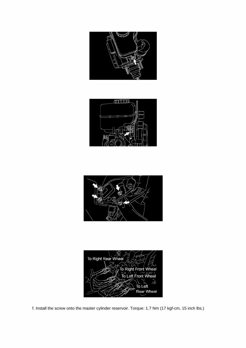
f. Install the screw onto the master cylinder reservoir. Torque: 1.7 Nm (17 kgf-cm, 15 inch lbs.)

37. INSTALL BRAKE ACTUATOR BRACKET NO.1
a. Install the fluid level warning switch connector. b. Using a hexagon wrench (5 mm), install thebrake actuator bracket No.1 with the screw.
Torque: 7.8 Nm (80 kgf-cm, 69 inch lbs.)
38. INSTALL BRAKE MASTER CYLINDER ASSEMBLY
a. Install a new brake booster gasket onto the master cylinder. b. Install the brake master cylinderwith the 4 nuts.
Torque: 14.2 Nm (145 kgf-cm, 10 ft. lbs.)
c. Using SST, connect the 4 brake lines to the correct positions of the brake master cylinder, asshown in the illustration. SST 09023-00101
Torque: 15.2 Nm (155 kgf-cm, 11 ft. lbs.)
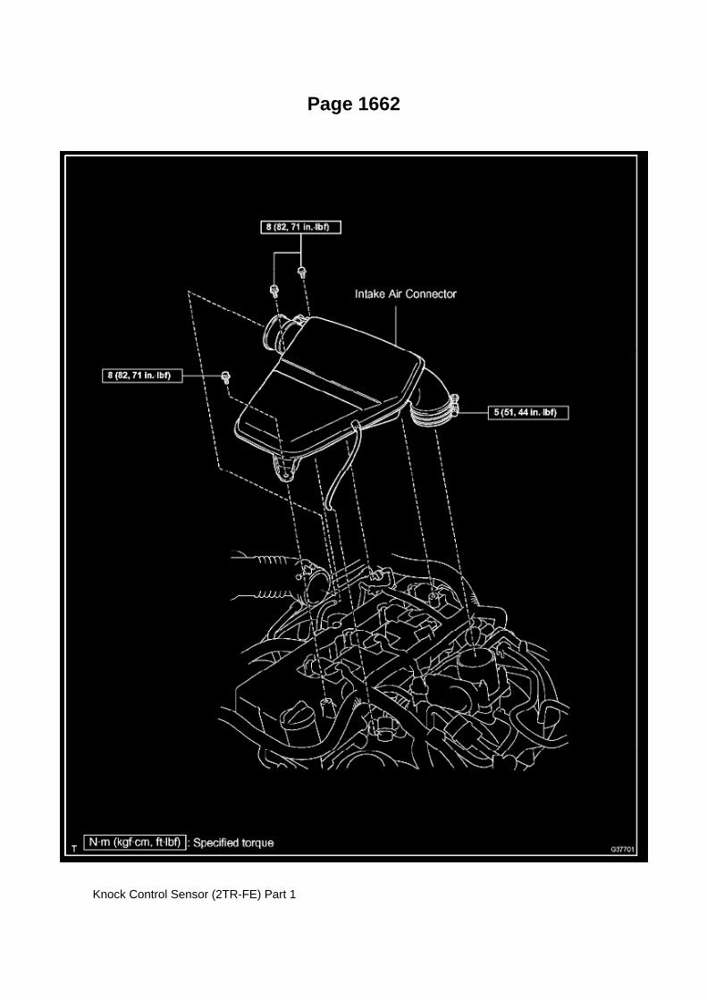
Page 1662
Knock Control Sensor (2TR-FE) Part 1

Page 97
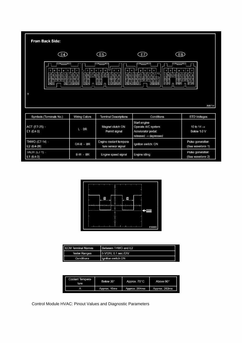
Control Module HVAC: Pinout Values and Diagnostic Parameters

INSPECT ECM (2TR-FE)
a. Connect the connector to the ECM and inspect the wire harness side connector from the backside, as shown in the table.
WAVEFORM 1:
Engine Coolant Temperature Sensor Signal
A Changes in accordance with the engine coolant temperature

Service and Repair
Camshaft: Service and Repair

CAMSHAFT (2TR-FE)

Page 1903
Diagram Legend
Diagram Legend
O: Indicates values or explains the function for reference during troubleshooting.
P: Indicates the reference showing the position on the vehicle of the parts in the system circuit.Example: Part L4 (Light Failure Sensor) * The letter in the code is from the first letter of the part,and the number indicates its order in parts starting with that letter.
Q: Indicates the reference showing the position on the vehicle of Relay Block Connectors in thesystem circuit.
Example: Connector "1" is described and is installed on the left side of the instrument panel.

R: Indicates the reference showing the position on the vehicle of J/B and Wire Harness in thesystem circuit.
Example: Connector "3C" connects the Instrument Panel Wire and J/B No.3. It is described and isinstalled on the instrument panel left side.
S: Indicates the reference describing the wiring harness and wiring harness connector (the femalewiring harness is shown first, followed by the male wiring harness).
Example: Connector "IE1" connects the floor wire (female) and Instrument panel wire (male). It isdescribed and is installed on the left side kick panel.
T: Indicates the reference showing the position of the ground points on the vehicle.
Example: Ground point "BO" is described and is installed on the back panel center.
U: Indicates the reference showing the position of the splice points on the vehicle.

Page 2140
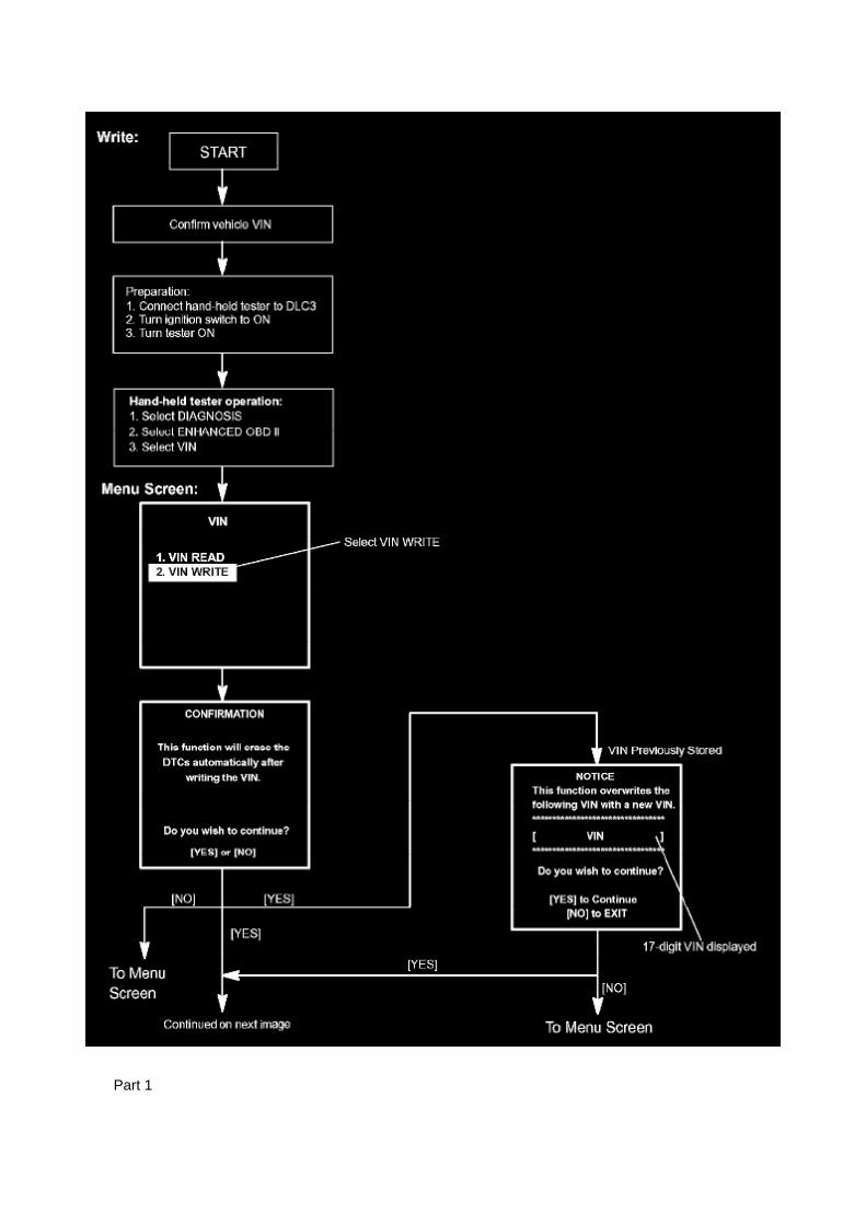
Part 1

Page 2612
SFI System

Page 2120

A/C - Fo

Page 2242
Ce - Ya

Locations

Ha - Op

Page 3319

Traction Control Indicator Lamp: Testing and Inspection VSC TRAC Warning Light Circuit (DoesNot Light Up)

VSC TRAC WARNING LIGHT CIRCUIT (DOES NOT LIGHT UP)
CIRCUIT DESCRIPTION
When the ECU stores DTC, the VSC warning light illuminates on the combination meter.

Page 2622

a. Using several steps, uniformly install and tighten the 5 bolts in the sequence shown in theillustration.

Torque: 21 N.m (214 kgf.cm, 16 ft.lbf) for bolt A 43 N.m (438 kgf.cm, 32 ft.lbf) for bolt B, C
9. INSTALL COMPRESSOR AND MAGNETIC CLUTCH (W/ AIR CONDITIONING)
10. INSTALL FAN AND GENERATOR BELT (W/ AIR CONDITIONING) 11. INSTALL ENGINEUNDER COVER SUB-ASSEMBLY NO.1 (PRE RUNNER AND 4WD TYPE)
12. CONNECT CABLE TO NEGATIVE BATTERY TERMINAL
Torque: 3.9 N.m (40 kgf.cm, 35 in.lbf)

Page 348
ABS With EBD & BA & TRAC & VSC SYSTEM

Page 2405
A/F and 02 Sensor Identification
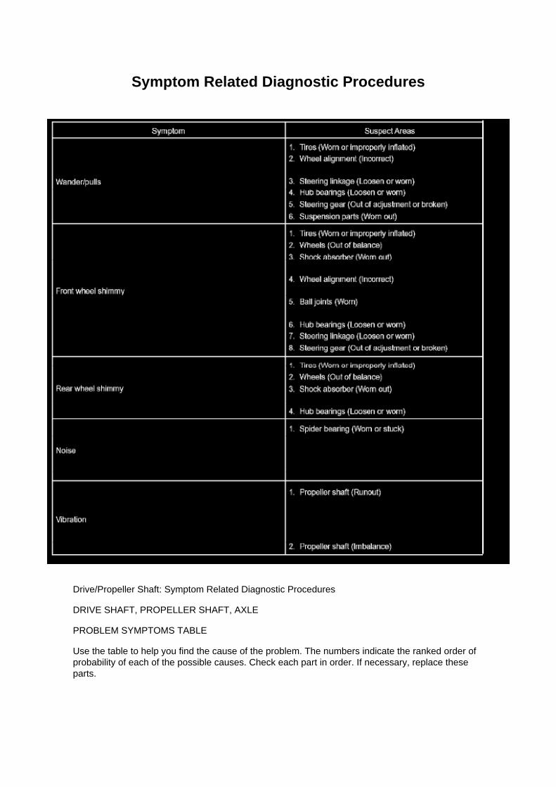
Symptom Related Diagnostic Procedures
Drive/Propeller Shaft: Symptom Related Diagnostic Procedures
DRIVE SHAFT, PROPELLER SHAFT, AXLE
PROBLEM SYMPTOMS TABLE
Use the table to help you find the cause of the problem. The numbers indicate the ranked order ofprobability of each of the possible causes. Check each part in order. If necessary, replace theseparts.

Page 536
b. Install the grommet, a new lock washer and the nut.
Torque: 6.9 Nm (70 kgf-cm, 61 inch lbs.)
c. Install the manual valve lever shaft onto the groove and turn it 2 notches counterclockwise to theneutral position. d. Align the neutral basic line with the switch groove and tighten the adjusting bolt.
Torque: 13 Nm (130 kgf-cm, 9 ft. lbs.)
e. Bend the tabs of the lock washer.
HINT: Bend at least 2 of the lock washer tabs.
5. CONNECT PARK/NEUTRAL POSITION SWITCH CONNECTOR 6. CONNECT CABLE TONEGATIVE BATTERY TERMINAL
Torque: 3.9 Nm (40 kgf-cm, 35 inch lbs.)
7. INSPECT PARK/NEUTRAL POSITION SWITCH ASSY 8. ADJUST PARK/NEUTRAL POSITIONSWITCH ASSY 9. ADJUST SHIFT LEVER POSITION
10. INSPECT SHIFT LEVER POSITION

Page 497

d. Disconnect the water bypass hose No.2.

e. Disconnect the ventilation hose No.3.
f. Disconnect the VSV connector.
g. Disengage the engine wire harness clamp. h. Disconnect the compressor magnetic clutchconnector.
(w/ AIR CONDITIONING)
i. Disengage the wire harness clamp.
j. Remove the bolt and harness clamp bracket.

Page 2664

Knock Control Sensor (2TR-FE) Part 2

Locations

Air Flow Meter/Sensor: Locations

He - Wi

Specifications

Harmonic Balancer - Crankshaft Pulley: Specifications

Crankshaft Pulley.........................................................................................................................................................260 Nm (1,650 kgf-cm, 192 ft. lbs.)

Page 1077

Engine Room R/B, J/B - Engine Compartment Left
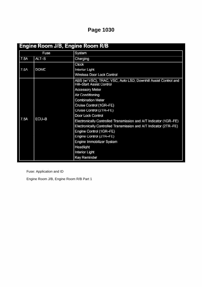
Page 1030
Fuse: Application and ID
Engine Room J/B, Engine Room R/B Part 1

Locations
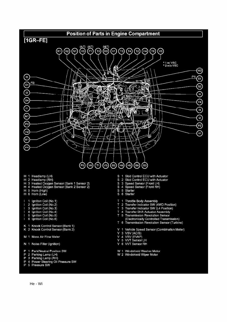
He - Wi

Page 171

[B] : For Waterproof Type Connector

HINT: Terminal retainer color is different according to connector body.
Example:
Terminal Retainer : Connector Body
Black or White : Gray
Black or White : Dark Gray
Gray or White : Black
"Case 1" Type where terminal retainer is pulled up to the temporary lock position (Pull Type).
Insert the special tool into the terminal retainer access hole (A Mark) and pull the terminal retainerup to the temporary lock position.
HINT: The needle insertion position varies according to the connector's shape (Number ofterminals etc.), so check the position before inserting it.
"Case 2" Type which cannot be pulled as far as Power Lock insert the tool straight into the accesshole of terminal retainer as shown.

Page 1100
Driver Side J/B - Lower Finish Panel

Page 2784
Shift Interlock Solenoid: Testing and Inspection
KEY INTER LOCK SOLENOID
INSPECTION
1. INSPECT KEY INTER LOCK SOLENOID
a. Disconnect the solenoid connector. b. Connect KLS+
(4) terminal to the battery positive (+) terminal, and KLS- (3) terminal to the battery negative (-)terminal, and apply about 12V between KLS+ and KLS terminals. Check that operation noise canbe
heard from the solenoid.
If the solenoid does not operate, replace the solenoid.
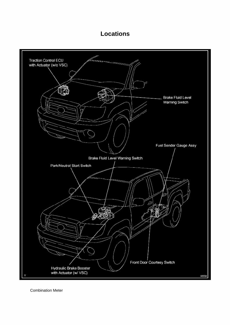
Locations
Combination Meter

Page 3055

^ If there are 2 alignment pins present the transmissionltransaxle assembly may be installedfollowing the applicable Repair Manual procedure.

NOTE:
A missing alignment pin may result in failure of the transmissionltransaxle assembly.
2. Install the missing alignment pin(s).
^ Refer to the applicable Repair Manual procedure for location of the cylinder block rear sidealignment pins.
NOTE
In the Repair Manual, the alignment pin is referred to as a "straight pin."

Locations

He - Wi

Page 2138

Engine Control Module: Service and Repair Control Module Programming and Relearning

Precaution
PRECAUTION
1. INITIALIZATION
NOTE: Perform the REGISTRATION (VIN registration) when replacing the ECM.
2. FOR USING HAND-HELD TESTER
CAUTION: Observe the following items for safety reasons: -
Read its instruction books before using the tester.
- Prevent the tester cable from being caught on the pedals, shift lever and steering wheel whendriving with the tester connected to the vehicle.
- When driving the vehicle for testing purposes using the tester, two persons are required. One isfor driving the vehicle, and the other operates the tester.
Registration
REGISTRATION
NOTE: The Vehicle Identification Number (VIN) must be input into the replacement ECM.
HINT: The VIN is in the form of a 17-digit alphanumeric vehicle identification number. A hand-heldtester is required to resister the VIN.
1. DESCRIPTION
This registration section consists of three parts, Input Instructions, Read VIN and Write VIN. a.Input Instructions: Explains the general VIN input instructions using a hand-held tester. b. ReadVIN: Explains the VIN reading process in a flowchart. This process allows the VIN stored in theECM to be read, in order to confirm
that the two VINs, provided with the vehicle and stored in the vehicle's ECM, are the same.
c. Write VIN: Explains the VIN writing process in a flowchart. This process allows the VIN to beinput into the ECM. If the ECM is changed, or
the VIN and VIN do not match, the VIN can be registered, or overwritten in the ECM by followingthis procedure.
2. INPUT INSTRUCTIONS
a. Hand-held tester
1. The arrow buttons (UP, DOWN, RIGHT and LEFT) and numerical buttons (0 to 9) are used, inorder to input the VIN.
b. Cursor Operation
1. To move the cursor around the tester screen, press the RIGHT and LEFT buttons.
c. Alphabetical Character Input
1. Press the UP and DOWN buttons to select the desired alphabetical character. 2. After selection,the cursor should move.
d. Numeric Character Input

1. Press the numerical button corresponding to the number that you want to input. 2. After input,the cursor should move.
HINT: Numerical characters can be selected by using the UP and DOWN buttons.
e. Correction
1. When correcting the input character(s), put the cursor onto the character using the RIGHT orLEFT buttons. 2. Select or input the correct character using the UP/DOWN buttons, or thenumerical buttons.
f. Finishing Input Operation 1. Make sure that the input VIN matches the vehicle VIN after input. 2.Press the ENTER button on the tester.
3. READ VIN (Vehicle Identification Number)

Page 508
Engine Bank Identification

Vehicle - Power System Initialization References
Power Window Control Module: Technical Service Bulletins Vehicle - Power System InitializationReferences
PRE-DELIVERY SERVICE PD008-05
Title: POWER SYSTEM INITIALIZATION DURING PDS
Models: '05 Applicable Toyota & Scion Models
January 27, 2005
Introduction
The following is a list of the vehicle systems (Power Window Sliding Roof Tire Pressure WarningSystem etc.) that need initialization during Pre-Delivery Service (PDS) and the TSB numberscontaining details on initializing each specific system.

NOTE
Items in RED also need to be initialized any time the battery has been disconnected.
Applicable Vehicles
^ 2005 model year Applicable Toyota and Scion vehicles listed in the table.
'05 MY Power System Initialization Table
Warranty Information

Page 3308

Ha - Op
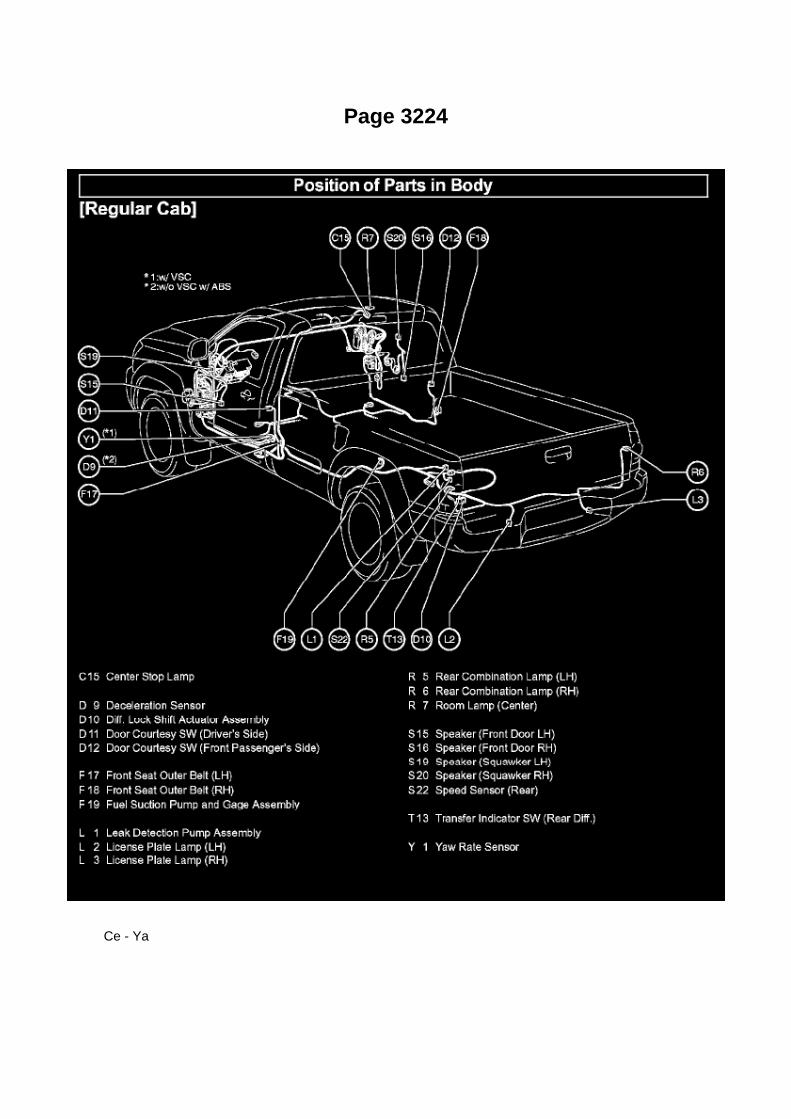
Page 3224
Ce - Ya

Air-Fuel Ratio (A/F) Sensor
Oxygen Sensor: Testing and Inspection Air-Fuel Ratio (A/F) Sensor
INSPECTION
INSPECT AIR FUEL RATIO SENSOR
a. Check the resistance.
1. Using an ohmmeter, measure the resistance between the terminals.
If the result is not as specified, replace the air fuel ratio sensor.

Page 2247
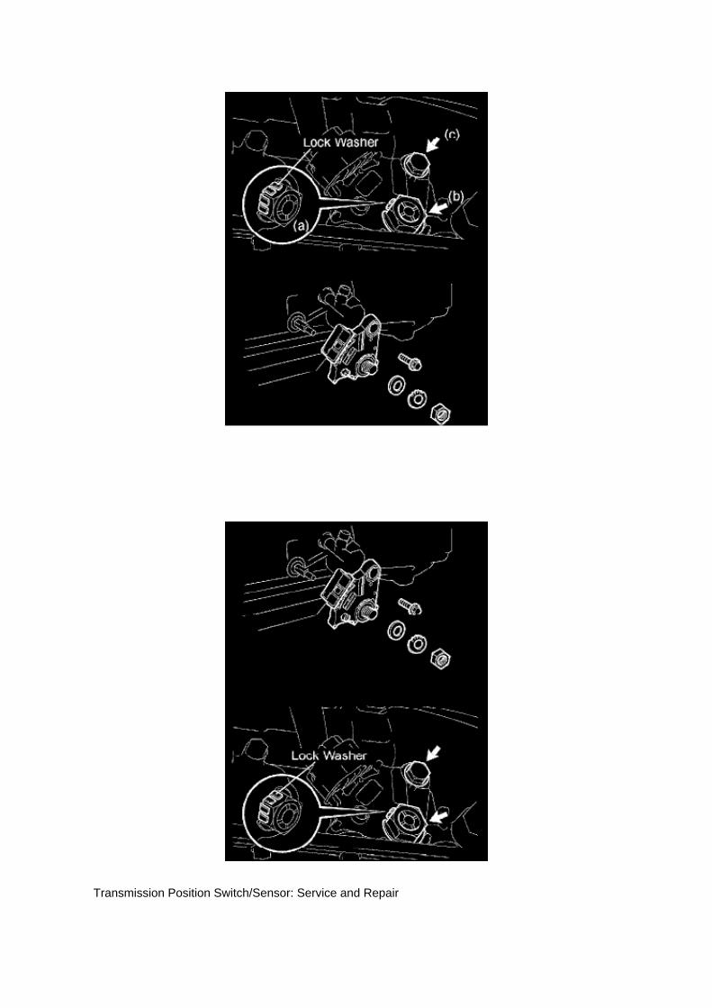
Transmission Position Switch/Sensor: Service and Repair

PARK/NEUTRAL POSITION SWITCH ASSY
REPLACEMENT
1. DISCONNECT CABLE FROM NEGATIVE BATTERY TERMINAL 2. DISCONNECTPARK/NEUTRAL POSITION SWITCH CONNECTOR
3. REMOVE PARK/NEUTRAL POSITION SWITCH ASSY
a. Using a screwdriver, unstake the lock washer. b. Remove the nut, lock washer and grommet. c.Remove the bolt and park/neutral position switch.
4. INSTALL PARK/NEUTRAL POSITION SWITCH ASSY
a. Install the park/neutral position switch onto the manual valve lever shaft and provisionally tightenthe adjusting bolt.

Page 543

He - Wi

Page 2869

Transmission Position Switch/Sensor: Service and Repair

PARK/NEUTRAL POSITION SWITCH ASSY
REPLACEMENT
1. DISCONNECT CABLE FROM NEGATIVE BATTERY TERMINAL 2. DISCONNECTPARK/NEUTRAL POSITION SWITCH CONNECTOR
3. REMOVE PARK/NEUTRAL POSITION SWITCH ASSY
a. Using a screwdriver, unstake the lock washer. b. Remove the nut, lock washer and grommet. c.Remove the bolt and park/neutral position switch.
4. INSTALL PARK/NEUTRAL POSITION SWITCH ASSY
a. Install the park/neutral position switch onto the manual valve lever shaft and provisionally tightenthe adjusting bolt.

Component Inspection
Variable Valve Timing Actuator: Testing and Inspection Component Inspection
INSPECT CAMSHAFT TIMING OIL CONTROL VALVE ASSEMBLY

a. Check the resistance.
1. Using an ohmmeter, measure the resistance between the terminals.
If the result is not as specified, replace the camshaft timing oil control valve.
b. Check the operation.
1. Apply battery voltage across the terminals, and check that the spool valve operates.
NOTE: Check that the spool valve is not stuck.
HINT: The spool valve may not return if foreign objects are caught in it. This may cause subtlepressure leakage to the advance side, and a DTC may be set.

Locations

Specifications

Page 230

Terminals Of ECM / Pinouts Part 4

Oscilloscope Waveforms

Service and Repair

Fuel Pressure Regulator: Service and Repair

REPLACEMENT
1. DISCHARGE FUEL SYSTEM PRESSURE 2. DISCONNECT CABLE FROM NEGATIVEBATTERY TERMINAL 3. REMOVE INTAKE AIR CONNECTOR 4. DISCONNECT FUEL HOSENO.2 5. REMOVE FUEL PRESSURE REGULATOR ASSEMBLY
a. Disconnect the throttle w/ motor body connectors. b. Disconnect the VSV connector. c.Disconnect the engine wire harness clamp. d. Remove the bolt, then remove the harness clampbracket.
e. Remove the 3 bolts, then remove the fuel pressure regulator.
6. INSTALL FUEL PRESSURE REGULATOR ASSEMBLY
a. Apply a light coat of gasoline or spindle oil to the O-ring.

Page 852
4 Of 6

Page 2202

Applicable Vehicles

Specifications

Fuel Pressure: Specifications

Fuel Pressure
At Idle.............................................................................................................................................281to 287 kPa (2.87 to 2.93 kgf/sq.cm, 40.8 to 41.7 psi)
After Engine Stopped for 5Min..............................................................................................................................................147kPa (1.5 kgf/sq.cm, 21 psi)

Page 1567
^ Power Supply Mode is used to maintain battery voltage at 13.5 volts while flash reprogrammingthe vehicle.
^ For details on how to use the GR8 Battery Diagnostic Station, refer to the located on TIS,Diagnostics - Tools & Equipment - Battery Diagnostics.

3. Click the appropriate calibration ID and reprogram the vehicle's ECU with Techstream.
A. After reviewing the procedures outlined in the selected TSB, click the appropriate calibration IDlink by matching the vehicle's current
calibration ID to the Previous Calibration ID in the Calibration Identification Chart.
NOTE
^ Calibration files are embedded as live links in the service bulletin.
^ Some vehicles require special preparation - please review the selected TSB carefully.
B. Click Open to load calibration file information.
Techstream pulls calibration files as needed to ensure the latest calibration file is used. Do NOTsave calibrations locally on the hard drive or other media.
NOTICE
Errors during the flash reprogramming process can permanently damage the vehicle ECU.Minimize the risk by following the steps below.
^ Battery voltage MUST NOT FALL BELOW 11.4 volts during reprogramming. Confirm batteryvoltage is higher than 11.4 volts, but be sure voltage DOES NOT RISE ABOVE 16.0 volts duringreprogramming.
^ Turn OFF all vehicle accessories (e.g. audio system, A/C, interior lights, DRL, etc.). Do NOT addto or significantly change the vehicle's electrical

Page 2062
Engine Bank Identification

Testing and Inspection
Terminals Of ECM/Pinouts
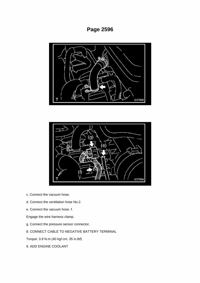
Page 2596
c. Connect the vacuum hose.
d. Connect the ventilation hose No.2.
e. Connect the vacuum hose. f.
Engage the wire harness clamp.
g. Connect the pressure sensor connector.
8. CONNECT CABLE TO NEGATIVE BATTERY TERMINAL
Torque: 3.9 N.m (40 kgf.cm, 35 in.lbf)
9. ADD ENGINE COOLANT

10. CHECK FOR ENGINE COOLANT LEAKAGE 11. INSTALL ENGINE UNDER COVERSUB-ASSEMBLY NO.1 (PRE RUNNER AND 4WD TYPE)

Page 726

5. RECONNECT THE NEGATIVE BATTERY CABLE

6. REPROGRAM THE RADIO STATION PRESETS AND SET THE CLOCK TO THEAPPROPRIATE TIME
C. VERIFY THE REPAIR USING THE SCAN TOOL
1. PREPARE THE SCAN TOOL
(a) Remove the DLC3 connector cover.
(b) Connect the scan tool to the DLC3 connector.
(c) Turn the ignition switch to the "ON" position.

Page 3294

c. Pull out the master cylinder reservoir. d. Remove the 3 grommets. e. Remove the cap.

14. REMOVE BRAKE ACTUATOR HOSE
a. Using needle-nose pliers, slide the 2 clips. b. Remove the brake actuator hose.
15. REMOVE BRAKE ACTUATOR TUBE NO.1
a. Using SST, remove the brake actuator tube No.
1. SST 09023-00101
16. REMOVE BRAKE BOOSTER W/ACCUMULATOR PUMP ASSEMBLY
a. Using a screwdriver, remove the 2 plugs.
b. Remove the 2 screws and pull the wire harness.
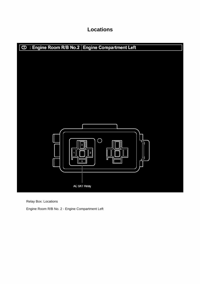
Locations
Relay Box: Locations
Engine Room R/B No. 2 - Engine Compartment Left

Page 2903

Trigger point at Start (0%)

C. Select Data Graph Display.
Select the following Data Parameters for display on the line graphs:
^ Shift SW Status (R Range)
^ Shift SW Status (D Range)
^ Neutral Position SW Signal
^ Stop Light Switch
7. Duplication test procedure.
The following inspection procedure can be performed with the vehicle on the lift or while driving thevehicle. If driving, select an area with NO traffic since extensive stopping and shifting between thePark, Neutral, Reverse, and Drive positions is required with the brake pressed and released in allgear positions.
A. Clear all stored DTCs using Techstream.
B. Start the vehicle.
C. Start Snapshot.
D. Shift between Park, Reverse, Neutral, and Drive positions.
E. Ensure engagement in all gear positions selected.
F. Press and release brake pedal when in all gear positions (this can be performed multiple times).

Page 2133

Oscilloscope Waveforms

Page 1862

M. Turn ignition OFF for a minimum of 10 seconds. Then click Next.

N. Turn ignition to the ON position. Then click Next.
0. Confirm all calibrations were updated as specified in the service bulletin. Then click Finish.

Page 3290

Locations

Engine Room R/B, J/B - Engine Compartment Left

Page 1700

He - Wi

Page 1371

49. REMOVE TIMING CHAIN GUIDE

a. Make sure that each matchmark is in the position shown in the illustration.
b. Remove the 2 bolts, timing chain guide and O-ring.
50. REMOVE CHAIN TENSIONER ASSEMBLY NO.1
NOTICE: -
When the chain tensioner is removed, do not rotate the crankshaft.
- When the chain is removed and the camshaft needs to be rotated, rotate the crankshaft 90° to theright.
a. Move the stopper plate upward to release the lock, and push the plunger deep into the tensioner.b. Move the stopper plate downward to set the lock, and insert a 3.0 mm (0.118 inch) diameter barinto the stopper plate hole.

Locations
A/C - Ge

Page 1879
Step 9
INSPECTION PROCEDURE

Page 1872

A/C - Fo
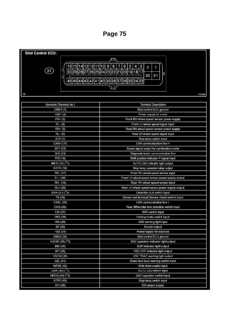
Page 75

Electronic Brake Control Module: Testing and Inspection ABS W/EBD, BA, TRAC & VSC Systems
Terminals Of Control Module / Pinouts Part 1

Page 2677

Spark Plug: Testing and Inspection

INSPECT SPARK PLUG
a. Clean the spark plugs.
Air pressure: Below 588 kPa (6.0 kgf/sq.cm, 85 psi) Duration: 20 seconds or less
b. Check the spark plug for any damage on its thread and insulator.
If damaged, replace the spark plug.
Recommended spark plug: SK20HR11 (DENSO made) ILFR6C11 (NGK made)
c. Check the spark plug electrode gap.
1. Using a spark plug gap gauge, measure the electrode gap.
Electrode gap: 1.0 to 1.1 mm (0.039 to 0.043 in.) Maximum electrode gap: 1.3 mm (0.051 in.)
If the result is greater than the maximum, replace the spark plug.

Locations

Traction Control Switch: Locations
A/C - Fo

Page 586

Knock Sensor: Service and Repair

REPLACEMENT
1. DISCONNECT CABLE FROM NEGATIVE BATTERY TERMINAL 2. REMOVE ENGINE UNDERCOVER SUB-ASSEMBLY NO.1 (PRE RUNNER AND 4WD TYPE) 3. DRAIN ENGINE COOLANT4. REMOVE INTAKE AIR CONNECTOR 5. REMOVE THROTTLE W/MOTOR BODY ASSEMBLY6. DISCONNECT FUEL HOSE 7. DISCONNECT FUEL HOSE NO.2 8. REMOVE INTAKEMANIFOLD
a. Disconnect the fuel vapor feed hose from the VSV.
b. Disconnect the vacuum hose.
c. Remove the bolt, then remove the clamp bracket.

Page 1929

[B] : For Waterproof Type Connector

HINT: Terminal retainer color is different according to connector body.
Example:
Terminal Retainer : Connector Body
Black or White : Gray
Black or White : Dark Gray
Gray or White : Black
"Case 1" Type where terminal retainer is pulled up to the temporary lock position (Pull Type).
Insert the special tool into the terminal retainer access hole (A Mark) and pull the terminal retainerup to the temporary lock position.
HINT: The needle insertion position varies according to the connector's shape (Number ofterminals etc.), so check the position before inserting it.
"Case 2" Type which cannot be pulled as far as Power Lock insert the tool straight into the accesshole of terminal retainer as shown.

Page 2672
o. Connect the fuel vapor feed hose to the VSV.
12. CONNECT FUEL HOSE 13. CONNECT FUEL HOSE NO.2 14. INSTALL THROTTLEW/MOTOR BODY ASSEMBLY 15. INSTALL INTAKE AIR CONNECTOR 16. CONNECT CABLETO NEGATIVE BATTERY TERMINAL
Torque: 3.9 N.m (40 kgf.cm, 35 in.lbf)
17. ADD ENGINE COOLANT 18. CHECK FOR ENGINE COOLANT LEAKAGE 19. CHECK FORFUEL LEAKAGE 20. INSTALL ENGINE UNDER COVER SUB-ASSEMBLY NO.1 (PRE RUNNERAND 4WD TYPE)

Locations
Throttle Body: Locations

Throttle W/motor Body Assy (2TR-FE) Part 1

Page 211
Engine Control Module: Technical Service Bulletins Engine Controls - Entering VIN WhenReplacing PCM/ECM
ENGINE EG045-04
Title: ENTERING VIN DURING ECM (PCM) REPLACEMENT AND/OR DTC P0630
Models: All '04 - '06 Models
October 14, 2004
TSB REVISION NOTICE:
^ June 3, 2005: Content has been updated to include 2004 and 2006 model year vehicles.Highlander HV has been added to step 4 of the VIN Write Procedure. Step 3 of the VIN ReadProcedure has been clarified to include Prius and Highlander HV vehicles.
^ January 24, 2005: Step 4 has been clarified to include Prius vehicles. Previous versions of thisTSB should be discarded.
Introduction
All 2005 and subsequent model year Toyota and Scion vehicles have the VIN (VehicleIdentification Number) stored in the Electronic Control Module (ECM) (SAE term: PowertrainControl Module/PCM) non-volatile memory. The VIN is accessible on the data stream using theToyota Diagnostic Tester and can also be written to a new ECM (PCM) using a VIN Read/Write"utility.
Service ECMs (supply parts) are shipped without the VIN; therefore, as part of the ECM (PCM)replacement procedure, the VIN must be written to the replacement ECM (PCM) using theDiagnostic Tester utility function.
For most 2005 model year vehicles, failure to write the VIN to the ECM (PCM) will result in a M.I.L."ON" condition and set DTC P0630: VIN Not Programmed or Mismatch - ECM (PCM). The fivemodels listed below do not support DTC P0630.
^ Corolla
^ ECHO
^ Matrix
^ Scion xA
^ Scion xB
It is very important to remember to enter the VIN on these vehicles. Vehicles with missing VINs aresubject to failing some state and local vehicle emissions Inspection and Maintenance programs.

NOTE:
2004 model year vehicles which have been flash reprogrammed may contain updated 2005 modelyear OBD II logic. These vehicles will require VIN entry into the ECM (PCM) after reprogramming.
Applicable Vehicles
^ 2004 model year vehicles that have been flash reprogrammed.
^ All 2005 - 2006 model year vehicles.
Warranty Information

Page 2066


Drivetrain - Drive/Axle Shaft Replacement Precautions
Drive/Propeller Shaft: Technical Service Bulletins Drivetrain - Drive/Axle Shaft ReplacementPrecautions
TRANSMISSION & CLUTCH TC003-07
Title: DRIVESHAFT ASSEMBLY REPLACEMENT
Models: '90 - '07 Toyota
Introduction The purpose of this bulletin is to provide information regarding anti-corrosion greasethat is present on replacement driveshaft assemblies. It is important to remove this grease prior to

installing the hub nut to prevent overtightening. This also applies when reusing an old driveshaftthat may have come into contact with oil or foreign matter.
Applicable Vehicles
^ 1990 - 2007 model year Toyota vehicles.
Required Tools & Material
Repair Procedure
Clean the threaded area of the driveshaft with Toyota Brake Cleaner (or equivalent) to remove theanti-corrosion grease, oil, or foreign matter before installing the driveshaft into the vehicle.
NOTE:
A new axle hub nut may be required when installing the driveshaft. Check the Repair Manualprocedure for more information.
Warranty Information

Page 170

"Case 1" Raise the terminal retainer up to the temporary lock position.

"Case 2" Open the secondary locking device.

Page 1928

"Case 1" Raise the terminal retainer up to the temporary lock position.

"Case 2" Open the secondary locking device.

Page 3231

Wiring Diagram
Step 1 - 3

Service and Repair

Clutch Disc: Service and Repair

CLUTCH UNIT (R155/R155F)
COMPONENTS
OVERHAUL
1. REMOVE MANUAL TRANSMISSION UNIT ASSY (R155 TRANSMISSION) 2. REMOVEMANUAL TRANSMISSION UNIT ASSY (R155F TRANSMISSION)
3. REMOVE CLUTCH RELEASE FORK SUB-ASSY
a. Remove the clutch release fork together with the clutch release bearing from the transmissionassy.
4. REMOVE CLUTCH RELEASE BEARING ASSY
a. Remove the clutch release bearing assy from the clutch release fork.
5. REMOVE RELEASE FORK SUPPORT
a. Remove the release fork support from the transaxle assy.
6. REMOVE RELEASE BEARING HUB CLIP

Page 1179

9. SEPARATE REAR BRAKE TUBE NO.8

a. Using SST, separate the brake tube, and use a container to catch the brake fluid as it flows out.
SST 09023-00101
10. REMOVE REAR AXLE SHAFT W/ BACKING PLATE
a. Remove the 4 nuts and rear axle shaft w/ backing plate. b. Remove the O-ring.
11. REMOVE REAR AXLE SHAFT LH OIL SEAL
a. Using SST, remove the oil seal.
SST 09308-00010
12. REMOVE REAR AXLE SHAFT LH SNAP RING
a. Using a snap ring expander, remove the snap ring.

Page 571

a. Using several steps, uniformly install and tighten the 5 bolts in the sequence shown in theillustration.

Torque: 21 N.m (214 kgf.cm, 16 ft.lbf) for bolt A 43 N.m (438 kgf.cm, 32 ft.lbf) for bolt B, C
9. INSTALL COMPRESSOR AND MAGNETIC CLUTCH (W/ AIR CONDITIONING)
10. INSTALL FAN AND GENERATOR BELT (W/ AIR CONDITIONING) 11. INSTALL ENGINEUNDER COVER SUB-ASSEMBLY NO.1 (PRE RUNNER AND 4WD TYPE)
12. CONNECT CABLE TO NEGATIVE BATTERY TERMINAL
Torque: 3.9 N.m (40 kgf.cm, 35 in.lbf)

Page 1983
- Rx: Reception from each ECU (sensor).
- Tx: Transmission to each ECU (sensor).
Diagnostic Trouble Code Descriptions
For information regarding B, C, P, U and Manufacturer Code Descriptions - See: Testing andInspection/Diagnostic Trouble Code Descriptions
Diagnostic Trouble Code Tests and Associated Procedures
For information regarding diagnosis of all B, C, P, U and Manufacturer Codes - See: Testing andInspection/Diagnostic Trouble Code Descriptions
Symptom Index
PROBLEM SYMPTOMS TABLE
1. COMMUNICATION STOP MODE TABLE
a. Complete "CHECK CAN BUS LINE" to confirm that there is no malfunction in the CAN bus line.Select "BUS CHECK" on the hand-held
tester via the CAN VIM.
b. Check the communication stop mode of the ECUs or sensors not displayed among the following:"ENGINE", "ABS/VSC/TRAC", "YAW
/DECELERATE" or "STEERING SENSOR".
NOTE: If 2 or more ECUs or sensors are not displayed on the hand-held tester via the CAN VIM,perform troubleshooting for the communication stop mode of each un-displayed ECU or sensor.(Either side of the CAN sub bus lines may be open)
2. DTC COMBINATION TABLE
a. Perform troubleshooting according to the combination of DTCs output.
HINT: -
Previous CAN communication system DTCs may be the cause if CAN communication systemDTCs are output and all ECUs and sensors connected to the CAN communication system aredisplayed on` the hand-held tester's "BUS CHECK" screen via the CAN VIM.
- U0073/94, U0123/62, U0124/95, U0126/63 and U0100/65 are the DTCs in the CANcommunication system.
- *2 ... U0100/65 is output if no power is supplied to the ECM.
- The table shows combinations of these DTCs.
- ... DTCs that are being output.
- ... DTCs that are not being output.
- SKID CONTROL ECU COMMUNICATION STOP MODE:
- STEERING ANGLE SENSOR COMMUNICATION STOP MODE:
- YAW RATE SENSOR COMMUNICATION STOP MODE:
- ECM COMMUNICATION STOP MODE: replace ECM.
Skid Control ECU Communication Stop Mode
SKID CONTROL ECU COMMUNICATION STOP MODE

Page 3094

a. Grind the rear axle bearing inner race surface using a grinder, and then chisel them out with achisel. b. Remove the rear axle shaft oil seal from the rear axle shaft.

19. INSPECT REAR AXLE SHAFT LH
a. Using a dial indicator, measure the runout of the shaft and flange.
Maximum runout:
Shaft runout: 1.5 mm (0.0591 inch) Flange runout: 0.05 mm (0.0020 inch)
If the rear axle shaft or flange is damaged or worn, or the runout is greater than the maximum,replace the rear axle shaft.
20. INSTALL REAR AXLE HUB BOLT
a. 2WD:
(1) Install a new deflector gasket and deflector onto the rear axle shaft.
HINT: Make sure that the deflector and deflector gasket are installed in the correct direction shownin the illustration.
(2) Install the 5 bolts through the axle hub. (3) Install a washer plate, as shown in the illustration,through the hub bolt, and install the hub bolt by tightening the hub nut.
b. 4WD and PRE RUNNER:
(1) Install a new deflector gasket and deflector onto the rear axle shaft.
HINT: Align the 2 notches.

Page 2558

a. Remove the 2 joint clips, then remove the fuel tank main tube and fuel tank return tube.

NOTE: -
Remove any dirt and foreign objects from the fuel tube connector before performing this work.
- Do not allow any scratches or foreign objects on the parts when disconnecting, as the fuel tubeconnector has the O-ring that seals the pipe.
- Perform this work by hand. Do not use any tools.
- Do not forcibly bend, twist or turn the nylon tube.
- Protect the disconnected part by covering it with a vinyl bag after disconnecting the fuel tube.
- If the fuel tube connector and pipe are stuck, push and pull to release them.
7. REMOVE FUEL SUCTION W/ PUMP & GAUGE TUBE ASSEMBLY
NOTE: Protect the connector and tube joint with masking tape or equivalent to prevent any foreignobjects from sticking to them. Clean any dirt and foreign objects from the fuel suction tubeassembly before removing.
a. Using a SST, loosen the retainer.
SST 09808- 14020 (09808- 01410, 09808- 01420, 09808-01430)
HINT: The ribs on the retainer can be fitted into a tip of the SST.
b. Remove the retainer. c. Pull the fuel pump assembly out of the fuel tank.
NOTE: Be careful not to bend the arm of the sender gauge.
d. Remove the gasket from the fuel tank.
8. DRAIN FUEL

Page 506

Applicable Vehicles

Page 696
Information
TECHNICAL INSTRUCTIONS

FOR
SPECIAL SERVICE CAMPAIGN 50I
2005 MODEL YEAR TACOMA REGULAR-CAB
FRONT BENCH SEAT WIRE SEAT JUMPER

Diagram Information and Instructions

Information Bus: Diagram Information and Instructions

Key to Diagrams
A: System Title
B: Indicates a Relay Block. No shading is used and only the Relay Block No. is shown todistinguish it from the J/B

Page 756
SFI System
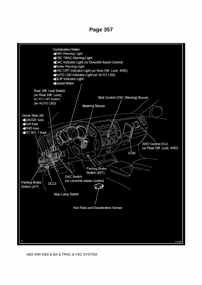
Page 357
ABS With EBD & BA & TRAC & VSC SYSTEM

Page 1832
Crankshaft Position Sensor: Testing and Inspection
INSPECT CRANKSHAFT POSITION SENSOR
Check the resistance.
Using an ohmmeter, measure the resistance between the terminals.
HINT: Cold and Hot mean the temperature of the coils themselves. Cold is from -10 to 50°C (14 to122°F) and Hot is from 50 to 100°C (122 to 212° F).
If the result is not as specified, replace the camshaft position sensor.

Page 1883

Terminals Of ECM / Pinouts Part 4

Oscilloscope Waveforms

Page 2886
Parts Information
Required Tools & Equipment
NOTE
Additional TIS Techstream units may be ordered by calling Approved Dealer Equipment (ADE).

Repair Procedure
1. Confirm that DTC P0705 (Transmission Range Control Circuit Malfunction (PRNDL Circuit)) isstored in the Freeze Frame Data.

Page 2018
Step 13 - 15
INSPECTION PROCEDURE

Check For an Open In One Side of Can Sub Bus Line
CHECK FOR AN OPEN IN ONE SIDE OF CAN SUB BUS LINE
CIRCUIT DESCRIPTION

Page 1681

Applicable Vehicles
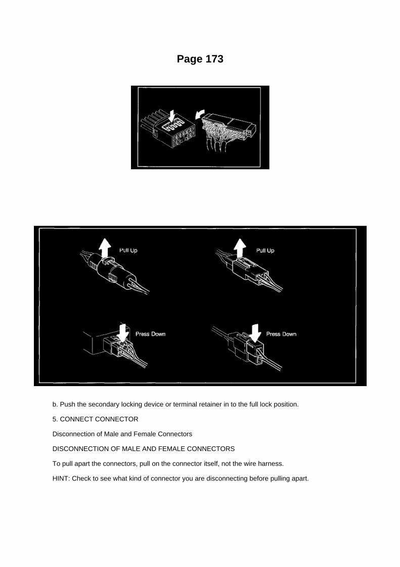
Page 173
b. Push the secondary locking device or terminal retainer in to the full lock position.
5. CONNECT CONNECTOR
Disconnection of Male and Female Connectors
DISCONNECTION OF MALE AND FEMALE CONNECTORS
To pull apart the connectors, pull on the connector itself, not the wire harness.
HINT: Check to see what kind of connector you are disconnecting before pulling apart.

Page 1069

a. Establish conditions in which voltage is present at the check point.

Example: [A] - Ignition SW on [B] - Ignition SW and SW 1 on [C] - Ignition SW, SW 1 and Relay on(SW 2 off)
b. Using a voltmeter, connect the negative lead to a good ground point or negative battery terminal,and the positive lead to the connector or
component terminal. This check can be done with a test light instead of a voltmeter.
Continuity and Resistance Check
CONTINUITY AND RESISTANCE CHECK
a. Disconnect the battery terminal or wire so there is no voltage between the check points.
b. Contact the two leads of an ohmmeter to each of the check points.

Locations

Vehicle Speed Sensor: Locations

He - Wi

Page 2698

Ha - Op

Page 1495
Coolant Temperature Sensor/Switch (For Computer): Testing and Inspection
INSPECT E.F.I. ENGINE COOLANT TEMPERATURE SENSOR
a. Check the resistance.
1. Using an ohmmeter, measure the resistance between the terminals.
NOTE: If checking the engine coolant temperature sensor in water, be careful not to allow water tointrude into the terminals. After checking, wipe the water off the engine coolant temperature sensor.

If the result is not as specified, replace the engine coolant temperature sensor.

Page 1230
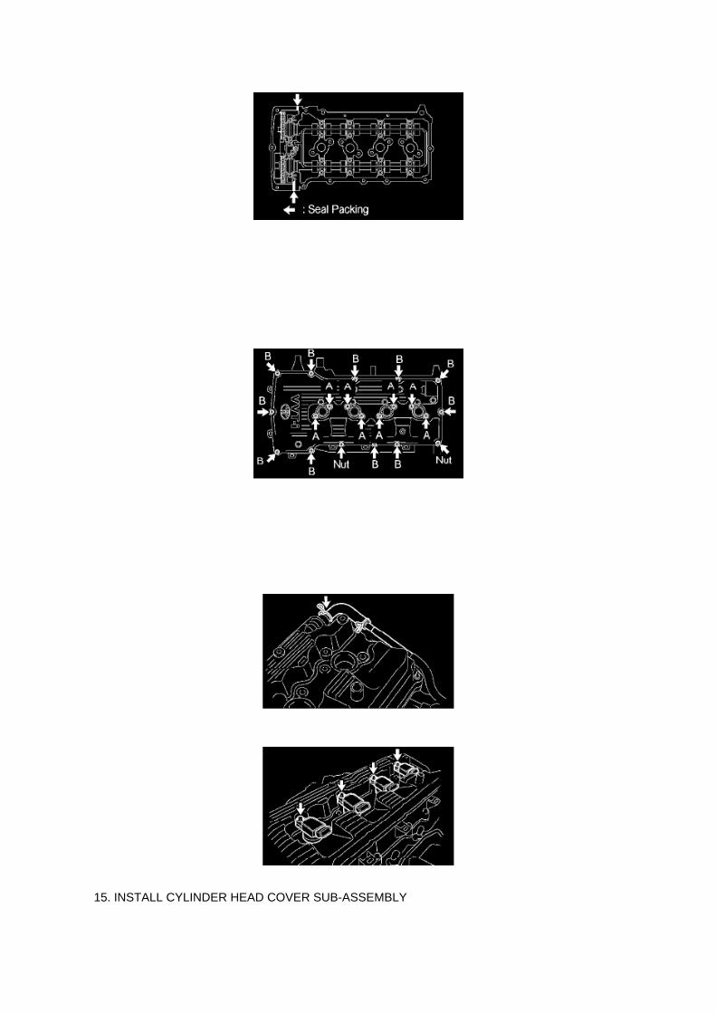
15. INSTALL CYLINDER HEAD COVER SUB-ASSEMBLY

a. Apply seal packing to the 2 locations shown in the illustration.
Seal packing: Part No.08826-00080 or equivalent
NOTICE: -
Remove any oil from the contact surface.
- Install the cylinder head cover within 3 minutes of applying the seal packing.
- Do not apply engine oil for at least 2 hours of installation.
b. Provisionally install the cylinder head cover with the 19 bolts and 2 nuts. c. Tighten bolts Ashown in the illustration.
Torque: 9.0 Nm (92 kgf-cm, 80 inch lbs.)
d. Tighten bolts B and nuts shown in the illustration.
Torque: 9.0 Nm (92 kgf-cm, 80 inch lbs.)
e. Tighten bolts A again.
Torque: 9.0 Nm (92 kgf-cm, 80 inch lbs.)
f. Connect the ventilation hose.
g. Install the ignition coils with the bolts.
Torque: 9.0 Nm (92 kgf-cm, 80 inch lbs.)

Air-Fuel Ratio (A/F) Sensor
Oxygen Sensor: Testing and Inspection Air-Fuel Ratio (A/F) Sensor
INSPECTION
INSPECT AIR FUEL RATIO SENSOR
a. Check the resistance.
1. Using an ohmmeter, measure the resistance between the terminals.
If the result is not as specified, replace the air fuel ratio sensor.
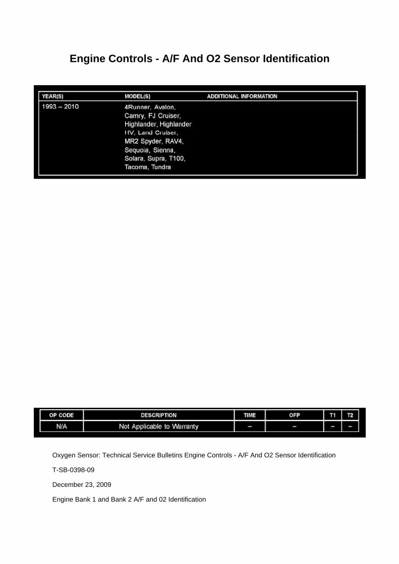
Engine Controls - A/F And O2 Sensor Identification
Oxygen Sensor: Technical Service Bulletins Engine Controls - A/F And O2 Sensor Identification
T-SB-0398-09
December 23, 2009
Engine Bank 1 and Bank 2 A/F and 02 Identification

Service Category Engine/Hybrid System
Section Engine Control
Market USA
Applicability
TSB SUPERSESSION NOTICE
The information contained in this TSB supersedes TSB No. EG034-07.
^ Applicability has been updated to include 2009 - 2010 model year vehicles and 2006 - 2010model year Highlander HV.
TSB No. EG034-07 is Obsolete and any printed versions should be discarded. Be sure to reviewthe entire content of this service bulletin before proceeding.
Introduction
This service bulletin provides information on the proper identification of engine bank 1 and enginebank 2 for correct A/F sensor and oxygen sensor replacement.
This bulletin contains information that identifies engine bank 1 and engine bank 2 on the followingengines: 1AZ-FE, 2AZ-FE, 2AZ-FE (PZEV), 1GR-FE, 2GR-FE, 2JZ-GE, 1MZ-FE, 3MZ-FE,1UR-FE, 3UR-FE, 2UZ-FE 5VZ-FE and 1ZZ-FE.
^ Bank 1 (B1) refers to the bank that includes cylinder No. 1.
^ Bank 2 (B2) refers to the bank opposite bank 1.
^ Sensor 1 (S1) refers to the sensor that is located before the catalytic converters.
^ Sensor 2 (S2) refers to the sensor that is located after the catalytic converters.
Warranty Information

Page 1779

1. Discharge the fuel system pressure (step 2). 2. Disconnect the fuel tank main tube. 3. Drain thefuel remaining in the fuel tank main tube. 4. Cover the disconnected fuel tank main tube (fuel tube

joint and fuel tube connector) with a vinyl bag to prevent damage and the intrusion
of foreign objects.
b. Take the following precautions when installing the fuel injector.
1. Do not reuse the O-ring. 2. Do not damage a new O-ring when installing it onto the fuel injector.3. Before installing a new O-ring, apply gasoline or spindle oil.
NOTE: Do not use engine oil, gear oil or brake oil.
4. Install the fuel injector into the fuel delivery pipe and cylinder head as illustrated.
HINT: Apply gasoline or spindle oil to the contact surface of the fuel delivery pipe and fuel injectorbefore installing the fuel injector.
c. Take the following precautions when disconnecting the fuel tube connector.
HINT: The structure of the fuel tube connector is as shown in the illustration.
1. Check the fuel tube connector and pipe for dirt and mud before removing the fuel tubeconnector.
If dirty, wipe it with a shop rag.

Adjustments
Shifter A/T: Adjustments
FLOOR SHIFT ASSY
ADJUSTMENT
1. INSPECT SHIFT LEVER POSITION
a. Check that the shift lever moves smoothly and appropriately from the P to R position, only whenthe ignition switch is turned to ON and the
brake pedal is depressed.
b. When starting the engine, make sure that the vehicle moves forward when shifting the lever fromthe N to D position and moves rearward
when shifting the lever to the R position.
2. ADJUST SHIFT LEVER POSITION
a. Push the control shaft fully rearward. b. Turn the control shaft lever 2 notches counterclockwiseto the N position. c. Set the shift lever to the N position.

Page 3324
Traction Control Indicator Lamp: Testing and Inspection Slip Indicator Light Circuit (Does Not LightUp)
SLIP INDICATOR LIGHT CIRCUIT (DOES NOT LIGHT UP)
Wiring Diagram
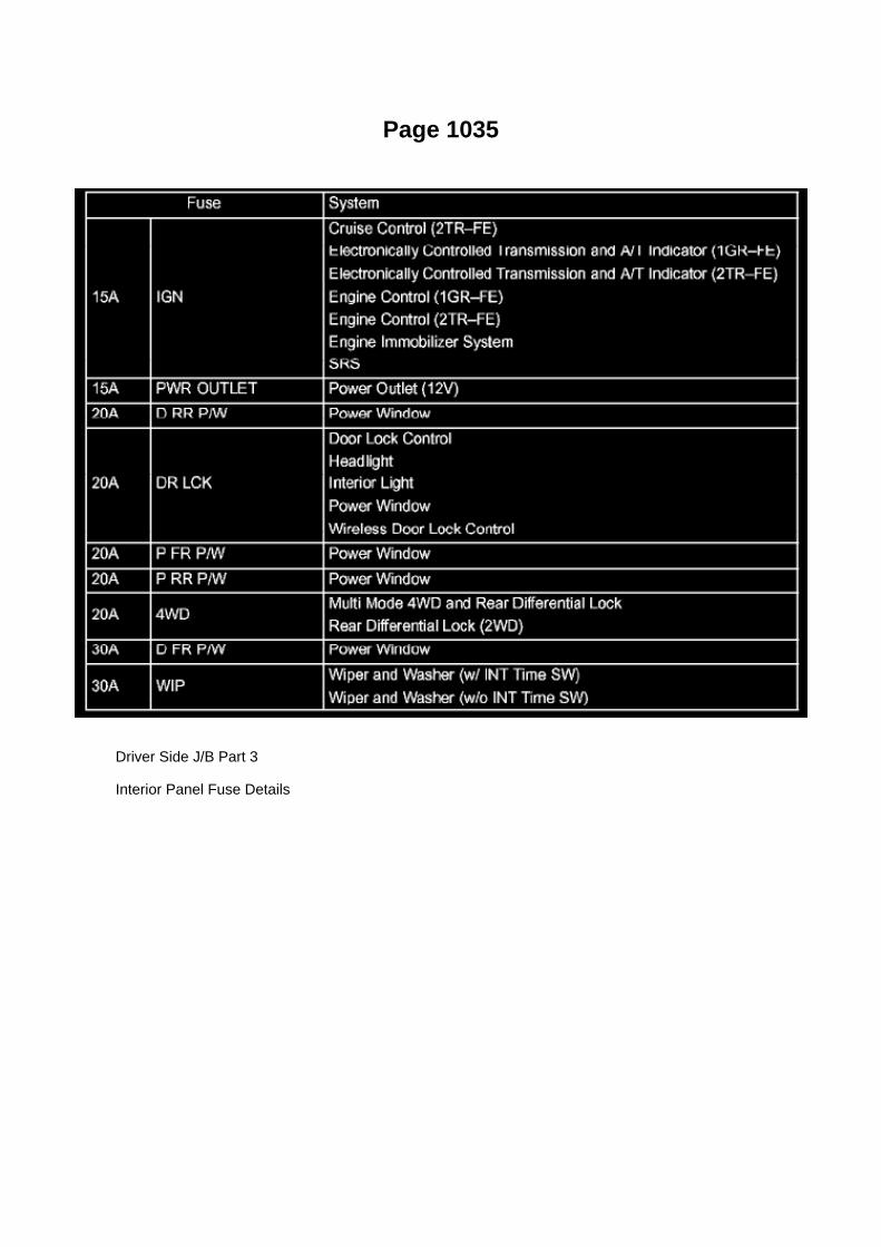
Page 1035
Driver Side J/B Part 3
Interior Panel Fuse Details

Locations

Air Flow Meter/Sensor: Locations

He - Wi

Page 175

Engine Room R/B, J/B - Engine Compartment Left

Page 1867
Engine Control Module: Technical Service Bulletins Engine/Transmission Controls - Resetting ECMMemory
TRANSMISSION & CLUTCH TC002-03 REVISED
Title: ECM RESET MEMORY FUNCTION
Models: '00 - '05 All Models
June 10, 2003
TSB REVISION NOTICE:
^ December 20, 2004: Applicable Vehicles section has been updated - 2004 and 2005 model yearsadded, models and model years updated for various models; and Reset Procedure 2 has beenrevised.
^ January 16, 2004: Tundra vehicles were added to the Applicable Vehicles chart.
^ December 17, 2003: T-100 vehicles were removed from the Applicable Vehicles chart.
Previous versions of this TSB should be discarded.
Introduction

Whenever an automatic transmission is replaced, overhauled or individual components arereplaced, use this procedure to clear Engine Control Module (ECM, SAE term: Powertrain ControlModule, PCM) "Learned Values" to minimize subsequent performance concerns.
CAUTION:
Failure to follow the procedure below may lengthen the time to readjust the ECM "Learned Values,"potentially resulting in performance concerns.
Required SSTs
Warranty Information
Applicable Vehicles

Page 1870

3. Start the engine and warm it up to normal operating temperatures before test-driving.

4. Perform a thorough test drive with several accelerations from a stop with "light throttle"application until proper transmission shifting is verified.
Reset Procedure 2
1. Disconnect the negative battery cable for 5 minutes.
2. Reconnect battery cable.
3. Start the engine and warm it up to normal operating temperatures before test-driving.
4. Perform a thorough test drive with several accelerations from a stop with "light throttle"application until proper transmission shifting is verified.

Page 45
Terminals Of Control Module / Pinouts - Check ECM

Page 220
CAN Communication System

Page 1401


Page 2553
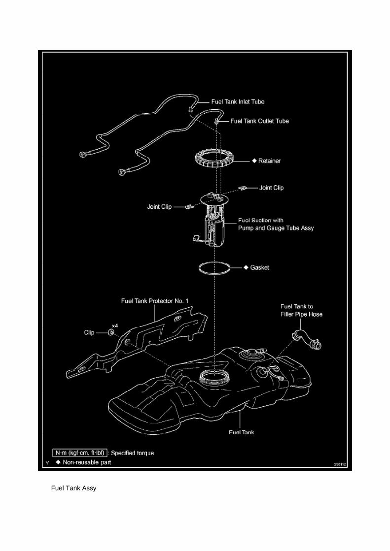
Fuel Tank Assy

Locations
A/C - Ge

Page 847
Alignment: Technical Service Bulletins ABS/TCS - Zero Point Calibration Information
T-SB-0020-08
March 25, 2008
Disconnect Battery & Perform Zero Point Calibration After Wheel Alignment Adjustment
Service Category Brake
Section Brake Control/Dynamic Control System
Market USA
Applicability
Introduction

The purpose of this TSB is to provide information on when and how to perform the zero pointcalibration on vehicles equipped with Vehicle Stability Control (VSC). Momentarily disconnectingthe battery is a necessary step for performing the zero point calibration.
Warranty Information
Required Tools & Equipment
^ Additional TIS techstream units may be ordered by calling Approved Dealer Equipment (ADE).
^ The Toyota Diagnostic Tester and CAN Interface Module may also be used to perform theservice procedures listed in this bulletin.
Preliminary Information
Perform this procedure if any of these repairs have been performed on the vehicle:
^ Wheel alignment has been adjusted.
^ Any chassis components have been removed/installed or replaced.

Page 2307
Required SSTs
Repair Procedure
1. Using the Diagnostic Tester, check for diagnostic trouble codes (DTCs).
If DTCs P043E, P043F, P2401, P2402, and P2419 are ALL present, refer to the TechnicalInformation System (TIS):
2005 model year Tacoma Repair Manual:
^ Diagnostics: SFI System (2TR-FE): EVAP Inspection Procedure
^ Diagnostics: SFI System (1GR-FE): EVAP Inspection Procedure
2006 model year Tacoma Repair Manual:
^ 1GR-FE Engine Control System: SFI System: EVAP System
^ 2TR-FE Engine Control System: SFI System: EVAP System
2. Replace the charcoal canister assembly if the EVAP pump module is diagnosed in the EVAPInspection Procedure as the suspected area.
3. Using the Diagnostic Tester, clear all DTCs.

4. Perform the Automatic EVAP System Check and verify that NO pending DTCs set.
NOTE:
If the Automatic EVAP System Check fails to run, perform the following:
^ Turn the ignition key OFF.
^ Turn the Diagnostic Tester OFF.
^ Turn the ignition key ON and the Diagnostic Tester ON and restart the Automatic EVAP SystemCheck.

Page 1970
Step 1 - 2

Page 3287

d. Use tags or labels to identify the place to reconnect each line.

e. Remove the 3 nuts and brake actuator with bracket.
5. REMOVE BRAKE ACTUATOR BRACKET ASSEMBLY
a. Remove the 2 nuts and bracket.
6. INSTALL BRAKE ACTUATOR BRACKET ASSEMBLY
a. Install the bracket with the 2 nuts.
Torque: 5.4 Nm (55 kgf-cm, 48 inch lbs.)
7. INSTALL BRAKE ACTUATOR ASSEMBLY
a. Install the actuator with bracket with the 3 nuts.
Torque: 19 Nm (194 kgf-cm, 14 ft. lbs.)
NOTICE: -
Be careful not to damage the brake tubes and wire harness.
- Tighten the bolts in order, from 1 to 3 as shown.

Page 1087

Instrument Panel J/B No. 2 Inner Circuit

Page 2669

k. Disconnect the 3 connectors. l.

Remove the nut shown in the illustration.
m. Disconnect the engine wire harness from the relay block.
n. Remove the 5 bolts and 2 nuts, then remove the intake manifold.
9. REMOVE KNOCK CONTROL SENSOR
a. Disconnect the knock control sensor connector. b. Remove the bolt, then remove the knockcontrol sensor.
10. INSTALL KNOCK CONTROL SENSOR
a. Install the knock control sensor with the bolt.
Torque: 20 N.m (204 kgf.cm, 15 ft.lbf)
NOTE: Make sure that the knock sensor is at the correct angle when installing.
b. Connect the knock control sensor connector.
11. INSTALL INTAKE MANIFOLD
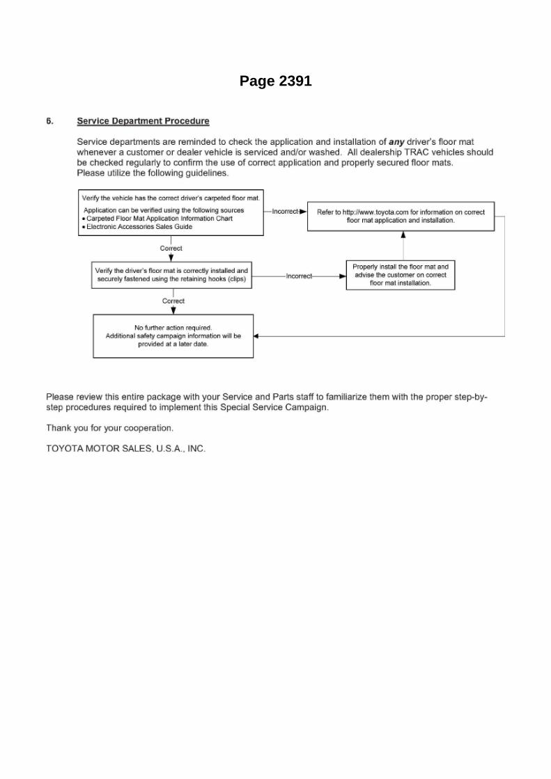
Page 2391
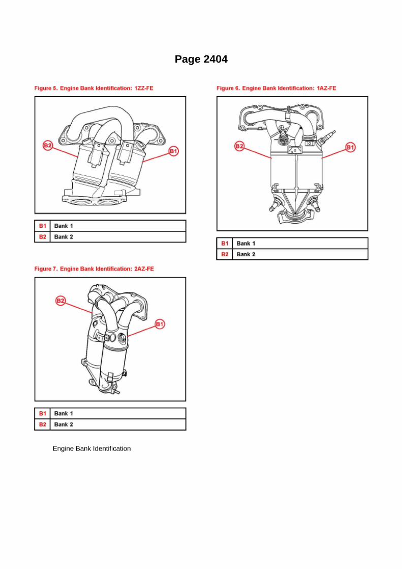
Page 2404
Engine Bank Identification

Page 2012
(CANL) of the DLC3.

Wiring Diagram

Page 1366

COMPONENTS

REPLACEMENT
1. REMOVE HOOD SUB-ASSEMBLY 2. DISCHARGE FUEL SYSTEM PRESSURE 3. REMOVEENGINE UNDER COVER SUB-ASSEMBLY NO.1 (PRE RUNNER AND 4WD TYPE)
a. Remove the 4 bolts, then remove the engine under cover No.1.
4. REMOVE ENGINE UNDER COVER SUB-ASSEMBLY NO.2 (PRE RUNNER AND 4WD TYPE,REGULAR CAB)
a. Remove the 4 bolts, then remove the engine under cover No.2.

Page 2107
^ Figure 17 shows an example of the update procedure for a two-processor ECU.
G. Turn ignition OFF. Then click Next.
H. Confirm the following:

^ Ignition is ON and engine is OFF or "READY" OFF (hybrid vehicles).
^ Hood is open.
^ All accessories are OFF.
^ Battery voltage is above 11.4 volts.
NOTICE
Verify the vehicle is connected to a battery charger before continuing - If battery voltage falls below11.4 volts, ECU damage may occur.

Page 1752
Knock Control Sensor (2TR-FE) Part 1

Page 855

Alignment: Service and Repair
NOTICE: For Zero Point Calibration information, please refer to: TSB T-SB-0020-8 (3/25/08).
FRONT WHEEL ALIGNMENT (4WD AND PRE RUNNER)
ADJUSTMENT
1. INSPECT TIRE
2. MEASURE VEHICLE HEIGHT
Vehicle height
PRE RUNNER

Page 2029

b. Measure the resistance according to the value(s) in the table.
Programming and Relearning
PRECAUTION
1. HANDLING PRECAUTIONS ON STEERING SYSTEM
a. Care must be taken when replacing parts. Incorrect replacement could affect the performance ofthe steering system and result in hazardous
driving.
2. HANDLING PRECAUTIONS ON SRS AIRBAG SYSTEM
a. This vehicle is equipped with an SRS (Supplemental Restraint System), such as the driverairbag and front passenger airbag. Failure to carry
out service operations in the correct sequence could cause the SRS airbag to unexpectedly deployduring servicing, possibly leading to a serious accident. Before servicing (including removal orinstallation of parts, inspection or replacement), be sure to read the precautionary notice for theSRS.
3. WIRE HARNESS REPAIR
a. After repairing the wire bus line with a solder, wrap the repaired part with vinyl tape.
NOTE: -
The CANL bus line and CANH bus line must be installed together all the time. When installing,make sure to twist them.
- The difference in length of the CANL bus line and CANH bus line should be within 100 mm (3.93in.).
- Untwisted parts around the connector should be within 80 mm (3.15 in.).

Page 1715

Ac - Ya

ABS With EBD System
ABS Light: Testing and Inspection ABS With EBD System
ABS Warning Light Circuit (Remains On)
ABS WARNING LIGHT CIRCUIT (REMAINS ON)
CIRCUIT DESCRIPTION

If any of the following is detected, the ABS warning light remains ON.
1. The skid control ECU connectors are disconnected from the skid control ECU. 2. There is amalfunction in the skid control ECU internal circuit. 3. There is an open in the harness between thecombination meter and skid control ECU.
HINT: -
When reading DTCs by SST (CHECK WIRE), if the ABS warning light remains on, troubleshoot byfollowing the inspection flow.
- The hand-held tester may not be usable when there is a malfunction in the skid control ECU.
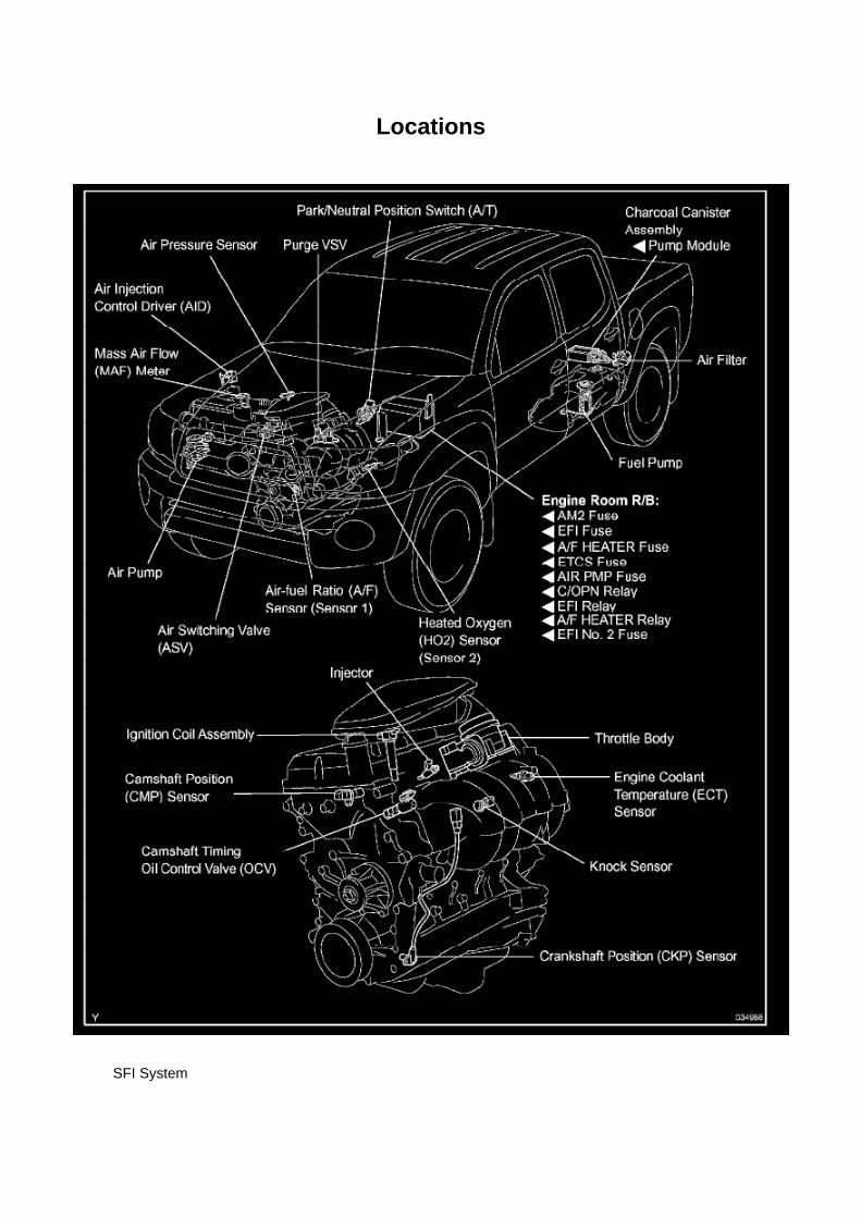
Locations
SFI System

Page 2663
Knock Control Sensor (2TR-FE) Part 1

Locations
Wheel Speed Sensor: Locations

ABS With EBD System

Page 1665
Knock Sensor: Testing and Inspection
INSPECT KNOCK SENSOR
a. Check the resistance.
1. Using an ohmmeter, measure the resistance between the terminals.
If the result is not as specified, replace the knock sensor.

Component Tests and General Diagnostics
Engine Control Module: Component Tests and General Diagnostics
ECM POWER SOURCE CIRCUIT
CIRCUIT DESCRIPTION
When the ignition switch is turned to ON, the battery voltage is applied to terminal IGSW of theECM. The ECM MREL output signal causes a current to flow to the coil, closing the contacts of theEFI relay and supplying power to terminal +B of the ECM.
Wiring Diagram

Page 1056

b. HANDLING CONNECTORS

1. When disconnecting a connector, first squeeze the mating halves tightly together to release thelock, then press the lock claw and separate the
connector.
2. When disconnecting a connector, do not pull on the harnesses. Grasp the connector directly andseparate it. 3. Before connecting the connector, check that there are no deformed, damaged, looseor missing terminals. 4. When connecting a connector, press firmly until you hear the lock closewith a "click" sound. 5. If checking the connector with a TOYOTA electrical tester, check it from thebackside (harness side) of the connector using a mini test lead.
NOTE: -
As a waterproof connector cannot be checked from the backside, check by connecting asub-harness.
- Do not damage the terminals by moving the inserted tester needle.
c. CHECKING CONNECTORS
1. Checking when the connector is connected: Squeeze the connector together to confirm that it isfully inserted and locked.
2. Checking when the connector is disconnected: Check by pulling the wire harness lightly from thebackside of the connector. Look for
unlatched terminals, missing terminals, loose crimps or broken conductor wires. Check visually forcorrosion, metallic or foreign objects and water; and bent, rusted, overheated, contaminated, anddeformed terminals.
NOTE: When testing a gold-plated female terminal, always use a gold-plated male terminal.

Page 2824
b. Install the grommet, a new lock washer and the nut.
Torque: 6.9 Nm (70 kgf-cm, 61 inch lbs.)
c. Install the manual valve lever shaft onto the groove and turn it 2 notches counterclockwise to theneutral position. d. Align the neutral basic line with the switch groove and tighten the adjusting bolt.
Torque: 13 Nm (130 kgf-cm, 9 ft. lbs.)
e. Bend the tabs of the lock washer.
HINT: Bend at least 2 of the lock washer tabs.
5. CONNECT PARK/NEUTRAL POSITION SWITCH CONNECTOR 6. CONNECT CABLE TONEGATIVE BATTERY TERMINAL
Torque: 3.9 Nm (40 kgf-cm, 35 inch lbs.)
7. INSPECT PARK/NEUTRAL POSITION SWITCH ASSY 8. ADJUST PARK/NEUTRAL POSITIONSWITCH ASSY 9. ADJUST SHIFT LEVER POSITION
10. INSPECT SHIFT LEVER POSITION

Page 86
Blower Motor Relay: Testing and Inspection
INSPECT HEATER RELAY
a. Check the resistance.

1. Using an ohmmeter, measure the resistance between each terminal.
If the result is not as specified, replace the relay

Page 1968

Step 15 - 17

INSPECTION PROCEDURE
Check Can Bus Line For Short to +B
CHECK CAN BUS LINE FOR SHORT TO +B
CIRCUIT DESCRIPTION
A short to +B is suspected in the CAN bus line when there is continuity between terminals 16 (BAT)and 6 (CANH) or terminals 16 (BAT) and 14

Page 589
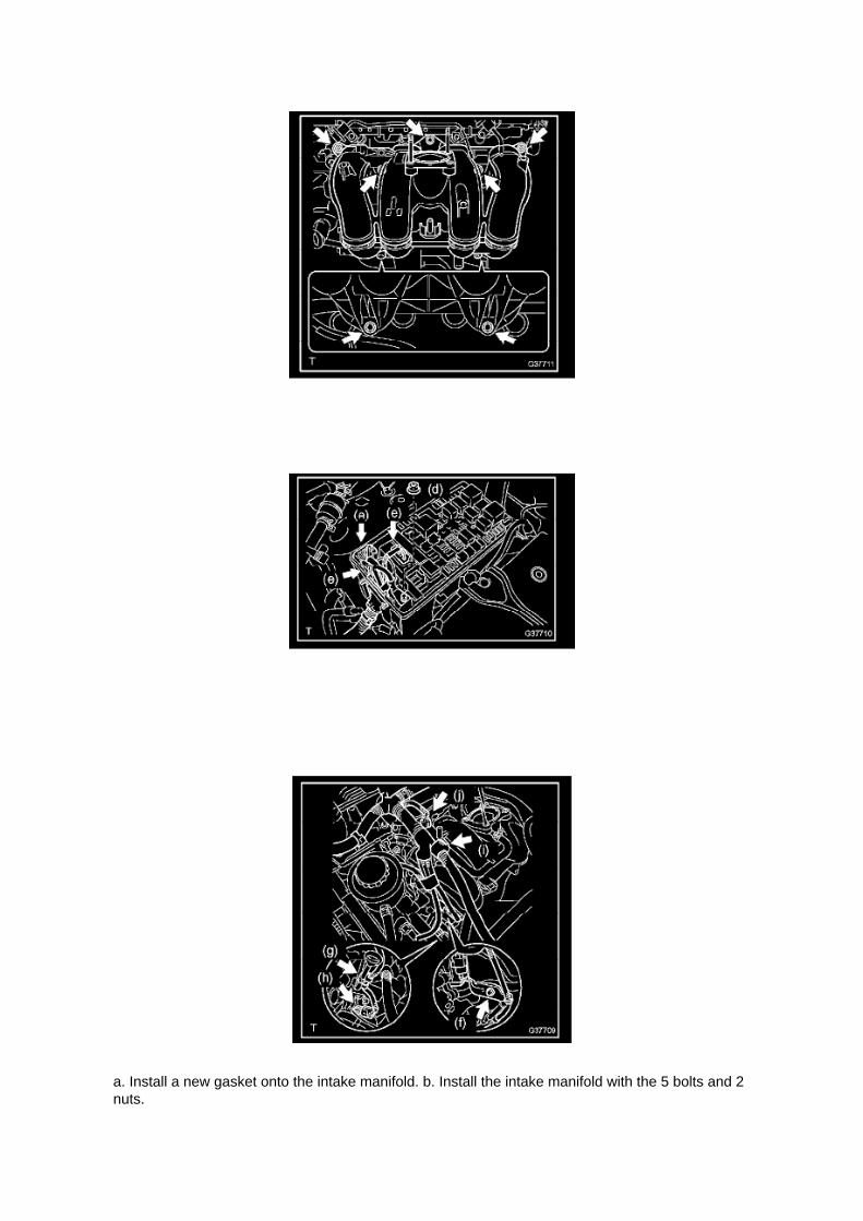
a. Install a new gasket onto the intake manifold. b. Install the intake manifold with the 5 bolts and 2nuts.

Torque: 25 N.m (255 kgf.cm, 18 ft.lbf)
c. Connect the engine wire harness to the relay block. d. Install the nut shown in the illustration.
Torque: 10 N.m (102 kgf.cm, 7 ft.lbf)
e. Connect the 3 connectors.
f. Install the harness clamp bracket with the bolt.
Torque: 8.2 N.m (84 kgf.cm, 73 in.lbf)
g. Engage the wire harness clamp. h. Connect the compressor magnetic clutch connector.

Page 440
Combination Meter

Locations

Transmission Speed Sensor: Locations

He - Wi

Page 3044

a. Using vernier calipers, inspect the depth and width of wear of the diaphragm spring.
Minimum:
A (Depth): 0.5 mm (0.020 inch) B (Width): 6.0 mm (0.236 inch)
If necessary, replace the clutch cover assy.
12. INSPECT FLYWHEEL SUB-ASSY
a. Using a dial indicator, inspect the flywheel sub-assembly runout.
Maximum runout: 0.1 mm (0.004 inch) If necessary, replace the flywheel sub-assembly.
13. INSPECT INPUT SHAFT BEARING
a. Turn the bearing by hand while applying force in the rotation direction.
If the bearing is stuck or difficult to turn, replace the input shaft bearing.
HINT: The bearing is permanently lubricated and requires no cleaning or lubrication.
14. REMOVE INPUT SHAFT BEARING
a. Remove the 4 bolts at diametrically opposite points. b. Using SST, remove the pilot bearing.
SST 09303-35011
15. INSTALL INPUT SHAFT BEARING
a. Using SST and a hammer, install the input shaft bearing.
SST 09304-30012
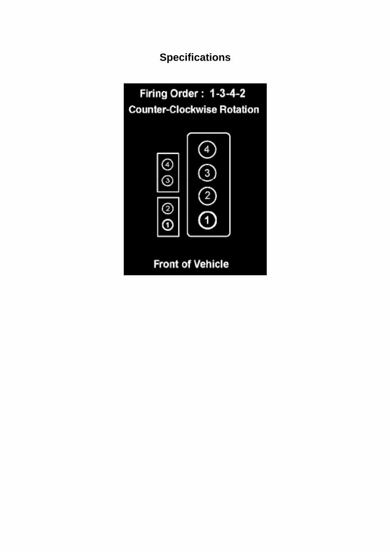
Specifications

Page 479
SFI System

Page 1042

Engine Compartment

Instrument Panel
Locations

Page 2892

D. Identify connector DD and Junction Block No.1 (see Figures 6 and 7).
E. Disconnect connector DD from Junction Block No. 1.
F. Carefully inspect both components for liquid or corrosion in the connector and the Junction Block(especially the male and female terminals).

Page 1904

Example: Splice point "I5" is on the Cowl Wire Harness and is described.
How to Read Connector List
HOW TO READ CONNECTOR LIST
A: Indicates connector to be connected to a part. (The numeral indicates the pin No.)
B: Junction Connector
Indicates a connector which is connected to a short terminal.
Junction connector in this include a short terminal which is connected to a number of wireharnesses. Always perform inspection with the short terminal installed. (When installing the wireharnesses, the harnesses can be connected to any position within the short terminal grouping.Accordingly, in other vehicles, the same position in the short terminal may be connected to a wireharness from a different part.) Wire harness sharing the same short terminal grouping have thesame color.
C: Parts Code
The first letter of the code is taken from the first letter of part, and the numbers indicates its order inparts which start with the same letter.
D: Connector Color
Connectors not indicated are milky white in color.

Page 1620
SFI System

Page 3182
Ce - Ya
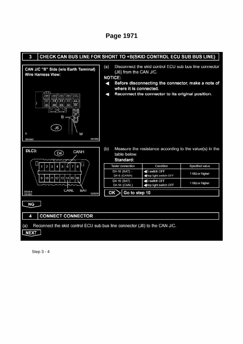
Page 1971
Step 3 - 4

Page 2902
4. Are any of the following Data List parameters "ON" when the Neutral Position SW Signal is"ON"?
^ Shift SW Status (R Range)
^ Shift SW Status (D Range)
^ Shift SW Status (4 or D)
^ Shift SW Status (3 Range)
^ Shift SW Status (2 Range)
^ Shift SW Status (L Range)
If NO - This TSB does NOT apply. Refer to the applicable model year Tacoma Repair Manual fordiagnostics for DTC P0705.
5. Using Techstream clear all stored DTCs and then attempt to duplicate the MIL "ON" DTC P0705.

6. Prepare Techstream Data List for performing the testing/duplication procedure in step 7.
HINT
^ Using the Snapshot feature of Techstream makes it easier to review data and confirm duplicationof this issue.
^ Refer to the University of Toyota online training class P901C "Techstream InDepth" forinformation about taking snapshots and graphing snapshots on Techstream.
A. Data List setup:
Select AT Datalist
B. Configure Snapshot as follows:
30 second duration

Page 722
(a) Slide the bench seat to the rearmost position.
(b) Locate the floor wire harness and connector under the seat on the driver's side closest to thefront edge of the seat cushion.

Page 2402

Applicable Vehicles

Locations
Fuse: Locations
Engine Room R/B No. 2 - Engine Compartment Left

Page 137

Engine Room R/B, J/B - Engine Compartment Left

Page 546
Ce - Ya

Locations
A/C - Ge

Page 1652

a. Apply a light coat of engine oil to the O-ring of the crankshaft position sensor.

b. Install the camshaft position sensor with the bolt.
Torque: 8.5 N.m (87 kgf.cm, 75 in.lbf)
NOTE: Make sure that the O-ring is not cracked or jammed when installing.
c. Connect the crankshaft position sensor connector and the 2 wire harness clamps.
8. INSTALL IDLE PULLEY ASSEMBLY W/BRACKET (W/ AIR CONDITIONING)

Locations
A/C - Ge

Page 2020

Step 1 - 3

Page 3295

c. Using a screwdriver, remove the clip.

d. Remove the brake booster w/ accumulator pump assembly.
e. Using a hexagon wrench (4 mm), remove the 2 pins. Remove the 2 bushes and 2 collars fromthe brake booster w/ accumulator pump
assembly.
17. REMOVE BRAKE ACTUATOR BRACKET
a. Using a hexagon wrench (5 mm), remove the screw and brake actuator bracket.
18. REMOVE BRAKE BOOSTER PUMP BRACKET
a. Using a hexagon wrench (5 mm), remove the 2 screws and brake booster pump bracket. b.Remove the bush from the brake booster pump bracket.
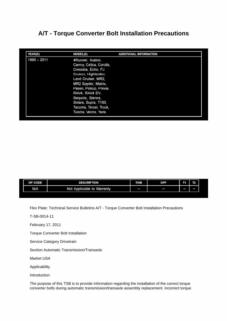
A/T - Torque Converter Bolt Installation Precautions
Flex Plate: Technical Service Bulletins A/T - Torque Converter Bolt Installation Precautions
T-SB-0014-11
February 17, 2011
Torque Converter Bolt Installation
Service Category Drivetrain
Section Automatic Transmission/Transaxle
Market USA
Applicability
Introduction
The purpose of this TSB is to provide information regarding the installation of the correct torqueconverter bolts during automatic transmission/transaxle assembly replacement. Incorrect torque

converter bolts or missing washers can cause damage to the torque converter assembly. Use theinformation in this bulletin when installing an automatic transmission/transaxle assembly.
NOTE
Not all applications will use washers on the torque converter bolts.
Warranty Information
Installation Procedure
^ When removing torque converter bolts and washers take special care that the same bolts andwashers are used when installing the torque converter.
^ Using an incorrect size bolt or washer may cause damage to the torque converter assembly.

Page 1368

25. REMOVE EXHAUST PIPE ASSEMBLY FRONT 26. REMOVE MANUAL TRANSMISSIONUNIT ASSEMBLY 27. REMOVE AUTOMATIC TRANSMISSION ASSEMBLY 28. REMOVE

ENGINE ASSEMBLY 29. REMOVE CLUTCH COVER ASSEMBLY (MANUAL TRANSMISSION)30. REMOVE CLUTCH DISC ASSEMBLY (MANUAL TRANSMISSION) 31. REMOVE FLYWHEELSUB-ASSEMBLY (MANUAL TRANSMISSION)
SST 09213-54015 (91651-60855), 09330-00021
32. REMOVE DRIVE PLATE & RING GEAR SUB-ASSEMBLY (AUTOMATIC TRANSMISSION)
SST 09213-54015 (91651-60855), 09330-00021
33. REMOVE REAR END PLATE
a. Remove the 2 bolts, then remove the rear end plate.
34. REMOVE INTAKE AIR CONNECTOR 35. REMOVE GENERATOR ASSEMBLY 36. REMOVEV-RIBBED BELT TENSIONER ASSEMBLY
37. REMOVE IDLER PULLEY SUB-ASSEMBLY NO.1
a. Remove the bolt and idler pulley sub-assembly No.1.
38. REMOVE IDLE PULLEY ASSEMBLY W/BRACKET (W/ AIR CONDITIONING) 39. REMOVECRANKSHAFT POSITION SENSOR 40. REMOVE CAMSHAFT POSITION SENSOR 41.REMOVE INTAKE MANIFOLD TO HEAD GASKET NO.1 42. REMOVE CYLINDER HEAD COVERSUB-ASSEMBLY
43. REMOVE CRANKSHAFT PULLEY
a. Set the No.1 cylinder to the TDC/compression.
(1) Turn the crankshaft pulley clockwise and align its timing mark notch with the timing mark "0". (2)Check that the timing marks of the camshaft timing gear are located as illustrated.
HINT: If not, turn the crankshaft to align the marks.

Page 3045

HINT: After assembling the input shaft bearing to the hub, make sure that it rotates smoothly.

b. Install 4 new bolts.
Torque: 27 Nm (270 kgf-cm, 20 ft. lbs.)
c. Mark each bolt with paint as shown in the illustration. d. Retighten each bolt by 90°. e. Checkthat the mark on each bolt is at a 90° angle from its original position.
16. INSPECT CLUTCH RELEASE BEARING ASSY
a. Turn the release bearing by hand while applying force in the axial direction.
HINT: The bearing is permanently lubricated and requires no cleaning or lubrication.
If necessary, replace the release bearing assy.
17. INSTALL CLUTCH DISC ASSY
a. Insert SST into the clutch disc assy, then insert them into the flywheel sub-assembly.
SST 09301-00210
NOTICE: Take care not to insert clutch disc assy in the wrong orientation.
18. INSTALL CLUTCH COVER ASSY

Page 1128
Circuit Inspection

Voltage Check
VOLTAGE CHECK

Page 2613
Camshaft Position Sensor: Testing and Inspection
INSPECT CAMSHAFT POSITION SENSOR
Check the resistance.
Using an ohmmeter, measure the resistance between the terminals.
HINT: Cold and Hot mean the temperature of the coils themselves. Cold is from -10 to 50°C (14 to122°F) and Hot is from 50 to 100°C (122 to 212° F).
If the result is not as specified, replace the camshaft position sensor.
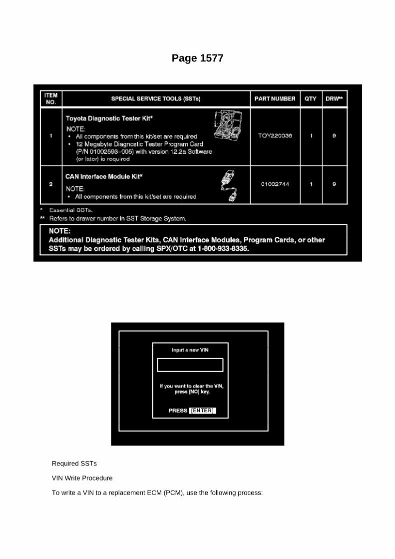
Page 1577
Required SSTs
VIN Write Procedure
To write a VIN to a replacement ECM (PCM), use the following process:

1. Confirm the VIN. It is located on the front left of the instrument panel.
2. Connect the Diagnostic Tester to DLC3.
3. Turn the ignition switch and Diagnostic Tester switch ON.
4. All vehicles except Prius and Highlander HV:
Select from the Diagnostic Tester menus: DIAGNOSIS, ENHANCED OBDII, VIN, and VIN WRITE.
Prius and Highlander HV vehicles:
Select from the Diagnostic Tester menus: DIAGNOSIS, OBD/MOBD, HV ECU, VIN, and VINWRITE.

Page 3321
Step 1

Page 3004

G. Remove the clutch pedal sub-assembly.

a. Remove the bolt and nut.
b. Remove the clutch pedal from the clutch pedal support.
4. Remove the clutch pedal spring holder from the clutch pedal support.
5. Remove the clutch pedal pad.
6. Remove the two (2) clutch pedal bushes from the clutch pedal.

Page 846

NOTE

Adjusting value for the set bolts is 6' - 30' (0.1° 0.5°). When making an adjustment of more than 45'replace the upper and lower steering knuckle set bolts with the adjusting bolts. If the camber isNOT within the specification, use the table shown to estimate how much additional camberadjustment will be required, and select the appropriate camber adjusting bolt.
I. Follow steps 4A through 4H again. Between steps 4B and 4C exchange one or two selectedbolts.
HINT
When exchanging the two bolts, exchange one bolt at a time.
If Vehicle Pull Is Eliminated: Repair Is Now Complete.

Page 2412
A/C - Ge

Recall - Seat Belt Sensor Wire Harness Modification
Technical Service Bulletin # SSC50I Date: 050701

ABS W/EBD System
Electronic Brake Control Module: Testing and Inspection ABS W/EBD System
Terminals Of Control Module / Pinouts - Terminals Of ECU
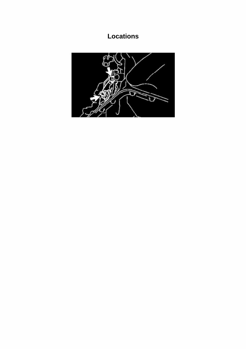
Locations

Page 1967
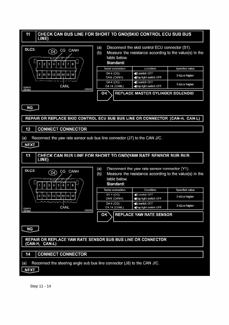
Step 11 - 14

Page 1373

a. Remove the bolt and chain vibration damper No.2.
56. REMOVE CHAIN VIBRATION DAMPER NO.3
a. Remove the 2 bolts and chain vibration damper No.3.
57. REMOVE CHAIN TENSIONER ASSEMBLY NO.2
a. Remove the nut and chain tensioner assembly No.2.
58. REMOVE NO.2 CHAIN SUB-ASSEMBLY
a. Remove the bolt, balance shaft drive gear shaft and balance shaft drive gear. b. Remove thecrankshaft timing sprocket No.2 and chain.
59. INSTALL NO.2 CHAIN SUB-ASSEMBLY
a. Install the chain with its mark links aligned with the timing marks on the crankshaft timingsprocket and balance shaft timing sprocket.
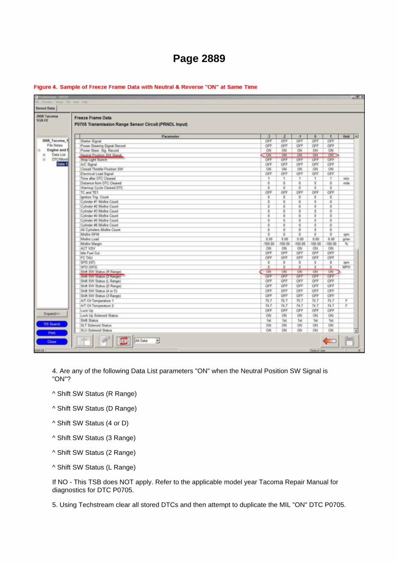
Page 2889
4. Are any of the following Data List parameters "ON" when the Neutral Position SW Signal is"ON"?
^ Shift SW Status (R Range)
^ Shift SW Status (D Range)
^ Shift SW Status (4 or D)
^ Shift SW Status (3 Range)
^ Shift SW Status (2 Range)
^ Shift SW Status (L Range)
If NO - This TSB does NOT apply. Refer to the applicable model year Tacoma Repair Manual fordiagnostics for DTC P0705.
5. Using Techstream clear all stored DTCs and then attempt to duplicate the MIL "ON" DTC P0705.

6. Prepare Techstream Data List for performing the testing/duplication procedure in step 7.
HINT
^ Using the Snapshot feature of Techstream makes it easier to review data and confirm duplicationof this issue.
^ Refer to the University of Toyota online training class P901C "Techstream InDepth" forinformation about taking snapshots and graphing snapshots on Techstream.
A. Data List setup:
Select AT Datalist
B. Configure Snapshot as follows:
30 second duration

Capacity Specifications

Fluid - Differential: Capacity Specifications

DIFFERENTIAL OIL CAPACITY:
2WD Models (except Prerunner)............................................................................................................................................... 3.3 L(3.5 qt., 2.9 Imp. qt.)
4WD models and Prerunner Front (4WD models): ................................................................................................................................................................. 1.5 L (1.6 qt., 1.3 Imp. qt.) Rear: ........................................................................................................................................................................................... 2.8 L (3.0 qt., 2.5 Imp. qt.)

Page 556

Air Flow Meter/Sensor: Testing and Inspection

INSPECT INTAKE AIR FLOW METER SUB-ASSEMBLY
a. Check the operation.
1. Apply battery voltage across terminals 1 (+B) and 2 (E2G). 2. Using a voltmeter, connect thepositive (+) tester prove to terminal 3 (VG) and the negative (-) tester prove to terminal 2 (E2G). 3.Blow air into the mass air flow meter and check that the voltage fluctuates.
If the voltage does not fluctuate, replace the mass air flow meter.
b. Check the resistance.
1. Using an ohmmeter, measure the resistance between the terminals.
If the result is not as specified, replace the mass air flow meter.

Page 157

c. Check the voltage.

1. In a circuit in which voltage is applied to the ECU connector terminal, an open circuit can bechecked by conducting a voltage check.
FIG 4: With each connector still connected, measure the voltage between the body ground andthese terminals (in this order): 1) terminal 1 of connector A at the ECU 5 V output terminal, 2)terminal 1 of connector B, and 3) terminal 1 of connector C.
2. Example results:
If your results match the examples above, an open circuit exists in the wire harness betweenterminal 1 of connector B and terminal 1 of connector C.
Check Short Circuit
CHECK SHORT CIRCUIT
a. If the wire harness is ground shorted (Fig. 5), locate the section by conducting a resistancecheck with the body ground.
b. Check the resistance with the body ground.

Page 2409

Engine Bank Identification

Page 182

Driver Side J/B Inner Circuit

Page 744

Combination Meter

Page 2261

He - Wi

Page 2592
Throttle Body: Testing and Inspection Component Inspection
INSPECT THROTTLE W/MOTOR BODY ASSEMBLY
a. Check the resistance.
1. Using an ohmmeter, measure the resistance between the terminals.
If the result is not as specified, replace the throttle body.

Page 475
Coolant Temperature Sensor/Switch (For Computer): Testing and Inspection
INSPECT E.F.I. ENGINE COOLANT TEMPERATURE SENSOR
a. Check the resistance.
1. Using an ohmmeter, measure the resistance between the terminals.
NOTE: If checking the engine coolant temperature sensor in water, be careful not to allow water tointrude into the terminals. After checking, wipe the water off the engine coolant temperature sensor.

If the result is not as specified, replace the engine coolant temperature sensor.

Page 2999

Repair Procedure Identification

Refer to the table below to determine which parts/modifications need to be performed.
Repair Procedure A
Carpet Modification
1. Remove the front door scuff plate LH. Disengage the 9 claws and remove the front door scuffplate.
2. Remove the front floor footrest. Disengage the 2 clips and remove the front floor footrest.

Page 215
Refer to Reset Procedure 1 for the vehicles with Electronically Controlled AutomaticTransmissions:

Page 3151

Fluid - M/T: Fluid Type Specifications

Transmission Fluid
Grade ............................................................................................................................................................................................................... GL-4 or GL-5 Viscosity ........................................................................................................................................................................................................... SAE75W-90

Page 179
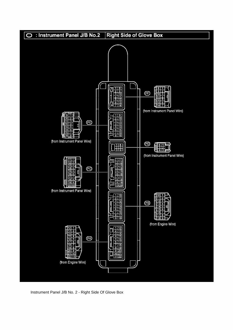
Instrument Panel J/B No. 2 - Right Side Of Glove Box
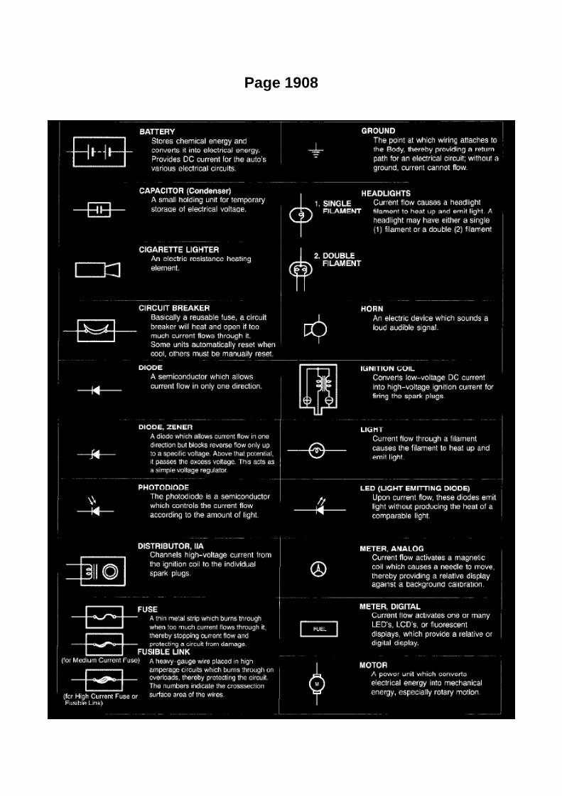
Page 1908

Glossary Of Terms And Sysmbols Part 1

Locations
Driver Side J/B - Lower Finish Panel

Page 270
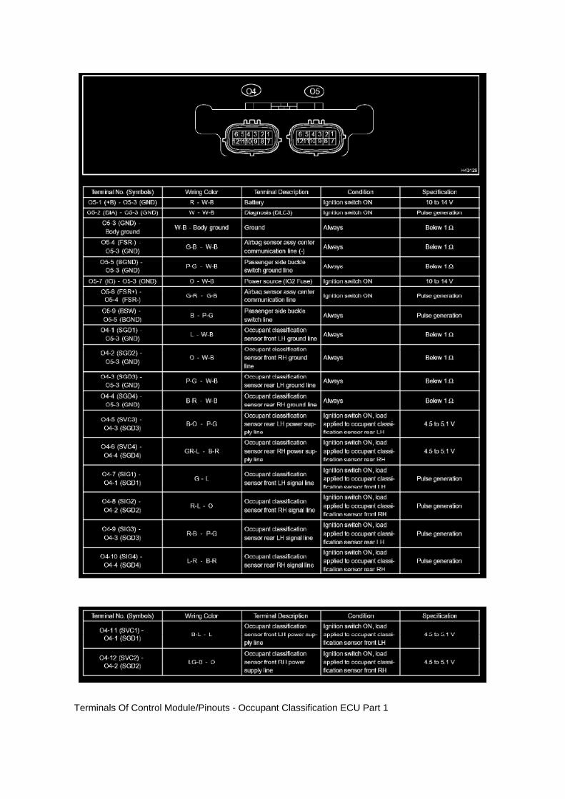
Terminals Of Control Module/Pinouts - Occupant Classification ECU Part 1

Terminals Of Control Module/Pinouts - Occupant Classification ECU Part 2

Page 1871
Engine Control Module: Locations
Instrument Panel

Page 1518

1. Remove coolant and any foreign material on rubber points "A," "B," and "C."

2. Check that points "A" and "B" are not deformed, cracked, or swollen.
3. Check that points "B" and "C" are not stuck together.
4. Apply engine coolant to point "B" before using the radiator cap tester.
^ Radiator Cap Tester: Snap-On/Sun P/N SVTS262A (or equivalent)
5. Before installing the radiator cap tester, use the applicable radiator cap adaptor provided in thefollowing SST kits in conjunction with the radiator cap tester:
^ SST P/N 09230-00030-01 (09231-10080-01) or 09230-00020-01 (09231-10060-01) or09230-00050-01(09231-10110-01
6. When using the radiator cap tester, tilt it more than 30 degrees.
7. Pump the radiator cap tester several times, and check the maximum pressure.
Pumping speed: 1 pump/second
HINT:
Stop pumping when the valve opens and read the gauge. The gauge must be within the standardvalues listed below when the pressure valve opens. The cap is considered OK when the pressureholds steady or falls very slowly, but holds within the standard values listed below for one minute.

Page 2943
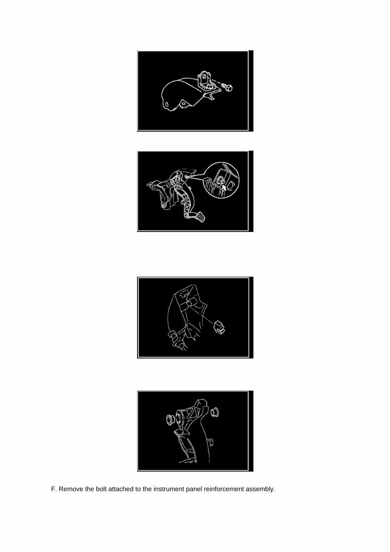
F. Remove the bolt attached to the instrument panel reinforcement assembly.

G. Remove the clutch pedal sub-assembly.
a. Remove the bolt and nut.
b. Remove the clutch pedal from the clutch pedal support.
4. Remove the clutch pedal spring holder from the clutch pedal support.
5. Remove the clutch pedal pad.

Locations

Timing Component Alignment Marks: Locations

Timing Mark Locations

Page 1753

Knock Control Sensor (2TR-FE) Part 2

Page 376

6. REMOVE INSTRUMENT PANEL UNDER TRAY (A/T TRANSMISSION) 7. SEPARATE HOODLOCK CONTROL LEVER SUB-ASSEMBLY 8. REMOVE INSTRUMENT PANEL FINISH PANEL

LOWER NO.1
9. SEPARATE DRIVER SIDE JUNCTION BLOCK
a. Remove the 2 bolts and bracket. b. Remove the 2 nuts and separate the driver side junctionblock assembly.
10. REMOVE CLUTCH SWITCH ASSEMBLY
a. Disconnect the connector. b. Loosen the nut and remove the clutch switch assembly.
11. INSTALL CLUTCH SWITCH ASSEMBLY
a. Install the clutch switch assembly and tighten the nut. b. Connect the connector.
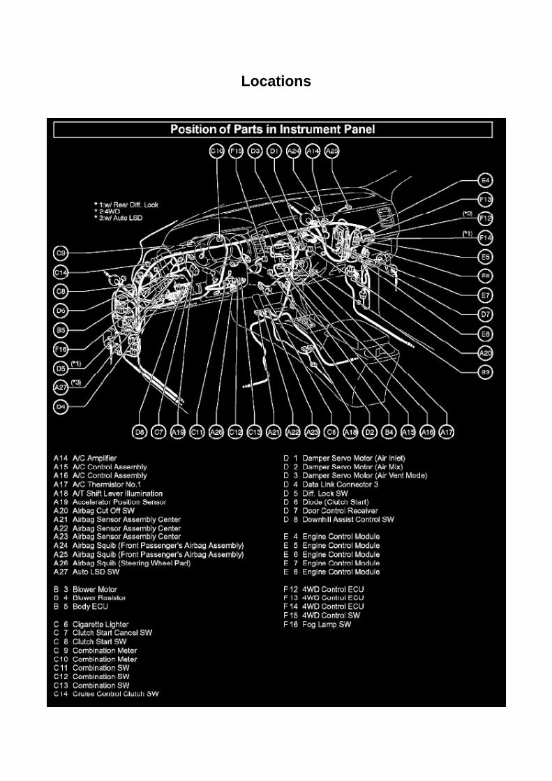
Locations

A/C - Fo

Page 1680
Oxygen Sensor: Technical Service Bulletins Engine Controls - Bank 1/Bank 2 O2 Sensoridentification
ENGINE EG034-07
Title: ENGINE BANK 1 AND BANK 2 A/F AND O2 IDENTIFICATION
Models: '93 - '08 Applicable Models
June 28, 2007
The information contained in this TSB supercedes TSB No. EG037-04. TSB No. EG037-04 is nowobsolete and should be discarded.
Introduction
This service bulletin provides information on the proper identification of engine bank 1 and enginebank 2 for correct A/F sensor and oxygen sensor replacement.
This bulletin contains information that identifies engine bank 1 and engine bank 2 on the followingengines: 1AZ-FE, 2AZ-FE, 2AZ-FE (PZEV), 1GR-FE, 2GR-FE, 2GR-FSE, 2JZ-GE, 1MZ-FE,3MZ-FE, 1UR-FSE, 3UR-FE, 2UZ-FE, 3UZ-FE, 5VZ-FE, and 1ZZ-FE.
^ Bank 1 (B1) refers to the bank that includes cylinder No. 1.

^ Bank 2 (B2) refers to the bank opposite bank 1.
^ Sensor 1 (S1) refers to the sensor that is located before the catalytic converters.
^ Sensor 2 (S2) refers to the sensor that is located after the catalytic converters.
Warranty Information

Page 3250
Ce - Ya

Page 639
Information
TECHNICAL INSTRUCTIONS

FOR
SPECIAL SERVICE CAMPAIGN 50I
2005 MODEL YEAR TACOMA REGULAR-CAB
FRONT BENCH SEAT WIRE SEAT JUMPER

Page 1634
SFI System
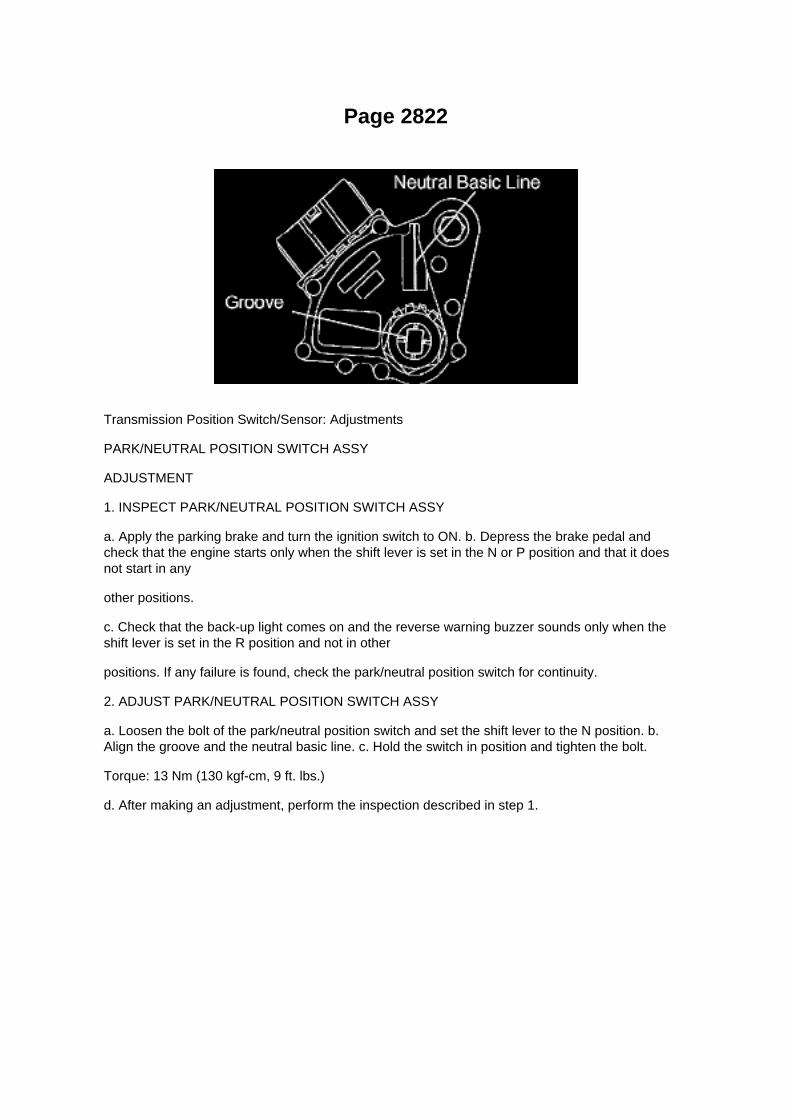
Page 2822
Transmission Position Switch/Sensor: Adjustments
PARK/NEUTRAL POSITION SWITCH ASSY
ADJUSTMENT
1. INSPECT PARK/NEUTRAL POSITION SWITCH ASSY
a. Apply the parking brake and turn the ignition switch to ON. b. Depress the brake pedal andcheck that the engine starts only when the shift lever is set in the N or P position and that it doesnot start in any
other positions.
c. Check that the back-up light comes on and the reverse warning buzzer sounds only when theshift lever is set in the R position and not in other
positions. If any failure is found, check the park/neutral position switch for continuity.
2. ADJUST PARK/NEUTRAL POSITION SWITCH ASSY
a. Loosen the bolt of the park/neutral position switch and set the shift lever to the N position. b.Align the groove and the neutral basic line. c. Hold the switch in position and tighten the bolt.
Torque: 13 Nm (130 kgf-cm, 9 ft. lbs.)
d. After making an adjustment, perform the inspection described in step 1.

Page 1159
Malfunction Indicator Lamp: Testing and Inspection
MIL CIRCUIT
CIRCUIT DESCRIPTION
The MIL (Malfunction Indicator Lamp) is used to indicate vehicle malfunction detections by theECM. By turning the ignition switch to ON, power is supplied to the MIL circuit, and the ECMprovides the circuit ground which illuminates the MIL.
The MIL operation can be checked visually: When the ignition switch is first turned to ON, the MILshould be illuminated and should then turn OFF. If the MIL remains illuminated or is not illuminated,conduct the following troubleshooting procedure using a hand-held tester.
Wiring Diagram

Specifications

Fuel Pressure: Specifications

Fuel Pressure
At Idle.............................................................................................................................................281to 287 kPa (2.87 to 2.93 kgf/sq.cm, 40.8 to 41.7 psi)
After Engine Stopped for 5Min..............................................................................................................................................147kPa (1.5 kgf/sq.cm, 21 psi)

Locations
Body Control Module: Locations
Instrument Panel

Page 1040
Driver Side J/B - Lower Finish Panel

Page 2165
SFI System

Capacity Specifications

Fluid - A/T: Capacity Specifications

Drain and Fill: 4 speed .................................................................................................................................................................... Up to 2.1 US. qt. (2.0 L)
Drain and Fill: 5 speed .................................................................................................................................................................... Up to 3.2 US. qt. (3.0 L)

Page 1481

Water Pump: Service and Repair

WATER PUMP ASSEMBLY (2TR-FE)
REPLACEMENT
1. DISCONNECT CABLE FROM NEGATIVE BATTERY TERMINAL 2. REMOVE ENGINE UNDERCOVER SUB-ASSEMBLY NO.1 (PRE RUNNER AND 4WD TYPE)
a. Remove the 4 bolts, then remove the engine under cover No.1.
3. DRAIN ENGINE COOLANT 4. REMOVE RADIATOR SUPPORT TO FRAME SEAL LH 5.REMOVE FAN SHROUD 6. REMOVE GENERATOR ASSEMBLY
7. REMOVE V-RIBBED BELT TENSIONER ASSEMBLY
a. Remove the 3 bolts, then remove the V-ribbed belt tensioner.
8. REMOVE WATER PUMP ASSEMBLY
a. Remove the 10 bolts, then remove the water pump and gasket.
9. INSTALL WATER PUMP ASSEMBLY
a. Install a new gasket, then install the water pump with the 10 bolts.
Torque:
21 Nm (214 kgf-cm, 15 ft. lbs.) for bolt A 9 Nm (92 kgf-cm, 80 inch lbs.) for bolt B

Page 1031

Engine Room J/B, Engine Room R/B Part 2

Page 678
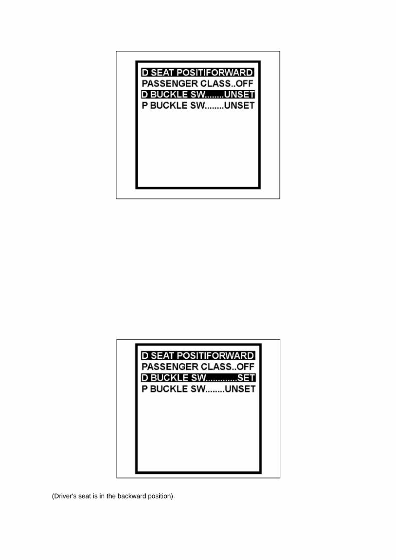
(Driver's seat is in the backward position).

^ "D BUCKLE SW UNSET" (Driver's seat belt buckle switch is unset/unbuckled).
(Test # 3)
(a) Move the bench seat to the foremost position.
(b) Leave the driver's seat belt unbuckled.
(c) Confirm that the scan tool displays the data shown below and in the illustration.
^ "D SEAT POSITIFORWARD"
(Driver's seat is in the forward position).
^ "D BUCKLE SW UNSET" (Driver's seat belt buckle switch is unset/unbuckled).
(Test # 4)
(a) Leave the bench seat in the foremost position.
(b) Buckle the driver's seat belt.

Page 359

3. A/T: Check that the shift lever is in the P position and apply the parking brake.
M/T: Check that the shift lever is in neutral and apply the parking brake.
NOTE: DTC C1210/36 and C1336/39 will be recorded if the shift lever is not in the P position.
4. Connect the hand-held tester to the DLC3. 5. Turn the ignition switch to the ON position.
6. Switch the ECU to test mode using the hand-held tester. Select the menu items: DIAGNOSTIC /OBD / MOBD / select vehicle / ABS /
VSC / TEST MODE.
7. Keep the vehicle stationary on a level surface for 2 seconds or more.
8. Check that the VSC TRAC warning light blinks as shown in the illustration.
NOTE: The VSC TRAC warning light (and VSC OFF indicator light [4WD, w/ rear diff. lock]) stayON when obtaining the zero point.

Page 3316
Step 3

ABS/TCS - Zero Point Calibration Information
Steering Angle Sensor: Technical Service Bulletins ABS/TCS - Zero Point Calibration Information
T-SB-0020-08
March 25, 2008
Disconnect Battery & Perform Zero Point Calibration After Wheel Alignment Adjustment
Service Category Brake
Section Brake Control/Dynamic Control System
Market USA
Applicability
Introduction

The purpose of this TSB is to provide information on when and how to perform the zero pointcalibration on vehicles equipped with Vehicle Stability Control (VSC). Momentarily disconnectingthe battery is a necessary step for performing the zero point calibration.
Warranty Information
Required Tools & Equipment
^ Additional TIS techstream units may be ordered by calling Approved Dealer Equipment (ADE).
^ The Toyota Diagnostic Tester and CAN Interface Module may also be used to perform theservice procedures listed in this bulletin.
Preliminary Information
Perform this procedure if any of these repairs have been performed on the vehicle:
^ Wheel alignment has been adjusted.
^ Any chassis components have been removed/installed or replaced.
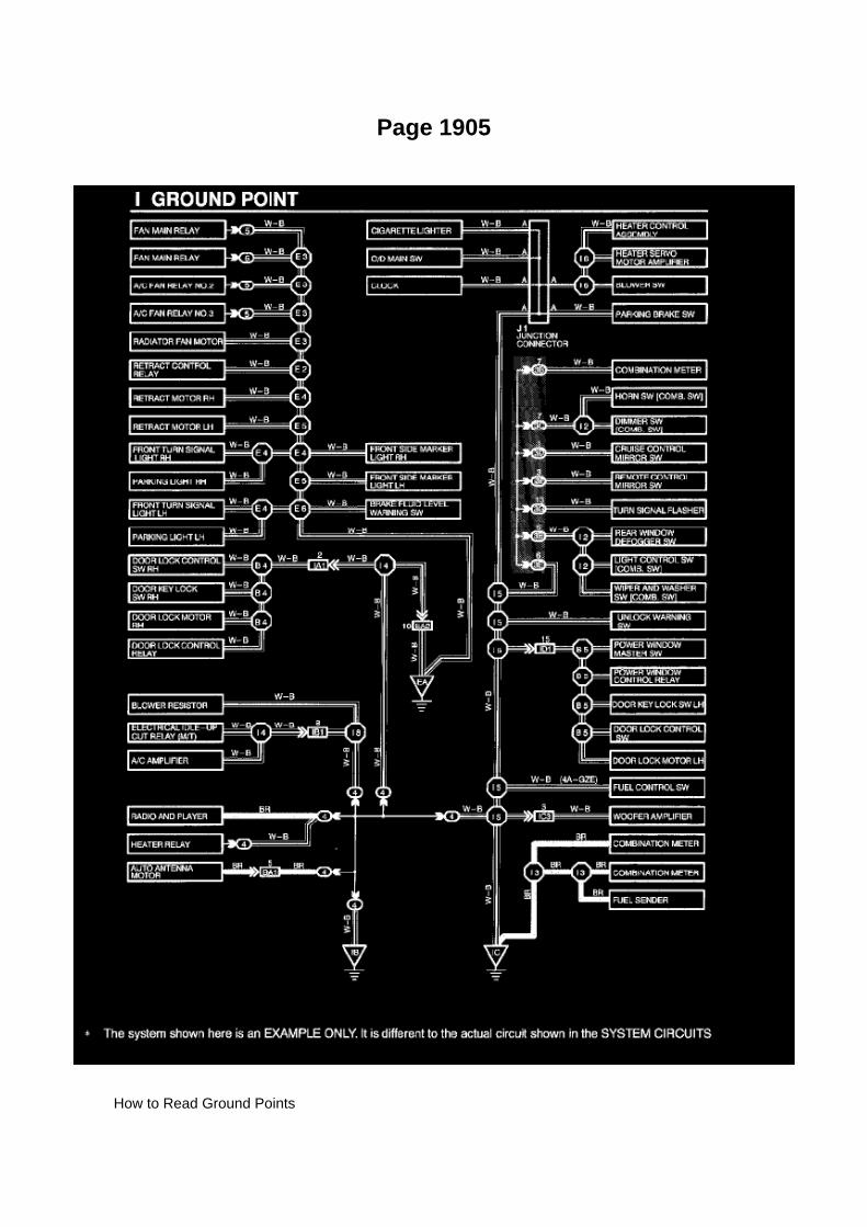
Page 1905
How to Read Ground Points

HOW TO READ GROUND POINTS
The ground points circuit diagram shows the connections from all major parts to the respectiveground points. When troubleshooting a faulty ground point, checking the system circuits which usea common ground may help you identify the problem ground quickly. The relationship betweenground points(EA, IB and IC is shown) can also be checked this way.
How to Read Power Source
HOW TO READ POWER SOURCE

Page 3293

d. Remove the 4 nuts and pull out the brake master cylinder. e. Remove the brake booster gasket.

12. REMOVE BRAKE ACTUATOR BRACKET NO.1
a. Using a hexagon wrench (5 mm), remove the screw and brake actuator bracket No.1.
b. Using a screwdriver, remove the fluid level warning switch connector.
13. REMOVE BRAKE MASTER CYLINDER RESERVOIR SUB-ASSEMBLY
a. Remove the screw from the master cylinder reservoir.
b. Using a pin punch and hammer, remove the pin from the master cylinder reservoir.

Page 2741
NOTE
On some models, DTCs may set as a result of reprogramming. If DTCs are present, clear codesand run the Health Check again. Troubleshoot any remaining Current, Pending, or History codes.Permanent codes will not be cleared using Techstream. Permanent codes do not illuminate the MILand do not require troubleshooting. They will clear during normal driving once the Universal TripDrive Pattern is performed.
4. Attach the Authorized Modifications Label.
A. Using a permanent marker or ball point pen complete the Authorized Modifications Label andattach to the vehicle. The Authorized
Modifications Label is available through the MDC P/N 00451-00001-LBL.
B. Attach the label under the hood in the location determined by the specific TSB or Campaign.
NOTE
Wait 60 - 90 seconds for ink to set before handling.

Locations

A/C - Fo

Page 2053
Malfunction Indicator Lamp: Testing and Inspection
MIL CIRCUIT
CIRCUIT DESCRIPTION
The MIL (Malfunction Indicator Lamp) is used to indicate vehicle malfunction detections by theECM. By turning the ignition switch to ON, power is supplied to the MIL circuit, and the ECMprovides the circuit ground which illuminates the MIL.
The MIL operation can be checked visually: When the ignition switch is first turned to ON, the MILshould be illuminated and should then turn OFF. If the MIL remains illuminated or is not illuminated,conduct the following troubleshooting procedure using a hand-held tester.
Wiring Diagram

Page 1086

Instrument Panel J/B No. 1 Inner Circuit

Page 2121
CAN Communication System

Page 591
o. Connect the fuel vapor feed hose to the VSV.
12. CONNECT FUEL HOSE 13. CONNECT FUEL HOSE NO.2 14. INSTALL THROTTLEW/MOTOR BODY ASSEMBLY 15. INSTALL INTAKE AIR CONNECTOR 16. CONNECT CABLETO NEGATIVE BATTERY TERMINAL
Torque: 3.9 N.m (40 kgf.cm, 35 in.lbf)
17. ADD ENGINE COOLANT 18. CHECK FOR ENGINE COOLANT LEAKAGE 19. CHECK FORFUEL LEAKAGE 20. INSTALL ENGINE UNDER COVER SUB-ASSEMBLY NO.1 (PRE RUNNERAND 4WD TYPE)

Page 2374


Locations

He - Wi

Page 1488

Coolant: Fluid Type Specifications

Coolant type:
In order to avoid technical problems, only use "Toyota Super Long Life Coolant" or similar highquality ethylene glycol based non-silicate, non-amine, non-nitrite, and non-borate coolant withlong-life hybrid organic acid technology.
Do not use plain water alone.

Specifications

Wheel Bearing: Specifications

WHEEL BEARING GREASE:................................................................................................................. Lithium base wheel bearinggrease, NLGI No.2

Service and Repair
Oil Filter: Service and Repair
OIL FILTER SUB-ASSEMBLY (2TR-FE)
REPLACEMENT
CAUTION: -
Prolonged and repeated contact with engine oil causes removal of natural oils from the skin,leading to dryness, irritation and dermatitis. In addition, used engine oil contains potentially harmfulcontaminants which may cause skin cancer.
- Precautions should be taken when replacing engine oil to minimize the risk of your skin makingcontact with used engine oil. Wear protective clothing and gloves. Wash your skin thoroughly withsoap and water, or use a waterless hand cleaner to remove any used engine oil. Do not use

gasoline, thinners or solvents.
- For environmental protection, used oil and used oil filters must be disposed of at designateddisposal sites.
1. DRAIN ENGINE OIL
a. Remove the oil filler cap. b. Remove the oil pan drain plug and drain the engine oil. c. Install anew gasket, then install the oil pan drain plug.
Torque: 38 Nm (382 kgf-cm, 28 ft. lbs.)
2. REMOVE OIL FILTER SUB-ASSEMBLY
a. Using SST, remove the oil filter.
SST 09228-07501
3. INSTALL OIL FILTER SUB-ASSEMBLY
a. Remove any dirt or foreign objects from the contact surface of the engine side. b. Apply a lightcoat of engine oil to the O-ring of a new oil filter. c. Install the oil filter by hand until the O-ringcomes into contact with the seat. d. Using SST, retighten it by 3/4 turn.
SST 09228-07501 Reference torque: 13 Nm (133 kgf-cm, 10 ft. lbs.)
4. ADD ENGINE OIL
a. Fill with fresh engine oil.
Capacity
5. CHECK FOR ENGINE OIL LEAKAGE
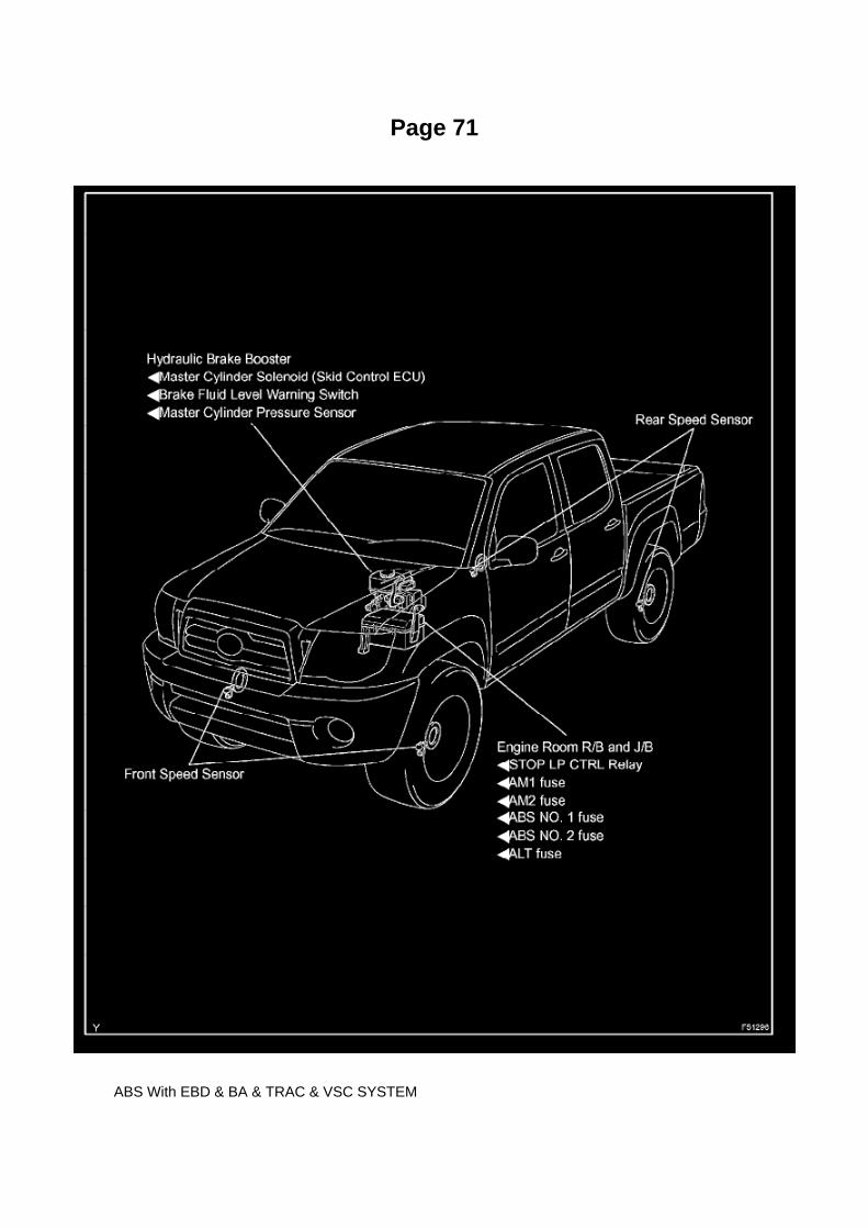
Page 71
ABS With EBD & BA & TRAC & VSC SYSTEM

Page 2730

Mongoose MFC Software and Driver MUST be installed before Mongoose MFC selection will beavailable.

See TIS - Diagnostics - Scantool page for additional information.
^ If using TIS Techstream select TIS Techstream VIM (this is the default).
4. Click OK.
Operation Procedure
1. Verify the vehicle's applicability for recalibration and locate desired calibration file.
A. Connect Techstream and establish a vehicle connection.
B. Click the Health Check button on the System Select tab.

Page 651

(Driver's seat is in the backward position).

^ "D BUCKLE SW UNSET" (Driver's seat belt buckle switch is unset/unbuckled).
(Test # 3)
(a) Move the bench seat to the foremost position.
(b) Leave the driver's seat belt unbuckled.
(c) Confirm that the scan tool displays the data shown below and in the illustration.
^ "D SEAT POSITIFORWARD"
(Driver's seat is in the forward position).
^ "D BUCKLE SW UNSET" (Driver's seat belt buckle switch is unset/unbuckled).
(Test # 4)
(a) Leave the bench seat in the foremost position.
(b) Buckle the driver's seat belt.

Page 3326

Step 2 - 3

INSPECTION PROCEDURE
CHECK FOR INTERMITTENT PROBLEMS
HINT: A momentary interruption (open circuit) in the connectors and/ or wire harness between thesensors and ECUs can be detected through the ECU data monitor function of the hand-held tester.
a. Turn the ignition switch off and connect the hand-held tester to the DLC3.

Page 2211

Oxygen Sensor: Locations

He - Wi

Page 165
Problem Symptoms Table
The suspected circuits or parts for each problem symptom are shown in the table . Use this table totroubleshoot when, during a DTC check, a "Normal" code is displayed but the problem is stilloccurring. Numbers in the table show the inspection order in which the circuits or parts should bechecked.
HINT: In some cases, the problem is not detected by the diagnostic system even though a problemsymptom is present. It is possible that the problem is occurring outside the detection range of thediagnostic system, or that the problem is occurring in a completely different system.

Page 2704
Transmission Position Switch/Sensor: Adjustments
PARK/NEUTRAL POSITION SWITCH ASSY
ADJUSTMENT
1. INSPECT PARK/NEUTRAL POSITION SWITCH ASSY
a. Apply the parking brake and turn the ignition switch to ON. b. Depress the brake pedal andcheck that the engine starts only when the shift lever is set in the N or P position and that it doesnot start in any
other positions.
c. Check that the back-up light comes on and the reverse warning buzzer sounds only when theshift lever is set in the R position and not in other
positions. If any failure is found, check the park/neutral position switch for continuity.
2. ADJUST PARK/NEUTRAL POSITION SWITCH ASSY
a. Loosen the bolt of the park/neutral position switch and set the shift lever to the N position. b.Align the groove and the neutral basic line. c. Hold the switch in position and tighten the bolt.
Torque: 13 Nm (130 kgf-cm, 9 ft. lbs.)
d. After making an adjustment, perform the inspection described in step 1.

Page 2289
f. Remove the nut, then remove the charcoal canister filter No.2.
7. INSTALL CHARCOAL CANISTER FILTER NO.2
a. Install the charcoal canister filter No.2 with the nut.
Torque: 20 N.m (204 Kgf.cm, 15 ft.lbf)
a. Connect the breather hose to the charcoal canister. b. Engage the clamp. c. Connect thebreather hose to the pipe. d. Connect the EVAP pipe to the clamp. e. Install the ABS wire harnessclamp with the bolt.
Torque: 14 N.m (142 Kgf.cm, 10 ft.lbf)
8. INSTALL FUEL TANK ASSEMBLY 9. CONNECT FUEL TANK MAIN TUBE AND FUEL TANKRETURN TUBE
10. REMOVE FUEL TANK PROTECTOR SUB-ASSEMBLY NO.1 (OFF ROAD PACKAGE) 11.CONNECT CABLE TO NEGATIVE BATTERY TERMINAL
Torque: 3.9 N.m (40 Kgf.cm, 35 in.lbf)
12. CHECK FOR FUEL LEAKAGE

Page 2395


Page 2193
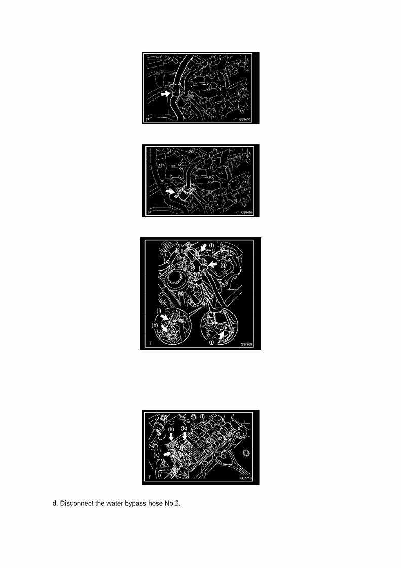
d. Disconnect the water bypass hose No.2.

e. Disconnect the ventilation hose No.3.
f. Disconnect the VSV connector.
g. Disengage the engine wire harness clamp. h. Disconnect the compressor magnetic clutchconnector.
(w/ AIR CONDITIONING)
i. Disengage the wire harness clamp.
j. Remove the bolt and harness clamp bracket.

Page 1268
2. After connecting the fuel tube connector, check that the fuel tube connector and pipe aresecurely connected by pulling them.

Page 3079

c. Using SST to hold the companion flange, tighten the nut.

Torque: 451 Nm (4,599 kgf-cm, 333 ft. lbs.) SST 09330-00021
17. INSPECT DIFFERENTIAL DRIVE PINION PRELOAD
a. Using a torque wrench, measure the preload of backlash between the drive pinion and ring rear.
New bearing: 1.27 to 1.86 Nm (13 to 19 kgf-cm, 11 to 16 inch lbs.) Reused bearing: 0.76 to 1.07Nm (7.7 to 11 kgf-cm, 6.7 to 9.5 inch lbs.)
If necessary, disassemble and inspect the differential assy.
18. INSTALL REAR DRIVE PINION NUT
a. Using a chisel and a hammer, stake the nut.
19. INSTALL PROPELLER SHAFT ASSY (2WD DRIVE TYPE, REGULAR CAB) 20. INSTALLPROPELLER W/CENTER BEARING SHAFT ASSY (2WD DRIVE TYPE, EXCEPT REGULARCAB) 21. INSTALL PROPELLER SHAFT ASSY (4WD DRIVE TYPE, REGULAR CAB) 22.INSTALL PROPELLER W/CENTER BEARING SHAFT ASSY (4WD DRIVE TYPE, EXCEPTREGULAR CAB) 23. FILL UP DIFFERENTIAL OIL 24. INSPECT DIFFERENTIAL OIL 25.INSPECT FOR DIFFERENTIAL OIL LEAKAGE

Engine, A/T Controls - Torque Converter Lock-Up
Shudder
PROM - Programmable Read Only Memory: All Technical Service Bulletins Engine, A/T Controls -Torque Converter Lock-Up Shudder
T-SB-0096-09
March 20, 2009

Torque Converter Flex Lockup Shudder
Service Category Drivetrain
Section Automatic Transmission/Transaxle
Market USA
Applicability
The information contained in this TSB supersedes TSB No. T-SB-0048-09.
^ The following sections have been updated to include information for 2005 - 2007 model yearTacoma vehicles:
^ Applicability
^ Warranty Information
^ Parts Information
^ Calibration Information
TSB No. T-SB-0048-09 is Obsolete and any printed versions should be discarded. Be sure toreview the entire content of this service bulletin before proceeding.
Introduction
Some customers with 4 cylinder (2TR-FE) and A340 (4-speed) automatic transmission equippedTacoma vehicles may experience an intermittent shudder or vibration. This condition lasts forapproximately one second and occurs when lightly accelerating after an upshift into 3rd or 4th gearwith the torque converter assembly in Flex Lockup. This vibration is commonly described as feelinglike driving over "rumble strips" or on a "washboard" road. The Engine Control Module/ECM (SAEterm: Powertrain Control Module/PCM) logic has been revised to prevent the learning of anincorrect value during certain driving conditions. Use the following repair procedure to addresscustomer concerns.
Production Change Information
This TSB applies to vehicles produced BEFORE the Production Change Effective VIN shown.

Page 1582

3. Start the engine and warm it up to normal operating temperatures before test-driving.

4. Perform a thorough test drive with several accelerations from a stop with "light throttle"application until proper transmission shifting is verified.
Reset Procedure 2
1. Disconnect the negative battery cable for 5 minutes.
2. Reconnect battery cable.
3. Start the engine and warm it up to normal operating temperatures before test-driving.
4. Perform a thorough test drive with several accelerations from a stop with "light throttle"application until proper transmission shifting is verified.

Page 1123

normally or lead to repairs not pertinent to the problem. Follow the procedures listed in theflowchart in the correct order.
Steps 4 - 6
- A flowchart showing how to proceed with troubleshooting using the DTC check is shown.Directions from the flowchart will indicate how to proceed either to DTC troubleshooting or to thetroubleshooting of each problem symptom.
Symptom Simulation

Page 3129
c. Align the matchmarks on the yoke and differential flange. d. Install the propeller shaft assy withthe 4 bolts, 4 nuts and 4 washers.
Torque: 88 Nm (899 kgf-cm, 65 ft. lbs.)

Page 637

Page 1664

Knock Control Sensor (2TR-FE) Part 3

Page 1741

a. Using several steps, uniformly install and tighten the 5 bolts in the sequence shown in theillustration.

Torque: 21 N.m (214 kgf.cm, 16 ft.lbf) for bolt A 43 N.m (438 kgf.cm, 32 ft.lbf) for bolt B, C
9. INSTALL COMPRESSOR AND MAGNETIC CLUTCH (W/ AIR CONDITIONING)
10. INSTALL FAN AND GENERATOR BELT (W/ AIR CONDITIONING) 11. INSTALL ENGINEUNDER COVER SUB-ASSEMBLY NO.1 (PRE RUNNER AND 4WD TYPE)
12. CONNECT CABLE TO NEGATIVE BATTERY TERMINAL
Torque: 3.9 N.m (40 kgf.cm, 35 in.lbf)

Locations
Shift Interlock Control Module: Locations
Instrument Panel

Page 106
ABS With EBD System

Page 2394

Page 3235

Step 2 - 3

INSPECTION PROCEDURE

Page 1061
2. Disconnect the ECU connector. Check the ground terminals (on the ECU side and wire harnessside) for evidence of bending, corrosion or
foreign material. Lastly check the contact pressure of the female terminals.
Customer Problem Analysis
CUSTOMER PROBLEM ANALYSIS
HINT:
- In troubleshooting, the problem symptoms must be confirmed accurately. Preconceptions shouldbe discarded in order to give an accurate judgement. To clearly understand what the problemsymptoms are, it is extremely important to ask the customer about the problem and the conditionsat the time it occurred.
- As much information as possible should be gathered for reference. Even past problems that seemunrelated may also help in some cases. In the Diagnostic Section, a customer problem analysistable is provided for each system.
- 5 items are important points in the problem analysis:
Important Points with Customer Problem Analysis -
What .......................................................................................................................................................................... Vehicle model, system name
- When .................................................................................................................................................................. Date, time, occurrence frequency
- Where ............................................................................................................................................................................................ Road conditions
- Under what conditions? ............................................................................................. Runningconditions, driving conditions, weather conditions

- How did it happen? ................................................................................................................................................................... Problem symptoms

Page 1417

Emissions - MIL ON/DTC's
P043E/P043F/P2401/P2402/P2419
Evaporative Emission Control Canister: All Technical Service Bulletins Emissions - MIL ON/DTC'sP043E/P043F/P2401/P2402/P2419
ENGINE EG025-06
Title: M.I.L. "ON" DTC P043E, P043F, P2401, P2402, & P2419
Models: '05 - '06 Tacoma
April 14, 2006
Introduction
Some 2005 and 2006 model year Tacoma vehicles may exhibit M.I.L. "ON" with DTCs P043E,P043F, P2401, P2402, and P2419 stored. The EVAP pump module, which is part of the charcoalcanister assembly, has been improved to correct this condition.
NOTE:
All five DTCs MUST be present for this TSB to be applicable.
Applicable Vehicles
^ 2005 - 2006 model year Tacoma vehicles produced BEFORE the Production Change EffectiveVINs shown below.

Production Change Information
Parts Information
Warranty Information
Applicable Warranty*:
^ This repair is covered under the Toyota Federal Emission Warranty. This warranty is in effect for36 months or 36,000 miles, whichever occurs first, from the vehicle's in-service date. For Californiaspecification vehicles sold, registered, and operated in California, Maine, Massachusetts, andVermont, this repair is covered under the California Emission Warranty, which is 36 months or50,000 miles, whichever occurs first, from the vehicle's in-service date.
^ 2006 model year Tacoma charcoal canister is covered under the California Emission Warranty.This warranty is in effect for 84 months or 70,000 miles, whichever occurs first, from the vehicle'sin-service date.
* Warranty application is limited to correction of a problem based upon a customer's specificcomplaint.

Page 1751
SFI System

Page 3161

Ha - Op

Page 3298

28. INSTALL PISTON

a. Apply lithium soap base glycol grease to the new piston. b. Install the piston onto the mastercylinder body.
c. Using 2 screwdrivers, install a new C-ring while pressing the piston
NOTICE: -
If the piston is pulled out at an angle, there is a possibility that the cylinder bore could be damaged.
- Be careful not to damage the rubber lips on the piston when reassembling.
29. INSTALL MASTER CYLINDER BOOT 30. INSTALL MASTER CYLINDER PUSH ROD CLEVIS
a. Install the lock nut and master cylinder push rod clevis onto the rod operating adapter. b. Installthe brake master cylinder side lock nut and rod operating adapter onto the brake master cylinder.
Torque: 25.5 Nm (260 kgf-cm, 19 ft. lbs.)
31. INSTALL BRAKE BOOSTER PUMP BRACKET
a. Using a hexagon wrench (5 mm), install the brake booster pump bracket with the 2 screws.
Torque: 7.8 Nm (80 kgf-cm, 69 inch lbs.)
b. Install the bush onto the brake booster pump bracket.
32. INSTALL BRAKE ACTUATOR BRACKET
a. Using a hexagon wrench (5 mm), install the brake actuator bracket with the screw.
Torque: 7.8 Nm (80 kgf-cm, 69 inch lbs.)

Page 2028
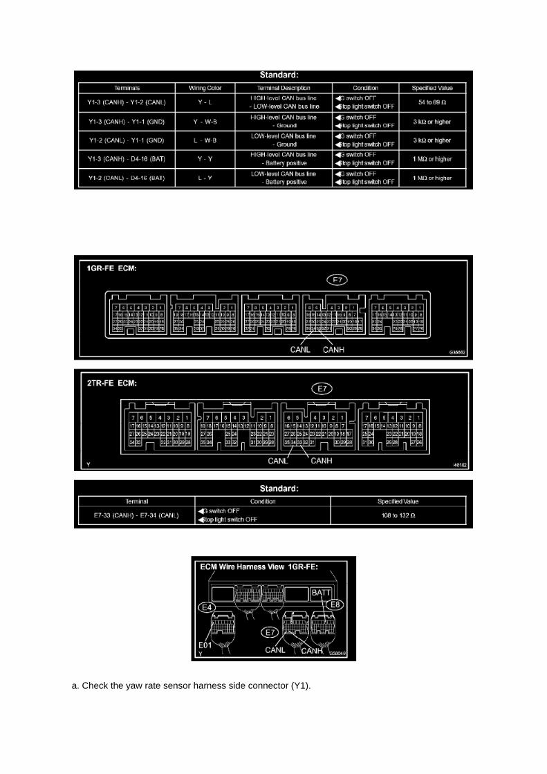
a. Check the yaw rate sensor harness side connector (Y1).

1. Disconnect the connector (Y1) from the yaw rate sensor. 2. Measure the resistance according tothe value(s) in the table.
6. ECM
a. Measure the resistance according to the value(s) in the table.

Page 1145
Driver Side J/B Inner Circuit

Page 1564

Mongoose MFC Software and Driver MUST be installed before Mongoose MFC selection will beavailable.

See TIS - Diagnostics - Scantool page for additional information.
^ If using TIS Techstream select TIS Techstream VIM (this is the default).
4. Click OK.
Operation Procedure
1. Verify the vehicle's applicability for recalibration and locate desired calibration file.
A. Connect Techstream and establish a vehicle connection.
B. Click the Health Check button on the System Select tab.

Page 563

Camshaft Position Sensor: Service and Repair

REPLACEMENT
1. DISCONNECT CABLE FROM NEGATIVE BATTERY TERMINAL 2. REMOVE CAMSHAFTPOSITION SENSOR
a. Disconnect the camshaft position sensor connector. b. Remove the bolt, then remove thecamshaft position sensor.
3. INSTALL CAMSHAFT POSITION SENSOR
a. Apply a light coat of engine oil to the O-ring of the camshaft position sensor.
b. Install the camshaft position sensor with the bolt.
Torque: 8.5 N.m (87 kgf.cm, 75 in.lbf)
NOTE: Make sure that the O-ring is not cracked or jammed when installing.
c. Connect the camshaft position sensor connector.
4. CONNECT CABLE TO NEGATIVE BATTERY TERMINAL
Torque: 3.9 N.m (40 kgf.cm, 35 in.lbf)

Air-Fuel Ratio Sensor
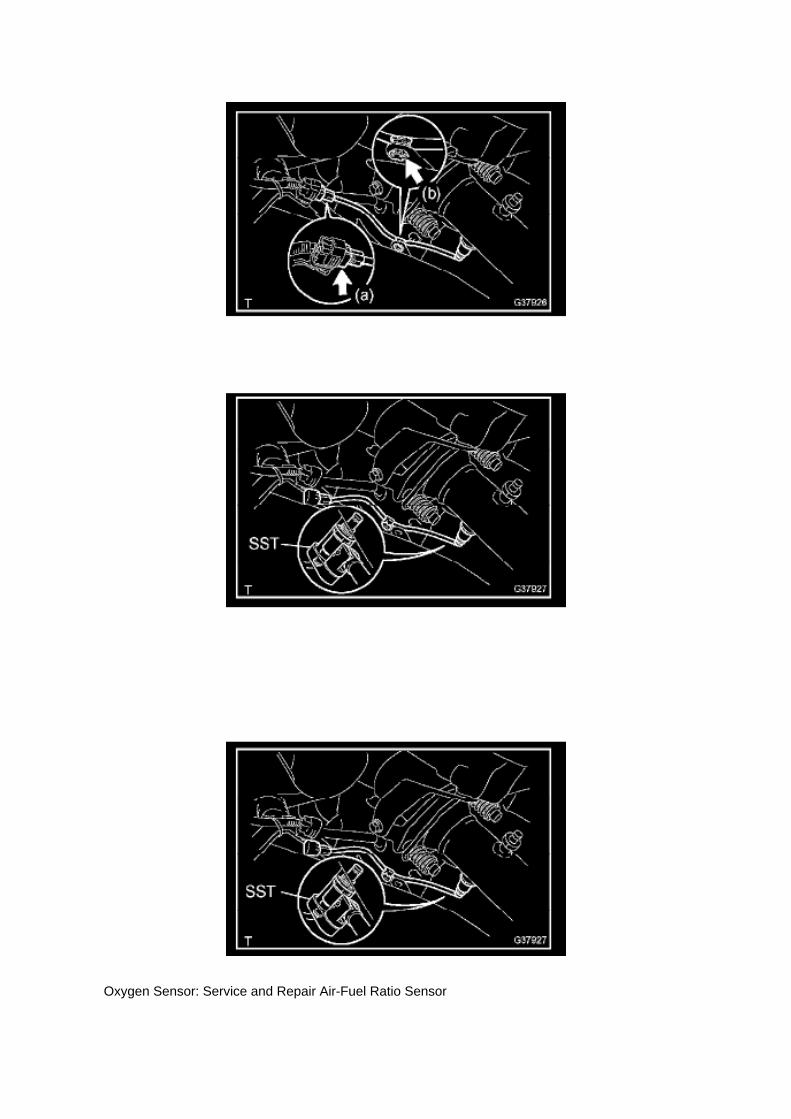
Oxygen Sensor: Service and Repair Air-Fuel Ratio Sensor

REPLACEMENT
1. DISCONNECT CABLE FROM NEGATIVE BATTERY TERMINAL 2. REMOVE AIR FUEL RATIOSENSOR
a. Disconnect the air fuel ratio sensor connector. b. Disconnect the wire harness clamp.
c. Using SST, remove the air fuel ratio sensor.
SST 09224-00010
3. INSTALL AIR FUEL RATIO SENSOR
a. Using SST, install the air fuel ratio sensor.
SST 09224-00010
Torque: 44 N.m (449 Kgf.cm, 33 ft.lbf) 40 N.m (408 Kgf.cm, 30 ft.lbf) with SST
NOTE: Use a torque wrench with a fulcrum length of 300 mm (11.81in.).

Locations

Ha - Op

Page 2927
Components
Repair Procedure

1. Record all radio presets before starting.
2. Disconnect the negative (-) battery terminal cable.
3. Remove the clutch pedal sub-assembly.

Page 1374

b. Bring the other mark link of the crankshaft timing sprocket behind the large timing mark of thebalance shaft drive gear. c. Insert the balance shaft drive gear shaft through the balance shaft drive

gear so that it fits into the thrust plate hole.
d. Align the small timing mark of the balance shaft drive gear with the timing mark of the balanceshaft timing gear. e. Install the bolt onto the balance shaft drive gear and tighten it.
Torque: 25 Nm (250 kgf-cm, 18 ft. lbs.)
f. Check that each timing mark is aligned with the corresponding mark link.

Removal and Installation

Engine Control Module: Service and Repair Removal and Installation

REPLACEMENT
NOTE: Perform REGISTRATION (VIN registration) when replacing the ECM.
1. DISCONNECT CABLE FROM NEGATIVE BATTERY TERMINAL 2. REMOVE GLOVECOMPARTMENT DOOR ASSEMBLY 3. REMOVE INSTRUMENT PANEL FINISH PANELSUB-ASSEMBLY LOWER RH 4. REMOVE ECM
a. Disconnect the 4 connectors. b. Remove the 2 bolts and nut, then remove the ECM.
5. REMOVE ECM BRACKET
a. Remove the 3 screws, then remove the ECM bracket.
6. REMOVE ECM BRACKET NO.2
a. Remove the 2 screws, then remove the ECM bracket No.2.
7. INSTALL ECM BRACKET NO.2
Torque: 3 N.m (32 kgf.cm, 28 in.lbf)
8. INSTALL ECM BRACKET
Torque: 3 N.m (32 kgf.cm, 28 in.lbf)

Page 824
c. Check the operation
1. Turn the wiper switch off. 2. Connect the battery positive lead to terminal 2 (+B) of the E7connector and the battery negative lead to terminals 1 (+S) of the E7 connector
and 2 (EW) of the E11 connector.
3. Connect the voltmeter positive terminal to terminal 3 (+1) of the E7 connector and the voltmeternegative terminal to terminal 2 (EW) of the
E11 connector.Turn the washer switch on and off, and check the voltage between terminals 3 (+1)of the E7 connector and 2 (EW) of the E11 connector.

Page 1065
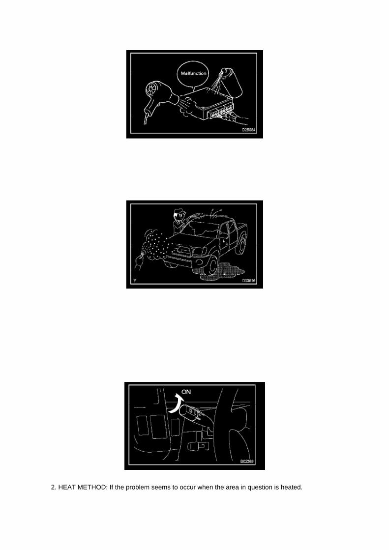
2. HEAT METHOD: If the problem seems to occur when the area in question is heated.

a. Heat the component that is the possible cause of the malfunction with a hair dryer or similardevice. Check if the malfunction occurs.
NOTE: -
Do not heat to more than 60°C (140°F). Exceeding this temperature may damage components.
- Do not apply heat directly to the parts in the ECU.
3. WATER SPRINKLING METHOD: When the malfunction seems to occur on a rainy day or inhigh-humidity.
a. Sprinkle water onto the vehicle and check if the malfunction occurs.
NOTE: -
Never sprinkle water directly into the engine compartment. Indirectly change the temperature andhumidity by applying water spray onto the front of the radiator.
- Never apply water directly onto the electronic components.
HINT: If the vehicle has or had a water leakage problem, the leakage may have damaged the ECUor connections. Look for evidence of corrosion or shorts. Proceed with caution during water tests.
4. HIGH ELECTRICAL LOAD METHOD: When a malfunction seems to occur when electrical loadis excessive.
a. Turn on the heater blower, headlamps, rear window defogger and all other electrical loads.Check if the malfunction reoccurs.
Diagnostic Trouble Code Chart
DIAGNOSTIC TROUBLE CODE CHART

Page 583

Knock Control Sensor (2TR-FE) Part 2

Page 2353

Page 2480
16. CONNECT FUEL HOSE NO.2
a. Align the fuel hose connector with the pipe stem, and insert the fuel hose until the retainermakes a "click" sound.
b. Push down the checker of the fuel hose.
NOTE: -
Check that there are no scratches or foreign objects around the disconnected parts of the fuel hoseconnector and pipe before performing this work.
- After connecting the fuel hose, check that the fuel hose is securely connected by pulling the fuelhose connector and pipe.
c. Push the fuel hose down until the checker of the fuel hose makes a "click" sound.
17. INSTALL THROTTLE W/MOTOR BODY ASSEMBLY 18. INSTALL INTAKE AIR CONNECTOR19. CONNECT CABLE TO NEGATIVE BATTERY TERMINAL
Torque: 3.9 N.m (40 kgf.cm, 35 in.lbf)
20. ADD ENGINE COOLANT 21. CHECK FOR ENGINE COOLANT LEAKAGE 22. CHECK FORFUEL LEAKAGE 23. INSTALL ENGINE UNDER COVER SUB-ASSEMBLY NO.1

Page 1668

k. Disconnect the 3 connectors. l.

Remove the nut shown in the illustration.
m. Disconnect the engine wire harness from the relay block.
n. Remove the 5 bolts and 2 nuts, then remove the intake manifold.
9. REMOVE KNOCK CONTROL SENSOR
a. Disconnect the knock control sensor connector. b. Remove the bolt, then remove the knockcontrol sensor.
10. INSTALL KNOCK CONTROL SENSOR
a. Install the knock control sensor with the bolt.
Torque: 20 N.m (204 kgf.cm, 15 ft.lbf)
NOTE: Make sure that the knock sensor is at the correct angle when installing.
b. Connect the knock control sensor connector.
11. INSTALL INTAKE MANIFOLD

Page 2371

Diagram Information and Instructions

Relay Box: Diagram Information and Instructions

Key to Diagrams
A: System Title
B: Indicates a Relay Block. No shading is used and only the Relay Block No. is shown todistinguish it from the J/B

Locations

Engine Room R/B, J/B - Engine Compartment Left

Page 1808

He - Wi
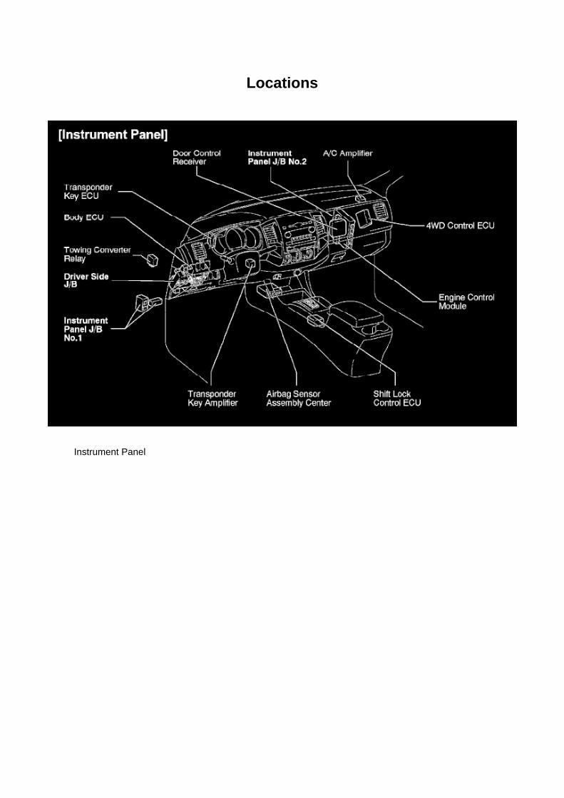
Locations
Instrument Panel

Page 3371
3. CHECK PEDAL FREE PLAY

a. Stop the engine and depress the brake pedal several times until there is no more vacuum left inthe booster. b. Push in the pedal until the beginning of the resistance is felt. Measure the distanceas shown.
Pedal free play: 1 to 6 mm (0.04 to 0.24 inch)
4. CHECK PEDAL RESERVE DISTANCE
a. Release the parking brake pedal. With the engine running, depress the pedal and measure thepedal reserve distance as shown. Pedal reserve
distance from asphalt sheet at 490 N (50 kgf, 110.2 ft. lbs.): More than 55 mm (2.17 inch) Ifincorrect, troubleshoot the brake system.

Page 1977

Step 1 - 3

Page 1532

7. CHECK FOR ENGINE COOLANT LEAKAGE

Page 1220
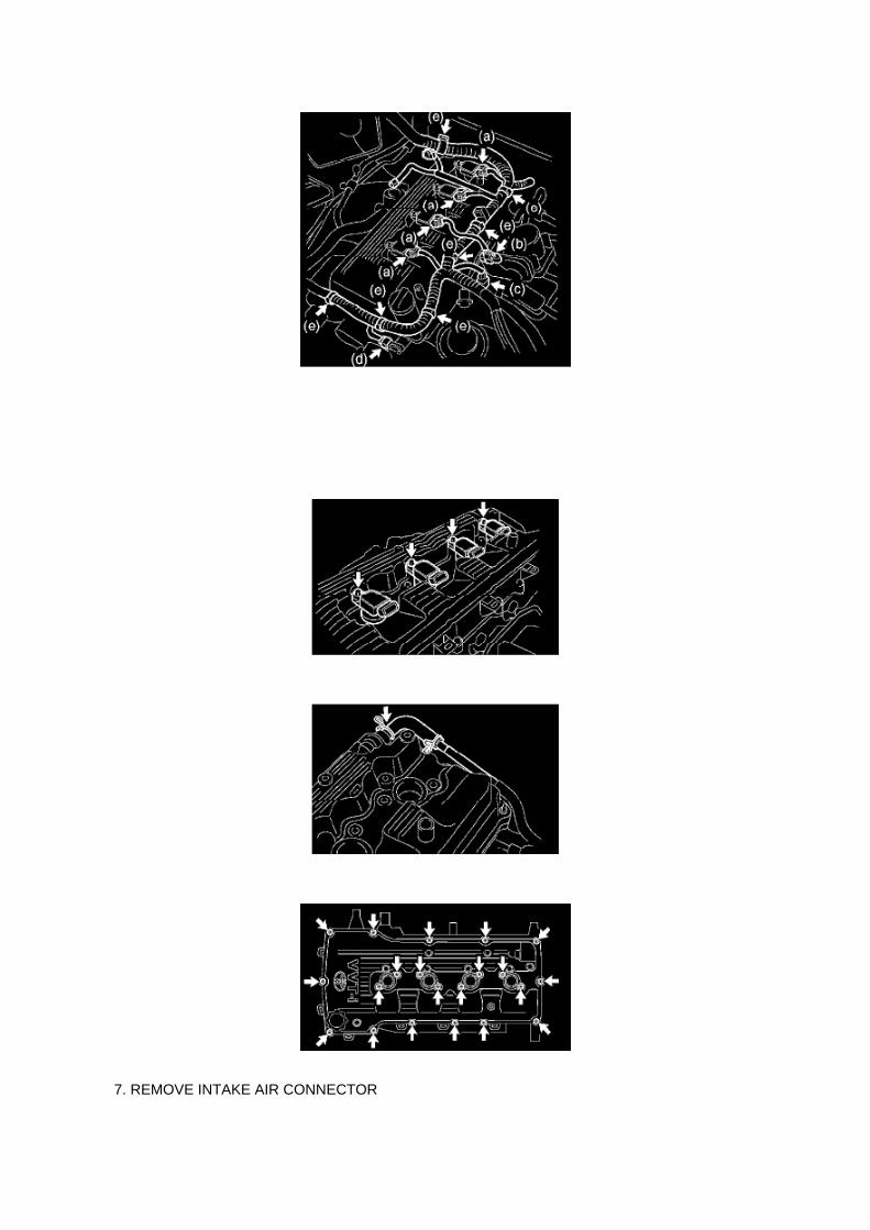
7. REMOVE INTAKE AIR CONNECTOR

8. REMOVE CYLINDER HEAD COVER SUB-ASSEMBLY
a. Disconnect the ignition coil connectors. b. Disconnect the throttle with motor body connector. c.Disconnect the VSV connector. d. Disconnect the camshaft position sensor connector. e.Disconnect the engine wire harness clamps.
f. Remove the bolts, then remove the ignition coils.
g. Disconnect the ventilation hose.
h. Remove the 19 bolts and 2 nuts, then remove the cylinder head cover.

Page 1408

e. Using a 10 mm socket hexagon wrench, remove the head straight screw plug.
49. REMOVE WATER INLET 50. REMOVE THERMOSTAT 51. REMOVE TIMING GEAR CASEOR TIMING CHAIN CASE OIL SEAL 52. INSTALL TIMING GEAR CASE OR TIMING CHAINCASE OIL SEAL
SST 09223-5001 0
53. INSTALL THERMOSTAT 54. INSTALL WATER INLET
55. INSTALL TIMING CHAIN COVER
a. Apply adhesive to the head straight screw plug.
Adhesive: Part No.08833-00070, THREE BOND 1324 or equivalent
b. Using a 10 mm socket hexagon wrench, install the head straight screw plug.
Torque: 17 Nm (170 kgf-cm, 12 ft. lbs.)
c. Install 4 new O-rings onto the timing chain cover as shown in the illustration. d. Apply continuousbeads of seal packing to the places shown in the illustration.
Seal packing: Part No.08826-00080 or equivalent
Seal width

Page 2975

7. Remove the clutch pedal shaft collar.

8. Using needle-nose pliers, remove the No. 1 cushion from the clutch pedal.
9. Install the clutch pedal No. 1 cushion on the NEW clutch pedal sub-assembly.
NOTE:
Install parts on the NEW clutch pedal sub-assembly BEFORE installing in the vehicle.
10. Install the clutch pedal shaft collar.
A. Apply MP grease to the clutch pedal shaft collar.
B. Install the clutch pedal shaft collar onto the clutch pedal.

Page 3035
Clutch Switch: Testing and Inspection Component Inspection
CLUTCH START SWITCH ASSEMBLY
INSPECTION
1. INSPECT CLUTCH START SWITCH ASSEMBLY
(a) Measure the resistance between the terminals when the switch is ON and OFF.

Front Axle LH Hub Bolt

Wheel Fastener: Service and Repair Front Axle LH Hub Bolt

FRONT AXLE LH HUB BOLT
REPLACEMENT
1. DISCONNECT CABLE FROM NEGATIVE BATTERY TERMINAL 2. REMOVE FRONT WHEEL3. DRAIN BRAKE FLUID
NOTICE: Immediately wash off any brake fluid that comes into contact with painted surfaces.
4. REMOVE FRONT DISC BRAKE CALIPER ASSY LH
SST 09023-00101
5. REMOVE FRONT DISC
6. REMOVE FRONT AXLE LH HUB BOLT
a. Using SST and a screwdriver, remove the hub bolt.
SST 09611-12010
7. INSTALL FRONT AXLE LH HUB BOLT
a. Install a new hub bolt through the axle hub.

Page 2043

a. Install a new gasket onto the intake manifold. b. Install the intake manifold with the 5 bolts and 2nuts.

Torque: 25 N.m (255 kgf.cm, 18 ft.lbf)
c. Connect the engine wire harness to the relay block. d. Install the nut shown in the illustration.
Torque: 10 N.m (102 kgf.cm, 7 ft.lbf)
e. Connect the 3 connectors.
f. Install the harness clamp bracket with the bolt.
Torque: 8.2 N.m (84 kgf.cm, 73 in.lbf)
g. Engage the wire harness clamp. h. Connect the compressor magnetic clutch connector.

Page 966
Coolant: Service and Repair
ENGINE COOLANT (2TR-FE)

REPLACEMENT
1. DRAIN ENGINE COOLANT
CAUTION: To avoid the danger of being burned, do not remove the radiator cap while the engineand radiator are still hot. Thermal expansion will cause hot engine coolant and steam to blow outfrom the radiator.
a. Remove the 4 bolts, then remove the engine under cover No.1. (PRERUNNER AND 4WDTYPE)
b. Install a vinyl hose onto the radiator side.
c. Install a vinyl hose onto the engine side.
d. Loosen the engine drain plug. e. Loosen the radiator drain plug. (9 Remove the radiator cap anddrain coolant. g. Drain the coolant from the reservoir tank.
2. ADD ENGINE COOLANT
a. Tighten the engine drain plug.
Torque: 13 Nm (130 kgf-cm, 9 ft. lbs.)
b. Tighten the radiator drain plug. c. Disconnect the 2 vinyl hoses. d. Slowly fill the system withengine coolant. Capacity:
M/T: 8.7 liters (9.2 US qts., 7.7 Imp. qts.) A/T: 8.6 liters (9.1 US qts., 7.6 Imp. qts.)
HINT: -
Use of improper coolants may damage the engine cooling system.
- Use only Toyota Super Long Life Coolant or similar high quality ethylene glycol basednon-silicate, non-amine, non-nitrite, and non-borate coolant with long-life hybrid organic acidtechnology (coolant with long-life hybrid organic acid technology consists of a combination of lowphosphates and organic acids.)
- New Toyota vehicles are filled with Toyota Super Long Life Coolant. When replacing the coolant,Toyota Super Long Life Coolant (color

Locations
Oil Pressure Sender: Locations

A/C - Ge

Page 2976

11. Install the clutch pedal bushes.
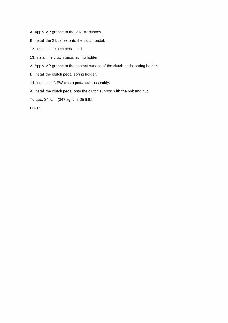
A. Apply MP grease to the 2 NEW bushes.
B. Install the 2 bushes onto the clutch pedal.
12. Install the clutch pedal pad.
13. Install the clutch pedal spring holder.
A. Apply MP grease to the contact surface of the clutch pedal spring holder.
B. Install the clutch pedal spring holder.
14. Install the NEW clutch pedal sub-assembly.
A. Install the clutch pedal onto the clutch support with the bolt and nut.
Torque: 34 N.m (347 kgf.cm, 25 ft.lbf)
HINT:

Page 2471

Fuel Injector Assy (2TR-FE)

Page 3280

g. Inspect front VSC solenoid (SMCF) operation.

HINT: -
ON: Activate SMCF and check that the brake pedal cannot be depressed (the pedal feels tight).
- OFF: Deactivate SMCF and check that the brake pedal can be depressed.
(1) Select "SRCF (SA1)" on the hand-held tester. (2) Turn the "SRCF (SA1)" on by the hand-heldtester, then depress the brake pedal with stable force and check that the pedal cannot be
depressed. If the pedal can be depressed, replace the brake master cylinder.
HINT: To protect the solenoid, hand-held tester turns off automatically 2 seconds after everysolenoid has been turned on.
NOTICE: When operating it continuously, set the interval of more than 20 seconds.
(3) Release the brake pedal. (4) When the solenoid is off, depress the brake pedal again and checkthat the brake pedal can be depressed.
If the pedal can be depressed, replace the brake master cylinder.
h. Prepare the vehicle.
(1) Jack up and support the vehicle. (2) Release the parking brake pedal (lever). (3) Shift the shiftlever to the "N" position and check the rear wheels by rotating them by hand.
i. Inspect front VSC solenoid (SREA) operation.
HINT: -
ON: Activate SREA and SMCF, depress the brake pedal, and then check that the front wheels donot rotate.
- OFF: Deactivate SREA and SMCF. Reactivate SMCF, depress the brake pedal, and then checkthat the front wheels rotate.
(1) Select "SRCR (SA2)" and "SRCF (SMCF)" on the hand-held tester. (2) Turn the "SRCR (SA2)"and "SRCF (SMCF)" on simultaneously by the hand-held tester, then depress the brake pedal withstable force. (3) When the solenoids are on, check that the front wheels do not rotate by hand.
If the front wheels rotate, replace the brake master cylinder.
HINT: -
To protect the solenoids, hand-held tester turns off automatically 2 seconds after every solenoidhas been turned on.
- When rotating the wheels fast, the fail-safe function is activated and judgement cannot be madeproperly. So rotate the wheels as slowly as possible.
NOTICE: When operating it continuously, set the interval of more than 20 seconds.
(4) When the solenoids are off, turn the "SRCF (SMCF)" on again, then depress the brake pedaland check the front wheels by rotating them
by hand.
If front wheels stop, replace the brake master cylinder. (5) When the "SRCF (SMCF)" is off,depress the brake pedal again and check that the brake pedal can be depressed. If the pedal canbe depressed, replace the brake master cylinder.

j. Inspect front ABS solenoid (SFRH) operation.
HINT: -
ON: Activate SFRH, depress the brake pedal, and then check that the right front wheel rotates.
- OFF: Deactivate SFRH, depress the brake pedal, and then check that the front right wheel doesnot rotate.
(1) Select"SFRH" on the hand-held tester. (2) Turn the "SFRH" on by the hand-held tester, thendepress the brake pedal with stable force. (3) When the solenoid is on, check the right front wheelby rotating it by hand.
If the right front wheel stops, replace the brake master cylinder.
HINT: -
To protect the solenoid, hand-held tester turns off automatically 2 seconds after every solenoid hasbeen turned on.
- When rotating the wheel fast, the fail-safe function is activated and judgement cannot be madeproperly. So rotate the wheel as slowly as possible.
NOTICE: When operating it continuously, set the interval of more than 20 seconds. (4) When thesolenoid is off, depress the brake pedal again and check that the right front wheel does not rotateby hand.
If the right front wheel rotates, replace the brake master cylinder.
k. Inspect front ABS solenoid (SFLH) operation.

Service and Repair

Fuel Pressure Pulsation Damper: Service and Repair

REPLACEMENT
1. DISCHARGE FUEL SYSTEM PRESSURE 2. DISCONNECT FUEL HOSE 3. REMOVE FUELPRESSURE PULSATION DAMPER ASSEMBLY
a. Remove the 2 bolts, then remove the fuel pressure pulsation damper.
4. INSTALL FUEL PRESSURE PULSATION DAMPER ASSEMBLY
a. Apply a light coat of gasoline or spindle oil to the O-ring.
b. Install the fuel pressure pulsation damper with the 2 bolts.
Torque: 8.5 N.m (87 kgf.cm, 75 in.lbf)
5. CONNECT FUEL HOSE 6. CHECK FOR FUEL LEAKAGE

Page 1402


Description and Operation

Malfunction Indicator Lamp: Description and Operation

MIL (Malfunction Indicator Lamp)
a. The MIL is illuminated when the ignition switch is first turned to ON (the engine is not running). b.The MIL should turn off when the engine is started. If the MIL remains illuminated, the diagnosissystem has detected a malfunction or
abnormality in the system.
HINT: If the MIL is not illuminated when the ignition switch is first turned to ON, check the MILcircuit.

Page 3233
Wiring Diagram

Page 859
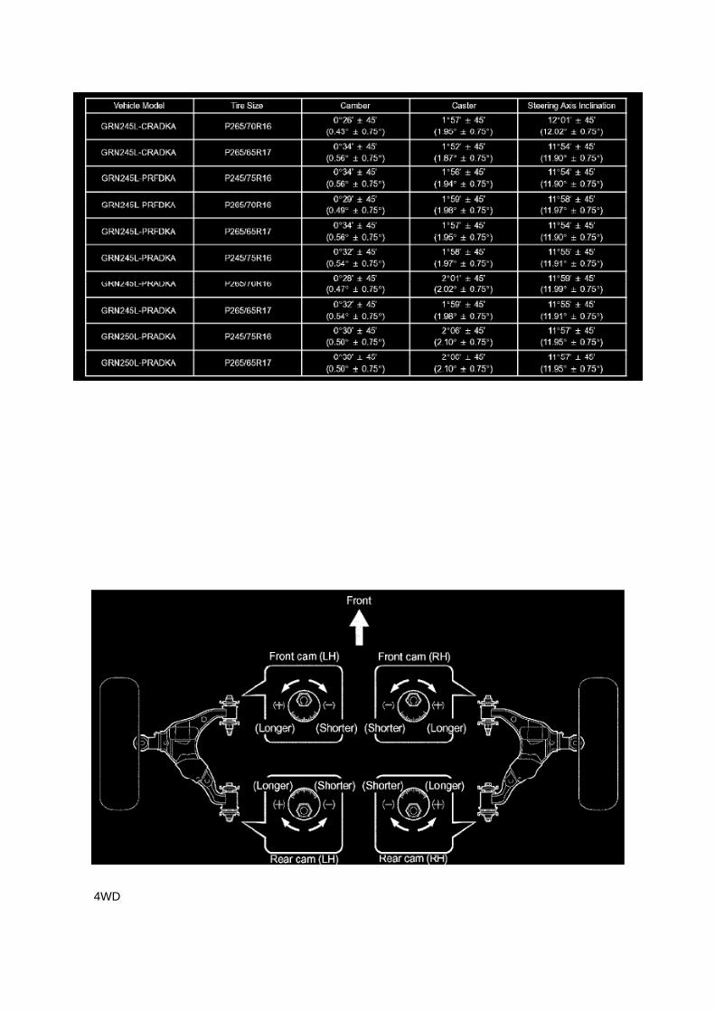
4WD

NOTICE: -
Perform the inspection while the vehicle is empty (without spare tires or tools on board).
- The tolerance of the difference between the left and right wheels is 30° (0.50°) or less for both thecamber and caster.
If the steering axis inclination is not as specified after the camber and caster have been correctlyadjusted, recheck the steering knuckle and front wheel for distortion and slack.
7. ADJUST CAMBER AND CASTER
NOTICE: Inspect the toe-in after the camber has been adjusted.
a. Loosen the nut and bolt. b. Turn the camber adjust cam No.2 and toe adjust cam and adjust thecamber and the caster.
HINT: Try to adjust the camber and caster to the central values.

Page 1602

Engine Control Module: Service and Repair Control Module Programming and Relearning

Precaution
PRECAUTION
1. INITIALIZATION
NOTE: Perform the REGISTRATION (VIN registration) when replacing the ECM.
2. FOR USING HAND-HELD TESTER
CAUTION: Observe the following items for safety reasons: -
Read its instruction books before using the tester.
- Prevent the tester cable from being caught on the pedals, shift lever and steering wheel whendriving with the tester connected to the vehicle.
- When driving the vehicle for testing purposes using the tester, two persons are required. One isfor driving the vehicle, and the other operates the tester.
Registration
REGISTRATION
NOTE: The Vehicle Identification Number (VIN) must be input into the replacement ECM.
HINT: The VIN is in the form of a 17-digit alphanumeric vehicle identification number. A hand-heldtester is required to resister the VIN.
1. DESCRIPTION
This registration section consists of three parts, Input Instructions, Read VIN and Write VIN. a.Input Instructions: Explains the general VIN input instructions using a hand-held tester. b. ReadVIN: Explains the VIN reading process in a flowchart. This process allows the VIN stored in theECM to be read, in order to confirm
that the two VINs, provided with the vehicle and stored in the vehicle's ECM, are the same.
c. Write VIN: Explains the VIN writing process in a flowchart. This process allows the VIN to beinput into the ECM. If the ECM is changed, or
the VIN and VIN do not match, the VIN can be registered, or overwritten in the ECM by followingthis procedure.
2. INPUT INSTRUCTIONS
a. Hand-held tester
1. The arrow buttons (UP, DOWN, RIGHT and LEFT) and numerical buttons (0 to 9) are used, inorder to input the VIN.
b. Cursor Operation
1. To move the cursor around the tester screen, press the RIGHT and LEFT buttons.
c. Alphabetical Character Input
1. Press the UP and DOWN buttons to select the desired alphabetical character. 2. After selection,the cursor should move.
d. Numeric Character Input

1. Press the numerical button corresponding to the number that you want to input. 2. After input,the cursor should move.
HINT: Numerical characters can be selected by using the UP and DOWN buttons.
e. Correction
1. When correcting the input character(s), put the cursor onto the character using the RIGHT orLEFT buttons. 2. Select or input the correct character using the UP/DOWN buttons, or thenumerical buttons.
f. Finishing Input Operation 1. Make sure that the input VIN matches the vehicle VIN after input. 2.Press the ENTER button on the tester.
3. READ VIN (Vehicle Identification Number)

Service and Repair

Air Injection Pump: Service and Repair

REPLACEMENT
1. DISCONNECT CABLE FROM NEGATIVE BATTERY TERMINAL 2. REMOVE AIR PUMPASSEMBLY
a. Remove the 2 bolts, then separate the washer jar.
HINT: Perform the above procedure to make space for removing the air pump assembly.
b. Disconnect the air injection system No.1 hose. c. Disconnect the air pump connector and wireharness clamp.
d. Remove the 3 bolts, then remove the air pump with bracket.

Page 1966
Step 9 - 10

Page 897
Compression Check: Testing and Inspection
INSPECT COMPRESSION
a. Warm up the engine, then stop it. b. Remove the intake air connector. c. Remove the ignitioncoils. d. Remove the spark plugs. e. Disconnect the fuel injector connector.
f. Inspect the compression. (1) Insert a compression gauge into the plug hole. (2) Crank the engine,then measure the compression pressure. Compression pressure: 1230 kPa (12.5 kgf/cm2, 178 psi)Minimum pressure: 880 kPa (9.0 kgf/cm2, 128 psi) or more Difference between each cylinder: 68kPa (0.7 kgf/cm2, 10 psi) or less
NOTICE: -
Use a fully-charged battery so the engine speed can be increased to 250 rpm or more.
- Inspect the other cylinders in the same way.
- Measure the compression pressure in as short a time as possible.
(3) If the compression pressure is low, pour a small amount of engine oil into the cylinder block,then measure it again.
HINT: -
If the compression pressure increases after adding the engine oil, the piston rings may be worn.
- If the compression pressure does not change after pouring engine oil, defects may be occurringaround the valves.

Locations

A/C - Fo

Page 1399

Page 1047
Diagram Legend
Diagram Legend
O: Indicates values or explains the function for reference during troubleshooting.
P: Indicates the reference showing the position on the vehicle of the parts in the system circuit.Example: Part L4 (Light Failure Sensor) * The letter in the code is from the first letter of the part,and the number indicates its order in parts starting with that letter.
Q: Indicates the reference showing the position on the vehicle of Relay Block Connectors in thesystem circuit.
Example: Connector "1" is described and is installed on the left side of the instrument panel.

R: Indicates the reference showing the position on the vehicle of J/B and Wire Harness in thesystem circuit.
Example: Connector "3C" connects the Instrument Panel Wire and J/B No.3. It is described and isinstalled on the instrument panel left side.
S: Indicates the reference describing the wiring harness and wiring harness connector (the femalewiring harness is shown first, followed by the male wiring harness).
Example: Connector "IE1" connects the floor wire (female) and Instrument panel wire (male). It isdescribed and is installed on the left side kick panel.
T: Indicates the reference showing the position of the ground points on the vehicle.
Example: Ground point "BO" is described and is installed on the back panel center.
U: Indicates the reference showing the position of the splice points on the vehicle.

Page 68

He - Wi

Page 296
Terminals Of Control Module/Pinouts - Check Driver J/B Assy (Multiplex Network Body ECU) Part2

Page 812

Ac - Ya

Locations
Fuse Block: Locations
Engine Room R/B No. 2 - Engine Compartment Left

Locations

Air Flow Meter/Sensor: Locations

He - Wi

Page 328
ABS With EBD & BA & TRAC & VSC SYSTEM

Page 1139
Driver Side J/B - Lower Finish Panel
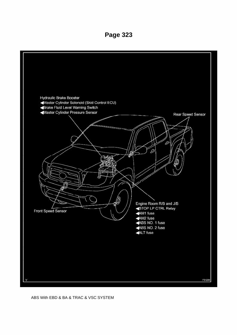
Page 323
ABS With EBD & BA & TRAC & VSC SYSTEM

Page 2802

Shift Solenoid: Diagrams

The shift solenoid identification and location in the valve body is contained in the valve bodyservice and repair procedures and overhaul articles for most models.

Page 1078
Driver Side J/B - Lower Finish Panel

Page 3107

26. INSTALL REAR AXLE SHAFT LH OIL SEAL

a. Using SST and a hammer, install a new oil seal.
SST 09950-60020 (09951-00770), 09950-70010 (09951-07150)
27. INSTALL REAR AXLE SHAFT W/ BACKING PLATE
a. Install a new O-ring. b. Install the rear axle shaft w/ backing plate with the 4 nuts.
Torque: 36 Nm (367 kgf-cm, 27 ft. lbs.)
28. INSTALL REAR BRAKE TUBE NO.8
a. Using SST, connect the brake tube.
SST 09023-00101 Torque: 15 Nm (155 kgf-cm, 11 ft. lbs.)
29. INSTALL PARKING BRAKE CABLE ASSY NO.3 30. INSTALL SPEED SENSOR REAR LH 31.APPLY HIGH TEMPERATURE GREASE 32. INSTALL REAR BRAKE SHOE
SST 09718-00010
33. INSTALL FRONT BRAKE SHOE
SST 09718-00010, 09921-00010
34. CHECK REAR DRUM BRAKE INSTALLATION 35. INSTALL REAR BRAKE DRUM SUB-ASSY36. ADJUST REAR DRUM BRAKE SHOE CLEARANCE 37. CONNECT CABLE TO NEGATIVEBATTERY TERMINAL
Torque: 3.9 Nm (40 kgf-cm, 35 inch lbs.)
38. FILL RESERVOIR WITH BRAKE FLUID (W/ VSC) 39. FILL RESERVOIR WITH BRAKE FLUID(W/O VSC) 40. BLEED MASTER CYLINDER (W/O VSC)
SST 09023-00101
41. BLEED BRAKE LINE (W/ VSC) 42. BLEED BRAKE LINE (W/O VSC) 43. CHECK FLUIDLEVEL IN RESERVOIR (W/ VSC) 44. CHECK FLUID LEVEL IN RESERVOIR (W/O VSC) 45.CHECK FOR BRAKE FLUID LEAKAGE
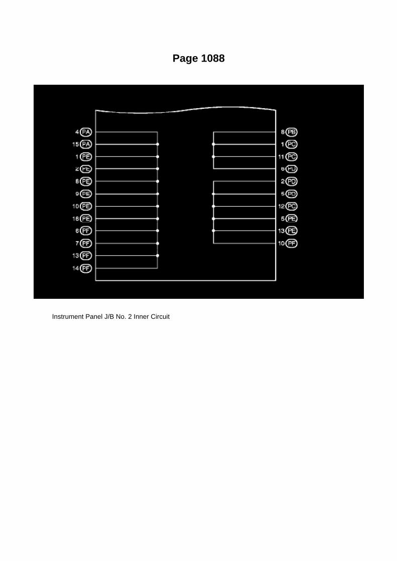
Page 1088
Instrument Panel J/B No. 2 Inner Circuit
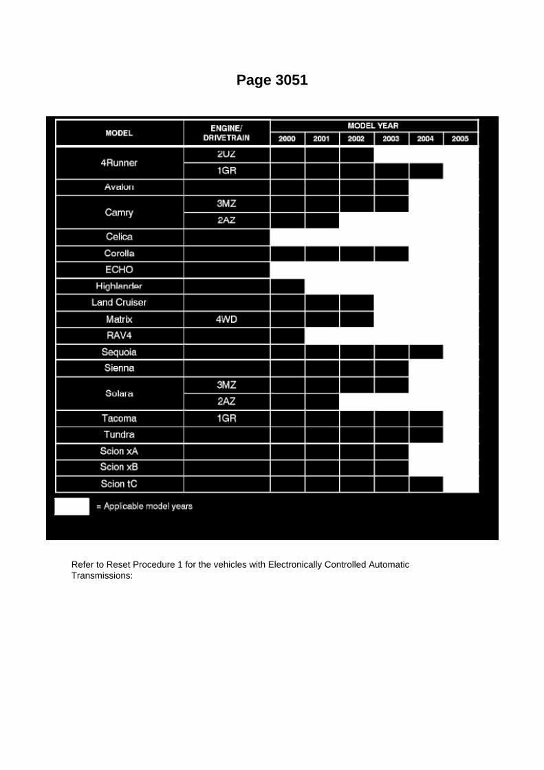
Page 3051
Refer to Reset Procedure 1 for the vehicles with Electronically Controlled AutomaticTransmissions:

Page 2356
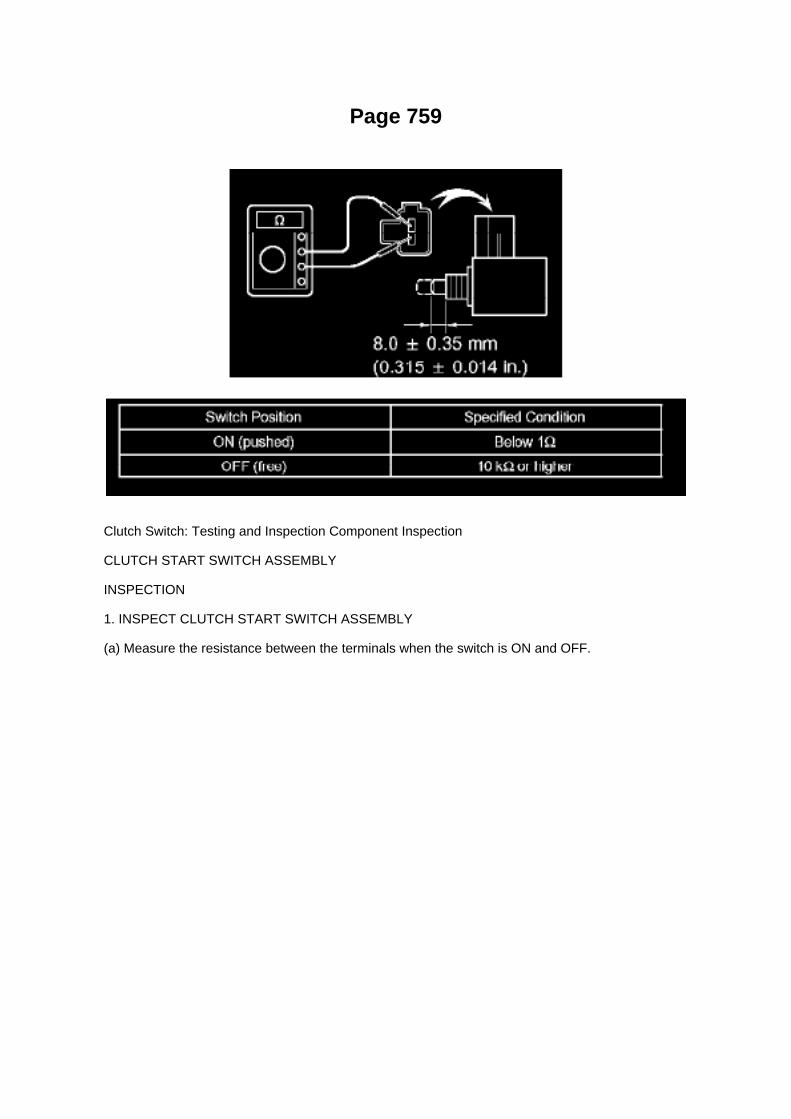
Page 759
Clutch Switch: Testing and Inspection Component Inspection
CLUTCH START SWITCH ASSEMBLY
INSPECTION
1. INSPECT CLUTCH START SWITCH ASSEMBLY
(a) Measure the resistance between the terminals when the switch is ON and OFF.

Page 1071
CAUTION: a. Do not open the cover or the case of the ECU unless absolutely necessary. (If the ICterminals are touched, the IC may be destroyed by static
electricity.)
b. When replacing the internal mechanism (ECU part) of the digital meter, be careful that no part ofyour body or clothing comes in contact with
the terminals of leads from the IC, etc. of the replacement part (spare part).

How to Replace Terminal
HOW TO REPLACE TERMINAL (with terminal retainer or secondary locking device)
1. PREPARE THE SPECIAL TOOL
HINT: To remove the terminal from the connector, please construct and use the special tool or likeobject shown.
2. DISCONNECT CONNECTOR
3. DISENGAGE THE SECONDARY LOCKING DEVICE OR TERMINAL RETAINER
a. Locking device must be disengaged before the terminal locking clip can be released and theterminal removed from the connector. b. Use a special tool or the terminal pick to unlock thesecondary locking device or terminal retainer.
NOTE: Do not remove the terminal retainer from connector body.
[A] : For Non-Waterproof Type Connector
HINT: The needle insertion position varies according to the connector's shape (number of terminalsetc.), so check the position before inserting it.

Locations

Switch: Locations
Po - Ya

Page 1283

Assenmacher Specialty Tools 1-800-525-2943
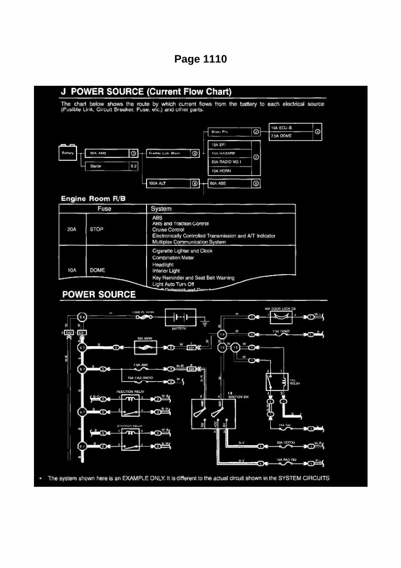
Page 1110

The "Current Flow Chart", describes which parts each power source (fuses, fusible links, and circuitbreakers) transmits current to. In the Power Source circuit diagram, the conditions when batterypower is supplied to each system are explained. Since all System Circuit diagrams start from thepower source, the power source system must be fully understood.

Page 2067

Engine Bank Identification

Page 351
Wheel Speed Sensor: Service and Repair Rear
SPEED SENSOR REAR LH
REPLACEMENT
HINT: The replacement procedures for the RH side are the same as those for the LH side.
1. DISCONNECT CABLE FROM NEGATIVE BATTERY TERMINAL
2. REMOVE SPEED SENSOR REAR LH
a. Disconnect the speed sensor connector. b. Remove the nut and speed sensor rear.
NOTICE: -
Do not attach any foreign matter to the sensor tip.
- Ensure that no foreign matter enters the sensor installation hole.
3. INSTALL SPEED SENSOR REAR LH
a. Install the rear speed sensor with the nut.
Torque: 8.0 Nm (82 kgf-cm, 71 inch lbs.)
NOTICE: Make sure that the sensor tip is clean.
b. Connect the speed sensor connector.
4. CONNECT CABLE TO NEGATIVE BATTERY TERMINAL
Torque: 3.9 Nm (40 kgf-cm, 35 inch lbs.)
5. CHECK ABS SENSOR SIGNAL

Page 568
Crankshaft Position Sensor: Testing and Inspection
INSPECT CRANKSHAFT POSITION SENSOR
Check the resistance.
Using an ohmmeter, measure the resistance between the terminals.
HINT: Cold and Hot mean the temperature of the coils themselves. Cold is from -10 to 50°C (14 to122°F) and Hot is from 50 to 100°C (122 to 212° F).
If the result is not as specified, replace the camshaft position sensor.

Page 1397

Page 1758

k. Disconnect the 3 connectors. l.

Remove the nut shown in the illustration.
m. Disconnect the engine wire harness from the relay block.
n. Remove the 5 bolts and 2 nuts, then remove the intake manifold.
9. REMOVE KNOCK CONTROL SENSOR
a. Disconnect the knock control sensor connector. b. Remove the bolt, then remove the knockcontrol sensor.
10. INSTALL KNOCK CONTROL SENSOR
a. Install the knock control sensor with the bolt.
Torque: 20 N.m (204 kgf.cm, 15 ft.lbf)
NOTE: Make sure that the knock sensor is at the correct angle when installing.
b. Connect the knock control sensor connector.
11. INSTALL INTAKE MANIFOLD

Page 2585

Air Flow Meter/Sensor: Testing and Inspection

INSPECT INTAKE AIR FLOW METER SUB-ASSEMBLY
a. Check the operation.
1. Apply battery voltage across terminals 1 (+B) and 2 (E2G). 2. Using a voltmeter, connect thepositive (+) tester prove to terminal 3 (VG) and the negative (-) tester prove to terminal 2 (E2G). 3.Blow air into the mass air flow meter and check that the voltage fluctuates.
If the voltage does not fluctuate, replace the mass air flow meter.
b. Check the resistance.
1. Using an ohmmeter, measure the resistance between the terminals.
If the result is not as specified, replace the mass air flow meter.

Locations
SFI System

Locations

Page 2657
Ignition Switch: Service and Repair
IGNITION OR STARTER SWITCH ASSEMBLY
REPLACEMENT
1. DISCONNECT CABLE FROM NEGATIVE BATTERY TERMINAL
2. REMOVE STEERING COLUMN COVER LWR
a. Remove the 2 screws. b. Disengage the 2 claws and remove the steering column cover LWR.
3. REMOVE IGNITION OR STARTER SWITCH ASSEMBLY

a. Disconnect the connector. b. Disengage the 2 clamps, then remove the ignition or starter switch.
4. INSTALL IGNITION OR STARTER SWITCH ASSEMBLY 5. INSTALL STEERING COLUMNCOVER LWR 6. CONNECT CABLE TO NEGATIVE BATTERY TERMINAL
Torque: 3.9 N.m (40 kgf.cm, 35 in.lbf)

Description and Operation

Malfunction Indicator Lamp: Description and Operation

MIL (Malfunction Indicator Lamp)
a. The MIL is illuminated when the ignition switch is first turned to ON (the engine is not running). b.The MIL should turn off when the engine is started. If the MIL remains illuminated, the diagnosissystem has detected a malfunction or
abnormality in the system.
HINT: If the MIL is not illuminated when the ignition switch is first turned to ON, check the MILcircuit.

Air-Fuel Ratio Sensor

Oxygen Sensor: Service and Repair Air-Fuel Ratio Sensor

REPLACEMENT
1. DISCONNECT CABLE FROM NEGATIVE BATTERY TERMINAL 2. REMOVE AIR FUEL RATIOSENSOR
a. Disconnect the air fuel ratio sensor connector. b. Disconnect the wire harness clamp.
c. Using SST, remove the air fuel ratio sensor.
SST 09224-00010
3. INSTALL AIR FUEL RATIO SENSOR
a. Using SST, install the air fuel ratio sensor.
SST 09224-00010
Torque: 44 N.m (449 Kgf.cm, 33 ft.lbf) 40 N.m (408 Kgf.cm, 30 ft.lbf) with SST
NOTE: Use a torque wrench with a fulcrum length of 300 mm (11.81in.).

Page 1055
Steps 7 - 8
General Information
GENERAL INFORMATION A large number of ECU controlled systems are used in the TOYOTATACOMA. In general, ECU controlled systems are considered to be very intricate, requiring a highlevel of technical knowledge to troubleshoot. However, most problem checking procedures onlyinvolve inspecting the ECU controlled system's circuits one by one. An adequate understanding ofthe system and a basic knowledge of electricity is enough to perform effective troubleshooting,accurate diagnoses and necessary repairs.
FOR USING OBD II SCAN TOOL OR HAND-HELD TESTER
- Before using the scan tool or tester, the scan tool's instruction book or tester's operator manualshould be read thoroughly.
- If the scan tool or tester cannot communicate with the ECU controlled systems when you haveconnected the cable of the tester to the DLC3 with the ignition switch and tester turned ON, there isa problem on the vehicle side or tester side.
1. If communication is normal when the tester is connected to another vehicle, inspect thediagnosis data link line (Bus(+)line) or ECU power circuit
of the vehicle.
2. If communication is still impossible when the tester is connected to another vehicle, the problemis probably in the tester itself. Perform the Self
Test procedures outlined in the tester Operator's manual.
Basic Inspection
BASIC INSPECTION
a. RESISTANCE MEASURING CONDITION OF ELECTRONIC PARTS

1. Unless stated, all resistance measurements should be made at an ambient temperature of 20°C(68°F). Resistance measurements may be
outside the specifications if measured at high temperatures, i.e. immediately after the vehicle hasbeen running. Measurements should be made after the engine has cooled down.

Page 1281
Drive Belt: Service and Repair

FAN AND GENERATOR V BELT (2TR-FE)
REPLACEMENT
1. REMOVE FAN AND GENERATOR V BELT
a. Turning the hexagonal bolt on the V-ribbed belt tensioner clockwise, loosen and then remove theV belt.
2. INSTALL FAN AND GENERATOR V BELT
a. Provisionally install the V belt onto each pulley.
NOTICE: Install the V belt onto each pulley and finally install the V belt onto the V-ribbed belttensioner.
b. Turn the hexagonal bolt on the V-ribbed belt tensioner clockwise and install the V belt onto theV-ribbed belt tensioner pulley.
3. INSPECT FAN AND GENERATOR V BELT

Brake Actuator Assembly (W/O VSC)

Hydraulic Control Assembly - Antilock Brakes: Service and Repair Brake Actuator Assembly (W/OVSC)

BRAKE ACTUATOR ASSEMBLY (W/O VSC)
REPLACEMENT
1. DISCONNECT CABLE FROM NEGATIVE BATTERY TERMINAL 2. DRAIN BRAKE FLUID
NOTICE: Immediately wash off any brake fluid that comes into contact with any painted surfaces.
3. REMOVE AIR INJECTION CONTROL DRIVER (2TR-FE ENGINE TYPE)
a. Disconnect the 2 connectors.
b. Remove the 2 bolts and air injection control driver.
4. REMOVE BRAKE ACTUATOR ASSEMBLY
a. Release the connector lock lever. b. Disconnect the brake actuator connector.
c. Using SST, disconnect the brake tubes from the brake actuator.
SST 09023-00101
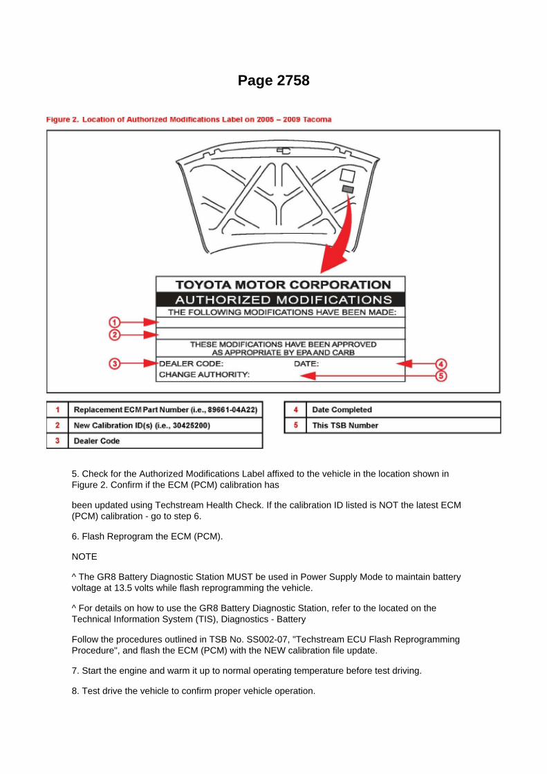
Page 2758
5. Check for the Authorized Modifications Label affixed to the vehicle in the location shown inFigure 2. Confirm if the ECM (PCM) calibration has
been updated using Techstream Health Check. If the calibration ID listed is NOT the latest ECM(PCM) calibration - go to step 6.
6. Flash Reprogram the ECM (PCM).
NOTE
^ The GR8 Battery Diagnostic Station MUST be used in Power Supply Mode to maintain batteryvoltage at 13.5 volts while flash reprogramming the vehicle.
^ For details on how to use the GR8 Battery Diagnostic Station, refer to the located on theTechnical Information System (TIS), Diagnostics - Battery
Follow the procedures outlined in TSB No. SS002-07, "Techstream ECU Flash ReprogrammingProcedure", and flash the ECM (PCM) with the NEW calibration file update.
7. Start the engine and warm it up to normal operating temperature before test driving.
8. Test drive the vehicle to confirm proper vehicle operation.

9. Install the Authorized Modifications Label.
A. Using a permanent marker enter the following information on the label:
^ ECM part number [Refer to the Parts Information section for the CURRENT PART NUMBER]
^ Calibration ID(s) [Refer to the Calibration Identification Chart for the NEW CALIBRATION ID]
^ Dealer Code
^ Repair Date
^ Change Authority [This TSB number]
B. Affix the Authorized Modifications Label to the vehicle at the location shown in Figure 2. TheAuthorized Modifications Label is available
through the MDC P/N 00451-00001-LBL.

Locations
Fusible Link: Locations
Engine Room R/B No. 2 - Engine Compartment Left

Page 1195

b. Install the washer plate, as shown in the illustration, through the hub bolt, and install the hub boltby tightening the hub nut.

8. INSTALL FRONT DISC 9. INSTALL FRONT DISC BRAKE CALIPER ASSY LH
SST 09023-00101
10. CONNECT CABLE TO NEGATIVE BATTERY TERMINAL
Torque: 3.9 Nm (40 kgf-cm, 35 inch lbs.)
11. FILL RESERVOIR WITH BRAKE FLUID (W/ VSC) 12. FILL RESERVOIR WITH BRAKE FLUID(W/O VSC) 13. BLEED MASTER CYLINDER (W/O VSC)
SST 09023-00101
14. BLEED BRAKE LINE (W/ VSC) 15. BLEED BRAKE LINE (W/O VSC) 16. CHECK FLUIDLEVEL IN RESERVOIR (W/ VSC) 17. CHECK FLUID LEVEL IN RESERVOIR (W/O VSC) 18.CHECK FOR BRAKE FLUID LEAKAGE 19. INSTALL FRONT WHEEL
Torque: 113 Nm (1,152 kgf-cm, 83 ft. lbs.)
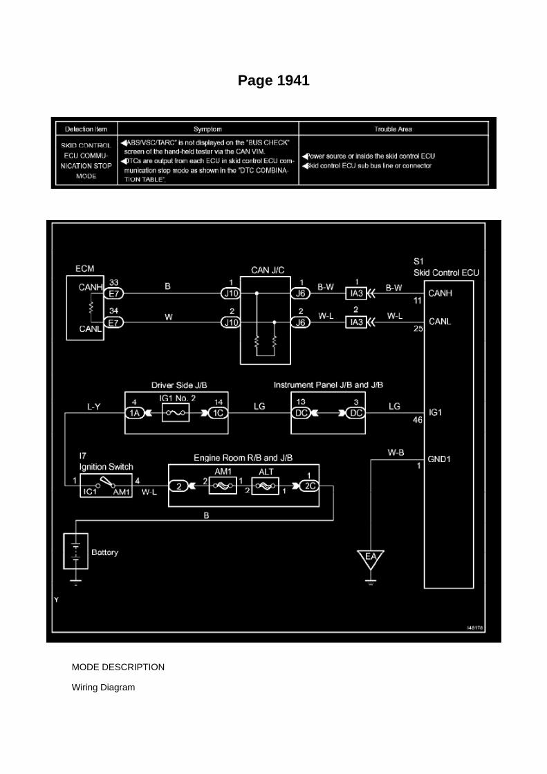
Page 1941
MODE DESCRIPTION
Wiring Diagram

Page 1080
Instrument Panel J/B No. 1 - Left Kick Panel

Page 1358

Page 649

(l) Select "7: SRS AIRBAG" from the "OBD/MOBD MENU".

(m)Press the "YES button when the "VERIFY CONNECTIONS" screen appears.
(n) Select "1: DATA LIST from the "DIAGNOSTIC MENU, AIRBAG/SRS" system.
(o) Select "ALL from the "SELECT DATA" menu.

Page 1841
ABS With EBD & BA & TRAC & VSC SYSTEM

Page 200
C. Choose desired ECU group(s) in the Health Check dialog box.
D. Click Next.
E. Click Continue to view Health Check results.

F. Available calibration updates are indicated by a link in the Cal. Update? column. Click the link toaccess the appropriate service bulletin on TIS.
NOTE
^ Note any DTCs stored in Systems that will be flash reprogrammed.
^ Clicking the link will automatically launch TIS and perform a calibration search.
G. Log in to TIS. (If already logged in skip this step.)
H. To review the TSB and access the calibration file click the service bulletin link in the DocumentTitle column of the Calibration Search Result
portlet.

Page 1068
Circuit Inspection

Voltage Check
VOLTAGE CHECK

Page 2618
SFI System

Page 617
9. REMOVE QUARTER TRIM PANEL LOWER LH
10. REMOVE QUARTER INSIDE TRIM BOARD LH 11. REMOVE REAR SEAT 3 POINT TYPEBELT ASSEMBLY OUTER
12. REMOVE AIR BAG SENSOR REAR LH
a. Disconnect the connector from the airbag sensor rear. b. Remove the nut and the airbag sensorrear.
13. INSPECT AIR BAG SENSOR REAR LH
14. INSTALL AIR BAG SENSOR REAR LH
a. Check that the ignition switch is OFF. b. Check that the cable is disconnected from the batterynegative (-) terminal.
CAUTION: After disconnecting the cable from the terminal, wait for at least 90 seconds beforestarting the operation.
c. Install the airbag sensor rear LH with the nut.
Torque: 9.0 N.m (92 kgf.cm, 80 in.lbf)
NOTE: -
Installation of the connector is done with the sensor assembly installed. Make sure the sensorassembly is installed to the specified torque.
- If the sensor assembly has been dropped, or there are cracks, dents or other defects in the case,bracket or connector, replace the sensor assembly with a new one.
- When installing the sensor assembly, make sure that the SRS wiring does not interfere with anyother parts and is not pinched between other parts.
- After installation, shake the sensor assembly to check that it is not loose.

15. INSTALL REAR SEAT 3 POINT TYPE BELT ASSEMBLY OUTER 16. INSTALL QUARTERINSIDE TRIM BOARD LH 17. INSTALL QUARTER TRIM PANEL LOWER LH 18. INSTALLLUGGAGE COMPARTMENT SIDE TRAY 19. INSTALL REAR DOOR OPENING TRIMWEATHERSTRIP LH 20. INSTALL REAR DOOR SCUFF PLATE LH 21. INSTALL REAR SEATBACK HINGE SUB-ASSEMBLY LH 22. INSTALL REAR SEAT BACK ASSEMBLY LH 23.INSTALL REAR SEAT BACK HINGE COVER 24. CONNECT CABLE TO NEGATIVE BATTERYTERMINAL
Torque: 3.9 N.m (40 kgf.cm, 35 in.lbf)
25. INSPECT SRS WARNING LIGHT

Page 3297

a. Connect the positive (+) lead from the battery to the red cable of the pump, and the negative (-)lead to the black cable. b. Check the brake booster pump operation.

OK: Operation sound is heard.
25. DISPOSE OF BRAKE BOOSTER ACCUMULATOR ASSEMBLY
a. Place the brake booster accumulator in a vise and cover it with a cloth. b. Slowly cut a hole onthe brake booster accumulator side in the A portion shown in the illustration on the left. Anddischarge the gas and liquid
inside.
NOTICE: -
As gas may spray out, cover the brake booster accumulator with a cloth when performing theoperation.
- Work slowly and do not cut the hole too quickly or suddenly.
- Wear protective glasses during the operation.
c. When the outer body of the brake booster accumulator is cut, gas and liquid discharge.
HINT: -
The gas is colorless, odorless and nonpoisonous nitrogen gas.
- The liquid is brake fluid.
26. INSTALL BRAKE BOOSTER ACCUMULATOR ASSEMBLY
a. Place the brake booster pump in a vise with a cloth. b. Install the brake booster accumulatorpipe, compression spring and a new O-ring.
NOTICE: Ensure that no foreign matter enters the pump.
c. Using a socket wrench (17 mm), install the brake booster accumulator onto the brake boosterpump.
Torque: 57.4 Nm (585 kgf-cm, 42 ft. lbs.)
27. INSTALL MASTER CYLINDER SOLENOID
a. Place a new gasket on the master cylinder solenoid and install them onto the master cylinderbody with 6 new bolts.
Torque: 31.9 Nm (325 kgf-cm, 24 ft. lbs.)
NOTICE: Do not let water, dust, and/or other objects attach to the surface and/or attaching surfaceof the master cylinder solenoid, master cylinder and body gasket.

Page 2952

d. Remove the 2 bolts, then remove the clutch master cylinder.

10. INSTALL CLUTCH MASTER CYLINDER ASSY
a. Install the clutch master cylinder with the 2 bolts.
Torque: 16 Nm (158 kgf-cm, 11 ft. lbs.)
b. Install the clutch start switch with the nut.
Torque: 16 Nm (160 kgf-cm, 12 ft. lbs.)
c. Using SST, connect the clutch master cylinder to 2 way tube.
SST 09023-00101 Torque: 15 Nm (155 kgf-cm, 11 ft. lbs.)
d. Connect the clutch reservoir tube.
11. INSTALL CLUTCH PEDAL W/CLUTCH MASTER CYLINDER
a. Install the clutch pedal w/clutch master cylinder onto the vehicle with the 2 nuts and bolt.
Torque:
14 Nm (145 kgf-cm, 10 ft. lbs.) for nut 24 Nm (245 kgf-cm, 18 ft. lbs.) for bolt

Page 1907

Abbreviations

Page 2912

a. Using vernier calipers, inspect the depth and width of wear of the diaphragm spring.

Minimum:
A (Depth): 0.5 mm (0.020 inch) B (Width): 6.0 mm (0.236 inch)
If necessary, replace the clutch cover assy.
12. INSPECT FLYWHEEL SUB-ASSY
a. Using a dial indicator, inspect the flywheel sub-assembly runout.
Maximum runout: 0.1 mm (0.004 inch) If necessary, replace the flywheel sub-assembly.
13. INSPECT INPUT SHAFT BEARING
a. Turn the bearing by hand while applying force in the rotation direction.
If the bearing is stuck or difficult to turn, replace the input shaft bearing.
HINT: The bearing is permanently lubricated and requires no cleaning or lubrication.
14. REMOVE INPUT SHAFT BEARING
a. Remove the 4 bolts at diametrically opposite points. b. Using SST, remove the pilot bearing.
SST 09303-35011
15. INSTALL INPUT SHAFT BEARING
a. Using SST and a hammer, install the input shaft bearing.
SST 09304-30012

Locations
Shift Interlock Control Module: Locations
Instrument Panel
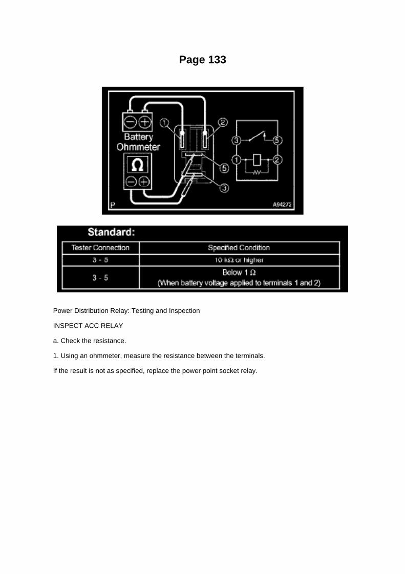
Page 133
Power Distribution Relay: Testing and Inspection
INSPECT ACC RELAY
a. Check the resistance.
1. Using an ohmmeter, measure the resistance between the terminals.
If the result is not as specified, replace the power point socket relay.

Page 2127
Step 9
INSPECTION PROCEDURE
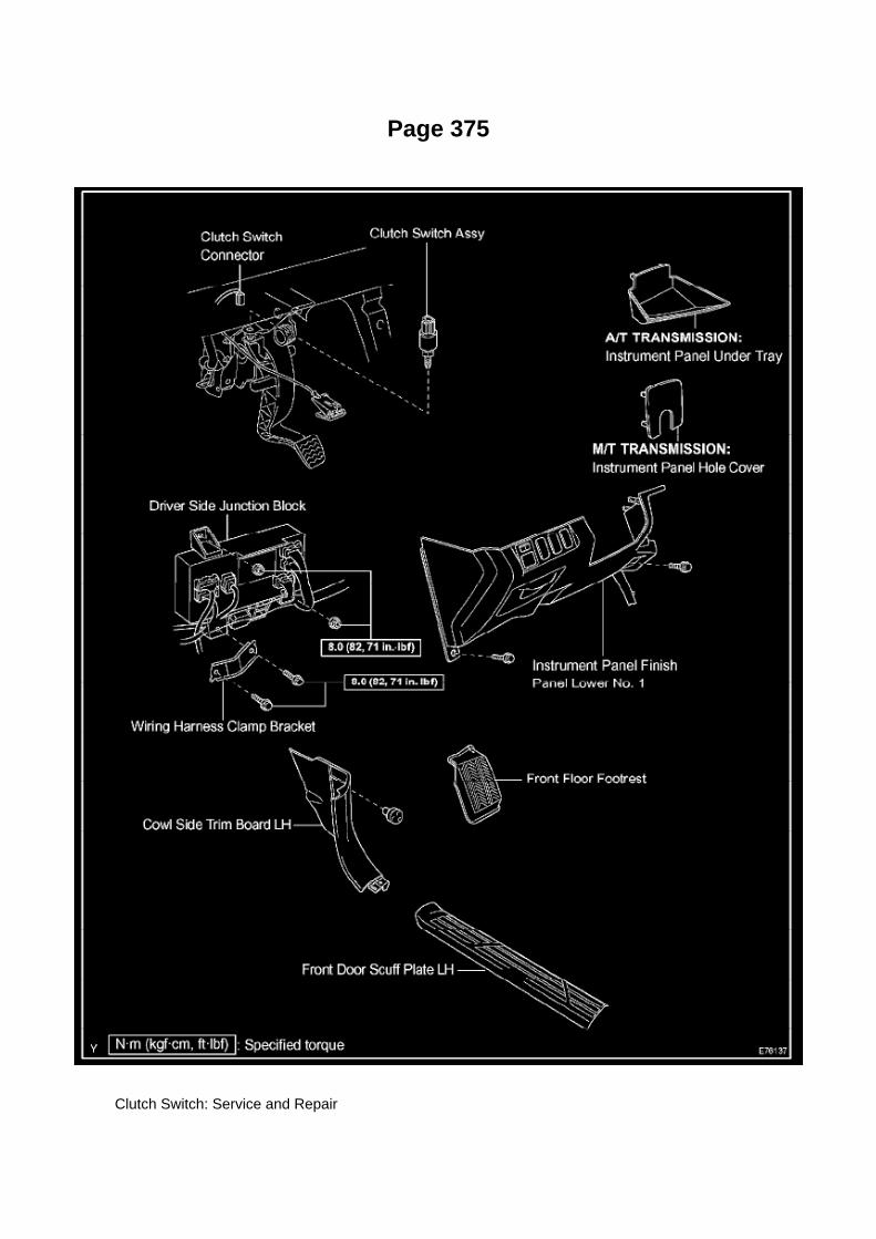
Page 375
Clutch Switch: Service and Repair

Clutch Switch Assy
CLUTCH SWITCH ASSEMBLY
REPLACEMENT
1. DISCONNECT CABLE FROM NEGATIVE BATTERY TERMINAL 2. REMOVE FRONT FLOORFOOTREST 3. REMOVE FRONT DOOR SCUFF PLATE LH 4. REMOVE COWL SIDE TRIMBOARD LH 5. REMOVE INSTRUMENT PANEL HOLE COVER (M/T TRANSMISSION)
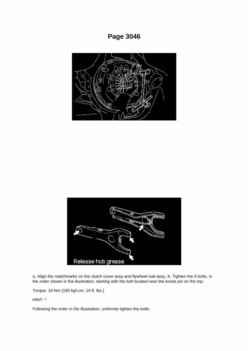
Page 3046
a. Align the matchmarks on the clutch cover assy and flywheel sub-assy. b. Tighten the 6 bolts, inthe order shown in the illustration, starting with the bolt located near the knock pin on the top.
Torque: 19 Nm (195 kgf-cm, 14 ft. lbs.)
HINT: ^
Following the order in the illustration, uniformly tighten the bolts.

^ Move SST up and down, right and left gently after checking that the disc is in the center, andtighten the bolts.
19. INSPECT AND ADJUST CLUTCH COVER ASSY
a. Using a dial indicator with roller instrument, check the diaphragm spring tip alignment.
Maximum non-alignment: 0.5 mm (0.020 inch) If the alignment is not as specified, adjust thediaphragm spring tip alignment using SST. SST 09333-00013
20. INSTALL RELEASE FORK SUPPORT
a. Install the release fork support onto the transaxle assy.
Torque: 47 Nm (479 kgf-cm, 35 ft. lbs.)
21. INSTALL RELEASE BEARING HUB CLIP
22. INSTALL CLUTCH RELEASE FORK SUB-ASSY
a. Apply release hub grease to the release fork and release bearing assy contact surfaces, releasefork and push rod contact surface and release
fork pivot point. Sealant: Part No.08887-01806, RELEASE HUB GREASE or equivalent
b. Install the release fork onto the release bearing assy.
23. INSTALL CLUTCH RELEASE BEARING ASSY
a. Apply clutch spline grease to the input shaft spline.
Sealant: Part No.08887-01706, CLUTCH SPLINE GREASE or equivalent
b. Install the bearing onto the release fork, and then install them onto the transaxle assy.
NOTICE: After installation, move the fork forward and backward to check that the release bearingslides smoothly.
24. INSTALL CLUTCH RELEASE FORK BOOT 25. INSTALL MANUAL TRANSMISSION UNITASSY (R155 TRANSMISSION) 26. INSTALL MANUAL TRANSMISSION UNIT ASSY (R155FTRANSMISSION)

Locations
Shift Interlock Control Module: Locations
Instrument Panel

Page 1882

Terminals Of ECM / Pinouts Part 3

Page 2621
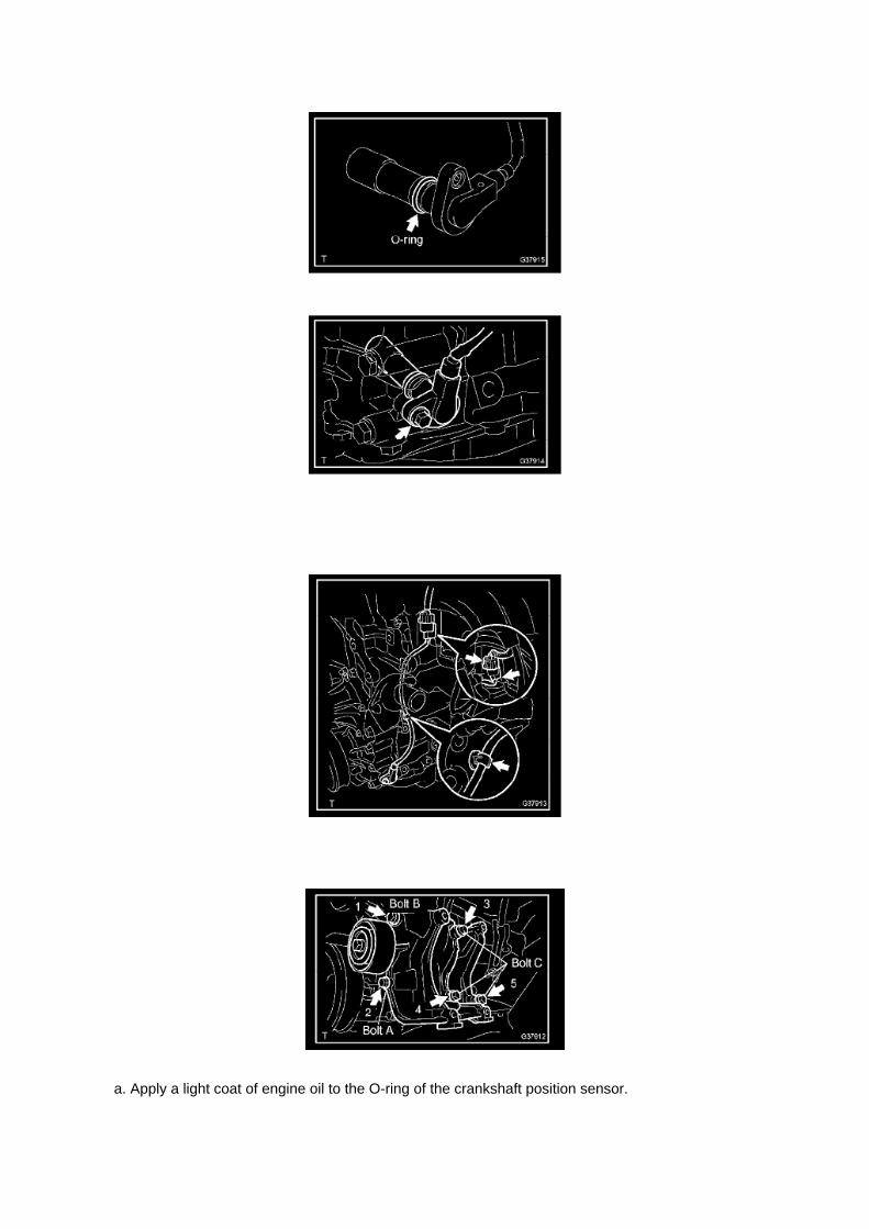
a. Apply a light coat of engine oil to the O-ring of the crankshaft position sensor.

b. Install the camshaft position sensor with the bolt.
Torque: 8.5 N.m (87 kgf.cm, 75 in.lbf)
NOTE: Make sure that the O-ring is not cracked or jammed when installing.
c. Connect the crankshaft position sensor connector and the 2 wire harness clamps.
8. INSTALL IDLE PULLEY ASSEMBLY W/BRACKET (W/ AIR CONDITIONING)

Page 465

Air Flow Meter/Sensor: Testing and Inspection

INSPECT INTAKE AIR FLOW METER SUB-ASSEMBLY
a. Check the operation.
1. Apply battery voltage across terminals 1 (+B) and 2 (E2G). 2. Using a voltmeter, connect thepositive (+) tester prove to terminal 3 (VG) and the negative (-) tester prove to terminal 2 (E2G). 3.Blow air into the mass air flow meter and check that the voltage fluctuates.
If the voltage does not fluctuate, replace the mass air flow meter.
b. Check the resistance.
1. Using an ohmmeter, measure the resistance between the terminals.
If the result is not as specified, replace the mass air flow meter.

Page 1911
Steps 7 - 8
General Information
GENERAL INFORMATION A large number of ECU controlled systems are used in the TOYOTATACOMA. In general, ECU controlled systems are considered to be very intricate, requiring a highlevel of technical knowledge to troubleshoot. However, most problem checking procedures onlyinvolve inspecting the ECU controlled system's circuits one by one. An adequate understanding ofthe system and a basic knowledge of electricity is enough to perform effective troubleshooting,accurate diagnoses and necessary repairs.
FOR USING OBD II SCAN TOOL OR HAND-HELD TESTER
- Before using the scan tool or tester, the scan tool's instruction book or tester's operator manualshould be read thoroughly.
- If the scan tool or tester cannot communicate with the ECU controlled systems when you haveconnected the cable of the tester to the DLC3 with the ignition switch and tester turned ON, there isa problem on the vehicle side or tester side.
1. If communication is normal when the tester is connected to another vehicle, inspect thediagnosis data link line (Bus(+)line) or ECU power circuit
of the vehicle.
2. If communication is still impossible when the tester is connected to another vehicle, the problemis probably in the tester itself. Perform the Self
Test procedures outlined in the tester Operator's manual.
Basic Inspection
BASIC INSPECTION
a. RESISTANCE MEASURING CONDITION OF ELECTRONIC PARTS

1. Unless stated, all resistance measurements should be made at an ambient temperature of 20°C(68°F). Resistance measurements may be
outside the specifications if measured at high temperatures, i.e. immediately after the vehicle hasbeen running. Measurements should be made after the engine has cooled down.

Page 2406
Oxygen Sensor: Technical Service Bulletins Engine Controls - Bank 1/Bank 2 O2 Sensoridentification
ENGINE EG034-07
Title: ENGINE BANK 1 AND BANK 2 A/F AND O2 IDENTIFICATION
Models: '93 - '08 Applicable Models
June 28, 2007
The information contained in this TSB supercedes TSB No. EG037-04. TSB No. EG037-04 is nowobsolete and should be discarded.
Introduction
This service bulletin provides information on the proper identification of engine bank 1 and enginebank 2 for correct A/F sensor and oxygen sensor replacement.
This bulletin contains information that identifies engine bank 1 and engine bank 2 on the followingengines: 1AZ-FE, 2AZ-FE, 2AZ-FE (PZEV), 1GR-FE, 2GR-FE, 2GR-FSE, 2JZ-GE, 1MZ-FE,3MZ-FE, 1UR-FSE, 3UR-FE, 2UZ-FE, 3UZ-FE, 5VZ-FE, and 1ZZ-FE.
^ Bank 1 (B1) refers to the bank that includes cylinder No. 1.

^ Bank 2 (B2) refers to the bank opposite bank 1.
^ Sensor 1 (S1) refers to the sensor that is located before the catalytic converters.
^ Sensor 2 (S2) refers to the sensor that is located after the catalytic converters.
Warranty Information
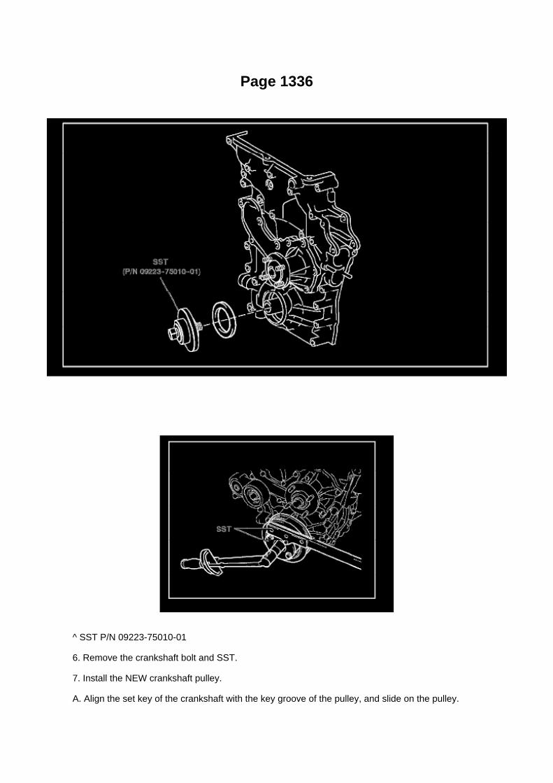
Page 1336
^ SST P/N 09223-75010-01
6. Remove the crankshaft bolt and SST.
7. Install the NEW crankshaft pulley.
A. Align the set key of the crankshaft with the key groove of the pulley, and slide on the pulley.

B. Temporarily install the NEW crankshaft pulley bolt onto the crankshaft.
C. Using the SSTs, hold the crankshaft pulley, and tighten the crankshaft pulley bolt.
^ SST P/N 09213-54015-01 (91651-60855-01), 09330-00021
Torque: 260 N.m (2,651 kgf.cm, 192 ft.lbf)
8. Reinstall the accessory belt.
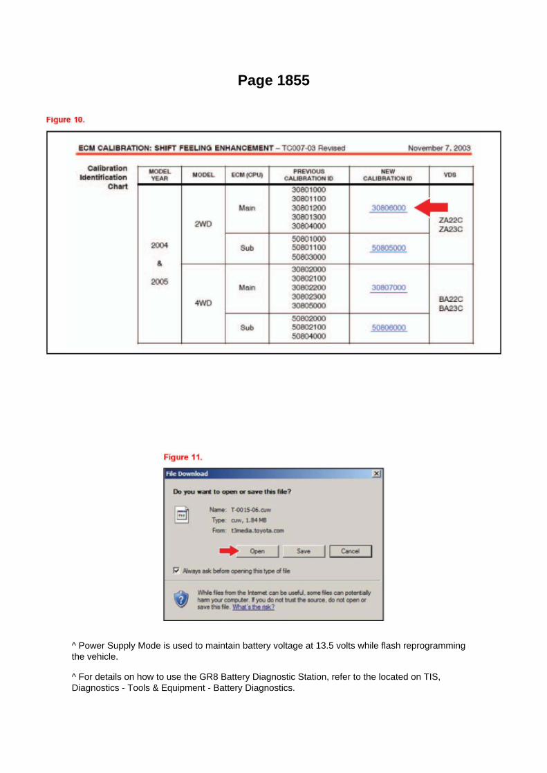
Page 1855
^ Power Supply Mode is used to maintain battery voltage at 13.5 volts while flash reprogrammingthe vehicle.
^ For details on how to use the GR8 Battery Diagnostic Station, refer to the located on TIS,Diagnostics - Tools & Equipment - Battery Diagnostics.

3. Click the appropriate calibration ID and reprogram the vehicle's ECU with Techstream.
A. After reviewing the procedures outlined in the selected TSB, click the appropriate calibration IDlink by matching the vehicle's current
calibration ID to the Previous Calibration ID in the Calibration Identification Chart.
NOTE
^ Calibration files are embedded as live links in the service bulletin.
^ Some vehicles require special preparation - please review the selected TSB carefully.
B. Click Open to load calibration file information.
Techstream pulls calibration files as needed to ensure the latest calibration file is used. Do NOTsave calibrations locally on the hard drive or other media.
NOTICE
Errors during the flash reprogramming process can permanently damage the vehicle ECU.Minimize the risk by following the steps below.
^ Battery voltage MUST NOT FALL BELOW 11.4 volts during reprogramming. Confirm batteryvoltage is higher than 11.4 volts, but be sure voltage DOES NOT RISE ABOVE 16.0 volts duringreprogramming.
^ Turn OFF all vehicle accessories (e.g. audio system, A/C, interior lights, DRL, etc.). Do NOT addto or significantly change the vehicle's electrical

Page 3053

3. Start the engine and warm it up to normal operating temperatures before test-driving.

4. Perform a thorough test drive with several accelerations from a stop with "light throttle"application until proper transmission shifting is verified.
Reset Procedure 2
1. Disconnect the negative battery cable for 5 minutes.
2. Reconnect battery cable.
3. Start the engine and warm it up to normal operating temperatures before test-driving.
4. Perform a thorough test drive with several accelerations from a stop with "light throttle"application until proper transmission shifting is verified.

Page 1583
Engine Control Module: Locations
Instrument Panel
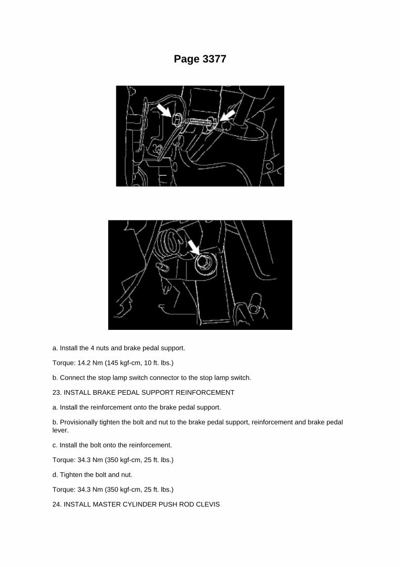
Page 3377
a. Install the 4 nuts and brake pedal support.
Torque: 14.2 Nm (145 kgf-cm, 10 ft. lbs.)
b. Connect the stop lamp switch connector to the stop lamp switch.
23. INSTALL BRAKE PEDAL SUPPORT REINFORCEMENT
a. Install the reinforcement onto the brake pedal support.
b. Provisionally tighten the bolt and nut to the brake pedal support, reinforcement and brake pedallever.
c. Install the bolt onto the reinforcement.
Torque: 34.3 Nm (350 kgf-cm, 25 ft. lbs.)
d. Tighten the bolt and nut.
Torque: 34.3 Nm (350 kgf-cm, 25 ft. lbs.)
24. INSTALL MASTER CYLINDER PUSH ROD CLEVIS

a. Apply lithium soap base glycol grease to the inner surface of the hole on the brake pedal lever.b. Install the push rod clevis onto the brake pedal lever with the push rod pin and clip.
25. CHECK BRAKE PEDAL HEIGHT 26. CHECK PEDAL FREE PLAY 27. CHECK PEDALRESERVE DISTANCE 28. INSTALL DRIVER SIDE JUNCTION BLOCK
Torque: 8.0 Nm (82 kgf-cm, 71 inch lbs.)
29. INSTALL INSTRUMENT PANEL FINISH PANEL LOWER NO.1 30. INSTALL INSTRUMENTPANEL UNDER TRAY (AUTOMATIC TRANSAXLE) 31. INSTALL INSTRUMENT PANEL HOLECOVER (MANUAL TRANSAXLE) 32. INSTALL COWL SIDE TRIM BOARD LH 33. INSTALLFRONT DOOR SCUFF PLATE LH 34. INSTALL FRONT FLOOR FOOTREST 35. CONNECTCABLE TO NEGATIVE BATTERY TERMINAL
Torque: 3.9 Nm (40 kgf-cm, 35 inch lbs.)

Page 645

(c) Connect the male portion of the wire seat jumper to the female portion of the floor wire harness,as shown in the illustration.

(d) Push and pull the connectors to confirm that they are locked in place.
(e) Insert the wire seat jumper connector clip into the slotted hole on the seat bracket.
(f) Connect the female portion of the wire seat jumper to the male portion of the floor wire harness,as shown in the illustration.
(g) Push and pull the connectors to confirm that they are locked in place.
(h) Confirm that the wire seat jumper is correctly routed.

Page 1759

a. Install a new gasket onto the intake manifold. b. Install the intake manifold with the 5 bolts and 2nuts.

Torque: 25 N.m (255 kgf.cm, 18 ft.lbf)
c. Connect the engine wire harness to the relay block. d. Install the nut shown in the illustration.
Torque: 10 N.m (102 kgf.cm, 7 ft.lbf)
e. Connect the 3 connectors.
f. Install the harness clamp bracket with the bolt.
Torque: 8.2 N.m (84 kgf.cm, 73 in.lbf)
g. Engage the wire harness clamp. h. Connect the compressor magnetic clutch connector.

Page 233
Oscilloscope Waveforms

Page 858

If the right and left turning angles of the inside and outside wheels are not within the specifiedranges, check the right and left rack end lengths.

6. INSPECT CAMBER, CASTER AND STEERING AXIS INCLINATION
a. Install the camber-caster-kingpin gauge and position the front wheel on the wheel alignmenttester. b. Inspect the camber, caster and steering axis inclination.
Camber, caster and steering axis inclination:
PRE RUNNER

Page 1733

Camshaft Position Sensor: Service and Repair

REPLACEMENT
1. DISCONNECT CABLE FROM NEGATIVE BATTERY TERMINAL 2. REMOVE CAMSHAFTPOSITION SENSOR
a. Disconnect the camshaft position sensor connector. b. Remove the bolt, then remove thecamshaft position sensor.
3. INSTALL CAMSHAFT POSITION SENSOR
a. Apply a light coat of engine oil to the O-ring of the camshaft position sensor.
b. Install the camshaft position sensor with the bolt.
Torque: 8.5 N.m (87 kgf.cm, 75 in.lbf)
NOTE: Make sure that the O-ring is not cracked or jammed when installing.
c. Connect the camshaft position sensor connector.
4. CONNECT CABLE TO NEGATIVE BATTERY TERMINAL
Torque: 3.9 N.m (40 kgf.cm, 35 in.lbf)

Page 42

Alarm Module: Testing and Inspection

Terminals Of Control Module / Pinouts - Check Transponder Key Amplifier

Locations
Shift Interlock Control Module: Locations
Instrument Panel

Page 1915

c. Check the voltage.

1. In a circuit in which voltage is applied to the ECU connector terminal, an open circuit can bechecked by conducting a voltage check.
FIG 4: With each connector still connected, measure the voltage between the body ground andthese terminals (in this order): 1) terminal 1 of connector A at the ECU 5 V output terminal, 2)terminal 1 of connector B, and 3) terminal 1 of connector C.
2. Example results:
If your results match the examples above, an open circuit exists in the wire harness betweenterminal 1 of connector B and terminal 1 of connector C.
Check Short Circuit
CHECK SHORT CIRCUIT
a. If the wire harness is ground shorted (Fig. 5), locate the section by conducting a resistancecheck with the body ground.
b. Check the resistance with the body ground.

Page 1569
When using Techstream Lite, select Generic J2534 Interface. Then click Next.
E. Confirm the following:
^ PC is connected to VIM.
^ VIM is connected to DLC3 connector.
^ Ignition is ON and engine is OFF or "READY" OFF (hybrid vehicles).

Page 1224

l. Using several steps, uniformly loosen and remove the 21 bearing cap bolts in the sequenceshown in the illustration.

NOTICE: Place the camshaft on a flat surface and loosen the bolts uniformly.
m. Remove the camshaft oil delivery pipe and O-ring.
n. Remove the camshaft bearing cap No.1 and 8 camshaft bearing caps No.2.
o. Remove the camshaft and No.2 camshaft.
NOTICE: -
Do not pry the camshaft with a tool by applying excessive force to it.
- Do not damage the cylinder head when removing the camshafts.
p. Tie the chain with a piece of string or wire.

Locations
Acceleration/Deceleration Sensor: Locations
Ac - Ou

Page 1210
Variable Valve Timing Actuator: Testing and Inspection On-Vehicle Inspection
INSPECT CAMSHAFT TIMING OIL CONTROL VALVE ASSEMBLY
a. Check the operation.
1. Connect the hand-held tester to the DLC3. 2. Turn the ignition switch to ON. 3. Turn thehand-held tester ON. 4. Start the engine and warm it up. 5. Select the following menu items:DIAGNOSIS / ENHANCED OBD II / ACTIVE TEST / VVT CTRL B1.
6. Operate the OCV using the hand-held tester, then check the engine speed.
If the operation is not as specified, check the camshaft timing oil control valve, wire harness andECM.

Page 3251

Acceleration/Deceleration Sensor: Service and Repair
DECELERATION SENSOR (W/O VSC FOR 4WD AND PRE RUNNER)
REPLACEMENT
1. DISCONNECT CABLE FROM NEGATIVE BATTERY TERMINAL 2. REMOVE FRONT SEATASSEMBLY (BENCH SEAT TYPE) 3. REMOVE FRONT SEAT ASSEMBLY LH (SEPARATESEAT TYPE) 4. REMOVE FRONT FLOOR FOOTREST 5. REMOVE FRONT DOOR SCUFFPLATE LH 6. REMOVE COWL SIDE TRIM BOARD LH 7. REMOVE SENSOR BRACKET
a. Turn up the floor carpet.
b. Remove the wire harness clamp. c. Remove the bolt and bracket.
8. REMOVE DECELERATION SENSOR
a. Disconnect the deceleration sensor connector. b. Remove the 2 bolts and deceleration sensor.
9. INSTALL DECELERATION SENSOR
a. Install the deceleration sensor with the 2 bolts.
Torque: 12.5 Nm (127 kgf-cm, 9 ft. lbs.)
NOTICE: Make sure the sensor is at the correct angle when installing.
b. Connect the deceleration sensor connector.

Page 2935
20. Install the instrument panel finish panel lower No. 1.
21. Install the cowl side trim board.
22. Install the front door opening trim LH (scuff plate).
23. Connect the negative (-) battery terminal cable.
Torque: 3.9 N.m (40 kgf.cm, 35 in..lbf)
24. Reset the memories for the clock, radio, etc.
25. Check the clutch release point.
A. Pull the parking brake lever and use wheel chocks.
B. Start the engine and allow it to idle.
C. Without depressing the clutch pedal, slowly move the shift lever into the reverse position untilthe gears engage (and grinding is heard).
D. Gradually depress the clutch pedal and measure the stroke distance from the point that the gearnoise stops (release point) up to the full stroke end position.
Standard distance: 25 mm (0.984 in.) or more (from pedal stroke end position to release point)
If the distance if NOT as specified, perform the following operations:
^ Check the pedal height.
^ Check the push rod play and pedal free play.
^ Bleed the clutch line.
^ Check the clutch cover assembly and the disc assembly.

Page 3350

Repair Procedure

1. Disconnect the cable from the negative (-) battery terminal for MORE THAN two (2) seconds.
2. Reconnect the cable to the negative (-) battery terminal.
3. Perform the applicable zero point calibration of the yaw rate sensor and/or the steering anglesensor.
HINT Refer to the applicable TSB or Repair Manual for the zero point calibration procedure.
4. Re-initialize all applicable systems available on the vehicle (power window sunroof power liftdoor etc.).

Page 3328
Traction Control Indicator Lamp: Testing and Inspection Skid Control Buzzer Circuit
SKID CONTROL BUZZER CIRCUIT
CIRCUIT DESCRIPTION The skid control buzzer sounds when the VSC or Hill-start Assist Control(HAC) operates.
Wiring Diagram

Page 1912

b. HANDLING CONNECTORS

1. When disconnecting a connector, first squeeze the mating halves tightly together to release thelock, then press the lock claw and separate the
connector.
2. When disconnecting a connector, do not pull on the harnesses. Grasp the connector directly andseparate it. 3. Before connecting the connector, check that there are no deformed, damaged, looseor missing terminals. 4. When connecting a connector, press firmly until you hear the lock closewith a "click" sound. 5. If checking the connector with a TOYOTA electrical tester, check it from thebackside (harness side) of the connector using a mini test lead.
NOTE: -
As a waterproof connector cannot be checked from the backside, check by connecting asub-harness.
- Do not damage the terminals by moving the inserted tester needle.
c. CHECKING CONNECTORS
1. Checking when the connector is connected: Squeeze the connector together to confirm that it isfully inserted and locked.
2. Checking when the connector is disconnected: Check by pulling the wire harness lightly from thebackside of the connector. Look for
unlatched terminals, missing terminals, loose crimps or broken conductor wires. Check visually forcorrosion, metallic or foreign objects and water; and bent, rusted, overheated, contaminated, anddeformed terminals.
NOTE: When testing a gold-plated female terminal, always use a gold-plated male terminal.

Page 463

He - Wi

Locations

A/C - Fo

Page 1422


Page 1580
Refer to Reset Procedure 1 for the vehicles with Electronically Controlled AutomaticTransmissions:

Page 850

2 Of 6

Page 2959

10. CONNECT CLUTCH RELEASE CYLINDER TO FLEXIBLE HOSE TUBE

a. Using SST, connect the flexible hose tube.
SST 09023-00101 Torque: 15 Nm (155 kgf-cm, 11 ft. lbs.)
b. Install the clutch line bracket.
Torque: 12 Nm (120 kgf-cm, 8.7 ft. lbs.)
11. BLEED CLUTCH PIPE LINE
a. Fill the brake reservoir tank with brake fluid and bleed the clutch system.
Torque: 11 Nm (110 kgf-cm, 8.0 ft. lbs.)
12. CHECK FOR CLUTCH FLUID LEAKAGE
13. INSTALL CLUTCH HOUSING COVER NO.1 (RA60/RA60F TRANSMISSION)
a. Install the clutch housing cover No.1 with the 3 bolts.
Torque: 12 Nm (120 kgf-cm, 8.7 ft. lbs.)

Locations
Crankshaft Position Sensor: Locations

A/C - Ge

Page 2217
Oxygen Sensor: Testing and Inspection Heated Oxygen Sensor
INSPECTION
INSPECT HEATED OXYGEN SENSOR
a. Check the resistance.
1. Using an ohmmeter, measure the resistance between the terminals.
If the result is not as specified, replace the heated oxygen sensor.
Page 967
is pink, premixed ethylene glycol concentration is approximately 50 % and freezing temperature is-35°C (-31°F)) is recommended.
NOTICE: Do not substitute plain water for engine coolant.
e. Check the coolant level inside the radiator by squeezing the inlet and outlet radiator hosesseveral times by hand. If the coolant level goes
down, add coolant.
f. Install the radiator cap securely.
g. Slowly pour coolant into the radiator reservoir until it reaches the FULL line.
h. Warm up the engine until the cooling fan operates.
- Set the air conditioning as follows while warming up the engine.
i. Squeeze the inlet and outlet radiator hoses several times by hand while warning up the engine.
j. Stop the engine and wait until the coolant cools down.
k. Remove the radiator cap and check the coolant level inside the radiator. l.
If the coolant level is below the full level, perform the steps from (d) through
k. and repeat the operation until the coolant level remains at the full level. m. Check the coolantlevel inside the radiator reservoir tank again. If it is below the full level, add coolant. n. Install theengine under cover No.1 with the 4 bolts. (PRE RUNNER AND 4WD TYPE)
Torque: 30 Nm (306 kgf-cm, 22 ft. lbs.)
3. CHECK FOR ENGINE COOLANT LEAKAGE
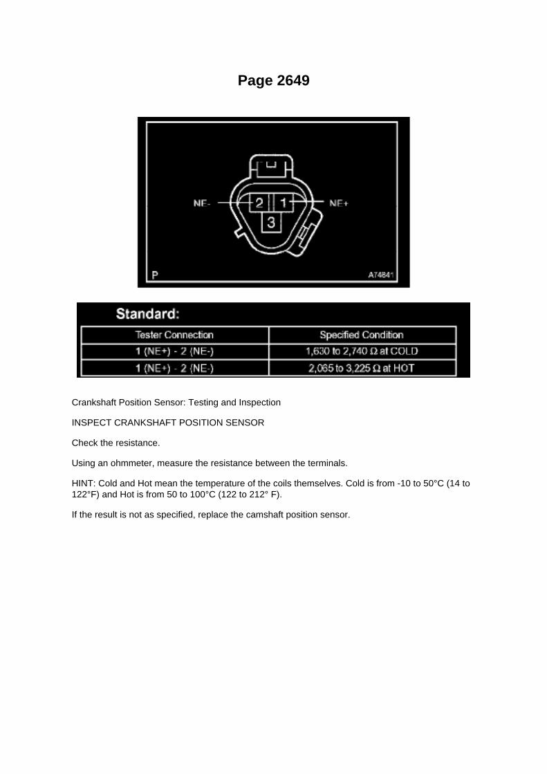
Page 2649
Crankshaft Position Sensor: Testing and Inspection
INSPECT CRANKSHAFT POSITION SENSOR
Check the resistance.
Using an ohmmeter, measure the resistance between the terminals.
HINT: Cold and Hot mean the temperature of the coils themselves. Cold is from -10 to 50°C (14 to122°F) and Hot is from 50 to 100°C (122 to 212° F).
If the result is not as specified, replace the camshaft position sensor.

Locations

Clutch Switch: Locations
A/C - Fo

Front
Wheel Speed Sensor: Service and Repair Front
SPEED SENSOR FRONT LH
REPLACEMENT
HINT: The replacement procedures for the RH side are the same as those for the LH side.
1. DISCONNECT CABLE FROM NEGATIVE BATTERY TERMINAL 2. REMOVE FRONT WHEEL
3. REMOVE SPEED SENSOR FRONT LH
a. Disconnect the speed sensor connector. b. Remove the bolt and front speed sensor.
NOTICE: -
Do not attach any foreign matter to the sensor tip.
- Ensure that no foreign matter enters the sensor installation part.
4. INSTALL SPEED SENSOR FRONT LH
a. Install the front speed sensor with the bolt.
Torque: 8.3 Nm (85 kgf-cm, 73 inch lbs.)
NOTICE: Make sure that the sensor tip is clean.

b. Connect the speed sensor connector.
5. INSTALL FRONT WHEEL
Torque: 113 Nm (1,152 kgf-cm, 83 ft. lbs.)
6. CONNECT CABLE TO NEGATIVE BATTERY TERMINAL
Torque: 3.9 Nm (40 kgf-cm, 35 inch lbs.)
7. CHECK ABS SENSOR SIGNAL

Page 59

Towing Converter Relay Part 4

Page 315

Ac - Ya

Specifications

Fuel Pressure: Specifications

Fuel Pressure
At Idle.............................................................................................................................................281to 287 kPa (2.87 to 2.93 kgf/sq.cm, 40.8 to 41.7 psi)
After Engine Stopped for 5Min..............................................................................................................................................147kPa (1.5 kgf/sq.cm, 21 psi)

Page 2002
Step 11 - 14

Page 3210

Transmission Position Switch/Sensor: Service and Repair

PARK/NEUTRAL POSITION SWITCH ASSY
REPLACEMENT
1. DISCONNECT CABLE FROM NEGATIVE BATTERY TERMINAL 2. DISCONNECTPARK/NEUTRAL POSITION SWITCH CONNECTOR
3. REMOVE PARK/NEUTRAL POSITION SWITCH ASSY
a. Using a screwdriver, unstake the lock washer. b. Remove the nut, lock washer and grommet. c.Remove the bolt and park/neutral position switch.
4. INSTALL PARK/NEUTRAL POSITION SWITCH ASSY
a. Install the park/neutral position switch onto the manual valve lever shaft and provisionally tightenthe adjusting bolt.

Page 3223

Ac - Ya

Locations

Data Link Connector: Locations
A/C - Fo

Page 246

Main Relay (Computer/Fuel System): Testing and Inspection

INSPECT E.F.I. CIRCUIT OPENING RELAY ASSEMBLY
a. Check the resistance.
1. Using an ohmmeter, measure the resistance between the terminals.
If the result is not as specified, replace the E.F.I. circuit opening relay assembly.
INSPECT EFI RELAY
a. Check the resistance.
1. Using an ohmmeter, measure the resistance between the terminals.
If the result is not as specified, replace the E.F.I. ECU relay.

Locations

Power Steering Pressure Switch: Locations

He - Wi

Page 2986

F. Remove the bolt attached to the instrument panel reinforcement assembly.

G. Remove the clutch pedal sub-assembly.
a. Remove the bolt and nut.
b. Remove the clutch pedal from the clutch pedal support.
4. Remove the clutch pedal spring holder from the clutch pedal support.
5. Remove the clutch pedal pad.

Service and Repair

Seals and Gaskets: Service and Repair
REAR DIFFERENTIAL CARRIER OIL SEAL
REPLACEMENT
1. DRAIN DIFFERENTIAL OIL 2. REMOVE PROPELLER SHAFT ASSY (2WD DRIVE TYPE,REGULAR CAB) 3. REMOVE PROPELLER W/CENTER BEARING SHAFT ASSY (2WD DRIVETYPE, EXCEPT REGULAR CAB) 4. REMOVE PROPELLER SHAFT ASSY (4WD DRIVE TYPE,REGULAR CAB) 5. REMOVE PROPELLER W/CENTER BEARING SHAFT ASSY (4WD DRIVETYPE, EXCEPT REGULAR CAB)
6. REMOVE REAR DRIVE PINION NUT
a. Using SST and a hammer, unstake the nut.
SST 09930-00010
b. Using SST to hold the companion flange, remove the nut.
SST 09330-00021
7. REMOVE REAR DRIVE PINION COMPANION FLANGE SUB-ASSY REAR
a. Using SST, remove the companion flange.
SST 09950-30012 (09951-03010, 09953-03010, 09954-03010, 09955-03030, 09956-03030)
8. REMOVE REAR DIFFERENTIAL CARRIER OIL SEAL
a. Using SST, remove the oil seal.
SST 09308-10010
9. REMOVE REAR DIFFERENTIAL DRIVE PINION OIL SLINGER (W/ DIFF. LOCK)

Page 2262

Po - Ya

Page 1107
Diagram Legend
Diagram Legend
O: Indicates values or explains the function for reference during troubleshooting.
P: Indicates the reference showing the position on the vehicle of the parts in the system circuit.Example: Part L4 (Light Failure Sensor) * The letter in the code is from the first letter of the part,and the number indicates its order in parts starting with that letter.
Q: Indicates the reference showing the position on the vehicle of Relay Block Connectors in thesystem circuit.
Example: Connector "1" is described and is installed on the left side of the instrument panel.

R: Indicates the reference showing the position on the vehicle of J/B and Wire Harness in thesystem circuit.
Example: Connector "3C" connects the Instrument Panel Wire and J/B No.3. It is described and isinstalled on the instrument panel left side.
S: Indicates the reference describing the wiring harness and wiring harness connector (the femalewiring harness is shown first, followed by the male wiring harness).
Example: Connector "IE1" connects the floor wire (female) and Instrument panel wire (male). It isdescribed and is installed on the left side kick panel.
T: Indicates the reference showing the position of the ground points on the vehicle.
Example: Ground point "BO" is described and is installed on the back panel center.
U: Indicates the reference showing the position of the splice points on the vehicle.

Page 2110

M. Turn ignition OFF for a minimum of 10 seconds. Then click Next.

N. Turn ignition to the ON position. Then click Next.
0. Confirm all calibrations were updated as specified in the service bulletin. Then click Finish.

Page 3085
Ce - Ya

Page 1519

Specification:

If the maximum pressure is less than the minimum standard value, replace the radiator capsub-assembly.
Type: Compact Cap, 108 kPa
1. Remove coolant and any foreign material on rubber points "A," "B," and "C."
2. Check that points "A" and "B" are not deformed, cracked, or swollen.
3. Check that points "B" and "C" are not stuck together.
4. Apply engine coolant to point "B" before using the radiator cap tester.
^ Radiator Cap Tester: Snap-On/Sun P/N SVTS262A (or equivalent)
5. Before installing the radiator cap tester, use the applicable radiator cap adaptor provided in thefollowing SST kits in conjunction with the radiator cap tester:
^ SST P/N 09230-00030-01 (09231-10080-01) or 09230-00020-01 (09231-10060-01) or09230-00050-01 (09231-10110-01)
6. When using the radiator cap tester, tilt it more than 30 degrees.
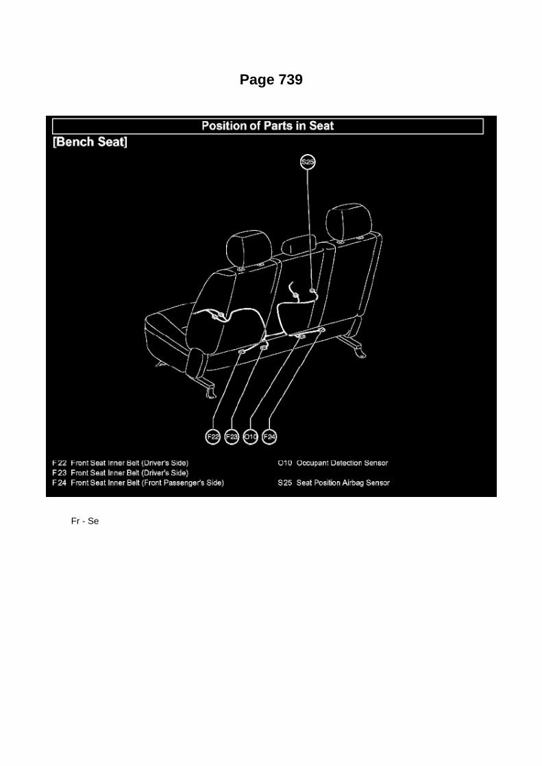
Page 739
Fr - Se

Page 149

Abbreviations

Page 2476
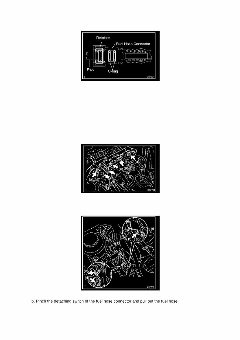
b. Pinch the detaching switch of the fuel hose connector and pull out the fuel hose.

NOTE: -
Remove any dirt and foreign objects on the fuel tube connector before performing this work.
- Do not allow any scratches or foreign objects on the parts when disconnecting, as the fuel tubeconnector has the O-ring that seals the pipe.
- Perform this work by hand. Do not use any tools.
- Do not forcibly bend, twist or turn the nylon tube.
- Protect the disconnected part by covering it with a vinyl bag after disconnecting the fuel hose.
- If the fuel tube connector and pipe are stuck, push and pull to release them.
9. REMOVE FUEL PRESSURE PULSATION DAMPER ASSEMBLY
10. REMOVE FUEL DELIVERY PIPE W/INJECTOR
a. Disconnect the 4 injector connectors. b. Disconnect the VSV connector. c. Disconnect theengine wire harness clamp.
d. Disconnect the compressor magnetic clutch connector.
(w/ AIR CONDITIONING)
e. Disconnect the wire harness clamp. f.
Remove the bolt, then remove the harness clamp bracket.

Page 1565
C. Choose desired ECU group(s) in the Health Check dialog box.
D. Click Next.
E. Click Continue to view Health Check results.

F. Available calibration updates are indicated by a link in the Cal. Update? column. Click the link toaccess the appropriate service bulletin on TIS.
NOTE
^ Note any DTCs stored in Systems that will be flash reprogrammed.
^ Clicking the link will automatically launch TIS and perform a calibration search.
G. Log in to TIS. (If already logged in skip this step.)
H. To review the TSB and access the calibration file click the service bulletin link in the DocumentTitle column of the Calibration Search Result
portlet.

Locations

Power Steering Pressure Switch: Locations

He - Wi

Page 2492

Fuel Pressure: Testing and Inspection

ON-VEHICLE INSPECTION
1. CHECK FUEL PUMP
a. Connect the hand-held tester to the DLC3. b. Turn the ignition switch to ON.
NOTE: Do not start the engine.
c. Turn the hand-held tester ON. d. Select the following menu items: DIAGNOSIS / ENHANCEDOBD II / ACTIVE TEST / FUEL PUMP / SPD. e. Check the fuel operation by operating it with thehand-held tester.
If the fuel pump does not operate, replace the fuel pump.
2. CHECK FUEL PRESSURE
a. Discharge the fuel system pressure. b. Using a voltmeter, measure the battery voltage.
Standard: 9.0 to 14 V
c. Disconnect the cable from the negative battery terminal. d. Remove the fuel pipe clamp. e.Disconnect the fuel hose.
f. Install SST into the vehicle.
SST 09268- 41048 (09268- 41500, 90467- 13001, 95336- 08070), 09268- 45014 (09268- 41200,09268-41220, 09268-41250, 90467-13001)

Page 2392

Page 2403


Locations
A/C - Ge

Locations

A/C - Fo

ABS/TCS - Zero Point Calibration Information
Yaw Rate Sensor: Technical Service Bulletins ABS/TCS - Zero Point Calibration Information
T-SB-0020-08
March 25, 2008
Disconnect Battery & Perform Zero Point Calibration After Wheel Alignment Adjustment
Service Category Brake
Section Brake Control/Dynamic Control System
Market USA
Applicability
Introduction

The purpose of this TSB is to provide information on when and how to perform the zero pointcalibration on vehicles equipped with Vehicle Stability Control (VSC). Momentarily disconnectingthe battery is a necessary step for performing the zero point calibration.
Warranty Information
Required Tools & Equipment
^ Additional TIS techstream units may be ordered by calling Approved Dealer Equipment (ADE).
^ The Toyota Diagnostic Tester and CAN Interface Module may also be used to perform theservice procedures listed in this bulletin.
Preliminary Information
Perform this procedure if any of these repairs have been performed on the vehicle:
^ Wheel alignment has been adjusted.
^ Any chassis components have been removed/installed or replaced.

Locations
Crankshaft Position Sensor: Locations

A/C - Ge

Page 1062

(Sample ) Supplemental Restraint System check sheet
Symptom Confirmation and Diagnostic Trouble Code
SYMPTOM CONFIRMATION AND DIAGNOSTIC TROUBLE CODE
HINT:
The diagnostic system in the TOYOTA TACOMA has various functions. -
The first function is the Diagnostic Trouble Code (DTC) check. A DTC is a code stored in the ECUmemory whenever a malfunction in the signal circuits to the ECU occurs. In a DTC check, aprevious malfunction's DTC can be checked by a technician during troubleshooting.
- Another function is the Input Signal Check, which checks if the signals from various switches aresent to the ECU correctly. By using these functions, the problem areas can be narrowed down andtroubleshooting is more effective. Diagnostic functions are incorporated in the above systems in theTOYOTA TACOMA:
- In the DTC check, it is very important to determine whether the problem indicated by the DTC is:1) still occurring, or 2) occurred in the past but has since returned to normal. In addition, the DTCshould be compared to the problem symptom to see if they are related. For this reason, DTCsshould be checked before and after confirmation of symptoms (i.e., whether or not problemsymptoms exist) to determine current system conditions, as shown in the flowchart. Never skip theDTC check. Failing to check DTCs may, depending on the case, result in unnecessarytroubleshooting for systems operating

Page 306
Ac - Ou

Page 2276
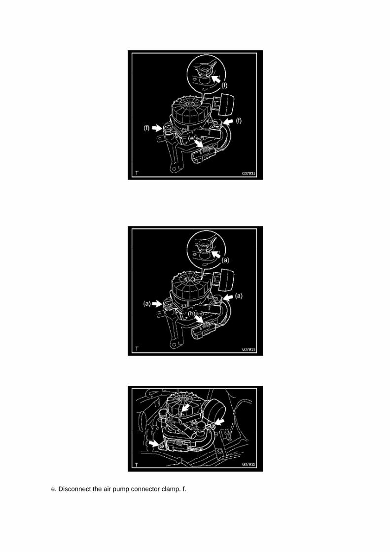
e. Disconnect the air pump connector clamp. f.

Disengage the 3 fittings of the air pump insulator, and remove the air pump from the bracket.
3. INSTALL AIR PUMP ASSEMBLY
a. Engage the 3 fittings of the air pump insulator, and install the air pump onto the bracket. b.Connect the air pump connector clamp.
c. Install the air pump with bracket with the 3 bolts.
Torque: 18 N.m (184 Kgf.cm, 13 ft.lbf)

Page 2159

He - Wi

Page 2408
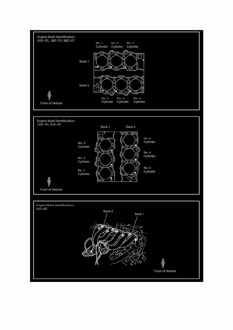

Page 833
4. REMOVE WINDSHIELD WIPER SWITCH ASSEMBLY
a. Disconnect the 2 connectors. b. Using a screwdriver wrapped with protective tape, disengagethe claw and remove the windshield wiper switch assembly.
NOTE: The claw will break if pressed too hard.
5. INSTALL WINDSHIELD WIPER SWITCH ASSEMBLY
a. Engage the claw and install the windshield wiper switch assembly. b. Connect the 2 connectors.

6. CONNECT CABLE TO NEGATIVE BATTERY TERMINAL
Torque: 3.9 N.m (40 kgf.cm, 35 in.lbf)
7. INSTALL STEERING COLUMN COVER UPR 8. INSTALL STEERING COLUMN COVER LWR

Page 3016

F. Remove the bolt attached to the instrument panel reinforcement assembly.

G. Remove the clutch pedal sub-assembly.
a. Remove the bolt and nut.
b. Remove the clutch pedal from the clutch pedal support.
4. Remove the clutch pedal spring holder from the clutch pedal support.
5. Remove the clutch pedal pad.

Page 2308

Evaporative Emission Control Canister: Testing and Inspection

INSPECTION
INSPECT CHARCOAL CANISTER ASSEMBLY
a. Visually check the charcoal canister for cracks and damage.
If cracks and damage are found, replace the charcoal canister assembly.
b. Check the charcoal canister operation.
1. While holding the purge port closed, blow air of 1.67 kPa (17.0 gf/sq.cm, 0.24 psi) into the ventport, and check that the air flows from the air
inlet port. If the result is not as specified, replace the charcoal canister assembly.
2. While holding the vent port closed, apply a vacuum of 1.10 kPa (8.3 mmHg, 0.32 in.Hg) into thepurge port, and check that the air flows from
the air inlet port. If the result is not as specified, replace the charcoal canister assembly.

Page 21

a. For an open circuit in the wire harness in Fig. 1, perform a resistance check (step b) or a voltagecheck (step c).

b. Check the resistance.
1. Disconnect connectors A and C and measure the resistance between them.
HINT: Measure the resistance while lightly shaking the wire harness vertically and horizontally.
If your results match the examples above, an open circuit exists between terminal 1 of connector Aand terminal 1 of connector C.
2. Disconnect connectors B and measure the resistance between the connectors.
If your results match the examples above, an open circuit exists between terminal 1 of connectorB2 and terminal 1 of connector C.

Page 2342

3. Install the fuel tank protector cover on top of the fuel suction plate sub-assembly as shown in theillustration.

Page 35

"Case 1" Raise the terminal retainer up to the temporary lock position.

"Case 2" Open the secondary locking device.

Specifications

Fuel Tank: Specifications

Fuel tank capacity:..............................................................................................................................................................21.1 gal. (80 L, 17.6 Imp. gal.)

Page 3330
Step 3 - 4
INSPECTION PROCEDURE
HINT: Start the inspection from step 1 when using a hand-held tester and start from step 2 whennot using a handheld tester.

CHECK FOR INTERMITTENT PROBLEMS
HINT: A momentary interruption (open circuit) in the connectors and/ or wire harness between thesensors and ECUs can be detected through the ECU data monitor function of the hand-held tester.

Page 2554

Fuel Tank: Service Precautions

WARNING: Adhere to the following procedures any time the fuel system is being worked on inorder to reduce the risk of fire and personal injury:
- Keep a dry chemical (Class B) fire extinguisher near the work area.
- Place a "CAUTION FLAMMABLE" sign in the work area.
- Work in a well-ventilated area. Do not smoke, and keep sparks and open flames away.
- Wear eye protection.
- Use caution when working near the catalytic converter to prevent the possibility of burns or fire.(The temperatures within the converter can exceed 537 degrees C (1000 degrees F)).
- Relieve the fuel system pressure prior to disconnecting fuel system components.
- Disconnect the negative battery cable except for tests where battery voltage is required.
- Use a suitable container to store or catch fuel.
- Do not replace fuel pipe with fuel hose.
- Plug all disconnected fuel line fittings and hoses.
- After making any fuel system repairs ALWAYS inspect for fuel leaks.

Page 2209

Engine Bank Identification

Locations
A/C - Ge

Page 1823

Camshaft Position Sensor: Service and Repair

REPLACEMENT
1. DISCONNECT CABLE FROM NEGATIVE BATTERY TERMINAL 2. REMOVE CAMSHAFTPOSITION SENSOR
a. Disconnect the camshaft position sensor connector. b. Remove the bolt, then remove thecamshaft position sensor.
3. INSTALL CAMSHAFT POSITION SENSOR
a. Apply a light coat of engine oil to the O-ring of the camshaft position sensor.
b. Install the camshaft position sensor with the bolt.
Torque: 8.5 N.m (87 kgf.cm, 75 in.lbf)
NOTE: Make sure that the O-ring is not cracked or jammed when installing.
c. Connect the camshaft position sensor connector.
4. CONNECT CABLE TO NEGATIVE BATTERY TERMINAL
Torque: 3.9 N.m (40 kgf.cm, 35 in.lbf)

Page 268

Air Bag Control Module: Pinout Values and Diagnostic Parameters
Terminals Of Control Module/Pinouts - Airbag Sensor Assy Center Part 1

Specifications
Camshaft Bearing: Specifications
Provisionally install the camshaft bearing cap No.1. Check the proper location of each camshaftbearing cap No.2 and install each one.
Tighten the bolts in the order shown in the illustration.
Torque..............................................................................................................................................................12 Nm (122 kgf-cm, 9 ft. lbs.) for bolt A Torque........................................................................................................................................ 16 Nm (158kgf-cm, 11 ft. lbs.) for bolts except bolt A
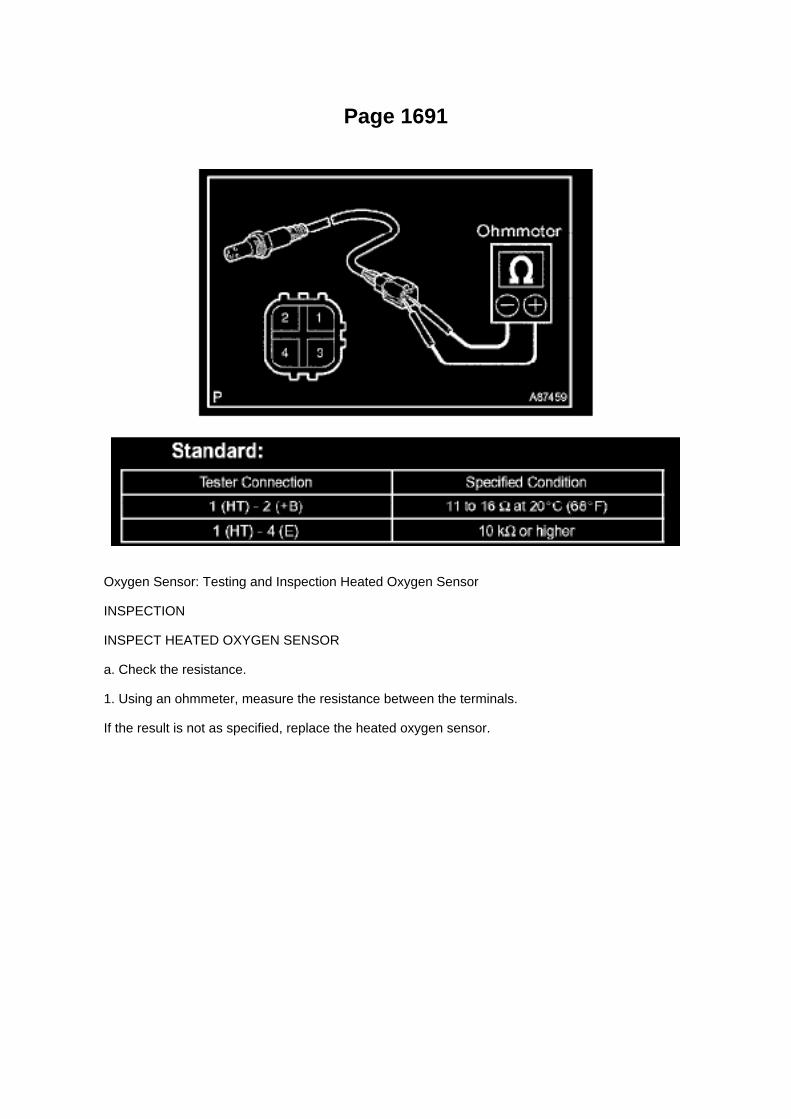
Page 1691
Oxygen Sensor: Testing and Inspection Heated Oxygen Sensor
INSPECTION
INSPECT HEATED OXYGEN SENSOR
a. Check the resistance.
1. Using an ohmmeter, measure the resistance between the terminals.
If the result is not as specified, replace the heated oxygen sensor.

Page 675

(g) Select "NEW VEHICLE" from the "VEHICLE SELECT" menu.

(h) Go through the options and select the following information.
^ MODEL YEAR-2005
^ MODEL SELECTION - Tacoma
^ ENGINE TYPE - 2TR-FE (4-cylinder)
(i) Once these options are selected, a vehicle confirmation screen (shown in the illustration) will bedisplayed.
(j) Review the vehicle selection.
(k) Press "YES to confirm the selection.

Page 1001

Refrigerant: Fluid Type Specifications

Refrigerant type: ..................................................................................................................................................................................... R134a (HFC-134a)

Page 1965
Step 7 - 8

Page 300
Power Window Control System

Service and Repair

Axle Shaft: Service and Repair
REAR AXLE SHAFT LH

System Diagnosis
Idle Speed: Testing and Inspection
INSPECT ENGINE IDLING SPEED

a. When using a hand-held tester:
(1) Connect the hand-held tester to the DLC3. (2) Turn the ignition switch to ON. (3) Turn thehand-held tester ON. (4) Start the engine and warm it up. (5) Select the following menu items:DIAGNOSIS / ENHANCED OBD II / DATA LIST / PRIMARY / ENGINE SPD.
Idling speed: 600 to 700 rpm
NOTICE: -
Turn all electrical systems OFF.
- When checking the idling speed, the transmission is in the neutral position.
HINT: Refer to the hand-held tester operator's manual for further in formation regarding theselection of DATA LIST.
b. When not using a hand-held tester:
(1) Turn the ignition switch to ON. (2) Start the engine and warm it up. (3) Install SST onto terminal9 (TAC) of the DLC3. Connect a tachometer, then measure the engine idling speed. SST09843-18030 Idling speed: 600 to 700 rpm
NOTICE: -
Turn all electrical systems OFF.
- When checking the idling speed, the transmission should be in the neutral position.

Locations
Body Control Module: Locations
Instrument Panel
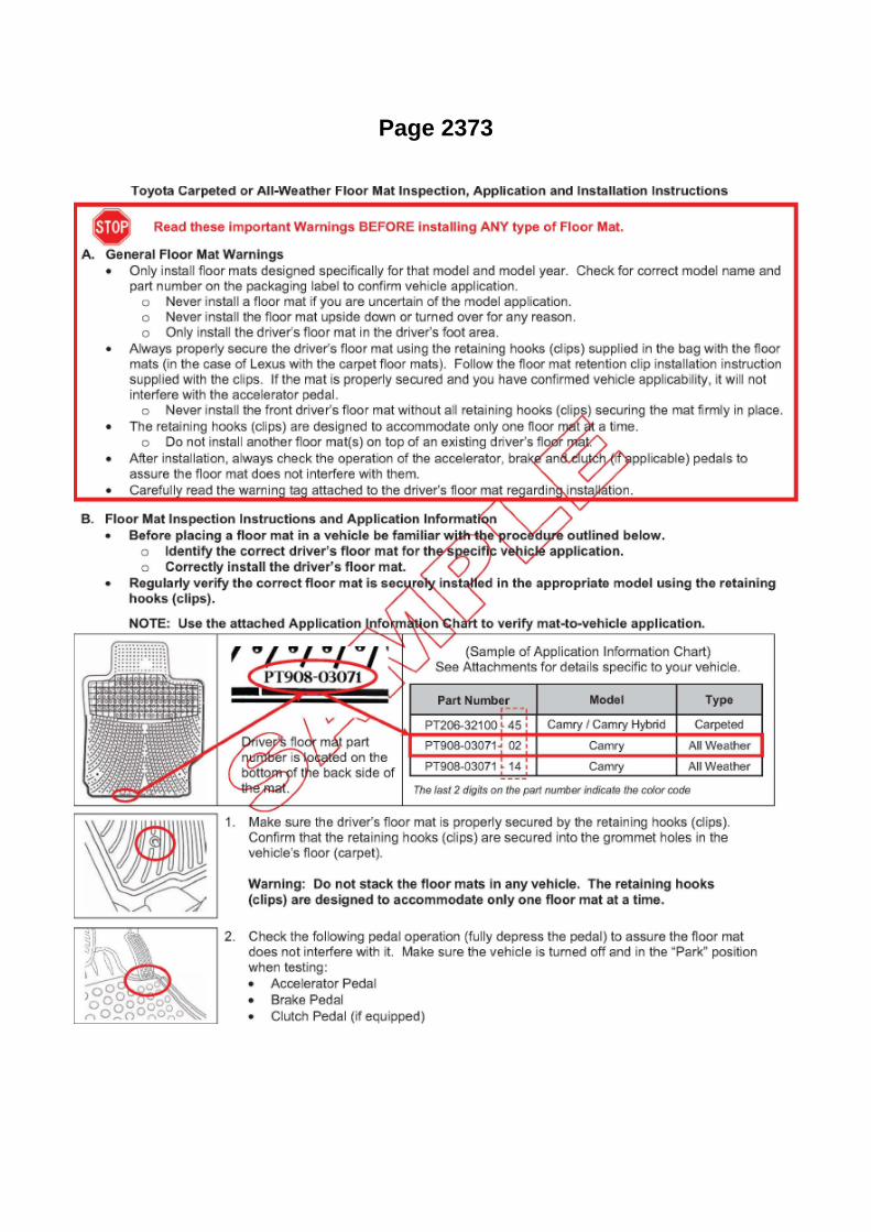
Page 2373

Page 3084

Ac - Ya
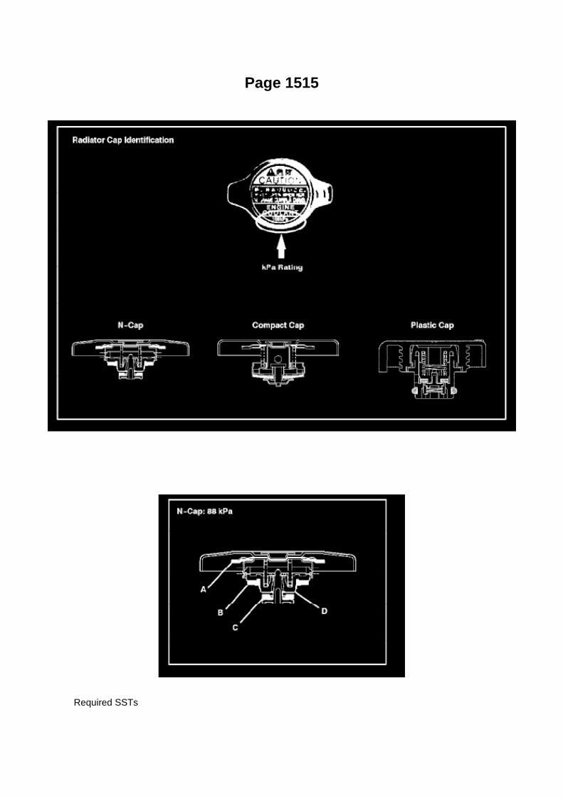
Page 1515
Required SSTs

Radiator Cap Identification Procedure
1. Use the illustration below to identify the vehicle's radiator cap type and kPa rating.
2. Proceed to the required inspection procedure for the radiator cap and kPa rating.
Radiator Cap Inspection Procedure
Type: N-cap, 88 kPa
1. Remove coolant and any foreign material on rubber points "A," "B," and "C."
2. Check that points "A," "B," and "C" are not deformed, cracked, or swollen.
3. Check that points "C" and "D" are not stuck together.
4. Apply engine coolant to points "B" and "C" before using the radiator cap tester.
^ Radiator Cap Tester: Snap-On/Sun P/N SVTS262A (or equivalent)

Page 281
Starter Relay: Testing and Inspection
INSPECT STARTER RELAY ASSEMBLY
a. Check the resistance.
1. Using an ohmmeter, measure the resistance between the terminals.
If the result is not as specified, replace the starter relay.

Page 32

a. Establish conditions in which voltage is present at the check point.

Example: [A] - Ignition SW on [B] - Ignition SW and SW 1 on [C] - Ignition SW, SW 1 and Relay on(SW 2 off)
b. Using a voltmeter, connect the negative lead to a good ground point or negative battery terminal,and the positive lead to the connector or
component terminal. This check can be done with a test light instead of a voltmeter.
Continuity and Resistance Check
CONTINUITY AND RESISTANCE CHECK
a. Disconnect the battery terminal or wire so there is no voltage between the check points.
b. Contact the two leads of an ohmmeter to each of the check points.

Page 439
Ce - Ya
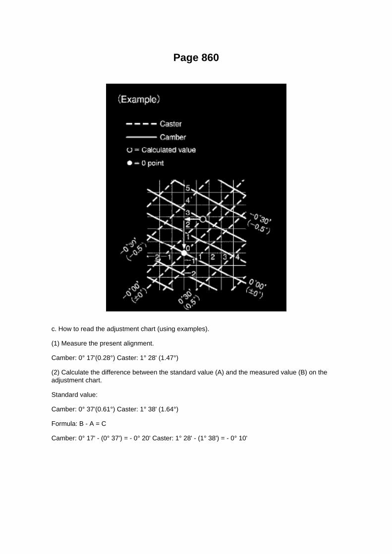
Page 860
c. How to read the adjustment chart (using examples).
(1) Measure the present alignment.
Camber: 0° 17'(0.28°) Caster: 1° 28' (1.47°)
(2) Calculate the difference between the standard value (A) and the measured value (B) on theadjustment chart.
Standard value:
Camber: 0° 37'(0.61°) Caster: 1° 38' (1.64°)
Formula: B - A = C
Camber: 0° 17' - (0° 37') = - 0° 20' Caster: 1° 28' - (1° 38') = - 0° 10'

Locations

Page 232

Oscilloscope Waveforms

Page 2852
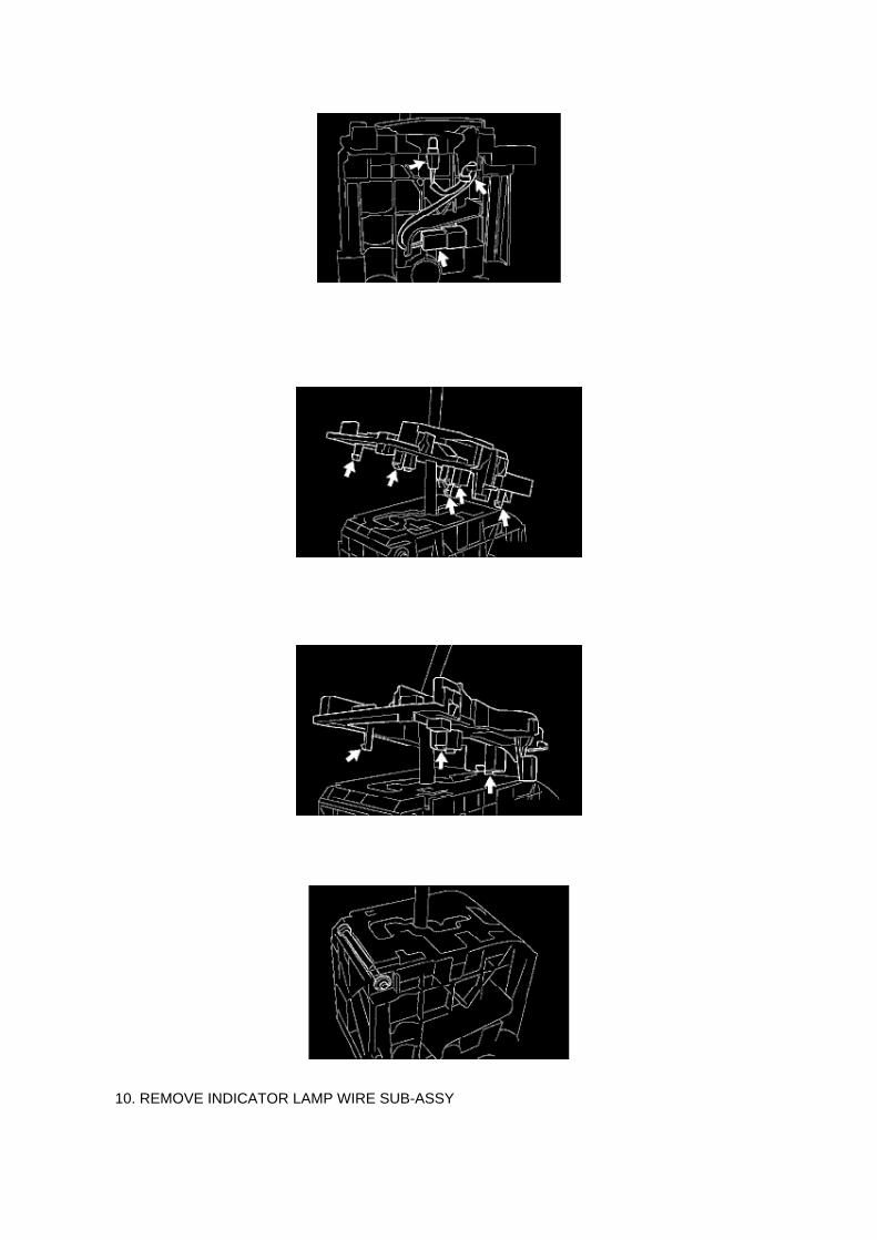
10. REMOVE INDICATOR LAMP WIRE SUB-ASSY

a. Remove the indicator lamp wire sub-assembly. b. Remove the bulb from the indicator lamp wiresub-assy.
11. REMOVE SHIFT LOCK RELEASE BUTTON
12. REMOVE POSITION INDICATOR HOUSING LOWER
a. CABLE TYPE:
(1) Release the 5 claws with a screwdriver and remove the position indicator housing lower.
b. ROD TYPE:
(1) Release the 3 claws with a screwdriver and remove the position indicator housing lower.
13. REMOVE SHIFT LOCK CONTROL ECU SUB-ASSY
a. Remove the shift lever nut and shift lever lock pin. b. Remove the shift lever guide housing. c.Release the 2 claws with a screwdriver and remove the shift lock release link and spring.

Page 1032

Engine Room J/B, Engine Room R/B Part 3

Engine Room Fuse Details

Page 155

3. Checking the contact pressure of the terminal: Prepare a spare male terminal. Insert it into afemale terminal, and check for good tension when

inserting and after full engagement.
d. REPAIR METHOD OF CONNECTOR TERMINAL
1. If there is any dirt on the terminal, clean the contact point using an air gun or shop rag. Neverpolish the contact point using sandpaper as the
platings may come off.
2. If there is abnormal contact pressure, replace the female terminal. If the male terminal isgold-plated (gold color), use a gold-plated female
terminal; if it is silver-plated (silver color), use a silver-plated female terminal.
3. Damaged, deformed, or corroded terminals should be replaced. If the terminal will not lock intothe housing, the housing may have to be
replaced.
e. HANDLING OF WIRE HARNESS
1. If removing a wire harness, check the wiring and clamping before proceeding so that it can berestored in the same way. 2. Never twist, pull or slacken the wire harness more than necessary. 3.Never make the wire harness come into contact with a high temperature part, or rotating, moving,vibrating or sharp-edged parts. Avoid panel
edges, screw tips and similar sharp items.
4. When installing parts, never pinch the wire harness. 5. Never cut or break the cover of the wireharness. If it is cut or broken, replace it or securely repair it with vinyl tape.
Check Open Circuit
CHECK OPEN CIRCUIT

Tools and Equipment
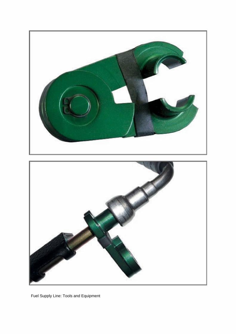
Fuel Supply Line: Tools and Equipment

Niss./Toy. Line Disconnect Tool
AST tool# 8026
5/16"Fuel Line Disconnect Tool. Used for disconnecting the fuel line from the fuel rail. Applicable to2004 and newer Nissan and Toyota Models
- 5/16" Fuel Line Disconnect Tool
- Quick Line Removal*Green-Anodized Aluminum Construction
- See Application Chart
- Included in the #8110 Line Disconnect Set.
Contact AST for pricing.
Assenmacher Specialty Tools 1-800-525-2943
This Tool is also available in the following kits:

Locations
SFI System

Page 3374

7. REMOVE INSTRUMENT PANEL FINISH PANEL LOWER NO.1 8. SEPARATE DRIVER SIDEJUNCTION BLOCK

9. SEPARATE MASTER CYLINDER PUSH ROD CLEVIS
a. Remove the clip and push rod pin, then separate the push rod clevis.
10. REMOVE BRAKE PEDAL SUPPORT REINFORCEMENT
a. Remove the bolt from the reinforcement.
b. Remove the bolt and nut, then remove the reinforcement from the brake pedal support.
11. REMOVE BRAKE PEDAL SUPPORT SUB-ASSEMBLY
a. Disconnect the stop lamp switch connector from the stop lamp switch.
b. Remove the 4 nuts and brake pedal support.

Page 2310

Evaporative Emission Control Canister: Service and Repair

REPLACEMENT
1. DISCHARGE FUEL SYSTEM PRESSURE 2. DISCONNECT CABLE FROM NEGATIVEBATTERY TERMINAL 3. REMOVE FUEL TANK PROTECTOR SUB-ASSEMBLY NO.1 (OFFROAD PACKAGE) 4. DISCONNECT FUEL TANK MAIN TUBE AND FUEL TANK RETURN TUBE5. REMOVE FUEL TANK ASSEMBLY 6. REMOVE CHARCOAL CANISTER FILTER NO.2 7.REMOVE CHARCOAL CANISTER ASSEMBLY
a. Disconnect the connector. b. Disconnect the EVAP tube.
c. Remove the bolt and 2 nuts, then remove the charcoal canister.
d. Disconnect the fuel tank vent hose.
1. Pinch the retainer and pull the fuel tank vent hose connector out of the charcoal canister todisconnect the fuel tank vent hose from the
charcoal canister.
NOTE: -
Remove any dirt and foreign objects from the fuel tank vent hose connector before performing thework.
- Do not allow any scratches or foreign objects on the parts when disconnecting, as the fuel tankvent hose connector has the O-ring that seals the pipe.
- Perform the work by hand. Do not use any tools.
- Do not forcibly bend, twist or turn the nylon tube.
- Protect the disconnected part by covering it with a vinyl bag after disconnecting the fuel tank venthose.
- If the fuel vent connector and pipe are stuck, push and pull them to release.
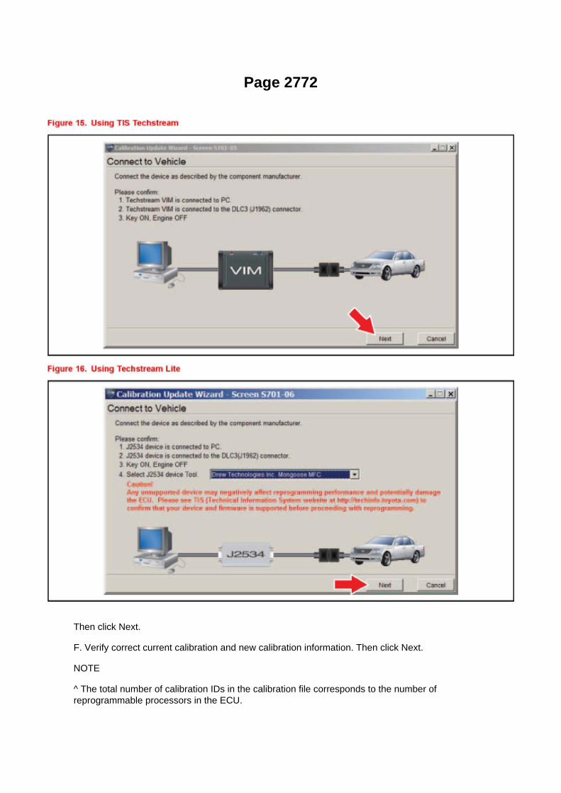
Page 2772
Then click Next.
F. Verify correct current calibration and new calibration information. Then click Next.
NOTE
^ The total number of calibration IDs in the calibration file corresponds to the number ofreprogrammable processors in the ECU.

^ Each calibration file may contain up to three separate calibrations.

Page 1938

CAN Communication System Check Sheet

Description of On-Board Diagnostics
FAIL-SAFE FUNCTION
a. When communication fails in any of the CAN bus lines (communication lines) due to a shortcircuit or any other causes, the fail-safe function,
which is specified for each system, operates to prevent the system from malfunctioning.
b. This function operates for each system when communication is impossible.
HINT:

Page 2636

(w/ AIR CONDITIONING)

i. Engage the engine wire harness clamp.
j. Connect the VSV connector.
k. Connect the ventilation hose No.3.
l. Connect the water bypass hose No.2.
m. Install the clamp bracket with the bolt.
Torque: 19 N.m (194 kgf.cm, 14 in.lbf)
n. Connect the vacuum hose.

Page 2034

He - Wi

Page 2901
3. Is the Neutral Position SW Signal value "ON" or "OFF" in the Freeze Frame Data?
NOTE
In Figure 3, transmission is not in any gear position on this vehicle.
^ If the Neutral Position SW Signal is "OFF" - This TSB does NOT apply.
Refer to the applicable model year Tacoma Repair Manual for diagnostics for DTC P0705. If theNeutral Position SW Signal is "ON" - Go to step 4.

Page 1425

COMPONENTS

OVERHAUL

Page 1909

Glossary Of Terms And Sysmbols Part 2

Service and Repair
Oil Filter: Service and Repair
OIL FILTER SUB-ASSEMBLY (2TR-FE)
REPLACEMENT
CAUTION: -
Prolonged and repeated contact with engine oil causes removal of natural oils from the skin,leading to dryness, irritation and dermatitis. In addition, used engine oil contains potentially harmfulcontaminants which may cause skin cancer.
- Precautions should be taken when replacing engine oil to minimize the risk of your skin makingcontact with used engine oil. Wear protective clothing and gloves. Wash your skin thoroughly withsoap and water, or use a waterless hand cleaner to remove any used engine oil. Do not use

gasoline, thinners or solvents.
- For environmental protection, used oil and used oil filters must be disposed of at designateddisposal sites.
1. DRAIN ENGINE OIL
a. Remove the oil filler cap. b. Remove the oil pan drain plug and drain the engine oil. c. Install anew gasket, then install the oil pan drain plug.
Torque: 38 Nm (382 kgf-cm, 28 ft. lbs.)
2. REMOVE OIL FILTER SUB-ASSEMBLY
a. Using SST, remove the oil filter.
SST 09228-07501
3. INSTALL OIL FILTER SUB-ASSEMBLY
a. Remove any dirt or foreign objects from the contact surface of the engine side. b. Apply a lightcoat of engine oil to the O-ring of a new oil filter. c. Install the oil filter by hand until the O-ringcomes into contact with the seat. d. Using SST, retighten it by 3/4 turn.
SST 09228-07501 Reference torque: 13 Nm (133 kgf-cm, 10 ft. lbs.)
4. ADD ENGINE OIL
a. Fill with fresh engine oil.
Capacity
5. CHECK FOR ENGINE OIL LEAKAGE
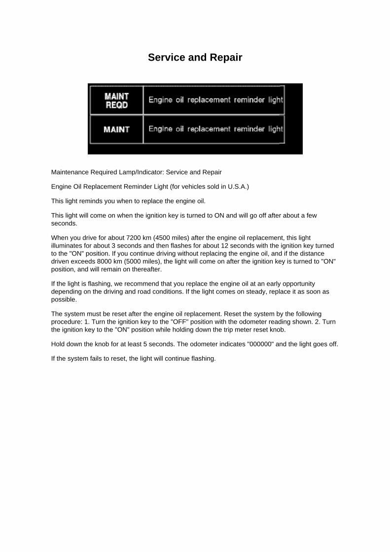
Service and Repair
Maintenance Required Lamp/Indicator: Service and Repair
Engine Oil Replacement Reminder Light (for vehicles sold in U.S.A.)
This light reminds you when to replace the engine oil.
This light will come on when the ignition key is turned to ON and will go off after about a fewseconds.
When you drive for about 7200 km (4500 miles) after the engine oil replacement, this lightilluminates for about 3 seconds and then flashes for about 12 seconds with the ignition key turnedto the "ON" position. If you continue driving without replacing the engine oil, and if the distancedriven exceeds 8000 km (5000 miles), the light will come on after the ignition key is turned to "ON"position, and will remain on thereafter.
If the light is flashing, we recommend that you replace the engine oil at an early opportunitydepending on the driving and road conditions. If the light comes on steady, replace it as soon aspossible.
The system must be reset after the engine oil replacement. Reset the system by the followingprocedure: 1. Turn the ignition key to the "OFF" position with the odometer reading shown. 2. Turnthe ignition key to the "ON" position while holding down the trip meter reset knob.
Hold down the knob for at least 5 seconds. The odometer indicates "000000" and the light goes off.
If the system fails to reset, the light will continue flashing.

Page 496

Knock Sensor: Service and Repair

REPLACEMENT
1. DISCONNECT CABLE FROM NEGATIVE BATTERY TERMINAL 2. REMOVE ENGINE UNDERCOVER SUB-ASSEMBLY NO.1 (PRE RUNNER AND 4WD TYPE) 3. DRAIN ENGINE COOLANT4. REMOVE INTAKE AIR CONNECTOR 5. REMOVE THROTTLE W/MOTOR BODY ASSEMBLY6. DISCONNECT FUEL HOSE 7. DISCONNECT FUEL HOSE NO.2 8. REMOVE INTAKEMANIFOLD
a. Disconnect the fuel vapor feed hose from the VSV.
b. Disconnect the vacuum hose.
c. Remove the bolt, then remove the clamp bracket.

Page 1857
When using Techstream Lite, select Generic J2534 Interface. Then click Next.
E. Confirm the following:
^ PC is connected to VIM.
^ VIM is connected to DLC3 connector.
^ Ignition is ON and engine is OFF or "READY" OFF (hybrid vehicles).

Specifications

Balance Shaft: Specifications

BALANCE SHAFT THRUST CLEARANCE
a. Using a dial indicator, measure the thrust clearance while moving the balance shaft back andforth.
Standard thrust clearance: 0.07 to 0.13 mm (0.0027 to 0.0051 inch) Maximum thrust clearance:0.20 mm (0.0079 inch)

Page 1986
Wiring Diagram

Page 1102

Engine Compartment

Instrument Panel
Locations

Page 668
are involved. As always, consult Dealer Daily/TIS to confirm VIN eligibility and to assure the SSC isapplicable. This will verify the vehicle is affected and has not already been completed prior todealer shipment or by another dealer. TMS warranty will not reimburse dealers for repairsconducted on vehicles that are not affected or were completed by another dealer.
III. Preparation
A. PARTS
B. TOOLS
^ Standard hand tools
^ Scan tool
IV. Background
On certain 2005 Model Year Tacoma Regular Cab (no rear seat) vehicles equipped with a frontbench seat, the Seat Position and Seatbelt Buckle Sensor Wire Harness Connector pins arepositioned incorrectly due to a wire harness manufacturing process error. In this condition, the seatposition and seatbelt buckle sensor may not function as designed, which, if the vehicle is involvedin a crash, could result in improper occupant restraint. In the worst case, this may lead to anincreased possibility of injury. Please note that even in this condition, the affected vehicles continueto comply with all applicable federal motor vehicle safety standards.
V. Work Procedure
A. INSPECT THE FRONT BENCH SEAT FLOOR WIRE HARNESS CONNECTOR WIRES
1. LOCATE THE BENCH SEAT FLOOR WIRE HARNESS

Page 1396

Locations
SFI System

Locations

Neutral Safety Switch: Locations

He - Wi

A/T Controls - MIL ON/DTC P0705 Set
Wiring Harness: All Technical Service Bulletins A/T Controls - MIL ON/DTC P0705 Set
T-SB-0277-09
August 18, 2009
MIL "ON" DTC P0705
Service Category Drivetrain
Section Automatic Transmission/Transaxle
Market USA
Applicability
Introduction
Some 2005 - 2009 model year Tacoma vehicles may exhibit a MIL "ON" condition with DTC P0705(Transmission Range Sensor Circuit Malfunction (PRNDL Input)) stored. Common symptoms withthis DTC can include possible delayed engagement into Reverse or Drive and possible harsh gearengagement when shifting between Park or Neutral into all other gears. Follow the procedure inthis TSB to determine if this service bulletin is applicable and to repair the vehicle.

Repair Procedure Overview
1. Review DTC P0705 Freeze Frame Data to determine if this TSB may be applicable.
2. Attempt to duplicate DTC using testing procedure shown in this TSB to confirm TSB application.
3. If DTC cannot be duplicated, examine indicated wire harness electrical connector and JunctionBlock for evidence of liquid or corrosion.
4. If liquid or corrosion is observed in indicated wire harness connector and Junction Block,replacement of the Engine Room Main W~re Harness and
Junction Block connector No.1 will be required to repair the vehicle.
Warranty Information
APPLICABLE WARRANTY
^ This repair is covered under the Toyota Comprehensive Warranty. This warranty is in effect for36 months or 36,000 miles, whichever occurs first, from the vehicle's in-service date.
^ Warranty application is limited to occurrence of the specified condition described in this bulletin.

Page 3240
Step 4 - 5

Specifications

Valve Clearance: Specifications

The 2TR-FE engine uses a hydraulic valve lash adjuster assembly. Adjustment is not required.

Page 851
3 Of 6

Page 2566

Main Relay (Computer/Fuel System): Testing and Inspection

INSPECT E.F.I. CIRCUIT OPENING RELAY ASSEMBLY
a. Check the resistance.
1. Using an ohmmeter, measure the resistance between the terminals.
If the result is not as specified, replace the E.F.I. circuit opening relay assembly.
INSPECT EFI RELAY
a. Check the resistance.
1. Using an ohmmeter, measure the resistance between the terminals.
If the result is not as specified, replace the E.F.I. ECU relay.

Page 2078
b. Connect the wire harness clamp. c. Connect the air fuel ratio sensor connector.
4. CONNECT CABLE TO NEGATIVE BATTERY TERMINAL
Torque: 3.9 N.m (40 Kgf.cm, 35 in.lbf)

Page 363
10. INSTALL SENSOR BRACKET
a. Install the bracket with the bolt.
Torque: 12.5 Nm (127 kgf-cm, 9 ft. lbs.)
b. Install the wire harness clamp.
11. INSTALL COWL SIDE TRIM BOARD LH 12. INSTALL FRONT DOOR SCUFF PLATE LH 13.INSTALL FRONT FLOOR FOOTREST 14. INSTALL FRONT SEAT ASSEMBLY (BENCH SEATTYPE) 15. INSTALL FRONT SEAT ASSEMBLY LH (SEPARATE SEAT TYPE) 16. CONNECTCABLE TO NEGATIVE BATTERY TERMINAL
Torque: 3.9 Nm (40 kgf-cm, 35 inch lbs.)
17. PERFORM YAW RATE SENSOR ZERO POINT CALIBRATION See: Brakes and TractionControl/Antilock Brakes / Traction Control
Systems/Testing and Inspection/Component Tests and General Diagnostics/ABS W/EBD & BA &TRAC & VSC System/Calibration
18. CHECK VSC SENSOR SIGNAL

Page 983
Fluid - M/T: Testing and Inspection
MANUAL TRANSAXLE OIL
ON-VEHICLE INSPECTION
1. CHECK TRANSMISSION OIL
a. Park the vehicle in a level place. b. Remove the transmission filler plug and gasket. c. Check thatthe oil surface is within 5 mm (0.20 inch) of the lowest point of the transmission filler plug opening.
NOTICE: -
Problems may occur when the oil level is too high or low.
- After replacing the oil, drive the vehicle and check the oil level again.
d. Check for oil leakage when the oil level is low. e. Install the transmission filler plug and a newgasket.
Torque: 37 Nm (377 kgf-cm, 27 ft. lbs.)

Page 2595

b. Install the throttle w/ motor body with the 2 bolts and 2 nuts.

Torque: 9 N.m (92 kgf.cm, 80 in.lbf)
c. Connect the water bypass hose. d. Connect the water bypass hose No.2. e. Connect the throttlemotor connector.
7. INSTALL INTAKE AIR CONNECTOR
a. Install the intake air connector with the 3 bolts.
Torque: 8 N.m (82 kgf.cm, 71 in.lbf)
b. Tighten the 2 hose clamp bolts.
Torque: 5 N.m (51 kgf.cm, 44 in.lbf)

Page 163

2. HEAT METHOD: If the problem seems to occur when the area in question is heated.
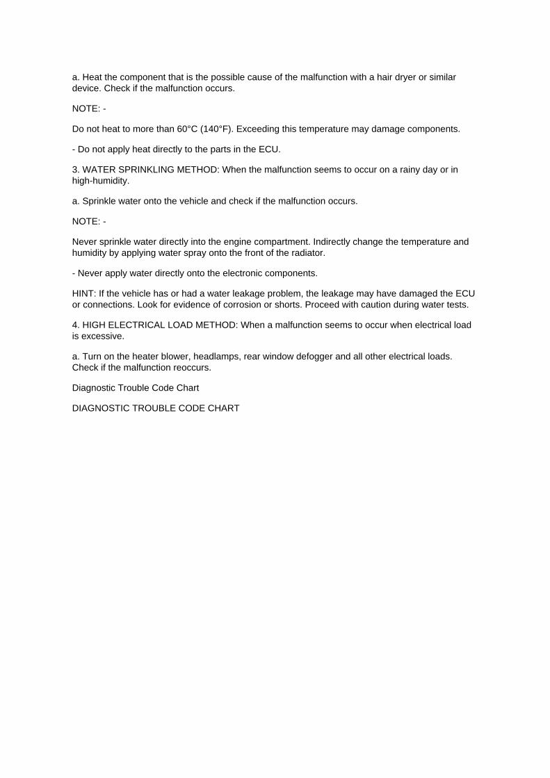
a. Heat the component that is the possible cause of the malfunction with a hair dryer or similardevice. Check if the malfunction occurs.
NOTE: -
Do not heat to more than 60°C (140°F). Exceeding this temperature may damage components.
- Do not apply heat directly to the parts in the ECU.
3. WATER SPRINKLING METHOD: When the malfunction seems to occur on a rainy day or inhigh-humidity.
a. Sprinkle water onto the vehicle and check if the malfunction occurs.
NOTE: -
Never sprinkle water directly into the engine compartment. Indirectly change the temperature andhumidity by applying water spray onto the front of the radiator.
- Never apply water directly onto the electronic components.
HINT: If the vehicle has or had a water leakage problem, the leakage may have damaged the ECUor connections. Look for evidence of corrosion or shorts. Proceed with caution during water tests.
4. HIGH ELECTRICAL LOAD METHOD: When a malfunction seems to occur when electrical loadis excessive.
a. Turn on the heater blower, headlamps, rear window defogger and all other electrical loads.Check if the malfunction reoccurs.
Diagnostic Trouble Code Chart
DIAGNOSTIC TROUBLE CODE CHART

Page 646
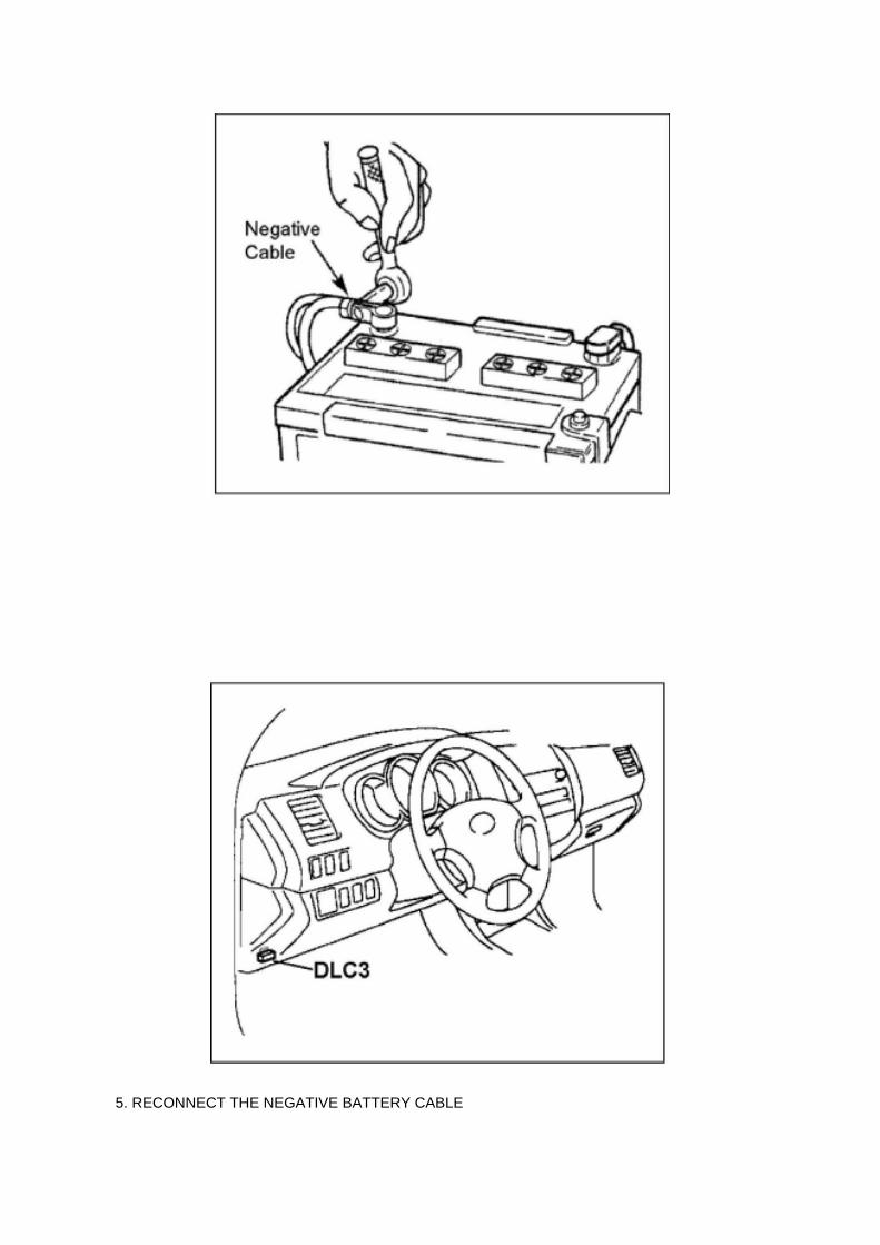
5. RECONNECT THE NEGATIVE BATTERY CABLE

6. REPROGRAM THE RADIO STATION PRESETS AND SET THE CLOCK TO THEAPPROPRIATE TIME
C. VERIFY THE REPAIR USING THE SCAN TOOL
1. PREPARE THE SCAN TOOL
(a) Remove the DLC3 connector cover.
(b) Connect the scan tool to the DLC3 connector.
(c) Turn the ignition switch to the "ON" position.

Recall 09V388000: Floor Mat/Accelerator Interference

Accelerator Pedal: Recalls Recall 09V388000: Floor Mat/Accelerator Interference

VEHICLE MAKE/MODEL: MODEL YEAR(S): Lexus/ES350 2007-2010 Lexus/IS 2006-2010Toyota/Avalon 2005-2010 Toyota/Camry 2007-2010 Toyota/Prius 2004-2009 Toyota/Tacoma2005-2010 Toyota/Tundra 2007-2010 MANUFACTURER: Toyota Motor Corporation
MFR'S REPORT DATE: October 05, 2009
NHTSA CAMPAIGN ID NUMBER: 09V388000
NHTSA Action Number: N/A COMPONENT: Vehicle Speed Control: Accelerator Pedal
POTENTIAL NUMBER OF UNITS AFFECTED: 3800000
SUMMARY: Toyota is recalling certain model year 2004-2010 passenger vehicles. The acceleratorpedal can get stuck in the wide open position due to its being trapped by an unsecured orincompatible driver's floor mat.
CONSEQUENCE: A stuck open accelerator pedal may result in very high vehicle speeds andmake it difficult to stop the vehicle, which could cause a crash, serious injury or death.
REMEDY: Toyota will notify owners of affected vehicles to remove any driver's floor mat and notreplace it with any other floor mat pending the development of model-specific remedies. Toyota willmail a second notification to owners of affected vehicles notifying them of the free remedies whenthey are available. The first notice is expected to be mailed during October 2009 and Toyota willadvise NHTSA of the estimated date when the remedies will be available. Owners may contactToyota at 1-800-331-4331, Lexus at 1-800-255-3987.
NOTES: Owners may also contact The National Highway Traffic Safety Administration's VehicleSafety Hotline at 1-888-327-4236 (TTY 1-800-424-9153), or go to http://www.safercar.gov.

Page 1678
Engine Bank Identification

Locations

Transmission Speed Sensor: Locations

He - Wi

Page 2190

Knock Control Sensor (2TR-FE) Part 3

Page 2068
A/F and 02 Sensor Identification

Page 2044

(w/ AIR CONDITIONING)

i. Engage the engine wire harness clamp.
j. Connect the VSV connector.
k. Connect the ventilation hose No.3.
l. Connect the water bypass hose No.2.
m. Install the clamp bracket with the bolt.
Torque: 19 N.m (194 kgf.cm, 14 in.lbf)
n. Connect the vacuum hose.

Locations
CAN Communication System

Locations
SFI System
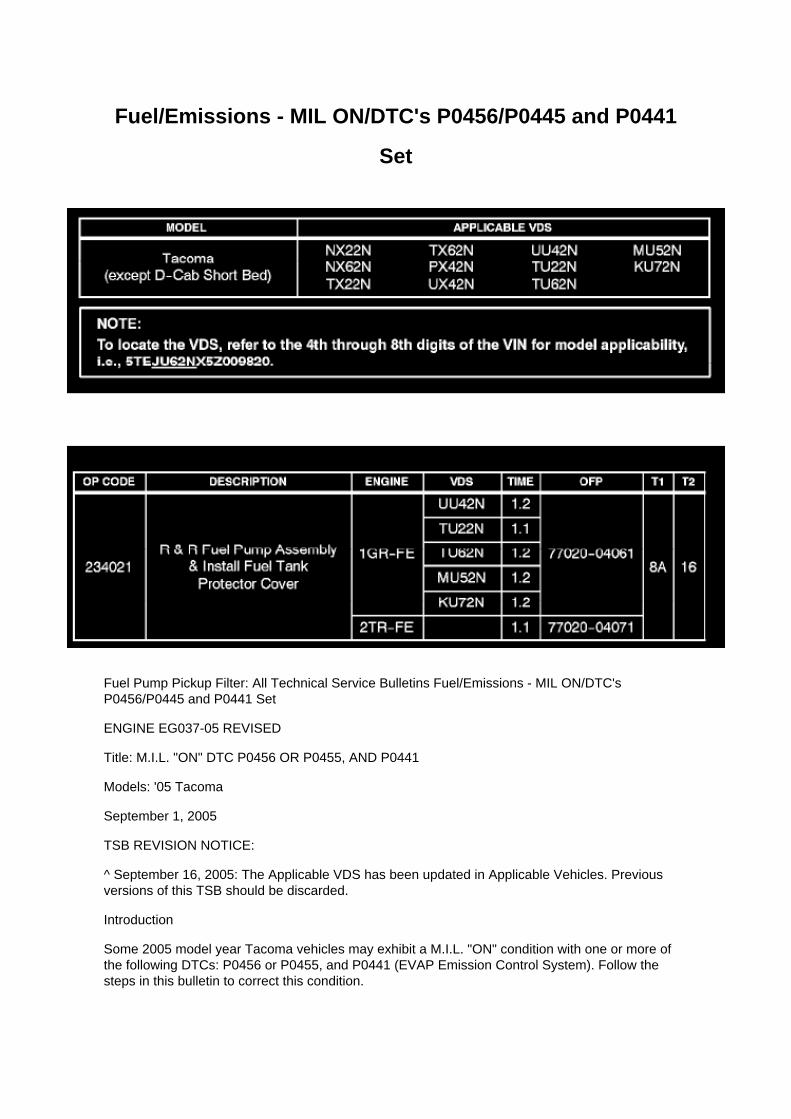
Fuel/Emissions - MIL ON/DTC's P0456/P0445 and P0441
Set
Fuel Pump Pickup Filter: All Technical Service Bulletins Fuel/Emissions - MIL ON/DTC'sP0456/P0445 and P0441 Set
ENGINE EG037-05 REVISED
Title: M.I.L. "ON" DTC P0456 OR P0455, AND P0441
Models: '05 Tacoma
September 1, 2005
TSB REVISION NOTICE:
^ September 16, 2005: The Applicable VDS has been updated in Applicable Vehicles. Previousversions of this TSB should be discarded.
Introduction
Some 2005 model year Tacoma vehicles may exhibit a M.I.L. "ON" condition with one or more ofthe following DTCs: P0456 or P0455, and P0441 (EVAP Emission Control System). Follow thesteps in this bulletin to correct this condition.

Applicable Vehicles
^ 2005 model year Tacoma vehicles (except D-Cab Short Bed), with the following VehicleDescription Section VDS) information shown below.
Warranty Information
Applicable Warranty*: This repair is covered under the Toyota Powertrain Warranty. This warrantyis in effect for 60 months or 60,000 miles, whichever occurs first, from the vehicle's in-service date.
* Warranty application is limited to correction of a problem based upon a customer's specificcomplaint.

Page 2652

a. Using several steps, uniformly install and tighten the 5 bolts in the sequence shown in theillustration.

Torque: 21 N.m (214 kgf.cm, 16 ft.lbf) for bolt A 43 N.m (438 kgf.cm, 32 ft.lbf) for bolt B, C
9. INSTALL COMPRESSOR AND MAGNETIC CLUTCH (W/ AIR CONDITIONING)
10. INSTALL FAN AND GENERATOR BELT (W/ AIR CONDITIONING) 11. INSTALL ENGINEUNDER COVER SUB-ASSEMBLY NO.1 (PRE RUNNER AND 4WD TYPE)
12. CONNECT CABLE TO NEGATIVE BATTERY TERMINAL
Torque: 3.9 N.m (40 kgf.cm, 35 in.lbf)
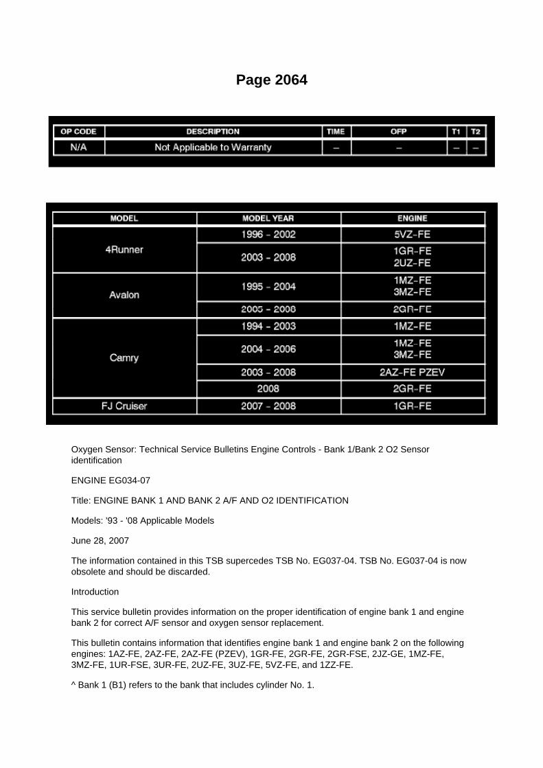
Page 2064
Oxygen Sensor: Technical Service Bulletins Engine Controls - Bank 1/Bank 2 O2 Sensoridentification
ENGINE EG034-07
Title: ENGINE BANK 1 AND BANK 2 A/F AND O2 IDENTIFICATION
Models: '93 - '08 Applicable Models
June 28, 2007
The information contained in this TSB supercedes TSB No. EG037-04. TSB No. EG037-04 is nowobsolete and should be discarded.
Introduction
This service bulletin provides information on the proper identification of engine bank 1 and enginebank 2 for correct A/F sensor and oxygen sensor replacement.
This bulletin contains information that identifies engine bank 1 and engine bank 2 on the followingengines: 1AZ-FE, 2AZ-FE, 2AZ-FE (PZEV), 1GR-FE, 2GR-FE, 2GR-FSE, 2JZ-GE, 1MZ-FE,3MZ-FE, 1UR-FSE, 3UR-FE, 2UZ-FE, 3UZ-FE, 5VZ-FE, and 1ZZ-FE.
^ Bank 1 (B1) refers to the bank that includes cylinder No. 1.

^ Bank 2 (B2) refers to the bank opposite bank 1.
^ Sensor 1 (S1) refers to the sensor that is located before the catalytic converters.
^ Sensor 2 (S2) refers to the sensor that is located after the catalytic converters.
Warranty Information

Page 2642
SFI System

Locations
Fr - Se

Page 1120

1. Disconnect connectors A and C and measure the resistance between terminals 1 and 2 ofconnector A and the body ground.

HINT: Measure the resistance while lightly shaking the wire harness vertically and horizontally.
If your results match the examples above, a short circuit exists between terminal 1 of connector Aand terminal 1 of connector C.
2. Disconnect connector B and measure the resistance between terminal 1 of connector A and thebody ground, and terminal 1 of connector B2
and the body ground. If your results match the examples above, a short circuit exists betweenterminal 1 of connector B2 and terminal 1 of connector C.
Check and Replace ECU
CHECK AND REPLACE ECU
NOTE:
- The connector should not be disconnected from the ECU. Perform the inspection from thebackside of the connector on the wire harness side.
- When no measuring condition is specified, perform the inspection with the engine stopped andthe ignition switch ON.
- Check that the connectors are fully seated. Check for loose, corroded or broken wires.
a. First check the ECU ground circuit. If it is faulty, repair it.
If it is normal, the ECU could be faulty. Replace the ECU with a normal functioning one and check ifthe symptoms occur. If the trouble symptoms stop, replace the ECU.
1. Measure the resistance between the ECU ground terminal and body ground.
Standard: Below 1 Ohms

Locations
Intake Air Temperature Sensor: Locations

SFI System
The Intake Air Temperature (IAT) Sensor is installed in the Mass Air Flow (MAF) Meter.

Page 2019

If 2 or more ECUs and/or sensors do not appear on the hand-held tester's "BUS CHECK" screenvia the CAN VIM, one side of the CAN sub-bus line may be open. (One side of the CAN-H [sub-busline]/CAN-L [sub-bus line] of the ECU and/or sensor is open.)
Wiring Diagram

Page 77
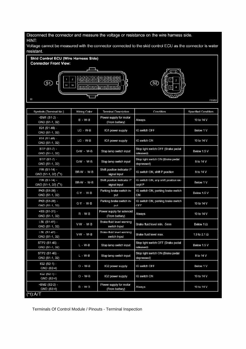
Terminals Of Control Module / Pinouts - Terminal Inspection

Page 490

He - Wi

Locations

Power Steering Pressure Switch: Locations

He - Wi

Page 2739

J. When Cal 1 has completed the update process turn ignition OFF for a minimum of 10 seconds.Then click Next.

K. Turn ignition to the ON position. Then click Start.
L. Do NOT disturb the vehicle during flash reprogramming.

Page 145
Diagram Legend
Diagram Legend
O: Indicates values or explains the function for reference during troubleshooting.
P: Indicates the reference showing the position on the vehicle of the parts in the system circuit.Example: Part L4 (Light Failure Sensor) * The letter in the code is from the first letter of the part,and the number indicates its order in parts starting with that letter.
Q: Indicates the reference showing the position on the vehicle of Relay Block Connectors in thesystem circuit.
Example: Connector "1" is described and is installed on the left side of the instrument panel.

R: Indicates the reference showing the position on the vehicle of J/B and Wire Harness in thesystem circuit.
Example: Connector "3C" connects the Instrument Panel Wire and J/B No.3. It is described and isinstalled on the instrument panel left side.
S: Indicates the reference describing the wiring harness and wiring harness connector (the femalewiring harness is shown first, followed by the male wiring harness).
Example: Connector "IE1" connects the floor wire (female) and Instrument panel wire (male). It isdescribed and is installed on the left side kick panel.
T: Indicates the reference showing the position of the ground points on the vehicle.
Example: Ground point "BO" is described and is installed on the back panel center.
U: Indicates the reference showing the position of the splice points on the vehicle.

Page 576
Ignition Switch: Service and Repair
IGNITION OR STARTER SWITCH ASSEMBLY
REPLACEMENT
1. DISCONNECT CABLE FROM NEGATIVE BATTERY TERMINAL
2. REMOVE STEERING COLUMN COVER LWR
a. Remove the 2 screws. b. Disengage the 2 claws and remove the steering column cover LWR.
3. REMOVE IGNITION OR STARTER SWITCH ASSEMBLY

a. Disconnect the connector. b. Disengage the 2 clamps, then remove the ignition or starter switch.
4. INSTALL IGNITION OR STARTER SWITCH ASSEMBLY 5. INSTALL STEERING COLUMNCOVER LWR 6. CONNECT CABLE TO NEGATIVE BATTERY TERMINAL
Torque: 3.9 N.m (40 kgf.cm, 35 in.lbf)

Page 842
With the customer accompanying you, drive the vehicle to confirm if the customer's complaintinvolves vehicle pulling to one side or steering wheel off center.
If the problem is steering wheel off center, refer to the Repair Manual for the adjustment procedure.For 2002 model year vehicles only, refer to TSB No. ST003-01, "Steering Wheel Off CenterAdjustment Procedure". Also check the direction of vehicle pulling and the extent of pulling.

C. Decide if vehicle pulling is due to wheel alignment or tires.
(1) Switch the left and right front tires (If the tires are non-unidirectional).
(2) Conduct a drive test to check whether the direction that the vehicle pulls has changed.
Helpful hints to determine cause of vehicle pulling:
^ The direction of lateral force from tire conicity becomes reversed when the left and right tires areswitched. Therefore if the pulling direction changes when the tires are switched it can be concludedthat vehicle pulling is caused by tire conicity.
^ The vehicle is pulled to the right by the lateral force exerted to the right.
^ The direction of the tires which exerted lateral force to the right has been changed, so the tiresnow exert lateral force to the left and the vehicle now pulls to the left.
^ If the pulling direction does not change after the front tires are switched the cause of vehiclepulling is not tire conicity. In this case the likely cause is a front wheel alignment condition.
2. Vehicle Pulling Caused by Wheel Alignment.

Page 1863
NOTE
On some models, DTCs may set as a result of reprogramming. If DTCs are present, clear codesand run the Health Check again. Troubleshoot any remaining Current, Pending, or History codes.Permanent codes will not be cleared using Techstream. Permanent codes do not illuminate the MILand do not require troubleshooting. They will clear during normal driving once the Universal TripDrive Pattern is performed.
4. Attach the Authorized Modifications Label.
A. Using a permanent marker or ball point pen complete the Authorized Modifications Label andattach to the vehicle. The Authorized
Modifications Label is available through the MDC P/N 00451-00001-LBL.
B. Attach the label under the hood in the location determined by the specific TSB or Campaign.
NOTE
Wait 60 - 90 seconds for ink to set before handling.

Page 3128
f. Insert the spider into the yoke, and then using SST, press the spider bearing into the snap ringgroove.
g. Press in the spider bearing on the opposite side in the same way.

SST 09332-25010
NOTICE: When pressing in the spider bearing, be careful not to damage its lip.
h. Using snap ring pliers, install new snap rings into the grooves of the yoke.
6. INSPECT PROPELLER SHAFT UNIVERSAL JOINT SPIDER BEARING
a. Check the spider bearings for wear and damage. b. Check each spider bearing's axial play byturning the yoke while holding the shaft tightly.
Maximum bearing axial play: 0 to 0.05 mm (0 to 0.002 inch)
7. INSPECT PROPELLER SHAFT
HINT: When replacing the spider bearing, make sure that the grease fitting assembly hole is facingin the direction shown in the illustration.
8. INSTALL PROPELLER SHAFT
a. Align the matchmarks on the yoke and transfer flange. b. Install the propeller shaft assy with the4 nuts and 4 washers.
Torque: 88 Nm (899 kgf-cm, 65 ft. lbs.)

Brake Master Cylinder Assembly (W/ VSC)

Hydraulic Control Assembly - Antilock Brakes: Testing and Inspection Brake Master CylinderAssembly (W/ VSC)
BRAKE MASTER CYLINDER ASSEMBLY (W/ VSC)
ON-VEHICLE INSPECTION
1. CHECK BRAKE MASTER CYLINDER FLUID PRESSURE CHANGE
a. Inspect the battery positive voltage.
Battery positive voltage: 10 to 14 V
b. Turn the ignition switch to OFF, and depress the brake pedal more than 20 times.
HINT: When pressure in the accumulator is released, the reaction force becomes lighter and thestroke becomes longer.
c. Install a LSPV gauge (SST) and brake pedal effort gauge, and bleed the air.
SST 09709-29018
d. When the booster does not operate:
(1) Depress the brake pedal and check the fluid pressure.
At 245 N (25 kgf, 55 ft. lbs.)
At 343 N (35 kgf, 77 ft. lbs.)
e. When the booster operates:
(1) Turn the ignition switch to ON, and wait until the pump motor has stopped.
HINT: Pump operating sound can be heard.
(2) Turn the ignition switch to OFF, and depress the brake pedal more than 20 times.
HINT: When pressure in the accumulator is released, the reaction force becomes lighter and thestroke becomes longer.
(3) Repeat (1) and (2) 5 times. (4) Turn the ignition switch to ON, and check that the pump stopsafter approximately 8 to 14 seconds.

Page 3043

7. REMOVE CLUTCH RELEASE FORK BOOT

8. REMOVE CLUTCH COVER ASSY
a. Align the matchmark on the clutch cover assy with the one on the flywheel sub-assembly. b.Loosen each set bolt one turn at a time until the spring tension is released. c. Remove the 6 boltsand clutch cover assy.
NOTICE: Do not drop the clutch disc assy.
9. REMOVE CLUTCH DISC ASSY
NOTICE: Keep the lining part of the clutch disc assy, pressure plate and surface of the flywheelsub-assy free from oil and foreign matter.
10. INSPECT CLUTCH DISC ASSY
a. Using vernier calipers, measure the rivet head depth.
Maximum rivet depth: 0.3 mm (0.012 inch) If necessary, replace the clutch disc assy.
b. Install the clutch disc assy onto the transaxle assy.
NOTICE: Take care not to insert the clutch disc assy in the wrong orientation.
c. Using a dial indicator, check the clutch disc assy runout.
Minimum runout: 0.8 mm (0.031 inch) If necessary, replace the clutch disc assy.
11. INSPECT CLUTCH COVER ASSY

Page 2637
o. Connect the fuel vapor feed hose to the VSV.
12. CONNECT FUEL HOSE 13. CONNECT FUEL HOSE NO.2 14. INSTALL THROTTLEW/MOTOR BODY ASSEMBLY 15. INSTALL INTAKE AIR CONNECTOR 16. CONNECT CABLETO NEGATIVE BATTERY TERMINAL
Torque: 3.9 N.m (40 kgf.cm, 35 in.lbf)
17. ADD ENGINE COOLANT 18. CHECK FOR ENGINE COOLANT LEAKAGE 19. CHECK FORFUEL LEAKAGE 20. INSTALL ENGINE UNDER COVER SUB-ASSEMBLY NO.1 (PRE RUNNERAND 4WD TYPE)

Engine/Transmission Controls - Resetting ECM Memory
Continuously Variable Transmission/Transaxle: Technical Service Bulletins Engine/TransmissionControls - Resetting ECM Memory
TRANSMISSION & CLUTCH TC002-03 REVISED
Title: ECM RESET MEMORY FUNCTION
Models: '00 - '05 All Models
June 10, 2003
TSB REVISION NOTICE:
^ December 20, 2004: Applicable Vehicles section has been updated - 2004 and 2005 model yearsadded, models and model years updated for various models; and Reset Procedure 2 has beenrevised.
^ January 16, 2004: Tundra vehicles were added to the Applicable Vehicles chart.
^ December 17, 2003: T-100 vehicles were removed from the Applicable Vehicles chart.
Previous versions of this TSB should be discarded.
Introduction

Whenever an automatic transmission is replaced, overhauled or individual components arereplaced, use this procedure to clear Engine Control Module (ECM, SAE term: Powertrain ControlModule, PCM) "Learned Values" to minimize subsequent performance concerns.
CAUTION:
Failure to follow the procedure below may lengthen the time to readjust the ECM "Learned Values,"potentially resulting in performance concerns.
Required SSTs
Warranty Information
Applicable Vehicles

Locations

Switch: Locations
Po - Ya

Page 1817

A/C - Fo

Page 613
3. REMOVE RADIATOR GRILLE
4. REMOVE AIRBAG SENSOR FRONT LH
a. Remove the 2 bolts and airbag front sensor. b. Disconnect the connector from the sensor.
5. INSPECT AIRBAG SENSOR FRONT LH
6. INSTALL AIRBAG SENSOR FRONT LH
a. Check that the ignition switch is OFF. b. Check that the cable is disconnected from the batterynegative (-) terminal.
CAUTION: After disconnecting cable from the terminal, wait for at least 90 seconds before startingthe operation.
c. Check that there is no slack in the installation parts of the airbag sensor front LH. d. Connect theconnector to the airbag sensor front LH. e. Install the airbag sensor front LH with the bolt.
Torque: 9.0 N.m (92 kgf.cm, 80 in.lbf)
NOTE: -
If the airbag sensor front LH has been dropped, or there are any cracks, dents or other defects inthe case or connector, replace it with a new one.
- When installing the airbag sensor front LH, make sure that the SRS wiring does not interfere withany other parts and that it is not pinched between other parts.
7. INSTALL RADIATOR GRILLE 8. CONNECT CABLE TO NEGATIVE BATTERY TERMINAL
Torque: 3.9 N.m (40 kgf.cm, 35 in.lbf)
9. INSPECT SRS WARNING LIGHT
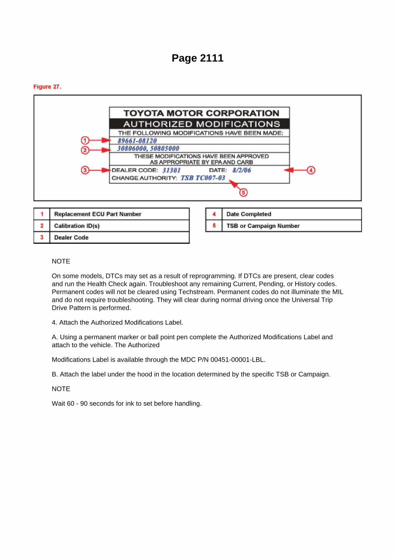
Page 2111
NOTE
On some models, DTCs may set as a result of reprogramming. If DTCs are present, clear codesand run the Health Check again. Troubleshoot any remaining Current, Pending, or History codes.Permanent codes will not be cleared using Techstream. Permanent codes do not illuminate the MILand do not require troubleshooting. They will clear during normal driving once the Universal TripDrive Pattern is performed.
4. Attach the Authorized Modifications Label.
A. Using a permanent marker or ball point pen complete the Authorized Modifications Label andattach to the vehicle. The Authorized
Modifications Label is available through the MDC P/N 00451-00001-LBL.
B. Attach the label under the hood in the location determined by the specific TSB or Campaign.
NOTE
Wait 60 - 90 seconds for ink to set before handling.

Page 2309

c. Check for air leakage.
1. Remove the air hose between ports A and B.
2. Connect the pressure gauge to the vent port of the charcoal canister.
SST 09992-00242
3. While holding port B, the purge port and air inlet port closed and port A open, apply pressurizedair of 19.6 kPa (0.2 kgf/sq.cm, 2.81 psi) into
the vent port. Then confirm that the pressure is retained. If the result is not as specified, replace thecharcoal canister assembly.
d. Check the leak detection pump.
1. Check that air flows from port A to ports B and C.
If the result is not as specified, replace the charcoal canister (pump module).
2. Apply battery positive voltage across the terminals. 3. Check that the valve is closed.
If the result is not as specified, replace the charcoal canister (pump module).

Page 418
ABS With EBD & BA & TRAC & VSC SYSTEM

Page 2239

He - Wi

Locations
A/C - Ge

Specifications

Thermostat: Specifications

Valve opening temperature: 80 to 84°C (176 to 183°F) Valve lift: 8.5 mm (0.355 inch) or more at95°C (203°F) Check that the valve is fully closed when the thermostat is at low temperatures(below 77°C (171°F)).

Page 697

II. Identification of Affected Vehicles

A. AFFECTED VIN RANGE
NOTE:
This SSC only involves certain 2005 Model Year Tacoma Regular-Cab vehicles equipped with afront bench seat. Not all vehicles in the VIN range

Service and Repair
Vehicle Lifting: Service and Repair

VEHICLE LIFT AND SUPPORT LOCATIONS
1. NOTE ABOUT VEHICLE CONDITION WHEN JACKING UP VEHICLE
a. The vehicle must be unloaded before jacking up the vehicle. Never jack up/lift up a heavilyloaded vehicle. b. When removing heavy equipment such as the engine and transmission, thecenter of gravity of the vehicle may shift. To stabilize the vehicle:
place a balance weight in a location where it will not roll or shift; or use a mission jack to hold thejacking support.
2. NOTE FOR USING 4 POST LIFT
a. Follow the safety procedures outlined in its instruction manual. b. Use precautionary measuresto prevent the free wheel beam from damaging tires or wheels. c. Use wheel chocks to secure thevehicle.

Page 1810

Air Flow Meter/Sensor: Testing and Inspection

INSPECT INTAKE AIR FLOW METER SUB-ASSEMBLY
a. Check the operation.
1. Apply battery voltage across terminals 1 (+B) and 2 (E2G). 2. Using a voltmeter, connect thepositive (+) tester prove to terminal 3 (VG) and the negative (-) tester prove to terminal 2 (E2G). 3.Blow air into the mass air flow meter and check that the voltage fluctuates.
If the voltage does not fluctuate, replace the mass air flow meter.
b. Check the resistance.
1. Using an ohmmeter, measure the resistance between the terminals.
If the result is not as specified, replace the mass air flow meter.

Page 1531

Thermostat: Service and Repair

THERMOSTAT (2TR-FE)
REPLACEMENT
1. DRAIN ENGINE COOLANT
2. REMOVE WATER INLET
a. Remove the bolt and 2 nuts, then remove the water inlet. b. Remove the gasket from the timingchain cover.
3. REMOVE THERMOSTAT
a. Remove the thermostat from the timing chain cover.
4. INSTALL THERMOSTAT
a. Install a new gasket onto the thermostat. b. Install the thermostat with the jiggle valve upward.
HINT: The jiggle valve may be set within 10° to either side of the prescribed position.
5. INSTALL WATER INLET
a. Install a new gasket and the water inlet with the bolt and 2 nuts.
Torque: 20 Nm (204 kgf-cm, 15 ft. lbs.)
6. ADD ENGINE COOLANT

Page 1137
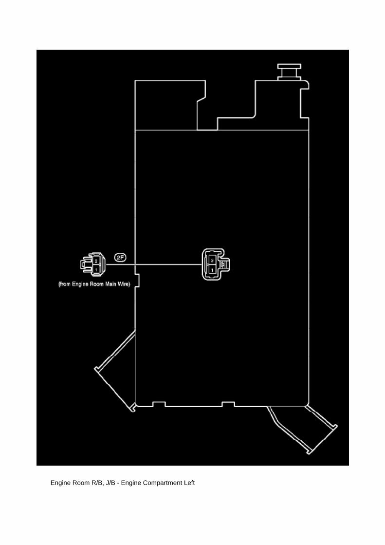
Engine Room R/B, J/B - Engine Compartment Left

Page 1048

Example: Splice point "I5" is on the Cowl Wire Harness and is described.
How to Read Connector List
HOW TO READ CONNECTOR LIST
A: Indicates connector to be connected to a part. (The numeral indicates the pin No.)
B: Junction Connector
Indicates a connector which is connected to a short terminal.
Junction connector in this include a short terminal which is connected to a number of wireharnesses. Always perform inspection with the short terminal installed. (When installing the wireharnesses, the harnesses can be connected to any position within the short terminal grouping.Accordingly, in other vehicles, the same position in the short terminal may be connected to a wireharness from a different part.) Wire harness sharing the same short terminal grouping have thesame color.
C: Parts Code
The first letter of the code is taken from the first letter of part, and the numbers indicates its order inparts which start with the same letter.
D: Connector Color
Connectors not indicated are milky white in color.

Page 804

He - Wi

Page 293
Power Window Control Module: Testing and Inspection

Terminals of Control Module/Pinouts - Check Power Window Regulator Master Switch (DOUBLECAB)

Page 2411

Oxygen Sensor: Locations

He - Wi

Page 327
ABS With EBD System

Locations
Oil Pressure Sender: Locations

A/C - Ge

Page 1645
Coolant Temperature Sensor/Switch (For Computer): Testing and Inspection
INSPECT E.F.I. ENGINE COOLANT TEMPERATURE SENSOR
a. Check the resistance.
1. Using an ohmmeter, measure the resistance between the terminals.
NOTE: If checking the engine coolant temperature sensor in water, be careful not to allow water tointrude into the terminals. After checking, wipe the water off the engine coolant temperature sensor.

If the result is not as specified, replace the engine coolant temperature sensor.
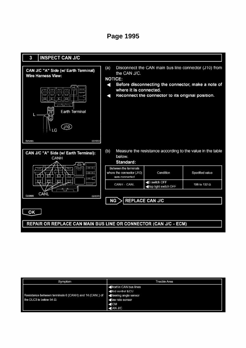
Page 1995

Step 3
INSPECTION PROCEDURE
Check CAN Bus Lines For Short Circuit
CHECK CAN BUS LINES FOR SHORT CIRCUIT
CIRCUIT DESCRIPTION
The CAN bus lines are considered to be shorted when the resistance between terminals 6 (CANH)and 14 (CANL) of the DLC3 is below 54 ohm.

Locations

Knock Sensor: Locations

He - Wi

Page 601

Supplemental Restraint System

Cooling System - Radiator Cap Inspection Procedure
Radiator Cap: Technical Service Bulletins Cooling System - Radiator Cap Inspection Procedure
ENGINE EG014-05
Title: RADIATOR CAP INSPECTION

Models: All Toyota Models
March 28, 2005
Introduction
The procedure for inspecting the radiator cap has been revised. Please refer to the followingprocedures when inspecting the radiator cap on all Toyota models.
Applicable Vehicles
^ All Toyota and Scion models.
Required Equipment
Warranty Information

Locations

Knock Sensor: Locations

He - Wi

Page 1684
A/F and 02 Sensor Identification

Page 1006

Refrigerant Oil: Fluid Type Specifications

Refrigerant oil type: .................................................................................................................................................................................................. RL-897

Specifications
Oil Pan: Specifications
OIL PAN
Install the stud bolt.
Using an E5 torx socket wrench, install the stud bolts labeled A for the oil pan as shown in theillustration. Using an E7 torx socket wrench, install the stud bolts labeled B for the oil strainer asshown in the illustration.
Torque:
7.5 Nm (76 kgf-cm, 66 inch lbs.) for stud bolt A 3.0 Nm (31 kgf-cm, 27 inch lbs.) for stud bolt B
Apply seal packing in a continuous bead as shown in the illustration.
Seal packing: Part No.08826-00080 or equivalent Seal width: 2 to 3 mm (0.08 to 0.12 inch)
NOTICE:
Remove any oil from the contact surface. Install the crankcase within 3 minutes after applying sealpacking. Do not start the engine for at least 4 hours after installing.
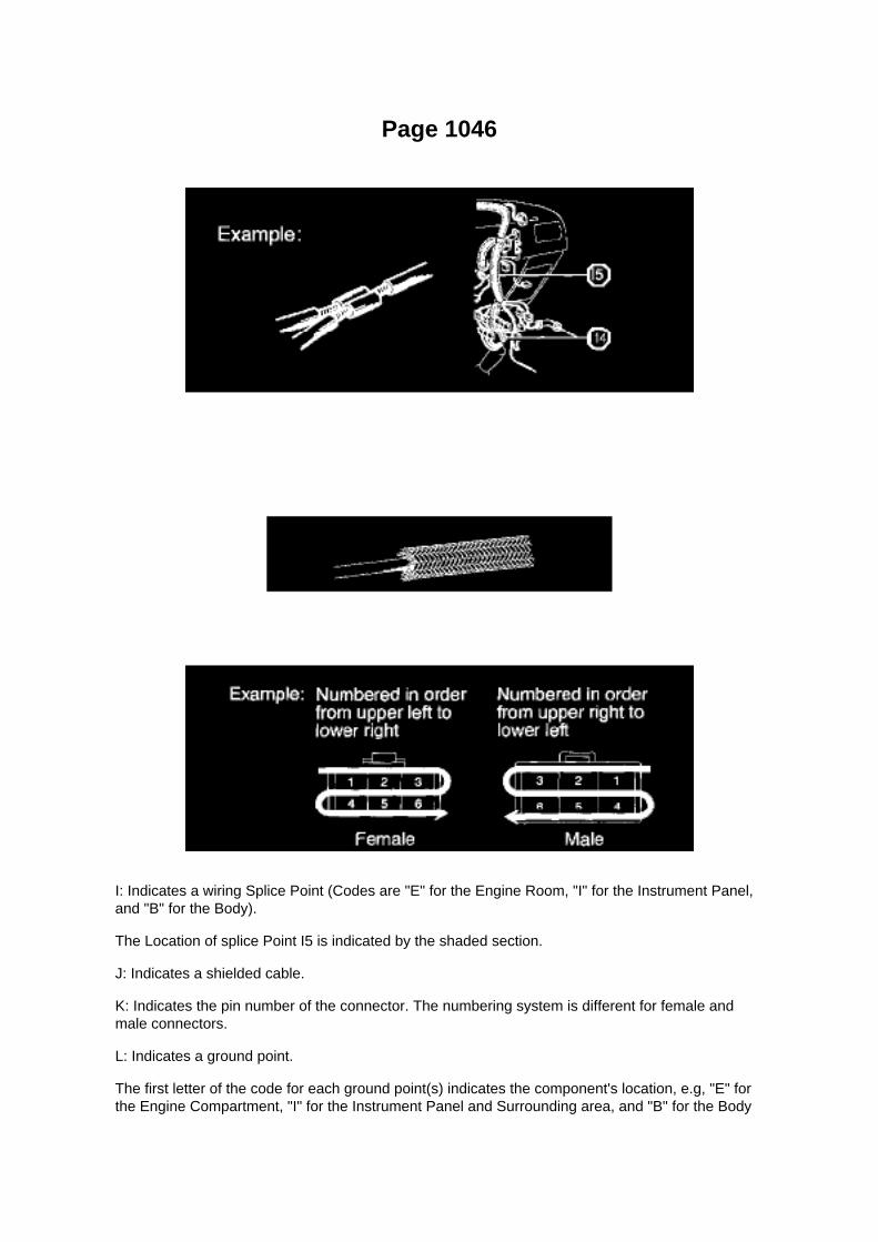
Page 1046
I: Indicates a wiring Splice Point (Codes are "E" for the Engine Room, "I" for the Instrument Panel,and "B" for the Body).
The Location of splice Point I5 is indicated by the shaded section.
J: Indicates a shielded cable.
K: Indicates the pin number of the connector. The numbering system is different for female andmale connectors.
L: Indicates a ground point.
The first letter of the code for each ground point(s) indicates the component's location, e.g, "E" forthe Engine Compartment, "I" for the Instrument Panel and Surrounding area, and "B" for the Body

and Surrounding area.
N: Explains the system outline.
SYSTEM OUTLINE
Current is applied at all times through the STOP fuse to TERMINAL 2 of the stop light SW. Whenthe ignition SW is turned on, current flows from the GAUGE fuse to TERMINAL 8 of the light failuresensor, and also flows through the rear lights warning light to TERMINAL 4 of the light failuresensor.
STOP LIGHT DISCONNECTION WARNING When the ignition SW is turned on and the brakepedal is pressed (Stop light SW on), if the stop light circuit is open, the current flowing fromTERMINAL 7 of the light failure sensor to TERMINALS 1, 2 changes, so the light failure sensordetects the disconnection and the warning circuit of the light failure sensor is activated.
As a result, the current flows from TERMINAL 4 of the light failure sensor to TERMINAL 11 toGROUND and turns the rear lights warning light on. By pressing the brake pedal, the currentflowing to TERMINAL 8 of the light failure sensor keeps the warning circuit on and holds thewarning light on until the ignition SW is turned off.

Locations
A/C - Ge
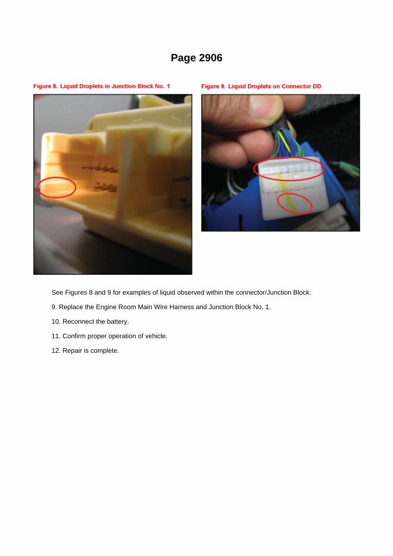
Page 2906
See Figures 8 and 9 for examples of liquid observed within the connector/Junction Block.
9. Replace the Engine Room Main Wire Harness and Junction Block No. 1.
10. Reconnect the battery.
11. Confirm proper operation of vehicle.
12. Repair is complete.

Page 2671

(w/ AIR CONDITIONING)

i. Engage the engine wire harness clamp.
j. Connect the VSV connector.
k. Connect the ventilation hose No.3.
l. Connect the water bypass hose No.2.
m. Install the clamp bracket with the bolt.
Torque: 19 N.m (194 kgf.cm, 14 in.lbf)
n. Connect the vacuum hose.

Page 1997
Step 1 - 2

Page 671

2. DISCONNECT THE NEGATIVE BATTERY CABLE

3. LOCATE THE BENCH SEAT FLOOR WIRE HARNESS
(c) Slide the bench seat to the rearmost position.
(d) Locate the floor wire harness and connector under the seat on the driver's side, closest to thefront edge of the seat cushion.
4. INSTALL THE WIRE SEAT JUMPER
NOTE:
DO NOT install the wire seat jumper on a vehicle which is NOT on the VIN list!
(a) Push the lock tab on the connector and pull to remove the female portion of the connector.
(b) Before installing the wire seat jumper to the vehicle, attach the Warning Label (shown in theillustration) onto the corrugated tubing, next to the
Part Number Label.
NOTE:
^ Attach the Warning Label in a similar manner to the Part Number Label, making sure not coverthe information printed on it.
^ DO NOT remove the Part Number Label or cover it with the Warning Label.
^ A small supply of labels were sent with the Service Manager Package. Additional labels can beordered from the Material Distribution Center (p/n 00410-92017).

Page 3131

c. Remove the 2 center support bearing bolts from the frame crossmember.

d. Place matchmarks on the propeller shaft flange and transfer flange. e. Remove the 4 nuts, 4washers and front propeller shaft assy.
2. INSPECT PROPELLER SHAFT UNIVERSAL JOINT SPIDER BEARING
a. Check the spider bearings for wear and damage. b. Check each spider bearing's axial play byturning the yoke while holding the shaft tightly.
Maximum bearing axial play: 0 to 0.05 mm (0 to 0.002 inch) If the bearing axial play is greater thanthe maximum, replace the spider bearing.
3. REMOVE PROPELLER SHAFT UNIVERSAL JOINT SPIDER BEARING
a. Place matchmarks on the propeller shaft and universal joint yoke.
b. Using a brass bar and hammer, slightly tap in the spider bearing. c. Using needle nose pliers,remove the 4 snap rings from the grooves.

Page 2475

Fuel Injector: Service and Repair

REPLACEMENT
1. DISCHARGE FUEL SYSTEM PRESSURE 2. DISCONNECT CABLE FROM NEGATIVEBATTERY TERMINAL 3. REMOVE ENGINE UNDER COVER SUB-ASSEMBLY NO.1 4. DRAINENGINE COOLANT 5. REMOVE INTAKE AIR CONNECTOR 6. REMOVE THROTTLE W/MOTORBODY ASSEMBLY 7. DISCONNECT FUEL HOSE
a. Pull the checker of the fuel hose upward.
b. Pinch the detaching switch of the fuel hose connector and pull out the fuel hose.
NOTE: -
Remove any dirt and foreign objects on the fuel tube connector before performing this work.
- Do not allow any scratches or foreign objects on the parts when disconnecting, as the fuel tubeconnector has the O-ring that seals the pipe.
- Perform this work by hand. Do not use any tools.
- Do not forcibly bend, twist or turn the nylon tube.
- Protect the disconnected part by covering it with a vinyl bag after disconnecting the fuel hose.
- If the fuel tube connector and pipe are stuck, push and pull to release them.
8. DISCONNECT FUEL HOSE NO.2
a. Pull the checker of the fuel hose upward.

Page 3362

c. Rear brake line.

(1) Connect the vinyl tube to the wheel cylinder. (2) Depress the brake pedal, hold it, and thenloosen the bleeder plug.
HINT: Brake fluid is pumped out automatically.
(3) Loosen the bleeder plug and release air.
NOTICE: Keep brake fluid in the reservoir tank above the MIN line during the above procedures.
(4) When the air is completely bled out of the brake fluid through the bleeder plug, tighten thebleeder plug.
Torque: 11 Nm (112 kgf-cm, 8 ft. lbs.)
(5) Repeat the above procedures to bleed the other brake line.
4. BLEED MASTER CYLINDER SOLENOID
HINT: If the brake master cylinder is disassembled, the brake line is disconnected from the brakemaster cylinder or if the reservoir become empty, bleed the brake master cylinder.
a. Connect the hand-held tester to the DLC3. b. Turn the ignition switch to ON. c. Select"ACTIVETEST" mode on the hand-held tester.
d. Connect the vinyl tube to the rear wheel cylinder. e. Loosen the bleeder plug. f.
Select "SRMF & SIGMA" to drive the solenoids and bleed air from the rear wheel cylinder.
NOTICE: -
Do not depress the brake pedal.
- Keep brake fluid in the reservoir tank above the MIN line during the above procedures.
HINT: -
Brake fluid is sent through the pump.
- To protect the solenoids, the hand-held tester turns OFF automatically 2 seconds after everysolenoid has been turned ON.

Page 3134

8. INSTALL CENTER SUPPORT BEARING ASSY NO.1

a. Install the center support bearing assy No.1 onto the intermediate shaft.
b. Coat the splines of the intermediate shaft with MP grease. c. Align the matchmarks on the centeryoke and intermediate shaft.
HINT: If replacing either the center yoke or intermediate shaft, reassemble them so that the frontside yoke of the intermediate shaft and the center yoke are facing in the same direction.
d. Install the spacer. e. Fix the yoke at the center bearing section in a vice. f.
Clamp the yoke in a vise, and press the bearing into position by tightening a new nut. Torque: 182Nm (1,850 kgf-cm, 134 ft. lbs.)
g. Loosen the nut. h. Torque the nut again.
Torque: 69 Nm (700 kgf-cm, 51 ft. lbs.)
i. Using a chisel and hammer, stake the lock nut.
9. INSTALL PROPELLER SHAFT UNIVERSAL JOINT SPIDER BEARING
a. Apply MP grease No.2 to a new spider and bearings. b. Fit the spider into the flange yoke.
c. Measure dimension A between the snap ring grooves. d. Insert the spider bearing into the spiderjournal portion, and then measure dimension B of the universal joint.
NOTICE: When measuring dimension B. fix the spider and needle roller bearings in a vise and holdthem firmly together.

Page 1604

Part 1

Locations

Canister Purge Solenoid: Locations

He - Wi

Page 2069

Oxygen Sensor: Locations

He - Wi

Capacity Specifications

Fluid - M/T: Capacity Specifications

Manual Transaxle M/T Oil Capacity 2WD:....................................................................................................................................................... 2.7US qt. (2.6 L, 2.3 Imp. qt.)

Page 1147

Instrument Panel J/B No. 2 Inner Circuit

Page 2147

Main Relay (Computer/Fuel System): Testing and Inspection

INSPECT E.F.I. CIRCUIT OPENING RELAY ASSEMBLY
a. Check the resistance.
1. Using an ohmmeter, measure the resistance between the terminals.
If the result is not as specified, replace the E.F.I. circuit opening relay assembly.
INSPECT EFI RELAY
a. Check the resistance.
1. Using an ohmmeter, measure the resistance between the terminals.
If the result is not as specified, replace the E.F.I. ECU relay.

Page 1183

26. INSTALL REAR AXLE SHAFT LH OIL SEAL

a. Using SST and a hammer, install a new oil seal.
SST 09950-60020 (09951-00770), 09950-70010 (09951-07150)
27. INSTALL REAR AXLE SHAFT W/ BACKING PLATE
a. Install a new O-ring. b. Install the rear axle shaft w/ backing plate with the 4 nuts.
Torque: 36 Nm (367 kgf-cm, 27 ft. lbs.)
28. INSTALL REAR BRAKE TUBE NO.8
a. Using SST, connect the brake tube.
SST 09023-00101 Torque: 15 Nm (155 kgf-cm, 11 ft. lbs.)
29. INSTALL PARKING BRAKE CABLE ASSY NO.3 30. INSTALL SPEED SENSOR REAR LH 31.APPLY HIGH TEMPERATURE GREASE 32. INSTALL REAR BRAKE SHOE
SST 09718-00010
33. INSTALL FRONT BRAKE SHOE
SST 09718-00010, 09921-00010
34. CHECK REAR DRUM BRAKE INSTALLATION 35. INSTALL REAR BRAKE DRUM SUB-ASSY36. ADJUST REAR DRUM BRAKE SHOE CLEARANCE 37. CONNECT CABLE TO NEGATIVEBATTERY TERMINAL
Torque: 3.9 Nm (40 kgf-cm, 35 inch lbs.)
38. FILL RESERVOIR WITH BRAKE FLUID (W/ VSC) 39. FILL RESERVOIR WITH BRAKE FLUID(W/O VSC) 40. BLEED MASTER CYLINDER (W/O VSC)
SST 09023-00101
41. BLEED BRAKE LINE (W/ VSC) 42. BLEED BRAKE LINE (W/O VSC) 43. CHECK FLUIDLEVEL IN RESERVOIR (W/ VSC) 44. CHECK FLUID LEVEL IN RESERVOIR (W/O VSC) 45.CHECK FOR BRAKE FLUID LEAKAGE

Page 183
Driver Side J/B Inner Circuit

Page 708

(Driver's seat is in the backward position).

^ "D BUCKLE SW UNSET" (Driver's seat belt buckle switch is unset/unbuckled).
(Test # 3)
(a) Move the bench seat to the foremost position.
(b) Leave the driver's seat belt unbuckled.
(c) Confirm that the scan tool displays the data shown below and in the illustration.
^ "D SEAT POSITIFORWARD"
(Driver's seat is in the forward position).
^ "D BUCKLE SW UNSET" (Driver's seat belt buckle switch is unset/unbuckled).
(Test # 4)
(a) Leave the bench seat in the foremost position.
(b) Buckle the driver's seat belt.

Page 2139

a. Read VIN using a hand-held tester.

4. WRITE VIN

Page 2874

He - Wi

Page 1603

a. Read VIN using a hand-held tester.

4. WRITE VIN

Page 28

2. HEAT METHOD: If the problem seems to occur when the area in question is heated.

a. Heat the component that is the possible cause of the malfunction with a hair dryer or similardevice. Check if the malfunction occurs.
NOTE: -
Do not heat to more than 60°C (140°F). Exceeding this temperature may damage components.
- Do not apply heat directly to the parts in the ECU.
3. WATER SPRINKLING METHOD: When the malfunction seems to occur on a rainy day or inhigh-humidity.
a. Sprinkle water onto the vehicle and check if the malfunction occurs.
NOTE: -
Never sprinkle water directly into the engine compartment. Indirectly change the temperature andhumidity by applying water spray onto the front of the radiator.
- Never apply water directly onto the electronic components.
HINT: If the vehicle has or had a water leakage problem, the leakage may have damaged the ECUor connections. Look for evidence of corrosion or shorts. Proceed with caution during water tests.
4. HIGH ELECTRICAL LOAD METHOD: When a malfunction seems to occur when electrical loadis excessive.
a. Turn on the heater blower, headlamps, rear window defogger and all other electrical loads.Check if the malfunction reoccurs.
Diagnostic Trouble Code Chart
DIAGNOSTIC TROUBLE CODE CHART

Service and Repair

Fuel Pressure Release: Service and Repair

PRECAUTION
1. PRECAUTION
a. Before working on the fuel system, disconnect the cable from the negative battery terminal. b.Do not work on the fuel system near fire. Never smoke during the work. c. Keep rubber and leatherparts away from gasoline.
2. DISCHARGE FUEL PRESSURE
CAUTION: -
Before removing fuel system parts, take precautions to prevent gasoline spillage.
- As some pressure remains in the fuel line even after taking precautions to prevent gasolinespillage, use a shop rag to prevent gasoline splashes when disconnecting the fuel line.
a. Disconnect the cable from the negative battery terminal. b. Remove the engine relay blockcover.
c. Remove the circuit opening relay. d. Connect the cable to the negative battery terminal.
Torque: 3.9 N.m (40 kgf.cm, 35 in.lbf)
e. Start the engine. f.
Turn the ignition switch to ON after the engine stops.
HINT: DTC P0171 (system to lean) may be present.
g. Crank the engine again, and check that the engine stops. h. Remove the fuel tank cap, anddischarge the pressure in the fuel tank completely. i.
Install the circuit opening relay.
3. FUEL SYSTEM
a. When disconnecting the high-pressure fuel line, a large amount of gasoline will splash. So takethe following precautions.

Specifications
Flywheel: Specifications
Flywheel
Step 1 ................................................................................................................................................................................ 27 Nm (270 kgf-cm, 20 ft. lbs.) Step 2 .............................................................................................................................................................................................. Additional 90degrees

Page 650

2. VERIFY THE REPAIR
(Test # 1)
(a) Move the bench seat to the rearmost position.
(b) Buckle the driver's seat belt.
(c) Confirm that the scan tool displays the data shown below and in the illustration.
^ "D SEAT POSITIOBKWARD" (Driver's seat is in the backward position).
^ "D BUCKLE SW SET"
(Driver's seat belt buckle switch is set/buckled).
(Test # 2)
(a) Leave the bench seat in the rearmost position.
(b) Unbuckle the driver's seat belt.
(c) Confirm that the scan tool displays the data shown below and in the illustration.
^ "D SEAT POSITIOBKWARD"

Page 2666
Knock Sensor: Testing and Inspection
INSPECT KNOCK SENSOR
a. Check the resistance.
1. Using an ohmmeter, measure the resistance between the terminals.
If the result is not as specified, replace the knock sensor.

Page 1395


Page 1947

Step 1 - 2

INSPECTION PROCEDURE
Steering Angle Sensor Communication Stop Mode
STEERING ANGLE SENSOR COMMUNICATION STOP MODE
MODE DESCRIPTION

Page 1136

Relay Box: Connector Views
Engine Room R/B, J/B - Engine Compartment Left

Page 1914

a. For an open circuit in the wire harness in Fig. 1, perform a resistance check (step b) or a voltagecheck (step c).

b. Check the resistance.
1. Disconnect connectors A and C and measure the resistance between them.
HINT: Measure the resistance while lightly shaking the wire harness vertically and horizontally.
If your results match the examples above, an open circuit exists between terminal 1 of connector Aand terminal 1 of connector C.
2. Disconnect connectors B and measure the resistance between the connectors.
If your results match the examples above, an open circuit exists between terminal 1 of connectorB2 and terminal 1 of connector C.

Page 2079
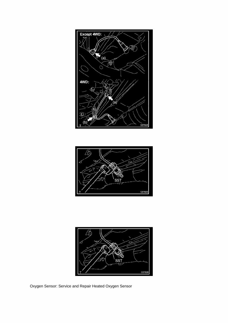
Oxygen Sensor: Service and Repair Heated Oxygen Sensor

REPLACEMENT
1. DISCONNECT CABLE FROM NEGATIVE BATTERY TERMINAL 2. REMOVE HEATEDOXYGEN SENSOR
a. Disconnect the heated oxygen sensor connector. b. Disconnect the wire harness clamp. (4WDDRIVE TYPE)
c. Using SST, remove the heated oxygen sensor.
SST 09224-00010
3. INSTALL HEATED OXYGEN SENSOR
a. Using SST, install the heated oxygen sensor.
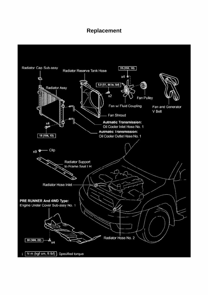
Replacement

Radiator: Service and Repair Replacement
RADIATOR ASSEMBLY (2TR-FE)

Page 3345
Wheel Speed Sensor: Service and Repair Rear
SPEED SENSOR REAR LH
REPLACEMENT
HINT: The replacement procedures for the RH side are the same as those for the LH side.
1. DISCONNECT CABLE FROM NEGATIVE BATTERY TERMINAL
2. REMOVE SPEED SENSOR REAR LH
a. Disconnect the speed sensor connector. b. Remove the nut and speed sensor rear.
NOTICE: -
Do not attach any foreign matter to the sensor tip.
- Ensure that no foreign matter enters the sensor installation hole.
3. INSTALL SPEED SENSOR REAR LH
a. Install the rear speed sensor with the nut.
Torque: 8.0 Nm (82 kgf-cm, 71 inch lbs.)
NOTICE: Make sure that the sensor tip is clean.
b. Connect the speed sensor connector.
4. CONNECT CABLE TO NEGATIVE BATTERY TERMINAL
Torque: 3.9 Nm (40 kgf-cm, 35 inch lbs.)
5. CHECK ABS SENSOR SIGNAL

Page 1379
b. Provisionally install the oil pan with the 18 bolts and 2 nuts. c. Uniformly tighten the 18 bolts and2 nuts in the sequence shown in the illustration.
Torque: 9.0 Nm (92 kgf-cm, 80 inch lbs.)
d. Install a new gasket and the drain plug.
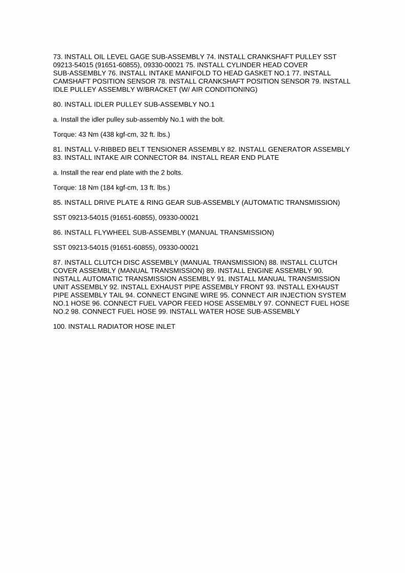
73. INSTALL OIL LEVEL GAGE SUB-ASSEMBLY 74. INSTALL CRANKSHAFT PULLEY SST09213-54015 (91651-60855), 09330-00021 75. INSTALL CYLINDER HEAD COVERSUB-ASSEMBLY 76. INSTALL INTAKE MANIFOLD TO HEAD GASKET NO.1 77. INSTALLCAMSHAFT POSITION SENSOR 78. INSTALL CRANKSHAFT POSITION SENSOR 79. INSTALLIDLE PULLEY ASSEMBLY W/BRACKET (W/ AIR CONDITIONING)
80. INSTALL IDLER PULLEY SUB-ASSEMBLY NO.1
a. Install the idler pulley sub-assembly No.1 with the bolt.
Torque: 43 Nm (438 kgf-cm, 32 ft. lbs.)
81. INSTALL V-RIBBED BELT TENSIONER ASSEMBLY 82. INSTALL GENERATOR ASSEMBLY83. INSTALL INTAKE AIR CONNECTOR 84. INSTALL REAR END PLATE
a. Install the rear end plate with the 2 bolts.
Torque: 18 Nm (184 kgf-cm, 13 ft. lbs.)
85. INSTALL DRIVE PLATE & RING GEAR SUB-ASSEMBLY (AUTOMATIC TRANSMISSION)
SST 09213-54015 (91651-60855), 09330-00021
86. INSTALL FLYWHEEL SUB-ASSEMBLY (MANUAL TRANSMISSION)
SST 09213-54015 (91651-60855), 09330-00021
87. INSTALL CLUTCH DISC ASSEMBLY (MANUAL TRANSMISSION) 88. INSTALL CLUTCHCOVER ASSEMBLY (MANUAL TRANSMISSION) 89. INSTALL ENGINE ASSEMBLY 90.INSTALL AUTOMATIC TRANSMISSION ASSEMBLY 91. INSTALL MANUAL TRANSMISSIONUNIT ASSEMBLY 92. INSTALL EXHAUST PIPE ASSEMBLY FRONT 93. INSTALL EXHAUSTPIPE ASSEMBLY TAIL 94. CONNECT ENGINE WIRE 95. CONNECT AIR INJECTION SYSTEMNO.1 HOSE 96. CONNECT FUEL VAPOR FEED HOSE ASSEMBLY 97. CONNECT FUEL HOSENO.2 98. CONNECT FUEL HOSE 99. INSTALL WATER HOSE SUB-ASSEMBLY
100. INSTALL RADIATOR HOSE INLET

Page 2988

11. Install the clutch pedal bushes.

A. Apply MP grease to the two (2) NEW bushes.
B. Install the two (2) bushes onto the clutch pedal.
12. Install the clutch pedal pad.
13. Install the clutch pedal spring holder.
A. Apply MP grease to the contact surface of the clutch pedal spring holder.
B. Install the clutch pedal spring holder.
14. Remove the clevis sub-assembly.
A. Measure length "A" of the clutch master cylinder.
a. Measure length "A" between the lock nut and the thread end with a ruler.
b. Record length "A".

Page 44
Terminals Of Control Module / Pinouts - Check Transponder Key ECU Assy Part 2

Locations

Page 922
2. After connecting the fuel tube connector, check that the fuel tube connector and pipe aresecurely connected by pulling them.

Page 1895

contact Toyota.

OBTAINING A CALIBRATION CD
The Calibration CD is compatible with the above mentioned scantools and J2534 interfaces. ACalibration CD contains all of the most current vehicle calibration files, applicable TSBs, theCalibration Update Wizard application software for a Windows PC, and instructions for use.
Calibration CDs can be ordered through the Toyota Material Distribution Center; order P/N00456-REPRG-001.
IMPORTANT NOTICE
It is possible to permanently damage a vehicle controller during the flash reprogramming process.It is especially important to understand that once started, the reprogramming process must not beinterrupted, reprogramming devices must not be disconnected and PCs must not be allowed to gointo standby, hibernation or similar power management modes. The information provided herein isintended expressly for use by qualified professional automobile technicians. To prevent damage toyour customer's vehicle and ensure safe service practice, read these materials completely andthoroughly before servicing the vehicle and be sure to follow all instructions.

Page 1667

d. Disconnect the water bypass hose No.2.

e. Disconnect the ventilation hose No.3.
f. Disconnect the VSV connector.
g. Disengage the engine wire harness clamp. h. Disconnect the compressor magnetic clutchconnector.
(w/ AIR CONDITIONING)
i. Disengage the wire harness clamp.
j. Remove the bolt and harness clamp bracket.

Page 2731
C. Choose desired ECU group(s) in the Health Check dialog box.
D. Click Next.
E. Click Continue to view Health Check results.

F. Available calibration updates are indicated by a link in the Cal. Update? column. Click the link toaccess the appropriate service bulletin on TIS.
NOTE
^ Note any DTCs stored in Systems that will be flash reprogrammed.
^ Clicking the link will automatically launch TIS and perform a calibration search.
G. Log in to TIS. (If already logged in skip this step.)
H. To review the TSB and access the calibration file click the service bulletin link in the DocumentTitle column of the Calibration Search Result
portlet.

Page 939

3. Install the fuel tank protector cover on top of the fuel suction plate sub-assembly as shown in theillustration.

Page 748

4. REMOVE OCCUPANT DETECTION ECU

a. Disconnect the connector from the occupant detection ECU.
b. Disengage the claw and remove the occupant detection ECU.
5. INSTALL OCCUPANT DETECTION ECU
a. Check that the ignition switch is OFF. b. Check that the cable is disconnected from the batterynegative (-) terminal is disconnected.
CAUTION: After removing the cable from the terminal, wait for at least 90 seconds before startingthe operation.
c. Engage the claw and install the occupant detection ECU.
NOTE: -
If the occupant classification ECU has been dropped, or there are cracks, dents or other defects inthe case or connector, replace it with a new one.
- When installing the occupant detection ECU, make sure that the SRS wiring does not interferewith any other parts and that it is not pinched between other parts.
d. Connect the connector to the occupant detection ECU.
6. INSTALL FRONT RH SEAT ASSEMBLY 7. CONNECT CABLE TO NEGATIVE BATTERYTERMINAL
Torque: 3.9 N.m (40 kgf.cm, 35 in.lbf)
8. OCCUPANT CLASSIFICATION ECU INITIALIZATION
Refer to Air Bag Systems; Testing and Inspection.
9. INSPECT SRS WARNING LIGHT

Locations
SFI System

Page 642
(a) Slide the bench seat to the rearmost position.
(b) Locate the floor wire harness and connector under the seat on the driver's side closest to thefront edge of the seat cushion.

Page 2746
Warranty Information
APPLICABLE WARRANTY
^ This repair is covered under the Toyota Federal Emission Warranty. This warranty is in effect for96 months or 80,000 miles, whichever occurs first,
from the vehicle's in-service date.

^ Warranty application is limited to correction of a problem based upon a customer's specificcomplaint.
Parts Information
NOTE
^ The ECM (PCM) should NOT be replaced as part of the repair procedure.
^ Authorized Modification Labels may be ordered in packages of 25 from the Materials DistributionCenter (MDC) through Dealer Daily - Dealer
Support Materials Orders.
Calibration Information
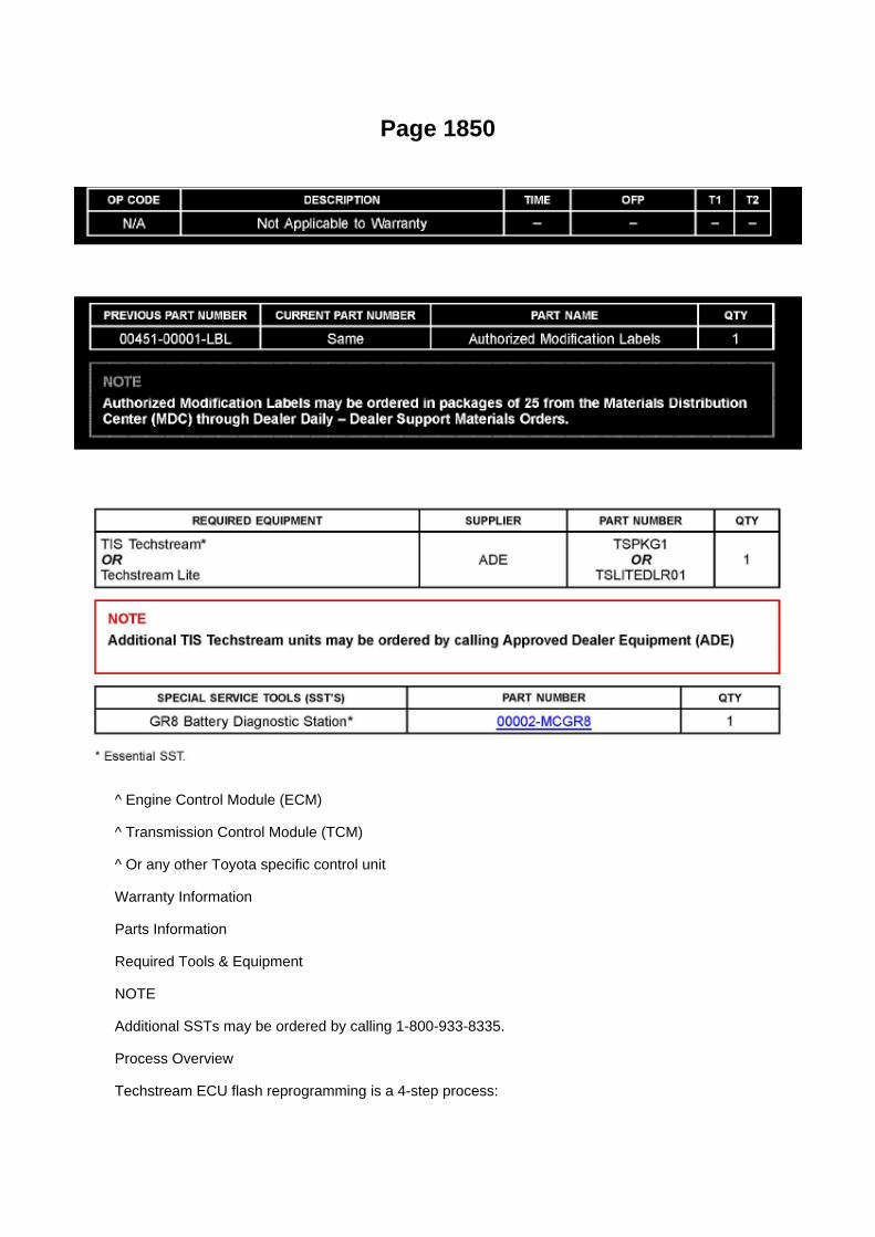
Page 1850
^ Engine Control Module (ECM)
^ Transmission Control Module (TCM)
^ Or any other Toyota specific control unit
Warranty Information
Parts Information
Required Tools & Equipment
NOTE
Additional SSTs may be ordered by calling 1-800-933-8335.
Process Overview
Techstream ECU flash reprogramming is a 4-step process:
1. Verify the vehicle's applicability for recalibration and locate desired calibration file by performingthe Techstream Health Check function.
NOTE
Techstream will automatically search TIS for the appropriate service bulletin using the currentCalibration ID from the vehicle. Calibration file links can be found embedded in the correspondingservice bulletin.
2. Connect the GR8 Battery Diagnostic Station using "Power Supply Mode" only.
The GR8 Battery Diagnostic Station includes a Power Supply Mode to help maintain batteryvoltage at 13.5 volts during ECU reprogramming.
ECU damage may occur if the correct battery charger mode setting is NOT used.
3. Locate appropriate calibration ID and reprogram the vehicle ECU with Techstream.
Techstream uses the Calibration Update Wizard (CUW) application to open calibration files andfacilitate the ECU flash reprogramming process.

Page 616
Impact Sensor: Service and Repair Rear Left Sensor
Air Bag Sensor Rear LH
REPLACEMENT
1. PRECAUTION

Refer to Air Bag Systems; Service Precautions.
2. DISCONNECT CABLE FROM NEGATIVE BATTERY TERMINAL
Wait for at least 90 seconds after disconnecting the cable to prevent the airbag from working.
3. REMOVE REAR SEAT BACK HINGE COVER 4. REMOVE REAR SEAT BACK ASSEMBLY LH5. REMOVE REAR SEAT BACK HINGE SUB-ASSEMBLY LH 6. REMOVE REAR DOOR SCUFFPLATE LH 7. REAR DOOR OPENING TRIM WEATHERSTRIP LH 8. REMOVE LUGGAGECOMPARTMENT SIDE TRAY

Page 1141

Instrument Panel J/B No. 2 - Right Side Of Glove Box

Page 1927
CAUTION: a. Do not open the cover or the case of the ECU unless absolutely necessary. (If the ICterminals are touched, the IC may be destroyed by static
electricity.)
b. When replacing the internal mechanism (ECU part) of the digital meter, be careful that no part ofyour body or clothing comes in contact with
the terminals of leads from the IC, etc. of the replacement part (spare part).

How to Replace Terminal
HOW TO REPLACE TERMINAL (with terminal retainer or secondary locking device)
1. PREPARE THE SPECIAL TOOL
HINT: To remove the terminal from the connector, please construct and use the special tool or likeobject shown.
2. DISCONNECT CONNECTOR
3. DISENGAGE THE SECONDARY LOCKING DEVICE OR TERMINAL RETAINER
a. Locking device must be disengaged before the terminal locking clip can be released and theterminal removed from the connector. b. Use a special tool or the terminal pick to unlock thesecondary locking device or terminal retainer.
NOTE: Do not remove the terminal retainer from connector body.
[A] : For Non-Waterproof Type Connector
HINT: The needle insertion position varies according to the connector's shape (number of terminalsetc.), so check the position before inserting it.

Page 1012

g. Repeat step (f) until all the air in the brake fluid is bled out. h. When the air is completely bled outof the brake fluid through the bleeder plug, tighten the bleeder plug.
Torque: 11 Nm (112 kgf-cm, 8 ft. lbs.)
i. Repeat the above procedures to bleed the other brake line.
j. Turn the ignition switch to OFF.
k. Turn the ignition switch to ON.
(1) Clear DTC.
5. CHECK FLUID LEVEL IN RESERVOIR
a. Turn the ignition switch to OFF, and depress the brake pedal more than 20 times (until the pedalreaction feels light and pedal stroke becomes
longer), and adjust the fluid level to the MAX level.
b. When the ignition switch is turned to the ON, brake fluid is sent to the accumulator and the fluidlevel decreases by approximately 5 mm from
the level when the ignition switch is off (normal).

Page 2117
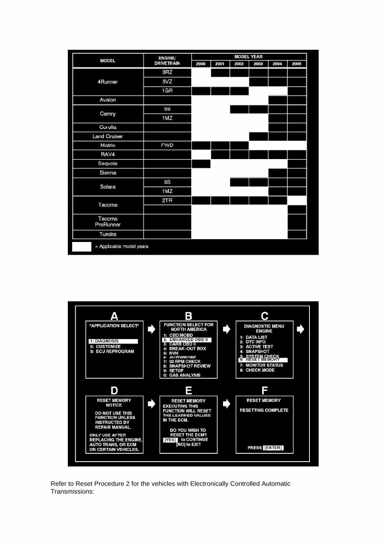
Refer to Reset Procedure 2 for the vehicles with Electronically Controlled AutomaticTransmissions:

Reset Procedure 1
1. Connect the Toyota Diagnostic Tester to the vehicle.
2. Reset the ECM (PCM). Refer to the procedures below.

Page 2128

Engine Control Module: Pinout Values and Diagnostic Parameters

Terminals Of ECM / Pinouts Part 1

Specifications

Wheel Bearing: Specifications

WHEEL BEARING GREASE:................................................................................................................. Lithium base wheel bearinggrease, NLGI No.2

Locations

Fuel Pump Relay: Locations
Engine Room R/B, J/B - Engine Compartment Left

Page 2196

(w/ AIR CONDITIONING)

i. Engage the engine wire harness clamp.
j. Connect the VSV connector.
k. Connect the ventilation hose No.3.
l. Connect the water bypass hose No.2.
m. Install the clamp bracket with the bolt.
Torque: 19 N.m (194 kgf.cm, 14 in.lbf)
n. Connect the vacuum hose.

Page 664

Page 2933
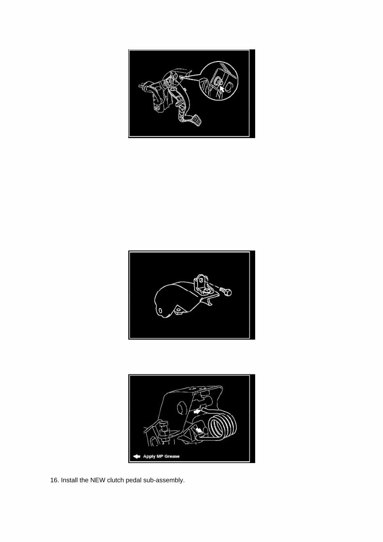
16. Install the NEW clutch pedal sub-assembly.

A. Install the clutch pedal onto the clutch support with the bolt and nut.
Torque: 34 N.m (347 kgf.cm, 25 ft.lbf)
HINT
Install the bolt from the left side of the vehicle.
B. Apply MP grease to the clutch pedal sub-assembly where the clevis sub-assembly contacts theclutch pedal.
NOTE:
Failure to apply grease to the clevis and clutch pedal sub-assemblies could cause the noise toreturn.
C. Tighten the bolt to the instrument panel reinforcement assembly.
Torque: 8 N.m (82 kgf.cm, 6 ft.lbf)
17. Install the turnover (compression) spring.
A. Apply MP grease to the contact surface of the spring holder, clutch pedal, and spring.
B. Install the spring onto the clutch pedal and spring holder.

Page 2667

Knock Sensor: Service and Repair
REPLACEMENT
1. DISCONNECT CABLE FROM NEGATIVE BATTERY TERMINAL 2. REMOVE ENGINE UNDERCOVER SUB-ASSEMBLY NO.1 (PRE RUNNER AND 4WD TYPE) 3. DRAIN ENGINE COOLANT4. REMOVE INTAKE AIR CONNECTOR 5. REMOVE THROTTLE W/MOTOR BODY ASSEMBLY6. DISCONNECT FUEL HOSE 7. DISCONNECT FUEL HOSE NO.2 8. REMOVE INTAKEMANIFOLD
a. Disconnect the fuel vapor feed hose from the VSV.
b. Disconnect the vacuum hose.
c. Remove the bolt, then remove the clamp bracket.

Page 1229

l. Hold the hexagonal lobe of the No.2 camshaft with the adjustable wrench.
m. Tighten the bolt.
Torque: 78 Nm (795 kgf-cm, 58 ft. lbs.)
n. Remove the 3.0 mm (0.118 inch) diameter bar from the chain tensioner. o. Apply adhesive to 2or 3 threads of the timing gear case with head straight screw plug.
Adhesive: Part No.08833-00070, THREE BOND 1324 or equivalent
p. Using a 10 mm socket hexagon wrench, install the timing gear case with head straight screwplug.
Torque: 17 Nm (170 kgf-cm, 12 ft. lbs.)
14. INSTALL TIMING CHAIN GUIDE
a. Install a new O-ring onto the camshaft bearing cap.
b. Install the timing chain guide with the 2 bolts.
Torque: 10 Nm (102 kgf-cm, 7 ft. lbs.)

Page 1953
Wiring Diagram
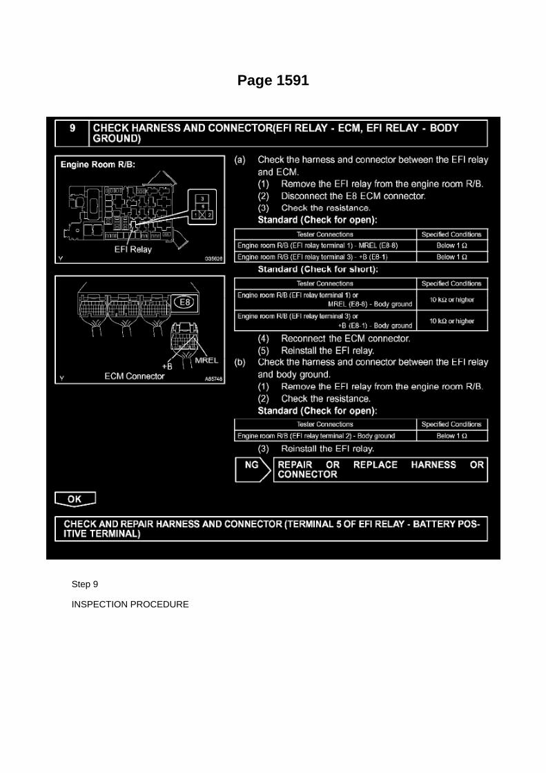
Page 1591
Step 9
INSPECTION PROCEDURE

Page 1118

a. For an open circuit in the wire harness in Fig. 1, perform a resistance check (step b) or a voltagecheck (step c).

b. Check the resistance.
1. Disconnect connectors A and C and measure the resistance between them.
HINT: Measure the resistance while lightly shaking the wire harness vertically and horizontally.
If your results match the examples above, an open circuit exists between terminal 1 of connector Aand terminal 1 of connector C.
2. Disconnect connectors B and measure the resistance between the connectors.
If your results match the examples above, an open circuit exists between terminal 1 of connectorB2 and terminal 1 of connector C.

Page 1562
^ Engine Control Module (ECM)
^ Transmission Control Module (TCM)
^ Or any other Toyota specific control unit
Warranty Information
Parts Information
Required Tools & Equipment
NOTE
Additional SSTs may be ordered by calling 1-800-933-8335.
Process Overview
Techstream ECU flash reprogramming is a 4-step process:

1. Verify the vehicle's applicability for recalibration and locate desired calibration file by performingthe Techstream Health Check function.
NOTE
Techstream will automatically search TIS for the appropriate service bulletin using the currentCalibration ID from the vehicle. Calibration file links can be found embedded in the correspondingservice bulletin.
2. Connect the GR8 Battery Diagnostic Station using "Power Supply Mode" only.
The GR8 Battery Diagnostic Station includes a Power Supply Mode to help maintain batteryvoltage at 13.5 volts during ECU reprogramming.
ECU damage may occur if the correct battery charger mode setting is NOT used.
3. Locate appropriate calibration ID and reprogram the vehicle ECU with Techstream.
Techstream uses the Calibration Update Wizard (CUW) application to open calibration files andfacilitate the ECU flash reprogramming process.
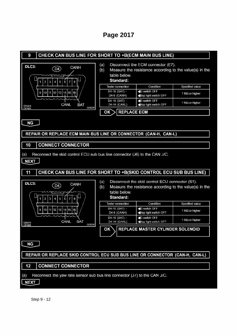
Page 2017
Step 9 - 12

Page 1282

Drive Belt: Tools and Equipment
Toyota Serpentine Belt Wrench
AST tool# TOY 1914
The TOY 1914 is a Toyota serpentine belt wrench that is equipped with 14mm and 19mm, 12 pointsecured attachments. Applications: 1998-2005 Corolla, 2004 Matrix, 2008 Highlander V6 (NonHybrid), 2002 RAV4 and 4.7L/5.7L V8 used in Tundra and Sequoia through 2008.
- Lightweight and Slim design
- Equipped with 14mm and 19mm, 12 point securing attachments
- Works on most Toyota applications (except Hybrids)
Contact AST for pricing.

Locations

Power Steering Pressure Switch: Locations

He - Wi

Page 3133

4. INSPECT PROPELLER W/ CENTER BEARING SHAFT ASSY

a. Using a dial indicator, check the propeller shaft runout.
Maximum runout: 0.6 mm (0.024 inch) If the shaft runout is greater than the maximum, replace theshaft.
5. INSPECT PROPELLER SHAFT
a. Using a dial indicator, check the propeller shaft runout.
Maximum runout: 0.6 mm (0.024 inch) If the shaft runout is greater than the maximum, replace theshaft.
6. REMOVE CENTER SUPPORT BEARING ASSY NO.1
a. Fix the yoke at the center bearing section in a vice. b. Using a chisel and a hammer, loosen thestaked part of the lock nut. c. Place matchmarks on the yoke and shaft. d. Using a brass bar andhammer, remove the center yoke, spacer and center support bearing from the intermediate shaft.
7. INSPECT CENTER SUPPORT BEARING ASSY NO.1
a. When turning the center bearing with your hand, check that it turns smoothly without catchingand that there are no cracks or damage.
If there are any defects, replace it.

Page 893

Spark Plug: Testing and Inspection
INSPECT SPARK PLUG
a. Clean the spark plugs.
Air pressure: Below 588 kPa (6.0 kgf/sq.cm, 85 psi) Duration: 20 seconds or less
b. Check the spark plug for any damage on its thread and insulator.
If damaged, replace the spark plug.
Recommended spark plug: SK20HR11 (DENSO made) ILFR6C11 (NGK made)
c. Check the spark plug electrode gap.
1. Using a spark plug gap gauge, measure the electrode gap.
Electrode gap: 1.0 to 1.1 mm (0.039 to 0.043 in.) Maximum electrode gap: 1.3 mm (0.051 in.)
If the result is greater than the maximum, replace the spark plug.

Page 2932

B. Remove the clevis sub-assembly from the master cylinder.

a. Loosen the lock nut.
b. Rotate and remove the clevis sub-assembly.
15. Install the NEW clevis sub-assembly.
A. Rotate the lock nut to match length "A".
B. Rotate and install the NEW clevis sub-assembly to contact the lock nut.
C. Tighten the lock nut and torque to specification.
Torque: 11.8 N.m (120 kgf.cm, 8.7 ft.lbf)
D. Apply MP grease to the ball end of the clevis sub-assembly where it will contact the clutchpedal.

Page 1502

g. Remove the fan pulley.

6. REMOVE RADIATOR ASSEMBLY
a. Disconnect the radiator hose inlet.
b. Disconnect the radiator hose No.2.
c. Disconnect the oil cooler inlet and outlet hoses. (AUTOMATIC TRANSMISSION)
d. Remove the 4 bolts, then remove the radiator.
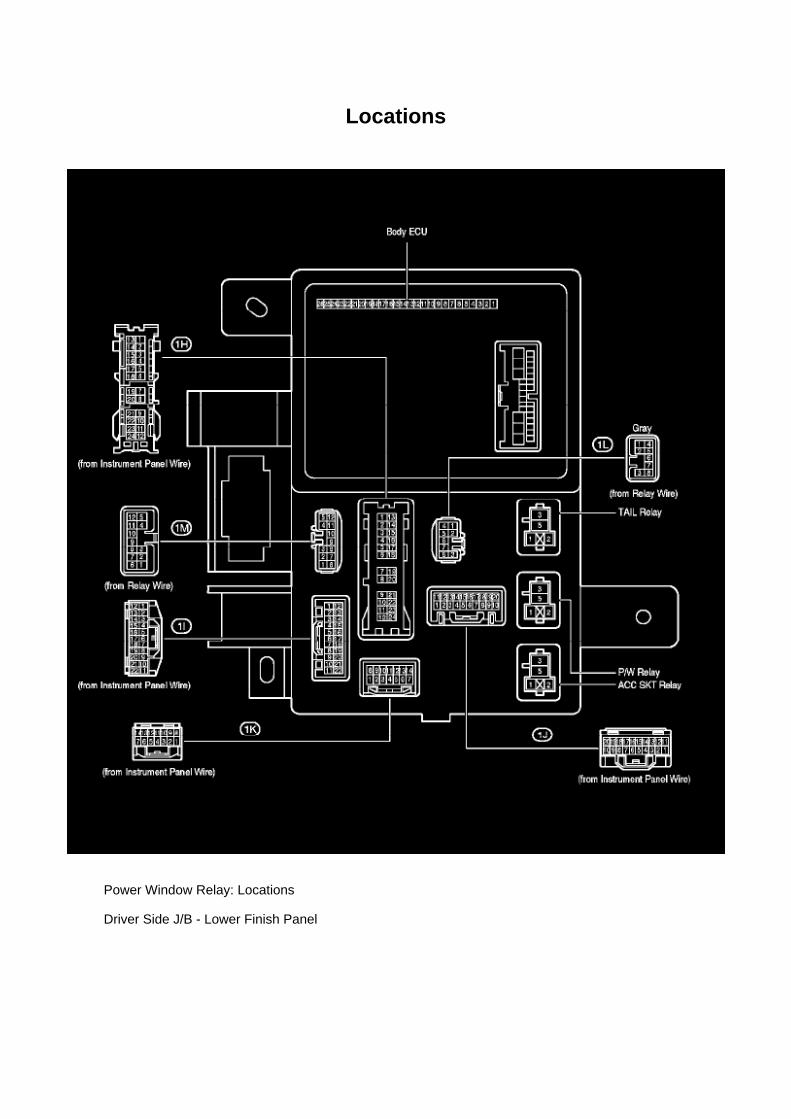
Locations
Power Window Relay: Locations
Driver Side J/B - Lower Finish Panel

Page 2950

Clutch Master Cylinder: Service and Repair
CLUTCH MASTER CYLINDER ASSY
COMPONENTS
REPLACEMENT
1. DRAIN CLUTCH FLUID 2. DISCONNECT CLUTCH RESERVOIR TUBE

Page 1117

3. Checking the contact pressure of the terminal: Prepare a spare male terminal. Insert it into afemale terminal, and check for good tension when

inserting and after full engagement.
d. REPAIR METHOD OF CONNECTOR TERMINAL
1. If there is any dirt on the terminal, clean the contact point using an air gun or shop rag. Neverpolish the contact point using sandpaper as the
platings may come off.
2. If there is abnormal contact pressure, replace the female terminal. If the male terminal isgold-plated (gold color), use a gold-plated female
terminal; if it is silver-plated (silver color), use a silver-plated female terminal.
3. Damaged, deformed, or corroded terminals should be replaced. If the terminal will not lock intothe housing, the housing may have to be
replaced.
e. HANDLING OF WIRE HARNESS
1. If removing a wire harness, check the wiring and clamping before proceeding so that it can berestored in the same way. 2. Never twist, pull or slacken the wire harness more than necessary. 3.Never make the wire harness come into contact with a high temperature part, or rotating, moving,vibrating or sharp-edged parts. Avoid panel
edges, screw tips and similar sharp items.
4. When installing parts, never pinch the wire harness. 5. Never cut or break the cover of the wireharness. If it is cut or broken, replace it or securely repair it with vinyl tape.
Check Open Circuit
CHECK OPEN CIRCUIT

Page 1338
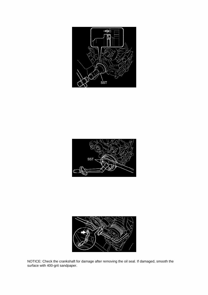
NOTICE: Check the crankshaft for damage after removing the oil seal. If damaged, smooth thesurface with 400-grit sandpaper.

7. INSTALL TIMING GEAR CASE OR TIMING CHAIN CASE OIL SEAL
a. Apply a light coat of MP grease to the lip of a new oil seal.
NOTICE: Keep the lip free of foreign objects.
b. Using SST, uniformly tap a new oil seal in until its surface is flush with the timing chain coveredge.
SST 09223-50010
NOTICE: -
Do not tap the oil seal in at an angle.
- Wipe any extra grease off the crankshaft.
8. INSTALL CRANKSHAFT PULLEY
a. Align the set key of the crankshaft with the key groove of the pulley, and slide on the pulley. b.Provisionally install a new crankshaft pulley bolt onto the crankshaft. c. Using SST, hold thecrankshaft pulley and tighten the crankshaft pulley bolt.
SST 09213-54015 (91651-60855), 09330-00021 Torque: 260 Nm (2,651 kgf-cm, 192 ft. lbs.)
NOTICE: Do not reuse the pulley bolt.
d. Install the bracket with the bolt. (w/ AIR CONDITIONING)
Torque: 7.5 Nm (76 kgf-cm, 66 inch lbs.)
9. INSTALL FAN SHROUD
10. INSTALL RADIATOR SUPPORT TO FRAME SEAL LH 11. ADD ENGINE COOLANT

Page 1456
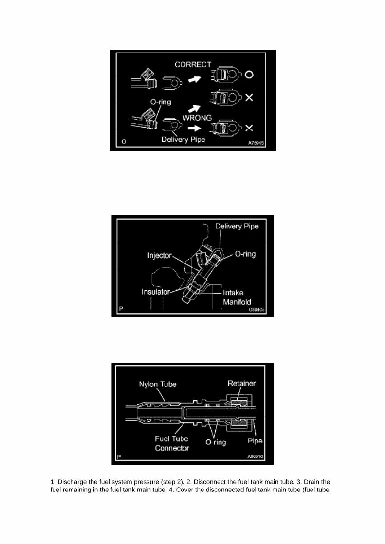
1. Discharge the fuel system pressure (step 2). 2. Disconnect the fuel tank main tube. 3. Drain thefuel remaining in the fuel tank main tube. 4. Cover the disconnected fuel tank main tube (fuel tube

joint and fuel tube connector) with a vinyl bag to prevent damage and the intrusion
of foreign objects.
b. Take the following precautions when installing the fuel injector.
1. Do not reuse the O-ring. 2. Do not damage a new O-ring when installing it onto the fuel injector.3. Before installing a new O-ring, apply gasoline or spindle oil.
NOTE: Do not use engine oil, gear oil or brake oil.
4. Install the fuel injector into the fuel delivery pipe and cylinder head as illustrated.
HINT: Apply gasoline or spindle oil to the contact surface of the fuel delivery pipe and fuel injectorbefore installing the fuel injector.
c. Take the following precautions when disconnecting the fuel tube connector.
HINT: The structure of the fuel tube connector is as shown in the illustration.
1. Check the fuel tube connector and pipe for dirt and mud before removing the fuel tubeconnector.
If dirty, wipe it with a shop rag.

Page 2355

Page 725
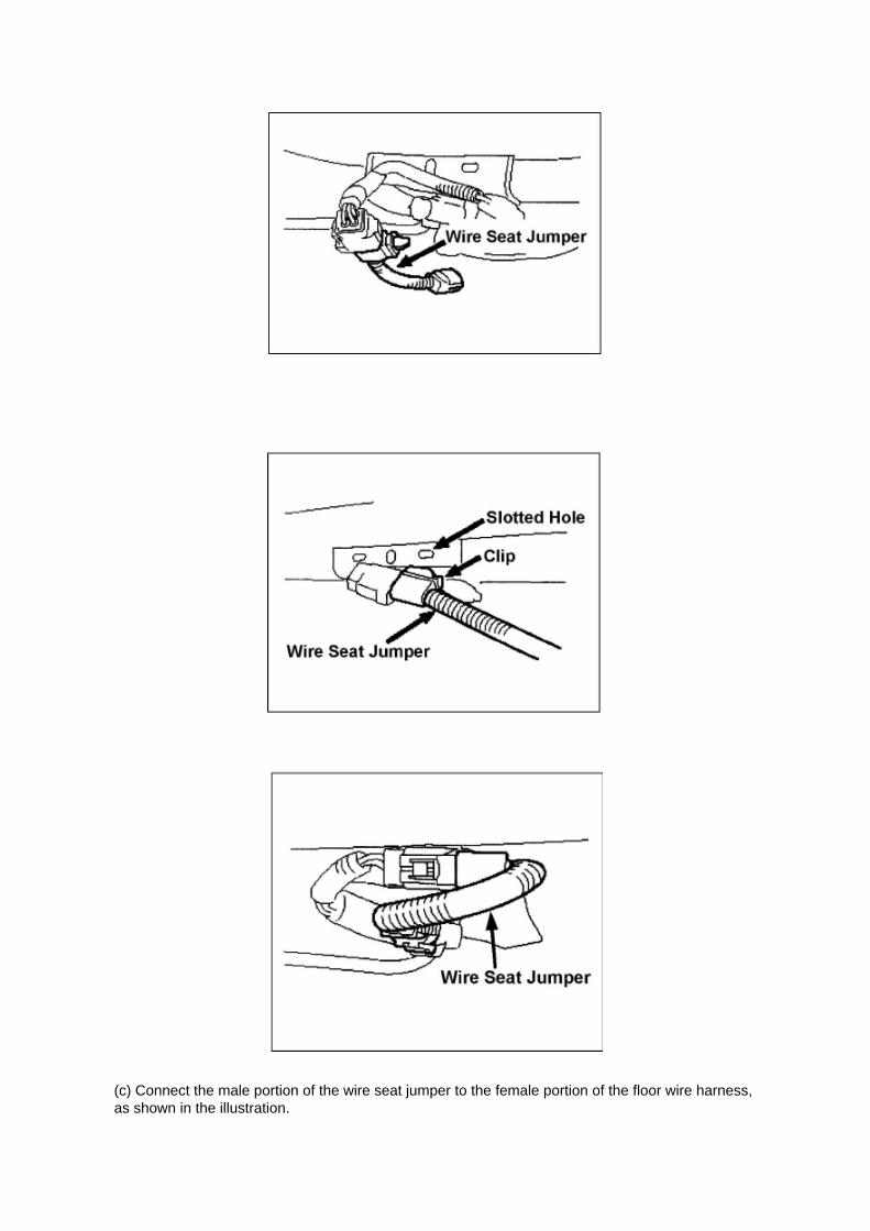
(c) Connect the male portion of the wire seat jumper to the female portion of the floor wire harness,as shown in the illustration.

(d) Push and pull the connectors to confirm that they are locked in place.
(e) Insert the wire seat jumper connector clip into the slotted hole on the seat bracket.
(f) Connect the female portion of the wire seat jumper to the male portion of the floor wire harness,as shown in the illustration.
(g) Push and pull the connectors to confirm that they are locked in place.
(h) Confirm that the wire seat jumper is correctly routed.

Page 3334

Step 1 - 2

Step 3
INSPECTION PROCEDURE
HINT: Start the inspection from step 1 when using a hand-held tester and start from step 2 whennot using a handheld tester.

Specifications

Timing Cover: Specifications
Apply adhesive to the head straight screw plug.
Adhesive: Part No.08833-00070, THREE BOND 1324 or equivalent
Using a 10 mm socket hexagon wrench, install the head straight screw plug.
Torque ............................................................................................................................................................................. 17 Nm (170 kgf-cm, 12 ft. lbs.)
Install 4 new O-rings onto the timing chain cover as shown in the illustration.
Apply continuous beads of seal packing to the places shown in the illustration. Seal packing: PartNo.08826-00080 or equivalent
Seal width

Page 2114
5. Write the VIN in accordance with the Diagnostic Tester display.
6. Compare the VIN displayed on the Diagnostic Tester with the VIN on the instrument panel. Ifthese are not the same, write the VIN again after turning the ignition switch OFF.

VIN Read Procedure
1. Connect the Diagnostic Tester to DLC3.
2. Turn the ignition switch and Diagnostic Tester switch ON.
3. All vehicles except Prius and Highlander HV:
Select from the Diagnostic Tester menus: DIAGNOSIS, ENHANCED OBDII, VIN, and VIN READ.
Prius and Highlander HV vehicles:
Select from the Diagnostic Tester menus: DIAGNOSIS, OBD/MOBD, HV ECU, VIN, and VINREAD.
4. Check the VIN displayed on the Diagnostic Tester.
HINT: For further explanations, refer to the Technical Information System (TIS), appropriate modelrepair manual: Diagnostics: SF1 System: Registration.

Page 621
4. REMOVE SEAT POSITION AIR BAG SENSOR
a. Disconnect the connector from the seat position airbag sensor. b. Using a torx(R) socket wrench(T30), remove the torx(R) screw and the seat position airbag sensor.
5. INSTALL SEAT POSITION AIR BAG SENSOR
a. Check that the ignition switch is OFF. b. Check that the cable is disconnected from the batterynegative (-) terminal.
CAUTION: After disconnecting the cable from the terminal, wait for at least 90 seconds beforestarting the operation.
NOTE: -
Installation of the connector is done with the sensor assembly installed. Make sure the sensorassembly is installed to the specified torque.
- If the sensor assembly has been dropped, or there are cracks, dents or other defects in the case,bracket or connector, replace the sensor assembly with a new one.
- When installing the sensor assembly, make sure that the SRS wiring does not interfere with anyother parts and is not pinched between other parts.
c. Using a torx(R) socket wrench (T30), tighten the torx(R) screw to install the seat position airbagsensor.
Torque: 8.0 N.m (82 kgf.cm, 71 in.lbf)
d. Make sure that the clearance between the seat position airbag sensor and the seat rail isbetween 0.6mm (0.023 in.) and 2 mm (0.079 in.).
Check that there is no slack in the installation parts of the seat position airbag sensor.
e. Connect the connector to the seat position airbag sensor.
6. INSTALL SEAT ASSEMBLY 7. CONNECT CABLE TO NEGATIVE BATTERY TERMINAL

Torque: 3.9 N.m (40 kgf.cm, 35 in.lbf)
8. INSPECT SRS WARNING LIGHT

Page 1588
Step 1 - 3

Page 647
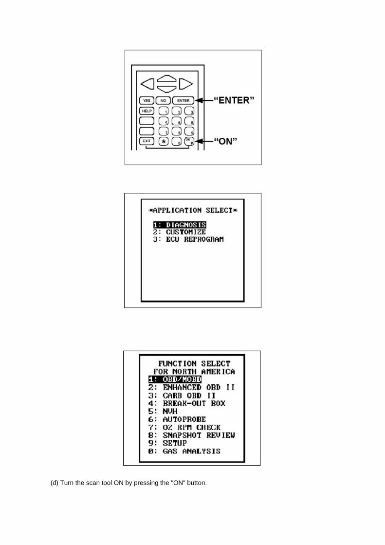
(d) Turn the scan tool ON by pressing the "ON" button.

(e) Press "ENTER" after the start up screen appears.
(e) Select "1: DIAGNOSIS from the "APPLICATION SELECT menu.
(f) Select "1: OBD/MOBD" from the "FUNCTION SELECT FOR NORTH AMERICA" menu.

Page 2104
load while reprogramming.
^ Confirm the hood is open and ensure under hood temperature does NOT exceed 158°F (70°C).
^ Confirm cable connections between the vehicle and Techstream are secure.
^ Do NOT disconnect or turn off Techstream or vehicle ignition during reprogramming.
^ Set parking brake.
^ Complete ALL flash calibration updates provided for each ECU.
^ If the battery's state of charge or capacity are in question, test with SST. No. 00002-8150-KIT"Digital Battery Analyze," and follow TSB No. PG001-06, "Battery Maintenance for In-Stock

Vehicles & Pre-Delivery" or the appropriate "Maintenance for HV & Auxiliary Batteries" servicebulletin.
^ The GR8 Battery Diagnostic Station MUST be used in Power Supply Mode to maintain batteryvoltage at 13.5 volts while flash reprogramming the vehicle. For details on how to use the GR8Battery Diagnostic Station, refer to the GR8 Instruction Manual located on TIS, Diagnostics - Tools& Equipment - Battery Diagnostics.
3C. Click Next to start the calibration update process.
D. When using TIS Techstream select Techstream VIM as the desired programming device. Thenclick Next.

Page 1305

Combination Meter

Locations
Electronic Brake Control Module: Locations
Engine Compartment

Page 2747
Required Tools & Equipment
NOTE
^ Additional SSTs may be ordered by calling 1-800-933-8335.
^ The GR8 Battery Diagnostic Station (P/N 00002-MCGR8) supersedes the Automatic TrickleCharger (P/N 00002-YA122-01) and Fast Battery
Chargers (Associated P/N ASE6OO3 and Christie P/N CAPPDQ). P/N 00002-YA122-01,ASE6003, and CAPPDQ are now obsolete.
Repair Procedure
1. Test drive the vehicle and confirm there is a vibration or shudder under light throttle acceleration.
2. Use TIS Techstream to take a snapshot when shudder vibration is occurring to confirm that itoccurs when in 3rd or 4th gear while lightly
accelerating.
Configure snapshot as follows:
30 Second Duration
Trigger Point at Midpoint (50%)
NOTE

Refer to the University of Toyota online training class P901C "Techstream InDepth" for informationabout taking snapshots and graphing snapshots on Techstream.

Page 1827
Coolant Temperature Sensor/Switch (For Computer): Testing and Inspection
INSPECT E.F.I. ENGINE COOLANT TEMPERATURE SENSOR
a. Check the resistance.
1. Using an ohmmeter, measure the resistance between the terminals.
NOTE: If checking the engine coolant temperature sensor in water, be careful not to allow water tointrude into the terminals. After checking, wipe the water off the engine coolant temperature sensor.

If the result is not as specified, replace the engine coolant temperature sensor.

Page 1973
Step 7 - 8

Page 1182

(2) Install the 6 bolts through the axle hub. (3) Install the washer plate, as shown in the illustration,through the hub bolt, and install the hub bolt by tightening the hub nut.

21. INSTALL REAR AXLE HUB & BEARING ASSY LH
a. Position the backing plate on the rear axle bearing, and install the 4 parking brake plates ontothe rear axle housing bolts using 2 socket
wrenches and a press.
22. INSTALL REAR AXLE SHAFT LH WASHER
a. Install the rear axle shaft plate washer onto the rear axle shaft.
23. INSTALL REAR AXLE BEARING RETAINER INNER LH
a. Install a new rear axle bearing retainer inner onto the rear axle shaft.
24. INSTALL REAR AXLE SHAFT LH
a. Using SST and a press, install the rear axle shaft onto the rear axle bearing.
SST 09521-25011
25. INSTALL REAR AXLE SHAFT LH SNAP RING
a. Using a snap ring expander, install a new snap ring.

M/T - Clutch Pedal Squeaking Noise
Technical Service Bulletin # TC004-06 Date: 060614
M/T - Clutch Pedal Squeaking Noise
TRANSMISSION & CLUTCH TC004-06
June 14, 2006
Title: CLUTCH PEDAL SQUEAK NOISE
Models: '05 - '06 Tacoma
Introduction
Some customers may complain about a "squeak" or "creak" noise when depressing or releasingthe clutch pedal. The clutch master cylinder clevis assembly has been improved to eliminate thiscondition.
Applicable Vehicles: ^
2005 - 2006 model year Tacoma vehicles equipped with manual transmission and producedBEFORE the Production Change Effective VIN shown below.
Production Change Information

Parts Information
Required Tools & Material
Warranty Information
Applicable Warranty:
This repair is covered under the Toyota Comprehensive Warranty. This warranty is in effect for 36months or 36,000 miles, whichever occurs first, from the vehicle's in-service date.
* Warranty application is limited to correction of a problem based upon a customer's specificcomplaint.

Page 728

(g) Select "NEW VEHICLE" from the "VEHICLE SELECT" menu.

(h) Go through the options and select the following information.
^ MODEL YEAR-2005
^ MODEL SELECTION - Tacoma
^ ENGINE TYPE - 2TR-FE (4-cylinder)
(i) Once these options are selected, a vehicle confirmation screen (shown in the illustration) will bedisplayed.
(j) Review the vehicle selection.
(k) Press "YES to confirm the selection.

Page 3327

b. Turn the ignition switch on. Follow the on-screen directions on the hand-held tester to display theDATA LIST and select areas which should be
monitored for momentary interruptions.
HINT: A momentary interruption (open circuit) cannot be detected for 3 seconds after the ignitionswitch is turned on (initial check).
HINT: -
If the hand-held tester status remains open, check the continuity between the ECU and thesensors, or between ECUs.
- The OPEN display on the hand-held tester remains on for 1 second after the harness signalchanges from momentary interruption (open circuit) to normal condition.
c. While observing the screen, gently jiggle the connector or wire harness between the ECU andsensors, or between ECUs.
OK: OPEN-screen display does not change.

Page 2860

8. INSTALL TRANSMISSION CONTROL CABLE ASSY

a. Install the transmission control cable assy with the nut.
Torque: 14 Nm (143 kgf-cm, 10 ft. lbs.)
b. Install the transmission control cable bracket and lock plate.
c. Connect the transmission control cable with the nut to the body.
Torque: 5.5 Nm (56 kgf-cm, 49 inch lbs.)
d. Connect the transmission control cable with the 2 nuts to the body.
Torque: 5.5 Nm (56 kgf-cm, 49 inch lbs.)
e. Connect the transmission control cable with the lock plate to the floor shift assy. f.
Install the transmission control cable onto the floor shift assy.
9. INSTALL VOLTAGE INVERTER ASSY (W/ VOLTAGE INVERTER)
10. INSTALL CONSOLE BOX FRONT 11. INSTALL INSTRUMENT PANEL CUP HOLDER TRAY12. INSTALL CONSOLE BOX ASSY REAR 13. INSTALL CONSOLE UPPER REAR PANELSUB-ASSY 14. INSTALL SHIFT LEVER KNOB SUB-ASSY 15. ADJUST SHIFT LEVER POSITION16. INSPECT SHIFT LEVER POSITION

Page 1984
MODE DESCRIPTION
Wiring Diagram

Page 3104
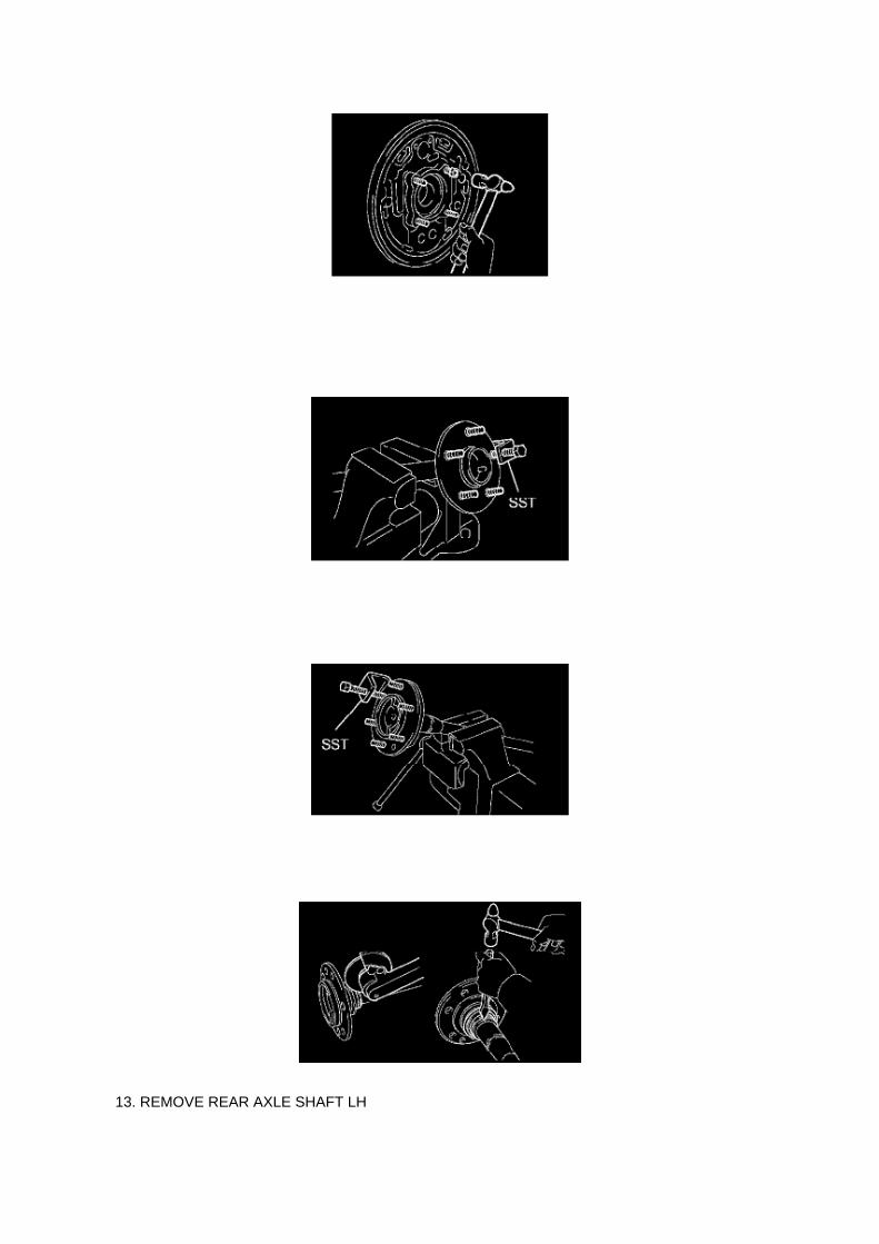
13. REMOVE REAR AXLE SHAFT LH

a. Using SST and press, remove the rear axle shaft.
SST 09521-25011, 09521-25021
14. REMOVE REAR AXLE BEARING RETAINER INNER LH
a. Remove the rear axle bearing retainer inner from the rear axle bearing.
15. REMOVE REAR AXLE SHAFT LH WASHER
a. Remove the rear axle shaft washer from the rear axle bearing.
16. REMOVE REAR AXLE HUB & BEARING ASSY LH
a. Attach the 4 nuts to the rear axle housing bolts. b. Using a hammer, remove the 4 rear axlehousing bolts and rear axle bearing.
NOTICE: Do not reuse the nuts previously removed from the vehicle.
17. REMOVE REAR AXLE HUB BOLT
a. 2WD: Using SST, remove the 5 hub bolts.
SST 09650-17011
b. Remove the deflector and deflector gasket from the rear axle shaft.
c. 4WD and PRE RUNNER: Using SST, remove the 6 hub bolts.
SST 09650-17011
d. Remove the deflector and deflector gasket from the rear axle shaft.
18. REMOVE REAR AXLE BEARING OIL SEAL

Locations
Crankshaft Position Sensor: Locations

A/C - Ge

Page 2643
Camshaft Position Sensor: Testing and Inspection
INSPECT CAMSHAFT POSITION SENSOR
Check the resistance.
Using an ohmmeter, measure the resistance between the terminals.
HINT: Cold and Hot mean the temperature of the coils themselves. Cold is from -10 to 50°C (14 to122°F) and Hot is from 50 to 100°C (122 to 212° F).
If the result is not as specified, replace the camshaft position sensor.

A/T - World Standard Automatic Transmission Fluid
Fluid - A/T: Technical Service Bulletins A/T - World Standard Automatic Transmission Fluid
T-SB-0006-11
January 6, 2011
World Standard Automatic Transmission Fluid
Service Category Drivetrain
Section Automatic Transmission/Transaxle
Market USA

Applicability
TSB SUPERSESSION NOTICE
The information contained in this TSB supersedes TSB No. TC010-07.
Applicability has been updated to include 2009 - 2011 model year Toyota vehicles.
TSB No. TC010-07 is Obsolete and any printed versions should be discarded. Be sure to reviewthe entire content of this service bulletin before proceeding.
Introduction
World Standard (WS) Automatic Transmission Fluid (ATF) was introduced to reduce maintenancecosts and increase the mileage between scheduled maintenance checks. Here are some importanttips when working with ATF-WS in Toyota vehicles requiring its use.
Warranty Information
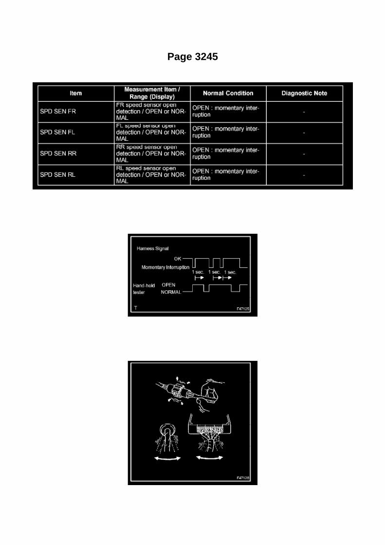
Page 3245

b. Turn the ignition switch on. Follow the on-screen directions on the hand-held tester to display theDATA LIST and select areas which should be
monitored for momentary interruptions.
HINT: A momentary interruption (open circuit) cannot be detected for 3 seconds after the ignitionswitch is turned on (initial check).
HINT: -
If the hand-held tester status remains open, check the continuity between the ECU and thesensors, or between ECUs.
- The OPEN display on the hand-held tester remains on for 1 second after the harness signalchanges from momentary interruption (open circuit) to normal condition.
c. While observing the screen, gently jiggle the connector or wire harness between the ECU andsensors, or between ECUs.
OK: OPEN-screen display does not change.

Recall - Floor Mat/Accelerator Pedal Interferance
Technical Service Bulletin # SSC90L Date: 091001

Specifications

Connecting Rod: Specifications

Rod Bearing Cap ................................................................................................................................................................. 25 Nm (250 kgf-cm, 18 ft. lbs.) Connecting Rod Thrust Clearance
Standard thrust clearance..................................................................................................................................... 0.150-0.350mm (0.0059-0.0138 inch) Maximum thrust clearance..............................................................................................................................................................0.40 mm (0.016 inch)
Connecting Rod Maximum bend................................................................................................................ 0.03 mm (0.0012 inch) per100 mm (3.94 inch) Connecting Rod Maximum twist................................................................................................................ 0.15 mm (0.0059 inch) per100 mm (3.94 inch) Connecting Rod Bolt
Standard diameter............................................................................................................................................................7.2-7.3 mm (0.283-0.287 inch) Minimum diameter ............................................................................................................................................................................ 7.0 mm (0.276 inch)

Page 1831
SFI System

Page 3074

Fluid - Differential: Fluid Type Specifications

OIL TYPE w/o Limited Slip :.....................................................................................................................................................Hypoid gear oil API GL-5 OIL TYPE w/ Limited Slip :............................................................................................................................... Hypoid gear oil forlimited slip API GL-5
RECOMMENDED OIL VISCOSITY: Front: ............................................................................................................................................................................................................... SAE 75W-90 Rear:Above -18°C (0°F): .................................................................................................................................................................................................. SAE 90 Below -18°C (0°F): ............................................................................................................................................................................. SAE 80W or80W-90

Page 69

He - Wi

Page 1740

a. Apply a light coat of engine oil to the O-ring of the crankshaft position sensor.

b. Install the camshaft position sensor with the bolt.
Torque: 8.5 N.m (87 kgf.cm, 75 in.lbf)
NOTE: Make sure that the O-ring is not cracked or jammed when installing.
c. Connect the crankshaft position sensor connector and the 2 wire harness clamps.
8. INSTALL IDLE PULLEY ASSEMBLY W/BRACKET (W/ AIR CONDITIONING)

Page 562
Camshaft Position Sensor: Testing and Inspection
INSPECT CAMSHAFT POSITION SENSOR
Check the resistance.
Using an ohmmeter, measure the resistance between the terminals.
HINT: Cold and Hot mean the temperature of the coils themselves. Cold is from -10 to 50°C (14 to122°F) and Hot is from 50 to 100°C (122 to 212° F).
If the result is not as specified, replace the camshaft position sensor.

Page 3353

3. A/T: Check that the shift lever is in the P position and apply the parking brake.
M/T: Check that the shift lever is in neutral and apply the parking brake.
NOTE: DTC C1210/36 and C1336/39 will be recorded if the shift lever is not in the P position.
4. Connect the hand-held tester to the DLC3. 5. Turn the ignition switch to the ON position.
6. Switch the ECU to test mode using the hand-held tester. Select the menu items: DIAGNOSTIC /OBD / MOBD / select vehicle / ABS /
VSC / TEST MODE.
7. Keep the vehicle stationary on a level surface for 2 seconds or more.
8. Check that the VSC TRAC warning light blinks as shown in the illustration.
NOTE: The VSC TRAC warning light (and VSC OFF indicator light [4WD, w/ rear diff. lock]) stayON when obtaining the zero point.

Page 1596
Oscilloscope Waveforms

Page 1856
load while reprogramming.
^ Confirm the hood is open and ensure under hood temperature does NOT exceed 158°F (70°C).
^ Confirm cable connections between the vehicle and Techstream are secure.
^ Do NOT disconnect or turn off Techstream or vehicle ignition during reprogramming.
^ Set parking brake.
^ Complete ALL flash calibration updates provided for each ECU.
^ If the battery's state of charge or capacity are in question, test with SST. No. 00002-8150-KIT"Digital Battery Analyze," and follow TSB No. PG001-06, "Battery Maintenance for In-Stock

Vehicles & Pre-Delivery" or the appropriate "Maintenance for HV & Auxiliary Batteries" servicebulletin.
^ The GR8 Battery Diagnostic Station MUST be used in Power Supply Mode to maintain batteryvoltage at 13.5 volts while flash reprogramming the vehicle. For details on how to use the GR8Battery Diagnostic Station, refer to the GR8 Instruction Manual located on TIS, Diagnostics - Tools& Equipment - Battery Diagnostics.
3C. Click Next to start the calibration update process.
D. When using TIS Techstream select Techstream VIM as the desired programming device. Thenclick Next.

Page 782

Repair Procedure

1. Disconnect the cable from the negative (-) battery terminal for MORE THAN two (2) seconds.
2. Reconnect the cable to the negative (-) battery terminal.
3. Perform the applicable zero point calibration of the yaw rate sensor and/or the steering anglesensor.
HINT Refer to the applicable TSB or Repair Manual for the zero point calibration procedure.
4. Re-initialize all applicable systems available on the vehicle (power window sunroof power liftdoor etc.).

Page 790

Repair Procedure

1. Disconnect the cable from the negative (-) battery terminal for MORE THAN two (2) seconds.
2. Reconnect the cable to the negative (-) battery terminal.
3. Perform the applicable zero point calibration of the yaw rate sensor and/or the steering anglesensor.
HINT Refer to the applicable TSB or Repair Manual for the zero point calibration procedure.
4. Re-initialize all applicable systems available on the vehicle (power window sunroof power liftdoor etc.).

Page 1073

[B] : For Waterproof Type Connector

HINT: Terminal retainer color is different according to connector body.
Example:
Terminal Retainer : Connector Body
Black or White : Gray
Black or White : Dark Gray
Gray or White : Black
"Case 1" Type where terminal retainer is pulled up to the temporary lock position (Pull Type).
Insert the special tool into the terminal retainer access hole (A Mark) and pull the terminal retainerup to the temporary lock position.
HINT: The needle insertion position varies according to the connector's shape (Number ofterminals etc.), so check the position before inserting it.
"Case 2" Type which cannot be pulled as far as Power Lock insert the tool straight into the accesshole of terminal retainer as shown.

Page 2102

NOTE

Only Toyota Certified Technicians and above may access calibration files.
2. Connect the GR8 Battery Diagnostic Station.
A. Connect the GR8 Battery Diagnostic Station to the vehicle and turn it ON.
B. Select Power Supply Mode by following the screen flow below.
NOTICE
^ ECU damage may occur if the correct battery charger and mode setting are NOT used.

Page 719
Information
TECHNICAL INSTRUCTIONS

FOR
SPECIAL SERVICE CAMPAIGN 50I
2005 MODEL YEAR TACOMA REGULAR-CAB
FRONT BENCH SEAT WIRE SEAT JUMPER

Locations

Vehicle Speed Sensor: Locations

He - Wi

Page 3375
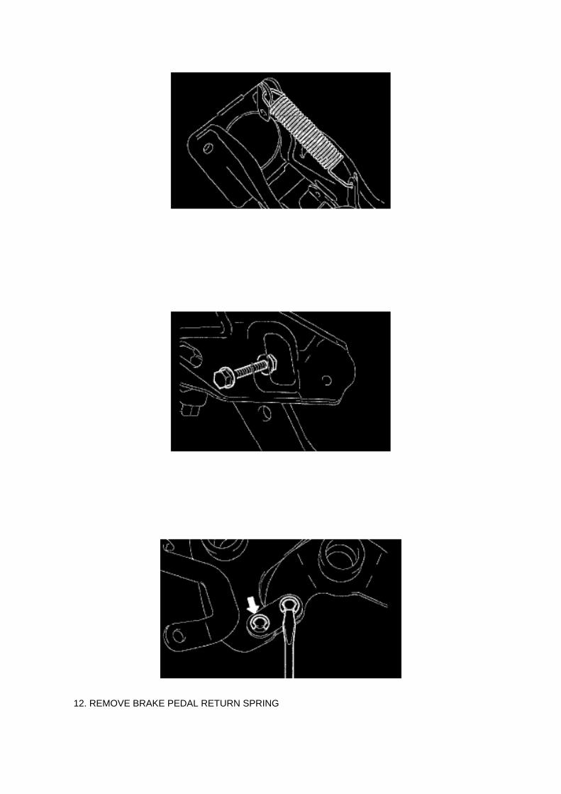
12. REMOVE BRAKE PEDAL RETURN SPRING

a. Remove the return spring from the brake pedal support and brake pedal.
13. REMOVE STOP LAMP SWITCH ASSEMBLY
a. Turn the stop lamp switch counterclockwise, and remove the stop lamp switch. b. Remove thestop lamp switch mounting adjuster from the brake pedal support.
14. REMOVE BRAKE PEDAL SUB-ASSEMBLY
a. Remove the bolt and nut, then remove the brake pedal from the brake pedal support. b. Removethe 4 brake pedal bushes from the brake pedal and brake pedal lever. c. Remove the 2 collars fromthe brake pedal and brake pedal lever.
15. REMOVE BRAKE PEDAL LEVER
a. Using a screwdriver, remove the 2 E-rings from the brake pedal link pin. b. Remove the 2 brakepedal link pins, 2 brake pedal shaft collars and 2 brake pedal links. c. Remove the brake pedallever from the brake pedal.
16. REMOVE BRAKE PEDAL PAD
a. Remove the brake pedal pad from the brake pedal.
17. INSTALL BRAKE PEDAL PAD
a. Install the brake pedal pad onto the brake pedal.
18. INSTALL BRAKE PEDAL LEVER
a. Apply lithium soap base glycol grease to the 2 brake pedal link pins, 2 pedal shaft collars and 2brake pedal links. b. Install the brake pedal lever with the 2 brake pedal link pins, 2 brake pedalshaft collars and 2 brake pedal links onto the brake pedal. c. Install 2 new E-rings onto each brakepedal link pin.
19. INSTALL BRAKE PEDAL SUB-ASSEMBLY
a. Apply lithium soap base glycol grease to the 2 collars and 4 brake pedal bushes. b. Install the 2collars and 4 brake pedal bushes onto the brake pedal and brake pedal lever.

Page 361
NOTE: DTC C1210/36 and C1336/39 will be recorded if the shift lever is not in the P position.
4. Using SST, connect terminals TS and CG of the DLC3.
SST 09843-18040
5. Turn the ignition switch to the ON position. 6. Keep the vehicle stationary on a level surface for 2seconds or more.

7. Check that the VSC TRAC warning light blinks as shown in the illustration.
NOTE: The VSC TRAC warning light (and VSC OFF indicator light [4WD, w/ rear diff. lock]) stayON when obtaining the zero point.
HINT: -
If the VSC warning light does not blink, perform the zero point calibration again.
- The zero point calibration is performed only once after the system enters test mode.
- Calibration cannot be performed again until the stored data is cleared once.

Page 1457

2. Pinch the retainer as illustrated, then pull the fuel tube connector out of the pipe.

3. If the fuel tube connector and pipe are stuck, pinch the pipe and push and pull the fuel tubeconnector to release it.
NOTE: Never use any tools.
4. After disconnecting the fuel tube, check the sealing surface of the pipe for dirt and mud.
If dirty, wipe it with a shop rag.
5. Cover the disconnected fuel tube connector and pipe with a vinyl bag to prevent damage and theintrusion of foreign objects.
d. Take the following precautions when installing the fuel tube connector.
1. Align the fuel tube connector with the pipe, then push in the fuel tube connector until the retainermakes a "click" sound.

Page 1987
Step 1 - 2

Page 951
Refrigerant Line

Page 1574

M. Turn ignition OFF for a minimum of 10 seconds. Then click Next.

N. Turn ignition to the ON position. Then click Next.
0. Confirm all calibrations were updated as specified in the service bulletin. Then click Finish.

Page 2855
21. INSTALL FLOOR SHIFT GEAR SHIFTING ROD SUB-ASSY
a. ROD TYPE:
(1) Install the floor shift gear shifting rod with nut.
Torque: 5.5 Nm (56 kgf-cm, 49 inch lbs.)
22. INSTALL CONSOLE BOX FRONT 23. INSTALL INSTRUMENT PANEL CUP HOLDER TRAY24. INSTALL CONSOLE BOX ASSY REAR 25. INSTALL CONSOLE UPPER REAR PANELSUB-ASSY 26. INSTALL SHIFT LEVER KNOB SUB-ASSY 27. ADJUST SHIFT LEVER POSITION28. INSPECT SHIFT LEVER POSITION

Page 3333
Traction Control Indicator Lamp: Testing and Inspection SLIP Indicator Light Circuit (Remains On)
SLIP INDICATOR LIGHT CIRCUIT (REMAINS ON)
CIRCUIT DESCRIPTION
- The SLIP indicator blinks when any of the TRAC, VSC and AUTO LSD operate.
- When the system fails, the SLIP indicator light illuminates to warn the driver.
Wiring Diagram

Page 982

Fluid - M/T: Fluid Type Specifications

Transmission Fluid
Grade ............................................................................................................................................................................................................... GL-4 or GL-5 Viscosity ........................................................................................................................................................................................................... SAE75W-90

Page 2220
b. Connect the wire harness clamp. c. Connect the air fuel ratio sensor connector.
4. CONNECT CABLE TO NEGATIVE BATTERY TERMINAL
Torque: 3.9 N.m (40 Kgf.cm, 35 in.lbf)

Page 1292

Engine Oil: Fluid Type Specifications

GRADE .................................................................................................................................... API SLEnergy-Conserving or ILSAC multigrade engine oil VISCOSITY ...................................................................................................................................................................................................... SAE5W-30
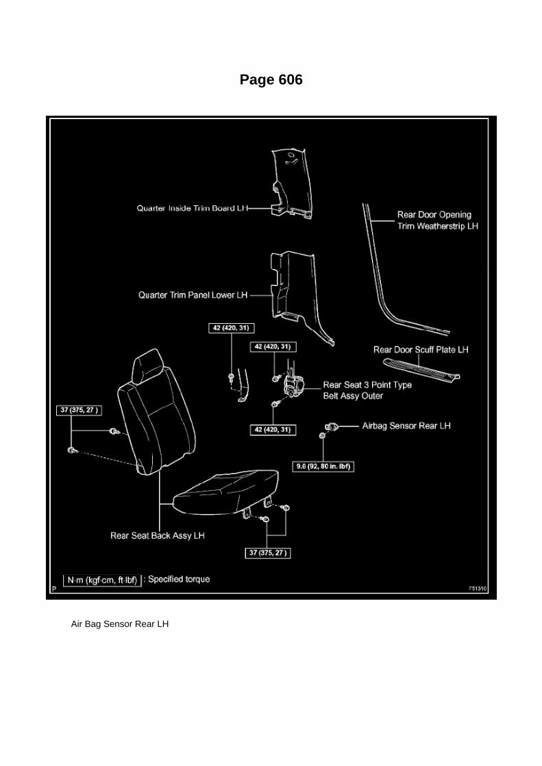
Page 606
Air Bag Sensor Rear LH

Capacity Specifications

Fluid - M/T: Capacity Specifications

Manual Transaxle M/T Oil Capacity 2WD:....................................................................................................................................................... 2.7US qt. (2.6 L, 2.3 Imp. qt.)

Page 399

He - Wi

Page 454
13. INSTALL HEADLAMP DIMMER SWITCH ASSEMBLY
a. Engage the 2 claws and install the headlamp dimmer switch assembly as shown in theillustration.
b. Install the headlamp dimmer switch assembly with the clamp. c. Connect the connector.
14. INSTALL WINDSHIELD WIPER SWITCH ASSEMBLY 15. INSTALL SPIRAL CABLESUB-ASSEMBLY 16. INSTALL STEERING COLUMN COVER UPR 17. INSTALL STEERINGCOLUMN COVER LWR 18. CENTER SPIRAL CABLE 19. INSTALL STEERING WHEELASSEMBLY 20. INSPECT STEERING WHEEL CENTER POINT 21. INSPECT HORN BUTTONASSEMBLY 22. INSTALL HORN BUTTON ASSEMBLY 23. CONNECT CABLE TO NEGATIVEBATTERY TERMINAL
Torque: 3.9 N.m (40 kgf.cm, 35 in.lbf)
24. INSPECT SRS WARNING LIGHT 25. INSTALL STEERING WHEEL COVER LOWER NO.326. INSTALL STEERING WHEEL COVER LOWER NO.2

Page 25

(Sample ) Supplemental Restraint System check sheet
Symptom Confirmation and Diagnostic Trouble Code
SYMPTOM CONFIRMATION AND DIAGNOSTIC TROUBLE CODE
HINT:
The diagnostic system in the TOYOTA TACOMA has various functions. -
The first function is the Diagnostic Trouble Code (DTC) check. A DTC is a code stored in the ECUmemory whenever a malfunction in the signal circuits to the ECU occurs. In a DTC check, aprevious malfunction's DTC can be checked by a technician during troubleshooting.
- Another function is the Input Signal Check, which checks if the signals from various switches aresent to the ECU correctly. By using these functions, the problem areas can be narrowed down andtroubleshooting is more effective. Diagnostic functions are incorporated in the above systems in theTOYOTA TACOMA:
- In the DTC check, it is very important to determine whether the problem indicated by the DTC is:1) still occurring, or 2) occurred in the past but has since returned to normal. In addition, the DTCshould be compared to the problem symptom to see if they are related. For this reason, DTCsshould be checked before and after confirmation of symptoms (i.e., whether or not problemsymptoms exist) to determine current system conditions, as shown in the flowchart. Never skip theDTC check. Failing to check DTCs may, depending on the case, result in unnecessarytroubleshooting for systems operating

Page 1873
CAN Communication System

Page 718

Fuel/Emissions - MIL ON/DTC's P0456/P0445 and P0441
Set
Fuel Pump Pickup Filter: All Technical Service Bulletins Fuel/Emissions - MIL ON/DTC'sP0456/P0445 and P0441 Set
ENGINE EG037-05 REVISED
Title: M.I.L. "ON" DTC P0456 OR P0455, AND P0441
Models: '05 Tacoma
September 1, 2005
TSB REVISION NOTICE:
^ September 16, 2005: The Applicable VDS has been updated in Applicable Vehicles. Previousversions of this TSB should be discarded.
Introduction
Some 2005 model year Tacoma vehicles may exhibit a M.I.L. "ON" condition with one or more ofthe following DTCs: P0456 or P0455, and P0441 (EVAP Emission Control System). Follow thesteps in this bulletin to correct this condition.

Applicable Vehicles
^ 2005 model year Tacoma vehicles (except D-Cab Short Bed), with the following VehicleDescription Section VDS) information shown below.
Warranty Information
Applicable Warranty*: This repair is covered under the Toyota Powertrain Warranty. This warrantyis in effect for 60 months or 60,000 miles, whichever occurs first, from the vehicle's in-service date.
* Warranty application is limited to correction of a problem based upon a customer's specificcomplaint.

Page 1999
Step 5 - 6

Page 2633

d. Disconnect the water bypass hose No.2.

e. Disconnect the ventilation hose No.3.
f. Disconnect the VSV connector.
g. Disengage the engine wire harness clamp. h. Disconnect the compressor magnetic clutchconnector.
(w/ AIR CONDITIONING)
i. Disengage the wire harness clamp.
j. Remove the bolt and harness clamp bracket.

Component Inspection
Variable Valve Timing Actuator: Testing and Inspection Component Inspection
INSPECT CAMSHAFT TIMING OIL CONTROL VALVE ASSEMBLY

a. Check the resistance.
1. Using an ohmmeter, measure the resistance between the terminals.
If the result is not as specified, replace the camshaft timing oil control valve.
b. Check the operation.
1. Apply battery voltage across the terminals, and check that the spool valve operates.
NOTE: Check that the spool valve is not stuck.
HINT: The spool valve may not return if foreign objects are caught in it. This may cause subtlepressure leakage to the advance side, and a DTC may be set.

Page 1572

Then click Start.
I. Do NOT disturb the vehicle during flash reprogramming.
NOTE
^ ECU flash reprogramming may take anywhere from 3 - 30 minutes per calibration file.
^ Reprogramming time will vary depending on model and ECU communication protocol. Vehiclesusing CAN communication protocol will reprogram much faster (2 - 7 minutes).
NOTE
^ If vehicle requires only ONE calibration update, then proceed to step N in this bulletin.
^ If vehicle requires a SECOND calibration update, then continue as follows:
^ For serial communication vehicles, go to step J.
^ For CAN communication vehicles, go to step L.

Page 413
Key Reminder Warning System

Page 1081

Instrument Panel J/B No. 2 - Right Side Of Glove Box

Page 3108

46. INSTALL REAR WHEEL

Torque: 113 Nm (1,152 kgf-cm, 83 ft. lbs.)
47. INSPECT PARKING BRAKE PEDAL TRAVEL (AUTOMATIC TRANSAXLE) 48. INSPECTPARKING BRAKE LEVER TRAVEL (MANUAL TRANSAXLE) 49. ADJUST PARKING BRAKEPEDAL TRAVEL (AUTOMATIC TRANSAXLE) 50. ADJUST PARKING BRAKE LEVER TRAVEL(MANUAL TRANSAXLE) 51. CHECK ABS SENSOR SIGNAL (W/ VSC) 52. CHECK ABSSENSOR SIGNAL (W/O VSC)

Page 2022

Step 8 - 11

Page 1606

Flash reprogramming may be accomplished using one of the following methods: -
Toyota/Lexus factory scantool
- Vetronix Mastertech
- J2534 Compatible Vehicle Interface (Toyota validated and approved)
REPROGRAMMING WITH SCANTOOL
Toyota/Scion/Lexus ECMs can be reprogrammed using either the Toyota/Lexus factory scantool,or the Vetronix Mastertech scantool. The ECM reprogramming function is only available with theauthentic Toyota factory scantool software which runs on either of the above mentioned scantools.Scantool software version requirements are specified in applicable Technical Service Bulletin(TSB)/Service Communication (SC) documents.
The Toyota/Lexus factory scantool and/or authentic factory software program cards can bepurchased through the official Toyota and Lexus Special Service Tool provider, SPX Corp. Toorder, call (800) 933-8335 and request either: -
P/N 01001271 for the Toyota/Lexus factory scantool including factory software program card
- P/N 01002593-005 for the "stand alone" program card
Program cards are provided with the latest production version software available at time ofpurchase.
Vehicle recalibration using a scantool requires use of the following: -
Personal Computer running a Microsoft Windows 2000 or Windows XP operating system
- Toyota Diagnostic Tester or Vetronix Mastertech Scantool with Toyota factory software
- Toyota/Lexus factory scantool program card
- PC Interface Cable (P/N 01001090) to transfer data from PC to scantool
- Calibration CD (00456-REPRG-001)
REPROGRAMMING WITH J2534 INTERFACE
Toyota/Scion/Lexus ECMs that can be reprogrammed with a scantool can also be reprogrammedusing a Toyota validated J2534-1 interface. Vehicle recalibration requires the use of the following: -
Toyota validated J2534 interface
- Toyota Calibration Update Wizard software (available on calibration CD)
- Personal Computer running Microsoft Windows 2000/XP or later operating system
- Calibration CD (00456-REPRG-001)
Toyota strongly recommends USING ONLY VALIDATED INTERFACE DEVICES that appear onthis list.
Validated J2534 Devices Toyota works closely with J2534 interface manufacturers to ensure thattheir hardware works safely and efficiently with their products. Every device listed on this page hasbeen thoroughly tested and validated on Toyota, Scion and Lexus vehicles.
It is important to understand that only the specific devices, firmware, DLLs and APIs listed herehave been tested by Toyota. Toyota does not recommend use of any other J2534 device, firmware,DLL or API that is not listed here. Changes to J2534 hardware/software is outside of Toyota's

control; in some cases, changes made to device hardware/software can negatively impactreprogramming performance. Toyota makes every effort to continue to work with J2534 interfacemanufacturers to ensure continued product compatibility as the respective products evolve.
Requirement for device:
Supplier Device Name Version (Firmware* / DLL* / API*)
Drew Technologies CarDAQ Plus (01.08.06 / 01.08.06 / 04.04)
Actia PassThru+ XS (02.01 / 02.01 / 04.04)
Vetronix Corporation ES6510 Flasher (06.12 / 04.23 / 04.04)
EASE Diagnostics Universal Reprogrammer (JPI1_11b / 1.3.0.13 / 04.04)
Snap-On Pass Thru Pro (02.01 / 02.01 / 04.04)
Blue Streak Electronics Inc. BSE-2534 Global Programmer (01.21 / 02.27 / 04.04)
* Original validated firmware/DLL versions may be superceded by the device manufacturer.Contact the device manufacturer if you are unable to find the versions listed above.
Support OS:
OS Name and Version: Windows 2000 SP2 or later Windows XP Pro SP1 or later
For more information about the J2534 devices listed above, contact the vendors. To reportcompatibility problems with listed hardware/software, please contact the device manufacturer.
For more information about Toyota vehicle reprogramming CDs or to report problems runningToyota's Calibration Update Wizard software, please

Locations
Camshaft Position Sensor: Locations

A/C - Ge

Page 2774

Then click Start.
I. Do NOT disturb the vehicle during flash reprogramming.
NOTE
^ ECU flash reprogramming may take anywhere from 3 - 30 minutes per calibration file.
^ Reprogramming time will vary depending on model and ECU communication protocol. Vehiclesusing CAN communication protocol will reprogram much faster (2 - 7 minutes).
NOTE
^ If vehicle requires only ONE calibration update, then proceed to step N in this bulletin.
^ If vehicle requires a SECOND calibration update, then continue as follows:
^ For serial communication vehicles, go to step J.
^ For CAN communication vehicles, go to step L.
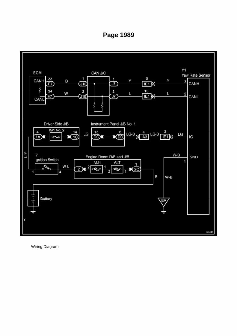
Page 1989
Wiring Diagram

Page 1410

g. Provisionally install the timing chain cover with the 19 bolts and 2 nuts.

NOTICE: If the vehicle is equipped with air conditioning, install bolts A' and B' when installing theidle pulley w/ bracket since they are for this purpose.
HINT: Bolt length:
75 mm (2.95 inch) for bolt A, B 87 mm (3.43 inch) for bolt C 95 mm (3.74 inch) for bolt D 35 mm(1.37 inch) for bolt E
h. Fully tighten the bolts and nuts, except bolts A, in the following order: Area 1, Area 3 and thenArea 2.
Torque: 21 Nm (214 kgf-cm, 15 ft. lbs.)
i. Fully tighten the bolts A in the following order: Area 2 and then Area 3. Torque: 46 Nm (469kgf-cm, 34 ft. lbs.)
j. Fully tighten the bolts E in Area
4. Torque: 21 Nm (214 kgf-cm, 15 ft. lbs.)

Testing and Inspection

Power Mirror Switch: Testing and Inspection

INSPECT OUTER MIRROR SWITCH ASSEMBLY
a. Check the resistance.
1. Press L on the left/right adjustment switch. 2. Using an ohmmeter, measure the resistancebetween the terminals.
If the result is not as specified, replace the outer mirror switch.
3. Press R on the left/right adjustment switch. 4. Using an ohmmeter, measure the resistancebetween the terminals.
If the result is not as specified, replace the outer mirror switch.

Page 2285

He - Wi

Page 2206
Oxygen Sensor: Technical Service Bulletins Engine Controls - Bank 1/Bank 2 O2 Sensoridentification
ENGINE EG034-07
Title: ENGINE BANK 1 AND BANK 2 A/F AND O2 IDENTIFICATION
Models: '93 - '08 Applicable Models
June 28, 2007
The information contained in this TSB supercedes TSB No. EG037-04. TSB No. EG037-04 is nowobsolete and should be discarded.
Introduction
This service bulletin provides information on the proper identification of engine bank 1 and enginebank 2 for correct A/F sensor and oxygen sensor replacement.
This bulletin contains information that identifies engine bank 1 and engine bank 2 on the followingengines: 1AZ-FE, 2AZ-FE, 2AZ-FE (PZEV), 1GR-FE, 2GR-FE, 2GR-FSE, 2JZ-GE, 1MZ-FE,3MZ-FE, 1UR-FSE, 3UR-FE, 2UZ-FE, 3UZ-FE, 5VZ-FE, and 1ZZ-FE.
^ Bank 1 (B1) refers to the bank that includes cylinder No. 1.

^ Bank 2 (B2) refers to the bank opposite bank 1.
^ Sensor 1 (S1) refers to the sensor that is located before the catalytic converters.
^ Sensor 2 (S2) refers to the sensor that is located after the catalytic converters.
Warranty Information

Front Left Sensor
Impact Sensor: Service and Repair Front Left Sensor

Airbag Front LH Sensor
REPLACEMENT
HINT: Use the same procedures for the RH side and LH side.
1. PRECAUTION
Refer to Air Bag Systems; Service Precautions.
2. DISCONNECT CABLE FROM NEGATIVE BATTERY TERMINAL
Wait for at least 90 seconds after disconnecting the cable to prevent the airbag from working.

Capacity Specifications

Engine Oil: Capacity Specifications

OIL CAPACITY (drain and refill):
With filter: ............................................................................................................................................................................ 5.8 L (6.1 US qt., 5.1 Imp. qt.) Without filter: ....................................................................................................................................................................... 5.1 L (5.4 US qt., 4.5 Imp.qt.)

Page 766
Ignition Switch: Testing and Inspection
INSPECT IGNITION OR STARTER SWITCH ASSEMBLY
a. Check the resistance.
1. Using an ohmmeter, measure the resistance between the terminals.
If the result is not as specified, replace the ignition or starter switch.

Page 2992
20. Install the instrument panel finish panel lower No. 1.
21. Install the cowl side trim board.
22. Install the front door opening trim LH (scuff plate).
23. Connect the negative (-) battery terminal cable.
Torque: 3.9 N.m (40 kgf.cm, 35 in..lbf)
24. Reset the memories for the clock, radio, etc.
25. Check the clutch release point.
A. Pull the parking brake lever and use wheel chocks.
B. Start the engine and allow it to idle.
C. Without depressing the clutch pedal, slowly move the shift lever into the reverse position untilthe gears engage (and grinding is heard).
D. Gradually depress the clutch pedal and measure the stroke distance from the point that the gearnoise stops (release point) up to the full stroke end position.
Standard distance: 25 mm (0.984 in.) or more (from pedal stroke end position to release point)
If the distance if NOT as specified, perform the following operations:
^ Check the pedal height.
^ Check the push rod play and pedal free play.
^ Bleed the clutch line.
^ Check the clutch cover assembly and the disc assembly.

Page 2191
Knock Sensor: Testing and Inspection
INSPECT KNOCK SENSOR
a. Check the resistance.
1. Using an ohmmeter, measure the resistance between the terminals.
If the result is not as specified, replace the knock sensor.

Page 2420
b. Connect the wire harness clamp. c. Connect the air fuel ratio sensor connector.
4. CONNECT CABLE TO NEGATIVE BATTERY TERMINAL
Torque: 3.9 N.m (40 Kgf.cm, 35 in.lbf)

Page 1510
b. Check the core plate height (H) after completing the caulking.
Plate height (H): 8.7 to 9.1 mm (0.343 to 0.358 inch) If the height is not as specified, readjust thestopper bolt of the handle, then caulk it again.
11. INSTALL RADIATOR DRAIN COCK
a. Install a new O-ring onto the drain cock plug. b. Install the drain cock plug.

Page 333
ABS With EBD & BA & TRAC & VSC SYSTEM

Testing and Inspection
Evaporative Check Valve: Testing and Inspection
INSPECTION
INSPECT VENTILATION VALVE SUB-ASSEMBLY
a. Check the operation.
1. Install a clean hose as shown in the illustration. 2. Blow air into the cylinder head side and checkthat the air passes through freely.

CAUTION: Do not suck air through the ventilation valve. Petroleum substances inside theventilation valve are harmful.
3. Blow air into the intake manifold side and check that the air does not pass through freely.
If the operation is not as specified, replace the ventilation valve.

Page 427
ABS With EBD & BA & TRAC & VSC SYSTEM

Page 575
Ignition Switch: Testing and Inspection
INSPECT IGNITION OR STARTER SWITCH ASSEMBLY
a. Check the resistance.
1. Using an ohmmeter, measure the resistance between the terminals.
If the result is not as specified, replace the ignition or starter switch.

Page 1064
SYMPTOM SIMULATION
HINT: The most difficult case in troubleshooting is when no problem symptoms occur. In suchcases, a thorough customer problem analysis must be carried out. A simulation of the same orsimilar conditions and environment in which the problem occurred in the customer's vehicle shouldbe carried out. No matter how much skill or experience a technician has, troubleshooting withoutconfirming the problem symptoms will lead to important repairs being overlooked and mistakes ordelays.
For example: With a problem that only occurs when the engine is cold or occurs as a result ofvibration caused by the road during driving, the problem can never be determined if the symptomsare being checked on a stationary vehicle or a vehicle with a warmed-up engine. Vibration, heat orwater penetration (moisture) is difficult to reproduce. The symptom simulation tests below areeffective substitutes for the conditions and can be applied on a stationary vehicle.
Important points in the symptom simulation test: In the symptom simulation test, the problemsymptoms as well as the problem area or parts must be confirmed. First, narrow down the possibleproblem circuits according to the symptoms. Then, connect the tester and carry out the symptomsimulation test, judging whether the circuit being tested is defective or normal. Also, confirm theproblem symptoms at the same time. Refer to the problem symptoms table for each system to

narrow down the possible causes.
1. VIBRATION METHOD: When vibration seems to be the major cause.
a. PART AND SENSOR
1. Apply slight vibration with a finger to the part of the sensor considered to be the cause of theproblem and check whether or not the
malfunction occurs.
HINT: Applying strong vibration to relays may open relays.
b. CONNECTORS
1. Slightly shake the connector vertically and horizontally.
c. WIRE HARNESS
1. Slightly shake the wire harness vertically and horizontally.
The connector joint and fulcrum of the vibration are the major areas that should be checkedthoroughly.

Page 2900
2. Print out the Freeze Frame Data for P0705 to allow easy review of data values. Note the valuesof the following parameters in the Data List:
^ Neutral Position SW Signal
^ Shift SW Status (R Range)
^ Shift SW Status (D Range)
^ Shift SW Status (4 or D)
^ Shift SW Status (3 Range)
^ Shift SW Status (2 Range)
^ Shift SW Status (L Range)
^ Stop Light Switch

Page 1956
Step 5 - 6

Page 13

The "Current Flow Chart", describes which parts each power source (fuses, fusible links, and circuitbreakers) transmits current to. In the Power Source circuit diagram, the conditions when batterypower is supplied to each system are explained. Since all System Circuit diagrams start from thepower source, the power source system must be fully understood.

Locations

A/C - Fo

Locations

Fuel Pump Relay: Locations
Engine Room R/B, J/B - Engine Compartment Left

Locations
Trailer Towing Relay: Locations
Instrument Panel

Page 1650
Crankshaft Position Sensor: Testing and Inspection
INSPECT CRANKSHAFT POSITION SENSOR
Check the resistance.
Using an ohmmeter, measure the resistance between the terminals.
HINT: Cold and Hot mean the temperature of the coils themselves. Cold is from -10 to 50°C (14 to122°F) and Hot is from 50 to 100°C (122 to 212° F).
If the result is not as specified, replace the camshaft position sensor.

Page 1858
Then click Next.
F. Verify correct current calibration and new calibration information. Then click Next.
NOTE
^ The total number of calibration IDs in the calibration file corresponds to the number ofreprogrammable processors in the ECU.

^ Each calibration file may contain up to three separate calibrations.

Page 1946
Wiring Diagram

Page 202
^ Power Supply Mode is used to maintain battery voltage at 13.5 volts while flash reprogrammingthe vehicle.
^ For details on how to use the GR8 Battery Diagnostic Station, refer to the located on TIS,Diagnostics - Tools & Equipment - Battery Diagnostics.

3. Click the appropriate calibration ID and reprogram the vehicle's ECU with Techstream.
A. After reviewing the procedures outlined in the selected TSB, click the appropriate calibration IDlink by matching the vehicle's current
calibration ID to the Previous Calibration ID in the Calibration Identification Chart.
NOTE
^ Calibration files are embedded as live links in the service bulletin.
^ Some vehicles require special preparation - please review the selected TSB carefully.
B. Click Open to load calibration file information.
Techstream pulls calibration files as needed to ensure the latest calibration file is used. Do NOTsave calibrations locally on the hard drive or other media.
NOTICE
Errors during the flash reprogramming process can permanently damage the vehicle ECU.Minimize the risk by following the steps below.
^ Battery voltage MUST NOT FALL BELOW 11.4 volts during reprogramming. Confirm batteryvoltage is higher than 11.4 volts, but be sure voltage DOES NOT RISE ABOVE 16.0 volts duringreprogramming.
^ Turn OFF all vehicle accessories (e.g. audio system, A/C, interior lights, DRL, etc.). Do NOT addto or significantly change the vehicle's electrical

Page 1854

NOTE

Only Toyota Certified Technicians and above may access calibration files.
2. Connect the GR8 Battery Diagnostic Station.
A. Connect the GR8 Battery Diagnostic Station to the vehicle and turn it ON.
B. Select Power Supply Mode by following the screen flow below.
NOTICE
^ ECU damage may occur if the correct battery charger and mode setting are NOT used.

Page 1415


Page 1160

Step 1 - 4

INSPECTION PROCEDURE

Page 666
Information
TECHNICAL INSTRUCTIONS

FOR
SPECIAL SERVICE CAMPAIGN 50I
2005 MODEL YEAR TACOMA REGULAR-CAB
FRONT BENCH SEAT WIRE SEAT JUMPER

Page 169
CAUTION: a. Do not open the cover or the case of the ECU unless absolutely necessary. (If the ICterminals are touched, the IC may be destroyed by static
electricity.)
b. When replacing the internal mechanism (ECU part) of the digital meter, be careful that no part ofyour body or clothing comes in contact with
the terminals of leads from the IC, etc. of the replacement part (spare part).

How to Replace Terminal
HOW TO REPLACE TERMINAL (with terminal retainer or secondary locking device)
1. PREPARE THE SPECIAL TOOL
HINT: To remove the terminal from the connector, please construct and use the special tool or likeobject shown.
2. DISCONNECT CONNECTOR
3. DISENGAGE THE SECONDARY LOCKING DEVICE OR TERMINAL RETAINER
a. Locking device must be disengaged before the terminal locking clip can be released and theterminal removed from the connector. b. Use a special tool or the terminal pick to unlock thesecondary locking device or terminal retainer.
NOTE: Do not remove the terminal retainer from connector body.
[A] : For Non-Waterproof Type Connector
HINT: The needle insertion position varies according to the connector's shape (number of terminalsetc.), so check the position before inserting it.

Page 1669

a. Install a new gasket onto the intake manifold. b. Install the intake manifold with the 5 bolts and 2nuts.

Torque: 25 N.m (255 kgf.cm, 18 ft.lbf)
c. Connect the engine wire harness to the relay block. d. Install the nut shown in the illustration.
Torque: 10 N.m (102 kgf.cm, 7 ft.lbf)
e. Connect the 3 connectors.
f. Install the harness clamp bracket with the bolt.
Torque: 8.2 N.m (84 kgf.cm, 73 in.lbf)
g. Engage the wire harness clamp. h. Connect the compressor magnetic clutch connector.

Page 1949
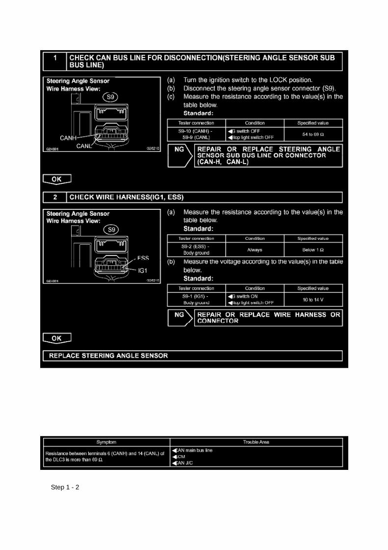
Step 1 - 2

INSPECTION PROCEDURE
Check CAN Main Bus Line For Disconnection
CHECK CAN MAIN BUS LINE FOR DISCONNECTION
CIRCUIT DESCRIPTION
The CAN main bus line and DLC3 sub bus line may have a disconnection when the resistancebetween terminals 6 (CANH) and 14 (CANL) of the DLC3 is more than 69 ohm.

Page 2575

Main Relay (Computer/Fuel System): Testing and Inspection

INSPECT E.F.I. CIRCUIT OPENING RELAY ASSEMBLY
a. Check the resistance.
1. Using an ohmmeter, measure the resistance between the terminals.
If the result is not as specified, replace the E.F.I. circuit opening relay assembly.
INSPECT EFI RELAY
a. Check the resistance.
1. Using an ohmmeter, measure the resistance between the terminals.
If the result is not as specified, replace the E.F.I. ECU relay.
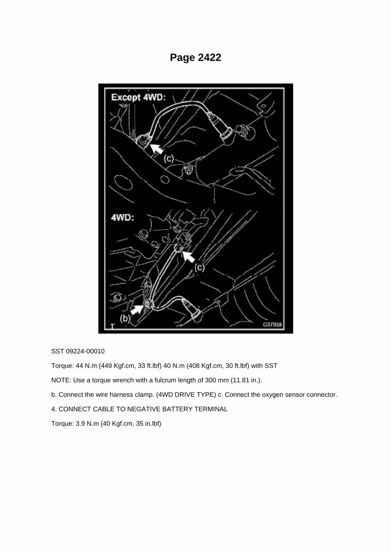
Page 2422
SST 09224-00010
Torque: 44 N.m (449 Kgf.cm, 33 ft.lbf) 40 N.m (408 Kgf.cm, 30 ft.lbf) with SST
NOTE: Use a torque wrench with a fulcrum length of 300 mm (11.81 in.).
b. Connect the wire harness clamp. (4WD DRIVE TYPE) c. Connect the oxygen sensor connector.
4. CONNECT CABLE TO NEGATIVE BATTERY TERMINAL
Torque: 3.9 N.m (40 Kgf.cm, 35 in.lbf)

Page 138
Driver Side J/B - Lower Finish Panel

Page 1370

46. REMOVE OIL STRAINER SUB-ASSEMBLY

a. Remove the 2 bolts, 2 nuts, oil strainer and gasket.
47. REMOVE OIL PAN SUB-ASSEMBLY
a. Remove the 16 bolts and 2 nuts.
b. Remove the oil pan by prying between the oil pan and cylinder block with a screwdriver.
HINT: Tape the screwdriver tip before use.
NOTICE: Be careful not to damage the contact surfaces of the cylinder block and oil pan.
48. REMOVE TIMING CHAIN COVER

Page 2661

He - Wi

Page 952

Hose/Line HVAC: Tools and Equipment

A/C Clamp Remover
AST tool# TOY 200

Page 676
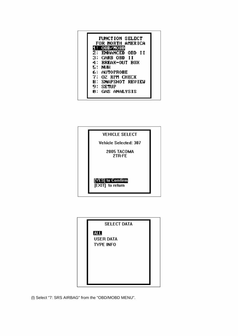
(l) Select "7: SRS AIRBAG" from the "OBD/MOBD MENU".

(m)Press the "YES button when the "VERIFY CONNECTIONS" screen appears.
(n) Select "1: DATA LIST from the "DIAGNOSTIC MENU, AIRBAG/SRS" system.
(o) Select "ALL from the "SELECT DATA" menu.
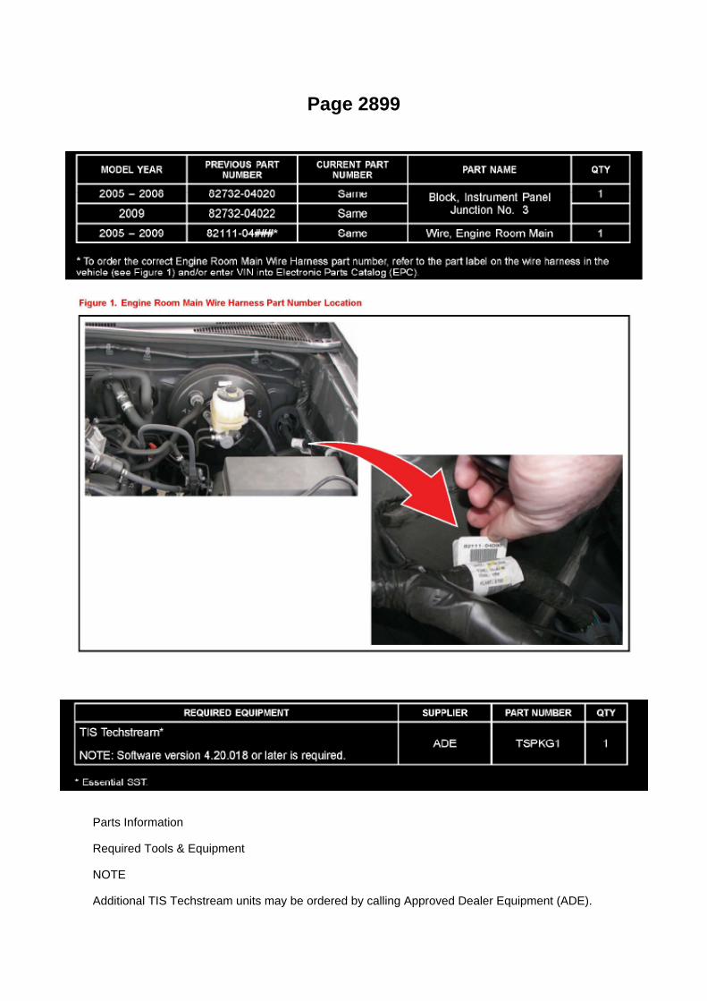
Page 2899
Parts Information
Required Tools & Equipment
NOTE
Additional TIS Techstream units may be ordered by calling Approved Dealer Equipment (ADE).

Repair Procedure
1. Confirm that DTC P0705 (Transmission Range Control Circuit Malfunction (PRNDL Circuit)) isstored in the Freeze Frame Data.

Page 2478

b. Apply a light coat of gasoline or spindle oil to the contact surfaces of the fuel delivery pipe andthe O-ring of the fuel injector. c. Apply a light coat of gasoline or spindle oil to the O-ring again, then

install the fuel injector into the fuel delivery pipe by turning it right and
left.
NOTE: Make sure that the O-ring is not cracked or jammed when installing.
d. Check that the fuel injector rotates smoothly.
If the fuel injector does not rotate, replace the O-ring.
13. INSTALL FUEL DELIVERY PIPE W/INJECTOR
a. Apply a light coat of gasoline or spindle oil to new O-rings, then install one onto each spacer. b.Install the 4 spacers onto the cylinder head. c. Install 4 new injector vibration insulators onto thecylinder head. d. Install the 2 delivery pipe No.1 spacers onto the cylinder head.
e. Install the fuel delivery pipe together with the 4 fuel injectors, then provisionally tighten the fueldelivery pipe with the 2 bolts.
NOTE: Do not drop the fuel injectors when installing the fuel delivery pipe.
f. Check that the fuel injector rotates smoothly. If the fuel injector does not rotate, replace theO-ring.
g. Retighten the 2 bolts to the specified torque.
Torque: 12 N.m (122 kgf.cm, 9 ft.lbf)

Page 1943
Wiring Diagram

Page 1516

5. Before installing the radiator cap tester, use the applicable radiator cap adaptor provided in thefollowing SST kits in conjunction with the radiator cap tester:

^ SST P/N 09230-00030-01 (09231-10080-01) or 09230-00020-01 (09231-10060-01) or09230-00050-01 (09231-10110-01
6. When using the radiator cap tester, tilt it more than 30 degrees.
7. Pump the radiator cap tester several times, and check the maximum pressure.
Pumping speed: 1 pump/second
HINT:
Stop pumping when the valve opens and read the gauge. The gauge must be within the standardvalues listed below when the pressure valve opens. The cap is considered OK when the pressureholds steady or falls very slowly, but holds within the standard values listed below for one minute.
Specification:
If the maximum pressure is less than the minimum standard value, replace the radiator capsub-assembly.
Type: N-cap, 108 kPa

Page 192

A/C - Fo

Page 2788

Shift Solenoid: Diagrams

The shift solenoid identification and location in the valve body is contained in the valve bodyservice and repair procedures and overhaul articles for most models.

Page 1685

Oxygen Sensor: Locations

He - Wi

Page 2630

Knock Control Sensor (2TR-FE) Part 3

Page 818

Ac - Ya

Specifications

Spark Plug: Specifications

SPARK PLUG TYPE:
DENSO ........................................................................................................................................................................................................... SK2OHR11 NGK ..................................................................................................................................................................................................................ILFR6C11
Correct electrode gap for new sparkplug.......................................................................................................................... 1.0 to 1.1 mm(0.039 to 0.043 in.)
Torque.....................................................................................................................................................................................18 N.m (184 kgf.cm, 13 ft.lbf)

Page 2177
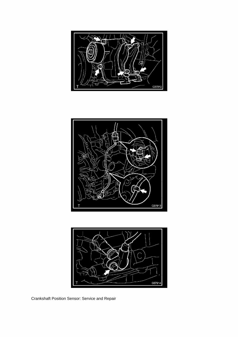
Crankshaft Position Sensor: Service and Repair

REPLACEMENT
1. DISCONNECT CABLE FROM NEGATIVE BATTERY TERMINAL 2. REMOVE ENGINE UNDERCOVER SUB-ASSEMBLY NO.1 (PRE RUNNER AND 4WD TYPE) 3. REMOVE FAN ANDGENERATOR BELT (W/ AIR CONDITIONING) 4. REMOVE COMPRESSOR AND MAGNETICCLUTCH (W/ AIR CONDITIONING) 5. REMOVE IDLE PULLEY ASSEMBLY W/BRACKET (W/ AIRCONDITIONING)
a. Remove the 5 bolts, then remove the idle pulley with bracket.
6. REMOVE CRANKSHAFT POSITION SENSOR
a. Disconnect the crankshaft position sensor connector and the 2 wire harness clamps.
b. Remove the bolt, then remove the crankshaft position sensor.
7. INSTALL CRANKSHAFT POSITION SENSOR

Page 1880

Engine Control Module: Pinout Values and Diagnostic Parameters

Terminals Of ECM / Pinouts Part 1

Page 2971
D. Cut the felt padding on the backside of the floor carpet without cutting the carpet using thecarpet knife adjusted only to the depth of the felt padding. Cut the felt padding in the shape shownbelow.
5. Replace the front floor pad.

A. Clean all residue from the backside of the carpet where the floor pad was located.
B. Attach the NEW front floor pad to the backside of the floor carpet.
C. Confirm that the square raised section on the foam pad is in the same position as the original toensure proper alignment.

Page 509
A/F and 02 Sensor Identification

Page 2040
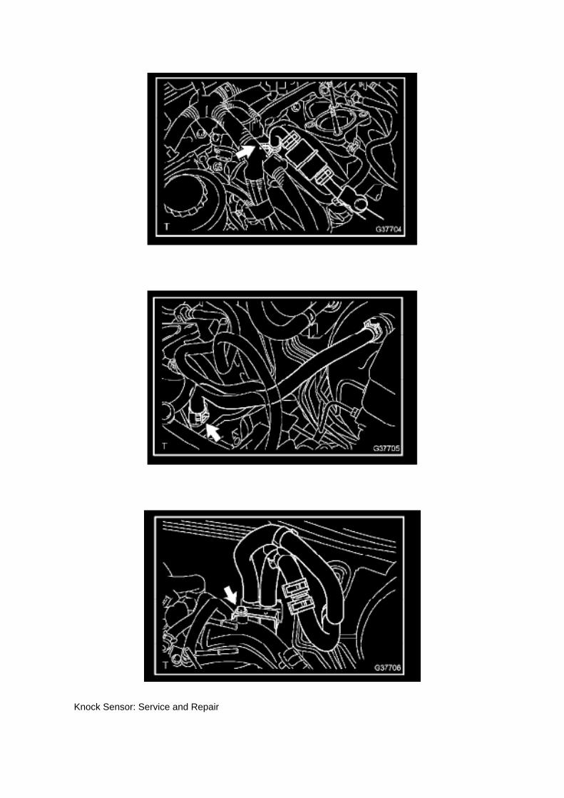
Knock Sensor: Service and Repair

REPLACEMENT
1. DISCONNECT CABLE FROM NEGATIVE BATTERY TERMINAL 2. REMOVE ENGINE UNDERCOVER SUB-ASSEMBLY NO.1 (PRE RUNNER AND 4WD TYPE) 3. DRAIN ENGINE COOLANT4. REMOVE INTAKE AIR CONNECTOR 5. REMOVE THROTTLE W/MOTOR BODY ASSEMBLY6. DISCONNECT FUEL HOSE 7. DISCONNECT FUEL HOSE NO.2 8. REMOVE INTAKEMANIFOLD
a. Disconnect the fuel vapor feed hose from the VSV.
b. Disconnect the vacuum hose.
c. Remove the bolt, then remove the clamp bracket.

Page 1185
Wheel Bearing: Tools and Equipment
Wheel Bearing Nut Socket
AST tool# TOY 185
For R and R of wheel bearing nut located on inboard side of wheel hub. Applicable: Newer Toyotatrucks and SUV's (2wd only).
- Made in USA
Contact AST for pricing.
Assenmacher Specialty Tools 1-800-525-2943

Page 2632

Knock Sensor: Service and Repair

REPLACEMENT
1. DISCONNECT CABLE FROM NEGATIVE BATTERY TERMINAL 2. REMOVE ENGINE UNDERCOVER SUB-ASSEMBLY NO.1 (PRE RUNNER AND 4WD TYPE) 3. DRAIN ENGINE COOLANT4. REMOVE INTAKE AIR CONNECTOR 5. REMOVE THROTTLE W/MOTOR BODY ASSEMBLY6. DISCONNECT FUEL HOSE 7. DISCONNECT FUEL HOSE NO.2 8. REMOVE INTAKEMANIFOLD
a. Disconnect the fuel vapor feed hose from the VSV.
b. Disconnect the vacuum hose.
c. Remove the bolt, then remove the clamp bracket.

Locations

Page 2972

6. Cut the dash panel insulator.

7. Return the carpet to its former position.
8. Go to Repair Procedure B, "Clutch Pedal Replacement."
Repair Procedure B
Clutch Pedal Replacement
1. Record all radio presets before starting.
2. Disconnect the negative (-) battery terminal cable.
3. Remove the clutch pedal sub-assembly.
NOTE:
Steps 3A - 3B can be skipped if Repair Procedure A was just performed.
A. Remove the front door opening trim LH (scuff plate).

Page 1592

Engine Control Module: Pinout Values and Diagnostic Parameters

Terminals Of ECM / Pinouts Part 1
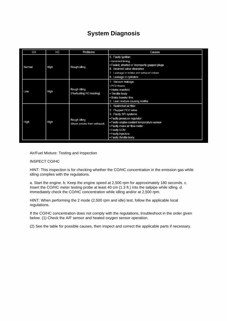
System Diagnosis
Air/Fuel Mixture: Testing and Inspection
INSPECT CO/HC
HINT: This inspection is for checking whether the CO/HC concentration in the emission gas whileidling complies with the regulations.
a. Start the engine. b. Keep the engine speed at 2,500 rpm for approximately 180 seconds. c.Insert the CO/HC meter testing probe at least 40 cm (1.3 ft.) into the tailpipe while idling. d.Immediately check the CO/HC concentration while idling and/or at 2,500 rpm.
HINT: When performing the 2 mode (2,500 rpm and idle) test, follow the applicable localregulations.
If the CO/HC concentration does not comply with the regulations, troubleshoot in the order givenbelow. (1) Check the A/F sensor and heated oxygen sensor operation.
(2) See the table for possible causes, then inspect and correct the applicable parts if necessary.
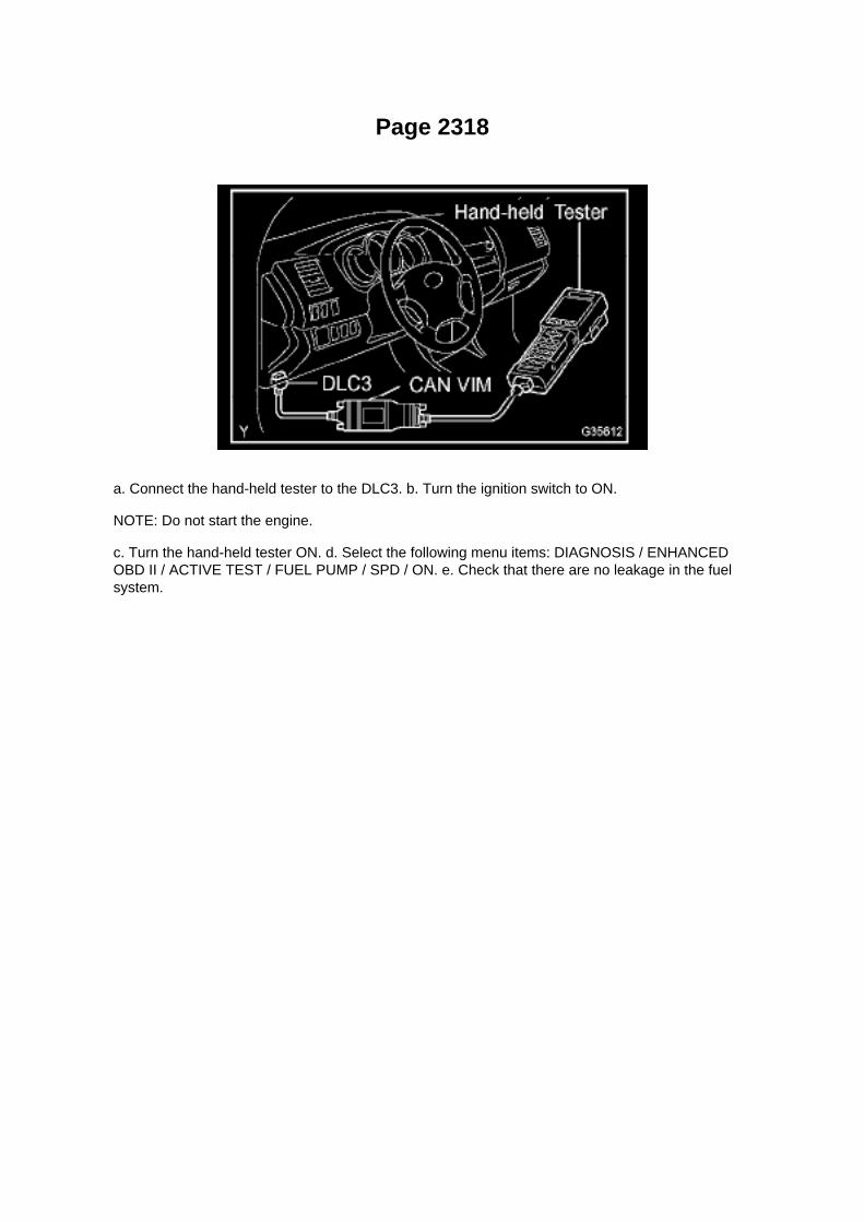
Page 2318
a. Connect the hand-held tester to the DLC3. b. Turn the ignition switch to ON.
NOTE: Do not start the engine.
c. Turn the hand-held tester ON. d. Select the following menu items: DIAGNOSIS / ENHANCEDOBD II / ACTIVE TEST / FUEL PUMP / SPD / ON. e. Check that there are no leakage in the fuelsystem.
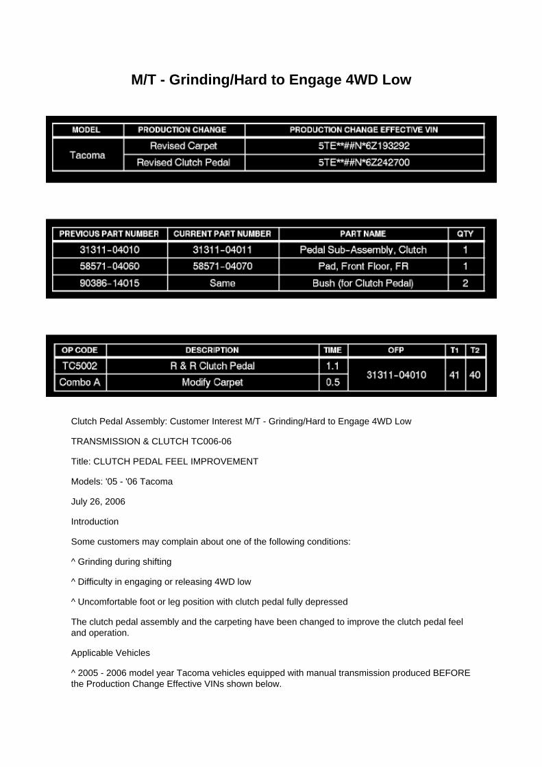
M/T - Grinding/Hard to Engage 4WD Low
Clutch Pedal Assembly: Customer Interest M/T - Grinding/Hard to Engage 4WD Low
TRANSMISSION & CLUTCH TC006-06
Title: CLUTCH PEDAL FEEL IMPROVEMENT
Models: '05 - '06 Tacoma
July 26, 2006
Introduction
Some customers may complain about one of the following conditions:
^ Grinding during shifting
^ Difficulty in engaging or releasing 4WD low
^ Uncomfortable foot or leg position with clutch pedal fully depressed
The clutch pedal assembly and the carpeting have been changed to improve the clutch pedal feeland operation.
Applicable Vehicles
^ 2005 - 2006 model year Tacoma vehicles equipped with manual transmission produced BEFOREthe Production Change Effective VINs shown below.

Production Change Information
Parts Information
Warranty Information
Applicable Warranty*: This repair is covered under the Toyota Comprehensive Warranty. Thiswarranty is in effect for 36 months or 36,000 miles, whichever occurs first, from the vehicle'sin-service date.
* Warranty application is limited to correction of a problem based upon a customer's specificcomplaint.

Page 2809

Required Tools & Equipment

ATF Level Inspection Temperature Range Table

Page 2375

Specifications

Valve Clearance: Specifications

The 2TR-FE engine uses a hydraulic valve lash adjuster assembly. Adjustment is not required.

Testing and Inspection

A/C - Fo

Page 798
Transmission Position Switch/Sensor: Adjustments
PARK/NEUTRAL POSITION SWITCH ASSY
ADJUSTMENT
1. INSPECT PARK/NEUTRAL POSITION SWITCH ASSY
a. Apply the parking brake and turn the ignition switch to ON. b. Depress the brake pedal andcheck that the engine starts only when the shift lever is set in the N or P position and that it doesnot start in any
other positions.
c. Check that the back-up light comes on and the reverse warning buzzer sounds only when theshift lever is set in the R position and not in other
positions. If any failure is found, check the park/neutral position switch for continuity.
2. ADJUST PARK/NEUTRAL POSITION SWITCH ASSY
a. Loosen the bolt of the park/neutral position switch and set the shift lever to the N position. b.Align the groove and the neutral basic line. c. Hold the switch in position and tighten the bolt.
Torque: 13 Nm (130 kgf-cm, 9 ft. lbs.)
d. After making an adjustment, perform the inspection described in step 1.

Page 1504

b. Install the fan shroud and fan with fluid coupling together.

NOTICE: Make sure that the fan shroud and fan with fluid coupling do not make any contact withthe radiator when they are installed.
c. Provisionally install the fan with fluid coupling with the 4 nuts.
d. Install the 2 bolts shown in the illustration.
Torque: 5.0 Nm (51 kgf-cm, 44 inch lbs.)
e. Connect the oil cooler inlet and outlet hoses to the fan shroud. (AUTOMATIC TRANSMISSION)
f. Connect the radiator reserve tank hose to the radiator.
g. Install the fan generator V belt.
h. Tighten the 4 nuts shown in the illustration.
Torque: 25 Nm (255 kgf-cm, 18 ft. lbs.)

Locations

Ha - Op

Page 1584

A/C - Fo
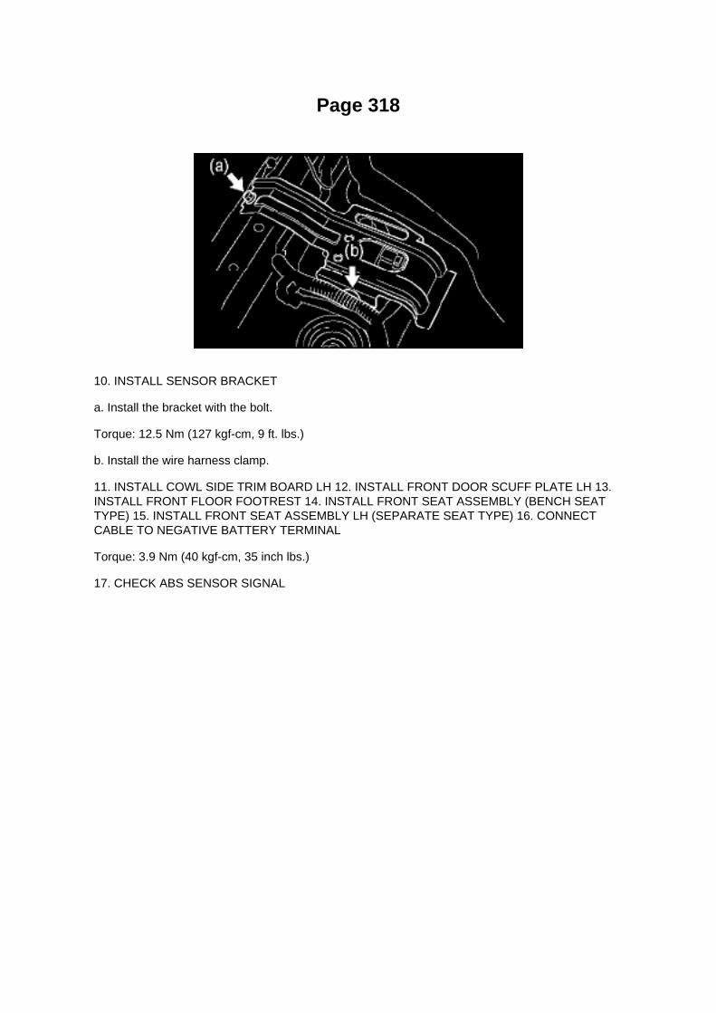
Page 318
10. INSTALL SENSOR BRACKET
a. Install the bracket with the bolt.
Torque: 12.5 Nm (127 kgf-cm, 9 ft. lbs.)
b. Install the wire harness clamp.
11. INSTALL COWL SIDE TRIM BOARD LH 12. INSTALL FRONT DOOR SCUFF PLATE LH 13.INSTALL FRONT FLOOR FOOTREST 14. INSTALL FRONT SEAT ASSEMBLY (BENCH SEATTYPE) 15. INSTALL FRONT SEAT ASSEMBLY LH (SEPARATE SEAT TYPE) 16. CONNECTCABLE TO NEGATIVE BATTERY TERMINAL
Torque: 3.9 Nm (40 kgf-cm, 35 inch lbs.)
17. CHECK ABS SENSOR SIGNAL

Locations
Wheel Speed Sensor: Locations

ABS With EBD System

Page 2812

Fluid - A/T: Fluid Type Specifications

Change Automatic Transmission Fluid Only As Necessary.
Generally, it is necessary to change automatic transmission fluid only if your vehicle is driven underone of the Special Operating Conditions listed under one of the Scheduled Maintenance Guide orOwners Manual Supplement.
When changing the automatic transmission fluid, use only "Toyota Genuine ATF Type T-IV" (ATFJWS3309 or NWS6500) to aid in assuring optimum transmission performance.
Notice: Using automatic transmission fluid other than "Toyota Genuine ATF Type T-IV" may causedeterioration in shift quality, locking up of your transmission accompanied by vibration, andultimately damage the automatic transmission of your vehicle.
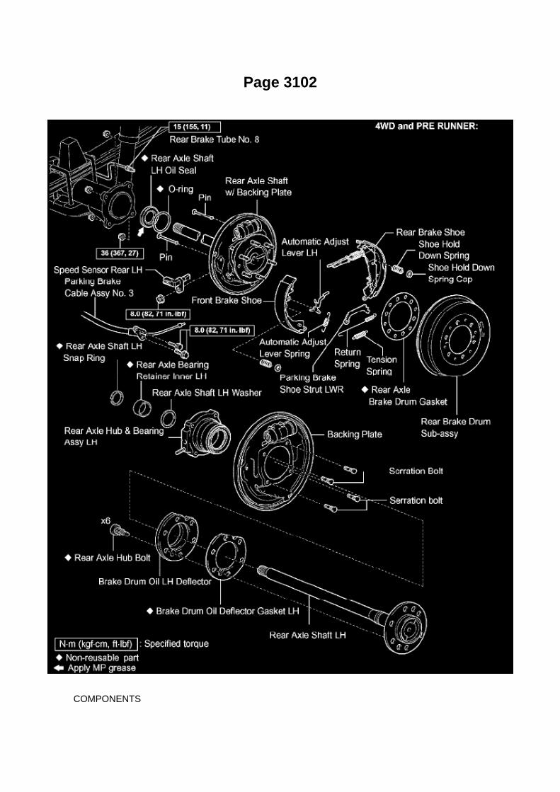
Page 3102
COMPONENTS

REPLACEMENT
1. DISCONNECT CABLE FROM NEGATIVE BATTERY TERMINAL 2. REMOVE REAR WHEEL 3.DRAIN BRAKE FLUID 4. REMOVE REAR BRAKE DRUM SUB-ASSY 5. REMOVE FRONTBRAKE SHOE
SST 09921-00010, 09718-00010
6. REMOVE REAR BRAKE SHOE
SST 09718-00010
7. REMOVE SPEED SENSOR REAR LH 8. SEPARATE PARKING BRAKE CABLE ASSY NO.3

Page 1760

(w/ AIR CONDITIONING)

i. Engage the engine wire harness clamp.
j. Connect the VSV connector.
k. Connect the ventilation hose No.3.
l. Connect the water bypass hose No.2.
m. Install the clamp bracket with the bolt.
Torque: 19 N.m (194 kgf.cm, 14 in.lbf)
n. Connect the vacuum hose.

Page 2352


Page 3278
NOTICE: If the pump does not stop, repeat step (3) again.
(5) Depress the brake pedal and check the fluid pressure.
At 49 N (5 kgf, 11 ft. lbs.)
At 98 N (10 kgf, 22 ft. lbs.)
At 147 N (15 kgf, 33 ft. lbs.)
At 196 N (20 kgf, 44 ft. lbs.)
2. CHECK BRAKE MASTER CYLINDER OPERATION
a. Inspect the battery positive voltage.
Battery positive voltage: 10 to 14 V

b. Turn the ignition switch to OFF, and depress the brake pedal more than 20 times.
HINT: When pressure in the accumulator is released, the reaction force becomes lighter and thestroke becomes longer.
c. Check that the brake pedal becomes easy to depress.
If the pedal does not become easy to depress, check and replace the brake line and brake mastercylinder.
d. Turn the ignition switch to ON and check the pump motor operation noise.
If the pump motor does not operate, check and replace the wire harness and pump motor.
e. Connect the hand-held tester.
(1) Connect the hand-held tester to the DLC3. (2) Turn the ignition switch to ON. (3) Select"ACTIVE TEST" mode on the hand-held tester.
HINT: -
Refer to the hand-held tester operator manual for further details.
- To protect the solenoids, hand-held tester turns off automatically 2 seconds after every solenoidhas been turned on.

Page 38
b. Push the secondary locking device or terminal retainer in to the full lock position.
5. CONNECT CONNECTOR
Disconnection of Male and Female Connectors
DISCONNECTION OF MALE AND FEMALE CONNECTORS
To pull apart the connectors, pull on the connector itself, not the wire harness.
HINT: Check to see what kind of connector you are disconnecting before pulling apart.
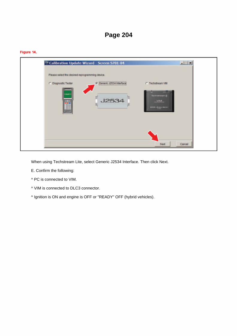
Page 204
When using Techstream Lite, select Generic J2534 Interface. Then click Next.
E. Confirm the following:
^ PC is connected to VIM.
^ VIM is connected to DLC3 connector.
^ Ignition is ON and engine is OFF or "READY" OFF (hybrid vehicles).

Page 1930

Push the terminal retainer down to the temporary lock position.

c. Release the locking lug from terminal and pull the terminal out from rear.
4. INSTALL TERMINAL TO CONNECTOR
a. Insert the terminal.
HINT: 1. Make sure the terminal is positioned correctly. 2. Insert the terminal until the locking luglocks firmly. 3. Insert the terminal with terminal retainer in the temporary lock position.

Page 717

Page 1418

Locations
Shift Interlock Control Module: Locations
Instrument Panel

Page 825
Windshield Washer Switch: Service and Repair
Windshield Wiper Switch Assy
WINDSHIELD WIPER SWITCH ASSEMBLY
REPLACEMENT
1. DISCONNECT CABLE FROM NEGATIVE BATTERY TERMINAL
Wait for at least 90 seconds after disconnecting the cable to prevent the airbag from working.
2. REMOVE STEERING COLUMN COVER LWR 3. REMOVE STEERING COLUMN COVER UPR

Page 2468

Fuel Injector: Pressure, Vacuum and Temperature Specifications

Fuel drop.......................................................................................................................................................................................1 drop or less in 12 minutes

Page 15

Glossary Of Terms And Sysmbols Part 1

Fuel/Emissions - MIL ON/DTC's P0456/P0445 and P0441
Set
Fuel Pump Pickup Filter: Customer Interest Fuel/Emissions - MIL ON/DTC's P0456/P0445 andP0441 Set
ENGINE EG037-05 REVISED
Title: M.I.L. "ON" DTC P0456 OR P0455, AND P0441
Models: '05 Tacoma
September 1, 2005
TSB REVISION NOTICE:
^ September 16, 2005: The Applicable VDS has been updated in Applicable Vehicles. Previousversions of this TSB should be discarded.
Introduction
Some 2005 model year Tacoma vehicles may exhibit a M.I.L. "ON" condition with one or more ofthe following DTCs: P0456 or P0455, and P0441 (EVAP Emission Control System). Follow thesteps in this bulletin to correct this condition.

Applicable Vehicles
^ 2005 model year Tacoma vehicles (except D-Cab Short Bed), with the following VehicleDescription Section VDS) information shown below.
Warranty Information
Applicable Warranty*: This repair is covered under the Toyota Powertrain Warranty. This warrantyis in effect for 60 months or 60,000 miles, whichever occurs first, from the vehicle's in-service date.
* Warranty application is limited to correction of a problem based upon a customer's specificcomplaint.

Locations

Brake Light Switch: Locations
Ha - Op

Page 201

NOTE

Only Toyota Certified Technicians and above may access calibration files.
2. Connect the GR8 Battery Diagnostic Station.
A. Connect the GR8 Battery Diagnostic Station to the vehicle and turn it ON.
B. Select Power Supply Mode by following the screen flow below.
NOTICE
^ ECU damage may occur if the correct battery charger and mode setting are NOT used.

Page 176
Driver Side J/B - Lower Finish Panel

Page 792
CAN Communication System

Page 2989

B. Remove the clevis sub-assembly from the master cylinder.

a. Loosen the lock nut.
b. Rotate and remove the clevis sub-assembly.
15. Install the NEW clevis sub-assembly.
A. Rotate the lock nut to match length "A".
B. Rotate and install the NEW clevis sub-assembly to contact the lock nut.
C. Tighten the lock nut and torque to specification.
Torque: 11.8 N.m (120 kgf.cm, 8.7 ft.lbf)
D. Apply MP grease to the ball end of the clevis sub-assembly where it will contact the clutchpedal.
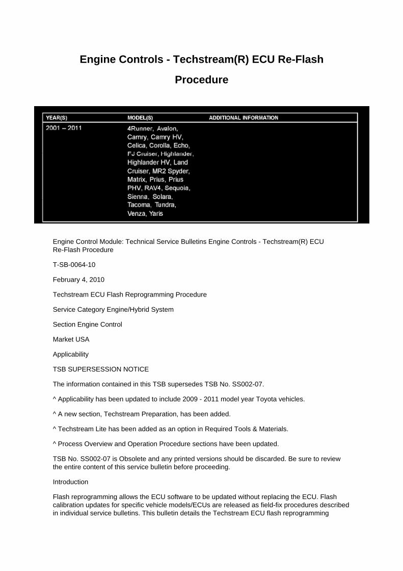
Engine Controls - Techstream(R) ECU Re-Flash
Procedure
Engine Control Module: Technical Service Bulletins Engine Controls - Techstream(R) ECURe-Flash Procedure
T-SB-0064-10
February 4, 2010
Techstream ECU Flash Reprogramming Procedure
Service Category Engine/Hybrid System
Section Engine Control
Market USA
Applicability
TSB SUPERSESSION NOTICE
The information contained in this TSB supersedes TSB No. SS002-07.
^ Applicability has been updated to include 2009 - 2011 model year Toyota vehicles.
^ A new section, Techstream Preparation, has been added.
^ Techstream Lite has been added as an option in Required Tools & Materials.
^ Process Overview and Operation Procedure sections have been updated.
TSB No. SS002-07 is Obsolete and any printed versions should be discarded. Be sure to reviewthe entire content of this service bulletin before proceeding.
Introduction
Flash reprogramming allows the ECU software to be updated without replacing the ECU. Flashcalibration updates for specific vehicle models/ECUs are released as field-fix procedures describedin individual service bulletins. This bulletin details the Techstream ECU flash reprogramming

process and outlines use of the Technical Information System (TIS) and the Calibration UpdateWizard (CUW). Flash calibration updates can only be applied to the vehicle/ECU combination forwhich they are intended. ECUs have internal security that will not allow them to be programmedwith another ECU's information.
ECU
Electronic Control Unit (ECU) is a Toyota term used to describe integrated computerized devicesresponsible for managing the operation of a system or subsystem. For the purposes of this bulletin,the term "ECU" is used as a generic label for the following SAE J1930 standard references:
^ Powertrain Control Module (PCM)

Page 181
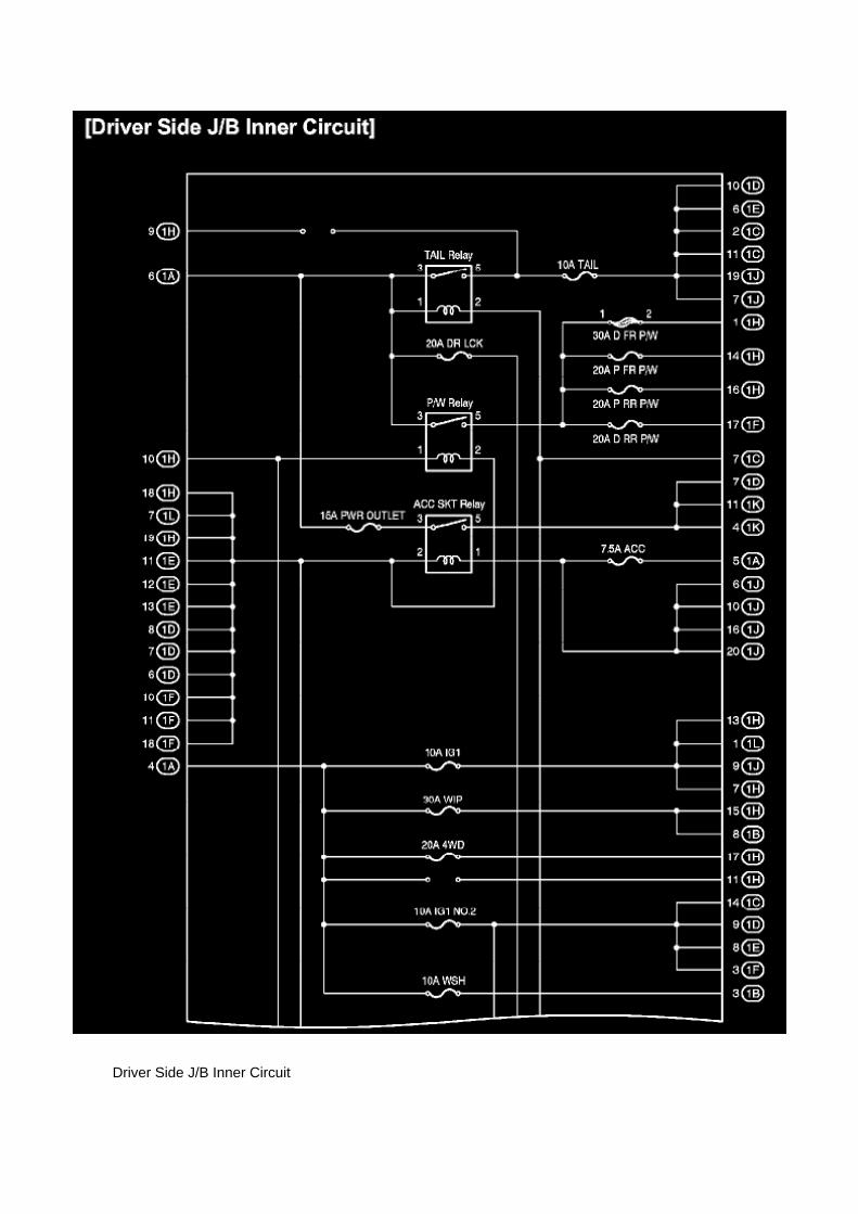
Driver Side J/B Inner Circuit

Page 98

WAVEFORM 2:

Engine Speed Signal
HINT: The wavelength becomes shorter as the engine rpm increases.
INSPECT ECM (1GR-FE)
a. Connect the connector to the ECM and inspect the wire harness side connector from the backside, as shown in the table.
WAVEFORM 1:

Page 3069
Ce - Ya

Page 2072
SFI System

Emissions - MIL ON/DTC's
P043E/P043F/P2401/P2402/P2419
Evaporative Emission Control Canister: Customer Interest Emissions - MIL ON/DTC'sP043E/P043F/P2401/P2402/P2419
ENGINE EG025-06
Title: M.I.L. "ON" DTC P043E, P043F, P2401, P2402, & P2419
Models: '05 - '06 Tacoma
April 14, 2006
Introduction
Some 2005 and 2006 model year Tacoma vehicles may exhibit M.I.L. "ON" with DTCs P043E,P043F, P2401, P2402, and P2419 stored. The EVAP pump module, which is part of the charcoalcanister assembly, has been improved to correct this condition.
NOTE:
All five DTCs MUST be present for this TSB to be applicable.
Applicable Vehicles
^ 2005 - 2006 model year Tacoma vehicles produced BEFORE the Production Change EffectiveVINs shown below.

Production Change Information
Parts Information
Warranty Information
Applicable Warranty*:
^ This repair is covered under the Toyota Federal Emission Warranty. This warranty is in effect for36 months or 36,000 miles, whichever occurs first, from the vehicle's in-service date. For Californiaspecification vehicles sold, registered, and operated in California, Maine, Massachusetts, andVermont, this repair is covered under the California Emission Warranty, which is 36 months or50,000 miles, whichever occurs first, from the vehicle's in-service date.
^ 2006 model year Tacoma charcoal canister is covered under the California Emission Warranty.This warranty is in effect for 84 months or 70,000 miles, whichever occurs first, from the vehicle'sin-service date.
* Warranty application is limited to correction of a problem based upon a customer's specificcomplaint.

Specifications

Fuel: Specifications

FUEL TYPE: UNLEADED gasoline
OCTANE RATING: 87 or higher (Research Octane Number 91)

Page 1696
SST 09224-00010
Torque: 44 N.m (449 Kgf.cm, 33 ft.lbf) 40 N.m (408 Kgf.cm, 30 ft.lbf) with SST
NOTE: Use a torque wrench with a fulcrum length of 300 mm (11.81 in.).
b. Connect the wire harness clamp. (4WD DRIVE TYPE) c. Connect the oxygen sensor connector.
4. CONNECT CABLE TO NEGATIVE BATTERY TERMINAL
Torque: 3.9 N.m (40 Kgf.cm, 35 in.lbf)

Page 1361

Page 1885
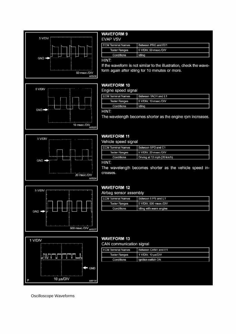
Oscilloscope Waveforms

Page 1570
Then click Next.
F. Verify correct current calibration and new calibration information. Then click Next.
NOTE
^ The total number of calibration IDs in the calibration file corresponds to the number ofreprogrammable processors in the ECU.

^ Each calibration file may contain up to three separate calibrations.

Page 1868
Refer to Reset Procedure 1 for the vehicles with Electronically Controlled AutomaticTransmissions:

Page 3318
Step 6 - 7
INSPECTION PROCEDURE

Page 1633

He - Wi

Locations

He - Wi

Page 653


Page 495
Knock Sensor: Testing and Inspection
INSPECT KNOCK SENSOR
a. Check the resistance.
1. Using an ohmmeter, measure the resistance between the terminals.
If the result is not as specified, replace the knock sensor.

Page 2101
C. Choose desired ECU group(s) in the Health Check dialog box.
D. Click Next.
E. Click Continue to view Health Check results.

F. Available calibration updates are indicated by a link in the Cal. Update? column. Click the link toaccess the appropriate service bulletin on TIS.
NOTE
^ Note any DTCs stored in Systems that will be flash reprogrammed.
^ Clicking the link will automatically launch TIS and perform a calibration search.
G. Log in to TIS. (If already logged in skip this step.)
H. To review the TSB and access the calibration file click the service bulletin link in the DocumentTitle column of the Calibration Search Result
portlet.

Page 584

Knock Control Sensor (2TR-FE) Part 3

Page 614
Impact Sensor: Service and Repair Side Sensor

Side Air Bag Sensor Assy LH
REPLACEMENT
1. PRECAUTION
Refer to Air Bag Systems; Service Precautions.
2. DISCONNECT CABLE FROM NEGATIVE BATTERY TERMINAL
Wait for at least 90 seconds after disconnecting the cable to prevent the airbag from working.
3. REMOVE FRONT DOOR SCUFF PLATE LH 4. REMOVE REAR DOOR SCUFF PLATE LH

Page 161

normally or lead to repairs not pertinent to the problem. Follow the procedures listed in theflowchart in the correct order.
Steps 4 - 6
- A flowchart showing how to proceed with troubleshooting using the DTC check is shown.Directions from the flowchart will indicate how to proceed either to DTC troubleshooting or to thetroubleshooting of each problem symptom.
Symptom Simulation

Page 1527
Coolant Temperature Sensor/Switch (For Computer): Testing and Inspection
INSPECT E.F.I. ENGINE COOLANT TEMPERATURE SENSOR
a. Check the resistance.
1. Using an ohmmeter, measure the resistance between the terminals.
NOTE: If checking the engine coolant temperature sensor in water, be careful not to allow water tointrude into the terminals. After checking, wipe the water off the engine coolant temperature sensor.

If the result is not as specified, replace the engine coolant temperature sensor.
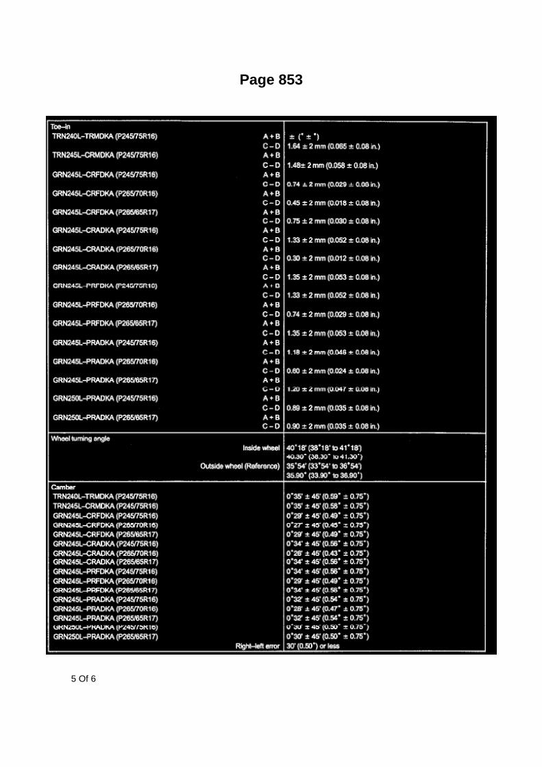
Page 853
5 Of 6

Specifications
Engine Oil Pressure: Specifications
Oil pressure

Page 406

Ac - Ya

Page 1367

5. DRAIN ENGINE OIL 6. DRAIN ENGINE COOLANT 7. REMOVE BATTERY 8. REMOVEBATTERY TRAY 9. REMOVE RADIATOR SUPPORT TO FRAME SEAL LH
10. REMOVE FAN SHROUD 11. REMOVE AIR CLEANER CAP SUB-ASSEMBLY 12. REMOVEAIR CLEANER FILTER ELEMENT SUB-ASSEMBLY 13. REMOVE AIR CLEANER CASE
a. Remove the 3 bolts, then remove the air cleaner case.
14. SEPARATE VANE PUMP ASSEMBLY
a. Disconnect the vane pump connector. b. Remove the 2 bolts, then separate the vane pump.
HINT: Do not disconnect the hose. Hang the vane pump with a rope.
15. REMOVE RADIATOR HOSE NO.2
16. SEPARATE COMPRESSOR AND MAGNETIC CLUTCH (W/ AIR CONDITIONING)
a. Remove the bolt shown in the illustration.
b. Disconnect the compressor and magnetic clutch connector. c. Remove the 4 bolts, thenseparate the compressor and magnetic clutch.
HINT: Do not disconnect the hose. Hang the vane pump with a rope.
17. REMOVE RADIATOR HOSE INLET 18. SEPARATE WATER HOSE SUB-ASSEMBLY 19.DISCONNECT FUEL HOSE 20. DISCONNECT FUEL HOSE NO.2 21. SEPARATE FUEL VAPORFEED HOSE ASSEMBLY 22. DISCONNECT AIR INJECTION SYSTEM NO.1 HOSE 23.DISCONNECT ENGINE WIRE 24. REMOVE EXHAUST PIPE ASSEMBLY TAIL

Page 143
Example: (1) Indicates Relay Block No.1

C: ( ) is used to indicate different wiring and connector, etc. when the vehicle model, engine type,or specification is different.
D: Indicates related system.
E: Indicates the wiring harness and wiring harness connector. The wiring harness with maleterminal is shown with arrows.
Outside numerals are pin numbers.
The first letter of the code for each wiring harness and wiring harness connector(s) indicates thecomponent's location, e.g, "E" for the Engine Compartment, "I" for the Instrument Panel andSurrounding area, and "B" for the Body and Surrounding area.
When more than one code has the first and second letters in common, followed by numbers (e.g,IH1, IH2), this indicates the same type of wiring harness and wiring harness connector.
F: Represents a part (all parts are shown in sky blue). The code is the same as the code used inparts position.
G: Junction Block (The number in the circle is the J/B No. and the connector code is shown besideit). Junction Blocks are shaded to clearly separate
them from other parts.
H: Indicates the wiring color.
Wire colors are indicated by an alphabetical code. B = Black L = Blue R = Red P = Pink O =Orange W = White V = Violet G = Green Y = Yellow BR = Brown SB = Sky Blue LG = Light GreenGR = Gray
The first letter indicates the basic wire color and the second letter indicates the color of the stripe.

Page 2684
Shift Interlock Solenoid: Testing and Inspection
KEY INTER LOCK SOLENOID
INSPECTION
1. INSPECT KEY INTER LOCK SOLENOID
a. Disconnect the solenoid connector. b. Connect KLS+
(4) terminal to the battery positive (+) terminal, and KLS- (3) terminal to the battery negative (-)terminal, and apply about 12V between KLS+ and KLS terminals. Check that operation noise canbe
heard from the solenoid.
If the solenoid does not operate, replace the solenoid.

Locations
Intake Air Temperature Sensor: Locations

SFI System
The Intake Air Temperature (IAT) Sensor is installed in the Mass Air Flow (MAF) Meter.

Locations

Switch: Locations
Po - Ya

Page 1935

Information Bus: Description and Operation System Outline

System Outline
Multiplex communication system (CAN) uses a serial communication protocol and communicateswith a differential voltage.
In this network system, TERMINALS CANH and CANL are used for communication between theECUs and sensors, and excellent data communication speed and communication error detectingfacility are provided. This system is working for the following system:
- Cruise Control
- Electronically Controlled Transmission and A/T Indicator
- Engine Control
- VSC

Page 1034

Driver Side J/B Part 2
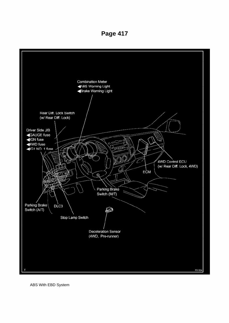
Page 417
ABS With EBD System

Specifications

Valve Clearance: Specifications

The 2TR-FE engine uses a hydraulic valve lash adjuster assembly. Adjustment is not required.

Page 240
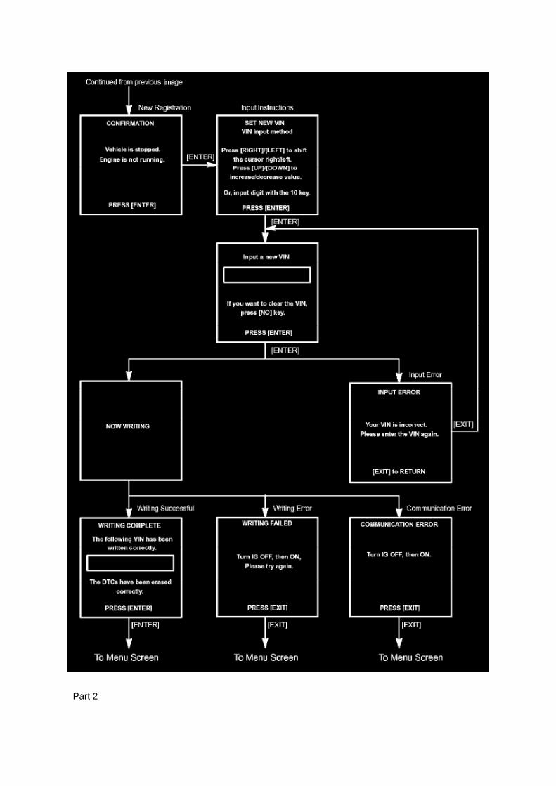
Part 2

a. Write VIN using the hand-held tester.
Vehicle Reprogramming
VEHICLE REPROGRAMMING
Beginning with some 2001 models and expanding to all models by 2007, Toyota/Scion and Lexusvehicles are equipped with flash reprogrammable Powertrain Control Modules (PCM).Reprogramming should only be performed if a Technical Service Bulletin or Service Campaignprovides direction to do so.

Page 2650

Crankshaft Position Sensor: Service and Repair

REPLACEMENT
1. DISCONNECT CABLE FROM NEGATIVE BATTERY TERMINAL 2. REMOVE ENGINE UNDERCOVER SUB-ASSEMBLY NO.1 (PRE RUNNER AND 4WD TYPE) 3. REMOVE FAN ANDGENERATOR BELT (W/ AIR CONDITIONING) 4. REMOVE COMPRESSOR AND MAGNETICCLUTCH (W/ AIR CONDITIONING) 5. REMOVE IDLE PULLEY ASSEMBLY W/BRACKET (W/ AIRCONDITIONING)
a. Remove the 5 bolts, then remove the idle pulley with bracket.
6. REMOVE CRANKSHAFT POSITION SENSOR
a. Disconnect the crankshaft position sensor connector and the 2 wire harness clamps.
b. Remove the bolt, then remove the crankshaft position sensor.
7. INSTALL CRANKSHAFT POSITION SENSOR

Page 1127
Problem Symptoms Table
The suspected circuits or parts for each problem symptom are shown in the table . Use this table totroubleshoot when, during a DTC check, a "Normal" code is displayed but the problem is stilloccurring. Numbers in the table show the inspection order in which the circuits or parts should bechecked.
HINT: In some cases, the problem is not detected by the diagnostic system even though a problemsymptom is present. It is possible that the problem is occurring outside the detection range of thediagnostic system, or that the problem is occurring in a completely different system.

Locations
Door Switch: Locations
Ac - Ou

Locations

A/C - Fo

Page 868
a. Connect the hand-held tester to the DLC3. b. Turn the ignition switch to ON.
NOTE: Do not start the engine.
c. Turn the hand-held tester ON. d. Select the following menu items: DIAGNOSIS / ENHANCEDOBD II / ACTIVE TEST / FUEL PUMP / SPD / ON. e. Check that there are no leakage in the fuelsystem.

Page 585
Knock Sensor: Testing and Inspection
INSPECT KNOCK SENSOR
a. Check the resistance.
1. Using an ohmmeter, measure the resistance between the terminals.
If the result is not as specified, replace the knock sensor.

Locations
A/C - Ge

Page 1407

b. Remove the 19 bolts and 2 nuts shown in the illustration.

HINT: If the vehicle is equipped with air conditioning, bolts A are already removed since they arefor installing the idle pulley w/ bracket.
c. Remove the timing chain cover by prying between the timing chain cover and cylinder head orcylinder block with a screwdriver.
HINT: Tape the screwdriver tip before use.
NOTICE: Be careful not to damage the contact surfaces of the cylinder head, cylinder block andtiming chain cover.
d. Remove the 4 O-rings.

Page 525

Oxygen Sensor: Service and Repair Heated Oxygen Sensor

REPLACEMENT
1. DISCONNECT CABLE FROM NEGATIVE BATTERY TERMINAL 2. REMOVE HEATEDOXYGEN SENSOR
a. Disconnect the heated oxygen sensor connector. b. Disconnect the wire harness clamp. (4WDDRIVE TYPE)
c. Using SST, remove the heated oxygen sensor.
SST 09224-00010
3. INSTALL HEATED OXYGEN SENSOR
a. Using SST, install the heated oxygen sensor.

Page 2270

a. Remove the 4 nuts, then remove the intake pipe insulator. b. Remove the 2 gaskets.

7. REMOVE AIR SWITCHING VALVE ASSEMBLY
a. Disconnect the vacuum hose. b. Disconnect the air switching valve connector.
c. Remove the 2 nuts, then remove the air switching valve. d. Remove the gasket.
8. INSTALL AIR SWITCHING VALVE ASSEMBLY
a. Install a new gasket onto the cylinder head. b. Install the air switching valve with the 2 nuts.
Torque: 20 N.m (204 Kgf.cm, 15 ft.lbf)

Page 2849


Page 1075
b. Push the secondary locking device or terminal retainer in to the full lock position.
5. CONNECT CONNECTOR
Disconnection of Male and Female Connectors
DISCONNECTION OF MALE AND FEMALE CONNECTORS
To pull apart the connectors, pull on the connector itself, not the wire harness.
HINT: Check to see what kind of connector you are disconnecting before pulling apart.

Page 1842
Supplemental Restraint System

Clutch Start Switch Assy
Clutch Switch: Service and Repair Clutch Start Switch Assy
Inspection
CLUTCH START SWITCH ASSEMBLY
ON-VEHICLE INSPECTION
1. CHECK CLUTCH START SYSTEM

a. Check that the engine does not start when the clutch pedal is released. b. Check that the enginestarts when the clutch pedal is fully depressed.
If necessary, replace the clutch start switch assembly.
Replacement
CLUTCH START SWITCH ASSEMBLY
REPLACEMENT
1. REMOVE CLUTCH START SWITCH ASSEMBLY
a. Disconnect the clutch start switch assembly connector. b. Remove the nut and clutch start switchassembly from the clutch pedal support.
2. INSTALL CLUTCH START SWITCH ASSEMBLY
a. Install the clutch start switch assembly with the nut.
Torque: 16 Nm (160 kgf-cm, 12 ft. lbs.)
b. Connect the clutch start switch assembly connector.
3. INSPECT CLUTCH START SWITCH ASSEMBLY

Page 610

CAUTION: For removal and installation procedures of the airbag sensor rear, see "Replacement"and be sure to follow the correct procedure.

AIRBAG SENSOR REAR (VEHICLE INVOLVED IN COLLISION AND AIRBAG IS DEPLOYED)
a. Replace the airbag sensor rear.
CAUTION: For removal and installation procedures of the airbag sensor rear, see "Replacement"and be sure to follow the correct procedure.
HINT: The airbag sensor rear on the impacted side should be replaced after the curtain shieldairbag assembly has deployed.
SEAT POSITION AIRBAG SENSOR (VEHICLE NOT INVOLVED IN COLLISION)
a. Perform a diagnostic system check.
Refer to Air Bag Systems; Testing and Inspection.
SEAT POSITION AIRBAG SENSOR (VEHICLE INVOLVED IN COLLISION)
a. Perform a diagnostic system check.
Refer to Air Bag Systems; Testing and Inspection.
b. Even if the airbag was not deployed, perform a visual check for damage to the seat positionairbag sensor. If there are any defects as mentioned
below, replace the seat position airbag sensor with a new one: -
Cracks, dents or chips in the case.
- Cracks or other damage to the connector.
CAUTION: For removal and installation procedures of the seat position airbag sensor, see"Replacement" and be sure to follow the correct procedure.

Page 1671
o. Connect the fuel vapor feed hose to the VSV.
12. CONNECT FUEL HOSE 13. CONNECT FUEL HOSE NO.2 14. INSTALL THROTTLEW/MOTOR BODY ASSEMBLY 15. INSTALL INTAKE AIR CONNECTOR 16. CONNECT CABLETO NEGATIVE BATTERY TERMINAL
Torque: 3.9 N.m (40 kgf.cm, 35 in.lbf)
17. ADD ENGINE COOLANT 18. CHECK FOR ENGINE COOLANT LEAKAGE 19. CHECK FORFUEL LEAKAGE 20. INSTALL ENGINE UNDER COVER SUB-ASSEMBLY NO.1 (PRE RUNNERAND 4WD TYPE)

Page 1184

46. INSTALL REAR WHEEL

Torque: 113 Nm (1,152 kgf-cm, 83 ft. lbs.)
47. INSPECT PARKING BRAKE PEDAL TRAVEL (AUTOMATIC TRANSAXLE) 48. INSPECTPARKING BRAKE LEVER TRAVEL (MANUAL TRANSAXLE) 49. ADJUST PARKING BRAKEPEDAL TRAVEL (AUTOMATIC TRANSAXLE) 50. ADJUST PARKING BRAKE LEVER TRAVEL(MANUAL TRANSAXLE) 51. CHECK ABS SENSOR SIGNAL (W/ VSC) 52. CHECK ABSSENSOR SIGNAL (W/O VSC)

Page 2214
SFI System

Page 2015
Step 5 - 6

Page 1394


Page 1335
Required SSTs
Repair Procedure
1. Verify leak exists from the crankshaft seal area.
2. Remove the accessory belt.
3. Remove the crankshaft pulley.
4. Remove the front oil seal.
5. Install the timing chain cover oil seal.
A. Apply MP grease to the lip of the NEW oil seal.
B. Place the oil seal into the correct location in the seal recess of the timing chain cover.
C. Install the SST into the crankshaft and lightly tighten until the seal is fully seated in the timingchain cover. Do NOT over tighten.

Page 1563
4. Attach the Authorized Vehicle Modification Label.

Modifications to ECU calibrations MUST be recorded and properly displayed on the vehicle usingthe Authorized Modification Label.
Techstream Preparation
Selecting the TIS Techstream VIM or the Mongoose MFC VIM.
Techstream software requires a VIM selection before you can use the Mongoose MFC VIM.
If using TIS Techstream no changes are needed.
Perform the following:
1. Select Setup from the Techstream Main Menu screen.
2. Select VIM Select from the Setup drop down menu.
3. Select the correct Interface Setup from the drop down list.
^ If using Techstream Lite select Mongoose MFC.
NOTE

Page 2098
^ Engine Control Module (ECM)
^ Transmission Control Module (TCM)
^ Or any other Toyota specific control unit
Warranty Information
Parts Information
Required Tools & Equipment
NOTE
Additional SSTs may be ordered by calling 1-800-933-8335.
Process Overview
Techstream ECU flash reprogramming is a 4-step process:

1. Verify the vehicle's applicability for recalibration and locate desired calibration file by performingthe Techstream Health Check function.
NOTE
Techstream will automatically search TIS for the appropriate service bulletin using the currentCalibration ID from the vehicle. Calibration file links can be found embedded in the correspondingservice bulletin.
2. Connect the GR8 Battery Diagnostic Station using "Power Supply Mode" only.
The GR8 Battery Diagnostic Station includes a Power Supply Mode to help maintain batteryvoltage at 13.5 volts during ECU reprogramming.
ECU damage may occur if the correct battery charger mode setting is NOT used.
3. Locate appropriate calibration ID and reprogram the vehicle ECU with Techstream.
Techstream uses the Calibration Update Wizard (CUW) application to open calibration files andfacilitate the ECU flash reprogramming process.

Locations
Camshaft Position Sensor: Locations

A/C - Ge

Page 1079
Driver Side J/B - Lower Finish Panel

Locations

He - Wi

Page 164
Diagnostic Trouble Code Chart
Use Diagnostic Trouble Codes (DTCs) (from the DTC checks) in the table to determine the troublearea and proper inspection procedure. The Supplemental Restraint System (SRS) DTC chart isshown as an example.
Problem Symptoms Table

PROBLEM SYMPTOMS TABLE

Page 3299

33. INSTALL BRAKE BOOSTER W/ACCUMULATOR PUMP ASSEMBLY

a. Install the 2 collars and 2 bushes onto the brake booster w/ accumulator pump assembly. b.Using a hexagon wrench (4 mm), install the 2 pins.
Torque: 7.8 Nm (80 kgf-cm, 69 inch lbs.)
c. Install the brake booster w/ accumulator pump assembly.
d. Install a new clip.
e. Install the wire harness with the 2 screws.
Torque: 2.9 Nm (30 kgf-cm, 26 inch lbs.)
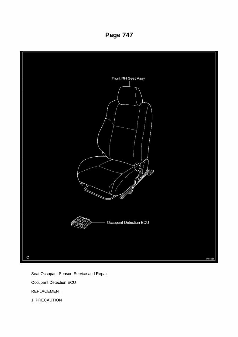
Page 747
Seat Occupant Sensor: Service and Repair
Occupant Detection ECU
REPLACEMENT
1. PRECAUTION

Refer to Air Bag Systems; Service Precautions.
2. DISCONNECT CABLE FROM NEGATIVE BATTERY TERMINAL
Wait for at least 90 seconds after disconnecting the cable to prevent the airbag from working.
3. REMOVE FRONT RH SEAT ASSEMBLY
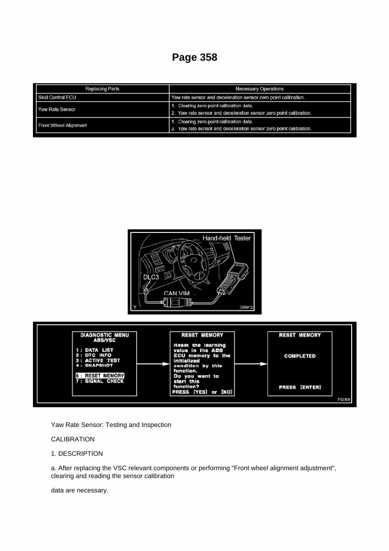
Page 358
Yaw Rate Sensor: Testing and Inspection
CALIBRATION
1. DESCRIPTION
a. After replacing the VSC relevant components or performing "Front wheel alignment adjustment",clearing and reading the sensor calibration
data are necessary.
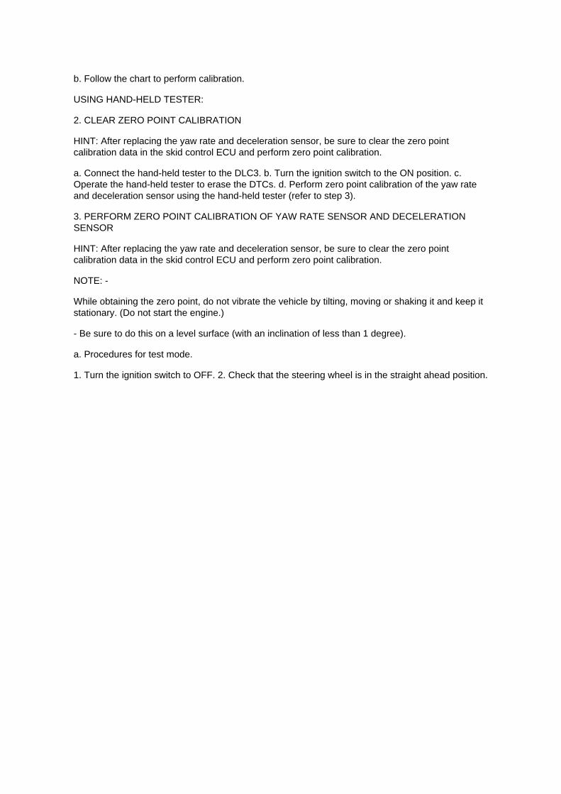
b. Follow the chart to perform calibration.
USING HAND-HELD TESTER:
2. CLEAR ZERO POINT CALIBRATION
HINT: After replacing the yaw rate and deceleration sensor, be sure to clear the zero pointcalibration data in the skid control ECU and perform zero point calibration.
a. Connect the hand-held tester to the DLC3. b. Turn the ignition switch to the ON position. c.Operate the hand-held tester to erase the DTCs. d. Perform zero point calibration of the yaw rateand deceleration sensor using the hand-held tester (refer to step 3).
3. PERFORM ZERO POINT CALIBRATION OF YAW RATE SENSOR AND DECELERATIONSENSOR
HINT: After replacing the yaw rate and deceleration sensor, be sure to clear the zero pointcalibration data in the skid control ECU and perform zero point calibration.
NOTE: -
While obtaining the zero point, do not vibrate the vehicle by tilting, moving or shaking it and keep itstationary. (Do not start the engine.)
- Be sure to do this on a level surface (with an inclination of less than 1 degree).
a. Procedures for test mode.
1. Turn the ignition switch to OFF. 2. Check that the steering wheel is in the straight ahead position.

Locations

Knock Sensor: Locations

He - Wi

Page 2738

Then click Start.
I. Do NOT disturb the vehicle during flash reprogramming.
NOTE
^ ECU flash reprogramming may take anywhere from 3 - 30 minutes per calibration file.
^ Reprogramming time will vary depending on model and ECU communication protocol. Vehiclesusing CAN communication protocol will reprogram much faster (2 - 7 minutes).
NOTE
^ If vehicle requires only ONE calibration update, then proceed to step N in this bulletin.
^ If vehicle requires a SECOND calibration update, then continue as follows:
^ For serial communication vehicles, go to step J.
^ For CAN communication vehicles, go to step L.
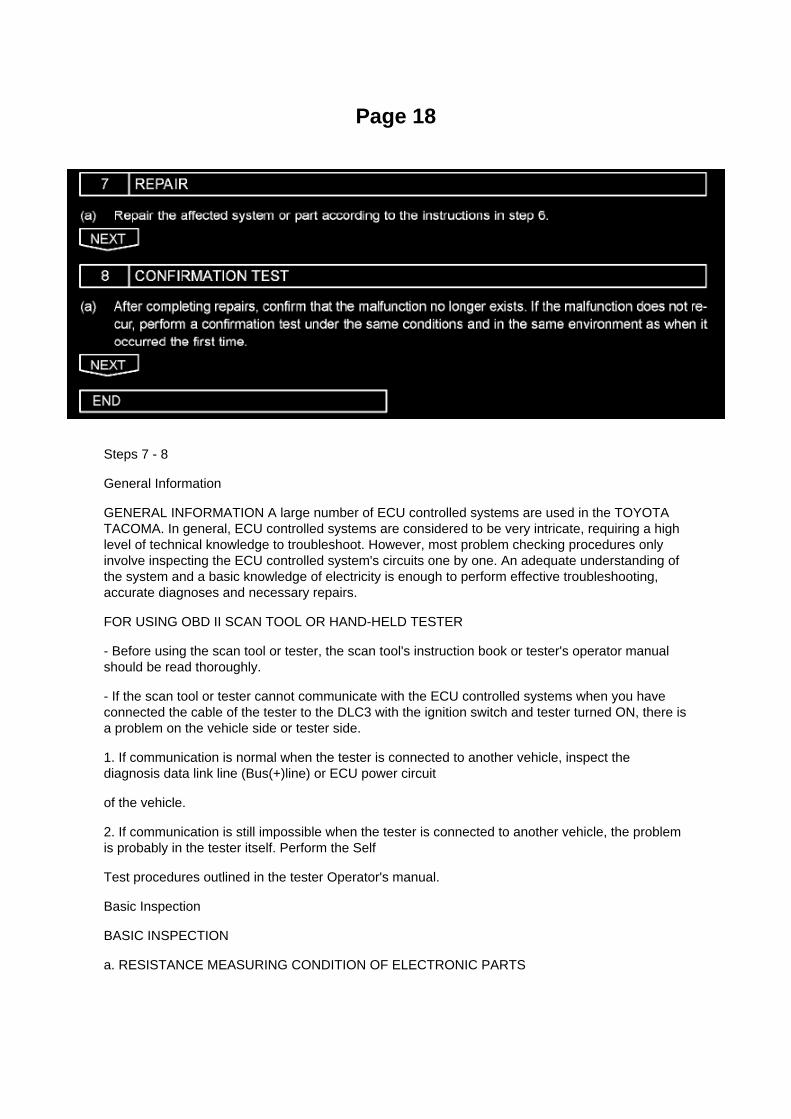
Page 18
Steps 7 - 8
General Information
GENERAL INFORMATION A large number of ECU controlled systems are used in the TOYOTATACOMA. In general, ECU controlled systems are considered to be very intricate, requiring a highlevel of technical knowledge to troubleshoot. However, most problem checking procedures onlyinvolve inspecting the ECU controlled system's circuits one by one. An adequate understanding ofthe system and a basic knowledge of electricity is enough to perform effective troubleshooting,accurate diagnoses and necessary repairs.
FOR USING OBD II SCAN TOOL OR HAND-HELD TESTER
- Before using the scan tool or tester, the scan tool's instruction book or tester's operator manualshould be read thoroughly.
- If the scan tool or tester cannot communicate with the ECU controlled systems when you haveconnected the cable of the tester to the DLC3 with the ignition switch and tester turned ON, there isa problem on the vehicle side or tester side.
1. If communication is normal when the tester is connected to another vehicle, inspect thediagnosis data link line (Bus(+)line) or ECU power circuit
of the vehicle.
2. If communication is still impossible when the tester is connected to another vehicle, the problemis probably in the tester itself. Perform the Self
Test procedures outlined in the tester Operator's manual.
Basic Inspection
BASIC INSPECTION
a. RESISTANCE MEASURING CONDITION OF ELECTRONIC PARTS

1. Unless stated, all resistance measurements should be made at an ambient temperature of 20°C(68°F). Resistance measurements may be
outside the specifications if measured at high temperatures, i.e. immediately after the vehicle hasbeen running. Measurements should be made after the engine has cooled down.

Page 2517
Refer to the Technical Information System (TIS):
^ 2005 model year Tacoma Repair Manual, Brake - Brake (front) - "Front Brake (4WD and PreRunner): Overhaul".
^ 2006 or 2007 model year Tacoma Repair Manual, Brake - Brake (front) - "Brake:

Front Brake (for 4WD and Pre -Runner): Removal".
3. Apply NEW grease on the brake pads as shown in red below.
4. Apply grease to the brake caliper as shown in red below.
5. Install the front brake pads and front rotors. Refer to TIS:
^ 2005 model year Tacoma Repair Manual, Brake - Brake (front) - "Front Brake (4WD and PreRunner): Overhaul".
^ 2006 or 2007 model year Tacoma Repair Manual, Brake - Brake (front) - "Brake: Front Brake (for4WD and Pre -Runner): Installation".
6. Road test the vehicle to confirm the front brake noise is NO longer present.

Page 2194
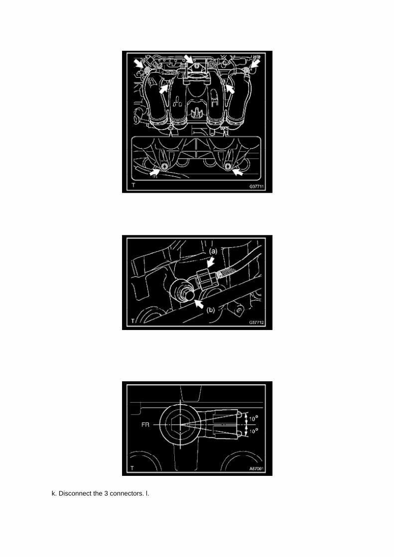
k. Disconnect the 3 connectors. l.

Remove the nut shown in the illustration.
m. Disconnect the engine wire harness from the relay block.
n. Remove the 5 bolts and 2 nuts, then remove the intake manifold.
9. REMOVE KNOCK CONTROL SENSOR
a. Disconnect the knock control sensor connector. b. Remove the bolt, then remove the knockcontrol sensor.
10. INSTALL KNOCK CONTROL SENSOR
a. Install the knock control sensor with the bolt.
Torque: 20 N.m (204 kgf.cm, 15 ft.lbf)
NOTE: Make sure that the knock sensor is at the correct angle when installing.
b. Connect the knock control sensor connector.
11. INSTALL INTAKE MANIFOLD

Page 729

(l) Select "7: SRS AIRBAG" from the "OBD/MOBD MENU".

(m)Press the "YES button when the "VERIFY CONNECTIONS" screen appears.
(n) Select "1: DATA LIST from the "DIAGNOSTIC MENU, AIRBAG/SRS" system.
(o) Select "ALL from the "SELECT DATA" menu.

Fuel/Emissions - MIL ON/DTC's P0456/P0445 and P0441
Set
Fuel Pump Pickup Filter: Customer Interest Fuel/Emissions - MIL ON/DTC's P0456/P0445 andP0441 Set
ENGINE EG037-05 REVISED
Title: M.I.L. "ON" DTC P0456 OR P0455, AND P0441
Models: '05 Tacoma
September 1, 2005
TSB REVISION NOTICE:
^ September 16, 2005: The Applicable VDS has been updated in Applicable Vehicles. Previousversions of this TSB should be discarded.
Introduction
Some 2005 model year Tacoma vehicles may exhibit a M.I.L. "ON" condition with one or more ofthe following DTCs: P0456 or P0455, and P0441 (EVAP Emission Control System). Follow thesteps in this bulletin to correct this condition.

Applicable Vehicles
^ 2005 model year Tacoma vehicles (except D-Cab Short Bed), with the following VehicleDescription Section VDS) information shown below.
Warranty Information
Applicable Warranty*: This repair is covered under the Toyota Powertrain Warranty. This warrantyis in effect for 60 months or 60,000 miles, whichever occurs first, from the vehicle's in-service date.
* Warranty application is limited to correction of a problem based upon a customer's specificcomplaint.

Page 2458

1. Discharge the fuel system pressure (step 2). 2. Disconnect the fuel tank main tube. 3. Drain thefuel remaining in the fuel tank main tube. 4. Cover the disconnected fuel tank main tube (fuel tube

joint and fuel tube connector) with a vinyl bag to prevent damage and the intrusion
of foreign objects.
b. Take the following precautions when installing the fuel injector.
1. Do not reuse the O-ring. 2. Do not damage a new O-ring when installing it onto the fuel injector.3. Before installing a new O-ring, apply gasoline or spindle oil.
NOTE: Do not use engine oil, gear oil or brake oil.
4. Install the fuel injector into the fuel delivery pipe and cylinder head as illustrated.
HINT: Apply gasoline or spindle oil to the contact surface of the fuel delivery pipe and fuel injectorbefore installing the fuel injector.
c. Take the following precautions when disconnecting the fuel tube connector.
HINT: The structure of the fuel tube connector is as shown in the illustration.
1. Check the fuel tube connector and pipe for dirt and mud before removing the fuel tubeconnector.
If dirty, wipe it with a shop rag.
Page 2376

Air-Fuel Ratio (A/F) Sensor
Oxygen Sensor: Testing and Inspection Air-Fuel Ratio (A/F) Sensor
INSPECTION
INSPECT AIR FUEL RATIO SENSOR
a. Check the resistance.
1. Using an ohmmeter, measure the resistance between the terminals.
If the result is not as specified, replace the air fuel ratio sensor.

Page 727

(d) Turn the scan tool ON by pressing the "ON" button.

(e) Press "ENTER" after the start up screen appears.
(e) Select "1: DIAGNOSIS from the "APPLICATION SELECT menu.
(f) Select "1: OBD/MOBD" from the "FUNCTION SELECT FOR NORTH AMERICA" menu.

Page 1739

Crankshaft Position Sensor: Service and Repair

REPLACEMENT
1. DISCONNECT CABLE FROM NEGATIVE BATTERY TERMINAL 2. REMOVE ENGINE UNDERCOVER SUB-ASSEMBLY NO.1 (PRE RUNNER AND 4WD TYPE) 3. REMOVE FAN ANDGENERATOR BELT (W/ AIR CONDITIONING) 4. REMOVE COMPRESSOR AND MAGNETICCLUTCH (W/ AIR CONDITIONING) 5. REMOVE IDLE PULLEY ASSEMBLY W/BRACKET (W/ AIRCONDITIONING)
a. Remove the 5 bolts, then remove the idle pulley with bracket.
6. REMOVE CRANKSHAFT POSITION SENSOR
a. Disconnect the crankshaft position sensor connector and the 2 wire harness clamps.
b. Remove the bolt, then remove the crankshaft position sensor.
7. INSTALL CRANKSHAFT POSITION SENSOR

Page 1835

a. Using several steps, uniformly install and tighten the 5 bolts in the sequence shown in theillustration.

Torque: 21 N.m (214 kgf.cm, 16 ft.lbf) for bolt A 43 N.m (438 kgf.cm, 32 ft.lbf) for bolt B, C
9. INSTALL COMPRESSOR AND MAGNETIC CLUTCH (W/ AIR CONDITIONING)
10. INSTALL FAN AND GENERATOR BELT (W/ AIR CONDITIONING) 11. INSTALL ENGINEUNDER COVER SUB-ASSEMBLY NO.1 (PRE RUNNER AND 4WD TYPE)
12. CONNECT CABLE TO NEGATIVE BATTERY TERMINAL
Torque: 3.9 N.m (40 kgf.cm, 35 in.lbf)

Page 1969
(CANL) of the DLC3.

Wiring Diagram

Page 441
Key Reminder Warning System

Page 2254
Variable Valve Timing Actuator: Testing and Inspection On-Vehicle Inspection
INSPECT CAMSHAFT TIMING OIL CONTROL VALVE ASSEMBLY
a. Check the operation.
1. Connect the hand-held tester to the DLC3. 2. Turn the ignition switch to ON. 3. Turn thehand-held tester ON. 4. Start the engine and warm it up. 5. Select the following menu items:DIAGNOSIS / ENHANCED OBD II / ACTIVE TEST / VVT CTRL B1.
6. Operate the OCV using the hand-held tester, then check the engine speed.
If the operation is not as specified, check the camshaft timing oil control valve, wire harness andECM.

Capacity Specifications

Coolant: Capacity Specifications

Total Cooling System Capacity M/T :................................................................................................................................ 8.7 L (9.1 US qt.,7.6 Imp. qt.)
Total Cooling System Capacity A/T :................................................................................................................................. 8.6 L (9.1 US qt.,7.6 Imp. qt.)

Page 680


Page 212
Required SSTs
VIN Write Procedure
To write a VIN to a replacement ECM (PCM), use the following process:

1. Confirm the VIN. It is located on the front left of the instrument panel.
2. Connect the Diagnostic Tester to DLC3.
3. Turn the ignition switch and Diagnostic Tester switch ON.
4. All vehicles except Prius and Highlander HV:
Select from the Diagnostic Tester menus: DIAGNOSIS, ENHANCED OBDII, VIN, and VIN WRITE.
Prius and Highlander HV vehicles:
Select from the Diagnostic Tester menus: DIAGNOSIS, OBD/MOBD, HV ECU, VIN, and VINWRITE.

Page 228

Terminals Of ECM / Pinouts Part 2

Page 1122

(Sample ) Supplemental Restraint System check sheet
Symptom Confirmation and Diagnostic Trouble Code
SYMPTOM CONFIRMATION AND DIAGNOSTIC TROUBLE CODE
HINT:
The diagnostic system in the TOYOTA TACOMA has various functions. -
The first function is the Diagnostic Trouble Code (DTC) check. A DTC is a code stored in the ECUmemory whenever a malfunction in the signal circuits to the ECU occurs. In a DTC check, aprevious malfunction's DTC can be checked by a technician during troubleshooting.
- Another function is the Input Signal Check, which checks if the signals from various switches aresent to the ECU correctly. By using these functions, the problem areas can be narrowed down andtroubleshooting is more effective. Diagnostic functions are incorporated in the above systems in theTOYOTA TACOMA:
- In the DTC check, it is very important to determine whether the problem indicated by the DTC is:1) still occurring, or 2) occurred in the past but has since returned to normal. In addition, the DTCshould be compared to the problem symptom to see if they are related. For this reason, DTCsshould be checked before and after confirmation of symptoms (i.e., whether or not problemsymptoms exist) to determine current system conditions, as shown in the flowchart. Never skip theDTC check. Failing to check DTCs may, depending on the case, result in unnecessarytroubleshooting for systems operating

Page 493

Knock Control Sensor (2TR-FE) Part 2

Page 2589

Throttle W/motor Body Assy (2TR-FE) Part 2

Page 2766

Mongoose MFC Software and Driver MUST be installed before Mongoose MFC selection will beavailable.

See TIS - Diagnostics - Scantool page for additional information.
^ If using TIS Techstream select TIS Techstream VIM (this is the default).
4. Click OK.
Operation Procedure
1. Verify the vehicle's applicability for recalibration and locate desired calibration file.
A. Connect Techstream and establish a vehicle connection.
B. Click the Health Check button on the System Select tab.

Page 845

^ The method of camber adjustment differs for different models, so please refer to the RepairManual of the vehicle involved. (The information below are samples from the Sienna Repair

Manual.)
A. Remove the front wheels and ABS speed sensor clamp.
B. Remove the two nuts on the lower side of the shock absorber.
C. Coat the threads of the nuts with engine oil.
D. Temporarily install the two nuts.
E. Adjust the camber by pushing or pulling the lower side of the shock absorber in the direction inwhich the camber adjustment is required.
F. Tighten the nuts.
Torque: 210 N*m (2150 kgf*cm, 155 ft*lbf)
G. Install the front wheels.
Torque: 104 N*m (1050 kgf*cm, 77 ft*lbf)
H. Check the camber.

Page 2115
Engine Control Module: Technical Service Bulletins Engine/Transmission Controls - Resetting ECMMemory
TRANSMISSION & CLUTCH TC002-03 REVISED
Title: ECM RESET MEMORY FUNCTION
Models: '00 - '05 All Models
June 10, 2003
TSB REVISION NOTICE:
^ December 20, 2004: Applicable Vehicles section has been updated - 2004 and 2005 model yearsadded, models and model years updated for various models; and Reset Procedure 2 has beenrevised.
^ January 16, 2004: Tundra vehicles were added to the Applicable Vehicles chart.
^ December 17, 2003: T-100 vehicles were removed from the Applicable Vehicles chart.
Previous versions of this TSB should be discarded.
Introduction

Whenever an automatic transmission is replaced, overhauled or individual components arereplaced, use this procedure to clear Engine Control Module (ECM, SAE term: Powertrain ControlModule, PCM) "Learned Values" to minimize subsequent performance concerns.
CAUTION:
Failure to follow the procedure below may lengthen the time to readjust the ECM "Learned Values,"potentially resulting in performance concerns.
Required SSTs
Warranty Information
Applicable Vehicles

Page 2421

Oxygen Sensor: Service and Repair Heated Oxygen Sensor

REPLACEMENT
1. DISCONNECT CABLE FROM NEGATIVE BATTERY TERMINAL 2. REMOVE HEATEDOXYGEN SENSOR
a. Disconnect the heated oxygen sensor connector. b. Disconnect the wire harness clamp. (4WDDRIVE TYPE)
c. Using SST, remove the heated oxygen sensor.
SST 09224-00010
3. INSTALL HEATED OXYGEN SENSOR
a. Using SST, install the heated oxygen sensor.

Page 14

Abbreviations

Locations

Knock Sensor: Locations

He - Wi

Service and Repair
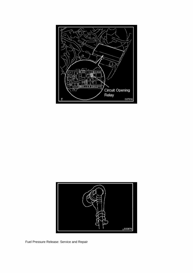
Fuel Pressure Release: Service and Repair

PRECAUTION
1. PRECAUTION
a. Before working on the fuel system, disconnect the cable from the negative battery terminal. b.Do not work on the fuel system near fire. Never smoke during the work. c. Keep rubber and leatherparts away from gasoline.
2. DISCHARGE FUEL PRESSURE
CAUTION: -
Before removing fuel system parts, take precautions to prevent gasoline spillage.
- As some pressure remains in the fuel line even after taking precautions to prevent gasolinespillage, use a shop rag to prevent gasoline splashes when disconnecting the fuel line.
a. Disconnect the cable from the negative battery terminal. b. Remove the engine relay blockcover.
c. Remove the circuit opening relay. d. Connect the cable to the negative battery terminal.
Torque: 3.9 N.m (40 kgf.cm, 35 in.lbf)
e. Start the engine. f.
Turn the ignition switch to ON after the engine stops.
HINT: DTC P0171 (system to lean) may be present.
g. Crank the engine again, and check that the engine stops. h. Remove the fuel tank cap, anddischarge the pressure in the fuel tank completely. i.
Install the circuit opening relay.
3. FUEL SYSTEM
a. When disconnecting the high-pressure fuel line, a large amount of gasoline will splash. So takethe following precautions.

Page 2469
Fuel Injector: Locations

Fuel Injector Assy (2TR-FE)

Page 590

(w/ AIR CONDITIONING)

i. Engage the engine wire harness clamp.
j. Connect the VSV connector.
k. Connect the ventilation hose No.3.
l. Connect the water bypass hose No.2.
m. Install the clamp bracket with the bolt.
Torque: 19 N.m (194 kgf.cm, 14 in.lbf)
n. Connect the vacuum hose.

Page 1746
Ignition Switch: Service and Repair
IGNITION OR STARTER SWITCH ASSEMBLY
REPLACEMENT
1. DISCONNECT CABLE FROM NEGATIVE BATTERY TERMINAL
2. REMOVE STEERING COLUMN COVER LWR
a. Remove the 2 screws. b. Disengage the 2 claws and remove the steering column cover LWR.
3. REMOVE IGNITION OR STARTER SWITCH ASSEMBLY

a. Disconnect the connector. b. Disengage the 2 clamps, then remove the ignition or starter switch.
4. INSTALL IGNITION OR STARTER SWITCH ASSEMBLY 5. INSTALL STEERING COLUMNCOVER LWR 6. CONNECT CABLE TO NEGATIVE BATTERY TERMINAL
Torque: 3.9 N.m (40 kgf.cm, 35 in.lbf)

Locations

Page 481

Crankshaft Position Sensor: Service and Repair

REPLACEMENT
1. DISCONNECT CABLE FROM NEGATIVE BATTERY TERMINAL 2. REMOVE ENGINE UNDERCOVER SUB-ASSEMBLY NO.1 (PRE RUNNER AND 4WD TYPE) 3. REMOVE FAN ANDGENERATOR BELT (W/ AIR CONDITIONING) 4. REMOVE COMPRESSOR AND MAGNETICCLUTCH (W/ AIR CONDITIONING) 5. REMOVE IDLE PULLEY ASSEMBLY W/BRACKET (W/ AIRCONDITIONING)
a. Remove the 5 bolts, then remove the idle pulley with bracket.
6. REMOVE CRANKSHAFT POSITION SENSOR
a. Disconnect the crankshaft position sensor connector and the 2 wire harness clamps.
b. Remove the bolt, then remove the crankshaft position sensor.
7. INSTALL CRANKSHAFT POSITION SENSOR

Locations
A/C - Ge

Page 1111

Abbreviations

Page 2001
Step 9 - 10

Page 743

Combination Meter

Page 1976

If 2 or more ECUs and/or sensors do not appear on the hand-held tester's "BUS CHECK" screenvia the CAN VIM, one side of the CAN sub-bus line may be open. (One side of the CAN-H [sub-busline]/CAN-L [sub-bus line] of the ECU and/or sensor is open.)
Wiring Diagram

Page 2764
^ Engine Control Module (ECM)
^ Transmission Control Module (TCM)
^ Or any other Toyota specific control unit
Warranty Information
Parts Information
Required Tools & Equipment
NOTE
Additional SSTs may be ordered by calling 1-800-933-8335.
Process Overview
Techstream ECU flash reprogramming is a 4-step process:

1. Verify the vehicle's applicability for recalibration and locate desired calibration file by performingthe Techstream Health Check function.
NOTE
Techstream will automatically search TIS for the appropriate service bulletin using the currentCalibration ID from the vehicle. Calibration file links can be found embedded in the correspondingservice bulletin.
2. Connect the GR8 Battery Diagnostic Station using "Power Supply Mode" only.
The GR8 Battery Diagnostic Station includes a Power Supply Mode to help maintain batteryvoltage at 13.5 volts during ECU reprogramming.
ECU damage may occur if the correct battery charger mode setting is NOT used.
3. Locate appropriate calibration ID and reprogram the vehicle ECU with Techstream.
Techstream uses the Calibration Update Wizard (CUW) application to open calibration files andfacilitate the ECU flash reprogramming process.

Locations
A/C - Ge

Page 731

(Driver's seat is in the backward position).
^ "D BUCKLE SW UNSET" (Driver's seat belt buckle switch is unset/unbuckled).
(Test # 3)
(a) Move the bench seat to the foremost position.
(b) Leave the driver's seat belt unbuckled.
(c) Confirm that the scan tool displays the data shown below and in the illustration.
^ "D SEAT POSITIFORWARD"
(Driver's seat is in the forward position).
^ "D BUCKLE SW UNSET" (Driver's seat belt buckle switch is unset/unbuckled).
(Test # 4)
(a) Leave the bench seat in the foremost position.
(b) Buckle the driver's seat belt.

Page 2358

Page 2166
Camshaft Position Sensor: Testing and Inspection
INSPECT CAMSHAFT POSITION SENSOR
Check the resistance.
Using an ohmmeter, measure the resistance between the terminals.
HINT: Cold and Hot mean the temperature of the coils themselves. Cold is from -10 to 50°C (14 to122°F) and Hot is from 50 to 100°C (122 to 212° F).
If the result is not as specified, replace the camshaft position sensor.

Engine Controls - Techstream(R) ECU Re-Flash
Procedure
Engine Control Module: Technical Service Bulletins Engine Controls - Techstream(R) ECURe-Flash Procedure
T-SB-0064-10
February 4, 2010
Techstream ECU Flash Reprogramming Procedure
Service Category Engine/Hybrid System
Section Engine Control
Market USA
Applicability
TSB SUPERSESSION NOTICE
The information contained in this TSB supersedes TSB No. SS002-07.
^ Applicability has been updated to include 2009 - 2011 model year Toyota vehicles.
^ A new section, Techstream Preparation, has been added.
^ Techstream Lite has been added as an option in Required Tools & Materials.
^ Process Overview and Operation Procedure sections have been updated.
TSB No. SS002-07 is Obsolete and any printed versions should be discarded. Be sure to reviewthe entire content of this service bulletin before proceeding.
Introduction
Flash reprogramming allows the ECU software to be updated without replacing the ECU. Flashcalibration updates for specific vehicle models/ECUs are released as field-fix procedures describedin individual service bulletins. This bulletin details the Techstream ECU flash reprogramming

process and outlines use of the Technical Information System (TIS) and the Calibration UpdateWizard (CUW). Flash calibration updates can only be applied to the vehicle/ECU combination forwhich they are intended. ECUs have internal security that will not allow them to be programmedwith another ECU's information.
ECU
Electronic Control Unit (ECU) is a Toyota term used to describe integrated computerized devicesresponsible for managing the operation of a system or subsystem. For the purposes of this bulletin,the term "ECU" is used as a generic label for the following SAE J1930 standard references:
^ Powertrain Control Module (PCM)

Page 2207

Applicable Vehicles

Page 2024

b. Press "ENTER" on the hand-held tester via the CAN VIM.

c. The screen displays the ECUs and sensors that are properly connected to the CANcommunication system.
HINT: There is a communication stop in the system of any properly connected ECUs or sensorsthat are not displayed.
Pinout Values and Diagnostic Parameters
TERMINALS OF ECU
HINT: This section describes the standard CAN values for all CAN related components.
1. CAN J/C

Page 2413

He - Wi

Page 1578
5. Write the VIN in accordance with the Diagnostic Tester display.
6. Compare the VIN displayed on the Diagnostic Tester with the VIN on the instrument panel. Ifthese are not the same, write the VIN again after turning the ignition switch OFF.

VIN Read Procedure
1. Connect the Diagnostic Tester to DLC3.
2. Turn the ignition switch and Diagnostic Tester switch ON.
3. All vehicles except Prius and Highlander HV:
Select from the Diagnostic Tester menus: DIAGNOSIS, ENHANCED OBDII, VIN, and VIN READ.
Prius and Highlander HV vehicles:
Select from the Diagnostic Tester menus: DIAGNOSIS, OBD/MOBD, HV ECU, VIN, and VINREAD.
4. Check the VIN displayed on the Diagnostic Tester.
HINT: For further explanations, refer to the Technical Information System (TIS), appropriate modelrepair manual: Diagnostics: SF1 System: Registration.

Service and Repair
Seals and Gaskets: Service and Repair
MANUAL TRANSMISSION EXTENSION HOUSING OIL SEAL (R155)
REPLACEMENT
1. REMOVE PROPELLER W/ CENTER BEARING SHAFT ASSY (ACCESS CAB) 2. REMOVEPROPELLER SHAFT ASSY (REGULAR CAB)
3. REMOVE MANUAL TRANSMISSION EXTENSION HOUSING OIL SEAL
a. Using SST, remove the oil seal.
SST 09308-00010
NOTICE: Do not damage the oil-seal-fitted surface of the extension housing.
4. INSTALL MANUAL TRANSMISSION EXTENSION HOUSING OIL SEAL

a. Using SST and a hammer, tap in the new oil seal to the extension housing.
SST 09223-00010 Drive in depth: 0 - 0.5 mm (0 - 0.020 inch)
NOTICE: Be careful not to damage the oil seal rip.
b. Coat the lip of a new oil seal with MP grease.
5. INSTALL PROPELLER W/ CENTER BEARING SHAFT ASSY (ACCESS CAB) 6. INSTALLPROPELLER SHAFT ASSY (REGULAR CAB) 7. CHECK FOR MANUAL TRANSMISSION OILLEAKAGE

Page 1114
Relay Box: Diagnostic Aids
Steps 1 - 6

Page 2007
Step 5 - 6

Page 1906

The "Current Flow Chart", describes which parts each power source (fuses, fusible links, and circuitbreakers) transmits current to. In the Power Source circuit diagram, the conditions when batterypower is supplied to each system are explained. Since all System Circuit diagrams start from thepower source, the power source system must be fully understood.
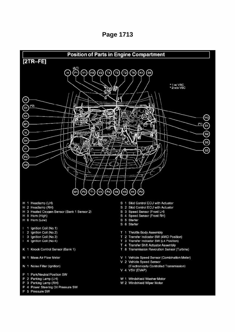
Page 1713

He - Wi

Page 1227
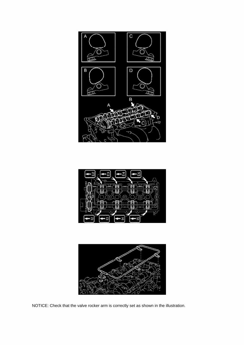
NOTICE: Check that the valve rocker arm is correctly set as shown in the illustration.

a. Apply clean engine oil to the camshaft's cam portion and the cylinder head journals. b. Install thechain onto the camshaft timing gear, with the painted mark of the link aligned with the timing markof the camshaft timing gear.
c. Set the 2 camshafts as shown in the illustration.
NOTICE: Align the paint mark with the timing mark before setting the camshaft.
d. Provisionally install the camshaft bearing cap No.1. e. Check the proper location of eachcamshaft bearing cap No.2 and install each one.
f. Install a new O-ring onto the camshaft bearing cap No.1.
g. Provisionally install the camshaft oil delivery pipe.

Service and Repair
Oil Change Reminder Lamp: Service and Repair
Engine Oil Replacement Reminder Light (for vehicles sold in U.S.A.)
This light reminds you when to replace the engine oil.
This light will come on when the ignition key is turned to ON and will go off after about a fewseconds.
When you drive for about 7200 km (4500 miles) after the engine oil replacement, this lightilluminates for about 3 seconds and then flashes for about 12 seconds with the ignition key turnedto the "ON" position. If you continue driving without replacing the engine oil, and if the distancedriven exceeds 8000 km (5000 miles), the light will come on after the ignition key is turned to "ON"position, and will remain on thereafter.
If the light is flashing, we recommend that you replace the engine oil at an early opportunitydepending on the driving and road conditions. If the light comes on steady, replace it as soon aspossible.
The system must be reset after the engine oil replacement. Reset the system by the followingprocedure: 1. Turn the ignition key to the "OFF" position with the odometer reading shown. 2. Turnthe ignition key to the "ON" position while holding down the trip meter reset knob.
Hold down the knob for at least 5 seconds. The odometer indicates "000000" and the light goes off.
If the system fails to reset, the light will continue flashing.

Page 3289

Hydraulic Control Assembly - Antilock Brakes: Service and Repair Brake Master Cylinder Assembly(W/ VSC)
BRAKE MASTER CYLINDER ASSEMBLY (W/ VSC)

Page 2942

A. Remove the front door opening trim LH (scuff plate).

B. Remove the cowl side trim board.
C. Remove the instrument panel finish panel lower No. 1.
D. Remove the driver's side Junction Block.
E. Remove the turnover (compression) spring.

Page 12
How to Read Ground Points

HOW TO READ GROUND POINTS
The ground points circuit diagram shows the connections from all major parts to the respectiveground points. When troubleshooting a faulty ground point, checking the system circuits which usea common ground may help you identify the problem ground quickly. The relationship betweenground points(EA, IB and IC is shown) can also be checked this way.
How to Read Power Source
HOW TO READ POWER SOURCE

Page 3167
Transmission Position Switch/Sensor: Adjustments
PARK/NEUTRAL POSITION SWITCH ASSY
ADJUSTMENT
1. INSPECT PARK/NEUTRAL POSITION SWITCH ASSY
a. Apply the parking brake and turn the ignition switch to ON. b. Depress the brake pedal andcheck that the engine starts only when the shift lever is set in the N or P position and that it doesnot start in any
other positions.
c. Check that the back-up light comes on and the reverse warning buzzer sounds only when theshift lever is set in the R position and not in other
positions. If any failure is found, check the park/neutral position switch for continuity.
2. ADJUST PARK/NEUTRAL POSITION SWITCH ASSY
a. Loosen the bolt of the park/neutral position switch and set the shift lever to the N position. b.Align the groove and the neutral basic line. c. Hold the switch in position and tighten the bolt.
Torque: 13 Nm (130 kgf-cm, 9 ft. lbs.)
d. After making an adjustment, perform the inspection described in step 1.

Page 2277
d. Connect the air pump connector and wire harness clamp. e. Connect the air injection systemNo.1 hose.
f. Install the washer jar with the 2 bolts.
Torque: 6 N.m (56 Kgf.cm, 49 in.lbf)
4. CONNECT CABLE TO NEGATIVE BATTERY TERMINAL
Torque: 3.9 N.m (40 Kgf.cm, 35 in.lbf)

Page 2131

Terminals Of ECM / Pinouts Part 4

Oscilloscope Waveforms

Page 620
Seat Position Air Bag Sensor (Bench Seat Type)
REPLACEMENT
1. PRECAUTION
Refer to Air Bag Systems; Service Precautions.

2. DISCONNECT CABLE FROM NEGATIVE BATTERY TERMINAL
Wait for at least 90 seconds after disconnecting the cable to prevent the airbag from working.
3. REMOVE SEAT ASSEMBLY

Page 1670

(w/ AIR CONDITIONING)

i. Engage the engine wire harness clamp.
j. Connect the VSV connector.
k. Connect the ventilation hose No.3.
l. Connect the water bypass hose No.2.
m. Install the clamp bracket with the bolt.
Torque: 19 N.m (194 kgf.cm, 14 in.lbf)
n. Connect the vacuum hose.

Page 1196

Wheel Fastener: Service and Repair Rear Axle Hub Bolt
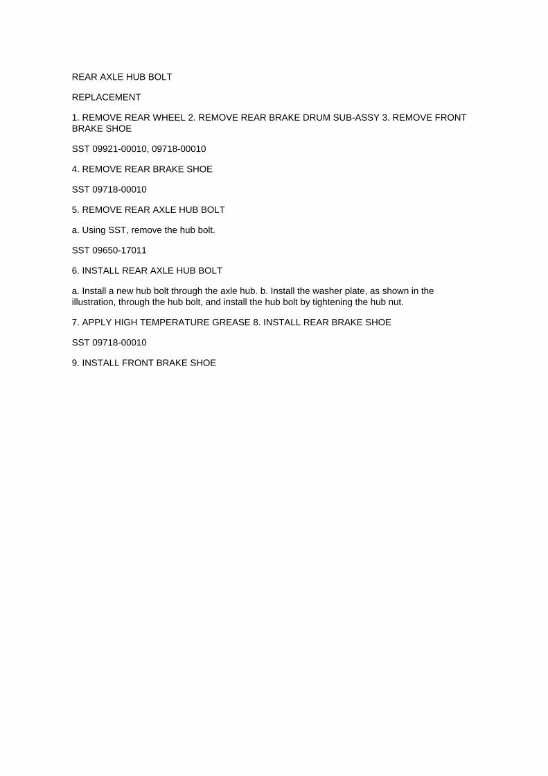
REAR AXLE HUB BOLT
REPLACEMENT
1. REMOVE REAR WHEEL 2. REMOVE REAR BRAKE DRUM SUB-ASSY 3. REMOVE FRONTBRAKE SHOE
SST 09921-00010, 09718-00010
4. REMOVE REAR BRAKE SHOE
SST 09718-00010
5. REMOVE REAR AXLE HUB BOLT
a. Using SST, remove the hub bolt.
SST 09650-17011
6. INSTALL REAR AXLE HUB BOLT
a. Install a new hub bolt through the axle hub. b. Install the washer plate, as shown in theillustration, through the hub bolt, and install the hub bolt by tightening the hub nut.
7. APPLY HIGH TEMPERATURE GREASE 8. INSTALL REAR BRAKE SHOE
SST 09718-00010
9. INSTALL FRONT BRAKE SHOE

Page 2634

k. Disconnect the 3 connectors. l.

Remove the nut shown in the illustration.
m. Disconnect the engine wire harness from the relay block.
n. Remove the 5 bolts and 2 nuts, then remove the intake manifold.
9. REMOVE KNOCK CONTROL SENSOR
a. Disconnect the knock control sensor connector. b. Remove the bolt, then remove the knockcontrol sensor.
10. INSTALL KNOCK CONTROL SENSOR
a. Install the knock control sensor with the bolt.
Torque: 20 N.m (204 kgf.cm, 15 ft.lbf)
NOTE: Make sure that the knock sensor is at the correct angle when installing.
b. Connect the knock control sensor connector.
11. INSTALL INTAKE MANIFOLD

Page 2929

F. Remove the bolt attached to the instrument panel reinforcement assembly.

G. Remove the clutch pedal sub-assembly.
a. Remove the bolt and nut.
b. Remove the clutch pedal from the clutch pedal support.
4. Remove the clutch pedal spring holder from the clutch pedal support.
5. Remove the clutch pedal pad.

Page 2548
8110 - 10-Pc. Line Disconnect Set

Diagrams
Windshield Wiper Switch Assy

Locations
A/C - Ge

Page 1416

Page 236

9. INSTALL ECM

Torque: 5 N.m (51 kgf.cm, 44 in.lbf)
10. INSTALL INSTRUMENT PANEL FINISH PANEL SUB-ASSEMBLY LOWER RH 11. INSTALLGLOVE COMPARTMENT DOOR ASSEMBLY 12. CONNECT CABLE TO NEGATIVE BATTERYTERMINAL
Torque: 3.9 N.m (40 kgf.cm, 35 in.lbf)

System Diagnosis
Idle Speed: Testing and Inspection
INSPECT ENGINE IDLING SPEED

a. When using a hand-held tester:
(1) Connect the hand-held tester to the DLC3. (2) Turn the ignition switch to ON. (3) Turn thehand-held tester ON. (4) Start the engine and warm it up. (5) Select the following menu items:DIAGNOSIS / ENHANCED OBD II / DATA LIST / PRIMARY / ENGINE SPD.
Idling speed: 600 to 700 rpm
NOTICE: -
Turn all electrical systems OFF.
- When checking the idling speed, the transmission is in the neutral position.
HINT: Refer to the hand-held tester operator's manual for further in formation regarding theselection of DATA LIST.
b. When not using a hand-held tester:
(1) Turn the ignition switch to ON. (2) Start the engine and warm it up. (3) Install SST onto terminal9 (TAC) of the DLC3. Connect a tachometer, then measure the engine idling speed. SST09843-18030 Idling speed: 600 to 700 rpm
NOTICE: -
Turn all electrical systems OFF.
- When checking the idling speed, the transmission should be in the neutral position.

Page 1489
Coolant: Service and Repair
ENGINE COOLANT (2TR-FE)

REPLACEMENT
1. DRAIN ENGINE COOLANT
CAUTION: To avoid the danger of being burned, do not remove the radiator cap while the engineand radiator are still hot. Thermal expansion will cause hot engine coolant and steam to blow outfrom the radiator.
a. Remove the 4 bolts, then remove the engine under cover No.1. (PRERUNNER AND 4WDTYPE)
b. Install a vinyl hose onto the radiator side.
c. Install a vinyl hose onto the engine side.
d. Loosen the engine drain plug. e. Loosen the radiator drain plug. (9 Remove the radiator cap anddrain coolant. g. Drain the coolant from the reservoir tank.
2. ADD ENGINE COOLANT
a. Tighten the engine drain plug.
Torque: 13 Nm (130 kgf-cm, 9 ft. lbs.)
b. Tighten the radiator drain plug. c. Disconnect the 2 vinyl hoses. d. Slowly fill the system withengine coolant. Capacity:
M/T: 8.7 liters (9.2 US qts., 7.7 Imp. qts.) A/T: 8.6 liters (9.1 US qts., 7.6 Imp. qts.)
HINT: -
Use of improper coolants may damage the engine cooling system.
- Use only Toyota Super Long Life Coolant or similar high quality ethylene glycol basednon-silicate, non-amine, non-nitrite, and non-borate coolant with long-life hybrid organic acidtechnology (coolant with long-life hybrid organic acid technology consists of a combination of lowphosphates and organic acids.)
- New Toyota vehicles are filled with Toyota Super Long Life Coolant. When replacing the coolant,Toyota Super Long Life Coolant (color

Page 2556

a. Loosen the clamp bolt. b. Disconnect the fuel breather tube.
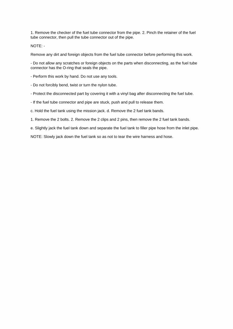
1. Remove the checker of the fuel tube connector from the pipe. 2. Pinch the retainer of the fueltube connector, then pull the tube connector out of the pipe.
NOTE: -
Remove any dirt and foreign objects from the fuel tube connector before performing this work.
- Do not allow any scratches or foreign objects on the parts when disconnecting, as the fuel tubeconnector has the O-ring that seals the pipe.
- Perform this work by hand. Do not use any tools.
- Do not forcibly bend, twist or turn the nylon tube.
- Protect the disconnected part by covering it with a vinyl bag after disconnecting the fuel tube.
- If the fuel tube connector and pipe are stuck, push and pull to release them.
c. Hold the fuel tank using the mission jack. d. Remove the 2 fuel tank bands.
1. Remove the 2 bolts. 2. Remove the 2 clips and 2 pins, then remove the 2 fuel tank bands.
e. Slightly jack the fuel tank down and separate the fuel tank to filler pipe hose from the inlet pipe.
NOTE: Slowly jack down the fuel tank so as not to tear the wire harness and hose.

Recall - Seat Belt Sensor Wire Harness Modification
Technical Service Bulletin # SSC50I Date: 050701

Page 1390

Provisionally install the timing chain cover with the 19 bolts and 2 nuts.
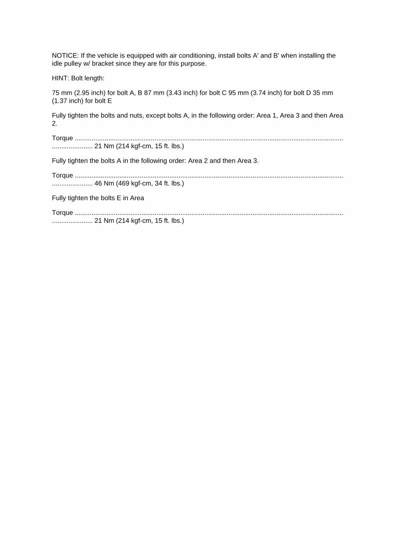
NOTICE: If the vehicle is equipped with air conditioning, install bolts A' and B' when installing theidle pulley w/ bracket since they are for this purpose.
HINT: Bolt length:
75 mm (2.95 inch) for bolt A, B 87 mm (3.43 inch) for bolt C 95 mm (3.74 inch) for bolt D 35 mm(1.37 inch) for bolt E
Fully tighten the bolts and nuts, except bolts A, in the following order: Area 1, Area 3 and then Area2.
Torque ....................................................................................................................................................................... 21 Nm (214 kgf-cm, 15 ft. lbs.)
Fully tighten the bolts A in the following order: Area 2 and then Area 3.
Torque ....................................................................................................................................................................... 46 Nm (469 kgf-cm, 34 ft. lbs.)
Fully tighten the bolts E in Area
Torque ....................................................................................................................................................................... 21 Nm (214 kgf-cm, 15 ft. lbs.)

Page 507


A/T Controls - MIL ON/DTC P0705 Set
Wiring Harness: Customer Interest A/T Controls - MIL ON/DTC P0705 Set
T-SB-0277-09
August 18, 2009
MIL "ON" DTC P0705
Service Category Drivetrain
Section Automatic Transmission/Transaxle
Market USA
Applicability
Introduction
Some 2005 - 2009 model year Tacoma vehicles may exhibit a MIL "ON" condition with DTC P0705(Transmission Range Sensor Circuit Malfunction (PRNDL Input)) stored. Common symptoms withthis DTC can include possible delayed engagement into Reverse or Drive and possible harsh gearengagement when shifting between Park or Neutral into all other gears. Follow the procedure inthis TSB to determine if this service bulletin is applicable and to repair the vehicle.

Repair Procedure Overview
1. Review DTC P0705 Freeze Frame Data to determine if this TSB may be applicable.
2. Attempt to duplicate DTC using testing procedure shown in this TSB to confirm TSB application.
3. If DTC cannot be duplicated, examine indicated wire harness electrical connector and JunctionBlock for evidence of liquid or corrosion.
4. If liquid or corrosion is observed in indicated wire harness connector and Junction Block,replacement of the Engine Room Main W~re Harness and
Junction Block connector No.1 will be required to repair the vehicle.
Warranty Information
APPLICABLE WARRANTY
^ This repair is covered under the Toyota Comprehensive Warranty. This warranty is in effect for36 months or 36,000 miles, whichever occurs first, from the vehicle's in-service date.
^ Warranty application is limited to occurrence of the specified condition described in this bulletin.

ABS/TCS - Zero Point Calibration Information
Steering Angle Sensor: Technical Service Bulletins ABS/TCS - Zero Point Calibration Information
T-SB-0020-08
March 25, 2008
Disconnect Battery & Perform Zero Point Calibration After Wheel Alignment Adjustment
Service Category Brake
Section Brake Control/Dynamic Control System
Market USA
Applicability
Introduction

The purpose of this TSB is to provide information on when and how to perform the zero pointcalibration on vehicles equipped with Vehicle Stability Control (VSC). Momentarily disconnectingthe battery is a necessary step for performing the zero point calibration.
Warranty Information
Required Tools & Equipment
^ Additional TIS techstream units may be ordered by calling Approved Dealer Equipment (ADE).
^ The Toyota Diagnostic Tester and CAN Interface Module may also be used to perform theservice procedures listed in this bulletin.
Preliminary Information
Perform this procedure if any of these repairs have been performed on the vehicle:
^ Wheel alignment has been adjusted.
^ Any chassis components have been removed/installed or replaced.

Page 648

(g) Select "NEW VEHICLE" from the "VEHICLE SELECT" menu.

(h) Go through the options and select the following information.
^ MODEL YEAR-2005
^ MODEL SELECTION - Tacoma
^ ENGINE TYPE - 2TR-FE (4-cylinder)
(i) Once these options are selected, a vehicle confirmation screen (shown in the illustration) will bedisplayed.
(j) Review the vehicle selection.
(k) Press "YES to confirm the selection.

Page 2732

NOTE

Only Toyota Certified Technicians and above may access calibration files.
2. Connect the GR8 Battery Diagnostic Station.
A. Connect the GR8 Battery Diagnostic Station to the vehicle and turn it ON.
B. Select Power Supply Mode by following the screen flow below.
NOTICE
^ ECU damage may occur if the correct battery charger and mode setting are NOT used.

Page 1651

Crankshaft Position Sensor: Service and Repair

REPLACEMENT
1. DISCONNECT CABLE FROM NEGATIVE BATTERY TERMINAL 2. REMOVE ENGINE UNDERCOVER SUB-ASSEMBLY NO.1 (PRE RUNNER AND 4WD TYPE) 3. REMOVE FAN ANDGENERATOR BELT (W/ AIR CONDITIONING) 4. REMOVE COMPRESSOR AND MAGNETICCLUTCH (W/ AIR CONDITIONING) 5. REMOVE IDLE PULLEY ASSEMBLY W/BRACKET (W/ AIRCONDITIONING)
a. Remove the 5 bolts, then remove the idle pulley with bracket.
6. REMOVE CRANKSHAFT POSITION SENSOR
a. Disconnect the crankshaft position sensor connector and the 2 wire harness clamps.
b. Remove the bolt, then remove the crankshaft position sensor.
7. INSTALL CRANKSHAFT POSITION SENSOR

Part 1
Timing Chain: Service and Repair Part 1

CHAIN (2TR-FE)
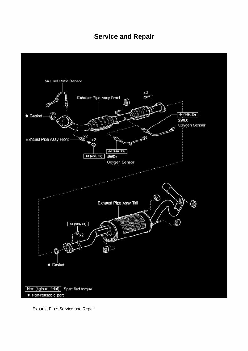
Service and Repair
Exhaust Pipe: Service and Repair

EXHAUST PIPE ASSEMBLY (2TR-FE)
COMPONENTS
Removal & Installation and Disassembly & Reassembly
1. DISCONNECT CABLE FROM NEGATIVE BATTERY TERMINAL 2. REMOVE AIR FUEL RATIOSENSOR
SST 09224-00010
3. REMOVE OXYGEN SENSOR
SST 09224-00010
4. REMOVE EXHAUST PIPE ASSEMBLY TAIL
a. Remove the 2 bolts and 2 nuts. b. Remove the exhaust pipe tail from the 4 exhaust pipesupports. c. Remove the gasket from the exhaust pipe front.

Page 3355
NOTE: DTC C1210/36 and C1336/39 will be recorded if the shift lever is not in the P position.
4. Using SST, connect terminals TS and CG of the DLC3.
SST 09843-18040
5. Turn the ignition switch to the ON position. 6. Keep the vehicle stationary on a level surface for 2seconds or more.

7. Check that the VSC TRAC warning light blinks as shown in the illustration.
NOTE: The VSC TRAC warning light (and VSC OFF indicator light [4WD, w/ rear diff. lock]) stayON when obtaining the zero point.
HINT: -
If the VSC warning light does not blink, perform the zero point calibration again.
- The zero point calibration is performed only once after the system enters test mode.
- Calibration cannot be performed again until the stored data is cleared once.

Removal and Installation

Engine Control Module: Service and Repair Removal and Installation

REPLACEMENT
NOTE: Perform REGISTRATION (VIN registration) when replacing the ECM.
1. DISCONNECT CABLE FROM NEGATIVE BATTERY TERMINAL 2. REMOVE GLOVECOMPARTMENT DOOR ASSEMBLY 3. REMOVE INSTRUMENT PANEL FINISH PANELSUB-ASSEMBLY LOWER RH 4. REMOVE ECM
a. Disconnect the 4 connectors. b. Remove the 2 bolts and nut, then remove the ECM.
5. REMOVE ECM BRACKET
a. Remove the 3 screws, then remove the ECM bracket.
6. REMOVE ECM BRACKET NO.2
a. Remove the 2 screws, then remove the ECM bracket No.2.
7. INSTALL ECM BRACKET NO.2
Torque: 3 N.m (32 kgf.cm, 28 in.lbf)
8. INSTALL ECM BRACKET
Torque: 3 N.m (32 kgf.cm, 28 in.lbf)

Page 1931
b. Push the secondary locking device or terminal retainer in to the full lock position.
5. CONNECT CONNECTOR
Disconnection of Male and Female Connectors
DISCONNECTION OF MALE AND FEMALE CONNECTORS
To pull apart the connectors, pull on the connector itself, not the wire harness.
HINT: Check to see what kind of connector you are disconnecting before pulling apart.

Page 2626

He - Wi

System Diagnosis
Air/Fuel Mixture: Testing and Inspection
INSPECT CO/HC
HINT: This inspection is for checking whether the CO/HC concentration in the emission gas whileidling complies with the regulations.
a. Start the engine. b. Keep the engine speed at 2,500 rpm for approximately 180 seconds. c.Insert the CO/HC meter testing probe at least 40 cm (1.3 ft.) into the tailpipe while idling. d.Immediately check the CO/HC concentration while idling and/or at 2,500 rpm.
HINT: When performing the 2 mode (2,500 rpm and idle) test, follow the applicable localregulations.
If the CO/HC concentration does not comply with the regulations, troubleshoot in the order givenbelow. (1) Check the A/F sensor and heated oxygen sensor operation.
(2) See the table for possible causes, then inspect and correct the applicable parts if necessary.

Page 706

(l) Select "7: SRS AIRBAG" from the "OBD/MOBD MENU".

(m)Press the "YES button when the "VERIFY CONNECTIONS" screen appears.
(n) Select "1: DATA LIST from the "DIAGNOSTIC MENU, AIRBAG/SRS" system.
(o) Select "ALL from the "SELECT DATA" menu.

Page 2930

6. Remove the two (2) clutch pedal bushes from the clutch pedal.

7. Remove the clutch pedal shaft collar.
8. Using needle-nose pliers, remove the No. 1 cushion from the clutch pedal.
9. Install the clutch pedal No. 1 cushion on the NEW clutch pedal sub-assembly.
NOTE:
Install parts on the NEW clutch pedal sub-assembly BEFORE installing in the vehicle.
10. Install the clutch pedal shaft collar.
A. Apply MP grease to the clutch pedal shaft collar.
B. Install the clutch pedal shaft collar onto the clutch pedal.

Page 521
Oxygen Sensor: Testing and Inspection Heated Oxygen Sensor
INSPECTION
INSPECT HEATED OXYGEN SENSOR
a. Check the resistance.
1. Using an ohmmeter, measure the resistance between the terminals.
If the result is not as specified, replace the heated oxygen sensor.

Page 29
Diagnostic Trouble Code Chart
Use Diagnostic Trouble Codes (DTCs) (from the DTC checks) in the table to determine the troublearea and proper inspection procedure. The Supplemental Restraint System (SRS) DTC chart isshown as an example.
Problem Symptoms Table

PROBLEM SYMPTOMS TABLE

Page 1093
Driver Side J/B - Lower Finish Panel

Specifications

Compression Check: Specifications

Compression pressure......................................................................................................................................................1230 kPa (12.5 kgf/cm2, 178 psi) Minimum pressure.................................................................................................................................................. 880kPa (9.0 kgf/cm2, 128 psi) or more Difference between each cylinder................................................................................................................................. 68 kPa (0.7kgf/cm2, 10 psi) or less

Page 1019

Air Bag(s) Arming and Disarming: Service and Repair Release Method of Airbag ActivationPrevention Mechanism

RELEASE METHOD OF ACTIVATION PREVENTION MECHANISM

Page 3135
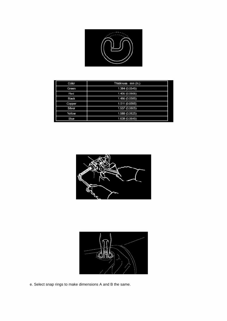
e. Select snap rings to make dimensions A and B the same.

Snap Ring Type
NOTICE: ^
Use new snap rings.
^ If possible, use snap rings of the same thickness for both edges.
f. Insert the spider into the yoke, and then using SST, press the spider bearing into the snap ringgroove.
g. Press in the spider bearing on the opposite side in the same way.
SST 09332-25010
NOTICE: When pressing in the spider bearing, be careful not to dam age its lip.
h. Using snap ring pliers, install new snap rings into the grooves of the yoke.
10. INSPECT PROPELLER SHAFT UNIVERSAL JOINT SPIDER BEARING
a. Check the spider bearings for wear and damage. b. Check each spider bearing's axial play byturning the yoke while holding the shaft tightly.
Maximum bearing axial play: 0 to 0.05 mm (0 to 0.002 inch)

Page 1925

a. Establish conditions in which voltage is present at the check point.

Example: [A] - Ignition SW on [B] - Ignition SW and SW 1 on [C] - Ignition SW, SW 1 and Relay on(SW 2 off)
b. Using a voltmeter, connect the negative lead to a good ground point or negative battery terminal,and the positive lead to the connector or
component terminal. This check can be done with a test light instead of a voltmeter.
Continuity and Resistance Check
CONTINUITY AND RESISTANCE CHECK
a. Disconnect the battery terminal or wire so there is no voltage between the check points.
b. Contact the two leads of an ohmmeter to each of the check points.

Page 2113
Required SSTs
VIN Write Procedure
To write a VIN to a replacement ECM (PCM), use the following process:

1. Confirm the VIN. It is located on the front left of the instrument panel.
2. Connect the Diagnostic Tester to DLC3.
3. Turn the ignition switch and Diagnostic Tester switch ON.
4. All vehicles except Prius and Highlander HV:
Select from the Diagnostic Tester menus: DIAGNOSIS, ENHANCED OBDII, VIN, and VIN WRITE.
Prius and Highlander HV vehicles:
Select from the Diagnostic Tester menus: DIAGNOSIS, OBD/MOBD, HV ECU, VIN, and VINWRITE.

Page 1960

Step 15 - 17

INSPECTION PROCEDURE
Check CAN Bus Line For Short to GND
CHECK CAN BUS LINE FOR SHORT TO GND
CIRCUIT DESCRIPTION
A short to GND is suspected in the CAN bus line when there is continuity between terminals 4 (CG)and 6 (CANH) or terminals 4 (CG) and 14 (CANL) of the DLC3.

Locations

Ha - Op

Page 1750

He - Wi
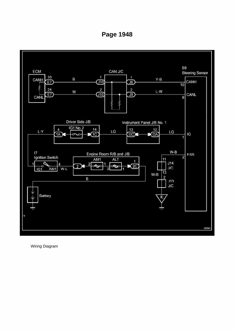
Page 1948
Wiring Diagram

Page 1506

Radiator: Service and Repair Overhaul
RADIATOR ASSEMBLY (2TR-FE)

Page 1074

Push the terminal retainer down to the temporary lock position.

c. Release the locking lug from terminal and pull the terminal out from rear.
4. INSTALL TERMINAL TO CONNECTOR
a. Insert the terminal.
HINT: 1. Make sure the terminal is positioned correctly. 2. Insert the terminal until the locking luglocks firmly. 3. Insert the terminal with terminal retainer in the temporary lock position.

Locations

Differential Lock Switch: Locations
A/C - Fo

Page 3096

26. INSTALL REAR AXLE SHAFT LH OIL SEAL

a. Using SST and a hammer, install a new oil seal.
SST 09950-60020 (09951-00770), 09950-70010 (09951-07150)
27. INSTALL REAR AXLE SHAFT W/ BACKING PLATE
a. Install a new O-ring. b. Install the rear axle shaft w/ backing plate with the 4 nuts.
Torque: 36 Nm (367 kgf-cm, 27 ft. lbs.)
28. INSTALL REAR BRAKE TUBE NO.8
a. Using SST, connect the brake tube.
SST 09023-00101 Torque: 15 Nm (155 kgf-cm, 11 ft. lbs.)
29. INSTALL PARKING BRAKE CABLE ASSY NO.3 30. INSTALL SPEED SENSOR REAR LH 31.APPLY HIGH TEMPERATURE GREASE 32. INSTALL REAR BRAKE SHOE
SST 09718-00010
33. INSTALL FRONT BRAKE SHOE
SST 09718-00010, 09921-00010
34. CHECK REAR DRUM BRAKE INSTALLATION 35. INSTALL REAR BRAKE DRUM SUB-ASSY36. ADJUST REAR DRUM BRAKE SHOE CLEARANCE 37. CONNECT CABLE TO NEGATIVEBATTERY TERMINAL
Torque: 3.9 Nm (40 kgf-cm, 35 inch lbs.)
38. FILL RESERVOIR WITH BRAKE FLUID (W/ VSC) 39. FILL RESERVOIR WITH BRAKE FLUID(W/O VSC) 40. BLEED MASTER CYLINDER (W/O VSC)
SST 09023-00101
41. BLEED BRAKE LINE (W/ VSC) 42. BLEED BRAKE LINE (W/O VSC) 43. CHECK FLUIDLEVEL IN RESERVOIR (W/ VSC) 44. CHECK FLUID LEVEL IN RESERVOIR (W/O VSC) 45.CHECK FOR BRAKE FLUID LEAKAGE

Page 1403
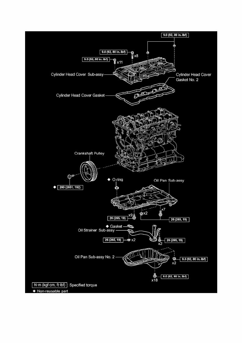

Locations
Body Control Module: Locations
Instrument Panel

Page 608
Seat Position Air Bag Sensor (Bench Seat Type)

Page 2323

2. Pinch the retainer as illustrated, then pull the fuel tube connector out of the pipe.

3. If the fuel tube connector and pipe are stuck, pinch the pipe and push and pull the fuel tubeconnector to release it.
NOTE: Never use any tools.
4. After disconnecting the fuel tube, check the sealing surface of the pipe for dirt and mud.
If dirty, wipe it with a shop rag.
5. Cover the disconnected fuel tube connector and pipe with a vinyl bag to prevent damage and theintrusion of foreign objects.
d. Take the following precautions when installing the fuel tube connector.
1. Align the fuel tube connector with the pipe, then push in the fuel tube connector until the retainermakes a "click" sound.

Page 1886
Oscilloscope Waveforms

Page 1380

101. INSTALL COMPRESSOR AND MAGNETIC CLUTCH (W/ AIR CONDITIONING)

a. Install the compressor and magnetic clutch with the 4 bolts.
Torque: 21 Nm (214 kgf-cm, 16 ft. lbs.)
b. Connect the compressor and magnetic clutch connector.
c. Install the bolt shown in the illustration.
Torque: 7.5 Nm (76 kgf-cm, 66 inch lbs.)
102. INSTALL RADIATOR HOSE NO.2
103. INSTALL VANE PUMP ASSEMBLY
a. Install the vane pump with the 2 bolts.
Torque: 21 Nm (214 kgf-cm, 16 ft. lbs.)
b. Connect the vane pump connector.
104. INSTALL AIR CLEANER CASE
a. Install the air cleaner case with the 3 bolts.
Torque: 12 Nm (122 kgf-cm, 9 ft. lbs.)
105. INSTALL AIR CLEANER FILTER ELEMENT SUB-ASSEMBLY 106. INSTALL AIR CLEANERCAP SUB-ASSEMBLY 107. INSTALL FAN SHROUD
108. INSTALL RADIATOR SUPPORT TO FRAME SEAL LH 109. INSTALL BATTERY TRAY 110.INSTALL BATTERY 111. ADD ENGINE OIL 112. ADD ENGINE COOLANT 113. CHECK ENGINEOIL LEVEL 114. CHECK FOR FUEL LEAKAGE 115. CHECK FOR ENGINE COOLANT LEAKAGE116. CHECK FOR OIL LEAKAGE 117. CHECK FOR EXHAUST GAS LEAKAGE 118. ENGINEUNDER COVER SUB-ASSEMBLY NO.1 (PRE RUNNER AND 4WD TYPE)
a. Install the engine under cover No.1 with the 4 bolts. Torque: 30 Nm (306 kgf-cm, 22 ft. lbs.)

Page 2132
Oscilloscope Waveforms

Page 2025
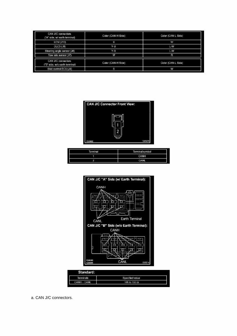
a. CAN J/C connectors.

HINT: -
The connectors connected to the CAN J/C can be distinguished by the colors of the bus lines andthe connecting side of the connector.
- J7, J8, J9 and J10 are inter changeable.
b. The terminals of the CAN J/C connectors.
c. Measure the resistance according to the value(s) in the table.

Page 217

3. Start the engine and warm it up to normal operating temperatures before test-driving.

4. Perform a thorough test drive with several accelerations from a stop with "light throttle"application until proper transmission shifting is verified.
Reset Procedure 2
1. Disconnect the negative battery cable for 5 minutes.
2. Reconnect battery cable.
3. Start the engine and warm it up to normal operating temperatures before test-driving.
4. Perform a thorough test drive with several accelerations from a stop with "light throttle"application until proper transmission shifting is verified.

Testing and Inspection
Horn Relay: Testing and Inspection
INSPECT RELAY (HORN)
a. Check the resistance.
1. Using an ohmmeter, measure the resistance between the terminals.
If the result is not as specified, replace the relay.

Page 1972
Step 5 - 6

Specifications

Exhaust Manifold: Specifications

Exhaust Manifold ................................................................................................................................................................ 36 Nm (367 kgf-cm, 27 ft. lbs.)

Page 1505
9. INSTALL RADIATOR SUPPORT TO FRAME SEAL LH
a. Install the radiator support to frame seal LH with the 9 clips.
10. CONNECT CABLE TO NEGATIVE BATTERY TERMINAL
Torque: 3.9 Nm (40 kgf-cm, 35 inch lbs.)
11. ADD ENGINE COOLANT 12. CHECK FOR ENGINE COOLANT LEAKAGE 13. INSTALLENGINE UNDER COVER SUB-ASSEMBLY NO.1 (PRE RUNNER AND 4WD TYPE)
a. Install the engine under cover No.1 with the 4 bolts.
Torque: 30 Nm (306 kgf-cm, 22 ft. lbs.)

Diagrams
Air Bag Sensor Assy Center

Locations

Engine Room R/B, J/B - Engine Compartment Left

Page 338

Repair Procedure

1. Disconnect the cable from the negative (-) battery terminal for MORE THAN two (2) seconds.
2. Reconnect the cable to the negative (-) battery terminal.
3. Perform the applicable zero point calibration of the yaw rate sensor and/or the steering anglesensor.
HINT Refer to the applicable TSB or Repair Manual for the zero point calibration procedure.
4. Re-initialize all applicable systems available on the vehicle (power window sunroof power liftdoor etc.).

Locations
A/C - Ge

Page 513

Engine Bank Identification

Page 1011

c. Rear brake line.

(1) Connect the vinyl tube to the wheel cylinder. (2) Depress the brake pedal, hold it, and thenloosen the bleeder plug.
HINT: Brake fluid is pumped out automatically.
(3) Loosen the bleeder plug and release air.
NOTICE: Keep brake fluid in the reservoir tank above the MIN line during the above procedures.
(4) When the air is completely bled out of the brake fluid through the bleeder plug, tighten thebleeder plug.
Torque: 11 Nm (112 kgf-cm, 8 ft. lbs.)
(5) Repeat the above procedures to bleed the other brake line.
4. BLEED MASTER CYLINDER SOLENOID
HINT: If the brake master cylinder is disassembled, the brake line is disconnected from the brakemaster cylinder or if the reservoir become empty, bleed the brake master cylinder.
a. Connect the hand-held tester to the DLC3. b. Turn the ignition switch to ON. c. Select"ACTIVETEST" mode on the hand-held tester.
d. Connect the vinyl tube to the rear wheel cylinder. e. Loosen the bleeder plug. f.
Select "SRMF & SIGMA" to drive the solenoids and bleed air from the rear wheel cylinder.
NOTICE: -
Do not depress the brake pedal.
- Keep brake fluid in the reservoir tank above the MIN line during the above procedures.
HINT: -
Brake fluid is sent through the pump.
- To protect the solenoids, the hand-held tester turns OFF automatically 2 seconds after everysolenoid has been turned ON.

Page 271
Air Bag Control Module: Service and Repair
Air Bag Sensor Assy Center
AIR BAG SENSOR ASSEMBLY CENTER
REPLACEMENT
1. PRECAUTION
Refer to Air Bag Systems; Service Precautions.
2. DISCONNECT CABLE FROM NEGATIVE BATTERY TERMINAL
Wait for at least 90 seconds after disconnecting the cable to prevent the airbag from working.
3. REMOVE CONSOLE UPPER REAR PANEL SUB-ASSEMBLY (AUTOMATICTRANSMISSION,SEPARATE SEAT TYPE) 4. REMOVE CONSOLE UPPER REAR PANELSUB-ASSEMBLY (MANUAL TRANSMISSION, SEPARATE SEAT TYPE) 5. REMOVE CONSOLEBOX ASSEMBLY REAR (SEPARATE SEAT TYPE) 6. REMOVE INSTRUMENT PANEL CUPHOLDER TRAY (AUTOMATIC TRANSMISSION, SEPARATE SEAT TYPE) 7. REMOVECONSOLE BOX FRONT (AUTOMATIC TRANSMISSION, SEPARATE SEAT TYPE) 8. REMOVECONSOLE BOX FRONT (MANUAL TRANSMISSION, SEPARATE SEAT TYPE)

Page 2359

Page 22

c. Check the voltage.

1. In a circuit in which voltage is applied to the ECU connector terminal, an open circuit can bechecked by conducting a voltage check.
FIG 4: With each connector still connected, measure the voltage between the body ground andthese terminals (in this order): 1) terminal 1 of connector A at the ECU 5 V output terminal, 2)terminal 1 of connector B, and 3) terminal 1 of connector C.
2. Example results:
If your results match the examples above, an open circuit exists in the wire harness betweenterminal 1 of connector B and terminal 1 of connector C.
Check Short Circuit
CHECK SHORT CIRCUIT
a. If the wire harness is ground shorted (Fig. 5), locate the section by conducting a resistancecheck with the body ground.
b. Check the resistance with the body ground.

Specifications

Brake Fluid: Specifications

Fluid type: ................................................................................................................................................................ SAE J1703 or FMVSS No.116 DOT 3

Page 2171
Coolant Temperature Sensor/Switch (For Computer): Testing and Inspection
INSPECT E.F.I. ENGINE COOLANT TEMPERATURE SENSOR
a. Check the resistance.
1. Using an ohmmeter, measure the resistance between the terminals.
NOTE: If checking the engine coolant temperature sensor in water, be careful not to allow water tointrude into the terminals. After checking, wipe the water off the engine coolant temperature sensor.

If the result is not as specified, replace the engine coolant temperature sensor.
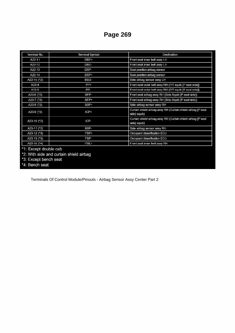
Page 269
Terminals Of Control Module/Pinouts - Airbag Sensor Assy Center Part 2

Page 63

60. INSTALL INSTRUMENT PANEL HOLE COVER (LEVER TYPE PARKING BRAKE) 61.INSTALL INSTRUMENT PANEL UNDER TRAY (PEDAL TYPE PARKING BRAKE) 62. INSTALL

FRONT PILLAR GARNISH LH 63. INSTALL FRONT PILLAR GARNISH RH 64. INSTALL FRONTDOOR OPENING TRIM WEATHERSTRIP LH 65. INSTALL FRONT DOOR OPENING TRIMWEATHERSTRIP RH 66. INSTALL COWL SIDE TRIM BOARD LH 67. INSTALL COWL SIDETRIM BOARD RH 68. INSTALL FRONT DOOR SCUFF PLATE LH 69. INSTALL FRONT DOORSCUFF PLATE RH 70. INSTALL FRONT FLOOR FOOTREST 71. CONNECT CABLE TONEGATIVE BATTERY TERMINAL
Torque: 3.9 N.m (40 kgf.cm, 35 in.lbf)
72. INSPECT SRS WARNING LIGHT

Page 1057

3. Checking the contact pressure of the terminal: Prepare a spare male terminal. Insert it into afemale terminal, and check for good tension when
inserting and after full engagement.
d. REPAIR METHOD OF CONNECTOR TERMINAL
1. If there is any dirt on the terminal, clean the contact point using an air gun or shop rag. Neverpolish the contact point using sandpaper as the
platings may come off.
2. If there is abnormal contact pressure, replace the female terminal. If the male terminal isgold-plated (gold color), use a gold-plated female
terminal; if it is silver-plated (silver color), use a silver-plated female terminal.
3. Damaged, deformed, or corroded terminals should be replaced. If the terminal will not lock intothe housing, the housing may have to be
replaced.
e. HANDLING OF WIRE HARNESS
1. If removing a wire harness, check the wiring and clamping before proceeding so that it can berestored in the same way. 2. Never twist, pull or slacken the wire harness more than necessary. 3.Never make the wire harness come into contact with a high temperature part, or rotating, moving,vibrating or sharp-edged parts. Avoid panel
edges, screw tips and similar sharp items.
4. When installing parts, never pinch the wire harness. 5. Never cut or break the cover of the wireharness. If it is cut or broken, replace it or securely repair it with vinyl tape.
Check Open Circuit
CHECK OPEN CIRCUIT

Page 1581

Refer to Reset Procedure 2 for the vehicles with Electronically Controlled AutomaticTransmissions:

Reset Procedure 1
1. Connect the Toyota Diagnostic Tester to the vehicle.
2. Reset the ECM (PCM). Refer to the procedures below.

Page 2974

G. Remove the clutch pedal sub-assembly.

a. Remove the bolt and nut.
b. Remove the clutch pedal from the clutch pedal support.
4. Remove the clutch pedal spring holder from the clutch pedal support.
5. Remove the clutch pedal pad.
6. Remove the two (2) clutch pedal bushes from the clutch pedal.

Page 615
5. REMOVE FRONT DOOR OPENING TRIM WEATHERSTRIP LH 6. REMOVE REAR DOOROPENING TRIM WEATHERSTRIP LH 7. REMOVE LAP BELT OUTER ANCHOR COVER 8.REMOVE CENTER PILLAR GARNISH LOWER LH
9. REMOVE SIDE AIR BAG SENSOR ASSEMBLY LH
a. Remove the bolt and the airbag sensor assembly. b. Disconnect the connector from the sideairbag sensor assembly.
10. INSPECT SIDE AIR BAG SENSOR ASSEMBLY LH
11. REMOVE SIDE AIR BAG SENSOR ASSEMBLY LH
a. Check that the ignition switch is OFF. b. Check that the cable is disconnected from the batterynegative (-) terminal.
CAUTION: After disconnecting the cable from the terminal, wait for at least 90 seconds beforestarting the operation.
c. Install the side airbag sensor assembly LH with the bolt.
Torque: 9.0 N.m (92 kgf.cm, 80 in.lbf)
NOTE: -
Installation of the connector is done with the sensor assembly installed. Make sure that the sensorassembly is installed to the specified torque.
- If the sensor assembly has been dropped, or there are cracks, dents or other defects in the case,bracket or connector, replace the sensor assembly with a new one.
- When installing the sensor assembly, make sure that the SRS wiring does not interfere with otherparts and is not pinched between other parts.
- After installation, shake the sensor assembly to check that it is not loose.
d. Check that there is no slack in the installation parts of the airbag sensor assembly LH. e.Connect the connector to the airbag sensor assembly LH.

12. INSTALL CENTER PILLAR GARNISH LOWER LH 13. INSTALL LAP BELT OUTER ANCHORCOVER
Torque: 42 N.m (428 kgf.cm, 31 ft.lbf)
14. INSTALL REAR DOOR OPENING TRIM WEATHERSTRIP LH 15. INSTALL FRONT DOOROPENING TRIM WEATHERSTRIP LH 16. INSTALL REAR DOOR SCUFF PLATE LH 17.INSTALL FRONT DOOR SCUFF PLATE LH 18. CONNECT CABLE TO NEGATIVE BATTERYTERMINAL
Torque: 3.9 N.m (40 kgf.cm, 35 in.lbf)
19. INSPECT SRS WARNING LIGHT

Page 1178
COMPONENTS

REPLACEMENT
1. DISCONNECT CABLE FROM NEGATIVE BATTERY TERMINAL 2. REMOVE REAR WHEEL 3.DRAIN BRAKE FLUID 4. REMOVE REAR BRAKE DRUM SUB-ASSY 5. REMOVE FRONTBRAKE SHOE
SST 09921-00010, 09718-00010
6. REMOVE REAR BRAKE SHOE
SST 09718-00010
7. REMOVE SPEED SENSOR REAR LH 8. SEPARATE PARKING BRAKE CABLE ASSY NO.3
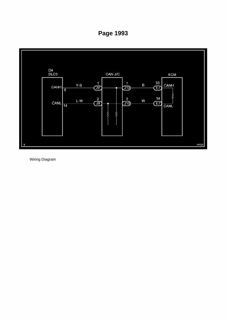
Page 1993
Wiring Diagram

Page 250
SFI System

Page 3291

COMPONENTS

OVERHAUL
NOTICE: Before starting the work, make sure that the ignition switch is OFF and depress the brakepedal more than 20 times.
HINT: When pressure in the accumulator is released, reaction force becomes lighter and strokebecomes longer.
NOTICE:

Page 2904
G. Review Snapshot after completing test to confirm if abnormal readings are observed.
H. Does the Neutral Position SW Signal show "ON" at any time when in Reverse or Drive?
^ If YES - Go to next step (7.1).
^ If NO - Go to step 8.
NOTE
Neutral Position SW Signal can show "ON" either with Stop Lamp Switch "ON" or "OFF".

I. Does the Neutral Position SW Signal change based on brake pedal input (Stop Lamp Switch"ON" or "OFF") when in Reverse or Drive?
^ If YES - Ground through Stop Lamp Circuit confirmed. Go to step 9.
^ If NO - TSB does NOT apply. Refer to the applicable model year Tacoma Repair Manual fordiagnostics for DTC P0705.
8. Inspect connector DD and Junction Block No. 1 for liquid contamination or corrosion.
A. Disconnect battery.
B. Locate connector DD and Junction Block No. 1.
C. Remove the left front kick panel.

Page 3027

7. REMOVE CLUTCH PEDAL SHAFT COLLAR

a. Remove the clutch pedal shaft collar.
8. REMOVE CLUTCH PEDAL NO.1 CUSHION
a. Using needle-nose pliers, remove the No.1 cushion from the clutch pedal.
9. INSTALL CLUTCH PEDAL NO.1 CUSHION
a. Install the No.1 cushion onto the clutch pedal.
10. INSTALL CLUTCH PEDAL SHAFT COLLAR
a. Apply MP grease to the clutch pedal shaft collar. b. Install the clutch pedal shaft collar onto theclutch pedal.
11. INSTALL CLUTCH PEDAL BUSH
a. Apply MP grease to 2 new bushes. b. Install the 2 bushes onto the clutch pedal.
12. INSTALL CLUTCH PEDAL PAD
13. INSTALL CLUTCH PEDAL SPRING HOLDER
a. Apply MP grease to the contact surface of the clutch pedal spring holder. b. Install the clutchpedal spring holder.

Page 2905

D. Identify connector DD and Junction Block No.1 (see Figures 6 and 7).
E. Disconnect connector DD from Junction Block No. 1.
F. Carefully inspect both components for liquid or corrosion in the connector and the Junction Block(especially the male and female terminals).

Page 698
are involved. As always, consult Dealer Daily/TIS to confirm VIN eligibility and to assure the SSC isapplicable. This will verify the vehicle is affected and has not already been completed prior todealer shipment or by another dealer. TMS warranty will not reimburse dealers for repairsconducted on vehicles that are not affected or were completed by another dealer.
III. Preparation
A. PARTS
B. TOOLS
^ Standard hand tools
^ Scan tool
IV. Background
On certain 2005 Model Year Tacoma Regular Cab (no rear seat) vehicles equipped with a frontbench seat, the Seat Position and Seatbelt Buckle Sensor Wire Harness Connector pins arepositioned incorrectly due to a wire harness manufacturing process error. In this condition, the seatposition and seatbelt buckle sensor may not function as designed, which, if the vehicle is involvedin a crash, could result in improper occupant restraint. In the worst case, this may lead to anincreased possibility of injury. Please note that even in this condition, the affected vehicles continueto comply with all applicable federal motor vehicle safety standards.
V. Work Procedure
A. INSPECT THE FRONT BENCH SEAT FLOOR WIRE HARNESS CONNECTOR WIRES
1. LOCATE THE BENCH SEAT FLOOR WIRE HARNESS

Page 1661
SFI System

Page 1726

Air Flow Meter/Sensor: Testing and Inspection

INSPECT INTAKE AIR FLOW METER SUB-ASSEMBLY
a. Check the operation.
1. Apply battery voltage across terminals 1 (+B) and 2 (E2G). 2. Using a voltmeter, connect thepositive (+) tester prove to terminal 3 (VG) and the negative (-) tester prove to terminal 2 (E2G). 3.Blow air into the mass air flow meter and check that the voltage fluctuates.
If the voltage does not fluctuate, replace the mass air flow meter.
b. Check the resistance.
1. Using an ohmmeter, measure the resistance between the terminals.
If the result is not as specified, replace the mass air flow meter.

Page 3209
Transmission Position Switch/Sensor: Adjustments
PARK/NEUTRAL POSITION SWITCH ASSY
ADJUSTMENT
1. INSPECT PARK/NEUTRAL POSITION SWITCH ASSY
a. Apply the parking brake and turn the ignition switch to ON. b. Depress the brake pedal andcheck that the engine starts only when the shift lever is set in the N or P position and that it doesnot start in any
other positions.
c. Check that the back-up light comes on and the reverse warning buzzer sounds only when theshift lever is set in the R position and not in other
positions. If any failure is found, check the park/neutral position switch for continuity.
2. ADJUST PARK/NEUTRAL POSITION SWITCH ASSY
a. Loosen the bolt of the park/neutral position switch and set the shift lever to the N position. b.Align the groove and the neutral basic line. c. Hold the switch in position and tighten the bolt.
Torque: 13 Nm (130 kgf-cm, 9 ft. lbs.)
d. After making an adjustment, perform the inspection described in step 1.

Page 1714

Po - Ya

Page 1363


Locations
Brake Fluid Level Sensor/Switch: Locations

A/C - Ge

Page 2775
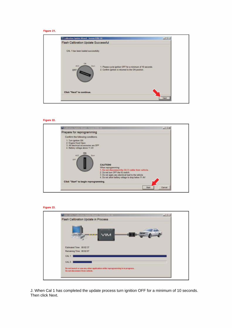
J. When Cal 1 has completed the update process turn ignition OFF for a minimum of 10 seconds.Then click Next.

K. Turn ignition to the ON position. Then click Start.
L. Do NOT disturb the vehicle during flash reprogramming.

Locations

Ha - Op

Component Tests and General Diagnostics
Engine Control Module: Component Tests and General Diagnostics
ECM POWER SOURCE CIRCUIT
CIRCUIT DESCRIPTION
When the ignition switch is turned to ON, the battery voltage is applied to terminal IGSW of theECM. The ECM MREL output signal causes a current to flow to the coil, closing the contacts of theEFI relay and supplying power to terminal +B of the ECM.
Wiring Diagram

Page 561
SFI System

Page 2410
A/F and 02 Sensor Identification