
AFR026_280212025752_Product Catalogue.pdf - EngNet
544
The New Complete Catalogue Günther Blasinger, Director Sales and Marketing Welcome Dear business partner In the past, we presented our range of products in two different cata- logues: - Technology for Environmental Protection - Pressure • Temperature • Level Our statistics show that almost all of our customers worked with both catalogues. Therefore, we have de- cided to provide you with a complete catalogue which contains all impor- tant information on our products in a single volume – technical descrip- tions, applications, outline drawings and options. Whether you are looking for solutions for environmental applications, ground water protection, flue gas control, energy saving or general measurement and control techno- logy – the AFRISO range provides proven, competitively priced stan- dard products. We also develop and manufacture complex customised products as well as complete system solutions – exactly to your specifications. Going against the general trend, we insist on a high degree of vertical manufacturing integration from our own tool design and construction department all the way to fully auto- matic assembly machines for elec- tronic components. This makes us fast, flexible and independent. AFRISO-EURO-INDEX GmbH Lindenstraße 20 D-74363 Güglingen Telephone +49 7135 102-0 Telefax +49 7135-102 147 E-mail [email protected] Internet http://www.afriso.de Extensions If you have any questions... Please feel free to contact us! Telephone: ++49 7135 102 - (for last 3 digits see extension numbers below!) Division I Tank • Heating • Environmental Protection North -121 Centre -169 South -124 Export -145 Division II Pressure • Temperature • Level North -138 Centre -215 South -101 -235 Export -132 Division III Gas Analysis Special Applications Germany -131 Export -166 Service and Repairs +49 7135 102-127 Please visit www.afriso.de for further information on contact persons. www.afriso.de 1 For us, globalisation is an opportu- nity to market our products – manu- factured in Germany and Europe – on a global scale. As a medium sized company, we place particular importance on personal contact with you. There are many factors that set AFRISO apart from others – one of them is the people who make up the com- pany. Competent experts provide you with optimum solutions – both technically and economically. Our external sales engineers will be glad to come to your site and assist you in choosing the right products and systems. And whenever you need it, a well trained team of ser- vice experts is at your disposal. We look forward to a successful cooperation. Günther Blasinger Director Sales and Marketing
-
Upload
khangminh22 -
Category
Documents
-
view
19 -
download
0
Transcript of AFR026_280212025752_Product Catalogue.pdf - EngNet

The New Complete Catalogue
Günther Blasinger, Director Sales and MarketingWelcomeDear business partner
In the past, we presented our rangeof products in two different cata-logues:- Technology for Environmental
Protection- Pressure • Temperature • Level
Our statistics show that almost allof our customers worked with bothcatalogues. Therefore, we have de-cided to provide you with a completecatalogue which contains all impor-tant information on our products ina single volume – technical descrip-tions, applications, outline drawingsand options.
Whether you are looking for solutionsfor environmental applications,ground water protection, flue gascontrol, energy saving or generalmeasurement and control techno-logy – the AFRISO range providesproven, competitively priced stan-dard products.
We also develop and manufacturecomplex customised products aswell as complete system solutions –exactly to your specifications.Going against the general trend, weinsist on a high degree of verticalmanufacturing integration from ourown tool design and constructiondepartment all the way to fully auto-matic assembly machines for elec-tronic components. This makes usfast, flexible and independent.
AFRISO-EURO-INDEX GmbHLindenstraße 20D-74363 GüglingenTelephone +49 7135 102-0Telefax +49 7135-102 147E-mail [email protected] http://www.afriso.de
Ext
ensi
on
s
If you have any questions...Please feel free to contact us!Telephone: ++49 7135 102 -(for last 3 digits see extensionnumbers below!)
Division ITank • Heating • EnvironmentalProtectionNorth -121Centre -169South -124Export -145
Division IIPressure • Temperature • LevelNorth -138Centre -215South -101
-235Export -132
Division IIIGas AnalysisSpecial ApplicationsGermany -131Export -166
Service and Repairs+49 7135 102-127
Please visit www.afriso.de for further information on contactpersons.
www.afriso.de 1
For us, globalisation is an opportu-nity to market our products – manu-factured in Germany and Europe –on a global scale.
As a medium sized company, weplace particular importance on personal contact with you. Thereare many factors that set AFRISOapart from others – one of them isthe people who make up the com-pany. Competent experts provideyou with optimum solutions – bothtechnically and economically. Ourexternal sales engineers will beglad to come to your site and assistyou in choosing the right productsand systems. And whenever youneed it, a well trained team of ser-vice experts is at your disposal.
We look forward to a successfulcooperation.
Günther BlasingerDirector Sales and Marketing

2 www.afriso.de
Level indicators and controllers, overfill alarm systems (capacitance/vibration principle) 11
Overfill alarm systems and PTC thermistor type levelcontrollers 53
Alarm units for oil, petrol and grease separators 65
Leak detectors and leak monitoring systems, linings internal tank 71
Gas and smoke alarms 93
Accessories for fuel oil tanks and oil carrying pipes and hoses 101
Accessories for boiler rooms and chimneys 117
Accessories for potable water supply and rain water harvesting. Water treatment 133
Heating controllers, thermostats, solar controllers 151
Temperature measuring instruments and controllers 159
Pressure gauges and controllers 229
Portable measuring instruments, analysers and testequipment 451
Stationary gas analysers 479
Alarm units, displays, signal processing, monitoring and communication systems 497
Appendix 515
010203040506070809101112131415
AFRISO ProductsContents and Product Range

www.afriso.de 3
Level - continuous indication: Mechanical, pneumatic, electro-pneumatic, hydrostatic, capacitance, ultrasonic, magnetostrictive, guided micropulse
Level - switches: Float, paddle, conductivity, capacitance, vibration
PTC thermistor level sensors for tanks in tank rooms, PTC thermistor level sensors for outdoor tanks, Ex approved PTCthermistor level sensors, overfill alarm systems with Ex and WHG approval, level controllers
Alarm units for oil/water separators, maximum level, silt and oil-on-water
Leak detectors - sight glass principle, leak detectors for liquid filled system, vacuum or pressure based leak detectors Leak detectors with probes (PTC thermistor, photoelectric, conductivity), drip pans Internal linings for fuel oil/diesel/rain water/liquid fertiliser/AHL/AdBlue, tank room linings
Gas alarms for domestic use, building automation and industrial applicationsGas alarms for 19“ rack mounting and in standard DIN-rail housing, gas sensors, leak test instrumentsElectronic gas and smoke detectors
Mounting accessories, tank fittings, overpressure devices, tank withdrawal systems, anti-siphon valves, pull cord, screw connections, fuel oil filters, filter inserts, automatic fuel oil de-aerators, heating oil meters
Motorised boiler room vent, draft stabiliser, boiler water low level alarms, thermal safety valves, combustion controllers, boiler safety equipment groups,safety valves, connection assemblies for expansion vessels, tamper-proof valves, pump connection kits, ball valves, solar pump stations, overflow val-ves, flow filters, filling devices for heating systems, boiler feed and drain cocks, air vents, distribution manifolds for underfloor heating, thermal actuators
Pressure reducers, water filters, non-return valves, strainers, boiler safety groups, safety valves, signal anodes, sacrificialanodes, back-up controller for rain water harvesting systems, Rain Water System Centre, oil tank conversion kits, rainwater filter, accessories for rain water harvesting, water treatment
Outdoor temperature compensated heating controls, thermostats with timers, room thermostats, differential temperaturecontrollers for solar collectors (solar controllers)
Bimetal thermometers and gas filled thermometers, industrial thermometers, thermometer/pressure gauge with capillary tube, thermostats, safety temperature switches, thermostats with housing, electronic thermometers, resistance thermometers
Test instruments for tank servicing and heating systems, leak test instruments for gas and oil pipes, handheld electronicinstruments for pressure/temperature/air speed/volume flow/humidity, flue gas analysers, condensate filters, gas treatmentsystems, water analysis instruments
Stationary gas sampling probes, universal filters, gas treatment systems, gas coolers, infrared gas analysers, oxygen measuring probes, oxygen analysers, dust concentration measurement system, volume flow measurement system, compact gas analysis units, emission computer
Isolating amplifiers, isolating amplifiers with supply, trip amplifier, selector switch, Ex safety barrier, Ex isolating amplifiers with supply, multifunctional transducer, digital plug-in display, digital display units, alarm lights with horn, alarm re-set unit, event reporting systems
Questionnaire/Checklists for enquiries, conversion table for pressure units, selection criteria for pressure gauges, dials forpressure gauges, information on the Pressure Equipment Directive, information on EN 50379, certificates, A-Z productkeyword index
Capsule type pressure gauges, Bourdon tube pressure gauges, diaphragm pressure gauges, differential pressure gauges, accessories for pressure gauges, diaphragm seals, electronic pressure instruments, pressure transducers, digital pressure gauges
010203040506070809101112131415

4 www.afriso.de
450 of our total staff of 820 are at work for you in Germany.
HeadquartersAFRISO-EURO-INDEXGüglingen/Württemberg
AFRISO-EURO-INDEXDietzenbach/Hessen
AFRISO-EURO-INDEXAmorbach/Odenwald
SystronikIllmensee/Lake Constance
Location Germany

www.afriso.de 5
A Tradition of InnovationMeasuring, control and monitoring devices for buildingtechnology, industry and environmental protection.
In 1869, our great-grandfatherAdalbert Fritz founded his companyin Thuringia. When his son FranzFritz, our grandfather, entered thecompany, the company name changed to „Adalbert Fritz & Sohn“,or, in short, AFRISO - which becamea renowned brand for temperatureand pressure measurement.For 50 years, the company focussedon glass thermometers, medicalglass instruments and laboratoryequipment.A small, thin-walled, circular andconcentrically shaped metal sheetcompletely changed the AFRISOworld around 1920. Two diaphragmhalf shells form a capsule elementwhich expands or contracts depen-ding on the pressure.
Precision pressure gauges, bloodpressure measurement instrumentsand temperature controllers becamethe most important products for thetime up to 1945 and the new begin-ning after that. After World War II,Franz Fritz and his son Georg, ourfather, rebuilt the company in Klein-gartach and in Güglingen/Württem-berg. Pneumatic level measurementdevices were developed on thebasis of pressure measurementinstruments, primarily for fuel oilstorage tanks.
Georg Fritz 1922 – 2004
Franz Fritz 1890 – 1968
Adalbert Fritz 1846 – 1918
Jürgen and Elmar Fritz, great-grandsons of the company founder
Other innovations included overfillalarms and leak monitoring systemsfor the safe storage of mineral oilproducts. Technology for environ-mental protection became the mainfocus of the product range. AFRISO secured the market leader-ship in this sector.
The early 60s marked the beginningof the internationalisation of AFRISO.AFRISO founded sales and pro-duction companies in almost allWestern European countries andchanged its name to AFRISO-EURO-INDEX.
After the oil crisis in 1973/1974,AFRISO developed a comprehensiverange of products for the efficientand environmentally friendly opera-tion of heating systems. After thepolitical change in Eastern Europe,subsidiaries were founded inHungary, Romania, the CzechRepublic, Poland, the Ukraine,Russia and China.
We are now the fourth Fritz genera-tion to lead the company. We arevery well aware of the benefits of amedium-sized company with a longtradition of innovation, run by itsowners. And we will continue to bereliable partners for our customers,suppliers and employees.
Elmar Fritz, Jürgen Fritz
Company history

6 www.afriso.de
Research
DevelopmentProduction
..the people at AFRISO...

www.afriso.de 7
Sales
Logistics
Service

8 www.afriso.de
Customised products
We develop and manufacture complex customised products...
In addition to our comprehensive range of standardised, proven off-the-shelfproducts, we also offer customised special products. Special products may, for example, consist of different housing geometries, shapes, colours,mechanical or electrical connections according to your specific requirements.
Alternatively, various individual products may be combined into a subassembly and delivered as a fully tested unit ready for installation.
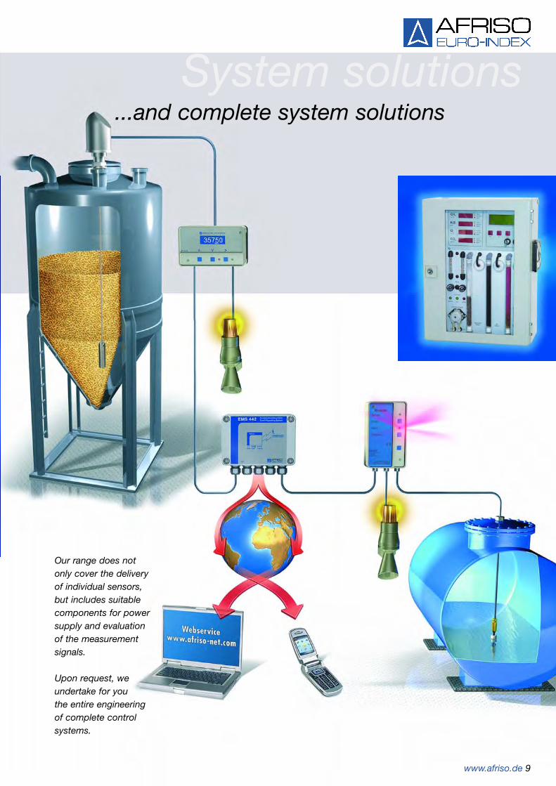
System solutions...and complete system solutions
www.afriso.de 9
Our range does not only cover the delivery of individual sensors, but includes suitablecomponents for powersupply and evaluation of the measurement signals.
Upon request, we undertake for you the entire engineering of complete controlsystems.

Contents
Our product range covers Measuring, control and monitoring devices for building technology, industryand environmental protection.This includes products for ground water protection, fluegas monitoring, effective use of energy, products forusing renewable energies (sun and rain) as well as a complete range of pressure, temperature and levelinstruments. In addition to the products presented inthis catalogue, we manufacture many customised pro-ducts. Please enquire.
Finding information
The catalogue is divided into 15 chapters. A chapteroverview is provided on pages 2 and 3. The blue chaptermarkings assist you in finding the required chapter. Each chapter begins with a detailed table of contents.To find individual products, you can also use the com-prehensive A-Z product keyword index in the appendix.Usually, all information on a product is found on onepage or cross references guide you to other pages foradditional information.
Enquiries
To make enquiries as simple as possible and to assistyou in gathering all the necessary information, theappendix contains a number of enquiry questionnaires/checklists for pressure gauges, level gauges and analy-sers.
Divisions
Our sales department is divided into three divisions,each with its own area of expertise. This way, we canprovide optimum assistance. You can find the division incharge of a given product at the bottom of the corre-sponding catalogue page.
Delivery times/stock items
All stock items have their part numbers printed in bluein the lists. Please enquire for delivery times of otheritems as they vary greatly depending on the specificati-on of the units.
Minimum order quantities
Many products can be manufactured in small quantities.In many cases, you may even order a single piece.However, for some items there are minimum orderquantities or packing units which must be observed. The listings provide the appropriate information.
Small order handling fee/minimum order value
For very small orders with net values below € 50.00, a handling fee of € 10.00 will be charged. No otherminimum order value restrictions apply.
Return of goods
Please note that we cannot accept the return of anyitems other than standard stock items.
Prices/terms of delivery
Please refer to your local AFRISO representation or getin touch with AFRISO headquarters for price informati-on. Our General Terms and Conditions apply (seewww.afriso.com). This catalogue supersedes all previousversions, including previous prices. All information without prejudice.
Technical modifications
As we are constantly improving our products, we re-serve the right to alter technical specifications withoutprior notice.
Copyright
Copyright 2006 by AFRISO-EURO-INDEX GmbH. No part of the catalogue may be reproduced, copied,distributed, translated or in any other way processedwithout prior written approval of AFRISO-EURO-INDEXGmbH.
How to work with this catalogue

www.afriso.de 11
Chapter 1Table of contents chapter 1
Contents gauges, level indicators and level controllers,Overfill alarm systems (capacitance/vibration)
Page
Mechanical tank contents gauges (Unimes, MT-Profil, dip stick) 12
Mechanical tank contents gauges with remote indication (Unimes E) 13
Pneumatic tank contents gauges and level indicators (Unitop, Unitel) 14-15
Tank contents gauges with mounting kit for plastic battery type tanks 16
Pneumatic tank contents gauges for AdBlue® (Unitop-Set AdBlue) 17
Electro-pneumatic tank contents gauges (Unimat) 18
Digital tank contents indicator for fuel oil and diesel fuel (DIT 01) 19
Digital tank contents indicator for water (DIT 02) 20
Hydrostatic level indicator for fuel oil and diesel (TankControl 01) 21
Universal hydrostatic level indicator (TankControl 02) 22
Hydrostatic level measurement (DMU 08) 23
Digital display units (DA 10/12/14) 24
Capacitance level indicators (CapFox® EFT 7, Series 20, EFM, S 74x) 25-30
Compact ultrasonic Level indicator (SonarFox®) 31
Magnetostrictive level indicator (MagFox MMG 01) 32
Guided micropulse level measuring system (PulsFox® PMG 01) 33-36
Level switches (Minimelder, Maximelder) 37
Compact rotary paddle switch (RotaFox® MLS 10) 38
Conductivity level switches 39-45(CoFox® ELT 8, ELT 500/4, ELT 680, ELT 68 C)
Compact capacitance level switch (CapFox® ENT 7) 46-47
Capacitance overfill alarm systems with Ex /WHG approval (CapFox® ENT 20) 48-49
Compact vibration level switch with WHG approval 50-52(VibraFox® GVG 10 – GVG 14)
01

12 Division I
Mechanical tank contents gauges
UnimesUniversal mechanical tank contentsgauge with brass and nickel silvermovement. Measuring range fullyadjustable from 90 to 200 cm tankheight or diameter. All measuringranges provide a full scale readingwith a pointer movement of 270°.Indication in percentage of level.Litre scale can be retro-fitted. Reference pointer for consumptioncontrol. Connection thread G11/2and G2. ABS housing and PE-HDfloat.
Ø 43 mm
G11/2G2
No. 16500 = G11/2
No. 16540 = G2
Measuring range fully adjustable from 90 to 200 cm
90 c
m 200
cm
MT-Profil R - 11/2 and - 2Universal, mechanical tank con-tents gauge with plastic planetarygear. Measuring range fully adjust-able from 0 to 250 cm by reversiblescale. Reversible scale 0-150 cmand 0-250 cm. Connection threadG11/2 or G 2. Stench-proof.Suitable for use in flood risk areas.
ReducerReducer G2 x 11/2, grey plastic(ABS).
Plastic dipstickPlastic design with cm graduation. Easy to read. With 100 cm long brasschain. Suitable for use with fuel oil and diesel.
DG: G PU Part no. Price €
Unimes 10 11500
Additional slide-in scales in litres 1 11900
Special slide-in scales 1 11999
MT-Profil R - 11/2 50 16500
MT-Profil R - 2 50 16540
Reducer 10 20903
Plastic dipstick:
Length 170 cm, measuring range 160 10 20010
Length 210 cm, measuring range 200 10 20011
Length 260 cm, measuring range 250 10 20012
Length 300 cm, measuring range 290 10 20013
• Unimes is the only mechanical contents gauge with litre scale
• High accuracy• Long service life• Universal 270° full scale reading
Additional slide-in scales inlitresFor Unimes and all standardisedtanks. When ordering, please specify the shape and capacity of tank.
Special slide-in scalesFor Unimes and tanks of any shapeand dimension. When ordering,please include tank drawing or dipchart.
* Additional freight charges apply for dipstick lengths of more than 210 cm.
Stench-proof!
Polyamide
PE-HD
ABS
Division II 13
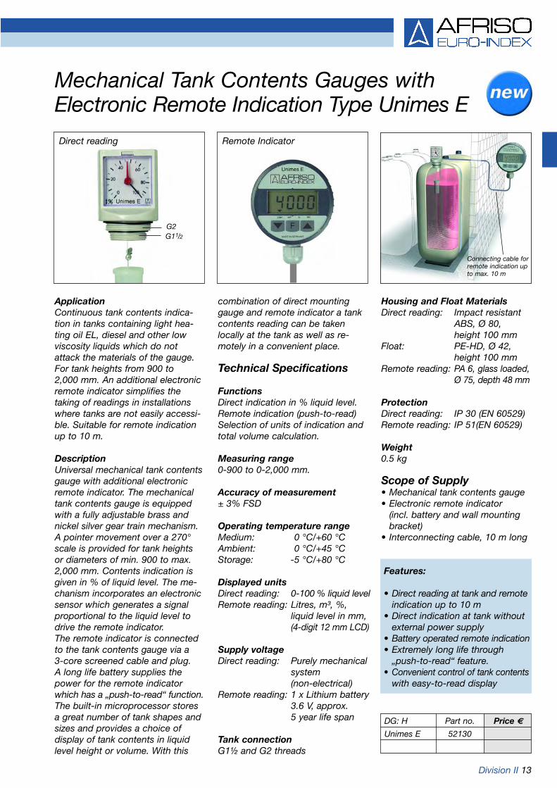
Mechanical Tank Contents Gauges withElectronic Remote Indication Type Unimes E
ApplicationContinuous tank contents indica-tion in tanks containing light hea-ting oil EL, diesel and other lowviscosity liquids which do notattack the materials of the gauge.For tank heights from 900 to 2,000 mm. An additional electronicremote indicator simplifies thetaking of readings in installationswhere tanks are not easily accessi-ble. Suitable for remote indicationup to 10 m.
Description Universal mechanical tank contentsgauge with additional electronicremote indicator. The mechanicaltank contents gauge is equippedwith a fully adjustable brass andnickel silver gear train mechanism.A pointer movement over a 270°scale is provided for tank heightsor diameters of min. 900 to max.2,000 mm. Contents indication isgiven in % of liquid level. The me-chanism incorporates an electronicsensor which generates a signalproportional to the liquid level todrive the remote indicator.The remote indicator is connectedto the tank contents gauge via a 3-core screened cable and plug.A long life battery supplies thepower for the remote indicatorwhich has a „push-to-read“ function.The built-in microprocessor storesa great number of tank shapes andsizes and provides a choice ofdisplay of tank contents in liquidlevel height or volume. With this
combination of direct mountinggauge and remote indicator a tankcontents reading can be takenlocally at the tank as well as re-motely in a convenient place.
Technical Specifications
FunctionsDirect indication in % liquid level. Remote indication (push-to-read)Selection of units of indication andtotal volume calculation.
Measuring range0-900 to 0-2,000 mm.
Accuracy of measurement± 3% FSD
Operating temperature rangeMedium: 0 °C/+60 °CAmbient: 0 °C/+45 °CStorage: -5 °C/+80 °C
Displayed unitsDirect reading: 0-100 % liquid levelRemote reading: Litres, m³, %,
liquid level in mm, (4-digit 12 mm LCD)
Supply voltageDirect reading: Purely mechanical
system (non-electrical)
Remote reading: 1 x Lithium battery 3.6 V, approx. 5 year life span
Tank connectionG1½ and G2 threads
Connecting cable forremote indication upto max. 10 m
Remote Indicator
G11/2G2
Direct reading
DG: H Part no. Price €
Unimes E 52130
Housing and Float MaterialsDirect reading: Impact resistant
ABS, Ø 80, height 100 mm
Float: PE-HD, Ø 42, height 100 mm
Remote reading: PA 6, glass loaded,Ø 75, depth 48 mm
ProtectionDirect reading: IP 30 (EN 60529)Remote reading: IP 51(EN 60529)
Weight0.5 kg
Scope of Supply• Mechanical tank contents gauge• Electronic remote indicator
(incl. battery and wall mountingbracket)
• Interconnecting cable, 10 m long
Features:
• Direct reading at tank and remoteindication up to 10 m
• Direct indication at tank withoutexternal power supply
• Battery operated remote indication• Extremely long life through
„push-to-read“ feature.• Convenient control of tank contents
with easy-to-read display

14 Division I
Pneumatic tank contents gauges and level indicators
Part no. 28100 = 700-1,200 mm Tank heightPart no. 28000 = 900-3,000 mm Tank heightPart no. 28200 = 3,000-4,000 mm Tank height
Tank
hei
ghtH
Unitop 3000Universal, pneumatic tank contentsgauge featuring capsule type move-ment for remote indication up to 50 m. Accuracy of measurement±2 % FSD. Zero correction andoverpressure protection device.Fully adjustable for tank heightsbetween 900 and 3,000 mm at adensity of 0.84 g/cm3 (fuel oil anddiesel). Reference pointer and dateindicator for easy consumptioncontrol. Impact resistant plastichousing for wall mounting.Indication in percentage of liquidlevel. Universal connection forcapillary tube with an outside diam.of 6 mm (also refer to pages 15,104 for Pneumofix and Euroflex). 6 separate litre scales are includedfor cylindrical, horizontal tanks.(3,000/5,000/7,000/10,000/16,000/20,000 l). Any other scale can be supplied.
• High accuracy• Unique movement suspension
separated from housing• Overpressure device• Consumption control with
date indication• Additional slide-in scales in
litres for all tank shapes• Front adjustable• Millions in daily use
Additional slide-in scales inlitresAdditional slide-in scales in litresfor Unitop 3000, Unitop 1200,Unitop 4000 and Unimat. Suitablefor all horizontally installed cylindri-cal tanks. When ordering, pleasespecify the shape and capacity oftank.
Special slide-in scalesFor tanks of any shape and dimen-sions, suitable for Unitop 3000,Unitop 1200, Unitop 4000 andUnimat. Scales are individually cali-brated to customer's specification.When ordering, please enclose asketch of the tank or a dip chartwith exact details of tank shape,size and capacity.
Unitop 1200Similar to Unitop 3000, but fullyadjustable for tank height H from700 to 1,200 mm.
Unitop 4000Similar to Unitop 3000, but fullyadjustable for tank height H from3,000 to 4,000 mm.
Unitop 2500 for waterSimilar to Unitop 3000, but workspre-set for liquids with a density of1 g/cm3 (water). The symbolshown below is printed on the dialfor easy identification.
DG: G PU Part no. Price €
Unitop 3000 10 28000
Unitop 1200 1 28100
Unitop 4000 1 28200
Unitop 2500 for water 1 28002
Additional slide-in scales in litres 1 289..
Special slide-in scales 1 28999
Please refer to pages 139 to 149 for additional products forrain water harvesting systems.
max.50 m

Division I 15
Pneumatic tank contents gauges and level indicators for fuel oil and water
Capillary tubeL = 10 m
Hose extensionpiece
hose clipDual threadedtankadaptor
To gauge
Capillarytube (internaldiameter 4)
Balance chamber
Condensatetrap
UnitelUniversal, pneumatic tank contentsgauge featuring capsule type move-ment for remote indication up to 50 m. Accuracy of measurement±3 % FSD. Zero correction andoverpressure device. Fully adjust-able for tank heights between 900and 3,000 mm at a density of 0.84 g/cm3 (fuel oil and diesel).Reference pointer for easy con-sumption control. Impact resistantplastic housing for wall mounting.Indication in percentage of liquidlevel.Universal connection for capillarytube with an outside diam. of 6 mm(also refer to page 104 forPneumofix and Euroflex).
Additional slide-in scales inlitres For Unitel and Unitel for water. Forall standardised tanks. When or-dering, please specify the shapeand capacity of tank.
Special slide-in scalesFor Unitel and Unitel for water. Fortanks of any shape and dimension.Scales are individually calibrated tocustomer's specification. Pleasespecify exact tank shape, size andcapacity.
PneumofixComplete, universal mounting kitfor pneumatic tank contents gau-ges and level indicators. Suitablefor tanks of up to 300 cm in heightor diameter. Consisting of dualthreaded tank adaptor G1 andG11/4, reducer G1 x G11/2 x G2.Capillary tube in tank (310 cm long)with balance chamber, condensatetrap. Capillary tube made frompolyethylene, 10 m. Hose clips andsteel nails, capillary extensionpiece. If no connection socket isavailable at the tank, we recom-mend the use of Euroflex (refer topage 104).
Montagefix extension set10 m PE capillary tube 4 x 1 mmwith capillary extension piece.
DG: G PU Part no. Price €
Unitel 10 72500
Unitel for water 10 72511
Unitel-Mon-tagefix-Water 10 72499
Additional slide-in scale in litres 1 725..
Special slide-in scale 1 72599
Pneumofix 10 20153
Montagefix-extensionset 10 20132
Capillarytube 50 m 1 20158
Capillaryextension piece 10 20036
Please refer to pages 139 to149 for additional products forrain water harvesting systems.
Rainwater
Unitel for waterFor remote indication up to 50 m,with capsule type movement.Accuracy of measurement ±3 %FSD. Zero correction and over-pressure device. Fully adjustablefrom 900 to 2,500 mm tank heightfor liquids with a density of 1g/cm3
(water). Reference pointer for easyconsumption control. Impact re-sistant plastic housing for wallmounting. Indication in percentageliquid level. Universal connectionfor capillary tube with an outsidediameter of 6 mm (e.g. Pneumofixor Unitel-Montagefix-Water).
Unitel-Montagefix-WaterComplete mounting kit for installa-tion in rain water harvestingsystems with all necessary installa-tion accessories.Scope of supply: Unitel forwater, 310 cm capillary tube withbalance chamber, 10 m PE capilla-ry tube 4 x 1 mm and installationaccessories.

16 Division I
Tank contents gauges with mounting kit forplastic battery type tanks
Oil / wateralarm unit *
Pullcord **
Many plastic fuel tanks becomeopaque over the years due to sedi-ments, dirt and age. Often there isno spare connection available for agauge. This special mounting kitmakes it possible to connect apneumatic remote reading con-tents gauge. There is no need toswitch off the burner.Many withdrawal systems alreadyhave corresponding markings onthe mounting flanges for the drillingof holes.
Attention:In most cases, it is prohibited to drill through the tank wall.This may render the warranty for the tank null and void.
This mounting set enablesquick and easy retrofitting ofplastic battery type tankswithout interruption of regularoperation.
• Instant installation - no problem!1. Drill a hole into the flange2. Install the capillary tube3. Check the level
Benefits:No components need to be dis-mantled for installation. Oil carry-ing pipes do not need to be dis-mantled and then recommission-ed and de-aerated.
Unitel-SetThis universal, pneumatic tank con-tents gauge for remote indicationup to 50 m comes with a mountingkit for installation on plastic batterytanks. Accuracy of measurement±3 % FSD. The unit is fully adjust-able for tank heights from 900 to3,000 mm for fuel oil EL or diesel(density = 0.84 g/cm3). Referencepointer for easy consumption con-trol. Indication in percentage ofliquid level. The mounting kit con-sist of the capillary tube 2.10 mwith balance chamber (Ø 9 mm),self-sealing tank adaptor for a 10 mm hole, 10 m capillary tube,hose clips, steel nails and a capilla-ry extension piece.
* Refer to page 86 for an oil/water alarm unit.
** Refer to page 108 for a pull cord.
Unitop-SetThis universal, pneumatic tank con-tents gauge for remote indicationup to 50 m comes with a mountingkit for installation on plastic batterytanks. Accuracy of measurement±2 % FSD. The unit is fully adjust-able for tank heights from 900 to3,000 mm for fuel oil EL or diesel(density = 0.84 g/cm3). Referencepointer and date indicator for easyconsumption control. Indication inpercentage of liquid level. Litrescales are available (a request cardis included with the kit). The moun-ting kit is identical to the Unitel kit.
DG: G PU Part no. Price €
Unitel-Set 10 72512
Unitop-Set 5 28004

Division I 17
Pneumatic Tank Contents Gauges for AdBlue® – Unitop-Set AdBlue
ApplicationContinuous tank contents indica-tion in vessels containing AdBlue®
(s.g. 1.09 g/cm³).For tank heights from 700 to 2,300 mm. Suitable for remoteindication up to 50 m. AdBlue® isidentical to „NOx-reduction materialAUS 32“ and „urea solution 32.5 %“.
Description Universal pneumatic tank contentsgauge with capsule gauge move-ment. Especially calibrated forAdBlue® specific gravity of 1.09 g/cm³. Fully adjustable over atank height range from 700 to2,300 mm. Measuring accuracy of±2 % FSD. Indication in % liquidlevel, optional slide-in scales, cali-brated in litres, are available.Front access to zero correction,adjustable reference pointer anddate display for simple consump-tion control and integrated over-pressure device. Universal capillaryconnector for rigid or flexible capil-lary tube with outside diameter of 6 mm. Easy installation with thespecific AdBlue® mounting kit.Process connection G1 and G1¼,high density PE standpipe, 2.5 mlong with stainless steel balancechamber, 10 m of PE 4 x 1 capillarytube.
Technical Specification
Measuring range0-700 to 0-2,300 mm tank height
Accuracy of measurement± 2 % FSD
Operating temperature rangeMedium: 0 °C/+35 °CAmbient: -5 °C/+55 °CStorage: -5 °C/+55 °C(Please refer to legal requirementsfor the storage of AdBlue!)
Dial 0 to 100 %
Displayed unitsIndication in % liquid level
HousingWall mounting housing, impactresistant plastic, with integratedhand pump W x H x D: 155 x 166 x 73 mm
Process connectionG1 and G1¼
StandpipeHigh density PE plastic (natural)Balance chamber stainless steelLength 2.5 m
Capillary tubePE capillary tube 4 x 1 mmLength 10 m
Scope of SupplyTank Contents Gauge andMounting Kit
Options• Additional slide-in-scales in litres,
see page 14• Capillary extension, see page 15
When erecting AdBlue® storagefacilities it is important to follow thelegal installation requirementsregarding suitable materials.
For suitable tank overfill alarmsystems see page 62, for suitableinternal tank linings see page 81.
DG: G PU Part no. Price €
Unitop-SetAdBlue 1 28040
Features:
• Specifically calibrated forAdBlue®
• Universally adjustable
• Simple installation
• Complete with specific mounting kit
• No external power supply required
Capillary tube PE 4 x 1, black
G11/4G1
StandpipeHigh density PE (natural)
Balance chamberStainless steel

18 Division I
Electro-pneumatic tank contents gauges
Low level alarm adjustable between 5-30 %
Refer to page 108 for Pneumofix 0 100 %
AC 230 V
max
. 8 m
max. 50 m
• Unimat with continuous indica-tion and low level alarm
• As soon as the low level (5-30 %) is reached, visual and audible alarm signals are triggered. In addition, a built-in relay provides contacts for ancillary alarms.
• The audible alarm can be muted.• Indication in percentage of level.• Additional slide-in scales in litres
are available for all DIN tanks.• Refer to page 14 for special
slide-in scales for non-DIN tanks.
Unimat 3000
ApplicationFor continuous level measurementin tanks containing fuel oil EL ordiesel. For tank heights from 900 to 3,000 mm. Suitable for remoteindication up to 50 m.
DescriptionUniversal, electro-pneumatic tankcontents gauge with capsule typemovement and electrical pump forcontinuous indication. Fully adjustable from 900 to 3,000 mm tank height.Accuracy of measurement ±2 % FSD.Indication in percentage of liquidlevel. Litre scales are optionallyavailable.Front access to zero correction,reference pointer for easy con-sumption control as well as inte-grated overpressure device. The visual and audible alarm signals for low level are adjustablebetween 5 and 30 %.Relay contact for external alarms.Electrical connection AC 230 V viamains plug.Capillary tube connection for tubeswith an outside diameter of 6 mm.Easy installation by means ofPneumofix mounting kit (refer topage 108) or Euroflex 3 combina-tion fitting (refer to page 104).
Technical specifications
Measuring range0/900 to 0/3,000 mm oil column
Accuracy of measurement±2 % FSD
Operating temperature rangeAmbient: -5 °C/+55 °CStorage: -25 °C/+55 °C
Dial0 to 100 %
Displayed unitsIndication in percentage of liquidlevel
Capillary connectionUniversal connection for rigid orflexible capillary tube, 6 mm
Supply voltageAC 230 V
Power consumptionMax. 15 VA
Relay outputRelay contact: 1 voltage-free
changeover contactContact rating: AC 230 V 2 A
Visual indicationRed lamp for low level alarm
Audible alarmIntegrated piezo-buzzer
HousingWall mounting housing made fromimpact resistant plastic (ABS)W x H x D: 215 x 165 x 130 mm
ProtectionIP 30 (EN 60529)
Weight2.3 kg
Unimat 8000Similar to Unimat 3000 but workspre-set for tanks with heights between 3,000 and 8,000 mm.When ordering, please specify thedesired tank height and the densityof the liquid to be measured.
Options/Accessories
• Additional slide-in scales in litres for DIN tanks
• Special scales in litres• Pneumofix mounting set• Euroflex 3 combination fitting
DG: G PU Part no. Price €
Unimat 3000 1 26000
Unimat 8000 1 26100

Division II 19
Digital tank contents indicator DIT 01 for fuel oil and diesel fuel
ApplicationFor continuous level measurementin tanks containing fuel oil EL, L ordiesel. Specially suitable for under-ground tanks and basement tanks.For liquid levels from 0.9 to 3 m.
DescriptionThe hydrostatic level measurementsystem consists of an evaluationunit with digital display (display unit)and a submersible probe with integrated pressure measuring cell.
Technical specifications
FunctionsPush-to-read, switching of display-ed units, calculation of total volume
Measuring range0/300 mbar
Accuracy of measurement±1.5 % FSD
Operating temperature rangeMedium: 0 °C/+60 °CAmbient: 0 °C/+45 °CStorage: -5 °C/+80 °C
Display4-digit, 12 mm high LCD 7-segment display with addi-tional symbols
Displayed unitsLitres, m3, %, height in mm
Submersible probeHousing stainless steel 1.4305Cable PVC, 5 m with
breather tubeDiaphragm stainless steel 1.4435Seals FKMSpacer POM, PE
Supply voltage1 x lithium battery 3.6 V (included)Service life approx. 5 years
HousingPA6, glass loaded, grey, Ø 75 mm,with wall mounting bracket, protection IP 51 (EN 60529)
Scope of supply
DIT 01• Evaluation unit with digital display• 5 m connection cable to probe
(can be extended by max. 10 m)• Junction box, protection IP 55
(min.)• Submersible probe with 5 m
submersible cable• Screw connector set
G1 x G11/2 x G2• Mounting kit for withdrawal
flange (PG 9 gland)• Wall mounting bracket
DIT 01-E• Evaluation unit with digital display• 5 m connection cable to probe• Junction box, protection IP 55
(min)• Submersible probe with 5 m
submersible cable• Combination fitting Euroflex 3
(suction and return pipe with integrated submersible probe, connection thread G1)
• Wall mounting bracket
Display unit
DG: H Part no. Price €
DIT 01 52122
DIT 01-E 52123
Submersible probe
DIT 01 features the following:
• Universal application in tanks with up to 3 m in height or diameter.
• No dip charts required since all standard tank shapes are stored.
• Fast and safe mounting with complete installation accessories.
• No external supply voltage required.
• Push-to-read function for ex-tremely long battery service life.
• High accuracy of measurement due to electronic sensor (pressure measuring cell).
• Display unit with easy-to-read display.
• Simple operation via menu-guided set-up procedure.
• Connection cable of the display unit can be extended by up to 10 m.

20 Division II
Digital tank contents indicator DIT 02for water
ApplicationSpecially suitable for continuouslevel measurement in rain watertanks and cisterns.For liquid levels from 1 to 4 m.
DescriptionThe hydrostatic level measurementsystem consists of an evaluationunit with digital display (display unit)and a submersible probe with inte-grated pressure measuring cell.
Technical specifications
FunctionsPush-to-read, switching of displayed units, calculation of totalvolume
Measuring range0/400 mbar
Accuracy of measurement±1.5 % FSD
Operating temperature rangeMedium: 0 °C/+60 °CAmbient: 0 °C/+45 °CStorage: -5 °C/+80 °C
Display4-digit, 12 mm high LCD 7-segment display with addi-tional symbols
Displayed unitsLitres, m3, %, height in mm
Submersible probeHousing stainless steel 1.4305Cable PVC, 6 m with
breather tubeDiaphragm stainless steel 1.4435Seals FKMSpacer POM, PE
Supply voltage1 x lithium battery 3.6 V (included)Service life approx. 5 years
HousingPA6, glass loaded, blue, Ø 75 mm,with wall mounting bracket, protection IP 51 (EN 60529)
Scope of supply
• Evaluation unit with digital display• 15 m connection cable to probe
(cannot be extended)• Junction box, protection IP 55
(min.)• Submersible probe with 6 m
submersible cable• Screw connector set
G1 x G11/2 x G2• Mounting kit for 15 mm hole
(PG 9 gland)• Wall mounting bracket
Digital tank contents indicator DIT 02
Submersibleprobe
Display unit
DG: H Part no. Price €
DIT 02 52124
Submersible probe
DIT 02 features the following:
• Universal application in tanks with up to 4 m in height or diameter.
• No dip charts required since all standard tank shapes are stored.
• Fast and safe mounting with complete installation accessories.
• No external supply voltage required.
• Push-to-read function for ex-tremely long battery service life.
• High accuracy of measurement due to electronic sensor (pressure measuring cell).
• Display unit with easy-to-read display.
• Simple operation via menu-guided set-up procedure.

Division II 21
ApplicationContinuous reading level indicatorwith graphic display of level, rate ofconsumption, forward coverage offuel based on past consumption aswell as as minimum fuel level alarm(reserve). Suitable for tanks from0.9 to max. 3 m liquid height. Forlight fuel oil EL, L or diesel. Remoteindication up to 15 m. Especiallydesigned for modern housing tech-nology.
Description The hydrostatic level indicatorsystem consists of a display instru-ment with graphics and a submer-sible probe with integrated pressu-re transducer.Choice of read-out in litres, m³, %,or liquid level in mm. When a pre-set minimum level, which is fullyadjustable, is reached, a visual andaudible alarm is initiated by theindicator. (The audible alarm can bemuted). An additional relay contactis provided for the connection ofadditional alarm units or telecom-munication and housing technologycontrol systems. The integrated microprocessorenables the user to call up on thedisplay important information suchas fuel consumption, last tank fil-ling, tank contents or forward cove-rage of fuel requirement (based onpast consumption rate). Simpleoperation with menu-guided instru-ment settings.Electronic measurement ensureshigh accurcy. Standard tank sizes
are memorized and accessible.Tank tables for special sizes can bepre-programmed (option).
Technical Specification
FunctionsSelection facility for units to bedisplayed, total volume calculation,daily memorization of fuel levels,consumption check, graphicdisplay of consumption over lastyear, 3 or 5 years, forward fuelcoverage, alarm functions, sensorfault and short circuit indication.
Measuring range0 to 300 mbar
Accuracy of measurement± 1.5 % FSD
Operating temperature rangeMedium: 0 °C/+60 °CAmbient: 0 °C/+45 °CStorage: -5 °C/+80 °C
DisplayGraphic display (23 x 46 mm),back lit and high resolution (64 x 128 Pixel). Choice of displayin litres, m³, % and liquid level inmm. Visual symbols for alarm infor-mation.
Submersible probeHousing stainless 1.4305Cable PVC, 5 m with
breather tubeMembrane stainless 1.4435Seals FKMSpacer POM, PE
DG: H Part no. Price €
TankControl 01 52132
Additional cost
Special tanktable programme
Hydrostatic Level IndicatorTankControl 01 for Fuel Oil and Diesel
Supply voltageAC 230 VLithium battery for calendar memo-ry function.
Relay outputRelay contact: 1x voltage-free
change-overContact rating: 2 A, non-inductive
Audible alarmIntegrated piezo-buzzer, re-settable
HousingWall mounting housing, impactresistant plastic (ABS)W x H x D: 97 x 163 x 62 mm
ProtectionIP 54 (EN 60529)
Scope of Supply• Digital display unit with graphics• Submersible probe with 5 m
submersible cable• Screw connector set
G x G1½ x G2• Mounting kit for withdrawal flange
on plastic battery type tanks• Weather-proof mains socket
Options• Programming to special tank
table
22 Division II
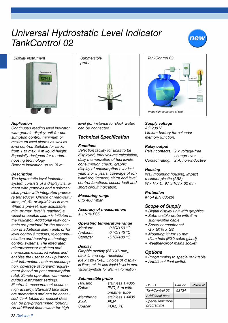
ApplicationContinuous reading level indicatorwith graphic display unit for con-sumption control, minimum ormaximum level alarms as well aslevel control. Suitable for tanksfrom 1 to max. 4 m liquid height.Especially designed for modernhousing technology. Remote indication up to 15 m.
Description The hydrostatic level indicatorsystem consists of a display instru-ment with graphics and a submer-sible probe with integrated pressu-re transducer. Choice of read-out inlitres, m³, %, or liquid level in mm.When a pre-set, fully adjustable,min. or max. level is reached, avisual or audible alarm is initiated atthe indicator. Additional relay con-tacts are provided for the connec-tion of additional alarm units or forlevel control functions, telecommu-nication and housing technologycontrol systems. The integratedmicroprocessor registers andmemorizes measured values andenables the user to call up impor-tant information such as consump-tion, coverage of forward require-ment (based on past consumptionrate). Simple operation with menu-guided instrument settings.Electronic measurement ensureshigh accurcy. Standard tank sizesare memorized and can be acces-sed. Tank tables for special sizescan be pre-programmed (option).An additional float switch for high
level (for instance for slack water)can be connected.
Technical Specification
FunctionsSelection facility for units to bedisplayed, total volume calculation,daily memorization of fuel levels,consumption check, graphicdisplay of consumption over lastyear, 3 or 5 years, coverage of for-ward requirement, alarm and levelcontrol functions, sensor fault andshort circuit indication.
Measuring range0 to 400 mbar
Accuracy of measurement± 1.5 % FSD
Operating temperature rangeMedium: 0 °C/+60 °CAmbient: 0 °C/+45 °CStorage: -5 °C/+80 °C
DisplayGraphic display (23 x 46 mm),back lit and high resolution (64 x 128 Pixel). Choice of displayin litres, m³, % and liquid level in mm.Visual symbols for alarm information.
Submersible probeHousing stainless 1.4305Cable PVC, 6 m with
breather tubeMembrane stainless 1.4435Seals FKMSpacer POM, PE
DG: H Part no. Price €
TankControl 02 52134
Additional cost
Special tank tableprogramme
Universal Hydrostatic Level IndicatorTankControl 02
Submersibleprobe
Display instrument TankControl 02
Probe right to bottom of tank
230V AC
Supply voltageAC 230 VLithium battery for calendar memory function.
Relay outputRelay contacts: 2 x voltage-free
change-overContact rating: 2 A, non-inductive
HousingWall mounting housing, impactresistant plastic (ABS)W x H x D: 97 x 163 x 62 mm
ProtectionIP 54 (EN 60529)
Scope of Supply• Digital display unit with graphics• Submersible probe with 6 m
submersible cable• Screw connector set
G x G1½ x G2• Mounting kit for 15 mm
diam.hole (PG9 cable gland)• Weather-proof mains socket
Options• Programming to special tank table• Additional float switch

Division II 23
Hydrostatic level measurement pressure transducer DMU 08
DMU 08 Digital display unit
Overpressure safetyMin. 2 x FS(burst pressure min. 3 x FS)
Operating temperature rangeMedium: -10 °C/+70 °CAmbient: -10 °C/+70 °CStorage: -25 °C/+70 °C
Temperature error bandin compensated range 0-70 °C < 1 % FSO(< 0.25 bar < 2 % FSO)
Dynamic characteristicsResponse time < 10 ms
MaterialsHousing stainless steel 1.4571Diaphragm stainless steel 1.4404Seals FKM (Viton)
Pressure transmission liquidSilicone oil
Supply voltageDC 12-36 VEx version DC 14-28 V
Output signal4-20 mA, 2-wire
Load4-20 mA < UB (V) – 12 V [Ohm]
0.02 A
ApplicationContinuous electronic level meas-urement in tanks, wells, drillingholes, water reservoirs and rivers orwaste water systems.
DescriptionThe DMU 08 pressure transducersuse silicon technology and featurecalibrated, amplified sensor signalswhich are converted into standard-ised voltage or current outputs.
Features:• Compact and robust stainless
steel design• Choice of PUR or FEP cable• Special calibration for all
standard pressure units• Integrated voltage overload
protection according to EN 61000-4-5
Accuracy of measurementDeviation according to IEC 60770 -limit point setting (non-linearity,hysteresis, repeatability): < ±0.35 % FSD(measuring ranges 0/100 mbar to0/400 mbar < ±0.5 % FSD)
Measuring ranges0/100 mbar to 0/40 bar, relativepressure
Current input4-20 mA < 25 mA
Protective electrical measuresShort circuit proof and polarity protected
Electrical connection (protection)PUR cable (IP 68)
CE conformity (EMC)EN 61326
Accessories (optional)• Screw connector set• Junction box• Lightning protection• Fixing clamp• Extended weight
Optional extras• Ex version (II 1/2 G EEx ia IIC T4)• FEP cable• Higher operating temperature
ranges
DG: H Part no. Price €
DMU 08 with 5 mPUR cableMeasuring range0/100 mbar 315550/160 mbar 315560/200 mbar 315570/250 mbar 315580/300 mbar 31519Plastic screwconnector set,G2 x 11/2 x 1 52125Junction boxwith pressurerelief port 31824
Refer to pages 415 to 449 for the complete range of„Pressure Transducer“
Digital display unitDA 12
Alarm unit
Pressure transducerDMU 08
Junction boxwith pressurerelief port
Screw connector set

24 Division II
Digital display units DA 10/12/14
Sensor inputAll analogue standard signals, e.g.4-20 mA, 0-20 mA, 0-1 V, 0-10 V
Analogue output0/4-20 mA, galvanically isolated
HousingStandard housing for panel mountingW x H x D: 96 x 48 x 135 mm
Panel cut-outW x H: 92 x 45 mm
Protection (front)IP 65 (EN 60529)
Electrical connectionPlug-in screw terminals (1.5 mm2)
LinearisationCustomer-specific linearisation with a max. of 24 points for theindication of volume (e.g. litres) in non-linear tanks. Dip charts for cylindrical, vertical and sphericaltanks are stored.
Min./max. value memoryStores and indicates the highestand lowest values attained duringoperation.
DescriptionDigital display unit (DA 10) alsoavailable with additional relay out-put (DA 12/14) for electronic trans-ducers.
Technical specifications
Display5-digit graphical LCD display, back-lit (white), text based user interface,choice of interface language(German/English/French), selectableunits of measurement.
Measuring range±99,999 digits (min. and max.values scalable)
Linearity±0.1 % of measuring range
ResolutionDecimal point position as required
Response time< 0.2 s
Operating temperature rangeAmbient: -10 °C/+55 °C
Supply voltageAC/DC 20-253 V
Sensor supplyIntegrated, galvanically isolatedpower supply for transducer:DC 20 V/20 mA
Additional functions DA 12Analogue output 20-10 V, galvanically isolated
Relay outputsRelay contacts: 2 voltage-freechangeover contacts (adjustablehysteresis) Contact rating: AC 250 V, 2 A, 100 VA
Additional function DA 14Analogue output 20-10 V, galvanically isolated
Relay outputs Relay contacts: 4 voltage-freechangeover contacts (adjustablehysteresis) Contact rating: AC 250 V, 2A, 100 VA
• 5-digit graphical LCD display
• Text-based user interface
• Linearisation for volume indication (24 points)
• Selectable units
• Universal power supply unit
• Integrated supply voltage for transducer
• Relay outputs (DA 12/14)
DG: H Part no. Price €
DA 10 31281
DA 12 31282
DA 14 31283
Wall-mountedhousingWAG 01 31287for mountingof one DA*
WAG 02 31288for mountingof two DAs*
WAG 03 31289for mountingof three DAs*
WAG 04 31290for mountingof four DAs*
* Price includes mounting if DA and WAG are ordered together.
Refer to pages 503 to 505 forthe complete „Digital DisplayUnits“ range.
Digital display unitDA 12
Alarm unit
Pressure transducerDMU 08
Junction boxwith pressurerelief port
Screw connector set

Division II 25
Compact capacitance level indicator CapFox® EFT 7
Output signals (load)4-20 mA (max. 500 Ohm)0-10 V (min. 10 kOhm)corresponds to measuring range0/100 %
Capacitance range0-200 pF
HousingWall mounting housing made ofimpact resistant plastic (ABS)W x H x D: 104 x 65 x 144 mm
ProtectionIP 65 (EN 60529)
Electrical connections2 x cable gland PG 11
Options/accessories
• Flexible band electrode 6,000 mm• Analogue indicators
(refer to page 26).• Digital display units with and
without switching function (refer to pages 503 to 505).
Technical specifications
Measuring range0/200 mm to 0/3,000 mm, depending on selected probe
Accuracy of measurement±2 % FSD
Operating temperature range-20 °C/+50 °C
Process pressureno pressure
Process connectionAluminiumFlexible band electrode G1BRod probe G11/2B
Flexible band electrode3,000 mm long flexible band elec-trode (can be shortened to 1,150 mm) with plastic probe weight
Rod probeElectrode stainless steel 1.4571Concentric screen tube, steelRequired probe length must be specified with orderMinimum length 200 mmMaximum length 1,500 mm
Supply voltageAC 230 V or DC 24 V or AC 24 V
Power consumptionAC 3 VA/DC 2 W
ApplicationCapacitance level indicator for continuous measurement of levelsin tanks and containers with fillingheights of 200 mm to 3,000 mm.Suitable for non-conducting liquids,especially fuel oil or diesel.
DescriptionEFT 7 capacitance level indicatorforms with its associated probe asingle compact unit.
The unit is available with either a flexible band electrode or a rigidrod probe.
The flexible band electrode can beused for liquid levels from a mini-mum of 1,150 mm to a maximum of3,000 mm.
The rod probe version with concen-tric screen tube is used for applica-tions involving small containers withheights or diameters 200 mm to1,500 mm. Please specify thelength of the rigid rod probe whenordering.
Zero and full scale can be adjustedvia an internal potentiometer.
The output signals are proportionalto the filling level.
2 glandsPG 11
Flexible probe
144
G1B
62
3010
163
m
65
Dimensions (in mm)CapFox® EFT 7 with flexible bandelectrode
CapFox® EFT 7 with rod probe
Digital display DA 12(optional)
DG: E Part no. Price €
EFT 7 52107with flexible bandelectrode 3 m
EFT 7 52108with rigid rodprobePlease specify length!
26 Division II
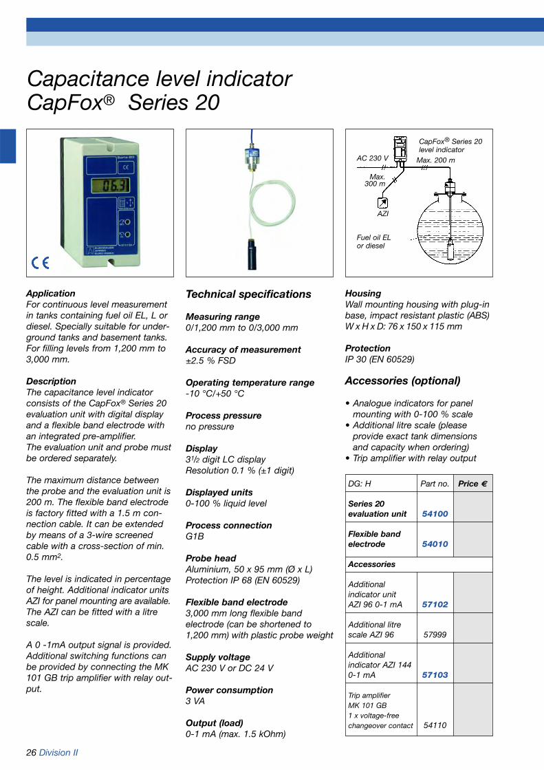
Capacitance level indicatorCapFox® Series 20
HousingWall mounting housing with plug-inbase, impact resistant plastic (ABS)W x H x D: 76 x 150 x 115 mm
ProtectionIP 30 (EN 60529)
Accessories (optional)
• Analogue indicators for panel mounting with 0-100 % scale
• Additional litre scale (please provide exact tank dimensions and capacity when ordering)
• Trip amplifier with relay output
Technical specifications
Measuring range0/1,200 mm to 0/3,000 mm
Accuracy of measurement±2.5 % FSD
Operating temperature range-10 °C/+50 °C
Process pressureno pressure
Display31/2 digit LC displayResolution 0.1 % (±1 digit)
Displayed units0-100 % liquid level
Process connectionG1B
Probe headAluminium, 50 x 95 mm (Ø x L)Protection IP 68 (EN 60529)
Flexible band electrode3,000 mm long flexible band electrode (can be shortened to1,200 mm) with plastic probe weight
Supply voltageAC 230 V or DC 24 V
Power consumption3 VA
Output (load)0-1 mA (max. 1.5 kOhm)
ApplicationFor continuous level measurementin tanks containing fuel oil EL, L ordiesel. Specially suitable for under-ground tanks and basement tanks.For filling levels from 1,200 mm to3,000 mm.
DescriptionThe capacitance level indicatorconsists of the CapFox® Series 20evaluation unit with digital displayand a flexible band electrode withan integrated pre-amplifier. The evaluation unit and probe mustbe ordered separately.
The maximum distance betweenthe probe and the evaluation unit is 200 m. The flexible band electrodeis factory fitted with a 1.5 m con-nection cable. It can be extendedby means of a 3-wire screenedcable with a cross-section of min.0.5 mm2.
The level is indicated in percentageof height. Additional indicator unitsAZI for panel mounting are available.The AZI can be fitted with a litrescale.
A 0 -1mA output signal is provided.Additional switching functions canbe provided by connecting the MK101 GB trip amplifier with relay out-put.
DG: H Part no. Price €
Series 20evaluation unit 54100
Flexible bandelectrode 54010
Accessories
Additionalindicator unitAZI 96 0-1 mA 57102
Additional litrescale AZI 96 57999
Additional indicator AZI 1440-1 mA 57103
Trip amplifierMK 101 GB 1 x voltage-freechangeover contact 54110
AC 230 V Max. 200 m
AZI
CapFox® Series 20level indicator
Fuel oil EL or diesel
Max.300 m

Division II 27
Capacitance level indicatorsCapFox® EFM 741/752/762
AC 230 V orDC 24 V
A
Fail-safe mode (752/762)Integrated selector switch for min.or max. fail-safe mode (low/high)
HousingWall mounting housing with plug-inbase, impact resistant plastic (ABS)W x H x D: 76 x 150 x 115 mm
ProtectionIP 30 (EN 60529)
Ordering information
Complete measuring system EFMseries (items to be ordered separately):• Evaluation unit EFM• HF probe insert type 3640 211• Probe• Concentric screen tube
(not required with flexible band electrode since the earth electrode is already integrated)
Refer to pages 29, 30 for probesand pre-amplifiers.Select according to the operatingconditions. Special customer-specific probes are available inaddition to the standard probes.
Technical specifications
Measuring range0/200 mm to 0/12,000 mm, depending on selected probe
Accuracy of measurement±2 % FSD
Operating temperature rangeAmbient: -10 °C/+50 °C
Process pressureDepending on selected probe
Display31/2 digit LCD displayResolution 0.1 % (±1 digit)
Displayed units0-100 % liquid level
Supply voltageAC 230 V or DC 24 V
Power consumption5 VA
Output signals0-10 V/4-20 mA
Relay outputs (relay contacts)EFM 741 NoneEFM 752 1 x voltage-free changeover contactEFM 762 2 x voltage-free changeover contacts
Switch ratingAC 250 V 3 ADC 24 V 0.5 A
Visual indication (752/762)Green LED normal operationRed LED alarm conditionSwitch point indication
ApplicationFor continuous level measurementin containers, silos, tanks or fillingsystems. Suitable for liquid, powdery, electri-cally conducting or non-conductingmedia. Also suitable for pressurised orvacuum tanks.
DescriptionThe capacitance level indicatorconsists of a series CapFox® EFMevaluation unit with digital display, aprobe and a pre-amplifier which isfactory fitted in the probe head.CapFox® EFM 741 provides onlyindication.CapFox® EFM 752 indication plusone limit switch. The fully adjus-table limit switch for a min. or max.signal, with variable hysteresis, canbe used for control functions (volt-age-free relay contact).CapFox® EFM 762 has two in-dependently adjustable limit switches to control filling/emptyingprocesses.The choice of probe (partly or fullyinsulated, rigid or flexible) dependson the properties of the material tobe measured and the shape of thetank. Fully insulated probes mustbe used for conducting media. Theprobes are equipped with a capaci-tance voltage transducer (HF probeinsert) in the probe head and aremounted vertically.
DG: E Part no. Price €
EFM 741 51741
EFM 752 51752
EFM 762 51762
Probe
Concentricscreen tube

28 Division II
Capacitance level indicator with Ex approvalCapFox® S 74x
Ex zone Non-hazardous area
ZLT/DDC AZ I
AC 230 Vor DC 24 V
ProtectionIP 30 (EN 60529)
Ex approvalEEx II C (EEx ia) II C T6BASEFA No. 96D2392
HF pre-amplifier ExHF pre-amplifier insert Ex type3640 021 exclusively for theCapFox® S 74x to ensure the intrinsic safety of the circuit. Thepre-amplifier is factory fitted in theprobe head.
Ordering informationComplete measuring system (itemsto be ordered separately):• Evaluation unit S 74x• HF probe insert type 3640 021• Rigid series 88 probe• Concentric screen tube
Refer to pages 29, 30 for probes.Select according to the operatingconditions. Special customer-specific probes are available inaddition to the standard probes.
Options• Supply voltage DC 24 V
Technical specifications
Measuring range0/200 mm to 0/3,000 mm, depending on selected probe
Accuracy of measurement±1.5 % FSD
Operating temperature rangeAmbient: -10 °C/+50 °C
Process pressureDepending on selected probe
Display31/2 digit LCD displayResolution 0.1 % (±1 digit)
Displayed units0-100 % liquid level
Supply voltageAC 230 V
Power consumption5 VA
Outputs0-10 V/0-1 mA/4-20 mA
Visual indicationYellow LED power „on“
Intrinsically safe circuitUM = 250 V, UO = 13.0 V, IO = 76 mAPO = 0.25 W, CO = 1.0 µF, LO = 6.1 mH
HousingWall mounting housing with plug-inbase, impact resistant plastic (ABS)W x H x D: 76 x 150 x 115 mm
ApplicationFor continuous level measurementin tanks and vessels in Ex zones 0,1 and 2. Suitable for liquids, powders, elec-trically conducting or non-conduc-ting media. Also suitable for pres-surised or vacuum tanks.
DescriptionThe capacitance level indicatorconsists of a series CapFox® S 74xevaluation unit with digital display, a probe and an Ex pre-amplifierwhich is factory fitted in the probehead.
CapFox® S 74x has an intrinsicallysafe probe circuit. In order to guarantee the intrinsic safety of thecircuit, the S 74x evaluation unitmay only be used in conjunctionwith a type Ex 3640 021HF pre-amplifier and a rigid series 88 capacitance probe. The evaluationunit must be installed outside of thehazardous area.
The choice of probe (partly or fullyinsulated, rigid) depends on theproperties of the material to bemeasured and the shape of the tank.Fully insulated probes must be usedfor conducting media. The probesare equipped with a capacitancevoltage transducer (HF probe insert)in the probe head and are mountedvertically.
DG: E Part no. Price €
S 74x 51745AC 230 V
S 74x 51746DC 24 V
HF-pre- 51791amplifier Ex
Division II 29
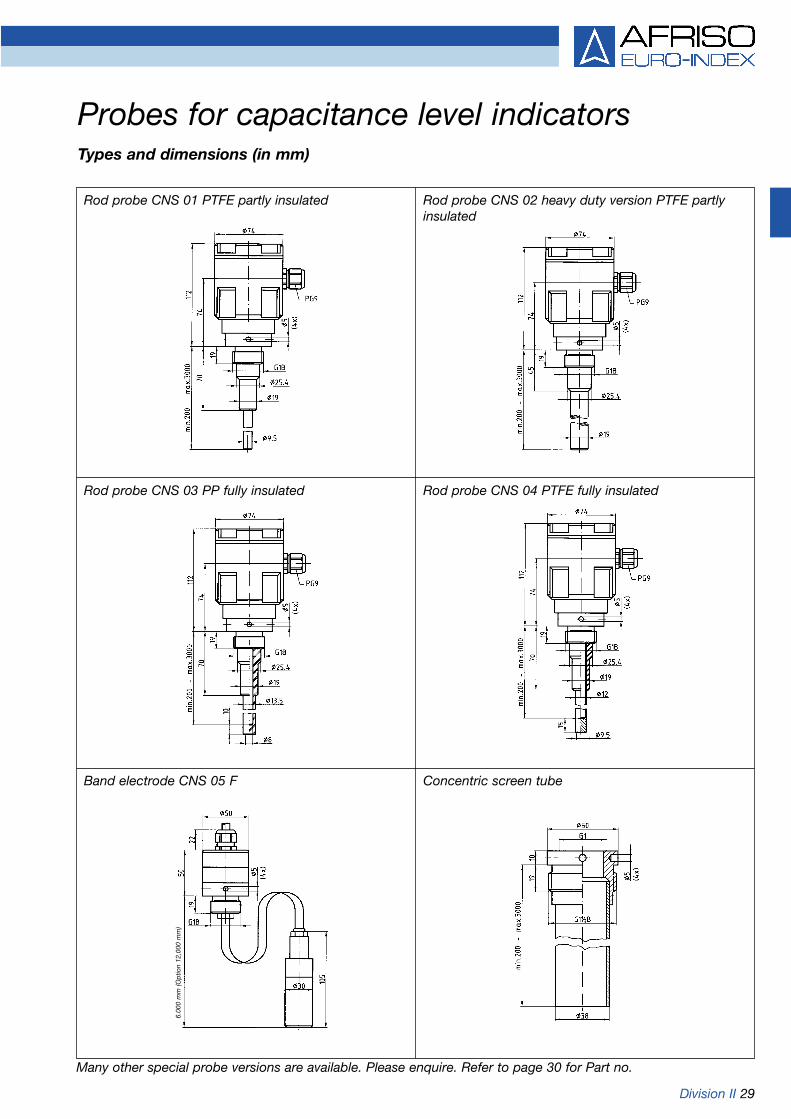
Probes for capacitance level indicatorsTypes and dimensions (in mm)
Rod probe CNS 02 heavy duty version PTFE partlyinsulated
Rod probe CNS 04 PTFE fully insulated
Band electrode CNS 05 F Concentric screen tube
Many other special probe versions are available. Please enquire. Refer to page 30 for Part no.
6.00
0 m
m (O
ptio
n 12
,000
mm
)
Rod probe CNS 01 PTFE partly insulated
Rod probe CNS 03 PP fully insulated

30 Division II
Type CNS 01 CNS 02 CNS 03 PP CNS 04 PTFE CNS 05 F CNS 05 FRod probe Rod probe Rod probe Rod probe Flexible band electrode Flexible band electrode
Version
Type number 8812-21-3000 8812-22-3000 8812-61-3300 8812-81-3300 8022-56-000 8022-56-000Suitable for EFM/S74x EFM/S74x EFM/S74x EFM/S74x EFM EFMPrice €Part no. 55509 55510 55520 55532 55552 55553
Probe headMaterial Aluminium die cast Aluminium die cast Aluminium die cast Aluminium die cast Aluminium Aluminium
Electrical PG 9 PG 9 PG 9 PG 9 2 m 2 mconnection fixed cable fixed cableProtection IP 66 IP 66 IP 66 IP 66 IP 68 IP 68Process G1B G1B G1B G1B G1B G1Bconnection (G11/2B)** (G11/2B)** (G11/2B)** (G11/2B)**ElectrodesMaterial Stainless steel Stainless steel Stainless steel Stainless steel Copper Copper
1.4571 1.4571 1.4571 1.4571Insulation PTFE partly PTFE partly PP fully PTFE fully PE partly PE partly
insulated insulated insulated insulated insulated insulatedDiameter 9.5 mm 19 mm 13.5 mm 12 mm 2 x 0.5 mm 2 x 0.5 mmLength* up to 1,000 mm up to 1,000 mm up to 1,000 mm up to 1,000 mm 6,000 mm 12,000 mm
can be shortened can be shortened
Application areaProcess pressure -1/+20 bar -1/+20 bar 0/20 bar 0/5 bar no pressure no pressureTemperature -20/+220 °C -20/+220 °C 20 bar: 50 °C 5 bar: 50 °C -20/+50 °C -20/+50 °Cof medium 10 bar: 100 °C 3 bar: 150 °C
Additional costs Price € Price € Price € Price € Price € Price €Part no. Part no. Part no. Part no. Part no. Part no.
HF-probe Standard Standardinsert 51790 51790 51790 51790HF-probe --- ---insert Ex 51791 51791 51791 51791Probe extensionper m --- ---(max. 3,000 mm)*Screen tube --- ---steel up to 3,000 mm* 55555 55555 55555 55555Screen tube --- ---stainless steel 1.4571 55557 55557 55557 55557up to 1,000 mm*Extensionscreen tube --- ---stainless steel per m
(max. 3,000 mm)*
Probes for capacitance level indicators
* Please specify exact probe length.** If a concentric screen tube is used, the process connection changes to G11/2B.
Many other probe versions are available. Please enquire.
DG: E

Division II 31
Compact ultrasonic level indicator SonarFox®
for non-contact level measurement
ApplicationFor continuous, non-contact levelmeasurement of liquids and free-flowing solids with various surfacecharacteristics and consistencies.
Especially suitable for controllingrakes and gates in sewage treat-ment plants and power plants.
DescriptionThe compact SonarFox® UST 02consists of the ultrasonic trans-ducer, process connection andhousing with screw-on lid.
A programming display can beplugged into the electronics blockto calibrate the instrument withouttime consuming filling and empty-ing procedures.
The vibration-decoupled ultrasonictransducer is mounted below theprocess connection.
SonarFox® UST 02 is equippedwith an output relay for echo lossindication.
Dimensions (in mm)
Version Part no. Price €
UST 02 56119DC 10.5-40 VAC 10.5-28 V
UST 02 56129AC 85-255 V
Programming 56109display
Sonar Fox
Alarm unit
Digital displayunit DA 12
250
mm
Blo
ckin
g d
ista
nce
Technical specifications
Measuring range0/6,000 mm(blocking distance 250 mm)
Accuracy of measurement±0.2 % FS
Measuring frequency80 kHz
Ultrasonic beam angle6°
Operating temperature rangeMedium: -30 °C/+80 °CAmbient: -30 °C/+60 °C
Process pressure0.3 to 3 bar absolute
Programming display (option)6-digit display
Process connectionPVDF, G2B
Ultrasonic transducerPVDF
Supply voltageDC 10.5-40 VAC 10.5-28 V
Power consumptionAC 4 VA DC 3.6 W
Output signals (load)4-20 mA (max. 600 Ohm), 4-wire
Echo loss indicationRelay contact: 1 voltage-free
changeover contactContact rating: AC 250 V 3 A
DampingAdjustable 6, 10 or 30 s
HousingImpact resistant plastic (PBT), glass fibre reinforced
ProtectionHousing IP 67 (EN 60529)Sensor IP 68 (EN 60529)
Electrical connections2 x cable gland PG 16
Options
• Programming display• Other process connections• Other materials• Supply voltage AC 85-255 V
DG: E
G2B
89 56.5
2x PG16
Ø42
148
60
AC/DC

32 Division II
Magnetostrictive Level Indicator MagFox MMG 01
ApplicationHigh accuracy continuous levelindicator for tanks and vessels from200 mm to 4,000 mm in height.Suitable for non-crystallising lowviscosity liquids which do notadhere to the sensing probe.
DescriptionMagFox works on the magnetostric-tive principle. A magnetostrictivewire is integrated in the tubularsensing probe.The microprocessor controlledsensor electronics generateelectromagnetic pulses which passthrough the wire and create a circular magnetic field. The float ofthe probe contains a magnet whichmagnetises the wire at the float´sposition. At the point where thetwo magnetic fields meet a torsionwave is created which then passesback up along the wire to theprobe head. The time of flight ofthe pulse is measured and proces-sed by the electronics of the unit.
Technical Specifications
Measuring range0/200 mm to 0/4,000 mm
Accuracy of measurement±0.25 mmResolution < 0.1 mm
Operating temperature rangeAmbient: -40 ºC/ +85 ºCMedium: -40 ºC/+125 ºC
Operating pressureMax. 16 bar
Process connectionStainless steel 1.4571Screw-in connector G1/2B, height adjustable
ProbeStainless steel 1.4571, Ø 12 mmprobe length 1,000 mm (min. length200 mm – max. length 4,000 mm)
FloatFor liquids 0.70 g/cm3
Stainless steel 1.4571, PN 16,cylindrical 43 x 43 mm (Ø x H)
Supply voltageDC 10-30 V
Output signal4-20mA, 2-wire transmitter
HousingRobust field mounting enclosurewith screw type lid.Stainless steel 1.4305
ProtectionIP 68 (EN 60529)
Electrical ConnectionsCable gland M16 x 1.5
Optional Versions• Ex approved type• Other process connections• Other probe materials• Other floats• Higher operating temperature• HART Protocol
Special MagFox features:
• Accuracy of measurement betterthan ±0.25 mm
• Robust design ensures long lifeexpectancy
• Insensitive to shocks and vibration
• Easy to install and easy to commission
• Fully adjustable measuring rangeover full length of probe
• Microprocessor controlled evaluation of measurement
• Temperature compensatedmeasuring principle
• Very short measuring intervals• ATEX Approval for Zone 0
(optional)• HART Protocol (optional)
DG: E
Version Part no. Price €
MMG 01 53510200 -1,000 mmPlease stateProbe length !
Additional cost
Probe extensionper 100 mm
Process connectionR 11/2, brass
Ex-Approval(II 1/2 G EEx ia IIC)
Higher TemperatureRange (of medium)-200 °C/+250 °C

Rigid/flexible Flexible probesmonoprobe type F/E type B
Typical application areas: Cement, limestone, aluminium Granular plastic materials Tank height < 6 m Highly viscous liquids Light powders with low dielectric constant Plastic powder, e.g. PVC Alcohols Granular plastic materials Water supply tanks
Recommended for the following applications:For high silos or tanks with liquids, Only for level measurement in cleangranular materials liquids
An existing stilling well can be used Flexible sensors up to 24 m In turbulent or flowing liquids theto create a coax version (calibration For smaller tanks with little headroom sensor acts like a stilling wellrequired) Liquid or steam jet in vicinity of probe
FEP coating for crystallising products Can be in contact with metal or Application with conducting foams tank wall
For very low dielectric constants
Do not use: For small socket diameters Turbulent liquids where probe Crystallising liquids
(< DN 100) cannot be anchored Liquids containing solid matter For high socket Product temperature > 240 °C Products tending to adhere
Powders Viscous liquids (e.g. crude oil)
Division II 33
Principle of operationPulsFox® PMG 01 level measuringsystems operate on the basis of theTDR principle (time domain reflecto-metry). This principle uses a probeas a micropulse guide.
Electromagnetic pulses are emittedat the speed of light, reflected by the surface of the medium to be measured and received by the signal converter.
Since the speed of light is constantand independent of the gas compo-sition in the tank, the PMG devicesdo not require commissioning.
Features
• The measurement is unaffected by changes in dielectric constant, pressure, temperature or density.
• Foam, steam, dust or a turbulent surface of the medium do not affect the accuracy of the measure-ment.
• No recalibration is required when a different medium is used.
• A great number of different materials and process connectionsare available and render the system suitable for use with corrosive media or, for example, in the food industry.
The units do not have any movingparts, thus being almost main-tenance-free.
Changes of the medium do notaffect the measuring accuracy of theTDR principle.
The pulse´s propagation time isdirectly proportional to the distancebetween the probe and the surfaceof the medium.
ApplicationsGuided Micropulse devices are usedto measure levels and interfaces of li-quids, granular materials and powders.
ProbesPMG 01
Flange pulse
Productlevel pulse
Probe selectionKOAX probetype C
Solvents, NH3, foam, alcohol,oil/water, separators
Guided micropulse level measuring systemsPulsFox® Technical information/product selection

Guided micropulse level measuring systemPulsFox® PMG 01
ApplicationFor continuous level measurementin containers, tanks or silos.Suitable for electrically conductingor non-conducting liquids and bulkmaterials. Also suitable for pressuri-sed or vacuum tanks.
DescriptionPulsFox® level measuring systemsoperate on the basis of the TDRprinciple (time domain reflectome-try). The measurement is un-affected by changes in dielectricconstant, pressure, temperature ordensity. Foam, steam, dust or a turbulent surface of the medium do not affect the accuracy of the measurement. No recalibration isrequired when a different mediumis used.
Technical specifications
Measuring rangeB/E probe < 24 mC probe < 6 mF probe < 3 mRefer to probe type for probe version
Accuracy of measurementLiquids:L < 15 m: ±5 mmL > 15 m: ±0.05 % of measuredvaluePowders/granular materials:L < 15 m: ±20 mmL > 15 m: ±0.05 % of measuredvalue
Dielectric constant (εεr)Monoprobe > 2.3Dual probe > 1.8Coax probe > 1.5
Operating temperature rangeMedium: -30 °C/+200 °CFlange: -30 °C/ +90 °CAmbient: -30 °C/ +60 °C
(Ex version -30 °C/ +55 °C)
Process pressure40 bar
Process connectionG1B(for PMG 01 DF = G11/2B)Probe type/probe materialF = rigid monoprobeStainless steel 1.4571B / E = 1-2 flexible probe(s):Stainless steel 1.4401 (Ø 4 mm)C = coax probe:Stainless steel 1.4571Wetted parts:Stainless steel 1.4571/1.4401,PTFE, FPM
Supply voltageDC 18-35 VEx version < DC 28 V
Output signal4-20 mA/HART, 2-wire
HousingAluminium die cast
ProtectionIP 65 (EN 60529)
Electrical connectionPlug DIN 43650-A (IP 65)
CE conformity (EMC)EN 50082-2, EN 50081-1
AccessoriesOperating and configuration software
Options
• Ex versions• Other process connections• Higher pressures• Other probe diameters• Higher flange temperatures• FEP coatings• Other seal materials• Digital plug-in displays
PMG 01with rigid monoprobe PMG 01 with flexible monoprobe
34 Division II Refer to page 36 for Part no.

Division II 35
Guided micropulse level measuring system PulsFox® PMG 01 Types and dimensions (in mm)
Housing
With flexible monoprobe and DIN plug With coax probe and DIN plug
Probes
L = Length (L’ = Length for coax with flange); A1 = Upper blocking distance;A2 = Lower blocking distance; D = range that cannot be measured
Type B flexible
dual probe
Type Ccoax probe
Type Eflexible
monoprobe
Type Frigid
monoprobe
εεr-value Zone Type B Type C Type E Type F80 A1 300 mm 0 mm 400 mm 400 mm80 A2 20 mm 10 mm 20 mm 20 mm2 A1 330 mm 0 mm 500 mm 500 mm2 A2 100 mm 100 mm 200 mm 200 mm
– D 80 mm – 100 mm –
PG 11 Ø 8-Ø 10DIN 43650-A
101
Spanner 41
4
204
42.2
28.3
100
G1
M 8 25
78
PG 11 8- 10DIN 43650-A
101
Spanner 41
78
28
204
42.2
28.3
G1
L
L
L’
L
L
DA
2
A2
A2
A2
D
A1
A1
A1
A1

36 Division II
Guided micropulse level measuring systemPulsFox® PMG 01Type PMG 01 MS PMG 01 MF PMG 01 KX PMG 01 DF
Version
Probe type Monoprobe, Monoprobe, Coax Dual probe,rigid flexible (Ø 4 mm) probe flexible
Standard probe length 3 m (max. 3 m) 3 m (max. 24 m) 3 m (max. 6 m) 3 m (max. 24 m)
Accuracy of measurement refer to data sheet refer to data sheet refer to data sheet refer to data sheet
Max. flange temperature up to 90 °C up to 90 °C up to 90 °C up to 90 °C
Seal FPM FPM FPM FPM
Supply voltage DC 18-35 V DC 18-35 V DC 18-35 V DC 18-35 V
Output signal 4-20 mA/HART 4-20 mA/HART 4-20 mA/HART 4-20 mA/HART
System 2-wire 2-wire 2-wire 2-wire
Electrical connection Plug DIN 43650 Plug DIN 43650 Plug DIN 43650 Plug DIN 43650
Basic price €
Part no. 53468 53470 53472 53474
Additional costs €
ATEX II 1 G IIC or IIB T6...T3
ATEX II 1/2 D T100 °C (powder)
Max. Ex flange temperature up to 200 °C
Process connection
G1B PN 40 Standard Standard Standard ---
G11/2B PN 40 --- --- --- Standard
1” NPT PN 40 ---
DIN and ANSI flanges on request on request on request on request
Clamp connection on request on request on request on request
Dairy fitting DIN 11851 on request on request on request on request
Probe
Probe extension per m ---
Probe diameter 8 mm --- --- ---
Probe extension Ø 8 mm per m --- --- ---
FEP coating for probe length up to 3 m --- --- ---(only for probe diameter 4 mm)
FEP coating per m --- --- ---
Seal
FFKM
Accessories Part no. Price €
HART USB modem 53485Digital plug-in display DA 06 31278Digital plug-in display DA 06-Ex 31279
* Process connection = G11/2B, weight = Ø 40 x 260 mm
DG : H

Division I 37
Level switches Minimelder, Minimelder-R and Maximelder-R
ApplicationDesigned to signal minimum ormaximum levels of water, heatingoil EL, L, M, oil/water mixtures andneutral, non-viscous and non-adhesive liquids in tanks.
DescriptionMini-/Maximelder consists of acontrol unit and a height-adjustablefloat probe. The Minimelder probeis suspended in the lower part ofthe tank and generates an alarmsignal when the liquid level dropsbelow the probe. The Maximelderprobe is mounted in the upper partof the tank and generates an alarmwhen the liquid reaches the probe.The switching level is adjustable.When these levels are reached, theunits generate visual and audiblealarms.
MinimelderGenerates an alarm signal whenthe level falls below the minimumlevel. Cost-effective solution forbuilding automation applications.System owners are alerted to a lowfuel oil level in time.
Only timely alarms allow you torespond to seasonal fuel oil pricefluctuations in such a way as toreduce costs.
Minimelder-RSimilar to Minimelder, but with arelay (normally open contact) fortransmission of the signal to exter-nal alarms or for connection totelecommunication or building con-trol systems. For professionalapplications.
Maximelder-RGenerates an alarm when the levelreaches the maximum set liquidlevel. In all other respects similar toMinimelder-R.
Technical specifications
Permitted media• Water• Fuel oil EL, L, M• Oil/water mixtures• Non-viscous and non-adhesive
liquids
Operating temperature rangeMedium: -5 °C/+50 °CAmbient: -5 °C/+55 °C
Process connectionPlastic screw connection G1, withcable gland for height adjustment
ProbeMagnetic float switchDimensions: 85 x 24 mm (L x Ø)Float: Plastic (PA/PP)Cable: 5 m oil-resistant
cable 2 x 0.5 mm2
Weight: brassProtection: IP 68 (EN 60529)Probe voltage: Max. AC 17 V
Connection probe - control unitMax. length: 50 m (screened)
Supply voltage (control unit)AC 230 V
Power consumption5 VA
Relay outputMinimelder-R and Maximelder-R:Relay contact: 1 voltage-free con-
tact, normally openContact rating: AC 250 V, 2 A
Visual indication1 green LED (power „on“)1 red LED (alarm)
Audible alarmIntegrated piezo-buzzer, with re-set
Operational testBy means of test button
HousingWall mounting housing made fromimpact resistant plastic (ABS)W x H x D: 97 x 163 x 62 mmProtection: IP 30 (EN 60529)
Ø 24
DG: G PU Part no. Price €
Minimelder 1 16700
Minimelder-R 1 16701
Maximelder-R 1 16702
Spare probefor Minimelder 1 16703
Spare probefor Maximelder 1 16704
Minimelder-R Maximelder-R

38 Division II
Compact rotary paddle switchRotaFox® MLS 10
ApplicationThe rotary paddle switch is used for detecting levels of bulk solidswith a minimum bulk density of 100 g/dm3. Designed for use insilos and bins.
DescriptionThe RotaFox® MLS 10 rotary paddle switch is a universal levelswitch. The sensor and the switching device form a single unit. The rotary paddle is driven by asynchronous motor via a reductiongear. When the free rotation of thepaddle is impeded by materialcovering the paddle, a microswitchoperates to generate an alarm switching signal. Power to themotor is then disconnected by asecond microswitch.RotaFox® MLS 10 features a voltage-free contact which switches whenthe limit value is reached. The con-tact transmits the signal to externaldevices, such as electric flaps orsliders, pumps, visual or audiblealarm units (e.g. alarm lamp orhorn).When the level drops the paddle isreleased and the motor will re-startagain and rotate the paddle.
Technical specifications
Minimum density of medium100 g/dm3
Operating temperature rangeSwitching unit: -20 °C/+60 °CRotary paddle: -20 °C/+80 °C
Process pressure0/0.5 bar
Process connectionG1½B
Paddle shaftStainless steel 1.4305, including dust sealLength 140 mm
Rotations of paddle5 rpm
Load on the rotary paddleMax. 250 N on the shaft (lateral)Max. 120 N on the shaft tip
Mechanical service life500,000 switchings
Supply voltageAC 230 V
Power consumption3.5 VA
Relay outputMicroswitch: 1 voltage-free
changeover contactContact rating: AC 250 V 4 A
(resistive load)
Response delayapprox. 1 s
HousingImpact resistant plastic (ABS)W x H x D: 104 x 65 x 144 mm
ProtectionIP 55 (EN 60529)
Electrical connections2 x cable gland PG 11
Options
• Longer paddle shaft (max. 1,000 mm)
Version Part no. Price €
MLS 10 56100Paddle shaft
140 mm
MLS 10 56116Paddle shaft
500 mm
MLS 10 56117Paddle shaft
750 mm
MLS 10 56118Paddle shaft
1,000 mm
G1½B
144
230
4014
0
6210432PG 11
75
6530
19
DG: E
Silo
Bulk material
Upper switching level
MLS 10
MLS 10
Alarm lamp
Alarm lamp
230 V/50 Hz
230 V/50 Hz
Lower switching level

Division II 39
Conductivity level switchCoFox® ELT 8
ELT 8
AC 230 VAC 230 V
to terminals 10 a.11
Horn
Pipe duct
Water pipes
Floor waterprobe Laundry rooms,
kitchens, basements
ApplicationDesigned for use with electricallyconducting liquids which do notfoam excessively, are not highlyviscous or adhesive (bridging), e.g.water, emulsions or waste water.Also suitable as a water alarm inconjunction with floor water probeBWS 11.
DescriptionThe CoFox® ELT 8 level controlleroperates on the basis of conductivi-ty. The following functions can beselected:• Level switch• Level control for filling• Level control for emptyingThe sensitivity is adjustable. 2 voltage-free changeover contactsare provided for switching func-tions. The units feature LED´s for„normal“ operation and „alarm“.
Switching functions
Level switchThe built-in relay can be pre-set toeither energise or de-energise whenthe probe is in contact with theliquid. Sensitivity must be adjustedaccording to the conductivity of theliquid.
Level control for fillingA minimum of 2 probe rods are re-quired. Set internal switch to „max“(H). The relay energises when themin. probe loses contact with theliquid. The relay de-energises whenthe liquid reaches the max. probe.
Version DG Part no. Price €
ELT 8AC 230 V E 53503
ELT 8DC 24 V E 53503A
Accessories:
Alarm resetunit AQ 220 E 53230
Combined visual and audiblealarm unit G 61020
Cable extensionfitting G 40041
Level control for emptyingA minimum of 2 probe rods are re-quired. Set internal switch to „min“(L). The relay energises when max.and min. probes are in contact withthe liquid. The relay de-energiseswhen the min. probe loses contactwith the liquid.
Technical specifications
Adjustment range2.5 - 50 kOhm (400 - 20 µS)Fully adjustable
Operating temperature rangeAmbient: -10 °C/+60 °C
Supply voltageAC 230 V
Power consumption4 VA
Probe circuitMax. AC 3 V
Relay outputsRelay contact: 2 voltage-free
changeover contactsContact rating: AC 250 V 500 VA
DC 12 V 1 A
Visual indicationGreen LED normal operationRed LED alarm condition
Fail-safe modeIntegrated selector for min. or max.fail-safe mode (low/high)
HousingWall mounting housing with plug-inbase, impact resistant plastic (ABS)W x H x D: 53 x 113 x 108 mm
ProtectionIP 30 (EN 60529)
Options
• Supply voltage DC 24 V
ProbesThe probes are not included.Please order separately (refer topages 43, 44)!Select according to the operatingconditions. Special customer-specific probes are available inaddition to the standard probes.

40 Division II
Conductivity alarm unitCoFox® ELT 500/4
AlarmorPump „off“
ApplicationDesigned for use with electricallyconducting liquids which do notfoam excessively and are not highlyviscous or adhesive (bridging), e.g.water, emulsions or waste water.
The CoFox® ELT 500/4 alarm unit issuitable for use in large installations.Several zones (also large areas) canbe monitored simultaneously withelectrodes (probes) at variouspoints.
DescriptionThe CoFox® ELT 500/4 level controller operates on the basis ofconductivity. The electrodes connected to the switching unitmonitor the status at several points.When one or several electrodes arebridged, the red LED of the corre-sponding electrode circuit is swit-ched on. For fast and precise loca-tion of the leak, a label is providedfor each LED. A common voltage-free relay contact can be used to control separate alarm devices (e.g.alarm light or horn). The describedfunction is only activated by elec-trode signals which are longer than1 second in duration. The alarm issaved and cannot be reset for theduration of the electrode signal.
The alarm condition must be clea-red before the alarm can be resetby pressing the reset button on theunit.
CoFox® ELT 500/4 can be usedwith a series of probes for largearea monitoring with centralisedcontrol.
Refer to page 42 for additionalapplication examples.
Technical specifications
Zone monitoring4 input circuits
Switching threshold50 kOhm
Operating temperature rangeAmbient: -10 °C/+50 °C
Supply voltageAC 230 V
Power consumption3 VA
Probe circuitMax. AC 3 V
Relay outputRelay contact: 1 voltage-free
changeover contactContact rating: AC 250 V 500 A
Visual indicationYellow LED power „on“4 red LEDs alarm condition
HousingWall mounting housing with plug-inbase, impact resistant plastic (ABS)W x H x D: 53 x 113 x 108 mm
ProtectionIP 30 (EN 60529)
ProbesThe probes are not included. Pleaseorder separately (refer to pages 43,44)!Select according to the operatingconditions.Special customer-specific probesare available in addition to the stan-dard probes.
Version DG Part no. Price €
ELT 500/4AC 230 V E 53505
Accessories:
Alarm resetunit AQ 220 E 53230
Combined visualand audiblealarm unit G 61020
Cable extensionfitting G 40041
Up to 4 probes Wide area monitoring
AlarmorPump
„off“

Division II 41
Conductivity level switchCoFox® ELT 680
ApplicationSuitable for use with electrically conducting materials, predominant-ly liquids, e.g. milk, wine, fruitjuices, waste water or lyes.Also suitable for foaming or ad-hesive media, e.g. beer or yoghurt.Specially designed for applicationsin the food industry.
DescriptionThe CoFox® ELT 680 level con-troller operates on the basis of con-ductivity.
The built-in timer can be set toavoid undesired switching as aresult of surface turbulences.
The sensitivity and adjustmentrange of the controller have beendesigned to ignore bridging resist-ances which could impair the relia-bility of the unit (e.g. foam acrossthe electrode insulators in brewer-ies, dairies and ice-cream plants).
Furthermore, the unit is capable ofinterface detection between liquidswith different levels of conductivity(e.g. water and milk) in pipes andtanks.
Switching functionsThe unit can be used with eitherone electrode as a single point con-troller or with two electrodes forpump „on-off“ control.
Technical specifications
Adjustment rangeVariable adjustmentRange HR 1 kOhm to 100 kOhmRange LR 50 Ohm to 2,000 Ohm
Operating temperature rangeAmbient: -10 °C/+60 °C
Supply voltageDC 24 V
Power consumption2.5 W
Probe circuitMax. AC 3 V
Relay outputRelay contact: 1 voltage-free
changeover contactContact rating: AC 250 V 750 VA
DC 12 V 1 A
Visual indicationGreen LED power „on“
TimerAdjustable form 0 to 20 s
Fail-safe modeIntegrated selector for min. or max.fail-safe mode (low/high)
HousingStandard DIN-rail housing made ofimpact resistant plastic (ABS)W x H x D: 73 x 55 x 112 mm
ProtectionIP 40 (EN 60529)
Options
• Supply voltage AC 230 V
ProbesThe probes are not included.Please order separately (refer topages 43, 44)! Select according tothe operating conditions.Special customer-specific probesare available in addition to the stan-dard probes.
Version DG Part no. Price €
ELT 680DC 24 V E 53682
ELT 680AC 230 V E 53681
Accessories:
Alarm resetunit AQ 220 E 53230
Combined visualand audiblealarm unit G 61020
Cable extensionfitting G 40041
Green LED (normal) relayhas responded
Fail-safeswitch
Relay output
Sensitivity potentiometerTimer
Power supplyPhase-L1-(DC+)ZeroEarth PE

42 Division II
Application examples for conductivity levelswitches and leak monitoring probes
Office buildingsIT archives Laundry rooms, kitchens, basements
Warehouses, industrial facilities
Water treatment, boiler roomsIndication of membrane rupture in largeexpansion vessels
Floor sensor
Sensor cable
Floor probeWater pipes
Pipe duct
AC 230 V
ELT
Water

Division II 43
Probes for conductivity level switchesTypes and dimensions (in mm)
Single-rod probe LST 12 Flexible probe LSE 23
Multi-rod probes LSM 01/LSM 02 Single-rod probe LST 32
Floor water probe BWS 11 Wall mounted rail probe WSS
Many other special probe versions are available. Please enquire.
1,00
0 (S
tand
ard
leng
th)
3,00
0 (S
tand
ard
leng
th)
1,00
0 (S
tand
ard
leng
th)
800
(Sta
ndar
d le
ngth
)
1,00
0 (S
tand
ard
leng
th)
View A
approx. 31.5
app
rox.
300
approx. 51
Ad
just
men
t ra
ng a
pp
rox.
200

44 Division II
Probes for conductivity level switches
Many other special probe versions are available. Please enquire.
DG: E
Type Single-rod probe Flexible probe Triple-rod probe Quadruple-rod probe Dual-rod probe Triple-rod probe Single-rod probe
LST 12 LSE 23 LSM 01 LSM 01 LSM 02 LSM 02 LST 32
Version
Type number 6921 21 1000 6622 27 1030 6272 14 1230 6272 14 1240 6812 24 002P 6812 24 003P 6812 21 000P
Suitable for CoFox® ELT 8/CoFox® ELT 680Price €
Part no. 55312 55323 55034 55021 55041 55044 55332Probe headMaterial Aluminium, Aluminium, PVC, PVC, Stainless Stainless Stainless
screw screw screw screw steel steel steelcover ABS cover ABS cover ABS cover ABS 1.4571 1.4571 1.4571
Electrical PG 11 PG 11 PG 11 PG 11 2 m 2 m 2 mconnection fixed cable fixed cable fixed cableProtection IP 66 IP 55 IP 65 IP 65 IP 66 IP 66 IP 66Process G1/2B G1B G1B G1B G1B G1B G1BconnectionElectrodesNumber 1 3 3 4 2 3 1Material 1.4571 1.4571 1.4571 1.4571 1.4571 1.4571 1.4571Insulator PTFE PTFE Epoxy resin Epoxy resin PTFE PTFE PTFEDiameter 9.5 mm 9.5 mm 3.2 mm 3.2 mm 3.2 mm 3.2 mm 9.5 mmLength 1,000 mm 3,000 mm 1,000 mm 1,000 mm 800 mm 800 mm 1,000 mmApplicationarea Process pressure 0/3 bar 0/2 bar 0/3 bar 0/3 bar 0/10 bar 0/10 bar -1/+20 barTemperature -20/+150 °C 2bar: 0/ 50 °C 0/50 °C 0/50 °C -20/+120 °C -20/+120 °C -20/+220 °Cof medium 1bar: 0/100 °C
Wall mounted rail probe WSSApplication Height-adjustable, wall-mounted probe,
suitable for CoFox® ELT 500/4 / CoFox® ELT 8 / CoFox® ELT 680Price €
Part no. 55050Temperature of medium 0/50 °CAdjustment range approx. 200 mmElectrical connection fixed cable, 150 cm
Floor water probe BWS 11Application Suitable for CoFox® ELT 500/4 / CoFox® ELT 8 / CoFox® ELT 680Price €
Part no. 55111Response level approx. 2-3 mmTemperature of medium 0/50 °CProbe diameter 75 mmMaterial PP, blackElectrical connection fixed cable, 150 cm

Division II 45
Compact conductivity level switchCoFox® ELT 68 C
ApplicationSuitable for use in electrically conducting materials, predominant-ly liquids, e.g. milk, wine or fruitjuices.Also suitable for foaming or ad-hesive media, e.g. beer or yoghurt.Specially designed for applicationsin the food industry.
DescriptionCoFox® ELT 68 C is a self-monitor-ing level switch operating on thebasis of conductivity.
The unit is primarily used as a minimum level switch in breweries,dairies and ice-cream plants. Theunit is also capable of detecting theinterface between cleaning emul-sions and the actual medium, e.g.milk/water, beer/foam, water/lye.
The sensitivity and adjustmentrange have been designed to ignorebridging resistances which couldimpair the reliability of the unit (e.g.foam across the electrode insula-tors in breweries, dairies and ice-cream plants).
The tank must be made of a conducting material and must notbe coated inside. If necessary, a separate groundelectrode must be installed in thetank and connected to the weldinggland.
The standard version includes theCoFox® ELT 68 C with a 300 mmprobe made of stainless steel1.4571 PTFE partly insulated. Thefail-safe mode can be selected onthe unit. The switching status isindicated by red and green LED´s.
Technical specifications
Adjustment range30 Ohm to 5 kOhm
Operating temperature rangeMedium: -10 °C/+100 °C
(short-term 135 °C)
Process pressure0/7 bar
Process connectionG1B
ElectrodeStainless steel 1.4571PTFE partly insulated300 mm long
Supply voltageDC 24±4 VCurrent input approx. 25 mA
OutputDC 0-24 V (source resistance 56 Ohm)Max. switching current 250 mA,suitable for opto-isolators and reedswitches, 3-wire technology
Version Part no. Price €
ELT 68 C 53679Additional costProbe extensionper 100 mmAccessoriesCoupling relayKR 100 ST 53700(1 x voltage-freechangeover contact)
DC 24 V
ELT 68C
DG: E
PG 11
Visual indication/relay switchingstateGreen LED normal operation
Relay energisedOutput DC 24 V (High)
Red LED alarm conditionRelay de-energisedOutput DC 0 V (Low)
Fail-safe modeIntegrated selector for min. or max.fail-safe mode
HousingAluminium die cast with screwcover, window for LED checking
ProtectionIP 66 (EN 60529)
Electrical connectionCable gland PG 11
AccessoriesWelding gland 50 x 26 mm (Ø x H)(included with unit)
Options• Other probe lengths (max. 3 m)

Compact capacitance level switchCapFox® ENT 7CapFox® ENT 7 with rod probe CapFox® ENT 7
with flexible probe
CapFox® ENT 7 HT version
HousingImpact resistant plastic (ABS)W x H x D: 104 x 65 x 144 mm
ProtectionIP 65 (EN 60529)
Electrical connections2 x cable gland PG 11
Options
• Supply voltage DC 24 V• Other probe lengths• Other probe designs• High-temperature version (HT)
up to max. 220 °C
Technical specifications
Capacitance range0-200 pF
Operating temperature rangeMedium: -20 °C/+80 °CAmbient: -20 °C/+60 °C
Process pressure0/0.5 bar
Process connectionG11/2B
Rigid rod probeStainless steel 1.4571 PP partlyinsulated, probe length 300 mm(min. length 300 mm – max. length1,000 mm) or PTFE fully insulated,probe length 300 mm
Flexible probeStainless steel 1.4571, PP partlyinsulated probe length 3,000 mm(min. length 1,000 mm - max.length 6,000 mm)
Supply voltageAC 230 V
Power consumption5 VA
Relay outputRelay contact: 1 voltage-free
changeover contactContact rating: AC 250 V 4 A
(resistive load)
Fail-safe modeIntegrated selector for min. or max.fail-safe mode (low/high)
ApplicationSuitable for detecting levels ofpowdered and finely grained bulksolids or of liquids. Especially suitable for use in silos, hoppers,tanks and containers.
DescriptionThe CapFox® ENT 7 capacitancelevel switch forms with its associa-ted probe a single compact unit.
The unit can be supplied with eithera flexible or a rod probe. The pro-bes, rigid or flexible (tensioned ifrequired) can be mounted horizon-tally, vertically or at an angle. Flexible probes can also be retrofit-ted to the unit via an adapter.
The sensitivity is adjustable.CapFox® ENT 7 features a voltage-free relay contact which switcheswhen the pre-set level is reached.The relay contact is used to controlancillary electrical equipment suchas conveyors, slider valves or flaps,pumps or blowers, visual or audiblealarms, or as an input to a PLC.
Minimum or maximum fail-safemode can be selected according toprocess requirements.
Version Part no. Price €
ENT 7, 300 mmPP partlyinsulated 52701
Additional cost,probe extension per 100 mm
ENT 7, 300 mmPTFE fullyinsulated 52707
ENT 7, 3 mflexible probe 52708
Additional cost, probe extension per m
ENT 7 HThigh-temperatureversion up tomax. 220 °C(300 mm activeprobe length) 52709
DG: E
46 Division II

Division II 47
Capacitance level switchCapFox® ENT 7 Types, dimensions (mm) and application examples
CapFox® ENT 7 with rod probe, PTFE fully insulated
CapFox® ENT 7 with flexible probe CapFox® ENT 7 HT with high-temperature barrier
Application example for flexible probe Application example for rod probes
Many other special probe versions are available. Please enquire.
ENT 7
230 V/50 Hz
Audible andvisual alarms
ENT 7
230 V/50 Hz
Audible andvisual alarms
CapFox® ENT 7 with rod probe, PP partly insulated
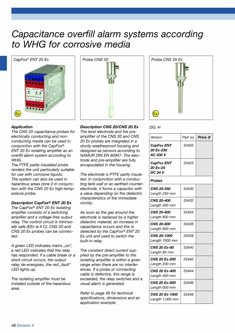
48 Division II
Capacitance overfill alarm systems accordingto WHG for corrosive media
Probe CNS 20 ExProbe CNS 20CapFox® ENT 20 Ex
ApplicationThe CNS 20 capacitance probes forelectrically conducting and non-conducting media can be used inconjunction with the CapFox®
ENT 20 Ex isolating amplifier as anoverfill alarm system according toWHG.The PTFE partly insulated proberenders the unit particularly suitablefor use with corrosive liquids.The system can also be used inhazardous areas zone 0 in conjunc-tion with the CNS 20 Ex high-temp-erature probe.
Description CapFox® ENT 20 ExThe CapFox® ENT 20 Ex isolatingamplifier consists of a switchingamplifier and a voltage-free outputrelay. The control circuit is intrinsic-ally safe (EEx ia II C). CNS 20 andCNS 20 Ex probes can be connec-ted.
A green LED indicates mains „on“,a red LED indicates that the relayhas responded. If a cable break or ashort circuit occurs, the outputrelay de-energises, the red „fault“LED lights up.
The isolating amplifier must beinstalled outside of the hazardousarea.
Description CNS 20/CNS 20 ExThe level electrode and the pre-amplifier of the CNS 20 and CNS20 Ex probes are integrated in asturdy weatherproof housing anddesigned as sensors according toNAMUR DIN EN 60947. The elec-trode and pre-amplifier are fullyencapsulated in the housing.
The electrode is PTFE partly insula-ted. In conjunction with a conduc-ting tank wall or an earthed counter-electrode, it forms a capacitor witha value depending on the dielectriccharacteristics of the immediatevicinity.
As soon as the gas around theelectrode is replaced by a higherdielectric material, an increase incapacitance occurs and this isdetected by the CapFox® ENT 20Ex unit and used to switch thebuilt-in relay.
The constant direct current sup-plied by the pre-amplifier to the isolating amplifier is within a givenrange when there are no interfer-ences. If a probe or connectingcable is defective, this range isexceeded, the relay switches and avisual alarm is generated.
Refer to page 49 for technical specifications, dimensions and anapplication example.
Version Part no. Price €
CapFox ENT 5342020 Ex-230 AC 230 V
CapFox ENT 5342520 Ex-24DC 24 V
Probes
CNS 20-250 53430Length 250 mm
CNS 20-400 53432Length 400 mm
CNS 20-600 53434Length 600 mm
CNS 20-800 53436Length 800 mm
CNS 20-1000 53438Length 1000 mm
CNS 20 Ex-80 53440Length 80 mm
CNS 20 Ex-200 53442Length 200 mm
CNS 20 Ex-400 53444Length 400 mm
CNS 20 Ex-600 53446Length 600 mm
CNS 20 Ex-1000 53448Length 1,000 mm
DG: H

Division II 49
Capacitance overfill alarm systems accordingto WHG for corrosive media
Technical specificationsCNS 20
Operating temperature range-20 °C/+80 °C
Process pressure0/16 bar
Process connectionG1B according to DIN 3852 part 2
Installation lengths250 to 1,000 mm as required
ElectrodePTFE fully insulatedSeal Viton
Switching characteristicsContact with the medium (can beadjusted in the terminal box viapotentiometer)
HousingRobust weatherproof housing with screw coverStainless steel 1.4571
ProtectionIP 68 (EN 60529) on process sideIP 67 (EN 60529) on wiring side
Electrical connectionCable gland PG 11
ApprovalOverfill alarm system according toWHG
Technical specificationsCNS 20 Ex
Operating temperature range-40 °C/+120 °C
Process pressure0/30 bar
Process connectionG1B according to DIN 3852 part 2
Installation lengths80 to 1,000 mm as required
ElectrodeStainless steel 1.4571Probe tip PTFE insulatedSeal Viton
Switching characteristicsContact with the medium (can beadjusted in the terminal box viapotentiometer)
HousingRobust weatherproof housing withscrew coverStainless steel 1.4571
ProtectionIP 68 (EN 60529) on process sideIP 67 (EN 60529) on wiring side
Electrical connectionCable gland PG 11
ApprovalOverfill alarm system according toWHGTÜV 01 ATEX 1661 (EEx ia II C T6...T4)
Technical specificationsENT 20 Ex
Operating temperature rangeAmbient: -20 °C/+60 °C
Supply voltageENT 20 Ex-230 AC 230 VENT 20-Ex-24 DC 24 V
Power consumptionENT 20 Ex-230 approx. 1.5 WENT 20-Ex-24 approx. 1.8 W
Probe circuitAccording to NAMUR DIN EN 60947
Relay outputRelay contact: 1 voltage-free
changeover contactContact rating: AC 250 V 8 A
DC 24 V 4 A
Visual indicationGreen LED mains „on“Yellow LED probeRed LED alarm condition
HousingStandard DIN-rail housingW x H x D: 40 x 70 x 110 mm
ProtectionIP 20 (EN 60529)
ApprovalOverfill alarm system according toWHGTÜV 01 ATEX 1660 (EEx ia II C)
Ø 53
Inst
alla
tion
leng
th90
25
Ø 16
G1B
Ø 53
90
25
Ø 20
G1B
8
Ø 16,5
Inst
alla
tion
leng
th
Ø 26
Refer to page 48 for Part no.
Hazardous area Non-hazardous area
Audibleand visual alarms

50 Division II
Compact vibration level switch for liquidsVibraFox® GVG
ApplicationSuitable for detecting levels inliquids with a maximum viscosity of10.000 mm2/s and a minimum density of 0.7 kg/dm2.Especially designed for applicationsin which float switches cannot beused due to liquid flow, turbulenceor product adherance. Ideally suitedas an overfill alarm or for dry-runprotection of pumps. The WHGapproved VibraFox® can be used aspart of an approved overfill alarmsystem.
DescriptionThe vibration fork of VibraFox® isexcited to its resonance frequency.When the fork comes into contactwith the medium a change in fre-quency occurs which is detectedby the electronics and convertedinto a switching signal. The unique evaluation electronics enable theapplication of the system evenunder adverse conditions, e.g. intanks with vibration or turbulentliquid surfaces.
VibraFox® vibration level switches feature:
• WHG approval• Maintenance-free• Compact design• High resistance to chemicals• Easy installation• Various process connections• Universal application
Technical specifications
Minimum density of medium0.7 kg/dm3
Max. viscosity of medium10,000 mm2/s
Operating temperature rangeMedium: -40 °C/+100 °CAmbient: -40 °C/ +70 °C
Process pressure-1 to 64 bar
Process connectionG3/4B or G1B (PN 64)
Vibration forkStainless steel 1.4435Installation length 69 mm or 117 mm
Supply voltageAC/DC 20-253 VLoad current min. 10 mA max. 250 mA or DC 10-55 VLoad current max. 250 mA
Power consumptionAC version: depending on
external loadDC version: max. 0.6 W
Output2-wire AC/DC or transistor (PNP)
Switching delayAfter immersion: 0.5 sAfter removal: 0.5 s
Switch pointVertical installation: 13 mmHorizontal installation: 14 mm(in water at 25 °C)
Switching hysteresisVertical installation: 2 mmHorizontal installation: 2 mm(in water at 25 °C)
Visual indicationBi colour LED green/red
Operational testWith test magnet (included)
HousingStainless steel 1.4435, cover PEI
Electrical connectionPlug DIN 43650-A (IP 65) or M 12 x 1 (IP 67)
Technical Approval of the GermanInstitute for Building Technology:Z-65.11-412
Options
• Extended operating temperature range -40 °C/+150 °C (medium)
• Other process connections• Surface roughness Ra < 0.8 µm• Welding gland• Other electrical connections• Coupling relay (only for DC version)
Refer to page 52 for Part no.

Division II 51
Compact vibration level switch for liquidsVibraFox® GVG Dimensions (mm) and electrical connections
GVG 10/12 GVG 10 HT/12 HTStandard version High temperature version
GVG 11 GVG 11 HTStandard version High temperature version
GVG 13/14 GVG 13 HT/14 HTStandard version High temperature version
GVG 10 MR/GVG 12 MR GVG 10 CP/GVG 12 CPDairy fitting Tri-Clamp
Wiring diagram 2-wire switching output Wiring diagram transistor output PNP
Protective cover M12x1
Protective cover M12x1
Dairy fittingDIN 11851 - DN25/40/50
Valve connector Plug connection
1 brown2 white3 blue4 black
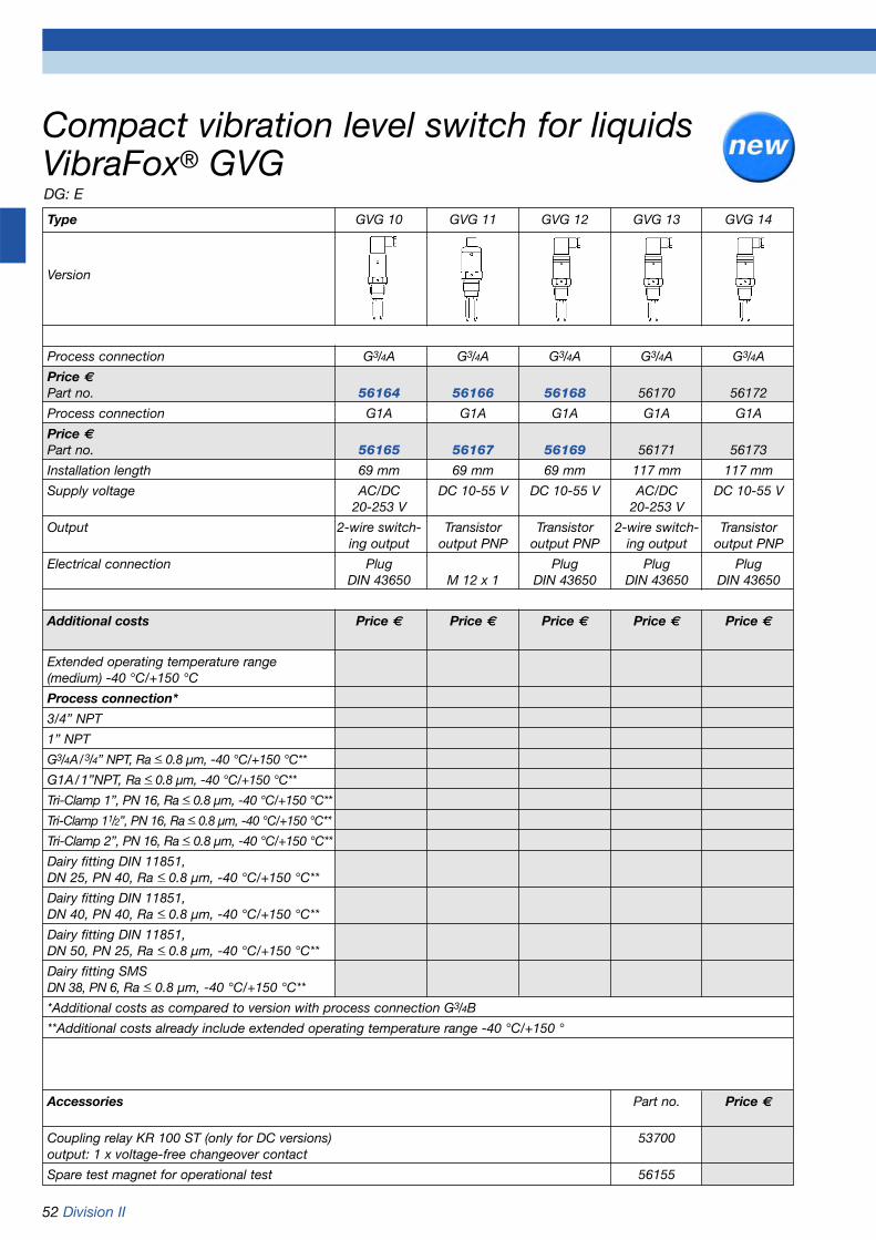
52 Division II
Type GVG 10 GVG 11 GVG 12 GVG 13 GVG 14
Version
Process connection G3/4A G3/4A G3/4A G3/4A G3/4A
Price €Part no. 56164 56166 56168 56170 56172
Process connection G1A G1A G1A G1A G1A
Price €Part no. 56165 56167 56169 56171 56173
Installation length 69 mm 69 mm 69 mm 117 mm 117 mm
Supply voltage AC/DC DC 10-55 V DC 10-55 V AC/DC DC 10-55 V20-253 V 20-253 V
Output 2-wire switch- Transistor Transistor 2-wire switch- Transistoring output output PNP output PNP ing output output PNP
Electrical connection Plug Plug Plug PlugDIN 43650 M 12 x 1 DIN 43650 DIN 43650 DIN 43650
Additional costs Price € Price € Price € Price € Price €
Extended operating temperature range(medium) -40 °C/+150 °C
Process connection*
3/4” NPT
1” NPT
G3/4A/3/4” NPT, Ra < 0.8 µm, -40 °C/+150 °C**
G1A/1”NPT, Ra < 0.8 µm, -40 °C/+150 °C**
Tri-Clamp 1”, PN 16, Ra < 0.8 µm, -40 °C/+150 °C**
Tri-Clamp 11/2”, PN 16, Ra < 0.8 µm, -40 °C/+150 °C**
Tri-Clamp 2”, PN 16, Ra < 0.8 µm, -40 °C/+150 °C**
Dairy fitting DIN 11851,DN 25, PN 40, Ra < 0.8 µm, -40 °C/+150 °C**
Dairy fitting DIN 11851,DN 40, PN 40, Ra < 0.8 µm, -40 °C/+150 °C**
Dairy fitting DIN 11851,DN 50, PN 25, Ra < 0.8 µm, -40 °C/+150 °C**
Dairy fitting SMSDN 38, PN 6, Ra < 0.8 µm, -40 °C/+150 °C**
*Additional costs as compared to version with process connection G3/4B
**Additional costs already include extended operating temperature range -40 °C/+150 °
Accessories Part no. Price €
Coupling relay KR 100 ST (only for DC versions) 53700output: 1 x voltage-free changeover contact
Spare test magnet for operational test 56155
Compact vibration level switch for liquidsVibraFox® GVGDG: E

www.afriso.de 53
Chapter 2 Table of contents chapter 2
Overfill alarm systems and PTCthermistor type level controllers 02
Page
PTC thermistor type level sensors for indoor tanks (GWG 12) 54
Accessories for PTC thermistor type level sensors (filler cap, KVA, reducer) 55
PTC thermistor type level sensors for outdoor tanks (GWG 23, GWG 84) 56-57
PTC thermistor type level sensors with Ex approval (GWG 81) 58
Overfill alarm systems Ex Zone 0 and WHG (LS 500, LS 300) 59-60
Overfill alarm systems WHG 61-62(NB 220 QSA, NB 220 H, NB 220 QS, level sensor type 76)
PTC thermistor type level controllers (RG 210) 63

54 Division I
PTC thermistor type level sensors for indoor tanksaccording to TRbF 511
G1
Robustversion yellow PN 45100
Simple version grey PN 45105
G11/2
GWG 12 K/1 yellow (PN 45100)
PTC thermistor type level sensor.Designed for use with battery typetanks made of sheet steel accor-ding to DIN 6620-1 design B andrectangular tanks according to DIN6625-1 welded on site with heightsbetween 1 and 4 m.
Storage liquid:Fuel oil according to DIN 51603-1,diesel according to DIN EN 590,biodiesel according to DIN EN14214. With G1 screw fitting.Adjustable from 70 to 338 mm.Height adjustment as per installa-tion manual supplied.The connection fitting for wallmounting type 905-yellow is impactresistant and shock resistant. A fillercap with type 906 GWG connectionfitting can also be used. (refer topage 55)Connection cable = 1.5 m long.Use KVA for cable extension (referto page 55). Technical Approval ofthe German Institute for BuildingTechnology: Z-65.17-182
GWG 12 K/1 greySimilar to PN AN 45100, but withgrey fitting.
GWG 12 K/1/5 yellow (PN 45160)Similar to PN 45100, but with 5 mlong connection cable.
GWG 12 K/1/5 greySimilar to PN 45100, but with greyfitting and 5 m long connectioncable.GWG 12 K/1 without fittingSimilar to PN 45100, but withoutconnection fitting.
GWG 12 K/1/5 without fittingSimilar to PN 45160, but withoutconnection fitting.
GWG 12 K/1C (Euroflex 312)Similar to GWG 12 K/1 yellow, butwith screw fitting which G11/2which is designed as a withdrawalunit equipped with a rapid-actionclosing valve. With connections forflow, return and capillary tube.
GWG 12 K/1 with bracketThis unit is similar in applicationand design to GWG 12 K/1 (PN45100) but with mounted type 905connection fitting made of greyplastic.
The connection fitting is fixed to analuminium bracket. The connectioncable of the level senor is pre-wired to the connection fitting. Fortanks with direct tank top filling(without external fill point).
GWG 12 K/MTSimilar to GWG 12-K/1/5 yellow,but with a G11/2 screwed fitting andmechanical tank contents gaugeMT-Profil R.Measuring range = 250 cmConnection cable = 5 m long.
Technical Approval of the GermanInstitute for Building Technology forall series GWG 12 K level sensors:Z-65.17.182
DG: G PU Part no. Price €
GWG 12 K/1 yellow 10 45100
GWG 12 K/1 grey 10 45105
GWG 12 K/1/5 yellow 10 45160
GWG 12 K/1/5 grey 10 45165
GWG 12 K/1 without fitting 10 45166
GWG 12 K/1/5 without fitting 10 45167
GWG 12 K/1C 5 20190
GWG 12 K/1 with bracket 5 45104
GWG 12 K/MT 5 45311
GWG 12 K/1CGWG 12 K/1
G11/2
GWG 12 K/MTGWG 12 K/1with bracket
G1

Division I 55
Accessories for PTC thermistor type level sensors
Please refer to page 452 for acomplete range of GWG level sensor test instruments.
GWG fitting907-R-Ms
907-W-Ms
GWG filler capFor fuel oil EL „standard“, dieseland bio-diesel. Bayonet connectionG2 according to DIN EN 14420-6with integrated level sensor con-nection fitting. Male coupling madeof brass. Filler cap made of oil- andweather resistant plastic. Lockable.
GWG filler cap - greenFor low sulphur fuel oil EL (greencolour code). With red plate alsoapproved for fuel oil EL „standard“,diesel and bio-diesel. Bayonet con-nection G2 according to DIN EN14420-6 with integrated level sen-sor connection fitting. Male coup-ling made of brass. Filler cap madeof oil- and weather resistant plastic.Lockable. Red plate (Also for fueloil EL „standard“) is included.Please refer to page 103 for addi-tional filler caps.
DG: G PU Part no. Price €
GWG-filler cap 10 20430
GWG-filler cap - green 10 20443
Reducer G11/2 x G1 10 20905
Reducer G2 x G11/2 10 20903
KVA 10 40041
Please refer to page 57 for GWGfittings.
KVACable extension fitting for 2-coreelectrical cables (max. 42 V/4 A).Clamp glands on both sides forcable diameters between 6 and 8.3 mm.
Reducer G11/2 x G1Reducer G11/2 x G1 made of greyplastic (ABS).
Reducer G2 x G11/2Reducer G2 x G11/2 made of greyplastic (ABS).
New directives:
1. The filler cap without colour code must only be used with systems which are exclusively used with fuel oil EL „standard“,diesel and bio-diesel.
2. The green filler cap must only be used with systems which are exclusively used with lowsulphur fuel oil EL.
3. The green filler cap in con-junction with the red plate(Also for fuel oil EL „standard“) must only be used with systemsusing low sulphur fuel oil EL, EL „standard“, diesel and bio-diesel.
Check www.schwefelarmes-heizoel.de to see whether thevarious units of a heatingsystems are suitable for use with low sulphur fuel oil EL.
Also forfuel oil EL„standard“

56 Division I
PTC thermistor type level sensors for outdoor tanks according TRbF 511
GWG 23 - RoThis PTC thermistor type level sensor is equipped with a heightadjustable probe. It features a G1brass screw fitting and is pressure-and vacuum tight (1 bar).Tube fitting made of yellow, highgrade impact resistant plastic withstrong chain and flange gasket.The version with grey fitting isimpact resistant and equipped witha tie instead of the chain, withoutflange gasket. The number after thetype designation indicates thelength of the GWG level sensor.When selecting, please check tosee that the fitting is as close aspossible under the access chambercover - the distance should not beless than 20 mm and not morethan 300 mm.
Application area:Aboveground and undergroundtanks containing fuel oil EL accor-ding to DIN 51603-1, diesel accor-ding to DIN EN 590 and bio-dieselaccording to DIN EN 14214.• Cylindrical, horizontal tanks made
of steel according to EN 12285-1,EN 12285-2 und EN 6624-1 or made of plastic or any other approved materials with shapesand dimensions which comply with the above mentioned stan-dards and which are type approved.
• Cylindrical, vertical steel tanks according to DIN 6619-1, 6623-1.
Underground tanks according toTRbF 40 no. 5.2 containing petrolaccording to DIN EN 228:• Cylindrical, horizontal steel tanks
according to EN 12285-1 under the following conditions:1. The layer of earth covering the
tank has to be at least 0.8 m thick.
2. Not suitable for continuousfuel withdrawal.
3. The withdrawal capacity per tank or tank compartment must not exceed 200 l/min.
4. The level sensor may only be connected to instruments which meet the requirements for the protection type „Intrinsically safe electrical systems“ accor-ding to VDE 0171 (DIN EN 50039).
(Fuel withdrawal is not consideredcontinuous if the pumping processis interrupted several times withinone hour, e.g. at petrol stations).
Aboveground tanks containingpetrol according to DIN EN 228
• Cylindrical, vertical steel tanks according to DIN 6623-1 under special conditions.
GWG 23 - WaSimilar to GWG 23 - Ro, but with ajunction box at the upper tube endas well as fitting for wall mounting.Also suitable for use in verticaltanks according to DIN 6618-1 andflat bottom tanks according to DIN 4119-1.
Technical Approval of the GermanInstitute for Building Technology forall series GWG 23 level sensors:Z-65.17-366.
G1
125
Leng
th
DG: G PU Part no. Price €
GWG 23 - Ro 400 yellow fitting 10 46115
GWG 23 - Ro 700 yellow fitting 10 46116
GWG 23 - Ro 1000 yellow fitting 10 46117
GWG 23 - Ro 1500 yellow fitting 1 46120
GWG 23 - Ro So yellow fitting 1 46118special lengths of up to max. 3,000 mm
GWG 23 - Ro 400 grey fitting 10 46125
GWG 23 - Ro 700 grey fitting 10 46126
GWG 23 - Ro 1000 grey fitting 10 46127
GWG 23 - Ro 1500 grey fitting 1 46129
GWG 23 - Wa 400 yellow fitting 1 46130
GWG 23 - Wa 700 yellow fitting 1 46131
GWG 23 - Wa 1000 yellow fitting 1 46132
GWG 23 - Wa 1500 yellow fitting 1 46135
GWG 23 - Wa So yellow fitting 1 46133special lengths of up to max. 3,000 mm
GWG 23 -Ro GWG 23 - Wa
G1
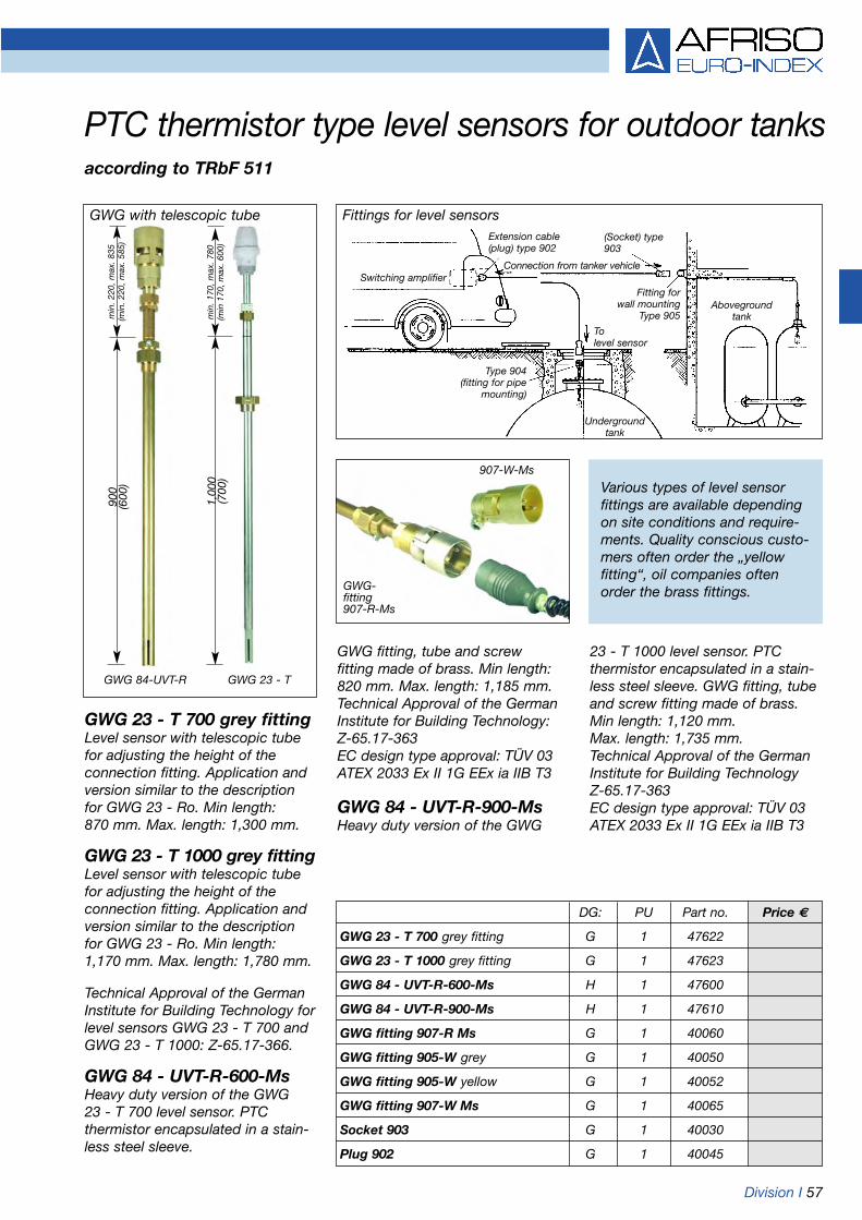
Division I 57
PTC thermistor type level sensors for outdoor tanksaccording to TRbF 511
GWG-fitting907-R-Ms
907-W-Ms
900
(600
)m
in. 2
20, m
ax. 8
35(m
in. 2
20, m
ax. 5
85)
1,00
0(7
00)
min
. 170
, max
. 780
(min
170
, max
. 600
)
GWG 84-UVT-R GWG 23 - T
GWG 23 - T 700 grey fittingLevel sensor with telescopic tubefor adjusting the height of the connection fitting. Application andversion similar to the descriptionfor GWG 23 - Ro. Min length: 870 mm. Max. length: 1,300 mm.
GWG 23 - T 1000 grey fittingLevel sensor with telescopic tubefor adjusting the height of the connection fitting. Application andversion similar to the descriptionfor GWG 23 - Ro. Min length: 1,170 mm. Max. length: 1,780 mm.
Technical Approval of the GermanInstitute for Building Technology forlevel sensors GWG 23 - T 700 andGWG 23 - T 1000: Z-65.17-366.
GWG 84 - UVT-R-600-MsHeavy duty version of the GWG 23 - T 700 level sensor. PTC thermistor encapsulated in a stain-less steel sleeve.
Various types of level sensor fittings are available dependingon site conditions and require-ments. Quality conscious custo-mers often order the „yellow fitting“, oil companies oftenorder the brass fittings.
GWG fitting, tube and screw fitting made of brass. Min length:820 mm. Max. length: 1,185 mm.Technical Approval of the GermanInstitute for Building Technology:Z-65.17-363EC design type approval: TÜV 03ATEX 2033 Ex II 1G EEx ia IIB T3
GWG 84 - UVT-R-900-MsHeavy duty version of the GWG
23 - T 1000 level sensor. PTC thermistor encapsulated in a stain-less steel sleeve. GWG fitting, tubeand screw fitting made of brass.Min length: 1,120 mm.Max. length: 1,735 mm.Technical Approval of the GermanInstitute for Building Technology Z-65.17-363EC design type approval: TÜV 03ATEX 2033 Ex II 1G EEx ia IIB T3
DG: PU Part no. Price €
GWG 23 - T 700 grey fitting G 1 47622
GWG 23 - T 1000 grey fitting G 1 47623
GWG 84 - UVT-R-600-Ms H 1 47600
GWG 84 - UVT-R-900-Ms H 1 47610
GWG fitting 907-R Ms G 1 40060
GWG fitting 905-W grey G 1 40050
GWG fitting 905-W yellow G 1 40052
GWG fitting 907-W Ms G 1 40065
Socket 903 G 1 40030
Plug 902 G 1 40045
GWG with telescopic tube Fittings for level sensorsExtension cable (plug) type 902
Undergroundtank
Type 904(fitting for pipe
mounting)
To level sensor
Fitting for wall mounting
Type 905Aboveground
tank
(Socket) type903
Connection from tanker vehicleSwitching amplifier
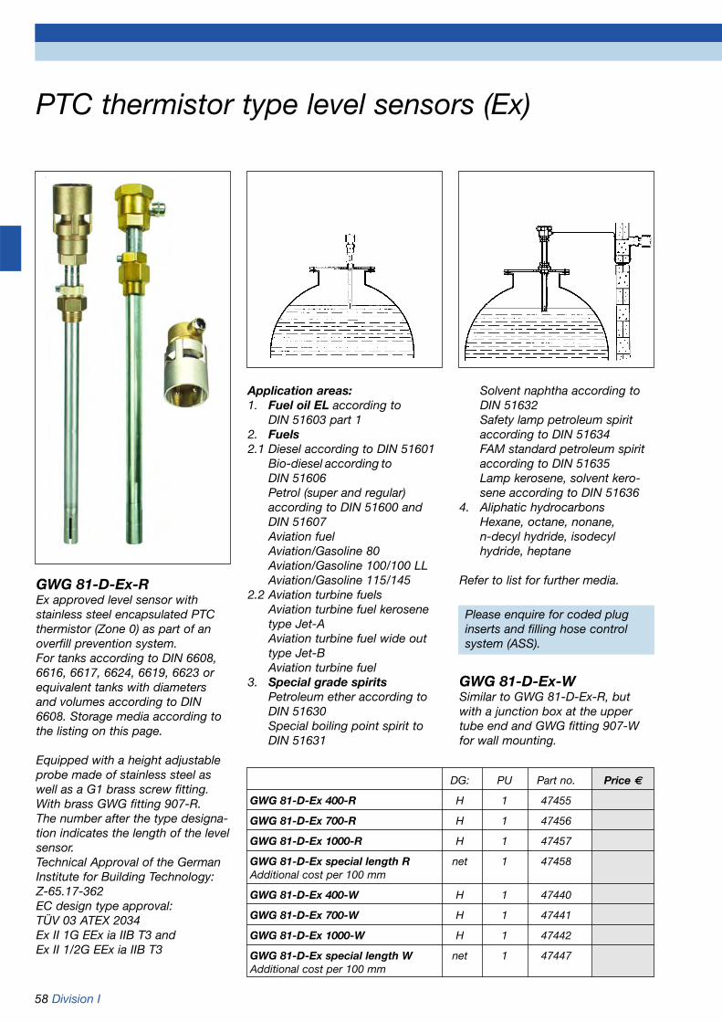
58 Division I
PTC thermistor type level sensors (Ex)
GWG 81-D-Ex-REx approved level sensor withstainless steel encapsulated PTCthermistor (Zone 0) as part of an overfill prevention system.For tanks according to DIN 6608,6616, 6617, 6624, 6619, 6623 orequivalent tanks with diametersand volumes according to DIN6608. Storage media according tothe listing on this page.
Equipped with a height adjustableprobe made of stainless steel aswell as a G1 brass screw fitting.With brass GWG fitting 907-R.The number after the type designa-tion indicates the length of the levelsensor.Technical Approval of the GermanInstitute for Building Technology:Z-65.17-362EC design type approval: TÜV 03 ATEX 2034Ex II 1G EEx ia IIB T3 andEx II 1/2G EEx ia IIB T3
Solvent naphtha according to DIN 51632Safety lamp petroleum spirit according to DIN 51634FAM standard petroleum spirit according to DIN 51635Lamp kerosene, solvent kero-sene according to DIN 51636
4. Aliphatic hydrocarbonsHexane, octane, nonane, n-decyl hydride, isodecyl hydride, heptane
Refer to list for further media.
GWG 81-D-Ex-WSimilar to GWG 81-D-Ex-R, butwith a junction box at the uppertube end and GWG fitting 907-Wfor wall mounting.
Application areas:1. Fuel oil EL according to
DIN 51603 part 12. Fuels2.1 Diesel according to DIN 51601
Bio-diesel according toDIN 51606Petrol (super and regular) according to DIN 51600 and DIN 51607Aviation fuelAviation/Gasoline 80Aviation/Gasoline 100/100 LLAviation/Gasoline 115/145
2.2 Aviation turbine fuels Aviation turbine fuel kerosene type Jet-AAviation turbine fuel wide out type Jet-BAviation turbine fuel
3. Special grade spiritsPetroleum ether according to DIN 51630Special boiling point spirit to DIN 51631
Please enquire for coded pluginserts and filling hose controlsystem (ASS).
DG: PU Part no. Price €
GWG 81-D-Ex 400-R H 1 47455
GWG 81-D-Ex 700-R H 1 47456
GWG 81-D-Ex 1000-R H 1 47457
GWG 81-D-Ex special length R net 1 47458Additional cost per 100 mm
GWG 81-D-Ex 400-W H 1 47440
GWG 81-D-Ex 700-W H 1 47441
GWG 81-D-Ex 1000-W H 1 47442
GWG 81-D-Ex special length W net 1 47447Additional cost per 100 mm
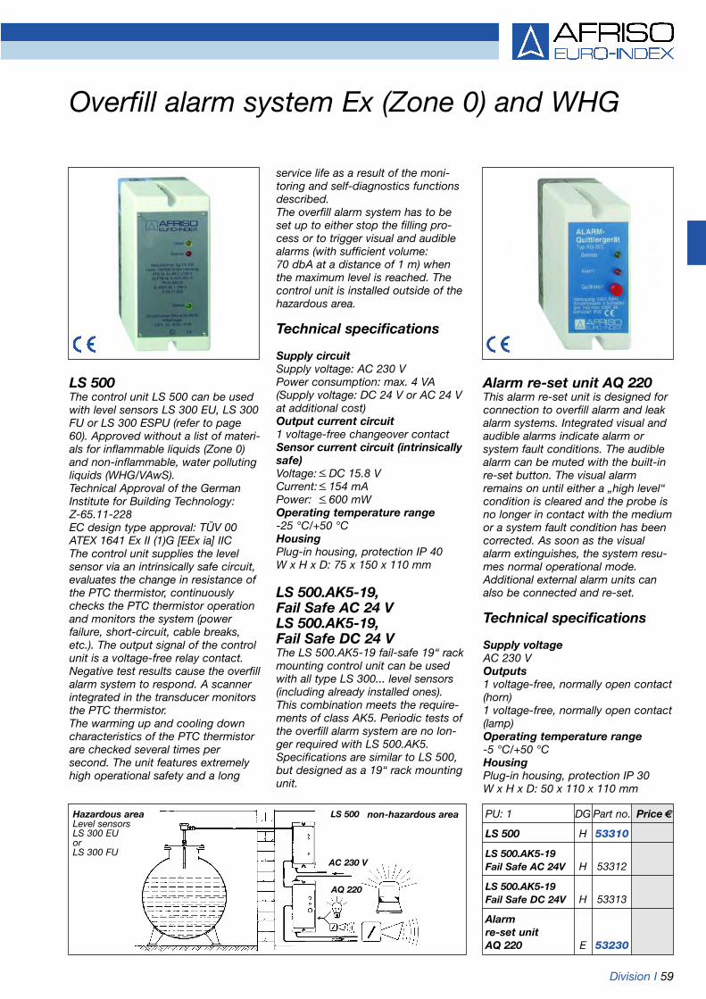
Division I 59
Overfill alarm system Ex (Zone 0) and WHG
LS 500The control unit LS 500 can be usedwith level sensors LS 300 EU, LS 300FU or LS 300 ESPU (refer to page60). Approved without a list of materi-als for inflammable liquids (Zone 0)and non-inflammable, water pollutingliquids (WHG/VAwS).Technical Approval of the GermanInstitute for Building Technology: Z-65.11-228EC design type approval: TÜV 00ATEX 1641 Ex II (1)G [EEx ia] IICThe control unit supplies the levelsensor via an intrinsically safe circuit,evaluates the change in resistance ofthe PTC thermistor, continuouslychecks the PTC thermistor operationand monitors the system (power failure, short-circuit, cable breaks,etc.). The output signal of the controlunit is a voltage-free relay contact.Negative test results cause the overfillalarm system to respond. A scannerintegrated in the transducer monitorsthe PTC thermistor.The warming up and cooling downcharacteristics of the PTC thermistorare checked several times persecond. The unit features extremelyhigh operational safety and a long
service life as a result of the moni-toring and self-diagnostics functionsdescribed.The overfill alarm system has to beset up to either stop the filling pro-cess or to trigger visual and audiblealarms (with sufficient volume: 70 dbA at a distance of 1 m) whenthe maximum level is reached. Thecontrol unit is installed outside of thehazardous area.
Technical specifications
Supply circuitSupply voltage: AC 230 VPower consumption: max. 4 VA(Supply voltage: DC 24 V or AC 24 Vat additional cost)Output current circuit1 voltage-free changeover contactSensor current circuit (intrinsicallysafe)Voltage: < DC 15.8 VCurrent: < 154 mAPower: < 600 mWOperating temperature range-25 °C/+50 °CHousingPlug-in housing, protection IP 40W x H x D: 75 x 150 x 110 mm
LS 500.AK5-19, Fail Safe AC 24 VLS 500.AK5-19, Fail Safe DC 24 VThe LS 500.AK5-19 fail-safe 19“ rackmounting control unit can be usedwith all type LS 300... level sensors(including already installed ones).This combination meets the require-ments of class AK5. Periodic tests ofthe overfill alarm system are no lon-ger required with LS 500.AK5.Specifications are similar to LS 500,but designed as a 19“ rack mountingunit.
Hazardous areaLevel sensors LS 300 EU or LS 300 FU
LS 500
AQ 220
non-hazardous area
AC 230 V
Alarm re-set unit AQ 220This alarm re-set unit is designed forconnection to overfill alarm and leakalarm systems. Integrated visual andaudible alarms indicate alarm orsystem fault conditions. The audiblealarm can be muted with the built-inre-set button. The visual alarmremains on until either a „high level“condition is cleared and the probe isno longer in contact with the mediumor a system fault condition has beencorrected. As soon as the visualalarm extinguishes, the system resu-mes normal operational mode.Additional external alarm units canalso be connected and re-set.
Technical specifications
Supply voltageAC 230 VOutputs1 voltage-free, normally open contact(horn)1 voltage-free, normally open contact(lamp)Operating temperature range-5 °C/+50 °CHousingPlug-in housing, protection IP 30W x H x D: 50 x 110 x 110 mm
PU: 1 DG Part no. Price €
LS 500 H 53310
LS 500.AK5-19Fail Safe AC 24V H 53312
LS 500.AK5-19Fail Safe DC 24V H 53313
Alarmre-set unitAQ 220 E 53230

60 Division I
Overfill alarm system Ex (Zone 0) and WHG
G3/8
All wetted parts made of stainlesssteel 1.4571.
Level sensor LS 300 EUTogether with the LS 500 controlunit (refer to page 59), the LS 300EU sensor is an approved part ofan overfill alarm system accordingto WHG (self-monitoring and withautomatic corrosion monitoring).Approved without a list of materialsfor inflammable liquids (Zone 0)and non-inflammable, water pollu-ting liquids (WHG).LS 300 EU consists of a heightadjustable probe tube made ofstainless steel with a PTC thermis-tor sensor element at the bottomend, a G3/8 screw fitting made ofstainless steel and a chrome-platedbrass junction box with integratedovervoltage protection. Standardlength 500 mm, max. length 3,000mm. Suitable for installation in alltypes of tanks and pipes.Hazardous area classification EExia IIC T4. The sensor can be usedin inflammable liquids up to 3 bar pressure (please specify higherpressure ranges when ordering).The sensor is suitable for liquidtemperatures from -25 °C/+50 °Cor from -25 °C/+80 °C. Technical Approval of the GermanInstitute for Building Technology:Z-65.11-228
DG: H Part no. Price €
Level sensorLS 300 EU 53300
Additional costfor high temperature version on-25 °C/+80 °C request
Special lengths –additional cost onper 100 mm request
Level sensorLS 300 FU 53307
Level sensorLS 300 ESPU 53305
Special lengths –additional cost onper 100 mm request
Level sensor LS 300 FSPU 53306
EC design type approval:TÜV 00 ATEX 1656XEx II 1G EEx ia IIC T4Ex II 1/2G EEx ia IIC T4
Level sensor LS 300 FUThe LS 300 FU level sensor consists of a probe tube welded tothe flange (gas-tight) and can beinstalled in tanks with pressures upto 3 bar. (Please specify higherpressures when ordering). A stain-less steel version with coating isavailable for use in containers withvery corrosive media (acids). Anadditional protective sensor sleevecan be supplied if strong gas/airflows are present around theresponse part of the level sensor.Approval specifications are as fortype LS 300 EU.
Please indicate the followingwhen ordering:Response length in mmPressure level (max. 25 bar) PNNominal width DNFlange norm according to EN 1092 /ASMEMedium (stored liquid)Please enquire for special versionswith 2 response points or differentmaterials.
Level sensor LS 300 ESPUThe LS 300 ESPU level sensor withintegrated testing unit is self-moni-toring and features automatic corrosion monitoring. Together withthe LS 500 transducer (refer topage 59), it is approved as part ofan overfill alarm system accordingto WHG for inflammable and non-inflammable liquids, without a listof materials.Approval specifications are as fortype LS 300 EU.The function test is carried out onthe installed unit either by means of a portable test instrument or astationary nitrogen system. ThePTC thermistor is subjected to agas flow (air, nitrogen) which coolsit down. In this way, it is subjectedto a genuine function test.All wetted parts are made of stain-less steel 1.4571. The probe headhousing is also made of stainlesssteel (please enquire for othermaterials). G1 screw connection,standard probe length 1,000 mm,see additional costs for other lengths.
Level sensor LS 300 FSPUSimilar to LS 300 ESPU, but withflange. Order information similar toLS 300 FU.
LS 300 EU LS 300 FU LS 300 FSPULS 300 ESPU
G1

Division I 61
Overfill alarm systems (WHG)
Level sensor
Level controller
Supply voltage
Level controller NB 220 QSAThis level controller in a wall mounted housing features state-of-the-art safety circuits. An internalcontrol circuit (scanner) providescontinuous monitoring of the sensor's function, short circuit ordefective cable. Alarm indication,audible signal, test button, re-setbutton for the alarm buzzer, a voltage-free relay contact for theexternal alarm lamp as well as anadditional resettable relay contactfor the external alarm horn are inte-grated in the unit. Approved withtype 76 A, 76 C, 76 M, 76 N, 76 S,76 W level sensors for the followinginflammable and non-inflammable,water polluting liquids. Technical Approval of the GermanInstitute for Building Technology:Z-65.11-193
Application areaInflammable liquids:• Diesel fuel according to DIN 51601• Bio-diesel according to DIN 51606• Fuel oil EL according to
DIN 51603, part 1• Used gear and engine oils• Hexanol 1• Ethyl aceto-acetate
(aceto-acetic ester)• Acrylic acid 2 ethylic hexylic ester• Cyclohexanol acetate• Benzaldehyde• Methyl aceto-acetate• Nitrobenzene• 1.2 dichlorobenzene• 2.4 dimethylaniline
(N, N dimethylaniline)
• n octanol (n octyl alcohol)• Diethyloxalate• Aniline plus comparable inflammable liquidswith similar heat conductivity.Non-inflammable, water polluting liquids:• Unused engine, gear and
hydraulic oils• Transformer oil• Vegetable oil• Antifreeze agents• Oil/water mixtures (e.g. drilling oil
or lubricating oil)• Cleaning agent/water mixtures• Perethylene and trichloroethyleneplus comparable non-inflammable,water polluting liquids with similarheat conductivity.
Technical specifications
Supply voltageAC 230 V (optional AC 24 V, 110 Vor DC 24 V)Power consumption3 VA, 5 WOutputs1 voltage-free changeover contactfor alarm lamp, solenoid valve, orpump1 voltage-free, re-settable change-over contact for audible alarmsContact rating for external alarmlamps and audible alarms:AC 230 V; 2,5 A; max. 500 VADC 250 V; 0,25 A; max. 50 WHousingW x H x D: 97 x 163 x 62 mmProtectionIP 30 (EN 60529)
Sensor current circuitVoltage: < 12.6 VCurrent: < 90 mAPower: < 700 mWRe-set current circuitVoltage: < 12.6 VCurrent: < 20 mAPower: < 60 mW
NB 220 QSA-AC 24 VThis level controller is similar to NB 220 QSA but with supply voltage AC 24 V.
NB 220 QSA-DC 24 VThis level controller is similar to NB 220 QSA but with supply voltage DC 24 V.
Slave unit Type 907 ZCan be connected to NB 220 QS(refer to page 62) as an additionalcontrol unit to enable connectionto a road tanker fitted with an over-fill prevention system.
DG: H, PU 1 Part no. Price €
Level controllerNB 220 QSA 53231
NB 220 QSA - AC 24 V 53231A
NB 220 QSA - DC 24 V 53231B
Slave unitType 907 Z 53232
Frame for panel mounting
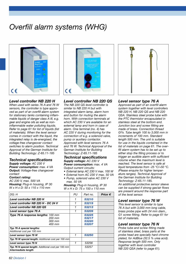
62 Division I
Overfill alarm systems (WHG)
Level controller NB 220 HWhen used with series 76 A and 76 Wsensors, the controller is type appro-ved as part of an overfill alarm systemfor stationary tanks containing inflam-mable liquids of danger class A III, e.g.gear and engine oils as well as non-inflammable water polluting liquids.Refer to page 61 for list of liquids (listof materials). When the level sensorcomes in contact with the liquid, theintegrated relay is de-energised, thevoltage-free changeover contactswitches to alarm position. TechnicalApproval of the German Institute forBuilding Technology: Z-65.11-185
Technical specificationsSupply voltage: AC 230 VPower consumption: max. 4 VAOutput: Voltage-free changeovercontactContact rating:AC 230 V, max. 500 VAHousing: Plug-in housing, IP 30W x H x D: 50 x 110 x 110 mm
Level controller NB 220 QSThe NB 220 QS level controller issimilar to NB 220 H but with integrated alarm lamp, alarm hornand button for muting the alarmhorn. With connection terminals atwhich AC 230 V are available for anexternal lamp and horn in case ofalarm. One terminal (no. 4) has AC 220 V during monitoring for the connection of e.g. a solenoid valve,pump or auxiliary contactor.Approved with level sensors 76 Aand 76 W. Technical Approval of theGerman Institute for BuildingTechnology: Z-65.11-185Technical specificationsSupply voltage: AC 230 VPower consumption: max. 4 VAOutput current circuits:• External lamp AC 230 V max. 100 W• External horn AC 230 V max. 50 VA• Pump, solenoid valve AC 230 V
max. 50 VAHousing: Plug-in housing, IP 30W x H x D: 75 x 150 x 110 mm
Level sensor type 76 AApproved as part of an overfill alarmsystem together with level controllersNB 220 H, NB 220 QS and NB 220QSA. Stainless steel probe tube withthe PTC thermistor encapsulated instainless steel at the bottom end.Junction box and screw fitting aremade of brass. Connection threadG3/4. Tube length 100 to 3,000 mm inincrements of 100 mm. Standardlength 500 mm. The unit is suitablefor use in the liquids contained in thelist of materials on page 61. The over-fill alarm system has to be set up toeither stop the filling process or totrigger an audible alarm with sufficientvolume when the maximum level is reached. The level sensor is safe atliquid temperatures from -25 °C/+50 °C.(Please enquire for higher temper-ature ranges). Technical Approval ofthe German Institute for BuildingTechnology: Z-65.11-185.An additional protective sensor sleevecan be supplied if strong gas/air flowsare present around the response partof the level sensor.
Level sensor type 76 WThis level sensor is similar to type 76 A but with 3,000 mm long cable,brass probe pipe with 24 mm diam.,G1 screw fitting. Refer to page 61 forlist of materials.
Level sensor type 76 NProbe tube and screw fitting made of stainless steel, brass parts at theprobe head are specially hard chromeplated, for AdBlue (32.5 % urea acid).Response length 500 mm. Onlytogether with level controller NB 220 QSA (refer to page 61).
DG: H PU Part no. Price €
Level controller NB 220 H 1 53210Level controller NB 220 H - DC 24 V 1 53219Level controller NB 220 QS 1 53213Level sensor type 76 A 1 53209Type 76 A response lengths: 100 mm 53225
200 mm 53217300 mm 53220400 mm 53207
Typ 76 A special lengths:Additional cost per 100 mm
Level sensor type 76 W 1 53250Typ 76 W special length: Additional cost per 100 mm
Level sensor type 76 N 1 53256Typ 76 N special length: Additional cost per 100 mm 53257Intermediate length

Division I 63
PTC thermistor type level controller
3 m
G1
Typ 937
Typ 150
Application examples: also refer to page 506, AQ 220 alarm re-set unit.
Example: fuel oil service tankExample: Full indication Example: Level control for emptying
RG 210PTC thermistor type level controllerwith selectable functions: • Level switch (1 probe)• Level control for filling (2 probes)• Level control for emptying
(2 probes)For use with electrically conductingand non-conducting liquids whichare not viscous or adhesive: fueloil, diesel, emulsions, water, andmedia which are not corrosive.
• Level switch with 1 probe: The relay switches when contactor loss of contact with the liquid occurs. When the switch point is set, it must be observed that the PTC thermistor requires 5 to 60 seconds to warm up depending on the ambient temperature.
• Level control for filling with 2 probes: Set internal switch to„fill“. Relay energises when min. probe is operational. Relay de-energises when max. probe comesinto contact with the liquid.
Attention: Not to be used as an over-fill alarm system according to TRbF.Requires either the connection of anoverflow pipe to the tank or the addi-tional installation of an overfill alarmsystem according to TRbF/WHG.
Flexible PTC thermistorprobe type 150Flexible PTC thermistor probe de-signed for use with electrically con-ducting and non-conducting liquidswhich are not viscous or adhesive,for connection to RG 210. Refer toRG 210 for further characteristicsof the liquids. The PTC thermistor is encapsula-ted in a glass sleeve embedded insilicone with oil resistant probecable (3 m long) and G1 gland,pressure proof up to 1 bar.
Flexible PTC thermistorprobe type 937Flexible PTC thermistor designedfor oils and other electrically non-conducting liquids (low viscosity,non-adhesive).The PTC thermistor connectionwires are not insulated. Not suit-able for installation in damp environ-ments.
• Level control for emptyingwith 2 probes: Set internal switch to „empty“. Relay energises whenmax. probe has contact with the liquid. Relay de-energises when the min. probe loses contact with the liquid and the thermistor warms up again.
DG: H, PU 1 Part no. Price €
RG 210 53206
Flex. PTC thermistorprobe type 150 53208
Flex. PTC thermistorprobe type 937 53204
Technical specificationsOperating temperature rangeMedium: -25 °C/+55 °CAmbient: -10 °C/+55 °CProbePTC thermistor probe, types 150 or 937Cable length 3 m (max. 50 m)Process connection G1Supply voltage AC 230 VPower consumption 12 VARelay contact (output)1 voltage-free changeover contactHousingPlug-in housing, IP 30 (EN 60529)W x H x D: 50 x 110 x 110 mm
Probetype 150 or type 937
Automated tank filling
RG 210 switches on at min. level and off at max. level
Automated tank emptying
RG 210 switches on at max. level and off at min. level
Pump contactor Pump contactor
onoff
onoff
Probes ProbesType 76 A Type 76 A
Level sensor Level sensor
Overfill alarmsystem is man-datory for waterpolluting liquids.
Overfill alarmsystem is man-datory for waterpolluting liquids.
Daily service tank Storage tank

64

www.afriso.de 65
Chapter 3Table of contents chapter 3
Alarm units for oil, petrol and grease separators
03Page
Alarm unit WGA 01 (layer level alarm/overflow alarm) 66
Alarm units WGA 02/WGA 03 (layer level alarm/overflow alarm) 67
Alarm units WGA 04/WGA 05 (silt alarm/layer level alarm) 68
Alarm unit WGA 06 (oil-on-water alarm/overflow alarm) 69
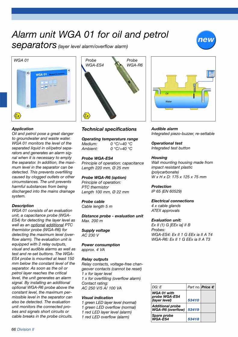
66 Division II
ApplicationOil and petrol pose a great dangerto groundwater and waste water.WGA 01 monitors the level of theseparated liquid in oil/petrol sepa-rators and generates an alarm sig-nal when it is necessary to emptythe separator. In addition, the maxi-mum level in the separator can bedetected. This prevents overfillingcaused by clogged outlets or othercircumstances. The unit preventsharmful substances from beingdischarged into the mains drainagesystem.
DescriptionWGA 01 consists of an evaluationunit, a capacitance probe (WGA-ES4) for detecting the layer level aswell as an optional additional PTCthermistor probe (WGA-R6) fordetecting the maximum level (over-flow alarm). The evaluation unit isequipped with 2 relay outputs,visual and audible alarms as well astest and re-set buttons. The WGA-ES4 probe is mounted at least 150mm below the constant level of theseparator. As soon as the oil orpetrol layer reaches the criticallevel, the unit generates an alarmsignal. By installing an additionaloptional WGA-R6 probe above theconstant level, the maximum per-missible level in the separator canalso be detected. The evaluationunit monitors the connected pro-bes and signals short circuits orcable breaks in the probe circuits.
Technical specifications
Operating temperature rangeMedium: 0 °C/+40 °CAmbient: 0 °C/+40 °C
Probe WGA-ES4Principle of operation: capacitanceLength 220 mm, Ø 25 mm
Probe WGA-R6 (option)Principle of operation: PTC thermistorLength 100 mm, Ø 22 mm
Probe cableCable length 5 m
Distance probe - evaluation unitMax. 200 m
Supply voltageAC 230 V
Power consumptionapprox. 4 VA
Relay outputsRelay contacts, voltage-free chan-geover contacts (cannot be reset)1 x for layer level1 x for overfilling (overflow alarm)Contact rating:AC 250 V/5 A/ 100 VA
Visual indication1 green LED layer level (normal)1 green LED overflow (normal)1 red LED layer level (alarm)1 red LED overflow (alarm)
Audible alarmIntegrated piezo-buzzer, re-settable
Operational testIntegrated test button
HousingWall mounting housing made fromimpact resistant plastic (polycarbonate)W x H x D: 175 x 125 x 75 mm
ProtectionIP 65 (EN 60529)
Electrical connections4 x cable glandsATEX approvals
Evaluation unit:Ex II (1) G [EEx ia] II BProbes:WGA-ES4: Ex II 1 G EEx ia II A T4WGA-R6: Ex II 1 G EEx ia II A T3
WGA 01 ProbeWGA-R6
DG: E Part no. Price €
WGA 01 withprobe WGA-ES4(layer level) 53410
Additional probeWGA-R6 (overflow) 53419
Spare probeWGA-ES4 53418
Alarm unit WGA 01 for oil and petrolseparators (layer level alarm/overflow alarm)
Water
Oil
ProbeWGA-ES4

Division II 67
WGA 03 ProbeWGA-AS
ApplicationOil, grease and petrol pose a greatdanger to groundwater and wastewater. WGA 02 monitors the thick-ness of the layer of separatedliquid in oil, petrol and greaseseparators and generates an alarmsignal when it is necessary toempty the separator. WGA 03 canalso detect the maximum level inthe separator. This prevents overfil-ling caused by clogged outlets orother circumstances. The unit pre-vents harmful substances frombeing discharged into the mainsdrainage system.
DescriptionWGA 02 consists of an evaluationunit and a conductivity probe(WGA-SD) for detecting the sepa-rating layer level. The evaluationunit is equipped with 2 relay out-puts, visual and audible alarms aswell as test and re-set buttons. TheWGA-SD probe is mounted belowthe constant level of the separator.As soon as the oil, petrol or greaselayer reaches the critical level, theunit generates an alarm signal.WGA 03 is equipped with an addi-tional capacitance probe (WGA-AS). This is mounted above theconstant level. An alarm is trigger-ed when the maximum permissiblelevel is reached. The evaluation unitmonitors the connected probesand signals short circuits or cablebreaks in the probe circuits.
Technical specificationsWGA 02
Operating temperature rangeMedium: 0 °C/+60 °CAmbient: -25 °C/+50 °C
Probe WGA-SD (layer level)Principle of function: conductivityLength 214 mm, Ø 25 mm
Probe cablePVC, oil resistant, length 5 m
Distance probe - evaluation unitMax. 300 m
Supply voltageAC 230 V
Power consumptionapprox. 2 VA
Relay outputsRelay outputs, 2 voltage-free chan-geover contacts (1 can be reset)Contact rating: AC 250 V/
5 A/100 VA
Visual indication1 green LED normal operation1 red LED alarm1 red LED fault
Audible alarmIntegrated piezo-buzzer, re-settable
Operational testIntegrated test button
HousingWall mounting housing made fromimpact resistant plastic (polycarbonate)W x H x D: 175 x 125 x 75 mm
DG: E Part no. Price €
WGA 02 withprobe WGA-SD 53400
WGA 03 withprobes WGA-SD,WGA-AS 53411
Spare probe WGA-SD 53403
Spare probeWGA-AS 53415
ProbeWGA-SD
Water
Oil
Alarm units WGA 02/WGA 03 for oil, petroland grease separators (layer level alarm/overflow alarm)
ProtectionIP 65 (EN 60529)
Electrical connections4 x cable gland M16
ATEX approvalsEvaluation unit:Ex II (1) G [EEx ia] II CProbe WGA-SD:Ex II 1 G EEx ia II A T4
Additional specificationsWGA 03
Probe WGA-AS (overflow)Principle of function: capacitanceLength 81 mm, Ø 82 mm
Power consumptionapprox. 4 VA
Visual indication1 green LED normal operation2 red LEDs alarm2 red LEDs fault
Electrical connections5 x cable gland M16
ATEX approvalsProbe WGA-AS:Ex II 1 G EEx ia II A T5
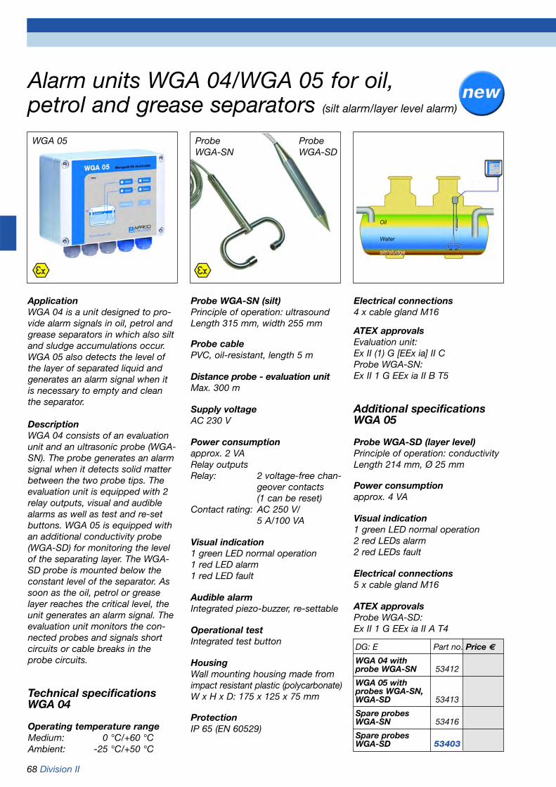
68 Division II
WGA 05
ApplicationWGA 04 is a unit designed to pro-vide alarm signals in oil, petrol andgrease separators in which also siltand sludge accumulations occur.WGA 05 also detects the level ofthe layer of separated liquid andgenerates an alarm signal when itis necessary to empty and cleanthe separator.
DescriptionWGA 04 consists of an evaluationunit and an ultrasonic probe (WGA-SN). The probe generates an alarmsignal when it detects solid matterbetween the two probe tips. Theevaluation unit is equipped with 2relay outputs, visual and audiblealarms as well as test and re-setbuttons. WGA 05 is equipped withan additional conductivity probe(WGA-SD) for monitoring the levelof the separating layer. The WGA-SD probe is mounted below theconstant level of the separator. Assoon as the oil, petrol or greaselayer reaches the critical level, theunit generates an alarm signal. Theevaluation unit monitors the con-nected probes and signals shortcircuits or cable breaks in theprobe circuits.
Technical specificationsWGA 04
Operating temperature rangeMedium: 0 °C/+60 °CAmbient: -25 °C/+50 °C
Probe WGA-SN (silt)Principle of operation: ultrasoundLength 315 mm, width 255 mm
Probe cablePVC, oil-resistant, length 5 m
Distance probe - evaluation unitMax. 300 m
Supply voltageAC 230 V
Power consumptionapprox. 2 VARelay outputsRelay: 2 voltage-free chan-
geover contacts (1 can be reset)
Contact rating: AC 250 V/5 A/100 VA
Visual indication1 green LED normal operation1 red LED alarm1 red LED fault
Audible alarmIntegrated piezo-buzzer, re-settable
Operational testIntegrated test button
HousingWall mounting housing made fromimpact resistant plastic (polycarbonate)W x H x D: 175 x 125 x 75 mm
ProtectionIP 65 (EN 60529)
Electrical connections4 x cable gland M16
ATEX approvalsEvaluation unit:Ex II (1) G [EEx ia] II CProbe WGA-SN:Ex II 1 G EEx ia II B T5
Additional specificationsWGA 05
Probe WGA-SD (layer level)Principle of operation: conductivityLength 214 mm, Ø 25 mm
Power consumptionapprox. 4 VA
Visual indication1 green LED normal operation2 red LEDs alarm2 red LEDs fault
Electrical connections5 x cable gland M16
ATEX approvalsProbe WGA-SD:Ex II 1 G EEx ia II A T4
DG: E Part no. Price €
WGA 04 withprobe WGA-SN 53412
WGA 05 withprobes WGA-SN,WGA-SD 53413
Spare probes WGA-SN 53416
Spare probesWGA-SD 53403
Probe WGA-SN
Probe WGA-SD
Alarm units WGA 04/WGA 05 for oil, petrol and grease separators (silt alarm/layer level alarm)
Water
Oil
silt/sludge

Division II 69
WGA 06 Probe WGA-ÖW
Probe WGA-AS
Alarm unit WGA 06 for oil, petrol and grease separators (oil-on-water alarm/overflow alarm)
ApplicationWhen used with the WGA-ÖWprobe, WGA 06 detects accumula-tions of oil in separator sumps orshafts and generates an alarmbefore pollutants are dischargedinto the mains drainage system. It is also possible to connect theWGA-AS probe. It enables thedetection of maximum levels inseparators or retention tanks. Thisprevents overfilling that may becaused by clogged outlets or othercircumstances. The unit keepsharmful substances from reachingthe sewage water system.
DescriptionWGA 06 consists of an evaluationunit and a capacitance probe(WGA-ÖW or WGA-AS). The evalu-ation unit is equipped with 2 relayoutputs, visual and audible alarmsas well as test and re-set buttons.Either the floating probe WGA-ÖWor the fixed probe WGA-AS can beconnected. WGA-ÖW floats on thesurface of the water in the shaftand generates an alarm signalwhen an oil, grease or petrol layerof at least 15 mm thickness hasbuilt up. WGA-AS is mountedabove the constant level of theseparator or the retention tank. Analarm is triggered when the maxi-mum permissible level is reached.The evaluation unit monitors theconnected probes and signalsshort circuits or cable breaks in theprobe circuits.
Technical specifications
Operating temperature rangeMedium: 0 °C/+60 °CAmbient: -25 °C/+50 °C
Floating probe WGA-ÖW (oil-on-water)Principle of operation: capacitance3 PVC floating ballsHeight 120 mm, Ø 370 mm
Probe WGA-AS (overflow)Principle of operation: capacitanceLength 81 mm, Ø 82 mm
Probe cablePVC, oil-resistant, length 5 m
Distance probe - evaluation unitMax. 300 m
Supply voltageAC 230 V
Power consumptionapprox. 2 VA
Relay outputsRelay: 2 voltage-free
changeover contacts (1 can be re-set)
Contact rating: AC 250 V/5 A/100 VA
Visual indication1 green LED normal operation1 red LED alarm1 red LED fault
Audible alarmIntegrated piezo-buzzer, re-settable
Operational testIntegrated test button
HousingWall mounting housing made from impact resistant plastic (polycarbonate)W x H x D: 175 x 125 x 75 mm
ProtectionIP 65 (EN 60529)
Electrical connections4 x cable gland M16
ATEX approvalsEvaluation unit:Ex II (1) G [EEx ia] II CProbes:WGA-ÖW: Ex II 1 G EEx ia II A T5WGA-AS: Ex II 1 G EEx ia II A T5
DG: E Part no. Price €
WGA 06without probes 53414
Floatingprobe WGA-ÖW,(oil-on-water) 53417
Probe WGA-AS(overflow) 53415
Water
Oil

70

www.afriso.de 71
Chapter 4Table of contents chapter 4
Leak detectors and leak monitoring systems, internal tank linings
04
Page
Leak detectors - sight glass principle (LAS 24/39/72/230) 72
Leak detectors, intrinsically safe (LAG-14 ER) 73
Leak detectors, not intrinsically safe (LAG-13) 74
Spare parts for leak detectors 75
Vacuum type leak detectors (Eurovac/LAZ)) 76-77
Test pressure gauge for double-skinned tanks 77
Internal linings for tanks containing fuel oil EL and diesel 78
Tank room lining for fuel oil and diesel storage 79
Internal linings for rain water harvesting 80
Internal linings for liquid fertiliser AHL, AdBlue 81
Mounting accessories for internal linings 82
Pressure type leak detectors for double-skinned tanks 83-85(Europress LAD-10, LAD-R)
Leak detection instruments, PTC thermistor based (oil/water alarm unit) 86
Leak detection instruments with photoelectric probes, 87drip pans (OM5)
Alarm instruments for oil and water (WWG, ÖWU) 88
Leak detection instruments, conductivity based 89-90(CoFox® ELT 8/ELT 500/4, probes BWS 11, WSS)
Oil-on-water detector, conductivity based (ÖAWD) 91
Leak alarm system TraceTek® 92
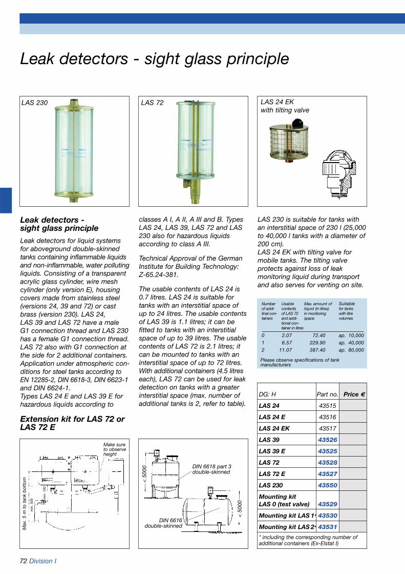
72 Division I
Leak detectors - sight glass principle
Leak detectors - sight glass principleLeak detectors for liquid systemsfor aboveground double-skinnedtanks containing inflammable liquidsand non-inflammable, water pollutingliquids. Consisting of a transparentacrylic glass cylinder, wire meshcylinder (only version E), housingcovers made from stainless steel(versions 24, 39 and 72) or castbrass (version 230). LAS 24, LAS 39 and LAS 72 have a maleG1 connection thread and LAS 230has a female G1 connection thread.LAS 72 also with G1 connection atthe side for 2 additional containers.Application under atmospheric con-ditions for steel tanks according toEN 12285-2, DIN 6618-3, DIN 6623-1and DIN 6624-1. Types LAS 24 E and LAS 39 E forhazardous liquids according to
classes A I, A II, A III and B. TypesLAS 24, LAS 39, LAS 72 and LAS230 also for hazardous liquidsaccording to class A III.
Technical Approval of the GermanInstitute for Building Technology:Z-65.24-381.
The usable contents of LAS 24 is0.7 litres. LAS 24 is suitable fortanks with an interstitial space ofup to 24 litres. The usable contentsof LAS 39 is 1.1 litres; it can be fitted to tanks with an interstitialspace of up to 39 litres. The usablecontents of LAS 72 is 2.1 litres; itcan be mounted to tanks with aninterstitial space of up to 72 litres.With additional containers (4.5 litreseach), LAS 72 can be used for leakdetection on tanks with a greaterinterstitial space (max. number ofadditional tanks is 2, refer to table).
DIN 6618 part 3double-skinned
DIN 6616double-skinned
< 5
000
< 5
000
Extension kit for LAS 72 or LAS 72 E
Number Usable Max. amount of Suitableof addi- contents liquid (in litres) for tankstinal con- of LAS 72 in monitoring with litretainers and addi- space volumes
tional con-tainer in litres
0 2.07 72.40 ap. 10,000
1 6.57 229.90 ap. 40,000
2 11.07 387.40 ap. 80,000
Please observe specifications of tank manufacturers
LAS 230 LAS 72 LAS 24 EK with tilting valve
DG: H Part no. Price €
LAS 24 43515
LAS 24 E 43516
LAS 24 EK 43517
LAS 39 43526
LAS 39 E 43525
LAS 72 43528
LAS 72 E 43527
LAS 230 43550
Mounting kitLAS 0 (test valve) 43529
Mounting kit LAS 1* 43530
Mounting kit LAS 2* 43531
* including the corresponding number ofadditional containers (Ex-Elstat I)
Make sureto observeheight
Max
. 5 m
to
tank
bot
tom
min
. 100
min
. 500
LAS 230 is suitable for tanks withan interstitial space of 230 l (25,000to 40,000 l tanks with a diameter of200 cm).LAS 24 EK with tilting valve formobile tanks. The tilting valve protects against loss of leak monitoring liquid during transportand also serves for venting on site.

Division I 73
Leak detectors, intrinsically safe according to ATEX, WHG and VbF
LAG-14 ER with relayThis class II (EN 13160-1: 2003)leak detector with an intrinsicallysafe probe circuit is designed fordouble-skinned tanks containingliquid in the interstitial space. The unit is designed for monitoringinflammable liquids of dangerclasses A I, A II, A III and B storedaboveground and non-inflammablewater-polluting liquids. The systemconsists of a control unit, a contai-ner for leak monitoring fluid and aprobe. CE-certified control unitwith visual and audible alarms, testbutton and increased interferenceprotection. With relay for connec-tion of additional alarm equipment.
Approved for tanks according toEN 12285-1, EN 12285-2, DIN 6618-1, DIN 6619-1, DIN 6623-1, DIN 6624-1.
The container for leak monitoringfluid is made from antistatic plasticand can be mounted in hazardousareas of zones I and II (e.g. accesschamber of petrol tanks). The con-trol unit can be panel mountedusing a special frame.
Technical Approval of the GermanInstitute for Building Technology: Z-65.24-1
EC design type approval:TPS 03 ATEX 15639 6Ex II (1) G [EEx ia] IIC and [EEx ia] IIB
DG: G PU Part no. Price €
LAG-14 ER with relay 5 43410
LAG containerblack 1 40731
LAG container, black,intrinsically safe, withoutprobeThe container for leak monitoringliquid serves as detection containerand, at the same time, as anexpansion vessel. Its usable con-tents amounts to 4.5 l (total con-tents 9 l). For underground tanks,the ratio between usable contentsand total volume of leak monitoringfluid must be no more than 1:100.This means that if the liquid in themonitoring system exceeds 450 l(for tanks according to EN 12285-1approx. more than 60,000 l), anadditional container must be used.The maximum ratio for above-ground tanks and tanks with nomore than 30 cm of earth coverageis 1:35 (i.e. for tanks according toEN 12285-1, EN 12285-2, approx.more than 20,000 l).
Additional container
Container with probe, permanently antistatic
Communi-cating connection tube
Non-hazardous area or hazardous areaNon-hazardousarea
Junction box, per-manently installed
Control unit
max
. 5 m
min
. 0,1
m Mains
Important information:As a result of the reclassification of water polluting substances inGermany, class WGK 0 for waterpolluting substances no longerexists. All substances previouslyassigned to WGK 0 now belong at least to class WGK 1. Thismeans that since June 30, 2003,liquid based leak detectors may no longer be put forward for useon underground, double-skinnedtanks. Legally existing installationsmay continue to be operated.Spare parts may be delivered. Thereclassification does not affectliquid based leak detectors used on aboveground, double-skinnedtanks. They continue to be compliant.
LAG-14 ER (intrinsically safe)
Junction boxControl unit
Watertight accesschamber Duct gastightwhen used with liquidsAI, AII and B
NYY 2 x 1,5 2
Vent and test valve min. 1/2“
Mains
Non-hazardous area or hazardous area
Non hazardous area
Recess
Liquids belonging to danger classesAIAIIAIIIB
min
. 0,1
m

74 Division I
Leak detectors, not intrinsically safeaccording to WHG and VbF
LAG-13 K (not intrinsicallysafe)Class II (EN 13160-1: 2003) leakdetector for double-skinned tankswith liquid in the interstitial space.The unit is designed for monitoringwater polluting liquids and inflam-mable liquids of danger classes A I,A II, A III and B stored aboveground.The system consists of a controlunit, a container for leak detectionfluid and a probe. CE-certified con-trol unit with visual and audiblealarms, test button and increasedinterference protection. Approvedfor tanks according to EN 12285-1,EN 12285-2, DIN 6618-1, DIN 6619-1,DIN 6623-1, DIN 6624-1. The con-trol unit can be panel mountedusing a special frame. TechnicalApproval of the German Institute forBuilding Technology: Z-65.24-380
LAG-13 KRSimilar to LAG-13K, but withintegrated relay. Voltage-free relaycontact for connection of additionalalarm equipment. Max. contactrating: AC 250 V 2A
Leak monitoring fluid -concentrate10 l container with 4 l of leak moni-toring fluid concentrate AntifrogenN, BAM no.: 1.3/9790-5.1/3436. Canbe mixed with water to 8 l at up to -30 °C or to 10 l at up to -25 °C.Please enquire for larger containers.
LAG mounting kitFor approved mounting of leakdetectors.
Mounting frameFor control panel mounting ofAFRISO control units.
LAG container whiteNot intrinsically safe, withoutprobe.
DG: G PU Part no. Price €
LAG-13 K (not intrinsically safe) 5 43500
LAG-13 KR 1 43501
LAG container white 1 40730
Mounting frame 1 43520
LAG mounting kit 5 40540
Mounting kit for additional LAGcontainer 1 40539
Leak monitoring fluid - concentrate 5 43645
Important information:As a result of the reclassification of water polluting substances inGermany, class WGK 0 for waterpolluting substances no longerexists. All substances previouslyassigned to WGK 0 now belong at least to class WGK 1. Thismeans that since June 30, 2003,liquid based leak detectors may no longer be put forward for useon underground, double-skinnedtanks. Legally existing installationsmay continue to be operated.Spare parts may be delivered. Thereclassification does not affectliquid based leak detectors used on aboveground, double-skinnedtanks. They continue to be compliant.
Control Unit
LAG container
Hose nipple G3/4“
Vent and test valve
Connection tube
Double-skinned tankacc. to DIN EN 12285-2
Part no. 40539incl. piece of hose
Hose connec-tion G1“
Additionalcontainer
Connectiontube
Cable extension fitting “KVA„

Division I 75
Spare parts for leak detectorsSpare parts for LAG and LAZ - when ordering spare parts, please provide us with the correct unit designation
(refer to type designation plate on the control unit). Spare parts for discontinued models are also listed.
Part no. PU: DG: Price €
LAG probe, plug-in connection 40510 1 G
Control unit LAG-14 ER 40642 1 G
„Operation“ indicator lamp LAG-14 E 40024 10 G
Spare lamp with screw base E 10
„Operation“ indicator lamp LAG-14 E 40019 10 G
Spare lamp with plastic tube base
„Alarm“ indicator lamp LAG-14 E, LAG-13 40023 10 G
Plug-in lamp, base W 2 x 4, 6d
Fuse LAG-14 E, LAG-14 ER, LAG-13, LAG-13 KR, LAG-10 Ke 40027 10 G
Control unit LAG-13 K 40630 1 G
Control unit LAG-13 KR 40638 1 G
„Operation“ indicator lamp LAG-13, LAG-11 40019 10 G
Spare lamp and plastic tube base
„Alarm“ indicator lamp LAG-13 E, LAG-11 40020 10 G
12 V lamp and plastic tube base
„Alarm“ indicator lamp LAG-13 E, LAG-14 40023 10 G
Plug-in lamp, base W 2 x 4, 6d
Fuse LAG-13 K 40026 10 G
Foil keypad for control units 1996 and later 18 05 000002 1 G
„Operation“ indicator lamp LAG-10 Ke (LWG-T) 40022 10 G
Yellow lamp with flying leads approx. 120 mm
„Alarm“ indicator lamp LAG-10 Ke (LWG-T) 40021 10 GRed lamp with flying leads approx. 120 mm
Spare parts LAG mounting kit:
Test valve plastic, complete 40555 1 G
Double nipple G1 40556 1 G
Hose connection G1 (angled) 40557 1 G
Hose nipple G3/4 40558 1 G
Hose EPDM 14 x 3 (price per m) 40543 G
LAZ spare parts:
Pump with motor LAZ-04/1 (HV) 43651 1 H
Pump with motor LAZ-04/3 (NV) 43652 1 H
Pressure switch HV 43653 1 H
Pressure switch NV 43654 1 H
Complete PCB with relay 43639 1 H
Non-return valve, complete 43657 1 H
„Operation“ indicator lamp LAZ-04 (yellow) 43659 1 H
„Alarm“ indicator lamp LAZ-04 (red) 43658 1 H
„Operation“ indicator lamp LAZ-04 (green) 43661 1 H
Please specifylength

Vacuum type leak detectors(according to WHG and VbF)
Mounting diagram
Vent valve
Mea
sure
Exh
aust
Suc
tion
Con
den
sate
trap
with
non-
retu
rnva
lve
3-way stop cock
Electr. connection
Tank vent
Transparent
Gre
en
Red
Liquid barrier
Outer tank wall
Interstitial space
Use liquid trap if gradient is uneven
Eurovac 04-1 (LAZ-04/1)Class I (EN 13160-1:2003) leakdetector, high vacuum based, foruse with double-skinned tanks andsingle-skinned tanks with internallining. The unit is designed formonitoring aboveground andunderground tanks containinginflammable liquids of danger classA III as well as non-inflammable,water polluting liquids. Also suitablefor renovating double-skinnedtanks which were previously moni-tored with leak detection fluid.(Refer to the operating instructionsfor a definition of the storedmedia).Eurovac 04-1 is adjusted for analarm vacuum level of 325 mbar andapproved for tanks up to Ø 2.9 mwhereby the suction tube connec-tion may end at the top of the tank. If mounted outdoors, special in-stallation requirements have to beobserved, e.g. protective housing,greater internal capillary tube dia-meters (6 mm), condensate traps.
Application
For tanks according to EN 12285-1,EN 12285-2 design A, DIN 6618-2,6619-1, 6623-1, 6624-1 as well asequivalent tanks made from steelor equivalent approved tanks madefrom plastic, provided that theyhave double walls or are equippedwith an approved leak protectionlining (internal lining) according toEN 12285-1 or by analogous appli-cation of EN 12285-1.
For tanks according to DIN 6625-1which are equipped with an appro-ved leak protection lining (internallining) and cylindrical, rectangularor spherical tanks made from rein-forced concrete or equivalent,approved tanks made from othermaterials which are equipped withan approved leak protection lining(internal lining).Technical Approval of the GermanInstitute for Building Technology:Z-65.22-4
Eurovac 04-3 (LAZ-04/3)
This vacuum leak detector is similarto Eurovac 04-1 but is adjusted foran alarm vacuum level of 34 mbarand certified for tanks up to Ø 2.9m; the suction pipe must run to thebottom of the tank.
Application
For tanks according to EN 12285-1,EN 12285-2 design A, DIN 6619-1,6624-1, 6625-1 and equivalenttanks made from steel or equiva-lent, approved tanks made fromplastic. Cylindrical, rectangular orspherical tanks made from reinfor-ced concrete or equivalent, appro-ved tanks made from other materi-als, equipped with an approved leakprotection lining (internal lining).Technical Approval of the GermanInstitute for Building Technology:Z-65.22-382
Supply voltage AC 230 V
DG: H; PU: 1 Part no. Price €
Eurovac 04-1 (LAZ-04/1) 43641
Eurovac 04-3 (LAZ-04/3) 43643
LAZ-04/1 in protective housing 43665
LAZ-04/3 in protective housing 43666
Connection pieceG1 x 4 mm 43697internal diameter
LAZ-04 in protective housingVacuum type leak detector LAZ-04in protective housing, pre-assem-bled and ready for connection, withhorn HPW 2. Protection IP 55.
Refer to pages 78-82 for internallinings and a complete range ofinstallation accessories.
Refer to page 453 for test instrumentsfor vacuum type leak detectors.
Proven pumps andpressure switches
terminalblock
76 Division I
Pump Pressure switch Mounting bracket
PCB with relay
Horn HPW2Protection IP 55
Instruction manual
Red
Gre
en
Tran
spar
ent

Division I 77
Application of vacuum type leakdetector LAZ-04/1 on double-skinned plastic or steel tanks whichare approved for leak detection withvacuum.
In this example, the LAZ-04/1 leakdetector is used to monitor thestorage of hazardous liquids class A III and non-inflammable, water-polluting liquids.
When planning such designs,observe the specific weight of the stored medium and the testpressure of the double-skinnedtank. Up to 5 tanks can be moni-tored with one leak detector.
Test pressure gauge for double-skinned tanksTest pressure gauge for monitoringthe vacuum in double-skinned stor-age and transport tanks, consistingof a Bourdon tube glycerine filledpressure gauge RF 50 Gly -1/0 barD 601, adapter with hollow screwfor mounting to the tank, 3-waystop cock with hose connectionsfor suction pump or pressure gauge.
Dial can be customised, e.g. withcoloured areas or company logo.
Part no. Price €
67002Minimum order quantity 50 pieces
DG : M
Application example of leak detection on double-skinned battery tanks with vacuum type detectors

78 Division I
Internal tank linings with complete accessoriesand Technical Approval of the German Institute for Building Technology. For fuel oil EL and diesel
Fastening ring
Protectiveplate
Internal lining Intermediate layer (fleece)
Condensate barLiquid barrier
Suction tube/perforated suction tube
AFRISO leak detector
This seal standsfor quality andsafety.
Felt overshoesprevent damageduring installa-tion.
Tank protection package AK-Sfor cylindrical DIN tanks
Litres Part no. DG: Price €
3,000 43901.003 H
5,000 43901.005 H
7,000 43901.007 H
10,000 43901.010 H
13,000 43901.013 H
15,000 43901.015 H
16,000 43901.016 H
20,000 43901.020 H
25,000 43901.025 H
30,000 43901.030 H
40,000 43901.040 H
50,000 43901.050 H
60,000 43901.060 H
80,000 43901.080 H
100,000 43901.100 H
A tank protection package comprises the following:Eurovac vacuum leak detector, internal tank lining accordingto DIN or custom-made (please enquire for dimensional drawings), 1 pair of felt overshoes, intermediate layer (fleece),protective plate and all required mounting accessories asper list (refer to page 82). If the tank is outdoors and above-ground, install 6 x 2 mm capillary tubing and use fittings with6 mm connections (please mark accessories list accordingly).
Prices for spherical and other tank shapes on request.
Technical Approval of the German Institute for BuildingTechnology: Z-65.30-162 (Percentage of biodiesel up to 20 % if fleece is used as intermediate layer)
Tank protection package AK-Sfor rectangular tanks
Up to... Litres Part no. DG: Price €3,000 43902.003 H
4,000 43902.004 H
5,000 43902.005 H
6,000 43902.006 H
7,000 43902.007 H
8,000 43902.008 H
9,000 43902.009 H
10,000 43902.010 H
11,000 43902.011 H
12,000 43902.012 H
13,000 43902.013 H
14,000 43902.014 H
15,000 43902.015 H
16,000 43902.016 H
17,000 43902.017 H
18,000 43902.018 H
19,000 43902.019 H
20,000 43902.020 H
21,000 43902.021 H
22,000 43902.022 H
23,000 43902.023 H
24,000 43902.024 H
25,000 43902.025 H
26,000 43902.026 H
27,000 43902.027 H
28,000 43902.028 H
29,000 43902.029 H
30,000 43902.030 H
Technical Approval of the German Institute for BuildingTechnology: Z-65.30-162

Division I 79
Tank room lining for fuel oil and diesel storage
DG: H Part no. Price €
Tank room lining, per m2 43868
Synthetic geotextiles, per m2 43965
Aluminium tape, per metre 43934
Nail dowel, per piece (4 per metre) 43617
For lining of drip pans and forrooms used for the storage ofwater polluting liquids.
A tank room lining package con-sists of foil, aluminium tape, geo-textiles and nail dowels.Approved for fuel oil EL and dieseloil. Technical Approval of theGerman Institute for BuildingTechnology: Z-59.21-77 and Z-59.21-78Please specify room dimensionswhen ordering.
Legislation like the German WaterAct (WHG and VAwS) containsstringent requirements regardingthe safety and leak proof aspect ofstorage rooms and drip pans foraboveground storage tanks. Manyolder tank rooms no longer providethe required safety levels due tocracks in walls or floors, inadequatecoating or other damages.
AFRISO special foil tank roomlinings ensure cost effective andpermanent environmental protec-tion for new or renovated tankrooms.
The tank contents is pumped intoan intermediate storage facility. Thesupply of the heating system in notinterrupted. The empty tanks arethen lifted up. The lining which ismanufactured to the exact tankroom dimensions is then laid down.The foil is then fixed to the wall and
Tank room foilDimensionsThickness 1.5 mm
ApprovalTechnical Approval of the GermanInstitute for Building Technology:Z-59.21-77 and Z-59.21-78.For fuel oil EL and diesel
Synthetic geotextiles, whiteDimensionsW 250 cm x running metre
Aluminium tapeDimensions30 x 3 mm x running metre forfastening of foil at upper edge
hard rubber discs are placed underthe tanks to prevent damage to thefoil. The tanks are then refilled.
• The special foil is suitable for all tank types and sizes.
• During the work process the tank is not removed but lifted using special lifting gear, air cushions or similar. Battery tanks,however, can be removed and re-installed easily.
• There are no special requirementsconcerning the wall and floor sur-faces. The protective foil covers cracks and adapts to uneven surfaces.
• Extensive preparation work in thetank room is not required.
• The lining can be installed during any season since the heating is not interrupted.
• The tank room lining is delivered as a complete package.
• Optional leak detectors can be installed.
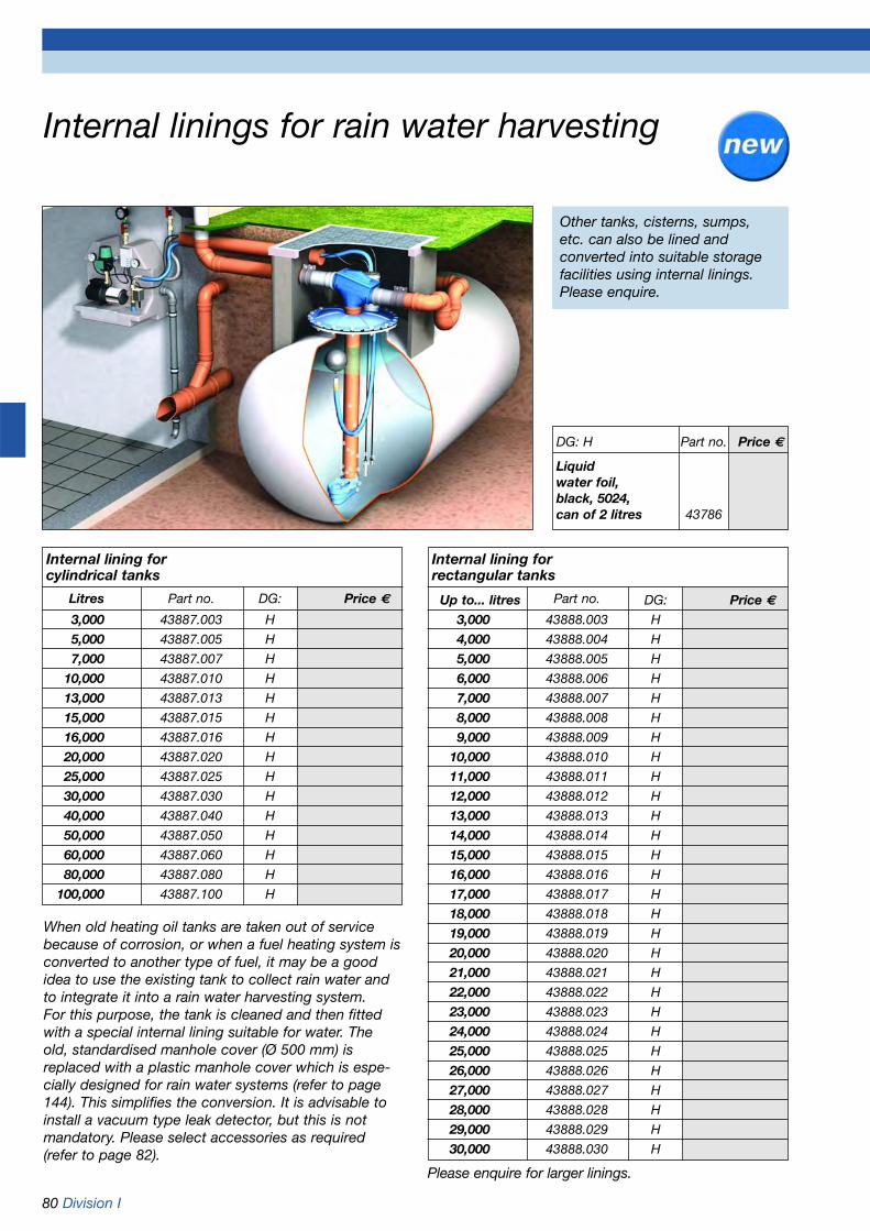
80 Division I
Internal linings for rain water harvesting
Internal lining forcylindrical tanks
Litres Part no. DG: Price €
3,000 43887.003 H
5,000 43887.005 H
7,000 43887.007 H
10,000 43887.010 H
13,000 43887.013 H
15,000 43887.015 H
16,000 43887.016 H
20,000 43887.020 H
25,000 43887.025 H
30,000 43887.030 H
40,000 43887.040 H
50,000 43887.050 H
60,000 43887.060 H
80,000 43887.080 H
100,000 43887.100 H
Internal lining forrectangular tanks
Up to... litres Part no. DG: Price €3,000 43888.003 H
4,000 43888.004 H
5,000 43888.005 H
6,000 43888.006 H
7,000 43888.007 H
8,000 43888.008 H
9,000 43888.009 H
10,000 43888.010 H
11,000 43888.011 H
12,000 43888.012 H
13,000 43888.013 H
14,000 43888.014 H
15,000 43888.015 H
16,000 43888.016 H
17,000 43888.017 H
18,000 43888.018 H
19,000 43888.019 H
20,000 43888.020 H
21,000 43888.021 H
22,000 43888.022 H
23,000 43888.023 H
24,000 43888.024 H
25,000 43888.025 H
26,000 43888.026 H
27,000 43888.027 H
28,000 43888.028 H
29,000 43888.029 H
30,000 43888.030 H
DG: H Part no. Price €
Liquidwater foil, black, 5024,can of 2 litres 43786
When old heating oil tanks are taken out of servicebecause of corrosion, or when a fuel heating system isconverted to another type of fuel, it may be a goodidea to use the existing tank to collect rain water andto integrate it into a rain water harvesting system.For this purpose, the tank is cleaned and then fittedwith a special internal lining suitable for water. Theold, standardised manhole cover (Ø 500 mm) is replaced with a plastic manhole cover which is espe-cially designed for rain water systems (refer to page144). This simplifies the conversion. It is advisable toinstall a vacuum type leak detector, but this is notmandatory. Please select accessories as required(refer to page 82).
Other tanks, cisterns, sumps, etc. can also be lined and converted into suitable storagefacilities using internal linings.Please enquire.
Please enquire for larger linings.

Division I 81
Internal linings for liquid fertiliser AHL, AdBlue
Fastening ring
Protectiveplate
Internallining
Intermediate layer (fleece)
Condensate barLiquid barrier
Suction tube/perforatedsuction tube
AFRISO leak detectorEurovac 04-1 (LAZ-04/1)
Leak protection lining for cylindrical DIN tanks or tanksmanufactured on site consisting of steel, glass-fibrereinforced plastic or asbestos cement. With test certi-ficate from the German Federal Institute for MaterialsTesting and Research BAM VI.2/10320/01. For storingliquid fertiliser AHL and urea solution 32.5 % AdBlue.When AdBlue is stored, the surface temperature must not exceed 35 °C. Made of PVC foil E 3855, 0.80 mmthick, resistant to liquid fertiliser.
Internal linings for AHL and AdBluefor cylindrical DIN tanks
Litres Part no. DG Price €2,000 43880.002 H
3,000 43880.003 H
4,000 43880.004 H
5,000 43880.005 H
6,000 43880.006 H
7,000 43880.007 H
8,000 43880.008 H
9,000 43880.009 H
10,000 43880.010 H
11,000 43880.011 H
12,000 43880.012 H
13,000 43880.013 H
14,000 43880.014 H
15,000 43880.015 H
16,000 43880.016 H
20,000 43880.020 H
25,000 43880.025 H
30,000 43880.030 H
40,000 43880.040 H
50,000 43880.050 H
60,000 43880.060 H
80,000 43880.080 H
100,000 43880.100 H
Please enquire for larger linings and other shapes.
Part no. DG Price €
Internal linings for liquidfertiliser AHL and AdBlue for 43870 Hrectangular tanks Per m2
Additional cost foradditional manhole 08027 HDifferent and specially dimensioned manhole sizes are also availableat short notice with a 5 % surcharge.
Stainless steel fastening ring 43900K HComplete with round gasket, foamrubber and cardboard gasket,500 mm diameter. As accessoryfor AdBlue on request.
Stainless steel fastening ring 43900L HComplete with round gasket, foamrubber and cardboard gasket,600 mm diameter As accessoryfor AdBlue on request.
Ensure that all relevant directivesconcerning construction and theselection of materials are com-plied with.

Mounting accessories for internal linings for fuel oil EL and dieselFigure Designation Part no. Specification Pieces/pack Single Price €
Please tick unit order DG: H4 Ø 6 Ø PU
Condensate bar 43692 Connections 4 mm 1 1043693 Connections 6 mm 1 10
Liquid barrier with 43646 Connections 4 mm 1 10condensate trap 43638 Connections 6 mm 1 10
and bracket
Angled nipple 43904 6 x 4 mm 1 25with spacer 43905 6 x 6 mm 1 10
Angled nipple short 43906 6 x 4 mm 1 2543907 6 x 6 mm 1 10
Angled nipple long 43908 6 x 4 mm 1 1043909 6 x 6 mm 1 10
a) Suction hose 43910 6 x 3 mm 1 1perforated (Roll 100m)
b) Suction hose 43911 6 x 3 mm 1 1not perforated (Roll 100m)
Fastening ring 43900A Ø 500 mm 1 5with round gasket, 43900B Ø 550 mm 1 5foam rubber and 43900C Ø 600 mm 1 5cardboard gasket 43900D Ø 620 mm 1 5
Hose connector 43945 4 x 4 mm 1 25for suction hose 43912 6 x 6 mm 1 25
T piece for 43944 4 x 4 x 4 mm 1 25suction hose 43913 6 x 6 x 6 mm 1 25
Hose connector 43914 G3/8 x 4 mm 1 2543915 G3/8 x 6 mm 1 1043916 G1/8 x 4 mm 1 2543917 G1/8 x 6 mm 1 10
Plate holder 43918 With plate 1 10and clamp
Please order separately (not included in package):
PVC hose red 43648 4 x 2 mm 1100 m 43662 6 x 2 mm 1
PVC hose green 43649 4 x 2 mm 1100 m 43663 6 x 2 mm 1
PVC hose transparent 43650 4 x 2 mm 1100 m 43664 6 x 2 mm 1
Sealing material 1 kg 43919 Epple 28 1Glue 1 kg 43920 Epple 4851 1
Overpressure 20466 G11/2 DG: Gdevice Release pressure 25
approx. 25 mbar
Polystyrene bar for T profiles 43927 1 m 50
Foam rubber roll 10 m 43926 50 x 5 mm 1
Foam rubber roll 10 m 43942 50 x 8 mm 1
Mipoplast floor plate 43928 800 x 800 mm 1
a) b)
82 Division I

Division I 83
Pressure type leak detectors for double-skinned tanks
Europress LAD-10Pressure type leak detector for double-skinned tanks. Used for water polluting,non-inflammable liquids and hazardousinflammable liquids of classes A I, A II, A III and B. LAD 10 switches on thealarm when the monitoring pressurefalls below 465 mbar. The integratedsafety valve prevents the pressure fromexceeding 570 mbar. Designed forinstallation in dry, accessible, frost-freerooms. Pressure type leak detectorsare operated with dried air (10 % relati-ve humidity). Drying filters with replace-able drying beads are used to dry theair.Please order the drying filter separately.
Technical Approval of the GermanInstitute for Building Technology: Z-65.23-3
Application for double-skinned tankswithout pressure in the storage space:• According to EN 12285-1;
EN 12285-2 design A; DIN 6619-2; DIN 6623-2; DIN 6624-1.
• Without leak detection fluid in the interstitial space.
• Ground water level up to 1,450 mm above the tank top permissible.
• Tank diameter Permissible densityor tank in m of height the liquid
in t/m3
< 2.00 < 1.90< 2.50 < 1.74< 2.60 < 1.67< 2.76 < 1.58< 2.84 < 1.53< 2.90 < 1.50
Technical specificationsOperating temperature rangeAmbient: -5 °C/+50 °C
Connectionsuction/pressure/capillaryFor capillary tubing 6 x 2 mm
Supply voltageAC 230 V
Power consumption100 VA
Switching outputRelay contact: 1 voltage-free
changeover contactContact rating: 250 V, 2 A
(resistive load)
HousingWall mounting housing made fromimpact resistant plastic (ABS)W x H x D: 215 x 165 x 100 mm
ProtectionIP 30 (EN 60529)
LAD-10 in protective housingLAD-10 in protective housing, completely pre-assembled and readyfor connection, with horn HPW 2.Protection IP 55.
LAD-10 in protective housing, heatedFor outdoor installation. Housingfeatures thermostat heating. LADcompletely pre-assembled and readyfor connection. Horn HPW 2 installedoutside. Protection IP 55.
DG: H; PU: 1 Part no. Price €Europress LAD-10 43680LAD-10 in protective housing 43681LAD-10 in protectivehousing, heated 43679Drying filter TF 220with bracket 43688Drying beads850 ml 69226Connection pieceG1 x LW 6 mm 43698internal diameter
Refer to page 82 for PVC capillary tubing 6 x 2.
Leak detectorLAD 10
Capillary tube
Drying filter
PressureSuc-tion
Qe.g. 16 m3
Tank according to EN 12285-1 or EN 12285-2
Number of drying filters for underground tanks:
1 x drying filter type TF 220
Number of drying filters for aboveground tanks:
Interstitial space No. ofvolume drying filtersto 300 Litres 1 x TF 220to 700 Litres 2 x TF 220to 1,000 Litres 3 x TF 220to 1,500 Litres 4 x TF 220to 1,800 Litres 5 x TF 220to 2,200 Litres 6 x TF 220to 2,600 Litres 7 x TF 220to 3,000 Litres 8 x TF 220
To leak detector
Suction opening

Pressure type leak detectors for double-skinned pipes
Permissible operating pressure < 1 bar 1 bar to < 10 bar 10 bar to < 16 bar
„Alarm On“ 2 bar 11 bar 17 bar
„Alarm Off“(minimum filling pressure) 6 bar 15 bar 21 bar
Max. filling pressure forleak monitoring medium 21 bar 21 bar 21 bar
Europress LAD-RLeak detector for monitoring double-skinned pipes using pressure withinert gas (e.g. nitrogen), without sta-tionary supply cylinder. To be usedon double-skinned pipes carryingwater polluting, non-inflammableliquids and hazardous inflammableliquids of classes A I, A II, A III and B.The double-skinned pipes must besuitable for the following pressures:• In the interstitial space: < 21 bar• In the inner pipe: < 16 barThe monitoring pressures for „AlarmOn“ and „Alarm Off“ can be adjustedvia the two contacts of the integratedpressure gauge. Factory settings:„Alarm On“ = 2 bar,„Alarm Off“ = 6 bar.The monitoring pressure for Alarm„ON“ must be at least 1 bar greaterthan the maximum operating pressurein the inner pipe. The switch point„Alarm Off“ can be set to a maximumof 21 bar.
The pressure gauge continuouslymeasures the pressure in the inter-stitial space of the pipe.If the total interstitial space volumedoes not exceed 1,200 l, severalinterstitial spaces can be connectedto one leak detector. Refer to page85 for distributor bars. A nitrogencylinder with pressure reducer isconnected to the test coupling of theleak detector via a filling and test fit-ting (please order separately) to fillthe interstitial space with inert gas.The filling pressure must not exceed21 bar. After filling, the fitting isremoved. If the pressure in the inter-stitial space falls below the adjustedthreshold for „Alarm On“, the unitgenerates audible and visual alarms.Additional equipment such as audi-ble and visual alarms, telecommuni-cation and event reporting systemscan be connected to the relay con-tact (1 voltage-free changeover con-tact).
Technical specificationsSupply voltage: AC 230 VPower consumption: Max. 7 VAOutput:1 voltage-free changeover contactContact rating: AC 250 V, 2 AHousing: Impact resistant plasticW x H x D: 215 x 165 x 100 mmProtection: IP 30 (EN 60529)Connection pressure pipe:Copper capillary tubing Ø 6 x 1 mmFilling pipe: Plug connector DN 5
Technical Approval of the GermanInstitute for Building Technology: Z-65.26-257
DG: H; PU: 1 Part no. Price €
Europress LAD-R 43684
Filling andtest fitting,for pressure type leak
detector LAD-R 43691
Pressure reducerwith safety valve,reducer group for
nitrogen cylinders 43695
LAD-R inprotective housing,completely pre-assembled
and ready for connection,
with horn HPW 2.
Protection IP 55 43694
Please enquire for heated protectivehousing.
Test valve
Filling valve
Pre
ssur
elin
e
Filli
nglin
e
Mai
ns
84 Division I

Division I 85
Manifolds for LAD-R
Manifolds for LAD-R are madefrom brass and feature a shut-offvalve. They can be supplied with or without a pressure gauge (accuracyclass 1.6). The manifolds are suitable for connection and moni-toring of several double-skinnedpipes simultaneously using pressu-re with inert gas (e.g. nitrogen) witha single leak detector. The totalinterstitial space volume must notexceed 1,200 l. Pressure connec-tion via copper capillary tubingØ 6 x 1 mm. The pressure gauge ismounted between the stop cockand the interstitial space. In a testsituation or in the event of a leak, thestop cocks can be closed so thatthe leaking pipe can be identifiedby the pressure drop indicated bythe corresponding pressure gauge.
Part no. PU DG Price €
X1 L
Manifold bar 4 with press. gauge 25 bar 192 200 43834 1 H
Manifold bar 4 with press. gauge 16 bar 192 200 43833 1 H
Manifold bar 4 without press. gauge 192 200 43830 1 H
Manifold bar 3 with press. gauge 25 bar 142 150 43829 1 H
Manifold bar 3 with press.gauge 16 bar 142 150 43828 1 H
Manifold bar 3 without press. gauge 142 150 43825 1 H
Manifold bar 2 with press.gauge 25 bar 92 100 43824 1 H
Manifold bar 2 with press. gauge 16 bar 92 100 43823 1 H
Manifold bar 2 without press. gauge 92 100 43820 1 H
Leak detectorLAD-R
Manifold
Double-skinned pipe
Interstitial space
Interstitial space
Interstitial space
Test valve
Test valve
Test valve

Leak detection instruments, PTC thermistor based
Oil/water alarm unit ÖWWG 3The PTC thermistor oil or wateralarm unit sets off visual and audiblealarms in the event of accumulationsof liquids which can be caused bytank leaks, backpressure, flooding,etc. The unit consists of an indicatorwith built-in operation and alarmlamps, a buzzer with mute facilityas well as a flexible PTC thermistorprobe. The PTC thermistor probe ismounted at the lowest point of thearea to be monitored. The alarm istriggered when the probe comesinto contact with liquid.
Frame for panel mounting
PTC thermistorglassencap-sulated
Cable 3 m long
Application examples
Drip pan
Double-skinnedtank
Duct
Storage room Access chamber
AC 230 V
AC 230 V
AC 230 V
AC 230 V
Applications
• Oil storage rooms• Drip pans• Inspection ducts• Ducts, protective pipes• Access chambers• Pipelines• Heating rooms• Water transfer rooms• Laundry rooms
The indicator is designed for wallmounting in dry rooms. It can alsobe mounted in panels or controlcabinets using a special mountingframe.
Technical specificationsSupply voltage: AC 230 VPower consumption: Max. 10 VAOutput:1 voltage-free changeover contactContact rating: AC 230 V, 2 AHousing: Wall mounting housingmade from impact resistant plastic(ABS)W x H x D: 97 x 163 x 62 mmProtection: IP 30 (EN 60529)
• Self-checking probe• Alarm when in contact with liquid• Alarm in the event of cable
damage or probe damage• Robust PTC thermistor probe• Test button for easy function check• Alarm memory with voltage-free
contact (pump off)• Built-in alarm buzzer with mute
facility• Fixed connection ensures safety• Suitable for use with AFRISO
series of safety devices
Technical Approval of the GermanInstitute for Building Technology:Z-65.40-339
DG: G; PU: 1 Part no. Price €
Oil / wateralarm unitÖWWG 3 44510
Spare probeÖWWG 3 44516
Probe fuse 44495
Main fuse 10820
AC 230 V
86 Division I
PTC thermistorprobe
Storage tank
Example ÖWWG 3monitors (a pipeduct)

Division I 87
Leak detection instruments with photoelectric probes, drip pans
Oil alarm OM5Oil alarm OM5 in connection with 1 to 5 photoelectric probes for thedetection of heating oil EL, L, M,diesel oil (danger class A III), lowviscosity lubricating oil, motor oil,gearbox oil, hydraulic oil, vegetableoil and transformer oil. OM5 is anindicator unit with integrated opera-tion and alarm lamps, buzzer withmute facility and output relay. Thephotoelectric probes are mountedin the areas to be monitored. Theunit indicates which probe triggeredan alarm. The oil alarm is designedfor wall mounting in dry rooms. Itcan also be mounted in panels orcontrol cabinets using a specialmounting frame. The photoelectric probes must beordered separately.
Technical specificationsSupply voltage: AC 230 VPower consumption: 5 VAOutput:1 voltage-free changeover contactContact rating: AC 230 V, 2 AResponse time: 2 secondsDimensions (W x H x D):97 x 163 x 62 mmProtection: IP 30 (EN 60529)Technical Approval of the GermanInstitute for Building Technology:Z-65.40-214
Water alarm WM5Leak detection instrument similar toOM5, but designed for the detec-tion of water.
Monitoring of up to 5 storage tanks.Mechanical probes are replaced by electronic units.
Probe
DG: G; PU: 1 Part no. Price €
Oil alarm OM5 44502
Water alarmWM5 44508
Photoelectric probe 44503
Drip pan 44512
Photoelectric probePhotoelectric probe for the detec-tion of liquids, to be used withOM5 and WM5. Diameter 10 mm,response level 5 mm, cable length10 m.
Drip panDrip pan made from white plastic(PE), dimensions 600 x 300 mm forcollecting liquids such as oil. Thedrip pans are cascadable (in a lineor at 90° angles). At the lowestpart of the drip pan the sensor ofan oil alarm such as ÖWWG 3 (partno. 44510) or OM5 (part no. 44502)can be installed. Drip pans shouldbe mounted below all oil fittingssuch as filters, oil vents, burners,etc. to prevent damage resultingfrom escaping oil and in order todetect leaks as early as possible. If the drip pan cannot be checkeddaily or is not easily accessible, oilalarms with audible and visual sig-nals are recommended.
Drip pan
Cascaded drippans
Application example
A mounting clamp for the sensor issupplied with the drip pan. Several cascaded drip pans can bemonitored using a single probe.Several independent drip pans canbe monitored with a single oil alarmOM5 and several probes.
Application example
Fix cable with PG 7 cable gland

Water alarms and oil/water alarms
Water alarm WWG1In wall mounting housing. WWG1 isused together with a special floorprobe for the detection of minuteamounts of electrically conductingliquids such as water. The responselevel of the floor probe shipped withthe alarm is approx. 2 to 3 mm.Water resulting from clogged drains,rain water, broken pipes, waste waterpump failure, etc. causes the unit totrigger visual and audible alarms. Theunit features two voltage-free outputrelays. One relay can be re-set (exter-nal audible alarm) the other relay isnot re-settable (external alarm lamp,solenoid valve, pump).The instrument is suitable for panelmounting using a mounting frame(refer to page 74).
Water alarm WWG2Similar to WWG1, but with heightadjustable wall mounting rail probe.
Oil and water alarm ÖWUAlarm instrument in wall mountinghousing for electrically conducting(e.g. water) and non-conductingliquids (e.g. oil). In connection withthe combination probe with photo-electric and conductivity sensorssupplied with the unit, the instrumentis designed for the detection ofliquids. An integrated microprocessordetermines whether the detectedmedium is oil or water. Integratedvisual and audible alarms with mutebutton as well as two output relays(one can be re-set).
Technical specificationsControl unit: Similar to WWG1Wall mounting rail probe:W x H x D: 40 x 300 x 55 mmStandard probe cables: 1.5 mPrinciple of operation:Infrared transmitter/receiver and conductivity measurementMedia: Water, fuel oil EL, diesel,lubricants, motor oil, gearbox oil,hydraulic oil, vegetable oil andtransformer oil. Refer to page 90 for additionalapplication examples.
DG: G; PU: 1 Part no. Price €
Water alarm WWG1 40029
Water alarm WWG2 40031
Oil and Wateralarm ÖWU 40028
Wall mounting rail probe for water
Floor probe Wall mounting rail probe for oil/water
88 Division I
Technical specificationsControl unit:Supply voltage: AC 230 VPower consumption: 5 VAOutput relay:1 changeover contact1 normally open contact (re-settable)Contact rating: Max. AC 250 V, 2 AProtection class: IIProtection: IP 30 (EN 60529)Noise suppression:According to EN 50081-1Noise immunity:According to EN 50082-2Weight: 0.5 kgDimensions (W x H x D):97 x 163 x 62 mm
Floor probe:Response level approx. 2-3 mmDimensions (Ø x L): 75 x 40 mmWall mounted rail probe:Height adjustable by approx. 200 mmW x H x D: 40 x 300 x 55 mmStandard probe cables: 1.5 mMax. length 50 m (screened)Principle of operation:ConductivityMedia: Rain water, tap water, freshwater, waste water, cooling water,heating water

Division II 89
Leak detection instruments, conductivity based
Water alarm unit CoFox® ELT 8The unit is used with a special floorprobe for the detection of minuteamounts of electrically conductingliquids such as water. The sensitivityis adjustable. The response level ofthe floor probe is approx. 2-3 mm.Water resulting from clogged drains,rain water, broken pipes, waste waterpump failure, etc. causes the relay inthe ELT 8 to respond and to operateexternal alarms via the voltage-freechangeover contact. Several probescan be connected in parallel. *
Technical specificationsSupply voltage: AC 230 VPower consumption: 4 VAAdjustment range: 2.5-50 kOhmRelay contacts:2 x voltage-free changeover contactsContact rating:AC 250 V, 2 AOperating temperature range:Ambient: -10 °C/+60 °CHousing: Wall mounting housingProtection: IP 30 (EN 60529)Dimensions (W x H x D):53 x 113 x 108 mm
Alarm re-set unit AQ 220This alarm re-set unit is designed forconnection to leak detection systemsand level switches (e.g. RG 210, ELT 8, etc.). Visual and audiblealarms indicate errors. The audiblesignal can be muted with the re-setbutton. The visual signal remains onuntil the problem is remedied or theprobe is no longer in contact with themedium (e.g. in case of leak alarm) orthe probe is submerged again (e.g. incase of dry-run protection). As soonas the visual alarm is switched off,the system resumes „ready“ mode.In addition, external alarms can beconnected. (If external alarm unitsare not connected via the AQ 220,there is a risk that they will un-intentionally remain switched off.)
Technical specificationsSupply voltage: AC 230 VRelay contacts:2 voltage-free, normally open contacts (horn, lamp)Operating temperature range:Ambient: -5 °C/+50 °CProtection: IP 30 (EN 60529)Refer to page 90 for applicationexamples.
Alarm unit CoFox® ELT 500/4Alarm unit for the detection of elec-trically conducting liquids such aswaste water, acids, etc. (responsethreshold 50 kOhm). Principle ofoperation and application areas aresimilar to those of ELT 8, but this unitfeatures four channels for separateprobe circuits. Central alarm via vol-tage-free changeover contact is pos-sible. Localisation of the leak bymeans of LEDs with fields that canbe labelled on the instrument. Re-setfunction for alarm. This allows thedetection of short term errors. It isrecommended to connect the alarmreset unit AQ 220 to the centralalarm. ELT 500/4 can be cascadedfor large area monitoring. Pleaseorder the probes separately. *
Technical specificationsSupply voltage: AC 230 VPower consumption: 3 VASwitching threshold: 50 kOhmRelay contact: 1 x voltage-freechangeover contactOperating temperature range:Ambient: -10 °C/+50 °CProtection: IP 30 (EN 60529)
DG: E; PU: 1 Part no. Price €
Water alarm unitCoFox® ELT 8 53503Alarm unitCoFox® ELT 500/4 53505Alarm reset unit AQ 220 53230
* Standard probes and special probes areavailable, please refer to page 90 and pages43, 44. The selection depends on theoperating conditions.
Application example: Alarm unit ELT 500/4
Up to 4 probes Multiples of 4 probe units
Alarm or
pump „Off“
Alarm or
pump „Off“

Probes for conductivity based leak detectioninstruments, application examples
Many other probe versions are available. Please enquire.
Floor water probe BWS 11 Wall mounting rail probe WSS
Floor water probe BWS 11Suitable for ELT 8, ELT 680 and ELT500/4. Probe diameter 75 mm,cable length 150 cm, response levelapprox. 2-3 mm.
Wall mounting rail probe WSSHeight adjustable probe with wallmounting rail. Cable length 150 cm.Adjustment range approx. 200 mm.
DG: E; PU: 1 Part no. Price €
Floor water probeBWS 11 55111Wall mounting railprobe WSS 55050
Rod probes(refer topages 43, 44)
90 Division II
Floor sensor
Warehouses, industrial premises
Sensor cable
Office buildings,data processingarchives
Pipe duct
Floor probeWater pipes
Water treatment, boiler rooms
Laundry rooms, kitchens, basements
Double-skinned pipes or cable ducts
Indication of membrane rupture inlarge expansion containers
Water
Floor water probe
Leak detection flat bottom tankConductive layer material

Division II 91
Oil-on-water detector, conductivity based
Oil-on-water detectorÖAWD-8ÖAWD uses the conductivity prin-ciple to detect oil layers on water.Please order the required floatprobe separately. The float probesubmerges the electrodes in thewater. The probe circuit is closed.An oil layer on the water (min.thickness 2 mm) breaks the circuit.The alarm is memorised and signal-led. The integrated voltage-freecontact allows for the connectionof additional alarm units such asAQ 220 or actuators (pumps, val-ves). The indicator is designed forwall mounting in dry rooms. It features „operation“ and „alarm“lamps as well as a test button anda re-set button. Mounting framesfor panel mounting are available. For applications with turbulent sur-faces, this version features a delayof approx. 8 seconds which pre-vents false alarms.
Floating probe SWSFloating probe with height adjusta-ble twin rod electrode for connec-tion to ÖAWD-8, ELT 8 or ELT 680(for emulsions and foam). With potted cable connection and10 m oil resistant 2-core cable. For the detection of oil on waterregardless of changing levels.
Dimensions (W x H x D):200 x 140 x 200 mmAdjustment range:2 to 10 mm oil level thickness
Please refer to page 69 for Ex version.
Inspection duct Collecting basin, overflow basin
Ground water
Floating probe SWS
DG: E; PU: 1 Part no. Price €
Oil-on-Waterdetector ÖAWD-8 55105
Oil-on-Waterdetector ÖAWD-1 55104
Floatingprobe SWS 55100
Technical specificationsSupply voltage: AC 230 VPower consumption: 10 VAOutput:Voltage-free changeover contactContact rating: AC 230 V, 2 AHousing: Wall mounting housingmade from impact resistant plastic(ABS)Dimensions (W x H x D):97 x 163 x 62 mmProtection: IP 42 (EN 60529)Delay:8 seconds, alternative: 1 secondMax. probe cable length: 50 m
Oil-on-water detectorÖAWD-1Oil-on-water detector similar topart no. 55105, but with a response delay of 1 second.Please order the floating probeseparately.

92 Division III
Trace Tek® leak alarm system with sensor cablefor conducting liquids (water/acids/lyes)
Localisation unit
Sensor cable
T piece End piece
Alarm unit TTC1
Connection cable
Sensor cable
End piece
Part no. DG Price €
Alarm unit TTC-1 43810 E
Localisation unit TTDM-128 43811 E
Sensor cable TT1000 complete with plug, for water detection
TT-1000-1M-PC (cable length 1 m) 43706 E
TT-1000-3M-PC (cable length 3 m) 43707 E
TT-1000-7.5M-PC (cable length 7.5 m) 43708 E
TT-1000-15M-PC (cable length 15 m) 43705 E
Sensor cable TT3000 complete with plug, for detection of chemicals (acids and lyes)
TT-3000-0.3M-MC (cable length 0.3 m) 43712 E
TT-3000-1.5M-MC (cable length 1.5 m) 43713 E
TT-3000-7.5M-MC (cable length 7.5 m) 43714 E
TT-3000-15M-MC (cable length 15 m) 43715 E
System accessories and small parts
TT-MLC-PC (connection cable 3.5 m for water) 43765 E
TT-MLC-MC (connection cable 3.5 m for chemicals) 43760 E
TT-MET-PC (sensor end piece for water) 43770 E
TT-MET-MC (sensor end piece for chemicals) 43775 E
TTE-PSA (transformer 230 V/24 V) 43740 E
TTE-XAL (additional alarm, external, audible) 43745 E
TTC-DRC (adapter for 35 mm rail) 43725 E
TT-MBC-PC (T piece for water cable) 43711 E
TT-MBC-MC (T piece for chemicals cable) 43716 E
TT-HDC-1/4-200 (fixing clips, 200 pieces) 43730 E
TT-MJC-15-PC (connection cable 15 m)* 43709 E
*(enables connection of sensor cables in non-adjacent areas or the connection of a remote control unit; connection cable fitted with plug;please enquire for other lengths: 1 m; 3 m; 7.5 m; 30 m))
Alarm unit TTC-1For monitoring smaller areas andinstallations where the area is easy tooversee. The alarm unit continuouslymonitors the sensor line for leaks andcable defects. Up to 60 m of sensorcable can be connected to one unit.The unit itself provides visual indica-tion of alarm or cable defects viaLEDs. Two integrated relays allow forseparate transmission of the alarm orcable break signal.
Technical specificationsSupply voltage:AC 12-24 V/DC 15-24 VAlarm relays: 2 for leak, 1 for faultdetection
Localisation unit TTDM-128Suitable for monitoring larger areas or for the precise localisation of leaks,for example if the cables cannot beseen. The localisation unit continuous-ly monitors up to 500 m of sensor linefor leaks and cable defects. When thecorresponding liquid is detected at asensor cable section, the TTDMmodule triggers an audible alarm, closes relay contacts and an LEDlights up. In addition, a display indicates the distance to the leak (in feet or metres).All status and event information canalso be transmitted to a buildingmanagement system via an RS-232/RS-485 interface.
Technical specificationsSupply voltage:AC 230 V/DC-AC 24 V (optional)Operating temperature range:0 °C/50 °CInterfaces: External serial interfacesRS-232/RS-485Relays: 3 (maintenance, leak, fault)(2-pole changeover)Protection: IP 54Power consumption: < 6 VA (5W)Please enquire for application exam-ples and additional specifications.
Double floors (water) Installation example Long-Line Installation example zones
End piece

www.afriso.de 93
Chapter 5Table of contents chapter 5
Gas and smoke alarms
05
Page
Gas alarms for domestic use (GS 1 – GS 4) 94
Electronic gas and smoke detectors (GRM) 95-96
Gas and smoke alarms for industrial and domestic use (GW-S) 97
Gas alarms for 19“ rack mounting/test gas unit 98
Gas alarm systems in standard DIN-rail housing (GW-SK) 99
Gas sensors (series 400 –800) 100

94 Division III
Gas alarms for domestic use
DG: M; PU: 1 Part no. Price €
Gas alarmGS 1.1 Methane 61184
GS 1.1Propane/Butane 61186
Gas alarmGS 2.1 Methane 61185
GS 2.1Propane/Butane 61187
Gas sensor GS 4.1 Methane 61188
GS 4.1Propane/Butane 61189
Gas alarm GS 3.1 CO 61190
Gas alarm GS 2.1 MethaneGas alarm GS 2.1 for applications indomestic dwellings with integratedsensor, alarm buzzer and relay outputfor connection of external alarm unitssuch as a horn or an alarm lamp.Function and operation are as for GS 1.1. The unit features an additional inputfor connection of an external gassensor type GS 4.1 as a secondmeasuring point. This enables themonitoring of two different rooms.The operating state or alarm condi-tion are visually indicated at bothmeasuring points. The audible alarmis only triggered at the central GS 2.1unit. This alarm can be muted withthe re-set button. The visual alarmremains „on“ as long as the alarmcondition exists.
The GS 4.1 gas sensor is a remotesensor for the GS 2 gas alarm. Thehousing contains the semiconductorsensor and the electronics.
Gas alarm GS 3.1 COGas alarm GS 3.1 for the detectionof dangerous CO concentrations.The unit is equipped with a semicon-ductor sensor (alarm threshold 300 ppm CO, service life approx. 5 years). The unit is only suitable fordomestic use. It is installed close tothe heating or hot water boiler.Housing, version and function areidentical to GS 1.1 (cross sensitive tolacquers, solvents, alcohols, etc.).
The arrangement of the LEDs cor-responds to that of the GS 1.1 and GS 2.1 units. The alarm condition ismemorised in the GS 2.1. The ser-vice life of the semiconductor sen-sors of the GS 1.1/GS 2.1/GS 4.1units is approx. 5 years, dependingon the operating conditions.
GS 2.1GS 1.1 GS 3.1
GS 4.1
Propane
Methane
Gas alarm GS 1.1 MethaneGS 1.1 is a gas alarm for applicationsin domestic dwellings, with integra-ted sensor and alarm buzzer. GS 1.1is a highly sensitive reliable alarmunit. LEDs for operation (green), alarm(red), fault (yellow), the test buttonand the re-set button are located atthe front of the housing. The alarm istriggered when approx. 20 % of LEL isreached. The audible alarm can bemuted with the re-set button. Thevisible alarm remains active until thealarm condition no longer exists (re-set). Factory pre-set for methane (nat-ural gas), the unit is also suitable forother gases such as propane orbutane.
Technical specificationsSupply voltage: AC 230 VDimensions (W x H x D):158 x 90 x 44 mmProtection: IP 20 (EN 60529)Temperature range: 0 °C/+50 °CHumidity: max. 75 % rel. humidity
app
rox
160
cm
Carbon monoxide CO
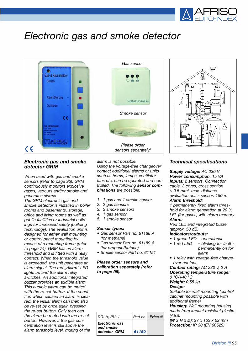
Division III 95
Electronic gas and smoke detector
DG: H; PU: 1 Part no. Price €
Electronic gasand smokedetector GRM 61150
Electronic gas and smoke detector GRM
When used with gas and smokesensors (refer to page 96), GRMcontinuously monitors explosivegases, vapours and/or smoke andgenerates alarms.The GRM electronic gas andsmoke detector is installed in boilerrooms and basements, storage,office and living rooms as well aspublic facilities or industrial build-ings for increased safety (buildingtechnology). The evaluation unit isdesigned for either wall mountingor control panel mounting bymeans of a mounting frame (referto page 74). GRM has an alarmthreshold and is fitted with a relaycontact. When the threshold valueis exceeded, the unit generates analarm signal. The red „Alarm“ LEDlights up and the alarm relayswitches. An additional integratedbuzzer provides an audible alarm.This audible alarm can be mutedwith the re-set button. If the condi-tion which caused an alarm is clea-red, the visual alarm can then alsobe re-set by once again pressingthe re-set button. Only then canthe alarm be muted with the re-setbutton. However, if the gas con-centration level is still above thealarm threshold level, muting of the
alarm is not possible.Using the voltage-free changeovercontact additional alarms or unitssuch as horns, lamps, ventilatorfans etc. can be operated and con-trolled. The following sensor com-binations are possible:
1. 1 gas and 1 smoke sensor2. 2 gas sensors3. 2 smoke sensors4. 1 gas sensor5. 1 smoke sensor
Sensor types:• Gas sensor Part no. 61188 A
(for methane)• Gas sensor Part no. 61189 A
(for propane/butane)• Smoke sensor Part no. 61151
Please order sensors and calibration separately (refer to page 96).
Technical specifications
Supply voltage: AC 230 VPower consumption: 15 VAInputs: 2 sensors, Connectioncable, 3 cores, cross section > 0.5 mm2, max. distance evaluation unit - sensor: 150 mAlarm threshold:1 permanently fixed alarm thres-hold for alarm generation at 20 %LEL (for gases) with alarm memoryAlarm:Red LED and integrated buzzer(approx. 50 dB)Indicators/outputs:• 1 green LED – operational• 1 red LED – blinking for fault -
permanently on for alarm
• 1 relay with voltage-free change-over contact
Contact rating: AC 230 V, 2 AOperating temperature range:0 °C/+40 °CWeight: 0.55 kgDesign:Suitable for wall mounting (controlcabinet mounting possible withadditional frame)Housing: Wall mounting housingmade from impact resistant plastic(ABS)(W x H x D): 97 x 163 x 62 mmProtection: IP 30 (EN 60529)
Smoke sensor
Gas sensor
Please order sensors separately!

96 Division III
Gas and smoke sensors for GRM electronic gas and smoke detectors
Gas sensor
Semiconductor gas sensor in plastic housing for connection toelectronic gas and smoke detectorGRM (refer to page 95). To be usedin dry rooms (e.g. heating installa-tions). Detectable gases: methane, butane, propane. LEDs indicate theoperating and alarm state of thesystem also at the sensor:• LED green – operational• LED yellow – fault• LED red – gas alarmThe sensors must be calibrated forthe relevant gas. Please specify thegas to be monitored when order-ing.
Technical specifications
Measured gasesInflammable gases and vapours inambient airMeasuring range0 to 50 % LELMeasuring principleSemiconductor (service life approx.5 years, depending on operatingconditions)Operating temperature range0 °C/+40 °CHumidityMax. 75 % relative humidityHousingWall mounting plastic housingDimensions (W x H x D): 80 x 80 x 35 mmWeight: approx. 100 g
Part no. PU DG Price €
Gas sensor for methane 61188A 1 H
Gas sensor for propane, butane 61189A 1 H
Calibration costs for gas sensor 61177 1 ---
Smoke sensor 61151 1 H
Smoke sensor
Photoelectronic smoke sensor inplastic housing for connection toelectronic gas and smoke detectorGRM (refer to page 95). To be usedprimarily in domestic dwellings(such as living rooms, bedrooms,halls, staircases, corridors). Theoperating and alarm state is indica-ted both at the alarm device (GRM)and at the smoke sensor:• Visual indication via LED
green/red at GRM and LED red/red at the smoke sensor.
• Audible alarm via internal piezo-electric buzzer in alarm unit GRMand at the smoke sensor.
Calibration costs for gassensor
Prior to shipment, the gas sensorslisted above are calibrated to thegas specified by the customer.Therefore, please always indicatethe gas type when ordering.
Please order sensors and cali-bration separately.
Technical specifications
SensorPhotoelectronic
Measuring principleScattered light principle
Supply voltageDC 12-28 V
Audible alarm85 dBA (at a distance of 3 m)
Test buttonFor sensitivity, audible alarm
Operating temperature range+5 °C/+39 °C
HumidityMax. 80 % relative humidity
HousingWall mounting plastic housing
Outside dimensionsØ 155 mm, height 38 mm
Electrical connectionsScrew terminal strip
Weightapprox. 195 g

Division III 97
Gas alarms systems series GW-Sfor industrial and domestic applications
GW-SCompact, freely programmable gasalarm system with wall mounted hous-ing for the connection of 1 or 2 sen-sors. The evaluation unit can monitorvarious types of gases. GW-S can beoperated in single or dual stagemode. Four integrated relays can beassigned as required (one relay isused for general alarm and one relayfor the audible alarm signal (horn). Theother relays are available for controloutputs. The gas alarm station feat-ures a display with alternating indica-tion of different measurement pointsand three operating levels:1. Measurement level: the unitdisplays the measured values, faultsand alarms.2. Parameter level: this level displaysmeasuring ranges, limit values andalarm groups.3. Service level: this level allows youto show the limit values, performfunction checks of the relays and editthe parameters (such as alarm groupand limit value settings, etc.).
OperationWhen the GW-S unit is switched on,the „ready“ LED lights up. The systemalternately displays the concentrationspresent at each measuring point. TheLED of the relevant sensor lights up.When the alarm levels 1 or 2 areexceeded, the relevant alarm LEDlights up. At the same time, the cor-responding alarm relay is activated.When the concentration falls below
alarm level 1, the alarm is cleared.This also applies to alarm 2, providedthe system runs in „non-memorising“mode. Otherwise, alarm 2 remainsactive and can be cleared by meansof the Reset button. The relay for thehorn can also be programmed foreach alarm level. It can be mutedimmediately by means of the Resetbutton or it is automatically deactiva-ted after 2 minutes. Each time a newalarm is triggered, the horn is activa-ted. In addition, an LED indicates thealarm status. In „stop“ mode, thesystem permanently indicates theconcentrations measured at a speci-fic measuring point. The system isself checking and monitors cabledefects, short circuit and power fail-ure. Such faults are indicated by anLED and a relay. In addition, thedisplay shows an „E“. Using a specialcode all system data can be modifiedor re-confirmed.
Special features• 2 sensors can be connected• Limit values can be adjusted as
required for each channel• Simple to service• 1 horn output• 1 fault output• Serial interface (option)• Displays concentrations present at
each measuring point in sequence or permanently displays the con-centration at one specific point
• Alarm test without test gas• Highly versatile and easy to use
due to microprocessor technology• Freely adjustable alarm levels (1-2)• Computer-aided setup• Alarm memory facility (1-2)• Self-monitoring: power failure
(option), cable break, sensor short circuit, computer defect
• Re-set for horn and alarm• LEDs for alarm and sensor faults• Digital display of concentration,
programming data or calibration data• Relay outputs for alarms freely
selectable (max. 2), 1 each for horn and general alarm
Technical specificationsSupply voltage: AC 230 VInputs:Up to two sensors can be connected,all sensor types with 4-20 mA outputAlarm thresholds:Max. 2, adjustable, „memorise“ or„non-memorise“ modeOutputs:4 voltage-free relay contacts, serialinterface (option)Controls:Keypad for alarm and horn reset,edit, menu selection, EnterDisplay elements:LEDs for:• Alarm and error for each measuring
point• „Operational“, horn and indicated
measuring point Digital display for:
• Concentration values, menus ...Operating temperature range:-10 °C/+40 °CPower consumption:Max. 20 VAProtection: IP 54 (EN 60529)Housing: Wall mounting housingDimensions (W x H x D):195 x 160 x 137 mmWeight: 1,300 gSensor types:Series 400, 500, 600, 700 and 800(refer to page 100)
GW-S4Similar to GW-S, but for connectionof up to 4 sensors
DG: H; PU: 1 Part no. Price €
GW-S 61146
GW-S4 61145

98 Division III
Gas alarm systems for 19“ rack mounting/testgas unit
Upon request, we design and buildthe complete gas alarm system for you and service it at regular inter-vals.
Refer to page 100 for sensors.
Test gas unit
For checking gas alarm systemsduring maintenance and repairwork.
GW-SE
Similar to GW-S but designed for19“ rack mounting. Each 19“ rackunit (3HE) accepts 7 plug-in modu-les (=total of 14 measuring points).2 sensors can be connected toeach plug-in module. Each plug-inmodule is equipped with its ownpower supply. Available accesso-ries comprise a back-up 24 Vemergeny power supply module aswell as a module fitted with a keyswitch for servicing purposes.
Part no. PU DG: Price €
GW-SE 19“ plug-in module 61147 1 H
Accessories:
19“ module, 24 V emergency power supply 69107 1 H
19“ module with key switch 69108 1 H
19“ rack unit 3 HE 61172 1 H
Wall mounting housing for 1 rack unit 3 HE 61173 1 H
Wall mounting housing for 2 rack unit 3 HE 61174 1 H
Wiring per 19“ board 61176 1 ---
Calibration costs calibration/programming costs for alarm thresholdfor standard gases (methane, propane/butane, hydrogen) per sensor 61177 1 ---
Calibration costs calibration/programming costs for alarm thresholds per sensor 61183 1 ---
Test gas unit 61100 1 E
MiniFlo valve with flow meterBrass valve and Perspex flow meter with stainless steel float forgas flow regulation from 0.5 to 1.5 l/min 69050 1 E
Test gas methane 20 % LEL, non-recyclable cylinder containing 12 l 69060 1 E
Test gas methane 40 % LEL, non-recyclable cylinder containing 12 l 69061 1 E
Test gas propane 20 % LEL, non-recyclable cylinder containing 12 l 69062 1 E
Test gas propane 40 % LEL, non-recyclable cylinder containing 12 l 69063 1 E
Test gas carbon monoxide (300 ppm), non-recyclable cylinder containing 12 l 69064 1 E
Synthetic air for zero point calibration, non-recyclable cylinder containing 12 l 69065 1 E
Please enquire for other test gases.
Scope of delivery
The unit consists of a plastic casewith inlay, test gas cap and withdra-wal unit (valve with flow meter andtest gas tube). Can accommodateup to 2 test gas cylinders. Test gasis not included. Please order testgas cylinders separately.
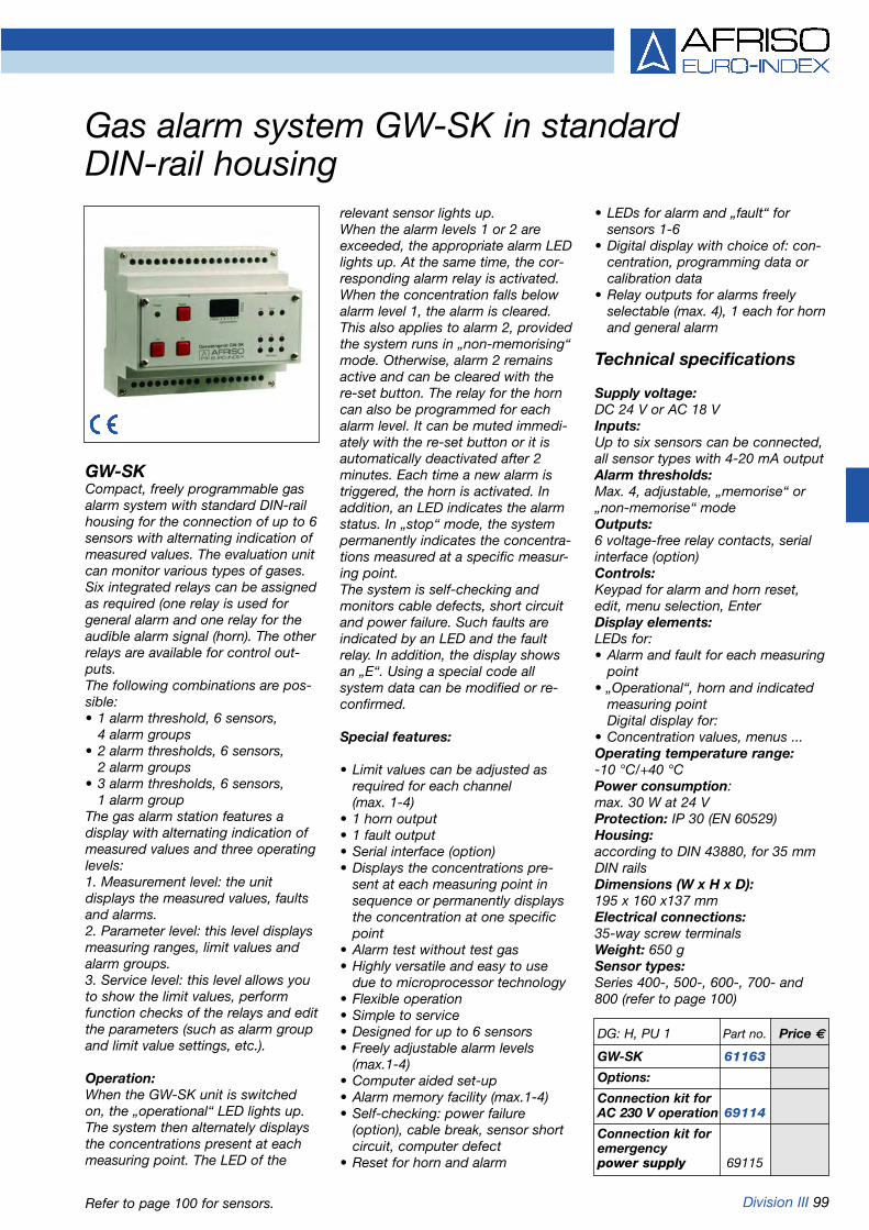
Division III 99
Gas alarm system GW-SK in standard DIN-rail housing
GW-SKCompact, freely programmable gasalarm system with standard DIN-railhousing for the connection of up to 6sensors with alternating indication ofmeasured values. The evaluation unitcan monitor various types of gases.Six integrated relays can be assignedas required (one relay is used forgeneral alarm and one relay for theaudible alarm signal (horn). The otherrelays are available for control out-puts.The following combinations are pos-sible:• 1 alarm threshold, 6 sensors,
4 alarm groups• 2 alarm thresholds, 6 sensors,
2 alarm groups• 3 alarm thresholds, 6 sensors,
1 alarm groupThe gas alarm station features adisplay with alternating indication ofmeasured values and three operatinglevels:1. Measurement level: the unitdisplays the measured values, faultsand alarms.2. Parameter level: this level displaysmeasuring ranges, limit values andalarm groups.3. Service level: this level allows youto show the limit values, performfunction checks of the relays and editthe parameters (such as alarm groupand limit value settings, etc.).
Operation:When the GW-SK unit is switchedon, the „operational“ LED lights up.The system then alternately displaysthe concentrations present at eachmeasuring point. The LED of the
relevant sensor lights up.When the alarm levels 1 or 2 areexceeded, the appropriate alarm LEDlights up. At the same time, the cor-responding alarm relay is activated.When the concentration falls belowalarm level 1, the alarm is cleared.This also applies to alarm 2, providedthe system runs in „non-memorising“mode. Otherwise, alarm 2 remainsactive and can be cleared with there-set button. The relay for the horncan also be programmed for eachalarm level. It can be muted immedi-ately with the re-set button or it isautomatically deactivated after 2minutes. Each time a new alarm istriggered, the horn is activated. Inaddition, an LED indicates the alarmstatus. In „stop“ mode, the systempermanently indicates the concentra-tions measured at a specific measur-ing point.The system is self-checking andmonitors cable defects, short circuitand power failure. Such faults areindicated by an LED and the faultrelay. In addition, the display showsan „E“. Using a special code allsystem data can be modified or re-confirmed.
Special features:
• Limit values can be adjusted as required for each channel (max. 1-4)
• 1 horn output• 1 fault output• Serial interface (option)• Displays the concentrations pre-
sent at each measuring point in sequence or permanently displays the concentration at one specific point
• Alarm test without test gas• Highly versatile and easy to use
due to microprocessor technology• Flexible operation• Simple to service• Designed for up to 6 sensors• Freely adjustable alarm levels
(max.1-4)• Computer aided set-up• Alarm memory facility (max.1-4)• Self-checking: power failure
(option), cable break, sensor short circuit, computer defect
• Reset for horn and alarm
• LEDs for alarm and „fault“ for sensors 1-6
• Digital display with choice of: con-centration, programming data or calibration data
• Relay outputs for alarms freely selectable (max. 4), 1 each for hornand general alarm
Technical specifications
Supply voltage:DC 24 V or AC 18 VInputs:Up to six sensors can be connected,all sensor types with 4-20 mA outputAlarm thresholds:Max. 4, adjustable, „memorise“ or„non-memorise“ modeOutputs:6 voltage-free relay contacts, serialinterface (option)Controls:Keypad for alarm and horn reset,edit, menu selection, EnterDisplay elements:LEDs for:• Alarm and fault for each measuring
point• „Operational“, horn and indicated
measuring pointDigital display for:
• Concentration values, menus ...Operating temperature range:-10 °C/+40 °CPower consumption:max. 30 W at 24 VProtection: IP 30 (EN 60529)Housing:according to DIN 43880, for 35 mmDIN railsDimensions (W x H x D):195 x 160 x137 mmElectrical connections:35-way screw terminalsWeight: 650 gSensor types:Series 400-, 500-, 600-, 700- and800 (refer to page 100)
DG: H, PU 1 Part no. Price €
GW-SK 61163
Options:
Connection kit forAC 230 V operation 69114
Connection kit foremergencypower supply 69115
Refer to page 100 for sensors.

100 Division III
Gas sensors series 400, 500, 600, 700, 800
Part no. PU DG: Price €Gas sensor 400 ST for detectingexplosive gases and vapours, semiconductor 69145 1 HGas sensor 400 ST onfor special gases, semiconductor 69145S 1 H requestGas sensor 500 ST for detectingexplosive gases and vapours, heat tone principle 69109 1 HGas sensor 500 ST onfor special gases, heat tone principle 69109S 1 H requestGas sensor 510 Ex with digital display for explosivegases and vapours, heat tone principle, Ex version 69111 1 HGas sensor 510 Ex with digital display for special ongases, heat tone principle 69111S 1 H requestGas sensor 600 ST-O2 for detecting oxygen concentrations(0-21 % by volume O2), electrochemical 61179 1 HGas sensor 600 ST-CO for detectingcarbon monoxide concentrations (0-300 ppm CO), electrochemical 61180 1 HGas sensor 700 ST-CO2 for detectingcarbon dioxide concentrations, infrared (0-5 % by volume) 69112 1 H Gas sensor 700 ST-CO2 LGapplication area: e.g. monitoring the air quality in low energy houses 69104 1 HGas sensor 800 ST-O2 for detectingoxygen concentrations (0.1-25 % by volume), zirconium dioxide 69113 1 HCalibration calibration/programming costs for the alarm thresholdsfor standard gases (methane, propane/butane, hydrogen) per sensor 61177 1 ---Calibration calibration/programming costs for thealarm thresholds for special gases per sensor 61183 1 ---
Gas sensors series 400,500, 600, 700 and 800Series 400 (semiconductor), 500 (heattone), 600 (electrochemical), 700 (infrared)and 800 (zirconium dioxide) for connectionto gas alarm systems (evaluation units)types GW-S, GW-SE, GW-S4 and GWSK.The gas sensors are connected to thecorresponding units. The sensors are suit-able for dusty and dirty environments.Depending on the version (measuringprinciple), they are used to detect inflam-mable and explosive or toxic gases. Allsensors of this series feature a 4-20 mAoutput signal. The gases and vapourswhich can be detected comprise: methane, propane, butane, hydrogen, ace-tylene, ammonia, acetone, alcohol andfuel vapours, CO, CO2, O2, etc. Pleaseenquire for calibration for other gases.
Measuring principle:Gas sensor 400ST semiconductorGas sensor 500ST/510 Ex heat toneGas sensor 600ST-O2 electrochemicalGas sensor 700ST-CO2 infraredGas sensor 800ST-O2 zirconium di-
oxide basisSupply voltage: DC 18-28 VAmbient temperature:Sensor 400/600/700: -10 °C/+40 °CSensor 500: -20 °C/+40 °CSensor 800: -10 °C/+50 °CPermissible relative humidity:Sensor 400: 40 % to 50 %Sensors 500/600/700/800: 15 % to 95 %Atmospheric pressure:Sensors 500/600/700/800: 900 to 1100hPaSensor 510 Ex: 700 to 1300hPaProtection: IP 40/54 (510 Ex)Housing/wall mounting: AluminiumDimensions: 400/500/600/700/800: 90 x 85 x 65mm (510 Ex) octagonal, H=108 mm, Ø=100 mmWeight: 400/500/600/700/800 approx. 0.4 kg510 Ex approx. 1.2 kgOutput: 4-20 mA, RS 232 (option)Connection cable: 3 x 1.5 mm2 Cu + protective conductor; screened cable; signal and return conductor max. 100 Ohm cable resistance.Approval: Sensor 510 ExEC design type approval by DeutscheMontan Technologie GmbH, according todirective 94/9/EG (ATEX100a) with the following certificate:BVS 03 ATEX E 260 XEx II 2G EEx d IIC T6
Technical specificationsMeasured gases:• Toxic gases (in ambient air)• Inflammable gases and vapours• Oxygen• Special gases (on request!)
Measuring ranges:Gas sensor 400ST 0 up to 50 % LELGas sensor 500ST/510 Ex0 up to 99 % LELGas sensor 600ST-O20 up to 21 % by vol.Gas sensor 700ST-CO20 up to 5 % by vol.Gas sensor 700ST-CO2LG0 up to 3000 ppmGas sensor 800ST-O20.1 to 21 % by vol.
Gas sensor 700 ST-CO2 LG
New development formonitoring air quality
Refer to page 459 for portable gas detectors

www.afriso.de 101
Chapter 6 Table of contents chapter 6
Accessories for fuel oil tanks and oil carrying pipes and hoses
06
Page
Equipment for a double skinned underground tank (overview) 102
Tank fittings, overpressure devices 103
Tank withdrawal systems (Euroflex, Miniflex) 104-105
Anti-siphon valves (MAV) 106-107
Mounting accessories, pull cord, screw connectors 108
Fuel oil filters 109-111
Automatic fuel oil de-aerators (Flow-Control, FloCo-TOP) 112-115
Fuel oil meters 116

102 Division I
Equipment for a double-skinned underground tank (overview)
11 Dip tube cap12 Contents gauge13 Condensate trap14 Leak detector15 LAG/LAZ mounting kit16 Liquid barrier
7 Vent cap8 Level sensor9 Combination fitting Euroflex,
plastic, acts as an isolating unit
10 Filler cap
1 Manhole cover2 Gasket3 Blind plugs4 Fill pipe5 Dip pipe6 Dipstick
Leak detection with vacuum
Leak detection with leak monitoring liquid
12

Division I 103
Tank fittings, overpressure devices
GWG filler cap - greenFor low sulphur fuel oil EL (greencolour code). Bayonet connectionG2 according to DIN EN 14420-6with integrated level sensor connection fitting. Brass malecoupling. Filler cap made from oil-and weather-resistant plastic.Lockable. Red plate („Also for fueloil EL standard“) is included. (Referto page 55)
Overpressure devicePrevents overpressurisation of stor-age tanks during filling. G11/2 male threaded connection. Opens torelease pressure at approx. 25mbar. Two or more overpressuredevices must be installed for fillingrates of more than 300 l/min.
DG: G PU Part no. Price €
Dip tube cap G1 x 11/4 25 20464
Filler cap G2 x 21/2Heavy duty version, fuel oil EL standard 55 20445
Filler cap — green G2 x 21/2Heavy duty version, fuel oil EL low sulphur 25 20452
Vent caps
Vent cap G2 plastic, push-on 25 20460
Vent cap G11/2 plastic, push-on 25 20450
Vent cap G2 plastic - male thread 25 20462
Vent cap G2 metal 25 20463
Vent cap G11/2 metal 25 20455
GWG filler capFor fuel oil EL standard, diesel andbio-diesel. Bayonet connection G2according to DIN EN 14420-6 withintegrated level sensor connectionfitting. Male coupling made frombrass. Filler cap made from oil- andweather resistant plastic. Lockable.
Filler capSimilar to GWG filler cap, butwithout the level sensor plug. DG: G PU Part no. Price €
GWG filler cap 10 20430
GWG filler cap - green 10 20443
Filler cap 10 20440
Overpressure device 25 20466
Also forfuel oil ELstandard

104 Division I
Tank withdrawal systems
Quick acting shut-offvalve
Flex. suction tube2.15 m (3.15 m)
Flex. capillary
Balance chamber(suction tube)
Balance chamber(capillary)
Connections:Suction tubeCapillary tubeG1Return pipe
Conversion kit for Euroflex: • shut-off valve for con-
version to an inherently secure suction pipe + 2 x adhesive labels.
Conditions for inherently secure suction pipesaccording to TRbF 231 (2/5-3)• Suction pipe with constant gradient to tank.• If a leak occurs, oil flows back into the tank
due to a break in the liquid column).• No non-return valve between Flow-Control
and suction point (remove foot valve).
Euroflex with conversion kit
Euroflex withfloat part no.20 130
DIN 4755recommendsfloating withdrawal(4.3.3.6.1)
According to TRbF 231 (No. 2/5-3), non-returnvalves must not be installed in inherently secu-re suction pipes. The conversion kit replacesthe non-return shut-off valve in the Euroflexwith a normal shut-off valve. The suction pipesof tanks installed at lower levels are oftenrequired to be inherently secure suction pipes.Non-return valves and foot valves must beremoved so that the oil can flow back into thetank in case of leaks. The burner cuts out andthe leakage is detected. Euroflex can be con-verted.
Euroflex
Euroflex 312 Miniflex
Euroflex 3 (2.15)Combination fitting as a withdrawalsystem for fuel oil, with capillaryand TÜV-tested isolating piece. G1tank connection. Throughput up to150 l/h. Threaded female connec-tion G3/8 (galvanised steel) for suc-tion and return pipes. Universalscrew connections for pipes with8/10/12 mm outside diameter.Capillary connection for hose or pipewith 6 mm outside diameter. Silentnon-return valve with elastic valveseat. Quick acting shut-off valve withlever arm for remote activation (referto page 108 for pull cord). Pressure-and vacuum-tight up to 1 bar. Type approval 01/BAM/3.10/185.TÜV report no.: S S218 2005 Z1
DG: G PU Part no. Price €
Euroflex 3 (2.15) hose 2.15 m 25 20160Euroflex 3 (3.15) hose 3.15 m 25 20164Euroflex 2 (2.15) without capillary 25 20162Conversion kit Float-Set G1 for Euroflex and Miniflex. 10 20125Conversion kit Float-Set G11/2 for communicating withdrawal systems. 10 20120Euroflex 3 with float, similar to Euroflex 3 (2.15), but suction hose end with float.Oil withdrawal always in „clean“ area. 10 20130Conversion kit shut-off valve for Euroflex (since 10/98), Miniflex andAFRISO withdrawal systems for battery tanks. 1 74305Euroflex 312 (GWG 12K/1C) similar to Euroflex 3, but with integrated level sensor forbattery tanks according to DIN 6620 and tanks assembled on site according to DIN 6625.Always useful if a female connector is not available at the tank. Connection G11/2. 5 20190Miniflex 3 Brass withdrawal system similar to 3, but with brass screw connection(i.e. cannot be used as an isolating piece). 25 74300Miniflex 2 Brass similar to Miniflex 3, but without connection for capillary tube. 25 74200
Withdrawel system without non-return shut-off valve used asinherently secure suction pipe,according to TRbF 231 (No. 2/5-3).

Division I 105
Euroflex with integrated tank heating, oil pipe heater
Euroflex TH 5 m heater bandEuroflex combination withdrawalsystem with integrated, temperatu-re controlled heater band (5 m) fortank heating. Designed for tankswhich are subjected to temperaturesbelow +5 °C (cloud point!). A heaterband is attached to the suctionpipe. At the bottom of the tank theband forms a spiral around the suc-tion point. The heat output is 25 Wper meter at a temperature of 10 °C.The required length depends on the tank type and size as well as theinstallation site. The temperaturecontrolled heater band preventsoverheating and burning out. Theband is connected to AC 230 V viaa connection cable (2 m) and anRCB safety switch (according toDIN VDE 0664 part 3, EN 61005).Using a special G1 female x G1male connection, the fitting can beadapted to the tank without twisting.
Pressure compensationunit DAEUsed to limit the pressure increa-ses resulting from liquid expansioncaused by temperature changes inclosed pipe sections. Suitable forheating oil pipe sections which areclosed at both ends (e.g. by sole-noid or non-return valves) andwhich are subject to considerabletemperature changes (e.g. due tooil pipe heaters). G3/8 female con-nections at both ends. A pipe volu-me of 725 cm3 can be buffered at atemperature difference of 40 °C.This corresponds to the followingmax. pipe lengths (depending onthe pipe diameter):
Oil pipe heaterElectrical pipe heater made from self-regulating heater band withconnection cable (2 m) for pipescarrying heating oil. Refer to thetable for standard lengths.Connection to AC 230 V by meansof an RCB safety switch.
RCB safety switchIn safety housing IP 65 with con-nection facility for remote sensor(outdoor or pipe temperature sen-sor).
RCB safety switch TS 5In safety housing IP 65 with inte-grated temperature switch (+5 °C).
Outdoor temperature sensor 5With temperature switch (+5 °C) forconnection to RCB safety switchpart no. 21025.
Pipe temperature sensor 5With temperature switch (+5 °C) forconnection to RCB safety switchpart no. 21025.
DG: G Part no. Price €
Euroflex TH 5 m heater band 21010
Euroflex TH 7.5 m heater band 21011
Euroflex TH 10 m heater band 21012
RCB safety switch 21025
RCB safety switch TS 5 21026
Outdoor temperature sensor 5 21027
Pipe temperature sensor 5 21028
Pressure compensation unit DAE 20800
Oil pipe heater 5 m 21015
Oil pipe heater 7 m 21016
Oil pipe heater 10 m 21017
Oil pipe heater 15 m 21018
Oil pipe heater 25 m 21019
Oil pipe heater 50 m 21020
Pipe diameter Max. pipe(mm) length (m)
Ø 8x1 25.5Ø 10x1 14Ø 12x1 9
Safety switch TS 5
Outdoor temperature sensor 5

106 Division I
Anti-siphon valves
Depending on national and locallegislation or directives, tank instal-lations for heating oil and theirassociated pipes are subject tocertain approvals. The objective isto prevent ground water pollution.
If the maximum oil level in the stor-age tank is higher than the bottomof the suction pipe (see installationexample), oil could be siphoned outfrom the tank if a leak exists oroccurs in the oil line. Therefore, suitable protection devices such assolenoid valves and diaphragmanti-siphon valves must be installed.In Germany and many other count-ries, both types of valves requireapproval by the relevant authorities incharge. It must be ensured that thevacuum at the suction side of theburner pump does not exceed 0.4bar.
Factors to be considered include:
• The maximum suction height at minimum oil level
• The suction pipe length• The viscosity of the oil in the
storage tank at extreme winter temperatures
• Additional pressure losses caused by fittings (such as oil filters, valves, etc.) and pipes
Max
. hei
ght
diff
eren
ce
(det
erm
ined
on
site
)
Anti-siphon valvePressure compensation unit

Division I 107
Anti-siphon valves
MAV-UniversalMAV 3 for oil carrying pipes at aheight difference of no more than 3 metres between the maximum oillevel in the tank and an oil burnerinstalled below that level. MAV-Universal is fully adjustable forheights from 1-3 m. MAV-Universalcan therefore be adapted to localsite conditions in an optimum way. The vacuum at the suction side ofthe oil burner pump is not unne-cessarily increased. Prevents oilfrom escaping in case of leaks inthe suction pipe. MAV-Universalcloses under spring pressure andopens with the vacuum created bythe pump suction. Refer to page108 for screw connections.
Technical Approval of the GermanInstitute for Building Technology:Z-65.50-415
Solenoid valve VakumatVakumat is installed in the suctionpipe between the oil tank and theburner if the burner is locatedbelow the upper edge of the tank.The solenoid valve prevents oil frombeing siphoned out of the tank ifthere is a leak in the suction pipe.The solenoid valve only opens whenthe burner is in operation. When theburner is off, the valve is closed.Vakumat safeguards suction pipeswithout pressure loss at fullthroughput regardless of any heightdifference between highest andlowest suction point levels. Vakumatis TÜV-tested. We recommendinstalling a pressure compensationunit (refer to page 105) between thesolenoid valve and the burner tocompensate for temperature relatedpressure increases in the oil line.
Technical specificationsOperation: Closed when de-energisedPressure: 0 to 1 barMedium: Fuel oilOperating temperature range:-20 °C/+80 °CValve housing: BrassSupply voltage: AC 230 VPower consumption: 18.5 VAProtection: IP 65 (EN 60529)Mounting position:Solenoid uprightConnection: G3/8 or G1/2Kvs value: 1.4 m3/h
DG: G PU Part no. Price €
MAV-Universal 10 20139
Diaphragm anti-siphon valve MAV 1.8 10 20184
Diaphragm anti-siphon valve MAV 3 10 20183
Solenoid valve Vakumat G3/8 10 20143
Solenoid valve Vakumat G1/2 10 20144
Technical specificationsFlow rate: Max. 120 l/hMounting position: HorizontalConnection thread: G3/8 femaleMaterial: BrassWeight: 0.38 kgOperating rangeVacuum: -0.4 barSuction pipe length: Max. 10 mHeight difference: Max. 3 m
Diaphragm anti-siphonvalve MAV 1.8Similar to MAV-Universal, but pre-set to a maximum height differenceof 1.8 m.
Diaphragm anti-siphonvalve MAV 3Similar to MAV-Universal, but pre-set to a maximum height differenceof 3.0 m.

108 Division I
Mounting accessories, pull cord, screw connectors
Reducer 2 x 11/2Reducer G2 x G11/2 made fromgrey plastic (ABS).
Reducer 11/2 x 1Reducer G11/2 x G1 made fromgrey plastic (ABS).
LAG mounting kitMounting kit designed for connec-ting leak detectors to double-skinned storage tanks with liquidfilled interstitial space. The kit con-sists of a test/vent valve with ahose connection and a G1 threa-ded pipe nipple for connection to
PneumofixMounting kit Pneumofix for pneu-matic tank contents gauges. Please refer to page 15 for details.Euroflex 3 is recommended if thetank has no spare socket for agauge capillary connections. AllEuroflex 3 versions have a gaugecapillary connection (refer to page104).
Pull cord, completeThe pull cord is supplied with ahandle and a sealable case for theremote activation of quick-actingvalves. TÜV-tested. Consisting of: • 10 m long pull cord
(steel, plastic-coated)• Handle• 4 eyelet screws for fastening/
deflecting the cord• Sealable case with wire and lead
seal• Dowels and screws
DG: G PU Part no. Price €
Reducer 2 x 11/2 10 20903
Reducer 11/2 x 1 10 20905
Bag of accessories for MAV(screw connection, 2 pieces each, with Cu flat gasket) G3/8 x 6 mm 10 20507
G3/8 x 8 mm 10 20504G3/8 x 10 mm 10 20505G3/8 x 12 mm 10 20506
LAG mounting kit 5 40540
Pneumofix 10 20153
Capillary tube 50 m 1 20158
Hose connector 10 20036
Condensate trap KG 2Universal connections for hose or pipewith 6 mm outside diameter. 5 20320
Pull cord, complete 10 20475
the storage tank. G3/4 hose connec-tion for container for leak monito-ring liquid. EPDM hose 20 x 3 mm,80 cm long (with BAM approval).Hose clips, cable connection fittingfor LAG probe, screws and dowelsfor mounting the LAG container.

Division I 109
Comparing heating oil filtersWhich filter is the best?
Felt sieve Stainless steelsieve
Filter bowl, longProvides for a sediment
space and for all standard, long filter inserts.
Sintered plastic sieve, shortStar shape for
large filter surface.
Sintered plastic sieve, long
Excellent filter effectiveness and long service life.
Tubular sieve 15.3 cm2
under felt rings (schematic
representation)
Paper filtersOptimum ultra-fine filtering. Speciallyfor very small and small burner capacities. Preferably for single lineoperation. Opticlean MC-7 ultra-fine filter Mesh size: 5-20 µmFilter surface: 700 cm2
Opticlean MC-18 ultra-fine filterMesh size: 5-20 µmFilter surface: 1850 cm2
Can be used with long filter bowl.Replacement filter cartridgeExcellent filter effectiveness.Mesh size: 12-30 µmFilter surface: 840 cm2
Can be used with all AFRISO filter types with additional adapter. Also suitable for operation under pressureand temperatures of up to 80 °C.
Opticlean MC-7Optimum filter surface
due to folded paper filter.
Opticlean MC-18Optimum filter
effectiveness and long service life.
Replacement filter cartridgeExcellent filter effectiveness, alsosuitable for operation under pres-
sure.
Sintered plastic sievesExcellent filter effectiveness. For smalland medium burner capacities. Suitablefor single- and dual line operation.Sintered plastic sieve, shortMesh size: 50 µm (colour code: yellow)Filter surface: 115 cm2
Sintered plastic sieve, longMesh size: 35 µm (colour code: white)Filter surface: 200 cm2
Can be used with long filter bowl.Preferably for single line operation.Filter bowl:Extra long filter bowl provides for asediment volume and space for allstandard, long filter inserts.
Vacuum gaugeTo check the degree of filter pollution (for installa-tion in suction pipe). Refer to page 115.
Felt sieveExcellent filter effectiveness. Formedium and large burner capacities.Suitable for single- and dual line operation.Mesh size: 50-75 µm.With additional tubular sieve (filter surface: 15.3 cm2) under the felt rings.Disadvantage: filter fibres may comeloose and get into the burner nozzles.
Stainless steel sieveFilter effectiveness: good. For mediumand large burner capacities. Suitablefor single- and dual line operation.Mesh size: 100 µm, filter surface: 48 cm2.Pollution can be seen. Disadvantage:air may collect in the filter bowl.

110 Division I
Fuel oil filters Optimum/Opticlean
Standard version with 50 µm sintered plastic sieve.
Universal screw connections8+10+12 mm are included withfilters with G3/8 connection
AFRISO fuel oil filters are availablefor single line and dual line systemsas well as single line systems witha return line. The filter housing ismade from brass, the filter bowl oftransparent, impact resistant pla-stic. All filters have a shut-off valvein the supply line. Dual line filtersare equipped with a non-returnvalve in the return line. Single linefilters with return line are equippedwith a vent valve with hose connec-tion. All filters with G3/8 connectionthread are delivered with universalscrew connections for pipes with 8, 10 and 12 mm outside diameter.Replaceable filter inserts from paper,stainless steel, felt or sintered plasticsieves with standard bayonet con-nection are available for all versions.The fuel oil filter Optimum featuresan extra long filter bowl with sedi-ment chamber for dirt particles anda star-shaped filter insert (meshsize 50 µm).
Dual-line filter Optimum Opticlean MC-18 ultra-fine filter Service box Optimum
DG: G PU Part no. Price €
Dual-line filter Optimum 10 20413
Single line filter R Optimum (return) 10 20276
Single line filter V Optimum 10 20284
Dual-line filter 1/2 - Optimum 10 20411
Single line filter V 1/2 - Optimum 10 20285
Sintered plastic sieve Optimum 50 µm yellow 10 20053
Sintered plastic sieve Optimum 35 µm white 10 20049
Service box Optimum 5 20260
Opticlean MC-18Ultra-fine filter 5-20 µm, long 10 20318
Plastic filter bowl Optimum 5 20258
Universal screw connection 8+10+12 mm 25 20409
The Opticlean paper filter with amesh size of 5-20 µm is recom-mended for ultra-fine filtering.Specially for very small burnercapacities.Optimum + Opticlean ensure opti-mum protection of the nozzle and
a long service life. All AFRISO fueloil filters are tested according tothe rules of the German Institutefor Building Technology and mar-ked with the Ü mark.
4 sintered plastic sieves Optimum 50 µm4 long filter bowls4 gaskets
Paper filter with excellent filter quality (5-20 µm) and long service life. Filter surface 1850 cm2.

Division I 111
Fuel oil filters, spare parts for filters
Selection table Part no. Connection Universal screw Filter *Oil throughput l/h PU DG: GTank Burner connection insert at ∆p=100 mbar €
Dual line filter Z 500 Si 20429 2 x 3/8i 2 x 3/8a 2 x 8/10/12 Sint. plastic 200 25Dual-line filter Z 500 F 20428 2 x 3/8i 2 x 3/8a 2 x 8/10/12 Felt 200 25Dual-line filter Z 500 St 20425 2 x 3/8i 2 x 3/8a 2 x 8/10/12 Steel 220 25Single-line filter R 500 Si (return) 20281 1 x 3/8i 2 x 3/8a 1 x 8/10/12 Sint. plastic 210 25Single-line filter R 500 F (return) 20282 1 x 3/8i 2 x 3/8a 1 x 8/10/12 Felt 240 25Single-line filter R 500 St (return) 20283 1 x 3/8i 2 x 3/8a 1 x 8/10/12 Steel 250 25Single-line filter V 500 Si 20292 1 x 3/8i 1 x 3/8a 1 x 8/10/12 Sint. plastic 250 25Single-line filter V 500 F 20293 1 x 3/8i 1 x 3/8a 1 x 8/10/12 Felt 290 25Single-line filter V 500 St 20294 1 x 3/8i 1 x 3/8a 1 x 8/10/12 Steel 320 25Dual line filter Z 1/2-500 Si 20480 2 x 1/2i 2 x 1/2i –– Sint. plastic 310 10Dual-line filter Z 1/2-500 F 20481 2 x 1/2i 2 x 1/2i –– Felt 400 10Dual-line filter Z 1/2-500 St 20482 2 x 1/2i 2 x 1/2i –– Steel 500 10Single-line filter V 1/2-500 Si 20485 1 x 1/2i 1 x 1/2i –– Sint. plastic 390 10Single-line filter V 1/2-500 F 20486 1 x 1/2i 1 x 1/2i –– Felt 470 10Single-line filter V 1/2-500 St 20487 1 x 1/2i 1 x 1/2i –– Steel 560 10
* at filter pollution degree of 50 %
Si = Sintered plastic sieve50-70 µm
F = Felt sieveSt = Steel sieve
Dual line filter Z 500 Si Single line filter R 500 Si with return line
Single line filter V 500 Si with valve
Refer to page 110 for a description of the fuel oil filters.
DG: G PU Part no. Price €
Opticlean MC-7 ultra-fine filter 5-20 µm, short 25 20319Sintered plastic sieve 50 -70 µm yellowin box of 25 pieces 25 20038Sintered plastic sieve 50 -70 µm yellowin box of 100 pieces 100 20045Sintered plastic sieve 35 µm whitein box of 25 pieces 25 20035Sintered plastic sieve 35 µm whitein box of 250 pieces 250 20027Felt sieve in box of 25 pieces 25 20031Felt sieve individually packed in re-sealablebag, in carton of 100 pieces 100 20034Stainless steel sieve 100 µm 25 20032Filter bowl plastic (suction operation) 10 20254Filter bowl bass (pressure operation) 10 20261O ring for filter bowl 10 20422
Opticlean MC-7ultra-fine paperfilter
Plastic filter bowl
Brass filter bowl
With brass union nut
Felt sieve
Sinteredplastic sieve
Steel sieve

112 Division I
Automatic fuel oil de-aerators Flow-ControlTÜV tested
The automatic fuel oil de-aeratorsFlow-Control 3/K-1 and 3/M aredesigned for continuous de-aera-tion in single line systems withreturn pipe connection in oil firedsystems. Application areas: Flow-Control 3/K-1 only for fuel oilEL according to DIN 51603-1.Flow-Control 3/M for fuel oil ELaccording to DIN 51603-1 and diesel according to DIN EN 590 aswell as biodiesel and vegetable oils(rape oil). The devices must not besubjected to undiluted additives,alcohol and acids. The max. per-missible operating temperature ofthe standard versions is 60 °C. Thespecial version of Flow-Control 3/Mcan be used at temperatures of upto 80 °C (please enquire). An oilhose with a ball-shaped sealing for60° cone and a G3/8 union nut issupplied for connection to the fueloil filter. All Flow-Control versionsare TÜV-tested.
Flow-Control 3/K-1Consists of a diecast zinc housingwith female G1/4 connection threadat the tank side and male G3/8connection threads with 60° coneto connect the burner hoses. Thede-aerator hood is made fromtransparent plastic.
Flow-Control 3/K-1 (G1/4)Similar to Flow-Control 3/K-1, butwith female G1/4 connections at theburner side.
Flow-Control 3/MEquipped with two separate floatchambers. The first one consists ofa metal de-aerator hood with anoperating and a de-aerating float.The second one is a transparentplastic safety float chamber. It pre-vents the oil foam from escapingvia the de-aerator opening (e.g.during commissioning/filterexchange) and indicates malfunc-tions of the de-aerator valve.Connection thread identical toFlow-Control 3/K-1.Also suitable for pressure operationup to 0.7 bar.
Flow Control 3/M is recommendedfor mounting below the max. fueloil level in the tank and for anyapplication requiring particularsafety.
DG: G PU Part no. Price €
Flow-Control 3/K-1 25 69930
Flow-Control3/K-1 (G1/4) 25 69978
Flow-Control 3/M 25 69929
Flow-Control3/M (G1/4) 25 70014
Technical specificationsBurner connection:G3/8 male with 60° cone for burnerhose or G1/4 female (part numbers69978 and 70014)Tank connection: G1/4 female, oroil hose G1/4 male x G3/8 union nutfor connection to the filter.Nozzle capacity: Max. 100 l/hReturn flow: Max. 120 l/hSeparation capacity air/gas:approx. 4 l/hMounting position: Float housingverticalAmbient temp.: Max. 60 °COperating temp.: Max. 60 °C,special version max. 80 °C.Operating overpressure:Max. 0.7 bar (corresponds to staticoil column of approx. 8 m).Test pressure: 6 barDimensions (W x H x D):Flow-Control 3/K-1:95 x 150 x 95 mmFlow-Control 3/M:95 x 200 x 95 mmTÜV-tested (S 159/02)
Flow-Control 3/K-1Safety floatchamber
Flow-Control 3/M
Benefits of Flow-Control:
• Automatic operation eliminates malfunctions.
• The danger of a leak in the return pipe going unnoticed is removed.It is no longer necessary to regularly check the return pipe for leaks.
• The amount of oil drawn from thetank corresponds exactly to the oil burnt. The service life of the fuel oil filter is considerably increased in comparison to dual-line operation.
• The suction pipe can usually have a smaller diameter.
Now with connection nipple for de-aeration hose

Division I 113
Automatic fuel oil de-aerators with integrated filter TÜV tested
FloCo-TOP-K FloCo-TOP-M FloCo-Optimum-K
FloCo-TOP-KAutomatic fuel oil de-aerator, safetyversion with integrated filter andstop valve for use in single-linesystems with return pipe connection. Metal housing. Plastic de-aeratorhood. With additional plastic hoodand safety float which prevents theoil foam from escaping via the de-aerator opening. In addition, it ispossible to detect malfunctions inthe de-aeration system.Connections for suction and returnhoses G3/8 male thread with innerconical section. Connection to tankG3/8 female thread. With short sin-tered plastic insert 50 µm andshort, transparent filter bowl.
DG: G PU Part no. Price €
FloCo-TOP-K 10 69960
FloCo-TOP-M 10 69959
FloCo-Optimum-K 10 69997
FloCo-Optimum-M 10 69957
Spanner foroil filters 25 70060
FloCo-TOP-MSimilar to FloCo-TOP-K, but withmetal de-aerator hood.
FloCo-Optimum-KSimilar to FloCo-TOP-K, but withlong sintered plastic insert 50 µmand long, transparent filter bowl.
FloCo-Optimum-MSimilar to FloCo-TOP-K, but withmetal de-aerator hood and longtransparent filter bowl with longsintered plastic insert 50 µm.
Technical specificationsBurner connection: G3/8 male with60° cone for burner hosesTank connection: G3/8 femaleNozzle capacity: Max. 100 l/hReturn flow: Max. 120 l/hSeparation capacity air/gas: 4l/hMounting position:Float housing verticalAmbient temp.: Max. 60 °COperating temp.: Max. 60 °C (please enquire for higher tempera-tures).Operating overpressure:Max. 0.7 bar (corresponds to staticoil column of approx. 8 m)Test pressure: 6 barDimensions (W x H x D):FloCo-Top-K and -M:165 x 272 x 95 mmFloCo-Optimum-K and -M:165 x 366 x 95 mmApplication areas:As for Flow-Control 3/K and 3/M(refer to page 112)TÜV-tested (S 133 2004 V1)
Oil filter spanner to loosen the union nut of the filterbowl and the exchange system fine fil-ter cartridges (refer to page 114).
Use cylindrical screw connectionswith flat gaskets at the tank end(refer to page 114).
Benefits:
• Fuel oil de-aerator, filter and stop valve in a single, compact unit.
• Safety version with metal hood for universal application.
• Safety version reliably prevents oil foam from escaping.
Now with connection nipple forde-aeration hose
Now with connection nipple forde-aeration hose
Now with connection nipple for de-aeration hose
G3/
8
Ø

114 Division I
Automatic fuel oil de-aerators with integrated filter and vacuum gauge
Our tip:Only installation by expert compa-nies ensures optimum operation ofthe automatic de-aerators as well asoptimum combustion, longer nozzleand filter service life and reliablefunction. The expert determines thefollowing prior to installation andcompares the values with thenomograph (see right):• Oil throughput per hour at
burner nozzle.• Inside diameter of existing
oil suction pipe.• Vacuum (overpressure) in the
oil carrying pipe upstream of the burner.
The oil suction pipe is often toolarge. Therefore, flow speeds of 0.2 - 0.5 m/sec., required accordingto DIN 4755 -T2, are often notobtained in systems converted fromdual line to single line operation.The nomograph on the right showsthe proper values for dimensioningthe suction pipe.
FloCo-TOP-KM FloCo-TOP-KMF FloCo-TOP-MM
FloCo-TOP-KMAutomatic fuel oil de-aerator, similar to FloCo-TOP-K, but withvacuum gauge for indication of thedegree of pollution of the filter. In addition, a possible static pre-pressure of up to 0.7 bar is indica-ted. The stop valve can be closedto check the suction capacity of theburner pump.
DG: G PU Part no. Price €
FloCo-TOP-KM 10 69980
FloCo-TOP-KMF 10 69999
FloCo-TOP-MM 10 70013
Spare filtercartridge 10 70010
Adapter for filterexchange system 10 70020
Spanner forfilter adapter 1 70065
Spare vacuumgauge 1 70030
Screw connectionG3/8 x 6 1 20509
Screw connectionG3/8 x 8 10 20508
Screw connectionG3/8 x 10 10 20510
Screw connectionG3/8 x 12 10 20512
FloCo-TOP-KMFSimilar to FloCo-Top-K, but withwith fine filter cartridge exchangesystem. Especially suited for smallburner capacities due to the largefilter surface (840 cm2) and ultra-fine mesh size (12-30 µm). Thegauge is used to determine whenthe filter needs to be replaced.
FloCo-TOP-MMSimilar to FloCo-TOP-M, but withvacuum gauge for indication of thedegree of pollution of the filter andchecking the suction capacity ofthe burner pump.
Adapter for filter exchangesystemThis unit can be fitted to all AFRISOfilter types and can then be opera-ted both in pressure and suctionmode.
Use cylindrical screw connectionswith flat gaskets at the tank end.G
3/8
SpannerFor easy and quick use with the filter exchange adapter.
Span
ner 6
9
With brass filterbowl also for operation underpressure up to 0.7 bar.
Ø
Nomograph for determining the internal pipe diameter(NW) of the heating oil suction pipe in order to preventgas from accumulating in higher pipe sections and sec-tions with downward gradients, or gas formation resultingfrom high flow speeds.
Noz
zle
cons
ump
tion
l/h
Internal diameterof the suction pipe
in mm
Flow speed ofthe heating oil
in m/s
Diam. smaller than 4 not recom-mended
Recommendedrange accordingto DIN 4755-T2
Example: A pipe with a diameter of 8 x 1 mm (NW6) isrequired for a volume of 20 l/h and an average flow rate ofapprox. 0.23 m/s.

Division I 115
Automatic fuel oil de-aerators with inte-grated Opticlean filter and vacuum gauge
FloCo-TOP-KM-OpticleanAutomatic fuel oil de-aerator, safetyversion with integrated Opticleanultra-fine filter element MC-7 andvacuum gauge to indicate the filtercondition.
FloCo-Opticlean-KMAutomatic fuel oil de-aerator, safetyversion with integrated Opticleanultra-fine filter element MC-18 andvacuum gauge to indicate the filtercondition.
Vacuum gaugeFor indication of the filter condition.Available for direct mounting tostandard fuel oil filters. G3/8 unionnut at filter end, G3/8 male threadwith 60° conical fitting at burnerend for burner hose. Or with G3/8female thread x G3/8 male threadfor mounting to filter with G3/8female thread at tank end.
DG: G PU Part no. Price €
Opticlean MC-7 ultra-fine filters 5-20 µm, short 25 20319Opticlean MC-18 ultra-fine filters 5-20 µm, long 10 20318
FloCo-TOP-KM-Opticlean 10 70005
FloCo-Opticlean-KM 10 70008
Pressure gauge G3/8 with 60° conical 10 20400
Pressure gauge G3/8 IG / G3/8 AG 10 20404
Hand-held suction pump for fuel oil 10 70050
Connecting hose for Hand-held suction pump 10 70055
Opticlean MC-7
Opticlean MC-18
Opticlean ultra-fine filtersOver the years, oil heating facilitieshave become genuine high-techsystems. The quality of fuel oil ELhas been adapted to the require-ments of state-of-the-art heatingtechnology. Condensing oil heatingsystems are becoming a genuinealternative to natural gas. Lowenergy houses and renovated pre-mises with optimum heat insulationrequire burners with minimum oilthroughput. This requires a new fil-ter technology. For this purpose,the Opticlean ultra-fine oil filterswere developed. They fit into anystandard fuel oil filter and ensuremaximum effectiveness due to asurface up to 37 times the size ofconventional filter inserts. For thefirst time, filter ratings of nominal 5µm and absolute 20 µm are possi-ble. Even smallest drops of waterand emulsion are retained withhigh reliability. The new environ-mentally friendly OpticleanTM filtercartridges are free from metal andcan therefore be recycled.
Filter systems which guarantee a high filter rating of 5 µm shouldbe operated in single line systemsfor optimum service life.Therefore, an additional oil de-aerator should be installed if itdoes not already exist.
Hand-held suction pumpfor fuel oilFor commissioning and problemsolving in the suction pipe system.With non-return valve/vent valve.

116 Division I
Fuel oil meters
Fuel oil meter HZ 3For oil fired stoves operated eitherin suction or pressure mode. Themeter increases the counter by onelitre after each rotation of the poin-ter (= 1 litre). The oil meter HZ 3 iscalibrated and displays consump-tion accurately to ±1 %. Very quietoperation. Suitable for fuel oil ELand diesel oil.
Technical specificationsMetering range:0.1 - 99999 litresVolume flow, calibrated:0.18 - 12 l/hNominal pressure: 6 barOperating temperature range:Max. 60 °CConnection thread:2 x G1/4 female threadsMounting: VerticalDimensions W x H x D:130 x 110 x 110 mm
PTB approval 5.223/92.02
Fuel oil meter HZ 5For mounting between the pumpand the solenoid valve directly atthe burner. HZ 5 is suitable for usein suction and pressure systems. If used for suction operation, a filtermust be installed upstream of thefuel oil meter. Litre indication viathe roll counter is accurate to ±1%.For pumps with integrated solenoidvalve, please order an additionalsolenoid valve and the appropriateinstallation kit.
Technical specificationsMetering range:0.1 - 99999.9 litresVolume flow:0.7 - 40 l/h = 0.6 - 34 kg/hBurner capacity: 7 - 400 kWNominal pressure: 25 barOperating temperature range:Max. 60 °CConnection thread:2 x G1/8 female threadMounting:Connections facing downDimensions W x H x D:60 x 85 x 60 mm
DG: H PU Part no. Price €
Fuel oil meter HZ 3 1 20523
Fuel oil meter HZ 5 1 20525
Solenoid valve for oil burners 1 20530
Cable for plug 1 20540
Solenoid valve for oil burnersFor connection downstream of fueloil meter HZ 5 to prevent dripping.2/2 way version, directly controlled.Coil AC 230 V, suitable for 100 %„energised“ operation, for 3-poleAMP plug. Please order cable forplug separately.
Technical specificationsNominal width: DN 1.7 mmNominal pressure: 0 - 25 barOperating temperature range:Ambient: Max. 40 °CConnection thread:2 x G1/8Dimensions W x H x D: 50 x 56 x 27 mmProtection: IP 65 (EN 60529)
Cable for plugOil resistant cable with AMP plugfor solenoid valve, 3 poles.Length: 350 mm

www.afriso.de 117
Chapter 7 Table of contents chapter 7
Accessories for boilers, boiler rooms and chimneys
07
Page
AFRISO products in a heating system with oil burner 118and solar collector (overview)
Motorised boiler room vent (Air-Control) controlled by burner 119
Draft stabiliser (WZB-1) 120
Boiler water low level alarms - mechanical (WMS-WP6) 121
Boiler water low level alarms – electronic (WMS 2/WMS 3) 122
Thermal safety valve, combustion controller 123
Boiler safety equipment groups, safety valves 124
Connection assembly for expansion vessel, anti-tamper valves 125
Pump connection kit, pump ball valves 126
Solar pump kits 127
Overflow valve, ball valves, pump ball valves 128
Flow filter/air flow filter 129
Filling devices for sealed heating systems, boiler feed and drain cocks, 130mulitiway union
Air vents, solar vents, air separators 131
Distribution manifolds for underfloor heating, thermal actuators 132

118 Division I
AFRISO products in a heating system with oilburner and solar collector
In the oil storage room1 GWG filler cap2 Level sensor3 Vent cap4 Withdrawal system
Outside of the oil storage or boilerrooms5 Event reporting system
„Phone Alarm“6 Pneumatic tank contents gauge
with remote indication „Unitel“7 Pull cord8 Oil/water alarm unit ÖWWG 39 Electronic gas and smoke detector
GRM
In the boiler room10 Motorised boiler room vent
„Air-Control“11 Anti-siphon valve MAV12 Automatic fuel oil de-aerator
FloCo-TOP KMF13 Boiler safety equipment group
KSG14 Connection assembly for
expansion vessel GAK15 Boiler water low level alarm
WMS-WP616 Boiler connection system17 Overflow valve18 Draft stabiliser WZB-119 Flue gas thermometer20 Flow filter27 Air separator28 Boiler safety group29 Oil drip pan
In the living area24 Distribution manifold for
underfloor heating and radiators
25 Room thermostat26 Programmable
thermostat
Solar21 Solar controller22 Solar vent23 Solar pump kit with
safety group
14
15
10
12
11
16
18
17
19
20
13
98765
4
3
2
21
22
23
25
24
26
29
28
27
1

Division I 119
Motorised boiler room vent Air-Control
Air-Control savesheating costs, isreliable and silent.
Air-ControlMotorised boiler room vent control-led by the burner, for use in boilerrooms with oil or gas fired burnerswith a capacity up to 50 kW.Suitable for installation in basementwindows or ventilation ducts.Robust, high-impact plastic hou-sing with injection moulded moun-ting flange, a counter-flange with aprotective grille and a gearedmotor for actuating the slide.Electrical connection AC 230 V.Can also be operated manually.Function indication. Boiler roomswhich are equipped with oil or gasburners must be supplied with asufficient amount of oxygen (inaccordance with FeuVo). This isoften achieved by constantly openboiler room window or by air ducts.The cold air which constantly flowsinto the boiler room causes theboiler and the water supply as wellas all pipes to cool down. As aresult, the burner is switched onmore frequently and consumesunnecessarily high amounts of oilor gas.
The boiler room window pane (orpart of it) is removed and replacedwith an acrylic panel with pre-cutopenings for Air-Control. This panelmeasures 500 x 500 mm and hasto be cut to size along two sidesand then fitted into the frame. Air-Control is then mounted onto thispanel and electrically connected tothe boiler thermostat. Air-Controlcan also be mounted onto airducts. Please observe DVGW-TRGI86/96 and all other pertinent regu-lations when doing so. The windowis now closed and the warmth insi-de is retained. As soon as the boi-ler temperature drops, the boilerthermostat switches on Air-Control.Opening the vent activates amicroswitch which closes the bur-ner circuit. The burner starts tooperate only when Air-Control isopen. The burner is supplied withpre-warmed room air in the ignitionphase. The air supply damperremains open during the entirecombustion process and providesthe boiler room with enough freshair (according to FeuVo) throughthe 150 cm3 opening.
The burner switches off when thepre-set temperature is reached.Air-Control closes automatically.
Technical specificationsDimensions:W x H x D: 260 x 300 x 115 mmInstallation opening: 210 x 160 mmCross section of fresh air supply:150 cm2
Supply voltage: AC 230 VContact rating: AC 250 V, 2 AProtection: IP 20 (EN 60529)Burner capacity: max. 50 kWFor larger installations several Air-Control units can be installed.Weight: 1.0 kg
Acrylic window panelThe acrylic panel allows for the cost-efficient installation of Air-Control.The openings are exactly cut tosize. Dimensions 500 x 500 mm.
DG: G PU Part no. Price€
Air-Control 5 69964
Acrylic 5 69961window panel
DVGW-Reg.-Nr.: DG-4609AO0753
Hood PVC
Terminal block
Screw M5 x 45 mm(4 pieces)
Connectioncable (4 cores)
Protective ABS grille
Window insert plexiglass part no. 69961
Insect screen Stain-less steel mesh
Housing ABS
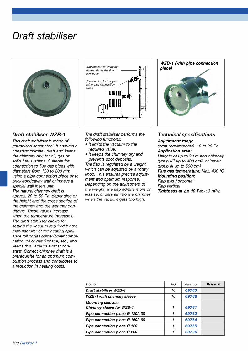
120 Division I
Draft stabiliser
„Connection to chimney“always above the flue connection
„Connection to flue gasusing pipe connectionpiece
Draft stabiliser WZB-1This draft stabiliser is made of galvanised sheet steel. It ensures aconstant chimney draft and keepsthe chimney dry; for oil, gas orsolid fuel systems. Suitable forconnection to flue gas pipes withdiameters from 120 to 200 mmusing a pipe connection piece or tobrickwork/cavity wall chimneys aspecial wall insert unit.The natural chimney draft isapprox. 20 to 50 Pa, depending onthe height and the cross section ofthe chimney and the weather con-ditions. These values increasewhen the temperature increases. The draft stabiliser allows for setting the vacuum required by themanufacturer of the heating appli-ance (oil or gas burner/boiler combi-nation, oil or gas furnace, etc.) andkeeps this vacuum almost con-stant. Correct chimney draft is aprerequisite for an optimum com-bustion process and contributes toa reduction in heating costs.
The draft stabiliser performs thefollowing functions:• It limits the vacuum to the
required value.• It keeps the chimney dry and
prevents soot deposits.The flap is regulated by a weightwhich can be adjusted by a rotaryknob. This ensures precise adjust-ment and optimum response.Depending on the adjustment ofthe weight, the flap admits more orless secondary air into the chimneywhen the vacuum gets too high.
WZB-1 (with pipe connectionpiece)
DG: G PU Part no. Price €
Draft stabiliser WZB-1 10 69760
WZB-1 with chimney sleeve 10 69768
Mounting sleeves:Chimney sleeve for WZB-1 1 69761
Pipe connection piece Ø 120/130 1 69762
Pipe connection piece Ø 150/160 1 69764
Pipe connection piece Ø 180 1 69765
Pipe connection piece Ø 200 1 69766
Technical specificationsAdjustment range(draft requirements): 10 to 26 PaApplication area:Heights of up to 20 m and chimneygroup I/II up to 400 cm2, chimneygroup III up to 500 cm2
Flue gas temperature: Max. 400 °CMounting position:Flap axis horizontalFlap verticalTightness at ∆∆p 10 Pa: < 3 m3/h

Division I 121
Boiler water low level alarms – mechanical
Test button
Cover
358
240
72
2719
5
85
59
Ø 62
Ø 2
6.5
G1
11
Manual re-setbutton
Float
Sludge opening
Housing
Vent screw88Switching
level
83
DG: G PU Part no. Price €
WMS-WP6, brass 15 42300with welding socket DN 20WMS-WP6, o.V. brass 15 42305with welding socket DN 20Upper part WMS-WP6 with manual re-set 1 42310Lower part WMS-WP6 without manual re-set 1 42311Probe body for WMS-WP6 1 42368
Installation example
Sectional drawing Dimensions
Burner
Junctionbox
Manualre-set
Switch
WP 6
Electrical connection
HornAC 230 V
AC 230 VL
N
SL
Blue
Brown
Black
Green-yellowearthconductor
WMS-WP6, brass with welding socket DN 20This mechanical boiler water lowlevel alarm with float for sealedheating systems according to DINEN 12828 consists of a cast brassbody with welding socket and afloat mechanism, an electricalswitch, test and manual re-set but-tons. TÜV-tested as a water levelswitch for a max. operating pressu-re of 10 bar and a max. operatingtemperature of 120 °C. Designedfor heating systems according toDIN EN 12828. If the water level inthe boiler drops below a minimumlevel, a float activates a switchwhich interrupts the power supplyto the burner. A locking mechanismprevents the burner from restartingautomatically. The test buttonallows the float to be lowered tosimulate a low water alarm condi-tion.
Technical specificationsHousing: Cast brassFloat: PlasticHeight: 358 mmWelding socket: DN 20Max. operating temp.: 120 °CMax. operating pressure: 10 barTest pressure: 15 barContact rating:AC 250 V, 10 (3) AProtection: IP 54 (EN 60529)Approval:TÜV.HWB.02-232
WMS-WP6, brass (withoutlocking mechanism)Low water level alarm switch simi-lar to WMS-WP6, but without re-set. For use in systems where aremote control panel re-set facilityis provided.
Boiler water low level alarms protectheat generators in sealed heatingsystems against overheating if a lowwater level occurs or insufficient waterflow is present in the system.According to DIN EN 12828, sealedheating systems with capacities ofmore than 300 kW must be equippedwith a TÜV-tested boiler water lowlevel alarm system.
Wiring diagram
Type designation plate
welding socket

122 Division I
Boiler water low level alarms – electronic
51
268 18
057
148
G1
G1“
Ø45
Ø27
R2DIN 2999
FemalethreadedconnectionG 2
max. 45º
Brass housingwith weldingsocket DN 20
WMS 2-1 WMS 3-1 Probe WMS Frame for panel mounting (refer to
page 74)
WMS 2-1 brass with welding socket DN 20This self-monitoring electronic boilerwater low level alarm with integratedpower failure lock operates on theconductivity principle. Consisting ofcontrol unit with test and re-set but-tons, angled probe with weldingsockets, electrode and electrode testfacility. TÜV-tested and suitable as a boilerwater low level alarm for a max. ope-rating pressure of 10 bar and a max.operating temperature of 120 °C.Designed for use in heating systemsaccording to DIN EN 12828.According to VdTÜV sheet „WaterLevel 100“ of 05.2002.If the water level in the boiler dropsbelow a minimum level, the electrodeis no longer submerged. The electro-nic system de-energises a relay whichswitches off the power supply to theburner and activates the alarm lamp.The electrical locking mechanismprevents the burner from restartingautomatically.
Technical specificationsControl unit:Supply voltage: AC 230 VRelay contact:1 changeover contactContact rating: 230 V, 2 AOperation indicator: Green LEDElectrode voltage: 12 V max.Temperature range: 0/+55 °CDimensions W x H x D:97 x 163 x 62 mmProtection: IP 42 (EN 60529)Approvals:TÜV.HWB.04-345TÜV.HWB.04-348
Probe:Plastic housing: Thermoplast GVElectrode rod: Stainless steel1.4571Probe cable:HO 5 RN-F 2 x 1 mm2, 1.5 m longPressure range: Max. 10 barTemperature range: Max. 120 °CProtection: IP 54 (EN 60529)Probe body: Cast brassWelding sockets: Steel DN 20Space requirements in mm:268 x 140, 200 x 100Screw connection R 2:R2 DIN 2999, steel, galvanised
WMS 3-1Boiler water low level alarm similar toWMS 2-1, but for external power fai-lure locking.
WMS 2-1-2Boiler water low level alarm similar toWMS 2-1, but with probe R 2.
MS 3-1-2Boiler water low level alarm similar toWMS 3-1, but with probe R 2.
Probe (Ms, DN 20) Probe R 2 Installation examples
DG: G PU Part no. Price €
WMS 2-1 brass with welding socket DN 20 5 42351
WMS 3-1, brass with welding socket DN 20 5 42352
WMS 2-1-2 5 42364
WMS 3-1-2 5 42365
Control unit WMS 2-1 1 42356
Control unit WMS 3-1 1 42357
Probe WMS brass with welding socket DN 20 1 42362
Probe WMS R 2 1 42366

Division I 123
Thermal safety valve, combustion controller
DG: G PU Part no. Price €
Thermal safety valve TSK 10 42370
FR 1 combustion controller 10 42294
Thermal safety valve TSKThermal safety valve with two inde-pendent sensor systems for solidfuel heating systems according toDIN EN 12828 with a max. heatingcapacity of 80,000 kcal. Also man-datory for dual fuel boilers whichcan be operated with solid fuels.Consisting of a brass valve housingwith G3/4 female threads at bothends, a valve, two independentbellow type probes with liquid filledtemperature sensors and a G1/2thermowell. Capillary tube - L = 1,300 mm - protected by flexi-ble metal conduit. The unit is con-nected to the water outlet of thewater heater or to the inlet of thesafety heat exchanger. If theresponse temperature of 95 °C isexceeded, the valve is opened bythe thermal probe. Cooling water issupplied to prevent the systemfrom exceeding the maximum ope-rating temperature.
Technical specifications
Operating pressure: Max. 10 barMax. temp. at capillary tube andsensor: 130 °CMax. temp. at bellows: 110 °CResponse temp.: 95 °CBlow-off capacity at 110 °C and∆p of 1 bar: 3,700 kg/hConnections:G2 x G3/4 female threadConnection immersion pipe:R1/2 male threadLength of immersion pipe:200 mm
Length of capillary tube:1,300 mmHousing: Hot pressed brass
FR 1 combustion controller
ApplicationFor temperature dependent adjust-ment of the air supply damper ofsolid fuel and dual fuel boilers.
DescriptionThe FR 1 combustion controllerregulates the combustion air supply. The temperature in the heat generator is detected by anintegrated thermostat.The thermostat is connected to theair supply damper via a lever and achain.Depending on the boiler supplytemperature, the air supply is con-trolled by opening or closing the airsupply damper.
Technical specifications
Control range30 °C/90 °C
Operating temperature rangeWater: Max.120 °CAmbient: Max. 60 °C
ConnectionR3/4
Immersion pipe length60 mm
Chain length1.2 m
Chain load100 to 800 g
Mounting positionHorizontal or vertical
MaterialsAdjustment knob plasticHousing brass, nickel platedImmersion pipe brass, nickel platedLever steel, galvanisedChain steel, galvanised
Please refer to chapter 10 for our complete range of„Temperature measuring instruments and controllers“.
• Thermometers• Thermostats• Safety temperature
switches• Room thermostats
with housing• Digital temperature
controllers
Temperaturetoo low
Temperaturetoo high
Boiler
Chain
Air
Air supply damper
TSK FR 1 Installation possibilities FR 1

124 Division I
Boiler safety equipment groups, safety valves
KSG – 3 bar with insulationPre-assembled boiler safety equip-ment group for sealed heatingsystems according to DIN EN 12828with a capacity of up to 50 kW.Consisting of: Carrier made of solidcast brass with G1 female boilerconnection, approved safety valveG1/2 x 3/4, with PTFE seal ring, forflexible positioning - responsepressure 3 bar, for capacities of upto 50 kW, pressure gauge for hea-ting installations 0-4 bar Ø 63,3/8 bottom connection, with moun-ting valve, air vent G3/8, 12 bar, withmounting valve plus two insulationparts.
KSG mini – 3 bar with insulationSimilar to KSG, but light weightversion and Ø 50 mm pressuregauge.
KSG maxi – 3 bar withoutinsulationPre-assembled boiler safety equip-ment group for heating boilers witha capacity of up to 100 kW. Brasscarrier, designed as multiway union,with G1 male thread boiler connec-tion. Safety valve G3/4 x 1, can berotated, response pressure 3 bar, forcapacities of up to 100 kW. Pressuregauge for heating installations 0-4 bar,diameter Ø 63-3/8 back connection,with mounting valve. Air vent G3/8,12 bar, with mounting valve. Freeconnection G3/4 and G1/2 female thread.
DG: G PU Part no. Price €
KSG – 3 bar with insulation 10 77938
KSG mini – 3 bar with insulation 10 77623
KSG maxi – 3 bar without insulation 10 77625
MS 1/2 – 2.5 bar 10 42385
MS 1/2 – 3.0 bar 10 42390
MS 3/4 – 2.5 bar 10 42386
MS 3/4 – 3.0 bar 10 42391
MS 1 – 2.5 bar 10 42383
MS 1 – 3.0 bar 10 42378
MSM 1/2 – 2.5 bar 10 42381
MSM 1/2 – 3.0 bar 10 42382
Diaphragm safety valve MS brass
KSG KSG mini KSG maxi
Diaphragm safety valve MS brassFor sealed heating systems accor-ding to TRD 721; VdTÜV sheetSafety Valve 100 and 100/4 sheet1; DIN EN 12828. Suitable for waterheating systems according to DIN4751-2 with supply temperatures ofup to 120 °C and DIN 4751-3 withsupply temperatures of up to 95 °C.Opening pressure factory pre-setto 2.5 or 3 bar. Brass housing. Thesize of the valve inlet determinesthe type of unit, the outlet is 1/4“larger.
Diaphragm safety valve MSMSimilar to diaphragm safety valvebrass, but with pressure gauge.
• Time saving installation with pre-assembled, leak tested assembly
• Service friendly – pressure gauge and air vent with self-sealing mounting valves, can be replaced without draining the system
• Safe venting due to top mounted connection for air vent
• Environmentally friendly – packing material is used for insulation purposes
Diaphragm safety valve with pressuregauge MSM

Division I 125
Connection assembly for expansion vessel,anti-tamper valves
Air Vent
Self-sealingmountingvalve G3/8
Vent chamber Sealed with
Teflon ring
Safety valve 3 bar,can be rotated
Pressure gauge forheating installations
Self-sealing mountingvalve G3/8
Anti-tam-per valve,with leadseal
Drain valve
Connection thread G3/4Stu
rdy
mou
ntin
g co
nsol
ew
ith s
crew
s an
d d
owel
s
Screw connection G3/4
Carrier made of solid cast brass
Protrusion 300 mm
• Time saving installation with pre-assembled, leak tested assembly
• Service friendly: pressure gauge, air vent and expansion vessel can be replaced without draining
• Safe venting due to top mountedconnection for air vent
• Environmentally friendly: packing material is used for insulation purposes
Diaphragm expansion vessel with anti-tamper valve according toDIN EN 12828
GAK 3 bar with insulationPre-assembled combination fittingfor the connection of diaphragmexpansion vessels up to 50 l in sea-led heating systems according toDIN EN 12828 with a capacity ofup to 50 kW.
Consisting of: Carrier made of solidcast brass with G3/4 female connec-tion at boiler end, integrated capvalve for connection of the dia-phragm expansion vessel, appro-ved safety valve G1/2 x 3/4 withTeflon sealing ring, can be rotated(response pressure 3 bar, capacity50 kW). Pressure gauge for heating installa-
tions Ø 63- G3/8 bottom connection(range 0-4 bar with red referencepointer) with mounting valve - self-sealing. Air vent G3/8, 12 bar, withmounting valve – self-sealing, plustwo insulation parts.
The insulation is also used topackage the assembly for safetransport.
Anti-tamper valveAnti-tamper valve G3/4 x 3/4 or G1 x 1for diaphragm expansion vessels inheating systems according to DINEN 12828. To be mounted at thewater inlet of the expansion vessel.The cap and lead seal of the anti-tamper valve safeguard against
DG: G, PU 10 Part no. Price €
GAK 3 bar 77932with insulationAnti-tamper valve 779243/4 - 3/4Anti-tamper valve 779341 - 1
inadvertent valve closure.The expansion vessel can be isola-ted from the heating system anddrained via the drain valve for therequired system test function or forreplacement. Nominal pressure PN 10.Max. operating temperature 120 °C.
Anti-tamper valve
G3/4 x 3/4
Anti-tamper valve
G1 x 1

126 Division I
Pump connection kit (without pumps),pump ball valves
PAS 1-G1Pump connection kit DN 20 withpipe connections G1 female thre-ad. Max. operating pressure PN 10,max. operating temperature 110 °C.PAS 1-G1 consists of:1 Pump ball valve G1 female
thread, at pump end with flange and union nut G11/2.
2 Combination valve G1 female thread, at pump end with flange and union nut G11/2. With inte-grated adjustable gravity brake, with free flow setting, with ther-mometer (with red dial marking) in the hand wheel.
3 Combination valve as described above, but without gravity brake. Thermometer with blue marking.
4 Adapter G11/2 male thread to G1 female thread.
5 Three flange gaskets (not shown).
The pump ball valves are fitted withextended operating elements toallow for pipe insulation. All parts aredelivered loose in an AFRISO box.
PAS 2-G1Pump connection kit DN 20 withpipe connections G1 female thread. Max. operating pressurePN 10, max. operating temperature110 °C. PAS 2-G1 consists of:1 Two pump ball valves G1 female
thread, at pump end with flange and union nut G11/2.
2 Pump ball valve G1 female thread, at pump end with flange and union nut G11/2. With inte-grated adjustable gravity brake, with free flow setting.
3 Adapter G11/2 male thread to G1 female thread.
4 Three flange gaskets (not shown).
The pump ball valves are fitted withextended operating elements toallow for pipe insulation. All parts aredelivered loose in an AFRISO box.
Pump ball valvesPump ball valves and combinationvalves with G1 female thread, atpump end with flange and unionnut G11/2. Max. operating pressurePN 10, max. operating temperature110 °C. Choice of long bar handleor hand wheel with integrated ther-mometer, with or without gravitybrake. Union nut and seal are notincluded.
DG: G PU Part no. Price €
PAS 1-G1 1 77630
PAS 2-G1 1 77650
Pump ball valve G1-K (with bar handle) 10 41944
Pump ball valve G1-T(with blue thermometer in hand wheel) 10 41945
Pump ball valve G1-KS(with bar handle and gravity brake) 10 41946
Pump ball valve G1-TS(with red thermometer in hand wheeland gravity brake) 10 41947
2
3
1
4
2
1
3
1
Pump ball valve G1-T
Available with blue or red dial marking.
Pump ball valve G1-K
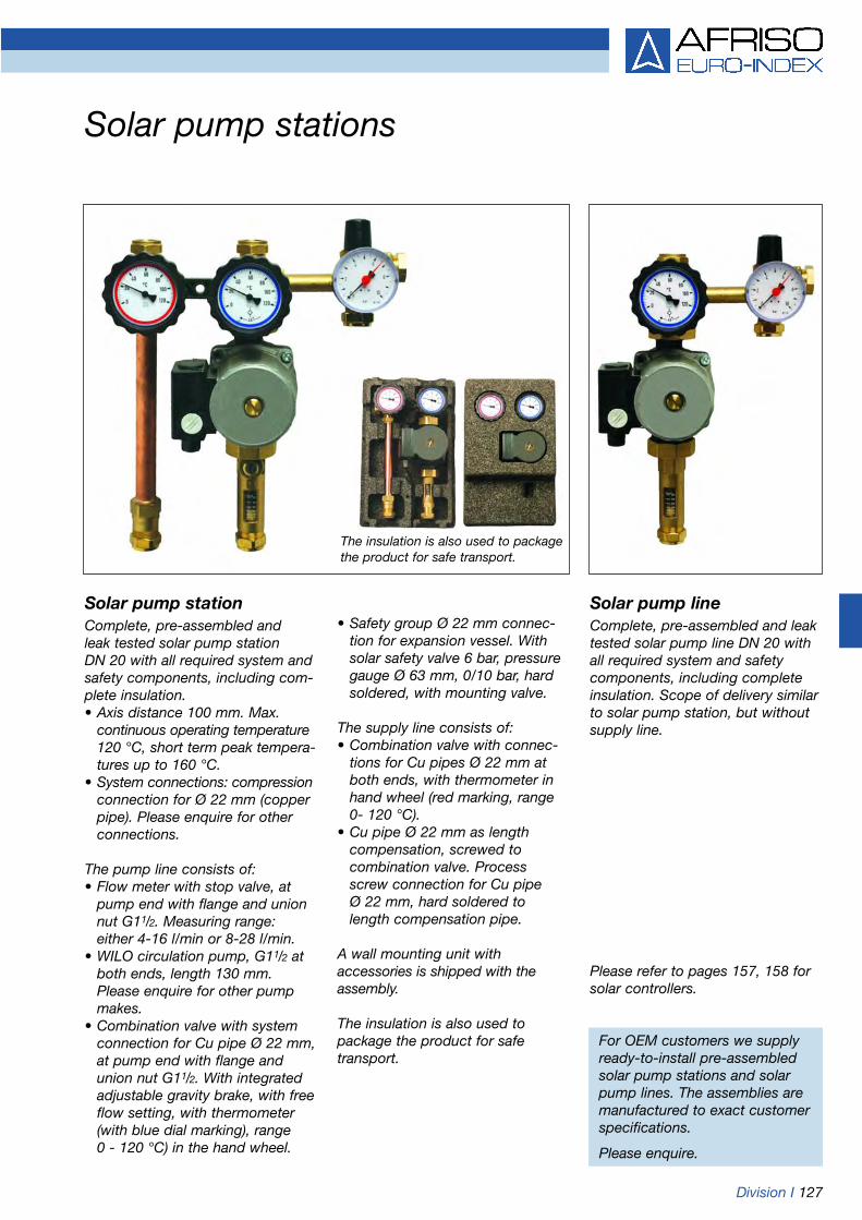
Division I 127
Solar pump stations
Solar pump stationComplete, pre-assembled and leak tested solar pump station DN 20 with all required system andsafety components, including com-plete insulation.• Axis distance 100 mm. Max.
continuous operating temperature120 °C, short term peak tempera-tures up to 160 °C.
• System connections: compressionconnection for Ø 22 mm (copper pipe). Please enquire for other connections.
The pump line consists of:• Flow meter with stop valve, at
pump end with flange and union nut G11/2. Measuring range: either 4-16 l/min or 8-28 l/min.
• WILO circulation pump, G11/2 at both ends, length 130 mm. Please enquire for other pump makes.
• Combination valve with system connection for Cu pipe Ø 22 mm, at pump end with flange and union nut G11/2. With integrated adjustable gravity brake, with free flow setting, with thermometer (with blue dial marking), range 0 - 120 °C) in the hand wheel.
Solar pump lineComplete, pre-assembled and leaktested solar pump line DN 20 withall required system and safetycomponents, including completeinsulation. Scope of delivery similarto solar pump station, but withoutsupply line.
• Safety group Ø 22 mm connec-tion for expansion vessel. With solar safety valve 6 bar, pressure gauge Ø 63 mm, 0/10 bar, hard soldered, with mounting valve.
The supply line consists of:• Combination valve with connec-
tions for Cu pipes Ø 22 mm at both ends, with thermometer in hand wheel (red marking, range 0- 120 °C).
• Cu pipe Ø 22 mm as length compensation, screwed to combination valve. Process screw connection for Cu pipe Ø 22 mm, hard soldered to length compensation pipe.
A wall mounting unit with accessories is shipped with theassembly.
The insulation is also used to package the product for safe transport.
For OEM customers we supplyready-to-install pre-assembledsolar pump stations and solarpump lines. The assemblies aremanufactured to exact customerspecifications.
Please enquire.
Please refer to pages 157, 158 forsolar controllers.
The insulation is also used to packagethe product for safe transport.

128 Division I
Overflow valve, ball valves, pump ball valves
DÜ with screw connectionDifferential pressure overflow valvewith adjustment scale for keeping aconstant pump pressure in sealedheating systems and for suppres-sing flow noise. Housing made ofbrass, angled version. G3/4 female thread inlet connection,outlet end screw connection withunion nut G3/4 and flat seal.
Operating temperature:Max.120 °COperating pressure: Max. 6 barDifferential pressure:Adjustable up to 0.5 bar
Pump ball valve, nickel platedFor heating installations. One endwith female thread, the other endwith flange, without union nut. With or without gravity brake. Operating temperature:Max. 110 °COperating pressure: Max. PN 10
Ball valve MS 58, brass, bare metal surfaceFor drinking water according to E-DIN 3433 (Nov. 1988), DIN-DVGW.Female x female, full ball, full flow,T handle, long.Operating temperature:Max. 110 °COperating pressure: Max. up toPN 10 depending on nominal widthand temperature.
DG: G PU Part no. Price €
DÜ with screw connection 10 42379
Ball valve MS 58, nickel plated
Ball valve G1/2 1 42046
Ball valve G3/4 1 42047
Ball valve G1 1 42048
Ball valve G11/4 1 42049
Ball valve G11/2 1 42050
Ball valve G2 1 42051
Ball valve MS 58, brass, bare metalsurface, for drinking water
Ball valve G1/2 1 42040
Ball valve G3/4 1 42041
Ball valve G1 1 42042
Ball valve G11/4 1 42043
Ball valve G11/2 1 42044
Ball valve G2 1 42045
Pump ball valve G1, without gravity brake,without union nut 10 42037
Pump ball valve G1, with gravity brake,without union nut 10 42036
Pump ball valve G11/4, without gravity brake,without union nut 10 42039
Pump ball valve G11/4, with gravity brake,without union nut 10 42038
Ball valve MS 58, nickel platedFor water (no steam or vapour).Female x female, full ball, full flow, Thandle, long.
Operating temperature:Max. 100 °COperating pressure: Max. up toPN 40 depending on nominal widthand temperature.

Division I 129
ApplicationFlow filters and air flow filters remo-ve lime, rust, sludge, dirt and gasfrom heating systems and ensureclean water and trouble-free opera-tion. Suitable for hot water heatingsystems, underfloor heatingsystems, solar systems (special ver-sions, please enquire), fuel cellsand renovation of system com-ponents (sludge removal). Also suitable for removing lime in the circulation circuit of non-potablewater facilities.
DescriptionMost advanced heating systemsuse water for heat transmission.However, this water also transportsunwanted substances such as lime,calcium, magnesium, oxide, carbo-nates as well as larger particlessuch as welding or soldering resi-due, metal chips and dirt. Thesesubstances may cause malfunctionsin fittings and control units. A compact flow filter (particle separator) was developed to remo-ve these particles from the water.The particles settle in the collectionchamber of the filter and can beflushed out via a cock with smallamounts of water. Clean waterensures trouble-free operation ofsystems and reduces fuel andmaintenance costs.
Clean system components have abetter thermal conduction, theyensure quicker warming up and thus contribute to reduced fuelconsumption and emission.
The combined air/flow filter wasdeveloped for heating systemswhich are subject to problems caused by oxygen or other gases. The de-aeration valve automaticallyremoves the gases.
In the case of non-potable water,the flow filter is installed in the circulation circuit. Lime particlessettle in the flow filter and can beflushed out. This reduces the depo-sits in pipes and fittings. Specialmaterials which are suitable for drin-king water were used for this appli-cation.
Technical specificationsHousingCast brass
Operating pressureMax. 10 bar
Operating temperatureMax. 95 °C
Dimensions (W x H x D):Flow filter: 120 x 194 x 60 mmAir/flow filter: 120 x 394 x 60 mm
ConnectionsFlow filter: Inlet G3/4
Outlet G1Air/flow filter: 2 x G3/4
Scope of deliveryFlow filters and air/flow filters aredelivered with foam insulation.
Flow filter/air flow filter
Benefits• Suitable for open and sealed
systems• Also suitable for the precipitation
of lime in the circulation circuit of non-potable water systems
• Reliable function principle without filter sieve
• Flushing possible during normal system operation
• Easy and cost effective installation
• Cost savings due to fewer malfunctions and longer service life of the installation
• Energy savings due to improved heat transfer with clean system components
DG: G PU Part no. Price €
Flow filter - heating 28 kW 5 78210Flow filter - heating 50 kW 5 78211Air/flow filter - heating 28 kW 5 78212Air/flow filter - heating 50 kW 5 78213Flow filter - non-potable water --- 5 78214

130 Division I
Filling fittings for sealed heating systems, boiler feed and drain cocks, multiway union
6-10 bar 0.5-3 bar
Filling fitting FAFilling fitting FAMFilling fitting for sealed heatingsystems according to DIN EN12828. Housing and spring cap are made from brass. Inlet 1/2“ malehose connection, outlet G1/2 femalethread. With G1/4 connection forpressure gauge for heating installa-tions. With pressure reducer, stopvalve and backflow preventer. Pre-pressure 6 to 10 bar, outletpressure adjustable between 0.5and 3 bar. Type FAM is similar totype FA, but with pressure gaugefor heating installations Ø 50 mm,0/4 bar, G1/4 bottom.
Filling fitting FA
Filling fitting FAM KFE cock Ms, brass, nickel platedKFE cock Ms, brass, baremetal surfaceBoiler feed and drain cock. Ballvalve version made from brass.Connections: G1/2 male thread withPTFE sealing ring and locking nut,and 1/2“ male hose connection withG3/4 union nut and blind cap withchain or strap. Available in plainbrass or nickel plated brass. 144 pieces in cardboard box. KFE cock, heavy duty version. 25 pieces in AFRISO box. Multiway union
Union for the efficient connectionof various pipes and for professio-nal installation of fittings, safetycomponents, indicators or sensors.Sealing of the male threads withTeflon rings and cast outer parts forhexagonal spanners ensure fastinstallation and safe positioning ofthe parts screwed into the union.
Operating pressure: Max. 10 barOperating temperature:Max. 120 °C
Connections:2 x G1/2 female thread1 x G3/4 male thread with PTFEsealing ring1 x G3/4 female thread1 x G1 female thread1 x G1 male thread with PTFE sealing ring
DG: G PU Part no. Price€
Filling fitting 5 42405FA
Filling fitting 5 42406FAM
KFE cock brass, 25 42404bare metalsurface,heavy dutyversionin AFRISO box
KFE cock brass, 144 42401bare metal surface,in cardboard box
KFE cock brass, 144 42407nickel-plated,in cardboard box
Multiway 10 77985union
AngledG3/4 x 3/4 10 77987
Angled G3/4 x 3/4
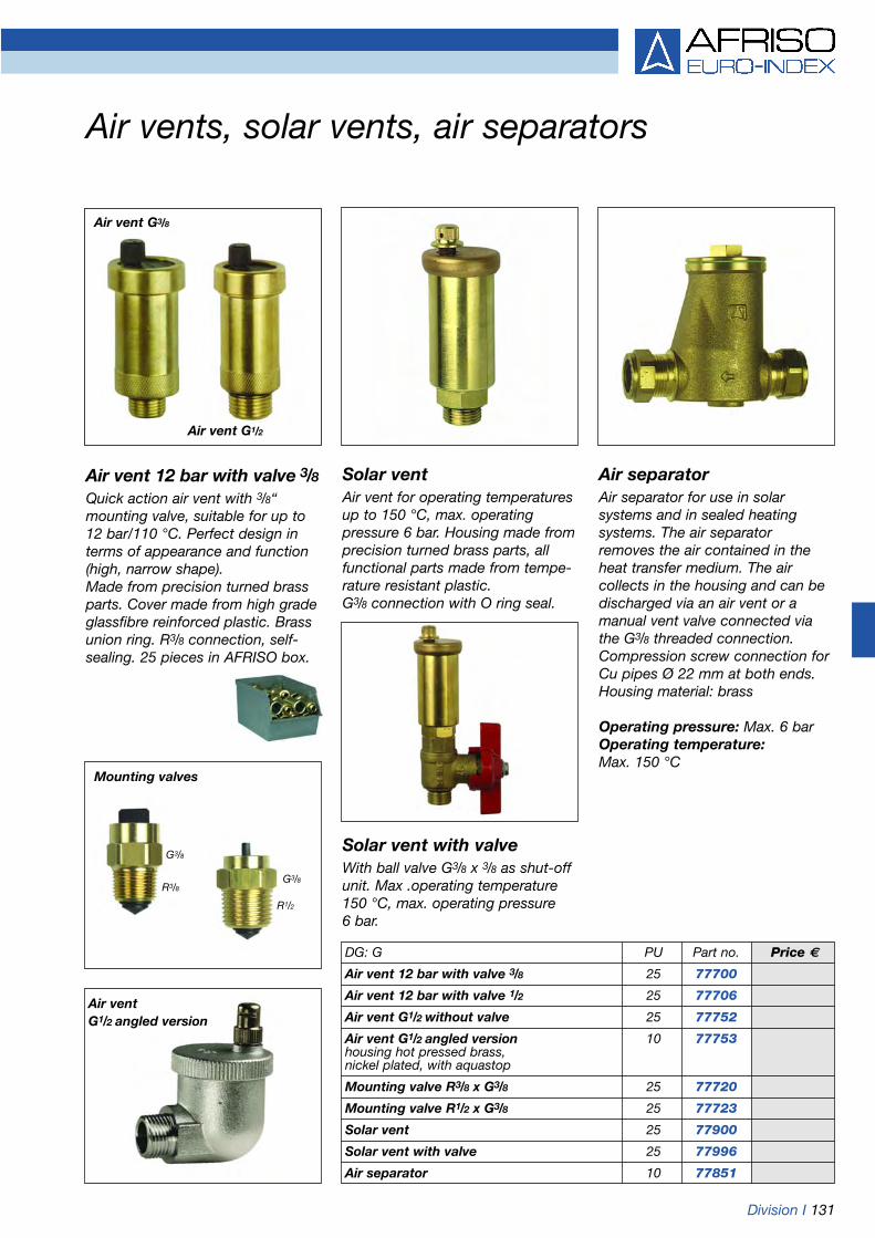
Division I 131
Air vents, solar vents, air separators
G3/8
R3/8
Air vent G3/8
Air ventG1/2 angled version
Mounting valves
Solar ventAir vent for operating temperaturesup to 150 °C, max. operating pressure 6 bar. Housing made fromprecision turned brass parts, allfunctional parts made from tempe-rature resistant plastic. G3/8 connection with O ring seal.
Solar vent with valveWith ball valve G3/8 x 3/8 as shut-offunit. Max .operating temperature150 °C, max. operating pressure 6 bar.
Air separatorAir separator for use in solarsystems and in sealed heatingsystems. The air separator removes the air contained in theheat transfer medium. The air collects in the housing and can bedischarged via an air vent or amanual vent valve connected viathe G3/8 threaded connection.Compression screw connection forCu pipes Ø 22 mm at both ends. Housing material: brass
Operating pressure: Max. 6 barOperating temperature:Max. 150 °C
DG: G PU Part no. Price €
Air vent 12 bar with valve 3/8 25 77700
Air vent 12 bar with valve 1/2 25 77706
Air vent G1/2 without valve 25 77752
Air vent G1/2 angled version 10 77753housing hot pressed brass,nickel plated, with aquastop
Mounting valve R3/8 x G3/8 25 77720
Mounting valve R1/2 x G3/8 25 77723
Solar vent 25 77900
Solar vent with valve 25 77996
Air separator 10 77851
Air vent G1/2
G3/8
R1/2
Air vent 12 bar with valve 3/8Quick action air vent with 3/8“mounting valve, suitable for up to12 bar/110 °C. Perfect design interms of appearance and function(high, narrow shape). Made from precision turned brassparts. Cover made from high gradeglassfibre reinforced plastic. Brassunion ring. R3/8 connection, self-sealing. 25 pieces in AFRISO box.

132 Division I
Distribution manifold for underfloor heating systems and radiator connection, thermal actuators
Distribution manifoldsWe supply OEM customers withdistribution manifolds and accesso-ries made from high quality plastics,covering a multitude of differentapplications, predominantly forunderfloor heating systems, radiatorconnection, distribution of non-potable water and tool cooling. Ouraccessories include thermal actua-tors and suitable electronic controlunits in addition to the completerange of connection fittings. Wemanufacture many of these pro-ducts to specific customer require-ments.
Radiator connectionVia distribution manifolds with inte-grated actuators for temperaturecontrol as well as adjustment andshut-off units. • Optimum temperature detection
using electronic room sensors.• Lower heating costs due to timer
control for individual radiators or heating areas.
• Optimised radiator design without unnecessary fittings.
Thermal actuatorsTo operate hot water valves in distribution manifolds for underfloorheating systems or on radiators.Thermal actuators convert the elec-tric signal they receive from roomthermostats or thermostats withtimers into a stroke from 0 to 3 mm.For easy function control, the valvestroke is visible from the outside.The thermal actuators are availablein the following versions:
- All standard operating voltages such as 230 V, 24 V, 12 V
- Closed when de-energised- Union nut 28 x 1.5 mm or 30 x
1.5 mm (other connection types and adapters are available)
Radiator connection and control viamanifold
We manufacture many of these products to specific customer requirements. Many years of experience in measurement and con-trol technology and in manufacturing plastic products to meet high techno-logical demands allow us to developand build all required components -one stop shopping at its best. We look forward to your enquiry.
Timer thermostat
Room thermostat
Thermal actuator
Distributionmanifold
Customer specific valveadaptation
Stroke
www.afriso.de 133
Chapter 8 Table of contents chapter 8
Accessories for potable water supply and rain water harvesting. Water treatment
08
Page
Pressure reducers, filters, non-return valves, strainers 134
Water filter with replaceable filter element / backwash water filters 135
Water filters with pressure reducer 136
Boiler safety groups, safety valves 137
Signal anodes, sacrificial anodes 138
Rain water harvesting (overview) 139
Back-up controller for rain water harvesting system (RENA) 140
Rain water harvesting system centres (ReMax, RWSC) 141 - 143
Oil tank conversion kits 144 - 145
Cleaning principle for rain water harvesting (overview) 146
Rain water filters 147 - 148
Accessories for rain water harvesting 149
Water treatment systems/reverse osmosis 150

134 Division I
Pressure reducers, filters, non-return valves, strainers
New design and technology
Pressure reducer DMIPressure reducer for water.Housing and spring cap as well as all functional parts are madefrom brass. Stainless steel sealseat. G1/4 connections at both endsfor pressure gauges. Available withvarious screw connections, femalethreads at both ends. Admissionpressure up to 16 bar, other sideadjustable between 1.5 and 6 bar.
Non-return valveBrass construction, suitable forwater, also suitable as a gravitybrake. Nylon valve, seal seat NBR,stainless steel spring. Temperatureup to 110 °C. „Up to 1“ size: 12 baroperating pressure, larger sizes: 10bar operating pressure.
Strainers for non-return valvesStainless steel sieve Aisi 316, nylonconnection piece. Max. operating temperature 110 °C.Mesh size 1.7 mm2, 16 holes per cm2.
DG: G PU Part no. Price €
Filter 3/8 25 42580Filter 1/2 25 42581Filter 3/4 25 42582Filter 1 25 42583Filter 11/4 25 42584Filter 11/2 25 42585Filter 2 25 42586Non-return valve 3/8 - DN 10 25 42540Non-return valve 1/2 - DN 15 25 42541Non-return valve 3/4 - DN 20 25 42542Non-return valve 1 - DN 25 25 42543Non-return valve 11/4 - DN 32 25 42544Non-return valve 11/2 - DN 40 25 42545Non-return valve 2 - DN 50 25 42546Strainer 3/8 - DN 10 50 20811Strainer 1/2 - DN 15 35 20812Strainer 3/4 - DN 20 20 20813Strainer 1 - DN 25 25 20814Strainer 11/4 - DN 32 20 20815Strainer 11/2 - DN 40 10 20816Strainer 2 - DN 50 6 20817
Please refer to pages 454 and 455for water pressure instruments.
DG: G, PU 5 Part no. Price €
DMI 1/2 42430
DMI 3/4 42431
DMI 1 42432
FilterHot-pressed brass design, replace-able stainless steel sieve speciallyfor water. Max. operating pressure16 bar.

Division I 135
Water filter with replaceable filter element,backwash water filters
ApplicationDIN 1988 requires the installationof suitable filters in drinking watersystems to prevent corrosion. Atthe same time, the filters preventparticles such as rust or sand fromreaching the domestic water instal-lation and protect valves, machi-nes, boilers, etc. from malfunctionscaused by dirt. Also suitable forhigh flow rates.
DescriptionSolid water filter. Cast brass filterhead. The brass connection piececan be rotated to facilitate installa-tion in horizontal or vertical pipes,even if the pipe is very close to awall. The filter insert consists of aplastic filter carrier with a stainlesssteel filter element with a lowerrating of 90 µm and an upper ratingof 125 µm. The transparent filterbowl, made from impact resistantplastic, shows the degree of pollu-tion. The filter bowl with an O ringseal is screwed to the filter headusing a brass union nut. A pressuregauge with the measuring range 0-10 bar or 0-16 bar to indicate theinlet pressure is included. Thecover can be rotated to mark thedate of the last filter replacementor backwashing.The backwash filter has a 7“ filterinsert, the filter without backwash-ing facility has an insert of 81/2“.Backwashing is performed manual-ly via a drain valve. The direction offlow through the filter is reversedand the dirt particles are washed
out of the filter. The owner caneasily backwash the filter himself.This should be done at intervals of2 months. Filter inserts of filterswithout backwashing facility mustbe replaced at regular intervals ofno more than 6 months. A filterspanner is included with this filterversion. The materials are non-toxicand comply with the GermanDrinking Water Act.
Technical specifications
Medium: Drinking water
Operating pressure: 10 bar/16 bar(observe measuring range of pressure gauge!)
Operating temperature:Max. 30 °C
Mounting position: Vertical
Connection: G3/4, G1 optional, can be rotated
Dimensions W x H x D:Backwash version:178 x 360 x 208 mmVersion without backwash facility:178 x 320 x 208 mm
Filter ratingLower 90 µmUpper 125 µm
Material:Filter head: Cu Zn 40 Pb 2
Connection pieces: Cu Zn 40 Pb 2
Filter bowl: Plastic(Trogamit T)
Filter sieve: Stainless steel
Scope of deliveryFilter complete with connectionpiece.Pressure gauge 10 bar (alternative:16 bar) with date indicator.Version without backwash facilityincludes filter spanner.
DG: G; PU: 1 Connections Part no. Price €
Water filter with replaceable filter element 81/2“ G3/4 42690
Water filter with replaceable filter element 81/2“ G1 42691
Backwash water filter 7“ G3/4 42688
Backwash water filter 7“ G1 42693
Spare sieve (replaceable filter element) 81/2“ 42700
Filter spanner 42701
Spare pressure gauge 10 bar with date indicator G1/4 axial 63544
Spare pressure gauge 16 bar with date indicator G1/4 axial 63545
With replaceable filter element Backwash filter
Connection can be rotated

136 Division I
Water filters with pressure reducer
ApplicationCombination fitting consisting ofwater filter, pressure reducer andbackflow preventer providing acomplete domestic drinking waterstation. The water filter preventsparticles from reaching the dome-stic water installation. The pressurereducer reduces the pressure to auniform, system-specific pressurein order to protect the installationand to ensure economic water consumption. The backflow pre-venter (optional) prevents water flow-ing back from the domestic waterinstallation into the public watersupply.
DescriptionSolid construction combination fit-ting consisting of water filter, pres-sure reducer and backflow preven-ter. Brass filter head with integratedpressure reducer housing. The brassconnection piece can be rotated tofacilitate installation in horizontal orvertical pipes, even if the pipe isvery close to a wall. The filter insertconsists of a plastic filter carrierwith a stainless steel filter elementwith a lower rating of 90 µm and anupper rating of 120 µm. The trans-parent filter bowl, made fromimpact resistant plastic, shows thedegree of pollution. The filter bowlwith an O ring seal is screwed tothe filter head using a brass unionnut. The pressure reducer is factorypre-set to 4 bar output pressure andcan be adjusted to any value from1.6 to 6 bar. A pressure gauge withmeasuring range 0/10 bar to indicatethe outlet pressure is included.
The rotatable cover allows you tomark the date of the last filterreplacement or backwashing. Thebackwash filter has a 7“ filter insert,the filter without backwashing faci-lity has an insert of 81/2“.Backwashing is performed manual-ly via a drain valve. The direction offlow through the filter is reversedand the dirt particles are washedout of the filter. The owner can easilybackwash the filter himself. Thisshould be done at intervals of 2months. The filter inserts of filterswithout backwashing facility mustbe replaced at regular intervals of nomore than 6 months. A filter span-ner is included with this filter ver-sion. The backflow preventer (optio-nal) can be fitted in lieu of the con-nection fitting. The materials arenon-toxic and comply with theGerman Drinking Water Act.
Technical specificationsMedium: Drinking waterOperating pressure: Min. 2 bar,
max. 16 barOutput pressure: Adjustable form
1.6 bar to 6 barOperating temperature:
Max. 30 °C
Mounting position: VerticalConnection: G3/4,
G1 optional, can be rotated
Dimensions: W x H x DBackwash version:178 x 420 x 208 mmVersion without backwash facility: 178 x 380 x 208 mmFilter rating:Lower 90 µmUpper 125 µmMaterial:Filter head: Cu Zn 40 Pb2Connection pieces: Cu Zn 40 Pb2Filter bowl: Plastic
(Trogamit T)Filter sieve: Stainless steel
Scope of deliveryFilter with pressure reducer, complete with connection piece.Pressure gauge 10 bar (optional 16 bar) with date indicator. Versionwithout backwash facility includesfilter spanner.
Option• Backflow preventer
DG: G; PU: 1 Connections Part no. Price €
Water filter with pressure reducer(replaceable filter element 81/2“) G3/4 42683
Water filter with pressure reducer(replaceable filter element 81/2“) G1 42684
Water filter with pressure reducer (backwash version) G3/4 42681
Water filter with pressure reducer (backwash version) G1 42686
Backflow preventer G3/4 42705
Backflow preventer G1 42706
Without backwash facility With backwash facility
Pressure gauge with date indicator

Division I 137
Boiler safety groups, safety valves
Boiler safety group BFK 12/10Safety group fitting for sealedwater heaters according to DIN1988 or DIN 4753-1, designed toprotect against overpressure. Noise characteristics according to DIN 4109 class 1. Combination fitting with safetyvalve 10 bar, shut-off facility, non-return valve and test screw.Clamp ring connection Ø 15 mm atboth ends.Available with various connectionsas well as safety valve 6 and 8 bar.Length and height 95 mm.
Boiler safety group DN 15Similar to BFK 12/10, but withadditional Bourdon tube pressuregauge 0-16 bar, Ø 50 mm, connection G1/4. Safety valve canbe rotated, outlet thread G3/4. With soldered screw connection Ø 18 mm at both ends.
Also available with safety valve andpressure gauge in other pressureranges.
Diaphragm safety valveMSW for water heatersAccording to TRD 721 and VdTÜVsheet Safety Valve 100. Suitable forsealed drinking water heatersaccording to DIN 1988 and DIN4753 T1. The safety valve must beinstalled as per DIN 1988 in thecold water inlet of the drinkingwater heater. The release pressure of the safety valve is factory pre-set. The size of thevalve inlet determines the unit type,the outlet is 1/4“ to 1/2“ larger.
DG: G PU Part no. Price €
Boiler safety group BFK 12/10 10 77988
Boiler safety group DN 15 10 77976Diaphragm safety valves for water:
MSW 1/2 x 3/4, 6 bar 10 42421
MSW 1/2 x 3/4, 8 bar 10 42422
MSW 1/2 x 3/4, 10 bar 10 42423
MSW 3/4 x 1, 6 bar 10 42425
MSW 3/4 x 1, 8 bar 10 42426
MSW 3/4 x 1, 10 bar 10 42427
MSW 1 x 11/4, 6 bar 10 42442
MSW 1 x 11/4, 8 bar 10 42443
MSW 1 x 11/4, 10 bar 10 42444
MSW 11/4 x 11/2, 6 bar 10 42446
MSW 11/4 x 11/2, 8 bar 5 42447
MSW 11/4 x 11/2, 10 bar 5 42448
MSW 11/2 x 2 , 6 bar 5 42476
MSW 11/2 x 2 , 8 bar 5 42477
MSW 11/2 x 2 , 10 bar 5 42478
MSW 2 x 21/2 , 6 bar 1 42487
MSW 2 x 21/2, 8 bar 1 42488
MSW 2 x 21/2, 10 bar 1 42489

138 Division I
Signal anodes, sacrificial anodes
Alarm signal
The signal anode, a sacrificialanode according to DIN EN 12828made of magnesium alloy preventsunnoticed corrosion damage inwater heaters. Defective areas inenamel or other passive protectivecoatings are subject to corrosion.This causes a flow of current whichis transformed into a protectivecurrent by the anode material. Themagnesium alloy anode materialthus falls victim to electro-chemicalcorrosion. With signal anodes,whose rod materials are used up,water penetrates into the testspace of the signal anode and ared discolouring occurs. With con-ventional anodes the boiler has tobe opened up for anode inspec-tion.
The outside of a signal anodeshows its state of usage.Since the protective function of theanode is not unlimited, consumedanodes have to be replaced. Signalanodes are primarily used insteadof conventional sacrificial anodes inhot water storage tanks with acapacity of 100 to 500 litres. Themagnesium anode is preferred inenamelled boilers but can also beused in hot water storage tankswith other types of passive protec-tive coatings. If the signal anode isinstalled via G3/4, G1, G11/4 femaleconnections or via M8 male, amore efficient way of checking boi-lers is achieved. Signal anodes aremanufactured from magnesiumalloy in accordance with the relevant
Signal anode U Sacrifical anode Chain anode
industry standards. The parts sub-merged in water are heat resistantup to operating temperatures of100 °C, pressure-proof up to 15bar system pressure and complywith the German Food Act. Variousanode concepts are used:
Signal anode UUniversal and complete signal anodes with M8 male connection,screw fitting, with signal unit andinstruction label. Length 500 mm,Ø 22 mm (G3/4), 26 mm (G1), 33 mm (G11/4).
Anode ISacrificial anode Ø 26 mm for iso-lated installation, with M8 maleconnection, isolating piece andearth conductor. Consumptioncontrol with AT1 anode tester.
Sacrificial anodeWith screw connection, withoutsignal unit. This type is suitable for
all standard vessels. With variouslengths, threads and diameters22/26/33 mm.
Chain anode Flexible anode with 4 individualelements along a stainless steelrope. With G3/4 screw connection,without signal unit, Length 800mm. A chain anode is used whenthere is insufficient space to installa rigid anode.
Anode tester AT1Tester for consumption control ofisolated sacrificial anodes (seeAnode I).
• Handheld tester with 4-level LED indication
• The actual state of an isolated installed anode is detected in a simple and time saving way
• Preventive maintenance - used anodes are replaced in good time
DG: G PU Part no. Price €
Signal anode U22-3/4 10 69800
Signal anode U26-1 10 69805
Signal anode U33-11/4 10 69810
Anode I 26-500-M8 10 69811
Anode tester AT1 DG: H, PU 1 69842
Sacrificial anode 22-500-3/4 10 69815
Sacrificial anode 22-700-3/4 10 69817
Sacrificial anode 26-500-1 10 69819
Sacrificial anode 26-700-1 10 69821
Sacrificial anode 33-550-11/4 10 69825
Chain anode 22-800-3/4 10 69829
Anode tester AT1 Anode I
Screw connection
Seal
Anode mount
Test space
Protective cap for test space
Unused magnesium anode
Steel core

Division I 139
Rain water harvesting – an ecological necessity
Drinking water is our most impor-tant resource. On average, inGermany, each person consumesapprox. 130 litres of drinking watereach day, but only approx. 3 litresare actually used for drinking andpreparing food. There are a host of good reasonsfor harvesting rain water:- Reserves of clean drinking water
are limited.- Drinking water is too valuable for
watering the garden, washing clothes and flushing the toilet.
- Rain water harvesting helps to save energy (water treatment and transport).
- Rain water is lime-free
Benefits:- Less detergent required- Better for horticultural purposes- Rain water tanks serve as inter-
mediate retainers and only small quantities are discharged at a timeinto the mains drainage system.
- Even in dry summers, there is nor-mally a sufficient supply of rain water.
- Several countries and regions subsidise rain water harvesting systems.
- Using rain water saves money and protects the environment.
The rain water from the roof area isfed through a filter system into therain water collection tank.
A pressure controlled pump feedsthe rain water through a specialpipework system into the building'sinstallation. If there is insufficientrain water, the exact amount requi-red is drawn from the mains watersupply. Rain water tanks can beinstalled in basements or under-ground in the garden. New installa-tions normally use plastic or con-crete tanks. However, it is also pos-sible to convert existing tanks, cess-pit or old oil tanks. For the latter,AFRISO also supplies specialcustomised plastic foil linings aswell as manhole covers with all therequired connections. The AFRISOrain water product range focuseson the measurement and controlaspect as well as the provision of acomplete range of installationaccessories (see pages 140 to 149).
In addition, we supply special filtercomponents with dirt collectors,activated carbon filters and UVdisinfection (please enquire).
UV disinfection with dirt filters andactivated carbon filters
1
2
1011
3 4
5
6
7
8
9
13
12
UV disinfectionwith dirt filtersand activated carbon filters
14
1 Rain Water System Centre RWSC
2 Level Indicator
3 Processed rain water pipework
4 Mains drinking water supply
5 Rain water suction pipe
6 Drinking water overflow
7 Tank filter with stainless steel sieve
8 Siphon
9 Floating suction fitting
10 Probe for minimum rain water level
11 Inlet unit for bottom filling2
12 Plastic manhole cover for steel tankwith inner lining
13 Rain water collection tank
14 Downpipe filter „Rainus“
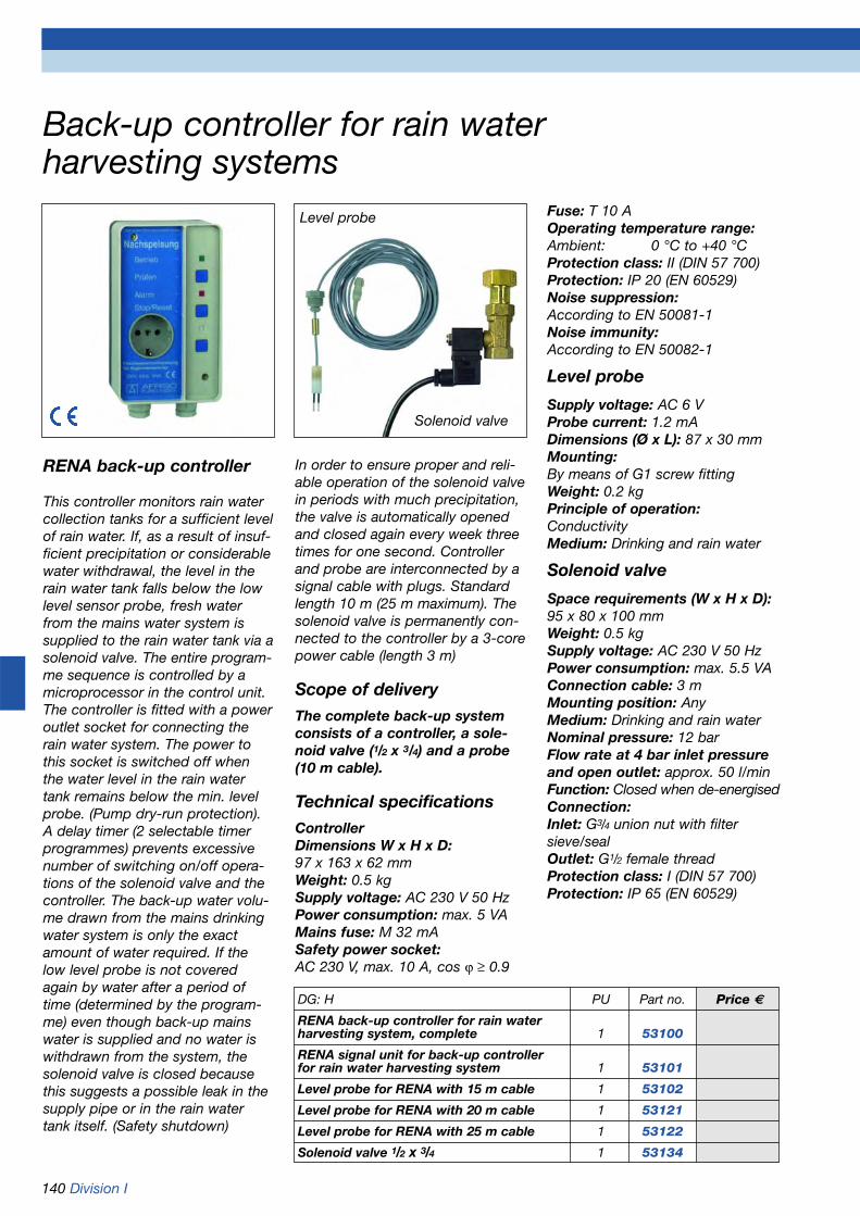
140 Division I
Back-up controller for rain water harvesting systems
RENA back-up controller
This controller monitors rain watercollection tanks for a sufficient levelof rain water. If, as a result of insuf-ficient precipitation or considerablewater withdrawal, the level in therain water tank falls below the lowlevel sensor probe, fresh waterfrom the mains water system issupplied to the rain water tank via asolenoid valve. The entire program-me sequence is controlled by amicroprocessor in the control unit.The controller is fitted with a poweroutlet socket for connecting therain water system. The power tothis socket is switched off whenthe water level in the rain watertank remains below the min. levelprobe. (Pump dry-run protection).A delay timer (2 selectable timerprogrammes) prevents excessivenumber of switching on/off opera-tions of the solenoid valve and thecontroller. The back-up water volu-me drawn from the mains drinkingwater system is only the exactamount of water required. If thelow level probe is not coveredagain by water after a period oftime (determined by the program-me) even though back-up mainswater is supplied and no water iswithdrawn from the system, thesolenoid valve is closed becausethis suggests a possible leak in thesupply pipe or in the rain watertank itself. (Safety shutdown)
In order to ensure proper and reli-able operation of the solenoid valvein periods with much precipitation,the valve is automatically openedand closed again every week threetimes for one second. Controllerand probe are interconnected by asignal cable with plugs. Standardlength 10 m (25 m maximum). Thesolenoid valve is permanently con-nected to the controller by a 3-corepower cable (length 3 m)
Scope of deliveryThe complete back-up systemconsists of a controller, a sole-noid valve (1/2 x 3/4) and a probe (10 m cable).
Technical specificationsControllerDimensions W x H x D:97 x 163 x 62 mmWeight: 0.5 kgSupply voltage: AC 230 V 50 HzPower consumption: max. 5 VAMains fuse: M 32 mASafety power socket:AC 230 V, max. 10 A, cos ϕ > 0.9
Fuse: T 10 AOperating temperature range:Ambient: 0 °C to +40 °CProtection class: II (DIN 57 700)Protection: IP 20 (EN 60529)Noise suppression:According to EN 50081-1Noise immunity:According to EN 50082-1
Level probe
Supply voltage: AC 6 VProbe current: 1.2 mADimensions (Ø x L): 87 x 30 mmMounting:By means of G1 screw fittingWeight: 0.2 kgPrinciple of operation:ConductivityMedium: Drinking and rain water
Solenoid valve
Space requirements (W x H x D):95 x 80 x 100 mmWeight: 0.5 kgSupply voltage: AC 230 V 50 HzPower consumption: max. 5.5 VAConnection cable: 3 mMounting position: AnyMedium: Drinking and rain waterNominal pressure: 12 barFlow rate at 4 bar inlet pressureand open outlet: approx. 50 l/minFunction: Closed when de-energisedConnection:Inlet: G3/4 union nut with filtersieve/sealOutlet: G1/2 female threadProtection class: I (DIN 57 700)Protection: IP 65 (EN 60529)
DG: H PU Part no. Price €
RENA back-up controller for rain water harvesting system, complete 1 53100
RENA signal unit for back-up controller for rain water harvesting system 1 53101
Level probe for RENA with 15 m cable 1 53102
Level probe for RENA with 20 m cable 1 53121
Level probe for RENA with 25 m cable 1 53122
Solenoid valve 1/2 x 3/4 1 53134
Level probe
Solenoid valve

1 Cover2 Upper part of housing
3 Lower part of housing4 Funnel insert5 Power supply plug
6 Muliple power outlet socket7 Relay for mains water back-up controller7a Water level sensor for cisterns8 Controller for submersible pressure
pump9 Solenoid valve for mains water back-up10 Switch box for submersible pressure
pump10a Submersible pressure pump with pump base and floating withdrawal unit
11 Back-up pump with float switch12 Overflow for back-up tank
Division I 141
ReMax rain water system centre withpressure pump in the rain water tank
Fully automatic rain water systemcentre with submersible pressurepump in the rain water tank.Compact modular design for indoorinstallation. Fully equipped and readyfor connection. Submersible pres-sure pump for installation in the rainwater tank. The submersible pres-sure pump supplies the rain waterfrom the rain water tank to the watersystem in the building. The pump is controlled by the pressure switchintegrated in the ReMax system. If any tap is opened (e.g. in the gar-den), the pressure in the pipedrops. The pressure switch detectsthis pressure drop and starts thepump. When there is no longer ademand for water, the pump isautomatically switched off.
Technical specificationsDimensions W x H x D:42 x 105 x 51 cmCompact ReMax centre, ready forconnection:• All connections with 3/4 male thread• Connection cable 1.5 m• Max. pumping pressure 4.4 bar• Max. pumping volume 4.0 cbm/h• Power consumption 800 W• AC 230 V/50 Hz• No commissioning required
ReMax connection kitFlexible, armoured stainless steelhoses with G3/4 union nut, one endwith elbow.Hose length adapted to ReMax.
DG: M PU Part no. Price €
ReMax 1 53095
Connection 1 53096kit
Wall duct 1 53097
Label set 1 53098
ReMax label setConsisting of:Engraved plateAdhesive tapeSection tape, length 10 mAdhesive flagPipe marker
ReMax wall duct For pipe or hole Ø 100 mm2 x Ø 32 mm (brass elbows)1 x Ø 16 mm2 x cable ducts
If the rain tank is empty, a drinkingwater back-up system ensurescontinuous water supply. A sensorin the rain water tank detects thewater level. If the level falls belowthe pre-set minimum, a relay oper-ates and opens the solenoid valve.Drinking water now flows into thebottom tank of the ReMax centre inwhich a small submersible pump islocated. This float-controlled sub-mersible pump then feeds the drink-ing water into the rain water tank.System advantages:- The distance between the rain
water tank and the building can be greater than for suction pump systems.
- Sound-proof plastic housing.
1
1110
98
7
5
4
3
2
6
1110a
11121111
7a
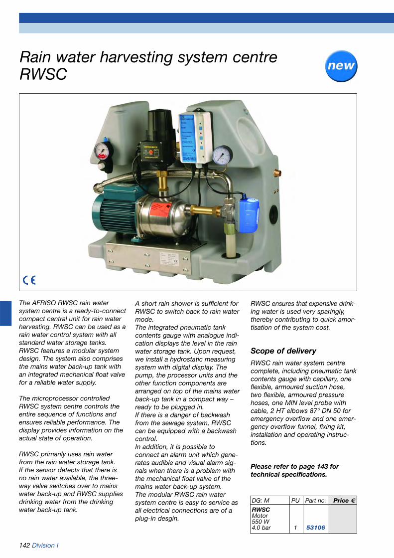
142 Division I
Rain water harvesting system centreRWSC
The AFRISO RWSC rain watersystem centre is a ready-to-connectcompact central unit for rain waterharvesting. RWSC can be used as arain water control system with allstandard water storage tanks.RWSC features a modular systemdesign. The system also comprisesthe mains water back-up tank withan integrated mechanical float valvefor a reliable water supply.
The microprocessor controlledRWSC system centre controls theentire sequence of functions andensures reliable performance. Thedisplay provides information on theactual state of operation.
RWSC primarily uses rain waterfrom the rain water storage tank. If the sensor detects that there isno rain water available, the three-way valve switches over to mainswater back-up and RWSC suppliesdrinking water from the drinkingwater back-up tank.
A short rain shower is sufficient forRWSC to switch back to rain watermode. The integrated pneumatic tankcontents gauge with analogue indi-cation displays the level in the rainwater storage tank. Upon request,we install a hydrostatic measuringsystem with digital display. Thepump, the processor units and theother function components arearranged on top of the mains waterback-up tank in a compact way –ready to be plugged in. If there is a danger of backwashfrom the sewage system, RWSCcan be equipped with a backwashcontrol. In addition, it is possible to connect an alarm unit which gene-rates audible and visual alarm sig-nals when there is a problem withthe mechanical float valve of themains water back-up system.The modular RWSC rain watersystem centre is easy to service asall electrical connections are of aplug-in desgin.
RWSC ensures that expensive drink-ing water is used very sparingly,thereby contributing to quick amor-tisation of the system cost.
Scope of deliveryRWSC rain water system centrecomplete, including pneumatic tankcontents gauge with capillary, oneflexible, armoured suction hose,two flexible, armoured pressurehoses, one MIN level probe withcable, 2 HT elbows 87° DN 50 foremergency overflow and one emer-gency overflow funnel, fixing kit,installation and operating instruc-tions.
Please refer to page 143 fortechnical specifications.
DG: M PU Part no. Price €
RWSCMotor550 W4.0 bar 1 53106

Division I 143
RWSC spare parts and accessories
The RWSC rain water system centre consists of individual systemmodules. All modules are electricallyinterconnected by plug-in connectionsand mechanically by union nuts with flatgaskets. This ensures quick and easyservicing or replacement of individualmodules. An optional probe for detec-tion of backwash from the sewagesystem can be connected to thesystem. RWSC is also laid out for theconnection of a maximum level alarmunit which provides audible and visualalarm signals when a problem occurswith the float valve for the mains
back-up water supply. Please order thebackwash probe and associated levelalarm unit separately. It is also possibleto install the DIT 02 digital level indica-tor in lieu of the TopFlex pneumatic tankcontents gauge at an additional cost.
Technical specificationsRWSC:Dimensions (W x H x D):650 x 600 x 300 mmWeight (without water): ~27.5 kgWeight (with water): ~45 kgMax. water volume in the tank: 18 litresOperating temperature range
Medium: 4 °C/35 °CAmbient: 4 °C/40 °CSupply voltage: AC 230 V/50 HzMax. power consumption: 1,500 VAMax. motor power: 550 WMax. pump head: 40 mMax. pressure: 4.0 barMax. pumping volume: 4,500 l/hMax. suction height: 8 mMax. suction distance: 15 mEmergency overflow: DN 50Protection class: I (EN 60335-1)Protection: IP42 (EN 60529)Electr. safety: According to EN 60335-1
1 Pump MXAM 204
2 Armoured suction hose 700 mm long, G1
3 Pneum. tank contents gauge TopFlex
4 Pressure switch/dry run protection
5 Rain water outlet G1
6 System control unit RWSC
7 Pressure gauge NG 63, 6 bar
8 Capillary tube for pressure indication
9 Float valve inlet G3/4 for mains water back-up
10 3-way valve G1
11 Mains back-up water tank
12 Connection for Maximelder-R1
2
3
4 5 6
7
8
9
10
11
12
DG Part no. PU Price €1 Pump MXAM 204 without screw connections M 22 03 02 10 1 2 Armoured suction hose 700 mm long, G1 f/f M 820 000 0033 1 3 Pneumatic tank contents gauge TopFlex (or DIT 02 optional) M 28032 1 3 Digital level indicator DIT 02 (refer to page 20) H 52124 1 4 Pressure switch/dry run protection M 04 00 000002 1 5 Armoured pressure hose 600 mm long, G1 f/f (not shown) M 820 000 0034 1 5 Armoured pressure hose 200 mm long, G3/4 f/f (not shown) M 820 000 0035 1 6 System control unit RWSC M 04 00 00 09 1 7 Pressure gauge NG 63, 6 bar G 63538 1 8 Connection piece with capillary tube M 04 00 00 08 1 9 Float valve for mains water back-up supply M 05 00 350103 1
Styrofoam float for float valve M 04 00 000023 110 3-way valve M 04 00 00 14 1 11 Mains back-up water tank M 04 00 000003 112 Maximelder-R G 16702 1 12 Probe for backwash alarm with 16.5 m cable (not shown) M 16713 1
Capillary tube 4 x 1 mm, 16.5 m, PE black (not shown) M 20358 1
Maximelder-R+ probe

144 Division I
Oil tank conversion kit I for rain waterusage in the house and the garden
If heating oil storage tanks can nolonger be used, for example due tocorrosion, or if the heating systemis converted to other types of fuel, it may be a good idea to usethe existing tank to collect rainwater and to integrate it into a rainwater harvesting system. For thispurpose, the tank is cleaned by aspecialist company and then fitted with a suitable inner lining(refer to page 80).The old, standardised manholecover (Ø 500 mm) is replaced by aplastic cover which is speciallydesigned for rain water systems.This considerably facilitates theconversion. The manhole covercontains all the required connections(filter, inlet, suction pipe and levelprobes).
Conversion kit I contains:- Rain water harvesting system
centre RWSC- Plastic manhole cover Ø 500 mm
with two connections for pipes Ø 100 mm
- Cartridge filter for direct mountingto the manhole cover. Connections for inlet and outlet pipes Ø 100 mm. Suitable for roof areas of up to 150 m2. Height offset inlet - outlet 60 mm.
- 2 quick-action connection pieces for the inlet and outlet pipes.
- Floating suction fitting with 215 cm long suction hose.
- Inlet unit for bottom filling.- Wall duct Ø 100 mm for suction
pipe and level probes. Please order the inner lining separately (refer to page 80).
Scope of deliveryRain water harvesting system centre RWSC
Plastic manhole cover Ø 500 mm
Cartridge filter
Quick-action connection pieces
Floating suction fitting with flexible suction hose
Inlet unit for bottom filling
Wall duct
DG: M PU Part no. Price €
Oil tank conversion kit I 1 53075
Plastic manhole cover Ø 500 mm 1 53099

Division I 145
DG: M PU Part no. Price €
Oil tank conversion kit II 1 53076
Oil tank conversion kit III 1 53077
Pump Forta Duo 1100 1 53078for conversion kits II and III
Oil tank conversation kits II + IIIfor rain water usage in the garden
Oil tank conversion made easy! We supply a number of individuallymanufactured special rain watercomponents for quick and easyinstallation. The tank cover is themost important component of thekit as it enables simple and cleanpiping through two openings. Thepipe is routed from the downpipeto the access chamber of the tankand then connected to the relevantfilter system.Depending on site conditions andavailable space in the accesschamber, it is recommended to in-stall a downpipe filter or a cartridgefilter. Quick-action connectors areused to connect the filter elements.The pipe to the sewage systemmust be constructed to form asiphon using the drain pipe elbows.The Forta Duo 1100 submersiblepressure pump with integratedpressure switch is ideally suited forwater withdrawal.
Refer to page 80 for inner liningsfor tanks.Refer to pages 15 and 20 for levelmeasurement.
Plastic manhole cover Ø 500 mm
Inlet unit for bottom filling
Plastic manhole cover Ø 500 mm
Inlet unit for bottom filling
Scope of delivery oil tank conversion kit II (up to 75 sqm roof area):
Rainus downpipe filter with 2 quick-action connection pieces
Scope of delivery oil tank conversion kit III (up to 150 sqm roof area):
Cartridge filter with 2 quick-action connection pieces
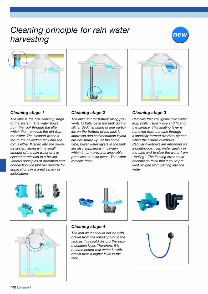
146 Division I
Cleaning principle for rain water harvesting
Cleaning stage 1The filter is the first cleaning stageof the system. The water flowsfrom the roof through the filterwhich then removes the dirt fromthe water. The cleaned water is fed to the collection tank and thedirt is either flushed into the sewa-ge system along with a smallamount of the rain water or it isejected or retained in a basket.Various principles of operation andconnection possibilities provide forapplications in a great variety ofinstallations.
Cleaning stage 2The inlet unit for bottom filling pre-vents turbulence in the tank duringfilling. Sedimentation of fine partic-les on the bottom of the tank isimproved and sedimentation layersare not stirred up. At the sametime, lower water layers in the tankare also supplied with oxygen,which in turn prevents anaerobicprocesses to take place. The waterremains fresh!
Cleaning stage 3Particles that are lighter than water(e.g. pollen) slowly rise and float onthe surface. This floating layer isremoved from the tank through a specially formed overflow siphonwhen the cistern overflows.Regular overflows are important fora continuous, high water quality inthe tank and to stop the water from„fouling“. The floating layer couldbecome so thick that it could pre-vent oxygen from getting into thewater.
Cleaning stage 4The rain water should not be with-drawn from the lowest point in thetank as this could disturb the sedi-mentation layer. Therefore, it isrecommended that water is with-drawn from a higher level in thetank.

Division I 147
Rain water filters
SF sinus filterRain water filter for fitting to thestorage tank or the dome shaft ofthe storage tank. For roof areas ofup to 150 sqm, without height offset. Optional backwash kit foreasy cleaning.
VF 1 volume filter with tele-scopic extension (for rain water)
For roof areas of up to 350 sqm.Preferably for underground installa-tion. Height offset between inletand outlet to the sewage system300 mm. Due to the dual-stage filtering principle (coarse filteringfirst, then fine filtering), the VF 1volume filter requires very littlemaintenance. Dirt is directly flushedinto the sewage system by the rainwater. 85 to 95 % of the rain wateris cleaned and fed to the rain waterstorage tank. The housing is made from highgrade polyethylene, the filter insertfrom stainless steel. The filter iseasy to clean and, therefore, neednot be replaced. An optional tele-scopic head-piece extension allowsthe filter cover to be set level withthe ground (250 mm to 750 mm).Please order the extension separa-tely.
PF cartridge filterRain water filter for fitting to in thestorage tank or the dome shaft ofthe storage tank. For roof areas ofup to 150 sqm, height offset 66mm. Optional backwash kit for easycleaning.
Backwash kitFor easy cleaning of sinus and car-tridge filter inserts. Approved forconnection to only one rain watertapping point. The kit consists ofspecial nozzles, 10 m PE pipe andcorresponding screw connections.
Backwash kit with automatic flushingFor automatic filter cleaning.Battery operated.
DG: M PU Part no. Price €
VF 1 volume filter 1 53088
Telescopic extension 1 53089
SF sinus filter 1 53090
PF cartridge filter 1 53091
Backwash kit 1 53092
Backwash kit with automatic flushing 1 53093

148 Division I
Rain water downpipe filters
Downpipe filter FFFor roof areas of up to 150 sqm,for pipe Ø 100 mm. Filters and collects the rain water for rain barrels and cisterns. The filterinsert can be easily and quicklyremoved for cleaning. Available in copper or zinc.
RainusDownpipe filter for roof areas of upto 75 sqm with stainless steel filtersieve. The dirt is ejected to the front,the cleaned rain water continues toflow through the downpipe.Therefore, Rainus is ideally suitedfor retrofitting to existing storagetanks or as a pre-filter for insuffi-ciently equipped rain watersystems. Suitable for downpipe Ø 100 and optionally for downpipeØ 80 and 110 mm. Ideal:• For seepage• For retrofitting• As a pond filter
Leaf filterFor roof areas of up to 80 sqm, for pipe Ø 100 mm for coarse filtering of the rain water. Leavesand similar debris are ejected outof the filter front. Adapter for pipe Ø 80 mm included.
DG: M PU Part no. Price €
Rainus 1 53081
Downpipe filter FF copper, DN 100 1 53082
Reducer set copper, DN 80 1 53083
Downpipe filter FF zinc, DN 100 1 53084
Reducer set zinc, DN 80 1 53085
Leaf filter, grey 1 53086
Leaf filter, brown 1 53087

Division I 149
Accessories for rain water harvesting
Overflow siphonMade from high grade PE, for tankoverflow, with stench trap, rodentstop and connection for backwashalarm. Connection DN 100. Withconnection piece for support pipe.
Floating suction fittingFor the withdrawal of rain waterfrom the storage tank. The floatingball ensures that the water isalways withdrawn from the clean-est layer. With non-return valve, dirtcollector and hose connection.
Inlet unit for bottom fillingEnsures the non-turbulent supplyof rain water to the collection tankand prevents sediments from beingstirred up. Suitable for pipes with Ø 100 and Ø 125 mm.
Flexible suction hoseØ 36 mm, for 1“ connections (e.g. floating suction fitting). Pleasespecify length when ordering.
Quick-action connectionpiecesFor simple mounting of filters intanks and pipes Ø 100 mm.
DG: M PU Part no. Price €
Overflow siphon with rodent stop 1 53113
Floating suction fitting 1 53153
Inlet unit for bottom filling 1 53111
Flexible suction hose per metre 1 53079
Quick-action connection pieces for DN 100 1 53080
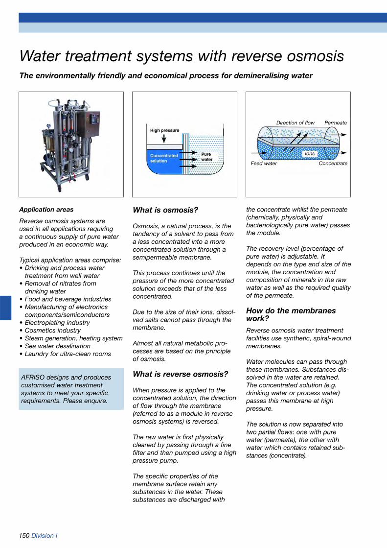
150 Division I
What is osmosis?
Osmosis, a natural process, is thetendency of a solvent to pass froma less concentrated into a moreconcentrated solution through asemipermeable membrane.
This process continues until thepressure of the more concentratedsolution exceeds that of the lessconcentrated.
Due to the size of their ions, dissol-ved salts cannot pass through themembrane.
Almost all natural metabolic pro-cesses are based on the principleof osmosis.
What is reverse osmosis?
When pressure is applied to theconcentrated solution, the directionof flow through the membrane(referred to as a module in reverseosmosis systems) is reversed.
The raw water is first physically cleaned by passing through a finefilter and then pumped using a highpressure pump.
The specific properties of themembrane surface retain any substances in the water. These substances are discharged with
the concentrate whilst the permeate(chemically, physically and bacteriologically pure water) passesthe module.
The recovery level (percentage ofpure water) is adjustable. Itdepends on the type and size of themodule, the concentration andcomposition of minerals in the rawwater as well as the required qualityof the permeate.
How do the membraneswork?Reverse osmosis water treatmentfacilities use synthetic, spiral-woundmembranes.
Water molecules can pass throughthese membranes. Substances dis-solved in the water are retained.The concentrated solution (e.g.drinking water or process water)passes this membrane at high pressure.
The solution is now separated intotwo partial flows: one with purewater (permeate), the other withwater which contains retained sub-stances (concentrate).
Water treatment systems with reverse osmosisThe environmentally friendly and economical process for demineralising water
Application areas
Reverse osmosis systems are used in all applications requiring a continuous supply of pure waterproduced in an economic way.
Typical application areas comprise:• Drinking and process water
treatment from well water• Removal of nitrates from
drinking water• Food and beverage industries• Manufacturing of electronics
components/semiconductors• Electroplating industry• Cosmetics industry• Steam generation, heating system• Sea water desalination• Laundry for ultra-clean rooms
AFRISO designs and producescustomised water treatmentsystems to meet your specificrequirements. Please enquire.
Direction of flow
Feed water Concentrate
Permeate
Ions

www.afriso.de 151
Chapter 9 Table of contents chapter 9
Heating controllers, thermostats, solar controllers
09
Page
Outdoor temperature compensated heating control equipment (AFRISO-Control) 152-155
Programmable thermostats, room thermostats 156
Differential temperature controllers for solar collectors 157-158

152 Division I
Outdoor temperature compensated heatingcontrol equipment
ApplicationOutdoor temperature compensatedcontrols are the most comfortableand energy efficient type of heatingcontrols. If the controllers are properly adapted to the heatingsystem, they ensure optimum roomtemperature stability. Outdoor temperature compensated heatingcontrollers should always be usedfor underfloor heating systems.
DescriptionOutdoor temperature compensatedheating controllers compare allincoming measurements with thepre-set and calculated setpoints toensure optimum interaction of allindividual heating system compo-nents. Based on these optimisedvalues, the burner or the circulationpump is switched on or off and themixer motor opened or closed asrequired. The result is a constantindoor temperature which is com-pletely independent of the outdoorweather conditions. To drivemixers, the AFRISO-Control unitsuse an external actuator. TheCompact-Control units are moun-ted directly on to the mixer using amounting kit. The optional FBR1remote control with integratedroom sensor can be used for allControl and Compact-Control devi-ces. FBR1 allows the user to con-veniently change the room tempe-rature by up to ±5 °C.
Basic functions of all heatingcontrollers
• Outdoor and indoor temperature compensated control
• Demand-dependent switching of the circulation pump
• Automatic function adaptation to the sensor configuration
Basic features of all heating controllers
• Function indicators on the controller
• Controls for all adjustment possibilities on the unit
• The room temperature setpoint can also be adjusted using the optional FBR1 remote control
AFRISO-Control K1 series
Suitable for retrofitting to existinginstallations with 1 heating circuitand a hot water circuit. Boiler temperature control is achieved byswitching the burner on/off depending on outdoor temperatures.Adjustable boiler start-up relieftemperature. Dynamic switchinghysteresis for the burner. Threepoint output for supply temperaturecontrol with mixer or dual pointoutput for boiler and hot watertemperature control with burnercontrol. Choice of hot water priorityor parallel operation. Frost protected> 3 °C. Mixer driven by externalactuator SM 40 or SM 70.
AFRISO-Control E8 series
For outdoor temperature compen-sated boiler, mixer circuit and hotwater control. 1 outdoor sensor forup to 6 controllers. Backlit displaywith plain text indication for allparameters in several languages.Simple single knob adjustment.Clearly structured menu guide foreasy programming. Numerousfunctions such as test, holiday, air conditioning, timemaster, anti-legionellae function, frost protec-tion and screed type floor func-tions. Indication of maintenanceintervals, running up/down tempe-rature optimisation. With EEPROMcheck, pump and mixer blockingprotection. Mixer driven by externalactuator SM 40 or SM 70.
AFRISO-Control E25 series
Indoor/outdoor temperature com-pensated controller for 2 heatingcircuits and a hot water circuit.Automatic boiler start-up relief.Minimum temperature limit for boi-ler. Dynamic hysteresis to improveburner runtime and to reduce thenumber of burner starts. Choice ofhot water control in parallel or prio-rity mode. Integrated sensor moni-toring. Minimum boiler temperatu-re. Pump follow-on run after burneris switched off. Two FBR1 remotecontrols with integrated room sen-sors can be connected. Mixer drivenby external actuator SM 40 or SM 70.
Outdoor temperature compensatedheating controller AFRISO-Control K1series
SM 40 actuator FBR1 remote control with roomsensor

Division I 153
Outdoor temperature compensated heatingcontrol equipment
AFRISO-Control K1 seriesOutdoor temperature compensateddigital heating controller K1 in 2versions (analogue or digital timer)with analogue operation, for wallmounting. Supplied with outdoorsensor AFS and surface mountingsensor VFAS. Sensor system:1kOhm PTC sensor.
AFRISO-Control HQN 2/K1AnalogueHeating controller K1 with quartztimer. The day/night programme withpower reserve (at least 50 hours) isadjustable as a single-channel hea-ting programme. Can be used asboiler controller, as boiler hot watercontrol or to drive a motor-adjust-able mixer for a heating circuit.
AFRISO-Control HDN 3/K1DigitalHeating controller K1 with digitaltimer. Day/night programme withpower reserve (at least 50 hours) isseparately adjustable as a dualchannel heating programme for hea-ting and hot water. Various modes,e.g. holiday mode. Other functionsare similar to those of HQN 2/K1Analogue (see above).
Remote control FBR1With integrated room sensor. Withrotary switch (heating, timer, redu-ced temperature) and rotary knobfor adjusting the room temperaturesetpoint by ±5 °C (relative to nor-mal operational mode).
AFRISO-Control E8 seriesOutdoor temperature compensatedheating controller E8 in 3 versionsfor mounting to boiler. With inter-faces for CAN bus and PC (optical).Compatible in case of replacementof devices. Inputs can be switchedto suit 1 kOhm PTC sensor or 5 kOhm NTC sensor.
AFRISO-Control E8.0231Suitable for single circuit heatingsystems with single or dual stageburners with or without hot watercontrol. Supply temperature con-trolled by switching on/off burnerand heating pump.
AFRISO-Control E8.0321Suitable for controlling heatingsystems with 2 separate heatingcircuits. The two supply temperat-ures are controlled independently:Heating circuit 1 (direct circuit) byswitching the burner and the circu-lation pump, circuit 2 via a motor-adjustable mixer.
AFRISO-Control E8.0631Suitable for controlling systemswith dual-stage burners or with 2boilers. In addition, 2 heating cir-cuits can be controlled by motor-adjustable mixers. Both heating circuits have their own timer pro-grammes and can be controlledseparately via two FBR1 remotecontrols.
AFRISO-Control E25 seriesOutdoor temperature compensateddigital heating controller E25 in 2 ver-sions with analogue operation. Forwall mounting and installation in con-trol panels and boilers. Supplied with1 sensor AFS and 2 sensors VFAS.Sensor system: 1 kOhm PTC sensor.
AFRISO-Control E25.0300-AnalogueHeating controller E25 with analo-gue timer. For single-stage burnercontrol, one mixer circuit and hotwater control. Control of heatingcircuit 1 by switching the burner,control of heating circuit 2 bymotor-adjustable mixer. Hot watercontrol by switching the pump.
AFRISO-Control E25.0300-DigitalHeating controller E25 with dualchannel digital timer with weeklyprogramme. Choice of assignmentof the timer channels, room sensorsetting can be adjusted separatelyfor each heating circuit if FBR1remote control is used. Other functions are similar to those ofE25.0300 Analogue (see above).
Programmable thermostatCOMO Room temperaturecontrollerSimple operation due to plain textdisplay, heating or AC mode, weeklytimer, max. 3 heating periods perday, Party and ECO buttons, holi-day programme. Frost protection,battery operated.
Outdoor temperature compensatedheating controller AFRSO-Control K1 series
Outdoor temperature compensatedheating controller AFRSO-Control E8 series
Outdoor temperature compensatedheating controller AFRSO-ControlE25 series

154 Division I
Outdoor temperature compensated heatingcontrol equipment
AFRISO-Compact-Control U2/ME 80Analogue
Mounting kits for AFRISO-Compact-Control U2/ME 80 Analogue and U3/ME80 Digital for virtually any standard mixer
Mounting kit 1: AEG, Buderus, Loell,Kiebak & Peter, Landis & Gyr, Bico,Honeywell, LMT (Amix) Mühlenberg,Viessmann (Nw 32-65), Klöckner,Holter, R u. S, Büche, L u. G, Serseg,Jasfa, Wita.Mounting kit 5: Billmann (France),Krona (three and four way), Ondal,Elesta, Olymp, ESBE, PAW, L+S, WiloMounting kit 9: Zentra -new, ZR andDR, Vaillant VRM 3 + 4 Mounting kit 11: Centra DRU
AFRISO-Compact-ControlseriesOutdoor temperature compensa-ted, digital heating controllerCompact-Control U2/ME 80, com-pact design (2 versions). With sur-face mounted supply line sensorand outdoor sensor. With remov-able transmission lever. For directmounting to virtually any standardflange or threaded mixer usingmounting kits (see above, mountingkits must be ordered separately).
AFRISO-Compact-ControlU2/ME 80 AnalogueEquipped with analogue 24h quartztimer with power reserve.(Day/night programme).
AFRISO-Compact-ControlU3/ME 80 DigitalSimilar to Compact-Control U2/ME80 Analogue, but with digital week-ly timer.
Actuator SM 40For small mixers. Direct mountingto the mixer using a suitable adap-tor (refer to table on the right foradapters for SM 40).
Actuator SM 70For standard mixers. Direct mount-ing to the mixer using a mountingkit. (Refer to table on the right formounting kits for SM 70 andCompact-Control)
DG: G PU Part no. Price €
AFRISO-Control HQN 2/K1 Analogue 1 69306
AFRISO-Control HDN 3/K1 Digital 1 69307
AFRISO-Control E8.0231 Digital 1 69319
Terminal kit for E8.0231 1 69330
AFRISO-Control E8.0321 Digital 1 69320
Terminal kit for E8.0321 69331
AFRISO-Control E8.0631 Digital 1 69329
Terminal kit for E8.0631 69331
AFRISO-Control E25.0300 Analogue 1 69321
AFRISO-Control E25.0300 Digital 1 69322
Programmable thermostat COMO 1 69323
AFRISO-Compact-Control U2/ME 80 Analogue 1 69297
AFRISO-Compact-Control U3/ME 80 Digital 1 69298
Actuator SM 40 for small mixers 1 69311
Actuator SM 70 for standard mixers 1 69324
Remote control FBR1 1 69308
Surface mounted sensor VFAS, 1 kOhm 1 69305
Storage tank sensor SPFS, 1 kOhm 1 69309
Outdoor sensor AFS, 1 kOhm 1 69249
Surface mounted sensor VF, 5 kOhm 1 69325
Storage tank sensor SPF, 5 kOhm 1 69326
Adaptors for SM 40 actuator:
Kromschröder, WITA, H-Mixer 1 69311KR
ESBE, Thermomix 1 69311ES
Holter Compact 1 69311HC
L&S 1 69311LS
Honeywell, Pommerening 1 69311HW
Mounting kits for SM 70 actuator and AFRISO-Compact-Control:
Mounting kit 1 1 69261
Mounting kit 5 1 69265
Mounting kit 9 1 69269
Mounting kit 11 1 69273
Mounting kit 1

Division I 155
Outdoor temperature compensated heatingcontrol equipment
Legend: • = yes/works/is fulfilled/can be connected • = is included in scope of delivery
Summary of heating controllers
Features of heating controllers, temperature sensors and remotecontrol
Heating controllers with timers
AFRISO-Control HQN 2/K1 • --- • --- • • • • • •analogue timerAFRISO-Control HDN 3/K1 • --- • --- • • • • • •digital timerAFRISO-Control E8.0231 • • --- --- • • • • --- •digital timer with LCD displayAFRISO-Control E8.0321 • --- • --- • • • • • •digital timer with LCD displayAFRISO-Control E8.0631 • • • • • • • • • •digital timer with LCD displayAFRISO-Control E25.0300 • --- • --- • • • • • •analogue timerAFRISO-Control E25.0300 • --- • --- • • • • • •digital timerAFRISO-Compact-Control U2/ME 80 --- --- • --- • • --- --- • •analogue timerAFRISO-Compact-Control U3/ME 80 --- --- • --- • • --- --- • •digital timerProgrammable thermostat COMO • --- --- --- --- --- --- --- --- ---
Z:
Bur
ner
ON
/OFF
(2
-poi
nt c
ontr
ol)
K:
Dua
l-st
age
bur
ner
or
2 in
div
idua
l bur
ners
M:M
ixer
1 c
onne
ctio
n as
per
pla
n
M:M
ixer
2 c
onne
ctio
n as
per
pla
n
W:H
ot w
ater
tem
per
atur
e tim
er-c
ontr
olle
d
Out
doo
r w
all s
enso
r A
FS
Hot
wat
er t
emp
erat
ure
cont
rolle
d, u
se S
PFS
Sup
ply
sen
sor
KFS
/VFA
S
used
as
boi
ler
sens
or K
FS
Sup
ply
sen
sor
VFA
S in
m
ixer
circ
uit
Rem
ote
cont
rol F
BR
1 fo
r te
mp
erat
ure
adju
stm
ent
Technical specifications of heating controllers and acutators
Series/typeK1 E8 E25 ME80 COMO SM 40 SM 70
Technical specifications
Room temperature 12 °C-28 °C 12 °C-28 °C 12 °C-28 °C 12 °C-28 °C 12 °C-28 °C --- ---Hot water temperature 10 °C-60 °C 10 °C-60 °C 10 °C-60 °C 10 °C-60 °C 10 °C-60 °C --- ---Minimum temperature 10 °C-60 °C 10 °C-60 °C 10 °C-60 °C 10 °C-60 °C 10 °C-60 °C --- ---Night reduction temperature 4 °C-20 °C 4 °C-20 °C 4 °C-20 °C 4 °C-20 °C 4 °C-20 °C --- ---Boiler start-up relief 1 °C-50 °C 1 °C-50 °C 1 °C-50 °C 1 °C-50 °C --- --- ---Ambient temperature 0 °C-50 °C 0 °C-50 °C 0 °C-50 °C 0 °C- 5 °C 0 °C-50 °C --- ---Automatic summer/winter switching • • • • --- --- ---Heating curve 0.2-3 0-3 0.2-3 0.2-3 --- --- ---Running time in seconds for ° angle --- --- --- 130 s/90° --- 150 s/90° 130 s/90°Setting angle (15° increments from 15° to 345°) --- --- --- 88°-85° --- 90° 88°-85°Torque --- --- --- 10 Nm --- 6 Nm 10 NmHousing Plastic Plastic Plastic Plastic Plastic Plastic PlasticDimensions of housing (H x W) 94 x 140 mm --- --- 94 x 140 mm 96 x 144 mm --- ---Dimensions panel mounting (H x W) --- 92 x 138 mm 92 x 138 mm --- --- --- ---Supply voltage AC 230 V AC 230 V AC 230 V AC 230 V 2 x 1,5 V Batt. AC 230 V AC 230 VPower consumption 5 VA 8 VA 5 VA 5 VA Batt.: > 1 J. 1.3 VA 3.5 VARelay output 250V, 2(2) A 250V, 2(2) A 250V, 2(2) A 250V, 2(2) A 250V, 2(2) A --- ---Protection IP 40 IP 40 IP 40 IP 40 IP 40 IP 41 IP 41
(EN 60529) (EN 60529) (EN 60529) (EN 60529) (EN 60529) (EN 60730) (EN 60730)Protection class (EN 60730) II II II I III I I

156 Division I
Programmable thermostats, room thermostats
Albatros B1Electronic thermostat with analo-gue clock, voltage-free changeovercontact, indicator lamp and selec-tor switch: Frost protection/day/night/timer. Quartz timer with dayprogramme, programmable in seg-ments of 15 minutes. Day and nighttemperatures can be adjusted sepa-rately between +5 °C and +30 °C.Battery operated.
Ibis B1Electronic thermostat with digitalclock, battery operated, with dayprogramme. Programmable in seg-ments of 30 minutes, night reduc-tion adjustable from +2 °C/ +10 °C.
Colibri 12Similar to 11, but with indicatorlamp for heating mode.
Colibri 13Similar to Colibri 12, but withON/OFF switch.
Colibri 14Similar to Colibri 12, but with selectorswitch for summer/winter (AC/heating).
Colibri 11Room thermostat with liquid-filledcapsule measuring element, withvoltage-free changeover contact.
DG: G PU Part no. Price €
Ibis B1 5 42656Albatros B1 5 42647Colibri 11 10 42630Colibri 12 10 42631Colibri 13 10 42639Colibri 14 10 42632
Roo
m t
herm
osta
tx
x
xx
xx
Sup
ply
vol
tage
AC
AC
AC
AC
DC
D
C
230
V23
0 V
230
V23
0 V
3 V
3 V
Wiri
ng3
33
22/
3
2
Con
trol
ran
ge (°
C)
5-30
5-30
5-30
5-30
5-30
10-3
0
Sw
itchi
ng
<0,
7<
0,7
<0,
7<
0,7
0,3
<0,
5d
iffer
entia
l (K
)
Fros
t p
rote
ctio
n5
55
55
6se
ttin
g(°
C)
Aut
omat
ic f
rost
no
noye
sye
sye
sye
sp
rote
ctio
n
Ind
icat
or la
mp
xx
x-
-x
Sw
itch
S/W
ON
/-
-
O/T
/T/
N/
OFF
N/U
U
Sw
itch
ratin
g10
1010
108
10(A
C 2
50 V
)(2
)A(2
)A(2
)A(2
)A(2
)A(2
)A
Tim
er-
--
-x
x
Sw
itchi
ng-
--
-D
ayD
ayp
rogr
amm
e
Am
bie
nt0-
500-
500-
500-
500-
500-
50te
mpe
ratu
re (°
C)
Pro
tect
ion
IP30
IP30
IP30
IP30
IP30
IP30
Dim
ensi
ons
(mm
)80
x80
x80
x80
x14
5x14
5x
80x4
080
x40
80x4
080
x40
85x4
590
x35
Sta
ndar
d co
lour
whi
tew
hite
whi
tew
hite
whi
tew
hiteIbis B 1
Albatros B1
Colibri 11
Colibri 12
Colibri 13
Colibri 14

Division I 157
Differential temperature controllers for solar collectors
Solar controller SR1
Solar controller SR1Designed for manual or automaticcontrol of solar systems for waterheaters with one hot water circuit.
In automatic mode, the pump is switched on when the temperaturedifference between the collector andthe storage tank has reached theadjustable value ∆ T. If ∆ T is belowthe set value or if the maximum tanktemperature Tmax. (adjustable) is reached, the pump is switched offand there is no further charging.
The digital display of the solar controller displays one of threeselectable temperatures. The solarcontroller consists of a control unitand a maximum of 3 temperatureprobes (2 probes are supplied withthe system). The control unit and theprobes are connected by two-coresignal cables (maximum length 50 m).Two probes detect the temperaturesnecessary to control the collector(TK) and the storage tank (TS). A third probe can be connected todisplay the temperature of an addi-tional measuring point (TM) (e.g. buf-fer tank).
However, the latter has no influenceon the control functions. The controlunit evaluates the probe signals andswitches the pump relay, dependingon the adjustable parameters „tem-perature differential ∆T“ and „maxi-mum storage tank temperatureTmax.“.
Operating mode is selected using theoperating mode selector switch withthe following settings:
0 Pump offAuto Automatic pump control
depending on collector and storage tank temperatures
1 Pump on
Technical specificationsControl unit:Dimensions W x H x D:113 x 53 x 108 mmWeight: 0.4 kgSupply voltage: AC 230 VPower consumption: 4 VAMeasuring range:-19.9 °C/+149.9 °CAccuracy of measurement: ±1 % FSProbe supply: 5 V, Ri = 1 kΩProbe type: Pt 1000Output relay:Changeover contact, max. 250 V, 3 AOn/off time delay in automaticmode: approx. 15 sDisplay:7-segment LED, 3 digits, -9.9 °C/+99.9 °C: resolution 0.1 °C
Switch points:• Temperature difference ∆ T:
Range +2 °C/+12 °C, adjustable,on/off switching hysteresis: 1.5 °C
• Storage tank max. temperatureTmax.:Range +30 °C/+90 °C,On/off switching hysteresis: 2 °C
• Collector max. temperature:140 °C, on/off switching hysteresis:2 °C
Ambient temperature:-10 °C/+50 °C
Protection class: II (EN 60730)Protection: IP 30 (EN 60529)Noise suppression: EN 50081-1Noise immunity: EN 50082-1Electrical safety: EN 60730
Probes:Dimensions (Ø x L): 6 x 45 mmSensor type:Pt 1000, DIN EN 60751 class BProbe cable• Collector sensor:
Silicone cable, 1.5 m, 2 x 0.5 mm2
-30 °C/+170 °C• Standard sensor:
Oil-resistant cable, 2.5 m,2 x 0.5 mm2 -5 °C/+80 °C
Solar controller SR1RSimilar to SR 1, but with integratedoverheating protection function. In automatic mode, the overheatingprotection prevents excessive tempe-ratures in the solar circuit if no wateris withdrawn or in case of intensivesunshine. The pump remains on evenif the set maximum storage tank temperature Tmax. is exceeded. Thisallows the system to be cooled downvia the collector after sundown. When Tmax. is reached, the pump isswitched off.If the maximum collector temperatureis exceeded in automatic mode, thepump is switched on to prevent fur-ther heating up, thereby protectingthe collector from possible damage.
DG: H PU Part no. Price €
Solar controllerSR1 1 78493
Solar controllerSR1R 1 78494
TK: Collector temperatureTS: Storage tank temperatureTM: Temperature of additional
measuring point,e.g. in buffer
Pump
Collector
Storage tank
Nur Pt1000-Temperaturfühlerverwenden!

158 Division I
Differential solar controllers SD 1, SD 2and SD 3
ApplicationAdvanced solar systems are primarilyused to heat process and pool waterand to support room heating systems.The differential solar controllers SD 1, SD 2 and SD 3 are used insolar systems with flat plate or tubecollectors to control the circulationpump, to cool the storage tank and,if necessary, to reheat by means ofpriority control.
DescriptionThe differential solar controller consists of a digital display and control unit as well as a collector andstorage tank sensor. If the temperaturedifference adjusted on the controlleris exceeded (the collector sensor isthen warmer than the storage tanksensor), the circulation pump is swit-ched on and the solar energy issupplied to the storage tank. If thetemperature difference falls below apre-set value, the pump is switchedoff. When the temperature fallsbelow the required temperature inthe draw-off area of the storage tank,a priority control signal is sent to theactual heating controller.
• LCD display with temperature, operating state and heat quantity calculation
• Simple programming• Automatic configuration and
sensor recognition• Pump kick function• Daily and total yield (in kW/MW)
Differential solar controllers (series SD 1 - SD 3)
Application example SD 2 Application example SD 3
Control functions of the differential controller SD 1 SD 2 SD 3
Solar control • • •Solid fuel boiler control • • •Solid fuel boiler control for 2 storage tanks •Solid fuel boiler control • •with solar integration
Solar control with 2 collectors • •Solar control with 2 storage tanks • •valve switching
Solar control with 2 storage tanks - •2 pumps
Solar control with reheating function • •Solar control with return flow increase • •of the heating system
Solid fuel boiler control with •return flow increase via mixer
Solar control with 2 cascaded •storage tanks
Solar control with stratifier •Sensor connections available (inputs) 3 4 4
Relay contacts 1 2 3
Technical specificationsProbes:Collector sensor KLF (F1 and F2):Pt 1000, 1 kOhm, ±0.2 % at 0 °CStorage tank sensor SPF (F3 and F4):NTC, 5 kOhm, ±1 % at 25 °CControl unit:Adjustment range SD1 – SD3Maximum temperature:Collector 80 °C/180 °CStorage tank 10 °C/130 °CSolid fuel boiler 30 °C/130 °CCurrent flow terminal L1´: 6.3 A max.Power reserve of timer: > 10 hOperating temperature range:Ambient 0 °C/50 °CStorage -20 °C/60 °CSupply voltage: AC 230 V
Power consumption: Max. 5 VAContact rating: 250 V, 2 (2) AHousing: Plastic housingW x H x D: 148 x 96 x 75 mmProtection: IP 40 (EN 60529)Protection class: II, protective
insulation(EN 60730)
DG: H PU Part no. Price €
AFRISO SD 1 1 69299AFRISO SD 2 1 69300AFRISO SD 3 1 69301Boiler sensor 1 69302KLF 1000(F1 and F2: Pt 1000, 1 kOhm, with silicone cable 1.5 m)
Storage tank 1 69326sensor SPF(F3 and F4: NTC, 5 kOhm)
Pulse
PulsePulse

www.afriso.de 159
Chapter 10 Table of contents chapter 10
Temperature measuring instruments and controllers
10
PageBimetal thermometers and gas-filled thermometersBimetal thermometers for heating and plumbing applications 160Bimetal standard thermometers/surface mounting thermometers 163Flue gas thermometers/flue gas temperature controllers 163Bimetal thermometers for industrial applications 168Bimetal air duct thermometers 168Bimetal stainless steel thermometers 173Bimetal thermometers for chemical applications 173Gas filled thermometers for chemical applications 177Summary connection types 181Standard thermowells 182Thermowells according to DIN 43772 183Additional costs for bimetal thermometers and gas-filled thermometers 182/184Industrial thermometers 185Thermometers/pressure gauges with capillary tubeThermometers with capillary tube 187Pressure gauges with capillary tube 191Combination thermometer/pressure gauges with capillary tube 193Mounting accessories 198Pockets 205Thermostats/safety temperature switchesThermostats 199Safety temperature switches 201Accessories 204Pockets 205Room thermostats (with housing)Surface mounting thermostats with housing 206Immersion thermostats with housing 208Capillary type thermostats with housing 210Room thermostats with housing 210Twin thermostats with housing 212Electronic thermometersPush-in-type resistance thermometers/cable-type resistance thermometers 215Resistance thermometers for heating, ventilation and air conditioning technology 215Resistance thermometers for machines and plant construction/process technology 217/219Resistance thermometer for hygienic processes 219/223Thermowells according to DIN 43772 for resistance thermometers 226Pipeline temperature sensors 227Digital thermometers/digital temperature controllers 228

160 Division II
Bimetal thermometers for heating and plumbing applications
AFRISO Ratio-Product
ApplicationHeating, plumbing, distributionsystems and underfloor heatingmanifolds
Nominal size40
Measuring elementBimetal spiral
Accuracy class2 (EN 13190)
Ranges0/60 °C
Working temperatureFull scale value
Operating pressureNo pressure
Standard version
ConnectionPlastic, push-in, Ø 15 mm, no pocket
Mounting positionCentre back
DialPlastic, white - dial marking black
PointerPlastic, black
HousingABS, white
Front glassClip-in plastic
ApplicationHeating, plumbing, distributionsystems and underfloor heatingmanifolds
Nominal size50
Measuring elementBimetal helix
Accuracy class2 (EN 13190)
Ranges0/60 °C
Working temperatureFull scale value
Operating pressure at pocketMax. 6 bar
Standard version
ConnectionStem plastic, Ø 9 mm, pocketG1/2B, plastic, removable
Mounting positionCentre back
DialPlastic, white - dial marking black
PointerPlastic, black
HousingABS, white
Front glassClip-in plastic
ApplicationHeating, plumbing
Nominal size63 - 80 - 100
Measuring elementBimetal helix
Accuracy class2 (EN 13190)
Ranges-20/+60, 0/60, 0/120 °C
Working temperatureFull scale value
Operating pressure at pocketMax. 6 bar
Standard version
ConnectionBrass stem, Ø 9 mm, brass pocketG1/2B, removable, stem length 40mm optional self-sealing threadwith PTFE sealing ring
Mounting positionCentre back(NG 63 optionally bottom back)
DialPlastic, white - dial marking black
PointerPlastic, black
HousingABS, black
Front glassClip-in plastic
Refer to page 162 for part no.
BiTh 40 K BiTh 50 K BiTh 63 K
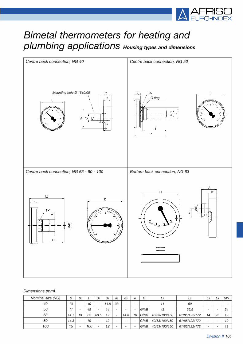
Division II 161
Bimetal thermometers for heating and plumbing applications Housing types and dimensions
Centre back connection, NG 40 Centre back connection, NG 50
Centre back connection, NG 63 - 80 - 100 Bottom back connection, NG 63
Dimensions (mm)
Nominal size (NG) B B1 D D1 d1 d2 d3 e G L1 L2 L3 L4 SW
40 13 - 40 - 14.8 33 - - - 11 50 - - -
50 11 - 49 - 14 - - - G1/2B 42 56.5 - - 24
63 14.7 13 62 63.5 12 - 14.8 16 G1/2B 40/63/100/150 61/85/122/172 14 25 19
80 14.3 - 79 - 12 - - - G1/2B 40/63/100/150 61/85/122/172 - - 19
100 15 - 100 - 12 - - - G1/2B 40/63/100/150 61/85/122/172 - - 19
Mounting hole Ø 15±0,05
O ring

162 Division II
Bimetal thermometers for heating and plumbing applications
Spare thermowells * Minimum ordering quantity 1 PU (packing unit)Delivery only in packing units
Type BiTh 40 K BiTh 50 K BiTh 63 K BiTh 80 K BiTh 100 K
Version
Housing-Ø 40 50 63 80 100Housing ABS, white ABS, white ABS, black, clip-in plastic front glassStem Plastic, Ø 15 mm Plastic, Ø 9 mm Brass, Ø 9 mmConnection Plastic, plug-on, Thermowell Thermowell G1/2B, brass,
no thermowell G1/2B, plastic outside Ø 12 mm, removableAccuracy class Class 2 according to EN 13190
Range -20/+60 °C -20/+60 °C -20/+60 °C -20/+60 °C -20/+60 °CStem length PU* PU* Price € PU* Price € PU* Price € PU*
Part no. Part no. Part no.40 mm --- --- 100 100 50
63763 63776 6367663 mm --- --- 100 100 50
63769 63777 63677100 mm --- --- 100 50 50
63770 63778 63678150 mm --- --- 50 40 25
63771 63779 63679Range 0/60 °C 0/60 °C 0/60 °C 0/60 °C 0/60 °CStem length Price € Price € Price € Price € Price €
Part no. Part no. Part no. Part no. Part no.40 mm 100 100 100 100 50
64066 63749 63760 63765 6369863 mm (refer to drawing --- 100 100 50
for stem 63761 63766 63699100 mm --- --- 100 50 50
63762 63767 63700150 mm --- --- 50 40 25
63764 63768 63701Range 0/120 °C 0/120 °C 0/120 °C 0/120 °C 0/120 °CStem length Price € Price € Price €
Part no. Part no. Part no.40 mm with --- --- 100 100 50
PTFE sealing ring 63702 63706 6368440 mm --- --- 100 100 50
63704 63708 6399763 mm --- --- 100 100 50
63710 63715 63695100 mm --- --- 100 50 50
63711 63716 63696150 mm --- --- 50 40 25
63714 63717 63697
DG: G
Connection G1/2B, brassStem length Part no. Price
40 mm with 63685PTFE sealing ring
40 mm 6385663 mm 63686
100 mm 63687150 mm 63688

Division II 163
Bimetal standard thermometers/surface mounting thermometers/flue gas thermometers
Bimetal standard thermometersApplicationHeating, plumbingNominal size50 - 63 - 80 - 100 - 160Measuring elementBimetal helixAccuracy class2 (EN 13190)Ranges °C-20/60, 0/60, 0/120, 0/160Working temperatureFull scale valueOperating pressure at thermowellMax. 6 barStandard versionConnectionStem brass, Ø 9 mm, thermowellbrass G1/2B, removableMounting positionNG 50 - 63 - 80 - 100 - 160 centre backNG 63 - 80 - 100 bottomDialUp to 120 °C plastic, > 160 °C aluminium, whiteDial marking blackPointerPlastic, blackHousingSheet steel, galvanisedPush on bezelSheet steel, nickel-platedFront glassPlasticOptions• Other ranges• Nominal size 34
Surface mounting thermometersApplicationHeating, plumbing
Nominal size63 - 80
Measuring elementBimetal spiral
Accuracy class2 (EN 13190)
Ranges °C0/60, 0/120
Working temperatureFull scale value
Standard versionConnectionNG 63 with heat-conducting ele-ment and fastening spring or uni-versal clamp for pipes 3/8“ to 11/2“NG 80 with heat-conducting ele-ment and fastening spring
Mounting positionNG 63 - 80 centre back
DialAluminium, white - dial marking black
PointerPlastic, black
HousingSheet steel, galvanised
Push on bezelSheet steel, nickel-plated
Front glassPlastic
Options• Other ranges
Flue gas thermometer RTFlue gas temperature controller RTCApplicationBurner control for gas and oil burners
Nominal size80
Measuring elementBimetal helix
Accuracy class2 (EN 13190)
Ranges °CRT: 0/300, 0/500RTC: 0/350
Working temperatureFull scale value
Standard versionConnectionRT: Stem stainless steel 1.4571,
plain, with adjustable cone, brass
RTC: Stem stainless steel 1.4571, plain, with magnetic ring holder
Mounting positionCentre back
DialAluminium, grey - dial marking blackRTC with green and red referencezones
PointerAluminium, blackRTC with additional max. pointer
HousingSheet steel, galvanised
Push on bezelSheet steel, nickel-plated
Front glassPlastic
Refer to pages 165-167 for part no.

164 Division II
Bimetal standard thermometers/surface mounting thermometers/flue gas thermometersHousing types and dimensions
Dimensions (mm)
Bimetal standard thermometersCentre back connection
Bimetal standard thermometersBottom connection
Surface mounting thermometersCentre back connection, with fastening spring
Surface mounting thermometersCentre back connection, with universal clamp for pipes 3/8“ to 11/2“
Flue gas thermometer RTCentre back connection
Flue gas temperature controller RTCCentre back connection
Nominal size (NG) a b1 b2 b3 D d1 d2 F G L1 L2 L3 SW
50 - 18 - - 50 12 - - G1/2B 19/22
63 10 20 35 13.5 63 12 - 29.3 G1/2B 19/22
80 10 21 33 13.5 80 12 6 47.3 G1/2B 19/22
100 10 23.7 40.5 - 100 12 - 59.3 G1/2B 19/22
160 10 22 - - 160 12 - - G1/2B 19/22
45 142 142
68 290
100
150
200
tapered Ø 8 to Ø 12

Division II 165
Bimetal standard thermometers
DG: G
Type BiTh 50 BiTh 63 BiTh 80 BiTh 100 BiTh 160
Version
Housing-Ø 50 63 80 100 160Housing Sheet steel, galvanised, push on bezel nickel-plated, plastic front glassStem Brass, Ø 9 mmConnection Thermowell G1/2B, brass, outside Ø 12 mm, removableAccuracy class Class 2 according to EN 13190
Minimum order quantity for non-stock items = 10 piecesRange -20/+60 °C -20/+60 °C -20/+60 °C -20/+60 °CStem length Price € Price € Price € Price €
Part no. Part no. Part no. Part no.45 mm ---
63951 63955 63959 6396368 mm ---
63952 63956 63960 63964100 mm ---
63953 63957 63961 63981150 mm ---
63954 63958 63962 63982Range 0/60 °C 0/60 °C 0/60 °C 0/60 °C 0/60 °CStem length Price € Price € Price € Price € Price €
Part no. Part no. Part no. Part no. Part no.45 mm
64027 63860 63865 63869 6387368 mm
64028 63861 63866 63870 63874100 mm
64029 63862 63867 63871 63875150 mm
64030 63864 63868 63872 63876Range 0/120 °C 0/120 °C 0/120 °C 0/120 °C 0/120 °CStem length Price € Price € Price € Price € Price €
Part no. Part no. Part no. Part no. Part no.45 mm
64031 63801 63806 63811 6381668 mm
64032 63802 63807 63812 63817100 mm
64033 63803 63808 63813 63818150 mm
64034 63804 63809 63814 63819Range 0/160 °C 0/160 °C 0/160 °C 0/160 °CStem length Price € Price € Price € Price €
Part no. Part no. Part no. Part no.45 mm ---
63983 63987 64015 6401968 mm ---
63984 63988 64016 64020100 mm ---
63985 63989 64017 64021150 mm ---
63986 63990 64018 64022

166 Division II
Bimetal standard thermometers
Spare thermowells
Connection G1/2B, brass (only for bottom connection)
DG: G
Stem length Part no. Price €45 mm 6385068 mm 63851
100 mm 63852150 mm 63853
Type BiTh 63 BiTh 80 BiTh 100
Version
Housing-Ø 63 80 100Housing Sheet steel, galvanised, push on bezel nickel-plated, plastic front glassStem Brass, Ø 9 mmConnection Thermowell G1/2B, brass, outside Ø 12 mm, removableAccuracy class Class 2 according to EN 13190
Range -20/+60 °C -20/+60 °C -20/+60 °CStem length Price € Price € Price €
Part no. Part no. Part no.45 mm
64039 64055 6407368 mm
64040 64056 64074100 mm
64041 64057 64075150 mm
64042 64058 64076Range 0/60 °C 0/60 °C 0/60 °CStem length Price € Price € Price €
Part no. Part no. Part no.45 mm
64043 64059 6407768 mm
64044 64060 64078100 mm
64045 64061 64079150 mm
64046 64062 64080Range 0/120 °C 0/120 °C 0/120 °CStem length Price € Price € Price €
Part no. Part no. Part no.45 mm
64047 64063 6408168 mm
64048 64064 64082100 mm
64049 64067 64083150 mm
64050 64068 64084

Division II 167
DG: G
Flue gas thermometers/thermometers for heating installations
DG: G
Surface mounting thermometers/eccentric thermometersType ATh 63 F ATh 80 F ATh 63 S BiTh 63 exz
Version
Housing-Ø 63 80 63 63
Housing Sheet steel, galvanised, push on bezel nickel-plated, plastic front glass Plastic
Connection Heat-conducting element with Universal clamp Eccentric malefastening spring for pipes 3/8“ to 11/2“ for pipes 3/8“ to 11/2“ connector Ø 15 mm
Accuracy class Class 2 according to EN 13190
Range 0/120 °C 0/120 °C 0/120 °C 20/100 °C
Price € Price € Price € Price €Part no. Part no. Part no. Part no.
63822 63821 63820 68895
Range 0/60 °C 0/60 °C 0/60 °C 0/60 °C
--- --- ---63826
Type RT 80 RTC 80 HTh 160 G HTh 160 W
Version
Housing-Ø 80 80 160 160
Housing Sheet steel, galvanised, push on bezel nickel- Aluminium, brass-coloured, Aluminium, brass-coloured,plated, plastic front glass straight version angled version 90°
Connection Plain stem, Plain stem, Screw-in pocket G1/2Bstainless steel 1.4571, stainless steel 1.4571, brass
adjustable cone magnet
Accuracy class Class 2 according to EN 13190
Range 0/300 °C 0/500 °C 0/350 °C 0/130 °C 0/130 °C
Stem length Price € Price € Price € Price € Price €Part no. Part no. Part no. Part no. Part no.
40 mm --- --- ---63931 63932
100 mm --- ---63833 Glass insert Glass insert
150 mm64238 63830 63832 63941 63942
300 mm --- --- ---64239 63831

168 Division II
Bimetal thermometers forindustrial applicationsApplicationMachines, plants, pipe engineering,boilers, heating technology
TypeD2
Nominal size63 - 80 - 100 - 160
Measuring elementBimetal helix
Accuracy class1 (EN 13190)
Ranges °C-20/60, 0/60, 0/120, 0/160
Working temperatureFull scale value
Operating pressure at thermowellMax. 6 bar
ProtectionIP 41 (EN 60529)
Standard version
ConnectionStem brass, Ø 9 mmThermowell G1/2B, brass, removable
Mounting positionNG 63 - 80 - 100 - 160 centre backNG 63 - 80 - 100 - 160 bottom
DialAluminium, white, dial marking black
PointerAluminium, black
HousingSheet steel, galvanised
Push on bezelSheet steel, nickel-plated
Front glassInstrument glass
Options• Other connection types• Other ranges• Other stem lengths
Bimetal air duct thermometersApplicationAir conditioning, ventilation
TypeD2
Nominal size63 - 80 - 100
Measuring elementBimetal helix
Accuracy class2 (EN 13190)
Ranges °C-30/50, -20/60, -20/40, 0/60
Working temperatureFull scale value
ProtectionIP 41 (EN 60529)
Standard version
ConnectionStem brass, Ø 9 mmMounting flange, steel Ø 80 mm orback flange, steel
Mounting positionNG 63 - 80 - 100 centre back
DialAluminium, white, dial marking black
PointerAluminium, black
HousingSheet steel, galvanised
Push on bezelSheet steel, nickel-plated
Front glassInstrument glass
Options• Other ranges• Other stem lengths• Accuracy class 1
Bimetal thermometers for industrial applicationsBimetal air duct thermometers
Refer to pages 170-172 for part no.

Division II 169
Bimetal thermometers for industrial applications/bimetal air duct thermometersHousing types and dimensionsBimetal thermometers for industrial applicationsCentre back connection
Bimetal air duct thermometersCentre back connection
Dimensions (mm)
Bottom connection
b l
Spanner
d2 GØD
b1
ØD
G
a
Spanner
lF
d2
Adjustable3x120°
d2
ØD
b2 min. 60 mm
l1
d1
d3
d4
Nominal size (NG) a b b1 b2 D d1 d2 d3 d4 F G l l1 SW
63 10 24 34 63 9 6 52 80 43.5 G1/2B 10 21/22
80 10 24 36 80 9 6 52 80 52 G1/2B 10 21/22
100 10 26 36 100 9 6 52 80 62 G1/2B 10 21/22
160 - 32 37 160 9 6 - - 92 G1/2B - 21/22
45
63
100
150
Ad
just
able

170 Division II
Bimetal thermometers for industrial applications
DG: H
Type BiTh 63 I D211 BiTh 80 I D211 BiTh 100 I D211 BiTh 160 I D211
Version
Housing-Ø 63 80 100 160Housing Sheet steel, galvanised, push on bezel nickel-plated, instrument grade front glassStem Brass, Ø 9 mmConnection Thermowell G1/2B, brass, outside Ø 12 mm, removableAccuracy class Class 1 according to EN 13190
Range -20/+60 °C -20/+60 °C -20/+60 °C -20/+60 °CStem length Price € Price € Price € Price €
Part no. Part no. Part no. Part no.45 mm
65106211 65206211 65306211 6540621163 mm
65107211 65207211 65307211 65407211100 mm
65108211 65208211 65308211 65408211150 mm
65109211 65209211 65309211 65409211Range 0/60 °C 0/60 °C 0/60 °C 0/60 °CStem length Price € Price € Price € Price €
Part no. Part no. Part no. Part no.45 mm
65131211 65231211 65331211 6543121163 mm
65132211 65232211 65332211 65432211100 mm
65133211 65233211 65333211 65433211150 mm
65134211 65234211 65334211 65434211Range 0/120 °C 0/120 °C 0/120 °C 0/120 °CStem length Price € Price € Price € Price €
Part no. Part no. Part no. Part no.45 mm
65146211 65246211 65346211 6544621163 mm
65147211 65247211 65347211 65447211100 mm
65148211 65248211 65348211 65448211150 mm
65149211 65249211 65349211 65449211Range 0/160 °C 0/160 °C 0/160 °C 0/160 °CStem length Price € Price € Price € Price €
Part no. Part no. Part no. Part no.45 mm
65151211 65251211 65351211 6545121163 mm
65152211 65252211 65352211 65452211100 mm
65153211 65253211 65353211 65453211150 mm
65154211 65254211 65354211 65454211
Refer to pages 182-184 for options and part no.

Division II 171Refer to pages 182-184 for options and part no.
Bimetal thermometers for industrial applications
DG: H
Type BiTh 63 I D201 BiTh 80 I D201 BiTh 100 I D201 BiTh 160 I D201
Version
Housing-Ø 63 80 100 160Housing Sheet steel, galvanised, push on bezel nickel-plated, instrument grade front glassStem Brass, Ø 9 mmConnection Thermowell G1/2B, brass, outside Ø 12 mm, removableAccuracy class Class 1 according to EN 13190
Range -20/+60 °C -20/+60 °C -20/+60 °C -20/+60 °CStem length Price € Price € Price € Price €
Part no. Part no. Part no. Part no.45 mm
65106201 65206201 65306201 6540620163 mm
65107201 65207201 65307201 65407201100 mm
65108201 65208201 65308201 65408201150 mm
65109201 65209201 65309201 65409201Range 0/60 °C 0/60 °C 0/60 °C 0/60 °CStem length Price € Price € Price € Price €
Part no. Part no. Part no. Part no.45 mm
65131201 65231201 65331201 6543120163 mm
65132201 65232201 65332201 65432201100 mm
65133201 65233201 65333201 65433201150 mm
65134201 65234201 65334201 65434201Range 0/120 °C 0/120 °C 0/120 °C 0/120 °CStem length Price € Price € Price € Price €
Part no. Part no. Part no. Part no.45 mm
65146201 65246201 65346201 6544620163 mm
65147201 65247201 65347201 65447201100 mm
65148201 65248201 65348201 65448201150 mm
65149201 65249201 65349201 65449201Range 0/160 °C 0/160 °C 0/160 °C 0/160 °CStem length Price € Price € Price € Price €
Part no. Part no. Part no. Part no.45 mm
65151201 65251201 65351201 6545120163 mm
65152201 65252201 65352201 65452201100 mm
65153201 65253201 65353201 65453201150 mm
65154201 65254201 65354201 65454201
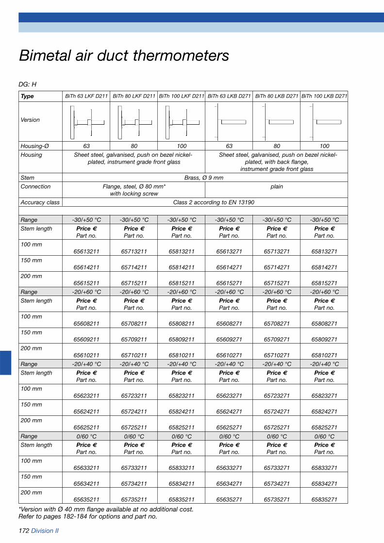
172 Division II
Bimetal air duct thermometers
DG: H
*Version with Ø 40 mm flange available at no additional cost.Refer to pages 182-184 for options and part no.
Type BiTh 63 LKF D211 BiTh 80 LKF D211 BiTh 100 LKF D211 BiTh 63 LKB D271 BiTh 80 LKB D271 BiTh 100 LKB D271
Version
Housing-Ø 63 80 100 63 80 100
Housing Sheet steel, galvanised, push on bezel nickel- Sheet steel, galvanised, push on bezel nickel-plated, instrument grade front glass plated, with back flange,
instrument grade front glass
Stem Brass, Ø 9 mm
Connection Flange, steel, Ø 80 mm* plainwith locking screw
Accuracy class Class 2 according to EN 13190
Range -30/+50 °C -30/+50 °C -30/+50 °C -30/+50 °C -30/+50 °C -30/+50 °C
Stem length Price € Price € Price € Price € Price € Price €Part no. Part no. Part no. Part no. Part no. Part no.
100 mm65613211 65713211 65813211 65613271 65713271 65813271
150 mm65614211 65714211 65814211 65614271 65714271 65814271
200 mm65615211 65715211 65815211 65615271 65715271 65815271
Range -20/+60 °C -20/+60 °C -20/+60 °C -20/+60 °C -20/+60 °C -20/+60 °C
Stem length Price € Price € Price € Price € Price € Price €Part no. Part no. Part no. Part no. Part no. Part no.
100 mm65608211 65708211 65808211 65608271 65708271 65808271
150 mm65609211 65709211 65809211 65609271 65709271 65809271
200 mm65610211 65710211 65810211 65610271 65710271 65810271
Range -20/+40 °C -20/+40 °C -20/+40 °C -20/+40 °C -20/+40 °C -20/+40 °C
Stem length Price € Price € Price € Price € Price € Price €Part no. Part no. Part no. Part no. Part no. Part no.
100 mm65623211 65723211 65823211 65623271 65723271 65823271
150 mm65624211 65724211 65824211 65624271 65724271 65824271
200 mm65625211 65725211 65825211 65625271 65725271 65825271
Range 0/60 °C 0/60 °C 0/60 °C 0/60 °C 0/60 °C 0/60 °CStem length Price € Price € Price € Price € Price € Price €
Part no. Part no. Part no. Part no. Part no. Part no.
100 mm65633211 65733211 65833211 65633271 65733271 65833271
150 mm65634211 65734211 65834211 65634271 65734271 65834271
200 mm65635211 65735211 65835211 65635271 65735271 65835271

Division II 173
Bimetal stainless steel thermometersBimetal thermometers for chemical applications
Bimetal stainless steel thermometersApplicationFor corrosive media. Suitable for a greatvariety of industrial applications.
TypeD3
Nominal size63 - 80 - 100
Measuring elementBimetal helix
Accuracy class1 (EN 13190)
Ranges °C-20/60, 0/60, 0/120, 0/160
Working temperatureFull scale value
Operating pressure at thermowellMax. 6 bar
ProtectionIP 43 (EN 60529)
Standard versionConnectionStem stainless steel 1.4571, Ø 8 mm,plain, adjustable
Mounting positionNG 63 - 80 - 100 centre backNG 63 - 100 bottom
DialAluminium, white - dial marking black
PointerAluminium, black
Housing and push on bezelStainless steel 1.4301
Front glassInstrument glass
Options• Thermowell G1/2B, stainless steel 1.4571• Other connection types• Other ranges• Other stem lengths
Bimetal thermometers forchemical applicationsApplicationFor corrosive media. Meets exactingmeasuring demands, e.g. in chemical,process technology and food industryapplications.
TypeD4
Nominal size63 - 100 - 160
Measuring elementBimetal helix
Accuracy class1 (EN 13190)
Ranges °C-20/60, 0/60, 0/120, 0/160
Working temperatureContinuous: full scale valueShort-term: 1.1 x full scale value
Operating pressure at thermowellMax. 6 bar
ProtectionIP 65 (EN 60529)
Standard versionConnectionStem stainless steel 1.4571, Ø 8 mm,plain, closed
Mounting positionNG 63 - 100 - 160 centre backNG 63 - 100 - 160 bottom
DialAluminium, white, dial marking black
PointerAluminium, black
HousingStainless steel 1.4301
Bayonet type bezelStainless steel 1.4301
Front glassInstrument glass
Options•Thermowell G1/2B, stainless steel
1.4571
•Grooved nut connection according to DIN 11851
•Other connection designs
•Other ranges
•Other stem lengths
•Laminated safety front glass
•Glycerine filling (type D4 only)
•Rotatable/tiltable housing (type D4 only)
•3-hole fixing, panel mounting bezel
•Back flange
•Special materials
•Electrical contacts
Refer to page 175/176 for part no.
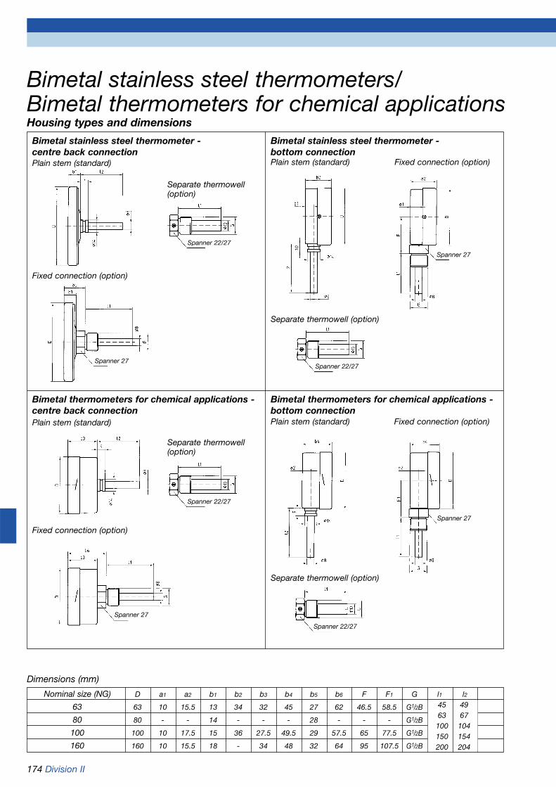
174 Division II
Bimetal stainless steel thermometer - centre back connection
Bimetal stainless steel thermometers/Bimetal thermometers for chemical applicationsHousing types and dimensions
Dimensions (mm)
Bimetal thermometers for chemical applications -centre back connection
Separate thermowell (option)
Separate thermowell (option)
Plain stem (standard)
Separate thermowell(option)
Fixed connection (option)
Bimetal stainless steel thermometer - bottom connectionPlain stem (standard) Fixed connection (option)
Plain stem (standard)
Separate thermowell(option)
Fixed connection (option)
Bimetal thermometers for chemical applications -bottom connectionPlain stem (standard) Fixed connection (option)
Nominal size (NG) D a1 a2 b1 b2 b3 b4 b5 b6 F F1 G l1 l2
63 63 10 15.5 13 34 32 45 27 62 46.5 58.5 G1/2B
80 80 - - 14 - - - 28 - - - G1/2B
100 100 10 17.5 15 36 27.5 49.5 29 57.5 65 77.5 G1/2B
160 160 10 15.5 18 - 34 48 32 64 95 107.5 G1/2B
45 4963 67100 104150 154200 204
10
Spanner 27
Spanner 22/27
Spanner 22/27
Spanner 27
Spanner 27
Spanner 22/27
Spanner 22/27
Spanner 27

Division II 175
DG: H
*Refer to pages 181/182 for other connection types. Refer to pages 182-184 for options and part no.
Bimetal stainless steel thermometers
Type BiTh 63 E D312 BiTh 80 E D312 BiTh 100 E D312 BiTh 63 E D302 BiTh 100 E D302
Version
Housing-Ø 63 80 100 63 100Housing Stainless steel 1.4301 with push on bezel 1.4301, instrument front glassStem Stainless steel 1.4571, Ø 8 mmConnection Plain stem (without thermowell)*Accuracy class Class 1 according to EN 13190
Range -20/+60 °C -20/+60 °C -20/+60 °C -20/+60 °C -20/+60 °CFor thermowell Price € Price € Price € Price € Price €with length L1 Part no. Part no. Part no. Part no. Part no.
63 mm66107312 66207312 66307312 66107302 66307302
100 mm66108312 66208312 66308312 66108302 66308302
150 mm66109312 66209312 66309312 66109302 66309302
200 mm66110312 66210312 66310312 66110302 66310302
Range 0/60 °C 0/60 °C 0/60 °C 0/60 °C 0/60 °CFor thermowell Price € Price € Price € Price € Price €with length L1 Part no. Part no. Part no. Part no. Part no.
63 mm66132312 66232312 66332312 66132302 66332302
100 mm66133312 66233312 66333312 66133302 66333302
150 mm66134312 66234312 66334312 66134302 66334302
200 mm66135312 66235312 66335312 66135302 66335302
Range 0/120 °C 0/120 °C 0/120 °C 0/120 °C 0/120 °CFor thermowell Price € Price € Price € Price € Price €with length L1 Part no. Part no. Part no. Part no. Part no.
63 mm66147312 66247312 66347312 66147302 66347302
100 mm66148312 66248312 66348312 66148302 66348302
150 mm66149312 66249312 66349312 66149302 66349302
200 mm66150312 66250312 66350312 66150302 66350302
Range 0/160 °C 0/160 °C 0/160 °C 0/160 °C 0/160 °CFor thermowell Price € Price € Price € Price € Price €with length L1 Part no. Part no. Part no. Part no. Part no.
63 mm66152312 66252312 66352312 66152302 66352302
100 mm66153312 66253312 66353312 66153302 66353302
150 mm66154312 66254312 66354312 66154302 66354302
200 mm66155312 66255312 66355312 66155302 66355302

176 Division II
DG: H
Bimetal thermometers for chemical applications
*Refer to pages 181/182 for other connection types.Refer to pages 182-184 for options and part no.
Type BiTh 63 Ch D412 BiTh 100 Ch D412 BiTh 160 Ch D412 BiTh 63 Ch D402 BiTh 100 Ch D402 BiTh 160 Ch D402
Type
Housing-Ø 63 100 160 63 100 160Housing Stainless steel 1.4301 with bayonet type bezel, instrument front glassStem Stainless steel 1.4571, Ø 8 mmConnection Plain stem (without thermowell)*Accuracy class Class 1 according to EN 13190
Range -20/+60 °C -20/+60 °C -20/+60 °C -20/+60 °C -20/+60 °C -20/+60 °CFor thermowell Price € Price € Price € Price € Price € Price €with length L1 Part no. Part no. Part no. Part no. Part no. Part no.
63 mm66607412 66807412 66907412 66607402 66807402 66907402
100 mm66608412 66808412 66908412 66608402 66808402 66908402
150 mm66609412 66809412 66909412 66609402 66809402 66909402
200 mm66610412 66810412 66910412 66610402 66810402 66910402
Range 0/60 °C 0/60 °C 0/60 °C 0/60 °C 0/60 °C 0/60 °CFor thermowell Price € Price € Price € Price € Price € Price €with length L1 Part no. Part no. Part no. Part no. Part no. Part no.
63 mm66632412 66832412 66932412 66632402 66832402 66932402
100 mm66633412 66833412 66933412 66633402 66833402 66933402
150 mm66634412 66834412 66934412 66634402 66834402 66934402
200 mm66635412 66835412 66935412 66635402 66835402 66935402
Range 0/120 °C 0/120 °C 0/120 °C 0/120 °C 0/120 °C 0/120 °CFor thermowell Price € Price € Price € Price € Price € Price €with length L1 Part no. Part no. Part no. Part no. Part no. Part no.
63 mm66647412 66847412 66947412 66647402 66847402 66947402
100 mm66648412 66848412 66948412 66648402 66848402 66948402
150 mm66649412 66849412 66949412 66649402 66849402 66949402
200 mm66650412 66850412 66950412 66650402 66850402 66950402
Range 0/160 °C 0/160 °C 0/160 °C 0/160 °C 0/160 °C 0/160 °CFor thermowell Price € Price € Price € Price € Price € Price €with length L1 Part no. Part no. Part no. Part no. Part no. Part no.
63 mm66652412 66852412 66952412 66652402 66852402 66952402
100 mm66653412 66853412 66953412 66653402 66853402 66953402
150 mm66654412 66854412 66954412 66654402 66854402 66954402
200 mm66655412 66855412 66955412 66655402 66855402 66955402

Division II 177
Gas filled thermometers for chemical applications
Operating pressure at thermowellMax. 10 bar (up to 300 °C)
ProtectionIP 65 (EN 60529)
Standard version
ConnectionStem stainless steel 1.4541, 100 x 10 mm, plain
Mounting positionCentre back or bottom, with joint
DialAluminium, whiteDial marking black
PointerAluminium, black
Zero correctionAt side of housing
MovementBrass
HousingStainless steel 1.4301
Bayonet type bezelStainless steel 1.4301
Front glassInstrument glass
Options• Rotatable/tiltable housing• Thermowell G1/2B,
stainless steel 1.4541• Grooved nut connection
according to DIN 11851• Nominal size 250• Other connection designs• Other ranges• Special scales• Glycerine filling (type D8)• 3-hole fixing panel mounting
bezel• Back flange• Capillary (stainless steel 1.4541)• Special materials• Electrical contacts
ApplicationFor corrosive media. Meets exactingmeasuring demands, e.g. in chemical, process technology andfood industry applications.
TypeD4
Nominal size100 - 160
Measuring principlePressurised gas filling
Accuracy class1 (EN 13190)
Ranges °C-20/60, 0/60, 0/120, 0/160,0/200, 0/300, 0/400, 0/500
Working temperatureContinuous: full scale valueShort-term: 1.1 x full scale value
Refer to pages 179/180 for part no.

178 Division II
Gas filled thermometersVersion for chemical applications type D 4 - NG 100/160 Housing types and dimensions
Centre back connection Bottom connection
Rotatable/tiltable housing Version with capillary and wall bracket
Version with capillary and back flange Version with capillary and 3-hole fixing panelmounting bezel
Dimensions (mm)
Nominal size (NG) a b b1 D d1 d2 d3
100 13 45 51 101 132 116 5.5160 13 45 51 161 196 178 6250 13 55 57 252 285 270 6

Division II 179
DG: H
Gas filled thermometers for chemical applications
*Refer to pages 181/182 for other connection types. Refer to pages 182-184 for options and part no.
Type FTh 100 Ch D412 FTh 160 Ch D412 FTh 100 Ch D402 FTh 160 Ch D402 FTh 100 Ch D482 FTh 160 Ch D482
Version
Housing-Ø 100 160 100 160 100 160Housing Stainless steel 1.4301 with bayonet type bezel, instrument front glassStem Stainless steel 1.4541, 100 x 10 mmConnection Plain stem (without thermowell)*Filling Pressurised gas fillingAccuracy class Class 1 according to EN 13190
Rotatable/tiltable housingRange -20/+60 °C -20/+60 °C -20/+60 °C -20/+60 °C -20/+60 °C -20/+60 °C
Price € Price € Price € Price € Price € Price €Part no. Part no. Part no. Part no. Part no. Part no.
64341412 64343412 64341402 64343402 64341482 64343482Range 0/60 °C 0/60 °C 0/60 °C 0/60 °C 0/60 °C 0/60 °C
Price € Price € Price € Price € Price € Price €Part no. Part no. Part no. Part no. Part no. Part no.
64361412 64363412 64361402 64363402 64361482 64363482Range 0/120 °C 0/120 °C 0/120 °C 0/120 °C 0/120 °C 0/120 °C
Price € Price € Price € Price € Price € Price €Part no. Part no. Part no. Part no. Part no. Part no.
64373412 64375412 64373402 64375402 64373482 64375482Range 0/160 °C 0/160 °C 0/160 °C 0/160 °C 0/160 °C 0/160 °C
Price € Price € Price € Price € Price € Price €Part no. Part no. Part no. Part no. Part no. Part no.
64377412 64379412 64377402 64379402 64377482 64379482Range 0/200 °C 0/200 °C 0/200 °C 0/200 °C 0/200 °C 0/200 °C
Price € Price € Price € Price € Price € Price €Part no. Part no. Part no. Part no. Part no. Part no.
64381412 64383412 64381402 64383402 64381482 64383482Range 0/300 °C 0/300 °C 0/300 °C 0/300 °C 0/300 °C 0/300 °C
Price € Price € Price € Price € Price € Price €Part no. Part no. Part no. Part no. Part no. Part no.
64389412 64391412 64389402 64391402 64389482 64391482Range 0/400 °C 0/400 °C 0/400 °C 0/400 °C 0/400 °C 0/400 °C
Price € Price € Price € Price € Price € Price €Part no. Part no. Part no. Part no. Part no. Part no.
64397412 64399412 64397402 64399402 64397482 64399482Range 0/500 °C 0/500 °C 0/500 °C 0/500 °C 0/500 °C 0/500 °C
Price € Price € Price € Price € Price € Price €Part no. Part no. Part no. Part no. Part no. Part no.
64401412 64403412 64401402 64403402 64401482 64403482

180 Division II
DG: H
Gas filled thermometers for chemical applications
*Refer to pages 181/182 for other connection types.Refer to pages 182-184 for options and part no.
Type FTh 100 Ch D442 FTh 160 Ch D442 FTh 100 Ch D472 FTh 160 Ch D472 FTh 100 Ch D432 FTh 160 Ch D432
Version
Housing-Ø 100 160 100 160 100 160Housing Stainless steel 1.4301 with bayonet type bezel, instrument front glassStem Stainless steel 1.4541, 100 x 10 mmConnection Plain stem (without thermowell)*Filling Pressurised gas fillingCapillary Stainless steel 1.4541, 1 metreMounting Bracket for wall mounting Back flange 3-hole fixing panel mounting bezel 1.4301
Accuracy class Class 1 according to EN 13190
Range -20/+60 °C -20/+60 °C -20/+60 °C -20/+60 °C -20/+60 °C -20/+60 °CPrice € Price € Price € Price € Price € Price €Part no. Part no. Part no. Part no. Part no. Part no.
64341442 64343442 64341472 64343472 64341432 64343432Range 0/60 °C 0/60 °C 0/60 °C 0/60 °C 0/60 °C 0/60 °C
Price € Price € Price € Price € Price € Price €Part no. Part no. Part no. Part no. Part no. Part no.
64361442 64363442 64361472 64363472 64361432 64363432Range 0/120 °C 0/120 °C 0/120 °C 0/120 °C 0/120 °C 0/120 °C
Price € Price € Price € Price € Price € Price €Part no. Part no. Part no. Part no. Part no. Part no.
64373442 64375442 64373472 64375472 64373432 64375432Range 0/160 °C 0/160 °C 0/160 °C 0/160 °C 0/160 °C 0/160 °C
Price € Price € Price € Price € Price € Price €Part no. Part no. Part no. Part no. Part no. Part no.
64377442 64379442 64377472 64379472 64377432 64379432Range 0/200 °C 0/200 °C 0/200 °C 0/200 °C 0/200 °C 0/200 °C
Price € Price € Price € Price € Price € Price €Part no. Part no. Part no. Part no. Part no. Part no.
64381442 64383442 64381472 64383472 64381432 64383432Range 0/300 °C 0/300 °C 0/300 °C 0/300 °C 0/300 °C 0/300 °C
Price € Price € Price € Price € Price € Price €Part no. Part no. Part no. Part no. Part no. Part no.
64389442 64391442 64389472 64391472 64389432 64391432Range 0/400 °C 0/400 °C 0/400 °C 0/400 °C 0/400 °C 0/400 °C
Price € Price € Price € Price € Price € Price €Part no. Part no. Part no. Part no. Part no. Part no.
64397442 64399442 64397472 64399472 64397432 64399432Range 0/500 °C 0/500 °C 0/500 °C 0/500 °C 0/500 °C 0/500 °C
Price € Price € Price € Price € Price € Price €Part no. Part no. Part no. Part no. Part no. Part no.
64401442 64403442 64401472 64403472 64401432 64403432

Division II 181
Summary of connection types for bimetal andgas filled thermometers (industrial, stainless steel and chemical application versions)
Plain stem
Separate screw-in thermowell (with locking screw)
Separate weld in thermowell (with locking screw)
Fixed male connection
Loose male connection
Loose union nut
Male compression fitting, adjustable on stem
DIN thermowell
Housing
Stem
Recess for locking screw
Housing
Stem
Loose nut (seat on shoulder on stem)
Housing
Thread for screw connection
Thermowell pushed on, fixed with locking screw
Housing
Stem
Loose female nut (seat on shoulder on stem)
Housing
Locking screw
Thermowell pushed on,for welding
Stem
Housing
Seals on stem
Compression fitting adjustable
Housing
Stem
Fixed threaded connection
Thermowell according to DIN 43772 with thread
Housing
Stem

182 Division II
Additional costs - connection types for bimetal andgas filled thermometers (industrial, stainless steel and chemical application versions)
DG: H
1) Only applicable to standard lengths 45/63/100/150/200/250/300/400 mm – additional cost for special lengths 2) Only for centre back connection, limited measuring ranges
Type Bimetal thermometers Gas filled thermometers
Material Brass Steel Stainless Brass Steel Stainless Stainlesssteel 1.4571 steel 1.4541 steel 1.4571
Price € Price € Price € Price € Price € Price € Price €Part no. Part no. Part no. Part no. Part no. Part no. Part no.
45 --- --- --- ---64506 64511 64501
63 --- --- --- ---64507 64512 64502
100 on64508 64513 64503 64456 64457 64463 request
150 --- --- --- ---64509 64514 64504
200 --- --- --- ---64510 64515 64505
45 --- --- --- --- ---64516 64520
63 --- --- --- --- ---64517 64521
100 --- --- on64450 64453 64434 64435 request
150 --- --- --- --- ---64518 64522
200 --- --- --- --- ---64519 64523
Stem extension --- --- ---per 100 mm 1) 64524 64525 64526 64527Thermowell extension --- --- ---per 100 mm 1) 64528 64529 64530 64531Fixed male connection G1/4B --- --- --- ---
64532 64533 64534Fixed male connection G1/2B --- --- ---
64447 64451 64454 64460Fixed male connection G3/4B --- --- ---
64535 64536 64537 64538Loose male connection G1/4B --- --- --- ---
64539 64540 64541Loose male connection G1/2B --- --- ---
64542 64543 64544 64545Loose male connection G3/4B --- --- ---
64546 64547 64548 64549Loose union nut --- --- ---G1/2 female 64448 64436 64455 64461Loose union nut --- --- ---G3/4 female 64551 64552 64553 64554Loose male connection G1/2B with --- --- --- --- --- ---separate thermowell (100 mm) G1/2B 64462Compression fitting --- --- --- ---adjustable G1/2B 64555 64556 64557Compression fitting --- --- --- --- ---adjustable G3/4B 64558 64559Capillary per metre, --- --- --- --- --- ---stainless steel 1.4571 64464Stem Ø 6 mm 2) --- --- --- --- ---Stem Ø 4 mm 2) --- --- --- --- ---Injection tip for Ø 8 mm 2) --- --- --- --- ---Injection tip for Ø 4 mm 2) --- --- --- --- --- ---
Stemlength mm
Separate screw-in thermo-well (with locking screw), G1/2Bfor stem up to
Ø 8 mm for bimetal thØ 10 mm for gas filled th
Separate weld-in thermo-well (with locking screw) for stem up to
Ø 8 mm for bimetal thØ 10 mm for gas filled th

Division II 183
DG: H
Thermowells according to DIN 43772
Design 5 Design 6 Design 4Type
* Applicable to static load (load always depends on medium, pressure and temperature of medium, installation length and material of thermowell).
Immersion shaft length of the thermometer (for fixed male connection, G1/2B): L = minus 10 mm.
d1 d2 E N D1 F1 K1 H1 H2 d1 d2 E N D1 F2 K1 H1 H2 d1 d2 F2 N F3 H1 H2
Dimensions 10 8 G1/2B G1/2 26 12 14 19 15 10 8 G1/2B G1/2 26 17 14 19 15 9 8 26 G1/2 15 19 15
(mm) 11 10 G1/2B G1/2 26 13 14 19 15 11 10 G1/2B G1/2 26 17 14 19 15 11 10 26 G1/2 17 19 15
d2 = stem diameter of instrument
ConnectionTo thermometer G1/2 female,
To thermometer G1/2 femaleprocess connection G1/2B
Version Several parts, screw-in One part, screw-in One part, weld-inMaterial Brass Stainless steel Steel Stainless steel Steel Stainless steelPmax* 25 bar 40 bar 160 bar 150 bar 160 bar 150 barTmax* 160 °C 400 °C 300 °C 400 °C 300 °C 400 °C
For stem diameters up to 8 mm
Lengths Price € Price € Lengths Price € Price € Lengths Price € Price €mm Part no. Part no. mm Part no. Part no. mm Part no. Part no.
L 110 L 110 L 110U1 82 U1 82 G 105G 105 64670 64674 G 105 64678 64682 U 65 64686 64690
L 170 L 170 L 170U1 142 U1 142 G 165G 165 64671 64675 G 165 64679 64683 U 65 64687 64691
L 210 L 210 L 200U1 182 U1 182 G 195G 205 64672 64676 G 205 64680 64684 U 65 64688 64692
L 260 L 260 L 260U1 232 U1 232 G 255G 255 64673 64677 G 255 64681 64685 U 125 64689 64693
For stem diameters up to 10 mmLengths Price € Price € Lengths Price € Price € Lengths Price € Price €
mm Part no. Part no. mm Part no. Part no. mm Part no. Part no.L 110 L 110 L 110U1 82 U1 82 G 105G 105 64694 64698 G 105 64702 64706 U 65 64710 64714
L 170 L 170 L 170U1 142 U1 142 G 165G 165 64695 64699 G 165 64703 64707 U 65 64711 64715
L 210 L 210 L 200U1 182 U1 182 G 195G 205 64696 64700 G 205 64704 64708 U 65 64712 64716
L 260 L 260 L 260U1 232 U1 232 G 255G 255 64697 64701 G 255 64705 64709 U 125 64713 64717

184 Division II
DG: H
Please refer to page 354 for contact protection relays and isolating amplifiers.
DG: H
Electrical contacts (only for gas filled thermometers)
* For version with separate thermowell
Additional costs for bimetal and gas filled thermometers (industrial, stainless steel and chemical application versions)
Bimetal thermometers Gas filled thermometers
Housing diameter (mm) < 100 100 160 100 160
Price € Price € Price € Price € Price €Part no. Part no. Part no. Part no. Part no.
Red mark on dial64465 64470 64478 64487 64492
1 reference pointer red, external knob adjustment(front glass = plastic 64467 64471 64479 64488 64493Tmax 160 °C only for instruments without filling)
Max pointer, external knob adjustment(front glass = plastic 64468 64473 64481 64489 64494Tmax 160 °C only for instruments without filling)
Glycerine filling (only for instruments with bayonet type bezel housing) 64475 64483 64490 64495
Silicone oil (only for instruments with bayonet type bezel housing) 64476 64484 64491 64496
Other ranges Minimum stem length Minimum stem length Price €(additional cost with reference to version 0/120 °C) back connection (in mm)* bottom connection (in mm)*
-20/+40 °C 63 100
-20/+60 °C 63 63
-30/+50 °C 63 63
-40/+40 °C 63 63
-40/+60 °C 63 63
0/ 60 °C 63 100
0/ 80 °C 63 63
0/100 °C 63 63
0/200 °C 63 63
0/250 °C 100 100
0/300 °C 75 63
0/400 °C 75 75
0/500 °C 63 63
0/600 °C 75 175
Design Magnetic spring contact Inductive contact
Code MK 1 MK 2 IK 1 IK 2Number of contacts 1 2 1 2Switching function: 1 = closes, 2 = opens 1 11, 12 1 11, 12(pointer moves clockwise) 2 21, 22 2 21, 22
The additional costs listed includemounting; gauge not included
Version Nominal size Housing Price € Price € Price € Price €gas filled thermometers 100 without fillingchemical 100 with fillingapplication versions 160 without filling
160 with filling

Division II 185
ApplicationHeating, industry, machine construction
Nominal size110 x 30 - 150 x 36 - 200 x 36
Upper partAluminium, V-shaped, polished,anodised brass-coloured.Numbers of the measuring range onthe right scale side below theanodised layer, printed, black.Adjustable by means of brass nut(spanner size 22), so that readingsfrom any angle are possible.
Glass insert (capillary)Prismatic capillary - completelymade from glass, Ø 6 mm.Graduation marks of the capillaryburnt in, black, completely resistant.Main graduation marks correspon-ding to the numbers printed in thehousing are especially bold andeasy-to-read.
Thermometer fillingStandard version: blue liquid indicating from -60/+200 °C.
StemBrass, Ø 10 mm, with fixed threadG1/2B.Stainless steel version on request.
AccuracyDIN 16195
Ranges °C-30/50, 0/60, 0/120, 0/160
Mounting positionStraightAngled 90°Angled 135°
Stem lengths (mm)40, 63, 100, 160
Options
• Other ranges• Other stem lengths• Other stem materials• Other threads• Upper part anodised aluminium-
coloured• Upper part made from plastic• Thermowells
Industrial thermometers
L14063100160
Refer to page 186 for part no.
Housing types and dimensions (in mm)
Type LVMTh 110 110VMTh 150 150VMTh 200 200
Spanner 27
G1/2B
G1/2BSpanner 27
L1
L 1L
L
Ø10
Ø10

186 Division II
DG: H
Industrial thermometers
Please enquire for angle 135° version.Additional cost for stainless steel screw-in socket
Type VMTh 110 VMTh 110 VMTh 150 VMTh 150 VMTh 200 VMTh 200
Version
Nominal size 110 x 30 110 x 30 150 x 36 150 x 36 200 x 36 200 x 36DIN 16181 16182 16185 16186 16189 16190Mounting position Straight Angled 90° Straight Angled 90° Straight Angled 90°Housing Aluminium, anodised brass-colouredStem Brass, Ø 10 mmConnection Version B with screw-in socket G1/2B, brassAccuracy According to DIN 16195
Range -30/+50 °C -30/+50 °C -30/+50 °C -30/+50 °C -30/+50 °C -30/+50 °CStem length Price € Price € Price € Price € Price € Price €
Part no. Part no. Part no. Part no. Part no. Part no.40 mm --- ---
64101 64120 64136 6415063 mm
64102 64121 64137 64151 64165 64181100 mm
64103 64122 64138 64152 64166 64182160 mm
64104 64123 64139 64153 64167 64183Range 0/60 °C 0/60 °C 0/60 °C 0/60 °C 0/60 °C 0/60 °CStem length Price € Price € Price € Price € Price € Price €
Part no. Part no. Part no. Part no. Part no. Part no.40 mm --- ---
64106 64124 64140 6415463 mm
64107 64125 64141 64155 64169 64185100 mm
64108 64126 64142 64156 64170 64186160 mm
64109 64127 64143 64157 64171 64187Range 0/120 °C 0/120 °C 0/120 °C 0/120 °C 0/120 °C 0/120 °CStem length Price € Price € Price € Price € Price € Price €
Part no. Part no. Part no. Part no. Part no. Part no.40 mm --- ---
64111 64128 64100 6411063 mm
64112 64129 64105 64115 64173 64189100 mm
64113 64130 64144 64158 64174 64190160 mm
64114 64131 64145 64159 64175 64191Range 0/160 °C 0/160 °C 0/160 °C 0/160 °C 0/160 °C 0/160 °CStem length Price € Price € Price € Price € Price € Price €
Part no. Part no. Part no. Part no. Part no. Part no.40 mm --- ---
64116 64132 64146 6416063 mm
64117 64133 64147 64161 64177 64193100 mm
64118 64134 64148 64162 64178 64194160 mm
64119 64135 64149 64163 64179 64195

Division II 187
Thermometers with capillary tube
Type THK 115/40 SNominal size40 mm
ConnectionCapillary tube (refer to dimension table)
MovementBrass
DialABS
PointerABS
HousingABS, black
Front glassPlastic
Ranges-40/+40 °C0/120 °C
Accuracy/test point -40/+40 °C/-20 °C = ±2 °C0/120 °C/ 30 °C = ±3 °C
ScaleDial white - numbers blackDial black - numbers whiteDial black - numbers yellow
Capillary lengthL = 500 mmL = 1,000 mmL = 1,500 mmL = 2,000 mm
BezelSquare bezel, blackSquare bezel, whiteSquare bezel, grey
Option• Nominal size 37 mm (type THK 113)
Type THK 110/52 SNominal size52 mm
ConnectionCapillary tube (refer to dimensiontable)
MovementBrass
DialABS
PointerABS
HousingABS, black
Front glassPlastic
Ranges-40/+40 °C0/120 °C
Accuracy/test point-40/+40 °C/-20 °C = ±2 °C0/120 °C/ 30 °C = ±3 °C
ScaleDial white - numbers blackDial black - numbers whiteDial black - numbers yellow
Capillary lengthL = 500 mmL = 1,000 mmL = 1,500 mmL = 2,000 mm
BezelCrimped bezel, blackCrimped bezel, chrome-platedSquare bezel, blackSquare bezel, whiteSquare bezel, grey
Type THK 130/45 SNominal size45 x 45 mm
ConnectionCapillary tube (refer to dimension table)
MovementBrass
DialABS
PointerABS
HousingABS, black
Front glassPlastic
Ranges-40/+40 °C0/120 °C
Accuracy/test point-40/+40 °C/-20 °C = ±2 °C0/120 °C/ 30 °C = ±3 °C
ScaleDial white - numbers blackDial black - numbers whiteDial black - numbers yellow
Capillary lengthL = 500 mmL = 1,000 mmL = 1,500 mmL = 2,000 mm
BezelBlackWhiteGrey
Refer to page 195 for part no.

188 Division II
Thermometers with capillary tubeDimensions (in mm) and capillary connection
Type THK 115/40 S
Type THK 110/52 S
Type THK 130/45 S
Range
-40/+40 °C
0/120 °C
Probe (F)
Ø 8.5 x 30Cu
Ø 6.5 x 30Cu
Capillary
Cu with PVC coating(R3, white)
Cu with PVC coating(R3, grey)
Range
-40/+40 °C
0/120 °C
Probe (F)
Ø 8.5 x 30Cu
Ø 6.5 x 30Cu
Capillary
Cu with PVC coating(R3, white)
Cu with PVC coating(R3, grey)
Range
-40/+40 °C
0/120 °C
Probe (F)
Ø 8,5 x 30Cu
Ø 6,5 x 30Cu
Capillary
Cu with PVC coating(R3, white)
Cu with PVC coating(R3, grey)
Capillary length
Spanner 12
Panel cut out
Capillary length
Panel cut out
Capillary length
Panel cut out
Spanner 12

Division II 189
Thermometers with capillary tube
Type THK 171/62 SNominal size62 x 11 mm
ConnectionCapillary tube (refer to dimension table)
MovementBrass
DialABS
PointerPrinted on inner side of front glass
HousingABS, black
Front glassPlastic
Ranges-40/+40 °C0/120 °C
Accuracy/test point-40/+40 °C/-20 °C = ±2 °C0/120 °C/ 30 °C = ±3 °C
ScaleDial white - numbers blackDial black - numbers whiteDial black - numbers yellow
Capillary lengthL = 500 mmL = 1,000 mmL = 1,500 mmL = 2,000 mm
BezelBlackWhiteGrey
Option• Vertical mounting position
Type THK 181/62 SNominal size62 x 11 mm
ConnectionCapillary tube (refer to dimension table)
MovementBrass
DialABS
PointerPrinted on inner side of front glass
HousingABS, black
Front glassPlastic
Ranges-40/+40 °C0/120 °C
Accuracy/test point-40/+40 °C/-20 °C = ±2 °C0/120 °C/ 30 °C = ±3 °C
ScaleDial white - numbers blackDial black - numbers whiteDial black - numbers yellow
Capillary lengthL = 500 mmL = 1,000 mmL = 1,500 mmL = 2,000 mm
BezelBlackWhiteGrey
Option• Vertical mounting position
Type THK 150/58 SNominal size58 x 25 mm
ConnectionCapillary tube (refer to dimension table)
MovementBrass
DialABS
PointerPrinted on inner side of front glass
HousingABS, black
Front glassPlastic
Ranges-40/+40 °C0/120 °C
Accuracy/test point-40/+40 °C/-20 °C = ±2 °C0/120 °C/ 30 °C = ±3 °C
ScaleDial white - numbers blackDial black - numbers whiteDial black - numbers yellow
Capillary lengthL = 500 mmL = 1,000 mmL = 1,500 mmL = 2,000 mm
BezelBlackWhiteGrey
Option• Vertical mounting position
Refer to page 195/196 for part no.

190 Division II
Thermometers with capillary tubeDimensions (in mm) and capillary connection
Type THK 150/58 S
Type THK 181/62 S
Type THK 171/62 S
Range
-40/+40 °C
0/120 °C
Probe (F)
Ø 8.5 x 30Cu
Ø 6.5 x 25Cu
Capillary
Cu with PVC coating(R3, white)
Cu with PVC coating(R3, grey)
Range
-40/+40 °C
0/120 °C
Probe (F)
Ø 8.5 x 30Cu
Ø 6.5 x 25Cu
Capillary
Cu with PVC coating(R3, white)
Cu with PVC coating(R3, grey)
Range
-40/+40 °C
0/120 °C
Probe (F)
Ø 8.5 x 30Cu
Ø 6.5 x 30Cu
Capillary
Cu with PVC coating(R3, white)
Cu with PVC coating(R3, gray)
Capillary length
Panel cut out
Capillary length
Panel cut out
Capillary length
Panel cut out

Division II 191
Pressure gauges with capillary tube
Type RFK 360/40 SNominal size40 mm
ConnectionCapillary tube (refer to dimension table)
MovementBrass
DialABS
PointerABS
HousingABS, black
Front glassPlastic
Ranges0/4 bar0/6 bar
Accuracy/test point0/4 bar/1 bar = ±0.2 bar0/6 bar/1 bar = ±0.2 bar
ScaleDial white - numbers blackDial black - numbers whiteDial black - numbers yellow
Capillary lengthL = 500 mmL = 1,000 mmL = 1,500 mmL = 2,000 mm
BezelSquare bezel, blackSquare bezel, whiteSquare bezel, grey
Option• Nominal size 37 mm (type RFK 323 )
Type RFK 320/52 SNominal size52 mm
ConnectionCapillary tube (refer to dimension table)
MovementBrass
DialABS
PointerABS
HousingABS, black
Front glassPlastic
Ranges0/4 bar0/6 bar
Accuracy/test point0/4 bar/1 bar = ±0.2 bar0/6 bar/1 bar = ±0.2 bar
ScaleDial white - numbers blackDial black - numbers whiteDial black - numbers yellow
Capillary lengthL = 500 mmL = 1,000 mmL = 1,500 mmL = 2,000 mm
BezelCrimped bezel, blackCrimped bezel, chrome-platedSquare bezel, blackSquare bezel, white
Type RFK 340/45 SNominal size45 x 45 mm
ConnectionCapillary tube (refer to dimension table)
MovementBrass
DialABS
PointerABS
HousingABS, black
Front glassPlastic
Ranges0/4 bar0/6 bar
Accuracy/test point0/4 bar/1 bar = ±0.2 bar0/6 bar/1 bar = ±0.2 bar
ScaleDial white - numbers blackDial black - numbers whiteDial black - numbers yellow
Capillary lengthL = 500 mmL = 1,000 mmL = 1,500 mmL = 2,000 mm
BezelBlackWhiteGrey
Option• Nominal size 37 mm (type RFK 343)
Refer to page 196/197 for part no.

192 Division II
Pressure gauges with capillary tubeDimensions (in mm) and capillary connection
Type RFK 320/52 S
Type RFK 340/45 S
Capillary
Cu with PVC coating(R3, grey)
Capillary
Cu with PVC coating(R3, grey)
Capillary
Cu with PVC coating(R3, grey)
Type RFK 360/40 S
Capillary length
Panel cut out
Capillary length
Panel cut out
Capillary length
Panel cut out
Spanner 14
Spanner 14
Spanner 14

Division II 193
Type THMK 560/40 SNominal size40 mm
ConnectionCapillary tube (refer to dimension table)
MovementBrass
DialABS
PointerABS
HousingABS, black
Front glassPlastic
Ranges0/120 °C – 0/4 bar0/120 °C – 0/6 bar
Accuracy/test point0/4 bar /1 bar = ±0.2 bar0/6 bar /1 bar = ±0.2 bar0/120 °C/30 °C = ±3 °C
ScaleDial white - numbers blackDial black - numbers whiteDial black - numbers yellow
Capillary lengthL = 500 mmL = 1,000 mmL = 1,500 mmL = 2,000 mm
BezelCrimped bezel, blackCrimped bezel, chrome-platedSquare bezel, blackSquare bezel, whiteSquare bezel, grey
Type THMK 520/52 SNominal size52 mm
ConnectionCapillary tube (refer to dimension table)
MovementBrass
DialABS
PointerABS
HousingABS, black
Front glassPlastic
Ranges0/120 °C - 0/4 bar0/120 °C - 0/6 bar
Accuracy/test point0/4 bar /1 bar = ±0.2 bar0/6 bar /1 bar = ±0.2 bar0/120 °C/30 °C = ±3 °C
ScaleDial white - numbers blackDial black - numbers whiteDial black - numbers yellow
Capillary lengthL = 500 mmL = 1,000 mmL = 1,500 mmL = 2,000 mm
BezelCrimped bezel, blackCrimped bezel, chrome-platedSquare bezel, blackSquare bezel, whiteSquare bezel, grey
Type THMK 540/73 SNominal size73 x 37 mm
ConnectionCapillary tube (refer to dimension table)
MovementBrass
DialABS
PointerABS
HousingABS, black
Front glassPlastic
Ranges0/120 °C - 0/4 bar0/120 °C - 0/6 bar
Accuracy/test point0/4 bar /1 bar = ±0.2 bar0/6 bar /1 bar = ±0.2 bar0/120 °C/ 30 °C = ±3 °C
ScaleDial white - numbers blackDial black - numbers whiteDial grey - numbers black
Capillary lengthL = 500 mmL = 1,000 mmL = 1,500 mmL = 2,000 mm
BezelBlackWhiteGrey
Combination thermometer/pressure gaugeswith capillary tube
Refer to page 197 for part no.

194 Division II
Type THMK 560/40 S
Type THMK 520/52 S
Combination thermometer/pressure gaugeswith capillary tube Dimensions (in mm) and capillary connection
Capillary
Cu with PVC coating(R3, grey)
Capillary
Cu with PVC coating(R3, grey)
Capillary
Cu with PVC coating(R3, grey)
Type THMK 540/73 S
Capillary length
Panel cut out
Capillary length
Ap
pro
x. 2
5
Spanner 14
Capillary length
Panel cut out
Capillary length
App
rox.
25
Spanner 14
Capillary length
Panel cut out
Capillary length
Ap
pro
x. 3
0
Spanner 14

Division II 195
Thermometers with capillary tube
DG: G
Type THK 113/37 S THK 115/40 S THK 110/52 S THK 130/45 S THK 150/58 S
Version
Housing-Ø 37 mm 40 mm 52 mm 45 x 45 mm 58 x 25 mm
Housing Plastic, black
Scale Dial black - numbers white
Packing unit* 50 pieces 50 pieces 50 pieces 50 pieces 50 pieces
Range -40/+40 °C -40/+40 °C -40/+40 °C -40/+40 °C -40/+40 °C
Capillary length Price € Price € Price € Price € Price €Part no. Part no. Part no. Part no. Part no.
1,000 mm67510115 67650115 67500115 67520115 67540115
1,500 mm67510125 67650125 67500125 67520125 67540125
2,000 mm67510135 67650135 67500135 67520135 67540135
Range 0/120 °C 0/120 °C 0/120 °C 0/120 °C 0/120 °C
Capillary length Price € Price € Price € Price € Price €Part no. Part no. Part no. Part no. Part no.
1,000 mm67512115 67652115 67502115 67522115 67542115
1,500 mm67512125 67652125 67502125 67522125 67542125
2,000 mm67512135 67652135 67502135 67522135 67542135
Other capillary lengths on request.*Minimum order quantity for non-stock items = 100 pieces

196 Division II
Thermometers/pressure gauges with capillary tubeDG: G
Type THK 150 S/58 S THK 171/62 S THK 181/62 S RFK 360/40 S RFK 320/52 S
Version
Housing-Ø 25 x 58 mm 62 x 11 mm 62 x 11 mm 40 mm 52 mm
Housing Plastic, black
Scale Dial black - numbers white
Packing unit* 50 Stück 50 pieces 50 pieces 50 pieces 50 pieces
Range -40/+40 °C -40/+40 °C -40/+40 °C 0/4 bar 0/4 bar
Capillary length Price € Price € Price € Price € Price €Part no. Part no. Part no. Part no. Part no.
1,000 mm67540115s 67560115 67580115 67665115 67595115
1,500 mm67540125s 67560125 67580125 67665125 67595125
2,000 mm67540135s 67560135 67580135 67665135 67595135
Range 0/120 °C 0/120 °C 0/120 °C 0/6 bar 0/6 bar
Capillary length Price € Price € Price € Price € Price €Part no. Part no. Part no. Part no. Part no.
1,000 mm67542115s 67562115 67582115 67666115 67596115
1,500 mm67542125s 67562125 67582125 67666125 67596125
2,000 mm67542135s 67562135 67582135 67666135 67596135
Other capillary lengths on request.*Minimum order quantity for non-stock items = 100 pieces

Division II 197
Combination thermometer/pressure gaugeswith capillary tubeDG: G
Type RFK 340/45 S RFK 343/37 S THMK 560/40 S THMK 520/52 S THMK 540/73 S
Version
Housing-Ø 45 x 45 mm 37 mm 40 mm 52 mm 73 x 37 mm
Housing Plastic, black
Scale Dial black - numbers white
Packing unit* 50 pieces 50 pieces 50 pieces 50 pieces 40 pieces
Range 0/4 bar 0/4 bar 0/120 °C 0/120 °C 0/120 °C0/4 bar 0/4 bar 0/4 bar
Capillary length Price € Price € Price € Price € Price €Part no. Part no. Part no. Part no. Part no.
1,000 mm67615115 67625115 67675115 67635115 67645115
1,500 mm67615125 67625125 67675125 67635125 67645125
2,000 mm67615135 67625135 67675135 67635135 67645135
Range 0/6 bar 0/6 bar 0/120 °C 0/120 °C 0/120 °C0/6 bar 0/6 bar 0/6 bar
Capillary length Price € Price € Price € Price € Price €Part no. Part no. Part no. Part no. Part no.
1,000 mm67616115 67626115 67676115 67636115 67646115
1,500 mm67616125 67626125 67676125 67636125 67646125
2,000 mm67616135 67626135 67676135 67636135 67646135
Other capillary lengths on request.*Minimum order quantity for non-stock items = 100 pieces

198 Division II
Mounting valve
Knurled nut
DG: G
Accessories for pressure gauges and thermometers with capillary tube
Spanner 21
G1/4
1/2NPT
Spanner 17
G1/4
G1/4
* Minimum order quantity = 1 packing unit
Packing unit* Part no. Female Male Material Price €
50 pieces 67960 G1/4 G1/4B Brass
50 pieces 67961 G1/4 1/2 NPT Brass
Packing unit* Part no. Width Height Material Price €
67965 Sheet steel,
50 pieces (Suitable for 55 mm 37 mm black
THMK 520)
67966 Sheet steel,
50 pieces (Suitable for 55 mm 23 mm black
THK 110)
67967 Sheet steel,
50 pieces (Suitable for 31 mm 49,5 mm black
THK 150)
Packing unit* Part no. Thread Height Material Price €
50 pieces 67968 M 6 x 1 6 mm Plastic
Fixing bracket

Division II 199
Type TRT 200/716Switch pointBetween 30 and 100 °C as required, factory-preset
Switch point accuracy±3 K
Switching differential3 ±1 K
Probe elementLiquid-filledTmax = 120 °C
Time constantDIN 3440
Housing protectionIP 00
Capillary tube coatingPVC R3, black
Contact ratingK1 16 (4)A 250V ACK1-2 6 (1)A 400V AC
Switching schematic
Accessories2 screws M 4x6
Options• Other capillary lengths• Temperature compensation• Gas-filled probe element
K K
Thermostats TRT 200
Refer to page 203 for part no.
Type TRT 200/711Operating range0/90 °C
ToleranceTmin ±5 K - Tmax ±3 K
Switching differential3 ±1 K
Probe elementLiquid-filledTmax = 120 °C
Time constantDIN 3440
Adjustment angle270 °
Housing protectionIP 00
Capillary tube coatingPVC R3, black
Contact ratingK1 16 (4)A 250V ACK1-2 6 (1)A 400V AC
Switching schematic
Accessories2 screws M 4x6
Options• Other operating ranges• Other capillary lengths• Temperature compensation• Gas-filled probe element
K K
Type TRT 200/712Operating range0/90 °C
ToleranceTmin ±5 K - Tmax ±3 K
Switching differential3 ±1 K
Probe elementLiquid-filledTmax = 120 °C
Time constantDIN 3440
Adjustment angle270 °
Housing protectionIP 00
Capillary tube coatingPVC R3, black
Contact ratingK1 16 (4)A 250V ACK1-2 6 (1)A 400V AC
Switching schematic
Accessories2 screws M 4x6
Options• Other operating ranges• Other capillary lengths• Temperature compensation• Gas-filled probe element
KK

200 Division II
Thermostats TRT 200Dimensions (in mm) and capillary connection
Type TRT 200/711 0/90 °C
Type TRT 200/712 0/90 °C
Type TRT 200/716 30/100 °C

Division II 201
Type STW 400/972FunctionPre-adjusted liquid filled temperatureswitch with automatic reset.
Switch point100 °C - factory pre-set(other switch points on request)
Switch point accuracy+0/-6 K
Switching differential10 to 15 K
Probe elementLiquid-filledTmax = 135 °C
Time constantDIN 3440
Housing protectionIP 00
Capillary tube coatingPVC R3, black
Contact ratingK1 16 (4)A 250V AC
Switching schematic
Accessories2 screws M4 x 6
Options• Other switch points• Other capillary lengths• Gold-plated• Temperature compensation
Type STB 400/971FunctionLiquid filled temperature switchwith manual reset.
Switch point100 °C - factory pre-set (other switch points on request)
Switch point accuracy+0/-6 K
Reset differential20 ±5 K
Probe elementLiquid-filledTmax = 135 °C
Time constantDIN 3440
Housing protectionIP 00
Capillary tube coatingPVC R3, black
Contact ratingK1 16 (4)A 250V ACK1-2 6 (1)A 400V AC
Switching schematic
AccessoriesProtective cover plastic, blackFastening nut M10 x 1
Options• Other switch points• Other capillary lengths• Gold-plated• Temperature compensation
Type ETB 400/961FunctionAdjustable liquid filled temperatureswitch with manual reset.
Operating range90/110 °C - adjustable
Calibration point110 °C
Switch point accuracy+0/-6 K
Reset differential20 ±5 K
Probe elementLiquid-filledTmax = 135 °C
Time constantDIN 3440
Housing protectionIP 00
Capillary tube coatingPVC R3, black
Contact ratingK1 16 (4)A 250V ACK1-2 6 (1)A 400V AC
Switching schematic
AccessoriesProtective cover plastic, blackFastening nut M10 x 1
Options• Other capillary lengths• Gold-plated• Temperature compensation
Safety temperature switches
Refer to page 204 for part no.
K K K K K
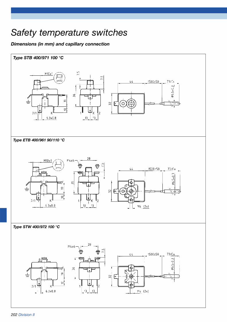
202 Division II
Safety temperature switchesDimensions (in mm) and capillary connection
Type STB 400/971 100 °C
Type ETB 400/961 90/110 °C
Type STW 400/972 100 °C

Division II 203
DG: G
Thermostats TRT 200
* Minimum order quantity for non-stock items = 100 pieces
Type TRT 200/711 EU TRT 200/711 E1 TRT 200/712 EU TRT 200/712 E1 TRT 200/716 FU TRT 200/716 F1
Version
Contact type Changeover contact Single contact Changeover contact Single contact Changeover contact Single contact
Adjustable Adjustable Factory pre-set
Adjustment spindle slotted
Packing unit* 50 pieces
Operating range/ 0/90 °C 0/90 °C 0/90 °C 0/90 °C 30/100 °C 30/100 °Cswitch point
Capillary length Price € Price € Price € Price € Price € Price €Part no. Part no. Part no. Part no. Part no. Part no.
500 mm67215 67212 67245 67242 67251 67248
1,000 mm67216 67213 67246 67243 67252 67249
1,500 mm67217 67214 67247 67244 67253 67250
Type TRT 200 Z/721 EU TRT 200 Z/721 E1 TRT 200 Z/722 EU TRT 200 Z/722 E1 TRT 200 Z/726 FU TRT 200 Z/726 F1
Version
Contact type Changeover contact Single contact Changeover contact Single contact Changeover contact Single contact
Adjustable Adjustable Factory pre-set
Adjustment spindle slotted
Packing unit* 50 pieces
Operating range/ 30/90 °C 30/90 °C 30/90 °C 30/90 °C 40/90 °C 40/90 °Cswitch point
Capillary length Price € Price € Price € Price € Price € Price €Part no. Part no. Part no. Part no. Part no. Part no.
500 mm67257 67254 67263 67260 67269 67266
1,000 mm67258 67255 67264 67261 67270 67267
1,500 mm67259 67256 67265 67262 67271 67268
TRT 200 Z - probe element gas-filled

204 Division II
DG: G
Accessories
Safety temperature switches
* Minimum order quantity for non-stock items = 100 pieces
DG: G
Type STB 400/971 FU STB 400/971 F1 ETB 400/961 EU ETB 400/961 E1 STW 400/972 F1
Version
Contact type Changeover contact Single contact Changeover contact Single contact Single contact
Factory pre-set Adjustable Factory pre-set
Packing unit* 50 pieces
Operating range/ 100 °C 100 °C 90/110 °C 90/110 °C 100 °Cswitch point
Capillary length Price € Price € Price € Price € Price €Part no. Part no. Part no. Part no. Part no.
500 mm67275 67272 67281 67278 67284
1,000 mm67276 67273 67282 67279 67285
1,500 mm67277 67274 67283 67280 67286
Description Part no.* Price €
Knob 42 mm for TRT 200, -35/+35 °C 67339
Knob 42 mm for TRT 200, 0/+40 °C 67340
Knob 42 mm for TRT 200, 0/+90 °C 67341
Knob 42 mm for TRT 200, +40/+90 °C 67342
Knob 42 mm for TRT 200, 0/+120 °C 67343
Knob 42 mm for TRT 200, 0/+210 °C 67344
Knob 42 mm for TRT 200, 0/+300 °C 67345
Bezel for TRT 200, black 67346
Bezel for TRT 200, chrome plated 67347
Fixing clamp 67348
Stop pin 67349
Threaded stop pin 67350

Division II 205
Pockets for pressure gauges, thermometersand thermostats with capillary tube
* Applicable to static load (load always depends on medium, pressure and temperature of medium, flow speed, installation length and material of thermowell).
** Delivery only in packing units (PU) - Minimum order quantity for non-stock items = 1 packing unit.
Type Pocket Pocket Pocket Profile pocketTG 1/2“ 7 x 8 mm TG 1/2“ 9 x 10 mm TG 1/2“ 15 x 16 mm TG 1/2“ 15 x 16 mm
Dimensions (mm)
Connection 1/2 NPT 1/2 NPT 1/2 NPT 1/2 NPT
Pmax* 4 bar 4 bar 4 bar 4 bar
Tmax* 200 °C 200 °C 200 °C 200 °C
Material Brass/Copper alloy
Length L1 Price € PU** Price € PU** Price € PU** Price € PU**Part no. Part no. Part no. Part no.
50 mm67320 250 67326 250 --- ---
100 mm67321 250 67327 250 67331 250 67335 250
120 mm67322 200 67328 200 67332 250 67336 250
150 mm67323 200 67329 200 67333 200 67337 200
200 mm67324 200 67330 200 67334 200 67338 200
As above, but nickel-plated
Length L1 Price € PU** Price € PU** Price € PU** Price € PU**Part no. Part no. Part no. Part no.
50 mm67320N 250 on request 250 --- ---
100 mm67321N 250 on request 250 67331N 250 67335N 250
120 mm67322N 200 on request 200 67332N 250 67336N 250
150 mm67323N 200 on request 200 67333N 200 67337N 200
200 mm67324N 200 on request 200 67334N 200 67338N 200
DG: G
Spanner 22 Spanner 22 Spanner 22 Spanner 22

206 Division II
Type GAT/7RCSurface mounting thermostat withhousing for strap-mounting onpipes, adjustable from outside.Specially suitable for underfloorheating systems.
Operating ranges0/60 °C0/90 °C
ToleranceTmin ±5 K - Tmax ±5 K
Switching differential8 K ±2 K
Probe elementBimetal
HousingBase plate galvanised sheet steel
Upper part and adjustment knobABS (UL 94 V0)
Housing protectionIP 40
Electrical connectionsCable gland PG 11
Contact ratingK1 16 (4) A 250V ACK1-2 06 (1) A 400V AC
Switching schematic
Approvals
Type GAT/7HCSurface mounting thermostat withhousing for strap-mounting onpipes, adjustable from inside.Specially suitable for underfloorheating systems.
Operating ranges0/60 °C0/90 °C
ToleranceTmin ±5 K - Tmax ±5 K
Switching differential8 K ±2 K
Probe elementBimetal
HousingBase plate galvanised sheet steelUpper part ABS (UL 94 V0)
Housing protectionIP 40
Electrical connectionsCable gland PG 11
Contact ratingK1 16 (4) A 250V ACK1-2 06 (1) A 400V AC
Switching schematic
Approvals
Type GSA/9SCAdjustable surface mounting thermostat with housing for strap-mounting on pipes, adjustable frominside. With manual reset. Speciallysuitable for underfloor heatingsystems.
Operating range30/70 °C - adjustable
Switch point accuracy+0/-6 K
Reset differential20 ±5 K
Probe elementLiquid-filled
HousingBase plate galvanised sheet steelUpper part ABS (UL 94 V0)
Housing protectionIP 40
Electrical connectionsCable gland PG 11
Contact ratingK1 16 (4) A 250V ACK1-2 06 (1) A 400V AC
Switching schematic
Approvals
Surface mounting thermostats with housingGAT/GSA
K KK
Refer to page 214 for part no.

Division II 207
Surface mounting thermostats with housingGAT/GSA Dimensions (in mm)
Type GAT/7RC
Type GAT/7HC
Type GSA/9SC

208 Division II
Type GTT/7RGImmersion thermostat with housing,with immersion stem and pocket,adjustable from outside.
Operating ranges0/60 °C0/90 °C
ToleranceTmin ±5 K - Tmax ±3 K
Switching differential5 K ±1 K
Probe elementLiquid-filled
PocketCu alloy, connection 1/2-14 NPT
Stem lengths100, 150, 200 mm
HousingBase plate galvanised sheet steelUpper part and adjustment knobABS (UL 94 V0)
Housing protectionIP 40
Electrical connectionsCable gland PG 11
Contact ratingK1 16 (4) A 250V ACK1-2 06 (1) A 400V AC
Switching schematic
Approvals
Type GTT/7HGImmersion thermostat with housing,with immersion stem and pocket,adjustable from inside.
Operating ranges0/60 °C0/90 °C
ToleranceTmin ±5 K - Tmax ±3 K
Switching differential5 K ±1 K
Probe elementLiquid-filled
PocketCu alloy, connection 1/2-14 NPT
Stem lengths100, 150, 200 mm
HousingBase plate galvanised sheet steelUpper part ABS (UL 94 V0)
Housing protectionIP 40
Electrical connectionsCable gland PG 11
Contact ratingK1 16 (4) A 250V ACK1-2 06 (1) A 400V AC
Switching schematic
Approvals
Type GST/9SGImmersion thermostat with housing,with immersion stem and pocket.With manual reset.
Switch point100 °C - factory pre-set (other switch points on request)
Switch point accuracy+0/-6 K
Reset differential20 ±5 K
Probe elementLiquid-filled
PocketCu alloy, connection 1/2-14 NPT
Stem length100 mm
HousingBase plate galvanised sheet steelUpper part ABS (UL 94 V0)
Housing protectionIP 40
Electrical connectionsCable gland PG 11
Contact ratingK1 16 (4) A 250V ACK1-2 06 (1) A 400V AC
Switching schematic
Approvals
Immersion thermostats with housing GTT/GST
K K
Refer to page 214 for part no.
K

Division II 209
Immersion thermostats with housing GTT/GSTDimensions (in mm)
Type GTT/7RG
Type GTT/7HG
Type GST/9SG

210 Division II
Type GTK/7RDCapillary type thermostat with housing, adjustable from outside.
Operating ranges-35/+35 °C, 0/60 °C, 0/90 °C
Tolerance-35/+35 °C: Tmin ±3 K - Tmax ±3 K0/60 and 0/90 °C:Tmin ±5 K - Tmax ±3 K
Switching differential-35/+35 °C: 2 K ±1 K0/60 and 0/90 °C: 5 K ±1 K
Capillary length1,000, 1,500 mm
Probe elementCu alloy/Ø 6,5 x 73 mm, liquid-filled
HousingGalvanised sheet steel base plate,with 2 holes Ø 4.2 for wall mountingUpper part and adjustment knobABS (UL 94 V0)
Housing protectionIP 40
Electrical connectionsCable gland PG 11
Contact ratingK1 16 (4) A 250V ACK1-2 06 (1) A 400V AC
Switching schematic
Options• Manual reset, switch point 100 °C
(type GSK/9SD)
Type GSK/9SFCapillary type safety thermostatwith housing, adjustable from inside. With manual reset. Speciallydesigned for flue gas monitoring.
Switch point70/110 °C - adjustable
Switch point accuracy+0/-8 K
Switching differential20 ±5 K
Capillary length1,500 mm
Probe elementCu alloy/Ø 5 x 90 mm, liquid-filled,Tmax 180 °C
HousingGalvanised sheet steel base plate,with 2 holes Ø 4.2 for wall mountingUpper part ABS (UL 94 V0)
Housing protectionIP 40
Electrical connectionsCable gland PG 11
Contact ratingGold contacts100 mV DC 0.3 A
Switching schematic
Type GRT/7RTRoom thermostat with housing forapplications in greenhouses, humidrooms and for animal breeding,adjustable from outside.
Operating ranges0/40 °C0/60 °C
ToleranceTmin ±5 K - Tmax ±3 K
Switching differential2 K ±1 K
Probe elementLiquid-filled
HousingPVC, grey
Housing protectionIP 55
Electrical connectionsCable gland PG 11
Contact ratingK1 16 (4) A 250V ACK1-2 06 (1) A 400V AC
Switching schematic
Options• Adjustable from inside (type 7HT)• With capillary, adjustable from
outside (type 7WD)• With capillary, adjustable from
inside (type 7KD)
Capillary type thermostats with housing GTK/GSKRoom thermostat with housing GRT
K
K
K
Refer to page 214 for part no.
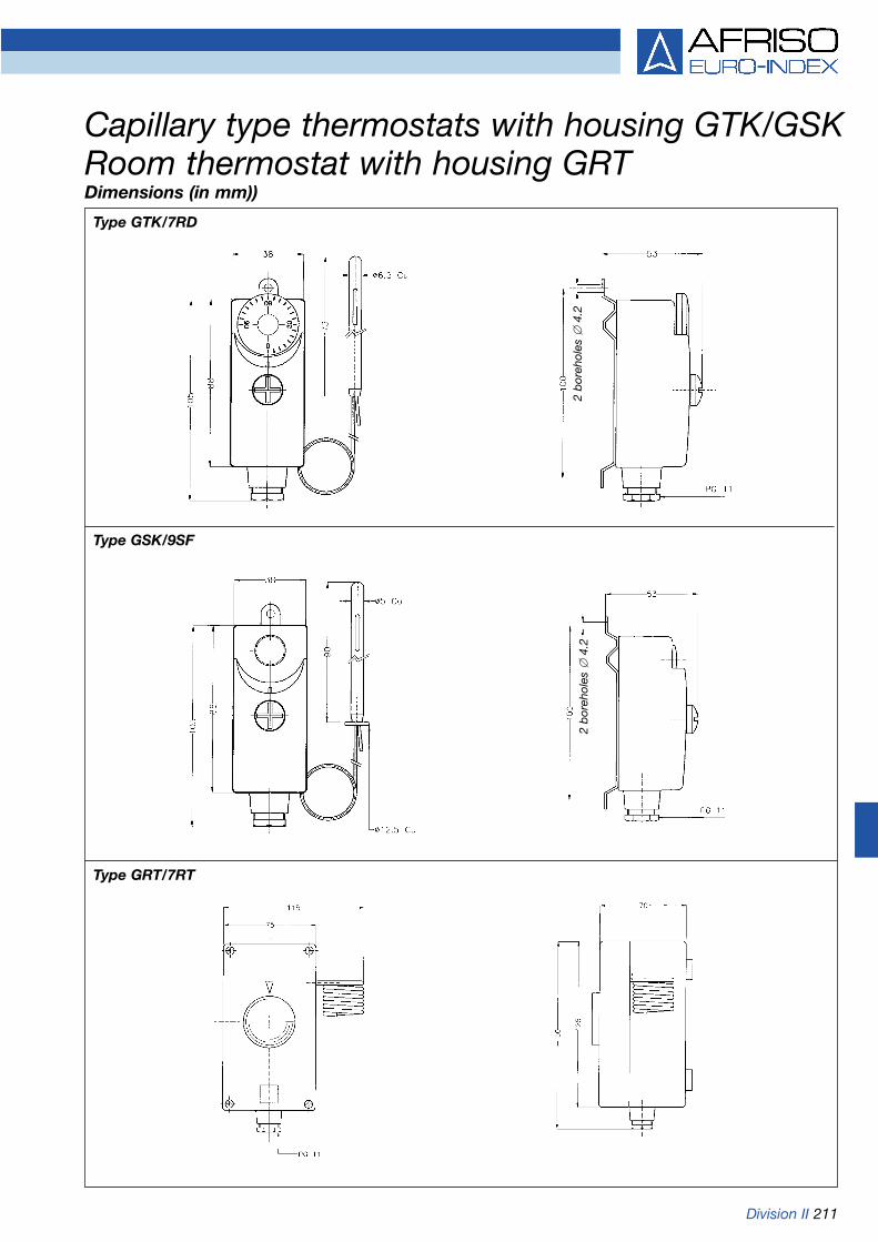
Type GTK/7RD
Type GSK/9SF
Capillary type thermostats with housing GTK/GSKRoom thermostat with housing GRTDimensions (in mm))
Type GRT/7RT
2 b
oreh
oles
4.
22
bor
ehol
es
4.2
Division II 211

212 Division II
Type GDT/8HRTwin thermostat with housing, withimmersion stem and pocket, with 2control thermostats, 1 x adjustable frominside, 1 x adjustable from outside.
Operating ranges0/60 °C - 30/120 °C0/90 °C - 30/120 °C
Tolerance±3 K
Switching differential5 K ±1 K
Probe elementLiquid-filled
PocketCu alloy, connection 1/2-14 NPT
Stem length100 mm
HousingBase plate galvanised sheet steelUpper part and adjustment knob ABS(UL 94 V0)
Housing protectionIP 40
Electrical connectionsCable gland PG 11
Contact ratingK1 16 (4) A 250V ACK1-2 06 (1) A 400V AC
Switching schematic
Approvals
Type GDT/8RSTwin thermostat with housing, withimmersion stem and pocket, consistingof temperature control thermostat (TRT),adjustable from outside, and safety tem-perature switch (STB) with manual reset.
Operating ranges (switch point STB)0/60 °C (100 °C)0/90 °C (100 °C)
Switch point accuracyTRT ±3 K/STB +0/-6 K
Switching differentialTRT 5 K ±1 K/STB 15 - 25 K
Probe elementLiquid-filled
PocketCu alloy, connection 1/2-14 NPT
Stem lengths100, 150, 200 mm
HousingBase plate galvanised sheet steelUpper part and adjustment knob ABS(UL 94 V0)
Housing protectionIP 40
Electrical connectionsCable gland PG 11
Contact ratingK1 16 (4) A 250V ACK1-2 6 (1) A 400V AC
Switching Switchingschematic STB schematic TRT
Approvals
Twin thermostats with housing GDT
Type GDT/8RRTwin thermostat with housing, withimmersion stem and pocket, with 2control thermostats, adjustable fromoutside.
Operating ranges0/60 °C - 30/120 °C0/90 °C - 30/120 °C
Tolerance±3 K
Switching differential5 K ±1 K
Probe elementLiquid-filled
PocketCu alloy, connection 1/2-14 NPT
Stem length100 mm
HousingBase plate galvanised sheet steelUpper part and adjustment knobs ABS(UL 94 V0)
Housing protectionIP 40
Electrical connectionsCable gland PG 11
Contact ratingK1 16 (4) A 250V ACK1-2 06 (1) A 400V AC
Switching schematic
Approvals
K K KK K K
Refer to page 214 for part no.

Division II 213
Twin thermostats with housing GDTDimensions (in mm)
Type GDT/8RR
Type GDT/8HR
Type GDT/8RS

214 Division II
Room thermostatsDG: G
Type Adjustment Operating range/ Capillary length Stem length Packing Part no. Price €switch point unit*
Surface mounting thermostats with housing
GAT/7RC outside 0/60 °C --- --- 28 67400
GAT/7RC outside 0/90 °C --- --- 28 67401
GAT/7HC inside 0/60 °C --- --- 28 67402
GAT/7HC inside 0/90 °C --- --- 28 67403
GSA/9SC inside 30/70 °C --- --- 28 67404
Immersion thermostats with housing
GTT/7RG outside 0/60 °C --- 100 mm 20 67405
GTT/7RG outside 0/90 °C --- 100 mm 20 67407
GTT/7RG outside 0/90 °C --- 150 mm 10 67408A
GTT/7RG outside 0/90 °C --- 200 mm 10 67408B
GTT/7HG inside 0/60 °C --- 100 mm 20 67411
GTT/7HG inside 0/90 °C --- 100 mm 20 67413
GTT/7HG inside 0/90 °C --- 150 mm 10 67414A
GTT/7HG inside 0/90 °C --- 200 mm 10 67414B
GST/9SG fixed 100 °C --- 100 mm 20 67417
Capillary type thermostats with housing/Room thermostats with housing
GTK/7RD outside 0/60 °C 1,000 mm --- 20 67419
GTK/7RD outside 0/90 °C 1,000 mm --- 20 67421
GTK/7RD outside -35/+35 °C 1,500 mm --- 20 67423
GSK/9SF inside 70/110 °C 1,500 mm --- 20 67418
GRT/7RT outside 0/40 °C --- --- 12 67464
GRT/7RT outside 0/60 °C --- --- 12 67465
GRT/7HT inside 0/40 °C --- --- 12 67466
GRT/7HT inside 0/60 °C --- --- 12 67467
GRT/7WD outside 0/40 °C 1,000 mm --- 12 67468
GRT/7WD outside 0/60 °C 1,000 mm --- 12 67469
GRT/7KD inside 0/40 °C 1,000 mm --- 12 67435
GRT/7KD inside 0/60 °C 1,000 mm --- 12 67437
Twin thermostats with housing
GDT/8RR outside/outside 0/60 °C - 30/120 °C --- 100 mm 5 67439
GDT/8RR outside/outside 0/90 °C - 30/120 °C --- 100 mm 10 67441
GDT/8HR inside/outside 0/60 °C - 30/120 °C --- 100 mm 5 67445
GDT/8HR inside/outside 0/90 °C - 30/120 °C --- 100 mm 10 67447
GDT/8RS fixed/outside 0/60 °C (100 °C) --- 100 mm 10 67451
GDT/8RS fixed/outside 0/90 °C (100 °C) --- 100 mm 5 67453
GDT/8RS fixed/outside 0/90 °C (100 °C) --- 150 mm 9 67454A
GDT/8RS fixed/outside 0/90 °C (100 °C) --- 200 mm 9 67454B
* Minimum order quantity for non-stock items = 100 pieces

Division II 215
Resistance thermometers types WTh 20/21/22
Type WTh 20VersionPlug-in type resistance thermometer
DesignRigid probe
Sensor1 x Pt 1002-, 3- or 4-wireClass B, IEC 751
ProbeØ 6 mm, length 50 mmStainless steel 1.4571
Electrical connectionEither cable with free ends (stan-dard), plug DIN 43650-A, or minia-ture round plug, or Lemosa plug
CableEither PVC (standard) or silicon orPFTE or fibreglass
Measuring range-35/+100 °C
Options• Coated measuring cable• Sensor class A• Process connection as adjustable
male compression fitting or fixed male connection
• Other probe diameters• Other probe lengths• Thermally decoupled• Bending protection
Type WTh 21VersionRoom and outside resistance thermometer for wall mounting
DesignClosed probe
Sensor1 x Pt 1002-, 3- or 4-wireClass B, IEC 751
ProbeØ 6 mm, length 44 mmStainless steel 1.4571
Electrical connectionCable gland
Measuring range-30/+60 °C
HousingImpact resistant plasticW x H x D: 58 x 64 x 34 mm
ProtectionIP 54 (EN 60529)
Options• Open probe• Sensor class A• Sensor Pt 1000/Ni 1000• Transmitter installation
Type WTh 22VersionResistance thermometer especiallyfor use in air ducts
Sensor1 x Pt 1003-wireClass B, IEC 751
ThermowellØ 8 x 1 mm, perforatedStainless steel 1.4571
Process connectionFastening flange Ø 41 mm, adjustable, stainless steel
Installation lengths100, 160, 250 mm
HousingImpact resistant plasticW x H x D: 58 x 64 x 34 mm
ProtectionIP 54 (EN 60529)
Measuring range0/130 °C
Options• Process connection G1/2B
(adjustable male compression fitting or fixed male connection)
• Transmitter installation (standard: 0/100 °C = 4-20 mA)
Refer to page 221 for part no.

216 Division II
Resistance thermometers types WTh 20/21/22Dimensions (in mm)
Type WTh 20
Type WTh 21
Type WTh 22
Cable
Probe length
Installation length

Division II 217
Resistance thermometers types WTh 23/24/25
Type WTh 23VersionVariable screw-in resistance thermometer, compact design
Sensor1 x Pt 1002-, 3- or 4-wireClass B, IEC 751
Measurement insertNot replaceable
ThermowellØ 6 mm, stainless steel 1.4571
Process connectionG1/4B stainless steel 1.4571
Installation length100 mm
Connection head (protection)Design J, aluminium die cast (IP 54)
Measuring range-35/+350 °C
Options• Sensor class A• Other thermowell diameters• Thermowell with shoulder,
measuring tip with spring• Neck• Other process connections• Other installation lengths• Transmitter installation
Type WTh 24VersionScrew-in resistance thermometerfor medium pressure and flowloads, specially for HVAC
Sensor1 x Pt 1003-wireClass B, IEC 751
Measurement insertReplaceable
ThermowellAccording to DIN 43772Ø 9 x 1 mm, stainless steel 1.4571
NeckØ 9 x 1 mm, 25 mm longStainless steel 1.4571
Process connectionG1/2B stainless steel 1.4571
Installation lengths100, 160, 250 mm
Connection head (protection)Design B according to DIN 43729Aluminium die cast (IP 54)
Measuring range-30/+180 °C
Options• Transmitter installation (standard:
0/100 °C = 4-20 mA)
Type WTh 25VersionScrew-in resistance thermometerfor medium pressure and flow loads
Sensor1 x Pt 1002-, 3- or 4-wireClass B, IEC 751
Measurement insertReplaceable, Ø 6 mm
ThermowellAccording to DIN 43772Ø 9 x 1 mm, stainless steel 1.4571
NeckØ 9 x 1 mm, 120 mm longStainless steel 1.4571
Process connectionG1/2B stainless steel 1.4571
Installation lengths100, 125, 160, 250, 400 mm
Connection head (protection)Design B according to DIN 43729Aluminium die cast (IP 54)
Measuring range-35/+400 °C
Options• Sensor class A• Reduced measuring tip (6 mm)• Transmitter installation• Ex version• Other thermowell materials,
process connections, installation lengths
Refer to page 221/222 for part no.

218 Division II
Resistance thermometers types WTh 23/24/25Dimensions (in mm)
Type WTh 23
Type WTh 24
Type WTh 25
Installation length
Neck length(Standard = 25) Installation length
Neck length(Standard = 120) Installation length
Spanner 19
Spanner 24
Spanner 24/27
Spanner 24/27

Division II 219
Resistance thermometers types WTh 26/27/28
Type WTh 27VersionFlanged resistance thermometer formedium pressure and flow loads
Sensor1 x Pt 1002-, 3- or 4-wireClass B, IEC 751
Measurement insertReplaceable, Ø 6 mm
Flanged thermowellSeveral parts, Ø 11 x 2 mmFlange connection according to EN 1092-1Design B 1, DN25, PN40Stainless steel 1.4571
NeckØ 11 x 2 mm, 120 mm longStainless steel 1.4571
Installation lengths100, 160, 250, 400 mm
Connection head (protection)Design B according to DIN 43729Aluminium die cast (IP 54)
Measuring range-35/+400 °C
Options• Sensor class A• Reduced measuring tip (6 mm)• Transmitter installation• Ex version• Other thermowell materials,
process connections, installation lengths, connection heads
Type WTh 28VersionResistance thermometer for hygienicprocesses, e.g. food, beverage,pharmaceutical, bio-technologicalapplications
Sensor1 x Pt 1002-, 3- or 4-wireClass B, IEC 751
Measurement insertReplaceable, Ø 6 mm
ThermowellØ 9 x 1 mm, stainless steel 1.4571
NeckØ 9 x 1 mm, 145 mm longStainless steel 1.4571
Process connectionEither clamp, screw connection DIN 11851, weld-in ball, weld-insocket
Installation length100, 125, 160, 250, 400 mm
Connection head (protection)Design B, type BUZAluminium die cast (IP 54)
Measuring range-35/+200 °C
Options• Sensor class A• Reduced measuring tip (6 mm)• Other thermowell materials• Other process connections• Other installation lengths• Transmitter installation• Ex version• Weatherproof housing
Refer to page 222 for part no.
Type WTh 26VersionWeld-in resistance thermometer forhigh pressure and flow loads
Sensor1 x Pt 1002-, 3- or 4-wireClass B, IEC 751
Measurement insertReplaceable, Ø 6 mm
ThermowellAccording to DIN 43772Stainless steel 1.4571
NeckØ 11 x 2 mm, 140 mm longStainless steel 1.4571
Installation lengths65, 100, 160, 250 mm
Connection head (protection)Design B according to DIN 43729Aluminium die cast (IP 54)
Measuring range-35/+550 °C
Options• Sensor class A• Without thermowell
(thread M18x1.5 and M14x1.5)• Transmitter installation• Ex version• Other thermowell materials,
process connections, installation lengths, connection heads

220 Division II
Resistance thermometers types WTh 26/27/28Dimensions (in mm)
Type WTh 26
Type WTh 28
9
Type WTh 27
Neck length(Standard = 140) Installation length
Spanner 27
Neck length(Standard = 120) Installation length
Spanner 27
Flange DN25
Neck length(Standard = 145) Installation length
e.g. clamp connection

Division II 221
Resistance thermometers
DG: E
* Applies to standard ranges (-50/+50, 0/50, 0/100, 0/120, 0/150, 0/200, 0/300 °C), additional cost in all other cases.
Type WTh 20 WTh 21 WTh 22 WTh 23 WTh 24
Version
Sensor 1 x Pt 100 1 x Pt 100 1 x Pt 100 1 x Pt 100 1 x Pt 1003-wire, class B 3-wire, class B 3-wire, class B 3-wire, class B 3-wire, class B
Thermowell/probe Rigid Closed PerforatedDiameter 6 mm 6 mm 8 mm 6 mm 9 mmMaterial Stainless steel 1.4571 Stainless steel 1.4571 Stainless steel 1.4571 Stainless steel 1.4571 Stainless steel 1.4571
Neck --- --- --- --- 25 mm
Process connection --- --- Fastening G1/4B G1/2Bflange Ø 41 mm Edelstahl 1.4571 Stainless steel 1.4571
Connection head/ PVC cable Plastic/cable gland Plastic/cable gland Design J/ DIN 43729, Design Belectrical connection free ends cable gland cable gland
Measuring range -35/+100 °C -30/+60 °C 0/+130 °C -35/+350 °C -30/+180 °C
Installation length Price € Price € Price € Price € Price €Part no. Part no. Part no. Part no. Part no.
44 mm --- --- ---32400
100 mm ---32215 32225 32210
160 mm ---32216 32226 32211
250 mm ---32217 32227 32212
400 mm --- --- --- ---32228
Additional costs
Per additional 100 mm --- ---installation length
1 x Pt 1004-wire
2 x Pt 100 --- --- --- ---2-wire
Sensor Class A
Connection head --- --- ---design BBK
Transmitter installation* --- on requestDC12-36V/4-20mA
Transmitter installation* --- on request ---DC18-40V/0-10V
Probe length 50 mmup to cable length
2,000 mm32220
Cable extensionper 500 mm

222 Division II
DG: E
Resistance thermometers
* Refer to page 226 for thermowells made of other materials. – ** Applies to standard ranges (-50/+50, 0/50,0/100, 0/120, 0/150, 0/200, 0/300, 0/400, 0/500 °C), additional cost in all other cases
Type WTh 25 WTh 26 WTh 27 WTh 28
Version
Sensor 1 x Pt 100 1 x Pt 100 1 x Pt 100 1 x Pt 1003-wire, class B 3-wire, class B 3-wire, class B 3-wire, class B
Thermowell/probe Design B Weld-in thermowell Flange DN 25/PN 40Diameter 9 mm according to DIN 43772* 11 mm 9 mmMaterial stainless steel 1.4571 stainless steel 1.4571 stainless steel 1.4571 stainless steel 1.4571
Neck 120 mm 140 mm 120 mm 145 mm
Process connection G1/2B Weld-in thermowell Flange DN 25/PN 40 Clamp 1“stainless steel 1.4571 according to DIN 43772*
Connection head/ DIN 43729, design B DIN 43729, design B DIN 43729, design B Design B, Typ BUZelectrical connection cable gland cable gland cable gland cable gland
Measuring range -35/+400 °C -35/+550 °C -35/+400 °C -35/+200 °C
Installation length Price € Price € Price € Price €Part no. Part no. Part no. Part no.
65 mm --- --- ---32250
100 mm32240 32251 32260 32230
125 mm --- ---32241 32231
160 mm32242 32253 32261 32232
250 mm32243 32254 32262 32233
400 mm ---32244 32263 32234
Additional costsPer additional 100 mm ---installation length
Transmitter installation**DC 12-36 V/4-20 mA
1 x Pt 1004-wire
2 x Pt 1002-wire
Sensor class A
Reduced measuring ---tip (Ø 6 mm)
Clamp 11/2“ --- --- ---
DIN 11851, DN 40 --- --- ---
Hygienic, DN 40 --- --- ---
Weld-in ball 0on request --- ---
Weld-in socket --- --- --- on request
Ex version WTh
Ex transmitter EEx ib**DC 12-36 V / 4-20 mA

Division II 223
Resistance thermometer WTh 30 forhygienic processes
ApplicationFor temperature measurement in tanks and pipelines and applications requiring hygienic process connections, materials andprocessing. Specially suitable forfood technology, pharmaceuticaland biotechnology applications dueto the compact design and thehigh accuracy.
DescriptionWTh 30 consists of a rugged stainless steel housing with variableprocess connections and a Pt 100measurement insert which isdirectly integrated in a thermowell.The change in resistance dependingon the measured temperature canbe used directly or detected by atransducer and converted into a 4-20 mA output signal. The instru-ment is connected by means of acompact M12 plug connection.
WTh 30 features:
• Hygienic design according to EHEDG recommendations
• Compact design• High accuracy• Short response time • Variable process connections• Integratable transducer
Technical specifications
Measuring range-50/+200 °C
Response timeAccording to IEC 751, test in flowing water (without transducer)T 90 = 5.5 s
Sensor1 x Pt 100, 4-wireClass A, IEC 751
ThermowellStainless steel 1.4404, Ø 6 mm
Installation lengths15, 25, 30, 35, 50, 100, 150, 200 mm
HousingStainless steel, Ø 18 mm
ProtectionIP 67 (EN 60529)
Electrical connectionsM 12 plug connectionPlug housing stainless steel
Process connectionsStainless steel 1.4435, one of thefollowing:G1/2BG1/2B, tapered, metallic sealM12x1.5, tapered, metallic sealGrooved union nut DIN 11851Clamp DIN 32676Clamp ISO 2852Tri-ClampVarivent quick-action connection
Surface roughnessRa < 0.8 µmWelding seam < 1.6 µm
Operating pressureMax. 16 bar (Varivent D68 max. 10 bar)
Technical specificationstransducer (option)
VersionTransducer directly integrated in the plug housing, with encapsulated electronics
Measuring range-50/+150 °C(configuration according to specifications)Minimum span 10 K
Supply voltageDC 10-35 V
Output signal4-20 mA, 2-wire
Options
• Integrated transducer• Other process connections• Electropolishing• Reduced measuring tip (Ø 4 mm)• Replaceable measurement insert• Other installation lengths• Weld-in connectors
Refer to page 225 for part no.

224 Division II
Resistance thermometer WTh 30Dimensions (in mm) and electrical connections
Connection G1/2B Connection M 12x1.5,metallic seal
Connection G1/2B, Weld-in connectormetallic seal
Tapered socket with grooved union nut DIN 11851
DN 25 G = Rd 52x1/6DN 32 G = Rd 58x1/6
Tri-Clamp 1“/1 ½“ D=31 for varivent housing DN 10 and 15ISO 2852 DN25/38 D=50 for varivent housing DN 25 and 1“ DIN32676 DN 25/40 D=68 for varivent housing DN 40-125
Clamp connection Varivent connection
Version Thermowellwith transducer versions
Pin assignment Pin assignmentwithout transducer with transducer
1 x Pt 100 4-20 mA, 2-wire
M12-plug connection4-pole
M12-plug connection4-pole
M12-plug connection4-pole
with control borehole
without control borehole
M12-plug connection4-pole
Rd.52x1/6 (DN25)Rd.58x1/6 (DN32)
M12-plug connection4-pole
M12-plug connection4-pole
M12-plug connection4-pole
temperature decoupler
10 a
ctiv
e le
ngth
10 a
ctiv
e le
ngth
1 brown2 white3 blue4 black
DC 10-35V 0 V

Division II 225
Resistance thermometer WTh 30
* Please specify desired measuring range: 0/+100 °C, 0/+150 °C, -50/+100 °C (corresponding to 4-20 mA each)
DG: E
Type WTh 30 WTh 30 DK WTh 30 MR WTh 30 CP WTh 30 VT
Version
Sensor 1 x Pt 100 1 x Pt 100 1 x Pt 100 1 x Pt 100 1 x Pt 1004-wire, class A 4-wire, class A 4-wire, class A 4-wire, class A 4-wire, class A
Thermowell/probe Diameter 6 mm 6 mm 6 mm 6 mm 6 mmMaterial Stainless steel 1.4404 Stainless steel 1.4404 Stainless steel 1.4404 Stainless steel 1.4404 Stainless steel 1.4404
Process connection G1/2B G1/2B tapered, Grooved union Clamp Variventmetallic nut DIN 11851 ISO 2852 D = 31
seal DN 25 DN 25Electrical connection M12 plug M12 plug M12 plug M12 plug M12 plug
connection connection connection connection connectionMeasuring range -50/+200 °C -50/+200 °C -50/+200 °C -50/+200 °C -50/+200 °CInstallation length L1 Price € Price € Price € Price € Price €
Part no. Part no. Part no. Part no. Part no.15 mm
32300 32308 32316 32324 3233225 mm
32301 32309 32317 32325 3233330 mm
32302 32310 32318 32326 3233435 mm
32303 32311 32319 32327 3233550 mm
32304 32312 32320 32328 32336100 mm
32305 32313 32321 32329 32337150 mm
32306 32314 32322 32330 32338200 mm
32307 32315 32323 32331 32339Additional costs Price € Price € Price € Price € Price Integrated transducer4-20 mA*Reduced measuringtip Ø 4 mmProcess connectionM12x1.5, tapered --- no additional cost --- --- ---DIN 11851 DN 32 --- --- --- ---ISO clamp DN 38 --- --- --- no additional cost ---DIN clamp DN 25 --- --- --- no additional cost ---DIN clamp DN 40 --- --- --- no additional cost ---Tri-Clamp 1“ --- --- --- no additional cost ---Tri-Clamp 11/2“ --- --- --- no additional cost ---Varivent D=50 --- --- --- ---Varivent D=68 --- --- --- ---
Accessories Part no. Price €Weld-in connector for G1/2B tapered, metallic seal, without control hole 32340Weld-in connector for G1/2B tapered, metallic seal, with control hole 32341

226 Division II
Thermowells for resistance thermometers
* The prices of the above thermowells vary greatly depending on the quantities ordered. Please enquire for project-specific prices.
Weld-in thermowells, single-piece according to DIN - design 4Max. operating pressure as per DIN 43772
Design Thermometer Hole Length Cone length Thermowell material Part no. Price*connection L3 L1
1.0460 (C 22.8) 645901.4571 (CrNiMoTi) 64591
D1 M 18 x 1.5 7 mm 140 mm 65 mm 1.7335 (13CrMo44) 645921.5415 (15Mo3) 645931.7380 (10CrMo910) 64594
1.0460 (C 22.8) 645951.4571 (CrNiMoTi) 64596
D2 M 18 x 1.5 7 mm 200 mm 125 mm 1.7335 (13CrMo44) 645971.5415 (15Mo3) 645981.7380 (10CrMo910) 64599
1.0460 (C 22.8) 646001.4571 (CrNiMoTi) 64601
D4 M 18 x 1.5 7 mm 200 mm 65 mm 1.7335 (13CrMo44) 646021.5415 (15Mo3) 646031.7380 (10CrMo910) 64604
1.0460 (C 22.8) 646051.4571 (CrNiMoTi) 64606
D5 M 18 x 1.5 7 mm 260 mm 125 mm 1.7335 (13CrMo44) 646071.5415 (15Mo3) 646081.7380 (10CrMo910) 64609
Weld-in thermowells, single-piece, similar to DIN - design 4Max. operating pressure as per DIN 43772
Design Thermometer Hole Length Cone length Thermowell material Part no. Price*connection L3 L1
1.4571 (CrNiMoTi) 64610D 0 S M 18 x 1.5 7 mm 110 mm 65 mm 1.7335 (13CrMo44) 64611
1.5415 (15Mo3) 646121.7380 (10CrMo910) 64613
1.4571 (CrNiMoTi) 64614D 1 S M 18 x 1.5 7 mm 140 mm 65 mm 1.7335 (13CrMo44) 64615
1.5415 (15Mo3) 646161.7380 (10CrMo910) 64617
1.4571 (CrNiMoTi) 64618D 4 S M 18 x 1.5 7 mm 200 mm 65 mm 1.7335 (13CrMo44) 64619
1.5415 (15Mo3) 646201.7380 (10CrMo910) 64621
1.4571 (CrNiMoTi) 64622D 5 S M 18 x 1.5 7 mm 200 mm 125 mm 1.7335 (13CrMo44) 64623
1.5415 (15Mo3) 646241.7380 (10CrMo910) 64625

Division II 227
Pipeline temperature sensor RTS
Technical specificationsPipeline temperature sensor
Measuring range0/150 °C
Sensor1 x Pt 1002-, 3- or 4-wireClass B, IEC 751
Basic valuesAccording to EN 60751
Measuring currentApprox. 1 mA (film measuring resistor)
Process connection (both ends)One of the following:Clamp DIN 32676Screwed pipe connectionDIN 11851/SMS with union nutMale thread DIN 11887/SMSFlange according to DIN 2633Flange according to ANSI B 16.5
Nominal widthsDN 25 to DN 100or 1“ to 4“
Pipe materialStainless steel 1.4301
Insulation resistance> 100 MOhm at 20 °C (DC 500 V)
Electrical connectionPlug DIN 43650-A
ProtectionIP 65 (EN 60529)
ApplicationSuitable for measuring temperaturein pipelines in which a probe can-not reach into the medium. Specially suitable for hygienic appli-cations in the food and pharmaceu-tical industries as well as for bio-technology and painting systems.
DescriptionThe RTS pipeline temperature sensor consists of a pipe piece withvariable process connections and asensor part contained in the centre.The sensor part contains a flush Pt 100 sensor.A number of thermal coupling anddecoupling measures at the Pt 100sensor minimise thermal errors.This allows for optimum detectionof the temperature of the medium.The pipeline temperature sensorcan be easily installed at any pointof the pipeline.There is no probe reaching into themedium. This offers the followingadvantages:
• The pipeline can be cleaned with a scraper.
• There are no swirls in the pipeline.• No danger of sensor damages in
highly viscous media.• Special internal coatings are
available for corrosive media.• Superior surface quality is possible
by means of electro-polishing.
RTS with plug DIN 43650-A RTS with round connector RTS with plug-in display DA 06
Technical specificationsTransmitter (option)
VersionCeramic hybrid transmitter, mounted directly in the neck
Ambient temperatureMax. 100 °C
Supply voltageDC 12-28 V
Output signal4-20 mA, 2-wire
Options
• Transmitter installation• Other pipe materials• Inner pipe electropolished• Other process connections• Other pipe dimensions• Other measuring ranges• Fixed cable connection• Other plug-in connectors• Sensor class A• Digital plug-in display DA 06
(for version with transmitter)
Price on request.

228 Division II
Dimensions (in mm) TD 10/TSD 20
Prices TD 10/TSD 20(prices include temperature probe)
Digital electronic thermometer TD 10Digital electronic temperature controller TSD 20
TSD 20Digital electronic temperature con-troller with microprocessor control
Range/sensor type-50/+150 °C PTC-50/+300 °C Pt 100, 3-wire
Resolution1 °C (0.1 °C from -19.9/+99.9 °C)
Temperature probePTC or Pt 100, 3-wireCable length 1.5 m
Supply voltageAC/DC 12 V ±10 %
Power consumptionmax. 3 VA
OutputRelay contact: 1 x changeover
contactContact rating: 250 V, 2 A
Switching differential - adjustable0.0 K to 25.5 K
HousingABS, blackBezel:W x H x D: 74 x 32 x 70 mmPanel cut out:W x H: 71 x 29 mmMounting by means of screws
70
28
70
74
32
TD 10Digital electronic thermometer withmicroprocessor control
Range/sensor type-50/+150 °C PTC-50/+300 °C Pt 100, 3-wire
Resolution1 °C (0.1 °C from -19.9/+99.9 °C)
Temperature probePTC or Pt 100, 3-wireCable length 1.5 m
Supply voltageAC/DC 12 V ±10 %
Power consumptionmax. 3 VA
HousingABS, blackBezel:W x H x D: 74 x 32 x 70 mmPanel cut out:W x H: 71 x 29 mmMounting by means of screws
TD 10/2 TSD 20/3 Temperature probe (Pt 100)
DG: H
Version Part no. Price €
TD 10/2 31261-50/+150 °CTD 10/3 31262-50/+300 °CTSD 20/2 31264-50/+150 °CTSD 20/3 31265-50/+300 °CTransformer 31266AC 230/12 VSpare temp. 31267probe -50/+150 °C (PTC)Spare temp. 31269probe -50/+300 °C(Pt 100, 3-wire)

www.afriso.de 229
Chapter 11 Table of contents chapter 11
11
PageCapsule type pressure gaugeStandard capsule type pressure gauge 231Capsule type pressure gauge with square bezel for panel mounting 235Capsule type pressure gauge for chemical applications 242Precision capsule type pressure gauges 244Additional costs for capsule type pressure gauges 248Bourdon tube pressure gaugesBourdon tube pressure gauges for heating/plumbing applications 249Standard Bourdon tube pressure gauges 255Additional costs for standard Bourdon tube pressure gauges 266Combined thermometer-pressure gauge/thermo-hydrometer 252Bourdon tube pressure gauges for industrial applications 267Glycerine filled Bourdon tube pressure gauges 273Glycerine filled Bourdon tube pressure gauges with hot pressed brass housing 288Bourdon tube pressure gauges for chemical applications 291Bourdon tube pressure gauges for chemical applications with glycerine filling 297Bourdon tube safety pressure gauges 303Additional costs for Bourdon tube pressure gauges (industrial, glycerine, chemical, safety versions) 308Bourdon tube pressure gauges type „Process Gauge“ 309Precision Bourdon tube pressure gauges 312Bourdon tube pressure gauges for panel mounting 318Bourdon tube pressure gauges for high pressures 320Bourdon tube pressure gauges for refrigeration applications 323Bourdon tube pressure gauges for welding applications 326Bourdon tube pressure gauges for gas applications 328Bourdon tube pressure gauges for ultra-pure gas applications 331Electrical contacts (contact devices) - technical description 334Bourdon tube pressure gauges with electrical contact 340Additional costs for electrical contacts 352Alarm unit for low gas level for connection to Bourdon tube pressure gauges with electrical contact 353Contact protection relay/isolating switching amplifier 354Accessories for panel mounting and wall mounting 383Diaphragm pressure gaugesStainless steel diaphragm pressure gauges 355Standard diaphragm pressure gauges 359Diaphragm pressure gauges for chemical applications 361Additional costs for diaphragm pressure gauges 358/364
Pressure gauges and controllers

230 www.afriso.de
Chapter 11 Table of contents chapter 11
Spring-diaphragm pressure gauges for differential pressure and chemical applications - overload protected 378Spring-diaphragm pressure gauges for differential pressure - overload protected 376Magnetic diaphragm pressure gauges for very low differential pressure 372Magnetic piston type pressure gauges for differential pressure - high overload protection 370Standard Bourdon tube pressure gauges for differential pressure 367Standard capsule type pressure gauges for differential pressure 365Pressure gauges for differential pressure
Page
Diaphragm pressure gauges for differential pressure for chemical applications - high overload protection 380Differential pressure switches 414Accessories for pressure gaugesPressure gauge stop cocks and valves 384Push-button stop cock 385Overpressure safety devices 385Siphons/U-shaped water pipes 387Reducers, adapters, connection nipples 388Mounting valves with self-sealing coating 388Seals 389Protective covers for pressure gauges 389Diaphragm sealsGeneral information 390Diaphragm seal - plastic version (MD 10) 391Diaphragm seal - compact version (MD 20, MD 21) 391/392Diaphragm seal - standard version (MD 30) 394Diaphragm seal for the paper and pulp industries (MD 40) 395Diaphragm seal for hygienic processes (MD 50-55, MD 60-62) 396Diaphragm seal for homogenising machines (MD 70) 398Tongue type diaphragm seal (MD 71) 398Diaphragm seal - flange version (MD 80) 399Diaphragm seal - „Tubus“ flange version (MD 81) 401In-line chemical seal for hygienic processes (RD 50, RD 51, RD 60) 402In-line chemical seal - intermediate flange version (RD 80) 403Fitting costs and accessories 411Electronic pressure instrumentsPressure switches (DS 600) 412Differential pressure switches (DS 01) 414Pressure transducer - compact version (DMU 01K) 415Pressure transducer - standard version (DMU 01) 416Pressure transducer - industrial version (DMU 03) 418Pressure transducer for hygienic processes (DMU 04) 422Pressure transducer - precision version (DMU 05) 424Pressure transducer - for level measurement (DMU 07) 428Pressure transducer - with submersible level probes (DMU 08, DMU 09) 430/432Accessories for submersible level probes 439Pressure transducer - differential pressure version (DMU 10 D, DMU 11 D) 434/436Intelligent pressure transducer (DMU 12, DMU 14) 440/445Pressure transducer with local display (DMU 13) 443Digital pressure gauge (DIM 10) 447

Division II 231
ApplicationFor gaseous, dry media which donot attack copper alloys.! When measuring gas or vapour,the instruments must be used in accordance with the safetyrecommendations of EN 837-2 (see appendix).
TypesD 2/D 3
Nominal size63 - 80 - 100
Accuracy class (EN 837-3/6)1.6
Ranges (EN 837-3/5)0/25 to 0/1,000 mbar and all corre-sponding vacuum and compoundranges with overpressure protection
Application areaStatic load:full scale valueDynamic load:0.9 x full scale valueOverload safety:1.3 x full scale value
Operating temperature rangeMedium: Tmax = +60 °CAmbient: Tmin = -20 °C
Tmax = +60 °C
Temperature performanceIndication error when the temperature of the measuring element deviates from 20 °C:rising temp. approx. ±0.6 % /10Kfalling temp. approx. ±0.6 % /10Kpercentage of full scale value
ProtectionIP 32 (EN 60529)
Standard version
ConnectionBrass, bottom or centre backNG 63 G1/4B - spanner size 14NG 80 - 100 G1/2B - spanner size22(EN 837-3/7.3)
Measuring elementCapsule element, CuBe alloy
MovementBrass
Zero correctionFrom the front
Seal„Perbunan“ nitrile rubber
DialAluminium, whiteDial marking black
PointerAluminium, black
HousingD 2 – black sheet steelD 3 – stainless steel 1.4301
Front glassClip-in plastic
Options
• Nominal size 50• Back flange• Panel mounting bezel for clamp
fixing• 3-hole fixing, panel mounting
bezel• Movement stainless steel
(NG 100)• Damping screw• Reference pointer• Special scales
Standard capsule type pressure gauges EN 837-3
Refer to pages 237-239 for part no.

232 Division II
Bottom connection Bottom connection, back flange
Dimensions (mm)
Centre back connection Centre back connection, 3-hole fixing, panel mounting bezel
Centre back connection, crimped bezel housing withclamp fixing, NG 63, (version D351)
Centre back connection, panel mounting bezel forclamp fixing, NG 80/100
Standard capsule type pressure gauges Type D 2/D 3 - NG 63/80/100Housing types and dimensions
* Dimensions for NG 100 according to DIN EN 837-3
Nominal size (NG) a a1 b b1 b2 b3 b4 Øc c1 c2 d1* d2 d3* d4 d5 d6 d7 G g g1 g2
63 9.5 12 33.7 36.2 35.7 30.5 - 5 2 13 75 85 3.5 68 68 64 66 G1/4B 56.7 58.7 53.5
80 14.8 17.8 43.3 46.3 44.6 - 46.5 6 3 20 95 110 4.8 - 86 81 83 G1/2B 75.3 76.6 -
100 15.6 19.1 44 47.5 45.6 - 47 6 3 20 116 132 4.8 - 107 101 105 G1/2B 76 77.6 -
Nominal size (NG) g3 h m n s s1 s2 s3 s4 s5 SW
63 - 52.7 94 82 3.7 5.5 3 2 7 4 14
80 78 69 - - 3.8 5.5 3.5 2 - 4.5 22
100 79 87 - - 3.5 5.5 3.5 2 - 4.5 22
Knob

Division II 233
ApplicationFor gaseous, dry media which donot attack copper alloys.! When measuring gas or vapour,the instruments must be used in accordance with the safety recommendations of EN 837-2 (see appendix).
TypeD 4
Nominal size63 - 100 - 160
Accuracy class (EN 837-3/6)1.6
Ranges (EN 837-3/5)NG 63-100 0/25 to 0/1,000 mbarNG 160 0/6 to 0/1,000 mbarand all corresponding vacuum and compound ranges with over-pressure protection
Application areaStatic load:full scale valueDynamic load:0.9 x full scale valueOverload safety:1.3 x full scale value
Operating temperature rangeMedium: Tmax = +60 °CAmbient: Tmin = -20 °C
Tmax = +60 °C
Seal„Perbunan“ nitrile rubber
DialAluminium, whiteDial marking black
PointerAluminium, black
HousingStainless steel 1.4301
Bayonet type bezelStainless steel 1.4301
Front glassInstrument glass
Options
• Overpressure safety 10 x FSD• Back flange• Panel mounting bezel for clamp
fixing• 3-hole fixing panel mounting
bezel• Damping screw• Reference pointer• Special scales
Temperature performanceAdditional error when the temperature of the measuring element deviates from +20 °C:rising temp. approx. ±0.6 % /10Kfalling temp. approx. ±0.6 % /10Kpercentage of full scale value
ProtectionIP 32 (EN 60529)
Standard version
ConnectionBrass, bottom or centre backNG 63 G1/4B - spanner size 14NG 100 - 160 G1/2B - spanner size 22(EN 837-3/7.3)
Measuring elementCapsule element, CuBe alloy
MovementBrass
Zero correctionFrom the front
Standard capsule type pressure gauges EN 837-3
Refer to pages 240/241 for part no.

234 Division II
Bottom connection Bottom connection, back flange
Centre back connection Centre back connection, 3-hole fixing, panel mountingbezel
Centre back connection, panel mounting bezel forclamp fixing
Standard capsule type pressure gauges Type D 4 - NG 63/100/160Housing types and dimensions
Dimensions (mm)
* Dimensions for NG 100 according to DIN EN 837-3
Nominal size (NG) a a1 b b1 b2 b3 Øc c1 c2 d1* d2 d3* d4 d5 d6 G g g1 h s1 s2
63 10.8 13.4 40 42.1 37 37 5 2 13 75 85 3.5 64 68 64 G1/4B 60 60 53 5.2 3
100 15.6 19.1 49 52.5 49 49 6 3 20 116 132 4.8 104 107 101 G1/2B 81 81 86 5.5 4
160 17.5 20.5 50 53 50 52 6 3 20 178 196 5.8 164 167 161 G1/2B 82 84 116 6 4
Nominal size (NG) s3 s4 SW
63 2 3 14
100 2 4 22
160 2 4.5 22

Division II 235
ApplicationFor gaseous, dry media which donot attack copper alloys.For panel mounting.! When measuring gas or vapour,the instruments must be used in accordance with the safety recommendations of EN 837-2 (see appendix).
TypesD 1 / D 2 / D 3
Nominal size72 x 72, 96 x 96, 144 x 144
Accuracy class (EN 837-3/6)1.6
Ranges (EN 837-3/5)0/25 to 0/1,000 mbar and all corresponding vacuum and com-pound ranges with overpressureprotection
Application areaStatic load:full scale valueDynamic load:0.9 x full scale valueOverload safety:1.3 x full scale value
Zero correctionFrom the front
Seal„Perbunan“ nitrile rubber
DialAluminium, whiteDial marking black
PointerAluminium, black
HousingNG 72 D1 – plastic, blackNG 96 D3 – stainless steel 1.4301NG 144 D2 – sheet steel, black
BezelNG 72 plastic, blackNG 96 aluminium, blackNG 144 sheet steel, black
Front glassPlastic
Options
• Damping screw• Reference pointer• Special scales
Operating temperature rangeMedium: Tmax = +60 °CAmbient: Tmin = -20 °C
Tmax = +60 °C
Temperature performanceIndication error when the temperature of the measuring element deviates from 20 °C:rising temp. approx. ±0.6 % /10Kfalling temp. approx. ±0.6 % /10Kpercentage of full scale value
ProtectionIP 54 (EN 60529)
Standard version
ConnectionBrass, centre backNG 72 x 72, 96 x 96 G1/4B - spanner size 14NG 144 x 144 G1/2B - spanner size 22(EN 837-3/7.3)
Measuring elementCapsule element, CuBe alloy
MovementBrass
Capsule type pressure gauge with square bezelfor panel mounting
Refer to pages 241 for part no.

236 Division II
Type D1 - NG 72 x 72
Type D3 / D2 - NG 96 x 96 / 144 x 144
Dimensions (mm)
Capsule type pressure gauge with square bezel for panel mounting NG 72 x 72/96 x 96/144 x 144Housing types and dimensions
Panel cut out
Nominal size (NG) A a b Øc c1 c2 d G g I1 I2 s SW T
72 x 72 72 63 63.5 5 2 13 66 G1/4B 86.5 17 6.5 8 14 68
96 x 96 96 88 32 5 2 13 88 G1/4B 55 - - 6.5 14 90
144 x 144 144 134 49 6 3 20 136 G1/2B 81 - - 9 22 138
90° drawed staggered

Division II 237
DG: M
Standard capsule type pressure gauges EN 837-3
Refer to page 248 for additional costs
3-hole fixing, panel 3-hole fixing, panelmounting bezel, mounting bezel,
black black
Part no. Part no. Part no. Part no. Part no. Part no.
Type KP63,D201 KP63,D211 KP63,D221 KP80,D201 KP80,D211 KP80,D221
Version
Housing-Ø 63 63 63 80 80 80
Housing Sheet steel, clip in plastic front glass
Meas. elem. Capsule element, CuBe alloy
Accuracy class 1.6 1.6 1.6 1.6 1.6 1.6
Connection G1/4B G1/4B G1/4B G1/2B G1/2B G1/2B
Range(mbar)
Price €
-25/0 35004201 35004211 35004221 35054201 35054211 35054221
-40/0 35005201 35005211 35005221 35055201 35055211 35055221
-60/0 35006201 35006211 35006221 35056201 35056211 35056221
-100/0 35007201 35007211 35007221 35057201 35057211 35057221
-160/0 35008201 35008211 35008221 35058201 35058211 35058221
-250/0 35009201 35009211 35009221 35059201 35059211 35059221
-400/0 35010201 35010211 35010221 35060201 35060211 35060221
-600/0 35011201 35011211 35011221 35061201 35061211 35061221
-1000/0 35012201 35012211 35012221 35062201 35062211 35062221
Price €
0/25 35016201 35016211 35016221 35066201 35066211 35066221
0/40 35017201 35017211 35017221 35067201 35067211 35067221
0/60 35018201 35018211 35018221 35068201 35068211 35068221
0/100 35019201 35019211 35019221 35069201 35069211 35069221
0/160 35020201 35020211 35020221 35070201 35070211 35070221
0/250 35021201 35021211 35021221 35071201 35071211 35071221
0/400 35022201 35022211 35022221 35072201 35072211 35072221
0/600 35023201 35023211 35023221 35073201 35073211 35073221
0/1000 35024201 35024211 35024221 35074201 35074211 35074221

238 Division II
Standard capsule type pressure gauges EN 837-3
Refer to page 248 for additional costs
DG: M
Type KP100,D201 KP100,D211 KP100,D221 KP63,D301 KP63,D311 KP63,D331 KP63,D351
Version
Housing-Ø 100 100 100 63 63 63 63
Housing Sheet steel black, clip-in plastic front glass Stainless steel 1.4301, clip in plastic front glass
Meas.elem. Capsule element, CuBe alloy Capsule element, CuBe alloy
Accurary class 1.6 1.6 1.6 1.6 1.6 1.6 1.6
Connection G1/2B G1/2B G1/2B G1/4B G1/4B G1/4B G1/4B
Range(mbar)
Price €
-25/0 35104201 35104211 35104221 35004301 35004311 35004331 35004351
-40/0 35105201 35105211 35105221 35005301 35005311 35005331 35005351
-60/0 35106201 35106211 35106221 35006301 35006311 35006331 35006351
-100/0 35107201 35107211 35107221 35007301 35007311 35007331 35007351
-160/0 35108201 35108211 35108221 35008301 35008311 35008331 35008351
-250/0 35109201 35109211 35109221 35009301 35009311 35009331 35009351
-400/0 35110201 35110211 35110221 35010301 35010311 35010331 35010351
-600/0 35111201 35111211 35111221 35011301 35011311 35011331 35011351
-1000/0 35112201 35112211 35112221 35012301 35012311 35012331 35012351
Price €
0/25 35116201 35116211 35116221 35016301 35016311 35016331 35016351
0/40 35117201 35117211 35117221 35017301 35017311 35017331 35017351
0/60 35118201 35118211 35118221 35018301 35018311 35018331 35018351
0/100 35119201 35119211 35119221 35019301 35019311 35019331 35019351
0/160 35120201 35120211 35120221 35020301 35020311 35020331 35020351
0/250 35121201 35121211 35121221 35021301 35021311 35021331 35021351
0/400 35122201 35122211 35122221 35022301 35022311 35022331 35022351
0/600 35123201 35123211 35123221 35023301 35023311 35023331 35023351
0/1000 35124201 35124211 35124221 35024301 35024311 35024331 35024351
3-hole fixing, panel 3-hole fixing, panelmounting bezel, mounting bezel, clamp fixing
black stainless steel 1.4301, polished
Part no. Part no. Part no. Part no. Part no. Part no. Part no.
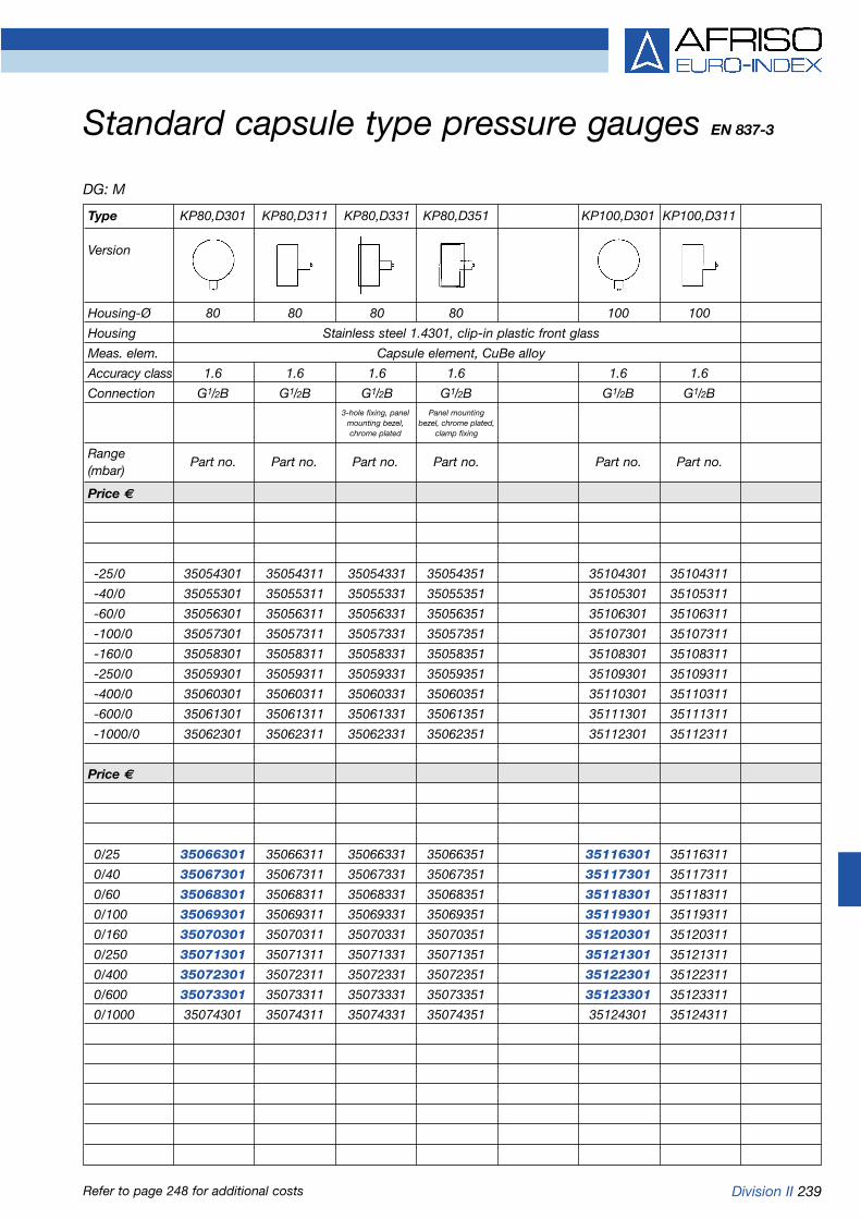
Division II 239
Standard capsule type pressure gauges EN 837-3
Refer to page 248 for additional costs
DG: M
Type KP80,D301 KP80,D311 KP80,D331 KP80,D351 KP100,D301 KP100,D311
Version
Housing-Ø 80 80 80 80 100 100
Housing Stainless steel 1.4301, clip-in plastic front glass
Meas. elem. Capsule element, CuBe alloy
Accuracy class 1.6 1.6 1.6 1.6 1.6 1.6
Connection G1/2B G1/2B G1/2B G1/2B G1/2B G1/2B
Range(mbar)
Price €
-25/0 35054301 35054311 35054331 35054351 35104301 35104311
-40/0 35055301 35055311 35055331 35055351 35105301 35105311
-60/0 35056301 35056311 35056331 35056351 35106301 35106311
-100/0 35057301 35057311 35057331 35057351 35107301 35107311
-160/0 35058301 35058311 35058331 35058351 35108301 35108311
-250/0 35059301 35059311 35059331 35059351 35109301 35109311
-400/0 35060301 35060311 35060331 35060351 35110301 35110311
-600/0 35061301 35061311 35061331 35061351 35111301 35111311
-1000/0 35062301 35062311 35062331 35062351 35112301 35112311
Price €
0/25 35066301 35066311 35066331 35066351 35116301 35116311
0/40 35067301 35067311 35067331 35067351 35117301 35117311
0/60 35068301 35068311 35068331 35068351 35118301 35118311
0/100 35069301 35069311 35069331 35069351 35119301 35119311
0/160 35070301 35070311 35070331 35070351 35120301 35120311
0/250 35071301 35071311 35071331 35071351 35121301 35121311
0/400 35072301 35072311 35072331 35072351 35122301 35122311
0/600 35073301 35073311 35073331 35073351 35123301 35123311
0/1000 35074301 35074311 35074331 35074351 35124301 35124311
3-hole fixing, panel Panel mountingmounting bezel, bezel, chrome plated,chrome plated clamp fixing
Part no. Part no. Part no. Part no. Part no. Part no.

240 Division II
Standard capsule type pressure gauges EN 837-3
Refer to page 248 for additional costs
DG: M
Type KP63,D401 KP63,D411 KP63,D431 KP63,D451 KP100,D401 KP100,D411 KP100,D431 KP100,D451
Version
Housing-Ø 63 63 63 63 100 100 100 100
Housing Stainless steel 1.4301 with bayonet type bezel, instrument grade front glass
Meas.elem. Capsule element, CuBe alloy
Accuracy class 1.6 1.6 1.6 1.6 1.6 1.6 1.6 1.6
Connection G1/4B G1/4B G1/4B G1/4B G1/2B G1/2B G1/2B G1/2B
Range(mbar)
Price €
-25/0 35004401 35004411 35004431 35004451 35104401 35104411 35104431 35104451
-40/0 35005401 35005411 35005431 35005451 35105401 35105411 35105431 35105451
-60/0 35006401 35006411 35006431 35006451 35106401 35106411 35106431 35106451
-100/0 35007401 35007411 35007431 35007451 35107401 35107411 35107431 35107451
-160/0 35008401 35008411 35008431 35008451 35108401 35108411 35108431 35108451
-250/0 35009401 35009411 35009431 35009451 35109401 35109411 35109431 35109451
-400/0 35010401 35010411 35010431 35010451 35110401 35110411 35110431 35110451
-600/0 35011401 35011411 35011431 35011451 35111401 35111411 35111431 35111451
-1000/0 35012401 35012411 35012431 35012451 35112401 35112411 35112431 35112451
Price €
0/25 35016401 35016411 35016431 35016451 35116401 35116411 35116431 35116451
0/40 35017401 35017411 35017431 35017451 35117401 35117411 35117431 35117451
0/60 35018401 35018411 35018431 35018451 35118401 35118411 35118431 35118451
0/100 35019401 35019411 35019431 35019451 35119401 35119411 35119431 35119451
0/160 35020401 35020411 35020431 35020451 35120401 35120411 35120431 35120451
0/250 35021401 35021411 35021431 35021451 35121401 35121411 35121431 35121451
0/400 35022401 35022411 35022431 35022451 35122401 35122411 35122431 35122451
0/600 35023401 35023411 35023431 35023451 35123401 35123411 35123431 35123451
0/1000 35024401 35024411 35024431 35024451 35124401 35124411 35124431 35124451
3-hole fixing, panel Panel mounting bezel, 3-hole fixing, panel Panel mounting bezelmounting bezel, 1.4301, polished, mounting bezel, 1.4301, polished,1.4301, polished clamp fixing 1.4301, polished clamp fixing
Part no. Part no. Part no. Part no. Part no. Part no. Part no. Part no.

Division II 241
Standard capsule type pressure gauges EN 837-3
Refer to page 248 for additional costs
DG: M Standard version Panel mounting version
Type KP160,D401 KP160,D411 KP160,D431 KP160,D451 KP72,D111 KP96,D311 KP144,D211
Version
Housing-Ø 160 160 160 160 72 x 72 96 x 96 144 x 144
Housing Stainless steel 1.4301 with bayonet type bezel Plastic Stainless steel Sheet steel
Meas.elem. Capsule element, CuBe alloy Capsule element, CuBe alloy
Accuracy class 1.6 1.6 1.6 1.6 1.6 1.6 1.6
Connection G1/2B G1/2B G1/2B G1/2B G1/4B G1/4B G1/2B
Range(mbar)
Price €
-6/0 35151401 35151411 35151431 35151451 --- --- ---
-10/0 35152401 35152411 35152431 35152451 --- --- ---
-16/0 35153401 35153411 35153431 35153451 --- --- ---
Price €
-25/0 35154401 35154411 35154431 35154451 35304111 35354311 35404211
-40/0 35155401 35155411 35155431 35155451 35305111 35355311 35405211
-60/0 35156401 35156411 35156431 35156451 35306111 35356311 35406211
-100/0 35157401 35157411 35157431 35157451 35307111 35357311 35407211
-160/0 35158401 35158411 35158431 35158451 35308111 35358311 35408211
-250/0 35159401 35159411 35159431 35159451 35309111 35359311 35409211
-400/0 35160401 35160411 35160431 35160451 35310111 35360311 35410211
-600/0 35161401 35161411 35161431 35161451 35311111 35361311 35411211
-1000/0 35162401 35162411 35162431 35162451 35312111 35362311 35412211
Price €
0/6 35163401 35163411 35163431 35163451 --- --- ---
0/10 35164401 35164411 35164431 35164451 --- --- ---
0/16 35165401 35165411 35165431 35165451 --- --- ---
Price €
0/25 35166401 35166411 35166431 35166451 35316111 35366311 35416211
0/40 35167401 35167411 35167431 35167451 35317111 35367311 35417211
0/60 35168401 35168411 35168431 35168451 35318111 35368311 35418211
0/100 35169401 35169411 35169431 35169451 35319111 35369311 35419211
0/160 35170401 35170411 35170431 35170451 35320111 35370311 35420211
0/250 35171401 35171411 35171431 35171451 35321111 35371311 35421211
0/400 35172401 35172411 35172431 35172451 35322111 35372311 35422211
0/600 35173401 35173411 35173431 35173451 35323111 35373311 35423211
0/1000 35174401 35174411 35174431 35174451 35324111 35374311 35424211
3-hole fixing, panel Panel mounting bezelmounting bezel, 1.4301, polished,1.4301, polished clamp fixing
Part no. Part no. Part no. Part no. Part no. Part no. Part no.
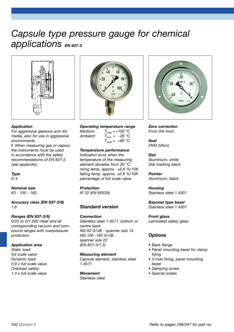
242 Division II
Operating temperature rangeMedium: Tmax =+100 °CAmbient: Tmin = -20 °C
Tmax = +60 °C
Temperature performanceIndication error when the temperature of the measuring element deviates from 20 °C:rising temp. approx. ±0.6 %/10Kfalling temp. approx. ±0.6 %/10Kpercentage of full scale value
ProtectionIP 32 (EN 60529)
Standard version
ConnectionStainless steel 1.4571, bottom orcentre backNG 63 G1/4B - spanner size 14NG 100 -160 G1/2B - spanner size 22(EN 837-3/7.3)
Measuring elementCapsule element, stainless steel1.4571
MovementStainless steel
ApplicationFor aggressive gaseous and drymedia, also for use in aggressiveenvironments. ! When measuring gas or vapour,the instruments must be used in accordance with the safety recommendations of EN 837-2 (see appendix).
TypeD 4
Nominal size63 - 100 - 160
Accuracy class (EN 837-3/6)1.6
Ranges (EN 837-3/5)0/25 to 0/1,000 mbar and all corresponding vacuum and com-pound ranges with overpressureprotection
Application areaStatic load:full scale valueDynamic load:0.9 x full scale valueOverload safety:1.3 x full scale value
Zero correctionFrom the front
SealFKM (Viton)
DialAluminium, whiteDial marking black
PointerAluminium, black
HousingStainless steel 1.4301
Bayonet type bezelStainless steel 1.4301
Front glassLaminated safety glass
Options
• Back flange• Panel mounting bezel for clamp
fixing• 3-hole fixing, panel mounting
bezel• Damping screw• Special scales
Capsule type pressure gauge for chemicalapplications EN 837-3
Refer to pages 246/247 for part no.

Division II 243
Bottom connection Bottom connection, back flange
Centre back connection Centre back connection, 3-hole fixing, panel mountingbezel
Centre back connection, panel mounting bezel forclamp fixing
Capsule type pressure gauge for chemical applications Type D 4 - NG 63/100/160Housing types and dimensions
* Dimensions for NG 100 according to DIN EN 837-3
Dimensions (mm)
Nominal size (NG) a a1 b b1 b2 b3 Øc c1 c2 d1* d2 d3* d4 d5 d6 G g g1 h s1 s2
63 10.8 13.4 40 42.1 37 37 5 2 13 75 85 3.5 64 68 64 G1/4B 60 60 53 5.2 3
100 15.6 19.1 49 52.5 49 49 6 3 20 116 132 4.8 104 107 101 G1/2B 81 81 86 5.5 4
160 17.5 20.5 50 53 50 52 6 3 20 178 196 5.8 164 167 161 G1/2B 82 84 116 6 4
Nominal size (NG) s3 s4 SW
63 2 3 14
100 2 4 22
160 2 4.5 22

244 Division II
Zero correctionFrom the front
Seal„Perbunan“ nitrile rubber
DialAluminium, whiteDial marking black
PointerKnife edge pointerAluminium, black
HousingStainless steel 1.4301
Bayonet type bezelStainless steel 1.4301
Front glassPlastic (PMMA)
Options
• Back flange• Panel mounting bezel for clamp
fixing• 3-hole fixing, panel mounting
bezel• Damping screw
Precision capsule type pressure gauges class 0.6
ApplicationFor gaseous, dry media which donot attack copper alloys. For highmeasuring accuracy. ! When measuring gas or vapour,the instruments must be used in accordance with the safety recommendations of EN 837-2 (see appendix).
TypeD 4
Nominal size160
Accuracy class (EN 837-3/6)0.6
Ranges (EN 837-3/5)0/40 to 0/1,000 mbar and all corre-sponding vacuum and compoundranges with overpressure protection
Calibration mediumAir
Application areaStatic load:full scale valueDynamic load:0.9 x full scale valueShort term:full scale value
Operating temperature rangeMedium: Tmax = +60 °CAmbient: Tmin = -20 °C
Tmax = +60 °C
Temperature performanceIndication error when the tempera-ture of the measuring element deviates from 20 °C:rising temp. approx. ±0.6 % /10Kfalling temp. approx. ±0.6 % /10Kpercentage of full scale value
ProtectionIP 32 (EN 60529)
Standard version
ConnectionBrass, bottom or centre backG1/2B - spanner size 22(EN 837-3/7.3)
Measuring elementCapsule element, CuBe alloy
MovementBrass
Refer to pages 247 for part no.
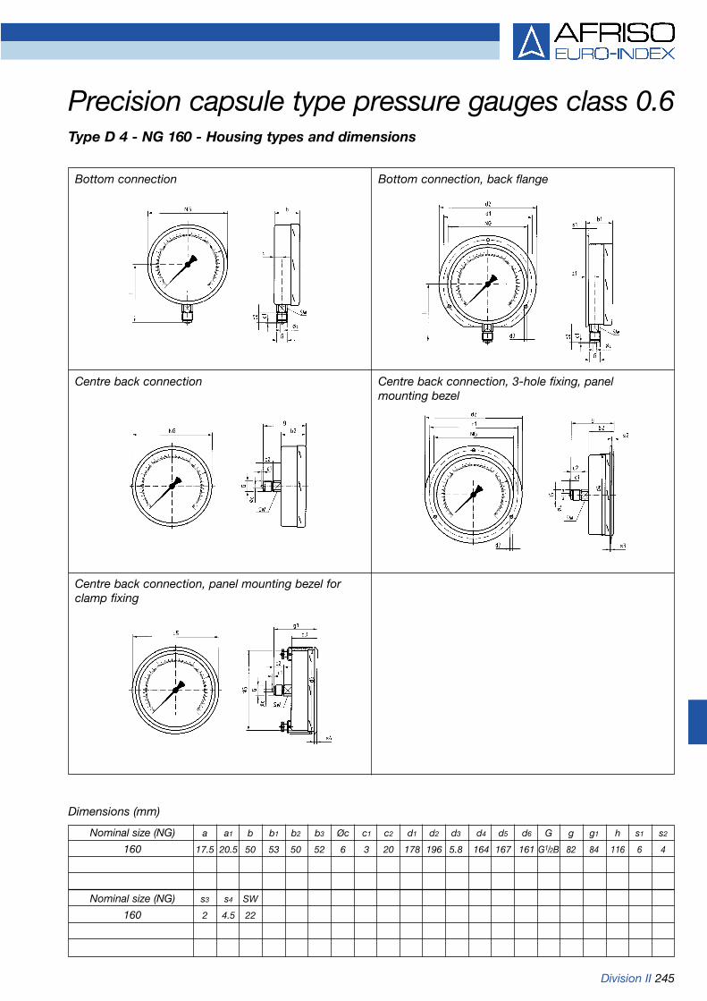
Division II 245
Bottom connection Bottom connection, back flange
Precision capsule type pressure gauges class 0.6Type D 4 - NG 160 - Housing types and dimensions
Centre back connection Centre back connection, 3-hole fixing, panelmounting bezel
Centre back connection, panel mounting bezel forclamp fixing
Dimensions (mm)
Nominal size (NG) a a1 b b1 b2 b3 Øc c1 c2 d1 d2 d3 d4 d5 d6 G g g1 h s1 s2
160 17.5 20.5 50 53 50 52 6 3 20 178 196 5.8 164 167 161 G1/2B 82 84 116 6 4
Nominal size (NG) s3 s4 SW
160 2 4.5 22

246 Division II
Capsule type pressure gauges for chemical applications EN 837-3
Refer to page 248 for additional costs
DG: M
Type KP63Ch,D402 KP63Ch,D412 KP63Ch,D432 KP63Ch,D452 KP100Ch,D402 KP100Ch,D412 KP100Ch,D432 KP100Ch,D452
Version
Housing-Ø 63 63 63 63 100 100 100 100
Housing Stainless steel 1.4301 with bayonet type bezel, laminated safety front glass
Meas. elem. Capsule element, stainless steel 1.4571
Accuracy class 1.6 1.6 1.6 1.6 1.6 1.6 1.6 1.6
Connection G1/4B G1/4B G1/4B G1/4B G1/2B G1/2B G1/2B G1/2B
Range(mbar)
Price €
-25/0 35004402 35004412 35004432 35004452 35104402 35104412 35104432 35104452
-40/0 35005402 35005412 35005432 35005452 35105402 35105412 35105432 35105452
-60/0 35006402 35006412 35006432 35006452 35106402 35106412 35106432 35106452
-100/0 35007402 35007412 35007432 35007452 35107402 35107412 35107432 35107452
-160/0 35008402 35008412 35008432 35008452 35108402 35108412 35108432 35108452
-250/0 35009402 35009412 35009432 35009452 35109402 35109412 35109432 35109452
-400/0 35010402 35010412 35010432 35010452 35110402 35110412 35110432 35110452
-600/0 35011402 35011412 35011432 35011452 35111402 35111412 35111432 35111452
-1000/0 35012402 35012412 35012432 35012452 35112402 35112412 35112432 35112452
Price €
0/25 35016402 35016412 35016432 35016452 35116402 35116412 35116432 35116452
0/40 35017402 35017412 35017432 35017452 35117402 35117412 35117432 35117452
0/60 35018402 35018412 35018432 35018452 35118402 35118412 35118432 35118452
0/100 35019402 35019412 35019432 35019452 35119402 35119412 35119432 35119452
0/160 35020402 35020412 35020432 35020452 35120402 35120412 35120432 35120452
0/250 35021402 35021412 35021432 35021452 35121402 35121412 35121432 35121452
0/400 35022402 35022412 35022432 35022452 35122402 35122412 35122432 35122452
0/600 35023402 35023412 35023432 35023452 35123402 35123412 35123432 35123452
0/1000 35024402 35024412 35024432 35024452 35124402 35124412 35124432 35124452
3-hole fixing, panel Panel mounting bezel, 3-hole fixing, panel Panel mounting bezel,mounting bezel, 1.4301, polished, mounting bezel, 1.4301, polished,1.4301, polished clamp fixing 1.4301, polished clamp fixing
Part no. Part no. Part no. Part no. Part no. Part no. Part no. Part no.

Division II 247
Capsule type pressure gauges Precision capsule type for chemical applications EN 837-3 pressure gauges
Refer to page 248 for additional costs
DG: M
Type KP160Ch,D402 KP160Ch,D412 KP160Ch,D432 KP160Ch,D452 KP160F,D401 KP160F,D411
Version
Housing-Ø 160 160 160 160 160 160
Housing Stainless steel 1.4301 with bayonet type bezel Stainless steel 1.4301 with bayonet type bezel
Meas. elem. Capsule element, stainless steel 1.4571 Capsule element, CuBe alloy
Accuracy class 1.6 1.6 1.6 1.6 0.6 0.6
Connection G1/2B G1/2B G1/2B G1/2B G1/2B G1/2B
Range(mbar)
Price €
-25/0 35154402 35154412 35154432 35154452 --- ---
-40/0 35155402 35155412 35155432 35155452 35205401 35205411
-60/0 35156402 35156412 35156432 35156452 35206401 35206411
-100/0 35157402 35157412 35157432 35157452 35207401 35207411
-160/0 35158402 35158412 35158432 35158452 35208401 35208411
-250/0 35159402 35159412 35159432 35159452 35209401 35209411
-400/0 35160402 35160412 35160432 35160452 35210401 35210411
-600/0 35161402 35161412 35161432 35161452 35211401 35211411
-1000/0 35162402 35162412 35162432 35162452 35212401 35212411
Price €
0/25 35166402 35166412 35166432 35166452 --- ---
0/40 35167402 35167412 35167432 35167452 35217401 35217411
0/60 35168402 35168412 35168432 35168452 35218401 35218411
0/100 35169402 35169412 35169432 35169452 35219401 35219411
0/160 35170402 35170412 35170432 35170452 35220401 35220411
0/250 35171402 35171412 35171432 35171452 35221401 35221411
0/400 35172402 35172412 35172432 35172452 35222401 35222411
0/600 35173402 35173412 35173432 35173452 35223401 35223411
0/1000 35174402 35174412 35174432 35174452 35224401 35224411
3-hole fixing, panel Panel mounting bezel,mounting bezel, 1.4301, polished,1.4301, polished clamp fixing
Part no. Part no. Part no. Part no. Part no. Part no.
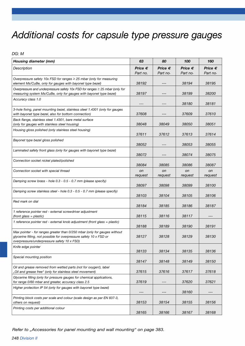
248 Division II
Additional costs for capsule type pressure gauges
DG: M
Housing diameter (mm) 63 80 100 160
Description Price € Price € Price € Price €Part no. Part no. Part no. Part no.
Overpressure safety 10x FSD for ranges > 25 mbar (only for measuringelement Ms/CuBe, only for gauges with bayonet type bezel) 38192 --- 38194 38195
Overpressure and underpressure safety 10x FSD for ranges > 25 mbar (only formeasuring system Ms/CuBe, only for gauges with bayonet type bezel) 38197 --- 38199 38200
Accuracy class 1.0--- --- 38180 38181
3-hole fixing, panel mounting bezel, stainless steel 1.4301 (only for gaugeswith bayonet type bezel, also for bottom connection) 37608 --- 37609 37610
Back flange, stainless steel 1.4301, bare metal surface(only for gauges with stainless steel housing) 38048 38049 38050 38051
Housing gloss polished (only stainless steel housing)37611 37612 37613 37614
Bayonet type bezel gloss polished38052 --- 38053 38055
Laminated safety front glass (only for gauges with bayonet type bezel)38072 --- 38074 38075
Connection socket nickel plated/polished38084 38085 38086 38087
Connection socket with special thread on on on onrequest request request request
Damping screw brass - hole 0.3 - 0.5 - 0.7 mm (please specify)38097 38098 38099 38100
Damping screw stainless steel - hole 0.3 - 0.5 - 0.7 mm (please specify)38103 38104 38105 38106
Red mark on dial38184 38185 38186 38187
1 reference pointer red - external screwdriver adjustment (front glass = plastic) 38115 38116 38117 ---
1 reference pointer red - external knob adjustment (front glass = plastic)38188 38189 38190 38191
Max pointer - for ranges greater than 0/250 mbar (only for gauges without glycerine filling, not possible for overpressure safety 10 x FSD or 38127 38128 38129 38130overpressure/underpressure safety 10 x FSD)
Knife edge pointer38133 38134 38135 38136
Special mounting position38147 38148 38149 38150
Oil and grease removed from wetted parts (not for oxygen!), label „Oil and grease free“ (only for stainless steel movement) 37615 37616 37617 37618
Glycerine filling (only for pressure gauges for chemical applications,for range 0/60 mbar and greater, accuracy class 2.5 37619 --- 37620 37621
Higher protection IP 54 (only for gauges with bayonet type bezel)--- --- 38160 ---
Printing block costs per scale and colour (scale design as per EN 837-3,others on request) 38153 38154 38155 38156
Printing costs per additional colour38165 38166 38167 38168
Refer to „Accessories for panel mounting and wall mounting“ on page 383.

Division II 249
Special versions
Pressure gauge for heatinginstallations NG 50-63-80for sealed heating systems Range 0/4 barConnection NG 50 G1/4B bottom
backNG 63 G1/4B or G3/8Bbottom or centre backNG 80 G1/2B bottom or G¼B centre back(with valve G1/4 x G1/2)
Dial with red mark at 3 bar andgreen sector from 1.5 to 3 barFront glass with adjustable red reference pointer and green flag
Hydrometer NG 100Water level indicator for standardheating systemsRanges 0/0.6 to 0/10 barConnection G1/2B bottomDual scale, bar outer scale, black,
metres water column inner scale, black
Front glass with adjustable red refe-rence pointer
Accessories
Mounting valveswith self-sealing coating, automatic-ally close during replacement ofgauge to enable fast and costeffective servicing (refer to page388 „Accessories for pressure gauges“).
Standard version
ConnectionSelf-sealing thread with PTFEring for safe and fast installation(Attention: 60° chamfer required atfemale thread)Brass, bottom or backNG 50-063 G1/4B - spanner size 14NG 80-100 G1/2B - spanner size 22
Measuring elementBourdon tube element, copper alloy„C“ type bourdon tube
MovementBrass
DialPlastic, whiteDial marking black
PointerPlastic, black
HousingBlack ABS, highly impact resistantand corrosion resistant
Front glassClip-in plasticNG 80-100 with adjustable red reference pointer
Bourdon tube pressure gauges for heating/plumbing applications with self-sealing connection thread
ApplicationFor gaseous and liquid media whichare not highly viscous, do not cry-stallize and do not attack copperalloys. ! When measuring gas or vapour,the instruments must be used in accordance with the safety recommendations of EN 837-2 (see appendix).
Nominal size50 - 63 - 80 - 100
Accuracy class (EN 837-1/6)NG 50 - 80: 2.5NG 100: 1.6
Ranges (EN 837-1/5)0/0.6 to 0/25 bar
Application areaStatic load:3/4 x full scale valueDynamic load:2/3 x full scale valueShort term:full scale value
Operating temperature rangeMedium: Tmax = +60 °CAmbient: Tmin = -20 °C
Tmax = +60 °C
Temperature performanceIndication error when the tempera-ture of the measuring element deviates from 20 °C:rising temp. approx. ±0.4 %/10Kfalling temp. approx. ±0.4 %/10Kpercentage of full scale value
ProtectionIP 32 (EN 60529)
Refer to page 251 for part no.

250 Division II
HZ 50 – bottom back connection
RF/HZ 63 – centre back connection
Bourdon tube pressure gauges for heating/plumbingapplications with self-sealing connection threadHousing types and dimensions
RF 80/HZ 80 – centre back connection
RF 63/HZ 63 – bottom connection
RF 80/HZ 80 – bottom connection
RF 100/HY 100 – bottom connection
* Attention: approx. 60° chamfer required at female thread
Dimensions (mm)
Nominal size (NG) a b b1 c c1 c2 e g g1 G* G1* h h1 s SW SW1
50 - 25.8 - 11.2 - - 14 43 - G1/4B - - - 3.8 14 -
63 9.8 30.4 29.7 11.2 13 11.5 - 49.9 50.4 G1/4B G3/8B 49 51.5 3.7 14 17
80 12.8 32.8 32.8 17 11.5 - - 55.8 - G1/2B G1/4B 68 - 2.8 22 14
100 15.5 34.5 - 17 - - - - - G1/2B - 78 - 3.5 22 -

Division II 251
Bourdon tube pressure gauges for heating/plumbing applicationsDG: G
Type RF 50 bottom RF 50 back RF 63 bottom RF 63 back RF 80 bottom RF 100 bottom HY 100 bottom
Version
Housing-Ø 50 50 63 63 80 100 100
Housing Black ABS, highly impact resistant and corrosion resistant
Meas. elem. Bourdon tube element, copper alloy
Accuracy class 2.5 2.5 2.5 2.5 2.5 1.6 1.6
Connection G1/4B G1/4B G1/4B G1/4B G1/2B G1/2B G1/2B
Thread Self-sealing with PTFE sealing ring
Range(bar)
Price €
-1/0 --- --- --- --- --- --- ---
0/0,6 --- --- --- --- --- --- 63281
0/1 --- --- --- --- --- --- 63282
0/1,6 --- --- --- --- --- 63610 63283
0/2,5 --- --- 63511 63536 63561 63611 63284
0/4 --- --- 63512 63537 63562 63612 63285
0/6 63122 63127 63513 63538 63563 63613 63286
0/10 63123 63128 63514 63539 63564 63614 63287
0/16 63124 63129 63515 63540 63565 63615 ---
0/25 --- --- --- --- 63566 63616 ---
Type HZ 50 back HZ 63 bottom HZ 63 back HZ 63 bottom HZ 63 back HZ 80 bottom HZ 80 back
Version
Housing-Ø 50 63 63 63 63 80 80
Housing Black ABS, highly impact resistant and corrosion resistant
Meas. elem. Bourdon tube element, copper alloy
Range 0/4 bar
Dial with red mark at 3 bar and green sector from 1.5 to 3 bar
Front glass with adjustable red reference pointer and green flag
Accuracy class 2.5 2.5 2.5 2.5 2.5 2.5 2.5
Connection G1/4B G3/8B G3/8B G1/4B G1/4B G1/2B
Thread Self-sealing with PTFE sealing ring
Price €
Part no. 63927 63910 63914 63911 63915 63918 63919
With adjustable Dual scalered reference pointer bar / mWC
Part no. Part no. Part no. Part no. Part no. Part no. Part no.
G1/4 with valveG1/4 x G1/2

252 Division II
Combined thermometer – pressure gauge/thermo-hydrometer
ApplicationFor liquid media which are nothighly viscous, do not crystallizeand do not attack copper alloys.For combined measurement ofpressure and temperature, especially in heating systems andheating boilers.
DescriptionThe combined thermometer-pres-sure gauge/thermo-hydrometerconsists of a Bourdon tube systemfor pressure measurement and a bimetal system for simultaneoustemperature measurement. Bothvalues are measured and displayedby a single gauge. A self-closingmounting valve enables easy re-placement of the gauge withouthaving to drain the system. Anoptional M 18 x 1 to G1/4 adapter isavailable if the combined thermo-meter-pressure gauge has to bemounted into an existing thermo-well with M 18 x 1 female thread.
TypeD1/D2
Nominal size63 - 80
Accuracy classPressure gauge/hydrometer:2.5 (EN 837-1/6)Thermometer:2 (EN 13190)
Application areaPressure gauge/hydrometer:Static load:3/4 x full scale valueDynamic load:2/3 x full scale valueShort term:full scale valueThermometer:20/120 °C
RangesPressure gauge/hydrometer:0/4 bar and 0/6mWS to 0/60 mWSThermometer:20/120 °C
Operating temperature rangeMedium: Tmax = +120 °CAmbient: Tmin = -20 °C
Tmax = +60 °C
Temperature performancePressure gauge/hydrometer:Indication error when the tempera-ture of the measuring elementdeviates from 20 °C:rising temp. approx. ±0.4 %/10Kfalling temp. approx. ±0.4 %/10Kpercentage of full scale value
ProtectionIP 32 (EN 60529)
Standard version
ConnectionBrass, centre backG1/4Bwith mounting valve G1/4 to R1/2
Measuring elementPressure: Bourdon tube element,copper alloyTemperature: bimetal element
DialPlastic, whiteDial marking blackwith red/blue circular arcs
PointerPressure gauge/hydrometer:Plastic, blackThermometer:Plastic, red
HousingD1 - plasticD2 - black sheet steel
Front glassClip-in plastic with adjustable redmark
Options
• Adapter M 18 x 1 to G1/4• Special scales
Refer to page 254 for part no.
TM 63 TH 80

Division II 253
Combined thermometer – pressure gauge/thermo-hydrometer
TM 63
TM 63 with mounting valve
Mounting valve Adapter
TM 80 with mounting valve
TM 80
Spanner 14Spanner 14
Spanner 22 Spanner 22

254 Division II
Combined thermometer – pressure gauge/thermo-hydrometerDG: G
Type TM 63,D211 TM 63,D211 TM 80,D111 TM 80,D211 TM 80,D211 TH 80,D211
Version
Housing-Ø 63 63 80 80 80 80
Housing Black steel sheet Plastic Black steel sheet
Accuracy class Pressure gauge/hydrometer 2.5 – thermometer 2
Connection G1/4B with mounting valve G1/4 to R1/2
Adapter without with without without with without
Range Part no. Part no. Part no. Part no. Part no. Part no.
Price €
0/4 bar 63318 63346 63317 63341 63348 ---20/120 °C
Range
0/6 mWS --- --- --- --- --- 6331120/120 °C
0/10 mWS --- --- --- --- --- 6331220/120 °C
0/16 mWS --- --- --- --- --- 6331320/120 °C
0/25 mWS --- --- --- --- --- 6331420/120 °C
0/40 mWS --- --- --- --- --- 6331520/120 °C
0/60 mWS --- --- --- --- --- 6331620/120 °C
Minimum order quantity for non-stock items = 100 pieces
DG: G Part no. Price €
Mounting valve G1/4 to R1/2, brass 05 00 25 12
Adapter G1/4 to M 18 x 1, brass 05 00 40 01
Spare parts

Division II 255
Measuring elementBourdon tube element, copper alloy< 60 bar „C“ type bourdon tube> 60 bar helical tube
MovementBrass
DialPlastic, whiteDial marking black
PointerPlastic, black
HousingBlack ABS, highly impact resistantand corrosion resistant
Front glassClip-in plasticNG 80-100 with adjustable red re-ference pointer
Options
• Damping screw• Reference pointer
Standard Bourdon tube pressure gauges EN 837-1
ApplicationFor gaseous and liquid media which are not highly viscous, do not crystallize and do not attackcopper alloys. ! When measuring gas or vapour,the instruments must be used in accordance with the safety recommendations of EN 837-2 (see appendix).
TypeD 1
Nominal size40 - 50 - 63 - 80 - 100
Accuracy class (EN 837-1/6)1.6
Ranges (EN 837-1/5)-1/0 to -1/+15 bar0/0.6 to 0/400 bar
Application areaStatic load:3/4 x full scale valueDynamic load:2/3 x full scale valueShort term:full scale value
Operating temperature rangeMedium: Tmax = +60 °CAmbient: Tmin = -20 °C
Tmax = +60 °C
Temperature performanceIndication error when the tempera-ture of the measuring element devi-ates from 20 °C:rising temp. approx. ±0.4 % /10Kfalling temp. approx. ±0.4 % /10Kpercentage of full scale value
ProtectionIP 32 (EN 60529)
Standard version
ConnectionBrass, bottom or centre backNG 40 G1/8B - spanner size 12NG 50-63 G1/4B - spanner size 14NG 80-100 bottom G1/2B - spanner size 22NG 80-100 centre back G1/4B -spanner size 14 (EN 837-1/7.3)
Refer to pages 263 for part no.

256 Division II
NG 40/50/63 – Bottom connection
NG 80 – Bottom connection
NG 100 – Bottom connection
NG 40/50/63 – Centre back connection
NG 80 – Centre back connection
NG 100 – Centre back connection
Standard Bourdon tube pressure gauges Type D 1 - NG 40/50/63/80/100Housing types and dimensions
Dimensions (mm)
Nominal size (NG) a b b1 Øc c1 c2 Øe e1 e2 g G G1 h s SW SW1
40 9.5 25 25 4 2 10 - - - 41.5 G1/8B G1/8B 36 3 12 -
50 10.3 26.8 27.1 5 2 13 - - - 47.1 G1/4B G1/4B 45 3.8 14 -
63 9.8 29.7 30.4 5 2 13 - - - 50.4 G1/4B G1/4B 51.5 3.7 14 -
80 12.8 32.8 32.8 6 3 20 5 2 13 55.8 G1/2B G1/4B 72 2.8 22 14
100 15.5 34.5 32 6 3 20 5 2 13 55 G1/2B G1/4B 82 3.5 22 14

Division II 257
MovementBrass
DialPlastic, whiteDial marking black
PointerPlastic, black
HousingD 2 – black sheet steelD 3 - stainless steel 1.4301
Front glassClip-in plastic
Options
• Panel mounting bezel for clamp fixing
• 3-hole fixing panel mounting bezel
• Damping screw• Reference pointer
Operating temperature rangeMedium: Tmax = +60 °CAmbient: Tmin = -20 °C
Tmax = +60 °C
Temperature performanceIndication error when the tempera-ture of the measuring element devi-ates from 20 °C:rising temp. approx. ±0.4 %/10Kfalling temp. approx. ±0.4 %/10Kpercentage of full scale value
ProtectionIP 32 (EN 60 529)
Standard version
ConnectionBrass, bottom or centre backNG 40 G1/8B - spanner size 12NG 50-63 G1/4B - spanner size 14(EN 837-1/7.3)
Measuring elementBourdon tube element, copper alloy< 60 bar „C“ type bourdon tube> 60 bar helical tube
Standard Bourdon tube pressure gauges EN 837-1
ApplicationFor gaseous and liquid media which are not highly viscous, do not crystallize and do not attackcopper alloys. ! When measuring gas or vapour,the instruments must be used in accordance with the safety recommendations of EN 837-2 (see appendix).
TypeD 2/D 3
Nominal size40 - 50 - 63
Accuracy class (EN 837-1/6)1.6
Ranges (EN 837-1/5)-1/0 to -1/+15 bar0/0.6 to 0/400 bar
Application areaStatic load:3/4 x full scale valueDynamic load:2/3 x full scale valueShort term:full scale value
Refer to pages 264/265 for part no.

258 Division II
Bottom connection Centre back connection
Centre back connection, 3-hole fixing, panel mounting bezel
Centre back connection, panel mounting bezel forclamp fixing
Standard Bourdon tube pressure gaugesType D 2/D 3 - NG 40/50/63Housing types and dimensions
Dimensions (mm)
Nominal size (NG) a b b1 b2 b3 Øc c1 c2 d1 d2 d3 d4 d5 d6 g g1 g2 G h m
40 8.5 23.5 25 26 28 4 2 10 51 61 3.6 41 45 44 41.5 42.5 46.6 G1/8B 36 50
50 10.5 26 26 27.5 30.3 5 2 13 60 71 3.6 50 54 54 47 49 51.3 G1/4B 45 58
63 9.5 29.4 29.4 30.3 30.3 5 2 13 75 85 3.6 63 66.5 67.8 50.4 51.3 53.3 G1/4B 51.5 72
Nominal size (NG) s s1 s2 s3 SW
40 3 2.5 2 5.2 12
50 3.8 2.5 2 5.4 14
63 3.7 2.5 2 5.6 14
Pan
el c
ut o
ut d
5+1

Division II 259
Operating temperature rangeMedium: Tmax = +60 °CAmbient: Tmin = -20 °C
Tmax = +60 °C
Temperature performanceIndication error when the tempera-ture of the measuring element devi-ates from 20 °C:rising temp. approx. ±0.4 % /10Kfalling temp. approx. ±0.4 % /10Kpercentage of full scale value
ProtectionIP 32 (EN 60 529)
Standard version
ConnectionBrass, bottom:NG 80 - 100 G1/2B - spanner size 22Brass, centre backNG 80 - 100 G1/4B - spanner size 14(EN 837-1/7.3)
Measuring elementBourdon tube element, copper alloy< 60 bar „C“ type bourdon tube> 60 bar helical tube
ApplicationFor gaseous and liquid media which are not highly viscous, do not crystallize and do not attackcopper alloys. ! When measuring gas or vapour,the instruments must be used in accordance with the safetyrecommendations of EN 837-2 (see appendix).
TypeD 2
Nominal size80 - 100
Accuracy class (EN 837-1/6)1.6
Ranges (EN 837-1/5)-1/0 to -1/+15 bar0/0.6 to 0/400 bar
Application areaStatic load:3/4 x full scale valueDynamic load:2/3 x full scale valueShort term:full scale value
MovementBrass
DialPlastic, whiteDial marking black
PointerPlastic, black
HousingSheet steel, black
Front glassClip-in plastic with adjustable redreference pointer
Options
• Stainless steel housing (NG 100)• Push on bezel• Instrument grade front glass• 3-hole fixing, panel mounting
bezel• Damping screw• Reference pointer
Standard Bourdon tube pressure gauges EN 837-1
Refer to pages 265 for part no.

260 Division II
Standard Bourdon tube pressure gauges Type D 2 - NG 80/100Housing types and dimensions (in mm)
Bottom connection, with push-on bezel Centre back connection, with push-on bezel
Bottom connection Centre back connection
Dimensions (mm)
Nominal size (NG) a b b1 Øc c1 c2 Øc1 c3 c4 g g1 G G1 h SW SW1
80 11.7 31 33.5 6 3 20 5 2 13 54 56.5 G1/2B G1/4B 72 22 14
100 11 29.5 34 6 3 20 5 2 13 52.5 57 G1/2B G1/4B 82 22 14

Division II 261
Operating temperature rangeMedium: Tmax = +60 °CAmbient: Tmin = -20 °C
Tmax = +60 °C
Temperature performanceIndication error when the tempera-ture of the measuring element devi-ates from 20 °C:rising temp. approx. ±0.4 % /10Kfalling temp. approx. ±0.4 % /10Kpercentage of full scale value
ProtectionIP 32 (EN 60 529)
Standard version
ConnectionBrass, bottom:G1/2B - spanner size 22
Measuring elementBourdon tube element, copper alloy< 60 bar „C“ type bourdon tube> 60 bar helical tube
ApplicationFor gaseous and liquid media which are not highly viscous, do not crystallize and do not attackcopper alloys. ! When measuring gas or vapour,the instruments must be used in accordance with the safety recommendations of EN 837-2 (see appendix).
TypeD 2
Nominal size160
Accuracy class (EN 837-1/6)1.6
Ranges (EN 837-1/5)-1/0 to -1/+15 bar0/0.6 to 0/400 bar
Application areaStatic load:3/4 x full scale valueDynamic load:2/3 x full scale valueShort term:full scale value
MovementBrass
DialAluminium, whiteDial marking blackwith adjustable red reference pointer
PointerAluminium, black
HousingSheet steel, black
Push-on bezelSheet steel, black
Front glassInstrument glass
Options
• Damping screw• Reference pointer
Standard Bourdon tube pressure gauges EN 837-1
Refer to pages 265 for part no.

262 Division II
Bottom connection
Standard Bourdon tube pressure gauges Type D 2 - NG 160Housing types and dimensions
Dimensions (mm)
Nominal size (NG) a b Øc c1 c2 G h SW
160 15.5 50 6 3 20 G1/2B 116 22

Division II 263
Standard Bourdon tube pressure gauges EN 837-1
Minimum order quantity for non-stock items = 100 piecesRefer to page 266 for additional costs.
DG: M
Type RF40,D101 RF40,D111 RF50,D101 RF50,D111 RF63,D101 RF63,D111 RF80,D101 RF100,D101
Versions
Housing-Ø 40 40 50 50 63 63 80 100
Housing ABS highly impact resistant, clip-in plastic front glass
Meas. elem. Bourdon tube element, copper alloy
Accuracy class 1.6 1.6 1.6 1.6 1.6 1.6 1.6 1.6
Connection G1/8B G1/8B G1/4B G1/4B G1/4B G1/4B G1/2B G1/2B
Packing unit* 100 pieces 100 pieces 100 pieces 100 pieces 100 pieces 100 pieces 50 pieces 50 pieces
Range(bar)
Price €
-1/0 85001101 85001111 85051101 85051111 85101101 85101111 85151101 85201101
-1/+0,6 --- --- --- --- 85102101 85102111 85152101 85202101
-1/+1,5 --- --- --- --- 85103101 85103111 85153101 85203101
-1/+3 --- --- --- --- 85104101 85104111 85154101 85204101
-1/+5 --- --- --- --- 85105101 85105111 85155101 85205101
-1/+9 --- --- --- --- 85106101 85106111 85156101 85206101
-1/+15 --- --- --- --- 85107101 85107111 85157101 85207101
Price €
0/0,6 85009101 85009111 85059101 85059111 85109101 85109111 85159101 85209101
0/1 85010101 85010111 85060101 85060111 85110101 85110111 85160101 85210101
0/1,6 85011101 85011111 85061101 85061111 85111101 85111111 85161101 85211101
0/2,5 85012101 85012111 85062101 85062111 85112101 85112111 85162101 85212101
0/4 85013101 85013111 85063101 85063111 85113101 85113111 85163101 85213101
0/6 85014101 85014111 85064101 85064111 85114101 85114111 85164101 85214101
0/10 85015101 85015111 85065101 85065111 85115101 85115111 85165101 85215101
0/16 85016101 85016111 85066101 85066111 85116101 85116111 85166101 85216101
0/25 85017101 85017111 85067101 85067111 85117101 85117111 85167101 85217101
0/40 85018101 85018111 85068101 85068111 85118101 85118111 85168101 85218101
Price €
0/60 85019101 85019111 85069101 85069111 85119101 85119111 85169101 85219101
0/100 85020101 85020111 85070101 85070111 85120101 85120111 85170101 85220101
0/160 85021101 85021111 85071101 85071111 85121101 85121111 85171101 85221101
0/250 85022101 85022111 85072101 85072111 85122101 85122111 85172101 85222101
0/400 --- --- 85073101 85073111 85123101 85123111 85173101 85223101
with adjustable red reference pointer in front glass
Part no. Part no. Part no. Part no. Part no. Part no. Part no. Part no.

264 Division II
Standard Bourdon tube pressure gauges EN 837-1
* Dual scale, bar outer, black, psi inner, redMinimum order quantity for non-stock items = 100 pieces
Refer to page 266 for additional costs.
DG: M
Type RF40,D201 RF40,D211 RF40,D231* RF40,D251* RF50,D201 RF50,D211 RF50,D231* RF50,D251*
Version
Housing-Ø 40 40 40 40 50 50 50 50
Housing Black sheet steel, plastic, clip-in front glass
Meas. elem. Bourdon tube element, copper alloy
Accuracy class 1.6 1.6 1.6 1.6 1.6 1.6 1.6 1.6
Connection G1/8B G1/8B G1/8B G1/8B G1/4B G1/4B G1/4B G1/4B
Range(bar)
Price €
-1/0 85001201 85001211 85001231 85001251 85051201 85051211 85051231 85051251
-1/+0,6 --- --- --- --- --- --- --- ---
-1/+1,5 --- --- --- --- --- --- --- ---
-1/+3 --- --- --- --- --- --- --- ---
-1/+5 --- --- --- --- --- --- --- ---
-1/+9 --- --- --- --- --- --- --- ---
-1/+15 --- --- --- --- --- --- --- ---
Price €
0/1 85010201 85010211 85010231 85010251 85060201 85060211 85060231 85060251
0/1,6 85011201 85011211 85011231 85011251 85061201 85061211 85061231 85061251
0/2,5 85012201 85012211 85012231 85012251 85062201 85062211 85062231 85062251
0/4 85013201 85013211 85013231 85013251 85063201 85063211 85063231 85063251
0/6 85014201 85014211 85014231 85014251 85064201 85064211 85064231 85064251
0/10 85015201 85015211 85015231 85015251 85065201 85065211 85065231 85065251
0/16 85016201 85016211 85016231 85016251 85066201 85066211 85066231 85066251
0/25 85017201 85017211 85017231 85017251 85067201 85067211 85067231 85067251
0/40 85018201 85018211 85018231 85018251 85068201 85068211 85068231 85068251
Price €
0/60 85019201 85019211 85019231 85019251 85069201 85069211 85069231 85069251
0/100 85020201 85020211 85020231 85020251 85070201 85070211 85070231 85070251
0/160 85021201 85021211 85021231 85021251 85071201 85071211 85071231 85071251
0/250 85022201 85022211 85022231 85022251 85072201 85072211 85072231 85072251
0/400 --- --- --- --- 85073201 85073211 85073231 85073251
Part no. Part no. Part no. Part no. Part no. Part no. Part no. Part no.
3-hole fixing, panel Panel mounting bezel, 3-hole fixing, panel Panel mounting bezelmounting bezel, chrome plated, mounting bezel, chrome plated,chrome plated clamp fixing chrome plated clamp fixing

Division II 265
Standard Bourdon tube pressure gauges EN 837-1
* Dual scale, bar outer, black, psi inner, redMinimum order quantity for non-stock items = 100 pieces
Refer to page 266 for additional costs.
DG: M
Type RF63,D201 RF63,D211 RF63,D231* RF63,D251* RF80,D201 RF100,D201 RF100,D211 RF160,D201
Version
Housing-Ø 63 63 63 63 80 100 100 160
Housing Black sheet steel, plastic, clip-in front glass Push on bezel
Meas. elem. Bourdon tube element, copper alloy
Accuracy class 1.6 1.6 1.6 1.6 1.6 1.6 1.6 1.6
Connection G1/4B G1/4B G1/4B G1/4B G1/2B G1/2B G1/4B G1/2B
Range(bar)
Price €
-1/0 85101201 85101211 85101231 85101251 85151201 85201201 85201211 85251201
-1/+0,6 85102201 85102211 85102231 85102251 85152201 85202201 85202211 85252201
-1/+1,5 85103201 85103211 85103231 85103251 85153201 85203201 85203211 85253201
-1/+3 85104201 85104211 85104231 85104251 85154201 85204201 85204211 85254201
-1/+5 85105201 85105211 85105231 85105251 85155201 85205201 85205211 85255201
-1/+9 85106201 85106211 85106231 85106251 85156201 85206201 85206211 85256201
-1/+15 85107201 85107211 85107231 85107251 85157201 85207201 85207211 85257201
Price €
0/0,6 85109201 85109211 85109231 85109251 85159201 85209201 85209211 85259201
0/1 85110201 85110211 85110231 85110251 85160201 85210201 85210211 85260201
0/1,6 85111201 85111211 85111231 85111251 85161201 85211201 85211211 85261201
0/2,5 85112201 85112211 85112231 85112251 85162201 85212201 85212211 85262201
0/4 85113201 85113211 85113231 85113251 85163201 85213201 85213211 85263201
0/6 85114201 85114211 85114231 85114251 85164201 85214201 85214211 85264201
0/10 85115201 85115211 85115231 85115251 85165201 85215201 85215211 85265201
0/16 85116201 85116211 85116231 85116251 85166201 85216201 85216211 85266201
0/25 85117201 85117211 85117231 85117251 85167201 85217201 85217211 85267201
0/40 85118201 85118211 85118231 85118251 85168201 85218201 85218211 85268201
Price €
0/60 85119201 85119211 85119231 85119251 85169201 85219201 85219211 85269201
0/100 85120201 85120211 85120231 85120251 85170201 85220201 85220211 85270201
0/160 85121201 85121211 85121231 85121251 85171201 85221201 85221211 85271201
0/250 85122201 85122211 85122231 85122251 85172201 85222201 85222211 85272201
0/400 85123201 85123211 85123231 85123251 85173201 85223201 85223211 85273201
Part no. Part no. Part no. Part no. Part no. Part no. Part no. Part no.
3-hole fixing, panel Panel mounting bezel,mounting bezel, chrome plated, with adjustable red reference pointerchrome plated clamp fixing

266 Division II
Additional costs for standard Bourdon tubepressure gaugesDG: M
Housing diameter (mm) 40 50 63 80 100 160
Description Price € Price € Price € Price € Price € Price €Part no. Part no. Part no. Part no. Part no. Part no.
Housing nickel/chrome plated(instead of steel housing) 38064 38065 38066 --- --- ---
Push-on bezel nickel/chrome plated side screw fixing (NS 160, instead of black bezel) 38250 38251 38252 38253 38254 38255
Stainless steel 1.4301 housing, vibration ground finish(instead of steel housing) 38256 38257 38258 --- 38300 ---
Stainless steel 1.4301 housing, polished(instead of steel housing) 38259 38260 38261 --- 38314 ---
Push-on bezel stainless steel 1.4301,polished side screw fixing 38262 38263 38264 --- --- ---
3-hole fixing, panel mounting bezel, black,side screw fixing --- --- --- --- 38266 38267
3-hole fixing, panel mounting bezel, chrome plated,side screw fixing --- --- --- --- 38269 38270
Back flange, black sheet steel(only for steel housing) --- --- --- --- 38044 38045
Connection socket nickel/chrome plated38082 38083 38084 38085 38086 38087
Connection socket with special thread on on on on on onrequest request request request request request
Damping screw brass - hole 0.3 - 0.5 - 0.7 mm(please specify) 38095 38096 38097 38098 38099 38100
Red mark on dial38182 38183 38184 38185 38186 38187
1 reference pointer, red, printed on front glass Standard Standard38315 38316 38109 ---
2 reference pointers, red, on dial, adjustable--- --- --- --- 38123 ---
Printing block costs per scale and colour (scaledesign as per EN 837-1, others on request) 38151 38152 38153 38154 38155 38156
Printing costs per additional colour38163 38164 38165 38166 38167 38168
DG: M
Spare front glass for standard Bourdon tube pressure gauges
* Minimum order quantity for non-stock items = 100 pieces per version and per delivery
Housing diameter (mm) 40 50 63 80 100 160
Description Price € Price € Price € Price € Price € Price €Part no. Part no. Part no. Part no. Part no. Part no.
Plastic front glass, clip-in,for plastic housing 38285 38271 38272 38273 38274 ---
Plastic front glass, clip-in,for steel housing 38275 38276 38277 38317 38318 ---
Instrument grade front glassfor steel housing --- --- --- 38278 38279 38280

Division II 267
Bourdon tube pressure gauges for industrial applications EN 837-1
Operating temperature rangeMedium: Tmax = +60 °CAmbient: Tmin = -20 °C
Tmax = +60 °C
Temperature performanceIndication error when the tempera-ture of the measuring element devi-ates from 20 °C:rising temp. approx. ±0.4 % /10Kfalling temp. approx. ±0.4 % /10Kpercentage of full scale value
ProtectionIP 32 (EN 60 529)
Standard version
ConnectionBrass, bottom or bottom back G1/2B - spanner size 22(EN 837-1/7.3)
Measuring elementBourdon tube element,< 60 bar „C“ type bourdon tube,copper alloy> 60 bar helical tube, stainless steel1.4571
ApplicationFor gaseous and liquid media whichare not highly viscous, do not crystallize and do not attackcopper alloys. For high measuring accuracy. ! When measuring gas or vapour,the instruments must be used in accordance with the safetyrecommendations of EN 837-2 (see appendix).
TypesD 2/D 3
Nominal size100
Accuracy class (EN 837-1/6)1.0
Ranges (EN 837-1/5)-1/0 to -1/+15 bar0/0.6 to 0/1,000 bar
Application areaStatic load:< 600 bar = full scale value> 600 bar = 3/4 x full scale valueDynamic load:< 600 bar = 0.9 x full scale value> 600 bar = 2/3 x full scale valueShort term:< 600 bar = 1.3 x full scale value> 600 bar = full scale value
MovementBrass
DialAluminium, whiteDial marking black
PointerAluminium, black
HousingD 2 – black sheet steelD 3 - stainless steel 1.4301
Front glassClip-in plastic
Options
• Back flange• Panel mounting bezel for clamp
fixing• 3-hole fixing, panel mounting
bezel• Damping screw• Reference pointer• Electrical contacts
Refer to pages 269 for part no.

268 Division II
Bottom connection Bottom connection, back flange
Bottom back connection Bottom back connection, 3-hole fixing, panel mounting bezel
Bottom back connection, panel mounting bezel forclamp fixing
Bourdon tube pressure gauges for industrial applications Type D 2/D 3 - NG 100Housing types and dimensions
Dimensions (mm)
Nominal size (NG) a a1 b b1 b2 b3 Øc c1 c2 d1 d2 d3 d4 d5 d6 e G g g1 g2 h
100 15.6 19.1 44 47.5 45.6 47 6 3 20 116 132 4.8 101 105 107 26.5 G1/2B 76 77.6 79 86
Nominal size (NG) s s1 s2 s3 s4 SW
100 3.5 5.5 3.5 2 4.5 22

Division II 269
Bourdon tube pressure gauges for industrial applications EN 837-1
Refer to page 308 for additional costs.
DG: M
Type RF100 I,D201 RF100 I,D211 RF100 I,D221 RF100 I,D301 RF100 I,D311 RF100 I,D331 RF100 I,D351
Version
Housing-Ø 100 100 100 100 100 100 100
Housing Black sheet steel, plastic clip-in front glass Stainless steel 1.4301 plastic clip-in front glass
Meas. elem. Bourdon tube, copper alloy (> 60 bar stainless steel 1.4571)
Accuracy class 1.0 1.0 1.0 1.0 1.0 1.0 1.0
Connection G1/2B G1/2B G1/2B G1/2B G1/2B G1/2B G1/2B
Range(bar)
Price €
-1/0 85301201 85301211 85301221 85301301 85301311 85301331 85301351
-1/+0,6 85302201 85302211 85302221 85302301 85302311 85302331 85302351
-1/+1,5 85303201 85303211 85303221 85303301 85303311 85303331 85303351
-1/+3 85304201 85304211 85304221 85304301 85304311 85304331 85304351
-1/+5 85305201 85305211 85305221 85305301 85305311 85305331 85305351
-1/+9 85306201 85306211 85306221 85306301 85306311 85306331 85306351
-1/+15 85307201 85307211 85307221 85307301 85307311 85307331 85307351
Price €
0/0,6 85309201 85309211 85309221 85309301 85309311 85309331 85309351
0/1 85310201 85310211 85310221 85310301 85310311 85310331 85310351
0/1,6 85311201 85311211 85311221 85311301 85311311 85311331 85311351
0/2,5 85312201 85312211 85312221 85312301 85312311 85312331 85312351
0/4 85313201 85313211 85313221 85313301 85313311 85313331 85313351
0/6 85314201 85314211 85314221 85314301 85314311 85314331 85314351
0/10 85315201 85315211 85315221 85315301 85315311 85315331 85315351
0/16 85316201 85316211 85316221 85316301 85316311 85316331 85316351
0/25 85317201 85317211 85317221 85317301 85317311 85317331 85317351
0/40 85318201 85318211 85318221 85318301 85318311 85318331 85318351
Price €
0/60 85319201 85319211 85319221 85319301 85319311 85319331 85319351
0/100 85320201 85320211 85320221 85320301 85320311 85320331 85320351
0/160 85321201 85321211 85321221 85321301 85321311 85321331 85321351
0/250 85322201 85322211 85322221 85322301 85322311 85322331 85322351
0/400 85323201 85323211 85323221 85323301 85323311 85323331 85323351
Price €
0/600 85324201 85324211 85324221 85324301 85324311 85324331 85324351
0/1000 85325201 --- --- 85325301 --- --- ---
Part no. Part no. Part no. Part no. Part no. Part no. Part no.
3-hole fixing, panel 3-hole fixing, panel Panel mounting bezel,mounting bezel, black mounting bezel, chrome plated
chrome plated clamp fixing

270 Division II
Operating temperature rangeMedium: Tmax = +60 °CAmbient: Tmin = -20 °C
Tmax = +60 °C
Temperature performanceIndication error when the tempera-ture of the measuring element devi-ates from 20 °C:rising temp. approx. ±0.4 % /10Kfalling temp. approx. ±0.4 % /10Kpercentage of full scale value
ProtectionIP 54 (EN 60 529)
Standard version
ConnectionBrass, bottom or bottom backG1/2B - spanner size 22(EN 837-1/7.3)
Measuring elementBourdon tube element,< 60 bar „C“ type bourdon tube,copper alloy> 60 bar helical tube, stainless steel1.4571
MovementBrass
DialAluminium, whiteDial marking black
PointerAluminium, black
HousingStainless steel 1.4301with blow-out
Bayonet type bezelStainless steel 1.4301
Front glassInstrument glass
Options
• Nominal size 250 (bottom connection)
• Back flange• Panel mounting bezel for clamp
fixing• 3-hole fixing, panel mounting
bezel• Safety front glass• Damping screw• Reference pointer• Electrical contacts
ApplicationFor gaseous and liquid media whichare not highly viscous, do not crystallize and do not attack copperalloys. For high accuracy measurement inarduous conditions. ! When measuring gas or vapour,the instruments must be used in accordance with the safetyrecommendations of EN 837-2 (see appendix).
TypeD 4
Nominal size100 - 160
Accuracy class (EN 837-1/6)1.0
Ranges (EN 837-1/5)-1/0 to -1/+15 bar0/0.6 to 0/1000 bar
Application areaStatic load:< 600 bar = full scale value> 600 bar = 3/4 x full scale valueDynamic load:< 600 bar = 0.9 x full scale value> 600 bar = 2/3 x full scale valueShort term:< 600 bar = 1.3 x full scale value> 600 bar = full scale value
Bourdon tube pressure gauges for industrial applications EN 837-1
Refer to pages 272 for part no.

Division II 271
Bottom connection Bottom connection, back flange
Bottom back connection Bottom back connection, 3-hole fixing, panel mountingbezel
Bottom back connection, panel mounting bezel forclamp fixing
Bourdon tube pressure gauges for industrial applications Type D 4 - NG 100/160Housing types and dimensions
* Dimensions according to DIN EN 837-1
Dimensions (mm)
Nominal size (NG) a a1 b b1 b2 b3 Øc c1 c2 d1* d2 d3* d4 d5 d6 e G g g1 h s1
100 15.6 19.1 49 52.5 49 49 6 3 20 116 132 4.8 104 107 101 26.5 G1/2B 81 81 86 5.5
160 17.5 20.5 50 53 50 52 6 3 20 178 196 5.8 164 167 161 26.5 G1/2B 82 84 116 6
250 16 - 57 59 - - 6 3 20 270 285 5.8 - - - - G1/2B - - 165 2
Nominal size (NG) s2 s3 s4 SW
100 4 2 4 22
160 4 2 4.5 22
250 - - - 22
Rotated by 90°

272 Division II
Bourdon tube pressure gauges for industrial applications EN 837-1
Refer to page 308 for additional costs.
DG: M
Type RF100 I,D401 RF100 I,D411 RF100 I,D431RF100 I,D451 RF160 I,D401 RF160 I,D411 RF160 I,D431 RF160 I,D451
Version
Housing-Ø 100 100 100 100 160 160 160 160
Housing Stainless steel 1.4301 with bayonet type bezel, Instrument grade front glass
Meas. elem. Bourdon tube, copper alloy (> 60 bar stainless steel 1.4571)
Accuracy class 1.0 1.0 1.0 1.0 1.0 1.0 1.0 1.0
Connection G1/2B G1/2B G1/2B G1/2B G1/2B G1/2B G1/2B G1/2B
Range(bar)
Price €
-1/0 85301401 85301411 85301431 85301451 85351401 85351411 85351431 85351451
-1/+0,6 85302401 85302411 85302431 85302451 85352401 85352411 85352431 85352451
-1/+1,5 85303401 85303411 85303431 85303451 85353401 85353411 85353431 85353451
-1/+3 85304401 85304411 85304431 85304451 85354401 85354411 85354431 85354451
-1/+5 85305401 85305411 85305431 85305451 85355401 85355411 85355431 85355451
-1/+9 85306401 85306411 85306431 85306451 85356401 85356411 85356431 85356451
-1/+15 85307401 85307411 85307431 85307451 85357401 85357411 85357431 85357451
Price €
0/0,6 85309401 85309411 85309431 85309451 85359401 85359411 85359431 85359451
0/1 85310401 85310411 85310431 85310451 85360401 85360411 85360431 85360451
0/1,6 85311401 85311411 85311431 85311451 85361401 85361411 85361431 85361451
0/2,5 85312401 85312411 85312431 85312451 85362401 85362411 85362431 85362451
0/4 85313401 85313411 85313431 85313451 85363401 85363411 85363431 85363451
0/6 85314401 85314411 85314431 85314451 85364401 85364411 85364431 85364451
0/10 85315401 85315411 85315431 85315451 85365401 85365411 85365431 85365451
0/16 85316401 85316411 85316431 85316451 85366401 85366411 85366431 85366451
0/25 85317401 85317411 85317431 85317451 85367401 85367411 85367431 85367451
0/40 85318401 85318411 85318431 85318451 85368401 85368411 85368431 85368451
Price €
0/60 85319401 85319411 85319431 85319451 85369401 85369411 85369431 85369451
0/100 85320401 85320411 85320431 85320451 85370401 85370411 85370431 85370451
0/160 85321401 85321411 85321431 85321451 85371401 85371411 85371431 85371451
0/250 85322401 85322411 85322431 85322451 85372401 85372411 85372431 85372451
0/400 85323401 85323411 85323431 85323451 85373401 85373411 85373431 85373451
Price €
0/600 85324401 85324411 85324431 85324451 85374401 85374411 85374431 85374451
0/1000 85325401 85325411 85325431 85325451 85375401 85375411 85375431 85375451
Add. costs Price €
Nominal size 250 --- --- --- --- --- --- ---
Part no. Part no. Part no. Part no. Part no. Part no. Part no. Part no.
3-hole fixing, panel Panel mounting 3-hole fixing, panel Panel mountingmounting bezel bezel 1.4301, mounting bezel bezel 1.4301,1.4301 polished clamp fixing 1.4301 polished clamp fixing
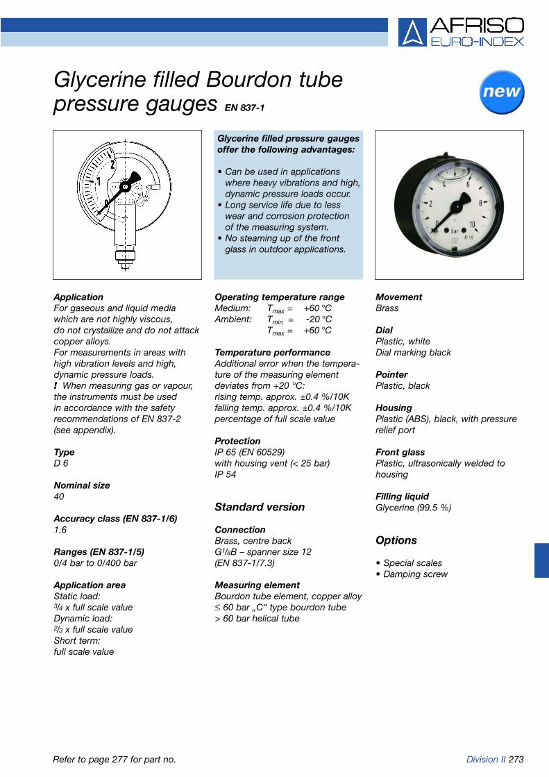
Division II 273
Glycerine filled Bourdon tube pressure gauges EN 837-1
ApplicationFor gaseous and liquid mediawhich are not highly viscous, do not crystallize and do not attackcopper alloys. For measurements in areas withhigh vibration levels and high,dynamic pressure loads. ! When measuring gas or vapour,the instruments must be used in accordance with the safetyrecommendations of EN 837-2 (see appendix).
TypeD 6
Nominal size40
Accuracy class (EN 837-1/6)1.6
Ranges (EN 837-1/5)0/4 bar to 0/400 bar
Application areaStatic load:3/4 x full scale valueDynamic load:2/3 x full scale valueShort term:full scale value
Operating temperature rangeMedium: Tmax = +60 °CAmbient: Tmin = -20 °C
Tmax = +60 °C
Temperature performanceAdditional error when the tempera-ture of the measuring elementdeviates from +20 °C:rising temp. approx. ±0.4 %/10Kfalling temp. approx. ±0.4 %/10Kpercentage of full scale value
ProtectionIP 65 (EN 60529)with housing vent (< 25 bar)IP 54
Standard version
ConnectionBrass, centre backG1/8B – spanner size 12(EN 837-1/7.3)
Measuring elementBourdon tube element, copper alloy< 60 bar „C“ type bourdon tube> 60 bar helical tube
MovementBrass
DialPlastic, whiteDial marking black
PointerPlastic, black
HousingPlastic (ABS), black, with pressurerelief port
Front glassPlastic, ultrasonically welded tohousing
Filling liquidGlycerine (99.5 %)
Options
• Special scales• Damping screw
Glycerine filled pressure gaugesoffer the following advantages:
• Can be used in applicationswhere heavy vibrations and high, dynamic pressure loads occur.
• Long service life due to less wear and corrosion protection of the measuring system.
• No steaming up of the front glass in outdoor applications.
Refer to page 277 for part no.

274 Division II
Centre back connection - NG 40
Glycerine filled Bourdon tube pressure gauges Type D 6 - NG 40Housing types and dimensions
Dimensions (mm)
Nominal size (NG) b Øc c1 c2 D G g SW
40 25 4 2 10 40 G1/8B 43 12

Division II 275
MovementBrass
DialAluminium, whiteDial marking black
PointerPlastic, black
HousingPolyamide, blackwith pressure relief port
Crimped bezelAluminium, black
Front glassPlastic
Filling liquidGlycerine (99.5 %)
Options
• Back flange (NG 63)• Clamp fixing• 3-hole fixing panel mounting
bezel (NG 63)• Damping screw
Operating temperature rangeMedium: Tmax = +60 °CAmbient: Tmin = -20 °C
Tmax = +60 °C
Temperature performanceIndication error when the tempera-ture of the measuring element devi-ates from 20 °C:rising temp. approx. ±0.4 % /10Kfalling temp. approx. ±0.4 % /10Kpercentage of full scale value
ProtectionIP 65 (EN 60529)with housing vent (< 25 bar)IP 54
Standard version
ConnectionBrass, bottom or centre backG1/4B - spanner size 14(EN 837-1/7.3)
Measuring elementBourdon tube element, copper alloy< 60 bar „C“ type bourdon tube> 60 bar helical tube
ApplicationFor gaseous and liquid media whichare not highly viscous, do not crystallize and do not attackcopper alloys. For measurements in areas withhigh vibration level and high, dyna-mic pressure loads. ! When measuring gas or vapour,the instruments must be used in accordance with the safetyrecommendations of EN 837-2 (see appendix).
TypeD 6
Nominal size50 - 63
Accuracy class (EN 837-1/6)1.6
Ranges (EN 837-1/5)-1/0 to -1/+15 bar0/0.6 to 0/400 bar
Application areaStatic load:3/4 x full scale valueDynamic load:2/3 x full scale valueShort term:full scale value
Refer to page 277 for part no.
Glycerine filled Bourdon tube pressure gauges EN 837-1

276 Division II
Bottom connection Bottom connection, back flange
Centre back connection Centre back connection, 3-hole fixing, panel mountingbezel
Centre back connection, clamp fixing
Glycerine filled Bourdon tube pressure gaugesType D 6 - NG 50/63Housing types and dimensions
* Dimensions according to DIN EN 837-1
Dimensions (mm)
Nominal size (NG) a a1 b b1 Øc c1 c2 d1* d2 d3* D G g h m n s s1 s2 SW
50 12 - 31.5 - 5 2 13 - - - 53 G1/4B 54.5 47 82 73 5 - - 14
63 10 13 32 35 5 2 13 75 85 3.6 68 G1/4B 55 53 94 82 7 5.5 3 14
Plastic tightening tool

Division II 277
Glycerine filled Bourdon tube pressure gauges EN 837-1
Minimum order quantity for non-stock items = 10 piecesRefer to page 308 for additional costs.
DG: M
Type RF40Gly,D611 RF50Gly,D601 RF50Gly,D611 RF50Gly,D641 RF63Gly,D601 RF63Gly,D611 RF63Gly,D621 RF63Gly,D641
Version
Housing-Ø 40 50 50 50 63 63 63 63
Housing ABS black Polyamide, black, with crimped bezel, black, plastic front glass
Meas. elem. Bourdon tube element, copper alloy
Accuracy class 1.6 1.6 1.6 1.6 1.6 1.6 1.6 1.6
Connection G1/8B G1/4B G1/4B G1/4B G1/4B G1/4B G1/4B G1/4B
Range(bar)
Price €
-1/0 --- 85051601 85051611 85051641 85101601 85101611 85101621 85101641
-1/+0,6 --- 85052601 85052611 85052641 85102601 85102611 85102621 85102641
-1/+1,5 --- 85053601 85053611 85053641 85103601 85103611 85103621 85103641
-1/+3 --- 85054601 85054611 85054641 85104601 85104611 85104621 85104641
-1/+5 --- 85055601 85055611 85055641 85105601 85105611 85105621 85105641
-1/+9 --- 85056601 85056611 85056641 85106601 85106611 85106621 85106641
-1/+15 --- 85057601 85057611 85057641 85107601 85107611 85107621 85107641
Price €
0/0,6 --- 85059601 85059611 85059641 85109601 85109611 85109621 85109641
0/1 --- 85060601 85060611 85060641 85110601 85110611 85110621 85110641
0/1,6 --- 85061601 85061611 85061641 85111601 85111611 85111621 85111641
0/2,5 --- 85062601 85062611 85062641 85112601 85112611 85112621 85112641
0/4 85013611 85063601 85063611 85063641 85113601 85113611 85113621 85113641
0/6 85014611 85064601 85064611 85064641 85114601 85114611 85114621 85114641
0/10 85015611 85065601 85065611 85065641 85115601 85115611 85115621 85115641
0/16 85016611 85066601 85066611 85066641 85116601 85116611 85116621 85116641
0/25 85017611 85067601 85067611 85067641 85117601 85117611 85117621 85117641
0/40 85018611 85068601 85068611 85068641 85118601 85118611 85118621 85118641
Price €
0/60 85019611 85069601 85069611 85069641 85119601 85119611 85119621 85119641
0/100 85020611 85070601 85070611 85070641 85120601 85120611 85120621 85120641
0/160 85021611 85071601 85071611 85071641 85121601 85121611 85121621 85121641
0/250 85022611 85072601 85072611 85072641 85122601 85122611 85122621 85122641
0/400 85023611 85073601 85073611 85073641 85123601 85123611 85123621 85123641
Part no. Part no. Part no. Part no. Part no. Part no. Part no. Part no.
3-hole fixing,Clamp fixing panel mounting bezel, Clamp fixing
black

278 Division II
ApplicationFor gaseous and liquid media whichare not highly viscous, do not cry-stallize and do not attack copperalloys. For measurement in areas with highlevels of vibration and high, dyna-mic pressure loads. ! When measuring gas or vapour,the instruments must be used in accordance with the safety recommendations of EN 837-2 (see appendix).
TypeD 7
Nominal size50 - 63
Accuracy class (EN 837-1/6)1.6
Ranges (EN 837-1/5)-1/0 to -1/+15 bar0/0.6 to 0/400 barNG 63 to 0/600 bar
Application areaStatic load:3/4 x full scale valueDynamic load:2/3 x full scale valueShort term:full scale value
MovementBrass
DialAluminium, whiteDial marking black
PointerAluminium, black
HousingStainless steel 1.4301with pressure relief port
Crimped bezelStainless steel 1.4301
Front glassPlastic
Filling liquidGlycerine (99.5 %)
Options
• Filling liquid silicone oil• Back flange (NG 63)• Clamp fixing• 3-hole fixing, panel mounting
bezel (NG 63)• Crimped bezel, polished• Special scales• Damping screw
Operating temperature rangeMedium: Tmax = +60 °CAmbient: Tmin = -20 °C
Tmax = +60 °C
Temperature performanceIndication error when the tempera-ture of the measuring element devi-ates from 20 °C:rising temp. approx. ±0.4 % /10Kfalling temp. approx. ±0.4 % /10Kpercentage of full scale value
ProtectionIP 65 (EN 60529)with housing vent (< 25 bar)IP 54
Standard version
ConnectionBrass, bottom or centre backG1/4B - spanner size 14(EN 837-1/7.3)
Measuring elementBourdon tube element, copper alloy< 60 bar „C“ type bourdon tube> 60 bar helical tube
Glycerine filled Bourdon tube pressure gauges EN 837-1
Refer to page 280 for part no.
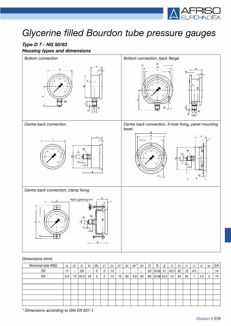
Division II 279
Bottom connection Bottom connection, back flange
Centre back connection Centre back connection, 3-hole fixing, panel mountingbezel
Centre back connection, clamp fixing
Dimensions (mm)
Glycerine filled Bourdon tube pressure gaugesType D 7 - NG 50/63Housing types and dimensions
* Dimensions according to DIN EN 837-1
Nominal size (NG) a a1 b b1 Øc c1 c2 d1* d2 d3* d4 D G g h m n s s1 s2 SW
50 11 - 28 - 5 2 13 - - - - 53 G1/4B 51 45.5 82 73 4.5 - - 14
63 9.5 13 30.5 34 5 2 13 75 85 3.6 64 68 G1/4B 53.3 53 94 82 7 5.5 2 14
Plastic tightening tool

280 Division II
Glycerine filled Bourdon tube pressure gauges EN 837-1
Refer to page 308 for additional costs.
* For single scales add the key code „E“ to Part No.!Minimum order quantity for non-stock items = 10 pieces
DG: M
Type RF50Gly,D701 RF50Gly,D711 RF50Gly,D751 RF63Gly,D701 RF63Gly,D711 RF63Gly,D731 RF63Gly,D751
Version
Housing-Ø 50 50 50 63 63 63 63
Housing Stainless steel 1.4301 with crimped bezel 1.4301, plastic front glass
Meas. elem. Bourdon tube element, copper alloy
Accuracy class 1.6 1.6 1.6 1.6 1.6 1.6 1.6
Connection G1/4B G1/4B G1/4B G1/4B G1/4B G1/4B G1/4B
Range(bar)
Price €
-1/0 85051701 85051711 85051751 85101701 85101711 85101731 85101751
-1/+0,6 85052701 85052711 85052751 85102701 85102711 85102731 85102751
-1/+1,5 85053701 85053711 85053751 85103701 85103711 85103731 85103751
-1/+3 85054701 85054711 85054751 85104701 85104711 85104731 85104751
-1/+5 85055701 85055711 85055751 85105701 85105711 85105731 85105751
-1/+9 85056701 85056711 85056751 85106701 85106711 85106731 85106751
-1/+15 85057701 85057711 85057751 85107701 85107711 85107731 85107751
Price €
0/0,6 85059701 85059711 85059751 85109701 85109711 85109731 85109751
0/1 85060701 85060711 85060751 85110701 85110711 85110731 85110751
0/1,6 85061701 85061711 85061751 85111701 85111711 85111731 85111751
0/2,5 85062701 85062711 85062751 85112701 85112711 85112731 85112751
0/4 85063701 85063711 85063751 85113701 85113711 85113731 85113751
0/6 85064701 85064711 85064751 85114701 85114711 85114731 85114751
0/10 85065701 85065711 85065751 85115701 85115711 85115731 85115751
0/16 85066701 85066711 85066751 85116701 85116711 85116731 85116751
0/25 85067701 85067711 85067751 85117701 85117711 85117731 85117751
0/40 85068701 85068711 85068751 85118701 85118711 85118731 85118751
Price €
0/60 85069701 85069711 85069751 85119701 85119711 85119731 85119751
0/100 85070701 85070711 85070751 85120701 85120711 85120731 85120751
0/160 85071701 85071711 85071751 85121701 85121711 85121731 85121751
0/250 85072701 85072711 85072751 85122701 85122711 85122731 85122751
0/400 85073701 85073711 85073751 85123701 85123711 85123731 85123751
Price €
0/600 --- --- --- 85124701 85124711 85124731 ---
Part no. Part no. Part no. Part no. Part no. Part no. Part no.
* Dual scale, bar outer, black, psi inner, red
Clamp fixing 3-hole fixing, panel Clamp fixingmounting bezel 1.4301

Division II 281
ApplicationFor gaseous and liquid media whichare not highly viscous, do not cry-stallize and do not attack copperalloys. For measurement in areas with highlevels of vibration and high, dyna-mic pressure loads. ! When measuring gas or vapour,the instruments must be used in accordance with the safetyrecommendations of EN 837-2 (see appendix).
TypeD 7
Nominal size80 - 100
Accuracy class (EN 837-1/6)1.6
Ranges (EN 837-1/5)-1/0 to -1/+15 bar0/1 to 0/400 bar
Application areaStatic load:3/4 x full scale valueDynamic load:2/3 x full scale valueShort term:full scale value
MovementBrass
DialAluminium, whiteDial marking black
PointerAluminium, black
HousingStainless steel 1.4301with pressure relief port
Crimped bezelStainless steel 1.4301
Front glassPlastic (Makrolon)
Filling liquidGlycerine (99.5 %)
Options
• Filling liquid silicone oil• Clamp fixing• 3-hole fixing, panel mounting
bezel (NG 100)• Crimped bezel, polished• Stainless steel measuring system
(up to 1,000 bar)• Special scales• Damping screw
Operating temperature rangeMedium: Tmax = +60 °CAmbient: Tmin = -20 °C
Tmax = +60 °C
Temperature performanceIndication error when the tempera-ture of the measuring element devi-ates from 20 °C:rising temp. approx. ±0.4 % /10Kfalling temp. approx. ±0.4 % /10Kpercentage of full scale value
ProtectionIP 65 (EN 60529)with housing vent (< 25 bar)IP 54
Standard version
ConnectionBrass, bottomNG 80-100 G1/2B - spanner size 22Brass, centre backNG 80 G1/4B - spanner size 14NG 100 G1/2B - spanner size 22(EN 837-1/7.3)
Measuring elementBourdon tube element, copper alloy< 60 bar „C“ type bourdon tube> 60 bar helical tube
Glycerine filled Bourdon tube pressure gauges EN 837-1
Refer to pages 283/284 for part no.

282 Division II
Bottom connection Centre back connection
Centre back connection, 3-hole fixing, panel mountingbezel (NG 100)
Centre back connection, clamp fixing
Dimensions (mm)
Glycerine filled Bourdon tube pressure gaugesType D 7 - NG 80/100Housing types and dimensions
Nominal size (NG) a b Øc c1 c2 d1 d2 d3 d4 D g G h M s s1 SW
80 Ms back - 33.5 5 2 13 - - - - 85 56.5 G1/4B - 82 7 - 14
80 VA back - 33.5 5 2 13 - - - - 85 59 G1/4B - 82 7 - 14
80 Ms bottom 12.2 33.5 6 3 20 - - - - 85 - G1/2B 71 - 7 - 22
80 VA bottom 12.2 33.5 6 3 20 - - - - 85 - G1/2B 79.5 - 7 - 22
100 Ms 12.2 33.5 6 3 20 116 132 4.8 101 106 65.5 G1/2B 81 106 7 3.8 22
100 VA 11.8 33.5 6 3 20 116 132 4.8 101 106 76.5 G1/2B 90 106 7 3.8 22

Division II 283
Glycerine filled Bourdon tube pressure gauges EN 837-1
Refer to page 308 for additional costs. Minimum order quantity = 10 pieces
DG: M Measuring system brass Measuring system stainless steel
Type RF80Gly,D701 RF80Gly,D711 RF80Gly,D751 RF80EGly,D702 RF80EGly,D712 RF80EGly,D752
Version
Housing-Ø 80 80 80 80 80 80
Housing Stainless steel 1.4301 with crimped bezel 1.4301, plastic front glass
Meas. elem. Bourdon tube, brass Bourdon tube, stainless steel 1.4571
Accuracy class 1.6 1.6 1.6 1.6 1.6 1.6
Connection G1/2B G1/4B G1/4B G1/2B G1/4B G1/4B
Range(bar)
Price €
-1/0 85151701 85151711 85151751 85151702 85151712 85151752
-1/+0,6 85152701 85152711 85152751 85152702 85152712 85152752
-1/+1,5 85153701 85153711 85153751 85153702 85153712 85153752
-1/+3 85154701 85154711 85154751 85154702 85154712 85154752
-1/+5 85155701 85155711 85155751 85155702 85155712 85155752
-1/+9 85156701 85156711 85156751 85156702 85156712 85156752
-1/+15 85157701 85157711 85157751 85157702 85157712 85157752
Price €
0/1 85160701 85160711 85160751 85160702 85160712 85160752
0/1,6 85161701 85161711 85161751 85161702 85161712 85161752
0/2,5 85162701 85162711 85162751 85162702 85162712 85162752
0/4 85163701 85163711 85163751 85163702 85163712 85163752
0/6 85164701 85164711 85164751 85164702 85164712 85164752
0/10 85165701 85165711 85165751 85165702 85165712 85165752
0/16 85166701 85166711 85166751 85166702 85166712 85166752
0/25 85167701 85167711 85167751 85167702 85167712 85167752
0/40 85168701 85168711 85168751 85168702 85168712 85168752
Price €
0/60 85169701 85169711 85169751 85169702 85169712 85169752
0/100 85170701 85170711 85170751 85170702 85170712 85170752
0/160 85171701 85171711 85171751 85171702 85171712 85171752
0/250 85172701 85172711 85172751 85172702 85172712 85172752
0/400 85173701 85173711 85173751 85173702 85173712 85173752
Price €
0/600 --- --- --- 85174702 85174712 85174752
0/1000 --- --- --- 85175702 85175712 85175752
Add. costs Price € Price € Price €
class 1.0 --- --- ---
Part no. Part no. Part no. Part no. Part no. Part no.
Clamp fixing Clamp fixing

284 Division II
Glycerine filled Bourdon tube pressure gauges EN 837-1
Minimum order quantity for non-stocks items = 10 pieces Refer to page 308 for additional costs.
DG: M Measuring system brass Measuring system stainless steel
Type RF100Gly,D701 RF100Gly,D711 RF100Gly,D731 RF100Gly,D751 RF100EGly,D702 RF100EGly,D712 RF100EGly,D732 RF100EGly,D752
Version
Housing-Ø 100 100 100 100 100 100 100 100
Housing Stainless steel 1.4301 with crimped bezel 1.4301, plastic front glass
Meas. elem. Bourdon tube, brass Bourdon tube, stainless steel 1.4571
Accuracy class 1.6 1.6 1.6 1.6 1.6 1.6 1.6 1.6
Connection G1/2B G1/2B G1/2B G1/2B G1/2B G1/2B G1/2B G1/2B
Range(bar)
Price €
-1/0 85201701 85201711 85201731 85201751 85201702 85201712 85201732 85201752
-1/+0,6 85202701 85202711 85202731 85202751 85202702 85202712 85202732 85202752
-1/+1,5 85203701 85203711 85203731 85203751 85203702 85203712 85203732 85203752
-1/+3 85204701 85204711 85204731 85204751 85204702 85204712 85204732 85204752
-1/+5 85205701 85205711 85205731 85205751 85205702 85205712 85205732 85205752
-1/+9 85206701 85206711 85206731 85206751 85206702 85206712 85206732 85206752
-1/+15 85207701 85207711 85207731 85207751 85207702 85207712 85207732 85207752
Price €
0/1 85210701 85210711 85210731 85210751 85210702 85210712 85210732 85210752
0/1,6 85211701 85211711 85211731 85211751 85211702 85211712 85211732 85211752
0/2,5 85212701 85212711 85212731 85212751 85212702 85212712 85212732 85212752
0/4 85213701 85213711 85213731 85213751 85213702 85213712 85213732 85213752
0/6 85214701 85214711 85214731 85214751 85214702 85214712 85214732 85214752
0/10 85215701 85215711 85215731 85215751 85215702 85215712 85215732 85215752
0/16 85216701 85216711 85216731 85216751 85216702 85216712 85216732 85216752
0/25 85217701 85217711 85217731 85217751 85217702 85217712 85217732 85217752
0/40 85218701 85218711 85218731 85218751 85218702 85218712 85218732 85218752
Price €
0/60 85219701 85219711 85219731 85219751 85219702 85219712 85219732 85219752
0/100 85220701 85220711 85220731 85220751 85220702 85220712 85220732 85220752
0/160 85221701 85221711 85221731 85221751 85221702 85221712 85221732 85221752
0/250 85222701 85222711 85222731 85222751 85222702 85222712 85222732 85222752
0/400 85223701 85223711 85223731 85223751 85223702 85223712 85223732 85223752
Price €
0/600 --- --- --- --- 85224702 85224712 85224732 85224752
0/1000 --- --- --- --- 85225702 85225712 85225732 85225752
Add. costs Price € Price € Price € Price €
class 1.0 --- --- --- ---
Part no. Part no. Part no. Part no. Part no. Part no. Part no. Part no.
3-hole fixing, panel 3-hole fixing, panelmounting bezel, Clamp fixing mounting bezel, Clamp fixing
1.4301 1.4301

Division II 285
Operating temperature rangeMedium: Tmax = +60 °CAmbient: Tmin = -20 °C
Tmax = +60 °C
Temperature performanceIndication error when the tempera-ture of the measuring element devi-ates from 20 °C:rising temp. approx. ±0.4 % /10Kfalling temp. approx. ±0.4 % /10Kpercentage of full scale value
ProtectionIP 65 (EN 60529)with housing vent (< 25 bar)IP 54
Standard version
ConnectionBrass, bottom or bottom back:G1/2B - spanner size 22(EN 837-1/7.3)
Measuring elementBourdon tube element,< 60 bar „C“ type bourdon tube,copper alloy> 60 bar helical tube, stainless steel1.4571
MovementBrass
DialAluminium, whiteDial marking black
PointerAluminium, black
HousingStainless steel 1.4301with blow-out
Bayonet type bezelStainless steel 1.4301
Front glassInstrument glass
Filling liquidGlycerine (99.5 %)
Options
• Back flange• Panel mounting bezel for clamp
fixing• 3-hole fixing, panel mounting
bezel• Special scales
Glycerine filled Bourdon tube pressure gauges EN 837-1
Refer to page 287 for part no.
ApplicationFor gaseous and liquid media whichare not highly viscous, do not cry-stallize and do not attack copperalloys. For measurements in areas withhigh levels of vibration and high,dynamic pressure loads. ! When measuring gas or vapour,the instruments must be used in accordance with the safetyrecommendations of EN 837-2 (see appendix).
TypeD 8
Nominal size100 - 160
Accuracy class (EN 837-1/6)1.0
Ranges (EN 837-1/5)-1/0 to -1/+15 bar0/0.6 to 0/1,000 bar
Application areaStatic load:< 600 bar = full scale value> 600 bar = 3/4 x full scale valueDynamic load:< 600 bar = 0.9 x full scale value> 600 bar = 2/3 x full scale valueShort-term:< 600 bar = 1.3 x full scale value> 600 bar = full scale value

286 Division II
Bottom connection Bottom connection, back flange
Bottom back connection Bottom back connection, 3-hole fixing, panel mountingbezel
Bottom back connection, panel mounting bezel forclamp fixing
Dimensions (mm)
Glycerine filled Bourdon tube pressure gaugesType D 8 - NG 100/160Housing types and dimensions
* Dimensions according to DIN EN 837-1
Nominal size (NG) a a1 b b1 b2 b3 Øc c1 c2 d1* d2 d3* d4 d5 d6 e G g g1 h s1
100 15.6 19.1 49 52.5 49 49 6 3 20 116 132 4.8 104 107 101 26.5 G1/2B 81 81 86 5.5
160 17.5 20 50 53 50 52 6 3 20 178 196 5.8 164 167 161 26.5 G1/2B 82 84 116 6
Nominal size (NG) s2 s3 s4 SW
100 4 2 4 22
160 4 2 4.5 22
Rotated by 90°

Division II 287
Glycerine filled Bourdon tube pressure gauges EN 837-1
DG: M
Refer to page 308 for additional costs.
Type RF100Gly,D801 RF100Gly,D811 RF100Gly,D831RF100Gly,D851 RF160Gly,D801 RF160Gly,D811 RF160Gly,D831 RF160Gly,D851
Version
Housing-Ø 100 100 100 100 160 160 160 160
Housing Stainless steel 1.4301, Instrument grade front glass
Meas. elem. Bourdon tube, copper alloy (> 60 bar stainless steel 1.4571)
Accuracy class 1.0 1.0 1.0 1.0 1.0 1.0 1.0 1.0
Connection G1/2B G1/2B G1/2B G1/2B G1/2B G1/2B G1/2B G1/2B
Range(bar)
Price €
-1/0 85201801 85201811 85201831 85201851 85251801 85251811 85251831 85251851
-1/+0,6 85202801 85202811 85202831 85202851 85252801 85252811 85252831 85252851
-1/+1,5 85203801 85203811 85203831 85203851 85253801 85253811 85253831 85253851
-1/+3 85204801 85204811 85204831 85204851 85254801 85254811 85254831 85254851
-1/+5 85205801 85205811 85205831 85205851 85255801 85255811 85255831 85255851
-1/+9 85206801 85206811 85206831 85206851 85256801 85256811 85256831 85256851
-1/+15 85207801 85207811 85207831 85207851 85257801 85257811 85257831 85257851
Price €
0/0,6 85209801 85209811 85209831 85209851 85259801 85259811 85259831 85259851
0/1 85210801 85210811 85210831 85210851 85260801 85260811 85260831 85260851
0/1,6 85211801 85211811 85211831 85211851 85261801 85261811 85261831 85261851
0/2,5 85212801 85212811 85212831 85212851 85262801 85262811 85262831 85262851
0/4 85213801 85213811 85213831 85213851 85263801 85263811 85263831 85263851
0/6 85214801 85214811 85214831 85214851 85264801 85264811 85264831 85264851
0/10 85215801 85215811 85215831 85215851 85265801 85265811 85265831 85265851
0/16 85216801 85216811 85216831 85216851 85266801 85266811 85266831 85266851
0/25 85217801 85217811 85217831 85217851 85267801 85267811 85267831 85267851
0/40 85218801 85218811 85218831 85218851 85268801 85268811 85268831 85268851
Price €
0/60 85219801 85219811 85219831 85219851 85269801 85269811 85269831 85269851
0/100 85220801 85220811 85220831 85220851 85270801 85270811 85270831 85270851
0/160 85221801 85221811 85221831 85221851 85271801 85271811 85271831 85271851
0/250 85222801 85222811 85222831 85222851 85272801 85272811 85272831 85272851
0/400 85223801 85223811 85223831 85223851 85273801 85273811 85273831 85273851
Price €
0/600 85224801 85224811 85224831 85224851 85274801 85274811 85274831 85274851
0/1000 85225801 85225811 85225831 85225851 85275801 85275811 85275831 85275851
Part no. Part no. Part no. Part no. Part no. Part no. Part no. Part no.
3-hole fixing, panel Panel mounting bezel, 3-hole fixing, panel Panel mounting bezel,mounting bezel, 1.4301, mounting bezel, 1.4301 1.4301 polished clamp fixing 1.4301 polished clamp fixing

288 Division II
ApplicationFor gaseous and liquid media whichare not highly viscous, do not cry-stallize and do not attack copperalloys. For measurements in areas subjectto extreme levels of vibration. ! When measuring gas or vapour,the instruments must be used in accordance with the safetyrecommendations of EN 837-2 (see appendix).
TypeD 0
Nominal size63
Accuracy class (EN 837-1/6)1.6
Ranges (EN 837-1/5)-1/0 to -1/+15 bar0/0.6 to 0/600 bar
Application areaStatic load:3/4 x full scale valueDynamic load:2/3 x full scale valueShort term:full scale value
MovementBrass
DialAluminium, whiteDial marking black
PointerAluminium, black
HousingHot pressed brass 2.0401, lacquered with brass colour,with pressure relief port
Screw type bezelBrass, bare metal surface, lacquered with transparent lacquer
Front glassLaminated safety front glass
Filling liquidGlycerine (99.5 %)
Options
• Filling liquid silicone oil• Bezel chrome plated, clamp
fixing• Special scales• Damping screw
Operating temperature rangeMedium: Tmax = +60 °CAmbient: Tmin = -20 °C
Tmax = +60 °C
Temperature performanceIndication error when the tempera-ture of the measuring element devi-ates from 20 °C:rising temp. approx. ±0.4 % /10Kfalling temp. approx. ±0.4 % /10Kpercentage of full scale value
ProtectionIP 65 (EN 60529)with housing vent (< 25 bar)IP 54
Standard version
ConnectionBrass, bottom or centre back1/4-18 NPT (EN 837-1/7.3)
Measuring elementBourdon tube element, copper alloy< 60 bar „C“ type bourdon tube> 60 bar helical tube
Glycerine filled Bourdon tube pressure gaugeswith hot pressed brass housing EN 837-1
Refer to page 290 for part no.

Division II 289
Bottom connection Centre back connection
Centre back connection, for clamp fixing Clamp fixing
Glycerine filled Bourdon tube pressure gaugeswith hot pressed brass housing Type D 0 - NG 63Housing types and dimensions
Dimensions (mm)
Nominal size (NG) a b b1 c1 c2 D d1 d2 d3 G g g1 h l m n s1 s2 s3
63 9 31 31 12 15 64 65 75 M4 1/4-18 NPT 54 54 52.5 25 70 46 11.5 8.2 11.2
Nominal size (NG) SW
63 14
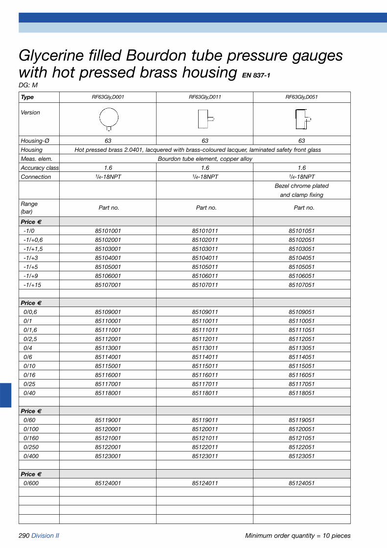
290 Division II Minimum order quantity = 10 pieces
Glycerine filled Bourdon tube pressure gaugeswith hot pressed brass housing EN 837-1
DG: M
Type RF63Gly,D001 RF63Gly,D011 RF63Gly,D051
Version
Housing-Ø 63 63 63
Housing Hot pressed brass 2.0401, lacquered with brass-coloured lacquer, laminated safety front glass
Meas. elem. Bourdon tube element, copper alloy
Accuracy class 1.6 1.6 1.6
Connection 1/4-18NPT 1/4-18NPT 1/4-18NPT
Bezel chrome plated
and clamp fixing
Range(bar)
Price €
-1/0 85101001 85101011 85101051
-1/+0,6 85102001 85102011 85102051
-1/+1,5 85103001 85103011 85103051
-1/+3 85104001 85104011 85104051
-1/+5 85105001 85105011 85105051
-1/+9 85106001 85106011 85106051
-1/+15 85107001 85107011 85107051
Price €
0/0,6 85109001 85109011 85109051
0/1 85110001 85110011 85110051
0/1,6 85111001 85111011 85111051
0/2,5 85112001 85112011 85112051
0/4 85113001 85113011 85113051
0/6 85114001 85114011 85114051
0/10 85115001 85115011 85115051
0/16 85116001 85116011 85116051
0/25 85117001 85117011 85117051
0/40 85118001 85118011 85118051
Price €
0/60 85119001 85119011 85119051
0/100 85120001 85120011 85120051
0/160 85121001 85121011 85121051
0/250 85122001 85122011 85122051
0/400 85123001 85123011 85123051
Price €
0/600 85124001 85124011 85124051
Part no. Part no. Part no.

Division II 291
Operating temperature rangeMedium: Tmax = +150 °CAmbient: Tmin = -20 °C
Tmax = +60 °C
Temperature performanceIndication error when the tempera-ture of the measuring element devi-ates from 20 °C:rising temp. approx. ±0.4 % /10Kfalling temp. approx. ±0.4 % /10Kpercentage of full scale value
ProtectionIP 65 (EN 60529)with housing vent (< 25 bar)IP 54
Standard version
ConnectionStainless steel 1.4571NG 50 bottom or bottom backNG 63 bottom or centre backG1/4B - spanner size 14(EN 837-1/7.3)
Measuring elementBourdon tube, stainless steel1.4571< 60 bar „C“ type bourdon tube> 60 bar helical tubeleak tested (EN 837-1/9.5.6)
ApplicationFor aggressive gaseous and liquidmedia which are not highly viscousand do not crystallize. Suitable foruse in corrosive atmospheres. ! When measuring gas or vapour,the instruments must be used in accordance with the safety recommendations of EN 837-2 (see appendix).
TypeD 9
Nominal size50 - 63
Accuracy class (EN 837-1/6)1.6
Ranges (EN 837-1/5)NG 50:-1/0 to -1/+15 bar0/0.6 to 0/600 barNG 63:-1/0 to -1/+15 bar0/0.6 to 0/1,000 bar
Application areaStatic load:3/4 x full scale valueDynamic load:2/3 x full scale valueShort term:full scale value
MovementStainless steel
DialAluminium, whiteDial marking black
PointerAluminium, black
HousingStainless steel 1.4301 with pressurerelief port
Crimped bezelStainless steel 1.4301
Front glassNG 50 plasticNG 63 laminated safety glass
Options
• Plastic front glass (NG 63)• Brass movement• Back flange (NG 63)• Clamp fixing• 3-hole fixing, panel mounting
bezel (NG 63)• Crimped bezel, polished• Special scales
Bourdon tube pressure gauges for chemical applications EN 837-1
Refer to page 293 for part no.

292 Division II
Bottom connection NG 50/63 Bottom connection, back flange, NG 63
Bottom back connection, 3-hole fixing, panelmounting bezel NG 63 NG 50
Bottom back connection, clamp fixing, NG 63
Dimensions (mm)
Bourdon tube pressure gauges for chemical applications Type D 9 - NG 50/63Housing types and dimensions
Bottom back connection, clamp fixing, NG 50
* Dimensions according to DIN EN 837-1
Bottom back connectionNG 63 NG 50
Nominal size (NG) a a1 b b1 Øc c1 c2 d1* d2* d3* d4 D e G g h m n s s1 s2
50 10.5 - 28 - 5 2 13 60 70 3.6 - 53 12.5 G1/4B 51 46 59 - 4.5 - 2.5
63 9.5 13 30.5 34 5 2 13 75 85 3.6 64 68 - G1/4B 56 53 94 82 7 5.5 2
Nominal size (NG) SW
50 14
63 14
Plastic tightening tool

Division II 293
Bourdon tube pressure gauges for chemical applications EN 837-1
Refer to page 308 for additional costs.
DG: M
Type RF50Ch,D902 RF50Ch,D912 RF50Ch,D952 RF63Ch,D902 RF63Ch,D912 RF63Ch,D932 RF63Ch,D952
Version
Housing-Ø 50 50 50 63 63 63 63
Housing Stainless steel 1.4301 with crimped bezel 1.4301
Meas. elem. Bourdon tube, stainless steel 1.4571
Accuracy class 1.6 1.6 1.6 1.6 1.6 1.6 1.6
Connection G1/4B G1/4B G1/4B G1/4B G1/4B G1/4B G1/4B
Range(bar)
Price €
-1/0 85051902 85051912 85051952 85101902 85101912 85101932 85101952
-1/+0,6 85052902 85052912 85052952 85102902 85102912 85102932 85102952
-1/+1,5 85053902 85053912 85053952 85103902 85103912 85103932 85103952
-1/+3 85054902 85054912 85054952 85104902 85104912 85104932 85104952
-1/+5 85055902 85055912 85055952 85105902 85105912 85105932 85105952
-1/+9 85056902 85056912 85056952 85106902 85106912 85106932 85106952
-1/+15 85057902 85057912 85057952 85107902 85107912 85107932 85107952
Price €
0/0,6 85059902 85059912 85059952 85109902 85109912 85109932 85109952
0/1 85060902 85060912 85060952 85110902 85110912 85110932 85110952
0/1,6 85061902 85061912 85061952 85111902 85111912 85111932 85111952
0/2,5 85062902 85062912 85062952 85112902 85112912 85112932 85112952
0/4 85063902 85063912 85063952 85113902 85113912 85113932 85113952
0/6 85064902 85064912 85064952 85114902 85114912 85114932 85114952
0/10 85065902 85065912 85065952 85115902 85115912 85115932 85115952
0/16 85066902 85066912 85066952 85116902 85116912 85116932 85116952
0/25 85067902 85067912 85067952 85117902 85117912 85117932 85117952
0/40 85068902 85068912 85068952 85118902 85118912 85118932 85118952
Price €
0/60 85069902 85069912 85069952 85119902 85119912 85119932 85119952
0/100 85070902 85070912 85070952 85120902 85120912 85120932 85120952
0/160 85071902 85071912 85071952 85121902 85121912 85121932 85121952
0/250 85072902 85072912 85072952 85122902 85122912 85122932 85122952
0/400 85073902 85073912 85073952 85123902 85123912 85123932 85123952
Price €
0/600 85074902 85074912 85074952 85124902 85124912 85124932 85124952
0/1000 --- --- --- 85125902 85125912 85125932 85125952
Part no. Part no. Part no. Part no. Part no. Part no. Part no.
3-hole fixing, panelClamp fixing mounting bezel 1.4301, Clamp fixing
bare metal surface

294 Division II
ApplicationFor aggressive gaseous and liquidmedia which are not highly viscousand do not crystallize. Suitable foruse in corrosive atmospheres. ! When measuring gas or vapour,the instruments must be used in accordance with the safety recommendations of EN 837-2 (see appendix).
TypeD 4
Nominal size100 - 160
Accuracy class (EN 837-1/6)1.0
Ranges (EN 837-1/5)-1/0 to -1/+15 barNG 100 0/0.6 to 0/1,000 barNG 160 0/0.6 to 0/1,600 bar
Application areaStatic load:< 600 bar = full scale value> 600 bar = 3/4 x full scale valueDynamic load:< 600 bar = 0.9 x full scale value> 600 bar = 2/3 x full scale valueShort term:< 600 bar = 1.3 x full scale value> 600 bar = full scale value
MovementStainless steel
DialAluminium, whiteDial marking black
PointerAluminium, black
HousingStainless steel 1.4301with blow-out
Bayonet type bezelStainless steel 1.4301
Front glassLaminated safety glass
Options
• Brass movement• Back flange• Panel mounting bezel for clamp
fixing• 3-hole fixing, panel mounting
bezel• Special scales• Electrical contacts
Operating temperature rangeMedium: Tmax = +150 °CAmbient: Tmin = -20 °C
Tmax = +60 °C
Temperature performanceIndication error when the tempera-ture of the measuring element devi-ates from 20 °C:rising temp. approx. ±0.4 % /10Kfalling temp. approx. ±0.4 % /10Kpercentage of full scale value
ProtectionIP 65 (EN 60529)with housing vent (< 25 bar)IP 54
Standard version
ConnectionStainless steel 1.4571, bottom orbottom backG1/2B - spanner size 22(EN 837-1/7.3)
Measuring elementBourdon tube, stainless steel1.4571< 60 bar „C“ type bourdon tube> 60 bar helical tubeleak tested (EN 837-1/9.5.6)
Bourdon tube pressure gauges for chemical applications EN 837-1
Refer to page 296 for part no.

Division II 295
Bottom connection Bottom connection, back flange
Bottom back connection Bottom back connection, 3-hole fixing, panel mountingbezel
Bottom back connection, panel mounting bezel forclamp fixing
Dimensions (mm)
Bourdon tube pressure gauges for chemical applications Type D 4 - NG 100/160Housing types and dimensions
* Dimensions according to DIN EN 837-1
Nominal size (NG) a a1 b b1 b2 b3 Øc c1 c2 d1* d2* d3* d4 d5 d6 e G g g1 h s1
100 15.6 19.1 49 52.5 49 49 6 3 20 116 132 4.8 104 107 101 34.5 G1/2B 83 83 86 5.5
160 17.5 20.5 50 53 50 52 6 3 20 178 196 5.8 164 167 161 34.5 G1/2B 84 86 116 6
Nominal size (NG) s2 s3 s4 SW
100 4 2 4 22
160 4 2 4.5 22

296 Division II
Bourdon tube pressure gauges for chemical applications EN 837-1
Refer to page 308 for additional costs.
DG: M
Type RF100Ch,D402 RF100Ch,D412 RF100Ch,D432 RF100Ch,D452 RF160Ch,D402 RF160Ch,D412 RF160Ch,D432 RF160Ch,D452
Version
Housing-Ø 100 100 100 100 160 160 160 160
Housing Stainless steel 1.4301 with bayonet type bezel, laminated safety front glass
Meas. elem. Bourdon tube, stainless steel 1.4571
Accuracy class 1.0 1.0 1.0 1.0 1.0 1.0 1.0 1.0
Connection G1/2B G1/2B G1/2B G1/2B G1/2B G1/2B G1/2B G1/2B
Range(bar)
Price €
-1/0 85201402 85201412 85201432 85201452 85251402 85251412 85251432 85251452
-1/+0,6 85202402 85202412 85202432 85202452 85252402 85252412 85252432 85252452
-1/+1,5 85203402 85203412 85203432 85203452 85253402 85253412 85253432 85253452
-1/+3 85204402 85204412 85204432 85204452 85254402 85254412 85254432 85254452
-1/+5 85205402 85205412 85205432 85205452 85255402 85255412 85255432 85255452
-1/+9 85206402 85206412 85206432 85206452 85256402 85256412 85256432 85256452
-1/+15 85207402 85207412 85207432 85207452 85257402 85257412 85257432 85257452
Price €
0/0,6 85209402 85209412 85209432 85209452 85259402 85259412 85259432 85259452
0/1 85210402 85210412 85210432 85210452 85260402 85260412 85260432 85260452
0/1,6 85211402 85211412 85211432 85211452 85261402 85261412 85261432 85261452
0/2,5 85212402 85212412 85212432 85212452 85262402 85262412 85262432 85262452
0/4 85213402 85213412 85213432 85213452 85263402 85263412 85263432 85263452
0/6 85214402 85214412 85214432 85214452 85264402 85264412 85264432 85264452
0/10 85215402 85215412 85215432 85215452 85265402 85265412 85265432 85265452
0/16 85216402 85216412 85216432 85216452 85266402 85266412 85266432 85266452
0/25 85217402 85217412 85217432 85217452 85267402 85267412 85267432 85267452
0/40 85218402 85218412 85218432 85218452 85268402 85268412 85268432 85268452
Price €
0/60 85219402 85219412 85219432 85219452 85269402 85269412 85269432 85269452
0/100 85220402 85220412 85220432 85220452 85270402 85270412 85270432 85270452
0/160 85221402 85221412 85221432 85221452 85271402 85271412 85271432 85271452
0/250 85222402 85222412 85222432 85222452 85272402 85272412 85272432 85272452
0/400 85223402 85223412 85223432 85223452 85273402 85273412 85273432 85273452
Price €
0/600 85224402 85224412 85224432 85224452 85274402 85274412 85274432 85274452
0/1000 85225402 85225412 85225432 85225452 85275402 85275412 85275432 85275452
0/1600 --- --- --- --- 85276402 85276412 85276432 85276452
Part no. Part no. Part no. Part no. Part no. Part no. Part no. Part no.
3-hole fixing, panel Panel mounting 3-hole fixing, panel Panel mountingmounting bezel, bezel, 1.4301 mounting bezel, bezel, 1.43011.4301 polished polished, clamp fixing 1.4301 polished polished, clamp fixing

Division II 297
Operating temperature rangeMedium: Tmax = +150 °CAmbient: Tmin = -20 °C
Tmax = +60 °C
Temperature performanceIndication error when the tempera-ture of the measuring element deviates from 20 °C:rising temp. approx. ±0.4 % /10Kfalling temp. approx. ±0.4 % /10Kpercentage of full scale value
ProtectionIP 65 (EN 60529)with housing vent (< 25 bar)IP 54
Standard version
ConnectionStainless steel 1.4571NG 50 bottom or bottom backNG 63 bottom or centre backG1/4B - spanner size 14(EN 837-1/7.3)
Measuring elementBourdon tube, stainless steel1.4571< 60 bar „C“ type bourdon tube> 60 bar helical tubeleak tested (EN 837-1/9.5.6)
MovementStainless steel
DialAluminium, whiteDial marking black
PointerAluminium, black
HousingStainless steel 1.4301with pressure relief port
Crimped bezelStainless steel 1.4301
Front glassNG 50 plasticNG 63 laminated safety glass
Filling liquidGlycerine (99.5 %)
Options
• Filling liquid silicone oil• Plastic front glass (NG 63)• Brass movement• Back flange (NG 63)• Clamp fixing• 3-hole fixing, panel mounting
bezel, (NG 63)• Crimped bezel, polished• Special scales
ApplicationFor aggressive gaseous and liquidmedia which are not highly viscousand do not crystallize. Suitable foruse in corrosive atmospheres. For measurement in areas subjectto high vibration levels and high,dynamic pressure loads. ! When measuring gas or vapour,the instruments must be used in accordance with the safetyrecommendations of EN 837-2 (see appendix).
TypeD 7
Nominal size50 - 63
Accuracy class (EN 837-1/6)1.6
Ranges (EN 837-1/5)NG 50:-1/0 to -1/+15 bar0/0.6 to 0/600 barNG 63:-1/0 to -1/+15 bar0/0.6 to 0/1,000 bar
Application areaStatic load:3/4 x full scale valueDynamic load:2/3 x full scale valueShort term:full scale value
Bourdon tube pressure gauges with glycerinefilling, for chemical applications EN 837-1
Refer to page 299 for part no.

298 Division II
Bottom connection NG 50/63 Bottom connection, back flange, NG 63
Centre or bottom back connectionNG 63 NG 50
Centre or bottom back connection, 3-hole fixing,panel mounting bezel NG 63 NG 50
Centre back connection, clamp fixing, NG 63
Bourdon tube pressure gauges with glycerine filling, for chemical applications Type D 7 - NG 50/63Housing types and dimensions
Bottom back connection, clamp fixing, NG 50
Dimensions (mm)
* Dimensions according to DIN EN 837-1
Nominal size (NG) a a1 b b1 Øc c1 c2 d1* d2* d3* d4 D e G g h m n s s1 s2
50 10.5 - 28 - 5 2 13 60 70 3.6 - 53 12.5 G1/4B 51 46 59 - 4.5 - 2.5
63 9.5 13 30.5 34 5 2 13 75 85 3.6 64 68 - G1/4B 56 53 94 82 7 5.5 2
Nominal size (NG) SW
50 14
63 14
Plastic tightening tool

Division II 299
Bourdon tube pressure gauges with glycerine filling, for chemical applications EN 837-1
Refer to page 308 for additional costs.
DG: M
Type RF50ChGly,D702 RF50ChGly,D712 RF50ChGly,D752 RF63ChGly,D702 RF63ChGly,D712 RF63ChGly,D732 RF63ChGly,D752
Version
Housing-Ø 50 50 50 63 63 63 63
Housing Stainless steel 1.4301 with crimped bezel 1.4301
Meas. elem. Bourdon tube, stainless steel 1.4571
Accuracy class 1.6 1.6 1.6 1.6 1.6 1.6 1.6
Connection G1/4B G1/4B G1/4B G1/4B G1/4B G1/4B G1/4B
Range(bar)
Price €
-1/0 85051702 85051712 85051752 85101702 85101712 85101732 85101752
-1/+0,6 85052702 85052712 85052752 85102702 85102712 85102732 85102752
-1/+1,5 85053702 85053712 85053752 85103702 85103712 85103732 85103752
-1/+3 85054702 85054712 85054752 85104702 85104712 85104732 85104752
-1/+5 85055702 85055712 85055752 85105702 85105712 85105732 85105752
-1/+9 85056702 85056712 85056752 85106702 85106712 85106732 85106752
-1/+15 85057702 85057712 85057752 85107702 85107712 85107732 85107752
Price €
0/0,6 85059702 85059712 85059752 85109702 85109712 85109732 85109752
0/1 85060702 85060712 85060752 85110702 85110712 85110732 85110752
0/1,6 85061702 85061712 85061752 85111702 85111712 85111732 85111752
0/2,5 85062702 85062712 85062752 85112702 85112712 85112732 85112752
0/4 85063702 85063712 85063752 85113702 85113712 85113732 85113752
0/6 85064702 85064712 85064752 85114702 85114712 85114732 85114752
0/10 85065702 85065712 85065752 85115702 85115712 85115732 85115752
0/16 85066702 85066712 85066752 85116702 85116712 85116732 85116752
0/25 85067702 85067712 85067752 85117702 85117712 85117732 85117752
0/40 85068702 85068712 85068752 85118702 85118712 85118732 85118752
Price €
0/60 85069702 85069712 85069752 85119702 85119712 85119732 85119752
0/100 85070702 85070712 85070752 85120702 85120712 85120732 85120752
0/160 85071702 85071712 85071752 85121702 85121712 85121732 85121752
0/250 85072702 85072712 85072752 85122702 85122712 85122732 85122752
0/400 85073702 85073712 85073752 85123702 85123712 85123732 85123752
Price €
0/600 85074702 85074712 85074752 85124702 85124712 85124732 85124752
0/1000 --- --- --- 85125702 85125712 85125732 85125752
Part no. Part no. Part no. Part no. Part no. Part no. Part no.
3-hole fixing, panelClamp fixing mounting bezel, 1.4301, Clamp fixing
bare metal surface

300 Division II
ApplicationFor aggressive gaseous and liquidmedia which are not highly viscousand do not crystallize. Suitable foruse in corrosive atmospheres. For measurement in areas with highvibration levels and high, dynamicpressure loads. ! When measuring gas or vapour,the instruments must be used in accordance with the safetyrecommendations of EN 837-2 (see appendix).
TypeD 8
Nominal size100 - 160
Accuracy class (EN 837-1/6)1.0
Ranges (EN 837-1/5)-1/0 to -1/+15 barNG 100 0/0.6 to 0/1,000 barNG 160 0/0.6 to 0/1,600 bar
Application areaStatic load:< 600 bar = full scale value> 600 bar = 3/4 x full scale valueDynamic load:< 600 bar = 0.9 x full scale value> 600 bar = 2/3 x full scale valueShort term:< 600 bar = 1.3 x full scale value> 600 bar = full scale value
Operating temperature rangeMedium: Tmax = +150 °CAmbient: Tmin = -20 °C
Tmax = +60 °C
Temperature performanceIndication error when the tempera-ture of the measuring element devi-ates from 20 °C:rising temp. approx. ±0.4 % /10Kfalling temp. approx. ±0.4 % /10Kpercentage of full scale value
ProtectionIP 65 (EN 60529)with housing vent (< 25 bar)IP 54
Standard version
ConnectionStainless steel 1.4571, bottom orbottom backG1/2B- spanner size 22(EN 837-1/7.3)
Measuring elementBourdon tube, stainless steel1.4571< 60 bar „C“ type bourdon tube> 60 bar helical tubeleak tested (EN 837-1/9.5.6)
MovementStainless steel
DialAluminium, whiteDial marking black
PointerAluminium, black
HousingStainless steel 1.4301with blow-out
Bayonet type bezelStainless steel 1.4301
Front glassLaminated safety glass
Filling liquidGlycerine (99.5 %)
Options
• Filling liquid silicone oil• Brass movement• Back flange• Panel mounting bezel for clamp
fixing• 3-hole fixing, panel mounting
bezel• Special scales
Bourdon tube pressure gauges with glyce-rine filling, for chemical applications EN 837-1
Refer to page 302 for part no.

Division II 301
Bottom connection Bottom connection, back flange
Bottom back connection Bottom back connection, 3-hole fixing, panel mountingbezel
Bottom back connection, panel mounting bezel forclamp fixing
Dimensions (mm)
Bourdon tube pressure gauges with glycerine filling, for chemical applications Type D 8 - NG 100/160Housing types and dimensions
* Dimensions according to DIN EN 837-1
Nominal size (NG) a a1 b b1 b2 b3 Øc c1 c2 d1* d2* d3* d4 d5 d6 e G g g1 h s1
100 15.6 19.1 49 52.5 49 49 6 3 20 116 132 4.8 104 107 101 34.5 G1/2B 83 83 86 5.5
160 17.5 20.5 50 53 50 52 6 3 20 178 196 5.8 164 167 161 34.5 G1/2B 84 86 116 6
Nominal size (NG) s2 s3 s4 SW
100 4 2 4 22
160 4 2 4.5 22

302 Division II
Bourdon tube pressure gauges with glycerine filling, for chemical applications EN 837-1
Refer to page 308 for additional costs.
DG: M
Type RF100ChGly, RF100ChGly, RF100ChGly, RF100ChGly, RF160ChGly, RF160ChGly, RF160ChGly, RF160ChGly,D802 D812 D832 D852 D802 D812 D832 D852
Version
Housing-Ø 100 100 100 100 160 160 160 160
Housing Stainless steel 1.4301 with bayonet type bezel, laminated safety front glass
Meas. elem. Bourdon tube, stainless steel 1.4571
Accuracy class 1.0 1.0 1.0 1.0 1.0 1.0 1.0 1.0
Connection G1/2B G1/2B G1/2B G1/2B G1/2B G1/2B G1/2B G1/2B
Range(bar)
Price €
-1/0 85201802 85201812 85201832 85201852 85251802 85251812 85251832 85251852
-1/+0,6 85202802 85202812 85202832 85202852 85252802 85252812 85252832 85252852
-1/+1,5 85203802 85203812 85203832 85203852 85253802 85253812 85253832 85253852
-1/+3 85204802 85204812 85204832 85204852 85254802 85254812 85254832 85254852
-1/+5 85205802 85205812 85205832 85205852 85255802 85255812 85255832 85255852
-1/+9 85206802 85206812 85206832 85206852 85256802 85256812 85256832 85256852
-1/+15 85207802 85207812 85207832 85207852 85257802 85257812 85257832 85257852
Price €
0/0,6 85209802 85209812 85209832 85209852 85259802 85259812 85259832 85259852
0/1 85210802 85210812 85210832 85210852 85260802 85260812 85260832 85260852
0/1,6 85211802 85211812 85211832 85211852 85261802 85261812 85261832 85261852
0/2,5 85212802 85212812 85212832 85212852 85262802 85262812 85262832 85262852
0/4 85213802 85213812 85213832 85213852 85263802 85263812 85263832 85263852
0/6 85214802 85214812 85214832 85214852 85264802 85264812 85264832 85264852
0/10 85215802 85215812 85215832 85215852 85265802 85265812 85265832 85265852
0/16 85216802 85216812 85216832 85216852 85266802 85266812 85266832 85266852
0/25 85217802 85217812 85217832 85217852 85267802 85267812 85267832 85267852
0/40 85218802 85218812 85218832 85218852 85268802 85268812 85268832 85268852
Price €
0/60 85219802 85219812 85219832 85219852 85269802 85269812 85269832 85269852
0/100 85220802 85220812 85220832 85220852 85270802 85270812 85270832 85270852
0/160 85221802 85221812 85221832 85221852 85271802 85271812 85271832 85271852
0/250 85222802 85222812 85222832 85222852 85272802 85272812 85272832 85272852
0/400 85223802 85223812 85223832 85223852 85273802 85273812 85273832 85273852
Price €
0/600 85224802 85224812 85224832 85224852 85274802 85274812 85274832 85274852
0/1000 85225802 85225812 85225832 85225852 85275802 85275812 85275832 85275852
0/1600 --- --- --- --- 85276802 85276812 85276832 85276852
Part no. Part no. Part no. Part no. Part no. Part no. Part no. Part no.
3-hole fixing, panel Panel mounting 3-hole fixing, panel Panel mountingmounting bezel, bezel, 1.4301 polished mounting bezel, bezel, 1.4301 polished1.4301 polished clamp fixing 1.4301 polished clamp fixing

Division II 303
Operating temperature rangeMedium: Tmax = +100 °CAmbient: Tmin = -20 °C
Tmax = +60 °C
Temperature performanceIndication error when the temperature of the measuring element deviates from 20 °C:rising temp. approx. ±0.4 % /10Kfalling temp. approx. ±0.4 % /10Kpercentage of full scale value
ProtectionIP 54 (EN 60529)
Standard version
ConnectionStainless steel 1.4571, bottom orbottom backG1/4B- spanner size 14(EN 837-1/7.3)
Measuring elementBourdon tube, stainless steel1.4571< 60 bar „C“ type bourdon tube> 60 bar helical tubeleak tested (EN 837-1/9.5.6)
ApplicationFor aggressive gaseous and liquidmedia which are not highly viscousand do not crystallize. Suitable foruse in corrosive atmospheres. Thisgauge is designed for applicationsaccording to EN 837-1/9.7.2.
TypeD 4
Nominal size63
Accuracy class (EN 837-1/6)1.6(> 0/600 bar 2.5)
Ranges (EN 837-1/5)-1/0 to -1/+15 bar0/0.6 to 0/1,000 bar
Application areaStatic load:3/4 x full scale valueDynamic load:2/3 x full scale valueShort term:full scale value
MovementStainless steel
DialAluminium, whiteDial marking black
PointerAluminium, black
HousingStainless steel 1.4301with solid baffle wall and blow-out
Bayonet type bezelStainless steel 1.4301
Front glassLaminated safety glass
Options
• Glycerine filling (type D 8)• 3-hole fixing, panel mounting
bezel
Bourdon tube safety pressure gauges EN 837-1
Refer to page 307 for part no.
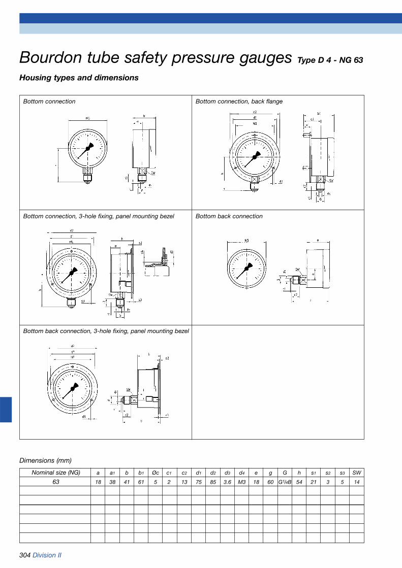
304 Division II
Bottom connection Bottom connection, back flange
Bottom connection, 3-hole fixing, panel mounting bezel Bottom back connection
Bottom back connection, 3-hole fixing, panel mounting bezel
Bourdon tube safety pressure gauges Type D 4 - NG 63
Housing types and dimensions
Dimensions (mm)
Nominal size (NG) a a1 b b1 Øc c1 c2 d1 d2 d3 d4 e g G h s1 s2 s3 SW
63 18 38 41 61 5 2 13 75 85 3.6 M3 18 60 G1/4B 54 21 3 5 14
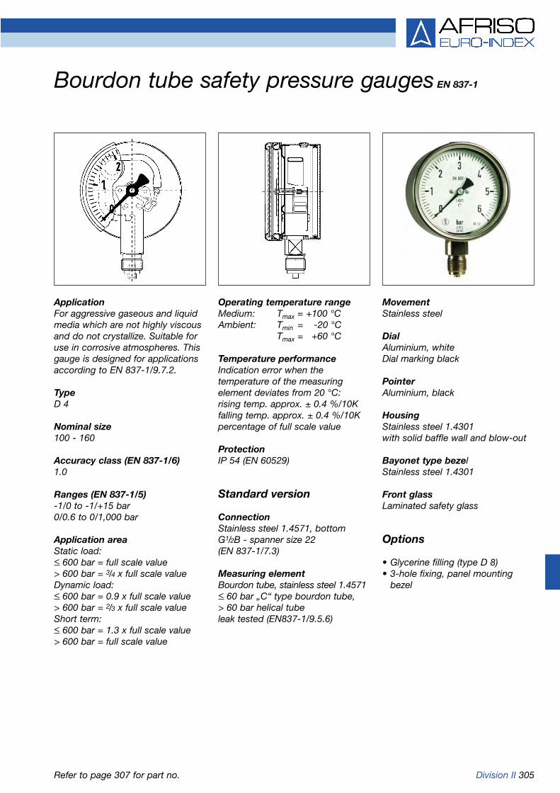
Division II 305
Operating temperature rangeMedium: Tmax = +100 °CAmbient: Tmin = -20 °C
Tmax = +60 °C
Temperature performanceIndication error when the temperature of the measuring element deviates from 20 °C:rising temp. approx. ± 0.4 %/10Kfalling temp. approx. ± 0.4 %/10Kpercentage of full scale value
ProtectionIP 54 (EN 60529)
Standard version
ConnectionStainless steel 1.4571, bottomG1/2B - spanner size 22(EN 837-1/7.3)
Measuring elementBourdon tube, stainless steel 1.4571< 60 bar „C“ type bourdon tube,> 60 bar helical tubeleak tested (EN837-1/9.5.6)
MovementStainless steel
DialAluminium, whiteDial marking black
PointerAluminium, black
HousingStainless steel 1.4301with solid baffle wall and blow-out
Bayonet type bezelStainless steel 1.4301
Front glassLaminated safety glass
Options
• Glycerine filling (type D 8)• 3-hole fixing, panel mounting
bezel
ApplicationFor aggressive gaseous and liquidmedia which are not highly viscousand do not crystallize. Suitable foruse in corrosive atmospheres. Thisgauge is designed for applicationsaccording to EN 837-1/9.7.2.
TypeD 4
Nominal size100 - 160
Accuracy class (EN 837-1/6)1.0
Ranges (EN 837-1/5)-1/0 to -1/+15 bar0/0.6 to 0/1,000 bar
Application areaStatic load:< 600 bar = full scale value> 600 bar = 3/4 x full scale valueDynamic load:< 600 bar = 0.9 x full scale value> 600 bar = 2/3 x full scale valueShort term:< 600 bar = 1.3 x full scale value> 600 bar = full scale value
Bourdon tube safety pressure gauges EN 837-1
Refer to page 307 for part no.

306 Division II
Bottom connection Bottom connection, back flange
Dimensions (mm)
Bottom connection, 3-hole fixing, panel mounting bezel
Bourdon tube safety pressure gauges Type D 4 - NG 100/160
Housing types and dimensions
* Dimensions according to DIN EN 837-1
Nominal size (NG) a a1 b b1 Øc c1 c2 d1* d2* d3* d4 G h s1 s2 s3 SW
100 27 57 60 90 6 3 20 116 132 4.8 M4 G1/2B 87 32 3 5 22
160 40 70 78 108 6 3 20 178 196 5.8 M5 G1/2B 118 32 3 5 22

Division II 307
Bourdon tube safety pressure gauges EN 837-1
Refer to pages 308 and 352 for additional costs and for electrical contacts respectively.
* > 0/600 bar class 2.5
DG: H with glycerine fillingType RF63Si. RF63Si, RF100Si, RF160Si, RF63SiGly, RF63SiGly, RF100SiGly, RF160SiGly,
D402 D412 D402 D402 D802 D812 D802 D802
Version
Housing-Ø 63 63 100 160 63 63 100 160
Housing Stainless steel 1.4301 with bayonet type bezel, laminated safety front glass, blow-out
Meas. elem. Bourdon tube, stainless steel 1.4571
Accuracy class 1.6* 1.6* 1.0 1.0 1.6* 1.6* 1.0 1.0
Connection G1/4B G1/4B G1/2B G1/2B G1/4B G1/4B G1/2B G1/2B
Range(bar)
Price €
-1/0 85401402 85401412 85451402 85501402 85401802 85401812 85451802 85501802
-1/+0.6 85402402 85402412 85452402 85502402 85402802 85402812 85452802 85502802
-1/+1.5 85403402 85403412 85453402 85503402 85403802 85403812 85453802 85503802
-1/+3 85404402 85404412 85454402 85504402 85404802 85404812 85454802 85504802
-1/+5 85405402 85405412 85455402 85505402 85405802 85405812 85455802 85505802
-1/+9 85406402 85406412 85456402 85506402 85406802 85406812 85456802 85506802
-1/+15 85407402 85407412 85457402 85507402 85407802 85407812 85457802 85507802
Price €
0/0.6 85409402 85409412 85459402 85509402 85409802 85409812 85459802 85509802
0/1 85410402 85410412 85460402 85510402 85410802 85410812 85460802 85510802
0/1.6 85411402 85411412 85461402 85511402 85411802 85411812 85461802 85511802
0/2.5 85412402 85412412 85462402 85512402 85412802 85412812 85462802 85512802
0/4 85413402 85413412 85463402 85513402 85413802 85413812 85463802 85513802
0/6 85414402 85414412 85464402 85514402 85414802 85414812 85464802 85514802
0/10 85415402 85415412 85465402 85515402 85415802 85415812 85465802 85515802
0/16 85416402 85416412 85466402 85516402 85416802 85416812 85466802 85516802
0/25 85417402 85417412 85467402 85517402 85417802 85417812 85467802 85517802
0/40 85418402 85418412 85468402 85518402 85418802 85418812 85468802 85518802
Price €
0/60 85419402 85419412 85469402 85519402 85419802 85419812 85469802 85519802
0/100 85420402 85420412 85470402 85520402 85420802 85420812 85470802 85520802
Price €
0/160 85421402 85421412 85471402 85521402 85421802 85421812 85471802 85521802
0/250 85422402 85422412 85472402 85522402 85422802 85422812 85472802 85522802
0/400 85423402 85423412 85473402 85523402 85423802 85423812 85473802 85523802
0/600 85424402 85424412 85474402 85524402 85424802 85424812 85474802 85524802
Price €
0/1000 85425402 85425412 85475402 85525402 85425802 85425812 85475802 85525802
Part no. Part no. Part no. Part no. Part no. Part no. Part no. Part no.
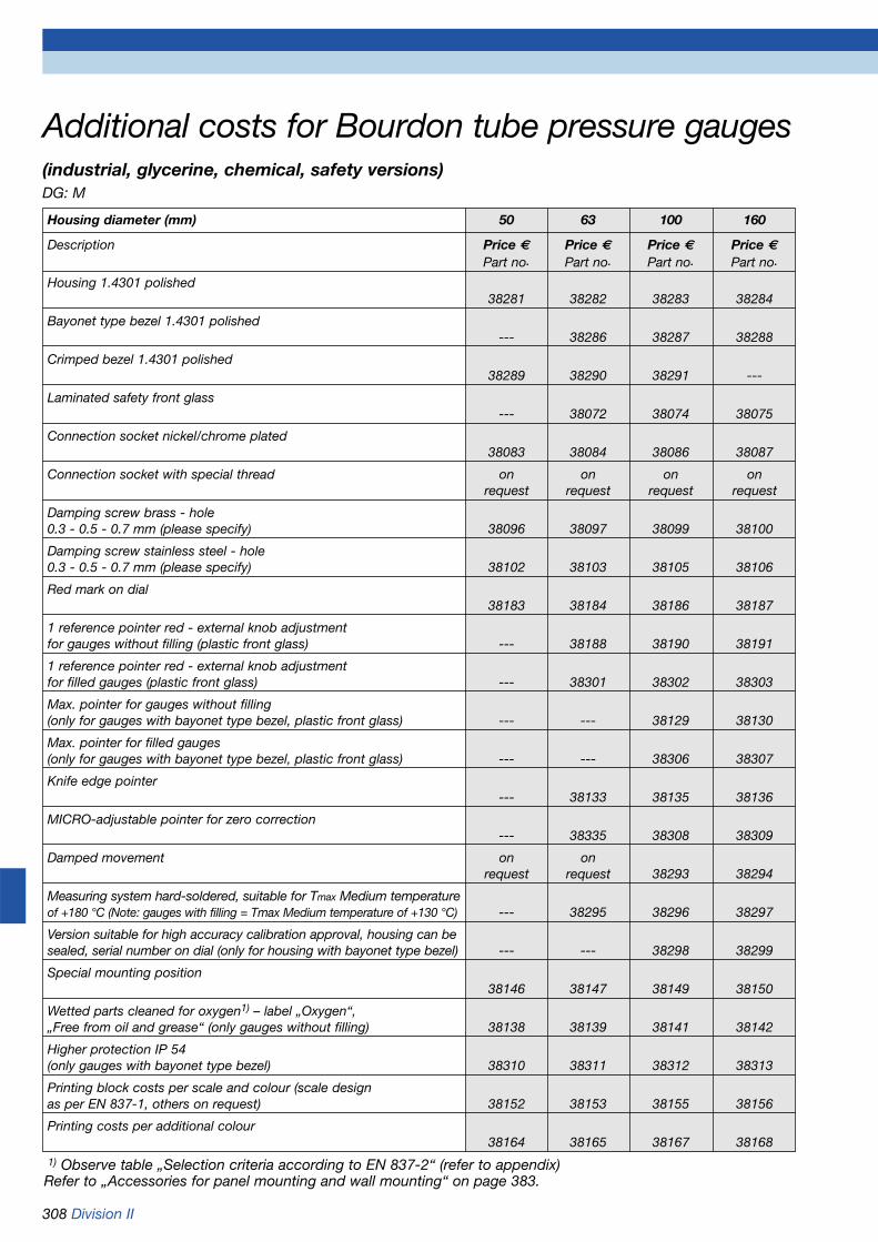
308 Division II
Additional costs for Bourdon tube pressure gauges(industrial, glycerine, chemical, safety versions)DG: M
Housing diameter (mm) 50 63 100 160
Description Price € Price € Price € Price €Part no. Part no. Part no. Part no.
Housing 1.4301 polished38281 38282 38283 38284
Bayonet type bezel 1.4301 polished--- 38286 38287 38288
Crimped bezel 1.4301 polished38289 38290 38291 ---
Laminated safety front glass--- 38072 38074 38075
Connection socket nickel/chrome plated38083 38084 38086 38087
Connection socket with special thread on on on onrequest request request request
Damping screw brass - hole0.3 - 0.5 - 0.7 mm (please specify) 38096 38097 38099 38100
Damping screw stainless steel - hole0.3 - 0.5 - 0.7 mm (please specify) 38102 38103 38105 38106
Red mark on dial38183 38184 38186 38187
1 reference pointer red - external knob adjustment for gauges without filling (plastic front glass) --- 38188 38190 38191
1 reference pointer red - external knob adjustmentfor filled gauges (plastic front glass) --- 38301 38302 38303
Max. pointer for gauges without filling(only for gauges with bayonet type bezel, plastic front glass) --- --- 38129 38130
Max. pointer for filled gauges(only for gauges with bayonet type bezel, plastic front glass) --- --- 38306 38307
Knife edge pointer--- 38133 38135 38136
MICRO-adjustable pointer for zero correction--- 38335 38308 38309
Damped movement on onrequest request 38293 38294
Measuring system hard-soldered, suitable for Tmax Medium temperatureof +180 °C (Note: gauges with filling = Tmax Medium temperature of +130 °C) --- 38295 38296 38297
Version suitable for high accuracy calibration approval, housing can besealed, serial number on dial (only for housing with bayonet type bezel) --- --- 38298 38299
Special mounting position38146 38147 38149 38150
Wetted parts cleaned for oxygen1) – label „Oxygen“,„Free from oil and grease“ (only gauges without filling) 38138 38139 38141 38142
Higher protection IP 54(only gauges with bayonet type bezel) 38310 38311 38312 38313
Printing block costs per scale and colour (scale designas per EN 837-1, others on request) 38152 38153 38155 38156
Printing costs per additional colour38164 38165 38167 38168
1) Observe table „Selection criteria according to EN 837-2“ (refer to appendix)Refer to „Accessories for panel mounting and wall mounting“ on page 383.

Division II 309
Temperature performanceIndication error when the tempera-ture of the measuring element devi-ates from 20 °C:rising temp. approx. ±0.3 % /10Kfalling temp. approx. ±0.3 % /10Kpercentage of full scale value
ProtectionIP 45 (EN 60529)
Standard version
ConnectionStainless steel AISI 316 Ti (1.4571),bottom or bottom back1/2-14 NPT - spanner size 22
Measuring elementBourdon tube, stainless steel 1.4571< 60 bar „C“ type bourdon tube> 60 bar helical tubeleak tested (EN 837-1/9.5.6)
MovementStainless steel
DialAluminium, whiteDial marking black
ApplicationFor aggressive gaseous and liquidmedia which are not highly viscousand do not crystallize. Specially suit-able for the oil and chemical indu-stries.
TypeD 1
Nominal size41/2’’
Accuracy classGrade 2A according to ANSI B 40.1(corresponds to class 0.5)
Ranges (EN 837-1/5)-1/0 to -1/+15 bar0/0.6 to 0/1,000 bar
Application areaStatic load:full scale valueDynamic load:0.9 x full scale valueShort term:1.3 x full scale value
Operating temperature rangeMedium: Tmax = +100 °CAmbient: Tmin = -40 °C
Tmax = +65 °C
PointerMicro-adjustable pointerBrass, blackGear brass, nickel plated
HousingPP-GF20, blackwith solid baffle wall and blow-outIntegrated back flange
Screw type bezelPP-GF20, blackinternal
Front glassPlastic (PMMA)
Options
• Glycerine filling (type D6)• Silicone oil filling (type D6)• Special scales• Copper alloy measuring system• Monel measuring system• Laminated safety front glass• Damping screw• Reference pointer• Max. pointer• Electrical contacts
Bourdon tube pressure gauges type Process Gauge
Refer to page 311 for part no.

310 Division II
Bottom connection Bottom back connection
Bottom connection, with electrical contacts Bottom back connection, with electrical contacts
Bourdon tube pressure gauges type Process Gauge Class 0.5 Type D 1/D 6 - NG 41/2“Housing types and dimensions
Dimensions (mm)
Nominal size (NG) a b b1 c1 c2 d1 d2 d3 ØD e G g h h1 h2 s1 s2 s3 SW
41/2“ (D 1/D 6) 40 82.5114.5 15 20 137 148 6 129 38 1/2-14 NPT 105.5 102 67 78 12.5 25 12.5 22
Junctionbox Junction
box
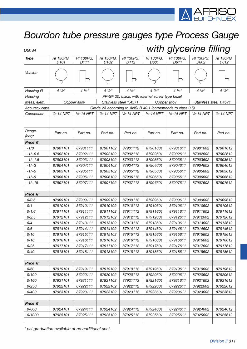
Division II 311
Bourdon tube pressure gauges type Process GaugeDG: M with glycerine fillingType RF130PG, RF130PG, RF130PG, RF130PG, RF130PG, RF130PG, RF130PG, RF130PG,
D101 D111 D102 D112 D601 D611 D602 D612
Version
Housing Ø 4 1/2“ 4 1/2“ 4 1/2“ 4 1/2“ 4 1/2“ 4 1/2“ 4 1/2“ 4 1/2“
Housing PP-GF 20, black, with internal screw type bezel
Meas. elem. Copper alloy Stainless steel 1.4571 Copper alloy Stainless steel 1.4571
Accuracy class Grade 2A according to ANSI B 40.1 (corresponds to class 0.5)
Connection 1/2-14 NPT 1/2-14 NPT 1/2-14 NPT 1/2-14 NPT 1/2-14 NPT 1/2-14 NPT 1/2-14 NPT 1/2-14 NPT
Range(bar)*Price €
-1/0 87901101 87901111 87901102 87901112 87901601 87901611 87901602 87901612
-1/+0.6 87902101 87902111 87902102 87902112 87902601 87902611 87902602 87902612
-1/+1.5 87903101 87903111 87903102 87903112 87903601 87903611 87903602 87903612
-1/+3 87904101 87904111 87904102 87904112 87904601 87904611 87904602 87904612
-1/+5 87905101 87905111 87905102 87905112 87905601 87905611 87905602 87905612
-1/+9 87906101 87906111 87906102 87906112 87906601 87906611 87906602 87906612
-1/+15 87907101 87907111 87907102 87907112 87907601 87907611 87907602 87907612
Price €
0/0.6 87909101 87909111 87909102 87909112 87909601 87909611 87909602 87909612
0/1 87910101 87910111 87910102 87910112 87910601 87910611 87910602 87910612
0/1.6 87911101 87911111 87911102 87911112 87911601 87911611 87911602 87911612
0/2.5 87912101 87912111 87912102 87912112 87912601 87912611 87912602 87912612
0/4 87913101 87913111 87913102 87913112 87913601 87913611 87913602 87913612
0/6 87914101 87914111 87914102 87914112 87914601 87914611 87914602 87914612
0/10 87915101 87915111 87915102 87915112 87915601 87915611 87915602 87915612
0/16 87916101 87916111 87916102 87916112 87916601 87916611 87916602 87916612
0/25 87917101 87917111 87917102 87917112 87917601 87917611 87917602 87917612
0/40 87918101 87918111 87918102 87918112 87918601 87918611 87918602 87918612
Price €
0/60 87919101 87919111 87919102 87919112 87919601 87919611 87919602 87919612
0/100 87920101 87920111 87920102 87920112 87920601 87920611 87920602 87920612
0/160 87921101 87921111 87921102 87921112 87921601 87921611 87921602 87921612
0/250 87922101 87922111 87922102 87922112 87922601 87922611 87922602 87922612
0/400 87923101 87923111 87923102 87923112 87923601 87923611 87923602 87923612
Price €
0/600 87924101 87924111 87924102 87924112 87924601 87924611 87924602 87924612
0/1000 87925101 87925111 87925102 87925112 87925601 87925611 87925602 87925612
Part no. Part no. Part no. Part no. Part no. Part no. Part no. Part no.
* psi graduation available at no additional cost.

312 Division II
Operating temperature rangeMedium: Tmax = +60 °CAmbient: Tmin = -20 °C
Tmax = +60 °C
Temperature performanceIndication error when the tempe-rature of the measuring elementdeviates from 20 °C:rising temp. approx. ±0.4 % /10Kfalling temp. approx. ±0.4 % /10Kpercentage of full scale value
ProtectionIP 54 (EN 60529)
Standard version
ConnectionBrass, bottom or bottom back (onlyNG 160)G1/2B - spanner size 22(EN 837-1/7.3)
Measuring elementBourdon tube element,< 100 bar „C“ type bourdon tube,copper alloy> 100 bar helical tube, stainlesssteel 1.4571
ApplicationFor gaseous and liquid media whichare not highly viscous, do notcrystallize and are not aggressive.For high measuring accuracy. ! When measuring gas or vapour,the instruments must be used inaccordance with the safetyrecommendations of EN 837-2 (seeappendix).
TypeD 4
Nominal size160 - 250
Accuracy class (EN 837-1/6)0.6
Ranges (EN 837-1/5)-1/0 bar to -1/+15 bar0/0.6 to 0/600 bar
Calibration medium< 40 bar: air> 40 bar: water
Application areaStatic load:3/4 x full scale valueDynamic load:2/3 x full scale valueShort term:full scale value
MovementBrass/nickel silver jewel bearing
DialAluminium, whiteDial marking black
PointerKnife edge pointerAluminium, black
HousingStainless steel 1.4301
Bayonet type bezelStainless steel 1.4301
Front glassPlastic (PMMA)
Options
• Glycerine filling (NG 160/type D 8)• Wetted parts stainless steel
(type D 4 x 2)• Laminated safety front glass
(NG 160)• Back flange (NG 160)• 3-hole fixing, panel mounting
bezel (NG 160)• Damping screw
Precision Bourdon tube pressure gauges Class 0.6
Refer to page 316 for part no.

Division II 313
Bottom connection Bottom connection, back flange, (NG 160 only)
Dimensions (mm)
Bottom back connection (NG 160 only) Bottom back connection, 3-hole fixing, panel mounting bezel (NG 160 only)
Precision Bourdon tube pressure gauges Class 0.6Type D 4 - NG 160/250Housing types and dimensions
Bottom back connection, panel mounting bezel,clamp fixing (NG 160 only)
* Dimensions according to DIN EN 837-1
Nominal size (NG) a a1 b b1 b2 b3 Øc c1 c2 d1* d2 d3* d4 d5 d6 e G g g1 h s1
160 17.5 20.5 50 53 50 52 6 3 20 178 196 5.8 164 167 161 44.5 G1/2B 82 84 116 6
250 16 - 57 - - - 6 3 20 - - - - - - - G1/2B - - 165 -
Nominal size (NG) s2 s3 s4 SW
160 4 2 4.5 22
250 - - - 22
Rotated by 90°

314 Division II
Operating temperature rangeMedium: Tmax = +60 °CAmbient: Tmin = -20 °C
Tmax = +60 °C
Temperature performanceIndication error when the tempera-ture of the measuring element devi-ates from 20 °C:rising temp. approx. ±0.4 % /10Kfalling temp. approx. ±0.4 % /10Kpercentage of full scale value
ProtectionIP 54 (EN 60529)
Standard version
ConnectionBrass, bottom or bottom back (only NG 160)G1/2B - spanner size 22(EN 837-1/7.3)
Measuring elementBourdon tube element,< 100 bar „C“ type bourdon tube,copper alloy> 100 bar helical tube, copper alloy
ApplicationFor gaseous and liquid media whichare not highly viscous, do not crystallize and are not aggressive.For very high measuring accuracy. ! When measuring gas or vapour,the instruments must be used in accordance with the safetyrecommendations of EN 837-2 (see appendix).
TypeD 4
Nominal size160 - 250
Accuracy class (EN 837-1/6)0.25
Ranges (EN 837-1/5)-1/0 bar to -1/+15 bar0/0.6 to 0/400 bar
Calibration medium< 40 bar: air> 40 bar: water
Application areaStatic load:3/4 x full scale valueDynamic load:2/3 x full scale valueShort term:full scale value
MovementBrass/nickel silverball bearing
DialAluminium, whiteDial marking blackNG 160 mirror scale 270°NG 250 mirror scale 330°with zero correction
PointerKnife edge pointerAluminium
HousingStainless steel 1.4301
Bayonet type bezelStainless steel 1.4301
Front glassPlastic (PMMA)
Options
• Back flange (NG 160)• 3-hole fixing, panel mounting
bezel (NG 160)• Factory test certificate
Precision Bourdon tube pressure gauges Class 0.25
Refer to page 317 for part no.

Division II 315
Bottom connection - NG 160 Bottom connection, back flange - NG 160
Dimensions (mm)
Bottom back connection - NG 160 Bottom back connection, 3-hole fixing, panelmounting bezel - NG 160
Precision Bourdon tube pressure gauges Class 0.25Type D 4 - NG 160/250Housing types and dimensions
Bottom connection - NG 250
* Dimensions according to DIN EN 837-1
Nominal size (NG) a a1 b b1 b2 b3 Øc c1 c2 d1* d2 d3* d4 d5 d6 e G g g1 h s1
160 17.5 20.5 50 53 50 52 6 3 20 178 196 5.8 164 167 161 44.5 G1/2B 82 84 116 6
250 16 - 57 - - - 6 3 20 - - - - - - - G1/2B - - 165 -
Nominal size (NG) s2 s3 s4 SW
160 4 2 4.5 22
250 - - - 22

316 Division II
Precision Bourdon tube pressure gauges Class 0.6
DG: M
Type RF160F,D401 RF160F,D411 RF160F,D431 RF160ChF,D402 RF160ChF,D412 RF160ChF,D432 RF250F,D401
Version
Housing Ø 160 160 160 160 160 160 250
Housing Stainless steel 1.4301 with bayonet type bezel
Meas. elem. Bourdon tube element, copper alloy Bourdon tube, stainless steel 1.4571 Cu alloy
Accuracy class 0.6 0.6 0.6 0.6 0.6 0.6 0.6
Connection G1/2B G1/2B G1/2B G1/2B G1/2B G1/2B G1/2B
Range(bar)
Price €
-1/0 85701401 85701411 85701431 85701402 85701412 85701432 85751401
-1/+0.6 85702401 85702411 85702431 85702402 85702412 85702432 85752401
-1/+1.5 85703401 85703411 85703431 85703402 85703412 85703432 85753401
Price €
-1/+3 85704401 85704411 85704431 85704402 85704412 85704432 85754401
-1/+5 85705401 85705411 85705431 85705402 85705412 85705432 85755401
-1/+9 85706401 85706411 85706431 85706402 85706412 85706432 85756401
-1/+15 85707401 85707411 85707431 85707402 85707412 85707432 85757401
Price €
0/0.6 85709401 85709411 85709431 85709402 85709412 85709432 85759401
0/1 85710401 85710411 85710431 85710402 85710412 85710432 85760401
0/1.6 85711401 85711411 85711431 85711402 85711412 85711432 85761401
Price €
0/2.5 85712401 85712411 85712431 85712402 85712412 85712432 85762401
0/4 85713401 85713411 85713431 85713402 85713412 85713432 85763401
0/6 85714401 85714411 85714431 85714402 85714412 85714432 85764401
0/10 85715401 85715411 85715431 85715402 85715412 85715432 85765401
0/16 85716401 85716411 85716431 85716402 85716412 85716432 85766401
0/25 85717401 85717411 85717431 85717402 85717412 85717432 85767401
0/40 85718401 85718411 85718431 85718402 85718412 85718432 85768401
Price €
0/60 85719401 85719411 85719431 85719402 85719412 85719432 85769401
0/100 85720401 85720411 85720431 85720402 85720412 85720432 85770401
0/160 85721401 85721411 85721431 85721402 85721412 85721432 85771401
0/250 85722401 85722411 85722431 85722402 85722412 85722432 85772401
0/400 85723401 85723411 85723431 85723402 85723412 85723432 85773401
0/600 85724401 85724411 85724431 85724402 85724412 85724432 85774401
Additional cost for glycerine filling (> 2.5 bar)
Part no. Part no. Part no. Part no. Part no. Part no. Part no.
3-hole fixing, panel 3-hole fixing, panelmounting bezel, 1.4301 mounting bezel, 1.4301
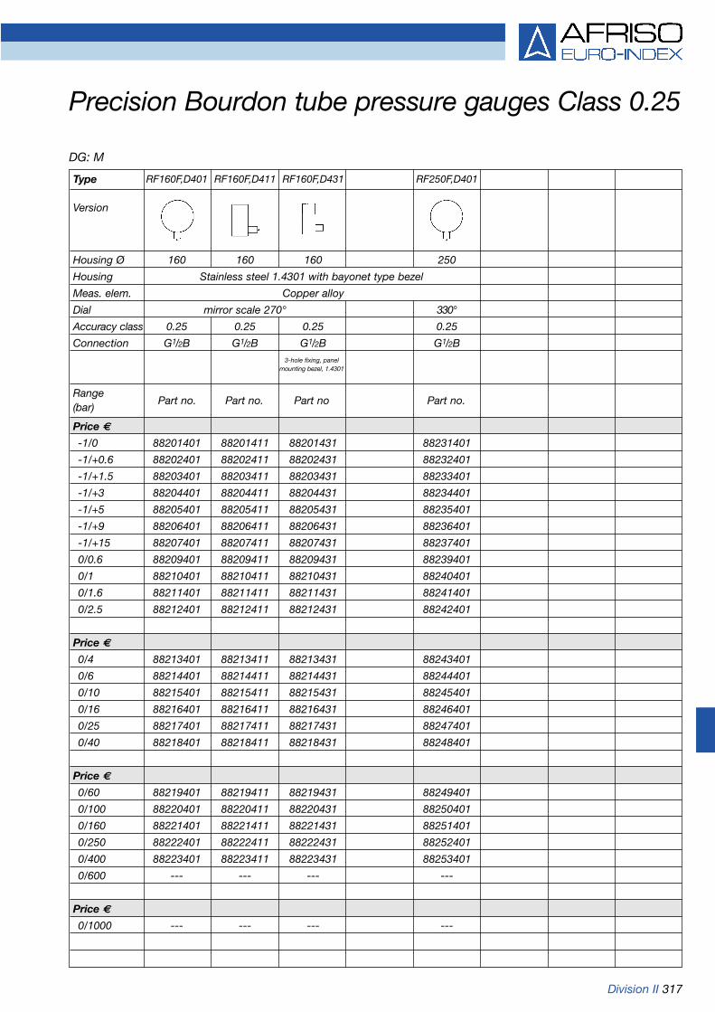
Division II 317
Precision Bourdon tube pressure gauges Class 0.25
DG: M
Type RF160F,D401 RF160F,D411 RF160F,D431 RF250F,D401
Version
Housing Ø 160 160 160 250
Housing Stainless steel 1.4301 with bayonet type bezel
Meas. elem. Copper alloy
Dial mirror scale 270° 330°
Accuracy class 0.25 0.25 0.25 0.25
Connection G1/2B G1/2B G1/2B G1/2B
Range(bar)
Price €
-1/0 88201401 88201411 88201431 88231401
-1/+0.6 88202401 88202411 88202431 88232401
-1/+1.5 88203401 88203411 88203431 88233401
-1/+3 88204401 88204411 88204431 88234401
-1/+5 88205401 88205411 88205431 88235401
-1/+9 88206401 88206411 88206431 88236401
-1/+15 88207401 88207411 88207431 88237401
0/0.6 88209401 88209411 88209431 88239401
0/1 88210401 88210411 88210431 88240401
0/1.6 88211401 88211411 88211431 88241401
0/2.5 88212401 88212411 88212431 88242401
Price €
0/4 88213401 88213411 88213431 88243401
0/6 88214401 88214411 88214431 88244401
0/10 88215401 88215411 88215431 88245401
0/16 88216401 88216411 88216431 88246401
0/25 88217401 88217411 88217431 88247401
0/40 88218401 88218411 88218431 88248401
Price €
0/60 88219401 88219411 88219431 88249401
0/100 88220401 88220411 88220431 88250401
0/160 88221401 88221411 88221431 88251401
0/250 88222401 88222411 88222431 88252401
0/400 88223401 88223411 88223431 88253401
0/600 --- --- --- ---
Price €
0/1000 --- --- --- ---
Part no. Part no. Part no Part no.
3-hole fixing, panelmounting bezel, 1.4301
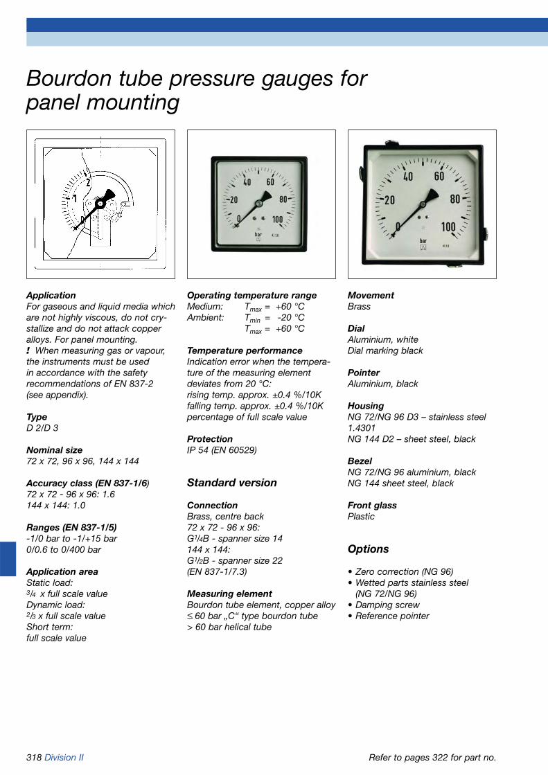
318 Division II
Operating temperature rangeMedium: Tmax = +60 °CAmbient: Tmin = -20 °C
Tmax = +60 °C
Temperature performanceIndication error when the tempera-ture of the measuring element deviates from 20 °C:rising temp. approx. ±0.4 %/10Kfalling temp. approx. ±0.4 %/10Kpercentage of full scale value
ProtectionIP 54 (EN 60529)
Standard version
ConnectionBrass, centre back72 x 72 - 96 x 96: G1/4B - spanner size 14144 x 144: G1/2B - spanner size 22(EN 837-1/7.3)
Measuring elementBourdon tube element, copper alloy< 60 bar „C“ type bourdon tube> 60 bar helical tube
ApplicationFor gaseous and liquid media whichare not highly viscous, do not cry-stallize and do not attack copperalloys. For panel mounting. ! When measuring gas or vapour,the instruments must be used in accordance with the safetyrecommendations of EN 837-2 (see appendix).
TypeD 2/D 3
Nominal size72 x 72, 96 x 96, 144 x 144
Accuracy class (EN 837-1/6)72 x 72 - 96 x 96: 1.6144 x 144: 1.0
Ranges (EN 837-1/5)-1/0 bar to -1/+15 bar0/0.6 to 0/400 bar
Application areaStatic load:3/4 x full scale valueDynamic load:2/3 x full scale valueShort term:full scale value
MovementBrass
DialAluminium, whiteDial marking black
PointerAluminium, black
HousingNG 72/NG 96 D3 – stainless steel 1.4301NG 144 D2 – sheet steel, black
BezelNG 72/NG 96 aluminium, blackNG 144 sheet steel, black
Front glassPlastic
Options
• Zero correction (NG 96)• Wetted parts stainless steel
(NG 72/NG 96)• Damping screw• Reference pointer
Bourdon tube pressure gauges for panel mounting
Refer to pages 322 for part no.
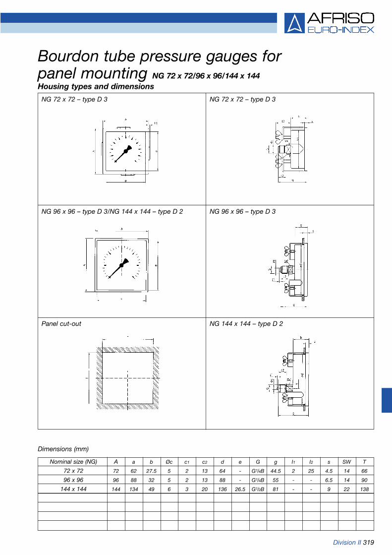
Division II 319
NG 72 x 72 – type D 3
Dimensions (mm)
Bourdon tube pressure gauges for panel mounting NG 72 x 72/96 x 96/144 x 144Housing types and dimensions
NG 72 x 72 – type D 3
NG 96 x 96 – type D 3/NG 144 x 144 – type D 2 NG 96 x 96 – type D 3
Panel cut-out NG 144 x 144 – type D 2
Nominal size (NG) A a b Øc c1 c2 d e G g I1 I2 s SW T
72 x 72 72 62 27.5 5 2 13 64 - G1/4B 44.5 2 25 4.5 14 66
96 x 96 96 88 32 5 2 13 88 - G1/4B 55 - - 6.5 14 90
144 x 144 144 134 49 6 3 20 136 26.5 G1/2B 81 - - 9 22 138

320 Division II
Temperature performanceIndication error when the tempe-rature of the measuring element deviates from 20 °C:rising temp. approx. ±0.4 %/10Kfalling temp. approx. ±0.4 %/10Kpercentage of full scale value
ProtectionIP 54 (EN 60529)
Standard version
ConnectionStainless steel 1.4571, bottomHP connection for 1/4“ pipeFemale thread M 16 x 1.5 or 9/16-18 UNFeach with sealing cone 60°
Measuring elementBourdon tube element, NiFe alloyhelical tube
MovementStainless steel
DialAluminium, whiteDial marking black
ApplicationFor measurement of extremely highpressures in corrosive, gaseous andliquid media which are not highlyviscous and do not crystallize.Suitable for use in corrosive atmos-pheres.
TypeD 4
Nominal size160
Accuracy class (EN 837-1/6)1.0
Ranges0/2,500 bar0/4,000 bar
Application areaStatic load:full scale valueDynamic load:3/4 x full scale value
Operating temperature rangeMedium: Tmax = +100 °CAmbient: Tmin = -20 °C
Tmax = +60 °C
PointerAluminium, black
HousingStainless steel 1.4301with solid baffle wall and blow-out
Bayonet type bezelStainless steel 1.4301
Front glassLaminated safety glass
MountingWall mounting instrument bracketwith 60 mm protrusion (included inscope of delivery) or panel moun-ting using 3-hole fixing, panelmounting bezel (option).Direct mounting onto rigid measu-ring pipe possible.
Options
• Nominal size 100• Glycerine filling (type D802)• 3-hole fixing, panel mounting
bezel• Other connections• Electrical contacts
Bourdon tube pressure gauges for high pressures EN 837-1
Refer to page 322 for part no.

Division II 321
Bottom connection Bottom connection, with instrument holder
Bottom connection, 3-hole fixing, panel mounting bezel
HP connection, female thread M 16 x 1.5
Dimensions (mm)
Bourdon tube pressure gauges for high pressures Type D 4 - NG 160Housing types and dimensions
* Dimensions according to DIN EN 837-1
Nominal size (NG) a a1 b b1 d1* d2 d3* d4 d5 d6 d7 G h o s s1 s2 s3 t t1 u
160 34 64 78 108 178 196 5.8 M 5 2.5 4.3 26 139 63 22 32 7 9 9.5 11 65
Nominal size (NG) u1 SW
160 56 22
M16x1.5
HP

322 Division II
HP connection 1/4” with female threadM16 x 1.5 or 9/16-18 UNF
with sealing cone 60°
DG: M Glycerine filling Glycerine filling
Bourdon tube pressure gauges for panel mountingBourdon tube pressure gauges for high pressuresType RF72, D311 RF96, D311 RF144, D211 RF96, D312 RF100HDGly, D802 RF160HD, D402 RF160HDGly, D802
Version
Housing Ø 72 x 72 96 x 96 144 x 144 96 x 96 100 160 160
Housing Stainless steel Stainless steel Sheet steel Stainless steel Stainless steel 1.4301
Meas. elem. Bourdon tube element, copper alloy Stainless steel Stainless steel 1.4571/NiFe
Accuracy class 1.6 1.6 1.0 1.6 1.0 1.0 1.0
Connection G1/4B G1/4B G1/2B G1/4B G1/2B
Range(bar)
Price €
-1/0 85828311 85801311 85851211 85801312 --- --- ---
-1/+0.6 85844311 85802311 85852211 85802312 --- --- ---
-1/+1.5 85845311 85803311 85853211 85803312 --- --- ---
-1/+3 85846311 85804311 85854211 85804312 --- --- ---
-1/+5 85847311 85805311 85855211 85805312 --- --- ---
-1/+9 85848311 85806311 85856211 85806312 --- --- ---
-1/+15 85849311 85807311 85857211 85807312 --- --- ---
Price €
0/0.6 85829311 85809311 85859211 85809312 --- --- ---
0/1 85830311 85810311 85860211 85810312 --- --- ---
0/1.6 85831311 85811311 85861211 85811312 --- --- ---
0/2.5 85832311 85812311 85862211 85812312 --- --- ---
0/4 85833311 85813311 85863211 85813312 --- --- ---
0/6 85834311 85814311 85864211 85814312 --- --- ---
0/10 85835311 85815311 85865211 85815312 --- --- ---
0/16 85836311 85816311 85866211 85816312 --- --- ---
0/25 85837311 85817311 85867211 85817312 --- --- ---
0/40 85838311 85818311 85868211 85818312 --- --- ---
Price €
0/60 85839311 85819311 85869211 85819312 --- --- ---
0/100 85840311 85820311 85870211 85820312 --- --- ---
0/160 85841311 85821311 85871211 85821312 --- --- ---
0/250 85842311 85822311 85872211 85822312 --- --- ---
0/400 85843311 85823311 85873211 85823312 --- --- ---
Price €
0/2500 --- --- --- --- 86031802 85277402 85277802
Price €
0/4000 --- --- --- --- --- 85278402 85278802
Part no. Part no. Part no. Part no. Part no. Part no. Part no.

Division II 323
Application areaStatic load:3/4 x full scale valueDynamic load:2/3 x full scale valueShort term:full scale value
Operating temperature rangeMedium: according to cooling
agentAmbient: Tmin = -20 °C
Tmax = +60 °C
Temperature performanceIndication error when the tempera-ture of the measuring element devi-ates from 20 °C:rising temp. approx. ±0.4 %/10Kfalling temp. approx. ±0.4 %/10Kpercentage of full scale value
ProtectionIP 65 (EN 60529), with housing vent (< 25 bar) IP 54
Standard version
ConnectionBrass, bottom or backNG 63 - 100 D 7 centre backNG 100 D 8 bottom back7/16-20 UNF, G1/4B, G1/2B (stainless steel 1.4571 for R 717)
Measuring elementBourdon tube element, copper alloy „C“ type bourdon tube (stainless steel 1.4571 for R 717)
MovementBrass
DialAluminium, whitePressure dial marking blackTemperature dial marking coloured(refer to appendix for examples)
PointerAluminium, black
HousingStainless steel 1.4301with blow-out
BezelD 7 - NG 63 - 80 - 100:Crimped bezel stainless steel1.4301D 8 - NG 100:Bayonet type bezel stainless steel1.4301
Front glassPlastic
Filling liquidGlycerine (99.5 %)
Options
• Temperature scales for other cooling agents
• Back flange• Clamp fixing• 3-hole fixing, panel mounting
bezel (NG 63/100)• Damping screw
Bourdon tube pressure gauges with glycerinefilling for refrigeration applications
ApplicationFor simultaneous measurement ofvapour pressures and temperaturesin refrigeration applications. ! When measuring gas or vapour,the instruments must be used in accordance with the safetyrecommendations of EN 837-2 (see appendix).
TypeD 7/D 8
Nominal size63 - 80 - 100 (D 7)100 (D 8)
Accuracy class (EN 837-1/6)NG 63: 1.6NG 80/NG 100: 1.0
Ranges-1/+ 9 bar-1/+12.5 bar-1/+15 bar-1/+24 bar-1/+30 bareach with temperature scale
Temperature scalesfor cooling agent:R 134aR 134a/R 22R 22/R 12/R 502R 12R 404AR 407AR 410AR 717 (NH3 ) - wetted parts stainless steel 1.4571
Refer to page 325 for part no.

324 Division II
Type D 7 – bottom connection Type D 7 - bottom connection, back flange
Type D 7 – centre/bottom back connection Type D 7 – centre/bottom back connection, 3-hole fixing, panel mounting bezel (NG 63/100)
Type D 8 – bottom connection
Bourdon tube pressure gauges for refrigeration applications Type D 7/D 8 – NG 63/80/100Housing types and dimensions
Type D 8 – bottom back connection
Dimensions (mm)
* Dimensions according to DIN EN 837-1
7/16-20UNF
7/16-20UNF
7/16-20UNF
Nominal size (NG) a a1 b b1 Øc c1 c2 c3 c4 d1* d2* d3* d4 D e g g1 G G1 h h1
63 (D 7) 9.5 13 30.5 34 5 2 13 4 9.5 75 85 3.6 64 68 - 53.5 55.5 G1/4B 53 55
80 (D 7) 12.2 15.2 33.5 36.5 6 3 20 4 9.5 95 110 5 - 85 - 65.5 58.5 G1/2B 71 62.5
100 (D 7) 12.2 15.7 33.5 37 6 3 20 4 9.5 116 132 4.8 101 106 - 65.5 58.5 G1/2B 81 72.5
100 (D 8) 15.6 19.1 49 52.5 6 3 20 - - - - - - - 26.5 81 - G1/2B - 86 -
Nominal size (NG) s s1 s2 SW SW1
63 (D 7) 7 5.5 2 14 14
80 (D 7) 7 5.5 - 22 14
100 (D 7) 7 5.5 3.8 22 14
100 (D 8) - 5.5 2 22 -

Division II 325
DG: M
Bourdon tube pressure gauges with glycerinefilling for refrigeration applicationsType RF63KTGly, RF63KTGly, RF80KTGly, RF80KTGly, RF100KTGly, RF100KTGly, RF100KTGly, RF100KTGly,
D701 D711 D701 D711 D701 D711 D802 D812
Version
Housing Ø 63 63 80 80 100 100 100 100
Housing Stainless steel 1.4301 with crimped bezel Stainless steel 1.4301with bayonet type bezel
Meas. elem. Bourdon tube element, copper alloy Stainless steel 1.4571
Scale according to selection table Temperature scale R 717
Accuracy class 1.6 1.6 1.0 1.0 1.0 1.0 1.0 1.0
Connection* 7/16-20 UNF 7/16-20 UNF 7/16-20 UNF 7/16-20 UNF 7/16-20 UNF 7/16-20 UNF G1/2B G1/2B
Range
(bar)
Price €
-1/+9 85130701 85130711 85180701 85180711 85230701 85230711 --- ---
-1/+12.5 85131701 85131711 85181701 85181711 85231701 85231711 85231802 85231812
-1/+15 85132701 85132711 85182701 85182711 85232701 85232711 85232802 85232812
-1/+24 85133701 85133711 85183701 85183711 85233701 85233711 85233802 85233812
-1/+30 85134701 85134711 85184701 85184711 85234701 85234711 --- ---
Add. costs Price €
Wetted parts1.4571* ---
Refer to pages 308 and 383 for additional costs.
Selection table - temperature scales for cooling agents (refer to appendix for examples)
Please specify the code of the required temperature scale along with the part number of the basic gauge.
Temperature scales for other cooling agents on request.
Temperature scale for cooling agent Code
R 134a A
R 134a/R 22 B
R 22/R 12/R 502 C
R 12 D
R 404A E
R 717 (NH3) – stainless steel 1.4571 with wetted parts only F
R 407A G
Part no. Part no. Part no. Part no. Part no. Part no. Part no. Part no.
* Connection NG 63/80 centre back G1/4B – NG 80 bottom/100 G1/2B for stainless steel wetted parts.

326 Division II
Temperature performanceIndication error when the tempera-ture of the measuring element deviates from 20 °C:rising temp. approx. ±0.4 %/10Kfalling temp. approx. ±0.4 %/10Kpercentage of full scale value
ProtectionIP 32 (EN 60529)
Standard version
ConnectionBrass, bottom or centre back, with damping in the pressure inletG1/4B - spanner size 14(EN 837-1/7.3)
Measuring elementBourdon tube element, copper alloy< 40 bar „C“ type bourdon tube> 40 bar helical tube(copper portion in case of acetylene< 70 %)
Degree of cleanlinessWetted parts are oil and greasefree.
MovementBrass
DialAluminium, whiteDial marking black
Marking„Oxygen“ for oxygen and symbolfor „free from oil and grease“„Acetylene“ for acetylene
PointerAluminium, black
HousingD 2 - sheet steel (gold or black)D 3 - stainless steel 1.4301 withrear blow-out
Front glassPlastic, snap-in
Options
• Litre scale for argon/CO2• Other connection threads
Bourdon tube pressure gauges for welding applications EN 562
ApplicationFor welding systems and cuttingmachines or similar processes.
TypeD 2/D 3
Nominal size50 - 63
VersionEN 562
Accuracy class (EN 562)2.5
Ranges (EN 562)0/1 to 0/400 bar-1/0 to -1/+15 bar
Application areaStatic load:3/4 x full scale valueDynamic load:2/3 x full scale valueShort term:full scale value
Operating temperature rangeMedium: Tmax = +60 °CAmbient: Tmin = -20 °C
Tmax = +60 °C
Refer to page 330 for part no.

Division II 327
Bottom connection Centre back connection
Dimensions (mm)
Blow-out - bottom connection
Bourdon tube pressure gauges for welding applications Type D 3 – NG 50/63Housing types and dimensions
Blow-out - centre back connection
Nominal size (NG) a b b1 Øc c1 c2 G g h s SW
50 10.5 29 26 5 2 13 G1/4B 47 46 3.8 14
63 11 29.5 29.5 5 2 13 G1/4B 50.5 53 3.7 14

328 Division II
Operating temperature rangeMedium: Tmax = +60 °CAmbient: Tmin = -20 °C
Tmax = +60 °C
Temperature performanceIndication error when the tempera-ture of the measuring element deviates from 20 °C:rising temp. approx. ±0.4 %/10Kfalling temp. approx. ±0.4 %/10Kpercentage of full scale value
ProtectionIP 32 (EN 60529)
Standard version
ConnectionBrass, bottom or centre backG1/4B - spanner size 14(EN 837-1/7.3)
Measuring elementBourdon tube element, copper alloy< 40 bar „C“ type bourdon tube> 40 bar helical tube
MovementBrass
DialAluminium, whiteDial marking black
PointerAluminium, black
HousingStainless steel 1.4301 with rearblow-out according to EN 562
Front glassPlastic, snap-in
Options
• Wetted parts stainless steel• Wetted parts oil and grease free• Helium leak test• Other connection threads• Damping screw
Bourdon tube pressure gauges for gas applications EN 837-1 (S2)
ApplicationFor gaseous and liquid media whichare not highly viscous and do notcrystallize. Especially designed forgas technology fittings and installa-tions. ! When measuring gas or vapour,the instruments must be used in accordance with the safetyrecommendations of EN 837-2 (see appendix).
TypeD 3
Nominal size50 - 63
Accuracy class (EN 837-1/6)1.6
Ranges (EN 837-1/5)-1/0 to -1/+15 bar0/1 to 0/400 bar
Application areaStatic load:3/4 x full scale valueDynamic load:2/3 x full scale valueShort term:full scale value
Refer to page 330 for part no.
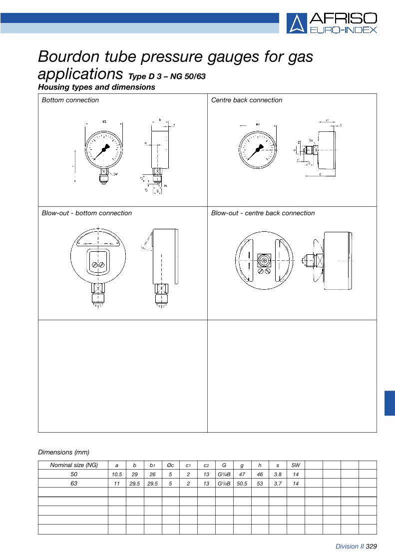
Division II 329
Bottom connection Centre back connection
Dimensions (mm)
Bourdon tube pressure gauges for gas applications Type D 3 – NG 50/63Housing types and dimensions
Blow-out - bottom connection Blow-out - centre back connection
Nominal size (NG) a b b1 Øc c1 c2 G g h s SW
50 10.5 29 26 5 2 13 G1/4B 47 46 3.8 14
63 11 29.5 29.5 5 2 13 G1/4B 50.5 53 3.7 14

330 Division II
Bourdon tube pressure gauges for welding/gas applications
Version for welding applications EN 562
1) with inscription „Acetylene“ 2) with inscription „Oxygen“ 3) Scale 0/30 l/min „Argon“ red, 0/28 l/min „CO2“ black4) additional costs for back connection – refer to page 308 for other additional costs
Type RF63ST, D301 RF50GT, D301 RF50GT, D311 RF63GT, D301 RF63GT, D311 RF50GT, D302 4) RF63GT, D302 4)
Version
Housing Ø 63 50 50 63 63 50 63
Housing Stainless steel 1.4301 with blow-out
Meas. elem. CU alloy, oil Copper alloy Stainless steel 1.4571and grease free
Accuracy class 2.5 1.6 1.6 1.6 1.6 1.6 1.6
Connection G1/4B G1/4B G1/4B G1/4B G1/4B G1/4B G1/4B
Rangebar)
Price €
-1/0 --- 85051301GT 85051311GT 85101301GT 85101311GT 85051302GT 85101302GT
-1/+0.6 --- 85052301GT 85052311GT 85102301GT 85102311GT 85052302GT 85102302GT
-1/+1.5 --- 85053301GT 85053311GT 85103301GT 85103311GT 85053302GT 85103302GT
-1/+3 --- 85054301GT 85054311GT 85104301GT 85104311GT 85054302GT 85104302GT
-1/+5 --- 85055301GT 85055311GT 85105301GT 85105311GT 85055302GT 85105302GT
-1/+9 --- 85056301GT 85056311GT 85106301GT 85106311GT 85056302GT 85106302GT
-1/+15 --- 85057301GT 85057311GT 85107301GT 85107311GT 85057302GT 85107302GT
Price €
0/0.6 --- 85059301GT 85059311GT 85109301GT 85109311GT 85059302GT 85109302GT
0/1 883003011) 85060301GT 85060311GT 85110301GT 85110311GT 85060302GT 85110302GT
0/1.6 883013011) 85061301GT 85061311GT 85111301GT 85111311GT 85061302GT 85111302GT
0/2.5 883023011) 85062301GT 85062311GT 85112301GT 85112311GT 85062302GT 85112302GT
0/4 88303301 85063301GT 85063311GT 85113301GT 85113311GT 85063302GT 85113302GT
0/6 883043012) 85064301GT 85064311GT 85114301GT 85114311GT 85064302GT 85114302GT
0/10 88305301 85065301GT 85065311GT 85115301GT 85115311GT 85065302GT 85115302GT
0/10 883063013) --- --- --- --- --- ---
0/16 883073012) 85066301GT 85066311GT 85116301GT 85116311GT 85066302GT 85116302GT
0/25 88308301 85067301GT 85067311GT 85117301GT 85117311GT 85067302GT 85117302GT
0/40 883093011) 85068301GT 85068311GT 85118301GT 85118311GT 85068302GT 85118302GT
0/40 883103012) --- --- --- --- --- ---
Price €
0/60 --- 85069301GT 85069311GT 85119301GT 85119311GT 85069302GT 85119302GT
0/100 --- 85070301GT 85070311GT 85120301GT 85120311GT 85070302GT 85120302GT
0/160 --- 85071301GT 85071311GT 85121301GT 85121311GT 85071302GT 85121302GT
0/250 88314301 85072301GT 85072311GT 85122301GT 85122311GT 85072302GT 85122302GT
0/315 883153012) 85079301GT 85079311GT 85129301GT 85129311GT 85079302GT 85129302GT
0/315 88316301 --- --- --- --- --- ---
0/400 88317301 85073301GT 85073311GT 85123301GT 85123311GT 85073302GT 85123302GT
Part no. Part no. Part no. Part no. Part no. Part no. Part no.
DG: M

Division II 331
Operating temperature rangeMedium: Tmax = +150 °CAmbient: Tmin = -20 °C
Tmax = +60 °C
Temperature performanceIndication error when the tempera-ture of the measuring element devi-ates from 20 °C:rising temp. approx. ±0.4 %/10Kfalling temp. approx. ±0.4 %/10Kpercentage of full scale value
ProtectionIP 32 (EN 60529)
Standard version
ConnectionBottom, either:1/4-18 NPT9/16-18 UNF, with pressure screw9/16-18 UNF, with union nut
Measuring elementBourdon tube element< 60 bar „C“ type bourdon tube> 60 bar helical tubeleak tested (helium), leak rate < 10-9 mbar x l/s
ApplicationDesigned for highly demandingapplications where product surfacequality and absolute purity of wet-ted parts are of utmost importance,particularly for measuring ultra-puregases. ! When measuring gas or vapour,the instruments must be used inaccordance with the safety recom-mendations of EN 837-2 (seeappendix).
TypeD 3
Nominal size63
Accuracy class (EN 837-1/6)1.6
Ranges (EN 837-1/5)-1/0 to -1/+15 bar0/0.6 to 0/400 bar
Calibration mediumNitrogen
Application areaStatic load:3/4 x full scale valueDynamic load:3/4 x full scale valueShort term:full scale value
Wetted partsConnection stainless steel 1.4404Measuring element stainless steel1.4571ultrasonically cleaned, flushed withnitrogen, electrolytically polished,surface roughness < Ra 0.6 µm
MovementStainless steel
DialAluminium, whiteDial marking blackLabel „Ultra-pure gas“
PointerAluminium, black
HousingStainless steel 1.4301 with rearblow-out
Push on bezelStainless steel 1.4301, bare metalsurface
Front glassPlastic
Options
• Surface roughness Ra 0.4/0.25 µm
• Housing polished• Push-on bezel polished• Electrical contacts
Bourdon tube pressure gauges for ultra-puregas applications
Refer to page 333 for part no.

332 Division II
Bottom connection, 1/4-18 NPT Bottom connection, 9/16-18 UNF, with pressure screw
Dimensions (mm)
Bottom connection, 9/16-18 UNF, with union nut Version with contacts - bottom connection, 1/4-18 NPT
Bourdon tube pressure gauges for ultra-puregas applications Type D 3 – NG 63Housing types and dimensions
Version with contacts – bottom connection, 9/16-18 UNF, with union nut
Version with contacts – bottom connection, 9/16-18 UNF, with pressure screw
Pressure screwVCR 9/16-18 UNF
Protectivecover
D
h
D1
b
as
Spanner 14
G
h 1
D
Spanner 19
Union nutVCR 9/16-18 UNF
D1
b
a s
D2
h 1
M 12 x 1.5
Spanner 16
Pressure screwVCR 9/16-18 UNF
Protectivecover
b2
b1
s1
s2
a
D1
D
h 1
Spanner 16
D1
b
a s
D2
M 12 x 1.5
h
b2
b1
s1
s2
a
D1
Spanner 14
G
D2
M 12 x 1.5
h 1
Union nutVCR 9/16-18 UNF
Spanner 19
b2
b1
s1
s2
a
D1
Nominal size (NG) a b b1 b2 D D1 D2 G h h1 S S1 S2
63 9 28 66 74 63 62 64 54 57 8 48 81/4-18NPT

Division II 333
DG: M with electrical contact
Bourdon tube pressure gauges for ultra-puregas applicationsType RF63RG, D302 RF63RG, D302 RF63RG, D302 RF63RG,MK1,D302 RF63RG,MK2,D302 RF63RG,IK1,D302 RF63RG,IK2,D302
Version
Housing Ø 63 63 63 63 63 63 63
Housing Stainless steel 1.4301 with push on bezel, plastic front glass
Meas. sys Connection stainless steel 1.4404/measuring element stainless steel 1.4571
Accuracy class 1.6 1.6 1.6 1.6 1.6 1.6 1.6
Connection 1/4-18 NPT 9/16-18 UNF, 9/16-18 UNF, 1/4-18 NPT 1/4-18 NPT 1/4-18 NPT 1/4-18 NPTwith pressure with union
screw nut
Range(bar)
Price €
-1/0 87001302 87051302 87101302 --- --- --- ---
-1/+0.6 87002302 87052302 87102302 87352302 87202302 87252302 87302302
-1/+1.5 87003302 87053302 87103302 87353302 87203302 87253302 87303302
-1/+3 87004302 87054302 87104302 87354302 87204302 87254302 87304302
-1/+5 87005302 87055302 87105302 87355302 87205302 87255302 87305302
-1/+9 87006302 87056302 87106302 87356302 87206302 87256302 87306302
-1/+15 87007302 87057302 87107302 87357302 87207302 87257302 87307302
Price €
0/0.6 87009302 87059302 87109302 --- --- --- ---
0/1 87010302 87060302 87110302 --- --- --- ---
0/1.6 87011302 87061302 87111302 87361302 87211302 87261302 87311302
0/2.5 87012302 87062302 87112302 87362302 87212302 87262302 87312302
0/4 87013302 87063302 87113302 87363302 87213302 87263302 87313302
0/6 87014302 87064302 87114302 87364302 87214302 87264302 87314302
0/10 87015302 87065302 87115302 87365302 87215302 87265302 87315302
0/16 87016302 87066302 87116302 87366302 87216302 87266302 87316302
0/25 87017302 87067302 87117302 87367302 87217302 87267302 87317302
0/40 87018302 87068302 87118302 87368302 87218302 87268302 87318302
Price €
0/60 87019302 87069302 87119302 87369302 87219302 87269302 87319302
0/100 87020302 87070302 87120302 87370302 87220302 87270302 87320302
0/160 87021302 87071302 87121302 87371302 87221302 87271302 87321302
0/250 87022302 87072302 87122302 87372302 87222302 87272302 87322302
0/400 87023302 87073302 87123302 87373302 87223302 87273302 8732330
Additional cost for 9/16-18 UNF pressure screw or
union nut
Part no. Part no. Part no. Part no. Part no. Part no. Part no.

334 Division II
Electrical contacts – electromechanical
General
Electrical contacts in measuringdevices with pointers are auxiliaryelectrical switches which open orclose electrical circuits at set limitvalues by means of a contact armwhich is moved in accordance withthe indicated value.
They consist of:
• an adjustable red setting pointer• a carrier arm which is connected
to the setting pointer and which carries the contact pin
• a contact arm which is moved by the gauge pointer and which carries the second contact pin
A contact adjustment lock allowsthe user to adjust the setting poin-ter to the value at which the deviceis to switch.
The gauge pointer can movebeyond the adjusted setting pointerafter the contact has been made.However, the contact remains acti-ve.
Two types of contacts are available:magnetic spring contacts and sliding contacts.
Electrical contacts - electromechanical
Magnetic spring contact
Principle of operation
Magnetic spring contacts have apermanent magnet screwed to thesetting pointer at the contact carrierarm.
To close the circuit, the contact pinof the moving contact arm is attrac-ted by the magnet and the contactcloses.
When the circuit opens, the magnetattracts the contact arm until theresetting force of the measuringelement overcomes the effectiveforce of the magnet and the con-tact opens again.
The snap action reduces arcingbetween the contacts, thus allowingfor greater switch ratings. Due tothe increased contact force, thistype of contact is also less sensitiveto vibrations. Furthermore, the sta-bility of contact is increased by greater contact pressure.
Application
Magnetic spring contacts can beused under almost any type of operating condition.They can also be integrated intogauges with filling.
In order to prevent switching errors(particularly in the case of greaterinductive switch ratings or consider-able system vibration or in gaugeswith filling) we recommend instal-ling our pulse-controlled seriesMSR contact protection relays.
Technical specifications
Nominal supply voltage250 V max.
Making and breaking current1.0 A max.
Permanent current0.6 A max.
Switch rating30 W 50 VA max.
Contact materialAg80 Ni20 Au 10 µ (additional costfor special materials)
Switching accuracyapprox. 2-5 % of full scale value
Operating temperature range-20 °C/+70 °C, depending on typeof gauge
Adjustment range5-95 % of the gauge measuringrange
Type designationplate screw
Type designation plate
Front plate
Contact base
Connection
Connection for protective
conductor
Spiral spring Jewel bearing (ruby)
Adjustment pin Red setting pointer
Carrier armContact pinMagnet holding plateScrew-in magnet
Contact arm with plate spring
Driving pin on gauge pointer

Division II 335
Electronic contact
General
Electronic contacts have non-con-tacting electrical displacement pick-ups (proximity switches).They consist of:
• an adjustable red setting pointer• a carrier arm which is connected
to the setting pointer and which carries the control head with the complete, encapsulated electronics
• a control flag which is moved by the gauge pointer
A contact adjustment lock allowsthe user to adjust the setting poin-ter to the value at which the unithas to switch.
The gauge pointer can movebeyond the adjusted setting pointerafter the contact has been made.However, the contact remains active.
Principle of operation
The slot type proximity switchesused in the electronic contacts aresimple 2-wire or 3-wire DC voltageswitches.
Due to the slot design, the proxi-mity switches are also referred toas slot initiators.
Electrical contacts - electronic
The electromagnetic field is con-centrated between two opposingcoils. The switch is activated whenthe aluminium control flag movedby the gauge pointer reaches thegap between the two coils (slot).The signal is generated without adelay, according to the movementof the gauge pointer.
The switching behaviour of the PNPswitches used in these contacts isusually defined as a normally opencontact, i.e.:
Control flag in the slot initiator• contact closed• output active
Control flag not in the slot initiator• contact open• output not active
Application
Due to the non-contacting switchingprocedure, the high switchingaccuracy and the long service life,electronic contacts with PNP out-put are ideal for any type of indu-strial application.
The use of these contacts is parti-cularly advantageous in applicationswith liquid filled measuring instru-ments, at low voltages (DC 10-30 V)and low DC loads (< 100 mA), e.g.
• for PLC signal input• to control opto-isolators• for other electronic evaluation
units
Version
Standard electronic contacts areshipped with a 3-wire initiator typeSi2-K08-AP6. The contacts are alsoavailable with the Si2-K08-AG6 2-wire initiator.
Technical specifications
Supply voltageDC 10 - 30 V
Switch rating< 100 mA
Switching accuracyapprox. 0.5 % of full scale value
Operating temperature range-25 °C/+70 °C, depending on typeof gauge
Adjustment range5-95 % of the gauge measuringrange
Adjustment pin Red setting pointer
Carrier arm2-wire/3-wire proximity switch(slot initiator)
Control flagDriving pin on gauge pointer
Jewel bearing (ruby)Spiral springContact base
Type designationplate
Front plate
Con-nection
Type designationplate screw

336 Division II
Inductive contact
General
Inductive contacts have non-contact electric displacement pick-ups according to EN 60947-5-6 or NAMUR.They consist of:
• an adjustable red setting pointer• a carrier arm which is connected
to the setting pointer and which carries the control head with the complete, encapsulated electronics
• a control flag which is moved by the gauge pointer
A contact adjustment lock allowsthe user to adjust the setting pointer to the value at which theunit has to switch.
The gauge pointer can movebeyond the adjusted setting pointerafter the contact has been made.However, the contact remains active.
Principle of operation
Inductive contacts are used in connection with a switching amplifier. The amplifier supplies the control head with direct voltage.As soon as the control flag reachesthe control head, the internal resistance in the control head increases (high ohmic initiator).
Electrical contacts - inductive
This causes the current to changeand is used to control the switchingamplifier.
The amplifier converts the input sig-nal into a binary output signal.
Therefore, the switching function ofinductive contacts is not only deter-mined by the slot initiator, but alsoby the switching amplifier.
Application
Due to the non-contacting switch-ing, the high switching accuracyand the long service life, inductivecontacts are ideal for industrialapplications and should be used inliquid filled gauges.Inductive contacts are particularlyrecommended when the switchingfrequency is very high and whenhighest demands are made on re-liability.
The electronics are fully encapsula-ted, therefore this type of contact isalso suitable for use in areas withcorrosive atmospheres.
If suitable isolating switching ampli-fiers are used (such as KFA6-SR2-Ex), the system will conform to thehazardous area classification „intrin-sic safety i“. It will be classified as
II 2G EEx ia IIC T6 or II 1G EEx ia IIC T6 and may be
used in hazardous areas zones 1and 2. The isolating switching
amplifier, however, must always beinstalled in the safe area, e.g. outsi-de the hazardous area.
For standard industrial applicationsnot requiring Ex protection, werecommend our cost-efficient multifunctional series MSR-I relays
Technical specifications
Nominal voltage8 V = (Ri 1 kOhm)
Supply voltage5-25 V
Current input3 mA (active area free)1 mA (active area covered)
Switching accuracyapprox. 0.5 % of full scale value
Operating temperature range-20 °C/+70 °C, depending on typeof gauge
Adjustment range5-95 % of the gauge measuringrange
Adjustment pin Red setting pointer
Carrier arm
Proximity switch(slot initiator)
Control flagDriving pin on gauge pointer
Jewel bearing (ruby)Spiral springContact base
Type designation plate
Front plateCon-nection
Type designationplate screw

Division II 337
Switching functions and definitions
Definition of switching function
1 = Contact closes clockwise when the set point is reached.
2 = Contact opens clockwise whenthe set point is reached.
W= 1 contact opens and 1 contact closes at the same time (changeover).
The switching function of a contactis always specified in terms of aclockwise movement of the pointer.
If the actual gauge pointer movescounter-clockwise, the switchingfunction is inverted!
Where several contacts are fitted toa gauge, the contact closest to theleft end of the scale is defined asthe „first“ contact.This also applies to vacuum ranges!
Optimisation of the switchingperformance
Application related information,such as the directional movementof the contact pointer (e.g. contactswitches with increasing or decrea-sing pressure), the switch point set-ting or the speed of pressure chan-ges, help to optimise contactadjustment to achieve a more accu-rate switching performance.
Selection table for switchingfunctionsThe selection tables for switchingfunctions on pages 338 and 339 listthe switching functions of single,double and the most common triplecontacts (with switching/wiring dia-gram).
This chart facilitates the quick andeasy finding of the correct contactdesignation for the required switch-ing function.
Description of the switchingscheme
Figure 1:• thin line = contact open, circuit
open• thick line = contact closed, circuit
closed
Description of the wiring diagram
Figure 2:• contact closed• circuit closed
Figure 3:• contact open• circuit open
Figure 1 Figure 2 Figure 3
Definition of the contact type
MK = magnetic spring contactSK = sliding contactEK = electronic contactIK = inductive contact
Depending on the type of the pres-sure gauge, up to four contacts canbe fitted to one gauge. The number of switching contactsis indicated by a figure (1 - 4) afterthe contact type designation.
Example: MK 2.12
Definition of complete gauge
The code for the contact is addedto the type designation of thegauge.
Example: RF100Ch IK1.2
Magnetic spring contact2 contacts1st contact closes2nd contact opens
Bourdon tubepressure gaugeNG 100Gauge for chemi-cal applicationsInductive contactOne contactContact opens

338 Division II
Switching functions of electrical contacts (electromechanical)
Switching scheme Wiring diagram Switching function Contact type
(pointer moves Magnetic spring Sliding contactin clockwise direction) contact
Single contact
Contact closes MK1.1 SK1.1
Contact opens MK1.2 SK1.2
Contact switches over, i.e MK1.W SK1.W
1 contact opens
1 contact closes
Double contact
1st contact closes MK2.11 SK2.11
2nd contact closes
1st contact closes MK2.12 SK2.12
2nd contact opens
1st contact opens MK2.21 SK2.21
2nd contact closes
1st contact opens MK2.22 SK2.22
2nd contact opens
Triple contact
1st contact opens MK3.212 SK3.212
2nd contact closes
3rd contact opens
1st contact closes MK3.121 SK3.121
2nd contact opens
3rd contact closes

Division II 339
Switching scheme Wiring diagram Switching function The clockwise Contact typerotation of the pointer
of the gauge moves the control flag...
Pointer moves clockwise Inductivecontact
Single contact
Contact closes outside the switch IK1.1contact head area
Contact opens inside the switch IK1.2contact head area
Double contact
1st contact closes the 1st and 2nd IK2.112nd contact closes contact outside the
switch contact head
1st contact closes the 1st contact outside IK2.122nd contact opens the switch contact head
the 2nd contact insidethe switch contact head
1st contact opens the 1st contact inside IK2.212nd contact closes the switch contact head
the 2nd contact outsidethe switch contact head
1st contact opens the 1st and 2nd IK2.222nd contact opens contact inside the
switch contact head
Triple contact
1st contact opens the 1st and 3rd IK3.2122nd contact closes contact inside the3rd contact opens switch contact head
the 2nd contact outsidethe switch contact head
1st contact closes the 1st and 3rd IK3.1212nd contact opens contact outside the3rd contact closes switch contact head
the 2nd contact insidethe switch contact head
Switching functions of electrical contacts(inductive)

340 Division II
Minimum measuring rangesContactSK single 2.5 barSK change-over contact 16 bar (up to 60 bar max.)
Switching pointExact details of the switching pointare required to ensure optimumoperation.
Operating temperature rangeMedium: Tmax = +150 °CAmbient: Tmin = -20 °C
Tmax = +60 °C
Temperature performanceIndication error when the tempera-ture of the measuring element devi-ates from 20 °C:rising temp. approx. ±0.4 %/10Kfalling temp. approx. ±0.4 %/10Kpercentage of full scale value
ProtectionIP 42 (EN 60529)
Standard version
ConnectionStainless steel 1.4571, bottomG1/4B - spanner size 14(EN 837-1/7.3)
Electrical connectionCable gland, 2 m cable
Measuring elementBourdon tube, stainless steel 1.4571< 60 bar „C“ type bourdon tube> 60 bar helical tube
MovementStainless steel
DialAluminium, whiteDial marking black
PointerAluminium, black
HousingStainless steel 1.4301 with rearblow-out according to EN 562
Crimped bezelStainless steel 1.4301
Contact coverMakrolon, with contact adjustmentlock
Options
• Wetted parts oil and grease free• Damping screw
Bourdon tube pressure gauges with electricalcontacts, nominal size 50
ApplicationFor aggressive gaseous and liquidmedia which are not highly viscousand do not crystallize. For measure-ment in areas with limited space.Especially suitable for monitoringminimum pressure in gas cylinderstogether with AFRISO alarm unit forlow gas level (refer to page 353).
TypeD 9
Nominal size50
Accuracy class (EN 837-1/6)1.6
Ranges (EN 837-1/5)-1/+1.5 to -1/+15 bar0/2.5 to 0/400 bar
Application areaStatic load:3/4 x full scale valueDynamic load:2/3 x full scale valueShort term:full scale value
Contact typesSliding contact (SK)
Refer to page 350 for part no.

Division II 341
Bottom connection
Dimensions (mm)
Bourdon tube pressure gauges with electricalcontacts, nominal size 50 Type D 9Housing types and dimensions
Nominal size (NG) a a1 b Øc c1 c2 D G h SW
50 10.5 13 43 5 2 13 53 G1/4B 46 14

342 Division II
Minimum measuring rangesContactMK single 1.6 barMK double 1.6 barEK/IK single 1.6 barEK/IK double 1.6 bar
Operating temperature rangeMedium: Tmax = +150 °CAmbient: Tmin = -20 °C
Tmax = +60 °C
Temperature performanceIndication error when the tempera-ture of the measuring element devi-ates from 20 °C:rising temp. approx. ±0.4 %/10Kfalling temp. approx. ±0.4 %/10Kpercentage of full scale value
ProtectionIP 42 (EN 60529)
Standard version
ConnectionStainless steel 1.4571, bottom orbottom backG1/4B - spanner size 14(EN 837-1/7.3)
Electrical connectionCable gland M 12 x 1.5 1 m cable
ApplicationFor aggressive gaseous and liquidmedia which are not highly viscousand do not crystallize. For measure-ment in areas with limited space.Especially suitable for monitoringminimum pressure in gas cylinderstogether with AFRISO alarm unit forlow gas level (refer to page 353).
TypeD 3
Nominal size63
Accuracy class (EN 837-1/6)1.6
Ranges (EN 837-1/5)-1/+0.6 to -1/+15 bar1/1.6 to 0/600 bar
Application areaStatic load:3/4 x full scale valueDynamic load:2/3 x full scale valueShort term:full scale value
Contact typesMagnetic spring contact (MK)Electronic contact (EK)Inductive contact (IK)Refer to pages 334-336 for technical specifications
Bourdon tube pressure gauges with electricalcontacts, nominal size 63
Measuring elementBourdon tube, stainless steel1.4571< 60 bar „C“ type bourdon tube> 60 bar helical tube
MovementStainless steel
DialAluminium, whiteDial marking black
PointerAluminium, black
HousingStainless steel 1.4301 with rearblow-out
Push on bezelStainless steel 1.4301
Front glassMakrolon, with contact adjustmentlock
Options
• Wetted parts oil and grease free (< 0/400 bar)
• Ultra-pure gas version• Back flange• Damping screw
Refer to page 350 for part no.

Division II 343
Dimensions (mm)
Bottom connection Bottom back connection
Bottom connection, back flange
Bourdon tube pressure gauges with electricalcontacts, nominal size 63 Type D 3Housing types and dimensions
Nominal size (NG) a a1 b b1 Øc c1 c2 D g G h s s1 s2 SW
63 9.5 13 66 69.5 5 2 13 64 89 G1/4B 46 47.5 8 5.5 14
M 12 x 1.5 M 12 x 1.5
M 12 x 1.5

344 Division II
Minimum measuring rangesContactMK single 1.6 barMK double 1.6 barEK/IK single 1 barEK/IK double 1 bar
Operating temperature rangeMedium: Tmax = +60 °CAmbient: Tmin = -20 °C
Tmax = +60 °C
Temperature performanceIndication error when the tempera-ture of the measuring element devi-ates from 20 °C:rising temp. approx. ±0.4 %/10Kfalling temp. approx. ±0.4 %/10Kpercentage of full scale value
ProtectionIP 32 (EN 60529)
Standard version
ConnectionBrass, bottom or bottom backG1/2B - spanner size 22(EN 837-1/7.3)
Electrical connectionCable gland M 12 x 1.51 m cable
ApplicationFor gaseous and liquid media whichare not highly viscous, do not cry-stallize and do not attack copperalloys. For high accuracy measure-ment.
TypeD 2
Nominal size100
Accuracy class (EN 837-1/6)Class 1.0
Ranges (EN 837-1/5)-1/0 to -1/+15 bar0/1 to 0/1,000 bar
Application areaStatic load:< 600 bar = full scale value> 600 bar = 3/4 x full scale valueDynamic load:< 600 bar = 0.9 x full scale value> 600 bar = 2/3 x full scale valueShort term:< 600 bar = 1.3 x full scale value> 600 bar = full scale value
Contact typesMagnetic spring contact (MK)Electronic contact (EK)Inductive contact (IK)Refer to pages 334-336 for technical specifications
Measuring elementBourdon tube element,< 60 bar „C“ type bourdon tube,copper alloy> 60 bar helical tube, 1.4571
MovementBrass
DialAluminium, whiteDial marking black
PointerAluminium, black
HousingSheet steel, black
Push-on bezelSheet steel, black
Front glassMakrolon, with contact adjustment lock
Options
• Back flange• 3-hole fixing, panel mounting
bezel• Damping screw• Junction box• Plug-in connectors
Bourdon tube pressure gauges with electricalcontacts for industrial applications
Refer to page 350 for part no.

Division II 345
Bottom connection
Bottom connection (back), back flange
Bottom back connection
Bottom back connection (or bottom), 3-hole fixing,panel mounting bezel
Dimensions (mm)
Bourdon tube pressure gauges with electricalcontacts for industrial applications Type D 2 - NG 100Housing types and dimensions
Bottom connection, with junction box (option) Bottom back connection, with junction box (option)
* Dimensions according to DIN EN 837-1
Nominal size (NG) a a1 b b1 Øc c1 c2 d1* d2* d3* D e g G h m n r1 r2 s s1
100 15.6 19.1 87 90.5 6 3 20 116 132 4.8 100.5 26.5 119 G1/2B 86 92 72 14 34.5 5.5 3
Nominal size (NG) s2 SW
100 2.5 22
M 12 x 1.5
M 12 x 1.5
M 12 x 1.5
M 12 x 1.5
M 20 x 1.5 M 20 x 1.5

346 Division II
ApplicationFor gaseous and liquid media whichare not highly viscous, do not cry-stallize and do not attack copperalloys. For high accuracy measure-ment.
TypeD 4
Nominal size100 - 160
Accuracy class (EN 837-1/6)1.0
Ranges (EN 837-1/5)-1/0 to -1/+15 bar0/1 to 0/1,000 bar
Application areaStatic load:< 600 bar = full scale value> 600 bar = 3/4 x full scale valueDynamic load:< 600 bar = 0.9 x full scale value> 600 bar = 2/3 x full scale valueShort term:< 600 bar = 1.3 x full scale value> 600 bar = full scale value
Contact typesMagnetic spring contact (MK)Electronic contact (EK)Inductive contact (IK)Refer to pages 334-336 for technical specifications
Minimum measuring rangesContactMK single 1.6 barMK double 1.6 barEK/IK single 1 barEK/IK double 1 bar
Operating temperature rangeMedium: Tmax = +60 °CAmbient: Tmin = -20 °C
Tmax = +60 °C
Temperature performanceIndication error when the tempera-ture of the measuring element devi-ates from 20 °C:rising temp. approx. ±0.4 %/10Kfalling temp. approx. ±0.4 %/10Kpercentage of full scale value
ProtectionIP 54 (EN 60529)
Standard version
ConnectionBrass, bottom or bottom backG1/2B - spanner size 22(EN 837-1/7.3)
Electrical connectionCable gland M 12 x 1.51 m cable
Measuring elementBourdon tube element,< 60 bar „C“ type bourdon tube,copper alloy> 60 bar helical tube, 1.4571
MovementBrass
DialAluminium, whiteDial marking black
PointerAluminium, black
HousingStainless steel 1.4301 with blow-out
Bayonet type bezelStainless steel 1.4301
Front glassMakrolon, with contact adjustment lock
Options
• Back flange• 3-hole fixing, panel mounting
bezel• Damping screw• Junction box• Plug-in connectors
Bourdon tube pressure gauges with electricalcontacts for industrial applications
Refer to page 351 for part no.

Division II 347
Bottom connection
Bottom connection (or bottom back), back flange
Bottom back connection
Bottom back connection (or bottom), 3-hole fixing,panel mounting bezel
Dimensions (mm)
Bourdon tube pressure gauges with electricalcontacts for industrial applications Type D 4 - NG 100/160Housing types and dimensions
Bottom connection, with junction box (option) Bottom back connection, with junction box (option)
* Dimensions according to DIN EN 837-1
Nominal size (NG) a a1 b b1 Øc c1 c2 d1* d2* d3* D e g G h m n r1 r2 s s1
100 15.6 19.1 87 90.5 6 3 20 116 132 4.8 101.5 26.5 119 G1/2B 86 92 72 14 34.5 5.5 2
160 17.5 20.5 97 100 6 3 20 178 196 5.8 161.5 26.5 129 G1/2B 116 122 72 14 34.5 6 2
Nominal size (NG) s2 SW
100 4 22
160 4 22
M 12 x 1.5
M 12 x 1.5
M 12 x 1.5
M 12 x 1.5
M 20 x 1.5 M 20 x 1.5

348 Division II
ApplicationFor corrosive, gaseous and liquidmedia which are not highly viscousand do not crystallize. Suitable foruse in corrosive atmospheres. Forhigh accuracy measurement.
TypeD 4
Nominal size100 - 160
Accuracy class (EN 837-1/6)1.0
Ranges (EN 837-1/5)-1/0 to -1/+15 bar0/1 to 0/1,000 bar
Application areaStatic load:< 600 bar = full scale value> 600 bar = 3/4 x full scale valueDynamic load:< 600 bar = 0.9 x full scale value> 600 bar = 2/3 x full scale valueShort term:< 600 bar = 1.3 x full scale value> 600 bar = full scale value
Contact typesMagnetic spring contact (MK)Electronic contact (EK)Inductive contact (IK)Refer to pages 334-336 for technical specifications
Minimum measuring rangesContactMK single 1.6 barMK double 1.6 barEK/IK single 1 barEK/IK double 1 bar
Operating temperature rangeMedium: Tmax = +150 °CAmbient: Tmin = -20 °C
Tmax = +60 °C
Temperature performanceIndication error when the tempera-ture of the measuring element devi-ates from 20 °C:rising temp. approx. ±0.4 %/10Kfalling temp. approx. ±0.4 %/10Kpercentage of full scale value
ProtectionIP 54 (EN 60529)
Standard version
ConnectionStainless steel, bottom or bottom backG1/2B- spanner size 22(EN 837-1/7.3)
Electrical connectionJunction box
Measuring elementBourdon tube, stainless steel1.4571< 60 bar „C“ type bourdon tube> 60 bar helical tube
MovementStainless steel
DialAluminium, whiteDial marking black
PointerAluminium, black
HousingStainless steel 1.4301 with pressurerelief port
Bayonet type bezelStainless steel 1.4301
Front glassMakrolon, with contact adjustmentlock
Options
• Liquid filling (silicone oil)• Back flange• 3-hole fixing, panel mounting
bezel• Damping screw• Plug-in connectors
Bourdon tube pressure gauges with electricalcontacts for chemical applications
Refer to page 351 for part no.

Division II 349
Bottom connection
Bottom connection, back flange
Bottom back connection
Bottom back connection, 3-hole fixing, panelmounting bezel
Dimensions (mm)
Bourdon tube pressure gauges with electricalcontacts for chemical applications Type D 4 - NG 100/160Housing types and dimensions
Bottom back connection, back flange Bottom connection, 3-hole fixing, panel mounting bezel
* Dimensions according to DIN EN 837-1
Nominal size (NG) a a1 b b1 Øc c1 c2 d1* d2* d3* D e g G h k m n s s1 s2
100 15.6 19.1 87 90.5 6 3 20 116 132 4.8 101.5 34.5 121 G1/2B 86 40 92 72 5.5 2 4
160 17.5 20.5 97 100 6 3 20 178 196 5.8 161.5 34.5 131 G1/2B 116 40 122 72 6 2 4
Nominal size (NG) SW
100 22
160 22
M 20 x 1.5
M 20 x 1.5
M 20 x 1.5
M 20 x 1.5
M 20 x 1.5

350 Division II
DG: M
Bourdon tube pressure gauges with electrical contactsType RF50SK1, RF50SKW, RF63MK1, RF63MK2, RF63IK1, RF63IK2, RF100IMK1, RF100IMK2,
D902 D902 D302 D302 D302 D302 D201 D201
Version
Housing Ø 50 50 63 63 63 63 100 100
Housing Stainless steel 1.4301 Stainless steel 1.4301 Sheet steel, black,
with crimped bezel with push-on bezel with push-on bezel
Meas. elem. Bourdon tube, stainless steel 1.4571 Copper alloy
Accuracy class 1.6 1.6 1.6 1.6 1.6 1.6 1.0 1.0
Connection G1/4B G1/4B G1/4B G1/4B G1/4B G1/4B G1/2B G1/2B
Contact type Sliding Sliding Magnetic spring Magnetic spring Inductive Inductive Magnetic spring Magnetic springsingle change-over single double single double single double
Range(bar)
Price €
-1/0 --- --- --- --- --- --- --- ---
-1/+0.6 --- --- 87402302 87502302 87452302 87552302 87602201 87652201
-1/+1.5 87430902 --- 87403302 87503302 87453302 87553302 87603201 87653201
-1/+3 87431902 --- 87404302 87504302 87454302 87554302 87604201 87654201
-1/+5 87432902 --- 87405302 87505302 87455302 87555302 87605201 87655201
-1/+9 87433902 --- 87406302 87506302 87456302 87556302 87606201 87656201
-1/+15 87434902 87480902 87407302 87507302 87457302 87557302 87607201 87657201
Price €
0/0.6 --- --- --- --- --- --- --- ---
0/1 --- --- --- --- --- --- --- ---
0/1.6 --- --- 87411302 87511302 87461302 87561302 87611201 87661201
0/2.5 87435902 --- 87412302 87512302 87462302 87562302 87612201 87662201
0/4 87436902 --- 87413302 87513302 87463302 87563302 87613201 87663201
0/6 87437902 --- 87414302 87514302 87464302 87564302 87614201 87664201
0/10 87438902 --- 87415302 87515302 87465302 87565302 87615201 87665201
0/16 87439902 87481902 87416302 87516302 87466302 87566302 87616201 87666201
0/25 87440902 87482902 87417302 87517302 87467302 87567302 87617201 87667201
0/40 87441902 87483902 87418302 87518302 87468302 87568302 87618201 87668201
Price €
0/60 87442902 87484902 87419302 87519302 87469302 87569302 87619201 87669201
0/100 87443902 --- 87420302 87520302 87470302 87570302 87620201 87670201
0/160 87444902 --- 87421302 87521302 87471302 87571302 87621201 87671201
0/250 87445902 --- 87422302 87522302 87472302 87572302 87622201 87672201
0/400 87446902 --- 87423302 87523302 87473302 87573302 87623201 87673201
Price €
0/600 --- --- 87424302 87524302 87474302 87574302 87624201 87674201
0/1000 --- --- --- --- --- --- 87625201 87675201
Part no. Part no. Part no. Part no. Part no. Part no. Part no. Part no.
Please specify required switching function (normally closed/normally open). Refer to page 351/352 for other versions.

Division II 351
DG: M
Bourdon tube pressure gauges with electrical contactsType RF100I RF100I RF100I RF100I RF100Ch RF100Ch RF100Ch RF100Ch
MK1, D401 MK2, D401 IK1, D401 IK2, D401 MK1, D402 MK2, D402 IK1, D402 IK2, D402
Version
Housing Ø 100 100 100 100 100 100 100 100
Housing Stainless steel 1.4301 with bayonet type bezel
Meas. elem. Bourdon tube, copper alloy Bourdon tube, stainless steel 1.4571
Accuracy class 1.0 1.0 1.0 1.0 1.0 1.0 1.0 1.0
Connection G1/2B G1/2B G1/2B G1/2B G1/2B G1/2B G1/2B G1/2B
Contact type Magnetic spring Magnetic spring Inductive Inductive Magnetic spring Magnetic spring Inductive Inductive
single double single double single double single double
Range(bar)
Price €
-1/0 --- --- 87701401 87751401 --- --- 87701402 87751402
-1/+0.6 87602401 87652401 87702401 87752401 87602402 87652402 87702402 87752402
-1/+1.5 87603401 87653401 87703401 87753401 87603402 87653402 87703402 87753402
-1/+3 87604401 87654401 87704401 87754401 87604402 87654402 87704402 87754402
-1/+5 87605401 87655401 87705401 87755401 87605402 87655402 87705402 87755402
-1/+9 87606401 87656401 87706401 87756401 87606402 87656402 87706402 87756402
-1/+15 87607401 87657401 87707401 87757401 87607402 87657402 87707402 87757402
Price €
0/0.6 --- --- 87709401 87759401 --- --- 87709402 87759402
0/1 --- --- 87710401 87760401 --- --- 87710402 87760402
0/1.6 87611401 87661401 87711401 87761401 87611402 87661402 87711402 87761402
0/2.5 87612401 87662401 87712401 87762401 87612402 87662402 87712402 87762402
0/4 87613401 87663401 87713401 87763401 87613402 87663402 87713402 87763402
0/6 87614401 87664401 87714401 87764401 87614402 87664402 87714402 87764402
0/10 87615401 87665401 87715401 87765401 87615402 87665402 87715402 87765402
0/16 87616401 87666401 87716401 87766401 87616402 87666402 87716402 87766402
0/25 87617401 87667401 87717401 87767401 87617402 87667402 87717402 87767402
0/40 87618401 87668401 87718401 87768401 87618402 87668402 87718402 87768402
Price €
0/60 87619401 87669401 87719401 87769401 87619402 87669402 87719402 87769402
0/100 87620401 87670401 87720401 87770401 87620402 87670402 87720402 87770402
0/160 87621401 87671401 87721401 87771401 87621402 87671402 87721402 87771402
0/250 87622401 87672401 87722401 87772401 87622402 87672402 87722402 87772402
0/400 87623401 87673401 87723401 87773401 87623402 87673402 87723402 87773402
Price €
0/600 87624401 87674401 87724401 87774401 87624402 87674402 87724402 87774402
0/1000 87625401 87675401 87725401 87775401 87625402 87675402 87725402 87775402
Part no. Part no. Part no. Part no. Part no. Part no. Part no. Part no.
Please specify required switching function (normally closed/normally open). Refer to page 350/352 for other versions.
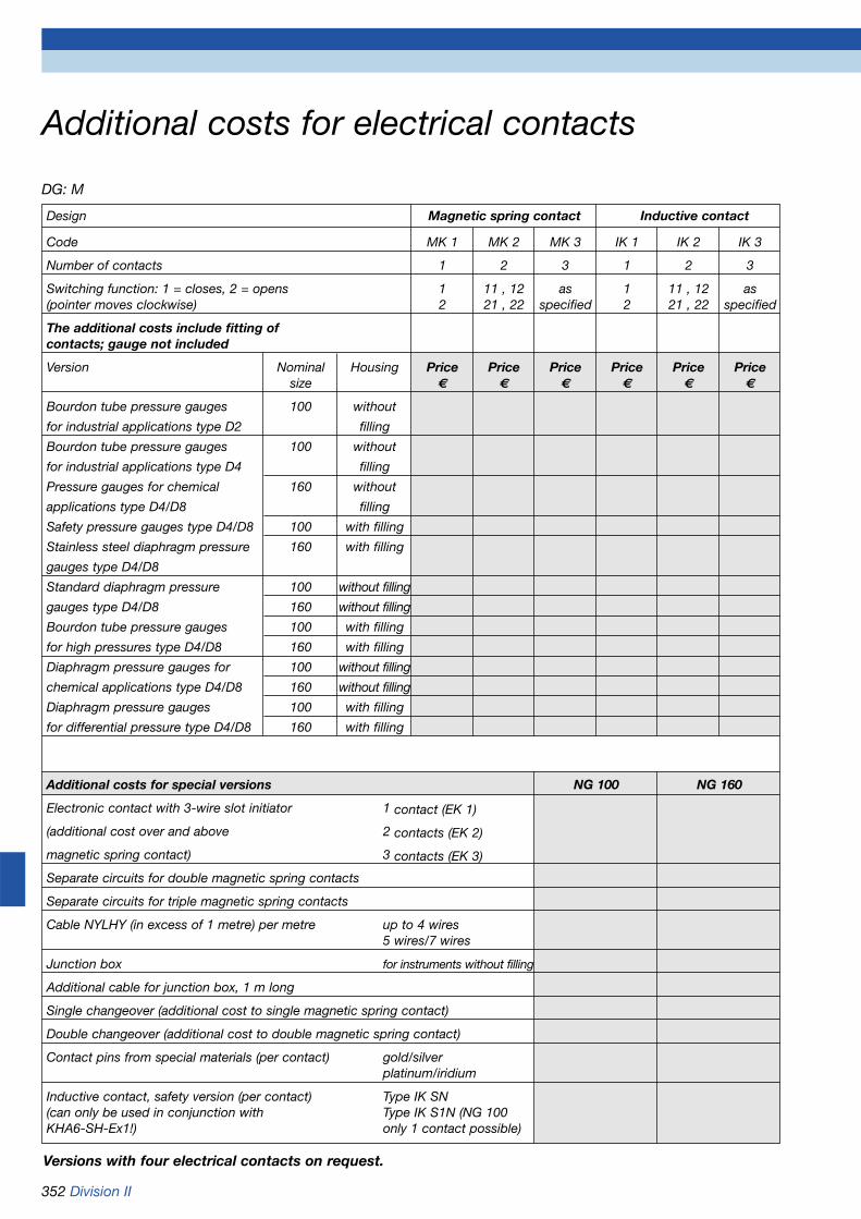
352 Division II
DG: M
Additional costs for electrical contacts
Versions with four electrical contacts on request.
Design Magnetic spring contact Inductive contact
Code MK 1 MK 2 MK 3 IK 1 IK 2 IK 3
Number of contacts 1 2 3 1 2 3
Switching function: 1 = closes, 2 = opens 1 11 , 12 as 1 11 , 12 as(pointer moves clockwise) 2 21 , 22 specified 2 21 , 22 specified
The additional costs include fitting of contacts; gauge not included
Version Nominal Housing Price Price Price Price Price Pricesize € € € € € €
Bourdon tube pressure gauges 100 without
for industrial applications type D2 filling
Bourdon tube pressure gauges 100 without
for industrial applications type D4 filling
Pressure gauges for chemical 160 without
applications type D4/D8 filling
Safety pressure gauges type D4/D8 100 with filling
Stainless steel diaphragm pressure 160 with filling
gauges type D4/D8
Standard diaphragm pressure 100 without filling
gauges type D4/D8 160 without filling
Bourdon tube pressure gauges 100 with filling
for high pressures type D4/D8 160 with filling
Diaphragm pressure gauges for 100 without filling
chemical applications type D4/D8 160 without filling
Diaphragm pressure gauges 100 with filling
for differential pressure type D4/D8 160 with filling
Additional costs for special versions NG 100 NG 160
Electronic contact with 3-wire slot initiator 1 contact (EK 1)
(additional cost over and above 2 contacts (EK 2)
magnetic spring contact) 3 contacts (EK 3)
Separate circuits for double magnetic spring contacts
Separate circuits for triple magnetic spring contacts
Cable NYLHY (in excess of 1 metre) per metre up to 4 wires5 wires/7 wires
Junction box for instruments without filling
Additional cable for junction box, 1 m long
Single changeover (additional cost to single magnetic spring contact)
Double changeover (additional cost to double magnetic spring contact)
Contact pins from special materials (per contact) gold/silverplatinum/iridium
Inductive contact, safety version (per contact) Type IK SN(can only be used in conjunction with Type IK S1N (NG 100KHA6-SH-Ex1!) only 1 contact possible)

Division II 353
Alarm unit for low gas level
ApplicationFor monitoring the pressure in gasfilled containers (e.g. gas installa-tions, gas cylinder batteries orbundle stations).
FunctionThe alarm signal is generated by apressure gauge fitted with an elec-trical contact. The alarm level canbe set to any value from 5 to 95 %via the contact arm of the pressuregauge.
A green LED indicates normal ope-ration.
In case of a power failure, the unitdoes not generate an alarm signal.When power is restored, the instru-ment immediately resumes opera-tion. If, in the meantime, the gaspressure has fallen below the setlimit, an alarm signal is generated.
When an alarm occurs, the red LEDlights up. In addition, the systemgenerates an audible alarm. Theaudible alarm can be re-set. Thered LED remains lit for as long asthe alarm condition prevails.
The proper functioning of thesystem can be checked at all timesby pressing the test button. Whenthe button is pressed, the systemmust generate an alarm, i.e. the redLED must light up and the audiblealarm must sound.
DescriptionThe system consists of one orseveral contact pressure gauges(connected in series), a control unit(alarm unit for low gas level) and, ifrequired, an additional alarm unit.
The contact pressure gauge isequipped with a magnetic springcontact which is actuated by thepointer of the pressure gauge. Theranges of the pressure gauges canbe selected as required.If several gas containers are to bemonitored, several contact pressuregauges can be connected in seriesand monitored by a single alarmunit for low gas level. It is also pos-sible to connect a separate alarmunit for each measuring point.
An additional alarm unit can beconnected to the relay output of thealarm unit as an auxiliary remotealarm.
Technical specifications
Operating temperature rangeAmbient: -5 °C/+40 °C
Supply voltageAC 230 V ±10 %
Power consumption5 VA
Circuit to pressure gaugeIntrinsically safe, U < 16.8 V, I < 57 mA
Relay outputRelay contact: 1 voltage-free
contact, normally open
Contact rating: Max. 250 V, 2 A, (resistive load)
Response delaynone
Intrinsic safety[EEx ia] IIC
HousingWall mounting housing made fromimpact resistant plastic (ABS)W x H x D: 97 x 163 x 62 mm
ProtectionIP 30 (EN 60529)
Protection classII (EN 60730)
InterferenceAccording to EN 61000-6-3
Noise immunityAccording to EN 61000-6-2
DG Part no. Price €Alarm unit for M 67006low gas level
Mounting G 43520framefor panel mounting
Additional
Gas cylinders
Contactpressure gauge
Alarm unit for low gas level
alarm unit
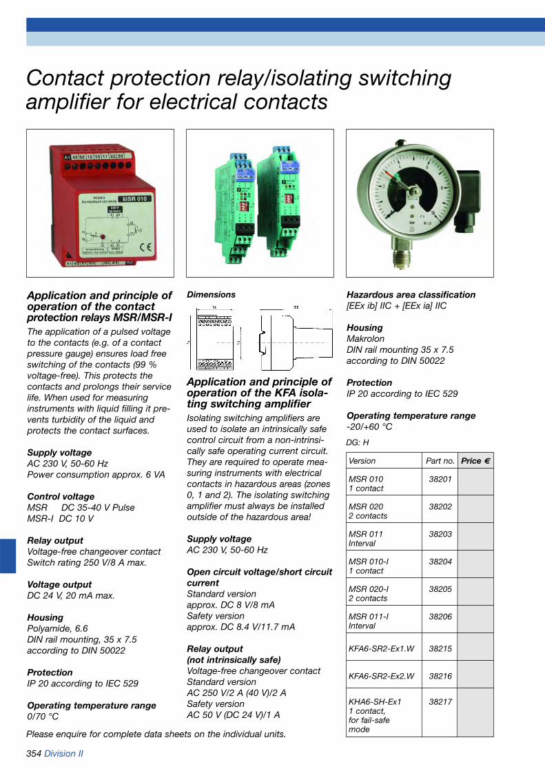
354 Division II
Contact protection relay/isolating switchingamplifier for electrical contacts
Please enquire for complete data sheets on the individual units.
Application and principle ofoperation of the contact protection relays MSR/MSR-IThe application of a pulsed voltageto the contacts (e.g. of a contactpressure gauge) ensures load freeswitching of the contacts (99 % voltage-free). This protects thecontacts and prolongs their servicelife. When used for measuringinstruments with liquid filling it pre-vents turbidity of the liquid andprotects the contact surfaces.
Supply voltageAC 230 V, 50-60 HzPower consumption approx. 6 VA
Control voltageMSR DC 35-40 V PulseMSR-I DC 10 V
Relay outputVoltage-free changeover contactSwitch rating 250 V/8 A max.
Voltage outputDC 24 V, 20 mA max.
HousingPolyamide, 6.6DIN rail mounting, 35 x 7.5 according to DIN 50022
ProtectionIP 20 according to IEC 529
Operating temperature range0/70 °C
Dimensions
Application and principle ofoperation of the KFA isola-ting switching amplifierIsolating switching amplifiers areused to isolate an intrinsically safecontrol circuit from a non-intrinsi-cally safe operating current circuit.They are required to operate mea-suring instruments with electricalcontacts in hazardous areas (zones0, 1 and 2). The isolating switchingamplifier must always be installedoutside of the hazardous area!
Supply voltageAC 230 V, 50-60 Hz
Open circuit voltage/short circuitcurrentStandard version approx. DC 8 V/8 mASafety version approx. DC 8.4 V/11.7 mA
Relay output(not intrinsically safe)Voltage-free changeover contactStandard versionAC 250 V/2 A (40 V)/2 ASafety versionAC 50 V (DC 24 V)/1 A
Hazardous area classification[EEx ib] IIC + [EEx ia] IIC
HousingMakrolonDIN rail mounting 35 x 7.5 according to DIN 50022
ProtectionIP 20 according to IEC 529
Operating temperature range-20/+60 °C
DG: H
Version Part no. Price €
MSR 010 382011 contact
MSR 020 382022 contacts
MSR 011 38203Interval
MSR 010-I 382041 contact
MSR 020-I 382052 contacts
MSR 011-I 38206Interval
KFA6-SR2-Ex1.W 38215
KFA6-SR2-Ex2.W 38216
KHA6-SH-Ex1 382171 contact,for fail-safemode

Division II 355
MovementBrass
DialAluminium, whiteDial marking black
PointerAluminium, black
HousingStainless steel 1.4301 with blow-out
Bayonet type bezelStainless steel 1.4301
Front glassLaminated safety glass
Options
• Glycerine filling• Wetted parts with special coating• Clamp connection• Flush mounting connection
flanges according to EN• Open connection flanges
according to EN/ANSI• Other connection threads• Electrical contacts (> 0/0.6 bar)
Operating temperature rangeMedium: Tmax = +100 °CAmbient: Tmin = -20 °C
Tmax = +60 °C
Temperature performanceIndication error when the tempera-ture of the measuring element devi-ates from 20 °C:rising temp. approx. ±0.8 %/10Kfalling temp. approx. ±0.8 %/10Kpercentage of full scale value
ProtectionIP 54 (EN 60529)
Standard version
ConnectionStainless steel 1.4571, bottomG1/2B - spanner size 22(EN 837-3/7.3)
Lower flangeStainless steel 1.4571
Upper flangeStainless steel 1.4571
Measuring elementDiaphragm:40 mbar to 2.5 bar stainless steel 1.45714 bar to 25 bar Duratherm
ApplicationFor corrosive, gaseous and liquidmedia, also suitable for use in cor-rosive atmospheres. Also suitablefor viscous and polluted media inconjunction with open connectionflange. With clamp connectionespecially suitable for hygienic pro-cesses. ! When measuring gas or vapour,the instruments must be used inaccordance with the safety recom-mendations of EN 837-2 (seeappendix).
TypeD 4
Nominal size100 - 160
Accuracy class (EN 837-3/6)1.6
Ranges (EN 837-3/5)0/40 mbar to 0/25 bar
Application areaStatic load:full scale valueDynamic load:0.9 x full scale value
Overpressure safety1.3 x full scale value
Stainless steel diaphragm pressure gauges EN 837-3
Refer to page 357 for part no.
Clamp connection

356 Division II
Stainless steel diaphragm pressure gauges Type D 4 - NG 100/160Housing types and dimensions (in mm)
Dimensions (mm)
Clamp connection 2“ according to ISO 2852, 0/1 bar to 0/6 bar
Connection flange according to EN 1092-1/B 1/DN 25/PN 40Open, 0/40 mbar Flush mounting, 0/1 bar to 0/25 bar to 0/6 bar
Flush mounting connection flange according to EN 1092-1/B 1/DN 50/PN 40, 0/40 mbar to 0/25 bar
Flush mounting connection flange according to EN 1092-1/B 1/DN 80/PN 40, 0/40 mbar to 0/25 bar
Bottom connection, 0/40 mbar to 0/2.5 bar Bottom connection, 0/4 bar to 0/25 bar
Nominal size (NG) a b c d1 d2 d3 d4 d5 d6 d7 d8 d9 d10 d11 dm dm1 D D1 D2 DN
100 15.6 49 20 68 85 115 4xØ18 102 125 165 8xØ18 138 160 200 48 68 69 78 64 25
160 17.5 50 20 68 85 115 4xØ18 102 125 165 8xØ18 138 160 200 48 68 69 78 64 25
Nominal size (NG) G G1 h h1 h2 h3 h4 h5 h6 s s1 s2 s3 s4 s5 SW
100 G1/2B 4xM12 117 117 86 102 96 86 90 2 30 3 20 3 24 22
160 G1/2B 4xM12 148 148 117 133 127 117 121 2 30 3 20 3 24 22

Division II 357
Stainless steel diaphragm pressure gauges EN 837-3
DG: H
Refer to page 358 for additional costs.
Type PF100E, D402 PF160E, D402 PF100CP, D402 PF160CP, D402 PF100E, D402 PF160E, D402 PF100E, D402 PF160E, D402
Version
Housing Ø 100 160 100 160 100 160 100 160
Housing Stainless steel 1.4301 with bayonet type bezel
Meas. elem. 1.4571, > 4 bar Duratherm Stainless steel 1.4571 Stainless steel 1.4571, > 4 bar Duratherm
Flanges Stainless steel 1.4571
Accuracy class 1.6 1.6 1.6 1.6 1.6 1.6 1.6 1.6
Connection G1/2B G1/2B Clamp 2“ Clamp 2“ Open connection flange Flush mounting connectionISO 2852 ISO 2852 according to EN 1092-1/ flange according to
B 1/DN 25/PN 40 EN 1092-1/ B 1/DN 50/PN 40
Range(mbar)
Price €
0/10 --- --- --- --- --- --- --- ---
0/16 --- --- --- --- --- --- --- ---
0/25 --- --- --- --- --- --- --- ---
0/40 85884402 85924402 --- --- 88904402 88924402 88944402 88964402
0/60 85885402 85925402 --- --- 88905402 88925402 88945402 88965402
0/100 85886402 85926402 --- --- 88906402 88926402 88946402 88966402
0/160 85887402 85927402 --- --- 88907402 88927402 88947402 88967402
0/250 85888402 85928402 --- --- 88908402 88928402 88948402 88968402
0/400 85889402 85929402 --- --- 88909402 88929402 88949402 88969402
Range(bar)
Price €
0/0.6 85890402 85930402 --- --- 88910402 88930402 88950402 88970402
0/1 85891402 85931402 88980402 88990402 88911402 88931402 88951402 88971402
0/1.6 85892402 85932402 88981402 88991402 88912402 88932402 88952402 88972402
0/2.5 85893402 85933402 88982402 88992402 88913402 88933402 88953402 88973402
Price €
0/4 85894402 85934402 88983402 88993402 88914402 88934402 88954402 88974402
0/6 85895402 85935402 88984402 88994402 88915402 88935402 88955402 88975402
0/10 85896402 85936402 --- --- 88916402 88936402 88956402 88976402
0/16 85897402 85937402 --- --- 88917402 88937402 88957402 88977402
0/25 85898402 85938402 --- --- 88918402 88938402 88958402 88978402
Part no. Part no. Part no. Part no. Part no. Part no. Part no. Part no.

358 Division II
DG: H
Additional costs for stainless steel diaphragmpressure gaugesProcess connection Price €
Groove/tongue according to EN 1092-1
Connection G1/4B
Connection 1/4 NPT
Connection 1/2 NPT
Connection M 20 x 1.5
Other connection threads on request
Channel bore Ø 10 mm in connection G1/2B Standard
Flush mounting connection flange according to Nominal width Nominal pressure Price €
DIN EN 1092-1/B1 (Additional cost over standard connection G1/2B)
DN 25 (0/1 bar PN 40
to 0/6 bar)
DN 50 PN 40
DN 80 PN 40
other connection flanges on request
Special coating Nominal width Price €
for diaphragm and lower flange
(only for flush mounting flange)
PTFE coating DN 25 PN 40
PTFE coating DN 50 PN 40
PTFE coating DN 80 PN 40
PFA coating DN 25 PN 40
PFA coating DN 50 PN 40
PFA coating DN 80 PN 40
Other materials on request
Glycerine filling Price €
Nominal size 100
Nominal size 160
Miscellaneous Price €
Overpressure safety 5 x FSD on request
Vacuum proof (> 0/4 bar) Standard
Electrical contacts (> 0/0.6 bar) See page 352
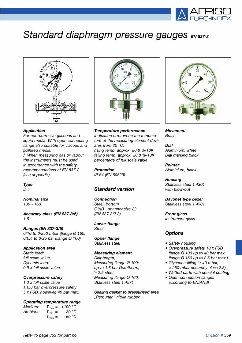
Division II 359
ApplicationFor non-corrosive gaseous andliquid media. With open connectingflange also suitable for viscous andpolluted media. ! When measuring gas or vapour,the instruments must be used in accordance with the safetyrecommendations of EN 837-2 (see appendix).
TypeD 4
Nominal size100 - 160
Accuracy class (EN 837-3/6)1.6
Ranges (EN 837-3/5)0/10 to 0/250 mbar (flange Ø 160)0/0.4 to 0/25 bar (flange Ø 100)
Application areaStatic load:full scale valueDynamic load:0.9 x full scale value
Overpressure safety1.3 x full scale value> 0.6 bar overpressure safety 5 x FSD, however, 40 bar max.
Operating temperature rangeMedium: Tmax = +100 °CAmbient: Tmin = -20 °C
Tmax = +60 °C
Temperature performanceIndication error when the tempera-ture of the measuring element devi-ates from 20 °C:rising temp. approx. ±0.8 %/10Kfalling temp. approx. ±0.8 %/10Kpercentage of full scale value
ProtectionIP 54 (EN 60529)
Standard version
ConnectionSteel, bottomG1/2B - spanner size 22(EN 837-3/7.3)
Lower flangeSteel
Upper flangeStainless steel
Measuring elementDiaphragm,Measuring flange Ø 100:up to 1.6 bar Duratherm,> 2.5 steelMeasuring flange Ø 160:Stainless steel 1.4571
Sealing gasket to pressurised area„Perbunan“ nitrile rubber
Standard diaphragm pressure gauges EN 837-3
MovementBrass
DialAluminium, whiteDial marking black
PointerAluminium, black
HousingStainless steel 1.4301 with blow-out
Bayonet type bezelStainless steel 1.4301
Front glassInstrument glass
Options
• Safety housing• Overpressure safety 10 x FSD
flange Ø 100 up to 40 bar max.,flange Ø 160 up to 2.5 bar max.)
• Glycerine filling (> 40 mbar,< 250 mbar accuracy class 2.5)
• Wetted parts with special coating• Open connection flanges
according to EN/ANSI
Refer to page 363 for part no.

360 Division II
Bottom connection, measuring flange Ø 100
Dimensions (mm)
Connection flange according to EN 1092-1, DN 25 Measuring flange Ø 100
Connection flange according to EN 1092-1, DN 50 Measuring flange Ø 100
Connection flange according to EN 1092-1, DN 25 Measuring flange Ø 160
Connection flange according to EN 1092-1, DN 50 Measuring flange Ø 160
Standard diaphragm pressure gauges Type D 4 - NG 100/160Housing types and dimensions
Bottom connection, measuring flange Ø 160
Nominal size (NG) a b Øc c1 c2 d1 d2 d3 d4 d5 d6 d7 d8 D D1 DN DN1 G G1 h h1
100 20 55 6 3 20 68 85 115 102 125 165 4x18 4x14 100 160 25 50 G1/2B 4xM12 127 111
160 20 55 6 3 20 68 85 115 102 125 165 4x18 4x14 100 160 25 50 G1/2B 4xM12 156 141
Nominal size (NG) h2 h3 h4 s s1 s2 s3 s4 s5 s6 s7 t SW
100 101 129 137 2 30 3 20 18 48 20 56 12 22
160 131 159 167 2 30 3 20 18 48 20 56 12 22

Division II 361
ApplicationFor corrosive, gaseous and liquidmedia and suitable for use in corro-sive atmospheres. With open con-necting flange also suitable forviscous and polluted media. ! When measuring gas or vapour,the instruments must be used in accordance with the safety recommendations of EN 837-2 (see appendix).
TypeD 4
Nominal size100 - 160
Accuracy class (EN 837-3/6)1.6
Ranges (EN 837-3/5)0/10 to 0/250 mbar (flange Ø 160)0/0.4 to 0/25 bar (flange Ø 100)
Application areaStatic load:full scale valueDynamic load:0.9 x full scale value
Overpressure safety1.3 x full scale value> 0.6 bar overpressure safety 5 x FSD, however 40 bar max.
Operating temperature rangeMedium: Tmax = +100 °CAmbient: Tmin = -20 °C
Tmax = +60 °C
Temperature performanceIndication error when the tempera-ture of the measuring element devi-ates from 20 °C:rising temp. approx. ±0.8 %/10Kfalling temp. approx. ±0.8 %/10Kpercentage of full scale value
ProtectionIP 54 (EN 60529)
Standard version
ConnectionStainless steel 1.4571, bottomG1/2B - spanner size 22(EN 837-3/7.3)
Lower flangeStainless steel 1.4571
Upper flangeStainless steel 1.4301
Measuring elementDiaphragm,Measuring flange Ø 100:DurathermMeasuring flange Ø 160:Stainless steel 1.4571
Sealing gasket to pressurised areaFPM (Viton)
MovementStainless steel
DialAluminium, whiteDial marking black
PointerAluminium, black
HousingStainless steel 1.4301 with blow-out
Bayonet type bezelStainless steel 1.4301
Front glassLaminated safety glass
Options
• Safety housing• Overpressure safety 10 x FSD
(flange Ø 100 up to 40 bar max., flange Ø 160 up to 2.5 bar max.)
• Glycerine filling (> 40 mbar,< 250 mbar accuracy class 2.5)
• Wetted parts with special coating• Open connection flanges
according to EN/ANSI
Diaphragm pressure gauges for chemical applications EN 837-3
Refer to page 363 for part no.

362 Division II
Dimensions (mm)
Connection flange according to EN 1092-1, DN 25 Measuring flange Ø 100
Connection flange according to EN 1092-1, DN 50 Measuring flange Ø 100
Connection flange according to EN 1092-1, DN 25 Measuring flange Ø 160
Connection flange according to EN 1092-1, DN 50 Measuring flange Ø 160
Diaphragm pressure gauges for chemical applications Type D 4 - NG 100/160Housing types and dimensions
Bottom connection, measuring flange Ø 100 Bottom connection, measuring flange Ø 160
Nominal size (NG) a b Øc c1 c2 d1 d2 d3 d4 d5 d6 d7 d8 D D1 DN DN1 G G1 h h1
100 20 55 6 3 20 68 85 115 102 125 165 4x18 4x14 100 160 25 50 G1/2B 4xM12 127 111
160 20 55 6 3 20 68 85 115 102 125 165 4x18 4x14 100 160 25 50 G1/2B 4xM12 156 141
Nominal size (NG) h2 h3 h4 s s1 s2 s3 s4 s5 s6 s7 t SW
100 101 129 137 2 30 3 20 18 48 20 56 12 22
160 131 159 167 2 30 3 20 18 48 20 56 12 22

Division II 363
Type PF100, D401 PF160, D401 PF100Gly, D801 PF160Gly, D801 PF100Ch, D402 PF160Ch, D402 PF100CHGly,802 PF160CHGly,802
Version
Housing Ø 100 160 100 160 100 160 100 160
Housing Stainless steel 1.4301 with bayonet type bezel
Meas. elem. Diaphragm, refer to data sheet
Lower flange Steel Stainless steel 1.4571
Accuracy class 1.6 1.6 1.6* 1.6* 1.6 1.6 1.6* 1.6*
Connection G1/2B G1/2B G1/2B G1/2B G1/2B G1/2B G1/2B G1/2B
Range(mbar)
Price €
0/10 85901401 85951401 --- --- 85901402 85951402 --- ---
0/16 85902401 85952401 --- --- 85902402 85952402 --- ---
0/25 85903401 85953401 --- --- 85903402 85953402 --- ---
0/40 85904401 85954401 85904801 85954801 85904402 85954402 85904802 85954802
Price €
0/60 85905401 85955401 85905801 85955801 85905402 85955402 85905802 85955802
0/100 85906401 85956401 85906801 85956801 85906402 85956402 85906802 85956802
0/160 85907401 85957401 85907801 85957801 85907402 85957402 85907802 85957802
0/250 85908401 85958401 85908801 85958801 85908402 85958402 85908802 85958802
Range(bar)
Price €
0/0.4 85909401 85959401 85909801 85959801 85909402 85959402 85909802 85959802
0/0.6 85910401 85960401 85910801 85960801 85910402 85960402 85910802 85960802
0/1 85911401 85961401 85911801 85961801 85911402 85961402 85911802 85961802
0/1.6 85912401 85962401 85912801 85962801 85912402 85962402 85912802 85962802
0/2.5 85913401 85963401 85913801 85963801 85913402 85963402 85913802 85963802
0/4 85914401 85964401 85914801 85964801 85914402 85964402 85914802 85964802
0/6 85915401 85965401 85915801 85965801 85915402 85965402 85915802 85965802
0/10 85916401 85966401 85916801 85966801 85916402 85966402 85916802 85966802
0/16 85917401 85967401 85917801 85967801 85917402 85967402 85917802 85967802
0/25 85918401 85968401 85918801 85968801 85918402 85968402 85918802 85968802
Part no. Part no. Part no. Part no. Part no. Part no. Part no. Part no.
DG: H with glycerine filling with glycerine filling
* < 250 mbar class 2.5 – Refer to page 364 for additional costs.
Standard diaphragmpressure gauges
Diaphragm pressure gaugesfor chemical applications

364 Division II
Add. costs for standard diaphragm pressure gauges/diaphragm pressure gauges for chemical applicationsDG: H
Refer to page 352 for additional costs for electrical contacts.
Open connection flanges Ranges 10 to 250 mbar Ranges 0.4 to 25 barMeasuring flange Ø 160 Measuring flange Ø 100
Material Steel Stainless steel Steel Stainless steel
Version Nominal width Price € Price € Price € Price €
EN 1092-1, PN 40 DN 15
DN 20
DN 25
DN 50
ANSI B 16.5, Class 150 DN 1/2“
DN 1“
DN 2“
Special connection Material steel Material stainless steel 1.4571
Price € Price €
Channel hole Ø 10 mm
Groove/spring accor. to EN 1092-1
RJT groove ANSI B16.5
Special materials Ranges 10 to 250 mbar Ranges 0.4 to 25 bar
for diaphragms Measuring flange Ø 160 Measuring flange Ø 100
Material Price € Price €
PTFE foil (> 40 mbar)
Silver foil (> 160 mbar on request
Tantalum foil (> 160 mbar)
Other materials on request
Special materials for lower Ranges 10 to 250 mbar Ranges 0.4 to 25 barmeasuring flange (wetted part) Measuring flange Ø 160 Measuring flange Ø 100for types D402 and D802
Connection G1/2B Flange, EN Flange, EN G½B Flange, EN Flange, EN1092-1, DN 1092-1, DN 1092-1 ,DN 1092-1, DN
15-25 Flange 50 Flange 15-25 Flange 50 FlangeANSI 1/2“, 1“ ANSI 2“ ANSI 1/2“, 1“ ANSI 2“
Material Price € Price € Price € Price € Price € Price €
PTFE lining
Other materials on request
Overpressure safety 10 x FSD Ranges 10 to 250 mbar Ranges 0.4 to 25 bar(Measuring flange Ø 100 up Measuring flange Ø 160 Measuring flange Ø 100
to 40 bar max., Price € Price €
Ø 160 up to 2.5 bar max.)
Safety housing Housing diameter 100 mm Housing diameter 160 mmwith solid baffle walland blow-out Price € Price €

Division II 365
Application areaStatic load:full scale valueDynamic load:0.9 x full scale value
Overpressure safetyfull scale value
Maximum static pressure400 mbar
Operating temperature rangeMedium: Tmax = +60 °CAmbient: Tmin = -20 °C
Tmax = +60 °C
Temperature performanceIndication error when the tempera-ture of the measuring element devi-ates from 20 °C:rising temp. approx. ±0.6 %/10Kfalling temp. approx. ±0.6 %/10Kpercentage of full scale value
ProtectionIP 66 (EN 60529)
Standard version
Connection (wetted parts)NG 63: 2 x G1/4B - spanner size 14centre back (brass)NG 100: 2 x G1/2B - spanner size 22bottom (stainless steel)2 x G1/2B - spanner size 22 centre back (brass)(EN 837-3/7.3)
ApplicationFor differential pressure measure-ment of gaseous, dry media whichare non-corrosive. Especially suitable for filter loss measurementin air conditioning and ventilationapplications. ! When measuring gas or vapour,the instruments must be used in accordance with the safety recommendations of EN 837-2 (see appendix).
TypeD 9/D 4
Nominal size63 - 100 - 160
FunctionThe „plus“ pressure (= high pressu-re) is applied to the inside of thediaphragm. The „minus“ pressure(= low pressure) is applied to theinside of the pressure tight housing.The pressure difference causes thediaphragm to change its shape,thus generating the movementrequired to measure the pressure.This displacement is picked up bythe movement. The differentialpressure is directly indicated by thepointer of the gauge.
Accuracy class (EN 837-3/6)1.6
Ranges (EN 837-3/5)NG 63 0/16 to 0/400 mbarNG 100 0/ 6 to 0/400 mbarNG 160 0/ 4 to 0/400 mbar
Standard capsule type pressure gauges for differential pressure
Measuring element (wetted part)Capsule element, CuBe alloy
Movement (wetted part)Brass
Seal (wetted part)„Perbunan“ nitrile rubber
Dial (wetted part)Aluminium, whiteDial marking black
Pointer (wetted part)Aluminium, black
Housing (wetted part)Stainless steel 1.4301
Bayonet type bezel/crimpedbezel Stainless steel 1.4301
Front glass (wetted part)Plastic (PMMA)
MountingWall mounting via back flange or 3-hole fixing, panel mounting bezel(each as option). Direct mounting torigid measuring pipe possible.
Options
• Back flange• 3-hole fixing, panel mounting
bezel• Hose connections
Refer to page 369 for part no.

366 Division II
Bottom connection (NG 100/160) Bottom connection, back flange (NG 100/160)
Back connection (NG 100/160) Back connection, 3-hole fixing, panel mountingbezel (NG 100)
Dimensions (mm)
Standard capsule type pressure gauges for differential pressure Type D 9 - NG 63/Type D 4 - NG 100/160Housing types and dimensions
Back connection (NG 63) Back connection, 3-hole fixing, panel mountingbezel (NG 63)
* Dimensions according to DIN EN 837-1
Nominal size (NG) a a1 b b1 c d1* d2 d3* D1 D2 D3 e1 e2 g G h S S1 S2 S3 SW
63 - - 30.5 - 2 75 85 3.6 68 62 64.3 - 20 53 G1/4B - 14 - 6 2 14
100 16 18 49 51 3 116 133 4.5 101 99 - 32 34.5 79 G1/2B 86 20 5 2.5 3 22
160 16 19 49 52 3 178 196 4.5 161 159 - 32 34.5 79 G1/2B 118 20 6 4.5 2 22

Division II 367
Accuracy class (EN 837-1 /6)1.6
Ranges (EN 837-1/5)0/0.6 to 0/60 bar
Application areaThe maximum pressure in thesystem must not exceed the fullscale value. To ensure good read-ability, the differential pressure tobe measured should not be lessthan approx. 20 % of the full scalevalue.
Operating temperature rangeMedium: Tmax = +60 °CAmbient: Tmin = -20 °C
Tmax = +60 °C
Temperature performanceIndication error when the tempera-ture of the measuring element devi-ates from 20 °C: rising temp. approx. ±0.4 %/10Kfalling temp. approx. ±0.4 %/10Kpercentage of full scale value
ProtectionIP 32 (EN 60529)
Standard version
ConnectionBrass, bottom, parallel in line2 x G1/2B - spanner size 22(EN 837-1/7.3)
ApplicationFor differential pressure measure-ment of gaseous and liquid mediawhich are not highly viscous, do notcrystallize and do not attack copperalloys. Specially suitable for heatingsystems (supply and return pipes). ! When measuring gas or vapour,the instruments must be used inaccordance with the safety recom-mendations of EN 837-2 (seeappendix).
TypeD 2
Nominal size100
FunctionThe pressures are measured in twoindependent Bourdon tube systems(„plus“ pressure = high pressure,„minus“ pressure = low pressure).The pressure is indicated on a dialby a pointer. The differential pres-sure scale covers 50 % of the rangeof the „plus“ pressure and 50 % ofthe range of the „minus“ pressure.The black pointer („plus“ connec-tion) and the red pointer („minus“connection) at the differential pres-sure gauge scale allow you to readthe pressures in either system onthe fixed scale.
Measuring elementBourdon tube element,< 60 bar „C“ type bourdon tube,copper alloy> 60 bar helical tube, 1.4571
MovementBrass
DialAluminium, whiteDial marking black (bar/mWC)
Pointer/dialAluminium
HousingSheet steel, black
Push-on bezelSheet steel, black
Front glassInstrument glass
Options
• Wetted parts stainless steel• Stainless steel housing and
push-on bezel• Nominal size 160 (D 1)• Back flange• 3-hole fixing, panel mounting
bezel• Damping screw
Example of a readingp1 (+pointer)p2 (-pointer)
p (differential pressure)p1
p2
p
Standard Bourdon tube pressure gauges fordifferential pressure
Refer to page 369 for part no.

368 Division II
Dimensions (mm)
Standard Bourdon tube pressure gauges fordifferential pressure Type D 2 - NG 100Housing types and dimensions
Bottom connection Bottom connection, back flange
Bottom connection, 3-hole fixing, panel mounting bezel
* Dimensions according to DIN EN 837-1
Nominal size (NG) a a1 b b1 Øc c1 c2 d1* d2* d3* G h k s s1 s2 SW
100 15.6 19.1 84 87.5 6 3 20 116 132 4.8 G1/2B 86 32 2 5.5 3 22

Division II 369
DG: M
Standard capsule type/Bourdon tube pressure gauges for differential pressure
Refer to page 383 for additional costs for mounting accessories
Type KP63Dif, D911 KP100Dif, D401 KP100Dif, D411KP160Dif, D401 KP160Dif, D411 RF100Dif, D201 RF100Dif, D301 RF160Dif, D101
Version
Housing Ø 63 100 100 160 160 100 100 160
Housing Stainless steel 1.4301, plastic front glass Sheet steel Stainless steel Polyamide
Meas. elem. Capsule element, CuBe alloy Bourdon tube element, copper alloy
Accuracy class 1.6 1.6 1.6 1.6 1.6 1.6 1.6 1.6
Connection G1/4B G1/2B G1/2B G1/2B G1/2B G1/2B G1/2B G1/2B
Dual scale bar/mWC, black
Range
Price €
0/4 mbar --- --- --- 35612401 35612411 --- --- ---
0/6 mbar --- 35563401 35563411 35613401 35613411 --- --- ---
0/10 mbar --- 35564401 35564411 35614401 35614411 --- --- ---
0/16 mbar 35515911 35565401 35565411 35615401 35615411 --- --- ---
0/25 mbar 35516911 35566401 35566411 35616401 35616411 --- --- ---
0/40 mbar 35517911 35567401 35567411 35617401 35617411 --- --- ---
0/60 mbar 35518911 35568401 35568411 35618401 35618411 --- --- ---
0/100 mbar 35519911 35569401 35569411 35619401 35619411 --- --- ---
0/160 mbar 35520911 35570401 35570411 35620401 35620411 --- --- ---
0/250 mbar 35521911 35571401 35571411 35621401 35621411 --- --- ---
0/400 mbar 35522911 35572401 35572411 35622401 35622411 --- --- ---
Price €
0/0.6 bar --- --- --- --- --- 85609201 85609301 ---
0/1 bar --- --- --- --- --- 85610201 85610301 85660101
0/1.6 bar --- --- --- --- --- 85611201 85611301 85661101
0/2.5 bar --- --- --- --- --- 85612201 85612301 85662101
0/4 bar --- --- --- --- --- 85613201 85613301 85663101
0/6 bar --- --- --- --- --- 85614201 85614301 85664101
0/10 bar --- --- --- --- --- 85615201 85615301 85665101
0/16 bar --- --- --- --- --- 85616201 85616301 85666101
0/25 bar --- --- --- --- --- 85617201 85617301 85667101
0/40 bar --- --- --- --- --- 85618201 85618301 85668101
Price €
0/60 bar --- --- --- --- --- 85619201 85619301 85669101
0/100 bar --- --- --- --- --- --- --- 85670101
0/160 bar --- --- --- --- --- --- --- 85671101
0/250 bar --- --- --- --- --- --- --- 85672101
0/400 bar --- --- --- --- --- --- --- 85673101
Add. costs Price € Price € Price €Wetted parts --- --- --- --- ---1.4571
Part no. Part no. Part no. Part no. Part no. Part no. Part no. Part no.

370 Division II
Seal (wetted part)NBR
DialAluminium, whiteDial marking black/red (bar/psi)Scale angle 90°
PointerAluminium, black
HousingStainless steel 1.4301 with rubbersealing ring at the front
Front glassInstrument glass
MountingWall mounting via a back mountingplate (optional) or pipe mounting bya combination of back plate andfixing clamp for 2“ pipe (optional).
Options
• Back mounting plate with fixing clamp
• 3-hole fixing, panel mounting bezel
• Max. static pressure PN 250/400• Other connection threads• Other connection designs• Acrylic front glass• Electrical contacts (Reed
contacts)• Filter in the „plus“ connection• Glycerine filling• Ref. pointer• Special scales
Magnetic piston type pressure gauges for differential pressure - high overload protection
ApplicationFor differential pressure measure-ments with very high static pres-sures. For gaseous and liquid, non-adhesive media which are not high-ly viscous. Particularly suitable formonitoring filters, pumps, pipesystems and cooling circuits.
TypeMAG 80/100 Dif D312
Nominal size80-100 mm
FunctionThe pressures act on two pressurechambers separated by a pistonmagnet. If there are different pres-sures in the chambers, the pistonmagnet is axially displaced againsta pressure spring. This displace-ment is transmitted from the pistonmagnet to the pointer via a rotarymagnet mounted to the pointerhub. The differential pressure is directlydisplayed.The complete mechanical separa-tion of pressure chamber anddisplay excludes the possibility ofleaks.
Accuracy of measurement±3 % of full scale value (at increa-sing differential pressure)
Ranges (EN 837-3/5)0/0.25 bar to 0/10 bar
Maximum static pressure100 bar
Overpressure safetyUp to the maximum static pressureon both sides
Operating temperature rangeMedium: Tmax = 100 °CAmbient: Tmin = 0 °C
Tmax = 80 °C
ProtectionIP 65 (EN 60529)
Standard version
Connection (wetted parts)Stainless steel 1.4401, Stainless steel 1.4401, on left andright hand side /directly oppositeeach other)2 x G1/4 female thread – spanner size 17 (EN 837-3/7.3)
Connection coverPlastic, glass-fibre reinforced, black
Measuring element (wetted part)Pressure springStainless steel 1.4310
Magnetic piston (wetted part)Stainless steel 1.4401/Strontiumferrite
• Extremely compact and robust stainless steel measuring system
• Selectable maximum static pressure PN 100/250/400
• Switching contacts can be retrofitted
• IP 65 protection for pressure gauge and switching contact
• Leak-proof due to mechanical separation of pressure chamberand display
• Various types of connections• Housing diameters 80 and100 mm• Optional glycerine filling
Low pressure
High pressure
Pointer
Measuring springReed switch
Seal
Piston magnet
Rotary magnet
Refer to page 374 for part no.

Division II 371
Connection on left and right hand side Connection on left and right hand side3-hole fixing, panel mounting bezel
Connection on left and right hand side with electrical contact
Back mounting plate and fixing clamp
Technical specifications electrical contact
Version: Reed contact, single pole changeover (SPDT)
Max. switching voltage: AC/DC 175 VMax. switch rating: AC 5 VA – DC 5 WMax. current: AC/DC 250 mASwitching hysteresis: approx. 5 %Adjustment range: 35-100 % of full scale valueElectrical connection: plug DIN 43650-A
Magnetic piston type pressure gauges for differentialpressure - high overload protection Type D 3 NG 80/100Types and dimensions (mm)
Wiring diagram
Fixing clamp
Back mounting plate
red
bla
ck
yello
w

372 Division II
Seal (wetted part)NBR
DialAluminium, whiteDial marking blackScale angle 90° (first graduationafter zero at 15% of full scale value)
PointerAluminium, black
HousingStainless steel 1.4301 with rubbersealing ring at the front
Front glassInstrument glass
MountingPanel mounting via mounting clips(standard), or wall mounting viaback mounting plate (optional) orpipe mounting via a combination ofback mounting plate and fixingclamp (optional) for 2“ pipe
Options
• Back mounting plate with fixingclamp
• Acrylic front glass• Electrical contacts (Reed
contacts)• Special scales
Magnetic diaphragm pressure gauges for very low differential pressure
ApplicationFor differential pressure measure-ments with very low differentialpressure. Especially suitable forgaseous media but in particular formonitoring filters and fans in airsupply, air conditioning and ultra-clean room applications.
TypeMAG 115 Dif D311
Nominal size115 mm
FunctionThe pressures act on two pressurechambers separated by a diaphragm.If there are different pressures inthe chambers, a magnet is axiallydisplaced against a pressure spring.This displacement is transmitted tothe pointer via a rotary magnet fit-ted to the pointer hub. The differen-tial pressure is directly displayed.
Accuracy of measurement±3 % of full scale value (at increa-sing differential pressure)
Ranges (EN 837-3/5)0/2.5 mbar to 0/100 mbar
Maximum static pressure2.4 bar
Overpressure safetyup to 2.4 bar on both sides
Operating temperature rangeMedium: Tmax = 60 °CAmbient: Tmin = 0 °C
Tmax = 60 °C
ProtectionIP 65 (EN 60529)
Standard version
Connection (wetted parts)Nylon 66, glass-fibre reinforced,choice of left and right hand side,or back (use enclosed blind plugs)2 x 1/8 NPT female thread or 2 x hose connection 5 mm(use enclosed adaptors)
Measuring element (wetted part)Diaphragm: NBRPressure spring: stainless steel1.4310Transmission unit:Stainless steel 1.4401
Magnet (wetted part)Strontium-ferrite
• Differential pressure ranges starting at 0/2.5 mbar
• Switching contacts can be retrofitted
• IP 65 protection for pressure gauge and switching contact
• Side or back connection• Delivery includes adapter for
hose connection and bracket for control panel mounting
Measuringspring
Low pressure
Separation dia-
Reed switch
PointerHigh pressure
MagnetRotary magnet
Refer to page 374 for part no.
phragm

Division II 373
Connection on left and right hand side or backconnection
Back mounting plate and fixing clamp
Connection on left and right hand side or backconnection with electrical contact
Technical specifications electrical contact
Version: Reed contact, single pole changeover (SPDT)
Max. switching voltage: AC/DC 175 VMax. switch rating: AC 5 VA – DC 5 WMax. current: AC/DC 250 mASwitching hysteresis: approx. 5 %Adjustment range: 40-80 % of full scale valueElectrical connection: plug DIN 43650-A
Magnetic diaphragm pressure gauges forvery low differential pressure Type D 3 NG 115Types and dimensions (mm)
Wiring diagram
Fixing clamp
Back mounting plate
2“ pipe
Screw M 4x10
Sealing plug 1/8-27 NPT
Sealing plug 1/8-27 NPT
red
yello
w
bla
ck
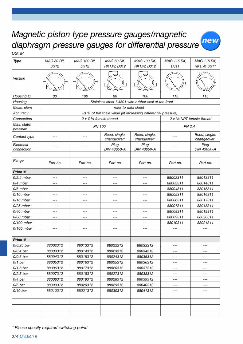
374 Division II
Magnetic piston type pressure gauges/magneticdiaphragm pressure gauges for differential pressureDG: M
* Please specify required switching point!
Type MAG 80 Dif, MAG 100 Dif, MAG 80 Dif, MAG 100 Dif, MAG 115 Dif, MAG 115 Dif,D312 D312 RK1.W, D312 RK1.W, D312 D311 RK1.W, D311
Version
Housing Ø 80 100 80 100 115 115
Housing Stainless steel 1.4301 with rubber seal at the front
Meas. elem refer to data sheet
Accuracy ±3 % of full scale value (at increasing differential pressure)
Connection 2 x G1/4 female thread 2 x 1/8 NPT female thread
Max. static PN 100 PN 2,4pressure
Contact type --- --- Reed, single, Reed, single, --- Reed, single,changeover* changeover* changeover*
Electrical --- --- Plug Plug --- Plugconnection DIN 43650-A DIN 43650-A DIN 43650-A
Range
Price €
0/2.5 mbar --- --- --- --- 88002311 88013311
0/4 mbar --- --- --- --- 88003311 88014311
0/6 mbar --- --- --- --- 88004311 88015311
0/10 mbar --- --- --- --- 88005311 88016311
0/16 mbar --- --- --- --- 88006311 88017311
0/25 mbar --- --- --- --- 88007311 88018311
0/40 mbar --- --- --- --- 88008311 88019311
0/60 mbar --- --- --- --- 88009311 88020311
0/100 mbar --- --- --- --- 88010311 88021311
0/160 mbar --- --- --- --- --- ---
Price €
0/0.25 bar 88002312 88013312 88022312 88033312 --- ---
0/0.4 bar 88003312 88014312 88023312 88034312 --- ---
0/0.6 bar 88004312 88015312 88024312 88035312 --- ---
0/1 bar 88005312 88016312 88025312 88036312 --- ---
0/1.6 bar 88006312 88017312 88026312 88037312 --- ---
0/2.5 bar 88007312 88018312 88027312 88038312 --- ---
0/4 bar 88008312 88019312 88028312 88039312 --- ---
0/6 bar 88009312 88020312 88029312 88040312 --- ---
0/10 bar 88010312 88021312 88030312 88041312 --- ---
Part no. Part no. Part no. Part no. Part no. Part no.
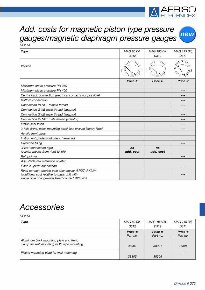
Division II 375
Add. costs for magnetic piston type pressuregauges/magnetic diaphragm pressure gaugesDG: M
Accessories
Type MAG 80 Dif, MAG 100 Dif, MAG 115 Dif,D312 D312 D311
Version
Price € Price € Price €
Maximum static pressure PN 250 ---
Maximum static pressure PN 400 ---
Centre back connection (electrical contacts not possible) ---
Bottom connection ---
Connection 1/4 NPT female thread ---
Connection G1/4B male thread (adaptor) ---
Connection G1/2B male thread (adaptor) ---
Connection 1/2 NPT male thread (adaptor) ---
Piston seal Viton ---
3-hole fixing, panel mounting bezel (can only be factory fitted) ---
Acrylic front glass
Instrument grade front glass, hardened
Glycerine filling ---
„Plus“ connection right no no ---(pointer moves from right to left) add. cost add. cost
Ref. pointer ---
Adjustable red reference pointer
Filter in „plus“ connection ---
Reed contact, double pole changeover (SPDT) RK2.W(additional cost relative to basic unit with ---single pole change-over Reed contact RK1.W !)
Type MAG 80 Dif, MAG 100 Dif, MAG 115 Dif,D312 D312 D311
Price € Price € Price €Part no. Part no. Part no.
Aluminum back mounting plate and fixingclamp for wall mounting or 2“ pipe mounting. 38001 38001 38304
Plastic mounting plate for wall mounting ---38305 38305
DG: M

376 Division II
Ranges (EN 837-3/5)0/250 mbar to 0/6 bar
Maximum static pressure25 bar
Overpressure safetyUp to 25 bar on both sides
Operating temperature rangeMedium: Tmax = +60 °CAmbient: Tmin = -20 °C
Tmax = +60 °C
Temperature performanceIndication error when the tempera-ture of the measuring element devi-ates from 20 °C:rising temp. approx. ±0.5 %/10Kfalling temp. approx. ±0.5 %/10Kpercentage of full scale value
ProtectionIP 54 (EN 60529)
Standard version
ConnectionBrass, nickel plated, bottom, parallel in line2 x G1/2B - spanner size 22 (EN 837-3/7.3)
Measuring elementPressure spring stainless steel 1.4310
ApplicationFor differential pressure measure-ment with low differential pressureand high static pressure. For gase-ous and liquid media with lowviscosity and non-corrosive.Particularly suitable for monitoringfilters, pumps and pipe systems.
TypeMF 100 Dif D401
Nominal size100
FunctionThe pressures act on two pressurechambers separated by an elasticdiaphragm. Different pressures inthe chambers cause an axial deflec-tion of the diaphragm against apressure spring which is proportion-al to the pressure. This is transmit-ted to the movement via a rod. Thedifferential pressure is directly indi-cated by a pointer. The diaphragmis held by metallic supports at bothsides providing an overpressuresafety of up to 25 bar.
Accuracy class (EN 837-3/6)2.5
DiaphragmViton
Measuring flangeAluminium eloxed
MovementBrass
DialAluminium, whiteDial marking black
PointerAluminium, black
HousingStainless steel 1.4301
Bayonet type bezelStainless steel 1.4301
Front glassLaminated safety glass
Options
• Back flange• Other connections
Function overview1. Movement2. Dial3. Pointer4. Transmission unit5. Measuring spring6. Diaphragm7. Measuring flange
Spring-diaphragm pressure gauges for differential pressure - overload protected
Refer to page 382 for part no.
1
2
3
4
5
6
7

Division II 377
Spring-diaphragm pressure gauges for differential pressure Type D 4 - NG 100Housing types and dimensions
Bottom connection Bottom connection, back flange
Dimensions (mm)
Nominal size (NG) a a1 b b1 Øc c1 c2 d1 d2 d3 G h k s SW
100 16 19.5 112.5 116 6 3 20 116 132 4.8 G1/2B 84 32 5.5 22

378 Division II
Ranges (EN 837-3/5)MF 100: 0/250 mbar to 0/6 barMFW 100: 0/250 mbar to 0/25 bar
Maximum static pressure25 bar
Overpressure safetyup to 25 bar on both sides
Operating temperature rangeMedium: Tmax = +60 °CAmbient: Tmin = -20 °C
Tmax = +60 °C
Temperature performanceIndication error when the tempera-ture of the measuring element devi-ates from 20 °C:rising temp. approx. ±0.5 %/10Kfalling temp. approx. ±0.5 %/10Kpercentage of full scale value
ProtectionIP 54 (EN 60529)
Standard version
ConnectionStainless steel 1.4571, bottom,parallel in line2 x G1/2B - spanner size 22 (EN 837-3/7.3)
Measuring elementPressure spring stainless steel 1.4310
ApplicationFor differential pressure measure-ment with low differential pressureand high static pressure. For corro-sive, gaseous and liquid mediawhich are not highly viscous, alsofor use in corrosive atmospheres.Particularly suitable for monitoringfilters, pumps and pipe systems.
TypesMF 100 Ch Dif D402MFW 100 Ch Dif D402
Nominal size100
FunctionThe pressures act on two pressurechambers separated by an elasticdiaphragm. Different pressures in the chambers cause an axialdeflection of the diaphragm againsta pressure spring which is propor-tional to the pressure. This is trans-mitted to the movement via a rod.The differential pressure is directlyindicated by a pointer. The dia-phragm is held by metallic supportsat both sides which provides for anoverpressure safety of up to 25 bar.
Accuracy class (EN 837-3/6)2.5
DiaphragmViton
Measuring flangeStainless steel 1.4571
MovementStainless steel
DialAluminium, whiteDial marking black
PointerAluminium, black
HousingStainless steel 1.4301
Bayonet type bezelStainless steel 1.4301
Front glassLaminated safety glass
Options
• Back flange (MF 100)• Other connections• Electrical contacts (MFW 100)
Spring-diaphragm pressure gauges for differential pressure and chemical applications - overload protected
Refer to page 382 for part no.

Division II 379
Dimensions (mm)
Nominal size (NG) a a1 b b1 b2 b3 Øc c1 c2 d1 d2 d3 ØD G h h1 k k1 m
100 16 19 84 87.5 49 87 6 3 20 116 132 4.8 99 G1/2B 86 177 32 37 92
Nominal size (NG) n s s1 s2 SW
100 72 2 5.5 3 22
MF 100 Ch Dif D402Bottom connection
MF 100 Ch Dif D472Bottom connection, back flange
MFW 100 Ch Dif D402Bottom connection
MFW 100 Ch Dif D402Bottom connection with electrical contacts
Spring-diaphragm pressure gauges for differential pressure and chemical applicationstype D 4 – NG 100 Housing types and dimensions

380 Division II
Accuracy class (EN 837-3/6)1.6
Ranges (EN 837-3/5)NG 100 0/0.6 to 0/25 barNG 160 0/40 mbar to 0/25 bar
Maximum static pressure40 bar/100 bar
Overpressure safetyUp to the maximum static pressureon one side
Operating temperature rangeMedium: Tmax = +100 °CAmbient: Tmin = -20 °C
Tmax = +80 °C
ProtectionIP 54 (EN 60529)
Standard version
ConnectionStainless steel, bottomFlange connection based on DIN 192132 x G1/2 female thread
Measuring elementDiaphragm,< 400 mbar stainless steel 1.4571> 400 mbar Duratherm
Intermediate blockAlMgSiPb – hard coated
Pressure transmission liquidAcid free oil
ApplicationFor differential pressure measure-ment with low differential pressureand very high static pressure. For corrosive, gaseous and liquidmedia, also for use in corrosiveatmospheres. Since the pressurechambers can be flushed, the unitsare also suitable for polluted media. ! When measuring gas or vapour,the instruments must be used inaccordance with the safety recom-mendations of EN 837-2 (seeappendix).
TypePF 100/160 Dif H D402
Nominal size100 - 160
FunctionEach of the pressures acts on adiaphragm. The diaphragms areconnected via a rod. To compen-sate for the static pressure, thechamber between the diaphragmsis filled with pressure transmissionliquid. At identical pressures, bothdiaphragms are in „rest“ position. Ifthe pressures are different, the dia-phragms change their shape in thedirection of the lower pressure. Thisdisplacement is picked up by themovement. The differential pressureis directly indicated by a pointer.
Function overview1. Connection rod2. O ring, overpressure-proof3. Diaphragm4. Movement5. Measuring shaft6. Transmission lever7. Pressure transmission
liquid
Zero correctionthrough top housing opening ±25 % of full scale value
SealsFPM (Viton)
MovementStainless steel
DialAluminium, whiteDial marking black
PointerAluminium, black
HousingStainless steel 1.4301
Bayonet type bezelStainless steel 1.4301
Front glassLaminated safety glass
MountingWall mounting via a back mountingplate (optional) or pipe mounting bya combination of a back mountingplate and fixing clamp (optional) for2“ pipe
Options
• Fixing clamp for 2“ pipe• Glycerine filling (type D 802)• Electrical contacts (> 100 mbar)
Diaphragm pressure gauges for differential pressurefor chemical applications - high overload protection
Refer to page 382 for part no.

Division II 381
Ranges 0/40 to 0/400 mbar NG 160
Diaphragm pressure gauges for differential pressure for chemical applications - high overload protection Type D 4 - NG 100/160 Housing types and dimensions (in mm)
Ranges 0/0.6 to 0/25 bar NG 100/160
120 (with built-in contacts)
90 (with built-in contacts)
184.5 (with built-in contacts)
239.5 (with built-in contacts)
PG cable gland13.5
PG cable gland13.5
2“-pipe
2“-pipe
Parts for pipe mounting
Parts for pipe mounting

382 Division II
Spring-diaphragm pressure gauges/diaphragmpressure gauges for differential pressureDG: H
Type MF 100 Dif, MF 100 Ch MFW 100 Ch MFW 100 Ch MFW 100 Ch PF 100 Ch PF 160 ChD401 Dif, D402 Dif, D402 Dif, MK1 D402 Dif, IK1 D402 Dif H, D402 Dif H, D402
Version
Housing-Ø 100 100 100 100 100 100 160
Housing Stainless steel 1.4301, bayonet type bezel stainless steel 1.4301
Meas. elem. refer to data sheet Stainless steel/Duratherm
Accuracy class 2.5 2.5 2.5 2.5 2.5 1.6 1.6
Connection 2 x G1/2B 2 x G1/2B 2 x G1/2B 2 x G1/2B 2 x G1/2B Flange connection based onDIN 19213, 2 x G1/2 female thread
Max. static 25 bar 25 bar 25 bar 25 bar 25 bar 40 barpressure
Range
Price €
0/40 mbar --- --- --- --- --- --- 88022402
0/60 mbar --- --- --- --- --- --- 88023402
0/100 mbar --- --- --- --- --- --- 88024402
0/160 mbar --- --- --- --- --- --- 88025402
0/250 mbar 88086401 88086402 88106402 88126402 88146402 --- 88026402
0/400 mbar 88087401 88087402 88107402 88127402 88147402 --- 88027402
0/600 mbar 88088401 88088402 88108402 88128402 88148402 88008402 88028402
Price €
0/1 bar 88089401 88089402 88109402 88129402 88149402 88009402 88029402
0/1.6 bar 88090401 88090402 88110402 88130402 88150402 88010402 88030402
0/2.5 bar 88091401 88091402 88111402 88131402 88151402 88011402 88031402
0/4 bar 88092401 88092402 88112402 88132402 88152402 88012402 88032402
0/6 bar 88093401 88093402 88113402 88133402 88153402 88013402 88033402
0/10 bar --- --- 88114402 88134402 88154402 88014402 88034402
0/16 bar --- --- 88115402 88135402 88155402 88015402 88035402
0/25 bar --- --- 88116402 88136402 88156402 88016402 88036402
Add. costs Price €
Max. static --- --- --- --- ---pressure PN 100
Glycerinefilling
Wall Back flange Connection piece for instrument bracket is standard.Standardmounting Refer to page 389 for instrument brackets.
Pipe mounting--- --- --- --- ---(2“)
Part no. Part no. Part no. Part no. Part no. Part no. Part no.

Division II 383
Accessories for panel mounting and wall mountingDG: M
Type Housing diameter (mm) 50 63 100 160
Description Price € Price € Price € Price €Part-no. Part-no. Part-no. Part-no.
3-hole fixing, panel mounting bezel Stainless steel 1.4301, bare metal surface, --- ---for retrofitting (with mounting aid) 38015 38017to RF 63, 100 centre back D7/D9(stainless steel housing with crimped bezel)
3-hole fixing, panel mounting bezelStainless steel 1.4301, bare metal surface, --- --- ---for retrofitting (front) to RF 63 38019centre back or bottom D6/D7/D9(plastic or stainless steel housingwith crimped bezel)
3-hole fixing, panel mounting bezelPlastic, black, for retrofitting to --- --- ---RF 63 back D611 (plastic housing 38003with crimped bezel)
3-hole fixing, panel mounting bezel (bayonet type) ---Stainless steel 1.4301, polished, for 38054 38056 38057factory-mounting to RF 100, 160 D4/D8KP 63, 100, 160 D4 (stainless steel housing with bayonet type bezel)
Clamp fixingStainless steel 1.4301, bare metal surface, --- ---with 2 hex socket screws M4 and knurled 38033 38034knob as mounting aid for retrofittingto RF 50, 63 D611 (plastic housing)RF 50, 63 D711 (stainless steel housing)
Back flangePlastic, black, for retrofitting to RF 63 --- --- ---bottom D601 (plastic housing 38018with crimped bezel)
Back flangeStainless steel 1.4301, bare metal surface, ---for factory-fitting to RF 63, 100, 160 38048 38050 38051D3/D4/D7/D8/D9 KP 63, 100, 160 D3/D4(stainless steel housing)
Back flangeSteel sheet, black, ---for factory-fitting to 38042 38044 38045RF 100, 160 D2KP 63,100, D2(steel sheet housing)

384 Division II
Pressure gauge stop valves
ApplicationShut-off or reducing element bet-ween pipe and pressure gauge.Stop valves with test port allow youto connect both, pressure gaugesand testing devices, to the pipe.Suitable for liquids, gases andsteam.
VersionDIN 16270 without test portDIN 16271 with test portDIN 16272 with test port which can
be closed separatelyDesign A female/female x male
connectorDesign B loose female coupling x
male connector and shaftfor instrument holder
Materials
Pressure gauge stop cocks
ApplicationShut-off element between pipe andpressure gauge. Stop cocks withtest port allow you to connect bothpressure gauges and testing devi-ces to the pipe. Suitable for liquids,gases and steam.
VersionDIN 16261 to 16263 (or based onDIN)
Operating temperature rangeMedium: -10/+50 °C
Connection and nominal pressurerefer to price list on page 386
Housing and tapBrass bare metal surface or stain-less steel bare metal surface. Thetap contains two holes which arearranged in the shape of a T. Thefunction depends on the tap posi-tion:1. Vent pressure gauge2. Apply pressure to pressure
gauge3. Blow out measuring pipe4. Apply pressure to testing device
Vent Operation Blow out Test
Operating temperature rangeBrass -10/+120 °CSteel 1.0460 -10/+120 °CStainl.steel 1.4571 -20/+200 °C
Connection and nominal pressurerefer to price list on pages 386/387
DIN 16270Design A Design B
Parts Brass Steel Stainl. steel
Housing Brass 1.0460 1.4571
Valve spindle 1.4104 1.4104 1.4571
Valve cone 1.4104 1.4104 1.4571
Packing PTFE PTFE PTFE
Cap Steel Steel Stainl. steel
Union nut Steel Steel Stainl. steel
Fem./fem. connector Steel Steel Stainl. steel
Loose fem. coupling Brass Steel Stainl. steel
Vent screw 1.4571 1.4571 1.4571
Wheel plastic plastic plastic
Pressure gauge stop cocks and valves
DIN 16271Design A Design B
DIN 16272Design A Design B
Refer to pages 386/387 for part no.

Division II 385
Overpressure safety device
ApplicationAdjustable overpressure deviceused to protect the system againstpeak pressures exceeding the maxi-mum rating of the pressure gauge.For use at measuring points whichare subject to great pressure varia-tions; it enables the use of differentpressure gauges with different ran-ges to be used and measure eventhe lower pressures accurately. Theoverpressure safety devices areadjusted according to the maximumpressure ratings of the variouspressure gauges installed.
OperationWhen the set pressure is reached, apiston valve shuts off the port tothe pressure gauge. After the pres-sure has dropped down again to avalue of approx. 25 % below theclosing pressure, the valve opensagain.
Operating temperature rangeMax. +80 °C
Overpressure safetyBrass 600 barStainless steel 1,000 barMax. vacuum range up to -1 bar, noadjustment function
MaterialsPush-button stop cock
ApplicationShut-off element between pipe andpressure gauge. Normally, thepush-button stop cock is closed. Inthis state no pressure is applied tothe pressure gauge. Push button toapply pressure to the pressuregauge and to display the operatingpressure. Suitable for gases.
VersionDVGW- and SVGW-tested, with ECtype approval, product ID numberCE-0085AQ0985
Operating temperature rangeMedium: 0/+70 °CAmbient: -20/+60 °C
Connection2 x female thread Rp1/2, DIN 2999
Nominal pressure5 bar (MOP 5)
HousingBrass, nickel-plated
Dimensions (in mm)
ConnectionG1/2 female x male connector
Dimensions (in mm)
Push-button stop cock/overpressure device
G1/2
Spanner 27
Ø 6
G1/2B62.532
20
90
20
Spanner 27
Refer to page 387 for part no.
Parts Brass Stainl. steel
Housing Brass 1.4571
Piston 1.4571 1.4571
Female/fem. connector Steel 1.4305
Diaphragm FPM FPM
O ring FPM FPM
Closing plug Brass A4
64
Rp
1/2
71.5
Rp
1/2
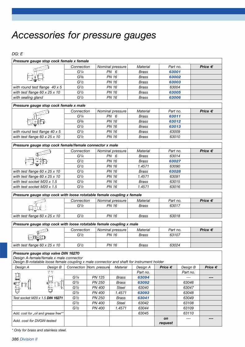
386 Division II
DG: E
* Only for brass and stainless steel.
Accessories for pressure gauges
Pressure gauge stop cock female x female
Connection Nominal pressure Material Part no. Price €G1/4 PN 6 Brass 63001G3/8 PN 16 Brass 63002G1/2 PN 16 Brass 63003
with round test flange 40 x 5 G1/2 PN 16 Brass 63004with test flange 60 x 25 x 10 G1/2 PN 16 Brass 63005with sealing gland G1/2 PN 16 Brass 63006
Pressure gauge stop cock female x male
Connection Nominal pressure Material Part no. Price €G1/4 PN 6 Brass 63011G3/8 PN 16 Brass 63012G1/2 PN 16 Brass 63013
with round test flange 40 x 5 G1/2 PN 16 Brass 63009with test flange 60 x 25 x 10 G1/2 PN 16 Brass 63010
Pressure gauge stop cock female/female connector x male
Connection Nominal pressure Material Part no. Price €G1/4 PN 6 Brass 63014G1/2 PN 16 Brass 63027G1/2 PN 16 1.4571 63090
with test flange 60 x 25 x 10 G1/2 PN 16 Brass 63028with test flange 60 x 25 x 10 G1/2 PN 16 1.4571 63091with test socket M20 x 1.5 G1/2 PN 16 Brass 63015with test socket M20 x 1.5 G1/2 PN 16 1.4571 63016
Pressure gauge stop cock with loose rotatable female coupling x female
Connection Nominal pressure Material Part no. Price €G1/2 PN 16 Brass 63017
with test flange 60 x 25 x 10 G1/2 PN 16 Brass 63018
Pressure gauge stop cock with loose rotatable female coupling x male
Connection Nominal pressure Material Part no. Price €G1/2 PN 16 Brass 63107
with test flange 60 x 25 x 10 G1/2 PN 16 Brass 63024
Pressure gauge stop valve DIN 16270Design A-female/female x male connectorDesign B-rotatable loose female coupling x male connector and shaft for instrument holderDesign A Design B Connection Nom. pressure Material Design A Price € Design B Price €
Part no. Part no.G1/4 PN 125 Brass 63094 --- ---G1/2 PN 250 Brass 63092 63046G1/2 PN 400 Steel 63040 63047G1/2 PN 400 1.4571 63093 63048
Test socket M20 x 1.5 DIN 16271 G1/2 PN 250 Brass 63041 63049G1/2 PN 400 Steel 63042 63108G1/2 PN 400 1.4571 63044 63109
Add. cost for „oil and grease free*“ 63045 63110
Add. cost for DVGW-testedon --- ---
request
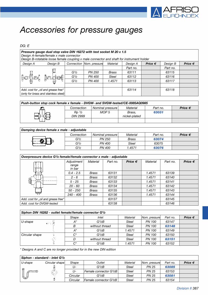
Division II 387
DG: E
Accessories for pressure gauges
Pressure gauge dual stop valve DIN 16272 with test socket M 20 x 1.5Design A-female/female x male connectorDesign B-rotatable loose female coupling x male connector and shaft for instrument holderDesign A Design B Connection Nom. pressure Material Design A Price € Design B Price €
Part no. Part no.G1/2 PN 250 Brass 63111 63115G1/2 PN 400 Steel 63112 63116G1/2 PN 400 1.4571 63113 63117
Add. cost for „oil and grease free“ 63114 63118(only for brass and stainless steel)
Push-button stop cock female x female - DVGW- and SVGW-tested/CE-0085AQ0985
Connection Nominal pressure Material Part no. Price €Rp 1/2 MOP 5 Brass, 63031
DIN 2999 nickel-plated
Damping device female x male - adjustable
Connection Nominal pressure Material Part no. Price €G1/2 PN 250 Brass 63074G1/2 PN 400 Steel 63075G1/2 PN 400 1.4571 63076
Overpressure device G1/2 female/female connector x male - adjustable
Adjustment Material Part no. Price € Material Part no. Price €rangein bar
0.4 - 2.5 Brass 63131 1.4571 631392 - 6 Brass 63132 1.4571 631405 - 25 Brass 63133 1.4571 6314120 - 60 Brass 63134 1.4571 6314250 - 250 Brass 63135 1.4571 63143240 - 400 Brass 63136 1.4571 63144
Add. cost for „oil and grease free“ 63137 63145Add. cost for DVGW-tested 63138 63146
Siphon DIN 16282 - outlet female/female connector G1/2
Shape Inlet Material Nom. pressure Part no. Price €U-shape A* G1/2B Steel PN 100 63147
B without thread Steel PN 100 63148A* G1/2B 1.4571 PN 100 63149
Circular shape C* G1/2B Steel PN 100 63150D without thread Steel PN 100 63151C* G1/2B 1.4571 PN 100 63152
* Designs A and C are no longer provided for in the new DIN edition
Siphon - standard - inlet G1/2
U-shape Circular shape Shape Outlet Material Nom. pressure Part no. Price €U- G1/2B Steel PN 25 63085U- Female connector G1/2B Steel PN 25 63153
Circular G1/2B Steel PN 25 63081Circular Female connector G1/2B Steel PN 25 63154

388 Division II
DG: E
Accessories for pressure gauges
Reducers and adapters
Female connector Male connector Material Part no. Price €G1/8 G1/4 Brass 63050G1/4 G1/8 Brass 63052G1/4 G3/8 Brass 63053G1/4 G1/2 Brass 63054G1/4 G1/2 1.4571 63051G3/8 G1/4 Brass 63056G3/8 G1/2 Brass 63057G1/2 G1/4 Brass 63058G1/2 G3/8 Brass 63059G1/2 M 20 x 1.5 Brass 63155
M 20 x 1.5 G1/2 Brass 63156
Female connector Female connector Material Part no. Price €G1/4 G1/8 Brass 63158G1/4 G1/4 Brass 63159G1/2 G1/4 Brass 63160G1/2 G1/2 Brass 63161
Male connector Male connector Material Part no. Price €G1/2 G1/2 Brass 63164G1/2 G1/2 1.4571 63165
Connection nipple - self-sealing
Female connector Male connector Material Part no. Price €G1/8 G1/4 Brass 63067G1/4 G3/8 Brass 63068G1/4 G1/2 Brass 63069G3/8 G1/2 Brass 63065
Mounting valve with self-sealing coating - closes automatically when the pressure gauge is replaced
Female connector Male connector Material Part no. Price €G1/4 G1/4 Brass 77907G1/4 G3/8 Brass 77908G3/8 G3/8 Brass 77917G1/4 G1/2 Brass 77914G3/8 G1/2 Brass 77918

Division II 389
DG: E
Accessories for pressure gauges
* Other nominal sizes and colours on request.
Union nut + nipple DIN 16284
Female connector Nipple Material Part no. Price €G1/4 6 mm Brass 63072G1/2 12 mm Brass 63084G1/2 12 mm 1.4571 63070
Female/female connector DIN 16283
Female connector Female connector Material Part no. Price €G1/4 left G1/4 Brass 63101G1/4 left G1/4 Steel 63102G1/4 left G1/4 1.4571 63103G1/2 left G1/2 Brass 63104G1/2 left G1/2 Steel 63105G1/2 left G1/2 1.4571 63106
Gauge bracket DIN 16281 - design H
Female connector Protrusion Material Part no. Price €26 mm 60 mm Aluminium 6307726 mm 100 mm Aluminium 6307826 mm 160 mm Aluminium 6307926 mm 100 mm 1.4571 63080
Adapter DIN 16281
Female connector Male connector Material Part no. Price €G1/2 G1/2 Brass 63095G1/2 G1/2 Steel 63097G1/2 G1/2 1.4571 63096
Seals
Design For thread Material Part no. Price €Profile seal for G1/4 Copper 39205
internal centering M 12 x 1.5Profile seal for G1/2 Copper 39206
internal centering M 20 x 1.5Flat gasket G1/4 Copper 39209DIN 16258 M 12 x 1.5Flat gasket G1/2 Copper 39210DIN 16258 M 20 x 1.5Flat gasket G1/2 1.4571 39211DIN 16258 M 20 x 1.5Flat gasket G1/2 PTFE 39212DIN 16258 M 20 x 1.5
Protective covers
Nominal size* Colour* Material Part no. Price €63 blue Rubber 6302963 red Rubber 6310063 black Rubber 6301980 black Rubber 63071
100 black Rubber 63030

390 Division II
Temperature performance
The system is filled at ambientroom temperature. Different tempe-ratures will change the volume ofthe filling liquid causing differencesin pressure readings. By specifyingthe exact operating temperatures atthe time of order, we can counter-act this effect by selecting the mostsuitable filling liquid. If the tempera-tures are higher than +100 °C, the gauge and the dia-phragm seal at the measuring pointshould be separated by a capillarytube or the system should beequipped with a cooling element.
Response time
Using a diaphragm seal will gener-ally result in a slightly delayedresponse of the pressure gauge.This effect can be useful for systemdamping purposes.
Filling liquid
The filling liquid for the diaphragmseal must be selected according tothe minimum and maximum opera-ting temperatures.Furthermore, the filling liquid mustbe compatible with the medium tobe measured as it cannot be ruledout that they may come into con-tact with each other, when a dia-phragm seal is damaged.
ApplicationDiaphragm seals are devices with aseparating diaphragm which areused to separate the measuring unitfrom the medium to be measured.They extend the application rangesof pressure gauges, pressure swit-ches and pressure transducers.
Diaphragm seals are used forthe following:
• Where the medium to be measu-red must not come into contact with the measuring element, for example: the medium is polluted or highly viscous, crystallizes or hardens.
• The medium is corrosive andspecial corrosion resistant materials would have to be used for Bourdon tubes, which is not always possible.
• The ambient temperatures at the measuring point or the tempera-ture of the medium are extremelyhigh.
• For hygienic reasons, there must be no „dead“ space.
• The site conditions do not allow for direct installation of a pressure gauge.
Principle of operation
Diaphragm seals are used in con-junction with Bourdon tube pres-sure gauges, pressure transducersor pressure switches. They are either mounted directly onto the measuring instrument or con-nected via a cooling element or acapillary tube.
The separating element is the maincomponent of a diaphragm seal. Itconsists of either a diaphragm, apipe or an immersion shaft. Thediaphragm type is the most com-monly used diaphragm seals.
It is always a sealed system inwhich the volume between theseparating element and the measu-ring gauge (end of Burdon tube) isfirst evacuated and then filled witha pressure transmission liquid.
The medium to be measured is incontact with the separating elementand causes it to bend which in turncauses a displacement of the volu-me within the system.
The element must have a displace-ment capacity which is sufficient tomove the measuring element of theassociated gauge.The deflection must always takeplace in the elastic area of theseparating diaphragm.This is determined by the diameter,the material and the shape.
Diaphragm seals

Division II 391Refer to page 404 for part no.
Dimensions (in mm) type MD 20
Dimensions (in mm) type MD 10
Diaphragm sealsplastic version/compact version
Type MD 10
ApplicationFor use with Bourdon tube pres-sure gauges or pressure switches.Especially designed for pollutedwaste water, fertilizers, corrosivemedia.
Technical specifications
Process connectionPVC, PP, PVDFFemale thread G1/2 or G1/4
DiaphragmEPDM, PTFE-coated internal
Instrument connectionFemale thread G1/2 or G1/4
Screws and nutsStainless steel
Pressure rangesRefer to price list section
Operating temperature rangePVC, PP -10 °C/+40 °CPVDF -10 °C/+50 °C
Options
• Other process connections• Other materials
Plastic version type MD 10 Compact version type MD 20
Type MD 20
ApplicationFor use with Bourdon tube pres-sure gauges, pressure transducersor pressure switches. For abrasive and polluted media.Specially for the concrete and paintspray industries.
Technical specifications
Process connectionStainless steel 1.4571 (316 Ti)G1/2B, fixed thread
DiaphragmNBR, crimped in
Instrument connectionStainless steel 1.4571 (316 Ti)Female thread G1/4
Filling liquidGlycerine
Pressure rangesRefer to price list section
Nominal pressurePN 60
Operating temperature range-10 °C/+60 °C
Options
• Capillary tube• Other threads• Other materials
G G1 d dM h h1 H SWG1/2B G1/4 26 13.5 21 7 46 27
G d D h HG1/4 25 72 15 71G1/2 32 100 22 90

392 Division II Refer to page 404 for part no.
Diaphragm seals, compact version
Type MD 21
ApplicationFor use with Bourdon tube pres-sure gauges, pressure transducersor pressure switches. For corrosive, hot and pollutedmedia at high pressures. Especiallyfor use in the machinery and che-mical industries.
Technical specifications
Process connectionStainless steel 1.4571 (316 Ti)G1/2B to G2B, fixed thread
DiaphragmStainless steel 1.4571 (316 Ti)flush mounting, welded flush toupper body
Instrument connectionWelded connection
Filling liquidGlycerine
Pressure rangesRefer to price list section
Nominal pressurePN 600 to 1000
Compact version type MD 21 Compact version type MD 22
Options
• Adapter for instrument connection G1/4/G1/2
• Cooling element (> 100 °C)• Capillary tube• Other threads• Other materials
Type MD 22
ApplicationFor use with Bourdon tube pres-sure gauges, pressure transducersor pressure switches. For corrosive, hot and pollutedmedia at high pressures. Especiallyfor use in the machinery and chemical industries.
Technical specifications
Process connectionStainless steel 1.4571 (316 Ti)G1/2B, fixed thread
Upper and lower partStainless steel 1.4571 (316 Ti)welded
DiaphragmStainless steel 1.4571 (316 Ti)internal, welded
Instrument connectionWelded connection
Filling liquidGlycerine
Pressure rangesRefer to price list section
Nominal pressurePN 40 to 250
Options
• Adapter for instrument connection G1/4/G1/2
• Cooling element (> 100 °C)• Capillary tube• Other threads• Other materials• Other filling liquids

Division II 393
Type MD 21
Pipe thread according to ISO 228-1
Type MD 22
Adapter for instrument connection G1/4/G1/2 Cooling element, can be welded at both endswith filling port
Diaphragm seals, compact versionTypes and dimensions (mm)
G d dm h H a b SWG1/2B 26 17.2 17 33.5 3 3 27G3/4B 32 23.5 19 34 3 3 32G1B 39 28 21 36 3 3 41G11/2B 55 40 25 48 3 3 55G2B 68 50 27 56 3 3.5 70
Pipe thread according to ANSI/ASME B1.20.1
G d dm h H a b SW1”NPT - 23.5 24 36 - - 4111/2”NPT - 35 25 45 - - 552”NPT - 48 26 50 - - 70
PN G ØA ØD h H40 G1/4B 55 6 13 44.540 G3/8B 55 6 16 47.540 G1/2B 55 10 20 51.540 1/4”NPT 55 6 15 46.540 1/2”NPT 55 10 20 51.5
250 G1/4B 40 6 13 44.5250 G3/8B 40 6 16 47.5250 G1/2B 40 10 20 51.5250 1/4”NPT 40 6 15 46.5250 1/2”NPT 40 10 20 51.5
up to 200 ºC = ø 27
up to 300 ºC = ø 40
up t
o 20
0ºC
= 8
0
up t
o 30
0ºC
= 1
08
at G
1 /2=
19
G1/4 or G1/2
at G
1 /4=
13
Spanner 22
Spanner 24

394 Division II
Diaphragm seals, standard versionThread connection - type MD 30
ApplicationFor use with Bourdon tube pres-sure gauges, pressure transducersor pressure switches. For corrosive, viscous, polluted orhot media.
Technical specifications
Process connection/lower partStainless steel 1.4571 (316 Ti)G1/2B or 1/2 NPTFemale or male thread
DiaphragmStainless steel 1.4435 (316 L)
SealViton (FPM)
Instrument connection/upper partStainless steel 1.4435 (316 L)Welded connection
Retaining flangesStainless steel 1.4571 (316 Ti)
Spacer ringStainless steel 1.4571 (316 Ti)
Screws and nutsStainless steel A2
Filling liquidSilicone oil
Dimensions (in mm)Pressure rangesRefer to price list section
Nominal pressurePN 25 to 250
Options
Process connection/lower part• Special materials/coatings• Other connection threads
Diaphragm• Special materials/coatings
Seal• Other materials
Instrument connection/upper part• Adapter for instrument
connection G1/4/G1/2• Cooling element (> 100 °C)• Capillary tube
Screws/nuts/spacer ring• Other materials
Miscellaneous• Other filling liquids
Refer to page 405 for part no.
Mounting example
G d1 PN dm D H n SWG1/2 10 25 36 95 60 4xM10 22
G1/2B 10 25 36 95 63 4xM10 221/2-14NPT 10 25 36 95 63 4xM10 22
G1/2 10 100 36 95 60 4xM10 22G1/2B 10 100 36 95 63 4xM10 22
1/2-14NPT 10 100 36 95 63 4xM10 22G1/2 10 250 56 95 56 8xM10 22
G1/2B 10 250 56 95 79 8xM10 221/2-14NPT 10 250 56 95 76 8xM10 22
BoltM10x35 DIN 933
WasherØ 10.5 DIN 125
NutM10 DIN 934
Diaphragm seal
Retainer flangeSpacer ringO-ringRetainer flangeCoupling flange

Division II 395
Accessories
Screws M 6 x 20, galvanized steelSeal („Perbunan“ nitrile rubber) 59 x 48 x 2 mm(included in scope of delivery)
Options
Process connection/tubus• Extended tubus 17 mm
(also suitable for O-ring seal)• Special materials• Silicone-free
Diaphragm• Special materials
Instrument connection• Adapter for instrument
connection G1/4/G1/2• Cooling element (> 100 °C)• Capillary tube
Miscellaneous• Other filling liquids
Mounting accessories• Welding flange
stainless steel 1.4301 (304)
ApplicationFor use with Bourdon tube pres-sure gauges, pressure transducersor pressure switches. For corrosive, highly viscous, polluted or media which tend toharden. Especially designed for usein the paper, pulp and lacquer indu-stries.
Technical specifications
Process connection/tubusStainless steel 1.4571(316 Ti), DN 48loose retaining flange,stainless steel 1.4301 (304)
DiaphragmStainless steel 1.4571 (316 Ti)
Seal„Perbunan“ nitrile rubber
Instrument connectionStainless steel 1.4571 (316 Ti)Welded connection
Filling liquidGlycerine
Pressure rangesRefer to price list section
Nominal pressurePN 40
Diaphragm seal for the paper and pulp industries - type MD 40
Dimensions (in mm)
MD 40
Welding flange (optional)
Refer to page 405 for part no.
Weld connection ø10

396 Division II
Diaphragm seals for hygienic applications
ApplicationFor use with Bourdon tube pres-sure gauges, pressure transducersor pressure switches. For viscous,perishable or hot media. Especiallydesigned for applications in thefood, beverage, pharmaceutical,chemical and biotech industries.
Type summary/process connections
Type MD 50: DIN 11851/11887
Type MD 51: SMS 1147
Type MD 52: Hygienic DIN 11864
Type MD 53: APV-RJT
Type MD 54: IDF
Type MD 55: APV-ISS
Type MD 60: Clamp ISO 2852
Type MD 61: Clamp DIN 32676
Type MD 62: Tri-Clamp
Refer to table on page 397 fornominal diameters.
Technical specificationsMD 50 - MD 55
Process connectionStainless steel 1.4435 (316 L)Male or female thread(grooved union nut stainless steel1.4301/304)
DiaphragmStainless steel 1.4435 (316 L), welded flush to upper body
Instrument connectionWelded connection
Filling liquidVegetable oil, food quality
Pressure rangesRefer to price list section
Nominal pressurePN 25 to 40
Options
• Adapter for instrument connection G1/4/G1/2
• Special materials/coatings• Electrolytically polished• Cooling element (> 100 °C)• Capillary tube• Other filling liquids
Technical specificationsMD 60 - MD 62
Process connectionStainless steel 1.4435 (316 L)Clamp 3/4“ to 3“
DiaphragmStainless steel 1.4435 (316 L), welded flush to upper body
Instrument connectionWelded connection
Filling liquidVegetable oil, food quality
Pressure rangesRefer to price list section
Nominal pressurePN 25 to 40
Options
• Adapter for instrument connection G1/4/G1/2
• Special materials/coatings• Electrolytically polished• Cooling element (> 100 °C)• Capillary tube• Other filling liquids (FDA-
approved)• Accessories (retainer ring, seal,
socket)
Refer to page 406 for part no.

Division II 397
Diaphragm seals for hygienic applicationsTypes and dimensions (mm)
Grooved union nut* Threaded socket*
Clamp connection ISO 2852
* Fig. shows connection DIN 11851
DN PN D dm d H b3/4’’ 40 25 17.2 19 20 3.6
1’’ 40 50.5 26 42 28 2.85
11/2’’ 40 50.5 36 42 28 2.85
2’’ 40 64 48 55 28 2.85
21/2’’ 25 77.5 59 68 28 2.85
3’’ 25 91 72 81 28 2.85
Version DN PN dm G D H25 40 23.5 Rd52 x 1/6 63 1432 40 28 Rd58 x 1/6 70 14
DIN 11851 40 40 36 Rd65 x 1/6 78 1450 25 48 Rd78 x 1/6 92 1565 25 - Rd95 x 1/6 112 -
11/2’’ 40 36 Rd60 x 1/6 74 14SMS norm 2’’ 40 48 Rd70 x 1/6 84 14
21/2’’ 25 - Rd85 x 1/6 100 -
Version DN PN dm G H25 40 23.5 Rd52 x 1/6 2132 40 28 Rd58 x 1/6 21
DIN 11851 40 40 36 Rd65 x 1/6 2150 25 48 Rd78 x 1/6 2165 25 - Rd95 x 1/6 -
11/2’’ 40 36 Rd60 x 1/6 17SMS norm 2’’ 40 48 Rd70 x 1/6 17
21/2’’ 25 - Rd85 x 1/6 -
Adapter for instrument connection G1/4/G1/2 withfilling hole
Cooling element, can be welded at both ends
up t
o 20
0 ºC
= 8
0
up t
o 30
0 ºC
= 1
08
up to 200 ºC =ø 27
up to 300 ºC =ø 40
G1/4 or G1/2Spanner 24
at G
1 /2=
19at
G1 /4
=13
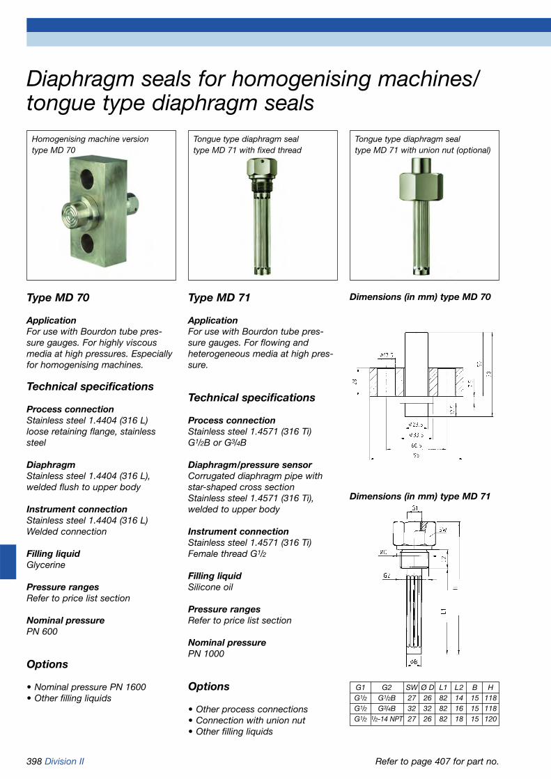
398 Division II
Type MD 71
ApplicationFor use with Bourdon tube pres-sure gauges. For flowing andheterogeneous media at high pres-sure.
Technical specifications
Process connectionStainless steel 1.4571 (316 Ti)G1/2B or G3/4B
Diaphragm/pressure sensorCorrugated diaphragm pipe withstar-shaped cross sectionStainless steel 1.4571 (316 Ti), welded to upper body
Instrument connectionStainless steel 1.4571 (316 Ti)Female thread G1/2
Filling liquidSilicone oil
Pressure rangesRefer to price list section
Nominal pressurePN 1000
Options
• Other process connections• Connection with union nut• Other filling liquids
Dimensions (in mm) type MD 70
Diaphragm seals for homogenising machines/tongue type diaphragm seals
Type MD 70
ApplicationFor use with Bourdon tube pres-sure gauges. For highly viscousmedia at high pressures. Especiallyfor homogenising machines.
Technical specifications
Process connectionStainless steel 1.4404 (316 L)loose retaining flange, stainlesssteel
DiaphragmStainless steel 1.4404 (316 L), welded flush to upper body
Instrument connectionStainless steel 1.4404 (316 L)Welded connection
Filling liquidGlycerine
Pressure rangesRefer to price list section
Nominal pressurePN 600
Options
• Nominal pressure PN 1600• Other filling liquids
Homogenising machine version type MD 70
Tongue type diaphragm seal type MD 71 with fixed thread
Dimensions (in mm) type MD 71
Refer to page 407 for part no.
Tongue type diaphragm seal type MD 71 with union nut (optional)
G1 G2 SW Ø D L1 L2 B HG1/2 G1/2B 27 26 82 14 15 118G1/2 G3/4B 32 32 82 16 15 118G1/2 1/2-14 NPT 27 26 82 18 15 120
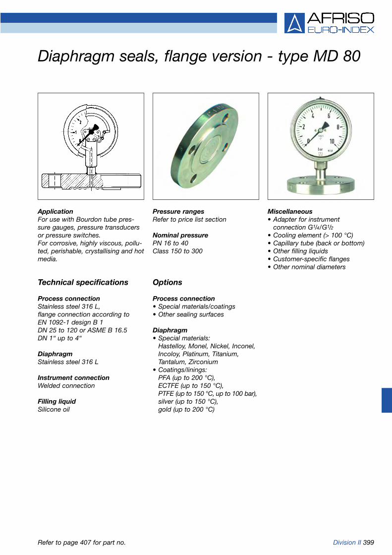
Division II 399
Diaphragm seals, flange version - type MD 80
ApplicationFor use with Bourdon tube pres-sure gauges, pressure transducersor pressure switches. For corrosive, highly viscous, pollu-ted, perishable, crystallising and hotmedia.
Technical specifications
Process connectionStainless steel 316 L,flange connection according to EN 1092-1 design B 1DN 25 to 120 or ASME B 16.5 DN 1“ up to 4“
DiaphragmStainless steel 316 L
Instrument connectionWelded connection
Filling liquidSilicone oil
Pressure rangesRefer to price list section
Nominal pressurePN 16 to 40Class 150 to 300
Options
Process connection• Special materials/coatings• Other sealing surfaces
Diaphragm• Special materials:
Hastelloy, Monel, Nickel, Inconel, Incoloy, Platinum, Titanium, Tantalum, Zirconium
• Coatings/linings: PFA (up to 200 °C), ECTFE (up to 150 °C), PTFE (up to 150 °C, up to 100 bar),silver (up to 150 °C), gold (up to 200 °C)
Miscellaneous• Adapter for instrument
connection G1/4/G1/2• Cooling element (> 100 °C)• Capillary tube (back or bottom)• Other filling liquids• Customer-specific flanges• Other nominal diameters
Refer to page 407 for part no.

400 Division II
DN PN D d1 d2 d3 H h dm25 40 115 68 85 4x14 18 - 3040 40 150 88 110 4x18 18 3 4850 40 165 102 125 4x18 18 3 5980 40 200 138 160 8x18 24 3 89100 40 235 162 190 8x22 24 3 89
DN CL D d1 d2 d3 H h dm
1“ 150 108 50.8 79.4 4x15.9 14.3 1.6 30300 123.9 50.8 88.9 4x19.1 17.5 1.6 30
11/2“ 150 127 73.2 98.6 4x15.9 17.5 1.6 48300 155.6 73.2 114.3 4x22.4 22.4 1.6 48
2“ 150 152.4 92.1 120.7 4x19.1 19.1 1.6 59300 165.1 92.1 127 8x19.1 25.4 1.6 59
3“ 150 190.5 127 152.4 4x19.1 23.9 1.6 89300 209.6 127 168.3 8x22.4 31.8 1.6 89
4“ 150 228.6 157.2 190.5 8x19.1 23.9 1.6 89300 254 157.2 200.1 8x22.3 31.7 1.6 89
Flange connection according to EN 1092-1 design B 1 Flange connection according to ASME B 16.5
Diaphragm seals, flange version - type MD 80Types and dimensions (mm)
Adapter for instrument connection G1/4/G1/2with filling hole
Cooling element, can be welded at both ends
up t
o 20
0 ºC
= 8
0
up t
o 30
0 ºC
= 1
08
up to 200ºC =ø27up to 200 ºC = ø 27
up to 300 ºC = ø 40
at G
1 /2=
19
G1/4 or G1/2
at G
1 /4=
13
Spanner 24
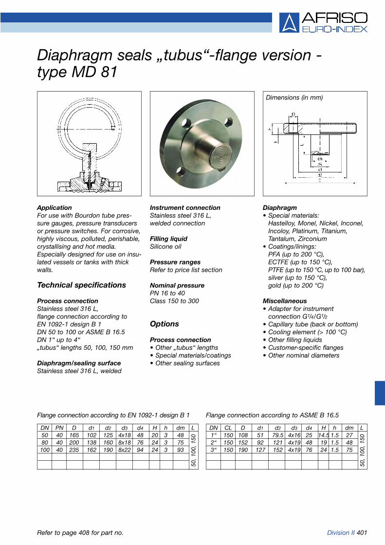
Division II 401
Diaphragm seals „tubus“-flange version - type MD 81
ApplicationFor use with Bourdon tube pres-sure gauges, pressure transducersor pressure switches. For corrosive,highly viscous, polluted, perishable,crystallising and hot media.Especially designed for use on insu-lated vessels or tanks with thickwalls.
Technical specifications
Process connectionStainless steel 316 L,flange connection according to EN 1092-1 design B 1DN 50 to 100 or ASME B 16.5 DN 1“ up to 4“„tubus“ lengths 50, 100, 150 mm
Diaphragm/sealing surfaceStainless steel 316 L, welded
Instrument connectionStainless steel 316 L,welded connection
Filling liquidSilicone oil
Pressure rangesRefer to price list section
Nominal pressurePN 16 to 40Class 150 to 300
Options
Process connection• Other „tubus“ lengths• Special materials/coatings• Other sealing surfaces
Diaphragm• Special materials:
Hastelloy, Monel, Nickel, Inconel, Incoloy, Platinum, Titanium, Tantalum, Zirconium
• Coatings/linings:PFA (up to 200 °C), ECTFE (up to 150 °C), PTFE (up to 150 °C, up to 100 bar),silver (up to 150 °C), gold (up to 200 °C)
Miscellaneous• Adapter for instrument
connection G1/4/G1/2• Capillary tube (back or bottom)• Cooling element (> 100 °C)• Other filling liquids• Customer-specific flanges• Other nominal diameters
Dimensions (in mm)
Flange connection according to EN 1092-1 design B 1 Flange connection according to ASME B 16.5
Refer to page 408 for part no.
DN PN D d1 d2 d3 d4 H h dm L50 40 165 102 125 4x18 48 20 3 4880 40 200 138 160 8x18 76 24 3 75100 40 235 162 190 8x22 94 24 3 93
50, 1
00, 1
50
DN CL D d1 d2 d3 d4 H h dm L1“ 150 108 51 79.5 4x16 25 14.5 1.5 272“ 150 152 92 121 4x19 48 19 1.5 483“ 150 190 127 152 4x19 76 24 1.5 75
50, 1
00, 1
50

402 Division II
In-line chemical seals for hygienic processesIn-line chemical seals with clamp connection
Dimensions (in mm)Type RD 50 DIN 11851/DIN 11887
DIN 11851/DIN 11887
Type RD 60 Clamp ISO 2852
Threaded socket type RD 50 Clamp connection type RD 60
Refer to page 410 for part no.
ApplicationFor use with Bourdon tube pres-sure gauges, pressure transducersor pressure switches. For flowing, corrosive and highly viscous media;designed for direct installation inpipes. Especially designed and suit-able for applications in the bio-chemical, food, beverage and phar-maceutical industries.
Technical specifications
Process connectionType RD 50 DIN 11851, 1.4404 (316 L), male thread DN 15 to DN 100, type RD 51 SMS, 1.4404(316 L), 1“ to 3“, type RD 60 ClampISO 2852, 1.4404 (316 L) 1/2“ to 3“
DiaphragmStainless steel 316 L, welded flushto body
Instrument connectionStainless steel 1.4404 (316 L)Welded connection
Filling liquidVegetable oil, food quality
Pressure rangesRefer to price list section
Nominal pressurePN 40
Options• Coatings• Cooling element (> 100 °C)• Capillary tube• Other filling liquids
DN PN G L D H
15 40 Rd34x1/8 240 16 20
25 40 Rd52x1/6 110 26 24
32 40 Rd58x1/6 110 32 29
40 40 Rd65x1/6 110 38 31.5
50 25 Rd78x1/6 110 50 37
65 25 Rd95x1/6 110 66 45
80 25 Rd110x1/4 60 81 51.5
100 25 Rd130x1/4 60 100 64
DN PN G L D H
1“ (DN25) 40 Rd40x1/6 110 22.2 24
11/2“ (DN38) 40 Rd60x1/6 110 34.8 31.5
2“ (DN51) 25 Rd70x1/6 110 47.8 37
21/2“ (DN63.5) 25 Rd85x1/6 110 60.3 45
3“ (DN76) 25 Rd98x1/6 60 72.9 51.5
DN PN D D1 L H
1“ 40 50.5 22.2 110 24
11/2“ 40 50.5 34.8 110 31.5
2“ 25 64 47.8 110 37
21/2“ 25 77.5 60.3 110 45
3“ 25 91 72.9 60 51.5
Type RD 51 SMS norm
Welded connection
Welded connection
Welded connection
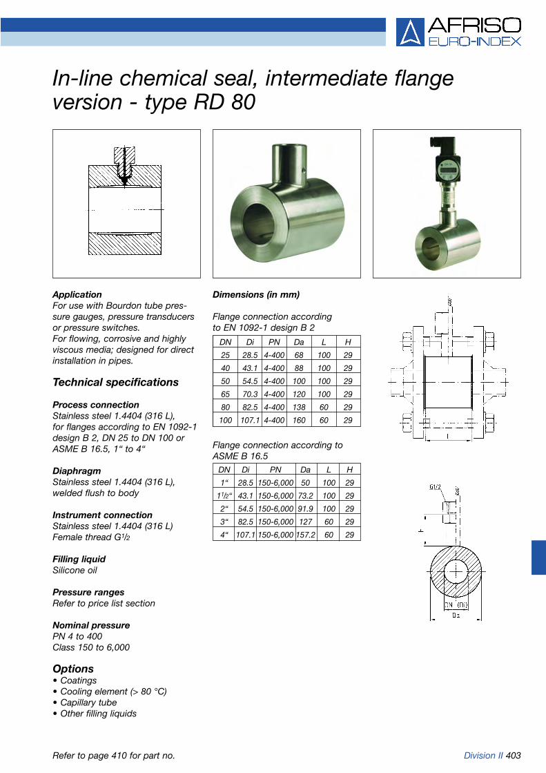
Division II 403
In-line chemical seal, intermediate flange version - type RD 80
ApplicationFor use with Bourdon tube pres-sure gauges, pressure transducersor pressure switches. For flowing, corrosive and highlyviscous media; designed for directinstallation in pipes.
Technical specifications
Process connectionStainless steel 1.4404 (316 L), for flanges according to EN 1092-1design B 2, DN 25 to DN 100 or ASME B 16.5, 1“ to 4“
DiaphragmStainless steel 1.4404 (316 L), welded flush to body
Instrument connectionStainless steel 1.4404 (316 L)Female thread G1/2
Filling liquidSilicone oil
Pressure rangesRefer to price list section
Nominal pressurePN 4 to 400Class 150 to 6,000
Options• Coatings• Cooling element (> 80 °C)• Capillary tube• Other filling liquids
Dimensions (in mm)
Flange connection according to EN 1092-1 design B 2
Flange connection according toASME B 16.5
Refer to page 410 for part no.
DN Di PN Da L H
25 28.5 4-400 68 100 29
40 43.1 4-400 88 100 29
50 54.5 4-400 100 100 29
65 70.3 4-400 120 100 29
80 82.5 4-400 138 60 29
100 107.1 4-400 160 60 29
DN Di PN Da L H
1“ 28.5 150-6,000 50 100 29
11/2“ 43.1 150-6,000 73.2 100 29
2“ 54.5 150-6,000 91.9 100 29
3“ 82.5 150-6,000 127 60 29
4“ 107.1 150-6,000 157.2 60 29

404 Division II
Diaphragm seals, types MD 10/20/21/22
DG: M
* Valid for standard filling liquid, direct mounting (without capillary tube) and at a room and medium temperature of 20 °C.
Additional costs for options, fixtures and accessories see page 411.
MD 10 plastic versionDiaphragm PTFE-coated, PN 10 (PVDF PN 16)Diaphragm Process Instrument Minimum meas. range* Part no. Price €seal body connection connection (in bar) at nominal size
63 100 160 DMU
PVC G1/4 G1/4 1.6 1.6 1.6 --- 31411
PVC G1/2 G1/2 1.6 1.6 1.6 --- 31412
PP G1/4 G1/4 1.6 1.6 1.6 --- 31900
PP G1/2 G1/2 1.6 1.6 1.6 --- 31901
PVDF G1/4 G1/4 4 4 4 --- 31902
PVDF G1/2 G1/2 4 4 4 --- 31903
MD 20 compact versionDiaphragm, crimped in, PN 60
Diaphragm Process Instrument Minimum meas. range* Part no. Price €material connection connection (in bar) at nominal size
63 100 160 DMU
NBR G1/2B G1/4 10 --- --- --- 31413
MD 21 compact versionDiaphragm stainless steel 1.4571, welded
Nominal Process Instrument Minimum meas. range* Part no. Price €pressure connection connection (in bar) at nominal size
63 100 160 DMU
PN 600 G1/2B welded 10 100 100 1 31415W
PN 1,000 G3/4B welded 4 100 100 1 31416W
PN 1,000 G1B welded 4 4 4 1 31328W
PN 600 G11/2B welded 0.6 1.6 1.6 0.6 31329W
PN 600 G2B welded 0.6 0.6 0.6 0.6 31330W on request
MD 22 compact versionDiaphragm stainless steel 1.4571, internal, welded
Nominal Process Instrument Minimum meas. range* Part no. Price €pressure connection connection (in bar) at nominal size
63 100 160 DMU
PN 40 G1/4B welded 0.6 0.6 0.6 0.6 31997W
PN 40 G1/2B welded 0.6 0.6 0.6 0.6 31998W
PN 40 1/2-14 NPT welded 0.6 0.6 0.6 0.6 31999W
PN 250 G1/4B welded 4 4 4 4 32000W
PN 250 G1/2B welded 4 4 4 4 32001W
PN 250 1/2-14 NPT welded 4 4 4 4 32002W

Division II 405
Diaphragm seals, types MD 30/40
DG: M
* Valid for standard filling liquid, direct mounting (without capillary tube) and at a room and medium temperature of 20 °C.
Additional costs for options, fixtures and accessories see page 411.
MD 30 standard version
Nominal Process connection Minimum meas. range* Part no. Price €pressure (in bar) at nominal size
63 100 160 DMU
PN 25 Stainless steel 1.4571, G1/2B 0.6 0.6 0.6 0.6 31417W
PN 100 Stainless steel 1.4571, G1/2B 0.6 0.6 0.6 0.6 31331W
PN 250 Stainless steel 1.4571, G1/2B 0.6 0.6 0.6 0.6 31332W
Additional costs
Process connection G1/2B, PFA-coated on request
Process connection 1/2-14 NPT
Process connection 1/2-14 NPT, PFA-coated on request
Process connection G1/2 female thread no add. costs
Process connection G1/2 female thread, PFA-coated on request
MD 40 version for the paper and pulp industries
Instrument connection stainless steel 1.4571, welded connection Process connection stainless steel 1.4571, DN 48, PN 40 (with seal and screws)Retaining flange 1.4301, ranges 0/1.6 to 0/40 bar*
Part no. Price €
Direct mounting connection 31347W
Spare parts/accessories
6 screws M6 x 20 31418
Spare seal, „Perbunan“ nitrile rubber 59 x 48 x 2 31419
Welding flange 1.4301 31351

406 Division II
Diaphragm seals, types MD 50/51/60
DG: M
Additional costs for options, fixtures and accessories see page 411.
* Valid for standard filling liquid, direct mounting (without capillary tube) and at a room and medium temperature of 20 °C.
MD 50 for hygienic processes, grooved union nut DIN 11851
Nominal width Nominal pressure Minimum meas. range* Part no. Price €DN PN (in bar) at nominal size
63 100 160 DMU
25 40 4 4 4 1 31300W
32 40 0.6 1.6 1.6 0.6 31301W
40 40 0.6 0.6 0.6 0.6 31302W
50 25 0.6 0.6 0.6 0.6 31303W
65 25 0.6 0.6 0.6 0.6 31304W
MD 50 for hygienic processes, threaded socket DIN 11851
Nominal width Nominal pressure Minimum meas. range* Part no. Price €DN PN (in bar) at nominal size
63 100 160 DMU
25 40 4 4 4 1 31306W
32 40 0.6 1.6 1.6 0.6 31307W
40 40 0.6 0.6 0.6 0.6 31308W
50 25 0.6 0.6 0.6 0.6 31309W
65 25 0.6 0.6 0.6 0.6 31310W on request
MD 51 for hygienic processes, grooved union nut SMS 1147
Nominal width Nominal pressure Minimum meas. range* Part no. Price €DN PN (in bar) at nominal size
63 100 160 DMU
11/2’’ 40 0.6 0.6 0.6 0.6 31314W
2’’ 40 0.6 0.6 0.6 0.6 31315W
21/2’’ 25 0.6 0.6 0.6 0.6 31316W on request
MD 51 for hygienic processes, threaded socket SMS 1147
Nominal width Nominal pressure Minimum meas. range* Part no. Price €DN PN (in bar) at nominal size
63 100 160 DMU
11/2’’ 40 0.6 0.6 0.6 0.6 31320W
2’’ 40 0.6 0.6 0.6 0.6 31321W
MD 60 clamp connection ISO 2852
Nominal width Nominal pressure Minimum meas. range* Part no. Price €DN PN (in bar) at nominal size
63 100 160 DMU3/4’’ 40 6 --- --- 1.6 31913W
1’’ 40 4 4 --- 1 31914W
11/2’’ 40 0.6 0.6 1.6 0.6 31324W
2’’ 40 0.6 0.6 0.6 0.6 31325W
21/2’’ 25 0.6 0.6 0.6 0.6 31326W

Division II 407
Diaphragm seals, types MD 70/71/80
DG: M
Additional costs for options, fixtures and accessories see page 409 and 411.
* Valid for standard filling liquid, direct mounting (without capillary tube) and at a room and medium temperature of 20 °C.
MD 70 version for homogenisation machines
Instrument connection stainless steel 1.4404 Part no. Price €Process connection stainless steel 1.4404, DN 23,9, PN 600Ranges 0/100 to 0/600 bar* 31352W
Price reduction without retaining flange netto
MD 71 tongue type diaphragm seal
Instrument connection stainless steel 1.4571, G1/2 Part no. Price €
Process connection stainless steel 1.4571, PN 1000
Ranges 0/60 to 0/1000 bar*
Process connection G1/2B 31353
Process connection G3/4B 31354
MD 80 flange version, flange connection according to EN 1092-1 design B 1
Nominal width Nominal pressure Minimum meas. range* Part no. Price €DN PN (in bar) at nominal size
63 100 160 DMU
25 40 4 4 4 0.6 31333W
40 40 4 4 4 0.6 31336W
50 40 0.6 0.6 0.6 0.6 31339W
80 40 4 4 4 0.6 31385W
100 40 0.6 0.6 0.6 0.6 31388W
MD 80 flange version, flange connection according to ASME B 16.5
Nominal width Nominal pressure Minimum meas. range* Part no. Price €DN Class (in bar) at nominal size
63 100 160 DMU
1’’ 150 4 4 4 0.6 31393W
300 4 4 4 0.6 31394W
11/2’’ 150 4 4 4 0.6 31396W
300 4 4 4 0.6 31397W
2’’ 150 4 4 4 0.6 31399W
300 4 4 4 0.6 31400W
3’’ 150 4 4 4 0.6 31402W
300 4 4 4 0.6 31403W
4’’ 150 4 4 4 0.6 31405W
300 4 4 4 0.6 31406W

408 Division II
* Valid for standard filling liquid, direct mounting (without capillary tube) and at a room and medium temperature of 20 °C.
Diaphragm seals, types MD 81
DG: M
Additional costs for options, fixtures and accessories see pages 409 and 411.
MD 81 „tubus“ flange version, „tubus“ length 50 mm,flange connection according to EN 1092-1 design B 1
Nominal width Nominal pressure Minimum meas. range* Part no. Price €DN PN (in bar) at nominal size
63 100 160 DMU
50 40 1 2.5 --- 4 31917W
80 40 0.6 0.6 1 4 31921W
100 40 0.6 0.6 1 4 31924W
MD 81 „tubus“ flange version, „tubus“ length 50 mm,flange connection according to ASME B 16.5
Nominal width Nominal pressure Minimum meas. range* Part no. Price €DN Class (in bar) at nominal size
63 100 160 DMU
1” 150 4 4 --- 4 31938W
2’’ 150 1 2.5 --- 4 31929W
3’’ 150 0.6 0.6 1 4 31931W
Additional costs €
Nominal width DN
„Tubus“ length 50/2“ 80/3“ 100
100 mm
150 mm

Division II 409
Additional costs for diaphragm seals, types MD 80/81DG: M
* Please enquire for special materials for groove or tongue version.
Additional costs for options, fixtures and accessories see page 411.
Type of sealing surface MD 80 MD 81Additional costs € Additional costs €
Groove, design D EN 1092-1 (for stainless steel) on request
Tongue, design C EN 1092-1 (for stainless steel) on request
Groove, design RJF ASME B 16.5 on request
Capillary connection
Capillary connection, centre back no additional cost no additional cost
Capillary connection, bottom back no additional cost no additional cost
Special materials Nominal widthfor wetted parts*
Hastelloy C276 DN 25 on request
DN 40 on request
DN 50 on request
DN 80 on request
DN 100 on request
Tantalum DN 25 on request
DN 40 on request
DN 50 on request
DN 80 on request
DN 100 on request
Monel 400, Nickel, on request on request
Inconel, Platinum, Titanium
Coatings*
PFA (up to 200 °C) DN 25 on request
DN 40 on request
DN 50 on request
DN 80 on request
DN 100 on request
ECTFE (up to 150 °C) DN 25 on request
DN 40 on request
DN 50 on request
DN 80 on request
DN 100 on request
PTFE, silver, gold on request on request

410 Division II
* Valid for standard filling liquid, direct mounting (without capillary tube) and at a room and medium temperature of 20 °C.
In-line chemical seals, types RD 50/51/60/80
DG: M
Additional costs for options, fixtures and accessories see page 411.
RD 50 for hygienic processes, male thread DIN 11851Nominal width Nominal pressure Minimum meas. range* Part no. Price €
DN PN (in bar) at nominal size
63 100 160 DMU
15 40 1.6 --- --- 4 31952W on request
25 40 1.6 2.5 --- 0.6 31365W
32 40 1 2.5 --- 0.6 31953W
40 40 1 2.5 4 0.6 31366W
50 40 1 2.5 4 0.6 31367W
80 40 1 2.5 4 0.6 31369W
RD 51 for hygienic processes, threaded socket SMS 1147
Nominal width Nominal pressure Minimum meas. range* Part no. Price €DN PN (in bar) at nominal size
63 100 160 DMU
1“ 40 1.6 2.5 --- 1.6 31371W
11/2“ 40 1.6 2.5 4 1.6 31372W
2“ 40 1 1.6 2.5 1.6 31373W
21/2“ 40 1 1.6 2.5 1.6 31374W
3“ 40 1 1.6 1.6 1.6 31375W
RD 60 clamp connection ISO 2852
Nominal width Nominal pressure Minimum meas. range* Part no. Price €DN PN (in bar) at nominal size
63 100 160 DMU
1“ 40 1.6 2.5 --- 1.6 31377W
11/2“ 40 1.6 2.5 4 1.6 31378W
2“ 40 1.6 2.5 2.5 1 31379W
21/2“ 40 1.6 2.5 2.5 1 31380W
3“ 40 1.6 2.5 2.5 1 31381W
RD 80 intermediate flange version for flanges according to EN 1092-1 design B 2
Nominal width Nominal pressure Minimum meas. range* Part no. Price €DN PN (in bar) at nominal size
63 100 160 DMU
25 4-400 1.6 2.5 --- 1.6 31355
40 4-400 1.6 2.5 4 1.6 31356
50 4-400 1.6 2.5 2.5 1 31357
65 4-400 1.6 2.5 2.5 1 31956
80 4-400 1.6 2.5 2.5 1 31358
RD 80 intermediate flange version for flanges according to ASME B 16.5
Nominal width Nominal pressure Minimum meas. range* Part no. Price €DN Class (in bar) at nominal size
63 100 160 DMU
1“ 150-6,000 1.6 2.5 --- 1.6 31360
11/2“ 150-6,000 1.6 2.5 4 1.6 31361
2“ 150-6,000 1.6 2.5 2.5 1 31362
3“ 150-6,000 1.6 2.5 2.5 1 31363
4“ 150-6,000 1.6 2.5 2.5 1 31364

Division II 411
Diaphragm seals - fitting costs and accessories
1) For differential pressure measuring devices = twice the additional cost 3) Only at positive overpressure2) Please enquire for other makes or measuring instruments 4) Up to a maximum of 160 bar
DG : M
The fitting costs include the mounting of the pressure gauge or pressure transducer to the diaphragm seal, filling of the system with transmission fluid, securing the screw connections and calibration of the system at a room temperature of +20 °C.The final price is made up of the price for the pressure gauge, the price for the diaphragm seal and the fitting cost as well asthe price for options and/or accessories, where applicable.
Fitting costs € 1) Length of Fitting to AFRISO Fitting to AFRISOcapillary tube Bourdon tube pressure gauges 2) pressure transducers 2)
Direct mounting (at >100 °C it Part no. Price € Part no. Price €is advisable to use a coolingelement or a capillary tube) --- 32007 32016
Fitting with capillary tube 1 metre 32008 32017
Capillary tube stainless steel 2 metres 32009 32018
1.4571, screwed or welded 3 metres 32010 32019
to diaphragm seal, with kink 4 metres 32011 32020
protection and connection piece 5 metres 32012 32021
for instrument bracket 6 metres 32013 32022
8 metres 32014 32023
10 metres 32015 32052
other on request on request
Additional costs Price €
Spiral protection hose per metre
Calibration of filled system at operating temperaturesother than +20 °C (between +20 and +100 °C), with dial marking tA = x °C dial
Calibration of filled system at operating temperaturesother than +20 °C (between 100 and +180 °C),with dial marking tA = x °C dial
Other filling liquids Operating tempe-rature range 3)
FM 01 Silicone oil -20/+200 °C Standard/no additional cost
FM 02 Silicone oil -90/+100 °C
FM 03 Glycerine 0/+230 °C Standard/no additional cost
FM 04 Glycerine/water -10/+120 °C no additional cost
FM 05 Vegetable oil -10/+250 °C Standard/no additional cost
FM 06 High temperature oil -10/+300 °C
FM 07 High temperature oil -10/+400 °C
FM 08 Halocarbon 4) -40/+175 °C(for oxygen or chlorine)
FM 09 Paraffin oil -10/+220 °C(FDA-compliant)
Accessories Version Part no. Price € Version Part no. Price €
Adapter for instrument connec- Instrument Instrumenttion with thread and filling port, connection 32003 connection 32004for welding to diaphragm seal G1/4 female G1/2 female
Cooling element, can be Up to Tmax Up to Tmaxwelded at both ends (only medium 32005 medium 32006factory-fitted) 200°C (Ø 27) 300°C (Ø 40)
Cooling element, screw Up to Tmax Up to Tmaxconnection at both ends medium 31420 medium 31421G1/2 female x male 200°C (Ø 27) 300°C (Ø 40)

412 Division II
Pressure switches DS 600
Refer to page 413 for part no.
Type DS 600/200
Switching pointSet to 1 bar (can be factory-adjusted between 0.5 and 6 bar)
Overpressure safety7 bar
Switching differential0.3 bar
Pressure connectionBrass, R1/4 DIN 2999, fixed thread
HousingPlastic/sheet steelW x H x D: 44 x 29 x 32 mm
ProtectionIP 00 (EN 60529)
Contact ratingK1 16 (4) A AC 250 VK1-2 6 (1) A AC 400 V
Switching diagram
Type DS 600/220
Switching pointSet to 1 bar (can be factory-adjusted between 1 and 6 bar)
Overpressure safety7 bar
Switching differential0.3 bar
Pressure connection/capillaryBrass, G1/4B, pressure screw (rotatable), capillary length 1,000 mm
HousingPlastic/sheet steelW x H x D: 44 x 37 x 34 mm
ProtectionIP 00 (EN 60529)
Contact ratingK1 16 (4) A AC 250 VK1-2 6 (1) A AC 400 V
Switching diagram
Type DS 600/250
Switching pointFactory pre-set to required value between 0.5 und 6 bar
Overpressure safety2 bar greater than switching point
Switching differential0.3 bar
Pressure connectionBrass, R1/4 DIN 2999, fixed thread
HousingPlastic/stainless steel34 x 26 mm (Ø x H)
ProtectionIP 00 (EN 60529)
Contact ratingK1 16 (4) A AC 250 VK1-2 6 (1) A AC 400 V
Switching diagram
Options• Fixed cable connection with
1 metre cable• Other switching points
+ ++
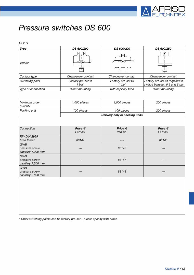
Division II 413
Pressure switches DS 600
* Other switching points can be factory pre-set – please specify with order.
DG: H
Type DS 600/200 DS 600/220 DS 600/250
Version
Contact type Changeover contact Changeover contact Changeover contact
Switching point Factory pre-set to Factory pre-set to Factory pre-set as required to1 bar* 1 bar* a value between 0.5 and 6 bar
Type of connection direct mounting with capillary tube direct mounting
Minimum order 1,000 pieces 1,000 pieces 200 piecesquantity
Packing unit 100 pieces 100 pieces 200 pieces
Delivery only in packing units
Connection Price € Price € Price €Part no. Part no. Part no.
R1/4 DIN 2999fixed thread 88142 --- 88140
G1/4Bpressure screw --- 88146 ---capillary 1,000 mm
G1/4Bpressure screw --- 88147 ---capillary 1,500 mm
G1/4Bpressure screw --- 88148 ---capillary 2,000 mm

414 Division II
ApplicationSuitable for all practically neutralmedia such as process water, hea-ting water, neutral gases, oils.Suitable for two-point control bymeans of a continuously adjustableswitching point (between 10 and100 % of pressure range).
FunctionA robust diaphragm type movementserves as the basis for this unit. It issuitable for pressure, vacuum anddifferential pressure measurements.The unit uses the same principle ofoperation for all three measuringapplications. The pressure or thedifferential pressure applies a forceto one side of the diaphragm. Thisforce displaces the diaphragmsystem and moves the measure-ment range spring. A switchingplunger fixed to the diaphragmactuates an electrical switching ele-ment. The switching point is adjust-ed via a knurled knob according tothe scale.
Pressure ranges0/0.6 to 0/4 bar
Maximum static pressure16 bar, device is overpressure-proofup to 16 bar and vacuum-proof
Differential pressure switches DS 01
Dimensions (in mm)
Operating temperature rangeMedium: Tmax = +80 °C Ambient: Tmax = +80 °C
Connection2 x G1/8 female thread
Pressure chamberBrass
DiaphragmNBR
MountingBracket for wall mounting
Electrical connectionCable gland M 12 x 1.5
Switching point10-100 % of pressure range, con-tinuously adjustable
ContactMicroswitch, normally closed ornormally open
Hysteresisapprox. 2 %
Max. ratingU ... AC/DC 250 V, I ... 3 AP ... 500 VA/250 W
Dimensions (in mm)
26 Pipe Ø 6
* Please specify required switching function (normally closed/normally open)
DG: H
Pressure range Part no. Price €
0/0.6 bar 88103
0/1 bar 88104
0/1.6 bar 88105
0/2.5 bar 88107
0/4 bar 88106
Additional costs - options
DG: H
Option Part no. Price €
Diaphragm FKM 88125
Fixed cable 881262.5 m*
Compression 88120fitting for6 mm pipe, steel
Compression 88108fitting for6 mm pipe, brass
Compression 88114fitting for8 mm pipe, brass
M 12 x 1.5

Division II 415
Supply voltageDC 12-36 V
Output signal4-20 mA, 2-wire
Load4-20 mA < UB (V) – 12 V [Ohm]
0,02 A
Current input4-20 mA < 30 mA
Protective electrical measuresShort circuit proof and polarity pro-tected
Electrical connection (protection)Plug and junction boxDIN 43650-A (IP 65)
CE conformity (EMC)EN 61326
Options
• Fixed cable connection• Other output signals
Measuring rangesRelative pressure: 0/1.6 to 0/100 bar
Overpressure safetyAt least 2 x FS(burst pressure at least 3 x FS)
Operating temperature rangeMedium: -25 °C/+125 °CAmbient: -25 °C/ +85 °CStorage: -40 °C/+125 °C
Temperature error bandIn compensated range 0-70 °C < 0.5 % FSO/10 K
Dynamic characteristicsResponse time < 10 ms
Process connectionG1/4B, DIN 3852
MaterialsHousing: stainless steel 1.4305Pressure-connection: stainless steel 1.4305Diaphragm: ceramic AI203 96 %Seal: FKM (Viton)
Pressure transducer DMU 01KCompact version
Dimensions (in mm) Wiring diagram
ApplicationSpecial OEM unit. For electronicpressure measurement in industrialor HVAC applications (such ashydraulic, pneumatic, automation,heating or air conditioning).
DescriptionThe DMU 01K pressure transducersuse proven ceramic measuring celltechnology and feature calibrated,amplified sensor signals which areavailable as standardised currentoutputs.
DMU 01K features:• Compact design• Superior price/performance ratio
due to automated mass produc-tion
• High temperature resistance• No mechanical ageing
Accuracy of measurementDeviation characteristics accordingto IEC 60770 - limit point setting(non-linearity, hysteresis, repeatability): < ±1 % FSO
Refer to page 420 for part no.
Supply +
Supply -

416 Division II
Current input4-20 mA < 25 mA0-10 V < 7 mA
Protective electrical measuresShort circuit proof and polarity protected
Electrical connection (protection)Plug and junction boxDIN 43650-A (IP 65)
CE conformity (EMC)EN 61326
Options
• Other connection threads• Fixed cable connection• Other plug-in connectors• Fitting of diaphragm seals
(measuring range > 0/10 bar)
Operating temperature rangeMedium: -25 °C/+125 °CAmbient: -25 °C/ +85 °CStorage: -40 °C/+100 °C
Temperature error bandIn compensated range < ±0.3 % FSO/10 K
Dynamic characteristicsResponse time < 10 ms
Process connectionG1/2B (EN 837-1/7.3) or G1/2B DIN 3852 with flush mounteddiaphragm (up to 0/25 bar max.)
MaterialsHousing: stainless steel 1.4305Pressure-connection: stainless steel 1.4305Diaphragm: ceramic AI203 96 %Seal: FKM (Viton), NBR for
100 bar and above
Output signal/supply voltage4-20 mA DC 12-36 V2-wire0-10 V DC 14-36 V3-wire
Load4-20 mA < UB (V) – 12 V [Ohm]
0.02 A 0-10 V > 10 kOhm
Pressure transducers DMU 01Standard version
Flush mounted diaphragm DMU 01 with DA 06 plug-in local display
ApplicationFor electronic pressure measure-ment in industrial applications (such as hydraulic and pneumaticapplications as well as machine andplant construction).
DescriptionThe DMU 01 pressure transducersuse proven ceramic measurementcell technology and feature calibra-ted, amplified sensor signals whichare available as standardised volt-age or current outputs.
DMU 01 features:• High temperature resistance• No mechanical ageing• No transmission liquid
Accuracy of measurementDeviation characteristics accordingto IEC 60770 - limit point setting(non-linearity, hysteresis, repeatabi-lity): < ±0,5 % FSO
Measuring rangesRelative pressure: -1/0 to 0/400 barAbsolute pressure: 0/1 to 0/400 bar
Overpressure safety< 250 bar min. 2 x FS> 250 bar min. 1.5 x FS(burst pressure min. 3 x FS)
Refer to pages 420/421 for part no.

Division II 417
Connection G1/2BEN 837
With diaphragm seal MD 30 - connection G1/2B
The units are shipped with a detailed wiring diagram.
Pressure transducers DMU 01Dimensions (in mm) and electrical connections
Wiring diagrams
2-wire
3-wire
Connection G1/4BEN 837
Connection G1/2B DIN 3852 with flush mounted diaphragm
4-20 mA
0-10 V
Pin assignment table
2-wire system: Supply +(4-20 mA) Supply –
Earth
3-wire system: Supply +(0-10 V) Supply –
Signal +Earth
Plug
DIN 43650
1
2
Earth pin
1
2
3
Earth pin
Cable colours
(DIN 47100)
white
brown
Screen
white
brown
green
Screen
ap. 1
95With diaphragm seal MD 80 - flange connection EN 1092-1
ap. 36 ap. 36 ap. 36
Flat gasket FKM(Viton)
Detail A
ap. 1
43
MD 80e.g. DN 25/PN 40
ap. 1
91,5
MD 30e.g. PN 250
Supply +
Supply -
Supply -
Signal +
Supply +

418 Division II
ApplicationFor electronic pressure measure-ment in machine and plant con-struction applications as well as inchemical and process technologyapplications. With flush mounteddiaphragm, the units are suitable foruse with sticky, highly viscous orcrystallising media.
DescriptionThe DMU 03 pressure transducersuse piezo-resistive stainless steelmeasuring cells and feature calibra-ted, amplified sensor signals whichare available as standardised volt-age or current outputs.
DMU 03 is available in the following versions:
• Threaded connection• Flush mounted diaphragm• Ex version (DMU 03Ex)• Weatherproof housing version• Weatherproof housing version
with display
Accuracy of measurementDeviation characteristic accordingto IEC 60770 - limit point setting(non-linearity, hysteresis, repeatabi-lity): < ±0.35 % FSO(measuring ranges 0/40 mbar to0/400 mbar < ±0.5 % FSO)
Long-term stability< ±0.1 % FSO/year
Measuring rangesRelative: 0/40 mbar to 0/600 barAbsolute: 0/100 mbar to 0/600 bar
Overpressure safety< 250 bar min. 2 x FS> 250 bar min. 1.5 x FS(burst pressure min. 3 x FS)
Operating temperature rangeMedium: -25 °C/+125 °C Ambient: -25 °C/ +85 °CStorage: -40 °C/+100 °C
Temperature error bandIn compensated range 0-70 °C < 1 % FSO (< 0.25 bar < 2 % FSO)
Dynamic characteristicsResponse time < 10 ms
Process connectionG1/2B (EN 837-1/7.3) or G1/2B DIN 3852 with flush mounted diaphragm (0/100 mbar to 0/40 bar)
MaterialsHousing: stainless steel 1.4301Pressure-connection: stainless steel 1.4571Diaphragm: stainless steel 1.4435Seal: FKM (Viton), NBR for
60 bar and above
Pressure transmission liquidSilicone oil
Pressure transducers DMU 03Industrial version
Flush mounted diaphragm
with display
Weatherproof housing version(optional)
Output signal/supply voltage4-20 mA DC 12-36 V2-wireEx version DC 14-28 V0-20 mA DC 14-36 V3-wire0-10 V DC 14-36 V3-wire
Load4-20 mA < UB (V) – 12 V [Ohm]
0.02 A 0-20 mA < 500 Ohm0-10 V > 10 kOhm
Current input4-20 mA < 25 mA0-20 mA < 25 mA0-10 V < 7 mA
Protective electrical measuresShort circuit proof and polarity protected
Electrical connection (protection)Plug and junction box DIN 43650-A (IP 65)
CE conformity (EMC)EN 61326
Options• Ex version (II 1 G EEx ia IIC T4)• Other process connections• Other electrical connections• Weatherproof housing
(stainless steel 1.4305)• Weatherproof housing with display• Other seal materials• CANopen interface• Higher accuracy• Greater overpressure safety• Diaphragm seal mounting
Refer to pages 420/421 for part no.

Division II 419
Connection G1/2BEN 837
Weatherproof housing Electrical connections
The units are supplied with a detailed wiring diagram.
Pressure transducers DMU 03Dimensions (in mm) and electrical connections
Wiring diagram
2-wire
3-wire
Connection G1/4BEN 837
Connection G1/2B DIN 3852 with flush mounted diaphragm
4-20 mA
0-10 V
The Ex version is 20 mm longer. The Ex version is 20 mm longer.
The Ex version is 26.5 mm longer.
DIN 43650 „Binder“ plug 723 „Buccaneer“ plug
0-20 mA
Pin assignment table
Plug
DIN 43650
1
2
Earth pin
1
2
3
Earth pin
Cable colours(DIN 47100)
white
brown
Screen
white
brown
green
Screen
2-wire system: Supply +(4-20 mA) Supply –
Earth
3-wire system: Supply +(0-10 V, Supply –
0-20 mA) Signal +Earth
ap. 60
Cable glandPg 13,5 IP 68
ap. 36 ap. 36 ap. 36
Detail A
Supply +
Supply -
Supply +
Supply -
Signal +
Supply +
Supply -
Signal +
O-Ring FKM(Viton)

420 Division II
DG: H
Pressure transducers
* Delivery only in packing units of 10 pieces per measuring range.
Type DMU 01 K* DMU 01 DMU 01 VM DMU 03 DMU 03 VM
Version
Measuring principle Piezo-resistive ceramic measuring cell Piezo-resistive stainless steel meas. cellAccuracy 1 % FSO 0.5 % FSO 0.5 % FSO 0.35 % FSO 0.35 % FSO(IEC 60770) (< 0.4 bar 0.5 % FSO) (< 0.4 bar 0.5 % FSO)
Wetted parts Ceramic/stainless steel 1.4305 Stainless steel 1.4571/1.4435Connection G1/4B G1/2B G1/2B DIN 3852 G1/2B G1/2B
DIN 3852 EN 837 with flush mounted diaphragm EN 837 with flush mounted diaphragm
Supply voltage DC 12-36 V DC 12-36 V DC 12-36 V DC 12-36 V DC 12-36 VOutput 4-20 mA 4-20 mA 4-20 mA 4-20 mA 4-20 mASystem 2-wire 2-wire 2-wire 2-wire 2-wireElectrical Plug Plug Plug Plug PlugConnection DIN 43650-A DIN 43650-A DIN 43650-A DIN 43650-A DIN 43650-A
Measuring range Part no. Part no. Part no. Part no. Part no.Price €-1/0 bar --- 31114 31619 31634 ----1/+1.5 bar 31608 31616 31620 31635 ----1/+3 bar 31609 31617 31621 31636 ----1/+5 bar 31610 31618 31622 31637 ---
Price €0/40 mbar --- --- --- 32024 ---0/60 mbar --- --- --- 32025 ---0/100 mbar --- --- --- 31638 316430/160 mbar --- --- --- 31639 316440/250 mbar --- --- --- 31145 311650/400 mbar --- --- --- 31146 311660/600 mbar --- --- --- 31147 31167
Price €0/1 bar --- 31115 31623 31148 311680/1.6 bar 31511 31116 31624 31149 311690/2.5 bar 31512 31117 31625 31150 311700/4 bar 31513 31118 31626 31151 311710/6 bar 31514 31119 31627 31152 311720/10 bar 31515 31120 31628 31153 311730/16 bar 31516 31121 31629 31154 311740/25 bar 31517 31122 31630 31155 311750/40 bar 31518 31123 --- 31156 320260/60 bar 31611 31124 --- 31157 ---0/100 bar 31612 31125 --- 31158 ---
Price €0/160 bar --- 31126 --- 31159 ---0/250 bar --- 31127 --- 31160 ---0/400 bar --- 31128 --- 31161 ---0/600 bar --- --- --- 31162 ---

Division II 421
DG: H
Additional costs for pressure transducers
Type DMU 01 DMU 01 VM DMU 03 DMU 03 VM
Version
Price € Price € Price € Price €
Ex protection II 1 G EEx ia IIC T4 --- ---
Connection G1/4 DIN 3852 --- --- ---
Connection G1/2 DIN 3852 --- standard no add. cost standard
Connection G1/4B EN 837 --- ---
Connection 1/4 NPT --- ---
Connection 1/2 NPT --- ---
Other connections on request on request on request on request
Suitable for oxygen --- ---
Weatherpr. housing (stainl. steel 1.4305) --- ---
Weatherproof housing with --- ---display (as DA 06)
„Binder“ plug 723 --- ---
Fixed cable connection 2 metres
Cable extension per metre
Output 0-20 mA, 3 wires --- ---
Output 0-10 V, 3 wires
Other output signals on request on request on request on request
Absolute pressure (measuring rangesaccording to data sheet)
Accuracy of measurement 0.25 % FSO --- ---
Calibration certificate (for accuracy --- ---of measurement 0.25 % FSO)
Fitting of diaphragm seal for measuring range 0/10 bar All measuring ranges, minimum range depends on design of diaphragm seal
Refer to chapter 14 for digital display units and signal processing.

422 Division II
ApplicationFor applications requiring hygienicprocess connections, materials orprocessing, especially in food tech-nology, pharmaceutical and biotechapplications.
DescriptionThe DMU 04 pressure transducersuse piezo-resistive measuring cellsand feature calibrated, amplifiedsensor signals which are availableas standardised voltage or currentoutputs.
DMU 04 is available in the following versions:• Flush diaphragm• Various process connections• Ex version (DMU 04Ex)• High temperature version up
to 300 °C (DMU 04HT)• Weatherproof housing version• Weatherproof housing version
with display
Accuracy of measurementDeviation characteristics accordingto IEC 60770 - limit point setting(non-linearity, hysteresis, repeatability): < ±0.35 % FSO (ranges < 0/400 mbar < ±0.5 % FSO)
Measuring rangesRelative: 0/100 mbar to 0/400 barAbsolute: 0/600 mbar to 0/400 bar
Overpressure safety< 250 bar min. 2 x FS> 250 bar min. 1.5 x FS(burst pressure min. 3 x FS)
Operating temperature rangeMedium: -25 °C/+125 °C Ambient: -25 °C/ +85 °CStorage: -40 °C/+100 °C
Temperature error bandIn compensated range 0-70 °C < 1 % FSO (< 0.25 bar < 2 % FSO)
Dynamic characteristicsResponse time < 10 ms
Process connectionsG1/2B DIN 3852 with flush diaphragm(> 0/2.5 bar), G1B DIN 3852, clamp 1“/11/2“/2“ ISO 2852, conical dairy fitting DIN 11851 DN 25/40/50 (without union nut)
MaterialsHousing: stainless steel 1.4301Pressure-connection: stainless steel 1.4435Diaphragm: stainless steel 1.4435
Pressure transmission liquidFood quality oil
Output signal/supply voltage4-20 mA DC 12-36 V2-wireEx version DC 14-28 V0-20 mA DC 14-36 V3-wire0-10 V DC 14-36 V3-wire
Pressure transducers DMU 04 for hygienic processes
Clamp connection
Load 4-20 mA < UB (V) – 12 V [Ohm]
0.02 A 0-20 mA < 500 Ohm0-10 V > 10 kOhm
Current input4-20 mA < 25 mA0-20 mA < 25 mA0-10 V < 7 mA
Protective electrical measuresShort circuit proof and polarity pro-tected
Electrical connection (protection)Plug and junction boxDIN 43650-A (IP 65)
CE conformity (EMC)EN 61326
Options
• Ex version (II 1 G EEx ia IIC T4)• Other process connections• Other electrical connections• Weatherproof housing• Weatherproof housing with
display• High temperature version• Higher accuracy• Union nut DN 25/40/50
Refer to pages 426/427 for part no.
High temperature version(optional)
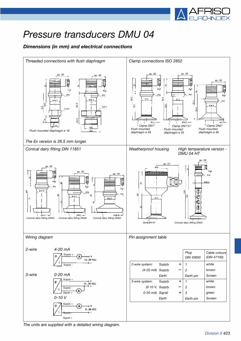
Division II 423
Pressure transducers DMU 04Dimensions (in mm) and electrical connections
Threaded connections with flush diaphragm
Conical dairy fitting DIN 11851 Weatherproof housing
The units are supplied with a detailed wiring diagram.
Wiring diagram
2-wire 4-20 mA
3-wire 0-20 mA
Clamp connections ISO 2852
The Ex version is 26.5 mm longer.
Pin assignment table
Plug
DIN 43650
1
2
Earth pin
1
2
3
Earth pin
Cable colours(DIN 47100)
white
brown
Screen
white
brown
green
Screen
2-wire system: Supply +(4-20 mA) Supply –
Earth
3-wire system: Supply +(0-10 V, Supply –
0-20 mA) Signal +Earth0-10 V
High temperature version -DMU 04 HT
62.5
20.5
Flush mounted diaphragm ø 18
ap. 36 ap. 36ap. 36 ap. 36
ap. 36
Clamp DN1“Flush mounted diaphragm ø 28
Clamp DN11/2“Flush mounted diaphragm ø 35
Clamp DN2“Flush mounted diaphragm ø 46
ap. 36
ap. 36ap. 36
Conical dairy fitting DN25 Conical dairy fitting DN40 Conical dairy fitting DN50
ap. 57
ap. 36
Conical dairy fitting DN50
Supply +
Supply -
Supply +
Supply -
Signal +
Supply +
Supply -
Signal +

424 Division II
ApplicationFor electronic pressure measure-ment in applications requiring highaccuracy of measurement andlong-term stability. Applicationareas include: process technology,electroplating, water treatment,laboratory applications as well asmeasurements of gas consumptionand heat energy.
DescriptionThe intelligent DMU 05 pressuretransducers are equipped with digital amplifier electronics (micro-processor and 16 bit A/D conver-ter). DMU 05 actively compensatesfor sensor-specific deviations (non-linearity and temperatureerror), allowing for superior measu-ring characteristics. DMU 05 canalso be supplied with an optionaldigital RS 232 interface for settingoffset, range and damping.
Accuracy of measurementDeviation characteristics accordingto IEC 60770 - limit point setting(non-linearity, hysteresis, repeatability): < ±0.1 % FSO
Long-term stability< ±0.1 % FSO/year
Measuring rangesRelative: 0/160 mbar to 0/600 barAbsolute: 0/160 mbar to 0/600 bar
Overpressure safety< 250 bar min. 2 x FS> 250 bar min. 1.5 x FS(burst pressure min. 3 x FS)
Operating temperature rangeMedium: -25 °C/+125 °CAmbient: -25 °C/ +85 °C Storage: -40 °C/+100 °C
Temperature error bandIn compensated range -20/+80 °C < 0.2 % FSO
Dynamic characteristicsResponse time < 40 ms
Process connectionG1/2B (EN 837-1/7.3) or G1/2B DIN 3852 with flush mounteddiaphragm (up to 0/25 bar)
MaterialsHousing: stainless steel 1.4301Pressure-connection: stainless steel 1.4571Diaphragm: stainless steel 1.4435Seal: FKM (Viton), NBR for
40 bar and above
Pressure transmission liquidSilicone oil
Pressure transducers DMU 05 PPrecision version
Output signal/supply voltage4-20 mA DC 12-36 V2-wireEx version DC 14-28 V
Load4-20 mA < UB (V) – 12 V [Ohm]
0.02 A
Current input4-20 mA < 25 mA
Protective electrical measuresShort circuit proof and polarity pro-tected
Electrical connection (protection)Plug and junction boxDIN 43650-A (IP 65)
CE conformity (EMC)EN 61326
Options
• RS 232 (interface and softwarerequired)
• Ex version (II 1 G EEx ia IIC T4)• Other process connections• Other electrical connections• Other seal materials
Refer to pages 426/427 for part no.
Flush mounted diaphragm

Division II 425
Screw-in version for level measurement Electrical connections
The units are supplied with a detailed wiring diagram.
Pressure transducers DMU 05Dimensions (in mm) and electrical connections
Pin assignment table
1) Software, interface and cable must be ordered separately.
Connection G1/2B EN 837
Electrical connections
DIN 43650 „Binder“ plug 723 „Binder“ plug 723(5 poles) (7 poles)
2-wire system: Supply + 1 3 3Supply – 2 4 1Earth Earth contact 5 2
RS 232 1) RxD – – 4TxD 5CTS 6GND 7
DIN 43650 „Binder“ plug 723 „Buccaneer“ plug
Connection G1/2B DIN 3852 with flush mounted diaphragm
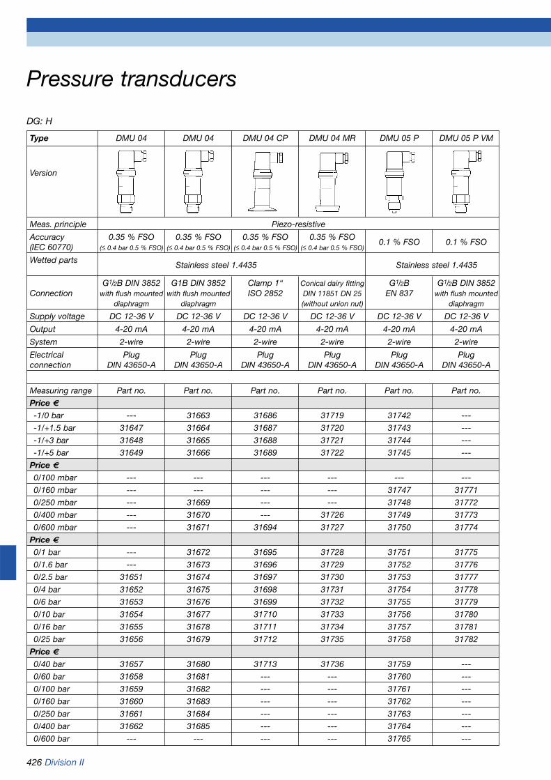
426 Division II
DG: H
Pressure transducers
Type DMU 04 DMU 04 DMU 04 CP DMU 04 MR DMU 05 P DMU 05 P VM
Version
Meas. principle Piezo-resistive
Accuracy 0.35 % FSO 0.35 % FSO 0.35 % FSO 0.35 % FSO0.1 % FSO 0.1 % FSO
(IEC 60770) (< 0.4 bar 0.5 % FSO) (< 0.4 bar 0.5 % FSO) (< 0.4 bar 0.5 % FSO) (< 0.4 bar 0.5 % FSO)
Wetted partsStainless steel 1.4435 Stainless steel 1.4435
G1/2B DIN 3852 G1B DIN 3852 Clamp 1“ Conical dairy fitting G1/2B G1/2B DIN 3852Connection with flush mounted with flush mounted ISO 2852 DIN 11851 DN 25 EN 837 with flush mounted
diaphragm diaphragm (without union nut) diaphragm
Supply voltage DC 12-36 V DC 12-36 V DC 12-36 V DC 12-36 V DC 12-36 V DC 12-36 V
Output 4-20 mA 4-20 mA 4-20 mA 4-20 mA 4-20 mA 4-20 mA
System 2-wire 2-wire 2-wire 2-wire 2-wire 2-wire
Electrical Plug Plug Plug Plug Plug Plugconnection DIN 43650-A DIN 43650-A DIN 43650-A DIN 43650-A DIN 43650-A DIN 43650-A
Measuring range Part no. Part no. Part no. Part no. Part no. Part no.
Price €-1/0 bar --- 31663 31686 31719 31742 ---
-1/+1.5 bar 31647 31664 31687 31720 31743 ---
-1/+3 bar 31648 31665 31688 31721 31744 ---
-1/+5 bar 31649 31666 31689 31722 31745 ---
Price €0/100 mbar --- --- --- --- --- ---
0/160 mbar --- --- --- --- 31747 31771
0/250 mbar --- 31669 --- --- 31748 31772
0/400 mbar --- 31670 --- 31726 31749 31773
0/600 mbar --- 31671 31694 31727 31750 31774
Price €0/1 bar --- 31672 31695 31728 31751 31775
0/1.6 bar --- 31673 31696 31729 31752 31776
0/2.5 bar 31651 31674 31697 31730 31753 31777
0/4 bar 31652 31675 31698 31731 31754 31778
0/6 bar 31653 31676 31699 31732 31755 31779
0/10 bar 31654 31677 31710 31733 31756 31780
0/16 bar 31655 31678 31711 31734 31757 31781
0/25 bar 31656 31679 31712 31735 31758 31782
Price €0/40 bar 31657 31680 31713 31736 31759 ---
0/60 bar 31658 31681 --- --- 31760 ---
0/100 bar 31659 31682 --- --- 31761 ---
0/160 bar 31660 31683 --- --- 31762 ---
0/250 bar 31661 31684 --- --- 31763 ---
0/400 bar 31662 31685 --- --- 31764 ---
0/600 bar --- --- --- --- 31765 ---

Division II 427
DG: H
Additional costs for pressure transducers
Type DMU 04 DMU 04 DMU 04 CP DMU 04 MR DMU 05 P DMU 05P VM
Version
Price € Price € Price € Price € Price € Price €
Ex protection II 1 G EEx ia IIC T4
Clamp 11/2“ ISO 2852 (> 0/400 mbar) --- --- no add.costs --- --- ---
Clamp 2“ ISO 2852 (> 0/250 mbar) --- --- --- --- ---
Conical dairy fitting DIN 11851 DN 40 --- --- --- --- ---(> 0/400 mbar)
Conical dairy fitting DIN 11851 DN 50 --- --- --- --- ---(> 0/250 mbar)
Sep. union nut DIN 11851 DN 25 --- --- --- --- ---
Sep. union nut DIN 11851 DN 40 --- --- --- --- ---
Sep. union nut DIN 11851 DN 50 --- --- --- --- ---
G1B with conical seal --- --- --- --- ---
Other process connections on request on request on request on request on request on request
High temperature version up --- ---to +300 °C
Food quality pressure --- ---transmission liquid
Weatherpr. housing (stainl. steel 1.4305) --- ---
Weatherproof housing --- ---with display (as DA 06)
„Binder“ plug 723
Fixed cable connection 2 metres
Cable extension --- ---per metre
Output 0-20 mA, 3 wires --- ---
Output 0-10 V, 3 wires --- ---
Other output signals on request on request on request on request on request on request
Absolute pressure (measuring rangesaccording to data sheet)
Accuracy of measurement 0.25 % FSO --- ---
Calibration certificate (for accuracy --- ---of measurement 0.25 % FSO)
RS 232 interface --- --- --- ---
Interface and software --- --- --- ---
Refer to chapter 14 for digital display units and signal processing.

428 Division II
Load 4-20 mA < UB (V) – 9 V [Ohm]
0.02 A 0-10 V > 10 kOhm
Current input4-20 mA < 21 mA0-10 V < 5 mA
Protective electrical measuresShort circuit proof and polarity protected
Electrical connection (protection)Plug and junction boxDIN 43650-A (IP 65)
CE conformity (EMC)EN 61326
Options
• PVDF pressure connection• Other seal materials• Weatherproof housing
(stainless steel 1.4305)• Weatherproof housing with
display• Higher accuracy• Other output signals
ApplicationFor continuous electronic levelmeasurement of liquids and pres-sure measurement of liquids andgases in plant construction.
DescriptionThe DMU 07 pressure transducersare equipped with a ceramic sensorelement for capacitive measure-ment. They feature a calibrated,amplified sensor signal which isavailable as a standardised currentoutput.
DMU 07 features:
• Flush mounted diaphragm• Measuring cell without oil filling• High resistance to chemicals• Mechanically insensitive ceramic
sensor• Robust and reliable design; also
suitable for arduous industrial applications (shock, vibration)
• Excellent long-term stability• Good temperature characteristics
Accuracy of measurementDeviation characteristics accordingto IEC 60770 - limit point setting(non-linearity, hysteresis, repeatability): < ±0.35 % FSO
Measuring rangesRelative pressure:0/40 mbar to 0/10 bar
Overpressure safety< 400 mbar min. 8 x FS> 400 mbar min. 4 x FS
Operating temperature rangeMedium: -25 °C/+125 °C Ambient: -25 °C/ +85 °CStorage: -40 °C/+100 °C
Temperature error bandIn compensated range 0/+85 °C < 0.1 % FSO/10 K
Dynamic characteristicsResponse time < 200 ms
Process connectionG11/2B flush mounted diaphragm
MaterialsHousing: stainless steel 1.4305Pressure-connection: stainless steel 1.4571Diaphragm: ceramic AI203 96 %Seal: FKM (Viton)
Output signal/supply voltage4-20 mA DC 9-36 V2-wire0-10 V DC 14-36 V3-wire
Pressure transducer DMU 07 for level measurement
Weatherproof housing version(option)
Refer to pages 438/439 for part no.
Digital display unitDA 12
Pressure transducerDMU 07
Alarm unit
Please refer to chapter 1 for thecomplete „Level Measurement“range.

Division II 429
Electrical connections
The units are supplied with a detailed wiring diagram.
Pressure transducers DMU 07Dimensions (in mm) and electrical connections
Wiring diagram
2-wire 4-20 mA
Connection G11/2B – weatherproof housing
DIN 43650 „Binder“ plug 723 „Buccaneer“ plug
Pin assignment table
2-wire system: Supply +(4-20 mA) Supply –
Earth
DIN 43650
1
2
Earth contact
Cable colours(DIN 47100)
white
brown
Screen
Electrical connections
Connection G11/2B – PVDF pressure connection
Connection G11/2B – plug and junction box DIN 43650-A
ap. 36
ap. 36
Supply +
Supply -
Cable glandPg 13,5

430 Division II
Pressure transducers DMU 08Level probe - stainless steel version
Digital display unitDMU 08
Refer to pages 438/439 for part no.
Overpressure safetyMin. 2 x FS(burst pressure min. 3 x FS)
Operating temperature rangeMedium: -10 °C/+70 °C Ambient: -10 °C/+70 °CStorage: -25 °C/+70 °C
Temperature error bandIn compensated range 0-70 °C < 1 % FSO (< 0.25 bar < 2 % FSO)
Dynamic characteristicsResponse time < 10 ms
MaterialsHousing: stainless steel 1.4571Diaphragm: stainless steel 1.4404Seals: FKM (Viton)
Pressure transmission liquidSilicone oil
Supply voltageDC 12-36 VEx version DC 14-28 V
Output signal4-20 mA, 2-wire
Load4-20 mA < UB (V) – 12 V [Ohm]
0.02 A
ApplicationFor electronic, continuous levelmeasurement in wells, drillingholes, water reservoirs, containersor in waste water systems.
DescriptionThe DMU 08 pressure transducersuse silicon technology and featurecalibrated, amplified sensor signalswhich are available as standardisedvoltage or current outputs.
Features:• Compact and robust stainless
steel design• Version with PUR or FEP cable• Special calibration for all
standard pressure units• Integrated overload protection
according to EN 61000-4-5
Accuracy of measurementDeviation characteristics accordingto IEC 60770 - limit point setting(non-linearity, hysteresis, repeatability): < ±0.35 % FSO (ranges 0/100 mbar to 0/400 mbar< ±0.5 % FSO)
Measuring ranges0/100 mbar to 0/40 barrelative pressure
Current input4-20 mA < 25 mA
Protective electrical measuresShort circuit proof and polarity pro-tected
Electrical connection (protection)PUR cable (IP 68)
CE conformity (EMC)EN 61326
Accessories (options)• Screw connector set• Junction box• Lightning protection• Clamp• Extension for weight
Options• Ex version (II 1 G EEx ia IIC T4)• FEP cable• Higher operating temperature
ranges
Please refer to chapter 1 for thecomplete „Level Measurement“range.
Digital display unitDA 12
Alarm unit
Pressure transducerDMU 08
Junction boxwith pressurerelief port
Screw connector set

Division II 431
Screw connector set Clamp Junction box with pressure relief port
The units are supplied with a detailed wiring diagram.
Pressure transducers DMU 08Dimensions (in mm) and electrical connections
Wiring diagram
2-wire 4-20 mA
Ex version
Pin assignment table
Standard version
2-wire system: Supply +(4-20 mA) Supply –
Earth
Cable colours(DIN 47100)
white
brown
Screen
124.
5
Cable diameter
Cable gland PG11 Pressure relief element
Supply
Supply
Earth
Earth
Supply +
Supply -
ap. 1
75

432 Division II
Current input4-20 mA < 25 mA
Protective electrical measuresShort circuit proof and polarity protected
Electrical connection (protection)FEP cable (IP 68)
CE conformity (EMC)EN 61326
Accessories (optional)• Screw connector set• Junction box• Lightning protection• Clamp
Options
• Other materials• Flexible conduit cable protection
ApplicationFor electronic, continuous levelmeasurement in extremely aggres-sive liquids such as chemicals orwaste water from waste collectionplants.
DescriptionThe DMU 09 pressure transducersuse capacitance ceramic sensorsand feature calibrated, amplifiedsensor signals which are availableas standardised current outputs.
DMU 09 features:
• Chemical resistant plastic version made of PVC
• Highly resistant FEP cable• Robust, insensitive ceramic
diaphragm• Special calibration for all
standard pressure units (option)
Accuracy of measurementDeviation characteristics accordingto IEC 60770 - limit point setting(non-linearity, hysteresis, repeatability): < ±0,35 % FSO
Measuring ranges0/40 mbar to 0/10 bar relative pres-sure
Overpressure safety< 400 mbar min. 8 x FS> 400 mbar min. 4 x FS
Operating temperature rangeMedium: 0 °C/+50 °C Ambient: 0 °C/+50 °CStorage: -10 °C/+50 °C
Temperature error bandIn compensated range 0-80 °C < 0.1 % FSO/10 K
Dynamic characteristicsResponse time < 200 ms
MaterialsHousing: PVC Diaphragm: ceramic AI203 96 %Seals: FKM (Viton)
Output signal/supply voltage4-20 mA DC 9-36 V2-wire
Load4-20 mA < UB (V) – 12 V [Ohm]
0.02 A
Pressure transducers DMU 09Level probe - plastic version
DMU 09 Digital display unit
Refer to pages 438/439 for part no.
Please refer to chapter 1 for thecomplete „Level Measurement“range.
Digital display unitDA 12
Alarm unit
Pressure transducerDMU 09
Junction boxwith pressurerelief port
Screw connector set

Division II 433
Screw connector set Clamp Junction box with pressure relief port
The units are supplied with a detailed wiring diagram.
Pressure transducers DMU 09Dimensions (in mm) and electrical connections
Wiring diagram
2-wire 4-20 mA
Pin assignment table
Cable colours(DIN 47100)
white
brown
Screen
2-wire system: Supply +(4-20 mA) Supply –
Earth
Cable diameter
Cable gland PG11
Pressure relief element
Supply
Supply
Earth
Earth
ap. 1
75
Supply +
Supply -

434 Division II
Pressure transducers DMU 10 DDifferential pressure version
Refer to pages 438/439 for part no.
DMU 10 D DMU 10 D with plug-in display DA 06
ApplicationFor electronic differential pressuremeasurements at very low differen-tial pressure. For non-corrosivegaseous media. Particularly suit-able for monitoring filters and fansin air moving and air conditioningequipment.
DescriptionThe DMU 10 D pressure transducersfeature piezo-resistive silicon measu-ring cells. When pressure is applied,the pressure difference between thepositive side and the negative side isconverted into a current or voltagesignal which is proportional to thedifferential pressure.
DMU 10 features:
• Robust aluminium housing• Compact design• Long service life• Excellent long-term stability• High overpressure safety• Plug-in display DA 06 for local
indication on site and switching output (optional)
Accuracy of measurementDeviation characteristics accordingto IEC 60770 - limit point setting(non-linearity, hysteresis, repeatability):> 0/160 mbar: < ±0.35 % FSO0/40-0/160 mbar: < ±1 % FSO < 0/40 mbar: < ±2 % FSO
Long-term stability< ±0.2 % FSO/year
Measuring ranges/overpressuresafety
Operating temperature rangeMedium: -25 °C/+125 °CAmbient: -25 °C/ +85 °CStorage: -40 °C/+100 °C
Temperature error band
Dynamic characteristicsResponse time < 5 ms
Process connection2 x G1/8 female thread
MaterialsHousing: aluminiumProcess-connection: aluminiumSensor: silicon, glass,
RTV, ceramic, Al2O3, nickel
Seal: PUR glued
Output signal/supply voltage4-20 mA DC 12-36 V2-wire0-20 mA DC 14-36 V3-wire0-10 V DC 14-36 V3-wire
Load4-20 mA < UB (V)-12 V [Ω ]
0.02 A0-20 mA = 500 Ohm0-10 V = 10 kOhm
Current input0/4-20 mA max. 25 mA0-10 V max. 7 mA
Protective electrical measuresShort circuit proof and polarity pro-tected
Electrical connection (protection)Plug and junction boxDIN 43650-A (IP 65)
CE conformity (EMC)EN 61326
Options
• Other process connections• Other electrical connections• Digital plug-in display DA 06
Differential Max. staticpressure range pressure 0/6 mbar to 100 mbar0/10 mbar0/25 mbar 200 mbar0/40 mbar to 350 mbar0/60 mbar0/100 mbar to 1,000 mbar0/400 mbar0/600 mbar to 3,000 mbar0/1,000 mbar
Differential In compensatedpressure range range 0/60 °C< 0/10 mbar < ±2 % FSO< 0/25 mbar < ±1.5 % FSO <0/250 mbar < ±1 % FSO>0/250 mbar < ±0.5 % FSO
Pressure transducerDMU 10 D
Digital display unitDA 14
P1 P2
Filter changealarm
Filter
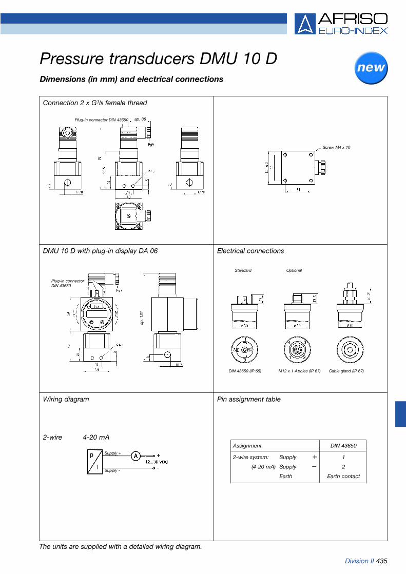
Division II 435
Wiring diagram Pin assignment table
Pressure transducers DMU 10 DDimensions (in mm) and electrical connections
Connection 2 x G1/8 female thread
DMU 10 D with plug-in display DA 06 Electrical connections
2-wire 4-20 mADIN 43650
1
2
Earth contact
Assignment
2-wire system: Supply +(4-20 mA) Supply –
Earth
Plug-in connector DIN 43650 ap. 36
Screw M4 x 10
Plug-in connector DIN 43650
ap. 1
31
Standard Optional
DIN 43650 (IP 65) M12 x 1 4 poles (IP 67) Cable gland (IP 67)
Supply +
Supply -
The units are supplied with a detailed wiring diagram.

436 Division II Refer to pages 438/439 for part no.
Measuring ranges/overload safety
Operating temperature rangeMedium: -25 °C/+125 °CAmbient: -25 °C/ +85 °CStorage: -40 °C/+100 °C
Temperature error bandIn compensated range 0-70 °C < 1.5 % FSO
Dynamic characteristicsResponse time < 5 ms
Process connection2 x G1/2B (EN 837-1/7.3)
MaterialsHousing: aluminiumPressure-connection: stainless steel 1.4571Diaphragm: stainless steel 1.4435Seal: FKM (Viton)
Output signal/supply voltage4-20 mA DC 12-36 V2-wire
Load4-20 mA < UB (V) – 12 V [Ohm]
0.02 A
Current input4-20 mA < 25 mA
Protective electrical measuresShort circuit proof and polarity pro-tected
Electrical connections (protection)Plug and DIN 43650-A (IP 65)
CE conformity (EMC)EN 61326
Accessories• Fixing bracket (included)
Options
• Other process connections• Other electrical connections• Other seal materials• Fitting of diaphragm seal
ApplicationFor electronic differential pressuremeasurement in industrial applica-tions. For aggressive gaseous andliquid media, which are not highlyviscous and do not crystallize.
DescriptionThe DMU 11 D pressure transdu-cers feature two piezo-resistivestainless steel measuring cells.When pressure is applied, the pres-sure difference between the posi-tive side and the negative side isconverted into a current signal,which is proportional to the differ-ential pressure.
Features:• High overload safety• Compact design• Overvoltage protection• Mechanically robust and reliable,
suitable for use in applications where vibration or shocks occur
Accuracy of measurementDeviation characteristics accordingto IEC 60770 - limit point setting(non-linearity, hysteresis, repeatability): < +0.5 % FSO
Pressure transducers DMU 11 DDifferential pressure version
Nominal Diff. pressure Max. staticpressure range pressure on
(bar) (bar) one side (bar)
0/0.04 0.4 up to 1
0/0.4
0/0.11.0 up to 3
0/1.0
0/0.252.5 up to 6
0/2.5
0/0.66.0 up to 20
0/6.0
0/1.616 up to 60
0/16
Digital display unitDA 12
Digital display unitDA 12
Pressure trans-ducer DMU 11 D
Filter
Filter changealarm
Pressure trans-ducer DMU 11 D
Pump
P1 P2 P1 P2

Division II 437
Connection 2 x G1/2B EN 837
Connection 2 x G1/4 female thread
The units are supplied with a detailed wiring diagram.
Pressure transducers DMU 11 DDimensions (in mm) and electrical connections
Wiring diagram
2-wire 4-20 mA
Pin assignment table
Connection 2 x 7/16 UNF
DIN 43650
1
2
Earth contact
Assignment
2-wire system: Supply +(4-20 mA) Supply –
Earth
Plug-in connector DIN 43650
Pressure connection G1/4 (female thread)
Pressure connection G1/4(female thread)
Spanner size 22
1010
4048
90
Plug-in connector DIN 43650 ap. 36
Plug-in connector DIN 43650
Supply +
Supply -
Screw M4 x 10
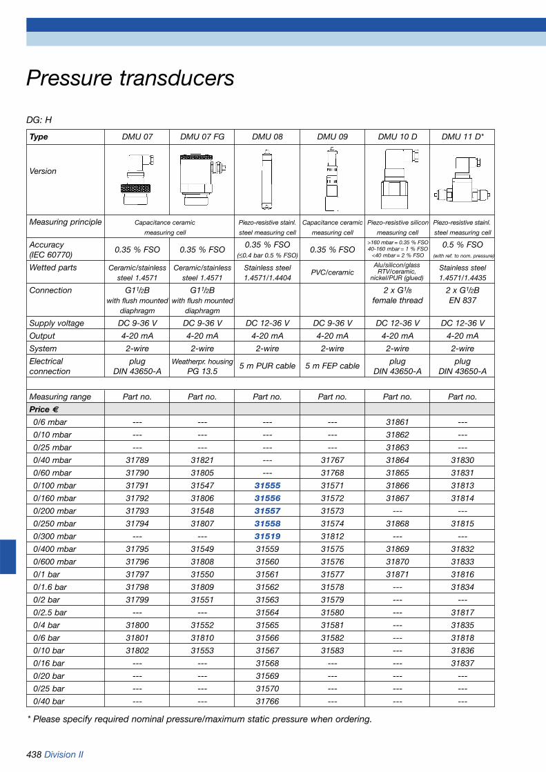
438 Division II
DG: H
Pressure transducers
Type DMU 07 DMU 07 FG DMU 08 DMU 09 DMU 10 D DMU 11 D*
Version
Measuring principle Capacitance ceramic Piezo-resistive stainl. Capacitance ceramic Piezo-resistive silicon Piezo-resistive stainl.
measuring cell steel measuring cell measuring cell measuring cell steel measuring cell
Accuracy0.35 % FSO 0.35 % FSO
0.35 % FSO0.35 % FSO
0.5 % FSO(IEC 60770) (<0.4 bar 0.5 % FSO) (with ref. to nom. pressure)
Wetted parts Ceramic/stainless Ceramic/stainless Stainless steelPVC/ceramic
Stainless steelsteel 1.4571 steel 1.4571 1.4571/1.4404 1.4571/1.4435
Connection G11/2B G11/2B 2 x G1/8 2 x G1/2Bwith flush mounted with flush mounted female thread EN 837
diaphragm diaphragm
Supply voltage DC 9-36 V DC 9-36 V DC 12-36 V DC 9-36 V DC 12-36 V DC 12-36 V
Output 4-20 mA 4-20 mA 4-20 mA 4-20 mA 4-20 mA 4-20 mA
System 2-wire 2-wire 2-wire 2-wire 2-wire 2-wire
Electrical plug Weatherpr. housing 5 m PUR cable 5 m FEP cable plug plugconnection DIN 43650-A PG 13.5 DIN 43650-A DIN 43650-A
Measuring range Part no. Part no. Part no. Part no. Part no. Part no.
Price €
0/6 mbar --- --- --- --- 31861 ---
0/10 mbar --- --- --- --- 31862 ---
0/25 mbar --- --- --- --- 31863 ---
0/40 mbar 31789 31821 --- 31767 31864 31830
0/60 mbar 31790 31805 --- 31768 31865 31831
0/100 mbar 31791 31547 31555 31571 31866 31813
0/160 mbar 31792 31806 31556 31572 31867 31814
0/200 mbar 31793 31548 31557 31573 --- ---
0/250 mbar 31794 31807 31558 31574 31868 31815
0/300 mbar --- --- 31519 31812 --- ---
0/400 mbar 31795 31549 31559 31575 31869 31832
0/600 mbar 31796 31808 31560 31576 31870 31833
0/1 bar 31797 31550 31561 31577 31871 31816
0/1.6 bar 31798 31809 31562 31578 --- 31834
0/2 bar 31799 31551 31563 31579 --- ---
0/2.5 bar --- --- 31564 31580 --- 31817
0/4 bar 31800 31552 31565 31581 --- 31835
0/6 bar 31801 31810 31566 31582 --- 31818
0/10 bar 31802 31553 31567 31583 --- 31836
0/16 bar --- --- 31568 --- --- 31837
0/20 bar --- --- 31569 --- --- ---
0/25 bar --- --- 31570 --- --- ---
0/40 bar --- --- 31766 --- --- ---
* Please specify required nominal pressure/maximum static pressure when ordering.
>160 mbar = 0.35 % FSO40-160 mbar = 1 % FSO
<40 mbar = 2 % FSO
Alu/silicon/glassRTV/ceramic,
nickel/PUR (glued)

Division II 439
DG: H
Additional costs for pressure transducersaccessories
Accessories for DMU 08/09
Type DMU 07 DMU 07 FG DMU 08 DMU 09 DMU 10 D DMU 11 D
Version
Price € Price € Price € Price € Price € Price €
Ex protection II 1 G EEx ia IIC T4 --- --- --- --- ---
2 x G1/4 female thread --- --- --- --- --- on request
2 x capillary connection 6 mm --- --- --- --- on request
2 x 7/16 UNF --- --- --- --- ---
Other connections on request on request --- --- on request on request
Cable connection per metre --- --- --- --- ---PUR cable
Cable connection per metre --- --- --- ---FEP cable
Extension for weight --- --- on request --- --- ---
Weatherproof housing with --- --- --- --- ---display (DA 06)
„Binder“ plug --- --- --- --- ---
Fixed cable connection 2 metres --- --- --- ---
Cable extension --- --- --- ---per metre
Output 0-20 mA, 3 wires --- --- --- ---
Output 0-10 V, 3 wires ---
Other output signals on request on request on request on request on request on request
Absolute pressure --- --- --- --- --- ---
Accuracy of measurement 0.25 % FSO --- --- --- ---
Calibration certificate (for accuracy --- --- --- ---of measurement 0.25 % FSO)
Part no. Price €
Screw connector set plastic G2“ – 11/2“ – 1“ 52125
Screw connector set stainless steel G1“ 31822
Adapter stainless steel G1“ to G11/2“ 31823
Junction box with pressure relief port (IP 65) 31824
Tensioning clamp 31825
DG: H
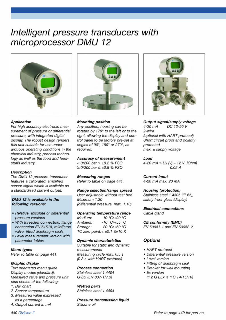
440 Division II
ApplicationFor high accuracy electronic mea-surement of pressure or differentialpressure, with integrated digitaldisplay. The robust design rendersthis unit suitable for use underarduous operating conditions in thechemical industry, process techno-logy as well as the food and feed-stuffs industry.
DescriptionThe DMU 12 pressure transducerfeatures a calibrated, amplified sensor signal which is available as a standardised current output.
DMU 12 is available in the following versions:
• Relative, absolute or differential pressure versions
• With threaded connection, flange connection EN 61518, relief/stop valve, fitted diaphragm seals
• Level measurement version with parameter tables
Menu typesRefer to table on page 441.
Graphic displayText orientated menu guideDisplay modes (standard):Measured value and pressure unitplus choice of the following:1. Bar chart 2. Sensor temperature3. Measured value expressed
as a percentage4. Output current in mA
Mounting positionAny position; housing can be rotated by 170° to the left or to theright, allowing the display and con-trol panel to be factory pre-set atangles of 90°, 180° or 270°, asrequired.
Accuracy of measurement< 0/200 bar < ±0.2 % FSO> 0/200 bar < ±0.5 % FSO
Measuring ranges Refer to table on page 441.
Range selection/range spreadUser adjustable without test bed Maximum 1:20(differential pressure, max. 1:10)
Operating temperature rangeMedium: -10 °C/+90 °CAmbient: -10 °C/+55 °CStorage: -20 °C/+60 °CTC zero point:< ±0.1 %/10 K
Dynamic characteristicsSuitable for static and dynamicmeasurementsMeasuring cycle max. 0.5 s (0.8 s with HART protocol)
Process connectionStainless steel 1.4404G1/2B (EN 837-1/7.3)
Wetted partsStainless steel 1.4404
Pressure transmission liquidSilicone oil
Intelligent pressure transducers with microprocessor DMU 12
Output signal/supply voltage4-20 mA DC 12-50 V2-wire(optional with HART protocol)Short circuit proof and polarity protectedmax. ± supply voltage
Load4-20 mA < UB (V) – 12 V [Ohm]
0.02 A
Current input4-20 mA max. 20 mA
Housing (protection)Stainless steel 1.4305 (IP 65),safety front glass (display)
Electrical connectionsCable gland
CE conformity (EMC)EN 50081-1 and EN 50082-2
Options
• HART protocol• Differential pressure version• Level version• Fitting of diaphragm seal• Bracket for wall mounting• Ex version
(II 2 G EEx ia II C T4/T5/T6)
Refer to page 449 for part no.

Division II 441
Intelligent pressure transducers with microprocessor DMU 12Menu typesThe following menus are available for displaying information and selecting parameters:
Menu type Meaning Menu type Meaning
Measuring range selection Specify min. and max. pressure Alarm condition Specify output currentrange, without actual pressure for fault or malfunction
Damping Select signal damping Calibrate Specify min. and max. pressurerange, with pressure
Min./max. values Display of min./max. values for Current balancing Adapt output signalpressure, level measurement to connected instrumentsand temperature
Signal evaluation Select transmission Factory defaults Re-set to factorymode defaults
Pressure units Selection of physical unit Security lock Protection againstwith conversion unauthorised use
Measurement cycle test Create a definedoutput signal
Measuring ranges Overpressure safety Measuring ranges Overpressure Max. staticsafety (on one side) pressure
Relative pressure: Differential pressure:-1/ +1 bar -1/ +6 bar 0/ 1 bar 6 bar 75 bar
-1/ +4 bar -1/ +10 bar 0/ 4 bar 10 bar 75 bar
-1/ +16 bar -1/ +30 bar 0/16 bar 30 bar 75 bar
-1/ +40 bar -1/ +75 bar
-1/+100 bar -1/+200 bar
-1/+400 bar -1/+500 bar
Absolute pressure:
0/ 1 bar 6 bar
0/ 4 bar 10 bar
0/16 bar 30 bar
Function diagram with HART protocol
Process level not Exprotected
Level measurementDifferential pressurePressure
Auxiliary power
HART modem
Controller
HART „Ex“ isolator

442 Division II
Standard version - connection G1/2B
Pressure transducers DMU 12Types and dimensions (in mm)
Differential pressure version - diaphragm seal fitted Wiring diagram
Cable gland Ø 5-10 mm
ap. 120
Diaphragm seal Diaphragm seal
Signal processing
12-50 VDC

Division II 443Refer to page 449 for part no.
Additional data transducer
Output signal/supply voltage4-20 mA DC 12-36 V2-wire
Load4-20 mA < UB (V) – 12 V [Ohm]
0.02 A
Current input4-20 mA < 25 mA
Long-term stability< ±0.2 % FSO/year
Temperature error bandin compensated range 0-70 °C < 1 % FSO
Pressure transmission liquidSilicone oil
Options
• Liquid filling (silicone oil)• Electrical contacts• Other process connections• Diaphragm seal fitting
Measuring ranges0/0.6 to 0/40 bar
Application areaStatic load:Full scale valueDynamic load:0.9 x full scale valueShort term:1.3 x full scale value
Operating temperature rangeMedium: -20 °C/+100 °CAmbient: -20 °C/ +60 °CStorage: -40 °C/ +70 °C
Housingwith solid baffle wall and blow-out
Front glassLaminated safety glass
ProtectionIP 54 (EN 60529)
Process connectionG1/2B - spanner size 22, bottom back (EN 837-1/7.3)
MaterialsHousing: stainless steel 1.4301Pressure- connection: stainless steel 1.4571Diaphragm: stainless steel 1.4404Seal: FKM (Viton)
Electrical connectionJunction box
ApplicationFor pressure measurements with apower-independent local display incombination with an electrical out-put signal.
DescriptionThe DMU 13 pressure transducersconsist of a mechanical Bourdontube measuring element and a piezo-resistive stainless steel measuringcell. The Bourdon tube measuringelement is used to provide an easy-to-read local display. The display is power-independent.Due to the integrated pressuretransducer, a high accuracy measurement in parallel is possible.A standardised current output isavailable for signal transmission andrecording of measured data. Therobust stainless steel housing has asolid baffle wall and blow-out (safe-ty housing).
Technical specifications
Nominal size100
Accuracy of measurementPressure gauge:Class 1.0 (EN 837-1/6)Pressure transducer:Deviation characteristics accordingto IEC 60770 - limit point setting(non-linearity, hysteresis, repeatability): < ±0.35 % FSO
Pressure transducers with local display DMU 13

444 Division II
Pressure transducers with local display DMU 13Types and dimensions (in mm)
Bottom connection Bottom connection, with electrical contact
Pin assignment table for pressure measuring cell (right hand junction box)
Pin assignment table for electrical contact (left hand junction box)Example: Magnetic spring contact MK2.12
Wiring diagram
1
2
Earth pin
Supply +
Supply -
Earth
1
2
4
Normally open contact
Normally closed contact
Common (+ve)
2-wire
Spannersize 22
Spannersize 22
Removable key, delivered loose with system
Supply +
Supply -

Division II 445
Intelligent pressure transducers DMU 14
Refer to page 449 for part no.
ApplicationFor electronic pressure measure-ment in applications requiring highaccuracy of measurement andlong-term stability, especially underarduous operating conditions. Withaluminium die cast housing, theunits are particularly suitable forprocess technology applications.With stainless steel weatherproofhousing and hygienic process con-nection, the units are ideally suitedfor applications in the food andbeverage industries.
DescriptionThe DMU 14 pressure transducersuse piezo-resistive stainless steelmeasuring cells and feature calibra-ted, amplified sensor signals whichare available as standardised cur-rent outputs.
DMU 14 features:• Robust housing versions• High accuracy• Long service life• High long-term stability• High overpressure safety• Turn Down 1:5• Display (optional)• HART communication (optional)• Ex version (optional)
Accuracy of measurementDeviation characteristics accordingto IEC 60770 - limit point setting(non-linearity, hysteresis, repeatability) 250 mbar: < ± 0.2 % FSO> 0/1 bar: < ± 0.1 % FSO
Long-term stability< ± 0.15 % FSO/year
Meas. ranges/overpressure safety
Operating temperature rangeWithout displayMedium: -40 °C/+125 °CAmbient: -40 °C/ +80 °CStorage: -40 °C/ +80 °CWith displayMedium: -40 °C/+125 °CAmbient: -20 °C/ +70 °CStorage: -30 °C/ +80 °C
Temperature error0.1 % FSO/10 K
Dynamic characteristicsResponse time < 200 ms
Process connectionG1/2B (EN 837-1/7.3)
MaterialsHousing: Stainless steel 1.4301
or aluminium die castProcess-connection: stainless steel 1.4571Diaphragm: stainless steel 1.4435Seal: FKM, NBR for > 35 bar
Adjustable parametersElectronic damping: 0/100 sOffset: 0/90 %Turn down (of span): 1:5
Output signal/supply voltage4-20 mA, 2-wire DC 10-30 V4-20 mA, 2-wire DC 10-28 Vwith Ex version/HART communication
LoadRmax = [(UB-UBmin ) /0.02] ΩHART-Kommunikation Rmin = 250 Ω
Current input4-20 mA max. 25 mA
Protective electrical measuresShort circuit proof and polarity protected
Electrical connection (protection)Connection terminals in terminalchamber (IP 67)
CE conformity (EMC)EN 61326
Options
• Other process connections• Ex version with HART
communication• High temperature version• Integrated local display
DMU 14 FG with clamp connection DMU 14 FG with display DMU 14 DG with display
Measuring range Max.overpressure 0/ 250 mbar 1,000 mbar0/1 bar 3 bar0/1.6 bar 6 bar0/6 bar 20 bar0/16 bar 60 bar0/25 bar 100 bar0/60 bar 140 bar0/160 bar 340 bar0/250 bar 600 bar0/600 bar 1,000 bar

446 Division II
Intelligent pressure transducers DMU 14Dimensions (in mm) and electrical connections
Wiring diagrams Pin assignment table
DMU 14 FG 1/2“ with and without local display DMU 14 FG clamp 11/2“ with and without local display
DMU 14 DG DMU 14 DG
Stainless steel Aluminium dieweatherproof housing cast housing
Connection terminals Connection terminals1 22 4- 3
6 1
Supply +Supply -Test
Earth
By connecting an ammeter between supply + and test terminals, the output signal can be checked without disconnecting the supply voltage.
ap. 90
ap. 90
Cable glandM16 x 1,5
ap. 90
ap. 90
Cable glandM16 x 1,5
ap. 61
Supply +
Supply -
Supply +
Supply -
2-wire system (current)
2-wire system (current) HART

Division II 447Refer to page 449 for part no.
Process connectionG1/4B (EN 837-1/7.3) bottom
MaterialsHousing: PA6, glass reinforcedPressure-connection: stainless steel
1.4305/1.4571Diaphragm: ceramic Al2O3, 96 %Seal: NBR
ProtectionIP 51 (EN 60529)
Supply voltage1 x lithium battery 3.6 V (included),battery life depends on usage (max.8 years)
Options
• Other process connections• Hygienic process connections• Temperature decoupler
(up to Tmax medium 150 °C)• Diaphragm seal fitting
ApplicationFor high accuracy electronic pres-sure measurement with local digitaldisplay and use in applications suchas hydraulics, pneumatics, machineand plant construction, gas and themedical technology field.
DescriptionCompact microprocessor controlledpressure gauge with thick-film cera-mic measuring cell. The micropro-cessor processes the signal recei-ved from the pressure sensor, con-verts it into the desired unit anddisplays it. Due to its modulardesign, the pressure gauge can beadapted in many ways to suitcustomer-specific requirements.
FunctionsSelection of measurement units,zero correction, password, push-to-read, battery status indication
Displayed valuesSelectable pressure units:bar/psi/MPa/mWC
Display4-digit, 12 mm high, 7-segmentLCD with additional symbols, canbe rotated by 330°
Accuracy of measurementDeviation characteristics accordingto IEC 60770 - limit point setting(non-linearity, hysteresis, repeatabi-lity): < ±0.5 % FSO (measuringrange -1/0 bar < ±1% FSO)
Measuring ranges-1/0 bar,0/1 bar to 0/400 bar
Overpressure safety< 160 bar min. 2 x FS> 160 bar min. 1.5 x FS
Burst pressureMin. 3 x FS
Operating temperature rangeMedium: -25 °C/+125 °CAmbient: 0 °C/ +45 °CStorage: -30 °C/ +80 °C
Temperature errorIn compensated range 0-70 °C < 2 % FSO
Dynamic characteristicsSuitable for static and dynamicmeasurements Scanning rate 1/s
Universal digital pressure gauge DIM 10
Clamp connection and temperature decoupler (optional)
Clamp connection (optional)

448 Division II
Digital pressure gauge DIM 10Types and dimensions (mm)
Connection G1/4B EN 837
Clamp connections ISO 2852 Clamp connection ISO 2852 with temperature decoupler (Tmax medium 150 °C)
Connection 1/4-NPT
ap. 1
04
Spanner size 27
ap. 1
06
Spanner size 27
ap. 1
11
Diaphragm Ø 24 Diaphragm Ø 32
Diaphragm Ø 32
ap. 1
29

Division II 449
* Measuring range -1/+x bar** Wetted parts of clamp or dairy fittings made from stainless steel 1.4435.
Pressure transducers/digital pressure gauge
DG: H
Type DMU 12 DMU 12 Dif DMU 13 DMU 14 FG DMU 14 DG DIM 10
Version
Housing-Ø 62 62 100 60 75 75Housing Stainless steel Stainless steel Stainless steel Stainless steel Aluminium PlasticAccuracy 0.2 % FSO 0.2 % FSO 0.35 % FSO refer to data sheet refer to data sheet 0.5 % FSOWetted parts Stainless steel Stainless steel Stainless steel Stainless steel Stainless steel Stainless steel
1.4404 1.4404 1.4571/1.4404 1.4571/1.4435 1.4571/1.4435 1.4305/CeramicConnection G1/2B EN 61518 G1/2B G1/2B G1/2B G1/4BSupply voltage DC 12-50 V DC 12-50 V DC 12-36 V DC 10-30 V DC 10-30 V DC 3.6 VOutput 4-20 mA 4-20 mA 4-20 mA 4-20 mA 4-20 mA ---
Measuring range Part no. Part no. Part no. Part no. Part no. Part no.Price €0/250 mbar --- --- --- 31977 31987 ---
Price €-1/0 bar --- --- --- --- --- 310600/0.6 bar --- --- 31076 --- --- ---0/1 bar 31040* 31049 31077 31978 31988 31061
Price €0/1.6 bar --- --- 31078 31979 31989 320510/2.5 bar --- --- 31079 --- --- 310620/4 bar 31041* 31050 31080 --- --- 310630/6 bar --- --- 31081 31980 31990 310640/10 bar --- --- 31082 --- --- 310650/16 bar 31042* 31051 31083 31981 31991 310660/25 bar --- --- 31084 31982 31992 310670/40 bar 31043* --- 31085 --- --- 31068
Price €0/60 bar --- --- --- 31983 31993 310690/100 bar 31044* --- --- --- --- 310700/160 bar --- --- --- 31984 31994 310710/250 bar --- --- --- 31985 31995 310720/400 bar 31045* --- --- --- --- 310730/600 bar --- --- --- 31986 31996 ---
Add. costs** Price € Price € Price € Price € Price € Price Ex protection with on request on request --- ---HART communication
Liquid filling --- --- --- --- ---Connection 1/2 NPT --- --- on request no add. cost no add. costClamp connection --- --- --- ---1“ oder 1 1/2“Clamp connection 2“ --- --- --- ---Dairy fitting DIN 11851 DN 25 --- --- --- ---Dairy fitting DIN 11851 DN 40 --- --- --- ---Dairy fittingDIN 11851 DN 50 --- --- --- ---High temperature --- --- --- ---version +300 °C

450

www.afriso.de 451
Chapter 12 Table of contents chapter 12
Portable measuring instruments, analysers and test equipment
12
Page
Test instruments for level sensors (GPR 4, ME 5) 452
Test instruments for tank servicing (S 2510, KWT 5) 453
Pressure gauges for pump test set (RF 50 PPS) 453
Condensate water test instruments (KWT 5) 453
Test and refill devices for expansion vessels (PNG, PGA, PGWA) 454
Pressure test set/test set for water (PGW, AS-2) 455
Volume flow and temperature measurement (Flowtemp) 455
Leak test sets for gas and oil pipes (DPK 54, 60, 60-2, 60-4, 61) 456-458
Gas detectors (GSP1, GSP3) 459
Handheld electronic pressure instruments 460-461(series 2400, FZM, DMG, series 2500)
Handheld electronic thermometers 462-463(TM6, TM8-IR, TM5, TMD5)
Handheld electronic air speed measuring instruments (LGM 1) 464
Handheld electronic volume flow measuring instruments (VMG 01) 465
Handheld electronic measuring instruments for humidity and air temperature 466(FT3–FT6)
Flue gas analysis computer EUROLYZER 467-468
Flue gas analysis computer MULTILYZER/MULTILYZER NG 469-471
Flue gas analysis computer MAXILYZER 472-473
Condensate filter and gas treatment system for portable flue gas analysers 474
Gas treatment system MAXISYSTEM 475
Water analysis instruments AQUALYZER, AQUASYSTEM 476
Sensors and electrodes for water analysis instruments 477-478

452 Division I
Test instruments for level sensors
For genuine function checks!Suitable for all GWG levelsensors, also for zone 0!
Sensor test instrument ME 5Ex-approved level sensor testinstrument with intrinsically safesensor circuit for genuine functionchecks of all sensors approvedaccording to TRbF 511, also forsensors which are installed inhazardous areas zone 0. All charac-teristics of the PTC thermistor arechecked via a microprocessor pro-gram. Test instructions as well astest results are alphanumericallydisplayed. Battery operated.
EC design type approval:TÜV 03 ATEX 2141Ex II (2) G EEx ia IIB
DG: H PU Part no. Price €
Sensor test instrument ME 5 1 62230
Sensor test instrument ME 5 P 1 62240
Carrying case for ME 5 1 62231
Charger for ME 5 1 62232
Sensor test instrument GPR 4 1 62301
Level sensor test instruments withplug - suitable for all level sensorfittings.
Sensor test instrumentGPR 4Simple sensor test instrument suit-able for use on storage tanks forfuel oils and diesel fuels. Not per-mitted for use in hazardous areasand not for level sensors, which areinstalled in tanks containing hazar-dous media. A signal lamp indi-cates function or error. Battery-operated. With GWG connector,also suitable for GWG with brassfitting.
Sensor test instrument ME 5 PLevel sensor test instrument similarto ME 5 but with product ID.
GPR 4
ME 5

Division I + II 453
Test instruments for tank servicing, pressure gauges for pump test set
Condensate water testerKWT 5Condensate water tester (conducti-vity principle) for checking fuel oiland diesel fuel tanks. The probe islowered to the bottom of the tank.The presence of condensate wateris indicated by a lamp. When theprobe is raised, the lamp extin-guishes as soon as the probe reaches the water/oil interface. This allows the exact level of con-densate water to be determined.Battery operated.
The S 2510 pressure and vacuummeasuring instrument is designedto quickly and reliably check theswitching and alarm points, thepumping capacity and the airtightness of the installation.
Pressure/vacuum instrument S 2510For measuring pressure, vacuum anddifferential pressure. For gaseous,dry media which are not corrosive.The series 2500 pressure meterswith digital display use state-of-the-art microprocessor technology andare designed for industrial applica-tions.
Measuring range:-1,000/+1,000 mbarAccuracy of measurement: < 1 % of measured value
Resolution selectable: 1 mbar or 0.1 mbar in the range from 0 to±199.9 mbar. The unit is operated via a smooth,easy-to-clean foil keypad. The mea-sured values are shown on a largeLCD display. They can be printedon an optional printer via the inte-grated infrared interface. Zero cor-rection is carried out automaticallyas soon as the unit is switched onor manually via a key. The instru-ment features a „hold“ function, sothat a current measured valueremains displayed on the LCD. Withhoses and adapters especially fortesting vacuum and pressure typeleak detectors.
RF 50 PPSApplicationPressure gauge for checking the pressure and suction capacity of oilburner pumps. Used in conjunctionwith standard, commercially avail-able pump test valves with G1/8connection.
RF 50 PPS D 101 – without glycerine fillingHousing Ø: 50 mmConnection: G1/8B bottom
without socketHousing: PlasticFront glass: PlasticAccuracy of measurement: Class 1.6
RF 50 PPS D 601 – with glycerine fillingHousing Ø: 50 mmConnection: G1/8B bottom
without socketHousing: PlasticFront glass: PlasticAccuracy of measurement: Class 1.6
Pressure gauges for pump test set
DG Part no. Price €
Pressure/vacuum instrument S 2510 H 69876A
Carrying case for S 2510 H 62300
Protective case S 2510 H 69341
Condensate water tester KWT 5 H 44010
RF 50 PPS D 101 – without glycerine filling -1/0 bar M 63991
RF 50 PPS D 101 – without glycerine filling 0/25 bar M 63995
RF 50 PPS D 601 – with glycerine filling -1/0 bar M 67165
RF 50 PPS D 601 – with glycerine filling 0/25 bar M 67166

454 Division II
Test and refill devices for expansion vessels
DG: H Part no. Price €
Test and refill device PNG-1, 0/4 bar 39616
Test and refill device PNG-3, 0/10 bar 39637
Refill bottle, 400 ml 39633
Test and refill device PNG-2 39634
Spare case of PNG-2 39635
Test device PGA-4-Set 39614
Test device PGA, 0/4 bar 39615
Test device PGWA-Set 39619
Test device PGA-4-SetFor expansion tanks, container andtyre pressure. Robust and veryaccurate pressure gauge in alumi-nium housing with zero correction.Measuring range 0/4 bar. With threeadapters for car valves which arealso used for expansion vessels.The three adapters (straight, 45°,90°) cater for use in even veryspace restricted areas. Plastic carry-ing case with insert included.
Test device PGAPressure test device PGA from thePGA-4 set, range 0/4 bar, with 45°adapter.
Test device PGWA-SetFor checking pressure in waterpipes and expansion vessels.Combination of PGA-4-Set andPGW-10-Set (refer to page 455)plus rigid connection extension andflexible hose with side mountedvalve (Vg8) for refilling.
Test and refill devices PNG-2For diaphragm expansion vessels in heating and oil supply systems,specially for systems with test valveswhich are not easily accessible.During testing and refilling, the fitting is pressed against the testvalve.
The test and refill device PNG-2consists of a rigid, 200 mm longtest lance with test head for pressingagainst the test valve of the expan-sion vessel and a ball valve with7/16-28 UNEF thread for refill bottleas well as a test pressure gauge Ø 40 mm, 0/4 bar, class 1.6.
The PNG-2 test and refill deviceincludes a refill bottle and a plasticcase.
Test and refill devices PNG-1/PNG-3For diaphragm expansion vessels inheating and oil supply systems. The test and refill devices PNG-1and PNG-3 consist of a 60 cm long,flexible filling hose with union nutVg8 for the test valve at the expan-sion vessel and a ball valve with7/16-28 UNEF thread for refill bottleas well as a test pressure gauge Ø 40 mm, class 1.6PNG-1 0/4 barPNG-3 0/10 bar.The refill bottle is not included.
Refill bottleCylinder for increasing the pressurecushion in expansion vessels. Withanti-corrosion component, notinflammable. Connection thread7/16-28 UNEF, suitable for PNG-1,PNG-2 and PNG-3. Contains 400 ml.

Division II + III 455
Pressure test set AS-2pressure measuring instrument S 2501AS-2 consists of the electronicpressure measuring instrument S 2501 (measuring range ±130mbar, 0.01 mbar at 0-19.99 mbar,refer to page 461) with plug-in testvalve with quick-action coupling,hose fitting with conical test plugs 12-21 mm and 18-34 mm as wellas hand ball pump.
ApplicationPressure test in pipes, fittings, smallcontainers, primarily however formains gas pipe testing. Also suit-able for checking pressure switchesand for carrying out safety tests onpressure monitors as well as othergeneral pressure/vacuum and dif-ferential pressure measurements.Data can be accessed via infraredinterface.
Options• EUROPRINTER thermal printer
Please refer to pages 456 to 458 forother leak test instruments.
Test set PGW-10-SetFor water pressure in pipes andcontainers. Robust and very accu-rate pressure gauge in aluminium housing with zero correction ring.Measuring range 0/10 bar. Withadapter for hose tap 1/2“ (threadG3/4), aerator M 24 x 1 (female) andM 22 x 1 (male). Complete with pla-stic carrying case with insert and aconnector for car valves.
Test instrument PGWPressure test unit PGW in robustaluminium housing with zero cor-rection ring. Measuring range 0/10 bar, with adapter for car val-ves. Also suitable for testing water pressures in conjunction with adap-ters from PGW-10-Set.
Instrument for volume flow and temperature measurement FlowtempFor checking and adjusting waterheaters. The measuring range forthe volume flow is selected by aninstrument disc with various holes:• 1.6 to 4 l/min• 4 to 8 l/min• 8 to 16 l/min
The instrument is held under anopen water tap and indicates thewater temperature at a certain flowrate. The unit is supplied in a robustplastic enclosure.
DG: H Part no. Price €
Instrument for volume flow andtemperature measurement Flowtemp 69790
Test set PGW-10-Set 39617
Test device PGW, 0/10 bar 39618
Pressure test set AS-2 with pressure measuringinstrument S 2501 in plastic case 39593
Plastic case 39596
Conical test plugs 12-22 mm 0814020123
Conical test plugs 19-35 mm 0814020121
Pressure test set in plastic case withoutpressure measuring instrument S 2501 39590
Pressure measuring instrument S 2501 69873
Pressure test set, pressure test set for water, instrumentfor volume flow and temperature measurement

456 Division II
Leak test instruments
Application areas for series DPK 60leak test sets:• Leak tests of pipe installations for
municipal gas, grid gas and naturalgas according to the pressure measurement method with air B 3.
• Leak tests according to the visual inspection method with air A 3.
• Pressure tests of pipes according to DVGW-TRGI (DVGW sheet G 600).
The TRGI regulations of 1986 distin-guish between two categories oftests for pipe systems:a)Pipes with operating pressures
up to 100 mbar.b)Pipes with operating pressures
of 100 mbar to 1 bar.
Tests according to a) comprise:1. The preliminary test is a load testof newly installed pipes without fit-tings or with fittings, if the nominalpressure rating of such fittings is atleast as high as the test pressure.Pipe openings must be closed withmetallic components. Connection togas carrying pipes is not permitted.Test pressure: 1 bar - 10 min.
The leak test instruments DPK 60 andDPK 60-2 are designed for such tasks.
2. The main test is a leak test of allpipes including fittings, but withoutany gas devices, associated control-lers or any safety equipment. Test pressure: 110 mbar - 10 min.The leak test set DPK 60-2 with elec-tronic pressure meter is particularlysuitable for these tests as it is cap-able of detecting small pressuredrops of 0.1 mbar within a measuringrange of up to 199.9 mbar.
Tests according to b) comprise:
A combined load and leak test ofthe pipes including fittings, the normal pressure ratings of which areat least as high as the test pressure.Test excludes pressure controllers, gas meters, gas instruments andassociated control and safety equip-ment. Pipe openings must be closedoff with metallic components.Connection of gas carrying pipes isnot permitted. Test pressure: 3 bar ata maximum pressure increase of 2bar/min.
The DPK 60-2 with pressure meter S 2510 and recorder is particularly suit-able for such tests.
• Additionally, the leak test instrumentscan be used for the following tasks:
1. Main test or combined load andleak test of pipes (before gas isadmitted), which are out of service orshut down and pressure tests, whichare used to prove that openings ofpipes are correctly sealed (generatedpressure is maintained for a short period of time).2. Leak tests according to the visualinspection method with air: A 3 withfoaming agents according to EN 14291:• Connections and transition points• Shut-off devices• Pressure controllers• Gas meters, other gas devices• Connection pipes for instruments
and fittings• Seals and test ports. These testsmust be carried out at the pressuresshown on the type designation labels(nominal pressure ratings) of therespective units. The test pressureshould not exceed these nominal pres-sure ratings.3. Pressure tests of gas supply pipesand installations on the basis of the visual inspection method with air A 3and the pressure measurementmethod with air B 3 according toDVGW sheet G 469 (7/87) and erratasheet (7/87) all in accordance with theregulations stipulated by DVGW sheetsG 459, 461/I, 462/ I and 472 (9/88).
DPK 60 DPK 60-2 Upgrade kit DPK 60-2
Refer to page 457 for part no.
Pressure gaugeHose connection Foot pump
Adapter
Connection sockets
Spanner
Rubber test plugs
Thumb screws
Adapter
Connection sockets Thumb screws
Rubber test plugs
Spanner
Foot pump
Pump hoseElectronic
pressure meter
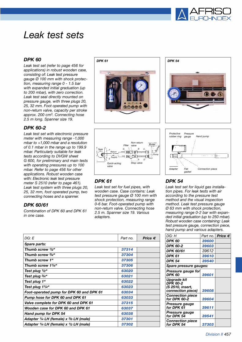
Division II 457
Leak test sets
DPK 60Leak test set (refer to page 456 forapplications) in robust wooden case,consisting of: Leak test pressuregauge Ø 100 mm with shock protec-tion, measuring range 0 - 1.5 barwith expanded initial graduation (upto 200 mbar), with zero correction.Leak test seal directly mounted onpressure gauge, with three plugs 20,25, 32 mm. Foot operated pump withnon-return valve, capacity per strokeapprox. 200 cm3. Connecting hose2.5 m long. Spanner size 19.
DPK 60-2Leak test set with electronic pressuremeter with measuring range -1,000mbar to +1,000 mbar and a resolutionof 0.1 mbar in the range up to 199.9mbar. Particularly suitable for leaktests according to DVGW sheet G 600, for preliminary and main testswith operating pressures up to 100mbar. Refer to page 456 for otherapplications. Robust wooden casewith: Electronic leak test pressuremeter S 2510 (refer to page 461).Leak test system with three plugs 20,25, 32 mm, foot operated pump, twoconnecting hoses and a spanner.
DPK 60/61Combination of DPK 60 and DPK 61in one case.
DPK 61 DPK 54
DPK 61Leak test set for fuel pipes, withwooden case. Case contains: Leaktest pressure gauge Ø 100 mm withshock protection, measuring range 0-6 bar. Foot-operated pump withnon-return valve. Connecting hose2.5 m. Spanner size 19. Variousadapters.
DPK 54Leak test set for liquid gas installa-tion pipes. For leak tests with airaccording to the pressure testmethod and the visual inspectionmethod. Leak test pressure gauge Ø 63 mm with shock protection,measuring range 0-2 bar with expan-ded initial graduation (up to 250 mbar).Robust wooden case containing: Leaktest pressure gauge, connection piece,hand pump and various adapters.
DG: E Part no. Price €
Spare parts:Thumb screw 1/2“ 37314Thumb screw 3/4“ 37304Thumb screw 1“ 37305Thumb screw 11/4“ 37306Test plug 1/2“ 63020Test plug 3/4“ 63021Test plug 1“ 63022Test plug 11/4“ 63023Foot-operated pump for DPK 60 and DPK 61 63034Pump hose for DPK 60 and DPK 61 63033Valve complete for DPK 60 and DPK 61 37315Wooden case for DPK 60 and DPK 61 63037Hand pump for DPK 54 63038Adapter 1/4 LH (female) x 3/8 LH (male) 37301Adapter 1/4 LH (female) x 1/2 LH (male) 37302
DG: H Part no. Price €
DPK 60 39600DPK 60-2 39603DPK 60/61 39612DPK 61 39610DPK 54 39540Spare pressure gauges:Pressure gauge forDPK 60 39601Upgrade kitDPK 60-2 (S 2510, insert,connection piece) 39608Connection piecefor DPK 60-2 39604Pressure gaugefor DPK 61 39611Pressure gaugefor DPK 54 39541Connection piecefor DPK 54 37303
Protectiverubber ring
Pressuregauge Hand pump
Adapter Flatgasket
Connection piece
Quick-actingvalve
Stop valve
Tank
BoilerFilterNon-returnvalve
PumpB
urne
r
Return
Supply
F
E
G B
A
C
D

458 Division III
Leak test set with electronic leak rate detectionDPK 60-4
An audible signal indicates the endof the test. Test reports (with dateand time) can be created via anoptional thermal printer with infra-red interface at the end of the test.
In addition, is suitablefor measuring pressure and differ-ential pressures up to 1,500 mbar.
Scope of delivery
• Leak test instrumentwith battery charger and leak ratesensor
• Handy and robust case with a comprehensive set of accessories
• Robust manual pump, firmly installed in the case
• External temperature sensor• Set of test plugs• Highly flexible connection hose
with precision bleed valve and quick-action couplings
• 1 bottle of leak detection spray• Test pressure gauge 1.6 bar
Technical specificationsPressureMeasuring range: 0/1,500 mbarResolution: 1 mbarAccuracy of measurement: 3 % of measured value (at 20 °C)
Leak rateMeasurement pressure: 10/150 mbarMeasuring range: 0/1 l/hResolution: 0.1 l/hAccuracy of measurement: 5 % of measured value
ApplicationThe leak test set DPK 60-4 offersthe following tests on gas pipes:
1. Test of newly installed pipes with operating pressures up to 100 mbar according to DVGW-TRGI sheet G 600:• Preliminary test (load test with
1 bar test pressure)• Main test (leak test with
110 mbar test pressure)2. Leak test of existing pipes with
operating pressures up to 100 mbar according to DVGW sheet G 624:• Measurement of leak rate (at 110 mbar test pressure)
Description
is a digital display leaktest instrument with state-of-the-artmicroprocessor technology with ahandy, compact design. The user-friendly system provides a keypadfor selecting the operating mode and other functions. The tests arecarried out quickly and efficiently.The large, backlit display shows the measured pressure and tempe-rature values. Depending on theoperating mode selected, the batterylevel „Pressure measurement“,pressure loss „Leak test“ and theleak rate „Leak rate measurement“are also displayed.
Max. pipe volume100 l
TemperatureMeasuring range: -20/+100 °CResolution: 0.1 °CAccuracy of measurement: ±1 °C
General specifications
Supply voltage: DC 6 VService time: Up to 60 hoursDisplay (backlit): 4 lines with 16 characters eachOperating temp.: -10/+50 °CStorage temp.: -20/+60 °CReal-time clock with dateSerial interfaceAuto-zero correction when switched on. Precision bleed valvefor easy setting of test pressure
Options• EUROPRINTER thermal printer• Single pipe union connector,
adapters with stop valves
DPK 60-4 Test Report
DG: H Part no. Price €
DPK 60-4 39605
Single pipe union 0814 020113connector DN32
Connecting 39709hose with 2quick-actioncouplings
EUROPRINTER 69480thermal printer
Please enquire about additional accessories and spare parts.
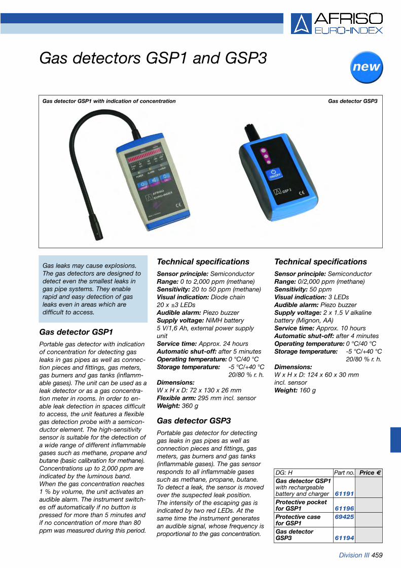
Division III 459
Gas detectors GSP1 and GSP3
Gas detector GSP1Portable gas detector with indicationof concentration for detecting gasleaks in gas pipes as well as connec-tion pieces and fittings, gas meters,gas burners and gas tanks (inflamm-able gases). The unit can be used as aleak detector or as a gas concentra-tion meter in rooms. In order to en-able leak detection in spaces difficultto access, the unit features a flexiblegas detection probe with a semicon-ductor element. The high-sensitivitysensor is suitable for the detection ofa wide range of different inflammablegases such as methane, propane andbutane (basic calibration for methane).Concentrations up to 2,000 ppm areindicated by the luminous band.When the gas concentration reaches1 % by volume, the unit activates anaudible alarm. The instrument switch-es off automatically if no button ispressed for more than 5 minutes andif no concentration of more than 80ppm was measured during this period.
DG: H Part no. Price €
Gas detector GSP1with rechargeablebattery and charger 61191Protective pocketfor GSP1 61196Protective case 69425for GSP1Gas detectorGSP3 61194
Technical specificationsSensor principle: SemiconductorRange: 0 to 2,000 ppm (methane)Sensitivity: 20 to 50 ppm (methane)Visual indication: Diode chain 20 x ±3 LEDsAudible alarm: Piezo buzzerSupply voltage: NiMH battery 5 V/1,6 Ah, external power supplyunitService time: Approx. 24 hoursAutomatic shut-off: after 5 minutesOperating temperature: 0 °C/40 °CStorage temperature: -5 °C/+40 °C
20/80 % r. h.Dimensions:W x H x D: 72 x 130 x 26 mmFlexible arm: 295 mm incl. sensorWeight: 360 g
Gas detector GSP3Portable gas detector for detectinggas leaks in gas pipes as well asconnection pieces and fittings, gasmeters, gas burners and gas tanks(inflammable gases). The gas sensorresponds to all inflammable gasessuch as methane, propane, butane.To detect a leak, the sensor is movedover the suspected leak position.The intensity of the escaping gas isindicated by two red LEDs. At thesame time the instrument generatesan audible signal, whose frequency isproportional to the gas concentration.
Technical specificationsSensor principle: SemiconductorRange: 0/2,000 ppm (methane)Sensitivity: 50 ppmVisual indication: 3 LEDsAudible alarm: Piezo buzzerSupply voltage: 2 x 1.5 V alkalinebattery (Mignon, AA)Service time: Approx. 10 hoursAutomatic shut-off: after 4 minutesOperating temperature: 0 °C/40 °CStorage temperature: -5 °C/+40 °C
20/80 % r. h. Dimensions:W x H x D: 124 x 60 x 30 mm incl. sensorWeight: 160 g
Gas detector GSP1 with indication of concentration Gas detector GSP3
Gas leaks may cause explosions.The gas detectors are designed todetect even the smallest leaks in gas pipe systems. They enable rapid and easy detection of gasleaks even in areas which are difficult to access.

460 Division III
Handheld electronic pressure instruments Series 2400 (FZM/DMG)
Connection fittings for FZM
ApplicationFor measuring pressure, vacuumand differential pressure.For gaseous, non-corrosive drymedia.
DescriptionThe series 2400 pressure instrumentsare based on a microprocessorcontrolled evaluation and displaysystem. A 4-digit LCD display indicates the measured values. Theinstruments are supplied by 9 V batteries. The electronic sensorsystem is built into a robust, handyhousing. When the unit is switchedon, all available segments of thedisplay are shown for 2 seconds.After this segment test, the unitswitches immediately to measuringmode. Automatic zero setting.Accessories include a protectivehousing (with magnetic holder,stand, transparent slide). These housings can be interconnectedthus allowing for a combination ofseveral units in one easy-to-manageassembly.
Technical specificationsSupply voltageAlkaline battery 9 V (included) Service life approx. 200 hours
Display13 mm high 4-digit LCD
Pressure unitmbar
Hose connections2 x for 3 mm hose with 1 mm wall thickness
Operating temperature rangeMedium: 0 °C/+50 °CAmbient: 0 °C/+50 °CStorage: -20 °C/+50 °C
HousingPlastic, blueW x H x D: 70 x 125 x 31 mm
Measuring range/accuracy of measurement (selectable MR I / MR II, accuracyof MV = of measured value)
Type FZM 20MR I: 0/±19.99 mbar
±1 % of MV (±1 digit)Resolution 0.01 mbar
MR II: 0/±150.0 mbar ±1 % of MV (± 1 digit)Resolution 0.1 mbar
Max. static pressure 1.3 bar
Type DMG 02MR I: 0/±199.9 mbar
±1% of MV (±1 digit)Resolution 0.1 mbar
MR II: 0/±500 mbar ±1 % (±1 digit)Resolution 1 mbar
Max. static pressure 1.3 bar
Type DMG 12MR I: 0/±199.9 mbar
±1 % of MV (±1 digit)Resolution 0.1 mbar
MR II: 0/±1,000 mbar ±1 % of MV (±1 digit)Resolution 1 mbar
Max. static pressure 3 bar
Connection fittings for DMG
Type DMG 22MR I: 0/±199.9 mbar
±1 % of MV (±1 digit)Resolution 0.1 mbar
MR II: -1,000/+1,999 mbar ±1 % of MV (±1 digit)Resolution 1 mbar
Max. static pressure 4 bar
Scope of delivery• Alkaline battery 9 V• FZM with connection fittings
part no. 18 06 00 05• DMG with connection fittings
part no. 18 05 00 05
With protective housing (option)
DG: H Part no. Price €
FZM 20 69655
DMG 02 69656
DMG 12 69657
DMG 22 69658
Accessories/spare parts
Protective housing 69425with magnet
Protective pocket 69848
Connection 18 06 00 05fittings for FZM
Connection 18 05 00 05fittings for DMG
Hose adapter 18 06 000501
(8 mm)
Silicone hose 68660

Division III 461
Handheld electronic pressure instrumentsSeries 2500 (microprocessor-controlled)
ApplicationFor measuring pressure, vacuumand differential pressure. For gaseous, non-corrosive dry media.
DescriptionThe series 2500 pressure meterswith digital display use state-of-the-art microprocessor technologyand are designed for industrial applications.The unit is operated via a smooth,easy-to-clean foil keypad. The mea-sured values are shown on a largeLCD display. They can be printed onan optional thermal printer via theintegrated infrared interface. Zerocorrection is initiated automaticallyas soon as the unit is switched on,or manually via a key. The instru-ment features a hold function sothat a current measured valueremains displayed on the LCD.
Technical specificationsSupply voltage2 Alkaline batteries 1.5 V (included),battery life approx. 300 hours (continuous operation)
Display13 mm high LC display
Pressure unitsbar, mbar, hPa (selectable)
Hose connections2 x Ø 8 mm plug connection (S 2501 and S 2510)2 x Ø 3 mm plug connection (S 2520 and S 2599)
Operating temperature rangeMedium: 0 °C/+40 °CAmbient: 0 °C/+40 °CStorage/transport: -20 °C/+50 °C
Temperature coefficient0.05 %/K< 0.03 %/K of FSO for version S 2501TC
HousingPlastic, blueW x H x D: 60 x 190 x 36 mm
Measuring ranges/accuracy of measurementAccuracy of measurement< 1.0 % of measured value< 0.6 % of measured value for S 2501TC
Type S 2501 – 0/±130 mbar0/19.99 mbar:Resolution 0.01 mbar> 20 mbar:Resolution 0.1 mbarMax. static pressure 1 bar
Type S 2510 – 0/±1,000 mbar0/199.9 mbar:Resolution 0.1 mbar200/1,000 mbar:Resolution 1 mbarMax. static pressure 2 bar
EUROPRINTER thermal printer
Battery compartment
Measuring ranges
Approvals
IR interface
Hose connections,draft, pressure,diff. pressure
Type S 2520 – -1,000/+2,000 mbar0/199.9 mbar:Resolution 0.1 mbar200/2,000 mbar:Resolution 1 mbarMax. static pressure 4 bar
Type S 2599 – -1/+7 bar0/1.999.9 mbar:Resolution: 0.1 mbar (to 199.9 mbar)
1.0 mbar (> 200 mbar)2.0/7.0 bar:Resolution: 0.01 barMax. static pressure 10 bar
Scope of deliveryIncludes 2 alkaline batteries 1.5 V
Options• Type S 2501 with temperature
compensation and calibration certificate (= type S 2501 TC, accuracy of measurement < 0.6 %)
DG: H Part no. Price €
S 2501 69873
S 2501TC 69690
S 2510 69876
S 2520 69877
S 2599 69884
Accessories:
Protective housingwith magnet 69341
Connectionfittings 69840
EUROPRINTER 69480thermal printer

462 Division III
Handheld electronic thermometers TM6 and TM8-IR
TM6
DescriptionVery handy, robust temperature mea-suring instrument for simple, accura-te and extremely fast measurementsof surfaces, liquids, soft-, plasticmedia or in air and gases. The unitfeatures max, min and „hold“ func-tion, an RS232 interface as well as amemory for 16 measured values. Inaddition, the displayed measuredvalue can be corrected, e.g. in orderto compensate for sensor tolerances(1 point-cal-function).
Refer to page 463 for sensorsTM5/TMD5.
Technical specificationsThermocoupleType K (NiCr-Ni)
Measuring range-99.9 °C/+1,370 °C
Accuracy of measurement±0.5 °C(±1 digit) (instrument only)
Resolution0.1 °C from -99.9 °C/+299.9 °C,otherwise 1 °C
Memory capacity20 measured values
Plug connectionMiniature connector
Operating temperature rangeAmbient: 0 °C/+50 °C
Display1 line LC display
HousingImpact resistant plastic (ABS)
DimensionsW x H x D: 65 x 130 x 25 mm
Weight240 g
Supply voltage2 x 1.5 V AA, batteries
Battery lifeApprox. 200 hours
TM8-IR
DescriptionThe TM8-IR temperature measuringinstrument is a non-contact infraredthermometer with laser aim andlarge, backlit LCD display. Infraredthermometers are particularly suitablefor measuring surface temperatures.The special benefit is the shortresponse time (less than a second)without having to come in contactwith the measured object. Therefore,the instrument is particularly suitablefor moving (e.g. paper reels, tyres) orlive (e.g. electrical assemblies, trans-formers) parts. Also for measure-ments in the food industry, becausethe medium is not polluted by a sen-sor. An additional NiCr-Ni thermo-couple can be connected to theinstrument.The ratio of distance to measurementpoint is 11:1.The measured object must always belarger than the diameter of the mea-surement point.
Technical specifications
Measuring range infrared-33 °C/+500 °C
Measuring range thermocouple-64 °C/+1,400 °C
Accuracy of measurement infrared±2 °C or ±2 % of measured value (the greater value applies)
Spectral sensitivity6/14 µm
Accuracy of measurement thermocouple±1 °C or ±1 % of measured value(the greater value applies)
Operating temperature rangeAmbient: 0/+50 °CStorage/transport: -10/+50 °C
Response time1 second
Ratio distance to Ø measurement point11:1
Adjustable degree of emission0.10 ~ 1,00 increments of 0,01
Battery lifeApprox. 140 hours of continuous operation
DimensionsW x H x D: 39 x 175 x 80 mm
Weight180 g (with batteries)
Ø approx Ø approx Ø approx 5 cm at 9 cm at 27 cm at0.5 m 1 m 3 m
DG: H Part no. Price €
TM6 70038TM8-IR 70039
TM6 TM8-IR
Ratio of distance to Ø of measurementpoint 11:1

Division III 463
Handheld electronic thermometers TM5 and TMD5
Temperature sensor
ApplicationFor simple, accurate and extremelyfast measurements of surfaces (e.g.supply and return pipes), liquids, softplastic media, air/gases and extreme-ly small objects as well as thermalthroughput values and insulationvalues.
DescriptionTM5 and TMD5 electronic thermo-meters consist of an electronic mea-suring system type K (NiCr-Ni) and amicroprocessor-controlled evaluationand display system. A 4-digit LCDdisplay shows the measured values.The instruments are supplied by 9 Vbatteries. When the unit is switchedon, all available segments of thedisplay are shown for 2 seconds.After this segment test, the unit isready for operation. The instrumentsfeature a measurement unit selectionfacility (Celsius or Fahrenheit). Withthe TMD5, it is sufficient to press akey to switch between the measuredvalues T1, T2 and T1-T2 (differentialtemperature). Accessories include aprotective housing (with magneticholder, stand, transparent slide) anda protective pocket.
Technical specificationsSensor connection TM52-pole standard connector suitablefor all NiCr-Ni sensors (type K).
Sensor connection TMD5Two 2-pole standard connectors T1,T2 and T1-T2=differential temperature.Selectable via keypad.
Sensor principleThermocouple NiCr-Ni (type K)
Measuring range-50 °C/+1,100 °C
Measured valuesMinimum, maximum, current value
Accuracy of measurement-50.0/0.0 °C ±0.6 % of MV ±0.5 °C0.1/1,100 °C ±0.5 % of MV ±0.3 °C
Resolution0.1 °C (from -50 °C/+99.9 °C)1 °C (from 100 °C/1,100 °C)
DisplayLCD 4 digits, 13 mm
Operating temperature rangeAmbient: 0 °C/+50 °CStorage/transport: -10 °C/+50 °C
Supply voltageBattery 9 V (included)Approx. 150 hours (zinc carbon
battery)Approx. 270 hours (alkaline battery,
not included)
DG: H Part no. Price €
TM5 70046
TMD5 70047
Accessories
Air, gas, liquid 69867sensor upto 900 °C
Surface sensor 69866up to 450 °C
Spike sensor 69868up to 600 °C
HT sensor 698531,200 °CL = 700 mm
HT sensor 698541,200 °CL = 1,000 mm
Protective pocket 69848TM5/TMD5
Please enquire about other sensors,e.g. gripper sensor for pipes.
TM5
Features:
• Extremely fast measurements• High resolution• High accuracy• Universal application
HousingPlastic, blueW x H x D: 70 x 125 x 34 mm
WeightApprox. 200 g with battery
TMD5 withprotectivepocket(option)

464 Division III
Air speed measuring instrumentLGM 1
LGM 1 – completeThis digital display air speed measuringinstrument with microprocessor isdesigned for connection to vane pro-bes. LCD with automatic batterycheck. The units can be switchedfrom 0.01 m/s to 1 ft/min. The mea-suring period can be set for either 2 or 16 seconds. The current andmean values can be displayed forboth measuring periods. The mini-mum and maximum values are stored.The unit is available with 2 differentvane probes:Ø 70 mm – 0.20 to 40 m/s, Ø 25 mm – 0.30 to 35 m/s.
Technical specificationsMeasuring ranges:Probe 70: 0.20/40.00 m/s
(35/7,300 ft/min)Probe 25: 0.30/35.00 m/s
(55/6,400 ft/min)Accuracy of measurement:Probe 70: ±0.5 % of measured valueProbe 25: ±1.0 % of measured value
±1 digit
Resolution: 0.01 m/s or 1 ft/minDisplay: 13 mm LCD displayPermissible operating temp.:Instrument: 0/+50 °CMeasuring probes -30 °C/+100 °C
Supply voltage:Battery 9 V IEC 6 LR 61Battery life: Approx. 40 hoursBattery check: AutomaticDimensions (W x H x D):Instrument: 60 x 125 x 36 mmProbe 70: Ø 70 mmProbe 25: Ø 25 mm
Scope of delivery:Instrument, vane probe 25 or 70 (please specify required vaneprobe when ordering), extensionrod, connection cable and case.
DG: H Part no. Price €
Air speed measuring instrument LGM 1 69900(with one vane probe)
Spare parts and individual partsVane probe 25 69905Vane probe 70 69906Kit of accessories 69907
Vane probe 70 Vane probe 25

Division III 465
Volume flow measuring instrumentsVMG 01
ApplicationPortable digital display instrumentfor simultaneous measurement ofspeed, temperature, volume flow,differential pressure and absolutepressure in flue gas ducts andpipes.
DescriptionThe gas is measured with thedynamic pressure probe in the fluegas volume flow. The differentialpressure is measured continuously.The differential pressure at thedynamic pressure probe indicatesthe speed of the flue gas. The vol-ume flow in the flue gas can bedetermined with reference to thecross section of the flue gas duct.The volume flow measuring instru-ment is particularly suitable formeasuring tasks requiring high pre-cision and online documentation.The application areas includemeasurements as a referenceinstrument for checking productionprocesses, comparison measure-ments for service and maintenanceas well as long term monitoring. The instrument features a compre-hensive memory for recordingmeasured values for subsequentevaluation with a PC.
Technical specifications
Measuring principleMeasurement of dynamic pressure
Measuring rangeDifferential pressure 0/10 mbar
Operating temperature rangeMedium: Max. 600 °CAmbient: 0 °C/+20 °C
Permissible gas speed> approx. 4 m/s
Dew point differenceMin. +5 K
DisplayGraphic backlit display with highresolution (128 x 64 pixels)
Menu systemVia 6 navigation keys
ProbeDynamic pressure probe withintegrated temperature sensor
Probe length300 mm
Supply voltageBattery 12 V/0.5 A
Battery lifeApprox. 18 hours without displaybacklight, approx. 5 hours withbacklit display on.
Memory58 measurements with 50 measured values each
InterfaceSerial interface for data transfer to PC
Scope of delivery• Instrument• Dynamic pressure probe• Power supply unit/battery
charger• Plastic case• PC software
Options• Probe lengths 400-2,000 mm
DG: E Part no. Price €
VMG 01 with 68975probe 300 mm
Features:
• Integrated memory• Serial interface for data
transfer to PC• Easy-to-follow menu guide
system• PC software for further
data processing included• Selection of measurement
units via menu
Dynamic pressure probe

466 Division III
Humidity and air temperature measuring instrumentsSeries FT3 to FT6
ApplicationFT3 to FT6 are used by estateagents, facility management compa-nies, surveyors, architects, construc-tion companies, manufacturers ofprefabricated houses, manufacturersof caravans and mobile homes, etc.to quickly check the substance ofbuildings or climatic room conditions.
DescriptionDigital display humidity and tempera-ture measuring instruments withelectronic sensor system.The units are supplied by 9 V batte-ries (type E block 6 F 22 or IEC 6 LR61). Various permanently connectedsensor versions are available, depen-ding on application requirements.FT3 - sensor integrated in
instrument housingFT4 - sensor with flexible
spiral cableFT5 - sensor fitted to 30 cm long
flexible probeFT6 - sensor integrated in
instrument housing
The FT3 to FT5 instruments measuretemperature and relative humidity.FT6 measures temperature andabsolute humidity in g/kg. The 4-digitLCD display with automatic batterycheck displays the measured value indigital form. The foil keypad allowsthe user to select various functions.Key ON/OFF for switching the instru-ment on and off. Selector key °C/°F.Selector key for measured value T =temperature, Td = dew point, rH =relative humidity (%) or - for FT6 -absH = absolute humidity (g/kg).
The selected measured value is indi-cated by an arrow symbol. KeyHOLD = selector key for „measure“or „hold“. Key MIN MAX = selectorkey for minimum, maximum or cur-rent measured value.
Technical specifications FT3 – FT5Dimensions (without sensor)W x H x D: 70 x 125 x 34 mm
Weight (with battery)Approx. 210 to 250 g (depending onversion)
Storage and transport temperature-10 °C/50 °C
Battery lifeApprox. 150 hours (zinc carbon battery) or approx. 270 hours (alkaline battery)
Sensor principleMultiparameter SingleChipSensor
Humidity
Measuring range0 % rF/100 % rF
Accuracy of measurement (10-90 % rF)±2 % rF ±1 digit, otherwise max. ±4 % rF
Resolution0.1 % rF
Repeatability±0.2 % rF
Response time (T63)< 5 seconds in slightly moving air
Temperature measuring range-40 °C/80 °C
Accuracy of measurement (0-40 °C)±0.5 °C ±1 digit, otherwise max. ±1.5 °C
Dew point (calculated)
Measuring range-40 °C/120 °C
Resolution0.1 °C
Technical specifications FT6HumidityAccording to EN-Norm 267 (for NOx emissions)
Temperature
Measuring range-40 °C/80 °C
Accuracy of measurement (0-40 °C)±0.5 °C ±1 digit, otherwise max. ±1.5 °C
DG: H Part no. Price €
FT3 70043FT4 70044FT5 70048FT6 70049
Accessories:Protective housing 69425with magnetProtective pocketfor FT3, FT4, FT6 69848Protective pocketfor FT5 61196

Division III 467
Flue gas analysis computer EUROLYZER
EUROLYZEREUROLYZER is a handheld digitaldisplay flue gas analyser with state-of-the-art processor technology and con-vincing, user-friendly design. This instru-ment is the ideal solution for checkingand servicing small heating systems(e.g. gas burners) according to theGerman BlmSchV guidelines. In addi-tion, EUROLYZER can be used for COconcentration safety checks in gas-fired systems. The bright, easy-to-readdisplay shows a freely selectable com-bination of two measured values, thusallowing for easy optimum burneradjustment.
Measured parameters:O2, CO, flue gas temperature, ambienttemperature, optionally draft.Calculated parameters:CO2, CO absolute, lambda, efficiency ηor flue gas losses qA.The simple and logically structuredkeypad allows for easy operation. Assoon as the unit is switched on, it per-forms an automatic segment test and a60 second calibration. Self-monitoringsystem with blinking error alarm andbattery status indication. The fuel isselected via the arrow keys on the keypad: fuel oil EL, heating oil M, heating
3 intruments in one• Flue gas analyser• Temperature measuring instrument
(dual-channel)• Pressure measuring instrument
(single-channel)
oil S, natural gas methane, liquid gaspropane or butane. The user only hasto confirm the fuel selection in order tostart the measuring program.State-of-the-art sensor technology withcompact sensors which are protected by selective filters ensures aprolonged service life.The arrow keys allow you to scrollthrough the available fuels. (up: O2, CO2, qA, TA, draft; down: CO, COabs, λ , TGAS ).The integrated infrared interface allowsyou to print the measured data and tocreate a record directly on site. With separate programme for (differen-tial) temperature and pressure measure-ment (only for part no. 69349).
EUROLYZERScope of delivery: EUROLYZERwith or without draft for O2, CO, TA,TGas, CO2, λ , qA, with batteries, cali-bration certificate, power supply unit,flue gas probe immersion depth 300 mm, ambient air sensor, connec-tion kit for gas fittings (only for EURO-LYZER with draft), protective housingwith magnet, aluminium case.
Please enquire about maintenancecontracts.
Technical specificationsFlue gas temperature:Measuring range: 0 °C/+1,000 °CResolution: 1 °CThermocouple: NiCr-Ni 1/2 DINOutside wall/air temperature:Measuring range: -20 °C/+200 °CResolution: 0.5 °C
O2 measurement:Measuring range: 0/21 % by volumeMax. deviation: ±0.2 % by volumeResolution: 0.1 % by volumeCO2 determination:Measuring range: 0/CO2 max.Resolution: 0.1 % by volumeCO measurement:Measuring range: 0/4,000 ppmResolution: 1 ppmDraft/pressure measurement (optional):Measuring range: ±50 mbarResolution: 0.01 hPaPower supply:2 x Mignon batteries or power supplyunitDisplay: LCD transflectiveHousing: Mineral fibre plasticColour: RAL 5015 (blue)Protective housing: Soft plasticKeypad: Foil keypadConnections: Ø 7 mm (draft/pressure) Ø 8 mm (Gas)Therm. connections:Ω-thermosocketsInterface: Infrared: HP protocolPrinter: Thermal printerDimensions W x H x D:60 x 190 x 36 mmWeight: Approx. 400 gTÜV By RgG 190/TÜV CO test
The measured datais transferred to thePDA via an infraredconnection. Dataand, if applicable,pictures are thentransferred from thePDA to a cell phoneand can then be sentanywhere in theworld.
DG: H Part no. Price €
EUROLYZERwithout draft,in case 69348AEUROLYZERwith draft,in case 69349AIrDA- oninterface request
IrDa interface
TÜV By RgG 190TÜV CO test
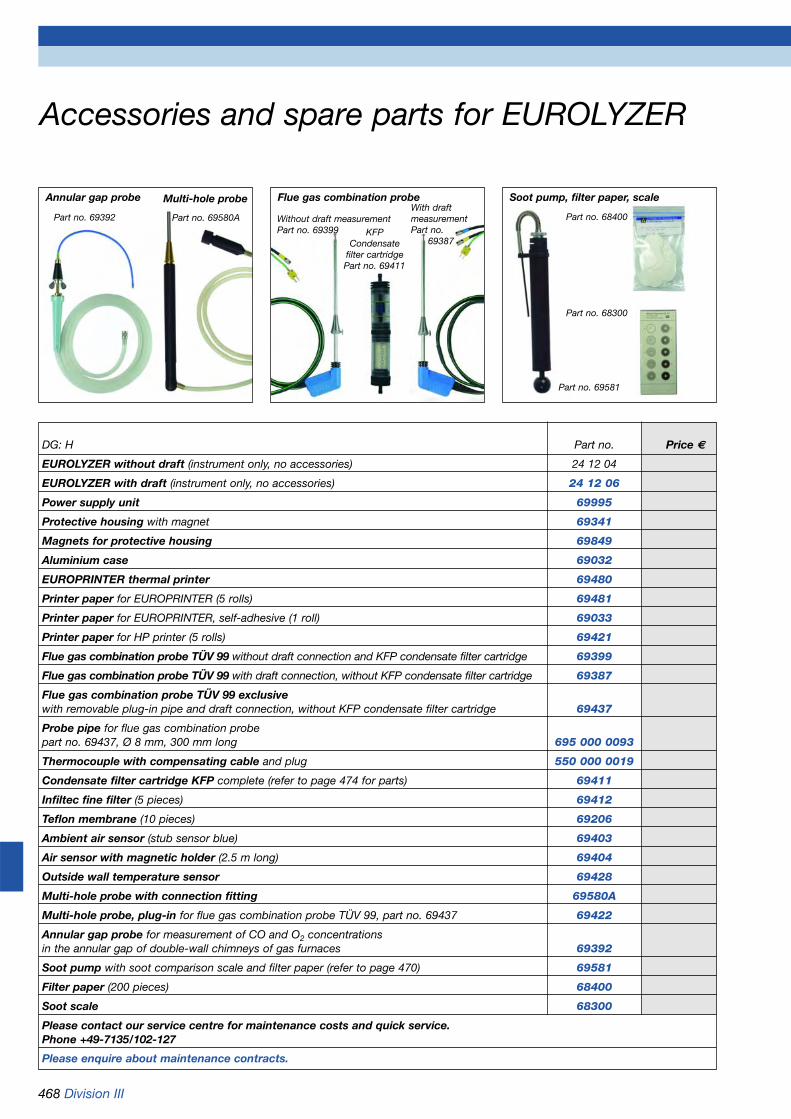
468 Division III
Accessories and spare parts for EUROLYZER
Part no. 69580A
KFPCondensate
filter cartridgePart no. 69411
Annular gap probe
Part no. 69392
Flue gas combination probe
Without draft measurementPart no. 69399
With draft measurementPart no.
69387
Soot pump, filter paper, scale
Part no. 69581
Part no. 68400
Part no. 68300
DG: H Part no. Price €
EUROLYZER without draft (instrument only, no accessories) 24 12 04
EUROLYZER with draft (instrument only, no accessories) 24 12 06
Power supply unit 69995
Protective housing with magnet 69341
Magnets for protective housing 69849
Aluminium case 69032
EUROPRINTER thermal printer 69480
Printer paper for EUROPRINTER (5 rolls) 69481
Printer paper for EUROPRINTER, self-adhesive (1 roll) 69033
Printer paper for HP printer (5 rolls) 69421
Flue gas combination probe TÜV 99 without draft connection and KFP condensate filter cartridge 69399
Flue gas combination probe TÜV 99 with draft connection, without KFP condensate filter cartridge 69387
Flue gas combination probe TÜV 99 exclusivewith removable plug-in pipe and draft connection, without KFP condensate filter cartridge 69437
Probe pipe for flue gas combination probepart no. 69437, Ø 8 mm, 300 mm long 695 000 0093
Thermocouple with compensating cable and plug 550 000 0019
Condensate filter cartridge KFP complete (refer to page 474 for parts) 69411
Infiltec fine filter (5 pieces) 69412
Teflon membrane (10 pieces) 69206
Ambient air sensor (stub sensor blue) 69403
Air sensor with magnetic holder (2.5 m long) 69404
Outside wall temperature sensor 69428
Multi-hole probe with connection fitting 69580A
Multi-hole probe, plug-in for flue gas combination probe TÜV 99, part no. 69437 69422
Annular gap probe for measurement of CO and O2 concentrationsin the annular gap of double-wall chimneys of gas furnaces 69392
Soot pump with soot comparison scale and filter paper (refer to page 470) 69581
Filter paper (200 pieces) 68400
Soot scale 68300
Please contact our service centre for maintenance costs and quick service. Phone +49-7135/102-127
Please enquire about maintenance contracts.
Multi-hole probe

Division III 469
Flue gas analysis computer MULTILYZER
MULTILYZERMULTILYZER is a digital display fluegas analysis computer with state-of-the-art processor technology andconvincing, compact design.Measured parameters: O2, COH2,flue gas temperature, combustion airtemperature, draft, pressure, diffe-rential pressure.Options: CO20,000, NO, SO2Calculated parameters: CO absolute,CO2, NOx, lambda, eta efficiency, fluegas losses, dew point, temperaturedifference.Options: Solid fuel calorific value EB,15 minutes mean value for solid fuelmeasurement, eta efficiency conden-sing systems.
Input possibilities for soot spot num-ber, oil derivatives, boiler tempera-ture and customer number. The unitfeatures a memory for 100 blocks ofmeasurements. This instrument is theideal solution for checking and servi-cing small and medium sized heatingsystems according to the GermanBlmSchV guidelines. In addition,MULTILYZER can be used for COconcentration safety checks in gas-fired systems. A second flushingpump protects the CO measuringcell even at high CO concentrations.
MULTILYZER is also designed formeasurements on all condensingsystems as well as wood burningsystems, in particular for optimumburner adjustment of wood pelletheating systems.
The electronic core search functionallows for optimum burner adjustmentwhich is further facilitated by continu-ous and simultaneous indication offour measurement parameters. Thezoom function lets you read the O2,CO and temperature values evenfrom a distance (large boilers installa-tions). The graphic display ofmeasured values facilitates optimumburner adjustment. The measuredvalues can be printed directly fromthe unit´s memory (100 measurementblocks) or transferred to a PC forfurther processing.
Scope of delivery:MULTILYZER up to 4 measuring cellsand TA, TGas, CO2, λ , qa, with cali-bration certificate, power supply unit,flue gas probe immersion depth 300mm, condensate filter cartridge,ambient air sensor, connection kit forgas fittings, protective housing withmagnet, aluminium case.
Options:IrDA interface, aluminium case,thermal printer.
MULTILYZER can be equipped withan optional IrDA interface for wire-less, bi-directional data transmission.IrOBEX protocol for pocket PCs(PDA, Palm, iPAQ) and all notebookssupporting IrDa. For example, themeasured values are transferred fromthe measuring instrument to a PDAvia the infrared connection. Thisinformation is then transmitted alongwith pictures of the heating systemto a cell phone and can then be sentanywhere in the world. This optimisesall processes involved in customerservice: documentation, qualifiedsupport of service technicians whoare on site, etc.
TÜV By RgG 183
Please refer to page 470 for technicalspecifications.
DG: H Part no. Price €
MULTILYZER O2, COH2, differential pressure 69415A
MULTILYZER O2, COH2,CO20,000, solid fuel prog., differ. press. 69418A
MULTILYZER O2, COH2, CO20,000, differential pressure 69601A
MULTILYZER O2,COH2, NO, differential pressure 69416A
MULTILYZER O2, COH2, CO20,000, NO, differential pressure 69603A
MULTILYZER special equipment 69606S on request
Infrared interface IrDAfor data transmission 69534 on request
Please enquire about maintenance contracts.
TÜV By RgG 183
EUROPRINTER thermal printer

470 Division III
Accessories and spare parts for MULTILYZERand MULTILYZER NG
Technical specificationsFlue gas temperature:Measuring range: 0 °C/+1,000 °CResolution: 1 °CCombustion air temperature:Measuring range: -20 °C/+100 °CResolution: 0.1 °CPressure measurement:Measuring range: ±150 hPa (mbar)Resolution: 0.01 hPaO2 measurement:Measuring range: 0/20.9 % by vol.Resolution: 0.1 % by vol.CO2 determination:Measuring range: 0/CO2 max.Resolution: 0.1 % by vol.CO measurement (without H2):Measuring range: 0/2.0 % by vol.Resolution: 0.01 % by vol.CO measurement solid fuels:Measuring range: 0/20,000 ppmResolution: 5 ppmNO measurement:Measuring range: 0/2,000 ppmResolution: 1 ppmSO2 measurement:Measuring range: 0/2,000 ppmResolution: 1 ppmFlue gas loss QA:Range: 0/100 %Efficiency eta:Range: 100 %/0 %Lambda:Range: 1/99,999Dew point:Range: 0/100 °CEfficiency calorific value - etaCV:Range: 110 %/0 %Power supply:NiMH battery 6V/2 Ah, ext. power supply unitDisplay: Alphanumerical,
backlit 6.5 x 4.5 cmMemory: 100 measurement blocks min.Interface: Infrared and RS 232Printer: Thermal printerPermissible operating temp.:+5 °C/+40 °CStorage temperature: -5 °C/+50 °CDimensions (W x H x D): 95x215x45 mmWeight MULTILYZER set: Ap. 2,500 g
DG: H Part no. Price €
MULTILYZER (instrument only, no accessories)
MULTILYZER without NO, with differential pressure 69352MULTILYZER with NO, with differential pressure 69353Battery charger 69406Protective housing with magnet 69350Protective pocket with magnet 69424Aluminium case 69032EUROPRINTER thermal printer 69480Printer paper for EUROPRINTER (5 rolls) 69481Printer paper for EUROPRINTER, self-adhesive (1 roll) 69033Printer paper for HP printer (5 rolls) 69421Software Eurosoft 69391Interface cable 69410Flue gas combination probe length 170 mm, without KFP 69482Flue gas combination probe TÜV 99 69468with removable plug-in pipe
with differential pressure connection, without KFP condensate filter cartridge 69437Flue gas probe plug-in pipe Ø 8 mm, 300 mm long 695 000 0093Thermocouple with compensating cable and plug 550 000 0043Condensate filter cartridge KFP complete 69411(refer to page 474 for parts)
Gas treatment system MGA-1, 69207e.g. for condensing systems
Infiltec fine filter (5 pieces) 69412Teflon membrane (10 pieces) 69206Ambient air sensor (stub sensor blue) 69403Air sensor with magnetic holder (2.5 m long) 69404Outside wall temperature sensor 69428Multi-hole probe, plug-in, instead of plug-in pipe 69422Annular gap probe for measurement of CO and O2 69392concentrations in the annular gap, refer to page 468
Differential pressure connection set 69839Soot pump with soot comparison scale and filter paper 69581Filter paper (200 pieces) 68400Soot scale 68300Please enquire about maintenance contracts.
Part no. 69392
Part no. 69422
Without differen-tial pressure part no. 69468With differentialpressure part no. 69437
Annular gap probe Flue gas combina-tion probe
MULTILYZER with protective housing
MULTILYZER withprotective pocket
Multi-hole probe Gas treatmentsystem MGA-1 forcondensing systemsPart no. 69207

Division III 471
Flue gas analysis computer MULTILYZER NG
MULTILYZER NGMULTILYZER NG is the ideal solutionfor checking and servicing small andmedium sized heating systems accor-ding to the German BlmSchV guide-lines. MULTILYZER NG can be used forCO concentration safety checks on gasfired systems. In addition, the instrumentcan be used for measurements andadjustments of solid fuel systems, inparticular for pellets, as well as bi-valent, modulating combined heatingand power plants.The compact design allows theinstrument to be equipped with anycombination of up to six electro-chemical cells.
In addition to the existing approvalsaccording to BImSchV and KÜO, MUL-TILYZER is also approved according tothe stringent rules of EN 50379 (part 2)and is therefore also suitable for mea-surements regulated by law in Europe.The large LCD display allows you todisplay either 5 or 10 measured values.The measured values can be printedeither directly from the measuring pro-gramme or from the memory via aninfrared printer. In addition, the instru-ment features a USB connection fordata transmission to a PC. MULTILY-ZER NG is also equipped with a devicemonitoring function, limit value monito-ring (flushing pump, can also be opera-ted manually), graphic evaluation of themeasured values with combustioncharts for small gas and fuel oilsystems as well as a core search func-tion. 4 measured gas values can bedisplayed and the pressure measure-ment value in six different units. Variousmeasuring programmes for (differential)pressure and temperature with min./max. indication of all measured valueswith re-set function are available.
Calculated parameters: CO absolute,lambda, CO2 , eta efficiency, flue gaslosses, dew point, temperature diffe-rence.
Scope of delivery: MULTILYZER NGup to 6 measuring cells and TA, TGas,CO2, λ , qa, with calibration certificate,power supply unit, flue gas probeimmersion depth 300 mm, condensatefilter cartridge, ambient air sensor, con-nection kit for gas fittings, protectivehousing with magnet, aluminium case.
Technical specificationsFlue gas temperature (includingseparate differential temperaturemeasurement)Meas. range: 0 °C/1,000 °CResolution: 1 °CThermocouple: NiCr-Ni (type K)
Outside wall / air temperatureMeas. range: -20 °C/+200 °CResolution: 0.1 °CThermocouple: NiCr-Ni (type K)
Draft/differential pressureMeas. range: ±70 hPa (nominal)/
±130 hPa (max.)Accur. of meas.:±1 % of MV/±2 % of MVResolution: 0.01 hPa
O2 measurementMeas. range: 0/21 % by volumeResolution: 0.1 % by volumeAccur. of meas.:±0.2 % by volume of MV
CO2 determinationRange: 0/CO2 max.Resolution: 0.1 % by volumeAccur. of meas.: ±0.2 % by volume
CO measurement (with H2 compensation)Meas. range: 0/4,000 ppmResolution: 1 ppmAccur. of meas.: ±3 ppm (up to 20 ppm)
±5 % of MV (> 20 ppm)
OptionsNO measurementMeas. range: 0/2,000 ppmResolution: 1 ppmAccur. of meas. ±5 ppm (up to 50 ppm)
±5 % of MV (> 50 ppm)
CO measurement solid fuels:Meas. range: 0/2.0 % by volume
(or 20,000 ppm)Resolution: 0.01 % by volumeAccur. of meas.: ±5 % of MV ± 1 digit
SO2 measurementMeas.. range: 0/2,000 ppmResolution: 1 ppmAccur. of meas.: ±10 ppm
(up to 150 ppm) ±5 % of MV(> 150 ppm)
NO2 measurementMeas. range: 0/200 ppmResolution: 1 ppmAccur. of meas.: ±10 ppm (up to 50 ppm)
±10 % of MV(> 50 ppm)
Features:
• USB interface for PC/notebookand infrared interface for printer
• Measuring configuration can be programmed as required
• Measuring mode with two active levels (multitasking mode)
• LCD display with up to 10 measured values at a glance
DG: H Part no. Price €
MULTILYZER NG O2,, COH2, differential pressure 69631A
MULTILYZER NG O2, COH2, NO, differential pressure 69632A
MULTILYZER NG O2, COH2, CO20,000, differential pressure 69633A
MULTILYZER NG O2,COH2, CO20,000, NO, differential pressure 69634A
MULTILYZER NG – special equipment 69635 on request
Please enquire about maintenance contracts.
Please refer to page 470 for accessories and spare parts.

472 Division III
Flue gas analysis computer MAXILYZER
TÜV By RgG 210
MAXILYZERThis flue gas analysis computer withstate-of-the-art technology andmodern design features an integratedprinter and gas treatment unit. Therobust, waterproof plastic housing con-tains the microprocessor-controlledelectronic system, the electro-chemicalmeasuring cells and sensors and theflue gas distribution system. Optimisedgas distribution to the sensors and anautomatic CO flushing function via asecond pump protect the sensors. Anefficient gas treatment system is inte-grated in the case lid.Measured parameters: O2, COH2,(options: CO20,000, NO and SO2), fluegas temperature, combustion air tem-perature, differential pressure, differen-tial temperature.
Calculated parameters:CO absolute, lambda, CO2, efficiency η, flue gas losses qA.15 minutes mean value programme forsolid fuels.When the lid is opened, all operatingand connection elements are easilyaccessible on the upper side of theanalyser. The connection pieces forpressure, temperature, charger, RS 232interface and connections for the fluegas combination probe are located atthe left hand side. The large, backlitgraphic display is located in the centre.Below the centre are the three special
soft keys. The dot matrix printer forhardcopies on standard paper can befound at the bottom. A foil keypad is located on the righthand side. The display has four lineswith an additional status line, graphicpresentation, zoom and „hold“ func-tions as well as an electronic coresearch function and sensor status dia-gnostics. Especially designed for theoptimisation of solid fuel, pellet andcondensing systems. The triple stagegas treatment unit is integrated in thecase lid.It features a condensate cartridge, adrying cartridge with drying beads and
Special features:• Dust and water-proof device housing
with vent valve• Most comprehensive sensor equipment:
O2, COH2, NO, CO20,000 and SO2• 4 measured values on brightly backlit
LCD display• Additional flushing function, depending
on measured concentration• Automatic self-checking• CO limit value monitoring with sensor
protection function• Graphic evaluation of measured
values, combustion chart (onlinefunction)
• Innovative sensor core with selective filter replacement for prolonged servicelife
• Powerful rechargeable battery, approx. 24 hours of continuous use with active display backlit function
• Intelligent charging technology via external power supply unit
• Hold function, zoom function, core search function, conversion of units
a dust cartridge with Infiltec dust filter. This protects the analyser from humidi-ty and dirt. The system is also equip-ped with the following components:memory for 100 to up to 250 measure-ment blocks, rechargeable battery for24 hours of operation, power supplyunit with intelligent rapid-charge tech-nology.
Scope of delivery:MAXILYZER with 2, 3 or 4, max. 5sensors. Case with battery charger,ambient air sensor, flue gas combi-nation probe, operating instructionsand accessories.TÜV By RgG 210
DG: H Part no. Price€
MAXILYZER O2, COH2 69193MAXILYZER O2, COH2, NO 69194MAXILYZER O2,COH2,CO20,000, NO 69195Spare parts:Ambient air sensor (stub sensor) 69196Flue gas combination probe 69197Case for flue gas combination probe 69198and accessoriesBattery charger 69199Options: Immediate installation when instrument is orderedCO-20,000 ppm without solid fuel programme 69536CO-20,000 ppm with solid fuel programme 69535SO2-2,000 ppm 69537Infrared interface IrDA onfor data transmission 69534 requestPrinter paper (5 rolls) 69182Ink ribbon 24 02 000304Rechargeable battery 670 000 0004Please enquire about maintenance contracts.

Division III 473
Flue gas analysis computer MAXILYZER
DG: H Part no. Price €
Spare parts for the gas treatment system MAXILYZER01 Inlet piece 695 000 9402 Assortment of O rings 6942703 Glass piston with arrow 695 000 9505 Inlet piece particle filter element 695 000 9306 Glass piston with logo 695 000 9907 Infiltec fine filter, 5 pieces 6941208 Intermediate piece 695 000 9709 Teflon membrane 69206
Ø 23.5 mm, 10 pieces.10 Outlet piece 695 000 9811 Filter pipe M6 695 000 9212 Outlet piece with cylinder 695 000 91
13 Drying beads, 850 ml can 69226Please enquire about maintenance contracts.
Technical specificationsFlue gas temperature:Measuring range: 0 °C/+1,000 °CResolution: 1 °CThermocouple: NiCr-Ni (type K)Outside wall/air temperature:Measuring range: -20 °C/+200 °CResolution: 0.1 °CThermocouple: NiCr-Ni (type K)Draft/differential pressure:Measuring range: ±150 mbarResolution: 0.01 hPa
O2 measurement:(electrochemical measuring cell)Measuring range: 0/20.9 % by vol.Resolution: 0.1 % by vol.
CO2 determination:(calculation on the basis of O2)Range: 0/CO2 max.Resolution: 0.1 % by vol.
CO measurement(electrochemical measuring cell, with H2compensation):Measuring range: 0/4,000 ppmResolution: 1 ppm
Options:CO measurement solid fuels:(without H2 compensation):Measuring range: 0/2.0 % by vol.
(20,000 ppm)Resolution: 0.01 % by vol.
NO measurement:(electrochemical measuring cell)Measuring range: 0/2,000 ppmResolution: 1 ppm
SO2 measurement:(electrochemical measuring cell)Measuring range: 0/2,000 ppmResolution: 1 ppm
Weight: Approx 2.8 kgDimensions W x H x D:273 x 178 x 247 mm
Gas treatment system for MAXILYZER
Maintenance informationHandle the gas treatment system withpatented water stop system with speci-al care in order to ensure maximumprotection of your MAXILYZER analysiscomputer.
Ensure that the following parts arereplaced in good time:09 Teflon membrane07 Infiltec fine filter13 Drying beadsIt is recommended to order these parts along with the system.

474 Division III
Condensate filter and gas treatment system for portable flue gas analysers
O ring 18 x 3Intermediate adapter
(695 000 97)
O ring 23 x 2O ring 23 x 2
Teflon membrane(69206) Glass piston with logo
(695 000 99)Centre piece(695 000 96)
Glass piston with arrow(695 000 95)
Inlet piece (695 000 94)
Outlet piece(695 000 98)
Infiltec fine filter(69412)
Dust filter
Gas treatment system MGA-1The MGA-1 gas treatment unit protectsthe portable flue gas analysers fromhumidity and dirt. MGA-1 separates the humidity in the bottom condensatebowl and dries the gas sample in theupper condensate bowl. The degree of saturation is indicated by a change in colour. The membrane retains soot,dirt and water. Especially suitable for measurements of gases with high con-densate concentration (gas furnaces and condensing systems).
Condensate filter cartridge KFP
DG: H Part no. Price €
Gas treatment system MGA-1 69207Teflon membrane (10 pieces) 69206Round filters (25 pieces) 69229Dust filters (25 pieces) 69225Dust filter complete 69230O rings 19 x 2.5 (4 pieces) 801 195 2000O rings 35 x 3 (4 pieces) 801 000 0070Dry beads 850 ml can 69226Upper filter bowl for MGA-1 69201Lower filter bowl for MGA-1 11 70 740010Locking screw 25 01 000002
Condensate filter cartridge KFP 69411Infiltec fine filter (5 pieces) 69412Assortment of O rings 69427Inlet piece 695 000 94Glass piston with arrow 695 000 95Centre piece 695 000 96Intermediate adapter 695 000 97Outlet piece 695 000 98Glass piston with logo 695 000 99Teflon membrane (10 pieces) 69206
Gas treatment system for measu-rements of gases with highcondensate concentration, e.g.condensing systems
Filter bowl, upper part(69201)
Drying beads, replace when 2/3 have changedtheir colour(69226)
O ring 35 x 3(801 000 0070)
Locking screw(25 01 000002)
O ring 19 x 2,5(801 195 2000)
MGA body with filter bowls(25 01 000000)
Filter bowl, lower part(11 70 740010)
Round filter(69229)
Teflon membraneØ 23 mm
(69206)
Fixing bracket(25 01 00 03)
Replace the Teflon membrane ifit has come into contact with water or if it is polluted with soot or oil derivatives. Is noticed when correct measuring results cannot be obtained. O2 remains at approx.20.9 % by volume, no CO2indication.
(smooth sidedown)
Dry filter

Division III 475
Mobile gas treatment system MAXISYSTEM
MAXISYSTEMPortable gas treatment system forlong-term measurements and appli-cations on different sites requiringhigh-precision gas analyses andinvolving pollution and condensatein the flue gas. The electronically controlled Peltiercooler prevents the formation ofcondensate and the precipitation ofpollutants in the flue gas analyserby reducing the dew point tempera-ture. MAXISYSTEM is particularlyhelpful if highly water-soluble gases(such as NO2 and SO2) are to beanalysed.The complete gas treatment system is contained in a small, robust caseto ensure accurate and reproduc-ible analyses quickly and with highreliability. This is most important fordemanding gas analysis applica-tions.
DescriptionThe basic version of the portablegas treatment system MAXISYSTEMfeatures all required functions andcomponents: • Gas cooling:
Gas cooling with Peltier gas cooler• Gas filtering:
Fine dust filter• Gas transport:
Gas pump in MAXILYZER• Condensate transport:
Condensate removal by means of hose pump
The gas treatment system isequipped with a status recognitionunit for the detection of the opera-ting status of the cooler and theheating hose. When the condensa-te alarm LA+ is activated, the 3/2-way solenoid valve for free suctionfrom the MAXILYZER instrument isopened and the internal gas pump(option) of the MAXISYSTEM isswitched off. In addition, there is amains switch and a switch for theinternal gas pump.
DG: H Part no. Price €
MAXISYSTEM with controllerfor heated pipe and condensate pump without gaspump, with mains cable 69486Gas pump 60 l/h onand activation pump ON/OFF when cooler is ready for operation 69486A requestCondensate alarmcondensate alarm LA+ pump „off“ switching and activation onof 3/2 way valve Teflon/Viton 69486B requestProbe 300 mm with accessories, not heatedHose for condensate outlet 300 mm, 1 m connection hose with 2 female connectors 69485Gas sampling probe PSP 4000, portable, heatedProbe temperature +100 °C/+180 °C, adjustable 68900Heated line 5 mtype WAP 183/04/030 with thermocouple PT 100 69476Heated line 3 mtype WAP 183/04/030 with thermocouple PT 100 69478
Gas withdrawal probe PSP 4000
With external ceramic filter element
Gas tobe mea-sured
Gas tobe mea-sured
Condensate
Air
MAXISYSTEM
TCIA-
100°C
TCIA+
5 °C
LA+
Technical specificationsGas cooler:• Gas inlet: Max. 60 °C dew point,
100 °C gas temperature• Ready for operation after app.15 min.Gas flow and filtering:• 70 l/h at 200 mbar• Fine dust filter with glass fibre
filter 2 µmStatus indication via LED at thefront:Temperature of cooler and heatinghose, status „Cooling active“ as well as condensate alarm LA+Connection:Hose NW 3 mm, hose connector, plug-inWetted parts:Duran glass, PVDF, Viton, stainlesssteelSupply voltage:AC 230 V/50 Hz, 60 WOperating and storage temperature:+8 °C/+40 °C and -15 °C/+55 °CProtection (EN 60529):IP 20 operating condition (open), IP 65 closedDimensions and weight:W x H x D: 273 x 178 x 247 mm approx. 4 kgGas flow chart(shown with options)

476 Division III
Water analysis instruments
DG: E PU Part no. Price €
AQUALYZER 8130pH: 0-14, temperature 0-50 °C 1 69660
AQUALYZER 8110O2: 0.1 - 30 mg/l, temperature 0-50 °C 1 69661
AQUALYZER 8120Conductivity: 0-20 µS/cm or 0-20 mS/cm, temperature 0-50 °C 1 69662
AQUALYZER 7030pH 0-14, O2: 0.1-30 mg/l, redox: ±900 mV,conductivity: 0-20 mS/cm, temperature: 0-50 °C 1 69663
AQUALYZER ISE (refer to page 478) 1 69664 on request
Case 1 69665
All prices include sensors, cables and plugs.
AQUASYSTEM 7430pH: 0-14, temperature: 0-50 °C 1 69666
AQUASYSTEM 7405Redox: ±900 mV, temperature: 0-50 °C 1 69667
AQUASYSTEM 7410O2: 0.1-40 mg/l, temperature: 0-50 °C 1 69668
AQUASYSTEM 7420Conductivity: 0-200 µS/cm; 0-20 mS/cmTemperature: 0-50 °C 1 69669
AQUASYSTEM ISE (refer to page 478) 1 69670 on request
iVM-IS74xxPC software (calibration,configuration, data recording) 69671
All prices include sensors, cables and plugs.
AQUALYZERHandheld measuring instruments for connection of one or severalsensors, with microprocessor andmemory. The instruments can beoperated via battery or mains. TheAUTO store function allows theunits to be used as a data logger.The stored measured values canbe read easily and processed fur-ther on a PC with the correspondingsoftware. Depending on the re-quirements, the instruments areequipped with temperature andpressure measurement facilities.Calibration solutions are suppliedfor the calibration of the instru-ments. An instrument case is avail-able as an option.
AQUASYSTEMCompact, stationary measuringinstruments for the connection ofone sensor or electrode with 4-20 mA or 0-2 V output each. Thesensors and electrodes are calibra-ted via the transmitter and themeasured value is temperature/pressure compensated, if required.The optional PC software and theRS 232 interface allows the measu-red values to be processed further.
AQUALYZER AQUASYSTEM
Please refer to pages 477 and 478 for sensors.
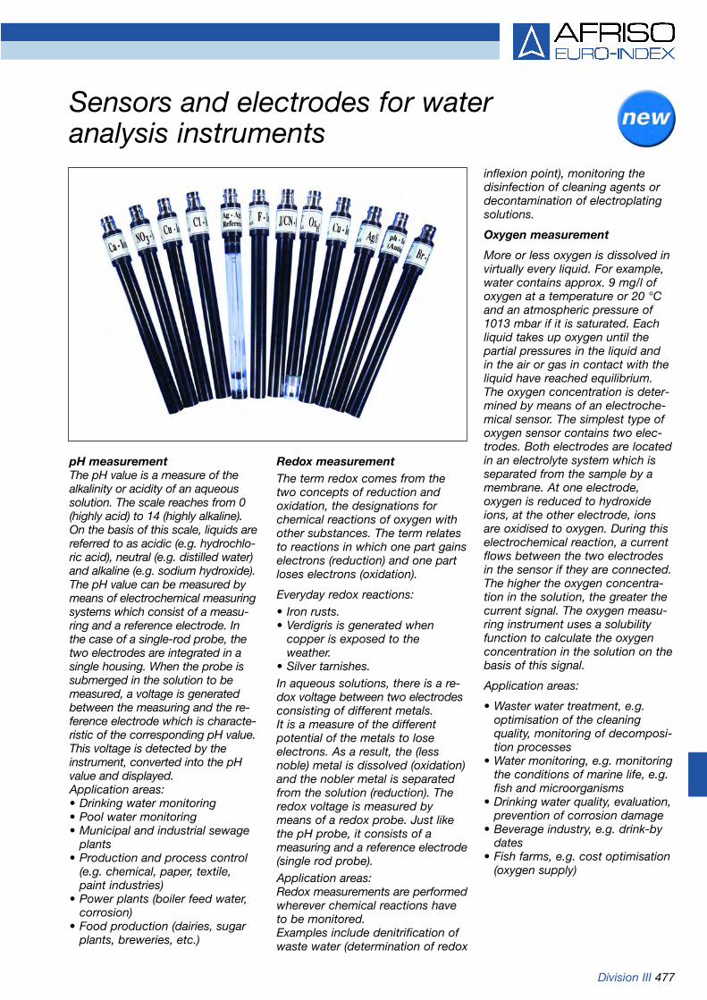
Division III 477
Sensors and electrodes for water analysis instruments
pH measurementThe pH value is a measure of thealkalinity or acidity of an aqueoussolution. The scale reaches from 0(highly acid) to 14 (highly alkaline). On the basis of this scale, liquids arereferred to as acidic (e.g. hydrochlo-ric acid), neutral (e.g. distilled water)and alkaline (e.g. sodium hydroxide).The pH value can be measured bymeans of electrochemical measuringsystems which consist of a measu-ring and a reference electrode. Inthe case of a single-rod probe, thetwo electrodes are integrated in asingle housing. When the probe issubmerged in the solution to bemeasured, a voltage is generatedbetween the measuring and the re-ference electrode which is characte-ristic of the corresponding pH value.This voltage is detected by theinstrument, converted into the pHvalue and displayed. Application areas:• Drinking water monitoring• Pool water monitoring• Municipal and industrial sewage
plants• Production and process control
(e.g. chemical, paper, textile, paint industries)
• Power plants (boiler feed water, corrosion)
• Food production (dairies, sugar plants, breweries, etc.)
Redox measurementThe term redox comes from thetwo concepts of reduction andoxidation, the designations forchemical reactions of oxygen withother substances. The term relatesto reactions in which one part gainselectrons (reduction) and one partloses electrons (oxidation).
Everyday redox reactions:• Iron rusts.• Verdigris is generated when
copper is exposed to the weather.
• Silver tarnishes.In aqueous solutions, there is a re-dox voltage between two electrodesconsisting of different metals. It is a measure of the differentpotential of the metals to lose electrons. As a result, the (lessnoble) metal is dissolved (oxidation)and the nobler metal is separatedfrom the solution (reduction). Theredox voltage is measured bymeans of a redox probe. Just likethe pH probe, it consists of a measuring and a reference electrode(single rod probe).Application areas:Redox measurements are performedwherever chemical reactions haveto be monitored. Examples include denitrification ofwaste water (determination of redox
inflexion point), monitoring thedisinfection of cleaning agents ordecontamination of electroplatingsolutions.
Oxygen measurement
More or less oxygen is dissolved invirtually every liquid. For example,water contains approx. 9 mg/l ofoxygen at a temperature or 20 °Cand an atmospheric pressure of1013 mbar if it is saturated. Eachliquid takes up oxygen until thepartial pressures in the liquid andin the air or gas in contact with theliquid have reached equilibrium.The oxygen concentration is deter-mined by means of an electroche-mical sensor. The simplest type ofoxygen sensor contains two elec-trodes. Both electrodes are locatedin an electrolyte system which isseparated from the sample by amembrane. At one electrode,oxygen is reduced to hydroxideions, at the other electrode, ionsare oxidised to oxygen. During thiselectrochemical reaction, a currentflows between the two electrodesin the sensor if they are connected.The higher the oxygen concentra-tion in the solution, the greater thecurrent signal. The oxygen measu-ring instrument uses a solubilityfunction to calculate the oxygenconcentration in the solution on thebasis of this signal.
Application areas:
• Waster water treatment, e.g. optimisation of the cleaning quality, monitoring of decomposi-tion processes
• Water monitoring, e.g. monitoringthe conditions of marine life, e.g. fish and microorganisms
• Drinking water quality, evaluation, prevention of corrosion damage
• Beverage industry, e.g. drink-by dates
• Fish farms, e.g. cost optimisation(oxygen supply)

478 Division III
Sensors and electrodes for water analysis instruments
DG: E PU Part no. Price €
ph single rod probefor connection to AQUALYZER 7030, 8130or AQUASYSTEM 7430 1 69650
Redox single rod probefor connection to AQUALYZER 7030 orAQUASYSTEM 7405 1 69651
Oxygen sensorfor connection to AQUALYZER 7030, 8110or AQUASYSTEM 7410 1 69652
Conductivity measuring cellfor connection to AQUALYZER 7030, 8120or AQUASYSTEM 7420 1 69653
Ion-selective electrodes ISE(please enquire for separate datasheets) for connection to AQUALYZER ISEor AQUASYSTEM ISE. 1 69654 on request
Conductivity measurementThe electrical conductivity is ameasure of the electrical currentbetween two points (electrodes)with different potential (voltage),e.g. in a liquid. The more minerals,acids or bases a solution contains,the greater its conductivity. Theunit for conductivity is S/m. Thescale for aqueous solutions beginswith pure water with a conductivityof 0.05 µS/cm (25 °C) and endswith some bases with a conductivi-ty of 1,000 µS/cm (e.g. potassiumsolutions). The conductivity ofnatural water such as drinkingwater or surface water is in therange of 100-1,000 µS/cm.The conductivity is measured bymeans of a measuring cell which,in the simplest case, consists oftwo electrodes. An alternating voltage applied at one electrodecauses the ions contained in thesolution to move to the electrode.The more ions in the solution, thegreater the current between theelectrodes. The instrument usesthe measured current to first calcu-late the conductance and then theconductivity level depending on thecell data.
Application areas:• Boiler feed water monitoring: lime
causes damage to the pipes.• Monitoring of industrial facilities:
production of ultra-pure water, drinking water treatment, demi-neralisation of water for cooling plants, waste water monitoring
• Food industry: milk, beverages, beer, bottle cleaning and CIP systems
Ion-selective electrodes ISE(e.g.: NO3
-, NH4+, F-, CI-, Ag+/S2-
Ion-selective electrodes enable thedetermination of activities or con-centrations of exactly one type ofion in liquids, irrespective of colour-ation and turbidity. The measure-ment is performed by submergingan ion-selective electrode and areference electrode in the samplesolution and measuring the cell voltage. Silver electrodes, silverchloride electrodes and saturatedcalomel electrodes are primarilyused as reference electrodes.
Application areas:• Water supply and distribution:
monitoring of drinking water, process and surface water. Fluoride concentrations in fluori-nated drinking water, water hard-ness, chlorine content, sulphateand sulphide in natural waters.
• Agriculture: examination of the nutrient content and fertiliser require-ments in terms of nitrate, chloride, fluoride, sodium, calcium, potassium and iodide.
• Medical technology: fluoride in tooth enamel, chloride,calcium, potassium, sodium and enzymes in the blood, serum andurine as well as chloride in body perspiration.
• Chemical industry: monitoring of base and laboratory chemicals, silver and halogen concentrations in the production of photo emulsions. Checking washing water in the photo-chemical industry.
• Food industry:measurement of nitrate due to itspotential toxicity in food, in parti-cular fresh vegetables, determi-nation of the salt content in meat, fish, milk, vegetable and fruit juices with chloride electrodes.
• Metallurgy: checking etching, flushing and electroplating solutions for silver, copper, fluoride, chloride and cyanide.

www.afriso.de 479
Chapter 13Table of contents chapter 13
Stationary gas analysis systems
13
Page
General information on gas concentration measurement 480
Stationary gas withdrawal probes 481
Universal filters for gas analysis 482
Gas treatment system MGK 744 483
Gas cooler MGK 741 484
Infrared gas analysers 485
Oxygen probe Oxystem 486
Oxygen analyser Oxystem 600 487
Oxygen analyser Oxystem 1800 - High temperature version 488
Oxygen trace analyser Oxystem S 489
Dust concentration measurement system S303/S305 490
Volume flow measurement unit VMG 02 491
Compact gas analysis unit EasySystem 492-493
Gas analysis system BIOLYZER 494
Emission computer 495

480 Division III
Stationary gas analysisGeneral information on gas concentration measurement
TaskThe basic objective of gas concen-tration measurement is to measureone of the components of a gasmixture continuously, selectivelyand quantitatively. The result is thentransformed into an electrical, stan-dardised signal. This signal can beprocessed for logging, control, cal-culation or analysis purposes.Each gas component is measuredon the basis of differentchemical/physical or physical principles of measurement. Such principles include:• Absorption of infrared radiation
(for measuring heteroatomic gases)
• Paramagnetism (this method measures oxygen concentrations)
• Ion conductivity of solid electro-lytes and liquid electrolytes
Before specifying a suitable measu-ring system, one must give consi-deration to the selectivity of thecomponent to be measured.Selectivity refers to the specifictechnical detectability of a certaincomponent in the measuring gaswithout it being influenced by othergases.
ApplicationThe analysis of gas mixtures withcontinuously operating measuringsystems is a part of industrial measuring technology. By usingcontinuously operating gas analysisunits it is possible to recognise tendencies, monitor, control and/or evaluate processes.
The technical analysis of gas emis-sions is prescribed by numerousenvironmental acts in many count-ries. For example, in Germany, thedirectives such as TA-Luft andBlmSchG stipulate, that certainsystems must be equipped withemission measuring facilities. AFRISO supplies tested and ap-proved analysers, turn-key analysissystems and/or auxiliary equipment(such as gas withdrawal probes, fil-ters, coolers) for such applications.These units make continuous analy-sis of gas components possible.Other typical application areasinclude:• Biological systems• Tunnel monitoring• Cooling plants• Fruit and vegetable storage halls• Purity measurements
Design featuresDue to the varied nature of measu-ring tasks and gas components, it isimperative to consider the opera-ting conditions and ambient condi-tions in addition to the selection ofthe measuring principle and themeasuring range. Therefore, whenplanning a measuring system, theoperating conditions (such as pres-sure, temperature, humidity, dirtaccumulation) and the ambientconditions (such as ambient temperature, corrosive environments,vibrations, dust concentration) mustbe taken into consideration.
Gas treatmentThe accuracy and the reliability of agas analysis system is very muchdetermined by the selection of the
gas withdrawal unit and the gas treatment. In most cases, the gas withdrawnfor analysis cannot be directly pro-cessed by the gas analyser. Theperformance of the analyser can beadversely affected by high dustconcentrations or high humidity,high dew points, too high or toolow pressures, too high tempera-tures as well as other detrimentalinfluences.The design of the gas analysissystem is a crucial factor for theusability of the analysis valuesgenerated by the analyser. Themost important conditions for mini-mum maintenance and trouble-freeoperation are the determination ofthe withdrawal point, the use of suit-able accessories and their properarrangement.A proper application related gastreatment is a prerequisite for accu-rate gas analysis. Take advantage ofAFRISO's many years of experienceand competence as a supplier ofcomplete analysis systems for solu-tions to your measuring problems.AFRISO supplies analysis systems:1. Individual system components2. Completely mounted on a panel,
wired, with capillary tubes readily connected.
3. Completely mounted, wired, with capillary tubes connected and installed in a control cabinet.
4. As a complete measurement station in a container or built onto a vehicle.
Custom-built units to your specifications - please enquire.
1. Withdrawal point2. Gas withdrawal probe3. Heated gas tube or pipe4. Cooler5. Condensate separation6. Filter7. Changeover cock8. Gas pump9. Flow monitor10. Flow meter11. Analyser12. Gas output

Division III 481
Stationary gas withdrawal probes
ApplicationWith continuous gas withdrawal, thefine dust is removed directly at thewithdrawal point through the withdra-wal probe. Part of the required main-tenance of the complete analysissystem is thereby focussed on thefirst element in the chain of compo-nents. This filter technology has theadvantage of retaining mixtures ofparticle matter and coarse dust andreduces maintenance to a minimum.Optimum adaptation of the withdra-wal probe to the process conditionsand the measuring task is a prerequi-site for optimum performance of thecomplete measuring system.
Gas withdrawal probeStationary gas withdrawal probe(standard version) with external elec-trically heated ceramics filter. Withmounting flange and G3/4 female thread for withdrawal pipe or prefilter.A deep-bed filter element with a largesurface is located in a housing with alow dead volume outside of the with-drawal space. The filter element iseasy to replace. There are no toolsrequired and the heated pipe doesnot need to be dismantled. Optimumheating of the complete filter housingincluding the mounting flange en-sures reliable operation without dewpoint problems at external areas. Theunit is heated to +180 °C by meansof self-controlling heating elements.Therefore, heating controllers are notrequired. A thermoswitch monitorsthe withdrawal probe for low tempe-ratures.
A 1 m long stainless steel withdrawalpipe is available as an optional item.It is screwed into the G3/4 thread.The modular probe design allows forthe combination of various materialsand withdrawal methods and ensuresoptimum adaptation to the processconditions.
Features:• Low dead volume, fast response• Simple filter replacement• Easy cleaning of filter space and
withdrawal pipe• Self-controlling electrical heating
system with low temperature alarm contact
• Small footprint• Easy installation
Please enquire for other gas with-drawal probes as well as heatedgas withdrawal pipes.
Technical specifications
Version SP210-H
Protection: IP 54 (EN 60529)Withdrawal pipe: SP210/SS optionalWithdrawal temperature: max. 600 °CWithdrawal pressure: 0.4/2 bar absoluteAmbient temperature:-20 °C/+80 °CDust admission: max. 1 g/m3
Filter space volume: 100 mlFilter element:Type F-2K, filter mesh 2 µm, ceramicProbe heating:+180 °C, self-controllingReady for operation: after 2 hLow temperature alarm contact:Switch point <160 °CSwitch rating AC 250 V, 3 A, DC 30 V, 3 AConnection gas output:1/4-NPT female with Swagelok pipeconnector Ø 6 x 1 mmSupply voltage:AC 110 to 240 V, 50/60 HzPower consumption:Starting phase: 400 VA, operation: 70 VA, fuse 6 AMounting flange: DN 65 PN 6,design B, stainless steel 1.4571Wetted parts:Stainless steel 1.4571, FFM, ceramicDimensions W x H x D:170 x 220 x 230 mmWeight: 6.5 kg
Version SP210-H/W
With weather protection hoodDimensions W x H x D:170 x 220 x 235 mmWeight: 8.5 kgOtherwise as SP210-H
DG: E PU Part no. Price €
Gas withdrawal probe SP 210-H, heated 1 68935Gas withdrawal probe SP 210-H/W, heated 1 68936Accessories:Stainless steel withdrawal pipeLength 1,000 mm, for max. temperature of 600 °C 1 68940Titanium withdrawal probeLength 1,000 mm, for highly corrosivegases and a max. temperature of 600 °C 1 68941Kanthal withdrawal probeFor max. temperatures of 1,300 °C 1 68942Prefilter for dust admission 2-16 g/m3 1 68945 on requestPrefilter for dust admission >10 g/m3 1 68946 on request Filter element F-2K 2 µm, ceramic 1 68950Please enquire for special probe design and heated gas pipes.
Gas output
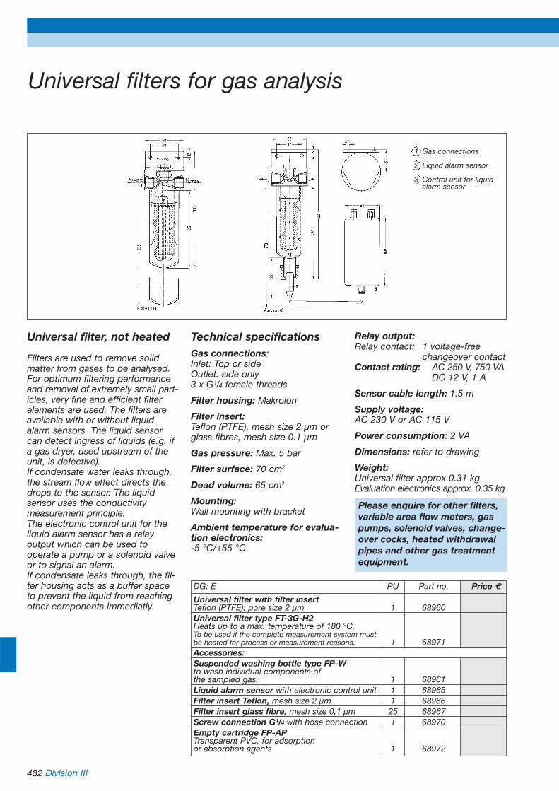
482 Division III
Universal filters for gas analysis
Universal filter, not heated
Filters are used to remove solidmatter from gases to be analysed.For optimum filtering performanceand removal of extremely small part-icles, very fine and efficient filterelements are used. The filters areavailable with or without liquidalarm sensors. The liquid sensorcan detect ingress of liquids (e.g. ifa gas dryer, used upstream of theunit, is defective). If condensate water leaks through,the stream flow effect directs thedrops to the sensor. The liquidsensor uses the conductivitymeasurement principle.The electronic control unit for theliquid alarm sensor has a relayoutput which can be used to operate a pump or a solenoid valveor to signal an alarm.If condensate leaks through, the fil-ter housing acts as a buffer spaceto prevent the liquid from reachingother components immediatly.
Technical specificationsGas connections:Inlet: Top or sideOutlet: side only 3 x G1/4 female threads
Filter housing: Makrolon
Filter insert:Teflon (PTFE), mesh size 2 µm orglass fibres, mesh size 0.1 µm
Gas pressure: Max. 5 bar
Filter surface: 70 cm2
Dead volume: 65 cm3
Mounting:Wall mounting with bracket
Ambient temperature for evalua-tion electronics:-5 °C/+55 °C
Relay output:Relay contact: 1 voltage-free
changeover contactContact rating: AC 250 V, 750 VA
DC 12 V, 1 A
Sensor cable length: 1.5 m
Supply voltage:AC 230 V or AC 115 V
Power consumption: 2 VA
Dimensions: refer to drawing
Weight:Universal filter approx 0.31 kgEvaluation electronics approx. 0.35 kg
DG: E PU Part no. Price €
Universal filter with filter insertTeflon (PTFE), pore size 2 µm 1 68960Universal filter type FT-3G-H2Heats up to a max. temperature of 180 °C.To be used if the complete measurement system mustbe heated for process or measurement reasons. 1 68971Accessories:Suspended washing bottle type FP-Wto wash individual components ofthe sampled gas. 1 68961Liquid alarm sensor with electronic control unit 1 68965Filter insert Teflon, mesh size 2 µm 1 68966Filter insert glass fibre, mesh size 0,1 µm 25 68967Screw connection G1/4 with hose connection 1 68970Empty cartridge FP-APTransparent PVC, for adsorptionor absorption agents 1 68972
1 Gas connections
2 Liquid alarm sensor
3 Control unit for liquid alarm sensor
Please enquire for other filters,variable area flow meters, gaspumps, solenoid valves, change-over cocks, heated withdrawalpipes and other gas treatmentequipment.

Division III 483
Gas treatment system MGK 744
Gas treatment system MGK 744Compact, portable and stationarygas treatment system in 1/2 19“housing for gas analysis systemswhich withdraws a gas sample forthe analysis process. Especially forlong-term or continuous measure-ments and measurements involvingpollution and/or condensate.Crucial for accurate and reproduc-ible measuring results.
DescriptionThe unit consists of a half 19“ rackunit with permanently installedPeltier gas cooler which cools thegas to be measured to a tempera-ture of +5 °C, irrespective of thewithdrawal temperature or theambient temperature. With hosepump for automatic condensateremoval, gas pump, dust particlefilter and flow meter with needlevalve.The gas treatment system is equip-ped with a status detection unit toshow the operational state of thecooler and also an additionalmaster switch for the gas pump.
Gas coolerPeltier gas cooler for cooling thegas to +5 °C.
Gas filterFine dust filter
Gas flowFlow setting using a rotameter andneedle valve
Gas transportGas pump
Condensate transportCondensate removal by a hosepump
The following options are available:
Options• 3/2-way solenoid valve (operation
via switch on the front or via digital input)
• Portable housing 1/2 19“, 3HU
Technical specifications
Gas output dew point: +5 °C
Gas input:Max. 40 °C dew point, max. 80 °Cgas temperature at 50l/h and 20 °Cambient temperature
Ready to operate:After approx. 15 min.
Gas flow and filtering:• 60 l/h at 200 mbar• Fine dust filter with glass fibre
filter 2 µm
Status indication of gas coolervia LED at the front:Temperature OK, cooling active,fault
Connection:Capillary tube: 4 x 1 mm, clampingring connection
Wetted parts:Duran glass, PA, PC, Viton
Supply voltage:AC 230 V/50 Hz, 60 W
Operating temperature range:Ambient: +5 °C/+40 °C Storage: -15 °C/+55 °C
Protection: IP 20 (EN 60529)
Dimensions and weight:W x H x D = 42 DU x 3 HU x 290 mmapprox 4.5 kg
DG: E Part no. Price €
Gas treatmentsystemMGK 744 69640
Additional cost for 3/2-way solenoid valve 69641
Additional costfor portable housing 69642
Gas flowchart MGK 744
Gas inlet
Condensate outlet Test gas inlet
Gas outlet

484 Division III
Gas cooler MGK 741
ApplicationGas coolers are used in gas analy-sis systems to reduce the dewpoint of humid gases in order toprevent condensation in the analy-sis system. Setting a stable gasoutput dew point prevents vapourcross sensitivity and volumetricerrors.
DescriptionPeltier gas cooler, compact, lowmaintenance and self-monitoring.Intelligent detail solutions ensureoptimum cooling of the gas, re-duce the wash-out effect to a mini-mum and guarantee reliable sepa-ration of the condensate. The con-densate is automatically dischargedvia an integrated hose pump. Theheat exchanger consists of Duranglass and is fitted in a heat-insula-ted cooling block. The heat isdischarged by a fan through cool-ing fins. LEDs are used to indicatethe operating state. High and lowtemperature alarms are available asgeneral alarms via a relay contact(voltage-free changeover contact).The compact and space savingdesign enables easy integration instationary gas treatment systems.
Features:• Virtually maintenance-free
no moving parts• Temperature monitoring • Low dead volume for short
analysis times• Resistant to shocks and
vibrations• Small dimensions and low weight
Technical specificationsHeat exchangerSingle-stage Duran glass reverseunit Gas input conditionsmax. 40 °C dew point and max.120 °C gas temperature at 50 l/hand 20 °C ambient temperatureReady to operateAfter approx. 15 min.Status alarmVoltage-free changeover contactAC 120 V 0.5 A, DC 48 V, 1 AMountingWall mountingConnectionCapillary tube: 4 x 1 mm, clampring connectionWetted partsDuran glass, PVDF, Viton, stainlesssteelSupply voltageAC 230 V, 50 HzOperating temperature rangeAmbient: +5 °C/+40 °CStorage: -15 °C/+55 °CDimensions and weightW x H x D = 230 x 230 x 95 mm,approx. 3.5 kg
DG: E Part no. Price €Gas coolerMGK 741 withhose pump 69510
CharacteristicsMGK 741
Other gas coolers, e.g. compres-sor type, on request.
The photo on the rightshows the mounting positionof the MGK 741 gas cooler.
Output dew point relative to input dew point and volume flow
Out
put
dew
poi
nt in
°C
Gas volume flow in l/h

Division III 485
Infrared gas analysers
Application• Room air control (CO, CO2,
coolants)• Monitoring of activated carbon
filters (CO, CO2)• Monitoring of inertness
(CO2, O2)• Monitoring of biological
processes (CO2, O2)• Measurement of landfill gases
(CH4, CO2)• Monitoring of cold stores
(O2, coolants)• Optimisation of heating systems
(CO, O2)
DescriptionThis NDIR unit provides continuousoperation and can selectively mea-sure and display the concentrationsof up to four different gas compo-nents. The NDIR function principleis based on the absorption of infra-red radiation by heteronuclearmolecule gases with several atoms.Optimum sensitivity and highselectivity with regard to othercomponents in the measurementgas are achieved by means ofopto-pneumatic radiation receiverswhich are optimised for the appli-cation. Due to a built-in thermostat,even extremely small measuringranges can be covered. An optionalelectro-chemical sensor makes itpossible to additionally measurethe oxygen concentration.Measuring range for oxygen up to25 % by vol.
Type-tested according toGerman directives (TA-Luft and BlmSchV 13 and 17)for the following components:0/250 mg CO0/500 mg SO20/400 mg NO0/10/25 O2 % by volume
A pressure-proof capsule versionallows for use in Ex area, zones 1and 2. The spectrum of measuredcomponents and combinations isgrowing constantly. An AFRISOexpert will be pleased to answerany questions you have concerningyour application. The conventionalmethod with test gas can be usedfor calibration.
Measuring range (selection) smallest measuring rangesCO 0 to 200 ppmCO2 0 to 100 ppmCH4 0 to 500 ppmSO2 0 to 1000 ppmC3H8 0 to 100 ppmC6H14 0 to 500 ppmNO 0 to 1000 ppmN2O 0 to 100 ppmFrigen 11 0 to 500 ppmFrigen 12 0 to 100 ppmFrigen 13b 0 to 100 ppmO2 0 to 10/25 Vol.-%Please enquire for other componentsor different versions of the system.
If the integrated calibration unit isused, test gas cylinders are notrequired. In addition, the systemcan be equipped with a pneumaticunit. It is also available in a housingfor wall mounting.
Technical specificationsSupply voltage: AC 230 VGas throughput: 20/100 l/hAnalogue output: 4-20 mAInterface: RS 232 C/V.24Display:4-digit, backlit LCD displaySetup time: 15 sWarming up time: 30 min.Weight: approx. 10 kgDesign: 19“ rack mounting or wallmounting
DG: E PU Part no. Price €
IR Analyser CO as 19“ unit 1 69966IR Analyser CO2 as 19“ unit 1 69967IR Analyser NO as 19“ unit 1 69968IR Analyser SO2 as 19“ unit 1 69969IR Analyser CO/CO2 as 19“ unit 1 69971IR Analyser CO/NO as 19“ unit 1 69972IR Analyser CO/SO2 as 19“ unit 1 69973IR Analyser NO/SO2 as 19“ unit 1 69974IR Analyser NO/CO2 as 19“ unit 1 69975IR Analyser NO/CO/SO2 as 19“ unit 1 69976Additional costs:Additional cost for O2 measurement 1 69977 Additional cost for wall mounting housing 1 69970 on request
Calibration unit for 1 IR component 1 699812 calibration units for 2 IR components 1 69982Pneumatic unit(pump, flow monitoring) 1 699832nd measuring range for single channel unit 1 699862nd measuring range for multi channel unit 1 69987

486 Division III
Oxygen probe Oxystem
Oxystem 300/CompactThis compact electronic oxygenmeasuring probe is designed forstationary installation. It consists ofa 300 mm long zirconium dioxidemeasuring probe with an adjustablescrew fitting and control elec-tronics. Measuring range: 0.3 to 24.6 % O2by volumeOutput: 0-10 V, alternative 4-20 mA
ApplicationFor monitoring combustion andproduction processes as well asstorage facilities, storage containerswhich require the oxygen concen-tration to be measured and/or controlled. The unit provides inlineoxygen measurement without gastreatment.A reliable dynamic zirconium dioxi-de O2 probe is used to generate themeasured values. The advantagesof the device result from the opera-ting principle of the O2 probe. Theprobe is calibrated in atmosphericair. No reference gases are requi-red. Due to the small compactdesign, the probe can be easilyinstalled in the flue gas pipe. Theprobe provides fast and accuratemeasuring results.Oxystem 300/Compact is suitablefor flue gas temperatures of up to300 °C.
Oxystem 300/Compact Oxystem 500/Wall mounting
DG: E Part no. Price €
Oxystem 300/Compact 69549Oxystem 300/Wall Mounting 69550Oxystem 500/Wall Mounting 69560Spare probe Oxystem 300/500, 300 mm long 69556Additional cost: probe extension by 150 mm 69538Additional cost: probe extension by 300 mm 69539Additional cost: probe extension by 450 mm 69540
Features:
• In situ measurement directly in the gas duct
• Compact design• Error-proof oxygen sensor• No gas treatment required• No test gas for calibration
required
Oxystem 500/WallMountingSimilar to Oxystem 300/Compact,but with electronics in wall moun-ting housing. Control electronicsand zirconium dioxide probe areconnected by a special 2 m longcable.Flue gas temperature up to 450 °C.
Technical specifications
Measuring range0.3/24.6 % O2 by volume, corresponding to: 0.12 V to 10 V
Accuracy of measurement±0.1 % O2 by vol.
Operating temperature rangeMedium: Type 300 max. 300 °C
Type 500 max. 450 °CAmbient: 0/+50 °C
Sensor operating temperature700 °C
Probe pipe (V2A)Ø 25 mm, L = 380 mm
Supply voltageOne of the following:AC 230 V, 10 VAAC 110 V, 10 VA
Warming up time5 minutes
Analogue output0-10 V
HousingType 300:Impact resistant plastic (ABS)W x H x D: 104 x 170 x 65 mmType 500:Sheet steel, lacqueredW x H x D: 165 x 160 x 90 mm
ProtectionIP 40 (EN 60529)
Weight2 kg

Division III 487
Oxygen analyser Oxystem 600
ApplicationCombustion monitoring and controlin power plants and other heatingsystems. Suitable for continuousoperation, even under arduousconditions.
DescriptionThe sensor of the flue gas probe is based on the principle of solidelectrolytes (zirconium dioxide).The free oxygen ion movementbegins at temperatures of more500 °C (solid electrolyte potentio-metric method). The sensor is heated. The oxygenconcentration is calculated fromthe cell voltage and the temperatureaccording to Nernst's law. The analyser consists of a probeand an evaluation unit. The probeis directly immersed into the gas to be measured (in situ). The probetip should be approximately in thecentre of the chimney. The electronic system is equipped witha cable (5 m) with plug which isplugged directly into the probe.The evaluation unit is operated bymeans of the keypad and thedisplay. The system displays thecurrent oxygen concentration inpercent by volume (0-21 % O2 )and the temperature of the measuring cell.3 relay outputs (2 x limit control, 1 x alarm) as well as 1 analogueoutput are available. The systemcan be set to automatic calibration.
Technical specificationsProbeOperating temperature rangeMedium: +150/+680 °CAmbient: -15 /+80 °C
Permissible reference throughput0.5 - 10 l/h
Permissible gas speed< 10 m/s
Supply voltageAC 42 V
Power consumption160 VA
Dimensions (Ø x L)51 x (250/400/800/1,300/1,800) mm
ProtectionIP 55 (EN 60529)
Weight4/6.5/8/10.5/12 kg, depending onselected probe length
Evaluation unitOperating temperature rangeAmbient: +5/+50 °C
Display4-line alphanumerical LCD display(temperature, oxygen concentration% by vol.). Range can be selectedas required between 21 % by volu-me and 1 % by volume O2.Operation via keypad and menus.
Supply voltageAC 110-230 V, 50-60 Hz
Power consumption20 VA
Analogue output0-20 mA or 4-20 mA (selectable)
Relay outputsRelay contacts: 3 voltage-freechangeover contactsContact rating: 0.5 A
Housing (with connection box)W x H x D: 310 x 270 x 220 mm
ProtectionIP 55 (EN 60529)
Weight4.5 kg
CE conformity (EMC)EN 50081-2 and EN 50082-2
Power supply unitOperating temperature rangeAmbient: -15/+50 °C
Supply voltageAC 110-230 V, 50-60 Hz
Power consumption160 VA (continuous operation)
DimensionsW x H x D: 260 x 180 x 130 mm
ProtectionIP 55 (EN 60529)
Weight7.5 kg
CE conformity (EMC)EN 50081-2 and 50082-2
DG: E Part no. Price €
Probe 250 mm 69447Probe 400 mm 69448Probe 800 mm 69449Probe 1,300 mm 69450Probe 1,800 mm 69451Evaluation unit 694532 limit control contacts 69454 Wall duct 69455Sep. power supply unit for T > 45 °C 69457
Evaluation unit Probe

488 Division III
Oxygen analyser Oxystem 1800High temperature version
ApplicationCombustion control and control ofthe furnace atmosphere at hightemperatures in furnaces used inthe ceramics and aluminium manu-facturing industries. Measurementstaken directly in the gas with shortresponse times.
DescriptionThe sensor of the probe is basedon the principle of solid electrolytes(zirconium dioxide). The free oxy-gen ion movement begins at tem-peratures of more 500 °C (solidelectrolyte potentiometric method).The probe is heated by the gasatmosphere, it does not have itsown heating. The oxygen concen-tration is calculated from the cellvoltage and the temperature accor-ding to Nernst´s law. The analyser consists of two com-ponents, the probe and the evalua-tion unit. The probe is mounted ei-ther horizontally or vertically (at tem-peratures of more than 1,200 °C).The evaluation unit and the probeare connected by a 2-core screen-ed cable and a screened thermocompensation wire, type S(Pt/PtRh10). The maximum lengthis 20 m. Operation via keypad and display.The display shows the current oxy-gen concentration in percent orppm and the temperature of themeasuring cell. The ranges auto-matically switch from % by vol. toppm and to e xx % by vol. O2.
Technical specifications
Probe
Operating temperature rangeMedium: +700/+1,450 °CAmbient: -15/ +70 °C
Permissible reference throughputNot required, in special cases 0.5 to 5 l/h
Supply voltageAC 42 V
Power consumption160 VA
Dimensions (Ø x L)25 x 600 mm, other lengths on request
ProtectionIP 55 (EN 60529)
Weight2.5 kg
Evaluation unit
Operating temperature rangeAmbient: 5/50 °C
Display4-line alphanumerical LCD display(temperature, oxygen concentration% by vol.). Range can be selectedas required between 21 % by vol-ume and 0.1 ppm O2. Operation viakeypad and menus.
Supply voltageAC 110-230 V, 50-60 Hz
Power consumption20 VA continuous operation
Analogue output0-20 mA or 4-20 mA (selectable)
Relay outputsRelay contacts: 3 voltage-free
changeover contactsContact rating: 0.5 A
Housing (with connection box)W x H x D: 310 x 270 x 220 mm
ProtectionIP 55 (EN 60529)
Weight4.5 kg
CE conformity (EMC)EN 50081-2 and 50082-2
DG: E Part no. Price €
Meas. probe 600 mm 69562Extension to 1 m 69563Evaluation unit 695642 limit control contacts 69454Wall duct 69455Thermal compen- 69565sation wire2-core measuring cable 69566
Evaluation unit Probe Features:
• In situ measurement directly in the gas duct
• Fast response• No gas treatment required• Easy to operate

Division III 489
Oxygen trace analyser Oxystem S
ApplicationMonitors inert gas atmospheres forabsence of oxygen in order toprevent oxidation. Measurement ofresidual oxygen concentration inthe production of noble gases andnitrogen.Oxygen measurement without cool-ing (hot measurement); the systemcan process gas directly at tempera-tures of up to 350 °C.
DescriptionThe sensor is based on the princi-ple of solid electrolytes (zirconiumdioxide). The free oxygen ionmovement begins at temperaturesof more 500 °C (solid electrolytepotentiometric method).The sensor is heated.The oxygen concentration is calcu-lated from the cell voltage and thetemperature according to Nernst'slaw. The analyser is designed as a19“ rack mounting unit 3 HU, 84DU. All components are integratedin a single housing.The electronic system is operatedvia keypad and display.The ranges % by volume, ppm ande xx % by volume O2 are fullyautomatically switched over on thedisplay. The menu item „Errorstatus“ provides more detailedinformation on the self-monitoringfunctions. All status and alarmmessages are indicated on thefront (display with blinking excla-mation marks) and output via avoltage-free changeover contact.
Technical specifications
Operating temperature rangeMedium: 5/350 °CAmbient: 5/ 45 °C
Display4-line, alphanumerical LCD display(temperature, oxygen concentration% by vol./ppm). Range can beselected as required between 100 % by volume and 0.1 ppm O2.Operation via keypad and menus.
Permissible reference throughput2 - 10 l/h
Gas input/output6 mm Swagelok/4 mm capillary tube connection
Supply voltageAC 230 V, 50-60 Hz
Power consumption40 VA
Analogue output0-20 mA or 4-20 mA (selectable)
Relay outputsRelay contacts: 3 voltage-free
changeover contactsContact rating: 0.5 A
Housing19“ rack mounting, 3 HUW x H x D: 470 x 134 x 315 mm
ProtectionIP 10 (EN 60529)
Weight10 kg
CE conformity (EMC)EN 50081-2 and 50082-2
DG: E Part no. Price €
Oxystem S 69551
Flow meter with 69552needle valve
Integrated 69553gas pump
2 limit control 69454 relays
Output 6 mm 69554Swagelok
Features:
• Oxygen analyser with largest range possible 100 % by volume to 10-25 % by volume O2 (oxidising and reducing atmospheres)
• Completely self-monitoring• Maintenance-free• Fully automatic operation
Oxystem S
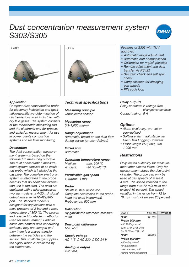
490 Division III
Dust concentration measurement systemS303/S305
ApplicationCompact dust concentration probefor stationary installation and quali-tative/quantitative determination ofdust emissions in all industries withdry flue gases. The system consistsof the triboelectric measuring rodand the electronic unit for processand emission measurement for usein power plants combustionsystems and for filter monitoring.
DescriptionThe dust concentration measure-ment system is based on thetriboelectric measuring principle.The dust concentration measure-ment system consists of an insula-ted probe which is installed in thegas pipe. The complete electronicsystem is integrated in the probehead so that no additional evalua-tion unit is required. The units areequipped with a microprocessor,two alarm relays, a 4-20 mA signaloutput and a serial RS422/485port. The standard model isdesigned for applications with amax. pressure of 2 bar and a max.temperature of 300 °C. The provenand reliable triboelectric method isused for measurement. Particlescome into contact with conductingsurfaces, they are charged andthen there is a charge transferbetween the particles and thesensor. This small charge suppliesthe signal which is evaluated by the electronics.
Technical specifications
Measuring principleTriboelectric sensor
Measuring range0.1-1,000 mg/m3
Range adjustmentAutomatic, based on the dust flowduring set-up (or user-defined)
Offset trimAutomatic
Operating temperature rangeMedium: max. 300 °CAmbient: -20 °C/+45 °C
Permissible gas speed> approx. 4 m/s
ProbeStainless steel probe rodComplete electronics in the probehead (no extra instrument)Probe length 500 mm
CalibrationBy gravimetric reference measure-ment
Dew point differenceMin. +5K
Supply voltageAC 115 V, AC 230 V, DC 24 V
Analogue output4-20 mA
Relay outputsRelay contacts: 2 voltage-free
changeover contactsContact rating: 5 A
Options• Alarm level relay, pre-set or
user-defined• Software alarm adjustable via
Dust Data Logging Software• Probe length 250, 500, 750,
1,000 mm
Restrictions
Only limited suitability for measure-ment after electric filters. Only formeasurement above the dew pointof water. The probe can only beused at gas speeds of at least 4 m/s. The speed variation in therange from 4 to 12 m/s must notexceed 10 percent. The speed variation in the range from 12 to 18 m/s must not exceed 20 percent.
S303 S305 Features of S305 with TÜV approval:• Automatic range adjustment• Automatic drift compensation• Calibration for mg/m3 possible• Remote adjustment and data
transfer via RS422• Self zero check and self span
check• Compensation for changing
gas speeds• PIN code lock
DG: E Part no. Price €
S305 69103Probe 500 mmwith TÜV approval:
13th, 17th, 27th, 30th
BImSchV and TA Luft
S303 69099Probe 500 mmwithout approval,
for quantitative
measurement, with
manual range adjustment

Division III 491
Volume flow measurement unitVMG 02
ApplicationThe volume flow measuring unit isan in situ measuring system for thecontinuous measurement of theflue gas speed/volume flow, thepressure and the temperature influe gas ducts and pipes. For conti-nuous emission measurement, thesystem can also display theamount of pollutants (mass flowkg/h) as well as the volume flow inoperating and standard norm state.
DescriptionThe gas is measured with thedynamic pressure probe in the flowgas volume flow. The differentialpressure is detected on a continu-ous basis. The differential pressureat a dynamic pressure probe indi-cates the speed of the flue gas.The volume flow in the flue gas canbe determined with reference tothe cross section of the flue gasduct. A serial RS232 or RS485connection and the PC softwareensures simple set-up of the probeas well as data transfer and furtherprocessing.
Two alarm relays and two analogueoutputs 4-20 mA are provided.Relay 1 signals System OK andrelay 2 is a programmable alarmlevel linked to the analogue output 1.The probe is connected by a signalcable. The unit requires a low DCsupply voltage between 8 and 30 V.
Technical specifications
Measuring principleDifferential pressure
Measuring rangeDifferential pressure 0/10 mbar
Operating temperature rangeMedium: max. 600 °CAmbient: -20 °C/+80 °C
Permissible gas speed> approx. 4 m/s
ProbeStainless steel probe rodDynamic pressure probe withintegrated temperature probe
Probe length300 mm
Dew point differenceMin. +5K
Supply voltageDC 8-30 V, 150 mA
Analogue outputs2 x 4-20 mA
Relay outputsRelay contacts: 2 voltage-free
changeover contactsContact rating: 1 A
HousingComplete electronics in the probehead (no extra instrument)Sheet steel, lacqueredW x H x D: 140 x 140 x 70 mm
ProtectionIP 65 (EN 60529)
Options• Probe length 400-2,000 mm• Backwashing• Digital display units
DG: E Part no. Price €
VMG 02 300 mm 68930
Features:
• Compact design• 2 analogue outputs• RS 232/485 port• Modbus protocol• With PC software for further
data processing
VMG 02 Digital display unit (option)
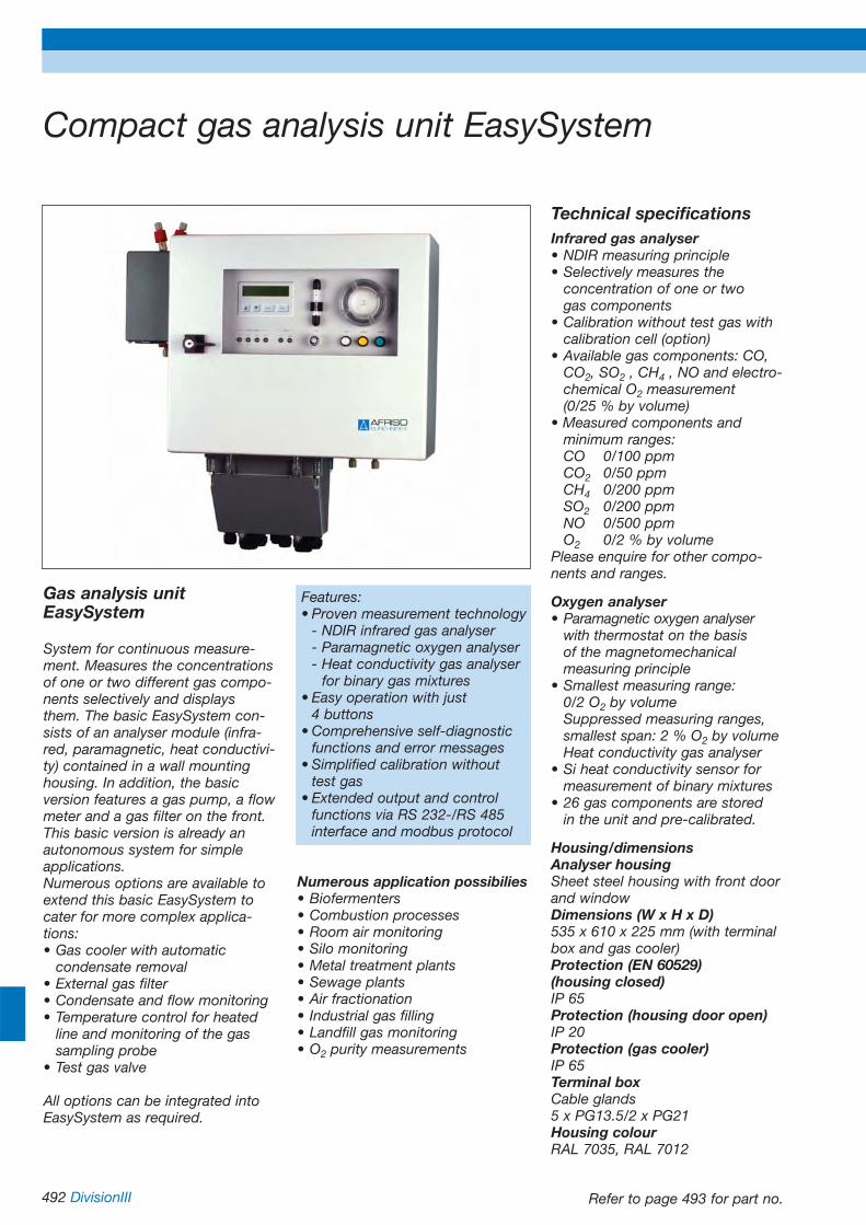
492 DivisionIII
Compact gas analysis unit EasySystem
Gas analysis unitEasySystem
System for continuous measure-ment. Measures the concentrationsof one or two different gas compo-nents selectively and displaysthem. The basic EasySystem con-sists of an analyser module (infra-red, paramagnetic, heat conductivi-ty) contained in a wall mountinghousing. In addition, the basicversion features a gas pump, a flowmeter and a gas filter on the front.This basic version is already anautonomous system for simpleapplications.Numerous options are available toextend this basic EasySystem tocater for more complex applica-tions: • Gas cooler with automatic
condensate removal• External gas filter• Condensate and flow monitoring• Temperature control for heated
line and monitoring of the gas sampling probe
• Test gas valve
All options can be integrated intoEasySystem as required.
Features:• Proven measurement technology
- NDIR infrared gas analyser- Paramagnetic oxygen analyser- Heat conductivity gas analyser
for binary gas mixtures• Easy operation with just
4 buttons• Comprehensive self-diagnostic
functions and error messages• Simplified calibration without
test gas• Extended output and control
functions via RS 232-/RS 485 interface and modbus protocol
Numerous application possibilies• Biofermenters• Combustion processes• Room air monitoring• Silo monitoring• Metal treatment plants• Sewage plants• Air fractionation• Industrial gas filling• Landfill gas monitoring• O2 purity measurements
Technical specificationsInfrared gas analyser• NDIR measuring principle• Selectively measures the
concentration of one or two gas components
• Calibration without test gas with calibration cell (option)
• Available gas components: CO, CO2, SO2 , CH4 , NO and electro-chemical O2 measurement (0/25 % by volume)
• Measured components and minimum ranges:CO 0/100 ppmCO2 0/50 ppmCH4 0/200 ppmSO2 0/200 ppmNO 0/500 ppmO2 0/2 % by volume
Please enquire for other compo-nents and ranges.
Oxygen analyser• Paramagnetic oxygen analyser
with thermostat on the basis of the magnetomechanicalmeasuring principle
• Smallest measuring range: 0/2 O2 by volumeSuppressed measuring ranges, smallest span: 2 % O2 by volumeHeat conductivity gas analyser
• Si heat conductivity sensor for measurement of binary mixtures
• 26 gas components are stored in the unit and pre-calibrated.
Housing/dimensionsAnalyser housingSheet steel housing with front doorand windowDimensions (W x H x D)535 x 610 x 225 mm (with terminalbox and gas cooler)Protection (EN 60529)(housing closed)IP 65Protection (housing door open)IP 20Protection (gas cooler)IP 65Terminal boxCable glands5 x PG13.5/2 x PG21Housing colourRAL 7035, RAL 7012
Refer to page 493 for part no.

Division III 493
DG: E PU Part no. Price €EasySystem CO in wall mounting housingBasic unit but with one IR component, consisting of:wall mounting housing, dust filter, rotameter, gas pump 1 69070
EasySystem NO in wall mounting housingBasic unit as above 1 69071
EasySystem CH4 in wall mounting housingBasic unit as above 1 69072
EasySystem SO2 in wall mounting housingBasic unit as above 1 69073
EasySystem CO2 in wall mounting housingBasic unit as above 1 69074
EasySystem O2 in wall mounting housingBasic unit but with paramagnetic measuring cell for measuring oxygen,consisting of: wall mounting housing, dust filter, rotameter, gas pump 1 69075
EasySystem O2/CO in wall mounting housingBasic unit but with one IR component and oxygen measurement with electrochemical cell,consisting of: wall mounting housing, dust filter, rotameter, gas pump 1 69076
EasySystem O2/NO in wall mounting housingBasic unit as above 1 69077
EasySystem O2/CH4 in wall mounting housingBasic unit as above 1 69078
EasySystem O2/SO2 in wall mounting housingBasic unit as above 1 69079
EasySystem O2/CO2 in wall mounting housingBasic unit as above 1 69080
EasySystem CO/CO2 in wall mounting housingBasic unit but with two IR components, consisting of: wall mountinghousing, dust filter, rotameter, gas pump 1 69081
EasySystem CO/NO in wall mounting housingBasic unit but with two IR components, consisting of: wall mountinghousing, dust filter, rotameter, gas pump 1 69082
EasySystem CO/SO2 in wall mounting housingBasic unit but with two IR components, consisting of: wall mountinghousing, dust filter, rotameter, gas pump 1 69083
EasySystem CO/CH4 in wall mounting housingBasic unit but with two IR components, consisting of: wall mountinghousing, dust filter, rotameter, gas pump 1 69084
EasySystem CO2/CH4 in wall mounting housingBasic unit but with two IR components, consisting of: wall mountinghousing, dust filter, rotameter, gas pump 1 69085
EasySystem H2- in wall mounting housingBasic unit but for H2 measurement, consisting of: wall mountinghousing, dust filter, rotameter, gas pump 1 69086
Additional cost:Stainless steel piping 1 69087
Automatic calibration 1 69088
Gas cooler with hose pump 1 69089
Flow monitoring, condensate monitoring 1 69090
External gas filter 1 69091
Temperature controller, heating tube and monitoring, heated probe 1 69092
3/2-way solenoid valve 1 69093
Gas analysis with EasySystem

494 Division III
Gas analysis system BIOLYZER for discontinuous measurement
ApplicationThe BIOLYZER gas analyser wasspecially designed for discontinu-ous analysis and regular processmonitoring of biogenous processgases such as biogas, sewage gasand landfill gas. All important gastypes such as methane, hydrogensulphide, oxygen and carbon dioxi-de can be monitored.
DescriptionComplete measuring system fordiscontinuous, selective measure-ment and indication of up to fourdifferent gas components CH4,H2S, O2 and CO2. CH4 and CO2 aredetected by means of infraredtechnology, O2 and H2S by meansof electrochemical sensors. Allcomponents are integrated in arobust housing for wall mounting.The system feature a 4-digit LEDdisplay and status indicators foreach measurement channel as wellas a 4-line, back lit LCD display.The memory has a history function,all values can be displayed. Output 4-20 mA, fully adjustable alarmlevel switches and binary outputsfor: Active, Error, Calibration,Alarm.
A gas treatment unit with all impor-tant components (gas cooler, hosepump, fine filter, aerosol filter, rota-meter with needle valve, anti-deto-nation device) is integrated in arobust, air-flushed housing. Thesystem is supplied complete withwiring, capillary tubes, calibrationand ready for installation.
Technical specifications
Gas types/measuring rangesCH4 0/100 % by vol.
IR double beamCO2 0/100 % by vol.
IR double beamO2 0/25 % by vol.
electrochemicalH2S 0/5,000 ppm
electrochemical
Measuring intervals can be pro-grammed for all individual gastypes. Manual measurement ispossible at all times.
Gas treatmentWith anti-detonation device, pro-tective filters, two pumps, two rota-meters, needle valves, gas coolerwith condensate trap and hosepump.
Display4-digit LED display, status indica-tors for each channel, 4-line backlit LCD display, memory with histo-ry functions, all values can bedisplayed.
CommunicationRS 232, analogue output per gastype, output 4-20 mA, linearised,data memory/history
Operating temperature rangeAmbient: 5/40 °C
Supply voltageAC 85-264 V, 47-63 Hz
DimensionsW x H x D: approx. 300 x 400 x 165 mm
BIOLYZER LT
BIOLYZER LT is intended for sim-ple and cost-effective routinechecks. It is a BIOLYZER version,but it does not feature a gas cooler.Neither does it have the load limita-tion for hydrogen sulphide measu-rement. Therefore, the standardmeasuring range is 0 to 1,000 ppmH2S.
Options
• Profibus• 2nd measuring point
DG: E Part no. Price €
BIOLYZER for CH4 , H2S, O2 and CO2 69643
BIOLYZER for CH4 , H2S and O2 69644
BIOLYZER for CH4 and H2S 69645
BIOLYZER LT for CH4 , H2S, O2 and CO2 69646
BIOLYZER LT for CH4 , H2S and O2 69647
BIOLYZER LT for CH4 and H2S 69648
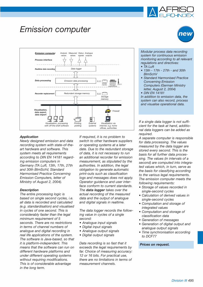
Division III 495
Emission computer
ApplicationNewly designed emission and datarecording system with state-of-the-art hardware and software. Thissystem meets all requirementsaccording to DIN EN 14181 regard-ing emission computers inGermany (TA Luft, 13th, 17th, 27thand 30th BImSchV, StandardHarmonised Practice ConcerningEmission Computers, letter ofMinistry of August 2, 2004).
DescriptionThe entire processing logic isbased on single second cycles, i.e.all data is recorded and calculated(e.g. standardisation) and visualisedin cycles of one second. This isconsiderably faster than the legalminimum requirement of 5seconds. There are no restrictionsin terms of channel numbers ofanalogue and digital recording inreal life applications of the system.The software is Java-based, so thatit is platform-independent. Thismeans that the software can run ondifferent hardware platforms andunder different operating systemswithout requiring modifications.This is of considerable advantagein the long term.
If required, it is no problem toswitch to other hardware suppliersor operating systems at a laterdate. Due to the redundant storageof data, it is not necessary to runan additional recorder for emissionmeasurement, as stipulated by theauthorities. In addition, the legalobligation to generate automaticprint-outs such as classificationlogs and messages does not apply.Operator guidance and user inter-face conform to current standards. The data logger takes over theactual recording of the measureddata and the output of analogueand digital signals in realtime.
The data logger records the follow-ing value in cycles of a singlesecond:• Analogue input signals• Digital input signals• Analogue output signals• Digital output signals
Data recording is so fast that itexceeds the legal requirements byfar. Choice of measuring accuracy:12 or 16 bits. For practical use,there are no limitations in terms ofmeasurement channels.
If a single data logger is not suffi-cient for the task at hand, additio-nal data loggers can be added asrequired.A separate computer is responsiblefor data processing. The valuesmeasured by the data logger arestored every second. This is thebasis for all further data proces-sing. The values (in intervals of asecond) are computed into integra-ted values which, in turn, serve asthe basis for classifying accordingto the various legal requirements.The emission computer meets thefollowing requirements:• Storage of values recorded in
single-second cycles• Calculation of derived values in
single-second cycles• Computation and storage of
integrated values• Computation and storage of
classification data• Generation of messages• Generation of digital output and
analogue output signals• Time synchronisation according
to DCF77
Prices on request.
Modular process data recordingsystem for continuous emissionmonitoring according to all relevantregulations and directives:• TA Luft• 13th - 17th - 27th - and 30th
BImSchV• Standard Harmonised Practice
Concerning Emission Computers (German Ministry letter, August 2, 2004)
• DIN EN 14181In addition to emission data, thesystem can also record, processand visualise operational data.
Emission computer
Process interface
Data processing
Recorder replacement
Realtime data recording
Visualisation,data export,data import
Visualisation, processingwith off-the-shelf software
Printing,plotting
Externalsystems
Visualisation viaInternet, e.g. homeoffices, authorities
Firewall
Storagememory
Storagememory
ClassifyingMessages
Logs/protocolsDCF77
Analysis Measured Status Analoguevalues values signals outputs
Data logger
Emission data processing
Redundant storage memory

496

www.afriso.de 497
Chapter 14Table of contents chapter 14
Alarm units, displays, signal processing, monitoring and communication systems
14
Page
Isolating amplifiers TV 22 GL/TV 200 GS 498
Isolating amplifier with power supply STV 22 GL 498
Trip amplifier MK 330 GS 499
Selector Switch MSU 499
Ex safety barrier GHG 111 499
Ex isolating amplifier with power supply STV 5104 B 500
Multifunctional transducer MFU 501
Digital plug-in display DA 06 502
Digital display units DA 10/12/14 panel mounting 503-504
Digital display and control unit DA 12 G in wall mounting housing 505
Horn KH 1/horn HPW 2 506
Alarm light with horn 506
Alarm light with rotating reflector 506
Alarm re-set unit AQ 220 506
AFRISO event reporting systems - overview 507-508
Event reporting system Phone Alarm SD1 509
Event reporting system GSM Alarm 510
Event reporting system Fuel Oil Manager INTERNET 511
Event reporting system EMS 220 512
Event reporting system EMS 442 513
Sensors for event reporting systems 514

498 Division II
DescriptionThe TV 200 GS isolating amplifier isused for galvanic isolation, conver-sion and amplification of standardoutput signals (V/mA). Input andoutput are galvanically isolated witha high level of isolation. The inte-grated high efficiency electronicpower supply unit prevents over-heating and allows for high outputloads. Offset and gain can be ad-justed by two potentiometers onthe unit front.
Technical specifications
HousingStandard DIN-rail housingW x H x D: 23 x 78 x 103 mm
Supply voltageDC 20-30 V or AC 230 V
Input4-20 mA or 0-10 V
Output0-10 V or 4-20 mA
Output loadI max. 900 Ohm/U min. 500 Ohm
Signal isolation/signal amplification
TV 22 GL STV 22 GLTV 200 GS
DescriptionThe TV 22 GL isolating amplifier isused for the galvanic isolation andamplification of DC current signals(mA). Input and output are galvani-cally isolated with a high level ofisolation. The integrated electronichigh efficiency power supply unitprevents overheating and allows forhigh output loads. The extremelynarrow design allows for spacesaving installation.
Technical specifications
HousingStandard DIN-rail housingW x H x D: 18 x 78 x 103 mm
Supply voltageAC/DC 20-253 V
Input0-20 mA or 4-20 mA
Output0-20 mA or 4-20 mA 1:1 proportional to input signal
Output loadMax. 400 Ohm
DescriptionThe STV 22 GL isolating amplifierwith supply is used for the galvanicisolation and amplification of DCcurrent signals (mA). The connectedtransducer is directly supplied via agalvanically isolated and limited sup-ply voltage. Input and output are gal-vanically isolated with a high level ofisolation. The integrated high effi-ciency electronic power supply unitprevents overheating and allows forhigh output loads.
Technical specifications
HousingStandard DIN-rail housingW x H x D: 18 x 78 x 103 mm
Supply voltageAC/DC 20-253 V
Sensor supplyDC 27 V open circuit voltageDC 21 V at 20 mA
Input0-20 mA or 4-20 mA
Output0-20 mA or 4-20 mA 1:1 proportional to input signal
Output loadMax. 800 Ohm
DG: H Part no. Price €
TV 22 GL 53701TW 41 GM 53702(isolator withoutpower supply)
TWH 41 GM 53703(HART-enabled)
DG: H Part no. Price €
TV 200 GS 53704Input 4/20 mAOutput 0/10 V
TV 200 GS 53705Input 0/10 VOutput 4/20 mA
other signals on request
DG: H Part no. Price €STV 22 GL 53706
STH 22 GL 53707(HART-enabled))

Division II 499
Trip amplifier, selector switch, Zener barrier
MK 330 GS GHG 111MSU 12
DescriptionThe MK 330 GS trip amplifier com-pares the measurement signal at theinput with the pre-set values of thecoding switches (0-99 %). If themeasurement signal exceeds or fallsbelow the setpoint, the correspon-ding output relay responds accor-ding to the selected fail-safe function(relay energises or de-energises). TheSMK 330 GS trip amplifier with inte-grated power supply also suppliesthe connected transducer.
Technical specifications
HousingStandard DIN-rail housingW x H x D: 23 x 78 x 103 mm
Supply voltageMK 330 GS: AC/DC 20-253 VSMK 330 GS: DC 20-30 V or AC 230 V
Input0-10 V or (0)4-20 mA
Input resistanceI 50 Ohm/U 400 kOhm
Output2 relays changeover contacts 250 V, 2 A, 100 VAFunction 2Max, 2Min or 1Max/Min
DescriptionThe MSU 6 and MSU 12 selectorsare designed for manual operation.They allow up to 6 3-wire or 4-wiretransducers (MSU 6) or up to 12 2-wire transducers to be connectedto a common display unit (or recor-der).
Technical specifications
HousingStandard rack housingW x H x D: 96 x 48 x 134 mm
Panel cut outW x H: 92 x 45 mm
Protection (front)IP 40 (EN 60529)
Mechanical service life>25,000 switching cycles
InputVoltage < 42 V, current < 2 A
Switch rating (resistive load)at 1 V/1.5 A (AC/DC)at 42 V/0.2 A (AC/DC)
DescriptionThe GHG 111 Ex safety barrier isdesigned for intrinsically safe moni-toring of measuring currents in Exzone 1. For connection to displayinstruments (0)4-20 mA and to Ex-approved sensors EEx ib/ia II B / II C.
Technical specifications
HousingStandard DIN-rail housing withplug-in baseW x H x D: 11 x 125 x 85 mm
EC design type approval:TÜV 99 ATEX 1449xII (1) G [EEx ia] II C
Input(0)4-20 mA
Output(0)4-20 mA intrinsically safe (i a)
Current circuits (max. data)U. 28/28 VI. 93/100 mAP. 651/40 mWLa 2.1/4 mHCa 83/83 nF
Ambient temperatureMax. 60 °C
DG: H Part no. Price €
MSU 6 537106 Inputs3- or 4-wire
MSU 12 5371112 Inputs2-wire
DG: H Part no. Price €
GHG 111 31284
DG: H Part no. Price €MK 330 GS 53708
SMK 330 GS 53709Transducer supplyDC 24 V
MSU 12

500 Division II
Ex isolating amplifier with power supply STV 5104 B
DescriptionSTV 5104 B is used to supply, gal-vanically isolate and amplify 2-wireand 3-wire transducers in hazardousareas. Input and output are galvani-cally isolated with a high level ofisolation.
Technical specifications
HousingStandard DIN-rail housingW x H x D: 23.5 x 109 x 130 mm
ProtectionHousing IP 50 (EN 60529)Terminal IP 20 (EN 60529)
Supply voltageAC/DC 24-230 V
Power consumption< 3 W
Transducer supplyDC 18-28 V(> 18 V at 20 mA)
Input0(4)-20 mA (min. 16 mA)0-10 V (min. 8 V)
Output0(4)-20 mA (min. 16 mA)0-10 V (min. 8 V)Configurable as required
Accuracy of measurement< 0.1 % FS
Temperature coefficient< 0.01 % FS/°C
Response time< 25 ms
Operating temperature rangeAmbient: -20 °C/+60 °C
Calibration temperature20-28 °C
Ex dataUm < 250 VU0 28 V DCI0 93 mA DCP0 < 0.65 WL0 < 3 mHC0 < 0.08 µF
Ex approvalsCENELEC [EEx ia] II CATEX II (1) GApplicable to zones 0, 1 or 2
Compliance with official directives/normsEMC 89/336/EECEmission EN 50 081-1
EN 50 081-2Immunity EN 50 082-2
EN 50 082-1LVD 73/23/EECEN 61 010-1PELV/SELV IEC 364-4-41 and EN 60 742ATEX 94/9/EG EN 50 014 and EN 50 020
DG: H
Version Part no. Price €
STV 5104 B 537201 channel
STV 5104 B 537212 channels
Connection diagramSTV 5104 B
Non-hazardous areaHazardousarea zones0, 1 or 2
DMUEx
STV5104 B
STV-ExTransducer
DA101214
Display
AC 230 V
• 1- or 2-channel version
• 2-wire supply
• > 18 V in hazardous area
• 20 programmable measuring
ranges
• Universal AC or DC supply

Division II 501
Multifunctional transducer MFU
MFU 01 Application• Easy operation
• Scalable as required
• Programming interface
• Extendable
• Universal input
• Integrated supply voltage fortransducer
• 2 analogue outputs
• Linearisation 16 x-y points
DescriptionUniversally programmable, multi-functional transducer for current,voltage, resistance transmitters (Pt 100 and others), potentiometer.2 linear analogue outputs (1 x (0)4-20 mA, 1 x (0)2-10 V) galvanicallyisolated from the input. 2 fully pro-grammable, voltage-free limit switches (can be extended to 4). Interface for configuration via PC.Three-colour, two-line LCD fordirect indication of the operatingstate.Universal power supply.
Technical specifications
DisplayTwo-line, 4-digit, 12 mm high, 3-colour LCD
Range0 to 9999 digits (min. and max.values scalable as required)Unit indication.
Accuracy of measurement±0.3 % of FS
ResolutionDecimal point setting as required
Sensor input2-wire transmitter (DC 24 V)3-wire transmitter (DC 24 V)Current max. 20 mAVoltage max 10 VPt 100 2-,3- or 4-wire (according to DIN IEC 751)Pt 1000 (according to DIN IEC 751)
Analogue outputs2 synchronous analogue outputs,scalable as required 0/100 %
Analogue output 1 (current)(0)4-20 mA, fully configurable, galvanically isolated from input
Analogue output 2 (voltage)(0)2-10 V, fully configurable, galvanically isolated from input
Relay outputs2 x voltage-free changeover con-tacts, fully adjustable AC 250 V 2A100 VA (a total of 4 voltage-freechangeover contacts if contactextension module is used)2 x open collector outputs, max. 30 V, 50 mA (earth switching) forcontact extension module
Linearisation (via software)Customer specific linearisation witha max. of 16 points for volume indication (e.g. litres) in non-lineartanks
Supply voltageAC/DC 20-253 V
HousingStandard DIN-rail housingW x H x D: 33 x 78 x 103 mm
Accessories (optional)
• Contact extension moduleInput: 3 control lines from MFUOutput: 2 changeover contactsAC 250 V, 2 A, 100 VAW x H x D: 23 x 78 x 103 mm
• Programming softwareWIN 95/98/2000/XP
DG: H Part no. Price €
MFU 01with display 53712and keys
MFU 02without display 53713without keys
MFU-KEMContact 53714extensionmodule
MFU-SSoftware and 53715interfacecable
– mA– Transmitter– V– Pt100/Pt1000
K3 K4K1 K2
0..4..20 mA0..2..10 V

502 Division II
Digital plug-in display DA 06
ApplicationCost-effective digital display unit forlocal indication on all transducerswith 4-20 mA output and DIN43650-A plug. Easy and quickmounting via plug-in system.Optional Ex protection (zones 0/1).
DescriptionDA 06 is mounted between theplug and the junction box and isimmediately ready for operation. Asthe unit is supplied via the 4-20 mAloop, it does not require a separatepower supply. The unit is pro-grammed via two keys on the front.The following parameters can beset:scaling, decimal point, dampening,switch point and time delay.In addition, the unit features amemory for min. and max. values.The settings are not lost in theevent of a power failure.Out of range values (min. or max.)can be displayed as messages.The integrated diagnostics systemcontinuously monitors all functionsof the display.The housing can be turned by 300°,the display by 330°.
Technical specifications
Measuring range-1.999/+9.999 digits (min. and max.values scalable as required)
Display4-digit, 7 mm high, red LED displayDisplay housing can be turned by 330°
Accuracy of measurement0.1 % ±1 digit
Adjustable parametersScaling, decimal point, dampening,switch point
Min./max. value memoryAllows to display the minimum andmaximum values recorded duringoperation.
HousingPlastic PA 6.6/polycarbonateW x H x D: 47 x 47 x 68 mmHousing can be turned by 300°
ProtectionIP 65 (EN 60529)
Operating temperature rangeAmbient/Electronics: -25 °C/+85 °CStorage: -40 °C/+85 °C
Electrical connectionAdapter for plug to DIN 43650-A
Input signal4-20 mA, 2-wire
Switching output1 open collector (PNP), max. 125mA (with Ex approval max. 70 mA,4.7 mH)On/off delay timer: 0/100 sTemperature influence: 0.1 %/10 K
CE conformityEN 61326
Options
• Ex protection II (1) 2 G EEx ia IIC T4
• Other electrical connections
DA 06
DG: H Part no. Price €
DA 06 31278
DA 06-Ex 31279
• Easy and quick mounting with plug-in system
• Indication fully scalable asrequired
• Housing and display can berotated fully
• Integrated diagnostic system
• Open collector switching output/PNP
• Optional Ex protection
• Protection IP 65

Division II 503
Digital display units DA 10/12/14
Sensor inputAll analogue standard signals, e.g. 4-20 mA, 0-20 mA, 0-1 V, 0-10 V
Analogue output0/4-20 mA, galvanically isolated
HousingStandard rack housingW x H x D: 96 x 48 x 135 mm
Panel cut outW x H: 92 x 45 mm
Protection (front)IP 65 (EN 60529)
Electrical connectionScrew terminals, plug-in (1.5 mm2)
LinearisationCustomer-specific linearisation witha max. of 24 points for volume indi-cation (e.g. litres) in non-lineartanks. Dip charts for cylindrical, vertical tanks and spherical tanksare pre-programmed.
Min./max. value memoryAllows to display the minimum andmaximum values recorded duringoperation.
DescriptionDigital display unit (DA 10), alsoavailable with additional relay out-put (DA 12/14), for electronic trans-ducers.
Technical specifications
Display5-digit graphic LCD display, backlit(white), text-based user interface,user interface language selectable(German/English/French), selectableunits of measurement.
Measuring range±99.999 digits (min. and max. fullyadjustable)
Linearity±0.1 % of measuring range
ResolutionDecimal point setting as required
Response time< 0.2 s
Operating temperature rangeAmbient: -10 °C/+55 °C
Supply voltageAC/DC 20-253 V
Sensor supplyIntegrated, galvanically isolatedpower supply for transducer: DC 20 V/20 mA
Additional functions DA 12
Analogue output 20-10 V, galvanically isolated
Relay outputsRelay contacts: 2 voltage-free changeover contacts (adjustablehysteresis)Contact rating: AC 250 V, 2 A, 100 VA
Additional function DA 14Analogue output 20-10 V, galvanically isolated
Relay outputsRelay contacts: 4 voltage-freechangeover contacts (adjustablehysteresis)Contact rating: AC 250 V, 2 A, 100 VA
• 5-digit graphic LCD display
• Text-based user interface
• Linearisation for volume
indication (24 points)
• Selectable units
• Universal power supply
• Integrated supply voltage fortransducer
• Relay outputs (DA 12/14)
DG: H Part no. Price €
DA 10 31281
DA 12 31282
DA 14 31283
Wall mountinghousingWAG 01 for 31287mounting ofone DA*
WAG 02 for 31288mounting oftwo DA*
WAG 03 for 31289mounting ofthree DA*
WAG 04 for 31290mounting offour DA*
* Price includes mounting if DA and WAG are ordered together.
Digital display unit DA 12
Alarm unit
Pressure transducer DMU 08
Vented junctionbox
Connection kit

504 Division II
Digital display units DA 10/12/14Dimensions (in mm) and connection diagrams
Connection diagram for standard application Connection diagram for Ex application
DADMU 10 AC 230 V
1214
Sensor Display
Ex area Safe areaZone1/2
DADMU- GHG 10 AC 230 V
Ex 111 1214
Sensor Zener Displaybarrier
Panel cut out DA 10/12/14
Wall mounting housing WAG 01/02 for up to 2 DA 10/12/14
Wall mounting housing WAG 03/04 for up to 4 DA 10/12/14
Fixing holes4 x Ø8,5
Fixing holes4 x Ø8,5
ap. 91.5
ap. 4
3
ap. 135
ap. 137

Division II 505
Digital display and control unit DA 12 G in wallmounting housing
InterfaceRS 485 (addresses 00 to 15, i.e.can be networked with up to 16devices)
HousingWall mounting housing made ofimpact resistant plastic (ABS)W x H x D: 163 x 97 x 62 mm
Protection (EN 60529)Front IP 65Housing IP 30 (with cable gland IP 42)
LinearisationCustomer specific linearisation witha max. of 24 points for voulme indi-cation (e.g. litres) in non-lineartanks. Dip charts for cylindrical, vertical tanks and spherical tanksare pre-programmed.
Min./max. value memoryAllows to display the minimum andmaximum values recorded duringoperation.
Linearity±0.1 % of measuring range
ResolutionDecimal point setting as required
Response time< 0.2 s
Operating temperature rangeAmbient: -10 °C/+55 °C
Supply voltageAC/DC 20-253 V
Sensor supplyIntegrated, galvanically isolatedpower supply for transducer: DC 20 V/20 mA
Sensor inputAll analogue standard signals, e.g.4-20 mA, 0-20 mA, 0-1 V, 0-10 V
Analogue output 10/4-20 mA, galvanically isolated
Analogue output 20-10 V, galvanically isolated
Relay outputsRelay contacts: 2 voltage-free
changeover contacts (adjustable hysteresis)
Contact rating: AC 250 V 2A 100 VA
DescriptionCompact, ready-to-connect univer-sal measuring and control unit in arobust wall mounting housing. Withintegrated sensor supply, 2 relayoutputs and RS 485 interface. Together with a transducer (e.g. forpressure, temperature, level, etc.),DA 12 G forms an autonomousmeasurement and control system.DA 12 G can be configured asrequired and features an integratedinterface for communication withcomputer based systems. In con-junction with a PC, an SSK485interface converter (RS 485 to RS232) and the PC Log1 software forWindows plus DA 12 G an extreme-ly cost-effective solution for recor-ding, data storage, long-term moni-toring, large display is created.
Technical specifications
Display5-digit graphic LCD display, backlit (white), text-based userinterface. User interface languageselectable (German/English/French), selectable measurementunits.
Measuring range±99.999 digits (min. and max. values scalable)
DA 12 G • Compact and ready to connect• Easy installation and
commissioning• 5-digit graphic LCD display• Text-based user interface• Selectable measurement units• Universal power supply• Integrated power supply for
transducer• 2 switching relay outputs• RS 485 interface
DG: H Part no. Price €
DA 12 G 31246
Interface 31270converter SSK 485(RS 485 to RS 232),with power supply unit
Software PC Log1,1 31272channel and 9 channels
PC-RS 232adapter cable 31247
Digital displayunit DA 12 G
Alarm unit
Pressure transducerDMU 08
Vented junctionbox
Connection kit

506 Division I
Audible and visual alarms
Horn KH 1 Combined alarmlight and horn
Horn HPW 2
Horn KH 1Horn with continuous tone for usein dry areas.
Technical specificationsSound level:90 dB (A), distance 1 mSupply voltage: AC 230 VPower consumption: 6 VAProtection: IP 20 (EN 60529)Weight: 0.18 kg
Alarm light with hornCombination alarm light and horn,can be controlled separately.
Technical specificationsSupply voltage: AC 230 VSound level:90 dB (A), distance 1 mPower consumption: 10 VAProtection: IP 33 (EN 60529)Weight: 0.19 kg
Horn HPW 2Horn with continuous tone for usein humid areas and for outdoorinstallation.
Technical specificationsSound level:110 dB (A), distance 1 mSupply voltage: AC 230 VPower consumption: 22 VAProtection: IP 55 (EN 60529)Weight: 1 kg
Alarm light with rotating reflectorAlarm light with rotating reflector,with yellow light, for use in humidareas and for outdoor installation.Highly effective due to rotatingreflector. Robust design with AI base. Maintenance-free, suitablefor continuous operation. Anymounting position.
Technical specificationsSupply voltage: AC 230 VProtection: IP 55 (EN 60529)Weight: 1.8 kg
PU Part no. DG Price €
Horn KH 1 1 61011 G
Alarm light with horn 1 61020 G
Horn HPW 2 1 61012 G
Alarm light with rotating reflector 1 61015 H
Alarm re-set unit AQ 220 1 53230 E
Alarm light with rotatingreflector
Alarm re-set unit AQ 220The alarm re-set unit AQ 220 isdesigned for connection to leakdetectors and level switches (e.g.RG 210, ELT 8). Visual and audiblesignals indicate alarms. The audiblesignal can be muted using the Re-set button. The visual signalremains on until the problem isremedied or the probe is no longerin contact with the medium (e.g. incase of leak alarm) or the probe issubmerged again (e.g. in case ofdry-run protection). As soon as thevisual alarm is switched off, thesystem resumes „ready“ mode. Inaddition, external alarm units canbe connected. (If external alarmsare not connected via the AQ 220,there is a risk that they will uninten-tionally remain switched off).
Technical specificationsSupply voltage: AC 230 VOutput: 2 voltage-free normallyopen contacts (horn, light)Operating temperature range:-5 °C /+50 °CDimensions W x H x D:50 x 110 x 110 mmProtection: IP 30 (EN 60529)
Alarm re-set unit AQ 220

Division II 507
AFRISO event reporting systemsRemote reporting, alarm generation, logging, remote polling, remote switching
Features:1. Event reporting
The reporting system calls you by phone or GSM and reports the events.
2. Remote controlYou can also call the event reporting system and send commands by phone to control lights, heating systems, air conditioning systems, shutters, blinds, etc.
3. Data loggingEvent reporting systems log data at specific intervals.
4. Remote data pollingYou can access the event repor-ting system via phone, GSM or Internet and receive current and stored data.
5. Remote programmingYou can program various para-meters by phone or GSM. For example, it is possible to remotelychange the telephone number to which the system is to report the events.
6. Integrated security systemThe event reporting systems integrate a whole range of security functions:• Password protection ensures
that unauthorised persons cannot access the system.
• If the number to be called by the system is busy, the system redials automatically.
• If the number is still busy after several attempts, the system calls the divert number.
AFRISO event reporting systemsmonitor a site for dangerous events and report such events viathe public telephone network orGSM by means of digital data orvoice messages.
Monitoring functions:• Events such as leaks, failure of
the heating system, glass break-ages, movements, burglary or robbery
• Events such as smoke, fire, gas or flooding
• Levels in tanks and containers• Leaks in tanks or pipes• Measured values such as
temperature, level, pressure
We provide a complete range ofsignal transducers. Depending onthe system configuration, the AFRISO event reporting systemsallow for full remote supervision ofthe complete residential and techni-cal installation.
All program settings, voice messa-ges and alarms not yet processedare saved in case of a power failure;the system resumes processingwhen power is restored.
Application example:Sensors and alarm devices monitorall the functions of your heatingsystem or even your completehouse around the clock.One or several temperature sensors(1) monitor endangered or criticalrooms. One or more surface moun-ting thermostats (2) check whetherthe water is hot, the burner andboiler as well as the circulationpumps function properly. A mini-mum level alarm (3) or a remotetank level indicator (4) with reservealarm indicate when you have torefuel. The remote indicator alsoallows for easy and regular levelmonitoring, e.g. in undergroundtanks or basement tanks which arenot easily accessible. We provide leak monitoring instru-ments (5) for all types of tanks and pipes.Many other areas can be monitoredwith technology provided by AFRISO. The sensors and alarmdevices activate the AFRISO eventreporting system (6) and providemessages via fax, phone, GSM orInternet to a single address or several addresses. Depending onthe system configuration, the indivi-dual problems can be treated as a single alarm or they can be differ-entiated. This allows the system tosend different types of messages todifferent addresses. For example, alow oil message is sent to your oilsupplier, a burner failure to yourburner service people, etc.
2
3
4
5
6
1
•

508 Division II
AFRISO event reporting systems – overview
Event reporting systemPhone Alarm SD1• 4 digital inputs (voltage-free NC
or NO contacts)• Recipient of the message: phone
or cell phone• Type of message: voice message
A voice message can be assigned to each alarm input.The alarm is reported via a voice message recorded by the user.
• Re-set mode: the alarm remains active until it is re-set.
Event reporting systemsEMS 220/EMS 442Suitable for a large range of dome-stic and industrial applications. Upto 4 continuous measurements and4 limit values can be monitoredwith one unit. In connection withthe AFRISO Net Webservice, datacan also be visualised, logged andmanaged.
Event reporting systemGSM Alarm• 4 digital inputs (voltage-free NC
or NO contacts)• Recipient of the message: cell
phone, phone, fax, PC with modem
• Type of message: SMS via mobile networkAn SMS text can be assigned to each of the 4 alarm inputs; this SMS can be sent to 2 different phone numbers. The SMS can beconverted to a voice, e-mail or fax message by the service provider.
• SMS is sent if the status or an input changes
• SMS is sent at intervals (e.g. every 24 hours)
• GSM alarm can be remotely programmed via SMS at any time
• Manual status query
Event reporting systemFuel Oil Manager INTERNET• Hydrostatic level measurement
system for fuel oil EL, L or diesel• Recipient of the message:
Mareon Internet data centre. The incoming data is presented in a detailed overview. This password protected overview can be accessed via the Internet.
• Type of message: When a defined low level is reached, an SMS or an e-mail message is sent to the customer.
• Automatic, regular updating of the measured data
• Analytic evaluation (planning and controlling)
• Internet service with annual fee
The event reporting system Fuel Oil Manager INTERNET allows youto manage tanks and delivers precise information on the actualtank contents.
Event reporting systemsEMS 220/EMS 442
Event reporting systemGSM Alarm
Fuel Oil ManagerINTERNET
Event reporting systemPhone Alarm SD1
Event reporting systems allow forremote monitoring of all AFRISOsignal transducers.

Division II 509
Event reporting system Phone Alarm SD1
Event reporting systemPhone Alarm SD1
The event reporting system PhoneAlarm SD1 is used to automaticallytransmit alarms or messages onmalfunctions via the public tele-phone network. In case of analarm, up to 4 phone numbers (e.g.landline, cell phone and emergencycentre) are dialled automatically, anidentification text and then one ofthe 4 event messages are transmit-ted. The identification text and theevent message can be recorded bythe user. The total length of themessages is 40 seconds. The alarmremains active until it is re-set.Connection is very simple. Voltage-free NC or NO alarm contacts areconnected to the inputs.Together with a home securitysystem or with the appropriate sig-nal transducers, Phone Alarm SD1is the perfect solution for homesecurity systems (fire, gas, water)or for monitoring power failures,refrigerator or freezer problems orto signal levels (e.g. minimum levelin the fuel oil tank). Phone AlarmSD1 can respond to 4 separatealarm inputs. Several sensors canbe connected in series or in paralleland then be monitored by a singlealarm input.The unit features an LCD display.The dialling unit is programmed viamenus and the LCD display.
The factory defaults ensure easycommissioning. However, thenumerous configuration optionsallow the system to be adapted toindividual requirements. SincePhone Alarm SD1 is only active incase of an alarm, it can be operatedat a common subscriber line to-gether with other equipment suchas telephone, fax and answeringmachine. Phone Alarm SD1 doesnot influence these devices in anyway.
Typical applications
• Malfunctions of technical installa-tions such as refrigeration, heating, elevator, air conditioning can be communicated imme-diately and directly to the service partner.
• Alarms from security systems canbe directly transmitted to securitystaff. They can then inform the police or the fire brigade.
• When home security systems or alarm contacts respond, the system reports this to relatives, neighbours, friends or the user's cell phone.
• Professional applications include status monitoring of vending machines.
Technical specificationsSupply voltageDC 11.5-14 V
Current input35 mA (standby), 70 mA (alarm)
Telephone connectionAnalogue land line
Alarm inputs4 digital inputs (voltage-free NC orNO contacts)
Voice messages40 seconds ±2 seconds
Telephone numbersUp to 4 x 24 digit numbers can be dialled
ProgrammingMenus via LCD display
Special featuresProgrammable alarm repeat, remote re-set
Scope of deliveryEvent reporting system PhoneAlarm SD1 with integratedmicrophone and speaker, analoguephone connector, installationinstructions
Dimensions W x H x D:150 x 104 x 30 mm
DG: H, PU: 1 Part no. Price €
Event reportingsystem Phone Alarm SD1 90003
Power supply unitfor AC 230 V 90010
Additional input
Alarm centre Dialling device
Telephone
Telephone line
Tel. no. 1
Tel. no. 2
Tel. no. 3
Tel. no. 4

510 Division II
Event reporting system GSM Alarm
Event reporting system GSM AlarmGSM Alarm is ideally suited for awhole range of remote monitoringtasks. When an alarm occurs, itsends SMS messages via themobile network. GSM Alarm hasfour digital inputs. If the state of aninput changes, the system sendsan SMS. This can be receivedanywhere in the world. The serviceprovider may be able to convertthe SMS into a voice, e-mail or faxmessage. Various systems, devicesand sensors can be connected tothe inputs and monitored. A sepa-rate SMS text can be assigned toeach input state (input open/closed); this SMS can be sent totwo different phone numbers. GSMAlarm sends this message when-ever the input state changes and, ifrequired, at predetermined inter-vals, for instance every 24 hours.Users may also request a report onthe state of the inputs. All GSMAlarm settings are made by SMSand can be changed at any timeand from anywhere. GSM Alarm issupplied with an internal GSMantenna, a SIM card reader, apower supply unit and a user'sguide.
Customised solutions are available if the standard version does notmeet all requirements for a givenapplication. This type of solution can be extended with digital andanalogue inputs and outputs, an RS 232 interface, various batteryoptions and software adaptations.GSM Alarm allows for remotemonitoring of all signal transducersfrom the AFRISO product range.
Application areas• Mobile monitoring
For remote monitoring of installations, devices and sensorsif no land line is available.
• Tank contents monitoringIf the level falls below a pre-set value, an SMS is sent to the fuel oil supplier or owner.
• Monitoring of heating systemsIf the heating fails or the temperature falls below or exceeds a given value, an SMS is sent.
• Monitoring of home security alarm systemsWhen an alarm occurs, messagesare sent to the owner, to security services, the police, the fire brigade, etc.
• Monitoring of technical equip-ment and installationsIn case of problems with air conditioning or heating systems, elevators etc., the service people are immediately notified via SMS.
Technical specifications
Supply voltageAC 230 V, power supply unit
Supply voltageDC 12-24 V
Power consumption• Standby mode
Max. 8 mA at 12 V• Transmission mode
Max. 120 mA at 12 V (GSM 900)
Alarm inputs4 digital inputs (voltage-free NC or NO contacts)
Operating temperature rangeAmbient: -20 °C/+55 °CStorage: -30 °C/+85 °C
GSM specificationsEGSM 900 and GSM 1800
HousingABS, blackW x H x D: 110 x 56 x 26 mm
ProtectionIP 40 (EN 60529)
WeightApprox. 100 g (without externalcables, without power supply unit)
DG: H, PU 1 Part no. Price €
Event reportingsystem GSM Alarm(without SIM card) 90002

Division II 511
DG: H, PU 1 Part no. Price €Fuel Oil ManagerINTERNET 90007
Installation and oncommissioning requestAnnual feefor Internet onservice request
Event reporting system Fuel Oil ManagerINTERNET
Fuel Oil Manager INTERNETThe Fuel Oil Manager INTERNETallows you to manage fuel oil stor-age tanks via the Internet and deli-vers precise information on theactual contents of the tanks. Thehydrostatic level measurementsystem consists of a submersibleprobe with integrated pressuremeasuring cell and evaluation unitwith a transmitter. The transmitterstation is supplied by Lithium bat-teries. External power or datacables are not required. The levelof the medium (fuel oil EL, L orDiesel) is measured hydrostaticallyat regular intervals and transmittedto the data centre via SMS. Theincoming data are presented in adetailed overview with the levels atgiven dates, precise consumptionanalyses and easy-to-read charts.The user can access this passwordprotected information from any-where in the world via the Internet.
Proactive purchasing and opti-mised storage policyThe accurate data allows the userto respond to considerable, sea-sonal fluctuations in prices.Supplies can be replenished whenthe prices are low. Unnecessarilyhigh stocks which tie up capitalcan be avoided.
Monitoring
Tank levels need no longer be readon site. This not only reduces theadministrative efforts, but also pre-vents reading and transcriptionerrors. The user can define a mini-mum level so that a signal is gene-rated as soon as the level in thetank falls below this value. This isthen transmitted via e-mail or SMS.
Reliable consumption analyses
As past data is memorised by thesystem, levels can be checkedretrospectively. These analysesassist in planning and controlling.In addition, the fuel oil managementsystem displays all fuel oil deliveriesalong with the corresponding dates.
Technical requirements
Internet access via MicrosoftInternet Explorer 5.0 and higher. Connection thread G1
Properties of measuring instru-ment
• Hydrostatic level measurement system for fuel oil EL, L or diesel
• Fully automatic measurement• Installation possible in tanks with
heights or diameters of up to 7.5 m with a maximum cable length of 10 m
• Up to 4 sensors can be connected to one evaluation unit
• Accurate measurements• Transmission via SMS/GSM• Battery operated (battery life of
5 years) No external power.• Waterproof housing
Serviceability
• 24/7 availability• No additional software required• Automatic, regular updating of
the measured data• Alarm function• Data memory• Display of consumption• Automatic recording and memo-
rising of fuel oil deliveries• Automatic calculation of next
delivery date

512 Division II
EMS 220 event reporting system
ApplicationThe EMS 220 event reportingsystem is suitable for a wide rangeof remote monitoring tasks, in par-ticular in building automation andfacility management applications.Up to two continuous measure-ments and two limit values can bemonitored with one unit. In connection with the AFRISO NetWebservice, data can also be visualised, logged and managed.Typical application areas comprise: • Monitoring and management of
fuel oil tanks• Monitoring of heating and service
rooms• Monitoring of ducts, drip pans,
pipes, etc.• Signal forwarding of danger and
status messages
EMS 220 can be combined withthe following AFRISO signal trans-ducers:• Level indicators• Level switches• Leak detection instruments• Gas and smoke detectors
DescriptionEMS 220 has 2 analogue and 2digit alarm inputs. EMS 220 sendsalarm signals or continuous mea-surement results to the cell phoneof the owner or to the AFRISO NetServer for documentation andonward transmission. From theserver, messages can be sent viaInternet, SMS or e-mail.
The owner can request informationon the system status or changeparameters via the cell phone atany time. Measuring intervals, limitvalues and transmission intervalsare fully programmable.
Technical specificationsOperating temperature rangeAmbient: -20 °C/+50 °C
Supply voltageAC 230 V
Sensor supply1 x DC 24 V, max. 25 mA1 x for probe DIT 01
Alarm inputs• 1 analogue input 4-20 mA, active
or passive• 1 analogue input for probe
DIT 01• 2 digital inputs, voltage-free
Data transferGSM short message system (SMS)with integrated GSM modem900/1800 MHz
Measuring intervals/transmission intervalsProgrammable as required
Parameter assignment/configurationVia cell phone
HousingWall mounting housing made fromimpact resistant plastic (ABS)W x H x D: 97 x 163 x 62 mm
ProtectionIP 30 (EN 60529)
Electrical connectionsCable glands
CE conformity (EMC)EN 61000-6-2 and 61000-6-3
AFRISO Net Webservicewww.afriso-net.comThe AFRISO Net Server collects alldata, archives these in a databaseand sends status or alarm messa-ges. Measurements are visualisedand documented. Reports andtrend charts for selectable periodscan be created automatically.
AFRISO Net is a cost effective wayof getting data online anywhereand at any time.
DG: H Part no. Price €EMS 220 90220
Set-up fee 90013on AFRISO Net Server(one-off charge)Monthly 90014basic charge
AFRISO Net Webservice

Division II 513
EMS 442 event reporting system
ApplicationThe EMS 442 event reportingsystem is the ideal solution for awhole range of industrial remotemonitoring tasks. Up to 4 contin-uous measurements and 4 limitvalues can be monitored with oneunit. In conjunction with the AFRI-SO Net Webservice, data can alsobe visualised, logged and man-aged.Typical application areas comprise:• Monitoring and management of
tank farms, oil storage facilities, silos, food tanks and chemicaltank installations
• Level measurement in wells, bore holes, rivers, lakes, etc.
• Monitoring of ducts, pump stations, waste water systems and separators
• Monitoring of production processes
• Monitoring of technical facilities such as heating, air conditioning, refrigerating systems, elevators, etc.
DescriptionEMS 442 features 4 analogue and4 digital alarm inputs as well as 2 relay outputs for connection ofadditional alarm equipment on site.EMS 442 sends alarm signal orcontinuous measurement results tothe cell phone of the user or to theAFRISO Net Server for documenta-tion and onward transmission.From the server, messages can besent via Internet, SMS or e-mail.
The user can request informationon the system status via the cellphone at any time. Measuring inter-vals, limit values and transmission in-tervals are fully programmable.
Technical specifications
Operating temperature rangeAmbient: -20 °C/+50 °C
Supply voltageAC 230 V
Sensor supply4 x DC 24 V, max. 25 mA
Alarm inputs• 4 analogue inputs 4-20 mA,
active or passive• 4 digital inputs, voltage-free
Relay outputsRelay contacts: 2 voltage-free changeover contactsContact rating:AC 250 V, 5 A/500 VADC 24 V, 5 A/100 VA
Data transferGSM short message system (SMS)with integrated GSM modem900/1800 MHz
Measuring intervals/transmission intervalsFully programmable
Parameter assignment/configurationVia cell phone
HousingWall mounting housing made fromimpact resistant plastic (polycarbonate)W x H x D: 175 x 125 x 75 mm
ProtectionIP 65 (EN 60529)
Electrical connections5 x cable glands M 16
CE conformity (EMC)EN 61000-6-2 and 61000-6-3
AFRISO Net Webservicewww.afriso-net.comThe AFRISO Net Server collects alldata, archives these in a databaseand sends status or alarm messa-ges. Measurements are visualisedand documented. Reports andtrend charts for selectable periodscan be created automatically.
AFRISO Net is a cost effective wayof getting data online anywhereand at any time.
DG: H Part no. Price €EMS 442 90442
Set-up fee 90013on AFRISONet Server(one-off charge)Monthly 90014basic charge

514
Sensors for event reporting systems
AFRISO offers a complete range of sensors for a wide variety ofapplications:
• Level indicators- Liquids (water, oil)- Solids (powders, granules)
• Leak detectors- Tank leaks- Leaks in pipes- Water leaks
• Alarm devices- Smoke- Fire- Gas- Water- Low water
• Temperature and pressure measuring instruments- Analogue and digital
• Controllers- Heating- Ventilation- Pumps- Valves
Please refer to the correspondingpages of this catalogue for detailedtechnical descriptions of the indivi-dual units and for applicationexamples.

www.afriso.de 515
Chapter 15Table of contents chapter 15
Appendix - technical information
15
Page
Questionnaire/Checklist for enquiries - level measurement 516
Questionnaire/Checklist for enquiries - thermometers 517
Questionnaire/Checklist for enquiries - resistance thermometers 518
Questionnaire/Checklist for enquiries - pressure gauges 519
Questionnaire/Checklist for enquiries - diaphragm seals 520
Questionnaire/Checklist for enquiries - pressure transducers 521
Questionnaire/Checklist for enquiries - water analysis 522
Questionnaire/Checklist for enquiries - gas analysis 523-524
Questionnaire/Checklist for enquiries - dust measurement 525
Questionnaire/Checklist for enquiries - volume flow measurement 526
Questionnaire/Checklist for enquiries - event reporting systems 527
Conversion table pressure units 528
Selection criteria for pressure gauges 529-530(safety considerations) according to EN 837-2
Dials for pressure gauges - graduation 531-533
Temperature scales for refrigerating agents 534
Information on the Pressure Equipment Directive (PED) 97/23/EC 535
Information on EN 50379 – flue gas analysis 536
Approval Certificates 537-541
A-Z Product Finder/Keyword Index 542-544

516 Division II
Questionnaire/Checklist for enquiriesLevel measurementCompany: Project/enquiry:
Quantity
Requirements Level measurement with local display Level measurement without local display Min. level switch Max. level switch Level control Other:
Preferred measuring principle Level detection: Continuous measurement: PTC thermistor Mechanical Conductivity Pneumatic Vibration Capacitance Rotary paddle Hydrostatic Capacitance Ultrasonic
Guided micropulse (TDR) Magnetostrictive
Required outputs 4-20 mA 0-10 V HART RS 232 Level switching contacts, number Other:
Required accuracy
Medium to be measured
Viscosity/density/size of granulesDielectric constant (εr )Surface Calm Foam Yes, thickness:
Turbulent No Water content: Changing media Yes NoEx protection No Yes, Ex zone Overfill alarm system required No Yes, (WHG/TRbF)Temperatures Tmax medium: Tmax ambient:Tank height/diameter
Tank shape Cylindrical Rectangular Square Vertical Horizontal
Is the tank pressurised? No, without pressure Yes, max. pressure: barIs the tank under vaccum? No Yes, max. vacuum barRequired process connection G1B G11/2B G2B Flange:
Other:Mounting position Top mounting Side mounting Other:Location of tank Aboveground Underground Welded in basementTank material
Are there stirrers, struts orother obstructions in the tank (please enclose sketch)

Division II 517
Questionnaire/Checklist for enquiriesThermometersCompany: Project/enquiry:
Quantity
Application
Medium to be measured
Version Bimetal thermometer Gas filled thermometerHousing diameter 34 50 63 80 100 160 250Range
Connection Bottom Back Rotatable or pivotedConnection type Plain stem Loose male connection
Sep. screw-in thermowell Loose union nut Sep. weld-in thermowell Compression fitting, adjustable DIN/EN thermowell Fixed male connectionNeck No
Yes mmConnection thread G NPT BSPT For welding
1/4 3/8 1/2 3/4 Other:
Stem length
Mounting for capillary type Bracket for wall mounting Back flange 3-hole fixing panel mounting bezel
Capillary length
Housing Plastic Sheet steel Stainless steel with push on bezel Stainless steel with bayonet
type bezelFilling Without Glycerine Silicone oil
Other:Stem material Brass Stainless steel 1.4571/1.4541 Other:Thermowell material Brass Steel Stainless steel
Other:Dial Single scale as per EN Dual scale:
Special scale:Customer´s logo Yes No Manufacturer´s logo Yes No
Accuracy Class 1 2 According to EN 13190Electrical contacts No(only for gas filled thermometers) Magnetic spring contact Inductive contact Electronic contact
Single Double TripleSwitching function:
Other

518 Division II
Questionnaire/Checklist for enquiriesResistance thermometersCompany: Project/enquiry:
Quantity
Application
Medium to be measured
Temperatures Tmax of medium: Tmax ambient:
Pressure loads Static: Dynamic: from to
Measuring range
Sensor 1 x 2 x Pt 100 Pt 500 Pt 1000 Other: Class B Class A according to IEC 751 2-wire 3-wire 4-wire
Neck No Yes, lenght mm Material 1.4571 Other material:
Installation length mm
Process connection Fixed male connection Compression fitting G NPT M Other: 1/4 1/2 18x1,5 14x1,5 Other: Mounting flange 41 mm 80 mm, adjustable Clamp DN DIN 11851 DN Hygienic DN Other:
Thermowell Weld-in thermowell as per DIN: Flanged thermowell, blind flange, DN 25, PN 40 Other:
Material for process Stainless steel 1.4571 Other:connection or thermowellReduced measuring tip No Yes 6 mm 4 mm
Required connection head orelectrical connectionTransmitter installation No Yes, output signal 4-20 mA 0-10 V
Measuring range of transmitter:Ex protection No Yes, for zone _____________
Other
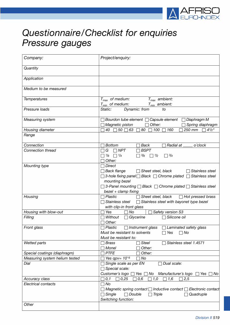
Division II 519
Questionnaire/Checklist for enquiriesPressure gaugesCompany: Project/enquiry:
Quantity
Application
Medium to be measured
Temperatures Tmax of medium: Tmax ambient:Tmin of medium: Tmin ambient:
Pressure loads Static: Dynamic: from to
Measuring system Bourdon tube element Capsule element Diaphragm M Magnetic piston Other: Spring diaphragm
Housing diameter 40 50 63 80 100 160 250 mm 41/2“Range
Connection Bottom Back Radial at o´clockConnection thread G NPT BSPT
1/8 1/4 3/8 1/2 3/4 Other:
Mounting type Direct Back flange Sheet steel, black Stainless steel 3-hole fixing panel Black Chrome plated Stainless steel
mounting bezel 3-Panel mounting Black Chrome plated Stainless steel
bezel + clamp fixingHousing Plastic Sheet steel, black Hot pressed brass
Stainless steel Stainless steel with bayonet type bezelwith clip-in front glass
Housing with blow-out Yes No Safety version S3Filling Without Glycerine Silicone oil
Other:Front glass Plastic Instrument glass Laminated safety glass
Must be resistant to solvents Yes NoMust be resistant to:
Wetted parts Brass Steel Stainless steel 1.4571 Monel Other:
Special coatings (diaphragm) PTFE Other:Measuring system helium tested Yes qpv= 10-6 NoDial Single scale as per EN Dual scale:
Special scale:Customer´s logo Yes No Manufacturer´s logo Yes No
Accuracy class 0,1 0,25 0,6 1,0 1,6 2,5Electrical contacts No
Magnetic spring contact Inductive contact Electronic contact Single Double Triple QuadrupleSwitching function:
Other

520 Division II
Questionnaire/Checklist for enquiriesDiaphragm sealsCompany: Project/enquiry:
Quantity
Application
Medium to be measured
Material for wetted parts
Temperatures Tmax of medium: Tmax ambient:Tmin of medium: Tmin ambient:
Pressure loads Static: Dynamic: from to
Vacuum Yes No
Special requirements
Information on the pressure gauge Pressure gauge Pressure transducerHousing diameter 63 100 160 ---
Range/measuring range
Connection Bottom Back ---
Please refer to Questionnaire/checklists„Pressure gauges“ and „Pressure transducers“for additional specifications
Details on the diaphragm seal Diaphragm seal Tongue-type diaphragm seal In-line chemical seal
Process connection (thread type and size /nominal width and nominal pressure)MaterialOther
Mounting of pressure gauge to diaphragm sealDirect mounting Yes NoCooling element between Yes Nopressure gauge and diaphragm sealMounting with capillary tube Capillary length m
Protective hose Yes NoHeight difference between pressure gauge anddiaphragm seal cm
Calibration temperature +20 °C (=standard) Others:
Preferred filling liquidOther

Division II 521
Questionnaire/Checklist for enquiriesPressure transducersCompany: Project/enquiry:
Quantity
Application
Medium to be measured
Material for wetted parts
Temperatures Tmax of medium: Tmax ambient:
Pressure loads Static: Dynamic: from to
Measuring principle Piezo-resistive ceramic measuring cell Piezo-resistive stainless Capacitance ceramic measuring cell steel measuring cell
Measuring range
Pressure type Relative pressure Absolute pressure Differential pressure
Connection type/connection thread Standard Protruding diaphragm Flush G NPT Other: 1/8 1/4 1/2 Other: Diaphragm seal mounted:Clamp connection:Dairy fitting DIN 11851:
Housing Standard Weatherproof housing Submersible probe Weatherproof housing with display
Electrical connection Plug DIN 43650-A Fixed cable metres PUR cable FEP cable Plug-in connector
Output signal 4-20 mA 0-20 mA 0-10 V Other: HART RS 232
Accuracy of measurement 0.1 0.25 0.35 0.5 1.0 % FS
Ex protection No Yes, for zone:
Accessories Digital display unit Without switching outputfor panel mounting With switching outputs
Digital plug-in display Integrated display Isolating amplifier Isolating amplifier with power supply
Other

522 Division III
Questionnaire/Checklist for enquiriesWater analysisCompany: Project/enquiry:
Quantity
Application
Parameters to be measured Standard:and measuring range pH value Redox Conductivity= mS/cm
Ion-selective (mg/l): Ammonium NH4
+= Lead2+= Bromide Br -= Calcium Ca2+= Chloride Cl -= Fluoride F-= Iodide/Cyanide/I-/CN-= Potassium K+= Copper Cu2+= Sodium Na+= Nitrate NO3
-= Silver/sulphide Ag+/S2-=
Gases dissolved in the water (mg/l): Oxygen O2= Carbon dioxide CO2= Chlorine Cl2= Ammonia NH3=
Measurement conditions Temperature= ºC Pressure= mbar absoluteFlow speed= m/spH value= Conductivity= mS/cmRedox= mVSalinity=Disruptive components (e.g. ammonia in mg/l or mol/l):
Measuring system/situation Portable Stationary Electrode only Installation in pipeline Thread PG13.5 Other thread: Installation into existing fitting (please specify):
Electrode design Standard 120 mm/Ø 12 mm Miniature screw-in electrode Special design (please specify) Electrode with fixed cable, length= m
Plug: BNC S7 DIN plug Without Electrode with plug
BNC S7 DIN plug Other:
Other
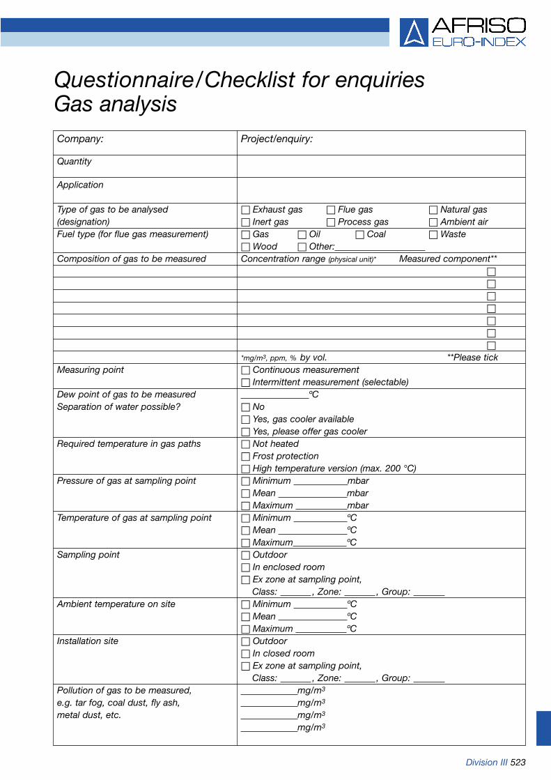
Division III 523
Questionnaire/Checklist for enquiriesGas analysisCompany: Project/enquiry:
Quantity
Application
Type of gas to be analysed Exhaust gas Flue gas Natural gas(designation) Inert gas Process gas Ambient airFuel type (for flue gas measurement) Gas Oil Coal Waste
Wood Other:Composition of gas to be measured Concentration range (physical unit)* Measured component**
*mg/m3, ppm, % by vol. **Please tickMeasuring point Continuous measurement
Intermittent measurement (selectable)Dew point of gas to be measured ºCSeparation of water possible? No
Yes, gas cooler available Yes, please offer gas cooler
Required temperature in gas paths Not heated Frost protection High temperature version (max. 200 °C)
Pressure of gas at sampling point Minimum mbar Mean mbar Maximum mbar
Temperature of gas at sampling point Minimum ºC Mean ºC Maximum ºC
Sampling point Outdoor In enclosed room Ex zone at sampling point,
Class: , Zone: , Group: Ambient temperature on site Minimum ºC
Mean ºC Maximum ºC
Installation site Outdoor In closed room Ex zone at sampling point,
Class: , Zone: , Group: Pollution of gas to be measured, mg/m3
e.g. tar fog, coal dust, fly ash, mg/m3
metal dust, etc. mg/m3
mg/m3
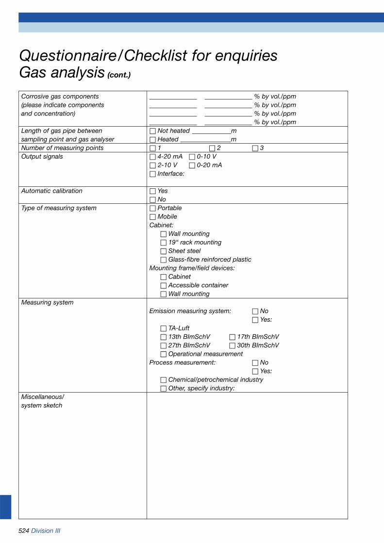
524 Division III
Questionnaire/Checklist for enquiriesGas analysis (cont.)
Corrosive gas components % by vol./ppm(please indicate components % by vol./ppmand concentration) % by vol./ppm
% by vol./ppmLength of gas pipe between Not heated msampling point and gas analyser Heated mNumber of measuring points 1 2 3Output signals 4-20 mA 0-10 V
2-10 V 0-20 mA Interface:
Automatic calibration Yes No
Type of measuring system Portable MobileCabinet:
Wall mounting 19“ rack mounting Sheet steel Glass-fibre reinforced plastic
Mounting frame/field devices: Cabinet Accessible container Wall mounting
Measuring systemEmission measuring system: No
Yes: TA-Luft 13th BImSchV 17th BImSchV 27th BImSchV 30th BImSchV Operational measurement
Process measurement: No Yes:
Chemical/petrochemical industry Other, specify industry:
Miscellaneous/system sketch
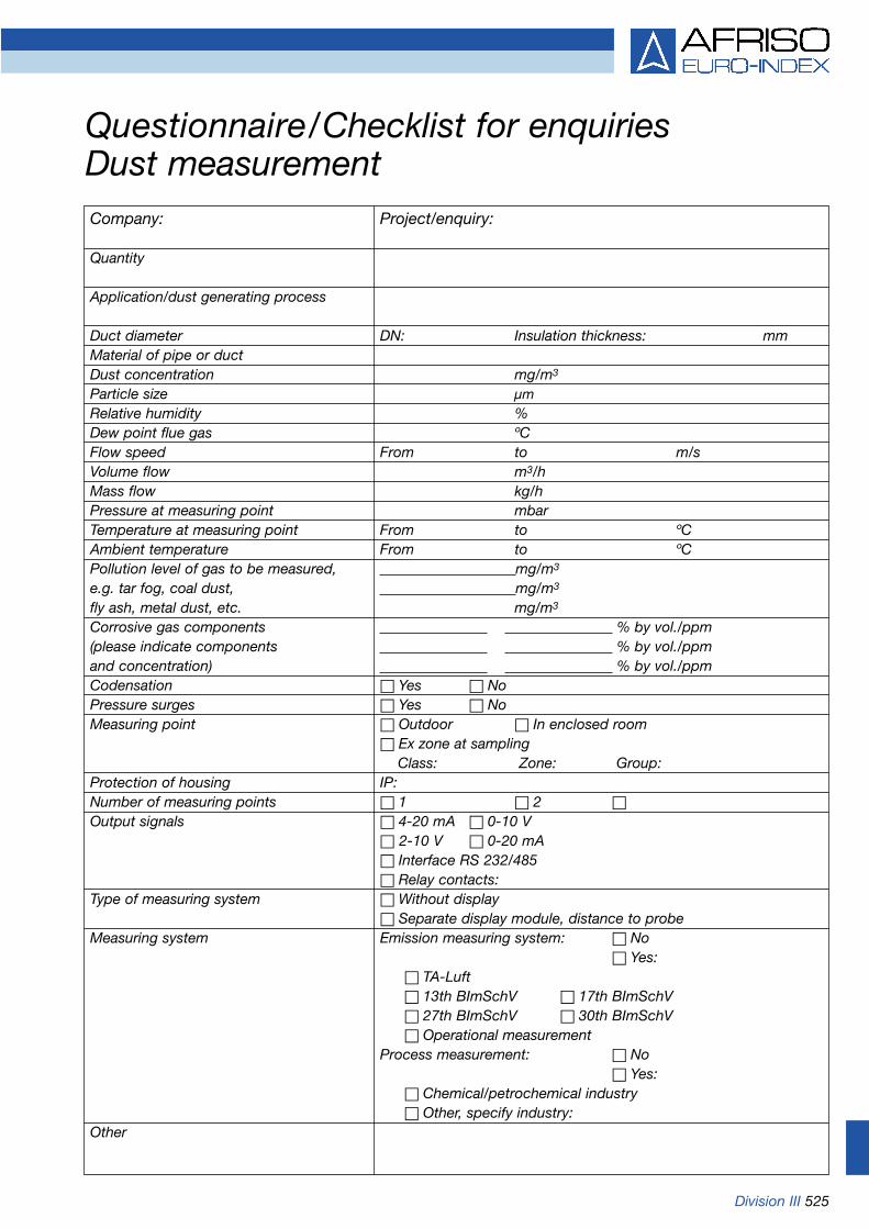
Division III 525
Questionnaire/Checklist for enquiriesDust measurementCompany: Project/enquiry:
Quantity
Application/dust generating process
Duct diameter DN: Insulation thickness: mmMaterial of pipe or ductDust concentration mg/m3
Particle size µmRelative humidity %Dew point flue gas ºCFlow speed From to m/sVolume flow m3/hMass flow kg/hPressure at measuring point mbarTemperature at measuring point From to ºCAmbient temperature From to ºCPollution level of gas to be measured, mg/m3
e.g. tar fog, coal dust, mg/m3
fly ash, metal dust, etc. mg/m3
Corrosive gas components % by vol./ppm(please indicate components % by vol./ppmand concentration) % by vol./ppmCodensation Yes NoPressure surges Yes NoMeasuring point Outdoor In enclosed room
Ex zone at samplingClass: Zone: Group:
Protection of housing IP:Number of measuring points 1 2 Output signals 4-20 mA 0-10 V
2-10 V 0-20 mA Interface RS 232/485 Relay contacts:
Type of measuring system Without display Separate display module, distance to probe
Measuring system Emission measuring system: No Yes:
TA-Luft 13th BImSchV 17th BImSchV 27th BImSchV 30th BImSchV Operational measurement
Process measurement: No Yes:
Chemical/petrochemical industry Other, specify industry:
Other

526 Division III
Questionnaire/Checklist for enquiriesVolume flow measurementCompany: Project/enquiry:
Quantity
Application
Measured gasMeasuring ranges Details Normal state Operating statusFlow speed From to m/sVolume flow From to m3/hMass flow From to kg/hPipe diameter (when used in pipes) Ø DNPressure of gas at Minimum mbarmeasuring point Mean mbar
Maximum mbarTemperature of gas at measuring point Minimum ºC
Mean ºC Maximum ºC
Ambient temperature Mean ºCCondensation Yes NoParticle load Yes NoPressure surges Yes NoMeasuring point Outdoor In enclosed room
Ex zone at sampling,Class: Zone: Group:
Protection of housing IPNumber of measuring points 1 2 Output signals 4-20 mA 0-10 V
2-10 V 0-20 mA Interface RS 232 Interface RS 485 Relay contacts:
Type of measuring system Stationary Without display With display Separate display module
PortableMeasuring system Emission measuring system: No
Yes: TA-Luft 13th BImSchV 17th BImSchV 27th BImSchV 30th BImSchV Operational measurement
Process measurement: No Yes:
Chemical/petrochemical industry Other, specify industry:
Automatic flushing Yes NoOther

Division II 527
Questionnaire/Checklist for enquiriesEvent reporting systemsCompany: Project/enquiry:
Quantity
Application
Parameters to be monitored Level Leak Dangerous cond. Process Min/max Tank leaks Gas temperature Continuous Burst Smoke Room Liquid pipes Fire temperature Solid Other: Water Doors
Low water Windows Burglary
Other parameters:
Ex protection No Yes, for zone:Supply voltage Battery operated Mains operatedData transmission GSM Public telephone network
Other:Required alarm inputs Digital Number: __________
Analogue Number:__________Required alarms SMS Call Internet/E-Mail
Local alarm: Visual Audible Other: Additional switching outputs: Additional alarm units
Remote data polling Not required Required - desired parameters:
Remote programming Not required Required - desired parameters:
Safety functions Not required Required - desired parameters:
Data logging Not required Required - desired parameters:
Data management and visualisation Not requiredvia Webservice (www.afriso-net.com) Optional
RequiredOther

528 Division II
Conversion table for standard pressure unitsU
nit
bar
mb
arP
akP
aM
Pa
kp/m
m²
kp/c
m²
atm
mm
Hg
mW
sm
mW
sp
si"H
2O"H
g
11
1000
1000
0010
00.
10.
0101
9716
1.01
9716
0.98
6923
750.
062
10.1
9716
1019
7.16
14.5
0377
401.
463
29.5
3b
ar 10.
001
110
00.
10.
001
0.00
0010
1972
0.00
1019
716
0.00
0986
923
0.75
0062
0.01
0197
1610
.197
160.
0145
0377
0.40
1463
0.02
953
mb
ar 10.
0000
10.
011
0.00
10.
0000
010.
0000
0010
20.
0000
1019
70.
0000
0986
90.
0075
0062
0.00
0101
9716
0.10
1971
60.
0001
4503
80.
0040
1463
0.00
0295
3P
a 10.
0110
1000
10.
001
0.00
0101
9716
0.01
0197
160.
0098
6923
7.50
062
0.10
1971
610
1.97
160.
1450
377
4.01
463
0.29
53kP
a
110
1000
010
0000
010
001
0.10
1971
610
.197
169.
8692
375
00.6
210
1.97
1610
1971
.614
5.03
7740
14.6
329
5.3
MP
a
198
.066
598
066.
598
0665
098
06.6
59.
8066
51
100
96.7
841
7355
5.9
1000
1000
000
1422
.334
439
370.
0828
95.9
016
kp/m
m²
10.
9806
6598
0.66
598
066.
598
.066
50.
0980
665
0.01
10.
9678
4173
5.55
910
1000
014
.223
344
393.
7008
28.9
5901
6kp
/cm
²
11.
0132
510
13.2
510
1325
101.
325
0.10
1325
0.01
0332
271.
0332
271
760
10.3
3227
1033
2.27
14.6
959
406.
3885
829
.921
26at
m 10.
0013
3322
41.
3332
2413
3.32
240.
1333
224
0.00
0133
322
0.00
0013
951
0.00
1359
510.
0013
1578
91
0.01
360
13.6
00.
0193
360.
5352
40.
0393
7m
mH
g
10.
0980
665
98.0
665
9806
.65
9.80
665
0.00
9806
650.
001
0.1
0.09
6784
173
.556
110
001.
4223
274
39.3
7008
2.89
5901
6m
Ws
10.
0000
9806
70.
0980
665
9.80
665
0.00
9806
650.
0000
0980
70.
0000
010.
0001
0.00
0096
784
0.07
3556
0.00
11
0.00
1422
327
0.03
9370
080.
0028
9590
2m
mW
s
10.
0689
4757
68.9
4757
6894
.757
6.89
4757
0.00
6894
757
0.00
7030
70.
0703
070.
0680
4651
.715
217
0.70
307
703.
071
27.6
82.
0352
9p
si 10.
0024
9089
2.49
089
249.
089
0.24
9089
0.00
0249
089
0.00
0025
40.
0025
40.
0024
5831
71.
8683
20.
0254
25.4
0.03
613
10.
0735
6"H
2O 10.
0338
639
33.8
639
3386
,43,
3864
0,00
3386
40,
0003
4531
20.
0345
312
0.03
3421
0425
.40.
3453
1634
5.31
60.
4911
513
.595
1"H
g

Division II 529
Selection criteria for pressure gauges (safety considerations) according to EN 837-2
Medium Liquid
Housing Without filling With filling
Nominal size 40/50/63/80 100/160/250 40/50/63/80 100/160/250
Range bar < 25 > 25 < 25 > 25 < 25 > 25 < 25 > 25
Abbreviation key forminimum safety 0 0 0 0 S1 S1 S1 S1version
AFRISO- All All All All D6/D7/ D6/D7/ D7/ D7/type designation D8 D8 D8 D8
Medium Gas or steam (attention: does not apply to oxygen + acetylene*)
Housing Without filling With filling
Nominal size 40/50/63/80 100/160/250 40/50/63/80 100/160/250
Range bar < 25 > 25 < 25 > 25 < 25 > 25 < 25 > 25
Abbreviation key forminimum safety 0 S2 S1 S3 S1 S2 S1 S3version
AFRISO- All „A“ D4/D9 RF D6/D7/ „B“ D6/D7 RFtype designation 100/160 Si D8 D8 100/160 Si
D4x2 D8x2
Explanations of key:
„A“ RF 63 Ch D 9x2, RF 63 Si D 4x2, RF 50/63 ST, RF 50/63 GT, RF 63 RG,RF 50 SK D 902, RF 63 MK/IK D 3x2
„B“ RF 63 D 7x2, RF 63 Si D 8x2
0 Pressure gauges without blow-outS1 Pressure gauges with blow-outS2 Safety pressure gauges without solid baffle wallS3 Safety pressure gauges with solid baffle wall
(for higher level of safety)
Note 1:Pressure gauges for oxygen and acetylene must meet the requirements for safety pressure gauges (NG 40 - 80 S2, NG 63/100/160 S3).
Note 2:Pressure gauges filled with glycerine must not be used for oxygen or other oxidization process fluids. High concentration fluorine liquids and chlorinated liquids (e.g. halocarbon) are suitable for such applications.
Note 3:This table contains the standard safety version with the corresponding keys. Users must take into considerationany knowledge they have of their own specific requirements and may also use safety pressure gauges at pressures below 25 bar.
* Please refer to page 530 for pressure gauges for oxygen and acetylene.

530 Division II
Selection criteria for pressure gauges (safety considerations) according to EN 837-2
Pressure gauges for oxygen and acetylene
Only safety pressure gauges (S2 and S3) may be used. All materials for wetted parts (parts coming into contact with oxygen or acetylene) must comply with EN 29539.
Pressure gauges for oxygen
The Bourdon tube and other wetted parts must be free from oil and grease. Only those lubricants suitable for oxygen at maximum operating pressure may be used.
The dial must bear the word "oxygen" in English and the international symbol for "free from oil and grease"(symbol 0248 according to ISO 7000 with the "oil prohibited" symbol):
Oxygen and acetylene
NG 40 - 80 NG 100 - 250S 2/S 3 S 3
Version RF 50 ST RF 100 Si D 4x2RF 50 GT adapted to EN 562 RF 160 Si D 4x2RF 63 STRF 63 GT adapted to EN 562RF 50 SK D 902RF 63 MK/IK D 3x2RF 63 Si D 4x2

Division II 531
Dials for pressure gauges - graduationHousing diameters (NG) 40, 50, 63, 72x72 – accuracy classes 1.6 and 2.5
ExampleRanges Graduation Ranges Graduation Ranges Graduation
0... 1 bar 0.05 bar 0... 10 mbar 0.5 mbar -60... +40 mbar 5 mbar-1... 0 bar 0.05 bar -4... +6 mbar 0.5 mbar -100... 0 mbar 5 mbar0... 10 bar 0.5 bar -6... +4 mbar 0.5 mbar 0... 1000 mbar 50 mbar
-1... +9 bar 0.5 bar -10... 0 mbar 0.5 mbar -400... +600 mbar 50 mbar0... 100 bar 5 bar 0... 100 mbar 5 mbar -600... +400 mbar 50 mbar0... 1000 bar 50 bar -40... +60 mbar 5 mbar -1000... 0 mbar 50 mbar
Ranges Graduation Ranges Graduation Ranges Graduation Example
0... 1,6 bar 0.05 bar 0... 16 mbar 0.5 mbar 0... 160 mbar 5 mbar-1... +0,6 bar 0.05 bar -6... +10 mbar 0.5 mbar -60... +100 mbar 5 mbar0... 16 bar 0.5 bar -10... +6 mbar 0.5 mbar -100... +60 mbar 5 mbar
-1... +15 bar 0.5 bar -16... 0 mbar 0.5 mbar -160... 0 mbar 5 mbar0... 160 bar 5 bar
Ranges Graduation Ranges Graduation Ranges Graduation Example
0... 2.5 bar 0.1 bar 0... 25 mbar 1 mbar 0... 250 mbar 10 mbar-1... +1.5 bar 0.1 bar -10... +15 mbar 1 mbar -100... +150 mbar 10 mbar0... 25 bar 1 bar -15... +10 mbar 1 mbar -150... +100 mbar 10 mbar0... 250 bar 10 bar -25... 0 mbar 1 mbar -250... 0 mbar 10 mbar
Ranges Graduation Ranges Graduation Ranges Graduation Example
0... 4 bar 0.2 bar 0... 40 mbar 2 mbar 0... 400 mbar 20 mbar-1... +3 bar 0.2 bar -15... +25 mbar 2 mbar -150... +250 mbar 20 mbar0... 40 bar 2 bar -25... +15 mbar 2 mbar -250... +150 mbar 20 mbar0... 400 bar 20 bar -40... 0 mbar 2 mbar -400... 0 mbar 20 mbar
Ranges Graduation Ranges Graduation Ranges Graduation Example
0... 0.6 bar 0.02 bar 0... 60 mbar 2 mbar 0... 600 mbar 20 mbar-0.6... 0 bar 0.02 bar -20... +40 mbar 2 mbar -200... +400 mbar 20 mbar
0... 6 bar 0.2 bar -40... +20 mbar 2 mbar -400... +200 mbar 20 mbar-1... +5 bar 0.2 bar -60... 0 mbar 2 mbar -600... 0 mbar 20 mbar0... 60 bar 2 bar0... 600 bar 20 bar

532 Division II
Dials for pressure gauges - graduationHousing diameters (NG) 80, 100, 160, 96x96, 144x144 – accuracy classes 1.0 and 1.6
Ranges Graduation Ranges Graduation Ranges Graduation Example
0... 1 bar 0.02 bar 0... 10 mbar 0.2 mbar -60... +40 mbar 2 mbar-1... 0 bar 0.02 bar -4... +6 mbar 0.2 mbar -100... 0 mbar 2 mbar0... 10 bar 0.2 bar -6... +4 mbar 0.2 mbar 0... 1000 mbar 20 mbar
-1... +9 bar 0.2 bar -10... 0 mbar 0.2 mbar -400... +600 mbar 20 mbar0... 100 bar 2 bar 0... 100 mbar 2 mbar -600... +400 mbar 20 mbar0... 1000 bar 20 bar -40... +60 mbar 2 mbar -1000... 0 mbar 20 mbar
Ranges Graduation Ranges Graduation Ranges Graduation Example
0... 1.6 bar 0.05 bar 0... 16 mbar 0.5 mbar 0... 160 mbar 5 mbar-1... +0.6 bar 0.05 bar -6... +10 mbar 0.5 mbar -60... +100 mbar 5 mbar0... 16 bar 0.5 bar -10... +6 mbar 0.5 mbar -100... +60 mbar 5 mbar
-1... +15 bar 0.5 bar -16... 0 mbar 0.5 mbar -160... 0 mbar 5 mbar0... 160 bar 5 bar0... 1600 bar 50 bar
Ranges Graduation Ranges Graduation Ranges Graduation Example
0... 2.5 bar 0.05 bar 0... 25 mbar 0.5 mbar 0... 250 mbar 5 mbar-1... +1.5 bar 0.05 bar -10... +15 mbar 0.5 mbar -100... +150 mbar 5 mbar0... 25 bar 0.5 bar -15... +10 mbar 0.5 mbar -150... +100 mbar 5 mbar0... 250 bar 5 bar -25... 0 mbar 0.5 mbar -250... 0 mbar 5 mbar
Ranges Graduation Ranges Graduation Ranges Graduation Example
0... 4 bar 0.1 bar 0... 40 mbar 0.1 mbar -25... +15 mbar 1 mbar-1... +3 bar 0.1 bar -1.5... +25 mbar 0.1 mbar -40... 0 mbar 1 mbar0... 40 bar 1 bar -2.5... +15 mbar 0.1 mbar 0... 400 mbar 10 mbar0... 400 bar 10 bar -4... 0 mbar 0.1 mbar -150... +250 mbar 10 mbar
0... 40 mbar 1 mbar -250... +150 mbar 10 mbar-15... +25 mbar 1 mbar -400... 0 mbar 10 mbar
Ranges Graduation Ranges Graduation Ranges Graduation Example
0... 0.6 bar 0.01 bar 0... 6 mbar 0.1 mbar -40... +20 mbar 1 mbar-0.6... 0 bar 0.01 bar -2... +4 mbar 0.1 mbar -60... 0 mbar 1 mbar
0... 6 bar 0.1 bar -4... +2 mbar 0.1 mbar 0... 600 mbar 10 mbar-1... +5 bar 0.1 bar -6... 0 mbar 0.1 mbar -200... +400 mbar 10 mbar0... 60 bar 1 bar 0... 60 mbar 1 mbar -400... +200 mbar 10 mbar0... 600 bar 10 bar -20... +40 mbar 1 mbar -600... 0 mbar 10 mbar
Example

Division II 533
Dials for pressure gauges - graduationHousing diameters (NG) 160, 250 – accuracy class 0.6 – DIN 16123
Ranges Graduation Ranges Graduation Ranges Graduation Example
0... 1 bar 0.005 bar 0... 10 mbar 0.05 mbar -60... +40 mbar 0.5 mbar-1... 0 bar 0.005 bar -4... +6 mbar 0.05 mbar -100... 0 mbar 0.5 mbar0... 10 bar 0.05 bar -6... +4 mbar 0.05 mbar 0... 1000 mbar 5 mbar
-1... +9 bar 0.05 bar -10... 0 mbar 0.05 mbar -400... +600 mbar 5 mbar0... 100 bar 0.5 bar 0... 100 mbar 0.5 mbar -600... +400 mbar 5 mbar
-40... +60 mbar 0.5 mbar -1000... 0 mbar 5 mbar
Ranges Graduation Ranges Graduation Ranges Graduation Example
0... 1.6 bar 0.01 bar 0... 16 mbar 0.1 mbar 0... 160 mbar 1 mbar-1... +0.6 bar 0.01 bar -6... +10 mbar 0.1 mbar -60... +100 mbar 1 mbar0... 16 bar 0.1 bar -10... +6 mbar 0.1 mbar -100... +60 mbar 1 mbar
-1... +15 bar 0.1 bar -16... 0 mbar 0.1 mbar -160... 0 mbar 1 mbar0... 160 bar 1 bar
Ranges Graduation Ranges Graduation Ranges Graduation Example
0... 2.5 bar 0.02 bar 0... 25 mbar 0.2 mbar 0... 250 mbar 2 mbar-1... +1.5 bar 0.02 bar -10... +15 mbar 0.2 mbar -100... +150 mbar 2 mbar0... 25 bar 0.2 bar -15... +10 mbar 0.2 mbar -150... +100 mbar 2 mbar0... 250 bar 2 bar -25... 0 mbar 0.2 mbar -250... 0 mbar 2 mbar
Ranges Graduation Ranges Graduation Ranges Graduation Example
0... 4 bar 0.02 bar 0... 40 mbar 0.2 mbar 0... 400 mbar 2 mbar-1... +3 bar 0.02 bar -15... +25 mbar 0.2 mbar -150... +250 mbar 2 mbar0... 40 bar 0.2 bar -25... +15 mbar 0.2 mbar -250... +150 mbar 2 mbar0... 400 bar 2 bar -40... 0 mbar 0.2 mbar -400... 0 mbar 2 mbar
Ranges Graduation Ranges Graduation Ranges Graduation Example
0... 0.6 bar 0.005 bar 0... 6 mbar 0.05 mbar -40... +20 mbar 0.5 mbar-0.6... 0 bar 0.005 bar -2... +4 mbar 0.05 mbar -60... 0 mbar 0.5 mbar
0... 6 bar 0.05 bar -4... +2 mbar 0.05 mbar 0... 600 mbar 5 mbar-1... +5 bar 0.05 bar -6... 0 mbar 0.05 mbar -200... +400 mbar 5 mbar0... 60 bar 0.5 bar 0... 60 mbar 0.5 mbar -400... +200 mbar 5 mbar0... 600 bar 5 bar -20... +40 mbar 0.5 mbar -600... 0 mbar 5 mbar
Example

534 Division II
R 134a R 134a/R 22
R 22/R 12/R 502 R 12
Standard colours for temperature scales: R 12 = blue/R 22 = green/R 502 und R 717 = red
Temperature scales for refrigerating agent dewpoint temperature Examples for measuring range -1/+24 bar
R 404A R 717 (NH3 )

Division II 535
Information on the Pressure EquipmentDirective (PED) 97/23/EC
Pressure Equipment Directive (PED)The European Pressure Equipment Directive (PED) came into force on May 30, 2002.The following paragraphs provide some information on the Directive itself and on ouractivities within the framework of this Directive.
AFRISO-EURO-INDEX GmbH pressure gauges with a full scale value of > 0.5 bar aresubject to the Pressure Equipment Directive and meet the appropriate requirements.
The final application conditions of most pressure gauges are not normally known completely at the time of manufacture. We therefore manufacture our products in accor-dance with the most stringent criteria (gases of group 1).
Our pressure gauges with a full scale value of > 200 bar therefore receive a CE markaccording to the conformity procedure.
Pressure gauges with a connection flange of > DN 25 receive a CE mark with a full scalerange of 0.5 bar and greater.
The CE mark is attached to the outside of the housing (type designation plate).
A declaration of conformity is provided on request. Detailed operating instructions andthe appropriate fact sheets are available at www.afriso.de and are also forwarded onrequest.
Pressure gauges with a full scale value of less than 0.5 bar and loose diaphragm seals donot fall under the PED and must not carry a CE mark.
Pressure gauges with a full scale value between 0.5 bar and 200 bar fall under „GoodEngineering Practice“ and must not carry a CE mark (section 3, paragraph 3).
We are not authorised to CE mark pressure gauges without a company name or a company logo.
Pressure gauges which are used as a part of a safety system to protect against exceeding permissible limit values (equipment parts with safety function) must be givenspecial consideration.
Our pressure gauges conform to the European Standard EN 837-1 and are manufacturedand tested according to appropriate requirements.

536 Division III
Information on EN 50379 (portable measuringinstruments)On March 01, 2007 EN 50379 for portable measuring instruments comes into effect. This standard coversdevices used to determine the gas concentration and other combustion parameters in the installation andmaintenance of domestic and industrial heating systems with standard fuels.
The standard defines the design, testing and operating requirements for portable devices, which are usedto determine specific flue gas parameters such as the concentration of individual gas components, thetemperature and/or the pressure in combustion processes in order to ensure compliance with national direc-tives regarding the operating behaviour of combustion systems.
The standard is divided into three parts:
Part 1: General requirements and test proceduresEN 50379-1 specifies the general requirements concerning the design, testing and operating behaviour of devices used for short-term measurements to determine specific flue gas parameters such as the concentration of individual gas components, the temperature and/or the pressure in combustion processes in order to ensure compliance with national directives regarding the operating behaviour of combustion systems using commercially available fuels in domestic and industrial applications.
Part 2: Requirements concerning the operating behaviour of devices used in statutory measurements and assessmentsEN 50379-2 applies to devices which are used in statutory measurements or measurements specified by regulations. National legislation covering the operating behaviour of combustion systems exists in several European countries. Authorised inspectors use such devices to measure flue gas parameters and verify the compliance of combustion systems with national directives.Since the results of such measurements have statutory consequences, there are stringent requirements concerning the accuracy of these devices. Therefore, EN 50379-2 specifies maximum values for measuring inaccuracy. Tests with real flue gases constitute an essential part in the proof of suitability for statutory measure-ments. The determination of the measuring inaccuracy must be demonstrated and confirmed with internationally approved methods for the entire measuring range.
Part 3: Requirements for devices in non-regulated areas in the maintenance of gas fired heating installationsEN 50379-3 applies to devices which are used in non-statutory applications. The requirements are less stringent because the devices are used in determining whether a gas fired combustion system may require maintenance or in setting up a gas fired combustion system during maintenance. The measuring inaccuracy does not have to be determined for such devices. These devices do not comply with the technical measuring specifications for measuring devices. Therefore, devices certified according to EN 50379-3 are not suitable for measuring combustion systems using fuels other than gas.
The standard was ratified on March 01, 2004. Binding dates for all member states:September 01, 2004 - Day of announcementMarch 01, 2005 - Publication as a National StandardMarch 01, 2007 - Withdrawal of contravening National Standards
AFRISO- EURO-INDEX is the first European manufacturer to have its complete range of flue gas measuringinstruments certified according to EN 50379-2.
All flue gas measuring instruments as well as the „Blue Line“ pressure and temperature measuring instrumentsmeet the stringent requirements of EN 50379-2. The TÜV quality mark (OCTOGON) confirms EN 50379-2 complianceand can only be used, if the production is audited by TÜV-SÜD at regular intervals. This line of measuring devices withthe TÜV-OCTOGON mark is backed by experience and competence. High quality pays off - both price/performanceratio and cost of ownership are convincing. High quality measuring devices also help to avoid conflicts and problems interms of product liability claims. All „Blue Line“ instruments meet the stringent requirements of EN 50379-2 and can continue to be used without restriction after March 01, 2007.

537

538

539

540

541

5
AAccessories for panel mounting and wallmounting 383Accessories for pressure gauges 383-389, 375
DDA 06, DA 06 Ex 502DA 10, DA 12, DA 14 503-504, 24DA 12 G 505Detectors 91
Exchange filter adapter 109, 114Exchange filter cartridge 109, 114FFelt type filter 109-111Filler and vent caps 55, 103
A - Z Product Finder/Keyword Index
Product description Page
Accessories for pressure reducer 411
42
Accessory bag for MAV 108Actuators, motorised 154AdBlue - Tank contents gauge 17AdBlue - Tank linings 81Additional display meters 26Additional slide-in scales 12, 14-15, 26AFRISO-Compact-Control series 154AFRISO-Control series 152-155Air-Control 119Air duct thermometer 168-169, 172Air flow filter 129Air sensors 468, 470Air separator unit 131Air speed measuring instrument 464Air vent 131AK-S Tank protection kit 78Alarm devices 506Alarm light with horn 506, 39-41Alarm re-set unit AQ 220 506, 39-41, 59, 89Ambient air sensor 472Ancillary control unit type 907 Z 61Anemometer/air speed measurement 464Annular gap probes 468, 470Anodes 138Anode tester AT1 138Anti-siphon valves 106-108Anti-tamper valves 125AQUALYZER 476AQUASYSTEM 476Automatic oil de-aerators 112-115Auxiliary alarm devices 506BBackwashing sets 147Ball valves 128Ball valves for potable water 128Bimetal thermometers 160-176, 182BIOLYZER 494Boiler-controlled air vent „Air-Control“ 119Boiler Safety Group Equipment 137Boiler safety group fittings 124Boiler water low level alarms 121-122Bottom filling device 149Bourdon tube pressure gauges 249-369, 453CCable extension fittings 39-41, 55CapFox EFM 741/752/762 27CapFox EFT 7 25CapFox ENT 7 46CapFox ENT 20 Ex 48CapFox Series 20 26CapFox S 74x 28Capsule type pressure gauges 231-248
365-369Chain anodes 138Chem. Industry Pressure Gauges 242-248
291-302, 361-364, 378-382Chem. Industry Thermometers 173-184CoFox ELT 8 39, 89CoFox ELT 500/4 40, 89CoFox ELT 68 C 45CoFox ELT 680 41Combined thermometers/pressure gauges
193-198, 252-254Combustion controller FR 1 123COMO 154Condensate filter cartridge 468, 470, 474Condensate trap KG 2 108Condensate water detector/tester KWT 5 453Connection assembly for expansion vessels125Connector and plug 57Contact protection relay 354Conversion kit: float-set 104Conversion kits for withdrawal systems 104Conversion kit: lever type shut-off valve 104Conversion set 1 for oil tanks 144Conversion sets II+III for oil tanks 145Coupler relay KR 100 ST 45
Diaphragm pressure gauges, chem. industry 380-382
Diaphragm pressure gauges, general 355-364 380-382
Diaphragm type anti-siphon valves MAV 107Diaphragm type chemical seals 391-409Diaphragm type safety valves 124, 137Differential overflow valves 128Differential pressure connection kit 470Differential pressure gauges 365-382Differential pressure switch DS 01 414Differential pressure transducers 434-449Differential temperature controls 157Digital display instruments
DA 06, DA 06 Ex 502DA 10, DA 12, DA 14 503-504, 24DA 12 G 505
Digital plug-in display DA 06 502Digital pressure gauge DIM 10/DIM 11 447-449Digital temperature controller TSD 228Digital thermometer 228DIM 10 447-449Dip sticks 12Dip stick cover, screwed 103Display/control unit DA 12 G 505Display units and controllers 24, 502-505Distribution manifolds for:
Potable water installations 132Tool cooling 132Underfloor heating 132
DIT 01 19DIT 02 20DMU 01 to DMU 14 415-449Downpipe filter 148Draught gauge FZM (handheld) 460Draught regulator 120Drip pans 87Dual line filter 110-111Dual Thermostats 212-214Dust measuring instrument S303/S305 490EEasySystem 492-493Elbow connector 130Electrodes for water analysis instruments
477-478Electronic digital temperature controller 228Electronic digital thermometer 228Electronic handheld pressure instruments 453-461Electronic handheld thermometers 462-463Emission computer 495EMS 220, EMS 442 512-513Euroflex 104Euroflex with tank heater 105EUROLYZER 467-468Europress LAD-10, LAD-R 83-84EUROPRINTER 461, 458, 468, 470Eurovac 04-1, 04-3 76-77Event reporting systems 507-514Event reporting system
EMS 220, EMS 442 512-513Fuel Oil Manager INTERNET 511GSM Alarm 510Phone Alarm SD1 509
Event reporting system - sensors 514Ex-certified instruments
CapFox ENT 20 Ex 48CapFox S 74x 28Digital plug-in display DA 06 Ex 502Gas sensor 510 Ex 100Isolating amplifier/supply unit STV 5104 B 500Leak Detector LAG-14 ER 73Level probes 60Level sensor test instrument ME 5 452Overfill preventer (Zone 0) 59Safety barrier GHG 111 499Thermistor level sensors (Ex) 57-58WAG 01 - WGA 06 66-69
Filler caps 55, 103Filling and test kit for LAD-R 84Filling device FA 130Filter 109-111, 115, 134, 468-482Filter cups 109-111, 474Filter, single line 110-111Filter spare parts 111, 114, 468, 474Fleece - „Geovlies“ 79Flexible suction hose 149Floating probe SWS 91Floating suction fitting 149FloCo-Opticlean 115FloCo-Optimum 113FloCo-TOP 113-115Flow-Control 112Flow filter 129Flowtemp 455Flue gas analysis computer:
EUROLYZER 467MAXILYZER 472MULTILYZER 469MULTILYZER NG 471
Flue gas combination probes 468-472Flue gas temperature controller 163-167Flue gas thermometer 163-167Foot pump 457Forta Duo 1100 145Frames for panel mounting 74, 353GGas analysis instrument BIOLYZER 494Gas analysis instrument for:
CO 467, 469, 471-472, 485, 492CO2 467, 469, 471-472, 485, 492, 494CH4 485, 492, 494H2S 494NO 469, 471-472, 485, 492NOx 469, 471-472, 485, 492O2 467, 469, 471-472, 485-489, 492, 494SO2 469, 471-472, 485, 492
Gas analysis MGA-1 474, 470Gas analysis MGK 744 483Gas analysis, stationary 480-495Gas analysis system EasySystem 492-493Gas and smoke detector GRM 95Gas cooler MGK 741 484Gas detector GSP1/GSP3 459Gas detectors 94-95, 97-99Gas filled chemical industry press.gauges
378-382Gas filled standard pressure gauge 376-382Gas filled thermometers 177-184Gas industry pressure gauges 328-330Gas sensors 96, 100Gas withdrawal probes 475, 481Glycerine filled pressure gauges 273-325,453GSM Alarm Event Reporting System 510HHandheld measuring instruments
Flue gas analysis 467-474Humidity/air temperature 464-466Pressure 453-461Temperature 462-463
Hand pump for DPK 54 457Hand suction pump for heating oil 115Heating controls 152-156Heating oil de-aerator 112-115Heating oil filter 109-115Heating oil filter Optimum/Opticlean110-111, 115Heating oil manager INTERNET 511Heating oil meter 116Heating oil withdrawal units 104-105HF pre-amplifier Ex 28High accuracy pressure gauges 244-248
312-317High pressure gauges 320-322Horn alarm unit KH 1/HPW 2 506Hose connector 15, 108

543
Humidity/temperature instruments FT3 - FT6 466Hydrometer 252-254IIndustrial pressure gauges 267-272Industrial thermometers 168-171, 177-184Infrared gas analysers 485Inner tank linings
Heating oil and Diesel 78Installation accessories 82Liquid fertiliser AHL, AdBlue 81Rain water 80
Installation kits for:Heating oil contents gauge 16, 19LAG 74, 108LAG additional expansion vessel 74LAS 72Water level indicator 15-16, 20
Isolating Amplifier 498, 500Isolating switching amplifier 48-49, 354KKFE - cocks 130KSG 124LLAD-10, LAD-R 83-84LAG-13 K, LAG-13 KR 74LAG-14 ER 73LAS 24/39/72/230 72LAZ-04/1, LAZ-04/3 76Leaf separation filter 148Leak alarm units 40, 89Leak detection instruments
CoFox ELT 500/4 40, 89Oil-water alarm unit ÖWWG 3 86Oil alarm unit OM 5 87Water alarm unit WM5 87
Leak detection system TraceTek 92Leak detector fluid, concentrate 74Leak detector spare parts 75Leak detectors, liquid filled systems 73-74Leak detectors, sight glass type 72Leak detectors, vacuum type 76-77Level alarm 37Level controller 26-28, 40-41, 63Level controllers/switches 37-41, 45-48, 50Level detection probes 60Level indicators for AdBlue 17Level indicators - general
Capacitance 25-28Hydrostatic 22-23Magnetostrictive 32Micropulse (TDR) 33-36Ultrasonic 31
Level indicators for oil tanks:Capacitance 25Electro-pneumatic 18Hydrostatic 19, 21Mechanical 12-13Pneumatic 14-16
Level indicators for water:Hydrostatic 20Pneumatic 14-15
Level sensor (thermistor) accessories 55Level sensor (thermistor) filler caps 55, 103Level sensor (thermistor) fittings 57Level sensors (thermistor) GWG 54-58Level sensor (thermistor) test instruments 452Level switches 38-63Level Switches
Capacitance 46-47Conductivity 39-45Float 37Rotary paddle 38Thermistor type 63Vibration 50-52
Lever type shut-off valve (conversion kit) 104Liquid filled leak detectors 73-74Liquid water foil, black 5024 80Low level gas alarm 353MMagFox MMG 01 32Magnetic piston type pressure gauges
370-371, 374-375
Magnet type diaphragm pressure gauges 372-375Manhole cover, plastic 144Manifolds for LAD-R 85MAV 1,8, MAV 3, MAV Universal 107MAXILYZER 472Maximelder, Minimelder 37, 143MAXISYSTEM 475Measuring instruments, portable
Air speed 464Flue gas analysis 467-474Gas analysis 474, 470Humidity/air temperature 466Pressure 453-461Temperature 462-463Volume flow 465Volume flow and temperature 455
MFU 01 and MFU 02 501Miniflex 104Minimelder, Maximelder 37Mixer control, motorised 152-155Montagefix extension set 15Motorised boiler room vent Air-Control 119Mounting frame for panel mounting 74, 353Mounting valves 131MT-Profil R 12Multi-functional transducer MFU 501Multi-hole probes 468MULTILYZER 469MULTILYZER NG 471Multi-way union 130NNon-return valve 134OOil alarm unit OM 5 87Oil burner solenoid valve 116Oil filter spanner 113Oil-on-water detector ÖAWD-1 91Oil-on-water detector ÖAWD-8 91Oil tank conversion set 1 144Oil tank conversion sets II+III 145Oil/water alarm unit ÖWWG 3 86Oil/water alarm unit ÖWU 88Oil withdrawal systems 104-105Opticlean micro filter 109-111Optimum filter 109-111Outdoor temperature compensated heatingcontrol equipment 152-155Outdoor temperature sensors 468, 470Outdoor temperature switch/sensor 5 105Overfill preventers 61-62Overfill prevention probes 62Overfill prevention systems:
Capacitance type 25-30Thermistor type 59-62
Overflow siphon 149Overflow valves 128Overpressure device 103Oxygen analysers 487-488Oxygen measuring probe 486Oxygen trace analyser 489Oxystem 486-489PPanel mounting pressure gauges 235-241
318-322Paper filter Opticlean 109-111Phone Alarm SD 1 509Pipe heating 105Pipe temperature sensor 5 105Pipe temperature sensor RTS 227Plastic dip sticks 12Plastic manhole cover 144 Pneumofix 15, 108Pockets/thermowells 205Potable water manifold 132Printer 461, 458, 468, 470Printer paper 468, 470Pressure compensation unit DAE 105Pressure gauge accessories 383-389, 375Pressure gauges/accessories 229-369
Bourdon tube type 249-369, 453Capsule type 231-248, 365-366, 369Chemical industry 242-382
Diaphragm type 355-382Differential pressure 365-382Digital 447-449Electrical limit contacts 340-352For pump test set 453Gas technology 328-330Glycerine filled 273-290, 297-325, 453Heating type 249-254High accuracy 244-317High pressure type 320-322Industrial type 267-272Magnetic diaphragm type 372-375Magnetic piston type 370-371, 374-375Overpressure device 385Panel mounting 235-241, 318-322Process-Gauge 309-311Push button stop cocks 385Refrigeration type 323-326Safety type 303-308Spring diaphragm type 376-379, 382Stainless steel 355-358Standard type 231-266, 359-377Stop cocks and valves 384Ultra-pure gas type 331-333Welding industry type 326-327, 330
Pressure gauges for heating installations 249-254Pressure gauges with capillary tubing 191-198Pressure indication 115Pressure instruments, mobile/handheld
453-458, 460-461Pressure reducer 84, 134Pressure switches DS 600 412-413Pressure test instruments 455 - 458Pressure test kit (for water) 455Pressure test sets 456 - 458 Pressure transducers 415-446, 23
DMU 01 415-417, 420-421DMU 03 418-421DMU 04 422-423, 426-427DMU 05 424-427DMU 07 428-429, 438-439DMU 08 430-431, 438-439, 23DMU 09 432-433, 438-439DMU 10 D 434-435, 438-439DMU 11 D 436-439DMU 12/DMU 12 D 440-442, 449DMU 13 443-444, 449DMU 14 445-446
Pressure type leak detectors 83-84Pressure/vacuum instrument S2510 453Probes/electrodes:
3-rod 444-rod 44Annular gap 468, 470Band electrode 25-26, 29-30Capacitance 29-30, 46-49Co-axial 35-36 Combination probe 88Conductivity 42-45Ex- 48-60, 66-69Flexible rope 43-44, 47Float type 37, 69, 91, 143Floor water probe 43, 90Flue gas combination - heated 475, 481Flue gas combination, not heated 468-472Gas analysis 486, 490Gas sampling 475, 481Hydrostatic 19-23Infrared 87Magnetostrictive 32Micropulse/Puls Reflex (TDR) 35-36Mono/single 35-36Multi-hole 468, 470Multi-rod 43RENA 140Rigid rod 29-30, 47Rotary paddle 464Single rod 43-44Submersible 430-433Thermistor 59-63, 86Twin probe 35-36Twin rod 44
A - Z Product Finder/Keyword Index
Product description Page

544
Ultrasonic 31Wall mounting rail 43, 90WGA- 66-69WMS- 122Zirconium dioxide 486-488
Process-Gauge 309-311Programmable thermostats 154, 156Pull cord 108PulsFox PMG 01 33-36Pump ball valves 126, 128Pump connection kits 126Pump Forta Duo 1100 145QQuick-action connector 149RRain water down pipe filter 148Rain water filter 147Rain water harvesting 139Rain water harvesting accessories 149Rain water System Centre ReMax 141Rain water System Centre RWSC 142Reducers 12, 55, 108Refrigeration type pressure gauges 323-326ReMax 141Remote control FBR 1 154RENA water top up instrument/set 140Resistance type thermometers 215-226Reverse osmosis 150Room thermostats 210-211, 214RotaFox MLS 10 38Rotating alarm lamp 506RWSC 142-143SSacrificial anodes 138Safety barriers for Ex Zone 1 499Safety pressure gauges 303-308Safety Switch RC 105Safety temperature switches 201-204Safety thermostats 201-204Safety valves 137Screw connectors 114Seals (chem. seals) 390-411
Accessories 411Diaphragm 391-409for homogenisers 398In-line 402-403, 410Tongue type 398
Selector switch 499Sensors:
Ex-Gas 100Gas 96, 100Smoke 96Water analysis 477-478
Service box Optimum 110Siku filters 109-111Single pipe union connector DN 32 458Smoke alarm GRM 95Smoke sensors 96Solar controller SR1 and SR1R 157Solar differential controllers SD 1 - SD 3 158Solar pump station 127Solar station 157Solar vents 131Solenoid valves 107, 116, 140SonarFox 31Soot comparison scale 468, 470Soot pump 468, 470 Spanner for exchange filter 114Spare exchange filter cartridge 114Spare parts for:
Anemometers 464Flue gas analysers 468, 470, 473Gas analysis 474-475Leak detectors 75Pressure gauges 460Pressure test set 457Rainwater System Centre 143
Spare probes for:Maxi- and Minimelder 37ÖAWD-1, ÖAWD-8 91ÖWWG 3 86OM5, WM5 87
Oxystem 486-489RENA 140WGA 01 - WGA 06 66-69WMS 2-1/WMS 2-1-2/ WMS 3-1-2 122
Spare thermowells/pockets 162Special slide-in scales 14-15Stainless steel filter 109, 111Stainless steel pressure gauges 355-358Stainless steel thermometers 173-184Standard pressure gauges 231-266, 359-377Standard thermometers 163-166Stationary gas analysis 480-495Stationary gas sampling probes 481Strainers 134Submersible pressure pump Forta Duo 1100 145Submersible transducers DMU 08/DMU 09
430-439Switching contacts for pressure gauges 334-339Switching contacts for thermometers 184TTank accessories 102-108TankControl 01 and 02 21-22Tank conversion kit 1 for rain water 144Tank conversion kit II+III for rain water 145Tank filling/pump controls 39, 63Tank fittings 103Tank linings for:
Heating oil and Diesel 78Liquid fertiliser AHL, AdBlue 81Rain water 80
Tank linings - installation accessories 82Tank protection kit AK-S 78Tank room lining 79Tank servicing test instruments 453Tank withdrawal systems 104Telescopic extension 147Temperature controllers 228Temperature control thermostats 199-200, 203Temperature measuring instruments159-198, 228Test and refilling units 454Test gas kit/case 98Test Instruments for:
Expansion vessels 454Gas pipes 455Heating installations 454Membrane type expansion vessels 454Pressure tightness 455-458Tank and tyre pressure 454Tank service 452-453Temperature 455Thermistor level sensors 452Vacuum 77Volume flow 455Water pipes 454-455
Test instrument set PGWA-Set 454Test set for water pressure PGW-10-Set 455Test set PGA-4-Set 454Thermal actuators 132Thermal printer 461, 458, 468, 470Thermal safety combustion controller 123Thermo element 468, 470Thermo-Hydrometers 252-254Thermometers: 159-198, 228
Air duct 168-169, 172Bimetal 160-176,182Chemical industry 173-184Digital 228Flue gas 163-164, 167Gas filled 177-184Heating type 160-162Industrial 168-171, 177-184Stainless steel 173-184Standard 163-166Surface type 163-164,167V-type Industrial 185-186
Thermometers for heating installations 160-162Thermometers-surface mountg. 163-164, 167Thermometers with capillary tubing 187-198Thermostats 199-214Thermostats, immersion type 208-209, 214Thermostats in housings:
Dual thermostats 212-214
Immersion thermostats 208-209, 214 Room thermostats 210-211, 214Surface thermostats 206-207, 214
Thermostats - surface mountg. 206-207, 214Thermowells/pockets 183, 226Tongue type pressure transducer 398Top-up controller and set RENA 140Trace Tek 92Transducers 501, 59-60Trip amplifiers 499, 26Tyre pressure test instrument 454UUltra-pure gas pressure gauges 331-333Ultrasonic transmitter SonarFox 31Unimat 18Unimes 12Unimes E (with remote indication) 13Unitel for heating oil 15Unitel for water 15Unitel Montagefix installation kit for water 15Unitel set 16Unitop for heating oil 14Unitop for water 14Unitop set 16Unitop set AdBlue 17Universal filter for gas analysis 482VVacuum gauges 109Vacuum type leak detector 76-77Valves/stop cocks:
3/2 way solenoid 483, 4933-way 143Anti-siphon 107Anti-tamper/with cap 125Differential overflow 128DPK 60/DPK 61 457Mounting 131Non-return 134Safety 124, 137Safety membrane type 124, 137Shut-off 104Solenoid 107
Vent caps 103VibraFox GVG 50-52Volume flow and temperature measuringinstrument Flowtemp 455Volume flow measuring instrument 465, 491V-type industrial thermometers 185-186WWall duct 141Wall mounting enclosures WAG 01 - WAG 04 24Wall mounting rail probe WSS 90Warning/alarm instruments for:
Oil/petrol and grease traps 67-69Oil/Water separators 66
Water alarm instruments:CoFox ELT 8 39, 89CoFox ELT 500/4 40, 89WM 5 87WWG 1, WWG 2, ÖWU 88
Water alarm WM5 87Water analysis instruments 476Water filter 135-136Water filter with pressure reducer 135-136Water pipe test instrument 454-455Water probe (for floor) BWS 11 90Water treatment systems 150Welding industry pressure gauges 326-330Withdrawal devices 104-105Withdrawal pump controller 39, 63WGA 01 66WGA 02/WGA 03 67WGA 04/WGA 05 68WGA 06 69WWG 1, WWG 2 88ZZener barrier 499
A - Z Product Finder/Keyword Index
Product description Page