AESTHETIC VALUES OF NANOART FOR FASHION DRESSES AND INTERIOR DESIGN
15
ARTTE Applied Researches in Technics, Technologies and Education Journal of the Faculty of Technics and Technologies, Trakia University https://sites.google.com/a/trakia-uni.bg/artte/ ARTTE Vol. 2, No. 1, 2014 ISSN 1314-8788 (print), ISSN 1314-8796 (online) 8 AESTHETIC VALUES OF NANOART FOR FASHION DRESSES AND INTERIOR DESIGN ElSayed A. Elnashar, Hanaa H. Sidhom Faculty of Specific Education, Kafrelsheikh University, Egypt El-Geish Street, 33516, Kafrelsheikh City, Egypt cell phone: (+2) (016) 9288940, fax: (+2) (047) 3213751, e-mails: [email protected], [email protected], [email protected] Abstract: The study identifies some milestones of the Nanoart-science-technology in different societies (fashion; dresses, interior Design, exhibitions), by focusing on the aesthetic components of the Nanotechnology environment. Mesh quilting is based on stitching 3D geometry elements together to reduce distortion of geometry elements inside the 3D space of the thin shell. The study offers innovative suggestions for fashion design by organizing the aesthetic components of the Nanoart-science-technology. These are formed in constructive ways that are commensurate with the dimensions of structural design by using computer. The most important results include: First, demonstrate the ability to achieve new designs through the aesthetic components available in the Nanoart-science-technology. Second, Disclosure of aesthetic values of NanoArt,and Show how enriched the Nanoart-science-technology is with artistic aesthetics that have been utilized as a source of inspiration in lie field of fashion design. Finally, Design a collection of new invented fashions by using computer; which lead to diversity in forms, colors, and re-organized Nanotechnology elements. Keywords: Nanotechnology, Nanoart, Fashion, Interior Design, Texture Synthesis, Geometric Detail. 1. INTRODUCTION Art is a product of human interaction with the environment. Nanoart plays on the aesthetic paradox of exposing ideas, concepts and artwork that cannot be seen. Nanoart is the perfect antidote for the massive amount of images that are 'projected' to us every day and every second. With all its diverse forms and colors, the environment becomes the source of inspiration, which feeds the human culture especially the artist who reflects on his art and more general forms of textures, such as bump mapping and volumetric textures, were introduced to palliate the artifacts of image texturing, while still eliminating the tedium of modeling and rendering every 3D detail of a surface such as a geometric texture synthesis algorithm in which a 3D texture sample given in the form of a triangle mesh is seamlessly applied inside a thin shell around an arbitrary surface through local stitching and deformation. In addition to their own work and experiences in the field, artists and designers always depend on a variety of sources from which they gain new ideas that match their innovations and creations. Therefore, they search for design sources that allow them to produce informative designs in such a verity that colors, units and elements form the intricate part of the design. Often, the visual design perception may include natural environment such as rivers, mountains, deserts, seas, plants, animals, climate, and nanoart of technology. It may also include industrial environment such as man-made productions of buildings, architectural art, installations, and roads. by combining the two sources from the designer and the environments, we may find a harmonious connection. While the designer is in fact a part of his environment, he can also be influenced by it. Therefore, the sources of inspiration; such as museums, cities, paintings, sculptures, films, photography, books and internet [25] arc unlimited.
Transcript of AESTHETIC VALUES OF NANOART FOR FASHION DRESSES AND INTERIOR DESIGN

ARTTE
Applied Researches in Technics, Technologies and Education
Journal of the Faculty of Technics and Technologies, Trakia University https://sites.google.com/a/trakia-uni.bg/artte/
ARTTE Vol. 2, No. 1, 2014 ISSN 1314-8788 (print), ISSN 1314-8796 (online)
8
AESTHETIC VALUES OF NANOART FOR
FASHION DRESSES AND INTERIOR DESIGN
ElSayed A. Elnashar, Hanaa H. Sidhom Faculty of Specific Education, Kafrelsheikh University, Egypt
El-Geish Street, 33516, Kafrelsheikh City, Egypt cell phone: (+2) (016) 9288940, fax: (+2) (047) 3213751,
e-mails: [email protected], [email protected], [email protected]
Abstract: The study identifies some milestones of the Nanoart-science-technology in different societies (fashion; dresses, interior Design, exhibitions), by focusing on the aesthetic components of the Nanotechnology environment. Mesh quilting is based on stitching 3D geometry elements together to reduce distortion of geometry elements inside the 3D space of the thin shell. The study offers innovative suggestions for fashion design by organizing the aesthetic components of the Nanoart-science-technology. These are formed in constructive ways that are commensurate with the dimensions of structural design by using computer. The most important results include: First, demonstrate the ability to achieve new designs through the aesthetic components available in the Nanoart-science-technology. Second, Disclosure of aesthetic values of NanoArt,and Show how enriched the Nanoart-science-technology is with artistic aesthetics that have been utilized as a source of inspiration in lie field of fashion design. Finally, Design a collection of new invented fashions by using computer; which lead to diversity in forms, colors, and re-organized Nanotechnology elements. Keywords: Nanotechnology, Nanoart, Fashion, Interior Design, Texture Synthesis, Geometric Detail.
1. INTRODUCTION Art is a product of human interaction with the environment. Nanoart plays on the aesthetic paradox of exposing ideas, concepts and artwork that cannot be seen. Nanoart is the perfect antidote for the massive amount of images that are 'projected' to us every day and every second. With all its diverse forms and colors, the environment becomes the source of inspiration, which feeds the human culture especially the artist who reflects on his art and more general forms of textures, such as bump mapping and volumetric textures, were introduced to palliate the artifacts of image texturing, while still eliminating the tedium of modeling and rendering every 3D detail of a surface such as a geometric texture synthesis algorithm in which a 3D texture sample given in the form of a triangle mesh is seamlessly applied inside a thin shell around an arbitrary surface through local stitching and deformation. In addition to their own work and experiences in the field, artists and designers always depend on a variety of sources from which they gain new ideas that match their innovations and creations. Therefore, they search for design sources that allow them to produce informative designs in such a verity that colors, units and elements form the intricate part of the design. Often, the visual design perception may include natural environment such as rivers, mountains, deserts, seas, plants, animals, climate, and nanoart of technology. It may also include industrial environment such as man-made productions of buildings, architectural art, installations, and roads. by combining the two sources from the designer and the environments, we may find a harmonious connection. While the designer is in fact a part of his environment, he can also be influenced by it. Therefore, the sources of inspiration; such as museums, cities, paintings, sculptures, films, photography, books and internet [25] arc unlimited.

ARTTE
Applied Researches in Technics, Technologies and Education
Journal of the Faculty of Technics and Technologies, Trakia University https://sites.google.com/a/trakia-uni.bg/artte/
ARTTE Vol. 2, No. 1, 2014 ISSN 1314-8788 (print), ISSN 1314-8796 (online)
9
1.1. Geometric of knitting stretch Surfaces The first successful representation for complex geometric details was introduced in [Kajiya and Kay 1989] [19] as three-dimensional textures, and has since then been proven to be efficient for rendering complex scenes containing forests, foliage, grass, hair, or fur [Neyret 1998] [20]. Pro-cedural 3D texture synthesis [Peachey 1985; Perlin 1985; Perlin and Hoffert 1989] [21, 22] can extend the applicability of such techniques. However, manipulating and animating the content of these volumetric textures can be particularly delicate. Recently, [Elber 2005; Porumbescu et al. 2005] [1, 24] advocated a more versatile representation for geometric detail modeling using mesh-based details. Both method simply tiles textures over the plane and then maps the textures to 3D surfaces. However, this process is limited to periodic textures and most importantly it will produce texture discontinuity across chart boundaries since arbitrary surfaces do not have a global parameterization over the plane. Although a few other papers have proposed such a mesh-based creation of geometric textures on arbitrary meshes (see [Fleischer et al. 1995]) [5], they are mostly restricted to the dissemination of simple texture elements over the surface, like scales or thorns, and do not allow the design of woven materials for instance. The fabric surface has small in jersey knitting deformation due to large tensile modulus, as a trace of the science-technology environment created to nanoart elements is used to improve the quality of fashion and design. These structures are visualized with research tools like scanning electron microscopes and atomic force microscopes and their scientific images surface are captured and further processed by using different artistic techniques to convert them into artworks as large bending deformation can easily be observed in fabric surfaces drape phenomena due to a relatively small out-of-surfaces knitting bending rigidity. For most particle-based drape simulation algorithm with a rectangular grid structure, for a particle surrounded by other particles , the sum of angles between adjacent two links is 2 at initial
state. However, it may not remain 2 during the simulation because the relative positions of particles may be changed. As the bending rigidity of the jersey knitting fabric is defined by a parameter ranging from 0 to 1 in this study, the bending behaviour of the Jersey Knitting Fabric (JKF) can be predicted by considering this parameter when calculating the sum of angles for each particle as shown in Equations (1-10). Then we can see fitting equation is the
Bust circumference ( 2 ) of Jersey Knitting Fabric (JKF) distance coefficient as follows:
FWFW FWE Bod
T
Ci2
(1)
2VSC/VSC100
BJKF
i
ii
in
(2)
Where: Ci= knitting courses, T= total numbers of needles operating, Y = maximum distance of node from the edge of the waistline contour, Where: Y = minimum distance of node from the edge of the waistline contour, n = number of nodes. Then we can see fitting equation is
the Arm circumference ( 3 ) of Jersey Knitting Fabric (JKF) distance coefficient as follows:
ARWARW ARWE Body
T
Ci3
(3)

ARTTE
Applied Researches in Technics, Technologies and Education
Journal of the Faculty of Technics and Technologies, Trakia University https://sites.google.com/a/trakia-uni.bg/artte/
ARTTE Vol. 2, No. 1, 2014 ISSN 1314-8788 (print), ISSN 1314-8796 (online)
10
3VSC/VSC100
AJKF
i
ii
in
(4)
Where: Y = maximum distance of node from the edge of the waistline contour, Where: Y = minimum distance of node from the edge of the waistline contour, n = number of nodes.
Then we can see fitting equation is the Back circumference ( 4 ) of stretch distance coefficient as follows:
BWBW BWE Body
T
Ci4
(5)
4VSC/VSC100
BJKF
i
ii
in
(6)
Where: Y = maximum distance of node from the edge of the waistline contour, Where: Y = minimum distance of node from the edge of the waistline contour, n = number of nodes.
Then we can see fitting equation is the waist circumference ( 5 ) of stretch distance coefficient as follows:
WGWG WGE Bod
T
Ci5
(7)
5VSC/VSC
100BJKF
i
ii
in
(8)
Where: Y = maximum distance of node from the edge of the waistline contour, Where: Y = minimum distance of node from the edge of the waistline contour, n = number of nodes.
Then we can see fitting equation is the Hip circumference ( 6 ) of Jersey Knitting Fabric (JKF) distance coefficient as follows:
HGHG HGE Body
T
Ci6
(9)
6VSC/VSC
100 HJKF
i
ii
in
(10)
Where: Y = maximum distance of node from the edge of the waistline contour, Where: Y = minimum distance of node from the edge of the waistline contour, n = number of nodes. The fitting form of designing system “body-clothes” from horizontal and vertical cross sections that crossed in more important and informative points. Systems of the equations, uniting both databases and allowing direct of indexes belonging to the clothes outline shape are generated. Relationships for the values of shapes and silhouettes of system "body-clothes" under the influence of pattern indexes (eases equal to differences between the pattern sizes and body dimensions, configuration of counter lines, position of darts, etc.) are received. Informative areas of main kinds of clothes and the equations for their changing are defined
[4]. Then we can see fitting equation is the Bust circumference ( 2 ) of stretch distance coefficient as follows:

ARTTE
Applied Researches in Technics, Technologies and Education
Journal of the Faculty of Technics and Technologies, Trakia University https://sites.google.com/a/trakia-uni.bg/artte/
ARTTE Vol. 2, No. 1, 2014 ISSN 1314-8788 (print), ISSN 1314-8796 (online)
11
FWFW FWE Bod2
(11)
2VSC/VSC100
BSDC
i
ii
in
(12)
Where: Y = maximum distance of node from the edge of the waistline contour, Where: Y = minimum distance of node from the edge of the waistline contour, n = number of nodes.
Then we can see fitting equation is the Arm circumference ( 3 ) of stretch distance coefficient as follows:
ARWARW ARWE Body3
(13)
3VSC/VSC100
ASDC
i
ii
in
(14)
Where: Y = maximum distance of node from the edge of the waistline contour, Where: Y = minimum distance of node from the edge of the waistline contour, n = number of nodes.
Then we can see fitting equation is the Back circumference ( 4 ) of stretch distance coefficient as follows:
BWBW BWE Body4 (15)
4VSC/VSC100
BSDC
i
ii
in
(16)
Where: Y = maximum distance of node from the edge of the waistline contour, Where: Y = minimum distance of node from the edge of the waistline contour, n = number of nodes.
Then we can see fitting equation is the waist circumference ( 5 ) of stretch distance coefficient as follows:
WGWG WG
E Bod5 (17)
5VSC/VSC100
BSDC
i
ii
in
(18)
Where: Y = maximum distance of node from the edge of the waistline contour, Where: Y = minimum distance of node from the edge of the waistline contour, n = number of nodes.
Then we can see fitting equation is the Hip circumference ( 6 ) of stretch distance coefficient as follows:
HGHG HG
E Body6 (19)

ARTTE
Applied Researches in Technics, Technologies and Education
Journal of the Faculty of Technics and Technologies, Trakia University https://sites.google.com/a/trakia-uni.bg/artte/
ARTTE Vol. 2, No. 1, 2014 ISSN 1314-8788 (print), ISSN 1314-8796 (online)
12
6VSC/VSC100
HSDC
i
ii
in
(20)
Where: Y = maximum distance of node from the edge of the waistline contour, Where: Y = minimum distance of node from the edge of the waistline contour, n = number of nodes. The fitting form of designing system “body-clothes” from horizontal and vertical cross sections that crossed in more important and informative points. Systems of the equations, uniting both databases and allowing direct of indexes belonging to the clothes outline shape are generated. Relationships for the values of shapes and silhouettes of system "body-clothes" under the influence of pattern indexes (eases equal to differences between the pattern sizes and body dimensions, configuration of counter lines, position of darts, etc.) are received. Informative areas of main kinds of clothes and the equations for their changing are defined. Figure 2 shown the theoretical frame of women jacket, for describe fitting clothes. In the table 1 the fragment of new classification connecting 2D pattern and fitting “body- clothes” is resulted [3]. The objective of this paper descript the new approaches for fashion dresses and interior design to generate convincing decorations by using the aesthetic nanoart values of nanotechnology for a wide range of geometric textures and to identify the aesthetic choices of each nanotechnology environment. The work will offer some innovative solutions for fashion design to re-arrange and organize the constituent parts of the aesthetic of items in the nanotechnology environment while corresponding with the dimensions of structural design by using a computer. 2. EXPERIMENTAL WORK The science-technology, which includes various activities of nanoart, and the modern ecology is known as, including natural and human influences, so fashion design technical language of modern cultures is a planned process of basics and elements that seek to organize the aesthetic relationship. This in turn creates an innovative costume. Several interesting effects can already be obtained by extending mesh quilting synthesis to be applicable to curved surfaces in 3D requires further work. In this section, we describe how a seamless quilting can be obtained by using local surface parameterizations and, optionally, a guidance vector field, before embedding the resulting mesh into shell- Surfaces. 2.1. Tools and Techniques Designs created by Adobe Photoshop CS5 program, through the integration of fashion and interior designs with selections Nanoart works in a single design using Photoshop layers, edit images, through the change of brightness or contrast, insert or remove other parts do not exist to the original file, add a special effects, by using some of Photoshop tools (Selection tools, Cropping, Moving, Marquee, Lasso, Magic Wand, Eraser and Retouching such as clone stamp tool) ,using some of Photoshop applications and Techniques (Art Layer, add a layer style, copy, paste into, opacity, fill, feather, free transform, extracting and filters). which significantly reduces product development costs and improves time-to-market through the creation of virtual garment samples. Using 3D simulation to test multiple print variations allows you to make important design decisions before a physical sample is produced thus saving both time and money. Transform 2D patterns to 3D garments of Patterns with easy file sharing there is no need for data conversion.

ARTTE
Applied Researches in Technics, Technologies and Education
Journal of the Faculty of Technics and Technologies, Trakia University https://sites.google.com/a/trakia-uni.bg/artte/
ARTTE Vol. 2, No. 1, 2014 ISSN 1314-8788 (print), ISSN 1314-8796 (online)
13
2.1.1. Geometric Texture on Surfaces of Nanoart Setup the base mesh that we wish to enhance with added geometric details. The geometric nanoart texture mesh used as a swatch that we wish to seamlessly tile the base mesh with nanoimages, a parameter is also provided to allow the user to specify the relative size of the input nanoart texture with respect to the base surface to choose the scale of the geometric details. From nanoimages to curved the algorithm in several modifications to accommodate curved domains. The 2D grid we used in the nanoimages case is easily replaced by the base mesh itself. The quilting process will stop only when there are no more unprocessed triangles. Similar to the 2D case, we pick the most constrained un-synthesized triangle, i.e., the one with most triangles synthesized in the neighborhood. We define a local nanoimages surface patch by starting from the chosen triangle and growing the region using breadth-first traversal until we reach a certain depth or when the total area of the nanoimages exceeds a user-defined threshold. Additionally, the position of vertices should no longer be put in a global coordinate system they should, instead, be located with respect to the base nanoimages mesh itself , based on this parameterization, we can convert the local mesh-based representation of the part of nanoimages inside this patch into an absolute representation as in the 2D case. 3. RESULTS AND DISCUSSIONS With the tools we described, a number of 3D texturing tasks become not only feasible, but quite straightforward for the user. To demonstrate the versatility of our approach, we show results using a number of different types of geometric details, and various input surfaces of arbitrary genus. Figure 5 demonstrates how weave-type textures can be applied to a curved object (note that in this example, the handle is treated separately because the original mesh was in two pieces); a packed-nut texture can also be applied to highly curved manifold to achieve quite a different visual effect. Various chain links and weave like textures can also be successfully applied to clothes or pieces of furniture. As a more complex example, a swatch providing a mesh representation of a section of ivy has been made to clinch onto a statue, through the use of guidance vector fields to allow for a natural look as demon, mesh quilting has similar limitations to traditional 2D texture synthesis algorithms. First, since mesh quilting on surface depends on local parameterization of surface patches, regions with very high curvature (as in high-genus, complex models) can be badly handled since the parametric distortion of small surface patches may be high. Another issue is that our algorithm cannot always achieve perfect matching if the swatch is untileable, even with major element deformation; in that case, the integrity of the geometry elements can sometimes not be established. When this happens, a post processing step is performed to remove those visually-displeasing elements, to achieve this aim, it has been necessary to make some relatively arbitrary choices about how certain parts of the software should work. This is particularly so in that part of the software that deals with creating patterns. In order to minimize the choices that had to be made, and to streamline the process, a couple of specific conventions have been built into the software: of the two stitch lines that make up the edges of a given panel, the stitch line with the lower number is deemed to be the left-hand side of the panel. each stitch type is deemed to run in a particular direction: horizontal stitch s run left-to-right, vertical stitch s run top-to-bottom , right diagonal stitch s run from top left to bottom right, left diagonal stitch s run from bottom left to top right, and geodesic stitch run in the direction in which they were created. Let us examine what these conventions actually mean, and what affect they have on the actual panel-creation process. Consider the tent portion below: Tent portion with stitch s defined on it, the dark lines represent the Stitch. When surface calculates the panels defined by this stitch is deemed to be the left-hand side

ARTTE
Applied Researches in Technics, Technologies and Education
Journal of the Faculty of Technics and Technologies, Trakia University https://sites.google.com/a/trakia-uni.bg/artte/
ARTTE Vol. 2, No. 1, 2014 ISSN 1314-8788 (print), ISSN 1314-8796 (online)
14
of the panel, and stitch the right-hand side. Next, it is necessary to find the start points of the stitch.
L
DLo
DD
o
2/
22
n/2
2/L
sine
(21)
Can be detrained: So,
Nl
NL
lN j
o
oj
jj
j
2 _
2/
2/
(22)
j : The sequence of any warp yarn, loj : The initial length of any one of the warp yarns., l j : The length of any one of the warp yarns after deformation, and N/2 similarly, the second panel (between stitch s 2 and 3) has stitch 2 on the left-hand side, stitch three on the right-hand side, and has the start points of the Stitch s at the bottom of the panel , And the panel produced from the tent region between stitch 2 and 3. [2]
3/)(3/)(),( 321
2
2/ nnnsn cbaTNL (23)
k
n
k
nandCn
t
n
t
nb
nna gn
..,
VSC.
VSC (24)
Where
i
sT is the volume of tetrahedron
i
sTin the shell surface corresponding to the
tetrahedron texture surface 2L - stretch value can be further normalized multiplying is
m
sm
k
tkTT /
such that 1.0 is a lower bound for the stretch value. Minimization
Algorithm To minimize 2L (n,M), we start with the initial shell map and perform several
optimization iterations to minimize this stretch measure. 3.1. Selection of Nanoart motives A. Creation design according to the works of Pilar Ruiz-Azuara, was born in the Dominican Republic (1943). She has a Doctorate in Sciences (Physics) from UNAM (1979) and also studied Art at the UABC Art School and House of Culture in Ensenada (2001-2008). Oil painting and digital Art are her favorite media of expression. The relationships between human beings and their environment – physical, economical, social and/or political –and fractals are her most exciting themes. Her works have been exhibited in many countries, and online in Nanoart since. She considers a challenge to develop Nanoart works. This is a new area, very broad. In the future, she thinks that some divisions have to be created. It is difficult to compare the different types of artworks that one can produce with the nanoimages. In 2011, the objective was to generate images with no restrictions. Form, color and texture from the 3 original seed nanoimages were explored. In some cases, additional fractal and 3D effects were included. In her work "Expansion", Mexico, 2011, fractals and 3D effects were introduced in order to create an expanding cubic world. [10] It is illustrated in figure 1.a, and our design is illustrated in figure 1.b.

ARTTE
Applied Researches in Technics, Technologies and Education
Journal of the Faculty of Technics and Technologies, Trakia University https://sites.google.com/a/trakia-uni.bg/artte/
ARTTE Vol. 2, No. 1, 2014 ISSN 1314-8788 (print), ISSN 1314-8796 (online)
15
Figures 1.a and 1.b Figures 2.a and 2.b
B. Creation design according to the works of Jean Constant, USA, He was for several years the visual communication & media technology program at the Northern New Mexico College, and is now dedicating his time for mathematics and art and his own research. He is active participant in various science and art project and participates in many aspect of the promotion of the visual arts to bridge the relationship between science and art. In his work "004 -Neo-Necromicon" (The genesis of the Phoenix's rebirth), It is one of the most powerful aspect of nano iconography is the realization that it has been present in the artist's mind for ages and inspired difficult but powerful representation. Using mirroring, layering and duplication, we found in the original template material that brought to life an iconography that could have inspired Necromicon like graphic and other unsettling images perceived then under a different light - as today we benefit from objective knowledge coming from scientific observation. [7] It is illustrated in figure 2.a, and our design is illustrated in figure 2.b.
C. Creation design according to the works of Daniela Caceta was born in 1977. Since 1992 she has been working on computer generated artwork. Working also with a Field Emission Gun Scanning Electron Microscope FEG to monitor the formation and the morphology of several nanostructures. In his work "Birth of the World", is redrawing the images obtained by scanning electron microscopy at high resolution by Nanotechnology. The image was obtained in black and white and colored with an editor. [11] It is illustrated in figure 3.a, and our design is illustrated in figure 3.b.
a
a
b b

ARTTE
Applied Researches in Technics, Technologies and Education
Journal of the Faculty of Technics and Technologies, Trakia University https://sites.google.com/a/trakia-uni.bg/artte/
ARTTE Vol. 2, No. 1, 2014 ISSN 1314-8788 (print), ISSN 1314-8796 (online)
16
D. Creation design according to the works of Karen Hochman Brown, USA, she received a BA in Art from Pitzer College. She did post-graduate work in Arts Education at California College of Arts and Crafts. Before finding a career as a graphic designer, she taught sewing, doll making workshops and geometry. She ran a children's book and gift store. While she maintains control of many aspects of the design, the computer programs she uses allow for randomness and discovery. Her recent works still maintain the structure of a six-pointed star. She creates the mandalas with a mindful eye to create order in our chaotic lives. [12] It is illustrated in figure 4.a "Are There Test Patterns in Space?", USA, 2011, and our design is illustrated in figure 4.b. E. Creation design according to the works of Karen Brown, for her works, she uses Adobe Photoshop, and ArtMatic by U&I Software to modular graphics synthesizer. The process starts with an image that she uses as a source for each session with ArtMatic where she selects modules that create a kaleidoscopic reflection on the image. These modules can have functions that employ polar space, fractal space, assorted modulations, reflections, waves, distortions, symmetry and more. On fiddling with the controls on each module, she identifies interesting images. She saves these “foundlings” for use in the final image. After collecting a number of foundlings, she opens up Photoshop and plays with them. With the exception of the background, she masks the foundlings to reveal specific shapes and patterns. Then she stacks these elements, sometimes scaling and/or rotating them. She uses many layer effects to augment the elements, her favorites being Drop Shadow and Bevel & Emboss. For the Nanoart images, she adds color using Color Overlay or Gradient Overlay layer effects. Finally, dots are added for emphasis, to draw attention to specific areas and to create a bit of whimsy. [13] It is illustrated in figure 5.a "A Flight of Flowers", USA, 2011, and our design is illustrated in figure 5.b. F. Creation design according to the works of Karen Brown,"Bug City", USA, 2011. [14] It is illustrated in figures 6&7.a, and our design is illustrated in figures 6&7.b.
b b
a
a
Figures 3.a and 3.b Figures 4.a and 4.b

ARTTE
Applied Researches in Technics, Technologies and Education
Journal of the Faculty of Technics and Technologies, Trakia University https://sites.google.com/a/trakia-uni.bg/artte/
ARTTE Vol. 2, No. 1, 2014 ISSN 1314-8788 (print), ISSN 1314-8796 (online)
17
Figures 5.a and 5.b Figures 6&7.a 6&7.b
G. Creation design according to the works of the artist and scientist Cris Orfescu. He was born in Bucharest, Romania, lives and works in Los Angeles since 1991, many years of experimenting with different media and being involved in a variety of projects: Nanoart, digital art, murals, acrylic and oil painting, mixed media, faux painting, graphics, animation, web design, logo design, and a backdrop for a TV show. Over 20 years of experimenting and perfecting a new art form, Nanoart, which reflects the transition from Science to Art through Technology. He creates Art from Science using Technology. His art is a reflection of the technological movement. He considers NanoArt to be a more appealing and effective way to communicate with the general public and to inform people about the new technologies of the 21st Century raising the public awareness of Nanotechnology and its impact on our lives. [16] His images being attractive to the public from the esthetic point of view awaken the curiosity of audience. As a result, people ask questions and have open discussions around these new technologies. He brings the small world in front of audience by visualizing with a scanning electron microscope the nanolandscapes and nanosculptures he creates by chemical and physical processing. He captures the monochromatic scans in a computer, and digitally paints and manipulates these images combining the realism of the scientific imaging with abstract coloring. He prints the final artworks on canvas or fine art paper with archival inks specially formulated to last for a long period of time (giclée prints). The depth and three dimensions achieved in NanoArt sets this process of electron imaging apart from traditional Photography where images are created by photons (particles of light) rather than by electrons (electrically charged particles) as in NanoArt. The electrons penetrate deeper inside the structure creating images with more depth, more natural 3D-look than the photographic images. Due to the quality of images obtained by studying the nanostructures, most people perceive them as artistic objects. [8] In his work "Blue Lava", Los Angeles, CA, USA, 2007. The artist created a nanosculpture by casting a tiny drop of colloidal graphite on a metallic foil and visualized the structure with a Scanning Electron Microscope. The monochromatic scan has been painted and manipulated digitally and the final image was printed on canvas with long-lasting inks. [9] It is illustrated in figure 8.a, and our design is illustrated in figure 8.b.

ARTTE
Applied Researches in Technics, Technologies and Education
Journal of the Faculty of Technics and Technologies, Trakia University https://sites.google.com/a/trakia-uni.bg/artte/
ARTTE Vol. 2, No. 1, 2014 ISSN 1314-8788 (print), ISSN 1314-8796 (online)
18
H. Creation design according to the works of Cris Orfescu,"Spinning Rock", USA, 2007. The artist created a nanosculpture by hydrolyzing a tiny drop of a Titanium organometallic compound and coating the structure with Gold in order to be properly visualized with a Scanning Electron Microscope.The monochromatic scan has been painted and manipulated digitally and was printed on canvas. The depth and natural three dimensions achieved in NanoArt sets this process of electron imaging. [16] It is illustrated in figure 9.a, and our design is illustrated in figure 9.b.
Figures 8.a and 8.b Figures 9.a and 9.b K. Creation design according to the works of Cris Orfescu "Leopard in Motion", 2007, NanoArt – Nanosculpture by hydrolyzation of a tiny drop of a Titanium organometallic compound and by coating the structure with Gold in order to be best visualized with a Scanning Electron Microscope. The monochromatic scan has been captured in a computer, painted and manipulated digitally, and the final image was printed on canvas with archival inks to last for a long time. This artistic-scientific process the images are created by electrons with more depth and natural 3D look. [16] It is illustrated in figure 10.a, and our design is illustrated in figure 10.b.
a
b b
a
Figures 10.a and 10.b
a b
ARTTE
Applied Researches in Technics, Technologies and Education
Journal of the Faculty of Technics and Technologies, Trakia University https://sites.google.com/a/trakia-uni.bg/artte/
ARTTE Vol. 2, No. 1, 2014 ISSN 1314-8788 (print), ISSN 1314-8796 (online)
19
L. Creation design according to the works of Valerio Voliani, Nest Lab – Scuola Normale Superiore of Pisa and Center of Nanotechnology Innovation. His PhD project focuses on the synthesis and derivatisation of metallic biocompatible nanoparticles. More specifically, he is using the remarkable optical properties of these new nano-tools to develop novel in vivo intracellular probes to study biological processes at single molecule/single bioevent level. His work "City1",2011, Image of crystals of CTAB (micrometers) took by STEM and colored by GIMP (GNU Image Manipulation Program). [15] It is illustrated in figure 11.a, and our design is illustrated in figure 11.b.
M. Creation design according to the works of Leonel Marques, PhD in Pharmacy (Nottingham University, UK) developing nanoarrays to be addressed by super-resolutions techniques. The production of modified nanoparticles incorporating photoswitchable dyes and polymeric films are placed together to create new nanosensors .He views most of his samples using Atomic Force Microscopy techniques, his second eyes to explore the nanoworld. His interest in designing and generating new nanodevices is his goal at the moment. Besides of his passion for Nanotechnology. In his work "The Battle", 2009, UK, A tapping-mode height atomic force microscopy image of silica and polystyrene nanoparticles spun-coated onto a silicon substrate is viewed. As the different nanoparticles displaced along the surface interact between each others the idea of giving swords to each nanoparticle was born, converting this nanospace into a battle field. The “nano swords” were added to the image using the paint software from windows. [7] It is illustrated in figure 12.a, and our design is illustrated in figure 12.b.
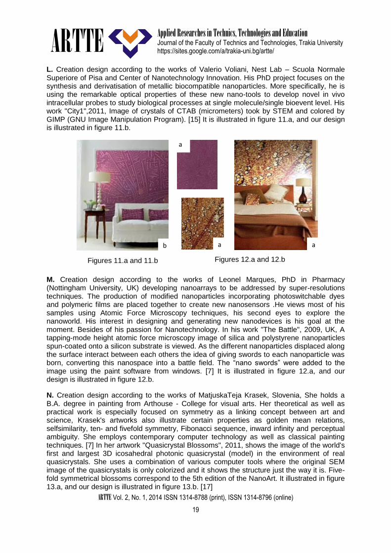
N. Creation design according to the works of MatjuskaTeja Krasek, Slovenia, She holds a B.A. degree in painting from Arthouse - College for visual arts. Her theoretical as well as practical work is especially focused on symmetry as a linking concept between art and science, Krasek's artworks also illustrate certain properties as golden mean relations, selfsimilarity, ten- and fivefold symmetry, Fibonacci sequence, inward infinity and perceptual ambiguity. She employs contemporary computer technology as well as classical painting techniques. [7] In her artwork "Quasicrystal Blossoms", 2011, shows the image of the world's first and largest 3D icosahedral photonic quasicrystal (model) in the environment of real quasicrystals. She uses a combination of various computer tools where the original SEM image of the quasicrystals is only colorized and it shows the structure just the way it is. Five-fold symmetrical blossoms correspond to the 5th edition of the NanoArt. It illustrated in figure 13.a, and our design is illustrated in figure 13.b. [17]
Figures 11.a and 11.b
Figures 12.a and 12.b
b a
a
b a
ARTTE
Applied Researches in Technics, Technologies and Education
Journal of the Faculty of Technics and Technologies, Trakia University https://sites.google.com/a/trakia-uni.bg/artte/
ARTTE Vol. 2, No. 1, 2014 ISSN 1314-8788 (print), ISSN 1314-8796 (online)
20
O. Creation design according to the works of Cris Orfescu, his artwork "NanoSymmetry", 2011, Nanolandscape: a mixture of graphite nano and microparticles was visualized with a scanning electron microscope. The image was captured in a computer, digitally painted and manipulated, and printed on canvas with archival inks. This way, the nanolandscape could be viewed by large audiences. [16] It is illustrated in figure 14.a, and our design is illustrated in figure 14.b.
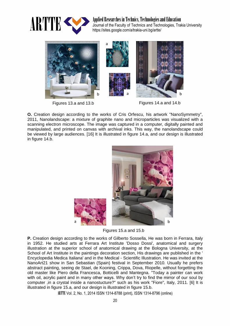
P. Creation design according to the works of Gilberto Sossella, He was born in Ferrara, Italy in 1952. He studied arts at Ferrara Art Institute 'Dosso Dossi', anatomical and surgery illustration at the superior school of anatomical drawing at the Bologna University, at the School of Art Institute in the paintings decoration section, His drawings are published in the ' Encyclopedia Medica Italiana' and in the Medical - Scientific Illustration. He was invited at the NanoArt21 show in San Sebastian (Spain) festival in September 2010. Usually he prefers abstract painting, seeing de Stael, de Kooning, Crippa, Dova, Riopelle, without forgetting the old master like Piero della Francesca, Botticelli and Mantegna. "Today a painter can work with oil, acrylic paint and in many other ways. Why don’t try to find the mirror of our soul by computer ,in a crystal inside a nanostucture?" such as his work "Fiore", Italy, 2011. [6] It is illustrated in figure 15.a, and our design is illustrated in figure 15.b.
Figures 14.a and 14.b
b a
Figures 13.a and 13.b
a
b
a
a
Figures 15.a and 15.b
b

ARTTE
Applied Researches in Technics, Technologies and Education
Journal of the Faculty of Technics and Technologies, Trakia University https://sites.google.com/a/trakia-uni.bg/artte/
ARTTE Vol. 2, No. 1, 2014 ISSN 1314-8788 (print), ISSN 1314-8796 (online)
21
3.2. Criteria and aesthetic values of Nanoart Benefit from objective knowledge coming from scientific observation, focusing on the aesthetic components of the Nanotechnology environment as a source of inspiration in visual art using techniques; which lead to diversity in forms, colours, and re-organized Nanotechnology elements. That seeks to organize the aesthetic relationship, so the ideas and meanings kick off. NanoArt is an artistic discipline at the art-science border; familiarize Audience with the omnipresence of the Nano world. It is more appealing and effective way to communicate with the new technologies. So the work of nanotechnology art reflects spirit of the age, where connects the artistic imagination between two visions: "organoleptic (scientific-technical) and spirituality" for formation of the idea. Thus the Appreciator, attracted to sentimental participation, is enjoying the symbolic meanings and aesthetic values and technology methods for the artwork. 4. CONCLUSIONS In this paper we constructed the 3D of woven stretch cloth of a garment with basic concepts curves surface patches, established the relations between the garment styles and the parameters of 3D garment of woven stretch cloth. By setting up the knowledge base with object-oriented technology and illation mechanism, we accomplished the 3D garment intelligent design. As the process of fashion design is a creative thought process, and the garment is a kind of flexible objects, it is a hard work to express and digitize the knowledge of design. we presented the first mesh-based 3D texture synthesis algorithm on arbitrary manifolds. As such, there is no doubt that several refinements can be provided to further increase the possibilities offered by such a technique. 5. REFERENCES
[1] ELBER G. 2005. Geometric texture modeling. IEEE Computer Graphics and Appli-cations 25, 4, 66–76.
[2] ELNASHAR A. Elsayed. Compact Force Using Rough Set Theory Of Geometry Shape For Stretch Clothes Design. 2nd SMARTEX-2012 Russia (World Textiles Conference), May, 28-29, 2012
[3] ELNASHAR A. Elsayed, Victor Kuzmichev & N. A. Sakharova. Fitting stretch model of three-dimensional for simulating apparel surfaces. 1st Smartex – Egypt 2011 (World textiles conference), nov. 22–24. 2011, Kafrelsheikh university, Egypt.
[4] HANNA Fady B. M. and ELNASHAR A.Elsayed. Utilizing Minimalism Paintings Of Unified Stretch Theory In Knitwear Of Fashion Trends. 2nd SMARTEX-2012 Russia (World Textiles Conference), May, 28-29, 2012
[5] FLEISCHER K. W., LAIDLAW D. H., CURRIN B. L., AND BARR A. H. 1995. Cellular texture generation. In Proceedings of SIGGRAPH 95, 239–248.
[6] http://nanoart21.org/nanoart\exhibitions/index.php/displayimage.php?pos=-564 [7] http://nanoart21.org/nanoart-exhibitions/ [8] http://www.crisorfescu.com/nanoart.html [9] http://www.absolutearts.com/portfolios/c/criorf/ [10] http://nanoart21.org/nanoart-exhibitions/index.php/displayimage.php?pos=-613 [11] http://nanoart21.org/nanoart-exhibitions/index.php/displayimage.php?pos=-542 [12] http://nanoart21.org/nanoart-exhibitions/index.php/displayimage.php?pos=-585 [13] http://www.HochmanBrown.com [14] http://nanoart21.org/nanoart-exhibitions/index.php/displayimage.php?pos=-583 [15] http://nanoart21.org/nanoart-exhibitions/index.php/displayimage.php?pos=-667

ARTTE
Applied Researches in Technics, Technologies and Education
Journal of the Faculty of Technics and Technologies, Trakia University https://sites.google.com/a/trakia-uni.bg/artte/
ARTTE Vol. 2, No. 1, 2014 ISSN 1314-8788 (print), ISSN 1314-8796 (online)
22
[16] http://www.absolutearts.com/portfolios/c/criorf/ [17] http://nanoart21.org/nanoart-exhibitions/thumbnails.php?album=194 [18] http://www.crisorfescu.com/nanoart.html [19] KAJIYA J. T., AND KAY T. L. 1989. Rendering fur with three dimensional textures. In
Proceedings of SIGGRAPH 89, 271–280. [20] NEYRET F. 1998. Modeling, animating, and rendering complex scenes using
volumetric textures. IEEE Transactions on Visualization and Computer Graphics 4, 1, 55–70.
[21] PEACHEY D. R. 1985. Solid texturing of complex surfaces. In Proceedings of SIGGRAPH 85, 279–286.
[22] PERLIN K. 1985. An image synthesizer. In Proceedings of SIGGRAPH 85, 287–296. [23] PERLIN K., AND HOFFERT E. M. 1989. Hypertexture. In Proceedings of SIG-
GRAPH 89, 253–262. [24] PORUMBESCU S. D., BUDGE B., FENG L., AND JOY K. I. 2005. Shell maps. ACM
Transactions on Graphics 23, 3, 626–633. [25] Yatham C., Seaman J. Fashion Design Drawing Course. Thames & Hudson Ltd,
USA, 2003.