
ACTS ADOPTED BY BODIES CREATED BY ... - EUR-Lex
31
ACTS ADOPTED BY BODIES CREATED BY INTERNATIONAL AGREEMENTS Only the original UNECE texts have legal effect under international public law. The status and date of entry into force of this Regulation should be checked in the latest version of the UNECE status document TRANS/ WP.29/343, available at: http://www.unece.org/trans/main/wp29/wp29wgs/wp29gen/wp29fdocstts.html Regulation No 100 of the Economic Commission for Europe of the United Nations (UNECE) — Uniform provisions concerning the approval of battery electric vehicles with regard to specific requirements for the construction, functional safety and hydrogen emission Revision 2 Incorporating all valid text up to: Supplement 1 to the original version of the Regulation — Date of entry into force: 21 February 2002 CONTENTS REGULATION 1. Scope 2. Definitions 3. Application for approval 4. Approval 5. Specifications and tests 6. Modifications and extension of the type approval for vehicle type 7. Conformity of production 8. Penalties for non-conformity of production 9. Production definitely discontinued 10. Names and addresses of technical services responsible for conducting approval tests and of administrative departments ANNEXES Annex 1 — Communication Annex 2 — Arrangements of approval marks Annex 3 — Protection against direct contacts of parts under voltage Annex 4 — Measurement of the insulation resistance using the traction battery Annex 5 — Symbol for the indication of a voltage Annex 6 — Essential characteristics of the vehicle Annex 7 — Determination of hydrogen emissions during the charge procedures of the traction battery 14.2.2009 EN Official Journal of the European Union L 45/17
-
Upload
khangminh22 -
Category
Documents
-
view
1 -
download
0
Transcript of ACTS ADOPTED BY BODIES CREATED BY ... - EUR-Lex

ACTS ADOPTED BY BODIES CREATED BY INTERNATIONAL AGREEMENTS
Only the original UNECE texts have legal effect under international public law. The status and date of entryinto force of this Regulation should be checked in the latest version of the UNECE status document TRANS/WP.29/343, available at: http://www.unece.org/trans/main/wp29/wp29wgs/wp29gen/wp29fdocstts.html
Regulation No 100 of the Economic Commission for Europe of the United Nations (UNECE) —Uniform provisions concerning the approval of battery electric vehicles with regard to specific
requirements for the construction, functional safety and hydrogen emission
Revision 2
Incorporating all valid text up to:
Supplement 1 to the original version of the Regulation — Date of entry into force: 21 February 2002
CONTENTS
REGULATION
1. Scope
2. Definitions
3. Application for approval
4. Approval
5. Specifications and tests
6. Modifications and extension of the type approval for vehicle type
7. Conformity of production
8. Penalties for non-conformity of production
9. Production definitely discontinued
10. Names and addresses of technical services responsible for conducting approval tests and of administrativedepartments
ANNEXES
Annex 1 — Communication
Annex 2 — Arrangements of approval marks
Annex 3 — Protection against direct contacts of parts under voltage
Annex 4 — Measurement of the insulation resistance using the traction battery
Annex 5 — Symbol for the indication of a voltage
Annex 6 — Essential characteristics of the vehicle
Annex 7 — Determination of hydrogen emissions during the charge procedures of the traction battery
14.2.2009 EN Official Journal of the European Union L 45/17

1. SCOPE
The following prescriptions apply to safety requirements with respect to all battery electric roadvehicles of categories M and N, with a maximum design speed exceeding 25 km/h.
2. DEFINITIONS
For the purpose of this proposal:
2.1. ‘Battery electric road vehicle’ means a vehicle with bodywork intended for road use, poweredexclusively by an electric motor whose traction energy is supplied exclusively by a traction batteryinstalled in the vehicle.
2.2. ‘Vehicle type’ means battery electric road vehicles which do not differ in such essential aspects as:
dimensions, structure, shape and nature of constituting materials;
installation of the power system components, battery or battery packs;
nature and type of electric and electronic components.
2.3. ‘Approval of a type of battery electric road vehicle’ means the approval of a type of electric vehicleregarding construction and functional safety requirements specific to the use of electric energy.
2.4. ‘Traction battery’ means the assembly of all battery modules which are electrically connected, forthe supply of energy of the power circuit.
2.5. ‘Battery module’ means the smallest single energy storage consisting of one cell or an assembly ofcells, electrically connected in serial or in parallel, placed in one container and mechanicallyassociated.
2.6. ‘Battery pack’ means a single mechanical assembly comprising battery modules and retainingframes or trays. A vehicle may have one or several, or no battery pack.
2.7. ‘Auxiliary battery’ means the battery unit whose reserve of energy is used only for the auxiliarynetwork supply.
2.8. ‘Auxiliary network’ means the assembly of auxiliary electric equipment with similar functions tothe one used on vehicles equipped with an internal combustion engine.
2.9. ‘On-board charger’ means an energy electronic converter linked by construction to the vehicle andused for charging the traction battery from an external electric power supply (mains network).
2.10. ‘Coupling system’ means all the parts used to connect the vehicle to an external electric powersupply (alternative or direct current supply).
2.11. ‘Power train’ means the electrical circuit including:
(i) the traction battery;
(ii) the electronic converters (on-board charger, electronic control of the traction motor, DC/DCconverter, etc.);
(iii) the traction motors, the associated wiring harness and connectors, etc.
(iv) the charging circuit;
(v) the power auxiliary equipment (e.g. heating, defrosting, power steering, etc.).
2.12. ‘Drive train’ means specific components of power train: traction motors, electronic control of thetraction motors, the associated wiring harness and connectors.
L 45/18 EN Official Journal of the European Union 14.2.2009

2.13. ‘Electronic converter’ means an apparatus allowing the control and/or transfer of electric energy.
2.14. ‘Passenger and load compartment’ means the space in the vehicle for occupant accommodationand bounded by the roof, floor, side walls, outside glazing, front bulkhead and the plane of therear-seat back support and eventually the partition between it and the compartment(s) containingthe battery or battery modules.
2.15. ‘Drive direction control unit’ means a specific device physically actuated by the driver in order toselect the drive direction (forwards or backwards), in which the vehicle will travel if the acceleratoris actuated.
2.16. ‘Direct contact’ means the contact of persons or livestock with live parts.
2.17. ‘Live parts’ means any conductor or conductive part(s) intended to be electrically energised innormal use.
2.18. ‘Indirect contact’ means contact of persons or livestock with exposed conductive parts.
2.19. ‘Exposed conductive part’ means any conductive part which can readily be touched and which isnot normally alive, but which may become electrically energised under fault conditions.
2.20. ‘Electrical circuit’ means an assembly of connected live parts through which an electrical current isdesigned to pass in normal operation conditions;
2.21. ‘Active driving possible mode’ means a vehicle mode when application of pressure to theaccelerator pedal (or activation of an equivalent control) will cause the drive train to move thevehicle.
2.22. ‘Nominal voltage’ means the root-mean-square (rms) value of the voltage specified by themanufacturer, for which the electrical circuit is designed and to which its characteristics arereferred.
2.23. ‘Working voltage’ means the highest root-mean-square (rms) value of an electrical circuit voltage,specified by the manufacturer, which may occur across any insulation, in open circuit conditionsor under normal operating conditions.
2.24. ‘Electrical chassis’ means a set made of conductive parts electrically linked together, and all otherconductive parts electrically linked to them, whose potential is taken as a reference.
2.25. ‘Key’ means any device designed and constructed to provide a method of operating a lockingsystem which is designed and constructed to be operated only by that device.
3. APPLICATION FOR APPROVAL
3.1. The application for approval of a vehicle type with regard to specific requirements for theconstruction and functional safety of battery electric road vehicles shall be submitted by vehiclemanufacturer or by his duly accredited representative.
3.2. It shall be accompanied by the undermentioned documents in triplicate and following particulars:
3.2.1. Detailed description of the battery electric road vehicle type as regards to the shape of thebodywork, the electric drive train (motors and controllers), traction battery (type, capacity, batterymanagement).
3.3. A vehicle representative of the vehicle type to be approved shall be submitted to the technicalservice responsible for conducting the approval tests.
3.4. The competent authority shall verify the existence of satisfactory arrangements for ensuringeffective control of the conformity of production before type approval is granted.
14.2.2009 EN Official Journal of the European Union L 45/19
4. APPROVAL
4.1. If the vehicle submitted for approval pursuant to this Regulation meets the requirements ofparagraph 5 below and Annexes 3, 4, 5 and 7 to this Regulation, approval of this vehicle typeshall be granted.
4.2. An approval number shall be assigned to each type approved. Its first two digits (at present 00 forthe Regulation in its original form) shall indicate the series of amendments incorporating the mostrecent major technical amendments made to the Regulation at the time of issue of the approval.The same Contracting Party shall not assign the same number to another vehicle type.
4.3. Notice of approval or of refusal or of extension or withdrawal of approval or production definitelydiscontinued of a vehicle type pursuant to this Regulation shall be communicated to the Parties tothe Agreement applying this Regulation, by means of a form conforming to the model in Annex 1to this Regulation.
4.4. There shall be affixed, conspicuously and in a readily accessible place specified on the approvalform, to every vehicle conforming to a vehicle type approved under this Regulation aninternational approval mark consisting of:
4.4.1. A circle surrounding the letter ‘E’ followed by the distinguishing number of the country which hasgranted approval (1).
4.4.2. The number of this Regulation, followed by the letter ‘R’, a dash and the approval number to theright of the circle described in paragraph 4.4.1.
4.5. If the vehicle conforms to a vehicle type approved under one or more other Regulations annexedto this Agreement in the country which has granted approval under this Regulation, the symbolprescribed in paragraph 4.4.1 need not be repeated; in this case the Regulation and approvalnumbers and the additional symbols of all the Regulations under which approval has been grantedin the country which has granted approval under this Regulation shall be placed in verticalcolumns to the right of the symbol prescribed in paragraph 4.4.1.
4.6. The approval mark shall be clearly legible and shall be indelible.
4.7. The approval mark shall be placed on or close to the vehicle data plate affixed by themanufacturer.
4.8. Annex 2 to this Regulation gives examples of the arrangements of the approval mark.
5. SPECIFICATIONS AND TESTS
5.1. Vehicle construction requirements
5.1.1. Traction battery
5.1.1.1. Installation of the traction battery in the vehicle shall not allow any potential dangerousaccumulation of gas pockets.
L 45/20 EN Official Journal of the European Union 14.2.2009
(1) 1 for Germany, 2 for France, 3 for Italy, 4 for the Netherlands, 5 for Sweden, 6 for Belgium, 7 for Hungary, 8 for theCzech Republic, 9 for Spain, 10 for Yugoslavia, 11 for the United Kingdom, 12 for Austria, 13 for Luxembourg, 14 forSwitzerland, 15 (vacant), 16 for Norway, 17 for Finland, 18 for Denmark, 19 for Romania, 20 for Poland, 21 forPortugal, 22 for the Russian Federation, 23 for Greece, 24 for Ireland, 25 for Croatia, 26 for Slovenia, 27 for Slovakia,28 for Belarus, 29 for Estonia, 30 (vacant), 31 for Bosnia and Herzegovina, 32 for Latvia, 33 (vacant), 34 for Bulgaria,35 (vacant), 36 for Lithuania, 37 for Turkey, 38 (vacant), 39 for Azerbaijan, 40 for The former Yugoslav Republic ofMacedonia, 41 (vacant), 42 for the European Community (Approvals are granted by its Member States using theirrespective ECE symbol), 43 for Japan, 44 (vacant), 45 for Australia, 46 for Ukraine, 47 for South Africa and 48 for NewZealand. Subsequent numbers shall be assigned to other countries in the chronological order in which they ratify oraccede to the Agreement Concerning the Adoption of Uniform Technical Prescriptions for Wheeled Vehicles,Equipment and Parts which can be Fitted and/or be Used on Wheeled Vehicles and the Conditions for ReciprocalRecognition of Approvals Granted on the Basis of these Prescriptions, and the numbers thus assigned shall becommunicated by the Secretary-General of the United Nations to the Contracting Parties to the Agreement.
5.1.1.2. Battery compartments containing battery modules which may produce hazardous gases shall besafely ventilated.
5.1.1.3. The traction battery and the power train shall be protected by properly rated fuses or circuitbreakers. The manufacturer shall supply data to the laboratory which allows verification that theircalibration ensures opening, if necessary;
5.1.2. Protection against electric shock
5.1.2.1. Protection against direct contact with live parts of the power train:
5.1.2.1.1. If the working voltage of the electric circuit is lower than 60 volts DC or 25 volts AC, norequirements are necessary;
5.1.2.1.2. Direct contact with live parts of the electrical power train whose maximum voltage is at least60 volts DC or 25 volts AC shall be prevented either by insulation or by the use of covers,protection grills, perforated metal sheets, etc. These protections shall be reliably secured and shallbe mechanically resistant. They shall not be able to be opened, disassembled or removed withoutthe use of tools.
5.1.2.1.3. In passenger and load compartments live parts in any case shall be protected by enclosures havinga protection degree of at least IPXXD.
5.1.2.1.4. Enclosures in other areas of the vehicle shall have a protection degree of at least IPXXB.
5.1.2.1.5. In the engine compartment the access to live parts shall only be possible with voluntary action.
5.1.2.1.6. After opening the cover, the access to the parts of the coupling system shall be protected withIPXXB protection.
5.1.2.1.7. Protection degrees IPXXB and IPXXD are related respectively, to the contact of a jointed test fingerand a test wire with hazardous parts (Annex 3).
5.1.2.1.8. Vehicle markings
Protection covers of live parts described in paragraph 5.1.2.1.2 shall be marked by a symbol asdescribed in Annex 5.
5.1.2.2. Protection against indirect contacts with exposed conductive parts of the power train.
5.1.2.2.1. If the working voltage of the electric circuit is lower than 60 volts DC or 25 volts AC, norequirements are necessary;
5.1.2.2.2. The design, installation, and manufacture of electric material shall be such that insulation failuresare avoided;
5.1.2.2.3. Protection against indirect contacts shall be ensured by using insulation and additionally, theexposed conductive parts of the on-board equipment shall be galvanically connected together.This potential equalisation is obtained by connecting the exposed conductive parts together eitherby a protective conductor, e.g. wire, ground truss, or directly by the vehicle metallic chassis. Twoexposed conductive parts welded together are considered as having no discontinuity points. Ifthere is some discontinuity, this point shall be by-passed by potential equalisation.
5.1.2.3. Insulation resistance
5.1.2.3.1. The insulation resistance measurement is performed after maintaining the vehicle for aconditioning time of 8 hours with the following conditions:
temperature: 23 ± 5 oC,
humidity: 90 % + 10/- 5 %.
14.2.2009 EN Official Journal of the European Union L 45/21

5.1.2.3.2. Using a measuring DC voltage equal to the nominal voltage of the traction battery, insulationresistances between any exposed conductive part and each polarity of the battery shall have aminimum value of 500 Ω/V of the nominal voltage (Annex 4 contains an example of how this testmay be conducted).
5.1.2.3.3. Resistance of the protective conductor:
The potential equalisation resistance between any two exposed conductive parts shall be lowerthan 0,1 Ω. This test shall be performed by a current of at least 0,2 A.
5.1.2.4. Connection of the vehicle to the mains network:
5.1.2.4.1. In no case the vehicle shall be capable to move by its own means when it is galvanically connectedto an energy supply network or to an off-board charger;
5.1.2.4.2. The components used when charging the battery from an external source shall allow the chargingcurrent to be cut in case of disconnection without physical damage;
5.1.2.4.3. The coupling system parts likely to be live shall be protected against any direct contact in alloperating conditions;
5.1.2.4.4. All exposed conductive parts shall be electrically linked through a conducting wire plugged toearth when charging.
5.2. Functional safety requirements
5.2.1. Power on procedure:
5.2.1.1. The power on procedure shall be applied via a key switch.
5.2.1.2. It shall not be possible to remove this key in any position that energises the drive train or makesactive driving possible.
5.2.2. Running and stopping conditions:
5.2.2.1. At least a momentary indication must be given to the driver either:
(a) when the vehicle is in ‘active driving possible mode’; or
(b) when one further action is required to place the vehicle in ‘active driving possible mode’.
5.2.2.2. When the state of charge of the battery reaches the minimum state of charge value defined by themanufacturer, the user shall be warned to perceive this situation quickly enough to be able to drivethe vehicle, on its own power, at least out of the traffic zone.
5.2.2.3. Unintentional acceleration, deceleration and reversal of the drive train shall be prevented. Inparticular, a failure (e.g. in the power train) shall not cause more than 0,1 m movement of astanding unbraked vehicle.
5.2.2.4. When leaving the vehicle, the driver shall be informed by an obvious signal (e.g. optical or audiblesignal) if the drive train is still in the active driving possible mode.
5.2.3. Reversing
5.2.3.1. Reversing shall be possible only after operation of a specific control. This action shall requireeither:
(a) the combination of two different actuations; or
(b) an electric switch which allows reverse to be engaged only when the vehicle is moving at aforward speed not exceeding 5 km/h. Above this speed all actions on this device shall beignored. The device shall have only one stable position.
L 45/22 EN Official Journal of the European Union 14.2.2009

5.2.3.2. The state of the drive direction control unit shall be readily identified to the driver.
5.2.4. Emergency power reduction
5.2.4.1. If the vehicle is equipped with a device to limit the performance in an emergency (e.g. overheatingof a component) the user shall be informed by an obvious signal.
5.3. Determination of hydrogen emissions
5.3.1. This test must be carried out on all battery electric road vehicles referred to in paragraph 1 of thisRegulation.
Road vehicles equipped with non-aqueous electrolyte batteries or sealed ‘gas recombinant’batteries are excluded.
5.3.2. The test must be conducted following the method described in Annex 7 to the present Regulation.The hydrogen sampling and analysis must be the ones prescribed. Other analysis methods can beapproved if it is proven that they give equivalent results.
5.3.3. During a normal charge procedure in the conditions given in Annex 7, hydrogen emissions mustbe below 125 g during 5 h, or below 25 × t2 g during t2 (in h).
5.3.4. During a charge carried out by an on-board charger presenting a failure (conditions given inAnnex 7), hydrogen emissions must be below 42 g. Furthermore the on-board charger must limitthis possible failure to 30 minutes.
5.3.5. All the operations linked to the battery charging are controlled automatically, included the stop forcharging.
5.3.6. It shall not be possible to take a manual control of the charging phases.
5.3.7. Normal operations of connection and disconnection to the mains or power cuts must not affectthe control system of the charging phases.
5.3.8. Important charging failures must be permanently signalled to the driver. An important failure is afailure that can lead to a disfunctioning of the on-board charger during charging later on.
5.3.9. The manufacturer has to indicate in the owner's manual, the conformity of the vehicle to theserequirements.
5.3.10. The approval granted to a vehicle type relative to hydrogen emissions can be extended to differentvehicle types belonging to the same family, in accordance with the definition of the family given inAnnex 7, Appendix 2.
6. MODIFICATIONS AND EXTENSION OF THE TYPE APPROVAL FOR VEHICLE TYPE
6.1. Every modification of the vehicle type shall be notified to the administrative department whichapproved the vehicle type. The department may then either:
6.1.1. consider that the modifications made are unlikely to have an appreciable adverse effect and that inany case the vehicle still complies with the requirements; or
6.1.2. require a further test report from the technical service responsible for conducting the tests.
6.2. Confirmation or refusal of approval, specifying the alteration shall be communicated by theprocedure specified in paragraph 4.3 above to the Parties to the Agreement applying thisRegulation.
6.3. The competent authority issuing the extension of approval shall assign a series number for suchan extension and inform thereof the other Parties to the 1958 Agreement applying the Regulationby means of a communication form conforming to the model in Annex 1 to this Regulation.
14.2.2009 EN Official Journal of the European Union L 45/23

7. CONFORMITY OF PRODUCTION
7.1. Every vehicle approved under this Regulation shall be so manufactured as to conform to the typeapproved by meeting the requirements set out in paragraph 5 above.
7.2. In order to verify that the requirements of paragraph 7.1 are met, suitable controls of theproduction shall be carried out.
7.3. The holder of the approval shall, in particular:
7.3.1. ensure the existence of procedures for the effective quality control of vehicles;
7.3.2. have access to the testing equipment necessary for checking the conformity of each approved type;
7.3.3. ensure that test result data are recorded and that the annexed documents remain available for aperiod to be determined in agreement with the administrative department;
7.3.4. analyse the results of each type of test, in order to verify and ensure the consistency ofcharacteristics of the vehicle, making allowance for permissible variations in industrial production;
7.3.5. ensure that for each type of vehicle at least the tests prescribed in paragraph 5 of this Regulationare carried out;
7.3.6. ensure that any set of samples or test pieces giving evidence of non-conformity with the type oftest in question shall give rise to a further sampling and test. All the necessary steps shall be takento reestablish conformity of the corresponding production.
7.4. The competent authority which has granted type approval may at any time verify the conformitycontrol methods applied in each production unit.
7.4.1. At every inspection, the test records and production records shall be presented to the visitinginspector.
7.4.2. The inspector may take samples at random to be tested in the manufacturer's laboratory. Theminimum number of samples may be determined according to the results of the manufacturer'sown checks.
7.4.3. When the quality level appears unsatisfactory or when it seems necessary to verify the validity ofthe tests carried out in application of paragraph 7.4.2, the inspector shall select samples to be sentto the technical service which has conducted the type approval tests.
7.4.4. The competent authority may carry out any test prescribed in this Regulation.
7.4.5. The normal frequency of inspections by the competent authority shall be one per year. Ifunsatisfactory results are recorded during one of these visits, the competent authority shall ensurethat all necessary steps are taken to reestablish the conformity of production as rapidly as possible.
8. PENALTIES FOR NON-CONFORMITY OF PRODUCTION
8.1. The approval granted in respect of a vehicle type, pursuant to this Regulation may be withdrawn ifthe requirements laid down in paragraph 7 are not complied with, or if the vehicle or itscomponents fail to pass the tests provided for in paragraph 7.3.5 above.
8.2. If a Contracting Party to the Agreement applying this Regulation withdraws an approval it haspreviously granted, it shall forthwith so notify the other Contracting Parties applying thisRegulation, by means of a communication form conforming to the model in Annex 1 to thisRegulation.
L 45/24 EN Official Journal of the European Union 14.2.2009

9. PRODUCTION DEFINITELY DISCONTINUED
If the holder of the approval completely ceases to manufacture a type of vehicle approved inaccordance with this Regulation, he shall so inform the authority which granted the approval.Upon receiving the relevant communication, that authority shall inform thereof the otherContracting Parties to the 1958 Agreement applying this Regulation by means of acommunication form conforming to the model in Annex 1 to this Regulation.
10. NAMES ANDADDRESSES OF TECHNICAL SERVICES RESPONSIBLE FOR CONDUCTING APPROVAL TESTSAND OF ADMINISTRATIVE DEPARTMENTS
The Contracting Parties to the 1958 Agreement applying this Regulation shall communicate tothe United Nations secretariat the names and addresses of the technical services responsible forconducting approval tests and the administrative departments which grant approval and to whichforms certifying approval or extension or refusal or withdrawal of approval or productiondefinitely discontinued, issued in other countries, are to be sent.
14.2.2009 EN Official Journal of the European Union L 45/25

ANNEX 1
COMMUNICATION
(maximum format: A4 (210 × 297 mm))
L 45/26 EN Official Journal of the European Union 14.2.2009
ANNEX 2
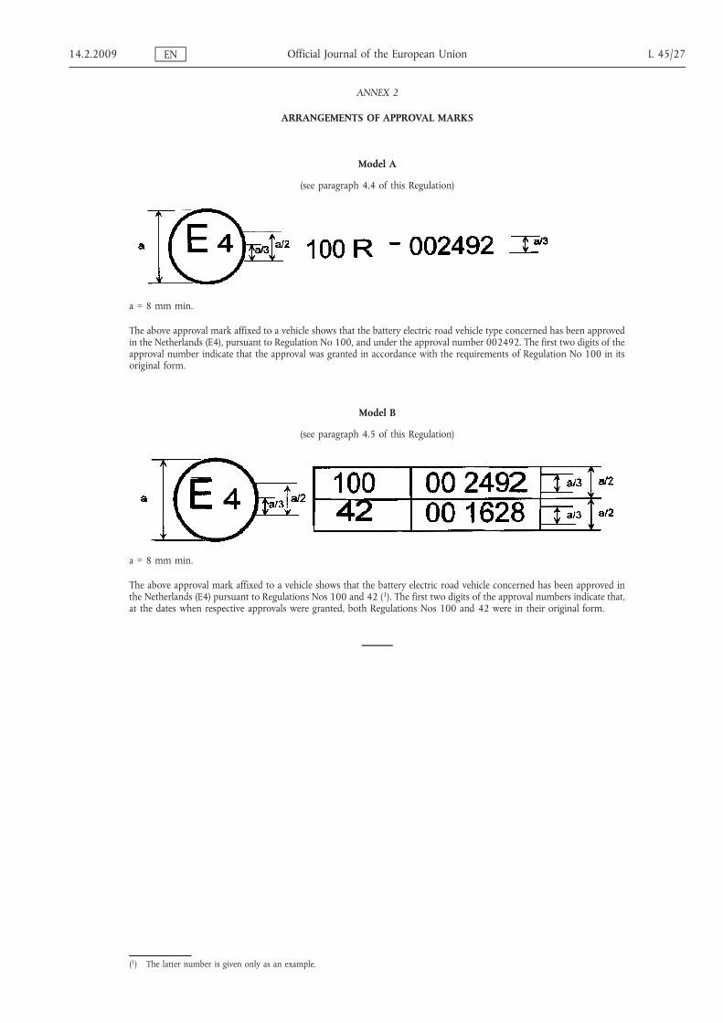
ARRANGEMENTS OF APPROVAL MARKS
Model A
(see paragraph 4.4 of this Regulation)
a = 8 mm min.
The above approval mark affixed to a vehicle shows that the battery electric road vehicle type concerned has been approvedin the Netherlands (E4), pursuant to Regulation No 100, and under the approval number 002492. The first two digits of theapproval number indicate that the approval was granted in accordance with the requirements of Regulation No 100 in itsoriginal form.
Model B
(see paragraph 4.5 of this Regulation)
a = 8 mm min.
The above approval mark affixed to a vehicle shows that the battery electric road vehicle concerned has been approved inthe Netherlands (E4) pursuant to Regulations Nos 100 and 42 (1). The first two digits of the approval numbers indicate that,at the dates when respective approvals were granted, both Regulations Nos 100 and 42 were in their original form.
14.2.2009 EN Official Journal of the European Union L 45/27
(1) The latter number is given only as an example.

ANNEX 3
PROTECTION AGAINST DIRECT CONTACTS OF PARTS UNDER VOLTAGE
Extract from the IEC 529 Standard (1989)
1. DEFINITIONS
For the purpose of this standard, the following definitions apply:
1.1. Enclosure
A part providing protection of equipment against certain external influences and, in any direction, protectionagainst direct contact (IEV 826-03-12).
Note: This definition taken from the existing international electrotechnical vocabulary (IEV) needs thefollowing explanations under the scope of this standard:
(a) Enclosures provide protection of persons (or livestock) against access to hazardous parts.
(b) Barriers, shapes of openings or any other means — whether attached to the enclosure orformed by the enclosed equipment — suitable to prevent or limit the penetration of thespecified test probes are considered as a part of the enclosure, except when they can beremoved without the use of a key or tool.
1.2. Direct contact
Contact of persons (or livestock) with live parts (IEV 826-03-05).
Note: This IEV definition is given for information. In this standard ‘Direct contact’ is replaced by ‘Access tohazardous parts’.
1.3. Degree of protection
The extent of protection provided by an enclosure against access to hazardous parts, against ingress of solid foreignobjects and/or against ingress of water and verified by standardised test methods.
1.4. IP code
A coding system to indicate the degrees of protection provided by an enclosure against access to hazardous parts,ingress of solid foreign objects, ingress of water and to give additional information in connection with suchprotection.
1.5. Hazardous part
A part that is hazardous to approach or touch.
1.5.1. Hazardous live part
A live part which, under certain conditions of external influences, can give an electric shock (see IEC 536, at presentDocument 64(CO)196).
1.5.2. Hazardous mechanical part
A moving part, other than a smooth rotating shaft, that is hazardous to touch.
1.6. Protection provided by an enclosure against access to hazardous parts.
The protection of persons against:
(a) contact with hazardous low-voltage live parts;
(b) contact with hazardous mechanical parts;
(c) approach to hazardous high-voltage live parts below adequate clearance inside an enclosure.
L 45/28 EN Official Journal of the European Union 14.2.2009

Note: This protection may be provided:
(a) by means of the enclosure itself;
(b) by means of barriers as part of the enclosure or distances inside the enclosure.
1.7. Adequate clearance for protection against access to hazardous parts
A distance to prevent contact or approach of an access probe to a hazardous part.
1.8. Access probe
A test probe simulating in a conventional manner a part of a person or a tool, or the like, held by a person to verifyadequate clearance from hazardous parts.
1.9. Object probe
A test probe simulating a solid foreign object to verify the possibility of ingress into an enclosure.
1.10. Opening
A gap or aperture in an enclosure which exists or may be formed by the application of a test probe at the specifiedforce.
2. TESTS FOR PROTECTION AGAINST ACCESS TO HAZARDOUS PARTS INDICATED BY THE ADDITIONALLETTER
2.1. Access probes
Access probes to verify the protection of persons against access to hazardous parts are given in table l.
2.2. Test conditions
The access probe is pushed against any openings of the enclosure with the force specified in table 1. If it partly orfully penetrates, it is placed in every possible position, but in no case shall the stop face fully penetrate through theopening.
Internal barriers are considered part of the enclosure as defined in paragraph 1.1.
For tests on low-voltage equipment, a low-voltage supply (of not less than 40 V and not more than 50 V) in serieswith a suitable lamp should be connected between the probe and the hazardous parts inside the enclosure.Hazardous live parts covered only with varnish or paint, or protected by oxidation or by a similar process, arecovered by a metal foil electrically connected to those parts which are normally live in operation.
The signal-circuit method should also be applied to the hazardous moving parts of high-voltage equipment.
Internal moving parts may be operated slowly, where this is possible.
2.3. Acceptance conditions
The protection is satisfactory if adequate clearance is kept between the access probe and hazardous parts.
In the case of the test for the additional letter B, the jointed test finger may penetrate to its 80 mm length, but thestop face (Ø 50 mm × 20 mm) shall not pass through the opening. Starting from the straight position, both jointsof the test finger shall be successively bent through an angle of up to 90o with respect to the axis of the adjoiningsection of the finger and shall be placed in every possible position.
In case of the tests for the additional letter D, the access probe may penetrate to its full length, but the stop face shallnot fully penetrate through the opening. See Annex A for further clarification.
Conditions for verification of adequate clearance are identical with those given in paragraph 2.3.1 below.
14.2.2009 EN Official Journal of the European Union L 45/29

2.3.1. For low-voltage equipment (rated voltages not exceeding 1 000 V AC and 1 500 V DC):
The access probe shall not touch hazardous live parts.
If adequate clearance is verified by a signal circuit between the probe and hazardous parts, the lamp shall not light.
Table 1
Access probes for the tests for protection of persons against access to hazardous parts
Firstnumer-
al
Addi-tionalletter
Access probe Test force
2 B
Jointed test fingerSee Figure 1 for full dimensions
10 N ± 10 %
4, 5, 6 D
Test wire 1,0 mm diameter 100 mm long
1 N ± 10 %
L 45/30 EN Official Journal of the European Union 14.2.2009

Figure 1
Jointed test finger
Material: metal, except where otherwise specified
Linear dimensions in millimeters
Tolerances on dimensions without specific tolerance:
On angles 0/- 10°
on linear dimensions:
up to 25 mm: 0/- 0,05
over 25 mm: ± 0,2
Both joints shall permit movement in the same plane and the same direction through an angle of 90° with a 0 to + 10°tolerance.
14.2.2009 EN Official Journal of the European Union L 45/31

ANNEX 4
MEASUREMENT OF THE INSULATION RESISTANCE USING THE TRACTION BATTERY
1. DESCRIPTION OF THE TEST METHOD
The traction battery shall be fully charged
The voltmeter used in this test shall measure DC values and have an internal resistance greater than 10 ΜΩ.
Measurement shall be made in two steps:
Step one:
Measure V1 and V’1.
Step two:
if V1 > V’1
L 45/32 EN Official Journal of the European Union 14.2.2009

Step three:
if V1 < V’1
where Ro is a resistance of 500 Ω/V
The value of the insulation resistance Ri is given by one of the formula:
Ri =V1 −V2
V2� Ro or Ri =
V’1 −V2V2
� Ro
14.2.2009 EN Official Journal of the European Union L 45/33
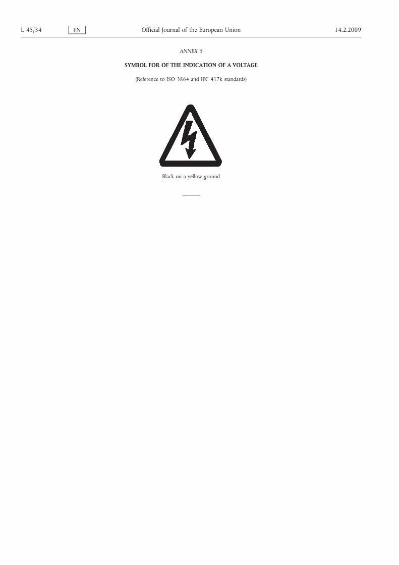
ANNEX 5
SYMBOL FOR OF THE INDICATION OF A VOLTAGE
(Reference to ISO 3864 and IEC 417k standards)
Black on a yellow ground
L 45/34 EN Official Journal of the European Union 14.2.2009

ANNEX 6
ESSENTIAL CHARACTERISTICS OF THE VEHICLE
1. GENERAL DESCRIPTION OF VEHICLE
1.1. Trade name or mark of the vehicle: . . . . . . . . . . . . . . . . . . . . . . . . . . . . . . . . . . . . . . . . . . . . . . . . . . . . . . . . . . . . . . . . . . . . . . . . . . . .
1.2. Vehicle type: . . . . . . . . . . . . . . . . . . . . . . . . . . . . . . . . . . . . . . . . . . . . . . . . . . . . . . . . . . . . . . . . . . . . . . . . . . . . . . . . . . . . . . . . . . . . . . . . . .
1.3. Manufacturer's name and address: . . . . . . . . . . . . . . . . . . . . . . . . . . . . . . . . . . . . . . . . . . . . . . . . . . . . . . . . . . . . . . . . . . . . . . . . . . . . .
1.4. If applicable, name and address of manufacturer's representative: . . . . . . . . . . . . . . . . . . . . . . . . . . . . . . . . . . . . . . . . . . . . . . .
1.5. Brief description of the power circuit components installation or drawings/pictures showing the location of thepower circuit components installation: . . . . . . . . . . . . . . . . . . . . . . . . . . . . . . . . . . . . . . . . . . . . . . . . . . . . . . . . . . . . . . . . . . . . . . . . .
1.6. Schematic diagram of all electrical functions included in power circuit: . . . . . . . . . . . . . . . . . . . . . . . . . . . . . . . . . . . . . . . . .
1.7. Working voltage: . . . . . . . . . . . . . . . . . . . . . . . . . . . . . . . . . . . . . . . . . . . . . . . . . . . . . . . . . . . . . . . . . . . . . . . . . . . . . . . . . . . . . . . . . . . V
1.8. Drawing and/or photograph of the vehicle:
2. DESCRIPTION OF MOTOR(S)
2.1. Make: . . . . . . . . . . . . . . . . . . . . . . . . . . . . . . . . . . . . . . . . . . . . . . . . . . . . . . . . . . . . . . . . . . . . . . . . . . . . . . . . . . . . . . . . . . . . . . . . . . . . . . . . .
2.2. Type: . . . . . . . . . . . . . . . . . . . . . . . . . . . . . . . . . . . . . . . . . . . . . . . . . . . . . . . . . . . . . . . . . . . . . . . . . . . . . . . . . . . . . . . . . . . . . . . . . . . . . . . . . .
2.3. Working principle: . . . . . . . . . . . . . . . . . . . . . . . . . . . . . . . . . . . . . . . . . . . . . . . . . . . . . . . . . . . . . . . . . . . . . . . . . . . . . . . . . . . . . . . . . . . .
2.3.1. Direct current/alternative current/number of phases (1)
2.3.2. Excitation: separate/shunt/series/compound (1)
2.3.3. Synchron/asynchron (1)
2.3.4. Cooling system: air/liquid (1)
3. DESCRIPTION OF TRANSMISSION
3.1. Type: manual/automatic/none/others (to specify) (1): . . . . . . . . . . . . . . . . . . . . . . . . . . . . . . . . . . . . . . . . . . . . . . . . . . . . . . . . . . . .
3.2. Transmission ratios: . . . . . . . . . . . . . . . . . . . . . . . . . . . . . . . . . . . . . . . . . . . . . . . . . . . . . . . . . . . . . . . . . . . . . . . . . . . . . . . . . . . . . . . . . . .
3.3. Dimension of tyres: . . . . . . . . . . . . . . . . . . . . . . . . . . . . . . . . . . . . . . . . . . . . . . . . . . . . . . . . . . . . . . . . . . . . . . . . . . . . . . . . . . . . . . . . . . .
4. TRACTION BATTERY
4.1. Trade name and mark of the battery: . . . . . . . . . . . . . . . . . . . . . . . . . . . . . . . . . . . . . . . . . . . . . . . . . . . . . . . . . . . . . . . . . . . . . . . . . .
4.2. Indication of all types of electrochemical couples used: . . . . . . . . . . . . . . . . . . . . . . . . . . . . . . . . . . . . . . . . . . . . . . . . . . . . . . . . .
. . . . . . . . . . . . . . . . . . . . . . . . . . . . . . . . . . . . . . . . . . . . . . . . . . . . . . . . . . . . . . . . . . . . . . . . . . . . . . . . . . . . . . . . . . . . . . . . . . . . . . . . . . . . . . . .
4.2.1. Nominal voltage: . . . . . . . . . . . . . . . . . . . . . . . . . . . . . . . . . . . . . . . . . . . . . . . . . . . . . . . . . . . . . . . . . . . . . . . . . . . . . . . . . . . . . . . . . . . V
4.2.2. Number of battery cells
4.2.3. Number of battery modules
Gas combination rate (in per cent)
4.3. Type(s) of ventilation for battery module/pack (1): . . . . . . . . . . . . . . . . . . . . . . . . . . . . . . . . . . . . . . . . . . . . . . . . . . . . . . . . . . . . . .
4.4. Description of cooling system (if any): . . . . . . . . . . . . . . . . . . . . . . . . . . . . . . . . . . . . . . . . . . . . . . . . . . . . . . . . . . . . . . . . . . . . . . . . .
4.5. Brief description of maintenance procedure (if any): . . . . . . . . . . . . . . . . . . . . . . . . . . . . . . . . . . . . . . . . . . . . . . . . . . . . . . . . . . . .
4.6. Battery energy: . . . . . . . . . . . . . . . . . . . . . . . . . . . . . . . . . . . . . . . . . . . . . . . . . . . . . . . . . . . . . . . . . . . . . . . . . . . . . . . . . . . . . . . . . . kWh
4.7. End of discharge voltage value: . . . . . . . . . . . . . . . . . . . . . . . . . . . . . . . . . . . . . . . . . . . . . . . . . . . . . . . . . . . . . . . . . . . . . . . . . . . . . V
14.2.2009 EN Official Journal of the European Union L 45/35

5. POWER TRAIN ELECTRONIC CONVERTERS AND POWER AUXILIARY EQUIPMENT
5.1. Brief description of each electronic converter and auxiliary equipment: . . . . . . . . . . . . . . . . . . . . . . . . . . . . . . . . . . . . . . . . .
5.2. Make of electronic converter assembly: . . . . . . . . . . . . . . . . . . . . . . . . . . . . . . . . . . . . . . . . . . . . . . . . . . . . . . . . . . . . . . . . . . . . . . . .
5.3. Type of electronic converter assembly: . . . . . . . . . . . . . . . . . . . . . . . . . . . . . . . . . . . . . . . . . . . . . . . . . . . . . . . . . . . . . . . . . . . . . . . . .
5.4. Make of each auxiliary equipment: . . . . . . . . . . . . . . . . . . . . . . . . . . . . . . . . . . . . . . . . . . . . . . . . . . . . . . . . . . . . . . . . . . . . . . . . . . . . .
5.5. Type of each auxiliary equipment: . . . . . . . . . . . . . . . . . . . . . . . . . . . . . . . . . . . . . . . . . . . . . . . . . . . . . . . . . . . . . . . . . . . . . . . . . . . . .
5.6. Charger: on board/external (1)
5.6.1. Make and type of different charger parts (2)
5.6.2. Drawing description of the charger (2)
Output nominal power (kW) (2)
Maximum voltage of charge (V) (2)
5.6.5. Maximum intensity of charge (A) (2)
Make and type of control unit (if any) (2)
5.6.7. Diagram of operating, controls and safety (2)
5.6.8. Description and characteristics of charge periods (2)
5.7. Specification of mains:
5.7.1. Type of mains: single phase/three phase (1)
5.7.2. Voltage: . . . . . . . . . . . . . . . . . . . . . . . . . . . . . . . . . . . . . . . . . . . . . . . . . . . . . . . . . . . . . . . . . . . . . . . . . . . . . . . . . . . . . . . . . . . . . . . . . . . . V
6. FUSE AND/OR CIRCUIT BREAKER
6.1. Type: . . . . . . . . . . . . . . . . . . . . . . . . . . . . . . . . . . . . . . . . . . . . . . . . . . . . . . . . . . . . . . . . . . . . . . . . . . . . . . . . . . . . . . . . . . . . . . . . . . . . . . . . . .
6.2. Diagram showing the functional range: . . . . . . . . . . . . . . . . . . . . . . . . . . . . . . . . . . . . . . . . . . . . . . . . . . . . . . . . . . . . . . . . . . . . . . . .
7. POWER WIRING HARNESS
7.1. Type: . . . . . . . . . . . . . . . . . . . . . . . . . . . . . . . . . . . . . . . . . . . . . . . . . . . . . . . . . . . . . . . . . . . . . . . . . . . . . . . . . . . . . . . . . . . . . . . . . . . . . . . . . .
(1) — Strike out what does not apply.
(2) — For vehicles equipped with an on-board charger.
L 45/36 EN Official Journal of the European Union 14.2.2009
ANNEX 7
DETERMINATION OF HYDROGEN EMISSIONS DURING THE CHARGE PROCEDURES OF THE TRACTIONBATTERY
1. INTRODUCTION
This Annex describes the procedure for the determination of hydrogen emissions during the charge procedures ofthe traction battery of all battery electric road vehicles, according to paragraph 5.3 of this Regulation.
2. DESCRIPTION OF TEST
The hydrogen emission test (Figure 7.1) is conducted in order to determine hydrogen emissions during the chargeprocedures of the traction battery with the on-board charger. The test consists in the following steps:
(a) vehicle preparation;
(b) discharge of the traction battery;
(c) determination of hydrogen emissions during a normal charge;
(d) determination of hydrogen emissions during a charge carried out with the on-board charger failure.
3. VEHICLE
3.1. The vehicle must be in good mechanical condition and have been driven at least 300 km during seven days beforethe test. The vehicle must be equipped with the traction battery subject to the test of hydrogen emissions, over thisperiod.
3.2. If the battery is used at a temperature above the ambient temperature, the operator must follow the manufacturer'sprocedure in order to keep the traction battery temperature in normal functioning range.
The manufacturer's representative must be able to certify that the temperature conditioning system of the tractionbattery is neither damaged nor presenting a capacity defect.
14.2.2009 EN Official Journal of the European Union L 45/37

Figure 7.1
Determination of hydrogen emissions during the charge procedures of the traction battery
L 45/38 EN Official Journal of the European Union 14.2.2009
4. TEST EQUIPMENT FOR HYDROGEN EMISSION TEST
4.1. Chassis dynamometer
The chassis dynamometer must meet the requirements of the 05 series of amendments to Regulation No 83.
4.2. Hydrogen emission measurement enclosure
The hydrogen emission measurement enclosure must be a gas-tight measuring chamber able to contain the vehicleunder test. The vehicle must be accessible from all sides and the enclosure when sealed must be gas-tight inaccordance with Appendix 1 to this Annex. The inner surface of the enclosure must be impermeable and non-reactive to hydrogen. The temperature conditioning system must be capable of controlling the internal enclosureair temperature to follow the prescribed temperature throughout the test, with an average tolerance of ± 2 K overthe duration of the test.
To accommodate the volume changes due to enclosure hydrogen emissions, either a variable-volume or anothertest equipment may be used. The variable-volume enclosure expands and contracts in response to the hydrogenemissions in the enclosure. Two potential means of accommodating the internal volume changes are movablepanels, or a bellows design, in which impermeable bags inside the enclosure expand and contract in response tointernal pressure changes by exchanging air from outside the enclosure. Any design for volume accommodationmust maintain the integrity of the enclosure as specified in Appendix 1 to this Annex.
Any method of volume accommodation must limit the differential between the enclosure internal pressure and thebarometric pressure to a maximum value of ± 5 hPa.
The enclosure must be capable of latching to a fixed volume. A variable volume enclosure must be capable ofaccommodating a change from its ‘nominal volume’ (see Annex 7, Appendix 1, paragraph 2.1.1), taking intoaccount hydrogen emissions during testing.
4.3. Analytical systems
4.3.1. Hydrogen analyser
4.3.1.1. The atmosphere within the chamber is monitored using a hydrogen analyser (electrochemical detector type) or achromatograph with thermal conductivity detection. Sample gas must be drawn from the mid-point of one side-wall or roof of the chamber and any bypass flow must be returned to the enclosure, preferably to a pointimmediately downstream of the mixing fan.
4.3.1.2. The hydrogen analyser must have a response time to 90 per cent of final reading of less than 10 seconds. Itsstability must be better than 2 per cent of full scale at zero and at 80 per cent ± 20 per cent of full scale, over a15-minute period for all operational ranges.
4.3.1.3. The repeatability of the analyser expressed as one standard deviation must be better than 1 per cent of full scale, atzero and at 80 per cent ± 20 per cent of full scale on all ranges used.
4.3.1.4. The operational ranges of the analyser must be chosen to give best resolution over the measurement, calibrationand leak checking procedures.
4.3.2. Hydrogen analyser data recording system
The hydrogen analyser must be fitted with a device to record electrical signal output, at a frequency of at least onceper minute. The recording system must have operating characteristics at least equivalent to the signal beingrecorded and must provide a permanent record of results. The recording must show a clear indication of thebeginning and end of the normal charge test and charging failure operation.
4.4. Temperature recording
4.4.1. The temperature in the chamber is recorded at two points by temperature sensors, which are connected so as toshow a mean value. The measuring points are extended approximately 0,1 m into the enclosure from the verticalcentre line of each side-wall at a height of 0,9 ± 0,2 m.
4.4.2. The temperatures of the battery modules are recorded by means of the sensors.
4.4.3. Temperatures must, throughout the hydrogen emission measurements, be recorded at a frequency of at least onceper minute.
4.4.4. The accuracy of the temperature recording system must be within ± 1,0 K and the temperature must be capable ofbeing resolved to ± 0,1 K.
4.4.5. The recording or data processing system must be capable of resolving time to ± 15 seconds.
14.2.2009 EN Official Journal of the European Union L 45/39
4.5. Pressure recording
4.5.1. The difference Δp between barometric pressure within the test area and the enclosure internal pressure must,throughout the hydrogen emission measurements, be recorded at a frequency of at least once per minute.
4.5.2. The accuracy of the pressure recording system must be within ± 2 hPa and the pressure must be capable of beingresolved to ± 0,2 hPa.
4.5.3. The recording or data processing system must be capable of resolving time to ± 15 seconds.
4.6. Voltage and current intensity recording
4.6.1. The on-board charger voltage and current intensity (battery) must, throughout the hydrogen emissionmeasurements, be recorded at a frequency of at least once per minute.
4.6.2. The accuracy of the voltage recording system must be within ± 1 V and the voltage must be capable of beingresolved to ± 0,1 V.
4.6.3. The accuracy of the current intensity recording system must be within ± 0,5 A and the current intensity must becapable of being resolved to ± 0,05 A.
4.6.4. The recording or data processing system must be capable of resolving time to ± 15 seconds.
4.7. Fans
The chamber must be equipped with one or more fans or blowers with a possible flow of 0,1 to 0,5 m3/second inorder to thoroughly mix the atmosphere in the enclosure. It must be possible to reach a homogeneous temperatureand hydrogen concentration in the chamber during measurements. The vehicle in the enclosure must not besubjected to a direct stream of air from the fans or blowers.
4.8. Gases
4.8.1. The following pure gases must be available for calibration and operation:
purified synthetic air (purity < 1 ppm C1 equivalent; < 1 ppm CO; < 400 ppm CO2; < 0,1 ppm NO); oxygencontent between 18 and 21 per cent by volume,
hydrogen (H2), 99,5 per cent minimum purity.
4.8.2. Calibration and span gases must contain mixtures of hydrogen (H2) and purified synthetic air. The realconcentrations of a calibration gas must be within ± 2 per cent of the nominal values. The accuracy of the dilutedgases obtained when using a gas divider must be within ± 2 per cent of the nominal value. The concentrationsspecified in Appendix 1 may also be obtained by a gas divider using synthetic air as the dilution gas.
5. TEST PROCEDURE
The test consists in the five following steps:
(i) vehicle preparation;
(ii) discharge of the traction battery;
(iii) determination of hydrogen emissions during a normal charge;
(iv) discharge of the traction battery;
(v) determination of hydrogen emissions during a charge carried out with the on-board charger failure.
If the vehicle has to be moved between two steps, it shall be pushed to the following test area.
5.1. Vehicle preparation
The ageing of traction battery must be checked, proving that the vehicle has performed at least 300 km duringseven days before the test. During this period, the vehicle must be equipped with the traction battery submitted tothe hydrogen emission test. If this cannot be demonstrated then the following procedure will be applied.
L 45/40 EN Official Journal of the European Union 14.2.2009

5.1.1. Discharging is stopped:
(a) when the vehicle is not able to run at 65 per cent of the maximum thirty minutes speed; or
(b) when an indication to stop the vehicle is given to the driver by the standard on-board instrumentation; or
(c) after having covered the distance of 100 km.
5.1.2. Initial charge of the battery
The charge is carried out:
(a) with the on-board charger;
(b) in an ambient temperature between 293 K and 303 K.
The procedure excludes all types of external chargers.
The end of traction battery charge criteria corresponds to an automatic stop given by the on-board charger.
This procedure includes all types of special charges that could be automatically or manually initiated like, forinstance, the equalisation charges or the servicing charges.
5.1.3. Procedure from paragraphs 5.1.1 to 5.1.2 must be repeated two times.
5.2. Discharge of the battery
The traction battery is discharged while driving on the test track or on a chassis dynamometer at a steady speed of70 per cent ± 5 per cent from the maximum thirty minutes speed of the vehicle.
Stopping the discharge occurs:
(a) when an indication to stop the vehicle is given to the driver by the standard on-board instrumentation; or
(b) when the maximum speed of the vehicle is lower than 20 km/h.
5.3. Soak
Within fifteen minutes of completing the battery discharge operation specified in paragraph 5.2, the vehicle isparked in the soak area. The vehicle is parked for a minimum of 12 hours and a maximum of 36 hours, betweenthe end of the traction battery discharge and the start of the hydrogen emission test during a normal charge. Forthis period, the vehicle must be soaked at 293 K ± 2 K.
5.4. Hydrogen emission test during a normal charge
5.4.1. Before the completion of the soak period, the measuring chamber must be purged for several minutes until a stablehydrogen background is obtained. The enclosure mixing fan(s) must also be turned on at this time.
5.4.2. The hydrogen analyser must be zeroed and spanned immediately prior to the test.
5.4.3. At the end of the soak, the test vehicle, with the engine shut off and the test vehicle windows and luggagecompartment opened must be moved into the measuring chamber.
5.4.4. The vehicle shall be connected to the mains. The battery is charged according to normal charge procedure asspecified in paragraph 5.4.7 below.
5.4.5. The enclosure doors are closed and sealed gas-tight within two minutes from electrical interlock of the normalcharge step.
5.4.6. The start of a normal charge for hydrogen emission test period begins when the chamber is sealed. The hydrogenconcentration, temperature and barometric pressure are measured to give the initial readings CH2i, Ti and Pi for thenormal charge test.
These figures are used in the hydrogen emission calculation (paragraph 6.). The ambient enclosure temperature Tmust not be less than 291 K and no more than 295 K during the normal charge period.
14.2.2009 EN Official Journal of the European Union L 45/41
5.4.7. Procedure of normal charge
The normal charge is carried out with the on-board charger and consists of the following steps:
(a) Charging at constant power during t1.
(b) Over-charging at constant current during t2. Over-charging intensity is specified by manufacturer andcorresponds to the one used during equalisation charging.
The end of traction battery charge criteria corresponds to an automatic stop given by the on-board charger to acharging time of t1 + t2. This charging time will be limited to t1 + 5 h, even if a clear indication is given to the driverby the standard instrumentation that the battery is not yet fully charged.
5.4.8. The hydrogen analyser must be zeroed and spanned immediately before the end of the test.
5.4.9. The end of the emission sampling period occurs t1 + t2 or t1 + 5 h after the beginning of the initial sampling, asspecified in paragraph 5.4.6. The different times elapsed are recorded. The hydrogen concentration, temperatureand barometric pressure are measured to give the final readings CH2f, Tf and Pf for the normal charge test, used forthe calculation in paragraph 6.
5.5. Hydrogen emission test with the on-board charger failure
5.5.1. Within seven days maximum after having completed the prior test, the procedure starts with the discharge of thetraction battery of the vehicle according to paragraph 5.2.
5.5.2. The steps of the procedure in paragraph 5.3 must be repeated.
5.5.3. Before the completion of the soak period, the measuring chamber must be purged for several minutes until a stablehydrogen background is obtained. The enclosure mixing fan(s) must also be turned on at this time.
5.5.4. The hydrogen analyser must be zeroed and spanned immediately prior to the test.
5.5.5. At the end of the soak, the test vehicle, with the engine shut off and the test vehicle windows and luggagecompartment opened must be moved into the measuring chamber.
5.5.6. The vehicle shall be connected to the mains. The battery is charged according to failure charge procedure asspecified in paragraph 5.5.9 below.
5.5.7. The enclosure doors are closed and sealed gas-tight within two minutes from electrical interlock of the failurecharge step.
5.5.8. The start of a failure charge for hydrogen emission test period begins when the chamber is sealed. The hydrogenconcentration, temperature and barometric pressure are measured to give the initial readings CH2i, Ti and Pi for thefailure charge test.
These figures are used in the hydrogen emission calculation (paragraph 6). The ambient enclosure temperature Tmust not be less than 291 K and no more than 295 K during the charging failure period.
5.5.9. Procedure of charging failure
The charging failure is carried out with the on-board charger and consists of the following steps:
(a) Charging at constant power during t’1.
(b) Charging at maximum current during 30 minutes. During this phase, the on-board charger is blocked atmaximum current.
5.5.10. The hydrogen analyser must be zeroed and spanned immediately before the end of the test.
5.5.11. The end of test period occurs t’1 + 30 minutes after the beginning of the initial sampling, as specified inparagraph 5.8.8. The times elapsed are recorded. The hydrogen concentration, temperature and barometricpressure are measured to give the final readings CH2f, Tf and Pf for the charging failure test, used for the calculationin paragraph 6.
6. CALCULATION
The hydrogen emission tests described in paragraph 5 allow the calculation of the hydrogen emissions from thenormal charge and charging failure phases. Hydrogen emissions from each of these phases are calculated using theinitial and final hydrogen concentrations, temperatures and pressures in the enclosure, together with the netenclosure volume.
L 45/42 EN Official Journal of the European Union 14.2.2009

The formula below is used:
MH2 = k� V� 10 − 4 �1þ Vout
V
� �� CH2f � Pf
Tf−CH2i � Pi
Ti
0BB@
1CCA
where:
MH2 = hydrogen mass, in gramsCH2 = measured hydrogen concentration in the enclosure, in ppm volumeV = net enclosure volume in cubic metres (m3) corrected for the volume of the vehicle, with the windows and
the luggage compartment open. If the volume of the vehicle is not determined a volume of 1,42 m3 issubtracted
Vout = Compensation volume in m3, at the test temperature and pressureT = ambient chamber temperature, in KP = absolute enclosure pressure, in kPak = 2,42
where: i is the initial readingf is the final reading
6.2. Results of test
The hydrogen mass emissions for the vehicle are:
MN = hydrogen mass emission for normal charge test, in gramsMD = hydrogen mass emission for charging failure test, in grams
14.2.2009 EN Official Journal of the European Union L 45/43
Appendix 1
CALIBRATION OF EQUIPMENT FOR HYDROGEN EMISSION TESTING
1. CALIBRATION FREQUENCY AND METHODS
All equipment must be calibrated before its initial use and then calibrated as often as necessary and in any case inthe month before type approval testing. The calibration methods to be used are described in this appendix.
2. CALIBRATION OF THE ENCLOSURE
2.1. Initial determination of enclosure internal volume
2.1.1. Before its initial use, the internal volume of the chamber must be determined as follows. The internal dimensionsof the chamber are carefully measured, taking into account any irregularities such as bracing struts. The internalvolume of the chamber is determined from these measurements.
The enclosure must be latched to a fixed volume when the enclosure is held at an ambient temperature of 293 K.This nominal volume must be repeatable within ± 0,5 per cent of the reported value.
2.1.2. The net internal volume is determined by subtracting 1,42 m3 from the internal volume of the chamber.Alternatively the volume of the test vehicle with the luggage compartment and windows open may be used insteadof the 1,42 m3.
2.1.3. The chamber must be checked as in paragraph 2.3. If the hydrogen mass does not agree with the injected mass towithin ± 2 per cent then corrective action is required.
2.2. Determination of chamber background emissions
This operation determines that the chamber does not contain any materials that emit significant amounts ofhydrogen. The check must be carried out at the enclosure's introduction to service, after any operations in theenclosure which may affect background emissions and at a frequency of at least once per year.
2.2.1. Variable-volume enclosure may be operated in either latched or unlatched volume configuration, as described inparagraph 2.1.1. Ambient temperature must be maintained at 293 K ± 2 K, throughout the 4-hour periodmentioned below.
2.2.2. The enclosure may be sealed and the mixing fan operated for a period of up to 12 hours before the four-hourbackground-sampling period begins.
2.2.3. The analyser (if required) must be calibrated, then zeroed and spanned.
2.2.4. The enclosure must be purged until a stable hydrogen reading is obtained, and the mixing fan turned on if notalready on.
2.2.5. The chamber is then sealed and the background hydrogen concentration, temperature and barometric pressure aremeasured. These are the initial readings CH2i, Ti and Pi used in the enclosure background calculation.
2.2.6. The enclosure is allowed to stand undisturbed with the mixing fan on for a period of four hours.
2.2.7. At the end of this time the same analyser is used to measure the hydrogen concentration in the chamber. Thetemperature and the barometric pressure are also measured. These are the final readings CH2f, Tf and Pf.
2.2.8. The change in mass of hydrogen in the enclosure must be calculated over the time of the test in accordance withparagraph 2.4 and must not exceed 0,5 g.
2.3. Calibration and hydrogen retention test of the chamber
The calibration and hydrogen retention test in the chamber provides a check on the calculated volume(paragraph 2.1) and also measures any leak rate. The enclosure leak rate must be determined at the enclosure'sintroduction to service, after any operations in the enclosure which may affect the integrity of the enclosure, and atleast monthly thereafter. If six consecutive monthly retention checks are successfully completed without correctiveaction, the enclosure leak rate may be determined quarterly thereafter as long as no corrective action is required.
2.3.1. The enclosure must be purged until a stable hydrogen concentration is reached. The mixing fan is turned on, if notalready switched on. The hydrogen analyser is zeroed, calibrated if required, and spanned.
L 45/44 EN Official Journal of the European Union 14.2.2009

2.3.2. The enclosure must be latched to the nominal volume position.
2.3.3. The ambient temperature control system is then turned on (if not already on) and adjusted for an initialtemperature of 293 K.
2.3.4. When the enclosure temperature stabilises at 293 K ± 2 K, the enclosure is sealed and the backgroundconcentration, temperature and barometric pressure measured. These are the initial readings CH2i, Ti and Pi used inthe enclosure calibration.
2.3.5. The enclosure must be unlatched from the nominal volume.
2.3.6. A quantity of approximately 100 g of hydrogen is injected into the enclosure. This mass of hydrogen must bemeasured to an accuracy of ± 2 per cent of the measured value.
2.3.7. The contents of the chamber must be allowed to mix for five minutes and then the hydrogen concentration,temperature and barometric pressure are measured. These are the final readings CH2f, Tf and Pf for the calibration ofthe enclosure as well as the initial readings CH2i, Ti and Pi for the retention check.
2.3.8. On the basis of the readings taken in paragraphs 2.3.4 and 2.3.7 and the formula in paragraph 2.4, the mass ofhydrogen in the enclosure is calculated. This must be within ± 2 per cent of the mass of hydrogen measured inparagraph 2.3.6.
2.3.9. The contents of the chamber must be allowed to mix for a minimum of 10 hours. At the completion of the period,the final hydrogen concentration, temperature and barometric pressure are measured and recorded. These are thefinal readings CH2f, Tf and Pf for the hydrogen retention check.
2.3.10. Using the formula in paragraph 2.4, the hydrogen mass is then calculated from the readings taken inparagraphs 2.3.7 and 2.3.9. This mass may not differ by more than 5 per cent from the hydrogen mass given byparagraph 2.3.8.
2.4. Calculation
The calculation of net hydrogen mass change within the enclosure is used to determine the chamber's hydrocarbonbackground and leak rate. Initial and final readings of hydrogen concentration, temperature and barometricpressure are used in the following formula to calculate the mass change.
MH2 = k� V� 10 − 4 �1þ Vout
V
� �� CH2f � Pf
Tf−CH2i � Pi
Ti
0BB@
1CCA
where:
MH2 = hydrogen mass, in gramsCH2 = measured hydrogen concentration into the enclosure, in ppm volumeV = enclosure volume in cubic metres (m3) as measured in paragraph 2.1.1Vout = compensation volume in m3, at the test temperature and pressureT = ambient chamber temperature, in KP = absolute enclosure pressure, in kPak = 2,42
where: i is the initial readingf is the final reading
3. CALIBRATION OF THE HYDROGEN ANALYSER
The analyser should be calibrated using hydrogen in air and purified synthetic air. See paragraph 4.8.2 of Annex 7.
Each of the normally used operating ranges is calibrated by the following procedure.
3.1. Establish the calibration curve by at least five calibration points spaced as evenly as possible over the operatingrange. The nominal concentration of the calibration gas with the highest concentrations to be at least 80 per centof the full scale.
3.2. Calculate the calibration curve by the method of least squares. If the resulting polynomial degree is greater than 3,then the number of calibration points must be at least the number of the polynomial degree plus 2.
3.3. The calibration curve must not differ by more than 2 per cent from the nominal value of each calibration gas.
14.2.2009 EN Official Journal of the European Union L 45/45
3.4. Using the coefficients of the polynomial derived from paragraph 3.2 above, a table of analyser readings againsttrue concentrations shall be drawn by steps no greater than 1 per cent of full scale. This is to be carried out foreach analyser range calibrated.
This table shall also contain other relevant data such as:
Date of calibration
Span and zero potentiometer readings (where applicable)
Nominal scale
Reference data of each calibration gas used
The real and indicated value of each calibration gas used together with the percentage differences
Calibration pressure of analyser
3.5. Alternative methods (e.g. computer, electronically controlled range switch) can be used if it is proven to thetechnical service that these methods give equivalent accuracy.
L 45/46 EN Official Journal of the European Union 14.2.2009

Appendix 2
ESSENTIAL CHARACTERISTICS OF THE VEHICLE FAMILY
1. PARAMETERS DEFINING THE FAMILY RELATIVE TO HYDROGEN EMISSIONS
The family may be defined by basic design parameters which must be common to vehicles within the family. In somecases there may be interaction of parameters. These effects must also be taken into consideration to ensure that onlyvehicles with similar hydrogen emission characteristics are included within the family.
2. To this end, those vehicle types whose parameters described below are identical are considered to belong to the samehydrogen emissions.
Traction battery:
— Trade name or mark of the battery
— Indication of all types of electrochemical couples used
— Number of battery cells
— Number of battery modules
— Nominal voltage of the battery (V)
— Battery energy (kWh)
— Gas combination rate (in per cent)
— Type(s) of ventilation for battery module(s) or pack
— Type of cooling system (if any)
On-board charger:
— Make and type of different charger parts
— Output nominal power (kW)
— Maximum voltage of charge (V)
— Maximum intensity of charge (A)
— Make and type of control unit (if any)
— Diagram of operating, controls and safety
— Characteristics of charge periods
14.2.2009 EN Official Journal of the European Union L 45/47