a new VGRF model for heel strike running technique - MATEC ...
6
* Corresponding author: [email protected] Runners on footbridges – a new VGRF model for heel strike running technique Marek Pańtak 1,* 1 Cracow University of Technology, Institute of Building Materials and Engineering Structures, Warszawska 24, 31-155 Cracow, Poland Abstract. In the paper the models of dynamic forces generated by people running referred to two running techniques i.e. forefoot strike running and heel strike (rearfoot strike) running are presented. The model of forces generated during forefoot strike running was refined taking into account proposals of various authors and the results of author’s own laboratory tests of running people. The model of the forces generated during heel strike running is a new author’s proposal elaborated on the basis of the results of laboratory tests. Presented results of analyses and the proposal of a new dynamic load model correct and complement the shortcomings of the existing models and complement the shortage of recommendations in the area of dynamic forces generated during heel strike running technique. 1 Introduction The dynamic susceptibility of the footbridges can be a serious problem in the case of the footbridges located along important pedestrian routes exposed to intense pedestrian traffic flow, footbridges in city centres, footbridges located in the vicinity of public utility buildings (large public transport stations, sports facilities, cultural centres, etc.). In dynamic analyses of the footbridges the issues of dynamic action of the group of pedestrians and crowd come to the foreground. Impacts of the pedestrian groups and crowd become especially important when the natural vibration frequency of the footbridge is within the range 1.7 – 2.0 Hz for vertical vibrations or 0.9 – 1.1 Hz for horizontal vibrations. When the natural vibration frequency of the footbridge is within the range 2.2 – 3.4 Hz (footbridges with medium span of 35 – 50 m) a dynamic impact of people running can be even more important than action of people walking (group of pedestrians or crowd). The dynamic action of runners can be especially important in the case of footbridges located in the vicinity of large public transport stations (train or metro stations, bus or tram stops etc.) as well as in the case of footbridges located in the recreational areas (city parks, walking boulevard or promenade etc.). In these places the risk of occurrence of people running (hurrying or exercising (jogging)) is high. The footbridges with natural vibration frequency in the range of frequency of running (2.2–3.4 Hz) will be exposed to excessive vibration of the deck. The results of the researches of numerous footbridges of a medium span carried out by the author (steel, concrete, composite and wood footbridges, beam, truss, arch and cable-stayed structure) indicate the that fundamental vibration frequency of the structures with span 35 – 50 m are often in the range of the step frequency during running with medium speed (jogging) 2.2–3.0 Hz (Fig. 1). Fig. 1. Fundamental vertical vibration frequencies of the footbridges with a medium span in relation to the step frequency during running (shaded area) – the author’s own research results. The dynamic load generated by people running (ground reaction forces GRF, in particular their vertical component VGRF) reaches a value of 2.0G – 2.5G (G – body weight of running person). Due to the large amplitudes of dynamic forces, in the case of excitation of resonant vibrations, the vibration acceleration of the footbridges can reach values of about 1.5 – 4.0 m/s 2 , particularly in the case of steel footbridges with low damping. These large amplitudes of vibrations can be induced only by one running person. The large vibration amplitudes strongly disturb walking of other pedestrians passing through the footbridge. The feet of pedestrians are bounced by vibrating footbridge deck, walking is difficult, vibrations are unpleasant. This level of vibrations is unacceptable especially in the case of frequent occurrence [1, 2]. At the design stage of the footbridges the modal analysis, calculations of the dynamic response of the structure, evaluation of the risk © The Authors, published by EDP Sciences. This is an open access article distributed under the terms of the Creative Commons Attribution License 4.0 (http://creativecommons.org/licenses/by/4.0/). MATEC Web of Conferences 262, 10011 (2019) https://doi.org/10.1051/matecconf/201926210011 KRYNICA 2018
-
Upload
khangminh22 -
Category
Documents
-
view
4 -
download
0
Transcript of a new VGRF model for heel strike running technique - MATEC ...
* Corresponding author: [email protected]
Runners on footbridges – a new VGRF model for heel strike running technique
Marek Pańtak1,*
1Cracow University of Technology, Institute of Building Materials and Engineering Structures, Warszawska 24, 31-155 Cracow, Poland
Abstract. In the paper the models of dynamic forces generated by people running referred to two running techniques i.e. forefoot strike running and heel strike (rearfoot strike) running are presented. The model of forces generated during forefoot strike running was refined taking into account proposals of various authors and the results of author’s own laboratory tests of running people. The model of the forces generated during heel strike running is a new author’s proposal elaborated on the basis of the results of laboratory tests. Presented results of analyses and the proposal of a new dynamic load model correct and complement the shortcomings of the existing models and complement the shortage of recommendations in the area of dynamic forces generated during heel strike running technique.
1 Introduction
The dynamic susceptibility of the footbridges can be a serious problem in the case of the footbridges located along important pedestrian routes exposed to intense pedestrian traffic flow, footbridges in city centres, footbridges located in the vicinity of public utility buildings (large public transport stations, sports facilities, cultural centres, etc.).
In dynamic analyses of the footbridges the issues of dynamic action of the group of pedestrians and crowd come to the foreground. Impacts of the pedestrian groups and crowd become especially important when the natural vibration frequency of the footbridge is within the range 1.7 – 2.0 Hz for vertical vibrations or 0.9 – 1.1 Hz for horizontal vibrations. When the natural vibration frequency of the footbridge is within the range 2.2 – 3.4 Hz (footbridges with medium span of 35 – 50 m) a dynamic impact of people running can be even more important than action of people walking (group of pedestrians or crowd).
The dynamic action of runners can be especially important in the case of footbridges located in the vicinity of large public transport stations (train or metro stations, bus or tram stops etc.) as well as in the case of footbridges located in the recreational areas (city parks, walking boulevard or promenade etc.). In these places the risk of occurrence of people running (hurrying or exercising (jogging)) is high. The footbridges with natural vibration frequency in the range of frequency of running (2.2–3.4 Hz) will be exposed to excessive vibration of the deck.
The results of the researches of numerous footbridges of a medium span carried out by the author (steel, concrete, composite and wood footbridges, beam, truss, arch and cable-stayed structure) indicate the that
fundamental vibration frequency of the structures with span 35 – 50 m are often in the range of the step frequency during running with medium speed (jogging) 2.2–3.0 Hz (Fig. 1).
Fig. 1. Fundamental vertical vibration frequencies of the footbridges with a medium span in relation to the step frequency during running (shaded area) – the author’s own research results.
The dynamic load generated by people running (ground reaction forces GRF, in particular their vertical component VGRF) reaches a value of 2.0G – 2.5G (G – body weight of running person). Due to the large amplitudes of dynamic forces, in the case of excitation of resonant vibrations, the vibration acceleration of the footbridges can reach values of about 1.5 – 4.0 m/s2, particularly in the case of steel footbridges with low damping. These large amplitudes of vibrations can be induced only by one running person. The large vibration amplitudes strongly disturb walking of other pedestrians passing through the footbridge. The feet of pedestrians are bounced by vibrating footbridge deck, walking is difficult, vibrations are unpleasant. This level of vibrations is unacceptable especially in the case of frequent occurrence [1, 2]. At the design stage of the footbridges the modal analysis, calculations of the dynamic response of the structure, evaluation of the risk
© The Authors, published by EDP Sciences. This is an open access article distributed under the terms of the Creative Commons Attribution License 4.0
(http://creativecommons.org/licenses/by/4.0/).
MATEC Web of Conferences 262, 10011 (2019) https://doi.org/10.1051/matecconf/201926210011KRYNICA 2018

of excitation of excessive vibration of the structure as well as evaluation of the comfort of use of the structure are necessary. It should be remembered that the footbridge location plays an important role in assessing the probability of occurrence and importance of dynamic load case in the form of people running on the analysed/designed footbridge.
2 The VGRF generated during running
Running, i.e. one of the ways of human locomotion, can be divided into two basic phases: support phase in which one leg has a contact with ground and flight phase in which neither feet are in contact with the ground (Fig. 2).
Fig. 2. Basic phases of running [3].
Fig. 3. Foot strike patterns during running: heel strike (rearfoot strike) and forefoot strike.
a)
b)
Fig. 4. Normalized vertical component of the ground reaction forces VGRF/G generated during running with frequency fr = 2.6 Hz by a) heel strike (rearfoot strike) runner, b) forefoot strike runner (curves on the graphs are an examples of scatter of the VGRFs generated by one running person).
During the support phase of running, the weight of the body is transferred to the ground via one foot. Moreover, human body falls to the surface of the ground from a certain height. With this reasons the vertical component of the ground reaction force VGRF reach a value of 2.0G–2.5G (G – body weight of running person). During running displacement of the body centre of mass is about 8.5 cm in the vertical direction and about 2.0 cm in the horizontal direction for running speed Vr = 2.5 m/s (fr ≈ 2.75 Hz, fr – frequency of running).
The time course of the VGRF depends on the foot strike patterns during running. The two most common strike patterns are: heel strike (rearfoot strike) and forefoot strike (Fig. 3). The heel strike runner initiates the contact with the ground throughout the heel (the rear part of the foot) whereas the forefoot strike runner contacts with the ground throughout the fore part of the foot. The normalized ground reaction forces (VGRF/G) for these two strike patterns are presented in Fig. 4.
The VGRF generated by a heel strike runner is characterised by two peaks: an impact peak (the first small peak) and a propulsive peak (the second big peak also known as the active peak). During the forefoot strike running only one active peak occurs. The active peak occurs when the body centre of mass is directly over the foot.
The time of occurrence of impact and active peaks as well as value of both peaks in relation to body weight of running person G were determined by the author on the basis of laboratory tests carried out with the participation of 14 people (women and men, age 22–40 years, height 160–187 cm, weight 52–108 kg, running in frequency range fr = 2.4–3.4 Hz i.e. slow and moderate pace of running, data acquisition by two AMTI force plates, sampling rate 1.0 kHz).
In the case of heel strike running the impact peak reached the values of Fip = 1.2G–2.1G (mean value Fip,m = 1.6G). The impact peak occurs at the time of tip = 32–48 ms after contact of the foot with the ground (mean value tip,m = 40 ms). The active peak occurs at the time of tap = 80–150 ms after contact of the foot with the ground respectively for moderate pace of running (fr = 3.4 Hz) and slow pace of running (fr = 2.4 Hz) (mean value tip,m = 115 ms) and reached the values Fap = 1.7G–2.5G (mean value Fap,m = 2.1G).
3 The VGRF models
3.1 Forefoot strike running
The VGRF generated by forefoot strike runner has a shape similar to half-cycle of sine wave and can be determined using equations (1) or (2) presented respectively in [4] and [5, 6]. In [4] the VGRF is described by Fourier series. The recommendation of [5, 6] describes the VGRF using half-cycle of sine wave.
( ) ( )∑=
−⋅⋅⋅+=n
iiri tfiAGtF
12sin ϕπ (1)
2
MATEC Web of Conferences 262, 10011 (2019) https://doi.org/10.1051/matecconf/201926210011KRYNICA 2018
where: G – the body weight of the running person, Ai = αi·G – dynamic amplification factor, αi – dynamic load factors, fr – running frequency, φi – the phase shifts of the i
th harmonics with respect to the 1st harmonic, i – the order number of the harmonic i = 1, 2, 3 ..., n – the total number of included harmonics (in the case of running the first three harmonics are usually considered), t – time step.
( ) ( )
( ) ( )
⋅+≤<⋅+
⋅+≤<⋅
⋅⋅=
rr
rrr
r
TitTki
TkitTitk
fGA
tF
10
sin
for
forπ
(2)
where: k – the contact time factor
r
cr
T
tk = (3)
Ar – the dynamic amplification factor
k
Ar ⋅=
2
π (4)
G – the body weight of the running person, tcr – contact time of the foot with the ground for running (tcr = 0.5Tr is recommended in [5, 6] for ordinary running activity), fr – running frequency, i = 0, 1, 2, 3,…, Tr = 1/fr – running period, t – time step.
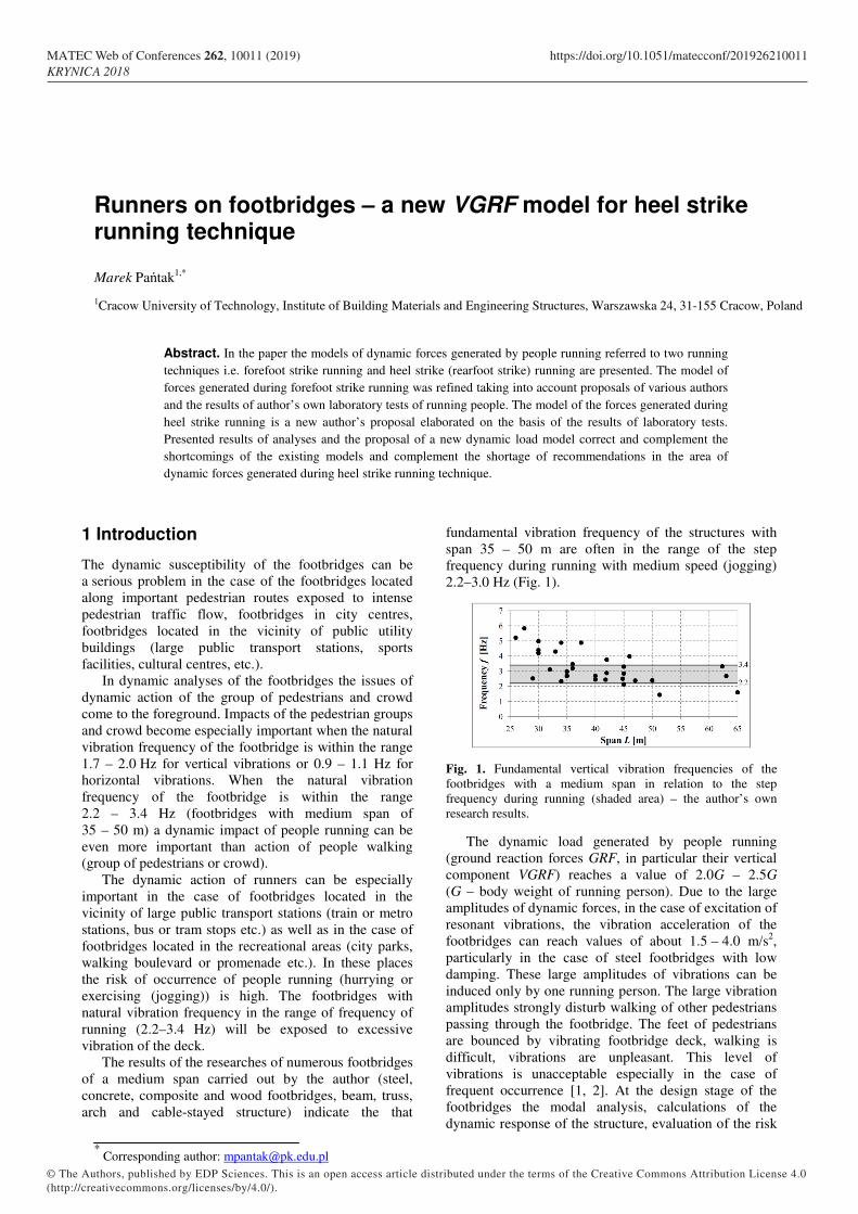
It is worth remembering that the recommendations presented in [4] and [5, 6] should be used with caution for several reasons: − the VGRF estimated using the values of the dynamic
load factors αi and the phase shifts φi recommended in [4] i.e. α1 = 1.6, α2 = 0.7, α3 = 0.2, φi – lack of recommendations (assumed values φ2 = φ3 = 0), represents the maximum value of the VGRF generated by running person (VGRF/G ≈ 3.0) which occurs sporadically. Usually the value of VGRF/G ≈ 2.1 – 2.5,
− the VGRF estimated using equation (1) is negative in the time interval corresponding approximately to the flight phase during the running. The negative VGRF values must be set to zero. Only positive VGRF values should be used in dynamic analyses.
− the value of the dynamic amplification factor Ar in equation (2) is very sensitive to changes of the value of the contact time tcr. For the tcr = 0.5Tr (i.e. k = 0.5) suggested in [5, 6] for ordinary running activity the VGRF reaches the high maximum value which occurs sporadically (VGRF/G = Ar = 3.14). The VGRFs determined by means of equations (1)
and (2) using the recommendations given in [4] and [5, 6] with reference to the VGRFs acquired during laboratory tests for running frequency 2.4 Hz, 2.8 Hz and 3.2 Hz are presented in Fig. 5.
A large inexactness can be observed in the estimation of the VGRF values. The VGRFs courses are estimated inaccurately. The maximum VGRF values are overestimated (consequently the vibration amplitudes of the structure will be overestimated). Moreover, assuming
tcr = 0.5Tr according to [5, 6] the contact time value tcr is estimated incorrectly. Consequently the VGRFs course is inaccurate and incorrect. The parameters in equations (1) and (2) should be adjusted to improve the estimation of the VGRF values.
a)
b)
Fig. 5. Calculated VGRF/G (bold line) with reference to the VGRF/G determined during laboratory tests (dashed lines) for running frequency 2.4 Hz, 2.8 Hz and 3.2 Hz a) the VGRF/G determined by means of equations (1) for α1 = 1.6, α2 = 0.7, α3 = 0.2, φ2 = φ3 = 0, b) the VGRF/G determined by means of equations (2) for tcr = 0.5Tr.
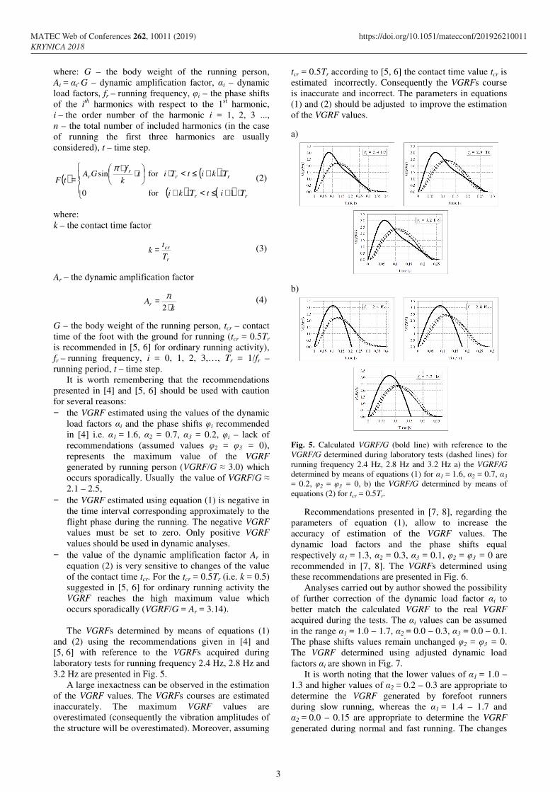
Recommendations presented in [7, 8], regarding the parameters of equation (1), allow to increase the accuracy of estimation of the VGRF values. The dynamic load factors and the phase shifts equal respectively α1 = 1.3, α2 = 0.3, α3 = 0.1, φ2 = φ3 = 0 are recommended in [7, 8]. The VGRFs determined using these recommendations are presented in Fig. 6.
Analyses carried out by author showed the possibility of further correction of the dynamic load factor αi to better match the calculated VGRF to the real VGRF acquired during the tests. The αi values can be assumed in the range α1 = 1.0 – 1.7, α2 = 0.0 – 0.3, α3 = 0.0 – 0.1. The phase shifts values remain unchanged φ2 = φ3 = 0. The VGRF determined using adjusted dynamic load factors αi are shown in Fig. 7.
It is worth noting that the lower values of α1 = 1.0 – 1.3 and higher values of α2 = 0.2 – 0.3 are appropriate to determine the VGRF generated by forefoot runners during slow running, whereas the α1 = 1.4 – 1.7 and α2 = 0.0 – 0.15 are appropriate to determine the VGRF generated during normal and fast running. The changes
3
MATEC Web of Conferences 262, 10011 (2019) https://doi.org/10.1051/matecconf/201926210011KRYNICA 2018
in the value of α3 allow for a slight correction of the VGRF values but have no significant impact on the VGRF.
Fig. 6. The VGRF/G determined by means of equation (1) for α1 = 1.3, α2 = 0.3, α3 = 0.1, φ2 = φ3 = 0 (bold line) with reference to the VGRF/G determined during laboratory tests (dashed lines) for running frequency 2.4 Hz, 2.8 Hz and 3.2 Hz
Fig. 7. The VGRF/G determined by means of equation (1) using adjusted dynamic load factors αi.
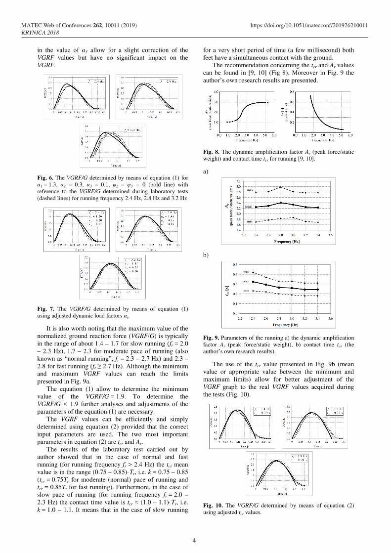
It is also worth noting that the maximum value of the normalized ground reaction force (VGRF/G) is typically in the range of about 1.4 – 1.7 for slow running (fr = 2.0 – 2.3 Hz), 1.7 – 2.3 for moderate pace of running (also known as “normal running”, fr = 2.3 – 2.7 Hz) and 2.3 – 2.8 for fast running (fr ≥ 2.7 Hz). Although the minimum and maximum VGRF values can reach the limits presented in Fig. 9a.
The equation (1) allow to determine the minimum value of the VGRF/G = 1.9. To determine the VGRF/G < 1.9 further analyses and adjustments of the parameters of the equation (1) are necessary.
The VGRF values can be efficiently and simply determined using equation (2) provided that the correct input parameters are used. The two most important parameters in equation (2) are tcr and Ar.
The results of the laboratory test carried out by author showed that in the case of normal and fast running (for running frequency fr > 2.4 Hz) the tcr mean value is in the range (0.75 – 0.85)·Tr, i.e. k = 0.75 – 0.85 (tcr = 0.75Tr for moderate (normal) pace of running and tcr = 0.85Tr for fast running). Furthermore, in the case of slow pace of running (for running frequency fr = 2.0 – 2.3 Hz) the contact time value is tcr ≈ (1.0 – 1.1)·Tr, i.e. k = 1.0 – 1.1. It means that in the case of slow running
for a very short period of time (a few millisecond) both feet have a simultaneous contact with the ground.
The recommendation concerning the tcr and Ar values can be found in [9, 10] (Fig 8). Moreover in Fig. 9 the author’s own research results are presented.
Fig. 8. The dynamic amplification factor Ar (peak force/static weight) and contact time tcr for running [9, 10].
a)
b)
Fig. 9. Parameters of the running a) the dynamic amplification factor Ar (peak force/static weight), b) contact time tcr (the author’s own research results).
The use of the tcr value presented in Fig. 9b (mean value or appropriate value between the minimum and maximum limits) allow for better adjustment of the VGRF graph to the real VGRF values acquired during the tests (Fig. 10).
Fig. 10. The VGRF/G determined by means of equation (2) using adjusted tcr values.
4
MATEC Web of Conferences 262, 10011 (2019) https://doi.org/10.1051/matecconf/201926210011KRYNICA 2018
Further adjustment of the VGRF values calculated using equation (2) is possible by replacing the Ar value determined in accordance with equation (4) with the appropriate value read from Fig. 9a between the minimum and maximum limits.
Fig. 11. The VGRF/G determined by means of equation (2) using adjusted tcr values.
3.1 Heel strike running
The second techniques of running – the heel strike running (rearfoot strike running) requires the correction or supplementation of previous VGRF models due to the impact peak occurrence a few millisecond after contact of the foot of running person with the ground.
The author’s proposal of the VGRF model generated by heel strike runners are the general equations (5) supplemented with equation (6) – the impact peak function.
( ) ( ) ( ) ( )( )
⋅≥≥⋅≤≤+
=Φr
r
TttF
tTtttFt
λϕλϕ
for
for 00 (5)
( ) ( )βπαϕ tfGAt rip ⋅⋅⋅⋅= sin (6)
where: F(t) – the VGRF values determined by means of equation (1) or (2), φ(t) – the impact peak function, φ(t) ≥ 0 (only the first cycle of sine wave should be used), G – the body weight of the running person, fr – running frequency, Aip – amplitude of the impact peak e.g. Aip ≈ 0.70. The Aip value can be adjusted accordingly. Typical Aip value can be assumed in the range 0.5-1.3 (the Aip ≥ 1.0 applies to the VGRF calculated using equation (1)), α – the impact peak location coefficient, α = 4 – 8 (the α can be a decimal number). For α = 5 – 8 the impact peak on VGRF graph will occur at the time of tip ≈ 30 – 50 ms after contact of the foot with the ground in frequency range fr = 2.4 – 2.8 Hz. For frequency range fr = 2.8 – 3.4 the α = 4, 5, 6 can be assumed. The coefficient should be adequately adjusted to the running frequency to achieve the location of the impact peak at the time of tip = 30–45 ms after contact of the foot with the ground, β – the impact peak slenderness coefficient (exponent). The β = 2, 3, 4, 5, ... can be assumed. Recommended value β = 4 (the β can be a decimal number), λ – the impact peak time range coefficient, λ ≈ 0.17·Tr (only the first cycle of the impact peak function should be used), t – time step.
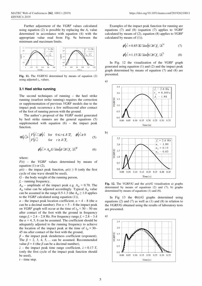
Examples of the impact peak function for running are equations (7) and (8) (equation (7) applies to VGRF calculated by means of (2), equation (8) applies to VGRF calculated by means of (1)).
( ) ( )46sin85.0 tfGt r ⋅⋅⋅⋅⋅= πϕ (7)
( ) ( )36sin15.1 tfGt r ⋅⋅⋅⋅⋅= πϕ (8)
In Fig. 12 the visualization of the VGRF graph generated using equation (1) and (2) and the impact peak graph determined by means of equation (7) and (8) are presented.
a)
b)
Fig. 12. The VGRF/G and the φ(t)/G visualisation a) graphs determined by means of equations (2) and (7), b) graphs determined by means of equations (1) and (8).
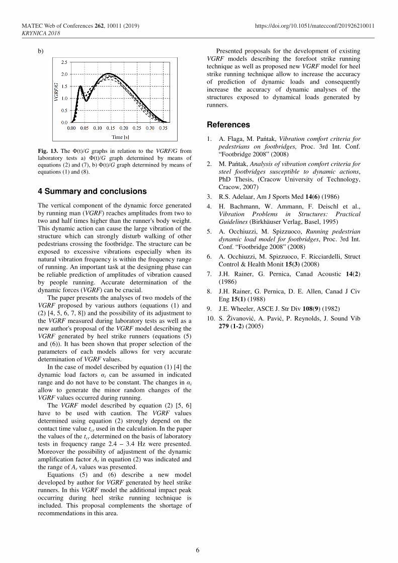
In Fig 13 the Φ(t)/G graphs determined using equations (2) and (7) as well as (1) and (8) in relation to the VGRF/G obtained using the results of laboratory tests are presented.
a)
5
MATEC Web of Conferences 262, 10011 (2019) https://doi.org/10.1051/matecconf/201926210011KRYNICA 2018
b)
Fig. 13. The Φ(t)/G graphs in relation to the VGRF/G from laboratory tests a) Φ(t)/G graph determined by means of equations (2) and (7), b) Φ(t)/G graph determined by means of equations (1) and (8).
4 Summary and conclusions
The vertical component of the dynamic force generated by running man (VGRF) reaches amplitudes from two to two and half times higher than the runner's body weight. This dynamic action can cause the large vibration of the structure which can strongly disturb walking of other pedestrians crossing the footbridge. The structure can be exposed to excessive vibrations especially when its natural vibration frequency is within the frequency range of running. An important task at the designing phase can be reliable prediction of amplitudes of vibration caused by people running. Accurate determination of the dynamic forces (VGRF) can be crucial.
The paper presents the analyses of two models of the VGRF proposed by various authors (equations (1) and (2) [4, 5, 6, 7, 8]) and the possibility of its adjustment to the VGRF measured during laboratory tests as well as a new author's proposal of the VGRF model describing the VGRF generated by heel strike runners (equations (5) and (6)). It has been shown that proper selection of the parameters of each models allows for very accurate determination of VGRF values.
In the case of model described by equation (1) [4] the dynamic load factors αi can be assumed in indicated range and do not have to be constant. The changes in αi allow to generate the minor random changes of the VGRF values occurred during running.
The VGRF model described by equation (2) [5, 6] have to be used with caution. The VGRF values determined using equation (2) strongly depend on the contact time value tcr used in the calculation. In the paper the values of the tcr determined on the basis of laboratory tests in frequency range 2.4 – 3.4 Hz were presented. Moreover the possibility of adjustment of the dynamic amplification factor Ar in equation (2) was indicated and the range of Ar values was presented.
Equations (5) and (6) describe a new model developed by author for VGRF generated by heel strike runners. In this VGRF model the additional impact peak occurring during heel strike running technique is included. This proposal complements the shortage of recommendations in this area.
Presented proposals for the development of existing VGRF models describing the forefoot strike running technique as well as proposed new VGRF model for heel strike running technique allow to increase the accuracy of prediction of dynamic loads and consequently increase the accuracy of dynamic analyses of the structures exposed to dynamical loads generated by runners.
References
1. A. Flaga, M. Pańtak, Vibration comfort criteria for
pedestrians on footbridges, Proc. 3rd Int. Conf. “Footbridge 2008” (2008)
2. M. Pańtak, Analysis of vibration comfort criteria for
steel footbridges susceptible to dynamic actions, PhD Thesis, (Cracow University of Technology, Cracow, 2007)
3. R.S. Adelaar, Am J Sports Med 14(6) (1986)
4. H. Bachmann, W. Ammann, F. Deischl et al., Vibration Problems in Structures: Practical
Guidelines (Birkhäuser Verlag, Basel, 1995)
5. A. Occhiuzzi, M. Spizzuoco, Running pedestrian
dynamic load model for footbridges, Proc. 3rd Int. Conf. “Footbridge 2008” (2008)
6. A. Occhiuzzi, M. Spizzuoco, F. Ricciardelli, Struct Control & Health Monit 15(3) (2008)
7. J.H. Rainer, G. Pernica, Canad Acoustic 14(2) (1986)
8. J.H. Rainer, G. Pernica, D. E. Allen, Canad J Civ Eng 15(1) (1988)
9. J.E. Wheeler, ASCE J. Str Div 108(9) (1982)
10. S. Živanović, A. Pavić, P. Reynolds, J. Sound Vib 279 (1-2) (2005)
6
MATEC Web of Conferences 262, 10011 (2019) https://doi.org/10.1051/matecconf/201926210011KRYNICA 2018