62awi13-202.pdf - Air Force
63
BY ORDER OF THE COMMANDER 62D AIRLIFT WING (AMC) 62D AIRLIFT WING INSTRUCTION 13-202 31 AUGUST 2017 Space, Missile, Command, and Control AIRFIELD OPERATIONS COMPLIANCE WITH THIS PUBLICATION IS MANDATORY ACCESSIBILITY: Publications and forms are available on the e-Publishing website at www.e-publishing.af.mil for downloading or ordering. RELEASABILITY: There are no releasability restrictions on this publication. OPR: 62 OSS/OSA Supersedes: 62 AWI 13-202, 5 NOVEMBER 2012 Certified by: 62 OSS/CC (LEONARD J. KOSINSKI, Col, USAF) Pages: 63 This instruction implements Air Force Instruction (AFI) 13-204, Vol 1, Airfield Operations Career Field Development, Vol 2, Airfield Operations Standardization and Evaluations, and Vol 3, Airfield Operations Procedures and Programs. It establishes policies and procedures governing air traffic control (ATC) and airfield operations, and it applies to permanent and temporarily based flying operations on Joint base-Lewis McChord - McChord Field, Washington. Maintain and dispose of records created as a result of prescribed processes in accordance with the Air Force Records Disposition Schedule (RDS) located at https://www.my.af.mil/gcss- af61a/afrims/afrims. Refer recommended changes and questions to OPR using the AF Form 847, Recommendation for Change of Publication. SUMMARY OF CHANGES This publication has been substantially revised and must be completely reviewed. Major changes include: (1.5.) Runway Note revised; (1.6.) CMA definition revised; (1.7.1.) Note OG approval for use of Kilo deleted.; (1.7.2.) Note 2 added; (1.8.) Visual and Radio Blind Spots revised; (1.12.) 62 AWI 13-213 Airfield Driving updated; (1.15.1.1.) Changed Runway 16 to calm wind runway; (1.15.2.2.) Added 62 AW/CP will disseminate exceptions; (1.16.) Revised; (1.17.1.) Added if conditions warrant for RCR checks on Hotel; (1.18.2.) Revised; (1.19.2.) Added Tower notification to Base WX; (1.19.3.) Deleted VFR requirement for taxiway Foxtrot; (1.20.) Note 1 Deleted Barrier Maintenance priority and changed response time to 30 minutes; (1.20.6.) Updated publication to JBLM Reg 95-3; (1.20.7.) Deleted; (1.23.1.1.) Deleted; (1.23.1.3.) Added
-
Upload
khangminh22 -
Category
Documents
-
view
0 -
download
0
Transcript of 62awi13-202.pdf - Air Force

BY ORDER OF THE COMMANDER
62D AIRLIFT WING (AMC)
62D AIRLIFT WING INSTRUCTION
13-202
31 AUGUST 2017
Space, Missile, Command, and Control
AIRFIELD OPERATIONS
COMPLIANCE WITH THIS PUBLICATION IS MANDATORY
ACCESSIBILITY: Publications and forms are available on the e-Publishing website at
www.e-publishing.af.mil for downloading or ordering.
RELEASABILITY: There are no releasability restrictions on this publication.
OPR: 62 OSS/OSA
Supersedes: 62 AWI 13-202,
5 NOVEMBER 2012
Certified by: 62 OSS/CC
(LEONARD J. KOSINSKI, Col, USAF)
Pages: 63
This instruction implements Air Force Instruction (AFI) 13-204, Vol 1, Airfield Operations
Career Field Development, Vol 2, Airfield Operations Standardization and Evaluations, and Vol
3, Airfield Operations Procedures and Programs. It establishes policies and procedures governing
air traffic control (ATC) and airfield operations, and it applies to permanent and temporarily
based flying operations on Joint base-Lewis McChord - McChord Field, Washington. Maintain
and dispose of records created as a result of prescribed processes in accordance with the Air
Force Records Disposition Schedule (RDS) located at https://www.my.af.mil/gcss-
af61a/afrims/afrims. Refer recommended changes and questions to OPR using the AF Form
847, Recommendation for Change of Publication.
SUMMARY OF CHANGES
This publication has been substantially revised and must be completely reviewed. Major changes
include: (1.5.) Runway Note revised; (1.6.) CMA definition revised; (1.7.1.) Note OG approval
for use of Kilo deleted.; (1.7.2.) Note 2 added; (1.8.) Visual and Radio Blind Spots revised;
(1.12.) 62 AWI 13-213 Airfield Driving updated; (1.15.1.1.) Changed Runway 16 to calm wind
runway; (1.15.2.2.) Added 62 AW/CP will disseminate exceptions; (1.16.) Revised; (1.17.1.)
Added if conditions warrant for RCR checks on Hotel; (1.18.2.) Revised; (1.19.2.) Added Tower
notification to Base WX; (1.19.3.) Deleted VFR requirement for taxiway Foxtrot; (1.20.) Note 1
Deleted Barrier Maintenance priority and changed response time to 30 minutes; (1.20.6.)
Updated publication to JBLM Reg 95-3; (1.20.7.) Deleted; (1.23.1.1.) Deleted; (1.23.1.3.) Added

2 62AWI13-202 31 AUGUST 2017
Localizer; (1.23.1.4.) Added ALSF-2; (1.23.) Note changed SOC to OG/CC; (1.23.1.13) Deleted;
(1.32.6.) Deleted (1.32.7.) Added; (1.32.8.) Added; (2.1.1.) Updated 62 AWI 13-213; (2.1.1.1.)
Updated regulation to JBLM Reg 95-3; (2.1.1.2.) Updated regulation to JBLM Reg 95-3 and
included that emergency vehicles will notify Tower and AMOPS when their activities could
impact ops; (2.1.1.3.) Updated regulation to JBLM Reg 95-3; (2.1.2.) Added and personnel;
(2.1.3.) Note revised; (2.5.5.1.) Revised; (2.6.1.2.); (2.8.1.) OG approval for use of Kilo deleted
Revised; (3.5.3.) Revised; (3.6.1.) Revised; (3.7.) Revised; (3.9.1.4.2.) Deleted; (3.11.) Revised;
(3.12.) Revised; (3.15.) Multiple approach procedures instructions changed; (3.16.2.) Note 2
added; (3.16.7.) Added; (3.21.) Deleted; (4.2.) PCAS daily test added; (4.2.1.3.) Revised;
(4.2.1.4.) Revised; (4.2.1.5.) Revised; (4.3.15.) Deleted; (4.10.) Jettison area radial changed;
(4.11.) Bailout area radial changed; (4.12.2.1.) Flight plan and engine start clearance added;
(5.2.) Revised; (5.3.1.) Quiet hour request deleted for NVD ops; (5.3.6.) Terminology for Assault
and NVG lighting changed; (5.4.) Deleted; (5.8.4) Added; (5.9.) Added; (6.1.) Deleted 194th
Regional Support Wing Det 1 Commander from AOB Members table; (6.3.) Changed to Ramp
Quiet Hours Request Procedures and revised; (6.4.) Deleted Det 1 194th RSW (ANG) and
updated AMOPS email address; (6.4.) Note 3 changed Det 1 to deployed hosted units;
Attachments revised; Numbering and General Formatting changes throughout.
Chapter 1— AIR TRAFFIC CONTROL, AIRFIELD MANAGEMENT OPERATIONS,
AND ATC AND LANDING SYSTEM (ATCALS) FACILITIES 7
1.1. Control Tower. ........................................................................................................ 7
1.2. Control Tower Evacuation: ..................................................................................... 7
1.3. Continuity of Air Traffic Services. ......................................................................... 7
1.4. Evacuation of Airfield Management Facility (Bldg. 1172). ................................... 7
1.5. Runway. .................................................................................................................. 7
1.6. Controlled Movement Area (CMA). ....................................................................... 8
1.7. Uncontrolled Movement Areas: .............................................................................. 8
1.8. Visual and Radio Blind Spots. ................................................................................ 8
1.9. Ground Navigational Aid (NAVAID) Checkpoint. ................................................ 8
1.10. Permanently Closed/Unusable Portions of the Airfield. ......................................... 8
1.11. Wingtip Clearance Reference Lines. ...................................................................... 8
1.12. Restricted Areas. ..................................................................................................... 8
1.13. Suspending Runway Operations. ............................................................................ 8
1.14. Airfield Inspections and Checks. ............................................................................ 9
1.15. Runway Selection. .................................................................................................. 10
1.16. Runway Change: ..................................................................................................... 10

62AWI13-202 31 AUGUST 2017 3
1.17. Runway Surface Condition (RSC)/Runway Condition Reading (RCR) Check. .... 10
1.18. Airfield Conditions: ................................................................................................ 10
1.19. Airfield Lighting. .................................................................................................... 11
1.20. Aircraft Arresting Systems: .................................................................................... 11
1.21. No-Notice ATCALS Preventive Maintenance Inspection (PMI) Schedule: .......... 12
1.22. Auxiliary Power for ATCALS Facilities. ............................................................... 13
1.23. CAT II ILS Operations: .......................................................................................... 13
1.24. ASR/PAR Approaches. ........................................................................................... 13
1.25. Terminal Advisory Service (TAS): ......................................................................... 13
1.26. Transient Alert Services. ......................................................................................... 13
1.27. Airfield Driving Program. ....................................................................................... 13
1.28. Airfield Management Procedures. .......................................................................... 14
1.29. Bird/Wildlife Control. ............................................................................................. 14
1.30. Bird Watch Conditions (BWC). .............................................................................. 14
1.31. Unmanned Aircraft System (UAS) Operations. ..................................................... 15
1.32. Miscellaneous Procedures:...................................................................................... 15
Chapter 2— GROUND MOVEMENT AND DEPARTURE CLEARANCE PROCEDURES 16
2.1. Control of Ground Traffic:...................................................................................... 16
2.2. Precision Approach Critical Areas. ......................................................................... 17
2.3. Ground Engine Runs: .............................................................................................. 17
2.4. Local Aircraft Radio Channelization. ..................................................................... 18
Table 2.1. Local Aircraft Radio Channelization. ..................................................................... 18
2.5. Departure Clearances/Procedures: .......................................................................... 19
2.6. Heavy Aircraft Taxiway/Parking Restrictions: ....................................................... 19
2.7. Armed Ordnance Ground Procedures. .................................................................... 20
2.8. Engine Running Crew Change (ERCC) Locations: ................................................ 20
2.9. Chaff/Flare Aircraft Parking. .................................................................................. 20
Chapter 3— AIR TRAFFIC CONTROL 21
3.1. Local Flying Area. .................................................................................................. 21

4 62AWI13-202 31 AUGUST 2017
3.2. Functional Check Flight Route. .............................................................................. 21
3.3. Operations within Class Delta Airspace. ................................................................ 21
3.4. Civil Aircraft Use: .................................................................................................. 21
3.5. VFR Traffic Patterns: .............................................................................................. 21
3.6. Weather Minimums for VFR Patterns: ................................................................... 22
3.7. Radar Traffic Patterns. ............................................................................................ 22
3.8. Protection of 360 Overhead. ................................................................................... 22
3.9. Departure Priorities. ................................................................................................ 23
3.10. Formation Flights. ................................................................................................... 24
3.11. Opposite-Direction Traffic...................................................................................... 24
3.12. Restricted Low Approaches. ................................................................................... 24
3.13. Standard Go-Around/Missed Approach Procedures. .............................................. 24
3.14. Circling Procedures: ............................................................................................... 24
3.15. Multiple Approach Procedures. .............................................................................. 25
3.16. Noise Abatement. .................................................................................................... 25
3.17. Separation (VFR - VFR, VFR - IFR). ..................................................................... 25
3.18. Reduced Same Runway Separation (RSRS). .......................................................... 25
Table 3.1. RSRS Standards. (* Standard separation will be applied IAW FAAO 7110.65.) .. 27
3.19. B-52 Aircraft Restrictions. ...................................................................................... 27
3.20. Armed Ordnance Recovery Procedures. ................................................................. 27
3.21. Communications Outage Procedures. ..................................................................... 27
Chapter 4— EMERGENCY PROCEDURES 28
4.1. General. ................................................................................................................... 28
4.2. Primary Crash Alarm System (PCAS). ................................................................... 28
4.3. Secondary Crash Net (SCN). .................................................................................. 29
4.4. Hot Brakes Procedures: .......................................................................................... 30
4.5. Hung Flare Procedures: .......................................................................................... 30
4.6. Hung Ordnance Procedures: ................................................................................... 30
4.7. Gun Malfunction Procedures: ................................................................................. 30

62AWI13-202 31 AUGUST 2017 5
4.8. Hydrazine Procedures. ............................................................................................ 31
4.9. Emergency Locator Transmitter (ELT)/Crash Position Indicator (CPI) Signals. ... 31
4.10. Fuel Tank, Ordnance, Cargo Jettison, and Fuel Dumping (Attachment 4). ............ 31
4.11. Controlled Bailouts: ................................................................................................ 32
4.12. Anti-Hijacking Procedures...................................................................................... 32
Chapter 5— SPECIAL PROCEDURES 34
5.1. C-130 Landing Zone (LZ) Operations (Runway 162/342): .................................... 34
5.2. Combat Offload Operations: ................................................................................... 35
5.3. Night Vision Device (NVD) Operations. ................................................................ 37
Table 5.1. Aircrew Phraseology Examples. ............................................................................. 39
Table 5.2. Controller Phraseology Examples........................................................................... 39
5.4. Tactical Ordnance Procedures. ............................................................................... 40
5.5. Unusual Maneuvers. ............................................................................................... 40
5.6. Request Procedures for Parachute Jumps/Airdrops onto McChord Field: ............. 40
5.7. McChord Field Drop Zone Operations. .................................................................. 41
5.8. Special VFR (SVFR) Procedures: .......................................................................... 42
5.9. Flight Check Procedures: ........................................................................................ 43
5.10. VR331 Procedures. ................................................................................................. 43
Chapter 6— ADMINISTRATION 44
6.1. Airfield Operations Board (AOB). ......................................................................... 44
Table 6.1. AOB Members. ....................................................................................................... 44
6.2. National Airspace System Notice to Airmen (NOTAM) Coordination
Procedures. ............................................................................................................... 45
6.3. Ramp Quiet Hours Request Procedures. ................................................................. 46
6.4. Flight Plan Filing Procedures: ................................................................................ 46

6 62AWI13-202 31 AUGUST 2017
Attachment 1— GLOSSARY OF REFERENCES AND SUPPORTING INFORMATION 48
Attachment 2— JBLM MCCHORD FIELD AIRFIELD DIAGRAM 52
Attachment 3— CONTROLLED MOVEMENT AREA 53
Attachment 4— FUEL TANK, ORDNANCE, AND CARGO JETTISON AREA 56
Attachment 5— LOCAL AIRSPACE 57
Attachment 6— SMOKEY LZ LIGHTING CONFIGURATION 58
Attachment 7— RWY 16 500' NVG ASSAULT LIGHTING CONFIGURATION 59
Attachment 8— RWY 34 500' NVG ASSAULT LIGHTING CONFIGURATION 60
Attachment 9— RWY 16 1000' NVG LIGHTING CONFIGURATION 61
Attachment 10— RWY 34 1000' NVG LIGHTING CONFIGURATION 62
Attachment 11— C-17 WINGTIP REFERENCE LINES 63
62AWI13-202 31 AUGUST 2017 7
Chapter 1
AIR TRAFFIC CONTROL, AIRFIELD MANAGEMENT OPERATIONS, AND ATC
AND LANDING SYSTEM (ATCALS) FACILITIES
1.1. Control Tower. The control tower is open 24 hours a day, 7 days a week.
1.2. Control Tower Evacuation:
1.2.1. Circumstances may exist that require the evacuation of the control tower. Evacuate the
control tower due to:
1.2.1.1. Tower Wind Limitations:
1.2.1.1.1. The tower is evacuated when the wind velocity reaches 70 knots (steady or
in gusts) or when deemed necessary by the watch supervisor/senior controller.
1.2.1.1.2. Controllers will proceed to Airfield Management Operations (AMOPS) in
Bldg. 1172 and standby until the wind diminishes to 65 knots and is forecast to
subside.
1.2.1.2. Fire.
1.2.1.3. Bomb Threat (received or when a bomb is located within 500 feet of the tower).
1.2.2. When directed by the JBLM Emergency Operations Center or the 62 AW Command
Post, implement shelter-in-place procedures IAW the JBLM CEMP and 62 AW Contingency
Action Plan.
1.2.3. Tower will activate the Primary Crash Alarm System (PCAS) to relay the evacuation
action and any other pertinent information.
1.2.4. AMOPS will activate the secondary crash alarm circuit to notify all concerned
agencies that the tower has been evacuated and issue an appropriate Notice to Airmen
(NOTAM).
1.2.5. The watch supervisor/senior controller ensures all local area traffic lands or diverts,
and ensures a blanket broadcast on all assigned frequencies before evacuating for any of the
situations outlined above.
1.3. Continuity of Air Traffic Services. Based on the control tower's construction and
equipment reliability, the 62 OG Commander has determined that a designated alternate control
tower facility is not required at McChord Field.
1.4. Evacuation of Airfield Management Facility (Bldg. 1172). In the event that Bldg. 1172
evacuates, AMOPS personnel will follow procedures outlined in local AMOPs checklists and
report to Hangar 4 (Room 4-201).
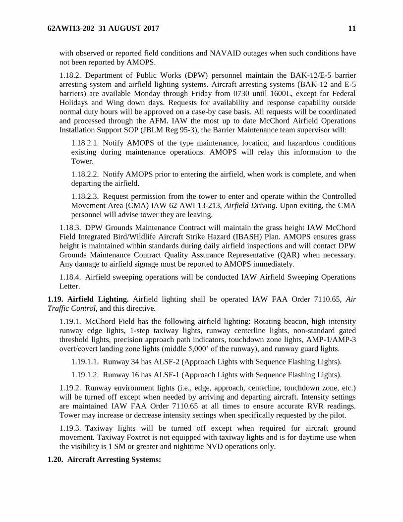
1.5. Runway. McChord Field’s Runway 16/34 is 10,108 feet long and 150 feet wide. Field
elevation is 322’ MSL. The overruns are 1,000 feet long by 150 feet wide with asphalt
composition. The southernmost 1,000 feet of the runway is composed of approximately 13
inches of concrete. The remaining 9,108 feet is flexible asphalt, generally less than 5 inches
thick, over crushed gravel. NOTE: Because of the flexible construction and relatively narrow
(150 feet) width, special restrictions apply to heavy aircraft on the flexible portion of the runway.

8 62AWI13-202 31 AUGUST 2017
Unless absolutely essential, 180-degree turns on the flexible portion of the runway are prohibited
for heavy aircraft.
1.6. Controlled Movement Area (CMA). The McChord Field CMA is the portion of the
movement area that requires Tower approval to operate on. This area is defined as the runway,
overruns, and landing zone, up to the Instrument and/or Visual Flight Rule (VFR) hold lines and
within 100 feet of runway, overruns, and the landing zone’s edges (see Attachment 3). When an
aircraft is parked on Kilo 2 taxiway Bravo becomes uncontrolled up to the VFR hold line
reference 1.7.2.
1.7. Uncontrolled Movement Areas:
1.7.1. Taxiways. McChord Field’s taxiways include: Alpha, 100 feet wide (at narrowest
point); Bravo, 75 feet wide; Charlie, 75 feet wide; Delta, 100 feet wide; Echo, 390 feet wide
(at narrowest point); Foxtrot, 75 feet wide; Hotel, 75 feet wide; Juliet, 75 feet wide, Kilo, 75
feet wide, Lima, 75 feet wide. (Attachment 2.)
1.7.2. Parking ramps. Primary ramps are Bravo B1-B8; Charlie C1-C9, Delta D1-D19
(transient), D25-D31, and D32-D43 (Delta Extension); Echo E1-E23; Foxtrot F1-F30, F32,
F34-F35, F38-F39, F40; Juliet J1-J15; Kilo 2; Lima L1. NOTE: Aircraft must use the north
Juliet Ramp taxi lane to park on spots B-7 and B-8.
1.8. Visual and Radio Blind Spots. Visual blind spots from the control tower are: Delta
transient ramp located behind Hangars 1 and 2, Taxiway Juliet, and Echo Ramp. Intermittent
radio blind spots have been identified throughout the airfield, most specifically on taxiway Echo.
1.9. Ground Navigational Aid (NAVAID) Checkpoint. The ground NAVAID checkpoint is
located at south hammerhead.
1.10. Permanently Closed/Unusable Portions of the Airfield. There are two permanently
closed/unusable portions: (1) the north-south taxiway (east of Taxiway Hotel and west of the
landing strip) and (2) the east-west taxiway (east of the runway and north of Taxiway Bravo).
1.11. Wingtip Clearance Reference Lines. There are C-17 wingtip clearance reference lines
painted in both hammerheads (Taxiways Alpha and Echo). The closest line to taxiway centerline
is the actual wingtip reference and the outboard lines represent 10-foot and 25-foot clearance
(see Attachment 11).
1.12. Restricted Areas. Depiction and description of McChord Field restricted areas and
associated entry control points can be found in 62 AWI 13-213, Airfield Driving.
1.13. Suspending Runway Operations.
1.13.1. The tower supervisor will suspend runway operations and notify AMOPS if
necessary when an unsafe condition is observed on the airfield. AMOPS must temporarily
suspend/close runway operations when any unsafe condition affects runway operations (e.g.,
FOD, severe bird/wildlife activity, snow and ice removal operations, arresting systems
maintenance/configuration changes, airfield construction, pavement repair, etc.). The
suspension/closure announcement will be accompanied with the time runway operations are
expected to resume. Prior to resuming normal operations AMOPS personnel will conduct a
runway check. If alert aircraft are present and the runway is temporarily closed, AMOPS
supervisor notifies the 62 AW Command Post (CP). 62 AW/CP will notify the Western Air
Defense Sector (WADS) Mission Crew Commander (MCC).

62AWI13-202 31 AUGUST 2017 9
1.13.2. After determining that normal operations can be resumed, the AMOPS supervisor
reopens the runway, advises Tower, and notifies 62 AW/CP of any change in runway status.
62 AW/CP will notify WADS MCC when the runway is back to operational status.
1.14. Airfield Inspections and Checks. AMOPS will conduct daily inspections and checks
IAW OSAA OI 13-204.
1.14.1. Daily Runway Inspections. AMOPS conducts thorough airfield inspections at least
once daily. Runway inspections are given priority to the maximum extent possible; if
necessary, practice approach aircraft will receive restricted low approaches during the
inspections.
1.14.2. Airfield Checks. At a minimum an airfield check is performed:
1.14.2.1. Prior to the start of local flying.
1.14.2.2. In-flight emergencies.
1.14.2.3. Ground emergencies.
1.14.2.4. FOD reports.
1.14.2.5. Report of a dropped object.
1.14.2.6. Bird activity.
1.14.2.7. Report of a bird strike.
1.14.2.8. Barrier engagement.
1.14.2.9. Barrier reconfigurations.
1.14.2.10. Prior to opening a closed movement area (runway, taxiway, apron).
1.14.2.11. Fuel spills.
1.14.2.12. Unauthorized aircraft landing.
1.14.2.13. Severe weather.
1.14.2.14. Natural disaster (tornado, earthquake, etc).
1.14.2.15. Combat off load.
1.14.2.16. Any report of runway/taxiway/parking ramp damage.
1.14.2.17. Runway Condition Reading.
1.14.2.18. Runway Surface Condition changes.
1.14.2.19. Airfield Lighting Serviceability.
1.14.3. Additional Inspections:
1.14.3.1. The Airfield Manager (AFM), in conjunction with the Department of Public
Works (DPW) (See McChord Field Support MOU) and Wing Safety (SE) will conduct
the Annual Certification/Safety Inspection IAW AFI 13-204V2.

10 62AWI13-202 31 AUGUST 2017
1.14.3.2. Quarterly joint inspection will be conducted by the AFM/DAFM, Waiver
Technician, Flight line Constable and representatives from ATC, Wing Safety and DPW
IAW the McChord Field Support MOU.
1.14.3.3. The AFM will conduct and document an inspection with representatives from
DPW and SE IAW the McChord Field Support MOU before and after completion of any
airfield construction, changes or additions to the flying mission or changes affecting
existing aircraft parking/taxi procedures.
1.15. Runway Selection. Tower will determine the active runway IAW FAAO 7110.65, Air
Traffic Control.
1.15.1. Preferred Runway:
1.15.1.1. Runway 34 is the “calm wind” runway between 0500L and 2300L, except
when tailwind component is 5 knots or more.
1.15.1.2. Conflicting Wind Information. If conflicting wind information is received,
Tower supervisor will use their best judgment when determining runway in use.
1.15.2. Noise Abatement:
1.15.2.1. In the interest of fostering positive community relations, the following
procedures apply between 2300L-0500L, 7 days a week. If surface wind is 10 knots or
less and other conditions permit, Tower coordinates with Seattle Approach Control to
designate direction of traffic as follows:
1.15.2.1.1. Land Runway 34. Arriving aircraft will make a straight-in full-stop
landing only.
1.15.2.1.2. Depart Runway 16.
1.16. Runway Change:
1.16.1. Tower notifies Seattle Approach Control, base weather station, and AMOPS of the
runway change via verbal notification.
1.16.2. AMOPS notifies the 62 AW/CP and Barrier Maintenance between 0730L-1630L,
Monday-Friday. Upon notification, Barrier Maintenance configures the cables as required.
1.17. Runway Surface Condition (RSC)/Runway Condition Reading (RCR) Check. When
weather conditions deteriorate, AMOPS will perform RSC/RCR checks as necessary. (Only
restricted low approaches are authorized during check periods.)
1.17.1. When an RCR check is performed on the runway, an RCR check will also be
performed on Taxiway Hotel if conditions warrant.
1.17.2. RCR values (Table 1.1.) are recorded on AFTO Form 277, Results of Runway
Braking Test, and filed with the Airfield Inspection/Check forms.
1.17.3. Report the RCR to 62 AW/CP, Weather, and Tower (ATC). NOTE: Reference
Flight Information Handbook for National/International Procedures.
1.18. Airfield Conditions:
1.18.1. AMOPS provides current information to Tower and the CP on construction,
obstructions, and airfield conditions. Tower provides AMOPS and Seattle Approach Control
62AWI13-202 31 AUGUST 2017 11
with observed or reported field conditions and NAVAID outages when such conditions have
not been reported by AMOPS.
1.18.2. Department of Public Works (DPW) personnel maintain the BAK-12/E-5 barrier
arresting system and airfield lighting systems. Aircraft arresting systems (BAK-12 and E-5
barriers) are available Monday through Friday from 0730 until 1600L, except for Federal
Holidays and Wing down days. Requests for availability and response capability outside
normal duty hours will be approved on a case-by case basis. All requests will be coordinated
and processed through the AFM. IAW the most up to date McChord Airfield Operations
Installation Support SOP (JBLM Reg 95-3), the Barrier Maintenance team supervisor will:
1.18.2.1. Notify AMOPS of the type maintenance, location, and hazardous conditions
existing during maintenance operations. AMOPS will relay this information to the
Tower.
1.18.2.2. Notify AMOPS prior to entering the airfield, when work is complete, and when
departing the airfield.
1.18.2.3. Request permission from the tower to enter and operate within the Controlled
Movement Area (CMA) IAW 62 AWI 13-213, Airfield Driving. Upon exiting, the CMA
personnel will advise tower they are leaving.
1.18.3. DPW Grounds Maintenance Contract will maintain the grass height IAW McChord
Field Integrated Bird/Wildlife Aircraft Strike Hazard (IBASH) Plan. AMOPS ensures grass
height is maintained within standards during daily airfield inspections and will contact DPW
Grounds Maintenance Contract Quality Assurance Representative (QAR) when necessary.
Any damage to airfield signage must be reported to AMOPS immediately.
1.18.4. Airfield sweeping operations will be conducted IAW Airfield Sweeping Operations
Letter.
1.19. Airfield Lighting. Airfield lighting shall be operated IAW FAA Order 7110.65, Air
Traffic Control, and this directive.
1.19.1. McChord Field has the following airfield lighting: Rotating beacon, high intensity
runway edge lights, 1-step taxiway lights, runway centerline lights, non-standard gated
threshold lights, precision approach path indicators, touchdown zone lights, AMP-1/AMP-3
overt/covert landing zone lights (middle 5,000’ of the runway), and runway guard lights.
1.19.1.1. Runway 34 has ALSF-2 (Approach Lights with Sequence Flashing Lights).
1.19.1.2. Runway 16 has ALSF-1 (Approach Lights with Sequence Flashing Lights).
1.19.2. Runway environment lights (i.e., edge, approach, centerline, touchdown zone, etc.)
will be turned off except when needed by arriving and departing aircraft. Intensity settings
are maintained IAW FAA Order 7110.65 at all times to ensure accurate RVR readings.
Tower may increase or decrease intensity settings when specifically requested by the pilot.
1.19.3. Taxiway lights will be turned off except when required for aircraft ground
movement. Taxiway Foxtrot is not equipped with taxiway lights and is for daytime use when
the visibility is 1 SM or greater and nighttime NVD operations only.
1.20. Aircraft Arresting Systems:

12 62AWI13-202 31 AUGUST 2017
1.20.1. BAK-12 installation requires 30 minutes prior notice and will only be installed or
removed by barrier maintenance Monday through Friday during normal duty hours. Requests
will be made through AMOPS. Additionally, up to a 2 hour period between successive
engagements should be used for planning purposes.
1.20.2. The standard aircraft arresting system configuration for Runways 16/34:
1.20.2.1. The North and South BAK-12 and E5 are normally disconnected and removed
from the runway.
1.20.2.1.1. NOTE 1: AMOPS shall temporarily suspend/close runway operations
when arresting systems maintenance/configuration changes. During reconfiguration,
aircraft conducting local pattern work can expect restricted low approaches and
departing aircraft can expect ground delays. During normal duty hours, Barrier
Maintenance will respond within 30 minutes to reconfigure cables. AMOPS will
complete an airfield check and barrier inspection and report the airfield status prior to
resuming runway operations.
1.20.2.1.2. NOTE 2: When tail-hook equipped aircraft are operating out of
McChord Field, cable configuration will be different than described above. Normally
the departure end BAK-12 and E-5 will be connected. Each flying unit will request
what cable configuration is desired on a real-time basis. This request will be made to
the AMOPS.
1.20.2.1.3. NOTE 3: The south E-5 is located 102’ into the Runway 16 overrun. The
southern BAK-12 is located 1,668’ from the approach end of Runway 34. The
northern BAK-12 is located 2,450’ from the approach end of Runway 16. The north
E-5 is located 240’ into the Runway 34 overrun.
1.20.3. Tower will initiate standard emergency procedures when advised of an unplanned
engagement or when an unplanned engagement occurs.
1.20.4. Tower will notify AMOPS when a barrier re-configuration is required.
1.20.5. AMOPS notifies Barrier Maintenance as required.
1.20.6. Barrier Maintenance is responsible for maintaining and performing daily checks on
arresting systems between 0730L-0900L IAW McChord Airfield Operations Installation
Support SOP (JBLM Reg 95-3). They will notify AMOPS of the status of the systems after
completing the daily checks and after a runway change. AMOPS will notify Tower of any
change in status and take necessary NOTAM action. Barrier Maintenance will notify the
Airfield Manager of annual re-certification dates.
1.21. No-Notice ATCALS Preventive Maintenance Inspection (PMI) Schedule:
1.21.1. PMIs are accomplished according to appropriate directives and operations letters.
1.21.2. Runway 16 or Runway 34 ILS: 0000L–0900L/1300L–1500L on Tuesday and
Thursday.
1.21.3. TACAN: 0000L–0900L/1300L–1500L on Wednesday. NOTE: The McChord
TACAN and Instrument Landing Systems are components of the National Airspace System
(NAS).

62AWI13-202 31 AUGUST 2017 13
1.21.4. ETVS: 0000L–0600L/1300L–1500L on Friday.
1.21.5. STARS: 0700L–0900L Tuesday.
1.22. Auxiliary Power for ATCALS Facilities. IAW AFI 13-204, Vol 3, auxiliary power
generators serving ATCALS facilities will remain in a standby status in the event of a
commercial power failure. Power Production personnel will obtain approval from the Tower
supervisor prior to transferring power sources IAW the McChord Airfield Support MOU.
1.23. CAT II ILS Operations:
1.23.1. Loss of any one of the following components prohibits CAT II ILS operations
(downgrade to CAT I) and requires issuing a NOTAM by AMOPS:
1.23.1.1. Glide Slope.
1.23.1.2. TACAN (only when Approach Control is unable to call the Final Approach Fix
[FAF] for aircraft).
1.23.1.3. Localizer Far Field Monitor.
1.23.1.4. Approach Lights (ALSF-2).
1.23.1.5. High Intensity Runway Lights.
1.23.1.6. Runway Centerline Lights.
1.23.1.7. Touchdown Zone Lights.
1.23.1.8. Touchdown Runway Visual Range (RVR) Equipment/Transmissometer.
1.23.1.9. Rollout RVR/Transmissometer when the RVR is less than 1,600’.
1.23.1.10. Remote Status Indicator (RSI).
1.23.1.11. All-Weather Runway Markings. NOTE: When runway markings are
obscured by snow, ice, and/or other weather phenomena, an assessment shall be made by
the OG/CC or designated representative to determine if CAT II operations may continue.
1.23.1.12. Sequenced Flashing Lights (SFL)
1.23.2. Loss of the following components will not prevent CAT II operations, but does
require a NOTAM to be issued:
1.23.2.1. Rollout RVR/Transmissometer when the RVR is greater than 1,600’.
1.24. ASR/PAR Approaches. These services are not available at McChord Field.
1.25. Terminal Advisory Service (TAS):
1.25.1. McChord Field’s TAS frequencies are published in appropriate FLIPs.
1.25.2. TAS is operational 24/7. Update TAS IAW FAAO 7110.65.
1.26. Transient Alert Services. Transient Alert Services are available 24 hours a day, 7 days a
week. Aircrews may experience delays due to limited parking.
1.27. Airfield Driving Program. Airfield driving procedures are outlined in 62 AWI 13-213,
Airfield Driving.

14 62AWI13-202 31 AUGUST 2017
1.28. Airfield Management Procedures. Airfield Management-specific procedures for the
following subject areas are outlined in local Airfield Management operating instructions.
1.28.1. Flight Planning Procedures.
1.28.2. NOTAM Procedures.
1.28.3. Flight Information Publication (FLIP) Accounts.
1.28.4. Waivers to Airfield/Airspace Criteria.
1.28.5. Prior Permission Required (PPR) Procedures.
1.28.6. Arriving Air Evacuation Flight Notification and Response Procedures.
1.28.7. Unscheduled/Unauthorized Aircraft Arrivals.
1.28.8. Dangerous/Hazardous Cargo.
1.28.9. Civilian Aircraft Operations.
1.28.10. Airfield Maintenance - Sweeper and Vegetation Management Operations.
1.29. Bird/Wildlife Control. Local Bird/Aircraft Strike Hazard (BASH) Program guidelines to
include migratory phases are established in 62 AW Integrated Bird/Wildlife Aircraft Strike
Hazard (IBASH) Plan.
1.30. Bird Watch Conditions (BWC).
1.30.1. Definitions:
1.30.1.1. LOW: Normal bird activity on or above the airfield with a low probability of
hazard (fewer than 5 large birds or fewer than 15 small birds).
1.30.1.2. MODERATE: Increased bird population in locations representing an
increased potential for a strike (5 to 15 large birds or 15 to 30 small birds).
1.30.1.3. SEVERE: High bird populations on or immediately above the active runaway
or other specific aircraft movement locations representing a high potential for a strike
(more than 15 large birds or more than 30 small birds). Note: The use of numbers (e.g.
“5-15 large birds”) in the definition of BWCs is intended solely as a guide. One bird in
any given location may drive the BWC to a higher state.
1.30.2. Operational Restrictions:
1.30.2.1. When the BWC is LOW, there are no restrictions.
1.30.2.2. When the BWC is MODERATE, initial takeoffs and final landings allowed
only when departure and arrival routes will avoid bird activity. Local IFR/VFR traffic
pattern activity is prohibited. ATC, Command Post, and Airfield Management will advise
aircraft on the anticipated delay, if known, for a return to BWC LOW. Airborne aircraft
will hold, divert, or full stop. Aircraft commanders should assess all factors before
accepting the risk of landing during periods of elevated BWC.
1.30.2.3. When the BWC is SEVERE, all takeoffs and landings are prohibited. Airborne
aircraft will hold or divert. Waiver authority is 62 OG/CC (or higher). Consideration
should be given to fuel, weather, or any other circumstances placing the crew at equal or

62AWI13-202 31 AUGUST 2017 15
greater risk. Airfield Management will aggressively pursue dispersal objectives to
minimize operational impact.
1.31. Unmanned Aircraft System (UAS) Operations. UAS Operations shall be IAW
appropriate Federal Aviation Regulations and users shall obtain clearance to operate via
agreements with all affected agencies.
1.32. Miscellaneous Procedures:
1.32.1. Wear of Hats on the Airfield–AFI21-101_ AMCSUP_62AWSUP 8, Aircraft and
Equipment Maintenance Management.
1.32.2. Airfield Smoking Policy–62 AWI 32-17, Base Fire Prevention Program.
1.32.3. Weather Dissemination and Coordination Procedures–62 AWI 15-101, Weather
Support.
1.32.4. Taking of Photographs–62 AWI 31-10, Normal Security Operations.
1.32.5. Airfield Snow Removal–JBLM McChord Field Snow Removal and Ice Control Plan.
1.32.6. Air Evacuation missions will be handled IAW FAAO 7110.65.
1.32.7. Tower will notify 62 AW/CP when an arriving DV aircraft is 10 miles from the
runway.
1.32.8. Rubber Removal Procedures–AFI 32-041 Pavement Evaluation, ETL 401-10
Determining the Need for Rubber Removal.

16 62AWI13-202 31 AUGUST 2017
Chapter 2
GROUND MOVEMENT AND DEPARTURE CLEARANCE PROCEDURES
2.1. Control of Ground Traffic:
2.1.1. McChord Tower controls all vehicles/aircraft crossing or operating on the CMA and
shares responsibility for the safety of personnel in these areas. Vehicles and pedestrians will
not operate on any part of the CMA without direct two-way radio communication, clearance,
and approval from Tower. Aircraft or vehicle movement within the loading, maintenance, or
parking areas is the responsibility of the pilot, aircraft/vehicle operator, or AMOPS. Ground
Control will advise aircraft taxiing from parking areas about other aircraft and vehicles on the
movement area that may be a factor. Rules for vehicles operating on the airfield are
contained in 62 AWI 13-213. If radio communications with a known aircraft, vehicle, or
pedestrian on the CMA are lost, the control tower will flash the runway/taxiway lights.
Vehicles or pedestrian will immediately depart the CMA. Vehicles and personnel must
withdraw to a point outside of the CMA when directed by Tower to "exit the runway or
taxiway."
2.1.1.1. IAW the McChord Airfield Operations Installation Support SOP (JBLM Reg 95-
3), Fire Department and medical response vehicles responding to Tower’s primary crash
alarm system activation require Tower approval to operate in the CMA. Tower will
monitor the crash net until all emergency response vehicles have exited the movement
area.
2.1.1.2. IAW the McChord Airfield Operations Installation Support SOP (JBLM Reg 95-
3), Fire Department and medical response vehicles responding to airfield emergencies
will notify Tower and AMOPS that they are responding to other airfield emergencies or
conducting any activities which could impact airfield operations, whether on or near the
airfield.
2.1.1.3. IAW the McChord Airfield Operations Installation Support SOP (JBLM Reg 95-
3), When Department of Emergency Services (DES) personnel or vehicles require access
on the CMA, DES personnel will contact Tower via the tower net for approval. DES
personnel should also advise AMOPS and Tower of any exercises on the airfield.
2.1.2. Aircraft, vehicles, and pedestrians unable to comply with the requirements listed
above may obtain individual clearance by prior coordination with AMOPS. AMOPS
coordinates such requests with Tower. As a minimum, vehicles and personnel operating on
the runway are escorted by trained personnel who are in continuous radio contact with
Tower.
2.1.3. Aircraft repositioning (including towing) on the airfield must have Tower clearance
before moving and must remain in radio contact with Tower during movement. NOTE:
During periods of reduced visibility, maintenance crews towing aircraft will turn on the
aircrafts navigation lights and beacon when available.
2.1.4. CMA incursions observed by Tower are reported to AMOPS via landline as soon as
all potential conflicts have been resolved. AMOPS personnel will assist tower by escorting

62AWI13-202 31 AUGUST 2017 17
the violator(s) off the airfield. The Airfield Manager reports all movement area incursions to
the Airfield Operations Flight (AOF) Commander.
2.1.4.1. For runway incursions that had an adverse impact on flight operations, an AF
IMT 651, Hazardous Air Traffic Report, will be submitted to Wing Safety, with an
information copy to the Airfield Manager.
2.1.4.2. For specific incidents of runway incursions and other CMA violations that did
not impact aircraft operations, AF IMT 457, USAF Hazard Report, will be completed and
forwarded to Wing Safety, with an information copy to the Airfield Manager.
2.2. Precision Approach Critical Areas. The POFZ procedures, localizer, and glide slope
critical areas for Runway 16/34, and the CAT II touchdown area for Runway 34 are depicted in
Attachment 2. These areas will be protected IAW FAA and AF directives any time precision
instrument approaches are in progress. The localizer and glide slope critical areas for Runway 34
conform to FAA criteria; the Runway 34 CAT II touchdown area conforms to AF criteria. The
localizer and glide slope critical areas for Runway 16 conform solely to AF criteria. Vehicles
will not enter the ILS Critical Areas without Tower approval IAW 62 AWI 13-201.
Vehicle/Aircraft operations in or through the ILS critical areas (Attachment 2) are subject to the
following conditions:
2.2.1. Localizer Critical Area for Runway 16: When weather conditions are below an 800-
foot ceiling or 2-miles visibility, do not authorize vehicle/aircraft operations in or over the
critical area when an aircraft conducting an ILS approach is inside the FAF.
2.2.2. Glide Slope Critical Area. When weather is below an 800-foot ceiling or 2-miles
visibility, do not authorize aircraft larger than fighter type to operate beyond the instrument
hold line (Runway 34) or to taxi/move beyond the instrument hold line on the east side of
Taxiway Bravo (Runway 16) when an aircraft conducting an ILS approach is inside the FAF.
2.2.2.1. NOTE 1: Parking spot K-2 is located inside the Runway 16 glide slope critical
area. Use of K-2 must be restricted when Runway 16 is in use and can only be used if
approved by the Airfield Manager or a higher authority.
2.2.2.2. NOTE 2: Combat offloads on Bravo East are conducted within the glide slope
area.
2.2.3. CAT II Touchdown Critical Area. When CAT II operations are in effect and the
reported ceiling is less than 200 feet or the RVR is 2,000 or less, do not allow vehicles or
aircraft to violate the touchdown critical area. Tower will instruct aircraft taxiing to RWY 34
via Taxiway Echo and aircraft taxiing from Taxiway Bravo east of the runway to “HOLD
SHORT OF (Runway) ILS CRITICAL AREA."
2.3. Ground Engine Runs:
2.3.1. Maintenance engine runs will be conducted IAW 62 AWI 21-301, Ramp Operations
Procedures. In addition to instructions outlined in that instruction, Maintenance
2.3.2. Operations Center (MOC) will maintain a log of the aircraft tail number, location,
estimated start time, duration, purpose and name of person providing the information.
2.3.3. Prior to engine runs, MOC will advise Tower of the aircraft tail number, location,
number of engines to be run, and whether it is an idle or power run. Maintenance personnel

18 62AWI13-202 31 AUGUST 2017
must monitor ground control frequency during engine runs. NOTE: In the interest of safety
or due to excessive noise, Tower may instruct any aircraft, on any spot, running at power to
return to idle immediately. A return to idle will be accomplished without delay. Tower can
also terminate engine runs at any time. Maintenance will be advised when runs may be
resumed.
2.3.4. The following procedures are implemented between Tower and MOC to reduce
engine noise in close proximity of the tower. These procedures are necessary for safe air
traffic control operations and are in effect 24 hours a day. The MOC is responsible for
ensuring that the following procedures are adhered to:
2.3.4.1. D-25 is authorized for idle and below. Maximum power engine runs on parking
spot D-26 through D-31 are restricted as follows:
2.3.4.2. For C-17 aircraft only:
2.3.4.2.1. Maximum power engine runs on spots D-26 through D-29 are authorized.
2.3.4.2.2. Maximum power engine runs on D-30 and D-31 are authorized provided
approval is granted by the control tower watch supervisor and close coordination is
maintained with Tower prior to and during above idle runs. NOTE: Maximum power
engine runs on D-31 are authorized provided that a return to idle power is
accomplished before aircraft taxiing on Hotel (north-south) are affected.
2.3.5. Maximum power engine runs on parking spots B-6 and B-8 are authorized provided:
2.3.5.1. Approval is granted by the tower watch supervisor and close coordination is
maintained with Tower prior to and during above-idle runs.
2.3.5.2. A return to idle is accomplished if there are aircraft taxiing on Hotel (north-
south) that are affected.
2.3.6. Maximum power engine runs on parking spots J-3, J-6, J-9, J-12, and J-15 are
authorized provided:
2.3.6.1. Approval is granted by the tower and close coordination is maintained prior to
and during above idle runs.
2.3.6.2. A return to idle is accomplished if there are aircraft taxiing on Hotel (north-
south) that are affected.
2.4. Local Aircraft Radio Channelization. Pilots and ATC may substitute and use radio
channels for radio frequencies. The channels and frequencies listed below may be used in radio
communications with 62 AW aircraft:
Table 2.1. Local Aircraft Radio Channelization.
CH
FREQ
UHF
AGENCIES
CH
FREQ
VHF
AGENCIES
1
2
3
279.65
259.3
377.15
TCM Ground Control
TCM Tower
Seattle Departure Control
1
2
3
118.175
124.8
126.5
TCM Ground Control
TCM Tower
Seattle Departure
Control

62AWI13-202 31 AUGUST 2017 19
2.5. Departure Clearances/Procedures:
2.5.1. All aircrews shall have an IFR/VFR flight plan on file with AMOPS prior to engine
start requests. If expected departure is more than 30 minutes prior to filed departure time,
pilots should advise Ground Control on initial contact of the new departure time (this will
facilitate update of the ATC computer system). NOTE: If expected departure is more than 90
minutes after the filed departure time, pilots should advise Ground Control as soon as
possible. This will allow ATC to keep the flight plan open.
2.5.2. Aircrews shall notify Pilot to Dispatch (PTD) anytime they plan on delaying in the
local IFR/VFR pattern on a separate clearance that has not been filed (i.e.,
TCM…SPAAN…TCM) prior to departing on their previously filed IFR flight plan.
2.5.3. Pilots requesting opposite direction departures will notify Ground Control of the
request on initial contact (aircrews should expect delays or non-approval). NOTE: Due to
rapidly changing air traffic situations, Tower will coordinate opposite direction IFR
departures no earlier than 10 minutes prior to departure time.
2.5.4. At ATC or pilot request, aircraft may make intersection takeoffs (see Attachment 2
for feet available). Exception: Fixed wing aircraft will not takeoff to the north from the
Taxiway Bravo intersection.
2.5.5. IFR departure procedures.
2.5.5.1. Aircraft departing McChord Field IFR into the National Airspace System (NAS)
can expect one of four departure procedures: the Olympic-X, Alder-X, MOCAA- X or
Puget-X. These departure procedures are located in the Low Altitude DOD Flight
Information Publication, Vol 1. McChord Tower will issue the appropriate departure
procedure as shown on the flight plan (Olympic-X departure, if a procedure was not
filed). Tower will issue an initial altitude IAW Seattle TRACON-TCM letter of
agreement. In the event of a TACAN outage, aircrews can expect runway heading and
radar vectors from Seattle TRACON.
2.5.5.2. Aircraft departing IFR into the local radar pattern for multiple approaches will
be issued the Puget-X departure and an initial altitude of 3,000’.
2.6. Heavy Aircraft Taxiway/Parking Restrictions:
2.6.1. Taxiways. Aircraft are required to stay within the taxiway edge lines when conducting
combat offloads or backing on Bravo East. Asphalt area located south of Bravo East is not
stressed for aircraft and used for aircraft support vehicles only.
2.6.1.1. Taxiways Alpha, Bravo, Charlie, Echo, and Juliet are available for use by all
aircraft. Due to the potential FOD hazard, C-5 and 747/E-4 aircraft may use Taxiway
Delta only if absolutely necessary.
2.6.1.2. Taxiway Foxtrot is used only during the daytime when visibility is 1 SM or
greater unless portable taxiway lights are installed or at nighttime if aircrews are NVG
ops.
2.6.1.3. Heavy aircraft shall be restricted from utilizing Taxiway Hotel south of Taxiway
Delta when the RCR on Hotel is reported as 4 or less.
2.6.2. Ramps.

20 62AWI13-202 31 AUGUST 2017
2.6.2.1. Bravo Ramp and Kilo parking spots are available for C-5 and 747/E-4
operations. NOTE: Delta Ramp and Juliet Ramp may be used with Airfield Management
approval.
2.6.2.2. Aircraft Parking. Aircraft parked on K-2 are positioned with the nose wheel on
the parking spot and the front of the aircraft pointed toward the runway. NOTE: Parking
spot K-2 is located inside the runway 16 glide slope critical area. Use of K-2 requires
approval of Airfield Manager or higher authority when Runway 16 is in use.
2.6.2.3. Transient aircraft parking on the Delta Extension (directly east of the tower) will
utilize D40–D43 and will taxi in/out via the southern taxi lane. This will prevent aircraft
from taxiing over the red carpet on DV2.
2.7. Armed Ordnance Ground Procedures. Any aircraft with an armed gun or live missiles is
considered HOT loaded.
2.7.1. Tower and pilots are not restricted from taxiing aircraft in front of HOT loaded
aircraft holding short of the runway.
2.7.2. Pilots will notify Tower anytime actual arming/de-arming is taking place. Tower will
restrict aircraft from taxiing directly in front of the aircraft being armed/de-armed.
2.7.3. Flight lead will notify Tower when the flight/aircraft begins arming/de-arming and
when the procedure is complete.
2.7.4. Notification is not required for arming/de-arming on the south hammerhead as long as
aircraft are being armed/de-armed in the south arming area, heading southeast. Arm/de-arm
operations may be conducted in either hammerhead (Taxiway Alpha or Echo) and primary
parking for armed aircraft is located on the Lima Pad.
2.8. Engine Running Crew Change (ERCC) Locations:
2.8.1. Primary: Inbound aircraft will taxi to Charlie Ramp ERCC #2 (single ship). Formation
aircraft will taxi to Charlie Ramp ERCC #1, #2, #3 (as required). Aircrews will taxi via the
concrete taxi lane to the ERCC locations (middle portion of Charlie Ramp is not stressed for
C-17 operations).
2.8.2. Secondary: As directed by Command Post.
2.9. Chaff/Flare Aircraft Parking. IAW AFMAN 91-201, Explosive Safety Standards, aircraft
configured with Aerial Defense Systems can be parked on any aircraft parking spot.

62AWI13-202 31 AUGUST 2017 21
Chapter 3
AIR TRAFFIC CONTROL
3.1. Local Flying Area. The following local flying area is established to facilitate required
activities (Attachment 4).
3.1.1. Local flying area - area enclosed with the following boundaries:
3.1.1.1. North boundary - United States/Canadian border.
3.1.1.2. East boundary - 115 degrees W. longitude.
3.1.1.3. South boundary - 42 degrees N. latitude.
3.1.1.4. West boundary - Pacific Air Defense Information Zone (ADIZ).
3.1.2. Aerobatic area - area enclosed within the following boundaries:
3.1.2.1. North boundary - 48 degrees 00' N. latitude.
3.1.2.2. East boundary - 123 degrees 45' W. longitude.
3.1.2.3. South boundary - 47 degrees 08' N. latitude.
3.1.2.4. West boundary - Pacific Ocean shoreline.
3.2. Functional Check Flight Route. The functional check flight route should be filed as a
point-to-point flight plan on a DD Form 175.
3.3. Operations within Class Delta Airspace. Aircraft in the Class D airspace will monitor
Tower frequency except when under the control of Seattle Approach Control.
3.4. Civil Aircraft Use:
3.4.1. Civil aircraft are not permitted to land at McChord Field except as permitted by AFI
10-1001, Civil Aircraft Landing Permits, and AFI 10-1002, Agreements for Civil Aircraft
Use of Air Force Airfields. For civil aircraft landings, a DD Form 2401, Civil Aircraft
Landing Permit, must be executed and on file in AMOPS, or the pilot must have declared an
in-flight emergency.
3.4.2. Civil aircraft may make practice instrument approaches providing traffic density
permits. These approaches must not degrade mission or training requirements of military
aircraft. Civil pilots must make low approaches only, unless specifically approved in writing
by 62 AW/CC.
3.5. VFR Traffic Patterns:
3.5.1. Standard traffic patterns are left traffic for Runway 16 and right traffic for Runway 34
(East). ATC may approve western patterns to alleviate traffic or to achieve other operational
needs. NOTE: Left traffic to Runway 16 may turn crosswind upon reaching 1,000’ AGL and
south of Spanaway Lake.
3.5.2. Rectangular patterns are flown at 1,800 feet MSL (or 2,300 feet MSL for fighter type
aircraft) with entry to the downwind at an angle of 45 degrees or as directed by ATC.

22 62AWI13-202 31 AUGUST 2017
Downwind leg is flown over Pacific Avenue or as directed/approved by Tower. NOTE:
Begin the base turn to Runway 34 south of Spanaway Lake.
3.5.3. Overhead pattern is published at 2,300 feet MSL and aircraft may not fly it at a lower
altitude unless approved by ATC and only if it’s for an operational necessity. Unless
otherwise coordinated, Seattle TRACON will vector aircraft for the overhead pattern “Initial”
not less than 6 NM from the runway end. Tower will instruct VFR aircraft where to report
initial. NOTE: If traffic dictates, Tower may instruct aircraft to “Re-enter initial.”
3.5.3.1. Initial Re-Entry will be flown on a 3-5 mile arc to the east of the runway. Tower
will instruct aircraft where to report initial, normally 3-5 mile initial (traffic conditions
may dictate that aircraft extend initial beyond 5 miles). NOTE: Aircraft should AVOID
overflying Pacific Avenue to ensure de-confliction with other aircraft in the overhead.
3.5.3.2. “Tactical Initial” is not authorized at McChord Field.
3.5.4. Closed Traffic patterns:
3.5.4.1. Begin the turn to crosswind after passing departure end of the runway.
3.5.4.2. When Tower states, "Closed traffic approved," it means fly the local procedures
and execute closed traffic. If Tower wants an aircraft to turn crosswind prior to departure
end, Tower will state: "Present position closed traffic approved." NOTE: The pilot is
still authorized to execute a normal crosswind turn, and, if unable to execute an early
crosswind turn, will advise Tower.
3.5.4.3. Runway 16: Aircraft delaying the turn to crosswind more than 1 NM south of the
field boundary should be alert to the Spanaway Airport traffic area. Spanaway Airport’s
delegated airspace is up to and including 1000’ MSL to the southeast. Aircraft operating
in this area are not required to maintain radio communication with McChord Tower.
3.5.5. Patterns must avoid Restricted Area R6703, located approximately 7 nautical miles
(NM) southwest of McChord Field, unless authorized by Approach Control.
3.6. Weather Minimums for VFR Patterns:
3.6.1. Ceiling shall be 2,000’AGL for the published rectangular pattern and 2,500’ AGL for
the published overhead pattern. Otherwise, the ceiling shall be 500’ above the pattern in use.
3.6.2. Ground visibility shall be at least 3 statute miles (SM).
3.6.3. Anytime weather conditions limit a controller's ability to maintain visual contact with
an aircraft, the watch supervisor will close the appropriate pattern regardless of the reported
weather until he/she determines the weather condition causing the sight limitation is no
longer a factor.
3.7. Radar Traffic Patterns. Radar patterns will be flown at 3,000’ MSL unless otherwise
coordinated.
3.8. Protection of 360 Overhead. During VFR conditions, aircraft making normal takeoffs,
low approaches, touch-and-go landings, stop-and-go landings, or missed approaches will not
climb above 1,800 feet MSL until the departure end of the runway. When the 360 overhead
pattern is in use, Tower shall issue the following to all IFR departing aircraft: “(ACID) cross

62AWI13-202 31 AUGUST 2017 23
departure end at or below 1,800 feet, overhead in use.” The 1,800-foot MSL restriction provides
500 feet separation from the 360 overhead traffic pattern.
3.9. Departure Priorities. Tower and Approach Control may delay, vector, hold, or breakout
local traffic and any traffic making a practice approach to facilitate “TIME CRITICAL”
departures. IAW FAAO 7110.65, departure time is considered the time the aircraft becomes
airborne. NOTE: Aircraft in distress have the right of way over all other aircraft.
3.9.1. In addition to priorities in FAAO 7110.65, and AFJI 11-204, Operational Procedures
for Aircraft Carrying Hazardous Materials, priorities for departures are:
3.9.1.1. First priority is an air evacuation aircraft requesting priority.
3.9.1.2. Second priority is AMC-scheduled time-critical missions. When required, 62
AW/CP will contact Tower and advise, “(Call-sign) is TIME CRITICAL at (time).”
Aircrews should be prepared to takeoff on either runway. Crews may request an opposite
direction departure if insufficient time exists to taxi to the primary runway. Tower will
coordinate with Approach Control as necessary. Time-critical departures are considered
on time when the aircraft departs no later than 2 minutes after the declared “TIME
CRITICAL” time. NOTE: If pilots insist on an opposite direction departure, additional
delays may be incurred due to traffic. Based on current traffic in the local pattern and
traffic controlled by Approach Control, departing from the runway in use might be more
expeditious.
3.9.1.3. Third priority is Priority Departures. Priority departures are normally given to
airdrop and air refueling missions whose delay could affect mission accomplishment. To
initiate this priority, pilots will request “PRIORITY DEPARTURE” with a specific
departure time when placing clearance on request. If there is an anticipated delay, Tower
will coordinate with Approach Control to ensure departure as close to the priority time as
possible. If the reason for requiring a priority takeoff becomes invalid, the pilot will
cancel the priority request. Priority departures are considered on time when the aircraft
departs at the declared “PRIORITY DEPARTURE” time.
3.9.1.3.1. NOTE 1: Tower will make every effort to facilitate on-time departures
based on traffic (current and expected), runway in use, and IAW all current AF and
FAA directives. Aircrews should make every effort to keep Tower informed of
changes, delays, etc., at the earliest possible opportunity.
3.9.1.3.2. NOTE 2: 62 AW/CP will advise Tower which AMC aircraft has
precedence if a conflict arises between two or more time-critical or priority mission
departures.
3.9.1.4. Fourth priority is a Distinguished Visitor (DV) aircraft.
3.9.1.4.1. AMOPS will notify Tower of all known aircraft requiring DV handling.
3.9.1.5. Fifth priority is C-17 demonstration flights.
3.9.2. To expedite traffic flow, Tower may ask aircraft awaiting departure if they can
expedite takeoff. This means aircraft, other than heavy jets, will move from position on the
taxiway/run-up area onto the runway and start takeoff roll without stopping. A clearance to
expedite takeoff for a heavy jet indicates the aircraft will move from its position on the
taxiway/run-up area onto the runway, STOP, and then begin takeoff roll as soon as possible.

24 62AWI13-202 31 AUGUST 2017
ATC cannot issue a clearance that implies or indicates approval of rolling takeoffs by heavy
aircraft. Any aircraft unable to comply with the ATC request will respond with, “Unable to
expedite takeoff.”
3.9.3. Inquiries pertaining to alleged ATC delays are immediately addressed to the Airfield
Operations Flight Commander or Chief Controller who will investigate and determine if the
air traffic system caused the delay.
3.10. Formation Flights. Formation takeoffs and landings are authorized and are governed by
aircraft operating procedures and command directives.
3.10.1. Two or more aircraft constitute a nonstandard formation for locally based C-17
aircraft. Lead pilots will inform the Tower of any exceptions.
3.10.2. Tower shall instruct the last aircraft in a nonstandard formation flight to squawk
1100.
3.11. Opposite-Direction Traffic. McChord Tower or Seattle Approach Control will
approve/disapprove opposite-direction operations based on existing/proposed traffic, priority
requirements, and noise abatement concerns. NOTE: All communication regarding opposite-
direction operations must include the phrase "OPPOSITE DIRECTION DEPARTURE OR
ARRIVAL (as appropriate), RUNWAY (number)."
3.11.1. The minimum cutoff point for opposite direction operations is defined as 10 nautical
miles from the runway threshold. Opposite direction operations with opposing traffic inside
the cutoff point are not authorized unless an emergency situation exists. All opposite
direction operations will be conducted IAW the TCM-S46 LOA.
3.12. Restricted Low Approaches. When personnel or equipment are operating on the runway,
Tower may authorize restricted low approaches at or above 900’ MSL (500 feet AGL) to include
locally assigned heavy aircraft. A higher altitude may be appropriate and will be issued as
deemed necessary by the controller.
3.13. Standard Go-Around/Missed Approach Procedures. In the event an aircraft has to
execute an unplanned go-around/missed approach, Tower shall issue the following instructions:
3.13.1. Upon pilot request, when the tower VFR traffic pattern is open, tower shall instruct
aircraft to remain in the closed traffic pattern and issue appropriate direction of turns and
altitude.
3.13.2. When the tower VFR traffic pattern is closed, Tower shall issue the following
clearance: "Fly runway heading, climb and maintain 2,000 feet. Contact departure on
(frequency)." NOTE: Tower will immediately inform Approach Control of all unplanned go-
around/missed approaches to include instructions issued/pilot's intentions.
3.14. Circling Procedures:
3.14.1. Circling approaches are available to Runway 34. All circling approaches will be
flown to the west of the runway. Runway 34 circle to 16 operations are authorized for
operational necessity only and must terminate in a full-stop. NOTE: An "operational
necessity" is based on aircraft emergencies, weather conditions, availability of NAVAIDS,
etc. Aircrew training requirements do not qualify as an operational necessity.

62AWI13-202 31 AUGUST 2017 25
3.14.2. 360-degree circling maneuvers (i.e. approach to 34 circle to 34) are authorized on
Runway 34 to the west only.
3.14.3. Approach to 16, circle to 34 procedures will have ground track east of I-5 and south
of Highway 512.
3.14.4. Approach to 34, circle to 16 procedures will have ground track crossing over I-5 and
Highway 512.
3.15. Multiple Approach Procedures. Aircraft conducting multiple IFR approaches or
requesting radar service from the VFR closed traffic pattern shall be issued the following climb-
out instructions: Puget X Departure; maintain 3,000 off of runway 34 and Puget X Departure;
climb via SID except maintain 3,000 off of runway 16. When necessary, alternate instructions
may be issued after coordination with approach control.
3.16. Noise Abatement. In the interest of community relations, the following procedures will
apply.
3.16.1. After takeoff, all aircraft will achieve the appropriate rate of climb, commensurate
with safety, to assure minimum noise level over populated areas.
3.16.2. When possible, pilots should avoid over-flight of the Brown’s Point and Downtown
Tacoma areas. Runway 34 is the primary landing runway unless safety or operational
requirements dictate otherwise. NOTE: When on radar vectors for a Runway 16 approach,
aircrews should query Seattle Approach Control about extended vectors that would impact
Brown’s Point and downtown Tacoma. Additionally, conditions permitting (i.e., good
weather, experienced crew levels), aircrews should request "short vectors." NOTE 2:
Reference paragraph 1.15.2.1 62 AWI 13-202
3.16.3. During non-precision approaches to Runway 16, do not descend to minimum descent
altitude so early that prolonged use of high-power settings at low altitudes are used.
3.16.4. Avoid over-flying the church located approximately 500 feet east of Pacific Avenue
midfield downwind and Pacific Lutheran University.
3.16.5. Avoid Eatonville and Swanson Field by 3 NM and 3,000 feet.
3.16.6. Safety should never be compromised, but arrivals and departures should be planned
with these noise-sensitive areas in mind.
3.16.7. Non-base assigned aircraft will be limited to full stops and departures only between
the hours of 2300L and 0500L daily without a noise abatement waiver from the 62 OG/CC.
3.17. Separation (VFR - VFR, VFR - IFR). Tower uses separation criteria IAW FAAO
7110.65 for all aircraft.
3.18. Reduced Same Runway Separation (RSRS). McChord tower controllers are authorized
to use minimum standards (para 3.18.8.) between McChord Field-assigned aircraft. Minimum
standards may also be applied between McChord Field-assigned aircraft and other aircraft
assigned to AMC, ACC, AETC, ANG, AFMC, AFRC, and AFSOC. Air traffic controllers must
be able to see all aircraft involved and determine distances by reference to suitable landmarks. If
any doubt exists, tower controllers must revert to FAAO 7110.65 separation standards.

26 62AWI13-202 31 AUGUST 2017
3.18.1. Any aircrew or tower controller may refuse RSRS when safety of flight may be
jeopardized. In these cases, apply appropriate separation standards published in FAAO
7110.65.
3.18.2. Aircraft will not overfly aircraft on the runway. Responsibility for separation rests
with the pilot. Controllers must provide appropriate traffic advisories to landing aircraft.
3.18.3. Controllers will provide cautionary wake turbulence advisories when required IAW
FAAO 7110.65; however; pilots are responsible for wake turbulence separation when
maintaining visual separation or operating under VFR. When operating IFR or under ATC
instructions, air traffic controllers must ensure standard wake turbulence separation exists.
3.18.4. For fighter-type aircraft only: A low approach following a full stop shall use the
alternate side of the runway when passing the aircraft on landing roll. Aircraft will not over-
fly aircraft on the runway. Responsibility for separation rests with the pilot. Controllers will
provide appropriate traffic advisories to aircraft involved.
3.18.5. RSRS between standard formation aircraft full stops are authorized provided aircraft
involved are the same type aircraft. Separation is measured between the trailing aircraft in the
lead formation and the lead aircraft in the trailing formation.
3.18.6. RSRS is not authorized:
3.18.6.1. During any situation involving an emergency aircraft.
3.18.6.2. During any situation where the lead aircraft is “cleared for the option” or “stop
and go.”
3.18.6.3. During any situation involving an aircraft “low approach” behind a “touch-and-
go” aircraft.
3.18.6.4. During any situation involving an aircraft “touch-and-go” behind a “full-stop.”
3.18.6.5. Between sunset and sunrise (night).
3.18.6.6. Anytime the runway surface condition is reported as wet, ice on runway, snow
on runway, or breaking action is reported as “fair,” “poor, ” or “nil” by any aircraft or by
AMOPS.
3.18.6.7. With aircraft assigned to MAJCOMs not designated in this instruction unless a
letter of agreement (LOA) is signed between owning MAJCOM/DO and the AMC/A3.
3.18.7. When applying RSRS standards, “same aircraft” means same airframe (i.e., H/C-17
behind H/C-17, F-15 behind F-15, T-38 behind T-38/AT-38, C-130 behind MC-130, etc.).
All other fighter, and trainer-type, operations mean not the same airframe (i.e., F-15 behind
F-16, F-16 behind F-18, T-38 behind T-37, etc.).
3.18.8. RSRS Standards:

62AWI13-202 31 AUGUST 2017 27
Table 3.1. RSRS Standards. (* Standard separation will be applied IAW FAAO 7 110.65.)
3.19. B-52 Aircraft Restrictions. Except in an emergency, B-52 aircraft are not permitted to
land due to a lack of outrigger clearance from the BAK-12 housings. B-52 low approaches are
permitted. Tower will ensure pilots are notified of the BAK-12 housing limitations prior to
starting the approach.
3.20. Armed Ordnance Recovery Procedures. HOT loaded aircraft will recover via normal
traffic routes to the active runway. There are no restrictions placed on number of practice traffic
patterns or instrument approaches flown by armed aircraft.
3.21. Communications Outage Procedures. In the event of an aircraft or tower
communications failure, procedures will be conducted IAW the Aeronautical Information
Manual, FAAO 7110.65, and the following procedures:
3.21.1. If the tower has a complete communications failure, all aircraft will deconflict
themselves and monitor the tower for light gun signals. Locally-assigned aircraft will make
full-stop landings. Transient aircraft will depart the Class Delta airspace and contact Seattle
Approach Control for clearance to an alternate location.
3.21.2. If an aircraft loses communication with the tower, the aircraft will monitor the
control tower for a light gun signal and expect to make a full-stop landing.

28 62AWI13-202 31 AUGUST 2017
Chapter 4
EMERGENCY PROCEDURES
4.1. General. An airfield emergency is any situation that places aircraft, people, or property, in
danger or distress. If there is any doubt that an emergency exists, it should be handled as an
emergency IAW FAA directives.
4.1.1. Response to airborne and ground emergencies will be IAW McChord Tower
Procedures, Letters of Agreement, and published disaster response plans.
4.1.2. Airborne aircraft experiencing an emergency will report to the controlling ATC
agency, which will alert the emergency ground response forces.
4.1.3. Refer questions pertaining to Aircraft Flight Manual Emergency Procedures to the 62
AW Command Post for AMC-operated aircraft.
4.1.4. The on-scene commander is the designated representative of the 62 AW/CC and
directs all military response activities at a disaster scene until operations conclude or are
relieved by higher authority. McChord Tower will stop all taxiing aircraft to allow fire/rescue
and ambulance crews priority access to the taxiways.
4.1.5. All responding vehicles still must obtain Tower approval before entering the CMA.
4.2. Primary Crash Alarm System (PCAS). The PCAS is activated by Tower and will be
tested daily between 0800L and 0900L. NOTE: If the PCAS is out of service, Tower will notify
AMOPS via landline. AMOPS will activate the Secondary Crash Net (SCN), relaying that PCAS
is OTS, and forward the pertinent emergency information.
4.2.1. Members on the PCAS are:
4.2.1.1. Tower.
4.2.1.2. AMOPS.
4.2.1.3. Flight Medicine and Medical Control Center (when staffed).
4.2.1.4. 911 Dispatch.
4.2.1.5. Security Forces (receive only).
4.2.2. The PCAS is activated for the following situations: (NOTE: This is a minimum list
and cannot cover all emergency situations. Tower supervisor may activate the system when
deemed necessary.)
4.2.2.1. In-flight emergency.
4.2.2.2. Ground emergency.
4.2.2.3. Unauthorized aircraft movement (Hijack).
4.2.2.4. Unplanned arresting system engagement.
4.2.2.5. Aircraft mishap.
4.2.2.6. Unauthorized aircraft landing.

62AWI13-202 31 AUGUST 2017 29
4.2.2.7. Emergency Locator Transmitter (ELT)/Crash Position Indicator (CPI) (with
supporting data, such as a known or possible downed aircraft).
4.2.2.8. Hydrazine loss (F-16 activation of Emergency Power Unit).
4.2.2.9. Arriving aircraft with hung ordnance.
4.2.2.10. Tower evacuation.
4.2.2.11. Inspection/exercise team inputs.
4.2.3. Tower personnel notified of or observing an aircraft emergency/accident will
immediately activate the PCAS, relaying the following information as a minimum:
4.2.3.1. Call sign and type aircraft (tail # if available).
4.2.3.2. Nature of emergency.
4.2.3.3. Pilot’s intentions.
4.2.3.4. Landing runway.
4.2.3.5. Wind direction and velocity.
4.2.4. After initiating action, obtain the following items or other pertinent information from
the pilot or aircraft operator as necessary:
4.2.4.1. Aircraft position.
4.2.4.2. Number and location of personnel on board.
4.2.4.3. Fuel remaining (time and amount).
4.2.4.4. Estimated time of arrival.
4.2.4.5. Cargo information (if dangerous cargo is on board).
4.2.5. Tower will monitor crash net and relay any additional information to the on-scene
commander.
4.3. Secondary Crash Net (SCN). When Tower passes information over the PCAS or when
AMOPS receives notification information from 62 AW/CP or other agency, AMOPS will
implement notification procedures over the SCN. Members on the SCN are:
4.3.1. DES - Fire Department (Rings to Dispatch on Lewis Main).
4.3.2. Weather.
4.3.3. DPTMS/Emergency Management
4.3.4. Flight Medicine and Medical Control Center.
4.3.5. Command Post.
4.3.6. DPW O & M
4.3.7. Maintenance Operations Center (MOC).
4.3.8. Safety.
4.3.9. Security Forces.

30 62AWI13-202 31 AUGUST 2017
4.4. Hot Brakes Procedures:
4.4.1. Hot brakes emergency parking areas are the hammerheads on each end of the runway
and as remote from other aircraft as possible.
4.4.2. Taxi to the hot brake area via a route requiring the least amount of taxiing.
4.4.3. Non-essential personnel will remain at least 300 feet from the aircraft until approved
by Fire Department personnel.
4.4.4. Pilots will follow directions of Fire Department and Aircraft Maintenance personnel.
4.5. Hung Flare Procedures:
4.5.1. When a hung flare condition is suspected in-flight, the aircrew will declare an in-flight
emergency.
4.5.1.1. Aircrews will avoid bringing the aircraft to a full stop anywhere on the ramp that
might block the normal taxi flow. Lima pad will be used for parking if available.
4.5.1.2. One crewmember will deplane to check for an actual hung flare.
4.5.1.3. If a hung flare is detected, the crew will shut down and evacuate the aircraft.
4.5.1.4. A 300-foot cordon (or as determined by the Fire Chief) will be established
around the aircraft.
4.5.2. If a hung flare is discovered during the ground inspection and an in-flight emergency
was not previously declared, the crew will declare a ground emergency with Ground Control.
4.5.2.1. The crew will shut down and evacuate the aircraft.
4.5.2.2. A 600-foot cordon will be established around the aircraft.
4.6. Hung Ordnance Procedures:
4.6.1. Runway 34 is the runway of choice.
4.6.2. Airborne aircraft will request vectors for an approach that avoids populated areas to
the maximum extent possible.
4.6.3. After landing, aircraft will make turns on the runway toward the east.
4.6.4. Position the aircraft in the primary (parking spot F-40) or secondary hung ordnance
area as directed by Tower or EOD on magnetic heading 145 degrees and follow directions of
weapons personnel.
4.6.5. If an arresting cable engagement is required, EOD/weapons personnel will be
available at the scene to "safe" the aircraft when approved by the Fire Department.
4.6.6. Monitor Ground Control frequency while following the directions of EOD/weapons
personnel.
4.6.7. Keep Ground Control apprised of the situation.
4.7. Gun Malfunction Procedures:
4.7.1. Landing Runway 34: Tower will direct aircraft to F-40, parked towards the gun berm
or make a 180-degree turn to the east and back taxi to the south de-arm area. If unable to

62AWI13-202 31 AUGUST 2017 31
back taxi, position the aircraft in the north de-arm area, pointing southeast, and await
EOD/weapons personnel.
4.7.2. Landing Runway 16: Proceed directly to F-40, parked towards the gun berm or to the
end of the runway, face south and wait for EOD/weapons personnel.
4.7.3. Monitor Ground Control frequency while following the directions of EOD/weapons
personnel.
4.7.4. Keep Ground Control apprised of the situation.
4.8. Hydrazine Procedures. If an aircraft reports having activated its Emergency Power Unit
(EPU) in-flight, after landing Tower will instruct the pilot to taxi the aircraft to parking spot F-40
and advise the pilot to position the aircraft with the EPU side of the fuselage downwind. NOTE:
Some pilots may not want to taxi with a hydrazine leak due to the possibility of contamination.
Make every effort to direct them to F-40 via the most direct route to avoid affecting additional
areas.
4.8.1. If spot F-40 is not available, the tower will coordinate with Fire Department to park
the aircraft as far away from other aircraft, structures, and personnel as possible.
4.8.2. IAW the McChord Airfield Support MOU, Fire Department will escort the aircraft if
necessary and Tower will provide progressive taxi instructions to aid the aircraft.
4.8.3. The Incident Commander will notify Tower of all emergency terminations.
4.8.3.1. Tower will notify AMOPS of ground/in-flight emergency termination times.
4.8.3.2. Tower will notify Seattle Approach of all in-flight emergency termination times.
4.9. Emergency Locator Transmitter (ELT)/Crash Position Indicator (CPI) Signals. All
ELT/CPI signals are considered an emergency until the source is located and proven otherwise.
NOTE: The first 5 minutes of each hour are designated for ELT testing, which is an alarm not
exceeding three audio sweeps. To preclude degradation of the system, the following procedures
are established when a signal is received and no supporting data is available:
4.9.1. Tower will notify AMOPS.
4.9.2. AMOPS notifies Life Support and MOC.
4.9.3. MOC determines the source of the signal and silences the active locator beacon. If
unable to locate the beacon on McChord Field, MOC notifies AMOPS and provides known
data, i.e., frequency, signal strength, bearing from McChord, etc.
4.9.4. AMOPS passes the data to Tower.
4.9.5. Tower notifies Seattle Center Watch Supervisor with all known ELT/CPI data via the
“FLOW” dial line 22.
4.9.6. Tower notifies AMOPS and Seattle Center Watch Supervisor of all emergency and
ELT/CPI terminations.
4.10. Fuel Tank, Ordnance, Cargo Jettison, and Fuel Dumping (Attachment 4). A portion
of R6703 is established as the jettison area for external fuel tanks and conventional ordnance.
The area is approximately 202 degrees/10 DME from the McChord TACAN. However, the
designated impact area is relatively small (4-3/4 by 2-3/8 miles) and the drop should be made as

32 62AWI13-202 31 AUGUST 2017
accurately as possible. NOTE: Anyone having knowledge of a planned fuel tank, ordnance, or
cargo jettison will contact the Range Control Officer (RCO) at Fort Lewis (253-967-6371 or on
VHF 141.125) as soon as possible with the pertinent details. The RCO, in turn, will ensure the
restricted/jettison areas are sterilized.
4.10.1. Seattle Approach Control will notify the RCO when an emergency drop is
contemplated. Approach Control may be contacted for vectors to the emergency drop when
an aircraft is unable to proceed VFR, or upon request.
4.10.2. Aircraft will approach the jettison area at 2,000 feet MSL on a southwesterly heading
(see Attachment 4). An alternate jettison area for cargo, fuel tanks, and ordnance is the
Pacific Ocean while the aircraft is under the control of Seattle Center. An aircraft requiring
internal fuel jettison normally is vectored to an over-water area. Fuel may be released
anytime above 5,000 feet AGL. Pilots will notify the appropriate ATC facility prior to fuel
release.
4.10.3. McChord does not have a designated fuel dumping area. When fuel dumping is
required, Seattle Approach or Seattle Center will designate a location.
4.11. Controlled Bailouts:
4.11.1. The controlled bailout area is the landing zone at the McChord Field 150/08 mile fix.
Aircraft should approach the controlled bailout area at 2,500 feet MSL (fighters use 5,000
feet MSL) heading 270 degrees. This should cause the aircraft to impact within Restricted
Area R6703.
4.11.2. During communications failure, pilots should set transponders to code 7600, fly to
the McChord TACAN, and proceed outbound on the 157-degree radial at 2,500 feet MSL
(fighters use 5,000 feet). When over the 8 DME fix, turn to heading 270 degrees and bailout.
4.11.3. Anyone having knowledge of a planned bailout will contact the RCO at JBLM–
Lewis Main (253-967-7974 or on VHF 141.125) as soon as possible with the pertinent
details. The RCO, in turn, will ensure the restricted/controlled bailout areas are sterilized.
4.12. Anti-Hijacking Procedures. Anti-hijack procedures are outlined in FAAO 7110.65, Air
Traffic Control, AFI 13-207, Preventing and Resisting Aircraft Piracy (FOUO), and JO 7610.4,
Special Operations, 62 AW OPLAN-1 and JBLM plans (OPLAN-2).
4.12.1. 62 AW/CP will notify Tower and AMOPS to initiate anti-hijack procedures if the
situation has not already been identified by Tower or other agencies.
4.12.2. Tower will:
4.12.2.1. Monitor ground activities. Ensure all engine starts, taxi, towing, and flight plan
information is received through the authorized agency (AMOPS, MOC, or 62 AW/CP).
All aircrews shall have an IFR/VFR flight plan on file with AMOPS prior to engine start
requests.
4.12.2.2. Obtain and document parking location on all engine running aircraft and the
origin and destination of all aircraft in tow.
4.12.2.3. Activate the PCAS when an actual or suspected unauthorized aircraft
movement is noticed or reported.

62AWI13-202 31 AUGUST 2017 33
4.12.2.4. Suspend airfield operations as required, and notify other affected aircraft of
temporary landing or taxi restrictions.
4.12.2.5. Authorize responding vehicles to aircraft location via the most direct or
requested route. Provide progressive movement/interception directions if necessary.
4.12.2.6. Respond to the requests of the Incident Commander when command is
established. Requests may include changes to airfield lighting, NAVAIDS, or other
equipment and services required to stop unauthorized aircraft movement.
4.12.2.7. Notify AMOPS and 62 AW/CP of termination time.

34 62AWI13-202 31 AUGUST 2017
Chapter 5
SPECIAL PROCEDURES
5.1. C-130 Landing Zone (LZ) Operations (Runway 162/342):
5.1.1. Circling approaches to the LZ are not authorized. C-130 aircraft making an
instrument/visual approach to the runway can transition to the LZ if the following conditions
are met:
5.1.1.1. Weather is at or above 1,000’ ceiling and 3 miles visibility.
5.1.1.2. The aircraft requests the transition and reports the LZ in sight.
5.1.1.3. Tower approves the transition to the LZ.
5.1.1.4. Aircraft requesting a transition to the LZ from an instrument approach are
transitioning from IFR to VFR operations.
5.1.2. Aircraft taxiing out for departure must hold short of the north run-up pad and
Taxiways Bravo, Charlie, and Delta west of the runway during all LZ operations. NOTE: All
turnoffs from the LZ are toward Taxiway Hotel unless otherwise directed/authorized by
Tower.
5.1.3. Transmissions to and from aircraft will include the phrase "LZ North (Runway 34) or
South (Runway 16)." (Example: "Wind Three Four Zero at One Zero LZ North Cleared to
Land" or “Report Left Base LZ South.”)
5.1.4. Separation Criteria (Departures). Departures from the main runway are not authorized
when aircraft are on the LZ. (EXCEPTION: Runway 16 departures from Taxiway Delta
may be approved provided the LZ traffic has stopped or exited onto Taxiway Charlie West).
Departures from the LZ are not authorized when an aircraft is on the runway north of
Taxiway Delta.
5.1.5. Separation Criteria (Arrival):
5.1.5.1. LZ-North Arrival preceded by a Runway 34/LZ North Arrival: Preceding
arriving traffic must be clear of the runway/LZ and established west of the VFR hold line
or prior to the LZ aircraft crossing the LZ landing threshold.
5.1.5.2. Runway 34 Landing preceded by a LZ-North Landing: The LZ traffic must be
clear of the LZ and headed toward Taxiway Hotel prior to the Runway 34 landing traffic
crosses the runway landing threshold.
5.1.5.3. LZ-South Landing preceded by a Runway 16/LZ Landing: Runway 16 traffic
must be west of the VFR hold line or on the runway south of Taxiway Delta prior the LZ
traffic crossing the LZ landing threshold.
5.1.5.4. Runway 16 Landing preceded by a LZ-South Landing: The LZ traffic must be
clear of the LZ and headed toward Taxiway Hotel before landing traffic crosses the
Runway 16 landing threshold.
5.1.6. Nighttime LZ operations require coordination with AMOPS and Tower. AMOPS will
notify Tower of scheduled nighttime operations.

62AWI13-202 31 AUGUST 2017 35
5.1.7. Simultaneous operations to the runway and LZ are not authorized.
5.1.8. LZ is for C-130 aircraft use only. Smaller than C-130 aircraft may use the LZ as
authorized by 62 OG/CC (i.e., during AMC Mobility Guardian).
5.1.9. No-light LZ operations may be conducted with 62 OG/CC approval. Users shall be
instructed to abide by the operating procedures in this instruction and the operation will be at
“own risk.” (See paragraph 5.3.)
5.2. Combat Offload Operations:
5.2.1. Taxiway Foxtrot, Southbound; is the primary combat offload area. Aircraft will
request permission from ground control prior to commencing ground ops. Approval
authorizes ground movement east of the ILS holding position marking on taxiway Bravo East
and all of taxiway Foxtrot until complete (further approval not required while in this area).
When complete, exit via south end of taxiway Foxtrot. Contact ground control for clearance
onto taxiway Charlie or Delta. NOTE 1: Taxiway lighting stops at the concrete to asphalt
transition. Night time operations on the unlit portion of taxiway Foxtrot are only authorized
with use of night vision goggles.
5.2.2. Taxiway Bravo East, Westbound; is the secondary combat offload area. Aircraft will
taxi to the Eastern most portion of the taxiway and execute a right 180° turn. The aircrew will
initiate the combat offload operation at the intersection of Bravo and Foxtrot and taxi
southwest along Taxiway Bravo. Aircraft will request permission from ground control prior
to commencing each combat offload. Approval for a combat offload authorizes aircraft to
cross the IFR and VFR hold lines once. Aircrews should make every effort to stop the
aircraft prior to crossing the VFR hold line. Backing is permitted without further clearance if
the aircraft did not cross the VFR hold line. If an aircraft crosses the IFR hold line they must
advise Ground Control. Aircrews must request and receive approval to cross the active
runway at all times.
5.2.2.1. The following conditions preclude use of Taxiway Bravo:
5.2.2.1.1. When the reported ceiling is less than 800 feet and/or the visibility is less
than 2 miles, and an aircraft is cleared for an ILS approach to Runway 16.
5.2.2.1.2. When any aircraft are parked on Kilo 2.
5.2.2.1.3. During or succeeding a combat offload on taxiway Foxtrot, until the pallets
have been cleared and a FOD check is complete.
5.2.2.1.3.1. NOTE 2: Aircraft on Taxiway Bravo East must be east of the
instrument hold line once an aircraft is inside the FAF to Runway 16 and the
weather is less than 800/2.
5.2.2.1.3.2. NOTE 3: Due to erroneous glide slope readings with aircraft
operating on Taxiway Bravo East, tower will notify aircraft inbound on ILS final
of any aircraft within the combat offload area when the weather is above 800’
ceilings and 2 SM visibility. If the weather is less than that, no aircraft shall be in
that area.
5.2.3. Taxiway Charlie East, Westbound; is the tertiary combat offload area. Aircraft will
taxi to Taxiway Delta, east of the runway, and then turn left onto Taxiway Charlie. Aircrew

36 62AWI13-202 31 AUGUST 2017
will initiate the combat offload at the intersection of Charlie and Delta and taxi northwest
along Taxiway Charlie. Aircraft will request permission from ground control prior to
commencing each combat offload. Approval for a combat offload authorizes aircraft to cross
the VFR hold line. Aircrews should make every effort to stop the aircraft prior to crossing the
VFR hold line. If during the course of completing the combat offload the aircraft crosses the
VFR hold line, the pilot must notify Ground Control. Backing is permitted without further
clearance if the aircraft did not cross the hold line. Aircrews must request and receive
approval to cross the active runway at all times.
5.2.3.1. Condition precluding use of Taxiway Charlie:
5.2.3.1.1. Any aircraft parked on Foxtrot 40.
5.2.3.1.2. Any aircraft is conducting ground operations on taxiway Foxtrot.
5.2.4. Procedures for a combat offload:
5.2.4.1. Combat offloads may be conducted on taxiways Foxtrot, Bravo and Charlie.
Combat offloads in other locations require approval from the 62 OG/CC or designated
representative.
5.2.4.1.1. Combat offloads will not be conducted on taxiway Foxtrot when the
visibility is less than 1 SM due to the lack of taxiway lights.
5.2.4.1.2. Aircraft must be visible from the tower regardless of reported weather
conditions.
5.2.4.2. Aircraft will:
5.2.4.2.1. Obtain taxi clearance to the selected combat offload location from Ground
Control.
5.2.4.2.2. Advise Ground Control of the number of combat offloads requested and
intentions following completion.
5.2.4.2.3. Obtain clearance for ground operations (taxiway Foxtrot) or for each
combat offload operation (taxiways Bravo and Charlie) from Ground Control.
5.2.4.2.4. Advise Ground Control when each combat offload operation is complete
(taxiways Bravo and Charlie only) and advise termination of ground operations (all
taxiways)
5.2.4.3. Tower will:
5.2.4.3.1. Approve/disapprove the commencement of ground operations (taxiway
Foxtrot) or for each combat offload and crossing of the runway (taxiways Bravo and
Charlie) based on traffic and weather conditions.
5.2.4.3.2. When a combat offload operation is approved on taxiway Bravo or Charlie,
departures will not be permitted and landing aircraft will not be allowed closer than
landing threshold.
5.2.4.3.3. Upon receiving notification of combat offload termination on taxiways
Bravo and Charlie, normal operations may resume.

62AWI13-202 31 AUGUST 2017 37
5.2.4.3.4. Notify AMOPS when combat offloads are complete if aircraft dropped a
pallet.
5.2.4.4. AMOPS will:
5.2.4.4.1. Accomplish FOD check after the operation has terminated if a pallet was
dropped.
5.2.4.4.2. Ensure that all maintenance equipment is secured or moved off parking
spots F1 and F2.
5.2.4.4.3. Call APS and request forklifts for pallet removal.
5.3. Night Vision Device (NVD) Operations. IAW AFI 13-204, Vol 3, non-participating
aircraft will not mix with participating NVD aircraft in any traffic pattern or on any controlled
movement area. EXCEPTION: Aircraft not performing NVD operations may mix with NVD
aircraft provided they are in compliance with the procedures outlined in this instruction and 62
OGI 11-1/11-1A.
5.3.1. Scheduling Procedures. Units requesting NVD operations must coordinate with 62
OSS/OSK, Combat Tactics Flight (DSN 382-3614) and 62 OSS/OSO, Current Operations
Flight (DSN 382-9920) at least 24 hours prior to operations. 62 OSS/OSO will schedule all
NVD operations on the Wing Daily Flying Schedule using GDSS2. The schedule will be
posted NLT 1700L the day prior to execution. Specific times for airspace and runway use
will be annotated and deconflicted using the Air Movement Table. In the event that two
transient aircraft, one participating and one non-participating, are attempting to fly local
patterns, priority will be given to any aircraft with a PPR. If neither aircraft has a PPR, then
priority will be on a first-come, first-serve basis.
5.3.2. Notification/Coordination Requirements. Any base-assigned aircraft not scheduled for
NVD operations may request the procedure with McChord tower. Tower will approve
operation on a first-come, first-serve basis, workload permitting. Unscheduled aircraft will be
the first to terminate procedures should it become necessary. 62 AW/CP will provide priority
guidance if scheduling conflicts arise. If a scheduling conflict arises, pilots are expected to
deconflict with 62 AW/CP. Transient aircraft must be briefed by 62 OSS/OSK on procedures
outlined in this instruction and 62 OGI 11-1/11-1A, and scheduled before they are authorized
to mix the pattern with participating aircraft.
5.3.2.1. AMOPS will
5.3.2.1.1. Conduct an airfield check of the designated NVD runway, taxi routes and
IR lighting configuration prior to the start of NVD operations.
5.3.2.1.2. Document and report discrepancies immediately. As a minimum notify the
Tower, 62 AW/CP, AFM, and AOF/CC if NVD operations must be suspended to due
airfield safety hazards.
5.3.2.1.3. Issue NOTAM for the scheduled period of NVD operations.
5.3.2.2. Tower will:
5.3.2.2.1. Include an advisory on the ATIS broadcast at least 30 minutes prior to, or
as soon as practical thereafter, of NVD operations commencing and continuing
through the duration of operations. “NVD OPERATIONS IN EFFECT AT

38 62AWI13-202 31 AUGUST 2017
MCCHORD FIELD UNTIL XXXXZ. ALL NON-PARTICIPATING AIRCRAFT
CONTACT GROUND CONTROL 10 MINUTES PRIOR TO DEPARTURE OR
PATTERN ENTRY FOR COORDINATION.”
5.3.2.2.2. If the ATIS is out of service, Tower will broadcast NVD operations
commencement on Local and Ground Control frequencies 30 minutes prior to NVD
operations or as soon as practical thereafter. “NVD OPERATIONS AT MCCHORD
FIELD (WILL BEGIN AT XXXXZ).”
5.3.3. Weather Requirements. Minimum weather requirements at McChord Field will be
2000’ AGL ceiling and 3 SM visibility for the rectangular pattern and 2500’ AGL ceiling and
3 miles visibility for the overhead pattern. Aircrews may fly IFR instrument approaches that
transition to NVD landings provided they comply with proficiency and weather minimums
IAW AFI 11-2C17, Vol 3, C-17 Operations Procedures.
5.3.4. NVD Aircraft Taxi Routes and NVD Traffic Pattern. Non-participating aircraft will
not be allowed to taxi until appropriate lighting is activated. All participating aircraft will
advise Tower of intended NVD taxi route. Taxiway lights will remain on unless specifically
requested by NVD aircrews. No restrictions apply once the airfield lighting is turned off and
pilots accept risk associated with unlit taxiways. Standard VFR traffic patterns will be flown
to all runways IAW this regulation and AFI 11-2C17, Vol 3. Aircraft making approaches are
expected to remain within the Class D airspace unless coordinated with tower. If aircraft are
unable to maintain required cloud clearance at 1800’, the tower pattern will be closed and
operations terminated.
5.3.5. Vehicle Operations. Vehicle movement will be restricted in the vicinity of the runway
during NVD operations. Vehicle movement on the rest of the airfield is unrestricted. No
specific routing is necessary. Vehicle operations should be kept to a minimum during periods
of reduced airfield lighting, although there is no requirement for vehicles to operate without
normal vehicle lighting. Vehicles are required to meet requirements to maintain two-way
radio communications with Tower while operating within the CMA.
5.3.6. Traffic Pattern/Flow Restrictions. Aircraft operating IAW with this instruction will be
considered as “participating aircraft” for purposes of handling by Tower. A participating
aircraft is one that is utilizing either Assault (overt) or NVG (covert) configurations, using
NVD to a blacked out runway, or an aircraft not on NVDs that has agreed to comply with
this regulation. A non-participating aircraft is any aircraft either VFR or IFR requiring
standard runway lighting that has not agreed to comply with NVD procedures. VFR
transitions will be considered non-participating and will be provided standard separation
(under normal circumstances VFR transitions will not prevent NVD operations).
5.3.6.1. The tower watch supervisor (WS) may reduce NVD operations if he/she deems
it necessary.
5.3.6.2. Aircrews will avoid all locally defined no-fly areas and noise abatement areas as
defined in this instruction when performing NVD operations at McChord Field.
5.3.6.3. Aircrews will operate within the pattern IAW AFI 11-2C-17 Vol 3 and this
instruction.

62AWI13-202 31 AUGUST 2017 39
5.3.6.4. When commencing NVD operations within the lateral/vertical limits of Class D
airspace, aircraft will remain in the Class D airspace unless otherwise authorized by
tower. Class D extensions will be requested by aircrews in a timely manner for ATC
coordination.
5.3.6.5. NVD Operations Phraseology: Aircrews will use phraseology in Table 5.1.
when requesting permission from the Tower to conduct NVD operations. Tower
controllers will use the phraseology in Table 5.2. when clearing participating aircraft for
arrivals/departure.
Table 5.1. Aircrew Phraseology Examples.
“TOWER, ACID, REQUEST RUNWAY 16/34 ASSAULT”
“TOWER, ACID, REQUEST RUNWAY 16/34, 500-FOOT NVG”
“TOWER, ACID, REQUEST RUNWAY 16/34, 1000-FOOT NVG”
Table 5.2. Controller Phraseology Examples.
“ACID, RUNWAY 16 ASSAULT, CLEARED FOR TAKEOFF”
“ACID, RUNWAY 34, 500-FOOT NVG, CLEARED FOR THE OPTION”
“ACID, RUNWAY 16, 1000-FOOT NVG, CLEARED TO LAND”
5.3.7. NVD Operation Suspension, Termination, and Resumption Procedures. NVD
operations may be suspended for the following reasons: unsafe airfield condition, emergency
response, in the opinion of the tower WS, or for a non-participating aircraft departure/arrival.
The tower WS has the authority to suspend, terminate, or resume operations at their
discretion.
5.3.7.1. IAW FAAO 7110.65, Tower will resume NVD lighting when a departing non-
participating aircraft departs the Class Delta airspace. Tower will restore normal lighting
for a non-participating IFR arrival before the aircraft begins final approach or before a
non-participating VFR arrival enters the Class D airspace. Lights will remain on until the
arrival is clear of the runway or, if taxiway lights are requested off, when the inbound
aircraft has parked. Tower will use the following phraseology prior to terminating NVD
operations: “ATTENTION (ALL ACFT) or (CALL SIGN), (LZ) / (NVD) OPERATIONS
TERMINATED/SUSPENDED FOR (REASON).” May be followed by “SAY
INTENTIONS.”
5.3.7.2. Tower will advise aircraft of anticipated delay to NVD operations if known.
5.3.7.3. Emergency knock-off/termination of NVD operations may be initiated by ATC
or the aircrew at any time.
5.3.8. McChord Tower Cab Lighting Configuration. The tower cab lighting configuration
will be at the discretion of the WS.
5.3.9. Airfield Lighting Configuration. Airfield lighting during NVD operations will vary
depending on NVD operation requested by the pilot. Airfield lighting is outlined in
Attachments 8-11. Standard airfield lighting will be turned on for non-participating aircraft
IAW FAAO 7110.65. Air traffic controllers will notify participating NVD aircrews prior to
turning on standard airfield lighting.

40 62AWI13-202 31 AUGUST 2017
5.3.9.1. Runway. Airfield lighting on runway will be completely turned off (to include
approach lighting, PAPIs, REILs, etc.). Non-participating aircraft and vehicles will not be
allowed to enter the runway. Desired LZ lights will be turned on as requested by
participating aircraft.
5.3.9.2. Ramps. All ramp lighting will remain on.
5.3.9.3. Rotating Beacon. The rotating beacon will remain on.
5.3.9.4. Airfield Obstruction Lighting. Airfield obstruction lights will remain on.
5.3.9.5. Restoring Airfield Lighting. Airfield lighting will be restored:
5.3.9.5.1. At the termination of NVD operations.
5.3.9.5.2. When required for emergency response.
5.3.9.5.3. When required in the opinion of the tower WS.
5.3.9.5.4. When required for a non-participating aircraft departure or arrival IAW the
following guidelines:
5.3.9.6. Restore taxiway lighting along the intended taxi route prior to a non-
participating aircraft taxiing, if previously turned off.
5.3.9.7. For arriving and departing non-participating aircraft, Tower will follow
paragraph 5.3.7.1.
5.3.10. Aircraft Lighting Requirements. There are currently no exceptions to FAR 91.209
granted by the FAA allowing aircraft position/anti-collision lights out operations within any
tower surface area airspace class within the U.S.
5.3.11. Vehicle Lighting Requirements. Vehicles operating on the airfield must utilize
proper lighting IAW 62 AWI 13-201, Airfield Driving. Vehicles operating lights-out during
periods of reduced airfield lighting must use hazard-warning flashers so that tower/aircrew
can see the vehicle. Mounted IR strobes are not authorized.
5.4. Tactical Ordnance Procedures. Transient aircraft may operate out of McChord Field with
live ordnance. Transient aircraft must provide 30 days (preferable) but not less than 15 days prior
notice to the 62 AW Plan and Programs office (XP). Transient aircraft must be compliant with
parent command and AMC safety directives, and abide by the following:
5.4.1. Approved by the 62 AW Commander.
5.4.2. Maximum number of aircraft involved must be provided during initial request. Any
changes must again be coordinated with 62 AW/XP prior to arrival.
5.5. Unusual Maneuvers. Tower will not approve pilot requests to conduct unusual maneuvers
within the Class D airspace unless they are essential to flight performance (reference FAAO
7110.65).
5.6. Request Procedures for Parachute Jumps/Airdrops onto McChord Field:
5.6.1. Units requesting parachute jumps or airdrops onto Farmer or Crate drop zones must
send a written request to 62 OSS Current Operations (62 OSS/OSO) at least 5 days in
advance, or as soon as possible thereafter. Requests are signed by the Flight Commander or
project officer, and must include:

62AWI13-202 31 AUGUST 2017 41
5.6.1.1. Date of operation.
5.6.1.2. Scheduled departure time (Local).
5.6.1.3. Time over target (Local) and requested block times (Local).
5.6.1.4. Units involved.
5.6.1.5. Drop zone name.
5.6.1.6. Type of operation.
5.6.1.7. Jumpers exit altitude/parachute activation altitude.
5.6.1.8. Altitude.
5.6.1.9. Type aircraft.
5.6.1.10. Call sign and unit providing aircraft.
5.6.1.11. Pilot name/contact info (phone number/e-mail address) if not a McChord-
assigned aircraft.
5.6.1.12. Route of flight.
5.6.1.13. Number of passes (with type and altitude for each).
5.6.1.14. Number of jumpers being dropped.
5.6.1.15. Point(s) of contact, e-mail address, duty phone and fax number.
5.6.2. Current Operations will provide a notice of approval/disapproval to the following
agencies:
5.6.2.1. Airfield Operations (OSA).
5.6.2.2. Airspace Manager (OSK).
5.6.2.3. Airdrop Operations (OSOX).
5.6.2.4. McChord Command Post
5.6.2.5. Seattle Approach Control Supervisor.
5.6.2.6. Requesting unit.
5.6.3. On-Field Airdrop ATC Procedures: All procedures will be IAW the Airdrop
Operations at McChord Field LOA and the Rogers DZ IFR Airdrop Corridor Procedures
LOA.
5.6.4. Once coordinated, 62 OSS/OSO will forward approved requests to 62 OSS/OSAA
who will issue a KTCM local-area Notice to Airman (NOTAM) for operations conducted
within McChord's Class Delta (5 NM radius, SFC-2,800' MSL) airspace. 62 OSS/OSAA will
coordinate with the Seattle Flight Service Station (FSS) to publish a KSEA NOTAM if
necessary. No published NOTAM for Para Drop Operations will close McChord’s Class
Delta Airspace.
5.7. McChord Field Drop Zone Operations.

42 62AWI13-202 31 AUGUST 2017
5.7.1. All 62 AW, 446 AW and Tanker Airlift Control Center (TACC) missions (questions
about an aircraft’s mission can be answered by 62AW/CP at 982-2636) take precedence over
airdrop operations. Drops at or above 3,000 feet may encounter significant air traffic delays
due to Seattle Approach Control's Class Bravo airspace congestion. The Class Bravo airspace
lowers to 3,000’ north of KTCM.
5.7.2. Static line and/or high altitude low opening (HALO) drops are permitted on McChord
Field DZs (excluding static line on Crate Circular DZ). High altitude high opening (HAHO)
operations will be approved on a case-by case basis. Units requesting drops other than
personnel will be in accordance with the approved DZ survey and subject to approval by the
62 OG/CC or their appointed representative on a case-by-case basis.
5.7.3. Communication and ATC procedures for ALL airdrop operations -
5.7.3.1. Agency Name and frequency to be used throughout drop operations:
5.7.3.1.1. DZ discrete 251.875 MHz - or Alternate FM frequency per coordination
5.7.3.1.2. McChord Ground Control . 279.65 MHz
5.7.3.1.3. McChord ATC Tower 124.8 MHz (Primary) or 259.3 MHz (Alternate)
5.7.3.1.4. Seattle Approach Control 126.5 MHz
5.7.4. Seattle Approach Control is the authorizing authority for airdrop missions within or
through its Class Bravo airspace.
5.7.5. Regardless of airdrop altitude, coordinate post-drop route of flight on Seattle
Approach Control prior to initiation of the airdrop.
5.7.6. McChord Tower maintains control of all ATC functions within its Class Delta
airspace during airdrop operations. DZ Control (DZCO/DZSO) will not assume control of
any McChord ATC frequency.
5.7.7. McChord Tower is responsible for ensuring non-participating aircraft (that it is in
contact with)do not conflict with jumpers or drop aircraft within McChord's Class Delta
airspace during execution.
5.7.7.1. NOTE 1: Often, VFR aircraft will fly above McChord's Class Delta airspace
yet remain below Seattle Approach Control's Class Bravo airspace and will not be in
contact with McChord ATC Tower.
5.7.7.2. NOTE 2 : Refer to the most current LETTER of AGREEMENT (LOA) for DZs
on JBLM McCHORD FIELD, WA for all operational specifics not covered here.
5.8. Special VFR (SVFR) Procedures:
5.8.1. Tower controllers will not approve simultaneous IFR and SVFR operations in the
Class Delta Surface Area. IFR aircraft will have landed or departed the Class Delta Surface
Area prior to allowing SVFR aircraft operations.
5.8.2. Tower shall notify Seattle Approach when SVFR aircraft have been authorized to
transition or operate in the Class Delta Surface Area.
5.8.3. SVFR operations will be authorized on a one-in, one-out basis when no conflict with
IFR traffic exists.

62AWI13-202 31 AUGUST 2017 43
5.8.4. All other SVFR phraseology and procedures will be IAW Seattle Approach/McChord
Field LOA and FAAO 7110.65.
5.9. Flight Check Procedures:
5.9.1. Tower controllers will control all flight check aircraft IAW FAAO 7110.65.
5.9.2. Flight check aircraft will receive priority handling, as required, to expedite the
evaluation.
5.10. VR331 Procedures. VR331 is a high-speed, low-level route approaching the runway
from the south. Aircraft inbound on VR331 will report approximately 20 miles south of the field
at point GOLF. Aircraft will be at airspeeds above 300KTS and operating VFR at low altitude.
Controllers must be aware the speed of aircraft inbound on VR331 will decrease normal space to
sequence aircraft inside of them. East Gate, Redline and Green Route procedures provide
additional traffic conflict for VR331 procedures. Although use of VR331 is specifically
addressed in the Gray Army Airfield/McChord Tower LOA, controllers should be vigilant for
traffic conflicts with East Gate traffic from Gray AAF.

44 62AWI13-202 31 AUGUST 2017
Chapter 6
ADMINISTRATION
6.1. Airfield Operations Board (AOB). IAW AFI 13-204, Vols 2 and 3, the AOB meets at
least quarterly, during the month immediately following the quarter.
6.1.1. AOB Members. The Joint Base Commander is the AOB chairperson with the 62
AW/CC acting as co-chair, unless delegated to the 62 OG/CC. Personnel occupying the
following positions are AOB members: (NOTE: Flying squadron DOs/ADOs may attend on
the commander’s behalf, but must be a field grade officer or higher.)
Table 6.1. AOB Members.
62d Operations Group Commander
446th Operations Group Commander
627th Air Base Group Commander
62/446 OG Standardization/Eval Officer
62/446 Wing Flight Safety Officer
62 AW Flying Squadron Commanders
62d Operations Support Squadron Commander
627th Civil Engineer Squadron Commander
62 AW Command Post
62d Maintenance Operations Center
Airfield Operations Flight Commander
Airfield Manager
Control Tower Chief Controller
Airspace Manager
Weather Officer
Community Planner
Communications-Electronics Staff Officer
Seattle TRACON Manager
Seattle ARTCC Manager, Airspace/Procedures
62 OG/CC
446 OG/CC
627 ABG/CC*
62/446 OG/OGV
62/446 AW/SEF
4, 7, 8, 10 AS/CC
62 OSS/CC
627 CES/CC*
62 AW/CP
62 MXG/MXO
62 OSS/OSA
62 OSS/OSAA
62 OSS/OSAB
62 OSS/OSK
62 OSS/OSW
DPTMS/AVN DIV*
627 CS/SCO*
FAA/TRACON
FAA/ZSE-4
*Note: IAW the McChord Airfield Support MOU. Also, the 627 CES/CC will determine additional
representation requirements for DPW.
6.1.2. Mandatory Agenda Items: Items are reviewed quarterly unless noted otherwise.
6.1.2.1. Airspace - Annually (February) or as changes occur.

62AWI13-202 31 AUGUST 2017 45
6.1.2.2. ATC/Flying Procedures - Annually (February) or as changes occur.
6.1.2.3. Military/FAA Concerns.
6.1.2.4. Airfield Operations Flight Staffing & Proficiency.
6.1.2.5. ATCALS.
6.1.2.6. Airfield Environment:
6.1.2.6.1. Number & Status of Permanent/Temporary Airfield Waivers.
6.1.2.6.2. Status of Deteriorating Airfield/Runway Conditions.
6.1.2.6.3. Airfield Projects.
6.1.2.6.4. Status of Airfield Waiver Program (May/August).
6.1.2.6.5. Aircraft Parking Plan (February).
6.1.2.7. Airfield Driving Program.
6.1.2.8. Runway Intrusions and Controlled Movement Area Violations.
6.1.2.9. Hazardous Air Traffic Reports.
6.1.2.10. Airfield Operations Compliance Inspection Observations.
6.1.2.11. LOP Review - Annually (August).
6.1.2.12. TERPS - Annually (November).
6.1.2.13. Air Installation Compatible Use Zone - Biennial (May).
6.1.2.14. Special Interest Items.
6.1.2.15. ATC Delays.
6.1.2.16. Airfield Tree/Vegetation Growth and Management.
6.1.2.17. Mission Design Series Changes (when applicable).
6.1.2.18. Review of Preventive Maintenance Inspection Schedule (November).
6.1.2.19. Review Engine Run Procedures - Annually (May).
6.1.2.20. Review of Mid-Air Collision Avoidance (MACA) Program - Semi-annually
(August).
6.1.2.21. Review of Airfield Customer Surveys.
6.1.2.22. BASH/Wildlife.
6.1.2.23. Annual Self-Inspection Results (November).
6.1.2.24. Quarterly Joint Inspection Review (March, June, September, December)
6.1.2.25. Airfield Safety/Certification Inspection (December).
6.2. National Airspace System Notice to Airmen (NOTAM) Coordination
Procedures. Tower is the NOTAM monitor facility. AMOPS is the NOTAM issuing agency.

46 62AWI13-202 31 AUGUST 2017
6.3. Ramp Quiet Hours Request Procedures. Organizations desiring quiet hours will send
their written requests to the Airfield Manager (62 OSS/OSAA) at least 14 calendar days in
advance. Requests are signed by the requesting unit commander or project officer and must
include the reason, date, time, location, and point of contact.
6.3.1. Quiet hours halt essential activities and consist of the following unless otherwise
coordinated, specific activities that must cease will be listed in the Quiet Hours Request letter
as signed by the 62 OG/CC:
6.3.2. Quiet hour requests are coordinated and approved by the 62 OG/CC. Upon 62 OG/CC
approval/disapproval, the Airfield Manager will provide notice of approval/disapproval to the
following agencies with specific restrictions:
6.3.2.1. 62 AW/CP/CCP/XPL.
6.3.2.2. 62 OSS/OSAA/OSAB/OSO.
6.3.2.3. 62 MXG/MXOS
6.3.2.4. 62 AMXS/MXA.
6.3.2.5. 62 APS/TRO.
6.3.2.6. WADS/DOS.
6.3.2.7. 446 OSF/DOO.
6.3.2.8. 4, 7, 8, and 10 AS/CC.
6.4. Flight Plan Filing Procedures:
6.4.1. 62/446 AW flying squadrons, Western Air Defense Sector (WADS), and hosted flying
units shall:
6.4.1.1. Authorize the assigned operations specialist or pilot-in-command to forward the
signed DD Form 175, Military Flight Plan, and a copy of crew orders (when applicable)
to AMOPS at least 45 minutes prior to departure time (e-mail:
[email protected]/ Fax (253-982-5402). DD Form 1801, DoD
International Flight Plan, must be e-mailed or faxed a minimum of 2 hours prior to
proposed departure time. Name and phone number of pilot-in-command must be
identified on the fax.
6.4.1.2. Contact AMOPS (253-982-5611/5612) within 15 minutes of e-mail/fax
transmission to confirm fax receipt.
6.4.1.3. Maintain the original DD Form 175/1801 (signed by pilot-in-command)
according to the Air Force Records Disposition Schedule.
6.4.1.4. Scheduled Air Carrier or General Aviation aircraft may file flight plans through
their company or appropriate Flight Service Station.
6.4.1.4.1. NOTE 1: If the AMOPS fax machine or e-mail is out of service, DD
Form 175/1801 will be filed in person.
6.4.1.4.2. NOTE 2: The Direct User Access System is not an alternative for filing
military flight plans. Audio/telephonic flight plans will not be accepted (reference
62AWI13-202 31 AUGUST 2017 47
AFI 13-204, Vol 3). Locally faxed flight plans can be amended via any means prior to
departure.
6.4.1.4.3. NOTE 3: WADS and deployed hosted units may file stereo flight plans by
e-mailing or faxing the next day's flying schedule to AMOPS NLT 1600L the day
prior. The flight schedule, signed and approved by the Director of Operations or
designated representative, will serve as the flight order for local sorties originating
and terminating at McChord Field. The schedule must contain: call sign, type/number
of aircraft, proposed departure time, stereo route, and any delay enroute.
6.4.2. WADS Air Defense Exercises (Simulated Penetration Air Defense Exercise (SPADE)
practice scramble procedures.
6.4.2.1. WADS/CVX will:
6.4.2.1.1. Provide an exercise flow sheet covering all anticipated practice scrambles
and estimated departure time to the AMOPS trusted agent NLT 1600L the day prior
to the exercise. Include type and number of aircraft, proposed departure time, stereo
route, whether the flight will be filed via an Airborne Order (ABO).
6.4.2.1.2. Ensure no changes are made to the IFR route of flight within 30 minutes of
the proposed departure time. Changes may be made to the type aircraft, proposed
departure time, requested altitude, MOA/restricted area delay time, and call sign by
calling AMOPS at 982-5611/5612.
6.4.2.1.3. Notify AMOPS of any cancellations or delays.
6.4.2.2. AMOPS shall:
6.4.2.2.1. Accept signed flight plans via e-mail or fax only if forwarded by the
assigned operations specialist or pilot-in-command.
6.4.2.2.2. Upon telephone confirmation of flight plan receipt, enter flight plan(s) into
Seattle ARTCC computer via the Aeronautical Information System. Flight plans are
entered according to time of departure.
6.4.2.2.3. File the e-mailed/faxed copy of DD Form 175/1801 IAW the Air Force
Records Disposition Schedule.
LEONARD J. KOSINSKI, Col, USAF
Commander

48 62AWI13-202 31 AUGUST 2017
Attachment 1
GLOSSARY OF REFERENCES AND SUPPORTING INFORMATION
References
AFI 10-1001, Civil Aircraft Landing Permits, 1 Sep 95
AFI 10-1002, Agreement for Civil Aircraft Use of Air Force Airfields, 1 Sep 95
AFI 11-2C-17 Vol 3, C-17 Operations Procedures, 15 Dec 05
AFJI 11-204, Operational Procedures for Aircraft Carrying Hazardous Materials, 11 Nov 94
AFI 13-204, Vol 1, Airfield Operations Career Field Development, 29 Jun 15
AFI 13-204, Vol 2, Airfield Operations Standardization and Evaluation, 29 Jun 15
AFI 13-204, Vol 3, Airfield Operations Procedures and Programs, 9 Jan 2012
AFI 13-207, Preventing and Resisting Aircraft Piracy (Hijacking), 21 Jun 2010
AFI 13-213, Airfield Management, 1 Jun 11
AFI 32-041, Pavement Evaluation
AFMAN 91-201, Explosives Safety Standards, 17 Nov 08
62 AWI 13-201, Airfield Driving, 17 Sep 12
62 AWI 15-101, Weather Support, 8 Aug 05
62 AWI 21-3010, Ramp Operation Procedures, 27 Sep 16
AFI21-101_ AMCSUP_62AWSUP 8 Aircraft and Equipment Maintenance Management, 8 Aug
2014
62 AWI 31-10, Normal Security Operations, 8 May 05
62 AWI 32-17, Base Fire Prevention Program, 9 Sep 08
McChord Field Integrated Bird/Wildlife Aircraft Strike Hazard (IBASH) Plan, 1 Jan 15
McChord Airfield Support MOU
JBLM McChord Field Snow Removal and Ice Control Plan
JBLM 95-3, McChord Airfield Operations Installation Support
FAA Order 7110.65, Air Traffic Control
FAA Order 7610.4, Special Operations (FOUO)
FAR part 91.209, Aircraft Lights, 9 Feb 1996
TCM-S46 LOA, Seattle Approach and McChord Tower Letter of Agreement
DoD Flight Information Publication AP/1 AREA PLANNING
Forms Prescribed. None.

62AWI13-202 31 AUGUST 2017 49
Forms Adopted. AF 457, USAF Hazard Report; AF IMT 651, Hazardous Air Traffic Report;
AFTO 277, Results of Runway Braking Test; DD Form 175, Military Flight Plan; DD Form
1801, DoD International Flight Plan; DD Form 2401, Civil Aircraft Landing Permit
Abbreviations and Acronyms
AFM—Airfield Manager
AGL—Above Ground Level
ARTCC—Air Route Traffic Control Center
AOB—Airfield Operations Board
ASP—Arrival Sequencing Program
AMOPS—Airfield Management Operations
ATC—Air Traffic Control
ATCALS—Air Traffic Control and Landing Systems
ATIS—Automatic Terminal Information Service
BAK—12Cable Arresting System
BWC—Bird Watch Condition
CAT II ILS—Category II Instrument Landing System
CEMP—Comprehensive Emergency Management Plan
CP—Command Post
CPI—Crash Position Indicators
DME—Distance Measuring Equipment associated with the TACAN
DPW—Department of Public Works
DVDistinguished Visitor—DZDrop Zone
DZCO—Drop Zone Control Officer
DZSO—Drop Zone Safety Officer
E5—Cable Arresting System
ELT—Emergency Locator Transmitters
EOD—Explosive Ordnance Disposal
EPU—Emergency Power Unit
ERCC—Engine Running Crew Change
ETVS—Enhanced Terminal Voice Switch
FAA—Federal Aviation Administration
FAF—Final Approach Fix
FLIP—Flight Information Publication

50 62AWI13-202 31 AUGUST 2017
FOD—Foreign Object Debris
HAHO—High Altitude High Opening
HALO—High Altitude Low Opening
IBASH—Integrated Bird/Wildlife Aircraft Strike Hazard
IFR—Instrument Flight Rules
ICAO—International Civil Aviation Organization
ILS—Instrument Landing System
KSEASeattle—Tacoma Airport
LOA—Letter of Agreement
LZ—Landing Zone
MACAMid—Air Collision Avoidance
MCCMission Crew Commander—MOCMaintenance Operations Center
MOUMemorandum of Understanding—MSLMean Sea Level
NAVAID—Navigational Aid
NAS—National Airspace System
NLT—No Later Than
NOTAM—Notice to Airman
NVD—Night Vision Device
NVG—Night Vision Goggles
OTS—Out of Service
PAR—Precision Approach Radar
PCAS—Primary Crash Alarm System
PMI—Preventive Maintenance Inspection
PTD—Pilot to Dispatch
QAR—Quality Assurance Representative
RCO—Range Control Officer
RCR—Runway Condition Reading
RDS—Records Disposition Schedule
RSC—Runway Surface Condition
RSI—Remote Status Indicator
RSRS—Reduced Same Runway Separation
RVR—Runway Visual Range

62AWI13-202 31 AUGUST 2017 51
SCAS—Secondary Crash Alarm System
SCN—Secondary Crash Net
SFL—Sequenced Flashing Lights
STARSStandard Terminal Automation Replacement System—SVFRSpecial Visual Flight
Rules
TACANTactical Air Navigation—TACCTanker Airlift Control Center
TAS—Terminal Advisory Service
TCM—McChord Field
TRACON—Terminal Radar Approach Control
UAS—Unmanned Aircraft System
VFR—Visual Flight Rules
WADS—Western Air Defense Sector
WS—Watch Supervisor
Terms
Approach Control—Also referred to as Seattle Approach or TRACON.
Priority Departure—A departure considered on time when the aircraft departs at the declared
"Priority Departure" time.
Seattle Center—Also referred to as Seattle ARTCC.
Time Critical Departure—A departure is considered on time when the aircraft departs as soon
as possible, but not later than 2 minutes after the declared "Time Critical" time.
Tower—McChord Field Air Traffic Control Tower.
Will—Used in this instruction means a procedure is mandatory.

52 62AWI13-202 31 AUGUST 2017
Attachment 2
JBLM MCCHORD FIELD AIRFIELD DIAGRAM
Figure A2.1. JBLM MCCHORD FIELD AIRFIELD DIAGRAM

62AWI13-202 31 AUGUST 2017 53
Attachment 3
CONTROLLED MOVEMENT AREA
Figure A3.1. CONTROLLED MOVEMENT AREA

54 62AWI13-202 31 AUGUST 2017

62AWI13-202 31 AUGUST 2017 55
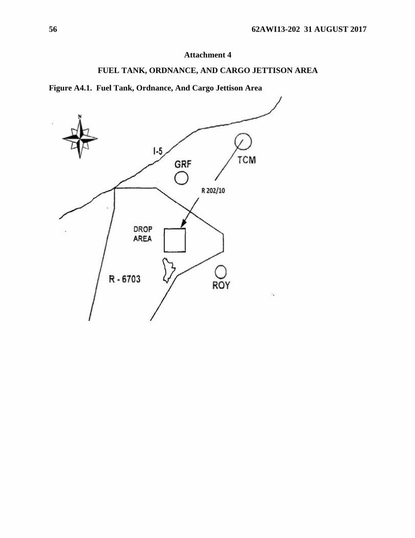
56 62AWI13-202 31 AUGUST 2017
Attachment 4
FUEL TANK, ORDNANCE, AND CARGO JETTISON AREA
Figure A4.1. Fuel Tank, Ordnance, And Cargo Jettison Area

62AWI13-202 31 AUGUST 2017 57
Attachment 5
LOCAL AIRSPACE
Figure A5.1. Lost Airspace

58 62AWI13-202 31 AUGUST 2017
Attachment 6
SMOKEY LZ LIGHTING CONFIGURATION
Figure A6.1. Smokey LZ Lighting Configuration
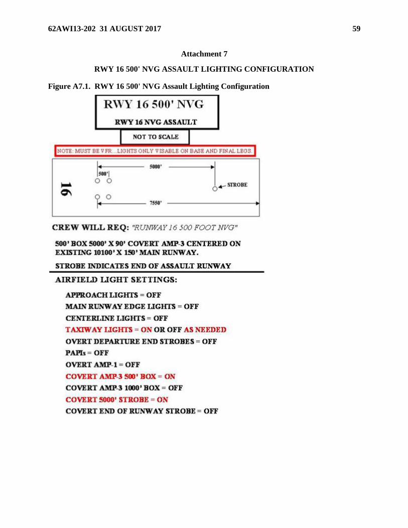
62AWI13-202 31 AUGUST 2017 59
Attachment 7
RWY 16 500' NVG ASSAULT LIGHTING CONFIGURATION
Figure A7.1. RWY 16 500' NVG Assault Lighting Configuration

60 62AWI13-202 31 AUGUST 2017
Attachment 8
RWY 34 500' NVG ASSAULT LIGHTING CONFIGURATION
Figure A8.1. RWY 34 500' NVG Assault Lighting Configuration

62AWI13-202 31 AUGUST 2017 61
Attachment 9
RWY 16 1000' NVG LIGHTING CONFIGURATION
Figure A9.1. RWY 16 1000' NVG Lighting Configuration

62 62AWI13-202 31 AUGUST 2017
Attachment 10
RWY 34 1000' NVG LIGHTING CONFIGURATION
Figure A10.1. RWY 34 1000' NVG Lighting Configuration

62AWI13-202 31 AUGUST 2017 63
Attachment 11
C-17 WINGTIP REFERENCE LINES
Figure A11.1. C-17 Wingtip Reference Lines