2755-837, AdaptaScan Bar Code Readers User Manual
96
User Manual AdaptaScan Bar Code Readers (Cat. No. 2755-SN3,-SN5, -SN8) Allen-Bradley
-
Upload
khangminh22 -
Category
Documents
-
view
3 -
download
0
Transcript of 2755-837, AdaptaScan Bar Code Readers User Manual

UserManual
AdaptaScanBar Code Readers
(Cat. No. 2755-SN3,-SN5, -SN8)
Allen-Bradley

Solid state equipment has operational characteristics differing from those ofelectromechanical equipment. “Safety Guidelines for the Application,Installation and Maintenance of Solid State Controls” (Publication SGI-1.1)describes some important differences between solid state equipment andhard–wired electromechanical devices. Because of this difference, and alsobecause of the wide variety of uses for solid state equipment, all personsresponsible for applying this equipment must satisfy themselves that eachintended application of this equipment is acceptable.
In no event will the Allen-Bradley Company be responsible or liable forindirect or consequential damages resulting from the use or application ofthis equipment.
The examples and diagrams in this manual are included solely for illustrativepurposes. Because of the many variables and requirements associated withany particular installation, the Allen-Bradley Company cannot assumeresponsibility or liability for actual use based on the examples and diagrams.
No patent liability is assumed by Allen-Bradley Company with respect to useof information, circuits, equipment, or software described in this manual.
Reproduction of the contents of this manual, in whole or in part, withoutwritten permission of the Allen-Bradley Company is prohibited.
Throughout this manual we use notes to make you aware of safetyconsiderations.
!ATTENTION: Identifies information about practices orcircumstances that can lead to personal injury or death, propertydamage, or economic loss.
Attentions help you:
• identify a hazard• avoid the hazard• recognize the consequences
Important: Identifies information that is especially important for successfulapplication and understanding of the product.
AdaptaScan is a trademark of Allen-Bradley Company, Inc.Microsoft and MS-DOS are registered trademarks, and Windows is a trademark of Microsoft Corporation.
Important User Information

����� � �����
i
Preface
Chapter Objectives P–1. . . . . . . . . . . . . . . . . . . . . . . . . . . . . . . . . . . . . . . . . . Overview of this Manual P–1. . . . . . . . . . . . . . . . . . . . . . . . . . . . . . . . . . . . . . . Intended Audience P–2. . . . . . . . . . . . . . . . . . . . . . . . . . . . . . . . . . . . . . . . . . . Terminology P–2. . . . . . . . . . . . . . . . . . . . . . . . . . . . . . . . . . . . . . . . . . . . . . . CE Directives P–2. . . . . . . . . . . . . . . . . . . . . . . . . . . . . . . . . . . . . . . . . . . . . . Related Publications P–2. . . . . . . . . . . . . . . . . . . . . . . . . . . . . . . . . . . . . . . . . Technical Support P–2. . . . . . . . . . . . . . . . . . . . . . . . . . . . . . . . . . . . . . . . . . .
Chapter 1
Chapter Objectives 1–1. . . . . . . . . . . . . . . . . . . . . . . . . . . . . . . . . . . . . . . . . . . Series B Changes 1–1. . . . . . . . . . . . . . . . . . . . . . . . . . . . . . . . . . . . . . . . . . . . Typical System 1–2. . . . . . . . . . . . . . . . . . . . . . . . . . . . . . . . . . . . . . . . . . . . . . Reader 1–3. . . . . . . . . . . . . . . . . . . . . . . . . . . . . . . . . . . . . . . . . . . . . . . . . . . .
Scan Window 1–3. . . . . . . . . . . . . . . . . . . . . . . . . . . . . . . . . . . . . . . . . . . . . . Configuration Port Connector 1–3. . . . . . . . . . . . . . . . . . . . . . . . . . . . . . . . . . . LED Indicators 1–4. . . . . . . . . . . . . . . . . . . . . . . . . . . . . . . . . . . . . . . . . . . . . . Wiring Base Connector 1–4. . . . . . . . . . . . . . . . . . . . . . . . . . . . . . . . . . . . . . . Operating Environment 1–4. . . . . . . . . . . . . . . . . . . . . . . . . . . . . . . . . . . . . . .
Typical Applications 1–5. . . . . . . . . . . . . . . . . . . . . . . . . . . . . . . . . . . . . . . . . . . Standalone 1–5. . . . . . . . . . . . . . . . . . . . . . . . . . . . . . . . . . . . . . . . . . . . . . . . Distributed (Master-Slave, DH-485) 1–6. . . . . . . . . . . . . . . . . . . . . . . . . . . . . . . Distributed (Peer-to-Peer) 1–7. . . . . . . . . . . . . . . . . . . . . . . . . . . . . . . . . . . . . .
Scanning Modes 1–8. . . . . . . . . . . . . . . . . . . . . . . . . . . . . . . . . . . . . . . . . . . . Linear Mode 1–8. . . . . . . . . . . . . . . . . . . . . . . . . . . . . . . . . . . . . . . . . . . . . Raster Mode 1–8. . . . . . . . . . . . . . . . . . . . . . . . . . . . . . . . . . . . . . . . . . . . .
Wiring Base 1–9. . . . . . . . . . . . . . . . . . . . . . . . . . . . . . . . . . . . . . . . . . . . . . . DeviceNet/Power Terminal Blocks 1–9. . . . . . . . . . . . . . . . . . . . . . . . . . . . . . RS-232 Terminal Block 1–9. . . . . . . . . . . . . . . . . . . . . . . . . . . . . . . . . . . . . . RS-422 / RS-485 Terminal Block 1–9. . . . . . . . . . . . . . . . . . . . . . . . . . . . . . . Reader Connector 1–10. . . . . . . . . . . . . . . . . . . . . . . . . . . . . . . . . . . . . . . . . I/O Module Sockets 1–10. . . . . . . . . . . . . . . . . . . . . . . . . . . . . . . . . . . . . . . . I/O Module Terminal Blocks 1–10. . . . . . . . . . . . . . . . . . . . . . . . . . . . . . . . . . Package Detect Terminal Block 1–10. . . . . . . . . . . . . . . . . . . . . . . . . . . . . . . . Power – Indicator LED 1–10. . . . . . . . . . . . . . . . . . . . . . . . . . . . . . . . . . . . . . Termination Switches 1–10. . . . . . . . . . . . . . . . . . . . . . . . . . . . . . . . . . . . . . .
Communication Options 1–11. . . . . . . . . . . . . . . . . . . . . . . . . . . . . . . . . . . . . . . DeviceNet Network 1–11. . . . . . . . . . . . . . . . . . . . . . . . . . . . . . . . . . . . . . . . RS-422 / RS-485 1–12. . . . . . . . . . . . . . . . . . . . . . . . . . . . . . . . . . . . . . . . . . RS-232 1–13. . . . . . . . . . . . . . . . . . . . . . . . . . . . . . . . . . . . . . . . . . . . . . . . . Protocols 1–13. . . . . . . . . . . . . . . . . . . . . . . . . . . . . . . . . . . . . . . . . . . . . . .
Using this Manual
Overview

Table of Contents
ii
AdaptaScan Software (Catalog No. 2755-ASN) 1–14. . . . . . . . . . . . . . . . . . . . . . Scanning Parameters 1–15. . . . . . . . . . . . . . . . . . . . . . . . . . . . . . . . . . . . . . . Focus Options 1–15. . . . . . . . . . . . . . . . . . . . . . . . . . . . . . . . . . . . . . . . . . . . Decoding Operations 1–16. . . . . . . . . . . . . . . . . . . . . . . . . . . . . . . . . . . . . . . System Monitoring 1–16. . . . . . . . . . . . . . . . . . . . . . . . . . . . . . . . . . . . . . . . . Online Adjustments 1–16. . . . . . . . . . . . . . . . . . . . . . . . . . . . . . . . . . . . . . . .
Safety Labels 1–17. . . . . . . . . . . . . . . . . . . . . . . . . . . . . . . . . . . . . . . . . . . . . . Ordering Information 1–18. . . . . . . . . . . . . . . . . . . . . . . . . . . . . . . . . . . . . . . . .
Chapter 2
Chapter Objectives 2–1. . . . . . . . . . . . . . . . . . . . . . . . . . . . . . . . . . . . . . . . . . Orientation Factors 2–1. . . . . . . . . . . . . . . . . . . . . . . . . . . . . . . . . . . . . . . . . . Reader Scan Beam 2–1. . . . . . . . . . . . . . . . . . . . . . . . . . . . . . . . . . . . . . . . . . Picket Fence or Step Ladder Orientation 2–2. . . . . . . . . . . . . . . . . . . . . . . . . . . Skew, Pitch and Tilt 2–3. . . . . . . . . . . . . . . . . . . . . . . . . . . . . . . . . . . . . . . . . . Recommended Skew Angle 2–3. . . . . . . . . . . . . . . . . . . . . . . . . . . . . . . . . . . . Usable Beam Width 2–4. . . . . . . . . . . . . . . . . . . . . . . . . . . . . . . . . . . . . . . . . .
Usable Beam Width (Catalog No. 2755-SN3) 2–4. . . . . . . . . . . . . . . . . . . . . . Usable Beam Width (Catalog No. 2755-SN5) 2–5. . . . . . . . . . . . . . . . . . . . . . Usable Beam Width (Catalog No. 2755-SN8) 2–5. . . . . . . . . . . . . . . . . . . . . .
Apparent Element Width 2–6. . . . . . . . . . . . . . . . . . . . . . . . . . . . . . . . . . . . . . . Reader Adjustments 2–7. . . . . . . . . . . . . . . . . . . . . . . . . . . . . . . . . . . . . . . . . Read Ranges 2–8. . . . . . . . . . . . . . . . . . . . . . . . . . . . . . . . . . . . . . . . . . . . . .
Chapter 3
Chapter Objectives 3–1. . . . . . . . . . . . . . . . . . . . . . . . . . . . . . . . . . . . . . . . . . General Mounting Guidelines 3–1. . . . . . . . . . . . . . . . . . . . . . . . . . . . . . . . . . . Dimensions and Clearances 3–2. . . . . . . . . . . . . . . . . . . . . . . . . . . . . . . . . . . .
Reader 3–2. . . . . . . . . . . . . . . . . . . . . . . . . . . . . . . . . . . . . . . . . . . . . . . . . Wiring Base 3–3. . . . . . . . . . . . . . . . . . . . . . . . . . . . . . . . . . . . . . . . . . . . . Reader / Base Assembly 3–3. . . . . . . . . . . . . . . . . . . . . . . . . . . . . . . . . . . .
Mounting the Wiring Base 3–4. . . . . . . . . . . . . . . . . . . . . . . . . . . . . . . . . . . . . . Top Mounting 3–4. . . . . . . . . . . . . . . . . . . . . . . . . . . . . . . . . . . . . . . . . . . . Bottom Mounting 3–5. . . . . . . . . . . . . . . . . . . . . . . . . . . . . . . . . . . . . . . . . . Wiring Base Dust Cover 3–5. . . . . . . . . . . . . . . . . . . . . . . . . . . . . . . . . . . . .
Conduit and Cable Connections 3–6. . . . . . . . . . . . . . . . . . . . . . . . . . . . . . . . . Cabling 3–6. . . . . . . . . . . . . . . . . . . . . . . . . . . . . . . . . . . . . . . . . . . . . . . . . Conduit 3–7. . . . . . . . . . . . . . . . . . . . . . . . . . . . . . . . . . . . . . . . . . . . . . . . . Hole Plugs 3–7. . . . . . . . . . . . . . . . . . . . . . . . . . . . . . . . . . . . . . . . . . . . . .
Mounting Bracket 3–8. . . . . . . . . . . . . . . . . . . . . . . . . . . . . . . . . . . . . . . . . . . . Installing the Mounting Bracket 3–8. . . . . . . . . . . . . . . . . . . . . . . . . . . . . . . . Top Post Mounting 3–9. . . . . . . . . . . . . . . . . . . . . . . . . . . . . . . . . . . . . . . . . Side Post Mounting 3–10. . . . . . . . . . . . . . . . . . . . . . . . . . . . . . . . . . . . . . . . Installing the Safety Wire 3–11. . . . . . . . . . . . . . . . . . . . . . . . . . . . . . . . . . . .
Installation Considerations
Installing the Wiring Baseand Power Supply

Table of Contents
iii
Power Requirements 3–12. . . . . . . . . . . . . . . . . . . . . . . . . . . . . . . . . . . . . . . . . Power Supplies 3–12. . . . . . . . . . . . . . . . . . . . . . . . . . . . . . . . . . . . . . . . . . . . .
Catalog No. 2755-PW46 Power Supply 3–13. . . . . . . . . . . . . . . . . . . . . . . . . . Catalog No. 2755-PW47 Power Supply 3–13. . . . . . . . . . . . . . . . . . . . . . . . . .
Power Connections 3–14. . . . . . . . . . . . . . . . . . . . . . . . . . . . . . . . . . . . . . . . . . Single Reader Power Connection 3–14. . . . . . . . . . . . . . . . . . . . . . . . . . . . . . Multiple Reader Connections using 2755-PW46/-PW47 Supply 3–14. . . . . . . . . Multiple Reader Connections using Other Power Supply 3–15. . . . . . . . . . . . . .
DeviceNet Connections 3–16. . . . . . . . . . . . . . . . . . . . . . . . . . . . . . . . . . . . . . . RS-485/RS-422 Connections 3–17. . . . . . . . . . . . . . . . . . . . . . . . . . . . . . . . . . .
Network or Point-to-Point 3–17. . . . . . . . . . . . . . . . . . . . . . . . . . . . . . . . . . . . Line Termination 3–17. . . . . . . . . . . . . . . . . . . . . . . . . . . . . . . . . . . . . . . . . .
RS-232 Connections 3–18. . . . . . . . . . . . . . . . . . . . . . . . . . . . . . . . . . . . . . . . . I/O Modules and Wiring 3–19. . . . . . . . . . . . . . . . . . . . . . . . . . . . . . . . . . . . . . .
Output Module Application 3–20. . . . . . . . . . . . . . . . . . . . . . . . . . . . . . . . . . . Input Module Application 3–21. . . . . . . . . . . . . . . . . . . . . . . . . . . . . . . . . . . . Package Detector 3–22. . . . . . . . . . . . . . . . . . . . . . . . . . . . . . . . . . . . . . . . .
Chapter 4
Chapter Objectives 4–1. . . . . . . . . . . . . . . . . . . . . . . . . . . . . . . . . . . . . . . . . . Installation 4–1. . . . . . . . . . . . . . . . . . . . . . . . . . . . . . . . . . . . . . . . . . . . . . . . Power-up Sequence 4–2. . . . . . . . . . . . . . . . . . . . . . . . . . . . . . . . . . . . . . . . . Checking Reader Operation 4–2. . . . . . . . . . . . . . . . . . . . . . . . . . . . . . . . . . . . Replacing a Reader 4–3. . . . . . . . . . . . . . . . . . . . . . . . . . . . . . . . . . . . . . . . . .
Chapter 5
Chapter Objectives 5–1. . . . . . . . . . . . . . . . . . . . . . . . . . . . . . . . . . . . . . . . . . Connecting a Personal Computer 5–1. . . . . . . . . . . . . . . . . . . . . . . . . . . . . . . . Downloading Firmware 5–2. . . . . . . . . . . . . . . . . . . . . . . . . . . . . . . . . . . . . . . . Downloading a Configuration 5–3. . . . . . . . . . . . . . . . . . . . . . . . . . . . . . . . . . .
Chapter 6
Chapter Objectives 6–1. . . . . . . . . . . . . . . . . . . . . . . . . . . . . . . . . . . . . . . . . . Technical Support 6–1. . . . . . . . . . . . . . . . . . . . . . . . . . . . . . . . . . . . . . . . . . . Equipment Required 6–1. . . . . . . . . . . . . . . . . . . . . . . . . . . . . . . . . . . . . . . . . Using the Troubleshooting Chart 6–1. . . . . . . . . . . . . . . . . . . . . . . . . . . . . . . . . Troubleshooting Chart 6–2. . . . . . . . . . . . . . . . . . . . . . . . . . . . . . . . . . . . . . . . LED Indicators 6–3. . . . . . . . . . . . . . . . . . . . . . . . . . . . . . . . . . . . . . . . . . . . . . Cleaning Scan Window 6–5. . . . . . . . . . . . . . . . . . . . . . . . . . . . . . . . . . . . . . . Replacing Scan Window 6–6. . . . . . . . . . . . . . . . . . . . . . . . . . . . . . . . . . . . . . .
Installing /Removing the Reader
DownloadingConfigurations
Troubleshooting and Maintenance

Table of Contents
iv
Appendix A
Electrical A–1. . . . . . . . . . . . . . . . . . . . . . . . . . . . . . . . . . . . . . . . . . . . . . . . . . Mechanical A–1. . . . . . . . . . . . . . . . . . . . . . . . . . . . . . . . . . . . . . . . . . . . . . . . Environment A–1. . . . . . . . . . . . . . . . . . . . . . . . . . . . . . . . . . . . . . . . . . . . . . . Optical A–2. . . . . . . . . . . . . . . . . . . . . . . . . . . . . . . . . . . . . . . . . . . . . . . . . . . Output Modules A–2. . . . . . . . . . . . . . . . . . . . . . . . . . . . . . . . . . . . . . . . . . . . . Input Modules A–2. . . . . . . . . . . . . . . . . . . . . . . . . . . . . . . . . . . . . . . . . . . . . .
Appendix B
Appendix C
Glossary
Index
Specifications
DIN Rail MountTerminal BlocksEuropean Union DirectiveCompliance

Preface
��� ��� �����
Read this chapter to familiarize yourself with the rest of the manual. You will learn about:
• Contents of this manual
• Intended audience
• Terminology
• CE Directives
• Related publications
The following table describes the contents of each chapter in thismanual.
Chapter Title Purpose
Preface Provides an overview of the manual.
1 OverviewDescribes the main features andoperating capabilities of the AdaptaScanReader.
2 Installation Considerations Describes the factors that determine theoptimum placement of the Reader.
3 Installing the Wiring Base and Power Supply
Describes how to mount and wire theReader wiring base.
4 Installing / Removing the Reader
Describes installation and initial powerupof the Reader. Instructions on how toremove a Reader are also provided.
5 Downloading Configurations Describes how to download firmware andReader configurations.
6 Troubleshooting andMaintenance
Provides assistance in identifying andcorrecting common operating problems.Procedures for routine maintenanceitems are also provided.
Chapter Objectives
Overview of this Manual

Using this ManualP1–2
Because the AdaptaScan Software runs in the Microsoft Windowsenvironment, you should know how to use a mouse, choosecommands, and work with windows and dialogs.
You should also have a basic understanding of PLC and SLCControllers.
Equipment installers must be familiar with standard wiringtechniques and terminology.
This manual contains some terms that may be unfamiliar. Use theglossary at the back of this manual for assistance.
The AdaptaScan Bar Code Readers (Catalog No. 2755-SN3, -SN5,-SN8) are referred to as Readers.
If the AdaptaScan Reader is installed within the European Union,Appendix C provides the legal requirements.
The following table lists other publications related to the AdaptaScanBar Code Reader.
Publication Number Description
2755-838 AdaptaScan Software User Manual
1485-6.7.1 DeviceNet Cable System Planning and Installation Manual
1770-6.2.2 Data Highway / Data Highway Plus / Data Highway-485 CableInstallation Manual
1787-6.5.3 DeviceNet Manager Software (Catalog No. 1787-MGR) User Manual
1749-6.5.5 DeviceNet Adapter Module (Catalog No. 1749-ADN) User Manual
1747-6.5.2 DeviceNet Scanner (Catalog No. 1747-SDN) Configuration Manual
1771-6.5.118 DeviceNet Scanner (Catalog No. 1771-SDN) Configuration Manual
If you should require assistance or need additional information onoperating the AdaptaScan Reader, Configuration Software, oraccessories, contact your local Allen-Bradley Support office orAllen-Bradley Technical Services at (216) 646-6800.
Terminology
CE Directives
Related Publications
Intended Audience
Technical Support

Chapter 1
��������
This chapter briefly describes the AdaptaScan Bar Code Reader.
Section Page
Typical System 1–2
Reader 1–3
Typical Applications 1–5
Scanning Modes 1–8
Wiring Base 1–9
Communication Options 1–11
AdaptaScan Software 1–14
Safety Labels 1–17
Options and Accessories 1–18
If you are familiar with the Series A Reader and/or are replacing aSeries A Reader, note the following changes in the Series B versions.
• New programming port connector, programming cable and dustcap.
• Soft-start power circuit reduces the current inrush when power issupplied. This allows more Readers to be powered using a singlesupply. The soft–start circuit also allows the use of currentlimited power supplies.
Programming CableCatalog No. 2755-NC48
Dust Cap
New Programming Connector
Important: The Series A Reader uses the 2755-NC43 programmingcable. This cable is not compatible with the Series B Reader.
Chapter Objectives
Series B Changes

Overview 1–2
A typical AdaptaScan installation consists of:
• Reader
• Wiring Base
• Package Detector
Configuration Cable
Personal Computer(For Configuration and Setup)
To Networkor Control Device
PackageDetector
Wiring Base
Reader
The Reader is configured using the AdaptaScan Software (CatalogNo. 2755-ASN) and configuration cable (Catalog No. 2755-NC48).One software package and configuration cable is required perinstallation.
Typical System

Overview 1–3
Scan Window
LED Indicators
ConfigurationPort Connector
Wiring BaseConnector
Dust Cap
The Reader scans and decodes bar code symbols. The integraldecoder decodes the most common bar code symbologies. The scanand decode functions are configured using software on a personalcomputer. Three scan speeds are available:
Catalog Num er can ateOptical Scan Angle➀
Catalog Number Scan RateMinimum Maximum
2755-SN3 300 22� 72�
2755-SN5 500 20� 50�
2755-SN8 800 18� 30�
➀ Usable scan angle is 80% of the optical scan angle.
Scan Window
The replaceable scan window allows laser light to exit the Reader.Light reflects off the bar code symbol, passes back through the scanwindow and is decoded by the Reader. The scan window can bereplaced with a glass or plastic window. See page 1–18 for detailson replacement window kits.
Configuration Port Connector
The RS-232 port allows a personal computer running theAdaptaScan Software (Catalog No. 2755-ASN) to download aconfiguration to one or more Readers.
The Configuration Port Connector is for temporary use duringconfiguration transfers and system setup.
Reader

Overview 1–4
LED Indicators
Seven LEDs provide the following indications.
Indicator Condition Indicates:
Green Normal operating state
Flashing Green Initialization and/or incorrect (unconfigured)configuration
Module Red Processor fault (nonrecoverable)ModuleFlashing Red Minor fault (recoverable). Occurs when down-
loading firmware.
Off No power applied to Reader
Green Normal DeviceNet operating state
Flashing Green Communication link established, but not datatransfer.
Netw rRed Communication fault
Network Flashing Red One or more DeviceNet devices are not re-sponding. Reader may not be able to performall configured functions.
Off DeviceNet communications not established
La erYellow Scan beam on
Laser OnOff Scan beam off
Yellow Scanning and decoding bar code symbol
On Symbol Flashing Bar code symbol read at less than 100% rateOn SymbolOff Not scanning bar code symbol
Yellow Package detected
Trigger / Read Green Valid readTrigger / ReadOff No trigger or no valid bar code symbol read
I/ 1Yellow Input/Output module 1 active
I/O 1Off Input/Output module 1 not active
I/ 2Yellow Input/Output module 2 active
I/O 2Off Input/Output module 2 not active
Wiring Base Connector
The 24-pin connector on the bottom of the Reader plugs into thesocket on the wiring base. No other connections to the Reader arerequired.
Operating Environment
The Reader operates under a variety of conditions.
• Cast aluminum enclosure meets NEMA Type 4 requirementswhen used with the wiring base.
• Operates in environments from 32 to 122�F (0 to 50�C).
• Mounts at any angle.
See Appendix A for a complete list of Reader specifications.

Overview 1–5
The flexibility of the Reader allows you to configure it for a varietyof applications. This section shows the basic system types.
Standalone
In a typical standalone setup, a single Reader scans bar codes on theside of a package moving down a conveyor.
➀
➁
➂
➃➄
The package crosses the beam between the package detector ➀ and
reflector ➁ . The Reader ➂ scans and decodes bar code symbols onthe package. You can configure the decoder with match table data.When decoded data is matched, the Reader turns on an outputmodule (in wiring base ➃ ) to control the operation of a diverter ➄
that directs the package to a location.
Typical Applications

Overview 1–6
Distributed (DeviceNet Master/Slave, DH-485)
The distributed application below shows three Readers scanning barcodes at different points in an assembly process. Data from anyReader is individually sent to a controller. The discrete I/O on eachReader provide distributed control independent of the PLCmonitoring the process.
➂
➁ Controller
➀
➃
Reader ➀ identifies major sub-assemblies for routing to the properfinal assembly area. Reader ➁ verifies the product code on theassembled product being shipped. Reader ➂ verifies that theshipping label matches the product code. PLC ➃ monitors theprocess.

Overview 1–7
Distributed (DeviceNet Peer-to-Peer)
Peer-to-Peer communications allows a single Reader to gather datafrom other Readers over a DeviceNet network. The Reader thentransfers the collected data to a host, such as a controller, over anRS-232 link.
➀
➁
➂
➃
➄
Readers ➀ through ➃ transfer data over a DeviceNet network toReader ➂ which collects the data and then transfers the data over anRS-232 link to the host ➄ .

Overview 1–8
You can configure a Reader as either a linear or raster scanner. Theorientation of the bar code label with the scanner usually determinesthe scanning mode appropriate for the application.
Linear Mode
Linear
Scan Line Elevationis adjustable.Scan Line Elevationis adjustable.
In the linear scan mode, the scan line elevation can be be adjusted.
Raster Mode
Raster
Upper and lower raster limits are adjustable.
Raster increment is adjust-able. Increment increases /decreases the number of scanlines in the raster pattern.
Flyback quickly returns thescan line to the upper rasterlimit after the lower limit isreached.
In raster scan mode, you can adjust or select:
• Upper and lower raster limits
Upper Raster Angle
Lower Raster Angle
• Raster increment
IncrementDecrease Increase
• Flyback enable
Flyback
Scanning Modes

Overview 1–9
The Reader plugs into a wiring base. All wiring base connectionsare made using common electrician tools. Install the Reader after thewiring base is installed to reduce the possibility of damage.
Wiring Base
Four conduit entrances
Reader
Sockets for 2 I/O Modules
Terminal Blocksfor I/O Modules
Package DetectTerminal Block
DeviceNet Communication and Power Terminal Blocks
RS-232 CommunicationTerminal Block
RS-422/RS-485CommunicationTerminal Block
Reader Connector Power Polarity – LED Indicator
CommunicationTermination Switches
DeviceNet/Power Terminal Blocks
The wiring base has 2 identical terminal blocks; one for incomingpower and communications, one for outgoing power andcommunications.
RS-232 Terminal Block
Connections for point-to-point communications with a personalcomputer or controller RS-232 port.
RS-422 / RS-485 Terminal Block
Connections for network or point-to-point communications withanother RS-422/RS-485 device or network.
Wiring Base

Overview 1–10
Reader Connector
The Reader plugs into this connector. All power andcommunications with the Reader occurs through this connector.
I/O Module Sockets
Two sockets support any combination of the following input andoutput modules. See specifications in Appendix A.
Description Catalog Number
DC Output Module – rated at 3 to 60 VDC. 2755-OB5S
AC Output Module – rated at 12 to 140 VAC. 2755-OA5S
AC Output Module – rated at 24 to 280 VAC. 2755-OM5S
DC Input Module – accepts 3.3 to 32 VDC. 2755-IB5S
AC/DC Input Module – accepts 90 to 140 VRMS or VDC 2755-IA5S
AC/DC Input Module – accepts 180 to 280 VRMS or VDC 2755-IM5S
I/O Module Terminal Blocks
Wiring connections for the optional input or output modules.
Package Detect Terminal Block
Connects the contacts of a sensor, which detects the presence of apackage in the Reader’s scan area. The package detect can be eitheran electronic (current sinking) or a hard contact type device. Mostapplications use a photo-reflective type sensor. The package detectstarts and stops decoding and determines when messages are sent orwhen outputs are energized.
Power – Indicator LED
Indicates normal operating and fault conditions.
Condition Indicates:
Green Power on.
Red Polarity of the power connections is reversed. Wiring must becorrected.
Off No power.
Termination Switches
Terminates a DeviceNet and RS-422/RS-485 network. Terminate thetwo devices furthest away from each other on a network by movingthe switch to the ON position.

Overview 1–11
This section defines the communication options for the Reader.
DeviceNet Network
AdaptaScan Readers support both DeviceNet Master/Slave andPeer-to-Peer protocols.
On a DeviceNet Master/Slave network, Readers and other DeviceNetslave devices communicate with a DeviceNet Scanner (Master). Upto 63 slave devices are allowed on a master/slave network.
On a DeviceNet peer-to-peer network, up to 32 Readers can beconnected together. These Readers can:
• work in a coordinated mode to read multiple bar code symbols ondifferent sides of the same package.
• combine data from several Readers to a single Reader thatcommunicates the data to a host.
• pass input and output status information between Readers.
Reader ReaderOther
PLC-5 with 1771-SDN (DeviceNet Scanner)
DeviceNet Devices
AdaptaScan Bar Code Readers operate on a DeviceNet network atthe following baud rates (Kbps = Kilobits per Second):
Baud Rate Supports Maximum Cable Length of:
125 Kbps 1640 feet (500 meters)
250 Kbps 656 feet (200 meters)
500 Kbps 328 feet (100 meters)
Communication Options

Overview 1–12
RS-422 / RS-485
An RS-422 / RS-485 port allows point-to-point communications witha single device. Through the RS-485 port, the AdaptaScan Readercan also communicate with a DH-485 network. Both master andslave modes are supported. As a master device, the Reader sendsdata directly to an SLC 5/03 or 5/04 processor’s data table; nopolling is required by the SLC. As a slave device, the Readerconnects to the Flexible Interface Module (Catalog No. 2760-RB) formulti-drop communications.
SLC 5/04
Link Coupler
DH485 DH485
Reader Reader
Note: You cannot use the RS-422/RS-485 port and the RS-232 portat the same time.

Overview 1–13
RS-232
The RS-232 port provides point-to-point communications with adevice having an RS-232 port, such as a PLC-5 Channel 0 port orcomputer.
RS-232
PLC-5
Channel 0(Configured for RS-232)
Reader
Protocols
The RS-485/RS-422 and RS-232 serial ports support these protocols.
Protocol Description
Allen-BradleyDF1
A peer-to-peer protocol that combines features of ANSI X3.28-1976specification subcategories D1 (data transparency) and F1 (two-waysimultaneous transmission with embedded responses).
Allen-BradleyDH485
A network protocol that allows DH485 devices (using the RS-485 stan-dard) to communicate on the Allen-Bradley DH485 link.
Terminal
Provides a simple interface to most serial devices. This is the least se-cure protocol since it does not confirm the delivery or accuracy of mes-sages. If security is required, we recommend that you use DF1 protocolwith Block Check Characters (BCC) and ACK/NAK handshaking.

Overview 1–14
The AdaptaScan Software (Catalog No. 2755-ASN), a WindowsTM
based package, lets you configure a Reader through a series ofmenus, tools and dialog boxes. Context sensitive help is available toassist with use of the software.
All Reader functions are configured from the Project dialog shownbelow, providing a single point of access for all operations.
The Project window has buttons for accessing these operations.
Select: To:
Define label setup and symbologies for Reader operation.
Define a unique name, node address, and description for the Reader.
Define scanning parameters and access the focus function.
Define the Reader trigger source for decoding and what symbols are de-coded. Also configures the intersymbol timer and performance indicator.
Define the operation for package detector, discrete inputs, discrete out-puts, timer and ASCII trigger commands.
Define communication parameters (RS-232, RS-422, RS-485) and proto-cols (ASCII, DH485, DF1) for the Reader’s communication ports.
Define match table, package and counter functions for decoded bar code data.
Define the format and content of bar code messages sent to the host bythe Reader.
Transfer configurations to all Readers on the same DeviceNet network.
Transfer a configuration to selected Reader.
Download new firmware to a Reader.
View the operation of a Reader.
Deletes the selected Bar Code Reader configuration from the Projectwindow.
Creates a new Bar Code Reader configuration (Bar Code Reader 1, BarCode Reader 2, Bar Code Reader 3, ...) in the Project window.
AdaptaScan Software(Catalog No. 2755-ASN)

Overview 1–15
Scanning Parameters
You can configure the Reader for linear or raster scanning. Setupdialogs determine when and how the laser scans a bar code symbol.
Raster Setup Linear Setup
Focus Options
The Reader has a variable focus distance. The software supportsmanual, preset, and focus options.
• ManualManual adjustment of the read range allows you to fine-tune thefocus setting for a maximum read percentage.
• PresetFour preset read ranges (A, B, C, C+) correspond approximatelyto bar code scanners (Catalog No. 2755-LD4, -LD8), allowing foreasy replacement of these scanners. See Chapter 2 for readranges.
• AutoFocusThe Reader scans for a label from the nearest to the farthest focaldistance. The number of reads at each distance is determined andthe focal distance is set halfway between the nearest and farthestfocal distance where 100% valid reads occur. The dialog showsthe autofocus function graphically.
Focus Setting

Overview 1–16
Decoding Operations
Menus and dialog boxes also define parameters that determine whenand how decoding occurs and the destination of the data.
System Monitoring
The software monitors a Reader on the network. Use this feature forinitial setup and adjustment.
Online Adjustments
Make online adjustments to one or more Readers on a DeviceNetnetwork using the Apply button which is available on specificdialogs. This allows fine tuning of an entire system from a singleconnection.

Overview 1–17
The Readers use a visible laser diode. As with any bright lightsource, such as the sun, you should avoid staring directly into thebeam. Momentary exposure to a CDRH Class II laser product is notknown to be harmful.
The following shows the location of all safety labels as they appear on the Reader.
!ATTENTION: Use of controls, adjustments, orprocedures other than those specified herein mayresult in hazardous laser light exposure.
Safety Labels

Overview 1–18
The following Readers are available.
Item Description Catalog No.
300 scans per second, raster/linear scan,VLD, scanner/decoder
2755-SN3➀
Reader500 scans per second, raster/linear scan,VLD, scanner/decoder
2755-SN5
800 scans per second, raster/linear scan,VLD, scanner/decoder
2755-SN8
➀ Contact Allen-Bradley for availability.
The following items are available. Each installation requires oneAdaptaScan Software package (Catalog No. 2755-ASN) and oneCommunication Cable (Catalog No. 2755-NC48).
Item Description Catalog No.
Wiring Bases
Reader wiring base:US versionMetric version
Each Reader requires one wiring base.
2755-NB402755-NB41
AdaptaScan SoftwareWindows based software used on a personalcomputer for creating configurations for AdaptaScan Bar Code Readers.
2755-ASN
Window Kits
Replacement scan window kit includes window - bezel - gasket assembly along withmounting screws and instructions.
Plastic window kitGlass window kit
2755-NW442755-NW45
Power Supplies
24 VDC power supply powers one Reader.
120 VAC Input, 60 Hz (US) – Wall mount240 VAC input, 50 Hz (European) – Desktop
2755-PW462755-PW47
Mounting Bracket KitMounting bracket attaches to the wiring baseand provides almost any combination of tilt,pitch and rotational positioning.
2755-NM42
Communication Cable
9 foot, 10 inch (3 meter) cable connects Read-er configuration port to a computer. Has a9-pin D shell connector for the computer’sRS-232 serial Com port.Note: The Series A Reader uses the2755-NC43 programming cable. This cable isnot compatible with the Series B Reader.
2755-NC48
I/O Modules Refer to page 1–10.
Ordering Information

Chapter 2
�� ���� � ������� ��
This chapter describes important factors that affect how theAdaptaScan Bar Code Reader is oriented in respect to package orcomponent labels.
Section Page
Orientation Factors 2–1
Reader Scan Beam 2–1
Picket Fence or Step Ladder Orientation 2–2
Skew, Pitch, and Tilt 2–3
Usable Beam Width 2–4
Apparent Element Width 2–6
Reader Adjustments 2–7
Read Ranges 2–8
Calculating Scans per Label 2–9
The mounting of the Reader for optimum performance depends on these factors.
• Read range
• Type of scanning
• Skew angle
The scan beam exits the scan window parallel to the base.
Scan Beam ExitsParallel to Base
Chapter Objectives
Orientation Factors
Reader Scan Beam

Installation Considerations 2–2
The Reader supports raster and linear scanning. The Reader can bemounted in either a step ladder or picket fence orientation withrespect to the bar code label. The type of scanning and theplacement of the bar code label usually determines the orientation.
Picket Fence Orientation Step Ladder Orientation
Reader MountedAbove Conveyor
Reader MountedOn Side of Conveyor
Reader MountedAbove Conveyor
Reader MountedOn Side of Conveyor
When the labels pass the Reader in a step ladder orienta-tion, a linear scan is preferred. The beam scans the labelas it passes. The number of scans per label dependsupon the label size, scan rate and the conveyor speed.
If a linear scanning Reader is aligned parallel with the long axis ofa picket fence label, the same strip of label is scanned repeatedly.Because of this, picket fence applications usually use a rasterscan.
Picket Fence orStep Ladder Orientation
Installation Considerations 2–3
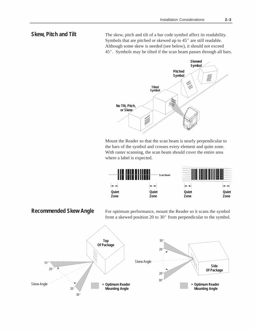
The skew, pitch and tilt of a bar code symbol affect its readability. Symbols that are pitched or skewed up to 45� are still readable.Although some skew is needed (see below), it should not exceed45�. Symbols may be tilted if the scan beam passes through all bars.
TiltedSymbol
SkewedSymbol
No Tilt, Pitch, or Skew
PitchedSymbol
Mount the Reader so that the scan beam is nearly perpendicular tothe bars of the symbol and crosses every element and quite zone.With raster scanning, the scan beam should cover the entire areawhere a label is expected.
QuietZone
QuietZone
QuietZone
QuietZone
Scan Beam
For optimum performance, mount the Reader so it scans the symbolfrom a skewed position 20 to 30� from perpendicular to the symbol.
Skew Angle
20�
20�= Optimum Reader
Mounting Angle
TopOf Package
SideOf Package
20�
= Optimum ReaderMounting Angle
30�
30�
20�
30�
Skew Angle
30�
Skew, Pitch and Tilt
Recommended Skew Angle

Installation Considerations 2–4
The usable beam width depends on the Reader type, the scan angleand the distance from the bar code symbol. Make sure that the scanbeam is wide enough for the area you are scanning. Increasing thescan angle setting (using configuration software) or moving theReader away from the symbol increases the beam width.
The usable beam width is approximately 80% of the total beamwidth. The end 10% on either side of the scan beam cannot decodebar code symbols.
Total Beam Width
Usable Beam Width
The following charts show the usable beam width for the defaultscan angle settings. We recommend that you use the default settingto determine the position of the Reader. This allows you to increaseor decrease the scan angle after installation.
Maximum Usable Beam Width (Catalog No. 2755-SN3) ➀
70 inches (1.78 meter)65 inches (1.65 meter)
60 inches (1.52 meter)
55 inches (1.40 meter)
45 inches (1.14 meter)
50 inches (1.27 meter)
40 inches (1.02 meter)
25 inches (.64 meter)
35 inches (.89 meter)
30 inches (.76 meter)
20 inches (.51 meter)
15 inches (.38 meter)
10 inches (.25 meter)
77.6 inches (1.97 meter)
72.1 inches (1.83 meter)
66.5 inches (1.69 meter)
61.0 inches (1.55 meter)
49.9 inches (1.27 meter)
55.4 inches (1.41 meter)
44.3 inches (1.12 meter)
27.7 inches (.70 meter)
38.8 inches (.98 meter)
33.2 inches (.84 meter)
22.2 inches (.56 meter)
16.6 inches (.42 meter)
11.1 inches (.28 meter)
At This Distance: Usable Beam Width Is:
Scan Angle = 72�58� = Default
➀ Contact your Allen-Bradley representative for availability.
Usable Beam Width

Installation Considerations 2–5
Maximum Usable Beam Width (Catalog No. 2755-SN5)
70 inches (1.78 meter)
65 inches (1.65 meter)
60 inches (1.52 meter)
55 inches (1.40 meter)
45 inches (1.14 meter)
50 inches (1.27 meter)
40 inches (1.02 meter)
25 inches (.64 meter)
35 inches (.89 meter)
30 inches (.76 meter)
20 inches (.51 meter)
15 inches (.38 meter)
10 inches (.25 meter)
At This Distance: Usable Beam Width Is:
Scan Angle = 50�40� = Default
51.0 inches (1.30 meter)47.3 inches (1.20 meter)
43.7 inches (1.11 meter)
40.0 inches (1.02 meter)
32.8 inches (.83 meter)
36.4 inches (.92 meter)
29.1 inches (.74 meter)
18.2 inches (.46 meter)
25.5 inches (.65 meter)
21.8 inches (.55 meter)
14.6 inches (.37 meter)
10.9 inches (.28 meter)
7.3 inches (.18 meter)
Maximum Usable Beam Width (Catalog No. 2755-SN8)
70 inches (1.78 meter)
65 inches (1.65 meter)
60 inches (1.52 meter)
55 inches (1.40 meter)
45 inches (1.14 meter)
50 inches (1.27 meter)
40 inches (1.02 meter)
25 inches (.64 meter)
35 inches (.89 meter)
30 inches (.76 meter)
20 inches (.51 meter)
15 inches (.38 meter)
10 inches (.25 meter)
At This Distance: Usable Beam Width Is:
Scan Angle = 30�24� = Default
29.8 inches (.76 meter)
27.6 inches (.70 meter)
25.5 inches (.65 meter)
23.4 inches (.59 meter)
19.1 inches (.48 meter)
21.2 inches (.54 meter)
17.0 inches (.43 meter)
10.6 inches (.27 meter)
14.9 inches (.38 meter)
12.8 inches (.32 meter)
8.5 inches (.22 meter)
6.4 inches (.16 meter)
4.2 inches (.11 meter)
Installation Considerations 2–6
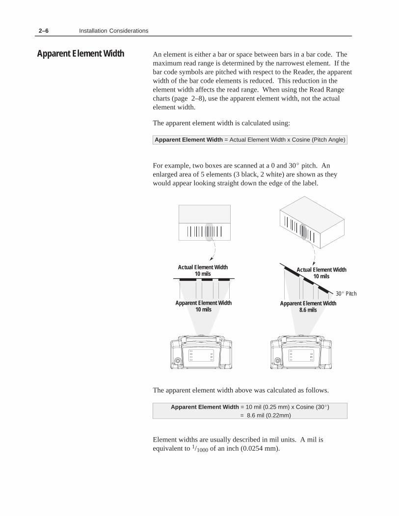
An element is either a bar or space between bars in a bar code. Themaximum read range is determined by the narrowest element. If thebar code symbols are pitched with respect to the Reader, the apparentwidth of the bar code elements is reduced. This reduction in theelement width affects the read range. When using the Read Rangecharts (page 2–8), use the apparent element width, not the actualelement width.
The apparent element width is calculated using:
Apparent Element Width = Actual Element Width x Cosine (Pitch Angle)
For example, two boxes are scanned at a 0 and 30� pitch. Anenlarged area of 5 elements (3 black, 2 white) are shown as theywould appear looking straight down the edge of the label.
Apparent Element Width10 mils
Apparent Element Width8.6 mils
30� Pitch
Actual Element Width10 mils
Actual Element Width10 mils
The apparent element width above was calculated as follows.
Apparent Element Width = 10 mil (0.25 mm) x Cosine (30�)= 8.6 mil (0.22mm)
Element widths are usually described in mil units. A mil isequivalent to 1/1000 of an inch (0.0254 mm).
Apparent Element Width

Installation Considerations 2–7
You can adjust the scan beam after the Reader is installed. Onlineadjustments can affect the width and location of the scan beam. Usethese adjustments to fine-tune an application, not to compensate forimproper installation. Chapter 6 describes how to make theseadjustments.
• Scan Angle adjusts the beam width.
Scanner Optical Scan Angles➀
2755-SN3 22� to 72� ➁
2755-SN5 20� to 50�
2755-SN8 18� to 30�➀ Usable scan angle is 80% of the optical scan angle.➁ Contact your Allen-Bradley representative for availability.
• Elevation (linear scanning only) adjusts the vertical angle atwhich the scan beam exits the Reader.
Elevation can be adjusted�10� from center line.
Center Line
3.6
inch
es(9
1 m
m)
• Upper and Lower Raster Angles (raster scanning only) adjuststhe highest and lowest raster angles. The range for each angle is10 to -10�. The lower raster angle must be equal to or less thanthe upper raster angle.
Lower Raster Angle �10� from center line.
Center Line
Upper Raster Angle �10� from center line.
Reader Adjustments

Installation Considerations 2–8
The following tables show tabular read range limits for the threeversions of the AdaptaScan Readers.
Table 2.A Read Ranges, Catalog No. 2755-SN3➀
Minimum Apparent Element Width➁ Read Range ➂
Mils mm Inches Meters
56
7.51013152025303540455055
.13
.15
.19
.25
.33
.38
.51
.64
.75
.891.021.141.271.40
1.9 - 3.61.9 - 5.31.4 - 7.21.4 - 10.91.4 - 16.21.4 - 19.51.4 - 28.41.4 - 36.81.9 - 42.91.9 - 51.41.9 - 59.32.4 - 64.42.9 - 69.43.4 - 74.6
.048 - .092
.048 - .135
.036 - .183
.036 - .277
.036 - .411
.036 - .495
.036 - .721
.036 - .935
.048 - 1.09
.048 - 1.31
.048 - 1.51
.061 - 1.64
.074 - 1.76
.086 - 1.89
Table 2.B Read Ranges Catalog No. 2755-SN5➀
Minimum Apparent Element Width➁ Read Range ➂
Mils mm Inches Meters
56
7.51013152025303540455055
.13
.15
.19
.25
.33
.38
.51
.64
.75
.891.021.141.271.40
1.9 - 4.71.9 - 7.31.9 - 8.91.4 - 14.01.4 - 19.51.9 - 21.81.9 - 29.72.4 - 36.22.4 - 42.52.4 - 51.53.4 - 56.93.9 - 61.94.4 - 67.95.4 - 71.6
.048 - .119
.048 - .185
.048 - .226
.036 - .356
.036 - .495
.048 - .554
.048 - .754
.061 - .919
.061 - 1.08
.061 - 1.31
.086 - 1.44
.099 - 1.57
.112 - 1.72
.137 - 1.82
Table 2.C Read Ranges Catalog No. 2755-SN8➀
Minimum Apparent Element Width ➁ Mils mm
Read Range ➂ Inches Meters
56
7.51013152025303540455055
.13
.15
.19
.25
.33
.38
.51
.64
.75
.891.021.141.271.40
1.4 - 5.71.4 - 8.21.4 - 10.71.4 - 16.01.4 - 21.01.9 - 25.42.4 - 34.33.4 - 42.25.4 - 50.26.4 - 55.67.4 - 62.18.4 - 65.4
10.4 - 69.011.4 - 72.5
.036 - .145
.036 - .208
.036 - .272
.036 - .406
.036 - .533
.048 - .645
.061 - .871
.086 - .107
.137 - 1.27
.163 - 1.41
.188 - 1.58
.213 - 1.66
.264 - 1.75
.290 - 1.84
Read Ranges
Read ranges based on four character Code39 labels with a wide to narrow bar ratio of2.6 to 1 and a print contrast ratio of .75 orbetter. Read ranges will vary with bar codesymbol quality.
When scanning labels at an angle apparentelement width is less than the actual elementwidth.
Read ranges measured from front edge ofwiring base. Add .58 inches (.015 meter) forthe distance to the scan window.
➀
➁
➂
Read RangeMeasured From This Point

Installation Considerations 2–9
Use the following formulas to calculate the number of scans perlabel and the minimum number of scans per second needed for anapplication. The minimum scan speed required is based on fivescans per label.
Picket Fence Orientation Step Ladder Orientation
Formulas
Scans per Label =
Minimum ScanSpeed Required =
(X-Y)Z A
A x HZ
Z x 5H
Z 5X-Yx
Where:A = Derated Scan Rate (Nominal Scan Rate –5%)
= 285 SPS for Catalog No. 2755-SN3 Readers= 475 SPS for Catalog No. 2755-SN5 Readers= 760 SPS for Catalog No. 2755-SN8 Readers
H = Height of bars in bar code. In inches ① .
X = Usable beam length at minimum read distance. In inches ① .
Y = Bar code length including quiet zones. Typically in inches ① .
Z = Label speed. In inches per second ① .
MINIMUM SCANS PER LABEL MUST BE � = 5.
① You can use other units of measure, such as meters, as long as allmeasurements use the same unit.
CalculatingScans per Label

Chapter 3
����� �� �� ����� ��� ���
���� ���� �
This chapter describes how to install and mount the wiring base.
Section Page
General Mounting Guidelines 3–1
Dimensions and Clearances 3–2
Mounting the Wiring Base 3–4
Conduit and Cable Connections 3–6
Mounting Bracket 3–8
Power Requirements 3–12
Power Supplies 3–12
Power Connections 3–14
DeviceNet Connections 3–16
RS-485/RS-422 Connections 3–17
RS-232 Connections 3–18
I/O Modules and Wiring 3–19
Package Detector 3–22
Before mounting the wiring base, determine the proper orientationand position as described in Chapter 2.
• Leave adequate clearances for wiring.
• The wiring base has four conduit openings. Seal unused conduitopenings with the 3 hole plugs provided with wiring base. Usecord grips with rubber grommets on cables that enter wiring base.Two different size grommets are provided with each cord grip.
• Route wires carefully to reduce or minimize electrical noise.When communication and power wiring must cross, make theirintersection perpendicular.
• Proper grounding of the wiring base limits the effects of noisedue to Electromagnetic Interference (EMI). The wiring base hasa ground screw for connecting cable shields and ground wires. Toavoid EMI problems, all cables must be shielded and grounded atone end. Grounding is also an important safety measure.
Wiring Base
Connect to Earth Ground
Chapter Objectives
General MountingGuidelines

Installing the Wiring Base and Power Supply 3–2
Make sure there is adequate space around the Reader for:
• Mounting and removing the Reader
• Wiring base connections
• Configuration cable
Reader
Front View
MidpointScanLine
Side View Back View
7.14 Inches(182 mm)
3.95 Inches(100 mm)
3.57 Inches(91 mm)
4.26 Inches(108 mm)
3.91 Inches(99 mm)
.35 Inches(9 mm)
Dimensions and Clearances

Installing the Wiring Base and Power Supply 3–3
Wiring Base
The wiring base is available in two versions:
• U.S. Version (Catalog No. 2755-NB40)
• Metric Version (Catalog No. 2755-NB41)
The dimensions are identical for both versions. Differences are inthe thread sizes of the conduit holes and the bottom mounting holes.
Front View End View
Bottom View
3.87 Inches(98 mm)
1.67 Inches(42 mm)
5.36 Inches(137 mm)
3.87 Inches(98 mm)
5.36 Inches(137 mm)
1.67 Inches(42 mm)
Reader / Base Assembly
Side ViewFront View
5.82 Inches(148 mm)
Read RangeMeasured From This Point
3.65 Inches(91 mm)
Scan Line at 0� Raster Angle

Installing the Wiring Base and Power Supply 3–4
There are 2 options for mounting the wiring base (Catalog No.2755-NB40 or -NB41):
• Top Mounting – Mount the base using 3 screws through the topmounting holes.
• Bottom Mounting – Mount the base using 3 screws through themounting surface into threaded holes on bottom of wiring base.
Top Mounting
The wiring base mounts from the top to any flat surface with three#10 or M5 mounting screws. The screw heads must be less than 3/8inch in diameter allowing them to fit inside the mounting hole. Thelength of the mounting screws must be 1/2 inch (12.5 mm) plus thedepth the screw penetrates the mounting surface.
Note: The 3 screws provided with the wiring base are suitable foruse with the mounting bracket (Catalog No. 2755-NM42).
ÎÎÎÎÎÎÎÎÎÎÎÎÎÎÎÎÎÎÎÎÎÎÎÎÎÎÎÎÎÎÎÎÎÎÎÎÎÎÎÎÎÎÎÎÎÎÎÎÎÎÎÎÎÎÎÎÎÎÎÎÎÎÎÎÎÎÎÎÎÎÎÎ
ÎÎÎÎÎÎÎÎÎÎÎÎÎÎÎÎÎÎÎÎÎÎÎÎÎÎÎÎÎÎÎÎÎÎÎÎÎÎÎÎÎÎÎÎÎÎÎÎÎÎÎÎÎÎÎÎÎÎÎÎÎÎÎÎÎÎÎÎÎÎÎÎ
ÎÎ
Î
A full size mounting template is provided with the wiring base. Usethe following diagram for reference.
Top Mounting Holes
Scan Beam
3 Holes
4.46 Inches(113 mm)
2.65 Inches(67 mm)
2.79 Inches(71 mm)
Mounting the Wiring Base

Installing the Wiring Base and Power Supply 3–5
Bottom MountingThe wiring base mounts from the bottom to any flat surface withthree mounting screws. The holes on the U.S. version have #10-32UNF-2B threads. The holes on the metric version have M5 x .8threads. The length of the screws must not be greater than 1/2 inch(12.5 mm) plus the thickness of the mounting surface.
ÎÎÎÎÎÎÎÎÎÎÎÎÎÎÎÎÎÎÎÎÎÎÎÎÎÎÎÎÎÎÎÎÎÎÎÎÎÎÎÎÎÎÎÎÎÎÎÎÎÎÎÎÎÎÎÎÎÎÎÎ
ÎÎÎÎÎÎÎÎÎÎÎÎÎÎÎÎÎÎÎÎÎÎÎÎÎÎÎÎÎÎÎÎÎÎÎÎÎÎÎÎÎÎÎÎÎÎÎÎÎÎÎÎÎÎÎÎÎÎÎÎÎÎ
ÎÎ
Wiring Base HasThree ThreadedMountng Holes
A full size mounting template is provided with the wiring base. Usethe following diagram for reference.
4.46 Inches(113 mm)
2.65 Inches(67 mm)
2.79 Inches(71 mm)
ÁÁ
ÁÁScan Beam
3 Holes.6 inch (15 mm) deep
Thread Size of Holes
#10-32 UNF-2BM5 x .8
U.S.Metric
Wiring Base Dust CoverTo prevent debris from entering the wiring base when a Reader is notinstalled, slip the dust cover over the base. The dust cover is held inplace by the stretch fit over the wiring base.
!ATTENTION: The wiring base dust cover is not forpermanent installation. The dust cover temporarilyprotects the wiring base until the Reader is installed.

Installing the Wiring Base and Power Supply 3–6
All permanent Reader connections are made to the wiring base.Wiring connections are made with conduit or cables. The conduitopenings in the wiring base are different for the U.S. and metricversions. The U.S. version (Catalog No. 2755-NB40) has 1/2-14NPSC threads, the metric version (Catalog No. 2755-NB41) hasPG13.5-18 threads. See the chart below for recommended wire andcable types.
Connection Recommended
Power ➀ Shielded Belden 9316
I/O Depends upon module rating. Refer to Appendix A
RS-485 Use Belden 9842
RS-422 Use Belden 9830
RS-232 Use Belden 8303 or Alpha 45123
DeviceNet Use Allen-Bradley Catalog No. 1485C-P1A50, -P1A150 or-P1A300
(50, 150 or 300 meter cable)
Package Detect #22 AWG minimum➀ DeviceNet cable contains wiring for power connections
Cabling
Where the cable enters the wiring base, use the supplied cord gripswith rubber grommets. Each cord grip comes with 2 different sizegrommets.
• Cord grips with small diameter grommet accommodate wirediameters 0.191 to 0.354 inches (4.9 to 9.0 mm).
• Cord grips with large diameter grommet accommodates wirediameters 0.236 to 0.472 inches (6.0 to 12.0 mm).
You can obtain additional cord grips from most electrical supplyoutlets. Make sure you use Teflon tape or other type of threadsealant to maintain a NEMA Type 4 rating.
Cable
Grommet
Nut
Threaded Bushing
Hole Plug(U.S. )
Hole Plug(Metric )
Cord Grip
Conduit and CableConnections

Installing the Wiring Base and Power Supply 3–7
Conduit
Use flexible conduit whenever possible. This allows you to adjustthe position of the Reader (when mounting bracket is used).
Conduit Fitting
Conduit
Wires
Hole Plug(U.S. )
Hole Plug(Metric )
User Supplied
Hole Plugs
Three hole plugs are supplied with the wiring base. Use these plugson unused conduit openings to maintain the NEMA Type 4 rating.
U.S. Wiring Base (Catalog No. 2755-NB40)
The conduit opening for the U.S. wiring base uses a NPSC threadedplug. Use Teflon tape or other thread sealant when inserting the holeplug in the conduit opening to maintain a NEMA Type 4 seal.Tighten hole plug with a 3/8” hex wrench.
Metric Wiring Base (Catalog No. 2755-NB41)
The conduit opening for the metric version requires an O-ring withthe hole plug. Place the O-ring on the hole plug, then insert the holeplug in the conduit opening and tighten with a flat blade screwdriver.

Installing the Wiring Base and Power Supply 3–8
The mounting bracket kit (Catalog No. 2755-NM42) is suitable for avariety of applications. This bracket allows you to mount the Readerat just about any angle or degree of rotation.
Kit Contents
The mounting bracket kit contains:
• Adjustable mounting bracket
• Mounting plate
• Safety wire
• Two hex socket screws
• Hex bolt
!ATTENTION: Install the safety wire when thebracket is mounted in an inverted position. If thebracket is mounted inverted and the locking knob isloosened, the Reader could release from the bracketand cause personal injury or damage to the Reader.
Installing the Mounting Bracket
The mounting bracket is attached to a mounting surface using threescrews (1/4 inch or M6).
ÉÉÉÉÉÉÉÉÉÉÉÉÉÉÉÉÉÉ
Mounting Surface
The mounting holes for the bracket consist of 3 holes spaced 120�
apart on a 4 5/16 inch (109.54 mm) diameter pattern.
120� 120�
4-5/16 inch (109.54 mm) Diameter Bolt Pattern
3 Bolt Holes120� Apart
Mounting Bracket

Installing the Wiring Base and Power Supply 3–9
Top Post Mounting
The mounting plate attaches to the bottom of the wiring base withthree screws (see next page). The mounting bracket post is threadedinto the hole at the center of the mounting plate. Lock the mountingpost in position by tightening the locking knob. For additionalsecurity, you can remove the locking knob and replace it with the hexbolt provided. The two hex socket screws are not used in thisconfiguration.
Mounting Plate to Reader Screws
Mounting Plate
Mounting Post
Adjustable Mounting Bracket
(Hardware Provided with Base)
Bracket Locking Knob orBolt (5/16 x 1 inch)
See Side Mounting Illustration Next PageScrews Into Mounting Plate
Adjustable Mounting Bracket
Wiring Base
3 Mounting Holes

Installing the Wiring Base and Power Supply 3–10
Side Post Mounting
The mounting plate attaches to the bottom of the wiring base withthree screws that are provided with the base. The mounting bracketpost (flat side) attaches to the mounting plate with two hex socketscrews. Five sets of 2 holes allow the bracket post to attach to thefront, back or either side of the mounting plate. Lock the mountingpost in position by tightening the locking knob. For additionalsecurity, you can remove the locking knob and replace it with the hexbolt provided.
Mounting Plate to Reader Screws
Mounting Plate
Mounting Post to Mounting Plate Screws
Adjustable Mounting Bracket
(1/4 – 20 x .5 Hex Socket)
Bracket Locking Knob orBolt (5/16 x 1 inch)
3 Mounting Holes(9 /32 inch diameter)
Use 3/16 inch Hex Wrench
Screws Provided Catalog No.(3) #10-32 x 1/2 Inch 2755-NB40(3) M5 -.8 x 16mm 2755-NB41

Installing the Wiring Base and Power Supply 3–11
Installing the Safety Wire
Install the safety wire whenever the mounting bracket is installed inan inverted position. The safety wire prevents the Reader fromdropping to the floor when the bracket locking knob is loosened.
Attaches toMounting Plate Screw
Loosen Locking Knobto Remove Clamping Nut
Safety Wire
Clamping Nut
Place one end of the safety wire under a mounting bracket clampingnut. With the bracket locking knob loosened, the clamping nut canbe removed by hand. The other end of the safety wire is attached tothe Reader using one of the screws that secure the mounting plate toReader wiring base.

Installing the Wiring Base and Power Supply 3–12
The Reader requires 14 watts (maximum) of power. The Readeraccepts 11 to 28 VDC at either one of the two DeviceNet terminalblocks (terminals 1 & 5), even if DeviceNet is not used.
11-28 VDC+
V-
From Power Supply
Reverse PolarityIndicator
Connect to Earth Ground
V-
11-28 VDC+
The reverse polarity LED (top illustration) is Green when power isproperly connected. If this LED is Red, the power + and –connections are reversed. You must correct a reverse polaritycondition before installing the Reader.
Two power supplies are available for the AdaptaScan Reader.
• 120 VAC Power Supply (Catalog No. 2755-PW46 ) plugs directlyinto a standard wall electrical socket.
• 240 VAC Power Supply (Catalog No. 2755-PW47 ) supplied withan IEC 320 unterminated power cord.
Use one of these power supplies or another 11 to 28 VDC powersource when power is not provided by another device on aDeviceNet network.
!ATTENTION: Permanent damage to the Readercan be caused by: • Connecting the power supply to more than one
Reader. • Connecting power supplies in parallel.• Shorting out the power supply.
Power Requirements
Power Supplies

Installing the Wiring Base and Power Supply 3–13
Catalog No. 2755-PW46 Power Supply
The 120 VAC Power Supply (Catalog No. 2755-PW46) providespower to one AdaptaScan Bar Code Reader. It is not rated forindustrial environments and must be mounted in a clean, dry locationor a suitable enclosure. Connections to the power supply are made atthe 3 screw terminals.
2.75 Inches(70mm)
3.25 Inches(83 mm)
+ –
Catalog No. 2755-PW47 Power Supply
The 240 VAC power supply (Catalog No. 2755-PW47) providespower to one Reader. Included is a standard IEC 320 unterminatedpower cord. The PW47 supply is not rated for industrialenvironments and sets on a flat surface. Connections to the powersupply are made at the 3 screw terminals.
3 Inches(76 mm)
5.25 Inches(133)
+ –GND
1 2 3

Installing the Wiring Base and Power Supply 3–14
Single Reader Power Connection
Below is a single power supply (Catalog No. 2755-PW46, -PW47)providing power to a single Reader. Do not connect other DeviceNetpower supplies to the 2755-PW46 or -PW47 supply.
Use a shielded cable (Belden 9316 recommended) when makingpower connections.
Note: You must ground V- to Earth Ground at a single point,preferably as near the power supply as possible.
Reader
V-
24V+
Ground Screwon Wiring Base
Multiple Reader Connections using 2755-PW46/-PW47 Supply
In the following illustration, each Reader is powered by a separateCatalog No. 2755-PW46 or -PW47 power supply. The Catalog No.2755-PW46 is shown. Do not connect power supplies in parallel.
Use a shielded cable (Belden 9316 recommended) when makingpower connections.
Note: You must ground V- to Earth Ground at a single point on thepower supply link, preferably as near the power supply as possible.
Ensure that the V+ lines are not connected together and that the V–lines are connected together as shown on top of next page.
Power Connections
Installing the Wiring Base and Power Supply 3–15
Reader 2 Reader 3Reader 1
Other DeviceNetDevices
24V+V- 24V+V- 24V+V-Ground Screwon Wiring Base
Ground Screwon Wiring Base
Ground Screwon Wiring Base
Ground Screwon Wiring Base
Ground V- at One Place
See DeviceNet Cable System Planning and Installation Manual(Publication No. DN-6.7.1) for recommendations and accessories.
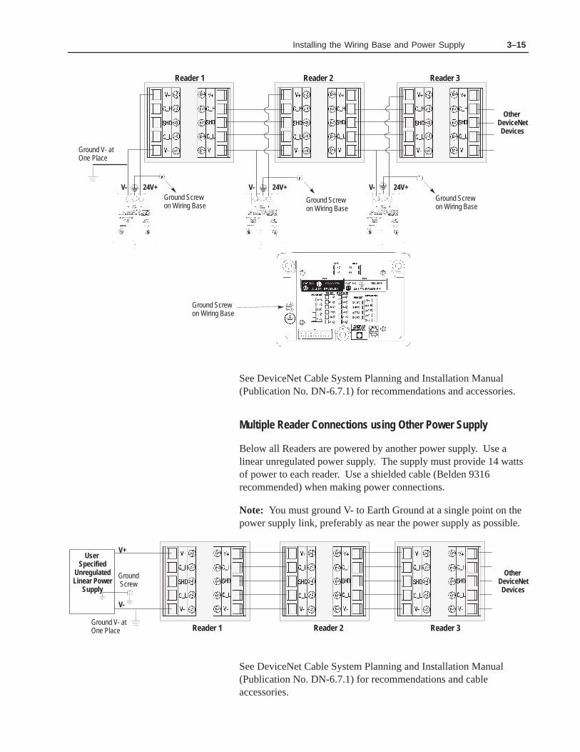
Multiple Reader Connections using Other Power Supply
Below all Readers are powered by another power supply. Use alinear unregulated power supply. The supply must provide 14 wattsof power to each reader. Use a shielded cable (Belden 9316recommended) when making power connections.
Note: You must ground V- to Earth Ground at a single point on thepower supply link, preferably as near the power supply as possible.
User Specified
UnregulatedLinear Power
Supply
Reader 2 Reader 3Reader 1
V-
V+
Other DeviceNetDevices
GroundScrew
Ground V- at One Place
See DeviceNet Cable System Planning and Installation Manual(Publication No. DN-6.7.1) for recommendations and cableaccessories.

Installing the Wiring Base and Power Supply 3–16
For network wiring, the wiring base has two DeviceNet terminalblocks; one for incoming power and communications, the other foroutgoing power and communications. DeviceNet communicationsrequires 3 wires (2 communications, 1 ground) and a shield. You caninstall the Reader in a single or multiple drop configuration. Up to 63slave devices can be installed on a single DeviceNet master/slavenetwork. Up to 32 Readers can be installed on a DeviceNetpeer-to-peer network.
Reader
Other Devices
Reader Reader
Both DeviceNet terminal blocks are tied to each other. You canconnect the wiring to either terminal block. Use cabling (CatalogNo. 1485C-P1A50, -P1A150 or -P1A300) for all DeviceNetconnections.
LineTermination
V+
Can_H
Shield
Can_L
V-
V+
Can_H
Shield
Can_L
V-
See DeviceNet Cable System Planning and Installation Manual(Publication No. 1485-6.7.1) for recommendations and cableaccessories.
Line Termination
The two devices furthest apart from each other on a DeviceNetnetwork must be terminated. A termination switch is provided.Only the devices at the ends of the network can be terminated.
DeviceNet Connections

Installing the Wiring Base and Power Supply 3–17
The wiring base has an RS-485/RS-422 terminal block forpoint-to-point or network communications. Up to 32 devices can beinstalled on a single DH485 network.
Important: The DH485 network cable requires proper shielding,grounding, and termination. Refer to Data Highway /Data Highway Plus / Data Highway DH485 CableInstallation Manual (Publication No. 1770-6.2.2).
Network or Point-to-Point
Allen-Bradley offers a variety of devices that support RS-485 orRS-422 communications. One of the more common RS-485 networktypes is an SLC DH485 network.
SLC 5/04
Link Coupler
DH485 DH485
Reader Reader
Use the link coupler (Catalog No. 1747-AIC) when the distancebetween the Reader and SLC is greater than 50 feet (15.2 meters).
The Reader can connect directly to another RS-485/RS-422 device.The connections for both network and point-to-point are the same.
LineTermination
TxA
TxB
RxA
RxB
Ground
Shield
RS-485/422
RS-485/422
RS-422
RS-422
Line Termination
The end devices on an RS-422/RS-485 network must be terminated.A termination switch is provided. Only the end devices, on eachend of a network, should be terminated.
RS-485 and RS-422Connections

Installing the Wiring Base and Power Supply 3–18
The RS-232 port provides point-to-point communications atdistances up to 50 feet (15.2 meters). Use the RS-232 port for adirect connection to a controller, personal computer, or other devicethat supports one of the protocols (terminal, Allen-Bradley DF1,Allen-Bradley DH485).
Reader
RS-232 connections are made to the RS-232 port terminal block.
Transmit (Tx)
Ground (GND)
Receive (Rx)
Clear to Send (CTS)
Ready to Send (RTS)
Shield (SHD)
RS-232 Connections

Installing the Wiring Base and Power Supply 3–19
The wiring base supports 2 optional input or output modules. Any ofthese modules can be used. These modules function like switches,they do not supply a voltage. Refer to Appendix A for specifications.
!ATTENTION: The wiring base contains hazardousvoltages which can cause shock, burns or death.Disconnect and lockout all power sources beforeservicing. Verify power with meter.
Description Catalog No.
DC Output Module – rated at 3 to 60 VDC. 2755-OB5S
AC Output Module – rated at 12 to 140 VAC. 2755-OA5S
AC Output Module – rated at 24 to 280 VAC. 2755-OM5S
DC Input Module – accepts 3.3 to 32 VDC. 2755-IB5S
AC/DC Input Module – accepts 90 to 140 VRMS or VDC 2755-IA5S
AC/DC Input Module – accepts 180 to 280 VRMS or VDC 2755-IM5S
All of the I/O modules plug into the wiring base and are secured by ascrew through the module.
Mounting Screw
Connect the I/O wiring to the two I/O terminal blocks. When usingDC modules, observe the polarity of the connections (shown oncircuit board or label on wiring base insulating cover).
I/O Connectors
I/O Modules
Earth Ground
Wiring Base
I/O Modules and Wiring

Installing the Wiring Base and Power Supply 3–20
Output Module Application
Shown below is a typical output module application. Whenconnecting high impedance loads, you may need to add a resistor inparallel with the load. This resistor (typically 300 to 6,000 ohms)provides a continuous minimum current flow (10 mA DC or 50 mAAC) through the output module in the closed state. See Appendix Cfor available Allen-Bradley fuse, diode and resistor terminal blocks.
–+
AC or DC Source
Optional Resistor
FuseRecommended
Load
Back Electromotive Force (EMF) is sometimes generated when aninductive load is switched off. Back EMF may damage the outputmodule. A diode in parallel with the inductive device dissipates theback EMF.
–+
DC Source
Optional Diode
FuseRecommended
InductiveLoad

Installing the Wiring Base and Power Supply 3–21
Input Module Application
External Power Source
A typical input module application using external power source:
AC or DC Source
ExternalInput Contacts
FuseRecommended
– +
The module and the switch receive power from an external AC orDC source. Although input modules may be used for packagedetection, use the package detect input (see next page) wheneverpossible. See Appendix B for available Allen-Bradley fuse, diodeand resistor terminal blocks.
Internal Power Source
A typical input module application using the package detect +12Vinternal power source and Catalog No. 2755-IB5S input module:
ExternalInput Contacts
To +12V
To +
To -
ToGND
The module and the switch receive power from the package detect+12V source. Only use input module Catalog No. 2755-IB5S forthis application.
Important: Package detect terminals are not powered until a Readeris installed on the wiring base.
Note: The circuit must not draw more than 50mA from the PackageDetect terminal block.

Installing the Wiring Base and Power Supply 3–22
The package detect input accepts only a current sinking output.Allen-Bradley Photoswitch� package detectors are recommended.Select a switch from the PhotoSeries 6000 or 9000 product line thatbest suits your application. Make sure you order a sinking (12VDC) type sensor. Mounting brackets and cables are also available.
Important: Package detect terminals are not powered until a Readeris installed on the wiring base.
The package detector must be able to operate using the +12V DCsource (12V) and not draw more than 100mA. The package detectsense line (TRG) must be able to sink 5mA at +12V DC.
Follow these guidelines when installing a package detector.
• Mount the package detector and reflector so that the scan beamdoes not strike either of them.
• Install the reflector within the operating range of the packagedetector.
• The package detector beam must be broken before the label is inposition for scanning. The package detect should remain activewhile the symbol is being scanned.
• Grounding the trigger (on Package Detect terminals in wiringbase) activates the package detect (scanner).
Package Detector

Installing the Wiring Base and Power Supply 3–23
The following is a typical package detector configuration:
PackageDetector
Reflector
Connect the package detect wiring to the wiring base as shown.
Note: If you are using a sensor with mechanical contacts, refer topage 3–21 for wiring connections to an input module.
PackageDetector
PKG DET
+12VDC
Ground
Trigger
Shield

Chapter 4
� ����� � � ����� � ��
������
This chapter describes how to install the Reader on the wiring base.
Section Page
Installation 4–1
Power-up Sequence 4–2
Checking Reader Operation 4–2
Replacing a Reader 4–3
The Reader plugs into the connector on the wiring base. Install theReader with or without the power disconnected from the wiring base.
To install the Reader:
Captive Screws 4 LocationsTighten to 18 inch-pounds(2.0 N�m)
Wiring BaseInsulating Cover
1. Make sure the insulating cover with warning label attached is inposition, so the flap covers the field wiring connections inside thewiring base.
2. Place the Reader over the wiring base and carefully align theconnector on the bottom of the Reader with the connector on thewiring base (to avoid bending pins).
3. Press Reader down firmly until it contacts the wiring base.
4. Secure the Reader with four screws. Alternately tighten screws toa torque of 18 inch-pounds (2.0 N�m).
Chapter Objectives
Installation

Installing / Removing the Reader 4–2
On initial power-up, the Reader performs a series of self-diagnostictests and LED tests (all LEDs flash). When the Module LED flashesand turns a steady green the power-up sequence is complete. Thecomplete power-up sequence takes a few seconds.
The Reader is shipped from the factory with these defaults:
• All symbologies enabled (except Pharma Code).
• Laser Light set to Always On in Scanner dialog.
If the initial Reader configuration has been changed, you mustenable the Code 39 symbology and the other parameters above.(Refer to the AdaptaScan Software user manual.)
To quickly check the operation of a Reader with factory defaults:
1. Apply power to the Reader.
2. Position the above Code 39 test symbol approximately 12 inches(.3 meter) from the Reader. Skew the page slightly.
Scan pageslightly skewed.
3. The scan beam should be scanning continuously.
4. Observe the Symbol LED. The Symbol LED illuminates whenthe Reader is scanning the bar code symbol.
Power-up Sequence
Checking Reader Operation

Installing / Removing the Reader 4–3
To replace a Reader:
Note: If you are installing more than one Reader on a network,install each Reader one at time and change the DeviceNet addressbefore installing the next Reader.
1. Loosen the 4 screws that secure the Reader to the wiring base.
Loosen the 4captive screws.
2. Pull the Reader straight up from the wiring base. When replacinga Reader, it is not necessary to disconnect the power.
3. Install the Reader by aligning the connector on the Reader withthe connector on the wiring base and pressing the the Readerdown firmly.
4. Tighten the four screws that secure the Reader to the wiring baseto 18 inch-pounds (2.0 N�m).
5. Set a (unique) DeviceNet address for the Reader using the Devicedialog of the AdaptaScan Software. The initial default address fora firmware download is 63.
Note: When downloading updated firmware to a Reader withexisting firmware, you must set the DeviceNet address to theaddress used by the Reader.
6. Download firmware to the Reader.
7. Download the Reader configuration to the Reader directlythrough the Configuration Port Connector or from any otherReader on the network.
Replacing a Reader

Chapter 5
�������� �����������
This chapter describes how to download a configuration between theReader and a personal computer running the AdaptaScan software.
Section Page
Connecting a Personal Computer 5–1
Downloading Firmware 5–3
Downloading a Configuration 5–4
AdaptaScan Bar Code Reader configurations and firmware aredownloaded:
• directly through the Configuration Port Connector on the Reader
• through any Reader on the same DeviceNet or RS-485 network
Remove the protective cap from the Reader’s Configuration PortConnector. Use the Configuration Cable (Catalog No. 2755-NC48)to connect the computer to a Reader. One cable end connects to theConfiguration Port Connector on the Reader. Connect the end withthe 9-pin D shell connector to the computer’s serial port. You mayneed a 9-to-25 pin adapter if your computer has a 25-pin serial port.
Note: The Series A Reader uses the 2755-NC43 programmingcable. This cable is not compatible with the Series B Reader.
!ATTENTION: Do not extend the length of theConfiguration Cable (Catalog 2755-NC48). Thisunshielded cable cannot exceed a length of 3 meters or9 feet, 10 inches.
Note: Configure the computer port and address for download usingPreferences dialog in the AdaptaScan Software.
Chapter Objectives
Connecting a Personal Computer

Downloading Configurations 5–2
The following figure shows the connections for downloadingfirmware or a Reader configuration.
Personal Computer
Configuration Cable(Catalog No. 2755-NC48)
9 to 25 Pin Adaptermay be required
9 Pin MaleD Connector
4 Pin FemaleCircular Connector
Configuration Port Connector(Has a protective cap)
Note: The Series A Reader uses the 2755-NC43 programmingcable. This cable is not compatible with the Series B Reader shownabove.
!ATTENTION: After downloading, replace theprotective cap on the Configuration Port Connector toprevent the collection of dirt and moisture in theconnector.

Downloading Configurations 5–3
This section shows the procedure used to download new firmware tothe AdaptaScan Bar Code Reader. Each Reader is shipped withfactory default firmware. The software will prompt you if you needto download new firmware.
Verify that your computer is connected to a Reader as shown onprevious page.
To download new firmware to a Reader:
1. Run the AdaptaScan software (Catalog No. 2755-ASN).
2. From the Project menu, choose Open or New.
HighlightProject
3. Select and open the project. If creating a new project, add a BarCode Reader by clicking the New button on the project dialog.
Verify that the DeviceNet address matches the address currentlyused by the Reader. If downloading firmware to a new Reader,check that the DeviceNet address is set to 63 in the Device dialog.
4. From the Project dialog, click the Firmware button. The FileOpen dialog appears.
Select .iniFirmware File
(aaaa is versionnumber)
Snexaaaa.ini
5. Select the firmware file (shows revision number) to downloadand click the OK button.
The following message appears as the firmware is downloaded.Download will take several minutes. During this time, theModule LED will flash red.
Resetting. Please Wait . . . Sending. Please Wait . . .
6. The message disappears when the download is complete.
Downloading Firmware

Downloading Configurations 5–4
This section shows how to download a configuration to one or moreReaders. Verify that your computer is connected to a Reader asshown on previous page.
To download a configuration to a Reader:
1. Run the AdaptaScan software (Catalog No. 2755-ASN).
2. From the Project menu, choose Open.
The Project Open dialog appears.
HighlightProject
3. Select and open the project containing the configuration you wantto download.
4. Verify that each device within the project has a unique DeviceNetaddress (even if you are not using DeviceNet communications).With the Reader name highlighted, click the Device button toopen the Device dialog and set the address.
Set toUnique
Address
5. From the Project dialog, select the Reader or Readers to whichyou want to download a configuration. To select multipleReaders, hold down the [Ctrl] button while making the selections.
6. Click the Send Device button to download to a selected Reader orthe Send All button to download to all Readers on the network.
The following message appears during the download.
Resetting. Please Wait . . .
Sending. Please Wait . . .
When the download is complete, this message disappears.
Downloading a Configuration

Chapter 6
������������ � �
��� �� � ��
This chapter describes how to isolate and correct the most commonoperating problems and perform routine maintenance tasks.
Section Page
Using the Troubleshooting Chart 6–1
Technical Support 6–1
Equipment Required 6–1
Troubleshooting Chart 6–2
LED Indicators 6–3
Cleaning the Scan Window 6–5
Replacing the Scan Window 6–6
If you should require assistance or need additional information onoperating the AdaptaScan Reader, Configuration Software, oraccessories, contact your local Allen-Bradley support office orAllen-Bradley Technical Support at (216) 646-6800.
Other than verifying that the correct power source is connected to thewiring base (use a voltmeter), no electronic diagnostic equipment isrequired for troubleshooting.
Table 6.A is the AdaptaScan troubleshooting chart. This chart liststhe most common operating problems, the probable causes, and stepsto correct the problem.
Chapter Objectives
Technical Support
Equipment Required
Using theTroubleshooting Chart

Troubleshooting and Maintenance 6–2
Table 6.A Troubleshooting Chart
Problem Probable Cause(s) Corrective Action(s)
Reader does not power up. No LED indicatorsilluminate.
1. Improper connection to power source.
2. Power source not providing 12 to 28VDC.
1. Check power source.
2. Check for green LED in wiring base.
3. Check the wiring base connector for bentpins.
No communications with personal computer. 1. Communications fault.
2. No power supply connection at DeviceNet connector
3. Computer fault.
4. Broken or bent pins on Configuration Portof Reader
1. Check cable connection.
2. Power must be supplied. See Chapter 3.
3. Refer to computer user manual.
4. Check Configuration Port of Reader fordamaged pins. If pins are damaged, re-turn Reader.
No laser beam emits from scan window. 1. No laser light trigger signal. 1. Verify Reader Laser Light trigger sourcefor proper configuration and operation.
Unable to read a label. 1. A label has not been defined.
2. Decoding functions not configured correctly.
3. Label(s) out of specification.
4. Scan line not on the label.
5. Reader is at incorrect angle or distancefrom bar code symbols.
1. Define a label and symbol.
2. Check decoder configuration to verify thatparameters are set appropriately for yourapplication. After making changes, SENDthe configuration and try again.
3. Use good quality labels that are withinspecifications.
4. Reposition the scan line.
5. Use autofocus to adjust the read range.Use the ON SYMBOL LED to verify thatthe Reader is scanning a possible barcode symbol.
No communications with host. 1. Baud rates not set properly.
2. Loose or incorrect wiring.
3. Broken or bent pins on 24-pin Readerconnector.
4. Reader DeviceNet address or DH485node and maximum node are not setproperly.
5. Termination switch not set properly.
1. Verify that Reader and host are set at thesame Baud rate.
2. Verify cable connections using connectiondiagrams in Chapter 3.
3. Check Reader connector for broken orbent pins.
4. Verify DeviceNet Address or DH485 nodenumber settings.
5. Check position of termination switch inwiring base. Set to correct position.
No communications with network. 1. Communications fault.
2. Loose or incorrect wiring.
3. Broken or bent pins on 24-pin Readerconnector.
4. Reader DeviceNet address or DH485node and maximum node are not setproperly.
5. Termination switch not set properly.
1. Check status of NETWORK LED, refer tosection “LED Indicators”.
2. Verify cable connections using connectiondiagrams in Chapter 3.
3. Check Reader connector for broken orbent pins.
4. Verify DeviceNet Address or DH485 nodenumber settings.
5. Check position of termination switch inwiring base. Set to correct position.
Troubleshooting Chart

Troubleshooting and Maintenance 6–3
Use the 7 LED indicators to isolate operating problems.
Figure 6.1 LED Indicators
On Symbol
Condition Indication
Yellow Bar code symbol is being scanned and decoded.
Flashing Bar code symbol is being read at less than 100% rate.
Off Not reading bar code symbol.
Trigger/Read
Condition Indication
Yellow Decoder trigger is active.
Green Valid bar code symbol read.
Off No trigger or valid bar code symbol read.
I/O 1 and I/O 2
Condition Indication
Yellow Corresponding input or output is in an On (closed contact) state.
Off Corresponding input or output is in Off (open contact) state.
LED Indicators

Troubleshooting and Maintenance 6–4
Network
Condition Indication
Green Normal DeviceNet operating state.
Flashing Green Communication link established but no data transfer.
Red DeviceNet communication fault detected.
Flashing Red One or more DeviceNet devices are not responding. Reader maynot be able to perform all configured functions.
Off No DeviceNet communications established.
Laser On
Condition Indication
Yellow The scan beam is On (active).
Off The scan beam is Off (inactive).
Module
Condition Indication
Green Normal operating condition. Power is applied to the Reader and nofaults have been detected.
Flashing Green Power-up initialization or incorrect configuration.
Red Processor fault (unrecoverable).
Flashing Red Minor fault (recoverable). Occurs when downloading firmware.
Off No power applied to Reader.

Troubleshooting and Maintenance 6–5
!ATTENTION: Other than cleaning the scan window,no user maintenance of the Reader is required. Do notopen the enclosure!
For optimum performance the scan window should be clean.
!ATTENTION: Only use reagent grade alcohol toclean the window. Do not use organic solvents. Donot use abrasive materials, such as disposable paperwipes to clean the scan window. Disposable wipesusually contain glass fibers which will scratch andcloud the window.
To clean the scan window:
1. Turn the Reader off.
!ATTENTION: Do not attempt to clean thewindow while the Reader is turned on. Althoughmomentary exposure to the laser light is notharmful, precautions should be taken to avoidlooking into the beam.
2. Verify that the Module LED on the Reader is off.
3. Dust off the scan window and adjacent areas with clean air.
4. Clean the window using a reagent grade alcohol or a similarcleaner for precision optics and lint free lens cleaning paper. Toavoid smearing and fingerprints, wipe the window in onedirection and then discard the tissue. Repeat as required.
Note: Clean the window in sections if the entire surface containscontaminants.
5. Apply power to the Reader. The Module LED on the Reader should be on.
Cleaning Scan Window

Troubleshooting and Maintenance 6–6
The scan window fits into an opening behind the front of the Reader.A bezel and gasket create a NEMA Type 4 seal.
The table below lists numbers for ordering a glass or plastic windowkit. Do not substitute other material for a damaged window. Thewindows have an optical coating necessary to Reader performance.
Window Kits Description
2755-NW45Replacement Glass Window Kit Includes bezel/window assembly with anti-reflective, opticalglass window.
2755-NW44Replacement Plastic Window KitIncludes bezel/window assembly with hard coated, anti-reflec-tive, optical quality, plastic window.
Figure 6.2 Scan Window Removal/Replacement
#6-32Bezel Screws (6)
Bezel/Window Assembly
!ATTENTION: When servicing the Reader, do nottouch components inside window. Do not touch theinternal mirrors! Fingerprints diffuse the laser beam.The internal mirrors cannot be serviced in the field.
To remove the scan window:
1. Shut off power to the Reader.
!ATTENTION: Disconnect power to the Readerbefore attempting to replace the scan window toavoid potential eye damage from the laser beam.
2. Clean area around window bezel.
Replacing Scan Window

Troubleshooting and Maintenance 6–7
3. Remove the six #6-32 screws from the bezel/window assembly.
4. Carefully pull bezel/window assembly away from the front of theReader.
5. Discard the old bezel/window assembly.
To install the replacement scan window:
1. Do not smudge the window when removing the bezel/windowassembly from package. If necessary, refer to page 6–5 forcleaning instructions.
2. Place the bezel/window assembly against the front of the Reader(with wider side at top of Reader), aligning the 6 screw holes withthe 6 holes on the Reader body.
Top ofScan Window
3. Tighten the six #6-32 screws to a torque of 10 inch–pounds (1.1N�m) in a side-to-side sequence providing even compression ofthe sealing gasket.
4. Refer earlier chapters in this manual to install, align and verifyoperation of the Reader before resuming full service of Reader.Observe all warnings and cautions.

Appendix A
������������
Electrical
Voltage 11 to 28V DC
Power 14 Watts maximum
Mechanical
EnclosureNEMA Type 4 (when used with properly sealedwiring base)
LED IndicatorsOn SymbolTrigger ReadInput / Output #1Input / Output #2NetworkLaser OnModule
YellowYellow/GreenYellowYellowGreen/RedYellowGreen/Red
Approximate Weight (Reader and Wiring Base)
4.6 lbs (2.1 kg)
DimensionsInchesMillimeters
5.58 (H) x 7.14 (W) x 3.95 (D)142 (H) x 182 (W) x 100 (D)
Shock 30G operating, 50G nonoperating
Vibration 2G, 10 to 150Hz (3 axis) operating
Package DetectExternal, +12 V DC, @ 100 mA max. 5 mA current sink (minimum)
Environment
Ambient TemperatureOperatingStorage
0 to 50° C (32 to 122° F)-30 to 70° C (-22 to 158° F)
Relative Humidity 5 to 95%, non-condensing

Specifications A–2
Optical
Light Source Visible Laser Diode (TE Cooled)
Wavelength 660 nm
Output Power 1.0 mW maximum
Scan Rate (Nominal)Catalog No. 2755-SN3Catalog No. 2755-SN5Catalog No. 2755-SN8
300 Scans/Second500 Scans/Second800 Scans/Second
Optical Scan AnglesCatalog No. 2755-SN3Catalog No. 2755-SN5Catalog No. 2755-SN8
22� to 72�20� to 50�18� to 30�
Maximum Usable Scan Angle 80% of optical scan angle
Read Ranges See Chapter 2
CDRH Standards Meets Class II Standards
Output Modules
Catalog Number 2755-OB5S 2755-OA5S 2755-OM5S
Nominal Line Voltage –– 120 VAC 240 VAC
Maximum Line Voltage 60 VDC 140 VAC 280 VAC
Minimum Line Voltage 3.0 VDC 12 VAC 24 VAC
Maximum Peak Off State Voltage 60 VDC 400 V peak 600 V peak
Maximum Peak Off State Leakage 1.0 mA 2.5 mA RMS 4.5 mA RMS
Static off-state dv/dt –– 200 V/usec 200 V/usec
Maximum On-State Current 0.5 A DC 0.5 A RMS 0.5 A RMS
Minimum On-State Current 10 mA DC 50mA RMS 50mA RMS
Maximum 1 Cycle Surge –– 4 A peak 4 A peak
Maximum 1 Second Surge 1.5 A DC –– ––
Peak On-State Voltage 1.5 V DC 1.6 V peak 1.6 V peak
Input Modules
Catalog Number 2755-IB5S➀ 2755-IA5S② 2755-IM5S②
Maximum Input Voltage 32 VDC 140V RMS/VDC
280 V RMS/VDC
Minimum Input Voltage 3.3 VDC 90V RMS/VDC 180 V RMS/VDC
Input Resistance 1 k ohm – –
Maximum Input Current 32mA DC@ 32VDC
10mA RMS@140 VRMS
8mA RMS@280VRMS
Drop Out Current 1.0 mA DC 2.5 mA RMS 1.5 mA RMS
Allowable Off-State Input Current 1.0 mA DC 3.0 mA RMS 2.0 mA RMS
Allowable Off-State Input Voltage 2.0 VDC 50 VRMS/VDC 120 VRMS/VDC
➀ Compatible with TTL level voltages.
② AC or DC Input Module

Specifications A–3
Certifications
UL ListingLISTED
LISTED
UL Listed
UL Listed to Canadian safety standards
European Union Directive Electromagnetic Compatibility Directive(89/336/EEC)
EN 50081-2Generic Emission Standard - Industrial Environment
EN 50082-2Generic Immunity Standard - Industrial Environment

Appendix B
��� ��� �����
������� ��� �
This appendix lists Allen-Bradley DIN Rail Mount Terminal Blocks(with diodes, fuses and resistors) that are available for use with theinput or output module applications described in Chapter 3. Refer toPublication 1492-1.0 for ordering and application information.
DIN RAIL MOUNT Terminal Block Type Catalog Number Voltage Rating Current Rating
4 terminal; internal 1N4007 Diode 1492-WD4DF 600V 1.0A
4 terminal; internal 1N4007 Diode (reverse polarity) 1492-WD4DR 600V 1.0A
4 terminal; internal 1N4007 Diode 1492-HM2D 600V 1.0A
4 terminal; internal Carbon fixed resistor 5% Tol., 1/2 Watt 1492-WD4RAxxx 300V
4 terminal; internal metal film fixed resistor 1% Tol., 1/4 Watt 1492-WD4RBxxx 250V
4 terminal; internal wire wound fixed resistor 1% Tol., 1/2 Watt 1492-WD4RAxxx 250V
4 terminal; internal Carbon fixed resistor 5% Tol., 1/2 Watt 1492-HM2RAxxx 300V
4 terminal; internal metal film fixed resistor 1% Tol., 1/4 Watt 1492-HM2RBxxx 250V
4 terminal; internal wire wound fixed resistor 1% Tol., 1/2 Watt 1492-HM2RAxxx 250V
2 terminal; replaceable fuse (5 x 20mm fuseholder) 1492-WFB4
2 terminal; replaceable fuse (5 x 20mm fuseholder with 24V LED Indicator) 1492-WFB424
2 terminal; replaceable fuse (5 x 20mm fuseholder with 250V Neon Indicator) 1492-WFB4250
2 terminal; replaceable fuse (1/4 inch x 1-1/4 inch fuseholder) 1492-H6 300V 12A max
2 terminal; replaceable fuse (1/4 inch x 1-1/4 inch fuseholder with 24V LED Indicator) 1492-H5 300V 12A max
2 terminal; replaceable fuse (1/4 inch x 1-1/4 inch fuseholder with 250V Neon Indicator) 1492-H5 300V 12A max

Appendix C
��� ���� �� � �������
� ������
If this product is installed within the European Union or EFTAregions, the following regulations apply.
This apparatus is tested to meet Council Directive 89/336Electomagnetic Compatibility (EMC):
• EN 50081-2 Class A (Industrial) Emissions
• EN 50082-2 Class A (Industrial) Immunity
According to these Standards, the factor which determines, for EMCpurposes, whether an apparatus is deemed to be “Industrial” or “Residential, commercial and light industrial”, is given in Clause 1of EN50081-2 as follows:
Apparatus covered by this standard is not intended for connectionto a public main network but is intended to be connected to apower network supplied from a high- or medium-voltagetransformer dedicated for the supply of an installation feeding amanufacturing or similar plant.
The product described in this manual is intended for use solely in anindustrial environment as defined above. When installed in Europe,any other application is in contravention of European UnionDirectives, and a breach of those laws.
Installation Requirements
EU Directive Compliance
Intended Use

European Union Directive Compliance C–2
Declaration of Conformity

A
ACK
An ASCII control character used to acknowledge the reception andacceptance of a transmission block.
address
1) A character string that uniquely identifies a memory location. 2)A character string that uniquely identifies the physical location of aninput or output circuit.
AIM
Automatic Identification Manufacturers.
alphanumeric
The character set containing letters, numbers, punctuation marks andsymbols.
ANSI
American National Standard Institute. An organization that developsand publishes voluntary industry standards in the United States.
application
A use to which something is put, or how it is used.
APM Protocol
Acronym for Application Protocol Messages. A protocol used bysystem integrators who want to design system applications withoutAdaptaScan Software.
ASCII
American Standards Code for Information Interchange. It is a 7-bitcode with an optional parity bit used to represent alphanumerics,punctuation marks, and control-code characters.
autodiscrimination
The ability of a bar code reader to recognize and correctly decodemore than one symbology.
autoload
The process of automatically transferring scanned character stringsand the symbology type into a match entry value.
Glossary

GlossaryG–2
B
bar
The dark element of a printed bar code.
bar code
An array of parallel rectangular bars and spaces that togetherrepresent data elements or characters in a particular symbology. Thebars and spaces are arranged in a predetermined pattern followingunambiguous rules defined by the symbology.
bar code density
The number of characters which can be represented in a linear inch.
bar code label
A label that carries one or more bar code symbols and is suitable tobe affixed to an article.
bar code symbol
A group of bars that represent a character or group of characterswhose width and spacing is determined by a set of rules. In mostcases, human readable characters are printed below the bars.
bar height
The bar dimension perpendicular to the bar width.
bidirectional decoding
A bar code symbology that can be read successfully independent ofscanning direction.
bit
Binary digit. The smallest unit of information in the binarynumbering system. A bit is represented by the digits 0 and 1.
bridge
An interface between links in a communication network that routesmessages from one link to another when a station on one linkaddresses a message to a station on another link.
byte
A string of 8 bits, operated on as a unit.

Glossary G–3
C
capture count
The number of consecutive identical valid decodes that result in avalid read.
character
One symbol of a set of symbols that normally includes both alphaand numeric codes plus punctuation marks and other symbols thatmay be read, stored, or written.
character self-checking
The feature which allows a bar code reader to determine if a scannedgroup of elements is a valid symbol character. If a symbology isdescribed as character self-checking, a single printed defect (edgeerror) in any symbol character does not produce a valid character.
character set
Those characters available for encodation in a particular automaticidentification technology.
check character
A character included within a symbol whose value is used for thepurpose of performing a mathematical check to ensure the symbolhas been decoded.
check digit
See check character.
clear area
See quiet zone.
code set
The specific assignment of data characters to symbol characters.
configuration
The arrangement and interconnection of hardware componentswithin a system, and the hardware (switch and jumper) and softwareselections that determine the operating characteristics of the system.
configuration file
The set of attributes which belongs to and defines the operation of asingle physical device.

GlossaryG–4
continuous code
A bar code symbology where all spaces within the symbol are partsof the characters (Interleaved 2 of 5). There is no interactive gap in acontinuous bar code symbology.
CPI
Characters per inch. See density.
D
data character
See character.
decode
The process of translating a bar code into data characters using aspecific set of rules for each symbology.
decoder
As part of a bar code reading system, the electronic package whichreceives the signals from the scanner, performs the algorithm tointerpret the signals into meaningful data and provides the interfaceto other devices.
density
The number of data characters which can be represented in a linearunit of measure. Bar code density is often expressed in charactersper inch (CPI).
discrete code
A bar code or symbol where the space between characters,intercharacter gap, are not part of the code as with Code 39. Seecontinuous code.
E
EAN
European Article Number System. The international standard barcode for retail food packages.
element
A single bar of space.

Glossary G–5
element width
The thickness of an element measured from the edge closest to thesymbol start character to the trailing edge of the same element.
encoded area
The total linear dimension consisting of all the characters of a codepattern, including start and stop characters and data.
error
A discrepancy between a computed, observed or measured value orcondition and the true, specified or theoretically correct value orcondition.
F
fault
Any malfunction that interferes with normal system operation.
G
guard bars
1) The bars at the ends and center of a UPC and EAN symbol thatensure a complete scan of the bar code. 2) The optional bars outsidethe quiet zone of an Interleaved 2 of 5 symbol that ensure a completescan of the bar code.
H
hexadecimal
A base-16 numbering system that uses the symbols0,1,2,3,4,5,6,7,8,9,A,B,C,D,E,F.
host
1) A central controlling computer in a network system. 2) Anydevice on a network system that provides a controlling function toanother device on the network. 3) Any intelligent device for whichanother device is providing a communication interface to a network.

GlossaryG–6
I
inter-symbol no–read count
The minimum number of no–reads that must occur between symbolsscanned when Self–Triggered (continuous decode) is selected as thedecode trigger. Symbols that are not preceeded by the minimumnuber of no–reads are ignored.
intercharacter gap
The space between two adjacent bar code characters in a discretecode (spaces between characters in Code 49).
Interleaved 2 of 5
A bar code in which characters are pared together using bars torepresent the first character and spaces to represent the second.
M
match
A condition in which decoded data matches data in the match entry.
match entry
An output condition in which decoded data matches and the data in amatch entry configuration.
message
1) A meaningful combination of alphanumeric characters thatestablishes the content and format of a report. 2) In acommunication network, the unit of exchange at the applicationlayer.
message buffer
Storage register for the temporary storage of data that allowsdecoding to continue while the host is retrieving data from the serialport.
message buffer warning
An output condition that occurs when the message buffer has used adefined amount of the message buffer.
metacharacters
A set of special purpose characters that perform logical functions.Metacharacters may be entered in the match table rule or message

Glossary G–7
find and replacement strings. There are both metacharacter searchand replacement characters.
misread
A condition which occurs when the data output of a reader does notagree with the encoded data presented.
modulo check digit or character
A calculated character within a data field used for error detection.The calculated character is determined by a modulus calculation onthe sum or the weighted sum of the data field contents.
MTBF
Mean Time Between Failure.
multi-drop link
1) A link that has more than 2 stations. 2) Contrasted withpoint-to-point link.
N
NAK
Negative acknowledgement. An ASCII control character transmittedby a receiver as a negative response to the sender.
network
A series of stations (nodes) connected by some type ofcommunication medium. A network may be made up of a singlelink or multiple links.
no-match
An output condition in which decoded data does not match an entryin the match code table.
no-read
An output condition in which bar codes on a package are not readcorrectly or are incomplete (fields per package count not satisfied).
node
The connection point at which media access is provided.

GlossaryG–8
O
orientation
The alignment of bars and spaces to the scanner. Often referred to asPicket Fence or Step Ladder.
output counter
A counter that is associated with each output condition. The counterincrements by 1 each time the condition occurs.
P
parity bit
An additional non-data bit attached to a binary word to provide acheck of the data integrity by making the sum of the number of onesin a word always even or odd.
percent good reads
The number of successful reads per refresh period. This is valid onlywhen the refresh period is set to 0.
performance indicator
A bar code decoder function that counts the number of decodesduring a trigger period. When the period = 0, the performanceindicator provides the number of decodes (up to 100 attempts). Usethe performance indicator to provide a general indication of bar codesymbol quality or verify proper setup of the scanner.
performance indicator limit
A set point that will produce a discrete output if the performanceindicator falls below the set point value.
picket fence code
A code pattern in which the direction of travel of the symbol isperpendicular to the bars and spaces of the code.
port
On a communication link, the logic circuitry or software at a stationthat determines its communication parameters for a particularcommunication channel.

Glossary G–9
Q
quiet zone
Spaces preceding the start character of a symbol and following thestop character. Sometimes called the clear area.
R
read
A condition in which an entire package is decoded.
reader
A device comprised of a scanner and a decoder.
RS-232C
An EIA standard that specifies electrical, mechanical, and functionalcharacteristics for serial binary communication circuits in apoint-to-point link.
RS-422
An EIA standard that specifies electrical characteristics ofbalanced-voltage digital interface circuits in a point-to-point link.
RS-485
An EIA standard that specified electrical characteristics ofbalanced-voltage digital interface circuits in a multi-point link.
S
scan
The search for a symbol or marks which are to be opticallyrecognized.
scan area
The area intended to contain a bar code symbol.
scanner
An electronic device to acquire and convert reflected light from thebars and spaces of a symbol into electrical signals for processing bythe decoder.

GlossaryG–10
self-checking
A bar code or symbol using a check algorithm which can be appliedto each character to guard against undetected errors. Codes withoutself-checking may employ a check digit or other redundancy inaddition to the data message.
sensor
A device that detects or measures something and generates acorresponding electrical signal to an input circuit of a controller.
space
The lighter element of a bar code formed by the background betweenbars.
spot
The undesirable presence of an area of low reflectance in a space.
start and stop characters
A bar code character that provides the scanner with informationabout how the code is bounded and its orientation. The startcharacter is normally at the left end of a horizontal code and adjacentto the most significant character. The stop character is normally atthe right end of the horizontal code and adjacent to the leastsignificant character.
step ladder orientation
A code pattern that moves perpendicular to the scan line.
string
A sequence of ASCII characters.
symbol
A combination of characters, including start and stop characters,quiet zones, data characters and check characters required by aparticular symbology, which forms a complete, scannable entity.
symbol density
The number of characters per linear inch.
symbol length
The length of the symbol measured from the beginning of the quietarea adjacent to the start character to the end of the quiet areaadjacent to the stop character.

Glossary G–11
symbology
The conventions, or rules, which govern the formation of charactersand strings of characters in a bar code symbol.
symbology identifier
An optional three character code which may prefix transmitted datafrom a bar code reader indicating the symbology read and anyoptions enabled in the reader or special features of a symbologyencountered (presence of FNC 1 in Code 128).
T
tag
A collection of information associated with a single variable or I/Opoint.
two-width symbology
A bar code symbology whose bar and spaces are characterizedsimply as wide or narrow. Codabar, Code 39, and Interleaved 2 of 5are examples of two-width symbologies.
U
UPC
Acronym for Universal Product Code. The standard bar code typefor retail food packaging in the United States.
V
void
The undesirable presence of an area of high reflectance in a bar.
W
window
A display area that the users interacts with to operate a tool.
word
A unit of data which contains two bytes (16 bits).

GlossaryG–12
X
X dimension
The nominal dimension of the narrow bars and spaces in a bar codesymbol.

Aaccessories, 1–18Apparent element width, 2–6Applications, 1–5
distributed (master–slave), 1–6distributed (peer–to–peer), 1–7standalone, 1–5
Autofocus, 1–15automatic focus, 1–15manual, 1–15preset, 1–15
BBaud rate,, DeviceNet network, 1–11
CCable lengths, DeviceNet network, 1–11Certifications, A–3Chapter Descriptions, P–1Comm Fault LED, 6–4Communications
DeviceNet network, 1–11protocols, 1–13RS–232, 1–13RS–485/RS–422, 1–12
Configuration port connector, 1–3
DDeviceNet / Power terminal block, 1–9DeviceNet network
baud rate, 1–11cable lengths, 1–11connections, 3–16termination, 3–16
DH–485 protocol, 1–13DH-485 protocol, 1–13Dimensions
Reader, 3–2wiring base, 3–3
Downloadinga Reader configuration, 5–4configuration cable, 5–1connecting computer, 5–1firmware, 5–3
EEuropean Union Directive Compliance, C–1
FFlyback enabled, 1–8
HHole plugs, wiring base, 3–7
II/O LEDs, 6–3I/O module sockets, 1–10I/O module terminal blocks, 1–10
module types, 3–19wiring, 3–19
Input module application, 3–21Input Modules, Specifications, A–2Installation, orientation, 2–1
LLaser On LED, 6–4LED Indicators, 1–4, A–1
Comm Fault, 6–4I/O, 6–3Laser On, 6–4On Symbol, 6–3Power Fault, 6–4Trigger Read, 6–3
Linear scanning, adjusting scan line elevation, 1–8, 2–7
MManual Contents, P–1Mounting bracket, 3–8
installing, 3–8safety wire, 3–11side post mounting, 3–10top post mounting, 3–9
IndexIndex

IndexI–2
OOn Symbol Indicator, 6–3Operating environment, 1–4Output module application, 3–20Output Modules, Specifications, A–2
PPackage detect terminal block, 1–10, 3–22Picket Fence Orientation, 2–2Pitch, 2–3Power connections
multiple readers (other power supply), 3–15multiple readers (-PW46/PW47 supply), 3–14single reader, 3–14
Power Fault LED, 6–4Power supplies
catalog no. 2755–PW46, 3–12catalog no. 2755–PW47, 3–13
Preset read ranges, 1–15Protocols
DF1, 1–13DH-485, 1–13terminal, 1–13
Publications, Related, P–2
RRaster scanning
flyback enable, 1–8raster increment, 1–8upper and lower raster limits, 1–8, 2–7
Read ranges, 2–8Reader
configuration port connector, 1–3dimensions and clearances, 3–2features, 1–3LED Indicators, 1–4operating environment, 1–4options, 1–18read ranges, 2–8safety labels, 1–17scan beam, 2–1scan speeds, 1–3scan window, 1–3wiring base, 1–9wiring base connector, 1–4
Reader connector, 1–10Related Publications, P–2
RS–232 communications, 1–13, 3–18RS–232 terminal block, 1–9RS–422 communications, 1–12RS–422/RS–485 terminal block, 1–9RS–485 communications, 1–12
network or point–to–point, 3–17termination, 3–17
SSafety labels, 1–17Scan angle, 2–7Scan beam, 2–1Scan speeds, 1–3Scan Window
cleaning, 6–5replacing, 6–6
Scan window, 1–3Scanning modes
linear, 1–8raster, 1–8
Skew, 2–3Software, 1–14
autofocus, 1–15decoding setup, 1–16main operations, 1–14monitoring, 1–16online adjustments, 1–16scanning parameters, 1–15
Specifications, A–1Standalone Setup, 1–5Step Ladder Orientation, 2–2Support, Technical, P–2, 6–1
TTechnical Support, P–2, 6–1Terminal Blocks, B–1Terminal protocol, 1–13Termination switches, 1–10Terminology, P–2Tilt, 2–3Trigger Read LED, 6–3Troubleshooting
Chart, 6–2chart, 6–1equipment, 6–1

Index I–3
UUsable beam width
catalog no. 2755–SN3, 2–4catalog no. 2755–SN5, 2–5catalog no. 2755–SN8, 2–5
WWiring base
bottom mounting, 3–5cabling, 3–6conduit, 3–6DeviceNet/Power Terminal Block, 1–9dimensions, 3–3
dust cover, 3–5hole plugs, 3–7I/O module sockets, 1–10I/O module terminal blocks, 1–10mounting guidelines, 3–1Reader connector, 1–10package detect terminal block, 1–10power connections, 3–12RS–232 terminal block, 1–9RS–422/RS–485 terminal block, 1–9termination switches, 1–10top mounting, 3–4versions, 3–3
Wiring base connector, 1–4

Code 39HIGH DENSITY
LOW DENSITY
MEDIUM DENSITY
Code 128HIGH DENSITY
LOW DENSITY
MEDIUM DENSITY
Interleaved 2 of 5HIGH DENSITY
LOW DENSITY
MEDIUM DENSITY
Universal Product CodeVERSION A VERSION E
European Article NumberEAN–13 EAN–8
Pharma Code
N B W 0 0 7 5 N B W 0 2 0
N B W 0 3 0
NBW= 0 0 7 5 N B W = 0 2 0
N B W = 0 3 0
0 0 1 0 0 0 2 0
0 0 3 0
0 1 2 3 4 5 6 7 8 9 0 5 0 1 2 3 4 5 6 5
5 0 1 2 3 4 5 6 7 8 9 0 0 5 0 1 2 3 4 5 2

PART NO. (P)
QUANTITY (Q)
SUPPLIER (V)
SERIAL (S)
27842
9106
0 0 0 1 2 3 4 5 6 7 8 9 0 5
9 00 38200 11413 8

Publication 2755-837 – September 1997
Rockwell Automation helps its customers receive a superior return on their investment by bringingtogether leading brands in industrial automation, creating a broad spectrum of easy-to-integrateproducts. These are supported by local technical resources available worldwide, a global networkof system solutions providers, and the advanced technology resources of Rockwell.
Worldwide representation.
Argentina • Australia • Austria • Bahrain • Belgium • Bolivia • Brazil • Bulgaria • Canada • Chile • China, People’s Republic of • Colombia • Costa Rica • Croatia • CyprusCzech Republic • Denmark • Dominican Republic • Ecuador • Egypt • El Salvador • Finland • France • Germany • Ghana • Greece • Guatemala • Honduras • Hong KongHungary • Iceland • India • Indonesia • Iran • Ireland • Israel • Italy • Jamaica • Japan • Jordan • Korea • Kuwait • Lebanon • Macau • Malaysia • Malta • Mexico • MoroccoThe Netherlands • New Zealand • Nigeria • Norway • Oman • Pakistan • Panama • Peru • Philippines • Poland • Portugal • Puerto Rico • Qatar • Romania • Russia • SaudiArabia • Singapore • Slovakia • Slovenia • South Africa, Republic of • Spain • Sweden • Switzerland • Taiwan • Thailand • Trinidad • Tunisia • Turkey • United Arab EmiratesUnited Kingdom • United States • Uruguay • Venezuela
Rockwell Automation Headquarters, 1201 South Second Street, Milwaukee, WI 53204-2496 USA, Tel: (1) 414 382-2000 Fax: (1) 414 382-4444Rockwell Automation European Headquarters, Avenue Hermann Debroux, 46, 1160 Brussels, Belgium, Tel: (32) 2 663 06 00, Fax: (32) 2 663 06 40Rockwell Automation Asia Pacific Headquarters, 27/F Citicorp Centre, 18 Whitfield Road, Causeway Bay, Hong Kong, Tel: (852) 2887 4788, Fax: (852) 2508 1846World Wide Web: http://www.ab.com
Publication 2755-837 – September 1997Supersedes Publication 2755-837 Dated August 1996
41062-024-01(A)Copyright 1997 Allen-Bradley Company, Inc. Printed in USA