2021 OWNER'S MANUAL 2021 S TEL VIO - Dealer E Process
280
2021 OWNER’S MANUAL
-
Upload
khangminh22 -
Category
Documents
-
view
1 -
download
0
Transcript of 2021 OWNER'S MANUAL 2021 S TEL VIO - Dealer E Process

2 0 2 1 O W N E R ’ S M A N U A L
2021
ST
EL
VIO
21_GU
_OM
_EN
_US
C
First Edition
©2020 FCA US LLC. All Rights Reserved. ALFA ROMEO is a registered trademark of FCA Group Marketing S.p.A., used with permission. App Store is a registered trademark of Apple Inc. Google Play Store is a registered trademark of Google.
Whether it’s providing information about specific product features, taking a tour through your vehicle’s heritage, knowing what steps to take following an accident or scheduling your next appointment, we know you’ll find the app an important extension of your Alfa Romeo brand vehicle.
Simply download the app, select your make and model and enjoy the ride. To get this app, go directly to the App Store® or Google Play® Store and enter the search keyword “Alfa Romeo” (U.S. residents only).
U. S.
alfaromeousa.com/ owners/owners-service-manual
Canada
alfaromeo.ca/en/ owners/owners-service-manual

This Owner’s Manual illustrates and describes the operation of features and equipment that are either standard or optional on this vehicle. This manual may also include a description of features and equipment that are no longer available or were not ordered on this vehicle. Please disregard any features and equipment described in this manual that are not on this vehicle. FCA US LLC reserves the right to make changes in design and specifications, and/or make additions to or improvements to its products without imposing any obligation upon itself to install them on products previously manufactured.
With respect to any vehicles sold in Canada, the name FCA US LLC shall be deemed to be deleted and the name FCA Canada Inc. used in substitution therefore.
If you are the first registered retail owner of your vehicle, you may obtain a complimentary printed copy of the Warranty Booklet by calling 1-844-253-2872 (U.S.) or 1-800-387-1143 (Canada) or by contacting your dealer.
This Owner’s Manual is intended to familiarize you with the important features of your vehicle. Your most up-to-date Owner’s Manual, Navigation /Uconnect manuals and Warranty Booklet can be found by visiting the website on the back cover. U.S. residents can purchase replacement kits by visiting www.techauthority.com and Canadian residents can purchase replacement kits by calling 1-800-387-1143.
The driver’s primary responsibility is the safe operation of the vehicle. Driving while distracted can result in loss of vehicle control, resulting in an accident and personal injury. FCA US LLC strongly recommends that the driver use extreme caution when using any device or feature that may take their attention off the road. Use of any electrical devices, such as cellular telephones, computers, portable radios, vehicle navigation or other devices, by the driver while the vehicle is moving is dangerous and could lead to a serious accident. Texting while driving is also dangerous and should never be done while the vehicle is moving. If you find yourself unable to devote your full attention to vehicle operation, pull off the road to a safe location and stop your vehicle. Some states or provinces prohibit the use of cellular telephones or texting while driving. It is always the driver’s responsibility to comply with all local laws.
This Owner’s Manual has been prepared to help you get acquainted with your new Alfa Romeo brand vehicle and to provide a convenient reference source for common questions.
Not all features shown in this manual may apply to your vehicle. For additional information, visit www.alfaromeousa.com (U.S.), www.alfaromeo.ca (Canada) or your local Alfa Romeo dealer.
Driving after drinking can lead to an accident. Your perceptions are less sharp, your reflexes are slower and your judgment is impaired when you have been drinking. Never drink and then drive.
WARNING!
Drunk driving is one of the most frequent causes of accidents. Your driving ability can be seriously impaired with blood alcohol levels far below the legal minimum. If you are drinking, don’t drive. Ride with a designated non-drinking driver, call a cab, a friend or use public transportation.
DRIVING AND ALCOHOL
WARNING: Operating, servicing and maintaining a passenger vehicle or off-highway motor vehicle can expose you to chemicals including engine exhaust, carbon monoxide, phthalates, and lead, which are known to the State of California to cause cancer and birth defects or other reproductive harm. To minimize exposure, avoid breathing exhaust, do not idle the engine except as necessary, service your vehicle in a well-ventilated area and wear gloves or wash your hands frequently when servicing your vehicle. For more information go to www.P65Warnings.ca.gov/passenger-vehicle.

1
Dear Customer,We would like to congratulate and thank you for the purchase of your Alfa Romeo.We have written this Owner’s Manual to help you get to know all of the features of your vehicle and use it in the best possible way. Please take thenecessary time to familiarize yourself with all the dynamic features of your vehicle.Here you will find important information and warnings regarding the use of your vehicle, and how to achieve the best performance from the tech-nical features of your Alfa Romeo.You are advised to read through the Owner’s Manual before taking it on the road for the first time. It is important to become familiar with thecontrols of your vehicle, especially with sections concerning the brakes, handling, transmission, and vehicle behavior on different road surfaces.This Owner’s Manual also provides a description of special features and tips, as well as essential information for the safe driving, care, and main-tenance of your Alfa Romeo over time.It is supplemented by Warranty Information, and customer-oriented documents. Within this information, you will find a description of the servicesthat Alfa Romeo offers to its customers, the vehicle's warranty coverage, and the details of the terms and conditions for maintaining its validity.We are sure that these will help you to get in touch with and appreciate both your new vehicle and the service provided by the people at Alfa Romeo.For questions or comments pertaining to your vehicle, please contact:Alfa Romeo Customer Care Center:P.O. Box 21–8004 Auburn Hills, MI48321–8004Phone: 1-844-Alfa-USA(1-844-253-2872)Alfa Romeo Customer Care (Canada):P.O. Box 1621Windsor, Ontario N9A 4H6Phone: 1-877-230-0563 (English)Phone: 1-877-515-9112 (French)
21_GU_OM_EN_USC_t.book Page 1

2
RE
AD
TH
IS C
AR
EF
ULL
Y RefuelingGas engines: Do not use fuel containing methanol or ethanol E85. Using these mixtures may cause misfiring and driving issues, as wellas damage vital components of the supply system.Diesel engines: Do not use other products or mixtures as they may cause damage to the engine beyond repair and consequently invali-date the warranty. For further details on the use of the correct fuel, see Ú page 255.
Starting The EngineMake sure that the electric park brake is engaged and that the transmission is in PARK (P) or NEUTRAL (N). Next, press the brake pedal,and then push the engine START/STOP button.
Parking On Flammable MaterialThe catalytic converter develops high temperatures during operation. Do not park the vehicle on potential fire hazards such as: grass, dryleaves, pine needles or other flammable material.
Respecting The EnvironmentThe vehicle is fitted with a system that carries out a continuous diagnosis of the emission-related components in order to help protect theenvironment (if equipped).
Electrical AccessoriesIf you decide to add electrical accessories after purchasing the vehicle, with the risk of gradually draining the battery, contact an autho-rized dealer. They can calculate the overall electrical requirement and check that the vehicle's electric system can support the requiredload.
Scheduled ServicingCorrectly performed maintenance procedures are essential for ensuring that your vehicle continuously maintains its quality in perfor-mance and safety features, environmental friendliness, and low running costs.
21_GU_OM_EN_USC_t.book Page 2

3
Rollover WarningUtility vehicles have a significantly higher rollover rate than other types of vehicles. This vehicle has a higher ground clearance and a higher centerof gravity than many passenger vehicles. It is capable of performing better in a wide variety of off-road applications. Driven in an unsafe manner,all vehicles can go out of control. Because of the higher center of gravity, if this vehicle is out of control it may roll over while some other vehiclesmay not.Do not attempt sharp turns, abrupt maneuvers, or other unsafe driving actions that can cause loss of vehicle control. Failure to operate this vehiclesafely may result in a collision, rollover of the vehicle, and severe or fatal injury. Drive carefully.
Rollover Warning Label
Failure to use the driver and passenger seat belts provided is a major cause of severe or fatal injury. In fact, the US government notes that theuniversal use of existing seat belts could cut the highway death toll by 10,000 or more each year and could reduce disabling injuries by two millionannually. In a rollover crash, an unbelted person is significantly more likely to die than a person wearing a seat belt. Always buckle up.
21_GU_OM_EN_USC_t.book Page 3

4
VE
HIC
LE C
HA
NG
ES
/ A
LTE
RA
TIO
NS Accessories Purchased By The Owner
If you decide to install electrical accessories that require a permanent electrical supply (e.g. radio, satellite anti-theft system, etc.) or accessoriesthat in any case drain the electrical supply after purchasing the vehicle, contact an authorized dealer. Dealer personnel will check whether thevehicles's electrical system is able to withstand the load required or whether it needs to be integrated with a more powerful battery.
NOTE:Use caution when adding additional spoilers, alloy wheel rims, or non-standard wheel hubs: they could reduce the ventilation of the brakes andaffect efficiency under sharp and repeated braking, or on long descents. Make sure that nothing obstructs the pedal (mats, etc.).
FCA US LLC shall not be liable for damage caused by the installation of accessories either not supplied or recommended by FCA US LLC and/or notinstalled in compliance with the provided instructions.
Installing Electrical/Electronic DevicesFCA US LLC authorizes the installation of transceivers provided that installation is carried out at a specialized center, in compliance with manufac-turer's specifications.
NOTE:Local authorities may not allow the vehicle on the road if devices that modify the features of the vehicle have been installed. This also may voidthe warranty in relation to faults caused by the change either directly or indirectly related to it.
FCA US LLC shall not be liable for damage caused by the installation of accessories either not supplied or recommended by FCA US LLC and/or notinstalled in compliance with the provided instructions.
WARNING!
Any change or alteration of the vehicle might seriously affect its safety and road handling, thus causing accidents, in which the occupants could even be fatally injured.
21_GU_OM_EN_USC_t.book Page 4

5
Radio Transmitters And Mobile PhonesRadio transmitter equipment (vehicle mobile phones, CB radios, amateur radio etc.) cannot be used inside the vehicle unless a separate antennais mounted externally.Transmission and reception of these devices may be affected by the shielding effect of the vehicle body. As far as the use of approved mobilephones is concerned, follow the usage instructions provided by the mobile phone manufacturer.
CAUTION!
The use of these devices inside the passenger compartment (without an external antenna) may cause the electrical systems to malfunction.This could compromise the safety of the vehicle in addition to constituting a potential hazard for passengers' health.
If mobile phones/laptops/smartphones/tablets are inside the vehicle and/or close to the electronic key, a reduced performance of the PassiveEntry/Keyless Start system may occur.
21_GU_OM_EN_USC_t.book Page 5
6
SY
MB
OLS
KE
Y
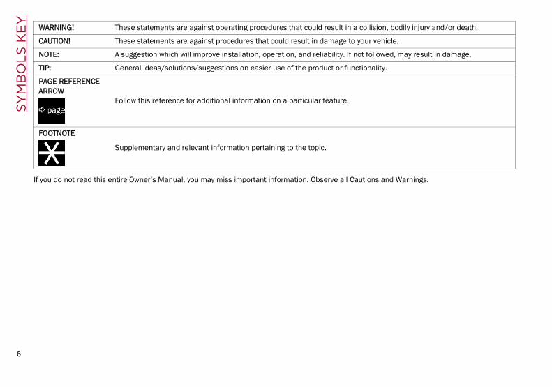
If you do not read this entire Owner’s Manual, you may miss important information. Observe all Cautions and Warnings.
WARNING! These statements are against operating procedures that could result in a collision, bodily injury and/or death.
CAUTION! These statements are against procedures that could result in damage to your vehicle.
NOTE: A suggestion which will improve installation, operation, and reliability. If not followed, may result in damage.
TIP: General ideas/solutions/suggestions on easier use of the product or functionality.
PAGE REFERENCE ARROW
Follow this reference for additional information on a particular feature.
FOOTNOTE
Supplementary and relevant information pertaining to the topic.
21_GU_OM_EN_USC_t.book Page 6

GETTING TO KNOW YOUR VEHICLE
GETTING TO KNOW YOUR INSTRUMENT PANEL
STARTING AND OPERATING
SAFETY
IN CASE OF EMERGENCY
SERVICING AND MAINTENANCE
TECHNICAL SPECIFICATIONS
CUSTOMER ASSISTANCE
INDEX
21_GU_OM_EN_USC_t.book Page 7

8
DEAR CUSTOMER
READ THIS CAREFULLY
Refueling..................................................... 2Starting The Engine....................................2Parking On Flammable Material ...............2Respecting The Environment .................... 2Electrical Accessories ................................2Scheduled Servicing ..................................2Rollover Warning ........................................ 3
VEHICLE CHANGES / ALTERATIONS
Accessories Purchased By The Owner......4Installing Electrical/Electronic Devices ....4Radio Transmitters And Mobile Phones ... 5
GETTING TO KNOW YOUR VEHICLE
KEYS..........................................................18Key Fob...................................................18
ENGINE IMMOBILIZER SYSTEM ..............20IGNITION SWITCH ...................................20
Keyless Push Button Ignition ................20REMOTE START — IF EQUIPPED .............22
How To Use Remote Start ..................... 22To Exit Remote Start Mode ................... 22Remote Start Comfort Systems —If Equipped .............................................23
VEHICLE SECURITY SYSTEM — IF EQUIPPED............................................. 23
To Arm The System................................ 23To Disarm The System .......................... 23Volumetric/Anti-Lift Protection — If Equipped............................................. 24
DOORS...................................................... 24Power Door Locks.................................. 24Locking The Doors With A DepletedBattery.................................................... 25Passive Entry System ........................... 25Power Lock Safety Device..................... 27Automatic Door Locks — If Equipped .. 27Child-Protection Door Lock System — Rear Doors ...................................................... 27
STEERING WHEEL.................................... 28Manual Tilt/Telescoping SteeringColumn ................................................. 28Heated Steering Wheel —If Equipped ............................................ 29
DRIVER MEMORY SETTINGS — IF EQUIPPED............................................. 30
Programming The Memory Feature ..... 30Memory Position Recall ........................ 30
SEATS ...................................................... 30Sparco Racing Seats (Quadrifoglio Vehicles) — If Equipped......................... 30Split Folding Rear Seat ......................... 31Power Adjustment (Front Seats)........... 33Heated Seats — If Equipped ................ 34Head Restraints .................................. 35
MIRRORS ..................................................37Automatic Dimming Mirror ....................37Vanity Mirror ...........................................37Outside Power Mirrors .........................38Power Folding Outside Mirrors..............38Outside Automatic Dimming Mirrors —If Equipped .............................................39Heated Mirrors .....................................39
UNIVERSAL GARAGE DOOR OPENER (HOMELINK®) ..........................................39
Before You Begin Programming HomeLink® ............................................39Erasing All The HomeLink® Channels.................................................39Identifying Whether You Have A Rolling Code Or Non-Rolling Code Device.........40Programming HomeLink® To A Garage Door Opener ..............................40Programming HomeLink® To A Miscellaneous Device............................41Reprogramming A Single HomeLink® Button .....................................................41Canadian/Gate Operator Programming..........................................41
EXTERIOR LIGHTS ....................................42Headlight Switch ..................................42Daytime Running Lights (DRLs) .........42High Beam Headlights ..........................43Automatic Headlights ...........................43Flash-To-Pass .........................................43
21_GU_OM_EN_USC_t.book Page 8

9
Automatic High Beam Headlights —If Equipped .............................................43Parking Lights ....................................... 44Headlight Off Delay................................ 44Rear Fog Lights ......................................44Adaptive Headlight System (AFS) —If Equipped .............................................44Turn Signals ........................................ 44Lane Change Assist ...............................44
INTERIOR LIGHTS .....................................44Front Map Reading Lights..................... 45Interior Ambient Lighting ......................45Rear Overhead Light .............................46Instrument Panel Dimmer Control ....... 46
WINDSHIELD WIPERS AND WASHERS....46Windshield Wiper Operation ...............46Rain Sensing Wipers..............................47Rear Window Wiper/Washer.................48Headlamp Washers — If Equipped ....... 48
CLIMATE CONTROLS ................................48Automatic Dual-Zone Climate Control System .................................................49
INTERIOR STORAGE AND EQUIPMENT....55Glove Compartment...............................55Center Console ......................................56Rear Armrest ..........................................56Power Outlets ......................................56Cigar Lighter And Ash Tray — If Equipped .............................................57Wireless Charging Pad — If Equipped...57
POWER WINDOWS................................... 58Power Window Controls ........................ 58Auto-Up Feature With Anti-PinchProtection............................................... 59Power Window System Initialization .... 59Wind Buffeting ...................................... 59
POWER SUNROOF — IF EQUIPPED.......... 59Power Sunroof ....................................... 59Opening And Closing The Sunroof........ 60Venting Sunroof ..................................... 60Sunshade Operation ............................. 60Pinch Protect Feature ........................... 60Re-Initialization Procedure.................... 60Sunroof Maintenance ........................... 61
HOOD........................................................ 61Opening The Hood................................. 61Closing The Hood................................... 62
POWER LIFTGATE..................................... 62Opening.................................................. 62Closing.................................................... 63Liftgate Initialization.............................. 64Cargo Area Features ............................. 64
GETTING TO KNOW YOUR INSTRUMENT PANEL
INSTRUMENT PANEL FEATURES............. 67Instrument Cluster ............................... 67Instrument Cluster Descriptions .......... 68
INSTRUMENT CLUSTER DISPLAY ............69Instrument Cluster Display Description .............................................69Reconfigurable Instrument Cluster Display ....................................................69Reconfigurable Display Items ...............69Customer Programmable Settings........72
WARNING LIGHTS AND MESSAGES ON THE INSTRUMENT PANEL..................74
Red Warning Lights................................74Amber Warning Lights............................75Green Indicator Lights ...........................78Blue Indicator Lights ..............................78Red Symbols...........................................78Amber Symbols ......................................80Green Symbols .......................................84Blue Symbols..........................................84
ONBOARD DIAGNOSTIC SYSTEM ............84Onboard Diagnostic System (OBD II) Cybersecurity..........................................84
EMISSIONS INSPECTION AND MAINTENANCE PROGRAM.......................85
21_GU_OM_EN_USC_t.book Page 9

10
STARTING AND OPERATING
STARTING THE ENGINE............................86Starting Procedure................................. 86Remote Starting System .......................86Cold Weather Operation........................87Extended Park Starting.......................... 87If Engine Fails To Start .......................... 87After Starting — Warming Up The Engine..................................................... 88Stopping The Engine..............................88Turbocharger Cool Down.......................88
ENGINE BLOCK HEATER —IF EQUIPPED .............................................89ENGINE BREAK-IN RECOMMENDATIONS...............................89
Engine Break-In......................................89ELECTRIC PARK BRAKE (EPB) .................90
Electric Park Brake (EPB) Operating Modes..................................................... 91Safe Hold................................................ 91
AUTOMATIC TRANSMISSION....................92Display ....................................................93Gear Selector ......................................... 93Transmission Operating Modes............ 94Automatic Transmission Limp HomeMode....................................................... 96Brake Transmission Shift Interlock (BTSI) System......................................... 96Important Notes.....................................97
ALFA DNA SELECTOR ...............................98Alfa DNA System ....................................98Driving Modes ........................................ 98
ALFA ACTIVE SUSPENSION (AAS) —IF EQUIPPED .......................................... 101
STOP/START SYSTEM............................101Operating Mode................................... 101System Manual Activation/Deactivation......................................... 102Possible Reasons The Engine DoesNot Autostop ........................................ 102Engine Restarting Conditions ............. 102Safety Functions.................................. 102Energy Saving Function.......................102Irregular Operation ..............................103Vehicle Inactivity.................................. 103
SPEED LIMITER......................................103Description...........................................103Activation ............................................. 103Speed Limit Programming .................. 103Exceeding The Programmed Speed ...104Programmed Speed Icon Flashing ..... 104Deactivation......................................... 104
CRUISE CONTROL SYSTEMS —IF EQUIPPED...........................................104
Cruise Control — If Equipped .............. 104Adaptive Cruise Control (ACC) —If Equipped .......................................... 106
HIGHWAY ASSIST SYSTEM (HAS) —IF EQUIPPED...........................................114
To Activate/Deactivate........................ 114Operation ............................................. 114Indications On The Display ................. 115System Status...................................... 115Limited System Availability/Operation ............................................. 116
TRAFFIC JAM ASSIST (TJA) SYSTEM — IF EQUIPPED...........................................117
To Activate/Deactivate........................ 117Operation ............................................. 118
Indications On The Display................. 118System Status ..................................... 119Limited System Availability/Operation ............................................. 119
TRAFFIC SIGN RECOGNITION (TSR) SYSTEM — IF EQUIPPED........................ 120
To Activate/Deactivate ....................... 120Indications On The Display................. 121
INTELLIGENT SPEED CONTROL (ISC) SYSTEM — IF EQUIPPED........................ 121
To Activate/Deactivate ....................... 122Indications On The Display................. 122Acceptance/Rejection Of TheSuggested Speed ................................ 122
PARKSENSE FRONT/REAR PARK ASSIST SYSTEM — IF EQUIPPED........................ 123
ParkSense Sensors............................. 123ParkSense Display .............................. 124Enabling And Disabling ParkSense.... 124ParkSense Warning Display ............... 125Operation With A Trailer...................... 125ParkSense System UsagePrecautions ......................................... 126
LANE DEPARTURE WARNING (LDW) SYSTEM.................................................. 126
Lane Departure Warning Operation... 126Turning Lane Departure Warning On Or Off.................................................... 127Lane Departure Warning Message.... 127Changing Lane Departure Warning Status................................................... 128
21_GU_OM_EN_USC_t.book Page 10

11
LANE KEEPING ASSIST (LKA) SYSTEM —IF EQUIPPED......................... 128
Turning Lane Keeping Assist On OrOff .........................................................129Lane Keeping Assist Warning Message ...............................................129
REAR BACK UP CAMERA / DYNAMIC GRIDLINES............................................. 132REFUELING THE VEHICLE ..................... 133
Refueling The Vehicle..........................133Refueling Capacity...............................133Refueling Procedure ...........................133
VEHICLE LOADING................................. 135Certification Label................................135
TRAILER TOWING................................... 136Common Towing Definitions ...............137Trailer Hitch Classification ..................137Trailer Towing Weights (MaximumTrailer Weight Ratings) .....................138Trailer And Tongue Weight .................138Towing Requirements..........................139Towing Tips ..........................................141Installing The Receiver ........................141Connecting The Electrical System ......141Removing The Receiver.......................142
SUGGESTIONS FOR DRIVING................ 142Saving Fuel...........................................142Driving Style .........................................142Conditions Of Use ................................142Performance — Quadrifoglio ...............143
SAFETY
ACTIVE SAFETY SYSTEMS......................145Anti-Lock Brake System (ABS) ........... 145Active Torque Vectoring (ATV)System — If Equipped.......................... 145Dynamic Steering Torque (DST) System ................................................. 146Drive Train Control (DTC) System....... 146Electronic Stability Control (ESC)System ................................................. 146Hill Descent Control (HDC) System —If Equipped...........................................147Hill Start Assist (HSA) System............. 148Panic Brake Assist (PBA) System ....... 149Traction Control System (TCS)............ 149
AUXILIARY DRIVING SYSTEMS ..............149Blind Spot Monitoring (BSM) System —If Equipped ......................................... 150Active Blind Spot Assist (ABSA)System — If Equipped ......................... 152Driver Attention Assist (DAA) System — If Equipped.......................... 155Forward Collision Warning Plus (FCW+) System — If Equipped ......................... 156Tire Pressure Monitoring System(TPMS)..................................................161
OCCUPANT RESTRAINT SYSTEMS........ 163Occupant Restraint Systems Features .............................................. 163Important Safety Precautions ............ 163Seat Belt Systems .............................. 164Supplemental Restraint Systems (SRS) .................................................... 169Child Restraints ................................. 178
SAFETY TIPS .......................................... 188Transporting Passengers.................... 188Transporting Pets ............................. 189Safety Checks You Should Make Inside The Vehicle .............................. 189Periodic Safety Checks You ShouldMake Outside The Vehicle.................. 190Exhaust Gas ..................................... 190Carbon Monoxide Warnings ............. 191
IN CASE OF EMERGENCY
HAZARD WARNING FLASHERS ............. 192SOS — EMERGENCY CALL..................... 192JACKING AND TIRE CHANGING............. 195
General Instructions ........................... 195Jack Information And Usage Precautions ......................................... 195Changing Procedure ........................... 196
TIRE SERVICE KIT — IF EQUIPPED........ 198Description .......................................... 198Inflation Procedure ............................. 199Checking And Restoring Tire Pressure............................................... 201
21_GU_OM_EN_USC_t.book Page 11

12
JUMP STARTING .................................... 201Remote Battery Connection Posts......202Jump Starting Procedure.....................203Bump Starting ..................................204
ENGINE OVERHEATING ......................... 204MANUAL PARK RELEASE ...................... 205TOWING A DISABLED VEHICLE ............. 205
Four-Wheel Drive (AWD) Models.........206TOW EYES .............................................. 206ENHANCED ACCIDENT RESPONSE SYSTEM (EARS) ..................................... 207EVENT DATA RECORDER (EDR) ............ 207
SERVICING AND MAINTENANCE
SCHEDULED SERVICING....................... 208Periodic Checks ...................................208Heavy Usage Of The Vehicle ...............208Maintenance Plan (2.0L Engine) ........209Maintenance Plan (2.9L Engine) ........212
ENGINE COMPARTMENT....................... 214Checking Levels — 2.0L Engine ..........214Checking Levels — 2.9L Engine ..........215Engine Oil .............................................215Engine Coolant Fluid............................216Washer Fluid For Windshield/Headlights ............................................217Brake Fluid ...........................................217Automatic Transmission Activation System Oil ............................................217Useful Advice For Extending The Life Of Your Battery..........................................217Battery ..................................................217Pressure Washing................................218
BATTERY RECHARGING .........................218Important Notes .................................. 218
VEHICLE MAINTENANCE........................219Engine Oil ............................................. 219Engine Oil Filter ................................... 220Engine Air Cleaner Filter ..................... 220Air Conditioning SystemMaintenance........................................ 220Lubricating Moving Parts Of The Bodywork ............................................. 220Windshield Wiper................................. 221Exhaust System ................................... 222Cooling System....................................223Braking System....................................224Automatic Transmission ..................... 225Replacing The Battery ......................... 225Fuses.................................................... 225Bulb Replacement............................... 229
TIRES ......................................................233Tire Safety Information .................... 233Tires — General Information .............. 239Spare Tires — If Equipped .................. 244Wheel And Wheel Trim Care ............ 245Tire Types............................................. 246Tire Chains and Traction Devices....... 247Tire Rotation Recommendations........ 247
DEPARTMENT OF TRANSPORTATION UNIFORM TIRE QUALITY GRADES.........248
Treadwear ............................................248Traction Grades ................................... 248Temperature Grades ........................... 248
STORING THE VEHICLE .........................249
BODYWORK ........................................... 249Protection Against Atmospheric Agents .................................................. 249Corrosion Warranty ............................. 250Preserving The Bodywork .................. 250
INTERIORS ............................................. 251Seats And Fabric Parts ....................... 251Leather Seats ...................................... 251Plastic And Coated Parts .................... 251Alcantara Parts — If Equipped............ 251Genuine Leather Parts........................ 251Carbon Fiber Parts .............................. 252
TECHNICAL SPECIFICATIONS
VEHICLE IDENTIFICATION NUMBER (VIN) ....................................... 253
Vehicle Identification Number............ 253Vehicle Identification Number (VIN) Plate............................................ 253
ENGINE .................................................. 254POWER SUPPLY..................................... 255TRANSMISSION ..................................... 255BRAKES.................................................. 255SUSPENSION ......................................... 256STEERING .............................................. 256DIMENSIONS ......................................... 257
Luggage Compartment Volume ......... 259WEIGHTS................................................ 259
21_GU_OM_EN_USC_t.book Page 12

13
FUEL REQUIREMENTS........................... 260Reformulated Gasoline ..................260Gasoline/Oxygenate Blends ..............260CNG And LP Fuel System Modifications .......................................261MMT In Gasoline..................................261Materials Added To Fuel ...................261Fuel System Cautions..........................261
FLUID CAPACITIES ................................. 262ENGINE FLUIDS AND LUBRICANTS ...... 263CHASSIS FLUIDS AND LUBRICANTS..... 264PERFORMANCE ..................................... 265
CUSTOMER ASSISTANCE
SUGGESTIONS FOR OBTAINING SERVICE FOR YOUR VEHICLE................266
Prepare For The Appointment ............ 266Prepare A List ...................................... 266Be Reasonable With Requests........... 266
IF YOU NEED ASSISTANCE ....................266Alfa Romeo Customer Center ............. 266Alfa Romeo Customer Care(Canada)............................................... 266Customer Assistance For The Hearing Or Speech Impaired (TDD/TTY)............................................. 266Service Contract ................................. 267
WARRANTY INFORMATION ................... 267REPORTING SAFETY DEFECTS ............. 267
In The 50 United States And Washington, D.C.................................. 267In Canada ............................................ 268
PUBLICATION ORDER FORMS ............. 268General Information.............................. 268
21_GU_OM_EN_USC_t.book Page 13

14
SY
MB
OL
GLO
SS
AR
Y Some car components have colored labelswith symbols indicating precautions to beobserved when using this component. It isimportant to follow all warnings when oper-ating your vehicle. See below for the definitionof each symbol Ú page 69.
Red Warning LightsAir Bag Warning
Light Ú page 74
Brake Warning Light Ú page 74
Electronic Braking Force Distribution
(EBD) Failure Ú page 75
Oil Temperature Warning Light
Ú page 75
Seat Belt Reminder Warning Light
Ú page 75
Amber Warning LightsAnti-Lock Brake System (ABS) Warning Light
Ú page 75
Electronic Stability Control (ESC)
Indicator Light — If Equipped
Ú page 76
Electronic Stability Control (ESC) OFF Indicator Light — If
Equipped Ú page 76
Tire Pressure Low Warning Light
Ú page 76
Tire Pressure Monitoring System
(TPMS) Warning Light
Ú page 76
Rear Fog Lights Ú page 77
Engine Check/Malfunction
Indicator Light (MIL) Ú page 77
Forward Collision Warning (FCW)
System Ú page 77
Fuel Reserve/Limited Range
Ú page 77
Green Warning LightsAutomatic High Beam Indicator
Light — If Equipped Ú page 78
Left Turn Signal Indicator Light
Ú page 78
Park/Headlight On Indicator Light
Ú page 78
Right Turn Signal Indicator Light
Ú page 78
Amber Warning Lights
21_GU_OM_EN_USC_t.book Page 14

15
Blue Warning LightsHigh Beam Indicator Light — If Equipped
Ú page 78
Red SymbolsAlfa Steering Torque
(AST) Failure Ú page 78
Alternator Failure Ú page 78
Automatic Transmission Failure
Ú page 78
Driver Attention Assist (DAA) System
Activation Ú page 78
Door Open Ú page 79
Power Steering Failure
Ú page 79
Electronic Throttle Control (ETC) Warning Light
Ú page 79
Engine Coolant Temperature Too
High Ú page 79
Hood Cap Not Properly Shut Ú page 79
Insufficient Engine Oil Level
Ú page 79
Low Engine Oil Pressure
Ú page 79
Trunk Lid Not Properly Shut Ú page 80
Amber SymbolsEngine Immobilizer
Failure/Break-In Attempt
Ú page 80
Fuel Cut-Off Indicator Light
Ú page 80
Park Sensors System Failure
Ú page 80
Red SymbolsEngine Oil Change
Required— If Equipped
Ú page 80
Engine Oil Pressure Sensor Failure
Ú page 80
Engine Oil Level Sensor Failure
Ú page 81
Forward Collision Warning (FCW)
System Failure — If Equipped
Ú page 81
Stop/Start System Failure
Ú page 81
Rain Sensor Failure Ú page 81
Dusk Sensor Failure Ú page 81
Blind Spot Monitoring System
Failure — If Equipped
Ú page 81
Amber Symbols
21_GU_OM_EN_USC_t.book Page 15

SY
MB
OL
GLO
SS
AR
Y
16
Fuel Level Sensor Failure
Ú page 81
Exterior Lights Failure
Ú page 81
Keyless System Failure
Ú page 81
Fuel Cut-Off System Failure
Ú page 81
Lane Departure Warning (LDW)
System Failure — If Equipped
Ú page 81
Automatic High Beam Headlights
Failure — If Equipped
Ú page 81
Automatic Transmission Fluid
Overheating Ú page 82
Audio System Failure
Ú page 82
Amber SymbolsSpeed Limiter System Failure
Ú page 82
Loose Fuel Filler Cap Ú page 82
Electric Park Brake Failure
Ú page 82
Low Coolant Level — If Equipped Ú page 82
Service Adaptive Cruise Control (ACC)
System Ú page 82
Wear On Brake Pads Ú page 82
Dynamic Drive Control System
Failure Ú page 82
Windshield Wiper Failure
Ú page 82
Generic Indication Ú page 83
Amber SymbolsAll Wheel Drive
Failure Ú page 83
Temporary All Wheel Drive Failure — If
Equipped Ú page 83
ABS Activation Ú page 83
Adaptive Front Lighting System
Failure Ú page 83
Soft Suspension Calibration Insertion
— If Equipped Ú page 83
Shock Absorbers Failure
Ú page 83
Windshield Washer Liquid Level Ú page 83
Wear ON Carbon Ceramic Material
(CCM) Brake Discs — If Equipped Ú page 83
Amber Symbols
21_GU_OM_EN_USC_t.book Page 16

17
Driver Attention Assist (DAA) System
Failure Ú page 83
Highway Assist System (HAS)/
Traffic Jam Assist (TJA) System Failure
Ú page 83
Amber Symbols Green Symbols
Headlights Ú page 84
Automatic Headlights Ú page 84
Stop/Start Operation
Ú page 84
Cruise Control Activated
Ú page 84
Adaptive Cruise Control (ACC) System — If Equipped
Ú page 84
Blue Indicator LightsAutomatic High
Beam Headlights — If Equipped Ú page 84
High Beam Headlights Ú page 84
21_GU_OM_EN_USC_t.book Page 17

18
GE
TT
ING
TO
KN
OW
YO
UR
VE
HIC
LEIn this section, you will find important informa-tion to help you become familiar with thefeatures needed to operate your vehicle, andhow they function.
KEYS
Key Fob
Your vehicle is equipped with a key fob whichsupports Passive Entry, Remote Keyless Entry(RKE), Remote Start (if equipped), and remoteliftgate operation. The key fob allows you tolock or unlock the doors and liftgate. The keyfob does not need to be pointed at the vehicleto activate the system. The key fob alsocontains an emergency key, which is storedinside the key fob.
NOTE:
The key fob’s wireless signal may beblocked if the key fob is located next to amobile phone, laptop, or other electronicdevice. This may result in poor perfor-mance.
With ignition in the ON position and thevehicle moving at 2 mph (4 km/h), all RKEcommands are disabled.
Key FobIn case the ignition switch does not changewith the push of a button, the key fob mayhave a low or fully depleted battery. A low keyfob battery can be verified by referring to theinstrument cluster, which will display direc-tions to follow Ú page 268.
To Lock/Unlock The Doors And Liftgate
Push and release the unlock button on the keyfob once to unlock the driver’s door or twicewithin one second to unlock all doors and theliftgate. To lock all the doors and the liftgate,push the lock button once.The current unlock setting can be changedthrough the radio system menu, so that thesystem unlocks: All doors on the first push of the key fob
unlock button.
The driver door on the first push of the keyfob unlock button.
The liftgate "independently" or "with doors".
When the doors are locked/unlocked, the turnsignals will flash and the illuminated entrysystem will be activated.
NOTE:If one or more doors are open when the lockbutton is pushed, or the liftgate is open, thedoors will lock. The doors will unlock againautomatically if the key is left inside thepassenger compartment, otherwise the doorswill stay locked.
Flashing of the turn signals upon locking/unlocking the doors, and activation of thecourtesy light upon unlocking the doors, canbe activated or deactivated through the radiosystem. For further information, refer to theInformation and Entertainment SystemOwner’s Manual Supplement.Opening The LiftgateRapidly push the button on the key fob twice toopen the liftgate. The turn signals will flash toindicate that the liftgate has been opened.
Replacing The Battery In The Key Fob
The recommended replacement battery is oneCR2032 battery.
NOTE:
Customers are recommended to use abattery obtained from Mopar. Aftermarketcoin battery dimensions may not meet theoriginal OEM coin battery dimensions.
21_GU_OM_EN_USC_t.book Page 18
19
Perchlorate Material — special handlingmay apply. See www.dtsc.ca.gov/hazard-ouswaste/perchlorate for further informa-tion.
Do not touch the battery terminals that areon the back housing or the printed circuitboard.
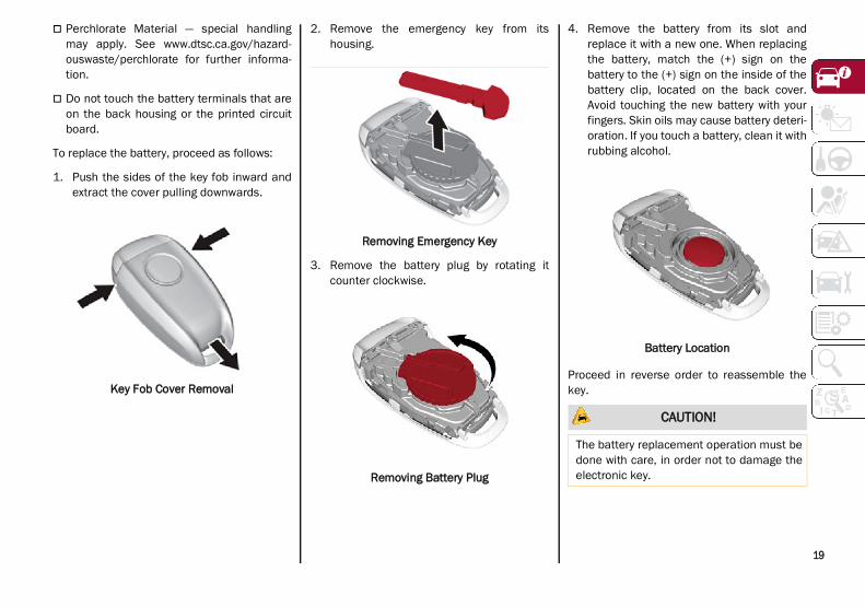
To replace the battery, proceed as follows:
1. Push the sides of the key fob inward andextract the cover pulling downwards.
Key Fob Cover Removal
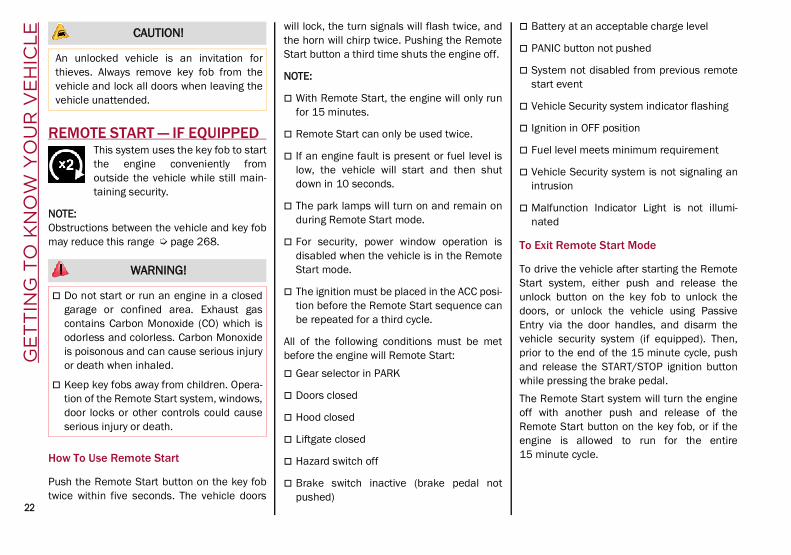
2. Remove the emergency key from itshousing.
Removing Emergency Key
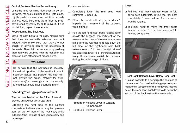
3. Remove the battery plug by rotating itcounter clockwise.
Removing Battery Plug
4. Remove the battery from its slot andreplace it with a new one. When replacingthe battery, match the (+) sign on thebattery to the (+) sign on the inside of thebattery clip, located on the back cover.Avoid touching the new battery with yourfingers. Skin oils may cause battery deteri-oration. If you touch a battery, clean it withrubbing alcohol.
Battery Location
Proceed in reverse order to reassemble thekey.
CAUTION!
The battery replacement operation must bedone with care, in order not to damage theelectronic key.
21_GU_OM_EN_USC_t.book Page 19

GE
TT
ING
TO
KN
OW
YO
UR
VE
HIC
LE
20
Programming And Requesting Additional Key Fobs
Programming the key fob may be performed byan authorized dealer.
NOTE:
Once a key fob is programmed to a vehicle,it cannot be re-purposed and repro-grammed to another vehicle.
Only key fobs that are programmed to thevehicle electronics can be used to start andoperate the vehicle. Once a key fob isprogrammed to a vehicle, it cannot beprogrammed to any other vehicle.
Duplication of key fobs may be performed atan authorized dealer. This procedure consistsof programming a blank key fob to the vehicleelectronics. A blank key fob is one that hasnever been programmed Ú page 268.
NOTE:
When having the Engine Immobilizersystem serviced, bring all vehicle keys withyou to an authorized dealer.
For Quadrifoglio models, if you need areplacement key fob, contact an authorizeddealer.
ENGINE IMMOBILIZER SYSTEMThe Engine Immobilizer system prevents unau-thorized use of the vehicle by disabling enginestarting. The system does not need to beenabled or activated. Operation is automatic,regardless of whether the vehicle is locked orunlocked.The system uses a key fob, keyless pushbutton ignition and a Radio Frequency (RF)receiver to prevent unauthorized vehicle oper-ation. Therefore, only key fobs that areprogrammed to the vehicle can be used tostart and operate the vehicle. The system willshut the engine off in two seconds if an invalidkey fob is used to start the engine.After placing the ignition switch in the ON/RUNposition, the vehicle security light will turn onfor three seconds for a bulb check. If the lightremains on after the bulb check, it indicatesthat there is a problem with the electronics. Inaddition, if the light begins to flash after thebulb check, it indicates that someone used aninvalid key fob to start the engine. Either ofthese conditions will result in the engine beingshut off after two seconds.
If the vehicle security light turns on duringnormal vehicle operation (vehicle running forlonger than 10 seconds), it indicates thatthere is a fault in the electronics. Should thisoccur, have the vehicle serviced as soon aspossible by an authorized dealer.
All of the key fobs provided with your newvehicle have been programmed to the vehicleelectronics.
NOTE:A key fob that has not been programmed isalso considered an invalid key Ú page 268.
IGNITION SWITCH
Keyless Push Button Ignition
This feature allows the driver to operate theignition switch with the push of a button aslong as the key fob is in the passengercompartment.The START/STOP ignition button has severaloperating modes. These modes are OFF, ACC,and ON/RUN.
WARNING!
Always remove the key fobs from thevehicle and lock all doors when leavingthe vehicle unattended.
Always remember to place the ignition inthe OFF mode.
CAUTION!
The Engine Immobilizer system is notcompatible with some aftermarket remotestarting systems. Use of these systems mayresult in vehicle starting problems and lossof security protection.
21_GU_OM_EN_USC_t.book Page 20

21
Keyless Ignition START/STOP ButtonThe push button ignition can be placed in thefollowing modes:OFF The engine is stopped
Steering is locked
Some electrical devices (e.g. centrallocking, alarm, etc.) are still available
ACC Engine is not started
Some electrical devices are available (e.g.power windows)
ON/RUN The engine will start (when foot is on the
brake pedal)
All the electrical devices are available (e.g.climate controls, etc.)
If the ignition switch does not change themode by pushing the button, the key fob mayhave a low or depleted battery. In this situa-
tion, a back up method can be used to operatethe ignition switch. Proceed as follows:
1. Lift the front armrest.
2. Lay the key fob on the indicated spot in thebottom of the center console, positioningthe key fob as shown in the followingimage, while pushing the START/STOPignition button to start the ignition.
Key Fob Placement Location
NOTE:
For more information on proper enginestarting procedures, see Ú page 86.
With the keyless ignition in the ACC position,if 30 minutes pass with the gear selector inPARK and the engine stopped, the keylessignition will automatically reset to the OFFposition.
When opening the driver's door with theignition in the ACC position (engine notrunning), a chime will sound to remind youto place the ignition in the OFF position. In
addition to the chime, the message willdisplay “Ignition Or Accessory On” in thecluster Ú page 268.
WARNING!
When exiting the vehicle, always makesure the ignition is in the OFF mode,remove the key fob from the vehicle, andlock your vehicle.
Never leave children alone in a vehicle, orwith access to an unlocked vehicle.
Allowing children to be in a vehicle unat-tended is dangerous for a number ofreasons. A child or others could be seri-ously or fatally injured. Children should bewarned not to touch the parking brake,brake pedal or the gear selector.
Do not leave the key fob in or near thevehicle, or in a location accessible to chil-dren, and do not leave the ignition of avehicle equipped with Keyless Enter-N-Goin the ON/RUN mode. A child couldoperate power windows, other controls, ormove the vehicle.
Do not leave children or animals insideparked vehicles in hot weather. Interiorheat build-up may cause serious injury ordeath.
21_GU_OM_EN_USC_t.book Page 21
GE
TT
ING
TO
KN
OW
YO
UR
VE
HIC
LE
22
REMOTE START — IF EQUIPPED This system uses the key fob to startthe engine conveniently fromoutside the vehicle while still main-taining security.
NOTE:Obstructions between the vehicle and key fobmay reduce this range Ú page 268.
How To Use Remote Start
Push the Remote Start button on the key fobtwice within five seconds. The vehicle doors
will lock, the turn signals will flash twice, andthe horn will chirp twice. Pushing the RemoteStart button a third time shuts the engine off.
NOTE:
With Remote Start, the engine will only runfor 15 minutes.
Remote Start can only be used twice.
If an engine fault is present or fuel level islow, the vehicle will start and then shutdown in 10 seconds.
The park lamps will turn on and remain onduring Remote Start mode.
For security, power window operation isdisabled when the vehicle is in the RemoteStart mode.
The ignition must be placed in the ACC posi-tion before the Remote Start sequence canbe repeated for a third cycle.
All of the following conditions must be metbefore the engine will Remote Start: Gear selector in PARK
Doors closed
Hood closed
Liftgate closed
Hazard switch off
Brake switch inactive (brake pedal notpushed)
Battery at an acceptable charge level
PANIC button not pushed
System not disabled from previous remotestart event
Vehicle Security system indicator flashing
Ignition in OFF position
Fuel level meets minimum requirement
Vehicle Security system is not signaling anintrusion
Malfunction Indicator Light is not illumi-nated
To Exit Remote Start Mode
To drive the vehicle after starting the RemoteStart system, either push and release theunlock button on the key fob to unlock thedoors, or unlock the vehicle using PassiveEntry via the door handles, and disarm thevehicle security system (if equipped). Then,prior to the end of the 15 minute cycle, pushand release the START/STOP ignition buttonwhile pressing the brake pedal.The Remote Start system will turn the engineoff with another push and release of theRemote Start button on the key fob, or if theengine is allowed to run for the entire15 minute cycle.
CAUTION!
An unlocked vehicle is an invitation forthieves. Always remove key fob from thevehicle and lock all doors when leaving thevehicle unattended.
WARNING!
Do not start or run an engine in a closedgarage or confined area. Exhaust gascontains Carbon Monoxide (CO) which isodorless and colorless. Carbon Monoxideis poisonous and can cause serious injuryor death when inhaled.
Keep key fobs away from children. Opera-tion of the Remote Start system, windows,door locks or other controls could causeserious injury or death.
21_GU_OM_EN_USC_t.book Page 22

23
Remote Start Comfort Systems — If Equipped
When Remote Start is activated, the heatedsteering wheel and front heated seat featureswill automatically activate when ambienttemperature is less than 39°F (4°C). Thesefeatures will stay on through the duration ofRemote Start.
NOTE:This feature can be activated through theradio system. Refer to the Information andEntertainment System Owner’s ManualSupplement for further information
VEHICLE SECURITY SYSTEM — IF EQUIPPEDThe Vehicle Security system monitors thevehicle doors, hood, liftgate, and the keylesspush button ignition for unauthorized opera-tion. It also monitors movement inside thepassenger compartment (volumetric protec-tion — if equipped), cutting of battery cables,and unexpected lifting/tilting of the vehicle(anti-lift protection — if equipped).While the Vehicle Security system is armed,interior switches for door locks are disabled.If something triggers the alarm, the VehicleSecurity system will provide the followingaudible and visible signals:
The horn will pulse
The turn signals will flash
The vehicle security light in the instrumentcluster will flash
NOTE:The Vehicle Security system is activated by theEngine Immobilizer system, which is automati-cally activated when you get out of the vehiclewith the key fob and lock the doors.
To Arm The System
Follow these steps to arm the Vehicle Securitysystem:
1. Make sure the vehicle’s ignition is placedin the OFF position.
2. Perform one of the following methods tolock the vehicle:
• Push the lock button on the interiorpower door lock switch with the driverand/or passenger door open.
• Push the lock button on the exteriorPassive Entry door handle with a validkey fob available in the same exteriorzone Ú page 25.
• Push the lock button on the key fob.
3. If any doors (or liftgate) are open, closethem.
To Disarm The System
The Vehicle Security system can be disarmedusing any of the following methods: Push the unlock button on the key fob.
Grab the Passive Entry door handle tounlock the door Ú page 25.
Cycle the ignition out of the OFF position todisarm the system.
NOTE:
The driver's door key cylinder and liftgatebutton on the key fob cannot arm or disarmthe Vehicle Security system. Use of the doorkey cylinder when the system is armed willsound the alarm when the door is opened.
When the Vehicle Security system is armed,the interior power door lock switches willnot unlock the doors.
The Vehicle Security system is designed toprotect your vehicle. However, you can createconditions where the system will give you afalse alarm. If one of the previously describedarming sequences has occurred, the VehicleSecurity system will arm, regardless ofwhether you are in the vehicle or not. If youremain in the vehicle and open a door, thealarm will sound. If this occurs, disarm theVehicle Security system.If the Vehicle Security system is armed and thebattery becomes disconnected, the VehicleSecurity system will remain armed when the
21_GU_OM_EN_USC_t.book Page 23

GE
TT
ING
TO
KN
OW
YO
UR
VE
HIC
LE
24
(Continued)
battery is reconnected; the exterior lights willflash, and the horn will sound. If this occurs,disarm the Vehicle Security system.
NOTE:The alarm does not disarm when the doors areunlocked by inserting the blade of the emer-gency key (found inside the key fob) into thedoor handle lock cylinder.
Volumetric/Anti-Lift Protection — If Equipped
To ensure the correct operation of the Volu-metric/Anti-Lift Protection system, completelyclose the side windows.To disable the function, push the Volumetric/Anti-Lift Protection button before activatingthe alarm.When the function is disabled, the light on theVolumetric/Anti-Lift Protection button flashesfor several seconds.
Volumetric/Anti-Lift Protection Button
Any disabling of the Volumetric/Anti-LiftProtection must be repeated each time theignition is placed in the OFF position.
DOORS
Power Door Locks
The power door lock switches are located oneach front door panel. Push the switch to lockor unlock the doors.Push the interior lock button on the rear doorpanel trim to lock the rear doors only.
Door Lock And Unlock Switch Panel
WARNING!
Do not leave children or animals insideparked vehicles in hot weather. Interiorheat build-up may cause serious injury ordeath.
For personal security and safety in theevent of a collision, lock the vehicle doorsas you drive as well as when you park andleave the vehicle.
Before exiting a vehicle, always shift theautomatic transmission into PARK, applythe parking brake, turn the engine OFF,remove the key fob from the vehicle andlock your vehicle.
Never leave children alone in a vehicle, orwith access to an unlocked vehicle.
Allowing children to be in a vehicle unat-tended is dangerous for a number ofreasons. A child or others could be seri-ously or fatally injured. Children should bewarned not to touch the parking brake,brake pedal or the gear selector.
Do not leave the key fob in or near thevehicle, or in a location accessible to chil-dren. A child could operate powerwindows, other controls, or move thevehicle.
CAUTION!
An unlocked vehicle is an invitation. Alwaysremove the key from the ignition and lockall of the doors when leaving the vehicleunattended.
WARNING! (Continued)
21_GU_OM_EN_USC_t.book Page 24

25
Locking The Doors With A Depleted Battery
Proceed as follows to lock the doors if thevehicle battery is depleted:
1. With the doors unlocked insert the emer-gency key from the key fob or a screwdriverinto the door lock manual release lockcylinder.
Door Lock Manual Release Lock Cylinder
2. Turn the manual release lock cylinderclockwise for the right door locks or coun-terclockwise for the left door locks.
3. Remove the key/screwdriver from themanual release lock.
Proceed in one of the following ways to realignthe door lock device (only when the batterycharge has been restored): Push the lock button on the key fob
Push the unlock button on the door panel
Unlock the driver’s door lock with the emer-gency key
Operate the internal door handle
NOTE:For the rear doors, if the Child Safety Locks areengaged, and the previously described lockingprocedure is carried out, operating the internalhandle will not open the door. Instead, it willonly realign the lock release device. To openthe door, the outside handle must be used.The door central locking/unlocking buttonsare not deactivated when the emergency lockis engaged.
Passive Entry System
The Passive Entry system is an enhancementto the vehicle’s key fob. This feature allows youto lock and unlock the vehicle’s door(s) andliftgate without having to push the key fob lockor unlock buttons.
NOTE:
Passive Entry may be programmed on/offthrough the radio screen. Refer to the Infor-mation and Entertainment System Owner’sManual Supplement for Passive Entrysettings.
The key fob may not be able to be detectedby the vehicle Passive Entry system if it islocated next to a mobile phone, laptop, orother electronic device; these devices may
block the key fob’s wireless signal andprevent the Passive Entry system fromlocking/unlocking the vehicle.
If wearing gloves, or if it has been raining/snowing on the Passive Entry door handle,the unlock sensitivity can be affected,resulting in a slower response time.
If the vehicle is unlocked by Passive Entryand no door is opened within 60 seconds,the vehicle will re-lock and (if equipped) willarm the Vehicle Security system.
To Unlock From The Driver Or Passenger SideWith a valid Passive Entry key fob close to thedoor handle, grab the handle to unlock thevehicle. Grabbing the driver’s door handle willunlock the driver door automatically. Grabbingthe passenger door handle will unlock alldoors and the liftgate automatically.
Passive Entry Door Handle Button
21_GU_OM_EN_USC_t.book Page 25

GE
TT
ING
TO
KN
OW
YO
UR
VE
HIC
LE
26
NOTE:
If “Unlock All Doors 1st Press” isprogrammed all doors will unlock when yougrab hold of the front driver’s door handle.You can select between “Unlock Driver Door1st Press” and “Unlock All Doors 1st Press”through the radio screen. Refer to the Infor-mation and Entertainment System Owner’sManual Supplement for Passive Entrysettings.
All doors will unlock when the frontpassenger door handle is grabbed regard-less of the driver’s door unlock preferencesetting.
External Liftgate Release Button (Vehicles With Passive Entry)
Frequency Operated Button Integrated Key(FOBIK-Safe)To minimize the possibility of unintentionallylocking a Passive Entry key fob inside yourvehicle, the Passive Entry system is equipped
with an automatic door unlock feature whichwill function if the ignition switch is in the OFFposition.The vehicle will not unlock the doors if anunauthorized key fob has been detected closeto the outside of the vehicle.If the Passive Entry function is disabledthrough the radio screen, the protections toavoid accidentally leaving the key fob insidethe vehicle are deactivated.To Lock The Vehicle’s Doors And LiftgateWith one of the vehicle’s Passive Entry keyfobs close to either front door handle, pushingthe Passive Entry lock button will lock thevehicle.
Passive Entry Door Handle Button
NOTE:DO NOT grab the door handle when pushingthe door handle lock button. This could unlockthe door(s).
Do NOT Grab The Door Handle When Locking
NOTE:
After pushing the Passive Entry lock button,you must wait two seconds before you canlock or unlock the doors, using eitherPassive Entry door handle. This is done toallow you to check if the vehicle is locked bypulling the door handle without the vehicleunlocking.
The Passive Entry system will not operate ifthe key fob battery is depleted.
The vehicle doors and liftgate can also belocked by pushing the lock button on thekey fob or on the interior door lock.
To Unlock/Enter The LiftgateWith one of the vehicle’s Passive Entry keyfobs close to the liftgate, push the liftgaterelease button.
21_GU_OM_EN_USC_t.book Page 26

27
External Liftgate Release Button
NOTE:
If the key fob is inadvertently forgotteninside of the cargo area, and an attempt ismade to close it from outside, the liftgatewill not lock. With the doors locked, the lift-gate unlocked, and the key fob detectedinside the vehicle, the liftgate will unlockagain and the lights flash twice.
Before driving, make sure the liftgate isclosed correctly.
To Lock The LiftgateWith a valid Passive Entry key fob close to thevehicle, push the Passive Entry button locatedas part of the liftgate release button switch. Alldoors and the liftgate will lock. Door lockingwill activate the alarm as well.
External Liftgate Release Switch (Vehicles With Passive Entry)
NOTE:The liftgate may still be locked by pushing thelock button on the key fob, pushing the doorlock button on the door handles, or pushingthe lock button on the interior door panel ofthe vehicle Ú page 268.
Power Lock Safety Device
The Power Lock Safety Device prevents theoperation of the interior door handles and thedoor lock and unlock buttons. The power lockalso prevents opening of the doors from insidethe passenger compartment.It is recommended to lock the vehicle doorseach time the vehicle is parked.Activating The Power LockThe Power Lock Safety Device is enabled on allthe doors by quickly pushing the lock buttonon the key fob twice.
The turn signals will flash to let you know thatthe power lock is active.If one or more of the doors are not closedcorrectly, the Power Lock Safety Device will notactivate, preventing a person from gettingstuck inside the passenger compartment byentering the vehicle, and then closing theopen door.Deactivating The Power LockThe Power Lock Safety Device disengagesautomatically: When the doors are unlocked by pushing
the unlock button on the key fob.
When the keyless ignition is placed in theON position.
Automatic Door Locks — If Equipped
The auto door lock feature default condition isenabled. When enabled, the door locks willlock automatically when the vehicle's speedexceeds 12 mph (20 km/h). The auto doorlock feature is enabled/disabled through theradio screen. Refer to the Information andEntertainment System Owner’s ManualSupplement for further information.
Child-Protection Door Lock System — Rear Doors
To provide a safer environment for small chil-dren riding in the rear seats, the rear doors areequipped with a Child-Protection Door Locksystem.
21_GU_OM_EN_USC_t.book Page 27

GE
TT
ING
TO
KN
OW
YO
UR
VE
HIC
LE
28
To use the system, open each rear door, use aflat blade screwdriver (or emergency key) androtate the dial to the lock or unlock position.
Child Safety Lock Positions
NOTE:
When the Child-Protection Door Locksystem is engaged, the door can be openedonly by using the outside door handle eventhough the inside door lock is in theunlocked position.
After disengaging the Child-Protection DoorLock system, always test the door from theinside to make certain it is in the unlockedposition.
After engaging the Child-Protection DoorLock system, always test the door from theinside to make certain it is in the lockedposition.
For emergency exit with the systemengaged, pull up on the door lock knob
(unlocked position), roll down the window,and open the door with the outside doorhandle.
NOTE:Always use this device when carrying children.After engaging the child lock on both reardoors, check for effective engagement bytrying to open a door with the internal handle.Once the Child-Protection Door Lock system isengaged, it is impossible to open the doorsfrom inside the vehicle. Before getting out ofthe vehicle, be sure to check that there is noone left inside.
STEERING WHEEL
Manual Tilt/Telescoping Steering Column
This feature allows you to tilt the steeringcolumn upward or downward. It also allowsyou to lengthen or shorten the steeringcolumn. The tilt/telescoping lever is locatedbelow the steering wheel at the end of thesteering column.
Steering Wheel Adjustment
WARNING!
Avoid trapping anyone in a vehicle in acollision. Remember that the rear doorscan only be opened from the outside whenthe Child-Protection locks are engaged(locked).
1 — Tilt/Telescoping Control Handle2 — Closed3 — Open4 — Tilt Movement5 — Telescoping Movement
21_GU_OM_EN_USC_t.book Page 28

29
To unlock the steering column, push the tilt/telescoping control handle down to the openposition. To tilt the steering column, move thesteering wheel upward or downward asdesired. To lengthen or shorten the steeringcolumn, pull the steering wheel outward orpush it inward as desired. To lock the steeringcolumn in position, push the tilt/telescopingcontrol handle to the closed position.
Heated Steering Wheel — If Equipped
The steering wheel contains a heating elementthat helps warm your hands in cold weather.The heated steering wheel has only onetemperature setting. The heated steeringwheel may not turn on when it is already warm.The heated steering wheel button is locatedon the instrument panel.
Push the heated steering wheel buttononce to turn the heating element on.
Push the heated steering wheel button asecond time to turn the heating element off.
When the function is enabled, the indicator onthe button will illuminate.
Heated Steering Wheel Button
NOTE:The engine must be running for the heatedsteering wheel to operate.
For information on use with the Remote Startsystem, see Ú page 23.
WARNING!
Do not adjust the steering column whiledriving. Adjusting the steering columnwhile driving or driving with the steeringcolumn unlocked, could cause the driverto lose control of the vehicle. Failure tofollow this warning may result in seriousinjury or death.
Do not place any objects on the steeringwheel (e.g. permanently fixed covers)which could interfere with the hand detec-tion sensor on the steering wheel of theActive Blind Spot Assist (ABSA), LaneKeeping Assist (LKA), Traffic Jam Assist(TJA), or Highway Assist systems (HAS) (ifequipped).
WARNING!
It is absolutely forbidden to carry out anyafter-market operation involving steeringsystem or steering column modifications(e.g. installation of anti-theft device) thatcould adversely affect performance. Doingso could void the New Vehicle LimitedWarrant, cause SERIOUS SAFETYPROBLEMS INCLUDING INJURY, and alsoresult in the vehicle not meetingtype-approval requirements.
WARNING!
Persons who are unable to feel pain to theskin because of advanced age, chronicillness, diabetes, spinal cord injury, medi-cation, alcohol use, exhaustion, or otherphysical conditions must exercise carewhen using the steering wheel heater. Itmay cause burns even at low tempera-tures, especially if used for long periods.
Do not place anything on the steeringwheel that insulates against heat, such asa blanket or steering wheel covers of anytype and material. This may cause thesteering wheel heater to overheat.
21_GU_OM_EN_USC_t.book Page 29

GE
TT
ING
TO
KN
OW
YO
UR
VE
HIC
LE
30
DRIVER MEMORY SETTINGS — IF EQUIPPEDThis feature allows the driver to store up tothree different memory profiles for easy recallthrough a memory switch. Each memoryprofile saves desired position settings for thefollowing features: Driver seat
Side mirrors
The memory setting switch is located on theoutboard side of the driver’s seat. The switchconsists of three buttons, one for eachmemory profile.
Seatback Width Adjustment
Programming The Memory Feature
To create a new memory profile, perform thefollowing:
1. Place the vehicle’s ignition in the ACC posi-tion (do not start the engine), and makesure the driver’s door is closed.
NOTE:A memory profile can also be set for threeminutes after the driver’s door has beenopened.
2. Adjust all memory profile settings todesired preferences, driver’s seat andmirror positions.
3. Push and hold the memory button youwant to program for 1.5 seconds.
NOTE:When a new profile as been set, the previouslyset profile for that button will be overwritten.
Memory Position Recall
To recall a previously set position, push andrelease the memory profile button assigned tothe desired positions.
NOTE:Memory position recall can be done forapproximately three minutes after the doorshave been opened, and for approximately oneminute after the ignition is placed in the OFFposition.
SEATS Seats are a part of the Occupant RestraintSystem of the vehicle.
Sparco Racing Seats (Quadrifoglio Vehicles) — If Equipped
Manual Seat Adjustment5 — Driver Memory Settings Buttons
WARNING!
It is dangerous to ride in a cargo area,inside or outside of a vehicle. In a colli-sion, people riding in these areas aremore likely to be seriously injured or killed.
Do not allow people to ride in any area ofyour vehicle that is not equipped withseats and seat belts. In a collision, peopleriding in these areas are more likely to beseriously injured or killed.
Be sure everyone in your vehicle is in aseat and using a seat belt properly.
1 — Adjustment Lever2 — Height Adjustment Button3 — Recline Lever
21_GU_OM_EN_USC_t.book Page 30

31
(Continued)
Adjusting The Seat Forward Or Rearward
The adjustment lever is at the front of the seat,near the floor. Pull the bar upward to move theseat forward or rearward. Release the baronce the seat is in the desired position. Usingbody pressure, move forward and rearward onthe seat to be sure that the seat adjustershave latched.
Adjusting The Seat Up Or Down
Push the height adjustment button upward ordownward to obtain your desired height.
Reclining The Seatback
To adjust the seatback, lift the recline leverlocated on the outboard side of the seat, leanback to the desired position and release thelever. To return the seatback, lift the lever,lean forward and release the lever.
Split Folding Rear Seat
The rear seat is a 40/20/40 seat that allowsthe luggage compartment to be partially ortotally extended.
Split Folding Rear SeatCentral Backrest Section TiltingBefore tilting the backrest, make sure that therear center seat belt is not fastened and thatthere aren't any objects on the seat itself (ifthere are any, remove them).Pull the release strap upward to release thecentral part of the backrest from its housingand tilt it forward using the head restraint.
Center Backrest Section Tilting
WARNING!
Adjusting a seat while driving may bedangerous. Moving a seat while drivingcould result in loss of control which couldcause a collision and serious injury ordeath.
Seats should be adjusted before fasteningthe seat belts and while the vehicle isparked. Serious injury or death couldresult from a poorly adjusted seat belt.
Do not ride with the seatback reclined sothat the shoulder belt is no longer restingagainst your chest. In a collision you couldslide under the seat belt, which couldresult in serious injury or death.
CAUTION!
Do not place any article under a power seator impede its ability to move as it maycause damage to the seat controls. Seattravel may become limited if movement isstopped by an obstruction in the seat'spath.
WARNING! (Continued)
21_GU_OM_EN_USC_t.book Page 31
GE
TT
ING
TO
KN
OW
YO
UR
VE
HIC
LE
32
Central Backrest Section RepositioningUsing the head restraint, lift the central portionupwards, manually guiding it back into place.Lightly push to make sure that it is properlylatched. Make sure that the armrest is prop-erly latched by gently trying to move it. If it isnot latched, repeat the operation.Repositioning The BackrestsMove the seat belts to the side, making surethat they are correctly extended and nottwisted. Also make sure that they are notcaught on anything behind the backrests ofthe seats. Then, lift the backrests by pushingthem rearward until you hear the lock click intoplace on both attachment mechanisms.
Extending The Luggage Compartment
The rear seatbacks can be folded forward toprovide an additional storage area.Extending the right side of the luggagecompartment allows you to carry two passen-gers on the left part of the rear seat, whileextending the left side allows you to carry onepassenger.
Proceed as follows:
1. Completely lower the rear seat headrestraints Ú page 35.
2. Place the seat belt so that it doesn'timpede the movement of the backrestwhile tilting it.
3. Pull the left-hand seat back release lever(inside the luggage compartment or therelease at the base of the rear seat acces-sible from the rear doors) to fold down theleft side, or the right-hand seat backrelease lever to fold down the right side ofthe backrest. It will fold forwards automat-ically. If necessary, assist the backrestduring the initial stage of tilting.
Seat Back Release Lever In Luggage Compartment
NOTE:
Pull both seat back release levers to folddown both backrests. Tilting the rear seatcompletely forward allows for maximumloading volume.
You may need to move the front seatsforward in order for the rear seats to foldforward completely.
Seat Back Release Lever Below Rear SeatIt is also possible to disengage the sections ofthe rear seat from inside the luggage compart-ment or by using one of the two levers locatedbelow the rear seat. Each lever folds down thesection of the backrest on the same side.
WARNING!
Be certain that the seatback is securelylocked into position. If the seatback is notsecurely locked into position the seat willnot provide the proper stability for childseats and/or passengers. An improperlylatched seat could cause serious injury.
1 — Seat Back Release Lever
21_GU_OM_EN_USC_t.book Page 32

33
Power Adjustment (Front Seats)
NOTE:The seat layout may vary according to thevehicle options.
The power seat switches are located on theoutboard side of the seat near the floor. Usethese switches to move the driver's seat up,down, forward, and rearward, or to recline theseatback.
Power Seat Adjustment
Adjusting The Seat Forward Or Rearward
The seat can be adjusted both forward andrearward by using the seat adjustment switch.The seat will move in the direction of theswitch. Release the switch when the desiredposition has been reached.
Adjusting The Seat Up Or Down
The height of the seats can be adjusted up ordown. Pull upward or push downward on theseat switch, and the seat will move in thedirection of the switch. Release the switchwhen the desired position is reached.
Tilting The Seat Up Or Down — If Equipped
The seat angle can be adjusted in four direc-tions. Lift or push the front part of seat switchto move the front part of the seat in the corre-sponding direction. Release the seat switchwhen the seat has reached the desired posi-tion.
Reclining The Seatback
The angle of the seatback can be adjustedforward or rearward by using the reclineswitch. The seat will move in the direction ofthe switch. Release the switch when thedesired position is reached.
Power Lumbar
The power lumbar switch is located on theoutboard side of the power seat. Push theswitch forward or rearward to increase ordecrease the lumbar support. Push the switchupward or downward to raise or lower thelumbar support.
1 — Seat Adjustment2 — Recline Adjustment3 — Lumbar Adjustment4 — Power Adjustable Bolster Buttons (If Equipped)
WARNING!
Adjusting a seat while driving may bedangerous. Moving a seat while drivingcould result in loss of control which couldcause a collision and serious injury ordeath.
Seats should be adjusted before fasteningthe seat belts and while the vehicle isparked. Serious injury or death couldresult from a poorly adjusted seat belt.
Do not ride with the seatback reclined sothat the shoulder belt is no longer restingagainst your chest. In a collision you couldslide under the seat belt, which couldresult in serious injury or death.
CAUTION!
Do not place any article under a power seator impede its ability to move as it maycause damage to the seat controls. Seattravel may become limited if movement isstopped by an obstruction in the seat'spath.
21_GU_OM_EN_USC_t.book Page 33

GE
TT
ING
TO
KN
OW
YO
UR
VE
HIC
LE
34
Seat Cushion Extension — If Equipped
Lift the adjustment lever and push the front ofthe cushion forward or rearward to extend thecushion by a few inches (centimeters).
Seat Cushion Extension
Power Bolster Adjustment — If Equipped
Push the power bolster adjustment buttons toregulate the width of the backrest through thelateral padding.
Easy Entry Function
The Easy Entry function is designed to movethe driver side seat forward automatically by2.36 inches (60 mm) to make it easier for thedriver to get in and out of the car.The movement is activated only if the seat isset to a driving position which is in front of theB-pillar of the vehicle.
The function is associated with power driverseats for each of the three stored positions.The Easy Entry function can be activated/deactivated through the radio system. Refer tothe Information and Entertainment SystemOwner’s Manual Supplement for further infor-mation.
Heated Seats — If Equipped
For information on use with the Remote Startsystem, see Ú page 23.
Front Heated Seats — If Equipped NOTE:Quadrifoglio vehicles equipped with SparcoRacing Seats will not be equipped with theheated seat feature.A push of the heated seat buttons located onthe instrument panel, near the climatecontrols, will select the heat levels in order ofhighest to lowest. A fourth push of the buttonwill turn the heated seat off.
NOTE:The heated seat function can also be activatedthrough the radio system. Refer to the Infor-mation and Entertainment System Owner’sManual Supplement for further information.You can select three heating levels: Maximum — three LED indicators illumi-
nated on the buttons Average — two LED indicators illuminated
on the buttons
Minimum — one LED indicator illuminatedon the buttons
Heated Seat Buttons
6 — Adjustment Lever
WARNING!
Persons who are unable to feel pain to theskin because of advanced age, chronicillness, diabetes, spinal cord injury, medi-cation, alcohol use, exhaustion or otherphysical condition must exercise carewhen using the seat heater. It may causeburns even at low temperatures, espe-cially if used for long periods of time.
Do not place anything on the seat or seat-back that insulates against heat, such asa blanket or cushion. This may cause theseat heater to overheat. Sitting in a seatthat has been overheated could causeserious burns due to the increasedsurface temperature of the seat.
21_GU_OM_EN_USC_t.book Page 34

35
NOTE:
After selecting a heating level, heat will befelt within a few minutes.
The engine must be running for the heatedseats to operate.
The “minimum” setting is automaticallydeactivated once a certain period of timehas elapsed.
Rear Heated Seats — If Equipped
If equipped with rear heated seats, thecontrols can be found on the rear of the centerconsole and will function the same as the frontheated seat controls.
Rear Heated Seat Buttons
NOTE:To preserve the battery charge, this functioncannot be activated when the engine is off.
Head Restraints
Head restraints are designed to reduce therisk of injury by restricting head movement inthe event of a rear impact. Head restraintsshould be adjusted so that the top of the headrestraint is located above the top of your ear.
Front Head Restraints
NOTE:For Quadrifoglio vehicles equipped withSparco Racing Seats, the head restraints arenot adjustable or removable.The front head restraints may beheight-adjustable.To raise the head restraint, pull up on the headrestraint until it clicks into place.
WARNING!
A loose head restraint thrown forward in acollision or hard stop could cause seriousinjury or death to occupants of the vehicle.Always securely stow removed headrestraints in a location outside the occu-pant compartment.
ALL the head restraints MUST be rein-stalled in the vehicle to properly protectthe occupants. Follow the re-installationinstructions above prior to operating thevehicle or occupying a seat.
Do not place items over the top of theReactive Head Restraint, such as coats,seat covers or portable DVD players.These items may interfere with the opera-tion of the Reactive Head Restraint in theevent of a collision and could result inserious injury or death.
WARNING!
All occupants, including the driver, shouldnot operate a vehicle or sit in a vehicle’sseat until the head restraints are placed intheir proper positions in order to minimizethe risk of neck injury in the event of acrash.
Head restraints should never be adjustedwhile the vehicle is in motion. Driving avehicle with the head restraints improp-erly adjusted or removed could causeserious injury or death in the event of acollision.
21_GU_OM_EN_USC_t.book Page 35

GE
TT
ING
TO
KN
OW
YO
UR
VE
HIC
LE
36
To lower the head restraint, push in the adjust-ment button and lower the head restraint tothe desired height while holding the button.Then, release the adjustment button.
Front Head Restraint
NOTE:To allow for maximum visibility for the driver, ifa seat is not occupied by a passenger, thehead restraint can be lowered to the fullylowered position.
Rear Head Restraint Adjustments
The height of the outboard head restraints canbe adjusted. The head restraint of the centerseat, if equipped, cannot be adjusted, onlyremoved.For upward adjustment, pull upward on thehead restraint until it clicks into place.For downward adjustment, push in the adjust-ment button and lower the head restraint atthe same time to the desired height.
Rear Head Restraint
NOTE:To allow for maximum visibility for the driver, ifa seat is not occupied by a passenger, thehead restraint should be lowered to the fullylowered position.
Head Restraint Removal
To remove the head restraints, proceed asfollows:
1. Recline the seat back to allow clearance ofthe head restraint from the vehicle’s roof.
2. Raise the head restraints to theirmaximum height.
1 — Release Button2 — Adjustment Button
WARNING!
All occupants, including the driver, shouldnot operate a vehicle or sit in a vehicle’sseat until the head restraints are placed intheir proper positions in order to minimizethe risk of neck injury in the event of acrash.
Head restraints should never be adjustedwhile the vehicle is in motion. Driving avehicle with the head restraints improp-erly adjusted or removed could causeserious injury or death in the event of acollision.
1 — Adjustment Button2 — Release Button
21_GU_OM_EN_USC_t.book Page 36

37
3. Push the adjustment button and therelease button at the side of the twosupports at the same time.
4. Pull upward on the head restraint to fullyremove it.
To reinstall the head restraints, proceed asfollows:
1. Hold down both the adjustment buttonand release button while placing the headrestraint posts into the holes.
2. Then, reposition the head restraint to theappropriate height for the passengers.
3. Replace the seat back to the appropriateposition for passengers.
MIRRORS
Automatic Dimming Mirror
The rearview mirror can be adjusted up, down,left, and right. The mirror should be adjustedto center on the view through the rear window.This mirror automatically adjusts for headlightglare from vehicles behind you.You can turn the feature on or off by pushingthe button at the base of the mirror.
Electrochromic Mirror Power Button
Vanity Mirror
On the driver and passenger sun visor, there isa light which illuminates the sun visor mirrorwhen folded down.
Lift For Vanity MirrorThe courtesy light turns on automatically bylifting the cover.
Sun Visors
The sun visors are located at the sides of theinterior rearview mirror. They can be adjustedforward and toward the side window.To direct the visor toward the passenger sidewindow, detach the visor from the interior rear-view mirror side hook and turn it towards theside window.From this position, the sun visor can also beextended toward the rear of the vehicle foradditional blockage of sunlight.
WARNING!
A loose head restraint thrown forward in acollision or hard stop could cause seriousinjury or death to occupants of the vehicle.Always securely stow removed headrestraints in a location outside the occu-pant compartment.
ALL the head restraints MUST be rein-stalled in the vehicle to properly protectthe occupants. Follow the re-installationinstructions above prior to operating thevehicle or occupying a seat.
CAUTION!
To avoid damage to the mirror duringcleaning, never spray any cleaning solutiondirectly onto the mirror. Apply the solutiononto a clean cloth and wipe the mirrorclean.
21_GU_OM_EN_USC_t.book Page 37

GE
TT
ING
TO
KN
OW
YO
UR
VE
HIC
LE
38
There are courtesy mirrors with lights on theback of the sun visors.
Rotate Sun Visor Toward Passenger Window
NOTE:A rear facing child restraint system shouldnever be fitted in the front passenger seat.Always comply with the instructions on the sunvisor Ú page 178.
Outside Power Mirrors
The power mirror switch is located on thedriver’s side door trim panel.To adjust the power mirrors, first select thedesired mirror using the power mirror control.To adjust the selected mirror, push the knob inthe direction desired.
NOTE:
Once adjustment is complete, rotate theknob to the neutral position to prevent acci-dental movements.
The power mirrors can be adjusted with theignition in the ACC or ON/RUN position.
Power Mirror Control
Power Folding Outside Mirrors
To fold the door mirrors in using the PowerFolding Mirror function, make sure the powermirror control knob is in the neutral position,and move the knob to the power folding posi-tion. Move the knob again to return the mirrorsto the driving position.If the power mirror control knob is movedagain during door mirror folding (from closedto open position and vice versa), the move-ment direction is reversed.
Folding MirrorAutomatic Power Folding MirrorsThe exterior mirrors will fold in when exitingthe vehicle (the ignition is OFF, all doors areclosed, and the doors are locked). The mirrorsreturn to the driving position when the vehicleis then unlocked.
1 — Power Mirror Control KnobA — LeftB — RightC — Power Folding PositionD — Neutral
WARNING!
Vehicles and other objects seen in anoutside convex mirror will look smaller andfarther away than they really are. Relyingtoo much on side convex mirrors couldcause you to collide with another vehicle orother object. Use your inside mirror whenjudging the size or distance of a vehicleseen in a side convex mirror.
21_GU_OM_EN_USC_t.book Page 38

39
If the door mirrors were folded using the powermirror control knob, they can only be returnedto the driving position by moving the knob tothe power folding position again.
NOTE:The power folding operation can be enabledonly when the vehicle speed is lower than31 mph (50 km/h).
Outside Automatic Dimming Mirrors — If Equipped
The outside mirrors will automatically dim forglare from vehicles behind you. This feature iscontrolled by the inside automatic dimmingmirror. The mirrors will automatically adjust forheadlight glare when the inside mirror adjusts.
Heated Mirrors
Push the rear defrost button, located withinthe climate controls, to activate the heatedmirrors.
UNIVERSAL GARAGE DOOR OPENER (HOMELINK®)
HomeLink® Buttons
HomeLink® replaces up to three hand-heldtransmitters that operate devices such asgarage door openers, motorized gates,lighting, or home security systems. TheHomeLink® unit is powered by your vehi-cles 12 Volt battery.
The HomeLink® buttons that are located inthe overhead console or sun visor designatethe three different HomeLink® channels.
To operate HomeLink®, push and releaseany of the programmed HomeLink®buttons. These buttons will activate the
devices they are programmed to with eachpress of the corresponding HomeLink®button.
The HomeLink® indicator light is locatedabove the center button Ú page 268.
Before You Begin Programming HomeLink®
For efficient programming and accurate trans-mission of the radio-frequency signal, it isrecommended that a new battery be placed inthe hand-held transmitter of the device that isbeing programmed to the HomeLink® system.Make sure your hand-held transmitter isprogrammed to activate the device you aretrying to program your HomeLink® button to.Ensure that your vehicle is parked outside ofthe garage before you begin programming.It is recommended that you erase all the chan-nels of your HomeLink® before you use it forthe first time.
Erasing All The HomeLink® Channels
To erase the channels, follow this procedure:
1. Place the ignition switch into the ON/RUNposition.
2. Push and hold the two outside HomeLink®buttons (I and III) for up to 20 seconds, oruntil the HomeLink® indicator lightflashes.
1 — Homelink® Button 12 — Homelink® Button 23 — Homelink® Button 34 — Homelink® Indicator
21_GU_OM_EN_USC_t.book Page 39

GE
TT
ING
TO
KN
OW
YO
UR
VE
HIC
LE
40
NOTE:Erasing all channels should only be performedwhen programming HomeLink® for the firsttime. Do not erase channels when program-ming additional buttons.
Identifying Whether You Have A Rolling Code Or Non-Rolling Code Device
Before programming a device to one of yourHomeLink® buttons, you must determinewhether the device has a rolling code ornon-rolling code.Rolling Code DevicesTo determine if your device has a rolling code,a good indicator is its manufacturing date.Typically, devices manufactured after 1995have rolling codes. A device with a rolling codewill also have a “LEARN” or “TRAIN” buttonlocated where the antenna is attached to thedevice. The button may not be immediatelyvisible when looking at the device. The nameand color of the button may vary slightly bymanufacturer.
NOTE:The “LEARN” or “TRAIN” button is not thebutton you normally use to operate the device.
Non-rolling Code DevicesMost devices manufactured before 1995 willnot have a rolling code. These devices will alsonot have a “LEARN” or “TRAIN” button.
Programming HomeLink® To A Garage Door Opener
To program any of the HomeLink® buttons toactivate your garage door opener motor, followthe steps below:
NOTE:All HomeLink® buttons are programmed usingthis procedure. You do not need to erase allchannels when programming additionalbuttons.
1. Place the ignition switch into the ON/RUNposition.
2. Place the garage door opener transmitter1 to 3 inches (3 to 8 cm) away from theHomeLink® button you wish to program,while keeping the HomeLink® indicatorlight in view.
3. Push and hold the HomeLink® button youwant to program while you push and holdthe garage door opener transmitter buttonyou are trying to replicate.
4. Continue to hold both buttons and observethe HomeLink® indicator light. The Home-Link® indicator light will flash slowly andthen rapidly. Once this happens, releaseboth buttons.
NOTE:Make sure the garage door opener motor isplugged in before moving on to the rollingcode/non-rolling code final steps.
Rolling Code Garage Door Opener Final Steps
NOTE:You have 30 seconds in which to initiate rollingcode final step 2, after completing rolling codefinal step 1.
1. At the garage door opener motor (in thegarage), locate the “LEARN” or “TRAIN”button. This can usually be found wherethe hanging antenna wire is attached tothe garage door opener motor. Firmly pushand release the “LEARN” or “TRAIN”button.
2. Return to the vehicle and push theprogrammed HomeLink® button threetimes (holding the button for two secondseach time). If the garage door openermotor operates, programming is complete.
3. Push the programmed HomeLink® buttonto confirm that the garage door openermotor operates. If the garage door openermotor does not operate, repeat the finalsteps for the rolling code procedure.
Non-Rolling Code Garage Door Opener FinalSteps
1. Push and hold the programmed Home-Link® button and observe the HomeLink®indicator light. If the HomeLink® indicatorlight stays on constantly, programming iscomplete.
21_GU_OM_EN_USC_t.book Page 40

41
2. Push the programmed HomeLink® buttonto confirm that the garage door openermotor operates. If the garage door openermotor does not operate, repeat the stepsfrom the beginning.
Programming HomeLink® To A Miscellaneous Device
Follow the procedure on programming Home-Link® to a garage door opener Ú page 40. Besure to determine if the device has a rollingcode, or non-rolling code before beginning theprogramming process.
NOTE:Canadian radio frequency laws require trans-mitter signals to time-out (or quit) after severalseconds of transmission, which may not belong enough for HomeLink® to pick up the
signal during programming. Similar to thisCanadian law, some U.S. gate operators aredesigned to time-out in the same manner. Theprocedure may need to be performed multipletimes to successfully pair the device to yourHomeLink® buttons.
Reprogramming A Single HomeLink® Button
To reprogram a single HomeLink® button thathas been previously trained, without erasingall the channels, follow the procedure below.Be sure to determine whether the new deviceyou want to program the HomeLink® button tohas a Rolling Code, or Non-rolling Code.
1. Place the ignition in the ON/RUN position,without starting the engine.
2. Push and hold the desired HomeLink®button until the HomeLink® indicator lightbegins to flash after 20 seconds. Do notrelease the button.
3. Without releasing the button, proceed withStep 2 in “Programming HomeLink® To AGarage Door Opener” and follow allremaining steps.
Canadian/Gate Operator Programming
The programming of transmitters in Canada/United States require the transmitter signalsto “time-out” after several seconds of trans-mission.
Canadian radio frequency laws require trans-mitter signals to time-out (or quit) after severalseconds of transmission – which may not belong enough for HomeLink® to pick up thesignal during programming. Similar to thisCanadian law, some U.S. gate operators aredesigned to time-out in the same manner.It may be helpful to unplug the device duringthe cycling process to prevent possible over-heating of the garage door or gate motor.
1. Place the ignition in the ON/RUN position.
2. Place the hand-held transmitter 1 to3 inches (3 to 8 cm) away from the Home-Link® button you wish to program whilekeeping the HomeLink® indicator light inview.
3. Continue to press and hold the Home-Link® button, while you press and release(cycle) your hand-held transmitter everytwo seconds until HomeLink® hassuccessfully accepted the frequencysignal. The indicator light will flash slowlyand then rapidly when fully trained.
4. Watch for the HomeLink® indicator tochange flash rates. When it changes, it isprogrammed. It may take up to 30 secondsor longer in rare cases. The garage doormay open and close while you are programming.
5. Press and hold the programmed Home-Link® button and observe the indicatorlight.
WARNING!
Your motorized door or gate will open andclose while you are programming theuniversal transceiver. Do not program thetransceiver if people or pets are in thepath of the door or gate.
Do not run your vehicle in a closed garage orconfined area while programming the transceiver.Exhaust gas from your vehicle contains CarbonMonoxide (CO) which is odorless and colorless.Carbon Monoxide is poisonous when inhaled andcan cause you and others to be severely injured orkilled.
21_GU_OM_EN_USC_t.book Page 41

GE
TT
ING
TO
KN
OW
YO
UR
VE
HIC
LE
42
NOTE:
If the indicator light stays on constantly,programming is complete and the garagedoor/device should activate when theHomeLink® button is pressed.
To program the two remaining HomeLink®buttons, repeat each step for eachremaining button. DO NOT erase the chan-nels.
If you unplugged the garage door opener/device for programming, plug it back in at thistime.Reprogramming A Single HomeLink® Button(Canadian/Gate Operator)To reprogram a channel that has been previ-ously trained, follow these steps:
1. Place the ignition to the ON/RUN position.
2. Press and hold the desired HomeLink®button until the indicator light begins toflash after 20 seconds. Do not release thebutton.
3. Without releasing the button, proceed with“Canadian/Gate Operator Programming”step 2 and follow all remaining steps.
EXTERIOR LIGHTS
Headlight Switch
The headlight switch is located on the left sideof the instrument panel, next to the steering
wheel. The headlight switch controls the oper-ation of the headlights, parking lights, instru-ment panel lights, instrument panel lightdimming, interior lights and rear fog lights.In addition, there are buttons for the Park-Sense system and Engine Stop/Start Ú page 86.
Headlight Switch
The instrument panel and the various controlson the dashboard will be illuminated when theexterior lights are turned on.To turn on the headlights, rotate the headlightswitch clockwise. When the headlight switch ison, the parking lights, taillights, license platelight and instrument panel lights are also
turned on. To turn off the headlights, rotatethe headlight switch back to the O (off) posi-tion.
Daytime Running Lights (DRLs)
The Daytime Running Lights (DRLs) (low inten-sity) come on automatically whenever the igni-tion is placed in the ON/RUN position, and theheadlight switch is turned to the position,and the dusk sensor detects sufficientexternal light.On some vehicles, the Daytime Running Lightsmay deactivate, or reduce intensity, on oneside of the vehicle (when a turn signal is acti-vated on that side), or on both sides of thevehicle (when the hazard warning lights areactivated).If equipped, the DRLs can be activated/deac-tivated from the radio system, by selecting thefollowing functions in sequence on the mainMENU:
1. “Settings.”
2. “Lights.”
3. “Daytime Running Lights.”
NOTE:The Daytime Running Lights cannot be deacti-vated in Canadian markets.
1 — ParkSense Button2 — Parking Lights, Daytime Running Lights, Headlight Switch3 — Instrument Panel Dimmer4 — Rear Fog Light Button5 — Engine Stop/Start Button
21_GU_OM_EN_USC_t.book Page 42

43
High Beam Headlights
Push the multifunction lever towards theinstrument panel to switch the headlights tohigh beams. The headlight switch must first beturned to the (auto) or (on) position.
With high beam headlights on, the HighBeam Indicator on the instrument panel willilluminate.
Multifunction LeverPulling the multifunction lever back will turnthe low beams on.
Automatic Headlights
This system automatically turns the headlightson or off according to ambient light levels. Toturn the system on, rotate the headlight switchto the (AUTO) position.
NOTE:The function can only operate with the ignitionposition cycled to ON/RUN.
To turn the automatic headlights off, turn theheadlight switch out of the (AUTO) position.
Flash-To-Pass
You can signal another vehicle with your head-lights by lightly pulling the multifunction levertoward you. This will cause the high beamheadlights to turn on, and remain on, until thelever is released.
Automatic High Beam Headlights — If Equipped
The Automatic High Beam Headlights systemprovides increased forward lighting at night byautomating high beam control through the useof a camera mounted on the windshield. Thiscamera detects vehicle specific light and auto-matically switches from high beams to lowbeams until the approaching vehicle is out ofview.This function is enabled with the radio system,and can only be activated with the light switchturned to (auto).If the high beam headlights are on, the blueicon/warning light will illuminate in theinstrument panel.When the speed is higher than 25 mph(40 km/h) and the function is active, the lightswill turn off if the multifunction lever is pushedagain.When the speed is lower than 15 mph(25 km/h) and the function is active, the func-tion switches the high beam headlights off.
If the high beam headlights are operatedquickly again (pushing the multifunction levertowards the instrument panel), the warninglight/icon will illuminate in the instrumentpanel, and the high beam headlights will turnon constantly until the speed exceeds 25 mph(40 km/h).When the speed of 25 mph (40 km/h) isexceeded again, the automatic functioning isreactivated.If the multifunction lever is pushed again withthe Automatic High Beam Headlights acti-vated, the Automatic High Beam Headlightsfunction deactivates.To deactivate the automatic headlight func-tion, rotate the headlight switch to the posi-tion.
NOTE:
If the system recognizes heavy traffic areas,the automatic functions remain disabledindependently of the vehicle’s speed.
The Automatic High Beam functionality mayalso be influenced by:
• Reflections on road signs
• Dim headlights from oncoming traffic
• Poor weather conditions
• Presence of dirt or other obstructions onthe sensor
• Damage to the windshield
21_GU_OM_EN_USC_t.book Page 43

GE
TT
ING
TO
KN
OW
YO
UR
VE
HIC
LE
44
Parking Lights
To turn on the parking lights and instrumentpanel lights, rotate the headlight switch clock-wise to the position. All of the parking lightswill turn on for eight minutes, and opening thedoor activates an audible warning.To leave only the lights on one side (right/left)illuminated, move the multifunction lever(located on the left side of the steering wheel)to the side that you want to remain on. Withthe parking lights on, the indicator light onthe instrument panel will illuminate.To turn off the parking lights, rotate the head-light switch back to the O (off) position.
Headlight Off Delay
To assist when exiting the vehicle, the “Head-light Off Delay” feature will leave the head-lights on for up to 90 seconds. This delay isinitiated when the ignition is placed in the OFFposition while the headlight switch is on, andthen the headlight switch is cycled off. Head-light delay can be canceled by either turningon the headlights or side lights, or by placingthe ignition in the ON position.The function can be activated from the radiosystem by selecting the following functions insequence on the main menu:
1. “Settings.”
2. “Lights.”
3. “Headlight Off Delay.”
Rear Fog Lights
The rear fog light switch is located within theheadlight switch.
Push the button, located in the center ofthe headlight switch, to turn the rear fog lightson/off.The rear fog lights turn on only when the head-lights or parking lights are also turned on. Thelights can be turned off by pushing the button again or by turning the headlight switchto the O (off) position.When the engine is stopped with the rear foglights on, they will be off the next time theengine is started.
Adaptive Headlight System (AFS) — If Equipped
This is a system combined with Xenon head-lights (Bi-Xenon 35 W headlamp, if equipped)which directs the headlights horizontally, andcontinuously and automatically adapts themto the driving conditions around bends orwhen cornering.The system directs the headlights to light upthe road in the best way, taking into accountthe speed of the vehicle and the bend orcorner angle, as well as the speed at which thesteering wheel is turned.The adaptive lights are automatically activatedwhen the vehicle is started.
Turn Signals
Move the multifunction lever up or down toactivate the turn signals. The arrows on eachside of the instrument cluster flash to showproper operation.
The or turn signal will blink on the instru-ment panel.
Lane Change Assist
Lightly push the lever up or down once, withoutmoving beyond the detent, and the turn signalwill flash five times then automatically turn off.To turn off the flashing before the end of thecycle, move the lever in the opposite directionuntil the first click (about half way).
INTERIOR LIGHTSCourtesy lights are turned on when the frontdoors are opened or when the dimmer controlis rotated to its farthest upward position. Theglove compartment light turns on automati-cally when the glove compartment is openedand turn off when it is closed. The door cour-tesy lights illuminate when one of the frontdoors is opened, and turn off when it is closed.The liftgate courtesy lights turn on automati-cally when the liftgate is opened and turn offwhen it is closed. All of these lights turn on andoff regardless of the ignition status.
21_GU_OM_EN_USC_t.book Page 44

45
Front Map Reading Lights
The front map/reading and overhead lightsare mounted in the overhead console. Eachlight can be turned on by pushing the corre-sponding switch on the console. Theseswitches are backlit for night time visibility. Toturn the lights off, push the switch a secondtime.
Overhead Console
NOTE:Before exiting the vehicle, ensure that theoverhead lights are off. This will prevent thebattery from discharging once the doors areclosed. If a light is left on accidentally, theoverhead lights will turn off automaticallyapproximately 15 minutes after the ignitionhas been placed in the OFF position.
Overhead Light TimingOn certain models, to assist getting in and outof the vehicle at night or in poorly-lit areas, twotimed modes have been provided.Timing While Getting Into The Vehicle — Theoverhead lights turn on according to thefollowing modes: Will illuminate for a few seconds when the
doors are unlocked.
Will illuminate for approximately threeminutes when one of the doors is opened.
Will illuminate for a few seconds when thedoors are locked.
Timing is interrupted when the ignition isplaced in the ON/RUN position.Three Modes Are Available For Turning OffOverhead Lighting: When all doors are closed after entering the
vehicle, the three-minute timer will stop anda seconds timer will start for the interiorlights. This timing will stop when the ignitionis placed in the ON/RUN position.
When doors are locked (either with key fobor with key inserted on driver side door), theoverhead light turns off.
The interior lights will turn off after15 minutes to preserve the battery.
Timing While Getting Out Of The Vehicle —After placing the ignition in the OFF position,the overhead lights will turn on as follows: For a few seconds after the engine stops.
For approximately three minutes when oneof the doors is opened.
For a few seconds when the last door isclosed.
The timing stops automatically when the doorsare locked.
Interior Ambient Lighting
The brightness of the interior passengercompartment lights can be adjusted throughthe radio system.To access the adjustment function, on themain menu select the following items insequence:
1. "Settings"
2. "Lights"
3. "Interior Ambient Lighting"
The lights can be adjusted to seven differentlevels of brightness.
1 — Driver’s Reading/Map Light Switch2 — Rear Overhead Lights Switch3 — Overhead Lights Switch4 — Overhead Lights On/Off When Doors Open5 — Passenger’s Reading/Map Light Switch6 — Passenger’s Reading/Map Light7 — Center Reading/Map Light8 — Driver’s Reading/Map Light
21_GU_OM_EN_USC_t.book Page 45

GE
TT
ING
TO
KN
OW
YO
UR
VE
HIC
LE
46
Rear Overhead Light
The rear overhead lights are activated or deac-tivated by on/off switches located on the frontoverhead console or within the rear overheadlights themselves.
Rear Overhead Light
The light turns on when a door is opened.
NOTE:The light will turn off automatically after a fewminutes if a door is left open. To turn it onagain, open another door or close and reopenthe same door.
Instrument Panel Dimmer Control
With the daytime running lights or headlightson, rotate the dimmer control upward toincrease the instrument panel brightness andthe control button icons. Rotate the dimmercontrol downward to decrease brightness.
Dimmer Control
WINDSHIELD WIPERS AND WASHERSThe windshield wiper stalk is located on theright side of the steering wheel.The windshield wipers will only operate withthe ignition is placed in the ACC or ON/RUNposition.
Windshield Wiper Operation
Rotating the switch to the Low ContinuousWiper Speed position (2) activates the first(low) level continuous speed of the windshieldwipers in manual mode.Rotating the switch to the High ContinuousWiper Speed position (1) activates the second(high) level continuous speed of the wind-shield wipers in manual mode.
1 — Passenger Rear Overhead Light2 — Driver Side Rear Overhead Light3 — Driver Side Rear Overhead Light Switch4 — Passenger Side Rear Overhead Light Switch
CAUTION!
Turn the windshield wipers off whendriving through an automatic car wash.Damage to the windshield wipers mayresult if the wiper control is left in any posi-tion other than off.
In cold weather, always turn off the wiperswitch and allow the wipers to return tothe “Park” position before turning off theengine. If the wiper switch is left on andthe wipers freeze to the windshield,damage to the wiper motor may occurwhen the vehicle is restarted.
Always remove any buildup of snow thatprevents the windshield wiper blades fromreturning to the off position. If the wind-shield wiper control is turned off and theblades cannot return to the off position,damage to the wiper motor may occur.
21_GU_OM_EN_USC_t.book Page 46

47
Windshield Wiper Stalk
Rain SensorsRotating the switch to the Low Sensitivity RainSensing position (4), activates the first, lesssensitive level of the Rain Sensing function.Rotating the switch to the High Sensitivity RainSensing position (3), activates the second,more sensitive level of the Rain Sensing func-tion Ú page 47.Windshield WasherTo use the washer, pull the windshield wiperlever toward the steering wheel and hold.Both the windshield washer jet and the wind-shield wiper will be activated. The wipers andwashers will continue to operate until you letgo of the lever.
The windshield wiper stops working threestrokes after the stalk is released, followed bya final stroke six seconds later to complete thecycle.MistPush the lever upward to the MIST positionand release for a single wiping cycle.
NOTE:The Mist feature does not activate the washerpump; therefore, no washer fluid will besprayed on the windshield. The wash functionmust be used in order to spray the windshieldwith washer fluid.
For information on wiper care and replace-ment, see Ú page 221.
Rain Sensing Wipers
This feature senses rain or snowfall on thewindshield and automatically activates thewipers. The Rain Sensor is located behind theinterior rearview mirror.
Rain SensorRotate the end of the multifunction lever toone of four settings to activate this feature.The sensor has an adjustment range thatvaries progressively from wiper still (no stroke)when the windshield is dry, to wiper at contin-uous speed (fast operation) with intense rain.ActivationRotating the wiper switch to the Low SensitivityRain Sensing position (4) or High SensitivityRain Sensing position (3) activates the rainsensor.The activation of the rain sensor system isdone by tapping the wiper stalk upwards whilethe switch is in the Low Sensitivity RainSensing position (4) or High Sensitivity RainSensing position (3).The variation in sensitivity during rain sensoroperation is also signaled by a stroke of thewiper.
1 — High Continuous Wiper Speed2 — Low Continuous Wiper Speed3 — High Sensitivity Rain Sensing4 — Low Sensitivity Rain Sensing5 — Windshield Wiper Off
WARNING!
Sudden loss of visibility through thewindshield could lead to a collision. Youmight not see other vehicles or otherobstacles. To avoid sudden icing of thewindshield during freezing weather, warmthe windshield with the defroster beforeand during windshield washer use.
21_GU_OM_EN_USC_t.book Page 47

GE
TT
ING
TO
KN
OW
YO
UR
VE
HIC
LE
48
If the windshield washer is used with the rainsensor activated, the normal washing cycle isperformed, and then the rain sensor resumesits normal automatic operation.
NOTE:Keep the glass in the sensor area clean.
DeactivationTo turn off the Rain Sensing Wipers, use thewiper switch or place the ignition in the OFFposition.In the event of malfunction of the rain sensorwhile it is active, the windshield wiper oper-ates intermittently at a speed consistent withthe sensitivity setting of the rain sensor,whether or not there is rain on the glass for aslong as the sensor failure is indicated on thedisplay.The sensor continues to operate and it ispossible to set the windshield wiper to contin-uous mode (1 or 2). The failure indicationremains on for as long as the sensor is active.
The rain sensor is able to recognize and auto-matically adjust itself in the presence of thefollowing conditions: Presence of dirt on the controlled surface
(e.g. salt, dirt, etc.).
Presence of streaks of water caused by theworn window wiper blades.
Difference between day and night.
Rear Window Wiper/Washer
Push the windshield wiper lever downward toactivate/deactivate continuous rear wiperoperation.Push the windshield wiper lever towards theinstrument panel to activate the rear windowwasher (a brief push activates one washingcycle, keeping the stalk pushed washescontinuously until the stalk is released).Shifting the vehicle into REVERSE with thewindshield wiper operating activates a singlecycle of the rear window wiper.
Headlamp Washers — If Equipped
The windshield wiper lever operates the head-light washers when the ignition is in the ONposition and the headlights are turned on. Touse the headlight washers, pull the levertoward you and release it. The headlightwashers will spray a timed high-pressure sprayof washer fluid onto each headlight lens. Inaddition, the windshield washers will spray thewindshield and the windshield wipers willcycle.
NOTE:The headlight washers work on every tenthwash cycle request.
CLIMATE CONTROLSThe Climate Control system allows you to regu-late the temperature, air flow, and direction ofair circulating throughout the vehicle. Thecontrols are located on the touchscreen andon the instrument panel below the radio.
21_GU_OM_EN_USC_t.book Page 48

49
Automatic Dual-Zone Climate Control System
Automatic Climate Control System
1 — Driver Temperature Adjustment Knob 9 — Passenger Temperature Adjustment Knob2 — Driver Side AUTO Button (Automatic Operation) 10 — SYNC Button (Set Temperature Alignment) Driver/Passenger Side3 — Driver Side Air Distribution Selection Button 11 — Passenger Heated Seat Button — If Equipped4 — Max Defrost Button 12 — Air Conditioning Button5 — Blower Speed Adjustment Knob 13 — Steering Wheel Heater Button — If Equipped6 — Rear Defrost Button 14 — Driver Heated Seat Button — If Equipped7 — Passenger Side Air Distribution Selection Button 15 — Air Recirculation Button8 — Passenger Side AUTO Button (Automatic Operation)
21_GU_OM_EN_USC_t.book Page 49

GE
TT
ING
TO
KN
OW
YO
UR
VE
HIC
LE
50
Automatic Climate Control System (Touchscreen Controls)
1 — Driver Side Temperature Adjustment Bar 8 — Heated Rear Window On/Off Button2 — Driver Side Air Distribution Buttons 9 — MAX-DEF Activation/Deactivation Button (Rapid Defrosting/Demisting)3 — Fan Speed Adjustment Button 10 — Air Recirculation On/Off Button4 — Passenger Side Air Distribution Buttons 11 — Climate Control System Compressor On/Off Button5 — Passenger Side Temperature Adjustment Bar 12 — Driver Side AUTO Button (Automatic Operation)6 — SYNC Button 13 — Climate Control System On/Off Button7 — Passenger Side AUTO Button (Automatic Operation)
21_GU_OM_EN_USC_t.book Page 50

51
Description
The Automatic Dual Zone Climate ControlSystem adjusts the temperature and air distri-bution independently between the driver andpassenger.The system maintains the set temperatureinside the passenger compartment andcompensates for outside temperature change.
NOTE:The reference temperature is 72°F (22°C) foroptimal comfort management.
The automatic setting will adjust the followingto maintain comfort within the passengercompartment: Air temperature from the driver/front
passenger side vents
Air distribution from the driver/frontpassenger side vents
Fan speed (continuous variation of the airflow)
Compressor variations (for cooling/dehu-midifying the air)
Air recirculation
The Climate Control System can also be oper-ated manually by using the buttons and knobson the faceplate.Manual selections will override the automaticsettings, which are stored until the AUTObutton is pushed. If the system intervenes forsafety reasons, the automatic setting will takecontrol of the system.The below operations will not deactivate theautomatic (AUTO) function: Air Recirculation activation/deactivation
A/C activation/deactivation
SYNC function activation
Rear Window Defrost activation/deactiva-tion
When in AUTO mode, the vehicle’s internaltemperature is controlled according to the settemperature.The following can be manually set or adjusted: Driver/passenger air temperature
Blower speed (continuous variation)
Air distribution (seven positions for driverand passenger)
A/C activation
Front Defroster
Air recirculation
Rear Defroster
System deactivation
A/C Compressor
Push the A/C button or the icon to activate ordeactivate the A/C compressor (indicator illu-minated when activated). The A/C compressorwill remain off even after the engine hasstopped.When the A/C compressor is turned off, thesystem deactivates air recirculation to preventthe windows from fogging up. If the climatecontrol system can maintain the temperature,with the A/C turned off, the AUTO feature willremain on and the AUTO button indicator lightwill not switch off.To restore automatic control of the A/Ccompressor, push the A/C button or the icon orthe AUTO button. With the A/C compressor off,the air speed can be set manually using the AirSpeed Adjustment Knob.When the A/C compressor is on, and theengine is running, air speed cannot be lowerthan the minimum speed (only one indicatorlight is lit).
CAUTION!
The system uses R1234yf refrigerant,which does not pollute the environment inthe event of accidental leakage. Under nocircumstances, use R134a and R12 fluids,which are incompatible with thecomponents of this system.
21_GU_OM_EN_USC_t.book Page 51

GE
TT
ING
TO
KN
OW
YO
UR
VE
HIC
LE
52
NOTE:When the A/C is off, the Climate Controlsystem can not produce air that is colder thanthe current outside temperature. Undercertain environmental conditions, windowscould fog up rapidly since the air is not dehu-midified.
Air Recirculation And Air Quality System (AQS)
Air Recirculation is managedaccording to the following operatingmode:
Automatic engagement: indicator is illumi-nated above the “A” on the Air RecirculationButton
Forced activation (air circulation alwaysactivated): indicator illuminated above the
icon on the Air Recirculation Button
Forced deactivation (air recirculationalways off with intake of outside air): bothindicators not illuminated on the Air Recir-culation Button
The three operating conditions are obtained bypushing the Air Recirculation Button insequence.Enabling The Air Quality System (AQS) Func-tion — If EquippedWhen the automatic recirculation function isselected, the AQS function automatically acti-vates internal air recirculation when theoutside air is polluted (e.g. in heavy traffic andtunnels).
At low external temperatures or in highhumidity, the automatic function turns off toavoid fogging up the windows. The user canselect the function again by pushing the AirRecirculation Button.In automatic operation, air recirculation will becontrolled by the system according to outsideenvironmental conditions.
NOTE:
With the AQS function active and after theinternal air recirculation system has beenfunctioning for a set amount of time, theClimate Control System enables air intaketo cycle the air in the passenger compart-ment for a set time. The AQS function isdisabled during the air changes.
The engagement of the recirculation systemmakes it possible to reach the requiredheating or cooling conditions faster. It is,however, inadvisable to use it on rainy/colddays as it can increase the possibility of thewindows fogging. When the outsidetemperature is low, recirculation is forcedoff to prevent the windows from fogging up.
Front Defrost
Air comes from the windshield andside window demist outlets. UseDefrost mode with maximumtemperature settings for best wind-
shield and side window defrosting and defog-ging.
Rear Defrost
Push the Rear Defrost button to acti-vate (indicators illuminated) theRear Defroster.
The Rear Defrost will turn off after 20 minutesor once the engine is turned off.
NOTE:To avoid damage, do not apply stickers overthe interior heating filaments of the RearDefroster.
Front Defrost And MAX-DEF Function
Push the MAX-DEF button (indicatorilluminated) to defrost the wind-shield and side windows.
While in MAX-DEF function, the air conditionerwill: Activate the air conditioner compressor
when the weather allows
Turn air recirculation off
Set the maximum air temperature (HI) onboth the driver and passenger side
Activate a blower speed based on thetemperature of the engine coolant
Adjust the air flow towards the windshieldand front side windows
Activate the Rear Window Defrost
Display the fan speed (indicators illumi-nated) and current air distribution setting
21_GU_OM_EN_USC_t.book Page 52

53
NOTE:The MAX-DEF function remains active forapproximately three minutes once the enginecoolant reaches the proper temperature.
When the function is on, AUTO mode will deac-tivate. The only manual operations possibleare adjusting blower speed and turning off theRear Window Defrost.
Pushing the button switches off theMAX-DEF function.
Air Temperature Adjustment
Rotate the driver or passenger TemperatureAdjustment Knob clockwise for warmertemperatures or counterclockwise for coolertemperatures. The set temperatures areshown on the radio system.Push the SYNC button to sync the driver andpassenger air temperatures.Rotate the passenger Temperature Adjust-ment Knob to cancel the SYNC function. Thiswill set a new passenger side temperature.Rotate the Temperature Adjustment Knob fullyclockwise to engage the HI (maximum heating)setting or fully counterclockwise to engage theLO (maximum cooling) setting. To deactivatethese functions, rotate the TemperatureAdjustment Knob to the desired temperature.Rear passengers’ temperature is linked todriver side selection.
AUTO Button
When the AUTO button is pushed (indicatorilluminated), the Climate Control system auto-matically adjusts the following settings: Quantity and distribution of air flow in the
passenger compartment
The air conditioner
Air recirculation
Cancels any manual settings
Selecting the AUTO function illuminates theindicator on the A/C button.If air distribution or the fan speed is manuallyadjusted, the AUTO button indicator will turnoff to indicate that the Climate Control systemis no longer in AUTO mode.After a manual adjustment, push the AUTObutton to resume the automatic system.
SYNC Button
Push the SYNC button (indicator illuminated)to sync the passenger side air temperaturewith the driver side air temperature.This function makes temperature regulationeasier when the driver is traveling alone.Turn the passenger Temperature AdjustmentKnob or push the passenger side Air Distribu-tion Selection Button to change the passengerside air temperature and return to separate airtemperature management.
Blower Speed
Turn the Blower Speed Knob to increase ordecrease the blower speed. The speed isdisplayed with lighted indicators in the radiosystem display. Maximum fan speed = all indicators illumi-
nated on the radio system display
Minimum fan speed = one indicator illumi-nated on the radio system display
The fan can be turned off by rotating theBlower Speed Knob counterclockwise to theoff position (all segments on the radio systemdisplay are turned off).
NOTE:To restore automatic control of the fan speed,push the AUTO button.
Air Distribution Selection
Push the Air Distribution Selection button onthe faceplate to change the mode of air distri-bution.
NOTE:In AUTO mode, the Climate Controls automati-cally manage the air distribution. When setmanually, the respective symbols on the radiosystem indicate the air distribution setting.
Panel Mode
Air comes from the outlets in theinstrument panel to ventilate thechest and face. Each of these outletscan be individually adjusted to direct
21_GU_OM_EN_USC_t.book Page 53
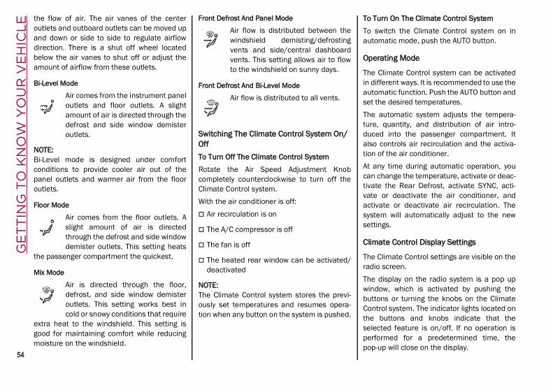
GE
TT
ING
TO
KN
OW
YO
UR
VE
HIC
LE
54
the flow of air. The air vanes of the centeroutlets and outboard outlets can be moved upand down or side to side to regulate airflowdirection. There is a shut off wheel locatedbelow the air vanes to shut off or adjust theamount of airflow from these outlets.
Bi-Level Mode
Air comes from the instrument paneloutlets and floor outlets. A slightamount of air is directed through thedefrost and side window demisteroutlets.
NOTE:Bi-Level mode is designed under comfortconditions to provide cooler air out of thepanel outlets and warmer air from the flooroutlets.
Floor Mode
Air comes from the floor outlets. Aslight amount of air is directedthrough the defrost and side windowdemister outlets. This setting heats
the passenger compartment the quickest.
Mix Mode
Air is directed through the floor,defrost, and side window demisteroutlets. This setting works best incold or snowy conditions that require
extra heat to the windshield. This setting isgood for maintaining comfort while reducingmoisture on the windshield.
Front Defrost And Panel Mode
Air flow is distributed between thewindshield demisting/defrostingvents and side/central dashboardvents. This setting allows air to flowto the windshield on sunny days.
Front Defrost And Bi-Level Mode
Air flow is distributed to all vents.
Switching The Climate Control System On/OffTo Turn Off The Climate Control SystemRotate the Air Speed Adjustment Knobcompletely counterclockwise to turn off theClimate Control system.With the air conditioner is off: Air recirculation is on
The A/C compressor is off
The fan is off
The heated rear window can be activated/deactivated
NOTE:The Climate Control system stores the previ-ously set temperatures and resumes opera-tion when any button on the system is pushed.
To Turn On The Climate Control SystemTo switch the Climate Control system on inautomatic mode, push the AUTO button.
Operating Mode
The Climate Control system can be activatedin different ways. It is recommended to use theautomatic function. Push the AUTO button andset the desired temperatures.The automatic system adjusts the tempera-ture, quantity, and distribution of air intro-duced into the passenger compartment. Italso controls air recirculation and the activa-tion of the air conditioner.At any time during automatic operation, youcan change the temperature, activate or deac-tivate the Rear Defrost, activate SYNC, acti-vate or deactivate the air conditioner, andactivate or deactivate air recirculation. Thesystem will automatically adjust to the newsettings.
Climate Control Display Settings
The Climate Control settings are visible on theradio screen.The display on the radio system is a pop upwindow, which is activated by pushing thebuttons or turning the knobs on the ClimateControl system. The indicator lights located onthe buttons and knobs indicate that theselected feature is on/off. If no operation isperformed for a predetermined time, thepop-up will close on the display.
21_GU_OM_EN_USC_t.book Page 54

55
Humidity Sensor
The Humidity Sensor helps prevent thewindows from fogging up. The AUTO function(indicator illuminated) must be on for theHumidity Sensor to function.When outside temperature is low, the systemmay turn the compressor on and turn air recir-culation off for safer driving.
Stop/Start
The Stop/Start system shuts off the enginewhen the vehicle speed is 0 mph (0 km/h), asa fuel conservation measure.In order to maintain comfort in the cabin, theStop/Start feature will not activate if any of thefollowing conditions exist: The Climate Control system is in AUTO mode
(indicator illuminated), and the vehicle hasyet to reach the set temperature
The Climate Control system is in LOmaximum cooling
The Climate Control system is in HImaximum heating
The Climate Control system is in theMAX-DEF status
When the Stop/Start system is active, theengine will restart if the inside temperaturechanges significantly, or if the LO setting, orMAX-DEF setting, is activated.
With Stop/Start system on (engine is OFF), airflow is reduced to keep the compartmentcomfort conditions for longer.Until the temperature drastically changeswithin the cabin, the climate control systemwill continue to maintain the temperaturewhile the engine is off. By deactivating theStop/Start system with the button (locatedby the headlight switch), the climate controlsystem operates normally according to thesettings.
NOTE:
In harsh climate conditions, limit the use ofthe Stop/Start system to prevent thecompressor from continuously switching onand off. This will cause rapid misting of thewindows and the accumulation of humidityin the passenger compartment.
When the Stop/Start system is on, theclimate control system will always take air infrom outside, reducing the probability of thewindows fogging up.
System Maintenance
In winter months, the Climate Control systemmust be turned on at least once a month forapproximately 10 minutes.Have the system inspected at an authorizeddealer before the summer.
INTERIOR STORAGE AND EQUIPMENT
Glove Compartment
The glove compartment is located on thepassenger side of the instrument panel.
Opening The Glove CompartmentPull the release handle to open the glovecompartment.When the glove compartment is opened, alight turns on to illuminate the inside of thecompartment.
NOTE:
If equipped with a lock, unlock the glovecompartment by placing the emergency keyin the lock on the handle.
Do not insert large objects that will preventthe glove compartment from closingcompletely.
21_GU_OM_EN_USC_t.book Page 55

GE
TT
ING
TO
KN
OW
YO
UR
VE
HIC
LE
56
Center Console
The center console storage compartment islocated between the front seats.To access the center console storage, lift theupper part of the center console as shownbelow.
Center Console
Rear Armrest
The rear armrest is foldable and can be storedin the backrest. To lower the armrest, pull on the tab located
at the top of the seatback and fold it down-ward.
To close the armrest, lift it until it is insertedinto the backrest.
There are two cupholders and a phonecompartment inside the armrest.
Rear Cupholder
NOTE:The armrest was not designed to support theweight of an adult passenger or a child. Onlyuse it to hold drinks or small objects.
Power Outlets
The Instrument Panel Power Outlet is locatedon the center stack under the climate controls.It will only operate when the ignition is in theON/RUN position.
Instrument Panel Power Outlet
NOTE:Do not connect devices, with a power ratinghigher than 180 W, to the outlet. Do not usepower adapters that do not fit the outlet as thismay damage it.
Luggage Compartment Power OutletThere is an additional power outlet located onthe left side of the luggage compartment. It willonly operate when the ignition is in the ON/RUN position.
WARNING!
Do not operate this vehicle with a glovecompartment in the open position. Drivingwith the glove compartment open mayresult in injury in a collision.
WARNING!
Do not operate this vehicle with a consolecompartment lid in the open position.Driving with the console compartment lidopen may result in injury in a collision.
21_GU_OM_EN_USC_t.book Page 56

57
Luggage Compartment Power Outlet
NOTE:Do not connect devices with powers higherthan 150 W to the socket. Do not damage theoutlet by using unsuitable adapters.
115 Volt Power Inverter — If EquippedThe power inverter is located inside of thecenter console. It can be used for smallbattery-powered electrical appliances withpowers up to 150 W (e.g. cameras, videocamera, tablets, razors, etc.)
NOTE:Do not connect devices with powers higherthan 150 W to the socket. Do not damage thesocket by using unsuitable adapters.
Power Inverter
Cigar Lighter And Ash Tray — If Equipped
If equipped, the cigar lighter is located on thebottom of the center stack, in front of thecupholders.To activate the cigar lighter, push in and wait afew seconds. Once the cigar lighter hasreturned to its original position, it is ready foruse.
NOTE:Always ensure the cigar lighter is turned offwhen not in use.
1 — Cigar LighterIf equipped, the ash tray is a removable plasticcontainer located inside the cupholder.
Wireless Charging Pad — If Equipped
Wireless Charging PadYour vehicle may be equipped with a 15 W (3 A)Qi wireless charging pad located inside of thecenter console. This charging pad is designedto wirelessly charge your Qi enabled mobilephone. Qi is a standard that uses magneticinduction to transfer power to your mobiledevice.
21_GU_OM_EN_USC_t.book Page 57

GE
TT
ING
TO
KN
OW
YO
UR
VE
HIC
LE
58
Your mobile phone must be designed for Qiwireless charging.
NOTE:
Do not place the key fob or any other type ofmetal/magnetized object inside the mobilephone housing or near the wirelesscharging pad.
Be sure to place the mobile device correctly(display facing upward) on the wirelesscharging pad.
The ignition must be in the ON/RUN positionin order for the phone to charge.
To avoid interference with the key fobsearch, the wireless charging pad will stopcharging when any door is opened.
The following messages will display in theradio system: “Your phone is being charged” — The phone
has begun to charge.
“Phone Fully Charged” — The phone hascompleted charging its battery.
“Foreign Object Detected” — The phone isnot enabled for wireless charging or anobject that is not permitted has been placedon the wireless charging pad.
“Unavailable System” — There is a malfunc-tion with the wireless charging pad.
The driver can deactivate these messagesthrough the radio system. Refer to the Infor-mation and Entertainment System Owner’sManual Supplement for further information.
POWER WINDOWS
Power Window Controls
The power window switches work with the igni-tion in the ACC or ON/RUN position and forthree minutes after the ignition has beenplaced in the OFF position. When one of thefront doors is opened, this operation isdisabled.The window controls on the driver's doorcontrol all the door windows.
Power Window Switches
The passenger door windows can also be oper-ated by using the single window controls onthe passenger door trim panel.To open the window part way (manually), pushthe window switch down briefly and release.Push past the detent to activate “continuousautomatic” operation.If the button is pushed again, the window willstop in the desired position.Pull the window switch to the first detent tomove the window upward. Pull the windowswitch to the second detent, and the windowwill go up automatically.
CAUTION!
The key fob should not be placed on thecharging pad or within 15 cm (150 mm) ofit. Doing so can cause excessive heatbuildup and damage to the fob. Placing thefob in close proximity of the charging padblocks the fob from being detected by thevehicle and prevents the vehicle fromstarting.
1 — Front Left Window Switch2 — Front Right Window Switch3 — Rear Right Window Switch4 — Window Lockout Switch5 — Rear Left Window Switch
21_GU_OM_EN_USC_t.book Page 58

59
To close the window, pull the window switchup. To stop the window during Auto-Up opera-tion, push or pull the window switch again.
Auto-Up Feature With Anti-Pinch Protection
The vehicle is equipped with an anti-pinchsafety device for closing the windows.If the safety system senses any obstacle whilethe window is closing, it will stop the window’smovement and reverse it, depending on itsposition.This device is also useful if the windows areactivated accidentally by children inside thevehicle.The anti-pinch safety function is activated bothduring the manual and the automatic opera-tion of the window.When the anti-pinch system is activated, thewindow closing is immediately interrupted.Then the window closing is automatically
reversed and the window lowers by about8 inches (20 cm) in relation to the first stopposition. The window cannot be operatedduring this time.
NOTE:In the event of an error, or if the anti-pinchprotection is activated three consecutivetimes, the automatic closing operation of thewindow will be deactivated. In order to restorethe correct operation of the system, thewindow must be lowered.
Power Window System Initialization
If power supply is interrupted, the electricwindow automatic operation must be reinitial-ized.To perform the initialization procedure, whichmust be done on each door with the doorsclosed, manually fully close the window to beinitialized.
Wind Buffeting
Wind buffeting can be described as theperception of pressure on the ears or a heli-copter-type sound in the ears. Your vehiclemay exhibit wind buffeting with the windowsdown, or the sunroof (if equipped) in certainopen or partially open positions. This is anormal occurrence and can be minimized. Ifthe buffeting occurs with the rear windowsopen, open the front and rear windows
together to minimize the buffeting. If thebuffeting occurs with the sunroof open, adjustthe sunroof opening to minimize the buffetingor open any window.
POWER SUNROOF — IF EQUIPPED
Power Sunroof
The power sunroof consists of a single glasspanel and is fitted with a power sunshade thefull length of the panel.Operation of the sunroof is only possible withthe ignition in the ACC or ON/RUN position Ú page 20.
Sunroof And Power Shade Buttons
WARNING!
Never leave children unattended in avehicle, and do not let children play withpower windows. Do not leave the key fob inor near the vehicle, or in a locationaccessible to children. Occupants,particularly unattended children, canbecome entrapped by the windows whileoperating the power window switches. Suchentrapment may result in serious injury ordeath.
1 — Power Shade Open/Close2 — Sunroof Open/Close Button3 — Vent Open/Close
21_GU_OM_EN_USC_t.book Page 59

GE
TT
ING
TO
KN
OW
YO
UR
VE
HIC
LE
60
The sunroof has three preset positions: Fully closed
Comfort (intermediate opening)
Fully open
NOTE:You cannot have the sunshade closed whenthe sunroof is open.
Opening And Closing The Sunroof
To open the sunroof’s front panel, push theopen/close button toward the rear of thevehicle to open to the comfort position (halfway). Pushing the button a second time willopen to the fully open position.To close the sunroof, push the open/closebutton toward the front of the vehicle. The roofwill close completely.The automatic motion can be interrupted inany position by pushing the open/close buttonagain.
Venting Sunroof
To bring the roof into vent position, push andrelease the vent button.This type of vent opening can be activatedregardless of the position of the sunroof.When starting with the roof in the closed posi-tion, pushing the vent button automaticallycauses the sunroof to open to the vent posi-tion. If the roof is already open, the buttonmust be held until the roof reaches thevent-opening position.Pushing the vent button again during auto-matic movement of the roof will stop it.
Sunshade Operation
The sunshade is power operated.Push the Power Shade open/close buttontoward the rear of the vehicle to open the sunshade.Push the Power Shade open/close buttontoward the front of the vehicle to close the sunshade.The automatic motion can be interrupted inany position by pushing the Power Shadeopen/close button again.
Pinch Protect Feature
The sunroof has an anti-pinch safety systemcapable of detecting the presence of anobstacle during the closing movement. If anobstacle is detected, the system intervenesand the movement of the sunroof is immedi-ately reversed.
Re-Initialization Procedure
Automatic operation of the sunroof must bere-initialized in case of faulty sunroof opera-tion. It may also be necessary to initialize thesunroof after the vehicle’s battery has beendisconnected and then reconnected.
NOTE:The anti-pinch safety device is deactivatedduring the re-initialization procedure.
WARNING!
Never leave children unattended in avehicle, or with access to an unlockedvehicle. Never leave the key fob in or nearthe vehicle, or in a location accessible to chil-dren. Do not leave the ignition of a vehicleequipped with keyless ignition in the ON/RUN mode. Occupants, particularly unat-tended children, can become entrapped bythe power sunroof while operating the powersunroof switch. Such entrapment may resultin serious injury or death.
In a collision, there is a greater risk ofbeing thrown from a vehicle with an opensunroof. You could also be seriouslyinjured or killed. Always fasten your seatbelt properly and make sure all passen-gers are also properly secured.
Do not allow small children to operate thesunroof. Never allow your fingers, otherbody parts, or any object, to projectthrough the sunroof opening. Injury mayresult.
CAUTION!
Do not open the sun roof if a roof rack orcrossbars are fitted. Do not open the sunroof if there is snow or ice on it: you maydamage it.
21_GU_OM_EN_USC_t.book Page 60
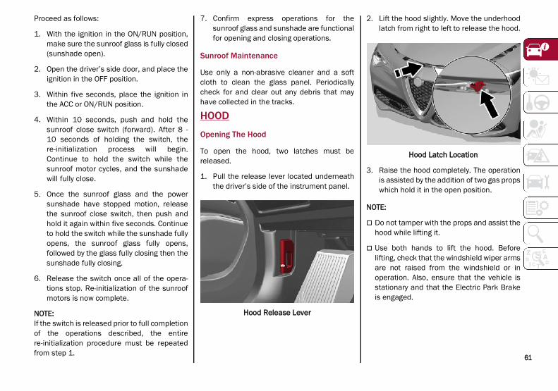
61
Proceed as follows:
1. With the ignition in the ON/RUN position,make sure the sunroof glass is fully closed(sunshade open).
2. Open the driver’s side door, and place theignition in the OFF position.
3. Within five seconds, place the ignition inthe ACC or ON/RUN position.
4. Within 10 seconds, push and hold thesunroof close switch (forward). After 8 -10 seconds of holding the switch, there-initialization process will begin.Continue to hold the switch while thesunroof motor cycles, and the sunshadewill fully close.
5. Once the sunroof glass and the powersunshade have stopped motion, releasethe sunroof close switch, then push andhold it again within five seconds. Continueto hold the switch while the sunshade fullyopens, the sunroof glass fully opens,followed by the glass fully closing then thesunshade fully closing.
6. Release the switch once all of the opera-tions stop. Re-initialization of the sunroofmotors is now complete.
NOTE:If the switch is released prior to full completionof the operations described, the entirere-initialization procedure must be repeatedfrom step 1.
7. Confirm express operations for thesunroof glass and sunshade are functionalfor opening and closing operations.
Sunroof Maintenance
Use only a non-abrasive cleaner and a softcloth to clean the glass panel. Periodicallycheck for and clear out any debris that mayhave collected in the tracks.
HOOD
Opening The Hood
To open the hood, two latches must bereleased.
1. Pull the release lever located underneaththe driver’s side of the instrument panel.
Hood Release Lever
2. Lift the hood slightly. Move the underhoodlatch from right to left to release the hood.
Hood Latch Location
3. Raise the hood completely. The operationis assisted by the addition of two gas propswhich hold it in the open position.
NOTE:
Do not tamper with the props and assist thehood while lifting it.
Use both hands to lift the hood. Beforelifting, check that the windshield wiper armsare not raised from the windshield or inoperation. Also, ensure that the vehicle isstationary and that the Electric Park Brakeis engaged.
21_GU_OM_EN_USC_t.book Page 61

GE
TT
ING
TO
KN
OW
YO
UR
VE
HIC
LE
62
Closing The Hood
To close, lower the hood to approximately16 inches (40 cm) from the engine compart-ment then let it drop. Make sure that the hoodis completely closed and fully latched.
NOTE:Since the hood is equipped with a doublelocking system, one for each side, you mustcheck that it is closed on each side.
POWER LIFTGATEUnlocking of the liftgate is electrically oper-ated and is deactivated when the vehicle is inmotion.If anything obstructs the power liftgate while itis closing or opening, the liftgate will automat-ically reverse to the closed or open position,provided it meets sufficient resistance.
Opening
The liftgate may be released in several ways: Pressing the liftgate release button on the
key fob twice within five seconds
Pushing the external liftgate release switch(when the liftgate is unlocked)
Lifting the interior liftgate release button onthe driver’s door panel trim.
External Liftgate Release Switch
Interior Liftgate Release
The turn signal indicators will blink and theinterior lights will turn on when the liftgate isopened. They turn off automatically when theliftgate is closed.The lights turn off automatically after a fewminutes if the liftgate is left open.A signal will chime while the liftgate is openingor closing.
NOTE:You can stop the liftgate from moving bypushing the interior liftgate release buttonagain.
Liftgate Emergency OpeningThere is a panel on the luggage compartmentinterior trim, next to the liftgate lock, acces-sible by folding down the rear seat backrest,which allows access to the manual lockrelease.
Manual Lock Release Location
WARNING!
Be sure the hood is fully latched beforedriving your vehicle. If the hood is not fullylatched, it could open when the vehicle is inmotion and block your vision. Failure tofollow this warning could result in seriousinjury or death.
1 — Interior Liftgate Release Switch
21_GU_OM_EN_USC_t.book Page 62

63
Pull to release the lock.
Manual Lock Release CordThe liftgate can now be opened manually.
Closing
It is possible to close the liftgate by pushing: The power liftgate switch.
The power lock switch located on the lift-gate (all the doors, including the liftgate, willbe locked).
The liftgate button on the key fob twice.
The power liftgate switch on the liftgate.
The power liftgate switch on the driver’sdoor panel trim and hold until the operationis complete.
Power Liftgate/Lock Switches
NOTE:It is possible to stop the liftgate from movingwith any of the Power Liftgate switches.
Customizing The Liftgate Opening Height
To avoid difficulties in tight spaces, you can setthe height at which the liftgate opens to.To customize the liftgate opening position,follow the steps below:
1. Open the liftgate manually and move it tothe position that you want the liftgate toopen to.
2. Press and hold one of the closing buttonsfor at least five seconds (successfulprogramming is indicated by the turnsignals flashing three times).
The liftgate is now programmed to open to theset position.
This function can be selected on the radiosystem.To set the liftgate opening height, refer to theInformation and Entertainment System Owner’sManual Supplement for further information.
Hands-Free Liftgate — If Equipped
To operate the Hands-Free Liftgate system:
1. If the doors are locked, the system mustdetect the electronic key near the liftgate.
2. If the doors are unlocked, the system doesnot have to detect the electronic key nearthe liftgate.
3. Go to the rear of the vehicle, in the centerand about 3 feet (1 m) from the liftgate.
4. Move your foot under the bumper, simu-lating a kick. When you have completedthis movement, withdraw your leg. To acti-vate the liftgate, both sensors must detectyour leg.
Hands Free Liftgate Activation Zone
1 — Power Liftgate Switch2 — Power Door Lock Switch
21_GU_OM_EN_USC_t.book Page 63

GE
TT
ING
TO
KN
OW
YO
UR
VE
HIC
LE
64 (Continued)
If it is closed, the Hands-Free Liftgate unlocksand opens completely, and with anothermovement of the foot, it stops. A further move-ment of the foot reverses the direction andcloses the liftgate completely, if you do notstop it again.If it is open, with a movement of the foot, theHands-Free Liftgate closes completely, andwith another movement of the foot, it stops. Ifthe liftgate is stopped, another movement ofthe foot will reverse the direction and open itcompletely.
NOTE:To conserve the battery charge, avoidperforming this operation repeatedly with theengine off.
You can activate/deactivate the Hands-FreeLiftgate on the radio system by pushing theMENU button to select the Main menu, andselecting the following items:
1. “Settings.”
2. “Doors And Locks.”
3. “Automatic Liftgate Opening.”
Liftgate Initialization
NOTE:Automatic operation of the liftgate must beinitialized again in case of faulty liftgate opera-tion. Proceed as follows:
1. Close all the doors and the liftgate.
2. Push the lock button on the key fob.
3. Push the unlock button on the key fob.
Cargo Area Features
Retractable Cargo Area Cover
The Retractable Cargo Area Cover can berolled up and removed.To Use The Cargo Area Cover:
1. From the rolled up (retracted) position,hold the handle and pull the cover outwardtoward the rear of the vehicle.
2. Then assist the cover pins into the slotslocated just inside the liftgate opening.
Retractable Cargo Area Cover
Removing The Cover:
1. Retract the cover by pulling the handleslightly rearward to release the cover pins.
2. Guide the cover forward until it is fullyretracted.
WARNING!
Driving with the liftgate open can allowpoisonous exhaust gases into your vehicle.You and your passengers could be injuredby these fumes. Keep the liftgate closedwhen you are operating the vehicle.
If you are required to drive with the liftgateopen, make sure that all windows areclosed, and the climate control blowerswitch is set at high speed. Do not use therecirculation mode.
During power operation, personal injury orcargo damage may occur. Ensure the lift-gate travel path is clear. Make sure theliftgate is closed and latched beforedriving away.
CAUTION!
The Hands-Free Liftgate can be turned offmanually in the radio system to avoidunintentional activation. For furtherinformation refer to the Information andEntertainment System Owner’s ManualSupplement.
WARNING! (Continued)
1 — Handle2 — Cover Pins
21_GU_OM_EN_USC_t.book Page 64

65
3. Pull the two cover hooks (one on eachside) towards the inside of the cargo area.Then lift the cover up and remove it.
Cover Attached
Rear Cargo Anchors
The cargo area floor may be equipped withfixed or mobile anchoring loops that allows youto anchor and secure luggage safely.The fixed anchor loops are located in the fourcorners of the cargo floor.
Anchor Loops
Cargo Area Adjustable Rail — If Equipped
The mobile loops (if equipped), slide on twoguides secured to the cargo area floor.To position a loop, push down the centerbutton while sliding the loop along the guide tothe desired position. Release the button andmove the loop slightly to the next fixed positionin the notches on the guide.
Adjustable Anchor Loop — If EquippedLift the loop to fasten the load.
Lift Adjustable Anchor Loop To Use
Cargo Net — If Equipped
Cargo nets can be used to contain lightweightmaterials during transport.The cargo net is included in the optional“Convenience Package” and is available froman authorized dealer.
3 — Cover Hook
WARNING!
In a collision, a loose cargo cover in thevehicle could cause injury. It could flyaround in a sudden stop and strikesomeone in the vehicle. Do not store thecargo cover on the cargo floor or in thepassenger compartment. Remove the coverfrom the vehicle when taken from itsmounting. Do not store it in the vehicle.
21_GU_OM_EN_USC_t.book Page 65

GE
TT
ING
TO
KN
OW
YO
UR
VE
HIC
LE
66
Grocery Hooks
Two hooks (one on the left side and one on theright side) are also available on the sidepanels to fix loads that are not excessivelyheavy (e.g. bags).
Grocery Hook
NOTE:Do not apply a load greater than 22 lbs (10 kg)on a single hook.
Accessing The Tire Service Kit — If Equipped
To access the Tire Service Kit Ú page 198, liftup the load floor by the handle.
Load Floor
21_GU_OM_EN_USC_t.book Page 66

67
GE
TT
ING
TO
KN
OW
YO
UR
INS
TR
UM
EN
T P
AN
EL This section gives you all the information you need to understand and use the instrument panel correctly.
INSTRUMENT PANEL FEATURES
Instrument Cluster
Instrument Cluster
21_GU_OM_EN_USC_t.book Page 67

GE
TT
ING
TO
KN
OW
YO
UR
INS
TR
UM
EN
T P
AN
EL
68
Quadrifoglio Instrument Cluster
Instrument Cluster Descriptions
1. Tachometer
• Indicates the engine speed in revolu-tions per minute (RPM x 1000).
• Inside the tachometer there is a lightsensor capable of detecting ambientlight conditions and adjusting the oper-ating mode (night/day) and the bright-ness of the instrument panel and theInformation and Entertainment Systemdisplay.
2. Engine Oil Temperature Gauge
• The digital bar indicator monitors thetemperature of the engine oil and startssupplying indications when the fluidtemperature reaches approximately122°F (50°C).
• Under normal usage, the digital scaleshould hover around the middle of thescale according to the working condi-tions.
WARNING!
A hot engine cooling system is dangerous.You or others could be badly burned bysteam or boiling coolant. It isrecommended to call an authorized dealerfor service if your vehicle overheats Ú page 223.
21_GU_OM_EN_USC_t.book Page 68
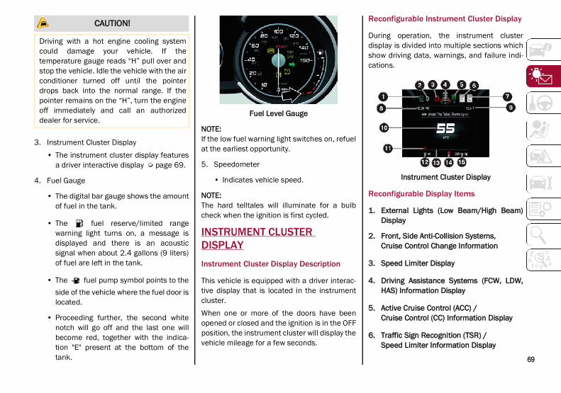
69
3. Instrument Cluster Display• The instrument cluster display features
a driver interactive display Ú page 69.
4. Fuel Gauge
• The digital bar gauge shows the amountof fuel in the tank.
• The fuel reserve/limited rangewarning light turns on, a message isdisplayed and there is an acousticsignal when about 2.4 gallons (9 liters)of fuel are left in the tank.
• The fuel pump symbol points to theside of the vehicle where the fuel door islocated.
• Proceeding further, the second whitenotch will go off and the last one willbecome red, together with the indica-tion "E" present at the bottom of thetank.
Fuel Level Gauge
NOTE:If the low fuel warning light switches on, refuelat the earliest opportunity.
5. Speedometer
• Indicates vehicle speed.
NOTE:The hard telltales will illuminate for a bulbcheck when the ignition is first cycled.
INSTRUMENT CLUSTER DISPLAY
Instrument Cluster Display Description
This vehicle is equipped with a driver interac-tive display that is located in the instrumentcluster.When one or more of the doors have beenopened or closed and the ignition is in the OFFposition, the instrument cluster will display thevehicle mileage for a few seconds.
Reconfigurable Instrument Cluster Display
During operation, the instrument clusterdisplay is divided into multiple sections whichshow driving data, warnings, and failure indi-cations.
Instrument Cluster Display
Reconfigurable Display Items
1. External Lights (Low Beam/High Beam)Display
2. Front, Side Anti-Collision Systems,Cruise Control Change Information
3. Speed Limiter Display
4. Driving Assistance Systems (FCW, LDW,HAS) Information Display
5. Active Cruise Control (ACC) / Cruise Control (CC) Information Display
6. Traffic Sign Recognition (TSR) /Speed Limiter Information Display
CAUTION!
Driving with a hot engine cooling systemcould damage your vehicle. If thetemperature gauge reads “H” pull over andstop the vehicle. Idle the vehicle with the airconditioner turned off until the pointerdrops back into the normal range. If thepointer remains on the “H”, turn the engineoff immediately and call an authorizeddealer for service.
21_GU_OM_EN_USC_t.book Page 69

GE
TT
ING
TO
KN
OW
YO
UR
INS
TR
UM
EN
T P
AN
EL
70
7. Traffic Sign Recognition (TSR) InformationDisplay
8. Time
9. External Temperature
10. Main Display: Vehicle Speed Display, TripComputer Information, etc...
The screens can be selected, on rotation,by pushing the MENU selection button onthe windshield wiper stalk.
MENU Selection ButtonDepending on the driving mode chosen us-ing the Alfa DNA (Dynamic, Natural, and Advanced Efficiency) the screens can be graphically different. Navigation instruc-tions and call information can be set and displayed in the Information and Entertain-ment System.
Home
The parameters shown on the display, for the modes: Dynamic, Normal and Ad-vanced Efficiency are:
• Time
• Outside Temperature
• Current speed (shown only if the repeatmode of the “Navigation” and “Phone”functions have not been previously acti-vated).
• Range
In RACE mode (if equipped) the consump-tion indication index is not active and a sports gearshift indicator is displayed.
Instrument Cluster Display
Instrument Cluster DisplayTrip A And B
For all driving modes (Dynamic, Natural, and Advanced Efficiency) and with the igni-tion device ON, the “Trip computer” can be used to display the measurements regard-ing the operating state of the vehicle. This function is characterized by two separate records, called “Trip A” and “Trip B” (the latter can be deactivated by Information and Entertainment System), where the “complete missions” (journeys) are record-ed in a reciprocally independent manner.
“Trip A” and “Trip B” are used to display the values relating to:
• Distance traveled
• Average fuel consumption
• Average speed
• Active trip
• Fuel consumption indicator
1 — Time2 — Temperature3 — Distance To Empty4 — Speed
21_GU_OM_EN_USC_t.book Page 70

71
Instrument Cluster DisplayTo reset the values, press and hold down the button on the windshield wiper stalk.
Reset ButtonPerformance
The displayed parameters differ according to the active mode. The modes which can be selected using the Alfa DNA system are:
Natural
Efficiency Consumption GraphThe screen graphically reproduces some parameters closely linked to the efficiency of the driving style, with a view to limiting consumption.
Advanced Efficiency
Dynamic Driving Style
The three central icons on the screen indi-cate the effectiveness of the driving style linked to the parameters of: acceleration, deceleration and gearshift with a view to reducing fuel consumption.
The graphic bar below the icons shows cur-rent consumption and the green line rep-resents the optimal area. The globe lights up gradually according to lower consump-tion.
Alternative Performance
The displayed parameters vary depending on the active mode. The modes can be se-lected through the Alfa DNA system and are as follows:
Normal and Advanced Efficiency
The display graphically shows the values of:
○ instantaneous consumption○ average fuel consumption (based
on “Trip A”);
Below a certain speed value, when the ac-celerator pedal is not pressed or in the event of failure, dashes are displayed in place of the consumption value ("– –. –").
1 — Acceleration2 — Deceleration3 — Gear Shifts
21_GU_OM_EN_USC_t.book Page 71

GE
TT
ING
TO
KN
OW
YO
UR
INS
TR
UM
EN
T P
AN
EL
72
Normal and Advanced EfficiencyDynamic
The display graphically shows the values of:
○ accelerator pedal position(expressed in percentage);
○ brake pedal position (expressed inpercentage);
○ engine coolant temperature (H =hot C = cold).
Dynamic
Race (If Equipped)
The display graphically shows the values of:
○ engine torque;○ turbocharger pressure;○ engine oil pressure (L = low pres-
sure/H= high pressure).NOTE:The engine torque and turbocharger pressurevalues vary according to the engine type.
RaceDynamic
Acceleration Gauge
The displayed parameters are related to vehicle stability, the graphs illustrate the trend of the longitudinal/lateral accelera-tions (G-meter information), considering gravity acceleration as a reference unit.
Lateral acceleration peaks are also indi-cated.
11. Driving Mode Display (Alfa DNA System)
12. Distance Traveled (miles/km) display
13. Fuel Consumption
14. Warning Indications Display (e.g. danger ofice, open doors, ABS operation, etc.)
15. Range
Customer Programmable Settings
Multiple settings can be programmed by theuser using the radio. This section describesonly the basic settings: Units & Language
Clock & Date
Cluster
21_GU_OM_EN_USC_t.book Page 72

73
To access the settings list in the radio, proceedas follows: Press the Home button to access the main
menu.
Select Settings from the main menu usingthe Rotary Knob or by pressing Settings onthe touchscreen.
Rotary Knob
Units & LanguageThe following settings can be modified underthe “Units & Language” menu: Units: select US, Metric, or Custom. The
custom option allows for individual selec-tion of the unit measures
Language: change the language of thesystem
Restore Unit & Language Settings: restoresthe factory settings
To access and the change the setting, turn andpush the Rotary Pad or press the desiredsetting on the touchscreen.Clock & DateThe following settings can be modified underthe “Clock & Date” menu: Sync With GPS Time: activates or deacti-
vates the clock synchronization through theGPS. If the function is deactivated, theoptions Set Time and Set Date are enabled
Set Time: set the time manually
Time Format: set the time format to either a12-hour or a 24-hour clock.
Set Date: set the date manually
Restore Clock & Date Settings: restores thefactory settings
To access and change the setting, turn andpush the Rotary Pad or press the desiredsetting on the touchscreen.ClusterThe following settings can be modified underthe “Cluster” menu: Warning Buzzer Volume: allows you to set
the volume of the warning buzzer on sevenlevels.
Trip B: activate or deactivate the Trip function.
Show Phone Info: allows you to activate/deactivate repetition of the phone functionscreens also on the instrument clusterdisplay.
Show Audio Info: allows you to activate/deactivate repetition of the audio functionscreens (Radio and Media) also on theinstrument cluster display.
Show Nav Info: allows you to activate/deac-tivate repetition of the navigator functionscreens also on the instrument clusterdisplay.
Digital Speed on all screens: this allows youto activate/deactivating of digital speed onthe instrument cluster display screens otherthan the main screen.
Consumption Bar: allows you to activate/deactivate the consumption baron thedisplay screens of the instrument panelwhere it is available.
Performance Pages: allows you to choose,for each driving mode, one of the two alter-native contents displayed in the screen.
Custom Areas: allows you to select whichcontent to display in each of the threecustomizable areas on the display of theinstrument panel: time, date, outsidetemperature, radio information, compass.
Restore Cluster Settings: deletes thecurrent settings and restores the factorysettings.
1 — ON/OFF Control And Volume Knob2 — OPTION Button3 — Rotary Pad4 — MENU Button
21_GU_OM_EN_USC_t.book Page 73
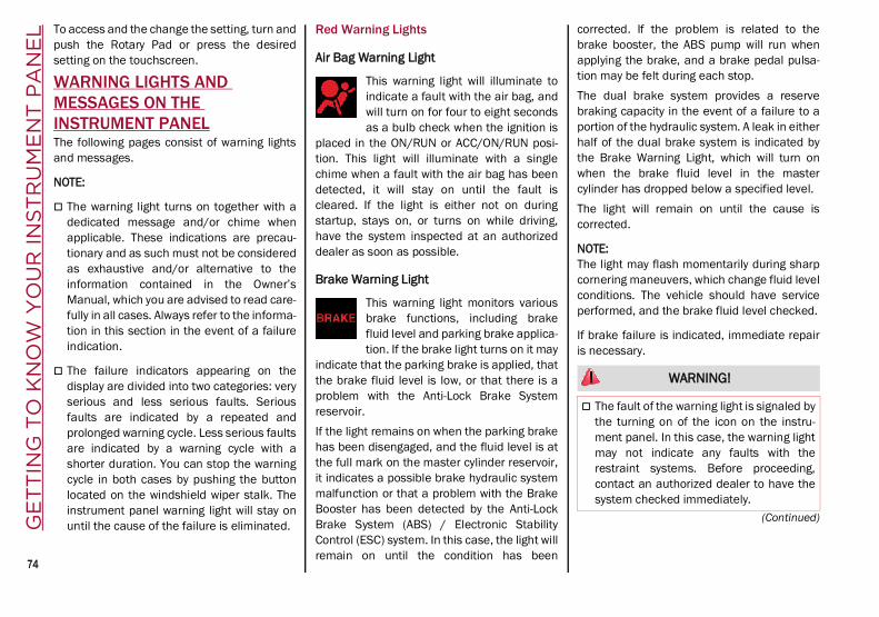
GE
TT
ING
TO
KN
OW
YO
UR
INS
TR
UM
EN
T P
AN
EL
74
(Continued)
To access and the change the setting, turn andpush the Rotary Pad or press the desiredsetting on the touchscreen.
WARNING LIGHTS AND MESSAGES ON THE INSTRUMENT PANELThe following pages consist of warning lightsand messages.
NOTE:
The warning light turns on together with adedicated message and/or chime whenapplicable. These indications are precau-tionary and as such must not be consideredas exhaustive and/or alternative to theinformation contained in the Owner’sManual, which you are advised to read care-fully in all cases. Always refer to the informa-tion in this section in the event of a failureindication.
The failure indicators appearing on thedisplay are divided into two categories: veryserious and less serious faults. Seriousfaults are indicated by a repeated andprolonged warning cycle. Less serious faultsare indicated by a warning cycle with ashorter duration. You can stop the warningcycle in both cases by pushing the buttonlocated on the windshield wiper stalk. Theinstrument panel warning light will stay onuntil the cause of the failure is eliminated.
Red Warning Lights
Air Bag Warning Light
This warning light will illuminate toindicate a fault with the air bag, andwill turn on for four to eight secondsas a bulb check when the ignition is
placed in the ON/RUN or ACC/ON/RUN posi-tion. This light will illuminate with a singlechime when a fault with the air bag has beendetected, it will stay on until the fault iscleared. If the light is either not on duringstartup, stays on, or turns on while driving,have the system inspected at an authorizeddealer as soon as possible.
Brake Warning Light
This warning light monitors variousbrake functions, including brakefluid level and parking brake applica-tion. If the brake light turns on it may
indicate that the parking brake is applied, thatthe brake fluid level is low, or that there is aproblem with the Anti-Lock Brake Systemreservoir.If the light remains on when the parking brakehas been disengaged, and the fluid level is atthe full mark on the master cylinder reservoir,it indicates a possible brake hydraulic systemmalfunction or that a problem with the BrakeBooster has been detected by the Anti-LockBrake System (ABS) / Electronic StabilityControl (ESC) system. In this case, the light willremain on until the condition has been
corrected. If the problem is related to thebrake booster, the ABS pump will run whenapplying the brake, and a brake pedal pulsa-tion may be felt during each stop.The dual brake system provides a reservebraking capacity in the event of a failure to aportion of the hydraulic system. A leak in eitherhalf of the dual brake system is indicated bythe Brake Warning Light, which will turn onwhen the brake fluid level in the mastercylinder has dropped below a specified level.The light will remain on until the cause iscorrected.
NOTE:The light may flash momentarily during sharpcornering maneuvers, which change fluid levelconditions. The vehicle should have serviceperformed, and the brake fluid level checked.
If brake failure is indicated, immediate repairis necessary.
WARNING!
The fault of the warning light is signaled bythe turning on of the icon on the instru-ment panel. In this case, the warning lightmay not indicate any faults with therestraint systems. Before proceeding,contact an authorized dealer to have thesystem checked immediately.
21_GU_OM_EN_USC_t.book Page 74

75
Vehicles equipped with the Anti-Lock BrakeSystem (ABS) are also equipped with Elec-tronic Brake Force Distribution (EBD). In theevent of an EBD failure, the Brake WarningLight will turn on along with the ABS Light.Immediate repair to the ABS system isrequired.Operation of the Brake Warning Light can bechecked by turning the ignition switch from theOFF position to the ON/RUN position. The lightshould illuminate for approximately twoseconds. The light should then turn off unlessthe parking brake is applied or a brake fault isdetected. If the light does not illuminate, havethe light inspected by an authorized dealer.The light also will turn on when the parkingbrake is applied with the ignition switch in theON/RUN position.
NOTE:This light shows only that the parking brake isapplied. It does not show the degree of brakeapplication.
Seat Belt Reminder Warning Light
When the ignition is first placed inthe ON/RUN position, if the driver’sseat belt is unbuckled, a chime willsound and the light will turn on.
When driving, if the driver or front passengerseat belt remains unbuckled, the Seat BeltReminder Light will flash or remain on contin-uously and a chime will sound Ú page 163.
Electronic Brake Force Distribution (EBD) Failure
The simultaneous turning on of theBRAKE (red) and (amber) warninglights with the engine on indicateseither a failure of the EBD system or
that the system is not available. In this case,the rear wheels may suddenly lock and thevehicle may swerve when braking abruptly.Drive very carefully to the nearest authorizeddealer to have the system inspected immedi-ately.
Oil Temperature Warning Light
This telltale indicates engine oiltemperature is high.
Stop the vehicle and shut off the engine assoon as possible. If the problem persists,contact an authorized dealer.
Amber Warning Lights
Anti-Lock Brake System (ABS) Warning Light
This light monitors the ABS. The lightwill turn on when the ignition isplaced in the ON/RUN position andmay stay on for as long as fourseconds.
If the ABS light remains on or turns on whiledriving, then the Anti-Lock portion of the brakesystem is not functioning and service is
If the warning light does not turn on whenthe ignition device is moved to ON or if itstays on when driving (together with themessage on the display), there might be afault in the restraint systems; in this case,the air bags or pretensioners may notdeploy in the event of an accident or, in alower number of cases, they could deployerroneously. Before proceeding, contactan authorized dealer to have the systemchecked immediately.
WARNING! (Continued)
WARNING!
The fault of the warning light is signaled bythe turning on of the icon on the instru-ment panel. In this case, the warning lightmay not indicate any faults with therestraint systems. Before proceeding,contact an authorized dealer to have thesystem checked immediately.
If the warning light does not turn on whenthe ignition device is moved to ON or if itstays on when driving (together with themessage on the display), there might be afault in the restraint systems; in this case,the air bags or pretensioners may notdeploy in the event of an accident or, in alower number of cases, they could deployerroneously. Before proceeding, contactan authorized dealer to have the systemchecked immediately.
21_GU_OM_EN_USC_t.book Page 75

GE
TT
ING
TO
KN
OW
YO
UR
INS
TR
UM
EN
T P
AN
EL
76
required. However, the conventional brakesystem will continue to operate normally if thebrake indicator light is not on.If the ABS light is on, the brake system shouldbe serviced as soon as possible to restore thebenefits of Anti-Lock Brakes. If the ABS lightdoes not turn on when the ignition is placed inthe ON/RUN position, have the light inspectedby an authorized dealer.
Electronic Stability Control (ESC) Indicator Light — If Equipped
When the ignition is cycled to ON, theindicator light illuminates, butshould turn off as soon as the engineis started.
ESC System Intervention: Intervention by thesystem is indicated by the flashing of the indi-cator light: it indicates that the vehicle is in crit-ical stability and grip conditions.ESC System Failure: If the indicator light doesnot turn off, or if it stays on with the enginerunning, a failure was found in the ESCsystem.Hill Start Assist System Failure: The illumina-tion of the indicator light indicates a Hill StartAssist system failure.In these cases, contact an authorized dealeras soon as possible.
Electronic Stability Control (ESC) OFF Indicator Light — If Equipped
When the ignition is cycled to ON, theindicator light illuminates, butshould turn off as soon as the engineis started.
The indicator light illuminates to indicate thatsome active safety systems have beenpartially or totally deactivated Ú page 145.When the active safety systems are reacti-vated, the indicator light turns off.
Tire Pressure Low Warning Light
The indicator light will illuminate toindicate that the tire pressure islower than the recommended valueand/or that slow pressure loss is
occurring. In these cases, optimal tire durationand fuel consumption may not be guaranteed.In any situation in which the message on thedisplay is “See Manual” Ú page 161.
Tire Pressure Monitoring System (TPMS) Warning Light
The warning light switches on and amessage is displayed to indicatethat the tire pressure is lower thanthe recommended value and/or that
slow pressure loss is occurring. In these cases,optimal tire duration and fuel consumptionmay not be guaranteed.
Should one or more tires be in the conditionmentioned above, the display will show theindications corresponding to each tire.
Each tire, including the spare (if provided),should be checked monthly when cold andinflated to the inflation pressure recom-mended by the vehicle manufacturer on thevehicle placard or tire inflation pressure label.If your vehicle has tires of a different size thanthe size indicated on the vehicle placard or tireinflation pressure label, you should determinethe proper tire inflation pressure for thosetires.As an added safety feature, your vehicle hasbeen equipped with a TPMS that illuminates alow tire pressure telltale when one or more ofyour tires is significantly underinflated. Accord-ingly, when the low tire pressure telltale illumi-nates, you should stop and check your tires assoon as possible, and inflate them to theproper pressure. Driving on a significantlyunderinflated tire causes the tire to overheatand can lead to tire failure. Under inflation
CAUTION!
Do not continue driving with one or moreflat tires as handling may be compromised.Stop the vehicle, avoiding sharp brakingand steering. If a tire puncture occurs,repair immediately using the dedicated tirerepair kit and contact an authorized dealeras soon as possible.
21_GU_OM_EN_USC_t.book Page 76

77
also reduces fuel efficiency and tire tread life,and may affect the vehicle’s handling andstopping ability.Please note that the TPMS is not a substitutefor proper tire maintenance, and it is thedriver’s responsibility to maintain correct tirepressure, even if under inflation has notreached the level to trigger illumination of theTPMS low tire pressure telltale.Your vehicle has also been equipped with aTPMS malfunction indicator to indicate whenthe system is not operating properly. TheTPMS malfunction indicator is combined withthe low tire pressure telltale. When the systemdetects a malfunction, the telltale will flash forapproximately one minute and then remaincontinuously illuminated. This sequence willcontinue upon subsequent vehicle start-upsas long as the malfunction exists. When themalfunction indicator is illuminated, thesystem may not be able to detect or signal lowtire pressure as intended. TPMS malfunctionsmay occur for a variety of reasons, includingthe installation of replacement or alternatetires or wheels on the vehicle that prevent theTPMS from functioning properly. Always checkthe TPMS malfunction telltale after replacingone or more tires or wheels on your vehicle toensure that the replacement or alternate tiresand wheels allow the TPMS to continue tofunction properly.
Rear Fog Lights
The indicator illuminates when therear fog light is activated.
Engine Check/Malfunction Indicator Light (MIL)
In normal conditions, when the igni-tion is cycled to ON, the indicatorlight illuminates, but it should turnoff as soon as the engine is started.
The operation of the indicator light may bechecked by the traffic police using specificdevices. Comply with the laws and regulationsof the country where you are driving.
Under these conditions, the vehicle cancontinue traveling at moderate speed butwithout demanding excessive effort from theengine or high speed. Prolonged use of thevehicle with the indicator light on constantlymay cause damage. Contact an authorizeddealer as soon as possible.
Forward Collision Warning (FCW) System
This indicator light informs the driverthat the frontal collision alarm func-tion is not enabled.
Drive carefully and contact an authorizeddealer as soon as possible.
Fuel Reserve/Limited Range
The indicator light (or the symbol inthe display) illuminates when about2.4 gallons (9 liters) of fuel is left inthe tank.
WARNING!
The TPMS has been optimized for theoriginal equipment tires and wheels. TPMSpressures and warning have beenestablished for the tire size equipped onyour vehicle. Undesirable system operationor sensor damage may result when usingreplacement equipment that is not of thesame size, type, and/or style. Aftermarketwheels can cause sensor damage. Usingaftermarket tire sealants may cause theTire Pressure Monitoring System (TPMS)sensor to become inoperable. After usingan aftermarket tire sealant it isrecommended that you take your vehicle toan authorized dealership to have yoursensor function checked.
CAUTION!
If, turning the ignition device to ON, thewarning light does not turn on or if itturns on steadily or flashing when traveling(on some versions together with themessage on the display), contact anauthorized dealer as soon as possible.
21_GU_OM_EN_USC_t.book Page 77

GE
TT
ING
TO
KN
OW
YO
UR
INS
TR
UM
EN
T P
AN
EL
78
Green Indicator Lights
Automatic High Beam Indicator Light — If Equipped
This indicator light will illuminatewhen the automatic high beamheadlights are activated.
Left Turn Signal Indicator Light
The instrument cluster directionalarrow will flash independently for theleft turn signal as selected, as wellas the exterior turn signal lamp(s)
(front and rear) as selected when the multi-function lever is moved down (left). This direc-tional arrow will flash in conjunction with theright directional arrow when the hazardwarning light button is pushed.
Park/Headlight On Indicator Light
This indicator will illuminate whenthe park lights or headlights areturned on.
Headlight Off DelayThis function allows the headlights to remainon for 30, 60 or 90 seconds after the ignitionwas placed in the OFF position.
Right Turn Signal Indicator Light
The instrument cluster directionalarrow will flash independently for theright turn signal as selected, as wellas the exterior turn signal lamp(s)
(front and rear) as selected when the multi-function lever is moved up (right). This direc-tional arrow will flash in conjunction with theleft directional arrow when the hazard warninglight button is pushed.
Blue Indicator Lights
High Beam Indicator Light — If Equipped
This indicator shows that the highbeam headlights are on. Push themultifunction control lever awayfrom you to switch the headlights to
high beam. Push the lever a second time toswitch the headlights back to low beam. Pullthe lever toward you for a temporary highbeam on, “flash to pass” scenario.
Red Symbols
Alfa Steering Torque (AST) Failure
The switching on of the telltalesignals a failure in the automaticsteering correction system.
Contact an authorized dealer to have thesystem checked.
Alternator Failure
The switching on of the telltale withengine on corresponds to an alter-nator failure.
Contact an authorized dealer as soon aspossible.
Automatic Transmission Failure
The telltale turns on, together with abuzzer warning, to indicate that theautomatic transmission is faulty.
Contact an authorized dealer as soon aspossible.
Driver Attention Assist (DAA) System Activation
The symbol appears, together with amessage on the display, in case ofactivation of the DAA system.
Stop to pause while driving, pulling the carover in safe conditions.
WARNING!
If the warning light (or the icon on thedisplay) flashes while driving, contact anauthorized dealer.
CAUTION!
Driving the vehicle with this symbol on mayseverely damage the gearbox, with resultingbreakage. The oil may also overheat:contact with hot engine or with exhaustcomponents at high temperature couldcause fires.
21_GU_OM_EN_USC_t.book Page 78

79
Door Open
The telltale turns on when one ormore doors are not completely shut.An acoustic signal is activated withthe doors open and the car moving.
Close the doors properly.
Power Steering Failure
If the telltale remains on, you maynot have steering assistance and theeffort required to operate thesteering wheel may be increased;steering is, however, possible.
NOTE:After the battery is disconnected, the steeringwheel must be initialized. The Power SteeringFailure light on the instrument panel will illumi-nate to indicate this. To carry out this proce-dure, simply turn the steering wheel all the wayfrom one end to the other, and then turn itback to the central position.
Contact an authorized dealer as soon aspossible.
Electronic Throttle Control (ETC) Warning Light
This warning light, along with therelated message, signals a failure inthe ETC.
If a failure is detected, the warning light turnson while the engine is running.
Place the gear selector in the Park (P) positionand the ignition in the off position: the warninglight should switch off. If the warning lightstays on with engine running, the vehicle canstill be driven.If the warning light flashes with the enginerunning, immediate intervention is required. Aloss of performance, irregular/high idlingspeed or engine stopping might take placeand the vehicle may need to be towed.Contact an authorized dealer as soon aspossible to have the failure eliminated.
Engine Coolant Temperature Too High
The telltale lights up when theengine has overheated.In normal driving conditions: stop
the car, turn off the engine and check that thecoolant level in the reservoir is not below theMIN mark. In this case, wait for the engine tocool down, then slowly and carefully open thecap, fill with coolant and check that the level isbetween the MIN and MAX marks on the reser-voir itself. Also check visually for any fluidleaks. Contact an authorized dealer if the tell-tale comes on when the engine is startedagain.If the vehicle is used under demanding condi-tions (e.g. in high-performance driving): slowdown and, if the warning light stays on, stopthe vehicle. Stop for two or three minutes withthe engine running and slightly accelerated tofacilitate better coolant circulation, then turn
the engine off. Check that the coolant level iscorrect as described above.
Hood Cap Not Properly Shut
The telltale turns on when the hoodcap is not properly closed, along withthe icon, an image of the vehicle withan open hood cap appears on thedisplay.
A buzzer is heard when the hood cap is openand the vehicle is moving.Close the hood properly.
Insufficient Engine Oil Level
The telltale turns on, along with therelated message on the display, toindicate low engine oil level.
Contact an authorized dealer to have thesystem checked.
Low Engine Oil Pressure
This telltale indicates low engine oilpressure. If the telltale turns onwhile driving, stop the vehicle andshut off the engine as soon as
possible. A chime will sound when this telltaleturns on. Do not operate the vehicle until thecause is corrected. This telltale does not indi-cate how much oil is in the engine.
NOTE:Do not use the vehicle until the failure hasbeen solved. The turning on of the telltale doesnot indicate the amount of oil in the engine:
21_GU_OM_EN_USC_t.book Page 79

GE
TT
ING
TO
KN
OW
YO
UR
INS
TR
UM
EN
T P
AN
EL
80
the oil level can be checked on the displayupon entering the vehicle and also by acti-vating the “Oil level” function on the Informa-tion and Entertainment System.
Contact an authorized dealer as soon aspossible.
Trunk Lid Not Properly Shut
The telltale turns on when the trunklid is not properly closed, along withthe icon, an image of the vehicle withan open trunk lid appears on thedisplay.
A buzzer is heard when the trunk lid is openand the vehicle is moving.Close the trunk lid properly.
Amber Symbols
Engine Immobilizer Failure/Break-In Attempt
Engine Immobilizer System FailureThe telltale will illuminate to report afailure of the Engine Immobilizersystem.
Break-In Attempt The telltale will illuminatewhen the ignition is cycled to ON position, toindicate a possible break-in attempt detectedby the alarm system.Electronic Key Not Recognized The telltale willilluminate when the engine is started and theelectronic key is not recognized by the system.Alarm System Failure The telltale will illumi-nate to report an alarm system failure.Contact an authorized dealer as soon aspossible.
Fuel Cut-Off Indicator Light
The telltale will illuminate after anaccident has occurred and thesystem has shut the fuel off.
For reactivating the fuel cut-off system Ú page 163. If it is not possible to restore thefuel supply, contact an authorized dealer.
Park Sensors System Failure
The telltale will illuminate when thesystem has failed or is not available.Contact an authorized dealer to havethe system checked.
Engine Oil Change Required — If Equipped
The telltale is illuminated only for alimited time.
NOTE:After the first indication, each time the engineis started the symbol will continue to illumi-nate as described above until the oil ischanged.
If the telltale flashes, this does not mean thatthere is a fault on the vehicle, rather it simplyreports that it is now necessary to change the oilas a result of regular use of the vehicle. The dete-rioration of engine oil is accelerated by using thevehicle for short drives, preventing the enginefrom reaching operating temperature.Contact an authorized dealer as soon aspossible.
Engine Oil Pressure Sensor Failure
The telltale will illuminate in theevent of engine oil pressure sensorfailure.
Contact an authorized dealer as soon aspossible.
CAUTION!
If the LOW ENGINE OIL PRESSURE symbolswitches on when driving, stop the engineimmediately and contact an authorizeddealer.
CAUTION!
Deteriorated engine oil should be replaced assoon as possible after the symbol is switchedon, and never more than 500 miles (805 km)after it first switches on. Failure to observe theabove may result in severe damage to theengine and invalidate the New Vehicle LimitedWarranty. When this symbol comes on, it doesnot mean that the level of engine oil is low, so ifit flashes you do not need to top up the engineoil.
21_GU_OM_EN_USC_t.book Page 80

81
Engine Oil Level Sensor Failure
The telltale will illuminate in theevent of engine oil level sensorfailure.
Contact an authorized dealer as soon aspossible.
Forward Collision Warning (FCW) System Failure — If Equipped
The telltale will illuminate in the caseof failure of the Forward CollisionWarning system.
Contact an authorized dealer as soon aspossible.
Stop/Start System Failure
This telltale will illuminate to report aStop/Start system failure.Contact an authorized dealer as soon as
possible to have the failure eliminated.
Rain Sensor Failure
The telltale will illuminate in the caseof failure of the automatic wind-shield wiper.
Contact an authorized dealer as soon aspossible.
Dusk Sensor Failure
The telltale will illuminate in the caseof failure of the automatic low beamalignment.
Contact an authorized dealer as soon aspossible.
Blind Spot Monitoring System Failure — If Equipped
The telltale will illuminate in theevent of a Blind Spot Monitoringsystem failure.
Contact an authorized dealer as soon aspossible.
Fuel Level Sensor Failure
The telltale will illuminate in theevent of fuel level sensor failure.
Contact an authorized dealer as soon aspossible.
Exterior Lights Failure
The telltale will illuminate to indicatea failure on the following lights:Daytime Running Lights (DRLs) /parking lights / trailer turn signal
indicators (if present) / trailer lights (ifpresent) / side lights / turn signal indicators /rear fog light / reversing light / brake lights /license plate lights.The failure may be caused by a blown bulb, ablown protection fuse, or an interruption of theelectrical connection.Replace the bulb or the relevant fuse. Contactan authorized dealer.
Keyless System Failure
The telltale will illuminate in theevent of keyless system failure.
Contact an authorized dealer as soon aspossible.
Fuel Cut-Off System Failure
The telltale will illuminate in theevent of fuel cut-off system failure.
Contact an authorized dealer as soon aspossible.
Lane Departure Warning (LDW) System Failure — If Equipped
The telltale will illuminate in theevent of a fault in the Lane Depar-ture Warning system.
Contact an authorized dealer as soon aspossible.
Automatic High Beam Headlights Failure — If Equipped
The telltale will illuminate to report afailure of the automatic high beamheadlights.
Contact an authorized dealer as soon aspossible to have the failure eliminated.
21_GU_OM_EN_USC_t.book Page 81
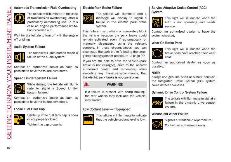
GE
TT
ING
TO
KN
OW
YO
UR
INS
TR
UM
EN
T P
AN
EL
82
Automatic Transmission Fluid Overheating
The telltale will illuminate in the caseof transmission overheating, after aparticularly demanding use. In thiscase an engine performance limita-tion is carried out.
Wait for the telltale to turn off with the engineoff or idling.
Audio System Failure
The telltale will illuminate to report afailure of the audio system.
Contact an authorized dealer as soon aspossible to have the failure eliminated.
Speed Limiter System Failure
While driving, the telltale will illumi-nate to signal a Speed Limitersystem failure.
Contact an authorized dealer as soon aspossible to have the failure eliminated.
Loose Fuel Filler Cap
Lights up if the fuel tank cap is openor not properly closed.Tighten the cap properly.
Electric Park Brake Failure
The telltale will illuminate and amessage will display to signal afailure in the electric park brakesystem.
This failure may partially or completely blockthe vehicle because the park brake couldremain activated even if automatically ormanually disengaged using the relevantcontrols. In these circumstances, you candisengage the park brake following the emer-gency disengagement procedure Ú page 90.If you are still able to drive the vehicle (parkbrake is not engaged), drive to the nearestauthorized dealer and remember, whenexecuting any maneuvers/commands, thatthe electric park brake is not operational.
Low Coolant Level — If Equipped
This telltale will illuminate to indicatethat the vehicle coolant level is low.
Service Adaptive Cruise Control (ACC) System
This light will illuminate when theACC is not operating and needsservice.
Contact an authorized dealer to have thesystem checked.
Wear On Brake Pads
This light will illuminate when thebrake pads have reached their wearlimit.
Contact an authorized dealer as soon aspossible.
NOTE:Always use genuine parts or similar becausethe Integrated Brake System (IBS) systemcould detect anomalies.
Dynamic Drive Control System Failure
The telltale will illuminate to signal afailure in the dynamic drive controlsystem.
Windshield Wiper Failure
Signals a windshield wiper failure.Contact an authorized dealer.
WARNING!
If a failure is present with sharp braking,the rear wheels may lock and the vehiclemay swerve.
21_GU_OM_EN_USC_t.book Page 82

83
Generic Indication
Signals information and failures.The accompanying messagesdescribe the failure.
All Wheel Drive Failure
This telltale will illuminate along withan accompanying message whenthe AWD dynamic control system istemporarily deactivated to prevent
damage. The traction system will work in RWDmode in this instance.Contact an authorized dealer as soon aspossible to have the failure eliminated.
Temporary All Wheel Drive Failure — If Equipped
This telltale will illuminate to indicatethat the AWD dynamic controlsystem is temporarily deactivated toprevent damage. The traction
system will work in RWD mode in this instance.In the event that this telltale illuminates,reduce the load to allow the system to cooldown. The AWD system will resume normaloperation when the symbol disappears fromthe display.
ABS Activation
This telltale will illuminate to indicatethat the ABS system has activated.
Adaptive Front Lighting System Failure
The telltale will illuminate to indicatethe automatic directional lightsystem failure.
Go to an authorized dealer to have the systemchecked.
Soft Suspension Calibration Insertion — If Equipped
The telltale will illuminate when themost comfortable suspensionsetting is activated.
Shock Absorbers Failure
While driving, if the telltale illumi-nates, it signals a failure in thesuspension system.
Contact an authorized dealer to have thesystem checked.
Windshield Washer Liquid Level
The telltale will illuminate to indicatethat the level of the windshield andheadlight washing fluid (if any) islow.
Always use liquid with the features indicated inthe “Fluids And Lubricants” Ú page 217.
WEAR ON Carbon Ceramic Material (CCM) Brake Discs — If Equipped
This light will illuminate when thecarbon ceramic material brake discshave reached their wear limit.
Contact an authorized dealer as soon aspossible.
Driver Attention Assist (DAA) System Failure
The symbol comes on in the event ofa DAA system failure.
Contact an Alfa Romeo Dealership as soon aspossible to have the failure eliminated.
Highway Assist System (HAS)/Traffic Jam Assist (TJA) System Failure
The symbol lights up in case of HASor TJA system failure.
Contact an Alfa Romeo Dealership as soon aspossible to have the failure eliminated.
WARNING!
It is recommended to use only OEM brakepads to ensure the original performance ofthe braking system.
21_GU_OM_EN_USC_t.book Page 83

GE
TT
ING
TO
KN
OW
YO
UR
INS
TR
UM
EN
T P
AN
EL
84
Green Symbols
Headlights
The telltale will illuminate when theheadlights are turned on.
Automatic Headlights
The symbol lights up when the auto-matic headlights are on.
Stop/Start Operation
The telltale will illuminate in the caseof Stop/Start system intervention(stopping the engine).
When the engine is restarted, the telltale willshut off Ú page 101.
Cruise Control Activated
The telltale will illuminate when theCruise Control system is activated.
Adaptive Cruise Control System — If Equipped
The symbol comes on when theAdaptive Cruise Control system isactivated.
Blue Symbols
Automatic High Beam Headlights — If Equipped
The telltale will illuminate when theautomatic high beam headlights areactivated.
High Beam Headlights
The telltale will illuminate when thehigh beam headlights are activated.
ONBOARD DIAGNOSTIC SYSTEMOperationThe Onboard Diagnostic system (OBD) carriesout a continuous diagnosis of the componentsof the vehicle related to emissions.It also alerts the driver of when these compo-nents are no longer in peak condition byswitching on the Engine Check/Malfunc-tion Indicator warning light on the instrumentpanel.
The aim of the OBD system (Onboard Diag-nostic) is to: Monitor the efficiency of the system
Indicate an increase in emissions
Indicate the need to replace damagedcomponents
The vehicle also has a connector, which caninterface with appropriate tools, that makes itpossible to read the error codes stored in theelectronic control units together with a seriesof specific parameters for engine operationand diagnosis. This check can be carried outby an authorized dealer.
NOTE:After eliminating a fault, to check the systemcompletely, an authorized dealer is obliged torun tests and, if necessary certain road tests.
Onboard Diagnostic System (OBD II) Cybersecurity
Your vehicle is required to have OBD II and aconnection port to allow access to informationrelated to the performance of your emissionscontrols. Authorized service technicians mayneed to access this information to assist withthe diagnosis and service of your vehicle andemissions system.
21_GU_OM_EN_USC_t.book Page 84

85
EMISSIONS INSPECTION AND MAINTENANCE PROGRAMIn some localities, it may be a legal require-ment to pass an inspection of your vehicle'semissions control system. Failure to passcould prevent vehicle registration.
For states that require an Inspectionand Maintenance (I/M), this checkverifies the Malfunction IndicatorLight (MIL) is functioning and is not
on when the engine is running, and that theOBD II system is ready for testing.Normally, the OBD II system will be ready. TheOBD II system may not be ready if your vehiclewas recently serviced, recently had a depletedbattery or a battery replacement. If the OBD IIsystem should be determined not ready for theI/M test, your vehicle may fail the test.Your vehicle has a simple ignition actuatedtest, which you can use prior to going to thetest station. To check if your vehicle's OBD IIsystem is ready, you must do the following:
1. Cycle the ignition switch to the ACC posi-tion, but do not crank or start the engine.
NOTE:If you crank or start the engine, you will have tostart this test over.
2. As soon as you cycle the ignition switch tothe ACC position, you will see the Malfunc-tion Indicator Light (MIL) symbol come onas part of a normal bulb check.
3. Approximately 15 seconds later, one oftwo things will happen:
• The MIL will flash for about 10 secondsand then return to being fully illumi-nated until you turn OFF the ignition orstart the engine. This means that yourvehicle's OBD II system is not ready andyou should not proceed to the I/Mstation.
• The MIL will not flash at all and willremain fully illuminated until you placethe ignition in the off position or startthe engine. This means that yourvehicle's OBD II system is ready and youcan proceed to the I/M station.
If your OBD II system is not ready, you shouldsee an authorized dealer or repair facility. Ifyour vehicle was recently serviced or had abattery failure or replacement, you may needto do nothing more than drive your vehicle asyou normally would in order for your OBD IIsystem to update. A recheck with the abovetest routine may then indicate that the systemis now ready.Regardless of whether your vehicle's OBD IIsystem is ready or not, if the MIL is illuminatedduring normal vehicle operation you shouldhave your vehicle serviced before going to theI/M station. The I/M station can fail yourvehicle because the MIL is on with the enginerunning.
WARNING!
ONLY an authorized service technicianshould connect equipment to the OBD IIconnection port in order to read the VIN,diagnose, or service your vehicle.
If unauthorized equipment is connected tothe OBD II connection port, such as adriver-behavior tracking device, it may:
• Be possible that vehicle systems,including safety related systems,could be impaired or a loss of vehiclecontrol could occur that may result inan accident involving serious injury ordeath.
• Access, or allow others to access,information stored in your vehiclesystems, including personal informa-tion.
21_GU_OM_EN_USC_t.book Page 85

86
(Continued)
ST
AR
TIN
G A
ND
OP
ER
AT
ING STARTING THE ENGINE
Before starting the engine, be sure to adjustthe seat, the interior rear view mirror, doormirrors, and fasten the seat belt correctly.Never press the accelerator pedal beforestarting the engine.If necessary, messages indicating the startingprocedure will be shown in the display.
Starting Procedure
Proceed as follows:
1. Apply the Electric Park Brake (EPB) andplace the gear selector in PARK (P) orNEUTRAL (N).
2. Fully press the brake pedal withouttouching the accelerator.
3. Briefly push the ignition button.
4. If the engine doesn't start within a fewseconds, you need to repeat the proce-dure.
If the problem persists, contact an authorizeddealer.
Remote Starting System
This system uses the key fob to start theengine conveniently from outside the vehiclewhile still maintaining security. The systemhas a range of at least 300 feet (91 meters).The remote starting system also activates theclimate control, the heated seats (ifequipped), and the heated steering wheel (ifequipped), depending on temperaturesoutside and inside of the vehicle.
NOTE:Obstructions between the vehicle and key fobmay reduce this range.
WARNING!
When leaving the vehicle, always removethe key fob from the vehicle and lock yourvehicle.
Never leave children alone in a vehicle, orwith access to an unlocked vehicle.
Allowing children to be in a vehicle unat-tended is dangerous for a number ofreasons. A child or others could be seri-ously or fatally injured. Children should bewarned not to touch the parking brake,brake pedal or the transmission gearselector.
Do not leave the key fob in or near thevehicle, or in a location accessible to chil-dren. A child could operate powerwindows, other controls, or move thevehicle.
Do not leave children or animals insideparked vehicles in hot weather. Interiorheat build-up may cause serious injury ordeath.
WARNING!
Never pour fuel or other flammable liquidinto the throttle body air inlet opening inan attempt to start the vehicle. This couldresult in flash fire causing seriouspersonal injury.
Do not attempt to push or tow your vehicleto get it started. Vehicles equipped with anautomatic transmission cannot be startedthis way. Unburned fuel could enter thecatalytic converter and once the enginehas started, ignite and damage theconverter and vehicle.
If the vehicle has a discharged battery,booster cables may be used to obtain astart from a booster battery or the batteryin another vehicle. This type of start canbe dangerous if done improperly Ú page 201.
CAUTION!
To prevent damage to the starter, do notcontinuously crank the engine for more than25 seconds at a time. Wait 60 secondsbefore trying again.
WARNING! (Continued)
21_GU_OM_EN_USC_t.book Page 86
87
How To Use Remote StartAll of the following conditions must be metbefore the engine will remote start: Gear selector in PARK (P).
Doors closed.
Hood closed.
Liftgate closed.
Hazard switch off.
Brake switch inactive (brake pedal notpressed).
Battery at an acceptable charge level.
PANIC button not pushed.
System not disabled from previous remotestart event.
Vehicle Security System indicator flashing.
Ignition in the OFF mode (if equipped withkeyless ignition system).
Fuel level meets minimum requirement.
Remote Start Comfort Systems — If EquippedWhen Remote Start is activated, the heatedsteering wheel and driver heated seat featureswill automatically turn on in cold weather.These features will stay on through the dura-tion of remote start until the ignition is placedin the ON/RUN mode.
Remote Start Windshield Wiper De–Icer Acti-vation — If EquippedWhen remote start is active and the outside ambienttemperature is less than 39°F (4°C), the WindshieldWiper De-Icer will be enabled. Exiting remote start willresume previous operation, except if the WindshieldWiper De-Icer is active.The Windshield Wiper De-Icer timer and oper-ation will continue.
Cold Weather Operation
To prevent possible engine damage whilestarting at low temperatures, this vehicle willinhibit engine cranking when the ambienttemperature is less than –22°F (–30°C) andthe oil temperature sensor reading indicatesan engine block heater has not been used. Anexternally-powered electric engine blockheater is available as optional equipment orfrom an authorized dealer.The message “plug in engine heater” will bedisplayed in the instrument cluster when theambient temperature is below 5°F (–15°C) at thetime the engine is shut off as a reminder to avoidpossible crank delays at the next cold start.
Extended Park Starting
If the vehicle has not been started or driven forat least 30 days, it is advisable to follow theindications below.To start the engine, proceed as follows:
1. Briefly push the ignition button
2. If the engine does not start, wait fiveseconds and let the starter cool down andthen repeat the starting procedure
3. If the engine does not start after eightattempts, let the starter cool down for atleast 10 seconds, and then repeat thestarting procedure
If the problem persists, contact an authorizeddealer.
NOTE:After prolonged vehicle inactivity, very difficultstarting, that can be noticed through rapidfatigue of the starter, might also be due to apartially drained battery Ú page 201.
If Engine Fails To Start
Starting the Engine with Key Fob Battery RunDown or DrainedIf the ignition does not respond when thebutton is pushed, the key fob battery might berun down or drained. Therefore, the systemdoes not detect the presence of the key fob inthe vehicle, and will display a dedicatedmessage Ú page 20.
CAUTION!
Use of the recommended oil and adheringto the prescribed oil change intervals isimportant to prevent engine damage andensure satisfactory starting in coldconditions.
21_GU_OM_EN_USC_t.book Page 87

ST
AR
TIN
G A
ND
OP
ER
AT
ING
88
After Starting — Warming Up The Engine
Proceed as follows: Travel slowly, letting the engine run at a
reduced RPM, without acceleratingsuddenly.
It is recommended to wait until the digitalengine coolant temperature indicator startsto rise for maximum performance.
Stopping The Engine
To stop the engine, proceed as follows:
1. Park the vehicle in a position that is notdangerous for oncoming traffic.
2. Engage the PARK (P) mode.
3. With engine idling, push the ENGINESTART/STOP button on the steering wheelto STOP the engine.
NOTE:Do not leave the ignition in ACC mode whenthe engine is off.
To shut off the engine with vehicle speedgreater than 5 mph (8 km/h), you must pushand hold the ignition or push the ENGINESTART/STOP button three times consecutivelywithin a few seconds. The engine will shutdown, and the ignition will be placed in theACC mode
With the keyless ignition system, it is possibleto exit the vehicle taking the key fob with you,without the engine switching off. The vehiclewill inform about the absence of the key onboard, when the doors are closed.After the engine has stopped (cycling from theACC to the OFF position) the accessories arestill powered for about three minutes, or untila door is opened.When the ignition is in the OFF mode, thewindow switches remain active for threeminutes. Opening a front door will cancel thisfunction.After severe driving, idle the engine to allowthe temperature inside the engine compart-ment to cool before shutting off the engine.
Turbocharger Cool Down
It is recommended before switching thevehicle off, to keep the engine idling for a fewminutes so that the turbocharger can be suit-ably lubricated. This procedure is particularlyrecommended after severe driving.After a full load operation, keep the engineidling for three to five minutes beforeswitching it off.This time allows the lubricating oil and theengine coolant to eliminate the excessive heatfrom combustion chamber, bearings, innercomponents and turbocharger.
WARNING!
Never pour fuel or other flammable liquidinto the throttle body air inlet opening inan attempt to start the vehicle. This couldresult in flash fire causing seriouspersonal injury.
Do not attempt to push or tow your vehicleto get it started. Vehicles equipped with anautomatic transmission cannot be startedthis way. Unburned fuel could enter thecatalytic converter and once the enginehas started, ignite and damage theconverter and vehicle.
If the vehicle has a discharged battery,booster cables may be used to obtain astart from a booster battery or the batteryin another vehicle. This type of start canbe dangerous if done improperly Ú page 201.
CAUTION!
To prevent damage to the starter, do notcontinuously crank the engine for more than25 seconds at a time. Wait 60 secondsbefore trying again.
21_GU_OM_EN_USC_t.book Page 88
89
ENGINE BLOCK HEATER — IF EQUIPPEDThe engine block heater warms the engineand permits quicker starts in cold weather.Connect the cord to a 110-115 Volt AC elec-trical outlet with a grounded, three-wire exten-sion cord.For ambient temperatures below 0°F (-18°C),the engine block heater is recommended. Forambient temperatures below -20°F (-29°C),the engine block heater is required.Follow the steps below to properly use theengine block heater:
1. Locate the engine block heater cord(access door on the passenger side wipercowl).
2. Pull the cord to the front of the vehicle andplug it into a grounded, three-wire exten-sion cord.
3. After the vehicle is running, properly stowthe cord away behind the access door onthe passenger side wiper cowl.
NOTE:
The engine block heater cord is a factoryinstalled option. If your vehicle is notequipped, heater cords are available froman authorized dealer.
The engine block heater will require 110 VoltsAC and 6.5 Amps to activate the heaterelement.
The engine block heater must be plugged inat least one hour to have a warming effecton the engine and at least four hours tohave a warming effect when ambienttemperatures are below -20°F (-29°C).
ENGINE BREAK-IN RECOMMENDATIONS
Engine Break-In
For both engines, use the following enginebreak-in recommendations:
NOTE:A new engine may consume some oil during itsfirst few thousand miles (kilometers) of opera-tion. This should be considered a normal partof the break-in period and not interpreted asan indication of a problem. Please monitoryour oil level during the break-in period andadd oil as required.
It is recommended for the operator to observethe following driving behaviors during the newvehicle break-in period:
0 to 100 miles (0 to 160 km): Do not allow the engine to operate at idle for
an extended period of time.
Press the accelerator pedal slowly and notmore than halfway to avoid rapid accelera-tion.
Avoid aggressive braking.
Drive with the engine speed less than 3,500 RPM.
Maintain vehicle speed below 55 mph(88 km/h) and observe local speed limits.
100 to 300 miles (160 to 483 km): Press the accelerator pedal slowly and not
more than halfway to avoid rapid accelera-tion in lower gears (FIRST to THIRD gears).
Avoid aggressive braking.
Drive with the engine speed less than 5,000 RPM.
Maintain vehicle speed below 70 mph(112 km/h) and observe local speed limits.
300 to 500 miles (483 to 805 km): Exercise the full engine RPM range, shifting
manually (paddles or gear shift) at higherRPM when possible.
Do not perform sustained operation withthe accelerator pedal at wide open throttle.
Maintain vehicle speed below 85 mph(136 km/h) and observe local speed limits.
WARNING!
Remember to disconnect the engine blockheater cord before driving. Damage to the110-115 Volt electrical cord could causeelectrocution.
21_GU_OM_EN_USC_t.book Page 89

ST
AR
TIN
G A
ND
OP
ER
AT
ING
90
For the first 1,500 miles (2,414 km): Do not participate in track events, sport
driving schools, or similar activities duringthe first 1,500 miles (2,414 km).
NOTE:Monitor engine oil with every refueling and addif necessary. Oil and fuel consumption may behigher through the first oil change interval.
ELECTRIC PARK BRAKE (EPB)The EPB features a switch located on thecenter console, a caliper with motor for eachrear wheel, and an electronic control module.
Electric Park Brake SwitchThe EPB can be engaged in two ways: Manually, by pulling the switch on the
center console.
Automatically, in “Safe Hold” or “Auto ParkBrake” conditions.
NOTE:Normally, the EPB is engaged automaticallywhen the engine is stopped. This function canbe deactivated/activated on the Informationand Entertainment system by selecting thefollowing items in sequence on the mainmenu: “Settings”, “Driver Assistance” and“Automatic Parking Brake”.
In addition to engaging the EPB, along withsteering and positioning chocks in front of thewheels (when on a steep slope), you mustalways place the vehicle in the PARK (P) modebefore leaving.
Should the vehicle battery be faulty, thebattery must be replaced in order to unlock theEPB.
Engaging The EPB ManuallyBriefly pull the switch located on the centerconsole to manually engage the EPB when thevehicle is stationary.Noise may be heard from the rear of thevehicle when engaging the EPB.A slight movement of the brake pedal may bedetected when engaging the EPB with thebrake pedal pressed.With the EPB engaged, the BRAKE warninglight on the instrument cluster display and theswitch will illuminate.
If, under exceptional circumstances, the useof the brake is required with the vehicle inmotion, keep the switch on the center consolepulled as long as the brake action is neces-sary.The BRAKE warning light may turn on with thehydraulic system temporarily unavailable; inthis case, braking is controlled by the motors.The brake lights will also automatically turn onin the same way as normal braking with theuse of the brake pedal.Release the switch on the center console tostop the braking action with the vehicle inmotion.If, through this procedure, the vehicle isbraked until a speed below 1.9 mph (3 km/h)is reached and the switch is kept pulled, theparking brake will definitively engage.
NOTE:Driving the vehicle with the EPB engaged, orusing it several times to slow down the vehicle,may cause severe damage to the brakingsystem.
CAUTION!
With the Electronic Parking Brake failurewarning light on, some functions of the EPBare deactivated. In this case the driver isresponsible for brake activation and vehicleparking in complete safety conditions.
21_GU_OM_EN_USC_t.book Page 90

91
(Continued)
Disengaging The EPB ManuallyIn order to manually release the parking brake,the ignition should be in the ACC mode. Pressthe brake pedal, and then push the switch onthe center console briefly.Noise may be heard from the rear of thevehicle, and a slight movement of the brakepedal may be detected during disengagement.After disengaging the EPB, the BRAKE warninglight on the instrument cluster display and thelight on the switch will turn off.If the BRAKE warning light on the instrumentcluster display remains on with the EPB disen-gaged, this indicates a fault: in this case,contact an authorized dealer.
NOTE:
Always engage the EPB when parking thevehicle to prevent injury or damage causedby the unexpected movement of the vehicle.
Never use gear position PARK (P) instead ofthe EPB.
Electric Park Brake (EPB) Operating Modes
The EPB may operate as follows: “Dynamic Operating Mode”: this mode is
activated by pulling the switch repeatedlywhile driving.
“Static Engagement and Release Mode”:with the vehicle stationary, the EPB can beactivated by pulling the switch on the centerconsole once. Push the switch and thebrake pedal at the same time to disengagethe brake.
“Drive Away Release” — if equipped: theEPB will automatically disengage with thedriver side seat belt fastened and the detec-tion of an action performed by the driver to
move the vehicle (DRIVE [D] or REVERSE[R]). This feature can be turned on or off inthe Information and Entertainment System.
NOTE:If the car is equipped with carbon-ceramicbrake discs, it is necessary to fasten the seatbelts or turn off the EPB before starting toavoid damages to the ceramic brake discs.
“Safe Hold”: if the vehicle speed is lowerthan 1.9 mph (3 km/h), the gear selector isnot in PARK (P) position and the driver'sintention of leaving the vehicle is detected,the EPB will automatically engage to holdthe vehicle in safety conditions.
“Auto Park Brake”: if the vehicle speed isbelow 1.9 mph (3 km/h), the EPB will auto-matically engage when the gear selector isin PARK (P) position. The light on the switchlocated on the center console switches ontogether with the BRAKE warning light onthe instrument cluster display when theparking brake is engaged and applied to thewheels. Each automatic parking brakeengagement can be canceled by pushingthe switch on the center console and at thesame time moving the gear selector for thetransmission to position PARK (P).
Safe Hold
Safe Hold is a safety function that automati-cally engages the EPB in the event of adangerous condition for the vehicle.
WARNING!
Never leave children alone in a vehicle, orwith access to an unlocked vehicle.
Allowing children to be in a vehicle unat-tended is dangerous for a number ofreasons. A child or others could be seri-ously or fatally injured. Children should bewarned not to touch the parking brake,brake pedal or the gear selector.
Do not leave the key fob in or near thevehicle or in a location accessible to chil-dren. A child could operate powerwindows, other controls, or move thevehicle.
Be sure the parking brake is fully disen-gaged before driving; failure to do so canlead to brake failure and a collision.
Always fully apply the parking brake whenleaving your vehicle, or it may roll andcause damage or injury.
WARNING! (Continued)
21_GU_OM_EN_USC_t.book Page 91

ST
AR
TIN
G A
ND
OP
ER
AT
ING
92
(Continued)
The EPB engages automatically to preventvehicle movement if: The vehicle speed is below 2 mph (3 km/h).
A transmission operating mode differentfrom PARK (P) is activated.
The driver's seat belt is not fastened.
The driver side door is open.
No attempts to apply pressure on the brakepedal have been detected.
The vehicle is parked on roads with a slopeof more than 4%.
The “Safe Hold” function can be temporarilydisabled by pushing the EPB switch located onthe center console and the brake pedal at thesame time, with the vehicle stationary and thedriver side door open.Once disabled, the function will activate againwhen the vehicle speed reaches 12 mph(20 km/h) or the ignition is cycled to OFF andthen to ACC.
AUTOMATIC TRANSMISSIONThe vehicle is equipped with an electronicallycontrolled 8-speed automatic transmissionwhere gear shifting automatically takes place,depending on the vehicle usage instanta-neous parameters (vehicle speed, grade, andaccelerator pedal position).Manual gear shifting can still occur thanks tothe “Sequential” mode position for the gearselector.
WARNING!
It is dangerous to shift out of PARK orNEUTRAL if the engine speed is higherthan idle speed. If your foot is not firmlypressing the brake pedal, the vehiclecould accelerate quickly forward or inreverse. You could lose control of thevehicle and hit someone or something.Only shift into gear when the engine isidling normally and your foot is firmlypressing the brake pedal.
Unintended movement of a vehicle couldinjure those in or near the vehicle. As withall vehicles, you should never exit avehicle while the engine is running. Beforeexiting a vehicle, always apply the parkingbrake, shift the transmission into PARK,and turn the ignition OFF. When the igni-tion is in the OFF mode, the transmissionis locked in PARK, securing the vehicleagainst unwanted movement.
When leaving the vehicle, always makesure the ignition is in the OFF mode,remove the key fob from the vehicle, andlock the vehicle.
Never leave children alone in a vehicle, orwith access to an unlocked vehicle.Allowing children to be in a vehicle unat-tended is dangerous for a number ofreasons. A child or others could be seri-ously or fatally injured. Children should bewarned not to touch the parking brake,brake pedal or the transmission gearselector.
Do not leave the key fob in or near thevehicle (or in a location accessible to chil-dren), and do not leave the ignition in theON/RUN or ACC mode. A child couldoperate power windows, other controls, ormove the vehicle.
CAUTION!
Damage to the transmission may occur ifthe following precautions are not observed:
Shift into or out of PARK or REVERSE onlyafter the vehicle has come to a completestop.
Do not shift between PARK, REVERSE,NEUTRAL, or DRIVE when the engine isabove idle speed.
Before shifting into any gear, make sureyour foot is firmly pressing the brakepedal.
WARNING! (Continued)
21_GU_OM_EN_USC_t.book Page 92

93
Display
The following information is shown on thededicated area of the display: In Automatic Mode: the active mode (P, R,
N, D) and with "D" the current gear number.
In Manual Drive Mode (Sequential): themode (M), the current gear and the doubleor single gear shift request, both up anddown (single or double arrow).
Gear Display
Gear Selector
The gear functioning is controlled by the gearselector, which can assume the following posi-tions: P = PARK
R = REVERSE
N = NEUTRAL
D = DRIVE (automatic forward speed)
AutoStick: + manually shift to higher gear; –manually shift to lower gear
The positions diagram is illustrated on the topof the gear selector.
Gear Selector Center Console
The letter corresponding to the mode selectedon the gear selector lights up and appears onthe instrument cluster display.To select a mode, move the gear selectorforward or rearward while pressing the brakepedal. To engage REVERSE (R), press thebrake pedal together with the gear selectorbutton.
Gear Selector
The gear selector is a joystick style shiftingmechanism which returns to the center posi-tion automatically. It can be pushed forwardtwice and rearward twice, based on thestarting condition.The PARK (P) mode can be enabled/disabledby pushing the PARK (P) button. PARK (P)mode is automatically activated if thefollowing conditions are met simultaneously: DRIVE (D) mode or REVERSE (R) mode is
active
The vehicle’s speed is close to 0 mph(0 km/h)
The brake pedal is released
The driver’s seat belt is not fastened
The driver’s door is open
1 — Gear Selector2 — PARK (P) Button
3 — Gear Selector Button
21_GU_OM_EN_USC_t.book Page 93
ST
AR
TIN
G A
ND
OP
ER
AT
ING
94
(Continued)
(Continued)
To transition the vehicle into REVERSE (R)mode from DRIVE (D) mode, or into DRIVE (D)mode from REVERSE (R) mode, it is necessaryto move the gear selector by pushing the gearselector button.AutoStick can be activated by moving the gearselector from DRIVE (D) to the left and thenforward toward the - symbol (or backwardtoward the + symbol) changing the gear.To shift out of PARK (P), or to pass from posi-tion NEUTRAL (N) to position DRIVE (D) orREVERSE (R), the vehicle must be moving at alow speed or stopped, and the brake pedalmust also be pressed.
NOTE:
DO NOT accelerate while shifting from posi-tion PARK (P) or NEUTRAL (N) to anotherposition.
After selecting a gear, wait a few secondsbefore accelerating. This precaution isparticularly important with engine cold.
It is not possible to select NEUTRAL (N)mode from PARK (P) mode.
Transmission Operating Modes
PARK (P)The transmission is locked in this mode. Theengine can be started in this mode.
NOTE:Never try to engage PARK (P) mode when thevehicle is moving. Before leaving the vehicle,make sure this mode is engaged (letter Pshown on the display and gear selector) andthat the parking brake is engaged.
When parking on a flat surface, first engagethe PARK (P) mode and then engage the EPB.When parking uphill, before activating thePARK (P) mode, engage the EPB. Otherwise, itcould be difficult to engage the (P) mode.To check that the PARK (P) mode is actuallyengaged, make sure (P) is illuminated on thedisplay and on the gear selector.
WARNING!
Never use the PARK position as a substi-tute for the parking brake. Always applythe parking brake fully when parked toguard against vehicle movement andpossible injury or damage.
Your vehicle could move and injure youand others if it is not in PARK. Check bytrying to move the gear selector out ofPARK with the brake pedal released.Make sure the transmission is in PARKbefore leaving the vehicle.
It is dangerous to shift out of PARK orNEUTRAL if the engine speed is higherthan idle speed. If your foot is not firmlypressing the brake pedal, the vehiclecould accelerate quickly forward or inreverse. You could lose control of thevehicle and hit someone or something.Only shift into gear when the engine isidling normally and your foot is firmlypressing the brake pedal.
Unintended movement of a vehicle couldinjure those in or near the vehicle. As withall vehicles, you should never exit avehicle while the engine is running. Beforeexiting a vehicle, always apply the parkingbrake, shift the transmission into PARK,and turn the ignition OFF. When the igni-tion is in the OFF mode, the transmissionis locked in PARK, securing the vehicleagainst unwanted movement.
When leaving the vehicle, always makesure the ignition is in the OFF mode,remove the key fob from the vehicle, andlock the vehicle.
WARNING! (Continued)
21_GU_OM_EN_USC_t.book Page 94

95
REVERSE (R)Select this mode only with the vehicle at astandstill.
NEUTRAL (N)Use this range when the vehicle is standing forprolonged periods with the engine running.The engine may be started in this range. Applythe EPB and shift the transmission into PARK(P) if you must leave the vehicle.
DRIVE (D)Use this mode in normal driving conditions.Shifting from DRIVE (D) to PARK (P) or REVERSE(R) modes must take place only after releasing theaccelerator pedal, with vehicle at a standstill andbrake pedal pressed.This mode ensures automatic engagement of themost suitable gears for driving needs andmaximum fuel economy in terms of consumption.In this position, the transmission shifts the gearsautomatically, selecting the most suitable forforward driving among those available as you go.In this way the vehicle's optimal driving charac-teristics are provided for all conditions.
AutoStickIn the case of frequent shifting (e.g. for sportdriving, when the vehicle is driven with a heavyload, on slopes, when towing heavy trailers), it isrecommended to use the AutoStick (sequentialshifting) mode to select and keep a lower fixedratio.In these conditions, the use of a lower gearimproves vehicle performance and prevents over-heating.It is possible to shift from DRIVE (D) mode to Auto-Stick mode regardless of vehicle speed.ActivationStarting from DRIVE (D) mode, to activate thesequential drive mode, move the gear selector tothe left (– and + indication of the trim). The gearengaged will be shown on the display.Shifting is made by moving the gear selectorforward, toward symbol – or backward, towardsymbol +.Steering Column Mounted Shift Paddles — IfEquippedThe gear can be manually shifted also by usingthe paddles behind the steering wheel, pullthe right paddle (+) toward the steering wheeland release it to engage a higher gear,perform the same operation with the leftpaddle (-) to engage a lower gear.
Never leave children alone in a vehicle, orwith access to an unlocked vehicle.Allowing children to be in a vehicle unat-tended is dangerous for a number ofreasons. A child or others could be seri-ously or fatally injured. Children should bewarned not to touch the park brake, brakepedal or the transmission gear selector.
Do not leave the key fob in or near thevehicle (or in a location accessible to chil-dren), and do not leave the ignition in theACC mode. A child could operate powerwindows, other controls, or move thevehicle.
CAUTION!
Before moving the transmission gearselector out of PARK, you must push theignition button to cycle from OFF mode tothe ACC mode, and also press the brakepedal. Otherwise, damage to the gearselector could result.
DO NOT race the engine when shiftingfrom PARK or NEUTRAL into another gearrange, as this can damage the drivetrain.
WARNING! (Continued)
WARNING!
Do not coast in NEUTRAL and never turn offthe ignition to coast down a hill. These areunsafe practices that limit your response tochanging traffic or road conditions. Youmight lose control of the vehicle and have acollision.
21_GU_OM_EN_USC_t.book Page 95

ST
AR
TIN
G A
ND
OP
ER
AT
ING
96
Steering Column Mounted Shift Paddles
NOTE:If only one manual shift is necessary, the letter(D) will remain on the display with the engagedgear next to it.
DeactivationTo deactivate the sequential driving mode,bring the gear selector back in position DRIVE(D) ("automatic" driving mode).
NOTE:
To select the correct gear for maximumdeceleration (engine brake), keep the gearpaddle pulled (–): the transmission goes to
an operating mode in which the vehicle canslow down easily.
The vehicle will keep the gear selected bythe driver until the safety conditions allow it.
This means, for example, that the systemwill try to prevent the engine from switchingoff, automatically downshifting if the enginespeed is too low.
Automatic Transmission Limp Home Mode
Transmission function is monitored electroni-cally for abnormal conditions. If a condition isdetected that could result in transmissiondamage, Transmission Limp Home Mode isactivated.In this condition, the transmission stays inFOURTH gear, regardless of the selected gear.Positions PARK (P), REVERSE (R) andNEUTRAL (N) still work.
The symbol might light up in the instrumentcluster.Temporary failureIn the event of a momentary problem, thetransmission can be reset to regain all forwardgears by performing the following steps:
1. Stop the vehicle.
2. Shift the transmission into PARK (P), ifpossible. If not, shift the transmission toNEUTRAL (N).
3. Push and hold the ignition until the engineturns off.
4. Wait for about 10 seconds, then restartthe engine.
5. Shift into the desired gear range. If theproblem is no longer detected, the trans-mission will return to normal operation.
NOTE:Even if the transmission can be reset, werecommend that you visit an authorized dealerat your earliest possible convenience. Anauthorized dealer has diagnostic equipment todetermine if the problem could reoccur. If thetransmission cannot be reset, service isrequired at an authorized dealer.
Brake Transmission Shift Interlock (BTSI) System
This vehicle is equipped with a BTSI that holdsthe gear selector in PARK (P) unless thebrakes are applied.This system prevents you from moving thegear selector from position PARK (P) unlessthe brakes are applied.To shift the transmission out of PARK (P), theignition must be cycled to the ON/RUN posi-tion (engine running or not) and the brakepedal must be pressed.
WARNING!
Do not downshift for additional enginebraking on a slippery surface. The drivewheels could lose their grip and the vehiclecould skid, causing a collision or personalinjury.
21_GU_OM_EN_USC_t.book Page 96

97
(Continued)
Brake Transmission Shift Interlock DisablingOnly if strictly necessary (e.g. pushing thevehicle, conveyor vehicle washing systems),inhibit the automatic activation of PARK (P)mode when stopping the engine. To do so,follow the directions below:
1. Bring the vehicle to a standstill.
2. Place the transmission in the NEUTRAL (N)position.
3. Push the ignition button for at least threeseconds.
The automatic activation of PARK (P) when theengine is stopped can also be deactivated onthe Information and Entertainment system byselecting the following functions on the mainmenu: "Settings", "Driver Assistance" and"Automatic Parking Brake".
Important Notes
Failure to comply with what is reported belowmay damage the transmission: Shift into PARK (P) mode only with the
vehicle at a standstill.
Select REVERSE (R) mode, or pass fromREVERSE to another mode only with thevehicle at a standstill and engine idling.
Do not change between PARK (P), REVERSE(R), NEUTRAL (N) or DRIVE (D) modes withengine running at a speed above idling.
Before activating any transmission oper-ating mode, fully press the brake pedal.
NOTE:The unexpected movement of the vehicle caninjure the occupants or people nearby. Do notleave the vehicle with engine running: beforegetting out of the passenger compartmentalways engage the EPB, select the PARK (P)mode, stop the engine.
WARNING!
It is dangerous to shift out of PARK orNEUTRAL if the engine speed is higherthan idle speed. If your foot is not firmlypressing the brake pedal, the vehiclecould accelerate quickly forward or inreverse. You could lose control of thevehicle and hit someone or something.Only shift into gear when the engine isidling normally and your foot is firmlypressing the brake pedal.
Unintended movement of a vehicle couldinjure those in or near the vehicle. As withall vehicles, you should never exit avehicle while the engine is running. Beforeexiting a vehicle, always apply the parkingbrake, shift the transmission into PARK,and turn the ignition OFF. When the igni-tion is in the OFF mode, the transmissionis locked in PARK, securing the vehicleagainst unwanted movement.
When leaving the vehicle, always makesure the ignition is in the OFF mode,remove the key fob from the vehicle, andlock the vehicle.
Never leave children alone in a vehicle, orwith access to an unlocked vehicle.Allowing children to be in a vehicle unat-tended is dangerous for a number ofreasons. A child or others could be seri-ously or fatally injured. Children should bewarned not to touch the parking brake,brake pedal or the transmission gearselector.
Do not leave the key fob in or near thevehicle (or in a location accessible to chil-dren), and do not leave the ignition in theON/RUN or ACC mode. A child couldoperate power windows, other controls, ormove the vehicle.
WARNING! (Continued)
21_GU_OM_EN_USC_t.book Page 97

ST
AR
TIN
G A
ND
OP
ER
AT
ING
98
ALFA DNA SELECTOR
Alfa DNA System
This vehicle is equipped with an Alfa DNAsystem selector (located on the centerconsole). There are up to four modes of opera-tion to be selected according to driving styleand road conditions:
Alfa DNA Pro System Selector d = Dynamic (sports driving mode).
n = Natural (mode for driving in normalconditions).
a = Advanced Efficiency (ECO driving modefor maximum fuel savings).
RACE = track race driving mode (ifequipped).
= Adjusts the calibration of the activesuspension (if equipped).
Unlike the other modes, the RACE positiondoes not latch; therefore, by rotating theselector to RACE, it will return to its initial posi-tion "d".
On the instrument cluster display, the differentmodes are characterized by different colors: Natural - Blue
Dynamic - Red
Advanced Efficiency - Green
RACE - Yellow
Mode DisplayEach driving mode is graphically different inframe color and contents of each individual"performance" screen.
Driving Modes
"Natural" Mode“Natural” Mode is characterized by reducedengine performance and ECO shifting strategyfor the automatic transmission.
CAUTION!
Only engage the gear with engine at idlingwhile fully pressing the brake pedal. If thetransmission temperature exceeds thenormal operating limits, the transmissioncontrol unit may change the gear engage-ment order and reduce the drive torque. Ifthe transmission overheats, it couldoperate incorrectly until it cools down.
When using the vehicle with extremely lowexternal temperatures, the transmissionoperation may change depending on theengine and transmission temperature, aswell as vehicle speed. Activation of thetorque converter clutch and of the EIGHTHgear is inhibited until the transmission oilis correctly warmed up. Complete opera-tion of the transmission will be enabled assoon as the fluid temperature reaches thepredefined value.
21_GU_OM_EN_USC_t.book Page 98

99
ActivationIt is activated by rotating the selector to theletter "n"; the display will light up in blue.
Natural ModeThe "Performance" screen graphically repro-duces some parameters closely linked to theefficiency of the driving style, with a view tolimiting consumption.
Natural Mode Performance Display
"Dynamic" ModeActivationIt is activated by rotating the selector to theletter "d"; the display will light up in red.
Dynamic ModeESC and ASR systems: intervention thresholdsthat ensure more enjoyable, sportier drivingwhile guaranteeing the stability of the vehicle.Engine and transmission: adoption of sportsmapping.
Dynamic Mode Performance DisplayThe "Performance" screen displays parame-ters related to vehicle stability, the graphsillustrate the trend of the longitudinal/lateralaccelerations (G-meter information), consid-ering gravity acceleration as a reference unit.Lateral acceleration peaks are displayed onthe right."Advanced Efficiency" ModeActivationIt is activated by rotating the selector to theletter “a”; the display will light up in green.
Advanced Efficiency Mode
WARNING!
In "Dynamic", the sensitivity of theaccelerator pedal increases considerably.Consequently, driving is less fluid andcomfortable.
21_GU_OM_EN_USC_t.book Page 99
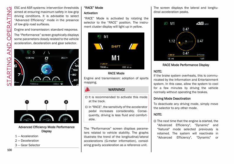
ST
AR
TIN
G A
ND
OP
ER
AT
ING
100
ESC and ASR systems: intervention thresholdsaimed at ensuring maximum safety in low-gripdriving conditions. It is advisable to select“Advanced Efficiency” mode in the presenceof low-grip road surfaces.Engine and transmission: standard response.The “Performance” screen graphically displayssome parameters closely related to the vehicleacceleration, deceleration and gear selector.
Advanced Efficiency Mode Performance Display
“RACE” ModeActivation“RACE” Mode is activated by rotating theselector to the “RACE” position. The instru-ment cluster display will light up in yellow.
RACE ModeEngine and transmission: adoption of sportsmapping.
The “Performance” screen displays parame-ters related to vehicle stability. The graphsillustrate the trend of the longitudinal/lateralaccelerations (G-meter information), consid-ering gravity acceleration as a reference unit.
The screen displays the lateral and longitu-dinal acceleration peaks.
RACE Mode Performance Display
NOTE:If the brake system overheats, this is commu-nicated by the Information and Entertainmentsystem. In this case, allow the system to coolfor a few minutes by driving the vehiclenormally without operating the brakes.
Driving Mode DeactivationTo deactivate any driving mode, simply movethe selector to any other mode.
NOTE:
The next time that the engine is started, the"Advanced Efficiency", "Dynamic" and"Natural" mode selected previously isretained. The system will reactivate in"Advanced Efficiency", "Dynamic" or1 — Acceleration
2 — Deceleration3 — Gear Selector
WARNING!
It is recommended to activate this modeat the track.
In "RACE", the sensitivity of the acceleratorpedal increases considerably. Conse-quently, driving is less fluid and comfort-able.
21_GU_OM_EN_USC_t.book Page 100

101
"Natural" mode, depending on which modewas selected before the engine wasstopped.
When the engine is started again, the"RACE" mode selected previously is notretained. The system will reactivate in"Dynamic" mode.
ALFA ACTIVE SUSPENSION (AAS) — IF EQUIPPEDThe vehicle's electronic suspension manage-ment system is aimed at optimizing thevehicle's performance.The system continuously monitors thedamping of the suspensions through the actu-ator installed on each shock absorber. Thisway, the calibration of the shock absorberscan be adjusted to the conditions of the roadsurface and to the dynamic conditions of thevehicle, improving its comfort and roadholding.The driver can choose, even while driving,(only in “Dynamic” mode), between two typesof suspension calibration: a more sporty or amore comfortable one.By pushing the button, the system changesthe shock absorber calibration.
Alfa Active Suspension Button
In case of a system failure, the symbol anda dedicated message will be shown on theinstrument cluster display.
STOP/START SYSTEMThe Stop/Start system automatically shuts offthe engine during a vehicle stop if the requiredconditions are met. Releasing the brake pedalor accelerator pedal will automatically restartthe engine.The function was developed to increasevehicle efficiency by reducing fuel consump-tion, gas emissions, and sound pollution.
NOTE:When the Stop/Start system stops the engine,the power steering is also disabled.
Operating Mode
Stopping The EngineWith the vehicle at a standstill and brake pedalpressed, the engine switches off if the gear selectoris in a position other than REVERSE (R).The system does not operate when the gearselector is in REVERSE (R), in order to makeparking maneuvers easier.In the event of stops uphill, engine switching off isdisabled to make the “Hill Start Assist” functionavailable (works only with running engine).
NOTE:The engine can only be automatically stoppedafter having run at about 6 mph (10 km/h). Afteran automatic restart, the vehicle only needs toexceed a speed of 0.3 mph (0.5 km/h) to stopthe engine.
Engine stopping is signaled by the symbollighting up on the instrument cluster display.Restarting The EngineTo restart the engine, release the brake pedalor, turn the steering wheel slightly (ifequipped).With the brake pressed and the transmissionin automatic mode DRIVE (D), the engine willrestart by shifting to REVERSE (R), to PARK (P)or to “AutoStick” Ú page 94.With brake pressed if the gear selector is in“AutoStick” mode, the engine will restart byshifting to PARK (P) or by moving the selectorto + or - Ú page 94.
21_GU_OM_EN_USC_t.book Page 101

ST
AR
TIN
G A
ND
OP
ER
AT
ING
102
System Manual Activation/Deactivation
To manually activate/deactivate the system,push the button located on the control panelto the left of the steering wheel.
Stop/Start ButtonSystem ActivationThe activation of the system is indicated by the
symbol lighting up on the display. In thiscondition, the light on the button is off.System DeactivationA message will appear on the display when thesystem is deactivated. In this condition, thelight on the button is on.
NOTE:Each time the engine is started, the system isactivated regardless of where it was when itwas previously switched off.
Possible Reasons The Engine Does Not Autostop
For higher comfort and increased safety, andto reduce emissions, there are certain condi-tions where the engine will not autostopdespite the system being active, such as: Engine still cold.
Extreme cold outside temperature.
Battery not sufficiently charged.
Driver's door not shut.
Driver's seat belt not fastened.
REVERSE (R) gear engaged (e.g. for parkingmaneuvers).
With the automatic climate control active,an adequate cabin heating or coolingcomfort has not been reached or withMAX-DEF function active.
During the first period of use, to initialize thesystem.
Steering angle beyond threshold.
Engine Restarting Conditions
Due to comfort, emission control, and safetyreasons, the engine can restart automaticallywithout any action by the driver, under specialconditions, such as: Battery not sufficiently charged.
Reduced braking system vacuum (e.g. if thebrake pedal is pressed repeatedly).
Vehicle moving (e.g. when driving on roadswith a grade).
Engine stopping by the Stop/Start systemfor more than approximately three minutes.
With the automatic climate control active,an adjustment in cabin heating or cooling ismade or with MAX-DEF function active.
Safety Functions
When the engine is stopped through the Stop/Start system, if the driver releases their seatbelt, opens the driver's or passenger's door, oropens the hood from inside the vehicle, theengine can be restarted only by using the igni-tion.This condition is indicated to the driver boththrough a buzzer and a message on the instru-ment cluster display.
Energy Saving Function
If the driver does not carry out any action formore than three minutes after the automaticengine restart, the Stop/Start system willswitch off the engine in order to prevent fuelconsumption.In this situation, the engine can only berestarted using the ignition device.
NOTE:It is possible to keep the engine running bydeactivating the system.
21_GU_OM_EN_USC_t.book Page 102

103
Irregular Operation
In the event of malfunction, the Stop/Startsystem is deactivated.For failure indications Ú page 74.
Vehicle Inactivity
In the event of vehicle inactivity (or if thebattery is replaced), special attention must bepaid to the disconnection of the battery powersupply.Proceed as follows:Remove connector from socket to disconnectsensor (battery status monitoring) installed onthe negative pole of the battery. This sensorshould never be disconnected from the poleexcept if the battery is replaced.
Battery Power Supply
NOTE:After setting the ignition to OFF and havingclosed the driver side door, wait at least oneminute before disconnecting the electricalsupply from the battery. When reconnectingthe electrical supply to the battery, make surethat the ignition is in the OFF mode and thedriver side door is closed.
SPEED LIMITER
Description
This feature allows the driver to program themaximum speed of the vehicle.
NOTE:The maximum set speed can be exceeded bycontinuing to press the accelerator pedal.
The maximum speed can be set with thevehicle stationary or in motion. The minimumspeed that can be set is 18 mph (30 km/h).When this feature is active, the vehicle speeddepends on the pressing of the acceleratorpedal until the programmed speed limit isreached Ú page 103.
Activation
The feature can be activated/deactivatedthrough the radio system.
Activating The DeviceTo access this feature, select the “Driver Assis-tance” widget in the radio system, then selectthe following items in sequence:
1. “Speed Limiter”
2. “ON”
The activation of this feature is signaled by theillumination of the green Speed Limiter icon,along with the last speed set, in the instru-ment cluster display. The Speed Limiterfeature can remain active concurrently withthe Cruise Control system. If a speed limitbelow the one indicated in the Cruise Controlis selected, the Cruise Control speed will belowered to that of the Speed Limiter. This func-tion remains available in RACE mode.
Speed Limiter Display
Speed Limit Programming
The speed limit can be programmed throughthe radio system.
1 — Socket2 — Sensor3 — Connector
21_GU_OM_EN_USC_t.book Page 103

ST
AR
TIN
G A
ND
OP
ER
AT
ING
104
To access the function on the main menu,select the following items in order:
1. “Driver Assistance”
2. “Speed Limiter - Set Speed”
By turning the Rotary Pad, the speed increasesby 5 mph (5 km/h), from a minimum of18 mph (30 km/h) to a maximum of 112 mph(180 km/h).
Exceeding The Programmed Speed
By fully pressing the accelerator pedal, theprogrammed speed can be exceeded evenwith the device active (e.g. in the event of over-taking).The device is disabled until the speed dropsbelow the set limit, after which it reactivatesautomatically.
Programmed Speed Icon Flashing
The programmed speed will flash in thefollowing scenarios: When the accelerator pedal has been fully
pressed and the vehicle has exceeded theprogrammed speed.
Activating the system after setting a limitbelow the effective speed of the vehicle.
In the event of overtake acceleration.
Deactivation
The feature can be activated/deactivatedthrough the radio system.Deactivating The DeviceTo access this feature, select the “Driver Assis-tance” widget in the radio system, then selectthe following items in sequence:
1. “Speed Limiter”
2. “OFF”
Automatic Deactivation Of The DeviceThe device deactivates automatically in theevent of fault in the system. In this case,contact an authorized dealer.Temporary Signal LossWhen the devices loses the signal, the whitesymbol without the speed indication illumi-nates on the display.System FailureIf there is a system failure, the amber symbolilluminates on the display.
CRUISE CONTROL SYSTEMS — IF EQUIPPED
Cruise Control — If Equipped
When engaged, the Cruise Control takes overaccelerator operations at speeds greater than20 mph (32 km/h).
Cruise Control On/Off SwitchThe Cruise Control buttons are located on theleft side of the steering wheel.While driving downhill, the system could brakethe vehicle to keep the set speed the same.
NOTE:In order to ensure proper operation, the CruiseControl system has been designed to shutdown if multiple Cruise Control functions areoperated at the same time. If this occurs, theCruise Control system can be reactivated bypushing the Cruise Control on/off button andresetting the desired vehicle set speed.
WARNING!
Cruise Control can be dangerous where thesystem cannot maintain a constant speed.Your vehicle could go too fast for theconditions, and you could lose control andhave an accident. Do not use Cruise Controlin heavy traffic or on roads that are winding,icy, snow-covered or slippery.
21_GU_OM_EN_USC_t.book Page 104

105
To Activate
To activate the Cruise Control System, pushthe on/off button located on the left side of thesteering wheel.The activation of the system is signaled by thewhite warning light illuminating in the instru-ment cluster display.
Cruise Control Indicator LightThe Cruise Control function can remain activeat the same time as the Speed Limiter System.If the set speed is higher than the speed setwith the Speed Limiter, the set speed will belowered to that of the Speed Limiter.
To Set A Desired Speed
To set a desired speed, proceed as follows:
1. Turn the Cruise Control on.
2. When the vehicle has reached the desiredspeed, push the SET switch up or downand release to activate. When the acceler-ator is released, the vehicle will maintainthe selected speed automatically.
SET Switch LocationIf needed (when overtaking for instance), youcan accelerate beyond the set speed bypressing the accelerator. When you releasethe pedal, the vehicle goes back to the previ-ously set speed.When traveling downhill with the systemactive, the vehicle speed may slightly exceedthe set one.
NOTE:Before pushing the SET switch, the vehiclemust be traveling at a constant speed on a flatsurface.
To Vary The Speed Setting
To Increase Or Decrease The Set SpeedWhen the Cruise Control is set, you canincrease the speed by pushing the SET switchupward or decrease the speed by pushing theSET switch downward.U.S. Speed (mph) Pushing the SET switch once will result in a
1 mph speed adjustment. Each subsequentmovement of the switch results in an adjust-ment of 1 mph.
If the switch is continually pushed, the setspeed will continue to adjust until the switchis released, then the new set speed will beestablished.
Metric Speed (km/h) Pushing the SET switch once will result in a
1 km/h speed adjustment. Each subse-quent movement of the switch results in anadjustment of 1 km/h.
If the switch is continually pushed, the setspeed will continue to adjust until the switchis released, then the new set speed will beestablished.
NOTE:Moving the SET switch allows for adjusting ofthe speed according to the selected unit ofmeasurement set on the radio system. Referto the Information and Entertainment SystemOwner’s Manual for more information.
WARNING!
Leaving the Cruise Control system on whennot in use is dangerous. You couldaccidentally set the system or cause it to gofaster than you want. You could lose controland have an accident. Always ensure thesystem is OFF when you are not using it.
21_GU_OM_EN_USC_t.book Page 105
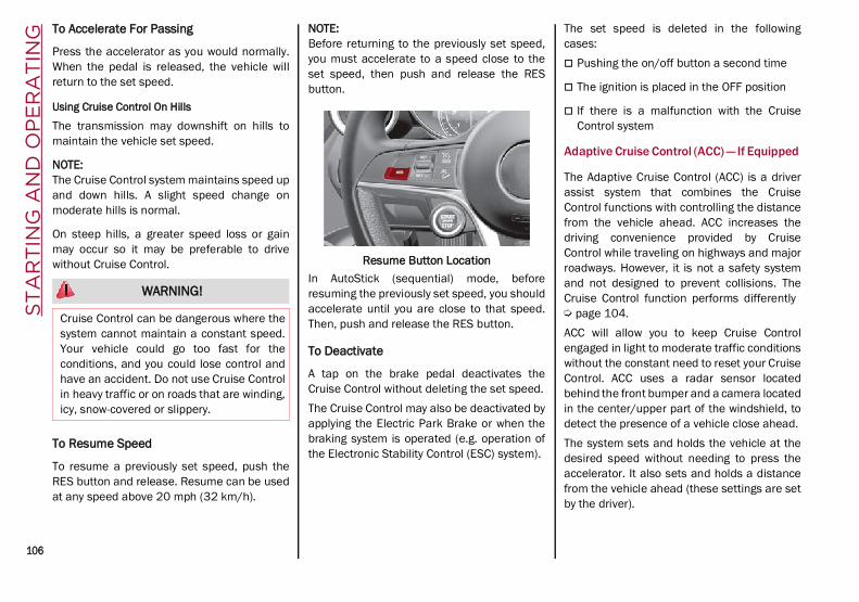
ST
AR
TIN
G A
ND
OP
ER
AT
ING
106
To Accelerate For Passing
Press the accelerator as you would normally.When the pedal is released, the vehicle willreturn to the set speed.
Using Cruise Control On Hills
The transmission may downshift on hills tomaintain the vehicle set speed.
NOTE:The Cruise Control system maintains speed upand down hills. A slight speed change onmoderate hills is normal.
On steep hills, a greater speed loss or gainmay occur so it may be preferable to drivewithout Cruise Control.
To Resume Speed
To resume a previously set speed, push theRES button and release. Resume can be usedat any speed above 20 mph (32 km/h).
NOTE:Before returning to the previously set speed,you must accelerate to a speed close to theset speed, then push and release the RESbutton.
Resume Button LocationIn AutoStick (sequential) mode, beforeresuming the previously set speed, you shouldaccelerate until you are close to that speed.Then, push and release the RES button.
To Deactivate
A tap on the brake pedal deactivates theCruise Control without deleting the set speed.The Cruise Control may also be deactivated byapplying the Electric Park Brake or when thebraking system is operated (e.g. operation ofthe Electronic Stability Control (ESC) system).
The set speed is deleted in the followingcases: Pushing the on/off button a second time
The ignition is placed in the OFF position
If there is a malfunction with the CruiseControl system
Adaptive Cruise Control (ACC) — If Equipped
The Adaptive Cruise Control (ACC) is a driverassist system that combines the CruiseControl functions with controlling the distancefrom the vehicle ahead. ACC increases thedriving convenience provided by CruiseControl while traveling on highways and majorroadways. However, it is not a safety systemand not designed to prevent collisions. TheCruise Control function performs differently Ú page 104.ACC will allow you to keep Cruise Controlengaged in light to moderate traffic conditionswithout the constant need to reset your CruiseControl. ACC uses a radar sensor locatedbehind the front bumper and a camera locatedin the center/upper part of the windshield, todetect the presence of a vehicle close ahead.The system sets and holds the vehicle at thedesired speed without needing to press theaccelerator. It also sets and holds a distancefrom the vehicle ahead (these settings are setby the driver).
WARNING!
Cruise Control can be dangerous where thesystem cannot maintain a constant speed.Your vehicle could go too fast for theconditions, and you could lose control andhave an accident. Do not use Cruise Controlin heavy traffic or on roads that are winding,icy, snow-covered or slippery.
21_GU_OM_EN_USC_t.book Page 106

107
(Continued)(Continued)
Front Bumper Radar Location
Windshield Camera LocationIf the system detects a vehicle ahead, it willautomatically intervene by slightly braking oraccelerating in order to maintain the presetdistance. It will not exceed the original setspeed when adapting to the speed of thevehicle ahead.
NOTE:Adaptive Cruise Control performance is notguaranteed under the following circum-stances, and it is recommended to turn thesystem off when:
Driving in fog, heavy rain, or snow.
Driving in heavy traffic or constructionzones.
Driving on icy, snowy, slippery roads, roadswith steep inclines, or roads with numerousturns and bends.
Entering a turn lane.
When circumstances do not allow safedriving at a constant speed Ú page 268.
WARNING!
Adaptive Cruise Control (ACC) is a conve-nience system. It is not a substitute foractive driver involvement. It is always thedriver’s responsibility to be attentive ofroad, traffic, and weather conditions,vehicle speed, distance to the vehicleahead; and, most importantly, brake oper-ation to ensure safe operation of thevehicle under all road conditions. Yourcomplete attention is always requiredwhile driving to maintain safe control ofyour vehicle. Failure to follow these warn-ings can result in a collision and death orserious personal injury.
The ACC system:
• May react to pedestrians, oncomingvehicles, and stationary objects (e.g.,a stopped vehicle in a traffic jam or adisabled vehicle) at speeds between2 mph and 35 mph (4 km/h and60 km/h).
• Cannot take street, traffic, andweather conditions into account, andmay be limited upon adverse sightdistance conditions.
• Does not always fully recognizecomplex driving conditions, which canresult in wrong or missing distancewarnings.
• Will bring the vehicle to a completestop while following a vehicle aheadand hold the vehicle for approximatelytwo minutes in the stop position. If thevehicle ahead does not start movingwithin two minutes, the parking brakewill be activated and the ACC systemwill be canceled.
You should switch off the ACC system:
When driving in fog, heavy rain, heavysnow, sleet, heavy traffic, and complexdriving situations (i.e., in highwayconstruction zones).
WARNING! (Continued)
21_GU_OM_EN_USC_t.book Page 107

ST
AR
TIN
G A
ND
OP
ER
AT
ING
108
Activating Adaptive Cruise Control (ACC)
The minimum set speed for the ACC system is19 mph (30 km/h) and the maximum is110 mph (180 km/h).The system cannot be activated: When pressing the brake pedal.
When the brakes are overheated.
When the Electric Park Brake has beenoperated.
When either PARK, REVERSE or NEUTRAL isengaged.
When the engine RPM is above a maximumthreshold.
When the vehicle speed is not within theoperational speed range.
When the Electronic Stability Control (ESC)(or Anti-Lock Brake System (ABS) or otherstability control systems) are operating orhave just operated.
When the ESC system is off.
When the Forward Collision Warning system(if equipped) is braking automatically.
In the event of a system failure.
When the engine is off.
In case of obstruction of the radar sensor (inthis case the bumper area where it islocated must be cleaned).
If the system is set, the conditions describedabove also cause a cancellation or deactiva-tion of the system. These situations may varyaccording to the conditions.
NOTE:The system will not be deactivated whenspeeds higher than those set are reached bypressing the accelerator pedal above110 mph (180 km/h). In these situations, thesystem may not work correctly and it is recom-mended to deactivate it.
To Activate/Deactivate
The system has four operating states: Enabled (speed not set)
Activated (speed set)
Paused
Deactivated
To ActivateTo enable the system, push and release theon/off button located on the left side on thesteering wheel.
On/Off ButtonWhen the system is enabled and ready tooperate, the display shows the white ACC iconabove dashes in place of the speed.
Enabled IconsSetting a speed activates the system. Thedisplay shows the icon in green with the setspeed.
When entering a turn lane or highway offramp; when driving on roads that arewinding, icy, snow-covered, slippery, orhave steep uphill or downhill slopes.
When circumstances do not allow safedriving at a constant speed.
WARNING! (Continued)
21_GU_OM_EN_USC_t.book Page 108

109
To Pause/DeactivateWith the feature enabled (speed not set), pushthe on/off button to disable.With the feature active (speed set), push theon/off button to pause. The display will showthe icon in white with the speed in brackets. Todeactivate the feature, push the on/off buttona second time.
To Set A Desired Speed
When the vehicle reaches the desired speed,push the RES/SET switch downward andrelease it to activate the system. When theaccelerator is released, the vehicle will main-tain the set speed automatically.
SET Switch
While the accelerator pedal is pressed, thesystem will not be able to control the distancebetween the vehicle and the one ahead. In thiscase, the speed will be determined only by theposition of the accelerator pedal.The system will return to normal operation assoon as the accelerator pedal is released.
To Vary The Speed Setting
To Increase Or Decrease The Set SpeedOnce the system has been activated, you canincrease the speed by pushing the RES/SETswitch upward or decrease the speed bypushing the RES/SET switch downward. Eachtime the switch is pushed, the speed isadjusted by 1 mph.Pushing and holding the switch upward ordownward will cause the set speed to adjust in5 mph increments until the button is released.The new set speed is reflected in the instru-ment cluster display.
NOTE:
Moving the RES/SET switch downwardallows you to adjust the speed according tothe selected unit of measurement ("U.S." or"Metric") set on the radio system. Refer tothe Information and Entertainment SystemOwner’s Manual for more information.
When the unit of measurement is set toMetric, pushing and holding the RES/SET
switch will adjust the speed in 10 km/hincrements.
By keeping the accelerator pedal pressed,the vehicle can continue to acceleratebeyond the set speed. In this case, use theRES/SET switch to set the speed to thevehicle’s current speed.
When you push the RES/SET button toreduce the speed, the braking system inter-venes automatically if the engine brakedoes not slow the vehicle down sufficientlyto reach the set speed. The device holds theset speed uphill and downhill; however aslight variation is entirely normal, particu-larly on slight inclines.
The transmission could shift to a lower gearwhen driving downhill, or when acceler-ating. This is normal and necessary to main-tain the set speed.
The system will disable while driving if thebrakes overheat.
To Resume
Once the system has been canceled but notdeactivated, to resume a previously set speed,simply push the RES/SET switch upward andremove your foot from the accelerator to recall it.The system will be set to the last stored speed.
WARNING!
Leaving the Adaptive Cruise Control (ACC)system on when not in use is dangerous. Youcould accidentally set the system or cause itto go faster than you want. You could losecontrol and have a collision. Always leave thesystem off when you are not using it.
21_GU_OM_EN_USC_t.book Page 109

ST
AR
TIN
G A
ND
OP
ER
AT
ING
110 (Continued)
Setting The Distance Between Vehicles
The distance between your vehicle and thevehicle ahead may be set to one bar (short),two bars (medium), three bars (long), or fourbars (maximum).
Distance IconsThe distances from the vehicle ahead areproportional to speed.The interval of time with relation to the vehicleahead remains constant and varies from onesecond (for the short distance one-bar setting)
to two seconds (for the maximum distancefour-bar setting).The set distance is shown on the display by adedicated icon.The setting is four bars (maximum) the firsttime the system is used. After the distance hasbeen modified by the driver, the new distancewill be stored even if the system is deactivatedand reactivated. To Decrease The DistancePush and release the distance button todecrease the distance setting. The distancesetting decreases by one bar (shorter) everytime the button is pushed.
Distance ButtonThe set speed is held if there are no vehiclesahead. Once the shortest distance has beenselected, the next push of the button will setthe maximum distance.If a slower vehicle is detected in the samelane, the vehicle icon on the display illumi-nates from grey to white. The system automat-
ically adjusts the vehicle’s speed to keep theset distance, independently of the set speed.The vehicle holds the set distance until: The vehicle ahead accelerates to a speed
higher than the set speed.
The vehicle ahead leaves the lane or thedetection field of the Adaptive CruiseControl system sensor.
The distance setting is changed.
The Adaptive Cruise Control system is deac-tivated/paused.
WARNING!
The Resume function should only be used iftraffic and road conditions permit. Resuminga set speed that is too high or too low forprevailing traffic and road conditions couldcause the vehicle to accelerate or deceleratetoo sharply for safe operation. Failure tofollow these warnings can result in a collisionand death or serious personal injury.
WARNING!
The maximum breaking applied by thesystem is limited. The driver may apply thebrakes in all cases if needed.
If the system predicts that the brakinglevel is insufficient to hold the setdistance, either “BRAKE!” or a dedicatedmessage is displayed to warn the driver ofapproaching the vehicle ahead. Anacoustic signal is also emitted. In thiscase, it is advised to brake immediately asnecessary to hold a safe distance from thevehicle ahead.
The driver is responsible for ensuring thatthere are no pedestrians, other vehicles orobjects along the direction of the vehicle.Failure to comply with these precautionsmay cause serious accidents and injuries.
21_GU_OM_EN_USC_t.book Page 110

111
Overtake Aid
When driving with ACC engaged and followinga vehicle at a speed greater than 45 mph(70 km/h), the system will provide an addi-tional acceleration up to the ACC set speed toassist in passing the vehicle. This additionalacceleration is triggered when the driverutilizes the left turn signal and will only beactive when passing on the left hand side.The system detects the direction of traffic auto-matically when the vehicle passes from lefthand traffic to right hand traffic. In this case,the overtaking assist function is only activewhen the reference vehicle is overtaken on theright. The additional acceleration is deactivatedwhen the driver uses the right direction indi-cator and returns to the original lane.
“Stop And Go” Function
The “Stop and Go” operating strategy allowsyou to maintain a safe distance from thevehicle ahead until the vehicle has completelystopped.In the event that the ACC system brings yourvehicle to a standstill while following thevehicle in front, if the vehicle in front starts
moving within two seconds of your vehiclecoming to a standstill, your vehicle will resumemotion without the need for any driver action.If the vehicle in front does not start movingwithin two seconds of your vehicle coming to astandstill, the driver will have to push the RES/SET switch upward to restart.
Deactivation
The system is deactivated and the set speed iscanceled if: The on/off button is pushed (when the
system is on or paused).
The ignition is placed in the OFF position
RACE mode is activated (Quadrifogliomodels)
The system is canceled (the set speed anddistance are stored): When the system is paused Ú page 108
When the conditions shown in the “ActivatingAdaptive Cruise Control (ACC)” section occur Ú page 108
Limited Operation Warning
If the dedicated message is shown on thedisplay, a condition limiting the AdaptiveCruise Control operation may have occurred.This could be due to an obstruction of thevehicle’s sensor or camera. It could also bedue to a fault in the system. If an obstructionis detected, clean the area of the windshieldopposite the interior rearview mirror, wherethe camera is located, as well as the area ofthe front fascia/bumper where the sensor islocated. Then check that the message hasdisappeared.When the conditions limiting the system func-tions end, normal operation will resume.Should the fault persist, contact an authorizeddealer.
Precautions While Driving With ACC
In certain driving situations, ACC may havedetection issues. In these cases, ACC maybrake late or unexpectedly. The driver needsto stay alert and may need to intervene. Thefollowing are examples of these types of situa-tions:
Towing A Trailer
Towing a trailer is not advised when using ACC.
Offset Driving
ACC may not detect a vehicle in the same lanethat is offset from your direct line of travel, ora vehicle merging in from a side lane. Theremay not be sufficient distance to the vehicle
The driver is fully responsible for holding asafe distance from the vehicle aheadrespecting the highway code in force inthe respective country.
WARNING! (Continued)
WARNING!
When the ACC system is resumed, thedriver must ensure that there are nopedestrians, vehicles or objects in the pathof the vehicle. Failure to follow thesewarnings can result in a collision and deathor serious personal injury.
21_GU_OM_EN_USC_t.book Page 111

ST
AR
TIN
G A
ND
OP
ER
AT
ING
112
ahead. The offset vehicle may move in and outof the line of travel, which can cause yourvehicle to brake or accelerate unexpectedly.
Turns And Bends
When driving on a curve with ACC engaged,the system may increase or decrease thevehicle speed for stability, with no vehicleahead detected. Once the vehicle is out of thecurve the system will resume your original setspeed. This is a part of normal ACC systemfunctionality.
NOTE:
On tight turns ACC performance may belimited. In this case, it is advisable to deac-tivate the system.
The system only limits the speed DURING abend and not BEFORE it.
Steering And Curves
Using ACC On Hills
When driving on hills, ACC may not detect avehicle in your lane. Depending on the speed,vehicle load, traffic conditions, and the steep-ness of the hills, ACC performance may belimited.
NOTE:The driver must maintain control of thevehicle, remain alert, and be ready to apply thebrakes if needed.
Lane Changing
ACC may not detect a vehicle until it iscompletely in the lane in which you are trav-eling. In the lane changing example below,ACC has not yet detected the vehicle changinglanes and it may not detect the vehicle until it'stoo late for the ACC system to take action. ACCmay not detect a vehicle until it is completelyin the lane. There may not be sufficientdistance to the lane-changing vehicle. Alwaysbe attentive and ready to apply the brakes ifnecessary.
Lane Change
Narrow Vehicles
Some narrow vehicles traveling near the outeredges of the lane or edging into the lane arenot detected until they have moved fully intothe lane. There may not be sufficient distanceto the vehicle ahead.
Narrow Vehicles
21_GU_OM_EN_USC_t.book Page 112

113
Stationary Objects And Vehicles
The ACC system can detect stationary vehicleswhen the vehicle is traveling at speedsbetween 2 mph and 35 mph (4 km/h and60 km/h). The driver should always be atten-tive and be ready to press the brakes if neces-sary.
Objects And Vehicles Moving In Opposite Or Crosswise Direction
The system cannot detect the presence ofobjects or vehicles traveling in opposite orcrosswise directions and consequently will notactivate Ú page 268.
Objects And Vehicles Moving In Opposite Or Crosswise Direction
IFETEL: RCPBOMR 14-0766La operación de este equipo está sujeta a lassiguientes dos condiciones:
1. es posible que este equipo o dispositivo nocause interferencia perjudicial y
2. este equipo o dispositivo debe aceptarcualquier interferencia, incluyendo la quepueda causar su operación no deseada.
Changes or modifications made to this equip-ment not expressly approved by RobertBOSCH GmbH may void the FCC authorizationto operate this equipment.This equipment has been tested and found tocomply with the limits for a Class A digitaldevice, pursuant to Part 15 of the FCC Rules.These limits are designed to provide reason-able protection against harmful interferencewhen the equipment is operated in a commer-cial environment. This equipment generates,uses, and can radiate radio frequency energyand, if not installed and used in accordancewith the instruction manual, may causeharmful interference to radio communica-tions. Operation of this equipment in a resi-dential area is likely to cause harmfulinterference in which case the user will berequired to correct the interference at his ownexpense.
Toutes modifications apportées à cet équipe-ment qui ne sont pas expressément homo-loguées par Robert BOSCH GmbH peuventannuler l'autorisation de la FCC de fairefonctionner cet équipement.Cet appareil a été vérifié et s'est révéléconforme aux normes applicables aux appar-eils numériques de catégorie A, en vertu de lasection 15 des règlements de la FCC. Cesnormes sont définies pour fournir une protec-tion raisonnable contre les interférences nuis-ibles lorsque l'équipement est utilisé dans lesinstallations résidentielles. Cet appareilgénère, utilise et peut émettre des ondesradioélectriques et, s'il n'est pas installé etutilisé conformément au manuel d’instruction,peut causer un brouillage radioélectriquenuisible aux communications radio. Lefonctionnement de cet équipement dans unezone résidentielle est susceptible de causerdes interférences nuisibles; dans ce cas,l'usager doit corriger les interférences à sespropres frais.Radio Frequency Exposure InformationThis equipment complies with FCC radiationexposure limits set forth for an uncontrolledenvironment. This equipment should beinstalled and operated with minimum distanceof 20 cm between the radiator and your body.This transmitter must not be co-located oroperating in conjunction with any otherantenna or transmitter.
21_GU_OM_EN_USC_t.book Page 113

ST
AR
TIN
G A
ND
OP
ER
AT
ING
114
Déclaration d’exposition aux radiationsCet équipement est conforme aux limitesd'exposition aux rayonnements IC établiespour un environnement non contrôlé. Cet équi-pement doit être installé et utilisé avec unminimum de 20 cm de distance entre lasource de rayonnement et votre corps.Ce transmetteur ne doit pas etre place aumeme endroit ou utilise simultanement avecun autre transmetteur ou antenne.
HIGHWAY ASSIST SYSTEM (HAS) — IF EQUIPPEDThe Highway Assist System (HAS) is a drivingassistance system that is only available whendriving on highways. The system operates upto speeds of 90 mph (145 km/h) when hori-zontal signs are detected.The system uses information from the frontcamera and radar to help keep the vehicle inthe center of the lane and at a constant speed.The HAS system combines Adaptive CruiseControl (ACC) functions with lane centeringlogic to control the trajectory of the vehicle.The HAS system requires the driver’s hands toremain on the steering wheel.Once HAS is activated, a dedicated screen willappear on the instrument cluster display.
To Activate/Deactivate
To ActivateTo activate the HAS system, push the buttonlocated on the left side of the steering wheel.
Highway Assist ButtonSuspension ConditionsThe following operations will suspend the HASsystem: Steer manually
Press the brake pedal
Disable the ACC device
Activate the turn signals
Push the ACC activation setting button fortwo seconds to activate Cruise Control
Place the gear selector in PARK, REVERSE,or NEUTRAL
Reactivating the ACC system will reactivateHAS Ú page 106.Automatic DeactivationThe system can be deactivated in the followingsituations: If there are narrow bends
When hands are removed from the steeringwheel
If the left or right turn signal is activated
If the driver intentionally changes laneswithout using the turn signal
If the driver’s seat belt is released
If the gear selector is placed in DRIVE
If the “Active Braking” function is activated Ú page 156
If the vehicle exits the highway
If the lane markings are not detected by thecamera
If the ACC device is deactivated
If the vehicle speed exceeds 90 mph(145 km/h)
NOTE:
When the HAS system is turned off, thesymbol on the display turns red and thengrey.
Hands on the steering wheel are detectedby a capacitive sensor installed in it.
When the automatic suspension conditionsare over, HAS will be automatically reacti-vated.
Operation
The HAS system only operates when thedriver’s hands are on the steering wheel.
21_GU_OM_EN_USC_t.book Page 114

115
If the system detects that the driver’s handshave been removed from the steering wheel,the system will alert the driver to place theirhands back on the steering wheel Ú page 115.If the vehicle crosses the lane boundary, thesteering wheel will vibrate and the dedicatedscreen will appear in the instrument clusterdisplay.
NOTE:The HAS system may take up to five secondsto turn on once all conditions are met. Duringthis time, a grey indicator light will appear onthe instrument cluster display and the systemwill automatically activate as soon as all of theconditions are met with no intervention fromthe driver.
The following conditions must be met beforethe HAS system turns on: The HAS system must be enabled by
pushing the button on the steering wheel
The vehicle must be on a highway
ACC must be activated
The right and left lane boundaries must bevisible
The vehicle speed must be between 0 and90 mph (0 and 145 km/h)
The camera, radar, and radio system mustbe functioning properly
The road lane width must be between 8.5 ftand 13.7 ft (2.6 m and 4.2 m)
The turn signals must not be activated
The HAS system must be functioning prop-erly
Other operating limits: If the speed of ACC can be set to a higher
value (top speed 110 mph (180 km/h), HASis only available as long as the vehiclespeed is equal to or less than 90 mph(145 km/h).
When the ACC speed is reduced and thevehicle speed is less than 90 mph(145 km/h), the system will automaticallyreactivate.
If the ACC speed is set to 90 mph (145 km/h),traveling downhill may increase the vehiclespeed. The HAS system will deactivate untilthe speed returns to 90 mph (145 km/h).
Indications On The Display
The HAS system status can always be viewedin the instrument cluster display.The system status is indicated by the color ofthe symbol on the display.The HAS system uses sensors in the steeringwheel to detect if the driver’s hands are on it.If the driver’s hands are not on the steeringwheel, a series of warnings will appear in theinstrument cluster display to alert the driver toreposition their hands on the steering wheel.
An acoustic signal will also sound. After aperiod of time, the HAS system will disable ifthe driver’s hands do not return to the steeringwheel.After a period of time, the HAS system willdisable if the driver has not repositioned theirhands on the steering wheel.When the system does not detect hands onthe steering wheel, it will warn the driver bydisplaying a dedicated screen on the instru-ment cluster display.
System Status
Active SystemWhen the system is active, the screen belowwill appear in the instrument cluster display.
Highway Assist System ActiveIf on a different menu screen, a symbol willappear on the instrument cluster display indi-cating that the system is active.When the driver’s hands are removed from thesteering wheel, the system disables after a fewseconds. A screen will appear in the instru-
21_GU_OM_EN_USC_t.book Page 115

ST
AR
TIN
G A
ND
OP
ER
AT
ING
116
ment cluster display warning the driver toreturn their hands to the steering wheel.Active System (Hands Removed From TheSteering Wheel For A Short Time)As soon as the driver removes their handsfrom the steering wheel, the screen below willappear in the instrument cluster display. Thesystem will remain active at this time.
Hands Removed Initial WarningIf the driver does not return their hands to thesteering wheel within a few seconds, thescreen below will appear in the instrumentcluster display.
Hands Secondary Warning
Active System (Hands Removed From TheSteering Wheel For A Long Time)If the driver still has not returned their handsto the steering wheel after the screen above isdisplayed, the below screen will now appear inthe instrument cluster display, and anacoustic signal will sound until the driverregains control of the vehicle.
Hands Removed Final WarningIf the driver’s hands are not returned to thesteering wheel after an extended period oftime, a deactivation message will appear onthe instrument cluster display. The steeringwheel control will be deactivated.This display will remain active even when thedriver’s hands are removed from the steeringwheel. The symbol on the display will turn grey.When HAS is active, the Lane Keeping Assist(LKA)/ Lane Departure Warning (LDW)systems (if equipped), if previously activated,will remain activated.
Limited System Availability/Operation
System AvailabilityExternal factors and conditions may affect theproper operation of the HAS system, such as: Narrow, winding, curvy streets
Poor visibility (due to heavy rain, snow, fog,etc.)
Front lights of oncoming vehicles or directsunlight or shade
Damage or obstructions caused by mud,ice, snow, etc.
Bumper damaged or not aligned
Interference with other equipment thatcauses electromagnetic waves
Presence of roadwork/road constructionsites
If the indications given by the navigationsystem (if any) of the radio system are notyet ready and/or if the navigation system isrecalculating the route
System Limited OperationThe HAS system may have limited or reducedfunctionality when one of the following condi-tions occur: Lane markings are not clear or in conditions
of poor visibility (e.g. in heavy rain, snow,fog, etc.)
21_GU_OM_EN_USC_t.book Page 116
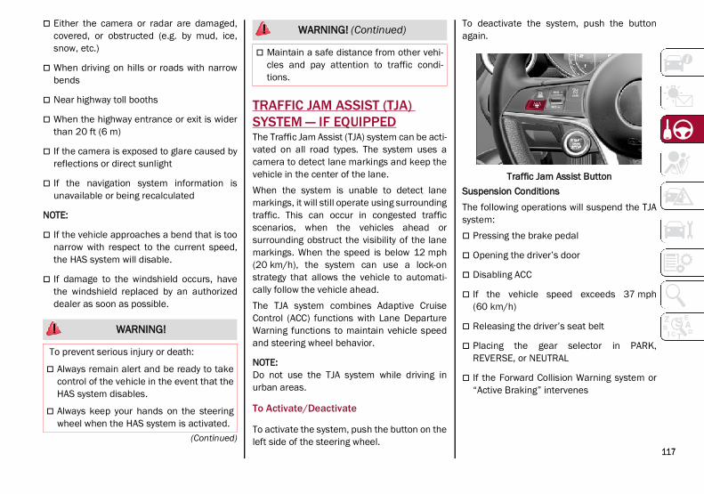
117(Continued)
Either the camera or radar are damaged,covered, or obstructed (e.g. by mud, ice,snow, etc.)
When driving on hills or roads with narrowbends
Near highway toll booths
When the highway entrance or exit is widerthan 20 ft (6 m)
If the camera is exposed to glare caused byreflections or direct sunlight
If the navigation system information isunavailable or being recalculated
NOTE:
If the vehicle approaches a bend that is toonarrow with respect to the current speed,the HAS system will disable.
If damage to the windshield occurs, havethe windshield replaced by an authorizeddealer as soon as possible.
TRAFFIC JAM ASSIST (TJA) SYSTEM — IF EQUIPPEDThe Traffic Jam Assist (TJA) system can be acti-vated on all road types. The system uses acamera to detect lane markings and keep thevehicle in the center of the lane.When the system is unable to detect lanemarkings, it will still operate using surroundingtraffic. This can occur in congested trafficscenarios, when the vehicles ahead orsurrounding obstruct the visibility of the lanemarkings. When the speed is below 12 mph(20 km/h), the system can use a lock-onstrategy that allows the vehicle to automati-cally follow the vehicle ahead.The TJA system combines Adaptive CruiseControl (ACC) functions with Lane DepartureWarning functions to maintain vehicle speedand steering wheel behavior.
NOTE:Do not use the TJA system while driving inurban areas.
To Activate/Deactivate
To activate the system, push the button on theleft side of the steering wheel.
To deactivate the system, push the buttonagain.
Traffic Jam Assist ButtonSuspension ConditionsThe following operations will suspend the TJAsystem: Pressing the brake pedal
Opening the driver’s door
Disabling ACC
If the vehicle speed exceeds 37 mph(60 km/h)
Releasing the driver’s seat belt
Placing the gear selector in PARK,REVERSE, or NEUTRAL
If the Forward Collision Warning system or“Active Braking” intervenes
WARNING!
To prevent serious injury or death:
Always remain alert and be ready to takecontrol of the vehicle in the event that theHAS system disables.
Always keep your hands on the steeringwheel when the HAS system is activated.
Maintain a safe distance from other vehi-cles and pay attention to traffic condi-tions.
WARNING! (Continued)
21_GU_OM_EN_USC_t.book Page 117

ST
AR
TIN
G A
ND
OP
ER
AT
ING
118
Automatic DeactivationSystem operation will be temporarily disabledunder the following conditions: When traveling around narrow bends
If the lane boundaries are not detected
One of the two lines is interrupted
The sun is low and reflects on the radarcamera
If the turn signals are activated
If the driver intentionally changes laneswithout using the turn signal
If manual steering begins
If the driver’s hands are removed from thesteering wheel
When there is no surrounding traffic andthere are no horizontal lane boundaries
If the system is not functioning properly
If lateral acceleration is high
NOTE:
When TJA is turned off, the symbol in theinstrument cluster display will turn red, andthen grey.
A sensor in the steering wheel detectswhether the driver’s hands are placed onthe steering wheel.
When the automatic suspension conditionsare over, the TJA system will be automaticallyreactivated.
Operation
The TJA system can only operate when thedriver’s hands are on the steering wheel.If the system detects that the driver’s handshave been removed from the steering wheel, amessage will appear in the instrument clusterdisplay to alert the driver to place their handsback on the wheel.
NOTE:
If the vehicle begins to cross the laneboundary, the steering wheel will vibrateand a dedicated screen will appear in theinstrument cluster display.
The TJA system may take up to five secondsto become active once all conditions aremet.
The following conditions must be met in orderto activate the system: The TJA system must be enabled
The Adaptive Cruise Control (ACC) systemmust be turned on
The right and left lane boundaries must berecognized by the system
The vehicle must be traveling at a speedbetween 0 and 37 mph (0 and 60 km/h)
The camera, radar, and radio system mustbe functioning properly
The road lane width must be between 8.5 ftand 13.7 ft (2.6 m and 4.2 m)
The turn signals must be turned off
The TJA system must be functioning prop-erly
If the ACC speed is set to 37 mph (60 km/h)or less, traveling downhill may increase thevehicle speed. The system will remain inac-tive until the speed returns to 37 mph(60 km/h) or less.
Indications On The Display
The TJA system status is indicated by the colorof the symbol in the instrument cluster display.The system uses sensors in the steering wheelto detect if the driver’s hands are present. Ifthe driver’s hands are removed, a series ofwarnings will appear in the instrument clusterdisplay to alert the driver to reposition theirhands on the steering wheel. Acoustic signalswill also be emitted.If the driver’s hands are not returned to thesteering wheel after a period of time, thesystem will be disabled.
21_GU_OM_EN_USC_t.book Page 118

119
System Status
Active SystemAn active system is indicated by the followingscreen in the “Driver Assistance” menu on theinstrument cluster display.
TJA System Active
Active System (Hands Removed From TheSteering Wheel For A Short Time)The following screen will appear in the instrumentcluster display immediately after the driver’shands are removed from the steering wheel. Thesystem still remains active at this time.
Hands Removed Initial Warning
If the driver does not return their hands to thesteering wheel within a few seconds, thefollowing screen will appear in the instrumentcluster display.
Hands Removed Secondary Warning
Active System (Hands Removed From TheSteering Wheel For A Long Time)If the driver’s hands have still not beenreturned to the steering wheel, the followingscreen will appear in the instrument clusterdisplay.
Hands Removed Final Warning
An acoustic signal will sound until the driverregains control of the vehicle (hands onsteering wheel). The system is still active atthis time.If the driver’s hands are not returned to thesteering wheel after a period of time, a deacti-vation message will appear on the instrumentcluster display and the steering wheel controlwill be deactivated.Once the symbol on the display turns grey, thesystem is no longer active and the driver musttake control of the vehicle. At this time, theAdaptive Cruise Control (ACC) system andLane Departure Warning system will also bedisabled.When the TJA system is active, the LaneKeeping Assist (LKA)/Lane DepartureWarning (LDW) systems (if equipped) will betemporarily disabled. When TJA is not active,the LKA system ( Ú page 128) and LDWsystem ( Ú page 126) will remain active.
Limited System Availability/Operation
System AvailabilityPerformance of the TJA system may beaffected by the following factors: Narrow, winding, curvy streets
Lane boundaries that are not clear or inconditions of poor visibility (e.g. heavy rain,snow, fog, etc.)
If the camera is exposed to glare from directsunlight or headlights of an oncoming vehicle
21_GU_OM_EN_USC_t.book Page 119

ST
AR
TIN
G A
ND
OP
ER
AT
ING
120
If the camera or sensor is damaged,covered, or obstructed (e.g. by mud, ice,snow, etc.)
The bumper is damaged or misaligned
Interference with other equipment causeselectromagnetic waves
Construction sites
If the indications given by the navigationsystem of the radio system are not yet readyor if the system is recalculating
System Limited OperationThe TJA system may have limited or reducedfunctionality when one of the following condi-tions occurs: Lane boundaries are not clear or in condi-
tions of poor visibility (e.g. in heavy rain,snow, fog, etc.)
Either the camera or radar are damaged,covered, or obstructed (e.g. by mud, ice,snow, etc.)
When driving on hills or narrow bends
Near highway toll booths
When the highway entrance or exit is morethan 20 ft (6 m) wide
If the camera is exposed to glare fromreflections or direct sunlight
NOTE:
If damage to the windshield occurs, havethe windshield replaced by an authorizeddealer as soon as possible.
If the vehicle approaches a bend that is toonarrow with respect to the current speed,the TJA system will deactivate.
TRAFFIC SIGN RECOGNITION (TSR) SYSTEM — IF EQUIPPEDThe Traffic Sign Recognition (TSR) systemuses a camera mounted on the windshield todetect recognizable road signs such as: Speed limits
Signs indicating the end of the situationsindicated above
If the camera does not detect valid speedlimits, the radio system navigation system maysuggest unregulated speed limits.The system always checks the traffic signsindicating the current speed limit signs. Thesystem is able to recognize and display up totwo different road signs in the instrumentcluster display.Depending on the unit of measurement (km ormph) set through the “Unit of Measurement”menu in the radio system, the TSR system willautomatically show the indication of the roadsign in the unit of measurements selected inthe instrument cluster display.
To Activate/Deactivate
The TSR system can be activated/deactivatedin the radio system in the “Driver Assistance”menu. The system activation is signaled byroad signs shown on the instrument clusterdisplay.
WARNING!
To prevent serious injury or death:
Always remain alert and be ready to takecontrol of the car in the event that the TJAsystem disables.
Always keep your hands on the steeringwheel when the TJA system is activated.
Maintain a safe distance from other vehi-cles and pay attention to traffic condi-tions.
The TJA system should only be used as adriving aid. The drive must always payattention to their surroundings when thesystem is operating and be ready to takecontrol of the vehicle at any time.
Do not place any objects on the steeringwheel (e.g. steering wheel covers) whichcould interfere with the hand detectionsensor on the steering wheel.
21_GU_OM_EN_USC_t.book Page 120

121
(Continued)
NOTE:
By selecting “Blinking”, the driver can acti-vate a warning to display when the speedexceeds the limit indicated by the TSRsystem. The speed road sign on the instru-ment cluster display will blink until thevehicle speed drops below the displayedlimit.
Selecting “Offset” will set the speed atwhich “Blinking” is activated up to amaximum of 6 mph (10 km/h) above thelimit detected by the system.
If no speed limit signs are found, the systemwill revert to the speed limit signs that arestored in the NAV system.
Indications On The Display
The system status can always be viewedthrough the instrument cluster display.The instrument cluster display shows only thespeed limit indications and consists of thefollowing steps: The new speed limit recognized by the
system, which is indicated by means of apredetermined color. The road sign indi-cating the end of the speed limit or a “RoadSign Not Detected” message may appear inthis zone.
After a predetermined distance, the previ-ously displayed road sign changes color toinform the driver that the speed limitprovided may no longer be valid.
1 — Traffic Sign Recognized
INTELLIGENT SPEED CONTROL (ISC) SYSTEM — IF EQUIPPEDThe Intelligent Speed Control (ISC) system isalways paired with the Adaptive Cruise Control(ACC) system. The ISC system suggests anautomatic speed adjustment to the driverbased on the speed limit for the road beingtraveled. The driver can decide whether toaccept or reject the automatic speed adjust-ment, using the switch on the steering wheel.
WARNING!
To prevent serious injury or death:
Always remain alert and be ready to takecontrol of the vehicle in the event that theTJA system disables.
Always keep your hands on the steeringwheel when the TJA system is activated.
Maintain a safe distance from other vehi-cles and pay attention to traffic conditions.
CAUTION!
Functionality may be limited or the systemmay not work if the sensor is obstructed.
The system may have limited operation ornot work at all in weather conditions suchas heavy rain, hail, thick fog, and lowtemperatures. Strong light contrasts caninfluence the recognition capability of thesensor.
The area surrounding the sensor must notbe covered with stickers or any otherobject.
Do not tamper or perform any operationsin the area of the windshield glass directlysurrounding the sensor.
Clean foreign matters such as bird drop-pings, insects, snow or ice on the wind-shield. Use specific detergents and cleancloths to avoid scratching the windshield.
CAUTION! (Continued)
21_GU_OM_EN_USC_t.book Page 121

ST
AR
TIN
G A
ND
OP
ER
AT
ING
122
If the speed limit is exceeded according to theroad signs or traffic conditions, a dedicatedgraphic message is displayed on the instru-ment panel display.
RES/SET Switch
To Activate/Deactivate
To ActivateThe system can be activated in the radiosystem within the “Driver Assistance” menu.The symbol illuminates in the instrumentcluster display when the system is active.
1 — ISC System Active
To DeactivateThe system is deactivated under the followingconditions: When the Traffic Sign Recognition (TSR)
system is deactivated
When the Adaptive Cruise Control (ACC)system is deactivated
NOTE:Selecting “Speed Offset” allows the driver toset the speed up to a maximum of 10 mph(16 km/h) above or below the suggestedspeed set by the ISC system. In this instance,the road sign information shown in the instru-ment cluster display will continue to bedetected by the TSR system.
Indications On The Display
The system status is indicated by a white orgreen icon in the instrument cluster display(similar to the Adaptive Cruise Control (ACC)device) to the left of the road sign indicationsprovided by the Traffic Sign Recognition (TSR)system.
Acceptance/Rejection Of The Suggested Speed
The system can be activated if the driver hasactivated the following systems beforehand: Adaptive Cruise Control (ACC)
Traffic Sign Recognition (TSR)
When these systems are active, a telltale willdisplay in the instrument cluster display indi-cating the suggested speed provided by theTSR system. The driver has the option toaccept or reject this using the RES/SET switchon the steering wheel.To accept the proposed speed and adjust thespeed set by ACC, move the RES/SET switchup or down in the direction indicated in the tell-tale.To reject the proposed speed, move the RES/SET switch up or down in the direction oppo-site of the arrow in the telltale. The ACC systemwill continue to regulate to the previously setspeed.If the speed set by the ACC system is the sameas the speed detected by the TSR system, thespeed limit indicator on the instrument clusterdisplay will be highlighted with a green circle.
1 — Suggested Speed Higher Than Current Speed
21_GU_OM_EN_USC_t.book Page 122
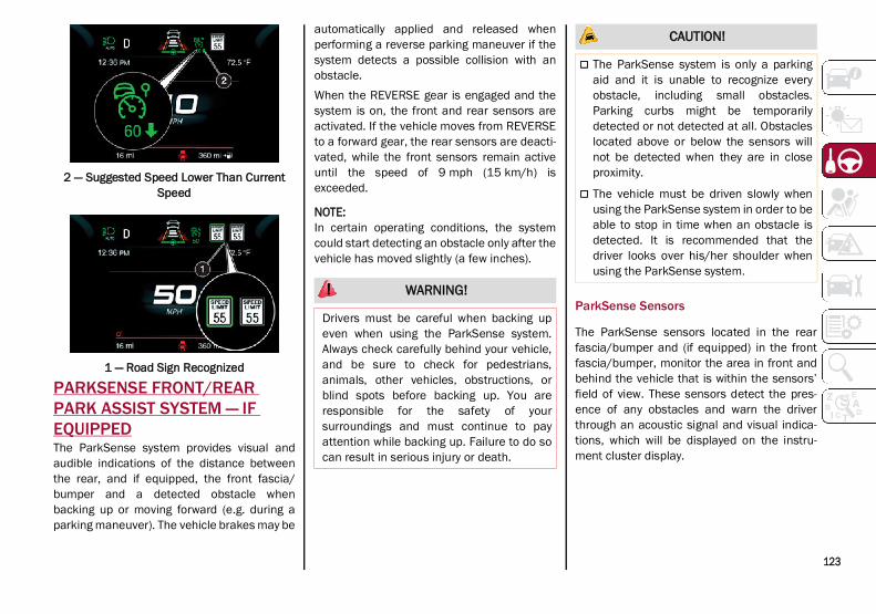
123
2 — Suggested Speed Lower Than Current Speed
1 — Road Sign Recognized
PARKSENSE FRONT/REAR PARK ASSIST SYSTEM — IF EQUIPPEDThe ParkSense system provides visual andaudible indications of the distance betweenthe rear, and if equipped, the front fascia/bumper and a detected obstacle whenbacking up or moving forward (e.g. during aparking maneuver). The vehicle brakes may be
automatically applied and released whenperforming a reverse parking maneuver if thesystem detects a possible collision with anobstacle.When the REVERSE gear is engaged and thesystem is on, the front and rear sensors areactivated. If the vehicle moves from REVERSEto a forward gear, the rear sensors are deacti-vated, while the front sensors remain activeuntil the speed of 9 mph (15 km/h) isexceeded.
NOTE:In certain operating conditions, the systemcould start detecting an obstacle only after thevehicle has moved slightly (a few inches).
ParkSense Sensors
The ParkSense sensors located in the rearfascia/bumper and (if equipped) in the frontfascia/bumper, monitor the area in front andbehind the vehicle that is within the sensors’field of view. These sensors detect the pres-ence of any obstacles and warn the driverthrough an acoustic signal and visual indica-tions, which will be displayed on the instru-ment cluster display.
WARNING!
Drivers must be careful when backing upeven when using the ParkSense system.Always check carefully behind your vehicle,and be sure to check for pedestrians,animals, other vehicles, obstructions, orblind spots before backing up. You areresponsible for the safety of yoursurroundings and must continue to payattention while backing up. Failure to do socan result in serious injury or death.
CAUTION!
The ParkSense system is only a parkingaid and it is unable to recognize everyobstacle, including small obstacles.Parking curbs might be temporarilydetected or not detected at all. Obstacleslocated above or below the sensors willnot be detected when they are in closeproximity.
The vehicle must be driven slowly whenusing the ParkSense system in order to beable to stop in time when an obstacle isdetected. It is recommended that thedriver looks over his/her shoulder whenusing the ParkSense system.
21_GU_OM_EN_USC_t.book Page 123

ST
AR
TIN
G A
ND
OP
ER
AT
ING
124
Front Sensor Locations
Rear Sensor Locations
ParkSense Display
The driver can select the type of warning theywould like to be displayed through the radiosystem. To access the function on the mainmenu, select in the following order:
1. “Settings”
2. “Driver Assistance”
3. “ParkSense”
4. “Mode”
5. “Sound and Display”
Visual IndicationsThe system indicates the presence of anobstacle by displaying a single red arc in thedetected area, in relation to the distance ofthe object and the position of the vehicle.If the obstacle is detected in the front or rearcentral area, a single red arc will be displayedas the obstacle approaches, first constant,then flashing, in addition to an acoustic signal.If the obstacle is detected in the front or rearleft and/or right area, a single red flashing arcwill be shown in the corresponding area on thedisplay and the system will emit an acousticsignal, either at frequent intervals orconstantly.In general, the vehicle is closer to the obstaclewhen a single red flashing arc is shown on thedisplay and the acoustic signal becomescontinuous.If several obstacles are detected simultane-ously in the front and rear area, the display willshow all of them, regardless of the area inwhich they were detected.It is not possible to exit from the display screenwhile the vehicle is in REVERSE.
Acoustic SignalIn the presence of an obstacle at the front orthe rear of the vehicle, an acoustic signal withvariable frequency will sound: The acoustic signal increases in frequency
as the distance between the vehicle and theobstacle decreases.
The acoustic signal becomes continuouswhen the distance between the vehicle andthe obstacle is less than 11 inches (30 cm),and stops if the distance increases.
The acoustic signal is constant if thedistance between the vehicle and theobstacle is unchanged.
NOTE:If the sensors detect several front and rearobstacles, the closest obstacle is considered.An intermittent signal will sound if the obsta-cles are at the same distance (front and rear).
When the system emits an acoustic signal, thevolume of the radio system, if activated, isautomatically lowered.An acoustic signal will not sound if the vehicleis in PARK.
Enabling And Disabling ParkSense
For vehicles only equipped with rear sensors,to turn the system off, push the ParkSensebutton located to the left of the headlightswitch. The indicator light within the button willilluminate when the system is turned off.
21_GU_OM_EN_USC_t.book Page 124

125
Pushing the button a second time will turn thesystem back on, and the indicator light willturn off.
ParkSense System On/Off ButtonFor vehicles equipped with front and rearsensors, to turn the front parking sensors off,push the ParkSense button located to the leftof the headlight switch. The indicator lightwithin the switch will illuminate when thesystem is turned off. Pushing the button asecond time will turn the front sensors backon, and the indicator light will turn off.
NOTE:Deactivation of both the front and rear parkingsensors can only be done through the radiosystem.
The indicator light within the ParkSensesystem switch will also be on in case of systemfailure. If the switch is pushed with a systemfailure, the indicator light will flash for approx-imately five seconds. The light will then stay onconstantly.
NOTE:When the ignition is placed in the ON/RUNposition, the ParkSense system keeps the laststate when the engine was stopped (activatedor deactivated) in its memory.
ParkSense Warning Display
Parking sensor faults, if any, will be indicatedwhen REVERSE is engaged by a message onthe instrument cluster display Ú page 74.In case of system failure, a dedicatedmessage appears on the instrument clusterfor about five seconds. Cleaning The Front Or Rear Sensors: If the
display shows a message requiring thesensors to be cleaned, make sure that theouter surface and the underside of the frontand rear bumpers are free of debris (e.g.snow, mud, ice, etc.). Once these areas areclear, place the ignition in the OFF position,then return it to ON/RUN. If the message isstill displayed, contact an authorizeddealer.
Audio System Not Available: If the displayshows a message that the audio system isnot available, it means that the acousticsignal will be emitted by the instrumentpanel, and not through the vehicle’sspeakers.
Operation With A Trailer
The operation of the ParkSense system isautomatically deactivated when a trailer’s
electrical connector is plugged into thevehicle. The sensors are automatically reacti-vated when the electrical connector isremoved.
WARNING!
Before using the ParkSense system, it isstrongly recommended that the ballmount and hitch ball assembly is discon-nected from the vehicle when the vehicleis not used for towing. Failure to do so canresult in injury or damage to vehicles orobstacles because the hitch ball will bemuch closer to the obstacle than the rearfascia when the vehicle sounds the contin-uous tone. Also, the sensors could detectthe ball mount and hitch ball assembly,depending on its size and shape, giving afalse indication that an obstacle is behindthe vehicle.
Drivers must be careful when backing upeven when using the ParkSense system.Always check carefully behind yourvehicle, look behind you, and be sure tocheck for pedestrians, animals, othervehicles, obstructions, and blind spotsbefore backing up. You are responsible forsafety and must continue to pay attentionto your surroundings. Failure to do so canresult in serious injury or death.
21_GU_OM_EN_USC_t.book Page 125

ST
AR
TIN
G A
ND
OP
ER
AT
ING
126
(Continued)
ParkSense System Usage Precautions
NOTE:Some conditions may influence the perfor-mance of the ParkSense system:
Reduced sensor sensitivity could be due tothe presence of ice, snow, mud, or thickpaint on the surface of the sensor.
The sensors may detect a false obstacle(echo interference) due to mechanical inter-ference, for example when washing thevehicle or in extreme weather.
The signals sent by the sensors can bealtered by the presence of ultrasonicsystems (e.g. pneumatic brake systems oftrucks or pneumatic drills) near the vehicle.
System performance can be influenced bythe position of the sensors. For example,due to a change in the ride setting (causedby wear to the shock absorbers or suspen-sion), by changing tires, overloading thevehicle or operations that require thevehicle to be lowered.
Be sure not to place bumper stickers orother adhesives over the sensors as this willaffect system performance.
The presence of a trailer hitch without atrailer. This may interfere with the operationof the parking sensors. Before using theParkSense system, it is recommended to
remove or close the trailer hitch assemblywhen the vehicle is not being used fortowing.
LANE DEPARTURE WARNING (LDW) SYSTEM
Lane Departure Warning Operation
The Lane Departure Warning system uses aforward looking camera located on the wind-shield to detect lane markings and measurevehicle position within the lane boundaries.When one or both lane limits are detected andthe vehicle passes over one without an acti-vated turn signal, the system emits a visual aswell as an acoustic signal.If the vehicle continues to go beyond the lineof the lane without any intervention from thedriver, the surpassed line will light up on thedisplay (left or right) to urge the driver to bringthe vehicle back into the limits of the lane.
CAUTION!
Projecting loads on the roof of the vehiclemay interfere with the correct operation ofthe camera. Before starting, make surethe load is correctly positioned in ordernot to cover the camera operating range.
Do not cover the operating range of thecamera with stickers or other objects.
Do not tamper with nor operate on thecamera. Do not close the openings in theaesthetic cover located under the interiorrearview mirror. In the event of a failure ofthe camera, contact your authorizeddealer.
The camera may have limited or absentoperation due to weather conditions suchas: heavy rain, hail, thick fog, heavy snow,formation of ice layers on the windshield.
Camera operation may also be compro-mised by the presence of dust, condensa-tion, dirt or ice on the windshield, by trafficconditions (e.g. vehicles that are drivingnot aligned with yours, vehicle driving in atransverse or opposite way on the samelane, bend with a small radius of curva-ture), by road surface conditions and bydriving conditions (e.g. off-road driving).Make sure the windshield is always clean.Use specific detergents and clean clothsto avoid scratching the windshield. Thecamera operation may also be limited orabsent in some driving, traffic and roadsurface conditions.
If the windshield must be replaced due toscratches, chipping or breakage, contactexclusively an authorized dealer. Do notreplace the windshield on your own. It isadvisable to replace the windshield if it isdamaged in the area of the camera.
CAUTION! (Continued)
21_GU_OM_EN_USC_t.book Page 126

127
Turning Lane Departure Warning On Or Off
The system is activated/deactivated bypushing the button located on the end of themultifunction lever, or through the “DriverAssistance” widget though the radio system.
Lane Departure Warning System Activation/Deactivation Button
NOTE:The Lane Departure Warning system will retainthe last system state on or off from the lastignition cycle when the ignition is placed in theON/RUN position.
Activation ConditionsOnce turned on, the system becomes activeonly if the following conditions are met: The vehicle speed is equal to or above
37 mph (60 km/h); the system is deacti-vated at speeds equal to or greater than110 mph (180 km/h).
The lane markings are visible at least onone side.
There are suitable visibility conditions.
The road is straight or with wide radiusbends.
A suitable distance is kept from the vehiclein front.
The turn signal is not active.
Lane Departure Warning Message
The Lane Departure Warning system advisesthe driver when the vehicle leaves the drivinglane by showing symbols and messages on theinstrument cluster display.When the system is active and the lane mark-ings have not been detected, the displayshows two grey lane lines.
Lane Markings Not Detected
Left Lane Departure — Only Left LaneDetectedWhen the system is active and only, forexample, the left lane marking has beendetected, the detected lane illuminates inwhite on the display. The system is then readyto provide visual warnings on the display in theevent of unintentional exiting of the lane (turnsignal not activated) to the left.
Left Lane Marking DetectedWhen the system detects that the vehicle hasapproached the lane line and is about to pass it,the left line on the display illuminates in yellow.
Left Lane Marking Approached
21_GU_OM_EN_USC_t.book Page 127

ST
AR
TIN
G A
ND
OP
ER
AT
ING
128
The system operates in the same way, butmirrored, in the event of exiting the right lanewhen only the right lane marking has beendetected.Left Lane Departure — Both Lanes DetectedWhen the system is active, both lane lines onthe display illuminate in white to indicate thatboth of the lane markings have been detected.When lane markings are detected, the systemis ready to provide indications in case thedriver unintentionally leaves the lane (turnsignal not activated).As the Lane Departure Warning systemdetects the lane markings while the vehicle isin motion, it will adjust the display accordingly(from white to yellow and yellow to white, andincrease their thickness).If a lane line is crossed, the driver is alerted byan audible signal as well as the visual indica-tion in the instrument cluster. The signal isemitted through the speakers on the side ofthe lane limit which is being crossed (e.g. if thevehicle is exceeding the left line of the lane,the audible signal will come from the speakerson the left of the vehicle).Limited Operation WarningIf a message appears on the display, a condi-tion limiting the Lane Departure Warningsystem operation may have occurred. Thiscould be an obstruction of the camera view, ora fault in the system.If an obstruction is detected, clean the area ofthe windshield by the interior rearview mirror.
Although the vehicle can still be driven innormal conditions, the system may not func-tion properly.When the conditions limiting the system arecorrected, it will go back to normal operation.Should a fault persist, contact an authorizeddealer.System Failure Warning
If the system turns off and appears on thedisplay, it means that there is a system fault.In this case, it is still possible to drive thevehicle, but you are advised to contact anauthorized dealer as soon as possible.
Changing Lane Departure Warning Status
The system's sensitivity can be set through theradio system. Sensitivity “High” or “Low” canbe selected.To access the function, from the main menuselect the following in order:
1. “Settings”
2. “Driver Assistance”
3. “Lane Departure Warning”
4. “Sensitivity”
LANE KEEPING ASSIST (LKA) SYSTEM —IF EQUIPPEDThe Lane Keeping Assist (LKA) system uses acamera located on the windshield to detectthe lane markings and calculate the position
of the vehicle within such markings, in order tomake sure that the vehicle remains inside thelane. This is an active system that will applytorque to the steering wheel if it senses thatthe vehicle is drifting out of the lane.When one or both lane markings are detectedand the vehicle passes over one without a turnsignal being applied, the system will applytorque to the steering wheel and a visualsignal will be displayed in the instrumentcluster display. An audible signal may alsosound.If the vehicle continues to go beyond the laneline without any driver intervention, thesurpassed lane line (left or right) will light upon the instrument cluster display to urge thedriver to bring the vehicle back inside the lanemarkings.
Lane Crossed
21_GU_OM_EN_USC_t.book Page 128
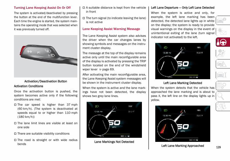
129
Turning Lane Keeping Assist On Or OffThe system is activated/deactivated by pressingthe button at the end of the multifunction lever.Each time the engine is started, the system main-tains the operating mode that was selected whenit was previously turned off.
Activation/Deactivation ButtonActivation ConditionsOnce the activation button is pushed, thesystem becomes active only if the followingconditions are met: The car speed is higher than 37 mph
(60 km/h). (The system is deactivated atspeeds equal to or higher than 110 mph(180 km/h))
The lane limit lines are visible at least onone side
There are suitable visibility conditions
The road is straight or with wide radiusbends
A suitable distance is kept from the vehiclein front
The turn signal (to indicate leaving the lane)is not active
Lane Keeping Assist Warning Message
The Lane Keeping Assist system also advisesthe driver when the car changes lanes byshowing symbols and messages on the instru-ment cluster display.The message at the top of the display remainsactive only until the main reconfigurable areaof the display is activated by pressing the TRIPbutton located on the end of the windshieldwiper lever Ú page 69.After activating the main reconfigurable area,the Lane Keeping Assist system messages willbe shown in the instrument cluster display.When the system is active and the lane mark-ings have not been detected, the displayshows two grey lane lines.
Lane Markings Not Detected
Left Lane Departure — Only Left Lane DetectedWhen the system is active and only, forexample, the left lane marking has beendetected, the detected lane lights up in whiteon the display; the system is ready to providevisual warnings on the display in the event ofunintentional exiting of the lane (turn signalindicator not activated) to the left.
Left Lane Marking DetectedWhen the system detects that the vehicle hasapproached the lane marking and is about topass it, the left line on the display lights up inyellow.
Left Lane Marking Approached
21_GU_OM_EN_USC_t.book Page 129

ST
AR
TIN
G A
ND
OP
ER
AT
ING
130
NOTE:The system operates in the same way, butmirrored, in the event of exiting the right lanewhen only the right lane marking has beendetected.
Left Lane Departure — Both Lanes DetectedWhen the system is active, both lane lines onthe display illuminate in white to indicate thesuccessful detection of both limits.When lane markings are detected, the systemis ready to provide indications in case thedriver unintentionally leaves the lane (turnsignal not activated).As the Lane Keeping Assist system detects thelane markings while the vehicle is in motion, itwill adjust the display accordingly (from whiteto yellow and yellow to white, and increasetheir thickness).If a lane line is crossed, the driver is alerted byan audible signal as well as the visual indica-tion in the instrument cluster. The signal isemitted through the speakers on the side ofthe lane marking which is being crossed (e.g.if the vehicle is exceeding the left line of thelane, the audible signal will come from thespeakers on the left of the vehicle).
Hands Presence On The Steering WheelDetectionThe system is able to detect the presence ofthe driver’s hands on the steering wheel.When the system does not detect the pres-ence of hands on the steering wheel for a fewseconds (up to 6 seconds), the followingscreen will be displayed on the instrumentcluster display. No acoustic warning will beemitted in this case.
Hand Presence On The Steering Wheel Not Detected Display (Up To 6 Seconds)
When the system does not detect the pres-ence of hands on the steering wheel for a fewseconds (from 6 to 15 seconds), the followingscreen will be displayed on the instrumentcluster display. A short acoustic signal willsound if hands are not detected on thesteering wheel for 6 to 12 seconds. A contin-uous signal will sound if hands are notdetected on the steering wheel for 12 to15 seconds.
Hand Presence On The Steering Wheel Not Detected Display (6 To 15 Seconds)
After 15 seconds with the hands removedfrom the steering wheel, the LKA system willbe deactivated and a dedicated message willbe shown on the instrument cluster display. Ashort acoustic signal will sound in this case.In any of the situations above where the handsare removed from the steering wheel for morethan 6 seconds, it is necessary to repositionthe hands on the steering wheel.Changing The System SensitivityThe system's sensitivity can be set through theradio system in the “Driver Assistance” menu.Select “Lane Keep Assist - Settings” and then“Keeping sensitivity”. Sensitivity “Early” or“Late” can be selected.
21_GU_OM_EN_USC_t.book Page 130

131
(Continued)
Changing The System StrengthThe system’s strength can be set through theradio system in the “Driver Assistance” menu.Select “Lane Keep Assist - Settings” and then“Strength”. Strength “Low” or “High” can beselected.Limited Operation WarningIf a message appears on the display, a condi-tion limiting the LKA system operation mayhave occurred. This could be an obstruction ofthe camera view, or a fault in the system.If an obstruction is detected, clean the area ofthe windshield by the interior rearview mirror.Although the vehicle can still be driven innormal conditions, the system may not func-tion properly.When the conditions limiting the system arecorrected, it will go back to normal operation.Should a fault persist, contact an authorizeddealer.System Failure Signaling
If the system turns off and appears on thedisplay, it means that there is a system fault.In this case, it is still possible to drive thevehicle, but you are advised to contact anauthorized dealer as soon as possible.
CAUTION!
Projecting loads on the roof of the vehiclemay interfere with the correct operation ofthe camera. Before starting, make surethe load is correctly positioned, in ordernot to cover the camera operating range.
If the windshield must be replaced due toscratches, chips or breakage, contact anauthorized dealer. Do not replace thewindshield on your own; there is risk ofmalfunction. It is advisable to replace thewindshield if it is damaged in the area ofthe camera.
Do not tamper with or operate on thecamera. Do not close the openings in theaesthetic cover located under the interiorrearview mirror. In the event of a failure ofthe camera, contact an authorized dealerimmediately.
Do not cover the operating range of thecamera with stickers or other objects. Alsopay attention to other objects on the hood(e.g. a layer of snow) and make sure theydo not interfere with the camera.
The camera may have limited or absentoperation due to weather conditions suchas: heavy rain, hail, thick fog, heavy snow,formation of ice layers on the windshield.
Camera operation may also be compro-mised by the presence of dust, condensa-tion, dirt or ice on the windshield, trafficconditions (e.g. vehicles that are drivingnot aligned with yours, vehicle driving in atransverse or opposite way on the samelane, bend with a small radius of curva-ture), or road surface conditions anddriving conditions (e.g. off-road driving).Make sure the windshield is always clean.Use specific detergents and clean clothsto avoid scratching the windshield. Thecamera operation may also be limited orabsent in some driving, traffic and roadsurface conditions.
CAUTION! (Continued)
21_GU_OM_EN_USC_t.book Page 131
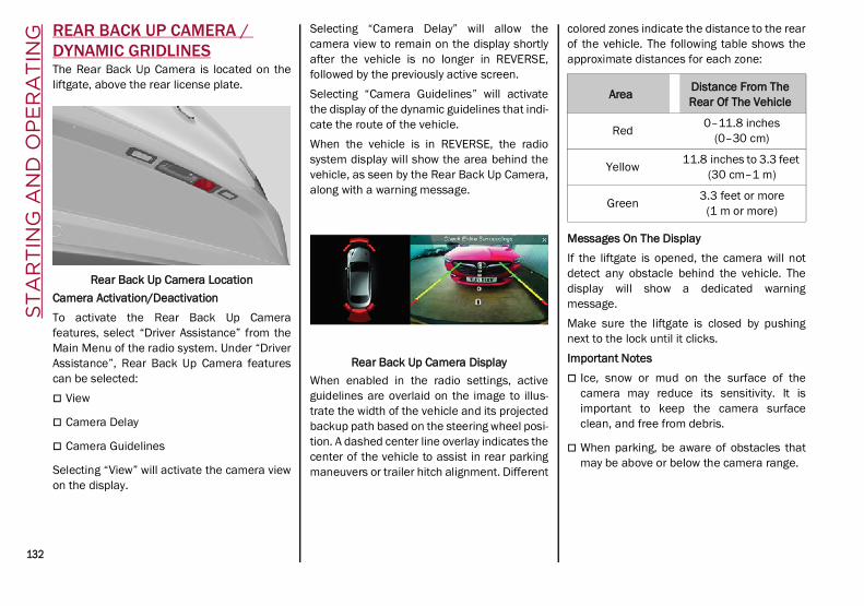
ST
AR
TIN
G A
ND
OP
ER
AT
ING
132
REAR BACK UP CAMERA / DYNAMIC GRIDLINESThe Rear Back Up Camera is located on theliftgate, above the rear license plate.
Rear Back Up Camera LocationCamera Activation/DeactivationTo activate the Rear Back Up Camerafeatures, select “Driver Assistance” from theMain Menu of the radio system. Under “DriverAssistance”, Rear Back Up Camera featurescan be selected: View
Camera Delay
Camera Guidelines
Selecting “View” will activate the camera viewon the display.
Selecting “Camera Delay” will allow thecamera view to remain on the display shortlyafter the vehicle is no longer in REVERSE,followed by the previously active screen.Selecting “Camera Guidelines” will activatethe display of the dynamic guidelines that indi-cate the route of the vehicle.When the vehicle is in REVERSE, the radiosystem display will show the area behind thevehicle, as seen by the Rear Back Up Camera,along with a warning message.
Rear Back Up Camera DisplayWhen enabled in the radio settings, activeguidelines are overlaid on the image to illus-trate the width of the vehicle and its projectedbackup path based on the steering wheel posi-tion. A dashed center line overlay indicates thecenter of the vehicle to assist in rear parkingmaneuvers or trailer hitch alignment. Different
colored zones indicate the distance to the rearof the vehicle. The following table shows theapproximate distances for each zone:
Messages On The DisplayIf the liftgate is opened, the camera will notdetect any obstacle behind the vehicle. Thedisplay will show a dedicated warningmessage.Make sure the liftgate is closed by pushingnext to the lock until it clicks.Important Notes Ice, snow or mud on the surface of the
camera may reduce its sensitivity. It isimportant to keep the camera surfaceclean, and free from debris.
When parking, be aware of obstacles thatmay be above or below the camera range.
Area Distance From The Rear Of The Vehicle
Red 0–11.8 inches(0–30 cm)
Yellow 11.8 inches to 3.3 feet (30 cm–1 m)
Green 3.3 feet or more(1 m or more)
21_GU_OM_EN_USC_t.book Page 132

133
REFUELING THE VEHICLE
Refueling The Vehicle
Before refueling, make sure that the fuel typeis correct.Also, stop the engine before refueling.
NOTE:An inefficient catalytic converter leads toharmful exhaust emissions, thus contributingto air pollution.
Refueling Capacity
To ensure that you fill the tank completely, topoff twice after the first click of the fuel nozzle.Further top-off could cause faults in the fuelfeeding system.
Refueling Procedure
The fuel filler door is unlocked when thecentral door locking system is unlocked. It isautomatically locked when the central lockingsystem is applied.Opening The Fuel Filler DoorTo refuel proceed as follows:
1. Open fuel filler door by pushing on thepoint shown by the arrow.
Fuel Door
2. Remove the fuel filler cap.
3. Insert the fuel nozzle fully into the fillerpipe.
WARNING!
Drivers must be careful when backing upeven when using the Rear Back Up Camera.Always check carefully behind your vehicle,and be sure to check for pedestrians,animals, other vehicles, obstructions, orblind spots before backing up. You areresponsible for the safety of yoursurroundings and must continue to payattention while backing up. Failure to do socan result in serious injury or death.
CAUTION!
To avoid vehicle damage, Rear Back UpCamera should only be used as a parkingaid. The Rear Back Up Camera is unableto view every obstacle or object in yourdrive path.
To avoid vehicle damage, the vehicle mustbe driven slowly when using the Rear BackUp Camera to be able to stop in time whenan obstacle is seen. It is recommendedthat the driver look frequently over his/hershoulder when using the Rear Back UpCamera.
CAUTION!
Never introduce leaded fuel to the tank,even in small amounts in an emergency, asthis would damage the catalytic converterbeyond repair.
21_GU_OM_EN_USC_t.book Page 133

ST
AR
TIN
G A
ND
OP
ER
AT
ING
134
4. When the fuel nozzle “clicks” or shuts off,before removing the nozzle, wait for atleast 10 seconds in order for the fuel toflow inside the tank.
5. Remove the fuel filler nozzle, tighten thegas cap about ¼ turn until you hear oneclick. This is an indication that cap is prop-erly tightened.
The label indicates the fuel type (UNLEAD-ED FUEL = gasoline).
Fuel Door Label
Emergency Fuel Door OpeningIn the event of an emergency, the fuel fillerdoor can be opened from inside the liftgate.Proceed as follows:Models With Compact Spare Tire
1. Open the liftgate and lift up the load floor.
Load Floor
2. Unlock the locking device and remove thecompact spare tire to reach the emer-gency opening cable on the side of the fueldoor.
Cargo Area
3. Pull the cable to release the fuel door lock.
Release Cable
4. Open the fuel door by pushing it.
1 — Locking Device
1 — Release Cable
21_GU_OM_EN_USC_t.book Page 134

135(Continued)
Models Without Compact Spare Tire
1. Open the liftgate and lift up the load floor.
Load Floor
2. Lift up the cover to reach the emergencyopening cable on the side of the fuel door.
Cargo Box
3. Pull the cable to release the fuel door lock.
Cargo Box Opened
4. Open the fuel door by pushing it.
NOTE:If the filler compartment is washed with a pres-sure washer, keep it at a distance of at least8 inches (20 cm).
VEHICLE LOADING
Certification Label
As required by National Highway Traffic SafetyAdministration regulations, your vehicle has acertification label affixed to the driver's sidedoor or pillar.This label contains the month and year ofmanufacture, Gross Vehicle Weight Rating(GVWR), Gross Axle Weight Rating (GAWR)front and rear, and Vehicle IdentificationNumber (VIN). A Month-Day-Hour (MDH)number is included on this label and indicatesthe Month, Day and Hour of manufacture. Thebar code that appears on the bottom of thelabel is your VIN.
1 — Cover
2 — Release Cable
WARNING!
Never have any smoking materials lit in ornear the vehicle when the fuel door isopen or the tank is being filled.
Never add fuel when the engine isrunning. This is in violation of most stateand federal fire regulations and maycause the Malfunction Indicator Lamp(MIL) to turn on.
A fire may result if gasoline is pumped intoa portable container that is inside of avehicle. You could be burned. Alwaysplace gas containers on the ground whilefilling.
WARNING! (Continued)
21_GU_OM_EN_USC_t.book Page 135

ST
AR
TIN
G A
ND
OP
ER
AT
ING
136
Gross Vehicle Weight Rating (GVWR)
The GVWR is the total permissible weight ofyour vehicle including driver, passengers,vehicle, options and cargo. The label alsospecifies maximum capacities of front andrear axle systems (GAWR). Total load must belimited so GVWR and front and rear GAWR arenot exceeded.
Payload
The payload of a vehicle is defined as theallowable load weight a truck can carry,including the weight of the driver, all passen-gers, options and cargo.
Gross Axle Weight Rating (GAWR)
The GAWR is the maximum permissible loadon the front and rear axles. The load must bedistributed in the cargo area so that the GAWRof each axle is not exceeded.Each axle GAWR is determined by the compo-nents in the system with the lowest loadcarrying capacity (axle, springs, tires orwheels). Heavier axles or suspension compo-nents sometimes specified by purchasers forincreased durability do not necessarilyincrease the vehicle's GVWR.
Tire Size
The tire size on the Vehicle Certification Labelrepresents the actual tire size on your vehicle.Replacement tires must be equal to the loadcapacity of this tire size.
Rim Size
This is the rim size that is appropriate for thetire size listed.
Inflation Pressure
This is the cold tire inflation pressure for yourvehicle for all loading conditions up to fullGAWR.
Curb Weight
The curb weight of a vehicle is defined as thetotal weight of the vehicle with all fluids,including vehicle fuel, at full capacity condi-tions, and with no occupants or cargo loadedinto the vehicle. The front and rear curb weightvalues are determined by weighing yourvehicle on a commercial scale before anyoccupants or cargo are added.
Loading
The actual total weight and the weight of thefront and rear of your vehicle at the ground canbest be determined by weighing it when it isloaded and ready for operation.The entire vehicle should first be weighed on acommercial scale to ensure that the GVWRhas not been exceeded. The weight on thefront and rear of the vehicle should then bedetermined separately to be sure that the loadis properly distributed over the front and rearaxle. Weighing the vehicle may show that theGAWR of either the front or rear axles hasbeen exceeded but the total load is within the
specified GVWR. If so, weight must be shiftedfrom front to rear or rear to front as appro-priate until the specified weight limitations aremet. Store the heavier items down low and besure that the weight is distributed equally.Stow all loose items securely before driving.Improper weight distributions can have anadverse effect on the way your vehicle steersand handles and the way the brakes operate.
TRAILER TOWINGIn this section you will find safety tips andinformation on limits to the type of towing youcan reasonably do with your vehicle. Beforetowing a trailer, carefully review this informa-tion to tow your load as efficiently and safelyas possible.To maintain the New Vehicle Limited Warrantycoverage, follow the requirements and recom-mendations in this manual concerning vehi-cles used for trailer towing.
CAUTION!
Do not load your vehicle any heavier thanthe GVWR or the maximum front and rearGAWR. If you do, parts on your vehicle canbreak, or it can change the way your vehiclehandles. This could cause you to losecontrol. Also overloading can shorten thelife of your vehicle.
21_GU_OM_EN_USC_t.book Page 136

137
Common Towing Definitions
The following trailer towing related definitionswill assist you in understanding the followinginformation:
Gross Vehicle Weight Rating (GVWR)
The GVWR is the total allowable weight of yourvehicle. This includes driver, passengers,cargo and tongue weight. The total load mustbe limited so that you do not exceed the GVWR Ú page 135.
Gross Trailer Weight (GTW)
The GTW is the weight of the trailer plus theweight of all cargo, consumables, and equip-ment (permanent or temporary) loaded in oron the trailer in its "loaded and ready for oper-ation" condition.The recommended way to measure GTW is toput your fully loaded trailer on a vehicle scale.The entire weight of the trailer must besupported by the scale.
Gross Combination Weight Rating (GCWR)
The GCWR is the total allowable weight of yourvehicle and trailer when weighed in combination.
Gross Axle Weight Rating (GAWR)
The GAWR is the maximum capacity of thefront and rear axles. Distribute the load overthe front and rear axles evenly. Make sure thatyou do not exceed either front or rear GAWR Ú page 135.
Tongue Weight (TW)
The tongue weight is the downward forceexerted on the hitch ball by the trailer. Youmust consider this as part of the load on yourvehicle.
Trailer Frontal Area
The frontal area is the maximum height multi-plied by the maximum width of the front of atrailer.
Weight-Carrying Hitch
A weight-carrying hitch supports the trailertongue weight, just as if it were luggagelocated at a hitch ball or some otherconnecting point of the vehicle. These kinds ofhitches are the most popular on the markettoday and they are commonly used to towsmall and medium sized trailers.
Weight-Distributing Hitch
A weight-distributing system works by applyingleverage through spring (load) bars. They aretypically used for heavier loads to distributetrailer tongue weight to the tow vehicle's front
axle and the trailer axle(s). When used inaccordance with the manufacturer's direc-tions, it provides for a more level ride, offeringmore consistent steering and brake controlthereby enhancing towing safety. The additionof a friction/hydraulic sway control alsodampens sway caused by traffic and cross-winds and contributes positively to tow vehicleand trailer stability. Trailer Sway Control and aweight distributing (load equalizing) hitch arerecommended for heavier Tongue Weights(TW) and may be required depending onvehicle and trailer configuration/loading tocomply with Gross Axle Weight Rating (GAWR)requirements.
Trailer Hitch Classification
The following chart provides the industry stan-dard for the maximum trailer weight a giventrailer hitch class can tow and should be usedto assist you in selecting the correct trailerhitch for your intended towing condition.
WARNING!
It is important that you do not exceed themaximum front or rear GAWR. A dangerousdriving condition can result if either rating isexceeded. You could lose control of thevehicle and have a collision.
WARNING!
An improperly adjusted Weight Distrib-uting Hitch system may reduce handling,stability, braking performance, and couldresult in a collision.
Weight Distributing Systems may not becompatible with Surge Brake Couplers.Consult with the hitch and trailer manu-facturer or a reputable RecreationalVehicle dealer for additional information.
21_GU_OM_EN_USC_t.book Page 137

ST
AR
TIN
G A
ND
OP
ER
AT
ING
138
Trailer Towing Weights (Maximum Trailer Weight Ratings)
Trailer And Tongue Weight
Never exceed the maximum tongue weightstamped on your fascia/bumper or trailerhitch.
Weight Distribution
Trailer Hitch Classification DefinitionsClass Max. Trailer Hitch Industry Standards
Class I - Light Duty 2,000 lbs (907 kg)
Class II - Medium Duty 3,500 lbs (1,587 kg)
Class III - Heavy Duty 6,000 lbs (2,722 kg)
Class IV - Extra Heavy Duty 10,000 lbs (4,535 kg)
Refer to the “Trailer Towing Weights (Maximum Trailer Weight Ratings)” chart for the Maximum Gross Trailer Weight (GTW) towable for your givendrivetrain.
All trailer hitches should be professionally installed on your vehicle.
Engine/Transmission Maximum GTW (Gross Trailer Wt.) Maximum Tongue Wt. (See Note)2.0L Engine 3,000 lbs (1360 kg) 300 lbs (136 kg)
Refer to local laws for maximum trailer towing speeds.
NOTE:The trailer tongue weight must be considered as part of the combined weight of occupants and cargo, and should never exceed the weight refer-enced on the Tire and Loading Information placard.
CAUTION!
Always load a trailer with 60% of the weightin the front of the trailer. This places 10% ofthe GTW on the tow hitch of your vehicle.Loads balanced over the wheels or heavierin the rear can cause the trailer to swayseverely side to side which will cause lossof control of the vehicle and trailer. Failureto load trailers heavier in front is the causeof many trailer collisions.
21_GU_OM_EN_USC_t.book Page 138

139(Continued)
Consider the following items when computingthe weight on the rear axle of the vehicle: The tongue weight of the trailer.
The weight of any other type of cargo orequipment put in or on your vehicle.
The weight of the driver and all passengers.
NOTE:Remember that everything put into or on thetrailer adds to the load on your vehicle. Also,additional factory-installed options ordealer-installed options must be consideredas part of the total load on your vehicle. Referto the “Tire And Loading Information” placardfor the maximum combined weight of occu-pants and cargo for your vehicle.
Towing Requirements
To promote proper break-in of your newvehicle drivetrain components, the followingguidelines are recommended:
Towing Requirements — Tires
Do not attempt to tow a trailer while using acompact spare tire.
Do not drive more than 50 mph (80 km/h)when towing while using a full size sparetire.
Proper tire inflation pressures are essentialto the safe and satisfactory operation ofyour vehicle.
Check the trailer tires for proper tire infla-tion pressures before trailer usage.
Check for signs of tire wear or visible tiredamage before towing a trailer.
Replacing tires with a higher load carryingcapacity will not increase the vehicle'sGVWR and GAWR limits.
For proper tire inflation procedures Ú page 233.
WARNING!
Improper towing can lead to a collision.Follow these guidelines to make your trailertowing as safe as possible:
Make certain that the load is secured inthe trailer and that it will not shift duringtravel. When trailering cargo that is notfully secured, dynamic load shifts canoccur that may be difficult for the driver tocontrol. You could lose control of yourvehicle and have a collision.
When hauling cargo, or towing a trailer, donot overload your vehicle or trailer. Over-loading can cause a loss of control, poorperformance, or damage to brakes, axle,engine, transmission, steering, suspen-sion, chassis structure, or tires.
Safety chains must always be usedbetween your vehicle and trailer. Alwaysconnect the chains to the frame or hookretainers of the vehicle hitch. Cross thechains under the trailer tongue and allowenough slack for turning corners.
Vehicles with trailers should not be parkedon a grade. When parking, apply theparking brake on the tow vehicle. Put thetow vehicle transmission in PARK. Alwaysblock or "chock" the trailer wheels.
GCWR must not be exceeded.
Total weight must be distributed betweenthe tow vehicle and the trailer such thatthe following four ratings are notexceeded:
• GVWR
• GTW
• GAWR
• Tongue weight rating for the trailerhitch utilized.
WARNING! (Continued) CAUTION!
Do not tow a trailer at all during the first500 miles (805 km) the new vehicle isdriven. The engine, axle or other partscould be damaged.
Then, during the first 500 miles (805 km)that a trailer is towed, do not drive over50 mph (80 km/h) and do not makestarts at full throttle. This helps the engineand other parts of the vehicle wear in atthe heavier loads.
21_GU_OM_EN_USC_t.book Page 139

ST
AR
TIN
G A
ND
OP
ER
AT
ING
140
Towing Requirements — Trailer Brakes
Do not interconnect the hydraulic brakesystem or vacuum system of your vehiclewith that of the trailer. This could causeinadequate braking and possible personalinjury.
An electronically actuated trailer brakecontroller is required when towing a trailerwith electronically actuated brakes. Whentowing a trailer equipped with a hydraulicsurge actuated brake system, an electronicbrake controller is not required.
Trailer brakes are recommended for trailersover 1,000 lbs (453 kg) and required fortrailers in excess of 2,000 lbs (907 kg).
Towing Requirements — Trailer Lights And Wiring
Whenever you pull a trailer, regardless of thetrailer size, stoplights and turn signals on thetrailer are required for motoring safety.The Trailer Tow Package may include a four-and seven-pin wiring harness. Use a factoryapproved trailer harness and connector.
NOTE:Do not cut or splice wiring into the vehicle’swiring harness.
The electrical connections are all complete tothe vehicle but you must mate the harness toa trailer connector. Refer to the following illus-trations.
NOTE:
Disconnect trailer wiring connector from thevehicle before launching a boat (or anyother device plugged into vehicle’s elec-trical connect) into water.
Be sure to reconnect once clear from waterarea.
Four-Pin Connector
Seven-Pin Connector
WARNING!
Do not connect trailer brakes to yourvehicle's hydraulic brake lines. It can over-load your brake system and cause it tofail. You might not have brakes when youneed them and could have an accident.
Towing any trailer will increase your stop-ping distance. When towing, you shouldallow for additional space between yourvehicle and the vehicle in front of you.Failure to do so could result in an acci-dent.
CAUTION!
If the trailer weighs more than 1,000 lbs(453 kg) loaded, it should have its ownbrakes and they should be of adequatecapacity. Failure to do this could lead toaccelerated brake lining wear, higher brakepedal effort, and longer stopping distances.
1 — Ground2 — Park3 — Left Stop/Turn4 — Right Stop/Turn
1 — Battery2 — Backup Lamps3 — Right Stop/Turn4 — Electric Brakes5 — Ground6 — Left Stop/Turn7 — Running Lamps
21_GU_OM_EN_USC_t.book Page 140

141
Towing Tips
Before setting out on a trip, practice turning,stopping, and backing up the trailer in an arealocated away from heavy traffic.
Automatic Transmission
Select the DRIVE range when towing. Thetransmission controls include a drive strategyto avoid frequent shifting when towing.However, if frequent shifting does occur whilein DRIVE, you can use the AutoStick shiftcontrol to manually select a lower gear.
NOTE:Using a lower gear while operating the vehicleunder heavy loading conditions will improveperformance and extend transmission life byreducing excessive shifting and heat build-up.This action will also provide better enginebraking.
Cruise Control — If Equipped
Do not use on hilly terrain or with heavyloads.
When using the Cruise Control, if you expe-rience speed drops greater than 10 mph(16 km/h), disengage until you can get backto cruising speed.
Use Cruise Control in flat terrain and withlight loads to maximize fuel efficiency.
Installing The Receiver
To properly install the receiver, follow thedirections below:
1. Retrieve the receiver from the luggagecompartment.
2. Push the receiver into the trailer hitch, andsecure by inserting the locking pin into thetrailer hitch.
3. Insert the safety split ring into the hole onthe locking pin.
NOTE:Ensure that the locking pin is removed fromthe trailer hitch before installing the receiver.
Trailer Hitch And Receiver
Connecting The Electrical System
To connect the trailer’s electrical system,follow the directions below:
1. Remove the socket protective cover.
2. Completely insert the plug into the socket.
Electrical Tow Connector
1 – Receiver2 – Locking Pin3 – Safety Split RingA – Trailer Hitch
Pin Number Function
1 Lights ground (Lights GND)
2 Position light, side markerlights, and license plate light
3 Left turn signal and stop light
4 Right turn signal and stoplight
21_GU_OM_EN_USC_t.book Page 141
ST
AR
TIN
G A
ND
OP
ER
AT
ING
142
Removing The Receiver
When the receiver is no longer needed, discon-nect the electrical connections and remove itfrom its position using the directions below:
1. Remove the safety split ring from thelocking pin.
2. Pull the locking pin out of the trailer hitch.
3. Remove the receiver from the trailer hitch.
SUGGESTIONS FOR DRIVING
Saving Fuel
Below are some suggestions which may helpyou save fuel and lower the amount of harmfulemissions released into the atmosphere.Vehicle MaintenanceChecks and operations should be carried outin accordance with the Maintenance Plan Ú page 208.TiresCheck the tire pressures at least once everyfour weeks: if the pressure is too low,consumption levels increase as resistance torolling is higher.
NOTE:Tire pressure that is too high can causepremature tire wear, reduced control, etc.
Unnecessary LoadsDo not travel with an overloaded liftgate. Theweight of the vehicle and its arrangementgreatly affect fuel consumption and stability.Electric DevicesUse electrical systems only for the amount oftime needed. The rear window defroster, addi-tional headlights, windshield wipers andheater blower fan require a considerableamount of energy; increasing the currentuptake increases fuel consumption (by up to+25% when city driving).Climate Control SystemUsing the climate control system will increaseconsumption: use standard ventilation whenthe temperature outside permits.Devices For Aerodynamic ControlThe use of non-certified devices for aerody-namic control may adversely affect air dragand consumption levels.
Driving Style
StartingDo not warm up the engine at low or high revswhen the vehicle is stationary; this causes theengine to warm up more slowly, therebyincreasing fuel consumption and emissions. Itis therefore advisable to drive off immediately,slowly, avoiding high speeds: by doing this theengine will warm up more quickly.
Unnecessary ActionsAvoid revving up when starting at traffic lightsor before stopping the engine. This action isunnecessary and causes increased fuelconsumption and pollution.Gear SelectionUse a high gear when traffic and road condi-tions allow it. Using a low gear for faster accel-eration will increase fuel consumption.Improper use of a high gear increasesconsumption, emissions and engine wear. Max. SpeedFuel consumption considerably increases asspeed increases. Maintain a constant speed,avoiding unnecessary braking and accelera-tion, which cost in terms of both fuel consump-tion and emissions.AccelerationAccelerating violently severely affectsconsumption and emissions: accelerationshould be gradual and should not exceed themaximum torque.
Conditions Of Use
Cold StartingShort trips and frequent cold starts will notallow the engine to reach optimum operatingtemperature. This results in a significantincrease in consumption levels (from +15 to+30% in city driving) and emissions.
21_GU_OM_EN_USC_t.book Page 142

143
Traffic And Road ConditionsHigh fuel consumption is caused by heavytraffic, for instance when traveling in trafficwith frequent use of low gears or in cities withmany traffic lights. Winding mountain roadsand rough road surfaces also adversely affectconsumption.Stops In TrafficDuring prolonged stops (e.g. railway cross-ings), turn off the engine.
Performance — Quadrifoglio
This vehicle is equipped with an enginecapable of delivering exceptionally fast accel-eration and speed: Peak power: 505 HP at 6,500 RPM.
Peak torque: 443 ft-lbs at 2,500–5,000 RPM.
Top speed: 176 mph (283 km/h).
Acceleration from 0 to 60 mph (0 to 100 km/h):3.6 seconds.
For safe driving, it is essential, particularlyduring the first days of use, to get to know thecar by driving carefully and gradually discov-ering its performance.BrakesThe car braking system may be available withfour carbon-ceramic material brake discs, oneon each wheel.
In order to guarantee the maximum brakingcapacity for the first use, Alfa Romeo performsa "run-in" procedure for discs and pads directlyat the factory.The use of carbon-ceramic material brakediscs guarantees braking features (betterdeceleration/pedal load ratio, brakingdistances, fading resistance) proportional tothe dynamic features of the car in addition toconsiderably decreasing the unsprung compo-nent weight.The materials used and the structural featuresof the system could generate unusual noiseswhich have absolutely no adverse effect oncorrect operation and reliability of the brakingsystem.Greater pressure may need to be applied tothe brake pedal the first time to keep the samebraking capacities in presence of condensa-tion or salt on the braking surfaces, forexample after washing or if the car is not usedfor a long time.
NOTE:Given the high technological level of thissystem, any servicing on it must be performedby an authorized dealer which exclusively hasthe skills needed for the repair and mainte-nance operations.
In case of intensive, high-performance use ofthe car, have the efficiency of thecarbon-ceramic material braking systeminspected as shown on the Maintenance Planat an authorized dealer.
Driving On Race TracksBefore driving on a track using a racing style, itis necessary to: Attend a race track driving course.
Check the liquid levels in the enginecompartment Ú page 208.
Have the car inspected at an authorizeddealer.
Remember that the car was not designed to bedriven exclusively on the race track and thatthis use increases stress and componentwear.
NOTE:Quadrifoglio front brakes are equipped withNon-Asbestos Organic (NAO) type pads. Thesepads are NOT suitable for high thermal loads(for example track use). If you want to usevehicle on a track it is recommended to usethe optional CCM Brakes (Carbon CeramicBrake disc).
21_GU_OM_EN_USC_t.book Page 143

ST
AR
TIN
G A
ND
OP
ER
AT
ING
144
Preheating the carbon ceramic material brakediscsThe brake discs must be warmed up to makethem fully efficient. You are advised to performthe following procedure to achieve optimalefficiency: Brake nine times from 80 mph to 18 mph
(130 km/h to 30 km/h) with decelerationequal to 0.7g (the longitudinal accelerationvalue is shown on the instrument clusterdisplay by setting RACE mode and selectingthe “Performance” page) with 20 secondintervals between brake applications; keepthe car at a speed comprised between37 mph and 62 mph (60 km/h and100 km/h) and do not brake for 4 minutesto allow the brakes to cool down.
Then brake three times from 124 mph to18 mph (200 km/h to 30 km/h) with decel-eration equal to 1.1g (ABS operation) with30 second intervals between brake applica-tions; keep the car at a speed comprisedbetween 37 mph and 62 mph (60 km/hand 100 km/h) and do not brake for5 minutes to allow the brakes to cool down.
21_GU_OM_EN_USC_t.book Page 144
145(Continued)
SA
FE
TY This very important section describes the
safety systems that your vehicle may beequipped with, and provides instructions onhow to use them correctly.
ACTIVE SAFETY SYSTEMSThe vehicle may be equipped with thefollowing active safety devices: Anti-Lock Brake System (ABS)
Active Torque Vectoring (ATV) System
Dynamic Steering Torque (DST) System
Drive Train Control (DTC) System
Electronic Stability Control (ESC) System
Hill Descent Control (HDC) System
Hill Start Assist (HSA) System
Panic Brake Assist (PBA) System
Traction Control System (TCS)
For system operation, see the following pages.
Anti-Lock Brake System (ABS)
An integral part of the braking system, the ABSprevents one or more wheels from locking andslipping in all road surface conditions, regard-less of the intensity of the braking action. Thesystem ensures that the vehicle can becontrolled even during emergency braking,allowing the driver to optimize stoppingdistances.
The system intervenes during braking whenthe wheels are about to lock, typically in emer-gency braking or low-grip conditions wherelocking may be more frequent.The system also improves control and stabilityof the vehicle when braking on a surfacewhere the grip of the left and right wheelsvaries, such as in a corner.The Electronic Braking Force Distribution(EBD) system works with the ABS, allowing thebrake force to be distributed between the frontand rear wheels.System InterventionThe ABS equipped on this vehicle is providedwith the "Brake-By-Wire", Integrated BrakeSystem (IBS), function. With this system, thecommand given by pressing the brake pedal isnot transmitted hydraulically, but electrically.Therefore, the light pulsation that is felt on thepedal with the traditional system is no longernoticeable.
Active Torque Vectoring (ATV) System — If Equipped
The dynamic drive control is used to optimizeand balance the drive torque between thewheels of the same axles. The ATV systemimproves the grip in turns, sending more drivetorque to the external wheel.
WARNING!
The ABS contains sophisticated electronicequipment that may be susceptible tointerference caused by improperlyinstalled or high output radio transmittingequipment. This interference can causepossible loss of anti-lock braking capa-bility. Installation of such equipmentshould be performed by qualified profes-sionals.
Pumping of the Anti-Lock Brakes willdiminish their effectiveness and may leadto a collision. Pumping makes the stop-ping distance longer. Just press firmly onyour brake pedal when you need to slowdown or stop.
The ABS cannot prevent the natural lawsof physics from acting on the vehicle, norcan it increase braking or steering effi-ciency beyond that afforded by the condi-tion of the vehicle brakes and tires or thetraction afforded.
The ABS cannot prevent collisions,including those resulting from excessivespeed in turns, following another vehicletoo closely, or hydroplaning.
The capabilities of an ABS equippedvehicle must never be exploited in a reck-less or dangerous manner that could jeop-ardize the user’s safety or the safety ofothers.
WARNING! (Continued)
21_GU_OM_EN_USC_t.book Page 145

SA
FE
TY
146
Given that, in a turn, the external wheels of thecar travel more than the internal ones andtherefore turn faster, sending a higher thrustto the external rear wheel allows for the car tobe more stable and to not suffer an "under-steer" condition. Understeer occurs when thevehicle is turning less than appropriate for thesteering wheel position.
Dynamic Steering Torque (DST) System
DST uses the integration of the ElectronicStability Control (ESC) system with the electricpower steering to increase the safety level ofthe whole vehicle.In critical situations (e.g. braking on surfaceswith different grip conditions), the ESC systeminfluences the steering through the DST func-tion to implement an additional torque contri-bution on the steering wheel in order tosuggest the most correct maneuver to thedriver.The coordinated action of the brakes andsteering increases the safety and control ofthe vehicle.
NOTE:The DST feature is only meant to help thedriver realize the correct course of actionthrough small torques on the steering wheel,which means the effectiveness of the DSTfeature is highly dependent on the driver’ssensitivity and overall reaction to the appliedtorque. It is very important to realize that this
feature will not steer the vehicle, meaning thedriver is still responsible for steering thevehicle.
Drive Train Control (DTC) System
Some models of this vehicle are equipped withan All-Wheel Drive (AWD) system, which offersan optimal drive for countless driving condi-tions and road surfaces. The system reducestire slipping to a minimum, automaticallyredistributing the torque to the front and rearwheels as needed.To maximize fuel savings, the vehicle withAWD automatically passes to Rear-WheelDrive (RWD) when the road and environmentalconditions are such that they wouldn't causethe tires to slip. When the road and environ-mental conditions require better traction, thevehicle automatically switches to AWD mode.
NOTE:
There may be a brief delay in shifting toAWD mode after a tire slipping event occurs.
If the system failure symbol switches on,after starting the engine or while driving, itmeans that the AWD system is not workingproperly. If the warning message activatesfrequently, it is recommended to carry outthe maintenance operations.
Electronic Stability Control (ESC) System
The ESC system improves the directionalcontrol and stability of the vehicle in variousdriving conditions.The ESC system corrects the vehicle’s under-steer and oversteer, distributing the brakeforce on the appropriate wheels. The torquesupplied by the engine can also be reduced inorder to maintain control of the vehicle.The ESC system uses sensors installed on thevehicle to determine the path that the driverintends to follow and compares it with thevehicle’s effective path. When the real pathdeviates from the desired path, the ESCsystem intervenes to counter the vehicle’soversteer or understeer. Oversteer occurs when the vehicle is
turning more than it should according to theangle of the steering wheel.
Understeer occurs when the vehicle isturning less than it should according to theangle of the steering wheel.
System InterventionThe intervention of the system is indicated bythe flashing of the ESC warning light on theinstrument panel, to inform the driver that thevehicle stability and grip are critical.
21_GU_OM_EN_USC_t.book Page 146

147
Hill Descent Control (HDC) System — If Equipped
The HDC function is an integral part of theElectronic Stability Control (ESC) system,keeping the vehicle at a constant speed whiledescending a hill by actively controlling thebrakes.HDC aims to create vehicle stability and saferdriving in various situations, including poorgrip conditions and steep descents.The system has three different modes: Off: the system is deactivated
Enabled: the system is enabled and ready tointervene when the activation conditionsare met
Active: the system actively controls thevehicle speed
Enabling The SystemTo enable the system, push the HDC switchlocated on the steering wheel.
HDC Switch
The system is enabled if the car speed is below20 mph (30 km/h). The system stays enableduntil the car speed reaches 37 mph (60 km/h),the system is disabled at speeds above 37 mph(60 km/h).Activation of the HDC system is indicated by
the white icon appearing in the instrumentcluster display.
HDC SymbolActivation Of The SystemOnce enabled, the HDC system will activateautomatically if the vehicle is driven on adownhill slope with sufficient gradient, greaterthan 8%.The speed set for the HDC system can beadjusted using the SET switch located on thesteering wheel.
WARNING!
Electronic Stability Control (ESC) cannotprevent the natural laws of physics fromacting on the vehicle, nor can it increasethe traction afforded by prevailing roadconditions. ESC cannot prevent accidents,including those resulting from excessivespeed in turns, driving on very slipperysurfaces, or hydroplaning. ESC alsocannot prevent accidents resulting fromloss of vehicle control due to inappro-priate driver input for the conditions. Onlya safe, attentive, and skillful driver canprevent accidents. The capabilities of anESC equipped vehicle must never beexploited in a reckless or dangerousmanner which could jeopardize the user’ssafety or the safety of others.
Vehicle modifications, or failure to prop-erly maintain your vehicle, may changethe handling characteristics of yourvehicle, and may negatively affect theperformance of the ESC system. Changesto the steering system, suspension,braking system, tire type and size or wheelsize may adversely affect ESC perfor-mance. Improperly inflated and unevenlyworn tires may also degrade ESC perfor-mance. Any vehicle modification or poorvehicle maintenance that reduces theeffectiveness of the ESC system canincrease the risk of loss of vehicle control,vehicle rollover, personal injury and death.
21_GU_OM_EN_USC_t.book Page 147
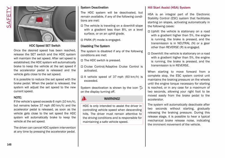
SA
FE
TY
148
HDC Speed SET SwitchOnce the desired speed has been reached,release the SET switch and the HDC systemwill maintain the set speed. After set speed isestablished, the HDC system will automaticallybrake to keep the vehicle at the set speed ifthe accelerator pedal is released and thevehicle gets close to the set speed.It is possible to reduce the set speed with thebrake pedal. When the pedal is released, thesystem will adjust the set speed to the newcurrent speed.
NOTE:If the vehicle’s speed exceeds 6 mph (10 km/h),but remains below 37 mph (60 km/h) and theaccelerator pedal is released, as soon as thevehicle gets close to the set speed the HDCsystem will automatically brake to keep thevehicle at the set speed.
The driver can cancel HDC system interventionat any time by pressing the accelerator pedal.
System DeactivationThe HDC system will be deactivated, butremain available, if any of the following condi-tions are met: The vehicle is traveling on a downhill slope
with a gradient less than 8%, on a levelsurface, or on an uphill grade.
PARK (P) mode is engaged.
Disabling The SystemThe system is disabled if any of the followingconditions are met: The HDC switch is pressed.
Cruise Control/Adaptive Cruise Control isactivated.
A vehicle speed of 37 mph (60 km/h) isexceeded.
System deactivation is shown by the icon on the display turning off.
Hill Start Assist (HSA) System
HSA is an integral part of the ElectronicStability Control (ESC) system that facilitatesstarting on slopes, activating automatically inthe following cases: Uphill: the vehicle is stationary on a road
with a gradient higher than 5%, the engineis running, the brake is pressed, and thetransmission is in NEUTRAL (N) or a gearother than REVERSE (R) is engaged.
Downhill: the vehicle is stationary on a roadwith a gradient higher than 5%, the engineis running, the brake is pressed, and thetransmission is in REVERSE.
When starting to move forward from acomplete stop, the ESC system control unitmaintains the braking pressure on the wheelsuntil the engine torque necessary for startingis reached, or in any case for a maximum oftwo seconds, allowing your right foot to bemoved easily from the brake pedal to theaccelerator.The system will automatically deactivate aftertwo seconds without starting, graduallyreleasing the braking pressure. During thisrelease stage, it is possible to hear a typicalmechanical brake release noise, indicatingthe imminent movement of the vehicle.
WARNING!
HDC is only intended to assist the driver incontrolling vehicle speed when descendinghills. The driver must remain attentive tothe driving conditions and is responsible formaintaining a safe vehicle speed.
21_GU_OM_EN_USC_t.book Page 148

149
Panic Brake Assist (PBA) System
The PBA system is designed to improve thevehicle’s braking capacity during emergencybraking.The system detects emergency braking bymonitoring the speed and force with which thebrake pedal is pressed, and consequentlyapplies the optimal brake pressure. This canreduce the braking distance: the PBA systemtherefore complements the ABS.Maximum assistance from the PBA system isobtained by pressing the brake pedal veryquickly. In addition, the brake pedal should bepressed continuously during braking, avoidingintermittent presses, to get the most out of the
system. Do not reduce pressure on the brakepedal until braking is no longer necessary.The PBA system is deactivated when the brakepedal is released.
Traction Control System (TCS)
The TCS automatically operates in the event ofslipping, loss of grip on wet roads (hydro-planing), and acceleration on one or both drivewheels on roads that are slippery, snowy, icy,etc. Depending on the slipping conditions, twodifferent control systems are activated: If the slipping involves both drive wheels,
the system intervenes, reducing the powertransmitted by the engine.
If the slipping only involves one of the drivewheels, the Brake Limited Differential (BLD)function is activated, automatically braking
the wheel which is slipping (the behavior ofa self-locking differential is simulated). Thiswill increase the engine torque transferredto the wheel which isn't slipping.
System InterventionThe intervention of the system is indicated bythe flashing of the ESC warning light on theinstrument panel, to inform the driver that thevehicle stability and grip are critical.
AUXILIARY DRIVING SYSTEMSThe following auxiliary driving systems areavailable in this vehicle: Blind Spot Monitoring (BSM) — if equipped
Active Blind Spot Assist (ABSA) — ifequipped
Forward Collision Warning Plus (FCW+)
Tire Pressure Monitoring System (TPMS)
The vehicle may also be fitted with thefollowing driving assistance systems: Driver Attention Assist (DAA)
Lane Departure Warning (LDW)
Lane Keeping Assist (LKA)
Highway Assist System (HAS)
Traffic Jam Assist (TJA)
Adaptive Cruise Control (ACC)
Intelligent Speed Control (ISC)
Traffic Sign Recognition (TSR)
WARNING!
There may be situations where the Hill StartAssist (HSA) will not activate and slightrolling may occur, such as on minor hills orwith a loaded vehicle, or while pulling atrailer. HSA is not a substitute for activedriving involvement. It is always the driver’sresponsibility to be attentive to distance toother vehicles, people, and objects, andmost importantly brake operation to ensuresafe operation of the vehicle under all roadconditions. Your complete attention isalways required while driving to maintainsafe control of your vehicle. Failure to followthese warnings can result in a collision orserious personal injury.
WARNING!
The Panic Brake Assist (PBA) cannotprevent the natural laws of physics fromacting on the vehicle, nor can it increasethe traction afforded by prevailing roadconditions. PBA cannot prevent collisions,including those resulting from excessivespeed in turns, driving on very slipperysurfaces, or hydroplaning. The capabilitiesof a PBA-equipped vehicle must never beexploited in a reckless or dangerousmanner, which could jeopardize the user'ssafety or the safety of others.
21_GU_OM_EN_USC_t.book Page 149

SA
FE
TY
150
For the operation of the DAA, LDW, LKA, HAS,TJA, ACC, ISC, or TSR systems, see Ú page 86.
NOTE:When driving on two-way roads where there isno lane dividing center line (e.g. on unpavedroads), the use of the ABSA, HAS, TJA, and LKAsystems is strongly discouraged as the systemcould detect the entire road as single-lanedividing lines.
NOTE:The driving assistance systems are designedto aid in driving the car. The driver must alwaysmaintain a sufficient level of attention to thetraffic and road conditions and control thetrajectory of the car.
Blind Spot Monitoring (BSM) System — If Equipped
The BSM system uses radar sensors, locatedin the rear fascia/bumper, to detect the pres-ence of other vehicles in the rear side blindspots of your vehicle.
Rear Sensor Location
The system warns the driver about the pres-ence of other vehicles in the detection area byilluminating the warning light located withinthe door mirror on the side in which the othervehicle was detected. If equipped, an audiblechime will also be heard to alert the driver (ifoption is selected within the radio system).
BSM Indicator LightWhen the engine is started, the warning lightilluminates briefly to signal the driver that thesystem is active.SensorsThe sensors are activated when any forwardgear is engaged at a speed higher thanapproximately 6 mph (10 km/h) or whenREVERSE is engaged.The sensors are temporarily deactivated whenthe vehicle is stationary or the vehicle is inPARK.The detection area of the system coversapproximately one lane on both sides of thevehicle, which is around 9 ft (3 m).
This area begins from the door mirror andextends for approximately 19 ft (6 m) towardsthe rear part of the vehicle.When the sensors are active, the system moni-tors the detection areas on both sides of thevehicle and warns the driver about thepossible presence of vehicles in these areas.While driving, the system monitors the detec-tion zone in three different situations: when you are being overtaken by a vehicle;
when you are overtaking a vehicle;
when a vehicle approaches from the side;
to check whether it is necessary to send asignal to the driver on both sides.
NOTE:
The system does not alert the driver of thepresence of fixed objects (e.g. safetybarriers, poles, walls, etc.). However, insome circumstances, the system may acti-vate in the presence of these objects. This isnormal and does not indicate a systemmalfunction.
The system does not alert the driver aboutthe presence of vehicles coming from theopposite direction, in the adjacent lanes.
If a trailer is hitched to the car, the systemautomatically deactivates.
21_GU_OM_EN_USC_t.book Page 150

151
NOTE:
For the system to operate properly, the rearfascia/bumper area where the radarsensors are located must stay free fromsnow, ice and dirt gathered from the roadsurface.
Do not cover the rear fascia/bumper areawhere the radar sensors are located withany object (e.g. adhesives, bike rack, etc.).
If you wish to install a rear tow eye afterpurchasing the vehicle, you will need todeactivate the system via the radio system.To access the function, select the followingitems in sequence on the main menu:
a. “Driver Assistance”
b. “Blind Spot Alert”
Rear ViewThe system detects vehicles coming from therear part of your vehicle on both sides andentering the rear detection area with a differ-ence in speed of less than 25 mph (40 km/h)in relation to your vehicle.Overtaking VehiclesIf another vehicle is overtaken slowly, with adifference in speed of less than approximately15 mph (25 km/h) and the vehicle stays in theblind spot for approximately 1.5 seconds, thewarning light on the door mirror of the corre-sponding side illuminates.If the difference in speed between the twovehicles is greater than approximately 15 mph(25 km/h), the warning light does not illumi-nate.Rear Cross Path Detection (RCP) SystemThe Rear Cross Path Detection (RCP) systemassists the driver during reverse maneuvers inthe case of reduced visibility.The RCP system monitors the rear detectionareas on both sides of the vehicle to detectobjects moving toward the sides of the vehicle,with a minimum speed between approximately1 mph (1 km/h) and 2 mph (3 km/h) andobjects moving at a maximum speed of21 mph (35 km/h), in areas such as parkinglots.
The system activation is signaled to the driverby an audible warning.
NOTE:
If the sensors are covered by objects orvehicles, the system may not work asintended.
For the system to operate correctly, the rearfascia/bumper area where the radarsensors are located must stay free fromsnow, ice and dirt gathered from the roadsurface.
Do not cover the rear fascia/bumper areawhere the radar sensors are located withany object (e.g. adhesives, bike rack, etc.).
WARNING!
The Blind Spot Monitoring system is only anaid to help detect objects in the blind spotzones. The BSM system is not designed todetect pedestrians, bicyclists, or animals.Even if your vehicle is equipped with theBSM system, always check your vehicle’smirrors, glance over your shoulder, and useyour turn signal before changing lanes.Failure to do so can result in serious injuryor death.
WARNING!
Rear Cross Path Detection (RCP) is not aback up aid system. It is intended to beused to help a driver detect an oncomingvehicle in a parking lot situation. Driversmust be careful when backing up, evenwhen using RCP. Always check carefullybehind your vehicle, look behind you, andbe sure to check for pedestrians, animals,other vehicles, obstructions, and blindspots before backing up. Failure to do socan result in serious injury or death.
21_GU_OM_EN_USC_t.book Page 151

SA
FE
TY
152
Operating ModeThe system may be activated/deactivated viathe radio system. To access the function,select the following items on the main menu insequence:
1. “Driving Assistance”
2. “Blind Spot Alert”
“Blind Spot Alert”, “Visual” ModeWhen the system is enabled, the warning lightwithin the door mirror on the side of thedetected object illuminates.The visual warning on the mirror will blink if thedriver activates the turn signals, indicating alane change.The warning light will be constant if the driverstays in the same lane.“Blind Spot Alert” Function DeactivationWhen the system is deactivated (“Blind SpotAlert” mode off), the BSM or RCP systems willnot emit an audible or a visual warning.The BSM system will store the operating modethat was active when the engine was stopped.Each time the engine is started, the operatingmode stored previously will be recalled andused Ú page 268.
Active Blind Spot Assist (ABSA) System — If Equipped
The ABSA system is to help avoid/limit lateralcollisions with cars coming from adjacent
lanes changing the vehicle’s trajectory in orderto try to keep it in the detected lane.The system warns the driver about the pres-ence of other vehicles in the detection area byilluminating the warning light located withinthe door mirror on the side in which the othervehicle was detected and by means of anacoustic signal and/or vibration on thesteering wheel and/or counter-steering torqueon the steering wheel (if the respective item onthe “Driver Assistance” menu is set up andthen “Safety” is selected on the radio system).When the engine is started, the warning lightilluminates briefly to signal the driver that thesystem is active (the warning light comes oneven if the system is activated through theradio system menu).
ABSA Indicator LightSensorsThe system uses radar sensors, located in therear fascia/bumper, to detect the presence ofvehicles (cars, trucks, motorbikes, etc.) in therear side blind spots of the car.
WARNING!
The accident risk persists despite theapplication of torque to the steering wheelby the ABSA system.
Applying a torque that corrects thesteering wheel alignment does not alwaysprevent an accident. It is always thedriver's responsibility to steer, brake oraccelerate, especially after the ABSAsystem warning or after the steering wheeltorque intervention. The driver is respon-sible for ensuring that there are no pedes-trians, other vehicles or objects along thedirection of the vehicle. Failure to complywith these precautions may cause seriousaccidents and injuries. The driver is fullyresponsible for holding a safe distancefrom the vehicle ahead respecting thehighway code in force in the respectivecountry.
In some cases, the system could apply animproper torque to the steering wheel.This application can be interrupted at anytime turning the steering wheel in theopposite direction.
21_GU_OM_EN_USC_t.book Page 152

153
The sensors are activated when any forwardgear is engaged at a speed higher than about6 mph (10 km/h), or when REVERSE (R) isengaged.The sensors are temporarily deactivated whenthe car is stationary and in PARK (P).The detection area of the system covers abouta lane on both sides of the car around 10 ft(3 meters).This area begins from the door mirror andextends for about 20 ft (6 meters) towards therear part of the car.When the sensors are active the system moni-tors the detection areas on both sides of thecar and warns the driver about the possiblepresence of cars in these areas.
Rear Sensor Location
While driving, the system monitors the detec-tion zone in three different situations: when you are being overtaken by a vehicle;
when you are overtaking a vehicle;
when a vehicle approaches from the side;
to check if it is necessary to intervene in orderto keep the vehicle inside the lane on bothsides.
NOTE:The system does not signal the presence offixed object (e.g. safety barriers, poles, walls,etc.). However, in some circumstances, thesystem may activate in the presence of theseobjects.This is normal and does not indicate asystem malfunction.
The system does not warn the driver about thepresence of cars coming from the oppositedirection, in the adjacent lanes.
Activation/deactivationThe system can be activated/deactivatedusing the “Driver Assistance” menu in theradio system. Select signal type, strengthlevels and sensitivity.
NOTE:Vehicles with an active system will display thefollowing screen, on the radio system.
System interventionThe system intervenes in the following condi-tions: the direction indicators have been turned
on;
there is a vehicle in the adjacent lane on thesame side of the direction indicator (blindspot area);
lane lines are not correctly detected;
the driver tries to change lanes intention-ally.
If the system detects the presence of a vehiclein the rear side blind spots of the car, it appliesa torque on the steering wheel (if it has beenset through the “Settings” menu of the radiosystem), in order to warn the driver of the needto keep the car inside the lane and thus avoidcollisions with other vehicles.The application of torque and vibration ishowever only available with car speedbetween 37 mph (60 km/h) and 110 mph(180 km/h).
21_GU_OM_EN_USC_t.book Page 153

SA
FE
TY
154
The application of torque, as well as of thevibration, is suppressed/inhibited if: The torque given by the driver of the
steering wheel is high
Lateral acceleration is high
The trailer is connected to the correctcontrol module
At least one hand is not detected on thesteering wheel for longer than a specifictime
The turn signal is turned off
NOTE:The steering wheel torque is not applied if thesystem is unable to detect a lane and if thedirection indicator for the appropriate side hasnot been switched on.
The steering wheel detects the presence ofthe driver’s hands by a capacitive sensorinstalled in the steering wheel and by theapplied torque measured on the steeringcolumn.
System availabilityAggressive driving of the car, or driving on themedian lines, will prevent the correct opera-tion of the system.
In case of intervention of the stability andbraking systems (FCW, ESC, ABS) they willprevent the system from operating.Lane change will disable the system for acertain period of time.The road must also comply with some specificcharacteristics, such as: Maximum/minimum lane width.
Clearly identified and defined double yellowlines and, for a limited period of time, a lanewith a single demarcation line.
NOTE:In some cases, for a limited period of time, thesystem may be activated by a lane with asingle median line.
In cases of good road surface conditions, thesystem could correctly recognize other typesof valid lane markings (e.g. road edges, side-walks, etc.).
Hands Presence On The Steering WheelDetectionThe system is able to detect the presence ofthe driver’s hands on the steering wheel.When the system does not detect the pres-ence of hands on the steering wheel for 0 to 6seconds, the following screen will be displayedon the instrument cluster display. No acousticwarning will be emitted in this case.
Hand Presence On The Steering Wheel Not Detected Display (Up To 6 Seconds)
When the system does not detect the pres-ence of hands on the steering wheel from 6 to15 seconds, the following screen will bedisplayed on the instrument cluster display. Ashort acoustic signal will sound if hands arenot detected on the steering wheel for 6 to12 seconds. A continuous signal will sound ifhands are not detected on the steering wheelfor 12 to 15 seconds.
Hand Presence On The Steering Wheel Not Detected Display (6 To 15 Seconds)
21_GU_OM_EN_USC_t.book Page 154

155
After 15 seconds with the hands removedfrom the steering wheel, the LKA system willbe deactivated and a dedicated message willbe shown on the instrument cluster display. Ashort acoustic signal will sound in this case.In any of the situations above where the handsare removed from the steering wheel for morethan 6 seconds, it is necessary to repositionthe hands on the steering wheel.Changing The System SensitivityThe system's sensitivity can be set through theradio system. Select the “Driver Assistance”menu and then select “Comfort”. Sensitivity“High” or “Low” can be selected.Rear Cross Path Detection (RCP) SystemThe Rear Cross Path Detection (RCP) systemassists the driver during reverse maneuvers inthe case of reduced visibility.When the ABSA system is active, the RCPsystem monitors the rear detection areas onboth sides of the vehicle to detect objectsmoving towards the sides of the vehicle at aminimum speed between 0.6 mph and 2 mph(1 km/h and 3km/h) from objects moving at amaximum speed of 22 mph (35 km/h).These are generally occurrences that happenin parking areas.The system activation is signaled to the driverby means of a visual and audible warning.
NOTE:If the sensors are covered by objects or vehi-cles, the system may not work as intended.
Changing the system sensitivityTo change the sensitivity and the strength ofthe torque intervention on the steering wheel,refer to “Settings” of the radio system Ú page 268.
Driver Attention Assist (DAA) System — If Equipped
The Driver Attention Assist (DAA) systemdetects when the driver is feeling fatigued andwarns the driver to pull over and take a break.
To Activate/Deactivate
The DAA system can be activated and deacti-vated through the radio system by selectingthe following in order:
1. “Driver Assistance”
2. “Driver Attention Assist”
System Intervention
Using information from the front camera, thesystem implements two operating logics: The first operating logic takes the driving
style into account, observing the road anddetecting to what extent the driver cancontinue driving with few lane crossingevents.
The second operating logic measures thetime spent behind the wheel with thevehicle speed above 40 mph (60 km/h)and below 110 mph (180 km/h). If the“Standard” option is selected, in theseconditions, the “Dozy Driver” message mayappear after three hours of driving. If the“Early” option is selected and these condi-tions occur, the “Dozy Driver” message willbe displayed after two hours of driving.
NOTE:If the conditions described above are notdetected continuously during the entire drivingperiod, the “Dozy Driver” message may bedisplayed later than two or three hours. If thedriving style indicates that the driver is unableto follow the road trajectory and respect thehorizontal lane markings, the red symbol willappear on the instrument cluster display tosuggest that the driver should stop for a break.An audible signal will also sound.
If the driver accepts the suggestion providedby the system by pushing the MENU button onthe multifunction lever, the message will
WARNING!
The DAA System is an aid for driving anddoes not relieve the driver of theresponsibility of driving the vehicle. If youexperience fatigue while driving, pull oversafely for a break without waiting for theDAA to intervene. Only return to the roadwhen you are in the right physical andmental condition to prevent endangeringyourself and other drivers.
21_GU_OM_EN_USC_t.book Page 155

SA
FE
TY
156
disappear from the display and the symbol willbe displayed in the dedicated area of theinstrument cluster display until the nextengine shutdown.If the driver ignores the warning provided bythe system and does not stop, the messagewill continue to remain on the display, alongwith the symbol.
NOTE:
In the event of a DAA system failure, anamber symbol will appear in the instrumentcluster display along with a dedicatedmessage.
If the ABS system activates, “ABS ACTIVE”will display in place of the DAA symbol andwill remain active until the ABS systemdeactivates.
DAA Warning Message
DAA Warning IconChanging The System SensitivityThe DAA system intervention sensitivity can beadjusted through the radio system within the“Driver Assistance” menu.
NOTE:
If “Race” mode (if equipped) is activated,the DAA system will be automatically deacti-vated.
The system sensitivity cannot be changed inthe event of a camera system failure.
Forward Collision Warning Plus (FCW+) System — If Equipped
This is a driving assistance system composedof a radar located behind the front fascia/bumper and a camera located in the center ofthe windshield.
Front fascia/bumper Radar Location
Windshield Camera LocationIn the event of an imminent collision, thesystem intervenes by automatically applyingthe vehicle’s brakes to prevent a collision orreduce its effects.The system provides the driver with audibleand visual signals through specific messageson the instrument cluster display.
21_GU_OM_EN_USC_t.book Page 156

157
The audible and visual signals warn the driverbefore the system activates, depending on thevehicle speed.
NOTE:No warning signals are generated at speedsbelow 20 mph (30 km/h).
The system may lightly brake to warn the driverif a possible frontal accident is detected(limited braking). Signals and limited brakingare intended to allow the driver to reactpromptly, in order to prevent or reduce theeffects of a potential accident.
In situations with the risk of collision, if thesystem detects no intervention by the driver, itprovides automatic braking to help slow thevehicle and mitigate the potential frontal colli-sion (automatic braking). If intervention by thedriver on the brake pedal is detected, but notdeemed sufficient, the system may intervenein order to improve the reaction of the brakingsystem, therefore reducing vehicle speedfurther (additional assistance in brakingstage).The system will intervene automatically incase of imminent collision or impact against apedestrian crossing the road (speed under31 mph (50 km/h)).
NOTE:For safety reasons, when the vehicle hasstopped, the brake calipers may remainblocked for about two seconds. Make sure topress the brake pedal if the vehicle movesslightly forward.
Engagement/DisengagementThe system may be disengaged (and engagedagain) in the “Driver Assistance” menu of theInformation and Entertainment system.The system can be deactivated even with theignition device in the ON position.
NOTE:The system status can be changed with car ata standstill only.
Select from among three operating modes: Warning and braking: the system (if active),
in addition to the visual and audible warn-ings, provides limited braking, automaticbraking and additional assistance in thebraking stage, where the driver does notbrake sufficiently in the event of a potentialfrontal impact.
Only warning: the system (if active), doesnot provide limited braking, but guaranteesautomatic braking or additional assistancein the braking stage, where the driver doesnot brake at all or not sufficiently in theevent of a potential frontal impact.
Disabled: the system does not providevisual and audible warnings, limitedbraking, automatic braking or additionalassistance in the braking stage. The systemwill therefore provide no indication of apossible collision.
WARNING!
Forward Collision Warning (FCW) is notintended to avoid a collision on its own, norcan FCW detect every type of potentialcollision. The driver has the responsibility toavoid a collision by controlling the vehiclevia braking and steering. Failure to followthis warning could lead to serious injury ordeath.
21_GU_OM_EN_USC_t.book Page 157

SA
FE
TY
158
Activation/DeactivationThe Forward Collision Warning system is acti-vated whenever the engine is started regard-less of what is shown on the radio system.Following a deactivation, the system will notwarn the driver about the possible collisionwith a preceding vehicle, regardless of thesetting selected in the radio system.
NOTE:Each time the engine is started, the system isactivated regardless of what setting wasselected when the engine was turned off.
This function is not active at a speed lowerthan 4 mph (7 km/h) or higher than 124 mph(200 km/h).The system is active: Each time the engine is started
When feature is selected within the radiosystem
When the ignition is in the ON position
When the vehicle speed is between 2 mph(4 km/h) and 124 mph (200 km/h)
When the front seat belts are fastened
The "Alfa DNA Pro" selector is not in RACEposition (if equipped)
NOTE:If the seat belts of the front seats are notcorrectly fastened, the system will not inter-
vene on the braking system (only audible andvisual signals will be provided).
Changing The System SensitivityThe sensitivity of the system can be changedthrough the Information and Entertainmentsystem menu, choosing from one of thefollowing three options: "Near", "Medium" or"Far". Refer to the description in the Informa-tion and Entertainment system Supplementfor how to change the settings.The default setting is "Medium". With thissetting, the system warns the driver of apossible collision with the vehicle in frontwhen that vehicle is at a standard distance,between that of the other two settings.With the system sensitivity set to "Far", thesystem will warn the driver of a possible colli-sion with the vehicle in front when that vehicleis at a greater distance, thus providing thepossibility of acting on the brakes more lightlyand gradually. This setting provides the driverwith the maximum possible reaction time toprevent a potential collision.With the option set to "Near", the system willalert the driver of a possible collision with thevehicle in front when that vehicle is close. Thissetting offers the driver a lower reaction timecompared to the "Medium" and "Far" settings,in the event of a potential collision, butpermits more dynamic driving of the vehicle.The system sensitivity setting is kept in thememory when the engine is turned off.
System Limited Operation WarningIf a dedicated message is displayed, a condi-tion limiting the system operation may haveoccurred. The possible reasons of this limita-tion are something is blocking the cameraview or a fault.If an obstruction is signaled, clean the area ofthe radar on the front fascia/bumper, and thecamera area on the windshield.If a fault in the system is occurring, it will stillbe possible to drive the vehicle normally, butautomatic braking will not be available in theevent of an impending collision.When the conditions limiting the system func-tions end, this will go back to normal andcomplete operation. Should the fault persist,contact an authorized dealer.System Failure SignalingIf the system turns off and a dedicatedmessage is shown on the display, it meansthat there is a fault with the system.In this case, it is still possible to drive thevehicle, but you are advised to contact anauthorized dealer as soon as possible.Radar Indication Not AvailableIf conditions are such that the radar cannotdetect obstacles correctly, the system is deac-tivated and a dedicated message appears onthe display. This generally occurs in the eventof poor visibility, such as when it is snowing orraining heavily.
21_GU_OM_EN_USC_t.book Page 158

159
The function of this system can also be tempo-rarily reduced due to obstructions such asmud, dirt or ice on the fascia/bumper. In suchcases, a dedicated message will be shown onthe display and the system will be deactivated.This message can sometimes appear in condi-tions of high reflectivity (e.g. tunnels withreflective tiles or ice or snow). When the condi-tions limiting the system functions end, it willgo back to normal and complete operation.In certain cases, this dedicated messagecould be displayed when the radar is notdetecting any vehicles or objects within itsview range.If atmospheric conditions are not the reasonbehind this message, check if the sensor isdirty. It could be necessary to clean or removeany obstructions in the area.If the message appears frequently, even in theabsence of atmospheric conditions such assnow, rain, mud or other obstructions, contactan authorized dealer for a sensor alignmentcheck.In the absence of visible obstructions, manu-ally removing the decorative cover trim andcleaning the radar surface could be required.Have this operation performed at an autho-rized dealer.
NOTE:It is recommended that you do not installdevices, accessories or aerodynamic attach-ments in front of the sensor or darken it in anyway, as this can compromise the correct func-tioning of the system.
Frontal Collision Alarm With Active Braking — IfEquippedIf this function is selected, the brakes areoperated to reduce the speed of the vehicle inthe event of potential frontal impact.This function applies an additional brakingpressure if the braking pressure applied by thedriver does not suffice to prevent potentialfrontal impact.The function is active with speed above 2 mph(4 km/h).
NOTE:When using an automatic car wash it is recom-mended to deactivate the system through thesettings of the radio system. The system maydetect the presence of a car, a wall or anotherobstacle and activate.
Driving In Special ConditionsIn certain driving conditions, system interven-tion might be unexpected or delayed. Thedriver must therefore be very careful, keepingcontrol of the vehicle to drive in completesafety.
Driving close to a bend.
The vehicle ahead is leaving a roundabout.
Vehicles with small dimensions and/or notaligned in the driving lane.
Lane change by other vehicles.
Vehicles traveling at right angles to thevehicle.
NOTE:
In particularly complex traffic conditions,the driver can deactivate the system manu-ally through the Information and Entertain-ment system.
If the driver depresses the brake pedal fullyor makes an excessive steering maneuverduring system operation, the automaticbraking function may deactivate (e.g. toallow a possible maneuver to avoid theobstacle).
The FCW system is automatically deacti-vated when operating in race mode and awarning message will be displayed on theinstrument cluster.
21_GU_OM_EN_USC_t.book Page 159

SA
FE
TY
160
Driving Close To A BendWhen entering or leaving a wide bend, thesystem may detect a vehicle in front of you, butnot driving in the same driving lane. In casessuch as these, the system may intervene.
Driving Around Wide CurvesThe Vehicle Ahead Is Leaving A RoundaboutOn a roundabout, the system could intervenewhen it detects a vehicle ahead that is leavingthe roundabout.
Driving In Roundabouts
Vehicles With Small Dimensions And/Or NotAligned In The Driving LaneThe system cannot detect vehicles in front ofthe vehicle if they are outside the range of theradar sensor and may not react to small vehi-cles, such as bicycles or motorcycles.
Driving Near Small VehiclesLane Change By Other VehiclesVehicles suddenly changing lanes to enter thesame lane as your vehicle within the operatingrange of the radar sensor, may cause thesystem to intervene.
Other Vehicles Changing LanesVehicles Traveling At Right Angles To TheVehicleThe system could temporarily react to avehicle that is passing at right angles throughthe radar sensor’s operating range Ú page 268.
Other Vehicle Passing Through Radar Range
21_GU_OM_EN_USC_t.book Page 160

161
Tire Pressure Monitoring System (TPMS)
The vehicle is equipped with a Tire PressureMonitoring System (TPMS) that sends theinflation pressure information of each tire tothe control unit, and will signal the driver in theevent of insufficient tire pressure.The TPMS uses wireless technology with wheelrim mounted electronic sensors to monitor tirepressure levels. Sensors, mounted to eachwheel as part of the valve stem, transmit tirepressure readings to the receiver module.Tire pressure will vary with temperature byapproximately 1 psi (7 kPa) for every 12°F(6.5°C). This means that when the outsidetemperature decreases, the tire pressure willalso decrease. Tire pressure should always beset based on cold inflation tire pressure. Thisis defined as the tire pressure after the vehiclehas not been driven for at least three hours, ordriven less than 1 mile (1.6 km) after a threehour period. The cold tire inflation pressuremust not exceed the maximum inflation pres-sure molded into the tire sidewall. The tirepressure will also increase as the vehicle isdriven. This is normal, and there should be noadjustment for this increased pressure.See Ú page 233 for information on how toproperly inflate the vehicle’s tires.The TPMS will signal the driver if pressure fallsbelow the warning limit for any reason,including the effects of low temperature andnormal loss of pressure from the tire.
The TPMS will stop indicating insufficient tirepressure when pressure is equal to or greaterthan the prescribed cold inflation level. There-fore, if insufficient tire pressure is indicated bythe ( ) warning light displaying in the instru-ment cluster, increase the inflation pressureup to the prescribed cold inflation value.The system will automatically update, and theTPMS Warning Light will turn off once thesystem receives the updated tire pressures.The vehicle may need to be driven for up to20 minutes above 15 mph (24 km/h) in orderfor the TPMS to receive this information.
NOTE:The TPMS cannot indicate sudden tire pres-sure drops (e.g. if a tire bursts). In this case,proceed with caution and avoid abruptsteering.
Operating ExampleFor example, your vehicle may have a recom-mended cold (parked for more than threehours) placard pressure of 33 psi (227 kPa). Ifthe ambient temperature is 68°F (20°C), andthe measured tire pressure is 28 psi (193 kPa),a temperature drop to 20°F (-7°C) willdecrease the tire pressure to approximately24 psi (165 kPa). This tire pressure is lowenough to turn on the “Tire Pressure MonitoringWarning Light.” Driving the vehicle may causethe tire pressure to rise to approximately 28 psi(193 kPa), but the TPMS Warning Light will stillbe on. In this situation, the TPMS Warning Light
WARNING!
The system has not been designed toprevent impacts and cannot detectpossible conditions leading to an accidentin advance. Failure to take into accountthis warning may lead to serious or fatalinjuries.
The system may activate, assessing thetrajectory of the vehicle, for the presenceof reflecting metal objects different fromother vehicles, such as safety barriers,road signs, barriers before parking lots,tollgates, level crossings, gates, railways,objects near road constructions sites orhigher than the vehicle (e.g. a fly-over). Inthe same way, the system may interveneinside multi-story parking lots or tunnels,or due to a glare on the road surface.These possible activations are a conse-quence of the real driving scenariocoverage by the system and must not beregarded as faults.
The system has been designed for roaduse only. If the vehicle is driven on a track,the system must be deactivated to avoidunnecessary warnings. Automatic deacti-vation is signaled by the dedicatedwarning light/symbol switching on in theinstrument panel Ú page 74.
21_GU_OM_EN_USC_t.book Page 161

SA
FE
TY
162
will turn off only after the tires are inflated to thevehicle’s recommended cold placard pressurevalue.
Insufficient Tire Pressure IndicationIf an insufficient pressure value is detected onone or more tires, the warning light in theinstrument cluster will display alongside thededicated messages, the system will highlightthe tire or tires with insufficient pressuregraphically, and an acoustic signal will beemitted.In this case, stop the vehicle, check the infla-tion pressure of each tire, and inflate thenecessary tire or tires to the correct cold infla-tion pressure value, shown on the display or inthe dedicated TPMS menu.TPMS Temporarily Disabled:TPMS Check MessageWhen a system fault is detected, the TPMSWarning Light will flash on and off for 75 seconds,and then remain on solid. The system fault willalso sound a chime. If the ignition is cycled, thissequence will repeat, provided that the systemfault still exists. The TPMS Warning Light will turnoff when the fault condition no longer exists. Asystem fault can occur due to any of thefollowing: Jamming due to electronic devices or
driving next to facilities emitting the sameradio frequencies as the TPMS sensors.
Installing some form of aftermarket windowtinting that affects radio wave signals.
Packed snow or ice around the wheels orwheel housings.
Using tire chains on the vehicle.
Using wheels/tires not equipped with TPMSsensors.
After the punctured tire has been repairedwith the original tire sealant contained in theTire Kit, the previous condition must berestored so that the warning light is offduring normal driving.TPMS DeactivationThe TPMS can be deactivated by replacing allfour wheel and tire assemblies (road tires)with wheel and tire assemblies that do nothave TPMS sensors, such as when installingwinter wheel and tire assemblies on yourvehicle.To deactivate the TPMS, first replace all fourwheel and tire assemblies (road tires) with tiresnot equipped with Tire Pressure MonitoringSystem (TPMS) sensors. Then, drive the vehiclefor 20 minutes above 15 mph (24 km/h). TheTPMS will chime, the TPMS Warning Light willflash on and off for 75 seconds and thenremain on. The instrument cluster will displaythe “SERVICE TPM SYSTEM” message and thendisplay dashes (--) in place of the pressurevalues.Beginning with the next ignition switch cycle,the TPMS will no longer chime or display the“SERVICE TPM SYSTEM” message in theinstrument cluster. Instead, dashes (--) willremain in place of the pressure values.
CAUTION!
The TPMS has been optimized for the orig-inal equipment tires and wheels. TPMSpressures and warning have been estab-lished for the tire size equipped on yourvehicle. Undesirable system operation orsensor damage may result when usingreplacement equipment that is not of thesame size, type, and/or style. The TPMSsensor is not designed for use on after-market wheels and may contribute to apoor overall system performance orsensor damage. Customers are encour-aged to use OEM wheels to assure properTPMS feature operation.
Using aftermarket tire sealants may causethe Tire Pressure Monitoring System(TPMS) sensor to become inoperable.After using an aftermarket tire sealant it isrecommended that you take your vehicleto an authorized dealer to have yoursensor function checked.
After inspecting or adjusting the tire pres-sure always reinstall the valve stem cap.This will prevent moisture and dirt fromentering the valve stem, which coulddamage the TPMS sensor.
21_GU_OM_EN_USC_t.book Page 162

163
To reactivate the TPMS, replace all four wheeland tire assemblies (road tires) with tiresequipped with TPMS sensors. Then, drive thevehicle for up to 20 minutes above 15 mph(24 km/h). The TPMS will chime, the TPMSWarning Light will flash on and off for 75seconds and then turn off. The instrumentcluster will display the “SERVICE TPMSYSTEM” message and then display pressurevalues in place of the dashes. On the next igni-tion switch cycle the “SERVICE TPM SYSTEM”message will no longer be displayed, as longas no system fault exists.
NOTE:
The TPMS is not intended to replace normaltire care and maintenance, or to providewarning of a tire failure or condition.
The TPMS should not be used as a tire pres-sure gauge while adjusting your tire pres-sure.
Driving on a significantly underinflated tirewill cause the tire to overheat, and can leadto tire failure. Underinflation also reducesfuel efficiency and tire tread life, and mayaffect the vehicle’s handling and stoppingability.
The TPMS is not a substitute for proper tiremaintenance, and it is the driver’s responsi-bility to maintain correct tire pressure usingan accurate tire pressure gauge, even if
underinflation has not reached the level totrigger illumination of the TPMS WarningLight.
Seasonal temperature changes will affecttire pressure, and the TPMS will monitor theactual tire pressure in the tire Ú page 268.
OCCUPANT RESTRAINT SYSTEMSSome of the most important safety features inyour vehicle are the restraint systems:
Occupant Restraint Systems Features
Seat Belt Systems
Supplemental Restraint Systems (SRS) AirBags
Child Restraints
Some of the safety features described in thissection may be standard equipment on somemodels, or may be optional equipment onothers. If you are not sure, ask an authorizeddealer.
Important Safety Precautions
Please pay close attention to the informationin this section. It tells you how to use yourrestraint system properly, to keep you andyour passengers as safe as possible.
Here are some simple steps you can take tominimize the risk of harm from a deploying airbag:
1. Children 12 years old and under shouldalways ride buckled up in the rear seat ofa vehicle with a rear seat.
2. A child who is not big enough to wear thevehicle seat belt properly must be securedin the appropriate child restraint orbelt-positioning booster seat in a rearseating position Ú page 178.
3. If a child from 2 to 12 years old (not in arear-facing child restraint) must ride in thefront passenger seat, move the seat as farback as possible and use the proper childrestraint Ú page 178.
4. Never allow children to slide the shoulderbelt behind them or under their arm.
5. You should read the instructions providedwith your child restraint to make sure thatyou are using it properly.
6. All occupants should always wear their lapand shoulder belts properly.
7. The driver and front passenger seatsshould be moved back as far as practicalto allow the front air bags room to inflate.
8. Do not lean against the door or window. Ifyour vehicle has side air bags, and deploy-ment occurs, the side air bags will inflate
21_GU_OM_EN_USC_t.book Page 163

SA
FE
TY
164
forcefully into the space between occu-pants and the door and occupants couldbe injured.
9. If the air bag system in this vehicle needsto be modified to accommodate a disabledperson, see Ú page 266 for customerservice contact information.
Seat Belt Systems
Buckle up even though you are an excellentdriver, even on short trips. Someone on theroad may be a poor driver and could cause acollision that includes you. This can happen faraway from home or on your own street.Research has shown that seat belts save lives,and they can reduce the seriousness of inju-ries in a collision. Some of the worst injurieshappen when people are thrown from the
vehicle. Seat belts reduce the possibility ofejection and the risk of injury caused bystriking the inside of the vehicle. Everyone in amotor vehicle should be belted at all times.
Enhanced Seat Belt Use Reminder System (BeltAlert)
Driver and Passenger BeltAlert (If Equipped)
BeltAlert is a feature intended to remindthe driver and outboard front seat passenger(if equipped with outboard front passengerseat BeltAlert) to buckle their seat belts. TheBeltAlert feature is active whenever the igni-tion switch is in the ON/RUN position.Initial IndicationIf the driver is unbuckled when the ignitionswitch is first in the ON/RUN position, a chimewill signal for a few seconds. If the driver oroutboard front seat passenger (if equippedwith outboard front passenger seat BeltAlert)is unbuckled when the ignition switch is first inthe ON/RUN position the Seat Belt ReminderLight will turn on and remain on until bothoutboard front seat belts are buckled. Theoutboard front passenger seat BeltAlert is notactive when an outboard front passenger seatis unoccupied.BeltAlert Warning SequenceThe BeltAlert warning sequence is activatedwhen the vehicle is moving above a specifiedvehicle speed range and the driver or outboardfront seat passenger is unbuckled (if equippedwith outboard front passenger seat BeltAlert)
(the outboard front passenger seat BeltAlert isnot active when the outboard front passengerseat is unoccupied). The BeltAlert warningsequence starts by blinking the Seat BeltReminder Light and sounding an intermittentchime. Once the BeltAlert warning sequencehas completed, the Seat Belt Reminder Lightwill remain on until the seat belts are buckled.The BeltAlert warning sequence may repeatbased on vehicle speed until the driver andoccupied outboard front seat passenger seatbelts are buckled. The driver should instruct alloccupants to buckle their seat belts.Change of StatusIf the driver or outboard front seat passenger(if equipped with outboard front passengerseat BeltAlert) unbuckles their seat belt whilethe vehicle is traveling, the BeltAlert warningsequence will begin until the seat belts arebuckled again.The outboard front passenger seat BeltAlert isnot active when the outboard front passengerseat is unoccupied. BeltAlert may be triggeredwhen an animal or other items are placed onthe outboard front passenger seat or when theseat is folded flat (if equipped). It is recom-mended that pets be restrained in the rearseat (if equipped) in pet harnesses or petcarriers that are secured by seat belts, andcargo is properly stowed.
Lap/Shoulder Belts
All seating positions in your vehicle areequipped with lap/shoulder belts.
WARNING!
Never place a rear-facing child restraint infront of an air bag. A deploying passengerfront air bag can cause death or seriousinjury to a child 12 years or younger,including a child in a rear-facing childrestraint.
Never install a rear-facing child restraint inthe front seat of a vehicle. Only use arear-facing child restraint in the rear seat.If the vehicle does not have a rear seat, donot transport a rear-facing child restraintin that vehicle.
21_GU_OM_EN_USC_t.book Page 164

165
(Continued)
(Continued)
(Continued)
The seat belt webbing retractor will lock onlyduring very sudden stops or collisions. Thisfeature allows the shoulder part of the seatbelt to move freely with you under normalconditions. However, in a collision the seatbelt will lock and reduce your risk of strikingthe inside of the vehicle or being thrown out ofthe vehicle.
WARNING!
Relying on the air bags alone could lead tomore severe injuries in a collision. The airbags work with your seat belt to restrainyou properly. In some collisions, the airbags won’t deploy at all. Always wear yourseat belt even though you have air bags.
In a collision, you and your passengerscan suffer much greater injuries if you arenot properly buckled up. You can strikethe interior of your vehicle or otherpassengers, or you can be thrown out ofthe vehicle. Always be sure you and othersin your vehicle are buckled up properly.
It is dangerous to ride in a cargo area,inside or outside of a vehicle. In a colli-sion, people riding in these areas aremore likely to be seriously injured or killed.
Do not allow people to ride in any area ofyour vehicle that is not equipped withseats and seat belts.
Be sure everyone in your vehicle is in aseat and using a seat belt properly. Occu-pants, including the driver, should alwayswear their seat belts whether or not an airbag is also provided at their seating posi-tion to minimize the risk of severe injury ordeath in the event of a crash.
Wearing your seat belt incorrectly couldmake your injuries in a collision muchworse. You might suffer internal injuries,or you could even slide out of the seatbelt. Follow these instructions to wearyour seat belt safely and to keep yourpassengers safe, too.
Two people should never be belted into asingle seat belt. People belted togethercan crash into one another in a collision,hurting one another badly. Never use alap/shoulder belt or a lap belt for morethan one person, no matter what theirsize.
WARNING!
A lap belt worn too high can increase therisk of injury in a collision. The seat beltforces won’t be at the strong hip andpelvic bones, but across your abdomen.Always wear the lap part of your seat beltas low as possible and keep it snug.
WARNING! (Continued)
A twisted seat belt may not protect youproperly. In a collision, it could even cutinto you. Be sure the seat belt is flatagainst your body, without twists. If youcan’t straighten a seat belt in your vehicle,take it to an authorized dealer immedi-ately and have it fixed.
A seat belt that is buckled into the wrongbuckle will not protect you properly. Thelap portion could ride too high on yourbody, possibly causing internal injuries.Always buckle your seat belt into thebuckle nearest you.
A seat belt that is too loose will not protectyou properly. In a sudden stop, you couldmove too far forward, increasing thepossibility of injury. Wear your seat beltsnugly.
A seat belt that is worn under your arm isdangerous. Your body could strike theinside surfaces of the vehicle in a colli-sion, increasing head and neck injury. Aseat belt worn under the arm can causeinternal injuries. Ribs aren’t as strong asshoulder bones. Wear the seat belt overyour shoulder so that your strongestbones will take the force in a collision.
WARNING! (Continued)
21_GU_OM_EN_USC_t.book Page 165

SA
FE
TY
166
Lap/Shoulder Belt Operating Instructions
1. Enter the vehicle and close the door. Sitback and adjust the seat.
2. The seat belt latch plate is above the backof the front seat, and next to your arm inthe rear seat (for vehicles equipped with arear seat). Grab the latch plate and pull outthe seat belt. Slide the latch plate up thewebbing as far as necessary to allow theseat belt to go around your lap.
3. When the seat belt is long enough to fit,insert the latch plate into the buckle untilyou hear a “click.”
Seat Belt Latch Plate Inserted Into Seat Belt Buckle
4. Position the lap belt so that it is snug andlies low across your hips, below yourabdomen. To remove slack in the lap beltportion, pull up on the shoulder belt. Toloosen the lap belt if it is too tight, tilt thelatch plate and pull on the lap belt. A snugseat belt reduces the risk of sliding underthe seat belt in a collision.
5. Position the shoulder belt across theshoulder and chest with minimal, if anyslack so that it is comfortable and notresting on your neck. The retractor willwithdraw any slack in the shoulder belt.
6. To release the seat belt, push the redbutton on the buckle. The seat belt willautomatically retract to its stowed posi-tion. If necessary, slide the latch platedown the webbing to allow the seat belt toretract fully.
Lap/Shoulder Belt Untwisting Procedure
Use the following procedure to untwist atwisted lap/shoulder belt.
1. Position the latch plate as close aspossible to the anchor point.
2. At about 6 to 12 inches (15 to 30 cm)above the latch plate, grab and twist theseat belt webbing 180 degrees to create afold that begins immediately above thelatch plate.
3. Slide the latch plate upward over thefolded webbing. The folded webbing mustenter the slot at the top of the latch plate.
4. Continue to slide the latch plate up until itclears the folded webbing and the seatbelt is no longer twisted.
Adjustable Upper Shoulder Belt Anchorage
In the driver and outboard front passengerseats, the top of the shoulder belt can beadjusted upward or downward to position theseat belt away from your neck. Push orsqueeze the anchorage button to release theanchorage, and move it up or down to the posi-tion that serves you best.
A shoulder belt placed behind you will notprotect you from injury during a collision.You are more likely to hit your head in acollision if you do not wear your shoulderbelt. The lap and shoulder belt are meantto be used together.
A frayed or torn seat belt could rip apart ina collision and leave you with no protec-tion. Inspect the seat belt system periodi-cally, checking for cuts, frays, or looseparts. Damaged parts must be replacedimmediately. Do not disassemble ormodify the seat belt system. Seat beltassemblies must be replaced after a colli-sion.
WARNING! (Continued)
21_GU_OM_EN_USC_t.book Page 166

167
Adjustable Upper Shoulder Belt AnchorageAs a guide, if you are shorter than average, youwill prefer the shoulder belt anchorage in alower position, and if you are taller thanaverage, you will prefer the shoulder beltanchorage in a higher position. After yourelease the anchorage button, try to move it upor down to make sure that it is locked in posi-tion.
NOTE:The adjustable upper shoulder belt anchorageis equipped with an Easy Up feature. Thisfeature allows the shoulder belt anchorage tobe adjusted in the upward position withoutpushing or squeezing the release button. Toverify the shoulder belt anchorage is latched,pull downward on the shoulder belt anchorageuntil it is locked into position.
Seat Belts And Pregnant Women
Seat Belts And Pregnant Women
Seat belts must be worn by all occupantsincluding pregnant women: the risk of injury inthe event of an accident is reduced for themother and the unborn child if they arewearing a seat belt.Position the lap belt snug and low below theabdomen and across the strong bones of thehips. Place the shoulder belt across the chestand away from the neck. Never place theshoulder belt behind the back or under thearm.
Seat Belt Pretensioner
The front outboard seat belt system isequipped with pretensioning devices that aredesigned to remove slack from the seat belt inthe event of a collision. These devices mayimprove the performance of the seat belt byremoving slack from the seat belt early in acollision. Pretensioners work for all size occu-pants, including those in child restraints.
NOTE:These devices are not a substitute for properseat belt placement by the occupant. The seatbelt still must be worn snugly and positionedproperly.
The pretensioners are triggered by the Occu-pant Restraint Controller (ORC). Like the airbags, the pretensioners are single use items. Adeployed pretensioner or a deployed air bagmust be replaced immediately.
WARNING!
Wearing your seat belt incorrectly couldmake your injuries in a collision muchworse. You might suffer internal injuries,or you could even slide out of the seatbelt. Follow these instructions to wearyour seat belt safely and to keep yourpassengers safe, too.
Position the shoulder belt across theshoulder and chest with minimal, if anyslack so that it is comfortable and notresting on your neck. The retractor willwithdraw any slack in the shoulder belt.
Misadjustment of the seat belt couldreduce the effectiveness of the safety beltin a crash.
Always make all seat belt height adjust-ments when the vehicle is stationary.
21_GU_OM_EN_USC_t.book Page 167

SA
FE
TY
168
(Continued)
Energy Management Feature
The front outboard seat belt system isequipped with an Energy Management featurethat may help further reduce the risk of injuryin the event of a collision. The seat belt systemhas a retractor assembly that is designed torelease webbing in a controlled manner.
Switchable Automatic Locking Retractors (ALR)
The seat belts in the passenger seating posi-tions are equipped with a Switchable Auto-matic Locking Retractor (ALR) which is used tosecure a child restraint system Ú page 185.The figure below illustrates the locking featurefor each seating position.
Switchable Automatic Locking Retractor (ALR) Locations
If the passenger seating position is equippedwith an ALR and is being used for normalusage, only pull the seat belt webbing out farenough to comfortably wrap around the occu-pant’s mid-section so as to not activate the
ALR. If the ALR is activated, you will hear aclicking sound as the seat belt retracts. Allowthe webbing to retract completely in this caseand then carefully pull out only the amount ofwebbing necessary to comfortably wraparound the occupant’s mid-section. Slide thelatch plate into the buckle until you hear a"click."In Automatic Locking Mode, the shoulder beltis automatically pre-locked. The seat belt willstill retract to remove any slack in the shoulderbelt. Use the Automatic Locking Mode anytimea child restraint is installed in a seating posi-tion that has a seat belt with this feature. Chil-dren 12 years old and under should always beproperly restrained in the rear seat of a vehiclewith a rear seat.
How To Engage The Automatic Locking Mode
1. Buckle the combination lap and shoulderbelt.
2. Grab the shoulder portion and pull down-ward until the entire seat belt is extracted.
3. Allow the seat belt to retract. As the seatbelt retracts, you will hear a clicking sound.This indicates the seat belt is now in theAutomatic Locking Mode.
How To Disengage The Automatic LockingModeUnbuckle the combination lap/shoulder beltand allow it to retract completely to disengagethe Automatic Locking Mode and activate thevehicle sensitive (emergency) locking mode.
WARNING!
Never place a rear-facing child restraint infront of an air bag. A deploying passengerfront air bag can cause death or seriousinjury to a child 12 years or younger,including a child in a rear-facing childrestraint.
Never install a rear-facing child restraint inthe front seat of a vehicle. Only use arear-facing child restraint in the rear seat.If the vehicle does not have a rear seat, donot transport a rear-facing child restraintin that vehicle.
WARNING!
The seat belt assembly must be replacedif the switchable Automatic LockingRetractor (ALR) feature or any other seatbelt function is not working properly whenchecked according to the procedures inthe Service Manual.
Failure to replace the seat belt assemblycould increase the risk of injury in colli-sions.
21_GU_OM_EN_USC_t.book Page 168

169
Supplemental Restraint Systems (SRS)
Some of the safety features described in thissection may be standard equipment on somemodels, or may be optional equipment onothers. If you are not sure, ask an authorizeddealer.The air bag system must be ready to protectyou in a collision. The Occupant RestraintController (ORC) monitors the internal circuitsand interconnecting wiring associated with theelectrical Air Bag System Components. Yourvehicle may be equipped with the following AirBag System Components:
Air Bag System Components
Occupant Restraint Controller (ORC)
Air Bag Warning Light
Steering Wheel and Column
Instrument Panel
Knee Impact Bolsters
Driver and Front Passenger Air Bags
Seat Belt Buckle Switch
Supplemental Side Air Bags
Supplemental Knee Air Bags
Front and Side Impact Sensors
Seat Belt Pretensioners
Seat Track Position Sensors
Air Bag Warning Light
The Occupant Restraint Controller(ORC) monitors the readiness of theelectronic parts of the air bag systemwhenever the ignition switch is in the
START or ON/RUN position. If the ignitionswitch is in the OFF position or in the ACC posi-tion, the air bag system is not on and the airbags will not inflate.The ORC contains a backup power supplysystem that may deploy the air bag systemeven if the battery loses power or it becomesdisconnected prior to deployment.The ORC turns on the Air Bag Warning Light inthe instrument panel for approximately four toeight seconds for a self-check when the igni-tion switch is first in the ON/RUN position.After the self-check, the Air Bag Warning Lightwill turn off. If the ORC detects a malfunctionin any part of the system, it turns on the AirBag Warning Light, either momentarily or
continuously. A single chime will sound to alertyou if the light comes on again after initialstartup.The ORC also includes diagnostics that will illu-minate the instrument panel Air Bag WarningLight if a malfunction is detected that couldaffect the air bag system. The diagnostics alsorecord the nature of the malfunction. Whilethe air bag system is designed to be mainte-nance free, if any of the following occurs, havean authorized dealer service the air bagsystem immediately. The Air Bag Warning Light does not come on
during the four to eight seconds when theignition switch is first in the ON/RUN posi-tion.
The Air Bag Warning Light remains on afterthe four to eight-second interval.
The Air Bag Warning Light comes on inter-mittently or remains on while driving.
NOTE:If the speedometer, tachometer, or any enginerelated gauges are not working, the OccupantRestraint Controller (ORC) may also bedisabled. In this condition the air bags may notbe ready to inflate for your protection. Have anauthorized dealer service the air bag systemimmediately.
Do not use the Automatic Locking Mode torestrain occupants who are wearing theseat belt or children who are using boosterseats. The locked mode is only used toinstall rear-facing or forward-facing childrestraints that have a harness forrestraining the child.
WARNING! (Continued)
21_GU_OM_EN_USC_t.book Page 169

SA
FE
TY
170
Redundant Air Bag Warning Light
If a fault with the Air Bag WarningLight is detected, which could affectthe Supplemental Restraint System(SRS), the Redundant Air Bag
Warning Light will illuminate on the instrumentpanel. The Redundant Air Bag Warning Lightwill stay on until the fault is cleared. In addi-tion, a single chime will sound to alert you thatthe Redundant Air Bag Warning Light hascome on and a fault has been detected. If theRedundant Air Bag Warning Light comes onintermittently or remains on while driving havean authorized dealer service the vehicle imme-diately.For additional information regarding theRedundant Air Bag Warning Light see Ú page 74.
Front Air Bags
This vehicle has front air bags and lap/shoulder belts for both the driver and frontpassenger. The front air bags are a supple-ment to the seat belt restraint systems. Thedriver front air bag is mounted in the center ofthe steering wheel. The passenger front airbag is mounted in the instrument panel, abovethe glove compartment. The words “SRSAIRBAG” or “AIRBAG” are embossed on the airbag covers.
Driver Front Air Bag
Passenger Front Air Bag
Driver Knee Air Bag Location/Knee Bolster Location
WARNING!
Ignoring the Air Bag Warning Light in yourinstrument panel could mean you won’thave the air bag system to protect you in acollision. If the light does not come on as abulb check when the ignition is first turnedon, stays on after you start the vehicle, or ifit comes on as you drive, have anauthorized dealer service the air bagsystem immediately.
21_GU_OM_EN_USC_t.book Page 170

171(Continued)
Passenger Knee Air Bag Location/Knee Bolster Location
Driver And Passenger Front Air Bag Features
The Advanced Front Air Bag system has multi-stage driver and front passenger air bags. Thissystem provides output appropriate to theseverity and type of collision as determined bythe Occupant Restraint Controller (ORC),which may receive information from the frontimpact sensors (if equipped) or other systemcomponents.The first stage inflator is triggered immediatelyduring an impact that requires air bag deploy-ment. A low energy output is used in lesssevere collisions. A higher energy output isused for more severe collisions.This vehicle may be equipped with a driverand/or front passenger seat belt buckleswitch that detects whether the driver or frontpassenger seat belt is buckled. The seat beltbuckle switch may adjust the inflation rate ofthe Advanced Front Air Bags.This vehicle may be equipped with driver and/orfront passenger seat track position sensors thatmay adjust the inflation rate of the AdvancedFront Air Bags based upon seat position.
Front Air Bag Operation
Front Air Bags are designed to provide addi-tional protection by supplementing the seatbelts. Front air bags are not expected toreduce the risk of injury in rear, side, or roll-over collisions. The front air bags will notdeploy in all frontal collisions, including somethat may produce substantial vehicle damage— for example, some pole collisions, truckunderrides, and angle offset collisions.On the other hand, depending on the type andlocation of impact, front air bags may deploy incrashes with little vehicle front-end damagebut that produce a severe initial deceleration.Because air bag sensors measure vehicledeceleration over time, vehicle speed and
WARNING!
Being too close to the steering wheel orinstrument panel during front air bagdeployment could cause serious injury,including death. Air bags need room toinflate. Sit back, comfortably extendingyour arms to reach the steering wheel orinstrument panel.
Never place a rear-facing child restraint infront of an air bag. A deploying passengerfront air bag can cause death or seriousinjury to a child 12 years or younger,including a child in a rear-facing childrestraint.
Never install a rear-facing child restraint inthe front seat of a vehicle. Only use arear-facing child restraint in the rear seat.If the vehicle does not have a rear seat, donot transport a rear-facing child restraintin that vehicle.
WARNING!
No objects should be placed over or nearthe air bag on the instrument panel orsteering wheel because any such objectscould cause harm if the vehicle is in a colli-sion severe enough to cause the air bag toinflate.
Do not put anything on or around the airbag covers or attempt to open themmanually. You may damage the air bagsand you could be injured because the airbags may no longer be functional. Theprotective covers for the air bag cushionsare designed to open only when the airbags are inflating.
Relying on the air bags alone could lead tomore severe injuries in a collision. The airbags work with your seat belt to restrainyou properly. In some collisions, air bagswon’t deploy at all. Always wear your seatbelts even though you have air bags.
WARNING! (Continued)
21_GU_OM_EN_USC_t.book Page 171

SA
FE
TY
172
damage by themselves are not good indicatorsof whether or not an air bag should havedeployed.Seat belts are necessary for your protection inall collisions, and also are needed to help keepyou in position, away from an inflating air bag.When the Occupant Restraint Controller (ORC)detects a collision requiring the front air bags,it signals the inflator units. A large quantity ofnon-toxic gas is generated to inflate the frontair bags.The steering wheel hub trim cover and theupper passenger side of the instrument panelseparate and fold out of the way as the airbags inflate to their full size. The front air bagsfully inflate in less time than it takes to blinkyour eyes. The front air bags then quicklydeflate while helping to restrain the driver andfront passenger.
Knee Impact Bolsters
The Knee Impact Bolsters help protect theknees of the driver and front passenger, andposition the front occupants for improvedinteraction with the front air bags.
Supplemental Driver And Front Passenger Knee Air Bags
This vehicle is equipped with a SupplementalDriver Knee Air Bag mounted in the instrumentpanel below the steering column and aSupplemental Passenger Knee Air Bagmounted in the instrument panel below theglove compartment. The Supplemental KneeAir Bags provide enhanced protection during afrontal impact by working together with theseat belts, pretensioners, and front air bags.
Supplemental Side Air Bags
Supplemental Seat-Mounted Side Air Bags(SABs)This vehicle is equipped with SupplementalSeat-Mounted Side Air Bags (SABs).Supplemental Seat-Mounted Side Air Bags(SABs) are located in the outboard side of thefront seats. The SABs are marked with “SRSAIRBAG” or “AIRBAG” on a label or on the seattrim on the outboard side of the seats.The SABs may help to reduce the risk of occu-pant injury during certain side impacts, in addi-tion to the injury reduction potential providedby the seat belts and body structure.
Front Supplemental Seat-Mounted Side Air Bag
When the SAB deploys, it opens the seam onthe outboard side of the seatback’s trim cover.The inflating SAB deploys through the seatseam into the space between the occupantand the door. The SAB moves at a very highspeed and with such a high force that it couldinjure occupants if they are not seated prop-erly, or if items are positioned in the areawhere the SAB inflates. Children are at aneven greater risk of injury from a deploying airbag.
WARNING!
Do not drill, cut, or tamper with the kneeimpact bolsters in any way.
Do not mount any accessories to the kneeimpact bolsters such as alarm lights,stereos, citizen band radios, etc.
WARNING!
Do not use accessory seat covers or placeobjects between you and the Side Air Bags;the performance could be adverselyaffected and/or objects could be pushedinto you, causing serious injury.
21_GU_OM_EN_USC_t.book Page 172

173
(Continued)
Supplemental Side Air Bag Inflatable Curtains(SABICs)This vehicle is equipped with SupplementalSide Air Bag Inflatable Curtains (SABICs).Supplemental Side Air Bag Inflatable Curtains(SABICs) are located above the side windows.The trim covering the SABICs is labeled “SRSAIRBAG” or “AIRBAG.”
Supplemental Side Air Bag Inflatable Curtain (SABIC) Location
SABICs may help reduce the risk of head andother injuries to front and rear seat outboardoccupants in certain side impacts, in additionto the injury reduction potential provided bythe seat belts and body structure.The SABIC deploys downward, covering theside windows. An inflating SABIC pushes theoutside edge of the headliner out of the wayand covers the window. The SABICs inflatewith enough force to injure occupants if theyare not belted and seated properly, or if itemsare positioned in the area where the SABICsinflate. Children are at an even greater risk ofinjury from a deploying air bag.The SABICs may help reduce the risk of partialor complete ejection of vehicle occupantsthrough side windows in certain side impactevents.
Side ImpactsThe Side Air Bags are designed to activate incertain side impacts. The Occupant RestraintController (ORC) determines whether thedeployment of the Side Air Bags in a particularimpact event is appropriate, based on theseverity and type of collision. The side impactsensors aid the ORC in determining the appro-priate response to impact events. The systemis calibrated to deploy the Side Air Bags on theimpact side of the vehicle during impacts thatrequire Side Air Bag occupant protection. Inside impacts, the Side Air Bags deploy inde-pendently; a left side impact deploys the leftSide Air Bags only and a right-side impactdeploys the right Side Air Bags only. Vehicledamage by itself is not a good indicator ofwhether or not Side Air Bags should havedeployed.The Side Air Bags will not deploy in all sidecollisions, including some collisions at certainangles, or some side collisions that do notimpact the area of the passenger
WARNING!
Do not mount equipment, or stack luggageor other cargo up high enough to block thedeployment of the SABICs. The trimcovering above the side windows where theSABIC and its deployment path are locatedshould remain free from any obstructions.
In order for the SABICs to work as intended,do not install any accessory items in yourvehicle which could alter the roof. Do notadd an aftermarket sunroof to your vehicle.Do not add roof racks that require perma-nent attachments (bolts or screws) forinstallation on the vehicle roof. Do not drillinto the roof of the vehicle for any reason.
WARNING! (Continued)
21_GU_OM_EN_USC_t.book Page 173
SA
FE
TY
174
(Continued)
compartment. The Side Air Bags may deployduring angled or offset frontal collisions wherethe front air bags deploy.Side Air Bags are a supplement to the seat beltrestraint system. Side Air Bags deploy in lesstime than it takes to blink your eyes.
NOTE:Air bag covers may not be obvious in the inte-rior trim, but they will open during air bagdeployment.
Rollover EventsSide Air Bags and seat belt pretensioners aredesigned to activate in certain rollover events.The Occupant Restraint Controller (ORC)determines whether deployment in a partic-ular rollover event is appropriate, based on theseverity and type of collision. Vehicle damageby itself is not a good indicator of whether ornot Side Air Bags and seat belt pretensionersshould have deployed.The Side Air Bags and seat belt pretensionerswill not deploy in all rollover events. The roll-over sensing system determines if a rolloverevent may be in progress and whether deploy-ment is appropriate. In the event the vehicleexperiences a rollover or near rollover event,
and deployment is appropriate, the rolloversensing system will deploy the side air bagsand seat belt pretensioners on both sides ofthe vehicle.The SABICs may help reduce the risk of partialor complete ejection of vehicle occupantsthrough side windows in certain rollover orside impact events.
Air Bag System Components
NOTE:The Occupant Restraint Controller (ORC) moni-tors the internal circuits and interconnectingwiring associated with electrical Air BagSystem Components listed below:
Occupant Restraint Controller (ORC)
Air Bag Warning Light
Steering Wheel and Column
Instrument Panel
Knee Impact Bolsters
Driver and Front Passenger Air Bags
Seat Belt Buckle Switch
Supplemental Side Air Bags
Supplemental Knee Air Bags
Front and Side Impact Sensors
Seat Belt Pretensioners
Seat Track Position Sensors
WARNING!
Occupants, including children, who are upagainst or very close to Side Air Bags canbe seriously injured or killed. Occupants,including children, should never lean on orsleep against the door, side windows, orarea where the side air bags inflate, evenif they are in an infant or child restraint.
Seat belts (and child restraints where appro-priate) are necessary for your protection inall collisions. They also help keep you inposition, away from an inflating Side Air Bag.To get the best protection from the Side AirBags, occupants must wear their seat beltsproperly and sit upright with their backsagainst the seats. Children must be properlyrestrained in a child restraint or booster seatthat is appropriate for the size of the child.
WARNING!
Side Air Bags need room to inflate. Do notlean against the door or window. Situpright in the center of the seat.
Being too close to the Side Air Bags duringdeployment could cause you to beseverely injured or killed.
Relying on the Side Air Bags alone couldlead to more severe injuries in a collision.The Side Air Bags work with your seat beltto restrain you properly. In some colli-sions, Side Air Bags won’t deploy at all.Always wear your seat belt even thoughyou have Side Air Bags.
WARNING! (Continued)
21_GU_OM_EN_USC_t.book Page 174

175
If A Deployment Occurs
The front air bags are designed to deflateimmediately after deployment.
NOTE:Front and/or side air bags will not deploy in allcollisions. This does not mean something iswrong with the air bag system.
If you do have a collision which deploys the airbags, any or all of the following may occur: The air bag material may sometimes cause
abrasions and/or skin reddening to theoccupants as the air bags deploy andunfold. The abrasions are similar to frictionrope burns or those you might get slidingalong a carpet or gymnasium floor. They arenot caused by contact with chemicals. Theyare not permanent and normally healquickly. However, if you haven’t healedsignificantly within a few days, or if you haveany blistering, see your doctor immediately.
As the air bags deflate, you may see somesmoke-like particles. The particles are anormal by-product of the process thatgenerates the non-toxic gas used for air baginflation. These airborne particles may irri-tate the skin, eyes, nose, or throat. If youhave skin or eye irritation, rinse the areawith cool water. For nose or throat irritation,move to fresh air. If the irritation continues,see your doctor. If these particles settle onyour clothing, follow the garment manufac-turer’s instructions for cleaning.
Do not drive your vehicle after the air bagshave deployed. If you are involved in anothercollision, the air bags will not be in place toprotect you.
NOTE:
Air bag covers may not be obvious in theinterior trim, but they will open during airbag deployment.
After any collision, the vehicle should betaken to an authorized dealer immediately.
Enhanced Accident Response System
In the event of an impact, if the communica-tion network remains intact, and the powerremains intact, depending on the nature of theevent, the Occupant Restraint Controller (ORC)will determine whether to have the EnhancedAccident Response System perform thefollowing functions: Cut off fuel to the engine (if equipped)
Cut off battery power to the electric motor (ifequipped)
Flash hazard lights as long as the batteryhas power
Turn on the interior lights, which remain onas long as the battery has power or for15 minutes from the intervention of theEnhanced Accident Response System
Unlock the power door locks
Your vehicle may also be designed to performany of these other functions in response to theEnhanced Accident Response System: Turn off the Fuel Filter Heater, Turn off the
HVAC Blower Motor, Close the HVAC Circula-tion Door
Cut off battery power to the:
• Engine
• Electric Motor (if equipped)
• Electric power steering
• Brake booster
• Electric park brake
• Automatic transmission gear selector
• Horn
• Front wiper
• Headlamp washer pump
WARNING!
Deployed air bags and seat beltpretensioners cannot protect you in anothercollision. Have the air bags, seat beltpretensioners, and the seat belt retractorassemblies replaced by an authorizeddealer immediately. Also, have theOccupant Restraint Controller Systemserviced as well.
21_GU_OM_EN_USC_t.book Page 175

SA
FE
TY
176
NOTE:After an accident, remember to cycle the igni-tion to the OFF position and remove the keyfrom the ignition switch to avoid draining thebattery. Carefully check the vehicle for fuelleaks in the engine compartment and on theground near the engine compartment and fueltank before resetting the system and startingthe engine. If there are no fuel leaks ordamage to the vehicle electrical devices (e.g.headlights) after an accident, reset the system
by following the procedure described below. Ifyou have any doubt, contact an authorizeddealer.
Enhanced Accident Response System Reset Procedure
After the event occurs, when the system isactive, a message regarding fuel cutoff isdisplayed. Turn the ignition switch from igni-tion ACC or ON/RUN to ignition OFF. Carefullycheck the vehicle for fuel leaks in the engine
compartment and on the ground near theengine compartment and fuel tank beforeresetting the system and starting the engine.Depending on the nature of the event the leftand right turn signal lights, located in theinstrument panel, may both be blinking andwill continue to blink. In order to move yourvehicle to the side of the road, you must followthe system reset procedure.
Customer ActionNOTE: Each step MUST BE held for at least two seconds
Customer Will See
1. Turn ignition OFF. (Turn Signal Switch Must be placed in Neutral State).
2. Turn ignition ACC. Right turn light BLINKS.Left turn light is OFF.
3. Turn right turn signal switch ON. Right turn light is ON SOLID.Left turn light BLINKS.
4. Place turn signal in neutral state. Right turn light is OFF.Left turn light BLINKS.
5. Turn left turn signal switch ON. Right turn light BLINKS.Left turn light is ON SOLID.
6. Place turn signal in neutral state. Right turn light BLINKS.Left turn light is OFF.
7. Turn right turn signal switch ON. Right turn light is ON SOLID.Left turn light BLINKS.
8. Place turn signal in neutral state. Right turn light is OFF.Left turn light BLINKS.
21_GU_OM_EN_USC_t.book Page 176

177
(Continued)
(Continued)
If a reset procedure step is not completed within 60 seconds, then the turn signal lights will blink and the reset procedure must be performed againin order to be successful.
Maintaining Your Air Bag System
9. Turn left turn signal switch ON. Right turn light is ON SOLID.Left turn light is ON SOLID.
10. Turn left turn signal switch OFF. (Turn Signal Switch Must be placed in Neutral State).
Right turn light is OFF.Left turn light is OFF.
11. Turn ignition OFF.
12. Turn ignition ACC. (Entire sequence needs to be completedwithin one minute or sequence will need to be repeated). System is now reset and the engine may be started.
Turn hazard flashers OFF (Manually).
Customer ActionNOTE: Each step MUST BE held for at least two seconds
Customer Will See
WARNING!
Modifications to any part of the air bagsystem could cause it to fail when youneed it. You could be injured if the air bagsystem is not there to protect you. Do notmodify the components or wiring,including adding any kind of badges orstickers to the steering wheel hub trimcover or the upper passenger side of theinstrument panel. Do not modify the frontfascia/bumper, vehicle body structure, oradd aftermarket side steps or runningboards.
It is dangerous to try to repair any part ofthe air bag system yourself. Be sure to tellanyone who works on your vehicle that ithas an air bag system.
WARNING! (Continued)
Do not attempt to modify any part of yourair bag system. The air bag may inflateaccidentally or may not function properly ifmodifications are made. Take your vehicleto an authorized dealer for any air bagsystem service. If your seat, including yourtrim cover and cushion, needs to beserviced in any way (including removal orloosening/tightening of seat attachmentbolts), take the vehicle to an authorizeddealer. Only manufacturer approved seataccessories may be used. If it is necessaryto modify the air bag system for personswith disabilities, contact an authorizeddealer.
WARNING! (Continued)
21_GU_OM_EN_USC_t.book Page 177

SA
FE
TY
178
Event Data Recorder (EDR)
This vehicle is equipped with an event datarecorder (EDR). The main purpose of an EDR isto record, in certain crash or near crash-likesituations, such as an air bag deployment orhitting a road obstacle, data that will assist inunderstanding how a vehicle’s systemsperformed. The EDR is designed to record datarelated to vehicle dynamics and safetysystems for a short period of time, typically 30seconds or less. The EDR in this vehicle isdesigned to record such data as: How various systems in your vehicle were
operating;
Whether or not the driver and passengersafety belts were buckled/fastened;
How far (if at all) the driver was depressingthe accelerator and/or brake pedal; and,
How fast the vehicle was traveling.
These data can help provide a better under-standing of the circumstances in whichcrashes and injuries occur.NOTE:EDR data are recorded by your vehicle only if anon-trivial crash situation occurs; no data arerecorded by the EDR under normal drivingconditions and no personal data (e.g., name,gender, age, and crash location) are recorded.However, other parties, such as law enforce-ment, could combine the EDR data with thetype of personally identifying data routinelyacquired during a crash investigation.
To read data recorded by an EDR, specialequipment is required, and access to thevehicle or the EDR is needed. In addition to thevehicle manufacturer, other parties, such aslaw enforcement, that have the special equip-ment, can read the information if they haveaccess to the vehicle or the EDR.
Child Restraints
Everyone in your vehicle needs to be buckledup at all times, including babies and children.Every state in the United States, and everyCanadian province, requires that small chil-dren ride in proper restraint systems. This isthe law, and you can be prosecuted forignoring it.Children 12 years or younger should ride prop-erly buckled up in a rear seat, if available.According to crash statistics, children aresafer when properly restrained in the rearseats rather than in the front.
There are different sizes and types ofrestraints for children from newborn size tothe child almost large enough for an adultsafety belt. Always check the child seatOwner’s Manual to make sure you have thecorrect seat for your child. Carefully read andfollow all the instructions and warnings in thechild restraint Owner’s Manual and on all thelabels attached to the child restraint.Before buying any restraint system, make surethat it has a label certifying that it meets allapplicable Safety Standards. You should alsomake sure that you can install it in the vehiclewhere you will use it.NOTE: For additional information, refer to http://
www.nhtsa.gov/parents-and-caregivers orcall: 1–888–327–4236
Canadian residents should refer to Trans-port Canada’s website for additional infor-mation: https://www.tc.gc.ca/en/services/road/child-car-seat-safety.html WARNING!
In a collision, an unrestrained child canbecome a projectile inside the vehicle. Theforce required to hold even an infant onyour lap could become so great that youcould not hold the child, no matter howstrong you are. The child and others couldbe badly injured or killed. Any child riding inyour vehicle should be in a proper restraintfor the child’s size.
21_GU_OM_EN_USC_t.book Page 178

179
(Continued)
Summary Of Recommendations For Restraining Children In Vehicles
Infant And Child Restraints
Safety experts recommend that children riderear-facing in the vehicle until they are twoyears old or until they reach either the heightor weight limit of their rear-facing childrestraint. Two types of child restraints can beused rear-facing: infant carriers and convert-ible child seats.The infant carrier is only used rear-facing inthe vehicle. It is recommended for childrenfrom birth until they reach the weight or heightlimit of the infant carrier. Convertible childseats can be used either rear-facing orforward-facing in the vehicle. Convertible childseats often have a higher weight limit in therear-facing direction than infant carriers do, sothey can be used rear-facing by children who
have outgrown their infant carrier but are stillless than at least two years old. Childrenshould remain rear-facing until they reach thehighest weight or height allowed by theirconvertible child seat.
Older Children And Child Restraints
Children who are two years old or who haveoutgrown their rear-facing convertible childseat can ride forward-facing in the vehicle.Forward-facing child seats and convertiblechild seats used in the forward-facing direc-tion are for children who are over two years oldor who have outgrown the rear-facing weight
Child Size, Height, Weight Or Age Recommended Type Of Child Restraint
Infants and ToddlersChildren who are two years old or younger and who have not reached the height or weight limits of their child restraint
Either an Infant Carrier or a Convertible Child Restraint, facing rearward in a rear seat of the vehicle
Small ChildrenChildren who are at least two years old or who have outgrown the height or weightlimit of their rear-facing child restraint
Forward-Facing Child Restraint with a five-point Harness, facing forward in a rear seat of the vehicle
Larger ChildrenChildren who have outgrown their forward-facing child restraint, but are too small to properly fit the vehicle’s seat belt
Belt Positioning Booster Seat and the vehicle seat belt, seated in a rear seat of the vehicle
Children Too Large for Child RestraintsChildren 12 years old or younger, who have outgrown the height or weight limit of their booster seat
Vehicle Seat Belt, seated in a rear seat of the vehicle
WARNING!
Never place a rear-facing child restraint infront of an air bag. A deploying passengerfront air bag can cause death or seriousinjury to a child 12 years or younger,including a child in a rear-facing childrestraint.
Never install a rear-facing child restraint inthe front seat of a vehicle. Only use arear-facing child restraint in the rear seat.If the vehicle does not have a rear seat, donot transport a rear-facing child restraintin that vehicle.
WARNING! (Continued)
21_GU_OM_EN_USC_t.book Page 179

SA
FE
TY
180(Continued)
or height limit of their rear-facing convertiblechild seat. Children should remain in aforward-facing child seat with a harness for aslong as possible, up to the highest weight orheight allowed by the child seat.All children whose weight or height is abovethe forward-facing limit for the child seatshould use a belt-positioning booster seatuntil the vehicle’s seat belts fit properly. If thechild cannot sit with knees bent over thevehicle’s seat cushion while the child’s back isagainst the seatback, they should use abelt-positioning booster seat. The child andbelt-positioning booster seat are held in thevehicle by the seat belt.
Children Too Large For Booster Seats
Children who are large enough to wear theshoulder belt comfortably, and whose legs arelong enough to bend over the front of the seatwhen their back is against the seatback,should use the seat belt in a rear seat. Use this
simple 5-step test to decide whether the childcan use the vehicle’s seat belt alone:
1. Can the child sit all the way back againstthe back of the vehicle seat?
2. Do the child’s knees bend comfortablyover the front of the vehicle seat – whilethe child is still sitting all the way back?
3. Does the shoulder belt cross the child’sshoulder between the neck and arm?
4. Is the lap part of the belt as low aspossible, touching the child’s thighs andnot the stomach?
5. Can the child stay seated like this for thewhole trip?
If the answer to any of these questions was“no,” then the child still needs to use a boosterseat in this vehicle. If the child is using the lap/shoulder belt, check seat belt fit periodicallyand make sure the seat belt buckle is latched.A child’s squirming or slouching can move thebelt out of position. If the shoulder beltcontacts the face or neck, move the childcloser to the center of the vehicle, or use abooster seat to position the seat belt on thechild correctly.
WARNING!
Improper installation can lead to failure ofan infant or child restraint. It could comeloose in a collision. The child could bebadly injured or killed. Follow the childrestraint manufacturer’s directionsexactly when installing an infant or childrestraint.
After a child restraint is installed in thevehicle, do not move the vehicle seatforward or rearward because it can loosenthe child restraint attachments. Removethe child restraint before adjusting thevehicle seat position. When the vehicleseat has been adjusted, reinstall the childrestraint.
When your child restraint is not in use,secure it in the vehicle with the seat belt orLATCH anchorages, or remove it from thevehicle. Do not leave it loose in thevehicle. In a sudden stop or accident, itcould strike the occupants or seatbacksand cause serious personal injury.
WARNING! (Continued)
21_GU_OM_EN_USC_t.book Page 180

181
Recommendations For Attaching Child Restraints
Lower Anchors And Tethers For CHildren (LATCH) Restraint System
LATCH Label
Your vehicle is equipped with the childrestraint anchorage system called LATCH,which stands for Lower Anchors and Tethersfor CHildren. The LATCH system has threevehicle anchor points for installingLATCH-equipped child seats. There are twolower anchorages located at the back of theseat cushion where it meets the seatback andone top tether anchorage located behind theseating position. These anchorages are usedto install LATCH-equipped child seats without
using the vehicle’s seat belts. Some seatingpositions may have a top tether anchorage butno lower anchorages. In these seating posi-tions, the seat belt must be used with the toptether anchorage to install the child restraint.Please see the following table for more infor-mation.
WARNING!
Never allow a child to put the shoulder belt under an arm or behind their back. In a crash, the shoulder belt will not protect a child properly,which may result in serious injury or death. A child must always wear both the lap and shoulder portions of the seat belt correctly.
Restraint TypeCombined Weight of
the Child + Child Restraint
Use Any Attachment Method Shown With An “X” Below
LATCH – Lower Anchors Only Seat Belt Only
LATCH – Lower Anchors + Top Tether
Anchor
Seat Belt + Top Tether Anchor
Rear-Facing Child Restraint Up to 65 lbs (29.5 kg) X X
Rear-Facing Child Restraint
More than 65 lbs (29.5 kg) X
Forward-Facing Child Restraint Up to 65 lbs (29.5 kg) X X
Forward-Facing Child Restraint
More than 65 lbs (29.5 kg) X
21_GU_OM_EN_USC_t.book Page 181

SA
FE
TY
182
LATCH Positions For Installing Child Restraints In This Vehicle
LATCH Positions Lower Anchorage Symbol (2 Anchorages
Per Seating Position) Top Tether Anchorage Symbol
Frequently Asked Questions About Installing Child Restraints With LATCH
What is the weight limit (child’s weight + weight of the child restraint) for using the LATCH anchorage system to attach thechild restraint?
65 lbs (29.5 kg)
Use the LATCH anchorage system until the combined weight of the child and the child restraint is 65 lbs (29.5 kg). Use the seat belt and tether anchor instead of the LATCH system once the combined weight is more than 65 lbs (29.5 kg).
Can the LATCH anchorages and the seatbelt be used together to attach a rear-facing or forward-facing child restraint?
No
Do not use the seat belt when you use the LATCH anchorage system to attach a rear-facing or forward-facing child restraint.Booster seats may be attached to the LATCH anchorages if allowed by the booster seat manufacturer. See your booster seat owner’s manual for more information.
21_GU_OM_EN_USC_t.book Page 182

183
Can a child seat be installed in the center position using the inner LATCH lower anchorages from the outboard seating positions?
No Use the seat belt and tether anchor to install a child seat in the center seating position.
Can two child restraints be attached usinga common lower LATCH anchorage? No
Never “share” a LATCH anchorage with two or more child restraints. If the center position does not have dedicated LATCH lower anchorages, use the seat belt to install a child seat in the center position next to a child seat using the LATCH anchorages in an outboard position.
Can the rear-facing child restraint touchthe back of the front passenger seat? Yes
The child seat may touch the back of the front passenger seat if the child restraint manufacturer also allows contact. See your child restraint owner’s manual for more information.
Can the rear head restraints be removed? Yes
All head restraints can be removed if they interfere with the installation of the child restraint. See “Head Restraints” in “Getting To Know Your Vehicle” for further information.
Frequently Asked Questions About Installing Child Restraints With LATCH
21_GU_OM_EN_USC_t.book Page 183

SA
FE
TY
184
Locating The LATCH Anchorages
The lower anchorages are roundbars that are found at the rear of theseat cushion where it meets theseatback. Each anchorage is under a
cover with the anchorage symbol on it. Lift thecover to access the lower anchorage.
LATCH Anchorage Locations
Locating The Upper Tether Anchorages
There are tether strap anchoragesbehind each rear seating positionlocated on the back of the seat.
Tether Strap Anchorage Locations
LATCH-compatible child restraint systems willbe equipped with a rigid bar or a flexible strapon each side. Each will have a hook orconnector to attach to the lower anchorageand a way to tighten the connection to theanchorage. Forward-facing child restraintsand some rear-facing child restraints will alsobe equipped with a tether strap. The tetherstrap will have a hook at the end to attach tothe top tether anchorage and a way to tightenthe strap after it is attached to the anchorage.
Center Seat LATCH
Always follow the directions of the childrestraint manufacturer when installing yourchild restraint. Not all child restraint systemswill be installed as described here.
To Install A LATCH-Compatible Child Restraint
If the selected seating position has a Switch-able Automatic Locking Retractor (ALR) seatbelt, stow the seat belt, following the instruc-tions below. See Ú page 185 to check whattype of seat belt each seating position has.
1 — LATCH Anchorage Bar2 — LATCH Anchorage Locations
3 — Tether Strap Anchorages
WARNING!
Do not install a child restraint in the centerposition using the LATCH system. Thisposition is not approved for installing childseats using the LATCH attachments. Youmust use the seat belt and tether anchorto install a child seat in the center seatingposition.
Never use the same lower anchorage toattach more than one child restraint. See Ú page 184 for typical installation instruc-tions.
21_GU_OM_EN_USC_t.book Page 184

185
(Continued)
1. Loosen the adjusters on the lower strapsand on the tether strap of the child seat sothat you can more easily attach the hooksor connectors to the vehicle anchorages.
2. Place the child seat between the loweranchorages for that seating position. If thesecond row seat can be reclined, you mayrecline the seat and/or raise the headrestraint (if adjustable) to get a better fit. Ifthe rear seat can be moved forward andrearward in the vehicle, you may wish tomove it to its rear-most position to makeroom for the child seat. You may also movethe front seat forward to allow more roomfor the child seat.
3. Attach the lower hooks or connectors ofthe child restraint to the lower anchoragesin the selected seating position.
4. If the child restraint has a tether strap,connect it to the top tether anchorage. See Ú page 187 for directions to attach atether anchor.
5. Tighten all of the straps as you push thechild restraint rearward and downwardinto the seat. Remove slack in the strapsaccording to the child restraint manufac-turer’s instructions.
6. Test that the child restraint is installedtightly by pulling back and forth on thechild seat at the belt path. It should notmove more than 1 inch (25.4 mm) in anydirection.
How To Stow An Unused Switchable-ALR (ALR) Seat Belt:
When using the LATCH attaching system toinstall a child restraint, stow all ALR seat beltsthat are not being used by other occupants orbeing used to secure child restraints. Anunused belt could injure a child if they playwith it and accidentally lock the seat beltretractor. Before installing a child restraintusing the LATCH system, buckle the seat beltbehind the child restraint and out of the child’sreach. If the buckled seat belt interferes withthe child restraint installation, instead of buck-ling it behind the child restraint, route the seatbelt through the child restraint belt path andthen buckle it. Do not lock the seat belt.Remind all children in the vehicle that the seatbelts are not toys and that they should not playwith them.
Installing Child Restraints Using The Vehicle Seat Belt
Child restraint systems are designed to besecured in vehicle seats by lap belts or the lapbelt portion of a lap/shoulder belt.
The seat belts in the passenger seating posi-tions are equipped with a Switchable Auto-matic Locking Retractor (ALR) that is designedto keep the lap portion of the seat belt tightaround the child restraint so that it is notnecessary to use a locking clip. The ALRretractor can be “switched” into a lockedmode by pulling all of the webbing out of the
WARNING!
Improper installation of a child restraint tothe LATCH anchorages can lead to failureof the restraint. The child could be badlyinjured or killed. Follow the child restraintmanufacturer’s directions exactly wheninstalling an infant or child restraint.
Child restraint anchorages are designedto withstand only those loads imposed bycorrectly-fitted child restraints. Under nocircumstances are they to be used foradult seat belts, harnesses, or forattaching other items or equipment to thevehicle.
WARNING!
Improper installation or failure to properlysecure a child restraint can lead to failureof the restraint. The child could be badlyinjured or killed.
Follow the child restraint manufacturer’sdirections exactly when installing aninfant or child restraint.
WARNING! (Continued)
21_GU_OM_EN_USC_t.book Page 185

SA
FE
TY
186
retractor and then letting the webbing retractback into the retractor. If it is locked, the ALRwill make a clicking noise while the webbing ispulled back into the retractor.Refer to the “Automatic Locking Mode”description on Ú page 168 for additionalinformation on ALR.Please see the table below and the followingsections for more information.
Lap/Shoulder Belt Systems For Installing Child Restraints In This Vehicle
Automatic Locking Retractor (ALR) LocationsALR — Switchable Automatic Locking Retrac-tor (ALR)
Top Tether Anchorage Symbol
Frequently Asked Questions About Installing Child Restraints With Seat BeltsWhat is the weight limit (child’s weight + weight of the child restraint) for using the Tether Anchor with the seat belt to attach a forward facing child restraint?
Weight limit of the Child Restraint
Always use the tether anchor when using the seat belt to install a forward facing child restraint, up to the recommended weight limit of the child restraint.
Can the rear-facing child restraint touch the back of the front passenger seat? Yes
Contact between the front passenger seat and the child restraint is allowed, if the child restraint manufacturer also allows contact.
Can the rear head restraints be removed? Yes
All head restraints can be removed if they interfere with the installation of the child restraint. See Ú page 35 for further information.
Can the buckle stalk be twisted to tighten the seat belt against the belt path of the child restraint?
No Do not twist the buckle stalk in a seating position with an ALR retractor.
21_GU_OM_EN_USC_t.book Page 186

187
Installing A Child Restraint With A Switchable Automatic Locking Retractor (ALR):
Child restraint systems are designed to besecured in vehicle seats by lap belts or the lapbelt portion of a lap/shoulder belt.
1. Place the child seat in the center of theseating position. If the second row seatcan be reclined, you may recline the seatand/or raise the head restraint (if adjust-able) to get a better fit. If the rear seat canbe moved forward and rearward in thevehicle, you may wish to move it to itsrear-most position to make room for thechild seat. You may also move the frontseat forward to allow more room for thechild seat.
2. Pull enough of the seat belt webbing fromthe retractor to pass it through the beltpath of the child restraint. Do not twist thebelt webbing in the belt path.
3. Slide the latch plate into the buckle untilyou hear a “click.”
4. Pull on the webbing to make the lapportion tight against the child seat.
5. To lock the seat belt, pull down on theshoulder part of the belt until you havepulled all the seat belt webbing out of theretractor. Then, allow the webbing toretract back into the retractor. As thewebbing retracts, you will hear a clickingsound. This means the seat belt is now inthe Automatic Locking mode.
6. Try to pull the webbing out of the retractor.If it is locked, you should not be able to pullout any webbing. If the retractor is notlocked, repeat step 5.
7. Finally, pull up on any excess webbing totighten the lap portion around the childrestraint while you push the child restraintrearward and downward into the vehicleseat.
8. If the child restraint has a top tether strapand the seating position has a top tetheranchorage, connect the tether strap to theanchorage and tighten the tether strap.See Ú page 187 for directions to attach atether anchor.
9. Test that the child restraint is installedtightly by pulling back and forth on thechild seat at the belt path. It should not
move more than 1 inch (25.4 mm) in anydirection.
Any seat belt system will loosen with time, socheck the belt occasionally, and pull it tight ifnecessary.
Installing Child Restraints Using The Top Tether Anchorage: WARNING!
Improper installation or failure to properlysecure a child restraint can lead to failureof the restraint. The child could be badlyinjured or killed.
Follow the child restraint manufacturer’sdirections exactly when installing aninfant or child restraint.
WARNING!
Do not attach a tether strap for arear-facing car seat to any location in frontof the car seat, including the seat frame ora tether anchorage. Only attach the tetherstrap of a rear-facing car seat to the tetheranchorage that is approved for that seatingposition, located behind the top of thevehicle seat. See the section “LowerAnchors and Tethers for CHildren (LATCH)Restraint System” for the location ofapproved tether anchorages in your vehicle.
21_GU_OM_EN_USC_t.book Page 187

SA
FE
TY
188
(Continued)
1. Look behind the seating position where youplan to install the child restraint to find thetether anchorage. You may need to move theseat forward to provide better access to thetether anchorage. If there is no top tetheranchorage for that seating position, move thechild restraint to another position in thevehicle if one is available.
2. Route the tether strap to provide the mostdirect path for the strap between the anchorand the child seat. If your vehicle is equippedwith adjustable rear head restraints, raise thehead restraint, and where possible, route thetether strap under the head restraint andbetween the two posts. If not possible, lowerthe head restraint and pass the tether straparound the outboard side of the headrestraint.
3. Attach the tether strap hook of the childrestraint to the top tether anchorage asshown in the diagram.
Rear Seat Tether Strap Mounting
4. Remove slack in the tether strap accordingto the child restraint manufacturer’sinstructions.
Center Tether Special Instructions
Center Tether Attachment:
1. If adjustable, lower the adjustable centerhead restraint to the full down position.
2. Route the tether strap over the seatbackand head restraint.
3. Attach the tether strap hook of the childrestraint to the center tether anchoragelocated on the back of the seat.
4. Remove slack in the tether strap accordingto the child restraint manufacturer’sinstructions.
SAFETY TIPS
Transporting Passengers
NEVER TRANSPORT PASSENGERS IN THECARGO AREA.
3 — Tether Strap Anchorages
WARNING!
An incorrectly anchored tether strap couldlead to increased head motion andpossible injury to the child. Use only theanchorage position directly behind thechild seat to secure a child restraint toptether strap.
If your vehicle is equipped with a split rearseat, make sure the tether strap does notslip into the opening between the seat-backs as you remove slack in the strap.
WARNING!
Do not leave children or animals insideparked vehicles in hot weather. Interiorheat build-up may cause serious injury ordeath.
It is extremely dangerous to ride in a cargoarea, inside or outside of a vehicle. In acollision, people riding in these areas aremore likely to be seriously injured or killed.
21_GU_OM_EN_USC_t.book Page 188

189
(Continued)
Transporting Pets
Air Bags deploying in the front seat could harmyour pet. An unrestrained pet will be thrownabout and possibly injured, or injure apassenger during panic braking or in a colli-sion.Pets should be restrained in the rear seat (ifequipped) in pet harnesses or pet carriers thatare secured by seat belts.
Safety Checks You Should Make Inside The Vehicle
Seat Belts
Inspect the seat belt system periodically,checking for cuts, frays, and loose parts.Damaged parts must be replaced immedi-ately. Do not disassemble or modify thesystem.Front seat belt assemblies must be replacedafter a collision. Rear seat belt assembliesmust be replaced after a collision if they havebeen damaged (i.e., bent retractor, tornwebbing, etc.). If there is any question
regarding seat belt or retractor condition,replace the seat belt.
Air Bag Warning Light
The Air Bag warning light will turn on forfour to eight seconds as a bulb check when theignition switch is first turned to ON/RUN. If thelight is either not on during starting, stays on,or turns on while driving, have the systeminspected at an authorized dealer as soon aspossible. After the bulb check, this light willilluminate with a single chime when a faultwith the Air Bag System has been detected. Itwill stay on until the fault is removed. If thelight comes on intermittently or remains onwhile driving, have an authorized dealerservice the vehicle immediately Ú page 163.
Defroster
Check operation by selecting the defrost modeand place the blower control on high speed.You should be able to feel the air directedagainst the windshield. See an authorizeddealer for service if your defroster is inoper-able.
Floor Mat Safety Information
Always use floor mats designed to fit yourvehicle. Only use a floor mat that does notinterfere with the operation of the accelerator,brake or clutch pedals. Only use a floor matthat is securely attached using the floor matfasteners so it cannot slip out of position andinterfere with the accelerator, brake or clutch
pedals or impair safe operation of your vehiclein other ways.
Do not allow people to ride in any area ofyour vehicle that is not equipped withseats and seat belts.
Be sure everyone in your vehicle is in aseat and using a seat belt properly.
WARNING! (Continued)
WARNING!
An improperly attached, damaged, folded,or stacked floor mat, or damaged floor matfasteners may cause your floor mat tointerfere with the accelerator, brake, orclutch pedals and cause a loss of vehiclecontrol. To prevent SERIOUS INJURY orDEATH:
ALWAYS securely attach your floor matusing the floor mat fasteners. DO NOTinstall your floor mat upside down or turnyour floor mat over. Lightly pull to confirmmat is secured using the floor matfasteners on a regular basis.
ALWAYS REMOVE THE EXISTING FLOORMAT FROM THE VEHICLE beforeinstalling any other floor mat. NEVERinstall or stack an additional floor mat ontop of an existing floor mat.
ONLY install floor mats designed to fit yourvehicle. NEVER install a floor mat thatcannot be properly attached and securedto your vehicle. If a floor mat needs to bereplaced, only use a FCA approved floormat for the specific make, model, andyear of your vehicle.
21_GU_OM_EN_USC_t.book Page 189

SA
FE
TY
190 (Continued)
(Continued)
Periodic Safety Checks You Should Make Outside The Vehicle
Tires
Examine tires for excessive tread wear anduneven wear patterns. Check for stones, nails,glass, or other objects lodged in the tread orsidewall. Inspect the tread for cuts and cracks.Inspect sidewalls for cuts, cracks, and bulges.Check the wheel nuts for tightness. Check thetires (including spare) for proper cold inflationpressure.
Lights
Have someone observe the operation of brakelights and exterior lights while you work the
controls. Check turn signal and high beamindicator lights on the instrument panel.
Door Latches
Check for proper closing, latching, and locking.
Fluid Leaks
Check area under the vehicle after overnightparking for fuel, coolant, oil, or other fluidleaks. Also, if gasoline fumes are detected or iffuel, or brake fluid leaks are suspected, thecause should be located and corrected imme-diately.
Exhaust Gas
ONLY use the driver’s side floor mat on thedriver’s side floor area. To check for inter-ference, with the vehicle properly parkedwith the engine off, fully depress theaccelerator, the brake, and the clutchpedal (if present) to check for interfer-ence. If your floor mat interferes with theoperation of any pedal, or is not secure tothe floor, remove the floor mat from thevehicle and place the floor mat in yourtrunk.
ONLY use the passenger’s side floor maton the passenger’s side floor area.
ALWAYS make sure objects cannot fall orslide into the driver’s side floor area whenthe vehicle is moving. Objects can becometrapped under accelerator, brake, orclutch pedals and could cause a loss ofvehicle control.
NEVER place any objects under the floormat (e.g., towels, keys, etc.). Theseobjects could change the position of thefloor mat and may cause interference withthe accelerator, brake, or clutch pedals.
WARNING! (Continued)
If the vehicle carpet has been removedand re-installed, always properly attachcarpet to the floor and check the floor matfasteners are secure to the vehicle carpet.Fully depress each pedal to check forinterference with the accelerator, brake,or clutch pedals then re-install the floormats.
It is recommended to only use mild soapand water to clean your floor mats. Aftercleaning, always check your floor mat hasbeen properly installed and is secured toyour vehicle using the floor mat fastenersby lightly pulling mat.
WARNING! (Continued)
WARNING!
Exhaust gases can injure or kill. Theycontain carbon monoxide (CO), which iscolorless and odorless. Breathing it canmake you unconscious and can eventuallypoison you. To avoid breathing (CO), followthese safety tips:
Do not run the engine in a closed garageor in confined areas any longer thanneeded to move your vehicle in or out ofthe area.
If you are required to drive with the trunk/lift-gate/rear doors open, make sure that allwindows are closed and the climate controlBLOWER switch is set at high speed. DO NOTuse the recirculation mode.
21_GU_OM_EN_USC_t.book Page 190

191
The best protection against carbon monoxideentry into the vehicle body is a properly main-tained engine exhaust system.Whenever a change is noticed in the sound ofthe exhaust system, when exhaust fumes canbe detected inside the vehicle, or when theunderside or rear of the vehicle is damaged,have a competent mechanic inspect thecomplete exhaust system and adjacent bodyareas for broken, damaged, deteriorated, ormispositioned parts. Open seams or looseconnections could permit exhaust fumes toseep into the passenger compartment. Inaddition, inspect the exhaust system eachtime the vehicle is raised for lubrication or oilchange. Replace as required.
Carbon Monoxide Warnings
If it is necessary to sit in a parked vehiclewith the engine running, adjust yourheating or cooling controls to forceoutside air into the vehicle. Set the blowerat high speed.
WARNING! (Continued)
WARNING!
Carbon monoxide (CO) in exhaust gases isdeadly. Follow the precautions below toprevent carbon monoxide poisoning:
Do not inhale exhaust gases. They containcarbon monoxide, a colorless and odor-less gas, which can kill. Never run theengine in a closed area, such as a garage,and never sit in a parked vehicle with theengine running for an extended period. Ifthe vehicle is stopped in an open area withthe engine running for more than a shortperiod, adjust the ventilation system toforce fresh, outside air into the vehicle.
Guard against carbon monoxide withproper maintenance. Have the exhaustsystem inspected every time the vehicle israised. Have any abnormal conditionsrepaired promptly. Until repaired, drivewith all side windows fully open.
21_GU_OM_EN_USC_t.book Page 191

192
IN C
AS
E O
F E
ME
RG
EN
CY Have a flat tire or a burnt-out bulb?
At times, a problem such as these may inter-fere with your driving experience.The section on emergencies can help you todeal with critical situations independently.In an emergency, we recommend that you callthe phone number found in “HelpfulAddresses And Telephone Numbers” under“How To Deal With Warranty Problems” in theWarranty Book.You may also consider contacting an autho-rized dealer.
HAZARD WARNING FLASHERSThe Hazard Warning Flashers switch is locatedin the switch bank below the radio screen.Push the switch once to turn the HazardWarning Flashers on. When the switch is acti-vated, all directional turn signals will flash onand off to warn oncoming traffic of an emer-gency. Push the switch a second time to turnthe Hazard Warning Flashers off.This is an emergency warning system and itshould not be used when the vehicle is inmotion. Use it when your vehicle is disabledand is creating a safety hazard for other motor-ists.When you must leave the vehicle to seekassistance, the Hazard Warning Flashers willcontinue to operate even though the ignition iscycled to OFF.
Hazard Warning Flashers Switch
Panic Brake Assist (PBA) SystemThe PBA system is designed to improve thevehicle’s braking capacity during emergencybraking Ú page 149.
SOS — EMERGENCY CALLYour vehicle has an on-board assistancefeature that is designed to provide support incase of an accident and/or emergency. Thisfeature is automatically activated by air bagintervention, or can be activated manually bypushing the button located on the base of therear view mirror.
NOTE:SOS - Emergency Call will only work with anenabled network operator.
SOS - Emergency Call ButtonThe SOS - Emergency Call system automati-cally forwards a call to emergency services inthe event of an accident with air bag interven-tion providing that the ignition device is in RUNposition and the air bags are working. Whenthe connection between the vehicle and apublic safety operator is made, your vehiclewill automatically transmit location andvehicle information to the emergency serviceoperator.Only a public safety operator can remotely endthe SOS - Emergency Call and, if necessary,call the vehicle back through the EmergencyCall system. Once the call has ended, you canstill call the emergency service operator toindicate additional information by pushing thebutton again.
CAUTION!
Prolonged use of the Hazard WarningFlashers may discharge the vehicle’sbattery.
21_GU_OM_EN_USC_t.book Page 192

193
To Use SOS - Emergency CallPush and hold the SOS - Emergency Callbutton for a few seconds. The LED, locatednext to the SOS button, will blink once andthen stay on indicating a call has been placed.
NOTE:If the SOS - Emergency Call button is acciden-tally pushed, there is a 10 second delay beforethe call is placed. The system will issue averbal alert that a call is about to be made. Tocancel the call connection, push the SOS -Emergency Call button again.
Once a connection between the vehicle and anemergency service operator is made, the SOS- Emergency Call system will transmit thefollowing important vehicle information to theoperator: Indication that the occupant placed an SOS
- Emergency Call.
The Vehicle Identification Number (VIN).
The last known GPS coordinates of thevehicle.
You will then be able to speak with the emer-gency service operator to determine if addi-tional help is needed.The SOS - Emergency Call has priority overother audio sources, which will be muted. Ifyou have a phone connected via Bluetooth, itis disconnected and reconnected at the end ofthe SOS - Emergency Call. Voice prompts willguide you during the SOS - Emergency Call. If a
connection is made between an emergencyservice operator and your vehicle, emergencyservice operators may record conversationsand sounds within your vehicle once a connec-tion is made, and by using the service youconsent to having this information shared.
NOTE:If you have not subscribed to the SOS serviceor if the service is not available or has expired,the Connect system will display a dedicatedscreen when the button is pressed informingyou to contact the national emergency number9-1-1 (the respective graphic button will bedisplayed to make the call if you haveconnected your mobile phone via Bluetooth®The call to the national emergency number9-1-1 will be made via the mobile phone bypressing red graphic button shown on theConnect system display.
SOS Screen Message
SOS - Emergency Call System LimitationsWhen the ignition switches to the RUN posi-tion, the Emergency Call system runs a routinecheck. During this check, a red indicator willilluminate for about three seconds. This signalmust not be confused with a fault warning. Inthe event of a malfunction, the red indicatorwould remain on. If the SOS - Emergency Callsystem detects a malfunction, any of thefollowing may occur at the time the malfunc-tion is detected:
NOTE:The SOS Call function may not be available forthe first minute after the vehicle is started
The LED next to the SOS button will becontinuously illuminated red.
The Emergency Call system is powered byits own non-rechargeable battery to ensureoperation, even when the vehicle battery isdischarged or disconnected. When systembattery is discharged, the instrumentcluster display will show a special message,different than other messages referring toother types of faults. In this case, thesystem works only if powered by thevehicle’s battery.
The instrument cluster will display amessage alerting you to contact the ServiceNetwork along with a failure warning light.
21_GU_OM_EN_USC_t.book Page 193

IN C
AS
E O
F E
ME
RG
EN
CY
194
(Continued)
Even if the SOS - Emergency Call system is fullyfunctional, external or uncontrolled factorsmay prevent or stop SOS - Emergency Calloperation. These include, but are not limitedto, the following factors: The ignition is in OFF position.
The vehicle’s electrical systems are notintact.
The SOS - Emergency Call system softwareand/or hardware is damaged during avehicle collision.
There are network problems that could limitor impair service operation (e.g., error byoperator, busy network, bad weather, etc.).
If the vehicle battery connection fails due to acollision or accident, the system can supportan SOS - Emergency Call for a limited period oftime. If the battery is disconnected for service,the system turns off. In this case, it will bepossible to make an SOS - Emergency Call onlywhen the battery is reconnected to thevehicle’s electrical system.System Requirements Vehicle must have an operable 3G network
connection.
Vehicle must be powered with a properlyfunctioning electrical system.
The ignition must be in the RUN or ACC posi-tion.
WARNING!
Never place anything on or near thevehicle’s 3G and GPS aerials. You couldprevent 3G and GPS signal reception,which can prevent your vehicle fromplacing an emergency call. An operable3G network connection and a GPS signalis required for the SOS-Emergency Callsystem to function properly.
Do not add any aftermarket electricalequipment to the vehicle’s electricalsystem. This may prevent your vehiclefrom sending a signal to initiate an emer-gency call. To avoid interference that cancause the SOS-Emergency Call system tofail, never add aftermarket equipment(e.g., two-way mobile radio, CB radio, datarecorder, etc.) to your vehicle’s electricalsystem or modify the antennas on yourvehicle. IF YOUR VEHICLE AND SYSTEMLOSES BATTERY POWER FOR ANYREASON (INCLUDING DURING OR AFTERAN ACCIDENT) THE SOS FEATURES, APPSAND SERVICES AMONG OTHERS WILLNOT OPERATE.
The Occupant Restraint Controller (ORC)turns on the air bag warning light in theinstrument cluster if a malfunction in anypart of the air bag system is detected. Ifthe air bag warning light is illuminated, theair bag system may not be working prop-erly and the SOS-Emergency Call systemmay not be able to send a signal to anemergency service operator. If the air bagwarning light is illuminated, contact theService Network to have the air bagsystem checked immediately.
Ignoring the LED on the SOS-EmergencyCall button could mean you will not haveemergency call services if needed. If theLED on SOS-Emergency Call button is illu-minated red, contact the Service Networkto have the emergency call systemchecked immediately.
If anyone in the vehicle could be in danger(e.g., fire or smoke is visible, dangerousroad conditions or location), do not waitfor voice contact from an emergencyservice operator. All occupants should exitthe vehicle immediately and move to asafe location.
Failure to perform scheduled mainte-nance and regularly inspect your vehiclemay result in vehicle damage, accident orinjury.
WARNING! (Continued)
21_GU_OM_EN_USC_t.book Page 194

195
(Continued)
Frequently Asked Questions:What happens if I accidentally push the SOS -Emergency Call Button? You have 10 secondsafter pushing the emergency button to cancelthe call. To cancel the call, push the buttonagain.What type of information is sent when I makean SOS - Emergency Call from my vehicle?Certain vehicle information, such as the VIN, istransmitted along with last known GPS loca-tion. Also note that emergency service opera-tors may record conversations and soundswithin your vehicle once a connection is made,and by using the service you consent to havingthis information shared.
When can I use the SOS - EmergencyCall button? You can ONLY use theSOS - Emergency Call button tomake a call if you or someone elseneeds emergency assistance.
JACKING AND TIRE CHANGING
General Instructions
This vehicle can be equipped with a TireService Kit Ú page 198.As an alternative to the Tire Service Kit, thevehicle may be purchased with a compactspare tire Ú page 196.
Jack Information And Usage Precautions
Jack Information The jack weighs 4.4 lb (2 kg).
The jack requires no adjustment.
The jack cannot be repaired, and in theevent of a fault it must be replaced byanother factory replacement.
No tool other than its extension lever maybe fitted on the jack.
Jack Maintenance Prevent any dirt from depositing on the
"worm screw".
Keep the "worm screw" lubricated.
Never modify the jack.
Conditions Of Non-Use Of The Jack Temperatures below −40°F (−40°C).
On sandy or muddy ground
On uneven ground
On steep slopes in extreme weather condi-tions.
In direct contact with the engine or forrepairs under the vehicle
On boats
WARNING!
Do not attempt to change a tire on theside of the vehicle close to moving traffic.Pull far enough off the road to avoid thedanger of being hit when operating thejack or changing the wheel.
Being under a jacked-up vehicle isdangerous. The vehicle could slip off thejack and fall on you. You could be crushed.Never put any part of your body under avehicle that is on a jack. If you need to getunder a raised vehicle, take it to a servicecenter where it can be raised on a lift.
Never start or run the engine while thevehicle is on a jack.
The jack is designed to be used as a toolfor changing tires only. The jack shouldnot be used to lift the vehicle for servicepurposes. The vehicle should be jacked ona firm level surface only. Avoid ice or slip-pery areas.
WARNING! (Continued)
21_GU_OM_EN_USC_t.book Page 195

IN C
AS
E O
F E
ME
RG
EN
CY
196
Changing Procedure
1. Park the vehicle on a firm, level surface.Avoid ice or slippery areas.
2. Turn on the Hazard Warning Flashers.
3. Apply the electric park brake.
4. Place the gear selector into PARK (P).
5. Place the ignition in the OFF mode.
6. Block both the front and rear of the wheeldiagonally opposite of the jacking position.For example, if changing the right fronttire, block the left rear wheel.
Wheels Blocked
7. Open the liftgate and lift up the load floorusing the handle.
8. Take the warning triangle and position it ata suitable distance from the vehicle towarn oncoming vehicles.
9. Unscrew the locking plate and take out thecompact spare tire and the aircompressor.
Compact Spare Tire — If Equipped
10. Remove the damaged wheel by using thewheel wrench to loosen the bolts by oneturn.
11. Position the jack under the vehicle, nearthe wheel to be changed, taking care notto damage the plastic body panel.
12. Lift the extension lever on the wrench.
Jacking Location
WARNING!
Do not attempt to change a tire on the sideof the vehicle close to moving traffic. Pullfar enough off the road to avoid being hitwhen operating the jack or changing thewheel.
1 — Locking Plate
2 — Extension Lever3 — Wrench Head4 — Jack5 — Lifting Block
21_GU_OM_EN_USC_t.book Page 196

197
13. Rotate the extension lever clockwise untilthe round pin on the jack engages in thehole in the lifting block located about6 inches (15 cm) from the outside edge ofthe body. The lifting points are marked bytriangles visible on the plastic bodypanel.
Jacking Point Indicators
14. Raise the vehicle by turning the jack screwclockwise, using the swivel wrench. Raisethe vehicle only until the tire just clears thesurface and enough clearance is obtainedto install the compact spare tire. Minimumtire lift provides maximum stability.
15. Remove the five wheel bolts and take thewheel off.
16. Make sure the contact surfaces betweencompact spare tire and hub are clean sothat the fastening bolts will not comeloose.
17. Fit the compact spare tire by inserting thefirst wheel bolt for two threads into thehole closest to the valve.
18. Take the wheel wrench and tighten thewheel bolts.
19. Inflate the compact spare tire by removingthe cap from its inflation valve andscrewing on the compressor inflation hosefitting.
20. Make sure that the switch on thecompressor is in the (off) O position, openthe liftgate and insert the plug into thepower socket in the cargo area, or on thecenter console and start the engine. Placethe on/off switch in the (on) I position.
Attaching Compressor To Tire
21. Inflate the compact spare tire to a pres-sure of 43.5 psi (3 bar).
NOTE:If spare tire is overinflated, be sure to lowerthe psi in the tire to the recommended amountby using the deflation button on the aircompressor.
22. Operate the wheel wrench on the jack tolower the vehicle.
CAUTION!
Do not attempt to raise the vehicle byjacking on locations other than thoseindicated in the Jacking Instructions for thisvehicle.
WARNING!
Raising the vehicle higher than necessarycan make the vehicle less stable. It couldslip off the jack and hurt someone near it.Raise the vehicle only enough to removethe tire.
CAUTION!
Be sure to mount the spare tire with thevalve stem facing outward. The vehiclecould be damaged if the spare tire ismounted incorrectly.
6 — Air Compressor7 — Pressure Gauge8 — Power Button
21_GU_OM_EN_USC_t.book Page 197

IN C
AS
E O
F E
ME
RG
EN
CY
198
23. Remove the jack.
24. Use the wheel wrench to fully tighten thebolts, passing alternately from one bolt tothe diagonally opposite one.
To obtain a more accurate reading, it is advis-able to check the pressure of the compactspare tire on the pressure gauge with thecompressor off.
NOTE:Do not stow the deflated tire in the compactspare tire location.
The compressor was designed for inflating thecompact spare tire. Do not use it for inflatingmattresses, rafts, etc.
NOTE:Spare tires are intended for temporary useonly.
Have the full-sized tire repaired or replaced, assoon as possible.
TIRE SERVICE KIT — IF EQUIPPED
Description
If a tire is punctured, you can make an emer-gency repair using the Tire Service Kit locatedin the rear storage area under the load plat-form.
1. Stop the vehicle in a position where youcan repair the tire safely. You should be asfar as possible from the side of the road,and in a position that is not dangerous foroncoming traffic. Turn on the HazardWarning Flashers, remove the safetytriangle from the luggage compartment,and place it at a suitable distance from thevehicle to make other drivers aware ofyour presence.
2. Verify that the valve stem (on the wheelwith the deflated tire) is in a position thatis near to the ground. This will allow the tire
repair kit hoses to reach the valve stemand keep the tire service kit flat on theground.
3. Place the gear selector in PARK (P).
4. Apply the electric park brake and turn theengine OFF.
To access the Tire Service Kit, open the liftgateand lift the load floor.
Load FloorThe Tire Service Kit consists of: Sealant cartridge containing the sealing
fluid
Filler Tube
Air compressor, complete with pressuregauge and connectors
Adhesive label with the writing "Max.50 mph (80 km/h)”, to be attached in aposition easily visible to the driver (e.g. onthe dashboard) after repairing the tire
WARNING!
To avoid the risk of forcing the vehicle offthe jack, do not tighten the wheel nuts fullyuntil the vehicle has been lowered. Failureto follow this warning may result in seriousinjury.
WARNING!
A loose tire or jack thrown forward in acollision or hard stop could endanger theoccupants of the vehicle. Always stow thejack parts and the spare tire in the placesprovided. Have the deflated (flat) tirerepaired or replaced immediately.
21_GU_OM_EN_USC_t.book Page 198

199
(Continued)
An instruction pamphlet for reference inprompt and correct use of the Tire ServiceKit, which must be then given to thepersonnel dealing with the sealant-treatedtire
A pair of protective gloves
Some adapters, for inflating differentelements
Tire Service Kit Components
NOTE:
The sealing fluid is effective with externaltemperatures of between -40°F (-40°C)and 122°F (50°C).
The sealing fluid has an expiration date.
Inflation Procedure
1 — Sealant Cartridge2 — Filling Hose3 — Adhesive Label4 — Air Compressor
WARNING!
Do not attempt to seal a tire on the side ofthe vehicle closest to traffic. Pull farenough off the road to avoid the danger ofbeing hit when using the Tire Service Kit.
Do not use Tire Service Kit or drive thevehicle under the following circum-stances:
• If the puncture in the tire tread isapproximately 1/4 inch (6 mm) orlarger.
• If the tire has any sidewall damage.
• If the tire has any damage from drivingwith extremely low tire pressure.
• If the tire has any damage from drivingon a flat tire.
• If the wheel has any damage.
• If you are unsure of the condition ofthe tire or the wheel.
Keep Tire Service Kit away from openflames or heat sources.
A loose Tire Service Kit thrown forward ina collision or hard stop could endangerthe occupants of the vehicle. Always stowthe Tire Service Kit in the place provided.Failure to follow these warnings can resultin injuries that are serious or fatal to you,your passengers, and others around you.
Take care not to allow the contents of TireService Kit to come in contact with hair,eyes, or clothing. Tire Service Kit sealant isharmful if inhaled, swallowed, orabsorbed through the skin. It causes skin,eye, and respiratory irritation. Flush imme-diately with plenty of water if there is anycontact with eyes or skin. Change clothingas soon as possible, if there is any contactwith clothing.
Tire Service Kit Sealant solution containslatex. In case of an allergic reaction orrash, consult a physician immediately.Keep Tire Service Kit out of reach of chil-dren. If swallowed, rinse mouth immedi-ately with plenty of water and drink plentyof water. Do not induce vomiting! Consulta physician immediately.
WARNING! (Continued)
21_GU_OM_EN_USC_t.book Page 199

IN C
AS
E O
F E
ME
RG
EN
CY
200
To use the Tire Service Kit, proceed as follows:
1. Apply the Electric Park Brake.
2. Connect the hose to the sealant cartridgecontaining the sealing liquid. Unscrew thetire valve cap, take out the filler tube andtighten the fitting on the tire valve.
Attaching Filler Tube To Deflated Tire
3. Make sure the power switch of thecompressor is in the off (O) position.
4. Insert the plug into the power outlet in thecenter console, then start the engine.
Inserting Plug Into Outlet
5. Start the compressor by placing the powerswitch in the on (I) position.
Air Compressor
6. Inflate the tire to a pressure of at least 32 psi(2.2 bar) Ú page 233. In order to obtain amore precise reading, check the pressurevalue on pressure gauge with thecompressor off.
7. If the pressure is not at least 26 psi (1.8 bar)after 15 minutes, disengage the compressorfrom the valve and power outlet. Then, movethe vehicle forwards approximately five tireturns in order to distribute the sealing fluidinside the tire evenly, and then repeat theinflation operation.
8. Drive the vehicle for about 5 miles (8 km),stop, engage the electric park brake, andrecheck the tire pressure.
9. If the pressure is less than 19 psi (1.3 bar),DO NOT drive the vehicle, and see anauthorized dealer.
10. If a pressure value of at least 19 psi (1.3 bar)is detected, restore the correct pressure(with engine running and electric park brakeengaged), and drive immediately with greatcare to an authorized dealer.
1 — Sealant Cartridge2 — Filler Hose4 — Air Compressor5 — Hose6 — Sealant Cartridge Connector
7 — Power Switch8 — Pressure Gauge
21_GU_OM_EN_USC_t.book Page 200

201
11. Apply the adhesive label from the sealantbottle where it can be easily seen by thedriver as a reminder that the tire has beentreated with a Tire Service Kit, as well asnot to exceed the speed restriction for thetreated tire.
NOTE:Only use original sealant cartridges, which canbe purchased at an authorized dealer.
Checking And Restoring Tire Pressure
The compressor can also be used to checkand, if necessary, restore the tire pressure.Proceed as follows:
1. Make sure that the power switch is in theO (off) position.
2. Connect the hose directly to the valve onthe tire to be inflated.
3. Insert the plug into the socket in thepassenger compartment or in the cargoarea and start the engine.
4. Start the compressor by putting the powerswitch to I (on). As soon as the correctpressure is reached, put the power switchto O (off).
Air Compressor And Components
If the tire is overinflated, reduce the pressureby pushing the PSI/BAR button and releasingit when the correct pressure is reached.
JUMP STARTINGIf your vehicle has a discharged battery, it canbe jump started using a set of jumper cablesand a battery in another vehicle, or by using aportable battery booster pack. Jump startingcan be dangerous if done improperly, soplease follow the procedures in this sectioncarefully.
NOTE:When using a portable battery booster pack,follow the manufacturer's operating instruc-tions and precautions.
WARNING!
Tire Service Kit is not a permanent flat tirerepair. Have the tire inspected and repairedor replaced after using Tire Service Kit. Donot exceed 50 mph (80 km/h) until the tireis repaired or replaced. Failure to follow thiswarning can result in injuries that areserious or fatal to you, your passengers,and others around you. Have the tirechecked as soon as possible at anauthorized dealer.
WARNING!
Do not adhere the speed restriction stickerto the padded area on the steering wheel.Adhering the speed restriction sticker to thepadded area on the steering wheel isdangerous because the air bag may notoperate (deploy) normally resulting inserious injury. In addition, do not adherethe sticker to areas where warning lights orthe speedometer cannot be viewed.
5 — Hose7 — Power Switch8 — Pressure Gauge9 — PSI/BAR Button
21_GU_OM_EN_USC_t.book Page 201

IN C
AS
E O
F E
ME
RG
EN
CY
202
Remote Battery Connection Posts
The remote posts of the battery for jumpstarting can be found inside the enginecompartment. The battery itself is located inthe luggage compartment.The negative terminal (-) is positioned next tothe passenger side hood lock.
Remote Negative Post Location
The positive post (+) can be accessed byremoving the cover, and opening the protec-tive flap.
Protective Flap
Remote Positive Post LocationTo carry out the operation, you need to havethe correct cables to connect to the battery ofanother vehicle or a portable battery boosterpack to the remote posts of the dischargedbattery. Usually, these cables have terminalsat the ends and are identified by differentsheath colors (red = positive, black = nega-tive).
WARNING!
Do not attempt jump starting if the batteryis frozen. It could rupture or explode andcause personal injury.
CAUTION!
Do not use a portable battery booster packor any other booster source with a systemvoltage greater than 12 Volts or damage tothe battery, starter motor, alternator orelectrical system may occur. WARNING!
Do not connect the jumper cable to thenegative (-) post of the discharged battery.The resulting electrical spark could causethe battery to explode and could result inserious injury. Only use the specific groundpoint, do not use any other exposed metalparts.
21_GU_OM_EN_USC_t.book Page 202
203
Jump Starting Procedure
Preparation For Jump Starting:
1. Firmly apply the parking brake, place thegear selector to PARK, place the ignition tothe OFF.
2. Turn off all electrical features in thevehicle.
3. If using another vehicle to jump start thebattery, park the vehicle within the jumpercables reach, apply the parking brake andmake sure the ignition is OFF.
Cable ConnectionProceed as follows to perform a jump startingprocedure:
1. Connect the positive (+) end of the jumpercable to the positive (+) post of the vehiclewith the discharged battery
2. Connect the opposite end of the positive (+)jumper cable to the positive (+) post of thebooster battery.
3. Connect the negative end (-) of the jumpercable to the negative (-) post of the boosterbattery.
4. Connect the opposite end of the negative (-)jumper cable to the remote negative (-) postof the vehicle with the discharged battery.
5. Start the engine in the vehicle that has thebooster battery, let the engine idle a fewminutes, and then start the engine in thevehicle with the discharged battery. Ifusing a portable battery booster pack,before starting the vehicle, wait a fewseconds after completing the connection.
Cable DisconnectionOnce the engine is started, remove theconnection cables in reverse sequence, asdescribed below:
1. Disconnect the negative (-) end of thejumper cable from the remote negative (-)post of the vehicle with the dischargedbattery.
2. Disconnect the negative end (-) of thejumper cable from the negative (-) post ofthe booster battery.
3. Disconnect the opposite end of the posi-tive (+) jumper cable from the positive (+)post of the booster battery.
WARNING!
Do not connect the jumper cable to thenegative (-) post of the discharged battery.The resulting electrical spark could causethe battery to explode and could result inserious injury. Only use the specific groundpoint, do not use any other exposed metalparts.
WARNING!
Failure to follow this jump startingprocedure could result in personal injury orproperty damage due to battery explosion.
CAUTION!
Failure to follow these procedures couldresult in damage to the charging system ofthe booster vehicle or the dischargedvehicle.
WARNING!
Do not allow vehicles to touch each otheras this could establish a ground connectionand personal injury could result.
WARNING!
Do not connect the jumper cable to thenegative (-) post of the discharged battery.The resulting electrical spark could causethe battery to explode and could result inserious injury. Only use the specific groundpoint, do not use any other exposed metalparts.
21_GU_OM_EN_USC_t.book Page 203

IN C
AS
E O
F E
ME
RG
EN
CY
204
4. Disconnect the positive (+) end of thejumper cable from the positive (+) post ofthe vehicle with the discharged battery.
If frequent jump starting is required to startyour vehicle, you should have the battery andcharging system inspected at an authorizeddealer.
Bump Starting
Never jump start the engine by pushing,towing or coasting downhill.
NOTE:You cannot start a vehicle with an automatictransmission by pushing it.
ENGINE OVERHEATINGIf your vehicle is overheating, it will need to beserviced at an authorized dealer.Engine overheating may occur in situationssuch as (but not limited to) extreme environ-mental temperatures or frequent enginestops/starts. If the engine becomes over-
heated, the Engine Temperature WarningLight in the instrument cluster will illuminatealong with a dedicated message Ú page 79.In any of the following situations, you canreduce the potential for overheating by takingthe appropriate action. On the highways — slow down.
In city traffic — while stopped, place thetransmission in NEUTRAL, but do notincrease engine idle speed.
NOTE:There are steps that you can take to slow downan impending overheat condition:
If your Air Conditioner (A/C) is on, turn it off.The A/C system adds heat to the enginecooling system and turning the A/C off canhelp remove this heat.
You can also turn the temperature controlto maximum heat, the mode control to floorand the blower control to high. This allowsthe heater core to act as a supplement tothe radiator and aids in removing heat fromthe engine cooling system.
NOTE:
If the cooling fan does not operate while theengine is running, the engine temperaturewill increase. Stop the engine and contactan authorized dealer.
If the engine continues to overheat orfrequently overheats, have the coolingsystem inspected. The engine could be seri-ously damaged unless repairs are made.Contact an authorized dealer.
CAUTION!
Accessories plugged into the vehicle poweroutlets draw power from the vehicle’sbattery, even when not in use (i.e., cellularphones, etc.). Eventually, if plugged in longenough without engine operation, thevehicle’s battery will discharge sufficientlyto degrade battery life and/or prevent theengine from starting.
WARNING!
You or others can be badly burned by hotengine coolant (antifreeze) or steam fromyour radiator. If you see or hear steamcoming from under the hood, do not openthe hood until the radiator has had time tocool. Never try to open a cooling systempressure cap when the radiator or coolantbottle is hot.
CAUTION!
Driving with a hot cooling system coulddamage your vehicle. If temperature gaugereads “H”, pull over and stop the vehicle.Idle the vehicle with the air conditionerturned off until the pointer drops back intothe normal range. If the pointer remains onthe “H”, turn the engine off immediately,and call for service.
21_GU_OM_EN_USC_t.book Page 204

205(Continued)
MANUAL PARK RELEASESee an authorized dealer to disengage themanual park release lever.
TOWING A DISABLED VEHICLEThis section describes procedures for towing adisabled vehicle using a commercial towingservice.
NOTE:If your vehicle is equipped with a Anti-LiftProtection system, you will need to disable thesystem prior to towing by pushing the buttonlocated on the overhead console Ú page 23.
The operators of the assistance vehicle mustbe informed with regard to the vehicle'sminimum height from ground in order to avoidcontact between the ends of the bumpers withthe equipment of the breakdown truck.The following image illustrates the front andrear attachment corners of the vehicle, to betaken into consideration when loading thevehicle on the commercial towing vehicle.
Front And Rear Loading Angles
Front And Rear Loading Angles
WARNING!
A special tool is required to perform thisprocedure. Damage to the vehicle orserious injury or death may occur if theprocedure is performed improperly. Pleasecontact an authorized dealer to have thisprocedure performed.
CAUTION!
The vehicle should be transported with allfour wheels OFF the ground on the flatbedof a roadside assistance vehicle. Avoidtowing with only the front (or rear) wheelslifted. When towing with only the front (orrear) wheels lifted, in addition todamaging the body, it could damage thetransmission.
Do not use sling-type equipment whentowing. Vehicle damage may occur.
When securing the vehicle to a flatbedtruck, do not attach to front or rearsuspension components. Damage to yourvehicle may result from improper towing.
Ensure that the Electric Park Brake isreleased, and remain released, whilebeing towed.
Damage from improper towing is notcovered under the New Vehicle LimitedWarranty.
CAUTION! (Continued)
AWD Models
A — Front Loading Angle 21.7°
B — Rear Loading Angle 18.3°
21_GU_OM_EN_USC_t.book Page 205

IN C
AS
E O
F E
ME
RG
EN
CY
206 (Continued)
Four-Wheel Drive (AWD) Models
It is recommended to tow the vehicle with allfour wheels OFF the ground on the flatbed of acommercial towing vehicle.
TOW EYESIf the vehicle has been in an accident or hasbroken down, a tow eye is provided in the toolscontainer located inside the luggage compart-ment for vehicle towing. Towing is meant onlyfor short distances on a paved road surface.
Proceed as follows to use the tow eye:
1. Unhook the cap on the front grille or rearbumper (if equipped), pushing on theupper part.
Front Tow Eye Cap
Rear Tow Eye Cap
2. Remove the tow eye from its housing in theluggage compartment and carefully cleanthe threaded housing on the vehiclebefore using it.
3. Tighten the vehicle's tow eye in place(about 11 turns).
NOTE:The largest work angle of a tow cable to fix onthe tow eye must not exceed 15°.
Work Angle Of Tow Cable
Quadrifoglio Models
A — Front Loading Angle 20.8°
B — Rear Loading Angle 21.0°
CAUTION!
DO NOT flat tow this vehicle. Damage tothe drivetrain will result.
DO NOT dolly tow this vehicle. Use of atowing dolly can cause significant damageto your vehicle.
Towing this vehicle in violation of the aboverequirements can cause severetransmission damage. Damage fromimproper towing is not covered under theNew Vehicle Limited Warranty.
WARNING!
Stand clear of vehicles when pulling withtow eyes.
Do not use a chain with a tow eye. Chainsmay break, causing serious injury ordeath.
Do not use a tow strap with a tow eye. Towstraps may break or become disengaged,causing serious injury or death.
21_GU_OM_EN_USC_t.book Page 206
207
ENHANCED ACCIDENT RESPONSE SYSTEM (EARS)This vehicle is equipped with an EnhancedAccident Response System.This feature is a communication network thattakes effect in the event of an impact Ú page 175.
EVENT DATA RECORDER (EDR)This vehicle is equipped with an event datarecorder (EDR). The main purpose of an EDR isto record data that will assist in understandinghow a vehicle’s systems performed undercertain crash or near crash-like situations,such as an air bag deployment or hitting a roadobstacle Ú page 178.
Failure to follow proper tow eye usage maycause components to break resulting inserious injury or death.
CAUTION!
The tow eye must be used exclusively forroadside assistance operations. Only usethe tow eye with an appropriate device inaccordance with the highway code (a rigidbar or rope) to flat tow the vehicle for ashort distance to the nearest service loca-tion.
Tow eyes MUST NOT be used to tow vehi-cles off the road or where there are obsta-cles.
In compliance with the above conditions,towing with a tow eye must take place withtwo vehicles (one towing, the other towed)aligned as much as possible along thesame center line. Damage to your vehiclemay occur if these guidelines are notfollowed.
When towing, only use a facility that cantow vehicles with low ground clearancesas extensive damage can result by using astandard tow truck platform.
WARNING! (Continued)
21_GU_OM_EN_USC_t.book Page 207

208
SE
RV
ICIN
G A
ND
MA
INT
EN
AN
CE Correct servicing permits the performance of
the vehicle to be maintained over time, as wellas limited running costs and safeguarding theefficiency of the safety systems.
SCHEDULED SERVICINGCorrect servicing is crucial for guaranteeing along life for the vehicle under the best condi-tions.For this reason, Alfa Romeo has planned aseries of checks and services for your vehicleat fixed intervals based on distance and time,as described in the Scheduled Servicing Plan.Before each service, it is always necessary tocarefully follow the instructions in the Sched-uled Servicing Plan (e.g. periodically checklevel of fluids, tire pressure, etc.).Scheduled Servicing is offered by an autho-rized dealer according to a set time schedule.If, during each operation, in addition to theones scheduled, the need arises for furtherreplacements or repairs, these may be carriedout with the owner’s explicit consent only.
NOTE:Scheduled Servicing intervals are required bythe manufacturer. Failure to have themcarried out may invalidate the New VehicleLimited Warranty.
You are advised to inform an authorizeddealer of any small operating irregularitieswithout waiting for the next service.
Periodic Checks
Every month or every 620 miles (1,000 km) orbefore long trips check and, if necessary, topoff: Engine coolant level.
Brake fluid level (if insufficient, see anauthorized dealer as soon as possible).
Windshield washer fluid level.
Tire inflation pressure and condition.
Operation of lighting system (headlights,direction indicators, hazard warning lights,etc.).
Operation of windshield washing/wipingsystem and positioning/wear of wiperblades.
Inspect the CV/Universal joints.
Oil consumption of the engine depends onconditions and driving style. For this reason,the engine oil level must be checked every1,860 miles (3,000 km), and top off if neces-sary; for further information Ú page 215.
Heavy Usage Of The Vehicle
If the vehicle is used under one of the followingconditions: Dusty roads.
Short, repeated journeys less than 4 miles(7 km) at sub-zero outside temperatures.
Engine often idling or driving long distancesat low speeds or long periods of inactivity.
In the event of a long period of inactivity.
The following checks must be carried out moreoften than indicated in the ScheduledServicing Plan: Check cleanliness of hood and liftgate
locks, cleanliness and lubrication oflinkage.
Visually inspect conditions of: engine, trans-mission, pipes and hoses (exhaust/fuelsystem/brakes) and rubber elements(sleeves/bushes, etc.).
Check battery charge and battery fluid level(electrolyte).
Visually inspect conditions of the accessorydrive belts.
Check and, if necessary, change engine oiland replace oil filter.
Check and, if necessary, replace cabin airfilter.
Check and, if necessary, replace air cleaner.
Severe Duty All ModelsChange engine oil at 4,000 miles (6,500 km)if the vehicle is operated in a dusty andoff-road environment or is operated predomi-nately at idle or only very low engine RPM. Thistype of vehicle use is considered Severe Duty.
21_GU_OM_EN_USC_t.book Page 208

209
Maintenance Plan (2.0L Engine)
Thousands of miles 10 20 30 40 50 60 70 80 90 100
110
120
130
140
150
Years 1 2 3 4 5 6 7 8 9 10 11 12 13 14 15
Thousands of kilometers 16 32 48 64 80 96 112
128
144
160
176
192
208
224
240
Change engine oil and replace oil filter1
SOS backup battery replacement (if equipped)2 ● ● ●
Check battery charge status with the proper instrument ● ● ● ● ● ● ● ● ● ● ● ● ● ● ●
Check tire condition/wear and adjust pressure, if necessary. Check the tire service kit recharge condition and expiration date
● ● ● ● ● ● ● ● ● ● ● ● ● ● ●
Check operation of lighting system (headlights, direction indicators, hazard warning lights, deck lid, passenger compartment, glove compartment, instrument panel warning lights, etc.)
● ● ● ● ● ● ● ● ● ● ● ● ● ● ●
Check and, if necessary, top up fluid levels3 ● ● ● ● ● ● ● ● ● ● ● ● ● ● ●
Check engine control system operation (via diagnostic tool) and engine oil degradation (if equipped)4
● ● ● ● ● ● ● ● ● ● ● ● ● ● ●
Visually inspect conditions of: exterior bodywork, underbody protection, pipes and hoses (exhaust, fuel system, brakes), rubber elements (sleeves, bushes, etc.)
● ● ● ● ● ● ●
Check position/wear of front windshield wiper blade ● ● ● ● ● ● ● ●
Check operation of the windshield wiper/washer system and adjust nozzles, if necessary ● ● ● ● ● ● ● ●
Check cleanliness of hood and luggage compartment locks, cleanliness and lubrication of linkage ● ● ● ● ● ● ●
21_GU_OM_EN_USC_t.book Page 209

SE
RV
ICIN
G A
ND
MA
INT
EN
AN
CE
210
(o) Recommended operations(●) Mandatory operations
Visually inspect conditions and wear of front/rear disc brake pads and operation of pad wear indicators ● ● ● ● ● ● ● ● ● ● ● ● ● ● ●
Visually inspect the condition and tensioning of the accessory drive belt(s) ● ● ● ● ● ● ● ● ● ● ● ●
Change engine coolant ●
Replace transfer case oil (AWD models only) ●
Replace accessory drive belt(s) ●
Replace air cleaner cartridge5 ● ● ● ● ●
Replace the additional fuel filter (if equipped) ● ● ● ● ● ● ● ● ● ● ● ● ● ● ●
Change the brake fluid6
Replace the passenger compartment cleaner7 o ● o ● o ● o ● o ● o ● o ● o
Spark plug replacement8 ● ●
1. The actual interval for changing engine oil and replacing the engine oil filter depends on the vehicle usage conditions and is signaled by the warning light or message in the instrument panel. In all cases, never exceed 1 year/10,000 miles (16,000 km).
2. The SOS backup battery must be replaced every five years, regardless of mileage.3. Top up using the fluids indicated, only after checking that the system is intact Ú page 263.4. If oil degradation ratio (data collectible from diagnostic device) is more than 80% (oil quality less than 20%), engine oil and filter replacement is recommended.5. If the vehicle is used in dusty areas, this engine air cleaner filter must be replaced every 10,000 miles (16,000 km).6. The brake fluid replacement has to be done every two years, regardless of the mileage.7. If the vehicle is used in dusty areas, this cleaner filter must be replaced every 10,000 miles (16,000 km).8. The spark plug change interval is mileage-based only. Yearly intervals do not apply.
Thousands of miles 10 20 30 40 50 60 70 80 90 100
110
120
130
140
150
Years 1 2 3 4 5 6 7 8 9 10 11 12 13 14 15
Thousands of kilometers 16 32 48 64 80 96 112
128
144
160
176
192
208
224
240
21_GU_OM_EN_USC_t.book Page 210

211
WARNING!
You can be badly injured working on oraround a motor vehicle. Do only servicework for which you have the knowledgeand the right equipment. If you have anydoubt about your ability to perform aservice job, take your vehicle to a compe-tent mechanic.
Failure to properly inspect and maintainyour vehicle could result in a componentmalfunction and effect vehicle handlingand performance. This could cause anaccident.
21_GU_OM_EN_USC_t.book Page 211

SE
RV
ICIN
G A
ND
MA
INT
EN
AN
CE
212
Maintenance Plan (2.9L Engine)
Thousands of miles 10 20 30 40 50 60 70 80 90 100
110
120
130
140
150
Years 1 2 3 4 5 6 7 8 9 10 11 12 13 14 15
Thousands of kilometers 16 32 48 64 80 96 112
128
144
160
176
192
208
224
240
SOS backup battery replacement (if equipped)1 ● ● ●
Check battery charge status with the proper instrument ● ● ● ● ● ● ● ● ● ● ● ● ● ● ●
Check tire condition/wear and adjust pressure, if necessary. Check the tire repair kit recharge condition and expiration date
● ● ● ● ● ● ● ● ● ● ● ● ● ● ●
Check operation of lighting system (headlights, direction indicators, hazard warning lights, trunk lid, passenger compartment, glove compartment, instrument panel warning lights, etc.)
● ● ● ● ● ● ● ● ● ● ● ● ● ● ●
Check and, if necessary, top up fluid levels2 ● ● ● ● ● ● ● ● ● ● ● ● ● ● ●
Check engine control system operation (via diagnostic tool) ● ● ● ● ● ● ● ● ● ● ● ● ● ● ●
Visually inspect conditions of: exterior bodywork, underbody protection, pipes and hoses (exhaust, fuel system, brakes), rubber elements (sleeves, bushes, etc.)
● ● ● ● ● ● ●
Check position/wear of front windshield wiper blade ● ● ● ● ● ● ● ●
Check operation of the windshield wiper/washer system and adjust nozzles, if necessary ● ● ● ● ● ● ● ●
Check cleanliness of hood and luggage compartment locks, cleanliness and lubrication of linkage ● ● ● ● ● ● ●
Visually inspect conditions and wear of front/rear disc brake pads and operation of pad wear indicators ● ● ● ● ● ● ● ● ● ● ● ● ● ● ●
21_GU_OM_EN_USC_t.book Page 212

213
Inspect the CV/Universal joints ● ● ● ● ● ● ● ● ● ● ● ● ● ● ●
Visually inspect the brake discs surface and edge ● ● ● ● ● ● ● ● ● ● ● ● ● ● ●
Brake pads/brake discs replacement3
Visually inspect the condition and tensioning of the accessory drive belt(s) ● ● ● ● ● ● ● ● ● ● ● ●
Change engine coolant ●
Change engine oil and replace oil filter ● ● ● ● ● ● ● ● ● ● ● ● ● ● ●
Replace transfer case oil (AWD models only) ●
Replace accessory drive belt/s4
Replace air cleaner cartridge 5 ● ● ● ● ● ● ●
Replace the additional fuel filter (if equipped) ● ● ● ● ● ● ● ● ● ● ● ● ● ● ●
Change the brake fluid6
Replace the cabin air filter 7 o ● o ● o ● o ● o ● o ● o ● o
Spark plug replacement8 ● ● ● ● ●
1. The SOS backup battery must be replaced every five years, regardless of mileage.2. Top off using the fluids indicated only after checking that the system is intact Ú page 263.3. The actual interval for changing the brake pads and the carbon ceramic brake discs depends on the vehicle usage conditions and is signaled by the warning light or message
on the instrument panel. After each discs replacement, reset the warning light using the diagnostic socket.4. Areas that are not dusty: recommended maximum mileage 36,000 miles (60,000 km). Regardless of the mileage, the belt must be replaced every 4 years. Dusty areas and/
or demanding use of the vehicle (cold climates, town use, long periods of idling): advised maximum mileage 18,000 miles (30,000 km). Regardless of the mileage, the belt must be replaced every 2 years.
5. If the vehicle is used in dusty areas, this engine air cleaner filter must be replaced every 10,000 miles (16,000 km).6. The brake fluid replacement has to be done every two years, regardless of the mileage.7. If the vehicle is used in dusty areas, this cleaner filter must be replaced every 10,000 miles (16,000 km).8. The spark plug change interval is mileage-based only. Yearly intervals do not apply.
Thousands of miles 10 20 30 40 50 60 70 80 90 100
110
120
130
140
150
Years 1 2 3 4 5 6 7 8 9 10 11 12 13 14 15
Thousands of kilometers 16 32 48 64 80 96 112
128
144
160
176
192
208
224
240
21_GU_OM_EN_USC_t.book Page 213

SE
RV
ICIN
G A
ND
MA
INT
EN
AN
CE
214
ENGINE COMPARTMENT
Checking Levels — 2.0L Engine
1 – Engine Coolant Reservoir Cap 4 –Intercooler Coolant Reservoir Cap2 – Brake Fluid Reservoir Access Cover 5 – Engine Oil Filler Cap3 – Windshield/Headlights Washer Fluid Reservoir Cap
21_GU_OM_EN_USC_t.book Page 214

215
Checking Levels — 2.9L Engine
Engine Oil
The engine oil level can be seen on the instru-ment cluster display every time the engine isstarted, or on the Information and Entertain-ment system display by activating on the mainmenu (MENU button) the following functions insequence:
1. “Apps”
2. “My Car”
3. “Oil Level”
Check that the oil level is between the MIN andMAX level on the instrument cluster displayusing the 6 notches shown. 1 notch displaysthe MIN level and 6 notches displays the MAXlevel.If the oil level is close to or below the MINmark, add oil gradually through the filler, (referto “Top-Up And Oil Level Indication Update OnDisplay” in this section) considering that eachnotch shown on the display corresponds toapproximately 8.8 fl oz (250 ml).The oil level can also be checked manually on2.9L Quadrifoglio models.
1 – Engine Coolant Reservoir Cap 4 – Intercooler Coolant Reservoir Cap2 – Brake Fluid Reservoir Cap Access Cover 5 – Engine Oil Dipstick3 – Windshield/Headlight Washer Fluid Reservoir Cap 6 – Engine Oil Filler
CAUTION!
Make sure not to add too much oil whentopping off the engine. Engine oil in excessmay damage the engine. Have the vehiclechecked. Never exceed the MAX level whentopping off engine oil. It is advisable tocheck the oil level in intermediate stepsusing the oil dipstick (2.9L QuadrifoglioOnly).
21_GU_OM_EN_USC_t.book Page 215
SE
RV
ICIN
G A
ND
MA
INT
EN
AN
CE
216
NOTE:Always reinstall the oil cap and tighten toproper torque whenever it is removed to addoil to engine. Never run the engine with capremoved as this could cause oil to leak fromengine.
Manual Oil Level Checking Procedure — 2.9LQuadrifoglioCheck that the oil level is between the MIN andMAX marks on dipstick, clean it with a lint-freecloth and reinsert it. Extract the dipstick againand check that the level is between the MINand MAX marks.Top-Up And Oil Level Indication Update OnDisplay — 2.9L QuadrifoglioIf an engine oil top-off is needed, in order toensure the correct indication of the oil level onthe display, proceed with the process below: Leave the car on flat ground with the engine
running for approximately five minutes(temperature higher than 198°F (90°C)and shut the engine off.
Wait for five minutes, turn the ignition to theACC mode without starting the engine andwait for a few seconds.
NOTE:If the level indication is not updated after thepreviously described procedure, repeat theengine adjustment, shut the engine off andwait another five minutes before starting itagain. If the indication is not updated after thesecond start, contact an authorized dealer.
Top-Up And Oil Level Indication Update OnDisplay — 2.0LIf an engine oil top-off is needed, in order toensure the correct indication of the oil level onthe display, proceed with the process below: Leave the car on flat ground with the engine
running for approximately five minutes(temperature higher than 176°F (80°C)and shut the engine off.
Start the engine again and idle it for abouttwo minutes.
NOTE:If you have added the specified amount of oiland the indicator is not reading “Full”, pleasecontact an authorized dealer.
Engine Coolant Fluid
If the level is too low, unscrew the cap of thereservoir and add the fluid described Ú page 263.
CAUTION!
The oil level is not refreshed immediatelyon the display after topping off.Consequently, wait for the oil level to berefreshed on the display and follow theprocedure below.
WARNING!
If the engine oil is being topped up, wait forthe engine to cool down before looseningthe filler cap, particularly for vehicles withaluminum cap (if equipped). WARNING: riskof burns!
CAUTION!
The oil level must never exceed the MAXmark.
If the MAX mark is exceeded (last notch onthe right turns red) after the fill-up, go to anauthorized dealer as soon as possible tohave the oil in excess removed.
Do not add oil with specifications differentfrom those of the oil already in the engine.
Used engine oil and oil filters containsubstances which are harmful to theenvironment. To change the oil and filters,we advise you to contact an authorizeddealer.
21_GU_OM_EN_USC_t.book Page 216

217
Washer Fluid For Windshield/Headlights
The windshield and headlight (if equipped)washer fluid reservoir is equipped with a tele-scopic filler neck.If the level is too low, remove reservoir cap andlift the filler neck. Then, add the fluiddescribed Ú page 263. After filling the reser-voir, lower the filler neck and install the reser-voir cap until you hear it click.
NOTE:The headlight washers are activated every 10activations of the windshield washer.
note:The headlight washing system will not work ifthe liquid level is low (situation indicated bythe symbol on the instrument cluster display Ú page 69). The windshield washer will keepworking.
On vehicles equipped with headlight washers,there is a reference notch on the dipstick:ONLY the windshield/rear window washeroperates with the level below this reference.
Brake Fluid
Check that the fluid is at the maximum level. Ifthe fluid level in the tank is low, contact anauthorized dealer to have the system checked.
Automatic Transmission Activation System Oil
The transmission control oil level should onlybe checked at an authorized dealer.
Useful Advice For Extending The Life Of Your Battery
To avoid draining your battery and make it lastlonger, observe the following instructions: When you park the vehicle, ensure that the
doors and liftgate are closed properly toprevent any lights from remaining on insidethe passenger's compartment.
Do not keep accessories (e.g. radio, hazardwarning lights, etc.) switched on for a longtime when the engine is not running.
Before performing any operation on theelectrical system, disconnect the negativebattery cable.
If you wish to install electrical accessoriesafter purchasing the vehicle that requirepermanent electrical supply (e.g. alarm, etc.),or accessories which influence the electricalsupply requirements, contact an authorizeddealer, who’s qualified staff will evaluate theoverall electrical consumption.
NOTE:After the battery is disconnected, the steeringmust be initialized. The warning light on theinstrument cluster display switches on to indi-cate this. To carry out this procedure, simplyturn the steering wheel all the way from oneend to the other, and then turn it back to thecentral position.
Battery
The battery does not require the electrolyte tobe topped up with distilled water. A periodiccheck carried out at an authorized dealer,however, is necessary to check efficiency.Follow the battery manufacturer's instructionsfor maintenance.
CAUTION!
If the charge level remains under 50% for along time, the battery may be damaged bysulfation, reducing its capacity andefficiency during the vehicle start. Thebattery is also more prone to the risk offreezing (at temperatures as high as 14°F(-10°C).
21_GU_OM_EN_USC_t.book Page 217

SE
RV
ICIN
G A
ND
MA
INT
EN
AN
CE
218
Replacing The BatteryIf necessary, replace the battery with anotheroriginal battery with the same specifications.Follow the battery manufacturer’s instructionsfor maintenance.
NOTE:It will not be possible to open the liftgate witha key or by pushing the button in thepassenger compartment when the battery isdisconnected. Always position the manual lift-gate opening strap on the liftgate lock before
disconnecting the battery. The procedure isdescribed in the “Liftgate EmergencyOpening” Ú page 62.
Pressure Washing
Cleaning the engine compartment with a highpressure washer is not recommended.
BATTERY RECHARGING
Important Notes
NOTE:
Before using the charging device, alwaysmake sure that it is appropriate for theinstalled battery, with constant voltage(below 14.8 Volts) and low amperage(maximum 15 Amps).
Recharge the battery in a well ventilatedenvironment.
Before using any devices to charge or tomaintain the charge of the battery, carefullyfollow the instructions provided with thedevice in order to properly and safelyconnect it to the vehicle battery.
You can recharge the battery without discon-necting the wires of the vehicle's electricalsystem. To reach the battery, remove the load floor
inside the liftgate.
Load Floor
WARNING!
Battery acid is a corrosive solution andcan burn or even blind you. Do not allowbattery acid to contact your eyes, skin, orclothing. Do not lean over a battery whenattaching clamps. If acid splashes in eyesor on skin, flush the area immediately withlarge amounts of water Ú page 201.
Battery gas is flammable and explosive.Keep flame or sparks away from thebattery. Do not use a booster battery orany other booster source with an outputgreater than 12 Volts. Do not allow cableclamps to touch each other.
Battery posts, terminals, and relatedaccessories contain lead and leadcompounds. Wash hands after handling.
CAUTION!
Precautions have been taken to safeguardall parts and connections however, thepressures generated by these machines issuch that complete protection againstwater ingress cannot be guaranteed.
WARNING!
Never charge or recharge a frozen battery:it may explode because of the nitrogentrapped inside the ice crystals.
At all times while charging or rechargingthe battery, make sure that any sparks oropen flames are kept sufficiently far awayfrom the battery.
21_GU_OM_EN_USC_t.book Page 218

219
Locate the battery access panel under theload floor.
Battery Access Panel Remove the protective cover and connect
the positive cable terminal of the charger(usually red) to the positive terminal (+) ofthe battery.
Connect the negative terminal of thecharger (usually black) to nut next to thenegative terminal (-) of the battery.
Battery
The vehicle is equipped with an IntelligentBattery Sensor (IBS), which is able to measurethe charge and discharge voltage, calculatethe charge level and the general condition ofthe battery. The sensor is placed next to thenegative terminal (-) of the battery.For a correct charge/discharge procedure, thecharge voltage must go through the IBSsensor.
1. Turn the charger on and follow the instruc-tions in the user's manual to completelyrecharge the battery.
2. When the battery is charged, turn thecharger off before disconnecting it fromthe battery.
3. Disconnect the black cable terminal of thebattery charger and then the red cableterminal.
4. Refit the protective cover of the positiveterminal of the battery and the accesscover to the battery compartment.
NOTE:If a "quick-type" battery charger is used withthe battery fitted on the vehicle, beforeconnecting it disconnect both cables of thebattery itself. Do not use a "quick-type" batterycharger to provide the starting voltage.
VEHICLE MAINTENANCEThe following pages contain instructions onthe required maintenance from the technicalpersonnel who designed the vehicle.In addition to these specific maintenanceinstructions specified for routine scheduledservicing, there are other components whichmay require periodic maintenance or replace-ment over the vehicle’s life cycle.
Engine Oil
Engine Oil Level CheckTo ensure correct engine lubrication, the oilmust always be kept at the prescribed level Ú page 214.Check the oil level at regular intervals, forexample every 1,864 miles (3,000 km).It must be checked about five minutes afterstopping the engine.
1 — Protective Cover2 — Negative Post (Nut)
21_GU_OM_EN_USC_t.book Page 219

SE
RV
ICIN
G A
ND
MA
INT
EN
AN
CE
220
Full operating temperature must be reached.The vehicle must also be parked on as level asurface as possible.The engine oil level can be checked using theInformation and Entertainment system. Toaccess the function, activate the main menu(MENU button) and select the followingoptions in sequence:
1. “Applications”
2. “Vehicle Information”
3. “Oil level”
Ensure that the oil level is within the intervalon the dipstick between the minimum andmaximum limits (Quadrifoglio only).Changing The Engine OilFor the correct servicing intervals Ú page 209.Choice Of Engine Oil TypeTo ensure optimal performance and maximumprotection in all operating conditions, it isadvised to use certified engine oils Ú page 263.Additives For Engine OilIt is strongly recommended not to use addi-tives (other than leak detection dyes) with theengine oil.The engine oil is a product designed speciallyfor the vehicle, and its performance may bedeteriorated through the use of further addi-tives.
Disposal Of Used Engine Oil And FiltersFor the disposal of the engine oil and filters,contact the appropriate body to determinelocal regulations.
NOTE:Incorrectly disposed used engine oil may seri-ously harm the environment.
Engine Oil Filter
Replacing the Engine Oil FilterThe engine oil filter must be replaced eachtime the engine oil is changed. It is advised toreplace it with a genuine spare part, specifi-cally designed for this vehicle.
Engine Air Cleaner Filter
Replacing the Engine Air Cleaner FilterFor the correct servicing intervals Ú page 209. It is advised to replace the engineair cleaner filter with a genuine spare part,specifically designed for this vehicle.
Air Conditioning System Maintenance
To ensure the best possible performance, theair conditioning system must be checked andundergo maintenance at an authorized dealerat the beginning of the summer.
Replace The Cabin Air FilterFor the correct servicing intervals Ú page 209. For cleaner replacement, contactan authorized dealer.
Lubricating Moving Parts Of The Bodywork
Ensure that the locks and bodywork junctionpoints, including components such as the seatguides, door hinges (and rollers), liftgate andhood are periodically lubricated withlithium-based grease to ensure correct, silentoperation and to protect them from rust andwear.
CAUTION!
Do not use chemicals to clean the airconditioning system, since the internalcomponents may be damaged. This kind ofdamage is not covered by warranty.
WARNING!
Use only refrigerants and compressorlubricants approved by the manufacturerfor your air conditioning system. Someunapproved refrigerants are flammable andcan explode, injuring you. Otherunapproved refrigerants or lubricants cancause the system to fail, requiring costlyrepairs. Refer to Warranty InformationBook, located in your owner’s informationkit, for further warranty information.
21_GU_OM_EN_USC_t.book Page 220

221
Thoroughly clean the components, eliminatingevery trace of dirt and dust. After lubricating,eliminate excess oil and grease. Also payparticular attention to the hood closingdevices, to ensure correct operation. Opera-tions of the hood are to be carried out with theengine cold. Remember to check, clean andlubricate the locking, release and safetydevices.Lubricate the external lock barrels twice ayear. Apply a small amount of high-qualitylubricant directly into the lock barrel.If necessary, contact an authorized dealer assoon as possible.
Windshield Wiper
Periodically clean the windshield, rear windowand rubber profile of the windshield wiperblades, using a sponge or a soft cloth and anon-abrasive detergent. This eliminates thesalt or impurities accumulated when driving.Prolonged operation of the windshield windowwipers with dry glass may cause the deteriora-tion of the blades, in addition to abrasion ofthe surface of the glass. To eliminate the impu-rities on the dry glass, always operate thewindshield washers.In the event of very low outdoor temperatures,below 0°F (-17.8°C), ensure that the move-ment of the rubber part in contact with theglass is not obstructed. Use a suitable deicingproduct to release it if required.
Avoid using the windshield wipers to removefrost or ice.Also avoid contact of the rubber profile of theblades with petroleum derivatives such asengine oil, gas, etc.
NOTE:The life of the windshield wiper blades variesaccording to the usage frequency. It is advisedto replace the blades approximately once ayear. When the blades are worn, noise, markson the glass or streaks of water may benoticed. In the presence of these conditions,clean the windshield wiper blades or, if neces-sary, replace them.
Raising The Windshield Wiper Blades(“Service Position” Function)The “service position” function allows thedriver to replace the windshield wiper bladeseasily. It is also recommended to activate thisfunction when it is snowing and to make iteasier to remove any dirt deposits in the areawhere the blades are normally positioned,while washing.
NOTE:If the windshield wipers are raised while not inthe “service position,” it is possible to damagethe hood.
Activation Of The FunctionTo activate this function, disable the wind-shield wiper before placing the ignition in theOFF position.This function can only be activated within twominutes of placing the ignition in the OFF posi-tion.To activate this function, move the leverupward for at least three seconds.
Windshield Wiper StalkFunction DeactivationThe function is deactivated if: More than two minutes has passed before
placing the ignition in the OFF position afterraising the lever and placing the wipers inservice position.
The ignition is placed in the ACC positionand the windshield wiper control is used.
If, after using the function, the ignition is setback to ACC with the blades in a position other
WARNING!
Driving with worn windshield wiper bladesis a serious hazard, because visibility isreduced in bad weather conditions.
21_GU_OM_EN_USC_t.book Page 221

SE
RV
ICIN
G A
ND
MA
INT
EN
AN
CE
222
than rest position (at the base of the wind-shield), they will only return to rest positionfollowing a command given using the stalk(stalk upwards, into unstable position) orwhen a speed of 3 mph (5 km/h) is exceeded.Replacing The Windshield Wiper Blades Proceed as follows:
1. Raise the wiper arm, push tab of theattachment spring and remove the bladefrom the arm.
Wiper Release Tab
2. Fit the new blade, inserting the tab in thededicated housing in the arm andchecking that it is locked.
3. Lower the wiper arm onto the windshield.
NOTE:Do not operate the windshield wiper with theblades lifted from the windshield.
Front/Rear Windshield WashersThe window washer nozzles are fixed. If thereis no jet of fluid, first check that there is fluid inthe reservoir Ú page 214
Front Windshield Washers
Rear Windshield Washer
Then, check that the nozzle holes are notclogged; use a needle to unblock them ifnecessary.
Exhaust System
Adequate maintenance of the engine exhaustsystem represents the best protection againstleaks of carbon monoxide into the passengercompartment.If an unusual noise from the exhaust or thepresence of smoke in the passenger compart-ment is identified, or if the underbody or rearsection of the vehicle have been damaged,have the entire exhaust system and adjoiningbodywork areas checked at an authorizeddealer to identify any components which arebroken, damaged, worn or have moved fromtheir correct fitting position.Open welding or loose connections may permitexhaust gas to enter the passenger compart-ment.Have the exhaust system checked every timethe vehicle is raised. Replace the componentswhere necessary (for these operations,contact an authorized dealer).In normal operating conditions, the catalyticconverter does not require maintenance. Toensure that it operates correctly, and preventit from getting damaged, it is extremelyimportant that the engine operates perfectly.
21_GU_OM_EN_USC_t.book Page 222

223
To minimize the risk of damaging the catalyticconverter, proceed as follows: Do not stop the engine or deactivate the
ignition with gear engaged and vehicle inmotion.
Do not attempt to start the engine by bumpstarting.
Do not use the vehicle if irregular idling oroperating conditions are experienced.
Cooling System
Coolant CheckYour vehicle has two cooling systems and bothneed to be checked to ensure they are atproper fill levels Ú page 214.Check the engine coolant and intercoolercoolant level every oil change or before longtrips.If there are impurities in the engine coolant,the system must be drained, flushed andrefilled: contact an authorized dealer.
Check the front part of the condenser for anybuild-up of insects, leaves or other debris.Should it be dirty, clean by spraying delicatelywith water.Check the hoses of the engine/intercoolercooling system to ensure that the rubber hasnot deteriorated and that there are no cracks,tears, cuts or obstructions in the expansiontank side and radiator side connectors. Shouldthere be any doubt regarding leaks from thesystem (e.g. if frequent top ups are required),have the seal checked at an authorizeddealer.With the engine off and at normal operatingtemperature, check that the cooling systemradiator cap is closed properly.
NOTE:Before removing the coolant reservoir cap,wait for the system to cool down.
WARNING!
Exhaust gases can injure or kill. Theycontain Carbon Monoxide (CO), which iscolorless and odorless. Breathing it canmake you unconscious and can eventuallypoison you.
A hot exhaust system can start a fire if youpark over materials that can burn. Suchmaterials might be grass or leaves cominginto contact with your exhaust system. Donot park or operate your vehicle in areaswhere your exhaust system can contactanything that can burn.
WARNING!
You or others can be badly burned by hotengine coolant (antifreeze) or steam fromyour radiator. If you see or hear steamcoming from under the hood, do not openthe hood until the radiator has had time tocool. Never open a cooling system pres-sure cap when the radiator or coolantbottle is hot.
Keep hands, tools, clothing, and jewelryaway from the radiator cooling fan whenthe hood is raised. The fan starts automat-ically and may start at any time, whetherthe engine is running or not.
When working near the radiator coolingfan, disconnect the fan motor lead or turnthe ignition to the OFF mode. The fan istemperature controlled and can start atany time the ignition is in the ON mode.
WARNING!
Do not open hot engine cooling system.Never add engine coolant (antifreeze)when the engine is overheated. Do notloosen or remove the cap to cool an over-heated engine. Heat causes pressure tobuild up in the cooling system. To preventscalding or injury, do not remove the pres-sure cap while the system is hot or underpressure.
Do not use a pressure cap other than theone specified for your vehicle. Personalinjury or engine damage may result.
21_GU_OM_EN_USC_t.book Page 223

SE
RV
ICIN
G A
ND
MA
INT
EN
AN
CE
224(Continued)
(Continued)
Topping Up / Draining / Flushing The Engine/Intercooler CoolantIf the engine coolant (antifreeze) is dirty, havecleaning and flushing carried out at an autho-rized dealer.For the correct servicing intervals Ú page 209.
NOTE:
For topping off, and proper coolant specifi-cations Ú page 263.
Do not use pure water, alcohol-based cool-ants, corrosions inhibitors or additionalanti-rust products because they may beincompatible with the engine coolant andcause the clogging of the radiator. The useof propylene glycol-based coolant is also notrecommended.
Engine Cooling/Intercooler System CapTo prevent loss of engine coolant, make surethat the expansion tank cap is closed. If it isopen, screw it completely until you reach/hearthe click.Periodically check the cap and clean it fromany foreign bodies that may have deposited onthe external surface.
Disposal of Used CoolantDisposal of engine/intercooler coolant issubject to legal requirements. Contact theappropriate body to determine local regula-tions.
NOTE:
To prevent the fluid from being ingested bychildren or animals, do not keep it in opencontainers or pour it on the ground. Ifingested, contact a doctor immediately.Eliminate any traces of fluid from theground immediately.
When the vehicle stops after a short trip,steam may be seen coming out from thefront of the hood. This is a normal phenom-enon which is due to the presence of rain,snow or a lot of moisture on the surface ofthe radiator.
With engine and system cold, do not top upwith coolant beyond the maximum levelindicated on the reservoir in the enginecompartment.
Braking System
In order to guarantee the efficiency of thebraking system, periodically check its compo-nents; for this operation, contact an autho-rized dealer.For the correct servicing intervals Ú page 209.
NOTE:Driving with your foot resting on the brakepedal may compromise its efficiency,increasing the risk of accidents. When driving,never keep your foot on the brake pedal anddon’t put unnecessary strain on it to preventthe brakes from overheating. Excess pad wearmay cause damage to the braking system.
When an insufficient oil level is detected,contact an authorized dealer to have thesystem checked.
Always keep the cap of the brake fluid reser-voir (in the engine compartment)completely closed.
WARNING!
Never add coolant with the engine hot oroverheated.
Do not attempt to cool an overheatedengine by loosening or removing the cap.The heat causes a considerable increasein pressure in the cooling system.
To prevent damage to the engine, only usethe engine cooling circuit caps provided.
WARNING! (Continued)
WARNING!
Use only manufacturer's recommendedbrake fluid Ú page 263. Using the wrongtype of brake fluid can severely damageyour brake system and/or impair itsperformance. The proper type of brakefluid for your vehicle is also identified onthe original factory installed hydraulicmaster cylinder reservoir.
21_GU_OM_EN_USC_t.book Page 224

225
Automatic Transmission
Use only a transmission oil with the character-istics indicated Ú page 263.Special AdditivesDo not use any type of additive with the auto-matic transmission oil. The automatic trans-mission oil is a product designed specially for
this vehicle and its performance may becompromised through the use of further addi-tives.
Frequency of Oil ChangesIn normal vehicle operating conditions, it is notnecessary to change the transmission oil.
Replacing The Battery
If necessary, replace the battery with anotherbattery with the same specifications. It isadvised to contact an authorized dealer forreplacement.Follow the battery manufacturer's instructionsfor maintenance.
Fuses
General Information
The fuses protect electrical systems againstexcessive current.When a device does not work, you must checkthe electrical circuit inside of the fuse for abreak/melt.Also, please be aware that using power outletsfor extended periods of time with the engineoff may result in vehicle battery discharge.
Blade Fuses
To avoid contamination from foreignmatter or moisture, use only new brakefluid or fluid that has been in a tightlyclosed container. Keep the mastercylinder reservoir cap secured at all times.Brake fluid in a open container absorbsmoisture from the air resulting in a lowerboiling point. This may cause it to boilunexpectedly during hard or prolongedbraking, resulting in sudden brake failure.This could result in a collision.
Overfilling the brake fluid reservoir canresult in spilling brake fluid on hot engineparts, causing the brake fluid to catch fire.Brake fluid can also damage painted andvinyl surfaces, care should be taken toavoid its contact with these surfaces.
Do not allow petroleum-based fluid tocontaminate the brake fluid. Brake sealcomponents could be damaged, causingpartial or complete brake failure. Thiscould result in a collision.
WARNING! (Continued)
CAUTION!
Do not use chemical flushes in yourtransmission as the chemicals can damageyour transmission components. Suchdamage is not covered by the New VehicleLimited Warranty.
CAUTION!
If a transmission fluid leak occurs, visit anauthorized dealer immediately. Severetransmission damage may occur. Anauthorized dealer has the proper tools toadjust the fluid level accurately.
1 — Electrical Circuit2 — Blade Fuse With Good Electrical Circuit3 — Blade Fuse With Bad Electrical Circuit
21_GU_OM_EN_USC_t.book Page 225

SE
RV
ICIN
G A
ND
MA
INT
EN
AN
CE
226
J-CASE Fuse
Fuse Extracting PliersTo replace a fuse, use the pliers hooked to thefuse box.
Fuse Box
Grab the pliers from the upper tabs, pressthem, and extract the pliers pulling upwards.The pliers have two different ends, both ofwhich are specifically designed to remove thedifferent types of fuses present in the vehicle:
Fuse Extracting Pliers
After use, return the pliers to their proper posi-tion by following the below procedures: Grasp the pliers from the upper tabs and
insert them into their housing.
Push downward on the pliers into theirhousing until they click into place.
1 — Electrical Circuit2 — Case Fuse With Good Electrical Circuit3 — Case Fuse With Bad Electrical Circuit
1 — MINI fuse2 — J-CASE fuse
WARNING!
When replacing a blown fuse, always usean appropriate replacement fuse with thesame amp rating as the original fuse.Never replace a fuse with another fuse ofhigher amp rating. Never replace a blownfuse with metal wires or any other mate-rial. Do not place a fuse inside a circuitbreaker cavity or vice versa. Failure to useproper fuses may result in seriouspersonal injury, fire and/or propertydamage.
Before replacing a fuse, make sure thatthe ignition is off and that all the otherservices are switched off and/or disen-gaged.
If the replaced fuse blows again, contactan authorized dealer.
If a general protection fuse for safetysystems (air bag system, braking system),power unit systems (engine system, trans-mission system) or steering system blows,contact an authorized dealer.
21_GU_OM_EN_USC_t.book Page 226
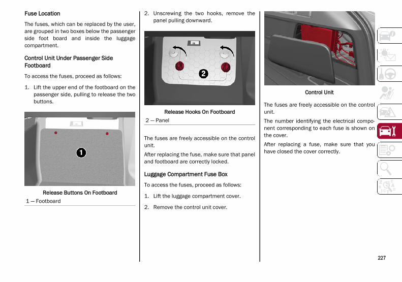
227
Fuse Location
The fuses, which can be replaced by the user,are grouped in two boxes below the passengerside foot board and inside the luggagecompartment.
Control Unit Under Passenger Side Footboard
To access the fuses, proceed as follows:
1. Lift the upper end of the footboard on thepassenger side, pulling to release the twobuttons.
Release Buttons On Footboard
2. Unscrewing the two hooks, remove thepanel pulling downward.
Release Hooks On Footboard
The fuses are freely accessible on the controlunit.After replacing the fuse, make sure that paneland footboard are correctly locked.
Luggage Compartment Fuse Box
To access the fuses, proceed as follows:
1. Lift the luggage compartment cover.
2. Remove the control unit cover.
Control Unit
The fuses are freely accessible on the controlunit.The number identifying the electrical compo-nent corresponding to each fuse is shown onthe cover.After replacing a fuse, make sure that youhave closed the cover correctly.
1 — Footboard
2 — Panel
21_GU_OM_EN_USC_t.book Page 227

SE
RV
ICIN
G A
ND
MA
INT
EN
AN
CE
228
Control Unit Under Passenger Side Footboard
Passenger Side Control Unit
FUNCTION FUSE AMPERAGE
Front power window (driver’s side) F33 25
Front power window (passenger side) F34 25
Supply for Information and Entertainment system, Climate Control system, alarm, power door mirror folding, EOBD system, USB port F36 15
Safe Lock device (driver side door unlock – if equipped), doors unlock, central lock F38 20
Windshield washer pump F43 20
Rear left power window F47 25
Rear right power window F48 25
Heater rear window coil F94 15
21_GU_OM_EN_USC_t.book Page 228

229
Luggage Compartment Fuse Box
Luggage Compartment Control Unit
Bulb Replacement
General Instructions
Before replacing a bulb, check the contactsfor oxidation.
Replace blown bulbs with others of thesame type and power.
After replacing a headlight bulb, alwayscheck its alignment.
When a light is not working, check that thecorresponding fuse is intact beforechanging the bulb.
NOTE:In some particular climate conditions, such aslow temperature, humidity, or after washingthe vehicle, a thin condensation layer mayform on the internal surfaces of the front andrear headlights. This condensation will disap-pear after switching on the headlights.
FUNCTION FUSE AMPERE
Receiver module (TTM/TTEBM) F01 40
Hi-Fi system F08 30
I-Drive / USB Socket / AUX / USB Charger F21 10
KL15/a 12 Volts Power socket in the luggage compartment F22 20
Trailer light control unit power supply (+30) F1 20
Trailer light control unit power supply (+30) F2 15
Trailer socket (only EMEA) (+30) F3 10
Tow bar (+15) F4 10
21_GU_OM_EN_USC_t.book Page 229
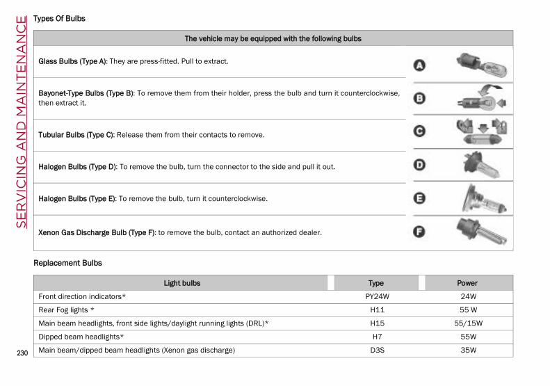
SE
RV
ICIN
G A
ND
MA
INT
EN
AN
CE
230
Types Of Bulbs
Replacement Bulbs
The vehicle may be equipped with the following bulbs
Glass Bulbs (Type A): They are press-fitted. Pull to extract.
Bayonet-Type Bulbs (Type B): To remove them from their holder, press the bulb and turn it counterclockwise,then extract it.
Tubular Bulbs (Type C): Release them from their contacts to remove.
Halogen Bulbs (Type D): To remove the bulb, turn the connector to the side and pull it out.
Halogen Bulbs (Type E): To remove the bulb, turn it counterclockwise.
Xenon Gas Discharge Bulb (Type F): to remove the bulb, contact an authorized dealer.
Light bulbs Type Power
Front direction indicators* PY24W 24W
Rear Fog lights * H11 55 W
Main beam headlights, front side lights/daylight running lights (DRL)* H15 55/15W
Dipped beam headlights* H7 55W
Main beam/dipped beam headlights (Xenon gas discharge) D3S 35W
21_GU_OM_EN_USC_t.book Page 230

231
*Only for basic version headlight with halogen main beam/dipped beam headlights
Replacing Exterior Bulbs
NOTE:Only replace bulbs when the engine is off. Alsoensure that the engine is cold, to prevent therisk of burns.
Front Light ClusterDirection IndicatorsProceed with the directions below to changebulbs:
1. Operating inside the engine compartment,locate the protective cover.
Protective Cover Location
2. Remove protective cover.
Protective Cover
3. Turn the bulb/connector assembly coun-terclockwise, and then slide it off the head-light body.
Bulb/Connector
4. Remove the bulb by sliding it off the bulbholder.
5. Install the new bulb, making sure it iscorrectly inserted in the bulb holder.
6. Insert the bulb/connector assembly in thehousing on the headlight body and turn itclockwise, making sure that it is lockedcorrectly.
7. Install the protective cover.
Sun visor light 1.5CP 2.1W
Glove compartment light W5W 4W
Liftgate light W5W 5W
Puddle lights (under door panel) W5W 5W
Light bulbs Type Power
21_GU_OM_EN_USC_t.book Page 231

SE
RV
ICIN
G A
ND
MA
INT
EN
AN
CE
232
Front Light Cluster With Main Beam XenonGas Discharge HeadlightsTo replace the bulbs of the main beam head-lights, contact an authorized dealer.
Replacing Interior Bulbs
Courtesy Mirror LightTo replace the bulbs, proceed as follows:
1. Lift the mirror cover and remove the lens,using a suitable tool.
Sun Visor
2. Change the bulb, releasing it from the sidecontacts, then insert the new bulb, makingsure that it is correctly fastened betweenthe contacts.
3. Install the lens, inserting it first on one sideand then pressing on the other side until itclicks into place.
Glove Compartment LightTo replace the bulb, proceed as follows:
1. Open the glove compartment.
2. Remove the courtesy light assembly, usinga suitable tool.
Courtesy Lamp Indent
3. Open protective cover and remove thebulb pulling out of the connector.
Cover And Bulb Removal Direction
4. Install bulb, making sure that it is correctlyinserted fully.
5. Close the protective cover on the lens.
6. Install courtesy light, inserting it first onone side and then pressing on the otherside until it clicks into place.
CAUTION!
Do not touch the new bulb with your fingers.Oil contamination will severely shorten bulblife. If the bulb comes in contact with anyoily surface, clean the bulb with rubbingalcohol.
1 — Mirror Cover2 — Lens
21_GU_OM_EN_USC_t.book Page 232
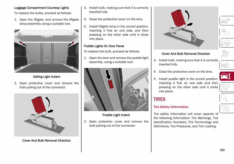
233
Luggage Compartment Courtesy LightsTo replace the bulbs, proceed as follows:
1. Open the liftgate, and remove the liftgatelamp assembly using a suitable tool.
Ceiling Light Indent
2. Open protective cover and remove thebulb pulling out of the connector.
Cover And Bulb Removal Direction
3. Install bulb, making sure that it is correctlyinserted fully.
4. Close the protective cover on the lens.
5. Install liftgate lamp in the correct position,inserting it first on one side, and thenpressing on the other side until it clicksinto place.
Puddle Lights On Door PanelTo replace the bulb, proceed as follows:
1. Open the door and remove the puddle lightassembly, using a suitable tool.
Puddle Light Indent
2. Open protective cover and remove thebulb pulling out of the connector.
Cover And Bulb Removal Direction
3. Install bulb, making sure that it is correctlyinserted fully.
4. Close the protective cover on the lens.
5. Install puddle light in the correct position,inserting it first on one side and thenpressing on the other side until it clicksinto place.
TIRES
Tire Safety Information
Tire safety information will cover aspects ofthe following information: Tire Markings, TireIdentification Numbers, Tire Terminology andDefinitions, Tire Pressures, and Tire Loading.
21_GU_OM_EN_USC_t.book Page 233

SE
RV
ICIN
G A
ND
MA
INT
EN
AN
CE
234
Tire Markings
Tire Markings
NOTE:
P (Passenger) — Metric tire sizing is basedon US design standards. P-Metric tires havethe letter “P” molded into the sidewallpreceding the size designation. Example:P215/65R15 95H.
European — Metric tire sizing is based onEuropean design standards. Tires designedto this standard have the tire size moldedinto the sidewall beginning with the sectionwidth. The letter "P" is absent from this tiresize designation. Example: 215/65R1596H.
LT (Light Truck) — Metric tire sizing is basedon US design standards. The size designa-tion for LT-Metric tires is the same as for
P-Metric tires except for the letters “LT” thatare molded into the sidewall preceding thesize designation. Example: LT235/85R16.
Temporary spare tires are designed fortemporary emergency use only. Temporaryhigh pressure compact spare tires have theletter “T” or “S” molded into the sidewallpreceding the size designation. Example:T145/80D18 103M.
High flotation tire sizing is based on USdesign standards and it begins with the tirediameter molded into the sidewall.Example: 31x10.5 R15 LT.
Tire Sizing Chart
1 — US DOT Safety Standards Code (TIN)2 — Size Designation3 — Service Description4 — Maximum Load5 — Maximum Pressure6 — Treadwear, Traction and Temperature Grades
EXAMPLE:
Example Size Designation: P215/65R15XL 95H, 215/65R15 96H, LT235/85R16C, T145/80D18 103M, 31x10.5 R15 LT
P = Passenger car tire size based on US design standards, or
"....blank...." = Passenger car tire based on European design standards, or
LT = Light truck tire based on US design standards, or
T or S = Temporary spare tire or
31 = Overall diameter in inches (in)
215, 235, 145 = Section width in millimeters (mm)
21_GU_OM_EN_USC_t.book Page 234

235
65, 85, 80 = Aspect ratio in percent (%) Ratio of section height to section width of tire, or
10.5 = Section width in inches (in)
R = Construction code "R" means radial construction, or
"D" means diagonal or bias construction
15, 16, 18 = Rim diameter in inches (in)
Service Description:
95 = Load Index A numerical code associated with the maximum load a tire can carry
H = Speed Symbol A symbol indicating the range of speeds at which a tire can carry a load corresponding to its load index under certain operating conditions
The maximum speed corresponding to the speed symbol should only be achieved under specified operating conditions (i.e., tire pressure,vehicle loading, road conditions, and posted speed limits)
Load Identification:Absence of the following load identification symbols on the sidewall of the tire indicates a Standard Load (SL) tire: XL = Extra load (or reinforced) tire, or
LL = Light load tire or
C, D, E, F, G = Load range associated with the maximum load a tire can carry at a specified pressure
Maximum Load – Maximum load indicates the maximum load this tire is designed to carry
Maximum Pressure – Maximum pressure indicates the maximum permissible cold tire inflation pressure for this tire
EXAMPLE:
21_GU_OM_EN_USC_t.book Page 235

SE
RV
ICIN
G A
ND
MA
INT
EN
AN
CE
236
Tire Identification Number (TIN)
The TIN may be found on one or both sides of the tire; however, the date code may only be on one side. Tires with white sidewalls will have the fullTIN, including the date code, located on the white sidewall side of the tire. Look for the TIN on the outboard side of black sidewall tires as mountedon the vehicle. If the TIN is not found on the outboard side, then you will find it on the inboard side of the tire.
Tire Terminology And Definitions
EXAMPLE:
DOT MA L9 ABCD 0301
DOT = Department of Transportation This symbol certifies that the tire is in compliance with the US Department of Transportation tire safety standards and is approved for highway
use
MA = Code representing the tire manufacturing location (two digits)
L9 = Code representing the tire size (two digits)
ABCD = Code used by the tire manufacturer (one to four digits)
03 = Number representing the week in which the tire was manufactured (two digits) 03 means the 3rd week
01 = Number representing the year in which the tire was manufactured (two digits) 01 means the year 2001
Prior to July 2000, tire manufacturers were only required to have one number to represent the year in which the tire was manufactured.Example: 031 could represent the 3rd week of 1981 or 1991
Term Definition
B-pillar The vehicle B-pillar is the structural member of the body located behind the frontdoor.
Cold Tire Inflation Pressure
Cold tire inflation pressure is defined as the tire pressure after the vehicle has notbeen driven for at least three hours, or driven less than 1 mile (1.6 km) after sittingfor a minimum of three hours. Inflation pressure is measured in units of PSI (poundsper square inch) or kPa (kilopascals).
21_GU_OM_EN_USC_t.book Page 236

237
Tire Loading And Tire Pressure
NOTE:The proper cold tire inflation pressure is listedon the driver’s side B-pillar or the rear edge ofthe driver's side door.
Check the inflation pressure of each tire,including the spare tire (if equipped), at leastmonthly and inflate to the recommended pres-sure for your vehicle.
Example Tire Placard Location (Door)
Example Tire Placard Location (B-pillar)
Tire And Loading Information Placard
Tire And Loading Information Placard
This placard tells you important informationabout the:
1. Number of people that can be carried inthe vehicle.
2. Total weight your vehicle can carry.
3. Tire size designed for your vehicle.
4. Cold tire inflation pressures for the front,rear, and spare tires.
Loading
The vehicle maximum load on the tire must notexceed the load carrying capacity of the tire onyour vehicle. You will not exceed the tire's loadcarrying capacity if you adhere to the loadingconditions, tire size, and cold tire inflationpressures specified on the Tire and LoadingInformation placard Ú page 135.
Maximum Inflation Pressure The maximum inflation pressure is the maximum permissible cold tire inflationpressure for this tire. The maximum inflation pressure is molded into the sidewall.
Recommended Cold Tire Inflation Pressure Vehicle manufacturer's recommended cold tire inflation pressure as shown on thetire placard.
Tire Placard A label permanently attached to the vehicle describing the vehicle’s loading capacity,the original equipment tire sizes and the recommended cold tire inflation pressures.
Term Definition
21_GU_OM_EN_USC_t.book Page 237

SE
RV
ICIN
G A
ND
MA
INT
EN
AN
CE
238
NOTE:Under a maximum loaded vehicle condition,gross axle weight ratings (GAWRs) for the frontand rear axles must not be exceeded. Forfurther information on GAWRs, vehicleloading, and trailer towing Ú page 135.
To determine the maximum loading conditionsof your vehicle, locate the statement “Thecombined weight of occupants and cargoshould never exceed XXX kg or XXX lbs” on theTire and Loading Information placard. Thecombined weight of occupants, cargo/luggageand trailer tongue weight (if applicable) shouldnever exceed the weight referenced here.
Steps For Determining Correct LoadLimit—(1) Locate the statement “Thecombined weight of occupants andcargo should never exceed XXX kg orXXX lbs.” on your vehicle's placard.(2) Determine the combined weight ofthe driver and passengers that will beriding in your vehicle.(3) Subtract the combined weight of thedriver and passengers from XXX kg orXXX lbs.
(4) The resulting figure equals the avail-able amount of cargo and luggage loadcapacity. For example, if “XXX” amountequals 1400 lbs. and there will be five150 lb passengers in your vehicle, theamount of available cargo and luggageload capacity is 650 lbs. (1400-750(5x150) = 650 lbs.).(5) Determine the combined weight ofluggage and cargo being loaded on thevehicle. That weight may not safelyexceed the available cargo and luggageload capacity calculated in Step 4.(6) If your vehicle will be towing a trailer,load from your trailer will be transferredto your vehicle. Consult this manual todetermine how this reduces the avail-able cargo and luggage load capacity ofyour vehicle.Metric Example For Load LimitFor example, if “XXX” amount equals 635 kgand there will be five 68 kg passengers in yourvehicle, the amount of available cargo andluggage load capacity is 295 kg (635-340(5x68) = 295 kg) as shown in step 4.
NOTE:
If your vehicle will be towing a trailer, loadfrom your trailer will be transferred to yourvehicle. The following table shows exampleson how to calculate total load, cargo/luggage, and towing capacities of yourvehicle with varying seating configurationsand number and size of occupants. Thistable is for illustration purposes only andmay not be accurate for the seating andload carry capacity of your vehicle.
For the following example, the combinedweight of occupants and cargo should neverexceed 865 lbs (392 kg).
21_GU_OM_EN_USC_t.book Page 238

239
(Continued)(Continued)
Tires — General Information
Tire Pressure
Proper tire inflation pressure is essential tothe safe and satisfactory operation of yourvehicle. Four primary areas are affected byimproper tire pressure:
Safety
Fuel Economy
Tread Wear
Ride Comfort and Vehicle Stability
Safety
WARNING!
Overloading of your tires is dangerous.Overloading can cause tire failure, affectvehicle handling, and increase yourstopping distance. Use tires of therecommended load capacity for yourvehicle. Never overload them.
WARNING!
Improperly inflated tires are dangerousand can cause collisions.
Underinflation increases tire flexing andcan result in overheating and tire failure.
Overinflation reduces a tire's ability tocushion shock. Objects on the road andchuckholes can cause damage that resultin tire failure.
Overinflated or underinflated tires canaffect vehicle handling and can failsuddenly, resulting in loss of vehiclecontrol.
Unequal tire pressures can cause steeringproblems. You could lose control of yourvehicle.
WARNING! (Continued)
21_GU_OM_EN_USC_t.book Page 239

SE
RV
ICIN
G A
ND
MA
INT
EN
AN
CE
240
Both underinflation and overinflation affectthe stability of the vehicle and can produce afeeling of sluggish response or over respon-siveness in the steering.
NOTE:
Unequal tire pressures from side to sidemay cause erratic and unpredictablesteering response.
Unequal tire pressure from side to side maycause the vehicle to drift left or right.
Fuel EconomyUnderinflated tires will increase tire rollingresistance resulting in higher fuel consump-tion.Tread WearImproper cold tire inflation pressures cancause abnormal wear patterns and reducedtread life, resulting in the need for earlier tirereplacement.
Ride Comfort And Vehicle StabilityProper tire inflation contributes to a comfort-able ride. Overinflation produces a jarring anduncomfortable ride.
Tire Inflation Pressures
The proper cold tire inflation pressure is listedon the driver's side B-pillar or rear edge of thedriver's side door.At least once a month: Check and adjust tire pressure with a good
quality pocket-type pressure gauge. Do notmake a visual judgement when determiningproper inflation. Tires may look properlyinflated even when they are underinflated.
Inspect tires for signs of tire wear or visibledamage.
Inflation pressures specified on the placardare always “cold tire inflation pressure”. Coldtire inflation pressure is defined as the tirepressure after the vehicle has not been drivenfor at least three hours, or driven less than1 mile (1.6 km) after sitting for a minimum ofthree hours. The cold tire inflation pressure
must not exceed the maximum inflation pres-sure molded into the tire sidewall.Check tire pressures more often if subject to awide range of outdoor temperatures, as tirepressures vary with temperature changes.Tire pressures change by approximately 1 psi(7 kPa) per 12°F (7°C) of air temperaturechange. Keep this in mind when checking tirepressure inside a garage, especially in theWinter.Example: If garage temperature = 68°F(20°C) and the outside temperature = 32°F(0°C) then the cold tire inflation pressureshould be increased by 3 psi (21 kPa), whichequals 1 psi (7 kPa) for every 12°F (7°C) forthis outside temperature condition.Tire pressure may increase from 2 to 6 psi (13 to 40 kPa) during operation. DO NOTreduce this normal pressure build up or yourtire pressure will be too low.
Tire Pressures For High Speed Operation
The manufacturer advocates driving at safespeeds and within posted speed limits. Wherespeed limits or conditions are such that thevehicle can be driven at high speeds, main-taining correct tire inflation pressure is veryimportant. Increased tire pressure andreduced vehicle loading may be required forhigh-speed vehicle operation. Refer to anauthorized tire dealer or original equipmentvehicle dealer for recommended safe oper-ating speeds, loading and cold tire inflationpressures.
Unequal tire pressures from one side ofthe vehicle to the other can cause thevehicle to drift to the right or left.
Always drive with each tire inflated to therecommended cold tire inflation pressure.
WARNING! (Continued)
CAUTION!
After inspecting or adjusting the tirepressure, always reinstall the valve stemcap. This will prevent moisture and dirt fromentering the valve stem, which coulddamage the valve stem.
21_GU_OM_EN_USC_t.book Page 240
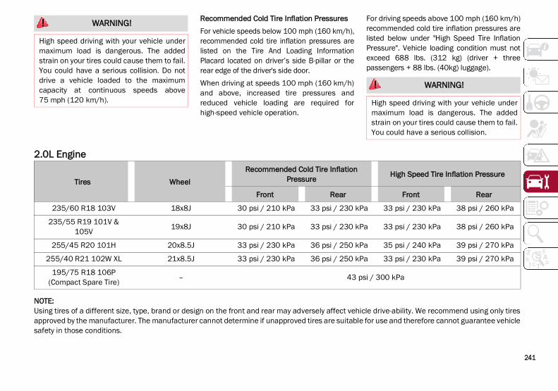
241
Recommended Cold Tire Inflation PressuresFor vehicle speeds below 100 mph (160 km/h),recommended cold tire inflation pressures arelisted on the Tire And Loading InformationPlacard located on driver’s side B-pillar or therear edge of the driver's side door.When driving at speeds 100 mph (160 km/h)and above, increased tire pressures andreduced vehicle loading are required forhigh-speed vehicle operation.
For driving speeds above 100 mph (160 km/h)recommended cold tire inflation pressures arelisted below under "High Speed Tire InflationPressure". Vehicle loading condition must notexceed 688 lbs. (312 kg) (driver + threepassengers + 88 lbs. (40kg) luggage).
2.0L Engine
NOTE:Using tires of a different size, type, brand or design on the front and rear may adversely affect vehicle drive-ability. We recommend using only tiresapproved by the manufacturer. The manufacturer cannot determine if unapproved tires are suitable for use and therefore cannot guarantee vehiclesafety in those conditions.
WARNING!
High speed driving with your vehicle undermaximum load is dangerous. The addedstrain on your tires could cause them to fail.You could have a serious collision. Do notdrive a vehicle loaded to the maximumcapacity at continuous speeds above75 mph (120 km/h).
WARNING!
High speed driving with your vehicle undermaximum load is dangerous. The addedstrain on your tires could cause them to fail.You could have a serious collision.
Tires WheelRecommended Cold Tire Inflation
Pressure High Speed Tire Inflation Pressure
Front Rear Front Rear
235/60 R18 103V 18x8J 30 psi / 210 kPa 33 psi / 230 kPa 33 psi / 230 kPa 38 psi / 260 kPa
235/55 R19 101V & 105V 19x8J 30 psi / 210 kPa 33 psi / 230 kPa 33 psi / 230 kPa 38 psi / 260 kPa
255/45 R20 101H 20x8.5J 33 psi / 230 kPa 36 psi / 250 kPa 35 psi / 240 kPa 39 psi / 270 kPa
255/40 R21 102W XL 21x8.5J 33 psi / 230 kPa 36 psi / 250 kPa 33 psi / 230 kPa 39 psi / 270 kPa
195/75 R18 106P (Compact Spare Tire) – 43 psi / 300 kPa
21_GU_OM_EN_USC_t.book Page 241

SE
RV
ICIN
G A
ND
MA
INT
EN
AN
CE
242
2.9L Engine
Radial Ply Tires Tire RepairIf your tire becomes damaged, it may berepaired if it meets the following criteria: The tire has not been driven on when flat.
The damage is only on the tread section ofyour tire (sidewall damage is not repairable).
The puncture is no greater than a ¼ of aninch (6 mm).
Consult an authorized tire dealer for tirerepairs and additional information.Damaged Run Flat tires, or Run Flat tires thathave experienced a loss of pressure should bereplaced immediately with another Run Flattire of identical size and service description(Load Index and Speed Symbol). Replace thetire pressure sensor as well as it is notdesigned to be reused.
Tires WheelRecommended Cold Tire Inflation
Pressure High Speed Tire Inflation Pressure
Front Rear Front Rear
255/45R20 101Y (Original Equipment) 20x9J 36 psi / 250 kpa - 39 psi / 270 kpa -
255/40 R21 102Y XL (Original Equipment) 21x9J 39 psi / 270 kpa - 39 psi / 270 kpa -
285/40R20 104Y (Original Equipment) 20x10J - 39 psi / 270 kpa - 42 psi / 290 kpa
285/35 R21 105Y XL (Original Equipment) 21x10J - 42 psi / 290 kpa - 42 psi / 290 kpa
255/45R20 M+S (Snow Tires) 20x9J 36 psi / 250 kpa - 39 psi / 270 kpa -
255/40 R21 M+S (Snow Tires) 21x9J 39 psi / 270 kpa - 39 psi / 270 kpa -
255/45R20 M+S (Snow Tires) 20x9J - 39 psi / 270 kpa - 42 psi / 290 kpa
285/35 R21 M+S (Snow Tires)
21x9J - 42 psi / 290 kpa - 42 psi / 290 kpa
WARNING!
Combining radial ply tires with other typesof tires on your vehicle will cause yourvehicle to handle poorly. The instabilitycould cause a collision. Always use radialply tires in sets of four. Never combine themwith other types of tires.
21_GU_OM_EN_USC_t.book Page 242

243
Run Flat Tires — If Equipped
Run Flat tires allow you the capability to drive50 miles (80 km) at 50 mph (80 km/h) after arapid loss of inflation pressure. This rapid lossof inflation is referred to as the Run Flat mode.A Run Flat mode occurs when the tire inflationpressure is of/or below 14 psi (96 kPa). Oncea Run Flat tire reaches the run flat mode it haslimited driving capabilities and needs to bereplaced immediately. A Run Flat tire is notrepairable. When a run flat tire is changedafter driving with underinflated tire condition,please replace the TPM sensor as it is notdesigned to be reused when driven under runflat mode 14 psi (96 kPa) condition.
NOTE:TPM Sensor must be replaced after driving thevehicle on a flat tire condition.
It is not recommended driving a vehicle loadedat full capacity or to tow a trailer while a tire isin the run flat mode.For more information Ú page 161.
Tire Spinning
When stuck in mud, sand, snow, or ice condi-tions, do not spin your vehicle's wheels above30 mph (48 km/h) or for longer than 30 secondscontinuously without stopping.
Tread Wear Indicators
Tread wear indicators are in the original equip-ment tires to help you in determining whenyour tires should be replaced.
Tire Tread
These indicators are molded into the bottom ofthe tread grooves. They will appear as bandswhen the tread depth becomes a 1/16 of aninch (1.6 mm). When the tread is worn to thetread wear indicators, the tire should bereplaced.
Life Of Tire
The service life of a tire is dependent uponvarying factors including, but not limited to: Driving style.
Tire pressure - Improper cold tire inflationpressures can cause uneven wear patternsto develop across the tire tread. Theseabnormal wear patterns will reduce treadlife, resulting in the need for earlier tirereplacement.
Distance driven.
Performance tires, tires with a speed ratingof V or higher, and Summer tires typicallyhave a reduced tread life. Rotation of thesetires per the vehicle scheduled mainte-nance is highly recommended.
WARNING!
Fast spinning tires can be dangerous. Forcesgenerated by excessive wheel speeds maycause tire damage or failure. A tire couldexplode and injure someone. Do not spinyour vehicle's wheels faster than 30 mph(48 km/h) for more than 30 secondscontinuously when you are stuck, and do notlet anyone near a spinning wheel, no matterwhat the speed.
1 — Worn Tire2 — New Tire
WARNING!
Tires and the spare tire should be replacedafter six years, regardless of the remainingtread. Failure to follow this warning canresult in sudden tire failure. You could losecontrol and have a collision resulting inserious injury or death.
21_GU_OM_EN_USC_t.book Page 243

SE
RV
ICIN
G A
ND
MA
INT
EN
AN
CE
244
NOTE:Wheel valve stem must be replaced as wellwhen installing new tires due to wear and tearin existing tires.
Keep dismounted tires in a cool, dry place withas little exposure to light as possible. Protecttires from contact with oil, grease, and gaso-line.
Replacement Tires
The tires on your new vehicle provide abalance of many characteristics. They shouldbe inspected regularly for wear and correctcold tire inflation pressures. The manufacturerstrongly recommends that you use tires equiv-alent to the originals in size, quality and perfor-mance when replacement is needed Ú page 243. Refer to the Tire and LoadingInformation placard or the Vehicle Certifica-tion Label for the size designation of your tire.The Load Index and Speed Symbol for your tirewill be found on the original equipment tiresidewall.See the Tire Sizing Chart example for moreinformation relating to the Load Index andSpeed Symbol of a tire Ú page 233.It is recommended to replace the two fronttires or two rear tires as a pair. Replacing justone tire can seriously affect your vehicle’shandling. If you ever replace a wheel, makesure that the wheel’s specifications matchthose of the original wheels.
It is recommended you contact an authorizedtire dealer or original equipment dealer withany questions you may have on tire specifica-tions or capability. Failure to use equivalentreplacement tires may adversely affect thesafety, handling, and ride of your vehicle.
Spare Tires — If Equipped
NOTE:For vehicles equipped with Tire Service Kitinstead of a spare tire Ú page 198.
Spare Tire Matching Original Equipped Tire And Wheel — If Equipped
Your vehicle may be equipped with a spare tireand wheel equivalent in look and function tothe original equipment tire and wheel found onthe front or rear axle of your vehicle. This sparetire may be used in the tire rotation for yourvehicle. If your vehicle has this option, refer toan authorized tire dealer for the recom-mended tire rotation pattern.
WARNING!
Do not use a tire, wheel size, load rating,or speed rating other than that specifiedfor your vehicle. Some combinations ofunapproved tires and wheels may changesuspension dimensions and performancecharacteristics, resulting in changes tosteering, handling, and braking of yourvehicle. This can cause unpredictablehandling and stress to steering andsuspension components. You could losecontrol and have a collision resulting inserious injury or death. Use only the tireand wheel sizes with load ratingsapproved for your vehicle.
Never use a tire with a smaller load indexor capacity, other than what was originallyequipped on your vehicle. Using a tire witha smaller load index could result in tireoverloading and failure. You could losecontrol and have a collision.
Failure to equip your vehicle with tireshaving adequate speed capability canresult in sudden tire failure and loss ofvehicle control.
CAUTION!
Replacing original tires with tires of adifferent size may result in falsespeedometer and odometer readings.
CAUTION!
Because of the reduced ground clearance,do not take your vehicle through anautomatic car wash with a compact orlimited use temporary spare installed.Damage to the vehicle may result.
21_GU_OM_EN_USC_t.book Page 244

245
Compact Spare Tire — If Equipped
The compact spare is for temporary emer-gency use only. You can identify if your vehicleis equipped with a compact spare by looking atthe spare tire description on the Tire andLoading Information Placard located on thedriver’s side door opening or on the sidewall ofthe tire. Compact spare tire descriptions beginwith the letter “T” or “S” preceding the sizedesignation. Example: T145/80D18 103M.T, S = Temporary Spare TireSince this tire has limited tread life, the orig-inal equipment tire should be repaired (orreplaced) and reinstalled on your vehicle atthe first opportunity.Do not install a wheel cover or attempt tomount a conventional tire on the compactspare wheel, since the wheel is designedspecifically for the compact spare tire. Do notinstall more than one compact spare tire andwheel on the vehicle at any given time.
Full Size Spare — If Equipped
The full size spare is for temporary emergencyuse only. This tire may look like the originallyequipped tire on the front or rear axle of yourvehicle, but it is not. This spare tire may havelimited tread life. When the tread is worn to thetread wear indicators, the temporary use fullsize spare tire needs to be replaced. Since it isnot the same as your original equipment tire,replace (or repair) the original equipment tireand reinstall on the vehicle at the first oppor-tunity.
Limited Use Spare — If Equipped
The limited use spare tire is for temporaryemergency use only. This tire is identified by alabel located on the limited use spare wheel.This label contains the driving limitations forthis spare. This tire may look like the originalequipped tire on the front or rear axle of yourvehicle, but it is not. Installation of this limiteduse spare tire affects vehicle handling. Since itis not the same as your original equipmenttire, replace (or repair) the original equipmenttire and reinstall on the vehicle at the firstopportunity.
Wheel And Wheel Trim Care
All wheels and wheel trim, especiallyaluminum and chrome plated wheels, shouldbe cleaned regularly using mild (neutral Ph)soap and water to maintain their luster and toprevent corrosion. Wash wheels with the samesoap solution recommended for the body ofthe vehicle and remember to always washwhen the surfaces are not hot to the touch.Your wheels are susceptible to deteriorationcaused by salt, sodium chloride, magnesiumchloride, calcium chloride, etc., and other roadchemicals used to melt ice or control dust ondirt roads. Use a soft cloth or sponge and mildsoap to wipe away promptly. Do not use harshchemicals or a stiff brush. They can damage
WARNING!
Compact and collapsible spares are fortemporary emergency use only. With thesespares, do not drive more than 50 mph(80 km/h). Temporary use spares havelimited tread life. When the tread is worn tothe tread wear indicators, the temporaryuse spare tire needs to be replaced. Besure to follow the warnings, which apply toyour spare. Failure to do so could result inspare tire failure and loss of vehicle control.
WARNING!
Limited use spares are for emergency useonly. Installation of this limited use sparetire affects vehicle handling. With this tire,do not drive more than the speed listed onthe limited use spare wheel. Keep inflatedto the cold tire inflation pressures listed onyour Tire and Loading Information Placardlocated on the driver’s side B-pillar or therear edge of the driver’s side door. Replace(or repair) the original equipment tire at thefirst opportunity and reinstall it on yourvehicle. Failure to do so could result in lossof vehicle control.
21_GU_OM_EN_USC_t.book Page 245
SE
RV
ICIN
G A
ND
MA
INT
EN
AN
CE
246
the wheel’s protective coating that helps keepthem from corroding and tarnishing.
When cleaning extremely dirty wheelsincluding excessive brake dust, care must betaken in the selection of tire and wheelcleaning chemicals and equipment to preventdamage to the wheels. Select a non-abrasive,non-acidic cleaner for aluminum or chromewheels.
NOTE:If you intend parking or storing your vehicle foran extended period after cleaning the wheelswith wheel cleaner, drive your vehicle andapply the brakes to remove the water dropletsfrom the brake components. This activity willremove the red rust on the brake rotors andprevent vehicle vibration when braking.
Dark Or Low Gloss Wheels
Tire Types
All Season Tires — If Equipped
All Season tires provide traction for all seasons(Spring, Summer, Autumn, and Winter). Trac-tion levels may vary between different allseason tires. All season tires can be identifiedby the M+S, M&S, M/S or MS designation onthe tire sidewall. Use all season tires only insets of four; failure to do so may adverselyaffect the safety and handling of your vehicle.
Summer Or Three Season Tires — If Equipped
Summer tires provide traction in both wet anddry conditions, and are not intended to bedriven in snow or on ice. If your vehicle isequipped with Summer tires, be aware thesetires are not designed for Winter or cold drivingconditions. Install Winter tires on your vehiclewhen ambient temperatures are less than40°F (5°C) or if roads are covered with ice orsnow. For more information, contact an autho-rized dealer.Summer tires do not contain the all seasondesignation or mountain/snowflake symbol onthe tire sidewall. Use Summer tires only in setsof four; failure to do so may adversely affectthe safety and handling of your vehicle.
Snow Tires
Some areas of the country require the use ofsnow tires during the Winter. Snow tires canbe identified by a “mountain/snowflake”symbol on the tire sidewall.
If you need snow tires, select tiresequivalent in size and type to theoriginal equipment tires. Use snow
CAUTION!
Avoid products or automatic car washesthat use acidic solutions or strong alkalineadditives or harsh brushes. Manyaftermarket wheel cleaners and automaticcar washes may damage the wheel'sprotective finish. Such damage is notcovered by the New Vehicle LimitedWarranty. Only car wash soap isrecommended.
CAUTION!
Do not use scouring pads, steel wool, abristle brush, metal polishes or ovencleaner. These products may damage thewheel's protective finish. Such damage isnot covered by the New Vehicle LimitedWarranty. Only car wash soap isrecommended.
CAUTION!
If your vehicle is equipped with thesespecialty wheels, DO NOT USE wheelcleaners, abrasives, or polishingcompounds. They will permanently damagethis finish and such damage is not coveredby the New Vehicle Limited Warranty. HANDWASH ONLY USING MILD SOAP AND WATERWITH A SOFT CLOTH. Used on a regularbasis; this is all that is required to maintainthis finish.
WARNING!
Do not use Summer tires in snow/iceconditions. You could lose vehicle control,resulting in severe injury or death. Drivingtoo fast for conditions also creates thepossibility of loss of vehicle control.
21_GU_OM_EN_USC_t.book Page 246

247
(Continued)
tires only in sets of four; failure to do so mayadversely affect the safety and handling ofyour vehicle.Snow tires generally have lower speed ratingsthan what was originally equipped with yourvehicle and should not be operated atsustained speeds over 75 mph (120 km/h).For speeds above 75 mph (120 km/h) refer tooriginal equipment or an authorized tire dealerfor recommended safe operating speeds,loading and cold tire inflation pressures.While studded tires improve performance onice, skid and traction capability on wet or drysurfaces may be poorer than that ofnon-studded tires. Some states prohibitstudded tires; therefore, local laws should bechecked before using these tire types.
Tire Chains and Traction Devices
It is possible to fit 13 mm chains on all thetires except for R20.Use of traction devices require sufficienttire-to-body clearance. Follow these recom-mendations to guard against damage.
NOTE:
Traction device must be of proper size forthe tire, as recommended by the tractiondevice manufacturer.
Use on rear tires only.
Check the tension of the snow chains afterthe first few meters have been driven.
Using snow chains with tires with non-orig-inal dimensions may damage the vehicle.
Using different tires sizes or types (M+S,snow, etc.) between the front and rear axlesmay adversely affect vehicle driveability,with the risk of losing control of the vehicleand resulting accidents.
Tire Rotation Recommendations
Tires on the front and rear axles of vehiclesoperate at different loads and performdifferent steering, driving, and braking func-tions. For these reasons, they wear at unequalrates. These effects can be reduced by timelyrotation of tires. Rotation will increase treadlife, maintain traction levels and contribute toa smooth, quiet ride.To resolve this problem, tires should berotated at each service interval (approximatelyevery 10,000 miles [16,000 km]). Morefrequent rotation is permissible if desired. Thereasons for any rapid or unusual wear shouldbe corrected prior to rotation being performed.Tire Rotations Not Recommended — IfEquippedDue to different size tires and wheels on frontand rear axles tire rotation is not possible for:2.0T GME Engine equipped with a differentfront and rear tire size.
CAUTION!
To avoid damage to your vehicle or tires,observe the following precautions:
Because of restricted traction deviceclearance between tires and othersuspension components, it is importantthat only traction devices in good condi-tion are used. Broken devices can causeserious damage. Stop the vehicle immedi-ately if noise occurs that could indicatedevice breakage. Remove the damagedparts of the device before further use.
Install device as tightly as possible andthen retighten after driving about ½ mile(0.8 km).
Do not exceed 30 mph (48 km/h).
Drive cautiously and avoid severe turnsand large bumps, especially with a loadedvehicle.
Do not drive for a prolonged period on drypavement.
Observe the traction device manufac-turer’s instructions on the method ofinstallation, operating speed, and condi-tions for use. Always use the suggestedoperating speed of the device manufac-turer’s if it is less than 30 mph (48 km/h).
Do not use traction devices on a compactspare tire.
CAUTION! (Continued)
21_GU_OM_EN_USC_t.book Page 247

SE
RV
ICIN
G A
ND
MA
INT
EN
AN
CE
248
Tire rotation contributes to the preservation ofthe grip and traction performance on wet,muddy or snowy roads, guaranteeing optimaldriveability of the vehicle.In the case of irregular wear of the tires iden-tify the cause and correct it as soon aspossible, by contacting an authorized dealer.The rotational direction of the tire must betaken into consideration when rotating thetires. The recommended rotation pattern fordirectional tires is shown below.
Tire RotationIt is recommended to avoid situations with alarge difference in wear between the front andrear tires and to strictly use Winter tires of thesizes given on the tire placard.
The AWD system and the original tires aredeveloped together to ensure the vehicle’sbest performance. When changing the tires, itis recommended to us the same “AR” markedtires, to maintain the same level of perfor-mance and component life.
DEPARTMENT OF TRANSPORTATION UNIFORM TIRE QUALITY GRADESThe following tire grading categorieswere established by the NationalHighway Traffic Safety Administration.The specific grade rating assigned bythe tire's manufacturer in each cate-gory is shown on the sidewall of thetires on your vehicle.All passenger vehicle tires mustconform to Federal safety require-ments in addition to these grades.
Treadwear
The Treadwear grade is a comparativerating, based on the wear rate of thetire when tested under controlledconditions on a specified governmenttest course. For example, a tire graded150 would wear one and one-half timesas well on the government course as atire graded 100. The relative perfor-mance of tires depends upon the
actual conditions of their use, however,and may depart significantly from thenorm due to variations in driving habits,service practices, and differences inroad characteristics and climate.
Traction Grades
The Traction grades, from highest tolowest, are AA, A, B, and C. Thesegrades represent the tire's ability tostop on wet pavement, as measuredunder controlled conditions on speci-fied government test surfaces ofasphalt and concrete. A tire marked Cmay have poor traction performance.
Temperature Grades
The temperature grades are A (thehighest), B, and C, representing thetire's resistance to the generation ofheat and its ability to dissipate heat,when tested under controlled condi-tions on a specified indoor laboratory
CAUTION!
Damage to the vehicle may occur ifdifferent front and rear tire sizes arerotated
WARNING!
The traction grade assigned to this tire isbased on straight-ahead braking tractiontests, and does not include acceleration,cornering, hydroplaning, or peak tractioncharacteristics.
21_GU_OM_EN_USC_t.book Page 248

249
test wheel. Sustained high temperaturecan cause the material of the tire todegenerate and reduce tire life, andexcessive temperature can lead tosudden tire failure. The grade C corre-sponds to a level of performance, whichall passenger vehicle tires must meetunder the Federal Motor Vehicle SafetyStandard No. 109. Grades B and Arepresent higher levels of performanceon the laboratory test wheel, than theminimum required by law.
STORING THE VEHICLE If the vehicle is left inactive for longer than amonth, the following precautions should beobserved: Park the vehicle in an area that is covered
and dry, and well-ventilated if possible.Slightly open the windows.
Check that the Electric Park Brake (EPB) isnot activated.
Carry out the “Liftgate Emergency Opening”procedure Ú page 62.
Disconnect the negative battery terminaland check the battery charge. Repeat thischeck once every three months duringstorage.
If the battery is not disconnected from theelectrical system, check its state of chargeevery 30 days.
Clean and protect the painted parts usingprotective wax.
Clean and protect the shiny metal parts usingspecial compounds available commercially.
Sprinkle talcum powder on the windshieldwiper rubber blades, and lift them off theglass.
Cover the vehicle with a fabric or perforatedplastic sheet, paying particular care not todamage the painted surface by draggingany dust that may have accumulated on it.Do not use compact plastic sheets, as theydo not allow humidity to evaporate from thesurface of the vehicle.
Inflate tires to +7.25 psi (+0.5 bar) abovethe standard prescribed pressure andcheck it periodically.
Do not drain the engine cooling system.
Any time the vehicle is left inactive for twoweeks or more, operate the air conditioningsystem with engine idling for at least five
minutes, setting external air and with fanset to maximum speed. This operation willensure appropriate lubrication for thesystem, thus minimizing the possibility ofdamage to the compressor when thesystem is operated again.
NOTE:After cycling the ignition to STOP and havingclosed the driver side door, wait at least oneminute before disconnecting the electricalsupply from the battery. When reconnectingthe electrical supply to the battery, make surethat the ignition is in the STOP position and thedriver’s side door is closed.
BODYWORK
Protection Against Atmospheric Agents
The vehicle is equipped with the best availabletechnological solutions to protect the body-work against corrosion.These include: Painting products and systems which give
the vehicle resistance to corrosion andabrasion.
Use of galvanized (or pre-treated) steelsheets, with high resistance to corrosion.
Spraying of plastic parts, with a protectivefunction in the more exposed points: underdoor, inner wing, edges, etc.
WARNING!
The temperature grade for this tire isestablished for a tire that is properly inflatedand not overloaded. Excessive speed,underinflation, or excessive loading, eitherseparately or in combination, can causeheat buildup and possible tire failure.
21_GU_OM_EN_USC_t.book Page 249

SE
RV
ICIN
G A
ND
MA
INT
EN
AN
CE
250
Use of “open” boxed sections to preventcondensation and pockets of moisturewhich could favor the formation of rustinside.
Use of special films to protect against abra-sion in exposed areas (e.g. rear wing, doors,etc.).
Corrosion Warranty
Your vehicle is covered by Corrosion Warrantyagainst perforation due to rust of any originalelement of the structure or bodywork. For thegeneral terms of this warranty, refer to theWarranty Booklet.
Preserving The Bodywork
PaintTouch up abrasions and scratches immedi-ately to prevent the formation of rust.Maintenance of paintwork consists of washingthe vehicle: the frequency depends on theconditions and environment where the vehicleis used. For example, it is advisable to washthe vehicle more often in areas with high levelsof atmospheric pollution or salted roads.Some parts of the vehicle may be covered witha matte paint which, in order to be maintainedintact, requires special care.To correctly wash the vehicle, follow theseinstructions: If high pressure jets or cleaners are used to
wash the vehicle, keep a distance of at least
15 inches (40 cm) from the bodywork toavoid damage or alteration. Build up ofwater could cause damage to the vehicle inthe long term.
To make it easier to remove any dirtdeposits in the area where the blades arenormally located it is recommended to posi-tion the windshield wipers vertically (serviceposition) Ú page 219.
Wash the bodywork using a low pressure jetof water if possible.
Wipe a sponge with a slightly soapy solutionover the bodywork, frequently rinsing thesponge.
Rinse well with water and dry with a leatherchamois.
Dry the less visible parts (e.g. door frames,hood, headlight frames, etc.) with special care,as water may stagnate more easily in theseareas. Do not wash the vehicle after it hasbeen left in the sun or with the hood hot: thismay alter the shine of the paintwork.
NOTE:Avoid parking under trees; the resin droppedby trees makes the paintwork go opaque andincreases the possibility of corrosion.
Exterior plastic parts must be cleaned in thesame way as the rest of the vehicle.
If washing the vehicle in a service that movesthe vehicle, for vehicles with automatic trans-missions, proceed with the following direc-tions: Ensure that the vehicle is on a flat surface.
Disable the automatic engagement of theparking brake Ú page 90.
With the vehicle stationary, the gear inNEUTRAL (N) and the brake pedal pressed,push the START button.
NOTE:The vehicle will remain in NEUTRAL (N) for15 minutes before PARK (P) will be engagedautomatically.
WindowsUse specific detergents and clean cloths toprevent scratching or altering the transpar-ency.
Front HeadlightsUse a soft cloth soaked in water and detergentfor washing vehicles.
CAUTION!
Wipe the rear window inside gently with acloth following the direction of the filamentsto avoid damaging the heating device.
21_GU_OM_EN_USC_t.book Page 250

251
NOTE:
Never use aromatic substances (e.g. gaso-line) or ketones (e.g. acetone) for cleaningthe plastic lenses of the headlights.
When cleaning with a pressure washer,keep the pressure washer at least eightinches (20 cm) away from the headlights.
Engine CompartmentAt the end of every Winter, wash the enginecompartment thoroughly, taking care not toaim the jet of water directly at the electroniccontrol units or at the windshield wipermotors. Have this operation performed at aspecialized workshop Ú page 218.
NOTE:The washing should take place with the enginecold and the ignition device in the STOP posi-tion. After the washing operation, make surethat the various protections (e.g. rubber capsand guards) have not been removed ordamaged.
INTERIORSPeriodically check the cleanliness of the inte-rior, beneath the mats, which could causeoxidation of the sheet metal.
Seats And Fabric PartsRemove dust with a soft brush or a vacuumcleaner. It is advised to use a moist brush onvelvet upholstery. Rub the seats with a spongemoistened with a solution of water and neutraldetergent.
Cleaning heat press images on seats — ifequipped:Due to the color, opacity and wear-resistantprotection with which the heat press imageson some seats are made, they may be subjectto temporary scratching if they are touched byfinger nails, keys, or other hard objects. Insuch cases, the visible signs do not impair theprofiled images, and can easily be removed bywiping the affected area with a microfibercloth moistened with water (not dry) to restorethe seat to its original condition. The micro-fiber cloth must not have been previouslysoaked in other substances or detergents.
Leather SeatsRemove the dry dirt with a chamois or slightlydamp cloth, without exerting too much pres-sure.Remove any liquid or grease stains using anabsorbent dry cloth, without rubbing. Thenclean with a soft cloth or buckskin cloth damp-ened with water and mild soap. If the stainpersists, use specific products and observethe instructions carefully.
NOTE:Never use alcohol. Make sure that thecleaning products used contain no alcohol oralcohol derivatives, even in small quantities.
Plastic And Coated PartsClean interior plastic parts with a damp cloth (ifpossible made from microfiber), and a solutionof water and neutral, non-abrasive detergent.
To clean oily or persistent stains, use specificproducts free from solvents and designed tomaintain the original appearance and color ofthe components.Remove any dust using a microfiber cloth, ifnecessary moistened with water. The use ofpaper tissues is not recommended as thesemay leave residues.
Alcantara Parts — If EquippedAlcantara parts maintenance procedure: Treat the surface with a microfiber cloth
moistened with mild marseille soap andwater, taking care to apply a uniform lightpressure over the entire area (do not rubvigorously).
Rinse and wring out the microfiber cloth,and pass it over the entire area again.
Let it dry, and then brush gently with a softbrush.
Genuine Leather PartsUse only water and mild soap to clean theseparts. Never use alcohol or alcohol-basedproducts.
CAUTION!
Precautions have been taken to safeguardall parts and connections however, thepressures generated by these machines issuch that complete protection againstwater ingress cannot be guaranteed.
21_GU_OM_EN_USC_t.book Page 251

SE
RV
ICIN
G A
ND
MA
INT
EN
AN
CE
252
Before using a specific product for cleaninginteriors, make sure that it does not containalcohol and/or alcohol based substances.
Carbon Fiber PartsTo eliminate small scratches and marks on thecarbon, contact an authorized dealer. Animproperly performed operation may irrepa-rably damage the carbon.
21_GU_OM_EN_USC_t.book Page 252

253
For the enthusiasts, the technician, or thosewho just want to know every detail of theirvehicle, useful information on understandinghow your vehicle works is contained in thischapter and illustrated with data, tables, andgraphics.
VEHICLE IDENTIFICATION NUMBER (VIN)The Vehicle Identification Number (VIN) isstamped on a plate on the front left corner ofthe dashboard trim, which can be seen fromoutside the vehicle, through the windshield.
Windshield VIN Location
Vehicle Identification Number
The Vehicle Identification Number (VIN) isstamped on a plate on the front left corner ofthe dashboard trim, which can be seen fromoutside the vehicle, through the windshield.
Windshield VIN Location
Vehicle Identification Number (VIN) Plate
The plates are located on the left side A-pillarand contain the data about: Vehicle Identification Number (VIN).
Vehicle type (USA and Canada only).
Color code.
Place of manufacturing of the vehicle (USAand Mexico only).
Vehicle manufacturing date.
Maximum permitted weights.
Permitted tire inflation pressure (USA andCanada only).
21_GU_OM_EN_USC_t.book Page 253

TE
CH
NIC
AL
SP
EC
IFIC
AT
ION
S
254
ENGINE2.0L Engine
Cycle Four
Number and position of cylinders 4 inline
Piston bore and stroke (mm) 84 / 90
Total displacement (cm³) 1,995
Compression ratio 10:1
Maximum power (SAE) (HP) 280
Maximum power (kW) 209
Corresponding engine speed (RPM) 5,200
Maximum torque (SAE) (ft-lb) 295
Maximum torque (Nm) 400
Corresponding engine speed (RPM) 2,250 - 4,000
Fuel 87 Octane Minimum (R+M)/2 Method, 91 Recommended, ethanol percentage is 0–15%.
2.9L Engine
Cycle Four
Number and position of cylinders 6 / V
Piston bore and stroke (mm) 86.5 × 82
Total displacement (cm³) 2,891
Compression ratio 9.3:1
Maximum power (SAE) (HP) 505
Maximum power (kW) 375
Corresponding engine speed (RPM) 6,500
Maximum torque (SAE) (ft-lb) 443
21_GU_OM_EN_USC_t.book Page 254

255(Continued)
POWER SUPPLY
TRANSMISSION
BRAKES
Maximum torque (Nm) 600
Corresponding engine speed (RPM) 2,500
Fuel 87 Octane Minimum (R+M)/2 Method, 91 Recommended, ethanol percentage is 0–15%.
Power supply
2.0L Engine Electronic timed sequential injection with knock control
2.9L Engine Phased sequential electronic injection with knock control and variable intake valve actuation
Version Transmission Traction
2.0L Engine
Eight Forward Gears Plus Reverse All-Wheel Drive
Eight Forward Gears Plus Reverse Rear-Wheel Drive
2.9L Engine Eight Forward Gears Plus Reverse All-Wheel Drive
Version Front brakes Rear brakes Parking brake
2.0L Engine Disc Disc Electric
2.9L Engine Disc or Carbon Ceramic Disc
Disc or Carbon Ceramic Disc Electric
2.9L Engine
21_GU_OM_EN_USC_t.book Page 255

TE
CH
NIC
AL
SP
EC
IFIC
AT
ION
S
256
SUSPENSION
STEERING
CAUTION!
Water, ice and salt spread on the roads may deposit on the brake discs, reducing braking efficiency the first time the brakes are applied.
To obtain the maximum efficiency of the braking system, a bedding-in period of about 300 miles (500 km) is needed: during this period it isbetter to avoid sharp, repeated and prolonged braking.
Version Front Rear
2.0L Engine Independent wheel double-wishbone suspension
Independent wheel with multilink system
2.9L Engine Independent wheel double-wishbone suspension
Independent wheel with multilink system
Version Curb-to-curb turning circle Type
2.0L Engine 38.55 ft (11.75 m) Rack and pinion with electric power steering
2.9L Engine 37.10 ft (11.30 m) Rack and pinion with electric power steering
21_GU_OM_EN_USC_t.book Page 256

257
DIMENSIONSDimensions are expressed in inches and refer to the vehicle equipped with its standard-supplied tires. Height is measured with vehicle unladen.
Small variations with respect to the reported values are possible depending on the dimensions of the rims.
AFront
Overhang
BWheelbase
CRear Overhang
DOverall Length
EOverall Height
FFront Track
GRear Track
HOverall Width (Incl Mirrors)
IOverall Width (Excl Mirrors)
33.9 inches(862 mm)
111 inches(2,818 mm)
39.7 inches(1,008 mm)
184.6 inches(4,688 mm)
66 inches(1,677 mm)
63.5 inches(1,612 mm)
65 inches(1,650 mm)
85.2 inches(2,163 mm)
74.9 inches(1,903 mm)
21_GU_OM_EN_USC_t.book Page 257

TE
CH
NIC
AL
SP
EC
IFIC
AT
ION
S
258
Quadrifoglio Model
A B C D E F G H I
31.3 inches(795 mm)
111 inches(2,818 mm)
40.3 inches(1,023.6 mm)
182.6 inches(4,638 mm)
56.1 inches(1,424.9 mm)
61.2 inches(1,554.5 mm)
63.3 inches(1,607.8 mm)
79.7 inches(2,024.4 mm)
73.7 inches(1,872 mm)
21_GU_OM_EN_USC_t.book Page 258

259
Luggage Compartment Volume
Capacity (VDA standards)Rear seats not foldedVehicle unladen: 18.54 cubic feet (525 liters)
WEIGHTSWeights (lbs) 2.0L Engine AWD 2.0L Engine RWD
Unladen weight (with all fluids, fuel tank filled to 90% and without optional equipment) 4,007 3,901
Payload including the driver1
1. If special equipment is fitted (trailer towing equipment, etc.) the empty weight will increase and consequently the payload will decrease in relation to the maximum permittedloads.
992 992
Maximum permitted loads2
2. Loads not to be exceeded. The user is responsible for arranging goods in the luggage compartment and/or on the load platform within the maximum permitted loads.
242 242
Front axle 2,491 2,403
Rear axle 2,976 2,932
Total 5,247 5,115
Towable loads - -
Braked trailer 3,000 lbs (1,360 kg) 3,000 lbs (1,360 kg)
Unbraked trailer 1,000 lbs (454 kg) 1,000 lbs (454 kg)
Maximum load on roof 165 lbs (75 kg) 165 lbs (75 kg)
Maximum load on tow hitch (braked trailer) 300 lbs (136 kg) 300 lbs (136 kg)
Weights (lbs) 2.9L engineUnladen weight (with all fluids, fuel tank filled to 90% and without optional equipment) 4,313
Payload including the driver1 992
21_GU_OM_EN_USC_t.book Page 259

TE
CH
NIC
AL
SP
EC
IFIC
AT
ION
S
260
FUEL REQUIREMENTSThis engine is designed to meet allemission regulations, and providesatisfactory fuel economy andperformance when using
high-quality unleaded “Regular” gasolinehaving a posted octane number of 87 as spec-ified by the (R+M)/2 method. For optimalperformance the use of 91 or higher octane“Premium” gasoline is recommended in theseengines.While operating on gasoline with the requiredoctane number, hearing a light knockingsound from the engine is not a cause forconcern. However, if the engine is heardmaking a heavy knocking sound, see anauthorized dealer immediately. Use of gaso-line with a lower than recommended octanenumber can cause engine failure and may voidor not be covered by the New Vehicle LimitedWarranty.
Poor quality gasoline can cause problemssuch as hard starting, stalling, and hesitations.If you experience these symptoms, try anotherbrand of gasoline before considering servicefor the vehicle.
Reformulated Gasoline
Many areas of the country require the use ofcleaner burning gasoline referred to as “refor-mulated gasoline”. Reformulated gasolinecontains oxygenates and are specificallyblended to reduce vehicle emissions andimprove air quality.The use of reformulated gasoline is recom-mended. Properly blended reformulated gaso-line will provide improved performance anddurability of engine and fuel system compo-nents.
Gasoline/Oxygenate Blends
Some fuel suppliers blend unleaded gasolinewith oxygenates such as ethanol.
Problems that result from using gasolinecontaining more than 15% ethanol (E-15) orgasoline containing methanol are not theresponsibility of the manufacturer and mayvoid or not be covered under New VehicleLimited Warranty.
Maximum permitted loads2 242
– Front axle 2,579
– Rear axle 2,976
– Total 5,423
Maximum load on roof 165 lbs (75 kg)1. If special equipment is fitted the empty weight will increase and consequently the payload will decrease in relation to the maximum permitted loads.2. Loads not to be exceeded. The user is responsible for arranging goods in the luggage compartment and/or on the load platform within the maximum permitted loads.
Weights (lbs) 2.9L engine
CAUTION!
DO NOT use E-85, gasoline containingmethanol, or gasoline containing more than15% ethanol (E-15). Use of these blendsmay result in starting and drivabilityproblems, damage critical fuel systemcomponents, cause emissions to exceedthe applicable standard, and/or cause theMalfunction Indicator Light to illuminate.Please observe pump labels as they shouldclearly communicate if a fuel containsgreater than 15% ethanol (E-15).
21_GU_OM_EN_USC_t.book Page 260

261
(Continued)
CNG And LP Fuel System Modifications
Modifications that allow the engine to run onCompressed Natural Gas (CNG) or LiquidPropane (LP) may result in damage to theengine, emissions, and fuel system compo-nents. Problems that result from running CNGor LP are not the responsibility of the manufac-turer and may void or not be covered under theNew Vehicle Limited Warranty.
MMT In Gasoline
Methylcyclopentadienyl Manganese Tricar-bonyl (MMT) is a manganese-containingmetallic additive that is blended into somegasoline to increase octane. Gasoline blendedwith MMT provides no performance advantagebeyond gasoline of the same octane numberwithout MMT. Gasoline blended with MMTreduces spark plug life and reduces emissionssystem performance in some vehicles. Themanufacturer recommends that gasolinewithout MMT be used in your vehicle. The MMTcontent of gasoline may not be indicated onthe gasoline pump; therefore, you should askyour gasoline retailer whether the gasolinecontains MMT. MMT is prohibited in Federaland California reformulated gasoline.
Materials Added To Fuel
Besides using unleaded gasoline with theproper octane rating, gasolines that containdetergents, corrosion and stability additivesare recommended. Using gasolines that have
these additives will help improve fueleconomy, reduce emissions, and maintainvehicle performance.
Designated TOP TIER DetergentGasoline contains a higher level ofdetergents to further aide in mini-mizing engine and fuel system
deposits. When available, the usage of TOPTIER Detergent Gasoline is recommended.Visit www.toptiergas.com for a list of TOP TIERDetergent Gasoline Retailers.Indiscriminate use of fuel system cleaningagents should be avoided. Many of thesematerials intended for gum and varnishremoval may contain active solvents or similaringredients. These can harm fuel systemgasket and diaphragm materials.
Fuel System Cautions
NOTE:Intentional tampering with the emissionscontrol system can result in civil penaltiesbeing assessed against you.
CAUTION!
Follow these guidelines to maintain yourvehicle’s performance:
The use of leaded gasoline is prohibited byFederal law. Using leaded gasoline canimpair engine performance and damagethe emissions control system.
An out-of-tune engine or certain fuel orignition malfunctions can cause the cata-lytic converter to overheat. If you notice apungent burning odor or some lightsmoke, your engine may be out of tune ormalfunctioning and may require imme-diate service. Contact an authorizeddealer for service assistance.
The use of fuel additives, which are nowbeing sold as octane enhancers, is notrecommended. Most of these productscontain high concentrations of methanol.Fuel system damage or vehicle perfor-mance problems resulting from the use ofsuch fuels or additives is not the responsi-bility of the manufacturer and may void ornot be covered under the New VehicleLimited Warranty.
CAUTION! (Continued)
21_GU_OM_EN_USC_t.book Page 261

TE
CH
NIC
AL
SP
EC
IFIC
AT
ION
S
262
FLUID CAPACITIES2.0L Engine
US Metric
Fuel tank 16.9 Gallons 64 Liters
Fuel tank reserve 2.5 Gallons 9.6 Liters
Engine cooling system 2.3 Gallons 8.8 Liters
Intercooler cooling system 1.4 Gallons 5.25 Liters
Engine oil sump and filter 5.5 Quarts 5.2 Liters
Hydraulic brake circuit 0.9 Quarts 0.9 Liters
Windshield washer fluid reservoir 1.1 Gallons 4.1 Liters
Automatic transmission 9.8 Quarts 9.3 Liters
RDU 230-LSD differential 0.9 Quarts 0.9 Liters
RDU 210-eLSD differential (if equipped) 1.4 Quarts 1.3 Liters
RDU 210/215-LSD differential 1.1 Quarts 1.1 Liters
AWD System FAD transfer case 0.5 Quarts 0.5 Liters
AWD System Transfer Case 0.7 Quarts 0.7 Liters
2.9L Engine
US Metric
Fuel tank 16.9 Gallons 64 Liters
Fuel tank reserve 2.5 Gallons 9.6 Liters
Engine cooling system 2.95 Gallons 11.2 Liters
Intercooler cooling system 1.5 Gallons 5.75 Liters
Engine oil sump and filter 7.2 Quarts 7 Liters
Hydraulic brake circuit 0.9 Quarts 0.9 Liters
21_GU_OM_EN_USC_t.book Page 262

263
ENGINE FLUIDS AND LUBRICANTS
If lubricants conforming to the requested specification are not available, products that meets indicated features can be used to top up; in this caseoptimal performance of the engine is not guaranteed.
Windshield washer fluid reservoir 1.1 Gallons 4.1 Liters
Automatic transmission 9.8 Quarts 9.3 Liters
Differentials and reduction gears RDU 230-TVMain body: 0.8 QuartsLeft TV: 0.64 Quarts
Right TV: 0.72 Quarts
Main body: 0.8 LitersLeft TV: 0.61 Liters
Right TV: 0.68 Liters
AWD System FAD transfer case 0.48 Quarts 0.45 Liters
AWD System Transfer Case 0.7 Quarts 0.7 Liters
Engine Features Specification Replacement interval
2.0LMopar ILSAC GF-6/API SP Certified SAE 0W-30 Full Synthetic Engine Oil. If GF-6/SP Certified Oil is not available, GF-5/SN Plus Certified Oil may be substituted.
FCA Material Standards MS-13340
According To Maintenance Plan
CAUTION!Using lubricants that do not meet the recommended ILSAC GF-6/API SP or equivalent oil specifications can cause engine damage not covered by the vehicle warranty.
2.9L 5W-40 ACEA C3 API SN FPT 9.55535-GH2 MS-12991
According To Maintenance Plan
2.9L Engine
US Metric
21_GU_OM_EN_USC_t.book Page 263

TE
CH
NIC
AL
SP
EC
IFIC
AT
ION
S
264
CHASSIS FLUIDS AND LUBRICANTS
Use Features Specification Applications
Lubricants and greases
ZF 8HP 50 – Synthetic ATF – Automatic transmission-2.0L / 2.9L
SAE 75W-85 Synthetic ATF FPW9.55550–DA9DifferentialRDU 195; RDU 230-LSD; RDU 210-eLSD; RDU 210/215-LSD / 2.0L engine
SAE 75W-80 APL GL-5 Synthetic lubricant FPW9.55550–DA10
AWD System FAD transfer case / 2.0LDifferential and reduction units RDU 230-TV / 2.9L
SAE 75W Synthetic lubricant FPW9.55550–DA11 AWD System transfer case
Brake fluid DOT 4 MS.90039 Hydraulic brakes
Engine coolant CUNA NC956–16ASTMD3306 MS.90032
Mix a minimum solution of 50% engine coolant. Not mixable with different formulation products.1
1. For particularly harsh climate conditions, a mixture of 60% product and 40% distilled water is recommended.
Windshield washer fluid CUNA NC 956-11 MS.90043 To be used diluted or undiluted in windshield washer/wiper systems.
HVAC R1234yf or R134a (depending on the market) – –
CAUTION!
The use of products with different specifications than those indicated above could cause damage to the engine that is not covered by thewarranty.
21_GU_OM_EN_USC_t.book Page 264
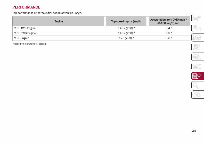
265
PERFORMANCETop performance after the initial period of vehicle usage.
* Based on manufacturer testing.
Engine Top speed mph / (km/h) Acceleration from 0-60 mph / (0-100 km/h) sec.
2.0L AWD Engine 143 / (230) * 5.4 *
2.0L RWD Engine 143 / (230) * 5.5 *
2.9L Engine 176 (283) * 3.6 *
21_GU_OM_EN_USC_t.book Page 265

266
CU
ST
OM
ER
AS
SIS
TA
NC
E SUGGESTIONS FOR OBTAINING SERVICE FOR YOUR VEHICLE
Prepare For The Appointment
All work to be performed may not be coveredby the warranty. Discuss additional chargeswith the service manager. Keep a mainte-nance log of your vehicle's service history, asthis can often provide a clue to the currentproblem.
Prepare A List
Make a written list of your vehicle's problemsor the specific work you want done. If you'vehad an accident or work done that is not onyour maintenance log, let the service advisorknow.
Be Reasonable With Requests
If you list a number of items and you musthave your vehicle by the end of the day,discuss the situation with the service advisorand list the items in order of priority. At manyauthorized dealers, you may obtain a rentalvehicle at a minimal daily charge. If you needa rental, it is advisable to make these arrange-ments when you call for an appointment.
IF YOU NEED ASSISTANCEFCA US LLC and its authorized dealers arevitally interested in your satisfaction. We wantyou to be happy with our products andservices.Warranty service must be done by an autho-rized dealer. We strongly recommend that youtake the vehicle to an authorized dealer. Theyknow your vehicle the best, and are mostconcerned that you get prompt and highquality service. FCA US LLC's authorizeddealers have the facilities, factory-trainedtechnicians, special tools, and the latest infor-mation to ensure the vehicle is fixed correctlyand in a timely manner.This is why you should always talk to an autho-rized dealer’s service manager first. If forsome reason you are still not satisfied, talk tothe general manager or owner of the autho-rized dealer. They want to know if you needassistance. If an authorized dealer is unable toresolve the concern, you may contact FCA USLLC's Customer Assistance center.Any communication to FCA US LLC's customercenter should include the following information: Owner's name and address
Owner's telephone number (mobile, homeand office)
Authorized dealer name
Vehicle Identification Number (VIN)
Vehicle delivery date and mileage
Alfa Romeo Customer Center
P.O. Box 21–8004Auburn Hills, MI 48321–8004Phone: 1-844-Alfa-USA (1-844-253-2872)
Alfa Romeo Customer Care (Canada)
P.O. Box 1621Windsor, Ontario N9A 4H6Phone: 1-877-230-0563 (English) Phone:1-877-515-9112 (French)
Customer Assistance For The Hearing Or Speech Impaired (TDD/TTY)
To assist customers who have hearing difficul-ties, the manufacturer has installed specialTelecommunication Devices for the Deaf(TDD) equipment at its customer center. Anyhearing or speech impaired customer, whohas access to a TDD or a conventional tele-typewriter (TTY) in the United States, cancommunicate with the manufacturer by dialing1-800-380-2479.Canadian residents with hearing difficultiesthat require assistance can use the specialneeds relay service offered by Bell Canada.For TTY teletypewriter users, dial 711 and forVoice callers, dial 1-800-855-0511 to connectwith a Bell Relay Service operator.
21_GU_OM_EN_USC_t.book Page 266

267
Service Contract
You may have purchased a service contract fora vehicle to help protect you from the high costof unexpected repairs after FCA US LLC's NewVehicle Limited Warranty expires. The MoparVehicle Protection plans are the ONLY vehicleextended protection plans authorized,endorsed and backed by FCA US LLC toprovide additional protection beyond yourvehicle’s warranty. If you purchased a MoparVehicle Protection Plan, you will receive PlanProvisions and an Owner Identification Card inthe mail within three weeks of the vehicledelivery date. If you have any questions aboutthe service contract, call FCA US LLC’s ServiceContract National Customer Hotline at1-800-521-9922 (Canadian residents, call(800) 465-2001 English / (800) 387-9983French).FCA US LLC is not responsible for any servicecontract you may have purchased fromanother manufacturer. If you require serviceafter the FCA US LLC New Vehicle LimitedWarranty expires, please refer to the contractdocuments, and contact the person listed inthose documents.We appreciate that you have made a majorinvestment when you purchased the vehicle.An authorized dealer has also made a majorinvestment in facilities, tools, and training toassure that you are absolutely delighted withthe ownership experience.
WARRANTY INFORMATIONSee the Warranty Information for the termsand provisions of FCA US LLC and FCA CanadaInc. warranties applicable to this vehicle andmarket.
REPORTING SAFETY DEFECTS
In The 50 United States And Washington, D.C.
If you believe that your vehicle has adefect that could cause a crash orcause injury or death, you should imme-diately inform the National HighwayTraffic Safety Administration (NHTSA) inaddition to notifying FCA US LLC.
If NHTSA receives similar complaints, itmay open an investigation, and if itfinds that a safety defect exists in agroup of vehicles, it may order a recalland remedy campaign. However,NHTSA cannot become involved in indi-vidual problems between you, yourauthorized dealer or FCA US LLC.To contact NHTSA, you may call theVehicle Safety Hotline toll free at1-888-327-4236 (TTY: 1-800-424-9153);or go to http://www.safercar.gov; or writeto: Administrator, NHTSA, 1200 NewJersey Avenue, SE., West Building, Wash-ington, D.C. 20590. You can also obtainother information about motor vehiclesafety from http://www.safercar.gov.
In Canada
If you believe that your vehicle has asafety defect, you should contact theCustomer Service Department immedi-ately. Canadian customers who wish toreport a safety defect to the Canadiangovernment should contact TransportCanada, Motor Vehicle Defect Investiga-tions and Recalls at 1-800-333-0510 orgo to wwwapps.tc.gc.ca/Saf-Sec-Sur/7/PCDB-BDPP.
WARNING!
Engine exhaust (internal combustionengines only), some of its constituents, andcertain vehicle components contain, oremit, chemicals known to the State ofCalifornia to cause cancer and birthdefects, or other reproductive harm. Inaddition, certain fluids contained invehicles and certain products ofcomponent wear contain, or emit,chemicals known to the State of Californiato cause cancer and birth defects, or otherreproductive harm.
21_GU_OM_EN_USC_t.book Page 267
CU
ST
OM
ER
AS
SIS
TA
NC
E
268
PUBLICATION ORDER FORMS To order the following manuals, you may useeither the website or the phone numbers listedbelow.Service ManualsThese comprehensive Service Manualsprovide a complete working knowledge of thevehicle, system, and/or components and iswritten in straightforward language with illus-trations, diagrams, and charts.Diagnostic Procedure ManualsDiagnostic Procedure Manuals are filled withdiagrams, charts and detailed illustrations.These manuals make it easy to find and fixproblems on computer-controlled vehiclesystems and features. They show exactly howto find and correct problems, usingstep-by-step troubleshooting and drivabilityprocedures, proven diagnostic tests and acomplete list of all tools and equipment.Owner's ManualsThese Owner's Manuals have been preparedwith the assistance of service and engineeringspecialists to acquaint you with specific FCAUS LLC vehicles.
To access your Owner's Information online,visit alfaromeousa.com/owners/
owners-service-manual(US)
alfaromeo.ca/fr/owners/owners-service-manual(Canada)
To order a hard copy of your Owner’s Informa-tion, visit: www.techauthority.com (US)OrCall Tech Authority toll free at: 1-800-890-4038 (US) 1-800-387-1143 (Canada)
General InformationThe following regulatory statement applies toall Radio Frequency (RF) devices equipped inthis vehicle:This device complies with Part 15 of the FCCRules and with Innovation, Science andEconomic Development Canada license-exempt RSS standard(s). Operation is subjectto the following two conditions:
1. This device may not cause harmful inter-ference, and
2. This device must accept any interferencereceived, including interference that maycause undesired operation.
Le présent appareil est conforme aux CNRd`Innovation, Science and Economic Develop-ment applicables aux appareils radio exemptsde licence. L'exploitation est autorisée auxdeux conditions suivantes:
1. l'appareil ne doit pas produire de brouil-lage, et
2. l'utilisateur de l'appareil doit accepter toutbrouillage radioélectrique subi, même si lebrouillage est susceptible d'en comprom-ettre le fonctionnement.
La operación de este equipo está sujeta a lassiguientes dos condiciones:
1. es posible que este equipo o dispositivo nocause interferencia perjudicial y
2. este equipo o dispositivo debe aceptarcualquier interferencia, incluyendo la quepueda causar su operación no deseada.
NOTE:Changes or modifications not expresslyapproved by the party responsible for compli-ance could void the user’s authority to operatethe equipment.
21_GU_OM_EN_USC_t.book Page 268

269
AAccessories Purchased By The Owner.......... 4Active Blind Spot Assist .............................152Active Safety Systems................................145Active Torque Vectoring (ATV) System ......145Adaptive Cruise Control (ACC)(Cruise Control) .................................104, 106
Off ...........................................................108On............................................................108
Additives, Fuel ............................................261Adjust
Forward.............................................. 31, 33Rearward ........................................... 31, 33
Air Bag.........................................................170Air Bag Operation...................................171Air Bag Warning Light ............................169Driver Knee Air Bag................................172Enhanced Accident Response .....175, 207Event Data Recorder (EDR)...................207Front Air Bag...........................................170If Deployment Occurs ............................175Knee Impact Bolsters ............................172Maintaining Your Air Bag System..........177Maintenance ..........................................177Redundant Air Bag Warning Light.........170Side Air Bags ..........................................172Transporting Pets...................................189
Air Bag Light ......................................169, 189Air Pressure
Tires ........................................................240Alfa Active Suspension (AAS).....................101Alfa DNA System ..........................................98Antifreeze (Engine Coolant) .......................262Anti-Lock Braking (ABS) System................145Anti-Lock Warning Light ...............................75
Automatic Climate Controls ........................ 49Automatic Dimming Mirror .......................... 37Automatic Door Locks ................................. 27Automatic Headlights .................................. 43Automatic Temperature Control (ATC)........ 49Automatic Transmission.............................. 92Auxiliary Driving Systems .......................... 149Auxiliary Power Outlet.................................. 56
BBattery ................................................. 78, 217
Charging System Light ............................ 78Keyless Key Fob Replacement ............... 18
Battery Recharging ....................................218Belts, Seat ..................................................189Blind Spot Monitoring................................ 150Bodywork (Cleaning And Maintenance) ...249B-Pillar Location ......................................... 237Brake System
Warning Light.....................................74, 75Brakes ........................................................ 255
Brake Fluid Level ................................... 217Brightness, Interior Lights ........................... 46Bulbs, Light ................................................ 190
CCamera, Rear ............................................. 132Capacities, Fluid ........................................ 262Carbon Monoxide Warning............... 190, 191Certification Label...................................... 135Chart, Tire Sizing........................................ 234Check Engine Light (MalfunctionIndicator Light) ............................................. 85Checking Levels ................................ 214, 215Checking Your Vehicle For Safety ............. 188
Checks, Safety ........................................... 188Child Restraint ........................................... 178Child Restraints
Booster Seats ........................................ 180Child Seat Installation........................... 187How To Stow An unused ALR Seat
Belt..................................................... 185Infant And Child Restraints................... 179LATCH Positions .................................... 182Lower Anchors And Tethers For
Children ............................................. 181Older Children And Child Restraints .... 179Seating Positions................................... 181
Clean Air Gasoline ..................................... 260Cleaning
Wheels ................................................... 245Climate Control ......................................48, 54
Automatic..................................................49Compact Spare Tire................................... 245Contract, Service ....................................... 267Cooling System
Cooling Capacity.................................... 262Selection Of Coolant (Antifreeze) ......... 262
Cruise Control (Speed Control) ........ 104, 106Customer Assistance ................................ 266
DDaytime Running Lights ...............................42Defroster, Windshield ............................... 189Dimensions ................................................ 257Disabled Vehicle Towing ........................... 205Door Ajar ................................................79, 80Door Ajar Light .......................................79, 80Door Locks ....................................................27
Automatic..................................................27
21_GU_OM_EN_USC_t.book Page 269

270
IND
EX Door Opener, Garage ................................... 39
Doors............................................................. 24Drive Train Control (DTC) System..............146Driving Modes .............................................. 98Dynamic Steering Torque (DST) System...146
EElectric Park Brake....................................... 90Electric Remote Mirrors ...............................38Electronic Speed Control (Cruise Control) .......................................................104Electronic Stability Control (ESC) System ........................................................146Electronic Throttle Control Warning Light...79Emergency
In Case Of ......................................192, 198SOS Emergency Call ..............................192
Emergency, In Case OfJump Starting .........................................201Overheating ............................................204Towing.....................................................206
Emission Control System Maintenance...... 85Engine .........................................................254
Block Heater.............................................89Engine Coolant Level .............................216Exhaust Gas Caution ....................190, 191Fuel Requirements ................................260Oil ............................................................262Oil Selection ...........................................262Overheating ............................................204Starting ...................................................204
Engine Compartment.................................214Engine Compartment (Washing) ...............250Engine Oil
Level Check ............................................215
Enhanced Accident Response Feature .............................................. 175, 207Ethanol ....................................................... 260Exhaust Gas Cautions ...................... 190, 191Exhaust System ......................................... 190Exterior Lighting .....................................42, 43Exterior Lights ..................................... 42, 190
FFlashers
Hazard Warning .....................................192Turn Signals ..............................44, 78, 190
Fluid Capacities ......................................... 262Fluid Leaks ................................................. 190Fluids And Lubricants ................................ 263Fog Lights, Rear ........................................... 44Forward Collision Warning ........................ 156Fuel
Additives................................................. 261Clean Air ................................................. 260Ethanol ...................................................260Light.......................................................... 80Materials Added ....................................261Methanol ................................................ 260Tank Capacity ........................................ 262
GGarage Door Opener (HomeLink) ............... 39Gasoline, Clean Air ....................................260Gasoline, Reformulated ............................ 260Gross Axle Weight Rating .......................... 137Gross Vehicle Weight Rating..................... 137GVWR.......................................................... 136
HHazard Warning Flashers.......................... 192Head Restraints............................................35Head Rests ...................................................35Headlights
Switch ................................................42, 43Headlights (Cleaning)................................ 250Heated Mirrors..............................................39Heated Seats ................................................34Heated Steering Wheel ................................29Heater, Engine Block....................................89Hill Decent Control (HDC) System ............ 147Hill Start Assist (HSA) System................... 148Hitches
Trailer Towing ........................................ 137HomeLink (Garage Door Opener) ................39Hood
Closing ......................................................61Opening.....................................................61
IIdentification Data..................................... 253Ignition ..........................................................20
Switch .......................................................20Immobilizer (Sentry Key) ..............................20In Case Of Emergency ............................... 192Installing Electrical/Electronic Devices......... 4Instrument Cluster .......................................67
Descriptions..............................................78Display ......................................................69
Instrument PanelFeatures....................................................67
Interior Lights................................................44Interiors (Cleaning).................................... 251
21_GU_OM_EN_USC_t.book Page 270
271
JJump Starting .............................................201
KKeyless Enter-N-Go ......................................25
Passive Entry............................................25Keys .............................................................. 18
LLane Change And Turn Signals ................... 44LaneSense..................................................126Lap/Shoulder Belts....................................164Latches .......................................................190Leaks, Fluid ................................................190Life Of Tires.................................................243Liftgate..........................................................62Light Bulbs..................................................190
Types Of Bulbs .......................................230Lights ..........................................................190
Air Bag ...........................................169, 189Automatic Headlights ..............................43Brake Warning .................................. 74, 75Courtesy/Reading............................. 45, 46Daytime Running .....................................42Electronic Stability Program(ESP)
Indicator ............................................... 79Exterior ...................................................190Fog ............................................................ 44Headlight Switch ............................... 42, 43Headlights ......................................... 42, 43High Beam................................................ 43Instrument Cluster ............................ 42, 43Intensity Control ....................................... 46Interior ............................................... 45, 46Low Fuel ...................................................80
Malfunction Indicator (Check Engine).... 77Map .......................................................... 45Park ....................................................44, 78Reading .................................................... 45Seat Belt Reminder ................................. 75Turn Signals ..............................44, 78, 190Warning Instrument Cluster
Descriptions...................................78, 79Loading Vehicle.......................................... 135
Tires........................................................ 237Locks
Automatic Door ........................................ 27Child Protection ....................................... 27
MMaintenance ................................................ 61Malfunction Indicator Light (Check Engine) .......................................77, 85Manual
Service.................................................... 268Memory Feature (Memory Seats) ............... 30Memory Seat................................................ 30Methanol .................................................... 260Mirrors .......................................................... 37
Automatic Dimming................................. 37Electric Powered...................................... 38Electric Remote ....................................... 38Heated...................................................... 39
OOccupant Restraints .................................. 163Oil Pressure Light......................................... 79Oil, Engine
Capacity..................................................262Pressure Warning Light ........................... 79
Recommendation.................................. 262Viscosity ................................................. 262
Opener, Garage Door (Homelink) ................39Operator Manual
Owner's Manual..................................... 268Outlet
Power ........................................................56Overheating, Engine .................................. 204
PPaintwork (Cleaning And Maintenance) .. 250Panic Brake Assist (PBA) System ............. 149Park Assist ................................................. 123ParkSense System .................................... 123Passive Entry ................................................25Pets ............................................................ 189Placard, Tire And Loading Information .... 237Power
Mirrors.......................................................38Outlet (Auxiliary Electrical Outlet)............56Seats .........................................................33Sunroof .....................................................59
Power SeatsForward..............................................31, 33Rearward ........................................... 31, 33Recline ...............................................31, 33
Power Supply ............................................. 255Pregnant Women And Seat Belts ............. 167Pretensioners
Seat Belts .............................................. 167Prolonged Vehicle Inactivity...................... 249
RRadial Ply Tires .......................................... 242Radio Transmitters And Mobile Phones ....... 5
21_GU_OM_EN_USC_t.book Page 271

272
IND
EX Rear Camera ..............................................132
Rear Cross Path .........................................150Reformulated Gasoline..............................260Refueling Procedure ..................................133Refueling The Vehicle ................................133Reminder, Seat Belt...................................164Remote Control
Starting System........................................ 22Remote Keyless Entry.................................. 18Remote Starting
Exit Remote Start Mode .......................... 22Remote Starting System....................... 22, 86Replacement Tires .....................................244Reporting Safety Defects...........................267Restraints, Child.........................................178Restraints, Head ..........................................35Rims And Tires ...........................................233Roll Over Warning........................................... 3
SSafety Checks Inside Vehicle ....................189Safety Checks Outside Vehicle..................190Safety Defects, Reporting..........................267Safety Information, Tire .............................233Safety Tips ..................................................188Safety, Exhaust Gas ...................................190Saving Fuel .................................................142Scheduled Servicing ..................................208Scheduled Servicing Program(2.0L T4 MAir Engine Versions).................209Scheduled Servicing Program(2.9L V6 Gasoline Engine Versions) .........212Seat Belt Reminder......................................75Seat Belts ..........................................164, 189
Adjustable Shoulder Belt.......................166
Adjustable Upper ShoulderAnchorage.......................................... 166
Adjustable Upper Shoulder Belt Anchorage.......................................... 166
Child Restraints .....................................178Energy Management Feature ............... 168Front Seat .............................................. 164Inspection .............................................. 189Lap/Shoulder Belt Untwisting............... 166Lap/Shoulder Belts ............................... 164Pregnant Women................................... 167Pretensioners......................................... 167Rear Seat ............................................... 164Reminder................................................ 164Seat Belt Pretensioner .......................... 167Untwisting Procedure ............................ 166
Seats.......................................................30, 33Adjustment..................................30, 31, 33Head Restraints....................................... 35Heated...................................................... 34Height Adjustment................................... 33Power........................................................ 33Tilting........................................................ 33
Security Alarm.............................................. 23Service Assistance.....................................266Service Contract......................................... 267Service Manuals ........................................ 268Servicing Procedures................................. 219Shoulder Belts............................................164Signals, Turn .................................44, 78, 190Snow Chains .............................................. 247Snow Tires ..................................................246Spare Tires ........................................ 244, 245
Speed ControlAccel/Decel .................................. 105, 106Accel/Decel (ACC Only) ......................... 109Cancel .................................................... 106Distance Setting (ACC Only).................. 110Resume.................................................. 106Set .......................................................... 105
Speed Control (Cruise Control) ................. 104Starting....................................................... 204
Button .......................................................20Cold Weather............................................87Remote .....................................................22
Starting And Operating.............................. 204Starting Procedures .................................. 204Starting The Engine......................................86Steering...................................................... 256
Wheel, Heated..........................................29Wheel, Tilt .................................................28
Stop/Start System..................................... 101Storage
Console .....................................................56Suggestions For Driving ............................ 142Sun Roof ................................................59, 61Supplemental Restraint System – Air Bag........................................................ 170Suspension ................................................ 256System, Remote Starting .............................22
TTelescoping Steering Column......................28Tilt Steering Column.....................................28Tire And Loading Information Placard ..... 237Tire Markings ............................................. 234Tire Safety Information ............................. 233Tire Service Kit........................................... 198
21_GU_OM_EN_USC_t.book Page 272

273
Tires .................................190, 239, 244, 248Aging (Life Of Tires)................................243Air Pressure ............................................239Changing.................................................198Compact Spare ......................................245General Information......................239, 244High Speed .............................................240Inflation Pressure...................................240Life Of Tires ............................................243Load Capacity.........................................237Pressure Monitoring System (TPMS)...... 76Quality Grading.......................................248Radial......................................................242Replacement..........................................244Safety.............................................233, 239Sizes .......................................................234Snow Tires ..............................................246Spare Tires ....................................244, 245Spinning..................................................243Trailer Towing.........................................139Tread Wear Indicators ...........................243
Tongue Weight/Trailer Weight ..................138Towing................................................136, 138
Disabled Vehicle ....................................205Towing Eyes ................................................206TPMS (Tire Pressure Monitoring System) .......................................................161
Traction Control System (TCS) .................. 149Trailer Towing............................................. 136
Hitches ...................................................137Minimum Requirements .......................139Tips .........................................................141Trailer And Tongue Weight.................... 138Wiring ..................................................... 140
Trailer Towing Guide.................................. 138Trailer Weight ............................................. 138Transmission.............................................. 255Transporting Pets....................................... 189Tread Wear Indicators ............................... 243Turn Signals ...........................................44, 78
UUconnect Settings
Customer Programmable Features........ 25Passive Entry Programming.................... 25
Uniform Tire Quality Grades ...................... 248Universal Transmitter .................................. 39Untwisting Procedure, Seat Belt ............... 166
VVehicle Changes/Alterations .........................4Vehicle Identification Number .................. 253Vehicle Loading................................. 135, 237
WWarning Lights (Instrument Cluster Descriptions).................................................76Warnings, Roll Over ........................................ 3Warranty Information ................................ 267Washer Fluid For Windshield/Headlights.................................................. 217Washers, Windshield....................................46Weights ...................................................... 259Wheel And Wheel Tire Care ...................... 245Wheel And Wheel Tire Trim....................... 245Wheels And Tires....................................... 233Wind Buffeting ..............................................59Windows (Cleaning)................................... 250Windshield Defroster ................................ 189Windshield Washers.....................................46Windshield Wiper
Replacing Blades .................................. 222Windshield Wipers........................................46Wipers, Rain Sensitive .................................46
21_GU_OM_EN_USC_t.book Page 273


This Owner’s Manual illustrates and describes the operation of features and equipment that are either standard or optional on this vehicle. This manual may also include a description of features and equipment that are no longer available or were not ordered on this vehicle. Please disregard any features and equipment described in this manual that are not on this vehicle. FCA US LLC reserves the right to make changes in design and specifications, and/or make additions to or improvements to its products without imposing any obligation upon itself to install them on products previously manufactured.
With respect to any vehicles sold in Canada, the name FCA US LLC shall be deemed to be deleted and the name FCA Canada Inc. used in substitution therefore.
If you are the first registered retail owner of your vehicle, you may obtain a complimentary printed copy of the Warranty Booklet by calling 1-844-253-2872 (U.S.) or 1-800-387-1143 (Canada) or by contacting your dealer.
This Owner’s Manual is intended to familiarize you with the important features of your vehicle. Your most up-to-date Owner’s Manual, Navigation /Uconnect manuals and Warranty Booklet can be found by visiting the website on the back cover. U.S. residents can purchase replacement kits by visiting www.techauthority.com and Canadian residents can purchase replacement kits by calling 1-800-387-1143.
The driver’s primary responsibility is the safe operation of the vehicle. Driving while distracted can result in loss of vehicle control, resulting in an accident and personal injury. FCA US LLC strongly recommends that the driver use extreme caution when using any device or feature that may take their attention off the road. Use of any electrical devices, such as cellular telephones, computers, portable radios, vehicle navigation or other devices, by the driver while the vehicle is moving is dangerous and could lead to a serious accident. Texting while driving is also dangerous and should never be done while the vehicle is moving. If you find yourself unable to devote your full attention to vehicle operation, pull off the road to a safe location and stop your vehicle. Some states or provinces prohibit the use of cellular telephones or texting while driving. It is always the driver’s responsibility to comply with all local laws.
This Owner’s Manual has been prepared to help you get acquainted with your new Alfa Romeo brand vehicle and to provide a convenient reference source for common questions.
Not all features shown in this manual may apply to your vehicle. For additional information, visit www.alfaromeousa.com (U.S.), www.alfaromeo.ca (Canada) or your local Alfa Romeo dealer.
Driving after drinking can lead to an accident. Your perceptions are less sharp, your reflexes are slower and your judgment is impaired when you have been drinking. Never drink and then drive.
WARNING!
Drunk driving is one of the most frequent causes of accidents. Your driving ability can be seriously impaired with blood alcohol levels far below the legal minimum. If you are drinking, don’t drive. Ride with a designated non-drinking driver, call a cab, a friend or use public transportation.
DRIVING AND ALCOHOL
WARNING: Operating, servicing and maintaining a passenger vehicle or off-highway motor vehicle can expose you to chemicals including engine exhaust, carbon monoxide, phthalates, and lead, which are known to the State of California to cause cancer and birth defects or other reproductive harm. To minimize exposure, avoid breathing exhaust, do not idle the engine except as necessary, service your vehicle in a well-ventilated area and wear gloves or wash your hands frequently when servicing your vehicle. For more information go to www.P65Warnings.ca.gov/passenger-vehicle.

2 0 2 1 O W N E R ’ S M A N U A L
2021
ST
EL
VIO
21_GU
_OM
_EN
_US
C
First Edition
©2020 FCA US LLC. All Rights Reserved. ALFA ROMEO is a registered trademark of FCA Group Marketing S.p.A., used with permission. App Store is a registered trademark of Apple Inc. Google Play Store is a registered trademark of Google.
Whether it’s providing information about specific product features, taking a tour through your vehicle’s heritage, knowing what steps to take following an accident or scheduling your next appointment, we know you’ll find the app an important extension of your Alfa Romeo brand vehicle.
Simply download the app, select your make and model and enjoy the ride. To get this app, go directly to the App Store® or Google Play® Store and enter the search keyword “Alfa Romeo” (U.S. residents only).
U. S.
alfaromeousa.com/ owners/owners-service-manual
Canada
alfaromeo.ca/en/ owners/owners-service-manual