2010 SCL Material Standards volume II revised 29/06/2012
580
material standards volume 2 seattle city light june 2012 arresters, IWCBs, limiters,and fuses 6800 separable connectors and misc 6860 insualtors 6900 underground including conduit 7000 underground including vaults 7200 tape, splice covers, and pumps 7350 tools and signs 7400 fasteners and fiber optics 7800 www.seattle.gov/light/engstd
-
Upload
khangminh22 -
Category
Documents
-
view
0 -
download
0
Transcript of 2010 SCL Material Standards volume II revised 29/06/2012

material standards volume 2 seatt le c i ty l ight
june 2012
a r r e s t e r s , I W C B s , l i m i t e r s , a n d f u s e s 6 8 0 0
s e p a r a b l e c o n n e c t o r s a n d m i s c 6 8 6 0
i n s u a l t o r s 6 9 0 0
u n d e r g r o u n d i n c l u d i n g c o n d u i t 7 0 0 0
u n d e r g r o u n d i n c l u d i n g v a u l t s 7 2 0 0
t a p e , s p l i c e c o v e r s , a n d p u m p s 7 3 5 0
t o o l s a n d s i g n s 7 4 0 0
f a s t e n e r s a n d f i b e r o p t i c s 7 8 0 0
w w w . s e a t t l e . g o v / l i g h t / e n g s t d


seattle city light_
2 0 1 2 mater ia l s tandards
v o l u m e 2
Welcome to your 2012 edition of the Material Standards. Seattle City Light’s standards, consisting of Construction Standards, Design Standards, Material Standards, and the Stock Catalog, define the utility’s best practices. Compliance with these standards is mandatory for City Light employees and contractors. Your cooperation is critical and essential to our success. Phil West, Customer Services-Energy Delivery Officer
1

Seattle City Light Material Standards
Published by the Seattle City Light Standards Group
Material Standards Version 2012
volume 2
Prepared by Rick Rice and Patti Berg
Seattle City Light Standards Group Seattle, Washington
June 2012
This year marks the 50th Anniversary of the Seattle World’s Fair, held from April 21st through October 21st of 1962. That occasion brought us many, many images that continue to have a hold on our imaginations, images that evoke
space, modernity and progress. The most well-known icon from that time is the Space Needle, now a major landmark of the Pacific Northwest region of the United States and an identifyer for Seattle itself.
2

S e a t t l e C i t y L i g h t mater ia l standards volume 2
table of contents
page
table of contents 3 standards group 5 warehouse contacts 6 grounding committee 7 looped radial standards committee 8 network standards committee 9 on-line access 10 printed standards publications 11 material evaluation guide 12 bad order equipment 13
vol 2tab vol 2
page directory directory 15 stock number index cross ref 23
Material Standards volume 1 (0026 to 6799) vol 1tab vol 1
page transformers section 1 0026 129 switches section 1 2500 183 safety 4000 247 transformers section 2 4100 275 switches section 2 4500 329 poles 5000 379 streetlight 5680 441 cable 6000 517 connectors 6500 647
Material Standards volume 2 (6800 to 8029) vol 2tab vol 2
page arresters, IWCBs, limiters, and fuses (6800-6859) 6800 63 separable connectors and miscellaneous (6860-6899)
6860 141
insulators (6900-6999) 6900 231 underground including conduit (7000-7199) 7000 305 underground including vaults (7200-7349) 7200 341 tape, splice covers, and pumps (7350-7399) 7350 435 tools and signs (7400-7699) 7400 467 fasteners and fiber optics (7800-8029) 7800 531

4

sea t t l e c i t y l i gh t_ mater ia l standards volume 2
standards group
Asset Management and Large Projects Division Standards Org 321
Standards staff: Supervisor: John Shipek 206-684-3950 Engineers: Aida Diop 206-684-3726 Brett Hanson 206-684-3048 Curtis Lu 206-684-3048 Quan Wang 206-386-1785 Publication Services and Archive: Patti Berg 206-233-2184 Quality Assurance: Todd Oki 206-386-1896 other contact information: URL: http://www.seattle.gov/light/engstd/ mailstop: SMT-28-22 Fax: 206-684-3945 email: [email protected] org unit: 321 Office Location: 700 Fifth Avenue (at Columbia Street) Seattle Municipal Tower 36th floor, room 3625, cubicle row “Q” Seattle Washington 98104-5031
Address for U.S. Postal Service: Attention: Standards Group or contact name Seattle City Light PO Box 34023 Seattle Washington 98124-4023
Address for Parcel Service: Attention: Standards Group or contact name (FedEx) Seattle City Light 700 5th Avenue, Suite 3200 Seattle Washington 98104 contact phone
Address for Parcel Service: Attention: Standards Group or contact name (UPS) Seattle City Light 700 5th Avenue, Suite 3200 Seattle Washington 98104 Rick Rice began with Seattle City Light in 1998 as a TES supporting Network Engineering. In 1999 he was offered a permanent position and joined Standards. Rick’s dedication, hard work, attention to detail, and artistry can be seen in virtually every product Standards has produced over the last thirteen years. Rick has been as proud of the accuracy and completeness of our subject indexes as he was of the standards manual covers he designed. Our standards look great largely because Rick created a style (moving target though it was) and encouraged us to follow it. Rick contributed to Standards by filling in for the incoming material inspector and acting as the Network Standards Committee meeting secretary for ten years. Rick also brought us into the 21st century by arranging for our standards to be available on the Internet. Rick will retire in July 2012 and will be sorely missed.
5

warehouse and tool room contacts
sea t t l e c i t y l i gh t_ mater ia l standards volume 2
City Light Warehouse contact information:
Boundary Warehouse Brad Larson, Senior Warehouser Pax 28-3326 509-446-3438 [email protected] Seattle City Light / Boundary Dam P.O. Box 219, Metaline Falls, WA 99153 or 10382 Boundary Road Metaline Falls, WA 99153
North Service Center (NSC) Warehouse
Irene Weiland, Manager 206-684-4202 [email protected] North Service Center, N-6, 205 Seattle City Light, 1300 N. 97th St, warehouse Seattle, WA 98103-3320 Suzi Miller, Warehouse Crew Chief 206-615-1137 [email protected]
Skagit Warehouse Marrilee Komboukos, Senior Warehouser 206-386-4490 [email protected] Seattle City Light, 500 Newhalem St, Rockport, WA 98283
South Service Center (SSC) Warehouse
Nancy Dailey, General Supervisor 3613 4th Avenue South Seattle, WA 98134-2207 general section Gary Boyd 206-386-1762 cell 206-730-1180 Rich Nobuyama 206-386-1626 cell 206-730-6977 shipping and receiving Steve McClintock 206-386-1736 cell 206-730-6973 toxic / salvage Rosauro Cayetano 206-386-1707 cell 206-730-6974
Tool Rooms, NSC and SSC Irene Weiland, Manager 206-684-4202 [email protected] NSC tool room Brian Russell, Custodian 206-684-4262 SSC tool room Beverly Lewis, Custodian 206-386-1927
6

sea t t l e c i t y l i gh t_ mater ia l standards volume 2
grounding standards committee
The Grounding Standards Committee serves to share information and solve problems related to grounding standards and practices.
If you have a grounding standards-related question or problem, please bring it to the attention of a member of the Grounding Standards Committee.
The Grounding Standards Committee meeting is held the third Tuesday of each month, from 10:00 a.m. until 12:00 p.m. Check with Standards to confirm time and place. Note, security requires that those without keycard rights obtain a pass on the 32nd floor to reach City Light offices and meeting rooms.
At the present time, the following employees are serving on the committee by generously lending their time, knowledge, and experience:
Asset Management Dave Albergine
Electrical Reviewers Tommy Edwards Rob Youngs
Energy Delivery Jeff Joy
Network Construction Lester Eastlick John Hansen
Network Engineering John Barnett Hamed Zadehgol
North Distr ibution Design Dave Russo
North Electrical Services and Construction
Skip Allen
South Distr ibution Design Tom Caddy Kevin McClaskey
Streetl ight Engineering Steve Crume
Substations Portia Romero
Transmission Bob Risch
Standards Group Aida Diop Brett Hanson, chair and clerk Curtis Lu Todd Oki John Shipek Quan Wang
7

looped radial standards committee
sea t t l e c i t y l i gh t_ mater ia l standards volume 2
The Looped Radial Standards Committee serves to share information and solve problems related to all facets of the overhead and underground distribution systems.
If you have a standards-related question or problem, please bring it to the attention of a member of the Standards Committee.
The Looped Radial Standards Committee meeting is held the second Tuesday of each month, from 9:00 a.m. until 11:30 a.m. Check with Standards to confirm time and place. Note, security requires that those without keycard rights obtain a pass on the 32nd floor to reach City Light offices and meeting rooms.
At the present time, the following employees are serving on the committee (in addition to regular Standards staff) by generously lending their time, knowledge, and experience:
Capital Projects Dave Albergine
Customer Care Nancy Robb
Compatible Units Jim Maloney
Electrical Reviewers Tommy Edwards Rob Youngs
Electric Service Engineering Ken Holder Abdi Yussuf
Energy Delivery Jeff Joy
Engineering John Barnett
Environmental Larry Garcia
Material Control Jenee Halse
North Distr ibution Design Eivind Perander Dave Russo
North Electrical Services and Construction
Michael Brooks
South Distr ibution Design Chris Detter Christine Knowlton Francis Sammy
South Electrical Services and Construction
Walt Aho Tom Caddy Bob Stewart Jason Trotter
Standards Group Aida Diop Brett Hanson Curtis Lu Todd Oki John Shipek, chair Quan Wang, clerk
Streetl ight Engineering Steve Crume
8

sea t t l e c i t y l i gh t_ mater ia l standards volume 2
network standards committee
The Network Standards Committee serves to share information and solve problems related to all facets of the Network system.
If you have a Network standards-related question or problem, please bring it to the attention of a member of the Network Standards Committee.
The Network Standards Committee meeting is held the third Thursday of each month, from 9:00 a.m. until 11:30 a.m., in the Seattle Municipal Tower Conference Room 3613. Check with Standards to confirm time and place. Note, security requires that those without keycard rights obtain a pass on the 32nd floor to reach City Light offices and meeting rooms.
At the present time, the following employees are serving on the committee by generously lending their time, knowledge, and experience:
Electrical Reviewers Tommy Edwards Rob Youngs
Environmental Larry Garcia
Energy Delivery Jeff Joy
Material Control Marsha Greenfield
Network Construction Arne Armfield Lester Eastlick Cris Francisco John Hansen
Network Engineering Shayan Arya John Barnett Mehari Gebrewold Kosea Kalebu Hamed Zadehgol
Standards Group Aida Diop Brett Hanson, clerk Curtis Lu, chair Todd Oki John Shipek Quan Wang
9

on-line access
sea t t l e c i t y l i gh t_ mater ia l standards volume 2
The City Light Material Standards as well as other Standards documents are available, on-line, through your computer system. The on-line versions of the Construction Standards, Design Standards, Material Standards, and Stock Catalog include the most recent updates and revisions.
Revisions Updates and revisions are made about twice a month. To make sure you have the latest copies of the Standards documents, please refer to the on-line versions. To obtain an email announcement on the release of revisions of Standards documents, please send a request to [email protected]. Write "revision announcement" in the subject line.
The Red Page on the City Light Computer Network An electronic copy of the City Light Standards can be viewed on your City Light computer by opening the City Light Standards Publications intranet files from the Red Page on City Light's computer network. The Red Page is an Adobe Acrobat PDF file from which you can search and access all of the published Standards documents. Obtain access to the Red Page by asking the Help Desk (684-3766) to add the Standards Publications NAL icon (“home101”) to your Start Menu. You will need Adobe Acrobat Reader to display the Red Page documents.
The Red Page NAL icon contains programming that helps you set up searches, but in doing a search from the Red Page, please remember to select “Currently Selected Indexes” on the “Advanced Search Option” menu.
Contact Patti Berg at City Light Standards Publications with questions about getting the Red Page.
Electronic Whole Volumes For internal City Light users, the Adobe Acrobat files of the Standards books are avaliable from the Red Page under “View Standards Volumes” and may be printed (also from the “J” drive.). Volumes are revised as documents are updated (the front cover has the date of the most recent update). As of May 2012 the most recent whole volumes, including revisions, are available from the Red Page:
Civil Crew Handbook of Selected Standards (May 2009)
Field Standards -- Construction Standards, Work Practices, and Operations Standards volume one (0000-1799, D1-D16, U1-U5)*
Field Standards -- Construction Standards, Work Practices, and Operations Standards volume two (U7-U13, DU, E, S, SL, Network)*
Design Standards (August 2010) Looped Radial Crew Handbook of Selected
Standards (September 2011) Material Standards volume 1 (June 2012) Material Standards volume 2 (June 2012) Network Crew Handbook of Selected Standards
(June 2011) Stock Catalog (June 2012)
* The two on-line Field Standards volumes contain all active Construction Standards, Network Construction Standards, Work Practices, and Operations Standards, even those not included in the “Handbook” series (above). The Construction Standards (Guidelines) and Network Construction Standards (Guidelines) are no longer printed as volumes in hard copy form -- see the “Handbook” series.
City Light Standards on the World Wide Web The Seattle City Light Standards Publications web site on the World Wide Web is available through your web browser. Type the following into the address field of your web browser: http://www.seattle.gov /light/engstd/. For all on-line Standards documents, the www web site offers electronic copies of the pages found in your printed version and they may be more up-to-date. The on-line documents are updated for revisions and additions (about twice a month) on the same schedule as City Light's intranet site plus one day. Not all Design Standards are made available on the SCL Standards web site. .
10

sea t t l e c i t y l i gh t_ mater ia l standards volume 2
printed standards publications
City Light Standards Book Distr ibution City Light Standards Group provides printed books for internal City Light users if you are on the distribution list (see column to the right). Digital files are available for printing all the Standards books. For internal City Light users, the Adobe Acrobat files of the Standards books are also avaliable from the Red Page (see previous page) under “View Standards Volumes” and may be printed.
Purchase City Light Standards Books Anyone can order the Standards books from Zebra Print and Copy, 206-223-1955, Columbia Center, Suite 307, 701 Fifth Avenue, Seattle, Washington 98104.
Ask Standards or Zebra Print and Copy which volumes are available. Check with the printing service for the current prices. Current editions:
Civil Crew Handbook of Selected Standards (May 2009)
Design Standards (August 2010) Looped Radial Crew Handbook of
Selected Standards (September 2011) Material Standards volume 1 (June 2012) Material Standards volume 2 (June 2012) Network Crew Handbook of Selected
Standards (June 2011) Stock Catalog (June 2012)
The Construction Standards and Guidelines were last published in hard copy form in 2008, titled Construction Guidelines and Network Construction Guidelines. Now Construction Standards and Guidelines in the hard copy form are found in the Handbook series – see above (for example the Network Crew Handbook of Selected Standards). For a complete source of all active Construction Standards, Network Construction Standards, Work Practices, and Operations Standards, see the previous page.
Book Request for City Light Employees For future publication cycles, City Light employees may request to be added to the distribution list for Standards books. Employees who are on the list receive email invitations to order and receive books. Send a request (for example, send an email to [email protected] and write "printed books" in the subject line).
If you are ordering books for a group, identify yourself as the order lead and coordinate with the group to make sure duplicate orders are not submitted. Copy this page, fill out the information and send it in or just email us ([email protected]).
City Light employee name
email address
org unit number
complete mail delivery address
internal mail delivery stop
phone number
number of books (quantity) of each
type of binding for each volume (coil, three ring binder, or three hole punched pages without a binder)
Updates For the latest revisions of the Standards publications, we continue to encourage users to rely on one of the on-line access sites, either the www.seattle.gov/light /engstd/ site or the Standards Red Page. The revision date (effective date) is listed on each document. Standards documents are revised throughout the year and the on-line versions will reliably keep you up-to-date.
To obtain an email announcement on the release of revisions to the Standards documents, please send a request to [email protected]. Write "revision announcement" in the subject line.
11

material evaluation guide
sea t t l e c i t y l i gh t_ mater ia l standards volume 2
an informal primer for prospective distributors, manufacturers, and their representatives Figure out what kinds of things we buy. We generally cannot spend time browsing through manufacturers' catalogs looking for things that they might wish to sell us; that is the job of the manufacturers and their sales forces.
If a certain type of part is not in our Stock Catalog, which lists about 5,000 stock items, we do not regularly stock it. Our tool rooms and substation people do buy some non-stock material, but the Standards Group is not involved in those purchases.
You may view and print pages from our Stock Catalog and Material Standards online at our Web site: www.seattle.gov/light/engstd. Look in the previous section (Printed Standards Publications) to find out how to obtain copies of the City Light Stock Catalog and Material Standards.
Our distribution system has higher voltages and higher fault currents than that of many other utilities. We do not buy or use any regulators, reclosers, or in-line disconnects. Our underground distribution system is truly underground for the most part, and submerged in water. We do not buy very many pedestal or padmounted components.
Figure out whether or not your product meets our specifications. If you see in the Stock Catalog listing a reference to an "SCL Matl. Std." followed by a number with 4 digits before a decimal point and one or more following numerals, then read that Material Standard, also available online. Please make sure that your product meets all City Light Material Standard specifications.
If you think you have something that meets our existing requirements, or if you believe that you have a novel item that will save us time or money but which does not match up to any of our existing items, we will consider it. Fill out a Material Evaluation form
(available from the Red Page) for each City Light Stock Number for which you wish approval. Please also supply us with a list of other electric utility users, with the contact names and telephone numbers of individuals there. We may request that you submit a sample to Standards along with a Material Evaluation form.
Before coming in to the Standards office to discuss a product, it is requested that you contact someone in the Standards Group and set up an appointment. Please do not contact our field personnel or other City Light employees unless it is at our request.
All chemical products must be accompanied by an MSDS.
Our evaluation may include a review of technical and test data, visual inspection of the item, discussion in Standards Committee(s), field evaluation by electrical workers, inquiries to other utilities, and laboratory testing. Some items require approval by our Environmental or Safety Units. The process may take several months. You will be informed of our decision at the end of the process.
The above is an informal summary. Procedures may vary depending upon the item, e.g., we don't want you to bring a sample of a padmount switch or a utility pole into our office. Sometimes we list items in our Stock Catalog and/or Material Standards that have almost no usage, and it may be determined that is neither worth your time nor ours to go through the evaluation process. You are welcome to contact Standards or Material Control to inquire about our annual usage for particular Stock Numbers.
You may always phone or e-mail to ask questions. The Standards Group tries to be helpful and fair.
12

sea t t l e c i t y l i gh t_ mater ia l standards volume 2
bad order equipment
It is important that all B.O. (bad order) parts, apparatus, equipment, or devices be properly tagged and promptly sent to Quality Assurance.
The tag (copies in the Stock Catalog) should include the following information:
Date of failure Name of Crew Chief or electrical worker
and their telephone number Location of failure Stock Number of the part Nature of problem or description of failure
Please send B.O. equipment to:
Q/A (Quality Assurance) SSC130 Todd Oki or Quan Wang (206) 386-1896 or (206) 386-1785
Front of Bad Order Equipment/Material Tag:
Back of Bad Order Equipment/Material Tag:
See your Stock Catalog for Bad Order Equipment/Material Tags
13

14

seat t le c i ty l ight_
mater ia l s tandards volume 2
directory
15

16

seat t le c i ty l ight_
mater ia l s tandards volume 2 directory
The Materials Standards are split into two volumes for this edition. The second volume starts at the 6800s. The Material Standards id numbers (5632.90, etc.) are changing to two digits to the right of the decimal point (renumbering). In most cases we will be adding a zero in the hundreds place, as where Standard number 5632.9 becomes 5632.90. There are cases where, in order to preserve the intended sequence of documents, we need to make 5632.6 become 5632.06. In a small number of cases we need to make other changes, as where we now have multiple decimal points, 7264.0.1 should become 7264.01. The document id numbers in this listing as well as in the book itself, are in numerical order, thus, 6969.02 and 6969.15 come before 6969.2.
volume 2 (6800-8029)
arresters, IWCBs, limiters, and fuses (6800-6859) 6800.1 3 kV Heavy Duty Distribution Class
Metal Oxide Surge Arrester 656801.3 21 kV Intermediate Class, Porcelain,
Metal-Oxide Surge Arrester 67
6801.40 21 kV Heavy Duty Distribution Class, Polymer, Metal-Oxide Surge Arrester 69
6801.60 21 kV Intermediate Class, Polymer, Metal-Oxide Surge Arrester 71
6808.11 Insulator Brackets for IWCB 73
6808.12 Bus Tie Switch Connector Plate 74
6808.6 Connector Plate for 8˝ and 6˝ IWCB 75
6808.7 Insulator Plate for 8˝ x 8˝ IWCB 77
6808.8 Current Transformer Connector Plate for 8˝ x 8˝ IWCB 79
6808.9 Accessories for IWCB Assembly 81
6820.10 Fuse Cutout, Enclosed 836820.90 Cutout, Open Type, Porcelain 846828.1 Fuses, Holders and Mountings 26 kV
Unit Substations & Heavy Industrial Substations
87
6828.8 Primary Metering Cabinet, 27 kV, Three Phase, Padmount 88
6836.2 Limiter, 600 Volt, Copper Cable to Bus Bar 91
6836.3 Limiter, 600 Volt, Copper Cable to Copper Cable 92
6836.50 Limiter, 600 Volt, Aluminum Cable to Bus Bar 93
6836.6 Limiter, 600 Volt, Aluminum Cable to Aluminum Cable 94
6837.10 Links, Distribution Fuse 95
6840.1 Fault Limiter, General Purpose Current-Limiting Fuse, "Type X" 96
6840.1.1 Fault Limiter, General Purpose Current-Limiting Fuse, “Type ET” 98
6840.2 Fault Limiter, Backup Current-Limiting Fuse 100
6840.3 Suggested Method for Contaminated Insulator Performance Test for 26 kV System Voltage 102
6840.4 Fault Limiter 27 kV, Submersible Gas Insulated 104
6849.1 Connector Bar 108
6849.5 Fuse Holder and Mounting Rack, Submersible, Single-Phase, 15.5 kV, 100 Ampere 109
6850.00 Overhead Fault Indicators 111
6855.05 Fuse, General Purpose, Non-Current Limiting, 250 and 600 Volt 114
6855.07 Dummy Neutrals, 250 Volt 117
6855.10 Fuse, Dual-Element, Time-Delay, 250 Volt 119
6855.15 Fuse, Dual-Element, Time-Delay, Plug Type, 125 Volt, S- and T-Series 121
6855.25 Fuse, Time-Delay, 480 Volt 123
6855.35 Fuse, Time-Delay, 125 Volt 125
6855.40 Fuse, Fast-Acting, 125 Volt, with Pin Indication 127
6855.50 Fuse, Fast-Acting, Current-Limiting, 600 Volt 129
6855.65 Fuse, Electronic, Small Dimension, Glass 131
6857.05 Fuse Holders, In-Line, Water-Resistant, and Insulating Boots 133
6857.10 Fuse Holders, Panel-Mount, 250 Volt 1386857.15 Fuse Holders, Block Type, Non-
Rejection, 600 Volt 139
17

separable connectors and misc (6860-6899) 6862.0 Bracket, Terminator 1436862.01 Adapter Plate and Gasket for Single-Phase
G&W 1/C, 27 kV Terminator Replacement 1446862.10 Straight Apparatus Bushing with
Boltable Adapter Plate for 13 kV Network Transformer 145
6862.2 Gasket for Terminator Adapter Plate 1466862.3 Terminator Adapter Plate to Replace
3/C, 27 kV Pothead G&W TRA 3855C 1476862.4 Terminator Adapter Plate, 3/C, 34.5 kV
Pothead G&W TRA 3925C 1486862.5 Weld-In Adapter Ring and Gasket for
13 kV PATR 1701 Terminator Replacement 149
6862.6 Bushing, Adapter Plate and Gasket for 26 kV Single-Phase G&W PATR 1802 Terminator Replacement 151
6862.7 Gaskets, Silicon Sponge Rubber 1546862.8 Adapter Ring and Gasket for 90°
Apparatus Bushing on 13 kV Network Transformer 155
6862.9 Adapter Plate for 90° Apparatus Bushing (26 kV Network Transformer) 156
6863.10 Compression Connectors, All-Aluminum Type 158
6863.15 Separable Connector, Deadbreak, Dielectric Components, 125 kV BIL 159
6863.16 Separable Connector, Bolted Type, Deadbreak, Cable Joint Parts and Kits, 600 A, 125 kV BIL 162
6863.17 Accessories, Separable Connector, 600 A, 125 kV BIL, Deadbreak 169
6863.25 Separable Connector, Deadbreak, Dielectric Components, 150 kV BIL 178
6863.27 Accessories, Separable Connector, 600 A, 150 kV BIL, Deadbreak 181
6863.30 Compression Connectors, All Copper Type 184
6863.34 Separable Connector, Deadbreak, Cooper Power Systems T-OP II, Kits, 900 A, 125 kV BIL 186
6863.37 Accessories, Separable Connector, 900 A, 125 kV BIL, Deadbreak 189
6863.5 Apparatus Bushing, 90 Degree, 600 Ampere 192
6864.00 Compression Connectors, Bi-Metallic Type, for 200 A Elbows 194
6864.03 Cover, Loadbreak Elbow 1966864.05 Separable Connector (Elbow), 200 A,
Loadbreak 1976864.07 Accessories, Separable Connector
(Elbow), 200 A, 125 kV BIL, Loadbreak 2006864.15 Separable Connector (Elbow), 200 A,
Deadbreak 2066864.17 Accessories, Separable Connector
(Elbow), 200 A, 125 kV BIL, Deadbreak 2106865.10 Terminators, High Voltage Cables 2186867.50 Bracket for Pole Riser Conduit 2206867.9 Gasket, Transformer to Network
Protector 2226871.3 Splices, 15 kV through 69 kV, Heat
Shrinkable 2236871.4 Splices, 15 kV through 25 kV, Cold
Shrink 2256873.11 Heat Shrink Splices, Straight, 110 kV
BIL, Tyco 2266877.3 Autotransformer, 100 VA, 277/125V 2296880.00 Bracket Assembly, Vertical Cable
Support 230
insulators (6900-6999) 6900.10 Insulator, Medium-Voltage, Porcelain,
Pin-Type 2336900.5 Insulators, Guy Strain, Glass-Fiber,
Clevis-Clevis, Two Rollers 2356901.10 Insulator, Porcelain, Guy Strain 2366901.30 Insulator, Vertical Line Post, Porcelain,
Tie-Top, for Distribution Systems 2386901.31 Stud Bolts for Line Post Insulators 2406901.40 Insulator, Vertical Line Post, Porcelain,
Clamp Top, for Distribution Systems 2416901.50 Insulators, Horizontal Line-Post 2436901.55 Insulator, Horizontal Line Post,
Polymer, for 115 kV Nominal Systems 244
6901.57 Insulator, Horizontal Line Post, Polymer, for 230 kV Systems 247
6901.60 Insulator, Horizontal Line Post, Porcelain, Clamp Top, for Distribution Systems 250
6901.80 Insulator, Station Post-Type, Porcelain 2526901.95 Insulator, Station Post, Polymer, for
115 kV Nominal Systems 254
18

seat t le c i ty l ight_
mater ia l s tandards volume 2 directory
6901.97 Insulator, Station Post, Polymer, for
230 kV Nominal Systems 256
6902.30 Insulator, Suspension, Polymer, for 26.4 kV Systems 259
6902.35 Insulator, Suspension, Polymer, for 115 kV Nominal Systems 262
6902.37 Insulator, Suspension, Polymer, for 230 kV Nominal Systems 264
6902.5 Insulators, Suspension, Porcelain Ball and Socket Type 267
6904.10 Insulator, Porcelain, Spool and Clevises 2696904.20 Bracket with Secondary Spool Insulator,
Assembled 2726907.1 Reinforced Porcelain Wireholders 2746908.0 Insulator, Phenolic Spool, Neutral Bus
Support 2756908.1 Insulator, Bus Bar Support,
Underground Vault 2766908.2 Base, Neutral Bus Support 2776910.10 Wildlife Protection Products, Assorted 2786910.30 Split, Silicone Rubber, Insulating Hose 2826910.40 Self Amalgamating, Silicone Rubber,
Insulating Tape 284
6912.07 Plastic Bird Spikes 286
6933.1 Clamps, Deadend, Quadrant Strain, Forged Steel and Malleable Iron 288
6937.1 Clamps, Aluminum Deadend, Quadrant Strain 289
6939.10 Clamps, Deadend, Straight Line, Malleable or Ductile Iron 290
6942.2 Clamps, Aluminum Deadend Strain Straight-Line, Hot Line Operable 291
6950.1 Clamps, Angle 2926950.2 Clamps, Malleable Iron Suspension 2936951.1 Clamps, Aluminum Suspension 2946951.5 Clamps, Trunnion, Line Post Insulator 2956955.1 Fittings, Forged Steel Insulator 2966955.2 Fittings, Strain Insulator 2976960.2 Fittings, Socket Eye, Strain Insulator 2986966.15 Anchor Shackles, Round Pin 2996966.17 Anchor Shackles, Screw Pin 3016968.1 Supports - Secondary Bus Insulator 302
underground including conduit (7000-7199) 7015.05 Schedule 40 PVC Conduit and Fittings 3077017.05 Directional Drilling Conduit Systems 3137020.05 Schedule 80 PVC Conduit 3157025.05 Fiberglass Conduit and Fittings,
Medium Wall, 5-Inch IPS 3187030.05 Steel Electrical Metallic Tubing (EMT) 3227050.05 Zinc-Coated Steel Conduit and Fittings 3237100.0 Pipe Fittings, PVC Plastic, DWV and
Schedule 40 3277134.5 Strap, One-Hole - Malleable 3287134.6 Spacer, Pipe-Strap, One-Hole,
Malleable Iron 3297134.7 Straps, Pipe, Two-Hole 3307150.00 Fluidized Thermal Backfills 331
underground including vaults (7200-7349) 7201.00 Acceptance Criteria for the Installation
of New Precast Concrete Distribution Facilities 343
7203.08 Handhole, 2΄ x 3΄ x 3΄ Precast 3457203.10 Handhole, Precast, Secondary,
Streetlight 3467203.12 Handhole, Secondary, Composite
Fiberglass, Reinforced Plastic Type 3507203.20 Polymer Concrete Handhole,
Secondary and Streetlight 351
7203.21 Precast Reinforced Concrete Structures - General 357
7203.26 444 Self-Grounding Electric Vault, Primary 361
7203.31 504 Self-Grounding Electric Vault, Primary 367
7203.36 507 Self-Grounding Electric Vault, Primary 373
7203.41 577 Self-Grounding Vaults 3787204.3 Hatch Assembly, Sidewalk Type,
4 ΄6 ˝ x 8 ΄0 ˝ Opening, Frame, Grating, Precast Slab 384
7204.70 Frames and Covers, 42-Inch Round, Iron 386
7205.1 Cabinet, Terminating for 26 kV Loadbreak Junctions 390
7206.09 Adapter Bracket, Four-Inch 3917206.11 Support Bracket, 600 Amp Splice and
Tap 392
19

7206.12 Bracket Assembly, Horizontal Cable Support 393
7206.2 Hooks, Cable Rack, Steel 3957206.3 Hazeltine Transmitter Support Rack 3967206.5 Bracket, Cable Support 3977216.7 Racks, Underground Cable 3987217.5 Porcelain Enamel Nameplates 3997217.80 Stake, Survey 4007226.6 Hinge, Continuous, Undrilled, Stainless
Steel 4017240.80 Survey and Construction Marking Paint 4027261.1 Compound, Oxide Inhibiting and
Lubricating (No Grit) 4037261.12 Compound, Oxide-Inhibiting, Synthetic
Base, No Grit 4047261.5 Cleaner, Electrical Insulation
(Replacement for 1,1,1 Trichloroethane) 4057261.8 Compound, Oxide-Inhibiting, Synthetic
Base, With Grit 4067262.2 Lubricant, Cable-Pulling 4077263.3 Absorbent Material, Oil and Water (for
Floors and Decks) 4087264.1 Sulfur Hexafluoride 4097268.1 Bags, Heavy Duty Paper 4117272.2 Rope, Synthetic Fiber 4127276.9 Gasket Material, Cork and Synthetic
(Buna N) Rubber Composition 4137303.0 Fluorescent Lamp 4147311.4 Connector, Hub, Watertight with O-Ring
Gasket 4157314.4 Caps, Service Entrance 4167318.1 Conduit Fitting, Cable Protector 4177325.1 Condulets for Aluminum or Galvanized
Steel-Threaded Rigid Conduit 4187326.0 Junction Box for Network Protector Fire
Protection Retrofit 4197330.0 Receptacles (Outlets) 4257331.0 Plugs, Lampholders, and Extension
Cords 4277333.0 Switches, Toggle-Flush 4297343.5 Conduit and Fittings, Rigid Aluminum 4307345.7 Fittings for Underground Use, Direct
Burial PVC 4317346.8 Spacers, Plastic, Nonmetallic Conduit 432
tape, splice covers, and pumps (7350-7399) 7353.6 Cable Wrap, Polytetrafluorethylene 4377358.1 Straps, Adjustable Plastic Tie 4387361.9 Tape, Cotton, Woven, Electrical 4397362.2 Shielding Tape, Electrical, Tinned
Copper Wire, Tubular Knit 4407364.0 Electrical Friction Tape 4417364.70 Sealing and Insulating Mastic Tape 4427365.20 Tape, Fire-Retardant, Electric Arc
Proofing 4437365.3 Tape, Linerless, High Voltage, Ozone
Resistant, Insulating 4457366.0 Tape, Electrical, Pressure Sensitive 4467366.5 Tape, Electrical, Pressure-Sensitive,
Low Temperature Type 4477366.6 Tape, Semiconducting, Electrical 4487367.1 Tape, Masking, Pressure Sensitive 4497367.3 Tape, Pipe Wrap, Plastic 4507367.5 Tape, Marking, Vinyl, Pressure
Sensitive 4517374.65 Tubing, Heat Shrink Type, Thin Wall 4527374.70 Tubing, Heat Shrink Type, Medium Wall 4547374.75 Tubing, Heat Shrink Type, Heavy Wall 4567374.80 Cable Breakout Boots, Heat Shrink
Type 4607374.85 Sealing Caps, Heat Shrink Type 4627392.8 Cast Iron Pump 465
tools and signs (7400-7699) 7403.4 Babbitt Metal 4697510.44 Lubricant, Switch Contact 4707531.0 Insulating Oil, Electrical, Naphthenic 4717601.1 Bag, Canvas, Line Hose 4737601.3 Bags, Glove 4747604.6 Hacksaw Blades, Hand, High Speed,
Bi-Metal 4757607.1 Bag, Canvas, Tool 4767609.30 Wheel Chocks, Aluminum 4777611.10 Traffic Safety Cones, Standard Profile 4787615.1 Twist Drills, High-Speed Steel, Straight
Shank, Jobbers Length (Fractional Sizes) 480
20

seat t le c i ty l ight_
mater ia l s tandards volume 2 directory
7616.1 Twist Drills, High-Speed Steel, Straight
Shank, Jobbers Length (Wire Gage Sizes) 481
7624.10 Flag, Warning 4827624.11 Staff, Warning Flag 4837633.3 Blankets, Rubber Insulating 4847634.17 Gloves, General Purpose, Leather 4857634.20 Protectors, Leather, for Class 0 Rubber
Insulating Gloves 4877634.21 Protectors, Leather, for Class 1 and 2
Rubber Insulating Gloves 4897634.3 Liners, Cotton, Knit, for Rubber or
Leather Gloves 4917634.60 Gloves, Insulating, Rubber, Class 0 4927634.61 Gloves, Insulating, Rubber, Class 1 4947634.62 Gloves, Insulating, Rubber, Class 2 4967638.1 Hammers, Hand, Fiberglass Handle 4987638.2 Handle, Hickory, Striking Tool
(Replacement) 4997639.0 Hats, Safety, Electrical Workers 5007644.20 Wood Ladders, Single and Extension,
Extra Heavy-Duty 5017645.40 Mandrels, Proofing 5037650.07 Reflective Letters and Numbers,
Pressure-Sensitive, 2-7/8˝ x 1-3/4˝, and Panel 505
7650.13 Number Tags, Aluminum, Embossed, 7/8˝ by 1-5/8˝, Bar Code 507
7651.10 Sign, Danger, High Voltage, 7˝ x 10˝ 5107651.8 Sign, Traffic Control 5117651.9 Sign, Danger 5127652.0 Sign, Danger, High Voltage, 10˝ x 14˝ 5137652.4 Sign, Tower/Circuit Identification,
6˝ x 20˝ 5147652.5 Sign, Danger, High Voltage - Keep Off,
14˝ x 20˝ 516
7653.16 Recording Card 5177653.22 Operations Tags 5187654.5 Slings, Wire Rope 5247654.80 Slings, Nylon 5257658.5 Embossing Tool, Hand 5277659.03 Funnels, Polyethylene, General
Purpose 5287659.21 Flashlight, LED Type 529
fasteners and fiber optics (7800-8029) 7800.7 Anchors - Light-Duty Screw 5337800.9 Anchor Bolts - Light-Duty Stud Bolts 5347801.10 Anchor, Flush-Mount, Internal-
Threaded 5367801.4 Anchors – Spring Toggle Bolt 5377804.1 Carriage Bolt with Nut 5387807.1 Square Head Machine Bolt with Square
Nut 5407820.0 Belleville Spring Washer Bolt Assembly
Kits and Parts Stainless/Aluminum 5437829.9 Steel Nuts 5457833.3 Silicon Bronze Hex Nut 5487845.1 Silicon Bronze Hex Head Cap Screw 5497846.10 Aluminum Hex Head Cap Screw, Heavy 5527846.15 Aluminum Hex Nut, Heavy 5547847.1 Steel Hex Bolt 5567847.2 Steel Hex Cap Screw, High Strength 5607852.1 Lag Screw 5627880.2 Copper Alloy Washers, Plain and Lock 5658001.0 Fiber Optic Outdoor Duct Cable 5678020.0 Duct, Aerial, Self-Supporting 5698021.00 Innerduct, Corrugated 571
21

22

seat t le c i ty l ight_
mater ia l s tandards volume 2
cross index
23

24

sea t t l e c i t y l i gh t_ mater ia l standards, volume 2
cross index
legend: 012270 = canceled
stk no matl std cat pg 010078 none 11-10 010079 none 11-10 010092 none 57-13 010103 none 40-1 010105 none 40-1 010106 none 40-1 010128 6025.10 60-5 010129 6775.10 65-18 010135 6863.10 70-61 010136 6863.10 70-61 010137 6863.15 70-63 010162 7829.9 78-21 010311 8001.0 80-1 010312 8020.0 80-2 010313 none 80-2 010314 none 80-2 010316 none 68-11 010317 none 73-18 010319 none 70-44 010320 6772.00 65-9 010333 7020.05 73-56 010334 7015.05 73-50 010335 none 78-4 010336 73-13 010337 7015.05 73-50 010338 7345.7 73-78 010339 73-13 010340 7345.7 73-53 010341 7015.05 73-52 010342 7015.05 73-52 010343 7015.05 73-52 010345 75-2 010346 none 57-12 010379 none 73-17 010382 6122.3 60-32 010389 none 76-17 010390 none 76-17 010395 5744.0 57-2 010396 5744.0 57-2 010397 5723.3 57-12 010398 5723.3 57-12 010399 5723.3 57-12 010402 7374.80 73-37 010408 5631.1 56-4 010411 none 73-17 010414 7374.70 73-36 010415 none 70-42 010416 none 73-19 010417 none 73-19 010418 none 73-19 010419 none 73-19
stk no matl std cat pg010420 none 73-19010443 7015.05 73-53010444 7015.05 73-53010446 7346.8 73-78010447 7346.8 73-78010448 7346.8 73-78010451 7366.6 73-34010462 57-4 010463 57-4 010467 6808.12 70-30010468 none 78-25010469 none 78-25010470 none 78-25010684 none 76-8 010692 none 73-9 010698 none 75-4 010699 5653.4 56-11010700 4015.10 11-78010701 4015.10 11-78 011158 6836.2 68-14011159 68-14011363 none 65-19011676 none 40-1 011677 none 40-1 011678 none 40-1 011679 none 40-1 011680 none 40-1 011682 none 73-37011683 none 73-37011684 none 73-37011685 none 73-37011905 none 40-1 011907 none 40-1 011908 none 65-18011909 6871.3 70-21011910 7847.2 78-18011911 7847.2 78-18011912 7847.2 78-18011958 5072.00 50-10011959 5632.90 56-6 011960 30-3 011961 none 70-41011962 none 70-41011963 none 70-41011964 none 70-41011965 none 70-41011966 none 70-41011967 5723.3 57-12011968 none 57-1 011969 none 57-1
stk no matl std cat pg011970 none 57-1 011971 none 57-1 011972 none 57-4 011973 none 57-4 011974 none 57-6 011975 none 57-6 012084 5650.3 80-2 012085 7050.05 73-70012086 7050.05 73-70012087 7050.05 73-70012088 none 73-8 012089 none 73-8 012090 none 73-8 012091 none 73-8 012092 7311.4 73-9 012093 none 73-18012094 none 73-18012095 none 73-18012096 none 73-8 012097 none 73-8 012098 6020.06 60-9 012099 6020.07 60-11012100 6020.07 60-11012101 6020.07 60-11012102 6020.07 60-11012105 none 73-53012106 none 73-53012107 none 73-53012108 none 73-53012109 none 73-53012110 none 73-53012111 none 73-53012112 none 73-53012113 none 73-53012114 none 73-53012115 none 73-53012116 none 73-53012119 4501.50 20-5 012120 none 20-5 012121 4501.50 20-5 012122 none 70-39012125 6865.10 70-22012126 6865.10 70-22012127 none 70-20012128 6863.30 70-92012131 6871.4 70-17012132 6871.4 70-17012133 none 70-17012134 none 70-17012164 none 57-11
25

legend: 012270 = canceled
stk no matl std cat pg 012165 none 57-11 012167 none 70-39 012168 6693.80 65-19 012169 6693.80 65-19 012170 6693.80 65-19 012171 6693.80 65-19 012172 6693.80 65-19 012173 6693.80 65-19 012176 7050.05 73-70 012179 5739.10 57-1 012182 none 69-66 012183 none 60-36 012185 none 56-10 012244 none 76-1 012245 none 76-11 012246 none 76-11 012249 none 75-1 012255 none 78-14 012256 none 78-15 012257 none 80-2 012258 none 80-2 012262 none 65-10 012263 none 40-2 012265 4008.10 11-42 012266 4008.10 11-42 012267 7634.20 11-88 012268 7634.20 11-88 012269 7634.60 11-86 012270 76-4 012271 none 70-26 012272 none 70-26 012273 none 70-26 012274 none 70-26 012276 none 68-11 012277 none 68-11 012278 none 68-11 012279 none 68-11 012280 none 68-11 012283 7829.9 78-21 012285 6863.17 70-67 012286 6863.17 70-67 012287 none 73-5 012288 none 73-5 012289 none 73-5 012290 none 73-5 012291 none 73-5 012292 none 73-5 012293 none 73-78 012294 5723.2 57-12 012295 - - 012296 - - 012330 6867.5 70-44
stk no matl std cat pg012380 5723.3 57-12012381 none 69-66012382 6901.57 69-26012383 6901.95 69-32012384 none 65-3 012385 none 65-3 012386 7801.10 78-2 012387 7345.7 73-78012388 7345.7 73-78012389 7345.7 73-78012390 none 77-4 012392 none 70-39012396 none 40-1 012407 none 40-1 012413 none 40-1 012414 none 40-1 012418 5723.2 57-12012426 none 70-38012433 none 40-1 012434 none 40-1 012435 6864.15 70-10012436 5082.00 50-10012437 5082.00 50-10012438 5082.00 50-10012439 5082.00 50-10012440 5082.00 50-10012441 5082.00 50-10012442 5082.00 50-10012443 5082.00 50-10012444 5082.00 50-10012445 5082.00 50-10012446 5082.00 50-10012447 5082.00 50-10012448 5082.00 50-10012449 5082.00 50-10012450 5082.00 50-10012451 5082.00 50-10012452 5082.00 50-10012454 5082.00 50-10012455 5082.00 50-10012456 5082.00 50-10012458 5082.00 50-10012459 5082.00 50-10012460 5082.00 50-10012462 5082.00 50-10012463 5082.00 50-10012464 5082.00 50-10012465 7206.09 70-42012466 7206.12 70-42012467 7206.12 70-42012468 6880.00 70-31012473 none 70-39
stk no matl std cat pg012474 none 57-10012475 57-10012476 7374.65 73-36012477 76-49012479 7374.80 73-37012480 none 73-78012481 none 11-16012486 6863.34 70-94012493 4008.10 11-42012494 4008.10 11-42012495 none 70-39012496 none 70-39012497 none 70-39012498 none 70-39012499 none 70-39012500 none 70-39012501 none 70-41012503 none 73-53012504 5630.5 56-4 012509 5813.1 56-1 012510 none 76-9 012520 none 70-53012521 none 70-53012522 none 73-9 012523 none 73-9 012524 none 73-9 012556 4501.67 20-4 012564 none 65-23012565 none 78-9 012567 none 70-43012569 none 76-10012570 none 76-10012580 6007.5 60-20012587 6864.15 70-10012590 none 11-78012591 none 65-1 012592 6591.8 65-1 012593 6801.60 68-1 012594 6801.60 68-1 012603 6857.05 68-58012609 2903.20 20-11012610 2903.20 20-11012611 2903.20 20-11012612 2903.20 20-11012613 2903.20 20-11012614 2903.20 20-11012615 2903.20 20-11012616 2903.20 20-11012617 2903.20 20-11012618 2903.20 20-11012619 6855.65 68-54012620 6855.65 68-54
26

sea t t l e c i t y l i gh t_ mater ia l standards, volume 2
cross index
legend: 012270 = canceled
stk no matl std cat pg 012621 2903.30 20-9 012622 2903.30 20-9 012623 2903.30 20-9 012624 2903.30 20-9 012625 2903.30 20-9 012626 2903.30 20-9 012636 7807.1 78-19 012637 7807.1 78-19 012638 7807.1 78-19 012639 7807.1 78-19 012640 7807.1 78-19 012641 7807.1 78-19 012642 7807.1 78-19 012643 7807.1 78-19 012647 2805.00 20-9 012649 2805.00 20-9 012651 5842.50 78-25 012652 7829.9 78-21 012658 4501.55 20-6 012660 7203.10 70-55 012662 none 70-20 012663 4501.55 20-6 012664 5724.00 57-11 012673 4501.65 20-4 012676 2501.65 20-4 012678 - - 012680 6103.90 60-28 012685 6842.00 68-16 012687 none 70-20 012689 8021.00 80-1 012690 none 76-17 012691 none 76-17 012692 none 76-17 012695 4501.67 20-4 012697 4501.55 20-6 012698 4501.55 20-6 012702 6100.00 60-29 012703 4501.67 20-4 012704 4501.67 20-4 012705 4501.65 20-4 012706 4501.65 20-4 012707 4501.65 20-4 012708 4501.65 20-4 012709 4501.65 20-4 012710 4501.67 20-4 012711 4501.67 20-4 012715 2903.20 20-11 012716 2903.20 20-11 012729 6786.05 65-11 012735 6025.60 60-5 012743 5722.45 57-20 012744 5722.45 57-20
stk no matl std cat pg012745 5722.45 57-20012748 4501.65 20-4 012753 7204.70 70-56012771 none 57-10012772 none 50-45012773 none 50-2 012774 none 68-2 012775 none 56-5 012776 5685.00 57-22012781 6901.97 69-32012782 6902.37 69-24012788 none 70-51012790 none 70-53012796 7634.60 11-86012797 7634.20 11-88012799 6050.10 60-16012801 6050.25 60-16012808 7025.05 73-60012809 7025.05 73-62012814 7025.05 73-62012815 7025.05 73-62012816 7025.05 73-62012817 7025.05 73-62012818 7025.05 73-62012819 7025.05 73-60012820 7025.05 73-60012821 7025.05 73-60012830 6901.55 69-26012831 none 76-3 012832 none 76-3 012833 none 76-3 012834 none 76-3 012836 none 76-3 012846 4501.65 20-4 012847 7025.05 73-62012848 7025.05 73-62012849 7025.05 73-62012850 7025.05 73-62012856 6863.16 70-66012857 none 73-74012862 5092.00 50-30012863 5092.00 50-30012864 5092.00 50-30012865 5092.00 50-30012868 none 11-16012873 none none 012874 none none 012880 4501.67 20-4 012885 4501.67 20-4 012904 5082.00 50-10012908 5082.00 50-10012924 7634.62 11-86
stk no matl std cat pg012925 7634.62 11-86012926 7634.62 11-86012927 7634.62 11-86012928 7634.62 11-86012929 7634.62 11-86012930 7634.62 11-86012931 7634.62 11-86012932 7634.62 11-86012940 5092.00 50-30012944 none 78-26012945 7203.10 70-55012946 none 11-12012950 4008.10 11-42012951 4008.10 11-42012952 4008.10 11-42012953 4008.10 11-42012954 4008.10 11-42012955 4008.10 11-42012958 6050.30 60-16012959 none 65-18012960 7801.10 78-2 012962 4015.15 11-3 012963 4015.15 11-78012964 4015.15 11-78012965 4015.15 11-78012966 4015.15 11-78012967 4015.15 11-78012968 4015.15 11-78012978 7203.10 70-55012979 7203.10 70-55012980 5820.50 56-13012994 6857.15 68-58012995 6857.15 68-58012997 7650.07 76-16 013002 none 11-2 013005 7240.80 72-21013006 6850.00 70-38013007 7644.20 76-7 013008 7644.20 76-7 013009 7644.20 76-7 013010 7644.20 76-7 013014 5722.45 57-20013015 5722.45 57-20013016 5722.45 57-20013017 5722.45 57-20013018 none 75-14013038 6910.10 56-80013039 6910.10 56-80013040 6910.10 56-80013041 6910.10 56-80013042 6910.10 56-80
27

legend: 012270 = canceled
stk no matl std cat pg 013043 6910.10 56-80 013044 6910.30 56-82 013045 6910.30 56-82 013046 6910.30 56-82 013047 6910.30 56-82 013048 6910.40 56-84 013049 6912.07 56-86 013055 6873.11 70-16 013056 6873.11 70-16 013057 6873.11 70-16 013060 5825.90 56-14 013062 7650.13 76-16 013063 7650.13 76-16 013064 7650.13 76-16 013065 7650.13 76-16 013066 7650.13 76-16 013067 7650.13 76-16 013068 7650.13 76-16 013069 7650.13 76-16 013070 7650.13 76-16 013071 7650.13 76-16 013072 7650.13 76-16 013073 7650.13 76-16 013074 7650.07 76-16 013075 6863.16 70-65 013076 6863.16 70-65 013078 5723.51 57-14 013079 none 50-45 013087 none 70-39 013089 7203.41 70-59 013090 7203.41 70-59 013091 7203.41 70-59 013092 7203.41 70-59 013093 7203.26 70-58 013094 7203.26 70-58 013095 7203.26 70-58 013096 7203.31 70-58 013097 7203.31 70-58 013098 7203.31 70-58 013128 - 76-11 013101 7203.36 70-59 013102 7203.36 70-59 013120 7203.26 70-58 013121 7203.26 70-58 013122 7203.31 70-58 013123 7203.31 70-58 013124 7203.36 70-59 013125 7203.41 70-59 013126 7203.41 70-59 013127 7203.41 70-59 013129 5693.10 57-21 013148 4501.61 20-4
stk no matl std cat pg013149 4501.61 20-4 013150 none 77-8 013151 7203.41 70-59013152 7203.41 70-59013156 7659.21 76-21013157 7203.26 70-58013158 7203.26 70-58013159 7203.31 70-58013160 7203.31 70-58013168 7659.03 76-6 013169 7659.03 76-6 013170 7659.03 76-6 013172 5214.14 50-20013173 5214.14 50-20013174 5214.14 50-20013175 5214.14 50-20013176 5214.14 50-20013177 5214.14 50-20013178 7203.10 70-55013189 7634.17 11-13013190 7634.17 11-13013191 7634.17 11-13013192 7634.17 11-13013193 7634.17 11-13013194 7634.17 11-13013195 7634.17 11-13013196 7634.17 11-13013197 7634.17 11-13013198 7634.17 11-13013199 7634.17 11-13013200 7634.17 11-13013201 7634.17 11-13013202 7634.17 11-13013203 7634.17 11-13013204 7634.17 11-13013205 7634.17 11-13013206 7634.17 11-13013207 7653.22 76-9 013208 7653.22 76-9 013209 4013.25 11-73013210 4013.25 11-73013211 4013.25 11-73013212 4013.25 11-73013213 4013.25 11-73013214 4013.25 11-73013215 4013.25 11-73013216 4013.25 11-73013217 4013.25 11-73013218 4013.25 11-73013219 4013.25 11-73013220 4013.25 11-73013221 4013.25 11-73
stk no matl std cat pg013222 4013.25 11-73013222 4013.25 11-73013222 4013.25 11-73013223 4013.25 11-73013224 4013.25 11-73013225 4013.25 11-73013226 4013.25 11-73013227 4013.25 11-73013228 4013.25 11-73013229 4013.29 11-73013230 4013.29 11-73013231 4013.29 11-73013232 4013.29 11-73013233 4013.29 11-73013234 4013.29 11-73013235 4013.29 11-73013236 4013.31 11-70013237 4013.31 11-46013238 4013.31 11-48013239 7653.22 76-9 013240 7653.22 76-9 013241 7510.44 20-8 013244 4501.67 20-4 013247 4501.67 20-4 013248 4501.67 20-4 013249 4501.67 20-4 013250 4501.55 20-6 013258 7634.60 11-86013259 7634.60 11-86013260 7634.20 11-88013261 7634.20 11-88013270 none 73-74013271 6007.50 60-20013272 4501.55 20-6 013279 4501.50 20-5 013280 4501.50 20-5 013282 5642.10 56-13013283 5640.32 65-24013294 7645.40 73-78013295 7645.40 73-78013296 7645.40 73-78013297 7645.40 73-78013298 7645.40 73-78013299 7645.40 73-78013300 7645.40 73-78013301 7645.40 73-78013302 7645.40 73-78013303 7645.40 73-78013304 7645.40 73-78013306 6025.02 60-8 013307 6901.55 69-26013308 6901.57 69-26
28

sea t t l e c i t y l i gh t_ mater ia l standards, volume 2
cross index
legend: 012270 = canceled
stk no matl std cat pg 013314 7025.05 73-60 013335 6762.90 none 013336 6762.90 none 013338 6762.90 none 013339 6762.90 none 013343 4019.85 11-95 013345 4501.61 20-4 013346 4501.61 20-4 013347 4501.65 20-4 013348 4501.67 20-4 013350 4501.67 20-4 013354 5723.49 57-14 013355 5723.49 57-14 013356 5723.49 57-14 013361 7634.60 11-86 110001 none 11-44 110002 none 11-2 110003 none 11-44 110004 none 11-1 110009 none 11-2 110010 none 11-1 110011 none 11-2 110012 none 11-2 110013 none 11-2 110014 none 11-1 110016 none 11-1 110018 none 11-1 110020 none 11-30 110021 none 11-30 110022 7639.0 11-30 110023 none 11-1 110024 none 11-2 110025 none 11-10 110028 none 11-1 110029 none 11-1 110030 none 11-2 110031 none 11-44 110033 none 11-2 110034 none 11-2 110038 none 11-2 110040 none 11-2 110055 none 11-44 110060 none 11-16 110061 none 11-2 110066 none 11-2 110067 none 11-1 110070 none 11-1 110071 none 11-2 110072 4008.10 11-42 110076 none 11-37 110083 none 11-48
stk no matl std cat pg110084 none 11-48110087 none 11-48110089 none 11-48110091 none 11-48110093 none 11-44110094 11-7 110095 none 11-1 110096 none 11-1 110106 none 11-12110107 none 11-12110108 none 11-12110110 none 11-46110111 none 11-46110112 7639.0 11-30110121 none 11-1 110123 none 11-1 110124 none 11-1 110125 none 11-1 110131 none 11-48110134 7634.3 11-12110135 7634.3 11-12110136 none 11-30110137 none 11-30110141 none 11-10110145 none 11-1 110155 none 11-37110156 none 11-37110157 none 11-37110158 none 11-37110159 none 11-37110160 none 11-16110161 none 11-16110170 none 11-1 110180 none 11-30110182 none 11-30110183 none 11-30110186 none 11-1 110190 none 11-30110200 none 11-1 110201 none 11-2 110210 none 11-44110221 none 11-48110223 4015.10 11-78110224 4015.10 11-78110225 4015.10 11-78110226 4015.10 11-78110227 4015.10 11-78110230 4008.10 11-42110232 none 11-7 110234 none 11-7 110236 none 11-7 110238 none 11-44
stk no matl std cat pg110239 none 11-44110247 11-7 110248 11-7 110250 none 11-12110252 none 11-12110254 none 11-12110256 none 11-12110260 none 11-12110261 none 11-12110262 none 11-12110263 none 11-12110264 none 11-12110280 none 11-7 110283 4008.10 11-42110284 4008.10 11-42110285 4008.10 11-42110286 none 11-7 110287 4008.10 11-42110292 none 11-7 110296 none 11-7 110300 none 11-7 110301 4008.10 11-42110302 none 11-7 110303 none 11-10110304 none 11-10110305 none 11-10110310 none 11-10110313 none 11-10110315 none 11-12110316 none 11-12110317 none 11-12110323 none 11-10110330 none 11-10110331 none 11-10110332 none 11-10110348 none 11-73110350 none 11-73110352 none 11-73110354 none 11-73110360 none 11-73110362 none 11-73110364 none 11-73110366 none 11-73110367 none 11-73110369 none 11-73110370 none 11-92110380 none 11-92110400 none 11-70110450 none 11-10110451 none 11-10110452 none 11-10110460 none 11-10
29

legend: 012270 = canceled
stk no matl std cat pg 110461 none 11-10 110462 none 11-10 110464 none 11-10 110500 11-3 110501 11-3 110502 11-3 110503 11-3 110504 11-3 118200 11-5 118202 none 11-37 210004 none 20-3 210111 2501.45 20-3 210115 2501.45 20-3 250030 none 20-7 250031 none 20-7 250045 none 20-5 250050 none 20-3 250051 none 20-3 250052 none 20-3 250053 none 20-3 250054 none 20-3 250060 2500.6 20-3 250061 2500.6 20-3 250062 2500.6 20-3 250100 none 20-5 250130 2501.1 20-5 250131 2501.3 20-5 250132 2501.3 20-5 250135 2501.3 20-5 250137 2501.3 20-5 250139 2501.3 20-5 250150 4501.50 20-5 250151 4501.50 20-5 250152 4501.50 20-5 250153 4501.50 20-5 250163 2501.9 68-16 250190 2501.9 20-1 250191 2501.9 20-1 250192 2501.9 20-1 250195 2501.9 20-1 254600 none 20-7 254601 none 20-7 254602 none 20-7 254851 none 20-7 254911 none 20-7 254912 none 20-7 254917 none 20-7 254918 none 20-7
stk no matl std cat pg254938 none 20-7 254939 none 20-7 254940 none 20-7 254941 none 20-7 254969 2549.8 20-7 254970 2549.8 20-7 254971 none 20-7 254973 none 20-7 254976 none 20-7 254978 2549.8 20-7 254979 none 20-7 254980 none 20-7 254984 none 20-7 254987 none 20-7 259100 none 68-16259413 none 68-16259423 none 68-16259426 none 68-16259443 68-16259500 none 68-16259846 none 68-16 290308 2903.1 20-9 290309 none 20-9 290310 2903.1 20-9 290311 none 20-9 290497 none 20-9 294001 2940.1 30-1 311048 none 30-1 313871 3138.7 30-1 314771 none 30-1 331001 none 30-3 332203 none 30-3 332204 none 30-3 332205 none 30-3 332206 none 30-3 332207 none 30-3 332208 none 30-3 332209 none 30-3 332403 none 30-3 332503 none 30-3 334201 none 30-3 334202 none 30-3 334203 none 30-3 334205 none 30-3 334207 none 30-3
stk no matl std cat pg334208 none 30-3 334209 3322.5 30-3 334210 none 30-3 334301 none 30-3 334302 none 30-3 334303 none 30-3 334308 none 30-3 334310 none 30-3 334403 none 30-3 335205 3322.5 30-3 335207 3322.5 30-3 335605 3322.5 30-3 335607 3322.5 30-3 336205 3322.0 30-3 336207 3322.0 30-3 344160 30-4 344166 30-4 344172 none 30-4 344260 none 30-4 344266 none 30-4 344272 none 30-4 344276 none 30-4 344278 30-4 344280 30-4 344476 none 30-4 344478 30-4 344480 none 30-4 344482 none 30-4 344484 30-4 344488 none 30-4 344490 none 30-4 344492 none 30-4 344572 none 30-4 344580 none 30-4 344592 none 30-4 345160 30-4 345166 none 30-4 345172 30-4 345260 30-4 345266 none 30-4 345272 none 30-4 345276 none 30-4 345278 none 30-4 345280 none 30-4 345472 none 30-4 345476 none 30-4 345480 none 30-4 345488 0035.5 30-4
30

sea t t l e c i t y l i gh t_ mater ia l standards, volume 2
cross index
legend: 012270 = canceled
stk no matl std cat pg 345492 0035.5 30-4 345494 0035.5 30-4 345576 30-4 345580 30-4 345586 30-4 345588 0035.5 30-4 345592 0035.5 30-4 345594 0035.5 30-4 345595 none 30-4 345596 none 30-4 345597 none 30-4 346000 none 30-4 347000 none 30-4 348000 none 30-4 349000 none 30-4 351116 none 30-16 351118 none 30-16 351122 none 30-16 351126 none 30-16 351132 none 30-16 351134 none 30-16 351136 none 30-16 351142 none 30-16 351318 none 30-16 351322 none 30-16 351332 none 30-16 351334 none 30-16 351336 none 30-16 351342 none 30-16 351718 30-5 351722 none 30-16 351732 none 30-16 351734 none 30-16 351736 none 30-16 351742 none 30-16 351818 none 30-16 351822 none 30-16 351826 none 30-16 351832 none 30-16 351834 none 30-16 351836 none 30-16 351842 none 30-16 352134 none 30-5 352136 none 30-5 352142 none 30-5 352834 none 30-5
stk no matl std cat pg352836 none 30-5 352842 none 30-5 353838 none 30-5 353840 none 30-5 353846 none 30-5 355022 4150.00 30-12355032 4150.00 30-12355034 4150.00 30-12355036 4150.00 30-12355042 4150.00 30-12355118 4150.00 30-12355122 4150.00 30-12355126 4150.00 30-12355132 4150.00 30-12355134 4150.00 30-12355136 4150.00 30-12355142 4150.00 30-12355232 4150.00 30-12355236 4150.00 30-12355322 4150.00 30-12355332 4150.00 30-12355334 4150.00 30-12355336 4150.00 30-12355342 4150.00 30-12355422 4150.00 30-12355432 4150.00 30-12355434 4150.00 30-5 355436 4150.00 30-12355442 4150.00 30-12355622 4150.00 30-12355632 4150.00 30-12355634 4150.00 30-12355636 4150.00 30-12355642 4150.00 30-12355734 4150.00 30-12355736 4150.00 30-12355742 4150.00 30-12355818 4150.00 30-12355822 4150.00 30-12355826 4150.00 30-12355832 4150.00 30-12355834 4150.00 30-12355836 4150.00 30-12355842 4150.00 30-12355922 4150.00 30-12355932 4150.00 30-12355934 4150.00 30-12355936 4150.00 30-12355942 4150.00 30-12355948 4150.00 30-12
stk no matl std cat pg356022 30-5 356032 30-5 356034 30-5 356036 30-5 356042 30-5 356118 none 30-14356122 none 30-14356126 none 30-14356132 none 30-14356134 none 30-14356136 none 30-14356142 none 30-14356322 none 30-14356332 none 30-14356334 none 30-14356336 none 30-14356342 none 30-14356422 30-5 356432 30-5 356434 30-5 356436 30-5 356442 none 30-14356622 none 30-14356632 none 30-14356634 none 30-14356636 none 30-14356642 none 30-14356818 30-5 356822 none 30-14356826 none 30-14356832 none 30-14356834 none 30-14356836 none 30-14356842 none 30-14356922 none 30-14356932 none 30-14356934 none 30-14356936 none 30-14356942 none 30-14356948 30-5 359942 4150.00 30-5 359948 4150.00 30-5 361122 none 30-6 361132 none 30-6 361134 none 30-6 361136 none 30-6 361222 none 30-6 361232 none 30-6 361234 none 30-6 361236 none 30-6
31

legend: 012270 = canceled
stk no matl std cat pg 361242 none 30-6 361832 none 30-6 362022 30-6 362032 30-6 362034 30-6 362036 30-6 362042 30-6 362122 4320.00 30-30 362132 4320.00 30-30 362134 4320.00 30-30 362136 4320.00 30-30 362142 4320.00 30-30 362222 4320.00 30-30 362232 4320.00 30-30 362234 4320.00 30-30 362236 4320.00 30-30 362242 30-6 362322 4320.00 30-30 362332 4320.00 30-30 362334 4320.00 30-30 362336 4320.00 30-30 362342 4320.00 30-30 362422 4320.00 30-30 362432 4320.00 30-30 362434 4320.00 30-30 362436 4320.00 30-30 362442 4320.00 30-30 362522 30-6 362532 30-6 362534 30-6 362536 30-6 362542 30-6 362622 4320.00 30-30 362632 4320.00 30-30 362634 4320.00 30-30 362636 4320.00 30-30 362642 4320.00 30-30 362722 30-6 362732 4320.00 30-30 362734 4320.00 30-30 362736 4320.00 30-30 362742 4320.00 30-30 362822 4320.00 30-30 362832 4320.00 30-30 362834 4320.00 30-30 362836 4320.00 30-30 362842 4320.00 30-30 362922 4320.00 30-30 362932 4320.00 30-30 362934 4320.00 30-30 362936 4320.00 30-30
stk no matl std cat pg362942 4320.00 30-30363122 none 30-6 363132 none 30-6 363134 none 30-6 363136 none 30-6 363142 none 30-6 363222 none 30-6 363232 none 30-6 363234 none 30-6 363236 none 30-6 363242 none 30-6 363622 none 30-6 363632 none 30-6 363634 none 30-6 363636 none 30-6 363642 none 30-6 363722 none 30-6 363732 none 30-6 363734 none 30-6 363736 none 30-6 363742 none 30-6 364466 4350.00 30-32364472 4350.00 30-32364476 4350.00 30-32364478 4350.00 30-32364480 4350.00 30-32364866 4350.00 30-32364872 4350.00 30-32364966 4350.00 30-32364972 4350.00 30-32364976 4350.00 30-32364978 4350.00 30-32364980 4350.00 30-32 365466 4350.00 30-32365472 4350.00 30-32365476 4350.00 30-32365478 4350.00 30-32365866 4350.00 30-32365872 0036.4 30-32 366136 0026.2 30-10366836 0026.2 30-10 371122 none 30-7 371126 none 30-7 371132 none 30-7 371134 none 30-7 371136 none 30-7 371142 none 30-7
stk no matl std cat pg372534 none 30-7 372538 none 30-7 372540 none 30-7 372550 none 30-7 372838 none 30-7 372840 none 30-7 372846 none 30-7 372850 none 30-7 372860 none 30-7 373122 4220.00 30-20373132 4220.00 30-20373134 4220.00 30-20373136 4220.00 30-20373142 4220.00 30-20 374434 4240.00 30-20374440 4240.00 30-20374446 4240.00 30-20374450 4240.00 30-20374460 4240.00 30-20374466 4240.00 30-20374472 0028.5 30-7 374476 0028.5 30-7 374478 0028.5 30-7 374480 0028.5 30-7 374840 4240.00 30-20374846 4240.00 30-20374850 4240.00 30-20374860 4240.00 30-20374866 4240.00 30-20374872 4240.00 30-20374950 none 30-7 375132 none 30-7 375134 none 30-7 375140 none 30-7 375218 none 30-7 375232 none 30-7 375234 none 30-7 375236 none 30-7 375334 none 30-7 375430 none 30-7 375434 none 30-7 375438 none 30-7 375440 none 30-7 375446 none 30-7 375450 none 30-7 375460 none 30-7 375580 none 30-7
32

sea t t l e c i t y l i gh t_ mater ia l standards, volume 2
cross index
legend: 012270 = canceled
stk no matl std cat pg 375634 none 30-7 375734 none 30-7 375760 none 30-7 375834 none 30-7 375846 none 30-7 375850 none 30-7 380095 none 30-38 380160 4370.00 30-36 380166 4370.00 30-36 380172 4370.00 30-36 380176 4370.00 30-36 380178 4370.00 30-36 380180 4370.00 30-36 380260 none 30-38 380266 none 30-38 380272 none 30-38 380460 none 30-38 380466 none 30-38 380472 none 30-38 380560 4370.00 30-36 380566 4370.00 30-36 380572 4370.00 30-36 380860 4370.00 30-36 380866 4370.00 30-36 380872 4370.00 30-36 380876 4370.00 30-36 380878 4370.00 30-36 380880 4370.00 30-36 384860 none 30-8 385136 none 30-8 386260 none 30-8 386366 none 30-8 386372 none 30-38 386460 none 30-38 386466 none 30-38 386472 30-8 386860 none 30-38 386866 none 30-38 386872 none 30-38 386876 none 30-38 386878 none 30-38 386880 none 30-38 386972 none 30-38 386976 none 30-38 386980 none 30-38 387360 none 30-38
stk no matl std cat pg388466 none 30-38 389160 none 30-38389166 none 30-38389172 none 30-38389176 none 30-38389178 none 30-38389180 none 30-38389460 none 30-38389466 none 30-38389472 30-8 389560 none 30-38389566 none 30-38389572 none 30-38389860 none 30-38389866 none 30-38389872 none 30-38389876 none 30-38389878 none 30-38389880 none 30-38389960 none 30-38389966 none 30-38389972 none 30-38 390001 0039.0 30-9 390002 0039.0 30-9 390003 30-9 390004 0039.0 30-9 390005 0039.0 30-9 390010 none 30-9 390015 none 30-9 390024 none 30-9 390032 none 30-9 390036 none 30-9 390040 none 30-9 390041 0039.3 30-9 390042 0039.3 30-9 390043 0039.3 30-9 390044 0039.3 30-9 390045 0039.3 30-9 390047 none 30-9 390048 0039.0 30-9 390049 0039.0 30-9 390050 0039.0 30-9 390051 0039.0 30-9 390055 0039.0 30-9 390289 0039.3 30-9 390290 0039.3 30-9 390291 0039.3 30-9 390292 0039.3 30-9 390520 none 30-9 390521 none 30-9
stk no matl std cat pg390565 none 30-9 390567 none 30-9 390571 none 30-9 390836 none 30-9 390838 none 30-9 390840 none 30-9 390846 none 30-9 391124 0039.0 30-9 391130 0039.0 30-9 391134 0039.0 30-9 391138 0039.0 30-9 391140 0039.0 30-9 391146 0039.0 30-9 391270 none 30-9 391271 none 30-9 391281 none 30-9 391282 none 30-9 391283 none 30-9 391285 4470.00 30-9 391286 4470.00 57-23391287 0039.3 30-9 391288 none 30-9 391289 0039.3 30-9 391290 0039.3 30-9 391291 0039.3 30-9 391292 0039.3 30-9 391295 0039.3 30-9 391339 none 30-9 391430 0039.3 30-9 391530 none 30-9 391534 none 30-9 400005 none 40-1 400025 40-1 400028 40-1 400035 none 40-1 400041 40-1 400064 40-1 400070 40-1 400083 40-1 400084 40-1 400096 40-1 400097 40-1 400104 40-1 400132 none 40-1 400133 40-1 400134 40-1 400143 40-1 400144 40-1 400150 40-1 400161 none 40-1
33

legend: 012270 = canceled
stk no matl std cat pg 400163 none 40-1 400195 none 40-2 400204 none 40-2 400209 none 40-2 400210 none 40-2 400214 none 40-2 400221 none 40-2 400222 none 40-2 400223 none 40-2 400224 none 40-2 400225 none 40-2 400226 none 40-2 400227 none 40-2 400301 none 40-2 400302 none 40-2 400303 none 40-2 400304 none 40-2 400305 none 40-2 400310 none 40-2 400316 none 40-2 400372 none 40-2 400373 none 40-2 400605 40-1 400608 40-1 400620 none 40-1 400621 none 40-1 400622 none 40-1 400623 none 40-1 400624 40-1 400630 none 40-1 454331 none 40-2 454332 none 40-2 501030 5072.00 50-10 501035 5072.00 50-10 501040 5072.00 50-10 501045 50-1 501047 50-1 501050 5072.00 50-10 501055 5072.00 50-10 501060 5072.00 50-10 501065 50-1 501070 50-1 501075 50-1 501080 50-1 501085 50-1 501090 50-1 501095 50-1 501100 50-1 501105 50-1 501110 50-1
stk no matl std cat pg 502030 5072.00 50-10502035 5072.00 50-10502045 50-1 502047 50-1 502050 5072.00 50-10502055 5072.00 50-10502060 5072.00 50-10502075 50-1 503030 5072.00 50-10503035 5072.00 50-10503040 5072.00 50-10503047 50-1 503050 5072.00 50-10503055 50-1 503060 50-1 503065 50-1 503070 50-1 504020 50-1 504025 50-1 504030 5072.00 50-10504035 5072.00 50-10504040 50-1 504045 50-1 504047 50-1 504050 50-1 506010 none 50-20506014 none 50-20506016 none 50-20506018 none 50-20 531040 50-1 531045 50-1 531047 50-1 531050 50-1 531055 50-1 531060 50-1 531065 5082.00 50-10531070 5082.00 50-10531075 5082.00 50-10531080 5082.00 50-10531085 5082.00 50-10531090 5082.00 50-10531095 5082.00 50-10531100 5082.00 50-10531105 5082.00 50-10531110 5082.00 50-10 532030 50-1
stk no matl std cat pg532035 50-1 532045 50-1 532047 50-1 532050 50-1 532060 50-1 532065 5082.00 50-10532070 5082.00 50-10532075 5082.00 50-10532080 5082.00 50-10532085 5082.00 50-10532090 5082.00 50-10532095 5082.00 50-10532100 5082.00 50-10532105 5082.00 50-10 533030 50-1 533035 50-1 533040 50-1 533045 50-1 533047 50-1 533050 50-1 533055 50-1 533060 50-1 533065 50-1 533070 50-1 533085 50-1 534030 50-1 534035 50-1 540014 5400.00 50-20540016 5400.00 50-20540018 5400.00 50-20540022 5400.00 50-20540146 5400.00 50-20540205 5400.00 50-20540209 5400.00 50-20540220 5400.00 50-20540221 5400.00 50-20 541365 5400.00 50-20 550150 none 50-20 560518 5605.1 56-14560520 5605.1 56-14560522 5605.1 56-14560524 5605.1 56-14560526 5605.1 56-14560528 5605.1 56-14560530 5605.1 56-14560532 5605.1 56-14
34

sea t t l e c i t y l i gh t_ mater ia l standards, volume 2
cross index
legend: 012270 = canceled
stk no matl std cat pg 561010 5610.1 56-14 561106 5610.1 56-14 561108 5610.1 56-14 561110 5610.1 56-14 561112 5610.1 56-14 561114 5610.1 56-14 561116 5610.1 56-14 561118 5610.1 56-14 561120 5610.1 56-14 561122 5610.1 56-14 561210 5610.1 56-14 561212 5610.1 56-14 561214 5610.1 56-14 562028 none 56-10 562030 none 56-10 562043 none 56-10 562050 5622.24 56-9 562058 5622.17 56-9 562070 56-10 562090 none 56-10 562096 none 56-10 562102 none 56-10 562110 none 56-10 562290 56-10 563005 5630.1 56-4 563010 5630.1 56-4 563013 5630.3 56-4 563015 5630.5 56-4 563019 5630.7 56-4 563055 none 56-8 563221 none 56-5 563222 5632.3 56-5 563223 5632.4 56-5 563224 5632.2 56-5 563225 5632.5 56-5 563226 5632.10 56-5 563227 5632.11 56-5 563228 5632.11 56-5 563253 5632.06 69-68 563291 5632.90 56-6 563294 5632.90 56-6 563295 5632.91 56-6 564012 5640.30 65-24 564022 none 65-23 564074 5642.1 56-13 564075 5642.1 56-13 564235 5642.1 56-13 564238 5642.1 56-13
stk no matl std cat pg564260 5642.1 56-13564604 5642.1 56-13564670 none 56-13 565005 none 56-5 565048 5650.3 56-11565049 5650.3 56-11565051 5650.3 56-11565052 5650.3 56-11565053 5650.3 56-11565054 5650.3 56-11565055 none 56-11565105 5650.1 56-11565122 5651.4 56-11565124 5651.4 56-11565126 5651.4 56-11565132 none 56-1 565142 none 56-1 565143 none 56-1 565168 5651.8 56-11565180 5651.13 56-2 565195 5651.15 56-11565196 none 56-5 565198 5651.15 56-11565199 5651.15 56-11565252 5652.1 56-14565254 5652.1 56-14565258 5652.1 56-14565260 5652.1 56-14565266 5652.1 56-14565274 none 56-10565280 5652.5 56-14565313 5653.1 56-8 565337 5653.4 56-11565338 5653.4 56-11565525 56-8 565526 56-8 566009 none 56-11566012 none 56-11566014 none 56-11566406 5664.1 56-11566407 5664.1 56-11566408 5664.1 56-11566409 5664.1 56-11566410 5664.1 56-11566425 5664.1 56-11 567105 5671.1 56-4 568025 none 57-6 568026 none 57-6
stk no matl std cat pg568027 none 57-6 568028 none 57-6 568029 none 57-6 568030 none 57-10568031 5680.0 57-10568032 none 57-10568033 5680.0 57-10568037 none 57-10568039 none 57-10568044 none 57-4 568046 5693.2 57-21568055 none 57-23568056 none 57-23568058 none 57-23568090 50-2 568098 50-2 568112 none 57-23568114 none 57-23568115 none 57-23568116 none 57-23568118 none 57-23568161 none 57-8 568163 none 57-8 568166 5719.0 57-8 568168 5719.0 57-8 568174 none 57-8 568175 none 57-8 568201 none 57-15568202 none 57-15568205 none 57-15568208 none 57-15568209 none 57-15568210 none 57-15568212 none 57-15568214 none 57-15568880 50-2 568900 none 50-45568902 none 50-45 569220 none 57-21569225 none 57-21569300 none 57-21569333 5693.00 57-21569334 5693.00 57-21569336 none 57-21569337 none 57-21569338 none 57-21569518 none 57-2 569530 none 57-2 569531 none 57-2 570210 none 57-6
35

legend: 012270 = canceled
stk no matl std cat pg 570501 5705.1 57-4 570502 5705.1 57-4 570503 5705.1 57-4 570507 5705.1 57-4 570512 5705.3 57-4 570525 5705.2 57-4 570526 5705.2 57-4 570527 5705.2 57-4 570528 5705.2 57-4 570545 none 57-10 570546 none 57-10 570548 none 57-4 570710 none 57-10 571660 none 57-6 571803 none 57-21 571804 none 57-21 571805 none 57-21 571806 none 78-9 571807 none 78-9 572201 5722.60 57-19 572205 5722.60 57-19 572220 5722.20 57-19 572225 5722.20 57-19 572230 5722.20 57-19 572232 5722.20 57-19 572233 5722.20 57-19 572240 57-2 572244 5722.4 57-19 572245 57-19 572246 5722.4 57-19 572247 57-19 572248 5722.50 57-19 572249 5722.4 57-19 572250 57-19 572255 5722.70 57-19 572260 57-19 572261 57-19 572270 5722.20 57-19 572290 5722.4 57-19 572351 none 57-13 572363 none 57-13 572374 none 57-12 572383 none 57-12 572385 57-13 572387 none 57-8 572397 none 57-12 572404 none 57-12 572407 5723.1 57-8 572408 5723.1 57-8 572415 none 57-13
stk no matl std cat pg572430 none 57-17572432 none 57-17572440 none 57-17572451 none 57-10572452 none 57-10572454 none 57-10572505 none 57-10572530 none 57-8 572531 none 57-8 572533 none 57-8 572534 none 57-8 572536 none 57-8 572542 none 57-8 572546 none 57-8 572547 none 57-8 572555 none 57-15572556 none 57-15572557 none 57-15572559 none 57-15572571 none 57-15572572 none 57-12572574 none 57-15572591 none 57-13572593 none 57-15572594 none 57-15572595 none 57-15572596 none 57-15572598 none 57-15572650 none 57-12572652 none 57-23572654 none 57-15572656 none 57-23572660 none 57-10572755 none 57-13572760 5723.2 57-12572761 5723.2 57-12572762 5723.2 57-12572763 5723.2 57-12572764 57-12572770 none 57-17572800 5723.1 57-8 572801 5723.1 57-8 572900 none 57-11572902 5721.0 57-11 573503 none 57-10573600 none 57-2 573700 none 57-11573703 none 57-11573705 none 57-11573720 none 57-11573752 none 57-4
stk no matl std cat pg573754 none 57-4 573756 none 57-4 573770 57-4 573775 none 57-4 573777 none 57-4 573806 5745.0 57-2 573809 5745.0 57-2 573818 5743.0 57-2 573820 5743.0 57-2 573822 5743.0 57-2 573971 57-2 573972 none 57-1 573973 5745.0 57-2 573977 none 57-1 573978 none 57-1 573979 none 57-1 573981 none 57-1 573984 5739.8 57-1 573985 5739.8 57-1 573986 5739.8 57-1 573987 none 57-1 573988 5739.10 57-1 573989 none 57-1 573991 none 57-1 573994 5739.10 57-1 573995 5739.10 57-1 573998 5739.10 57-1 574003 none 57-2 574004 none 57-2 574007 none 57-2 574010 none 57-2 574020 none 57-2 574030 none 57-2 574203 none 57-17574204 57-17574205 57-17574300 none 57-17574310 none 57-17574312 none 57-17574313 none 57-17574320 none 57-17574322 none 57-17574330 none 57-17574332 none 57-17574505 none 57-6 580220 56-8 580222 56-8 580415 none 68-3 580505 5805.1 69-68580510 5632.7 69-68
36

sea t t l e c i t y l i gh t_ mater ia l standards, volume 2
cross index
legend: 012270 = canceled
stk no matl std cat pg 580515 none 69-68 580671 none 65-8 580672 none 65-8 580673 none 65-8 580676 none 65-8 580678 none 65-8 580725 5807.1 65-8 580727 5807.1 65-8 580735 none 70-19 580760 65-15 580762 65-15 580763 65-15 580776 6910.10 56-80 581301 5813.4 56-1 581302 5813.4 56-1 581303 5813.4 56-1 581304 5813.4 56-1 581305 5813.4 56-1 581308 5813.1 56-1 581310 5813.1 56-1 581315 5813.1 56-1 581320 5813.1 56-1 581332 5813.2 56-1 581333 5813.2 56-1 581334 5813.2 56-1 581335 5813.2 56-1 581337 5813.2 56-1 581340 5813.30 56-1 581342 5813.30 56-1 581344 5813.30 56-1 581348 none 65-9 581741 70-7 581743 70-7 581799 5817.1 20-8 582060 5820.50 56-13 582320 none 56-8 582521 none 56-14 582528 5825.90 56-14 582532 none 76-3 582665 5826.7 56-4 582680 5826.7 56-4 582910 none 56-7 583136 none 56-4 583180 5832.9 78-5 583200 5832.9 78-5 583261 5832.9 78-5 583370 5833.9 56-4 583388 none 57-21
stk no matl std cat pg584130 none 78-25584133 7820.0 78-25584135 none 78-25584250 5842.1 78-25584252 5842.1 78-25584253 5842.1 78-25584255 5842.1 78-25584257 5842.50 78-25584260 5842.1 78-25584261 5842.50 78-25584265 5842.1 78-25584267 5842.50 78-25584375 5843.5 56-4 584775 5847.1 78-24584928 none 78-24584945 5847.1 78-24584947 5847.1 78-24584963 5847.1 78-24 585020 5847.1 78-24585025 5847.1 78-24585030 5847.1 78-24585035 5847.1 78-24585040 5847.1 78-24585045 5847.1 78-24585135 5847.1 78-24585200 none 56-8 600020 6000.00 60-1 600021 6000.00 60-1 600040 6000.00 60-1 600041 6000.00 60-1 600044 6000.00 60-1 600085 none 60-1 600113 6000.20 60-1 600121 6000.20 60-1 600126 6000.20 60-1 600318 6005.1 60-1 600522 6005.2 60-6 600612 6006.2 60-20600664 6007.5 60-20600669 6007.5 60-20600672 6007.5 60-20600673 6007.5 60-20600734 6007.5 60-20600735 6007.5 60-20600738 6007.5 60-20600741 6007.5 60-20 601007 60-42601011 6010.10 60-24601014 6010.10 60-24
stk no matl std cat pg601015 6010.10 60-24601016 6010.10 60-24601018 6009.0 60-24 602025 6020.03 60-9 605040 6010.10 60-24605076 6010.10 60-24605084 6010.10 60-24605142 6010.10 60-24605176 6010.10 60-24605186 6010.10 60-24 610006 6100.1 60-2 610008 6100.1 60-2 610020 none 60-2 610208 6102.20 60-28610210 6102.20 60-28610218 6102.20 60-28610222 6102.20 60-28610300 none 60-28610397 6103.9 60-28610412 6103.90 60-28610414 6103.90 60-28610425 6103.90 60-28610434 6103.90 60-28610524 6104.5 60-28610600 none 60-28610833 6108.5 60-2 611367 60-1 611390 6114.50 60-2 611392 6114.50 60-2 611393 6114.50 60-2 611442 6114.50 60-2 611444 6114.50 60-2 612215 6122.3 60-32612217 6122.3 60-32612218 6122.3 60-32612219 6122.3 60-32612220 6122.3 60-32612221 6122.3 60-32612222 6122.3 60-32612223 6122.3 60-32612224 6122.3 60-32612225 6122.3 60-32612226 6122.3 60-32612227 6122.3 60-32612228 6122.3 60-32612229 6122.3 60-32612230 6122.3 60-32
37

legend: 012270 = canceled
stk no matl std cat pg 612232 6122.3 60-32 612233 6122.3 60-32 612234 6122.3 60-32 612250 6122.3 60-32 612252 6122.3 60-32 612254 6122.3 60-32 612255 6122.3 60-32 612256 6122.3 60-32 612260 6122.3 60-32 612272 6122.3 60-32 612274 6122.3 60-32 612275 6122.3 60-32 612276 6122.3 60-32 612277 6122.3 60-32 612278 6122.3 60-32 612279 6122.3 60-32 612280 6122.3 60-32 612282 6122.3 60-32 612284 6122.3 60-32 612286 6122.3 60-32 612287 6122.3 60-32 612288 6122.3 60-32 612298 6122.3 60-32 612300 6122.3 60-32 612302 6122.3 60-32 612304 6122.3 60-32 612306 6122.3 60-32 612500 none 60-36 612501 none 60-36 612502 none 60-36 612503 none 60-36 612605 none 60-32 613212 6010.20 60-4 613222 6010.20 60-4 613520 60-3 613521 6020.02 60-8 613522 6020.02 60-8 613523 6020.01 60-7 613526 6020.01 60-7 613530 6020.01 60-7 613531 none 60-4 613532 none 60-7 613533 none 60-4 613534 none 60-7 613540 6020.05 60-11 613543 6020.05 60-11 613613 none 60-13 613615 none 60-13 613618 none 60-13 613619 none 60-13 613645 6020.14 60-11
stk no matl std cat pg613655 6020.14 60-11613730 6010.00 60-26613732 6010.00 60-26613733 6010.00 60-26613734 6010.00 60-26613735 6010.00 60-26613736 6010.00 60-26613737 6010.00 60-26613738 6010.00 60-26613740 6010.00 60-26613743 6010.00 60-26 614114 none 60-20614115 none 60-20 615500 none 65-26615505 none 65-26615776 6158.2 60-32615777 6158.2 60-32615828 6158.2 60-32615829 6158.2 60-32615853 6158.2 60-32615874 none 60-32 616090 6158.2 60-32 618614 none 60-28618615 none 60-28618624 none 60-28618625 none 60-28 623640 6025.70 60-5 623650 none 60-9 623655 6236.60 60-13623670 6025.60 60-5 630025 6300.0 60-40630026 6300.0 60-40630027 6300.0 60-40630029 6300.0 60-40630030 6300.0 60-40630031 6300.0 60-40630051 none 60-40630052 none 60-40630053 none 60-40630055 none 60-40630505 6305.0 60-40630506 none 60-40630507 6305.0 60-40630508 6305.0 60-40630509 6305.0 60-40
stk no matl std cat pg640300 none 60-5 640440 6404.40 60-20640442 6404.11 60-36640443 6404.11 60-36640444 6404.11 60-36640447 6404.11 60-36640449 6404.11 60-36640450 6404.50 60-26640462 6404.11 60-36640464 6404.11 60-36640467 6404.11 60-36640469 6404.11 60-36 642082 6420.5 60-36642083 6420.5 60-36642084 6420.5 60-36 650100 6501.1 65-1 650102 6501.1 65-1 650104 6501.1 65-1 650106 6501.1 65-1 650138 6501.1 65-1 650172 6501.1 65-1 650174 6501.1 65-1 650196 6501.1 65-1 650198 6501.1 65-1 650205 none 65-26650210 none 65-26650212 none 65-26650215 none 65-26650220 none 65-26650225 none 65-26650230 none 65-26650235 none 65-26650240 none 65-26650245 none 65-26650267 none 65-10650314 6501.1 65-9 650400 none 65-3 650402 none 65-3 650404 none 65-3 650406 none 65-3 650410 none 65-3 650412 none 65-3 650414 none 65-3 650416 none 65-3 650418 none 65-3 650420 none 65-3 650422 none 65-3 650424 none 65-3 650501 6774.3 65-3 650502 6774.3 65-3
38

sea t t l e c i t y l i gh t_ mater ia l standards, volume 2
cross index
legend: 012270 = canceled
stk no matl std cat pg 650503 6774.3 65-3 650554 6774.2 65-3 650557 6774.2 65-3 650558 6774.2 65-3 650559 6774.2 65-3 650561 6774.2 65-3 650562 6774.2 65-3 650563 6774.2 65-3 650564 6774.2 65-3 650565 6774.2 65-3 650567 6774.2 65-3 650568 6774.2 65-3 650569 6774.2 65-3 650578 6772.00 65-9 650579 6772.00 65-9 650591 none 65-4 650593 none 65-4 650609 6774.1 65-4 650611 6774.1 65-4 650613 6774.1 65-4 650631 6774.7 65-4 650632 6774.7 65-4 650634 6774.7 65-4 650637 6774.7 65-4 650639 6774.7 65-4 650641 6774.7 65-4 650663 6775.6 65-1 650665 6775.6 65-1 650666 6775.6 65-1 650668 6775.6 65-1 650708 65-4 650915 65-4 651090 none 65-8 651091 none 65-8 651092 none 65-8 651093 none 65-8 651094 none 65-8 651095 none 65-8 651096 none 65-8 651097 none 65-8 651099 none 65-8 651100 none 65-8 651101 none 65-8 651102 none 65-8 651105 none 65-8 651106 none 65-8 651107 none 65-8 651108 none 65-8 651109 none 65-8 651110 6596.4 65-3 651113 none 65-8
stk no matl std cat pg651116 none 65-8 651132 6693.5 65-9 651134 6693.5 65-9 651214 none 65-10651220 none 65-6 651222 none 65-6 651224 none 65-6 651229 none 65-6 651255 6774.9 65-10651256 6774.9 65-10651257 6774.9 65-10651258 6774.9 65-10651265 6774.9 65-10651267 6774.8 65-10651268 6774.8 65-10651269 6774.8 65-10651270 6774.8 65-10651271 6774.8 65-10651272 6774.8 65-10651274 6774.8 65-10651275 6774.8 65-10651276 6774.8 65-10651277 6774.8 65-10651278 6774.8 65-10651279 6774.8 65-10651294 6774.8 65-10651295 6774.8 65-10651296 6774.8 65-10651310 none 65-10651312 none 65-10651314 none 65-10651324 none 65-10 652020 none 65-9 658915 6589.1 56-2 658920 6589.1 56-2 658935 6589.3 56-2 658940 6589.3 56-2 658944 6589.3 56-2 658946 6589.3 56-2 658950 none 56-2 658965 none 56-2 658979 none 56-2 658981 none 56-2 658991 none 56-2 658993 none 56-2 659123 none 65-1 659130 none 65-1 659144 none 65-1 659148 none 65-1
stk no matl std cat pg659150 65-1 659151 65-1 659184 none 65-1 659194 6591.8 65-1 659195 6591.8 65-1 659197 6591.8 65-1 659239 none 65-6 659425 none 65-1 659471 65-4 659668 none 65-6 659669 none 65-6 659799 none 65-6 659859 none 65-1 661241 6677.1 65-21661244 6677.1 65-21661252 none 65-21661255 none 65-19 663506 6775.10 65-18663524 6775.10 65-18663530 6775.10 65-18663538 6775.10 65-18663544 6775.10 65-18663559 6775.10 65-18663561 6775.10 65-18663562 6775.10 65-18663563 6775.10 65-18663564 6775.10 65-18663565 6775.10 65-18663567 6775.10 65-18663570 none 65-18663572 none 65-18663574 none 65-18 667786 6677.1 65-21667791 na 668810 6688.3 65-20668811 6688.3 65-20668812 6688.3 65-20668813 6688.3 65-20668822 6688.5 65-10668823 6688.5 65-10668825 6688.5 65-10668826 6688.5 65-10668860 6688.7 65-19668861 6688.7 65-19668862 6688.7 65-19668864 6688.7 65-19668867 6688.7 65-19668872 none 65-19
39

legend: 012270 = canceled
stk no matl std cat pg 669138 6691.5 65-20 669140 6691.5 65-20 669141 6691.5 65-20 669379 6693.70 65-19 669380 6693.70 65-19 669381 6693.70 65-19 669382 6693.70 65-19 669383 6693.70 65-19 669384 6693.70 65-19 670232 none 65-21 670243 none 65-21 670283 none 65-21 670288 none 65-21 670610 none 65-20 671372 none 65-19 671375 none 65-19 671415 none 65-19 676102 6761.1 65-19 676104 6761.1 65-19 676115 6761.1 65-19 676117 6761.1 65-19 676120 6761.1 65-19 676123 6761.1 65-19 676150 none 65-19 676200 6762.1 65-23 676254 6762.7 65-23 676255 6762.7 65-23 676271 6762.7 65-23 676277 6762.7 65-23 676283 6762.7 65-23 676285 6762.7 65-23 676286 6762.7 65-23 676287 6762.7 65-23 676315 6763.1 65-23 676317 6763.1 65-23 676389 6762.7 65-23 676392 6762.7 65-23 676393 6762.7 65-23 676398 6762.7 65-23 676410 6762.7 65-23 676427 6762.7 65-23 676551 6762.7 65-23 676644 none 65-23 676647 none 65-23 676674 6766.1 65-23 676675 6766.1 65-23 676676 6766.1 65-23 676694 6766.1 65-23 676695 6766.1 65-23
stk no matl std cat pg677065 6770.7 65-18677069 6770.7 65-18677071 6770.7 65-18677072 6770.7 65-18677075 6770.7 65-18677077 6770.7 65-18677079 6770.7 65-18677081 6770.7 65-18677083 6770.7 65-18677085 6770.7 65-18677087 6770.7 65-18677091 6770.7 65-18677096 6770.7 65-18677100 6770.7 65-18677110 6770.7 65-18677120 none 65-29677121 none 65-29677126 none 65-29677141 6771.20 65-29677144 6771.20 65-29677145 6771.20 65-29677151 6771.30 65-28677153 6771.30 65-28677154 6771.30 65-28677155 6771.30 65-28677156 6771.30 65-28677157 6771.30 65-28677159 6771.20 65-29677160 6771.30 65-28677161 6771.20 65-29677164 6771.30 65-28677165 6771.30 65-28677166 6771.30 65-28677167 6771.30 65-28677168 6771.30 65-28677169 6771.20 65-29677170 6771.30 65-28677172 6771.30 65-28677173 6771.30 65-28677174 6771.30 65-28677175 6771.30 65-28677176 6771.30 65-28677177 6771.30 65-28677178 6771.30 65-28677179 6771.30 65-28677180 none 65-20677181 none 65-20677182 none 65-20677184 6771.30 65-27677185 6771.30 65-27677186 6771.30 65-27677187 6771.20 65-29
stk no matl std cat pg677188 6771.20 65-29677189 6771.20 65-29677190 6771.20 65-27677191 6771.20 65-27677192 6771.30 65-27677193 6771.20 65-29677194 none 65-20677195 none 65-20677196 6771.30 65-27677197 6771.30 65-27677200 6771.30 65-27677201 6771.30 65-27677206 6771.30 65-27677207 6771.30 65-27677210 6771.30 65-27677211 6771.30 65-27677212 6771.30 65-27677213 6771.30 65-27677291 6770.7 65-18677300 6774.05 65-17677303 6774.05 65-17677304 6774.05 65-17677306 6774.05 65-17677309 6774.05 65-17677310 6774.05 65-17677311 6774.05 65-17677323 6773.5 65-25677325 6773.5 65-25677326 6773.5 65-25677329 6773.5 65-25677330 6773.5 65-25677331 6773.5 65-25677332 6773.5 65-25677333 6773.5 65-25677336 6773.5 65-25677337 6774.6 65-17677338 6774.6 65-17677340 6774.6 65-17677341 6774.6 65-17677343 6774.6 65-17677345 6774.6 65-17677347 6774.6 65-17677348 6774.6 65-17677349 6774.6 65-17677351 6774.6 65-17677354 6773.8 65-17677355 6773.8 65-17677357 6773.8 65-17677358 6773.8 65-17677359 6773.8 65-17677360 6773.8 65-17677361 6773.8 65-17
40

sea t t l e c i t y l i gh t_ mater ia l standards, volume 2
cross index
legend: 012270 = canceled
stk no matl std cat pg 677362 6773.8 65-17 677363 6773.8 65-17 677364 6773.8 65-17 677365 6773.8 65-17 677367 6773.8 65-17 677371 6773.8 65-17 677373 6773.8 65-17 677384 6771.30 65-28 677386 6771.30 65-28 677390 6771.20 65-29 677391 6771.20 65-29 677392 6771.30 65-28 677425 6771.20 65-29 677510 none 65-23 677512 none 65-23 677514 none 65-23 677532 6775.4 65-15 677533 6775.4 65-15 677535 6775.4 65-15 677536 6775.4 65-15 677537 6775.4 65-15 677538 6775.4 65-15 677539 6775.4 65-15 677540 6775.4 65-15 677541 6775.4 65-15 677544 6775.4 65-15 677545 6775.4 65-15 677556 6775.4 65-15 677577 6775.4 65-15 677581 6775.4 65-15 677796 6778.1 65-15 677802 6778.1 65-15 677803 6778.1 65-15 677804 6778.1 65-15 677808 6778.1 65-15 677901 6778.1 65-15 677903 6778.1 65-15 678005 none 70-42 678326 none 65-13 678397 none 65-13 678618 6786.2 65-11 678620 6786.2 65-12 678630 none 65-12 678660 none 65-12 678663 6786.2 65-11 678665 none 65-12 678687 6786.00 65-11 678689 6786.00 65-11 678692 6786.00 65-11 678693 6786.00 65-11 678694 6786.00 65-11
stk no matl std cat pg678695 6786.00 65-11678696 6786.00 65-11678697 6786.00 65-11678698 6786.00 65-11678699 6786.00 65-11678700 6786.00 65-11678703 6780.0 65-11678707 6780.0 65-11678713 6780.0 65-11678715 6780.0 65-11678750 none 65-12678752 none 65-12678760 none 65-12678761 none 65-12678763 none 65-12678800 6780.0 65-11 679648 none 65-25679757 6303.00 70-29679760 6303.00 70-29679762 6303.00 70-29679763 6303.00 70-29679764 6303.00 70-29679775 6774.4 65-18679778 6774.4 65-18679780 6774.4 65-18679783 6774.4 65-18679785 6774.4 65-18679789 6774.4 65-18679790 6774.4 65-18679791 6774.4 65-18 680002 6800.1 68-1 680050 none 68-1 680055 none 68-1 680115 6801.40 68-1 680117 6801.40 68-1 680121 6801.3 68-1 680800 6808.9 70-30680801 6808.9 70-30680802 6808.9 70-30680806 none 70-30680850 70-30680860 6808.6 70-30680874 6808.7 70-29680885 6808.8 70-30 682047 6820.10 68-3 682087 68-3 682097 5632.12 56-5 682099 6820.90 68-3 682160 68-7
stk no matl std cat pg682278 none 68-3 682295 none 68-3 682297 6820.90 68-3 682335 6857.05 68-58682346 6857.05 68-58682348 6857.10 68-58682349 6857.05 68-58682350 6857.05 68-58682351 6857.05 68-58682352 6857.05 68-58682353 6857.05 68-58682360 6857.05 68-58682366 6857.05 68-58682370 6857.05 68-58682403 6828.1 68-3 682415 6828.1 68-3 682512 na 682570 na 682580 none 68-3 682585 none 68-3 682587 none 68-3 682601 none 70-36682602 none 70-36682603 none 70-36682604 none 70-36682605 none 70-36682606 none 70-36682607 6855.05 68-50682608 none 30-9 682609 6855.05 68-50682610 none 70-36682611 none 70-36682612 none 70-36682614 none 70-36682615 none 70-36682618 none 70-36682619 none 70-36682625 none 70-36682630 none 70-36682631 none 70-36682633 none 70-36682637 none 70-36682638 none 70-36682639 none 70-36682640 none 70-36682641 none 70-36682646 none 70-36682647 none 70-36682847 6828.1 68-3 682871 6828.1 68-3 682890 7205.1 70-26682893 6828.8 70-26
41

legend: 012270 = canceled
stk no matl std cat pg 682897 none 70-36 682899 none 70-26 683003 6855.15 68-52 683020 6855.05 68-50 683021 6855.05 68-50 683023 6855.05 68-50 683024 6855.05 68-50 683025 6855.05 68-50 683026 6855.05 68-50 683027 6855.05 68-50 683028 6855.05 68-50 683029 6855.05 68-50 683030 6855.05 68-50 683031 6855.05 68-50 683032 6855.05 68-50 683033 6855.05 68-50 683034 6855.05 68-50 683035 6855.05 68-50 683037 6855.10 68-50 683039 6855.10 68-50 683040 6855.10 68-50 683042 6855.10 68-50 683043 6855.10 68-50 683045 6855.10 68-50 683047 6855.10 68-50 683049 6855.10 68-50 683050 6855.10 68-50 683120 6855.40 68-56 683151 6855.50 68-56 683153 6855.50 68-56 683156 6855.50 68-56 683157 6855.50 68-56 683158 6855.50 68-56 683160 6855.50 68-56 683162 6855.50 68-56 683163 6855.25 68-52 683165 6855.25 68-52 683171 6855.25 68-52 683172 6855.25 68-52 683193 6855.35 68-54 683199 6855.35 68-54 683235 6855.07 68-60 683240 6855.07 68-60 683290 6855.65 68-54 683320 6833.5 none 683337 6833.5 none 683342 6833.5 none 683344 6833.5 none 683350 6855.15 68-52 683351 6855.15 68-52 683353 6855.15 68-52
stk no matl std cat pg683354 6855.15 68-52683355 6855.15 68-52683356 6855.15 68-52683357 6855.15 68-52683358 6855.15 68-52683360 6855.65 68-54683411 6855.15 68-52683471 none 68-12683472 none 68-12683480 none 68-12683481 none 68-12683482 none 68-12683483 none 68-12683484 none 68-12683590 none 68-14683615 6836.6 68-14683616 6836.6 68-14683617 6836.6 68-14683618 6836.6 68-14683621 6836.2 68-14683622 6836.2 68-14683623 6836.2 68-14683624 6836.2 68-14683625 6836.2 68-14683626 6836.2 68-14683627 6836.2 68-14683629 6836.2 68-14683630 6836.2 68-14683637 6836.50 68-14683638 6836.50 68-14683639 6836.50 68-14683641 6836.3 68-14683643 6836.3 68-14683646 6836.3 68-14683647 6836.3 68-14683648 6836.3 68-14683649 6836.3 68-14683650 6836.3 68-14683651 6836.3 68-14683652 6836.3 68-14683659 6836.50 68-14683706 6837.10 68-7 683708 6837.10 68-7 683710 6837.10 68-7 683711 6837.10 68-7 683713 6837.10 68-7 683715 6837.10 68-7 683717 6837.10 68-7 683718 6837.10 68-7 683724 6837.10 68-7 683726 6837.10 na 683728 6837.10 68-7
stk no matl std cat pg683739 none 68-7 684081 na 684358 none 68-9 684359 none 68-9 684711 6828.1 68-7 684714 6828.1 68-7 684721 none 68-7 684727 none 68-7 684729 none 68-7 684731 none 68-7 684735 none 68-7 684736 none 68-7 684737 none 68-7 684751 none 68-7 684756 none 68-7 684757 none 68-7 684758 none 68-7 684883 68-9 684900 6840.2 68-9 684902 6840.2 68-9 684905 6840.2 68-9 684907 6840.2 68-9 684908 6840.4 68-10684910 6849.1 68-9 684912 6849.1 68-9 684913 none 68-9 684915 none 68-9 684920 none 68-9 684925 none 68-9 684930 6849.5 68-10684933 6849.5 68-10684935 6840.1.1 68-10684937 6840.1.1 68-10684957 68-10 685006 6840.1 68-10685008 6840.1 68-10685010 6840.1 68-10685011 6840.1 68-10685101 none 68-7 685102 none 68-7 685103 none 68-7 685105 none 68-7 685106 none 68-7 685252 na 686056 6772.00 65-9 686075 6772.00 65-9 686076 6772.00 65-9 686078 6772.00 65-9 686103 none 70-23
42

sea t t l e c i t y l i gh t_ mater ia l standards, volume 2
cross index
legend: 012270 = canceled
stk no matl std cat pg 686106 none 70-23 686113 none 70-23 686125 none 70-23 686128 none 70-23 686130 none 70-23 686138 none 70-23 686143 none 70-23 686145 none 70-23 686146 none 70-23 686150 none 70-23 686152 none 70-23 686154 none 70-23 686156 none 70-23 686196 6862.01 70-47 686197 none 70-47 686200 6862.0 70-45 686201 6862.4 70-49 686202 6862.3 70-49 686203 6862.4 70-49 686204 6862.3 70-49 686205 6862.3 70-49 686208 6862.3 70-49 686209 6862.4 70-49 686210 70-42 686211 70-42 686213 6862.10 70-47 686216 6864.07 70-4 686220 6862.2 70-49 686221 none 70-49 686223 6863.34 70-94 686226 6863.34 70-94 686227 6863.34 70-94 686228 6863.34 70-94 686231 6862.7 56-78 686232 6862.7 56-78 686233 6862.7 56-78 686234 6862.7 56-78 686235 6862.7 56-78 686236 6862.7 56-78 686240 none 70-22 686250 6862.5 70-47 686264 70-31 686270 6862.01 70-47 686273 6862.6 70-75 686280 6862.8 70-47 686281 6862.6 70-47 686282 6862.6 70-47 686283 6862.9 70-47 686300 70-31 686310 6863.15 70-63 686314 6863.10 70-12 686315 6863.15 70-63
stk no matl std cat pg686345 6863.10 70-12686346 6863.15 70-63686348 6863.15 70-63686349 6863.10 70-61686350 6863.15 70-63686351 6863.10 70-61686352 6863.15 70-63686353 6863.17 70-69686354 6863.17 70-73686355 6863.17 70-73686356 6863.17 70-69686357 6863.17 70-69686358 6863.17 70-71686359 6863.10 70-61686360 6863.15 70-63686361 6863.15 70-63686362 6863.10 70-61686363 6863.17 70-73686364 70-12686365 6863.15 70-63686366 6863.10 70-61686369 6863.10 70-61686370 6863.15 70-63686372 6863.15 70-63686375 6863.10 70-61686376 6863.10 70-61686377 6863.10 70-61686378 6863.10 70-61686379 6863.17 70-71686380 6863.17 70-71686382 6863.17 70-71686383 6863.17 70-67686384 6863.17 70-67686386 6862.5 70-47686387 6862.10 70-75686392 6863.17 70-71686393 6863.17 70-71686394 6863.17 70-71686396 6863.17 70-69686397 6863.17 70-71686398 6863.10 70-61686399 6863.17 70-71686411 6864.17 70-11686412 6864.15 70-10686413 6864.15 70-10686414 6864.15 70-10686416 6864.15 70-10686417 6864.00 70-2 686418 70-13686420 6864.17 70-13686421 6864.00 70-2 686423 6864.05 70-7
stk no matl std cat pg686424 6864.00 70-2 686426 6864.15 70-10686430 6864.17 70-12686431 none 70-51686432 6864.17 70-13686433 6864.17 70-12686434 6864.17 70-12686435 6864.17 70-12686437 6864.17 70-12686440 6864.15 70-10686442 6864.05 70-3 686443 6864.07 70-5 686444 6864.07 70-5 686445 6864.05 70-3 686447 70-7 686449 6864.07 70-5 686450 6864.07 70-5 686451 6864.07 70-5 686452 6864.07 70-4 686453 6864.07 70-5 686454 6864.07 70-4 686455 6864.07 70-4 686456 6864.17 70-11686458 6864.17 70-13686461 none 70-23 70-49686462 6864.17 70-13686463 6864.17 70-13686464 6864.0.3 70-4 686465 7653.16 70-7 686466 none 70-7 686467 6864.03 70-7 686469 6864.17 70-11686471 none 70-23686479 none 70-23686480 none 70-23686482 none 70-23686484 none 70-23686490 70-23686512 none 70-20686514 none 70-20686516 none 70-20686521 6865.10 70-22686522 6865.10 70-22686526 6865.10 70-22686527 6865.10 70-22686528 6865.10 70-22686531 6865.10 70-22686532 6865.10 70-22686534 6865.10 70-22686535 70-22686536 6865.10 70-22
43

legend: 012270 = canceled
stk no matl std cat pg 686538 6865.10 70-22 686541 none 73-37 686551 6864.17 70-14 686552 6864.07 70-4 686555 6864.07 70-4 686560 6864.17 70-14 686561 6864.17 70-14 686562 6864.17 70-14 686563 6864.17 70-14 686580 none 73-18 686611 6871.3 70-18 686612 6871.3 70-18 686613 6871.3 70-18 686616 6871.3 70-18 686726 6864.17 70-12 686730 6864.17 70-11 686732 6864.17 70-11 686784 6867.5 70-44 686786 6867.5 70-44 686790 6867.5 70-44 686792 6867.5 70-44 686794 6867.5 70-44 686796 6867.5 70-44 686798 6867.9 70-49 686799 6867.9 70-49 686830 none 70-45 686835 none 70-45 686855 none 70-26 686860 none 70-26 686865 none 70-26 686870 none 70-26 686900 6863.37 70-96 686905 6863.37 70-96 686910 6863.37 70-96 686913 6863.30 70-92 686914 6863.30 70-92 686915 6863.37 70-96 686916 6863.30 70-92 686917 6863.30 70-92 686918 6863.30 70-92 686919 6863.30 70-92 686920 6863.30 70-92 686925 6863.37 70-96 687002 6863.10 70-12 687009 6863.5 70-47 687019 6863.25 70-82 687020 6863.25 70-82 687025 6863.25 70-82 687028 6863.25 70-82 687030 6863.25 70-82 687035 6863.25 70-82
stk no matl std cat pg687045 70-10687049 70-13687053 70-13687060 6863.25 70-82687108 70-13687112 70-13687113 70-13687117 70-13687119 70-13687120 70-13687130 6871.3 70-18687132 6871.3 70-18687134 6871.3 70-18687136 6871.3 70-18687138 6871.3 70-18687140 6871.3 70-18687160 none 70-17687163 none 70-17687250 70-15687260 6863.27 70-84687270 6863.27 70-84687280 6863.27 70-84687340 6863.27 70-84687345 none none 687429 6863.16 70-65687430 6863.16 70-65687431 6863.16 70-65687435 6863.16 70-66687437 6863.16 70-65687490 6863.16 70-66687502 6871.3 70-18687503 6871.3 70-18687504 6871.3 70-18687506 6871.3 70-18687507 6871.3 70-18687508 6871.3 70-18687510 6871.3 70-18687514 6871.3 70-18687516 6871.3 70-18687520 6871.3 70-18687530 none 70-19687540 6871.3 70-21687541 6871.3 70-21687545 6871.3 70-21687546 6871.3 70-21687551 6871.3 70-21687553 6871.3 70-21687554 6871.3 70-21687604 6863.16 70-66687606 6863.16 70-66687610 6863.16 70-66687612 6863.16 70-66
stk no matl std cat pg687614 6863.16 70-66687615 6863.16 70-66687619 none 70-19687620 none 70-19687622 none 70-19687624 none 70-19687630 none 70-19687700 none 70-39687701 none 70-39687705 70-39687710 70-39687715 70-39687716 none 70-39687717 none 70-39687720 none 70-39687725 7206.3 70-39687726 none 70-39687727 none 70-39687730 6877.3 30-9 687745 none 70-39687750 none 70-39687755 70-39687762 none 70-39 688001 none 70-38688005 none 70-38 + 689754 none 70-44689757 none 70-44689759 none 70-44689760 none 70-44689761 none 70-44689762 none 70-44689764 none 70-44689766 none 70-44689768 none 70-44689770 none 70-44689772 none 70-44689774 none 70-44689754 none 70-44689757 none 70-44689759 none 70-44689760 none 70-44689761 none 70-44689762 none 70-44689764 none 70-44689766 none 70-44689768 none 70-44689770 none 70-44689772 none 70-44689774 none 70-44
44

sea t t l e c i t y l i gh t_ mater ia l standards, volume 2
cross index
legend: 012270 = canceled
stk no matl std cat pg 690005 6900.10 69-10 690090 6900.5 69-54 690092 6900.5 69-54 690094 6900.5 69-54 690096 6900.5 69-54 690104 6901.10 69-54 690106 6901.10 69-54 690137 none 69-42 690138 none 69-42 690139 none 69-42 690154 69-9 690157 6901.30 69-12 690159 6901.4 69-12 690161 6901.30 69-12 690163 6901.4 69-12 690166 6901.4 69-12 690173 6901.6 69-12 690176 none 69-22 690177 none 69-22 690178 none 69-22 690179 none 69-22 690180 69-7 690181 none 69-22 690184 6901.5 69-22 690186 6901.80 69-30 690187 6901.80 69-30 690189 6901.55 69-26 690192 69-9 690208 6902.1 69-10 690210 6902.5 69-20 690214 6902.5 69-20 690215 6902.5 69-20 690220 6902.5 69-20 690233 6902.30 69-14 690235 6902.30 69-14 690237 6902.35 69-24 690253 6901.80 69-30 690262 6902.7 69-30 690280 6901.80 69-30 690284 none 69-30 690289 6902.7 69-30 690292 6902.7 69-30 690402 6904.20 69-1 690404 6904.20 69-1 690405 none 69-1 690411 none 69-1 690452 6904.10 69-1 690455 6904.10 69-1 690458 6904.10 69-1 690656 6906.1 69-1 690658 6906.1 69-1 690706 6907.1 69-1
stk no matl std cat pg690765 none 70-41690770 none 70-41690772 none 70-41690775 none 70-41690777 none 70-41690780 none 70-41690856 6908.1 70-29690862 6808.11 70-29690880 6908.0 70-29690882 6908.2 70-29 693008 none 69-78693009 none 69-78693010 none 69-78693015 none 69-66693017 none 69-68693043 none 69-78693045 none 69-78693060 none 69-76693085 none 69-76693370 6933.1 69-72693805 6937.1 69-72693825 6937.1 69-72693901 6939.10 69-72 694292 6942.2 69-72694294 6942.2 69-72 695015 6950.2 69-76695016 6950.1 69-76695115 6951.1 69-76695119 6951.1 69-76695137 6951.1 69-76695155 6951.1 69-76695167 6951.1 69-76695182 6951.5 69-78695183 6951.5 69-78695192 6951.5 69-78695193 6951.5 69-78695194 6951.5 69-78695195 6951.5 69-78695196 6951.5 69-78695505 6955.1 69-60695515 6955.1 69-60695525 6955.1 69-60695540 6955.2 69-60695545 6955.2 69-60695550 6955.2 69-60695860 6955.1 69-60695970 6955.2 69-60 696008 6960.2 69-60
stk no matl std cat pg696017 6960.2 69-60696020 6960.2 69-60696029 6960.2 69-60696135 6955.1 69-60696195 none 69-62696200 none 69-62696603 6966.15 69-62696604 6966.15 69-62696605 6966.15 69-62696618 6966.18 69-62696620 6966.17 69-62696621 6966.17 69-62696622 6966.17 69-62696623 6966.17 69-62696624 6966.17 69-62696625 6966.17 69-62696626 6966.17 69-62696627 6966.17 69-62696826 6901.31 69-66696828 6901.31 69-66696832 6968.1 70-29696836 6968.1 70-29 710100 7100.0 70-34710101 7100.0 70-34710110 7100.0 70-34710112 7100.0 70-34710114 7100.0 70-34710116 7100.0 70-34710117 7100.0 70-34710118 7100.0 70-34710122 7100.0 70-34710123 7100.0 70-34710124 7100.0 70-34710127 7100.0 70-34710128 7100.0 70-34710129 7100.0 70-34710363 none 71-2 710364 none 71-2 710365 none 71-2 710366 none 71-2 710367 none 71-2 710368 none 71-2 710369 none 71-2 710370 none 71-2 711071 none 71-8 711073 none 71-8 711075 none 71-10711172 none 71-5 711173 none 71-5 711174 none 71-5
45

legend: 012270 = canceled
stk no matl std cat pg 711175 none 71-5 711176 none 71-5 711177 none 71-5 711178 none 71-5 711179 none 71-5 711181 none 71-5 711182 none 71-5 711183 none 71-5 711184 none 71-5 711185 none 71-5 711186 none 71-5 711187 none 71-5 711188 none 71-5 711189 none 71-5 711190 none 71-5 711191 none 71-5 711192 none 71-5 711193 none 71-5 711194 none 71-5 711195 none 71-5 711196 none 71-5 711197 none 71-5 711198 none 71-5 711203 none 71-5 711343 none 71-5 711344 none 71-5 711345 none 71-5 711346 none 71-5 711347 none 71-5 711348 none 71-5 711349 none 71-5 711350 none 71-5 711351 none 71-5 711353 none 71-5 711431 none 76-43 711440 none 76-43 711503 none 71-8 711522 76-43 711523 76-43 711661 none 71-4 711662 none 71-4 711663 none 71-4 711664 none 71-4 711665 none 71-4 711666 none 71-4 711667 none 71-4 711668 none 71-4 711669 none 71-4 711670 none 71-4 711901 none 71-5 711902 none 71-5 711903 none 71-5
stk no matl std cat pg711904 none 71-5 711905 none 71-5 711906 none 71-5 711907 none 71-5 711908 none 71-5 711909 none 71-5 711910 none 71-5 711924 none 71-5 711925 none 71-5 711926 none 71-5 711927 none 71-5 711928 none 71-5 711929 none 71-5 711942 none 71-5 711944 none 71-5 711945 none 71-5 711946 none 71-5 711947 none 71-5 711948 none 71-5 711949 none 71-5 712104 none 71-6 712105 none 71-6 712106 none 71-6 712107 none 71-6 712108 none 71-6 712109 none 71-6 712212 none 76-43712781 none 71-4 712782 none 71-4 712783 none 71-4 712784 none 71-4 712785 none 71-4 712786 none 71-4 712787 none 71-4 712788 none 71-4 712789 none 71-4 712790 none 71-4 712791 none 71-4 712802 none 71-4 712803 none 71-4 712804 none 71-4 712805 none 71-4 712822 none 71-4 712823 none 71-4 712824 none 71-4 712825 none 71-4 712826 none 71-4 712827 none 71-4 712828 none 71-4 712844 none 71-4 712845 none 71-4
stk no matl std cat pg712846 none 71-4 712847 none 71-4 712848 none 71-4 712849 none 71-4 712850 none 71-4 712854 none 71-4 712861 none 71-4 712862 none 71-4 712863 none 71-4 712864 none 71-4 712865 none 71-4 712866 none 71-4 712867 none 71-4 712868 none 71-4 712869 none 71-4 712882 none 71-4 712883 none 71-4 712884 none 71-4 712885 none 71-4 712886 none 71-4 712887 none 71-4 712888 none 71-4 712889 none 71-4 712903 none 71-4 712904 none 71-4 712905 none 71-4 712906 none 71-4 712907 none 71-4 712908 none 71-4 712909 none 71-4 712910 none 71-4 712922 none 71-4 712924 none 71-4 712925 none 71-4 712927 none 71-4 712929 none 71-4 712943 none 71-4 712944 none 71-4 712945 none 71-4 712946 none 71-4 712947 none 71-4 712948 none 71-4 712949 none 71-4 712951 none 71-4 712964 none 71-4 712965 none 71-4 712966 none 71-4 712982 none 71-4 712983 none 71-4 712984 none 71-4 712985 none 71-4 712986 none 71-4
46

sea t t l e c i t y l i gh t_ mater ia l standards, volume 2
cross index
legend: 012270 = canceled
stk no matl std cat pg 712987 none 71-4 712988 none 71-4 712989 none 71-4 713004 none 71-4 713024 none 71-4 713025 none 71-4 713083 none 76-43 713281 none 71-4 713283 none 71-4 713285 none 71-4 713287 none 71-4 713289 none 71-4 713291 none 71-4 713293 none 71-4 713295 none 71-4 713297 none 71-4 713338 7134.6 73-12 713380 none 71-6 713381 none 71-6 713383 none 71-6 713384 none 71-6 713386 none 71-6 713387 none 71-6 713388 none 71-6 713389 none 71-6 713390 none 71-6 713393 none 71-6 713396 none 71-6 713397 none 71-6 713398 none 71-6 713400 none 71-6 713401 none 71-6 713402 none 71-6 713440 7134.5 73-12 713441 7134.5 73-12 713442 7134.5 73-12 713443 7134.5 73-12 713444 7134.5 73-12 713445 7134.5 73-12 713446 7134.5 73-12 713447 7134.5 73-12 713448 7134.5 73-12 713449 7134.5 73-12 713450 7134.5 73-12 713451 7134.5 73-12 713452 7134.6 73-12 713453 7134.6 73-12 713454 7134.6 73-12 713455 7134.6 73-12 713456 7134.6 73-12 713461 7134.7 73-12
stk no matl std cat pg713462 7134.7 73-12713463 7134.7 73-12713464 7134.7 73-12713465 7134.7 73-12713466 7134.7 73-12713467 7134.7 73-12713468 7134.7 73-12713469 7134.7 73-12713470 7134.7 73-12713488 none 71-8 713542 none 71-6 713543 none 71-6 713544 none 71-6 713545 none 71-6 713546 none 71-6 713547 none 71-6 713548 none 71-6 713549 none 71-6 713639 none 71-6 713782 none 71-10713783 none 71-10713822 none 71-6 713823 none 71-6 713824 none 71-6 713825 none 71-6 713826 none 71-6 713827 none 71-6 713828 none 71-6 713829 none 71-6 713902 none 71-8 713903 none 71-8 713904 none 71-8 713905 none 71-8 713906 none 71-8 713925 none 71-8 713926 none 71-8 713972 none 71-8 713973 none 71-8 713974 none 71-8 713975 none 71-8 713976 none 71-8 713977 none 71-8 713978 none 71-8 714076 none 71-8 714077 7100.0 70-34714079 7100.0 70-34 720080 none 72-4 720117 none 72-9 720119 none 72-9 720130 none 70-33
stk no matl std cat pg720194 none 70-56720224 none 70-56720226 7204.70 70-56720228 none 70-57720229 none 70-56720230 none 70-56720235 none 70-57720236 none 70-57720386 none 70-25720388 7203.08 70-55720391 7203.10 70-55720393 7203.12 70-55720394 7203.12 70-55720397 7203.12 70-55720399 7203.12 70-55720402 7203.10 70-55720461 7204.70 70-56720463 70-56720465 7204.70 70-56720466 7204.70 70-56720475 none 70-26720550 7204.3 70-56720619 none 70-40720620 none 70-40720621 none 70-40720623 none 70-40720625 7206.2 70-40720626 7206.2 70-40720627 7206.11 70-42720629 7206.2 70-40720630 7206.5 70-45720631 7206.2 70-40720632 none 70-42720633 none 70-42720634 none 70-42720635 none 70-42720638 none 56-5 720640 none 70-45720641 none 56-5 720644 72-4 720645 none 70-42720658 none 70-42720659 none 70-42720700 none 72-4 720710 none 70-51720726 none 72-2 720737 none 56-8 721216 none 72-4 721228 none 72-4 721234 none 72-4 721236 none 72-4
47

legend: 012270 = canceled
stk no matl std cat pg 721238 none 72-4 721630 none 72-9 721662 7216.7 70-40 721664 7216.7 70-40 721666 7216.7 70-40 721722 none 72-7 721782 7217.80 72-4 721785 7217.80 72-4 721788 72-4 721790 72-4 722020 none 75-3 722022 none 75-3 722040 72-11 722046 none 72-11 722047 none 72-11 722048 72-11 722050 none 72-11 722076 none 72-11 722077 none 72-11 722078 none 72-11 722132 none 72-14 722139 none 72-14 722142 none 72-14 722153 none 72-14 722159 none 72-14 722162 none 72-14 722176 none 73-27 722200 none 76-49 722204 none 76-49 722208 none 76-49 722212 none 76-49 722213 none 76-49 722218 none 76-6 722220 none 76-6 722224 none 76-6 722228 none 76-6 722232 none 77-8 722234 none 76-49 722236 none 76-49 722244 none 72-12 722268 none 72-11 722275 none 72-11 722292 none 72-11 722293 none 72-11 722316 none 72-7 722320 none 72-7 722324 none 72-7 722328 none 72-7 722336 none 72-7 722340 none 72-7 722344 none 72-7
stk no matl std cat pg722386 none 76-32722389 none 76-32722392 none 76-32722395 none 76-32722400 none 76-32722403 none 76-32722496 none 76-6 722498 none 76-6 722500 none 76-6 722502 none 76-6 722504 none 76-6 722506 none 76-6 722508 none 76-6 722509 none 72-12722510 none 72-12722512 none 72-12722520 none 72-12722524 none 72-12722525 none 72-12722527 none 72-12722575 none 72-9 722594 none 72-9 722596 none 72-9 722598 none 72-9 722599 none 72-9 722600 none 72-9 722601 none 72-9 722602 none 72-9 722636 none 72-12722644 none 72-12722648 none 72-12722652 none 72-12722658 7226.6 72-14722660 7226.6 72-14722662 none 72-14722666 none 72-14722670 none 72-14722678 none 72-14722686 none 72-14722698 none 72-14722702 none 72-14722710 none 72-14722726 none 72-14722738 none 72-14722742 none 72-14722752 none 72-12722756 none 72-12722758 none 72-12722760 none 72-12722768 none 72-12722770 none 72-12722822 none 72-12
stk no matl std cat pg722844 none 76-32 723024 none 72-9 723030 none 75-3 723031 none 75-1 723032 none 75-1 723034 none 75-1 723040 none 72-7 723044 none 72-7 723046 none 72-7 723048 none 72-7 723052 none 72-7 723054 none 72-7 723055 none 72-7 723064 none 72-7 723106 none 72-7 723108 none 72-7 723114 none 72-7 723120 none 72-7 723121 none 72-7 723184 none 72-12723186 none 72-12723195 none 72-12723220 none 72-12723298 none 76-45723301 none 71-10723306 none 76-6 723334 none 71-10723338 none 72-11723359 7658.5 76-17723360 7658.5 76-17723362 7658.5 76-17723364 7658.5 76-17723365 7658.5 76-17723366 7658.5 76-17723370 7658.5 76-17723372 7658.5 76-17723374 none 72-9 723376 none 76-17723378 none 76-17723380 7658.5 76-17723382 7658.5 76-17723502 none 70-40723505 none 70-40723506 none 70-40723510 none 70-40723603 none 78-22723604 none 78-22723605 none 78-22723606 none 78-22723607 none 78-22723608 none 78-22
48

sea t t l e c i t y l i gh t_ mater ia l standards, volume 2
cross index
legend: 012270 = canceled
stk no matl std cat pg 723609 none 78-22 723610 none 78-22 723611 none 78-22 723613 none 78-22 723615 none 78-22 723620 none 78-22 723622 none 78-22 723624 none 78-22 723633 none 78-22 723752 none 76-42 723760 none 76-42 724354 none 72-20 724358 none 72-20 724372 none 72-20 724432 none 72-20 724434 none 72-20 724440 7240.5 72-20 724478 none 72-20 724484 none 72-20 724512 none 72-20 724513 none 72-20 724514 none 72-20 724564 none 72-20 724776 none 72-20 724779 7240.80 72-21 724780 7240.80 72-21 724782 7240.80 72-21 724784 72-21 724785 7240.80 72-21 724786 7240.80 72-21 724787 7240.80 72-21 724830 none 72-21 724910 none 72-21 724911 none 72-21 724982 none 72-20 725020 none 72-20 725128 none 72-21 725130 none 72-21 725231 none 72-21 725238 none 72-21 725286 none 72-21 725294 none 72-21 725334 none 72-21 725386 none 72-21 725471 none 72-22 725472 none 72-22 725474 none 72-22 725488 none 72-22 725662 none 72-22 725694 none 72-21
stk no matl std cat pg725696 none 75-2 725704 none 72-21725720 72-22725760 none 72-22725788 none 72-22 726027 none 75-4 726028 none 75-3 726034 none 75-1 726066 none 72-9 726074 72-9 726156 none 75-4 726157 7261.5 75-4 726158 7261.5 75-4 726163 7261.5 75-4 726164 none 77-4 726166 none 75-4 726167 none 75-4 726168 none 75-4 726180 7261.8 75-2 726181 7261.12 75-2 726182 7261.1 75-2 726223 7262.2 75-2 726225 7262.2 75-2 726226 7262.2 75-2 726227 7262.2 75-2 726239 none 72-9 726241 none 72-9 726245 none 72-9 726279 none 72-9 726290 none 75-3 726294 none 75-2 726318 none 75-2 726320 none 75-2 726322 none 75-2 726323 none 75-2 726324 none 75-2 726330 none 76-12726332 7263.3 76-12726334 none 76-12726335 none 76-12726350 none 75-3 726366 none 75-3 726390 none 77-6 726391 none 77-6 726446 none 76-40726480 none 75-3 726481 none 75-3 726482 7264.1 75-3 726486 none 75-3 726494 none 75-3 726502 none 76-40
stk no matl std cat pg726510 none 76-40726515 none 76-40726518 none 76-40726532 none 75-1 726536 none 75-1 726537 none 75-1 726548 none 75-3 726550 none 75-3 726555 none 75-3 726570 none 75-1 726572 none 75-1 726580 none 75-1 726654 none 75-3 726662 75-3 726670 none 75-3 726680 none 75-3 726682 none 75-3 726684 none 75-3 726685 none 75-3 726690 none 75-4 726706 75-4 726708 none 75-4 726744 none 75-4 726810 7268.1 72-16726818 7268.1 72-16726828 7268.1 72-16726832 7268.1 72-16726834 7268.1 72-16726838 none 72-18726839 none 72-19726840 none 72-19726844 none 77-8 726846 none 77-8 726848 none 77-8 726850 none 77-8 726860 none 56-8 726861 none 56-8 726870 none 77-8 726902 none 72-16726918 none 72-16726934 none 72-16726992 none 72-16 727008 none 72-18727022 none 72-16727023 none 72-16727024 none 72-16727032 none 72-16727034 none 72-16727172 none 76-49727228 none 72-16727230 7272.2 72-16
49

legend: 012270 = canceled
stk no matl std cat pg 727232 7272.2 72-16 727233 7272.2 72-16 727234 7272.2 72-16 727239 7272.2 72-16 727340 none 72-16 727342 none 72-16 727358 none 72-16 727366 none 72-16 727686 7276.9 72-18 727687 7276.9 72-18 727696 7276.9 72-18 727706 7276.9 72-18 727708 7276.9 72-18 727710 7276.9 72-18 727712 7276.9 72-18 727714 7276.9 72-18 727716 none 72-18 727720 none 72-18 728016 none 76-41 728112 none 76-41 728136 none 76-41 728496 none 76-41 728504 none 76-41 728514 none 76-41 728528 none 76-41 728536 none 76-41 730203 none 73-31 730210 none 73-31 730211 none 73-31 730232 73-31 730233 none 73-31 730234 none 73-31 730235 none 73-31 730244 none 73-31 730332 7303.0 73-31 730344 7303.0 73-31 730345 7303.0 73-31 730346 7303.0 73-31 730347 7303.0 73-31 730348 7303.0 73-31 730349 7303.0 73-31 730350 7303.0 73-31 730390 none 73-30 730392 none 73-30 730461 none 73-30 730511 none 73-30 730512 none 73-30 730519 none 73-30 730530 none 73-30 730552 none 73-30
stk no matl std cat pg730553 none 73-30730582 5722.15 57-19730584 5722.15 57-19730621 none 73-30730622 none 73-30730623 none 73-30730625 none 73-30730626 none 73-30730627 none 73-30730628 none 73-30730629 none 73-30730630 none 73-30730631 none 73-30730655 none 73-30730656 none 73-30730671 5722.10 57-19730673 none 73-30730674 5722.10 57-19730675 5722.10 57-19730692 none 73-30730693 none 73-30 731001 none 73-9 731027 none 73-8 731028 none 73-8 731029 none 73-8 731030 none 73-8 731032 none 73-8 731038 none 73-5 731040 none 73-5 731042 none 73-5 731047 none 73-8 731048 none 73-8 731049 none 73-8 731050 none 73-8 731051 none 73-8 731052 none 73-8 731053 none 73-8 731059 none 73-9 731061 7343.5 73-65731062 7343.5 73-65731063 7343.5 73-65731066 7343.5 73-65731067 7343.5 73-65731069 7343.5 73-65731076 none 73-72731077 none 73-72731078 none 73-72731079 none 73-72731080 none 73-72731081 none 73-72731082 none 73-72
stk no matl std cat pg731083 none 73-72731084 none 73-72731085 none 73-72731086 none 73-72731090 none 73-9 731091 7050.05 73-72731092 7050.05 73-72731093 7050.05 73-72731094 7050.05 73-72731095 7050.05 73-72731096 7050.05 73-72731097 7050.05 73-72731098 7050.05 73-72731099 7050.05 73-72731100 7050.05 73-72731102 7050.05 73-72731115 none 73-9 731130 7311.4 73-9 731131 7311.4 73-9 731142 none 70-42731146 none 73-72731149 none 73-72731150 none 73-72731152 none 73-72731153 none 73-72731155 none 73-72731181 none 73-5 731182 none 73-5 731183 none 73-5 731189 none 73-5 731190 none 73-5 731191 none 73-5 731196 none 73-5 731260 none 73-72731270 none 73-18731271 none 73-18731272 none 73-18731274 none 73-18731275 none 73-18731276 none 73-18731279 none 73-18731282 none 73-18731283 none 73-18731284 none 73-18731301 none 73-9 731302 none 73-9 731310 none 73-9 731311 none 73-9 731312 none 73-9 731318 none 73-9 731319 none 73-9 731325 none 73-9
50

sea t t l e c i t y l i gh t_ mater ia l standards, volume 2
cross index
legend: 012270 = canceled
stk no matl std cat pg 731331 none 73-9 731402 none 73-12 731412 none 73-12 731418 none 73-12 731419 none 73-12 731420 none 73-12 731425 7314.4 73-10 731426 7314.4 73-10 731427 7314.4 73-10 731428 7314.4 73-10 731429 7314.4 73-10 731430 7314.4 73-10 731431 7314.4 73-10 731432 7314.4 73-10 731433 7314.4 73-10 731434 7314.4 73-10 731439 none 73-10 731490 none 73-74 731491 none 73-74 731492 none 73-74 731493 none 73-74 731494 none 73-74 731495 none 73-74 731496 none 73-74 731497 none 73-74 731498 none 73-74 731499 none 73-74 731505 none 73-74 731506 none 73-74 731507 none 73-74 731508 none 73-74 731509 none 73-74 731510 none 73-74 731515 none 73-74 731516 none 73-74 731517 none 73-74 731519 none 73-74 731520 none 73-74 731521 none 73-74 731522 none 73-74 731523 none 73-74 731524 none 73-74 731530 none 73-74 731531 none 73-74 731532 none 73-74 731534 none 73-74 731554 none 73-18 731555 none 73-18 731556 none 73-18 731557 none 73-18 731558 none 73-18 731559 none 73-18
stk no matl std cat pg731565 none 73-74731566 none 73-74731567 none 73-74731568 none 73-74731569 none 73-74731570 none 73-74731571 none 73-74731572 none 73-74731573 none 73-74731574 none 73-74731575 none 73-74731591 none 73-74731592 none 73-74731593 none 73-74731594 none 73-74731595 none 73-74731701 none 73-78731703 none 73-78731705 none 73-78731715 none 73-78731800 7318.1 73-78731801 7318.1 73-78 732017 none 73-17732018 none 73-17732019 none 73-17732050 none 73-17732060 none 73-17732061 none 73-17732062 none 73-17732065 none 73-17732066 none 73-17732067 none 73-17732069 none 73-17732071 none 73-17732080 none 73-17732081 none 73-17732082 none 73-17732085 none 73-17732095 none 73-17732130 none 73-17732139 none 73-17732142 none 73-17732149 none 73-18732163 none 73-17732214 none 73-18732215 none 73-19732230 none 73-19732233 none 73-19732242 none 73-19732251 none 73-19732282 none 73-19
stk no matl std cat pg732305 none 73-19732307 none 73-19732309 none 73-19732311 none 73-19732313 none 73-19732316 none 73-19732317 none 73-19732318 none 73-19732527 7325.1 73-11732528 7325.1 73-11732574 7325.1 73-11732575 7325.1 73-11732576 7325.1 73-11732577 7325.1 73-11732578 7325.1 73-11732579 7325.1 73-11732580 7325.1 73-11732581 7325.1 73-11732582 73-11732596 7325.1 73-11732597 7325.1 73-11732598 7325.1 73-11732599 73-11732600 7325.1 73-11732601 7325.1 73-11732607 7325.1 73-11732608 7325.1 73-11732609 7325.1 73-11732610 7325.1 73-11732611 7325.1 73-11732612 7325.1 73-11732613 7325.1 73-11732625 7325.1 73-11732629 7325.1 73-11732634 7325.1 73-11732639 7325.1 73-11732646 7325.1 73-11732647 73-11 733011 7330.0 73-23733014 7330.0 73-23733041 7330.0 73-23733042 7330.0 73-23733054 7330.0 73-23733055 7330.0 73-23733060 7330.0 73-23733061 7330.0 73-23733082 none 73-23733083 none 73-23733084 none 73-23733090 none 73-23733099 7331.0 73-23
51

legend: 012270 = canceled
stk no matl std cat pg 733115 none 73-23 733116 none 73-23 733120 none 73-26 733123 none 73-26 733125 7331.0 73-22 733129 7331.0 73-22 733132 7331.0 73-22 733135 7331.0 73-22 733136 7331.0 73-22 733137 7331.0 73-22 733138 7331.0 73-22 733139 7331.0 73-22 733140 7331.0 73-22 733141 7330.0 73-22 733142 7330.0 73-22 733143 7330.0 73-22 733144 7330.0 73-22 733146 none 73-26 733152 73-8 733154 none 73-9 733156 none 73-9 733301 73-26 733339 73-26 733342 73-26 733376 7333.0 73-25 733377 7333.0 73-25 733378 7333.0 73-25 733379 7333.0 73-25 733380 7333.0 73-25 733381 7333.0 73-25 733382 7333.0 73-25 733386 7333.0 73-25 733388 7333.0 73-25 733391 7333.0 73-25 733392 7333.0 73-25 733401 none 73-25 733402 none 73-25 733404 none 73-25 733408 none 73-25 733417 none 73-25 733421 none 73-25 733428 none 73-25 733429 none 73-25 733430 none 73-25 733432 none 73-25 733504 none 73-31 733505 none 73-31 733552 73-27 733562 na 733566 none 73-74 733567 none 73-74 733568 none 73-74
stk no matl std cat pg733569 none 73-12733570 none 73-27733571 none 73-27733572 none 73-27733573 none 73-27733574 none 73-27733575 none 73-27733576 none 73-27733611 7331.0 73-26733636 none 73-27733637 none 73-27733736 none 73-31733777 none 73-27 734334 73-13734336 73-13734344 73-13734346 73-13734348 73-13734349 73-62734350 73-62734376 73-13734378 73-62734468 none 73-14734470 none 73-53734480 none 73-53734508 7015.05 73-52734510 73-14734512 7015.05 73-52734513 7015.05 73-52734514 7015.05 73-52734515 7015.05 73-52734516 7015.05 73-52734517 7015.05 73-52734518 7015.05 73-52734519 7015.05 73-52734520 7015.05 73-52734521 7015.05 73-52734522 7015.05 73-52734523 7015.05 73-50734524 7015.05 73-50734525 7015.05 73-50734526 7015.05 73-50734527 7015.05 73-50734528 7015.05 73-50734529 7015.05 73-50734530 7015.05 73-50734531 7015.05 73-50734532 7015.05 73-50734533 7015.05 73-50734536 7015.05 73-52734537 7015.05 73-52
stk no matl std cat pg734538 7015.05 73-52734539 7015.05 73-52734540 7015.05 73-52734541 7015.05 73-52734542 7015.05 73-52734543 7015.05 73-52734544 7015.05 73-52734545 7015.05 73-52734546 7015.05 73-50734547 7015.05 73-50734548 7015.05 73-50734549 7015.05 73-50734550 7015.05 73-50734551 7015.05 73-50734553 7015.05 73-50734554 7015.05 73-50734555 7015.05 73-50734557 7015.05 73-50734558 7015.05 73-50734559 7015.05 73-50734560 7015.05 73-50734561 7015.05 73-50734562 7015.05 73-50734563 7015.05 73-50734564 7015.05 73-50734565 7345.7 73-53734566 7015.05 73-50734567 none 73-18734568 7015.05 73-50734569 none 73-18734571 none 73-18734572 none 73-18734669 7346.8 73-78734670 7346.8 73-78734671 7015.05 73-50734680 7346.8 73-78734690 7346.8 73-78734692 7346.8 73-78734740 7050.05 73-70734741 7050.05 73-70734742 7050.05 73-70734743 7050.05 73-70734744 7050.05 73-70734745 7050.05 73-70734747 7050.05 73-70734751 7343.5 73-65734752 7343.5 73-65734753 7343.5 73-65734754 7343.5 73-65734755 7343.5 73-65734756 7343.5 73-65734757 7343.5 73-65
52

sea t t l e c i t y l i gh t_ mater ia l standards, volume 2
cross index
legend: 012270 = canceled
stk no matl std cat pg 734758 7343.5 73-65 734759 7343.5 73-65 734765 7343.5 73-65 734766 7343.5 73-65 734767 7343.5 73-65 734768 7343.5 73-65 734769 7343.5 73-65 734770 7343.5 73-65 734771 7343.5 73-65 734772 7343.5 73-65 734804 7050.05 73-70 734805 7050.05 73-70 734806 7050.05 73-70 734808 7050.05 73-70 734809 7050.05 73-70 734810 7050.05 73-70 734820 7050.05 73-70 734821 7050.05 73-70 734822 7050.05 73-70 734823 7050.05 73-70 734824 7050.05 73-70 734826 7050.05 73-70 734845 none 73-62 734850 none 73-60 734855 none 73-62 734865 none 73-62 734868 7050.05 73-72 734869 7050.05 73-72 734870 7050.05 73-72 734871 7050.05 73-72 734872 7050.05 73-72 734873 7050.05 73-72 734874 7050.05 73-72 734880 7030.05 73-5 734881 7030.05 73-5 734882 7030.05 73-5 734895 none 73-8 734896 none 73-8 734897 none 73-8 734914 7015.05 73-52 734918 7015.05 73-52 734920 7015.05 73-52 734921 7015.05 73-52 734923 7015.05 73-52 734924 7015.05 73-52 734925 7015.05 73-52 734926 7015.05 73-52 734938 7345.7 73-78 734940 7345.7 73-78 734942 7345.7 73-78 734943 7345.7 73-78 734944 7345.7 73-53
stk no matl std cat pg734946 7345.7 73-53734947 7345.7 73-53734948 7345.7 73-53734949 7345.7 73-53 735214 none 73-39735217 none 73-39735221 none 73-39735283 none 73-39735361 7353.6 73-39735363 7353.6 73-39735800 none 73-40735801 none 73-40735802 none 73-40735804 7358.1 73-40735805 7358.1 73-40735806 7358.1 73-40735807 7358.1 73-40735809 7358.1 73-40735810 7358.1 73-40735811 7358.1 73-40735812 7358.1 73-40735814 none 73-40735815 none 73-40735820 none 73-40735850 none 73-40735852 none 73-40 736162 7361.9 73-34736166 7361.9 73-34736170 7361.9 73-34736243 7362.2 73-34736244 7362.2 73-34736245 none 73-34736400 7364.0 73-33736401 7364.0 73-33736415 7364.0 73-33736470 7364.70 73-33736500 7365 73-34736501 7365 73-34736502 7365 73-34736503 7365.3 73-34736504 7365.3 73-34736505 7365.3 73-34736512 none 73-34736525 7365.20 73-33736527 7365.20 73-33736632 none 73-34736644 7366.0 73-33736650 7366.0 73-33736655 7366.5 73-33736656 7366.5 73-33
stk no matl std cat pg736670 7366.6 73-34736671 7366.6 73-34736682 none 73-34736684 none 73-34736690 none 75-3 736702 7367.1 72-18736704 7367.1 72-18736710 7367.1 72-18736715 none 72-18736730 7367.3 73-33736745 none 73-40736750 none 73-33736775 7367.5 73-33736776 7367.5 73-33736777 7367.5 73-33736778 7367.5 73-33736779 7367.5 73-33736780 7367.5 73-33736781 7367.5 73-33736784 none 73-33736785 none 70-5 736800 none 70-51 736900 none 70-51 73-40 737100 none 73-39737101 none 73-39737450 7374.75 73-36737451 7374.75 73-36737452 7374.75 73-36737453 7374.75 73-36737455 7374.75 73-36737456 7374.75 73-36737457 none 73-37737475 7374.85 73-37737477 7374.85 73-37737479 7374.85 73-37737481 7374.85 73-37737483 7374.85 73-37737485 7374.85 73-37737513 7374.80 73-37737517 7374.80 73-37737518 7374.5 73-37737520 7374.80 73-37737530 none 70-52737531 none 70-52737532 none 70-52737533 none 70-52737541 none 70-52737542 none 70-52737543 none 70-52
53

legend: 012270 = canceled
stk no matl std cat pg 737601 7374.75 73-36 737602 7374.75 73-36 737603 7374.75 73-36 737604 7374.75 73-36 737620 none 73-37 737621 none 73-37 737622 7374.70 73-36 737623 7374.70 73-36 738365 none 20-3 738380 none 50-45 738740 7020.05 73-56 738741 7020.05 73-56 738742 7020.05 73-56 738743 7020.05 73-56 738744 7020.05 73-56 738745 7020.05 73-56 738746 7020.05 73-56 739290 7392.8 70-33 739404 none 70-33 739405 none 70-33 739406 none 70-33 739407 none 70-33 739408 none 70-33 739409 none 70-33 739410 none 70-33 739411 none 70-33 740062 7400.9 na 740064 7400.9 na 740332 7403.4 74-1 740955 7409.7 na 740960 7409.7 na 740965 7409.7 na 740970 7409.7 na 740975 7409.7 na 741617 na 741632 na 741655 na 741659 na 741691 na 741705 na 741707 na 741770 na 743310 na 743316 na 743318 na 743327 na 743516 na
stk no matl std cat pg743671 none 74-1 745074 none 71-10745801 none 71-2 746818 none 74-1 746822 none 74-1 746826 none 74-1 750010 none 65-8 750012 none 65-8 750015 none 65-8 750016 none 65-8 750500 none 75-1 752100 none 75-1 752116 none 75-1 753100 7531.0 75-2 755100 none 76-12755200 none 76-12755300 none 76-12755400 none 76-12755500 none 76-12 756100 none 76-13756101 none 76-13756102 none 76-13756103 none 76-13756104 none 76-13756105 none 76-13756106 none 76-13756107 none 76-13756108 none 76-13756109 none 76-13756110 76-13756111 none 76-13756112 none 76-13756113 none 76-13756114 none 76-13 760022 none 76-42760024 none 76-42760026 none 76-42760148 7601.1 76-1 760153 7601.3 76-1 760154 7601.3 76-1 760165 none 76-1 760175 none 76-45760185 none 76-21760186 none 76-21
stk no matl std cat pg760187 none 76-21760189 none 76-21760190 none 76-21760191 none 76-21760192 none 76-21760194 none 76-21760352 none 76-28760356 none 76-28760360 none 76-28760362 none 76-28760415 none 76-28760460 none 76-38760465 none 76-38760480 7604.6 76-38760505 none 76-32760554 none 76-28760555 none 76-28760556 none 76-28760557 none 76-28760558 none 76-28760559 none 76-28760560 none 76-28760562 none 76-28760563 none 76-28760564 none 76-28760570 none 76-4 760571 none 76-4 760572 none 76-4 760578 none 76-4 760579 none 76-4 760580 none 76-4 760581 none 76-4 760582 none 76-4 760583 none 76-4 760584 none 76-4 760586 none 76-4 760587 none 76-4 760588 none 76-4 760589 none 76-4 760590 none 76-4 760591 none 76-4 760592 none 76-4 760593 none 76-4 760594 none 76-4 760595 none 76-4 760605 none 76-28760620 none 76-40760625 none 76-41760635 none 76-47760643 none 76-47760644 none 76-47760645 none 76-47
54

sea t t l e c i t y l i gh t_ mater ia l standards, volume 2
cross index
legend: 012270 = canceled
stk no matl std cat pg 760646 none 76-47 760648 none 76-47 760650 none 76-47 760655 none 76-47 760660 none 76-47 760665 none 76-47 760667 none 76-47 760669 none 76-47 760675 none 76-47 760681 none 76-47 760682 none 76-47 760684 none 76-47 760687 none 76-47 760695 76-47 760720 none 76-47 760722 none 76-47 760732 76-47 760735 7607.1 76-1 760740 none 76-47 760775 76-21 760880 none 76-36 760885 none 76-21 760889 none 76-21 760902 none 76-38 760904 none 76-38 760906 none 76-38 760908 none 76-38 760910 none 76-38 760912 none 76-38 760920 none 76-45 760930 76-6 760931 7609.30 76-6 760932 none 76-6 761125 7611.10 76-11 761150 none 76-10 761152 none 76-10 761154 none 76-10 761161 none 76-12 761162 none 76-12 761163 none 76-12 761164 none 76-12 761165 none 76-12 761166 none 76-9 761167 none 76-12 761168 none 76-12 761170 none 76-12 761171 none 76-10 761172 none 76-12 761173 none 76-10 761174 none 76-10 761176 none 76-10
stk no matl std cat pg761177 none 76-10761178 none 76-10761180 none 76-10761181 none 76-10761195 none 76-12761216 none 76-1 761221 none 76-1 761227 none 76-1 761233 none 76-45761352 none 77-8 761353 none 77-8 761355 none 56-11761364 none 76-27761392 none 76-27761393 none 76-27761504 7615.1 76-27761505 7615.1 76-27761506 7615.1 76-27761507 7615.1 76-27761508 7615.1 76-27761509 7615.1 76-27761510 7615.1 76-27761511 7615.1 76-27761512 7615.1 76-27761513 7615.1 76-27761514 7615.1 76-27761515 7615.1 76-27761516 7615.1 76-27761517 7615.1 76-27761518 7615.1 76-27761519 7615.1 76-27761520 7615.1 76-27761521 7615.1 76-27761522 7615.1 76-27761523 7615.1 76-27761524 7615.1 76-27761525 7615.1 76-27761526 7615.1 76-27761527 7615.1 76-27761528 7615.1 76-27761529 7615.1 76-27761530 7615.1 76-27761531 7615.1 76-27761532 7615.1 76-27761533 7615.1 76-27761535 7615.1 76-27761588 none 76-27761601 7616.1 76-27761602 7616.1 76-27761603 7616.1 76-27761604 7616.1 76-27761605 7616.1 76-27
stk no matl std cat pg761606 7616.1 76-27761607 7616.1 76-27761608 7616.1 76-27761609 7616.1 76-27761610 7616.1 76-27761611 7616.1 76-27761612 7616.1 76-27761613 7616.1 76-27761614 7616.1 76-27761615 7616.1 76-27761616 7616.1 76-27761617 7616.1 76-27761618 7616.1 76-27761619 7616.1 76-27761620 7616.1 76-27761621 7616.1 76-27761622 7616.1 76-27761623 7616.1 76-27761624 7616.1 76-27761625 7616.1 76-27761626 7616.1 76-27761627 7616.1 76-27761628 7616.1 76-27761629 7616.1 76-27761630 7616.1 76-27761631 7616.1 76-27761632 7616.1 76-27761633 7616.1 76-27761634 7616.1 76-27761635 7616.1 76-27761636 7616.1 76-27761637 7616.1 76-27761638 7616.1 76-27761639 7616.1 76-27761640 7616.1 76-27761641 7616.1 76-27761642 7616.1 76-27761643 7616.1 76-27761644 7616.1 76-27761645 7616.1 76-27761646 7616.1 76-27761647 7616.1 76-27761648 7616.1 76-27761649 7616.1 76-27761650 7616.1 76-27761651 7616.1 76-27761652 7616.1 76-27761653 7616.1 76-27761654 7616.1 76-27761655 7616.1 76-27761656 7616.1 76-27761657 7616.1 76-27
55

legend: 012270 = canceled
stk no matl std cat pg 761658 7616.1 76-27 761659 7616.1 76-27 761660 7616.1 76-27 761665 7616.1 76-27 761681 none 76-27 761684 none 76-27 761687 none 76-27 761750 7331.0 73-26 761755 7331.0 73-26 761760 7331.0 73-26 761765 7331.0 73-26 761770 7331.0 73-26 761948 none 76-35 761952 none 76-34 761955 none 76-34 761972 none 76-35 761975 none 76-35 761982 none 76-35 761984 none 76-35 761985 none 76-35 762000 none 76-34 762001 none 76-34 762002 none 76-34 762003 none 76-34 762004 none 76-34 762005 none 76-34 762011 none 76-34 762013 none 76-34 762014 none 76-34 762021 none 76-34 762022 none 76-34 762023 none 76-34 762024 none 76-34 762025 76-34 762033 none 76-35 762034 none 76-35 762050 none 76-34 762051 none 76-34 762052 none 76-34 762053 none 76-34 762054 none 76-34 762055 none 76-34 762064 none 76-34 762073 none 76-34 762074 none 76-34 762081 none 76-34 762103 none 76-35 762104 none 76-35 762106 none 76-35 762107 none 76-35 762108 none 76-35
stk no matl std cat pg762109 none 76-35762116 none 76-35762142 none 76-35762143 none 76-35762144 none 76-35762145 none 76-35762146 none 76-35762147 none 76-35762153 none 76-35762154 none 76-35762156 none 76-35762163 none 76-35762164 none 76-35762172 none 76-35762173 none 76-35762174 none 76-35762212 none 76-35762213 none 76-35762214 none 76-35762216 none 76-35762217 none 76-35762222 none 76-35762223 none 76-35762224 none 76-35762225 none 76-35762226 none 76-35762264 none 76-35762274 none 76-35762280 none 76-49762405 none 76-10762407 7624.10 76-10762408 7224.11 76-10762409 7224.11 76-10762410 none 76-11762415 none 76-40762420 none 76-38762428 none 77-2 762431 none 76-6 762435 none 76-6 762437 none 76-6 762439 none 76-6 762450 none 76-6 762855 none 76-42762890 none 76-42762892 none 76-42762910 none 76-42762920 none 76-42 763302 none 76-3 763325 none 76-3 763326 none 76-3 763327 none 76-3
stk no matl std cat pg763330 7633.3 76-3 763332 none 76-3 763336 7633.3 76-3 763338 7634.61 11-86763339 7634.61 11-86763340 7634.61 11-86763342 7634.61 11-86763344 7634.61 11-86763346 7634.61 11-86763348 7634.61 11-86763350 7634.21 11-88763351 7634.21 11-88763352 7634.21 11-88763353 7634.21 11-88763354 7634.21 11-88763355 7634.21 11-88763356 7634.21 11-88763357 7634.21 11-88763359 7634.60 11-86763360 7634.60 11-86763362 7634.60 11-86763364 7634.60 11-86763366 7634.60 11-86763368 7634.60 11-86763373 7634.20 11-88763374 7634.20 11-88763375 7634.20 11-88763376 7634.20 11-88763377 7634.20 11-88763379 7634.20 11-88763380 7634.20 11-88763400 none 11-12763470 none 76-23763480 none 76-2 763482 none 76-2 763483 none 76-2 763485 none 76-2 763488 none 76-2 763489 none 76-2 763490 none 76-2 763492 none 76-2 763495 none 76-2 763497 none 76-2 763499 none 76-2 763543 none 70-43763545 none 70-43763546 none 70-43763547 none 70-43763548 none 70-43763549 none 70-43763550 none 70-43763551 none 70-43
56

sea t t l e c i t y l i gh t_ mater ia l standards, volume 2
cross index
legend: 012270 = canceled
stk no matl std cat pg 763554 none 70-43 763555 none 70-43 763556 none 70-43 763560 none 70-43 763830 7638.1 76-23 763840 7638.1 76-23 763842 7638.1 76-23 763845 7638.1 76-23 763850 7638.1 76-23 763852 7638.1 76-23 763860 7638.1 76-23 763870 7638.1 76-23 763899 none 77-1 763900 none 77-1 763905 none 76-36 763906 none 76-36 763907 none 76-36 763908 none 76-36 763955 7638.2 76-42 763985 none 72-12 764041 none 76-2 764042 none 76-2 764043 none 76-2 764046 none 76-2 764050 none 76-43 764080 none 76-40 764110 none 76-1 764120 none 76-1 764145 none 76-1 764190 none 76-27 764210 none 76-40 764215 none 76-45 764220 none 76-1 764221 none 76-1 764225 none 76-45 764308 76-6 764310 76-6 764312 76-6 764338 76-21 764360 none 76-32 764377 none 76-21 764378 none 76-21 764380 none 76-40 764425 none 76-42 764435 7638.1 76-23 764662 none 76-49 764667 none 76-49 764688 none 76-49 764689 none 76-49 764709 none 77-1 764715 none 77-2
stk no matl std cat pg764718 none 76-42764725 none 76-42764745 none 76-23764747 none 76-23764749 none 76-23764764 none 76-23764772 none 76-23764773 none 76-23764807 none 76-19764810 none 76-45764840 none 76-38764998 none 76-32764999 none 76-32 765015 none 76-45765110 none 76-23765112 none 76-23765116 none 76-23765118 none 76-23765120 none 76-23765127 none 76-23765129 none 76-23765131 none 76-23765133 none 76-23765162 none 76-42765164 none 76-42765170 none 76-42765172 none 76-42765181 7651.10 76-8 765182 none 76-8 765186 7651.8 76-10765188 none 76-10765194 none 76-8 765195 7651.9 76-8 765201 none 76-8 765205 none 76-1 765206 none 76-8 765207 7652.5 76-8 765208 none 76-8 765209 none 76-8 765210 7652.4 76-8 765211 none 76-8 765212 7652.0 76-8 765220 none 76-1 765230 none 76-38765255 none 76-9 765263 none 76-25765264 none 76-25765265 none 76-25765267 none 76-25765268 none 76-25765276 none 76-25
stk no matl std cat pg765277 none 76-25765278 none 76-25765279 none 76-25765280 none 76-25765281 none 76-25765282 none 76-25765283 none 76-25765284 none 76-25765285 none 76-25765286 none 76-25765287 none 76-25765289 none 76-25765294 none 76-25765295 none 76-25765296 none 76-25765297 none 76-25765299 none 76-25765300 none 76-25765301 none 76-25765303 none 76-25765304 none 76-25765305 none 76-25765306 none 76-25765307 none 76-25765320 none 76-6 765321 none 76-6 765345 none 76-32765350 none 77-2 765365 none 72-7 765375 none 72-7 765410 none 76-1 765420 7654.5 76-5 765424 7654.5 76-5 765428 7654.5 76-5 765432 7654.5 76-5 765434 7654.5 76-5 765440 7654.5 76-5 765454 7654.5 76-5 765458 7654.5 76-5 765462 7654.5 76-5 765464 7654.5 76-5 765470 7654.5 76-5 765480 7654.80 76-5 765484 7654.80 76-5 765485 7654.80 76-5 765486 7654.80 76-5 765488 7654.80 76-5 765490 7654.80 76-5 765492 7654.80 76-5 765505 none 76-30765507 none 76-30765508 none 76-30
57

legend: 012270 = canceled
stk no matl std cat pg 765509 none 76-30 765510 none 76-30 765511 none 76-30 765512 none 76-30 765515 none 76-30 765525 none 76-30 765526 none 76-30 765527 none 76-30 765528 none 76-30 765529 none 76-30 765530 none 76-30 765531 none 76-30 765532 none 76-30 765547 none 76-30 765548 none 76-30 765549 none 76-30 765550 none 76-30 765551 none 76-30 765552 none 76-30 765601 none 76-30 765602 none 76-30 765603 none 76-30 765604 none 76-30 765605 none 76-30 765607 none 76-30 765608 none 76-30 765621 none 76-30 765622 none 76-30 765623 none 76-30 765624 none 76-30 765625 none 76-30 765627 none 76-30 765628 none 76-30 765629 none 76-30 765641 none 76-30 765642 none 76-30 765643 none 76-30 765644 none 76-30 765645 none 76-30 765647 none 76-30 765648 none 76-30 765661 none 76-30 765662 none 76-30 765663 none 76-30 765664 none 76-30 765666 none 76-30 765681 none 76-30 765682 none 76-30 765683 none 76-30 765684 none 76-30 765685 none 76-30 765686 none 76-30
stk no matl std cat pg765701 none 76-30765702 none 76-30765703 none 76-30765704 none 76-30765720 none 76-30765721 none 76-30765722 none 76-30765723 none 76-30765724 none 76-30765725 none 76-30765805 none 76-32765806 none 76-32765815 none 76-32765825 none 76-32765830 none 72-18765835 none 72-18765845 none 70-36765850 none 76-19765860 none 76-19765862 70-38765864 none 70-38765866 none 70-38765872 6850.00 70-38765877 none 76-40765878 none 76-40765879 none 76-40765886 7658.5 76-17765887 7658.5 76-17765893 none 76-40765894 none 76-40765895 none 76-40765896 none 76-40765897 none 76-40765905 none 76-12765910 none 76-12765920 none 76-12 766001 76-16766002 76-16766003 76-16766004 76-16766005 76-16766006 76-16766007 76-16766008 76-16766009 76-16766010 76-16766011 76-16766012 76-16766013 76-16766014 76-16766015 76-16
stk no matl std cat pg766016 76-16766018 76-16766023 76-16766024 76-16766025 76-16766026 76-16766029 76-16766031 76-16766032 76-16766033 76-16766035 76-16766037 76-16766041 76-16766042 76-16766043 76-16766044 76-16766045 76-16766046 76-16766047 76-16766048 76-16766049 76-16766050 76-16766051 76-16766052 76-16766053 76-16766054 76-16766055 76-16766056 76-16766058 76-16766062 76-16766063 76-16766064 76-16766065 76-16766066 76-16766069 76-16766071 76-16766072 76-16766073 76-16766075 76-16766077 76-16766140 none 76-25766145 none 76-25766150 none 76-25766155 none 76-25766160 none 76-25766162 none 76-25766175 none 76-25766180 none 76-25766185 none 76-25766190 none 76-25766205 none 76-25766206 none 76-25
58

sea t t l e c i t y l i gh t_ mater ia l standards, volume 2
cross index
legend: 012270 = canceled
stk no matl std cat pg 766207 none 76-25 766208 none 76-25 766209 none 76-25 766210 none 76-25 766211 none 76-25 766215 none 76-25 766300 7650.07 76-16 766310 7650.07 76-16 766311 7650.07 76-16 766312 7650.07 76-16 766313 7650.07 76-16 766314 7650.07 76-16 766315 7650.07 76-16 766316 7650.07 76-16 766317 7650.07 76-16 766318 7650.07 76-16 766319 7650.07 76-16 766320 7650.07 76-16 766321 7650.07 76-16 766322 7650.07 76-16 766323 7650.07 76-16 766324 7650.07 76-16 766325 7650.07 76-16 766326 7650.07 76-16 766327 7650.07 76-16 766328 7650.07 76-16 766329 7650.07 76-16 766330 7650.07 76-16 766331 7650.07 76-16 766332 7650.07 76-16 766333 7650.07 76-16 766334 7650.07 76-16 766335 7650.07 76-16 775004 none 77-4 775010 none 77-2 775015 none 77-2 775025 none 77-4 775205 none 77-1 775215 none 77-1 775216 none 77-1 775217 none 77-1 775218 none 77-1 775221 none 77-1 775226 none 77-1 775227 none 77-1 775230 none 77-1 775235 none 77-1 775240 none 77-1 775245 none 77-1 775247 none 77-1 775250 none 77-1
stk no matl std cat pg775283 none 77-1 775284 none 77-1 775448 none 77-4 775450 none 77-4 775452 none 77-4 775453 none 77-4 775454 none 77-4 775455 none 77-4 775456 none 11-12775457 none 77-4 775458 none 77-4 775459 none 77-4 775460 none 77-4 775470 none 77-4 775485 none 77-4 775490 none 77-4 775495 none 77-4 775498 none 77-4 775499 none 77-4 775501 none 77-4 775502 none 77-4 775524 none 77-4 775525 none 77-4 775526 none 77-4 775527 none 77-4 775580 none 77-8 775590 none 77-8 775594 none 77-8 775600 none 77-6 775630 none 77-2 776300 none 77-1 776305 none 77-1 776306 none 77-1 776755 none 77-6 776925 none 77-8 776940 none 77-8 776941 none 77-8 776944 none 77-8 776960 none 77-6 777203 77-8 777205 77-8 777209 77-8 777210 none 77-8 777211 77-8 777360 none 77-4 777365 none 77-4 777380 none 77-2 777425 none 77-2 777608 none 77-8 777609 none 77-8
stk no matl std cat pg775283 none 77-1 777626 none 77-8 777627 none 77-8 777641 none 76-12777642 none 77-8 777646 none 77-8 777856 none 77-6 777910 none 72-7 777920 none 72-7 777930 none 72-7 780010 none 78-4 780022 7800.9 78-3 780023 7800.9 78-3 780024 7800.9 78-3 780030 none 78-2 780032 7800.9 78-3 780033 7800.9 78-3 780034 7800.9 78-3 780048 none 78-26780049 none 78-26780050 none 78-26780060 none 78-2 780062 none 78-2 780064 none 78-2 780071 7800.7 78-2 780072 7800.7 78-2 780074 7800.7 78-2 780075 7800.7 78-2 780076 7800.7 78-2 780078 7800.7 78-2 780091 7800.9 78-3 780092 7800.9 78-3 780095 7800.9 78-3 780103 7800.9 78-3 780104 7800.9 78-3 780105 7800.9 78-3 780111 7800.9 78-3 780113 7800.9 78-3 780115 7800.9 78-3 780127 none 70-45780131 7801.4 78-4 780132 7801.4 78-4 780136 7801.4 78-4 780137 7801.4 78-4 780141 7800.9 78-3 780143 7800.9 78-3 780145 7800.9 78-3 780146 7801.4 78-4 780147 7800.9 78-3 780148 7801.4 78-4 780434 7804.1 78-20
59

legend: 012270 = canceled
stk no matl std cat pg 780436 7804.1 78-20 780438 7804.1 78-20 780440 7804.1 78-20 780441 7804.1 78-20 780442 7804.1 78-20 780443 7804.1 78-20 780445 7804.1 78-20 780468 7804.1 78-20 780471 7804.1 78-20 780492 7804.1 78-20 780494 7804.1 78-20 780496 7804.1 78-20 780498 7804.1 78-20 780500 7804.1 78-20 780501 7804.1 78-20 780502 7804.1 78-20 780503 7804.1 78-20 780504 7804.1 78-20 780505 7804.1 78-20 780506 7804.1 78-20 780507 7804.1 78-20 780510 7804.1 78-20 780524 7804.1 78-20 780530 7804.1 78-20 780533 7804.1 78-20 780534 7804.1 78-20 780711 78-19 780794 7807.1 78-19 780796 7807.1 78-19 780800 7807.1 78-19 780803 7807.1 78-19 780804 7807.1 78-19 780805 7807.1 78-19 780806 7807.1 78-19 780808 7807.1 78-19 780810 7807.1 78-19 780812 7807.1 78-19 780814 7807.1 78-19 780815 7807.1 78-19 780816 7807.1 78-19 780817 7807.1 78-19 780818 7807.1 78-19 780827 7807.1 78-19 780828 7807.1 78-19 780831 7807.1 78-19 780834 7807.1 78-19 780836 7807.1 78-19 780838 7807.1 78-19 780840 7807.1 78-19 780844 7807.1 78-19 780845 7807.1 78-19 780846 7807.1 78-19
stk no matl std cat pg780847 7807.1 78-19780848 7807.1 78-19780849 7807.1 78-19780850 7807.1 78-19780875 7807.1 78-19780876 7807.1 78-19780877 7807.1 78-19780878 7807.1 78-19780879 7807.1 78-19780880 7807.1 78-19780998 none 78-26780999 none 78-26 781000 none 78-26781040 7807.1 78-19781046 7807.1 78-19781070 7807.1 78-19781072 7807.1 78-19781809 7846.10 78-12781813 7846.10 78-12781815 7846.10 78-12781817 7846.10 78-12781819 7846.10 78-12 782040 7820.0 78-12782041 7820.0 78-12782042 7820.0 78-12782050 7820.0 78-12782051 7820.0 78-12782052 7820.0 78-12782053 7820.0 78-12782286 none 78-5 782338 none 78-5 782340 none 78-5 782415 none 78-5 782416 none 78-5 782420 none 78-5 782426 none 78-5 782483 none 78-5 782982 7829.9 78-21782983 7829.9 78-21782984 7829.9 78-21782986 7829.9 78-21782989 7829.9 78-21 783076 7829.9 78-21783078 7829.9 78-21783079 7829.9 78-21783114 7829.9 78-21783116 7829.9 78-21783118 7829.9 78-21783119 7829.9 78-21
stk no matl std cat pg783121 7829.9 78-21783222 none 78-21783225 none 78-21783226 none 78-21783227 none 78-21783228 none 78-21783229 none 78-21783231 none 78-21783262 none 78-21783265 none 78-21783266 none 78-21783267 none 78-21783268 none 78-21783269 none 78-21783302 none 78-21783303 none 78-21783311 none 78-21783321 7833.3 78-21783322 7833.3 78-21783323 7833.3 78-21783325 7833.3 78-21783326 7833.3 78-21783327 7833.3 78-21783376 none 78-22783477 none 78-22783558 7846.15 78-12783560 7846.15 78-12 784440 none 78-15784503 7845.1 78-18784505 7845.1 78-18784506 7845.1 78-18784509 7845.1 78-18784511 7845.1 78-18784523 7845.1 78-18784525 7845.1 78-18784529 7845.1 78-18784531 7845.1 78-18784533 7845.1 78-18784543 7845.1 78-18784545 7845.1 78-18784546 7845.1 78-18784547 7845.1 78-18784548 7845.1 78-18784549 7845.1 78-18784550 7845.1 78-18784551 7845.1 78-18784585 7845.1 78-18784586 7845.1 78-18784587 7845.1 78-18784588 7845.1 78-18784589 7845.1 78-18
60

sea t t l e c i t y l i gh t_ mater ia l standards, volume 2
cross index
legend: 012270 = canceled
stk no matl std cat pg 784590 7845.1 78-18 784591 7845.1 78-18 784593 7845.1 78-18 784595 7845.1 78-18 784605 7845.1 78-18 784607 7845.1 78-18 784609 7845.1 78-18 784627 7845.1 78-18 784629 7845.1 78-18 784701 7847.1 78-17 784703 7847.1 78-17 784705 7847.1 78-17 784706 7847.1 78-17 784707 7847.1 78-17 784708 7847.1 78-17 784709 7847.1 78-17 784710 7847.1 78-17 784711 7847.1 78-17 784712 7847.1 78-17 784713 7847.1 78-17 784717 7847.1 78-17 784731 7847.1 78-17 784733 7847.1 78-17 784735 7847.1 78-17 784736 7847.1 78-17 784737 7847.1 78-17 784738 7847.1 78-17 784739 7847.1 78-17 784740 7847.1 78-17 784741 7847.1 78-17 784742 7847.1 78-17 784743 7847.1 78-17 784763 7847.1 78-17 784765 7847.1 78-17 784766 7847.1 78-17 784767 7847.1 78-17 784768 7847.1 78-17 784769 7847.1 78-17 784770 7847.1 78-17 784771 7847.1 78-17 784772 7847.1 78-17 784773 7847.1 78-17 784775 7847.1 78-17 784795 7847.1 78-17 784796 7847.1 78-17 784797 7847.1 78-17 784799 7847.1 78-17 784823 7847.1 78-17 784825 7847.1 78-17 784826 7847.1 78-17 784827 7847.1 78-17 784828 7847.1 78-17
stk no matl std cat pg784829 7847.1 78-17784830 7847.1 78-17784831 7847.1 78-17784832 7847.1 78-17784833 7847.1 78-17784834 7847.1 78-17784835 7847.1 78-17784837 7847.1 78-17784841 7847.1 78-17784885 7847.1 78-17784886 7847.1 78-17784887 7847.1 78-17784888 7847.1 78-17784889 7847.1 78-17784890 7847.1 78-17784891 7847.1 78-17784892 7847.1 78-17784893 7847.1 78-17784895 7847.1 78-17784897 7847.1 78-17784917 7847.1 78-17784918 7847.1 78-17784919 7847.1 78-17784921 7847.1 78-17784922 7847.1 78-17784923 7847.1 78-17784925 7847.1 78-17784927 7847.1 78-17785210 7852.1 78-10785211 7852.1 78-10785212 7852.1 78-10785213 7852.1 78-10785214 7852.1 78-10785215 7852.1 78-10785216 7852.1 78-10785226 7852.1 78-10785227 7852.1 78-10785229 7852.1 78-10785241 7852.1 78-10785242 7852.1 78-10785243 7852.1 78-10785244 7852.1 78-10785245 7852.1 78-10785246 7852.1 78-10785259 7852.1 78-10785261 7852.1 78-10785265 7852.1 78-10785787 none 78-14786169 78-15786526 none 78-14786600 none 78-26787182 none 78-9
stk no matl std cat pg787190 none 78-9 787200 none 78-9 787937 none 78-26787982 none 78-26788006 none 78-23788010 none 78-23788022 7880.2 78-23788024 7880.2 78-23788025 7880.2 78-23788026 7880.2 78-23788027 7880.2 78-23788028 7880.2 78-23788030 7820.0 78-24788031 7820.0 78-24788041 none 78-24788042 none 78-24788043 none 78-24788044 none 78-24788045 none 78-24788046 none 78-24788048 none 78-24788071 none 78-24788072 none 78-24788073 none 78-24788101 7880.2 78-23788102 7880.2 78-23788103 7880.2 78-23788104 7880.2 78-23788105 7880.2 78-23788117 none 78-23788118 none 78-23788119 none 78-23788121 7880.2 78-23788122 7880.2 78-23788123 7880.2 78-23788125 7880.2 78-23788126 7880.2 78-23788127 7880.2 78-23788131 none 78-25788141 none 78-25788142 none 78-25788143 none 78-25788156 none 78-25788160 7820.0 78-25788180 none 78-25788190 none 78-24788192 none 78-24788253 none 78-23788254 none 78-23788273 none 78-23788274 none 78-23788300 7820.0 78-25
61

62

seat t le c i ty l ight_
mater ia l s tandards volume 2
6800‐6859 arresters, IWCBs, limiters and fuses
6800.1 3 kV Heavy Duty Distribution
Class Metal Oxide Surge Arrester 6801.3 21 kV Intermediate Class,
Porcelain, Metal-Oxide Surge Arrester
6801.40 21 kV Heavy Duty Distribution Class, Polymer, Metal-Oxide Surge Arrester
6801.60 21 kV Intermediate Class, Polymer, Metal-Oxide Surge Arrester
6808.11 Insulator Brackets for IWCB
6808.12 Bus Tie Switch Connector Plate
6808.6 Connector Plate for 8˝ and 6˝ IWCB
6808.7 Insulator Plate for 8˝ x 8˝ IWCB
6808.8 Current Transformer Connector Plate for 8˝ x 8˝ IWCB
6808.9 Accessories for IWCB Assembly
6820.10 Fuse Cutout, Enclosed
6820.90 Cutout, Open Type, Porcelain
6828.1 Fuses, Holders and Mountings 26 kV Unit Substations & Heavy Industrial Substations
6828.8 Primary Metering Cabinet, 27 kV, Three Phase, Padmount
6836.2 Limiter, 600 Volt, Copper Cable to Bus Bar
6836.3 Limiter, 600 Volt, Copper Cable to Copper Cable
6836.50 Limiter, 600 Volt, Aluminum Cable to Bus Bar
6836.6 Limiter, 600 Volt, Aluminum Cable to Aluminum Cable
6837.10 Links, Distribution Fuse
6840.1 Fault Limiter, General Purpose Current-Limiting Fuse, "Type X"
6840.1.1 Fault Limiter, General Purpose Current-Limiting Fuse, “Type ET”
6840.2 Fault Limiter, Backup Current-Limiting Fuse
6840.3 Suggested Method for Contaminated Insulator Performance Test for 26 kV System Voltage
6840.4 Fault Limiter 27 kV, Submersible Gas Insulated
6849.1 Connector Bar
6849.5 Fuse Holder and Mounting Rack, Submersible, Single-Phase, 15.5 kV, 100 Ampere
6850.00 Overhead Fault Indicators
6855.05 Fuse, General Purpose, Non-Current Limiting, 250 and 600 Volt
6855.07 Dummy Neutrals, 250 Volt
6855.10 Fuse, Dual-Element, Time-Delay, 250 Volt
6855.15 Fuse, Dual-Element, Time-Delay, Plug Type, 125 Volt, S- and T-Series
6855.25 Fuse, Time-Delay, 480 Volt
6855.35 Fuse, Time-Delay, 125 Volt
6855.40 Fuse, Fast-Acting, 125 Volt, with Pin Indication
6855.50 Fuse, Fast-Acting, Current-Limiting, 600 Volt
6855.65 Fuse, Electronic, Small Dimension, Glass
6857.05 Fuse Holders, In-Line, Water-Resistant, and Insulating Boots
6857.10 Fuse Holders, Panel-Mount, 250 Volt
6857.15 Fuse Holders, Block Type, Non-Rejection, 600 Volt
63

64

SEATTLE CITY LIGHT
MATERIAL STANDARDSTANDARD NUMBER:
PAGE:SUPERSEDING:
EFFECTIVE DATE:
6800.11 of 2October 27, 2004June 9, 2006
STANDARDS COORDINATOR STANDARDS SUPERVISOR UNIT DIRECTOR
John Shipek John Barnett Hardev Juj
3 k V H E A V Y D U T Y D I S T R I B U T I O N C L A S SM E T A L - O X I D E S U R G E A R R E S T E R
680002
1. Scope
This Material Standard applies to surge arresters used on a 4160GrdY/2400 volt power system. Surgearresters will be installed on riser poles to protect underground cable and equipment.
2. Industry Standards
Surge arresters shall meet all applicable requirements of the following national standard:
IEEE C62.11-1999, Standard for Metal-Oxide Surge Arresters for AC Power Circuits (> 1 kV)
3. Electrical Requirements
Class (recognized by IEEE C62.1 1): ................................... Heavy Duty Distribution
Subclass (recognized by industry):....................................... Riser Pole
Type: ...................................................................................... Metal-Oxide
Duty-Cycle Rating: ............................................................... 3 kV rms
Maximum Continuous Operating Voltage (MCOV): ......... 2.55 kV rms
Maximum Front-of-Wave Voltage Cresting in 0.5Microseconds for 10 kA Wave: ............................................. 10.3 kV crest
Maximum Discharge Voltage for 8 X 20 Microsecond5 kA Wave:............................................................................. 8.6 kV crest
Maximum Discharge Voltage for 8 X 20 Microsecond20 kA Wave: .......................................................................... 10.4 kV crest
Minimum Symmetrical RMS Fault-Current WithstandRating: .................................................................................. 20 kA rms
Minimum Temporary Overvoltage Capability for ThreeSeconds at 60 Degrees Centigrade Ambient and No PriorEnergy Absorption (Overvoltage/MCOV):.............................. 1.4 per Unit
65

SEATTLE CITY LIGHT
MATERIAL STANDARDSTANDARD NUMBER:
PAGE:SUPERSEDING:
EFFECTIVE DATE:
6800.12 of 2October 27, 2004June 9, 2006
4. Construction
Housing Material: .......................................................... Polymer.
Housing Material/Hanger Bracket Color: .................... Gray.
Ground Lead Isolator: ................................................... Required.
Terminal - Top: .............................................................. 3/8-16 stainless steel stud with Penn Union STS-4,Burndy KF-23, or Dossert DGG-6 connector (StockNo. 668872).
Terminal - Bottom: ........................................................ 3/8-16 stainless steel stud with Penn Union STS-4,Burndy KF-23, or Dossert DGG-6 connector (StockNo. 668872).
Nameplate: ..................................................................... Required per IEEE C62.11-1999, Section 10.1Identification data.
6. Marking and Packaging
Surge arresters shall be packaged fully assembled, one per cardboard box. Each package shall be legiblymarked with manufacturer's name or symbol, product description, and quantity contained. Shipping containersshall be marked with manufacturer's name or symbol and Seattle City Light's purchase order number. Apacking slip shall be included with each shipment.
7. Stock Unit: EA
8. Stock Number 680002
Approved Manufacturers Type Catalog Number
Cooper Power Systems Vari-Star URS0303-0M1X-1A1AGeneral Electric Tranquell 9L27HXX003Hubbell (Ohio Brass) PVR 221603-7111Joslyn Manufacturing Co. ZJP ZRP003-0000000
66

SEATTLE CITY LIGHT
MATERIAL STANDARDSTANDARD NUMBER:
PAGE:SUPERCEDING:
EFFECTIVE DATE:
6801.31 of 2February 8, 1999December 22, 2005
STANDARDS COORDINATOR STANDARDS SUPERVISOR UNIT DIRECTOR
2 1 K V I N T E R M E D I A T E C L A S S , P O R C E L A I N ,M E T A L - O X I D E S U R G E A R R E S T E R
680121
1. Scope
This Material Standard applies to 21 kV duty-cycle rating, intermediate class, porcelain-housed, metal-oxidesurge arresters.
2. Application
Intermediate class surge arresters are intended for use on maximum 26400GrdY/15240 Volt power systems inareas where the fault duty is nominally between 20 kA and 40 kA rms symmetrical.
Porcelain surge arresters are used to construct terminal riser poles.
In situations where vertical pole space is limited, refer to Material Standard 6801.6 - 21 kV Intermediate Class,Polymer, Metal-Oxide Surge Arrester.
In areas where the fault duty is less than 20 kA, refer to Material Standard 6801.4 - 21 kV, Heavy DutyDistribution Class, Polymer, Metal-Oxide Surge Arrester.
Surge arresters designed with gaps (6801.4) offer slightly better electrical performance than surge arrestersdesigned without gaps (6801.3 and 6801.6). Intermediate class arresters are not available with gaps.
3. Industry Standards
Surge arresters shall meet all applicable requirements of the following national standard:
IEEE C62.11-1999, Standard for Metal-Oxide Surge Arresters for AC Power Circuits (> 1 kV)
67

SEATTLE CITY LIGHT
MATERIAL STANDARD21 kV Intermediate Class, Porcelain,Metal-Oxide Surge Arrester
STANDARD NUMBER:
PAGE:SUPERCEDING:
EFFECTIVE DATE:
6801.32 of 2February 8, 1999December 22, 2005
4. Electrical Requirements
Class (recognized by IEEE C62.11): ......................................................... intermediateType: .......................................................................................................... metal-oxideDuty-Cycle Rating: ..................................................................................... 21.0 kV rmsMaximum Continuous Operating Voltage (MCOV):................................... 17.0 kV rmsMaximum Front-of-Wave Voltage Cresting in 0.5 Microseconds for5 kA Wave:................................................................................................. 60.6 kV crest
Maximum Discharge Voltage for 8 X 20 Microsecond 5 kA Wave:........... 50.8 kV crest
Maximum Discharge Voltage for 8 X 20 Microsecond 20 kA Wave:......... 61.8 kV crestMinimum Symmetrical RMS Fault-Current Withstand Rating:................... 40 kA rmsMinimum Temporary Overvoltage Capability for Three Seconds at 60Degrees Centigrade Ambient and No Prior Energy Absorption(Overvoltage/MCOV):................................................................................. 1.4 per unit
5. ConstructionHousing Material: .................................................................................... porcelainHousing Material/Hanger Bracket Color: ................................................ grayGround Lead Isolator:..................................................................................... not required or desiredTerminal – Top: ...................................................................................... metal with three 0.625 inch diameter
holes on 8.75 inch bolt circleTerminal – Bottom: ................................................................................. metal with three 0.625 inch diameter
holes on 8.75 inch bolt circleHeight: .................................................................................................... 23 inches, +/- 1 inchCantilever Strength (minimum): ............................................................. 5,000 in-lbs.Nameplate: ............................................................................................. required per IEEE C62.11-1999,
Section 10.1 identification data
7. Marking and Packaging
Surge arresters shall be packaged fully assembled, one per cardboard box or wood crate. Each package shallbe legibly marked with manufacturer's name or symbol, product description, and quantity contained. Shippingcontainers shall be marked with manufacturer's name or symbol and Seattle City Light's purchase ordernumber. A packing slip shall be included with each shipment.
8. Stock Unit: EA
9. Manufacturers
Stock Number 680121
Approved Manufacturer Type Catalog Number
Cooper Power Systems AZF AZF1A21
68

Seatt le Ci ty Light
MATERIAL STANDARD
standard number : superseding:
e f fec t ive date: page:
6801.40 December 11, 2008 August 13, 2010 1 of 2
standards coordinator standards manager unit director
John Shipek John Shipek Pamela S. Johnson
2 1 K V H E A V Y D U T Y D I S T R I B U T I O N C L A S S , P O L Y M E R , M E T A L - O X I D E S U R G E A R R E S T E R
680115 680117 Riser Pole Type Pad Mount Type stainless steel 3/8˝ - 16 stud stainless steel 3/8˝ flat washer stainless steel 3/8˝ lock washer silicon bronze 3/8˝ nut
1. Scope
This Material Standard applies to 21 kV duty-cycle rating, heavy duty distribution class, polymer-housed, metal-oxide surge arresters.
2. Application
Heavy duty distribution class surge arresters are intended for use on maximum 26400GrdY/15240 Volt power systems in areas where the nominal fault duty is less than 20 kA rms symmetrical.
In areas where the fault duty is greater than 20 kA, refer to Material Standard 6801.60 - 21 kV, Intermediate Class, Polymer, Metal-Oxide Surge Arrester.
Surge arresters designed with gaps (6801.40) offer slightly better electrical performance than surge arresters designed without gaps (6801.3 and 6801.60). Intermediate class arresters are not available with gaps.
This Material Standard applies to two types of surge arresters. The first type of surge arrester is installed on riser poles to protect underground cable and equipment. The second type is installed inside pad mount switches. These two surge arresters differ only in their bottom terminal hardware.
This Material Standard applies to two types of surge arresters. The first type of surge arrester is installed on riser poles to protect underground cable and equipment. The second type is installed inside pad mount switches. These two surge arresters differ only in their bottom terminal hardware and ground lead isolator.
3. Industry Standards
Surge arresters shall meet all applicable requirements of the following national standard:
IEEE C62.11-1999, Standard for Metal-Oxide Surge Arresters for AC Power Circuits (> 1 kV)
4. Electrical Requirements
Class (recognized by IEEE C62.11):.....................................
heavy duty distribution
Subclass (recognized by industry) ...... riser pole
Type:................................................... metal-oxide
Duty-Cycle Rating: .............................. 21.0 kV rms
Maximum Continuous Operating Voltage (MCOV): ................................ 17.0 kV rms
69

Seat t l e C i t y L igh t
MATERIAL STANDARD 21 kV Heavy Duty Distribution Class, Polymer, Metal-Oxide Surge Arrester
s tandard number : superseding:
e f fec t ive date: page:
6801.40 December 11, 2008August 13, 2010 2 of 2
4. Electrical Requirements, continued
Maximum Front-of-Wave Voltage Cresting in 0.5 Microseconds for 10 kA Wave:........................................... 64.8 kV crest
Maximum Discharge Voltage for 8 X 20 Microsecond 5 kA Wave: .......... 46.3 kV crest
Maximum Discharge Voltage for 8 X 20 Microsecond 20 kA Wave: ....... 57.9 kV crest
Minimum Symmetrical RMS Fault-Current Withstand Rating: .................... 20 kA rms
Minimum Temporary Overvoltage Capability for Three Seconds at 60 Degrees Centigrade Ambient and No Prior Energy Absorption (Overvoltage/MCOV): ........................... 1.78 per unit
5. Construction
Housing Material: ................. silicon rubber
Housing Material/Hanger Bracket Color: ...................... gray
Ground Lead Isolator for Stock No. 680115 (riser pole required
Ground Lead Isolator for Stock No. 680117 (pad mount): ................................ not required or desired
Terminal – Top (both types):.........................
3/8-16 stainless steel stud with Penn Union STS-4, Burndy KF-23, or Dossert DGG-6 connector (Stock No. 668872), or approved equivalent
Terminal - Bottom for Stock No. 680115 (riser pole): .......
3/8-16 stainless steel stud with Penn Union STS-4, Burndy KF-23, or Dossert DGG-6 connector (Stock No. 668872), or approved equivalent
Terminal - Bottom for Stock No. 680117 (pad mount): .....
3/8-16 stainless steel stud with one stainless steel flat washer, one stainless steel lock washer, and one silicon bronze nut
Nameplate: .......................... required per IEEE C62.11-1999, Section 10.1 Identification data
7. Marking and Packaging
Surge arresters shall be packaged fully assembled, one per cardboard box. Each package shall be legibly marked with manufacturer's name or symbol, product description, and quantity contained. Shipping containers shall be marked with manufacturer's name or symbol and Seattle City Light's purchase order number. A packing slip shall be included with each shipment.
8. Stock Unit: EA
9. Manufacturers
Stock Number 680115 Riser Pole Type Arrester
Approved Manufacturer
Catalog Number
URT2109-0M1X-1A1ACooper Power Systems
URG2109-0M1X-1A1A
Stock Number 680117 Pad Mount Type Arrester
Approved Manufacturer
Catalog Number
URT2109-0M0D-0A1ACooper Power Systems
URG2109-0M0D-0A1A
10. References
Shipek, John; SCL Standards Engineer, subject matter expert of 6801.40 ([email protected])
235-99; UltraSIL Polymer-Housed Evolution (10 kA) Surge Arresters; (Electrical Apparatus); Cooper Power Systems, September 2008
70

Seatt le Ci ty Light
MATERIAL STANDARD
standard number : superseding:
e f fec t ive date: page:
6801.60 February 14, 2006 December 11, 20081 of 2
standards coordinator standards supervisor unit director
John Shipek John Shipek Pam S. Johnson
2 1 k V I n t e r m e d i a t e C l a s s , P o l y m e r , M e t a l - O x i d e S u r g e A r r e s t e r
012593 Riser pole type
1. Scope
This Material Standard applies to 21 kV duty-cycle rating, intermediate class, polymer-housed, metal-oxide surge arresters.
2. Application
Intermediate class surge arresters are intended for use on maximum 26400GrdY/15240 volt power systems in areas where the nominal fault duty is between 20 kA and 40 kA rms symmetrical. In areas where the fault duty is less than 20 kA, refer to Material Standard 6801.4 - 21 kV, Heavy Duty Distribution Class, Polymer, Metal-Oxide Surge Arrester. Surge arresters designed with gaps (6801.4) offer slightly better electrical performance than surge arresters designed without gaps (6801.3 and 6801.60). Intermediate class arresters are not available with gaps. This Material Standard applies to two types of surge arresters. The first type of surge arrester (Stock No. 012593) is installed on riser poles to protect underground cable and equipment. The second type (Stock No. 012594) is installed inside pad mount switches. These two surge arresters differ only in their bottom terminal hardware and provision for ground lead isolator.
3. Industry Standards
Surge arresters shall meet all applicable requirements of the following national standard: IEEE C62.11-1999, Standard for Metal-Oxide Surge Arresters for AC Power Circuits (> 1 kV)
4. Electrical Requirements Class (recognized by IEEE C62.11): intermediate Type: metal-oxide Duty-Cycle Rating: 21.0 kV rms Maximum Continuous Operating Voltage (MCOV):
17.0 kV rms
Maximum Front-of-Wave Voltage Cresting in 0.5 Microseconds for 10 kA Wave:
59.5 kV crest
Maximum Discharge Voltage for 8 X 20 Microsecond 5 kA Wave:
51.3 kV crest
Maximum Discharge Voltage for 8 X 20 Microsecond 20 kA Wave:
61.3 kV crest
Minimum Symmetrical RMS Fault-Current Withstand Rating:
40 kA rms
Minimum Temporary Overvoltage Capability for Three Seconds at 60 Degrees Centigrade Ambient and No Prior Energy Absorption (Overvoltage/MCOV):
1.4 per unit
71

Seat t l e C i t y L igh t
MATERIAL STANDARD 21 kV Intermediate Class, Polymer, Metal-Oxide Surge Arrester
s tandard number : superseding:
e f fec t ive date: page:
6801.60 February 14, 2006 December 11, 2008 2 of 2
5. Construction
Housing Material: silicon rubber
Housing Material/ Hanger Bracket Color:
gray
Ground Lead Isolator for Stock No. 012593 (riser pole):
required
Ground Lead Isolator for Stock No. 012594 (pad mount):
not required or desired
Terminal – Top (both types):
stainless steel stud with “L” bracket and eyebolt connector that accepts copper or aluminum conductors #6 AWG to 250 kcmil
Terminal - Bottom for Stock No. 012593 (riser pole):
3/8-16 stainless steel stud with Penn Union STS-4, Burndy KF-23, or Dossert DGG-6 connector (Stock No. 668872), or approved equivalent
Terminal - Bottom for Stock No. 012594 (pad mount):
stainless steel stud with one stainless steel flat washer, one stainless steel lock washer, and one silicone bronze nut
Stainless Steel Stud
Stainless Steel Flat Washer
Stainless Steel Lock Washer
Silicon Bronze Nut
Nameplate: required per IEEE C62.11-1999, Section 10.1 Identification data
7. Marking and Packaging
Surge arresters shall be packaged fully assembled, one per cardboard box. Each package shall be legibly marked with manufacturer's name or symbol, product description, and quantity contained. Shipping containers shall be marked with manufacturer's name or symbol and Seattle City Light's purchase order number. A packing slip shall be included with each shipment.
8. Stock Unit: EA
9. Manufacturers Cooper Power Systems, Type VariSTAR
Stock Number Type Catalog Number
012593 Riser Pole Type Arrester
UI021017121NL26
012594 Pad Mount Type Arrester
UI021017121KB26
10. References
Shipek, John; SCL Standards Engineer, subject matter expert of 6801.60 ([email protected])
235-75; UltraSIL Housed VariSTAR Type UI Intermediate Class Surge Arresters; (Electrical Apparatus); Cooper Power Systems
72

SEATTLE CITY LIGHT
MATERIAL STANDARD
STANDARD NUMBER:PAGE:DATE:
REV:
6808.111 of 1Sept. 2, 1975July 1, 2002
ORIGINATOR STANDARDS COORDINATOR STANDARDS SUPERVISOR UNIT DIRECTOR
INSULATOR BRACKETS FOR IWCB
Notes:
A. Ends are to be flat and free of burrs and sharp projections.
B. Ends must be parallel.
C. Dimension tolerances shall be ± 1/32", except hole diameters.
Material: Cast aluminum A356-T6, per ASTM B26.
Dimensions, InchesApproved
ManufacturerStockNumber Description A B C D E Homac
690862 Size 2 for 8" x 8" IWCB 8 4 5-7/8 2-15/16 1 IWCBS-88-3
73

SEATTLE CITY LIGHTMATERIAL STANDARD
STANDARD NUMBER:
PAGE:SUPERCEDING:
EFFECTIVE DATE:
6808.121 of 1November 2, 2001May 23, 2005
STANDARDS COORDINATOR STANDARDS SUPERVISOR UNIT DIRECTOR
B U S T I E S W I T C H C O N N E C T O R P L A T E
680812.tif
NOTES:
Finished unit shall be free of sharp edges, sharp corners and burrs.
Material is 1/2 inch thick, C11000 copper plate (flat bus).
Stock No.: 010467
1.0"
2.75"
4.75"
7.5"
8.5"
± 0.062
± 0.062
± 0.062
± 0.062
± 0.062
± 0.062
± 0.031
± 0.0624.0"
2.875"
1.125"
typical+0.031 -0
Ø 0.5625" hole
74

SEATTLE CITY LIGHT
MATERIAL STANDARD
STANDARD NUMBER: PAGE:
SUPERSEDING: EFFECTIVE DATE:
6808.6 1 of 2 April 10, 2000 December 21, 2006
STANDARDS COORDINATOR STANDARDS SUPERVISOR UNIT DIRECTOR
Bill Shoemaker
000
John Barnett Hardev Juj
C O N N E C T O R P L A T E F O R 6 ” A N D 8 " I W C B
1. Foreword
1.1 Scope This material standard covers the fabrication requirements for aluminum alloy connector plates. This material standard applies to the following Seattle City Light Stock Number: 680860
1.2 Application Connector plates are bolted to integral web channel bus (IWCB) to create attachment points for electrical connectors. Bus of this type is used exclusively in the network system.
2. Fabrication
2.1 Common Requirements Product shall be fabricated from aluminum plate of one of the following the alloys: 6061-T6
6061-T651 Note: Seattle City Light stocks aluminum plate meeting these requirements; it is identified by Stock Number 630052. Finished product shall be free of sharp edges, sharp corners, and burrs.
2.2 Detailed Requirements Product shall be fabricated according to Figure 1. Maximum allowable tolerances shall be as cited in Figure 1.
3. Packaging
Each standard package shall be legibly marked with the following information • Fabricator's identification • Seattle City Light's Stock Number • Quantity contained
Each shipping container shall be legibly marked with the following information
• Fabricator's identification • Seattle City Light's Purchase Order Number • Seattle City Light's Stock Number
4. Shipping Product shall be shipped to the address specified on the Purchase Order.
5. Issuance Stock Unit: EA
6. Approved Manufacturers Seattle City Light's Machine Shop is an approved fabricator. Seattle City Light Material Control personnel may identify and approve alternate, external fabricators.
75

SEATTLE CITY LIGHT
MATERIAL STANDARD Connector Plate For 6” And 8" IWCB
STANDARD NUMBER: PAGE:
SUPERSEDING: EFFECTIVE DATE:
6808.6 2 of 2 April 10, 2000 December 21, 2006
Figure 1
All dimensions are in inches. Maximum allowable tolerances are as follows:
Length, Width ± 0.06 in Thickness, Edge radius easing, Hole diameter ± 0.03 in
76

SEATTLE CITY LIGHT
MATERIAL STANDARD
STANDARD NUMBER: PAGE:
SUPERSEDING: EFFECTIVE DATE:
6808.7 1 of 2 December 21, 2006 August 1, 2007
STANDARDS COORDINATOR STANDARDS SUPERVISOR UNIT DIRECTOR
Bill Shoemaker
000
John Barnett John Nierenberg
I N S U L A T O R P L A T E F O R 8 ˝ X 8 ˝ I W C B
1. Foreword
1.1 Scope This material standard covers the fabrication requirements for aluminum alloy mounting plates. This material standard applies to the following Seattle City Light Stock Number: 680874
1.2 Application Insulator mounting plates are used to mount standard ANSI insulators to integral web channel bus (IWCB). Bus of this type is used exclusively in the network system.
2. Fabrication
2.1 Common Requirements Product shall be fabricated from aluminum plate of one of the following alloys: 6061-T6
6061-T651 Note: Seattle City Light stocks aluminum plate meeting these requirements; it is identified by Stock Number 630053. Finished product shall be free of sharp edges, sharp corners, and burrs.
2.2 Detailed Requirements Product shall be fabricated according to Figure 1. Maximum allowable tolerances shall be cited in Figure 1.
3. Packaging
Each standard package shall be legibly marked with the following information
• Fabricator's identification
• Seattle City Light's Stock Number
• Quantity contained
Each shipping container shall be legibly marked with the following information
• Fabricator's identification • Seattle City Light's Purchase Order Number • Seattle City Light's Stock Number
4. Shipping Product shall be shipped to the address specified on the Purchase Order.
5. Issuance Stock Unit: EA
6. Approved Manufacturers Seattle City Light's Machine Shop is an approved fabricator. Seattle City Light Material Control personnel may identify and approve alternate, external fabricators.
77

SEATTLE CITY LIGHT
MATERIAL STANDARD Insu la tor P la te For 8" X 8" IWCB
STANDARD NUMBER: PAGE:
SUPERSEDING: EFFECTIVE DATE:
6808.7 2 of 2 December 21, 2006 August 1, 2007
Drill 4xØ 0.687"+0.015,- 0.000
Ø 0.020 A BS
Countersink4xØ 1.2"+0.015,-0.000 x82°
Ø 0.004 C
- C -
- B -
- A -
Figure 1
All dimensions are in inches. Maximum allowable tolerances are as follows unless otherwise specified:
Tolerances = .X ± 0.03 in .XX ± 0.015 in
Fraction = ± 1/16
78

SEATTLE CITY LIGHT
MATERIAL STANDARD
STANDARD NUMBER: PAGE:
SUPERSEDING: EFFECTIVE DATE:
6808.8 1 of 2 December 21, 2006 January 3, 2007
STANDARDS COORDINATOR STANDARDS SUPERVISOR UNIT DIRECTOR
Bill Shoemaker
000
John Barnett Hardev Juj
CURRENT TRANSFORMER CONNECTOR PLATE FOR 8" X 8" IWCB
1. Foreword
1.1 Scope This material standard covers the fabrication requirements for aluminum alloy current transformer mounting plates. This material standard applies to the following Seattle City Light Stock Number: 680885
1.2 Application Current transformer mounting plates are used to mount current transformers to integral web channel bus (IWCB). Bus of this type is used exclusively in the network system.
2. Fabrication
2.1 Common Requirements Product shall be fabricated from aluminum plate of one of the following the alloys: 6061-T6
6061-T651 Note: Seattle City Light stocks aluminum plate meeting these requirements; it is identified by Stock Number: 630052. Finished product shall be free of sharp edges, sharp corners, and burrs.
2.2 Detailed Requirements Product shall be fabricated according to Figure 1. Maximum allowable tolerances shall be as cited in Figure 1.
3. Packaging
Each standard package shall be legibly marked with the following information • Fabricator's identification • Seattle City Light's Stock Number • Quantity contained
Each shipping container shall be legibly marked with the following information
• Fabricator's identification • Seattle City Light's Purchase Order Number • Seattle City Light's Stock Number
4. Shipping Product shall be shipped to the address specified on the Purchase Order.
5. Issuance Stock Unit: EA
6. Approved Manufacturers Seattle City Light's Machine Shop is an approved fabricator. Seattle City Light Material Control personnel may identify and approve alternate, external fabricators.
79

SEATTLE CITY LIGHT
MATERIAL STANDARD Current T ransformer Connector P la te For 8" X 8" IWCB
STANDARD NUMBER:
PAGE: SUPERCEDING:
EFFECTIVE DATE:
6808.8 2 of 2 December 21, 2006 January 3, 2007
Figure 1
All dimensions are in inches. Maximum allowable tolerances are as follows:
Length, Width ± 0.06 in Thickness, Edge radius easing, Hole diameter ± 0.03 in
80

SEATTLE CITY LIGHT
MATERIAL STANDARD
STANDARD NUMBER:PAGE:DATE:
REV:
6808.91 of 2November 20, 1975October 27, 2003
ORIGINATOR STANDARDS COORDINATOR STANDARDS SUPERVISOR UNIT DIRECTOR
7.250
0.750
6.500
5.000
2.500
45°
5.000
2.500
4.500
8.125
3.625
0.875
9.000
0.500
0.563 dia. -4 places
0.688 dia. 4 places
90°
ACCESSORIES FOR IWCB ASSEMBLY
Stock Number: 680802Measurements in drawings are in inches.
PLATE, MOUNTING, INSULATOR TO RAIL
NOTES FOR MOUNTING PLATE:
(1) Dimension tolerance shall be ± 0.031”, except hole diameters which shall be + 0.015 and – 0.000.
(2) Finished units shall be free of sharp edges, corners, and burrs.
References: DU-390
Material: Hot-rolled mild steel, ASTM A36.
Stock Number: 680802
81

SEATTLE CITY LIGHT
MATERIAL STANDARDSTANDARD NUMBER:
PAGE:6808.9Page 2 of 2
3.000 ± 0.125
25.000± 0.125
47.000± 0.125
69.000± 0.125
72.000± 0.250
Slotted Holes - 4 places. See Detail A-A for slot dimension.
A A
Stock Number: 680800Measurements in drawings are in inches.
TIE, ANCHOR TO RAIL
Material:Anchor and Rail Tie, 12-gage steel Channel, 1-5/8" x 1-5/8"unpunched, pre-galvanized finish.
Unitstrut #P1000 (PG); Eristrut #A12 (PG); Powerstrut #PS200(PG) or equivalent.
Stock Unit: EA
Detail A-A:
RAILSlot and Cross-Section
RAIL, TIE TO MOUNTING PLATEStock Number: 680801
1-5/8(REF)
1-5/8 (REF.)0.813 ± 0.031
2.500 ± 0.125
0.563 +0.015, -0.000
0.813 ± 0.0311-5/8 (REF.)
1-5/8
(REF.)
12.000 ± 0.250
6.000 ± 0.125
0.688 dia. + 0.015, - 0.000
82

Seatt le Ci ty Light
MATERIAL STANDARD
standard number : superseding:
e f fec t ive date: page:
6820.10 October 24, 2008 June 19, 2009 1 o f 1
s tandards coord ina to r s tandards manager un i t d i rec to r
John Shipek John Shipek Pamela S. Johnson
F U S E C U T O U T , E N C L O S E D
1. Scope
This material standard covers the requirements for 2.6 kV, totally-enclosed, porcelain, fuse cutouts, SCL Stock No. 682047.
2. Application
Enclosed fuse cutouts described here are for use on the 2400/4160Y volt overhead primary distribution system.
3. Industry Standards
These enclosed fuse cutouts shall meet the applicable requirements of the following industry standards:
ANSI C37.41-1981 –Standard Design Tests for High-Voltage Fuses, Distribution Enclosed Single-Pole Air Switches, Fuse Disconnecting Switches, and Accessories ANSI C37.42-1981 – Switchgear – Distribution Cutouts and Fuse Links - Specifications NEMA SG-2 (1986) – National Electrical Manufacturers Association; January 1, 1993
4. Ratings and attributes
Continuous current rating, RMS amperes, minimum:
100
Interrupting rating, 2.6 kV, five-shot, RMS asymmetrical amperes, minimum:
8,000
Interrupting rating, 2.6 kV, one-shot, RMS asymmetrical amperes, minimum:
14,000
Cutout enclosure material: porcelain Cutout enclosure color: gray NEMA "A" crossarm mounting bracket:
not required or desired
5. Tests and Test Reports
Data that establishes compliance with the requirements of ANSI C37.41, ANSI C37.42, and this material standard shall be provided upon request.
6. Marking
The cutout door of each assembly shall be permanently marked with the device's nameplate rating.
7. Packaging
Each fuse cutout shall be packaged to prevent damage during shipping, storage, and casual handling prior to installation.
Each package shall be marked with Seattle City Light's Stock Number.
8. Issuance
EA
9. Approved Manufacturer Stock No. Manufacturer Style Type 682047 ABB 632A808A01 EU
10. References ABB Descriptive Bulletin 38-611, “Type EU and EUH Enclosed Fuse Cutouts”; rev. July 2003
83

Seatt le Ci ty Light
MATERIAL STANDARD
standard number : superseding:
e f fec t ive date: page:
6820.90 December 23, 2009 May 14, 2010 1 of 3
standards coordinator standards manager unit director
John Shipek John Shipek Pam S. Johnson
2 7 K V C U T O U T , O P E N T Y P E , P O R C E L A I N
1. Scope
This material standard covers the requirements for 27 kV, open type, porcelain cutouts and their related accessories.
This material standard applies to the following Seattle City Light Stock Numbers:
Stock Number Description
682099 cutout with fuseholder tube
682297 replacement fuseholder tube
682278 300 A, blade disconnect
2. Appl icat ion
27 kV cutouts provide overcurrent protection for Seattle City Light's 26.4 kV primary distribution circuits and visible indication of fuse operation.
27 kV cutouts should not be installed in areas where the available fault current exceeds 10,600 A (RMS) symmetrical.
Note: The cutouts specified in this standard have undergone additional electrical testing and have a higher interrupting rating than is published in manufacturer's standard literature or marked on the unit's nameplate.
Note: When evaluating protective devices, be careful not to confuse symmetrical rms ratings with asymmetrical rms ratings.
Disconnect blades, Stock Number 682278, are used to convert fuse cutouts to 300 A disconnect switches. Figure 2, 300 A, bade disconnect
682278
27 kV cutouts, fuseholder tubes, and accessories are designed to be electrically and mechanically interchangeable between different manufacturers.
Fuse links appropriate for use with this cutout are specified in Material Standard 6837.10.
84

Seat t l e C i t y L igh t
MATERIAL STANDARD 27 kV Cutout, Open Type, Porcelain
s tandard number : superseding:
e f fec t ive date: page:
6820.90 December 23, 2009 May 14, 2010 2 of 3
3. Industry Standards
Cutout, fuseholder tube, and accessories shall meet the applicable requirements of the following industry standards:
ANSI C37.42-1996 - Specification for High-Voltage Expulsion Type Distribution Class Fuses, Cutouts, Fuse Disconnecting Switches and Fuse Links IEEE C37.41-2008 - Standard Design Tests for High-Voltage (>1000 V) Fuses, Fuse and Disconnecting Cutouts, Distribution Enclosed Single-Pole Air Switches, Fuse Disconnecting Switches, and Fuse Links and Accessories Used with These Devices
4. Attr ibutes Cutout with fuseholder installed shall have the following ratings and attributes:
Cutout type Open, distribution class
Fuse type Expulsion
Rated maximum voltage, kV 27
Rated continuous current, A (rms)
100
Rated interrupting current (breaking capacity), kA (rms)
symmetrical 10.6
asymmetrical 16
Basic impulse insulation level (BIL), kV
150
Cutout material One-piece, solid porcelain
Color Gray
Leakage distance, in 17
Cutout shall be provided with attachment hooks for use with an S&C Electric Company load-break tool.
Cutout shall be provided with two parallel-groove connectors, each capable of accepting two conductors 0.162 to 0.447 inches in diameter.
Bottom connector shall be field rotatable over 90 degrees and lockable in either position. Refer to Figure 4. for one example of an acceptable bottom connector.
Figure 4, Example of acceptable bottom connector
5. Test ing and Test Reports
Data that establishes compliance with the requirements of IEEE C37.41, ANSI C37.42, and this material standard shall be provided upon request.
6. Marking
Cutouts shall be marked according to the requirements of ANSI C37.42, Section 3.6. This information shall include, but not be limited to:
• Manufacturer's name or symbol • Manufacturer's type or identification number • Rated continuous current • Rated maximum voltage • Rated interrupting current
7. Packaging
Cutouts, fuseholder tubes, and accessories shall be packaged to prevent damage during shipping, handling, and storage.
8. Issuance
EA
9. References 327-30; “Cutouts and Fuse Links, UltraSIL Polymer-Insulated and Porcelain Type L, Open Distribution Cutout;” Cooper Power Systems; June 2009 351-31; “Specification Bulletin, Type XS Fuse Cutouts, Outdoor Distribution (4.16 kV through 25 kV);” S&C Electric Company; October 5, 2009 6837.10; “Links, Distribution Fuse;” Material Standard; SCL “Cutouts (Standard, Linkbreak & Loadbreak) and Cutout-Arrester Combinations,” Section 10A; Hubbell Power Systems; September 2007 Shipek, John; SCL Standards Engineer, subject matter expert and originator of 6820.90 ([email protected])
85

Seatt le Ci ty Light
MATERIAL STANDARD
standard number : superseding:
e f fec t ive date: page:
6820.90 December 23, 2009 May 14, 2010 3 of 3
10. Approved Manufacturers
Item and Stock Number
Cutout with Fuseholder
Replacement Fuseholder
300 A Disconnect Blade
682099 682297 682278 Manufacturer Type Catalog Number Catalog Number Catalog Number
ABB ICX X5NCNDMM12 7194C60G06MP 7194C60G08
Cooper Power Systems L L9DAP0A LDCA00A LDC300A
Hubbell Power Systems (Chance) C C710313P T710313T T710333T
S&C Electric Company XS 89052R10-D 89532R10 89622R10
86

SEATTLE CITY LIGHT
MATERIAL STANDARD
STANDARD NUMBER:PAGE:DATE:
REV:
6828.11 of 1March 27, 1963February 8, 1999
ORIGINATOR STANDARDS COORDINATOR STANDARDS SUPERVISOR UNIT DIRECTOR
FUSES, HOLDERS AND MOUNTINGS 26-KV UNIT SUBSTATIONS & HEAVYINDUSTRIAL SUBSTATIONS
Power Fuses, Holders, and Mountings of the types shown are used on 26-kV unit substations and heavy industrialsubstations of 2,500 to 10,000 kVA, 3 Ø capacity. Insulators shall be standard station post type conforming to therequirements of ANSI C29.9 for wet process porcelain. Glaze color shall be sky gray, ANSI No. 70.
Stock Unit: Each
Stock For Use with Number Item Item No.* Amps Style Mfr. & Cat. No. Item No. *682847 Mounting M-1 300 Max Inverted S&C 190804R2 H-1682871 Mounting M-2 300 Max Vertical S&C 190604R2 H-2682415 Holder H-1 300 Max Inverted S&C 86194R2 M-1, F-2, F-3682403 Holder H-2 300 Max Vertical S&C 86154R2 † M-2, F-2, F-3684711 Fuse F-2 250E SM-5 S&C 134400R4 H-1, H-2684714 Fuse F-3 300E SM-5 S&C 264500R4 H-1, H-2
* Item No. indicates assembly combinations.† Old-style Cat. No. 86154 with addition of new-style pull rings will interchange with No. 86154R2.
87

SEATTLE CITY LIGHT
MATERIAL STANDARD
STANDARD NUMBER:PAGE:DATE:
REV:
6828.81 of 3May 21, 1999New
ORIGINATOR STANDARDS COORDINATOR STANDARDS SUPERVISOR UNIT DIRECTOR
PRIMARY METERING CABINET, 27 KV, THREE PHASE, PADMOUNT
1. Scope
1.1 This specification is for a self-contained, totally enclosed, dead-front, outdoor, padmount, 27 kV,three-phase metering assembly with voltage transformer fusing.
1.2 This metering cabinet is intended for use on a 26.4 kV, three-phase, Hertz, grounded, neutralunderground distribution system.
2. General
2.1 Except as modified by this specification, the metering cabinet furnished shall comply with the material andtesting requirements of the latest revisions of all applicable standards by ANSI, IEEE, and NEMA.
2.2 The manufacturer shall provide sufficient notice to allow Seattle City Light representatives to inspectthe metering cabinet during its manufacture, if requested.
3. Ratings
3.1 The rating of the entire metering assembly shall be 27 kV.
3.2 The metering cabinet shall have a continuous current rating of 200 amperes. It shall have aminimum, one-time, fault-closing, duty cycle of 20,000 amperes asymmetrical at 27 kV.
4. Insulation
4.1 The basic impulse insulation level shall be 125 kV BIL.
4.2 The maximum RIV at 1,000 kHz shall be 100 microvolts when energized at rated voltage.
5. Voltage and Current Transformers
5.1 Seattle City Light will provide and install the voltage transformers and the current transformers.
5.2 The metering cabinet shall be designed for the installation of three General Electric outdoor typeJVW-6 voltage transformers and three General Electric outdoor type JKW-6 current transformers.
6. Fuse provisions
6.1 Seattle City Light will provide and install the fuses.
6.2 The metering assembly shall have provisions for three fuses for the voltage transformers. The fusemountings shall be Cooper Power Products catalog number FABOL D8, mounting code number 6.
7. Primary Bushings
7.1 The primary bushings shall consist of 25 kV bushing wells with replaceable studs. The bushingwells shall have a rating of 200 amperes, 125 kV BIL and shall be suitable for operation on a 26,400Grd. Y/15,240 volt system. The bushing wells shall meet the applicable requirements of the latestrevision of ANSI/IEEE 386.
7.2 The bushing wells shall include hold down bails tabs. For clamp-type bushing wells that include bailtab holes in the clamping ring, the bail tab holes shall be on the same plane as the surface of thebushing well.
7.3 The bushing wells shall have a cover or cap to prevent the entrance of moisture or dirt duringshipping or storage. The covers shall be secured in a manner that prevents loss. e.g., wire from bailtab to bail tab.
88

SEATTLE CITY LIGHT
MATERIAL STANDARDSTANDARD NUMBER:
PAGE:6828.8Page 2 of 3
7.4 Load break parking stands per ANSI C57.12.26-1987, Section 7.2.3 and Figure 5 shall be provided.The parking stands shall not be coated with paint or other materials that preclude the installation ofa standoff bushing.
8. Interlocks and Barriers
8.1 Each metering cabinet shall have a removable back barrier to guard against inadvertent contactwith the live parts.
8.2 All phase separation panels and barriers shall be of inert material.
9. Neutral Bushing
9.1 The metering cabinet shall have one insulated neutral bushing which extends through the equipmentfirewall.
9.2 The fault duty capability of the neutral bushing shall be a minimum of 20,000 amperes for 12 cycles.
9.3 The neutral bushing shall have a copper pad on each end. The two copper pads shall each be 2" x3-1/2" with two 9/16" holes spaced 1-3/4" on center.
10. Grounding Pads
10. 1 The metering cabinet shall have two grounding pads, one on each side of the equipment.
10.2 The fault duty capability of each grounding pad shall be a minimum of 20,000 amperes for 12cycles.
10.3 The grounding pads shall consist of an unpainted, copper-faced steel or stainless steel pad, 2” x 3-1/2” with two 9/16" - 13 NC holes spaced on a 1-3/4” center. The pads shall be welded to theframe, one in each of the two compartments.
11. Buses
All buses shall be of copper or aluminum. Buses wrapped with organic material will not be permitted.All joints shall have suitable hardware and treatment to prevent harmful oxidation and loss of optimumcontact pressure.
12. Enclosure
12.1 The enclosure shall meet all of the requirements for enclosure security required by ANSI C57.12.28.
12.2 Access to the unit for maintenance shall be through the rear doors. The doors shall be securedwith a padlock shackle and penta head bolts for back-up protection.
12.3 The cabinet shall be 300 series stainless steel 11 gauge (0.12 inches) minimum thickness.
12.4 The maximum enclosure width shall be 66". The maximum enclosure depth shall be 75”.
12.5 The entire underside of the roof shall be coated with a "no-drip" asphalt-base mastic, minimum 1/8"thick.
12.6 A hole for a 3/4” bushing shall be punched in the firewall near the bottom of the cabinet adjacentto the neutral bushing.
12.7 The minimum inside depth of the dead front side of the cabinet shall be 16”.
13. Paint Finish
13.1 The color of the finish coat will be Munsell 7GY 3.29/1.5 padmount green.
13.2 The paint coating system shall meet all of the enclosure coating system performance requirementsof ANSI C57.12.28.
89

SEATTLE CITY LIGHT
MATERIAL STANDARDSTANDARD NUMBER:
PAGE:6828.8Page 3 of 3
14. Data to be Submitted with Bid
Each bidder shall submit with its proposal the data listed below. The bidder shall submit a description ofany changes, additions, or exceptions to this specification it proposes, together with the reasons for thedeparture. Product evaluation and conformance to specification will be determined on the basis of theinformation submitted. The drawings and data furnished must be sufficient in detail and clarity to enablemaking a complete and positive check with the technical provisions of this specification.
(a) Outline drawings with overall dimensions including those dimensions described in Section 12.4.
(b) Information concerning details of construction including type of stainless steel to be used.
(c) Total weight of metering assembly.
(d) Indicate construction and testing compliance per latest revision of ANSI C57.12.28.
15. Data to be Furnished by Successful Bidder
The successful bidder shall supply:(a) Outline drawings with overall dimensions; see Section 12.4.
(b) One certified copy of the enclosure security performance tests required by ANSI C57.12.28 only whenrequested.
16. Guarantee
If any part of this equipment fails due to defective design, material, and/or workmanship within 24months after delivery, it shall be replaced without cost to Seattle City Light.
17. Approved Manufacturer
Scott Engineering Drawing 130507-R1
SCL Stock No. 682893
90

Seatt le Ci ty Light
MATERIAL STANDARD
standard number :superceding:
ef fect ive date:page:
6836.2 December 18, 2008December 14, 20101 of 1
standards coordinator standards manager unit director
John Shipek John Shipek Pamela S. Johnson
L I M I T E R – 6 0 0 V O L T , C O P P E R C A B L E T O B U S B A R
1. Cable Limiters of the configuration shown are intended to protect copper cables on 277/480, 120/208, or 120/240 volt, 1-phase or 3-phase, underground or overhead, distribution or network systems.
2. Interrupting Duty: The cable limiter shall have an AC interrupting duty of 200,000 amperes rms symmetrical at 600 volts or less, and shall clear faults within its duty range without any visible external physical damage to the cable or limiter. No ionized gases or volatilized metal shall be emitted.
3. Terminals: Terminal "A" shall be plated copper bar of size and drilling meeting all applicable requirements of NEMA CC 1 (ANSI C 119.3).
Terminal "B" shall be plated copper meeting all applicable requirements of NEMA SG 8.1. Terminal "B" shall meet the tool and die requirements listed below, and shall have durable markings showing the conductor size, either on the terminal or on the limiter body.
4. Insulating Sleeves: Not desired.
5. Reference Specifications: NEMA CC 1, Electric Power Connectors for Substations; ANSI C 119.3; latest revisions NEMA SG 8.1, Pressure Connectors for Copper Conductor; 8/59
6. Stock Unit: EA
Limiters
Approved Manufacturers Terminal Tool and Die Requirements
Stock Numbers
Cable Size
Cooper/ Bussmann Mersen
EEI Die Index Burndy
Cooper/ Kearney T&B
683621 #4 KDY – 08 242, U4CRT 5/16 29
683622 #2 KDA CP2C3 10 162, U2CRT 3/8 33
683623 2/0 AWG KDD CP2/0C3 13 241, U26RT 9/16 45
683624 3/0 AWG KDE – 14 243, U27RT 9/16 50
683625 4/0 AWG KDF CP4/0C3 15 U28RT 5/8 54
683626 250 kcmil KDH CP250C3 16 166, U29RT 11/16 62
683627 350 kcmil KDJ CP350C3 18 168, U31RT 840 71
683629 500 kcmil KDM CP500C3 20 251, U34RT 1 87
011158 600 kcmil KDU CP600C3 – U36RT, P36RT – –
683630 750 kcmil KDR-S CP750C3 24 209, S39RT H25 106
91

SEATTLE CITY LIGHT
MATERIAL STANDARD
STANDARD NUMBER: PAGE:
SUPERSEDING: EFFECTIVE DATE:
6836.3 1 of 1 December 14, 2010 August 23, 2011
standards coordinator standards supervisor unit director
John Shipek John Shipek Darnell Cola
L I M I T E R - 6 0 0 V O L T - C O P P E R C A B L E T O C O P P E R C A B L E
1. Application: Cable Limiters of the configuration shown are intended protect copper cables on 277/480, 120/208, or 120/240 volt, 1-phase or 3-phase, underground or overhead, distribution or network systems.
2. Interrupting Duty: The cable limiter shall have an AC interrupting duty of 200,000 amperes rms symmetrical at 600 volts or less, and shall clear faults within its duty range without any visible external physical damage to the cable or limiter. No ionized gases or volatilized metal shall be emitted.
3. Terminals: Both terminals shall be plated copper. The terminals shall have durable markings showing the conductor size, either on the terminals or on the limiter body.
4. Stock Unit: EA
Approved Manufacturers
Stock Numbers Cable Size Cooper/ Bussmann Mersen
683641 #4 KCY –
683643 #2 KCA CP2C1
683646 2/0 AWG KCD CP2/0C1
683647 3/0 AWG KCE –
683648 4/0 AWG KCF CP4/0C1
683649 250 kcmil KCH CP250C1
683650 350 kcmil KCJ CP350C1
683651 500 kcmil KCM CP500C1
683652 750 kcmil KCR CP750C1
92

SEATTLE CITY LIGHT
MATERIAL STANDARD
STANDARD NUMBER: PAGE:
SUPERSEDING: EFFECTIVE DATE:
6836.50 [6836.5] 1 of 1 April 11, 2007 December 14, 2010
standards coordinator standards manager unit director
John Shipek John Shipek Pamela S. Johnson
L I M I T E R – 6 0 0 V O L T , A L U M I N U M C A B L E T O B U S B A R
1. Cable Limiters of the configuration shown are intended protect aluminum cables on 277/480, 120/208, or 120/240 volt, 1-phase or 3-phase, underground or overhead, distribution or network systems.
2. Cable Class: The cable limiters shall coordinate with the insulation damage curves of L-260 (See AIEE Paper 59-27.).
3. Interrupting Duty: The cable limiter shall have an AC interrupting duty of 200,000 amperes rms symmetrical at 600 volts or less, and shall clear faults within its duty range without any visible external physical damage to the cable or limiter. No ionized gases or volatilized metal shall be emitted.
4. Terminals: Terminal "A" shall be plated copper bar of size and drilling meeting all applicable requirements of NEMA CC 1.
Terminal "B" shall be aluminum meeting all applicable requirements of NEMA CC 3. Terminal "B" shall be factory-filled with a measured amount of oxide-inhibiting compound that will not affect the dielectric strength or power factor of cables insulated with butyl, polyvinyl chloride, polyethylene, or cross-linked polyethylene. Terminal "B" shall meet the tool and die requirements listed below, and shall have durable body markings showing the conductor size, either on the terminal or on the limiter body.
5. Insulating Sleeves: Not desired.
6. Reference Specifications: AIEE Paper 59-27, June 1959, No. 42, pages 129-416, Power Apparatus and Systems. NEMA Standard CC 1, Electrical Power Connection for Power Stations, latest revision. NEMA Standard CC 3 (EEI TDJ-162), Connectors for Use Between Aluminum or Aluminum-Copper Overhead Conductors, latest revision.
7. Stock Unit: EA
Limiters
Approved Manufacturers Terminal Tool and Die Requirements
Stock Numbers
Cable Size Bussmann Mersen
Die Index Burndy Kearney T&B
683637 4/0 AWG – CP4/0A3 11A 298, U28AR 840 76
683638 350 kcmil – CP350A3 13A 299, U31AR 1-1/8 96
683639 500 kcmil CDB-R CP500A3 15A 300, U34AR 1-5/16 115
683659 750 kcmil CDB-W CP750A3-SP2* – 301, P39AR 1-1/2 125
* SP2 = Special Production 2.
93

SEATTLE CITY LIGHT
MATERIAL STANDARD
STANDARD NUMBER: PAGE:
SUPERSEDING: EFFECTIVE DATE:
6836.6 1 of 1 June 7, 2007 December 14, 2010
standards coordinator standards manager unit director
John Shipek John Shipek Pamela S. Johnson
L I M I T E R - 6 0 0 V O L T - A L U M I N U M C A B L E T O A L U M I N U M C A B L E
1. Application: Cable Limiters of the configuration shown are intended protect aluminum cables on 277/480, 120/208, or 120/240 volt, 1-phase or 3-phase, underground or overhead, distribution or network systems.
2. Interrupting Duty: The cable limiter shall have an AC interrupting duty of 200,000 amperes rms symmetrical at 600 volts or less, and shall clear faults within its duty range without any visible external physical damage to the cable or limiter. No ionized gases or volatilized metal shall be emitted.
3. Terminals: Both terminals shall be aluminum. Both terminals shall be factory-filled with a measured amount of oxide-inhibiting compound. Both terminals shall have durable markings showing the conductor size, either on the terminals or on the limiter body.
4. Stock Unit: EA
Approved Manufacturers
Stock Numbers Cable Size Cooper/ Bussmann Mersen
683615 4/0 AWG – CP4/0A1
683616 250 kcmil – CP350A1
683617 350 kcmil CDA-R CP500A1
683618 750 kcmil CDA-W CP750A1
94

Seatt le City Light
MATERIAL STANDARD
stock c lass:superseding:
ef fect ive date:page:
6837.10 January 25, 2008 June 27, 2008 1 o f 1
L I N K S , D I S T R I B U T I O N F U S E
standards coordinator standards supervisor unit director
John Shipek John Barnett Richard Kent
1. Distribution Fuse Links shall be the universal, removable buttonhead type for use in enclosed cutouts, and shall conform to the requirements of ANSI C37.42 except as modified herein.
Auxiliary tubes shall be firmly affixed to the ferrule to prevent loosening after installation. All fuse elements shall be of solderless construction. The fusible element shall be made of silver in the 6-ampere to 100-ampere fuse links, inclusive.
The threaded portion of the buttonhead shall be 1/4-28 UNF, Class 2A in accordance with ANSI B1.1, Unified Inch Screw Threads.
The fuse rating shall be legibly stamped on the head or shoulder of the ferrule so the rating may be read if the washer is removed.
2. Industry Standards Distribution fuse links shall meet the applicable requirements of the following industry standards:
B1.1 – “Unified Inch Screw Threads”; ANSI, Edition 95 C37.42 – “Specification for High-Voltage Expulsion Type Distribution Class Fuses, Cutouts, Fuse Disconnecting Switches and Fuse Links”; ANSI; 1996
3. Melting Time-Current Characteristics shall be EEI-NEMA Type K (except the 3-ampere*). The fuse shall have a suitable time-current characteristic to allow for energization surges of the applicable distribution transformers listed in the table below, and be of the approved manufacturer's type listed below.
4. Stock Unit: EA
5. Approved Manufacturers
Stock Number Fuse Rating, Amperes
Chance/ Hubbell Cooper Kearney S&C
683706 003* M3TA23 FL12H3 21003 64003 683708 006K – FL6K6 – 265006 683710 010K – FL6K10 – 265010 683711 015K – FL6K15 – 265015 683713 025K – FL6K25 – 265025 683715 040K – FL6K40 – 265040 683717 050K – FL6K50 – 265050 683718 065K – FL6K65 – 265065 683724 100K – FL6K100 – 265100 683726** 140K M140KA23 – 31140 265140R1 683728 200K M200KA23 – 31200 265200R1 * EEI-NEMA Type T, standard speed or manufacturer's special high-surge link. Type is approved as listed above ** No longer purchased. Information presented here for reference only. For fusing schedule, see Construction Guideline DU11-1.
95

SEATTLE CITY LIGHT
MATERIAL STANDARDSTANDARD NUMBER:
PAGE:DATE:
REV:
6840.11 of 2September 13, 1988June 20, 1997
ORIGINATOR STANDARDS COORDINATOR STANDARDS SUPERVISOR UNIT DIRECTOR
FAULT LIMITERGENERAL PURPOSE CURRENT-LIMITING FUSE, “TYPE X”
Description
This standard applies to high-voltage general purpose current-limiting fuses and accessories for use on anAC-grounded wye 27/15.5 kV system. These current-limiting fuses are to be used both in single-phase andthree-phase applications.
The fuse shall be a non-expulsion silver element fuse and shall comply with the latest revision ofANSI C37.47 except as amended by this material specification.
This general purpose current-limiting fuse will be mounted in SMU-20 fuse holders in pad mount switchgearor SMD-20 overhead cutouts. The fuse will be used to protect distribution transformers and equipmentagainst low-impedance, high current faults.
Construction
Weight: 12 pounds maximum
Housing: The fuse shall be sealed for outdoor use. The tube shall be reinforced fiberglass, coated withan ultraviolet-resistant two-part epoxy paint, and have an EPDM rubber-skirted sleeve. Thefuse must have no external element solder joints.
Terminals: The top and bottom end terminals shall be suitable to retrofit the fuse for mounting in existingS&C Electric 27-kV SMU-20 fused units. The fuse must operate the indicator mechanism onthe SMU-20 live parts after operation. A terminal bottom end fitting adapter shall be suppliedwith each fuse unit.
Electrical Specifications
Voltage Rating 15.5 kV phase-to-neutral and 27-kV three-phase on solidly-grounded wye system
Rated Continuous Current The fuse must meet ANSI 65E definition, ANSI 40E definition, or ANSI 25Edefinition as specified
Interrupting Rating Shall be a minimum of 50,000 amperes RMS symmetrical
Basic Insulation The BIL rating of the fuse shall be 125-kV
Radio Influence The RIV of the complete device, fuse and fittings, shall not be greater than 30microvolts at 1 megahertz when energized at 17.4 kV
Leakage Distance The leakage distance of the fuse and assembly shall be equivalent to 19 inchesof porcelain and shall be a material of proven dielectric integrity.
Labeling
In addition to the fuse markings as required under Section 6.2 of ANSI C37.47-1981, the manufacturer shallprovide an identifying part number for the fuse and a part number for the end fitting, the date ofmanufacture, and the BIL rating. The fuse markings shall be legible and permanently installed on both thefuse and carton. The carton label shall also include the City Light stock number.
Packaging
Each fuse shall be packaged one to a carton, with the end fitting adapter attached to the bottom end terminaland instructions for mounting the fuse with S&C SM-20 fittings.
.
96

SEATTLE CITY LIGHT
MATERIAL STANDARDSTANDARD NUMBER:
PAGE:6840.1Page 2 of 2
FAULT LIMITERGENERAL PURPOSE CURRENT-LIMITING FUSE
Test Requirement
The fuses must be 100% electrically tested before shipment to withstand 95% minimum melt energy withoutdamage.
Data To Be Submitted for Qualification as an Approved Manufacturer
The manufacturer shall indicate any exceptions to this material specification and/or any test requirements asoutlined in the latest revision of ANSI C37.47.
a. Time-Current characteristic graphs on standard-size transparencies
b. Maximum developed switching surge voltage
c. Maximum let-through Ampere-Squared-Seconds
d. Weight, dimensions, outside body material, and leakage distance
e. Test data on contaminated insulator performance. The test shall be as suggested in Seattle CityLight Standard 6840.3, A Suggested Method for Contaminated Insulator Performance Test for 27-kV System Voltage, or a City Light approved equivalent test method.
f. Certified test data on 15.5 kV interrupting tests at critical current (that current which allowsmaximum energy let-through)
g. Certified test data on interruption at 15.5 kV where the applied voltage immediately rises to 27 kVand is held for 10 minutes
h. Certified test data on interrupting three-phase and phase-to-phase faults
i. End fitting terminal adapter drawings
j. Part number for fuse and part number for bottom end fitting retaining nut
Warranty
The manufacturer shall warrant the fault limiter to be free of defects of workmanship and materials whenused for the applications as stated in this specification (three-phase operation at 27 kV) for a period of fiveyears from the date of shipment.
Stock No. Size MAX I2T Approved Mfg. Cat. No.
685006 25x 31 kA Cooper 15F025EHC2CN
685008 40x 110 kA Cooper 15F040EHC2CN
685010 65x 240 kA Cooper 15F065EHC2CN
685011 Nut, end fitting retainer Cooper EF-H
97

SEATTLE CITY LIGHT
MATERIAL STANDARDSTANDARD NUMBER:
PAGE:DATE:
REV:
6840.1.11 of 2July 21, 1997June 14, 2000
ORIGINATOR STANDARDS COORDINATOR STANDARDS SUPERVISOR UNIT DIRECTOR
FAULT LIMITERGENERAL PURPOSE CURRENT-LIMITING FUSE, “TYPE ET”
Description
This standard applies to high-voltage general purpose current-limiting fuses and accessories for use on anAC-grounded wye 27/15.5 kV system. These current-limiting fuses are to be used both in single-phase andthree-phase applications.
The fuse shall be a non-expulsion silver element fuse and shall comply with the latest revision of ANSI C37.47except as amended by this material specification.
This general purpose current-limiting fuse will be mounted in a air insulated submersible fuse holder and beused to protect distribution transformers and equipment against low-impedance, high current faults.
Construction
Weight: 12 pounds maximum
Housing: The tube shall be reinforced fiberglass. The fuse must have no external element solder joints.
Terminals: The top and bottom end terminals shall be of the dimensions shown in Figure 1 below.
FIGURE 1
Electrical Specifications
Voltage Rating 15.5 kV phase-to-neutral and 27-kV three-phase on solidly-grounded wye system
Rated Continuous Current The fuse must meet ANSI 65E definition, or ANSI 40E definition, definition asspecified.
Interrupting Rating Shall be a minimum of 50,000 amperes RMS symmetrical
Basic Insulation The BIL rating of the fuse shall be 125-kV
Radio Influence The RIV of the complete device, fuse and fittings, shall not be greater than 30microvolts at 1 megahertz when energized at 17.4 kV
Leakage Distance The leakage distance of the fuse and assembly shall be equivalent to 19 inches ofporcelain and shall be a material of proven dielectric integrity.
98

SEATTLE CITY LIGHT
MATERIAL STANDARDSTANDARD NUMBER:
PAGE:6840.1.1Page 2 of 2
FAULT LIMITERGENERAL PURPOSE CURRENT-LIMITING FUSE, TYPE “ET”
Labeling
In addition to the fuse markings as required under Section 6.2 of ANSI C37.47-1981, the manufacturer shallprovide an identifying part number for the fuse, the date of manufacture, and the BIL rating. The fusemarkings shall be legible and permanently installed on both the fuse and carton. The carton label shall alsoinclude the City Light stock number.
Packaging
Each fuse shall be packaged one to a carton, with instructions for mounting the fuse.Test Requirement
The fuses must be 100% electrically tested before shipment to withstand 95% minimum melt energy withoutdamage.
Data To Be Submitted for Qualification as an Approved Manufacturer
The manufacturer shall indicate any exceptions to this material specification and/or any test requirements asoutlined in the latest revision of ANSI C37.47.
a. Time-Current characteristic graphs on standard-size transparencies
b. Maximum developed switching surge voltage
c. Maximum let-through Ampere-Squared-Seconds
d. Weight, dimensions, outside body material, and leakage distance
e. Certified test data on 15.5 kV interrupting tests at critical current (that current which allowsmaximum energy let-through)
f. Certified test data on interruption at 15.5 kV where the applied voltage immediately rises to 27 kVand is held for 10 minutes
g. Certified test data on interrupting three-phase and phase-to-phase faults
Warranty
The manufacturer shall warrant the fault limiter to be free of defects of workmanship and materials when usedfor the applications as stated in this specification (three-phase operation at 27 kV) for a period of five yearsfrom the date of shipment.
Stock No. Size MAX I2T Approved Mfg. Cat. No.
684935 40ET 20 kA Cooper 15F040ET/SEA
684937 65ET 75 kA Cooper 15F065ET/SEA
99

SEATTLE CITY LIGHT
MATERIAL STANDARDSTANDARD NUMBER:
PAGE:DATE:
REV:
6840.21 of 2September 13, 1988May 28, 1997
ORIGINATOR STANDARDS COORDINATOR STANDARDS SUPERVISOR UNIT DIRECTOR
FAULT LIMITERBACKUP CURRENT LIMITING FUSE
Description
This standard applies to high voltage backup current limiting fuses and accessories for use on an ACgrounded wye 27/15.5 kV system. These current limiting fuses are to be used both in single-phase andthree-phase applications.
The fuse shall be a non-expulsion silver element fuse and shall comply with the latest revision of ANSIC37.47 except as amended by this material specification.
This backup current limiting fuse will be used to protect distribution transformers and equipment against lowimpedance faults.
Construction
Weight: 12 pounds maximum.
Housing: The fuse shall be sealed for outdoor use. The tube shall be reinforced fiberglass, coated withan ultraviolet resistant two-part epoxy paint, and with EDPM rubber skirted sleeve. The fusemust have no external element solder joints.
Terminals: The top terminal shall be single hole spade type suitable for a bolted connector. Tin-platedaluminum shall not be used. The bottom terminal shall be a stud designed to support thelimiter in a vertical or horizontal position. The stud shall be approximately 2 inches long,knurled, and have a diameter of 0.33 ± 0.04 inches. Tin-plated aluminum shall not be used.
Electrical Specifications
Voltage Rating: 15.5 kV phase to neutral and 27 kV three-phase on solidly grounded wye system.
Rated ContinuousCurrent:
The backup fuse must be current rated and must coordinate with the respective ANSIK definition fuse links for currents less than 2,000 amperes. The minimum meltingtime-current characteristic of the limiter shall be greater than the total-clearing TCCof the K-speed fuse link for currents less than the TCC Intersect current
Interrupting Rating: Shall be a minimum of 50,000 amperes RMS symmetrical.
Basic Insulation: The BIL rating of the fuse shall be 125 kV.
Radio Influence: The RIV of the complete device, fuse and connectors shall not be greater than 30microvolts at 1 megahertz when energized at 17.4 kV.
Maximum Let-ThroughAmpere SquaredSeconds:
The maximum I2T shall be indicated by the manufacturer.
Leakage Distance: The leakage distance of the fuse and assembly shall be equivalent to 17 inches ofporcelain and shall be a material of proven dielectric integrity.
Labeling
In addition to the fuse markings as required under Section 6.2 of ANSI C37.47, the manufacturer shallprovide the date of manufacture, BIL rating, and coordinating K link fuse size. The fuse markings shall belegible and permanently installed on both the fuse and carton. The carton label shall also include the CityLight Stock Number.
100

SEATTLE CITY LIGHT
MATERIAL STANDARDSTANDARD NUMBER:
PAGE:6840.2Page 2 of 2
Packaging
Each fuse, shall be packaged one to a carton and include an eyebolt connector for #4 to #2 copperconductors, bolted to the spade end.
Test requirement
The fuses must be 100% electrically tested before shipment to withstand 95% minimum melt energy withoutdamage.
Data to be Submitted for Qualification as a Manufacturer
The manufacturer shall indicate any exceptions to this material specification and/or any test requirements asoutlined in the latest revision of ANSI C37.47.
A. Time-Current characteristic graphs on standard size transparencies.
B. Maximum developed switching surge voltage.
C. Maximum let-through Ampere-Squared-Seconds.
D. TCC intersect point in Amperes with respective coordinating K links.
E. Weight, dimensions, outside body material and leakage distance.
F. Test data on contaminated insulator performance. The test shall be as suggested in Seattle CityLight Standard 6840.3, “A Suggested Method for Contaminated Insulator Performance Test for27 kV System Voltage,” or a pre-approved equivalent test method.
G. Certified test data on 15.5 kV interrupting tests at critical current (that current which allowsmaximum energy let-through).
H. Certified test data on interruption at 15.5 kV where the applied voltage immediately rises to 27kV and is held for 10 minutes.
I. Certified test data on interrupting three-phase and phase-to-phase faults.
J. Part number for fuse.
Warranty
The manufacturer shall warrant the fault limiter to be free of defects of workmanship and materials whenused for the applications as stated in this specification (three-phase operation at 27 kV) for a period of fiveyears from the date of shipment.
Stock Unit: Each
STOCKNO. K LINK SIZE I2T
TCCINTERSECT
COOPERCAT. NO.
684900 12k (A) 15,000 450 155 K12-SEA684902 25k (B) 40,000 750 155 K25-SEA684905 50k (C) 160,000 1000 155 K50-SEA684907 65k (D) 200,000 1800 155 K65-SEA
101

SEATTLE CITY LIGHT
MATERIAL STANDARD
STANDARD NUMBER:PAGE:DATE:
REV:
6840.31 of 2June 5, 1974July 1, 2002
ORIGINATOR STANDARDS COORDINATOR STANDARDS SUPERVISOR UNIT DIRECTOR
SUGGESTED METHODFOR CONTAMINATED INSULATOR PERFORMANCE TEST
FOR 26-KV SYSTEM VOLTAGE
Objective. In general, to demonstrate the ability of an insulator design to maintain its dielectric integrityunder exposure to contaminants due to coastal and/or industrial environments when energized at normaloperating voltage.
Specifically, to demonstrate that an operated current-limiting fuse or fault limiter will sustain normal operatingvoltage and switching surge voltage across its terminals, without disruptive failure, during a reasonable periodfollowing operation of the device due to degradation of the insulating surface.
Power Frequency (60 Hz) Withstand Tests
A. Basic Test Technique.
A complete description of the test technique and an explanation of the test parameters is given in CIGREPaper No. 25-08, 1968, entitled The Salt Fog Artificial Pollution Test, by Lambeth, Looms, Leroy,Porcheron, Carrara, and Sforzini.
B. Specimen Description and Mounting
The test specimen shall be an operated device previously tested for current interruption performance atthe maximum interrupting rating of the device.
Mounting of the specimen for the salt-fog test shall be representative of all field-mounting positions. Bothvertical and horizontal mounting positions must be tested if they are used.
C. Surface Preparation
It is important that the surface of the sample under test be "wettable" and "weathered". A wettablesurface is one where large continuous films of water can be formed on the surface. A weathered surfaceis one which is representative of field exposure and typically, for non-porcelain materials, implies asurface that is rough and has the filler materials exposed. Sandblasting or sanding before the test is anormal requirement for these materials, and flame-treating, etching, and ultraviolet light exposure mayalso have to be used. All grease and dirt should be removed before each test.
D. Test Voltage
The unit shall be tested at the maximum phase-to-ground design voltage of the device. This would be15.5 kV for 27 kV maximum system level.
E. Withstand Salinity Level
The device shall have a withstand salinity greater than or equal to 40 grams per liter. Full three-phaserated devices can be adequately tested for field performance at the phase-to-ground voltage and theabove salinity level.
102

SEATTLE CITY LIGHT
MATERIAL STANDARDSTANDARD NUMBER:
PAGE:6840.3Page 2 of 2
Switching Surge Withstand Test
A. Test Technique
The sample shall be exposed to the salt fog for 45 minutes without voltage, as indicated in the 60-Hzdescription above. After the pre-fog period, the sample shall be subjected to an actual or simulatedswitching surge wave. The test circuit should be capable of supplying one amp to the test device at thecrest surge voltage with less than a 10 per cent drop in the intended surge crest. The device shouldwithstand switching surge voltage applications at the design salinity level. Testing should be limited to amaximum of 75 minutes of fogging.
B. Specimen Description and Mounting (same as 60-Hz test requirements)
The test specimen shall be an operated device previously tested for current interruption performance atthe maximum interrupting rating of the device.
Mounting of the specimen for the salt-fog test shall be representative of all field-mounting positions. Bothvertical and horizontal mounting positions must be tested if they are used.
C. Specimen Preparation (same as 60-Hz test requirements)
It is important that the surface of the sample under test be "wettable" and "weathered". A wettablesurface is one where large continuous films of water can be formed on the surface. A weathered surfaceis one which is representative of field exposure and typically, for non-porcelain materials, implies asurface that is rough and has the filler materials exposed. Sandblasting or sanding before the test is anormal requirement for these materials, and flame-treating, etching, and ultraviolet light exposure mayalso have to be used. All grease and dirt should be removed before each test.
D. Test Voltage
The crest voltage of the test wave should be equal to the crest switching surge voltage generated by thedevice under any fault conditions. The shape of the wave shall have a time to crest and a time to half-value on the tail of the wave, equal to a representative switching surge generated by the device.
E. Withstand Salinity Level (same as 60-Hz test requirements)
The device shall have a withstand salinity greater than or equal to 40 grams per liter. Full three-phaserated devices can be adequately tested for field performance at the phase-to-ground voltage and theabove salinity level.
103

104

105

106

107

SEATTLE CITY LIGHT
MATERIAL STANDARD
STANDARD NUMBER:PAGE:DATE:
REV:
6849.11 of 1March 23, 1990September 28, 2000
ORIGINATOR STANDARDS COORDINATOR STANDARDS SUPERVISOR UNIT DIRECTOR
CONNECTOR BAR
6849-1.TIF
Connector Bars are used to offset fault limiters from fused cutouts, particularly on wire #2 in three-phaseconstruction.Material: #2/0 copper trolley wire (Stock No. 610020)Manufacturer: City Light ShopsReference Standards: Construction Guideline D11-2Stock Unit: EA
108

SEATTLE CITY LIGHT
MATERIAL STANDARDSTANDARD NUMBER:
PAGE:DATE:
REV:
6849.51 of 2June 12, 2000February 5, 2004
ORIGINATOR STANDARDS COORDINATOR STANDARDS SUPERVISOR UNIT DIRECTOR
FUSE HOLDER AND MOUNTING RACK, SUBMERSIBLESINGLE-PHASE, 15.5 kV, 100 AMPERE
1. General
1.1 This specification covers submersible, air insulated single-phase, 15.5 kV, 100 ampere fuse holderand mounting rack for three units.
1.2 The fuse holder shall meet or exceed the material and testing requirements of the latest revision ofall applicable standards by ANSI, IEEE, NEMA, except as modified herein.
1.3 The completed unit shall be capable of withstanding internal failure without explosion of fire.
2. Service
This fuse holder is intended for use on a 26.4 GRD-Y/15.2 kV, three-phase, 60 Hertz distribution system.
3. Ratings
The ratings for the integrated fuseholder assembly shall be as follows:
Normal Voltage - phase to ground.................................................................15.5 kVMaximum Design Voltage..............................................................................15.5 kVBasic Impulse Insulation Level (BIL) ..............................................................125 kVFlashover ........................................................................................................200 kVContinuous Current Rating ...................................................................100 amperesShort-Circuit Rating – one second......................................... 20,000 amperes, sym.
4. Materials
4.1 The fuse holder tank shall be constructed of 14 gauge 304 stainless steel
4.2 The fuse holder rack shall be constructed of mild steel angle stock and shall be hot dip galvanized.
4.3 Hot dip galvanizing shall meet the requirements of ASTM A 153.
5. Fuse Holder Tank
5.1 The stainless steel tank shall be all welded construction.
5.2 The sides of the fuseholder shall be painted black for improved heat transfer. Paint is not requiredon the top of bottom of the tank.
5.3 The fuse holder shall be constructed to withstand all pressure buildup during interruption withoutpermanent distortion or damage to any portion of the structure.
5.4 Four mounting tabs shall be provided for securing the fuse holder to the mounting rack.
5.5 A Load break parking stand shall be supplied on each fuse holder.
5.6 A 1/4" NPT half coupling and pipe plug shall be located on the top of the tank for installation of apressure relief valve by City Light.
6. Grounding Provisions
Each fuse holder shall have a grounding nut, threaded 1/2" x 13 Welded to the front of the tank within 8inches of the top.
109

SEATTLE CITY LIGHT
MATERIAL STANDARDSTANDARD NUMBER:
PAGE:6849.5Page 2 of 2
7. Bushings
7.1 Primary bushings shall be 200 ampere bushing wells. The bushing wells shall be rated200 amperes and 125 kV BIL and shall meet the requirements of the 15.2 kV version of Figure 3of ANSI/IEEE 386-95 for 200 A bushing-well interface, 8.3 kV, 15.2 kV, and 21.1 kV.
7.2 Each bushing well shall have a cap to prevent the entrance of moisture or contamination duringshipping and storage. The bushings shall be protected against damage during shipping.
8. Operation
8.1 The bayonet access for fuse replacement shall be secured with three cam lock releases which areeasily operated with a switch stick.
8.2 The bayonet fuse access shall be interlocked to prevent opening without first removing the elbowconnector.
9. Mounting Rack
Top shall slant fifteen degrees out from the mounting surface.
10. Signs and Nameplates
Each fuseholder shall be provided with a stainless steel nameplate indicating the following:(a) Manufacturer's name and drawing or catalog number for the completed assembly.(b) Voltage ratings.(c) Continuous current rating.(d) Short-circuit ratings.(e) One line diagram.
11. Guarantee
Any fuse holder failing due to defective design, material, and/or workmanship within 12 months afterbeing energized or 18 months after delivery shall be repaired or replaced at no charge to the City ofSeattle Light Department. Any defect in design, material, and/or construction discovered within thisperiod shall be corrected either by repair or replacement on all units furnished on this order by themanufacturer at no charge to the City of Seattle Light Department.
12. Approved Manufacturers
Stock No. DescriptionTrayer Engineering
Cat. No.
684930 Fuse Holder, 100 Ampere, 1 Phase, 15.5 kV, Submersible,Air Insulated
311ATDOM1DWG # 000321 REV. C
684933 Rack, Fuse Holder Mounting, 3 Phase, Submersible,Galvanized Steel
HDGR3-10DWG # 961021 REV. B
Stock Unit: EA
110

Seatt le Ci ty Light
MATERIAL STANDARD
standard number : superseding:
e f fec t ive date: page:
6850.00 March 21, 2006 January 8 , 2010 1 o f 3
s tandards coord ina to r s tandards manager un i t d i rec to r
John Shipek John Shipek Pamela S. Johnson
O V E R H E A D F A U L T I N D I C A T O R S
1. Scope
This material standard covers the detailed requirements for single-phase overhead fault indicators.
Because product design engineers are constantly attempting improvements, overhead fault indicators are available in a wide variety of models and features. To be effective, field personnel require a clear understanding of the operating characteristics of each type of fault indicator on the system. For these reasons, to simplify training, operational work practices, and maintenance requirements, only one overhead fault indicator manufactured by one supplier shall be approved for purchase at a time (for this application). A thoughtful review should occur before changing technology.
2. Appl icat ion
Fault indicators are intended for semi-permanent installation on 26.4 kV, three-phase, bare, overhead, distribution conductors for the purpose of aiding crews with locating faults.
Fault indicators are intended for installation at the following locations:
Mid-point of the feeder near switches Feeder “getaways” Underground dips Un-fused laterals 3/4 point on long feeders
Fault indicators may be installed alone on one conductor or in sets of three on a circuit.
Fault indicators may be installed alone on one conductor or in sets of three on a circuit.
Units may be manually reset with Test/Reset magnet, Stock number 013006.
3. Industry Standard
Fault indicators shall meet the requirements of the following industry standard:
IEEE 495-1986 - Guide for Testing Faulted Circuit Indicators
4. Requirements
4.1 Electrical Parameters
Type: Non-directional, fixed trip
Fixed trip point: 1200 A (steady state) + / - 10% Trip speed: 1 cycle (at 4500 A) 3 cycles (at 3000 A) 12 cycles (at 1500 A) Operating temperature range:
-40 to +85 degrees C
Operating voltage (maximum):
46 kV
Current withstand (minimum):
25 kA (10 cycles)
Fault indicators shall trip according to the time current characteristic curve shown in Figure 4.1.
111

Seat t l e C i t y L igh t
MATERIAL STANDARD Overhead Fault Indicators
s tandard number : superseding:
e f fec t ive date: page:
6850.00 March 21, 2006 January 8 , 2010 2 o f 3
4. Requirements, cont inued
Figure 4.1
112

Seat t l e C i t y L igh t
MATERIAL STANDARD Overhead Fault Indicators
s tandard number : superseding:
e f fec t ive date: page:
6850.00 March 21, 2006 January 8 , 2010 3 o f 3
4 . Requirements, cont inued
4.2 Indication*
Indication type: High intensity light emitting diodes (LED)
Indication color: Red, yellow, or both Flashing frequency (minimum):
30 per minute
Visibility (day): 1000 feet Visibility (night): 2000 feet *Adequacy of indication based on SCL field tests and Standards review
4.3 Reset
Reset type: Time Time reset duration: 4 hours, +/- 1 hours Manual reset capable: Yes
4.4 Mounting
Wire diameter range low-end (maximum):
0.3 in
Wire diameter range high-end (minimum):
1.2 in
Hot stick installation capable: Yes
4.5 Power Supply
Power supply type: Lithium battery Battery shelf life: 20 years Battery replaceability: Replaceable or
non-replaceable Low battery voltage indication:
Yes
Continuous flash life (minimum):
400 hours
5. Marking
Each fault indicator shall be marked with the last two digits of its year of manufacture.
Two digit year code marking shall be reflective (or on reflective background) in 3/4 + 1/4, - 1/16 inch high characters.
6. Packaging
Fault indicators shall be packaged fully assembled, one per cardboard box, complete with installation instructions.
Individual boxes shall be marked with manufacturer’s name or symbol, product description, catalog number, year of manufacture, quantity contained, and Seattle City Light’s Stock Number.
Shipping containers shall be marked with manufacturer’s name or symbol, Seattle City Light’s Purchase Order Number, and Seattle City Light’s Stock Number.
7. Issuance
Stock Unit: EA
8 . Approved Manufacturer
Stock Number Description
Power Delivery Products Catalog Number
765872 Overhead fault Indicator
PDP 41-2001-271-1500A, Navigator LM
013006 Test/ reset magnet
49-6001-002
9. References
Shipek, John; SCL Standards Engineer, subject matter expert and originator of 6850.00 ([email protected]}
113

Seatt le Ci ty Light
MATERIAL STANDARD
standard number :superseding:
ef fect ive date:page:
6855.05 January 8 , 2010 December 14, 20101 of 3
standards coordinator standards manager unit director
John Shipek John Shipek Pamela S. Johnson
F U S E , G E N E R A L P U R P O S E , N O N - C U R R E N T L I M I T I N G , 2 5 0 A N D 6 0 0 V O L T
1 . Scope This material standard covers the requirements for 250 and 600 Vac rated, general purpose, non-current limiting, cartridge type fuses. This material standard applies to the following Seattle City Light Stock Numbers:
Stock Number
Voltage Rating, Vac
Current Rating, A
683020 250 1 683021 250 3 683023 250 6 683024 250 10 683025 250 15 683026 250 20 683027 250 25 683028 250 30 683029 250 35 683030 250 40 683031 250 45 683032 250 50 683033 250 60 683034 250 70 683035 250 80 682607 600 3 682609 600 10
2 . Appl icat ion General purpose fuses are used to protect feeder and branch circuits where the available short-circuit current does not exceed 50,000 amperes for circuits rated up to 60 A (or 10,000 amperes for circuits rated 65 to 600 A). General purpose fuses are appropriate for lighting, heating, and other non-inductive circuits. General purpose fuses are intended for dry applications only. Stock Numbers 682607 and 682609 are used in fire detection control cabinets. Refer to Construction Guidelines NCB-140 and NCB-141.
3. Industry Standards General purpose fuses shall meet the applicable requirements of the following industry standards and their amendments:
UL Standard 248-6; Underwriters Laboratories Inc., Low Voltage Fuses - Part 6: Class H, Non-Renewable Fuses, January 1, 2000
UL Standard 248-6 (Amendment); Underwriters Laboratories Inc., Low Voltage Fuses - Part 6: Class H, Non-Renewable Fuses, April 14, 2004
4. Attr ibutes General purpose fuses shall have the following attributes:
4.1 Fuses rated 0 to 60A
UL class K5 Interrupting rating (IR) 50,000 A RMS
symmetrical Terminal style ferrule Figure 4.1
114

Seat t l e C i t y L igh t
MATERIAL STANDARD Fuse, Genera l Purpose, Non-Current L imi t ing, 250 and 600 Vol t
s tandard number :superseding:
ef fect ive date:page:
6855.05 January 8 , 2010 December 14, 20102 of 3
Figure 4.1, Ferrule, non-rejection style fuse
4.2 Fuses rated 65 to 600A
UL class H Interrupting rating (IR) 10,000 A RMS
symmetrical Terminal style end blade Figure 4.2
Figure 4.2, End blade, non-rejection style fuse
5 . Tests and Test Reports Data that establishes compliance with the requirements of UL 248-6 and this material standard shall be provided upon request.
6. Marking Each general purpose fuse shall be permanently marked with:
Manufacturer's name or symbol Manufacturer's catalog number Voltage rating Ampere rating
7. Packaging General purpose fuses shall be packaged to prevent damage during shipping, handling, and storage.
8. Issuance EA
9. Approved Manufacturers Catalog Numbers Stock Number
Voltage Rating, Vac
Current Rating, A
Diameter, in
Length, in Bussman Mersen Littelfuse
683020 250 1 9/16 2 NON-1 OT1 NLN-1
683021 250 3 9/16 2 NON-3 OT3 NLN-3
683023 250 6 9/16 2 NON-6 OT6 NLN-6
683024 250 10 9/16 2 NON-10 OT10 NLN-10
683025 250 15 9/16 2 NON-15 OT15 NLN-15
683026 250 20 9/16 2 NON-20 OT20 NLN-20
683027 250 25 9/16 2 NON-25 OT25 NLN-25
683028 250 30 9/16 2 NON-30 OT30 NLN-30
683029 250 35 13/16 3 NON-35 OT35 NLN-35
683030 250 40 13/16 3 NON-40 OT40 NLN-40
683031 250 45 13/16 3 NON-45 OT45 NLN-45
683032 250 50 13/16 3 NON-50 OT50 NLN-50
683033 250 60 13/16 3 NON-60 OT60 NLN-60
683034 250 70 1-1/16 5-5/8 NON-70 OT70 NLN-70
683035 250 80 1-1/16 5-5/8 NON-80 OT80 NLN-80
682607 600 3 13/16 5 NOS-3 OTS3 NLS-3
682609 600 10 13/16 5 NOS-10 OTS10 NLS-10
115

Seat t l e C i t y L igh t
MATERIAL STANDARD Fuse, Genera l Purpose, Non-Current L imi t ing, 250 and 600 Vol t
s tandard number :superseding:
ef fect ive date:page:
6855.05 January 8 , 2010 December 14, 20103 of 3
10. References
6830.5 (canceled); “Fuse, Cartridge, One-Time, Zinc Alloy, 250-Volt;” Material Standard; SCL
Cooper Bussmann Full Line Catalog No. 1007; 2007
NCB-140; “Fire Detection Installation Details and Wiring Diagram for Dry Vault;” Construction Guideline; SCL
NCB-141; “Fire Detection Installation Details and Wiring Diagram for Wet Vaults;” Construction Guideline; SCL
Shipek, John; SCL Standards Engineer, subject matter expert and originator of SCL Material Standard 6855.05 (john.shipek@seattle .gov)
116

Seatt le Ci ty Light
MATERIAL STANDARD
standard number :superseding:
ef fect ive date:page:
6855.07 January 8 , 2010 October 21, 2011 1 o f 2
standards coordinator standards supervisor unit director
John Shipek John Shipek Darnell Cola
D U M M Y N E U T R A L S , 2 5 0 V O L T
1. Scope This material standard covers the requirements for 250 Vac rated, dummy neutrals. This material standard applies to the following Seattle City Light Stock Numbers:
Stock Number
Fuse Size Equivalent, A
683235 30 683240 60
2. Appl icat ion Dummy neutrals are used where a neutral conductor terminates on a UL Class H fuse block and it is not appropriate for a fuse to be in that leg of the circuit. Dummy neutrals are installed in fuse blocks to effectively form a short-circuit across the terminals of the block. Dummy neutrals are not fuses. Dummy neutrals are also known as neutral slugs.
3. Attr ibutes Stock Number 683235 shall:
• Mimic the physical dimensions of a 250 Vac, 30 ampere, UL Class H fuse.
• Form an effective short-circuit across the terminals of a 250 Vac, 1/10 to 30 ampere rated, Class H fuse block.
Stock Number 683240 shall: • Mimic the physical dimensions of a 250 Vac, 60
ampere, UL Class H fuse. • Form an effective short-circuit across the
terminals of a 250 Vac, 31 to 60 ampere rated, Class H fuse block.
4. Packaging Dummy neutrals shall be packaged to prevent damage during shipping, handling, and storage.
5. Issuance EA
6. Approved Manufacturer
Catalog Numbers Stock Current
Fuse Size Equivalent, A
Diameter, in
Length, in Bussman Mersen Littelfuse
683235 30 0.54 2 NTN-R-30 - - 683120 60 0.84 5 NTN-R-60 - -
117

Seat t l e C i t y L igh t
MATERIAL STANDARD Dummy “Neutrals,” 250 Volt
s tandard number :superseding:
ef fect ive date:page:
6855.07 January 8 , 2010 October 21, 2011 2 of 2
7. References
6832.3 (canceled); “Solid Neutral Slugs”; Material Standard; SCL
Cooper Bussmann Full Line Catalog No. 1007; 2007
Shipek, John; SCL Standards Engineer, subject matter expert and originator of 6855.07 (john.shipek@seattle .gov)
UL Standard 248-6 - Underwriters Laboratories Inc.; Low Voltage Fuses - Part 6: Class H, Non-Renewable Fuses; January 1, 2000
118

Seatt le Ci ty Light
MATERIAL STANDARD
standard number : superseding:
e f fec t ive date: page:
6855.10 January 8 , 2010 December 14, 20101 of 2
standards coordinator standards manager unit director
John Shipek John Shipek Pamela S. Johnson
F U S E , D U A L - E L E M E N T , T I M E - D E L A Y , 2 5 0 V O L T
1 . Scope This material standard covers the requirements for 250 Vac rated, dual-element, time-delay, cartridge type fuses with rejection feature terminals. This material standard applies to the following Seattle City Light Stock Numbers:
Stock Number
Current Rating, A
683037 100 683039 125 683040 150 683042 200 683043 225 683045 300 683047 400 683049 500 683050 600
2. Appl icat ion Unlike single-element, general purpose fuses (Material Standard 6855.05), dual-element, time-delay fuses can be sized closer to provide both high performance short-circuit protection and reliable overload protection in circuits subject to temporary overloads and surge currents. Dual-element fuses are appropriate for motor, transformer, and other inductive circuits. Dual-element fuses are intended for dry applications only.
3. Industry Standards Dual-element fuses shall meet the applicable requirements of the following industry standard and its amendments:
UL Standard 248-12; Underwriters Laboratories Inc., Low Voltage Fuses - Part 12: Class R Fuses, January 1, 2000
UL Standard 248-12 (Amendment); Underwriters Laboratories Inc., Low Voltage Fuses - Part 12: Class R Fuses, April 14, 2004
4. Attr ibutes Dual element fuses shall have the following attributes:
UL class RK5 Voltage Rating 250 Vac Interrupting rating (IR) 200,000 A RMS symmetrical Terminal style end blade, with rejection
feature
5. Tests and Test Reports Data that establishes compliance with the requirements of UL 248-12 and this material standard shall be provided upon request.
6. Marking Each dual-element fuse shall be permanently marked with:
Manufacturer's name or symbol Manufacturer's catalog number Voltage rating Ampere rating
119

Seat t l e C i t y L igh t
MATERIAL STANDARD Fuse, Dual -E lement , T ime-Delay, 250 Vol t
s tandard number :superseding:
ef fect ive date:page:
6855.10 January 8 , 2010 December 14, 20102 of 2
7 . Packaging
Dual-element fuses shall be packaged to prevent damage during shipping, handling, and storage.
8. Issuance EA
9. Approved Manufacturers
Catalog Numbers Stock Number
Current Rating, A
Diameter, in
Length, in Bussman Mersen Littelfuse
683037 100 1-1/16 5-5/8 FRN-R-100 TR-R100 FLNR-100 683039 125 1-9/16 7-1/8 FRN-R-125 TR-R125 FLNR-125 683040 150 1-9/16 7-1/8 FRN-R-150 TR-R150 FLNR-150 683042 200 1-9/16 7-1/8 FRN-R-200 TR-R200 FLNR-200 683043 225 2-1/16 8-5/8 FRN-R-225 TR-R225 FLNR-225 683045 300 2-1/16 8-5/8 FRN-R-300 TR-R300 FLNR-300 683047 400 2-1/16 8-5/8 FRN-R-400 TR-R400 FLNR-400 683049 500 2-19/32 10-3/8 FRN-R-500 TR-R500 FLNR-500 683050 600 2-19/32 10-3/8 FRN-R-600 TR-R600 FLNR-600
10. References
6830.6 (canceled); “Fuse, Cartridge, One-Time, 250 Volt, 200,000 Amp Interrupting”; Material Standard; SCL
Cooper Bussmann Full Line Catalog No. 1007, 2007
Shipek, John; SCL Standards Engineer, subject matter expert and originator of 6855.10 (john.shipek@seattle .gov)
120

Seatt le Ci ty Light
MATERIAL STANDARD
standard number :superseding:
ef fect ive date:page:
6855.15 February 19, 2010 December 14, 20101 of 2
standards coordinator standards manager unit director
John Shipek John Shipek Pamela S. Johnson
F U S E , D U A L - E L E M E N T , T I M E - D E L A Y , P L U G T Y P E , 1 2 5 V O L T , S - A N D T - S E R I E S
1 . Scope This material covers the requirements for 125 Vac rated, dual-element, time-delay, S- and T-series, plug type, fuses, and an adapter. This material standard applies to the following Seattle City Light Stock Numbers:
Stock Number Series Base Type
Current Rating, A
683003 T Edison 6 683354 T Edison 10 683355 T Edison 15 683356 T Edison 20 683357 T Edison 25 683358 T Edison 30 683350 S Rejection 15 683351 S Rejection 20 683353 S Rejection 30
683411 Adapter, T series (Edison) to S series (Rejection)
2. Appl icat ion Plug fuses are used to protect branch circuits where the available short-circuit current does not exceed 10,000 amperes. T-series (Edison base) plug fuses are appropriate for general purpose circuits and can provide small motor overload protection when used with box cover units. S-series plug fuses are designed with an industry standard attribute called rejection feature. Fuses
with rejection feature promote safety by preventing the overfusing of branch circuits. Plug fuses are intended for dry applications, only. T- to S-series adapters, Stock Number 683411, screw into Edison thread fuse sockets of standard fuse boxes making it easy to retrofit existing fuse installations. Adapters only accept 15 A plug fuses, Stock Number 683350.
3. Industry Standards Plug fuses shall meet the applicable requirements of the following industry standard and its amendment:
UL Standard 248-11 - Underwriters Laboratories Inc., Low Voltage Fuses - Part 11: Plug Fuses, January 1, 2000
UL Standard 248-11 (Amendment) - Underwriters Laboratories Inc., Low Voltage Fuses - Part 11: Plug Fuses, April 14, 2004
4. Attr ibutes 4.1 T-series plug fuses shall have the following
attributes:
UL type T Voltage rating 125 Vac Interrupting rating (IR)
10,000 A RMS symmetrical
Base Brass with Edison threads
Body ceramic Figure 4.1
121

Seat t l e C i t y L igh t
MATERIAL STANDARD Fuse, Dual-Element, Time-Delay, Plug Type, 125 Volt, S and T Series
s tandard number :superseding:
ef fect ive date:page:
6855.15 February 19, 2010 December 14, 20102 of 2
Figure 4.1, T-series plug fuse 4.2 S-series plug fuses shall have the following
attributes:
UL type S Voltage rating 125 Vac Interrupting rating (IR)
10,000 A RMS symmetrical
Base ceramic with rejection threads
Body ceramic Figure 4.2 Figure 4.2, S-series plug fuse (typical)
5 . Tests and Test Reports Data that establishes compliance with the requirements of UL 248-11 and this material standard shall be provided upon request.
6. Marking Each plug fuse shall be permanently marked with:
Manufacturer's name or symbol Manufacturer's catalog number Voltage rating Ampere rating
7. Packaging Plug fuses shall be packaged to prevent damage during shipping, handling, and storage.
8. Issuance EA
10. References
6833.5 (canceled); “Fuses – Plug, Dual Element, Time-Delay”; Material Standard; SCL
Cooper Bussmann Full Line Catalog No. 1007; 2007
Shipek, John; SCL Standards Engineer, subject matter expert and originator of 6855.15 (john.shipek@seattle .gov)
9. Approved Manufacturers Catalog Numbers Stock Number Series Base Type
Current Rating, A Bussman Mersen Littelfuse
683003 T Edison 6 T-6 GT6 TOO-6 683354 T Edison 10 T-10 GT10 TOO-10 683355 T Edison 15 T-15 GT15 TOO-15 683356 T Edison 20 T-20 GT20 TOO-20 683357 T Edison 25 T-25 GT25 TOO-25 683358 T Edison 30 T-30 GT30 TOO-30 683350 S Rejection 15 S-15 - SOO-15 683351 S Rejection 20 S-20 - SOO-20 683353 S Rejection 30 S-30 - SOO-30
683411 Adapter, T-series(Edison) to S-series (Rejection)
SA-15 SAG15 SAO-15
122

Seatt le Ci ty Light
MATERIAL STANDARD
standard number :superseding:
ef fect ive date:page:
6855.25 February 19, 2010 December 14, 2010 1 o f 2
standards coordinator standards manager unit director
John Shipek John Shipek Pamela S. Johnson
F U S E , T I M E - D E L A Y , 4 8 0 V O L T
1 . Scope This material standard covers the requirements for 480 Vac rated, time-delay, cartridge type fuses. This material standard applies to the following Seattle City Light Stock Numbers:
Stock Number Current Rating, A 683171 10 683172 15 683165 35 683163 50
2. Appl icat ion Time-delay fuses are used to protect branch circuits where the available short-circuit current does not exceed 100,000 amperes. Time-delay fuses are appropriate for lighting, heating, and other non-inductive circuits. Time-delay fuses are designed with varied lengths to prevent misapplication. Time-delay fuses are used in holders specified in Material Standard 6857.05. Stock Number 683171 is used in physical totaling metering schemes (rare).
3. Industry Standards Time-delay fuses shall meet the applicable requirements of the following industry standard and its amendment:
UL Standard 248-5 - Underwriters Laboratories Inc., Low Voltage Fuses - Part 5: Class G Fuses, January 1, 2000
UL Standard 248-5 (Amendment) - Underwriters Laboratories Inc., Low Voltage Fuses - Part 5: Class G Fuses, April 14, 2004
4. Attr ibutes Time-delay fuses shall have the following attributes:
UL class G Voltage rating 480 Vac Interrupting rating (IR) 100,000 A RMS symmetrical Terminal style ferrule
5. Tests and Test Reports Data that establishes compliance with the requirements of UL 248-5 and this material standard shall be provided upon request.
6. Marking Each time-delay fuse shall be permanently marked with:
Manufacturer's name or symbol Manufacturer's catalog number Voltage rating Ampere rating
7. Packaging Time-delay fuses shall be packaged to prevent damage during shipping, handling, and storage.
8. Issuance EA
123

Seat t l e C i t y L igh t
MATERIAL STANDARD Fuse, Time-Delay, 480 Volt
s tandard number :superseding:
ef fect ive date:page:
6855.25 February 19, 2010 December 14, 20102 of 2
9. Approved Manufacturers
Catalog Numbers Stock Number
Current Rating, A
Diameter, in
Length, in Bussman Mersen Littelfuse
683171 10 13/32 1-5/16 SC-10 AG10 SLC-10
683172 15 13/32 1-5/16 SC-15 AG15 SLC-15
683165 35 13/32 2-1/4 SC-35 AG35 SLC-35
683163 50 13/32 2-1/4 SC-50 AG50 SLC-50
10. References
6857.05; “Fuse Holders, In-line, Water-Resistant, and Insulating Boots”; Material Standard; SCL Cooper Bussmann Full Line Catalog No. 1007; 2007
Shipek, John; SCL Standards Engineer, subject matter expert and originator of 6855.25 (john.shipek@seattle .gov)
124

Seatt le Ci ty Light
MATERIAL STANDARD
standard number :superseding:
ef fect ive date:page:
6855.35 February 19, 2010 December 14, 20101 of 2
standards coordinator standards manager unit director
John Shipek John Shipek Pamela S. Johnson
F U S E , T I M E - D E L A Y , 1 2 5 V O L T
1 . Scope This material standard covers the requirements for 125 Vac rated, time-delay, cartridge type fuses. This material standard applies to the following Seattle City Light Stock Numbers:
Stock Number Current Rating, A 683193 5 683199 10
2. Appl icat ion Time-delay fuses may be used only where proper protection is already being provided by a branch circuit device. Time-delay fuses are used to provide supplementary protection on branch circuits so that the branch circuit fuse is not disturbed in downstream, overcurrent situations. Time-delay fuses may be used only where the available short-circuit current does not exceed 10,000 amperes at 125 Vac. Interrupting rating significantly decreases with voltage. Time-delay fuses are appropriate for general purpose, lighting, and meter circuits. Fuses measuring 13/32 x 1-1/2 inches are also known as midget fuses.
3. Industry Standards Time-delay fuses shall meet the applicable requirements of the following industry standard and its amendment:
UL Standard 248-14 - Underwriters Laboratories Inc., Low Voltage Fuses - Part 14: Supplemental Fuses, January 1, 2000
UL Standard 248-14 (Amendment) - Underwriters Laboratories Inc., Low Voltage Fuses - Part 14: Supplemental Fuses, April 14, 2004
4. Attr ibutes Time-delay fuses shall have the following attributes:
UL type Supplemental Interrupting rating (IR) 10,000 A RMS
symmetrical at 125 Vac Diameter 13/32 in Length 1-1/2 in Terminal style ferrule
5. Tests and Test Reports Data that establishes compliance with the requirements of UL 248-14 and this material standard shall be provided upon request.
6. Marking Each time-delay fuse shall be permanently marked with:
Manufacturer's name or symbol Manufacturer's catalog number Voltage rating Ampere rating
7. Packaging Time-delay fuses shall be packaged to prevent damage during shipping, handling, and storage.
8. Issuance EA
125

Seat t l e C i t y L igh t
MATERIAL STANDARD Fuse, Time-Delay, 125 Volt
s tandard number :superseding:
ef fect ive date:page:
6855.35 February 19, 2010 December 14, 20102 of 2
9. Approved Manufacturers
Catalog Numbers Stock Number
Current Rating, A Bussman Mersen Littelfuse
683193 5 FNM-5 TRM5 FLM-5 683199 10 FNM-10 TRM10 FLM-10
10. References
Cooper Bussmann Full Line Catalog No. 1007; 2007
Shipek, John; SCL Standards Engineer, subject matter expert and originator of SCL Material Standard 6855.35 (john.shipek@seattle .gov)
126

Seatt le Ci ty Light
MATERIAL STANDARD
standard number :superseding:
ef fect ive date:page:
6855.40 January 8 , 2010 October 21, 2011 1 of 2
standards coordinator standards supervisor unit director
John Shipek John Shipek Darnell Cola
F U S E , F A S T - A C T I N G , 1 2 5 V O L T , W I T H P I N I N D I C A T I O N
1 . Scope This material standard covers the requirements for 125 Vac rated, fast-acting, cartridge type fuses with pin indication. This material standard applies to the following Seattle City Light Stock Number:
Stock Number Current Rating, A 683120 5
2. Appl icat ion Fast-acting fuses may be used only where proper protection is already being provided by a branch circuit device. Fast-acting fuses may be used only where the available short-circuit current does not exceed 10,000 amperes. Fast-acting fuses have a red pin indicator that provides visual identification of failed circuits, resulting in faster troubleshooting. Fast-acting fuses are appropriate for control and electronic circuits.
3. Industry Standards Fast-acting fuses shall meet the applicable requirements of the following industry standard and its amendment:
UL Standard 248-14 - Underwriters Laboratories Inc., Low Voltage Fuses - Part 14: Supplemental Fuses, April 14, 2004
UL Standard 248-14 (Amendment) - Underwriters Laboratories Inc., Low Voltage Fuses - Part 14: Class G Fuses, April 14, 2004
4 . Attr ibutes Fast-acting fuses shall have the following attributes:
UL type Supplemental Voltage rating 125 Vac Interrupting rating (IR) 10,000 A RMS symmetrical Diameter 1/4 in Length 1-1/4 in Terminal style ferrule
5. Tests and Test Reports Data that establishes compliance with the requirements of UL 248-14 and this material standard shall be provided upon request.
6. Marking Fast-acting fuses shall be permanently marked with:
• Manufacturer's name or symbol • Manufacturer's catalog number • Voltage rating • Ampere rating
7. Packaging Fast-acting fuses shall be packaged to prevent damage during shipping, handling, and storage.
8. Issuance EA
127

Seat t l e C i t y L igh t
MATERIAL STANDARD Fuse, Fast-Acting, 125 Volt, with Pin Indication
s tandard number :superseding:
ef fect ive date:page:
6855.40 January 8 , 2010 October 21, 2011 2 of 2
9. Approved Manufacturers
Catalog Numbers Stock Current
Number Rating, A Bussman Mersen Littelfuse
683120 5 GBA-5 - -
10. References
Shipek, John; SCL Standards Engineer, subject matter expert and originator of 6855.40 (john.shipek@seattle .gov)
Cooper Bussmann Full Line Catalog No. 1007; 2007
128

Seatt le Ci ty Light
MATERIAL STANDARD
standard number :superseding:
ef fect ive date:page:
6855.50 December 14, 2010February 1 , 2011 1 of 2
standards coordinator standards supervisor unit director
John Shipek John Shipek Pamela S. Johnson
F U S E , F A S T - A C T I N G , C U R R E N T - L I M I T I N G , 6 0 0 V O L T
1 . Scope This material standard covers the requirements for 600 Vac rated, fast-acting, current-limiting, cartridge type fuses. This material standard applies to the following Seattle City Light Stock Numbers:
Stock Number Current Rating, A 683151 3 683153 5 683156 10 683157 15 683158 20 683160 30 683162 40
2. Appl icat ion Fast-acting fuses may be used only where proper protection is already being provided by a branch circuit device. Fast-acting fuses are used to provide supplementary protection on branch circuits so that the branch circuit fuse is not disturbed in downstream, overcurrent situations. Fast-acting fuses may be used only where the available short-circuit current does not exceed 100,000 amperes. Fast-acting fuses are appropriate for lighting, control, and meter circuits. Fast-acting fuses are not appropriate for protecting motors or motor circuits.
Stock Number 683156 is used to fuse underground supplied streetlight lamps rated 175 to 700 W. Stock Number 683157 is used to fuse underground supplied streetlight lamps rated 1000 W. Stock Number 683153 is used to fuse all analog and digital, station meter circuits. Fuses measuring 13/32 x 1-1/2 inches are also known as midget fuses.
3. Industry Standards Fast-acting fuses shall meet the applicable requirements of the following industry standard and its amendment:
UL Standard 248-14 - Underwriters Laboratories Inc., Low Voltage Fuses - Part 14: Supplemental Fuses, January 1, 2000
UL Standard 248-14 (Amendment) - Underwriters Laboratories Inc., Low Voltage Fuses - Part 14: Supplemental Fuses, April 14, 2004
4. Attr ibutes Fast-acting fuses shall have the following attributes:
UL type: Supplemental Interrupting rating (IR): 100,000 A RMS symmetricalDiameter: 13/32 in Length: 1-1/2 in Terminal style: ferrule
129

Seat t l e C i t y L igh t
MATERIAL STANDARD Fuse, Fast-Acting, Current-Limiting, 600 Volt
s tandard number :superseding:
ef fect ive date:page:
6855.50 December 14, 2010February 1 , 2011 2 of 2
5. Tests and Test Reports Data that establishes compliance with the requirements of UL 248-14 and this material standard shall be provided upon request.
6. Marking Fast-acting fuses shall be permanently marked with:
• Manufacturer's name or symbol • Manufacturer's catalog number • Voltage rating • Ampere rating
7. Packaging Fast-acting fuses shall be packaged to prevent damage during shipping, handling, and storage.
8. Issuance EA
9. Approved Manufacturers
Catalog Numbers Stock Number
Current Rating, A Bussman Mersen Littelfuse
683151 3 KTK-3 ATM3 KLK-3 683153 5 KTK-5 ATM5 KLK-5 683156 10 KTK-10 ATM10 KLK-10 683157 15 KTK-15 ATM15 KLK-15 683158 20 KTK-20 ATM20 KLK-20 683160 30 KTK-30 ATM30 KLK-30 683162 40 KTK-40 ATM40 KLK-40
10. References
Cooper Bussmann Full Line Catalog No. 1007; 2007
NCB-70; “Traffic and Streetlight Services in Network Areas”; Construction Guideline; SCL SL-1/NSL-10; “Arterial and Residential Street Lighting, Installation Details for Anchor Base Aluminum Standard, Mast Arm Luminaire with Pe Control”; Construction Guideline; SCL SL-2/NSL-20; “Fusing Schedule, Underground Streetlighting”; Construction Guideline; SCL
Shipek, John; SCL Standards Engineer, subject matter expert and originator of 6855.50 (john.shipek@seattle .gov)
130

Seatt le Ci ty Light
MATERIAL STANDARD
standard number :superseding:
ef fect ive date:page:
6855.65 May 14, 2010 December 14, 20101 of 2
standards coordinator standards manager unit director
John Shipek John Shipek Pamela S. Johnson
F U S E , E L E C T R O N I C , S M A L L D I M E N S I O N , G L A S S
1 . Scope This material standard covers the requirements for electronic, small dimension, glass fuses. This material standard applies to the following Seattle City Light Stock Numbers:
Stock Number Current Rating , A
683290 1 683360 30 012620 1 012619 2
2. Appl icat ion Electronic fuses are appropriate for electronic circuits.
Stock Number 683360 is a time-delay type that avoids needless blows from starting currents or surges. This fuse is used in fuse holder Stock Number 682348 to protect streetlight relays.
3. Industry Standards Electronic fuses shall meet the applicable requirements of the following industry standard and its amendment:
UL Standard 248-14 - Underwriters Laboratories Inc., Low Voltage Fuses - Part 14: Supplemental Fuses, January 1, 2000
UL Standard 248-14 (Amendment) - Underwriters Laboratories Inc., Low Voltage Fuses - Part 14: Supplemental Fuses, April 14, 2004
4 . At tr ibutes
Stock Number 683290 683360 012620 012619
General type fast-acting time-delay fast-acting fast-acting
Voltage Rating, Vac 250 32 250 250
Current Rating, A 1 30 1 2
Interrupting rating (IR) 35 at 250 Vac n/a 35 A at 250 Vac
10 kA at 125 Vac
100 A at 250 Vac
10 kA at 125 Vac
Diameter 1/4 inch 9/32 inch 5 mm 5 mm
Length 1-1/4 inch 1-1/4 inch 20 mm 20 mm
UL type supplemental
Terminal style nickel plated brass ferrules
131

Seat t l e C i t y L igh t
MATERIAL STANDARD Fuse, Electronic, Small Dimension, Glass
s tandard number :superseding:
ef fect ive date:page:
6855.65 May 14, 2010 December 14, 20102 of 2
5. Tests and Test Reports Data that establishes compliance with the requirements of UL 248-14 and this material standard shall be provided upon request.
6. Marking Each electronic fuse shall be permanently marked with:
Manufacturer's name or symbol Manufacturer's catalog number Ampere rating
7. Packaging Electronic fuses shall be packaged to prevent damage during shipping, handling, and storage.
8. Issuance EA
9. Approved Manufacturers
Catalog Numbers Stock Number
Current Rating, A Bussman Mersen Littelfuse
683290 1 AGC-1 GGC1 312.1
683360 30 MDM-30 - -
012620 1 GMA-1-R GGM1 -
012619 2 GMA-2-R GGM2 -
10. References 6857.10; “Fuse Holders, Panel-Mount”; Material Standard; SCL
Cooper Bussmann Full Line Catalog No. 1007; 2007
Shipek, John; SCL Standards Engineer, subject matter expert and originator of SCL Material Standard 6855.65 (john.shipek@seattle .gov)
132

Seatt le Ci ty Light
MATERIAL STANDARD
standard number :superseding:
ef fect ive date:page:
6857.05 September 2 , 2010November 4 , 2011 1 of 5
standards coordinator standards supervisor unit director
John Shipek John Shipek Darnell Cola
F U S E H O L D E R S , I N - L I N E , W A T E R - R E S I S T A N T , A N D I N S U L A T I N G B O O T S
1 . Scope This material standard covers the requirements for water-resistant, single-pole, break-away and non-break-away, in-line fuse holders and insulating boots. This material standard applies to the following Seattle City Light Stock Numbers:
Stock Number
Voltage Rating, V
for Fuses measuring, diameter x length, in
682370 600 13/32 x 1-5/16
682346 600 13/32 x 1-1/2
682349
682350
682351
682353
682366
682335 480 13/32 x 2-1/4
682352
012603
682360 Rubber-insulating boot, single-pole (two required per holder)
2 . Appl icat ion In-line fuse holders may be used in dry or wet locations. In wet locations, use rubber insulating boots, Stock Number 682360, to provide added protection against dirt and water. When called for, two boots are required per in-line holder. Fuse holder assembly, Stock Number 682366, is a breakaway version which includes a set of rubber insulating boots; all other Stock Numbers are non-breakaway and absent boots. Fuse holders, Stock Numbers 682346, 682349, 682350, 682351, 682353, and 682366 are used with the "midget" fuses cited in Material Standards 6855.35 and 6855.50. Fuse holder, Stock Number 682370, is used with the 480 V fuses, Stock Numbers 683171 and 683172, cited in Material Standard 6855.25. Fuse holders, Stock Numbers 682335, 682352, and 012603 are used with the 480 V fuses, Stock Numbers 683165 and 683163, cited in Material Standard 6855.25. Recommended coupling nut torque is 10 to 20 in-lb.
3. At tr ibutes Fuse holders shall be Underwriters Laboratories Inc. (UL) or other approved agency recognized. Fuse holders shall be water-resistant. Fuse holders shall be in-line, single-pole type.
4. Tests and Test Reports Data that establishes compliance with the requirements of UL 248-14 and this material standard shall be provided upon request.
133

Seat t l e C i t y L igh t
MATERIAL STANDARD Fuse, Electronic, Small Dimension, Glass
s tandard number :superseding:
ef fect ive date:page:
6857.05 September 2 , 2010November 4 , 2011 2 of 5
5 . Marking Each fuse holder shall be permanently marked with:
Manufacturer's name or symbol Manufacturer's catalog number Voltage rating Ampere rating UL (or other approved agency) recognition
6 . Packaging Fuse holders shall be packaged to prevent damage during shipping, handling, and storage.
7. Issuance EA
8 . Approved Manufacturers
Stock Number 682370 Voltage rating, V 600 Current rating, maximum, A 15 For fuses measuring, d x l, in 13/32 x 1-5/16 Loadside terminal #12 to #8, Cu crimp Lineside terminal #12 to #8, Cu crimp Breakaway design? no Catalog Number
Bussmann HEG-AA Mersen -
Littelfuse -
Stock Number 682346 Voltage rating, V 600 Current rating, maximum, A 30 For fuses measuring, d x l, in 13/32 x 1-1/2 Loadside terminal #12 to #8, Cu crimp Lineside terminal #12 to #8, Cu crimp Breakaway design? no Catalog Number
Bussmann HEB-AA Mersen -
Littelfuse -
134

Seat t l e C i t y L igh t
MATERIAL STANDARD Fuse Holders, In-Line, Water-Resistant, and Insulating Boots
s tandard number :superseding:
ef fect ive date:page:
6857.05 September 2 , 2010November 4 , 2011 3 of 5
Stock Number 682349 Voltage rating, V 600 Current rating, maximum, A 30 For fuses measuring, d x l, in 13/32 x 1-1/2 Loadside terminal #12 to #3, Cu setscrew Lineside terminal #12 to #3, Cu setscrew Breakaway design? no Catalog Number
Bussmann HEB-JJ Mersen - Littelfuse -
Stock Number 682350 Voltage rating, V 600 Current rating, maximum, A 30 For fuses measuring, d x l, in 13/32 x 1-1/2 Loadside terminal #12 to #8, Cu crimp Lineside terminal #6, Cu crimp Breakaway design? no Catalog Number
Bussmann HEB-AB Mersen - Littelfuse -
Stock Number 682351 Voltage rating, V 600 Current rating, maximum, A 30 For fuses measuring, d x l, in 13/32 x 1-1/2 Loadside terminal #12 to #2, Al setscrew Lineside terminal #12 to #2, Al setscrew Breakaway design? no Catalog Number
`
Bussmann HEB-LL Mersen - Littelfuse -
135

Seat t l e C i t y L igh t
MATERIAL STANDARD Fuse Holders, In-Line, Water-Resistant, and Insulating Boots
s tandard number :superseding:
ef fect ive date:page:
6857.05 September 2 , 2010November 4 , 2011 4 of 5
Stock Number 682353 Voltage rating, V 600 Current rating, maximum, A 30 For fuses measuring, d x l, in 13/32 x 1-1/2 Loadside terminal #12 to #3, Cu setscrew Lineside terminal #12 to #2, Al setscrew Breakaway design? no Catalog Number
Bussmann HEB-JY Mersen - Littelfuse -
Stock Number 682366 Voltage rating, V 600 Current rating, maximum, A 30 For fuses measuring, d x l, in 13/32 x 1-1/2 Loadside terminal #12 to #8, Cu crimp Lineside terminal #6, Cu crimp Breakaway design? yes Catalog Number
Bussmann HEB-AW-RCL-B Mersen - Littelfuse -
Stock Number 682335 Voltage rating, V 480 Current rating, maximum, A 60 For fuses measuring, d x l, in 13/32 x 2-1/4 Loadside terminal #6 stranded to #4 solid,
Al crimp Lineside terminal #6 stranded to #4 solid,
Al crimp Breakaway design? no Catalog Number
Bussmann HEJ-PP Mersen -
Littelfuse -
136

Seat t l e C i t y L igh t
MATERIAL STANDARD Fuse Holders, In-Line, Water-Resistant, and Insulating Boots
s tandard number :superseding:
ef fect ive date:page:
6857.05 September 2 , 2010November 4 , 2011 5 of 5
Stock Number 682352
Voltage rating, V 480 Current rating, maximum, A 60 For fuses measuring, d x l, in 13/32 x 2-1/4 Loadside terminal #12 to #2, Al setscrew Lineside terminal #12 to #2, Al setscrew Breakaway design? no Catalog Number
Bussmann HEJ-LL Mersen -
Littelfuse -
Stock Number 012603
Voltage rating, V 480 Current rating, maximum, A 60 For fuses measuring, d x l, in 13/32 x 2-1/4 Loadside terminal #2, stranded Cu crimp Lineside terminal #2, stranded Cu crimp Breakaway design? no Catalog Number
Bussmann HEJ-DD Mersen - Littelfuse -
Stock Number 682360 Description Rubber insulating boot,
single-pole (two used per holder)
Catalog Number
Bussmann 2A0660 Mersen - Littelfuse -
9. References 6855.25, “Fuse, Time-Delay, 480 Volt”; Material Standard; SCL 6855.35, “Fuse, Time-Delay, 120 Volt”; Material Standard; SCL 6855. 50, “Fuse, Fast-Acting, Current-Limiting, 600 Volt”; Material Standard; SCL
Cooper Bussmann Full Line Catalog No. 1007; 2007
Shipek, John; SCL Standards Engineer, subject matter expert and originator of 6857.05 ([email protected])
137

Seatt le Ci ty Light
MATERIAL STANDARD
standard number :superseding:
ef fect ive date:page:
6857.10 January 8 , 2010 December 14, 20101 of 1
standards coordinator standards manager unit director
John Shipek John Shipek Pamela S. Johnson
F U S E H O L D E R S , P A N E L - M O U N T , 2 5 0 V O L T
1 . Scope This material standard covers the requirements for 250 V rated, single-pole, panel-mount fuse holders. This material standard applies to the following Seattle City Light Stock Number:
Stock Number
Voltage Rating, V
for Fuses Measuring diameter x length, in
682348 250 1/4 x 1-1/4
2. Appl icat ion Panel-mount fuse holders are used to mount small dimension, electronic, glass fuses in panels. Panel-mount fuse holders are intended for mounting in panel holes 0.505 +/- .005 inches in diameter. Panel-mount fuse holders may be used with fuse Stock Number 683360, cited in Material Standard 6855.65.
3. Attr ibutes Panel-mount fuse holders shall be Underwriters Laboratories Inc. (UL) or other approved agency recognized. Panel-mount fuse holders shall be suitable for installation in panels up to 5/16-inch thick. Panel-mount fuse holders shall have a maximum current rating of 30 A. Panel-mount fuse holders shall feature:
Thermoplastic body, cap, and nut Bayonet-type knob Vibration resistance Tin-plated brass, quick-connect/solder type
terminals
4. Tests and Test Reports Data that establishes compliance with the requirements of this material standard shall be provided upon request.
5. Marking Each panel-mount fuse holder shall be permanently marked with:
Manufacturer's name or symbol Manufacturer's catalog number Voltage rating Ampere rating UL (or other approved agency) recognition
6. Packaging Panel-mount fuse holders shall be packaged to prevent damage during shipping, handling, and storage.
7. Issuance EA
8. Approved Manufacturers Catalog Numbers Stock Number Bussman Mersen Littlefuse 682348 HKP GPM-G -
9. References 6855.65; “Fuse, Electronic, Small Dimension, Glass”; Material Standard; SCL Cooper Bussmann Full Line No.1007; 2007 Cooper Bussmann Data Sheet No. 2106 Shipek, John; SCL Standards Engineer, subject matter expert and originator of SCL Material Standard 6857.10 (john.shipek@seattle .gov)
138

Seat t l e C i t y L igh t
MATERIAL STANDARD
standard number :superseding:
ef fect ive date:page:
6857.15 January 8 , 2010 October 21, 2011 1 of 2
standards coordinator standards supervisor unit director
John Shipek John Shipek Darnell Cola
F U S E H O L D E R S , B L O C K T Y P E , N O N - R E J E C T I O N , 6 0 0 V O L T
1 . Scope This material standard covers the requirements for 600 volt rated, single- and three-pole, block type, non-rejection, fuse holders. This material standard applies to the following Seattle City Light Stock Numbers:
Stock Number
Description
012994 single-pole 012995 three-pole
2. Appl icat ion Block type fuse holders accept all fuses measuring 13/32 x 1-1/2 inch. Fuses measuring 13/32 x 1-1/2 inch are also known as midget fuses. Block type fuse holders may be mounted to a variety of flat surfaces. Refer to specific manufacturer's literature for mounting hole drill patterns. The block type fuse holders specified in this standard lack an optional industry standard attribute called rejection feature. Fuse holders with rejection feature (UL Class CC) promote safety by preventing the insertion of low fault duty rated fuses in high fault duty circuits. Block type fuse holders will accept the any of the fuses cited in Material Standards 6855.35 and 6855.50.
3. Attr ibutes Block type fuse holders shall be Underwriters Laboratories Inc. (UL) or other approved agency recognized.
Block type fuse holders shall have the following attributes: Voltage rating, V 600 Current rating, maximum, A
30
Short-circuit withstand rating, A RMS symmetrical
10,000
For fuses measuring, diameter x length, in
13/32 x 1-1/2
Material thermoplastic Terminal type box lug Terminal wire range #6 to #14 AWG,
copper only
4. Tests and Test Reports Data that establishes compliance with the requirements of this material standard shall be provided upon request.
5. Marking Each block type fuse holder shall be permanently marked with:
• Manufacturer's name or symbol • Manufacturer's catalog number • Voltage rating • Ampere rating • UL (or other approved agency) recognition
139

Seat t l e C i t y L igh t
MATERIAL STANDARD Fuse Holders, Block Type, Non-Rejection, 600 Volt
s tandard number :superseding:
ef fect ive date:page:
6857.15 January 8 , 2010 October 21, 2011 2 of 2
6. Packaging Block type fuse holders shall be packaged to prevent damage during shipping, handling, and storage.
7. Issuance EA
8. Approved Manufacturers Catalog Numbers Stock Number Description Bussman Mersen Littelfuse 012994 single-pole BM6031B - -
012995 three-pole BM6033B - -
9. References 6855.35; Fuse, Time-Delay, 125 Volt; Material Standard; SCL 6855.50; Fuse, Fast-Acting, Current-Limiting, 600 Volt; Material Standard; SCL Cooper Bussmann Data Sheet No. 1104; dated September 4, 2002
Cooper Bussmann Full Line Catalog No. 1007; 2007
Shipek, John; SCL Standards Engineer, subject matter expert and originator of 6857.15 (john.shipek@seattle .gov)
UL Standard 248-4 - Underwriters Laboratories Inc., Low Voltage Fuses - Part 4: Class CC Fuses; January 1, 2000
140

seat t le c i ty l ight_
mater ia l s tandards volume 2
6860‐6899 separable connectors and misc.
6862.0 Bracket, Terminator
6862.01 Adapter Plate and Gasket for Single-Phase G&W 1/C, 27 kV Terminator Replacement
6862.10 Straight Apparatus Bushing with Boltable Adapter Plate for 13 kV Network Transformer
6862.2 Gasket for Terminator Adapter Plate
6862.3 Terminator Adapter Plate to Replace 3/C, 27 kV Pothead G&W TRA 3855C
6862.4 Terminator Adapter Plate, 3/C, 34.5 kV Pothead G&W TRA 3925C
6862.5 Weld-In Adapter Ring and Gasket for 13 kV PATR 1701 Terminator Replacement
6862.6 Bushing, Adapter Plate and Gasket for 26 kV Single-Phase G&W PATR 1802 Terminator Replacement
6862.7 Gaskets, Silicon Sponge Rubber
6862.8 Adapter Ring and Gasket for 90° Apparatus Bushing on 13 kV Network Transformer
6862.9 Adapter Plate for 90° Apparatus Bushing (26 kV Network Transformer)
6863.10 Compression Connectors, All-Aluminum Type
6863.15 Separable Connector, Deadbreak, Dielectric Components, 125 kV BIL
6863.16 Separable Connector, Bolted Type, Deadbreak, Cable Joint Parts and Kits, 600 A, 125 kV BIL
6863.17 Accessories, Separable Connector, 600 A, 125 kV BIL, Deadbreak
6863.25 Separable Connector, Deadbreak, Dielectric Components, 150 kV BIL
6863.27 Accessories, Separable Connector, 600 A, 150 kV BIL, Deadbreak
6863.30 Compression Connectors, All Copper Type
6863.34 Separable Connector, Deadbreak, Cooper Power Systems T-OP II, Kits, 900 A, 125 kV BIL
6863.37 Accessories, Separable Connector, 900 A, 125 kV BIL, Deadbreak
6863.5 Apparatus Bushing, 90 Degree, 600 Ampere
6864.00 Compression Connectors, Bi-Metallic Type, for 200 A Elbows
6864.03 Cover, Loadbreak Elbow
6864.05 Separable Connector (Elbow), 200 A, Loadbreak
6864.07 Accessories, Separable Connector (Elbow), 200 A, 125 kV BIL, Loadbreak
6864.15 Separable Connector (Elbow), 200 A, Deadbreak
6864.17 Accessories, Separable Connector (Elbow), 200 A, 125 kV BIL, Deadbreak
6865.10 Terminators, High Voltage Cables
6867.50 Bracket for Pole Riser Conduit
6867.9 Gasket, Transformer to Network Protector
6871.3 Splices, 15 kV through 69 kV, Heat Shrinkable
6871.4 Splices, 15 kV through 25 kV, Cold Shrink
6873.11 Heat Shrink Splices, Straight, 110 kV BIL, Tyco
6877.3 Autotransformer, 100 VA, 277/125V
6880.00 Bracket Assembly, Vertical Cable Support
141

142

SEATTLE CITY LIGHT
MATERIAL STANDARD
STANDARD NUMBER:PAGE:DATE:
REV:
6862.01 of 1November 21, 1983February 7, 2002
ORIGINATOR STANDARDS COORDINATOR STANDARDS SUPERVISOR UNIT DIRECTOR
BRACKET, TERMINATOR(FOR PAT 1902, 1872, ALUMA FORM CS-820)
Terminator Brackets, shall be of the configuration and dimensions shown.
Material: The brackets shall be made of Merchant Quality, two-inch, steel channel that conforms to ASTMA 29, Grade M1020. The channel shall weigh 2.32 pounds per foot.
Galvanizing: The brackets shall be hot-dipped galvanized after fabrication, in accordance with ASTM A 123and in accordance with City Light Material Standard 7240.1.
Reference Specifications: ASTM A 29, Grade M1020, and ASTM A 123, latest revisions.
Stock Unit: EA
Stock Number: 686200
143

Seatt le City Light
MATERIAL STANDARD
standard number : superseding:
e f fec t ive date: page:
6862.01 May 21, 2000 June 27, 2008 1 of 1
A D A P T E R P L A T E A N D G A S K E T F O R S I N G L E - P H A S E G & W 1 / C , 2 7 k V T E R M I N A T O R R E P L A C E M E N T
s tandards coord ina to r s tandards superv i so r un i t d i rec to r
John Shipek
John Barnett
Richard Kent
Adapter Plate
Description: Seattle City Light (SCL) Shops made. Application: Application for both the adapter plate and gasket (686270). For conversion of G&W TR 180245R or W pothead to 600 ampere apparatus bushing on 26 kV network transformers and other apparatus. See Stock Catalog page 70-47 for more information. Stock No.: 686196 Stock Unit: EA
Fabrication Notes: 1. "Flower Pot" bushing - Elastimold K1601-
T1 (SCL Stock No. 686434) 2. Fabricated from 1/2-inch 304 stainless steel
plate. 3. Weld all around stainless steel flange on
"flower pot" bushing well. While welding, be sure to provide a heat sink!
4. Test weld with 3 lbs. nitrogen pressure and apply Leak Tec to test for leaks.
5. Package in plastic bag.
Adapter Plate Gasket
Description: Seattle City Light Shops made from cork and synthetic rubber composition in 1/4-inch sheets (SCL Stock No. 727714). Refer to SCL Material Standard 7276.9. Application: Application for use with the adapter plate left (686196). Stock No.: 686270 Stock Unit: EA
144

Seattle City Light
MATERIAL STANDARD
s tandard number : superseding:
e f fec t ive date: page:
6862.10 1 of 1 September 30, 2003 July 29, 2008
STANDARDS COORDINATOR STANDARDS SUPERVISOR UNIT DIRECTOR
John Shipek John Barnett Pamela S. Johnson
S T R A I G H T A P P A R A T U S B U S H I N G W I T H B O L T A B L E A D A P T E R P L A T E F O R 1 3 k V N E T W O R K T R A N S F O R M E R
1. Application:
For conversion of G & W pothead terminations to straight 600 ampere apparatus bushing on 13 kV network transformers and other apparatus. Used with gasket Stock Number: 686386. See Stock Catalog for further information.
Also for use with 26kV Network Transformers when welding in adapter ring (Stock Number 686250, Material Standard 6862.5).
2. Manufacture
2.1 600A straight apparatus bushing - SCL Stock Number 686392 (Material Standard 6863.17), Elastimold K650-T1.
2.2 Adapter plate, SCL Stock No. 686213
2.3 Reduce OD of welding flange embedded in bushing to 3-3/4 to provide clearance at bolt circle holes of boltable flange.
2.4 Weld all around stainless steel flange on bushing. Be sure to provide a heat sink while welding to prevent heat damage to the epoxy bushing.
2.5 Test the weld for leaks in the shop test fixture using Leak Tec with nitrogen at 3 lbs. pressure.
2.6 Perform dielectric test: One minute at 150 percent of rated voltage.
2.7 Package in plastic bags.
3. Bushing with Adapter Plate:
Seattle City Light Shops Made Stock Unit: EA Stock Number: 686387
4. Adapter Plate only:
Seattle City Light Shops Made Stock Unit: EA Stock Number: 686213
686387
Bushing with Adapter Plate
686213
Adapter Plate Only
145

SEATTLE CITY LIGHT
MATERIAL STANDARD
STANDARD NUMBER:PAGE:DATE:
REV:
6862.21 of 1January 10, 1980September 18, 2000
ORIGINATOR STANDARDS COORDINATOR STANDARDS SUPERVISOR UNIT DIRECTOR
GASKET FOR TERMINATOR ADAPTER PLATE
For terminator adapter plates, Stock Numbers 686201, 686203, and 686209.
Material shall be as per City Light Material Standard 7276.9 (Stock No. 727714).Gasket shall be one-piece construction.
Stock No. 686220
3-7/16"
6-7/8"
10-5/16"
13-3/4"
28-3/4"
2"
5/8"
4-1/16"
11-1/2"
5/8" DIA., 22 HOLES
14-3/8"
2"
146

Seatt le City Light
MATERIAL STANDARD
standard number : superseding:
e f fec t ive date: page:
6862.3 March 12, 2001 November 13, 2009 1 o f 1
standards coordinator standards manager unit director
Quan Wang John Shipek Pam S. Johnson
TERMINATOR ADAPTER PLATE TO REPLACE 3/C, 27-kV POTHEAD G&W TRA 3855C
NOTES:
1. Blind drill and tap 3/8" -16NC x 1/2" deep. Install 18, 3/8" -16NC x 1-1/2" bronze studs. Protect studs with Caplug® or equal. Seat stud lightly. On terminator adapter plate (Stock #686205), use 18, 3/8" -16NC x 1-1/2" bronze studs (Stock #012944). No bolt circle holes or studs required for "flower pot" bushing wells.
2. 5/8-inch steel plate 3. Weld all around stainless steel flange on "flower pot" bushing well. While welding, be sure to provide heat sink. 4. Finish Coat: 4.1 Adapter Plate for PATR Terminators. Prime outside (stud side) with DuPont LF-1858S and paint with
black (Devoe Coatings Devguard 4308). Prime inside with epoxy primer (DuPont Corlar #824S) and paint with epoxy white (Impron #508U).
4.2 Adapter Plate with "Flower Pot" Bushing Wells. Prime topside (well side) with DuPont LF-1858S and paint black (Devoe Coatings Devguard 4308) and cover all welds, but do not coat the stainless steel surfaces. Prime bottom side with epoxy primer (DuPont Corlar #824S) and paint with epoxy white (Impron 508U). Protect "flower pot" bushings from contamination.
Stock Unit: EA
Adapter Plate Stock # Termination Device
Bushing Stock # "A" "B"
686202 PATR 1802 686482 4-3/8" 5-7/8" 686204 PATR 1873 686461 5-1/8" 6-5/8" 686205 Network 600 Amp BLR Bushing 687009 3-3/4" 4-3/4"
90° Straight 686387 686208 ASSY Flower Pot Bushing 3 EA
Elastimold K1601-PC-T1 686434 2-5/8" Welded
147

Seatt le City Light
MATERIAL STANDARD
standard number : date :
rev : page:
6862.4 March 12, 2001 November 13, 2009 1 o f 1
standards coordinator standards manager unit director
Quan Wang John Shipek Pam S. Johnson
TERMINATOR ADAPTER PLATE 3/C, 34.5 KV POTHEAD G&W TRA 3925C
NOTES 1. Blind drill 3/8″-1/2″ deep, tap 3/8″ -16NC. Install 3/8" -16NC x 1-1/2″ bronze stud (18 required - Stock number
012944). No bolt circle holes or studs required for "flower pot" bushing wells. 2. 5/8-inch steel plate 3. Weld all around stainless steel flange on "flower pot" bushing well. While welding, be sure to provide a heat sink. 4. Finish coat: 4.1 Adapter Plate for PATR Terminators. Prime outside (stud side) with DuPont LF-1858S and paint with
black (Devoe Coatings Devguard 4308). Prime inside with epoxy primer (DuPont Corlar #824S) and paint with epoxy white (Impron #508U).
4.2 Adapter Plate with "Flower Pot" Bushing Wells. Prime topside (well side) with DuPont LF-1858S and paint black (Devoe Coatings Devguard 4308) and cover all welds, but do not coat the stainless steel surfaces. Prime bottom side with epoxy primer (DuPont Corlar #824S) and paint with epoxy white (Impron 508U). Protect "flower pot" bushings from contamination.
Stock Unit: EA
Adapter Plate Stock # Termination Device
Bushing Stock # "A" "B"
686201 PATR 1802 686482 4-3/8″ 5-7/8″ 686203 PATR 1873 686461 5-1/8″ 6-5/8″
686209 ASSY Flower Pot Bushing 3 EA Elastimold K1601-PC-T1
686434 2-5/8″ ----
148

Seattle City Light
MATERIAL STANDARD standard number :
superseding: e f fec t ive date:
page:
6862.5 September 10, 2001 November 13, 2009 1 of 2
standards coordinator standards manager unit director
Quan Wang John Shipek Pam S. Johnson
WELD-IN ADAPTER RING AND GASKET FOR 13 kV PATR 1701 TERMINATOR REPLACEMENT
Also used to convert 26kV Network Transformers when welded onto terminal
chamber and using bushing Stock Number 686387.
Adapter Plate Stock No.: 686250
Install 6 each: 3/8″ - 16NC x “L” bronze stud. For Stock No. 687009, L = 2-3/8″ (Stock No. 786600) For Stock No. 686387, L = 1-1/2″ (Stock No. 012944) Seat studs lightly. Locktite in place. Protect studs with Caplug® or equal.
Application: For conversion of wiped lead pothead to straight 600 ampere bushing on 13 kV network transformers and other apparatus. See Stock Catalog page 70-47 for gasket and bushing Stock Numbers.
149

SEATTLE CITY LIGHTMATERIAL STANDARD
STANDARD NUMBER:
PAGE:6862.5Page 2 of 2
GASKETStock No. 686386
For use with 686250 adapter plate shown on page 1.
Material: Cork & Synthetic (Buna N) Rubber Composition: 3/16", C.L. Stock No.: 727687
Material Standard: 7276.9
Stock Unit: EA
Application: For both the adapter plate and gasket. For conversion of PATR 1701 pothead to 600ampere apparatus bushing on 13 kV network transformers and other apparatus. See Stock Catalogpage 70-47 for more information.
150

SEATTLE CITY LIGHT
MATERIAL STANDARDSTANDARD NUMBER:
PAGE:DATE:
REV:
6862.61 of 3March 19, 1986September 30, 2003
ORIGINATOR STANDARDS COORDINATOR STANDARDS SUPERVISOR UNIT DIRECTOR
BUSHING, ADAPTER PLATE AND GASKETFOR 26 kV SINGLE-PHASE G&W PATR 1802 TERMINATOR REPLACEMENT
BUSHING WITH ADAPTER PLATE
Notes:
1. 600A straight apparatus bushing - C.L. StockNo. 686392 (Material Standard 6863.1),Elastimold K650-T1.
2. Adapter plate, C. L. Stock No. 686282 (seepage 2).
3. Reduce O. D. of welding flange embedded inbushing to 3-3/4” to provide clearance at boltcircle holes of boltable flange.
4. Weld all around stainless steel flange onbushing, Be sure to provide a heat sink whilewelding to prevent heat damage to the epoxybushing.
5. Test the weld for leaks in the shop test fixtureusing Leak Tec with nitrogen at 3 lbs. pressure.
6. Perform dielectric test: One minute at 150percent of rated voltage.
7. Package in plastic bags with gasket.68626a.tif
City Light Shops MadeStock Unit: EA
Stock Number: 686273
Application: For conversion of G & W PATR 1802 pothead terminations to straight 600 ampere apparatusbushing on 26 kV network transformers and other apparatus. Used with gasket Stock Number: 686281.See Stock Catalog for further information.
151

SEATTLE CITY LIGHT
MATERIAL STANDARDSTANDARD NUMBER:
PAGE:6862.6Page 2 of 3
ADAPTER PLATE FOR 26 kV SINGLE-PHASEG&W PATR 1802 TERMINATOR REPLACEMENT
ADAPTER PLATE ONLY
68626b.tifStock Unit: EAStock Number: 686282
152

SEATTLE CITY LIGHT
MATERIAL STANDARDSTANDARD NUMBER:
PAGE:6862.6Page 3 of 3
GASKET FOR 26 kV SINGLE-PHASEG&W PATR 1802 TERMINATOR REPLACEMENT
GASKET ONLY
68626c.tif
Stock Unit: EAGasket Stock Number: 686281
Gasket Material:1/4” thick cork and synthetic rubber (Buna N)composition.Composition C.L. Stock Number: 727714.Material Standard: 7276.9
153

SEATTLE CITY LIGHT
MATERIAL STANDARD
STANDARD NUMBER:PAGE:DATE:
REV:
6862.71 of 1August 29, 1985June 24, 2002
ORIGINATOR STANDARDS COORDINATOR STANDARDS SUPERVISOR UNIT DIRECTOR
GASKETS, SILICONE SPONGE RUBBER
Scope: Silicone sponge rubber gaskets of the configurations shown are intended to be used on pole-typetransformers where the gasket will be outdoors on a pole exposed to the sun, wind, rain, ozone, corona, andair pollutants.The gaskets will be used to fill gaps between the bird guard and the porcelain high-voltage bushing.
Material: The gaskets shall be cut from stabilized soft-density closed-cell silicone sponge rubber meeting therequirements of ASTM D 1056. The material shall be Groendyk 7910 or equal.Physical Characteristics:
§ Color: Gray§ Finish: Fabric impression, both sides§ Water Absorption: 10% maximum§ Compression/Deflection: 2 to 6 psi
§ Compression Set: maximum 35% after 22 hours§ Percent Elongation: 350% minimum on 1/8" samples§ Tensile Strength: 75 psi minimum on 1/8" samples§ Temperature Range: -30º F to 450º F (-17º C to 230º C)§ Flame Resistance: 1-1/2" flame vertical for 12 seconds
Fabrication: The gaskets shall be die cut with the following tolerances:
0.05” on 1/2” material0.03” on 1/4” material0.01” on 1/8” material
± 1/16" maximum tolerance on dimensions,out-of-round, and concentricity.
Stock Number Fig. Number O.D. In. I.D. In. Thickness, In.686236 1 3-1/8 1-7/8 1/2686235 1 3-1/8 1-7/8 1/4686234 1 3-1/8 1-7/8 1/8686233 2 1-7/8 1-1/4 1/2686232 2 1-7/8 1-1/4 1/4686231 2 1-7/8 1-1/4 1/8
Since Figure 2 gaskets can be made from the center punching of Figure 1, gaskets are most economicalwhen ordered in equal quantities of Figures 1 and 2 (for the same material thickness).
154

SEATTLE CITY LIGHT
MATERIAL STANDARDSTANDARD NUMBER:
PAGE:DATE:
REV:
6862.81 of 1February 23, 1989October 21, 1996
ORIGINATOR STANDARDS COORDINATOR STANDARDS SUPERVISOR UNIT DIRECTOR
ADAPTER RING & GASKETfor 90° APPARATUS BUSHING
on 13 kV NETWORK TRANSFORMER
Application: For conversion of G & W pothead to 90°, 600 ampere apparatus bushing on 13kV network transformers and other apparatus. See also Stock Catalog page 70-47. 90°apparatus bushing Stock Number is 687009.
Stock Unit: EachAdapter Ring Stock Number: 686280Gasket Stock Number: 686386
155

SEATTLE CITY LIGHT
MATERIAL STANDARDSTANDARD NUMBER:
PAGE:DATE:
REV:
6862.91 of 1April 2, 1996June 12, 1996
ORIGINATOR STANDARDS COORDINATOR STANDARDS SUPERVISOR UNIT DIRECTOR
ADAPTER PLATE
FOR 90° APPARATUS BUSHING(26 kV NETWORK TRANSFORMER)
68629a.psd
Application: For conversion of G & W pothead to 90°, 600 ampere apparatus bushing on 26 kV networktransformers and other apparatus. See Stock Catalog page 70-47 for gasket & 90° apparatus bushing StockNumbers.
Stock Unit: EAStock Number: 686283
3-27/64" ± 1/64"
5-7/8" ± 1/64"
6-7/8" ± 1/16"
60º
MADE FROM 1/4"TYPE 304STAINLESS STEEL
FURNISH SIX7/16" ± 1/32" HOLES
156

SEATTLE CITY LIGHT
MATERIAL STANDARD
standard number :superseding:
ef fect ive date:page:
6863.10 January 25, 2008 October 24, 2008 1 o f 2
standards coordinator standards supervisor unit director
John Shipek John Shipek Pamela S. Johnson
C O M P R E S S I O N C O N N E C T O R S , A L L - A L U M I N U M T Y P E
1. Scope
This material standard covers the requirements for all-aluminum type compression connectors.
The requirements for bi-metallic compression connectors, intended for use with 200 A separable connectors, are specified in 6864.00. The requirements for all-copper compression connectors, intended for use with 900 A separable connectors, are specified in 6863.30.
This material standard applies to the following Seattle City Light Stock Numbers:
Stock Number Conductor 686375 #1 AWG compressed,
1/0 AWG solid 686377 2/0 AWG compact 686376 2/0 AWG compressed 686378 3/0 AWG compressed 686369 4/0 AWG compressed 686366 350 kcmil compact 686351 350 kcmil compressed 686362 500 kcmil compact 010135 500 kcmil compressed 686349 750 kcmil compact 686359 750 kcmil compressed 686398 1000 kcmil compact 010136 1000 kcmil compressed
2. Application
All-aluminum compression connectors are used to make up 600 A, 125 kV and 150 kV BIL, deadbreak separable connectors, utilizing the dielectric components specified in Material Standards 6863.15 and 6863.25, respectively.
2. Application, continued
All-aluminum compression connectors can be used with either aluminum or copper conductor cable. For cable technical data, refer to E6-1.0/NGE-70.
3. Industry Standards
Compression connectors shall meet the applicable requirements of the following industry standard:
ANSI C119.4-2004 – American National Standard for Electric Connectors – Connectors for Use Between Aluminum-to-Aluminum or Aluminum-to-Copper Conductors
4. Detailed Requirements
Compression connectors shall be designed and fabricated for use with the 125 kV and 150 kV BIL, deadbreak separable connector dielectric components specified in Material Standards 6863.15 and 6863.25 respectively. Compression connectors shall accommodate conductor according to Section 9, below. Compression connectors shall be all-aluminum, and tin-plated. Compression connectors shall be current Class A, as defined in ANSI C119.4. Compression connectors shall be tensile strength Class 3, minimum tension (or better), as defined in ANSI C119.4. Compression connector shall be highly conductive aluminum. Compression connector barrel shall be pre-filled with oxide inhibitor. Compression connector barrel ends shall be capped or sealed to protect the oxide inhibitor from contamination.
157

Seattle City Light
MATERIAL STANDARD Compression Connectors, All-Aluminum Type
s tandard number :superseding:
ef fect ive date:page:
6863.10 January 25, 2008 October 24, 2008 2 o f 2
4. Detailed Requirements, continued
Each compression connector shall be provided with tool type, die number, and number of crimps information for:
Burndy Kearney Alcoa Thomas & Betts (T&B) EEI reference
5. Marking
Each compression connector shall be permanently marked with:
Manufacturer’s name Manufacturer’s catalog number Conductor types and sizes (ranges) Die number
6. Packaging
Compression connectors shall be packaged to prevent damage during shipping.
Each shipping container shall be legibly marked with the following information:
Manufacturer's identification Product description Quantity contained Seattle City Light's Purchase Order Number Seattle City Light's Stock Number
Shipping container weight shall not exceed 50 pounds.
7. Issuance
EA
8. Approved Manufacturers
Manufacturers’ Catalog Numbers
Stock Number
Cooper Power Systems
Richards Manufacturing Co.
Thomas & Betts (Elastimold) Conductor
686375 CC6A12U P6AL-8 03700230 #1 AWG compressed 1/0 AWG solid 686377 CC6A13U P6AL-9 03700240 2/0 AWG compact 686376 CC6A14U P6AL-10 03700250 2/0 AWG compressed 686378 CC6A15U P6AL-11 03700260 3/0 AWG compressed 686369 CC6A16U P6AL-12 03700270 4/0 AWG compressed 686366 CC6A18U P6AL-14 03700290 350 kcmil compact 686351 CC6A19U P6AL-15 03700300 350 kcmil compressed 686362 CC6A21U P6AL-17 03700320 500 kcmil compact 010135 CC6A22U P6AL-18 03700330 500 kcmil compressed 686349 CC6A24U P6AL-21 03700360 750 kcmil compact 686359 CC6A25U P6AL-23 03700380 750 kcmil compressed 686398 CC6A26U P6AL-26 03700400 1000 kcmil compact 010136 CC6A27U P6AL-28 03700410 1000 kcmil compressed
9. References
6863.15; “Separable Connector Dielectric Components, 125 kV BIL, Deadbreak”; Material Standards; SCL 6863.25; “Separable Connector Dielectric Components, 150 kV BIL, Deadbreak”; Material Standards; SCL 6863.30; “Compression Connectors, All-Copper Type”; Material Standards; SCL 6864.00; “Compression Connectors, Bi-Metallic Type, for 200 A Elbows”; Material Standards; SCL B100-02024; Components Master Catalog, 5 kV-35 kV Electrical Distribution Systems, Specifiers Guide, Cooper Power Systems E6-1.0/NGE-70; “Properties of Medium Voltage Cables; Construction Guidelines; SCL PG-CA-0506; Cable Accessories for 5 kV-35 kV Distribution Systems, Product Selection Guide; Elastimold Shipek, John; SCL Standards Engineer, subject matter expert and originator of 6863.10 ([email protected])
158

Seatt le Ci ty Light
MATERIAL STANDARD
standard number :superseding:
ef fect ive date:page:
6863.15 January 25, 2008 June 11, 2010 1 of 3
standards coordinator standards manager unit director
John Shipek John Shipek Pamela S. Johnson
S E P A R A B L E C O N N E C T O R , D E A D B R E A K , D I E L E C T R I C C O M P O N E N T S , 1 2 5 K V B I L
T-body adapter
1 . Scope This material standard covers the requirements for 125 kV BIL, deadbreak, separable connector dielectric components. Separable connector dielectric components consist of T-bodies, and cable adapters. The requirements for 125 kV BIL, deadbreak, straight line apparatus connector kits are specified in Material Standard 6863.16. The requirements for 600 A and 900 A compression connectors are specified in Material Standards 6863.10 and 6863.30 respectively. The requirements for 125 kV BIL, 600 A and 900 A junction boxes, plugs, miscellaneous components and tools, and accessories are specified in Material Standards 6863.17 and 6863.37 respectively. The requirements for 150 kV BIL, deadbreak, separable connector dielectric components are specified in Material Standard 6863.25.
This Material Standard applies to the following Seattle City Light Stock Numbers:
Stock Number Description 686350 T-body 686310 cable adapter 0.640-0.820 686315 cable adapter 0.785-0.950 686370 cable adapter 0.850-1.050 686361 cable adapter 0.980-1.140 686365 cable adapter 1.090-1.280 686352 cable adapter 1.220-1.420 686346 cable adapter 1.370-1.560 686348 cable adapter 1.480-1.630 686360 cable adapter 1.515-1.700 686372 cable adapter 1.640-1.780 010137 cable adapter 1.725-1.840
159

Seat t l e C i t y L igh t
MATERIAL STANDARD Separable Connector, Deadbreak, Dielectric Components, 125 kV BIL
s tandard number :superseding:
ef fect ive date:page:
6863.15 January 25, 2008 June 11, 2010 2 of 3
2. Appl icat ion A separable connector (elbow) is a fully insulated and shielded system for terminating and electrically connecting an insulated power cable to electrical apparatus, other power cables, or both, so designed that the electrical connection can be readily established or broken by engaging or separating the connector at the operating interface. The separable connectors specified in this material standard are intended for use on the following three-phase, 60 Hz systems:
13.8 kV, 3-wire, delta, where load consists of network type transformers with delta-connected primary and grounded wye-connected secondary
26.4 kV, 4-wire, solidly-grounded, wye-connected
125 kV BIL T-bodies, and cable adapters cannot be used interchangeably with 150 kV BIL dielectric components. New construction should utilize 125 kV BIL material, except in cases where the equipment being connected to has 150 kV BIL bushings. 600 A and 900 A compression connectors can be used to make up either 125 kV BIL or 150 kV BIL separable connectors. Dielectric components alone do not have a current rating. Because of high fault duty, connectors rated 200 A continuous are not appropriate for network systems. Network systems should be constructed with connectors rated 600 A (or 900 A) continuous. For cable technical data, refer to E6-1.0/NGE-70. For cable specific information relating to the parts required to make-up a complete separable connector, including jacket sealing and metallic shield adapters, refer to U5-17.05.
3. Industry Standards Separable connector dielectric components shall meet the applicable requirements of the following industry standard:
IEEE 386-2006 – Standard for Separable Insulated Connector Systems for Power Distribution Systems Above 600 V
4. Detai led Requirements Separable connector dielectric components shall have the following electrical ratings and attributes:
voltage class 25 kV
maximum voltage rating (ph-g)
8.3 kV RMS (delta systems)
15.2 kV RMS (grounded WYE systems)
4. Detai led Requirements, continued
BIL 125 kV crest
continuous current rating
600 A RMS (with all-aluminum compression connector)
900 A RMS (with all-copper compression connector)
short-time current rating
25 kA RMS, symmetrical
IEEE 386 interface Figure 11
Each separable connector T-body shall be provided with assembly instructions. Cable adapters shall be designed and fabricated for use with the 125 kV BIL T-body specified in this material standard.
5. Test ing Separable connector dielectric components shall be tested according to the requirements of IEEE 386, Section 7. Test results shall be provided upon request.
6. Design Changes Manufacturer shall inform Seattle City Light in writing of all design changes that could affect the product's understood or published capabilities.
7. Marking Separable connector dielectric components shall be marked according to the requirements of IEEE 386, Section 6.1.
8. Packaging Separable connector dielectric components shall be packaged to prevent damage and/or contamination during shipping, handling, and storage. Each shipping container shall be legibly marked with the following information: Manufacturer's identification Product description Quantity contained Seattle City Light's Purchase Order Number Seattle City Light's Stock Number
Shipping container weight shall not exceed 50 pounds.
9. Issuance EA
160

Seat t l e C i t y L igh t
MATERIAL STANDARD Separable Connector, Deadbreak, Dielectric Components, 125 kV BIL
s tandard number :superseding:
ef fect ive date:page:
6863.15 January 25, 2008 June 11, 2010 3 of 3
10. Approved Manufacturers
Manufacturers’ Catalog Numbers
Stock Number Description
Cable Insulation OD Minimum Range, in
Cooper Power Systems
Richards Manufacturing Co.
Thomas & Betts (Elastimold)
686350 T-body - DT625 P625HH00 K655BLRN 686310 cable adapter 0.640-0.820 CA625AB P625CA-F 655CA-F 686315 cable adapter 0.785-0.950 CA625CC P625CA-G 655CA-G 686370 cable adapter 0.850-1.050 CA625CC P625CA-H 655CA-H 686361 cable adapter 0.980-1.140 CA625DD P625CA-J 655CA-J 686365 cable adapter 1.090-1.280 CA625EE P625CA-K 655CA-K 686352 cable adapter 1.220-1.420 CA625EE P625CA-L 655CA-L 686346 cable adapter 1.370-1.560 CA625GG P625CA-M 655CA-M 686348 cable adapter 1.480-1.630 CA625GG P625CA-M 655CA-M 686360 cable adapter 1.515-1.700 CA625HH P625CA-N 655CA-N 686372 cable adapter 1.640-1.780 CA625HH P625CA-N 655CA-N 010137 cable adapter 1.725-1.840 CA625 J J P625CA-P 655CA-P
11. References 6863.10; “Compression Connectors, All-Aluminum Type”; Material Standard; SCL 6863.16; “Separable Connector, Deadbreak, Straight Line Apparatus Connector Kits, 125 kV BIL”; Material Standard; SCL 6863.17; “Separable Connector Accessories, 125 kV BIL, 600 A”; Material Standard; SCL 6863.25; “Separable Connector, Deadbreak, Dielectric Components, 150 kV BIL”; Material Standard; SCL 6863.30; “Compression Connectors, All-Copper Type”; Material Standard; SCL 6863.37; “Separable Connector Accessories, 125 kV BIL, 900 A”; Material Standard; SCL B100-02024; “Components Master Catalog, 5 kV-35 kV Electrical Distribution Systems, Specifiers Guide’; Cooper Power Systems E6-1.0/NGE-70; “Properties of Medium Voltage Cables”; Construction Guideline; SCL PG-CA-0506; “Cable Accessories for 5 kV-35 kV Distribution Systems, Product Selection Guide”; Thomas & Betts (Elastimold) Shipek, John; SCL Standards Engineer, subject matter expert and originator of 6863.15 ([email protected]) U5-17.05; ‘’Separable Connector (T-Body), 125 kV BIL, Deadbreak”; Construction Guideline; SCL
161

Seatt le Ci ty Light
MATERIAL STANDARD
standard number : superseding:
e f fec t ive date: page:
6863.16 August 19, 2008 June 2, 2010 1 of 7
standards coordinator standards manager unit director
John Shipek John Shipek Pam S. Johnson
S E P A R A B L E C O N N E C T O R , B O L T E D T Y P E , D E A D B R E A K , C A B L E J O I N T P A R T S A N D K I T S , 6 0 0 A , 1 2 5 K V B I L
1 . Scope This material standard covers the requirements for 125 kV BIL, 600 A, bolted, deadbreak, cable joint kits, straight cable-to-apparatus connector kits, insulating caps with bails, cable adapter retaining rings and special tools. Connector systems of this type are known within Seattle City Light as modular systems. Straight cable-to-apparatus connectors are sometimes referred to as SOB connectors, where SOB stands for straight-on-bushing. Cable joint parts consist of housings, bolts, flat washers, Belleville washers, insulated bus bars, straight receptacle adapters, and cable adapter retaining rings. Compression lugs and cable adapters are outside the scope of this standard, but required to make a complete connection. For selection information, refer to Material Standard 6863.10 for 600 A compression connectors and Material Standard 6863.15 for 125 kV BIL cable adapters. Jacket sealing and metallic shield adapters are also outside the scope of this standard. For more information regarding the installation of straight cable-to-apparatus connection kits, refer to Construction Guidelines NSP-320 and NSP-321. This Material Standard applies to the following Seattle City Light Stock Numbers:
Stock Number Description Page 687429 Housing kit 3 013075 3-way bus (only) 4 013076 4-way bus (only) 4 687430 H joint kit 4 687431 Y joint kit 4 687437 Straight cable-to-apparatus connector kit 4 687435 Insulating cap with bail 5 687604 Cable adapter retaining ring, #1 AWG
compressed conductor 5
none Cable adapter retaining ring, 2/0 AWG compressed conductor
5
687606 Cable adapter retaining ring, 3/0 AWG compressed conductor
5
687610 Cable adapter retaining ring, 350 kcmil compact conductor
5
687612 Cable adapter retaining ring, 500 kcmil compact conductor
5
none Cable adapter retaining ring, 500 kcmil compressed conductor
6
687614 Cable adapter retaining ring, 750 kcmil compact conductor
6
687615 Cable adapter retaining ring, 1000 kcmil compressed conductor
6
687490 Assembly/disassembly tool 6 012856 Assembly/disassembly tool 6
162

Seat t l e C i t y L igh t
MATERIAL STANDARD Separable Connector, Bolted Type, Deadbreak, Cable Joint Parts and Kits, 600 A, 125 kV BIL
s tandard number : superseding:
e f fec t ive date: page:
6863.16 August 19, 2008 June 2, 2010 2 o f 7
2. Appl icat ion A bolted cable joint is a fully insulated and shielded system for terminating and electrically connecting an insulated power cable to electrical apparatus or other power cables. Bolted cable joints are available in cable-to-apparatus (one way), straight (two-way), Y (three way), and H (four way) versions. De-energized (and grounded) joints can be quickly and easily connected and disconnected using standard hand tools. Bus bars can be changed to add or remove cables from the joint. Note that when modifying an existing joint, jacket sealing and metallic shield adapter connections may need to be reworked. The cable-to-apparatus connector specified in this standard has an IEEE 386 interface on one end and is designed to be operated in the same manner as 600 A, T-body, separable connector. The connectors specified in this material standard are intended for use on the following three-phase, 60 Hz systems:
13.8 kV, 3-wire, delta, where load consists of network type transformers with delta-connected primary and grounded wye-connected secondary
26.4 kV, 4-wire, solidly-grounded, wye-connected
For cable technical data, refer to E6-1.0/NGE-70.
3. Industry Standards Bolted cable joints shall meet the applicable requirements of either one of the following industry standards:
IEEE 386-2006 – Standard for Separable Insulated Connector Systems for Power Distribution Systems Above 600 V IEEE 404-2006 - Standard for Extruded and Laminated Dielectric Shielded Cable Joints Rated 2500 V to 500 000 V
4. Detai led Requirements Bushing interfaces shall meet the applicable requirements of IEEE 386 and have the following electrical ratings and attributes:
voltage class 25 kV
maximum voltage rating (ph-g)
8.3 kV RMS (delta systems)
15.2 kV RMS (grounded WYE systems)
BIL 125 kV crest
continuous current rating 600 A RMS
short-time current rating 25 kA RMS, symmetrical
IEEE 386 interface Figure 11
Bolted cable joints shall have the following electrical ratings and attributes:
voltage class 25 kV
voltage rating (ph-ph) 25 kV RMS (grounded WYE systems)
voltage rating (ph-g) 15.2 kV RMS (grounded WYE systems)
BIL 125 kV crest
continuous current rating 600 A RMS
short-time current rating 25 kA RMS, symmetrical
Bolted cable joint kits (H or Y joint kits) shall include:
Straight receptacle housings (quantity appropriate for number of ways)
Insulated bus Bolts, flat washers, Belleville washers
(quantity appropriate for number of ways) Silicone lubricant Vent rod Instruction sheet
Each insulated bus bar shall be provided with a test point with cap. Straight cable-to-apparatus connector kits shall include:
Straight receptacle housing (with shipping cap each end)
Bushing converter Contact adapter Brass bolt (5/8-11, specialized socket head) Loctite 271, thread locker, single application
package Stainless steel bolt (5/8-11 x 1-1/2), flat
washer, Belleville washer Silicone lubricant, single application package Vent rod Instruction sheet
Cable adapter retaining rings shall be marked with the intended conductor size or an application code (manufacturer shall provide Seattle City Light with a legend, if an application code is employed.)
5. Test ing Bushing interfaces shall be tested according to the requirements of IEEE 386, Section 7. Bolted cable joints shall be tested according to the requirements of IEEE 386, Section 7, or IEEE 404, Section 7. Test results shall be provided upon request.
163

Seat t l e C i t y L igh t
MATERIAL STANDARD Separable Connector, Bolted Type, Deadbreak, Cable Joint Parts and Kits, 600 A, 125 kV BIL
s tandard number : superseding:
e f fec t ive date: page:
6863.16 August 19, 2008 June 2, 2010 3 o f 7
6. Design Changes
Manufacturer shall inform Seattle City Light in writing of all design changes that could affect the product's understood or published capabilities.
7. Marking Bushing interfaces shall be marked according to the requirements of IEEE 386, Section 6.1. Bolted cable joints shall be marked according to the requirements of IEEE 386, Section 6.1, or IEEE 404, Section 6.1.
8. Packaging Bolted cable joint parts and kits shall be individually packaged in heavy duty, clear plastic bags or cardboard boxes, as appropriate for their size and weight, to prevent damage and/or contamination during shipping, handling, and storage.
8. Packaging, cont inued Each individual package shall be marked with the following information:
Manufacturer's identification Product description Each shipping container shall be legibly
marked with the following information: Manufacturer's identification Product description Quantity contained Seattle City Light's Purchase Order Number Seattle City Light's Stock Number
9. Issuance EA
10. Approved Manufacturers
Stock Number: 687429
Description: Housing kit, includes bolt and washers
Application: For adding a primary cable to an existing insulated bus with at least one unused way. Additional parts are required to complete the connection.
housing bolt washers
Richards Manufacturing Co. P625JS1 lubricant
Thomas & Betts (Elastimold) K655Y-BSR
Stock Number: 013075
Description: 3-way bus (only)
Application: For building a Y-joint when housingsand bolt kits will be obtained elsewhere.
Richards Manufacturing Co. P625JY0
Stock Number: 013076
Description: 4-way bus (only)
Application: For building a H-joint when housings and bolt kits will be obtained elsewhere.
Richards Manufacturing Co. P625JH0
164

Seat t l e C i t y L igh t
MATERIAL STANDARD Separable Connector, Bolted Type, Deadbreak, Cable Joint Parts and Kits, 600 A, 125 kV BIL
s tandard number : superseding:
e f fec t ive date: page:
6863.16 August 19, 2008 June 2, 2010 4 o f 7
10. Approved Manufacturers, continued
Stock Number: 687430
Description: H joint kit vent rods
Application: For joining four primary cables through a single, insulated bus. Additional parts are required to complete the connection.
bolt washer lubricant
Richards Manufacturing Co.
Thomas & Betts (Elastimold)
P625JH2
K656CH-HP
housing bus not shown: instructions assembly aid
Stock Number: 687431
Description: Y joint kit vent rods
Application: For joining three primary cables through a single, insulated bus. Additional parts are required to complete the connection.
bolts washers lubricant
Richards Manufacturing Co. P625JY2
Thomas & Betts (Elastimold) K656CY-HP housings bus not shown: instructions assembly aid
Stock Number: 687437
Description: Straight cable-to-apparatus connector kit
bolt and washer
Application: For connecting primary cable inline to an IEEE 386, 600 A, apparatus bushing. Additional parts are required to complete the connection.
brass bolt adapter converter thread locker
Richards Manufacturing Co. P625SRA1
Thomas & Betts (Elastimold) K655-BSR lubricant housing not shown: instructions
165

Seat t l e C i t y L igh t
MATERIAL STANDARD Separable Connector, Bolted Type, Deadbreak, Cable Joint Parts and Kits, 600 A, 125 kV BIL
s tandard number : superseding:
e f fec t ive date: page:
6863.16 August 19, 2008 June 2, 2010 5 o f 7
10. Approved Manufacturers, continued
Stock Number: 687435
Description: Insulating cap, with bail
Application: An accessory device designed to electrically insulate, electrically shield, and mechanically seal an unused way of an insulated bus.
Richards Manufacturing Co. P625JIC Thomas & Betts (Elastimold) K655YDR
Stock Number: 687604
Description: Cable adapter retaining ring
Application: To secure the cable adapter within a bolted cable joint. For #1 AWG compressed conductor.
Richards Manufacturing Co. P6JR-8 Thomas & Betts (Elastimold) 650ARR-230 (part stamped 10)
Stock Number: none
Description: Cable adapter retaining ring
Application: To secure the cable adapter within a bolted cable joint. For 2/0 AWG compressed conductor.
photo not available
Richards Manufacturing Co. P6JR-10 Thomas & Betts (Elastimold) 650ARR-250
Stock Number: 687606
Description: Cable adapter retaining ring
Application: To secure the cable adapter within a bolted cable joint. For 3/0 AWG compressed conductor.
Richards Manufacturing Co. P6JR-11 Thomas & Betts (Elastimold) 650ARR-260 (part stamped 1)
Stock Number: 687610
Description: Cable adapter retaining ring
Application: To secure the cable adapter within a bolted cable joint. For 350 kcmil compact conductor.
Richards Manufacturing Co. P6JR-14 Thomas & Betts (Elastimold) 650ARR-290 (part stamped 3)
Stock Number: 687612
Description: Cable adapter retaining ring
Application: To secure the cable adapter within a bolted cable joint. For 500 kcmil compact conductor.
Richards Manufacturing Co. P6JR-17 Thomas & Betts (Elastimold) 650ARR-320 (part stamped 4)
166

Seat t l e C i t y L igh t
MATERIAL STANDARD Separable Connector, Bolted Type, Deadbreak, Cable Joint Parts and Kits, 600 A, 125 kV BIL
s tandard number : superseding:
e f fec t ive date: page:
6863.16 August 19, 2008 June 2, 2010 6 o f 7
10. Approved Manufacturers, cont inued
Stock Number: none
Description: Cable adapter retaining ring
Application: To secure the cable adapter within a bolted cable joint. For 500 kcmil compressed conductor.
photo not available
Richards Manufacturing Co. P6JR-18 Thomas & Betts (Elastimold) 650ARR-330
Stock Number: 687614
Description: Cable adapter retaining ring
Application: To secure the cable adapter within a bolted cable joint. For 750 kcmil compact conductor.
Richards Manufacturing Co. P6JR-21 Thomas & Betts (Elastimold) 650ARR-360 (part stamped 6)
Stock Number: 687615
Description: Cable adapter retaining ring
Application: To secure the cable adapter within a bolted cable joint. For 1000 kcmil compressed conductor.
Richards Manufacturing Co. P6JR-28 Thomas & Betts (Elastimold) 650ARR-410 (part stamped 8)
Stock Number: 687490
Description: Assembly/disassembly tool, lever drive type
Application: Recommended for ease of assembly/disassembly of receptacle to insulated bus bar.
Thomas & Betts (Elastimold) 600YADT
Stock Number: 012856
Description: Assembly/disassembly tool, worm gear type
Application: Recommended for ease of assembly/disassembly of receptacle to insulated bus bar.
Richards Manufacturing Co. P6JAT3
167

Seat t l e C i t y L igh t
MATERIAL STANDARD Separable Connector, Bolted Type, Deadbreak, Cable Joint Parts and Kits, 600 A, 125 kV BIL
s tandard number : superseding:
e f fec t ive date: page:
6863.16 August 19, 2008 June 2, 2010 7 o f 7
11. References
6863.10; “Compression Connectors, All-Aluminum Type”; Material Standards; SCL
6863.15; “Separable Connector, Deadbreak, Dielectric Components, 125 kV BIL”; Material Standards; SCL
E6-1.0/NGE-70; “Properties of Medium Voltage Cables”; Construction Guidelines; SCL
NSP-320; “Deadbreak Straight Line Connector 600 Amp, 13 kV and 26 kV”; Construction Guidelines SCL
NSP-321; “25 kV 600 Amp, Straight Receptacle Installation Instructions”; Construction Guidelines; SCL
PG-CA-0506; Cable Accessories for 5 kV-35 kV Distribution Systems, Product Selection Guide; Thomas & Betts (Elastimold)
Shipek, John; SCL Standards Engineer, subject matter expert and originator of 6863.16 ([email protected])
168

SEATTLE CITY LIGHT
MATERIAL STANDARD
STANDARD NUMBER: PAGE:
SUPERSEDING: EFFECTIVE DATE:
6863.17 1 of 9 January 25, 2008 February 1, 2008
STANDARDS COORDINATOR STANDARDS SUPERVISOR UNIT DIRECTOR
John Shipek John Barnett Richard Kent
A C C E S S O R I E S , S E P A R A B L E C O N N E C T O R , 6 0 0 A , 1 2 5 k V B I L , D E A D B R E A K
1. Scope
This material standard covers the requirements for 600 A, 125 kV BIL, deadbreak, separable connector accessories, such as multi-way junction boxes (J-boxes), parking bushings, extension bushings, apparatus bushings, wells, plugs, caps, threaded studs, and special tools.
The requirements for 125 kV BIL, deadbreak, separable connector dielectric components are specified in Material Standard 6863.15.
The requirements for 125 kV BIL, deadbreak, straight cable-to-apparatus connector kits are specified in Material Standard 6863.16.
The requirements for 600 A, 150 kV BIL, deadbreak, separable connector accessories are specified in Material Standard 6863.27.
The requirements for 900 A, 125 kV BIL, deadbreak, separable connector accessories are specified in Material Standard 6863.37.
This material standard applies to the following Seattle City Light Stock Numbers:
Stock Number Description Page
686383 Multi-way junction (J-Box), three-bushing
3
686384 Multi-way junction (J-Box), four-bushing
3
012285 Multi-way junction (J-Box), three-bushing, cast resin
4
Stock Number Description Page
012286 Multi-way junction (J-Box), four-bushing, cast resin
4
686396 Threaded stud 4
686353 Connecting plug with one loose stud
5
686356 Insulated plug with test point cap
5
686357 Insulated plug with test point cap and one loose stud
5
686355 Deadbreak reducing tap plug 5
686354 Deadbreak reducing tap plug with one loose stud
6
686363 Reducing tap well with one loose stud
6
686380 Bushing extender with one loose stud
6
686379 Insulated cap with test point and one stud
6
686382 Insulated parking bushing 7
686394 Integral bushing with 2-15/16 inch shank
7
686392 Integral bushing with 8-9/16 inch shank
7
686393 Integral bushing with 18 inch shank
8
686399 In-air bushing with 8-1/2 inch shank
8
686397 Boot and collars 8
686358 Spanner wrench 8
169

SEATTLE CITY LIGHT
MATERIAL STANDARD STANDARD NUMBER:
PAGE: 6863.17 2 of 9
Accessories, Separable Connector, 600 A, 125 kV BIL, Deadbreak
SUPERSEDING: EFFECTIVE DATE:
January 25, 2008 February 1, 2008
2. Application
The cable accessories specified in this standard are intended to be used in conjunction with 125 kV BIL, deadbreak separable connector dielectric components (T-bodies and cable adapters), Material Standard 6863.15, to construct complete connector systems.
Important Note: Some accessories are provided with a stud. If an accessory is provided with the stud factory-installed, it should be considered permanent and not removable.
3. Industry Standards
Separable connectors (elbows) accessories shall meet the applicable requirements of the following industry standard:
IEEE 386-2006 – Standard for Separable Insulated Connector Systems for Power Distribution Systems Above 600 V
4. General Requirements
600 A interfaces shall have the following electrical ratings and attributes:
voltage class 25 kV
maximum voltage rating (ph-g)
15.2 kV RMS
BIL 125 kV crest
continuous current rating
600 A RMS
short-time current rating
25 kA RMS, symmetrical
IEEE 386 interface Figure 11
200 A deadbreak interfaces shall have the following electrical ratings and attributes:
voltage class 25 kV
maximum voltage rating (ph-g)
15.2 kV RMS
BIL 125 kV crest
continuous current rating
200 A RMS
short-time current rating
10 kA RMS, symmetrical
IEEE 386 interface Figure 4
4. General Requirements, continued
200 A bushing well interfaces shall have the following electrical ratings and attributes:
voltage class 15, 25, and 35 kV
maximum voltage rating (ph-g)
21.1 kV RMS
BIL 150 kV crest
continuous current rating
200 A RMS
short-time current rating
10 kA RMS, symmetrical
IEEE 386 interface Figure 3
Brackets and mounting hardware shall be stainless steel or other corrosion-proof alloy. Galvanized parts are not acceptable.
Multi-way junction boxes shall be provided with adjustable angle mounting brackets.
Any accessory that requires permanent grounding shall be equipped with a connector for attaching a #2 AWG, bare, stranded copper grounding conductor.
Insulated caps shall be provided with grounding tab for the purpose of attaching a drain wire lead.
For the purposes of this Material Standard, parking stands designed for use with Elastimold type 160 grounding and insulated parking bushings shall be designated type 160PS. Parking stands of this design have a nominal horizontal opening of 2 inches. IEEE 386 does not provide specifications for 160PS parking stands.
Figure 4.1, type 160PS parking stand
5. Testing
Separable connector (elbow) accessories shall be tested according to the requirements of IEEE 386, Section 7.
170

SEATTLE CITY LIGHT
MATERIAL STANDARD STANDARD NUMBER:
PAGE: 6863.17 3 of 9
Accessories, Separable Connector, 600 A, 125 kV BIL, Deadbreak
SUPERSEDING: EFFECTIVE DATE:
January 25, 2008 February 1, 2008
8. Packaging, continued 6. Design Changes
Each individual package shall be marked with the following information:
Manufacturer shall inform Seattle City Light in writing of all design changes that could affect the product's understood or published capabilities.
Manufacturer's identification Product description 7. Marking
Each shipping container shall be legibly marked with the following information:
Separable connector (elbow) accessories shall be marked according to the requirements of IEEE 386, Section 6.1.
Manufacturer's identification Product description
8. Packaging Quantity contained
Separable connector (elbow) accessories shall be individually packaged in heavy duty, clear plastic bags or cardboard boxes, as appropriate for their size and weight, to prevent damage and/or contamination during shipping, handling, and storage.
Seattle City Light's Purchase Order Number Seattle City Light's Stock Number
9. Issuance
EA
10. A
pproved Manufacturers
Stock Number: 686383
Description: Multi-way junction (J-Box), three-bushing, with type 160PS parking stand each end.
Application: An accessory device with three interconnected bushings. Center-to-center spacing is four inches.
Cooper Power Systems DJ625A3B Richards Manufacturing Co. - Thomas & Betts (Elastimold) K650J3-U
Stock Number: 686384
Description: Multi-way junction (J-Box), four-bushing, with type 160PS parking stand each end.
Application: An accessory device with four interconnected bushings. Center-to-center spacing is four inches.
Cooper Power Systems DJ625A4B Richards Manufacturing Co. - Thomas & Betts (Elastimold) K650J4-U
171

SEATTLE CITY LIGHT
MATERIAL STANDARD STANDARD NUMBER:
PAGE: 6863.17 4 of 9
Accessories, Separable Connector, 600 A, 125 kV BIL, Deadbreak
SUPERSEDING: EFFECTIVE DATE:
January 25, 2008 February 1, 2008
10. Approved Manufacturers, continued
Stock Number: 012285
Description: Multi-way junction (J-Box), three-bushing, cast resin type, with type 160PS parking stand each end.
Application: An accessory device with three interconnected bushings. Center-to-center spacing is four inches. Cast resin type junctions are for installations where extra high-reliability components are required.
Cooper Power Systems (formerly Patton & Cooke)
JB I25C3BSPS
Richards Manufacturing Co. - Thomas & Betts (Elastimold) -
Stock Number: 012286
Description: Multi-way junction (J-Box), four-bushing, cast resin type, with type 160PS parking stand each end.
Application: An accessory device with four interconnected bushings. Center-to-center spacing is four inches. Cast resin type junctions are for installations where extra high-reliability components are required.
Cooper Power Systems (formerly Patton & Cooke)
JB I25C4BSPS
Richards Manufacturing Co. - Thomas & Betts (Elastimold) -
Stock Number: 686396
Description: Threaded stud, 5/8 inch, aluminum
Application: For replacement purposes if original threaded stud is lost or damaged. This part is only appropriate for 600 A rated connector systems.
Cooper Power Systems STUD-A Richards Manufacturing Co. P625H IP-STUD
Thomas & Betts (Elastimold) 650SA
172

SEATTLE CITY LIGHT
MATERIAL STANDARD STANDARD NUMBER:
PAGE: Accessories, Separable Connector, 600 A, 125 kV BIL, Deadbreak
SUPERSEDING: EFFECT
6863.17 5 of 9
IVE DATE: January 25, 2008 February 1, 2008
10. Approved Manufacturers, continued
Stock Number: 686353
Description: Connecting plug with one loose stud
Application: A connector that provides two in-line bushing interfaces.
Cooper Power Systems DCP625AS
Richards Manufacturing Co. P625CP-LS
Thomas & Betts (Elastimold) K650CPS
Stock Number: 686356
Description: Insulated plug with test point cap
Application: An accessory device designed to electrically insulate, electrically shield, and mechanically seal an elbow interface. Test point cap is removable to allow access to capacitive test point. Requires stud.
Cooper Power Systems DIP625A
Richards Manufacturing Co. P625H IP
Thomas & Betts (Elastimold) K650B IP
Stock Number: 686357
Description: Insulated plug with test point cap and one loose stud
Application: An accessory device designed to electrically insulate, electrically shield, and mechanically seal an elbow interface. Test point cap is removable to allow access to capacitive test point.
Cooper Power Systems DIP625AS
Richards Manufacturing Co. P625H IP-LS
Thomas & Betts (Elastimold) K650B IPS
Stock Number: 686355
Description: Deadbreak reducing tap plug
Application: An accessory device designed for the transition of a 600 A deadbreak system to a 200 A deadbreak system. Requires stud.
Cooper Power Systems -
Richards Manufacturing Co. P625RTP
Thomas & Betts (Elastimold) K650RTP
173

SEATTLE CITY LIGHT
MATERIAL STANDARD STANDARD NUMBER:
PAGE: 6863.17 6 of 9
Accessories, Separable Connector, 600 A, 125 kV BIL, Deadbreak
SUPERSEDING: EFFECTIVE DATE:
January 25, 2008 February 1, 2008
10. Approved Manufacturers, continued
Stock Number: 686354
Description: Deadbreak reducing tap plug with one loose stud
Application: An accessory device designed for the transition of a 600 A deadbreak system to a 200 A deadbreak system.
Cooper Power Systems - Richards Manufacturing Co. P625RTP-LS Thomas & Betts (Elastimold) K650RTPS
Stock Number: 686363
Description: Reducing tap well with one loose stud
Application: A connector that provides a transition from a 600 A elbow to a 200 A bushing well.
Cooper Power Systems - Richards Manufacturing Co. P625RTW-LS Thomas & Betts (Elastimold) K650RTWS
Stock Number: 686380
Description: Bushing extender with one loose stud
Application: A connector that provides two in-line elbow interfaces.
Cooper Power Systems DBE625S Richards Manufacturing Co. - Thomas & Betts (Elastimold) K655BE
Stock Number: 686379
Description: Insulated cap with test point and one stud. Stud may be loose or permanent.
Application: An accessory device designed to electrically insulate, electrically shield, and mechanically seal a bushing insert or integral bushing.
Cooper Power Systems DPC625 Richards Manufacturing Co. - Thomas & Betts (Elastimold) K656DR
174

SEATTLE CITY LIGHT
MATERIAL STANDARD STANDARD NUMBER:
PAGE: 6863.17 7 of 9
Accessories, Separable Connector, 600 A, 125 kV BIL, Deadbreak
SUPERSEDING: EFFECTIVE DATE:
January 25, 2008 February 1, 2008
10. Approved Manufacturers, continued
Stock Number: 686382
Description: Insulated parking bushing, type 160PS
Application: An accessory device designed to electrically insulate, electrically shield, and mechanically seal a power cable terminated with an elbow and to be installed into a type 160PS parking stand. Requires stud.
Cooper Power Systems ISB625A
Richards Manufacturing Co. P625IPB
Thomas & Betts (Elastimold) K650SOP
Stock Number: 686394
Description: Integral bushing with 2-15/16 inch shank
Application: An apparatus bushing designed for use with another connector component, such as an elbow. Requires stud. For sidewall, under oil mounting.
Cooper Power Systems -
Richards Manufacturing Co. - Thomas & Betts (Elastimold) K650S1
Stock Number: 686392
Description: Integral bushing with 8-9/16 inch shank
Application: An apparatus bushing designed for use with another connector component, such as an elbow. Requires stud. Use with adapter plate, Stock Number 686213, to convert G&W pothead termination to straight apparatus bushing on 13.8 kV network transformer. This assembly requires welding. Refer to Material Standard 6862.10. Use with adapter plate, Stock Number 686282, to convert G&W PATR 1802 pothead termination to straight apparatus bushing on 26.4 kV network transformer. This assembly requires welding. Refer to Material Standard 6862.6. For in-air application, use with Stock Number 686397.
Cooper Power Systems -
Richards Manufacturing Co. - Thomas & Betts (Elastimold) K650T1
175

SEATTLE CITY LIGHT
MATERIAL STANDARD STANDARD NUMBER:
PAGE: 6863.17 8 of 9
Accessories, Separable Connector, 600 A, 125 kV BIL, Deadbreak
SUPERSEDING: EFFECTIVE DATE:
January 25, 2008 February 1, 2008
10. Approved Manufacturers, continued
Stock Number: 686393
Description: Integral bushing with 18 inch shank
Application: An apparatus bushing designed for use with another connector component, such as an elbow. Requires stud. For CS transformers.
Cooper Power Systems - Richards Manufacturing Co. - Thomas & Betts (Elastimold) K650L18-CS458
Stock Number: 686399
Description: In-air bushing with 8-1/2 inch shank
Application: Apparatus bushing
Central Maloney 70-2522-53 Cooper Power Systems -
Elliot 1201-6 with 1902-CR-4A2F Richards Manufacturing Co. - Thomas & Betts (Elastimold) -
Stock Number: 686397
Description: Boot and collars
Application: To allow in-air application of 8-9/16 inch shank, integral bushing, Stock Number 686392.
Cooper Power Systems -
Richards Manufacturing Co. - Thomas & Betts (Elastimold) 600BC
Stock Number: 686358
Description: Spanner wrench
Application: Used to install connecting plugs, deadbreak reducing tap plugs, and reducing tap wells.
Cooper Power Systems -
Richards Manufacturing Co. - Thomas & Betts (Elastimold) 600SW
176

SEATTLE CITY LIGHT
MATERIAL STANDARD STANDARD NUMBER:
PAGE: 6863.17 9 of 9
Accessories, Separable Connector, 600 A, 125 kV BIL, Deadbreak
SUPERSEDING: EFFECTIVE DATE:
January 25, 2008 February 1, 2008
11. References
6863.15; “Separable Connector, Deadbreak, Dielectric Components, 125 kV BIL”; Material Standards; SCL
6863.16; “Separable Connector, Bolted Type, Deadbreak, Cable Joint Parts and Kits, 125 kV BIL; 600 A”; Material Standards; SCL
6863.27; “Accessories, Separable Connector, 600 A, 150 kV BIL, Deadbreak”; Material Standards; SCL
6863.37; “Accessories, Separable Connector, 900 A, 125 kV BIL, Deadbreak”; Material Standards; SCL
B100-02024; Components Master Catalog; 5 kV-35 kV Electrical Distribution Systems, Specifiers Guide; Cooper Power Systems
Components & Protective Equipment UD (Underground Distribution) Manual; Cooper Power Systems; 1993
PG-CA-0506; Cable Accessories for 5 kV-35 kV Distribution Systems, Product Selection Guide; Thomas & Betts (Elastimold)
Shipek, John; SCL Standards Engineer, subject matter expert and originator of 6863.17 ([email protected])
177

SEATTLE CITY LIGHT
MATERIAL STANDARD
STANDARD NUMBER: PAGE:
SUPERSEDING: EFFECTIVE DATE:
6863.25 1 of 3 January 25, 2008 May 27, 2008
STANDARDS COORDINATOR STANDARDS SUPERVISOR UNIT DIRECTOR
John Shipek John Barnett Richard Kent
S E P A R A B L E C O N N E C T O R , D E A D B R E A K , D I E L E C T R I C C O M P O N E N T S , 1 5 0 K V B I L
T-body
adapter
1. Scope
This material standard covers the requirements for 150 kV BIL, deadbreak, separable connector dielectric components. Separable connector dielectric components consist of T-bodies, and cable adapters.
The requirements for 600 A and 900 A compression connectors are specified in Material Standards 6863.10 and 6863.30 respectively.
The requirements for 150 kV BIL, 600 A connecting and insulating plugs are specified in Material Standards 6863.27. 150 kV BIL, multi-way junction boxes (J-boxes) are non-stock items.
The requirements for 125 kV BIL, deadbreak, separable connector dielectric components are specified in Material Standard 6863.15.
This Material Standard applies to the following Seattle City Light Stock Numbers:
Stock Number Description
Cable Insulation OD Minimum Range, in.
687060 T-body -
687019 Cable adapter 0.875-0.985
687020 Cable adapter 1.220-1.375
687025 Cable adapter 1.285-1.395
687028 Cable adapter 1.485-1.595
687030 Cable adapter 1.575-1.685
687035 Cable adapter 1.665-1.780
178

SEATTLE CITY LIGHT
MATERIAL STANDARD STANDARD NUMBER:
PAGE: 6863.25 2 of 3
Separable Connector, Deadbreak, Dielectric Components, 150 kV BIL
SUPERSEDING: EFFECTIVE DATE:
January 25, 2008 May 27, 2008
2. Application
A separable connector (elbow) is a fully insulated and shielded system for terminating and electrically connecting an insulated power cable to electrical apparatus, other power cables, or both, so designed that the electrical connection can be readily established or broken by engaging or separating the connector at the operating interface.
The separable connectors specified in this material standard are intended for use on the following three-phase, 60 Hz systems:
13.8 kV, 3-wire, delta, where load consists of network type transformers with delta-connected primary and grounded wye-connected secondary
26.4 kV, 4-wire, solidly-grounded, wye-connected
150 kV BIL T-bodies, and cable adapters cannot be used interchangeably with 125 kV BIL dielectric components. New construction should utilize 125 kV BIL material, except in cases where the equipment being connected to has 150 kV BIL bushings.
600 A and 900 A compression connectors can be used to make up either 125 kV BIL or 150 kV BIL separable connectors. Dielectric components alone do not have a current rating.
Because of high fault duty, connectors rated 200 A continuous are not appropriate for network systems. Network systems should be constructed with connectors rated 600 A (or 900 A) continuous.
For cable technical data, refer to E6-1.0/NGE-70.
For cable specific information relating to the parts required to make-up a complete separable connector, including jacket sealing and metallic shield adapters, refer to U5-17.10.
3. Industry Standards
Separable connector dielectric components shall meet the applicable requirements of the following industry standard:
IEEE 386-2006 – Standard for Separable Insulated Connector Systems for Power Distribution Systems Above 600 V
4. Detailed Requirements Separable connector dielectric components shall have the following electrical ratings and attributes:
voltage class 35 kV
maximum voltage rating (ph-g)
21.1 kV RMS ((grounded WYE systems)
BIL 150 kV crest
continuous current rating
600 A RMS (with all-aluminum compression connector)
900 A RMS (with all-copper compression connector)
short-time current rating
25 kA RMS, symmetrical
IEEE 386 interface Figure 13
Each separable connector T-body shall be provided with assembly instructions.
Cable adapters shall be designed and fabricated for use with the 150 kV BIL T-body specified in this material standard.
Cable adapters shall meet the dimensional requirements specified in Section 10.
5. Testing
Separable connector dielectric components shall be tested according to the requirements of IEEE 386, Section 7.
Test results shall be provided upon request.
6. Design Changes
Manufacturer shall inform Seattle City Light in writing of all design changes that could affect the product's understood or published capabilities.
7. Marking
Separable connector dielectric components shall be marked according to the requirements of IEEE 386, Section 6.1.
179

SEATTLE CITY LIGHT
MATERIAL STANDARD STANDARD NUMBER:
PAGE: 6863.25 3 of 3
Separable Connector, Deadbreak, Dielectric Components, 150 kV BIL
SUPERSEDING: EFFECTIVE DATE:
January 25, 2008 May 27, 2008
8. Packaging
Separable connector dielectric components shall be packaged to prevent damage and/or contamination during shipping, handling, and storage.
Each shipping container shall be legibly marked with the following information: Manufacturer's identification Product description Quantity contained Seattle City Light's Purchase Order Number Seattle City Light's Stock Number
9. Issuance
EA
10. Approved Manufacturers
Manufacturers’ Catalog Numbers
Stock Number Description
Cable Insulation OD Minimum Range, in.
Cooper Power Systems
Richards Manufacturing Co.
Thomas & Betts (Elastimold)
687060 T-body - DT635 P635HH00 K755BLRN 687019 Cable adapter 0.875-0.985 CA635D P635CA-H 755CA-H 687020 Cable adapter 1.220-1.375 CA635K P635CA-L 755CA-L 687025 Cable adapter 1.285-1.395 CA635L P635CA-L 755CA-L 687028 Cable adapter 1.485-1.595 CA635N P635CA-M 755CA-M 687030 Cable adapter 1.575-1.685 CA635Q P635CA-N 755CA-N 687035 Cable adapter 1.665-1.780 CA635R P635CA-N 755CA-N Note: Refer to Construction Guideline U5-17.10 for selecting the best cable adapter for a given cable.
11. References
6863.10; “Compression Connectors, All-Aluminum Type”; Material Standards; SCL
6863.15; “Separable Connector, Deadbreak, Dielectric Components, 125 kV BIL”; Material Standards; SCL
6863.27; “Accessories, Separable Connector, 600 A, 150 kV BIL, Deadbreak”; Material Standards; SCL
6863.30; “Compression Connectors, All-Copper Type”; Material Standards; SCL
B100-02024; Components Master Catalog; 5 kV-35 kV Electrical Distribution Systems, Specifiers Guide; Cooper Power Systems
Components & Protective Equipment UD (Underground Distribution) Manual; Cooper Power Systems; 1993 E6-1.0/NGE-70; “Properties of Medium Voltage Cables”; Construction Guidelines; SCL
PG-CA-0506; Cable Accessories for 5 kV-35 kV Distribution Systems, Product Selection Guide; Thomas & Betts (Elastimold)
Shipek, John; SCL Standards Engineer, subject matter expert and originator of 6863.25 ([email protected])
U5-17.10; “Separable Connector (T-Body), 150 kV BIL, Deadbreak”; Construction Guidelines; SCL
180

SEATTLE CITY LIGHT
MATERIAL STANDARD
STANDARD NUMBER: PAGE:
SUPERSEDING: EFFECTIVE DATE:
6863.27 1 of 3 new January 25, 2008
STANDARDS COORDINATOR STANDARDS SUPERVISOR UNIT DIRECTOR
John Shipek John Barnett Richard Kent
A C C E S S O R I E S , S E P A R A B L E C O N N E C T O R , 6 0 0 A , 1 5 0 k V B I L , D E A D B R E A K
1. Scope
This material standard covers the requirements for 600 A, 150 kV BIL, deadbreak, separable connector accessories, such as connecting and insulating plugs and caps. 150 kV BIL, multi-way junction boxes (J-boxes) are non-stock items.
The requirements for 150 kV BIL, deadbreak, separable connector dielectric components are specified in Material Standard 6863.25.
The requirements for 600 A, 125 kV BIL, deadbreak, separable connector accessories are specified in Material Standard 6863.17.
This material standard applies to the following Seattle City Light Stock Numbers:
Stock Number Description
687260 Connecting plug with one stud
687270 Insulated plug with test point cap
687280 Insulated plug with test point cap and one loose stud
687340 Insulated cap
2. Application
The cable accessories specified in this standard are intended to be used in conjunction with 150 kV BIL, deadbreak separable connector dielectric components (T-bodies and cable adapters), Material Standard 6863.25, to construct complete connector systems.
3. Industry Standards
150 kV BIL T-bodies and cable adapters cannot be used interchangeably with 125 kV BIL dielectric components. New construction should utilize 125 kV BIL material, except in cases where the equipment being connected to has 150 kV BIL bushings.
Separable connectors (elbows) shall meet the applicable requirements of the following industry standard:
IEEE 386-2006 – Standard for Separable Insulated Connector Systems for Power Distribution Systems Above 600 V
4. General Requirements
600 A interfaces shall have the following electrical ratings and attributes:
voltage class 35 kV
maximum voltage rating (ph-g) 21.1 kV RMS
BIL 150 kV crest
continuous current rating 600 A RMS
short-time current rating 25 kA RMS, symmetrical
IEEE 386 interface Figure 13
Insulated caps shall be provided with grounding tab for the purpose of attaching a drain wire lead.
181

SEATTLE CITY LIGHT
MATERIAL STANDARD STANDARD NUMBER: 6863.27
Accessories, Separable Connector, 600 A, 150 kV BIL, Deadbreak
PAGE: SUPERSEDING:
EFFECTIVE DATE:
2 of 3 new January 25, 2008
5. Testing
Separable connector (elbow) accessories shall be tested according to the requirements of IEEE 386, Section 7.
6. Design Changes
Manufacturer shall inform Seattle City Light in writing of all design changes that could affect the product's understood or published capabilities.
7. Marking
Separable connector (elbow) accessories shall be marked according to the requirements of IEEE 386, Section 6.1.
8. Packaging
Separable connector (elbow) accessories shall be individually packaged in heavy duty, clear plastic bags or cardboard boxes, as appropriate for their size and weight, to prevent damage and/or contamination during shipping, handling, and storage.
8. Packaging, continued
Each individual package shall be marked with the following information:
Manufacturer's identification Product description
Each shipping container shall be legibly marked with the following information:
Manufacturer's identification Product description Quantity contained Seattle City Light's Purchase Order Number Seattle City Light's Stock Number
9. Issuance
EA
10. Approved Manufacturers
Stock Number: 687260
Description: Connecting plug with one stud
Application: A connector that provides two in-line bushing interfaces.
Cooper Power Systems DCP635AS
Richards Manufacturing Co. -
Thomas & Betts (Elastimold) 750CPS
Stock Number: 687270
Description: Insulated plug with test point cap
Application: An accessory device designed to electrically insulate, electrically shield, and mechanically seal an elbow interface. Test point cap is removable to allow access to capacitive test point. Requires stud.
Cooper Power Systems DIP635A
Richards Manufacturing Co. -
Thomas & Betts (Elastimold) 750B IP
182

SEATTLE CITY LIGHT
MATERIAL STANDARD STANDARD NUMBER: 6863.27
Accessories, Separable Connector, 600 A, 150 kV BIL, Deadbreak
PAGE: SUPERSEDING:
EFFECTIVE DATE:
3 of 3 new January 25, 2008
10. Approved Manufacturers, continued
Stock Number: 687280
Description: Insulated plug with test point cap and one loose stud
Application: An accessory device designed to electrically insulate, electrically shield, and mechanically seal an elbow interface. Test point cap is removable to allow access to capacitive test point.
Cooper Power Systems (formerly Patton & Cooke) D IP635AS
Richards Manufacturing Co. -
Thomas & Betts (Elastimold) 750B IPS
Stock Number: 687340
Description: Insulated cap
Application: An accessory device designed to electrically insulate, electrically shield, and mechanically seal a bushing insert or integral bushing. For 35 kV loadbreak, transformer and junction box bushings.
Cooper Power Systems (formerly Patton & Cooke) -
Richards Manufacturing Co. -
Thomas & Betts (Elastimold) 350-DR
11. References
6863.25; “Separable Connector, Deadbreak, Dielectric Components, 150 kV BIL”; Material Standards; SCL
6864.17; “Accessories, Separable Connector (Elbow), 200 A, 125 kV BIL, Deadbreak”; Material Standards; SCL
B100-02024; Components Master Catalog; 5 kV-35 kV Electrical Distribution Systems, Specifiers Guide; Cooper Power Systems
Components & Protective Equipment UD (Underground Distribution) Manual; Cooper Power Systems; 1993
PG-CA-0506; Cable Accessories for 5 kV-35 kV Distribution Systems, Product Selection Guide; Elastimold
Shipek, John; SCL Standards Engineer, subject matter expert and originator of 6863.27 ([email protected])
183

Seatt le Ci ty Light
MATERIAL STANDARD
standard number : superseding:
e f fec t ive date: page:
6863.30 January 25, 2008May 14, 2010 1 of 2
standards coordinator standards manager unit director
John Shipek John Shipek Pam S. Johnson
C O M P R E S S I O N C O N N E C T O R S , A L L - C O P P E R T Y P E
1. Scope
This material standard covers the requirements for all copper-type compression connectors.
The requirements for bi-metallic, compression connectors, intended for use with 200 A separable connectors, are specified in 6864.00. The requirements for all-aluminum compression connectors, intended for use with 600 A separable connectors, are specified in 6863.10.
This material standard applies to the following Seattle City Light Stock Numbers:
Stock Number Conductor
686913 #1 AWG compressed
686914 3/0 AWG compressed
686916 350 kcmil compact
686917 500 kcmil compact
686918 500 kcmil compressed
686919 750 kcmil compact
686920 1000 kcmil compact
012128 1000 kcmil compressed
2. Appl icat ion
All-copper compression connectors are used to make up 900 A, 125 kV and 150 kV BIL, deadbreak separable connectors, utilizing the dielectric components specified in Material Standards 6863.15 and 6863.25, respectively.
2. Appl icat ion, cont inued
All-copper compression connectors can only be used with copper conductor cable; all-copper compression connectors shall not be used with aluminum conductor cable.
For cable technical data, refer to 9660.04.
3. Industry Standards
Compression connectors shall meet the applicable requirements of the following industry standard:
ANSI C119.4-2004 – American National Standard for Electric Connectors – Connectors for Use Between Aluminum-to-Aluminum or Aluminum-to-Copper Conductors
4. Detai led Requirements
Compression connectors shall be designed and fabricated for use with the 125 kV and 150 kV BIL, deadbreak separable connector dielectric components specified in Material Standards 6863.15 and 6863.25 respectively.
Compression connectors shall accommodate conductor according to Section 8, below.
Compression connectors shall be all-copper and tin-plated.
Compression connectors shall be current Class A, as defined in ANSI C119.4.
Compression connectors shall be tensile strength Class 3, minimum tension (or better), as defined in ANSI C119.4.
184

Seat t l e C i t y L igh t
MATERIAL STANDARD Compression Connectors, All-Copper Type
s tandard number : superseding:
e f fec t ive date: page:
6863.30 January 25, 2008 May 14, 2010 2 of 2
4. Detai led Requirements, continued
Each compression connector shall be provided with tool type, die number, and number of crimps information for:
Alcoa Burndy EEI reference Kearney Thomas & Betts (T&B)
5. Marking
Each compression connector shall be permanently marked with:
Manufacturer’s name Manufacturer’s catalog number Conductor types and sizes (ranges) Die number
6. Packaging
Compression connectors shall be packaged to prevent damage during shipping.
Each shipping container shall be legibly marked with the following information:
Manufacturer's identification Product description Quantity contained Seattle City Light's Purchase Order Number Seattle City Light's Stock Number
Shipping container weight shall not exceed 50 pounds.
7. Issuance
EA
8. Approved Manufacturers
Manufacturers’ Catalog Numbers Stock Number
Cooper Power Systems
Richards Manufacturing Co.
Thomas & Betts (Elastimold) Conductor
686913 CC6C62U P9CU-8 03702-230 #1 AWG compressed 686914 CC6C65U P9CU-11 03702-260 3/0 AWG compressed 686916 CC6C68U P9CU-14 03702-290 350 kcmil compact 686917 CC6C71U P9CU-17 03702-320 500 kcmil compact 686918 CC6C72U P9CU-18 03702-330 500 kcmil compressed 686919 CC6C74U P9CU-21 03702-360 750 kcmil compact 686920 CC6C76U P9CU-26 03702-400 1000 kcmil compact 012128 CC6C77U P9CU-28 03702-410 1000 kcmil compressed
9. References
6863.10; “Compression Connectors All-Aluminum Type”; Material Standard; SCL
6863.15; “Separable Connector Dielectric Components, 125 kV BIL, Deadbreak”; Material Standard; SCL
6863.25; “Separable Connector Dielectric Components, 150 kV BIL, Deadbreak”; Material Standard; SCL
6864.00; “Compression Connectors Bi-Metallic Type, for 200 A Elbows”; Material Standard; SCL
9660.04; “Properties of Medium Voltage Cables; Design Standard; SCL
B100-02024; Components Master Catalog, 5 kV-35 kV Electrical Distribution Systems, Specifiers Guide; Cooper Power Systems
RMC-HVC-0708; High Voltage Product Catalog; Richards Manufacturing Co.
PG-CA-0506; Cable Accessories for 5 kV-35 kV Distribution Systems, Product Selection Guide; Elastimold
Shipek, John; SCL Standards Engineer, subject matter expert and originator of 6863.30 ([email protected])
185

Seatt le Ci ty Light
MATERIAL STANDARD
standard number :superseding:
ef fect ive date:page:
6863.34 January 25, 2008 June 11, 2010 1 o f 3
standards coordinator standards manager unit director
John Shipek John Shipek Pamela S. Johnson
S E P A R A B L E C O N N E C T O R , D E A D B R E A K , C O O P E R P O W E R S Y S T E M S T - O P I I , K I T S , 9 0 0 A , 1 2 5 K V B I L
1 . Scope This material standard covers the requirements for Cooper Power Systems, 900 A, 125 kV BIL, T-OP II, deadbreak, separable connector system kits. Kits are cable specific and include a T-body with test point, test point cap, cable adapter, threaded copper stud, copper compression connector, and an insulated cap for the 200 A bushing. This Material Standard applies to the following Seattle City Light Stock Numbers:
Stock Number Description 686223 T-OP II kit for 28 kV, 1/0 AWG cable012486 T-OP II kit for 28 kV, 500 kcmil cable686226 T-OP II kit for 28 kV, 750 kcmil cable686227 Combined operating, test, and torque
tool 686228 5/16-inch T-wrench
2. Appl icat ion A separable connector (elbow) is a fully insulated and shielded system for terminating and electrically connecting an insulated power cable to electrical
apparatus, other power cables, or both, so designed that the electrical connection can be readily established or broken by engaging or separating the connector at the operating interface. The separable connectors specified in this material standard are intended for use on the following three-phase, 60 Hz system: 26.4 kV, 4-wire, solidly-grounded, wye-connected. A T-OP II separable connector may be used where a 200 A interface is required for testing, grounding, or overvoltage protection. A T-OP II separable connector has an alignment segment and internal rotating nut feature in the loadbreak reducing tap plug which, along with the extended length stud, eliminates cross threading and ensures proper torque. For cable technical data, refer to E6-1.0/NGE-70.
3. Industry Standards T-OP II separable connectors shall meet the applicable requirements of the following industry standard:
IEEE 386-2006 – Standard for Separable Insulated Connector Systems for Power Distribution Systems Above 600 V
186

Seat t l e C i t y L igh t
MATERIAL STANDARD Separable Connector, Deadbreak, Cooper Power Systems T-OP II, Kits, 900 A, 125 kV BIL
s tandard number :superseding:
ef fect ive date:page:
6863.34 January 25, 2008 June 11, 2010 2 of 3
4. Detai led Requirements 600 A interfaces shall have the following electrical ratings and attributes:
voltage class 25 kV maximum voltage rating (ph-g)
15.2 kV RMS
BIL 125 kV crest continuous current rating
900 A RMS (with included all-copper compression connector)
short-time current rating
25 kA RMS, symmetrical
IEEE 386 interface Figure 11
200 A loadbreak interfaces shall have the following electrical ratings and attributes:
voltage class 25 kV maximum voltage rating (ph-g)
15.2 kV RMS
maximum voltage rating (ph-g/ph-ph)
15.2/26.3 kV RMS
BIL 125 kV crest continuous current rating 200 A RMS short-time current rating 10 kA RMS,
symmetrical IEEE 386 interface Figure 7
Each T-OP II separable connector kit shall consist of:
T-body with test point and cap
Cable adapter
Copper compression connector
Extended length, T-OP II threaded copper stud
200 A, loadbreak reducing tap plug (LRTP)
Insulated cap
Silicon lubricant
Assembly instructions Insulated caps shall be provided with grounding tab for the purpose of attaching a drain wire lead.
5. Test ing T-OP II separable connectors shall be tested according to the requirements of IEEE 386, Section 7. Test results shall be provided upon request.
6. Design Changes Manufacturer shall inform Seattle City Light in writing of all design changes that could affect the product's understood or published capabilities.
7. Marking T-OP II separable connectors shall be marked according to the requirements of IEEE 386, Section 6.1.
8. Packaging T-OP II separable connectors shall be individually packaged in heavy duty, clear plastic bags or cardboard boxes. Each individual package shall be marked with the following information:
Manufacturer's identification
Product description Each shipping container shall be legibly marked with the following information:
Manufacturer's identification
Product description
Quantity contained
Seattle City Light's Purchase Order Number
Seattle City Light's Stock Number
9. Issuance
EA
10. Approved Manufacturers
Stock Number: 686223
Description: T-OP II separable connector kit for 1/0 AWG
Application: 28 kV, 1/0 AWG solid aluminum, bare CN cable, Stock Number 602025
28 kV, 1/0 AWG solid aluminum, jacketed CN cable, Stock Number 012098
Cooper Power Systems
TP625CC12TC photo not available
187

Seat t l e C i t y L igh t
MATERIAL STANDARD Separable Connector, Deadbreak, Cooper Power Systems T-OP II, Kits, 900 A, 125 kV BIL
s tandard number :superseding:
ef fect ive date:page:
6863.34 January 25, 2008 June 11, 2010 3 of 3
10. Approved Manufacturers, continued
Stock Number: 012486
Description: T-OP II separable connector kit for 500 kcmil
Application: 28 kV, 500 kcmil compact stranded copper cable, Stock Number 012100
Cooper Power Systems TP625FF22TC photo not available
Stock Number: 686226
Description: T-OP II separable connector kit for 750 kcmil
Application: 28 kV, 750 kcmil compact stranded copper cable, Stock Number 012101
Cooper Power Systems
TP625HH24TC
Stock Number: 686227
Description: Combined operating, test, and torque tool
Application: Allows single hotstick operation of Cooper Power System T-OP II. The tool is used with a hotstick to test for circuit de-energization and to install and remove a 25 kV Class loadbreak reducing tap plug (LRTP) equipped connector for an apparatus tap. Tool is equipped with a molded EPDM rubber cap and torque limiter to allow proper tool seating and gripping of the T-OP II connector. It also ensures that the connector has been properly torqued into the mating bushing.
Cooper Power Systems OTTQ625
Stock Number: 686228
Description: 5/16-inch T-Wrench
Application: For installing loadbreak reducing tap plug (LRTP) into Cooper Power Systems T-OP II
Cooper Power Systems TWRENCH
11. References 600-32; “Molded Rubber Products, 600 A 25 kV Class, T-OP II Deadbreak Connector”; Cooper Power Systems; 2005 E6-1.0/NGE-70; “Properties of Medium Voltage Cables”; Construction Guideline; SCL Shipek, John; SCL Standards Engineer, subject matter expert and originator of 6863.34 ([email protected])
188

SEATTLE CITY LIGHT
MATERIAL STANDARD
STANDARD NUMBER: PAGE:
SUPERSEDING: EFFECTIVE DATE:
6863.37 1 of 3 January 25, 2008 February 1, 2008
STANDARDS COORDINATOR STANDARDS SUPERVISOR UNIT DIRECTOR
John Shipek John Barnett Richard Kent
A C C E S S O R I E S , S E P A R A B L E C O N N E C T O R , 9 0 0 A , 1 2 5 k V B I L , D E A D B R E A K
1. Scope
This material standard covers the requirements for 900 A, 125 kV BIL, deadbreak, separable connector accessories, such as apparatus bushings, plugs, caps, wells, and threaded studs.
The requirements for 125 kV BIL, deadbreak, separable connector dielectric components are specified in Material Standard 6863.15.
This material standard applies to the following Seattle City Light Stock Numbers:
Stock Number Description Page
686925 Threaded stud 2
686905 Connecting plug with one loose stud
2
686910 Insulated plug with test point cap
3
686915 Reducing tap well 3
686900 Integral bushing 3
2. Application
The cable accessories specified in this standard are intended to be used in conjunction with 125 kV BIL, deadbreak separable connector dielectric components (T-bodies and cable adapters), Material Standard 6863.15, to construct complete connector systems.
Important Note: Some accessories are provided with a stud. If an accessory is provided with the stud factory-installed, it should be considered permanent and not removable.
3. Industry Standards
Separable connectors (elbows) shall meet the applicable requirements of the following industry standard:
IEEE 386-2006 – Standard for Separable Insulated Connector Systems for Power Distribution Systems Above 600 V
4. General Requirements
900 A interfaces shall have the following electrical ratings and attributes:
voltage class 25 kV
maximum voltage rating (ph-g)
15.2 kV RMS
BIL 125 kV crest
continuous current rating 900 A RMS
short-time current rating 25 kA RMS, symmetrical
IEEE 386 interface Figure 11
200 A bushing well interfaces shall have the following electrical ratings and attributes:
voltage class 15, 25, and
35 kV
maximum voltage rating (ph-g)
21.1 kV RMS
BIL 150 kV crest
continuous current rating 200 A RMS
short-time current rating 10 kA RMS, symmetrical
IEEE 386 interface Figure 3
189

SEATTLE CITY LIGHT
MATERIAL STANDARD STANDARD NUMBER:
PAGE: 6863.37 2 of 3
Accessories, Separable Connector, 900 A, 125 kV BIL, Deadbreak
SUPERSEDING: EFFECTIVE DATE:
January 25, 2008 February 1, 2008
4. General Requirements, continued
Any accessory that requires permanent grounding shall be equipped with a connector for attaching a #2 AWG, bare, stranded copper grounding conductor.
Insulated caps shall be provided with grounding tab for the purpose of attaching a drain wire lead.
5. Testing
Separable connector (elbow) accessories shall be tested according to the requirements of IEEE 386, Section 7.
Test results shall be provided upon request.
6. Design Changes
Manufacturer shall inform Seattle City Light in writing of all design changes that could affect the product's understood or published capabilities.
7. Marking
Separable connector (elbow) accessories shall be marked according to the requirements of IEEE 386, Section 6.1.
8. Packaging
Separable connector (elbow) accessories shall be individually packaged in heavy duty, clear plastic bags or cardboard boxes, as appropriate for their size and weight, to prevent damage and/or contamination during shipping, handling, and storage.
Each individual package shall be marked with the following information:
Manufacturer's identification Product description
Each shipping container shall be legibly marked with the following information:
Manufacturer's identification Product description Quantity contained Seattle City Light's Purchase Order Number Seattle City Light's Stock Number
9. Issuance
EA
10. Approved Manufacturers
Stock Number: 686925
Description: Threaded stud, 5/8-inch, copper
Application: For replacement purposes if original threaded stud is lost or damaged. This part may be used for 600 or 900 A rated connector systems.
Cooper Power Systems STUD-C
Richards Manufacturing Co. P925HIP-STUD
Thomas & Betts (Elastimold) 675SA
Stock Number: 686905
Description: Connecting plug with one loose copper stud
Application: A connector that provides two in-line bushing interfaces.
Cooper Power Systems DCP625CS
Richards Manufacturing Co. P925CP-LS
Thomas & Betts (Elastimold) K675CPS
190

SEATTLE CITY LIGHT
MATERIAL STANDARD STANDARD NUMBER:
PAGE: 6863.37 3 of 3
Accessories, Separable Connector, 900 A, 125 kV BIL, Deadbreak
SUPERSEDING: EFFECTIVE DATE:
January 25, 2008 February 1, 2008
10. Approved Manufacturers, continued
Stock Number: 686910
Description: Insulated plug with test point cap and one loose copper stud
Application: An accessory device designed to electrically insulate, electrically shield, and mechanically seal an elbow interface. Test point cap is removable to allow access to capacitive test point.
Cooper Power Systems DIP625CS
Richards Manufacturing Co. P925HIP-LS
Thomas & Betts (Elastimold) K675B IPS
Stock Number: 686915
Description: Reducing tap well
Application: A connector that provides a transition from a 600 A elbow to a 200 A bushing well.
Cooper Power Systems -
Richards Manufacturing Co. -
Thomas & Betts (Elastimold) K675RTW
Stock Number: 686900
Description: Integral bushing with 2-15/16 inch shank
Application: An apparatus bushing designed for use with another connector component, such as an elbow. Requires copper stud. For sidewall, under oil mounting.
Cooper Power Systems -
Richards Manufacturing Co. -
Thomas & Betts (Elastimold) K675S1
11. References
6863.15; “Separable Connector, Deadbreak, Dielectric Components, 125 kV BIL”; SCL Material Standard
B100-02024; Cooper Power Systems Components Master Catalog, 5 kV-35 kV Electrical Distribution Systems, Specifiers Guide; Cooper Power Systems
PG-CA-0506; Elastimold Cable Accessories for 5 kV-35 kV Distribution Systems, Product Selection Guide; Thomas & Betts (Elastimold)
Shipek, John; SCL Standards Engineer, subject matter expert and originator of SCL Material Standard 6863.37 ([email protected])
191

SEATTLE CITY LIGHT
MATERIAL STANDARD
STANDARD NUMBER:PAGE:DATE:
REV:
6863.51 of 2June 12, 1985June 24, 2002
ORIGINATOR STANDARDS COORDINATOR STANDARDS SUPERVISOR UNIT DIRECTOR
APPARATUS BUSHING, 90 DEGREE, 600 AMPERE
Figure 1
1. General
The bushing will be used to terminate XLPE power cable with separable connectors on the primary side ofnetwork transformers. The bushing will be clamped into the terminal chamber with the lower endsubmersed in oil and the outer end interfaced to terminate with 600 ampere deadbreak elbows andcomponents.
2. RatingsA. For use on 25 kV class equipment.B. BIL: 125 kV.C. Withstand: 42 kV, 60 Hz, 1 minute.
80 kV, D.C., 15 minutes.D. Corona:19 kV extinction.E. Current:600 amperes rms continuous.F. Momentary: 40,000 amperes rms, asymmetrical, 12 cycles.
27,000 amperes, symmetrical, 4 seconds.
192

SEATTLE CITY LIGHT
MATERIAL STANDARDSTANDARD NUMBER:
PAGE:6863.5Page 2 of 2
3. Construction
The bushing shall be constructed as shown in Figure 1. The current-carrying parts shall be aluminum.
The 5/8" x 11 NC stud on the bushing interface shall be made of aluminum and shall be removable.
The bushing interface shall be in accordance with ANSI/IEEE Standard 386-1995, Figure 11.
The bushing construction shall be capable of withstanding clamping forces of 14 ft-lbs applied to six boltsevenly spaced around a clamping ring. See Material Standard 6862.8 for clamping ring.
4. Data to be Submitted with Bid
Each bidder shall submit with his proposal all the data necessary to evaluate the item bid. The bidder shallsubmit a description of any changes, additions or exceptions to the specifications that the bidder proposes,together with reasons for departure. The drawings and data furnished must be in sufficient detail and clarity toenable making a complete and positive check with the technical provisions of the specifications.
5. Data to be Furnished by Successful Bidder
The successful bidder shall supply with every shipment a certificate of compliance to include test resultsverifying the ratings in Section 2 of this specification.
6. Receiving of Apparatus Bushings
All apparatus bushings may be X-rayed upon receipt by Seattle City Light. Any units found defective (voids,foreign material, etc.,) will be rejected and the manufacturer shall replace the defective units at his expense.
Stock Unit: EA
Stock Number: 687009
Approved Manufacturer: Elliott Industries #1611-625L
Reference: ANSI C57.12.40, Figures 1 and 2ANSI/IEEE Standard 386-1995, Figure 11Seattle City Light Material Standard 6862.8
193

SEATTLE CITY LIGHT
MATERIAL STANDARD
STANDARD NUMBER: PAGE:
SUPERSEDING: EFFECTIVE DATE:
6864.00 1 of 2 new January 25, 2008
STANDARDS COORDINATOR STANDARDS SUPERVISOR UNIT DIRECTOR
John Shipek John Barnett Richard Kent
C O M P R E S S I O N C O N N E C T O R S , B I - M E T A L L I C T Y P E , F O R 2 0 0 A E L B O W S
1. Scope This material standard covers the requirements for bi-metallic (copper-top) type compression connectors. The requirements for all-aluminum compression connectors, intended for use with 600 A separable connectors, are specified in 6863.10. The requirements for all-copper compression connectors, intended for use with 900 A separable connectors, are specified in 6863.30. This material standard applies to the following Seattle City Light Stock Numbers:
Stock Number Conductor
686417 #1 AWG stranded, 1/0 AWG solid
686421 #2 AWG stranded, #1 AWG solid
686424 #8 AWG stranded (Kerite)
2. Application
Bi-metallic compression connectors are used to make up 200 A loadbreak and 200 A deadbreak separable connectors (elbows), Material Standards 6864.05 and 6864.15 respectively.
In the majority of cases, 200 A elbow kits include a bi-metallic compression connector. Bi-metallic compression connectors are available separately for situations where the connector provided with a particular kit is lost, damaged, or not the correct size.
Bi-metallic compression connectors can be used with either aluminum or copper conductor cable.
Compression connector, Stock Number 686424, is used exclusively with elbows, Stock Numbers
2. Application, continued
686442 or 686440, to terminate 27 kV, #8 AWG copper cable (Kerite), Stock Number 623650. For cable technical data, refer to E6-1.0/NGE-70.
3. Industry Standards
Compression connectors shall meet the applicable requirements of the following industry standard:
ANSI C119.4-2004 – American National Standard for Electric Connectors – Connectors for Use Between Aluminum-to-Aluminum or Aluminum-to-Copper Conductors
4. Detailed Requirements
Compression connectors shall be designed and fabricated to be used with 200 A loadbreak and 200 A deadbreak separable connectors (elbows), Material Standards 6864.05 and 6864.15 respectively.
Compression connectors shall be bi-metallic, with copper top.
Compression connectors shall be current Class A, as defined in ANSI C119.4.
Compression connectors shall be tensile strength Class 3, minimum tension (or better), as defined in ANSI C119.4.
Compression connector barrel shall be highly conductive aluminum.
Compression connector barrel shall be pre-filled with oxide inhibitor.
Compression connector barrel ends shall be capped or sealed to protect the oxide inhibitor from contamination.
Compression connector shall accommodate conductor according to Section 8, below.
194

SEATTLE CITY LIGHT
MATERIAL STANDARD Compression Connectors, Bi-Metallic Type, for 200 A Elbows
STANDARD NUMBER: PAGE:
SUPERSEDING: EFFECTIVE DATE:
6864.00 2 of 2 new January 25, 2008
4. Detailed Requirements, continued
Each compression connector shall be provided with tool type, die number, and number of crimps information for:
Burndy Kearney Alcoa Thomas & Betts (T&B) EEI reference
5. Marking
Each compression connector shall be permanently marked with:
Manufacturer’s name Manufacturer’s catalog number Conductor types and sizes (ranges) Die number
6. Packaging
Compression connectors shall be packaged to prevent damage during shipping.
Each shipping container shall be legibly marked with the following information:
Manufacturer's identification Product description Quantity contained Seattle City Light's Purchase Order Number Seattle City Light's Stock Number
Shipping container weight shall not exceed 50 pounds.
7. Issuance
EA
↵
8. Approved Manufacturers
Manufacturers’ Catalog Numbers
Stock Number Cooper Power Systems
Thomas & Betts (Elastimold) Conductor
686417 CC2C05T 02500230 #1 AWG stranded
1/0 AWG solid
686421 CC2C04T 02500220 #2 AWG stranded
#1 AWG solid
686424 na 164LRC-4 #8 AWG stranded
9. References 6863.10; “Compression Connectors All-Aluminum Type; Material Standards; SCL 6863.30; “Compression Connectors, All-Copper Type; Material Standards; SCL 6864.15; “Separable Connector (Elbow), 200 A, Deadbreak; Material Standards; SCL 6864.05; “Separable Connector (Elbow), 200 A, Loadbreak; Material Standards; SCL B100-02024; Components Master Catalog, 5 kV-35 kV Electrical Distribution Systems, Specifiers Guide; Cooper Power Systems E6-1.0/NGE-70; “Properties of Medium Voltage Cables”; Construction Guideline; SCL PG-CA-0506; Cable Accessories for 5 kV-35 kV Distribution Systems, Product Selection Guide; Elastimold Shipek, John; SCL Standards Engineer, subject matter expert and originator of 6864.00 ([email protected])
195

SEATTLE CITY LIGHT
MATERIAL STANDARD
standard number :superseding:
ef fect ive date:page:
6864.03 July 24, 2001 March 25, 2011 1 o f 1
standards coordinator standards supervisor unit director
John Shipek John Shipek Pamela S. Johnson
C O V E R , L O A D B R E A K E L B O W
Covers for loadbreak elbows, of the configuration shown, are intended to aid in keeping the loadbreak elbow/bushing interfaces free of dirt, mud, and other contaminants. Reasonable variations are acceptable.
Covers shall be made from PVC, polyethylene, or other plastic material suitable for use in underground vaults. The covers may be fabricated from 3" PVC conduit.
Color: Black
Stock Unit: EA
Approved Manufacturer Stock Number CMC
686467 CC-1928-1
196

Seatt le Ci ty Light
MATERIAL STANDARD
standard number : superseding:
e f fec t ive date: page:
6864.05 June 19, 2009 June 11, 2010 1 o f 3
standards coordinator standards manager unit director
John Shipek John Shipek Pamela S. Johnson
S E P A R A B L E C O N N E C T O R ( E L B O W ) , 2 0 0 A , L O A D B R E A K
1. Scope
This material standard covers the requirements for 200 A, loadbreak, separable connectors (elbows) kits.
The requirements for 200 A deadbreak elbows are specified in Material Standard 6864.15.
This material standard applies to the following Seattle City Light Stock Numbers:
Stock Number Description
686445 Loadbreak elbow kit for 28 kV, 1/0 AWG cable
686442 Loadbreak elbow kit for 27 kV, #8 AWG, Kerite cable
686423 Loadbreak probe
2. Application
A separable connector (elbow) is a fully insulated and shielded system for terminating and electrically connecting an insulated power cable to electrical apparatus, other power cables, or both, so designed that the electrical connection can be readily established or broken by engaging or separating the connector at the operating interface.
The separable connectors specified in this material standard are intended for use on the following three-phase, 60 Hz systems:
26.4 kV, 4-wire, solidly-grounded, wye-connected
5 kV and below
Because of high fault duty, connectors rated 200 A continuous are not appropriate for network systems. Network systems should be constructed with connectors rated 600 A (or 900 A) continuous.
For cable technical data, refer to E6-1.0/NGE-70.
For cable specific information relating to jacket sealing and metallic shield adapters, refer to U5-15.05.
3. Industry Standards
Separable connectors (elbows) shall meet the applicable requirements of the following industry standard:
IEEE 386-2006 – Standard for Separable Insulated Connector Systems for Power Distribution Systems Above 600 V
197

Seat t l e C i t y L igh t
MATERIAL STANDARD Separable Connector (Elbow), 200 A, Loadbreak
s tandard number : superseding:
e f fec t ive date: page:
6864.05 June 19, 2009 June 11, 2010 2 o f 3
4. Detailed Requirements
Separable connectors (elbows) shall have the following electrical ratings and attributes:
voltage class 25 kV
maximum voltage rating (ph-g)
15.2 kV RMS
maximum voltage rating (ph-g/ph-ph)
15.2/26.3 kV RMS
BIL 125 kV crest
continuous current rating 200 A RMS
short-time current rating 10 kA RMS, symmetrical
IEEE 386, interface Figure 7
Separable connectors (elbows) shall have the following features:
Test point with cap
Removable white band with centered black strip as specified in IEEE 386, Section 6.1 e) 2) to indicate both phase-to-ground and phase-to-phase voltage ratings
Each separable connector (elbow) kits shall include:
Body
Compression connector (Stock Number 686445 only)
Loadbreak probe
Probe installation tool
Silicone lubricant
Instruction sheet
Compression connectors shall be bi-metallic, with copper top and meet the requirements of Material Standard 6864.00.
Separable connector (elbow) shall be designed for a cable insulation shield cutback length of 6-7/8 in. measured from the end of the installed compression connector.
Figure 4, Cutback Length
5. Testing
Separable connectors (elbows) shall be tested according to the requirements of IEEE 386, Section 7.
Test results shall be provided upon request.
6. Design Changes
Manufacturer shall inform Seattle City Light in writing of all design changes that could affect the product's understood or published capabilities.
7. Marking
Separable connectors (elbows) shall be marked according to the requirements of IEEE 386, Section 6.1.
Optional color-coding as described in IEEE 386, Section 6.1 f) is not required or desired.
8. Packaging
Separable connectors (elbows) shall be individually packaged in heavy duty, clear plastic bags or cardboard boxes.
Each individual package shall constitute a kit that includes all of the parts cited in Section 4 of this material standard.
Each individual package shall be marked with the following information:
Manufacturer's identification
Product description
Each shipping container shall be legibly marked with the following information:
Manufacturer's identification
Product description
Quantity contained
Seattle City Light's Purchase Order Number
Seattle City Light's Stock Number
9. Issuance
Unit: EA
198

Seat t l e C i t y L igh t
MATERIAL STANDARD Separable Connector (Elbow), 200 A, Loadbreak
s tandard number : superseding:
e f fec t ive date: page:
6864.05 June 19, 2009 June 11, 2010 3 o f 3
10. Approved Manufacturers
Stock Number: 686445
Description: Loadbreak elbow kit
Application: 28 kV, 1/0 AWG solid aluminum, bare CN cable, Stock No. 602025
28 kV, 1/0 AWG solid aluminum, jacketed CN cable, Stock No. 012098
Cooper Power Systems LE225CC05T (new June 2010) LE225MC05T (old)
Thomas & Betts (Elastimold) 276LR-CC5230
Stock Number: 686442
Description: Loadbreak elbow kit
Application: 27 kV, #8 AWG copper Kerite cable, Stock Number 623650
Cooper Power Systems
LE225AB00TX (quantities under 20)
LE225AB00T (standard package of 20)
Stock Number: 686423
Description: loadbreak probe kit, includes probe, installation tool, silicone lubricant, and instruction sheet
Application: For replacement of spent loadbreak elbow probes of any make
Cooper Power Systems PK225
Thomas & Betts (Elastimold) 274LRF
11. References
6864.00; “Compression Connectors, Bi-Metallic Type, for 200 A Elbows;” Material Standard; SCL
6864.15; “Separable Connector (Elbow), 200 A, Deadbreak;” Material Standard; SCL
B100-02024; Cooper Power Systems Components Master Catalog, 5 kV-35 kV Electrical Distribution Systems, Specifiers Guide; Cooper Power Systems
E6-1.0/NGE-70; “Properties of Medium Voltage Cables;” Construction Guideline; SCL
PG-CA-0506; Elastimold Cable Accessories for 5 kV-35 kV Distribution Systems, Product Selection Guide; Thomas & Betts (Elastimold)
Shipek, John; SCL Standards Engineer, subject matter expert and originator of SCL Material Standard 6864.05 ([email protected])
U5-15.05; “Separable Connector (Elbow), 200 A, Loadbreak;” Construction Guideline; SCL
199

SEATTLE CITY LIGHT
MATERIAL STANDARD
STANDARD NUMBER: PAGE:
SUPERSEDING: EFFECTIVE DATE:
6864.07 1 of 6 January 25, 2008 May 27, 2008
STANDARDS COORDINATOR STANDARDS SUPERVISOR UNIT DIRECTOR
John Shipek John Barnett Richard Kent
A C C E S S O R I E S , S E P A R A B L E C O N N E C T O R ( E L B O W ) , 2 0 0 A , 1 2 5 k V B I L , L O A D B R E A K
1. Scope
This material standard covers the requirements for 200 A, 125 kV BIL, loadbreak, separable connector (elbow) accessories, such as multi-way junction boxes (J-boxes), parking bushings, wells, inserts, plugs, caps, grounding elbows, threaded studs, and test probes.
The requirements for 200 A, 125 kV BIL, loadbreak, separable connector (elbow) kits are specified in Material Standard 6864.05.
The requirements for 200 A, 125 kV BIL, deadbreak, separable connector (elbow) accessories are specified in Material Standard 6864.17.
This material standard applies to the Seattle City Light Stock Numbers in the table, right.
2. Application
The cable accessories specified in this standard are intended to be used in conjunction with 200 A, 125 kV BIL, loadbreak separable connector (elbow) kits, Material Standard 6864.05 to construct complete connector systems.
Because of high fault duty, connectors rated 200 A continuous are not appropriate for network systems. Network systems should be constructed with connectors rated 600 A (or 900 A) continuous.
Stock Number Description Page
686452 Insulated cap 3
686555 Multi-way junction (J-Box), five-well 3
686216 Threaded stud 3
686455 Multi-way junction (J-Box), four-bushing
4
686454 Multi-way junction (J-Box), three-bushing
4
686552 Multi-way junction (J-Box), two-bushing
4
686453 Feed-thru parking bushing 4
686449 Bushing insert 5
686450 Insulated parking bushing 5
686451 Grounding parking bushing 5
686444 Grounding elbow with 5’ ground lead 5
686443 Test probe 6
3. Industry Standards
Separable connectors (elbows) shall meet the applicable requirements of the following industry standard:
IEEE 386-2006 – Standard for Separable Insulated Connector Systems for Power Distribution Systems Above 600 V
200

SEATTLE CITY LIGHT
MATERIAL STANDARD STANDARD NUMBER:
PAGE: 6864.07 2 of 6
Accessories, Separable Connector (Elbow), 200 A, 125 kV BIL, Loadbreak
SUPERSEDING: EFFECTIVE DATE:
January 25, 2008 May 27, 2008
4. General Requirements
Separable connector (elbow) accessories (except bushing well interfaces) shall have the following electrical ratings and attributes:
voltage class 25 kV
maximum voltage rating (ph-g)
15.2 kV RMS
maximum voltage rating (ph-g/ph-ph)
15.2/26.3 kV RMS
BIL 125 kV crest
continuous current rating
200 A RMS
short-time current rating
10 kA RMS, symmetrical
IEEE 386 interface Figure 7
Bushing well interfaces shall have the following electrical ratings and attributes:
voltage class 15, 25, and 35 kV
maximum voltage rating (ph-g)
21.1 kV RMS
BIL 150 kV crest
continuous current rating
200 A RMS
short-time current rating
10 kA RMS, symmetrical
IEEE 386 interface
Figure 3
Brackets and mounting hardware shall be stainless steel or other corrosion-proof alloy. Galvanized parts are not acceptable.
Multi-way junction boxes shall be provided with adjustable angle mounting brackets.
Each cable accessory well shall be provided with a threaded stud.
Grounding parking bushing bases shall be marked red, orange, or yellow.
Grounding parking bushings shall be provided with 5-foot, flexible, 2/0 AWG copper ground leads.
Grounding elbows shall be provided with 5-foot, flexible, covered, 2/0 AWG copper ground leads.
Any accessory that requires permanent grounding shall be equipped with a connector for attaching a #2 AWG, bare, stranded copper grounding conductor.
Insulated caps shall be provided with grounding tab for the purpose of attaching a drain wire lead.
For the purposes of this Material Standard, parking stands designed for use with Elastimold type 151 grounding and insulated parking bushings shall be designated type 151PS. Parking stands of this design have a nominal horizontal opening of 3/8 inch. Parking stands designed for use with Elastimold type 160 grounding and insulated parking bushings shall be designated type 160PS. Parking stands of this design have a nominal horizontal opening of 2 inches. IEEE 386 does not differentiate between type 151PS and 160PS parking stands.
Figure 4.0, type 151PS parking stand
Figure 4.1, type 160PS parking stand
5. Testing Separable connector (elbow) accessories shall be tested according to the requirements of IEEE 386, Section 7. Test results shall be provided upon request.
6. Design Changes Manufacturer shall inform Seattle City Light in writing of all design changes that could affect the product's understood or published capabilities.
7. Marking Separable connectors (elbows) shall be marked according to the requirements of IEEE 386, Section 6.1.
201

SEATTLE CITY LIGHT
MATERIAL STANDARD STANDARD NUMBER:
PAGE: 6864.07 3 of 6
Accessories, Separable Connector (Elbow), 200 A, 125 kV BIL, Loadbreak
SUPERSEDING: EFFECTIVE DATE:
January 25, 2008 May 27, 2008
8. Packaging 8. Packaging, continued
Separable connector (elbow) accessories shall be individually packaged in heavy duty, clear plastic bags or cardboard boxes, as appropriate for their size and weight, to prevent damage and/or contamination during shipping, handling, and storage.
Each shipping container shall be legibly marked with the following information:
Manufacturer's identification Product description Quantity contained Seattle City Light's Purchase Order Number Each individual package shall be marked with the
following information: Seattle City Light's Stock Number Manufacturer's identification Product description 9. Issuance
EA ↵
10. Approved Manufacturers
Stock Number: 686452
Description: Insulated cap with 5-foot drain wire lead
Application: An accessory device designed to electrically insulate, electrically shield, and mechanically seal a bushing insert or integral bushing. For 26.4 kV or 5 kV loadbreak, transformer and junction box bushings.
Cooper Power Systems L PC225CS Thomas & Betts (Elastimold) 273DRG-5
Stock Number: 686555
Description: Multi-way junction (J-Box), five-well, with type 160PS parking stand each end
Application: An accessory device with five interconnected wells. Center-to-center spacing is four inches. This Stock No. does not include bushing inserts. Order five loadbreak bushing inserts, Stock No. 686449, or five deadbreak bushing inserts, Stock No. 686430, for each five-well, junction box to form a complete unit.
Cooper Power Systems JBI25C5WSPS Thomas & Betts (Elastimold) -
Stock Number: 686216
Description: Threaded stud, 1-5/16″ x 3/8″-16
Application: For replacement purposes if original threaded stud is lost or damaged. Stud is used to connect a loadbreak bushing insert, Stock No. 686449, or deadbreak bushing insert, Stock No. 686430, into a Patton & Cooke or Cooper Power Systems five-well, junction box, Stock No. 686555.
Cooper Power Systems JBIWELLSTUD Thomas & Betts (Elastimold) -
202

SEATTLE CITY LIGHT
MATERIAL STANDARD STANDARD NUMBER:
PAGE: 6864.07 4 of 6
Accessories, Separable Connector (Elbow), 200 A, 125 kV BIL, Loadbreak
SUPERSEDING: EFFECTIVE DATE:
January 25, 2008 May 27, 2008
10. Approved Manufacturers, continued
Stock Number: 686455
Description: Multi-way junction (J-Box), four-bushing, with type 160PS parking stand each end
Application: An accessory device with four interconnected bushings. Center-to-center spacing is four inches.
Cooper Power Systems L J225C4B Thomas & Betts (Elastimold) 274J4
Stock Number: 686454
Description: Multi-way junction (J-Box), three-bushing, with type 160PS parking stand each end
Application: An accessory device with three interconnected bushings. Center-to-center spacing is four inches.
Cooper Power Systems L J225C3B Thomas & Betts (Elastimold) 274J3
Stock Number: 686552
Description: Multi-way junction (J-Box), two-bushing, with type 160PS parking stand each end
Application: An accessory device with two interconnected bushings. Center-to-center spacing is four inches.
Cooper Power Systems L J225C2B Thomas & Betts (Elastimold) 274J2
Stock Number: 686453
Description: Feed-thru parking bushing
Application: An accessory device with two electrically interconnected bushing interfaces that can be installed into a type PS160 parking stand.
Cooper Power Systems L PF225H Thomas & Betts (Elastimold) 274FT
203

SEATTLE CITY LIGHT
MATERIAL STANDARD STANDARD NUMBER:
PAGE: 6864.07 5 of 6
Accessories, Separable Connector (Elbow), 200 A, 125 kV BIL, Loadbreak
SUPERSEDING: EFFECTIVE DATE:
January 25, 2008 May 27, 2008
10. Approved Manufacturers, continued
Stock Number: 686449
Description: Bushing insert
Application: A connector component intended for insertion into a bushing well designed for use with another connector component, such as an elbow.
Cooper Power Systems L BI225 Thomas & Betts (Elastimold) 2701A4
Stock Number: 686450
Description: Insulated parking bushing, type 160PS
Application: An accessory device designed to electrically insulate, electrically shield, and mechanically seal a power cable terminated with an elbow and to be installed into a type 160PS parking stand.
Cooper Power Systems ISB225S Thomas & Betts (Elastimold) 272SOP
Stock Number: 686451
Description: Grounding parking bushing, type 160PS, with 5’ ground lead, 2/0 AWG copper
Application: An accessory device designed to electrically ground and mechanically seal a de-energized power cable terminated with an elbow and to be installed into a type 160PS parking stand.
Cooper Power Systems - Thomas & Betts (Elastimold) 371GB
Stock Number: 686444
Description: Grounding elbow with 5’ ground lead, 2/0 AWG copper
Application: A connector component for connecting a ground conductor to a bushing for the purpose of aiding the safe operation of the system. May be used in conjunction with a feed-thru parking bushing to ground a power cable.
Cooper Power Systems GE225-2Y06 Thomas & Betts (Elastimold) 370GLR
204

SEATTLE CITY LIGHT
MATERIAL STANDARD STANDARD NUMBER:
PAGE: 6864.07 6 of 6
Accessories, Separable Connector (Elbow), 200 A, 125 kV BIL, Loadbreak
SUPERSEDING: EFFECTIVE DATE:
January 25, 2008 May 27, 2008
10. Approved Manufacturers, continued
Stock Number: 686443
Description: Test probe
Application: An accessory device designed to extend the energized bus contained within a bushing for the purpose of allowing easy attachment of a voltage detector, fault locator, or other test equipment. Test probe is not rated for grounding.
Cooper Power Systems 2606602A01
Thomas & Betts (Elastimold) 370TR
11. References 6864.05; “Separable Connector (Elbow), 200 A, Loadbreak”; Material Standards; SCL 6864.17; “Accessories, Separable Connector (Elbow), 200 A, 125 kV BIL, Deadbreak”; Material Standards; SCL B100-02024; Components Master Catalog; 5 kV-35 kV Electrical Distribution Systems, Specifiers Guide; Cooper Power Systems Components & Protective Equipment UD (Underground Distribution) Manual; Cooper Power Systems; 1993 PG-CA-0506; Cable Accessories for 5 kV-35 kV Distribution Systems, Product Selection Guide; Thomas & Betts (Elastimold) Shipek, John; SCL Standards Engineer, subject matter expert and originator of 6864.07 ([email protected])
205

Seattle City Light
MATERIAL STANDARD standard number :
superseding: e f fec t ive date:
page:
6864.15 January 25, 2008 June 12, 2008 1 of 4
S E P A R A B L E C O N N E C T O R ( E L B O W ) , 2 0 0 A , D E A D B R E A K
s tandards coord ina to r s tandards superv i so r un i t d i rec to r
John Shipek
John Barnett
Richard Kent
1 . Scope This material standard covers the requirements for 200 A, deadbreak, separable connectors (elbows) kits. The requirements for 200 A, loadbreak separable connectors (elbows) are specified in Material Standard 6864.05. This material standard applies to the following Seattle City Light Stock Numbers:
Stock Number Description
686412 Deadbreak elbow kit for 5 kV, #2 AWG cable
686413 Deadbreak elbow kit for 5 kV, 1/0 AWG cable
686414 Deadbreak elbow kit for 15 kV, 1/0 AWG cable
686416 Deadbreak elbow kit for 28 kV, 1/0 AWG cable
686440 Deadbreak elbow kit for 27 kV, #8 AWG, Kerite cable
686426 Probe contact
012435 Hold down bail assembly, spring loaded, for Cooper Power Systems elbows
012587 Hold down bail assembly, spring loaded, for Elastimold elbows
2. Appl icat ion A separable connector (elbow) is a fully insulated and shielded system for terminating and electrically connecting an insulated power cable to electrical apparatus, other power cables, or both, so designed that the electrical connection can be readily established or broken by engaging or separating the connector at the operating interface. The separable connectors specified in this material standard are intended for use on the following three-phase, 60 Hz systems:
26.4 kV, 4-wire, solidly-grounded, wye-connected
5 kV and below Elbow kits, Stock Numbers 686412, 686413, and 686414, are special cases. Little technical information is known about the cables they are to be used with. Elbows and related cables were installed in the Seattle neighborhoods of Laurelhurst, Hillcrest, and/or Edge-O-Town. Kits are spares for emergency replacement. Because of high fault duty, connectors rated 200 A continuous are not appropriate for network systems. Network systems should be constructed with connectors rated 600 A (or 900 A) continuous. For cable technical data, refer to E6-1.0/NGE-70. For cable specific information relating to jacket sealing and metallic shield adapters, refer to U5-16.05.
206

Seattle City Light
M A T E R I A L S T A N D A R D Separable Connector (Elbow), 200 A, Deadbreak
standard number: superseding:
effective date: page:
6864.15 January 25, 2008 June 12, 2008 2 of 4
3. Industry Standards Separable connectors (elbows) shall meet the applicable requirements of the following industry standard:
IEEE 386-2006 – Standard for Separable Insulated Connector Systems for Power Distribution Systems Above 600 V
4. Detai led Requirements Separable connectors (elbows) shall have the following electrical ratings and attributes:
voltage class 25 kV
maximum voltage rating (ph-g)
15.2 kV RMS
maximum voltage rating (ph-g/ph-ph)
15.2/26.3 kV RMS
BIL 125 kV crest
continuous current rating
200 A RMS
short-time current rating
10 kA RMS, symmetrical
IEEE 386 interface
Figure 4
Separable connectors (elbows) shall be equipped with a test point with cap. Each separable connector (elbow) kit shall include:
Body Compression connector (not included with
Stock Number 686440) Probe contact Probe installation tool Silicone lubricant Spring loaded hold down bail assembly Instruction sheet
Separable connector (elbow) kit Stock Number 686412 shall be designed to accommodate cable with XLP insulation with an outside diameter of 0.540 inch. Separable connector (elbow) kit Stock Number 686413 shall be designed to accommodate cable with XLP insulation with an outside diameter of 0.585 inch. Separable connector (elbow) kit Stock Number 686414 shall be designed to accommodate cable with XLP insulation with an outside diameter of 0.765 inch. Compression connectors shall be bi-metallic, with copper top, and meet the requirements of 6864.00. Separable connector (elbow) shall be designed for a cable insulation shield cutback length of 6-7/8 in. measured from the end of the installed compression connector.
Figure 4, Cutback Length
Spring loaded hold down bail assemblies shall be stainless steel.
5. Test ing Separable connectors (elbows) shall be tested according to the requirements of IEEE 386, Section 7. Test results shall be provided upon request.
6. Design Changes Manufacturer shall inform Seattle City Light in writing of all design changes that could affect the product's understood or published capabilities.
7. Marking Separable connectors (elbows) shall be marked according to the requirements of IEEE 386, Section 6.1.
8. Packaging Separable connectors (elbows) shall be individually packaged in heavy duty, clear plastic bags or cardboard boxes. Each individual package shall constitute a kit that includes all of the parts cited in Section 4 of this material standard. Each individual package shall be marked with the manufacturer's identification and product description. Each shipping container shall be legibly marked with the following information:
Manufacturer's identification Product description Quantity contained Seattle City Light's Purchase Order Number Seattle City Light's Stock Number
9. Issuance EA
207

Seattle City Light
M A T E R I A L S T A N D A R D Separable Connector (Elbow), 200 A, Deadbreak
standard number: superseding:
effective date: page:
6864.15 January 25, 2008 June 12, 2008 3 of 4
10. Approved Manufacturers
Stock Number: 686412
Description: Deadbreak elbow kit
Application: 5 kV, #2 AWG cable, Stock Number none, Seattle neighborhoods of Laurelhurst, Hillcrest, and/or Edge-O-Town
Cooper Power Systems DE225BA04TSP Thomas & Betts (Elastimold) 156LR-EB5220-CS624
Stock Number: 686413
Description: Deadbreak elbow kit
Application: 5 kV, 1/0 AWG cable, Stock Number none, Seattle neighborhoods of Laurelhurst, Hillcrest, and/or Edge-O-Town
Cooper Power Systems DE225BA06TSP Thomas & Betts (Elastimold) 156LR-FA5240-CS624
Stock Number: 686414
Description: Deadbreak elbow kit
Application: 15 kV, 1/0 AWG cable, Stock Number none, Seattle neighborhoods of Laurelhurst, Hillcrest, and/or Edge-O-Town
Cooper Power Systems DE225DA06TSP Thomas & Betts (Elastimold) 156LR-F5240-CS624
Stock Number: 686416
Description: Deadbreak elbow kit
Application: 28 kV, 1/0 AWG solid aluminum, bare CN cable, Stock Number 602025
28 kV, 1/0 AWG solid aluminum, jacketed CN cable, Stock Number 012098
Cooper Power Systems DE225HA05TSP Thomas & Betts (Elastimold) 156LR-H5230-CS624
Stock Number: 686440
Description: Deadbreak elbow kit (does not include compression connector)
Application: 27 kV, #8 AWG copper Kerite cable, Stock Number 623650
Cooper Power Systems DE225DA00TSP Thomas & Betts (Elastimold) 156LR-F-CS624
208

Seattle City Light
M A T E R I A L S T A N D A R D Separable Connector (Elbow), 200 A, Deadbreak
standard number: superseding:
effective date: page:
6864.15 January 25, 2008 June 12, 2008 4 of 4
10. Approved Manufacturers, cont inued
Stock Number: 686426
Description: Probe contact
Application: replacement
Cooper Power Systems 2638370C01EX
Thomas & Betts (Elastimold) 156LR-F
Stock Number: 012435
Description: Hold down bail assembly, spring loaded, for Cooper Power Systems elbows
Application: replacement
Cooper Power Systems 2690322D02
Stock Number: 012587
Description: Hold down bail assembly, spring loaded, for Elastimold elbows
Application: replacement
Thomas & Betts (Elastimold) 158BA
11. References
6864.00; “Compression Connectors, Bi-Metallic Type for 200 A Elbows”; Material Standards; SCL
6864.05; “Separable Connector (Elbow), 200 A, Loadbreak”; Material Standards; SCL
B100-02024; Components Master Catalog; 5 kV-35 kV Electrical Distribution Systems, Specifiers Guide; Cooper Power Systems
E6-1.0/NGE-70; “Properties of Medium Voltage Cables”; Construction Guideline; SCL
PG-CA-0506; Cable Accessories for 5 kV-35 kV Distribution Systems, Product Selection Guide; Elastimold
U5-16.05; “Separable Connector (Elbow), 200 A, Deadbreak”; Construction Guideline; SCL
Shipek, John; SCL Standards Engineer, subject matter expert and originator of 6864.15 ([email protected])
209

SEATTLE CITY LIGHT
MATERIAL STANDARD
STANDARD NUMBER: PAGE:
SUPERSEDING: EFFECTIVE DATE:
6864.17 1 of 8 January 25, 2008 May 27, 2008
STANDARDS COORDINATOR STANDARDS SUPERVISOR UNIT DIRECTOR
John Shipek John Barnett Richard Kent
A C C E S S O R I E S , S E P A R A B L E C O N N E C T O R ( E L B O W ) , 2 0 0 A , 1 2 5 k V B I L , D E A D B R E A K
1. Scope
This material standard covers the requirements for 200 A, 125 kV BIL, deadbreak, separable connector (elbow) accessories, such as multi-way junction boxes (J-boxes), parking bushings, wells, inserts, plugs, caps, and special purpose hold down bails.
The requirements for 200 A, 125 kV BIL, deadbreak, separable connector (elbow) kits, which include spring-loaded hold down bails, are specified in Material Standard 6864.15.
The requirements for 200 A, 125 kV BIL, loadbreak, separable connector (elbow) accessories are specified in Material Standard 6864.07.
This material standard applies to the Seattle City Light Stock Numbers, right:
2. Application
The cable accessories specified in this standard are intended to be used in conjunction with 200 A, 125 kV BIL, deadbreak separable connector (elbow) kits, Material Standard 6864.15 to construct complete connector systems.
Because of high fault duty, connectors rated 200 A continuous are not appropriate for network systems. Network systems should be constructed with connectors rated 600 A (or 900 A) continuous.
Stock Number Description Page686411 Insulated cap 3 686469 Shipping cap 3
686732 Multi-way junction box, three-way 4 686730 Multi-way junction box, four-way 4 686420 T-splice 4
686432 Grounding parking bushing, 151PS 4 686463 Grounding parking bushing, 160PS 5 686458 Insulated parking bushing, 151PS 5 686462 Insulated parking bushing, 160PS 5 686456 Insulated plug 5
686433 Bushing well, 4-hole ring 6 686434 Bushing well, 9-1/2 inch 6 686435 Bushing well, 10-1/2 inch 6 686437 Bushing well, 15 inch 6 686430 Bushing insert 6 686726 Feed-thru bushing insert 7
686551 Bail, dual elbow 7 686560 Bail, “T” connector 7 686561 Bail, deadend plug 7 686562 Bail, elbow 8 686563 Bail, insulating cap 8
210

SEATTLE CITY LIGHT
MATERIAL STANDARD STANDARD NUMBER:
PAGE: 6864.17 2 of 8
Accessories, Separable Connector (Elbow), 200 A, 125 kV BIL, Deadbreak
SUPERSEDING: EFFECTIVE DATE:
January 25, 2008 May 27, 2008
3. Industry Standards
Separable connectors (elbows) shall meet the applicable requirements of the following industry standard:
IEEE 386-2006 – Standard for Separable Insulated Connector Systems for Power Distribution Systems Above 600 V
4. General Requirements
Separable connector (elbow) accessories (except bushing well interfaces) shall have the following electrical ratings and attributes:
voltage class 25 kV
maximum voltage rating (ph-g)
15.2 kV RMS
BIL 125 kV crest
continuous current rating
200 A RMS
short-time current rating
10 kA RMS, symmetrical
IEEE 386 interface
Figure 4
Bushing well interfaces shall have the following electrical ratings and attributes:
voltage class 15, 25, and 35 kV
maximum voltage rating (ph-g)
21.1 kV RMS
BIL 150 kV crest
continuous current rating
200 A RMS
short-time current rating
10 kA RMS, symmetrical
IEEE 386 interface
Figure 3
Hold down bails for separable connector (elbow) accessories shall be provided separately, unless stated otherwise.
Brackets and mounting hardware shall be stainless steel or other corrosion-proof alloy. Galvanized parts are not acceptable.
Multi-way junction boxes shall be provided with adjustable angle mounting brackets.
Grounding parking bushing bases shall be marked red, orange, or yellow.
Grounding parking bushings and grounding elbows shall be provided with 5-foot, flexible, covered, 2/0 AWG copper ground leads.
Any accessory that requires permanent grounding shall be equipped with a connector for attaching a #2 AWG, bare, stranded copper grounding conductor.
Insulated caps shall be provided with grounding tab for the purpose of attaching a drain wire lead.
For the purposes of this Material Standard, parking stands designed for use with Elastimold type 151 grounding and insulated parking bushings shall be designated type 151PS. Parking stands of this design have a nominal horizontal opening of 3/8 inch. Parking stands designed for use with Elastimold type 160 grounding and insulated parking bushings shall be designated type 160PS. Parking stands of this design have a nominal horizontal opening of 2 inches. IEEE 386 does not differentiate between type 151PS and 160PS parking stands.
Figure 4.0, type 151PS parking stand
Figure 4.1, type 160PS parking stand
211

SEATTLE CITY LIGHT
MATERIAL STANDARD STANDARD NUMBER:
PAGE: 6864.17 3 of 8
Accessories, Separable Connector (Elbow), 200 A, 125 kV BIL, Deadbreak
SUPERSEDING: EFFECTIVE DATE:
January 25, 2008 May 27, 2008
5. Testing
Separable connector (elbow) accessories shall be tested according to the requirements of IEEE 386, Section 7.
Test results shall be provided upon request.
6. Design Changes
Manufacturer shall inform Seattle City Light in writing of all design changes that could affect the product's understood or published capabilities.
7. Marking
Separable connectors (elbows) shall be marked according to the requirements of IEEE 386, Section 6.1.
8. Packaging
Separable connector (elbow) accessories shall be individually packaged in heavy duty, clear plastic bags or cardboard boxes, as appropriate for their size and weight, to prevent damage and/or contamination during shipping, handling, and storage.
Each individual package shall be marked with the following information:
Manufacturer's identification Product description
Each shipping container shall be legibly marked with the following information:
Manufacturer's identification Product description Quantity contained Seattle City Light's Purchase Order Number Seattle City Light's Stock Number
9. Issuance
EA
10. Approved Manufacturers
Stock Number: 686411
Description: Insulated cap
Application: An accessory device designed to electrically insulate, electrically shield, and mechanically seal a bushing insert or integral bushing. For 26.4 kV or 5 kV deadbreak, transformer and junction box bushings.
Cooper
Cooper Power Systems DRC250
Thomas & Betts (Elastimold) K150DR
Elastimold
Stock Number: 686469
Description: Shipping cap
Application: Replacement shipping cap for instances when original cap is lost. Shipping caps are used to keep the mating surface of the elbow clean during shipping, storage, and handling prior to installation. It has no dielectric properties and is not to be used on energized systems.
Cooper Power Systems -
Thomas & Betts (Elastimold) 180PPC
212

SEATTLE CITY LIGHT
MATERIAL STANDARD STANDARD NUMBER:
PAGE: 6864.17 4 of 8
Accessories, Separable Connector (Elbow), 200 A, 125 kV BIL, Deadbreak
SUPERSEDING: EFFECTIVE DATE:
January 25, 2008 May 27, 2008
10. Approved Manufacturers, continued
Stock Number: 686732
Description: Multi-way junction (J-Box), three-bushing, with type 160PS parking stand each end
Application: An accessory device with three interconnected bushings. Center-to-center spacing is four inches.
Cooper Power Systems - Thomas & Betts (Elastimold) K1501-J3U-8
Stock Number: 686730
Description: Multi-way junction (J-Box), four-bushing, with type 160PS parking stand each end
Application: An accessory device with four interconnected bushings. Center-to-center spacing is four inches.
Cooper Power Systems - Thomas & Betts (Elastimold) K1501-J4U-8
Stock Number: 686420
Description: T-Splice
Application: A receptacle connector component for connecting a power cable to two in-line bushing interfaces, so designed that the axes of the cable and bushing interfaces are perpendicular. Hold down bails are required, but not included.
Cooper Power Systems DJ250-T1 Thomas & Betts (Elastimold) K150T
Stock Number: 686432
Description: Grounding parking bushing, type 151PS
Application: An accessory device designed to electrically ground and mechanically seal a de-energized power cable terminated with an elbow and to be installed into a type 151PS parking stand.
Cooper Power Systems DPE250 w/ground lead Thomas & Betts (Elastimold) 151GP
213

SEATTLE CITY LIGHT
MATERIAL STANDARD STANDARD NUMBER:
PAGE: 6864.17 5 of 8
Accessories, Separable Connector (Elbow), 200 A, 125 kV BIL, Deadbreak
SUPERSEDING: EFFECTIVE DATE:
January 25, 2008 May 27, 2008
10. Approved Manufacturers, continued
Stock Number: 686463
Description: Grounding parking bushing, type 160PS
Application: An accessory device designed to electrically ground and mechanically seal a de-energized power cable terminated with an elbow and to be installed into a type 160PS parking stand.
Cooper Power Systems - Thomas & Betts (Elastimold) 152-GP
Stock Number: 686458
Description: Insulated parking bushing, type 151PS
Application: An accessory device designed to electrically insulate, electrically shield, and mechanically seal a power cable terminated with an elbow and to be installed into a type 151PS parking stand.
Cooper Power Systems DPS250 Thomas & Betts (Elastimold) K151SOP
Stock Number: 686462
Description: Insulated parking bushing, type 160PS
Application: An accessory device designed to electrically insulate, electrically shield, and mechanically seal a power cable terminated with an elbow and to be installed into a type 160PS parking stand.
Cooper Power Systems - Thomas & Betts (Elastimold) K152SOP
Stock Number: 686456
Description: Insulated plug
Application: An accessory device designed to electrically insulate, electrically shield, and mechanically seal an elbow interface.
Cooper Power Systems - Thomas & Betts (Elastimold) K150DP
214

SEATTLE CITY LIGHT
MATERIAL STANDARD STANDARD NUMBER:
PAGE: 6864.17 6 of 8
Accessories, Separable Connector (Elbow), 200 A, 125 kV BIL, Deadbreak
SUPERSEDING: EFFECTIVE DATE:
January 25, 2008 May 27, 2008
10. Approved Manufacturers, continued
Stock Number: 686433
Description: Bushing well, 4-hole clamp ring, gasket to be field fabricated
Application: An apparatus bushing having a cavity for insertion of connector component, such as a bushing insert.
Cooper Power Systems - Elliot 1101-E200-25A with 1901CR4S clamp ring Thomas & Betts (Elastimold) -
Stock Number: 686434
Description: Bushing well, 9-1/2-inch shank
Application: An apparatus bushing having a cavity for insertion of connector component, such as a bushing insert.
Cooper Power Systems -
Thomas & Betts (Elastimold) K1601-PC-T1-R 686434
Stock Number: 686435
Description: Bushing well, 10-1/2-inch shank, 3/8-inch stud
Application: An apparatus bushing having a cavity for insertion of connector component, such as a bushing insert. Bushing well designed to fit in 2.31 inch hole.
Coltec 702131-52 Cooper Power Systems - 686435 Thomas & Betts (Elastimold) -
Stock Number: 686437
Description: Bushing well, 15-inch shank
Application: An apparatus bushing having a cavity for insertion of connector component, such as a bushing insert.
Cooper Power Systems - 686437 Thomas & Betts (Elastimold) K1601-PC-L15
Stock Number: 686430
Description: Bushing insert
Application: A connector component intended for insertion into a bushing well designed for use with another connector component, such as an elbow.
Cooper Power Systems - Thomas & Betts (Elastimold) K1501A1
215

SEATTLE CITY LIGHT
MATERIAL STANDARD STANDARD NUMBER:
PAGE: 6864.17 7 of 8
Accessories, Separable Connector (Elbow), 200 A, 125 kV BIL, Deadbreak
SUPERSEDING: EFFECTIVE DATE:
January 25, 2008 May 27, 2008
10. Approved Manufacturers, continued
Stock Number: 686726
Description: Feed-thru bushing insert
Application: An accessory device with two electrically interconnected bushing interfaces that can be installed into a bushing well.
Cooper Power Systems - Thomas & Betts (Elastimold) K1502A1
Stock Number: 686551
Description: Bailing assembly connectors, special purpose, dual elbow hold down assembly
Application: Hold down two elbows on inline junction and/or “T” connector. To be used in conjunction with hold down bails provided with elbows.
Cooper Power Systems - Thomas & Betts (Elastimold) 150TB3
Stock Number: 686560
Description: Bail, special purpose, “T” connector hold down assembly
Application: Hold down “T” connector to apparatus
Cooper Power Systems - Thomas & Betts (Elastimold) 150TB1
Stock Number: 686561
Description: Bail, special purpose, deadend plug hold down assembly
Application: Hold down deadend plug inside “T” connector
Cooper Power Systems - Thomas & Betts (Elastimold) 150TB2
216

SEATTLE CITY LIGHT
MATERIAL STANDARD STANDARD NUMBER:
PAGE: 6864.17 8 of 8
Accessories, Separable Connector (Elbow), 200 A, 125 kV BIL, Deadbreak
SUPERSEDING: EFFECTIVE DATE:
January 25, 2008 May 27, 2008
10. Approved Manufacturers, continued
Stock Number: 686562
Description: Bail, special purpose, elbow hold down assembly
Application: Hold down deadbreak elbow on J-box or transformer bushing.
Cooper Power Systems - Thomas & Betts (Elastimold) 150BA (2) Wilcor DPFM-1
Stock Number: 686563
Description: Bail, special purpose, insulating cap hold down assembly
Application: Hold down insulating cap, Stock Number 686411.
Cooper Power Systems - INWESCO 82A59 Thomas & Betts (Elastimold) -
11. References
6864.15; “Separable Connector (Elbow), 200 A, Deadbreak”; Material Standards; SCL
6864.07; “Accessories, Separable Connector (Elbow), 200 A, 125 kV BIL, Loadbreak”; Material Standards; SCL
B100-02024; Components Master Catalog; 5 kV-35 kV Electrical Distribution Systems, Specifiers Guide; Cooper Power Systems
Components & Protective Equipment UD (Underground Distribution) Manual; Cooper Power Systems; 1993
PG-CA-0506; Cable Accessories for 5 kV-35 kV Distribution Systems, Product Selection Guide; Thomas & Betts (Elastimold)
Shipek, John; SCL Standards Engineer, subject matter expert and originator of 6864.17 ([email protected])
217

SEATTLE CITY LIGHT
MATERIAL STANDARD
STANDARD NUMBER: PAGE:
SUPERSEDING: EFFECTIVE DATE:
6865.10 1 of 2 May 27, 2008 July 13, 2011
standards coordinator standards supervisor unit director
John Shipek John Shipek Darnell Cola
T E R M I N A T O R S – H I G H V O L T A G E C A B L E S
Figure 1. Cold Shrink
Figure 2. Heat Shrink
1. Scope This specification is for outdoor isolated phase cable terminations to be used on single or multi-phase circuits of a 26.4 kV or 34.5 kV solid grounded neutral system.
2. Construction 2.1 The terminators shall be made of irradiated ethylene-propylene diene monomer (EPDM) formulated to resist
severe atmospheric contamination without tracking and to withstand thermal, ultraviolet, and oxidation decomposition under electrical stress. The insulation shall comply with the ASTM D2303 (latest revision) test for liquid contaminant, inclined plane tracking, and erosion of insulating materials. Silicone rubber will be accepted for the weather shedding materials. Creepage distance shall be 24" minimum.
2.2 Cold Shrink Terminators (Figure 1) shall be a one-piece, EPDM relief tube inside a silicone skirted insulator that is a non-force fit.
2.3 Heat Shrink Terminators (Figure 2) shall have a coating of meltable adhesive or meltable tape on the inner wall, which on the application of heat, shall adhere to the cable jacket forming a watertight seal. The weather shedding skirts shall be heat-shrink non-force fit.
3. Specifications All terminators shall meet the requirements of the latest revision of IEEE 48 for Class I terminations. Voltage rating and BIL shall be as shown on page 2 of this material standard.
4. Packaging The terminator shall be packaged complete in self-contained kits including all material required for a single cable termination including skirts (modules), caps, and ground clamps.
5. Instructions Each terminator package shall contain complete, current instructions for installation of all materials required for a single cable termination and any accessories. If the package contains three terminations, three sets of instructions shall be included.
218

SEATTLE CITY LIGHT MATERIAL STANDARD Terminators – High Voltage Cables
STANDARD NUMBER: PAGE:
SUPERSEDING: EFFECTIVE DATE:
6865.10 2 of 2 May 27, 2008 July 13, 2011
6. Details and Approved Manufacturers
6.1 Cold Shrink Terminators Refer to SCL Construction Guideline U5-26.20 for selecting appropriate Stock No. for a given cable size.
Approved Manufacturer
Fig. Stock No.
Stock Unit
Voltage, kV
BIL, kV
Insulation OD Range, in. 3M
1 686531 EA 35 200 0.64 – 0.90 7663 - S - HSG - 8
1 686532 EA 35 200 0.83 – 1.53 7664 - S - 8
1 012125 EA 35 200 1.05 - 1.80 7665 - S - HSG - 8
1 686534 KT 35 200 1.10 - 1.65 5697K*
1 012126 EA 35 200 1.53 - 2.32 7666 - S - HSG - 8
6.2 Heat Shrink Terminators
Approved Manufacturer
Fig. Stock No.
Stock Unit
Voltage, kV
BIL, kV
Nominal Range
Insulation OD Range, in. Raychem
City Light Cable Size
Pigtail Connector Stock No.
2 686521♥ EA 05 095 300 - 500 0.80 - 1.25 HVT - Z - 82 - SG 350 650578
2 686522♥ EA 15 110 400 - 1000 1.10 - 1.65 HVT - Z - 153 - SG 400 - 1000 na
2 686526♥ EA 25 150 #2 - 400 0.85 - 1.40 HVT - Z - 252/352 - SJ #1 - 1/0 URD 686056
2 686527♥ EA 25 150 350 - 1000 1.25 - 1.80 HVT - Z - 253/353 - SJ 350 URD 650578
2 686528♥ EA 25 150 300 - 750 1.10 - 1.70 HVT - Z - 253/353 - SG 350 650578
500 650579
750 686075
2 686536♥ EA 35 200 750 - 1750 1.60 - 2.45 HVT - Z - 254/354 - SG 750 CR 686075
2 686538§ EA 46 250 1000 - 1500 1.97 - 2.56 EHVT - 464 - SG 1000 CR 677110
* The unit of issue and the standard package is the "kit". Each "kit" includes three terminations. All other items on
this page are issued in quantities of one each (EA).
♥ Pigtail connector not included. See Seattle City Light Material Standard 6772.00 for pigtail connectors.
§ Two bolt paddle not included. Shown on Seattle City Light Material Standard 6770.70.
219

Seatt le Ci ty Light
MATERIAL STANDARD
standard number :superseding:
ef fect ive date:page:
6867.50 December 23, 2009 October 21, 2011 1 of 2
standards coordinator standards supervisor unit director
John Shipek John Shipek Darnell Cola
B R A C K E T , F O R P O L E R I S E R C O N D U I T
Figure 1, Conduit bracket (not to scale) 1. Scope
Conduit Bracket shall be of the configuration and dimensions shown, free of rough or uneven surfaces and edges. This standard applies to the following Seattle City Light Stock Numbers:
Without Brace With Brace Stock No. Length, in Stock No. Length, in 686784 10-1/2 686792 10-1/2 686786 12-1/2 686794 12-1/2 686790 18 686796 18 012330 26
2. Industry Standards ASTM A109, Steel, Strip, Carbon (0.25 Maximum Percent), Cold-Rolled, latest revisions ASTM A123, Zinc (Hot-Dip Galvanized) Coatings on Iron and Steel Products, latest revisions
3. Galvaniz ing The bracket shall be galvanized, after fabrication, in accordance with ASTM A123.
4. Mater ia l The bracket shall be made of cold-rolled steel strip in accordance with ASTM A109. The channel shall be Power Strut PS-501, Unistrut P-4101, Super Strut B1402, Speed Strut 800-2, or equal.
5. Packaging Brackets shall be packaged in boxes that will fit on a standard wood pallet. Boxes shall be suitable for inside storage. Individual boxes shall not exceed 500 pounds in weight.
6. Issuance Stock Unit: EA
220

Seat t l e C i t y L igh t
MATERIAL STANDARD Bracket, For Pole Riser Conduit
s tandard number :superseding:
ef fect ive date:page:
6867.50 December 23, 2009October 21, 2011 2 of 2
7. Approved Manufacturers
Bracket Without Brace
Stock Number Length, in. Morfab Co. Wesanco Wilcor
686784 10-1/2 105S0SMC W-1012-10.5 WH WA10SB
686786 12-1/2 125S0SMC W-1012-12.5 WH WA12SB
686790 18 18S0SMC W-1012-18 WH WA18SB
Bracket With Brace
Stock Number Length, in. Morfab Co. Wesanco Wilcor
686792 10-1/2 105S0SMCB W-1013-10.5 WH WA10SB-S
686794 12-1/2 125S0SMCB W-1013-12.5 WH WA12SB-S
686796 18 18S0SMCB W-1013-18 WH WA18SB-S
012330 26 – WSF 101663 WHHD –
Figure 2, 26-inch bracket with brace (not to scale)
221

SEATTLE CITY LIGHT
MATERIAL STANDARD
STANDARD NUMBER:PAGE:DATE:
REV:
6867.91 of 1May 29, 1977February 26, 2002
ORIGINATOR STANDARDS COORDINATOR STANDARDS SUPERVISOR UNIT DIRECTOR
GASKET, TRANSFORMER TO NETWORK PROTECTOR
Gasket for 800 through 1875 AMP Protectors Stock No. 686798
Gasket for 2500 through 3500 AMP Protectors Stock No. 686799
Stock Unit: EA
Stock Number Fits686798 800-1875 AMP Protectors686799 2500-3500 AMP Protectors
Material 1/4 inch cork and synthetic (Buna N) rubberper ASTM D 1170, Type 2, ID P2245A.City Light Stock No.: 727714Material Standard: 7276.9
222

SEATTLE CITY LIGHT
MATERIAL STANDARD
STANDARD NUMBER: PAGE: DATE:
REV:
6871.3 1 of 2 January 15, 2003 June 11, 2010
standards coordinator standards manager unit director
John Shipek John Shipek Pamela S. Johnson
SPLICES 15-kV Through 69-kV, HEAT SHRINKABLE
This specification covers four items: (1) Splices to be used to join 28 kV or 35 kV solid dielectric power cables. (2) Splices to be used to join 15 kV or 28 kV solid dielectric to PILC power cables in a transition joint. (3) Three and four way “wye” splices. (4) Live end seals for 15 kV solid dielectric power cables. All items shall meet or exceed the requirements of the latest revision of ANSI/IEEE Standard 404, except as modified herein.
For 15 kV, straight, heat shrink splices for solid dielectric cable, refer to Construction Standard 0535.11.
Transition splices shall withstand 15 psi or more of continuous internal operating oil pressure under load.
All splices shall have a 25-year minimum shelf life under normal storage conditions.
Manufacturers shall submit electrical data and test data and supply two samples for utility testing, evaluation, and approval before being listed as an approved manufacturer.
Grounding kits and/or connectors listed on Page 2 shall be supplied with splicing kits.
HEATSHRINK, 3 OR 4 WAY WYE SPLICE 15 kV, 110 kV BIL
Stock No. Item
Main Cable Range
Tap Cable Range
Main Dia. Min-Max, In.
Tap Dia. Min-Max, In.
BIL kV Raychem Cat. No.
687540 Splice #2 to 350 #2 to 350 0.65 to 1.05 0.65 to 1.05 110 HVSY-1522S-SCL687545 4 way Mod. kit #2 to 350 #2 to 350 0.65 to 1.05 0.65 to 1.05 110 HVSH-1522-MOD687541 Splice 250 – 750 #2 – 750 0.95 to 1.45 0.65 to 1.45 110 HVSY-1523S-SCL687546 4 way Mod. kit 250 – 750 #2 – 750 0.95 to 1.45 0.65 to 1.45 110 HVSH-1523-MOD011909 Splice 750 – 1000 #1 – 250 1.05 to 1.70 0.65 to 1.05 110 HVSY-1524S-SCL Modification Kits are used when making a 4-way splice. The diameter over the insulation must be less than 1.05".
SHIM KITS for 3 or 4 Way Wye Splices and Straight Splices
Stock No. Item Raychem Cat. No.687551 Shim Kit HVS-SHIM-1 687553 Shim Kit HVS-SHIM-3 687554 Shim Kit HVS-SHIM-4
223

SEATTLE CITY LIGHT MATERIAL STANDARD
STANDARD NUMBER:
PAGE: 6871.3 Page 2 of 2
SPLICES, 15-kV Through 69-kV, HEAT SHRINKABLE
Cable Insulation Diameter
Stock No. Item kV Bil Connector Min. Max. City Light Cable Range
Mfr’s Labeled Cable Range
Approved Mfr. Raychem
Catalog No.
686611 Live End Seal, 1/C XLP 15 110 None 0.65 1.05 #1-3/0 XLP #4-4/0 HVES-1521D
686612 Live End Seal, 1/C XLP 15 110 None 0.90 1.30 350 to 500 kcmil XLP 250-350 HVES-1522D
686613 Live End Seal, 1/C XLP 15 110 None 1.10 1.60 750 kcmil XLP 500-750 HVES-1523D
686616 Live End Seal, 3/C PILC 15 110 None 0.60 1.00 #4 to 3/0 PILC #4-4/0 HVES-3-1591
687130 Splice, Transition, 3/C PILC to 3-1/C XLP
15 110 None 0.65 XLP 0.60 PILC
1.05 XLP 1.00 PILC
#1-3/0 XLP to #4-3/0 PILC #4-4/0 HVS-T-1581S w/ HVS-EG-1
687132 Splice, Transition, 3/C PILC to 3-1/C XLP
15 110 None 0.90 XLP 0.85 PILC
1.30 XLP 1.10 PILC
350 kcmil XLP to #3/0-300 kcmil PILC
250-350 HVS-T-1582S w/ HVS-EG-1
687134 Splice, Transition, 3/C PILC to 3-1/C XLP
15 110 None 1.10 XLP 1.05 PILC
1.60 XLP 1.50 PILC
500 kcmil XLP to 500 kcmil PILC
500-750 HVS-T-1583S w/ HVS-EG-2
687136 Splice, Transition, 3/C PILC to 3-1/C XLP
25 150 Homac SAC 4/0R2
0.90 XLP 0.85 PILC
1.25 XLP 1.20 PILC
#1-1/0 XLP to #1-4/0 PILC
#1-250 HVS-T-2582E w/ HVS-EG-1
687138 Splice, Transition, 3/C PILC to 3-1/C XLP
25 150 Homac SAC 350R4/0
0.90 XLP 0.85 PILC
1.25 XLP 1.20 PILC
350 kcmil XLP to #4/0 PILC
#1-250 HVS-T-2582E w/ HVS-EG-2
687140 Splice, Transition, 3/C PILC to 3-1/C XLP
25 150 Homac SAC 500R350
1.15 XLP 1.15 PILC
1.50 XLP 1.40 PILC
350 kcmil XLP to 500 kcmil PILC
350-500 HVS-T-2583E w/ HVS-EG-2
687506 Splice, Repair, Extra long, 1/C XLP
25 150 None 0.90 1.20 #1-1/0 2/C XLP #1-250 HVS-2511E-R
687507 Splice, 1/C XLP 25 150 None 0.90 1.20 #1-1/0 2/C XLP #1-250 HVS-2511E
687508 Splice, 1/C XLP 25 150 None 1.20 1.50 350 kcmil 2/C XLP 350-500 HVS-2512E
687510 Splice, 1/C XLP, Cu Tape
25 150 None 0.90 1.20 #1 XLP #1-250 HVS-2521S w/ HVS-EG-1
687514 Splice, 1/C XLP, Cu Shielded
25 150 None 1.20 1.50 350-500 kcmil XLP 350-500 HVS-2522S w/ HVS-EG-2
687516 Splice, 1/C XLP, Cu Shielded
25 150 None 1.50 1.80 750-1000 kcmil XLP 750-1000 HVS-2523S w/ HVS-EG-2
687520 Splice, 1/C XLP, Cu Shielded
69 250 Raychem EPPA047-27/52-130
1.69 2.13 1000 kcmil XLP 35 kV (420 mil)
1000 EHVS-6921W-C17
Also for Sumitomo 750 kcmil compact sector 15 kV cable. For Salmon Bay steel 1000 kcmil 35 kV cables in South Sub. Raychem catalog No. EHVS-7221-C17 is the same splice as that listed
above and is OK to use.
224

SEATTLE CITY LIGHT
MATERIAL STANDARD
STANDARD NUMBER:PAGE:DATE:
REV:
6871.41 of 1April 3, 2003NEW
ORIGINATOR STANDARDS COORDINATOR STANDARDS SUPERVISOR UNIT DIRECTOR
SPLICES15 kV THROUGH 25 kV, COLD SHRINK
This specification covers cold shrink splices to be used to join 15 kV or 28 kV solid dielectric power cables.
All splices shall meet or exceed the requirements of the latest revision of ANSI/IEEE Standard 404, except asmodified herein.
All splices shall have a 3-year minimum shelf life under normal storage conditions.
Splices shall be provided without connector.
StockNo. kV BIL
Cable InsulationDiameter in inches City Light Cable Size & Type 3M Catalog No.
012131 25 150 1.11 to 1.64 350 & 500 28 kV flat strap or drain wire 5525A
012132 25 150 1.69 to 2.13 750 & 1000 28 kV flat strap or drain wire 5526A
225

Seatt le Ci ty Light
MATERIAL STANDARD
standard number :superseding:
ef fect ive date:page:
6873.11 new June 11, 2010 1 of 3
standards coordinator standards manager unit director
John Shipek John Shipek Pamela S. Johnson
H E A T S H R I N K S P L I C E S , S T R A I G H T , 1 1 0 K V B I L , T Y C O
1 . Scope This Material Standard covers the requirements for Tyco, 110 kV BIL, straight, heat shrink cable splices. Cable splices are also known as cable joints. This Material Standard applies to the Seattle City Light Stock Numbers shown below:
Stock Number City Light Application, AWG/kcmil
013055 #1 - 2/0
013056 350 - 500
013057 750 - 1000
2. Appl icat ion Heat shrink splices are used to permanently join two like- sized conductors, TRXLPE or EPR insulated, tape or flat strap shielded, medium voltage cable ends.
The current and temperature rating of a properly installed heat shrink splice is equal to or greater than that of the cable for which it is designed. The heat shrink splices specified in this material standard are intended for use on Seattle City Light's 13.8 kV, 3-wire, delta network system, where load consists of network type transformers with delta connected primary and grounded wye connected secondary. Heat shrink type joints consist of one or more expanded polymeric extruded tubes or molded parts that undergo thermally activated recovery when heated to an appropriate temperature. Heat shrink kits contain everything that is needed to make up a splice, except the connector. For cable-specific application information, refer to Construction Standard 0535.11 - Heat Shrink Splice, Straight, 110 kV BIL The industry-popular Raychem Corporation was purchased by Tyco Electronics in 1999; in some circles, heat shrink splices are still referred to as Raychems.
226

Seat t l e C i t y L igh t
MATERIAL STANDARD Heat Shrink Splices, Straight, 110 kV BIL, Tyco
s tandard number :superseding:
ef fect ive date:page:
6873.11 new June 11, 2010 2 of 3
3. Industry Standards Heat shrink splices shall meet the requirements of the following industry standard:
IEEE 404-2006 - Standard for Extruded and Laminated Dielectric Shielded Cable Joints Rated 2500 V to 500 000 V
4. Detai led Requirements Heat shrink splices described in this Standard shall have the following electrical ratings and attributes: Voltage class 15 kV Maximum voltage rating (ph-g), grounded systems
8.7 kV rms
Maximum voltage rating (ph-ph)
15 kV rms
Basic impulse insulation level, BIL 110 kV crest Withstand voltage, 15 minute
75 kV DC
Withstand fault current, 100 cycles
10 kA rms
Specific heat shrink splices shall be designed for use with the cables described in Table 4.
Table 4, Splice to Cable Cross Reference
Stock Number
Conductor Size, AWG/kcmil
Insulation overall dia, range, in
Jacket overall dia, max, in
013055 #2 - 2/0 0.65 - 0.95 1.20 013056 3/0 - 400 0.85 - 1.30 1.65 013057 500 - 750 1.10 - 1.55 1.90 Each heat shrink splice kit shall include (quantities of some components may vary with kit size): 4 - Strips adhesive-backed copper tape 1 - Red/black triple layer tube 1 - SRM-stress relief mastic 4 - Red sealant strips 1 - Ground braid with solder block 2 - Spring clamps 3 - Rolls shielding mesh 1 - Black/green wraparound sleeve 2 - Stainless steel channels 1 - Stainless steel retention clip 1 - Set installation instructions
Figure 4, Heat Shrink Splice Kit Contents:
adhesive-backed copper strips instructions
red/black triple layer tube
ground braid
SRM stress relief mastic
spring clamps
red sealant strips steel retention clip shielding mesh (approx. 2x)
black/green
wrap-around sleeve
stainless steel channels
227

Seatt le Ci ty Light
MATERIAL STANDARD Heat Shrink Splices, Straight, 110 kV BIL, Tyco
standard number :superseding:
ef fect ive date:page:
6873.11 new June 11, 2010 3 of 3
5. Test ing Heat shrink splices shall be tested according to the requirements of IEEE 404, Section 7. Test results shall be provided upon request.
6. Design Changes Manufacturer shall inform Seattle City Light in writing of all design changes that could affect the product's understood or published capabilities.
7. Marking Heat shrink splices shall be marked according to the requirements of IEEE 404, Section 6.1. This shall include but not be limited to:
Company name or logo Part identification Date of manufacture (month and year)
8. Packaging Heat shrink splices shall be individually packaged to prevent damage during shipping, handling, and storage. Each individual package shall constitute a kit that includes all of the parts cited in Section 4 of this material standard. Individual packages shall be legibly marked with:
Manufacturer's name Manufacturer's catalog number Product description Seattle City Light's Stock Number
Shipping containers shall be legibly marked with: Seattle City Light's Purchase Order Number Seattle City Light's Stock Number
9. Issuance Stock unit: EA
10. Approved Manufacturers Stock Number
City Light Application, AWG/kcmil
Tyco Electronics Energy Division
013055 #1 - 2/0 HVS-C-1531S-SCL 013056 350 - 500 HVS-C-1532S-SCL 013057 750 - 1000 HVS-C-1533S-SCL
11. References 2-1773453-8 E322; Tyco Electronics Energy Division, Raychem Rayfit In-Line Heat Shrinkable Splices; HVS-C-1530S & HVS-S-1530S, 1/C Shielded Longitudinal Corrugated and FS Cables 15 kV; November 2008 0535.11, “Heat Shrink Splice, Straight, 110 kV BIL, Tyco”; Construction Standard; SCL 6871.3; Splices, “15-kV through 69-kV, Heat Shrinkable”; Material Standard; SCL PCN DH793P-000; Installation Instructions, Tyco Electronics, HVS-C-1530S-SCL, 15 kV Class, Splice for Extruded Dielectric (Poly/EPR) Power Cable with Flat Strap Neutral (FS) or Table Shield; April 23, 2010 Shipek, John, SCL Standards Engineer, subject matter expert and originator of 6873.11 ([email protected])
228

SEATTLE CITY LIGHTMATERIAL STANDARD
STANDARD NUMBER:PAGE:DATE:
REV:
6877.31 of 1April 26, 1994Febuary 7, 2001
ORIGINATOR STANDARDS COORDINATOR STANDARDS SUPERVISOR UNIT DIRECTOR
AUTOTRANSFORMER, 100 VA, 277/125V
1. GENERAL
This specification covers single-phase, 60 Hertz, dry-type autotransformers that will be used tosupply power to network monitoring transmitters and will be installed within a network protectorcase.
2. RATINGS
2.1 Primary Voltage (Terminals 1-3): 277 volts
2.2 Secondary Voltage (Terminals 2-3): 125 volts
2.3 Frequency: 60 Hertz
2.4 Secondary Load Current: 0.83 amperes
2.5 Regulation: 5% maximum at 125o C. ambient, no load to full load.
3. ENVIRONMENTAL REQUIREMENTS
3.1 Temperature: -20o C. to 150o C. Internal temperature rise at nominal load shall not exceed 150o C.
3.2 Humidity: 0% to 95% relative humidity.
4. DIELECTRIC WITHSTAND
4.1 Primary winding shall withstand 3.5 kV RMS, 60 Hz, applied between it and the core for 5 seconds.
5. PHYSICAL REQUIREMENTS
5.1 Mounting: 0.125 inch rolled steel brackets suitable for chassis mounting.
5.2 Terminals: Insulated stranded wire, No. 20 AWG, 200o C. Teflon insulation, color coded,minimum 18 inches long.
5.3 Corrosion Protection: Metallic surfaces shall be cadmium plated or equivalent. Windings shall be impregnated against moisture.
5.4 Grounding: The core shall be grounded to the mounting brackets.
5.5 Marking: Markings shall include manufacturer’s name, voltage, current, and frequency ratings, and terminal identification.
5.6 Maximum size: 3.0 inches wide, 4.0 inches long, 3.5 inches high.
6. APPROVED MANUFACTURERS
Tierney Electrical Mfg. Co. Model AC100A-277V125A
7. STOCK NUMBER 687730
229

SEATTLE CITY LIGHT
MATERIAL STANDARD
STANDARD NUMBER: PAGE:
SUPERCEDING: EFFECTIVE DATE:
6880.00 1 of 1 new February 1, 2008
STANDARDS COORDINATOR STANDARDS SUPERVISOR UNIT DIRECTOR
John Shipek John Barnett Richard Kent
B R A C K E T A S S E M B L Y , V E R T I C A L C A B L E S U P P O R T
1. Scope: This Material Standard covers the fabrication and assembly of a cable support bracket utilized by Seattle City
Light Construction Guideline NSP-270. 2. Fabrication and Assembly: Cut, drill, shape, and weld item 8 as shown. Following fabrication, paint exposed steel
with zinc-rich, gray, single-component, primer. 3. Material List
Item Quantity Description Typical Cable Application
Stock No.
1 1* Thermoplastic cable support 28 kV, 1/0, 2/C, bare 011961 28 kV, 350 kcmil, 1/C
28 kV, 1/0, 2/C, jacketed 011962
28 kV, 500 kcmil, 1/C 011963 28 kV, 750 kcmil, 1/C 011964 28 kV, 1000 kcmil, 1/C 012501 2 1 Adapter bracket, 4 in. 012465 3 1 Washer, flat, square, with tabs and 9/16 in. hole 720658 4 1 Nut, 3/8 in., with short spring for 13/16 x 1-5/8 in. strut channel 723608 5 1 Washer, steel, flat, zinc-plated, 3/8 in. 788044E 6 1 Washer, steel, lock, split, zinc-plated, 3/8 in. 010468 7 1 Cap screw, steel, hex head, zinc-plated, 3/8 x 1 in. 784765E 8 22 in. (approx.) 13/16 x 1-5/8 in. channel, without holes 723506 * Non-ceramic cable support assembly (consisting of a stainless steel clamp set and a thermoplastic cushion) is
issued as a separate item.
4. Stock Unit: EA 5. City Light Stock No.: 012468
230

seat t le c i ty l ight_
mater ia l s tandards volume 2
6900‐6999 insulators
6900.10 Insulator, Medium-Voltage,
Porcelain, Pin-Type 6900.5 Insulators, Guy Strain, Glass-Fiber,
Clevis-Clevis, Two Rollers 6901.10 Insulator, Porcelain, Guy Strain
6901.30 Insulator, Vertical Line Post, Porcelain, Tie-Top, for Distribution Systems
6901.31 Stud Bolts for Line Post Insulators
6901.40 Insulator, Vertical Line Post, Porcelain, Clamp Top, for Distribution Systems
6901.50 Insulators, Horizontal Line-Post
6901.55 Insulator, Horizontal Line Post, Polymer, for 115 kV Nominal Systems
6901.57 Insulator, Horizontal Line Post, Polymer, for 230 kV Systems
6901.60 Insulator, Horizontal Line Post, Porcelain, Clamp Top, for Distribution Systems
6901.80 Insulator, Station Post-Type, Porcelain
6901.95 Insulator, Station Post, Polymer, for 115 kV Nominal Systems
6901.97 Insulator, Station Post, Polymer, for 230 kV Nominal Systems
6902.30 Insulator, Suspension, Polymer, for 26.4 kV Systems
6902.35 Insulator, Suspension, Polymer, for 115 kV Nominal Systems
6902.37 Insulator, Suspension, Polymer, for 230 kV Nominal Systems
6902.5 Insulators, Suspension, Porcelain Ball and Socket Type
6904.10 Insulator, Porcelain, Spool and Clevises
6904.20 Bracket with Secondary Spool Insulator, Assembled
6907.1 Reinforced Porcelain Wireholders
6908.0 Insulator, Phenolic Spool, Neutral Bus Support
6908.1 Insulator, Bus Bar Support, Underground Vault
6908.2 Base, Neutral Bus Support
6910.10 Wildlife Protection Products, Assorted
6910.30 Split, Silicone Rubber, Insulating Hose
6910.40 Self Amalgamating, Silicone Rubber, Insulating Tape
6912.07 Plastic Bird Spikes
6933.1 Clamps, Deadend, Quadrant Strain, Forged Steel and Malleable Iron
6937.1 Clamps, Aluminum Deadend, Quadrant Strain
6939.10 Clamps, Deadend, Straight Line, Malleable or Ductile Iron
6942.2 Clamps, Aluminum Deadend Strain Straight-Line, Hot Line Operable
6950.1 Clamps, Angle
6950.2 Clamps, Malleable Iron Suspension
6951.1 Clamps, Aluminum Suspension
6951.5 Clamps, Trunnion, Line Post Insulator
6955.1 Fittings, Forged Steel Insulator
6955.2 Fittings, Strain Insulator
6960.2 Fittings, Socket Eye, Strain Insulator
6966.15 Anchor Shackles, Round Pin
6966.17 Anchor Shackles, Screw Pin
6968.1 Supports - Secondary Bus Insulator
231

232

Seatt le Ci ty Light
MATERIAL STANDARD
s tandard number :superseding:
ef fect ive date:page:
6900.10 October 27, 2006June 30, 2011 1 of 2
standards coordinator standards supervisor unit director
Aida Diop John Shipek Darnell Cola
I N S U L A T O R , M E D I U M - V O L T A G E , P O R C E L A I N , P I N - T Y P E
1 . Scope This standard covers the requirements for porcelain medium-voltage pin-type insulators. This standard applies to Seattle City Light Stock Number 690005.
2. Appl icat ion Porcelain medium-voltage pin-type insulators are installed on wood cross arms to support lines rated up to 2.6 kV, phase-to-ground.
3. Industry Standards Porcelain pin-type insulators shall meet the requirements of the following national standard:
ANSI C29.5-1984 - American National Standard for Wet-Process Porcelain Insulators Low- and Medium-Voltage Types
4. Requirements Porcelain pin-type insulators shall meet the following requirements:
ANSI C29.5 Class 55-2 (Radio Freed)
60 Hz dry flashover, kV rms, nominal 45
60 Hz wet flashover, kV rms, nominal 25
Positive critical impulse flashover, kV crest, nominal 70
Leakage distance, in, nominal 5
Strike/dry arc distance, in, nominal 3-3/8
Pin height, in, minimum 4
Pin diameter, in, nominal 1
Cantilever strength, ultimate, lbs 2500
Porcelain color gray, according to ANSI C29.5, Section 5.2
Semi-conductive glaze required
Top and side wire grooves according to ANSI C29.5, Figure 2
Neck type “C”
233

Seat t l e C i t y L igh t
Material Standard Insulator, Medium-Voltage, Porcelain, Pin-Type
s tandard number :superseding:
ef fect ive date:page:
6900.10 October 27, 2006June 30, 2011 2 of 2
5. Test ing Test data that establishes compliance with the requirements of ANSI C29.5, Section 8 shall be provided upon request.
6. Marking Porcelain, pin-type insulators shall be clearly and indelibly marked in accordance with ANSI C29.5-Section 7. Marking shall include but not be limited to:
• Manufacturer’s name or symbol • Year of manufacture • Product Identification Number
7. Packaging Porcelain pin-type insulators shall be packaged in a way that prevents damage during shipping, handling, and long-term outside storage. Crates shall be secured to pallets for handling by forklifts. Pallets shall not exceed 4 feet in height or 1,000 pounds in weight. Individual packages shall be legibly marked with:
• Manufacturer’s name • Manufacturer’s catalog number • Seattle City Light’s Stock Number
Shipping containers shall be legibly marked with: • Seattle City Light’s Purchase Order Number • Seattle City Light’s Stock Number
8. Issuance
Stock Unit: EA
9. Approved Manufacturers
Manufacturers and Catalog Numbers
Stock No
Gamma Insulators (formerly Lapp)
PPC (Seves)
Santa Terezinha (CST)
Victor Insulators, Inc.
690005 6188R-70 253-S 1112 8R
10. References Diop, Aida; SCL Standards Engineer, subject matter expert and originator of 6900.10 ([email protected]) Shipek, John; SCL Standards Engineer, subject matter expert for 6900.10 ([email protected])
234

SEATTLE CITY LIGHT
MATERIAL STANDARD
STANDARD NUMBER:PAGE:
SUPERCEDING:EFFECTIVE DATE:
6900.51 of 1July 10, 2002April 18, 2006
STANDARDS COORDINATOR STANDARDS SUPERVISOR UNIT DIRECTOR
Charles L. Shaffer John G. Skinner Hardev Juj
I N S U L A T O R S - G U Y S T R A I NG L A S S - F I B E R , C L E V I S - C L E V I S , T W O R O L L E R S
1. Glass-Fiber Strain Insulators of the configuration shown, shall be made of glass-fiber filaments in a suitable resinbinder and designed to meet the strength requirements listed in the table below.
2. The surface of the Insulator Shaft shall have a high-gloss finish to resist the adherence of contaminating materialsand to minimize tracking. The insulator shall have excellent weathering characteristics, remain stable and uniform invarying temperatures, and have high resistance to impact and to torque loading.
3. The End Fittings may be of pearlitic malleable iron, cast, or forged high-strength heat-treated aluminum alloy.Pearlitic malleable iron shall conform to ASTM specification A220. Cast aluminum shall be of 356-T6 alloy, and forgedaluminum of 2014-T6 alloy.
The preferred method of attachment for the end fittings shall be compression. Prior approved insulators shall besubject to random sample testing. Any failure will be grounds for rejection of the entire lot and returned at themanufacturer’s expense.
4. Castings and Forgings shall be free of cracks, cold shuts, flash, porosity or other defects.
5. Rollers: Each insulator shall be equipped with two rollers having a 5/16-inch groove radius.
6. Galvanizing: Ferrous parts shall be galvanized in accordance with ASTM specification A153.
7. Reference Specifications: ASTM A153, A220, latest revisions.
8. Stock Unit: EA
9. Approved Manufacturers:
Flashover kV,Minimum Approved Manufacturers:
StockNumber
"L"Minimum,in.
MinimumBreakingStrength,lbs. Dry Wet
BIL kV,Min.
Hubbell/Chance
HughesBros. MacLean
690090 035 ±1 21,000 297 185 0,550 GS 21036CC2 CF694-36R2 GCC21-36R2
690092 012 15,000 130 045 0,200 GS 16012CC2 CF692-12R2 GCC15-12R2
690094 108 21,000 930 580 1,500 GS 21108CC2 CF694-108R2 GCC21-108R2
690096 024 35,000 220 120 0,400 – CF696-24R2 GCC36-24R2
235

Seatt le Ci ty Light
MATERIAL STANDARD
s tandard number :superseding:
ef fect ive date:page:
6901.10 December 22, 2005July 13, 2011 1 of 2
standards coordinator standards supervisor unit director
Aida Diop John Shipek Darnell Cola
I N S U L A T O R , P O R C E L A I N , G U Y S T R A I N
1 . Scope This standard covers the requirements for porcelain guy strain insulators. The Seattle City Light Stock Numbers for this insulator type are 690104 and 690106.
2. Appl icat ion Porcelain guy strain insulators are installed in down guys and span guys to create an electric break. Their use is governed by NESC, Section 21, Rule 215. Porcelain guy strain insulators provide a safer working space in the area of high voltage conductors and minimize corrosion of anchors and anchor rods.
3. Industry Standards Porcelain guy strain insulators shall meet the requirements of the following national standard:
ANSI C29.4-1989 - American National Standard for Wet-Process Porcelain Insulators Strain Type
4. Requirements Porcelain guy strain insulators shall meet the following requirements:
Stock No 690104 690106
ANSI C29.4 Class 54-2 54-3
60 Hz dry flashover, kV rms, nominal 30 35
60 Hz wet flashover, kV rms, nominal 15 18
Leakage distance, in, nominal 1-7/8 2-1/4
Length, in, nominal 4-1/4 5-1/2
Rated tensile strength, lbs, nominal 12,000 20,000
Porcelain color gray, according to ANSI C29.4, Section 5
gray, according to ANSI C29.4, Section 5
236

Seat t l e C i t y L igh t
Material Standard Insulator, Porcelain, Guy Strain
s tandard number :superseding:
ef fect ive date:page:
6901.10 December 22, 2005July 13, 2011 2 of 2
5. Test ing Test data that establishes compliance with the requirements of ANSI C29.4, Section 8 shall be provided upon request.
6. Marking Porcelain guy strain insulators shall be clearly and indelibly marked in accordance with ANSI C29.4, Section 7. Marking shall include but not be limited to:
• Manufacturer’s name or symbol • Year of manufacture • Product Identification Number
7. Packaging Porcelain guy strain insulators shall be packaged in a way that prevents damage during shipping, handling, and long-term outside storage. Crates shall be secured to pallets for handling by forklifts. Pallets shall not exceed 4 feet in height or 1,000 pounds in weight. Individual packages shall be legibly marked with:
• Manufacturer’s name • Manufacturer’s catalog number • Seattle City Light’s Stock Number
Shipping containers shall be legibly marked with: • Seattle City Light’s Purchase Order Number • Seattle City Light’s Stock Number
8. Issuance
Stock Unit: EA
9. Approved Manufacturers
Manufacturers and Catalog Numbers
Stock No
Gamma Insulators (formerly Lapp)
PPC Insulators (Seves)
Santana Terezinha (CST)
Victor Insulators, Inc.
690104 8504-70 504 1197 V I 4604
690106 8506-70 506 1173 V I 4606
10. References
Diop, Aida; SCL Standards Engineer, subject matter expert and originator of 6901.10 ([email protected])
IEEE C2-2007; National Electrical Safety Code
Shipek, John; SCL Standards Engineer, subject matter expert for 6901.10 ([email protected])
237

Seatt le Ci ty Light
MATERIAL STANDARD
s tandard number :superseding:
ef fect ive date:page:
6901.30 September 16, 2011November 18, 20111 of 2
standards coordinator standards supervisor unit director
Aida Diop John Shipek Darnell Cola
I N S U L A T O R , V E R T I C A L L I N E - P O S T , P O R C E L A I N , T I E - T O P , F O R D I S T R I B U T I O N S Y S T E M S
1 . Scope This standard covers requirements for porcelain, tie-top vertical line post insulators. This standard applies to Seattle City Light Stock Numbers 690157 and 690161.
2. Appl icat ion Porcelain, tie top, vertical line post insulators are used on wood poles to support distribution conductors. The following table gives the application for each of the Stock Numbers. Stock No Application 690157 26 kV lines, nominal 690161 26 kV lines, nominal in
contaminated and non-contaminated areas
3. Industry Standards Porcelain, vertical line post insulators shall meet the requirements of the following national standard:
ANSI C29.7-1996 – American National Standard for Wet-Process Porcelain Insulators – High- Voltage Line-Post Type
4. Requirements Porcelain, vertical line post insulators shall meet the following requirements:
Stock No
690157 690161
ANSI C29.7 Class 57-2 57-3
60 Hz dry flashover, kV rms, minimum 100 125
60 Hz wet flashover, kV rms, minimum 070 95
Positive critical impulse flashover, kV crest, minimum 160 200
Leakage distance, in, nominal 22 29
Strike/dry arc distance, in, nominal 09.5 12.25
Reference length, in, nominal 12 15
Ultimate cantilever strength, lb 2800 2800
Center hole thread, in, nominal 3/4 – 10, UNC 3/4 – 10, UNC
Neck type “F” “F”
Porcelain color gray, according to ANSI C29.7, Section 5.2
Insulator base according to ANSI C29.7, Section 5.3
238

Seat t l e C i t y L igh t
Material Standard Insulator, Vertical Line-Post, Porcelain, Tie-Top, for Distribution Systems
s tandard number :superseding:
ef fect ive date:page:
6901.30 September 16, 2011November 18, 20112 of 2
5. Test ing Test data that establishes compliance with the requirements of ANSI C29.7, Section 8 shall be provided upon request.
6. Marking Porcelain, vertical line-post insulators shall be clearly and indelibly marked in accordance with ANSI C29.7, Section 7. Marking shall include but not be limited to:
Manufacturer’s name or symbol Year of manufacture Product Identification Number
7. Packaging Porcelain, vertical line-post insulators shall be packaged in a way that prevents damage during shipping, handling, and long-term outside storage.
Crates shall be secured to pallets for handling by forklifts. Pallets shall not exceed 4 feet in height or 1,000 pounds in weight. Individual packages shall be legibly marked with:
Manufacturer’s name Manufacturer’s catalog number Seattle City Light’s Stock Number
Shipping containers shall be legibly marked with: Seattle City Light’s Purchase Order Number Seattle City Light’s Stock Number
8. Issuance
Stock Unit: EA
9. References Diop, Aida; SCL Standards Engineer, subject matter expert and originator of 6901.30 ([email protected]) Shipek, John; SCL Standards Engineer, subject matter expert for 6901.30 ([email protected])
10. Approved Manufacturers
Manufacturers and Catalog Numbers
Stock No
Gamma Insulators (formerly Lapp)
Newell Porcelain Company
PPC Insulators (Seves)
Victor Insulators, Inc.
690157 9335X-70 37620-7001 5135 62055
690161 9345X-70 41640-7001 5145 62056
239

SEATTLE CITY LIGHT
MATERIAL STANDARDSSTANDARD NUMBER:
PAGE:SUPERCEDING:
EFFECTIVE DATE:
6901.311 of 1January 15, 2003October 11, 2004
STANDARDS COORDINATOR STANDARDS SUPERVISOR UNIT DIRECTOR
S T U D B O L T S F O R L I N E P O S T I N S U L A T O R S
Long and short bolts shall be interchangeable in the insulators. All parts shall be hot-dip galvanized perASTM A-153 (2 mils min.).
Long stud bolts shall be furnished with a 2-1/4" x 2-1/4" square washer, a lock washer, a square nut, and ahelical spring washer. The helical spring washer shall have a section width of 0.234" and a section thicknessof 0.188" meeting ANSI B18.21.1. See City Light Material Standard 5842.5, Stock No. 584267.
Short stud bolts shall be furnished with two lock washers and a hex nut.
It shall be the Bidder's responsibility to update and/or maintain the referenced manufacturer's catalog numbersshown. A written explanation must accompany each bid if different from the numbers shown.
Stock Unit: EA
Approved Manufacturers
Stock No. SizeHubbell/Chance Joslyn Lapp Locke Newell
Porc.Prod. Util. Ser. Victor
696826 Short Stud C903-9508 J25249.1 10186 27542 87573 6502 6502 72088
696828 Long Stud C903-9517S J25250.34 101875 – 87574 S 6512-
7-1/2 S 6512 S 72087 S
Note: S = Special; coil spring washer in place of standard locknut.
240

Seatt le Ci ty Light
MATERIAL STANDARD
s tandard number :superseding:
ef fect ive date:page:
6901.40 November 10, 2005June 2, 2011 1 of 2
standards coordinator standards supervisor unit director
Aida Diop John Shipek Darnell Cola
I N S U L A T O R , V E R T I C A L L I N E P O S T , P O R C E L A I N , C L A M P T O P , F O R D I S T R I B U T I O N S Y S T E M S
1 . Scope This Material Standard applies to porcelain, vertical line post insulators. This Material Standard applies to Seattle City Light Stock Numbers 690159, 690163, and 690166.
2. Appl icat ion Vertical line post insulators are used on wood poles to support distribution conductors. The following table gives the application for each of the Stock Numbers. Stock No Application 690159 26 kV lines, nominal 690163 46 and 26 kV lines in contaminated areas 690166 69 and 35 kV lines in contaminated areas
3. Industry Standards Vertical line post insulators shall meet the requirements of the following industry standard:
ANSI C29.7-1996 – American National Standard for Wet Process Porcelain Insulators – High Voltage Line Post Type
4. Requirements Vertical line post insulators shall meet the following requirements:
Stock No 690159 690163 690166
ANSI C29.7 Class 57-12 57-13 57-15
60 Hz dry flashover, kV rms, minimum 110 125 160
60 Hz wet flashover, kV rms, minimum 085 100 130
Positive critical impulse flashover, kV crest, minimum 180 200 265
Leakage distance, in, nominal 22 29 45
Strike/dry arc distance, in, nominal 09.5 12.25 17.25
Reference length, in, nominal 13 16 21.5
241

Seat t l e C i t y L igh t
Material Standard Insulator, Vertical Line Post, Porcelain, Clamp Top, for Distribution Systems
s tandard number :superseding:
ef fect ive date:page:
6901.40 November 10, 2005June 2, 2011 2 of 2
4. Requirements, continued
Stock No 690159, 690163, and 690166
Cantilever strength ultimate, lbs 2800 proof test, lbs 1400
Center hole thread, in 3/4 – 10, UFS-2B
Porcelain color gray, according to ANSI C29.7, Section 5.2
Insulator base and clamp bracket
according to ANSI C29.7, Section 5.3
Trunnion bolt, City Light special
2 inches long with hot-dipped galvanized jam nut
5. Test ing Test data that establishes compliance with the requirements of ANSI C29.7, Section 8 shall be provided upon request.
6. Marking Vertical line-post insulators shall be clearly and indelibly marked in accordance with ANSI C29.7-1996, Section 7. Marking shall include but not limited to:
• Manufacturer’s name or symbol • Year of manufacture • Product Identification Number
7. Packaging Vertical line-post insulators shall be packaged in a way that prevents damage during shipping, handling, and long-term outside storage. Crates shall be secured to pallets for handling by forklifts. Pallets shall not exceed 4 feet in height or 1,000 pounds in weight. Individual packages shall be legibly marked with:
• Manufacturer’s name • Manufacturer’s catalog number • Seattle City Light’s Stock Number
Shipping containers shall be legibly marked with: • Seattle City Light’s Purchase Order Number • Seattle City Light’s Stock Number
8. Issuance
Stock Unit: EA
9. Approved Manufacturers
Manufacturers and Catalog Numbers
Stock No
Lapp Insulator
Newell Porcelain Company
Victor Insulators, Inc.
690159 4235LN70 43930-7401 62155-SL
690163 4245LN70 43940-7401 62156-SL
690166 4266LN70 43970-7401 62158-SL
10. References Diop, Aida; SCL Standards Engineer, subject matter expert and originator of 6901.40 ([email protected]) Shipek, John; SCL Standards Engineer, subject matter expert for 6901.40 ([email protected])
242

Seatt le Ci ty Light
MATERIAL STANDARD
standard number : superseding:
e f fec t ive date: page:
6901.50 Apr i l 26, 2006 October 21, 2011 1 o f 1
standards coordinator standards supervisor unit director
Aida Diop John Shipek Darnell Cola
I N S U L A T O R S H O R I Z O N T A L L I N E - P O S T
Note: Clamp shown for reference only. See Material Standard 6951.5 for
clamps. Clamps are not included in this specification.
1. Scope: This specification covers high-voltage line-post insulators for horizontal mounting used in the transmission and distribution of electrical energy. The insulators shall be of the clamp-top type with integral base and pole gain.
2. Horizontal Line-Post Insulators shall meet all the applicable requirements of ANSI Standard C29.7, Wet-Process Porcelain Insulators (High-Voltage Line-Post Type), except as modified herein. The insulator base and clamp bracket shall be made of malleable iron conforming to ASTM A 47. The base shall be designed to tilt the insulator 5 to 7 above true horizontal. The color of the porcelain glaze shall be sky gray, ANSI #70. Standard brown glaze shall be accepted on approval only if the #70 color is not available.
3. Trunnion Bolts shall be 2˝ nominal length and shall include a hot dip galvanized jam nut.
4. Reference Specifications: ANSI C29.7, ASTM A 47, latest revisions.
5. Stock Unit: EA
Stock Number 690184 is no longer purchased. Use to depletion. Refer to Material Standard 6901.55 for alternates.
Flashover, kV Approved Manufacturers
Stock No. Voltage Rating, kV
Cantilever Strength, lbs Dry Wet
Leakage Distance, in Lapp NGK-Locke Newell
690184 115 2800 284 206 67 58707LN70 LS-03513G41 47041-7001
243

Seatt le Ci ty Light
MATERIAL STANDARD
s tandard number :superseding:
ef fect ive date:page:
6901.55 December 23, 2009October 5 , 2011 1 of 3
standards coordinator standards supervisor unit director
Aida Diop John Shipek Darnell Cola
I N S U L A T O R , H O R I Z O N T A L L I N E P O S T , P O L Y M E R , F O R 1 1 5 K V N O M I N A L S Y S T E M S
690189
Note: Size and number of actual weathersheds will vary.
1 . Scope
This Material Standard applies to polymer, horizontal line post insulators used to construct 115 kV transmission lines. Insulators have a trunnion end fitting. This standard applies to the Seattle City Light Stock Numbers: 012830,013307, and 690189.
2. Appl icat ion Horizontal line post insulators are used on wood or steel poles to support transmission conductors. The following table gives the application for each of the Stock Numbers. Stock No Application 012830 115 kV, nominal, steel poles, no base 013307 115 kV, nominal, steel poles, flat base 690189 115 kV, nominal, wood poles, curved base In 2008 Stock Number 012830 was used with SCL-fabricated bases to re-insulate the 115 kV north to the Bothell line. If an insulator on the 115 kV north to Bothell line becomes damaged, re-use the existing base with the new insulator. If base is required, SCL’s Shop will need to be contacted to fabricate a base.
3. Industry Standards Insulators shall meet the applicable requirements of the following national standards:
ANSI C29.1-1988 (R2002) Test Methods for Electrical Power Insulators
ANSI C29.7-1996 (R2002) Wet Process Porcelain Insulators – High Voltage Line Post Type
ANSI C29.11-1989 (R1996) Tests for Composite Suspension Insulators for Overhead Transmission Lines
ASTM A153-1982 Zinc Coating (Hot Dip) on Iron and Steel Hardware
4. Requirements 4.1 Common Requirements
Ultimate mechanical strength ratings shall be based on fully assembled insulators; insulators with base and end fittings attached.
60 Hz dry flashover, kV rms, minimum 325
60 Hz wet flashover, kV rms, minimum 295
Positive critical impulse flashover, kV crest, minimum 505
Horizontal coupling length, in 46 (plus 3, minus 2)
Mounting angle, degrees 12
Leakage, in, minimum 82
244

Seat t l e C i t y L igh t
MATERIAL STANDARD Insulator, Horizontal Line Post, Polymer, for 115 kV Nominal Systems
standard number :superseding:
ef fect ive date:page:
6901.55 December 23, 2009October 5 , 2011 2 of 3
4. Requirements, continued
4.1 Common Requirements, continued
Strike/dry arc distance, in,
33
Ultimate mechanical strength in cantilever pounds, minimum
3,790 as defined by ANSI C29.1-1988 (R2002) and ANSI C29.7-1996 (R2002), section 8
Maximum design cantilever (MDC), lb, minimum
1,515 where MDC is defined as 40% of the ultimate mechanical strength in cantilever
Ultimate mechanical strength in tension, lb, minimum
5,000 at 0%, MDC shall be as defined by ANSI C29.1-1988 (R2002), section 5
End fitting type (line end)
Horizontal trunnion (clamp top) similar to ANSI C29.7-1996 (R2002), figure 11, with one supplemental hole capable of accepting a 3/4-inch diameter Y-clevis and carrying the full design load of the insulator. Trunnion bolt shall be at least 2 inches long and include a hot dip galvanized jam nut.
Weathershed/ sheath material
Silicon rubber – to qualify as silicon type, weathershed/ sheath material must be composed of at least 33% silicon by weight; “EP/silicon alloys” do not qualify.
Weathershed/ sheath material color
gray
4.2 Stock Number 690189 Requirements, Bendable Curved Base
Base type (structure end)
Steel or aluminum gain channel (A.K.A. bendable)
Base mounting bolt holes
Two holes spaced 12 inches vertically from one hole or slot, designed to accommodate 3/4-inch nominal diameter fasteners.
Figure 4.2, Bendable curved base
4.3 Stock Number 013307 Requirements, Bendable
Flat Base
Base type (structure end)
Steel or aluminum formed channel (aka, bendable)
Base mounting bolt holes
Two holes spaced 12 inches vertically from one hole or slot. Four holes or slots in rectangular pattern spaced 10 inches vertically and 8 inches horizontally. Holes shall be designed to accommodate 3/4-inch nominal diameter fasteners.
Figure 4.3, Bendable flat base
4.4 Stock Number 012830 Requirements Insulator shall be furnished without a base. Insulator shall be furnished with sets of mounting fasteners.
245

Seat t l e C i t y L igh t
MATERIAL STANDARD Insulator, Horizontal Line Post, Polymer, for 115 kV Nominal Systems
standard number :superseding:
ef fect ive date:page:
6901.55 December 23, 2009October 5 , 2011 3 of 3
4. Requirements, continued
4.5 Flat Base Requirements – No Stock Number Base shall be fabricated by SCL Shop according to L2-SN251-28 W/ELT.
Base type (structure end)
Steel or aluminum formed channel (A.K.A. bendable)
Base mounting bolt holes
Four holes or slots in rectangular pattern spaced 13 inches vertically and 8 inches horizontally, designed to accommodate 3/4-inch nominal diameter fasteners.
Figure 4.5, Bendable flat base
5. Not ice of Changes Manufacturer shall provide Seattle City Light reasonable notice of anticipated insulator design changes. This includes, but is not limited to, changes in polymer formulation, dimensions, electrical characteristics, mechanical characteristics, or accessories.
6. Marking Insulators shall be clearly and indelibly marked with the manufacturer’s name or symbol, the year of manufacture, and the maximum design cantilever (MDC). Load ratings shall be stated in units of pounds. Labeling shall be in English.
7. Packaging Insulators shall be packaged in wood crates to protect against physical damage that could occur during shipping, handling, or long-term outside storage. If slatted crates are used, each insulator shall be sealed in plastic. If sealed crates are used, plastic is not required.
Insulator weathersheds shall not bear any load due to it’s own weight or that of insulators or crates above or below it. Crates shall be secured to pallets for handling by forklift. Pallets shall not exceed 4 feet in height or 1,000 pounds in weight. Crates shall be marked with the manufacturer’s name or symbol, catalog number, Seattle City Light’s Stock Number, and Purchase Order number. Number of insulators per crate: 16 maximum.
8. Issuance
Stock Unit: EA
9. Approved Manufacturers
Manufacturers and Catalog Numbers Stock No NGK-Locke MacLean Power Systems
012830 L2-SN251-2 (without base) -
013307 L2-SN211-28 H212044VX06
690189 L2-SN251-23 W/ELT
NBKG30XH02-3S0-122
10. References Diop, Aida; SCL Standards Engineer, subject matter expert for 6901.55 ([email protected]) Shipek, John; SCL Standards Engineer, subject matter expert and coriginator of 6901.55 ([email protected]) Shop Drawing for Catalog No. L2-SN251-28 W/ELT; dated 8/1/2008; NGK-Locke
246

Seatt le Ci ty Light
MATERIAL STANDARD
standard number :superseding:
ef fect ive date:page:
6901.57 July 29, 2008 October 5 , 2011 1 of 3
standards coordinator standards supervisor unit director
Aida Diop John Shipek Darnell Cola
I N S U L A T O R , H O R I Z O N T A L L I N E P O S T , P O L Y M E R , F O R 2 3 0 k V N O M I N A L S Y S T E M S
012382
Note: Size and number of actual weathersheds will vary.
1. Scope This Material Standard applies to polymer, horizontal line post insulators used to construct 230 kV transmission lines. Insulators have a drop eye end fitting and are designed for mounting on single wood poles. This standard applies to the Seattle City Light Stock Numbers: 012382, and 013308.
2. Appl icat ion Horizontal line post insulators are used on wood or steel poles to support transmission conductors. The following table gives the application for each of the Stock Numbers. Stock No Application 012382 230 kV, nominal, wood poles, curved base 013308 230 kV, nominal, steel poles, flat base
3. Industry Standards Insulators shall meet the applicable requirements of the following national standards:
ANSI C29.1-1988 (R2002) Test Methods for Electrical Power Insulators ANSI C29.2-1992 (R1999) Wet Process Porcelain and Toughened Glass - Suspension Type
ANSI C29.11-1989 (R1996) Tests for Composite Suspension Insulators for Overhead Transmission Lines
ASTM A153-1982 Zinc Coating (Hot Dip) on Iron and Steel Hardware
4. Requirements 4.1 Common Requirements
Ultimate mechanical strength ratings shall be based on fully assembled insulators; insulators with base and end fittings attached. 60 Hz dry flashover, kV rms, minimum
618
60 Hz wet flashover, kV rms, minimum
555
Positive critical impulse flashover, kV crest, minimum
990
Horizontal coupling length, in
74 (plus 1, minus 1)
Mounting angle, degrees 12
Leakage, in, minimum 177
Strike/dry arc distance, in, minimum
63
247

Seat t l e C i t y L igh t
MATERIAL STANDARD Insulator, Horizontal Line Post, Polymer, for 230 kV Nominal Systems
s tandard number :superseding:
ef fect ive date:page:
6901.57 July 29, 2008 October 5 , 2011 2 of 3
4. Requirements, continued 4.1 Common Requirements, continued
Ultimate mechanical strength in cantilever, lbs, minimum
2,330 as defined by ANSI C29.1-1988 (R2002) and ANSI C29.7-1996 (R2002), section 8
Maximum design cantilever (MDC), lbs, minimum
930 where MDC is defined as 40% of the ultimate mechanical strength in cantilever
Ultimate mechanical strength in tension, lbs, minimum
15,000 at 0% MDC as defined by ANSI C29.1-1988 (R2002), section 5
End fitting type (line end), in
extended two-hole (also known as two-hole drop eye) with centers of holes or slots spaced 2-3/4 inches (plus 2-1/4, minus 0) apart
Weathershed/sheath material
silicon rubber – to qualify as silicon type, weathershed/ sheath material must be composed of at least 33% silicon by weight; “EP/silicon alloys” do not qualify
Weathershed/sheath material color
gray
4.2 Stock Number 012382 Requirements, Bendable Curved Base Base type (structured end)
Steel or aluminum gain channel (aka, bendable)
Base mounting bolt holes, in
one 15/16 or 1 diameter hole spaced 12 inches vertically from one 15/16 or 1 x 1-5/16 or 1-1/2 slot
Figure 4.2, Bendable curved base
4.3 Stock Number 013308 Requirements, Flat Base
Base type (structured end)
Steel or aluminum formed channel
Base mounting bolt holes
Two holes spaced 12 inches vertically from one hole or slot. Four holes or slots in rectangular pattern spaced 10 inches vertically and 8 inches horizontally. Holes shall be designed to accommodate 3/4-inch nominal diameter fasteners.
Figure 4.3, Bendable flat base
248

Seat t l e C i t y L igh t
MATERIAL STANDARD Insulator, Horizontal Line Post, Polymer, for 230 kV Nominal Systems
s tandard number :superseding:
ef fect ive date:page:
6901.57 July 29, 2008 October 5 , 2011 3 of 3
5. Grading Ring One 9-inch diameter (plus or minus 3 inches) grading ring shall be provided for the line end of each insulator. Grading rings shall be designed to allow easy installation and removal with the conductor in place. No information bands or tags shall be placed in the area where the grading ring brackets are mounted to the end fitting. Grading ring installation instructions shall be packaged with each insulator in a waterproof, ultraviolet-light resistant plastic envelope or other waterproof, Seattle City Light approved means.
6. Not ice of Changes Manufacturer shall provide Seattle City Light reasonable notice of anticipated insulator design changes. This includes, but is not limited to, changes in polymer formulation, dimensions, electrical characteristics, mechanical characteristics, or accessories.
7. Marking
Insulators shall be clearly and indelibly marked with the manufacturer’s name or symbol, the year of manufacture, and the maximum design cantilever (MDC). Load ratings shall be stated in units of pounds. Labeling shall be in English.
8. Packaging
Insulators shall be packaged in wood crates to protect against physical damage that could occur during shipping, handling, or long-term outside storage. If slatted crates are used, each insulator shall be sealed in plastic. If sealed crates are used, plastic is not required.
Insulator weathersheds shall not bear any load due to its own weight or that of insulators or crates above or below it.
Crates shall be secured to pallets for handling by forklift. Pallets shall not exceed 4 feet in height or 1,000 pounds in weight. Crates shall be marked with the manufacturer’s name or symbol, catalog number, Seattle City Light’s Stock Number, and Purchase Order number.
Number of insulators per crate: 16 maximum.
9. Stock Unit : EA
10. Approved Manufacturers
Manufacturers and Catalog Numbers
Stock No NGK-Locke
MacLean Power Systems
012382 L2-SN431-13-W NBSG30XH043S0
013308 L2-SN431-18-W H211074VA02
11. References Diop, Aida; SCL Standards Engineer, subject matter expert for 6901.57 ([email protected]) Shipek, John; SCL Standards Engineer, subject matter expert and originator of 6901.57 ([email protected])
249

Seatt le Ci ty Light
MATERIAL STANDARD
s tandard number :superseding:
ef fect ive date:page:
6901.60Apr i l 6 , 2011 May 20, 2011 1 of 2
standards coordinator standards supervisor unit director
Aida Diop John Shipek Darnell Cola
I N S U L A T O R , H O R I Z O N T A L L I N E P O S T , P O R C E L A I N , C L A M P T O P , F O R D I S T R I B U T I O N S Y S T E M S
1 . Scope This Material Standard applies to porcelain, horizontal line post insulators. This Material Standard applies to Seattle City Light Stock Number 690173.
2. Appl icat ion Horizontal line post insulators are used to construct 26.4 and 34.5 kV overhead distribution lines.
3. Industry Standards Horizontal line post insulators shall meet the requirements of the following industry standard:
ANSI C29.7-1996 – American National Standard for Wet Process Porcelain Insulators – High Voltage Line Post Type
4. Requirements Horizontal line post insulators shall meet the following requirements:
ANSI C29.7 Class 57-22
60 Hz dry flashover, kV rms 110, minimum
60 Hz wet flashover, kV rms 100, minimum
Positive critical impulse flashover, kV crest
180, minimum
Leakage distance, in 22, nominal
Strike/dry arc distance, in 9.5, nominal
Reference length, in 14, nominal
Cantilever strength
ultimate, lbs 2800, nominal
proof test, lbs 1400, minimum
Center hole thread, in 3/4 – 10, UFS-2B
Porcelain color gray, according to ANSI C29.7, Section 5.2
Insulator base and clamp bracket
according to ANSI C29.7, Section 5.3
Trunnion bolt, City Light special
2 inches long with hot-dipped galvanized jam nut
5 . Test ing Test data that establishes compliance with the requirements of ANSI C29.7, Section 8 shall be provided upon request.
6. Marking Horizontal line-post insulators shall be clearly and indelibly marked in accordance with ANSI C29.7-1996, Section 7. Marking shall include but not limited to:
• Manufacturer’s name or symbol • Year of manufacture • Product Identification Number
250

Seat t l e C i t y L igh t
Material Standard Insulator, Horizontal Line Post, Porcelain, Clamp Top, for Distribution Systems
s tandard number :superseding:
ef fect ive date:page:
6901.60Apr i l 6 , 2011 May 20, 2011 2 of 2
7. Packaging Horizontal line-post insulators shall be packaged in a way that prevents damage during shipping, handling, and long-term outside storage. Crates shall be secured to pallets for handling by forklifts. Pallets shall not exceed 4 feet in height or 1,000 pounds in weight. Individual packages shall be legibly marked with:
• Manufacturer’s name • Manufacturer’s catalog number • Seattle City Light’s Stock Number
Shipping containers shall be legibly marked with: • Seattle City Light’s Purchase Order Number • Seattle City Light’s Stock Number
8. Issuance
Stock Unit: EA
9. Approved Manufacturers
Manufacturers and Catalog Numbers
Stock No
Lapp Insulator
Newell Porcelain Company
Victor Insulators, Inc.
690173 4635LN70 48623-7401 62255-SL
10. References Diop, Aida; SCL Standards Engineer, subject matter expert and originator of 6901.60 ([email protected]) Shipek, John; SCL Standards Engineer, subject matter expert for 6901.60 ([email protected])
251

Seatt le Ci ty Light
MATERIAL STANDARD
s tandard number :superseding:
ef fect ive date:page:
6901.80 May 14, 2010 August 23, 20111 of 2
standards coordinator standards supervisor unit director
Aida Diop John Shipek Darnell Cola
I N S U L A T O R , S T A T I O N P O S T - T Y P E , P O R C E L A I N
1 . Scope This standard covers the requirements for porcelain station post-type insulators. This standard applies to Seattle City Light Stock Numbers 690253, 690280, 690186 and 690187.
2. Appl icat ion Porcelain station post-type insulators are used in substations to support buses or apparatus. The following table gives the maximum voltage ratings for each of the Stock Numbers and their ANSI Technical Reference (TR) numbers.
Stock Number
ANSI TR Number
Voltage Rating, maximum
690253 202 07.5 kV
690280 222 07.5 kV
690186 205 15 kV
690187 208 23 kV
3. Industry Standards Porcelain station post-type insulators shall meet the requirements of the following national standard:
ANSI C29.9-1983 – American National Standard for Wet-Process Porcelain Insulators Apparatus, Post –Type
4. Requirements Porcelain station post-type insulators shall meet the following requirements:
Stock Number
690253 690280 690186 690187 ANSI C29.9 TR Number 202 222 205 208
BIL (Basic Impulse Insulation Level) rating, kV, nominal 095 095 110 150
60 Hz, wet flashover, kV, rms, nominal 030 030 045 060
Positive critical impulse flashover, kV crest, nominal 105 105 125 170
Leakage distance, in, nominal 10-1/2 10-1/2 15-1/2 24
Four tapped holes, size, in
1/2−13, UFS
5/8−11, UFS
1/2−13, UFS
1/2−13, UFS
Bolt circle diameter, in 3 05 03 03
Height, in, overall 7-1/2 10 10 14
Height, in, tolerance ±1/32 ±1/32 ±1/32 ±1/32
Cantilever strength, lb, ultimate, upright 2000 4000 2000 2000 Porcelain color for station post-type insulators shall be gray, according to ANSI C29.9, Section 4.2. Cap material and coating for station post-type insulators shall be hot-dipped galvanized iron or steel, according to ANSI C29.9, Section 4.3.
252

Seat t l e C i t y L igh t
Material Standard Insulator, Station Post-Type, Porcelain
s tandard number :superseding:
ef fect ive date:page:
6901.80 May 14, 2010 August 23, 20112 of 2
5. Test ing Test data that establishes compliance with the requirements of ANSI C29.9, Section 7 shall be provided upon request.
6. Marking Porcelain station post-type insulators shall be clearly and indelibly marked in accordance with ANSI C29.9, Section 6. Marking shall include but not limited to:
• Manufacturer’s name or symbol • Year of manufacture • Product Identification Number
7. Packaging Porcelain station post-type insulators shall be packaged in a way that prevents damage during shipping, handling, and long-term outside storage.
Crates shall be secured to pallets for handling by forklifts. Pallets shall not exceed 4 feet in height or 1,000 pounds in weight. Individual packages shall be legibly marked with:
• Manufacturer’s name • Manufacturer’s catalog number • Seattle City Light’s Stock Number
Shipping containers shall be legibly marked with: • Seattle City Light’s Purchase Order Number • Seattle City Light’s Stock Number
8. Issuance
Stock Unit: EA
9. References Diop, Aida; SCL Standards Engineer, subject matter expert and originator of 6901.80 ([email protected]) Shipek, John; SCL Standards Engineer, subject matter expert for 6901.80 ([email protected])
10. Approved Manufacturers
Manufacturers and Catalog Numbers
Stock Number
Gamma Insulators
Lapp Insulators
Locke Insulators
Newell Porcelain Company
PPC Insulators (Seves)
Victor Insulators, Inc.
690253 8420 315202-70 PS00910 231001-7001 095 SU 1750
690280 na 315222-70 PH00910 41510-7001 095 HU 1766
690186 8425 315205-70 PS01110 231002-7001 110 SU 1751
690187 8428 315208-70 PS01510 231003-7001 150 SU 1752
253

SEATTLE CITY LIGHT
MATERIAL STANDARDSTANDARD NUMBER:
PAGE:SUPERCEDING:
EFFECTIVE DATE:
6901.951 of 2NEWOctober 11, 2004
STANDARDS COORDINATOR STANDARDS SUPERVISOR UNIT DIRECTOR
I N S U L A T O R , S T A T I O N P O S T , P O L Y M E RF O R 1 1 5 k V N O M I N A L S Y S T E M S
012383
Note: Size and number ofactual weathersheds will vary.
1. ScopeThis Material Standard applies to polymer, station post insulators used to support 115 kV bus in substations.The end of each insulator has a 5-inch diameter bolt circle end fitting.This insulator, in combination with a steel trunnion adapter, Stock No. 012381, can also be used as a 115 kVvertical line post insulator.
2. Industry StandardsInsulators shall meet the applicable requirements of the following national standards:ANSI C29.1-1988 (R2002) Test Methods for Electrical Power InsulatorsANSI C29.9-1983 (R1996) Wet Process Porcelain Insulators – Apparatus, Post-TypeASTM A153-1982 Zinc Coating (Hot Dip) on Iron and Steel HardwareInsulator is intended to be as similar as practical to Technical Reference Number 286 unit as identified in Table2 of ANSI C29.9-1983 (R1996) for porcelain post type insulators. No industry standard exists for polymerstation post insulators.
3. RequirementsOverall height: 45 (plus/minus 1/16 )Impulse withstand: 550 kV crest minimumLeakage: 99 minimumPositive critical impulse flashover: 610 kV crest minimum60 Hz wet withstand: 230 kV rms minimumUltimate mechanical strength in cantilever: 2,600 lbs. minimumUltimate mechanical strength in tension: 17,500 lbs. minimumUltimate mechanical strength in compression: 12,000 lbs. minimumUltimate mechanical strength in torsion: 30,000 in.-lbs. minimum
Ultimate mechanical strength ratings shall be based on fully assembled insulators; insulators with base andend fittings attached.
254

SEATTLE CITY LIGHT
MATERIAL STANDARDSTANDARD NUMBER:
PAGE:SUPERCEDING:
EFFECTIVE DATE:
6901.952 of 2NEWOctober 11, 2004
3. Requirements, Continued
Base type (structure end): 5 bolt circle as defined by ANSI C29.9-1983 (R1996),Table 2, for technical reference number 286 type insulators.
End fitting type (line end): 5 bolt circle as defined by ANSI C29.9-1983 (R1996),Table 2, for technical reference number 286 type insulators.
Weathershed/sheath material: Silicon rubber – to qualify as silicon type,weathershed/sheath material must be composed of at least33% silicon by weight; “EP/silicon alloys” do not qualify.
Weathershed/sheath material color: Gray
4. Notice of Changes
Manufacturer shall provide Seattle City Light reasonable notice of anticipated insulator design changes. Thisincludes, but is not limited to, changes in polymer formulation, dimensions, electrical characteristics, mechanicalcharacteristics, or accessories.
5. Marking
Insulators shall be clearly and indelibly marked with the manufacturer’s name or symbol, the year ofmanufacture, and load ratings. Load ratings shall be stated in units of pounds. Labeling shall be in English.
6. Packaging
Insulators shall be packaged in wood crates to protect against physical damage that could occur duringshipping, handling, or long-term outside storage. If slatted crates are used, each insulator shall be sealed inplastic. If sealed crates are used, plastic is not required.
Insulator weathersheds shall not bear any load due to it’s own weight or that of insulators or crates above orbelow it.
Crates shall be secured to pallets for handling by forklift. Pallets shall not exceed 4 feet in height or 1,000pounds in weight. Crates shall be marked with the manufacturer’s name or symbol, catalog number, SeattleCity Light’s Stock Number, and Purchase Order number.
Number of insulators per crate: 12 maximum.
Stock Unit: EA
Stock Number 012383
Approved Manufacturers Type Catalog Number
MacLean Power Systems Armoursil NAA100XH23S0NGK-Locke 2-1/2 Core S2–SG311–21NGK-Locke 3-1/2 Core S4–SH251–22
255

SEATTLE CITY LIGHT
MATERIAL STANDARD
STANDARD NUMBER:
PAGE: SUPERSEDING:
EFFECTIVE DATE:
6901.97 1 of 3 September 14, 2007 October 3, 2007
STANDARDS COORDINATOR STANDARDS SUPERVISOR UNIT DIRECTOR
Sean Parker John Barnett John Nierenberg
I N S U L A T O R , S T A T I O N P O S T , P O L Y M E R F O R 2 3 0 k V N O M I N A L S Y S T E M S
012781 height
size and number of actual weathersheds will vary
1. Scope
This material standard applies to polymer, station post insulators.
This material standard applies to the following Seattle City Light Stock Number:
Stock No.: 012781
2. Application
Insulator is intended for use in substations to support 230 kV bus.
This insulator, in combination with a steel trunnion adapter, Stock No. 012381, can also be used as a 230 kV vertical line post insulator.
3. Industry Standards
Insulator shall meet the applicable requirements of the following industry standards:
ANSI C29.1-1988 (R2001) Test Methods for Electrical Power Insulators ANSI C29.9-1983 (R2002) Wet-Process Porcelain Insulators —Apparatus, Post Type ASTM A153-2005 Standard Specification for Zinc Coating (Hot Dip) on Iron and Steel Hardware
Insulator is intended to be as similar as practical to Technical Reference Number 304 unit as identified in Table 2 of ANSI C29.9 for porcelain post type insulators. No industry standard exists for polymer station post insulators.
256

SEATTLE CITY LIGHT
MATERIAL STANDARD Insulator, Station Post, Polymer for 230 kV Nominal Systems
STANDARD NUMBER: PAGE:
SUPERSEDING: EFFECTIVE DATE:
6901.97 2 of 3 September 14, 2007 October 3, 2007
4. Construction
4.1 General Unless indicated otherwise, all values cited below should be consistent with industry standards – they are repeated here for the convenience of the reader. Values or requirements different from industry standards are identified with the symbol ▲.
Insulator shall meet the following requirements (with the grading ring installed):
Requirements Reference
Stock Number 012781 -
BIL Rating, kV 00,900 ANSI C29.9, Table 2
Overall Height, in. 00,080 +/- 1/8 ANSI C29.9, Table 2
Impulse Withstand Minimum, kV rms 00,900 ANSI C29.9, Table 2
Leakage Distance, minimum, in. 00,165 ANSI C29.9, Table 2
Positive Critical Impulse Flashover, minimum, kV peak-to-peak 01,010 ANSI C29.9, Table 2
Low Frequency Wet Withstand Minimum, kV rms 00,385 ANSI C29.9, Table 2
Ultimate Mechanical Strength Cantilever, lb 01,600 ▲ SCL preference
Ultimate Mechanical Strength In Tension, lb 17,500 ▲ SCL preference
Ultimate Mechanical Strength In Compression, lb 03,400 ▲ SCL preference
Ultimate Mechanical Strength In Torsion, in-lb 30,000 ▲ SCL preference
4.2 Weathershed/Sheath Material
Weathershed/sheath material shall be made out of silicon rubber – to qualify as silicon type, weathershed/sheath material must be composed of at least 33% silicon by weight; “EP silicon alloys” do not qualify.
Parting lines along the weathershed/sheath must be kept to a minimum so as to reduce the likelihood of tracking when contaminated.
Weathershed/sheath material shall be gray.
4.3. End Fittings
Requirements Reference Material ductile iron or forged steel SCL preference
End Fitting Type (top/structure) flange ANSI C29.9, Table 2
End Fitting Type (bottom/line) flange ANSI C29.9, Table 2
End fittings shall have a 5” inch diameter bolt circle as defined in ANSI C29.9, Table 2 for technical reference number 304 type insulators.
4.4 Grading Ring
One 9” diameter (plus/minus 3”) grading ring shall be provided for the line end of each insulator. Grading rings shall be designed to allow easy installation and removal with the conductor in place. No information bands or tags shall be placed in the area where the grading ring brackets are mounted to the end fitting. Grading ring installation instructions shall be packed with each insulator in a waterproof, ultraviolet-light resistant plastic envelope or other waterproof, Seattle City Light approved means.
257

SEATTLE CITY LIGHT
MATERIAL STANDARD Insulator, Station Post, Polymer for 230 kV Nominal Systems
STANDARD NUMBER: PAGE:
SUPERSEDING: EFFECTIVE DATE:
6901.97 3 of 3 September 14, 2007 October 3, 2007
5. Notice of Changes
Manufacturer shall provide Seattle City Light reasonable notice of anticipated design changes. This includes, but is not limited to, changes in polymer formulation, dimensions, electrical characteristics, mechanical characteristics, or accessories.
6. Testing
Insulator test data that establishes compliance with the requirements of ANSI C29.9, Section 7 shall be provided upon request.
7. Marking
Insulator shall be clearly and indelibly marked in accordance with ANSI C29.9, Section 6. Load ratings shall be stated in units of pounds.
Labeling shall be in English.
8. Packaging
Insulators shall be packaged in wood crates to protect against physical damage that could occur during shipping, handling, or long-term outside storage. If slatted crates are used, each insulator shall be sealed in plastic. If sealed crates are used, plastic is not required.
Insulator weathersheds shall not bear any load due to its own weight or that of insulators or crates above or below it.
Crates shall be secured to pallets for handling by forklift. Pallets shall not exceed 4 feet in height or 1,000 pounds in weight. Crates shall be marked with the manufacturer’s name or symbol, catalog number, Seattle City Light’s Stock Number, and Purchase Order number.
Number of insulators per crate: 18 maximum.
9. Issuance
Stock Unit: EA
10. Approved Manufacturers
Manufacturer Catalog No.
MacLean Power Systems (Reliable Power Products)
NAA100XH46S1
NGK-Locke S2-SN471-22-W
258

Seatt le Ci ty Light
MATERIAL STANDARD
s tandard number :superseding:
ef fect ive date:page:
6902.30 December 18, 2008May 10, 2012 1 of 3
standards coordinator standards supervisor unit director
Aida Diop John Shipek Darnell Cola
I N S U L A T O R , S U S P E N S I O N , P O Y L M E R , F O R 2 6 . 4 K V S Y S T E M S
1 . Scope This standard applies to overhead distribution polymer, suspension insulators. This standard applies to the following Seattle City Light Stock Numbers:
Stock No Nominal Section Length, in
690233 20 690235 25
2. Appl icat ion Suspension insulators are intended for use in overhead distribution systems nominally rated up to 26.4 kV phase-to-phase, 60Hz. Insulators with a nominal section length of 20 inches are used to deadend overhead distribution conductors. Insulators with a nominal section length of 25 inches are used in situations where additional
section length is required, such as preserving climbing space.
3. Industry Standards Insulator shall meet the applicable requirements of the following industry standards:
ANSI C29.1-1988 (R2000) Test Methods for Electrical Power Insulators ANSI C29.13-2000 For Insulators- Composite- Distribution Deadend Type ASTM A153-2005 Standard Specification for Zinc Coating (Hot Dip) on Iron and Steel Hardware
4. Speci f icat ions
4.1 General Unless indicated otherwise, all values cited below should be consistent with industry standards – they are repeated here for the convenience of the reader. Values or requirements different from industry standards are identified with the symbol ▲.
259

Seat t l e C i t y L igh t
Material Standard Insulator, Suspension, Polymer, for 26.4 kV Systems
s tandard number :superseding:
ef fect ive date:page:
6902.30 December 18, 2008May 10, 2012 2 of 3
4. Speci f icat ions, continued
4.1 General, continued Insulator shall meet the following requirements:
Stock Number 690233 690235 Reference
Section length, in 20 ±2 ▲ 25 +1/-0 ▲ SCL preference
Class DS-35 none ANSI 29.13, Table 2
Strike/dry arc distance, minimum, in 00013.5 ▲ 00020 ▲ SCL preference
Leakage distance, minimum, in 00028.7 00028.7 ANSI 29.13, Table 2
60 Hz dry flashover minimum, kV rms 00145 00145 ANSI 29.13, Table 2
60 Hz wet flashover minimum, kV rms 00130 00130 ANSI 29.13, Table 2
Positive critical impulse flashover, minimum, kV peak-to-peak
00250 00250 ANSI 29.13, Table 2
Specified Mechanical Load, minimum, lb 15,000 ▲ 15,000 ▲ SCL preference
Routine Test Load, minimum, lb 07,500 ▲ 07,500 ▲ SCL preference
Torsional Load, minimum, ft / lb 00035 00035 ANSI 29.13, Table 2
▲ values and requirements differ from industry standards
4.2 End Fittings
Stock Number 690233 690235 Reference Material ductile iron,
aluminum or forged steel
ductile iron, aluminum or forged steel SCL preference
End fitting type (top/structure) end clevis, ANSI 52-2 class
clevis, ANSI 52-2 class ANSI 29.13, Figure 1
End fitting type (bottom/line) end tongue, ANSI 52-2 class
tongue, ANSI 52-2 class ANSI 29.13, Figure 1
Clevis pin shall be nominal 5/8-inch diameter. Cotter pin shall be stainless steel and humped; self-retaining and self-locking after each installation.
4.3 Weathershed/Sheath Material Weathershed/sheath material shall be made out of silicon rubber – to qualify as silicon type, weathershed/sheath material must be composed of at least 33% silicon by weight; “EP silicon alloys” do not qualify. Parting lines along the weathershed/sheath must be kept to a minimum so as to reduce the likelihood of tracking when contaminated. Weathershed/sheath material shall be gray.
5. Not ice of Change Manufacturer shall provide Seattle City Light reasonable notice of anticipated design changes. This includes, but is not limited to, changes in polymer formulation, dimensions, electrical characteristics, mechanical characteristics, or accessories.
260

Seat t l e C i t y L igh t
MATERIAL STANDARD Insulator, Suspension, Polymer, for 26.4 kV Systems
standard number :superseding:
ef fect ive date:page:
6902.30 December 18, 2008May 10, 2012 3 of 3
6. Test ing Insulator test data that establishes compliance with the requirements of ANSI C29.13, Section 7 shall be provided upon request.
7. Marking Suspension insulators shall be clearly and indelibly marked in accordance with ANSI C29.13-2000, Section 6. Marking shall include but not limited to:
Manufacturer’s name or symbol Year of manufacture Product Identification Number
8. Packaging Suspension insulators shall be packaged in a way that prevents damage during shipping, handling, and long-term outside storage. Crates shall be secured to pallets for handling by forklifts. Pallets shall not exceed 4 feet in height or 1,000 pounds in weight. Individual packages shall be legibly marked with:
Manufacturer’s name Manufacturer’s catalog number Seattle City Light’s Stock Number
Shipping containers shall be legibly marked with: Seattle City Light’s Purchase Order Number Seattle City Light’s Stock Number
8. Issuance
Stock Unit: EA
9 . Approved Manufacturers
Manufacturers and Catalog Numbers
Stock Number
Nominal Section Length, in
APR Advanced Rubber Products
Hubbell Power Systems (Ohio Brass) K-Line
MacLean Power Systems (Reliable)
Salisbury by Honeywell
690233 20 ARP-35SKCE-S 4010250215 KL35SCTM DS-35M 9503U-SI
690235 25 ARP-35SKCE-SHP 4010350215 - - -
10. References Diop, Aida; SCL Standards Engineer, subject matter expert for 6902.30 ([email protected]) Parker, Sean; SCL Standards Student Intern, subject matter expert for 6902.30 Shipek, John; SCL Standards Engineer, subject matter expert for 6902.30 ([email protected])
261

Seatt le Ci ty Light
MATERIAL STANDARD
standard number :superseding:
ef fect ive date:page:
6902.35 October 11, 2004 Ju ly 29, 2008 1 o f 2
standards coordinator standards supervisor unit director
John Shipek John Barnett Pamela S. Johnson
I N S U L A T O R , S U S P E N S I O N , P O L Y M E R F O R 1 1 5 k V N O M I N A L S Y S T E M S
Note: Size and number of actual weathersheds will vary.
1. Scope
This Material Standard applies to polymer, suspension insulators used to construct 115 kV transmission lines. Insulators have an ANSI 52-5 type J socket on their structure end and an ANSI 52-5 type J ball on their line end.
This material Standard applies to the following Seattle City Light Stock Number: 690237
2. Industry Standards
Insulators shall meet the applicable requirements of the following national standards:
ANSI C29.1-1988 (R2002) Test Methods for Electrical Power Insulators ANSI C29.2-1992 (R1999) Wet Process Porcelain and Toughened Glass - Suspension Type
ANSI C29.11-1989 (R1996) Tests for Composite Suspension Insulators for Overhead Transmission Lines
ASTM A153-1982 Zinc Coating (Hot Dip) on Iron and Steel Hardware
3. Requirements 60 Hz dry flashover: 395 kV rms
minimum
60 Hz wet flashover: 356 kV rms minimum
Positive critical impulse flashover:
645 kV crest minimum
3. Requirements, continued
Horizontal coupling length: 50″ (plus 3″, minus 2″)
Leakage: 105″ minimum
Strike/dry arc distance: 38″ minimum
Specified mechanical load (SML) as defined by ANSI C29.11-1989 (R1996):
30,000 lbs. minimum
Routine test load (RTL): 15,000 lbs. minimum, where RTL is defined as 50% of SML.
End fitting type (top/structure end):
ANSI 52-5, type J socket according to ANSI C29.2-1992 (R1999), Table 3, with stainless steel humped cotter key.
End fitting type (bottom/line end):
ANSI 52-5, type J ball according to ANSI C29.2-1992 (R1999), Table 3.
Weathershed/sheath material:
silicon rubber – to qualify as silicon type, weather-shed/sheath material must be composed of at least 33% silicon by weight; “EP/silicon alloys” do not qualify.
Weathershed/sheath material color:
gray
262

Seat t l e C i t y L igh t
MATERIAL STANDARD Insulator, Suspension, Polymer for 115 kV Nominal Systems
standard number :superseding:
ef fect ive date:page:
6902.35 October 11, 2004 Ju ly 29, 2008 2 o f 2
4. Notice of Changes
Manufacturer shall provide Seattle City Light reasonable notice of anticipated insulator design changes. This includes, but is not limited to, changes in polymer formulation, dimensions, electrical characteristics, mechanical characteristics, or accessories.
5. Marking Insulators shall be clearly and indelibly marked according to ANSI C29.11-1989 (R1996), section 6.
Load ratings shall be stated in units of pounds.
Labeling shall be in English.
6. Packaging
Insulators shall be packaged in wood crates to protect against physical damage that could occur during shipping, handling, or long-term outside storage. If slatted crates are used, each insulator shall be sealed in plastic. If sealed crates are used, plastic is not required.
Insulator weathersheds shall not bear any load due to its own weight or that of insulators or crates above or below it.
Crates shall be secured to pallets for handling by forklift. Pallets shall not exceed 4 feet in height or 1,000 pounds in weight. Crates shall be marked with the manufacturer’s name or symbol, catalog number, Seattle City Light’s Stock Number, and Purchase Order number.
Number of insulators per crate: 50 maximum.
7. Stock Unit: EA
8. Approved Manufacturers
Manufacturers Type Catalog Number
Hubbell Power Systems (Ohio Brass)
Hi * L i te XL
815007–1301
MacLean Power Systems
S5 Series S578052VX05
NGK-Locke SS Shed Series
301–SS310–SJ
263

SEATTLE CITY LIGHT
MATERIAL STANDARD
STANDARD NUMBER: PAGE:
SUPERSEDING: EFFECTIVE DATE:
6902.37 1 of 3 new August 29, 2007
STANDARDS COORDINATOR STANDARDS SUPERVISOR UNIT DIRECTOR
Sean Parker John Barnett John Nierenberg
I N S U L A T O R , S U S P E N S I O N , P O L Y M E R F O R 2 3 0 K V N O M I N A L S Y S T E M S
size and number of actual weathersheds will vary
1. Scope
This material standard applies to 230 kV polymer, suspension insulators.
This material standard applies to the following Seattle City Light Stock Number:
Stock No.: 012782
2. Application
Insulator is intended for use in overhead transmission systems nominally rated up to 230 kV phase-to-phase, 60Hz.
3. Industry Standards
Insulator shall meet the applicable requirements of the following industry standards:
ANSI C29.1-1988 (R2002) Test Methods for Electrical Power Insulators
ANSI C29.2-1992 (R1999) Insulators – Wet-Process Porcelain and Toughened Glass – Suspension Types
ANSI C29.11-1989 (R1996) Tests for Composite Suspension Insulators for Overhead Transmission Lines
ANSI C29.12-1997 (R2002) Insulators—Composite Suspension Type
ASTM A153-2005 Standard Specification for Zinc Coating (Hot Dip) on Iron and Steel Hardware
4. Construction
4.1 General
Insulator shall meet the following requirements (with the grading ring installed):
section length, in. 089 (± 2)
strike/dry arc distance, minimum, in. 075
leakage distance, minimum, in. 150
60 Hz dry flashover minimum, kV RMS 725
60 Hz wet flashover minimum, kV RMS 625
positive critical impulse flashover, minimum, kV peak-to-peak 1105
specified mechanical load, minimum, lb. 30,000
routine test load, minimum, lb. 15,000
264

SEATTLE CITY LIGHT
MATERIAL STANDARD STANDARD NUMBER:
PAGE: 6902.37 2 of 3
Insulator, Suspension, Polymer for 230 kV Nominal Systems SUPERSEDING:
EFFECTIVE DATE: new August 29, 2007
4.2 Weathershed/Sheath Material
Weathershed/sheath material shall be made out of silicon rubber – to qualify as silicon type, weathershed/sheath material must be composed of at least 33% silicon by weight; “EP silicon alloys” do not qualify.
Parting lines along the weathershed/sheath must be kept to a minimum so as to reduce the likelihood of tracking when contaminated.
Weathershed/sheath material shall be gray.
4.3 End Fittings
Insulator shall meet the following requirements: Requirements Reference
material ductile iron or forged steel SCL preference
end fitting type (top/structure end) socket, ANSI 52-5 class ANSI C29.2 Table 3
end fitting type (bottom/line end) ball, ANSI 52-5 class ANSI C29.2 Table 3
Cotter key shall be stainless steel and humped, self-retaining and self-locking after each installation.
4.4 Grading Ring
One 9″ diameter (plus/minus 3″) grading ring shall be provided for the line end of each insulator. Grading rings shall be designed to allow easy installation and removal with the conductor in place. No information bands or tags shall be placed in the area where the grading ring brackets are mounted to the end fitting. Grading ring installation instructions shall be packed with each insulator in a waterproof, ultraviolet-light resistant plastic envelope or other waterproof, Seattle City Light approved means.
5. Notice of Changes
Manufacturer shall provide Seattle City Light reasonable notice of anticipated design changes. This includes, but is not limited to, changes in polymer formulation, dimensions, electrical characteristics, mechanical characteristics, or accessories.
6. Testing
Insulator test data that establishes compliance with the requirements of ANSI C29.11, Section 7 shall be provided upon request.
7. Marking
Insulator shall be clearly and indelibly marked in accordance with ANSI C29.12, Section 6.
Load ratings shall be stated in units of pounds.
Labeling shall be in English.
8. Packaging
Insulators shall be packaged in wood crates to protect against physical damage that could occur during shipping, handling, or long-term outside storage. If slatted crates are used, each insulator shall be sealed in plastic. If sealed crates are used, plastic is not required.
Insulator weathersheds shall not bear any load due to its own weight or that of insulators or crates above or below it.
Crates shall be secured to pallets for handling by forklift. Pallets shall not exceed 4 feet in height or 1,000 pounds in weight. Crates shall be marked with the manufacturer’s name or symbol, catalog number, Seattle City Light’s Stock Number, and Purchase Order number.
Number of insulators per crate: 18 maximum
265

SEATTLE CITY LIGHT
MATERIAL STANDARD STANDARD NUMBER:
PAGE: 6902.37 3 of 3
Insulator, Suspension, Polymer for 230 kV Nominal Systems SUPERSEDING:
EFFECTIVE DATE: new August 29, 2007
9. Issuance
Stock Unit: EA
10. Approved Manufacturers
Manufacturer Catalog No.
MacLean Power Systems (Reliable Power Products) S578089VA07
NGK-Locke 301-SC640-SJ-08
266

SEATTLE CITY LIGHT
MATERIAL STANDARDSTANDARD NUMBER:
PAGE:SUPERCEDING:
EFFECTIVE DATE:
6902.51 of 2October 11, 2004May 10, 2006
STANDARDS COORDINATOR STANDARDS SUPERVISOR UNIT DIRECTOR
Charles L. Shaffer John G. Skinner Hardev Juj
I N S U L A T O R S , S U S P E N S I O NP O R C E L A I N B A L L A N D S O C K E T T Y P E
690210 690214 690220690215
1. ScopeThis specification covers 10-inch diameter standard and fog type porcelain ball and socket type suspensioninsulators.
2. Industry StandardsInsulators shall meet all applicable requirements of the following National Standards:ANSI Standard C29.2-1992 (R1999), Wet-Process Porcelain and Toughened Glass - Suspension TypeInsulators.
3. Requirements
Stock Number 690210 690214 690215 690220
ANSI Class 52-3 52-5 52-5 52-3*Leakage Distance, in. 11.5 11 11 17M&E Strength, lbs. 15,000 25,000 25,000 15,000Flashover, kV, Dry 80 80 80 80Flashover, kV, Wet 50 50 50 50Color brown gray brown gray
* Increased leakage version of 690210.
4. Cotter PinsShall be made of stainless steel and shall be self-retaining and self-locking after installation.
5. MarkingEach insulator shall bear symbols identifying the manufacturer and giving the year of manufacture and thetension proof load in pounds, identified by the word “TEST”. The markings shall be legible and durable.
267

SEATTLE CITY LIGHT
MATERIAL STANDARDSTANDARD NUMBER:
PAGE:SUPERCEDING:
EFFECTIVE DATE:
6902.52 of 2October 11, 2004May 10, 2006
6. PackagingInsulators shall be securely crated and assembled with cotter pins in place. Class 52-3 and 52-5 insulatorsshall be assembled in six-unit strings, and the fog type insulators in five-unit strings. Each crate shall bemarked with the manufacturer’s name and catalog number of the insulators contained therein.
7. Stock Unit: EA
8. Approved Manufacturers
Catalog NumbersStock Number Lapp NGK-Locke690210 8200 20S840 (brown)
690214 5960A-70 30S255 (light gray)
690215 5960A –
690220 302268-70 CA-826MC (light gray) orCA-825ME (brown)*
* This item is non-conforming in color. Purchase only with specific approval of transmission engineer.
268

Seatt le Ci ty Light
MATERIAL STANDARD
s tandard number :superseding:
ef fect ive date:page:
6904.10 February 7 , 2001August 30, 2011 1 of 3
standards coordinator standards supervisor unit director
Aida Diop John Shipek Darnell Cola
I N S U L A T O R , P O R C E L A I N , S P O O L A N D C L E V I S E S
690455
1 . Scope This standard covers the requirements for porcelain spool insulators and their assembly parts. This standard applies to the following Seattle City Light Stock Numbers:
Stock No
Spool ANSI C29.3 Class Description
690658 53-1 spool only
690656 53-2 spool only
690455 53-1 with clevis
690452 53-2 with clevis
690458 53-5 with clevis
2. Appl icat ion Stock Numbers 690452, 690455, 690456, and 690658 are used to deadend a variety of secondary conductors. Stock Number 690458 is used to deadend common neutral conductors.
3 . Industry Standards Porcelain spool insulators and their assembly parts shall meet the requirements of the following national standards:
ANSI C29.3-1986 – American National Standard for Wet Process Porcelain Insulators-Spool Type
ASTM A153 / A153M - 09 Standard Specification for Zinc Coating (Hot-Dip) on Iron and Steel Hardware
ASTM A 568/A 568M – 95, Standard Specification for Steel, Sheet, Carbon, and High-Strength, Low-Alloy, Hot-Rolled and Cold-Rolled, General Requirements for
EEI TD-1, 1949 – Specifications for Steel Bolts and Nuts, approved by the Transmission and Distribution Committee Edison Electric Institute
269

Seat t l e C i t y L igh t
Material Standard Insulator, Porcelain, Spool, Spool And Clevises
s tandard number :superseding:
ef fect ive date:page:
6904.10 February 7 , 2001August 30, 2011 2 of 3
4. Requirements Porcelain spool insulators and their assembly parts shall meet the following requirements:
Stock No
690658 690656 690455 690452 690458
ANSI C29.3 Class 53-1 53-2 53-1 53-2 53-5
60 Hz, dry flashover, kV rms, nominal
20 25 20 25 35
60 Hz, wet flashover, kV rms, nominal
vertical 08 12 08 12 18
horizontal 10 15 10 15 25
Length, in, nominal 2.13 3 2.13 3 4.13
Mechanical strength, lbs, nominal
2000 3000 2000 3000 6000
Groove diameter, in, nominal
0.83 1.3 0.83 1.3 0.83
Insulator neck type "A" "A" "A" "A" "F"
Clevis hole diameter, in, nominal
na na 11/16 11/16 11/16
Clevis pin diameter, in, nominal
na na 5/8 5/8 5/8
Clevis material na na flat steel flat steel flat steel
Clevis yokes na na hot rolled carbon steel in accordance with ASTM A568/A 568M
hot rolled carbon steel in accordance with ASTM A568/A 568M
hot rolled carbon steel in accordance with ASTM A568/A 568M
Buttonhead spool pins na na according to EEI TD-1
according to EEI TD-1
according to EEI TD-1
Cotter pins City Light special
na na self retaining and self locking
self retaining and self locking
self retaining and self locking
The color of the spool insulator porcelain shall be gray, according to C29.3, Section 5.2. All steel parts shall be hot-dipped galvanized according to ASTM A153.
270

Seat t l e C i t y L igh t
Material Standard Insulator, Porcelain, Spool, Spool And Clevises
s tandard number :superseding:
ef fect ive date:page:
6904.10 February 7 , 2001August 30, 2011 3 of 3
5. Test ing Test data that establishes compliance with the requirements of ANSI C29.3, Section 8 shall be provided upon request.
6. Marking Porcelain spool insulators shall be clearly and indelibly marked in accordance with ANSI C29.3, Section 7. Marking shall include but not be limited to:
• Manufacturer’s name or symbol • Year of manufacture • Product Identification Number
7. Packaging Stock Numbers 690452, 690455, and 690458 shall be assembled in accordance with EE1 packaging standards. Porcelain spool insulators shall be packaged in a way that prevents damage during shipping, handling, and long-term outside storage. Crates shall be secured to pallets for handling by forklifts. Pallets shall not exceed 4 feet in height or 1,000 pounds in weight.
Individual packages shall be legibly marked with: • Manufacturer’s name • Manufacturer’s catalog number • Seattle City Light’s Stock Number
Shipping containers shall be legibly marked with: • Seattle City Light’s Purchase Order Number • Seattle City Light’s Stock Number
8. Issuance
Stock Unit: EA
9. References
Diop, Aida; SCL Standards Engineer, subject matter expert and originator of 6904.10 ([email protected])
10. Approved Manufacturers
Manufacturers and Catalog Numbers
Stock No
Hubbell Power Systems, Inc (Chance) Kortick
MacLean Power Systems
PPC Insulators (Seves)
Santana Terezinha (CST)
Victor Insulators, Inc.
Insulator only
690658 C909-1031 - - 5112 1101 VI 2611
690656 DE4S5 - J151 5101 1108 VI 2612
Insulator assembled with clevis
690455 0341 wi th
C909-1031 K9101 with K524 (gray) - - - -
690452
- K9245 with K516 (gray)
J0342 with J151 - - -
690458 0344 wi th
C909-1035 K9104 with K540 (gray) - - - -
271

SEATTLE CITY LIGHT
MATERIAL STANDARD
STANDARD NUMBER: PAGE:
SUPERSEDING: EFFECTIVE DATE:
6904.20 1 of 2 January 25, 2008 May 14, 2010
standards coordinator standards manager unit director
John Shipek John Shipek Pam S. Johnson
B R A C K E T – W I T H S E C O N D A R Y S P O O L I N S U L A T O R , A S S E M B L E D
Figure 1, Angle Bracket, Small Stock Number 690402
All linear dimensions to be ± 1/8" unless specific tolerance is shown.
1. Angle Brackets shall be of the configurations and dimensions shown, and shall be made of hot-rolled carbon steel. The steel shall meet the requirements of ASTM Specification A 569. See page 2 for Angle Bracket, Large (Stock Number 690404).
2 Industry Standards
Angle brackets shall meet the applicable requirements of the following industry standards:
A 569; “Steel Carbon, Hot-Rolled Sheet & Strip, Commercial”; ASTM
A153; “Standard Specification for Zinc Coating (Hot-Dip) on Iron and Steel Hardware”; ASTM
A36; “Standard Specification for Carbon Structural Steel”; ASTM
C29.3; “Wet-Process Porcelain Insulators-(Spool Type)”; ANSI
6906.1; “Insulators, Porcelain Spool”; SCL Construction Guidelines
3. Galvanizing: The brackets shall be galvanized, after assembly, in accordance with ASTM Specification A 153 (3 mils minimum). Hole diameters are minimums following plating. Maximum diameter following plating shall not exceed + 1/32 inch.
4. Spool Pins shall be firmly affixed to the brackets by welding. The welding shall only be on the side opposite the spool location. The hole to receive the 5/8 inch spool pin shall be the minimum
diameter to allow clearance of the pin. The steel shall meet the requirements of ASTM Specification A 36.
5. Cotter Pins shall be made of hard-drawn bronze or stainless steel, and shall be self-locking. The cotter pin must be of an appropriate size to allow insertion with reasonable force and withdrawal with 4 lb. minimum force.
6. Insulator. The insulator, of the configuration shown, below, shall be assembled on the bracket. The insulator shall be made of commercial-grade, wet-process porcelain in accordance with ANSI C29.3. The color of the glaze shall by Sky Gray, ANSI No. 70. (Brown may be accepted, upon approval, only if Sky Gray is unavailable.) Note, insulators listed on SCL Material Standard 6906.1 may be substituted.
Figure 2, ANSI, Class 53-2
272

SEATTLE CITY LIGHT
MATERIAL STANDARD
STANDARD NUMBER: PAGE:
SUPERSEDING: EFFECTIVE DATE:
6904.20 2 of 2 January 25, 2008 May 14, 2010
Figure 3, Angle Bracket, Large
Stock Number 690404 All linear dimensions to be ± 1/8" unless specific tolerance is shown.
7. Stock Unit: EA
8. Approved Manufacturers
Angle Bracket Figure
Stock Number Wilcor
small 1 690402 WAPRS
large 3 690404 WAPRS-X
273

SEATTLE CITY LIGHT
MATERIAL STANDARD
STANDARD NUMBER:PAGE:DATE:
REV:
6907.11 of 1February 3, 1960July 31, 2002
ORIGINATOR STANDARDS COORDINATOR STANDARDS SUPERVISOR UNIT DIRECTOR
REINFORCED PORCELAIN WIREHOLDERS
Reinforced Porcelain Wireholders shall be similar to configuration shown and shall be made of a goodcommercial grade, dry-process porcelain in accordance with EEI specification TD-24, except for dimensionalchanges shown in the figure above.
The color of the porcelain glaze shall be sky gray. Standard brown glaze may be accepted, on approval, onlyif the gray color is not available.
The wood screw shall be #22 x 2-1/4 inches. Minimum length shall be 2-1/8 inches.
Reference Specification: EEI TD-24, latest revision
Stock Unit: EA
Approved Manufacturers
Stock Number Cooper FWCHubbell/Chance Joslyn
PorcelainProducts
690706 DW2R 9 FW089SG 3-11-44 J089HG 1986
274

SEATTLE CITY LIGHT
MATERIAL STANDARD
STANDARD NUMBER:PAGE:DATE:
REV:
6908.01 of 1October 7, 1988July 31, 2002
ORIGINATOR STANDARDS COORDINATOR STANDARDS SUPERVISOR UNIT DIRECTOR
INSULATOR, PHENOLIC SPOOLNEUTRAL BUS SUPPORT
General: Molded phenolic insulator is intended for a maximum of 750 volt service. All threads are 5/8" - 11NC with a minimum of 11/16" thread depth. Cantilever rating is 250 foot pounds (minimum).
Stock Unit: EA
Stock Number: 690880
Approved Manufacturer: O.B. Products #16835
Phoenix Mining Equip. #8525
275

SEATTLE CITY LIGHT
MATERIAL STANDARD
STANDARD NUMBER:PAGE:DATE:
REV:
6908.11 of 1June 14, 1961April 17, 2003
ORIGINATOR STANDARDS COORDINATOR STANDARDS SUPERVISOR UNIT DIRECTOR
INSULATORBUS BAR SUPPORT
UNDERGROUND VAULT
The insulator shall be of the configuration shown and meet the requirements of the latest revisionof ANSI C37.31 tables 1 and 4 for class A indoor insulators. Material shall be composite (notporcelain).
Reference Specifications: ANSI C37.31
Stock Unit: EA
ApprovedManufacturers
StockNumber BIL kV Rating kV
Bending Momentat Base: In-lbs
TorsionIn.-Lbs
TensionLbs
NEMAClass
C-KComposites
690856 75 7.5 21,000 6,000 5,000 A-30 16-D-7191REV. 2
276

SEATTLE CITY LIGHT
MATERIAL STANDARDSTANDARD NUMBER:
PAGE:SUPERCEDING:
EFFECTIVE DATE:
6908.21 of 1October 27, 2003May 23, 2005
STANDARDS COORDINATOR STANDARDS SUPERVISOR UNIT DIRECTOR
B A S E , N E U T R A L B U S S U P P O R T
1. Material: Support shall be formed from 1/4" steel, electro-galvanized after forming, or may be any of thefollowing standard 1-5/8" x 1-5/8" channel mounting brackets modified by increasing the diameter of theexisting 9/16" center hole to 11/16" as shown.
CAUTION: If a standard channel bracket is used to manufacture this part, the redrilled hole shall bedeburred and re-plated.
3. Stock Unit: EA
4. Stock No.: 690882
5. Approved Manufacturers and Catalog Numbers:
B-Line Eristrut Superstrut Unistrut Wesanco
B333-1NS11/16 U13SCL AN259-1SCL P1048 W-5307 E/G
277

Seatt le Ci ty Light
MATERIAL STANDARD
standard number :superseding:
ef fect ive date:page:
6910.10 new March 2, 2010 1 of 4
standards coordinator standards manager unit director
John Shipek John Shipek Pam S. Johnson
W I L D L I F E P R O T E C T I O N P R O D U C T S , A S S O R T E D
1 . Scope This material standard covers the requirements for an assortment of small wildlife protection products. This material standard applies to the following Stock Numbers:
Stock Number Description
013038 Raptor protection cover, single arm/pin construction
013039 Raptor protection cover, double arm/pin construction
013040 Line and insulator protector, single pin/arm
013041 Pin insulator cover
013042 Cutout cover, Kaddas Enterprises, Inc.
013043 Wildlife connector cap
580776 Wildlife guard
Protection products for large raptors, such as eagles and osprey, will be specified in future Material Standard 6910.20.
2 . Appl icat ion The products specified in this standard are intended to cover a variety of exposed high-voltage parts commonly found on the 26.4 kV, overhead distribution system for the purpose of protecting small birds, such as crows and pigeons, and other wildlife from electrical shock. Products are suitable for indoor or outdoor applications and are non-tracking. Operations personnel shall determine if products may be installed on energized systems or if equipment must be de-energized and grounded first. It should not be necessary to disassemble system components to install protection products. Protective products may be cut to improve fit. Operations personnel are encouraged to try different products and report their experiences and findings to Standards. For additional information, refer to Construction Standard 0072.01 - Avian and Wildlife Protection, Small Birds and Animals.
278

Seat t l e C i t y L igh t
MATERIAL STANDARD Wildlife Protection Products, Assorted
s tandard number :superseding:
ef fect ive date:page:
6910.10 new March 2, 2010 2 of 4
3. Product Requirements
3.1 Stock Number 013038 Description Raptor protection cover, single arm/pin
construction
Manufacturer Tyco Electronics/Raychem
Catalog Number BCIC-G-PIN-556-01
Color Gray
Material Track resistant, UV resistant, polymer
Overall length 42 inches Specific application Product is installed over vertical, tie-top, "F" neck, Class 57-2 porcelain insulators
or over vertical, clamp top, Class 57-12 porcelain insulators. Tie-top, "F" neck insulators are typically used with 397.5 kcmil (Chickadee) or smaller conductor. Clamp top insulators are typically used with 954 kcmil (Rail) conductor. Flexible cover allows conductors to exit up to 30 degree angles from any axis.
3.2 Stock Number 013039 Description Raptor protection cover, double arm/pin
construction
Manufacturer Tyco Electronics/Raychem
Catalog Number BCIC-G-DPIN-556-01
Color Gray
Material Track resistant, UV resistant, polymer
Overall length 42 inches Specific application Product is installed over vertical, tie-top, "F" neck, Class 57-2 porcelain
insulators or over vertical, clamp top, Class 57-12 porcelain insulators. Tie-top, "F" neck insulators are typically used with 397.5 kcmil (Chickadee) or smaller conductor. Clamp top insulators are typically used with 954 kcmil (Rail) conductor. Flexible cover allow conductors to exit up to 30 degree angles from any axis.
3.3 Stock Number 013040 Description Line and insulator protector, single
pin/arm construction
Manufacturer Kaddas Enterprises
Catalog Number KE1039-F-GR, Reference 27017 Color Gray Material Fire retardant, flame resistant ABS/PVC
blend with UV inhibitors
Overall length 32 inches Specific application Product is installed over vertical, tie-top, "F" neck, Class 57-2 porcelain
insulators or over vertical, clamp top, Class 57-12 porcelain insulators. Tie-top, "F" neck insulators are typically used with 397.5 kcmil (Chickadee) or smaller conductor. Clamp top insulators are typically used with 954 kcmil (Rail) conductor.
279

Seat t l e C i t y L igh t
MATERIAL STANDARD Wildlife Protection Products, Assorted
s tandard number :superseding:
ef fect ive date:page:
6910.10 new March 2, 2010 3 of 4
3. Product Requirements
3.4 Stock Number 013041 Description Pin insulator cover Manufacturer Midsun Group
Catalog Number 126-00-01
Color Gray
Material Silicone rubber
Overall length 15 inches
Specific application Product is installed over vertical, tie-top, "F" neck, Class 57-2 porcelain insulators. Tie-top, "F" neck insulators are typically used with 397.5 kcmil (Chickadee) or smaller conductor.
3.5 Stock Number 013042 Description Cutout cover Manufacturer Kaddas Enterprises, Inc.
Catalog Number pending
Color Gray
Material Fire retardant, flame resistant ABS/PVC blend with UV inhibitors
Specific application Product is installed over 100 ampere, open type, porcelain cutouts, Seattle City Light Stock Number 682099.
3.6 Stock Number 013043
Description Wildlife connector cap Manufacturer Seves/ PPC
Catalog Number 65014
Color Gray
Material Molded glass-filled polyester
Specific application Product is used to add wildlife protection to overhead distribution transformer primary bushings. Unscrew the original connector and install new connector in its place. Connector will accept copper or aluminum conductor up to 2/0 AWG. Note: All new overhead transformers are already provided with this type of protective connector.
3.7 Stock Number 580776 Description Wildlife guard Manufacturer Colt Industries/Central Moloney
Catalog Number 703803-85
Color Gray
Material UV stabilized polypropylene
Specific application Hinged cover snaps and locks around overhead distribution transformer primary bushings. This cover is approximately 5 inches in diameter and may be used with other types of equipment.
280

Seat t l e C i t y L igh t
MATERIAL STANDARD Wildlife Protection Products, Assorted
s tandard number :superseding:
ef fect ive date:page:
6910.10 new March 2, 2010 4 of 4
4. Packaging Products shall be packaged to prevent damage during shipping, handling, and storage.
5. Issuance Stock Unit: EA (for all products)
6. Approved Manufacturers Approved manufacturers and catalog numbers are cited in Section 3 of this standard.
7. References 0072.01; “Avian & Wildlife Protection, Small Birds and Animals;” Construction Standard; SCL 6910.20; “Large Raptor Protection Products, Assorted” Material Standard; SCL (future) 6820.90; “27 kV, Cutout, Open Type, Porcelain;” Material Standard; SCL
4-1773455-0 E361; “Energy Ready Reference Guide, Generation, Distribution, Transmission,” Tyco Electronics; 12/09
KE1039; Revision C; “Line Protector,” Drawing; Kaddas Enterprises; Released 05-11-08
Midsun Group; Pin Insulator Cover, Drawing Part No. 126-00-01, dated 8/10/2005
Shipek, John; SCL Standards Engineer, subject matter expert and originator of 6910.10 (john.shipek@seattle .gov)
281

Seatt le Ci ty Light
MATERIAL STANDARD
standard number :superseding:
ef fect ive date:page:
6910.30 March 2, 2010 March 8, 2010 1 of 2
standards coordinator standards manager unit director
John Shipek John Shipek Pam S. Johnson
S P L I T , S I L I C O N E R U B B E R , I N S U L A T I N G H O S E
1. Scope
This material standard covers the requirements for split, silicone rubber, insulating hose.
This standard applies to the Seattle City Light Stock Numbers shown in Table 1.
Table 1
Stock Number
Conductor Diameter Use Range, in Application
013044 up to 0.45 #4 AWG - 2/0 AWG 013045 0.50 - 0.75 3/0 AWG - 336.4 kcmil 013046 0.75 - 1.00 397.5 kcmil - 636 kcmil 013047 1.00 - 1.20 666.6 kcmil - 954 kcmil
2 . Appl icat ion
Insulating hose is used to cover bare, high-voltage leads and jumpers for the purpose of protecting small birds and other wildlife from electrical shock.
Insulating hose is suitable for indoor or outdoor applications, non-tracking, and easy to install over existing conductor. Refer to Table 1 for more-specific application information.
Insulating hose may only be installed on de-energized and grounded systems.
Insulating hose is not appropriate for covering spans of bare conductor; it would be too time-consuming to install.
For additional information, refer to Construction Standard 0072.01 - Avian and Wildlife Protection, Small Birds and Animals.
3. Attr ibutes
Insulating hose shall have the following attributes:
Base material silicone rubber Color gray Continuous operating temperature, maximum
90 degrees C
Install temperature, minimum
0 degrees C
Withstand voltage, one minute dry, AC, minimum
20 kV
Insulating hose shall have the nominal dimensions cited in Table 1.
4. Packaging
Insulating hose shall be packaged to prevent damage during shipping, handling, and storage.
Individual packages or spools shall be legibly marked with:
• Manufacturer's name
• Manufacturer's catalog number
• Product description
• Seattle City Light's Stock Number
Shipping containers shall be legibly marked with:
• Seattle City Light's Purchase Order Number
• Seattle City Light's Stock Number
282
RiceR
revI

Seat t l e C i t y L igh t
MATERIAL STANDARD Split, Silicone Rubber, Insulating Hose
s tandard number :superseding:
ef fect ive date:page:
6910.30 March 2, 2010 March 8, 2010 2 of 2
5. Issuance
Stock Unit: RL
6. Approved Manufacturers
Stock Number
Tyco Electronics Energy Division/ Raychem Midsun Group
013044 MVCC-G-10/.40 E/INS-050
013045 MVCC-G-19/0.750 E/INS-075
013046 MVCC-G-25/1.0 E/INS-100
013047 - E/INS-125
7. References
0072.01; “Avian & Wildlife Protection, Small Birds & Animals”; Construction Standard, SCL
4-1773455-0 E361; “Energy Ready Reference Guide, Generation, Distribution, Transmission”; Tyco Electronics; 12/09
EDR-5461, Revision 0; Tyco Electronics, Medium Voltage Conductor Cover Electrical Qualification Testing, February 3, 2009
Shipek, John; SCL Standards Engineer, subject matter expert and originator of 6910.30 ([email protected])
283

Seatt le Ci ty Light
MATERIAL STANDARD
standard number :superseding:
ef fect ive date:page:
6910.40 March 2, 2010 August 13, 20101 of 2
standards coordinator standards manager unit director
John Shipek John Shipek Pamela S. Johnson
S E L F A M A L G A M A T I N G , S I L I C O N E R U B B E R , I N S U L A T I N G T A P E
1. Scope
This material standard covers the requirements for self amalgamating, silicone rubber, insulating tape.
This standard applies to the following Seattle City Light Stock Number:
Stock Number Description 013048 2-inch wide x 36 foot long roll
2. Appl icat ion
Self amalgamating, insulating tape is used to cover exposed, high-voltage conductor, bus, and fittings for the purpose of protecting small birds and other wildlife from electrical shock.
Self amalgamating, insulating tape is suitable for indoor or outdoor applications, non-tracking, and easy to install.
Self amalgamating, insulating tape may only be installed on de-energized and grounded systems.
Upon application, the tape amalgamates the overlapped layers together, producing a complete seal. A single layer of tape, two-thirds overlapped, will provide an AC voltage withstand rating of 15 kV. A second layer will increase the AC voltage withstand rating to 35 kV.
Surface should be free of sharp edges or burrs and thoroughly cleaned and degreased before applying. Use sufficient tension to provide snug fit, but do not stretch more than 10%.
Although insulating tape will stick to itself and other insulating materials, it will not adhere to metal or porcelain allowing easy removal.
For additional information, refer to Construction Standard 0072.01 - Avian and Wildlife Protection, Small Birds and Animals.
3. Attr ibutes
Self amalgamating, insulating tape shall have the following attributes:
Base material silicone rubber Color gray Continuous operating temperature, maximum
90 degrees C
Install temperature, minimum 0 degrees C Withstand voltage, one minute dry, AC, minimum
One insulation layer 15 kV Two insulation layers 35 kV
4. Packaging
Insulating tape shall be packaged to prevent damage during shipping, handling, and storage.
Individual packages shall be legibly marked with:
Manufacturer's name
Manufacturer's catalog number
Product description
Seattle City Light's Stock Number
284

Seat t l e C i t y L igh t
MATERIAL STANDARD Self Amalgamating, Silicone Rubber, Insulating Tape
s tandard number :superseding:
ef fect ive date:page:
6910.40 March 2, 2010 August 13, 20102 of 2
4. Packaging, cont inued
Shipping containers shall be legibly marked with:
Manufacturer's name
Manufacturer's catalog number
5. Issuance
Stock unit: RL
6. Approved Manufacturer
Stock Number Description
Approved Manufacturer
013048 2 inch wide x 36 foot long roll
Tyco Electronics/ Raychem, MVFT-G-2-12(B4)
7. References
0072.01; “Avian and Wildlife Protection, Small Birds and Animals”; Construction Standard, SCL
EDR-5465; Medium Voltage Fusion Tape (MVFT) Electrical Qualification Testing; Tyco Electronics; January 28, 2009
PCN F1814P-000; Medium Voltage Fusion Tape, General Information and Installation Instructions, Tyco Electronics; May 1, 2009
Shipek, John; SCL Standards Engineer, subject matter expert and originator of 6910.40 ([email protected])
285

Seatt le Ci ty Light
MATERIAL STANDARD
standard number :superseding:
ef fect ive date:page:
6912.07new March 2, 2010 1 of 2
standards coordinator standards manager unit director
John Shipek John Shipek Pam S. Johnson
P L A S T I C B I R D S P I K E S
1. Scope
This material standard covers the requirements for plastic bird spikes.
This standard applies to the following Seattle City Light Stock Number:
Stock Number Description 013049 7-inch coverage x 2-foot section
2. Appl icat ion
Plastic bird spikes can be installed on ledges, conduit, large flat surfaces, and nesting areas to deter pigeons, crows and seagulls from landing and roosting near high voltage lines or equipment. Product is non-conductive and may be installed on overhead distribution cross arms.
Plastic bird spikes require no maintenance, are virtually unbreakable, and are UV protected.
Plastic bird spikes may be glued, nailed, screwed, or tied down. One standard tube of outdoor rated adhesive (not silicone based) will secure approximately 24 feet of spike sections to steel, brick, stone, or concrete. Use rust-proof, #8 wood screws for mounting to wood, ten screws per two-foot section. Use UV protected tie-wraps for mounting to curved surfaces.
For additional information, refer to Construction Standard 0072.01 - Avian and Wildlife Protection, Small Birds and Animals.
3 . Attr ibutes
Plastic bird spikes shall have the following attributes:
Base material UV stabilized polycarbonate
Color light gray Temperature resistance, range
+310 to -200 degrees F
Dimensions width 7 inches height 4-1/2 inches length 2 feet Electrical properties Non-conductive
4. Packaging
Plastic bird spikes shall be packaged to prevent damage during shipping, handling, and storage.
Individual packages shall be legibly marked with:
• Manufacturer's name
• Manufacturer's catalog number
• Product description
• Seattle City Light's Stock Number
Shipping containers shall be legibly marked with:
• Seattle City Light's Purchase Order Number
• Seattle City Light's Stock Number
286

Seat t l e C i t y L igh t
MATERIAL STANDARD Plastic Bird Spikes
s tandard number :superseding:
ef fect ive date:page:
6912.07new March 2, 2010 2 of 2
5. Issuance
Stock Unit: EA
6. Approved Manufacturer
Stock Number Description
Approved Manufacturer
013049 7-inch x 2-foot section
Bird-B-Gone, part number BBG2000-7
7. References
0072.01; “Avian and Wildlife Protection, Small Birds and Animals”; Construction Standard; SCL
Installation and Applications; “Spike 2000” System; Bird-B-Gone, Inc.
Shipek, John; SCL Standards Engineer, subject matter expert and originator of 6912.07 ([email protected])
287

SEATTLE CITY LIGHT
MATERIAL STANDARD
STANDARD NUMBER:PAGE:DATE:
REV:
6933.11 of 1March 9, 1960May 25, 2004
ORIGINATOR STANDARDS COORDINATOR STANDARDS SUPERVISOR UNIT DIRECTOR
CLAMPS,DEADEND, QUADRANT STRAIN,
FORGED STEEL AND MALLEABLE IRON
69331b.tif
Strain Clamps of the type shown, their keepers and connectors, shall be made of malleable iron ordrop-forged steel. Malleable iron shall conform to ASTM A47, and forged steel shall conform to ASTM A273.The clamps shall meet the strength requirements listed in the table below. The clamp bodies and keepersshall be smooth surfaced, and all edges rounded to prevent damage to the conductor or the formation ofcorona. A stringing, or pulling eye shall be an integral part of the clamp body.
Socket Eyes. The clamp shall be equipped with socket eye connectors meeting the requirements of ANSIC29.2 as it applies to ball and socket gauges for Class 52-3 insulators.
Cotter Pins. Cotter pins for the socket eye and button-head pins shall be hard-drawn bronze or stainlesssteel. They shall be the humpback type, and shall be self-locking and self-retaining.
Galvanizing. The clamps shall be galvanized in accordance with ASTM A153.
Reference Specifications: ANSI C29.2, ASTM A47, A153, A273, latest revisions.
Stock Unit: EA
Conductor Diameter, InchesApproved
Manufacturer
StockNumber
Conductor Size,Copper Minimum Maximum
UltimateStrength, Lbs.
Line HardwareInc.
693370 1/0-300 0.30 0.68 20,000 QSC 724-S
288

SEATTLE CITY LIGHT
MATERIAL STANDARDSTANDARD NUMBER:
PAGE:SUPERCEDING:
EFFECTIVE DATE:
6937.11 of 1May 25, 2004November 10, 2005
STANDARDS COORDINATOR STANDARDS SUPERVISOR UNIT DIRECTOR
C L A M P S , A L U M I N U M D E A D E N D , Q U A D R A N T S T R A I N
1. Aluminum Strain Clamps of the type shown, and their keepers, shall be made of 356-T6 cast aluminum alloy orhigh-strength, heat-treated wrought aluminum alloy, and shall be designed to meet the ultimate strengths listed below.The body and keeper pieces of the clamps shall be smooth surfaced and all edges rounded to prevent formation ofcorona or damage to the conductor. A string, or pulling, eye shall be an integral part of the clamp body.
2. Socket Eyes. Socket eye connectors for the clamps shall be made of malleable iron conforming to ASTM A 47, or drop-forged steel conforming to ASTM A 273. The dimensions of the socket eye shall meet the requirements of ASA C29.2as it applies to ball-and-socket gauges for Class 52-3 and Class 52-5 insulators.
3. Cotter Pins. Cotter pins for the socket eye and button-head pins shall be stainless steel, humpback type, and shallbe self-locking and self-retaining.
4. Galvanizing. All ferrous parts shall be galvanized in accordance with ASTM A 153.
5. Reference Specifications: ASTM A 47, A 153, A 273, ASA C29.2, latest revisions.
6. Stock Unit: EA
ConductorDiameter, in. Approved ManufacturersStock
Number
ConductorSize,ACSR Min. Max.
UltimateStrength,lbs. Hubbell/Anderson MacLean
693805 397.5-477 0.58 0.94 25,000 SD-86-S* ADE-24-SADE-120-SAQDH-94-S
693825 477 - 954 1.00 1.30 30,000 SD-130-S ADE-2526-SADE-26-SADE-140-S
* SD 98-S OK if in stock – no longer made.
289

SEATTLE CITY LIGHT
MATERIAL STANDARD
standard number :superseding:
ef fect ive date:page:
6939.10 May 28, 2002 March 25, 2011 1 o f 1
standards coordinator standards supervisor unit director
John Shipek John Shipek Pamela S. Johnson
C L A M P S – D E A D E N D , S T R A I G H T L I N E M A L L E A B L E O R D U C T I L E I R O N
Straight Line Deadend Clamps of the type shown shall be made of malleable iron conforming to ASTM Specification A 47, Grade 35018, or ductile iron conforming to ASTM specifications A 439 and A 571.
The body and keeper piece of the clamps shall be smooth surfaced and all edges rounded to prevent damage to the conductor.
A stringing or pulling eye shall be an integral part of the clamp body, and the keeper shall have a lifting eye for hot-line work.
Cotter pins for the button head pins shall be made of stainless steel.
The clamps shall be galvanized in accordance with ASTM A 153.
Split lock washers shall be included under each nut.
Reference Specifications: ASTM A 47, A 153, latest revisions.
Stock Unit: EA
Conductor Dia., in Approved Manufacturer Stock Number Min. Max.
Ultimate Strength, lb MacLean Power Systems
693901 0.36 0.93 15,000 clamp 12,000 sag eye
SDE-93F
290

SEATTLE CITY LIGHT
MATERIAL STANDARDSTANDARD NUMBER:
PAGE:DATE:
REV:
6942.21 of 1June 5, 1969June 5, 2003
ORIGINATOR STANDARDS COORDINATOR STANDARDS SUPERVISOR UNIT DIRECTOR
CLAMPS, ALUMINUM DEADEND STRAINSTRAIGHT-LINE, HOT LINE OPERABLE
Aluminum Spring Loaded, Side Opening Straight Line Strain Clamps shall be of the configuration shownand shall be capable of being installed on an energized conductor before it is cut, without removing keeperpiece, bolts or nuts.
The body and keeper shall be fabricated from 356-T6 aluminum alloy. All surfaces shall be smooth and alledges rounded to prevent damage to conductor or the formation of corona.
All bolts, nuts, washers and buttonhead pins shall be steel and shall be hot-dipped galvanized in accordancewith ASTM A 123.
Cotterpins and compression springs shall be made of stainless steel.
Reference Specifications: ASTM A 123, A 313, latest revisions.
Stock Unit: EA
Conductor Range,Inches
ApprovedManufacturer
StockNumber Min. Max. Conductor Type ACSR
UltimateStrength, Lbs
Reliable/MacLean
694292 0.502 0.888 #3/0 - 397 12,000 ASO- 858-2-N
694294 0.666 1.263 336.4* - 954 (45/7)“Rail”
15,000 ASO-1259-2-N
*Note to lineworkers: Engineering recommends use of 694292 for 397.5 ACSR and smaller.
291

SEATTLE CITY LIGHT
MATERIAL STANDARD
STANDARD NUMBER:PAGE:DATE:
REV:
6950.11 of 1July 17, 1963February 26, 2004
ORIGINATOR STANDARDS COORDINATOR STANDARDS SUPERVISOR UNIT DIRECTOR
CLAMPS, ANGLE
Angle clamps, used for turning angles to 120 degrees, shall be made of ductile iron or forged steel. Ductileiron shall conform to ASTM A 536, and steel shall meet the requirements of ASTM A 711.
The clamps shall be so designed that they may be worked hot when required.
The clamps shall be galvanized in accordance with ASTM A 153.
The cotter pins for the buttonhead pins shall be made of stainless steel or hard-drawn bronze, and shall beself-retaining after installation.
Reference Specifications: ASTM A 536, A 153, A 711, latest revisions
Stock Unit: EA
Conductor Diameter, Inches Approved Manufacturers
Stock Number Min. Max.Ultimate
Strength, LbsHubbell/
AndersonLine
Hardware Inc.
695016 0.162 0.6 7,000 82860-2000 AC60
292

SEATTLE CITY LIGHT
MATERIAL STANDARD
STANDARD NUMBER:PAGE:DATE:
REV:
6950.21 of 1March 23, 1960January 27, 1999
ORIGINATOR STANDARDS COORDINATOR STANDARDS SUPERVISOR UNIT DIRECTOR
CLAMPSMALLEABLE IRON SUSPENSION
Malleable Iron Suspension Clamps, bodies, keepers, and connector fittings shall be made of high-strength,heat-treated malleable iron. The malleable iron shall meet the requirements of ASTM A 47.
The body and keeper pieces shall be smooth surfaced, and all edges rounded to prevent damage to theconductor and to prevent the formation of corona.
Socket Eyes. The clamps shall be equipped with socket eye connectors. The dimensions of the socket eyeshall conform to ANSI C29.2, as it applies to ball and socket gauge for Class 52-3 insulators.
Cotter Pins. Cotter pins for the socket eye and button-head pins shall be hard-drawn bronze or stainlesssteel. They shall be the humpback type, and shall be self-locking and self-retaining.
Galvanizing. All ferrous components shall be galvanized in accordance with ASTM A 153.
Reference Specifications: ASTM A 47, A 153, ANSI C29.2, latest revisions.
Stock Unit: Each
Stock Cond. Range Cond. Size Ult. Str. Approved ManufacturersNo. Min. Max. Min. Max. Lbs. Anderson Reliable ACE
695015 0.40 0.82 2/0 500 kcmil 18,000 MS-82-S FS-83-S FLS-88-S
293

SEATTLE CITY LIGHT
MATERIAL STANDARD
STANDARD NUMBER:PAGE:DATE:
REV:
6951.11 of 1March 23, 1960July 10, 2002
ORIGINATOR STANDARDS COORDINATOR STANDARDS SUPERVISOR UNIT DIRECTOR
CLAMPS,ALUMINUM SUSPENSION
Aluminum Suspension Clamps, and their keepers, shall be made of high-strength, heat-treated No. 356-T6cast aluminum alloy.
The body and keeper pieces shall be smooth surfaced, and all edges rounded to prevent damage to theconductor and to prevent the formation of corona.
Socket Eyes. The clamps shall be equipped with socket eye connectors made of malleable iron conformingto ASTM A 47, or drop-forged steel conforming to ASTM A 273. The dimensions of the connector socket eyeshall meet the requirements of ASA C29.2, as it applies to ball and socket gauge for Class 52-3 insulators.
Cotter Pins. Cotter pins shall be made of hard-drawn bronze or stainless steel. The cotter pins in the socketeye shall be self-locking and self-retaining after installation.
Galvanizing. All ferrous components shall be galvanized in accordance with ASTM A 153.
Reference Specifications: ASTM A 47, A 153, A 273, ASA C29.2, latest revisions.
Stock Unit: EA
Cond. Dia., In. Approved ManufacturersStock
Number Min. Max. ACSR RangeUltimateStr.-Lbs.
Anderson/Hubbell
Bethea/MacLean Lapp
O.B./Hubbell
695115 0.40 0.80 4/0-397.5 15,000 HAS-85S LS-1S 51453 87085695119 0.50 1.02 477-556.5 25,000 HAS-104S LS-1-2S 51456 87105695137 1.00 1.45 795 25,000 HAS-147S LS-6S 51468 87145695155 1.25 1.82 477-556.5 w/rods 25,000 HAS-182S LS-8S 51474 87185695167 1.75 2.25 795 w/rods 25,000 HAS-227S ASC-10S 51480 87225
C&R Products, clamps CRSC-1-S and CRSC-2-S, are approved for Stock Nos. 695115 and 695119, respectively.
294

SEATTLE CITY LIGHT
MATERIAL STANDARD
STANDARD NUMBER:
PAGE:SUPERSEDING:
EFFECTIVE DATE:
6951.51 of 1June 5, 2003August 30, 2006
STANDARDS COORDINATOR STANDARDS SUPERVISOR UNIT DIRECTOR
John Shipek John Barnett Hardev Juj
C L A M P S , T R U N N I O N , L I N E P O S T I N S U L A T O R
1. Line Post Insulator Clamp bodies and keeper pieces shall be:• Smooth surfaced with all edges rounded to prevent damage to the
conductor and to prevent the formation of corona.• Functionally compatible with the clamp top line post insulators specified
by the latest revision of ANSI C29.7.
2. Aluminum Clamps and Keeper Pieces for use with all aluminum orACSR conductors, shall be made of high-strength, heat-treatedNo. 356-T6 aluminum alloy. figure 1, single bolt
3. Malleable Iron Clamps and Keeper Pieces for use with copper conductorsshall be made of malleable iron that conforms to the requirements of thelatest revision of ASTM A 47.
4. Anti-Static Springs: All trunnion clamps shall be provided with a stainlesssteel anti-static spring installed in one of the trunnions.
5. Cap screws shall be American Standard Course Thread Series Class 2 fit. figure 2, two bolt
6. Spring Lock Washers: Each cap screw shall be provided with a springlock washer.
7. Galvanizing: All ferrous parts shall be galvanized in accordance withASTM A 153.
8. Reference Specifications: ANSI C29.7, ASTM A 47, ASTM A 153.
9. Stock Unit: EA figure 3, four bolt
Approved ManufacturersConductorDiameter, in. single bolt (figure 1) two bolt (figure 2)Stock
No.ClampMetal Min. Max. Columbia Mfg Lindsey Anderson C & R Lapp MacLean
3 4 . 5 k V L i n e P o s t R a t i n g695182 Fe 0.25 0.56 ALPS-57-SE* 1101-RIV* 270650-2001-ARIV – 47101-S1 LPS-57-F
695183 Fe 0.50 1.06 – – 270651-3001-ARIV – 47103A-S1 LPS-118-F
695192 Al 0.25 0.56 – 1100-RIV* TSC-57-ARIV CRTC-1 47111-S1 ACTS-057-SL1
695193 Al 0.50 1.06 – 1104-RIV* TSC-106-ARIV CRTC-2 – ACTS-118-SL1
695196 Al 0.99 1.50 ALPS-150-SE†* – – – – –
1 1 5 k V L i n e P o s t R a t i n g695194 Al 1.00 1.50 – 1108-RIV* TSC-150-ARIV CRTC-3 47114-S1 ACTS-150-SL1
695195 Al 1.50 2.00 ALPS-200-SE* 1128-RIV* TSC-200-ARIV ▲ CRTC-4 47115-S1 ACTS-200-SL1
* Hot line operable clamps † Captive stainless steel bolts ▲ Four bolt clamp (figure 3)
295

SEATTLE CITY LIGHT
MATERIAL STANDARD
STANDARD NUMBER:PAGE:DATE:
REV:
6955.11 of 1April 27, 1960October 27, 2003
ORIGINATOR STANDARDS COORDINATOR STANDARDS SUPERVISOR UNIT DIRECTOR
FITTINGS, FORGED STEEL INSULATOR
6955-1ii.tif
Insulator Fittings commonly used to attach suspension insulators to supporting structures shall be made ofheat-treated, drop-forged steel of AISI No. C-1038 grade. The dimensions of the ball shall meet therequirements of EEI-NEMA standard TDJ-52 as it applies to ball-and-socket gauge for Class 52-3 insulators.
Cotterpins, where required, shall be made of hard-drawn bronze or stainless steel, and shall be self-locking.The insulator fitting, Figure 5, shall be shipped assembled.
The fittings shall be galvanized in accordance with ASTM specification A 153.
Reference Specifications: ASTM A 153; EEI-NEMA TDJ-52, latest revisions.
Stock Unit: EA
Approved ManufacturersStock
NumberFig.No.
Type ofFitting
UltimateStr-Lbs
Anderson/Hubbell B.T./Joslyn Flagg/ Joslyn
Reliable/MacLean
695505 1 Ball Clevis 30,000 BC-30 BT3055 13200 CB-55695515 2 Ball Clevis 30,000 70488-2000 – 13201 CB-55L695525 3 Y-Clevis Ball 30,000 YBC-30 BT3030 – YCB-65A695860 4 Ball Eye 30,000 BE-30 BT3014 13000 OEB-55
696135 5 Tower 30,000 BE-30-AS-50 BT3014/BT3025 – ASBE-65A
296

SEATTLE CITY LIGHT
MATERIAL STANDARDSTANDARD NUMBER:
PAGE:DATE:
REV:
6955.21 of 1May 18, 1960July 10, 2002
ORIGINATOR STANDARDS COORDINATOR STANDARDS SUPERVISOR UNIT DIRECTOR
FITTINGSSTRAIN INSULATOR
Strain Insulator Fittings, shown, shall be made of drop-forged steel or malleable iron, and shall meet the strengthrequirements listed in the table below.
Malleable Iron shall be made in accordance with ASTM A47.
Drop-Forged Steel shall be made in accordance with ASTM A235.
Ball Socket dimensions shall be in accordance with EEI-NEMA TDJ-52.
Cotter Pins shall be made of hard-drawn bronze or stainless steel, and shall be self-locking and self-retaining afterinstallation.
Galvanizing: The fittings shall be galvanized in accordance with ASTM A153.
Reference Specifications: ASTM A47, A235, A153; EEI-NEMA TDJ-52, latest revisions.
Stock Unit: EA
Approved ManufacturersStockNumber
Fig.No. Type of Fitting
UltimateStrength, Lbs. Anderson Joslyn Lindsey Reliable
695540 1 Socket Clevis 18,000 11545-2000 – – –
695545 2 Socket Clevis 30,000 SC-30 33301 3183 SCR55
695550 3 Socket Clevis 30,000 SC-30AHM 33302 3180 SCL55B
695970 4 Clevis Eye, 90o 18,000 CE025-04 – – RCE-55-625
297

SEATTLE CITY LIGHT
MATERIAL STANDARD
STANDARD NUMBER:PAGE:DATE:
REV:
6960.21 of 1February 20, 1963July 10, 2002
ORIGINATOR STANDARDS COORDINATOR STANDARDS SUPERVISOR UNIT DIRECTOR
FITTINGS – SOCKET EYESTRAIN INSULATOR
Socket Eye Fittings shall be made of malleable iron conforming to ASTM A 47 or drop-forged AISI GradeC-1038 steel.
Ball Socket dimensions shall conform to NEMA TDJ-52.
Cotter Pins shall be made of hard-drawn bronze or stainless steel, and shall be self-locking andself-retaining after installation.
Galvanizing The fittings shall be galvanized in accordance with ASTM A 153.
Reference Specifications: ASTM A 47, A 153; NEMA TDJ-52, latest revisions.
Stock Unit: EA
Dim., In. Approved Manufacturers
Stock No. A BMin. Ult. Str.,
Lbs.Hubbell/
Anderson MacLean O.B.
696008 1/2 11/16 16,000 SA-04 SI-500 78721
696017 3/4 11/16 18,000 SA-06 SI-750 83626
696020 3/4 13/16 27,000 SA-10-13 – 93603
696029 1 11/16 18,000 SA-10 – 77861
298

Seatt le Ci ty Light
MATERIAL STANDARD
standard number :superseding:
ef fect ive date:page:
6966.15 new October 1 , 2010 1 of 2
standards coordinator standards manager unit director
John Shipek John Shipek Pamela S. Johnson
A N C H O R S H A C K L E S , R O U N D P I N
1. Scope This material standard covers the requirements for Class 1 anchor shackles with round pins. This material standard applies to the following Seattle City Light Stock Numbers:
Stock Number
Body Diameter, Nominal, in
Ultimate Strength, Minimum, lbs
696603 1/2 20,000 696604 5/8 32,500 696605 3/4 (wide bow) 47,500 696618 3/4 47,500 Class 2 anchor shackles with screw pins and Class 3 safety anchor shackles are outside the scope of this standard. Anchor shackles used for rigging are specified in Material Standard 6966.17.
2. Appl icat ion Anchor shackles with round pins are for constructing permanent assemblies, such as attaching a high-voltage insulator to a steel tower. Anchor shackles with round pins can be used in tie down, towing, suspension or lifting applications where the load is strictly applied in-line. Round pin shackles should never be used in rigging applications to gather multiple sling legs, or where side loading conditions may occur.
Working load limit (WWL) values are calculated by dividing a shackle’s ultimate strength (also known as breaking load rating) by a safety factor. Working load limit is also known as safe working load (SWL). Seattle City Light transmission line engineers commonly employ a safety factor of four. Federal Specification RR-C-271D calculates working load limits based on a safety factor of five. If a shackle is marked with a working load limit (WWL) or safe working load (SWL) value, the ultimate strength or breaking load is (probably) five times higher. If a shackle is marked with an ultimate strength, the working load limit is calculated as either four or fives times less, depending on the user’s choice of safety factor. An anchor shackle should never be applied above its working load limit.
3. Industry Standard Anchor shackles shall be manufactured according to the following industry standards:
Federal Specification RR-C-271D; “Chains and Attachments, Welded and Weldless”; September 25, 1990
Federal Specification RR-C-271D, “Chains and Attachments, Welded and Weldless,” Amendment 1, November 29, 1995
ASTM A153-2005 “Standard Specification for Zinc Coating (Hot Dip) on Iron and Steel Hardware,” 2005
299

Seat t l e C i t y L igh t
MATERIAL STANDARD Anchor Shackles, Round Pin
s tandard number :superseding:
ef fect ive date:page:
6966.15 new October 1 , 2010 2 of 2
4. Requirements and Attr ibutes Anchor shackles shall meet the requirements of Federal Specification RR-C-271D as clarified below: Anchor shackles shall be Type IVA, Grade A, regular and shall be Class 1. Anchor shackles and pins shall be hot-dipped galvanized according to ASTM A153. Cotter pins shall be bronze or stainless steel. Cotter pins shall be of humped design. Anchors shackles shall be provided with round and cotter pins installed.
Stock number
Body diameter, nominal, in
Pin diameter, nominal, in
Width between eyes, nominal. in
Length inside, nominal. in
Bow width, min., in
Weight per 100 shackles, approx., lb
Ultimate strength min., lb
D P W L B
696603 1/2 5/8 13/16 1-7/8 1-3/16 74 20,000 696604 5/8 3/4 1-1/16 2-13/32 1-1/2 144 32,500 696605 3/4 7/8 1-1/2 2-27/32 1-3/4 216 47,500 696618 3/4 3/4 1-3/4 3-1/8 1-1/2 216 47,500
5. Test ing Test data that establishes compliance with the requirements of Federal Specification RR-C-271D shall be provided upon request.
6. Marking Each anchor shackle body shall be permanently and legibly marked in raised or stamped letters on the side of the shackle bow according to the requirements of Federal Specification RR-C-271D, Section 3.5.3.1.6. Marking shall include but not be limited to the following information:
Manufacturer’s name or symbol Size (body diameter) Working load limit (WLL), safe working load
(SWL), or ultimate strength
7. Packaging Anchor shackles shall be packaged to prevent damage during shipping, handling and storage. Individual packages shall be legibly marked with:
Manufacturer's name Manufacturer's catalog number Product description Seattle City Light's Stock Number
Shipping containers shall be legibly marked with: Seattle City Light's Purchase Order Number Seattle City Light's Stock Number
8. Issuance Stock Unit: EA
9. Approved Manufacturers
Catalog numbers
Stock Number
Body Diameter, Nominal, in
Hubbell Power Systems/ Anderson
MacLean Power Systems
696603 1/2 AS-25 ASH-45
696604 5/8 AS-35 ASH-56
696605 3/4 (wide bow) AS-50-W ASH-67
696618 3/4 AS-50 ASH-66A
10. References 6966.1; “Shackles – Anchor and Chain” (canceled); Material Standard; SCL 6966.17, “Anchor Shackles, Screw Pin”; Material Standard; SCL Ng, Sharon; subject matter expert; ([email protected]) Shipek, John; SCL Standards Engineer, subject matter expert and originator of 6966.15 ([email protected]) www.everyspec.com
300

Seatt le Ci ty Light
MATERIAL STANDARD
standard number :superseding:
ef fect ive date:page:
6966.17 new October 1 , 2010 1 o f 2
standards coordinator standards manager unit director
John Shipek John Shipek Pamela S. Johnson
A N C H O R S H A C K L E S , S C R E W P I N
1. Scope This material standard covers the requirements for Class 2 anchor shackles with screw pins. This material standard applies to the following Seattle City Light Stock Numbers:
Stock Number
Body Diameter, Nominal, in
Ultimate Strength, Minimum, lbs
696620 1/4 05,000 696621 3/8 10,000 696622 7/16 15,000 696623 1/2 20,000 696624 5/8 32,500 696625 3/4 47,500 696626 7/8 65,000 696627 1 85,000 Class 1 anchor shackles with round pins and Class 3 safety anchor shackles are outside the scope of this standard. Anchor shackles used for construction are specified in Material Standard 6966.15.
2. Appl icat ion Anchor shackles with screw pins are for pick and place applications.
Anchor shackles with screw pins can be used in side-loading situations; however users should be aware that this reduces effective working load limits. There are many dos and donts to rigging. Inexperienced users should not attempt rigging without consulting someone who is. Working load limit (WWL) values are calculated by dividing a shackles’ ultimate strength (also known as breaking load rating) by a safety factor. Working load limit is also known as safe working load (SWL). Federal Specification RR-C-271D calculates working load limits based on a safety factor of five. An anchor shackle should never be applied above its working load limit.
3. Industry Standard Anchor shackles shall be manufactured according to the following industry standards:
Federal Specification RR-C-271D; “Chains and Attachments, Welded and Weldless”; September 25, 1990
Federal Specification RR-C-271D; “Chains and Attachments, Welded and Weldless”; Amendment 1; November 29, 1995
ASTM A153-2005; “Standard Specification for Zinc Coating (Hot Dip) on Iron and Steel Hardware”; 2005
301

Seat t l e C i t y L igh t
MATERIAL STANDARD Anchor Shackles, Screw Pin
s tandard number :superseding:
ef fect ive date:page:
6966.17 new October 1 , 2010 2 of 2
4. Requirements and Attr ibutes Anchor shackles shall meet the requirements of Federal Specification RR-C-271D as clarified below: Anchor shackles shall be Type IVA, Grade A, regular, Class 1. Anchor shackles and pins shall be hot-dipped galvanized according to ASTM A153. Anchors shackles shall be provided with screw pin installed.
Stock number
Body diameter, nominal, in
Pin diameter, nominal, in
Width between eyes, nominal, in
Length inside, nominal, in
Bow width, min., in
Weight per 100 shackles, approx., lb
Ultimate strength, min., lb
D P W L B 696620 1/4 5/16 15/32 1-1/8 3/4 12 05,000 696621 3/8 7/16 21/32 1-7/16 15/16 30 10,000 696622 7/16 1/2 23/32 1-11/16 1-1/16 49 15,000 696623 1/2 5/8 13/16 1-7/8 1-3/16 74 20,000 696624 5/8 3/4 1-1/16 2-13/32 1-1/2 144 32,500 696625 3/4 7/8 1-1/4 2-27/32 1-3/4 216 47,500 696626 7/8 1 1-7/16 3-5/16 2 337 65,000 696627 1 1-1/8 1-11/16 3-3/4 2-5/16 530 85,000
5. Test ing Test data that establishes compliance with the requirements of Federal Specification RR-C-271D shall be provided upon request.
6. Marking Each anchor shackle body shall be permanently and legibly marked in raised or stamped letters on the side of the shackle bow according to the requirements of Federal Specification RR-C-271D, Section 3.5.3.1.6. Marking shall include but not be limited to the following information:
Manufacturer’s name or symbol Size (body diameter) Working load limit (WLL), safe working load
(SWL), or ultimate strength
7. Packaging Anchor shackles shall be packaged to prevent damage during shipping, handling and storage. Individual packages shall be legibly marked with:
Manufacturer's name Manufacturer's catalog number Product description Seattle City Light's Stock Number
Shipping containers shall be legibly marked with: Seattle City Light's Purchase Order Number Seattle City Light's Stock Number
8. Issuance Stock Unit: EA
9. Approved Manufacturer
Catalog number Stock Number
Body Diameter, Nominal, in Crosby
696620 1/4 1018375 696621 3/8 1018419 696622 7/16 1018437 696623 1/2 1018455 696624 5/8 1018473 696625 3/4 1018491 696626 7/8 1018516 696627 1 1018534
10. References 6966.1; “Shackles – Anchor and Chain” (canceled); Material Standard; SCL 6966.15, “Anchor Shackles, Round Pin”; Material Standard; SCL Ng, Sharon; subject matter expert; ([email protected]) Shipek, John; SCL Standards Engineer, subject matter expert and originator of 6966.17 ([email protected]) www.thecrosbygroup.com
302

SEATTLE CITY LIGHT
MATERIAL STANDARD
STANDARD NUMBER:
PAGE:SUPERCEDING:
EFFECTIVE DATE:
6968.11 of 1January 4, 2001March 16, 2005
STANDARDS COORDINATOR STANDARDS SUPERVISOR UNIT DIRECTOR
S U P P O R T S - S E C O N D A R Y B U S I N S U L A T O R
6968.1.dwg
1. Secondary Bus Insulator Supports shall be of the configuration and dimensions shown, and shall behot-formed from 3/8" x 3" carbon steel bars conforming to the requirements of ASTM A-36, latestrevision. The supports shall be hot dipped galvanized after fabrication in accordance with ASTMspecification A123, Grade 100.
2. Reference Specifications: ASTM A-36, A123, latest revisions.
3. Stock Unit: EA
Dimensions, inchesStockNumber A B Support Type696832 8-1/2 14-1/2 For installation in normal working space.696836 6 09-1/2 For limited working space.
1-1/2" 2"12" 12"
2" 1"
3"
1"6"
2-1/2"
A
3-1/2" 8"8"
2" 8" 2"
B
9/16" x 1-1/4"SLOTTED HOLE
7/8" x 1-1/4"SLOTTED HOLE
9/16" x 1-1/4"SLOTTED HOLE
7/8" x 1-1/4"SLOTTED HOLE
9/16" x 1-1/4"SLOTTED HOLE
7/8" x 1-1/4"SLOTTED HOLE
CL
7/8" x 1-1/4"SLOTTED HOLE
9/16" x 1-1/4"SLOTTED HOLE
7/8" x 1-1/4"SLOTTED HOLE
9/16" x 1-1/4"SLOTTED HOLE
9/16" x 1-1/4"SLOTTED HOLE
7/8" x 1-1/4"SLOTTED HOLE
±1/8" TOLERANCE ON ALL BRACKET DIMENSIONS
1/4"
303

304

seat t le c i ty l ight_
mater ia l s tandards volume 2
7000‐7199 underground including conduits
7015.05 Schedule 40 PVC Conduit and Fittings
7017.05 Directional Drilling Conduit Systems
7020.05 Schedule 80 PVC Conduit
7025.05 Fiberglass Conduit and Fittings, Medium Wall, 5-Inch IPS
7030.05 Steel Electrical Metallic Tubing (EMT)
7050.05 Zinc-Coated Steel Conduit and Fittings
7100.0 Pipe Fittings, PVC Plastic, DWV and Schedule 40
7134.5 Strap, One-Hole - Malleable
7134.6 Spacer, Pipe-Strap, One-Hole, Malleable Iron
7134.7 Straps, Pipe, Two-Hole
7150.00 Fluidized Thermal Backfills
305

306

Seatt le Ci ty Light
MATERIAL STANDARD
standard number :superseding:
ef fect ive date:page:
7015.05 December 23, 2009 September 2 , 1010 1 of 6
s tandards coord ina to r s tandards manager un i t d i rec to r
John Shipek John Shipek Pamela S. Johnson
S C H E D U L E 4 0 P V C C O N D U I T A N D F I T T I N G S
1. Scope
This material standard covers the requirements for Schedule 40 extruded rigid PVC (polyvinyl chloride) conduit and fittings consisting of elbows, couplings, adapters. The requirements for Schedule 80 PVC conduit and fittings are located in Material Standard 7020.05.
2. Appl icat ion Schedule 40 PVC conduit and fittings are used to construct smooth raceways for the pulling in of cable installed in a variety of looped radial and network system applications:
• Service • Secondary • Primary • Communication • Control
Schedule 40 PVC conduit is not appropriate for riser pole applications. Design engineers should be aware that different types of conduit have widely different physical properties that affect their application. For new construction, design engineers are directed to utilize the following standard trade sizes, Iron Pipe Standard (IPS):
For new construction, design engineers are directed to utilize the following standard trade sizes (IPS):
1/2 in 3/4 in 2 in 3 in 4 in
Design engineers should gravitate away from utilizing these trade sizes (IPS):
1 in 1-1/4 in 1-1/2 in 2-1/2 in 3-1/2 in 6 in
Five inch (IPS) size conduit is a special case. Historically, at Seattle City Light, it has been widely used for new, primary construction, however, recently, 5 inch IPS fiberglass conduit, Material Standard 7025.05, has been selected to be the new standard for this application.
Five inch (IPS) size conduit is specified with both ends straight cut to minimize the gap at the conduit joints. Minimized gaps are less likely to catch debris during construction and lead to damaged cable.
307

Seat t l e C i t y L igh t
MATERIAL STANDARD Schedule 40 PVC Conduit and Fittings
s tandard number :superseding:
ef fect ive date:page:
7015.05 December 23, 2009September 2 , 1010 2 of 6
2. Appl icat ion, cont inued Elbows are also known as bends. Large radius elbows are also known as sweeps. For the purpose of this standard, 5 degree angle couplings shall be considered elbows. The straight cut end of a section of conduit or elbow is also known as the spigot end.
3. Industry Standards Schedule 40 PVC conduit and fittings shall meet the requirements of the following industry standard:
UL 651 - Standard for Schedule 40 and 80 Rigid PVC Conduit and Fittings, 7th Edition, dated October 4, 2005
The following clarifications apply: • Five inch (IPS) size shall meet the requirements
for specific applications, Section 4.5 (straight cut, without couplings or adapters).
• All other (IPS) sizes shall meet the requirements for general use, Section 4.6 (one bell end).
4. Detai led Requirements
4.1 General Conduit and fittings shall be suitable for above ground use indoors or outdoors exposed to sunlight and weather, and for underground use by direct burial or encasement in concrete. Conduit and fitting dimensions shall conform to UL 651 and the Iron Pipe Standard (IPS), where dimensions are based on outside diameters of iron pipe sizes. Conduit and fitting color shall be medium to dark gray. Conduit and fittings shall not have any features that can abrade or otherwise damage cable. All conduit and elbow straight cut ends, 2 inch (IPS) and larger, shall be chamfered according to Figure 4.1. Conduit, elbows, and fittings shall be designed and manufactured to be a system intended to guarantee complete interchangeability and compatibility between components.
Figure 4.1
4.2 Conduit Conduit shall be certified by Underwriters Laboratories or one of the following NRTLs (Nationally Recognized Testing Laboratories) as meeting the minimum requirements of Standard UL 651:
• CSA (Canadian Standards Association) • ETL • NSF International
Manufacturer shall inform Seattle City Light in writing of all design changes that could affect the product's understood or published capabilities or attributes. Dimensional information cited in Sections 4.2, 4.3, and 4.4 should be consistent with UL requirements and is provided for the convenience of Seattle City Light design engineers, construction crews, inspectors, and quality assurance personnel who do not have ready access to UL 651. Conduit shall meet the following performance requirements: hierarchy Table 4.2a, Conduit performance requirements
Description UL 651 Section
Tensile strength 07
Deflection under heat and load 08 Extrusion process 09 Low-temperature handling 10 Water absorption 11 Resistance to crushing 12 Resistance to impact 13 Flame 14 Conduit for use with 90 degree C wire
17
Resistance to specific reagents 18 Sunlight resistance 19 Pipe stiffness 20 Pull-joint separation 21 Bending and pull-joint separation 22 Joint water tightness 23 Elastomeric materials accelerated aging
24
Permanency of printing 25
308

Seat t l e C i t y L igh t
MATERIAL STANDARD Schedule 40 PVC Conduit and Fittings
s tandard number :superseding:
ef fect ive date:page:
7015.05 December 23, 2009September 2 , 1010 3 of 6
4. Detai led Requirements, continued
4.2 Conduit, continued
Table 4.2b, Conduit dimensions, straight (str)
Stock Number
Trade Size, IPS, in
End #1
End #2
Outside Diameter, Min., in
Outside Diameter, Average, in
Outside Diameter, Max., in
Inside Diameter, Minimum, Average, in
Wall Thickness, Min., in
Weight, Nominal, lbs / ft
734525 0-1/2 bell str cut 0.832 0.840 0.848 0.578 0.109 0.16 734526 0-3/4 “ “ 1.040 1.050 1.060 0.780 0.113 0.22 734527 1 “ “ 1.305 1.315 1.325 1.004 0.133 0.32 734528 1-1/4 “ “ 1.648 1.660 1.672 1.335 0.140 0.43 734529 1-1/2 “ “ 1.888 1.900 1.912 1.564 0.145 0.52 734530 2 “ “ 2.363 2.375 2.387 2.021 0.154 0.70 734531 2-1/2 “ “ 2.860 2.875 2.890 2.414 0.203 1.11 734532 3 “ “ 3.485 3.500 3.515 3.008 0.216 1.45 734533 3-1/2 “ “ 3.950 4.000 4.050 3.486 0.226 1.74 734523 4 “ “ 4.450 4.500 4.550 3.961 0.237 2.10 734524 5 str cut “ 5.513 5.563 5.613 4.975 0.258 2.80 010334 6 bell “ 6.575 6.625 6.675 5.986 0.280 3.63
4.3 Elbows
Table 4.3a, Elbow dimensions, 90 and 45 degree
Stock Number
Trade Size, IPS, in
Degree Bend
End #1
End #2
Radius, in
734551 0-1/2 90 bell str. cut 04 734671 0-3/4 90 “ “ 04-1/2 734550 1 90 “ “ 05-3/4 734546 1-1/4 90 “ “ 07-1/4 734547 1-1/2 90 “ “ 08-1/4 90 degree elbow
734548 2 90 “ “ 24
734549 2-1/2 90 “ “ 24 734553 1-1/4 45 “ “ 07-1/4 734554 1-1/2 45 “ “ 08-1/4 734555 2 45 “ “ 18 734557 3 45 “ “ 36 734558 3-1/2 45 “ “ 36 45 degree elbow
734559 4 45 “ “ 36
734560 5 45 str. cut “ 48
010337 6 45 bell “ 48
309

Seat t l e C i t y L igh t
MATERIAL STANDARD Schedule 40 PVC Conduit and Fittings
s tandard number :superseding:
ef fect ive date:page:
7015.05 December 23, 2009September 2 , 1010 4 of 6
4. Detai led Requirements, continued
4.3 Elbows, continued
Table 4.3b, Elbow dimensions, 22-1/2 and 5 degree
Stock Number
Trade Size, IPS, in
Degree Bend
End #1
End #2
Radius, in
734561 2 22-1/2 “ “ 18 734562 2-1/2 22-1/2 “ “ 18 734563 3 22-1/2 “ “ 24
734564 3-1/2 22-1/2 “ “ 24 22-1/2 degree elbow
734566 4 22-1/2 “ “ 24
734568 5 22-1/2 str. cut “ 24 010444 4 5 bell “ n/a 010443 5 5 bell “ n/a 5 degree bend
4.4 Fittings Female adapters shall have straight threads. Coupling fittings, 2 inch (IPS) and larger, shall be of molded manufacture, not expanded.
Table 4.4a, Fittings, female (F), male (M), and slip (S)
Stock Number
Trade Size, IPS, in Description Ends
734508 0-1/2 female adapter S x F 734540 0-3/4 “ “ 734541 1 “ “ 734542 1-1/4 “ “ 734543 1-1/2 “ “ 734544 2 “ “ 734545 2-1/2 “ “
female adapter
734537 3 “ “ 734538 3-1/2 “ “ 734539 4 “ “ 734536 5 “ “ 010342 6 “ “ 734920 0-1/2 male adapter S x M 734914 0-3/4 “ “ 734918 1 “ “ 734924 1-1/4 “ “ 734925 1-1/2 “ “ male adapter 734926 2 “ “ 734921 3 “ “ 734923 4 “ “ 010341 6 “ “
310

Seat t l e C i t y L igh t
MATERIAL STANDARD Schedule 40 PVC Conduit and Fittings
s tandard number :superseding:
ef fect ive date:page:
7015.05 December 23, 2009September 2 , 1010 5 of 6
4. Detai led Requirements, continued
4.4 Fittings, continued Coupling fittings, 2 inch (IPS) and larger, shall be of molded manufacture, not expanded. S=slip
Table 4.4b, Fittings, straight couplings, slip (S)
Stock Number
Trade Size, IPS, in Description Ends
734512 0-1/2 straight coupling S x S 734513 0-3/4 “ “ 734514 1 “ “ 734515 1-1/4 “ “ 734516 1-1/2 “ “ 734517 2 “ “ 734518 2-1/2 “ “ 734519 3 “ “ 734520 3-1/2 “ “ 734521 4 “ “ 734522 5 “ “ 010343 6 “ “
5 . Marking Each conduit section shall be marked according to the requirements of UL 651, Section 25. The outer surface of each conduit section shall be marked with the following minimum information:
• Trade Size • Schedule Number or equivalent information • Manufacturer's name or symbol • Date (or period) of manufacture • UL or NRTL mark
Each fitting shall be marked according to the requirements of UL 651, Section 46. The outer surface of each fitting shall be marked with the following minimum information:
• Manufacturer's name or symbol • Catalog number
6. Test ing Conduit and fitting test data that establishes compliance with the requirements of UL 651 and this material standard shall be provided upon request.
7. Packaging Straight conduit shall be furnished in 10 ft sections, unless specified otherwise on the purchase order. Master bundles shall be secured with at least two bands of steel or UV-resistant plastic strapping. Standard packaging for straight conduit shall be as follows: Each master bundle shall be legibly marked with the following information:
• Manufacturer's identification • Product description • Seattle City Light's Purchase Order Number • Seattle City Light's Stock Number • Gross, net, and tare weight
8. Shipping Conduit may be delivered on enclosed, covered, or flatbed trucks. If conduit is delivered on a flatbed truck, conduit shall be side-loaded. Because Washington State law requires a 10 inch minimum side board when driving a forklift or pallet jack onto the bed of a truck or trailer, most flatbed trucks or trailers must be side-loaded to ease off-loading.
311

Seat t l e C i t y L igh t
MATERIAL STANDARD Schedule 40 PVC Conduit and Fittings
s tandard number :superseding:
ef fect ive date:page:
7015.05 December 23, 2009September 2 , 1010 6 of 6
9. Issuance
Conduit FT
Elbows EA
All Other Fittings EA
10. Approved Manufacturers
Conduit Straight Sections Cantex Cresline NW Heritage Plastics Incorporated IPEX JM Eagle Prime Conduit (formerly Carlon) Ridgeline Pipe Manufacturing Royal Pipe Systems
Elbows Cantex Cresline NW Heritage Plastics Incorporated IPEX JM Eagle Kraloy Picoma Industries Raceway Technology & Mfr. Ridgeline Pipe Manufacturing Thomas & Betts (formerly Carlon)
All Other Fittings Cantex Cresline NW Heritage Plastics Incorporated IPEX JM Eagle Kraloy Picoma Industries Ridgeline Pipe Manufacturing Thomas & Betts (formerly Carlon)
11. References 7020.05; “Schedule 80 PVC;” Material Standard; SCL 7025.05: “Fiberglass Conduit and Fittings, Medium Wall, Five-Inch IPS;” Material Standard; SCL 7100.0; “Pipe Fittings, PVC Plastic, DWV and Schedule 40”; Material Standard; SCL 7345.2; “Conduit and Fittings, EPC 40 and EPC 80 Rigid Polyvinyl Chloride” (cancelled); Material Standard; SCL F 512; “Standard Specification for Smooth-Wall Poly (Vinyl Chloride) (PVC) Conduit and Fittings for Underground Installation”; ASTM
Shipek, John; SCL Standards Engineer, subject matter expert and originator of 7015.05 ([email protected])
312

Seatt le Ci ty Light
MATERIAL STANDARD
standard number :superseding:
ef fect ive date:page:
7017.05 new January 12, 20111 of 2
standards coordinator standards manager unit director
John Shipek John Shipek Pamela S. Johnson
D I R E C T I O N A L D R I L L I N G C O N D U I T S Y S T E M S
1 . Scope This material standard covers the requirements for conduit systems specifically intended for directional drilling construction projects.
2. Appl icat ion Directional drilling is an underground excavation method using a steerable system for installing pipe, conduit and cable using a surface launched drill rig. A fluid-filled pilot bore is drilled using a fluid-driven motor, and the bore is then enlarged by pre-reaming when necessary, and back reaming to the size required for product pipe installation. The drill head steers the pilot boring. The conduit systems cited in this standard have been reviewed and approved by Seattle City Light for use on our system.
3. Industry Standards Conduit shall meet the applicable requirements of the following industry standard:
UL 651 - Standard for Schedule 40 and 80 Rigid PVC Conduit and Fittings, 7th Edition, dated October 4, 2005
4. Requirements Conduit shall meet the requirements of the latest revision of Material Standard 7015.05 with the following clarification: the requirements of Material Standard 7015.05 are waived where they conflict with the specific nature of the approved, directional drilling-designed joints.
Conduit shall be listed by Underwriters Laboratories, Standard UL 651.
5. Marking Each conduit section shall be marked according to the requirements of UL 651, Section 25. The outer surface of each conduit section shall be marked with the following minimum information:
• Trade Size • Schedule Number or equivalent information • Manufacturer's name or symbol • Date (or period) of manufacture
6. Test ing Conduit test data that establishes compliance with the requirements of UL 651 and this material standard shall be provided upon request.
7. Packaging Conduit shall be furnished in 20 ft sections, unless specified otherwise.
8. Approved Manufacturers Can>Loc by Cantex Certa-Com by CertainTeed Bore-Gard by Prime Conduit
313

Seat t l e C i t y L igh t
MATERIAL STANDARD Directional Drilling Conduit Systems
s tandard number :superseding:
ef fect ive date:page:
7017.05 new January 12, 20112 of 2
9. References
7010.05; “Schedule 40 PVC Conduit and Fittings”; Material Standard; SCL City of Seattle Standard Specifications for Road, Bridge, and Municipal Construction, 2008 edition
Lu, Curtis; SCL Standards Engineer, subject matter expert ([email protected])
Shipek, John; SCL Standards Engineer, subject matter expert and originator of 7017.05 ([email protected]) www.cantexinc.com www.certainteed.com www.primeconduit.com
314

Seat t l e C i t y L igh t
MATERIAL STANDARD Schedule 80 PVC Condui t
s tandard number :superseding:
ef fect ive date:page:
7020.05 Apr i l 23, 2009 December 23, 2009 1 of 3
standards coordinator standards manager unit director
John Shipek John Shipek Pam S. Johnson
S C H E D U L E 8 0 P V C C O N D U I T
1. Scope
This material standard covers the requirements for Schedule 80 extruded rigid PVC (polyvinyl chloride) conduit.
The requirements for Schedule 40 PVC conduit and fittings are located in Material Standard 7015.05.
2. Appl icat ion
Schedule 80 PVC conduit is used to construct smooth raceways for the pulling in of cable installed in a variety of applications.
Five inch IPS (Iron Pipe Standard) size conduit is specified with both ends straight cut to minimize the gap at the conduit joints. Minimized gaps are less likely to catch debris during construction and lead to damaged cable.
Schedule 80 PVC conduit is appropriate for riser pole applications.
Design engineers should be aware that different types of conduit have widely different physical properties that affect their application.
The straight cut end of a section of conduit is also known as the spigot end.
3. Industry Standards
Schedule 80 PVC conduit and fittings shall meet the requirements of the following industry standard:
UL 651 - Standard for Schedule 40 and 80 Rigid PVC Conduit and Fittings, 7th Edition, dated October 4, 2005
The following clarifications apply:
Five inch IPS size shall meet the requirements for specific applications, Section 4.5 (straight cut, without couplings or adapters).
All other IPS sizes shall meet the requirements for specific applications, Section 4.6 (one bell end).
4. Detai led Requirements
4.1 General
Conduit shall be suitable for above ground use indoors or outdoors exposed to sunlight and weather and for underground use by direct burial or encasement in concrete.
Conduit dimensions shall conform to UL 651 and the IPS, where dimensions are based on outside diameters of iron pipe sizes.
Conduit color shall be medium to dark gray.
315

Seat t l e C i t y L igh t
MATERIAL STANDARD Schedule 80 PVC Conduit
s tandard number :superseding:
ef fect ive date:page:
7020.05 Apr i l 23, 2009 December 23, 2009 2 of 3
4. Detai led Requirements, cont inued
4.1 General , cont inued
Conduit shall not have any features that can abrade or otherwise damage cable.
All conduit, 2 inch (IPS) and larger, shall be chamfered according to Figure 4.1.
Manufacturer shall inform Seattle City Light in writing of all design changes that could affect the product's understood or published capabilities or attributes. Dimensional information cited in Section 4.2 should be consistent with UL requirements and is provided for the convenience of Seattle City Light design engineers, construction crews, inspectors, and quality assurance personnel who do not have ready access to UL 651. Figure 4.1
4.2 Conduit Conduit shall be certified by Underwriters Laboratories or one of the following NRTLs
(Nationally Recognized Testing Laboratories) as meeting the minimum requirements of Standard UL 651:
CSA (Canadian Standards Association) ETL NSF International
Table 4.2b, Conduit shall meet the following performance requirements:
Description UL 651 Section
Tensile strength 07 Deflection under heat and load 08 Extrusion process 09 Low-temperature handling 10 Water absorption 11 Resistance to crushing 12 Resistance to impact 13 Flame 14 Conduit for use with 90 degree C wire 17 Resistance to specific reagents 18 Sunlight resistance 19 Pipe stiffness 20 Pull - joint separation 21 Bending and pull - joint separation 22 Joint water tightness 23 Elastomeric materials accelerated aging 24 Permanency of printing 25
Table 4.2a, straight (str)
Stock No.
Trade Size, IPS, in
End #1
End #2
Outside Diameter, Minimum, in
Outside Diameter, Average, in
Outside Diameter, Maximum, in
Inside Diameter, Minimum, Average, in
Wall Thickness, Minimum, in
Weight, Nominal, lbs / ft
738740 1-1/2 bell str cut 1.888 1.900 1.912 1.446 0.200 0.69
738741 2 " " 2.363 2.375 2.387 1.881 0.218 0.96
738742 2-1/2 " " 2.860 2.875 2.890 2.250 0.276 1.50
738743 3 " " 3.485 3.500 3.515 2.820 0.300 1.96
738744 3-1/2 " " 3.950 4.000 4.050 3.280 0.318 2.35
738745 4 " " 4.450 4.500 4.550 3.737 0.337 2.86
738746 5 str cut " 5.513 5.563 5.613 4.713 0.375 3.98
010333 6 bell " 6.575 6.625 6.675 5.646 0.432 5.47
316

Seat t l e C i t y L igh t
MATERIAL STANDARD Schedule 80 PVC Conduit
s tandard number :superseding:
ef fect ive date:page:
7020.05 Apr i l 23, 2009 December 23, 2009 3 of 3
5. Marking
Each conduit section shall be marked according to the requirements of UL 651, Section 25.
The outer surface of each conduit section shall be marked with the following minimum information:
Trade Size
Schedule Number or equivalent information
Manufacturer's name or symbol
Date (or period) of manufacture
UL or NRTL mark
6. Test ing
Conduit test data that establishes compliance with the requirements of UL 651 and this material standard shall be provided upon request.
7. Packaging
Straight conduit shall be furnished in 10 ft sections, unless specified otherwise on the purchase order.
Master bundles shall be secured with at least two bands of steel or UV-resistant plastic strapping.
Standard packaging for straight conduit shall be as follows:
Each master bundle shall be legibly marked with the following information:
Manufacturer's identification
Product description
Seattle City Light's Purchase Order Number
Seattle City Light's Stock Number
Gross, net, and tare weight
8. Shipping
Conduit may be delivered on enclosed, covered, or flatbed trucks. If conduit is delivered on a flatbed truck, conduit shall be side-loaded.
Because Washington State law requires a 10 inch minimum side board when driving a forklift or pallet jack onto the bed of a truck or trailer, most flatbed trucks or trailers must be side-loaded to ease off-loading.
9. Issuance
Stock Unit: FT
10. Approved Manufacturers
Conduit Straight Sections Cantex Cresline NW Heritage Plastics Incorporated IPEX JM Eagle Prime Conduit (formerly Carlon) Ridgeline Pipe Manufacturing Royal Pipe Systems
11. References
7015.05; “Schedule 40 PVC;” Material Standard; SCL
7345.2 (cancelled); “Conduit and Fittings, EPC 40 and EPC 80 Rigid Polyvinyl Chloride”; Material Standard; SCL
F 512; “Standard Specification for Smooth-Wall Poly (Vinyl Chloride) (PVC) Conduit and Fittings for Underground Installation”; ASTM
Shipek, John; SCL Standards Engineer, subject matter expert and originator of 7020.05 ([email protected])
317

Seatt le Ci ty Light
MATERIAL STANDARD
standard number : superseding:
e f fec t ive date: page:
7025.05 July 31, 2009 December 8 , 2011 1 of 4
standards coordinator standards supervisor unit director
John Shipek John Shipek Darnell Cola
F I B E R G L A S S C O N D U I T A N D F I T T I N G S , M E D I U M W A L L , F I V E - I N C H I P S
1. Scope This standard covers the requirements for 5-inch IPS (iron pipe standard), medium wall, fiberglass conduit, fittings, and accessories. This collection of components may be considered a system. This material standard applies to the following Seattle City Light Stock Numbers:
Stock Number Description
012808 conduit, 20 foot straight section 012809 elbow, 90 degree x 60 in 012847 elbow, 90 degree x 144 in 012848 elbow, 11-1/4 degree x 144 in 012849 elbow, 22-1/2 degree x 144 in 012850 elbow, 45 degree x 144 in 012814 stop coupling 012815 end bell, socket type 012816 double bell coupling, 5 degree 012817 female terminal adapter 012818 fiberglass end cap with gasket 012819 adhesive gun 012820 epoxy cartridge, 20 fl oz 012821 adhesive kit 013314 mixing tip, spare
The purpose of this standard is three-fold: Promote the standardization of material across
URD and Network boundaries. Make available a family of fiberglass conduit and
fittings that reduces engineering construction costs by guaranteeing high component quality, fit, and compatibility. Unlike PVC and steel, fiberglass conduit and fittings are not universally interchangeable between suppliers; to ensure component compatibility, the subject family must be considered a system and sole-sourced.
Facilitate ordering by providing a cross-reference between Seattle City Light Stock Numbers, common applications, and the manufacturer's catalog numbers.
2. Appl icat ion Five-inch fiberglass conduit systems are intended for use with the following Seattle City Light standard cables (three phases installed per conduit):
15 kV, 1000 kcmil, 3-1/C (Stock No. 623670)
28 kV, 500 kcmil, 1/C (Stock No. 012100)
28 kV, 750 kcmil, 1/C (Stock No. 012101)
28 kV, 1000 kcmil, 1/C (Stock No. 012102)
318

Seattle City Light
M A T E R I A L S T A N D A R D Fiberglass Conduit and Fittings, Medium Wall, Five-Inch IPS
standard number : superseding:
e f fec t ive date: page:
7025.05 July 31, 2009 December 8 , 2011 2 o f 4
2 . Appl icat ion, continued
Fiberglass conduit is an alternative to PVC conduit systems where the following (superior) attributes are required:
Wide operating temperature range, -60 to +250 degrees F (-51 to +121 degrees C)
Resistant to cable pull burn through Low relative coefficient of friction Shatter-proof Shape retention after impact
Fiberglass conduit is an alternative to galvanized steel where the following (superior) attributes are required:
Corrosion resistance Low relative unit cost Low relative unit weight Low relative coefficient of friction Non-conductive Shape retention after impact
Five-inch fiberglass conduit systems are appropriate for riser pole, other above ground, and below ground (encased in concrete) applications. For 5-inch fiberglass conduit, one 20 fl oz adhesive cartridge, Stock Number 012820, will make about 20 joints. Adhesive is required at:
Joints where a field cut has been made and the interference joint is not available
Joints between large sweep elbows and vertical risers
All end bells Adhesive gun, Stock Number 012819, may be considered expendable and issued with each job. Adhesive curing time is approximately one hour at an ambient temperature of 75 degrees F (29 degrees C). Cold weather adhesive is available from the manufacturer by special order. Female terminal adapter, Stock Number 012817, is used for joining fiberglass conduit to galvanized rigid steel (GRS) conduit. Adapter has same threads as GRS. Joining may be made easier by applying a lubricant, such as American Polywater or 3M Compound, on the Elastomeric gasket prior to inserting the spigot end into the belled end. Joining a field cut with a belled end should be discouraged because of the sharp edge created; use a coupling instead.
3 . Industry Standards
Five-inch fiberglass conduit and fittings shall meet the above ground (type AG) requirements of the following industry standards:
ASTM F512 - 93 - Standard Specification for Smooth-Wall Poly (Vinyl Chloride (PVC) Conduit and Fittings for Underground Installation. NEMA TC 14-2002 - Standard for Reinforced Thermosetting Resin Conduit (RTRC) and Fittings UL 1684 - Standard for Safety for Reinforced Thermosetting Resin Conduit (RTRC) and Fittings, Third Edition, Dated March 17, 2000
4. Detai led Requirements
4.1 General Conduit and fittings shall be listed by Underwriters Laboratories, Standard UL 1684. Conduit and fittings shall be medium wall, type AG (above ground). Conduit and fitting dimensions shall conform to the Iron Pipe Standard (IPS), where dimensions are based on outside diameters of iron pipe sizes. Resin system shall be epoxy with no fillers. Glass shall be E-type. Conduit and fittings shall be manufactured from the same resin/hardener/glass systems manufactured by the same filament wound system. Conduit and fittings shall be halogen-free as defined by UL 1684. Conduit, fittings, and accessories shall be designed and manufactured to be a system intended to guarantee complete interchangeability and compatibility between components. Manufacturer shall inform Seattle City Light in writing of all design changes that could affect the product's understood or published capabilities or attributes.
4.2 Conduit
trade size 5 inch, IPS
outside diameter minimum 5.544 inch average 5.572 inch maximum 5.606 inch
inside diameter, minimum 5.380 inch
wall thickness, nominal 0.096 inch
319

Seattle City Light
M A T E R I A L S T A N D A R D Fiberglass Conduit and Fittings, Medium Wall, Five-Inch IPS
standard number : superseding:
e f fec t ive date: page:
7025.05 July 31, 2009 December 8 , 2011 3 o f 4
4 . Detai led Requirements
4.2 Conduit , continued
length 20 feet
weight per foot, nominal 1.20 lbs
joining system Gasket joint (triple seal) consisting of an integral bell and spigot. Bell end shall have a triple seal gasket in addition to the interference joint.
pull out strength
triple seal gasket with interference joint 2,000 lbs
triple seal gasket without interference joint (after field cut) 500 lbs
UV stability meeting the requirements of UL 1684
fire resistance meeting the requirements of UL 1684
Conduit shall be manufactured having non-tapered sections (except for belled ends) to allow for field cutting and joining.
4.3 Fi t t ings Fittings, consisting of couplers and elbows, shall be appropriate and compatible for use with the conduit specified in this standard. Elbow angles shall be accurate to ± 2% of specified. Female terminal adapter shall have straight threads.
4.4 Accessories Accessory components, consisting of two-part adhesives, adhesive guns, stir sticks, and abrading supplies, shall be appropriate and compatible for use with the conduit and fittings specified in this standard. Adhesive curing time shall be approximately one hour at an ambient temperature of 75 degrees F (29 degrees C). Adhesive shall be suitable for bonding fiberglass and PVC together.
5 . Marking Each conduit section and fitting shall be marked according to the requirements of UL 1684, Section 6.
6. Test ing Conduit test data that establishes compliance with the requirements of UL 1684 and this material standard shall be provided upon request.
7. Packaging Standard crate dimensions shall be approximately 4 feet by 4 feet by 20 feet. Each crate shall be legibly marked with the following information:
Manufacturer's identification Product description Seattle City Light's Purchase Order Number Seattle City Light's Stock Number
8. Shipping Conduit may be delivered on enclosed, covered, or flatbed trucks. If conduit is delivered on a flatbed truck, conduit shall be side-loaded. Because Washington State law requires a 10 inch minimum side board when driving a forklift or pallet jack onto the bed of a truck or trailer, most flatbed trucks or trailers must be side-loaded to ease off-loading.
9. Issuance Conduit FT Fittings EA Accessories EA
10. Approved Manufacturer Champion Fiberglass, Spring, Texas
Stock Number Description
Item Number
012808 conduit, 20-foot straight section 50C-MW-20-G
012809 elbow, 90º x 60 in 50C-MW-94-P
012847 elbow, 90º x 144 in 50C-MW-9CR144P
012848 elbow, 11-1/4º x 144 in 50C-MW-5CR144P
012849 elbow, 22-1/2º x 144 in 50C-MW-6CR144P
012850 elbow, 45º x 144 in 50C-MW-8CR144P
012814 stop coupling 50C-MW-40
320

Seattle City Light
M A T E R I A L S T A N D A R D Fiberglass Conduit and Fittings, Medium Wall, Five-Inch IPS
standard number : superseding:
e f fec t ive date: page:
7025.05 July 31, 2009 December 8 , 2011 4 o f 4
10 . Approved Manufacturer , continued
Stock Number Description
Item Number
012815 end bell, socket type 50C-MW-29
012816 double bell coupling, 5º 50C-MW-44
012817 female terminal adapter 50C-MW-32-SCL
012818 fiberglass end cap with gasket 50C-MW-23-G
012819 adhesive gun CM-AG
012820 epoxy cartridge, 20 fl oz, 70º F CM-2070
012821 adhesive kit; includes can of base adhesive, can of hardener, stir sticks, sand paper, and instructions; 70º F
CF-1070
013314 mixing tip, spare for use with epoxy cartridge Stock Number 012820
CMMT
11. References Bulletin No. TCB 2-2000; “NEMA Guidelines for the Selection and Installation of Underground Nonmetallic Duct”; National Electrical Manufacturers Association CD-0807; Champion Duct Fiberglass Conduit product catalog; Champion Fiberglass; 2003 “Gasket Joint Installation Recommendations”; Champion Fiberglass “Instructions for Installing Champion Duct Below Ground (Encased in Concrete and Direct Buried)”; Champion Fiberglass Shipek, John; SCL Standards Engineer, subject matter expert and originator of 7025.05 ([email protected]) www.championfiberglass.com
321

Seatt le Ci ty Light
MATERIAL STANDARD
standard number :superseding:
ef fect ive date:page:
7030.05 new September 10, 20081 of 1
standards coordinator standards supervisor unit director
S T E E L E L E C T R I C A L M E T A L L I C T U B I N G ( E M T )
1 . Scope This material standard covers the requirements for steel electrical metallic tubing, also known as EMT or thinwall conduit. EMT bends and fittings are outside the scope of this standard. This material standard applies to the following Seattle City Light Stock Numbers:
Stock Number Trade Size, in 734880 1/2 734881 3/4 734882 1
John Shipek John Shipek Pam S. Johnson
2. Appl icat ion EMT conduit is used to construct smooth, exposed or concealed raceways for the pulling in of low voltage wire or cable. EMT conduit is not appropriate for use in concrete below grade or in contact with soil without supplementary corrosion protection.
3. Industry Standards EMT conduit shall meet the requirements of the following industry standard:
ANSI C80.3-2005 - American National Standard for Steel Electrical Metallic Tubing (EMT)
4. Requirements EMT conduit shall meet the requirements of ANSI C80.3. EMT conduit shall not have any features that can abrade or otherwise damage wire or cable.
5. Marking Each EMT conduit section shall be marked according to the requirements of ANSI C80.3. The outer surface of each EMT conduit section shall be marked with the manufacturer's name or symbol.
6. Test ing Test data that establishes compliance with the requirements of ANSI C80.3 and this material standard shall be provided upon request.
7. Packaging EMT conduit shall be furnished in 10 ft sections, unless specified otherwise on the purchase order. Bundles shall be legibly marked with the following information:
• Manufacturer's identification • Product description • Seattle City Light's Purchase Order Number • Seattle City Light's Stock Number • Gross, net, and tare weight
8. Shipping EMT conduit may be delivered on enclosed, covered, or flatbed trucks. If conduit is delivered on a flatbed truck, conduit shall be side-loaded. Because Washington State law requires a 10 inch minimum side board when driving a forklift or pallet jack onto the bed of a truck or trailer, most flatbed trucks or trailers must be side-loaded to ease off-loading.
9. Issuance Stock Unit: FT
10. Approved Manufacturers Seattle City Light Material Control personnel may identify and approve distributors, and hence manufacturers, of EMT conduit.
11. References
NFPA 70/NEC-2008, National Electrical Code, Article 358, Electrical Metallic Tubing: Type EMT
Shipek, John; SCL Standards Engineer, originator of 7030.05 ([email protected])
322

Seatt le Ci ty Light
MATERIAL STANDARD
standard number :superseding:
ef fect ive date:page:
7050.05 September 10, 2008June 2, 2010 1 of 4
standards coordinator standards manager unit director
John Shipek John Shipek Pam S. Johnson
Z I N C - C O A T E D S T E E L C O N D U I T A N D F I T T I N G S
1. Scope
This material standard covers the requirements for zinc-coated steel conduit and fittings consisting of elbows, couplings, and nipple stock.
2. Appl icat ion Zinc-coated steel conduit and fittings are used to construct smooth raceways for the pulling in of cable. Design engineers should be aware that different types of conduit have widely different physical properties that affect their application. Less expensive Schedule 40 PVC, Schedule 80 PVC, and/or fiberglass conduit systems should be considered first. Refer to Design Standard 9220.05 for more information matching conduit with cable and application. For new construction, design engineers are directed to utilize the following standard conduit trade sizes:
1/2 1-1/2 2 3 4 5
Design engineers should move away from utilizing these trade sizes (IPS):
3/4 1 2-1/2 3-1/2
Steel conduit is also known as electrical rigid metal conduit - steel, abbreviated ERMC-S. Conduit that is finished means it has a threaded coupling attached to one end.
Elbows are also known as bends. Large radius elbows are also known as sweeps or large sweeps. Five-inch trade size, 60-inch radius sweeps, Stock Number 734826, are used at the base of a riser pole. Underground duct systems typically utilize elbows that are bent in the field from straight sections. Field bending elbows allows for custom angles and better nesting of multiple runs. UL 6 defines a nipple to be a straight section of conduit 24 inches in length or less, with male pipe threads at each end. Technically, Seattle City Light purchases nipple stock, also known as running thread.
3. Industry Standards Zinc-coated steel conduit and fittings shall meet the requirements of the following industry standard:
UL 6 - Standard for Electrical Rigid Metal Conduit - Steel, 14th Edition, dated November 30, 2007
4. Detai led Requirements
4.1 General Conduit and fittings shall be suitable for above ground use indoors or outdoors exposed to sunlight and weather, and for underground use by direct burial or encasement in concrete. Conduit and fittings shall not have any features that can abrade or otherwise damage cable. Conduit and fittings shall be provided with a primary coating of zinc. Dimensional information cited in Sections 4.2 through 4.5 should be consistent with UL requirements and is provided for the convenience of Seattle City Light design engineers, construction crews, inspectors, and quality assurance personnel who do not have ready access to UL 6.
323

Seat t l e C i t y L igh t
MATERIAL STANDARD Zinc-Coated Steel Conduit and Fittings
s tandard number :superseding:
ef fect ive date:page:
7050.05 September 10, 2008June 2, 2010 2 of 4
4. Detai led Requirements, cont inued
4.2 Straight Sect ion Conduit Conduit shall be listed by Underwriters Laboratories, Standard UL 6. Each straight conduit section shall be finished with one threaded coupling attached.
Table 4.2, Conduit
Stock No.
Trade Size, in
Outside Diameter, Minimum, in
Outside Diameter, Average, in
Outside Diameter, Maximum, in
Inside Diameter, Nominal, in
Wall Thickness, Nominal, in
Weight, Minimum, lbs / ft
012085 0-1/2 0.825 0.840 0.855 0.632 0.104 0.79
012086 0-3/4 1.035 1.050 1.065 0.836 0.107 1.05
012087 1 1.300 1.315 1.330 1.063 0.126 1.53
734740 1-1/2 1.885 1.900 1.915 1.624 0.138 2.49
734741 2 2.351 2.375 2.399 2.083 0.146 3.32
734742 2-1/2 2.846 2.875 2.904 2.489 0.193 5.27
734743 3 3.465 3.500 3.535 3.090 0.205 6.82
734744 3-1/2 3.960 4.000 4.040 3.570 0.215 8.31
734745 4 4.455 4.500 4.545 4.050 0.225 9.27
734747 5 5.507 5.563 5.619 5.073 0.245 13.1
4 .3 Elbow s Elbows shall be listed by Underwriters Laboratories, Standard UL 6. Elbow angles shall be accurate to +/- 2% of specified. Figure 4.3a, Conduit Elbows
324

Seat t le C i ty L ight
MATERIAL STANDARD Zinc-Coated Steel Conduit and Fittings
s tandard number :superseding:
ef fect ive date:page:
7050.05 September 10, 2008June 2, 2010 3 of 4
4. Detai led Requirements, cont inued
4.3 Elbow s, cont inued
Table 4.3b, Standard Sweep Elbows Figure 4.3b, Standard Sweep Elbows
Stock No.
Trade Size, in
Degree Bend
Radius, in
Straight End Length, in
734804 1/2 90 4 1-1/2
734805 3/4 “ 4-1/2 1-1/2
734806 1 “ 5-3/4 1-7/8
734808 1-1/2 “ 8-1/4 2
734809 2 “ 9-1/2 2
734810 2-1/2 “ 10-1/2 3
Table 4.3c, Large Sweep Elbows Figure 4.3c, Large Sweep Elbows
Stock No.
Trade Size, in
Degree Bend
Radius, in
Straight End Length, in
734820 2 90 36 11
734821 2-1/2 “ 36 11
734822 3 “ 36 11
734823 3-1/2 “ 36 11
734824 4 “ 36 11
012176 4 “ 48 12
734826 5 “ 60 12
4.4 Threaded Coupl ings Threaded couplings shall be listed by Underwriters Laboratories, Standard UL 6. Threaded couplings shall be straight-tapped.
Table 4.4, Straight Threaded Couplings Figure 4.4, Threaded Coupling Stock No. Trade Size, in 731091 0-1/2
731092 0-3/4
731093 1
731094 1-1/4
731095 1-1/2
731096 2
731097 2-1/2
731098 3
731099 3-1/2
731100 4
731102 5
325

Seat t le C i ty L ight
MATERIAL STANDARD Zinc-Coated Steel Conduit and Fittings
s tandard number :superseding:
ef fect ive date:page:
7050.05 September 10, 2008June 2, 2010 4 of 4
4 . Detai led Requirements, cont inued
4.5 Nipple Stock Nipple stock shall be provided in three-foot lengths.
Table 4.5, Nipple Stock
Stock No.
Trade Size, in
Threads per in
734868 0-1/2 14 734869 0-3/4 14 734870 1 11-1/2 734871 1-1/4 11-1/2 734872 1-1/2 11-1/2 734873 2 11-1/2 734874 2-1/2 08
Figure 4.5, Nipple Stock
5 . Marking
Each straight length of finished conduit, elbow, and threaded coupling shall be marked according to the requirements of UL 6, Section 7. This marking shall include, but not be limited to:
• Manufacturer's name or symbol • "electrical rigid metal conduit" or "ERMC-S"
(conduit and elbows only) • "EC" (couplings only)
6. Test ing Conduit and fitting test data that establishes compliance with the requirements of UL 6 and this material standard shall be provided upon request.
7. Packaging Straight conduit shall be furnished in 10 ft sections, unless specified otherwise on the purchase order. Each bundle shall be legibly marked with the following information:
• Manufacturer's identification • Product description • Seattle City Light's Purchase Order Number • Seattle City Light's Stock Number • Gross, net, and tare weight
8. Shipping Conduit may be delivered on enclosed, covered, or flatbed trucks. If conduit is delivered on a flatbed truck, conduit shall be side-loaded. Because Washington State law requires a 10 inch minimum side board when driving a forklift or pallet jack onto the bed of a truck or trailer, most flatbed trucks or trailers must be side-loaded to ease off-loading.
9. Issuance Conduit FT Fittings EA
10. Approved Manufacturers Allied Tube and Conduit Shamrock Cal Conduit Products Steelduct Conduit Pipe Products Torrance Occidental Triangle Picoma Western Republic Wheatland
11. References 7347.5; “Conduit and Fittings, Rigid Steel, Galvanized” (cancelled); Material Standard; SCL 7347.6; “Elbow, 90° Large Sweep, Rigid Galvanized Steel Conduit” (cancelled); Material Standard; SCL 9220.05; “Electric Power Cable and Conduit Application” (in development); Design Standard; SCL
Shipek, John; SCL Standards Engineer, subject matter expert and originator of 7050.05 ([email protected])
326

SEATTLE CITY LIGHT
MATERIAL STANDARD
STANDARD NUMBER: PAGE: DATE:
REV:
7100.0 1 of 1 February 18, 2003 July 20, 2010
standards coordinator standards manager unit director
John Shipek John Shipek Pam S. Johnson
PIPE FITTINGS, PVC PLASTIC, DWV AND SCHEDULE 40
Standards: Plastic Pipe Fittings shall conform to the requirements of the latest revision of the following standards: ASTM D 1784, Class 12454-B for polyvinyl chloride (PVC) material; ASTM D 3311 or ASTM D 2466 for fittings dimensions; and ASTM D 2672 for bell-end dimensions.
Usage: Plastic Pipe Fittings are for permanent installation above or below ground for low to moderate pressure vault sump pump discharge systems.
Type & Color: Fittings shall be polyvinyl chloride DWV or Schedule 40 of the sizes and types as listed below. The color of the fittings shall be white or gray.
Marking: Fittings shall be marked in accordance with ASTM D 2241 and D 2466, respectively.
Packaging shall be in accordance with the manufacturer's standard commercial practice to assure safe undamaged delivery.
Stock Units: EA
PVC Pipe Fittings - DWV and Schedule 40 Stock Number Description Size Joint Type 710100 Elbow, 45° 1-1/4" IPS S x S DWV 710101 Elbow, 90° 1-1/4" IPS S x S DWV 710110 Tee, Sanitary 2" IPS S x S DWV 710112 Adapter, M 2" IPS MIPT x S SCH 40 710114 Elbow, 45° 2" IPS S x S DWV 710116 Elbow, 90° 2" IPS S x S DWV 710117 Elbow, 90° 2" IPS S x S SCH 40 710118 Tee, Sanitary 1-1/4" IPS S x S DWV
710122 Tee, Cleanout 2" IPS S x FIPT x S DWV
710123 Plug, Cleanout 2" IPS MIPT DWV
710124 Bushing, Flush, Reducer 2" x 1-1/4" S x S DWV
710127 Adapter and Plug, Clean out 1-1/4" IPS FIPT x S
MIPT DWV
710128 Adapter, Clean out 2" IPS FIPT x S DWV
710129 Bushing, Flush, Reducer
1-1/2" x 1-1/4" S x S SCH 40
714079 Check Valve 1-1/4" S x S DWV
714077 Check Valve, Union type 2" S x S DWV
327

SEATTLE CITY LIGHT
MATERIAL STANDARDSTANDARD NUMBER:
PAGE:SUPERCEEDING:
EFFECTIVE DATE:
7134.51 of 1August 26, 2002June 20, 2005
STANDARDS COORDINATOR STANDARDS SUPERVISOR UNIT DIRECTOR
S T R A PO N E - H O L E - M A L L E A B L E
One-Hole Malleable Pipe Straps for rigid conduit of the general configuration shown shall be made ofmalleable iron conforming to ASTM Specification A 47.
The straps shall be hot-dipped galvanized, after fabrication, in accordance with ASTM Specification A 153.
Reference Specifications: ASTM A 47, A 153, latest revisions.
Stock Unit: EA
Approved ManufacturersStockNo.
Size,in. Appleton Bridgeport
O-Z/Gedney RACO Steel City
Thomas &Betts
713440 1/4 – – 14-25G – – –713441 3/8 – 900 14-38G 1301 HS-400 1275713442 1/2 CL-50MN 901 14-50G 1302 HS-401 1276713443 3/4 CL-75MN 902 14-75G 1303 HS-402 1277713444 1 CL-100MN 903 14-100G 1304 HS-403 1278713445 1-1/4 CL-125MN 904 14-125G 1305 HS-404-SC 1279713446 1-1/2 CL-150MN 905 14-150G 1306 HS-405 1280713447 2 CL-200MN 906 14-200G 1308 HS-406 1281713448 2-1/2 CL-250MN 907 14-250G 1310 HS-407 1282713449 3 CL-300MN 908 14-300G 1312 HS-408 1283713450 3-1/2 CL-350MN 909 14-350G 1314 HS-409 1284713451 4 CL-400MN 910 14-400G 1316 HS-410 1285
328

SEATTLE CITY LIGHT
MATERIAL STANDARD
STANDARD NUMBER:PAGE:
SUPERCEDING:EFFECTIVE DATE:
7134.61 of 1July 6, 2005July 28, 2005
STANDARDS COORDINATOR STANDARDS SUPERVISOR UNIT DIRECTOR
S P A C E R , P I P E - S T R A P , O N E - H O L E , M A L L E A B L E I R O N
Malleable Pipe-Strap Spacers of the general configuration shown are intended to space rigid conduit fromwet masonry surfaces.
The spacers shall be made of malleable iron conforming to ASTM Specification A 47.
The spacers shall be hot-dipped galvanized, after fabrication, in accordance with ASTM Specification A 153.
Reference Specifications: ASTM A 47, A 153, latest revisions.
Stock Unit: EA
Approved ManufacturersStockNumber Size, in. Appleton Bridgeport O-Z/Gedney RACO T & B
713338 1/2 CLB-50MN 941 141G 1342 1350
713452 3/4 CLB-75MN 942 142G 1343 1350
713453 1 CLB-100MN 943 143G 1344 1350
713454 1-1/4 CLB-125MN 944 144G 1345 1351
713455 1-1/2 CLB-150MN 945 145G 1346 1351
713456 2 CLB-200MN 946 146G 1348 1351
329

SEATTLE CITY LIGHT
MATERIAL STANDARD
STANDARD NUMBER:PAGE:
SUPERCEDING:EFFECTIVE DATE:
7134.71 of 1May 23, 2005July 6, 2005
STANDARDS COORDINATOR STANDARDS SUPERVISOR UNIT DIRECTOR
S T R A P S , P I P E , T W O - H O L E
Two Hole Pipe Straps for rigid conduit shall be made of galvanized sheet steel conforming to ASTMSpecification A 90 for sizes 3/8-inch to 1-inch (nominal pipe size).
Pipe Straps of 1-1/4-inch to 3-inch (NPS) size shall be made of hot-rolled carbon steel strip, commercialquality, meeting the requirements of ASTM Specification A 425. The straps shall be galvanized afterfabrication.
Reference Specifications: ASTM A 90, A 569, latest revisions. See City Light shop drawing A-4648.
Stock Unit: EA
Dimensions, in . Approved Manufacturers
StockNo.
NominalIPS*
Min.Width
Max.Width
Min.HoleDia.
Min.Thick-ness
Max.Thick-ness
CLShop Cooper Minerallac Unistrut Wesanco
713461 0-3/8 0-5/8 1 9/32 1/16 1/8 – 2580110 228 – –
713462 0-1/2 0-9/16 1-5/8 9/32 1/16 1/8 – 2580140 240 P2558-5 W-7826
713463 0-3/4 0-3/4 1-5/8 9/32 1/16 1/8 – 2580180 250 P2558-7 W-7828
713464 1 0-7/8 1-5/8 9/32 3/32 1/8 – 2580200 260 P2558-10 W-7830
713465 1-1/4 0-7/8 1-5/8 9/32 3/32 1/8 – 2580260 – P2558-12 W-7832
713466 1-1/2 0-7/8 1-5/8 9/32 3/32 1/8 – 2580300 – P2558-15 W-7834
713467 2 1-1/4 1-5/8 11/32 3/32 1/4 – – HD290 P2558-20 W-7838
713468 2-1/2 1-1/4 1-5/8 13/32 3/32 1/4 A4648 – HD292 P2558-25 W-7842
713469 3 1-1/4 1-5/8 13/32 1/8 1/4 A4648 – HD294 P2558-30 W-7846
713470 3-1/2 1-1/4 1-5/8 13/32 3/16 1/4 A4648 – HD295 P2558-35 W-7850
* IPS = Iron Pipe Size
330

Seatt le Ci ty Light
MATERIAL STANDARD
standard number :superseding:
ef fect ive date:page:
7150.00 February 1 , 2008 March 27, 2009 1 of 9
standards coordinator standards manager unit director
John Shipek John Shipek Pamela S. Johnson
F L U I D I Z E D T H E R M A L B A C K F I L L
1. Forew ord
1.1 Scope
This material standard covers the requirements for formulation, production, installation, and testing of thermally conductive concrete and controlled low-strength material used in the construction of encased electrical power conduits (duct banks), including:
Seattle City Light-owned high-strength Fluidized Thermal Backfill (FTB) with fluidizer
Seattle City Light-owned high-strength FTB without fluidizer (special application)
Seattle City Light-owned low-strength FTB with fluidizer
Seattle City Light-owned low-strength FTB without fluidizer (special application)
Seattle City Light-owned pumpable FTB (special application)
Proprietary (privately-owned) high-strength FTB Proprietary low-strength FTB
FTB is a non-stock commodity at Seattle City Light.
1.2 Material Standard Document Organization
Section Section No. Page Foreword 1 1 Mix Design 2 2 Delivery and Placement 3 4 Testing Criteria 4 5 Testing Procedure 5 6 Engineering Data 6 7 References 7 9
1.3 Application
Fluidized Thermal Backfill™ is used to encase and cover underground power conduits that will contain transmission or distribution cables which may operate at or above normal ampere capacity (ampacity). FTB transfers heat away from power cables, allowing them to conduct more power.
Low-Strength FTB is used like controlled density fill (CDF) to backfill trenches over the high-strength FTB duct banks, and also for encasement where high-strength is not desired. It provides superior thermal properties to other backfills, and is self-compacting – a very desirable property in traffic areas.
331

Seat t l e C i t y L igh t
MATERIAL STANDARD Fluidized Thermal Backfill
s tandard number :superseding:
ef fect ive date:page:
7150.00 February 1 , 2008 March 27, 2009 2 of 9
1.3 Application, continued
High-Strength FTB is used like concrete for duct bank encasement. It provides maximum protection against dig-ins and undermining during future excavations. As a rule, high-strength FTB is more thermally conductive than low-strength FTB, but it is much more difficult to remove in future excavations.
FTB is normally not required for vault, manhole, or handhole backfill.
FTB should not be left exposed to outdoor air to avoid fissures caused by freezing and thawing. It is especially prone to this damage due to it’s lack of entrained air.
Admixtures must be pre-approved by SCL. See Section 2.6 for a list of approved admixtures.
SCL-owned mix designs are paid for and owned by SCL, and published for general use by FTB producers. SCL makes periodic adjustments to the designs to ensure the desired thermal performance.
Proprietary mix designs are paid for and owned by outside agencies or companies, typically a ready-mix concrete producer. The mix owner guarantees the thermal and strength performance of their mix, and proprietary mix designs must be re-formulated every 2 years to accommodate natural variations in component materials.
Note: The name Fluidized Thermal Backfill is a registered trademark owned by Geotherm, Inc.
1.4 Industry Standards
ASTM C31/C31M-03a Practice for Making and Curing Concrete Test Specimens in the Field
ASTM C39/C39M-05 Standard Test Method For Comprehensive Strength of Cylindrical Concrete Specimens
ASTM C94/C94M-05 Standard Specification for Sampling Ready-Mixed Concrete
ASTM C136-06 Test Method for Sieve Analysis of Fine and Coarse Aggregates
ASTM C143/C143M-05a Standard Test Method for Slump of Hydraulic-Cement Concrete
ASTM C150-07 Standard Specification for Portland Cement
ASTM C172-04 Standard Practice for Sampling Freshly Mixed Concrete
ASTM C618-05 Standard Specification for Coal Fly Ash and Raw or Calcined Natural Pozzolan for Use as a Mineral Admixture in Concrete
ASTM C989-05 Standard Specification for Ground Granulated Blast-Furnace Slag for Use in Concrete and Mortars
In this Standard, the term “City Spec” refers to: “2005 City of Seattle Standard Specifications for Road, Bridge, and Municipal Construction”. The SCL Civil Inspector for the project shall perform the duties prescribed for the Engineer in this reference.
See also section 7, References
2. Mix Design
2.1 General
2.1A FTB mix designs must specify the source of all FTB component materials, including the source pit for aggregate materials.
2.1B FTB mix designs must be engineered by a Seattle City Light-approved consultant.
2.1C FTB component materials may include: 3/8” minus (medium) aggregate –
ASTM C136 Sieve Analysis required for approval.
Building sand (fine aggregate) – ASTM C136 Sieve Analysis required for approval
Portland Cement – type I per ASTM C150
Fluidizer – Approved fluidizers are listed in Section 2.5.
Water – clean potable water required, or as approved by SCL.
Red concrete dye, where specified by Seattle City Light engineering.
Admixtures – Approved admixtures are listed in Section 2.6.
2.1D Mix Design Criteria: FTB mix designs shall meet or exceed the criteria in Table 4.1.
2.1E Air Content: The total air content of any FTB mix shall not exceed 2% by volume.
2.1F Substitutions: No substitutions allowed for any component material without Seattle City Light permission.
2.1G Withdrawal of Mix Design Approval: SCL reserves the right to temporarily suspend or permanently withdrawal approval of any mix design.
332

Seat t l e C i t y L igh t
MATERIAL STANDARD Fluidized Thermal Backfill
s tandard number :superseding:
ef fect ive date:page:
7150.00 February 1 , 2008 March 27, 2009 3 of 9
2.2 Seattle City Light-Owned Mix Designs
The mix designs in Table 2.2 may be used for all projects that specify FTB for Seattle City Light system construction. Any ready-mix concrete supplier may produce SCL-approved FTB from these formulas.
Table 2.2, Seattle City Light Mix Designs Component Low-Strength High-Strength
medium aggregate source
DuPont Pit #B-335
DuPont Pit #B-335
medium aggregate quantity (lbs/cu yd)
1800 1700
fine aggregate source
DuPont Pit #B-335
DuPont Pit #B-335
fine aggregate quantity (lbs/cu yd)
1400 1350
medium/fine ratio
1.286 1.259
fluidizer fly ash fly ash
fluidizer quantity (lbs/cu yd)
280 100
cement (lbs/cu yd)
35 520
water (lbs/cu yd)
305 360
2.3 Producer’s Identification Codes
The producer’s mix design identification code (Mix ID Codes) is provided for convenience in this document, but use of a specific mix ID does not imply conformance with the requirements in this Standard.
Table 2.3, Producer’s Mix ID Codes Producer Low-Strength High-Strength
Cadman 100420 100430
Glacier NW 0307 3253
Salmon Bay S & G
S003100N S3551006
Stoneway 307FTB see 2.5B
2.4 Seattle City Light-owned Special Application Mixes
This section is reserved for future development.
2.5 Approved Proprietary Mix Designs
The mix designs in Table 2.5B may be used for all projects that specify FTB for Seattle City Light system construction.
Table 2.5A, Low-Strength Approved Proprietary Mix Designs
Producer ID Code Expiration
none - -
Table 2.5B, High Strength Approved Proprietary Mix Designs
Producer ID Code Expiration
Stoneway 357370 12/31/2009
2.6 Requirements for Approval of Proprietary FTB Mix Designs
Seattle City Light encourages concrete producers to work directly with a qualified FTB consultant to produce FTB mix designs. Proprietary mix designs must meet the following conditions:
2.6A Each proprietary mix design shall conform to the specifications set forth in this Standard.
2.6B Proprietary mix designs not owned by Seattle City Light must be approved by Seattle City Light.
2.6C Each proprietary mix design must specify the source of each aggregate and the fluidizer.
2.6D Aggregates: Aggregates must be drawn from WSDOT-approved gravel pit, or the pit must be approved for FTB production by Seattle City Light.
2.6E Identification of Component Materials: Separate proprietary mix design approvals are required for any change to a source component, e.g. building sand drawn from two different pits requires a separate mix designation for each pit. Each mix design shall be assigned unique mix identification code by the ready-mix producer.
333

Seat t l e C i t y L igh t
MATERIAL STANDARD Fluidized Thermal Backfill
s tandard number :superseding:
ef fect ive date:page:
7150.00 February 1 , 2008 March 27, 2009 4 of 9
2.6 Requirements for Approval of Proprietary FTB Mix Designs, continued
2.6F Thermal Dryout Graph: The mix design owner shall supply a thermal dryout graph from a Seattle City Light-approved consultant for each FTB mix design. The graph shall demonstrate compliance with these specifications.
2.6G Compressive Strength Test: The mix design owner shall supply a 28-day compressive strength test per ASTM C39 for each mix design that demonstrates compliance with these specifications.
2.6H Expiration: Proprietary mix designs are approved for a period of two years from the date of Seattle City Light approval. The mix design may be renewed by providing new thermal dryout graphs and compressive strength tests that demonstrate compliance with these specifications.
2.7 Fluidizers
The purpose of fluidizer is to enhance flowability and inhibit segregation of materials in freshly mixed FTB, especially in low-strength mixes.
2.7A Fluidizer Approval
Seattle City Light-approved fluidizers may be used interchangeably where produced under the same ASTM specification. Unapproved fluidizers are not interchangeable with approved fluidizers. For example, approved fly ash (ASTM C618) may be used in any mix design that specifies fly ash but it may not be substituted for blast furnace slag (ASTM 989) in another mix design. Also, an approved fly ash may not be substituted for unapproved fly ash.
Fluidizer approval requires formulation of a mix design through an approved consultant, and two compliance certification reports that demonstrate consistent physical properties over a six-month period. Seattle City Light may withdraw approval at any time.
High-strength FTB mix designs may be formulated without fluidizer. Low-strength FTB mix designs must be formulated with fluidizer.
2.7B Fly Ash, per ASTM C618-05
Fly ash used in FTB mix designs shall be Class F per ASTM C618-05. Class C fly ash is not acceptable. New mix designs using fly ash for fluidizer should use SCL-approved fly ash sources. Approved Class F fly ash sources:
Centralia Power Plant, Centralia, Washington
Genesee Generating Station, Alberta, Canada
2.7C Ground Granulated Blast Furnace Slag (GGBFS), per ASTM C989-05
GGBFS used in low-strength FTB mix designs shall be Grade 80 per ASTM 989-05. Approved Grade 80 GGBFS sources: none
2.8 Admixtures
Admixtures must be approved for use in FTB by Seattle City Light. When allowed, the admixture shall be added per manufacturer recommendation.
2.8A Air Entraining Admixture
No air entrainment admixture shall be added to FTB under any circumstances.
2.8B Accelerating Admixture
The following accelerating admixture is approved for use in Seattle City Light FTB: Pozzolith NC 534, manufactured by BASF Admixtures, Inc.
2.8C Other admixtures require pre-approval by Seattle City Light engineering.
3. Del ivery and Placement
3.1 Conformance to Mix Design
Quantities of batched component materials shall match those specified in the FTB mix design within the tolerances specified in City Spec 6-02.3(5)A, “Conformance To Mix Design”.
3.2 Documentation
The FTB supplier shall provide a Manufacturer’s Certificate of Compliance for each truckload of FTB as per City Spec 6-02.3(5)B, “Certification Of Compliance”. The Certificate shall also provide:
334

Seat t l e C i t y L igh t
MATERIAL STANDARD Fluidized Thermal Backfill
s tandard number :superseding:
ef fect ive date:page:
7150.00 February 1 , 2008 March 27, 2009 5 of 9
3.2 Documentation, continued Delivery location Quantity of water added to mix after batching
3.3 Delivery Time Limit
The duration between the time the ready mix concrete truck is batched with FTB at the central plant and the time the FTB pour begins shall be no longer than 90 minutes.
FTB shall not be batched at the installation site without permission from Seattle City Light engineering.
3.4 Retempering
Retempering is prohibited. Refer to City Spec 6-02.3(4)D.
3.5 FTB Placement
3.5A FTB shall be placed per the applicable provisions of City Spec 6-02.3(6). The requirement for electrical as-built drawings contained therein shall not apply. As-built drawing requirements shall be specified by Seattle City Light. Installers are advised to note the following requirement of 6-02.3(6):
If the concrete is to drop more than 5 feet, it shall be deposited through a sheet metal (or other approved material) conduit. No aluminum conduits or tremies shall be used to pump or place concrete.
3.5B FTB shall flow readily and fill all voids during installation. Formation of air pockets during installation shall be cause for rejection.
3.5C Conduit buoyancy: Conduits to be encased in FTB shall be adequately anchored so that they do not float during FTB placement. The water content of FTB may not be reduced to mitigate conduit buoyancy.
3.6 Vibration
3.6A SCL requires that FTB be formulated and installed with a nine-inch slump so it can flow around the duct bank and fill the voids without using vibration. A thin flowable mix is mandatory rather than a thick vibrated mix.
3.6B Where the standard FTB mixtures are too thin for the application described in 3.6A, e.g., on hillsides where FTB pools at the bottom, exceptions can be made. Such exceptions require contractors obtain special approval from SCL engineering.
In these cases the FTB shall be ordered with a three-inch slump (four-inch slump maximum) and the FTB shall only be vibrated lightly to ensure that the FTB surrounds the duct bank and chases out the entrapped air.
3.7 Remedies for Installation of Unapproved FTB Mixes
Installation of an FTB mix, where specified, that has not been approved by Seattle City Light requires one of the following remedies:
3.7A Removal and replacement of all non-compliant FTB with a Seattle City Light-approved mix.
3.7B In-field thermal testing of all non-compliant FTB as described under “FTB Mix Design and Field Test Approval Requirements” in this Standard. Any unapproved FTB that does not meet the FTB Mix Design Requirements set forth in this Standard shall be removed and replaced with a Seattle City Light-approved mix.
4. Test ing Requirements
For SCL power system construction projects that require more than 100 cubic yards of any combination of FTB materials that are subject to this specification, the project manager shall provide an FTB thermal test and an FTB compressive strength test for each FTB mix design employed by the project. The testing shall be done at the beginning of FTB placement for that project. Both thermal and compressive strength samples shall be drawn from the same batch of FTB. This requirement may be waived with written permission from an SCL Engineering Supervisor.
4.1 Resistivity Testing
Approval criteria for testing FTB are provided in Table 4.1. The Mix Design parameters shall apply to mix designs submitted by an approved FTB consultant for SCL approval. The Field Test parameters shall apply to field approvals of FTB encasement and backfill where required.
The Thermal Resistivity requirement will be evaluated by comparing the FTB thermal test report specified under “Thermal Testing Procedure” below to the resistivity benchmarks from Table 4.1.
For the purposes of this Standard, the Moisture Content of the FTB will be expressed as percent moisture by weight. The Critical Moisture Content is 3% for low-strength FTB and 2% for high-strength FTB. The thermal resistivity must be less than the applicable values provided in Table 4.1 at the Critical Moisture Content.
335

Seat t l e C i t y L igh t
MATERIAL STANDARD Fluidized Thermal Backfill
s tandard number :superseding:
ef fect ive date:page:
7150.00 February 1 , 2008 March 27, 2009 6 of 9
Table 4.1, Mix Design and Field Test Criteria
Low-Strength FTB High-Strength FTB Criteria Unit Mix Design Field Test Mix Design Field Test Testing Method
thermal resistivity maximum at 0% moisture content (°C-cm)/W 100 110 75 75
SCL-Approved Consultant
maximum at critical moisture content (°C-cm)/W 70 80 60 65
SCL-Approved Consultant
minimum 28-day compressive strength lbs/sq in none none 3000 3000 ASTM C39-05
maximum 28-day compressive strength lbs/sq in 100 150 none none ASTM C39-05
minimum dry density lbs/cu ft 130 130 136 136 ASTM C39-05
minimum slump in 6 6 5 5 ASTM C143-05
maximum slump in 9 9 9 9 ASTM C143-05
Table 4.1 Note: Mix design criteria are intended to be equal to or stricter than field test criteria because of expected variation among batches during FTB production.
4.2 Spot Testing
Seattle City Light Field Inspectors may require field testing of FTB at the developer’s expense for quality assurance. The Inspector should show cause for spot testing.
5 . Test ing Procedure
5.1 Thermal Testing Procedure
Seattle City Light uses thermal testing results to assess FTB performance and to investigate FTB-related issues. FTB documentation shall be adequate to trace the source of each aggregate and the source of fluidizer material for each batch of FTB installed.
5.1A Where compressive strength testing and thermal testing is done on the same batch of FTB, the samples shall have identical sample locations (see 5.1F below), or other matching sample identification codes, assigned to both sets. The purpose is correlation of test data.
5.1B Thermal testing shall be conducted in compliance with IEEE Standard 442, “IEEE Guide for Soil Thermal Resistivity Measurements”.
5.1C Sample containers shall be cylindrical, 3” diameter and 6” tall.
5.1D A set of 3 sample containers are required for each thermal test.
5.1E The sample containers shall be prepared per ASTM C94, and sealed to prevent moisture loss.
5.1F Each sample container shall receive a label with the following information:
Name of the SCL Inspector, SCL Crew Chief, or person responsible for sampling.
Date of sample. Location where sampled FTB was
installed. The description of the location should be detailed enough to determine which duct bank, or portion thereof, was sampled.
Project name. The SCL Work Order number should be noted if known.
Type of FTB (high-strength, low-strength, pumpable, etc.).
FTB Producer. FTB Producer’s Mix Design No.
5.1G The concrete delivery ticket and batching compliance report shall be included with each set of samples. Legible copies are acceptable.
5.1H The samples shall cure 24 hours prior to shipping.
5.1J The samples shall be shipped in a cardboard box with adequate packing materials to prevent damage during shipping.
336

Seat t l e C i t y L igh t
MATERIAL STANDARD Fluidized Thermal Backfill
s tandard number :superseding:
ef fect ive date:page:
7150.00 February 1 , 2008 March 27, 2009 7 of 9
5.1 Thermal Testing Procedure, continued
5.1K The samples will be shipped to an SCL-approved thermal testing consultant.
5.1L The testing consultant shall provide a complete copy of the test report to SCL that includes:
The name and contact information of the thermal testing consultant.
The report date The concrete delivery ticket number The FTB Producer The FTB Producer’s Mix Design No. The dry density of each sample set, in
pounds/cubic foot. The thermal dryout curve for each
sample set that plots percent moisture content by volume on the
abscissa and thermal resistivity (°C-centimeter/watt) on the ordinate. A sample report can be found under “Engineering Data” below.
5.2 Strength Testing
Strength testing for high-strength FTB shall be performed in compliance with ASTM C39-05, “Standard Test Method For Comprehensive Strength of Cylindrical Concrete Specimens”. A complete copy of the test report shall be provided to Seattle City Light.
Sampling shall be performed in compliance with ASTM C31-03a, and the samples shall be labeled as described in the Thermal Testing Procedure. When strength and thermal testing are to be performed on the same batch, the labeling of all samples shall match so the two test reports may be associated.
5.3 In-Field Thermal Testing
5.3A Where required, In-Field Thermal Testing shall be done by an SCL-approved consultant in compliance with IEEE Standard 442, “IEEE Guide for Soil Thermal Resistivity Measurements”.
5.3B One test required for each batch of FTB installed, or every 30 linear feet of trench, whichever is greater.
5.3C The test report will contain the information specified under “Thermal Testing Procedure”, above
6. Engineering Data
The information in this section is provided for engineering convenience and does not include any contractual binding requirements.
6.1 Nominal Mix Design Properties
The Nominal Mix Design Properties in Table 6.1 may be useful to electrical design engineers and civil design engineers. The data represents properties achieved by the mix design consultant in a laboratory setting, and may not be representative of average values found in the field.
The Critical Moisture, as defined by Engineering Standards, is the moisture content value at the knee of the resistivity-moisture content curve for a specific FTB mix. See “FTB Mix Design and Field Test Approval Criteria” for values set by Engineering Standards. The critical moisture resistivity values in Table 2.2 may be valuable for modeling the cable ampacity effects of specific FTB mix designs.
.
Table 6.1, Nominal Mix Design Properties
Thermal Resistivity (°C-cm/W)
Mix Design Zero Per Cent Moisture
Critical Moisture
Compressive Strength, psi
SCL Low Strength FTB 100 59 100
Stoneway 0305370 LS FTB (Icon) 95 62 250
Stoneway 0305370 LS FTB (Glacier) 95 56 250
SCL High Strength FTB 65 50 3000
Stoneway 357370 HS FTB (Icon) 68 61 3000
Stoneway 357370 HS FTB (Glacier) 68 49 3000
337

Seat t l e C i t y L igh t
MATERIAL STANDARD Fluidized Thermal Backfill
s tandard number :superseding:
ef fect ive date:page:
7150.00 February 1 , 2008 March 27, 2009 8 of 9
6.2 Sample FTB Thermal Dryout Curve
Figure 6.2, Thermal Dryout Curve
Wet Soil:. High water content provides for heat conduction (“thermal bridges”), therefore the soil thermal resistivity is low.
Damp Soil. As soil dries, discontinuities develop in the heat conduction path due to low water content, therefore the soil thermal resistivity increases.
The Thermal Dryout Curves were produced by an SCL-approved engineering consultant. Each curve represents a thermal resistivity test on a sample of FTB. The thermal dryout curve is used to determine if the anticipated thermal resistivity of the mix design or the installed FTB is adequate for SCL’s needs. The standard 0% moisture benchmark resistivity value should demonstrate that thermal runaway will be prevented. The standard critical moisture benchmark should establish the lowest possible resistivity values for local component materials under worst-case local soil moisture conditions. This makes the critical moisture resistivity useful in cable ampacity modeling.
338

Seat t l e C i t y L igh t
MATERIAL STANDARD Fluidized Thermal Backfill
s tandard number :superseding:
ef fect ive date:page:
7150.00 February 1 , 2008 March 27, 2009 9 of 9
6.2 Sample FTB Thermal Dryout Curve, continued
Table 6.2, Thermal Resistivity of Components
Soil Grains
Description Thermal Resistivity
quartz 012 granite 030 limestone 040 sandstone 050 shale (sound) 060 shale (highly friable) 200 mica 170
Others
Description Thermal Resistivity
ice ~ 0045 water ~ 0165 organics 0~ 500 oil (petroleum) 0~ 800 air ~ 4500
7 . References
See also section 1.4, Industry Standards
“2005 City of Seattle Standard Specifications for Road, Bridge, and Municipal Construction” [City Spec]; City of Seattle; 2005 (The SCL Civil Inspector for the project shall perform the duties prescribed for the “Engineer” in this reference.)
442-1981; "Guide for Soil Thermal Resistivity Measurements"; IEEE; 1981
“Design and Testing of Fluidized Thermal Backfill”; Deepak Parmar; Geotherm Inc. for Seattle City Light; November 15, 2002
Detter, Chris; SCL Engineer, subject matter expert for 7150.00 (chris.detter@ seattle.gov)
EL-2128, RP 7861; "Soil Thermal Resistivity and Thermal Stability Measuring Instrument"; S.A. Boggs, H.S. Radhakrishna, F.Y. Chu, G.L. Ford, J.D.A. Griffin and J.E. Steinmanis; EPRI; 1981
Underground Cable Thermal Backfill; "Thermal Property Measurements Using a Thermal Probe"; J.E. Steinmanis; Pergamon Press, Toronto; 1982; pp.72-85
339

340
seat t le c i ty l ight_
mater ia l s tandards volume 2
7200‐7349 underground including vaults
7201.00 Acceptance Criteria for the
Installation of New Precast Concrete Distribution Facilities
7203.08 Handhole, 2΄ x 3΄ x 3΄ Precast
7203.10 Handhole, Precast, Secondary, Streetlight
7203.12 Handhole, Secondary, Composite Fiberglass, Reinforced Plastic Type
7203.20 Polymer Concrete Handhole, Secondary and Streetlight
7203.21 Precast Reinforced Concrete Structures - General
7203.26 444 Self-Grounding Electric Vault, Primary
7203.31 504 Self-Grounding Electric Vault, Primary
7203.36 507 Self-Grounding Electric Vault, Primary
7203.41 577 Self-Grounding Vaults
7204.3 Hatch Assembly, Sidewalk Type, 4 ΄6 ˝ x 8 ΄0 ˝ Opening, Frame, Grating, Precast Slab
7204.70 Frames and Covers, 42-Inch Round, Iron
7205.1 Cabinet, Terminating for 26 kV Loadbreak Junctions
7206.09 Adapter Bracket, Four-Inch
7206.11 Support Bracket, 600 Amp Splice and Tap
7206.12 Bracket Assembly, Horizontal Cable Support
7206.2 Hooks, Cable Rack, Steel
7206.3 Hazeltine Transmitter Support Rack
7206.5 Bracket, Cable Support
7216.7 Racks, Underground Cable
7217.5 Porcelain Enamel Nameplates
7217.80 Stake, Survey
7226.6 Hinge, Continuous, Undrilled, Stainless Steel
7240.80 Survey and Construction Marking Paint
7261.1 Compound, Oxide Inhibiting and Lubricating (No Grit)
7261.12 Compound, Oxide-Inhibiting, Synthetic Base, No Grit
7261.5 Cleaner, Electrical Insulation (Replacement for 1,1,1 Trichloroethane)
7261.8 Compound, Oxide-Inhibiting, Synthetic Base, With Grit
7262.2 Lubricant, Cable-Pulling
7263.3 Absorbent Material, Oil and Water (for Floors and Decks)
7264.1 Sulfur Hexafluoride
7268.1 Bags, Heavy Duty Paper
7272.2 Rope, Synthetic Fiber
7276.9 Gasket Material, Cork and Synthetic (Buna N) Rubber Composition
7303.0 Fluorescent Lamp
7311.4 Connector, Hub, Watertight with O-Ring Gasket
7314.4 Caps, Service Entrance
7318.1 Conduit Fitting, Cable Protector
7325.1 Condulets for Aluminum or Galvanized Steel-Threaded Rigid Conduit
7326.0 Junction Box for Network Protector Fire Protection Retrofit
7330.0 Receptacles (Outlets)
7343.5 Conduit and Fittings, Rigid Aluminum
7345.7 Fittings for Underground Use, Direct Burial PVC
7346.8 Spacers, Plastic, Nonmetallic Conduit
341

342

SEATTLE CITY LIGHT
MATERIAL STANDARD
STANDARD NUMBER: PAGE:
SUPERSEDING: EFFECTIVE DATE:
7201.00 1 of 2 new February 1, 2008
STANDARDS COORDINATOR STANDARDS SUPERVISOR UNIT DIRECTOR
Chris Detter John Barnett Richard Kent
A C C E P T A N C E C R I T E R I A F O R T H E I N S T A L L A T I O N O F N E W P R E C A S T C O N C R E T E D I S T R I B U T I O N F A C I L I T I E S
Figure 1. Precast Ring Vault
1. Purpose
This Material Standard sets criteria for acceptability and repair of new precast concrete panel vaults, ring vaults, manholes, handholes and equipment pads from manufacture through the warranty period. Design parameters such as surface loading are not included.
2. General
2.1 Vaults and manholes installed with duct windows, risers, and/or panel seams placed contrary to the original design may be rejected at the discretion of SCL Engineering.
2.2 All repairs referred to in this criteria will be performed by the manufacturer in his yard and the installing contractor in the field.
2.3 Repairs will be performed in accordance with SCL Guideline U2-6.
2.4 These procedures assume an adequate structural unit design is used per established good engineering practices, with sound material and good workmanship conforming to the design. This criteria will not limit SCL's recourses if the above assumptions are not met.
2.5 Manufacturer will provide a one (1) year warranty on all repairs and patches.
2. General, continued
2.6 The Manufacturer will not be held responsible for damage that can be determined to be caused by unusual conditions outside of his control.
3. Action While in Manufacturer's Yard
3.1 Roof-top surface
a. The manufacturer shall replace the roof if cracks 0.012 inch or wider, that run from one edge to another edge or to the manhole opening, or appears to go through the concrete or through a ladder insert.
b. The manufacturer shall replace the roof if a crack 0.062 inch wide or greater develops.
c. Any spalled concrete 0.375 inch or deeper shall be repaired.
d. Exposed rebar shall be repaired.
Figure 2. Precast Panel Vault
343

SEATTLE CITY LIGHT
MATERIAL STANDARD STANDARD NUMBER:
PAGE: 7201.00 2 of 2
Acceptance Criteria for the Installation of New Precast Concrete Distribution Facilities
SUPERSEDING: EFFECTIVE DATE:
new February 1, 2008
3. Action While in Manufacturer's Yard, continued
3.2 Roof -inside surface, risers, walls, and floor slabs
a. Cracks 0.012 inch or wider will be repaired.
b. Repair shall be made for any spalled concrete 0.375 inch deep or greater.
c. Exposed rebar shall be repaired.
3.3 Major defects or excessive patching can be cause for rejection.
4. Action from Facility Placement through SCL Approval
4.1 The installing contractor shall provide repairs to facilities that have been delivered to the installation site in acceptable condition and are damaged after delivery.
4.2 Roof-top surface
a. The installing contractor shall replace the roof if cracks 0.012 inch or wider, that run from one edge to another edge or to the manhole opening, or appears to go through the concrete.
b. The installing contractor shall replace the roof if a crack 0.062 inch wide or greater develops.
4.3 Roof-inside surface, risers, walls, and floor slabs
a. Cracks 0.012 inch wide or greater shall be repaired.
b. Concrete spalls 0.375 inch deep or greater shall be repaired.
c. Exposed rebar shall be repaired.
d. SCL Civil Engineering Department shall determine the remedial action to be taken by the installing contractor for cracks 0.125 inch wide or greater, extensive smaller cracking, and/or delamination of concrete.
4.4 Water intrusion due to structure quality problems, or improper installation, can be cause for rejection.
5. References
224.IR-07; “Causes, Evaluation, and Repair of Cracks in Concrete Structures”; American Concrete Institute
Detter, Chris; SCL Standards Engineer, subject matter expert and originator of 7201.00 ([email protected])
NVH-80; “Network Area Requirements for Panel or Cast-In-Place Vaults”; SCL Construction Guidelines
U2-6; “Inspecting and Repair Procedures for Precast Vaults and Manholes”; SCL Construction Guidelines
344

SEATTLE CITY LIGHT
MATERIAL STANDARD
STANDARD NUMBER: PAGE:
SUPERSEDING: EFFECTIVE DATE:
7203.08 1 of 1 June 20, 2005 January 25, 2008
STANDARDS COORDINATOR STANDARDS SUPERVISOR UNIT DIRECTOR
John Shipek John Barnett Richard Kent
H A N D H O L E , 2 ΄ X 3 ΄ X 3 ΄ P R E C A S T
2΄ x 3΄ x 3΄ Precast Handhole shall be of the general configuration and dimensions shown. It shall be sound and free of cracks. The words “SEATTLE CITY LIGHT” or “CITY LIGHT” shall be cast in the concrete, as shown. The cover shall have an approved locking device to prevent easy removal by unauthorized persons. Lifting holes shall be cleanly drilled and free from debris. Concrete. The handhole shall be cast of concrete meeting a minimum strength of 4000 psi after 28 days. Cover and Frame. The cover shall be made of slip resistant steel plate:
Steel SlipNOT® Grade 3-coarse, by W.S. Molnar Co. (sole approved surface) The cover shall be 5/16˝ in thickness or other design pre-approved by Seattle City Light. The cover shall be identified on the underside with the type of surface (“S3” for SlipNOT® 3) and the year of manufacture. Example: “S3 2005.” The identification shall be bead-welded or clearly stamped into a metal surface on the underside of each lid, or labeled with an adhesive metallic foil-backed label. The frame shall be made of steel meeting the requirements of ASTM A 283. The angle-iron frame shall be securely anchored in the concrete. Galvanizing. The frame and cover shall be hot-dip galvanized after fabrication in accordance with ASTM A 123. Reference Specifications: ASTM A 123, A 283, latest revisions. Stock Unit: EA
Approved Manufacturer Stock Number Description
Approximate Weight, lbs. Utility Vault (Oldcastle)
720388 2΄ x 3΄ x 3΄ Handhole 2,700 233-LA
345
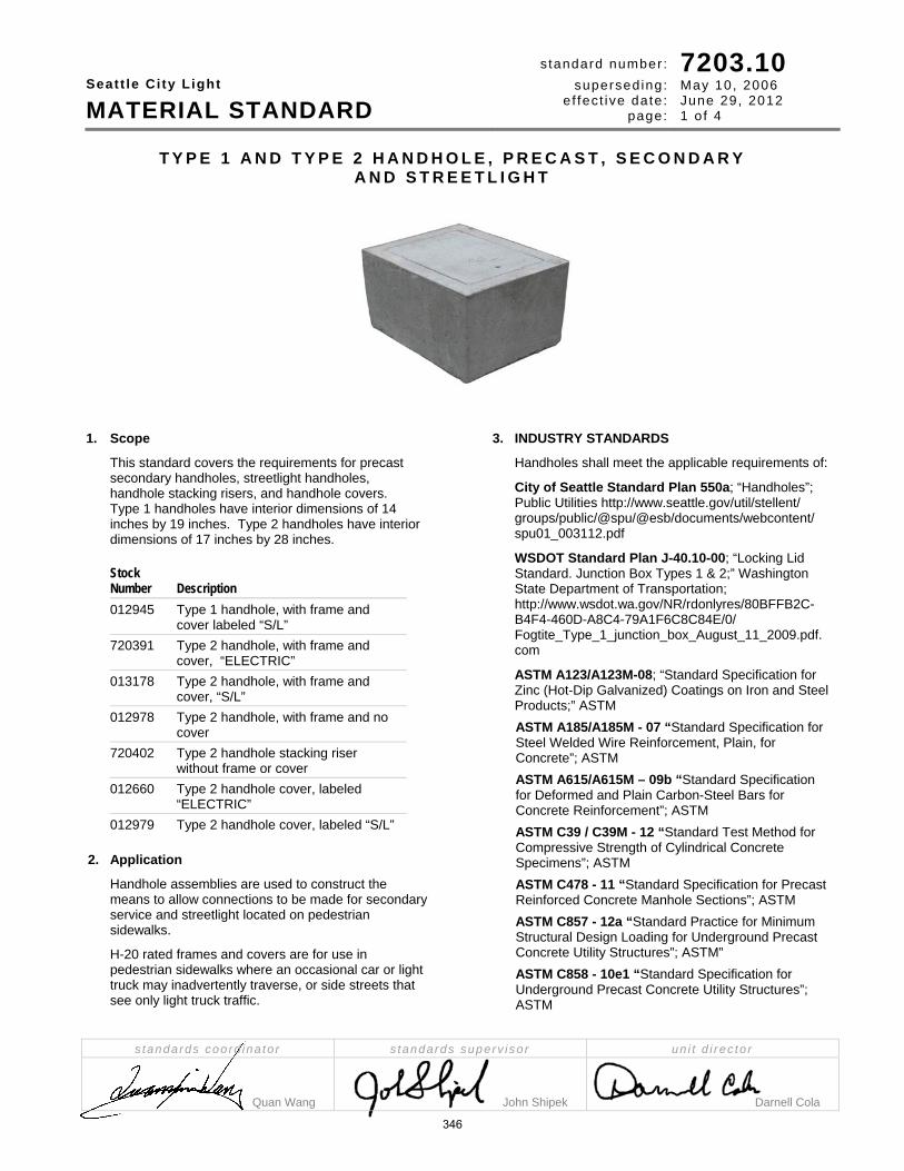
Seatt le Ci ty Light
MATERIAL STANDARD
standard number : superseding:
e f fec t ive date: page:
7203.10 May 10, 2006 June 29, 2012 1 o f 4
s tandards coord ina to r s tandards superv i so r un i t d i rec to r
Quan Wang John Shipek Darnell Cola
T Y P E 1 A N D T Y P E 2 H A N D H O L E , P R E C A S T , S E C O N D A R Y A N D S T R E E T L I G H T
1. Scope
This standard covers the requirements for precast secondary handholes, streetlight handholes, handhole stacking risers, and handhole covers. Type 1 handholes have interior dimensions of 14 inches by 19 inches. Type 2 handholes have interior dimensions of 17 inches by 28 inches.
Stock Number Description 012945 Type 1 handhole, with frame and
cover labeled “S/L” 720391 Type 2 handhole, with frame and
cover, “ELECTRIC” 013178 Type 2 handhole, with frame and
cover, “S/L” 012978 Type 2 handhole, with frame and no
cover 720402 Type 2 handhole stacking riser
without frame or cover 012660 Type 2 handhole cover, labeled
“ELECTRIC” 012979 Type 2 handhole cover, labeled “S/L”
2. Application
Handhole assemblies are used to construct the means to allow connections to be made for secondary service and streetlight located on pedestrian sidewalks.
H-20 rated frames and covers are for use in pedestrian sidewalks where an occasional car or light truck may inadvertently traverse, or side streets that see only light truck traffic.
3. INDUSTRY STANDARDS
Handholes shall meet the applicable requirements of:
City of Seattle Standard Plan 550a; “Handholes”; Public Utilities http://www.seattle.gov/util/stellent/ groups/public/@spu/@esb/documents/webcontent/ spu01_003112.pdf
WSDOT Standard Plan J-40.10-00; “Locking Lid Standard. Junction Box Types 1 & 2;” Washington State Department of Transportation; http://www.wsdot.wa.gov/NR/rdonlyres/80BFFB2C-B4F4-460D-A8C4-79A1F6C8C84E/0/ Fogtite_Type_1_junction_box_August_11_2009.pdf. com
ASTM A123/A123M-08; “Standard Specification for Zinc (Hot-Dip Galvanized) Coatings on Iron and Steel Products;” ASTM ASTM A185/A185M - 07 “Standard Specification for Steel Welded Wire Reinforcement, Plain, for Concrete”; ASTM ASTM A615/A615M – 09b “Standard Specification for Deformed and Plain Carbon-Steel Bars for Concrete Reinforcement”; ASTM ASTM C39 / C39M - 12 “Standard Test Method for Compressive Strength of Cylindrical Concrete Specimens”; ASTM ASTM C478 - 11 “Standard Specification for Precast Reinforced Concrete Manhole Sections”; ASTM ASTM C857 - 12a “Standard Practice for Minimum Structural Design Loading for Underground Precast Concrete Utility Structures”; ASTM” ASTM C858 - 10e1 “Standard Specification for Underground Precast Concrete Utility Structures”; ASTM
346

Seattle City Light
MATERIAL STANDARD Type 1 and Type 2 Handhole, Precast, Secondary and Streetlight
s tandard number : superseding:
e f fec t ive date: page
7203.10 May 10, 2006 June 29, 2012 2 o f 4
4. Conflict
Where conflict exists, the following order of precedence shall apply:
1) Seattle City Light Purchase Order (PO) 2) Seattle City Light General Terms and
Conditions 3) This material standard 4) Other industry standards
5. Construction
The handhole shall meet Washington State Department of Transportation Standard Plan J-40.10 with the following clarifications.
Dimensions (for handholes, inside dimension), nominal, in Stock
Number Item Type Length Width Height/ Thickness Cover Label
012945 handhole with frame 1 19 14 12 - cover 1 17 13 5/16 “SL” 720391 handhole with frame 1 28 17 12 - cover 1 26-5/8 16-1/2 5/16 “ELECTRIC” 013178 handhole, with frame 2 28 17 12 cover 1 26-5/8 16-1/2 5/16 “SL” 012978 handhole with frame 2 28 17 12 - 720402 stacking riser 2 28 17 12 - 012660 cover only 2 26-5/8 16-1/2 5/16 “ELECTRIC” 012979 cover only 2 26-5/8 16-1/2 5/16 “SL”
Figure 5, Handhole
347

Seattle City Light
MATERIAL STANDARD Type 1 and Type 2 Handhole, Precast, Secondary and Streetlight
s tandard number : superseding:
e f fec t ive date: page
7203.10 May 10, 2006 June 29, 2012 3 o f 4
5.2 Precast Handhole
Precast secondary and streetlight handholes shall be of the general configuration shown, in accordance with City of Seattle Standard Plan 550a.
Handhole minimum inside dimensions shall meet the requirement of respective Type 1 (14 inches x 28 inches) and Type 2 (17 inches x 28 inches) handholes.
Handhole shall be designed to nest, with an easy, snug fit to increase the depth of the handhole when necessary.
Handhole shall be sound and free of cracks.
5.3 Concrete
The handhole shall be cast of concrete meeting a minimum strength of 4000 psi after 28 days.
5.4 Cover Plate
a. The cover shall comply with City of Seattle Standard Plan No. 550a.
b. The cover shall be 5/16-inch (nominal) in thickness or other design pre-approved by Seattle City Light.
c. The cover shall be at least H-20 rated.
d. The cover shall have 1/16-inch to 1/8-inch clearance on each edge within the frame after galvanizing.
5.5 Frame
a. The frame shall comply with City of Seattle Standard Plan No. 550a
b. The steel frame shall be securely anchored in the concrete.
c. The frame shall have a ground point, which the copper braid from the cover may be attached
5.6 Non Slip Surface The cover and frame shall have a non slip surface with the following properties:
a. Slip resistant surface shall be coated with SlipNOT® Grade 3-coarse, by W.S. Molnar Company or have minimum coefficient of friction of 0.8
b. Bond strength to the plate of 4000 psi or greater
c. Surface hardness of 55 minimum on the Rockwell “C” scale
d. The cover shall be identified on the underside with the Type of surface (“S3” for SlipNOT® 3) and the year of manufacture. Example: “S3 2005.” The identification shall be bead-welded or clearly stamped into a metal surface on the underside of each lid, or labeled with an adhesive metallic foil-backed label.
5.7 Grounding
A 4-foot length of copper braid, equivalent to a #8 THNW or THHW copper wire, shall be secured from the handhole cover.
All handholes shall have a 5/16-inch ground insert or a ground pad on the interior wall.
5.8 Labeling
The word “ELECTRIC” or “SL” for streetlight shall be cast or otherwise permanently affixed to the cover and shall be easily readable. The affixing of lettering shall not be performed in a manner that might create a tripping hazard.
5.9 Lock
The cover shall have an approved locking device to prevent easy removal by unauthorized persons.
5.10 Galvanizing
The frame and cover shall be hot-dip galvanized after fabrication in accordance with ASTM A123M.
6. Documentation
6.1 General
Documentation shall be in English and use customary inch-pound units.
Documentation shall utilize common industry terminology and well-understood abbreviations.
6.2 Bidder’s Data
Bidder shall return the following technical information with their bids:
a. Manufacturer’s name
b. Manufacturing plant locations (all possible)
c. Bid information shall be presented in a clear and consolidated manner for ease of review.
348

Seattle City Light
MATERIAL STANDARD Type 1 and Type 2 Handhole, Precast, Secondary and Streetlight
s tandard number : superseding:
e f fec t ive date: page
7203.10 May 10, 2006 June 29, 2012 4 o f 4
7. Issuance
EA
8. Approved Manufacturer Catalog Numbers Stock Number Fog-Tite Christy (Oldcastle) 012945 J-11 Type 1, with
non-skid cover, SL
WDOT Type 1 Box with Cover - Galv. Non-Slip, “SL”
720391 J-11 Type 2 , with non-skid cover, Electric
WDOT Type 2 Box with Cover– Galv. Non-Slip, “Electric
013178 J-11 Type 2 , with non-skid cover, S/L
WDOT Type 2 Box with Cover – Galv. Non-Slip, “SL”
012978 J-11 Type 2 bottom
WDOT Type 2 Box – Galv
720402 J-11 Type 2 ext. WDOT Type 2 riser 012660 J-11 Type 2
non-skid cover, Electric
WDOT Type 2 Cover –Galv., Non-Slip, “Electric”
012979 J-11 Type 2 non-skid cover, SL
WDOT Type 2 Cover– Galv., Non-Slip, “SL”
9. References
9-34.6; Standard Specifications for Road, Bridge and Municipal Construction; City of Seattle; Public Utilities; http://www.seattle.gov/util/groups/public/@spu/@engineering/documents/webcontent/01_011339.pdf Smalley, Edward; SCL Engineer; subject matter expert, Streetlights; ([email protected])
Wang, Quan; SCL Standards Engineer, originator and subject matter expert for 7203.26 ([email protected])
349

SEATTLE CITY LIGHT
MATERIAL STANDARD
STANDARD NUMBER: PAGE:
SUPERSEDING: EFFECTIVE DATE:
7203.12 1 of 1 7203.10.1 September 20, 2004 November 30, 2006
STANDARDS COORDINATOR STANDARDS SUPERVISOR UNIT DIRECTOR
Rick Rice John Barnett Hardev Juj
H A N D H O L E , S E C O N D A R Y C O M P O S I T E F I B E R G L A S S , R E I N F O R C E D P L A S T I C T Y P E
1. Composite Fiberglass, Reinforced Plastic, or Fiberglass Reinforced Mortar Secondary Handholes shall be of the configuration shown and shall meet the applicable requirements of Western Underground Committee Guide 3.6, except as modified herein. The handholes are for use in light vehicular traffic areas.
The handholes shall have good abrasion resistance, high dielectric strength, a low moisture-absorption rate and be impervious to rot and fungus growth. They shall also be inert to corrosive chemicals, including acids, alkalies, and organic solvents.
2. Covers. Handhole covers shall be made of the same material and have an embossed slip resistant surface to enhance pedestrian safety. The covers shall be provided with a locking device to prevent easy removal by unauthorized persons.
3. Extensions. Extensions, used to extend hole depth, shall be designed to nest with the handholes for a snug fit. Handholes may be 1 or 2 piece to equal a 24” to 26” depth.
4. Color. The color of the handholes and extensions shall be light to medium grey.
5. Marking. The words "Seattle City Light" shall be molded in the handhole cover.
6. Reference Specification. Western Underground Committee, Guide 3.6, latest revision.
7. Stock Unit: EA
Approved Manufacturers Stock No. Item Description Carson Ind. Electrimold Quazite 720393* Handhole 17" x 30" x 12" or 24-26" H1730-24 ECBA-173024 DO-EH PC1730BA
720397 Cover 17" x 30" x 3/4" or 2" H1730-P1 ECCA-173002 DO-EH PC1730CA
720394 Handhole 24" x 36" x 18" H2436-24 ECBA-243618 DO-EH PG2436BA
720399 Cover 24" x 36" x 2” or 3" H2436-P1 ECCA-243603 DO-EH PG2436CA * Quazite requires two PC1730BA sections for the 24-inch depth and for the City Light stock number.
formerly Material Standard 7203.10.1
350

Seatt le Ci ty Light
MATERIAL STANDARD
standard number :superseding:
ef fect ive date:page:
7203.20 new June 29, 2012 1 of 4
standards coordinator standards supervisor unit director
Aida Diop John Shipek Darnell Cola
P O L Y M E R C O N C R E T E H A N D H O L E , S E C O N D A R Y A N D S T R E E T L I G H T
1 . Scope
This standard covers requirements for precast polymer handholes. There are three main components that make up a handhole assembly: box, extension, and cover. This standard applies to the following Seattle City Light Stock Numbers: 013321, 013322, 013323, and 013324.
2. Appl icat ion Precast polymer handholes are non-conductive, non-flammable, corrosion resistant, and lightweight underground enclosures used to house connections for secondary service and streetlight (SL) located on pedestrian sidewalks. Two types of handholes are approved for secondary and SL connections. Type 1 and 2 with nominal interior dimensions of 13 inches by 24 inches and 17 inches by 30 inches, respectively.
The following table gives the application for each of the Stock Numbers.
Stock number 013322 can be used as a box or an extension.
Stock Number Type Description Application
013321 1 box with cover streetlight
013322 2 box/extension, without cover
secondary or streetlight
013323 2 cover secondary
013324 2 cover streetlight
Polymer concrete handholes are not intended for use in constant traffic areas.
3. Industry Standards Polymer precast concrete handholes shall meet the following national standard:
ANSI/SCTE 77 2010: Specification for Underground Enclosure Integrity
351

Seat t l e C i t y L igh t
MATERIAL STANDARD Polymer Concrete Handhole, Secondary and Streetlight
s tandard number : superseding:
e f fec t ive date: page:
7203.20 new June 29, 2012 2 of 4
4 . Requirements
Figure 4, Precast Polymer Cover, Box and Extension cover cover box/extension underside of cover
4.1 General
Stock Number 013321 013322 013323 013324
Type 1 2 2 2
Description box and cover box/extension cover cover
Dimensions, inside , in, nominal
Length (L) 24 24 30 30 30 Width (W) 13 13 17 17 17 Height/Thickness 12 02 12 02 02
Cover label - "STREETLIGHT" - "ELECTRIC" "STREETLIGHT"
Design load
Vertical, lb, nominal 22,500 22,500 22,500 22,500 22,500 Lateral, lb/sq ft 800 800 800 800 800
Test Load
Vertical, lb, nominal 33,750 33,750 33,750 33,750 33,750 Lateral, lb/sq ft 1,200 1,200 1,200 1,200 1,200
Lifting eye (pull slot), lb, minimum - 3,000 - 3,000 3,000
352

Seat t l e C i t y L igh t
MATERIAL STANDARD Polymer Concrete Handhole, Secondary and Streetlight
s tandard number : superseding:
e f fec t ive date: page:
7203.20 new June 29, 2012 3 of 4
4 . Requirements , cont inued
4.2 Box, Cover and Extension Handhole box, cover and extension shall be:
a. Polymer concrete b. Gray in color c. Non-conductive d. Non-flammable e. Corrosion resistant f. ANSI Tier 22 load rated, designed for
areas subjected to occasional non-deliberate heavy vehicular traffic.
g. To avoid accidental placement of both the box body and the cover in areas for which they are not rated, each product shall display securely affixed labels stating “Sidewalk Use Only”.
h. The chemical resistance (sunlight exposure, water absorption, and flammability) of polymer handholes and covers shall be according to ANSI/SCTE 77 2010, Section 6.
4.3 Box and Extension Handhole box and extension shall be:
a. Bottomless without any knockouts or mouseholes.
b. Straight wall and stackable.
4.4 Cover Cover shall:
a. Require the use of tools to open to avoid easy removal by unauthorized persons.
b. Be skid resistant with a minimum coefficient of friction of 0.5 percent.
c. Have recessed bolt holes such that the bolt head will not protrude above the cover surface.
d. Be attached to the handhole box by two, stainless steel, captive, penta head bolts (1/2 inches – 13 UNC, 2-1/2 or 3 inches long).
e. Have 1/16-inch to 1/8-inch clearance on each edge of the box.
f. Be marked with the ANSI load rating (Tier 22)
5. Test ing The structural testing shall be in accordance with ANSI/SCTE 77 2010, Section 7. The maximum deflection shall be one-half-inch for vertical tests and one-quarter-inch per foot of length for lateral tests. Test data that establishes compliance with the requirements of STCE 77 shall be provided upon request. Tests of complete boxes and covers shall be performed by an independent testing agency.
6. Marking
Handhole covers shall have embedded on the top surface an identifying mark or label that defines the function of the enclosure: “ELECTRIC” or “STREETLIGHT”.
Polymer handholes shall be clearly and indelibly marked in accordance with NEC2008. Marking shall include but not be limited to:
Manufacturer’s name Year of manufacture Product identification number ANSI load rating
7. Packaging Handholes, covers, and extensions shall be packaged in a way that allows the product to withstand normal shipping and installation practices without chipping, cracking, or structural damage. Individual packages shall be legibly marked with:
Manufacturer’s name Manufacturer’s catalog number Product description Seattle City Light’s Stock Number
Shipping containers shall be legibly marked with: Seattle City Light’s Purchase Order Number Seattle City Light’s Stock Number
8. Issuance Stock Unit: EA
353

Seat t l e C i t y L igh t
MATERIAL STANDARD Polymer Concrete Handhole, Secondary and Streetlight
s tandard number : superseding:
e f fec t ive date: page:
7203.20 new June 29, 2012 4 of 4
9 . Approved Manufacturers
Manufacturers
Stock Number Description Hubbell
Oldcastle Enclosure Systems
Armorcast Products Company
0013321 Type 1 Assembly, Streetlight
PG1324Z584 13241265 A6001946HDAPCX12
0013322 Type 2 Box/Extension PG1730B701 17302006 A6001640PCX12
0013323 Type 2 Cover, Electric PG1730H554CG2 17304016 A6001947HD-EL
0013324 Type 2 Cover, Streetlight PG1730H554CH2 17304192 A6001947HD-SL
10. References Diop, Aida; Standards Engineer; originator and subject matter expert for 7203.20 ([email protected]) National Electrical Code (NEC) 2008; “Article 314.30“ Ng, Sharon; Senior Civil Engineer; subject matter expert for 7203.20 ([email protected])
SCL 7203.10; “Handhole, 17″ x 28″ Precast, Secondary”; Material Standard
SCL 7203.12; “Handhole, Secondary, Composite Fiberglass, Reinforced Plastic Type”; Material Standard Standard Plan J-40.10-02; Washington State Department of Transportation Standard Plan no. 550a; City of Seattle Standard Plans and Specifications, 2010 Wang, Quan; Standards Engineer; subject matter expert for 7203.20 ([email protected]) Western Underground Committee; “Guide 3.6 – Non-Concrete Enclosures”
354

Seatt le Ci ty Light
MATERIAL STANDARD
standard number : superseding:
e f fec t ive date: page:
7203.21 new June 29, 2012 1 of 6
standards coordinator standards supervisor unit director
Quan Wang John Shipek Darnell Coal
P R E C A S T R E I N F O R C E D C O N C R E T E S T R U C T U R E S - G E N E R A L
1 . Table of Contents
Section Page 1. Table of Contents ........................................ 1 2. Scope .......................................................... 1 3. Application ................................................... 1 4. Definitions .................................................... 1 5. Industry Standards ................................... 1, 2 6. Conflict ......................................................... 2 7. Order Information ........................................ 2 8. Structural Requirements .......................... 2, 3 9. Grounding .................................................... 3 10. Knockouts and Vault Openings ................... 4 11. Lifting Methods ............................................ 4 12. Accessories ................................................. 4 13. Metal Doors and Access Cover Plates ........ 5 14. Non-Slip Surfaces......................................... 5 15. Identification ................................................ 5 16. Quality Control ............................................. 5 17. Documentation ............................................ 5 18. Product Approval ..................................... 5, 6 19. Issuance ...................................................... 6 20. Approved Manufacturer ............................... 6 21. References .................................................. 6
2. Scope
This standard covers the general requirements for precast reinforced concrete structures used at Seattle City Light.
This standard applies to the following Seattle City Light reinforced concrete products: Vaults Vault cover slabs Pads or slabs
Specific requirements shall be according to the detailed material standards and purchase orders issued subsequent to competitive solicitations.
This standard does not apply to panel vaults.
3 . Appl icat ion
Precast concrete structures are used to construct the underground electric system. Precast concrete structure may be used to house equipment, cables, service connections and splices for the distribution system.
The H20-rated 444 vault assemblies are not intended to be used in high density traffic locations.
Some vault floors may exceed 12 feet 6 inches below finished grade; in which case, a fixed ladder is required.
4. Def in i t ions
Vault (as defined by NESC) - A structurally solid enclosure, (including all sides, top, and bottom), above or below ground, where entry is limited to personnel qualified to install, maintain, operate, or inspect the equipment or cable enclosed. The enclosure may have openings for ventilation, personnel access, cable entrance, and other openings required for operation of equipment in the vault.
Vault (as defined by SCL) - An enclosure that is used for primary service. Enclosures 444 or larger.
Ring Vault (as defined by SCL) - A vault that is comprised of multi-sections, i.e. base, mid-section, and a top section. These vaults may also have various risers to achieve the proper height and access openings. Enclosures 818 and 814.
Concrete Encased Electrode (as defined by NESC) - A metallic wire, rod, or structural shape, meeting Rule 93E5 and encased in concrete, that is not insulated from direct contact with earth, shall constitute an acceptable ground electrode. The concrete depth below grade shall be not less than 1 foot, and a depth of 2.5 feet is recommended. Wire shall be no smaller than AWG No. 4 if copper, or 3/8-inch diameter or AWG No. 1/0 if steel. It shall be not less than 20 feet long, and shall remain entirely within the concrete except for the external connection. The conductor should be run as straight as practical.
5. Industry Standards
Concrete structure shall meet the applicable requirements of the following industry standards:
ACI 318-11 – Building Code Requirements for Structural Concrete and Commentary,
355

Seat t l e C i t y L igh t
MATERIAL STANDARD Precast Reinforced Concrete Structures - General
s tandard number :
superseding: e f fec t ive date:
page:
7203.21 new June 29, 2012 2 of 6
5 . Industry Standards , cont inued
ANSI/AWS D1.4/D1.4M – 11 “Structural Welding Code – Reinforced Steel”
ASTM A123/A123M-08; “Standard Specification for Zinc (Hot-Dip Galvanized) Coatings on Iron and Steel Products;” ASTM
ASTM A185/A185M - 07 “Standard Specification for Steel Welded Wire Reinforcement, Plain, for Concrete”
ASTM A497/A497M - 07 “Standard Specification for Steel Welded Wire Reinforcement, Deformed, for Concrete”
ASTM A615/A615M – 09b “Standard Specification for Deformed and Plain Carbon-Steel Bars for Concrete Reinforcement”
ASTM A706/A706M – 09b “Standard Specification for Low-Alloy Deformed and Plain Bars for Concrete Reinforcement”
ASTM C39/C39M – 10 “Standard Test Method for Compressive Strength of Cylindrical Concrete Specimens”
ASTM C150/C150M – 12 “Standard Specification for Portland Cement”
ASTM C478 – 09 “Standard Specification for Precast Reinforced Concrete Manhole Sections”
ASTM C857 – 11 “Standard Practice for Minimum Structural Design Loading for Underground Precast Concrete Utility Structures”
ASTM C858 - 10e1 “Standard Specification for Underground Precast Concrete Utility Structures”
NESC - 2012 – National Electric Safety Code, Rule 094B6, Concrete-Encased Electrodes
6. Conf l ict
Where conflict exists, the following order of precedence shall apply:
1. SCL Purchase Order (PO) 2. SCL General Terms and Conditions 3. This material standard 4. SCL detailed material standard 5. ASTM standards 6. Other industry standards
7. Order Informat ion
Seattle City Light orders will provide the following minimum information:
Vault size and description SCL general material standard number citing
revision date SCL detailed material standard number citing
revision date
SCL Stock number Total order quantity Delivery date Delivery location Ladder requirement
8. Structural Requirements
8.1 General All concrete vaults and accessories, including special order (non-stock) materials shall be manufactured in accordance with the requirements herein. Design changes shall require the prior written approval of an Org 321 Standards Engineer.
8.2 Reinforced Concrete Minimum compressive strength of concrete shall not be less than 4,500 pounds per square inch in 28 days as determined by the ASTM Method C39 Cement shall conform to ASTM C150 No additives containing calcium chloride or any other material that will produce corrosive ions shall be used in the concrete. Welded wire fabric shall conform to ASTM A185 or A497. Steel Reinforcing Bars shall conform to ASTM A615, Grade 60 or ASTM A706, Grade 60. Welding of reinforcing steel shall conform to the Structural Welding Code, Reinforcing Steel (AWS D1.4) of the American Welding Society. The concrete cover (measured from the surface of the concrete to the outside surface of the reinforcement) for reinforcement shall be 1-1/2 inches minimum for main reinforcing bars and 3/4 inch for stirrups and ties. The concrete finish shall be free of rock pockets and honeycombed areas. The interior walls, ceiling and exterior surfaces exposed shall be smooth. Rock pockets over 3/8 inch deep and other imperfections on all surfaces shall be patched and troweled to match the surrounding surface.
8.3 Structural Design Structural design of the precast vault shall conform to ACI 318 and ASTM C857 with the following exceptions:
Top of vault shall be assumed to be at a minimum of 2 feet and maximum (unless noted on drawings) 5 feet below grade.
Live Load: AASHTO HS-20 truck, P=16 kips. Traffic can approach the structure from any direction.
356

Seat t l e C i t y L igh t
MATERIAL STANDARD Precast Reinforced Concrete Structures - General
s tandard number :
superseding: e f fec t ive date:
page:
7203.21 new June 29, 2012 3 of 6
8 . Structural Requirements, cont inued
8.3 Structural Design, continued 30% Live load impact load factor for soil
cover less than or equal to 3 feet.
No live load surcharge for soil cover greater than 8 feet.
Soil density shall be 120 pounds force per cubic foot
40 pounds force per cubic foot Equivalent Fluid Pressure Lateral Soil Pressure Above Water Table
80 pounds force per cubic foot Equivalent Fluid Pressure Lateral Soil Pressure Below Water Table
80 pounds per square foot Live Load Surcharge
Buoyancy - The weight of vault (without equipment) plus weight of soil cover shall be greater than 1.1 times the hydrostatic uplift force on the base of the vault. It cannot rely on skin frictional resistance between backfill and vault wall surfaces. If the gravity load is insufficient, then the vault shall be designed with restraints to withstand the buoyant force. The restraint design shall be submitted for review and approval.
The groundwater table shall be assumed to be 5 feet below grade.
8.4 Cable Support and “C” Channel Vault shall be provided with cast-in-place channel, 1-5/8 inches by 1-5/8 inches. “C” channels shall be included on each of the four interior walls unless stated otherwise in the detailed material standard.
9. Grounding
9.1 Electrodes Concrete-encased electrodes shall comply with NESC 094B6. The electrode shall meet, but not be limited to, the following specifications:
Electrode shall be no smaller than AWG No. 4 if copper or 3/8 inch diameter (AWG No. 1/0) if steel
Electrode shall be no less than 20 feet long and shall remain entirely within the concrete except for the external connections.
Electrode shall be installed as straight as possible.
Electrode shall be encased with a minimum of 1-1/2 inches of concrete.
Electrode shall be positioned a minimum of 2-1/2 feet below the top of the vault.
9.2 Ground Insert Connector
The ground insert connector shall be installed flush (neither recessed nor protruding) with the vault wall. Each bronze insert shall be tapped for 1/2-inch 13 bolts, and located on two opposite walls. The lead rod, a 3/8-inch steel or bronze rod, shall be connected to the ground electrode with arc or Cadweld (Exothermic Connection) at a minimum of three points as shown in Figure 9. Inserts shall be plugged to prevent contamination from entering. The inserts shall be exposed and marked prior to pick-up or delivery. On multi sectioned vaults (3 or more sections):
The inserts shall be aligned vertically.
Only the middle section will have the inserts that face inside and outside of the vault.
All other inserts in the vault shall be placed in accordance with the drawing of the specific vaults on manufacturer’s specifications and approved by Seattle City Light.
Figure 9, Lead Rod and Ground Electrode Weld
Details
10. Knockouts and Vaul t Openings
10.1 Vault Openings Vaults 7 feet by 12 feet (inside dimensions) and larger shall have two 42-inch-diameter access entries, unless specified otherwise in the detailed material standards.
All vaults shall have cable knockouts located in each lower corner of the enclosure according to the manufacturer’s standard and Seattle City Light’s requirements.
357

Seat t l e C i t y L igh t
MATERIAL STANDARD Precast Reinforced Concrete Structures - General
s tandard number :
superseding: e f fec t ive date:
page:
7203.21 new June 29, 2012 4 of 6
10. Knockouts and Vaul t Openings
10.1 Openings, continued
Knockout and duct openings shall be beveled on the exterior surface.
Each enclosure with a floor shall have a ground-rod knockout at two corners of the base of the enclosure. Size, shape, quantity and location of knockouts shall be as specified in the detailed material standards.
10.2 Duct Bank Knockout Threaded Inserts For 712 and larger vaults, and all panel vaults, provide four minimum 1/2-inch diameter ferrule-threaded insert at perimeter of each duct bank knockout. These threaded inserts are to allow the duct bank rebar to dowel into the vault wall. Threaded inserts shall be spaced 12 inches (nominal) apart along the height of each knockout panel.
11. L i f t ing Methods Lifting provisions shall be provided per manufacturer’s and Seattle City Light’s requirements.
11.1 Covers All vault covers, pads or slabs, or risers weighing less than 9,000 pounds shall have 3/4-inch lifting inserts on each corner of the top surface, or as described in the detailed material standards.
11.2 Burke Fittings All vault covers or structures over 9,000 pounds shall have either a 2-ton or a 4-ton Burke fitting placed in each corner of the top surface or on the four walls, as described in the detailed material standards.
11.3 Lifting Inserts Lifting inserts shall be provided as shown in the detailed material standards. All metal lifting devices cast into the internal or external surfaces of vaults for handling purpose shall be hot-dipped galvanized or made from stainless steel.
12. Accessories Items to be included with all vaults:
12.1 Cable Pulling Device Vaults larger than 577 shall have 7/8-inch cable pulling irons mounted on each corner of the vault and be suitable as anchors for cable pulling operations. 7/8-inch cable pulling iron mounts shall withstand 10 kips maximum working tension and 20 kips ultimate strength.
577 and smaller vaults shall have 1/2-inch cable pulling irons mounted on each corner of the vault and be suitable as anchors for cable pulling operations. 1/2-inch cable pulling iron mounts shall withstand 5 kips maximum working tension and 10 kips ultimate strength The pulling irons shall be stainless steel or hot dipped galvanized steel. The pulling iron’s maximum working tension shall be stenciled on the wall surface near two of the roof pulling irons. Burke Lifting devices are not suitable for cable pulling purposes.
12.2 Drainage and Sump All vaults shall have a drain sump. Vaults that are 7 feet by 12 feet (inside dimensions) and larger shall have a rectangular sump at one end wall. Sump shall be equipped with galvanized grating. Vaults smaller than 7 feet by 12 feet shall have a circular sump with cover located near the center of the vault. The floor shall be sloped to drain to the sump in 577 or larger vaults.
12.3 Ladders Where a ladder is required, the ladder shall conformed to the following
Ladders shall be corrosion resistant.
Ladder shall be made according to SCL drawing D-28304 – Retractable Ladder, Vault and Manhole Access.
12.4 Joint Sealant Vault Sections shall be provided with butyl rubber joint sealant material or gasket mastic to be used between vault keyways and sections, including hatch riser rings.
358

Seat t l e C i t y L igh t
MATERIAL STANDARD Precast Reinforced Concrete Structures - General
s tandard number :
superseding: e f fec t ive date:
page:
7203.21 new June 29, 2012 5 of 6
13 . Metal Doors and Access Cover Plates
All lids, hatches and frames shall be provided with a grounding site.
13.1 Frames and Covers All frames and hatch covers for shall be designed for at least 20.8 kips wheel load (HS20 + 30% impact) applied in any direction. All frames and lids shall have a non-slip surface. The 42-inch round cover and frames shall also comply with requirements in SCL Material Standard 7204.70, Frames and Covers, 42 inch Round, Iron.
13.2 Doors All doors shall include one 5/8-inch diameter bonding hole located in an underside bearing bar, approximately centered in the door and 2-1/2 to 3-1/2 inches from the hinged edge. All doors shall be designed for at least 20.8 kips wheel loading (H20 + 30% impact). Aluminum doors for 34-inch by 37-inch and 34-inch by 74-inch opening access shall be designed for at least 26 kips wheel loading (H25 + 30% impact or equivalent H30 + 8% impact). All steel doors and access cover plates shall be hot dipped galvanized in accordance with ASTM A123, unless otherwise approved in accordance with Section 8.1. All doors shall be hinged and shall fully open 180 degrees. All doors shall not exceed 65 pounds equivalent lift. All doors shall have a non-slip surface. All doors shall have a locking mechanism, such as a Penta head bolt, to prevent unsolicited access. Locking mechanism shall not protrude above the door surface. Square or rectangular doors shall open along the lengthwise of the access opening.
14. Non-sl ip Surfaces All non-slip surfaces shall have the following properties:
minimum coefficient of friction of 0.8 bond strength to the plate of 4000 psi or greater surface hardness of 55 minimum on the Rockwell
“C” scale
Type of non-slip surface (“S3” for SlipNOT® 3) and the year of manufacture shall be identified on the underside of the door. Example: “S3 2005.” The identification shall be bead welded or clearly stamped into a metal surface on the underside of each lid, or labeled with an adhesive metallic foil-backed label.
15. Ident i f icat ion
All lids and doors shall be permanently marked with 3-inch high letters “Electric” clearly visible on the top where distribution cables occupy the enclosure.
16. Qual i ty Control Precast concrete vaults shall be manufactured in accordance with ASTM C858. The vault(s) may be rejected if it fails to conform to ASTM C858’s construction and dimensional tolerances except for concrete cover over reinforcing shall not be less than listed above. Vaults may also be rejected if it does not meet SCL Material Standard 7201.00, “Acceptance criteria for the installation of new precast concrete distribution facilities”. Minor defects that can be repaired in accordance to criteria in SCL Material Standard shall be done in accordance to SCL Construction Guidelines U2-6/NVH-20, “Inspection and Repair Procedures for Precast Vaults and Manholes”. The vaults shall be warranted for one year against design and manufacturing defects including those resulting from poor workmanship and materials.
17. Documentat ion
17.1 General Documentation shall be in English and use customary inch-pound units. Documentation shall utilize common industry terminology and well-understood abbreviations.
17.2 Bidder’s Data Bidder shall return the following technical information with their bids: Manufacturer’s name Manufacturing plant location (all possible) Manufacturer’s experience and qualification. Bid information shall be presented in a clear and consolidated manner for ease of review.
18. Product Approval Manufacturers interested in having their precast concrete vaults and accessories approved for purchase by Seattle City Light must participate in the stepped processed summarized below.
Provide evidence of National Precast Concrete Association, NPCA, Certification.
Quality Control Program in accordance with the NPCA, plant certification.
Product specifications and cut sheet review
359

Seat t l e C i t y L igh t
MATERIAL STANDARD Precast Reinforced Concrete Structures - General
s tandard number :
superseding: e f fec t ive date:
page:
7203.21 new June 29, 2012 6 of 6
18. Product Approval , cont inued
Sample concrete enclosure field trail Review and evaluate field trail Conduct a prototype pulling iron test
demonstrate that the pulling iron could withstand 40 kips ultimate load without failure. Submit the certified test report.
Manufacturer shall have a local representative or agent who will provide technical support and authorized to allow returns and repairs to be conducted by SCL or contractors.
Manufacturers are encouraged to plan accordingly. The approval process can take up to six months to complete.
19. Issuance EA
20. Approved Manufacturers
Approved manufacturers are identified in the detailed material standard.
21. References
SCL Drawing D-28304; “Retractable Ladder, Vault and Manhole Access.” SCL U2-6/NVH-20; “Inspection and Repair Procedures for Precast Vaults and Manholes”. SCL 7201.00; “Acceptance Criteria for the Installation of New Precast Concrete Distribution Facilities” SCL 7203.08; “Handhole, 2″ x 3 ″ x 3 ″ Precast”; Material Standard SCL 7203.10; “Handhole, Precast, Secondary and Streetlight”; Material Standard SCL 7204.70; “Frames and Covers, 42-inch Round, Iron”; Material Standard Detter, Chris; SCL Distribution Engineer, subject matter expert ([email protected]) “Vault Standard Specifications;” Ng, Sharon; SCL Civil Engineer, ([email protected]) Ng, Sharon; Senior Civil Engineer; subject matter expect ([email protected] Wang, Quan; SCL Standards Engineer, subject matter expert for 7203.21; ([email protected])
360

SEATTLE CITY LIGHT
MATERIAL STANDARD
s tandard number :superseding:
ef fect ive date:page:
7203.26new June 29, 20121 of 6
standards coordinator standards supervisor unit director
Quan Wang John Shipek Darnell Cola
4 4 4 E L E C T R I C V A U L T , P R I M A R Y S E R V I C E
1. Table of Contents 1. Table of Contents ....................................... 1 2. Scope ......................................................... 1 3. Application ................................................. 2 4. General Requirements ............................... 2 5. Component Requirements ......................... 2
5.1. Grounding and Bonding .................... 2 5.2. Vault Base ........................................ 2 5.3. Cover Slab ........................................ 4
6. Vault Assemblies ....................................... 5 7. Issuance ..................................................... 5 8. References ................................................. 6 9. Approved Manufacturers ............................ 6
2. Scope
This standard covers the detailed requirements for the 444 electrical vault components (vault base and cover slabs with cover hatch) and the assembled 444 electric vaults assembled from those components. The basic components can be ordered separately or they can be ordered as assembled vaults with cover slabs.
This standard applies to the following Seattle City Light Stock Numbers:
Stock Number 444 Vault Components
013093 vault base, standard 444
013094 cover slab, 4- by 4-foot slab with one 3- by 3-foot, non-slip, H-20, solid cover hatch
013095 cover slab, 4- by 4-foot slab with one 42-inch round, solid cover and frame, H-20
013157 cover slab, 4-foot, 4-inch by 4-foot, 7-inch slab with one 34- by 37-inch, non-slip, solid cover hatch, H-30
Stock Number Assembled 444 Vaults with Cover Slabs
013120 assembled 444 vault with 4- by 4-foot cover slab with one 3-foot by 3-foot, non-slip, H-20, solid cover hatch
013121 assembled 444 vault with 4- by 4-foot cover slab with one 42-inch round, solid cover and frame, H-20
013158 assembled 444 vault with 4-foot, 4-inch by 4-foot, 7-inch slab with one 34- by 37-inch, non-slip, solid cover hatch, H-30
361

Seattle City Light
MATERIAL STANDARD 444 Electric Vault, Primary Service
s tandard number :superseding:
ef fect ive date:page:
7203.26new June 29, 20122 of 6
3 . Appl icat ion
The 444 vaults are intended for use in the construction of underground electric systems. The precast concrete structure may be used to house load break junction boxes, and in making service connections and splices for the distribution system.
The H20-rated 444 vault assemblies are not intended to be used in high density traffic locations.
The standard 444 vault assembly typically consists of the 444 base (Stock Number 013093) and the 4-foot by 4-foot cover slab with one 3- by 3-foot non-slip, H-20 solid cover (Stock Number 013094).
Due to different applications, the vault may need to be customized with a different entry opening.
Depending on the application for the enclosure selected, it can be defined as a handhole or a vault.
When Seattle City Light uses the 444 enclosure for primary service, the 444 enclosure will be designated as a vault. For non-primary service the 444 enclosure can typically be referred to as a handhole (not covered in this Standard).
Steps for selecting the proper vault assembly for your application:
1. Select the appropriate vault base (one option for the 444 size)
2. Select slab cover (three options for the 444)
4 . General Requirements
This detailed standard is to be used in conjunction with the latest revision of:
City Light Material Standard 7203.21, “Precast Reinforced Concrete Structures – General”
City Light Material Standard 7204.70, “Frames and Covers, 42-Inch Round, Iron”
5. Component Requirements
5.1 Grounding Vault grounding shall comply with Material Standard 7203.21, Section 9, Grounding.
5.2 Vault Base The SCL 444 vault base (Stock No. 013093) shall have shall have an overall nominal dimension of 4-feet by 4-feet by 3-feet 6-inches high as shown in Table 5.2a and Figure 5.2. Approximate base weight is 2,200 pounds.
Table 5.2a, Standard 444 Vault Base Dimensions
Nominal Dimensions, ft-in
Wall, Outside Wall, Inside Height Stock Number Length Width Length Width Outside Inside 013093 4-0 4-0 3-6 3-6 3-6 3-3
362

Seattle City Light
MATERIAL STANDARD 444 Electric Vault, Primary Service
s tandard number :superseding:
ef fect ive date:page:
7203.26new June 29, 20123 of 6
5. Component Requirements, continued
5.2 Vault Base, continued
Table 5.2b, Vault Base Attributes
All Standard 444 Vault Bases Shall Have the Following Features:
Size, Nominal, in Location
Per Location
Total Number
Knockouts round 4-3/4 dia all 4 walls, on bottom 8 ea side 32 ground rod 2 dia 2 corners of floor 1 ea 02
Channels
galvanized “C” channel, horizontal, embedded in walls
24 long all walls, above all knockouts 1 ea side 04
Pulling Irons 1/2 dia 1 ea corner of floor (typical) 1 ea corner 04
Lift Holes 1-1/2 dia 4 walls, center of wall, above channel 1 ea side 04
Ground Inserts, bronze 1/2 dia 2 walls, opposite, internal and external 2 ea side 04
Ladder not required
Figure 5.2, Standard 444 Vault Base (Stock Number 013093) dimensions shown are nominal values
363

Seattle City Light
MATERIAL STANDARD 444 Electric Vault, Primary Service
s tandard number :superseding:
ef fect ive date:page:
7203.26 new June 29, 2012 4 o f 6
5. Component Requirements, continued
5.3 Cover Slab
Cover slabs shall have a nominal overall dimension of 4 feet by 4 feet. Thickness shall be 6 inches. Approximate slab weight is 650 pounds.
All cover slabs shall have overall dimension as shown in Table 5.3. Cover slabs shall have shall have a keyed form to match the base for proper assembly.
All cover slabs shall have 3/4-inch diameter (nominal) lift insert at each corner on the top, as shown in Figure 5.3a.
Caps shall be provided to cover the lift inserts.
Cover slab with the 42-inch round cover shall include a 4-inch deep, round frame, as shown in Figure 5.3b. Note, the iron frame in the slab for round opening extends over the sides of the slab.
Figure 5.3a, 4-Foot Square Cover Slab with 3-Foot Square Cover (Stock Number 013094) dimensions shown are nominal values
Table 5.3, Cover Slab
Cover Slab Dimensions, Nominal, ft-in Stock Number Length Width Thickness Opening, in Cover/Hatch
013094 4-0 4-0 0-6 36 by 36, square one 3- by 3-foot, non-slip, solid cover hatch, H-20
013095 4-0 4-0 0-6 38, dia, round one 42-inch round, solid cover and frame, H-20
013157 4-4 4-7 0-6 34 by 37, rectangle one 34- by 37-inch, non-slip, solid cover hatch, H-30
364

Seattle City Light
MATERIAL STANDARD 444 Electric Vault, Primary Service
s tandard number :superseding:
ef fect ive date:page:
7203.26new June 29, 20125 of 6
5. Component Requirements, continued
5.3 Cover Slab, continued
4-Foot, 8-inch Square Cover Slabs, dimensions shown are nominal values
Figure 5.3b, Slab with 42-Inch Round Cover Figure 5.3c, Slab with 34- by 37-Inch Hatch (Stock Number 013095) (Stock Number 013157)
6. 444 Vaul t Assemblies
Table 6, Assembled 444 Vault Components
Assembled Vault Stock Number
Vault Base Stock Number
Cover Slab Stock Number Cover
013120 013093 013094 H-20 solid square hatch, 3- by 3-foot
013121 013093 013095 H-30 solid round, 42-inch
013158 013093 013157 H-30 solid square hatch, 34- by 37-inch
Refer to Tables 5.2a, 5.2b, and 5.3 for the various components included in each vault assembly.
6.1 Assembly Options All vault assemblies use the same vault base. Depending on the type of cover hatch desired, the vault base may be paired with a different cover slab size with appropriate cover hatch, as shown in Table 6.
6.2 Assembly Requirements All solid cover hatches have non-slip surfaces. Each section of the vault components shall have keyways for proper assembly.
365

Seattle City Light
MATERIAL STANDARD 444 Electric Vault, Primary Service
s tandard number :superseding:
ef fect ive date:page:
7203.26new June 29, 20126 of 6
7. Issuance Unit: EA
8. Approved Manufacturers
Catalog Number Stock Number Description Oldcastle/Utility Vault
130093 standard base 444-LA Base w/ Iron and GRD In & Out
130094 cover slab, 4-foot by 4-foot cover slab with one 3- by 3-foot, non-slip solid cover
44-33F Cover w/ I.D. Marker
130157 cover slab, 4-foot, 4-inch by 4-foot, 7-inch slab with one 34-inch by 37-inch, non-slip, solid cover hatch, H-30
Oversized Special 44 Top w/3437 LW Hatch
013120 assembled vault with 4-foot by 4-foot cover slab with one 3-foot by 3-foot, non-slip, H-20, solid cover hatch
444-LA Base w/ Iron and GRD In & Out w/332P Non-Slip-SCL
013121 assembled vault with 4-foot by 4-foot cover slab with one 42-inch round, solid cover and frame, H-20
444-LA Base w/ Iron and GRD In & Out w/42” Cover & Frame-SCL
013158 assembled vault with 4-foot, 4-inch by 4-foot, 7-inch slab with one 34-inch by 37-inch, non-slip, solid cover hatch, H-30
444-LA Base w/ Iron and GRD In & Out w/ Oversized Special 44 Top w/3437 LW Hatch
9 . References
Detter, Chris; SCL Distribution Engineer, subject matter expert for 7203.26 ([email protected])
Ng, Sharon; SCL Civil Engineer, subject matter expert for 7203.26 ([email protected])
SCL 7203.21; “Precast Reinforced Concrete Structure, General”; Material Standard
SCL 7204.70; “Frames and Covers, 42-Inch Round, Iron”; Material Standard
SCL 9246.10; “Pulling Irons - Fundamentals and Detailed Requirements, Looped Radial and Network Systems”; Design Standard Wang, Quan; SCL Standards Engineer, originator and subject matter expert for 7203.26 ([email protected])
366

SEATTLE CITY LIGHT
MATERIAL STANDARD
s tandard number :superseding:
ef fect ive date:page:
7203.31new June 29, 20121 of 6
standards coordinator standards supervisor unit director
Quan Wang John Shipek Darnell Cola
5 0 4 E L E C T R I C V A U L T , P R I M A R Y S E R V I C E
1. Table of Contents 1. Table of Contents ....................................... 1 2. Scope ......................................................... 1 3. Application ................................................. 2 4. General Requirements ............................... 2 5. Component Requirements ......................... 2
5.1. Grounding and Bonding .................... 2 5.2. Vault Base ........................................ 2 5.3. Cover Slab ........................................ 4
6. Vault Assemblies ....................................... 5 7. Issuance ..................................................... 6 8. Approved Manufacturer .............................. 6 9. References ................................................. 6
2. Scope
This standard covers the detailed requirements for the 504 electrical vault components (vault base and cover slabs with cover hatch) and the assembled 504 electric vaults assembled from those components. The basic
components can be ordered separately or they can be ordered as assembled vaults with cover slabs.
This standard applies to the following Seattle City Light Stock Numbers:
Stock Number 504 Vault Components
013096 vault base, standard 504
013097 cover slab, 4-foot, 8-inch by 4-foot, 8-inch slab with one 3- by 3-foot, non-slip, solid cover hatch, H-20
013098 cover slab, 4-foot, 8-inch by 4-foot, 8-inch slab with one 42-inch round, solid cover and frame, H-20
013159 cover slab, 4-foot, 8-inch by 4-foot, 8-inch slab with one 34- by 37-inch, non-slip, solid cover hatch, H-30
367

Seattle City Light
MATERIAL STANDARD 504 Electric Vault, Primary Service
s tandard number :superseding:
ef fect ive date:page:
7203.31new June 29, 20122 of 6
2. Scope, continued
Stock No Assembled 504 Vaults with Cover Slabs
013122 assembled 504 vault with 4-foot, 8-inch by 4-foot, 8-inch cover slab with one 3- by 3-foot, non-slip, solid cover hatch, H-20
013123 assembled 504 vault with 4-foot, 8-inch by 4-foot, 8-inch cover slab with one 42-inch round, solid cover and frame, H-20
013160 assembled 504 vault with cover slab, 4-foot, 8-inch by 4-foot, 8-inch slab with one 34- by 37-inch, non-slip, solid cover hatch, H-30
3. Appl icat ion
The 504 vaults are intended for use in the construction of underground electric systems. The precast concrete structure may be used to house load break junction boxes, and in making service connections and splices for the distribution system.
The H20-rated 504 vault assemblies are not intended to be used in high density location.
The standard 504 vault assembly typically consists of the 504 base (Stock Number 013096) and the 4-foot, 8-inch by 4-foot, 8-inch cover slab with one 3- by 3-foot non-slip, H-20 solid cover (Stock Number 013097).
Due to different applications, the vault may need to be customized with a different entry opening.
Depending on the application for the enclosure selected, it can be defined as a handhole or a vault.
When Seattle City Light uses the 504 enclosure for primary service, the 504 enclosure will be designated as a vault. For non-primary service the 504 enclosure can typically be referred to as a handhole (not covered in this Standard).
Steps for selecting the proper vault assembly for your application:
1. Select the appropriate vault base (one option for the 504 size)
2. Select slab cover (two options for the 504)
4. General Requirements
This detailed standard is to be used in conjunction with the latest revision of:
City Light Material Standard 7203.21, “Precast Reinforced Concrete Structures – General”
City Light Material Standard 7204.70, “Frames and Covers, 42-Inch Round, Iron”
5. Component Requirements
5.1 Grounding Vault grounding shall comply with Material vault Standard 7203.21, Section 9, Grounding.
5.2 Vault Base
Table 5.2a, Vault Base Attributes
All Standard 504 Vault Bases Shall Have the Following Features:
Size, Nominal, in Location
Per Location
Total Number
Knockouts round 4-3/4 dia all 4 walls, on bottom 8 ea side 32 ground rod 2 dia 2 corners of floor 1 ea 02
Channels
galvanized “C” channel, horizontal, embedded in walls
36 length all walls, above all knockouts 1 ea side 04
Sump 12 dia floor, center 1, to one side 01
Pulling Irons 1/2 dia 1 ea corner of floor (typical) 1 ea corner 04
Lift Holes 1-1/2 dia 2 walls, center of wall, above channel, opposite
1 ea side 02
Ground Inserts, bronze 1/2 dia 2 walls, opposite, internal and external 2 ea side 04
Ladder not required
368

Seattle City Light
MATERIAL STANDARD 504 Electric Vault, Primary Service
s tandard number :superseding:
ef fect ive date:page:
7203.31new June 29, 20123 of 6
5. Component Requirements, continued
5.2 Vault Base, continued The SCL 504 vault base (Stock No. 013096) shall have shall have an overall nominal dimension of 4-feet, 8-inches by 4-feet, 8-inches by 3-feet 6-inches high as shown in Table 5.2b and Figure 5.2. Approximate base weight is 2,900 pounds.5.2.
Table 5.2b, Standard 504 Vault Base Dimensions
Nominal Dimensions, ft-in
Wall, Outside Wall, Inside Height Stock Number Length Width Length Width Outside Inside 013096 4-8 4-8 4-2 4-2 3-6 3-2
Figure 5.2, Standard 504 Vault Base (Stock No. 013096) dimensions shown are nominal values
369

Seattle City Light
MATERIAL STANDARD 504 Electric Vault, Primary Service
s tandard number :superseding:
ef fect ive date:page:
7203.31 new June 29, 2012 4 o f 6
5. Component Requirements, continued
5.3 Cover Slabs
Cover slabs shall have a nominal overall dimension of 4-feet, 8-inches by 4-feet, 8-inches. Note the dimensions for the 504 slab is sometimes referred to as 5 by 5, but the actual is 4-feet, 8-inches square. Thickness shall be 6 inches. Approximate slab weight is 1,200 pounds.
All cover slabs shall have overall dimension as shown in Table 5.3. Note, slab for square opening
is tapered from top to bottom and is notched on the bottom to fit inside the sides of the vault.
All cover slabs shall have 3/4-inch diameter (nominal) lift insert at each corner on the top, as shown in Figure 5.3a.
Caps shall be provided to cover the lift inserts.
Cover slab with the 42-inch round cover shall include a 4-inch deep, round frame, as shown in Figure 5.3b. Note, the iron frame in the slab for round opening extends over the sides of the slab.
Figure 5.3a, 4-Foot, 8-inch Square Cover Slab with 3-Foot Square Hatch
(Stock No 013097) dimensions shown are nominal values
Table 5.3, Cover Slab
Cover Slab Dimensions, Nominal, ft-in Stock Number Length Width Thickness Opening, in Cover/Hatch
013094 4-8 4-8 0-6 36 by 36, square one 3- by 3-foot, non-slip, solid cover hatch, H-20
013095 4-8 4-8 0-6 38, dia, round one 42-inch round, solid cover and frame, H-20
013159 4-8 4-8 0-6 34 by 37, rectangle one 34- by 37-inch, non-slip, solid cover hatch, H-30
370

Seattle City Light
MATERIAL STANDARD 504 Electric Vault, Primary Service
s tandard number :superseding:
ef fect ive date:page:
7203.31new June 29, 20125 of 6
5. Component Requirements, continued
5.3 Cover Slab, continued
4-Foot, 8-inch Square Cover Slabs, dimensions shown are nominal values
Figure 5.3b, Slab with 42-Inch Round Cover Figure 5.3c, Slab with 34 by 37-Inch Hatch (Stock No 013098) (Stock No 013159)
6. 504 Vaul t Assemblies
Table 6, Assembled 504 Vault Components
Assembled Vault Stock No
Vault Base Stock No
Cover Slab Stock No Cover
013122 013096 013097 H-20 solid square hatch, 3- by 3-foot
013123 013096 013098 H-30 solid round, 42-inch
013160 013096 013159 H-30 solid hatch, 34- by 37-inch
Refer to Tables 5.2a, 5.2b, and 5.3 for the various components included in each vault assembly.
6.1 Assembly Options All vault assemblies use the same vault base. Depending on the type of cover hatch desired, the vault base may be paired with a different cover slab size with appropriate cover hatch, as shown in Table 6.
6.2 Assembly Requirements All solid cover hatches shall have non-slip surfaces. Each section of the vault components shall have keyways for proper assembly.
371

Seattle City Light
MATERIAL STANDARD 504 Electric Vault, Primary Service
s tandard number :superseding:
ef fect ive date:page:
7203.31new June 29, 20126 of 6
7. Issuance
8. Approved Manufacturers Unit: EA
Catalog Number Stock Number Description Oldcastle/Utility Vault
130096 standard base 504-LA Base w/ Iron and GRD In & Out
130097 cover slab, 4-foot, 8-inch by 4-foot, 8-inch cover slab with one 3- by 3-foot, non-slip solid cover, H-20
55-33F Cover w/ I.D. Marker
130098 cover slab, 4-foot, 8-inch by 4-foot, 8-inch cover slab with one 42-inch round solid cover, H-20
55-42C Cover w/ I.D. Marker and 42” Cover & Frame
130159 cover slab, 4-foot, 8-inch by 4-foot, 8-inch slab with one 34-inch by 37-inch, non-slip, solid cover hatch, H-30
55-w/3437 LW Hatch Cover w/ I.D. Marker
013122 assembled vault with 4-foot, 8-inch by 4-foot, 8-inch cover slab with one 3- by 3-foot, non-slip, solid cover hatch, H-20
504-LA Base w/ Iron and GRD In & Out w/332P Non-Slip-SCL
013123 assembled vault with 4-foot, 8-inch by 4-foot, 8-inch cover slab with one 42-inch round, solid cover and frame, H-20
504-LA Base w/ Iron and GRD In & Out w/42” Cover & Frame-SCL
013160 assembled vault assembled 504 vault with cover slab, 4-foot, 8-inch by 4-foot, 8-inch slab with one 34- by 37-inch, non-slip, solid cover hatch, H-30
504-LA Base w/ Iron and GRD In & Out w/3437 LW Non-Slip-SCL
9 . References
Detter, Chris; SCL Distribution Engineer, subject matter expert for 7203.31 ([email protected])
Ng, Sharon; SCL Civil Engineer, subject matter expert for 7203.31 ([email protected])
SCL 7203.21; “Precast Reinforced Concrete Structure, General”; Material Standard
SCL 7204.70; “Frames and Covers, 42-Inch Round, Iron”; Material Standard
SCL 9246.10; “Pulling Irons - Fundamentals and Detailed Requirements, Looped Radial and Network Systems”; Design Standard
Wang, Quan; SCL Standards Engineer, originator and subject matter expert for 7203.31 ([email protected])
372

SEATTLE CITY LIGHT
MATERIAL STANDARD
s tandard number :superseding:
ef fect ive date:page:
7203.36new June 29, 20121 of 5
standards coordinator standards supervisor unit director
Quan Wang John Shipek Darnell Cola
5 0 7 E L E C T R I C V A U L T , P R I M A R Y S E R V I C E
1. Table of Contents 1. Table of Contents ....................................... 1 2. Scope ......................................................... 1 3. Application ................................................. 2 4. General Requirements ............................... 2 5. Component Requirements ......................... 2
5.1. Grounding and Bonding .................... 2 5.2. Vault Base ........................................ 2 5.3. Cover Slab ........................................ 4
6. Vault Assemblies ....................................... 4 7. Issuance ..................................................... 5 8. Approved Manufacturer .............................. 5 9. References.................................................. 5
2. Scope
This standard covers the detailed requirements for the 507 (also known as 557) electrical vault components (vault base and cover slabs with cover hatch) and the assembled 507 electric vaults assembled from those
components. The basic components can be ordered separately or they can be ordered as assembled vaults with cover slabs.
This standard applies to the following Seattle City Light Stock Numbers:
Stock No 507 Vault Components
013101 vault base, standard 507
013102 cover slab, 4-foot, 8-inch by 4-foot, 8-inch slab with one 3- by 3-foot, grated vent hatch
Stock No Assembled 507 Vaults with Cover Slabs
013124 assembled 507 vault with 4-foot, 8-inch by 4-foot, 8-inch cover slab with one 3- by 3-foot, grated vent hatch
373

Seattle City Light
MATERIAL STANDARD 507 Electric Vault, Primary Service
s tandard number :superseding:
ef fect ive date:page:
7203.36new June 29, 20122 of 5
3. Appl icat ion
The 507 vaults are intended for use in the construction of underground electric systems. The precast concrete structure may be used to house medium-size transformers, load break junction boxes, and in making service connections and splices for the distribution system.
The H20-rated 507 vault assemblies are not intended to be used in high density location.
The standard 507 vault assembly typically consists of the 507 base (Stock Number 013101) and the 4-foot, 8-inch by 4-foot, 8-inch cover slab with one 3- by 3-foot, grated vent hatch (Stock Number 013102).
Due to different applications, the vault may need to be customized with a different entry opening.
Depending on the application for the enclosure selected, it can be defined as a handhole or a vault.
When Seattle City Light uses the 507 enclosure for primary service, the 507 enclosure will be designated as a vault. For non-primary service the 507 enclosure can typically be referred to as a handhole (not covered in this Standard).
Steps for selecting the proper vault assembly for your application:
1. Select the appropriate vault base (one option for the 507)
2. Select slab cover (one options for the 507)
4. General Requirements
This detailed standard is to be used in conjunction with the latest revision of:
City Light Material Standard 7203.21, “Precast Reinforced Concrete Structures – General”
5. Component Requirements
5.1 Grounding and Bonding Requirements Vault grounding shall comply with Material Standard 7203.21, Section 9, Grounding.
5.2 Vault Base The SCL 507 vault base (Stock No. 013101) shall have shall have an overall nominal dimension of 4-feet, 8-inches by 4-feet, 8-inches by 6-feet 6-inches high as shown in Table 5.2b and Figure 5.2. Approximate base weight is 5,000 pounds.
Table 5.2a, Vault Base Attributes
All standard 577 vault bases shall have the following features:
Size, Nominal, in Location
Per Location
Total Number
Knockouts round 4-3/4 dia all 4 walls, on bottom 8 ea side 32 round 4-3/4 dia 4 panels of 4 on middle of all walls 16 ea side 64 ground rod 2 dia 2 corners of floor 1 ea 02
Channels
galvanized “C” channel, horizontal, embedded in walls
36 long all walls, above all knockouts 1 ea side 04
Sump 12 dia floor, center 1, to one side 01
Pulling Irons 1/2 dia 1 ea corner of floor (typical) 1 ea corner 04
Lift Holes 1-1/2 dia 2 opposite walls, center wall horizontally 1 ea side 02
Ground Inserts, bronze 1/2 dia 2 walls, opposite, internal and external 2 ea side 04
Ladder not required 374

Seattle City Light
MATERIAL STANDARD 507 Electric Vault, Primary Service
s tandard number :superseding:
ef fect ive date:page:
7203.36new June 29, 20123 of 5
5. Component Requirements , continued
5.2 Vault Base, continued
Table 5.2b, Standard 507 Vault Base Dimensions
Nominal Dimensions, ft-in
Wall, Outside Wall, Inside Height Stock Number Length Width Length Width Outside Inside 013101 4-8 4-8 4-2 4-2 6-6 6-0
Figure 5.2, Standard 507 Vault Base (Stock No. 013101) dimensions shown are nominal values
375

Seattle City Light
MATERIAL STANDARD 507 Electric Vault, Primary Service
s tandard number :superseding:
ef fect ive date:page:
7203.36 new June 29, 2012 4 o f 5
5. Component Requirements , continued
5.3 Cover Slabs
Cover slabs shall have a nominal overall dimension of 4-feet, 8-inches by 4-feet, 8-inches. Note the dimensions for the 507 slab is sometimes referred to as 5 by 5, but the actual is 4-feet, 8-inches square. Nominal thickness shall be 6 inches.
Approximate slab weight is 1,200 pounds.
All cover slabs shall have overall dimension as shown in Table 5.3. Note, slab for square opening is tapered from top to bottom and is notched on the bottom to fit inside the sides of the vault.
All cover slabs shall have 3/4-inch diameter (nominal) lift insert at each corner on the top, as shown in Figure 5.3.
Caps shall be provided to cover the lift inserts.
Figure 5.3, 4-Foot, 8-inch Square Cover Slab with 3-Foot Square Hatch (Stock No 013102) dimensions shown are nominal values Table 5.3, Cover Slab
Cover Slab Dimensions, Nominal Slab Top, ft-in Stock
Number Length Width Thickness, in Opening, in Hatch
013102 4-8 4-8 6 36 by 36, square one 3- by 3-foot, grated vent hatch
376

Seattle City Light
MATERIAL STANDARD 507 Electric Vault, Primary Service
s tandard number :superseding:
ef fect ive date:page:
7203.36new June 29, 20125 of 5
6. Vaul t Assemblies
Table 6, Assembled 507 Vault Components
Assembled Vault Stock Number
Vault Base Stock No
Cover Slab Stock No Cover
013124 013101 013102 grated vent hatch, 3- by 3-foot Refer to Tables 5.2a, 5.2b, and 5.3 for the various components included in each vault assembly.
6.1 Assembly Options All vault assemblies use the same base and the same size cover slab.
6.2 Assembly Requirements All solid cover hatches shall have non-slip surfaces. Each section of the vault components shall have keyways for proper assembly.
7. Issuance Unit: EA
8. Approved Manufacturer Catalog Number Stock
Number Description Oldcastle/Utility Vault
130101 Standard Base 507-LA Base w/ Irons and GRD In & Out
130102 cover slab, 4-foot, 8-inch by 4-foot, 8-inch slab with one 3- by 3-foot, grated vent hatch
55-332 GV
013124 assembled 507 vault with 4-foot, 8-inch by 4-foot, 8-inch cover slab with one 3- by 3-foot, grated vent hatch
507-LA Base w/ Iron and GRD In & Out w/Grate Vent-SCL
9. References
Detter, Chris; SCL Distribution Engineer, subject matter expert for 7203.36 ([email protected])
Ng, Sharon; SCL Civil Engineer, subject matter expert for 7203.36 ([email protected])
SCL 7203.21; “Precast Reinforced Concrete Structure, General”; Material Standard
SCL 7204.70; “Frames and Covers, 42-Inch Round, Iron”; Material Standard
SCL 9246.10; “Pulling Irons - Fundamentals and Detailed Requirements, Looped Radial and Network Systems”; Design Standard Wang, Quan; SCL Standards Engineer, originator and subject matter expert for 7203.36 ([email protected])
377

SEATTLE CITY LIGHT
MATERIAL STANDARD
standard number :superseding:
ef fect ive date:page:
7203.41 new June 29, 2012 1 o f 6
standards coordinator standards supervisor unit director
Quan Wang John Shipek Darnell Cola
5 7 7 E L E C T R I C V A U L T , P R I M A R Y S E R V I C E
1. Table of Contents 1. Table of Contents .............................................. 1 2. Scope ................................................................ 1 3. Application ........................................................ 2 4. General Requirements ...................................... 2 5. Component Requirements ................................ 2
5.1. Grounding and Bonding ........................... 2 5.2. Vault Base ............................................... 2 5.3. Divider Wall ............................................. 3 5.4. Cover Slab ............................................... 4
6. Vault Assemblies .............................................. 5 7. Issuance ............................................................ 5 8. Approved Manufacturer ..................................... 5 9. References ........................................................ 6
2. Scope
This standard covers the detailed requirements for the 577 electrical vault components (vault base, cover slabs with cover hatches, and divider walls) and the assembled 577 electric vaults assembled from those components. The basic components can be ordered separately or they can be ordered as assembled vaults with cover slabs.
This standard applies to the following Seattle City Light Stock Numbers:
Stock Number 577 Vault Components
013089 vault base, standard 577
013090 removable divider wall, standard 577
013091 cover top, 7-foot by 4-foot-8-inch by 12-inch slab with two 3- by 3-foot, non-slip, solid cover hatches, H-20
013092 cover top, 7-foot by 4-foot-8-inch by 12-inch slab with two 3- by 3-foot, H-20 cover hatches (one non-slip, solid hatch and one grated vent hatch)
013151 cover slab, 7-foot-6-inch by 5-foot-2-inch slab with two non-slip, H-30 cover hatches
Stock Number Assembled 577 Vaults with Cover Slabs
013125 assembled 577 vault with two 3- by 3-foot, non-slip, H-20 solid cover hatches
013126 assembled 577 vault with divider wall and with two 3- by 3-foot, H-20 cover hatches (one non-slip, solid hatch and one grated vent hatch)
013127 assembled 577 vault with divider wall and with two 3- by 3-foot, non-slip, H-20 solid cover hatches
013152 assembled 577 vault with two non-slip, H-30 cover hatches
378

Seattle City Light
MATERIAL STANDARD 577 Electric Vault, Primary Service
s tandard number :superseding:
ef fect ive date:page:
7203.41new June 29, 20122 of 6
3. Appl icat ion
577 vaults are intended for use in the construction of underground electric systems. This precast concrete structure may be used to house medium-size transformers, load break junction boxes, and in making service connections and splices for the distribution system.
The H20-rated 577 vault assemblies are not intended to be used in high density location.
The standard 577 vault assembly typically consists of the 577 base (Stock Number 013089) and the 7-foot by 4-foot-8-inch cover slab with two 3- by 3-foot non-slip, H-20 solid covers (Stock Number 013091).
Due to different applications, the vault may need to be customized with a divider wall and/or different entry openings and covers.
Depending on the application for the enclosure selected, it can be defined as a handhole or a vault. When Seattle City Light uses the 577 enclosure for primary service, the 577 enclosure will be designated as a vault. For non-primary service the 577 enclosure can typically be referred to as a handhole (not covered in this Standard).
Steps for selecting the proper vault assembly for your application:
1. Select vault base 2. Determine if divider wall is needed 3. Select removable divider wall (optional) 4. Select slab cover
4. General Requirements
This detailed standard is to be used in conjunction with the latest revision of Seattle City Light Material Standard 7203.21, “Precast Reinforced Concrete Structures – General”.
5. Component Requirements
5.1 Grounding Requirements Vault grounding shall comply with Material Standard 7203.21, Section 9, Grounding.
5.2 Vault Base The SCL 577 vault base (Stock No. 013089) shall have overall nominal dimensions of 7 feet by 4 feet 8 inches by 6 feet high as shown in Figure 6.2. Approximate weight is 6,000 pounds.
Table 5.2, Vault Base Attributes
All standard 577 vault bases shall have the following features:
Size, Nominal, in Location
Per Location
Total Number
Knockouts round 4-3/4 dia all 4 walls, on bottom 8 ea side 32 round 4-3/4 dia 3 rows of 2 in center of 2 long walls 6 ea side 12 waffle (12 - 6″ squares) 18 x 24 all 4 walls 2 ea side 08 waffles ground rod 2 dia 2 corners of floor 1 ea 02
Channels 42 long short walls, above waffle 1 ea side 02 42 long short walls, below waffle 1 ea side 02 72 long long walls, above waffle 1 ea side 02
galvanized “C” channel, horizontal, embedded in walls
72 long long walls, below waffle 1 ea side 02
Sump, round 12 dia floor, off center (long axis) 1, to one side 01
Pulling Irons 1/2 dia 1 ea corner of floor (typical) 1 ea corner 04
Lift Holes 1-1/2 dia 2 center of wall, just below channel, long walls, opposite
1 ea side 02
Ground Inserts, bronze 1/2 dia on opposite long walls, on the internal and external of walls
2 ea side 04
Ladder not required
379

Seattle City Light
MATERIAL STANDARD 577 Electric Vault, Primary Service
s tandard number :superseding:
ef fect ive date:page:
7203.41new June 29, 20123 of 6
5. Component Requirements, continued
5.2 Vault Base, continued
Figure 5.2, Standard 577 Vault Base (Stock Number 013089)
dimensions shown are nominal values
5.3 Removable 577 Divider Wall (Stock Number 013090)
Divider wall shall be reinforced with #4 rebar. Divider wall shall be 3 inches thick (nominal). Approximate weight is 1,000 pounds. The removable 577-divider wall shall include: (see Figure 5.3)
1/2-inch diameter lift ring, placed in the top edge
4-3/4-inch diameter knockouts, 6 locations in divider, 3 to a side laterally
1/2-inch diameter inserts, 3 on bottom face of wall only 3/4-inch diameter inserts, 4 on the top face of wall only
Figure 5.3, Removable Divider Wall
380

Seattle City Light
MATERIAL STANDARD 577 Electric Vault, Primary Service
s tandard number :superseding:
ef fect ive date:page:
7203.41new June 29, 20124 of 6
5. Component Requirements, continued 5.4 Cover Slabs
Cover slabs shall have a nominal overall dimension of 7 feet by 4 feet 8 inches. Thickness shall be 12 inches. Approximate weight is 2,200 pounds.
All cover slabs shall have 3/4-inch lift insert at each corner on the top, as shown in Figure 5.4.
Caps shall be provided to cover the lift inserts.
Hinges for the lids shall be along the length of the cover slab.
Cover slabs shall have shall have a keyway to match the base for proper assembly.
Figure 5.4, Cover Slab (Stock Number 013091) dimensions shown are nominal values
Table 5.4, 577 Vault Cover Slab Options
Inside Dimensions, Nominal, ft-in
Outside Dimensions, Nominal, ft-in Stock
Number Length Width Length Width Cover Hatch Options 013091 6-6 4-2 7-0 4-8 with two 3- by 3-foot, non-slip, H-20 solid
cover hatches 013092 6-6 4-2 7-0 4-8 with two 3- by 3-foot, H-20 cover hatches: one
non-slip, solid hatch and one grated vent hatch
013151 6-6 4-2 7-6 5-2 with two non-slip, H-30 LW cover hatches
381

Seattle City Light
MATERIAL STANDARD 577 Electric Vault, Primary Service
s tandard number :superseding:
ef fect ive date:page:
7203.41new June 29, 20125 of 6
6. 577 Vaul t Assemblies
Table 6, Assembled 577 Vault Components
Cover Hatches Assembled Vault Stock Number
Vault Base Stock Number
Divider Wall Stock Number
Cover Slab Number 1 2
013125 013089 none 013091 H-20 solid H-20 solid 013126 013089 013090 013091 H-20 solid H-20 solid 013127 013089 013090 013092 H-20 solid H-20 grate 013152 013089 none 013151 H-30 solid H-30 solid
Refer to Table 6 for the various components included in each vault assembly.
6.1 Assembly Options All vault assemblies use the same vault base. The assemblies differ on whether they are provided with a divided wall or not and on the type of cover hatch. Depending on the type of cover hatches desired, the vault base may be paired with a different cover slab size with appropriate hatches, as shown in Table 6.
6.2 Assembly Requirements All solid cover hatches are and have non-slip surfaces. Each section of the vault components shall have keyways for proper assembly.
7. Issuance Unit: EA
8. Approved Manufacturer
Catalog Number Stock Number Description Oldcastle/Utility Vault 013089 vault base, standard 577 577-LA w/ GRD In & Out
013090 removable divider wall, standard 577 577-Divider Wall
013091 cover slab, 7-foot by 4-foot-8-inch slab with two 3- by 3-foot, non-slip, H-20, solid cover hatches
57-2-332-NS-SA-80
013092 cover slab, 7-foot by 4-foot-8-inch slab with two 3- by 3-foot, H-20 cover hatches (one non-slip, solid hatch and one grated vent hatch)
57-2-332-NS-GV-SA-80
013151 cover slab, 7-foot-6-inch by 5-foot-2-inch slab with two non-slip, H-30 cover hatches
57 Top w/ LW Hatch 34″ x 74″
013125 assembled 577 vault with two 3- by 3-foot, non-slip, H-20 solid cover hatches
577-LA w/ GRD In & Out w/ 2-33 cover - SCL
013126 assembled 577 vault with divider wall and with two 3- by 3-foot, H-20 cover hatches (one non-slip, solid hatch and one grated vent hatch)
577-LA w/ Iron, GRD In & Out w/ grate and 33 cover - SCL
013127 assembled 577 vault with divider wall and with two 3- by 3-foot, non-slip, H-20 solid cover hatches
577-LA w/ Iron, GRD In & Out w/ 2-33 cover - SCL
013152 assembled 577 vault with two non-slip, H-30 cover hatches
577-LA w/ Iron, GRD In & Out w/ LW Hatches
382

Seattle City Light
MATERIAL STANDARD 577 Electric Vault, Primary Service
s tandard number :superseding:
ef fect ive date:page:
7203.41new June 29, 20126 of 6
9 . References
Detter, Chris; SCL Distribution Engineer, subject matter expert for 7203.41 ([email protected])
Ng, Sharon; SCL Civil Engineer, subject matter expert for 7203.41 ([email protected])
SCL 7203.21; “Precast Reinforced Concrete Structure, General”; Material Standard
Wang, Quan; SCL Standards Engineer, originator and subject matter expert for 7203.41 ([email protected])
383

SEATTLE CITY LIGHT
MATERIAL STANDARD
STANDARD NUMBER:PAGE:DATE:
REV:
7204.31 of 2July 19, 1967January 6, 1999
ORIGINATOR STANDARDS COORDINATOR STANDARDS SUPERVISOR UNIT DIRECTOR
HATCH ASSEMBLY, SIDEWALK TYPE4' 6" x 8' 0" OPENING
FRAME - GRATING - PRECAST SLAB
1. Scope
This specification covers a hatch assembly consisting of Frame, Grating and Precast Slab.
2. General
Frames, Gratings and Slabs shall be fabricated true to form and in a plane to prevent rocking of theintegral assembly. Top surfaces of all units shall be flush when assembled.
3. Fabrication
Fabrication shall be done in a neat and workmanlike manner. All welding shall be performed inaccordance with AWS "Standard Code for Arc and Gas Welding in Building Construction." Welds onmating surfaces between frames, gratings and slabs shall be flush.
4. Finish
After fabrication and welding, all slag and rough or sharp edges shall be removed. Except for thereinforcing bar, the whole assembly shall be sand-blasted in accordance with SSPC SP7 and paintedwith two coats of black gilsonite base paint, meeting the requirements of Federal Specification TTV-51.
5. Inspection and Rejection
Inspection may be made either at the manufacturer's plant or upon receipt, at the option of thepurchaser. Failure to meet any of the requirements of this specification will be cause for rejection.
Reference Specifications: AWS Code for Arc and Gas Welding in Building Construction; SSPC SP7;Fed. Spec. TTV-51; ASTM A 36, latest revisions.
Stock No. 720550 Hatch Grating, Sidewalk Type
384

SEATTLE CITY LIGHT
MATERIAL STANDARDSTANDARD NUMBER:
PAGE:7204.3Page 2 of 2
GRATING, HATCHSIDEWALK TYPE
4' 10-5/8" x 4' 10-5/8"
1. Grating shall be Gary Type SSGW-125, or equal.
2. Steel shapes shall be in accordance with ASTM A 36.
3. Safe concentrated load: 850 lbs.Safe uniform load: 375 lbs. per square foot.
Stock No. 720550
385

SEATTLE CITY LIGHT
MATERIAL STANDARD
STANDARD NUMBER: PAGE:
SUPERSEDING: EFFECTIVE DATE:
7204.70 1 of 4 September 4, 2001 September 14, 2007
STANDARDS COORDINATOR STANDARDS SUPERVISOR UNIT DIRECTOR
John Shipek John Barnett John Nierenberg
F R A M E S A N D C O V E R S , 4 2 - I N C H R O U N D , I R O N
1. Foreword 1.1 Scope
This material standard covers the requirements for 42-inch round, iron, frames and covers.
This material standard applies to the following Seattle City Light Stock Numbers:
Stock Number Description Load Rating (Minimum) 720226 cover, vented H-20
720466 cover, solid H-20
720461 frame, 4-lug H-20
012753 frame, 8-lug H-25 1.2 Application
Frame and cover assemblies are used to construct the means for entering and exiting underground vaults located in pedestrian sidewalks, side streets, or arterials and highways.
Vented covers are for use with vaults that meet any one of the following conditions, unless provisions are made for separate ventilation:
•
•
•
•
•
•
•
Require special ventilation
Contain more than 75 kVA of transformer capacity
Solid covers are for use with vaults that meet any one of the following conditions:
Do not require special ventilation
Contain 75 kVA or less of transformer capacity
Where higher security is desired
Where debris falling into the vault may be a concern
Where a minimum load rating of H-25 is required
H-10 rated frames and covers are only for use in pedestrian sidewalks where motor vehicle access is not possible.
386

SEATTLE CITY LIGHT
MATERIAL STANDARD STANDARD NUMBER:
PAGE: 7204.70 2 of 4
Frames and Covers, 42-Inch Round, Iron SUPERSEDING:
EFFECTIVE DATE: September 4, 2001 September 14, 2007
1.2 Application, continued
H-20 rated frames and covers are for use in pedestrian sidewalks where an occasional car or light truck may inadvertently traverse, or side streets that see only light truck traffic; garbage trucks are not considered light trucks.
H-25 rated frames and covers are for use in arterials and highways that see frequent, heavy traffic from trucks and buses.
H-30 rated frames and covers are for use at heavily-used bus stops, or where repetitive, impact, and sustained loading (plus horizontal loading due to braking) is present.
For the purposes of this standard, H-20 may be considered equivalent to HS-20; H-25 may be considered equivalent to HS-25. AASHTO HB-17, Division I, Section 3.7, defines H loading as a two-axle truck and HS loading as tractor truck with semi-trailer.
AASHTO HB-17, Division I, Section 3.8, defines wheel loading in detail. Wheel loading classes above or below H-20 are calculated by simple ratio. For example,
if, H-20 wheel loading = 32,000 pounds
then, H-25 wheel loading = 25/20 x 32,000 pounds
= 40,000 pounds
Previous versions of this standard denoted H-25 as H-20+.
Four-lug (H-25) frames are no longer manufactured – cancelled Stock Number 720465 is retained here for record keeping and possible returns to Stores. Engineers should specify the 8-lug (H-25) frame for new designs.
1.3 Industry Standards
Frames and covers shall meet the applicable requirements of the latest revisions of following industry standards:
AASHTO HB-17 - American Association of State Highway and Transportation Officials Standard Specification for Highway Bridges, 17th Edition, 2002
ASTM A 48 - Standard Specification for Gray Iron Castings
ASTM A 536 - Standard Specification for Ductile Iron Castings
1.4 References
Federal Specification RR-F-621E, February 23, 1989 - Frames, Covers, Gratings, Steps, Sump and Catch Basin, Manhole
ASTM C 857-1995 – Minimum Structural Design Loading for Underground Precast Concrete Utility Structures
2. Construction
2.1 General
Unless stated otherwise in this standard, dimensional tolerances shall be +/- 1/16 inch, and an additional tolerance of +/- 1/16 inch per foot of dimension.
Finished product shall be free of blowholes, splits, cracks, blisters, mold-pull, sharp edges, and other imperfections that may impair serviceability or pose a hazard.
2.2 Frame and Cover Assemblies
Not withstanding allowed dimensional tolerances, all frames and covers of the same nominal size shall assemble interchangeably.
Any cover placed in a matched frame shall seat without rocking.
The difference in level between a cover and a matched frame shall not exceed 1/8 inch at any point, and shall not exceed 1/16 inch over a total of more than one quarter of the frame perimeter.
Side play between a cover edge and a matched frame shall not exceed 1/8 inch per foot of diameter.
387

SEATTLE CITY LIGHT
MATERIAL STANDARD STANDARD NUMBER:
PAGE: 7204.70 3 of 4
Frames and Covers, 42-Inch Round, Iron SUPERSEDING:
EFFECTIVE DATE: September 4, 2001 September 14, 2007
2.3 Frames
Frames shall be gray cast iron produced according to ASTM A 48, Class 30B (minimum).
Frames shall meet the dimensional requirements of Figures 2.3.1 and 2.3.2.
Figure 2.3.1 Figure 2.3.2
4-Lug Frame, H-20 8-Lug Frame, H-25 Stock Number 720461 Stock Number 012753 Ring Top View Ring Top View Ring Section Ring Section
2.4 Covers
Covers shall be ductile cast iron produced according to ASTM A 536, Grade 80-55-06.
Covers shall meet the dimensional requirements of Figures 2.4.1 and 2.4.2.
Solid covers shall be manufactured with a safety tread design.
The word "ELECTRIC" shall be cast in the center of each solid cover and along the edge of each vented cover.
Each cover shall have a minimum of six, equally-spaced, 7/8 inch diameter holes for lifting.
The bottom center of each cover shall be provided with a spin ring that extends at least 1-1/2 inches below the underside of the outside edge.
The center of each cover shall have one 1/2 inch, UNC-series threaded hole for a lifting eye bolt.
A plug shall be provide to protect the 1/2 inch, UNC-series threaded hole from debris and normal wear.
Each vented cover shall have at least 500 square inches of clear opening for ventilation.
388

SEATTLE CITY LIGHT
MATERIAL STANDARD STANDARD NUMBER:
PAGE: 7204.70 4 of 4
Frames and Covers, 42-Inch Round, Iron SUPERSEDING:
EFFECTIVE DATE: September 4, 2001 September 14, 2007
Figure 2.4.1 Figure 2.4.2 vented cover solid cover Stock Number 720226 Stock Number 720466 Cover Top View Cover Top View Cover Section Cover Section
3. Packaging
Frames and covers shall be shipped strapped to wood pallets.
Each pallet shall be legibly marked with the following information:
•
•
•
•
•
•
Manufacturer's identification
Product description
Package weight (gross or net)
Date of manufacture
Seattle City Light's Purchase Order Number
Seattle City Light's Stock Number 4. Shipping
Product shall be shipped to the address specified on the Purchase Order. 5. Issuance
EA 6. Approved Manufacturers
Stock Number Description
Load Rating
Nominal Weight, lbs.
East Jordan Iron Works Utility Vault
720226 cover, vented H-20 445 - 4220 CS
720466 cover, solid H-20 450 - 4220 S
720461 frame, 4-lug H-20 272 - 4210-4220
720465 (cancelled) frame, 4-lug H-20+ H-25 670 not available 4220-HD
012753 frame, 8-lug H-25 652 1843Z 4220-HD
389

SEATTLE CITY LIGHT
MATERIAL STANDARDSTANDARD NUMBER:
PAGE:DATE:
REV:
7205.11 of 1December 3, 1997August 17, 2004
STANDARDS COORDINATOR STANDARDS SUPERVISOR UNIT DIRECTOR
CABINET – TERMINATING FOR 26 KV LOADBREAK JUNCTIONS
This specification covers Terminating Cabinets for mounting two-, three-, or four-position 25-kV-class loadbreak junctionsthat include their own adjustable mounting brackets. The cabinets shall meet the physical dimensions listed and thefollowing minimum requirements.CABINET: The cabinet door shall be a "lift-up" design and shall include a door stop. It shall be all welded constructionwith welds ground smooth and fully assembled. The cabinet shall meet the security requirements of ANSI C57.12.28,including a corrosion-proof penta head security bolt and a recessed padlocking provision. The roof shall be designed toshed water. Cut edges shall be free of burrs.MATERIAL: Cabinet: 12-gauge 304 Stainless SteelMounting Channel: 12-gauge 304 stainless steel, full cabinet width, as dimensioned above. It shall include four 5/8"min. holes with four 1⁄2" - 13 stainless steel nuts welded to the back side for the purpose of mounting junctions. Thechannel shall be intermittent welded 6"-6" T&B, minimum, to cabinet.Hinges Locking Mechanism, and Other Hardware: Stainless SteelFINISH: The finish paint shall meet ANSI C57.12.28, Section 5. The color shall be MUNSELL GREEN 7GY3.29/1.5 orreasonable variation with prior approval.GROUNDING BOSS: Two 1⁄2" - 13 stainless steel grounding nuts shall be welded to the cabinet 4" ± 1" above the baseand from the end walls.PLACARD MOUNTING: For the purpose of attaching switching/clearance cards unique to Seattle City Light, the cabinetshall include either (a) two 1⁄4" - 20 X 1⁄2" stainless steel "Nelson" type studs, or (b) two 1⁄4" - 20 stainless steel bosseswelded to the cover as shown. The studs or bosses shall be 291⁄4" apart and approximately 4" ± 1⁄2" from the hinged edge.SUGGESTED SUPPLIERS: Continental Columbus; Cooper Power Systems; Durham; Electrical Equipment; Malton;Reliable.STOCK NUMBER: 682890
390

SEATTLE CITY LIGHT
MATERIAL STANDARDSTANDARD NUMBER:
PAGE:SUPERCEDING:
EFFECTIVE DATE:
7206.091 of 1July 6, 2005February 14, 2006
STANDARDS COORDINATOR STANDARDS SUPERVISOR UNIT DIRECTOR
A D A P T E R B R A C K E T , F O U R - I N C H
1. Material: Made from steel, strut-type channel, 1-5/8-inch by 1-5/8-inch, with holes or slots on 2-inchcenters.
2. Construction
Cut channel on every-other slot (or hole) as shown. Grind ends and points smooth to eliminate hazard fromsharp edges. Hot dip galvanize after cutting and grinding.
3. Stock Unit: EA
4. Stock No.: 012465
5. Approved Manufacturers:Wesanco – La Mirada, CaliforniaWilcor – Seattle, Washington
391

SEATTLE CITY LIGHT
MATERIAL STANDARD
STANDARD NUMBER:PAGE:DATE:
REV:
7206.111 of 1May 25, 1976January 27, 1999
ORIGINATOR STANDARDS COORDINATOR STANDARDS SUPERVISOR UNIT DIRECTOR
SUPPORT BRACKET600 AMP SPLICE and TAP
Material: Made from 3/8" x 4" flat, mild, hot-rolled steel. Galvanize after fabrication, in accordancewith ASTM Specification A 123, latest revision.
Stock No: 720627
Stock Unit: Each
392

SEATTLE CITY LIGHT
MATERIAL STANDARDSTANDARD NUMBER:
PAGE:SUPERCEDING:
EFFECTIVE DATE:
7206.121 of 2NewJuly 6, 2005
STANDARDS COORDINATOR STANDARDS SUPERVISOR UNIT DIRECTOR
B R A C K E T A S S E M B L Y , H O R I Z O N T A L C A B L E S U P P O R T
1. Scope: This Material Standard covers the fabrication and assembly of a cable support bracket utilizedby Seattle City Light Construction Guideline U11-8.
2. Fabrication and Assembly: Cut, drill, shape, and weld as shown (see page 2). Paint exposed steel with zinc-rich, gray, single-component, primer following fabrication.
4. Installation Details:
Base for Installation Base for Concreteof Support in Dirt Mounting
End View
5. Stock Unit: EA
393

SEATTLE CITY LIGHT
MATERIAL STANDARDSTANDARD NUMBER:
PAGE:SUPERCEDING:
EFFECTIVE DATE:
7206.122 of 2NewJuly 6, 2005
6. Material List
Item Stock No. Quantity Description01 711349 1 Cap, galvanized malleable iron, 2 02 723510 13 in.* Strut channel, galvanized steel, 1-5/8 x 1-5/8
723510 16 in.* Strut channel, galvanized steel, 1-5/8 x 1-5/803 723609 3 Nut, 3/8 , with long spring for 1-5/8 x 1-5/8 strut channel04 720658 3 Washer, flat, square, with tabs and 9/16 hole05 012465 3 Adapter bracket, 4 06 788044E 3 Washer, flat, round, zinc-plated, 3/8 07 010468 3 Washer, lock, split, zinc-plated, 3/8 08 784767E 3 Cap screw, steel, hex head, zinc-plated, 3/8 x 1-1/209 011961 ** Non-ceramic cable support assembly 28 kV, 1/0 solid, 2/C, bare
011962 ** Non-ceramic cable support assembly 28 kV, 350 kcmil, 1/C10 710369 ** Pipe, galvanized steel, 2 11 712109 ** Flange, floor, for galvanized steel pipe, 2
* Strut channel is 13 inches long for 1/0 cable and 16 inches long for 350 kcmil cable.** Items 9, 10 and 11 are issued separately.
Stock No. For Cable Size012466 28 kV, 1/0 solid, 2/C, bare012467 28 kV, 350 kcmil, 1/C
394

Seatt le Ci ty Light
MATERIAL STANDARD
standard number :superseding:
ef fect ive date:page:
7206.2 October 27, 2003 Ju ly 11, 2008 1 of 1
standards coordinator standards supervisor unit director
H O O K S , C A B L E R A C K , S T E E L
1 . Construct ion Cable Rack Hooks, or supports, shall be fabricated from hot-rolled carbon steel strip conforming to ASTM Specification A 425. The surface of the hooks shall be smooth and free of imperfections to protect the cable from damage. The interlock of the hook shall fit snugly in the rack to provide a rigid support for the cable. The hooks shall be galvanized after fabrication in accordance with ASTM Specification A 153.
2. Industry Standards ASTM A 425 - Specification for Hot-Rolled Carbon Steel Strip, Commercial Quality ASTM A 153 - Standard Specification for Zinc Coating (Hot-Dip) on Iron And Steel Hardware
3. Issuance Stock Unit: EA
4. Approved Manufacturer
Dimensions, in Approved Manufacturers
Stock No. Length Steel Size AB Chance Inwesco Joslyn
720625 04 1-1/2 x 1-1/16 x 3/16 C-203-1131 10A35 –
720626 07-1/2 1-1/2 x 1-1/16 x 3/16 C-203-1132 10A36 J5132A
720629 10 1-1/2 x 1-1/16 x 3/16 C-203-1133 10A37 J5133A
720631 14 1-1/2 x 1-1/16 x 3/16 C-203-0315 10A38 J5134A
John Shipek John Barnett Pamela S. Johnson
395

SEATTLE CITY LIGHT
MATERIAL STANDARD
STANDARD NUMBER:PAGE:DATE:REV:
7206.31 of 1November 19, 1987July 6, 1999
ORIGINATOR STANDARDS COORDINATOR STANDARDS SUPERVISOR UNIT DIRECTOR
HAZELTINE TRANSMITTER SUPPORT RACK
Support Rack shall be fabricated from mild steel stock, 1-1/4" wide by 1/8" thick. Each piece shall be madefrom new stock, free of rust, cracks, or other manufacturing defects. The rack shall then be hot-dip galvanizedin accordance with ASTM A 153.
Reference Specifications: ASTM A 153Stock Unit: EachStock No.: 687725
Seattle City Light shop made
396

SEATTLE ClTY LIGHT MATERIAL STANDARD
Specification 7206.5 Issued Apr. 19, 1967
BRACKET CABLE SUPPORT REV: Jan. 15, 1992
-9
-m
I
L
3/4 -7 -11/16 Dia )liob
- 9116 Dla Hole
2 Dia 3 Hole8
k--- 5-l/2
All dimensions are in inches. All radii are l/4" maximum inside radius.
CABLE SUPPWJ! BRACKET shall be of the configuration and dimensions shown, free of rough or uneven surfaces and edges, furnished with three (3) J bolts and 3/81x-2 galvanized nuts. The bracket is fastened to the pole to suppwt cables independent of riser conduit,
Steel. The bracket and J bolts shall be made of hot rolled carbon steel bars meeting the requirements of ASTM specification AlO%
Galvanizing. The bracket and J bolts shall be galvanized, after fabrication, in accordance with ASTM specification Al23.
Reference Specifications: ASTM AlO7; Al23, latest revisions. I-
Stock Unit: Each
Stock Number: 720630 8
+ ORIGINATOR STANDARDS COORDINATOR STANDARDS SUPl?RVISOR VNIt DIRECTOR I
397

SEATTLE CITY LIGHT
MATERIAL STANDARD
STANDARD NUMBER:PAGE:DATE:
REV:
7216.71 of 1August 30, 1961June 24, 2002
ORIGINATOR STANDARDS COORDINATOR STANDARDS SUPERVISOR UNIT DIRECTOR
RACKS, UNDERGROUND CABLE
Underground Cable Racks shall be of the configuration shown, and shall be made of hot-rolled, carbon-steelchannel conforming to ASTM Specification A 107, Grade C-1020.
Cable racks shall be galvanized, after fabrication, in accordance with ASTM Specification A 153.
Reference Specifications: ASTM A 107, A 153 (latest revisions)
Stock Unit: EA
Dimensions, Inches
Spacing Approved Manufacturers
StockNumber Lgth. Hook Hole
No. ofHoles Cooper
Hubbell/Chance Inwesco Josyln Kort. MacLean Slacan
UtilityVault
721662 15 1.5 13.5 8 DU17B2 C203-1124 10A05 5124 5108 617 2124 5910030
721664 24 1.5 22.5 14 DU17B3 C203-1125 10A08 5125 5114 618 2125 5910045
721666 30 1.5 28.5 18 DU17B4 C203-1126 10A11 5126 5118 619 2126 5910050
398

SEATLE CITY LIGHT STANDARD NUMBER: 7217.5 LF
PAGE OF PAGES: 1 of 1 MATERIAL STANDARD DATE: Sept. 2, 1959 I
PORCELAIN ENAMEL NAMEPLATES REV: June 29, 1990
b- 18"pj t
I------ 18"--1 ; 3 -YsEATTL~ LIGHT
l
LINE DISC ’ i:: l BUS 2 . 0 * l t
ETAIL C 1 II PETAll. 0
DETAIL 6 DETAIL F OETAIL G
DETAIL H ' II 1 DETAIL [
TYPICAL MOUNTING COLOR DESCRIPTION I 1 J HOLE ARRANGEMENT T ;'
4 HOLES 3/8" DIA.
GENERAL: Porcelain enamel namplates shall be manufactured in accordance with Porcelain Enamel Institute Standard PEI: S-100, latest revision.
PLATES: 20 gauge enameling grade sheet iron shall be of the dimensions shown in the details above and as indicated in the purchase order. Each plate shall have four holes 3/8" in diameter located as shown in the typical mounting hole arrangement above. The holes shall be drilled or punched before enameling. The four corners of the plates shall be rounded off to l/2' radius.
GROMMETS: After enameling, each hole in the plates shall be equipped with a vinyl grommet, Walsco Cat. 7034, or equal, with l/4" I.D. for 3/8" mounting hole.
LETTERING: Letters and numerals shall be U.S. Bureau of Public Roads Standards, Series "C" and size shown above and as indicated in the purchase order. All lettering, except that of Detail "D" and "F" shall be black on a yellow background. "D" and "F" shall be white on a red background,
Lettering of Detail
COLORS: Colors shall be in accordance with Porcelain Enamel Institute color standard PEI: CG-1 and designated: yellow PEI-7, red PEI-12; black PEI-28; white PEI-1.
ORIGINATOR STANDARDS COORDINATOR STANDARDS SUPERVISOR UNIT DIRECTOR
u&A%* q$- jK'4L 4%mwc.d 49&a mu_- -.-a -I- 399

Seattle City Light
MATERIAL STANDARD standard number :
superseding: e f fec t ive date:
page:
7217.80 July 15, 1991 June 12, 2008 1 of 1
s tandards coord ina to r s tandards superv i so r un i t d i rec to r
John Shipek
John Barnett
Richard Kent
S U R V E Y S T A K E S
1. Survey Stakes shall be made from No. 1 select Western Redcedar or Douglas-fir. 1-1/2-inch sides shall be suitable for writing. Sound, tight 1-inch or smaller scattered knots are acceptable except in top of stake. Dimensions shall be as shown. Stakes shall have one end pointed to allow stake to be driven into the earth.
Size, in Stock Number
Nominal, Side x Side
Actual, Side x Side
Overall Length
Point Length
721785 1 x 2 3/4 x 1-1/2 18 ± 1/2 5
721782 1 x 2 3/4 x 1-1/2 24 ± 1/2 5
2. Stock Unit: EA
400

SEATTLE CITY LIGHT No. 7226.6 MATERIAL STANDARDS Page 1 of 1
HINGE DATE: Jan. 8, 1964 CONTINUOUS, UNDRILLED Rev: May 3g 1973
STAINLESS STEEL
R E=l- STAINLESS STEEL, PLAIN, UNDRILLED, CONTINUOUS HINGE for general use, shall be of commercial "18-8" chromium-nickel alloy steel (300 series), with No. 2D finish on both sides.
Pin shall be fast, stainless steel.
Maximum length of joint (loop) shall be one inch.
Purchase Unit: 720Inch Lengths
Stock Unit: Foot
Stock Open Width Number In. 722658 l-1/16 722660 2
Metal Thickness Inc.
.040 + .w5
. 0627 .005
Pin Diameter In.
.090
.
STANDARDS COMMITTEE CHAIRMAN STANDARDS COORD I NATOR DIVISION HEAD STELR I NG COMM I TTWHAI RHAW
401

Seatt le Ci ty Light
MATERIAL STANDARD
standard number : page:
superseding: e f fec t ive date:
7240.80 1 of 1 June 11, 2010 September 16, 2010
standards coordinator standards manager unit director
John Shipek John Shipek Pamela S. Johnson
S U R V E Y A N D C O N S T R U C T I O N M A R K I N G S P R A Y P A I N T
1. Scope
This material standard covers the requirements for water and solvent-based, air-drying paint dispensed in inverted spray cans.
2. Application Paint shall be suitable for use on soil, grass, gravel, asphalt, concrete, wood, and metal for marking underground facilities, warning of construction site hazards, surveying, and other inverted spray uses. Solvent-based Stock Number 013005 should be used only in situations where long-lasting durability is required. Asphalt black, Stock Number 724782, is used to spray over other colors.
3. Requirements Cans shall be designed for inverted spray application. Individual cans shall have a nominal net weight of 20 oz consisting of approximately 17 oz of pigment and 2 oz of propellant.
Paint shall be formulated to dry within 15 minutes under normal conditions. Products shall be hexane-free.
4. Marking Cases shall be marked with manufacturer’s name, product description, color, and Seattle City Light’s Stock Number.
5 Packaging Paint shall be packaged 12 cans per case. Individual cases shall contain only paint of the same color.
6. Shipping Paint shall be shipped in whole cases only.
7. Issuance Unit: CN
8. References Shipek, John; SCL Standards Engineer, subject matter expert and originator of 7240.80 ([email protected])
www.kpg-industrial.com 9. Approved Manufacturers
Stock Number Color Base Krylon Rust-Oleum
724780 APWA brilliant white water S03901 - 724786 fluorescent safety red water S03610 - 724779 orange fluorescent water S03700 - 724785 APWA blue water S03903 - 724787 APWA utility yellow water S03801 - 013005 fluorescent safety red solvent - 6YH11 724782 asphalt black solvent S03550 -
402

SEATTLE CITY LIGHT
MATERIAL STANDARD
STANDARD NUMBER:PAGE:DATE:
REV:
7261.11 of 1April 19, 1960September 4, 2001
ORIGINATOR STANDARDS COORDINATOR STANDARDS SUPERVISOR UNIT DIRECTOR
COMPOUND,OXIDE INHIBITING AND LUBRICATING
(No Grit)
Scope: This specification covers an oxide-inhibiting compound free of all abrasive materials for use onaluminum-to-aluminum and aluminum-to-copper flat-to-flat surfaces, such as bus-to-bus and terminal pad-tobus connections.
Network Area: This is the only recommended flat to flat compound to use in the Network.
Compound: The compound shall be a petroleum-base compound that acts to dissolve aluminum or copperoxide films, promote low-resistance joints, and seals the contact surfaces against moisture and furtheroxidation. The compound shall remain stable under the heat-cycling test conditions of EEI publicationTJD-162. The dropping point shall not be less than 65º C (150º F) when tested in accordance withASTM D-566 and shall retain film strength to a minimum of 90º C and (194º F).
Grit: The compound shall not contain any metallic, abrasive, or grit particles of any kind.
Packaging: The compound shall be supplied in 8-oz., round or oval, plastic dispensing containers.(Generally packaged with ten 8 oz. containers to a carton.)
Reference Specification: EEI TJD 162, ASTM D-566
Stock Unit: EA
Stock Number: 726182
Approved Manufacturers: Alcoa - Alcoa No. 2 EJC
403

SEATTLE CITY LIGHT
MATERIAL STANDARD
STANDARD NUMBER:PAGE:DATE:
REV:
7261.121 of 1February 5, 1977December 10, 2001
ORIGINATOR STANDARDS COORDINATOR STANDARDS SUPERVISOR UNIT DIRECTOR
COMPOUNDOXIDE-INHIBITING
SYNTHETIC BASE - NO GRIT
Scope. This specification covers an oxide-inhibiting compound intended to be used on aluminum-to-aluminum and aluminum-to-copper; cable-to-joint, flat-to-flat, and sliding surfaces. The compound shalleffectively lower contact resistance, seal out moisture, and be compatible with cable insulations.
Compound Carrier. The compound carrier shall be synthetic base (non petroleum) compound that iscompatible with rubber, PVC, and polyethylene cable insulations. It shall be nontoxic and shall not harmlinemen's leather and rubber goods, and when soiled clothing is laundered, no residual stains shall remain.The carrier shall be insoluble in water and noncorrosive to aluminum, copper, tin, zinc, and silver. It shalleffectively seal electrical joints and surfaces against oxidation and corrosion and shall remain stable under theheat cycling test conditions of EEI-NEMA TDJ-162. The maximum pour point (the lowest temperature atwhich the compound is required to flow) shall be 0º F (-8º C) when tested in accordance with ASTM D-97.The minimum dropping point (the temperature at which the compound passes from a semisolid to a liquid)shall be 350º F (177º C) when tested in accordance with ASTM D566.
Metal Particles. The compound shall not contain any conductive or abrasive particles of any kind that mayimpair or abrade the contact surfaces.
Packaging. The compound shall be supplied in 8* or 10¥ oz. round or oval plastic dispensing containers.
Stock Unit: EA * ¥
Approved ManufacturersStockNumber Alcoa Blackburn Fargo Ilsco
726181 Alnox-UG¥ Contax CT-B8* GF-178* DE-OX*
* Packaged in 8 oz. containers¥ Packaged in 10 oz. containers
404

SEATTLE CITY LIGHT
MATERIAL STANDARD
STANDARD NUMBER:PAGE:
SUPERCEDING:EFFECTIVE DATE:
7261.51 of 1April 10, 2004August 17, 2005
STANDARDS COORDINATOR STANDARDS SUPERVISOR UNIT DIRECTOR
C L E A N E R , E L E C T R I C A L I N S U L A T I O N( R E P L A C E M E N T F O R 1 , 1 , 1 - T R I C H L O R O E T H A N E )
1. This Electrical Insulation Cleaner is intended primarily for cleaning electrical cables in the process ofmaking electrical splices and terminations. It may also be used as a general purposecleaner/degreaser for cleaning electrical and mechanical parts.
This cleaning solvent must be a safe to use halogen-free colorless dielectric liquid. This solvent mustcontain no known ozone-depleting chemicals and not adversely affect the environment. It may containpetroleum distillates. It must effectively remove greases and oils from solid surfaces and be compatiblewith all plastic and rubber cable insulations. Test reports from manufacturers of underground electricalcable, connectors, and terminators are required.
2. Dielectric Strength: When tested by ASTM D877 method (100 mil gap), the cleaner shall show avoltage withstand of at least 35 kV before breakdown.
3. Toxicity and Combustibility: This cleaner must contain no suspected carcinogens, teratogens ormutagens. Saturated wipes shall have no flash point and shall be non-flammable. Flash point of liquidproducts must be 140° F minimum (closed cup method) and boiling point must be 365° F minimum.Products must be classified under the RCRA as “non-hazardous” and must be classified as “non-flammable” or “combustible” by the DOT and OSHA.
4. Directions: Clean surfaces per instructions found on product container labels. Wipe surface with drylint-free wipe after cleaning to speed evaporation. Wiping on top of the semiconducting insulationshield is not recommended.
5. NOTE: The products in quart and 5-gallon containers will evaporate much more slowly than 1,1,1-trichloroethane, typically slightly slower than water. However, the products are 100% volatile and willcompletely dry.
6. Approved Manufacturers
Approved Manufacturers
StockNumber
StockUnit Packaging Polywater
PT Technologies“PF” 3M
726157 PK Saturated 8” x 12” wipein sealed pouch.
TR-1L – –
726163 EA 1-Quart Bottle HP-35LF 61432 CC-4
726158 GL Pail, 5 Gallon HP-640 61405 –
405

SEATTLE CITY LIGHT
MATERIAL STANDARD
STANDARD NUMBER:PAGE:DATE:
REV:
7261.81 of 1February 5, 1977March 10, 2004
ORIGINATOR STANDARDS COORDINATOR STANDARDS SUPERVISOR UNIT DIRECTOR
OXIDE-INHIBITING COMPOUNDSYNTHETIC BASE - WITH GRIT
Scope. A compression joint compound for aluminum cables in aluminum connectors and copper cables inaluminum connectors, which is compatible with cable insulation and effectively lowers contact resistance andseals out moisture.
Compound Carrier. The compound carrier shall be a synthetic base (non petroleum) compound that iscompatible with rubber, PVC, and polethylene cable insulations. It shall be nontoxic and not harm linemen'sleather and rubber goods, and when soiled clothing is laundered, no residual stains shall remain. The carriershall be insoluble in water and noncorrosive to aluminum or copper. It shall effectively seal electrical jointsagainst oxidation and corrosion and shall remain stable under the heat cycling test conditions of EEI-NEMATDJ-162. The maximum pour point (the lowest temperature at which the compound is required to flow) shallbe -20º F (-29º C). The minimum dropping point (the temperature at which the compound passes from asemisolid to a liquid) shall be 500º F (260º C). The pour point and the dropping point shall be determined inaccordance with ASTM D-97 and D-566.
Metal Particles: The compound shall contain conductive metal particles, harder than aluminum (zinc,stainless steel, or nickel), whose function is to break through the oxide film on the contact surfaces, providegreater current-carry "bridges" and aid gripping of the conductor for better mechanical integrity.
Packaging: 8-ounce round or oval plastic dispensing containers. City Light would prefer (not require) thatthe inside diameter of the neck of the container, with the cap removed, be approximately 1-1/4" so that thecontainer will slide over 750 kcmil cable.
Stock Unit: EA
Approved Manufacturers
Stock Number BurndySomerset(Homac) Mac Products
726180 PENA13-8 M-56 Mactex-HV
406

SEATTLE CITY LIGHT
MATERIAL STANDARD
STANDARD NUMBER:PAGE:
SUPERCEDING:EFFECTIVE DATE:
7262.21 of 1August 17, 2004August 17, 2005
STANDARDS COORDINATOR STANDARDS SUPERVISOR UNIT DIRECTOR
L U B R I C A N T , C A B L E - P U L L I N G
1. General: Cable-pulling lubricant is used to provide maximum tension reduction in high stress electricaland communications cable pulling operations. It shall be polymer/water-based and have theconsistency of a gel, except that the pourable version shall be a gel with a lower viscosity making iteasy to pour or pump.
2. Compatibility with Cable and Conduit: It must have no effect on any type of cable insulation orjacket, including rubber, neoprene, lead, PVC, nylon, and polyethylene, including cross-linkedpolyethylene (XLP) and low density polyethylene (LDPE). Product must have been tested for effect oncable tensile strength after immersion.It must have no effect on semiconducting cable jackets or shields. Product must have been tested forresistance levels in accordance with ICEA T-25-425, NEMA WC 5, and NEMA WC 7.It must not cause stress cracking of polyethylene. Product must have been tested in accordance withASTM D 1693.Product must have been tested and approved by a number of major cable manufacturers forcompatibility with insulation and semiconducting jackets. Test reports are required. Product must beUL listed as a wire pulling compound.It shall have no adverse effects on hardware or any conduit, including steel, galvanized steel,aluminum, copper, PVC, and ABS.
3. Properties: It must have no significant soap, free alkali, or free acid content. The pH must be withinthe range of 5.0 to 8.5. The product may leave a slippery film but must not cause any locking orcementing of cable to conduit. Product must be suitable for a temperature range of 28° F to 110° Fduring application.
4. Safety: It must be non-toxic. It shall have no more than a mild, inoffensive odor. It shall benoninjurious to skin and to rubber or leather gloves. It shall not stain clothing nor, when dried onclothing, leave any residue that may appear offensive to personnel. It shall be easily cleaned fromclothing with soap and water. It shall be non-flammable and non-combustible.
5. Markings: Each container shall bear the manufacturer's brand name.
6. Reference Standards: ICEA T-25-425; NEMA WC 5; WC 7; ASTM D 1693; latest revisions.
7. Approved Manufacturers
Approved Manufacturers
StockNumber
StockUnit Description and Packaging
IdealAqua-Gel II
PolywaterJ
PTTechnologiesHD
726223 BG plastic bags designed for 3 andlarger conduit; 64 oz. each.
31-377 J-55 61110
726225 GL plastic 1 gallon buckets. 31-371 J-128 61101
726226 GL pourable version, plastic 1 gallon jugs 31-421 PJ-128 61601
726227 PL pourable version, plastic 5 gallon pails 31-425 PJ-640 61100
407

SEATTLE CITY LIGHT
MATERIAL STANDARD
STANDARD NUMBER:PAGE:DATE:
REV:
7263.31 of 1July 12, 1961December 26, 2001
ORIGINATOR STANDARDS COORDINATOR STANDARDS SUPERVISOR UNIT DIRECTOR
ABSORBENT MATERIALOIL AND WATER (FOR FLOORS AND DECKS)
Oil and Water Absorbent Material, for use on floors, shall be a silicate-type mixture free of organic andforeign matter, and shall meet the requirements of Federal Specification P-A-1056A.
Purchase Unit: 50-lb. bag, maximum
Reference Specification: Federal Specification P-A-1056A, latest revision.
Stock Unit: LB
Stock Number: 726332
408

Seatt le Ci ty Light
MATERIAL STANDARD
s tandard number : superseding:
e f fec t ive date: page:
7264.1 November 5, 2003 December 29, 2011 1 o f 2
standards coordinator standards supervisor unit director
John Shipek John Shipek Darnell Cola
S U L F U R H E X A F L U O R I D E
1. Scope
This specification applies to sulfur hexafluoride for use as an electrical insulating gas.
2. Applicable Documents
ASTM Standards:
D1070 Test Methods for Specific Gravity (Relative Density) of Gaseous Fuels
D2029 Test Methods for Water Vapor Content of Electrical Insulating Gases by Measurement of Dew Point
D2284 Test Method for Acidity of Sulfur Hexafluoride
D2472 Standard Specification for Sulfur Hexafluoride
D2685 Test Method for Nitrogen and Carbon Tetrafluoride in Sulfur Hexafluoride by Gas Chromatography
3. Detail Requirements
Sulfur Hexafluoride for use as an electrical insulation material shall conform to the requirements prescribed in Table 1.
4. Sampling
All sampling for the test methods listed in Section 5 shall be with the cylinder inverted; that is, the cylinder valve shall be lower than any other portion of the cylinder. This will allow liquid phase delivery from the cylinder.
5. Test Methods
5.1 Water Content - Test Method D2029.
5.2 Hydrolyzable Fluorides - Determine the acidity, expressed as HF, in accordance with Test Method D2284.
5.3 Air - Determine the amount of noncondensable gases, expressed as nitrogen, by gas chromatographic analysis in accordance with Test Method D2685.
5.4 Carbon Tetrafluoride - Gas chromatographic analysis in accordance with Test Method D2685
5.5 Molecular Weight - Test Method D1070.
5.6 Toxicity - The Underwriters' Laboratories criterion for acceptance in Group VI as follows: Guinea pigs should not appear to have injury when exposed for 2 hours to a gas concentration of 20% volume in air.
5.7 Assay - Assay shall be by difference, after impurity content has been determined.
409

Seat t l e C i t y L igh t
MATERIAL STANDARD Sulfur Hexafluoride
s tandard number : superseding:
e f fec t ive date: page:
7264.1 November 5, 2003 December 29, 2011 2 o f 2
TABLE 1
Detail Requirements for Sulfur Hexafluoride
Requirements Property
Water Content, maximum dew point, degrees Centigrade*.
– 65º C (– 85º F)
Hydrolyzable fluorides, expressed as HF acidity, maximum parts per million (ppm) by weight.
0.3 ppm
Air, expressed as N2, maximum, weight percent. 0.05%
Carbon tetrafluoride, maximum, weight percent. 0.05%
Molecular Weight 146 ± 2%
Toxicity The manufacturer shall certify that the material is at least as nontoxic as Group VI of the Underwriters’ Laboratories classification.
Assay, minimum, weight percent. 99.9%
* Corresponds to a maximum water content of 0.65 ppm by weight or 5.3 ppm by volume.
Stock Unit: not stocked, order from vendor
410

SEATTLE CITY LIGHT
MATERIAL STANDARDSTANDARD NUMBER:
PAGE:DATE:
REV:
7268.11 of 1July 17, 1963February 5, 2004
ORIGINATOR STANDARDS COORDINATOR STANDARDS SUPERVISOR UNIT DIRECTOR
BAGS, HEAVY DUTY PAPER
Paper Bags: shall be fabricated from rosin-sized paper of 100% unbleached sulfate (Kraft) fibers.
Packing: Paper bags shall be packaged in accordance with the table below.
Stock Unit: EA
Approximate Dimensions,Inches Approved Manufacturers
Stock No. Bag No. Face Bottom Length
BasisWeight,
Lbs.Bail
Quantity
BailWeight,
Lbs. Duro Weyerhauser
726810 2 4-1/16 2-1/2 8-1/4 50 3000 51 80005
726818 6 6 3-5/8 11 50 1000 36 80010 Order by
726828 16 7-3/4 4-7/8 15-3/4 60 500 35 80960 Description
726832 625 8-3/8 6-1/8 15-3/4 60 500 41 –
726834 86 12 7 17 75 400 62 80080
411

SEATTLE CITY LIGHT
MATERIAL STANDARDSTANDARD NUMBER:
PAGE:DATE:
REV:
7272.21 of 1October 18, 1985February 18, 2003
ORIGINATOR STANDARDS COORDINATOR STANDARDS SUPERVISOR UNIT DIRECTOR
ROPE, SYNTHETIC FIBER
Scope: This specification covers heavy-duty synthetic fiber rope, to be used for pulling lines, hand lines,bull lines, capstan work for stringing conductor, hoisting transformers, and general purpose, heavy-dutyutility work.
Description:1. Three-strand, twisted, standard right-hand lay.
2. The rope shall be made of a combination of monofilament and multifilament polyester (polyethyleneterephthalate), and polyethylene and polypropylene (olefins) fibers.
3. The basic color of the rope shall be white (except 1/4" barrier tope 727230).
Characteristics: The rope shall have good abrasion resistance, high dielectric strength, a low-moistureabsorption rate, and be impervious to rot, mold, mildew, and fungus growth. The rope shall also be inert tomost chemicals, including acids, alkalies, and organic solvents.
Packaging: The rope shall be put up on reels with a minimum of 1,200 feet unless otherwise specified on thepurchase order. Each length shall be continuous throughout, containing no splices, hockles, kinks, or looseends. The ends of the rope shall be secured to prevent fraying or unlaying of the strands.
Specification:
Rope Dim. (Approx.)Stock
Number Dia., In. Circ., In.
Lbs. Per100 Feet**Density
Avg. BreakStrength,
Lbs.
RecommendedWorking Load,
Lbs. Lay727230* 1/4 3/4 1.2 1050 105 –
727232 7/16 1-1/4 4.9 3900 390 Medium
727233 1/2 1-1/2 7.5 5400 600 Medium
727234 3/4 2-1/4 13.2 9800 1400 Firm
727239 1 3 24.2 17000 2428 Firm
* Stk. No. 727230 - 1/4" barrier rope shall be yellow with one strand of black and may be monofilamentpolypropylene.
** A specification sheet indicating all of the above specifications, or a letter of compliance to the abovespecifications, and a description of the makeup of the rope; i.e., polyester, polypropylene, or polyethylenefiber construction shall accompany each bid. At time of receipt, acceptance of material shall be subject toverification of compliance to the pounds-per-100-feet requirement. Material found to be less than 95% ofthe table value shall be rejected and replaced at no cost to Seattle City Light.
Stock Unit: FT
Approved Manufacturers:Bevis Continental Western (Stock No. 727230 only, part no. 301015)The Cordage Group JacksonTubbs U.S. RopeWall Wellington Puritan, Inc.
412

SEATTLE CITY LIGHT
MATERIAL STANDARD
STANDARD NUMBER:PAGE:DATE:
REV:
7276.91 of 1April 5, 1961March 4, 1999
ORIGINATOR STANDARDS COORDINATOR STANDARDS SUPERVISOR UNIT DIRECTOR
GASKET MATERIALCORK AND SYNTHETIC (BUNA N) RUBBER COMPOSITION
Scope. Cork and synthetic rubber composition gasket material is intended for general purpose gasketing ofoil-filled electrical equipment. Cork and synthetic rubber materials provide a transition from the compressibilityof cork composition to the non-compressibility of synthetic rubber. This material will compress 25% to 35% at400 psi without excessive side flow and shall be 60% synthetic rubber and 40% cork.
Material. The gasket material shall meet the requirements of ASTM Specification D 1170 (F 104), Type 2,Identification No. P2245A. The granulated cork shall be fine grain. It shall pass through a No. 20 sieve, andshall be retained on a No. 40 sieve.
Reference Specification: ASTM D 1170, (F 104) latest revisionPurchase Unit: 36" x 36"
SYNTHETIC NITRILE (BUNA N) RUBBER(Special Purpose)
Scope. Synthetic rubber gasket material is intended for special-purpose gasketing of oil-filled electricalequipment, such as high-voltage bushing assemblies. It is especially well adapted where its property ofextensibility allows it to flow into threads or recesses. To effect a seal, minimum flange loads of 500 psishould be available. As a general rule, it is best not to deflect synthetic rubber more than 20%.
Material. The material shall meet the requirements of SAE-ASTM Specification D 735 for Type S, Class SB,Grade SB715 synthetic rubber material.
Reference Specification: SAE-ASTM D 735, latest revisionPurchase Unit: 36" x 36" Sheet, or 36" Width Roll, Approx. 185 Lbs.Stock Unit: Sheet
Notes:1. All products are to be marked with CURE DATE AND MANUFACTURER NAME2. The manufacturer's catalog numbers listed are for reference only, and are not intended to indicate
compliance with this specification.
Stock Thick. Stock Approved ManufacturersNumber In. Unit Armstrong Dutch Brand Hercules Global Tech. Southland Cork727686 1/8 Sheet NC-710 NF 716 547 HC-60 SC-92727687 3/16 Sheet NC-710 NF 716 547 HC-60 SC-92
727714* 1/4 Roll HC-60727696 3/8 Sheet NC710 NF716 HC-60 SC-92
* to be purchased in width of 40" +/- 1/4". Stock Unit: Roll
Stock Thick. Approved ManufacturersNumber In. A.B. Boyd Co.
727706 1/16 AB-SB 715E3F727708 1/8 AB-SB 715E3F727710 3/16 AB-SB 715E3F727712 1/4 AB-SB 715E3F
413

SEATTLE CITY LIGHT
MATERIAL STANDARD
STANDARD NUMBER: PAGE:
SUPERSEDING: EFFECTIVE DATE:
7303.0 1 of 1 November 18, 2005 February 2, 2007
STANDARDS COORDINATOR STANDARDS SUPERVISOR UNIT DIRECTOR
Bill Shoemaker John Barnett Hardev Juj
F L U O R E S C E N T L A M P
1. Shape
Bulb shape shall be T12.
2. TCLP Compliance Lamp shall be compliant with EPA Toxicity Characteristic Leaching Procedure test except for 215-watt size.
3. Operating Position Lamp shall be capable of proper operation in all operating positions.
4. Stock Unit: EA 5. Description
Stock Number Watts Starting Color Indicator
Nominal Length, in.
Package Quantity
Average Rated Life, Hours
730332 034 rapid start Spec. 41 48 30 20,000
730349 034 rapid start cool white 48 30 20,000
730348 034 rapid start warm white 48 30 20,000
730345 060 instant start cool white 96 15 12,000
730344 075 instant start Spec. 41 96 15 12,000
730350 095 rapid start cool white 96 15 12,000
730347 110 rapid start cool white 96 15 12,000
730346 215 rapid start cool white 96 15 as noted 6. Approved Manufacturers
GE Osram Sylvania Philips
Product No.
Stock Number
Order Code Description
Product No. Ordering Abbreviation 046677- Ordering Code
730332 23166 F34/SP41/RS/WM/ECO 24542 F34/D41/SS/ECO 14255-4 F34T12/841/EW/ALTO
730349 23010 F34/CW/RS/WM/ECO 24596 F34CW/SS/ECO 24470-7 F34/CW/RS/EW/ALTO
730348 45065 F34/WW/RS/WM/ECO 24538 F34WW/SS/ECO 25686-7 F34/WW/RS/EW/ALTO
730345 27186 F96T12/CW/WM/ECO 29505 F96T12/CW/SS/ECO 25840-0 F96T12/CW/EW/ALTO
730344 – – 29798 F96T12/D41/ECO 36650-0 F96T12841-ALTO
730350 – – 25001 F96T12/CW/HO/SS/ECO 26660-1 F96T12/CW/HO/EW/ALTO
730347 – – 25129 F96T12/CW/HO/CT/ECO 38176-4 F96T12/CW/HO-O/ALTO
730346 13781 F96T12/CW/1500 (10,000 hr)
25209 F96T12/CW/VHO (10,000 hr)
34234-5 F96T12/CW/VHO (12,000 hr)
414

SEATTLE CITY LIGHT
MATERIAL STANDARD
STANDARD NUMBER:PAGE:DATE:
REV:
7311.41 of 1April 25, 1962April 3, 2003
ORIGINATOR STANDARDS COORDINATOR STANDARDS SUPERVISOR UNIT DIRECTOR
CONNECTOR – HUBWATERTIGHT WITH O-RING GASKET
Watertight Hubs with O-Ring Gaskets shall be of the general configuration shown and, when properlyinstalled, shall provide a positive watertight seal and positive electrical ground.
Body: The threaded body and nut shall be zinc-base alloy die castings manufactured in accordance withASTM B 86. The hub and nut flange surfaces shall be serrated to assure a positive electrical ground andvibration-proof service.
O-Ring: The O-Ring shall be neoprene rubber.
Reference Specification: ASTM B 86, latest revision
Stock Unit: EA
Approved ManufacturersStockNumber
Conduit SizeInches Steel City Thomas & Betts
012092 1/2 H050-SC H050-SC
731130 3/4 H075-SC H075-SC
731131 1 H0100-SC H0100-SC
415

SEATTLE CITY LIGHT
MATERIAL STANDARDSTANDARD NUMBER:
PAGE:SUPERCEDING:
EFFECTIVE DATE:
7314.41 of 1December 26, 2001February 14, 2006
STANDARDS COORDINATOR STANDARDS SUPERVISOR UNIT DIRECTOR
C A P SS E R V I C E E N T R A N C E
1. Threadless Universal Service Entrance Caps shall be of the configuration shown and shall be designed forinstallation in either horizontal or vertical position.
2. Body: The bodies shall be made of high-strength cast aluminum alloy.
3. Wire Insulator: The wire insulator shall be high-impact, phenolic resin or other suitable high-strength insulatingmaterial.
4. Screws shall be stainless steel or cadmium-plated steel.
5. Stock Unit: EA
Approved ManufacturersStock Number Conduit Size, in. Bridgeport Steel City731425 0 - 1/2 1251 SH-101731426 0 - 3/4 1252 SH-102731427 1 1253 SH-103731428 1 - 1/4 1254 SH-104731429 1 - 1/2 1255 SH-105731430 2 1256 SH-106731431 2 - 1/2 1257 SH-107731432 3 1258 SH-108731433 3 - 1/2 1259 SH-109731434 4 1260 SH-110
416

SEATTLE CITY LIGHT
MATERIAL STANDARD
STANDARD NUMBER:PAGE:DATE:
REV:
7318.11 of 1February 27, 1963August 16, 2001
ORIGINATOR STANDARDS COORDINATOR STANDARDS SUPERVISOR UNIT DIRECTOR
CONDUIT FITTING, CABLE PROTECTOR
Cable Protectors for installation in duct and conduit ends shall be of the configuration shown, andshall be made from stress-relieved virgin nylon meeting the requirements of ASTM D789 or high-density polyethylene meeting the requirements of ASTM D1248. The material shall have thefollowing additional requirements.
Exceptional resistance to abrasionLow coefficient of frictionBurning rate of 1.04"/minute or slower per ASTM D635Temperature range: -20 to +90°C., and retain uniform characteristicsResistant to weak acids and alkalisColor shall be white, light gray or other light colors which can be written on with a black marker. Black is unacceptable.
Reference Specification: ASTM D789, ASTM D1248, ASTM D635
Stock Unit: EA
Approved Manufacturers
StockNumber
ConduitSize-In.
VirginiaPlastics
Anchor IndustrialPlastics Condux
Electrical MaterialsCo. (EMCO)
731800E 2 to 21⁄2 LG-225 APCP-2 80423-01 27-2 Grey
731801E 3 to 6 LG-345 APCP-3 80423-00 27-1 Grey
417

SEATTLE CITY LIGHT
MATERIAL STANDARDSTANDARD NUMBER:
PAGE:DATE:
REV:
7325.11 of 1July 15, 1959June 16, 2004
ORIGINATOR STANDARDS COORDINATOR STANDARDS SUPERVISOR UNIT DIRECTOR
CONDULETS FOR ALUMINUM OR GALVANIZED STEEL-THREADED RIGID CONDUIT
Conduit Bodies shall be fabricated from essentially copper-free cast aluminum alloy.▲ Covers shall be fabricated fromcast or sheet aluminum with stainless steel or aluminum captive screws. Gaskets shall be synthetic rubber. Covers,gaskets, and bodies shall be either supplied as completely assembled units or all of the items for each condulet shall bepackaged in a sealed heavy plastic bag. Conduit body types other than those illustrated are not normally stocked. Whenspecial conduit bodies are needed, order by Stores Requisition for special pickup.
Type “LB”Stock No. Size, In.732574 1/2732575 3/4732576 1732577 1-1/4732578 1-1/2732579 2732580 2-1/2732581 3
Type “C”Stock No. Size, In.732527 1/2732528 3/4
Type “T”Stock No. Size, In.732625 1/2732629 3/4732634 1732639 1-1/4732646 1-1/2
Type “LL”Stock No. Size, In.732596 1/2732597 3/4732598 1732600 1-1/2732601 2
Type “LR”Stock No. Size, In.732607 1/2732608 3/4732609 1732610 1-1/4732611 1-1/2732612 2
Typical Gasket (Neoprene)
Typical Cover with Captive Screws
▲Some sizes of conduit bodies may not be available in aluminum. Hot-dipped galvanized malleable or ductile iron bodiesare an acceptable substitute.
Approved ManufacturersAppleton Crouse-Hinds Killark
Form 85 with Type GK *N Gasket and Type K Covers
Mark 9 with Mark 9 Gaskets andCovers
O Series with OLK *RG Gaskets and OL or OCL Covers
*Manufacturer's Designation for Conduit Size
Stock Unit: EAReference Specifications: Federal Specification W-C-586, latest revision as applies to Type I, Design 1, Cast AluminumBodies.
418

SEATTLE CITY LIGHT
MATERIAL STANDARDSTANDARD NUMBER:
PAGE:DATE:
REV:
7326.01 of 6September 2, 1999September 21, 2001
ORIGINATOR STANDARDS COORDINATOR STANDARDS SUPERVISOR UNIT DIRECTOR
JUNCTION BOX FOR NETWORK PROTECTOR FIRE PROTECTION RETROFIT
BILL OF MATERIALS
Quantity Description Size & Details1 U FRAME 1/4" FB x 2-1/2" x 16". Bend up in to "U" with 5" inside dimension.1 U FRAME TOP 1/2" FB x 2-1/2" x 5". Drill & tap 3/4" N.P.T. in center. Large end of taper to be
OUTSIDE box when assembled.1 BACK 5/16" FB x 6" x 6". Drill & tap 4 – 3/8-18 N.P.T. Large end of taper to be
INSIDE box when assembled.1 FRONT FLANGE 1/4" Plate x 8" x 8" with 4-3/4" x 5" cutout. Drill 8 - 5/16" holes.1 FRONT COVER 1/4" Plate x 8" x 8". Drill 8 – 5/16" holes.1 GASKET "Cork-prene", Stock No. 727686, 1/8" x 8" x 8". Punch 8 – 5/16" holes.
Box must be waterproof when completed (except for the five tapped holes).1. Bend U FRAME up in to "U" with 5" inside dimension.2. U FRAME TOP: Drill & tap 3/4"-14 N.P.T. in center. Large end of taper to be OUTSIDE box when
assembled.3. BACK: Drill & tap 4 –3/8"-18 N.P.T. Large end of taper to be INSIDE box when assembled.4. Weld U Frame to back and weld U Frame Top to back and to U Frame.5. FRONT FLANGE: Make 4-3/4" x 5" cutout. Drill 8 - 5/16" holes. Weld to U Frame & U Frame Top.6. FRONT COVER: Drill 8 – 5/16" holes.7. Cut GASKET and make 8 – 5/16" holes.Exact sequence of operations performed to be determined by Shop Personnel.
419

SEATTLE CITY LIGHT
MATERIAL STANDARDSTANDARD NUMBER:
PAGE:7326.0Page 2 of 6
JUNCTION BOX FOR NETWORK PROTECTOR FIRE PROTECTION RETROFIT
COMPLETE ASSEMBLY
0.3125
2.5
6
0.625
Ø 0.31251.258
0.25
0.25
0.125
3.4375
420

SEATTLE CITY LIGHT
MATERIAL STANDARDSTANDARD NUMBER:
PAGE:7326.0Page 3 of 6
JUNCTION BOX FOR NETWORK PROTECTOR FIRE PROTECTION RETROFIT
U FRAME & TOP
0.255
0.5
2.5
5.5
5.5
0.5
2.5
5
1.25
Ø 0.75
2.5
U FRAME TOP
U FRAME
U FRAME TOP
DRILL AND TAP3/4" NTP
421

SEATTLE CITY LIGHT
MATERIAL STANDARDSTANDARD NUMBER:
PAGE:7326.0Page 4 of 6
JUNCTION BOX FOR NETWORK PROTECTOR FIRE PROTECTION RETROFIT
BACK
630.5
0.5
0.3125
30.5
0.5
6
DRILL AND TAP3/8" NTP4 PLACES
BACK
422

SEATTLE CITY LIGHT
MATERIAL STANDARDSTANDARD NUMBER:
PAGE:7326.0Page 5 of 6
JUNCTION BOX FOR NETWORK PROTECTOR FIRE PROTECTION RETROFIT
FLANGE
0.258
3.375
3.375
0.6250.6253.3753.375
0.625
51.5 1.5
1.75
4.75
1.5
Ø 0.3125
1/8" RADIUS4 CORNERS
FRONTFLANGE
0.625
423

SEATTLE CITY LIGHT
MATERIAL STANDARDSTANDARD NUMBER:
PAGE:7326.0Page 6 of 6
JUNCTION BOX FOR NETWORK PROTECTOR FIRE PROTECTION RETROFIT
FRONT COVER or GASKET
0.25
8
8
3.375
3.375
0.6250.6253.3753.375
0.625
0.125
1/8" RADIUS4 CORNERS
0.625
GASKET
FRONT COVER
424

SEATTLE CITY LIGHT
MATERIAL STANDARD
STANDARD NUMBER: PAGE:
SUPERSEDING: EFFECTIVE DATE:
7330.0 1 of 2 May 10, 2006 May 27, 2008
STANDARDS COORDINATOR STANDARDS SUPERVISOR UNIT DIRECTOR
John Shipek John Barnett Richard Kent
R E C E P T A C L E S ( O U T L E T S )
1. Scope: This specification applies to 120 - 250 Volt electrical appliance receptacles with 15 or 20 ampere capacities. 2. General: The receptacles shall be specification grade and meet the latest revisions of the Federal Specifications, ANSI,
and NEMA Standards cited in the descriptions below, except as modified herein. 3. Contacts: All power and grounding contacts shall be bronze, double wiping, and meet the requirements on NEMA
Standard WD 1-3.02. 4. Ground-Strap: The ground strap shall be one piece and a minimum of 0.052 inches (1.32 mm) thick. 5. Wiring Connections: All wire contact screws shall be no smaller than #8-32. The back wiring contacts shall be clamped
by the wiring screws. The wiring connections shall be suitable for all wire up to #10 AWG. 6. Case: The receptacles shall be totally enclosed in a heavy-duty case and cover. 7. Reference: Federal Specs. WC 596 and WL 142, ANSI C73 series, NEMA WD-1, UL 817. 8. Note: See Material Standard 7331.0 for plugs.
Approved Manufacturers Stock Number Description
Arrow Hart Bryant
Eric- son Hubbell Leviton
Pass & Seymour Sierra
Wood-head
733011 RECEPTACLE, single, side wired, 20A, 250V NEMA configuration 10-20R, Fed. Spec. W-C-596/26
9140 – – HBL- 6810
5032 6810
– –
733014 RECEPTACLE, duplex, tandem slots with ground, back & side wired, brown color, 15A, 250V. NEMA configuration 6-15R, Fed. Spec. W-C-596/16
5662 5662 – HBL- 5662
5662 5930 5662-A 5662
733041 RECEPTACLE, duplex, parallel slots with ground, back & side wired, brown color, 15A, 125V. NEMA configuration 5-15R, Fed. Spec. W-C-596/11-2
5282 5282 – HBL- 5282
5042 – – –
733042 RECEPTACLE, duplex, ivory, 2 wire with ground, 20A, 125V NEMA config. 5-20R
– – – CR- 5362-I
– – – 5362 DWI
733054 RECEPTACLE, duplex, parallel slots with ground, back & side wired, brown color, 15A, 125V, NEMA configuration 5-15R, Fed. Spec. W-C-596/12-2
5262 5262 – CR- 5262
5262 5262 1454X 5262 DW
425

SEATTLE CITY LIGHT STANDARD NUMBER: PAGE:
7330.0 2 of 2 MATERIAL STANDARD
Receptacles (Outlets) SUPERSEDING:
EFFECTIVE DATE: May 10, 2006 May 27, 2008
Approved Manufacturers
Stock Number Description
Arrow Hart Bryant
Eric- son Hubbell Leviton
Pass & Seymour Sierra
Wood-head
733055 RECEPTACLE, single, parallel slots with ground, back & side wired, brown color, 15A, 125, NEMA configuration 5-15R, Fed. Spec. W-C-596/11-2
5261 5261 – HBL- 5261
5261 5261 1200X 5261 DW
733060 RECEPTACLE, duplex, parallel slots with ground, back & side wired, ivory color, 15A, 125V, NEMA configuration 5-15R, Fed. Spec. W-C-596/12-1
5262-I 5262-I – CR- 5262-I
5262-I 5262-I 1454 5262 DWI
733061 RECEPTACLE, duplex, parallel slots with ground & GFCI, double wiping contacts, brown color, 15A outlets with 20A feedthrough, UL 2003, 125V, NEMA configuration 5-15R.
– GF52A – – 7599 – – –
733141 RECEPTACLE, single 2 wire with ground , weather resistant, 20A, 125V, UL 2003, NEMA config. 5-20R
– – – HBL-15W33
– – – 15W33
733142 RECEPTACLE, single locking 2-wire, 20A, 250V NEMA configuration L2- 20R, ANSI Std. C73.32, Fed. Spec. WC 596/76-1
– – – HBL-7101-C
– 7101 – –
733143 RECEPTACLE, single, locking 3-wire 20A, 250V Non-standard
7314-C 7314 – HBL-7314-C
7314-C – – 2708
733144 RECEPTACLE, single, parallel slot with ground, 15A, 125V NEMA config. 5-15R ANSI Std. C73.11, Fed. Spec. WC 596/14-1
5269-N 5269 NSY
1610-C HBL-5269-C
5269-C 5269- SS
– 5269
426

SEATTLE CITY LIGHT
MATERIAL STANDARDSTANDARD NUMBER:
PAGE:SUPERCEEDING:
EFFECTIVE DATE:
7331.01 of 2December 4, 1998May 23, 2005
STANDARDS COORDINATOR STANDARDS SUPERVISOR UNIT DIRECTOR
P L U G S , L A M P H O L D E R S , A N D E X T E N S I O N C O R D S
1. General. Except as modified by this specification, each plug, connector, receptacle, lampholder, and extension cordshall comply with the latest revisions of the Federal Specifications, ANSI, and NEMA Standards in the descriptions below.
2. Plugs, Connectors, and Lampholders. All electrical parts shall be brass. The wiring terminals shall be suitable for thecapacity of the device. All wiring clamps shall have their pressure maintained by screws. The bodies of these devicesshall be built of materials that withstand high impact and crushing forces, and shall be resistant to grease, oil, solvents,moisture, and temperature extremes. The plug, connector, and portable lampholder bodies shall have a suitable meansof clamping the cable. There shall be no protruding metal or other sharp edges to cut or damage personnel andequipment. The completed assembly shall be corrosion resistant.
3. Cordsets. The plugs and connectors shall comply with the description of their corresponding units. The completedassembly shall comply with the latest revision of UL Standard 817.
Approved ManufacturersStockNo. Description
ArrowHart Bryant Ericson Hubbell Leviton
Wood–head
733099 LAMPHOLDER, weatherproofwith 41⁄2" #14AWG copperpigtails, 600V, 300W.Fed. Spec. WL 142
– – 44W – – 600
733125 PLUG, parallel blade, 15A,125VNEMA configuration 1–15PANSI Std. C73.10Fed. Spec. WC 596/3A
– – 1505-PW HBL5866-VY
111 1404
733129 PLUG, crowfoot, 20A,125/250VNEMA configuration 10–20PANSI Std. C73.13,Fed Spec WC 596/26A
9151N 9320 – HBL9977-C
9151-N –
733132 PLUG, locking, 20A, 250VNEMA configuration L2–20PANSI Std. C73.32Fed. Spec. WC 596/75–1
7102N 7102N – HBL7102C
– –
733135 PLUG, polarized, 20A, 250VNEMA configuration 2–20PANSI Std. C73.21Fed. Spec. WC 596/23A
– – – HBL9758-VY
– –
733136 PLUG, crowfoot, 50A,125/250VNEMA configuration 10–20PANSI Std. C73.25Fed Spec WC 596/37
4524-N 7513 – – 9450-P –
733137 PLUG, parallel blade with ground,15A, 125VNEMA configuration 5–15PANSI Std. C73.11Fed. Spec. WC 596/13
5266-N 5266NCR
1510-PW HBL5266-C
5266-C 5266
427

SEATTLE CITY LIGHT
MATERIAL STANDARDSTANDARD NUMBER:
PAGE:SUPERCEEDING:
EFFECTIVE DATE:
7331.02 of 2December 4, 1998May 23, 2005
Approved ManufacturersStockNo. Description
ArrowHart Bryant Ericson Hubbell Leviton
Wood–head
733138 PLUG, locking 3–wire, 20A,250VNon–standard
9965-C – – HBL9965-C
7311 2608
733139 PLUG, tandem blade with ground,15A, 250VNEMA config. 6–15AANSI Std. C73.20Fed.Spec. WC 596/17–1
5666-N 5666NSY
1514-PW HBL5666-CY
5666-C 5666
733140 PLUG, 2 wire with ground,weather resistant, 20A, 125VNEMA config. 5–20P
– – – 14W33 – 14W33
Coleman Ericson Hubbell McGill Woodhead733611 LAMPHOLDER, hand portable with
reflector guard, SWand groundedoutlet, 25 ft. #16/3 cord, 100W, 15A,125V, Fed.Spec. WL 142
– – – 5025-SRG 276USA-163
761750 CORD, extension, 3/C, #14AWG, SO, 600V, copper withdead–front NEMA 5–15P Plugand 5–15R receptacle, 25 ft.
– 1510PW143A
– – 14W47A143
761755 CORD, extension, 3/C, #14,AWG, SO, 600V, copper withdead–front NEMA 5–15P plugand 5–15R receptacle, 50 ft.
– 1510PW143B
– – 14W47B143
761760 CORD, extension, #12/3SJEOW–A Yellow, with NEMA5–15P plug, tri–source NEMA5–15R receptacle and plug–mounted GFCI, 120V, 15A,1800W, 25 ft.
02837 – – – –
761765 CORD, extension, #12/3SJEOW–A Yellow, w/ NEMA5–15P plug, tri–source NEMA5–15R receptacle and plug–mounted GFCI, 120V, 15A,1800W 50 ft.
02838 – – – –
761770 CORD, extension, #14/3SJTW–A Yellow, with NEMA5–15P plug and single GFCINEMA 5–15R receptacle,120V, 15A, 18 in.
– – GFP4C15M – –
Reference: Federal Specs. WC 596 and WL 142, ANSI C73 series, NEMA WD–1, UL 817.Note: See Material Standard 7330.0 for receptacles.
428

SEATTLE CITY LIGHT
MATERIAL STANDARD
STANDARD NUMBER:
PAGE:SUPERCEDING:
EFFECTIVE DATE:
7333.01 of 1March 5, 1999September 20, 2005
STANDARDS COORDINATOR STANDARDS SUPERVISOR UNIT DIRECTOR
S W I T C H E S – T O G G L E - F L U S H
1. Scope. This specification is for 120-277 volt, 15- through 30-ampere, flush-mount toggle switches,back-and side-wired with screw terminals. The switches are to be mounted in wall outlet boxes.
2. General. The switches shall be specification-grade and shall meet the latest revisions of all applicableNEMA and industrial standards, and Federal Specification W-S-896, except as modified herein.
3. Contacts3.1 The switching contacts shall be silver alloy.
3.2 The wiring contact screws shall be #8-32 or larger in size. The back wiring contacts shall beclamped by the wiring screws. The wiring contacts shall be suitable for all wire up to #10 AWG.
4. Case. The case shall completely enclose the switching contacts and shall be highly resistant to arcing and tracking.The case shall have low moisture absorption and be scratch-and shatter-resistant. The case shall be color coded.
5. Mounting Strap. The mounting strap shall be one-piece steel at least 0.052 inches (1.32 mm) thick. The switch bodyshall be securely fastened to the strap.
6. Identification. The packaging of the assembly shall clearly show the manufacturer's catalog number, style, or model number.
7. Reference Specifications: Federal Specification W-S-896.
8. Stock Unit: EA
Description Approved ManufacturersStockNo. Voltage Amp Type Color Bryant Hubbell Leviton
Pass &Seymour
– 120-277 15 1 pole AC brown 4801 HBL 1201 1201-2 PS15AC1733386 120-277 15 1 pole AC ivory 4801-I HBL 1201-I 1201-2I PS15AC1-I733376 120-277 15 1 pole AC GLO ivory 4801-GLI HBL 1201-IL 1201-LHI PS15AC1-ISL733377 120-277 15 2 pole AC brown 4802 HBL 1202 1202-2 PS15AC2733378 120-277 15 3 way AC brown 4803 HBL 1203 1203-2 PS15AC3733338 120-277 15 3 way AC ivory 4803-I HBL 1203-I 1203-2I PS15AC3-I733379 120-277 15 3 way AC GLO ivory 4803-GLI HBL 1203-IL 1203-LHI PS15AC3-ISL733380 120-277 20 1 pole AC brown 4901 HBL 1221 1221-2 PS20AC1733391 120-277 20 1 pole AC ivory 4901-I HBL 1221-I 1221-2I PS20AC1-I– 120-277 20 2 pole AC brown 4902 HBL 1222 1222-2 PS20AC2
733381 120-277 20 2 pole AC ivory 4902-I HBL 1222-I 1222-2I PS20AC2-I733392 120-277 20 3 way AC ivory 4903-I HBL 1223-I 1223-2I PS20AC3-I– 120-277 30 1 pole AC brown 3001 HBL 3031 3031-2 PS30AC1– 120-277 30 1 pole AC ivory 3001-I HBL 3031-I 3031-2I PS30AC1-I
733382 120-277 30 2 pole AC brown 3002 HBL 3032 3032-2 PS30AC2– 120-277 30 2 pole AC ivory 3002-I HBL 3032-I 3032-2I PS30AC2-I– 120-277 30 3 way AC brown 3003BRN HBL 3033 3033-2 PS30AC3– 120-277 30 3 way AC ivory 3003-I HBL 3033-I 3033-2I PS30AC3-I
429

SEATTLE CITY LIGHT
MATERIAL STANDARDSTANDARD NUMBER:
PAGE:SUPERCEDING:
EFFECTIVE DATE:
7343.51 of 1June 19, 2001April 26, 2006
STANDARDS COORDINATOR STANDARDS SUPERVISOR UNIT DIRECTOR
Charley L. Shaffer John G. Skinner Hardev Juj
C O N D U I T A N D F I T T I N G S , R I G I D A L U M I N U M
1. Scope: This specification covers rigid aluminum conduit and associated fittings – couplings, elbows, bends, andnipples. Conduit and fittings shall comply with the requirements of ANSI Standard Specification C80.5 for RigidAluminum Conduit and Underwriters' Laboratories, Inc. Standard UL6 for Rigid Metallic Conduit.
2. Identification: Each length of conduit, elbow, or nipple shall be identified with the manufacturer's name or trademark,UL label, and the words "Rigid Aluminum Conduit" or "Rigid Metal Conduit" -- except that close-threaded nipples neednot be so identified.
3. Couplings: Each 10-foot length of conduit shall be furnished with a coupling attached to one end, and the otherthreaded end shall be protected by a suitable cover.
4. Packaging: Conduit and fittings shall be packaged in accordance with the manufacturer's commercial practice toensure safe delivery without damage.
5. Inspection and Test: Conduit and fittings may be subject to test and inspection under the provisions of ANSI C80 orUL6. The supplier shall, at his own expense, replace any rejected conduit.
6. Rigid Aluminum CouplingsStock Unit: EA
StockNumber
NominalPipe Size,in.
StockNumber
NominalPipe Size,in.
731061 001/2 731066 2731062 003/4 731067 2-1/2731063 1 731069 3-1/2
7. Rigid Aluminum ConduitStock Unit: FT
StockNumber
NominalPipe Size,in.
StockNumber
NominalPipe Size,in.
734751 01/2 734756 2734752 03/4 734757 2-1/2734753 1 734758 3734754 1-1/4 734759 3-1/2734755 1-1/2
8. Elbows – Standard 900Stock Unit: EA
StockNumber
NominalPipe Size,in.
StockNumber
NominalPipe Size,in.
734765 01/2 734769 1-1/2734766 03/4 734770 2734767 1 734771 2-1/2734768 1-1/4 734772 3
430

SEATTLE CITY LIGHT
MATERIAL STANDARDSTANDARD NUMBER:
PAGE:DATE:
REV:
7345.71 of 1July 10, 1985September 2, 2004
STANDARDS COORDINATOR STANDARDS SUPERVISOR UNIT DIRECTOR
FITTINGS FOR UNDERGROUND USE – DIRECT BURIAL PVC
This specification is for polyvinyl chloride (PVC) plastic utilities fittings suitable for underground installations:Type DB-120 for direct burial.
The fittings shall comply with the latest revision to NEMA TC 9, "Fittings for Polyvinyl Chloride (PVC) PlasticUtilities Duct for Underground Installation."
Fittings shall be rated for direct burial use and furnished in the sizes and types specified on the purchase order.Sweep elbows shall have plain square cut ends free of ridges and burrs. Sockets shall be in accordance withTable 2-2 or 2-3 of NEMA TC 9. Plugs and end bells shall be in accordance with Tables 2-12 and 2-7 or 2-8,respectively, of NEMA TC 9.
Color. Fittings shall be medium to dark gray in color.
Markings. In addition to the marking requirements of NEMA TC 9, each shipping lot shall be marked with theCity purchase order number, gross and net weights, and the name and address of the manufacturer.
Reference Specifications: NEMA TC 9, ASTM D 2672, ASTM F 512 (latest revisions)
Stock Units: EA
SWEEP ELBOWS END BELLS (Note 1) PLUGS (Note 2)
Stock No.Nom Size,
InchesBend,
DegreesRadius,Inches Stock No.
Nom Size,Inches Stock No.
Nom Size,Inches
* 3 22-1/2 150 734944 2 734938 2
* 4 22-1/2 150 734946 3 734940 3
* 5 22-1/2 150 734947 3-1/2 – –
* 3 30 150 734948 4 734942 4
* 4 30 150 734949 5 734943 5
* 5 30 150 010340 6 010338 6*Starred items are not stocked, but are listed for contractor’s information.
Notes1. Approved Manufacturers: Cantex, Carlon; Kraloy; PW Eagle Inc., dba PWPipe; Scepter.2. Approved Manufacturer: Carlon only.3. For regular couplings and adapters and 45º and 90º bends, see CL Material Standard 7345.2.
ADAPTER3-1/2” nom. round to 3-1/2” nom. square by 24” long.Stock No. 734565
Approved Manufacturers: Carlon; J-M Manufacturing Inc.; Picoma; PW Eagle Inc., dba PWPipe;Raceways Tech.
431

SEATTLE CITY LIGHT
MATERIAL STANDARDSTANDARD NUMBER:
PAGE:DATE:
REV:
7346.81 of 2September 13, 1961October 27, 2003
ORIGINATOR STANDARDS COORDINATOR STANDARDS SUPERVISOR UNIT DIRECTOR
SPACERS, PLASTIC -- NONMETALLIC CONDUIT
Base Spacer Intermediate SpacerFigure 1 Figure 2
Plastic Spacers for Nonmetallic Conduit shall be of the general configuration shown, and shall be moldedfrom a general-purpose polystyrene meeting the requirements of ASTM Standard D4549 for Type 1 moldingmaterial.Each unit shall have two lugs for interlocking on one side and bottom, and two mating holes on the other sideand top. The lugs shall fit corresponding holes snugly, permitting rapid, secure field assembly of multipleunits. Separation between conduits shall be 2 inches for all sizes of spacers.
Reference Specification: ASTM D4549, latest revision.
Stock Unit: EA
Dimensions in Inches Approved ManufacturersStock
NumberFigure
Number
NominalConduit
Size A C R CalAm *GS Industries Kraloy/Ipex734669E 2 3 5.6 2.0 1.8 4130-20 158-1 IV-3020734670E 2 4 6.6 2.0 2.3 4140-20 124-1 IV-4020734680E 2 5 7.9 2.0 2.9 4150-20 130-1 IV-5020
inte
rmed
iate
010447E 2 6 8.7 2.0 3.4 4160-20 134-1 IV-6020010448E 1 3 5.6 2.0 1.8 4030-20 159-1 BV-3020734690E 1 4 6.6 2.0 2.3 4040-20 125-1 BV-4020734692E 1 5 7.9 2.0 2.9 4050-20 131-1 BV-5020ba
se
010446E 1 6 8.7 2.0 3.4 4060-20 135-1 BV-6020* GS Industries of Bassett, Inc. GS Industries spacers marked "Underground Products" are acceptable.
See next page for items approved for contractor use but NOT for City Light stock.
432

SEATTLE CITY LIGHT
MATERIAL STANDARDSTANDARD NUMBER:
PAGE:7346.8Page 2 of 2
These items are approved for contractor use but NOT for City Light stock.
Approved Manufacturersfor Contractor use only
Spacer TypeNominal Conduit
Size, Inches Cantex PWPipe
Intermediate 3 5336020 6268 030020
Intermediate 4 5336019 6268 040020
Intermediate 5 5336029 6268 050020
Intermediate 6 5336050 6268 060020
Base 3 5335964 6266 030020
Base 4 5335967 6266 040020
Base 5 5335976 6266 050020
Base 6 5336051 6266 060020
433

434

seat t le c i ty l ight_
mater ia l s tandards volume 2
7350‐7399 tape, splice covers and pumps
7353.6 Cable Wrap, Polytetrafluorethylene
7358.1 Straps, Adjustable Plastic Tie
7361.9 Tape, Cotton, Woven, Electrical
7362.2 Shielding Tape, Electrical, Tinned Copper Wire, Tubular Knit
7364.0 Electrical Friction Tape
7364.70 Sealing and Insulating Mastic Tape
7365.20 Tape, Fire-Retardant, Electric Arc Proofing
7365.3 Tape, Linerless, High Voltage, Ozone Resistant, Insulating
7366.0 Tape, Electrical, Pressure Sensitive
7366.5 Tape, Electrical, Pressure-Sensitive, Low Temperature Type
7366.6 Tape, Semiconducting, Electrical
7367.1 Tape, Masking, Pressure Sensitive
7367.3 Tape, Pipe Wrap, Plastic
7367.5 Tape, Marking, Vinyl, Pressure Sensitive
7374.65 Tubing, Heat Shrink Type, Thin Wall
7374.70 Tubing, Heat Shrink Type, Medium Wall
7374.75 Tubing, Heat Shrink Type, Heavy Wall
7374.80 Cable Breakout Boots, Heat Shrink Type
7374.85 Sealing Caps, Heat Shrink Type
7392.8 Cast Iron Pump
435

436

SEATTLE CITY LIGHT
MATERIAL STANDARDSTANDARD NUMBER:
PAGE:SUPERCEDING:
EFFECTIVE DATE:
7353.61 of 1December 26, 2001December 1, 2004
STANDARDS COORDINATOR STANDARDS SUPERVISOR UNIT DIRECTOR
C A B L E W R A PP O L Y T E T R A F L U O R E T H Y L E N E
1. ScopeCable Wrap of the configuration shown shall be Type III, Grade 2, Class B (Teflon) polytetrafluoroethylenemeeting the material requirements of ASTM D 1457 and D 3369, latest revision.
2. Industry StandardsASTM D 1457..... Specification for Polytetrafluorethylene (PTFE) Molding and Extrusion Materials (Withdrawn
1996)ASTM D 3369..... Standard Specification for Polytetrafluoroethylene (PTFE) Resin Cast Film
3. RequirementsColor:.................. The color of the cable wrap shall be natural (clear).
Dimensons, inches
Stock No. Size, inches A B CWire BundleDiameter, in.
735361 0.250 0.250 0.025 – 0.035 0.375 3/16 to 2735363 0.500 0.500 0.022 – 0.060 0.500 3/8 to 4
4. Packaging
Shipping containers shall be marked with the type, size, and quantity of the items, the City Purchase Ordernumber, the name and address of the manufacturer, and the name and address of the City of Seattle receivingwarehouse.
Approved Manufacturers
Stock No. AMP Panduit Tyton Wieland Spiroband
735361 500024-2 T25T-L 2P –735363 – T50T-Q – SP 1/2-TF
Stock Unit: FT
437

SEATTLE CITY LIGHT
MATERIAL STANDARD
STANDARD NUMBER:PAGE:DATE:
REV:
7358.11 of 1March 4, 1964June 5, 2003
ORIGINATOR STANDARDS COORDINATOR STANDARDS SUPERVISOR UNIT DIRECTOR
STRAPS, ADJUSTABLE PLASTIC TIE
Bundle Diameter, InchesStockNumber Type Min. Max.
Approx.Length,Inches
Width, Min.,Inches
TensileStrength,Pounds Color
735804 Tie 1/16 - 7/8 4 0.098 18 Natural735805 Tie 1/16 - 1-3/4 7 0.184 50 Black735806 Tie 1/16 - 1-3/4 7 0.184 50 Natural735811 Tie 3/16 - 3-1/2 14 0.300 120 Black735812 Tie 1 - 5 20 0.500 175 Black735807 Identification 3/8 - 1-3/4 7 0.184 50 Natural735809 Identification 3/4 - 4 15 0.184 50 Natural735810 Clamp 1/16 - 1-3/4 8 0.184 50 Natural
Adjustable Plastic Tie Straps of the configuration shown above are intended to harness or secure many different typesof electrical wires and cables such as small control wire, triplex service cable, high-voltage power cables, etc. The strapsare intended for a one-time use and are not required to be releasable.
The tie straps shall be made of polymide (nylon) plastic compound in accordance with MIL-M-20693, Type I (natural) orType II (UV-resistant black). The straps shall meet all applicable requirements of MIL-S-23190.
The straps shall meet the minimum tensile strengths listed above, regardless of the angle or direction in which the force is applied.(This is to simulate the movement of a single cable with the remaining cables in the bundle held stationary.)
Packaging: In sealed plastic bags of not more than 100 to a bag.
Stock Unit: EA
Approved ManufacturersStock Number Type Panduit T & B
735804 Tie PLT1M-C –735805 Tie PLT2S-CO TY525MX735806 Tie PLT2S-C TY525M735811 Tie PLT4H-LO –735812 Tie PLT5EH-CO –735807 Identification PLM2S-C TY546M735809 Identification PLM4S-C TY548M735810 Clamp PLC2S-S10-C TY535M
438

SEATTLE CITY LIGHT
MATERIAL STANDARD
STANDARD NUMBER:PAGE:DATE:
REV:
7361.91 of 1June 15, 1960May 13, 1999
ORIGINATOR STANDARDS COORDINATOR STANDARDS SUPERVISOR UNIT DIRECTOR
TAPECOTTON, WOVEN, ELECTRICAL
Cotton Woven Tape for electrical purposes shall be made from unbleached, undyed yarn in accordancewith ASTM D 335, except as modified herein.
Rolls of tape shall be 36 yards in length with no more than one splice per roll, and shall be packaged 10 or20 rolls to the carton. Each package shall be marked with the name of the supplier and the nominaldimensions of the tape.
Tape furnished under this specification is subject to inspection and test. All tests shall be made inaccordance with ASTM D 259, Methods of Testing and Tolerances for Woven Tapes.
Reference Specifications: ASTM D 335, ASTM D 259, latest revisions.
Approved Manufacturers: Elizabeth Webbing Mills, Fiber Manufacturing Company,Insulation Manufacturers Corporation, MAC Products.
Stock Unit: Roll
Stock Width Thickness Total Picks Min. Yds. Break. Str.Number Weave Inches Inches Ends Per Ins. Per Lb. Min. in Lbs.736162 Plain 1/2 0.007 36 36 290 25736166 Plain 3/4 0.007 56 36 190 30736170 Plain 1 0.007 72 36 140 40
439

SEATTLE CITY LIGHT
MATERIAL STANDARDSTANDARD NUMBER:
PAGE:DATE:
REV:
7362.21 of 1November 14, 1962March 10, 2004
ORIGINATOR STANDARDS COORDINATOR STANDARDS SUPERVISOR UNIT DIRECTOR
SHIELDING TAPE, ELECTRICALTINNED COPPER WIRE, TUBULAR KNIT
Electrical Shielding Tape for use as electrostatic shielding in high-voltage cable joints and potheads, shallbe a two-filament tubularly knitted tape made from tinned copper wire.
Wire shall be tinned, annealed copper wire meeting the requirements of ASTM B 33.
Dimensions: The nominal width of the tape shall be measured, without tension, across the flattened tubulartape.
Reference Specifications: ASTM B 33, latest revision
Stock Unit: RL
Stock NumberTape Width,
Inches Feet/Roll AWGNo. of Stitches
per Row
No. of Rowsper Inch
(Approximate)
736244 1 15 36 26 18
736243 2-1/2 25 36 26 18
Approved ManufacturersStock
Number 3M CCCElectro-
Braid MACMontgomery
Co. Plymouth
736244 #24 SB1-15 16500 SA-121 – 5415-01
736243 – – – – 222536-025-2026 2230-00
440

Seatt le City Light
MATERIAL STANDARD
standard number: page:
superceding: effective date:
7364.0 1 of 1 March 21, 2006 December 8, 2011
standards coordinator standards supervisor unit director
John Shipek John Shipek Darnell Cola
E L E C T R I C A L F R I C T I O N T A P E 1. Scope: This specification covers the purchase and acceptance of general purpose electrical tape.
2. Applicable Specifications: Tape obtained in conformity with this specification shall comply with the requirements of ASTM D-69, Friction Tape for General Use for Electrical Purposes, of the issue in effect on the date of invitations for bid, except as these requirements are expressly modified herein.
3. General Requirements 3.1 Raveling. The tape shall not ravel when being unwound from the original roll. 3.2 Winding Uniformity. The tape shall be evenly wound during manufacture so that when unwound, the tape
exhibits uniform unwinding adhesion. There shall be no visible gaps between any two successive layers of tape.
3.3 Cold weather unwinding adhesion. When first unwound from the roll as received, the unwinding adhesion when measured at 40 F shall not be less than the same adhesion when measured at 70 F.
4. Specific Requirements 4.1 Performance. When tested in accordance with the methods prescribed by ASTM D-69, the tape shall meet the
specific requirements stated in Table I. 4.2 Test Report. Each bidder shall submit with its bid a certified report of tests for those properties covered by
Table 1.
Property ASTM Referenced D-69 Unit of Measurement RequirementAdhesion paragraphs 5 & 20 maximum rate of unwinding in inches per minute 0010 Dielectric Strength paragraphs 10 & 24 minimum volts 1000 Tensile Strength paragraph 9 minimum breaking strength in pounds per inch of width 0040 Pinholes paragraphs 8 & 23 maximum in any 3 yards of 3/4 inch width 0006
5. Packaging: Each roll shall be securely wrapped in a moisture-proof material to preserve freshness and may be further enclosed in a paper carton.
6. Marking of Shipping Containers: Each shipping container shall be marked with the following information: Product Information Name of Manufacturer
7. Inspection: All tape furnished under this specification is subject to inspection, including testing, upon receipt at the City of Seattle warehouse.
8. Rejection 8.1 Tape not conforming to this specification will be rejected. The supplier shall at its own expense replace any
rejected tape with an equal amount of tape meeting this specification. 8.2 This procedure for rejection and retests will follow the provisions of Paragraph 19-b of ASTM D-69.
9. Seattle City Light Warehouse Instructions, Shelf Life: Receiving shall mark each container with an expiration date of two years from the date of receipt.
10. Stock Unit: RL
11. Approved Manufacturers:
Approved Manufacturers Stock Number
Roll Width, in
Roll Length, ft Plymouth/Bishop 3M
736400 3/4 60 1002 Temflex 1755 (UPC 50218) 736401 1 60 1036 Scotchcast P-4 restricting tape736415 2 82-1/2 1039 –
441

SEATTLE CITY LIGHT
MATERIAL STANDARD
STANDARD NUMBER: PAGE:
SUPERSEDING: EFFECTIVE DATE:
7364.70 1 of 1 November 6, 2002 January 25, 2008
STANDARDS COORDINATOR STANDARDS SUPERVISOR UNIT DIRECTOR
John Shipek John Barnett Richard Kent
S E A L I N G A N D I N S U L A T I N G M A S T I C T A P E
1. Scope:
This Material Standard covers the requirements for self-amalgamating sealing and insulating mastic.
2. Application:
For sealing all types of overhead and direct buried electrical connections up to 600 volts. For waterproofing duct work, cable ends, and all types of splices. Product is not appropriate for applications that may contact the semi-con layer of primary cable.
3. Physical Requirements:
Size: 1/8 x 3-3/4 x 120 Water Absorption: 2.5% maximum by weight
per ASTM D 570, Paragraph 7.1; 24 hour immersion at 73.4° F (23° C)
4. Electrical Requirements:
Dielectric Strength: 350 volts/mil minimum on .020 thick specimen
5. Temperature Properties During Operation:
-40o F to 194o F (-40o C to 90o C)
6. Common Name:
This product is commonly referred to as "Aqua seal", regardless of who manufactured it.
7. Packaging:
In roll form with release liner on one side to assure easy unrolling. Rolls to be packaged individually.
8. Stock Unit: RL
9. Approved Manufacturers:
Stock Number: 736470
Manufacturer Trade Name Catalog Number
3M Scotch Seal 2229 Cooper Power Systems (formerly Kearney)
Aqua Seal 104742
Plymouth 10 Plyseal 2626
10. References
D-570, “Standard Test Method for Water Absorption of Plastics,” ASTM, 1995.
442

Seatt le Ci ty Light
MATERIAL STANDARD
standard number : superseding:
e f fec t ive date: page:
7365.20 May 13, 2009 August 13, 20091 of 2
standards coordinator standards manager unit director
John Shipek John Shipek Pamela S. Johnson
T A P E , F I R E - R E T A R D A N T , E L E C T R I C A R C P R O O F I N G
1. Scope
This material standard covers the requirements for fire-retardant, electric arc proofing tape dispensed in rolls.
This material standard applies to the following Seattle City Light Stock Numbers:
Stock Number Description
736525 1-1/2″ x 20′ roll 736527 3″ x 20′ roll
2 . Appl icat ion
Tape is applied to high-energy, communication, and control cables that are within 18 inches of other cables to offer protection in the event of a fault from fire and electric arcs until limiting devices have time to operate.
Tape is formulated to expand in a fire to form a thick char buildup. This insulating shield protects cables and accessories from fault arc generated heat and flames.
Tape is conformable and easy to apply. Wrap tape in half-lapped layers. Tape may be stretched to obtain a snug, wrinkle-free wrap which conforms to the cable. Overlap the last 6 inches of protected cable when starting a new roll of tape. Because tape is not adhesive coated, it must be held in place after wrapping with bands of silicone adhesive glass cloth tape, Stock Number 736632. The most effective and economical way to hold tape in place is by banding (two complete wraps) the first and last applied wrap.
Tape is light in color to facilitate visual inspection.
Prior to application, engineering should review tape's potential affect on cable rating.
3. Propert ies (nominal) color white to light gray thickness, in 0.030 adhesive none
breaking strength 1200 psi
elongation 0023 degrees C
150% at break
0-12 degrees C 130% at break
flame resistant, per UL 94 (self-extinguishing)
V-O
oxygen index, per ASTM D-2863
29-30%
dielectric breakdown 500 V/mil
shelf life 5 years from the date of manufacture
4. Testing
Test data that confirms the properties cited in the manufacturer's data sheet and this material standard shall be provided upon request.
5. Packaging
Each roll of tape shall be individually protected with plastic and legibly marked with the following information: • Manufacturer's name • Manufacturer’s catalog number • Product description
443

Seat t l e C i t y L igh t
MATERIAL STANDARD Tape, Fire-Retardant, Electric Arc Proofing
standard number : superseding:
e f fec t ive date: page:
7365.20 May 13, 2009 August 13, 2009 2 of 2
5 . Packaging, continued
Each shipping container shall be marked with Seattle City Light's Purchase Order Number.
6. Issuance
RL
7. Approved Manufacturer
3M Scotch Brand Stock Number
Product Number Description UPC
736525 77W 1-1/2″ x 20′ roll
00051138983741
736527 77W 3″ x 20′ roll
00051138983758
8. References 78-8124-5426-8 C; 3M Scotch Fire-Retardant Electric Arc Proofing Tape 77 Series, Data Sheet, March 2009 Shipek, John; SCL Standards Engineer, subject matter expert and originator of 7365.20 ([email protected]) www.3m.com Youngs, Rob; subject matter expert ([email protected])
444

SEATTLE CITY LIGHT
MATERIAL STANDARDSSTANDARD NUMBER:
PAGE:DATE:
REV:
7365.31 of 1May 14, 1996July 19, 2006
STANDARDS COORDINATOR STANDARDS SUPERVISOR UNIT DIRECTOR
John Shipek John Barnett Hardev Juj
T A P E , L I N E R L E S S , H I G H V O L T A G E O Z O N E R E S I S T A N T ,I N S U L A T I N G
1. ScopeThis specification is for high voltage, ozone resistant, ethylene-propylene compound insulating tapedesigned for splicing electrical wires and cables operating at 15,000 to 69,000 volts.The tape must be suitable for use on polyethylene, cross-linked polyethylene, butyl rubber, oil based rubber,or ethylene-propylene rubber insulated cables.The tape shall be completely self-fusing and shall meet the requirements of ASTM D 4388 and D 4325(latest revision) except as modified herein.
2. CertificationThe manufacturer shall certify that the tape furnished shall(a) be suitable for use with cable that has a normal conductor temperature of 90°C and an emergency
conductor temperature of 130°C, and(b) have a dielectric strength of a minimum 600 volts/mil when tested in accordance with ASTM D 4325,
and(c) have a minimum shelf life of five years from the date of manufacture.
3. PackagingThe tape shall be rolled lengthwise without any removable liner. The inside diameter of the rolls shall not begreater than 1-1/2″. Each roll shall be enclosed, sealed in plastic. Directions for application shall be includedwith each roll.
4. MarkingEach roll box and shipping container shall be marked with the manufacturer’s name or trademark and thenominal thickness, width, and length of the tape as well as the date of manufacture.
5. Freshness and datingSeattle City Light will not accept tape with a manufactured date more than 12 months prior to delivery.
6. InspectionThe tape shall be subject to inspection and test upon receipt at the City of Seattle. Failure to meet therequirements of this specification shall be cause for rejection.
7. Stock Unit: Roll
8. Approved Manufacturer
Stock No. Size Approved Manufacturer * 3M736503 3/4˝ x .030˝ x 30΄ Scotch 130C – 3/4˝736504 1˝ x .030˝ x 30΄ Scotch 130C – 1˝736505 1-1/2˝ x .030˝ x 30΄ Scotch 130C – 1-1/2˝
*Seattle City Light has decided to approve only one manufacturer for reasons of compatibility.
445

SEATTLE CITY LIGHT
MATERIAL STANDARD
STANDARD NUMBER:PAGE:DATE:
REV:
7366.01 of 1June 9, 1959November 6, 2002
ORIGINATOR STANDARDS COORDINATOR STANDARDS SUPERVISOR UNIT DIRECTOR
TAPE, ELECTRICAL, PRESSURE SENSITIVE
Scope: This specification covers pressure-sensitive electrical insulating tape.Applicable Specifications: Except as modified herein, this tape shall meet the applicable electrical andphysical requirements of Military Specification MIL-I-7798. Electrical and physical tests shall be in accordancewith ASTM D 1000, except for flammability test which shall be conducted as indicated below.In all cases where this specification conflicts with the reference specifications, this specification shall prevail.
Properties and TestsLength ........................................ 36 yardsWidth.......................................... 1 or 2 inchesThickness................................... 10 milsBreaking Strength ...................... 26 lbs./in. width (minimum)Ultimate Elongation.................... 150% (minimum)Adhesion Strength ..................... 25 oz./in. width (minimum)Dielectric Strength, Dry .............. 10,000 volts
Flammability Tests: These tests shall be conducted asfollows: Two test specimens of 12 inches in length shall betaken from each roll tested. A gauge mark shall be drawnacross the specimen three inches from one end. A 3/4" x 3/4"square of cellophane tape is attached to the adhesive side sothat it laps 1/16" as shown in sketch. The specimen isclamped vertically in the test chamber with the cellophanetape at the bottom. Light the cellophane tape and close thedoor of the test chamber. Tapes will be considered to havefailed this test if burning extends beyond the gauge line.
Freshness and Dating: No tape will be accepted under this specification that was manufactured more thansix months previous to delivery. The date of manufacture shall be marked on each shipping container.Packaging: Each roll shall be on a core of not less than one-inch diameter and shall be individually packagedin plastic or metal container.Reference Specifications: MIL-I-7798; ASTM D1000, latest revisions.Stock Unit: RL
Approved ManufacturersStockNumber
Width,Inches 3M Nashua Permacel Plymouth Werner
736644 1 22 A-10 P-30-105 3874-81 Cable-wrap 10736650 2 22 A-10 P-30-105 3865-81 Cable-wrap 10
446

SEATTLE CITY LIGHT
MATERIAL STANDARDSTANDARD NUMBER:
PAGE:DATE:
REV:
7366.51 of 1June 30, 1986November 6, 2002
ORIGINATOR STANDARDS COORDINATOR STANDARDS SUPERVISOR UNIT DIRECTOR
TAPE, ELECTRICAL, PRESSURE-SENSITIVELOW TEMPERATURE TYPE
1. Scope: This specification covers plastic, weather-resistant, pressure-sensitive adhesive, self-extinguishing electrical insulating tape useable in a temperature range of -12oC (10oF) to 80oC (176oF).
2. Applicable Specifications: Except as modified herein, the tape shall meet the electrical, physical, andtest requirements of Federal Specification HH-I-595a for Insulating Tape, Electrical, Pressure-Sensitive,Plastic for Low Temperature Application; or MIL-I-7798, Insulation Tape, Electrical, Pressure-SensitiveAdhesive, Plastic.
3. Test Reports: Where this specification is used as a basis for bidding to supply tape under a yearlycontract, each bidder shall certify that the tape he intends to supply meets the requirements of FederalSpecification HH-I-595.
Each bidder shall supply four rolls of tape for evaluation. These rolls may be tested by the City of Seattle,in accordance with Federal Specification HH-I-595a, or MIL-I-7798.
4. Packaging: Each roll shall be on a core of not less than one and one-half inch inside diameter. Each rollshall be individually packaged in plastic, cellophane, or metal containers, which shall be packaged incartons with not more than one hundred rolls per carton.
5. Freshness and Dating: The City of Seattle will accept no tape manufactured more than twelve monthsprior to delivery. The date of manufacture shall be marked on each shipping carton. The manufacturershall submit an identification number decoder, with an example, to allow Seattle City Light Receiving toverify the manufacture date from the manufacturer's identification number on the shipping carton.
6. Color: The color of the tape shall be black.
Reference Specifications: Federal Specification HH-I-595 and MIL-I-7798, latest revision.
Stock Unit: RL
Stock Number Width, Inches Thickness Length, Feet736655 3/4 7 mils minimum 66736656 1-1/2 7 mils only 44 to 66
Approved ManufacturersStock Number Plymouth Permacel 3M
736655 8801-00 P29+ 15 or 37736656 8805-00 P29+ 15
447

SEATTLE CITY LIGHT
MATERIAL STANDARDSSTANDARD NUMBER:
PAGE:DATE:
REV:
7366.61 of 1January 15, 2003July 19, 2006
STANDARDS COORDINATOR STANDARDS SUPERVISOR UNIT DIRECTOR
John Shipek John Barnett Hardev Juj
T A P E , S E M I C O N D U C T I N G , E L E C T R I C A L
1. Scope:This specification covers electrical, semiconducting tape.The tape must be suitable for use on polyethylene, cross-linked polyethylene, butyl rubber, oil-based rubber,or ethylene-propylene rubber insulated cables.The tape shall be a soft, conformable self-fusing EPDM rubber conducting tape. It shall have a highconductivity when stretched or heated in service. The tape shall be imprinted with a caution that states thatthe tape is conductive. The tape shall be usable for indoor or outdoor application in a highly stretchedcondition.
2. Certification:The manufacturer shall certify that the tape he proposes to furnish shall be suitable for use with cable that hasa normal conductor temperature of 90°C and an emergency conductor temperature of 130°C.
3. Separator:The separator may be of parchment paper, glazed sheeting or plastic film interposed between adjacent layersand covering the outside of the tape. The separator shall show no undue tendency to stick to the rubber norleave any residue upon removal.
4. Packaging:Each roll shall be enclosed, sealed in plastic.
5. Marking:Each box shall be marked with the manufacturer’s name or trademark and the nominal thickness, width andlength of the tape.
6. Freshness and Date:The City of Seattle will accept no tape manufactured more than twelve (12) months prior to delivery. The dateof manufacture shall be marked on each shipping container.
7. Inspection:The tape shall be subject to inspection and test upon receipt at the Seattle City Light warehouse. Failure tomeet the requirements of this specification shall be cause for rejection.
8. Stock Unit: Roll
9. Approved Manufacturer:
Approved ManufacturerStock No. Size 3M Plymouth736670 3/4˝ x .030˝ x 15΄ Scotch 13 - 3/4˝ 2104-91736671 1˝ x .030˝ x 15΄ Scotch 13 - 1˝ 8210-00010451 1-1/2˝ x .030˝ x 15΄ Scotch 13 – 1-1/2˝ 2156-91
448

SEATTLE CITY LIGHT
MATERIAL STANDARD
STANDARD NUMBER:PAGE:DATE:
REV:
7367.11 of 1September 27, 1967April 3, 2003
ORIGINATOR STANDARDS COORDINATOR STANDARDS SUPERVISOR UNIT DIRECTOR
TAPE, MASKINGPRESSURE SENSITIVE
Scope: This specification covers high performance pressure-sensitive masking tape consisting of apressure-sensitive adhesive on crepe paper backing.
Applicable Specification: Except as modified by this specification, the tape shall meet the requirements ofFederal Specification UU-T-106, Type I, latest revision.
Clean Stripping: When applied to a properly painted surface, this tape shall strip clean, leaving no film orresidue and shall not strip off or remove any of the underlying paint coating.
Physical Properties:Thickness, maximum ........................................................................... 7.5 milsTensile strength, longitudinal pounds per inch of width, minimum....... 19 lbs.Ultimate elongation, minimum.............................................................. 10 per centAdhesion to steel, min. ounces per inch width ..................................... 30 ounces
Packaging: The tape shall be uniformly and smoothly wound in 60-yard rolls on a suitable core having aninside diameter of 3 ± 1/32 inches. The tape shall be packaged with wax paper separators (or equivalent)between rolls.
Reference Specification: Fed. Spec. UU-T-106, Type I, latest revision
Stock Unit: RL
Approved Manufacturer3M
Stock Number Width, InchesPackagingRolls/Case Product No. Part No. (UPC)
736702 3/4 (18 mm) 48 233+ 26334
736704 1 (24 mm) 24 233+ 26336
736710 2 (48 mm) 12 233+ 26340
449

SEATTLE CITY LIGHT
MATERIAL STANDARDSTANDARD NUMBER:
PAGE:SUPERCEDING:
EFFECTIVE DATE:
7367.31 of 1November 6, 2002October 27, 2004
STANDARDS COORDINATOR STANDARDS SUPERVISOR UNIT DIRECTOR
T A P E , P I P E W R A P , P L A S T I C
1. ScopeThis specification covers a polyvinyl chloride (PVC) plastic tape formulated to resist corrosion when applied tounderground pipe and conduits.
2. Industry StandardsThe tape shall meet the applicable requirements of the following national standards:ASTM D 1000, Standard Test Method for Pressure-Sensitive Adhesive-Coated Tapes Used for Electrical andElectronic Applications
3. RequirementsColor* .............................................................................. greenLength ............................................................................. 100 feetWidth ............................................................................... 2 inchesTotal Thickness ............................................................... 10 mi ls
Backing Material, PVC, Thickness ........................... 8 mi lsAdhesive, Synthetic Rubber with Fungus Inhibitor... 2 mi ls
Tensile Strength .............................................................. 25 lb. / in. /widthElongation at Break, Minimum ........................................ 150 percentAdhesion to Backing ....................................................... 20 oz. / in. /widthAdhesion to Polished Steel ............................................. 25 oz. / in. /widthMoisture Resistance, Length .......................................... 2800 gramsMoisture Resistance, Width ............................................ 3000 gramsDielectric Strength........................................................... 1000 V/mi lElectrolytic Corrosion Factor, Minimum .......................... 1.0Operating Temperature................................................... -20º F to +176º FApplication Temperature ................................................. 0º FFreshness........................................................................ No tape will be accepted that was manufactured
more than 12 months prior to delivery.* Black is acceptable IF the tape has bold printing indicating manufacturer's trade mark or the words "Pipe Wrap" or
“Scotchrap.” This requirement is to differentiate between ELECTRICAL TAPE and PIPE WRAP TAPE.
4. PackagingEach roll shall be on a core not less than one inch in diameter. The date of manufacture shall be marked oneach shipping container.
Stock Unit: RL
Stock Number 736730
Approved Manufacturers Catalog Number
Nashua AVI10Plymouth 4601-41Scotch 50 Pr inted (Scotchrap UPC 054007-00013)
450

SEATTLE CITY LIGHT
MATERIAL STANDARD
STANDARD NUMBER:PAGE:DATE:
REV:
7367.51 of 1May 28, 1984October 27, 2003
ORIGINATOR STANDARDS COORDINATOR STANDARDS SUPERVISOR UNIT DIRECTOR
TAPE, MARKING, VINYLPRESSURE SENSITIVE
Scope: This specification covers vinyl plastic, pressure-sensitive marking tape used for cable and circuitidentification.
Reference Specification: Except as modified herein, this tape shall meet all physical and testingrequirements of Federal Specification PPP-T-66 Type I, Class B (latest revision), for Pressure-SensitiveAdhesive Vinyl Marking Tape.
Colors: Marking tape shall be available in the seven following colors: red, white, blue, yellow, brown,green, and orange.
Color Fading: There shall be no significant change in color after tape has been exposed for a period of sixmonths to the exterior climatic conditions prevalent in this area.
Packaging: Each roll shall be end sealed and securely wrapped in a dirt-proof material and may be furtherenclosed in a paper carton.
Freshness and Dating: No tape will be accepted under this specification that was manufactured more thanone year prior to delivery. The manufacture date shall be marked on each shipping container.
Physical Requirements:Width ................................0.5 inchesThickness .........................5-7 milsLength ..............................20 feet
Tensile Strength............... 20 lbs./in.Elongation at Break ......... 150%Adhesion .......................... 25 oz./in.
Guaranty and Warranty: Guaranty to replace, at no cost for the first 24 months from the manufactureddate, a new roll for every roll of tape that shows deterioration in composition or loss of integrity and generalusefulness. The following are examples of deterioration exemplifying cause for rejection:
separation of glue or adhesion as applied and intended during the manufacturing process; andsticking of the protective wrapping to the tape, making removal difficult.
A copy of such warranty shall be included with each bid submitted.
Stock Unit: RL
Approved ManufacturersStock Number Color 3M Werner Wrap Plymouth
736775 White #35 W 3171-00
736776 Yellow #35 Y 3168-00
736777 Blue #35 Bl 3170-00
736778 Red #35 R 3169-00
736779 Green #35 G 3167-00
736780 Orange #35 O 3173-00
736781 Brown #35 Br 3172-00The manufacturer's catalog numbers listed are for reference only, and are not intended to indicatecompliance with this specification.
451

Seatt le Ci ty Light
MATERIAL STANDARD
s tandard number :superseding:
ef fect ive date:page:
7374.65new March 14, 20121 of 2
standards coordinator standards supervisor unit director
John Shipek John Shipek Darnell Cola
T U B I N G , H E A T S H R I N K T Y P E , T H I N W A L L
1 . Scope This standard covers the requirements for thin wall, heat shrink type tubing. This standard applies to Seattle City Light Stock Number 012476. Medium wall heat shrink tubing and heavy wall splice covers are outside the scope of this standard.
2. Appl icat ion Thin wall heat shrink tubing is for general, non-electrical use. Tubing may be used for wire jacket marking. The requirements for medium wall heat shrink tubing and heavy wall splice covers are specified in Material Standards 7374.70 and 7374.75 respectively.
3. Attr ibutes Shrink tubing shall have the following attributes:
Material polyolefin
Color black
Shrink ratio, expanded-recovered
2:1
Full recovery temperature, degrees C
121
Shrink temperature, minimum, degrees C
90
Operating temperature, continuous, degrees C
minimum -55 maximum 110
Tensile strength, pound-force per square inch, minimum
1500
Shelf life, minimum 10 years
Shrink tubing shall be supplied uncoated, without adhesive. Shrink tubing length, expanded internal diameter, recovered internal diameter, and wall thickness shall be as specified in Section 6.
4. Packaging Shrink tubing shall be packaged to prevent damage during shipping, handling, and inside storage. Shrink tubing shall be packaged and shipped in its natural round state. Product received excessively deformed will not be accepted.
452

Seat t l e C i t y L igh t
Material Standard Tubing, Heat Shrink Type, Thin Wall
s tandard number :superseding:
ef fect ive date:page:
7374.65new March 14, 20122 of 2
4. Packaging, continued Individual packages shall be legibly marked with:
Manufacturer's name Manufacturer's catalog number Product description Seattle City Light's Stock Number
Shipping containers shall be legibly marked with:
Seattle City Light's Purchase Order Number
5. Issuance Stock Unit: PC
6. Approved Manufacturers
Diameter, in
Stock Number
Cut Piece Length, Nominal, in
As Supplied, Minimum
Recovered, Maximum
Recovered Wall Thickness, Nominal, in
Approved Manufacturer
Catalog Number
012476 48 0.250 0.125 0.025 Alpha Wire FIT-221-1/4 black
DSG-Canusa CPX100, 0250, BK, 48
TE Connectivity CA8545-000, CPGI-RNF-100-1/4-48-BLSK, SP=25
Note: TE Connectivity products have previously gone under the names of Tyco Electronics, Tyco, and Raychem.
7. References AlphaWire; www.alphawire.com Shipek, John; SCL Standards Engineer, originator and subject matter expert for 7374.65 ([email protected]) Tyco Electronics catalog; 4-1773455-0 E361; 12/2009
453

Seatt le Ci ty Light
MATERIAL STANDARD
s tandard number :superseding:
ef fect ive date:page:
7374.70 new March 14, 2012 1 of 2
standards coordinator standards supervisor unit director
John Shipek John Shipek Darnell Cola
T U B I N G , H E A T S H R I N K T Y P E , M E D I U M W A L L
1 . Scope This standard covers the requirements for medium wall, heat shrink type tubing. This standard applies to the following Seattle City Light Stock Numbers:
Stock Number
Body Use Diameter, Maximum, in
010414 1.25 737622 1.70 737623 2.90
Heavy and thin wall heat shrink tubing are outside the scope of this standard.
2. Appl icat ion Medium wall heat shrink tubing is applied over broken-out, taped-shielded cable to provide mechanical and environmental protection. Cables of this type are exclusive to the Network system. Medium wall heat shrink tubing may also act as primary insulation for systems rated 600 volts and below. Product is considered non-flame retardant. Use only an approved propane torch, Stock Number 765897, to install heat shrink products.
3. Attr ibutes Shrink tubing shall have the following attributes:
Material cross-linked polyolefin
Color black Shrink ratio, expanded-recovered
3:1
Shrink temperature, minimum, degrees C
121
Dielectric rating, kV 1 Operating temperature, continuous, degrees C
minimum -55 maximum 110 Tensile strength, pound-force per square inch, minimum
2400
Shelf life, minimum 10 years Shrink tubing interiors shall be lined their full length with a smooth coating of thermoplastic (hot melt) adhesive. Shrink tubing lengths, expanded internal diameters, recovered internal diameters, and wall thicknesses shall be as specified in Section 6.
454

Seat t l e C i t y L igh t
Material Standard Tubing, Heat Shrink Type, Medium Wall
s tandard number :superseding:
ef fect ive date:page:
7374.70 new March 14, 2012 2 of 2
4. Packaging Shrink tubing shall be packaged to prevent damage during shipping, handling, and inside storage. Shrink tubing shall be packaged and shipped in its natural round state. Product received bent, collapsed, creased, or otherwise excessively deformed will not be accepted. Individual packages shall be legibly marked with:
Manufacturer's name Manufacturer's catalog number Product description Seattle City Light's Stock Number
Shipping containers shall be legibly marked with:
Seattle City Light's Purchase Order Number
5. Issuance Stock Unit: EA
6. Approved Manufacturers
Body Use Diameter, in Stock Number
Cut Piece Length, Nominal, in Minimum Maximum
Recovered Wall Thickness, Nominal, in
Approved Manufacturer
Catalog Number
010414 48 0.50 1.25 0.08 DSG-Canusa CFM1300, BK, PRT, D, 48
INERTIA-REPL, Inc. MWT3712-48A
TE Connectivity MWTM-35/12-1200-S
737622 48 0.65 1.70 0.08 DSG-Canusa CFM1700, BK, PRT, D, 48
INERTIA-REPL, Inc. MWT5017-48A
TE Connectivity MWTM-50/16-1200-S
737623 48 1.00 2.90 0.11 DSG-Canusa CFM3500, BK, PRT, D, 48
INERTIA-REPL, Inc. MWT8024-48A
TE Connectivity MWTM-85/25-1200-S
note: TE Connectivity products have previously gone under the names of Tyco Electronics, Tyco, and Raychem
7. References DSG-Canusa; www.dsgcanusa.com INERTIA-REPL, Inc.; CAT010509; Rev. 1; January 2009 Shipek, John; SCL Standards Engineer, originator and subject matter expert for 7374.70 ([email protected]) Tyco Electronics catalog; 4-1773455-0 E361; 12/2009
455

Seatt le Ci ty Light
MATERIAL STANDARD
s tandard number :superseding:
ef fect ive date:page:
7374.75 new March 14, 2012 1 of 4
standards coordinator standards supervisor unit director
John Shipek John Shipek Darnell Cola
S P L I C E C O V E R S , H E A T S H R I N K T Y P E , H E A V Y W A L L
1 . Scope This standard covers the requirements for heavy wall, heat shrink type splice covers. This standard applies to the Seattle City Light Stock Numbers cited in Section 8. Sealing caps, breakout boots, and medium and thin wall heat shrink tubing are outside the scope of this standard.
2. Appl icat ion Splice covers, also known as shrink tubes or shrinks, are used to seal, insulate, and protect cable joints and terminations. They are appropriate for submersible and direct burial installations. Splice covers may also act as primary insulation for systems rated 600 volts and below. Product is considered non-flame retardant. Use only an approved propane torch, Stock Number 765897, to install heat shrink products.
3. Industry Standards Splice covers shall meet the applicable requirements of the following industry standards:
ANSI C119.1-2011 - American National Standard for Electric Connectors-Sealed Insulated Underground Connector Systems Rated 600 Volts
UL Standard 486D - Insulated Wire Connectors for Use with Underground Connectors
4. Attr ibutes Splice covers shall have the following attributes:
Material cross-linked
polyolefin
Color black
Shrink ratio, expanded-recovered, minimum
3:1
Shrink temperature, minimum, degrees C
121
Dielectric rating, kV 1
Operating temperature, continuous, degrees C
minimum -55
maximum 110
Tensile strength, pound-force per square inch, minimum
2400
Shelf life, minimum 10 years Splice cover interiors shall be lined their full length with a smooth coating of thermoplastic (hot melt) adhesive. Splice covers shall be non-corrosive. Splice cover lengths, expanded internal diameters, recovered internal diameters, and wall thicknesses shall be as specified in Section 8.
456

Seat t l e C i t y L igh t
Material Standard Splice Covers, Heat Shrink Type, Heavy Wall
s tandard number :superseding:
ef fect ive date:page:
7374.75 new March 14, 2012 2 of 4
5. Design Changes Manufacturer shall inform Seattle City Light in writing of all design changes that could affect the product's understood or published attributes.
6. Packaging Splice covers shall be packaged to prevent damage during shipping, handling, and inside storage.
Splice covers shall be packaged and shipped in their natural round state. Product received bent, collapsed, creased, or otherwise deformed will not be accepted. Individual packages shall be legibly marked with:
Manufacturer's name Manufacturer's catalog number Product description Seattle City Light's Stock Number
Shipping containers shall be legibly marked with:
Seattle City Light's Purchase Order Number
7. Issuance Stock Unit: EA
8 . Approved Manufacturers
Stock Number
Length, Nominal, in
Expanded Internal Diameter Minimum, in
Recovered Internal Diameter Maximum, in
Recovered Wall Thickness, Nominal, in
Approved Manufacturer
Catalog Number
737450 9 1.10 0.37 0.120 3M ITCSN-1100-9
DSG-Canusa CFW1100-BK-PRT-D-9
INERTIA-REPL, Inc. HWT-3008-9A
MAC Products, Inc. ISA 300-9
TE Connectivity WCSM-34/8-225-S
737451 12 0.75 0.24 0.090 3M ITCSN-0800-12A
DSG-Canusa CFW750-BK-PRT-D-12
INERTIA-REPL, Inc. HWT-2007-12A
MAC Products, Inc. ISA 250-12
TE Connectivity WCSM-24/6-300-S
737452 12 1.50 0.50 0.140 3M ITCSN-1500-12
DSG-Canusa CFW1500-BK-PRT-D-12
INERTIA-REPL, Inc. HWT-4012-12A
MAC Products, Inc. ISA 400-12
TE Connectivity WCSM-48/12-300-S
737453 12 1.10 0.37 0.120 3M ITCSN-1100-12
DSG-Canusa CFW1100-BK-PRT-D-12
INERTIA-REPL, Inc. HWT-3008-12A
MAC Products, Inc. ISA 300-12
TE Connectivity WCSM-34/8-300-S
457

Seat t l e C i t y L igh t
Material Standard Splice Covers, Heat Shrink Type, Heavy Wall
s tandard number :superseding:
ef fect ive date:page:
7374.75 new March 14, 2012 3 of 4
8. Approved Manufacturers, continued
Stock Number
Length, Nominal, in
Expanded Internal Diameter Minimum, in
Recovered Internal Diameter Maximum, in
Recovered Wall Thickness, Nominal, in
Approved Manufacturer
Catalog Number
737455 12 2.00 0.75 0.160 3M ITCSN-2000-12
DSG-Canusa CFW2000-BK-PRT-D-12
INERTIA-REPL, Inc. HWT-5518-12A
MAC Products, Inc. ISA 500-12
TE Connectivity WCSM-110-30-300-S
737456 12 3.00 1.25 0.160 3M ITCSN-3000-12
DSG-Canusa CFW3500-BK-PRT-D-12
INERTIA-REPL, Inc. HWT-8022-12A
MAC Products, Inc. ISA 750-12
TE Connectivity WCSM-110-30-300-S
737601 48 1.29 0.37 0.120 3M -
DSG-Canusa -
INERTIA-REPL, Inc. -
MAC Products, Inc. -
TE Connectivity WCSM-34/8-1200-S
737602 48 1.50 0.50 0.160 3M ITCSN-1500-48
DSG-Canusa CFW1500-BK-PRT-D-48
INERTIA-REPL, Inc. HWT-4012-48A
MAC Products, Inc. ISA 400-48
TE Connectivity WCSM-48/12-300-S
737603 48 2.00 0.75 0.160 3M ITCSN-2000-48
DSG-Canusa CFW2000-BK-PRT-D-48
INERTIA-REPL, Inc. HWT-5518-48A
MAC Products, Inc. ISA 500-48
TE Connectivity WCSM-56/16-1200-S
737604 48 3.00 1.25 0.160 3M ITCSN-3000-48
DSG-Canusa CFW3500-BK-PRT-D-48
INERTIA-REPL, Inc. HWT-8022-48A
MAC Products, Inc. ISA 750-48
TE Connectivity WCSM-110/30-1200-S
note: TE Connectivity products have previously gone under the names of Tyco Electronics, Tyco, and Raychem
458

Seat t l e C i t y L igh t
MATERIAL STANDARD Splice Covers, Heat Shrink Type, Heavy Wall
s tandard number :superseding:
ef fect ive date:page:
7374.75 new January 23, 20124 of 4
7. References
3M Data Sheet; 78-8126-0422-7 C; 3M Heavy Wall Heat Shrink Tubing ITCSN; June 2011
DSG-Canusa; www.dsgcanusa.com
INERTIA-REPL, Inc.; CAT010509; Rev. 1; January 2009
MAC Products Inc.; www.macproducts.net
Shipek, John; SCL Standards Engineer, originator and subject matter expert for 7374.75 ([email protected])
Tyco Electronics catalog; 4-1773455-0 E361; 12/2009
459

Seatt le Ci ty Light
MATERIAL STANDARD
s tandard number :superseding:
ef fect ive date:page:
7374.80 new March 14, 2012 1 of 2
standards coordinator standards supervisor unit director
John Shipek John Shipek Darnell Cola
C A B L E B R E A K O U T B O O T S , H E A T S H R I N K T Y P E
1 . Scope This standard covers the requirements for heat shrink type cable breakout boots. This standard applies to the following Seattle City Light Stock Numbers:
Stock Number
Number of Legs
Body Use Diameter, Maximum, in
737513 3 2.20
737517 3 2.90
010402 3 4.53
012479 4 8.50
737520 6 3.85
Sealing caps, and heavy, medium and thin wall heat shrink tubing are outside the scope of this standard.
2. Appl icat ion Cable breakout boots provide strain relief and mechanical and environmental protection for breakouts in three-, four-, and six-conductor cables. Cables of this type are exclusive to the Network system. Product is considered non-flame retardant. Use only an approved propane torch, Stock Number 765897, to install heat shrink products.
3. Attr ibutes Break out boots shall have the following attributes:
Material cross-linked
polyolefin
Color black
Leg length, minimum, in 1
Shrink temperature, minimum, degrees C
121
Operating temperature, continuous, degrees C
minimum -55
maximum 110
Shelf life, minimum 10 years
Breakout boot interiors shall be lined their full length with a smooth coating of thermoplastic (hot melt) adhesive. Breakout boots shall be non-corrosive. Breakout boots details shall be as specified in Section 7.
460

Seat t l e C i t y L igh t
Material Standard Cable Breakout Boots, Heat Shrink Type
s tandard number :superseding:
ef fect ive date:page:
7374.80 new March 14, 2012 2 of 2
4. Design Changes Manufacturer shall inform Seattle City Light in writing of all design changes that could affect the product's understood or published attributes.
5. Packaging Breakout boots shall be packaged to prevent damage during shipping, handling, and inside storage. Breakout boots shall be packaged and shipped in their natural round state. Product received bent, collapsed, creased, or otherwise deformed will not be accepted. Individual packages shall be legibly marked with:
Manufacturer's name Manufacturer's catalog number Product description Seattle City Light's Stock Number
Shipping containers shall be legibly marked with:
Seattle City Light's Purchase Order Number
6. Issuance Stock Unit: EA
7. Approved Manufacturers
Body Use Diameter, in Leg Use Diameter, in Stock Number
Number of Legs Minimum Maximum Minimum Maximum
Approved Manufacturer
Catalog Number
737513 3 0.85 2.20 0.35 0.90 TE Connectivity CBR-3-2-A
737517 3 1.10 2.90 0.52 1.25 INERTIA-REPL CB33A
TE Connectivity CBR-3-3-A
010402 3 1.77 4.53 0.87 2.05 INERTIA-REPL CB34AOX
TE Connectivity 402W248/S
012479 4 2.75 8.50 0.87 2.00 TE Connectivity no quote
737520 6 1.45 3.85 0.60 ph 1.50 ph TE Connectivity CBR-6-1-A 0.30 gr 0.75 gr
note: TE Connectivity products have previously gone under the names of Tyco Electronics, Tyco, and Raychem
8. References Shipek, John; SCL Standards Engineer, originator and subject matter expert for 7374.80 ([email protected]) Tyco Electronics catalog; 4-1773455-0 E361; 12/2009
461

Seatt le Ci ty Light
MATERIAL STANDARD
s tandard number :superseding:
ef fect ive date:page:
7374.85 new March 14, 2012 1 of 3
standards coordinator standards supervisor unit director
John Shipek John Shipek Darnell Cola
S E A L I N G C A P S , H E A T S H R I N K T Y P E
1 . Scope This standard covers the requirements for heat shrink type cable end sealing caps. This standard applies to the following Seattle City Light Stock Numbers:
Stock Number
Internal Diameter, Maximum Recovered, in
737475 0.36
737477 0.70
737479 1.00
737485 1.26
737483 1.77
737481 2.76
Breakout boots, and heavy, medium and thin wall heat shrink tubing are outside the scope of this standard.
2. Appl icat ion Sealing caps are used to seal cable ends and provide mechanical and environmental protection. Sealing caps may also be used as a live end seal for systems rated 600 volts and below. Product is considered non-flame retardant. Use only an approved propane torch, Stock Number 765897, to install heat shrink products.
3. Industry Standards Sealing caps shall meet the applicable requirements of the following industry standard:
ANSI C119.1-2011 - American National Standard for Electric Connectors-Sealed Insulated Underground Connector Systems Rated 600 Volts
4. Attr ibutes Sealing caps shall have the following attributes:
Material cross-linked polyolefin
Color black
Shrink temperature, minimum, degrees C
121
Dielectric rating, minimum, kV 1
Operating temperature, continuous, degrees C
minimum -55
maximum 110
Shelf life, minimum 10 years
Sealing cap interiors shall be lined their full length with a smooth coating of thermoplastic (hot melt) adhesive. Sealing caps shall be non-corrosive. Sealing caps details shall be as specified in Section 8.
462

Seat t l e C i t y L igh t
Material Standard Sealing Caps, Heat Shrink Type
s tandard number :superseding:
ef fect ive date:page:
7374.85 new March 14, 2012 2 of 3
5. Design Changes Manufacturer shall inform Seattle City Light in writing of all design changes that could affect the product's understood or published attributes.
5. Packaging Sealing caps shall be packaged to prevent damage during shipping, handling, and inside storage. Sealing caps shall be packaged and shipped in their natural round state. Product received bent, collapsed, creased, or otherwise deformed will not be accepted. Individual packages shall be legibly marked with:
Manufacturer's name Manufacturer's catalog number Product description Seattle City Light's Stock Number
Shipping containers shall be legibly marked with:
Seattle City Light's Purchase Order Number
6. Issuance Stock Unit: EA
7. Approved Manufacturers
Stock Number
Expanded Length, Nominal, in
Expanded Internal Diameter Minimum, in
Recovered Internal Diameter Maximum, in
Recovered Wall Thickness, Nominal, in
Approved Manufacturer
Catalog Number
737475 2.2 0.79 0.36 0.09 3M SKE 8/20
DSG-Canusa -
INERTIA-REPL, Inc. EC2A
MAC Products, Inc. -
TE Connectivity ESC-2/A
737477 3.5 1.37 0.70 0.12 3M SKE 15/40
DSG-Canusa -
INERTIA-REPL, Inc. EC3A
MAC Products, Inc. ISC 115
TE Connectivity ESC-3/A
737479 5.7 2.17 1.00 0.13 3M SKE 25/63
DSG-Canusa -
INERTIA-REPL, Inc. EC4A
MAC Products, Inc. ISC 150
TE Connectivity ESC-4/A
463

Seat t l e C i t y L igh t
Material Standard Sealing Caps, Heat Shrink Type
s tandard number :superseding:
ef fect ive date:page:
7374.85 new March 14, 2012 3 of 3
7. Approved Manufacturers, continued
Stock Number
Expanded Length, Nominal, in
Expanded Internal Diameter Minimum, in
Recovered Internal Diameter Maximum, in
Recovered Wall Thickness, Nominal, in
Approved Manufacturer
Catalog Number
737485 6.5 2.87 1.26 0.13 3M SKE 30/76
DSG-Canusa -
INERTIA-REPL, Inc. EC5A
MAC Products, Inc. ISC 250
TE Connectivity ESC-5/A
737483 6.5 3.94 1.77 0.16 3M SKE 45/100
DSG-Canusa -
INERTIA-REPL, Inc. EC6A
MAC Products, Inc. ISC 360
TE Connectivity ESC-6/A
737481 5.7 4.70 2.76 0.16 3M -
DSG-Canusa -
INERTIA-REPL, Inc. EC7A
MAC Products, Inc. -
TE Connectivity ESC-7/A
note: TE Connectivity products have previously gone under the names of Tyco Electronics, Tyco, and Raychem
8. References
3M product documentation, Heat Shrink Heavy Duty End Caps; 3M Part Numbers SKE 4/10 to SKE 45/100; dated September 1997
DSG-Canusa; www.dsgcanusa.com
INERTIA-REPL, Inc.; CAT010509; Rev. 1; January 2009
MacProducts Inc.; www.macproducts.net
Shipek, John; SCL Standards Engineer, originator and subject matter expert for 7374.85 ([email protected])
Tyco Electronics catalog; 4-1773455-0 E361; 12/2009
464

SEATTLE CITY LIGHT
MATERIAL STANDARD
STANDARD NUMBER: PAGE:
SUPERSEDING: EFFECTIVE DATE:
7392.8 1 of 2 December 26, 2001 June 7, 2007
STANDARDS COORDINATOR STANDARDS SUPERVISOR UNIT DIRECTOR
John Barnett John Barnett John Nierenberg
C A S T I R O N P U M P
1. Scope
This specification is for 110V-120V submersible centrifugal pumps intended for use in underground transformer vaults. The effluent to be pumped consists of water mixed with silt, small amounts of sand and gravel (up to 3/8″ diameter), detergents, and other materials typical of what might be washed off city streets. The pumps shall comply with the latest revisions to all applicable ANSI, NEMA, NEC, MIL-P-28607 Type lll, Class III, and UL requirements, except where modified by this specification. The motor shall be rated single-phase, 110-120V, 1 phase, 60 Hz.
2 Industry Standards
Cast iron pumps shall meet the applicable requirements of the latest industry standards: NEMA MG-1 – Motors and Generators MIL-P-28607 – Military Specification, Pump, Submersible ANSI National Electrical Code
3. Performance
The 1/2-hp pump shall have a minimum capacity of 45 U.S. gallons per minute at a 10-foot head. The maximum head shall not be less than 34 feet. The pumps shall be capable of passing suspended solids (up to 1″ in diameter) equal to 30% by volume of the water being pumped without clogging the impeller or pump passages.
465

SEATTLE CITY LIGHT
MATERIAL STANDARD STANDARD NUMBER:
PAGE: 7392.8 2 of 2
Cast Iron Pump SUPERSEDING: EFFECTIVE DATE:
December 26, 2001 June 7, 2007
4. Construction
4.1 Materials
The pump housing shall be cast iron. The rotor shaft shall be of 403 stainless steel. The semi-vortex impeller may be corrosion-resistant steel or urethane rubber material. If the impeller is not corrosion-resistant steel, the material must be pre-approved by engineering. All external fasteners shall be stainless steel.
4.2 Motor
The motor shall be rated for 115V, single-phase, 60 Hz., intermittent operation and thermally protected by an automatic reset overload protection device. The motor locked rotor rating shall not exceed NEMA Code M. The motor shall have permanently lubricated sealed bearings at both ends of the shaft (bushings are unacceptable). The motor shall be split-phase without a capacitor.
4.3 Outlet/Inlet
The 1/2-hp pump shall have a straight outlet with 2″ NPT female threads. The inlet base shall be cast iron.
4.4 Power Cord
The power cord shall be 16 to 20 feet in length and shall be UL approved for submersible use.
5. Approved Manufacturer Approved Manufacturer
Stock Number Horsepower Tsurumi
739290 1/2 HS2-4S-62
466

seat t le c i ty l ight_
mater ia l s tandards volume 2
7400‐7699 tools and signs
7403.4 Babbitt Metal
7510.44 Lubricant, Switch Contact
7531.0 Insulating Oil, Electrical, Naphthenic
7601.1 Bag, Canvas, Line Hose
7601.3 Bags, Glove
7604.6 Hacksaw Blades, Hand, High Speed, Bi-Metal
7607.1 Bag, Canvas, Tool
7609.30 Wheel Chocks, Aluminum
7611.10 Traffic Safety Cones, Standard Profile
7615.1 Twist Drills, High-Speed Steel, Straight Shank, Jobbers Length (Fractional Sizes)
7616.1 Twist Drills, High-Speed Steel, Straight Shank, Jobbers Length (Wire Gage Sizes)
7624.10 Flag, Warning
7624.11 Staff, Warning Flag
7633.3 Blankets, Rubber Insulating
7634.17 Gloves, General Purpose, Leather
7634.20 Protectors, Leather, for Class 0 Rubber Insulating Gloves
7634.21 Protectors, Leather, for Class 1 and 2 Rubber Insulating Gloves
7634.3 Liners, Cotton, Knit, for Rubber or Leather Gloves
7634.60 Gloves, Insulating, Rubber, Class 0
7634.61 Gloves, Insulating, Rubber, Class 1
7634.62 Gloves, Insulating, Rubber, Class 2
7638.1 Hammers, Hand, Fiberglass Handle
7638.2 Handle, Hickory, Striking Tool (Replacement)
7639.0 Hats, Safety, Electrical Workers
7644.20 Wood Ladders, Single and Extension, Extra Heavy-Duty
7645.40 Mandrels, Proofing
7650.07 Reflective Letters and Numbers, Pressure-Sensitive, 2-7/8˝ x 1-3/4˝, and Panel
7650.13 Number Tags, Aluminum, Embossed, 7/8˝ by 1-5/8˝, Bar Code
7651.10 Sign, Danger, High Voltage, 7˝ x 10˝
7651.8 Sign, Traffic Control
7651.9 Sign, Danger
7652.0 Sign, Danger, High Voltage, 10˝ x 14˝
7652.4 Sign, Tower/Circuit Identification, 6˝ x 20˝
7652.5 Sign, Danger, High Voltage - Keep Off, 14˝ x 20˝
7653.16 Recording Card
7653.22 Operations Tags 7654.5 Slings, Wire Rope
7654.80 Slings, Nylon
7658.5 Embossing Tool, Hand
7659.03 Funnels, Polyethylene, General Purpose
7659.21 Flashlight, LED Type
467

468

-
SEATTLE CITY LIGHT
MATERIAL STANDARD Specification 7403.4 Issued Oct. 4, 1961
REV. Jan. 15, 1992
BABBITT METAL
BABBITTMETAL, used principally for generator, synchronous oondenser, and turbine bearings, shall conform to the requirements of ASTM Specifica- tion B 23, Grade 2.
Reference Specification: ASTM B 23, latest revision.
Purchase Unit: loo-Lb. Lots
Acceptable Manufacturer: Non-Ferrous Metals Inc.
Stock Unit: Lb.
Stock Number: 740332
ORIGINATOR STANDARDS COORDINATOR $TANDARDS SUPERVISOR UNIT DIRECTOR
469

Seatt le Ci ty Light
MATERIAL STANDARD
s tandard number :superseding:
ef fect ive date:page:
7510.44new Apr i l 6 , 2011 1 of 1
standards coordinator standards supervisor unit director
John Shipek John Shipek Pamela S. Johnson
L U B R I C A N T , S W I T C H C O N T A C T
1. Scope This material standard covers the requirements for switch contact lubricant. This material standard applies to Seattle City Light Stock Number 013241.
2. Appl icat ion For lubricating S&C Electric type PMH, padmount, Mini-Rupter switch contacts. Avoid contact with skin or eyes. During use, wear chemical resistant gloves and safety glasses. No ingredients are known to be hazardous under normal usage. Refer to S&C Electric Data Bulletin 662-90 for type PMH switchgear inspection and maintenance recommendations.
3 . Attr ibutes
Product name NYE Rheolube 368
Physical state semi-solid
Packaging type/size tube, 1/4 oz
Color light tan to light yellow
4. Packaging Tubes shall be packaged to prevent damage during shipping, handling, and storage. Each shipping container shall be marked with:
• Seattle City Light's Purchase Order Number • Seattle City Light's Stock Number
5. Issuance Stock Unit: TU
6. Approved Manufacturer S&C Electric part number 9999-044
7. References Data Bulletin 662-90; S&C Electric; August 8, 1994 Shipek, John; SCL Standards Engineer, subject matter expert and originator of 7510.44 (john.shipek @seattle.gov) www.SandC.com
470

SEATTLE CITY LIGHT
MATERIAL STANDARD
STANDARD NUMBER:PAGE:DATE:
REV:
7531.01 of 2December 9, 1959October 5, 1999
ORIGINATOR STANDARDS COORDINATOR STANDARDS SUPERVISOR UNIT DIRECTOR
INSULATING OIL, ELECTRICALNAPHTHENIC
1. Scope This specification is for new inhibited naphthenic mineral oil refined for use as an insulatingand cooling medium in oil-immersed transformers, oil switches, oil circuit breakers and relatedequipment. The oil shall be furnished in accordance with the latest revision of ASTM D-3487 Type IIoil.
2. Chemical and Physical Properties The chemical and physical properties shall be as specified inTable 1, when tested in accordance with the applicable test procedures specified in Section 3.
3. Supplier's Responsibility for Sampling, Inspection, and Tests3.1 Sampling for purposes of inspection and test shall be in accordance with ASTM D-117, latest
revision. A composite sample of not less than 5 gallons of oil shall be taken from each lot.3.2 Lot. For purposes of sampling, a lot shall consist of a manufacturer's batch. If the material
cannot be identified by batch, a lot shall consist of not more than 10,000 gallons of oil of thesame grade offered for delivery at one time.
3.3 Inspection and Tests, as listed in Table 1, shall be conducted in accordance with the applicableASTM test method.
3.4 Test Reports. The supplier shall ensure that all inspection and tests required by thisspecification are performed on each batch of electrical insulating oil furnished.3.4.1 All inspection and tests shall be the responsibility of the supplier and shall be performed
at his expense in a recognized laboratory. These test reports shall be certified by anauthorized representative of the laboratory conducting the tests.
3.4.2 A certified test report shall accompany the packing list.
4. Packaging Unless otherwise specified in the purchase order, oil will be shipped in tanker lots.
5. Receiving Sampling Upon receipt at the City of Seattle warehouse, the purchaser will test the oilfor dielectric strength in accordance with the requirements of Table 1, and may further inspect ortest for any or all of the requirements of Table 1.
6. Rejection and Replacement6.1 Oil may be rejected for failure to meet specified values as listed in Table 1.6.2 The supplier shall replace with an equal amount of oil any oil rejected under this specification.
471

SEATTLE CITY LIGHT
MATERIAL STANDARDSTANDARD NUMBER:
PAGE:7531.0Page 2 of 2
INSULATING OIL – ELECTRICALNAPHTHENIC
Stock No.: 753100Table 1
Oil Characteristics
General: Insulating oil is refined mineral oil obtained from fractional distillation of crude petroleum. Itshall not contain moisture, inorganic acids, alkalies, free sulfur, or any other substances that willinjuriously affect its electrical insulating properties.
Oil shall contain 0.15% to 0.30% D.B.P.C.1 inhibitor. Reaction............................................................. NeutralNeutralization number: (mg. KOH per g. oil) (ASTM D-974) ........................................................... 0.03 max.Free or combined corrosive sulfur (ASTM D-1275)..................................................................... Non-corrosiveFlash point (ASTM D-92) .................................................................................................... 145º C (293º F) min.Pour point (ASTM D-97) ..................................................................................................... -40º C (-40º F) min.Viscosity (ASTM D-88 or D-445, 37.8º C, [100º F]) ............................................................... 60.5 sec. max.
(ASTM D-88 or D-445 0º C [32º F]) ......................................................................... 320 sec. max.Moisture Content (ASTM 1533) .....................................................................................................35 ppm max.Specific Gravity (ASTM D-1298) at 15.5º C (60º F).........................................................0.91 (26.07 API) max.Interfacial tension (ASTM D-971) dynes/cm............................................................................................ 40 min.Power Factor 60 cycle 25º C (77º F) (ASTM D-924) ......................................................................0.05% max.Dielectric Strength (ASTM D-877) .....................................................................................................30 kV min.* Dielec tric Constant .......................................................................................................................................2.2* Prec ipitation number .................................................................................................................................. zero* Spec ific Heat .................................................................................................................................4.88 approx.* Coef ficient of expansion at 0º C (32º F) ..........................................................................................0.000725
100º C (212º F).....................................................................................0.000755* W eight per gallon .................................................................................................................................. 7.5 lbs.Color (ASTM D-1500) ........................................................................................................................... .5 max.Oxidation Life (ASTM D-943) ........................................................................................................1000 min. hr.PCB ........................................................................................................................................ Less than 1 ppm.
* Inc luded for reference information; testing not required.1 Ditertiary-Butyl-Para-Cresol
472

SEATTLE CITY LIGHT
MATERIAL STANDARDSSTANDARD NUMBER:
PAGE:DATE:
REV:
7601.11 of 1August 23, 1967February 12, 2001
ORIGINATOR STANDARDS COORDINATOR STANDARDS SUPERVISOR UNIT DIRECTOR
BAG, CANVAS, LINE HOSE
Materials: Canvas line hose bags shall be made of water repellent cotton duck cloth meeting therequirements of Federal Specification CCC-C-419b; Cloth, Cotton, Duck, Unbleached, Plied Yarns, Type I,Numbered Duck.
The weight of the canvas cloth shall be 18-ounce (No. 6) or heavier hard textured canvas duck. Thewaterproof bottom and cuff shall be made of harness leather conforming to Federal Specification KK-L-156b or molded rubber. The top of the bag shall be formed with a nonmetallic ring over which the canvasis stitched. The stitching shall be of the best commercial practice.
Handle: The rope handle shall be reinforced with leather at attachment points.
Color: The color of the canvas duck shall be natural white or yellow.
Packing: The bags shall be packaged in accordance with the manufacturer’s commercial practice toensure safe delivery, without damage.
Reference Specifications: Federal CCC-C-419b, KK-L-156b, latest revisions
Stock Unit: EA
Stock No. Bag DimensionDiameter-Length
760148 7 or 8” x 42”
473

SEATTLE CITY LIGHT
MATERIAL STANDARD
STANDARD NUMBER:PAGE:DATE:
REV:
7601.31 of 1October 16, 1978August 26, 2002
ORIGINATOR STANDARDS COORDINATOR STANDARDS SUPERVISOR UNIT DIRECTOR
BAGS, GLOVE
Canvas Bags for Rubber Glove Storage shall be made of water-repellent, cotton duck cloth meeting theapplicable requirements of Federal Specifications CCC-C-419b; Cloth, Cotton, Duck, Unbleached, PliedYarns, Type I, Numbered Duck.
The weight of the canvas cloth for rubber glove bags shall be (#10) minimum 15 ounces per square yard.
The bags shall be furnished with heavy-duty button snaps, securely anchored, reinforced, snap hook, andventilation and drain hole(s) in the bottom of the bags. Strain points shall be bar-tacked or riveted and thebags lock-stitched with nylon thread. The color of the canvas duck shall be white or yellow.
Reference Specification: Federal CCC-C-419b, latest revisions.
Vinyl Bags Made for Rubber Glove Storage shall be made of 10 ounce per square yard, vinyl-coated bothsides, open-weave nylon cloth with beveled side gussets 2 inches at bottom and 4 inches at top.
The bags shall be furnished with two each #24 line nickel-plated brass snap button fasteners for closing, asecurely-anchored, reinforced snap hook, and equally-spaced No. 1 brass grommets in bag bottom. Sewingshould be with nylon thread, double row of stitching with corner stress points bar-tacked. Color: yellow.
Lettering: Each bag type shall be lettered "High-Voltage Gloves," or "Low-Voltage Gloves." Letter size shallbe a minimum of 1/2 inches high.
Packaging: The bags shall be packaged in accordance with the manufacturer's commercial practice toensure safe delivery without damage.
Stock Unit: EA
Approved ManufacturersStock
NumberGloveType
Size(Minimum)
Inches Material Bashlin Buzzline Estex Klein Miller SalisburyCanvas 24 #20 2220B-SCL 5124-15 9 45-14
760153 HighVoltage 8 x 15 ±1/4
Vinyl 24-BC – – 5124-15VC 10-16-H –Canvas 24-M #19 2210B-SCL – – 45-12
760154 LowVoltage 8 x 12 ±1/4
Vinyl – – – – 9-11-H –
474

SEATTLE CITY LIGHT
MATERIAL STANDARD
STANDARD NUMBER:PAGE:DATE:
REV:
7604.61 of 1March 4, 1964August 26, 2002
ORIGINATOR STANDARDS COORDINATOR STANDARDS SUPERVISOR UNIT DIRECTOR
HACKSAW BLADES, HANDHIGH-SPEED, BI-METAL
Hand Hacksaw Blades, for general use, shall be of shatterproof, high-speed steel for the tooth line andspring steel alloy for the back.
Packaging: 100 blades per box (bundles of 10 each)
Stock Unit: EA
Approved Manufacturers
StockNumber
NominalLength,Inches
TeethPer Inch
AmericanLenox
Hackmaster 2
DisstonProSelectBi-Metal
MilfordRezistorBi-Metal Morse
NicholsonBi-Metal
SandvikSandflexBi-Metal
760460 12 14 20115-214HE – 20544 HHB 1214 NT1214 –
760465 12 18 20116-218HE B1218 20545 HHB 1218 NT1218 38061218
760480 12 24 20117-224HE B1224 20546 HHB 1224 NT1224 38061224
475

SEATTLE CITY LIGHT STANDARD NUMBER: 7607.1 MATERIAL STANDARDS PAGE: 1 of 1
DATE: August 23, 1967 REV: May IO, 1995
BAG, CANVAS, TOOL
MATERIALS: Canvas tool bags shall be made of No. 4 or heavier water repellent cotton duck cloth meeting the requirements of Federal Specification CCC-C-419b. The weight of the canvas cloth shall be a minimum of 25 oz. per square yard. The hardened, waterproofed bottom and cuff shall be made of leather or rubber. Polypropylene or other plastics are not acceptable. If made of leather, it shall meet Federal Specification KK-L-156b. The top of the bag shall be formed with a nonmetallic ring over which the canvas cloth is stitched. All stitching shall be done with nylon thread. The handle shall be l/2” Safety Yellow polypropylene (hollow braid), tensile strength a minimum of 3,780 lb., working load a minimum of 420 pounds. A pocket of 6” x 6” minimum size shall be provided inside the tool bag located 3” from the top of the bag.
DRAINAGE HOLE: A l/4” hole shall be placed in the bottom of the bag for water drainage. If the bag has a leather bottom, the hole shall be reinforced with nonmetallic material or grommet.
COLOR: The color of the bag shall be white or yellow.
12” diameter x 16” to 17” deep. SIZE:
PACKAGING: The bags shall be packaged in accordance with the manufacturer’s commercial practice to ensure safe delivery, without damage.
REFERENCE SPECIFICATIONS: CCC-C-41 9b “Cloth, Cotton Duck, Unbleached, Plied Yarns, Type I, Numbered Duck”. KK-L-156b “Leather, Cattlehide, Harness, Vegetable Tanned”.
APPROVEDMANUFACTURERS: Buzzline (Heim) #32-203 (Rubber) Estex #2060-SCL (Rubber) Klein #5104 (Leather) Salisbury #30/l 328 (Leather)
Stock Unit: Each
Stock No. 760735
ORIGINATOR STANDARDS COORDINATOR STANDARDS SUPERVISOR UNIT DIRECTOR
476

Seatt le Ci ty Light
MATERIAL STANDARD
standard number : superseding:
e f fec t ive date: page:
7609.30 October 1 , 2010 November 18, 2010 1 of 1
standards coordinator standards manager unit director
John Shipek John Shipek Pamela S. Johnson
W H E E L C H O C K S , A L U M I N U M
1. Scope
This material standard covers the requirements for aluminum wheel chocks. Each wheel chock is equipped with handle.
This material standard applies to Seattle City Light Stock Number 760931.
2. Appl icat ion
Wheel chocks are used as a back up measure to prevent a vehicle from rolling down a hill in the event the vehicle’s parking break system fails.
The wheel chock specified in this standard is only approved for use that conforms to the latest revision of Work Practice 0057.03 – Wheel Chock Application. Extensive field testing went into the development of Work Practice 0057.03.
Misapplication of wheel chocks could lead to serious personal injury to Seattle City Light employees or the general public.
3. Construct ion
Wheel chocks shall meet the requirements of the following Seattle City Light fabrication drawing:
A-5174 – Aluminum Wheel Chock, revision number 3, dated October 28, 2010
4. Pre-Product ion Approval
Successful bidder shall submit a first article (proto-type) to Seattle City Light Standards for approval prior to the fabrication of the first production piece.
Successful bidder shall submit a first production piece to Seattle City Light Standards for approval prior to the fabrication of the balance of the order.
5. Packaging
Wheel chocks shall be stacked and shrink-wrapped to wood pallets in quantities not to exceed 50 units per pallet.
Each pallet shall be marked with Seattle City Light’s Stock Number.
6. Issuance
EA
7. Approved Manufacturers
Bids may be solicited from any fabricator identified by Civil/Mechanical Engineering or Material Control as being capable.
9. References SAE J348, SAE International, Surface Vehicle Standard, revision June 1990 0057.03; “Wheel Chock Application,” Work Practice; SCL 7609.3; “Wheel Chock (canceled); Material Standard; SCL Ng, Sharon; SCL civil engineer and subject matter expert for 7609.30 ([email protected]) Shipek, John; SCL Standards Engineer, subject matter expert and originator of 7609.30 ([email protected])
477

Seatt le Ci ty Light
MATERIAL STANDARD
standard number : superseding:
e f fec t ive date: page:
7611.10 November 2 , 1998 Apr i l 20, 2012 1 of 2
standards coordinator standards supervisor unit director
John Shipek John Shipek Darnell Cola
T R A F F I C S A F E T Y C O N E S , S T A N D A R D P R O F I L E
1. Scope
This standard covers the requirements for standard profile, retroreflectorized traffic safety cones.
This standard applies to Seattle City Light Stock Number 761125.
2. Appl icat ion
Traffic safety cones are used to channelize road users, divide opposing vehicular traffic lanes, divide lanes when two or more lanes are kept open in the same direction, and delineate short duration maintenance and utility work.
The cones specified in this standard are appropriate for day or night time use on low-speed roadways or freeways.
To minimize the possibility of being blown over or displaced by moving vehicular traffic, cones may be doubled up to increase their weight.
3. Industry Standards
Traffic safety cones shall meet the requirements of the following standard:
Federal Highway Administration (FHWA) Manual on Uniform Traffic Control Devices (MUTCD), 2009
4 . Requirements
Material
Base black PVC
Underline pink PVC
Top Coat highly-pigmented, UV-stabilized PVC
Color brilliant fluorescent orange
Tensile strength, minimum 1200 psi
Tear strength, maximum 250 lbs/in
Weight, nominal 8 lbs
Wall thickness, nominal
Top 0.075 in
Bottom 0.130 in
Cones shall be provided with a 6-inch wide white, retroreflectorized band located 3 to 4 inches from the top of the cone with an additional 4-inch wide band located approximately 2 inches below the 6-inch band. Cones shall be designed and fabricated to nest neatly and separate easily when stacked.
Cones shall be inner (in-mold) stenciled with “SCL” or equivalent text in letters readable from a distance of ten feet.
478

Seat t l e C i t y L igh t
MATERIAL STANDARD Traffic Safety Cones, Standard Profile
s tandard number : superseding:
e f fec t ive date: page:
7611.10 November 2 , 1998 Apr i l 20, 2012 2 of 2
4. Requirements, cont inued
Dimensions, nominal
Height 28 in
A 02.38 in
B 10.5 in
C 14.5 in
Figure 4
5. Test ing
Test data that establishes compliance with this material standard shall be provided upon request.
6. Packaging
Each shipping container shall be marked with:
Seattle City Light's Purchase Order Number
Seattle City Light's Stock Number
7. Issuance
EA
8. Approved Manufacturers
Catalog Numbers Stock
Number Jackson Safety JBC Safety 761125 3000SCL JBC700SCL
9. Reference
Shipek, John; SCL Standards Engineer, subject matter expert and originator of 7611.10 ([email protected])
479

SEATTLE CITY LIGHT
MATERIAL STANDARD
STANDARD NUMBER:PAGE:DATE:
REV:
7615.11 of 1July 10, 1963April 10, 2002
ORIGINATOR STANDARDS COORDINATOR STANDARDS SUPERVISOR UNIT DIRECTOR
TWIST DRILLS, HIGH-SPEED STEELSTRAIGHT SHANK, JOBBERS LENGTH
(Fractional Sizes)
High-speed steel, twist drills, for general use on ferrous and nonferrous materials. Shall meet therequirements of ANSI Standard B94-11 for Jobbers Length, Straight-Shank Drills.
Reference Specifications: USA B5-12, latest revisions.
Stock Unit: EA
Purchase Unit: Commercial Package
Approved Manufacturers: Ace, Chicago-Latrobe, Cleveland, Continental, Dormer Tools, Morse, National*,New Process, Precision Twist Drill, Republic, Viking, Whitman & Barnes.
Length, In. Length, In.Stock
NumberSize
Dia. In.
DecimalEquiv.
In. Overall L Flute FStock
NumberSize
Dia. In.
DecimalEquiv.
In. Overall L Flute F761504 3/64 0.0469 1-3/4 3/4 761520 19/64 0.2969 4-3/8 3-1/16761505 1/16 0.0625 1-7/8 7/8 761521 5/16 0.3125 4-1/2 3-3/16761506 5/64 0.0781 2 1 761522 21/64 0.3281 4-5/8 3-5/16761507 3/32 0.0938 2-1/4 1-1/4 761523 11/32 0.3438 4-3/4 3-7/16761508 7/64 0.1094 2-5/8 1-1/2 761524 23/64 0.3594 4-7/8 3-1/2761509 1/8 0.1250 2-3/4 1-5/8 761525 3/8 0.3750 5 3-5/8761510 9/64 0.1406 2-7/8 1-3/4 761526 25/64 0.3906 5-1/8 3-3/4761511 5/32 0.1562 3-1/8 2 761527 13/32 0.4062 5-1/4 3-7/8761512 11/64 0.1719 3-1/4 2-1/8 761528 27/64 0.4219 5-3/8 3-15/16761513 3/16 0.1875 3-1/2 2-5/16 761529 7/16 0.4375 5-1/2 4-1/16761514 13/64 0.2031 3-5/8 2-7/16 761530 29/64 0.4531 5-5/8 4-3/16761515 7/32 0.2188 3-3/4 2-1/2 761531 15/32 0.4688 5-3/4 4-5/16761516 15/64 0.2344 3-7/8 2-5/8 761532 31/64 0.4844 5-7/8 4-3/8761517 1/4 0.2500 4 2-3/4 761533 1/2 0.5000 6 4-1/2761518 17/64 0.2656 4-1/8 2-7/8 761535 17/32 0.5312 6-5/8 4-13/16
761519 9/32 0.2812 4-1/4 2-15/16* Distributed by Standard Tool Co.
480

SEATTLE CITY LIGHT
MATERIAL STANDARD
STANDARD NUMBER:PAGE:DATE:
REV:
7616.11 of 1July 10, 1963April 10, 2002
ORIGINATOR STANDARDS COORDINATOR STANDARDS SUPERVISOR UNIT DIRECTOR
TWIST DRILLS, HIGH-SPEED STEELSTRAIGHT SHANK, JOBBERS LENGTH
(Wire Gage Sizes)
High-speed steel, twist drills, for general use on ferrous and nonferrous materials. Shall meet the requirements ofANSI Standard B94-11 for Jobbers Length, Straight-Shank Drills.Reference Specifications: USA B5-12, latest revisions.Stock Unit: EAPurchase Unit: Commercial PackageApproved Manufacturers: Ace, Chicago-Latrobe, Cleveland, Continental, Dormer Tools, Morse, National*, NewProcess, Precision Twist Drill, Republic, Viking, Whitman & Barnes.
Length, In. Length, In.StockNumber
Size WireGage
DecimalEquiv. In. Overall L Flute F
StockNumber
Size WireGage
DecimalEquiv. In. Overall L Flute F
761601 1 0.2280 3-7/8 2-5/8 761632 32 0.1160 2-3/4 1-5/8761602 2 0.2210 3-7/8 2-5/8 761633 33 0.1130 2-5/8 1-1/2761603 3 0.2130 3-3/4 2-1/2 761634 34 0.1110 2-5/8 1-1/2761604 4 0.2090 3-3/4 2-1/2 761635 35 0.1110 2-5/8 1-1/2761605 5 0.2055 3-3/4 2-1/2 761636 36 0.1065 2-1/2 1-7/16761606 6 0.2040 3-3/4 2-1/2 761637 37 0.1040 2-1/2 1-7/16761607 7 0.2010 3-5/8 2-7/16 761638 38 0.1015 2-1/2 1-7/16761608 8 0.1990 3-5/8 2-7/16 761639 39 0.0995 2-3/8 1-3/8761609 9 0.1960 3-5/8 2-7/16 761640 40 0.0980 2-3/8 1-3/8761610 10 0.1935 3-5/8 2-7/16 761641 41 0.0960 2-3/8 1-3/8761611 11 0.1910 3-1/2 2-5/16 761642 42 0.0935 2-1/4 1-1/4761612 12 0.1890 3-1/2 2-5/16 761643 43 0.0890 2-1/4 1-1/4761613 13 0.1850 3-1/2 2-5/16 761644 44 0.0860 2-1/8 1-1/8761614 14 0.1820 3-3/8 2-3/16 761645 45 0.0820 2-1/8 1-1/8761615 15 0.1800 3-3/8 2-3/16 761646 46 0.0810 2-1/8 1-1/8761616 16 0.1770 3-3/8 2-3/16 761647 47 0.0785 2 1761617 17 0.1730 3-3/8 2-3/16 761648 48 0.0760 2 1761618 18 0.1695 3-1/4 2-1/8 761649 49 0.0730 2 1761619 19 0.1660 3-1/4 2-1/8 761650 50 0.0700 2 1761620 20 0.1610 3-1/4 2-1/8 761651 51 0.0670 2 1761621 21 0.1590 3-1/4 2-1/8 761652 52 0.0635 1-7/8 7/8761622 22 0.1570 3-1/8 2 761653 53 0.0595 1-7/8 7/8761623 23 0.1540 3-1/8 2 761654 54 0.0550 1-7/8 7/8761624 24 0.1520 3-1/8 2 761655 55 0.0520 1-7/8 7/8761625 25 0.1495 3 1-7/8 761656 56 0.0465 1-3/4 3/4761626 26 0.1470 3 1-7/8 761657 57 0.0430 1-3/4 3/4761627 27 0.1440 3 1-7/8 761658 58 0.0420 1-5/8 11/16761628 28 0.1405 2-7/8 1-3/4 761659 59 0.0410 1-5/8 11/16761629 29 0.1360 2-7/8 1-3/4 761660 60 0.0400 1-5/8 11/16761630 30 0.1285 2-3/4 1-5/8 761665 65 0.0350 1-1/2 5/8761631 31 0.1200 2-3/4 1-5/8
* Distributed by Standard Tool Co.
481

SEATTLE CITY LIGHT
MATERIAL STANDARDS No. 7624.10 Page 1 of 1
DATE: Oct. 2, 1963 FLAG, WARNING Rev: ibg. 24, 1989
16”
Corset Stay - l/2 x 15 x .O2O Inches
Nylon Fabric, Vinyl Coated - Fluorescent Red-Orange Color
Gov. Designation No. 633 of MIL-~-21563~ or NO. 28915 of Federal Std. 595.
- Padded End - Flag Material
- Pocket 3/4" Staff (Optional)
- Double Stitched and Bar Tacked on End to Prevent Tearing (Optional)
Brass Grommets Size 00 Through Top Fold Only (Optional) Cord Stitched In, #450 Venetian Blind or Equal
WARNING FLAG of the configuration shown shall be made of nylon fabric, heat sealed between vinyl plastic sheets. The nylon base fabric shall be at least 4 oz. per sq. yd., and shall be 13 oz. per sq, yd. after sealing in vinyl.
Color. The color shall be red-orange fluorescent matching Government Designation Color No. 633 of MIL-~-21463~ or No. 28915 of Federal Standard 595.
Stitching. The thread shall be nylon size ~-46 or equal, lock stitch, 7 stitches. per inch, plus or minus one stitch.
Packaging and Shipping. Warning flags shall be packaged in accordance with the manufacturer's commercial practice to assure safe delivery without damage. Ship- ping containers shall be legibly marked with the type and quantity of items, the City Purchase Order number, the name and address of the manufacturer, and the address of the receiving warehouse.
Reference Specifications: ~1~-~-21563~; Fed. Std. 595. Stock Unit: Each Stock Number: 762407
ORIGINATOR STANDARDS COORDINATOR STANDARDS SUPERVISOR ’ UNIT DIRECTOR 1 I
482

SEATTLE CITY LIGHT
MATERIAL STANDARDSTANDARD NUMBER:
PAGE:DATE:
REV:
7624.111 of 1August 28, 1963March 17, 1999
ORIGINATOR STANDARDS COORDINATOR STANDARDS SUPERVISOR UNIT DIRECTOR
STAFF, WARNING FLAG
Flag Staff shall be of the configuration shown and shall be free of sharp edges. The saw cut shall be cleanand smooth.
Material:vvStock No. 762408: The staff shall be fabricated from 1/2" nominal size Schedule 80, rigid polyvinylchloride pipe meeting the requirements of NEMA TC 2. (Equivalent wood substitute acceptable.)
JJStock No. 762409: The staff shall be fabricated from 3/4" nominal size Schedule 80, rigid polyvinylchloride pipe meeting the requirements of NEMA TC 2.
Reference Specification:NEMA TC 2
Stock Unit: Each
Stock No. Material Length In. Nom. OD In. Nom. Wall Thickness Color
v762408 Schedule 80 PVC 30 0.750 0.147 Gray or Black
J762409 Schedule 80 PVC 30 1.050 0.154 Gray or Black
483

Seatt le Ci ty Light
MATERIAL STANDARD
standard number : superseding:
e f fec t ive date: page:
7633.3 March 23, 2000 January 27, 2012 1 o f 1
standards coordinator standards supervisor unit director
John Shipek
John Shipek
Darnell Cola
BLANKETS RUBBER INSULATING
This specification is for rubber insulating blankets used as portable protective devices to guard against accidental contact with live electrical conductors. Rubber insulating blankets shall meet the requirements of the latest revision of ASTM D 1048 for Type II, CLASS 4, Style A Blankets. The blankets shall be molded of corona-resistant, chlorosulphonated polyethylene rubber or ethylene, propolene, diene, modified rubber (EPDM) compounded to withstand the ASTM Voltage Test of 40,000 (RMS AC) and 70,000 DC applied for 3 minutes as per Sections 9 and 18.6 for Class 4 Blankets. The rubber compound shall remain flexible in a temperature range of -20º F to 235º F. The blankets shall be of the beaded edge type with molded eyelets. The color of the blankets shall be highly visible orange per ASTM D 1048 Section 7.3.1, latest revision. Insulating blankets shall be packaged in accordance with the manufacturer's commercial practice to ensure safe delivery without damage. Reference Specifications: ASTM D 1048, latest revision. Stock Unit: EA
Approved Manufacturer Stock Number Size - Inches Style Salisbury
763330 22 x 22 x 1/8 Snap Button #13 "Orange Salcor"
763332 36 x 36 x 1/8 Eyelet #900-E "Orange Salcor"
484

Seatt le Ci ty Light
MATERIAL STANDARD
standard number :superseding:
ef fect ive date:page:
7634.17 new March 16, 2011 1 of 2
standards coordinator standards supervisor unit director
John Shipek John Shipek Pamela S. Johnson
G L O V E S , G E N E R A L P U R P O S E , L E A T H E R
1 . Scope This material standard covers the requirements for general purpose, leather gloves. Leather protector gloves that are worn over insulating rubber gloves are outside the scope of this standard. This material standard applies to the following Seattle City Light Stock Numbers: Stock No. Size Style 013189 small cowhide 013190 medium cowhide 013191 large cowhide 013192 extra-large cowhide 013193 07 goatskin 013194 08 goatskin 013195 09 goatskin 013196 10 goatskin 013197 11 goatskin 013198 12 goatskin 013199 13 goatskin 013200 07 goatskin with gauntlet 013201 08 goatskin with gauntlet 013202 09 goatskin with gauntlet 013203 10 goatskin with gauntlet 013204 11 goatskin with gauntlet 013205 12 goatskin with gauntlet 013206 13 goatskin with gauntlet
2. Appl icat ion General purpose gloves are worn to protect hands against cuts, abrasions, and punctures. Cowhide gloves are durable and warmer than goatskin, but are prone to get stiff after being wet. Cowhide gloves are not washable. Goatskin gloves are durable, supple, and waterproof, but do not retain heat as well as cowhide. Goatskin gloves are washable. Because goatskin gloves do not stretch, they must fit on first try. General purpose gloves with gauntlets offer additional protection. General purpose gloves are not appropriate for use as protectors over insulating rubber gloves or for any sort of protection against hazardous voltage.
3. Requirements
3.1 Cow hide Cream color, LM weight (3.5 oz to 3.75 oz), side grain, economy grade cowhide palm; yellow canvas back. Full fit, gunn pattern with leather finger tips, and knuckle strap, red elastic band at back of wrist. Straight thumb. Two-inch stiff canvas safety cuff with "RAWHIDE" emblazoned in red letters, leather heel pull.
485

Seat t l e C i t y L igh t
MATERIAL STANDARD Gloves, General Purpose, Leather
s tandard number :superseding:
ef fect ive date:page:
7634.17 new March 16, 2011 2 of 2
3.2 Goatskin Cream color, goatskin, non-insulated, seamless palm, fully welted wing thumb, brown colored leather band top.
3.3 Goatskin w i th Gaunt lets Cream color, goatskin, non-insulated, seamless palm, fully welted wing thumb, brown colored leather 4-inch gauntlet top.
4. Packaging Gloves shall be packaged to keep them clean and dry during shipping and storage. Gloves shall be packaged in lots of 12. The outside of each package shall be marked with Seattle City Light's Stock Number.
5. Issuance PR
6. References
Shipek, John; SCL Standards Engineer, subject matter expert and originator of 7634.17 ([email protected]) www. napaglove.com www.northstar.com
7. Approved Manufacturers Manufacturers and Catalog Number
Stock No. Size Style Napa Glove and Safety, Inc
North Star Glove Co.
013189 small cowhide - 4822, S 013190 medium cowhide - 4822, M 013191 large cowhide - 4822, L 013192 extra-large cowhide - 4822, XL 013193 07 goatskin 54, size 7 - 013194 08 goatskin 54, size 8 - 013195 09 goatskin 54, size 9 - 013196 10 goatskin 54, size 10 - 013197 11 goatskin 54, size 11 - 013198 12 goatskin 54, size 12 - 013199 13 goatskin 54, size 13 - 013200 07 goatskin with gauntlet 57, size 7 - 013201 08 goatskin with gauntlet 57, size 8 - 013202 09 goatskin with gauntlet 57, size 9 - 013203 10 goatskin with gauntlet 57, size 10 - 013204 11 goatskin with gauntlet 57, size 11 - 013205 12 goatskin with gauntlet 57, size 12 - 013206 13 goatskin with gauntlet 57, size 13 -
486

Seatt le Ci ty Light
MATERIAL STANDARD
standard number :superseding:
ef fect ive date:page:
7634.20 January 8 , 2010May 12, 2011 1 of 2
standards coordinator standards supervisor unit director
John Shipek John Shipek Darnell Cola
P R O T E C T O R S , L E A T H E R , F O R C L A S S 0 R U B B E R I N S U L A T I N G G L O V E S
1. Scope This material standard covers the requirements for leather protector gloves appropriate for use with Class 0 electrical insulating rubber gloves, Material Standard 7634.60. The requirements for leather protector gloves appropriate for use with Class 1 and 2 electrical insulating rubber gloves are specified in Material Standard 7634.21. This material standard applies to the following Seattle City Light Stock Numbers:
Stock Number Size Length, in 012267 07 10 012268 07-1/2 10 763373 08 10 012797 08 short finger 10 763374 09 10 763379 09-1/2 10 763375 10 10 763380 10-1/2 10 763376 11 10 763377 12 10 013260 10 13 013261 11 13
2. Appl icat ion Leather protector gloves, also known as keepers, are worn over rubber insulating gloves to protect against cuts, abrasions, and punctures. Rubber insulating gloves shall not be used without leather protector gloves. Leather protector gloves shall not be used alone for protection against electric shock. Gloves with an overall length of 13 inches, Stock Numbers 013260 and 013261, are used exclusively by network protector crews.
3. Industry Standards Gloves shall meet the requirements of the following industry standard:
ASTM F 696-06 - Standard Specification for Leather Protectors for Rubber Insulating Gloves and Mittens
4 . Detai led Requirements Leather protector gloves shall have the following attributes:
length as specified in section 10 glove color may vary from pearl to tan cuff design 10 in length no cuff 13 in length straight cuff type goatskin required options shirred elastic back
487

Seat t l e C i t y L igh t
MATERIAL STANDARD Protectors, Leather, for Class 0 Rubber Insulating Gloves
s tandard number :superseding:
ef fect ive date:page:
7634.20 January 8 , 2010 May 12, 2011 2 of 2
5. Marking Each glove shall be marked according to the requirements of ASTM F-696, Section 9.
6. Test ing Gloves shall be tested according to the requirements of ASTM F-696, Section 8. Test data that establishes compliance with the requirements of ASTM F-696 shall be provided upon request.
7. Packaging Gloves shall be packaged to keep them clean during shipping and storage.
8. Issuance PR
10. Approved Manufacturers
9. References 7634.21; “Protectors, Leather, for Class 1 and 2 Rubber Insulating Gloves;” Material Standard; SCL 7634.60: “Gloves, Insulating, Rubber, Class 0;” Material Standard; SCL D 120-08; “Standard Specification for Rubber Insulating Gloves”; ASTM F 496-08; “Standard Specification for In-Service Care of Insulating Gloves and Sleeves”; ASTM
Shipek, John; SCL Standards Engineer, subject matter expert and originator of 7634.20 ([email protected])
www.kunzglove.com
www.whsalisbury; Salisbury by Honeywell
Manufacturers and Catalog Numbers
Stock Number Size
Length, in
Edwards Glove Company
Kunz Glove Company
Protective Industrial Products (PIP) Salisbury
012267 07 10 309G-7 999-7 - -
012268 07-1/2 10 309G-7.5 999-7.5 - -
763373 08 10 309G-8 999-8 - LPG10/8
012797 08 short finger 10 - - 148-1000 -
763374 09 10 309G-9 999-9 - LPG10/9
763379 09-1/2 10 309G-9.5 999-9.5 - LPG10/9H
763375 10 10 309G-10 999-10 - LPG10/10
763380 10-1/2 10 309G-10.5 999-10.5 - LPG10/10H
763376 11 10 309G-11 999-11 - LPG10/11
763377 12 10 309G-12 999-12 - LPG10/12
013260 10 13 - 913-10 - -
013261 11 13 - 913-11 - -
488

Seatt le Ci ty Light
MATERIAL STANDARD
standard number :superseding:
ef fect ive date:page:
7634.21 new March 27, 2009 1 of 2
standards coordinator standards manager unit director
John Shipek John Shipek Pamela S. Johnson
P R O T E C T O R S , L E A T H E R , F O R C L A S S 1 A N D 2 R U B B E R I N S U L A T I N G G L O V E S
1. Scope This material standard covers the requirements for leather protector gloves appropriate for use with Class 1 and 2 electrical insulating rubber gloves, Material Standards 7634.61 and 7634.62 respectively. The requirements for leather protector gloves appropriate for use with Class 0 electrical insulating rubber gloves are specified in Material Standard 7634.20. This material standard applies to the following Seattle City Light Stock Numbers:
Stock Number Size
763353 08
763350 08-1/2
763354 09
763351 09-1/2
763355 10
763352 10-1/2
763356 11
763357 12
2. Appl icat ion Leather protector gloves, also known as keepers, are worn over rubber insulating gloves to protect against cuts, abrasions, and punctures. Rubber insulating gloves shall not be used without leather protector gloves. Leather protector gloves shall not be used alone for protection against electric shock.
3. Industry Standards Gloves shall meet the requirements of the following industry standard:
ASTM F 696-06 - Standard Specification for Leather Protectors for Rubber Insulating Gloves and Mittens
4 . Detai led Requirements Leather protector gloves shall have the following attributes:
length 12 inches
glove color may vary from cream to tan
cuff design straight
cuff color (backside) fluorescent orange
type cowhide
required options non-metallic buckle and pull strap
489

Seat t l e C i t y L igh t
MATERIAL STANDARD Protectors, Leather, for Class 1 and 2 Rubber Insulating Gloves
s tandard number :superseding:
ef fect ive date:page:
7634.21 new March 27, 2009 2 of 2
5. Marking Each glove shall be marked according to the requirements of ASTM F-696, Section 9.
6. Test ing Gloves shall be tested according to the requirements of ASTM F-696, Section 8. Test data that establishes compliance with the requirements of ASTM F-696 shall be provided upon request.
7. Packaging Gloves shall be packaged to keep them clean during shipping and storage.
8. Issuance PR
10. Approved Manufacturers
9. References 7634.20; “Protectors, Leather, for Class 0 Rubber Insulating Gloves;” Material Standard; SCL 7634.61: “Gloves, Insulating, Rubber, Class 1;” Material Standard; SCL 7634.62: “Gloves, Insulating, Rubber, Class 2;” Material Standard; SCL D 120-08; “Standard Specification for Rubber Insulating Gloves”; ASTM F 496-08; “Standard Specification for In-Service Care of Insulating Gloves and Sleeves”; ASTM
Shipek, John; SCL Standards Engineer, subject matter expert and originator of 7634.21 ([email protected])
Stock Number Size Edwards Glove Company
Kunz Glove Company Salisbury
763353 08 303B-8 1050-3*8 LP3S/8
763350 08-1/2 303B-8.5 1050-3*8.5 LP3S/8H
763354 09 303B-9 1050-3*9 LP3S/9
763351 09-1/2 303B-9.5 1050-3*9.5 LP3S/9H
763355 10 303B-10 1050-3*10 LP3S/10
763352 10-1/2 303B-10.5 1050-3*10.5 LP3S/10H
763356 11 303B-11 1050-3*11 LP3S/11
763357 12 303B-12 1050-3*12 LP3S/12
490

SEATTLE CITY LIGHT
MATERIAL STANDARD
STANDARD NUMBER:PAGE:DATE:
REV:
7634.31 of 1December 5, 1975September 23, 2002
ORIGINATOR STANDARDS COORDINATOR STANDARDS SUPERVISOR UNIT DIRECTOR
LINERS, COTTON, KNITFOR RUBBER OR LEATHER GLOVES
Cotton glove liners are used for cold weather protection and to reduce the discomfort of lineworkers' rubberor leather gloves (keepers).
The liners shall be made of 100% cotton yarn in a seamless, one-piece knit construction. The liners shallhave a minimum of 3-1/2" length of thermal-knit wrist cuff to prevent the cuff from rolling up and bunching inthe palm.
The liners shall be free from holes, cuts, tears, and dropped or loose stitches.
Stock Unit: PR
Approved Manufacturers
Stock Number SizeOverallLength Perfect Fit North Star
110135 Men's 12"-14" UL18ATC 3266
110134 Women's 10"-13" UL18ALTC 2246
491

Seatt le Ci ty Light
MATERIAL STANDARD
standard number :superseding:
ef fect ive date:page:
7634.60May 12, 2011 May 10, 2012 1 of 2
standards coordinator standards supervisor unit director
John Shipek John Shipek Darnell Cola
G L O V E S , I N S U L A T I N G , R U B B E R , C L A S S 0
1. Scope
This material standard covers the requirements for Class 0 electrical insulating rubber gloves. The requirements for leather protector gloves, appropriate for use with Class 0 rubber gloves, are specified in Material Standard 7634.20. The requirements for Class 1 and 2 insulating rubber gloves are specified in Material Standards 7634.61 and 7634.62 respectively. This material standard applies to the following Seattle City Light Stock Numbers:
Stock Number Size Length, in 012269 07 11 763359 08 11 012796 08 short finger 11 763360 09 11 763362 09-1/2 11 763364 10 11 763366 10-1/2 11 763368 11 11 013361 12 11 013258 09-1/2 14 013259 10-1/2 14
2. Appl icat ion The phase-to-ground voltage to which the rubber insulating gloves may be exposed shall be limited to the maximum use voltage (see detailed requirements) of the glove. The gloves specified in this standard are only appropriate for use on systems rated 1000 V or less. Refer to WAC 296-45 and ASTM F-496, Section 3 for more information.
Gloves with an overall length of 14 inches, Stock Numbers 013258 and 013259, are used exclusively by network protector crews.
3. Industry Standards Gloves shall meet the requirements of the following industry standards:
ASTM D 120-08 - Standard Specification for Rubber Insulating Gloves ASTM F 496-08 - Standard Specification for In-Service Care of Insulating Gloves and Sleeves
4. Detai led Requirements Gloves shall have the following electrical ratings and attributes:
type I, non-resistant to ozone
class 0
length as specified in section 9
length tolerance, in +0, -1/2
glove color (outside) yellow
glove color (inside) yellow
cuff design straight
halogenation treatment
required, or approved equal treatment
class color red
proof test 5,000 V ac (rms)
maximum use voltage
1,000 V ac (rms)
492

Seat t l e C i t y L igh t
MATERIAL STANDARD Gloves, Insulating, Rubber, Class 0
s tandard number :superseding:
ef fect ive date:page:
7634.60May 12, 2011 May 10, 2012 2 of 2
5. Marking Each glove shall be marked according to the requirements of ASTM D-120, Section 7.
6. Test ing Gloves shall be tested according to the requirements of ASTM D-120 and F-496. Test data that establishes compliance with the requirements of ASTM D-120 and ASTM F-496 shall be provided upon request.
7. Packaging Gloves shall be packaged according to the requirements of ASTM D-120, Section 15, with the following clarification that the outside of each package shall be marked with Seattle City Light's Stock Number.
8. Issuance PR
9 . Approved Manufacturers Manufacturers and Catalog Numbers
Stock No Size Length, in Chance
Marigold Industrial Salisbury
012269 07 11 PSC011Y7 - E011Y/7
763359 08 11 PSC011Y8 - E011Y/8
012796 08 short finger 11 - 1570118 -
763360 09 11 PSC011Y9 - E011Y/9
763362 09-1/2 11 PSC011Y9H - E011Y/9H
763364 10 11 PSC011Y10 - E011Y/10
763366 10-1/2 11 PSC011Y10H - E011Y/10H
763368 11 11 PSC011Y11 - E011Y/11
013361 12 11 PSC011Y12 - E011Y12
013258 09-1/2 14 - - E014Y/9H
013259 10-1/2 14 - - E014Y/10H
10. References
ASTM F 696-06: “Standard Specification for Leather Protectors for Rubber Insulating Gloves and Mittens;” ASTM
ASTM F 819-08: “Standard Terminology Relating to Electrical Protective Equipment for Workers;” ASTM
Chance product catalog; Chance (Hubbell Power Systems)
Chance website; www.hubbellpowersystems.com
The Lineman's and Cableman's Handbook; McGraw-Hill Professional; 9th edition
Salisbury product catalog; Salisbury
Salisbury by Honeywell website; www.whsalisbury
SCL 7634.20; “Gloves, Leather Protectors”; Material Standard
SCL 7634.61; “Gloves, Insulating, Rubber, Class 1”; Material Standard
SCL 7634.62; “Gloves, Insulating, Rubber, Class 2”; Material Standard
Shipek, John; SCL Standards Engineer; originator and subject matter expert for 7634.60 ([email protected])
Tawney, Everette; subject matter expert ([email protected])
WAC 296-25505 (1); "Personal Protective Equipment"; Washington Administrative Code; Washington State
493

Seatt le Ci ty Light
MATERIAL STANDARD
standard number :superseding:
ef fect ive date:page:
7634.61 February 19, 2009 October 27, 2010 1 of 2
s tandards coord ina to r s tandards manager un i t d i rec to r
John Shipek John Shipek Pamela S. Johnson
G L O V E S , I N S U L A T I N G , R U B B E R , C L A S S 1
1. Scope
This material standard covers the requirements for Class 1 electrical insulating rubber gloves. The requirements for leather protector gloves, appropriate for use with Class 1 and 2 rubber gloves, are specified in Material Standard 7634.21. The requirements for Class 0 and 2 insulating rubber gloves are specified in Material Standards 7634.60 and 7634.62 respectively. This material standard applies to the following Seattle City Light Stock Numbers:
Stock Number Size
763338 08
763339 08-1/2
763340 09
763342 09-1/2
763344 10
763346 10-1/2
763348 11
2. Appl icat ion In Washington State, insulating rubber gloves are only appropriate for use as a secondary layer of personal protection for the purpose of guarding against accidental contact with primary voltage. The phase-to-ground voltage to which the rubber insulating gloves may be exposed shall be limited to the maximum use voltage (see detailed requirements) of the glove.
The gloves specified in this standard are only appropriate for use on Seattle City Light systems nominally rated 4 kV (line-to-line) or less. Refer to WAC 296-45 and ASTM F-496, Section 3 for more information.
3. Industry Standards Gloves shall meet the requirements of the following industry standards:
ASTM D 120-08 - Standard Specification for Rubber Insulating Gloves ASTM F 496-08 - Standard Specification for In-Service Care of Insulating Gloves and Sleeves
4. Detai led Requirements Gloves shall have the following electrical ratings and attributes:
type I, non-resistant to ozone
class 1
length 14 inches
glove color (outside) black
glove color (inside) red
cuff design straight
halogenation treatment
required, or approved equal treatment
class color white
proof test 10,000 V ac (rms)
maximum use voltage
07,500 V ac (rms)
494

Seat t l e C i t y L igh t
MATERIAL STANDARD Gloves, Insulating, Rubber, Class 1
s tandard number :superseding:
ef fect ive date:page:
7634.61 February 19, 2009 October 27, 2010 2 of 2
5. Marking Each glove shall be marked according to the requirements of ASTM D-120, Section 7.
6. Test ing Gloves shall be tested according to the requirements of ASTM D-120 and F-496. Test data that establishes compliance with the requirements of ASTM D-120 and ASTM F-496 shall be provided upon request.
7 . Packaging Gloves shall be packaged according to the requirements of ASTM D-120, Section 15, with the following clarification that the outside of each package shall be marked with Seattle City Light's Stock Number.
8. Issuance PR
9 . Approved Manufacturer Stock No Size Chance Salisbury 763338 08 PSC114RB8 E114RB/8 763339 08-1/2 PSC114RB8H E114RB/8H 763340 09 PSC114RB9 E114RB/9 763342 09-1/2 PSC114RB9H E114RB/9H 763344 10 PSC114RB10 E114RB/10 763346 10-1/2 PSC114RB10H E114RB/10H 763348 11 PSC114RB11 E114RB/11
10. References
7634.21; “Gloves, Leather Protectors;” Material Standard; SCL
7634.60; “Gloves, Insulating, Rubber, Class 0;” Material Standard; SCL
7634.62; “Gloves, Insulating, Rubber, Class 2;” Material Standard; SCL
ASTM F 696-06: “Standard Specification for Leather Protectors for Rubber Insulating Gloves and Mittens;” ASTM
ASTM F 819-08: “Standard Terminology Relating to Electrical Protective Equipment for Workers;” ASTM
Chance product catalog; Chance (Hubbell Power Systems)
Chance website; www.hubbellpowersystems.com
The Lineman's and Cableman's Handbook; McGraw-Hill Professional; 9th edition
Salisbury product catalog; Salisbury
Salisbury website; www.salisburybyhoneywell.com
Shipek, John; SCL Standards Engineer, subject matter expert and originator of 7634.61 ([email protected])
Tawney, Everette; subject matter expert ([email protected])
WAC 296-25505 (1); "Personal Protective Equipment"; Washington Administrative Code; Washington State
495

Seatt le Ci ty Light
MATERIAL STANDARD
standard number :superseding:
ef fect ive date:page:
7634.62 February 25, 2009 October 27, 2010 1 of 2
s tandards coord ina to r s tandards manager un i t d i rec to r
John Shipek
John Shipek
Pamela S. Johnson
G L O V E S , I N S U L A T I N G , R U B B E R , C L A S S 2
1. Scope
This material standard covers the requirements for Class 2 electrical insulating rubber gloves. The requirements for leather protector gloves, appropriate for use with Class 1 and 2 rubber gloves, are specified in Material Standard 7634.21. The requirements for Class 0 and 1 insulating rubber gloves are specified in Material Standards 7634.60 and 7634.61 respectively. This material standard applies to the following Seattle City Light Stock Numbers:
Stock Number Size
012924 8
012925 8-1/2
012926 9
012927 9-1/2
012928 10
012929 10-1/2
012930 11
012931 11-1/2
012932 12
2. Appl icat ion In Washington State, insulating rubber gloves are only appropriate for use as a secondary layer of personal protection for the purpose of guarding against accidental contact with primary voltage. The phase-to-ground voltage to which the rubber insulating gloves may be exposed shall be limited to the maximum use voltage (see detailed requirements) of the glove.
The gloves specified in this standard are only appropriate for use on systems rated 26.4 kV (line-to-line) or less. Refer to WAC 296-45 and ASTM F-496, Section 3 for more information.
3. Industry Standards Gloves shall meet the requirements of the following industry standards:
ASTM D 120-08 - Standard Specification for Rubber Insulating Gloves ASTM F 496-08 - Standard Specification for In-Service Care of Insulating Gloves and Sleeves
4. Detai led Requirements Gloves shall have the following electrical ratings and attributes:
type I, non-resistant to ozone
class 2
length 14 inches
glove color (outside) black
glove color (inside) red or yellow
cuff design straight
halogenation treatment
required, or approved equal treatment
class color yellow
proof test 20,000 V ac (rms)
maximum use voltage
17,000 V ac (rms)
496

Seat t l e C i t y L igh t
MATERIAL STANDARD Gloves, Insulating, Rubber, Class 2
s tandard number :superseding:
ef fect ive date:page:
7634.62 February 25, 2009 October 27, 2010 2 of 2
5. Marking Each glove shall be marked according to the requirements of ASTM D-120, Section 7.
6. Test ing Gloves shall be tested according to the requirements of ASTM D-120 and F-496. Test data that establishes compliance with the
requirements of ASTM D-120 and ASTM F-496 shall be provided upon request.
7. Packaging Gloves shall be packaged according to the requirements of ASTM D-120, Section 15.
8. Issuance PR
9. Approved Manufacturer Salisbury Chance Stock No Size Inside Red Inside Yellow Inside Red Inside Yellow 012924 8 E214RB/8 E214YB/8 PSC214RB8 PSC214YB8
012925 8-1/2 E214RB/8H E214YB/8H PSC214RB8H PSC214YB8H
012926 9 E214RB/9 E214YB/9 PSC214RB9 PSC214YB9
012927 9-1/2 E214RB/9H E214YB/9H PSC214RB9H PSC214YB9H
012928 10 E214RB/10 E214YB/10 PSC214RB10 PSC214YB10
012929 10-1/2 E214RB/10H E214YB/10H PSC214RB10H PSC214YB10H
012930 11 E214RB/11 E214YB/11 PSC214RB11 PSC214YB11
012931 11-1/2 E214RB/11H E214YB/11H PSC214RB11H PSC214YB11H
012932 12 E214RB/12 E214YB/12 PSC214RB12 PSC214YB12
10. References
7634.21; “Gloves, Leather Protectors;” Material Standard; SCL
7634.60; “Gloves, Insulating, Rubber, Class 0;” Material Standard; SCL
7634.61; “Gloves, Insulating, Rubber, Class 1;” Material Standard; SCL
ASTM F 696-06: “Standard Specification for Leather Protectors for Rubber Insulating Gloves and Mittens;” ASTM
ASTM F 819-08: “Standard Terminology Relating to Electrical Protective Equipment for Workers;” ASTM
Chance product catalog; Chance (Hubbell Power Systems)
Chance website; www.hubbellpowersystems.com
The Lineman's and Cableman's Handbook; McGraw-Hill Professional; 9th edition
Salisbury product catalog; Salisbury
Salisbury website; www.salisburybyhoneywell.com
Shipek, John; SCL Standards Engineer, subject matter expert and originator of 7634.62 ([email protected])
Tawney, Everette; subject matter expert ([email protected])
WAC 296-25505 (1); "Personal Protective Equipment"; Washington Administrative Code; Washington State
497

SEATTLE CITY LIGHTMATERIAL STANDARD
STANDARD NUMBER:PAGE:DATE:
REV:
7638.11 of 1August 7, 1963October 30, 1992
ORIGINATOR STANDARDS COORDINATOR STANDARDS SUPERVISOR UNIT DIRECTOR
HAMMERS, HAND, FIBERGLASS HANDLE
Forged steel hammers shall be made in accordance with Federal Specification GGG-H-86
Hammer Handles shall be made of fiberglass.
Packaging shall be in accordance with the manufacturer's commercial practice to insuredelivery without damage.
Marking. Shipping containers shall be legibly marked with the type and quantity of the items,the City Purchase Order number, the name and address of the manufacturer, and theaddress of the receiving warehouse.
Reference Specifications: Federal Specification GGG-H-86,ANSI B173.1, B173.2, B173.3
Stock Unit: Each
StockNumber.
HammerType
HeadWeight
HandleLength
Manufacturer and PartNumber
13" Nupla 21-017 (M-16SG)763830 Ball Peen 16 oz 12-3/4" Stanley 54-316
13-1/16" Proto 1316PGD763840 St. Claw 20 oz 14" Nupla 19-021 (R20SG)763842 St. Claw 22 oz 16" Nupla 19-023 (R-22SG)763845 Curv. Claw 20 oz 14" Nupla 17-021 (C-20SG)763845 Curv. Claw 16 oz 13-1/4” Stanley 51-110763850 Eng. D.F. 2 lb. 14" Nupla 27-021 (BD-2SG)763852 Eng. D.F. 3 lb. 14" Nupla 27-035 (BD-3SG)
32" Nupla 27-091 (BD-8SG)763860 Sledge 8 lb. 32" Proto 1437G
36" Woodings Verona 769AF763870 Sledge 12 lb. 32" Nupla 27-121 (BD-12SG)
764435 Maul 8 lb. 36"Nupla 22-082 (SM-8SG)
Woodings-Verona 607AF
498

SEATTLE CITY LIGHT
MATERIAL STANDARDSTANDARD NUMBER:
PAGE:DATE:
REV:
7638.21 of 1August 7, 1963October 31, 1996
ORIGINATOR STANDARDS COORDINATOR STANDARDS SUPERVISOR UNIT DIRECTOR
HANDLE, HICKORY, STRIKING TOOL(Replacement)
Hickory Handles for replacement in striking tools, shall be made of fast growth, sound, straight grainedhickory meeting the requirements of Federal Specification NN-H-0093. Handles covered by this specificationare: pick.
Finish The handles shall be smoothly finished and may be flame treated or color stained, and shall becoated with a transparent lacquer that does not conceal the annual rings of growth or the grain of the wood.Painted handles are not acceptable.
Packaging shall be in accordance with the manufacturer’s commercial practice to insure delivery withoutdamage.
Marking: Shipping containers shall be legibly marked with the type and quantity of items, The City purchaseorder number, the name and address of the manufacturer, and the address of the receiving warehouse.
Reference Specification: NN-H-0093, latest revision
Stock Unit: Each
HandleStock No. Tool Length, Inches Type Class Grade763955 Railroad Pick 36 V 1 AA
499

SEATTLE CITY LIGHT
MATERIAL STANDARD 1
STANDARD NUMBER: 7639.0 wp LF
PAGE OF PAGES: 1 of 1 DATE: 6-2-86
HATS, SAFETY
ELECTRICAL WORKERS
ELECTRICAL WORKERS' SAFETY HATS shall be the full brim type and shall meet all the require- ments ot Federal Specification GGG-H-177, Type 1, except as modified herein.
Materials. Hat shells shall be fabricated from water resistant, fire resistant, acid resistant, non- conducting plastic.
Dielectric Strength. When tested, using the procedure described in Federal Specification No. GGG-H-142, hat shells shall withstand a 15 kV, 60-cycle voltage for a duration of one minute and with a maximum leakage current of 5 ma. The momentary application of a 60-cycle, 50 kV voltage shall produce no breakdown.
Impact Resistance. When tested, using the procedure described in Federal Specification No. GGG-H-142, the average force transmitted shall not be in excess of 800 lbs.
Penetration Resistance. When tested, using the procedure described in Federal Specification No. GGG-H-142, hats shall not be dented or pierced to a depth greater than l/4-inch nor shall the hat shell be pushed down so as to touch the standard head form, nor shall the crown straps pull free from the shell or break.
Color. -shells shall be furnished in either yellow conforming to Federal Standard No. 595, Color No. 13538, or white, Color No. 17875.
Suspension. Rat suspension shall be of the fixed crown type with adjustable woven nylon straps and adjustable built-in nape strap. Suspension shall provide a suitable firm fit to head and hat shall be free from bounce.
shall be in accordance with the manufacturer's approved practice to ensure deliv- ery without damage.
Marking. Seattle City Light logo, in black, shall either be hot-stamped or decal applied to the front of each hat. Details of the logo may be obtained from the Seattle City Light Safety Unit.
Reference Specifications: Fed. Specs. GGG-H-142 and GGG-H-177 and Fed Std. 595, latest revisions
Approved Manufacturers: E. D. Bullard Co., with 6-point dihedral suspension Mine Safety Appliance Co. "V-Gard" with "Staz-on
suspension.
Stock Unit: Each.
I Manufacturer's Part Nos. Stock No. Color ullard .
I 110022 I
Yellow 110112 White I
303Y 303w I
454730 454733 I
ORIGINATOR STANDARDS COORDINATOR STANDARDS SUPERVISOR UNIT DIRECTOR 500

Seatt le Ci ty Light
MATERIAL STANDARD
standard number :superseding:
ef fect ive date:page:
7644.20 new January 8 , 2010 1 o f 2
standards coordinator standards manager unit director
John Shipek John Shipek Pamela S. Johnson
W O O D L A D D E R S , S I N G L E A N D E X T E N S I O N , E X T R A H E A V Y - D U T Y
1. Scope This material standard covers the requirements for extra heavy-duty, wood, single and extension ladders and accessories. This material standard applies to the Seattle City Light Stock Numbers shown in Table 1.
Table 1
Stock Number
Descr ip t ion , Ladder Type
H ighes t S tand ing Leve l
Wt . , l b
013007 16-foot single 12 feet 6 inches 33 013008 18-foot single 14 feet 6 inches 42 013009 24-foot
extension 17 feet 4 inches 55
013010 Slip-on ladder shoes, pair -
2. Appl icat ion Wood ladders are used by operations personnel to access underground vaults and above ground structures. Highest standing levels may be found in Table 1. Maximum intended load is 300 pounds. Ladders are furnished with pivot shoes as standard. If slip-on shoes are required, request Stock Number 013010. Contact Standards for information on how to perform the retrofit.
3. Industry Standards Wood ladders shall meet the applicable requirements of the following:
ANSI-ASC A14.1-2007 - American National Standard for Ladders - Wood Safety Requirements Chapter 296-876 WAC - Ladders, Portable and Fixed
4. Construct ion
4.1 General Ladder side rails shall be constructed of straight-grained Western Hemlock or a species equivalent in strength as determined by ANSI A14.1. Ladder rungs shall be constructed of hickory or oak. Ladder rungs shall be fully rodded with truss blocks. Each ladder shall have at least three coats of a moisture-resistant, synthetic sealer; sealer shall be Sher-Wood Homoclad. Each ladder shall be provided with a pair of Johnson #360810 pivot shoes installed.
4.2 Single Ladders Single ladders shall be type IA, equating to a maximum intended load rating of 300 pounds. Single ladder channels shall be parallel.
501

Seat t l e C i t y L igh t
MATERIAL STANDARD Wood Ladders, Single and Extension, Extra Heavy-Duty
s tandard number :superseding:
ef fect ive date:page:
7644.20 new January 8 , 2010 2 of 2
4 . Construct ion, cont inued
4.3 Extension Ladders Extension ladders shall be type IA, equating to a maximum intended load rating of 300 pounds. Extension ladder channels shall be parallel. Each extension ladder shall be provided with rope and pulley according to the requirements of ANSI A14.1, Section 6.3.3.10.
5. Tests and Test Reports Data that establishes compliance with the requirements of ANSI A14.1, WAC, and this material standard shall be provided upon request.
6. Marking Each wood ladder shall be marked according to the requirements of ANSI A14.1, Section 9.
7. Packaging Wood ladders shall be packaged to prevent damage during shipping, handling, and storage.
8. Issuance EA
9 . Approved Manufacturers
Stock Number
Description, ladder type Manufacturer
013007 16-foot single Stinson Model 1560-16 with Johnson #360810 pivot shoes
013008 18-foot single Stinson Model 1560-18 with Johnson #360810 pivot shoes
013009 24-foot extension Stinson Model 1480-24 with Johnson #360810 pivot shoes
013010 Slip-on ladder shoes, pair
Johnson #360210
10. References
7643.2 (canceled) “Ladders, Portable, Wood, Single and extension;” Material Standard, SCL
Shipek, John; SCL Standards Engineer, subject matter expert and originator of 7644.20 (john.shipek@seattle .gov)
Shoemaker, Bill; SCL subject matter expert for 7644.20 (bill.shoemaker@seattle .gov)
502

Seatt le Ci ty Light
MATERIAL STANDARD
standard number :superseding:
ef fect ive date:page:
7645.40 September 16, 2011 December 29, 2011 1 of 2
standards coordinator standards supervisor unit director
Brett Hanson John Shipek Darnell Cola
M A N D R E L S , P R O O F I N G
1. Scope This standard covers the requirements for rigid proofing mandrels. This standard applies to the following Seattle City Light Stock Numbers.
Stock Number Conduit Trade Size, in 013294 3/4
013295 1
013296 1-1/4
013297 1-1/2
013298 2
013299 2-1/2
013300 3
013301 3-1/2
013302 4
013303 5
013304 6
2. Appl icat ion Rigid proofing mandrels are used to test for obstructions in an underground conduit run after trench backfill and/or conduit pour is complete. The mandrel size should be at least as large as the largest cable pulling head (or grip) that could be used within that conduit to ensure cable can be pulled in successfully.
3. Construct ion Proofing mandrels corresponding to conduit sizes up to and including 3-1/2 inches shall be constructed per Figure 3.1. Proofing mandrels corresponding to conduit sizes 4 inches and larger will be constructed per Figure 3.2. At each end of the mandrel, 1/2 inch galvanized steel oval eye nuts shall be installed and secured with red Loctite compound to the 1/2 inch galvanized rod via a lock washer and flat washer. Acceptable dimensional mandrel length and diameter tolerance is +0% to -3% Each mandrel shall be marked in a permanent legible fashion with the stock number and date of manufacture. Marking shall appear on the mandrel end face to prevent damage.
503

Seat t l e C i t y L igh t
MATERIAL STANDARD Mandrels, Proofing
s tandard number :superseding:
ef fect ive date:page:
7645.40 September 16, 2011December 29, 20112 of 2
3. Construct ion, cont inued Figure 3.1, Mandrel Figure 3.2, Mandrel Stock number
Conduit Trade Size, in
Mandrel Diameter, in
Mandrel Length, in
Taper Length, in
Taper Depth, in Material Figure
013294 3/4 0.62 01.0 - - delrin or nylon 3.1
013295 1 0.78 01.25 - - delrin or nylon 3.1
013296 1-1/4 1.0 01.5 - - delrin or nylon 3.1
013297 1-1/2 1.25 01.75 - - delrin or nylon 3.1
013298 2 1.62 02.25 - - delrin or nylon 3.1
013299 2-1/2 2.0 02.75 - - delrin or nylon 3.1
013300 3 2.5 03.25 - - delrin or nylon 3.1
013301 3-1/2 3.0 03.75 - - delrin or nylon 3.1
013302 4 3.5 08.00 1.0 0.5 delrin or nylon 3.2
013303 5 4.75 12.0 1.5 0.5 delrin or nylon 3.2
013304 6 5.5 14.0 2.0 0.69 delrin or nylon 3.2
4. Pre-Product ion Approval Successful bidder shall submit a first prototype to Seattle City Light Standards for approval prior to the fabrication of the first production piece. Successful bidder shall submit a first production piece to Seattle City Light Standards for approval prior to the fabrication of the balance of the order.
5. Issuance Stock Unit: EA
6. Approved Manufacturers Bids may be solicited from any fabricator identified by Civil/Mechanical Engineering or Material Control as being capable.
7. References U2-11 / NDK-40; “Mandreling and Cleaning of Ducts and Conduits”; Construction Standard; SCL Hanson, Brett; SCL Standards Engineer, subject matter expert and originator of 7645.40 ([email protected]) Jerochim, Pete; SCL Electrical Inspector, subject matter expert ([email protected]) Youngs, Rob; SCL Electrical Inspector, subject matter expert ([email protected])
504

Seatt le Ci ty Light
MATERIAL STANDARD
standard number :superseding:
ef fect ive date:page:
7650.07 October 22, 2009 Apr i l 30, 2010 1 o f 2
standards coordinator standards manager unit director
John Shipek John Shipek Pam S. Johnson
R E F L E C T I V E L E T T E R S A N D N U M B E R S , P R E S S U R E - S E N S I T I V E , 2 - 7 / 8 ″ X 1 - 3 / 4 ″, A N D P A N E L
1. Scope
This material standard covers the requirements 2-7/8" x 1-3/4", pressure sensitive, reflective letters and numbers and flexible mounting panel.
2. Application
Pressure sensitive, reflective letters and numbers are used to mark a variety of equipment and material, including wood poles.
Pressure sensitive, reflective letters and numbers are appropriate for above and below ground applications.
Letters and numbers may be affixed to wood poles with the aid of flexible, horizontal panels, Stock Number 766300, which provide backing for up to eight characters.
3. Attributes
3.1 Letters and Numbers
Adhesive acrylic Grade standard Dimensions
Character height, in 2-1/2 Backing height, in 2-7/8 Backing width, in 1-3/4
Color Character yellow Backing black
Service life, years, min 7
3.2 Panel Panel shall be designed and fabricated to be used with the letters and numbers specified in this material standard.
Material Lexan Orientation horizontal Dimensions
Height, in 3-15/16 Width, in 17-3/4
Number of characters, max 8
Figure 3.2 Panel
4. Packaging
Pressure sensitive, reflective letters and numbers shall be packaged to prevent damage during shipping, inside storage, and casual handling prior to installation.
Pressure sensitive, reflective letters and numbers shall be packaged in individual character sets, in packs of 25.
505

Seat t l e C i t y L igh t
MATERIAL STANDARD Reflective Letters And Numbers, Pressure-Sensitive, 2-7/8″ X 1-3/4″, and Panel
s tandard number :superseding:
ef fect ive date:page:
7650.07 October 22, 2009 Apr i l 30, 2010 2 o f 2
4. Packaging, continued
Each package shall be marked with the following information:
• Manufacturer's name or symbol
• Manufacturer's catalog number
• Seattle City Light stock number
• Date of manufacture
5. Issuance
PK (25 per pack), letters and numbers
EA, panel
6. Approved Manufacturers
Stock Number Character
Electromark Catalog Number
766310 0 REFL-YK-2.5-0 766311 1 REFL-YK-2.5-1 766312 2 REFL-YK-2.5-2 766313 3 REFL-YK-2.5-3 766314 4 REFL-YK-2.5-4 766315 5 REFL-YK-2.5-5 766316 6 REFL-YK-2.5-6 766317 7 REFL-YK-2.5-7 766318 8 REFL-YK-2.5-8 766319 9 REFL-YK-2.5-9 766328 A REFL-YK-2.5-A 766332 B REFL-YK-2.5-B 766329 C REFL-YK-2.5-C 766335 D REFL-YK-2.5-D 012997 E REFL-YK-2.5-E 013074 F REFL-YK-2.5-F 766320 H REFL-YK-2.5-H 766334 K REFL-YK-2.5-K 766321 M REFL-YK-2.5-M 766322 N REFL-YK-2.5-N 766323 P REFL-YK-2.5-P 766324 S REFL-YK-2.5-S 766333 T REFL-YK-2.5-T 766330 U REFL-YK-2.5-U 766325 V REFL-YK-2.5-V 766326 W REFL-YK-2.5-W 766331 FDR REFL-YK-2.5-FDR 766327 - [ Dash ] REFL-YK-2.5-- 766300 panel PAN-2.5-H8
7. References
Electromark Handbook, 4th Edition. Wolcott, NY; www.Electromark.com
Shipek, John; SCL Standards Engineer, subject matter expert and originator of 7650.07 ([email protected])
506

Seatt le Ci ty Light
MATERIAL STANDARD
standard number : superseding:
e f fec t ive date: page:
7650.13 new Apr i l 30, 2010 1 of 3
standards coordinator standards manager unit director
John Shipek John Shipek Pam S. Johnson
N U M B E R T A G S , A L U M I N U M , E M B O S S E D , 7 / 8 ″ B Y 1 - 5 / 8 ″ B A R C O D E , A N D H O L D E R
1. Scope This material standard covers the requirements of 7/8 by 1-5/8 inches, embossed aluminum number tags, custom sequential bar codes, and aluminum mounting holder. This material standard applies to the following Seattle City Light Stock Numbers:
Stock Number Description
013062 0
013063 1
013064 2
013065 3
013066 4
013067 5
013068 6
013069 7
013070 8
013071 9
013072 holder only
013073 assembled set
2. Appl icat ion Embossed aluminum number tags and custom sequential bar codes are primarily used to mark power and streetlight poles. They may also be used to mark other assets. Embossed aluminum number tags and custom sequential bar codes are intended for above ground applications. Embossed aluminum number tags and custom sequential bar codes are affixed to poles with the aid of vertical, aluminum holders, Stock Number 013072, which provide backing for up to seven numbers plus one bar code. Individual number tags are available as separate stock items to repair damaged sets. Custom sequential bar codes are only available as components of assembled, sequential sets. If assembled sets are required, users must contact Material Control and provide a beginning and ending number sequence.
507

Seat t l e C i t y L igh t
MATERIAL STANDARD Number Tags, Aluminum, Embossed, 7/8″ by 1-5/8″, Bar Code, and Holder
s tandard number : superseding:
e f fec t ive date: page:
7650.13 new Apr i l 30, 2010 2 of 3
3. Attr ibutes
3.1 Number Tags
Base material aluminum, 1100-H14Base material thickness, in 0.025 +/- .005 Dimensions character height, in 0.750 +/- .005 tag height, in 0.875 +/- .005 tag width, in 1.594 +/- .005 tag corner radius, in 0.062 +/- .005 Embossing height of raised
character above base material, in
0.030 +/- .005
Color character black background yellow
3.2 Bar Code
Base material aluminum, anodizedBase material thickness, in 0.012 +/- .005 Dimensions tag height, in 0.875 +/- .005 tag width, in 1.600 +/- .005 tag corner radius, in 0.063 +/- .005 Color character black background natural aluminum Finish/coating matte Sequence integrity type A (no missing
labels) Numbering Sequence as specified on
purchase order Data characters 7 Symbology code 39 Density, cpi 7.741 Wide to narrow ratio 3.0:1
3.3 Holder (only) Holder shall be designed and fabricated to be used with the number tags and bar codes specified in this material standard.
Material aluminum Material thickness, in 0.024 +/- .005 Orientation vertical Dimensions height, in 10.245 +/- .005 width, in 1.62 +/- .030 Capacity (number of tags excluding bar code)
7
Holder shall be furnished with mounting slots and holes as pre-approved by Seattle City Light Standards.
3.4 Assembled Sets
An assembled set shall consist of seven numbers and one corresponding custom sequential bar code installed in one holder. Assembled sets shall be composed of components meeting the requirements of this material standard. The numbering sequence shall be as specified on the purchase order.
4. Packaging Embossed aluminum number tags, holders, and assembled sets shall be packaged to prevent damage during shipping, inside storage, and casual handling prior to installation. Each package shall be marked with the following information:
• Manufacturer's name or symbol
• Manufacturer's catalog number
• Seattle City Light stock number
5. Issuance PK (25 per pack), number tags EA, holder Custom sequential bar codes are only available as a component of assembled, sequential sets.
508

Seat t l e C i t y L igh t
MATERIAL STANDARD Number Tags, Aluminum, Embossed, 7/8″ by 1-5/8″ Bar Code, and Holder
s tandard number :superseding:
ef fect ive date:page:
7650.13 new Apr i l 29, 2010 3 of 3
6. Approved Manufacturer
Manufacturer’s Part Number Stock
Number Character Almetek Industries, Inc.
013062 0 V5000
013063 1 V5001
013064 2 V5002
013065 3 V5003
013066 4 V5004
013067 5 V5005
013068 6 V5006
013069 7 V5007
013070 8 V5008
013071 9 V5009
none bar code Seattle City Light Pole, Drawing EX-35339
013072 holder only TH-8A-SL
013073 assembled set TH-8A-SL-SCL
7. References Shipek, John; SCL Standards Engineer, subject matter expert and originator of 7650.13 ([email protected])
509

SEATTLE CITY LIGHT
MATERIAL STANDARD
STANDARD NUMBER:PAGE:DATE:
REV:
7651.101 of 1December 20, 1967August 20, 2002
ORIGINATOR STANDARDS COORDINATOR STANDARDS SUPERVISOR UNIT DIRECTOR
SIGN, DANGERHIGH VOLTAGE
7” X 10”
Danger Signs of the configuration shown shall be made of fiberglass of 1/16" minimum thickness. Theyshall conform to the applicable requirements of OSHA 1910.145, "Specifications for Accident PreventionSigns." The signs are for use on wood poles.
Dimensions. The sign dimensions shall be 7 by 10 inches, with radiused corners and with 1/4-inch hole ineach corner. The signs shall be semiflexible for attaching to pole surfaces without cracking.
Packaging. The signs shall be packaged in accordance with the manufacturer's commercial practice toensure safe delivery without damage.
Reference Specification: OSHA 1910.145, latest revision.
Stock Unit: EA
Stock Number: 765181
Approved Manufacturers: W. H. Brady/Signmark *#20118339Safety Sign Co. #07-01-002 "Plastron"Electromark #4705-7x10-F
*Brady special Seattle City Light number with 1/4-inch holes (Sign may have standard Brady number.).
510

r’ ‘1
SEATTLE CITY LIGHT No. 7651.8 MATERIAL STANDARDS Page i of 1
DATE: Nov. 9, 1966 _.---- Rev: April 20, 1995
SIGN TRAFFIC CONTROL
White, Fed. Color 17875
Red, Fed. Color 11105
White Lettering Fed. Color 17875
TRAFFIC COR'PROL SIGNS shall be of the configuration shown and shall conform to Part 5 of ANSI 06.1, "Manual on Uniform Traffic Control Devices for Streets and Highways." Each sign shall include a suitable coupler for connecting the sign to a 2-inch diameter staff.
Letters. All letters shall be 6-inch high, Series C, per Bureau of Public Roads "Standard Alphabets for Highway Signs."
Fabrication. The signs shall be 24" to 26"in diameter and fabricated from ABS plastic meeting the requirements of AS!t!M Dl788 for mpe 1, Grade 2 material. The 2-inch diameter, 24-inch long handle shall be securely attached to the sign body with bolts.
Colors. Colors of background, letters and staff shall be air-drying enamel and shall conform to Federal Standard 595. Paint shall be reflectorized.
Reference Specifications: ANSI D6.1 (Part V); Bureau of Public Roads "Standard Alphabets for Highway Signs"; AS!M D1788; Federal Standard 595, latest revisions.
Stock Unit: Each APPROVED MAEUFAC!I!URERS: Safety Guide $02450
I Stock Number: 765186 ORIGINATOR STANDARDS COORDINATOR STANDARDS SUPERVISOR UNIT DIRECTOR
511

SEATTLE CITY LIGHT
MATERIAL STANDARD
STANDARD NUMBER:PAGE:DATE:
REV:
7651.91 of 1October 19, 1966August 26, 2002
ORIGINATOR STANDARDS COORDINATOR STANDARDS SUPERVISOR UNIT DIRECTOR
SIGN, DANGER
Danger Signs shall be of the configuration shown. Letters shall be U.S. Bureau of Public Roads StandardAlphabets for Highway Signs, 2" Series "E", latest revision.
Material. The sign shall be fabricated from Scotchlite Silver White No. 329C reflective sheeting. Thebackground shall be screened with 3M Co. No. 712 "Stop Sign" Red, or equivalent.
Adhesive. Back of sheeting shall be coated with a suitable adhesive to assure a durable waterproof bond toclean, well-painted surfaces. Adhesive shall be protected by an easily removable overlay.
Reference Specification: U.S. Bureau of Public Roads Standard Alphabets for Highway Signs, 2"Series "E", latest revision
Stock Unit: EAStock Number: 765195
512

SEATTLE CITY LIGHT
MATERIAL STANDARD
STANDARD NUMBER:PAGE:DATE:
REV:
7652.01 of 1November 15, 1967February 8, 1999
ORIGINATOR STANDARDS COORDINATOR STANDARDS SUPERVISOR UNIT DIRECTOR
SIGN, DANGERHIGH VOLTAGE, 10” x 14”
Danger Signs shall be of the configuration shown and shall meet the applicable requirements of the latestrevisions to ANSI Standards Z535.2 Environmental and Facility Safety Signs, and Z535.1 Safety Color Code.The signs shall be made of fiberglass or porcelain enamel on aluminum sheets. The sign shall be 10" x 14"with radiused corners and six 3/8” mounting holes as shown in the illustration.
Material
Fiberglass signs shall be made of 1/8-inch woven fiberglass and polyester resin with ultraviolet radiationprotection. The colors and lettering shall be covered by a resin coating with ultraviolet protection. Themounting holes shall be cleanly drilled without fracturing the material.
Porcelain Enamel on Aluminum signs shall be made from blanks of 0.32 inch 6061 aluminum alloy sheet.Holes shall be punched and all edges deburred before enameling.
Grommets Each hole in the sign blanks shall be equipped with a vinyl grommet (Walsco Cat. No. 7034, orequal with 1/4" I.D. for 3/8" mounting hole). Install grommets after resin coating or enameling.
Enameling shall be in accordance with Porcelain Enamel Institute Specification for Porcelain Enamel onAluminum for Weather Exposure PEI: ALS-105. Colors and lettering shall be in accordance withANSI Z535.2 for Danger Signs.
Reference Specifications: ANSI Z535.1, Z535.2, Z535.3, PEI: ALS-105, latest revisions.
Stock Unit: Each
Approved Manufacturers: National Safety Products Co.California Metal Enameling Co.Porcelain Enameled Steel Products Co.Brady Sign Co. (a.k.a. Ideal)Electromark
Stock Number: 765212
513

SEATTLE CITY LIGHT
MATERIAL STANDARD
STANDARD NUMBER:PAGE:DATE:
REV:
7652.41 of 2March 24, 1988December 26, 2001
ORIGINATOR STANDARDS COORDINATOR STANDARDS SUPERVISOR UNIT DIRECTOR
SIGNTOWER/CIRCUIT IDENTIFICATION
6” x 20”
Tower/Circuit identification signs shall be of the configuration shown.
Material. Signs shall be made from 6-inch by 20-inch blanks of .0508" 6061 alloy aluminum sheet. Thesign shall have two slots, 1" x 3/8", located in the positions shown, for mounting. The holes shall bepunched and all the edges deburred.
Lettering. See page 2 for lettering specifications.
Finishing. See page 2 for finishing specifications.
Stock Number: 765210 (Includes only the aluminum sign. See page 2.)
Stock Unit: EA
514

SEATTLE CITY LIGHT
MATERIAL STANDARDSTANDARD NUMBER:
PAGE:7652.4Page 2 of 2
SIGNTOWER/CIRCUIT IDENTIFICATION
6" x 20"
Tower/Circuit identification signs shall be of the configuration shown and shall meet the applicablerequirements of the latest revisions to ANSI standard Z53.1, Safety Color Code for Marking PhysicalHazards.
Lettering. Letters and numbers shall be black on a yellow background. They shall be fabricated fromMinnesota Mining Company No. 3271 yellow Scotchlite® (or approved equal) and screened with No. 305opaque black (or approved equal). The lettering and numbering shown on the example above are forillustration purposes only and are not necessarily representative of the actual sign. The size of the lettersshall be as follows: 1-1/2" letters and numbers on 1-3/4"-high backing; 2" (numbers only) on 3" backing; and3" (letters only) on 4" backing. Lettering is not part of Stock No. 765210, and is shown for example only.
Finishing. No finishing is needed other than installing the letters and numbers on the aluminum sign blank.
Reference Specification: ANSI Z53.1
Note: Lettering is shown only as an example of a typical installation. Letters and numbers are to besupplied by City Light crews, and are not part of Stock No. 765210.
515

SEATTLE CITY LIGHT
MATERIAL STANDARD STANDARD NUMBER: 7652.5 LF
PAGE OF PAGES: 1 0 f I. DATE: 24 March.1988
SIGN, DANGER HIGH VOLTAGE
1; I-- 1 q-
& I’ SLOT. 4 PLACES
DANGER SIGNS of the configuration shown shall meet the applicable requirements of the latest revisions to ANSI Standards 235.1, 235.4, Industrial Accident Prevention Signs and 253.1, Safety Color Code for Marking Physical Hatards.The signs shall be made of porcelain enamel on aluminum sheets. The signs shall be 14" x 20" with radiused corners. The signs shall have the signal word "DANGER" in white with- in a red oval background outlined in white on a black background in the upper panel, The upper panel shall be 5" high.The lower panel shall contain the following wording, with height as shown, in black on a white background:
DANGER & KEEP OFF 2-l/2 inch high letters
HIGH VOLTAGE l-1/2 inch high letters TRESPASSERS WILL BE PROSECUTED 3/4 inch high letters
SEATTLE CITY LIGHT DEPT. 3/4 inch high letters
MATERIAL Signs shall be made from 14" x 20" blanks of 0.063" aluminum sheet. The sign shall have four slots the size and location shown on the sketch, for mounting purposes. Holes shall-be punched and all edges deburred before enameling.
ENAMELING-shall be in accordance with the Porcelain Enamel Institute specifications for Porcelain Enamel on Aluminum for Weather Exposure, PEI ALS-105. Colors and lettering shall be in accordance with ANSI 235.1, sec. 5.3 for Danger Signs.
REFERENCE SPECIFICATIONS: ANSI 235.1, 235.4, 253.1; PEI ALS-105 (latest revision).
STOCK NUMBER: 765207
ORIGINATOR
- c,
STANDARDS COORDINATOR STANDARDS SUPERVISOR UNIT DIRECTOR
516

SEATTLE CITY LIGHT
MATERIAL STANDARD
standard number :superseding:
ef fect ive date:page:
7653.16 June 16, 1998 March 25, 2011 1 o f 1
standards coordinator standards supervisor unit director
John Shipek John Shipek Pamela S. Johnson
R E C O R D I N G C A R D
The recording card, of the configuration shown, shall be made of 15 mil (min.) plastic that shall withstand moisture, grease, and dirt. The surface shall be a matte finish that is easy to write on with ball-point pen or pencil. The background shall be yellow, and the lettering shall be black as shown. Camera ready artwork available from City Light Engineering Standards. A perforated circle approximately 3/16" in diameter shall be located adjacent to the words or numbers as shown. The perforated circles shall be easily removed or punched out with an object similar to a pen or pencil. The cards shall be packaged 25 per package. Reasonable variations are acceptable upon approval from City Light. Stock Number: 686465 Stock Unit: EA
517

Seatt le Ci ty Light
MATERIAL STANDARD
standard number : superseding:
e f fec t ive date: page:
7653.22 May 4, 2011 Apr i l 4 , 2012 1 of 6
standards coordinator standards supervisor unit director
John Shipek John Shipek Darnell Cola
O P E R A T I O N S T A G S
1. Scope
This standard covers the requirements for operations tags.
This standard applies to the following Seattle City Light Stock Numbers:
Stock Number Tag Label
013207 Danger Keep Open
013208 Abnormal Condition
013239 Station Warning Tag
013240 Recloser Off
2. Appl icat ion
Operations tags are used by field personnel in the performance of switching and tagging procedures.
A complete description of how operations tags are used may be found in Seattle City Light’s Systems Operations Clearance Keep Open and Hold Open Procedures book.
Note: Only solid-yellow Abnormal Condition tags are under the control of System Operations. Multi-colored Abnormal Condition Tags are in use at Seattle City Light but outside the control of System Operations. The use of these tags is the responsibility of the divisions for which their use is intended. Under no circumstances shall multi-colored tags be substituted for the solid-yellow tag.
Operations tags were once all manufactured in-house and assigned form numbers such as 413-L. As Seattle City Light’s tags become standardized, references to these form numbers will gradually give way to Stock Numbers.
3. Requirements
3.1 General Tags shall be fabricated from a material that can be reliably and durably written on in pencil. Tags intended for outdoor application shall be water-proof and ultraviolet-light-resistant, suitable for long-term exposure.
518

Seat t l e C i t y L igh t
MATERIAL STANDARD Operations Tags
s tandard number : superseding:
e f fec t ive date: page:
7653.22May 4, 2011 Apr i l 4 , 2012 2 of 6
3. Requirements , continued 3.2 Danger Keep Open
Stock Number 013207
Text, layout and corners according to Figures 3.2
Dimensions height, in 3-1/8, ± 1/16 width, in 6-1/4, ± 1/16
Punched hole, dia., in 7/16, + 1/16, -0; located as shown in Figures 3.2
Reinforced eyelet none required
Attachment method none required
Tag material rigid PVC vinyl
Tag thickness, mils 15
Color background florescent orange-red printed font black
City Light Form Number (historical reference only) 413-L
Application outdoor
Figure 3.2a, front
Figure 3.2b, back
note: color in figures does not represent the color requirements for the tag
519

Seat t l e C i t y L igh t
MATERIAL STANDARD Operations Tags
s tandard number : superseding:
e f fec t ive date: page:
7653.22May 4, 2011 Apr i l 4 , 2012 3 of 6
3. Requirements, continued 3.3 Abnormal Condition
Stock Number 013208
Text, layout and corners according to Figures 3.3
Dimensions height, in 3-1/8, ± 1/16 width, in 6-1/4, ± 1/16
Punched hole, dia., in 7/16, + 1/16, -0; located as shown in Figures 3.3
Reinforced eyelet none required
Attachment method none required
Tag material rigid PVC vinyl
Tag thickness, mils 15
Color background florescent yellow printed font black
City Light Form Number (historical reference only) 205-L
Application outdoor
Figure 3.3a, front
Figure 3.3b, back
note: color in figures does not represent the color requirements for the tag
520

Seat t l e C i t y L igh t
MATERIAL STANDARD Operations Tags
s tandard number : superseding:
e f fec t ive date: page:
7653.22May 4, 2011 Apr i l 4 , 2012 4 of 6
3. Requirements, continued
3.4 Station Warning Tag
Stock Number 013239
Text, layout and corners according to Figures 3.4
Dimensions height, in 6-1/4, ± 1/16 width, in 3-1/8, ± 1/16
Punched hole, dia., in 7/16, + 1/16, -0; located as shown in Figures 3.4
Reinforced eyelet none required
Attachment method none required
Tag material card stock
Tag thickness basis weight, lb 100 caliper, mil 15
Color background florescent orange-red printed font black
City Light Form Number (historical reference only) 33-L
Application indoors
Figure 3.4a, front Figure 3.4b, back
note: color in figures does not represent the color requirements for the tag
521

Seat t l e C i t y L igh t
MATERIAL STANDARD Operations Tags
s tandard number : superseding:
e f fec t ive date: page:
7653.22May 4, 2011 Apr i l 4 , 2012 5 of 6
3. Requirements, continued 3.5 Recloser Off
Stock Number 013240
Text, layout and corners according to Figures 3.5
Dimensions height, in 6-1/4, ± 1/16 width, in 3-1/8, ± 1/16
Punched hole, dia., in 7/16, + 1/16, -0; located as shown in Figures 3.5
Reinforced eyelet none required
Attachment method none required
Tag material rigid PVC vinyl
Tag thickness, mils 15
Color background blue printed font black
City Light Form Number (historical reference only) 649-L
Application outdoor
Figure 3.5a, front
Figure 3.5b, back
note: color in figures does not represent the color requirements for the tag
522

Seat t l e C i t y L igh t
MATERIAL STANDARD Operations Tags
s tandard number : superseding:
e f fec t ive date: page:
7653.22May 4, 2011 Apr i l 4 , 2012 6 of 6
4. Packaging
Tags shall be packaged to prevent damage during shipping, handling, and storage.
Tags shall be packaged in bundles of 50.
Each shipping container shall be marked with: Seattle City Light's Purchase Order Number Seattle City Light's Stock Number
5. Issuance EA
6. References
Designer Decal; www.designerdecal.com
SCL Form 205-L (9-10); “Abnormal Condition”; yellow tag
SCL Form 33-L (10-80); “Station Warning Tag”; red tag
SCL Form 413-L (1-97); “Danger Keep Open”; red tag
SCL Form 649-L (2-94); “Recloser Off”; blue tag
SCL; Seattle City Light, Systems Operations Clearance Keep Open and Hold Open Procedures; Revised October 2007
Shipek, John; SCL Standards Engineer, originator and subject matter expert for 7653.22; ([email protected])
WAC 296-45-175; “Hazardous energy control (lockout/tagout) procedures”; Washington State code
WAC 296-45-335; “De-energizing lines and equipment for employee protection;” Washington State code
7. Approved Manufacturers
Manufacturers and Catalog Nos. Stock No.
Tag Label
Form Number (historical only) Designer Decal
013207 Danger Keep Open 413-L #013207
013208 Abnormal Condition 205-L #013208
013239 Station Warning Tag 33-L #013239
013240 Recloser Off 649-L #013240
523

SEATTLE CITY LIGHT
MATERIAL STANDARD
STANDARD NUMBER:PAGE:DATE:
REV:
7654.51 of 1December 7, 1960August 1, 1995
ORIGINATOR STANDARDS COORDINATOR STANDARDS SUPERVISOR UNIT DIRECTOR
SLINGS, WIRE ROPE
CROSS SECTION VIEW
Wire Rope Slings shall be made of wire rope conforming to the requirements of Federal SpecificationRR-W-410 and ANSI B3Q.9, except as modified herein.
Fabrication. The wire rope shall be Type 1, Class 2, Construction 4, 6 x 19 improved plow steel, withindependent wire rope core (IWRC).
Lay. The wire rope shall have right regular lay.
Finish. The wire rope shall have an uncoated finish (bright).
Loop. The sling loops shall be formed by opening the end of the wire rope and laying it back so threestrands pass around the loop in one direction and the other three strands, with the independent wire ropecore, pass around the loop in the other direction (Flemish splice). The throat of the loop shall have allends securely compressed under a steel sleeve. Under normal load conditions, the loop shall be freefrom "bird caging", evidenced by protrusion of the core.
Marking. The manufacturer's name or identifying mark shall be permanently impressed upon the sleeveor upon a permanently attached metal tag.
Approved Manufacturers: (1) B & J Equipment; (2) Broderick-Bascom; (3) West Pacific - WR; (4) N.W.Wire Rope; (5) West Coast - WR; (6) Pacific Industrial Supply.
Rope Dimensions Nominal One SlingStock Diameter Sling Length Loop in Inches Breaking Strength Max Work Load
Stra.Max Work Load Choker
Number Inches Ft. W L Lbs. Pull - Lbs. Hitch - Lbs.
765420 3/8 2 3 6 13,000 2,450 1,900765424 3/8 3 3 6 13,000 2,450 1,900765428 3/8 4 3 6 13,000 2,450 1,900765432 3/8 5 3 6 13,000 2,450 1,900765434 3/8 6 3 6 13,000 2,450 1,900765440 3/8 12 3 6 13,000 2,450 1,900765454 1/2 3 4 8 23,000 4,300 3,400765458 1/2 4 4 8 23,000 4,100 3,400765462 1/2 5 4 8 23,000 4,100 3,400765464 1/2 6 4 8 23,000 4,100 3,400765470 1/2 12 6 12 23,000 4,100 3,400
524

SEATTLE CITY LIGHT
MATERIAL STANDARD
standard number :superseding:
ef fect ive date:page:
7654.80 March 16, 1998 Apr i l 12, 2011 1 o f 2
standards coordinator standards supervisor unit director
John Shipek John Shipek Pamela S. Johnson
S L I N G S , N Y L O N
1. Scope This material standard covers the requirements for nylon slings, also known as synthetic webbing slings. This material standard applies to the following Seattle City Light Stock Numbers: Stock Number Length, ft Construction 765480 03 one-ply 765484 04 one-ply 765485 05 two-ply 765486 06 two-ply 765488 08 two-ply 765490 10 two-ply 765492 12 two-ply
2. Appl icat ion Slings are used to rig and hoist loads. Before starting a job, sling users shall be trained in the selection, inspection, cautions to personnel, effects of the environment, and rigging practices cited in ANSI/ASME B30.9.
3. Industry Standards Slings shall meet the applicable requirements of the following industry standard:
ANSI/ASME B30.9-2010 – Slings, Safety Standard for Cableways, Cranes, Derricks, Hoists, Hooks, Jacks, and Slings
4. Requirements
4.1 Common
Webbing material nylon
Webbing material color yellow
Abrasion resistant webbing treatment required
Webbing construction, tensile strength, minimum
9,800 lb/in of webbing width
Width, in 2
Length, ft as cited in section 9 of this Standard
Type, per ANSI/ASME B30.9 IV (twisted-eye)
Class, per ANSI/ASME B30.9 7
Design factor 5 to 1
Eyes leather or Cordura® brand reinforced
Wear indicator system required
525

Seat t l e C i t y L igh t
MATERIAL STANDARD Slings, Nylon
s tandard number :superseding:
ef fect ive date:page:
7654.80 March 16, 1998 Apr i l 12, 2011 2 of 2
4. Requirements, continued
4.2 One-Ply
Rated capacity, minimum
Vertical, lb 03,100
Basket, lb 06,200
Choker, lb 02,480
4.3 Two-Ply
Rated capacity, minimum
Vertical, lb 06,200
Basket, lb 12,400
Choker, lb 04,960
5. Marking Each sling shall be marked according to the requirements of ANSI/ASME B30.9, Section 9-5.7. This information shall include, but not be limited to:
• Name or trademark of manufacturer • Manufacturer’s code or stock number • Rated load for at least one hitch type and the
angle upon which it is based • Type of synthetic web material • Number of legs, if more than one
In addition, each sling shall be marked with: • “SEATTLE CITY LIGHT” • Date of manufacture
Height of sling marking text shall be at least 3/16 inch. Sling marking shall appear on a permanently attached tag made of leather or abrasion resistant polymer.
6. Test ing Test data that establishes compliance with the requirements of ANSI/ASME B30.9 shall be provided upon request.
7. Packaging Slings shall be individually packaged to prevent damage during shipping, handling, and storage. Each shipping container shall be marked with:
• Seattle City Light's Purchase Order Number • Seattle City Light's Stock Number
8. Issuance Stock Unit: EA
9. Approved Manufacturers
Manufacturers and Catalog Numbers Stock Numbers
Length, ft Construction Lift-All Lift-It Olympic Tuffy
765480 03 one-ply EE1802NTT x 3’ LONG - EE1-902-3 TYPE 4 EET-1-902-3
765484 04 one-ply EE1802NTT x 4’ LONG EE1-902-4HT EE1-902-4 EET-1-902-4
765485 05 two-ply EE2802NTT x 5’ LONG EE2-902-5HT EE2-902-5 EET-2-902-5
765486 06 two-ply EE2802NTT x 6’ LONG EE2-902-6HT EE2-902-6 EET-2-902-6
765488 08 two-ply EE2802NTT x 8’ LONG EE2-902-8HT EE2-902-8 EET-2-902-8
765490 10 two-ply EE2802NTT x 10’ LONG EE2-902-10HT EE2-902-10 EET-2-902-10
765492 12 two-ply EE2802NTT x 12’ LONG EE2-902-12HT EE2-902-12 EET-2-902-12
10. References Part No. 1910, Standard No. 1910.184, Subpart N; “Part Title: Occupational Safety and Health Standards; Subpart Title: Materials Handling and Storage; Title: Slings”; Occupational Safety and Health Administration
Shipek, John; SCL Standards Engineer, subject matter expert and originator of 7654.80 ([email protected]) www.lift-all.com www.lift-it.com www.ospsling.com www.tuffyweb.com
526

SEATTLE CITY LIGHT
MATERIAL STANDARD
STANDARD NUMBER:PAGE:DATE:
REV:
7658.51 of 1September 18, 1963December 10, 2001
ORIGINATOR STANDARDS COORDINATOR STANDARDS SUPERVISOR UNIT DIRECTOR
EMBOSSING TOOL, HAND
Plastic Embosser Metal Embosser
Hand Embossing Tools shall be of the general configuration show, and shall be Type III, single line, handportable, in accordance with Federal Specification 00-E-491. Embossing tools for metal tape shall be Type III,Class A, Style 2, with square cutoff. Embossing tools for plastic tape shall be Type III, Class B, Style 2, withsquare cutoff.
Tapes: Embossing tapes shall be 1/2-inch in width. Plastic tapes shall have a glossy finish, and shall meetthe requirements of Federal Specification UU-T-94. Metallic tapes shall be stainless steel or aluminumwithout adhesive.
Packaging: Packaging shall be in accordance with the manufacturer's commercial practice to ensure safedelivery without damage.
Reference Specifications: Fed. 00-E-491, UU-T-94, latest revisions
Tool Stock Unit: EATape Stock Unit: RL
EMBOSSING TOOL
Approved ManufacturersStockNumber Tape Type Federal Tool Classification Dymo Rotex
765886 Plastic Type III, Class B, Style 2 1540-001570-00 600-68
765887 Metal Type III, Class A, Style 2 1011-05 –
TAPE TAPE
Stock Number Color Stock Number Color723359 Black 723365 Blue723360 Yellow 723366 Green723362 Red 723370 Stainless723364 Gray 723372 Aluminum
Approved Manufacturers of Tape: Dymo, General, Rotex
527

Seatt le Ci ty Light
MATERIAL STANDARD
standard number :superseding:
ef fect ive date:page:
7659.03 new March 16, 20111 of 1
standards coordinator standards supervisor unit director
Devyn Byrnes John Shipek Pamela S. Johnson
F U N N E L S , P O L Y E T H Y L E N E , G E N E R A L P U R P O S E
1 . Scope This material standard covers the requirements for general purpose plastic funnels. This material standard applies to Seattle City Light the following Stock Numbers: Stock No Capacity, oz 013168 16 013169 32 013170 48
2. Appl icat ion For general purpose liquid channeling. May be used for petroleum products.
3. Requirements
Stock No Material
Nominal Capacity, oz
Nominal Diameter, in
Nominal Height, in
013168 polyethylene 16 5.5 4.5 013169 polyethylene 32 7.5 7.0 013170 polyethylene 48 8.0 7.0 Funnels shall be professional grade and suitable for general purpose application in a utility environment. Capacity indicates what volume the funnel will hold when the outlet is blocked.
4 . Packaging Funnels shall be packaged to prevent damage during shipping, handling, and storage. Each shipping container shall be marked with:
• Seattle City Light's Purchase Order Number • Seattle City Light's Stock Number
5. Issuance EA
6. Approved Manufacturers
Manufacturer and Catalog No Stock No
Capacity, oz
Plews Edelmann
Wilmar Corp. Wirthco
013168 16 75-062 W4015 32831 013169 32 - W4064 - 013170 48 75-064 W54275 -
7. References
Byrnes, Devyn; SCL Standards Student Intern, subject matter expert and originator of 7659.03 ([email protected])
528

Seatt le Ci ty Light
MATERIAL STANDARD
standard number :superseding:
ef fect ive date:page:
7659.21 new January 12, 20111 of 1
standards coordinator standards manager unit director
John Shipek John Shipek Pamela S. Johnson
F L A S H L I G H T , L E D T Y P E
1 . Scope This material standard covers the requirements for battery-powered, LED (light emitting diode) type flashlights. This material standard applies to Seattle City Light Stock Number 013156.
2. Appl icat ion For general purpose, hand-held lighting needs. Do not mix new and old batteries. Do not mix alkaline, standard (carbon-zinc), or rechargeable batteries. Do not look directly into the beam of an LED type flashlight; the light is much brighter than that of traditional incandescent type flashlights and can cause eye damage.
3. Requirements Light source single, high performance LED Light output 120 lumens, minimum Efficiency comparable to Cree XP-C
technology or better LED life 50,000 hours, minimum Battery configuration four AA Alkaline Battery run time 4 hours, nominal Flashlight shall be impact- and water-resistant. Flashlight shall be professional grade, suitable for general purpose application in a utility environment.
4. Product Approval Manufacturers and/or distributors interested in having their product approved for purchase by Seattle City Light must participate in the stepped processed summarized below. Contact Standards for the details.
• Submit evidence that product meets the requirements of this standard
• Provide one sample for evaluation
5. Packaging Flashlight shall be packaged to prevent damage during shipping, handling, and storage. Each shipping container shall be marked with:
• Seattle City Light's Purchase Order Number • Seattle City Light's Stock Number
6. Issuance EA
7. Approved Manufacturers Ray-O-Vac RNF4AA-B 120 Lumens Roughneck
9. References
Shipek, John; SCL Standards Engineer, subject matter expert and originator of 7659.21 ([email protected]) www.rayovac.com www.cree.com
529

530

seat t le c i ty l ight_
mater ia l s tandards volume 2
7800‐8029 fasteners and fiber optics
7800.7 Anchors - Light-Duty Screw
7800.9 Anchor Bolts - Light-Duty Stud Bolts
7801.10 Anchor, Flush-Mount, Internal-Threaded
7801.4 Anchors – Spring Toggle Bolt
7804.1 Carriage Bolt with Nut
7807.1 Square Head Machine Bolt with Square Nut
7820.0 Belleville Spring Washer Bolt Assembly Kits and Parts Stainless/Aluminum
7829.9 Steel Nuts
7833.3 Silicon Bronze Hex Nut
7845.1 Silicon Bronze Hex Head Cap Screw
7846.10 Aluminum Hex Head Cap Screw, Heavy
7846.15 Aluminum Hex Nut, Heavy
7847.1 Steel Hex Bolt
7847.2 Steel Hex Cap Screw, High Strength
7852.1 Lag Screw
7880.2 Copper Alloy Washers, Plain and Lock
8001.0 Fiber Optic Outdoor Duct Cable
8020.0 Duct, Aerial, Self-Supporting
8021.00 Innerduct, Corrugated
531

532

SEATTLE CITY LIGHT
MATERIAL STANDARD
STANDARD NUMBER:
PAGE:SUPERCEDING:
EFFECTIVE DATE:
7800.71 of 1May 18, 1998October 19, 2005
STANDARDS COORDINATOR STANDARDS SUPERVISOR UNIT DIRECTOR
A N C H O R S – L I G H T - D U T Y S C R E W
1. Light-Duty Screw Anchors of the configuration shown are for masonry anchoring where holdingrequirements do not exceed the safe working loads listed in the table below.
2. Material. The anchor is composed of a hard zinc alloy, internally threaded cone, and a lead caulkingsleeve.
3. Thread Protection. The bottom of the cone shall be closed to exclude dirt and dust from the threads.
4. Caulking Tool. One caulking tool shall be included in each box of anchors.
5. Stock Unit: EA
Approved Manufacturers
Stock No.
ScrewSize,in.
SafeLoad,lbs.
DrillDiameter,in.
MinimumHole Depth,in.
MKTFastening Powers
780071 8-32 100 5/16 1/2 – 9205
780072 10-24 150 3/8 5/8 1405000 9210
780074 1/4-20 200 1/2 7/8 1407000 9220
780075 5/16-18 300 5/8 1 1408000 9225
780076 3/8-16 450 3/4 1-1/4 1409000 9230
780078 1/2-13 600 7/8 1-1/2 1411000 9240
533

Seatt le Ci ty Light
MATERIAL STANDARD
standard number : superceding:
e f fec t ive date: page:
7800.9 November 10, 2005 March 2, 2012 1 o f 2
standards coordinator standards supervisor unit director
John Shipek John Shipek Darnell Cola
A N C H O R B O L T S L I G H T - D U T Y S T U D B O L T S
1. Anchor Bolts (Stud Bolt Anchors)
Anchor Bolts (stud bolt anchors) shall consist of the material shown in the information below. Anchor bolts shall be of the configuration shown and shall be as follows: 1.1 Bolts shall have UNC special thread and shall be complete with washer and hex nut. 1.2 Length Identification. Anchor bolts shall have a length identification code. This shall be located at the head
or impact section of the bolt.
2. Carbon Steel Anchor Bolts 2.1 Carbon steel anchor bolts and shall conform to ASTM A 510 with chemical composition of ANSI 1038
material. 2.2 Anchor Wedges shall be carbon steel conforming to ANSI 1010. Wedges shall be a single-piece wedge that
performs as three independent wedges. 2.3 Nuts shall meet the chemical requirements of ASTM A 563, Grade A, and the dimensional requirements of
ANSI B 18.2.2. 2.4 Washers shall be carbon steel conforming to SAE 1005-1033 and shall meet the dimensional requirements of
ANSI 18.22.1, type A plain. 2.5 Plating. All carbon steel parts shall be zinc plated in accordance with ASTM B 633, Type III. Fe/Zn 5.
3. 316 Stainless Steel Anchor Bolts 3.1 Stainless steel anchor bolts and wedges shall be type 316 stainless steel and shall conform to ASTM A
276. 3.2 Nuts shall be type 316 stainless steel, shall conform to ASTM F 594, and shall meet the dimensional
requirements of ANSI B 18.2.2. 3.3 Washers shall be type 316 stainless steel conforming to ASTM A 240.
4. Instal lat ion
Hole depths shall be as indicated in the Stock Catalog. The manufacturer's written installation instructions shall be strictly adhered to, including drilled hole diameter, hole cleaning, and required installation torque.
5. Stock Unit : EA See tables on next page for carbon steel and stainless steel anchor bolts.
534

Seatt le Ci ty Light
MATERIAL STANDARD Anchor Bol ts , L ight -Duty Stud Bol ts
s tandard number : superseding:
e f fec t ive date: page
7800.9 November 10, 2005 February 28, 2012 2 o f 2
Table 1, Carbon Steel Anchor Bolts
Stock No. Nominal Size, in. Hilti “Kwik Bolt 3” catalog number
780091 1/4-20 x 1-3/4 282502 780092 1/4-20 x 2-1/4 282503 780095 1/4-20 x 3-1/4 282504 780103 3/8-16 x 2-1/4 282505 780104 3/8-16 x 3 282522 780105 3/8-16 x 3-3/4 282523 780022 1/2-13 x 2-3/4 282509 780111 1/2-13 x 3-3/4 282526 780113 1/2-13 x 5-1/2 282528 780024 5/8-11 x 4-3/4 282530 780115 5/8-11 x 6 282531 780023 3/4-10 x 7 282537
Table 2 , Stainless Steel Anchor Bolts
Stock No. Nominal Size, in. Hilti “Kwik Bolt 3” catalog number
780032 1/2-13 x 2-3/4 3002082* 780141 1/2-13 x 3-3/4 282569 780143 1/2-13 x 5-1/2 282571 780147 5/8-11 x 3-3/4 282572 780034 5/8-11 x 4-3/4 282573 780145 5/8-11 x 6 282574 780033 3/4-10 x 7 3002084*
* Hilti “Kwik Bolt II”
535

Seatt le Ci ty Light
MATERIAL STANDARD
standard number :superseding:
ef fect ive date:page:
7801.10 new January 8 , 2010 1 of 1
standards coordinator standards manager unit director
Quan Wang John Shipek Pamela S. Johnson
A N C H O R , F L U S H - M O U N T , I N T E R N A L - T H R E A D E D
1. Scope This material standard covers the requirements for stainless-steel flush-mount internal-threaded anchors. This material standard applies to the following Seattle City Light Stock Numbers:
Stock No. Dimension, in
012960 1/2 x 2
012386 5/8 x 2-9/16
2. Appl icat ion The anchors are use in concrete or masonry where protruding bolt anchors would pose a hazard. The anchors allow for reusable applications such as for setting temporary pulling plates or blocks as well as mounting items on the wall that may later be used elsewhere. The anchors are used for installing pulling plates in Network vaults.
3. Attr ibutes Anchors shall be of stainless steel material (chromium-nickel steel), meeting the requirement of American Iron and Steel Institute (AISI) grade 303 stainless steel specifications also designated as UNS S30300 (Unified Numbering System for Metals and Alloys). Anchors shall have the following attributes:
Bolt Size, in Allowable Working Load, 4000 psi concrete, lb
Stock No.
Internal Thread
Embedment and Anchor Length Tension Shear
012960 1/2 2 1840 2760
012386 5/8 2-9/16 2630 4510
4. Packaging Anchors shall be packaged to prevent damage during shipping and storage. Each package and carton shall be marked with:
• Seattle City Light's Stock Number • Manufacturer’s name or symbol • Manufacturer’s catalog number • Thread diameter
5. Issuance Stock Unit: EA
6. Approved Manufacturer
Hilti HDI SS303
Package Master Carton Stock No.
Thread Dia., in Item No. Qty. Item No. Qty.
012960 1/2 00336432 50 339619 300
012386 5/8 00336433 25 339620 100
7. References
Wang, Quan; SCL Standards Engineer; subject matter expert and originator of Material Standard 7801.10; [email protected]
536

SEATTLE CITY LIGHT
MATERIAL STANDARD
STANDARD NUMBER:
PAGE:SUPERCEDING:
EFFECTIVE DATE:
7801.41 of 1August 17, 2004October 19, 2005
STANDARDS COORDINATOR STANDARDS SUPERVISOR UNIT DIRECTOR
A N C H O R S – S P R I N G T O G G L E B O L T
Spring Toggle Bolt Anchors of the configuration shown are for very light anchoring in hollow walls andhorizontal surfaces.The anchors are composed of full-threaded, round-head bolts and spring-loaded toggle heads. The anchorsshall be zinc or cadmium plated for protection against rust.
Stock Unit: EA
Bolt Size, in. Approved ManufacturersStockNo. Diameter Length ARRO
MKTFastening Nelson Powers Star
780131 3/16 3 8015 8315 1433 4131 3010 30
780132 3/16 4 8020 8320 – 4141 3010 40
780136 1/4 3 8035 8335 1443 4231 3015 30
780137 1/4 4 8040 8340 1444 4241 3015 40
780146 3/8 3 8070 8370 1463 4431 3025 30
780148 3/8 5 8078 8378 1465 4451 3025 50
537

SEATTLE CITY LIGHT
MATERIAL STANDARD
STANDARD NUMBER:
PAGE: SUPERSEDING:
EFFECTIVE DATE:
7804.1 1 of 2 November 6, 2002 June 29, 2006
STANDARDS COORDINATOR STANDARDS SUPERVISOR UNIT DIRECTOR
John Shipek John Barnett Hardev Juj
C A R R I A G E B O L T W I T H N U T
1. Foreword 1.1 Scope
This material standard covers the requirements for zinc-coated carriage bolts, each provided with one square (or hex) nut.
1.2 Application Carriage bolts and nuts are for general use.
1.3 Industry Standards Carriage bolts and nuts shall meet the applicable requirements of the following industry standards:
ASME B18.5-1990 (R2003) - Round Head Bolts (Inch Series) ASME B18.2.2-1987 (R1999) - Square and Hex Nuts (Inch Series) ASME B18.12-2001 - Glossary of Terms for Mechanical Fasteners ASTM A153/A153M-2004 - Standard Specification for Zinc Coating (Hot-Dip) on Iron and Steel Hardware ASTM B695-2004 – Standard Specification for Coatings of Zinc Mechanically Deposited on Iron and Steel
2. Fabrication 2.1 Common Requirements – Bolts
Requirements Reference Product Name round head square neck bolt ASME B18.12, Section 3.1.1.6.5 Material steel ASME B18.5, Section 2.8.1 Dimensions per reference ASME B18.5, Table 2 Minimum Thread Length per reference ASME B18.5, Section 2.6.2 Corrosion Protection per reference ASTM A153 or ASTM B695
2.2 Common Requirements - Nuts Nuts shall be provided installed on bolts, one nut per bolt.
Requirements Reference square nut ASME B18.12, Section 3.2.1.29 Product Name hexagon nut ASME B18.12, Section 3.2.1.14.
Material steel ASME B18.2.2, Table 1, General Note (f)square nuts ASME B18.2.2, Table 1 Dimensions hexagon nuts ASME B18.2.2, Table 3
Corrosion Protection per reference ASTM A153 or ASTM B695
538

SEATTLE CITY LIGHT
MATERIAL STANDARD Carriage Bolt with Nut
STANDARD NUMBER:
PAGE: SUPERSEDING:
EFFECTIVE DATE:
7804.1 2 of 2 November 6, 2002 June 29, 2006
2.3 Marking Bolt heads shall bear the manufacturer's symbol or identification mark.
2.4 Detailed Requirements
Nominal Size, in.
Threads per in.
Minimum Thread Length, in.
Bolt Length, in.
Stock Number
1/4 20 3/4 1-1/2 780434 2 780436 2-1/2 780438 3 780440 3-1/2 780441 4 780442 4-1/2 780443 5-1/2 780445
5/16 18 7/8 2-1/2 780468 3-1/2 780471
3/8 16 1 1 780492 1-1/2 780494 2 780496 2-1/2 780498 3 780500 3-1/2 780501 4 780502 4-1/2 780503 5 780504 5-1/2 780505 6 780506 1-1/4 6-1/2 780507 8 780510
1/2 13 1-1/4 1-1/2 780524 3 780530 4-1/2 780533 5 780534
3. Packaging 3.1 Quantity
Standard package quantity shall not exceed 100 per box.
3.2 Weight Standard package weight shall not exceed 50 pounds.
3.3 Package Marking Each standard package shall be legibly marked with the following information:
• Manufacturer's identification • Product description • Seattle City Light's Stock Number • Quantity contained
3.4 Shipping Container Each shipping container shall be legibly marked with the following information:
• Manufacturer's identification • Country of origin • Product description • Seattle City Light's Purchase
Order Number • Seattle City Light's Stock Number
4. Shipping Product shall be shipped to the address specified on the Purchase Order.
5. Issuance Stock Unit: EA
6. Approved Manufacturers: A. B. Chance (Hubbell Power Systems) Hughes Brothers, Inc., Seward, NE Joslyn Manufacturing
(MacLean Power Systems) Kortick, Hayward, CA Portland Bolt, Portland, OR
Seattle City Light Material Control personnel may identify and approve distributors, and hence manufacturers, for 5/16 and smaller hardware.
539

SEATTLE CITY LIGHT
MATERIAL STANDARDSTANDARD NUMBER:
PAGE:SUPERCEDING:
EFFECTIVE DATE:
7807.11 of 3November 6, 2002April 18 2006
STANDARDS COORDINATOR STANDARDS SUPERVISOR UNIT DIRECTOR
John Shipek John D. Skinner Hardev Juj
S Q U A R E H E A D M A C H I N E B O L T W I T H S Q U A R E N U T
1. Foreword1.1 Scope
This material standard covers the requirements for zinc-coated, square head, steel machine bolts, each providedwith one square nut.
1.2 ApplicationMachine bolts and nuts are used in overhead line construction and where the applied load is primarily a tensile load.Refer to IEEE C135.1, Table 10 for minimum tensile strength values.
1.3 Industry StandardsMachine bolts and nuts shall meet the applicable requirements of the following industry standards:
IEEE C135.1-1999 - Standard for Zinc-Coated Steel Bolts and Nuts for Overhead Line ConstructionASME B18.12-2001 - Glossary of Terms for Mechanical FastenersASTM A153/A153M-2004 - Standard Specification for Zinc Coating (Hot-Dip) on Iron and Steel Hardware
2. Fabrication
2.1 Common Requirements – Bolts
Requirements ReferenceProduct Name square head bolt ASME B18.12, Section 3.1.1.39
Material steel IEEE C135.1, Section 3.1.
Dimensions per reference IEEE C135.1, Tables 1, 6, 7 & 9
product length 4 in. or greater IEEE C135.1, Section 5.5.Minimum Thread Length
product length 4 in. or less ASME B18.2.1, Table 1
Corrosion Protection zinc-coated IEEE C135.1, Section 8
Machine bolt threads shall be machine-rolled; cut threads are not acceptable. This requirement is a clarification toIEEE C135.1, Section 5.1.
2.2 Common Requirements – Nuts
Requirements Reference
Product Name square nut ASME B18.12, Section 3.2.1.29Material steel IEEE C135.1, Section 3.2.Dimensions per reference IEEE C135.1, Tables 4 & 8Corrosion Protection zinc-coated IEEE C135.1, Section 8
Nuts shall be provided installed on bolts, one nut per bolt.
540

SEATTLE CITY LIGHT
MATERIAL STANDARDSquare Head Machine Bolt with Square Nut
STANDARD NUMBER:
PAGE:SUPERCEDING:
EFFECTIVE DATE:
7807.12 of 3November 6, 2002April 18, 2006
2.3 MarkingBolt heads shall bear the manufacturer's symbol or identification mark according to IEEE C135.1,Section 10.
2.4 Detailed Requirements
NominalSize,in.
Threadperin.
MinimumThreadLengthin.
ProductLengthin.
StockNumber
01-1/2 780794
02 780796
1-1/4
03 780800
04-1/2 780803
05 780804
05-1/2 780805
06 780806
3
07 780808
08 780810
09 780812
4
10 780814
12 780815
14 780816
16 780817
1/2 13
6
18 780818
02 780827
02-1/2 780828
1-1/2
03-1/2 780831
05 780834
06 780836
3
07 780838
08 7808404
10 780844
12 780845
14 780846
16 780847
18 780848
20 780849
22 780850
24 781040
5/8 11
6
30 781046
541

SEATTLE CITY LIGHT
MATERIAL STANDARDSquare Head Machine Bolt with Square Nut
STANDARD NUMBER:
PAGE:SUPERCEDING:
EFFECTIVE DATE:
7807.13 of 3November 6, 2002April 18, 2006
2.4 Detailed Requirements (continued)
NominalSize,in.
Threadperin.
MinimumThreadLengthin.
ProductLengthin.
StockNumber
12 78087514 78087616 78087718 78087820 78087922 78088024 781070
3/4 10 6
26 78107212 01263614 01263716 01263818 01263920 01264022 01264324 012641
7/8 9 6
26 012642
3. Packaging3.1 Quantity: Detailed Standard package quantity shall not exceed 100 per box.
3.2 Weight: Detailed Standard package weight shall not exceed 50 pounds.
3.3 Package Marking: Each standard package shall be legibly marked with the following information: Manufacturer's identification Product description Seattle City Light's Stock Number Quantity contained
3.4 Container Marking: Each shipping container shall be legibly marked with the following information: Manufacturer's identification Country of origin Product description Seattle City Light's Purchase Order Number Seattle City Light's Stock Number
4. Shipping4.1 Shipping containers shall be delivered on open flatbed trucks suitable for side unloading by forklift.4.2 Product shall be shipped to the address specified on the Purchase Order.
5. IssuanceStock Unit: EA
6. Approved ManufacturersA. B. Chance (Hubbell Power Systems)Hughes Brothers, Inc., Seward NEJoslyn Manufacturing (MacLean Power Systems)Kortick, Hayward, CAPortland Bolt, Portland, OR
542

Seatt le Ci ty Light
MATERIAL STANDARD
standard number : superseding:
e f fec t ive date: page:
7820.0 August 26, 2002 March 2, 2012 1 of 2
standards coordinator standards supervisor unit director
John Shipek John Shipek Darnell Cola
BELLEVILLE SPRING WASHER BOLT ASSEMBLY KITS AND PARTS STAINLESS/ALUMINUM
1. General
This specification is for prepackaged Belleville spring washer bolt assembly kits and replacement parts. The kits will contain one bolt, one nut, two flat washers, and one Belleville spring washer. The assembly kits are used for making bolted copper and aluminum electrical connections. Replacement stainless steel parts shall be supplied separately.
2. Material
2.1 Stainless steel parts shall meet the latest requirements of ASTM F593 and F594 for the manufacturing and supply of stainless steel nut and cap screws. The bolt, nut, and flat washers shall be a Group I stainless steel alloy; i.e., 304, XM7. The Belleville spring washer shall be 17-7 PH Rockwell C 38/43 annealed and fully heat treated stainless steel; the flat deflection shall be 0.024 ± 10% with a flat load rating of 3,000 lbs. ± 10%.
2.2 Aluminum hex-head cap screws shall be 6061-T6 or 2024-T4 aluminum alloy. Aluminum finished hex-head nuts shall be 6061-T6 aluminum alloy.
3. Packaging
3.1 The bolt/nut/washer assembly kits shall be shipped as a complete assembly in individual packages containing all the parts for one complete assembly kit. The packaged kits shall be clearly marked with the SCL Stock Number and the contents of the kit; e.g., alloy, size of bolt, and manufacturer of Belleville washer.
3.2 Individual stainless steel parts may be shipped in boxes containing up to 100 units, with each box marked indicating the part and number of units in the box; e.g., 1/2" stainless steel split lock washers, quantity: 50, 6 digit SCL Stock Number.
4. Bid Submittal
The manufacturer shall include as part of the bid submittal all exceptions to this specification. Suppliers shall indicate the actual manufacturer of each individual part or parts of the assembly kit with the manufacturer's test or specification sheet indicating compliance with this specification.
543

Seattle City Light
MATERIAL STANDARD Belleville Spring Washer Bolt Assembly Kits And Parts, Stainless/Aluminum
standard number : superseding:
e f fec t ive date: page:
7820.0 August 26, 2002 March 2, 2012 2 of 2
Description Stock No. Bolt, Inches Nut, Inches Flat Washer, Inches Belleville Washer,
Inches
782042 1/2-13 UNC x 1-1/2 SS
782040 1/2-13 UNC x 2 SS
Stainless Steel Bolt Kit
782041 1/2-13 UNC x 2-1/2 SS
1/2-13 UNC SS 0.515 x 1.5 0.125 thick SS
0.515 x 1.312 0.098 thick SS
782050 1/2-13 UNC x 1-3/4 AL
782051 1/2-13 UNC x 2 AL
782053 1/2-13 NC x 2-1/2 AL
Aluminum Bolt Kit
782052 1/2-13 NC x 3-1/2 AL
1/2-13 UNC AL 0.515 x 1.5 0.125 thick SS
0.515 x 1.312 0.098 thick SS
584133 For use with 1/2-inch bolts 0.515 x 1.312 0.098 thick SS
Belleville Washer SS
788300 For use with 5/8-inch bolts 0.656 x 1.25 0.098 thick SS
788030 For use with 1/2-inch bolts 0.515 x 1.5 0.125 thick SS – Flat Washer SS
788031 For use with 5/8-inch bolts 0.656 x 1.5 0.125 thick SS –
Stock Unit: EA
Bolted Electrical Connection Assembly Kits w ith Bellevi l le Spring Washers
544

SEATTLE CITY LIGHT
MATERIAL STANDARDSTANDARD NUMBER:
PAGE:SUPERSEDING:
EFFECTIVE DATE:
7829.91 of 3March 10, 2004July 19, 2006
STANDARDS COORDINATOR STANDARDS SUPERVISOR UNIT DIRECTOR
John Shipek John Barnett Hardev Juj
S T E E L N U T S
1. Foreword
1.1 Scope
This material standard covers the requirements for zinc-coated and cadmium-coated steel, square andhex nuts.
1.2 Application
Square nuts are generally used in the overhead system. Hex nuts are used in the underground system,networks, substations, and in a variety of other applications.
A zinc-coated nut can resist corrosion longer than a cadmium-coated nut.
1.3 Industry Standards
Nuts shall meet the applicable requirements of the following industry standards:
ASME B18.2.2-1987 (R1999) - Square and Hex Nuts (Inch Series)
ASME B18.12-2001 - Glossary of Terms for Mechanical Fasteners
ASTM A153/A153M-2004 - Standard Specification for Zinc Coating (Hot-Dip) on Iron andSteel Hardware
ASTM B695-2004 - Standard Specification for Coatings of Zinc Mechanically Deposited onIron and Steel
ASTM B766-1986 (R2003) - Standard Specification for Electrodeposited Coatings ofCadmium
2. Fabrication
2.1 Common Requirements – Hex Type
Requirements Reference
Product Name hexagon nut ASME B18.12, Section 3.2.1.14
Material steel ASME B18.2.2, Table 3, Note (e)
Dimensions per reference ASME B18.2.2, Table 3
Threads standard series UNC Class 2B ASME B18.2.2, Table 3, Note (d)
Corrosion Protection cadmium-coated, per reference ASTM B766
zinc-coated, per reference ASTM A153 or ASTM B695
545

SEATTLE CITY LIGHT
MATERIAL STANDARDSteel Nuts
STANDARD NUMBER:PAGE:
SUPERSEDING:EFFECTIVE DATE:
7829.92 of 3March 10, 2004July 19, 2006
2.2 Common Requirements – Square Type
Requirements ReferenceProduct Name square nut ASME B18.12, Section 3.2.1.29Material steel ASME B18.2.2, Table 1, Note (f)Dimensions per reference ASME B18.2.2, Table 1Threads standard series UNC Class 2B ASME B18.2.2, Table 1, Note (e)Corrosion Protection zinc-coated, per reference ASTM A153 or ASTM B695
2.3 Detailed Requirements
Stock Number by TypeNominalSize,in.
Threadsper in.
Hex,cadmium-coated
Hex,zinc-coated
Square,zinc-coated
1/4 20 782982 – –5/16 18 782983 – –3/8 16 782984 783114 –7/16 14 012283 – –1/2 13 782986 783116 7830765/8 11 010162 783118 7830783/4 10 782989 783119 7830797/8 09 – – 0126521 08 – 783121 –
3. Packaging
Standard package quantity shall be as follows:
Nominal Size, in. Quantity per Box1/4, 5/16, 3/8 50 or 1007/16, 1/2, 5/8 25 or 503/4, 7/8, 1 10, 20 or 25
Each standard package shall be legibly marked with the following information: Manufacturer's identification Product description Seattle City Light's Stock Number Quantity contained
Each shipping container shall be legibly marked with the following information: Manufacturer's identification Country of origin Product description Seattle City Light's Purchase Order Number Seattle City Light's Stock Number
546

SEATTLE CITY LIGHT
MATERIAL STANDARDSteel Nuts
STANDARD NUMBER:PAGE:
SUPERSEDING:EFFECTIVE DATE:
7829.93 of 3March 10, 2004July 19, 2006
4. Shipping
Product shall be shipped to the address specified on the Purchase Order.
5. Issuance
Stock Unit: EA
6. Approved Manufacturers
A. B. Chance (Hubbell Power Systems)
Hughes Brothers, Inc., Seward, NE
Joslyn Manufacturing (MacLean Power Systems)
Kortick, Hayward, CA
Portland Bolt, Portland, OR
Seattle City Light Material Control personnel may identify and approve distributors, and hence manufacturers,for 5/16 inch and smaller hardware.
547

SEATTLE CITY LIGHT
MATERIAL STANDARD
STANDARD NUMBER: PAGE:
SUPERSEDING: EFFECTIVE DATE:
7833.3 1 of 1 July 19, 2006 May 27, 2008
STANDARDS COORDINATOR STANDARDS SUPERVISOR UNIT DIRECTOR
John Shipek John Barnett Richard Kent
S I L I C O N B R O N Z E H E X N U T
1. Scope
This material standard covers the requirements for silicon bronze hex nuts.
2. Appl icat ion Silicon bronze hardware is used to make up electrical connections. Refer to Construction Guideline D14-4/NSV-20. Silicon bronze hardware is also used in situations where high-strength and corrosion-resistance is desired.
3. Industry Standards Hex nuts shall meet the applicable requirements of the following industry standards:
ASME B18.2.2-1987 (R1999) - Square and Hex Nuts (Inch Series) ASTM F467-1993 - Standard Specification for Nonferrous Nuts for General Use ASME B18.12-2001 - Glossary of Terms for Mechanical Fasteners
4. Fabr icat ion
4.1 Common Requirements
Requirements Reference Product Name
hexagon nut ASME B18.12, Section 3.2.1.14
Material silicon bronze alloy 651
ASTM F467, Tables 1 and 2
Dimensions per reference ASME B18.2.2, Table 3
Threads standard series UNC Class 2B
ASME B18.2.2, Table 3, General Note (d)
4.2 Marking Nuts shall be marked according to ASTM F467, Section 17.1.
4.3 Detai led Requirements
Stock Number
Nominal Size, in
Threads per in
783321 1/4 20 783322 5/16 18 783323 3/8 16 783325 1/2 13 783326 5/8 11 783327 3/4 10
5. Packaging Nuts shall be packaged 25, 50 or 100 per box. Each standard package shall be legibly marked with the following information: • Manufacturer's identification • Product description • Seattle City Light's Stock Number • Quantity contained
Each shipping container shall be legibly marked with the following information: • Manufacturer's identification • Country of origin • Product description • Seattle City Light's Purchase Order Number • Seattle City Light's Stock Number
6. Shipping Product shall be shipped to the address specified on the Purchase Order.
7. Issuance Stock Unit: EA
8. Approved Manufacturers Seattle City Light Material Control personnel will identify and approve distributors, and hence manufacturers, for this group of Stock Numbers.
9. References Shipek, John; SCL Standards Engineer, subject matter expert and originator of 7833.3 ([email protected])
548

SEATTLE CITY LIGHT
MATERIAL STANDARDSTANDARD NUMBER:
PAGE:SUPERSEDING:
EFFECTIVE DATE:
7845.11 of 3September 7, 2004July 19, 2006
STANDARDS COORDINATOR STANDARDS SUPERVISOR UNIT DIRECTOR
John Shipek John Barnett Hardev Juj
S I L C O N B R O N Z E H E X H E A D C A P S C R E W
1. Foreword
1.1 Scope
This material standard covers the requirements for silicon bronze, hex head, cap screws.
1.2 Application
Silicon bronze hardware is used to make up electrical connections. Refer to Construction GuidelineD14-4/NSV-20. Silicon bronze hardware is also used in situations where high-strength and corrosion-resistance is desired.
Refer to ASTM F468, Table 2 for tensile strength values.
1.3 Industry Standards
Cap screws shall meet the applicable requirements of the following industry standards:
ASME B18.2.1-1996 - Square and Hex Bolts and Screws (Inch Series)
ASTM F468-03a - Standard Specification for Nonferrous Bolts, Hex Cap Screws, and Studs forGeneral Use
ASME B18.12-2001 - Glossary of Terms for Mechanical Fasteners
2. Fabrication
2.1 Common Requirements
Requirements Reference
Product Name hex cap screw ASME B18.12, Section 3.1.2.7
Material silicon bronze alloy 651 ASTM F468, Tables 1 and 2
Dimensions per reference ASME B18.2.1, Table 4
Threads standard series UNC Class 2A ASME B18.2.1, Table 4, Note (12)
Minimum Thread Length per reference ASME B18.2.1, Table 4, Note (9)
2.2 Marking
Cap screw heads shall be marked according to ASME B18.2.1, Section 2.8.
549

SEATTLE CITY LIGHT
MATERIAL STANDARDSilcon Bronze Hex Head Cap Screw
STANDARD NUMBER:PAGE:
SUPERSEDING:EFFECTIVE DATE:
7845.12 of 3September 7, 2004July 19, 2006
2.3 Detailed Requirements
Nominal Size, in. Threads per in. Length, in. Stock Number
1/4 20 0-3/4 784503
1 784505
1-1/4 784506
2 784509
2-1/2 784511
5/16 18 0-3/4 784523
1 784525
2 784529
2-1/2 784531
3 784533
3/8 16 0-3/4 784543
1 784545
1-1/4 784546
1-1/2 784547
1-3/4 784548
2 784549
2-1/4 784550
2-1/2 784551
1/2 13 1 784585
1-1/4 784586
1-1/2 784587
1-3/4 784588
2 784589
2-1/4 784590
2-1/2 784591
3 784593
4 784595
5/8 11 1 784605
1-1/2 784607
2 784609
3/4 10 1-1/2 784627
2 784629
550

SEATTLE CITY LIGHT
MATERIAL STANDARDSilcon Bronze Hex Head Cap Screw
STANDARD NUMBER:PAGE:
SUPERSEDING:EFFECTIVE DATE:
7845.13 of 3September 7, 2004July 19, 2006
3. Packaging
Cap screw standard packaging shall be as follows:
Nominal Size, in. Length, in. Quantity per Box
1/4 all 50 or 100
5/16, 3/8 all 25 or 50
1/2 all 25 or 50
5/8, 3/4 all 10, 20 or 25
Each standard package shall be legibly marked with the following information: Manufacturer's identification Product description Seattle City Light's Stock Number Quantity contained
Each shipping container shall be legibly marked with the following information: Manufacturer's identification Country of origin Product description Seattle City Light's Purchase Order Number Seattle City Light's Stock Number
4. Shipping
Product shall be shipped to the address specified on the Purchase Order.
5. Issuance
Stock Unit: EA
6. Approved Manufacturers
Seattle City Light Material Control personnel will identify and approve distributors, and hence manufacturers,for this family of products.
551

SEATTLE CITY LIGHT
MATERIAL STANDARDSTANDARD NUMBER:
PAGE:SUPERSEDING:
EFFECTIVE DATE:
7846.101 of 2NEWJuly 19, 2006
STANDARDS COORDINATOR STANDARDS SUPERVISOR UNIT DIRECTOR
John Shipek John Barnett Hardev Juj
A L U M I N U M H E X H E A D C A P S C R E W , H E A V Y
1. Foreword
1.1 Scope
This material standard covers the requirements for aluminum, heavy hex cap screws.
1.2 Application
Aluminum hardware is used to make up bolted aluminum-to-aluminum and aluminum-to-copperelectrical connections. Refer to Construction Guideline D14-4/NSV-20. This includes connections tointegral web channel bus (IWCB) in the Network, transformer and bus terminals, and aluminum lugs instations and elsewhere.
Aluminum fasteners are anodized and lubricated for corrosion resistance and to prevent galling andseizing.
Refer to ASTM F468, Table 2 for tensile strength values.
1.3 Industry Standards
Cap screws shall meet the applicable requirements of the following industry standards:
ASME B18.2.1-1996 - Square and Hex Bolts and Screws (Inch Series)
ASTM F468-03a - Standard Specification for Nonferrous Bolts, Hex Cap Screws, and Studs forGeneral Use
ASME B18.12-2001 - Glossary of Terms for Mechanical Fasteners
2. Fabrication
2.1 Common Requirements
Requirements Reference
Product Name heavy hex cap screw ASME B18.12, Section 3.1.2
Material aluminum alloy 2024-T4 ASTM F468, Tables 1 and 2
Dimensions per reference ASME B18.2.1, Table 6
Threads standard series UNC Class 2A ASME B18.2.1, Table 6, Note (12)
Minimum Thread Length per reference ASME B18.2.1, Table 6, Note (9)
Cap screws shall be anodized and coated with Aluminite 205.
552

SEATTLE CITY LIGHT
MATERIAL STANDARDAluminum Hex Head Cap Screw, Heavy
STANDARD NUMBER:PAGE:
SUPERSEDING:EFFECTIVE DATE:
7846.102 of 2NEWJuly 19, 2006
2.2 Marking
Cap screw heads shall be marked according to ASME B18.2.1, Section 2.8.
2.3 Detailed Requirements
Nominal Size, in. Threads per in. Length, in. Stock Number
1/2 13 2 781809
5/8 11 1 781819
2 781813
2-1/2 781815
3 781817
3. Packaging
Cap screw standard packaging shall be as follows:
Nominal Size, in. Length, in. Quantity per Box
1/2 all 50
5/8 all 25
Each standard package shall be legibly marked with the following information: Manufacturer's identification Product description Seattle City Light's Stock Number Quantity contained
Each shipping container shall be legibly marked with the following information: Manufacturer's identification Country of origin Product description Seattle City Light's Purchase Order Number Seattle City Light's Stock Number
4. Shipping
Product shall be shipped to the address specified on the Purchase Order.
5. Issuance
Stock Unit: EA
6. Approved Manufacturers
Seattle City Light Material Control personnel will identify and approve distributors, and hence manufacturers,for this group of Stock Numbers.
553

SEATTLE CITY LIGHT
MATERIAL STANDARDSTANDARD NUMBER:
PAGE:SUPERSEDING:
EFFECTIVE DATE:
7846.151 of 2NEWJuly 19, 2006
STANDARDS COORDINATOR STANDARDS SUPERVISOR UNIT DIRECTOR
John Shipek John Barnett Hardev Juj
A L U M I N U M H E X N U T , H E A V Y
1. Foreword
1.1 Scope
This material standard covers the requirements for aluminum heavy hex nuts.
1.2 Application
Aluminum hardware is used to make up bolted aluminum-to-aluminum and aluminum-to-copperelectrical connections. Refer to Construction Guideline D14-4/NSV-20. This includes connections tointegral web channel bus (IWCB) in the Network, transformer and bus terminals, and aluminum lugs instations, and elsewhere.
Aluminum fasteners are anodized and lubricated for corrosion resistance and to prevent galling andseizing.
1.3 Industry Standards
Hex nuts shall meet the applicable requirements of the following industry standards:ASME B18.2.2-1987 (R1999) - Square and Hex Nuts (Inch Series)ASTM F467-1993 - Standard Specification for Nonferrous Nuts for General UseASME B18.12-2001 - Glossary of Terms for Mechanical Fasteners
2. Fabrication
2.1 Common Requirements
Requirements Reference
Product Name heavy hexagon nut ASME B18.12, Section 3.2.1.14
Material aluminum alloy 6262-T9 ASTM F467, Tables 1 and 2
Dimensions per reference ASME B18.2.2, Table 9
Threads standard series UNC Class 2B ASME B18.2.2, Table 9, General Note (d)
Nuts shall be anodized and coated with Aluminite 205.
554

SEATTLE CITY LIGHT
MATERIAL STANDARDAluminum Hex Nut, Heavy
STANDARD NUMBER:PAGE:
SUPERSEDING:EFFECTIVE DATE:
7846.152 of 2NEWJuly 19, 2006
2.2 Marking
Nuts shall be marked according to ASTM F467, Section 17.1.
2.3 Detailed Requirements
Stock Number Nominal Size, in. Threads per in.
783558 1/2 13
783560 5/8 11
3. Packaging
Nuts shall be packaged 25, 50 or 100 per box.
Each standard package shall be legibly marked with the following information: Manufacturer's identification Product description Seattle City Light's Stock Number Quantity contained
Each shipping container shall be legibly marked with the following information: Manufacturer's identification Country of origin Product description Seattle City Light's Purchase Order Number Seattle City Light's Stock Number
4. Shipping
Product shall be shipped to the address specified on the Purchase Order.
5. Issuance
Stock Unit: EA
6. Approved Manufacturers
Seattle City Light Material Control personnel will identify and approve distributors, and hence manufacturers,for this group of Stock Numbers.
555

SEATTLE CITY LIGHT
MATERIAL STANDARDSTANDARD NUMBER:
PAGE:SUPERSEDING:
EFFECTIVE DATE:
7847.11 of 4February 5, 2004July 19, 2006
STANDARDS COORDINATOR STANDARDS SUPERVISOR UNIT DIRECTOR
John Shipek John Barnett Hardev Juj
S T E E L H E X B O L T
1. Foreword
1.1 Scope
This material standard covers the requirements for steel hex bolts.
1.2 Application
Hex bolts are for general use.
1.3 Industry Standards
Hex bolts shall meet the applicable requirements of the following industry standards:ASME B18.2.1-1996 - Square and Hex Bolts and Screws (Inch Series)ASME B18.12-2001 - Glossary of Terms for Mechanical FastenersASTM B633-98e1 - Standard Specification for Electrodeposited Coatings of Zinc on Iron and SteelASTM B695-2004 - Standard Specification for Coatings of Zinc Mechanically Deposited on Ironand Steel
2. Fabrication
2.1 Common Requirements
Requirements Reference
Product Name hexagon head bolt ASME B18.12, Section 3.1.1.17
Material steel ASME B18.2.1, Table 2, Note (15)
Dimensions per reference ASME B18.2.1, Table 2
Threads standard series UNC Class 2A ASME B18.2.1, Table 2, Note (13)
Minimum Thread Length per reference ASME B18.2.1, Table 2, Note (11)
Corrosion Protection zinc-coated ASTM B633 or ASTM B695
2.1 Common Requirements, continued
Hex bolt thread length shall be according to ASME B18.2.1, Table 2, Note (11).
Hex bolts shall be protected from corrosion according to ASTM B633 or ASTM B695.
2.2 Marking
Hex bolt heads shall be marked according to ASME B18.2.1, Section 2.8.
556

SEATTLE CITY LIGHT
MATERIAL STANDARDSteel Hex Bolt
STANDARD NUMBER:PAGE:
SUPERSEDING:EFFECTIVE DATE:
7847.12 of 4February 5, 2004July 19, 2006
2.3 Detailed Requirements
NominalSize,in.
Threadsperin.
MinimumThreadLength,in.
ProductLength,in.
StockNumber
1/4 20 full 0-1/2 7847010-3/4 784703
0-3/4 1 7847051-1/4 7847061-1/2 7847071-3/4 7847082 7847092-1/4 7847102-1/2 7847112-3/4 7847123 7847134 784717
5/16 18 full 0-1/2 7847310-3/4 784733
0-7/8 1 7847351-1/4 7847361-1/2 7847371-3/4 7847382 7847392-1/4 7847402-1/2 7847412-3/4 7847423 784743
3/8 16 full 0-3/4 7847631 784765
1 1-1/4 7847661-1/2 7847671-3/4 7847682 7847692-1/4 7847702-1/2 7847712-3/4 7847723 7847733-1/2 784775
557

SEATTLE CITY LIGHT
MATERIAL STANDARDSteel Hex Bolt
STANDARD NUMBER:PAGE:
SUPERSEDING:EFFECTIVE DATE:
7847.13 of 4February 5, 2004July 19, 2006
2.3 Detailed Requirements, continued
NominalSize,in.
Threadsperin.
MinimumThreadLength,in.
ProductLength,in.
StockNumber
7/16 14 full 1 7847951-1/8 1-1/4 784796
1-1/2 7847972 784799
1/2 13 full 0-3/4 7848231 7848251-1/4 784826
1-1/4 1-1/2 7848271-3/4 7848282 7848292-1/4 7848302-1/2 7848312-3/4 7848323 7848333-1/4 7848343-1/2 7848354 7848375 784841
5/8 11 full 1 7848851-1/4 7848861-1/2 784887
1-1/2 1-3/4 7848882 7848892-1/4 7848902-1/2 7848912-3/4 7848923 7848933-1/2 7848954 784897
3/4 10 full 1-1/2 7849171-3/4 784918
1-3/4 2 7849192-1/2 7849212-3/4 7849223 7849233-1/2 7849254 784927
558

SEATTLE CITY LIGHT
MATERIAL STANDARDSteel Hex Bolt
STANDARD NUMBER:PAGE:
SUPERSEDING:EFFECTIVE DATE:
7847.14 of 4February 5, 2004July 19, 2006
3. Packaging
Bolt standard packaging shall be as follows:
NominalSize, in.
ProductLength, in.
Quantityper Box
1/4 all 50 or 100
5/16, 3/8 all 25 or 50
7/16, 1/2 all 25 or 50
5/8, 3/4 all 10, 20 or 25
Each standard package shall be legibly marked with the following information: Manufacturer's identification Product description Seattle City Light's Stock Number Quantity contained
Each shipping container shall be legibly marked with the following information: Manufacturer's identification Country of origin Product description Seattle City Light's Purchase Order Number Seattle City Light's Stock Number
4. Shipping
Product shall be shipped to the address specified on the Purchase Order.
5. Issuance
Stock Unit: EA
6. Approved Manufacturers
Seattle City Light Material Control personnel will identify and approve distributors, and hence manufacturers,for this group of Stock Numbers.
559

SEATTLE CITY LIGHT
MATERIAL STANDARDSTANDARD NUMBER:
PAGE:SUPERSEDING:
EFFECTIVE DATE:
7847.21 of 2January 15, 2003July 19, 2006
STANDARDS COORDINATOR STANDARDS SUPERVISOR UNIT DIRECTOR
John Shipek John Barnett Hardev Juj
S T E E L H E X H E A D C A P S C R E W , H I G H S T R E N G T H
1. Foreword
1.1 Scope
This material standard covers the requirements for high strength, zinc-coated steel, hex head capscrews.
1.2 Application
High strength cap screws are for use on network protectors.
An ASTM A449 steel cap screw is equivalent in strength to an SAE Grade 5 fastener.
1.3 Industry Standards
Cap screws shall meet the applicable requirements of the following industry standards:ASME B18.2.1-1996 - Square and Hex Bolts and Screws (Inch Series)ASME B18.12-2001 - Glossary of Terms for Mechanical FastenersASTM A449-1993 - Standard Specification for Quenched and Tempered Steel Bolts andStudsASTM B695-2004 - Standard Specification for Coatings of Zinc Mechanically Deposited onIron and Steel
2. Fabrication
2.1 Common Requirements
Requirements ReferenceProduct Name hex cap screw ASME B18.12, Section 3.1.2.7Material type 1 or type 2 steel ASTM A449Dimensions per reference ASME B18.2.1, Table 4Threads standard series UNC Class 2A ASME B18.2.1, Table 4, Note (12)Minimum Thread Length per reference ASME B18.2.1, Table 4, Note (9)Corrosion Protection zinc-coated ASTM A449, Section 5.1.3, and
ASTM B695, Class 50
560

SEATTLE CITY LIGHT
MATERIAL STANDARDSteel Hex Head Cap Screw, High Strength
STANDARD NUMBER:PAGE:
SUPERSEDING:EFFECTIVE DATE:
7847.22 of 2January 15, 2003July 19, 2006
2.2 Marking
Cap screw heads shall be marked according to ASME B18.2.1, Section 2.8 and ASTM A449,Section 15.
type marking
2.3 Detailed Requirements
NominalSize,in.
Threadsperin.
ProductLengthin.
StockNumber
1/2 13 1-1/4 0119101-1/2 0119111-3/4 011912
3. Packaging
Standard package quantity shall not exceed 50 per box.
Each standard package shall be legibly marked with the following information: Manufacturer's identification Product description Seattle City Light's Stock Number Quantity contained
Each shipping container shall be legibly marked with the following information: Manufacturer's identification Country of origin Product description Seattle City Light's Purchase Order Number Seattle City Light's Stock Number
4. Shipping
Product shall be shipped to the address specified on the Purchase Order.
5. Issuance
Stock Unit: EA
6. Approved Manufacturers
Seattle City Light Material Control personnel will identify and approve distributors, and hence manufacturers,for this group of Stock Numbers.
561

SEATTLE CITY LIGHT
MATERIAL STANDARDSTANDARD NUMBER:
PAGE:SUPERSEDING:
EFFECTIVE DATE:
7852.11 of 3January 15, 2003July 19, 2006
STANDARDS COORDINATOR STANDARDS SUPERVISOR UNIT DIRECTOR
John Shipek John Barnett Hardev Juj
L A G S C R E W
gimlet point pi lot point cone pointtype fet ter dr ive fet ter dr ive
1. Foreword
1.1 Scope
This material standard covers the requirements for zinc-coated, square head, gimlet-point and fetter-drive, steel lag screws.
1.2 Application
Lag screws are used in overhead line construction and where the applied load is primarily a tensileload.
Gimlet-point lag screws are generally twisted into wood members, while fetter-drive lag screws aregenerally installed with a hammer.
Refer to IEEE C135.3, Section 5 for minimum tensile strength values.
1.3 Industry Standards
Lag screws shall meet the applicable requirements of the following industry standards:IEEE C135.3-1987 - Zinc-Coated Ferrous Lag Screws for Pole and Transmission LineConstructionASME B18.2.1-1996 - Square and Hex Bolts and Screws (Inch Series)ASME B18.12-2001 - Glossary of Terms for Mechanical FastenersASTM A153/A153M-2004 - Standard Specification for Zinc Coating (Hot-Dip) on Iron andSteel Hardware
2. Fabrication
2.1 Common Requirements – Gimlet Type
Requirements Reference
Product Name gimlet point lag screw ASME B18.12, Sections 2.2.12.3 and 3.1.2.12
Material steel IEEE C135.3, Section 3.1
Dimensions per reference ASME B18.2.1, Tables 8 (square head) and 9A
Corrosion Protection per reference IEEE C135.3, Section 6
562

SEATTLE CITY LIGHT
MATERIAL STANDARDLag Screw
STANDARD NUMBER:PAGE:
SUPERSEDING:EFFECTIVE DATE:
7852.12 of 3January 15, 2003July 19, 2006
2.2 Common Requirements – Fetter Type
Requirements Reference
Product Name product length greater than 5 in.,pilot point fetter drive lag screwor cone point fetter drive lagscrew
IEEE C135.3, Figure 1
product length 5 in. or less, pilotpoint fetter drive lag screw
IEEE C135.3, Figure 1
Material steel IEEE C135.3, Section 3.1
Dimensions per reference based on reasonable extrapolations ofIEEE C135.3, Figure 1 (square head)
Corrosion Protection per reference IEEE C135.3, Section 6
2.3 Marking
Lag screws shall bear the manufacturer's symbol or identification mark according to IEEE C135.3,Section 9.
2.4 Detailed Requirements
Nominal Size, in. Type Length, in. Stock Number
1/4 gimlet point 1 785210
1-1/4 785211
2 785212
2-1/2 785213
3 785214
3-1/2 785215
4 785216
5/16 gimlet point 1-1/2 785226
2 785227
3 785229
3/8 gimlet point 1-1/2 785241
2 785242
2-1/2 785243
3 785244
3-1/2 785245
fetter drive 4 785246
1/2 gimlet point 3 785259
fetter drive 4 785261
6 785265
563

SEATTLE CITY LIGHT
MATERIAL STANDARDLag Screw
STANDARD NUMBER:PAGE:
SUPERSEDING:EFFECTIVE DATE:
7852.13 of 3January 15, 2003July 19, 2006
3. Packaging
Standard package quantity shall not exceed 100 per box.
Standard package weight shall not exceed 50 pounds.
Each standard package shall be legibly marked with the following information: Manufacturer's identification Product description Seattle City Light's Stock Number Quantity contained
Each shipping container shall be legibly marked with the following information: Manufacturer's identification Country of origin Product description Seattle City Light's Purchase Order Number Seattle City Light's Stock Number
4. Shipping
Product shall be shipped to the address specified on the Purchase Order.
5. Issuance
Stock Unit: EA
6. Approved Manufacturers
A. B. Chance (Hubbell Power Systems)
Hughes Brothers, Inc., Seward, NE
Joslyn Manufacturing (MacLean Power Systems)
Kortick, Hayward, CA
Portland Bolt, Portland, OR
564

SEATTLE CITY LIGHT
MATERIAL STANDARDSTANDARD NUMBER:
PAGE:SUPERSEDING:
EFFECTIVE DATE:
7880.21 of 2July 10, 2001July 19, 2006
STANDARDS COORDINATOR STANDARDS SUPERVISOR UNIT DIRECTOR
John Shipek John Barnett Hardev Juj
C O P P E R A L L O Y W A S H E R S , P L A I N A N D L O C K
plain external tooth split lock
1. Foreword
1.1 Scope
This material standard covers the requirements for copper alloy, plain, external tooth and helical spring(split) lock washers.
1.2 Application
Copper alloy washers are used in conjunction with silicon bronze cap screws and nuts to make upelectrical connections. Refer to Construction Guideline D14-4/NSV-20. Silicon bronze hardware is alsoused in situations where high-strength and corrosion-resistance is desired.
1.3 Industry Standards
Washers shall meet the applicable requirements of the following industry standards:
ASME B18.21.1-1999 - Lock Washers (Inch Series)
ASME B18.22.1-1965 (R2003) - Plain Washers
ASME B18.12-2001 - Glossary of Terms for Mechanical Fasteners
ASTM B96-1993 - Standard Specification for Copper-Silicon Alloy Plate, Sheet, Strip, and RolledBar for General Purposes and Pressure Vessels
ASTM B99-2001 - Standard Specification for Copper-Silicon Alloy Wire for General Applications
ASTM B591-1993 - Standard Specification for Copper-Zinc-Tin Alloys Plate, Sheet, Strip, andRolled Bar
2. Fabrication
2.1 Common Requirements – Plain Washers
Requirements ReferenceProduct Name plain washer ASME B18.12, Section 3.3.1.13Material copper alloy UNS No. C65100
(general name, silicon bronze)ASTM B96, Table 1
Dimensions per reference ASME B18.22.1, Type B, Table 2, Regular
565

SEATTLE CITY LIGHT
MATERIAL STANDARDCopper Alloy Washers, Plain and Lock
STANDARD NUMBER:PAGE:
SUPERSEDING:EFFECTIVE DATE:
7880.22 of 2July 10, 2001July 19, 2006
2. Fabrication, continued2.2 Common Requirements – External Tooth Lock Washers
Requirements ReferenceProduct Name external tooth lock washer ASME B18.12, Section 3.3.1.17Material copper alloy UNS No. C42500 ASTM B591, Tables 1, 2, and 4Dimensions per reference ASME B18.21.1, Type A, Table 8
2.3 Common Requirements – Helical Spring (Split) Washers
Requirements ReferenceProduct Name helical spring lock washer ASME B18.12, Section 3.3.1.10Material copper alloy UNS No. C65100 ASTM B99, Tables 1 and 2Dimensions per reference ASME B18.21.1 Table 1 (for Regular) or
Table 2 (for Heavy)
2.4 Detailed RequirementsStock NumberNominal
Size, in. Plain External Tooth Split Lock1/4 788022 788101 7881215/16 788025 788102 7881223/8 788024 788103 7881231/2 788026 788104 7881255/8 788027 788105 7881263/4 788028 – 788127
3. PackagingStandard package quantity shall not exceed 100 per box.Each standard package shall be legibly marked with the following information:
Manufacturer's identification Product description Seattle City Light's Stock Number Quantity contained
Each shipping container shall be legibly marked with the following information: Manufacturer's identification Country of origin Product description Seattle City Light's Purchase Order Number Seattle City Light's Stock Number
4. ShippingProduct shall be shipped to the address specified on the Purchase Order.
5. IssuanceStock Unit: EA
6. Approved Manufacturers
Seattle City Light Material Control personnel will identify and approve distributors, and hence manufacturers,for this group of Stock Numbers.
566
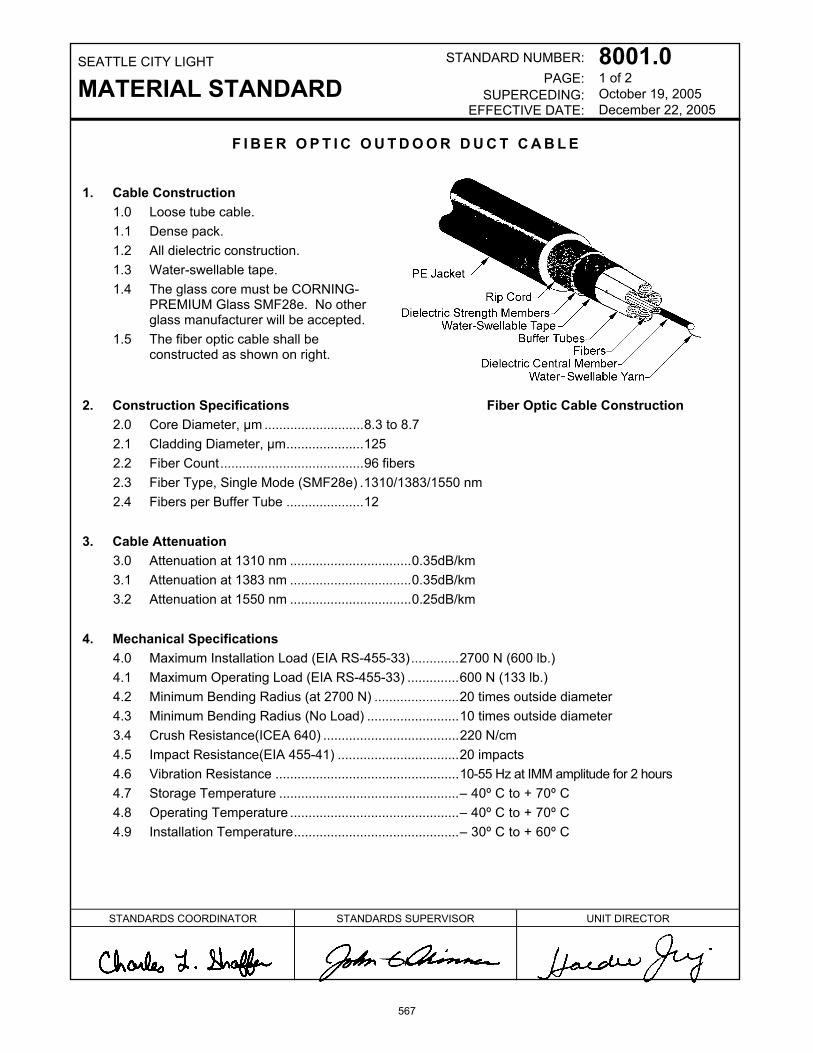
SEATTLE CITY LIGHT
MATERIAL STANDARDSTANDARD NUMBER:
PAGE:SUPERCEDING:
EFFECTIVE DATE:
8001.01 of 2October 19, 2005December 22, 2005
STANDARDS COORDINATOR STANDARDS SUPERVISOR UNIT DIRECTOR
F I B E R O P T I C O U T D O O R D U C T C A B L E
1. Cable Construction1.0 Loose tube cable.1.1 Dense pack.1.2 All dielectric construction.1.3 Water-swellable tape.1.4 The glass core must be CORNING-
PREMIUM Glass SMF28e. No otherglass manufacturer will be accepted.
1.5 The fiber optic cable shall beconstructed as shown on right.
2. Construction Specifications Fiber Optic Cable Construction2.0 Core Diameter, µm ...........................8.3 to 8.72.1 Cladding Diameter, µm.....................1252.2 Fiber Count.......................................96 fibers2.3 Fiber Type, Single Mode (SMF28e) .1310/1383/1550 nm2.4 Fibers per Buffer Tube .....................12
3. Cable Attenuation3.0 Attenuation at 1310 nm .................................0.35dB/km3.1 Attenuation at 1383 nm .................................0.35dB/km3.2 Attenuation at 1550 nm .................................0.25dB/km
4. Mechanical Specifications4.0 Maximum Installation Load (EIA RS-455-33).............2700 N (600 lb.)4.1 Maximum Operating Load (EIA RS-455-33) ..............600 N (133 lb.)4.2 Minimum Bending Radius (at 2700 N) .......................20 times outside diameter4.3 Minimum Bending Radius (No Load) .........................10 times outside diameter3.4 Crush Resistance(ICEA 640) .....................................220 N/cm4.5 Impact Resistance(EIA 455-41) .................................20 impacts4.6 Vibration Resistance ..................................................10-55 Hz at IMM amplitude for 2 hours4.7 Storage Temperature .................................................– 40º C to + 70º C4.8 Operating Temperature ..............................................– 40º C to + 70º C4.9 Installation Temperature.............................................– 30º C to + 60º C
567

SEATTLE CITY LIGHT
MATERIAL STANDARDFiber Optic Outdoor Duct Cable
STANDARD NUMBER:PAGE:
SUPERCEDING:EFFECTIVE DATE:
8001.02 of 2October 19, 2005December 22, 2005
5. Cable Identification. Length markings on cable shall indicate length in feet.
6. Reel Requirements. The cable reels shall be constructed as follows (see diagram). Deviation fromstated reel size must be approved by City Light communications engineer. Each reel end shall have twodrive holes (“dog holes”).
6.0 Minimum Cable Length on Reel, ft. .........................................25,0006.1 Reel Height, not to exceed, in. ................................................846.2 Reel Width, not to exceed, in. .................................................536.3 Arbor Hole, in...........................................................................3.256.4 Minimum Drive Hole diameter, in. ...........................................1.56.5 Maximum Drive Hole diameter, in. ..........................................2.06.6 Minimum Drive Hole, center to center, in. ...............................116.7 Maximum Drive Hole, center to center, in. ..............................28
Reel, End View
7. City Light Stock No.: 010311
8. Stock Unit: FT
9. Approved Manufacturers and Product Numbers:
AFL Telecommunications (Fujikura) P/N LE0964C8101N1
Corning Cable Systems P/N 096EW4-T4100D20
Prysmian (formerly Pirelli) P/N 0096HBS1LAFESJA
568

SEATTLE CITY LIGHT
MATERIAL STANDARD
STANDARD NUMBER:
PAGE: SUPERCEDING:
EFFECTIVE DATE:
8020.0 1 of 2 April 1, 2005 May 14, 2010
standards coordinator standards manager unit director
John Shipek John Shipek Pam S. Johnson
D U C T , A E R I A L , S E L F - S U P P O R T I N G
Aerial Duct
1. Duct Construction
1.1 Construction material: High tensile strength high density polyethylene (HDPE) with smooth inside and smooth outside and color shall be black with UV protection formula.
1.2 “Figure 8” construction incorporating galvanized support for aerial placement. The supporting strand shall be Class A flooded, 3/8-inch extra high-strength galvanized.
1.3 Standard dimension ratios (SDR): SIDR 9 (standard inside diameter dimension ratios).
1.4 The interior of the duct must be constructed of a material such that the coefficient of friction is, at a minimum, 79-per cent less than standard HDPE conduit with identical pulling forces.
1.5 Minimum bending radius (see construction specifications table) must prevent the duct exceeding 5-per cent of ovality.
1.6 Construction Specifications:
Typical Diameter, Inches
Inside Duct Outside Duct
Minimum Breaking Strength, Pounds
Minimum Bending Radius, Inches
Approximate Weight per 100 Feet, Pounds
1.25 1.5 15,000 16 55
569

SEATTLE CITY LIGHT MATERIAL STANDARD
STANDARD NUMBER:
PAGE: SUPERCEDING:
EFFECTIVE DATE:
8020.0 2 of 2 April 1, 2005 May14, 2010
2. Shipping
Duct shall be shipped in 5,000-foot lengths per reel. Duct shall be supplied on non-returnable reels.
3. Reels
The cable reels shall be constructed as follows (see diagram). Reels, including arbor hole, must meet City Light vehicle restraints.
Not to Exceed, inches Drive Holes (“Dog Holes”) 2 in Each Reel End
City Light Stock No.
Duct Length on Reel, feet
Max. Flange Diameter
Max. Outside Width of Reel
Arbor Hole, Diameter, inches
Diameter, inches
Center to Center, inches
010312 5,000 84 53 3.25 1.5 min. 2.0 max.
11 min. 28 max.
Reel, End View
4. Stock Unit: FT
5. Approved Manufacturer and Product Number:
AD Technologies, Part No. 5-152305-5000
570

Seat t le Ci ty L ight
MATERIAL STANDARD
s tandard number : superseding:
e f fec t ive date: page:
8021.00 October 27, 2006 May 14, 2010 1 of 2
standards coordinator standards manager unit director
John Shipek John Shipek Pam S. Johnson
I N N E R D U C T , C O R R U G A T E D
1. Scope This material standard covers the requirements for orange, high-density, polyethylene, corrugated innerduct. This material standard applies to the following Seattle City Light Stock Number: Stock No. Size, in Packaging 012689 1 reel
2. Application Innerduct is placed inside existing duct and is used to protect fiber-optic communications cable. Product is intended for pulls under 1000 feet and is provided with a silicon lining to minimize friction.
3. Construction 3.1 General
Innerduct shall be corrugated type. 3.2 Material
Innerduct material shall be orange, high-density polyethylene. Innerduct shall be provided with a silicon lining.
3.3 Dimensional Duct size, nominal........................................................... 1 in Diameter, average inside ......................................... 1.085 in Diameter, average outside ........................1.385 +/- 0.020 in Wall thickness, minimum.......................................... 0.060 in Wall thickness, maximum......................................... 0.080 in
3.4 Other Attributes Bend radius, minimum .................................................. 14 in Pull rope type .......................................................1/4 in. poly Pull rope ultimate tensile rating .............................. 1,250 lbs Pull rope safe working rating..................................... 500 lbs Pull rope shall have.......................... sequential foot marking
571

Seat t l e C i t y L igh t
MATERIAL STANDARD Innerduct, Corrugated
s tandard number : superseding:
e f fec t ive date: page:
8021.00 October 27, 2006 May 14, 2010 2 of 2
4. Packaging Innerduct shall be packaged on reels as follows:
Stock Number
Size, in
Length per Reel, ft
Reel Diameter, Nominal, in
Reel Width, Nominal, in
Weight per 100 feet, lbs
Weight per Reel, Approximate, lbs
012689 1 3,000 64 43 12.8 550 Reels shall be reusable, painted, tubular steel. Each reel shall be legibly marked with the following information:
• Manufacturer's identification • Product description • Shipping length of innerduct on reel • Date of manufacture • Seattle City Light's Purchase Order Number • Seattle City Light's Stock Number
5. Shipping Product shall be shipped to the address specified on the Purchase Order.
6. Issuance Stock Unit: FT
7. Approved Manufacturers
Manufacturer Catalog Number Reel Disassembly and Return Procedure Technical Bulletin
AD Technologies 4-156722-3000 DCEB-00001
572


![Kabasilas 20120206 revised[1]](https://static.fdokumen.com/doc/165x107/6312229a706da55dc20bc86d/kabasilas-20120206-revised1.jpg)