(12) United States Patent (10) Patent No.: US 7,321,834 B2
15
US007321834B2 (12) United States Patent (10) Patent No.: US 7,321,834 B2 Chu et al. (45) Date of Patent: Jan. 22, 2008 (54) METHOD FOR CALCULATING POWER 5,808,452 A * 9/1998 Gyugyi et al. ............ .. 323/207 FLOW SOLUTION OEAPOWER 6,011,381 A * 1/2000 Andrei 323/215 TRANsMIssION NETWORK THAT 6,025,701 A * 2/2000 Weinhold ................. .. 323/207 INCLUDES INTERLINE POWER FLOW 6,411,065 B1* 6/2002 Underwood et al. ........ .. 322/20 CONTROLLER (IPFC) 6,414,853 B2* 7/2002 Buckles et al. . . . . . . . . . . .. 363/14 6,498,464 B1 * 12/2002 Doht et al. ..... .. 323/247 (75) Inventors: Chia-Chi Chu, KWei-Shan (TW); 6,577,108 B2* 6/2003 Hubert et a1. 323/207 Sheng-Huei Lee, KWei-Shan (TW); 6,963,187 B2 * 11/2005 Bebic et al. .............. .. 323/207 Hung-Chi Tsai, KWei-Shan (TW) (73) Assignee: Chang Gung University, KWei-Shan OTHER PUBLICATIONS (TW) Edris, A-A., Adapa, R., Baker, M. H., Bohmann, L., Clark, K., . . . . . Habashi, K., Gyugyi, L., Lemay, J., Mehraban, A. S., Myers, A. K., ( ) Not1ce. Subject' to any d1scla1mer,~the term of this Reeve, J‘, Sener, F‘, Torgerson, D‘ R‘, Wood, R‘ R‘, “Proposed Terms Patent 15 extended or adlusted under 35 and De?nitions for Flexible AC Tranmission System (FACTS)”, U-S-C~ 15403) by 61 days- IEEE Transactions on Power Delivery, vol. 12, No. 4, Oct 1997, pp. 1848-1853. (21) Appl. No.: 11/183,051 _ (Contmued) Primary Examiner4Carol S. W. Tsai (74) Attorney, Agent, or FirmiC. G. Mersereau; Nikolai & (22) Filed: Jul. 15, 2005 (65) Prior Publication Data Mersereau’ PA‘ US 2007/0027642 A1 Feb. 1, 2007 (57) ABSTRACT (51) Int. Cl. (52) I50s2JC3l/04 (200%321260 702/179_ 702/188_ PoWer ?oW models of Interline PoWer FloW Controllers (IPFC) for large-scale poWer systems are studied, in details. Mathematical models of the IPFC, using the d-q axis decom positions of control parameters are derived. In this frame Work, for each IPFC, only tWo control parameters are added to the unknown vector in the iteration formula and the quadratic convergence characteristic is preserved. Simula tions results from several practical large-scale poWer sys tems embedded With multiple Convertible Static Compen sators (CSCs) demonstrate the effectiveness of the proposed (56) References Cited models. Comparisons With existing models are made to elucidate the performance of the convergence. 702/117; 307/102; 307/98; 307/99; 700/287; 700/293; 700/297; 700/291; 323/207; 323/282; 363/81 (58) Field of Classi?cation Search .............. .. 702/581, 702/60, 64, 67, 75, 179*181, 117, 188; 307/98, 307/99, 102; 323/207, 282; 363/81; 700/287, 700/297, 293, 291 See application ?le for complete search history. U.S. PATENT DOCUMENTS 5,698,969 A 12/1997 Gyugyi ..................... .. 323/207 8 Claims, 7 Drawing Sheets 307 301 \ 302 Calculate mismatch Modify the mismatch vector vector Using (13) 308 Modify the Jacobian Matrix Using (15) Form Jacobian matrix Update the unknown variables by the N-R iteration formula Using(12) Calculate d-q components of lPFC teminal bus voltage Using (1) 30 ls convergence obtained? Calculate P51, 051, Prl, Qn Using (5) (6) 305 Calculate Psk, Qsk, Prk, l Qrk ,Using (8) and (7) Calculate vserk Using(17) 306 Calculate Pdc Using (2)
-
Upload
khangminh22 -
Category
Documents
-
view
1 -
download
0
Transcript of (12) United States Patent (10) Patent No.: US 7,321,834 B2

US007321834B2
(12) United States Patent (10) Patent No.: US 7,321,834 B2 Chu et al. (45) Date of Patent: Jan. 22, 2008
(54) METHOD FOR CALCULATING POWER 5,808,452 A * 9/1998 Gyugyi et al. ............ .. 323/207
FLOW SOLUTION OEAPOWER 6,011,381 A * 1/2000 Andrei 323/215 TRANsMIssION NETWORK THAT 6,025,701 A * 2/2000 Weinhold ................. .. 323/207
INCLUDES INTERLINE POWER FLOW 6,411,065 B1* 6/2002 Underwood et al. ........ .. 322/20
CONTROLLER (IPFC) 6,414,853 B2* 7/2002 Buckles et al. . . . . . . . . . . .. 363/14
6,498,464 B1 * 12/2002 Doht et al. ..... .. 323/247
(75) Inventors: Chia-Chi Chu, KWei-Shan (TW); 6,577,108 B2* 6/2003 Hubert et a1. 323/207 Sheng-Huei Lee, KWei-Shan (TW); 6,963,187 B2 * 11/2005 Bebic et al. .............. .. 323/207
Hung-Chi Tsai, KWei-Shan (TW)
(73) Assignee: Chang Gung University, KWei-Shan OTHER PUBLICATIONS (TW) Edris, A-A., Adapa, R., Baker, M. H., Bohmann, L., Clark, K.,
. . . . . Habashi, K., Gyugyi, L., Lemay, J., Mehraban, A. S., Myers, A. K., ( ) Not1ce. Subject' to any d1scla1mer,~the term of this Reeve, J‘, Sener, F‘, Torgerson, D‘ R‘, Wood, R‘ R‘, “Proposed Terms
Patent 15 extended or adlusted under 35 and De?nitions for Flexible AC Tranmission System (FACTS)”, U-S-C~ 15403) by 61 days- IEEE Transactions on Power Delivery, vol. 12, No. 4, Oct 1997, pp.
1848-1853. (21) Appl. No.: 11/183,051 _
(Contmued) Primary Examiner4Carol S. W. Tsai (74) Attorney, Agent, or FirmiC. G. Mersereau; Nikolai &
(22) Filed: Jul. 15, 2005
(65) Prior Publication Data Mersereau’ PA‘ US 2007/0027642 A1 Feb. 1, 2007
(57) ABSTRACT (51) Int. Cl.
(52) I50s2JC3l/04 (200%321260 702/179_ 702/188_ PoWer ?oW models of Interline PoWer FloW Controllers (IPFC) for large-scale poWer systems are studied, in details. Mathematical models of the IPFC, using the d-q axis decom positions of control parameters are derived. In this frame Work, for each IPFC, only tWo control parameters are added to the unknown vector in the iteration formula and the quadratic convergence characteristic is preserved. Simula tions results from several practical large-scale poWer sys tems embedded With multiple Convertible Static Compen sators (CSCs) demonstrate the effectiveness of the proposed
(56) References Cited models. Comparisons With existing models are made to elucidate the performance of the convergence.
702/117; 307/102; 307/98; 307/99; 700/287; 700/293; 700/297; 700/291; 323/207; 323/282;
363/81 (58) Field of Classi?cation Search .............. .. 702/581,
702/60, 64, 67, 75, 179*181, 117, 188; 307/98, 307/99, 102; 323/207, 282; 363/81; 700/287,
700/297, 293, 291 See application ?le for complete search history.
U.S. PATENT DOCUMENTS
5,698,969 A 12/1997 Gyugyi ..................... .. 323/207 8 Claims, 7 Drawing Sheets
307 301 \
302 Calculate mismatch Modify the mismatch
vector vector Using (13) 308
Modify the Jacobian Matrix Using (15)
Form Jacobian matrix
Update the unknown variables by the N-R
iteration formula Using(12) Calculate d-q components
of lPFC teminal bus voltage Using (1)
30
ls convergence obtained? Calculate P51, 051, Prl,
Qn Using (5) (6) 305
Calculate Psk, Qsk, Prk, l Qrk ,Using (8) and (7) Calculate vserk Using(17)
306
Calculate Pdc Using (2)

US 7,321,834 B2 Page 2
OTHER PUBLICATIONS
Gyugyi, L., Kalyan, K., Schauder C. D., “The Interline Power Flow Controller Concept: A New Approach to Power Flow Management in Transmission Systems”, IEEE Transactions on Power Delivery, vol. 14, No. 3, Jul. 1999, pp. 1115-1123. Zhang, X. -P., “Modelling of the interline power ?ow controller and the generalised uni?ed power ?ow controller in Newton power ?ow”, IEE Proc.-Gener. Transm. Distrib., vol. 150, No. 3, May 2003, pp. 268-274.
Wei, X. Chow, J. H., Fardanesh, B. & Edris, A-A., “A Common Modeling Framework of Voltage-Sourced Converters for Load Flow, Sensitivity and Dispatch Analysis”, IEEE Transactions on Power Systems, vol. 19, No. 2, May 2004, pp. 934-941. Fardanesh, B., “Optimal Utilization, Sizing, and Steady-State Per formance Comparison of Multiconverter VSC-Based FACTS Con trollers”, IEEE Transactions on Power Delivery, vol. 19, No. 3, Jul. 2004, pp. 1321-1327.
* cited by examiner

U.S. Patent Jan. 22, 2008 Sheet 1 0f 7 US 7,321,834 B2
H .2» 6 P gs
_ 2 a 28: Q GE fa a > >
_ A 23H DH“, -_> g ~m> _“ 2.
Va C(CL v6

U.S. Patent Jan. 22, 2008 Sheet 2 0f 7 US 7,321,834 B2
m wk. P
Dmk E QA VE
+@ km
+ @N i3 + @fmmk .DI \PS A?
N .3 kl
mkmw Qk
Twwkb. 76% %
NEW K
utmnkbl -
a.
UNMK .FTQNMHA Wank .DIQQMN

U.S. Patent
301
302
303
Jan. 22, 2008
START
1
Sheet 3 0f 7
Calculate mismatch vector
t Form Jacobian matrix
Calculate d-q components of lPFC teminal bus voltage Using (1)
US 7,321,834 B2
c? f3” Modify the mismatch vector Using (13)
Matrix Using (15)
Update the unknown 2 variables by the N-R
iteration formula Using(12)
so4c\ ____i___ 305
306
Calculate P51, Q51 , Pn, Qn Using (5) (6)
Calculate Psk, Qsk, Prk, Qrk,Using (8) and (7)
Calculate Pdc Using (2)
ls convergence obtained?
’ Calculate Vserk Using(17)l (jg
/
308
t / Modify the Jacobian
309
310
311

U.S. Patent Jan. 22, 2008 Sheet 4 0f 7 US 7,321,834 B2
m
w .wE m
Even 20 E? 2m Eve: at E2 h“e .82 “a “$2 6
--4
En D t.
umewsaw

U.S. Patent Jan. 22, 2008 Sheet 5 0f 7 US 7,321,834 B2
3; EQWEQ: m
E mfg? 2
3.

U.S. Patent Jan. 22, 2008 Sheet 6 0f 7 US 7,321,834 B2
IPFC
Vir] \ _
VSQerm -0.0191 ta---|a---E|---E|---a---{J
2 4 Iterations
-0.02
hjdvmmmzo> Fig. 6

U.S. Patent Jan. 22, 2008 Sheet 7 0f 7 US 7,321,834 B2
Iteration numbers of Tested System Required for Power Flow Solutio in Different Cases
Case A B C D
Iterati
number 5 5 5 6
Fig.7

US 7,321,834 B2 1
METHOD FOR CALCULATING POWER FLOW SOLUTION OF A POWER TRANSMISSION NETWORK THAT
INCLUDES INTERLINE POWER FLOW CONTROLLER (IPFC)
BACKGROUND OF THE INVENTION
Field of the Invention
The present invention relates generally to a steady-state model of an Interline Power Flow Controller (IPFC) in this technical ?eld, and more particularly to an improved method for incorporating the IPFC model into a power ?ow solver which can be applied to simulation software of power systems. Not only does this method deliver a feature of rapid convergence, but it also considers the actual losses arising from the IPFC. So, it serves as an important foundation for installation and control of the Interline Power Flow Con troller (IPFC), while expanding and facilitating the conges tion management/prevention of power systems.
The newly-developed ?exible AC transmission system is composed of VSCs (voltage source-based converters). Typi cal examples of USCs are Static Synchronous Compensator (STATCOM), Static Synchronous Compensator (SSSC), Uni?ed Power Flow Controller (U PFC) and Interline Power Flow Controller (IPFC). Of which, many scholars put efforts on the study of steady-state models of IPFC relating to the calculation of the power ?ow, among whom Gyugyi, L. was the ?rst one to put forward the IPFC for controlling the power ?ow in an electric transmission system in ‘Apparatus and Method for Interline Power Flow Control’ (US. Pat. No. 5,698,969, Dec. 16, 1997).
Moreover, the basic theory and operating principle of the IPFC were initiated in 1999 by Gyugyi, L., Sen, K. and Schauder, C.: ‘The Interline Power Flow Controller Con cept: a New Approach to Power Flow Management in Transmission Systems’, (IEEE Trans. on Power Delivery, Vol. 3, No. 14, 1999, pp. 1115-1123). This article showed that the IPFC can resolve the congestion of a transmission system by adjusting the active power and the reactive power ?ow of the transmission line.
Furthermore, a Newton-Raphson (NR) algorithm incor porating of the IPFC steady-state model was developed in 2003 by X.-P. Zhang, “Modeling of the Interline Power Flow Controller and the Generalized Uni?ed Power Flow Con troller in Newton Power Flow”, (IEE Proceedings. Genera tion, Transmission & Distribution, Vol. 150, No. 3, May. 2003, pp. 268-274). This article provided a Newton-Raph son algorithm for power ?ow analysis when a power system is embedded with IPFC.
Subsequently, the application of the IPFC based on VSC was further developed by B. Fardansh: ‘Optimal UtiliZation, SiZing, and Steady-State Performance Comparison of Multi level VSC-Based FACTS Controller’ (IEEE Trans. on Power Delivery, Vol. 19, No. 3, July. 2004, pp. 1321 1327)iand Xuan. Wei, J. H. Chow, BehurZ Fardanesh and Abdel-Aty Edris: ‘A Common Modeling Framework of Load Flow, Sensitivity, and Dispatch Analysis’ (IEEE Trans. on Power System, Vol. 19, No. 2, May. 2004, pp. 934-941).
In fact, Interline Power Flow Controller (IPFC) is based on a framework wherein Voltage Source Converters (VSCs) are linked to a DC coupling capacitor. Among the VSCs, one of the converters is a system with one degree of freedom, which is able to adjust the active or reactive power of a transmission line, whereas each of the remaining converters is a system with two degrees of freedom, which is able to adjust simultaneously the active and reactive power of a plurality of transmission lines.
20
25
30
35
40
45
50
55
60
65
2 Owing to an increasing electrical load demand, existing
power transmission systems cannot satisfy the requirements of long-distance and high-capacity power transmission. Also, erection of new transmission lines remains limited for environmental protection purposes. Therefore, an important approach to resolve this problem would be utiliZing the potential capability of the existing transmission network by improving the power ?ow distribution. Additionally, as power systems operate in a more complex environment with the adoption of market-oriented power management sys tems, the power system must have a stronger control ability to meet the technical and economical requirements of cus tomers.
SUMMARY OF THE INVENTION
Thus, the objective of the present invention is to provide a method for incorporating the steady-state model of an Interline Power Flow Controller (IPFC) into a Newton Raphson algorithm. The steady-state model of IPFC can take into account the losses arising from coupling transformers, without compromise of the rapid convergence characteristic for the system solution, while the speed of convergence is insensitive to the selection of the initial values of the control variables of the IPFC model, thus exhibiting the advantages of a new model such as robustness and rapid convergence.
To accomplish the previously mentioned object, Interline Power Flow Controller (IPFC) comprises a plurality of VSCs and a DC coupling capacitor, where all converters are linked to the DC coupling capacitor. Among the VSCs, one converter is a system with one degree of freedom, which is able to adjust the active or reactive power of transmission line, whereas each of the remaining converters is a system with two degrees of freedom, which is able to adjust simultaneously the active and reactive power of a plurality of transmission lines, thus avoiding ef?ciently the conges tion of the transmission system. When the Newton-Raphson method is used to calculate unknown control variables, the variables of the IPFC model are expressed in d-q compo nents. This feature can preserve the characteristic of rapid convergence and reduce both the complexity of computation and the number of control variables incorporating into the iteration formula. The other features and advantages of the present invention
will be more readily understood upon a thoughtful delibera tion of the following detailed description of a preferred embodiment of the present invention with reference to the accompanying drawings and icons. However, it should be appreciated that the present invention is capable of a variety of embodiments and various modi?cations by those skilled in the art, and all such variations or changes shall be embraced within the scope of the following claims.
BRIEF DESCRIPTION OF THE DRAWINGS
FIG. 1 shows a framework of Interline Power Flow Controller (IPFC) of the present invention.
FIG. 2 shows an equivalent circuit of Interline Power Flow Controller (IPFC) of the present invention.
FIG. 3 shows the ?ow chart of calculating power ?ow with introduction of IPFC model.
FIG. 4 depicts the power mismatch of bus terminal voltage of Interline Power Flow Controller (IPFC) of the present invention.
FIG. 5 depicts the quadratic convergence characteristic of a power system embedded with Interline Power Flow Con troller (IPFC).
FIG. 6 Convergence characteristics of control parameters of IPFC.
FIG. 7 refers to Table 1 of the present invention.

US 7,321,834 B2 3
DETAILED DESCRIPTION OF THE INVENTION
The present invention intends to provide a method for incorporating a steady-state model of IPFC into the Newton Raphson algorithm. The steady-state model according to the present invention can fully depict the reactive power com pensation and the active power exchanged among VSCs, and take into account of the losses arising from coupling trans formers. An interline Power Flow Controller (IPFC) com prises a plurality of VSCs and a DC coupling capacitor, where the DC sides of converters are linked together to the DC coupling capacitor. Among the VSCs, one converter is a system with one degree of freedom, which is able to adjust the active or reactive power of a transmission line, whereas each of the remaining converters is a system with two degrees of freedom, which is able to adjust simultaneously the active and reactive power of a plurality of transmission lines, thus avoiding e?iciently the congestion of a transmis sion system. When the Newton-Raphson method is used to calculate unknown control variables, the variables of the interline power ?ow controller are expressed as d-q axis components using orthogonal projection technology. This model can preserve the characteristic of rapid convergence and reduce both the complexity of computation and the number of the additional iteration variables due to the introduction of IPFC. IPFC Static Model
Operating Principle of IPFC The framework of the Interline Power Flow Controller
(IPFC) is shown in FIG. 1, wherein it comprises a plurality of VSCs and a DC coupling capacitor. VSCl is a system with one degree of freedom, which can compensate the reactive power to the transmission line through a coupling transformer, and then can balance the active power with VSC2~VSCn by modulating the voltage of the DC coupling capacitor. Each of VSC2~VSCn is a control system with two degrees of freedom. The DC sides of VCSs are linked together to the DC coupling capacitor. All converters are linked to the transmission lines via coupling transformers. Each of the transmission lines is separately compensated with the reactive power. In addition, the active power is transferred among the transmission lines via the DC link of VSCs. The VSC2~VSCn of the present invention can simul taneously compensate both the active and reactive power, while various transmission lines are controlled indepen dently with each other, thereby avoiding ef?ciently the congestion of the system.
IPFC Equivalent Circuit For the steady-state model of the IPFC according to the
present invention, the variables of the models are decom posed into two orthogonal components, d-axis and q-axis components, thus ensuring that the active and reactive power of transmission lines are subjected to decoupling control. The new model adjusts the active power of the transmission lines using the converter’s d-axis current, and the q-axis current is responsible for adjusting the reactive power. Meanwhile, the d-axis current of VSCl is respon sible for adjusting the voltage of the DC coupling capacitor. After a d-q decomposition, the voltage variable is expressed as:
nfvnkgwawerresv (1)
wherein, the superscript “D” and “Q” refer to the d component and q component of the speci?ed variable; the subscript “k” refers to the converter of no. k; and the subscript “x” can be replaced by “s”, “r”, or “ser”, for indicating the variables related to the sending-bus, the receiving-end bus and the series branch of the IPFC.
20
25
30
35
40
50
55
60
65
4 Based on a d-q axis decomposition, the present invention
provides a steady-state model of an Interline Power Flow Controller (IPFC). The equivalent circuit of a static model of an IPFC is shown in FIG. 2, where the IPFC’s series branch represents a voltage source and equivalent impedance, while the impedance models the coupling transformer. If the converters are lossless, the transferred active power among converters is expressed as:
” (2) Pdc = Pserl + Z Pserk = 0
/<:2
where, Pserk is the active power injected by VSCk, and SSSC refers to a special version of the Interline Power Flow Controller (IPFC). Because the SSSC is with a single series branch, equation (2) becomes PdCIP IPFC Power Flow Model
serl '
IPFC Equivalent Load Model
The IPFC model of the present invention is represented by nonlinear load demands at the terminal buses of the IPFC. The equivalent load demands can be modi?ed at each iteration according to control objectives and the voltage of the buses. Based on the d-q decomposition, the ?rst series branch’s current of IPFC model is expressed as:
D D D
Iserl _ l [Rmr _Xserl ] Vsl + Vserl — Vrl (3) 13,1 Rszerl + Xé? Xserl Rserl vsgrl _ v5
VVID and VVIQ in equation (3) can be obtained from DandV serl 58,1 Q of the
?rst branch are unknown variables when using Newton Raphson (N-R) method, which may be updated at each iteration;
equation (1). The d-q components V
According to the de?nition of the complex power, the load demand of the ?rst branch of IPFC is expressed as:
[PS1]_ [VS] 0 ] [Sen] (4) Qsl O _ S1 ISQM
{Mk v3 v5 12,1] (5) Q1 v3 —v.? 15.1
Apart from the ?rst branch, other branches of IPFC control the objectives according to different power ?ows, with the equivalent load demand expressed as:
ref Plinek ref Qlinek
where, Ph-nek’ef and Oil-Mk"?f are reference values of active and reactive power of the bus at the receiving end of the No. k branch. Apart from the ?rst branch, the equivalent load demand of the other branches of IPFC at the sending end bus is:

US 7,321,834 B2 6
branch of the IPFC is replaced by tWo nonlinear equivalent loads, the mismatch vector is modi?ed as follows:
fIfl'AfIPFC (12)
Where,
AfIPFc = [Afbus | AfcontrollT
f‘ is the mismatch vector considering the equivalent load of Interline PoWer FloW Controller (IPFC), AfIPFC includes AfBuS and Afcomrol, of Which AfBuS refers to the variable of bus terminal of Interline PoWer FloW Controller (IPFC), and Afcomrol refers to control constraints related to Interline PoWer FloW Controller (IPFC). The unknown vectors Will be changed When an IPFC is
embedded in a poWer system. In Interline PoWer FloW
Controller (IPFC), VserlD and VSMQ indicate state variables. Thus, the elements of the unknown vector related to Interline PoWer FloW Controller (IPFC) can be expressed as:
T XIPFC = [Xbm | xControl] (13)
T = [011 V11 0A Vrl 01k Vsk ark Vrk I VSIZrJ V51]
Where, xBMS includes the original state variables and xcon’ troZ includes the control variables introduced by IPFC. The Jacobian matrix of IPFC can be obtained from the ?rst-order partial differentiation for f‘:
[p1 ] _ v1 v5 121 ] <7> Qsk v5 —V!Z 15,1
5
Where,
13,1 _ 1 V1; V5 [PM] 10 15,1 "31 v5 4/11’ Qrk
PoWer Compensation of Converter 15 After simple algebraic manipulation, the poWer injected
by VSCs is:
PSEAIISEAD VSEr1D+ISEr1QVSEr1Q (8)
Pserk:Iserk;)( VrkD_ V519)” serkQ( VrkD+ VSICQ)+(ISEVICDZ+ 20 Imk )Rmk (9)
VSCl is used to maintain a balanced active poWer among converters. In addition, VSCl provides a compensation of the reactive poWer, and controls the active or reactive poWer betWeen the sending-end s1 and the receiving-end r1 of the 25 bus:
fser1 :Prl+Plinelref:0 OTfSEr1IQr1+QIinE1rEf (10)
N-R Iteration Algorithm 30 PoWer ?oW solution can be obtained from Newton-Raph
son method, With the iteration equation expressed beloW:
x(k+l):x(k)—flf(x) (11)
Where x is an unknoWn vector. The state variables in x 35 include voltage magnitude and phase angle of the bus as Well as independent control variables of IPFC. f(x) refers to the mismatch vector of the active and reactive poWer of buses. J refers to the corresponding Jacobian matrix. Because each
60x1 60x1 60A
(9Q11 (9Q11 aQn 6 0S1 19 V11 6 0r1
3Pr1 3Pr1 3Pr1 3 0S1 19 V11 3 0r1
6Q1 6Q1 aQr1 6 0S1 6 Vsl 6 OH
BPSk O O
AJIPFC = 60x1
aQsk O 0
60x1 0 O O
O O O
BPdc BPdc BPdc 6 0S1 19 V11 6 0r1
afserl afserl afserl 3 0S1 19 V11 3 0r1
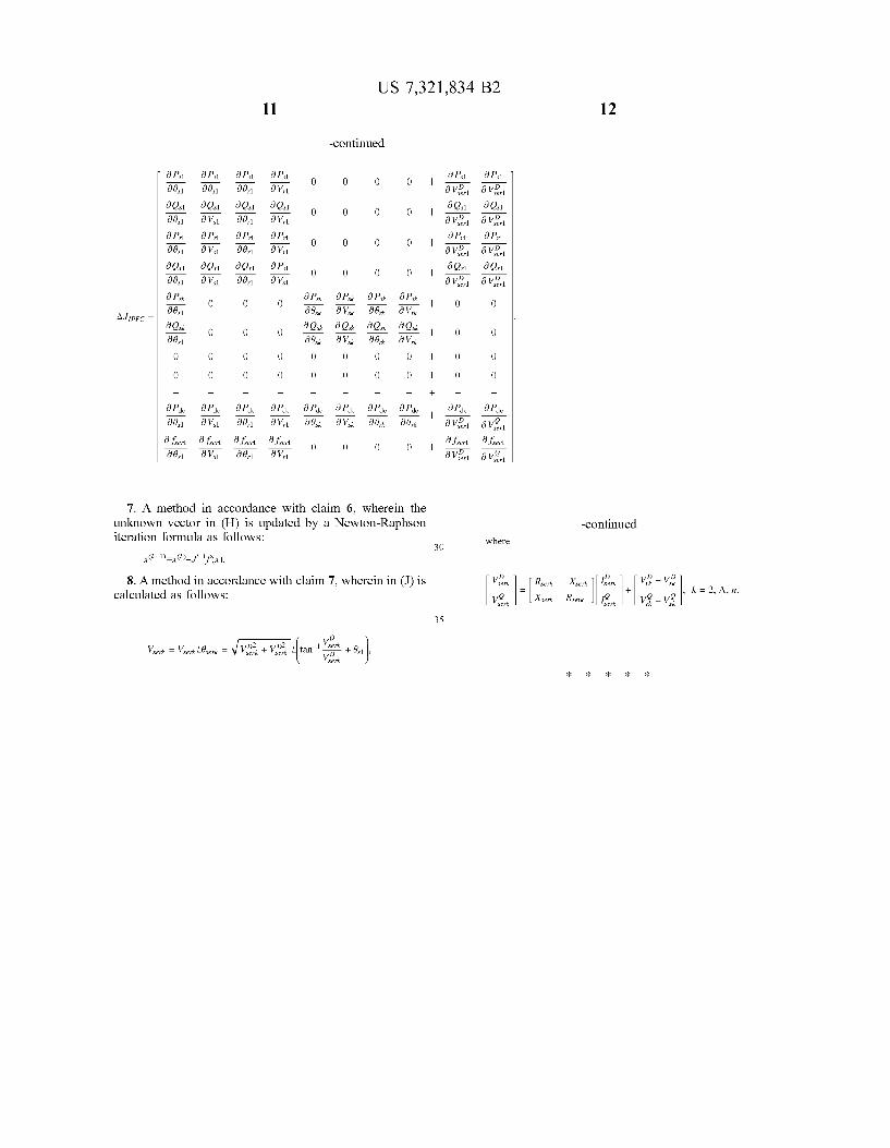
J’:J+AJ l 4 [PFC
Where:
a Vrl ‘9 vslgrl ‘9 VSQEA
6 Q1 3 Q11 6 Q1 0 0 0 0
a Vrl i 6 VSIZA ‘9 VSlLZrl l9 Prl l9 Prl l9 Prl
0 0 0 0 ‘9 Vrl ‘9 VSlLZrl ‘9 VSlLZrl a PS1 6 Qrl a Qrl
0 0 0 0 19 V11 i 6 VSIZA ‘9 VSlLZrl
6 PS 6 PS 6 PS 6 PS 0 k k k k 0 O a 01k 3 Vsk l9 ark l9 Vrk 6 6 6 6 O Qsk Qsk Qsk Qsk ‘ O O a 01k 6 Vsk a ark a Vrk
0 0 0 0 0 | 0 0
0 0 0 0 0 | 0 0
_ _ _ _ + _ _
6 Pdc 6 Pdc 6 Pdc 6 Pdc 6 Pdc 6 Pdc 6 Pdc
a Vrl a 01k 6 Vsk a ark a Vrk 6 V5,, 6 vgrl
a ser a ser a ser f 1 0 0 0 0 ‘ f D 1 f 1 ‘9 Vrl ‘9 Vim 6 vg?

US 7,321,834 B2 7
The elements at upper left comer are the original Jacobian matrix. The siZe of the Jacobian matrix is increased by two. Accordingly, the siZe of the unknown vector and the mis match vector will increase by two due to the introduction of the IPFC. It can facilitate the fast convergence speed and preserve the original quadratic convergence characteristic. This theoretical derivation will be veri?ed by subsequent simulation results.
Equivalent Series Voltage of Converter If the power ?ow solution converges, the d-q components
of the series voltage of VSC2-VSCn may be expressed as:
D D D D
Vserk : [Rmk _Xserk ] Iserk + Vrk — Vsk , k = 2, A, n (15) Vim Xmk RM 4% V5 — V5
Thus, the siZe and phase of synchronous voltage of VSC2-VSCn can be expressed as:
(16)
serk
Case Analysis To validate the IPFC model of the present invention,
different test systems are imbedded with the IPFCs. FIG. 3 shows a ?ow chart of calculating power ?ow solution with incorporation of IPFC model. The ?rst step (301) is to calculate the original mismatch vector, then establish the corresponding Jacobian matrix in step (302). Next, step (303) is to obtain d-q components of bus voltage VVD and V’Q at the receiving-end of IPFC after using an orthogonal decomposition, and step (304) to calculate the active and reactive power of the sending-end and receiving-end buses of VSC1. Furthermore, step (305) is to calculate the active and reactive power of the sending-end and receiving-end buses of VSC2-VSCn, step (306) to calculate the active power ?owing from the DC coupling capacitor Pdc, fol lowed by steps (307) and (308) to modify the mismatch vector and the Jacobian matrix, and step (3 09) to update the unknown vector via Newton-Raphson iteration, step (310) to judge the convergence of the ?ow solution. Otherwise, return to step (301) to recalculate the mismatch vector. In the case of convergence, the ?nal step (311) is to obtain the voltage of converter. In the end, steady-state model of IPFC of the present invention and GUPFC of FACTS family are added into two test systems, whereby Matpower 2.0 is used to verify the performance. The test system includes IEEE 57 bus system and IEEE 118 bus system, which conduct analysis in the following four cases: 1. Case A: analyZe IEEE 57 bus system, without installation
of any Interline Power Flow Controller (IPFC). 2. Case B: IEEE 57 bus system is embedded with an
Interline Power Flow Controller (IPFC) and a GUPFC. The Interline Power Flow Controller (IPFC) installed between the transmission line 8-7 and the transmission line 9-13 to control the active power of transmission line 8-7 and both the active and reactive power of transmission line 9-13. The GUPFC controls both the voltage magni tude of bus 56 and both the active and reactive power ?ow of the transmission line 56-42 and transmission line 41-11.
20
25
30
35
40
55
60
65
8 3. Case C: analyZe IEEE 118 bus system, without installa
tion of Interline Power Flow Controller (IPFC). 4. Case D: IEEE 118 bus system is embedded with two 2
Interline Power Flow Controller (IPFC) and 2 GUPFC. IPFC1 installed between the transmission line 12-11 and transmission line 12-3 to control the active power of the transmission line 12-11 and both the active and reactive power of transmission line 12-3. IPFC2 installed between the transmission line 80-77 and transmission line 80-97 to control the active power of transmission line 80-77 and both the active and reactive power of the transmission line 80-97. GUPFCl is used to control the voltage magnitude of bus 45 and both the active and reactive power ?ow of the transmission line 45-44 and transmission line 45-46. GUPFC2 is used to control the voltage magnitude of bus 94 and both the active and reactive power ?ow of trans mission lines 94-95, 94-93 and 94-100. It is assumed that all parameters of the coupling trans
formers are the same: Rser:0.01 p.u. and Xser:0.1 p.u. The permissible tolerance of Newton-Raphson iteration is 10-12, and control variables VserlD and Vserzg of Interline Power Flow Controller (IPFC) have Zero initial values. The com parison of iteration numbers required for system conver gence in different cases is listed in Table 1 (eg FIG. 7). The simulation results show that the system can improve its stability and maintain an excellent convergence feature with introduction of an IPFC model.
To verify the applicability of a model initiated by the present invention, Interline Power Flow Controller (IPFC) is connected to different sending-end busses. FIG. 4 shows the power mismatch of bus terminal voltage with introduction of Interline Power Flow Controller (IPFC), wherein the mis match is close to 10-15 after 5 iterations. The iteration numbers of the test system required for a power ?ow solution in different cases are listed in Table 1. For the same test system embedded with a IPFC model initiated by Zhang, X.-P., “Modeling of the Interline Power Flow Controller and the Generalized Uni?ed Power Controller in Newton Power Flow” (IEE Proc. Gener. Trans. Distrib., Vol. 3, No. 150, pp. 268-274, 2003), 8 iterations are required to obtain a con verged solution. But in fact, the test system embedded with IPFC of the present invention can obtain a converged solution after 6 iterations, showing that IPFC of the present invention features a rapid convergence. FIG. 5 depicts the results of quadratic convergence for IPFC in Case D, where the dashed line is a typical quadratic convergence curve, showing that quadratic convergence curve of the present invention is similar to a typical curve. FIG. 6 depicts the convergence pattern of control variables of IPFC in Case D which can reach to a nearly target value after 2 iterations, showing an excellent convergence feature of this system.
In brief, the aforementioned involve an innovative inven tion that can promote overall economic efficiency thanks to its many functions and actual value. And, no similar prod ucts or equivalent are applied in this technical ?eld, so it would be appreciated that the present invention is granted patent as it meets the patent-pending requirements. What is claimed is: 1. A method for calculating power ?ow solution of a
power transmission network that includes the interline power ?ow controllers (IPFCs), said IPFC having a plurality of voltage source converters (VSCs), wherein the DC sides of said VSCs are linked together to a DC coupling capacitor and the AC sides are linked to the transmission lines of said power transmission network through coupling transformers; said VSCs being modeled by a plurality of series branches, each series branch comprising a voltage source in series with

US 7,321,834 B2
an impedance; the ?rst series branch being able to adjust the active or reactive power of a transmission line of said power transmission network; each of the remaining series branches being able to adjust simultaneously the active and reactive power of a transmission line of said power transmission network; said power ?ow solution including the voltage at each bus of said power transmission network and the equiva lent voltages of the VSCs; said method comprising: A) calculating an original mismatch vector without con
sidering the IPFC; B) establishing a Jacobian matrix corresponding to the
original mismatch vector in A); C) obtaining d-q components of a receiving-end bus
voltage of the IPFC by a d-q axis decomposition; D) calculating equivalent active and reactive loading at
sending-end and receiving-end buses of a ?rst branch of the IPFC;
E) calculating equivalent active and reactive loading at sending-end and receiving-end buses of remaining series branches;
F) calculating active power ?owing from a DC coupling capacitor;
G) modifying the original mismatch vector and the J aco bian matrix;
H) updating an unknown vector by an iteration formula; I) judging convergence of the power ?ow solution; if the
solution converges within a speci?ed tolerance, going to J); otherwise, going to A);
J) calculating the equivalent voltage of a converter; and k) using the result in J in setting up a steady state model
of IPFC. 2. A method in accordance with claim 1, wherein the d-q
axis decomposition of the receiving-end bus voltage in (C) is calculated as follows:
3. A method in accordance with claim 2, wherein the equivalent active and reactive loading at the sending-end and receiving-end buses of the ?rst series branch of the IPFC in (D) is obtained as follows:
f’ = f + AfIPFc;
1’ = J +AJIPFC;
where,
AfIPFc = [Afbus | AfmmmllT,
20
25
30
40
45
10 where
Rser]
4. A method in accordance with claim 3, wherein the equivalent active and reactive loading at the sending-end and receiving-end buses of remaining series branches in (E) are obtained as follows:
5. A method in accordance with claim 4, wherein the active power ?owing from the DC coupling capacitor in (F) is obtained as follows:
n
Pdc = serl +2 Pserk = 0, /<:2
where
_ D D Q Q Pserl — Iserl Vserl + Iserl Vserl
6. A method in accordance with claim 5, wherein the original mismatch vector and the Jacobian matrix in (G) is modi?ed as follows:
Prk fml lT,