1056 KAHE-SISENDILINE INTELLIGENTNE ANALÜSAATOR
124
Juhend PN 51-1056/rev.I Märts 2012 1056 KAHE-SISENDILINE INTELLIGENTNE ANALÜSAATOR
-
Upload
khangminh22 -
Category
Documents
-
view
3 -
download
0
Transcript of 1056 KAHE-SISENDILINE INTELLIGENTNE ANALÜSAATOR
JuhendPN 51-1056/rev.I Märts 2012 1056
KAHE-SISENDILINE INTELLIGENTNE ANALÜSAATORDUAL-INPUT INTELLIGENT ANALYZER
Instruction ManualPN 51-1056/rev.IMarch 2012 1056

ESSENTIAL INSTRUCTIONSREAD THIS PAGE BEFORE PROCEEDING!
Your instrument purchase from RosemountAnalytical, Inc. is one of the finest available for yourparticular application. These instruments have beendesigned, and tested to meet many national andinternational standards. Experience indicates that itsperformance is directly related to the quality of theinstallation and knowledge of the user in operatingand maintaining the instrument. To ensure their con-tinued operation to the design specifications, per-sonnel should read this manual thoroughly beforeproceeding with installation, commissioning, opera-tion, and maintenance of this instrument. If thisequipment is used in a manner not specified by themanufacturer, the protection provided by it againsthazards may be impaired.• Failure to follow the proper instructions may
cause any one of the following situations tooccur: Loss of life; personal injury; property dam-age; damage to this instrument; and warrantyinvalidation.
• Ensure that you have received the correct modeland options from your purchase order. Verify thatthis manual covers your model and options. Ifnot, call 1-800-854-8257 or 949-757-8500 torequest correct manual.
• For clarification of instructions, contact yourRosemount representative.
• Follow all warnings, cautions, and instructionsmarked on and supplied with the product.
• Use only qualified personnel to install, operate,update, program and maintain the product.
• Educate your personnel in the proper installation,operation, and maintenance of the product.
• Install equipment as specified in the Installation section of this manual. Follow appropriate localand national codes. Only connect the product toelectrical and pressure sources specified in thismanual.
• Use only factory documented components forrepair. Tampering or unauthorized substitution ofparts and procedures can affect the performanceand cause unsafe operation of your process.
• All equipment doors must be closed and protec-tive covers must be in place unless qualified per-sonnel are performing maintenance.
Equipment protected throughout by double insulation. • Installation and servicing of this product may expose personel
to dangerous voltages. • Main power wired to separate power source must be
disconnected before servicing.• Do not operate or energize instrument with case open!• Signal wiring connected in this box must be rated at least
240 V. • Non-metallic cable strain reliefs do not provide grounding
between conduit connections! Use grounding type bushings and jumper wires.
• Unused cable conduit entries must be securely sealed by non-flammable closures to provide enclosure integrity in compliance with personal safety and environmental protectionrequirements. Unused conduit openings must be sealed with NEMA 4X or IP65 conduit plugs to maintain the ingress protection rating (NEMA 4X).
• Electrical installation must be in accordance with the NationalElectrical Code (ANSI/NFPA-70) and/or any other applicable national or local codes.
• Operate only with front panel fastened and in place. • Safety and performance require that this instrument be
connected and properly grounded through a three-wire power source.
• Proper use and configuration is the responsibility of the user.
This product generates, uses, and can radiate radio frequencyenergy and thus can cause radio communication interference.Improper installation, or operation, may increase such interfer-ence. As temporarily permitted by regulation, this unit has notbeen tested for compliance within the limits of Class A comput-ing devices, pursuant to Subpart J of Part 15, of FCC Rules,which are designed to provide reasonable protection againstsuch interference. Operation of this equipment in a residentialarea may cause interference, in which case the user at his ownexpense, will be required to take whatever measures may berequired to correct the interference.
This product is not intended for use in the light industrial,residential or commercial environments per the instru-ment’s certification to EN50081-2.
Emerson Process Management
2400 Barranca ParkwayIrvine, CA 92606 USATel: (949) 757-8500Fax: (949) 474-7250
http://www.rosemountanalytical.com
© Rosemount Analytical Inc. 2012
WARNINGRISK OF ELECTRICAL SHOCK
CAUTION
CAUTION
PÕHIJUHISED ENNE ALUSTAMIST TUTVU SELLE LEHEKÜLJEGA!
Sinu ostetud Rosemount Analytical Inc. seade on üks parimaid saadaolevatest valikutest konkreetse kasutusala tarbeks. Need seadmed on projekteeritud vastavalt mitmetele riiklikele ja rahvusvahelistele standarditele ning need on läbinud vastavad testid. Kogemused näitavad, et seadme töövõime on otseses seoses paigalduse kvaliteediga ning kasutaja oskusega seadet käitada ja hooldada. Et seade toimiks järjepidevalt vastavalt oma tehnilisele kirjeldusele, peaks personal enne selle paigaldamist, kasutuselevõtmist, käitamist ja hooldamist käesoleva kasutusjuhendiga põhjalikult tutvuma. Kui seadet kasutatakse viisil, mida tootja ei ole ette näinud, võib selle pakutav kaitse ohtude vastu nõrgeneda.
• Täpsete juhiste eiramine võib põhjustada järgmisi olukordi: Inimohver; tervisekahjustus; varaline kahju, seadme kahjustus; garantii tühistamine.
• Veendu, et saadud mudel ja valikud vastavad sinu ostutellimusele. Kontrolli, kas käesolev juhend käsitleb sinu mudelit ja valikuid. Kui mitte, siis helista numbrile 18008548257 või 9497578500 ning küsi endale õige juhend.
• Juhiste täpsustamiseks võta ühendust oma Rosemounti esindajaga.
• Järgi kõiki toote peal ja sellega kaasas olevaid hoiatusi, ettevaatusabinõusid ja juhiseid.
• Lase toodet paigaldada, käitada, uuendada, programmeerida ja hooldada üksnes selleks kvalifitseeritudpersonalil.
• Tutvusta oma personalile toote õiget paigaldamist, käitamist ja hooldamist.
• Paigalda seade vastavalt käesoleva juhendi Paigaldamise peatükis olevatele juhistele. Järgi asjakohaseid kohalikke ja riiklikke eeskirju. Ühenda toode üksnes juhendis nimetatud elektri- ja rõhuallikatega.
• Kasuta remontimisel ainult tehase poolt dokumenteeritud komponente. Seadme osade ja protseduuride rikkumine või nende volitamata väljavahetamine võib töövõimet kahjustada ning muuta protsessi ohtlikuks.
• Seadme kõik luugid peavad olema suletud ja kaitsekaaned paigaldatud, välja arvatud siis, kui kvalifitseeritudpersonalteostabhooldust.
Kogu seade on kaitstud kahekordse isolatsiooniga.• Toote paigaldamisel ja hooldamisel võib personal puutuda
kokku ohtliku pingega.• Enne hooldust tuleb eraldiseisva vooluallikaga ühendatud
peamine toitejuhe lahti ühendada.• Ära käita ega käivita seadet, kui korpus on avatud!• Karbis ühendatud signaalijuhtmestiku nimipinge peab
olema vähemalt 240 V.• Mittemetallist tõmbetõkised kaablitel ei loo maandust
juhtmeliitmike vahel! Kasuta maanduse tüüpi läbiviike ja vahekuid.
• Kaablikarbiku kasutamata sisendid tuleb mittesüttivast materjalist sulguritega kindlalt sulgeda, et tagada korpuse terviklikkus vastavalt isiku- ja keskkonnakaitse nõuetele. Kasutamata juhtmesisendid tuleb sulgeda NEMA 4X või IP65 korkidega, et säilitada seadmele omistatud IP-koodi (NEMA 4X).
• Elektriliste seadmete paigaldamine peab olema kooskõlas National Electrical Code'iga (ANSI/NFPA-70) ja/või kõigi teiste kehtivate riiklike või kohalike nõuetega.
• Käita seadet ainult siis, kui esipaneel on kinnitatud ja paigas.
• Ohutuse ja töövõime huvides peab seade olema ühendatud ja korralikult maandatud kolmejuhtmelise toiteallika kaudu.
• Korrektse kasutamise ja konfigureerimise eest vastutabkasutaja.
See toode tekitab, kasutab ja võib kiirata raadiosageduselenergiat ning võib seega põhjustada kahjulikku interferentsi raadiosidevahenditele.Ebaõige paigaldus või kasutus võib seda interferentsi suurendada. Nagu määrustikus ajutiselt lubatud, ei ole testitud selle seadme vastavust A-klassi arvutusseadmete piirväärtustele FCC eeskirja 15. peatüki alajaotuse J alusel, mis on mõeldud pakkuma mõistlikku kaitset seesuguse interferentsi eest. Seadme kasutamine elurajoonis võib põhjustada interferentsi, mispuhul kasutaja peab omal kulul rakendama kõiki vajalikke meetmeid selle interferentsi kõrvaldamiseks.
Vastavalt standardile EN50081-2, millele seade on tunnistatud vastavaks, ei ole see toode mõeldud kasutamiseks tootmis-, elu- ega ärirajoonides.
HOIATUSELEKTRILÖÖGI OHT
Emerson Process Management
2400 Barranca ParkwayIrvine, CA 92606 USATel: (949) 757-8500Faks: (949) 474-7250
http://www.rosemountanalytical.com
© Rosemount Analytical Inc.
ETTEVAATUSTESSENTIAL INSTRUCTIONSREAD THIS PAGE BEFORE PROCEEDING!
Your instrument purchase from RosemountAnalytical, Inc. is one of the finest available for yourparticular application. These instruments have beendesigned, and tested to meet many national andinternational standards. Experience indicates that itsperformance is directly related to the quality of theinstallation and knowledge of the user in operatingand maintaining the instrument. To ensure their con-tinued operation to the design specifications, per-sonnel should read this manual thoroughly beforeproceeding with installation, commissioning, opera-tion, and maintenance of this instrument. If thisequipment is used in a manner not specified by themanufacturer, the protection provided by it againsthazards may be impaired.• Failure to follow the proper instructions may
cause any one of the following situations tooccur: Loss of life; personal injury; property dam-age; damage to this instrument; and warrantyinvalidation.
• Ensure that you have received the correct modeland options from your purchase order. Verify thatthis manual covers your model and options. Ifnot, call 1-800-854-8257 or 949-757-8500 torequest correct manual.
• For clarification of instructions, contact yourRosemount representative.
• Follow all warnings, cautions, and instructionsmarked on and supplied with the product.
• Use only qualified personnel to install, operate,update, program and maintain the product.
• Educate your personnel in the proper installation,operation, and maintenance of the product.
• Install equipment as specified in the Installation section of this manual. Follow appropriate localand national codes. Only connect the product toelectrical and pressure sources specified in thismanual.
• Use only factory documented components forrepair. Tampering or unauthorized substitution ofparts and procedures can affect the performanceand cause unsafe operation of your process.
• All equipment doors must be closed and protec-tive covers must be in place unless qualified per-sonnel are performing maintenance.
Equipment protected throughout by double insulation. • Installation and servicing of this product may expose personel
to dangerous voltages. • Main power wired to separate power source must be
disconnected before servicing.• Do not operate or energize instrument with case open!• Signal wiring connected in this box must be rated at least
240 V. • Non-metallic cable strain reliefs do not provide grounding
between conduit connections! Use grounding type bushings and jumper wires.
• Unused cable conduit entries must be securely sealed by non-flammable closures to provide enclosure integrity in compliance with personal safety and environmental protectionrequirements. Unused conduit openings must be sealed with NEMA 4X or IP65 conduit plugs to maintain the ingress protection rating (NEMA 4X).
• Electrical installation must be in accordance with the NationalElectrical Code (ANSI/NFPA-70) and/or any other applicable national or local codes.
• Operate only with front panel fastened and in place. • Safety and performance require that this instrument be
connected and properly grounded through a three-wire power source.
• Proper use and configuration is the responsibility of the user.
This product generates, uses, and can radiate radio frequencyenergy and thus can cause radio communication interference.Improper installation, or operation, may increase such interfer-ence. As temporarily permitted by regulation, this unit has notbeen tested for compliance within the limits of Class A comput-ing devices, pursuant to Subpart J of Part 15, of FCC Rules,which are designed to provide reasonable protection againstsuch interference. Operation of this equipment in a residentialarea may cause interference, in which case the user at his ownexpense, will be required to take whatever measures may berequired to correct the interference.
This product is not intended for use in the light industrial,residential or commercial environments per the instru-ment’s certification to EN50081-2.
Emerson Process Management
2400 Barranca ParkwayIrvine, CA 92606 USATel: (949) 757-8500Fax: (949) 474-7250
http://www.rosemountanalytical.com
© Rosemount Analytical Inc. 2012
WARNINGRISK OF ELECTRICAL SHOCK
CAUTION
CAUTION
ESSENTIAL INSTRUCTIONSREAD THIS PAGE BEFORE PROCEEDING!
Your instrument purchase from RosemountAnalytical, Inc. is one of the finest available for yourparticular application. These instruments have beendesigned, and tested to meet many national andinternational standards. Experience indicates that itsperformance is directly related to the quality of theinstallation and knowledge of the user in operatingand maintaining the instrument. To ensure their con-tinued operation to the design specifications, per-sonnel should read this manual thoroughly beforeproceeding with installation, commissioning, opera-tion, and maintenance of this instrument. If thisequipment is used in a manner not specified by themanufacturer, the protection provided by it againsthazards may be impaired.• Failure to follow the proper instructions may
cause any one of the following situations tooccur: Loss of life; personal injury; property dam-age; damage to this instrument; and warrantyinvalidation.
• Ensure that you have received the correct modeland options from your purchase order. Verify thatthis manual covers your model and options. Ifnot, call 1-800-854-8257 or 949-757-8500 torequest correct manual.
• For clarification of instructions, contact yourRosemount representative.
• Follow all warnings, cautions, and instructionsmarked on and supplied with the product.
• Use only qualified personnel to install, operate,update, program and maintain the product.
• Educate your personnel in the proper installation,operation, and maintenance of the product.
• Install equipment as specified in the Installation section of this manual. Follow appropriate localand national codes. Only connect the product toelectrical and pressure sources specified in thismanual.
• Use only factory documented components forrepair. Tampering or unauthorized substitution ofparts and procedures can affect the performanceand cause unsafe operation of your process.
• All equipment doors must be closed and protec-tive covers must be in place unless qualified per-sonnel are performing maintenance.
Equipment protected throughout by double insulation. • Installation and servicing of this product may expose personel
to dangerous voltages. • Main power wired to separate power source must be
disconnected before servicing.• Do not operate or energize instrument with case open!• Signal wiring connected in this box must be rated at least
240 V. • Non-metallic cable strain reliefs do not provide grounding
between conduit connections! Use grounding type bushings and jumper wires.
• Unused cable conduit entries must be securely sealed by non-flammable closures to provide enclosure integrity in compliance with personal safety and environmental protectionrequirements. Unused conduit openings must be sealed with NEMA 4X or IP65 conduit plugs to maintain the ingress protection rating (NEMA 4X).
• Electrical installation must be in accordance with the NationalElectrical Code (ANSI/NFPA-70) and/or any other applicable national or local codes.
• Operate only with front panel fastened and in place. • Safety and performance require that this instrument be
connected and properly grounded through a three-wire power source.
• Proper use and configuration is the responsibility of the user.
This product generates, uses, and can radiate radio frequencyenergy and thus can cause radio communication interference.Improper installation, or operation, may increase such interfer-ence. As temporarily permitted by regulation, this unit has notbeen tested for compliance within the limits of Class A comput-ing devices, pursuant to Subpart J of Part 15, of FCC Rules,which are designed to provide reasonable protection againstsuch interference. Operation of this equipment in a residentialarea may cause interference, in which case the user at his ownexpense, will be required to take whatever measures may berequired to correct the interference.
This product is not intended for use in the light industrial,residential or commercial environments per the instru-ment’s certification to EN50081-2.
Emerson Process Management
2400 Barranca ParkwayIrvine, CA 92606 USATel: (949) 757-8500Fax: (949) 474-7250
http://www.rosemountanalytical.com
© Rosemount Analytical Inc. 2012
WARNINGRISK OF ELECTRICAL SHOCK
CAUTION
CAUTION
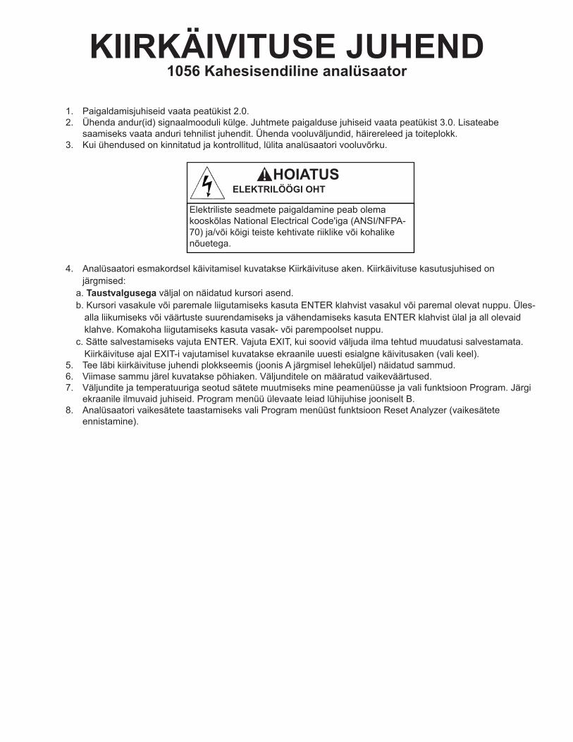
KIIRKÄIVITUSE JUHEND1056 Kahesisendiline analüsaator
1. Paigaldamisjuhiseid vaata peatükist 2.0.2. Ühenda andur(id) signaalmooduli külge. Juhtmete paigalduse juhiseid vaata peatükist 3.0. Lisateabe
saamiseks vaata anduri tehnilist juhendit. Ühenda vooluväljundid, häirereleed ja toiteplokk.3. Kui ühendused on kinnitatud ja kontrollitud, lülita analüsaatori vooluvõrku.
4. Analüsaatori esmakordsel käivitamisel kuvatakse Kiirkäivituse aken. Kiirkäivituse kasutusjuhised on järgmised:
a. Taustvalgusega väljal on näidatud kursori asend.b. Kursori vasakule või paremale liigutamiseks kasuta ENTER klahvist vasakul või paremal olevat nuppu. Üles-
alla liikumiseks või väärtuste suurendamiseks ja vähendamiseks kasuta ENTER klahvist ülal ja all olevaid klahve. Komakoha liigutamiseks kasuta vasak- või parempoolset nuppu.
c. Sätte salvestamiseks vajuta ENTER. Vajuta EXIT, kui soovid väljuda ilma tehtud muudatusi salvestamata. Kiirkäivituse ajal EXIT-i vajutamisel kuvatakse ekraanile uuesti esialgne käivitusaken (vali keel).
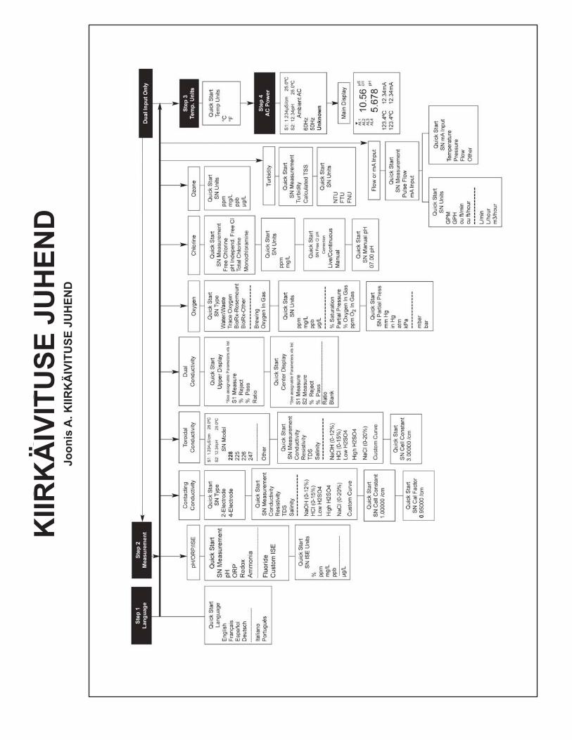
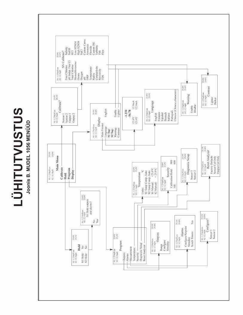
5. Tee läbi kiirkäivituse juhendi plokkseemis (joonis A järgmisel leheküljel) näidatud sammud.6. Viimase sammu järel kuvatakse põhiaken. Väljunditele on määratud vaikeväärtused.7. Väljundite ja temperatuuriga seotud sätete muutmiseks mine peamenüüsse ja vali funktsioon Program. Järgi
ekraanile ilmuvaid juhiseid. Program menüü ülevaate leiad lühijuhise jooniselt B.8. Analüsaatori vaikesätete taastamiseks vali Program menüüst funktsioon Reset Analyzer (vaikesätete
ennistamine).
ESSENTIAL INSTRUCTIONSREAD THIS PAGE BEFORE PROCEEDING!
Your instrument purchase from RosemountAnalytical, Inc. is one of the finest available for yourparticular application. These instruments have beendesigned, and tested to meet many national andinternational standards. Experience indicates that itsperformance is directly related to the quality of theinstallation and knowledge of the user in operatingand maintaining the instrument. To ensure their con-tinued operation to the design specifications, per-sonnel should read this manual thoroughly beforeproceeding with installation, commissioning, opera-tion, and maintenance of this instrument. If thisequipment is used in a manner not specified by themanufacturer, the protection provided by it againsthazards may be impaired.• Failure to follow the proper instructions may
cause any one of the following situations tooccur: Loss of life; personal injury; property dam-age; damage to this instrument; and warrantyinvalidation.
• Ensure that you have received the correct modeland options from your purchase order. Verify thatthis manual covers your model and options. Ifnot, call 1-800-854-8257 or 949-757-8500 torequest correct manual.
• For clarification of instructions, contact yourRosemount representative.
• Follow all warnings, cautions, and instructionsmarked on and supplied with the product.
• Use only qualified personnel to install, operate,update, program and maintain the product.
• Educate your personnel in the proper installation,operation, and maintenance of the product.
• Install equipment as specified in the Installation section of this manual. Follow appropriate localand national codes. Only connect the product toelectrical and pressure sources specified in thismanual.
• Use only factory documented components forrepair. Tampering or unauthorized substitution ofparts and procedures can affect the performanceand cause unsafe operation of your process.
• All equipment doors must be closed and protec-tive covers must be in place unless qualified per-sonnel are performing maintenance.
Equipment protected throughout by double insulation. • Installation and servicing of this product may expose personel
to dangerous voltages. • Main power wired to separate power source must be
disconnected before servicing.• Do not operate or energize instrument with case open!• Signal wiring connected in this box must be rated at least
240 V. • Non-metallic cable strain reliefs do not provide grounding
between conduit connections! Use grounding type bushings and jumper wires.
• Unused cable conduit entries must be securely sealed by non-flammable closures to provide enclosure integrity in compliance with personal safety and environmental protectionrequirements. Unused conduit openings must be sealed with NEMA 4X or IP65 conduit plugs to maintain the ingress protection rating (NEMA 4X).
• Electrical installation must be in accordance with the NationalElectrical Code (ANSI/NFPA-70) and/or any other applicable national or local codes.
• Operate only with front panel fastened and in place. • Safety and performance require that this instrument be
connected and properly grounded through a three-wire power source.
• Proper use and configuration is the responsibility of the user.
This product generates, uses, and can radiate radio frequencyenergy and thus can cause radio communication interference.Improper installation, or operation, may increase such interfer-ence. As temporarily permitted by regulation, this unit has notbeen tested for compliance within the limits of Class A comput-ing devices, pursuant to Subpart J of Part 15, of FCC Rules,which are designed to provide reasonable protection againstsuch interference. Operation of this equipment in a residentialarea may cause interference, in which case the user at his ownexpense, will be required to take whatever measures may berequired to correct the interference.
This product is not intended for use in the light industrial,residential or commercial environments per the instru-ment’s certification to EN50081-2.
Emerson Process Management
2400 Barranca ParkwayIrvine, CA 92606 USATel: (949) 757-8500Fax: (949) 474-7250
http://www.rosemountanalytical.com
© Rosemount Analytical Inc. 2012
WARNINGRISK OF ELECTRICAL SHOCK
CAUTION
CAUTION
HOIATUSELEKTRILÖÖGI OHT
Elektriliste seadmete paigaldamine peab olema kooskõlas National Electrical Code'iga (ANSI/NFPA-70) ja/või kõigi teiste kehtivate riiklike või kohalike nõuetega.
QU
ICK
STA
RT
GU
IDE
Figu
re A
. QU
ICK
STA
RT
GU
IDE
KIIR
KÄ
IVIT
USE
JU
HEN
DJo
onis
A. K
IIRK
ÄIV
ITU
SE J
UH
END
QU
ICK
REF
EREN
CE
GU
IDE
Figu
re B
. MO
DEL
105
6 M
ENU
TR
EE
QU
ICK
REF
EREN
CE
GU
IDE
Figu
re B
. MO
DEL
105
6 M
ENU
TR
EE
LÜH
ITU
TVU
STU
SJo
onis
B. M
UD
EL 1
056
MEN
ÜÜ
D
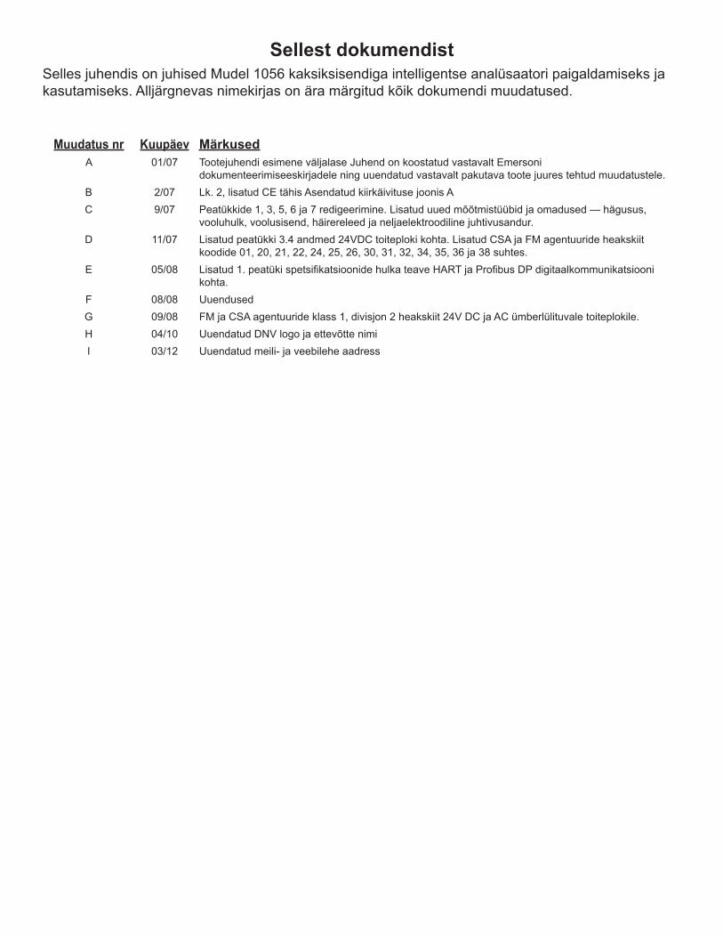
Sellest dokumendist Selles juhendis on juhised Mudel 1056 kaksiksisendiga intelligentse analüsaatori paigaldamiseks ja kasutamiseks. Alljärgnevas nimekirjas on ära märgitud kõik dokumendi muudatused.
Muudatus nr Kuupäev MärkusedA 01/07 Tootejuhendi esimene väljalase Juhend on koostatud vastavalt Emersoni
dokumenteerimiseeskirjadele ning uuendatud vastavalt pakutava toote juures tehtud muudatustele.B 2/07 Lk. 2, lisatud CE tähis Asendatud kiirkäivituse joonis AC 9/07 Peatükkide 1, 3, 5, 6 ja 7 redigeerimine. Lisatud uued mõõtmistüübid ja omadused — hägusus,
vooluhulk, voolusisend, häirereleed ja neljaelektroodiline juhtivusandur.D 11/07 Lisatud peatükki 3.4 andmed 24VDC toiteploki kohta. Lisatud CSA ja FM agentuuride heakskiit
koodide 01, 20, 21, 22, 24, 25, 26, 30, 31, 32, 34, 35, 36 ja 38 suhtes.E 05/08 Lisatud1.peatükispetsifikatsioonidehulkateaveHARTjaProfibusDPdigitaalkommunikatsiooni
kohta.F 08/08 UuendusedG 09/08 FM ja CSA agentuuride klass 1, divisjon 2 heakskiit 24V DC ja AC ümberlülituvale toiteplokile.H 04/10 Uuendatud DNV logo ja ettevõtte nimiI 03/12 Uuendatud meili- ja veebilehe aadress

MUDEL 1056KAHESISENDILINE INTELLIGENTNE ANALÜSAATOR
SISUKORD
KIIRKÄIVITUSE JUHENDLÜHITUTVUSTUSSISUKORD
Peatükk Pealkiri Lehekülg1.0 KIRJELDUS JA SPETSIFIKATSIOONID 12.0 PAIGALDAMINE 112.1 Lahti pakkimine ja ülevaatus................................................................................................................ 112.2 Paigaldamine......................................................................................................................................... 11
3.0 PAIGALDAMINE................................................................................................................................... 193.1 Üldine .................................................................................................................................................... 193.2 Juhtmesisendite ettevalmistus .............................................................................................................. 193.3 Andurikaablie ettevalmistus ................................................................................................................... 203.4 Voolu-, väljundi-, alarmide ja sensorite ühendused................................................................................ 204.0 EKRAAN JA KASUTUS........................................................................................................................ 274.1 Kasutajaliides ........................................................................................................................................ 274.2 Seadme klahvid ..................................................................................................................................... 274.3 Põhiaken ............................................................................................................................................... 284.4 Menüüd .................................................................................................................................................. 295.0 PROGRAMMEERIMINE- PÕHITÕED................................................................................................... 315.1 Üldine .................................................................................................................................................... 315.2 Käivitussätete muutmine......................................................................................................................... 315.3 Temperatuuriühikute ning manuaalse või automaatse temperatuuri kompenseerimise valimine........... 325.4 Vooluväljunditekonfiguratsioonjavahemikuseadistamine................................................................... 325.5 Turvakoodi seadistamine ....................................................................................................................... 345.6 Turvapääs................................................................................................................................ 35
5.7 Seiskamise kasutamine............................................................................................................. 35
5.8 Tootja vaikesätete ennistamine - analüsaatori ennistamine ................................................................. 365.9 Häirereleed.......................................................................................................................................... 376.0 PROGRAMEERIMINE - MÕÕTMISED................................................................................................. 416.1 Mõõtmiste programmeerimine - sissejuhatus......................................................................................... 416.2 pHmõõtmine........................................................................................................................................... 426.3 ORP mõõtmine........................................................................................................................................ 436.4 Juhtivuse kontaktmõõtmine..................................................................................................................... 456.5 Juhtivuse toroidaalne mõõtmine.............................................................................................................. 486.6 Kloori mõõtmine ..................................................................................................................................... 51
Vaba kloori mõõtmine ............................................................................................................................ 51
6.6.2 Kogukloori mõõtmine ................................................................................................................... 53
6.6.3 Monoloramiini mõõtmine .............................................................................................................. 546.6.4pH-stsõltumatuvabakloorimõõtmine......................................................................................... 55
6.7 Hapnikumõõtmine............................................................................................................................... 576.8 Osooni mõõtmine ................................................................................................................................. 59
MUDEL 1056 SISUKORD
i
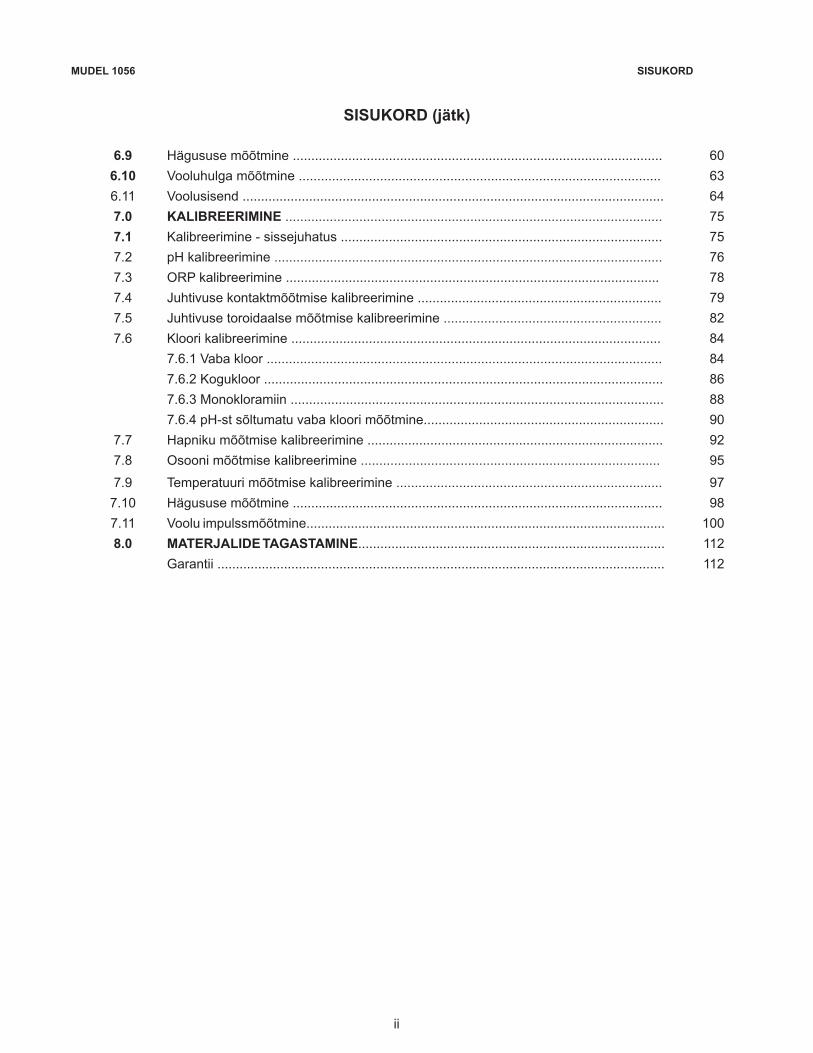
SISUKORD (jätk)
6.9 Hägususemõõtmine.................................................................................................... 606.10 Vooluhulga mõõtmine .................................................................................................. 636.11 Voolusisend .................................................................................................................. 647.0 KALIBREERIMINE ...................................................................................................... 757.1 Kalibreerimine - sissejuhatus ....................................................................................... 757.2 pHkalibreerimine......................................................................................................... 767.3 ORP kalibreerimine ..................................................................................................... 787.4 Juhtivuse kontaktmõõtmise kalibreerimine .................................................................. 797.5 Juhtivuse toroidaalse mõõtmise kalibreerimine ........................................................... 827.6 Kloori kalibreerimine .................................................................................................... 84
7.6.1 Vaba kloor ........................................................................................................... 847.6.2 Kogukloor ............................................................................................................ 867.6.3 Monokloramiin ..................................................................................................... 887.6.4pH-stsõltumatuvabakloorimõõtmine................................................................. 90
7.7 Hapnikumõõtmisekalibreerimine................................................................................ 927.8 Osooni mõõtmise kalibreerimine ................................................................................. 95
7.9 Temperatuuri mõõtmise kalibreerimine ........................................................................ 977.10 Hägususemõõtmine.................................................................................................... 987.11 Voolu impulssmõõtmine................................................................................................. 1008.0 MATERJALIDE TAGASTAMINE................................................................................... 112
Garantii ......................................................................................................................... 112
MUDEL 1056 SISUKORD
ii

SISUKORD (jätk)
JOONISTE NIMEKIRIJoon.# Peatükk Joonise pealkiri Lehekülg
A EELSÕNA Kiirkäivituse juhend 63
B EELSÕNA Lühitutvustus 64
2-1 PTK 2,0 Paneelile kinnitamise mõõdud ................................................................................................. 12
2-2 PTK 2,0 Torule ja seinale kinnitamise mõõdud ...................................................................................... 13
2-3 PTK 2,0 CSAsertifikatsioonosa1......................................................................................................... 14
2-4 PTK 2,0 CSAsertifikatsioonosa2......................................................................................................... 15
2-5 PTK 2,0 FM mittesüttiv osa 1 ................................................................................................................ 16
2-6 PTK 2,0 FM mittesüttiv osa 2 ................................................................................................................ 17
3-1 PTK 3,4 115/230 V vahelduvvoolu toiteplokk ........................................................................................ 20
3-2 PTK 3,4 24VDC Toiteplokk .................................................................................................................... 20
3-3 PTK 3,4 Ümberlülituv vahelduvvoolu toiteplokk ..................................................................................... 20
3-4 PTK 3,4 Vooluväljundi juhtmestik .......................................................................................................... 21
3-5 PTK 3,4 HäirereleejuhtmestikMudel1056ümberlülitusegatoiteplokile............................................... 21
3-6 PTK 3,4 Juhtivuse kontaktmõõtmise moodul ja andurikaabli juhtmed .................................................. 22
3-7 PTK 3,4 Juhtivuse toroidaalse mõõtmise moodul ja andurikaabli juhtmed ........................................... 22
3-8 PTK 3,4 pH/ORP/ISEsignaalmooduljaandurikaablijuhtmestik .......................................................... 23
3-9 PTK 3,4 Amperomeetriline moodul (Cl, O2, Osoon) ja andurikaabli juhtmestik ..................................... 23
3-10 PTK 3,4 Hägususesignaalmoodulkoospistikplokigaanduriühendusega ............................................ 24
3-11 PTK 3,4 Vooluhulga/voolusisendi signaalmoodul ja anduri kaabli juhtmestik ....................................... 24
3-12 PTK 3,4 Mudel 1056 115/230 VAC toitekaabeldus ................................................................................ 25
3-13 PTK 3,4 Mudel 1056 85-265 VAC toitekaabeldus ................................................................................. 25
3-14 PTK 3,4 Mudel 1056 pea-PCB väljundi juhtmestik ................................................................................. 26
3-15 PTK 3,4 Mudel 1056 24 VDC toitejuhtmed ............................................................................................ 26
4-1 PTK 4,3 Põhiakna seadistamine ........................................................................................................... 30
5-1 PTK 5.3.2 Temperatuuriühikute ning manuaalse või automaatse temperatuuri kompenseerimise valimine 32
5-2 PTK 5.4.5 Vooluväljunditekonfiguratsioonjavahemikuseadistamine...................................................... 33
5-3 PTK 5.5.2 Turvakoodi seadistamine ......................................................................................................... 34
5-4 PTK 5.7.2 Seiskamise kasutamine ............................................................................................................ 35
5-5 PTK 5.8.2 Tootja vaikesätete ennistamine ................................................................................................ 36
6-1 PTK 6,2 pH/ORPmõõtmisekonfigureerimine ........................................................................................ 67
6-2 PTK 6,4 Kontaktmõõtmisekonfigureerimine .......................................................................................... 68
6-3 PTK 6,5 Toroidaalsemõõtmisekonfigureerimine ................................................................................... 69
6-4 PTK 6,6 Kloorimõõtmisekonfigureerimine ............................................................................................ 71
6-5 PTK 6,7 Hapnikumõõtmisekonfigureerimine ........................................................................................ 70
6-6 PTK 6,8 Osoonimõõtmisekonfigureerimine .......................................................................................... 71
6-7 PTK 6,9 Hägususemõõtmisereguleerimine .......................................................................................... 72
6-8 PTK 6,10 Vooluhulgamõõtmisekonfigureerimine.................................................................................... 73
6-9 PTK 6,11 mAvoolusisendimõõtmisekonfigureerimine ........................................................................... 73
7-1 PTK 7,2 pHmõõtmisekalibreerimine ..................................................................................................... 103
7-2 PTK 7,3 ORP mõõtmise kalibreerimine .................................................................................................. 104
7-3 PTK 7,4 Juhitvuse kontakt- ja toroidaalse mõõtmise kalibreerimine ...................................................... 105
7-4 PTK 7,6 Kloori mõõtmise kalibreerimine ................................................................................................ 106
7-5 PTK 7,7 Hapnikumõõtmisekalibreerimine ............................................................................................ 107
7-6 PTK 7,8 Osooni mõõtmise kalibreerimine .............................................................................................. 108
7-7 PTK 7.9 Temperatuuri mõõtmise kalibreerimine..................................................................................... 109
7-8 PTK 7,10 Hägususemõõtmisekalibreerimine ......................................................................................... 110
7-9 PTK 7,11 Vooluhulga mõõtmise kalibreerimine ........................................................................................ 111
MUDEL 1056 SISUKORD
iii
SISUKORD (jätk)
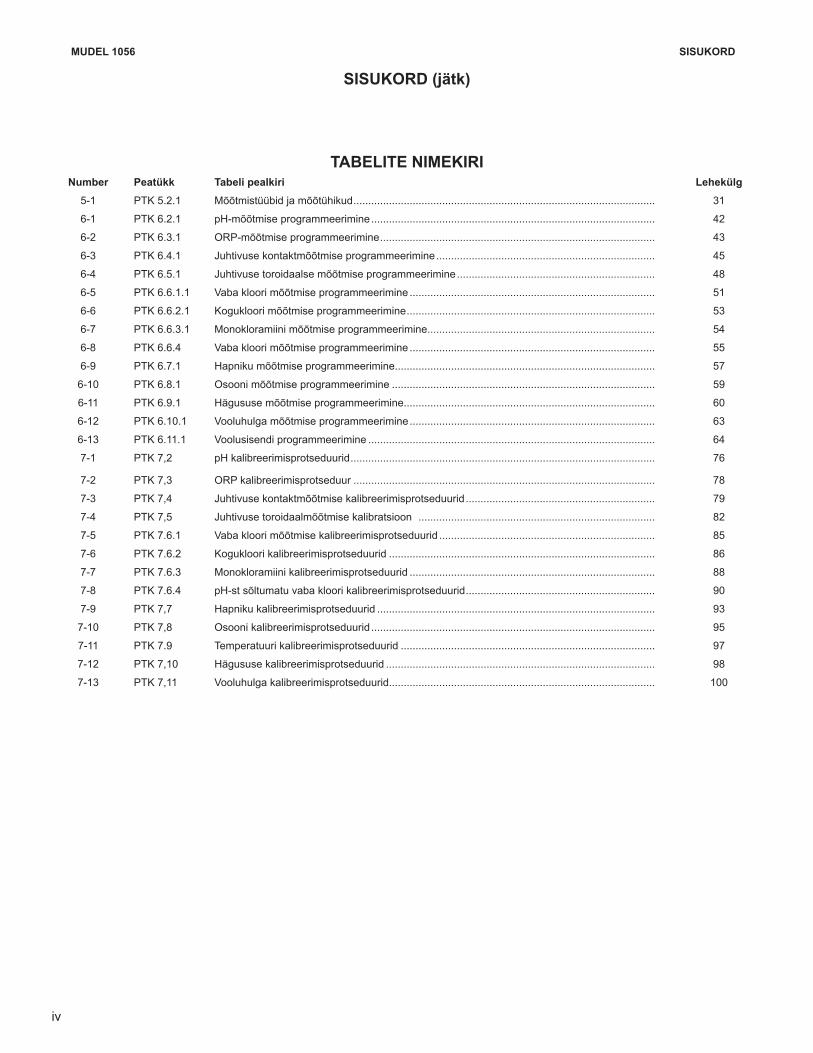
TABELITE NIMEKIRINumber Peatükk Tabeli pealkiri Lehekülg
5-1 PTK 5.2.1 Mõõtmistüübid ja mõõtühikud ...................................................................................................... 31
6-1 PTK 6.2.1 pH-mõõtmiseprogrammeerimine ................................................................................................ 42
6-2 PTK 6.3.1 ORP-mõõtmise programmeerimine ............................................................................................. 43
6-3 PTK 6.4.1 Juhtivuse kontaktmõõtmise programmeerimine .......................................................................... 45
6-4 PTK 6.5.1 Juhtivuse toroidaalse mõõtmise programmeerimine ................................................................... 48
6-5 PTK 6.6.1.1 Vaba kloori mõõtmise programmeerimine ................................................................................... 51
6-6 PTK 6.6.2.1 Kogukloori mõõtmise programmeerimine .................................................................................... 53
6-7 PTK 6.6.3.1 Monokloramiini mõõtmise programmeerimine............................................................................. 54
6-8 PTK 6.6.4 Vaba kloori mõõtmise programmeerimine ................................................................................... 55
6-9 PTK 6.7.1 Hapnikumõõtmiseprogrammeerimine........................................................................................ 57
6-10 PTK 6.8.1 Osooni mõõtmise programmeerimine ......................................................................................... 59
6-11 PTK 6.9.1 Hägususemõõtmiseprogrammeerimine..................................................................................... 60
6-12 PTK 6.10.1 Vooluhulga mõõtmise programmeerimine ................................................................................... 63
6-13 PTK 6.11.1 Voolusisendi programmeerimine ................................................................................................. 64
7-1 PTK 7,2 pHkalibreerimisprotseduurid ....................................................................................................... 76
7-2 PTK 7,3 ORP kalibreerimisprotseduur ...................................................................................................... 78
7-3 PTK 7,4 Juhtivuse kontaktmõõtmise kalibreerimisprotseduurid ................................................................ 79
7-4 PTK 7,5 Juhtivuse toroidaalmõõtmise kalibratsioon ................................................................................ 82
7-5 PTK 7.6.1 Vaba kloori mõõtmise kalibreerimisprotseduurid ......................................................................... 85
7-6 PTK 7.6.2 Kogukloori kalibreerimisprotseduurid .......................................................................................... 86
7-7 PTK 7.6.3 Monokloramiini kalibreerimisprotseduurid ................................................................................... 88
7-8 PTK 7.6.4 pH-stsõltumatuvabakloorikalibreerimisprotseduurid ................................................................ 90
7-9 PTK 7,7 Hapnikukalibreerimisprotseduurid .............................................................................................. 93
7-10 PTK 7,8 Osooni kalibreerimisprotseduurid ................................................................................................ 95
7-11 PTK 7.9 Temperatuuri kalibreerimisprotseduurid ...................................................................................... 97
7-12 PTK 7,10 Hägususekalibreerimisprotseduurid ........................................................................................... 98
7-13 PTK 7,11 Vooluhulga kalibreerimisprotseduurid.......................................................................................... 100
MUDEL 1056 SISUKORD
vi
1
MUDEL 1056
PEATÜKK 1.0 KIRJELDUS JA SPETSIFIKATSIOONID
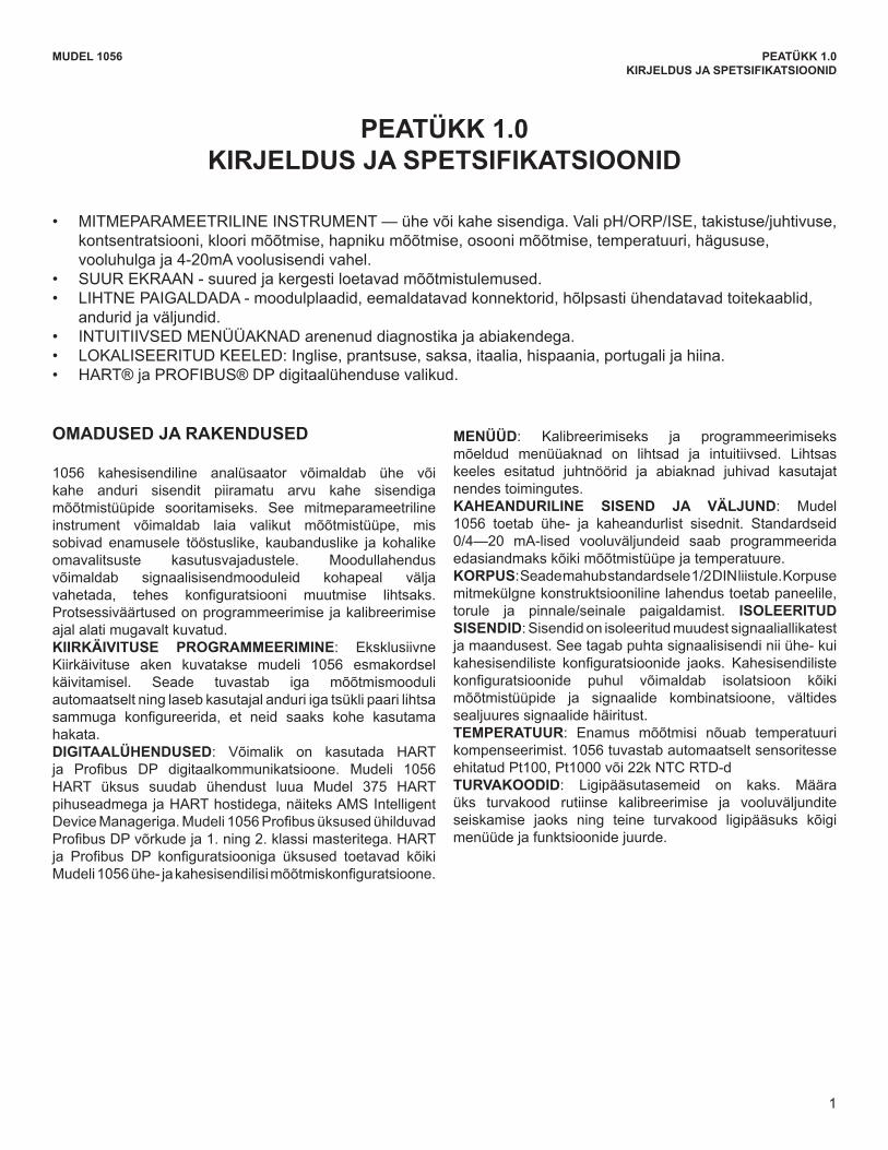
• MITMEPARAMEETRILINEINSTRUMENT—ühevõikahesisendiga.ValipH/ORP/ISE,takistuse/juhtivuse,kontsentratsiooni, kloori mõõtmise, hapniku mõõtmise, osooni mõõtmise, temperatuuri, hägususe, vooluhulga ja 4-20mA voolusisendi vahel.
• SUUR EKRAAN - suured ja kergesti loetavad mõõtmistulemused.• LIHTNEPAIGALDADA-moodulplaadid,eemaldatavadkonnektorid,hõlpsastiühendatavadtoitekaablid,
andurid ja väljundid.• INTUITIIVSED MENÜÜAKNAD arenenud diagnostika ja abiakendega.• LOKALISEERITUD KEELED: Inglise, prantsuse, saksa, itaalia, hispaania, portugali ja hiina.• HART®jaPROFIBUS®DPdigitaalühendusevalikud.
PEATÜKK 1.0KIRJELDUS JA SPETSIFIKATSIOONID
OMADUSED JA RAKENDUSED
1056 kahesisendiline analüsaator võimaldab ühe või kahe anduri sisendit piiramatu arvu kahe sisendiga mõõtmistüüpide sooritamiseks. See mitmeparameetriline instrument võimaldab laia valikut mõõtmistüüpe, mis sobivad enamusele tööstuslike, kaubanduslike ja kohalike omavalitsuste kasutusvajadustele. Moodullahendus võimaldab signaalisisendmooduleid kohapeal välja vahetada, tehes konfiguratsiooni muutmise lihtsaks.Protsessiväärtused on programmeerimise ja kalibreerimise ajal alati mugavalt kuvatud. KIIRKÄIVITUSE PROGRAMMEERIMINE: Eksklusiivne Kiirkäivituse aken kuvatakse mudeli 1056 esmakordsel käivitamisel. Seade tuvastab iga mõõtmismooduli automaatselt ning laseb kasutajal anduri iga tsükli paari lihtsa sammuga konfigureerida, et neid saaks kohe kasutamahakata. DIGITAALÜHENDUSED: Võimalik on kasutada HARTja Profibus DP digitaalkommunikatsioone. Mudeli 1056HART üksus suudab ühendust luua Mudel 375 HARTpihuseadmegajaHARThostidega,näiteksAMSIntelligentDeviceManageriga.Mudeli1056ProfibusüksusedühilduvadProfibusDPvõrkudeja1.ning2.klassimasteritega.HARTja Profibus DP konfiguratsiooniga üksused toetavad kõikiMudeli1056ühe-jakahesisendilisimõõtmiskonfiguratsioone.
MENÜÜD: Kalibreerimiseks ja programmeerimiseks mõeldud menüüaknad on lihtsad ja intuitiivsed. Lihtsas keeles esitatud juhtnöörid ja abiaknad juhivad kasutajat nendes toimingutes. KAHEANDURILINE SISEND JA VÄLJUND: Mudel 1056 toetab ühe- ja kaheandurlist sisednit. Standardseid 0/4—20 mA-lised vooluväljundeid saab programmeerida edasiandmaks kõiki mõõtmistüüpe ja temperatuure. KORPUS: Seade mahub standardsele 1/2 DIN liistule. Korpuse mitmekülgne konstruktsiooniline lahendus toetab paneelile, torule ja pinnale/seinale paigaldamist. ISOLEERITUD SISENDID: Sisendid on isoleeritud muudest signaaliallikatest ja maandusest. See tagab puhta signaalisisendi nii ühe- kui kahesisendiliste konfiguratsioonide jaoks. Kahesisendilistekonfiguratsioonide puhul võimaldab isolatsioon kõikimõõtmistüüpide ja signaalide kombinatsioone, vältides sealjuures signaalide häiritust.TEMPERATUUR: Enamus mõõtmisi nõuab temperatuuri kompenseerimist. 1056 tuvastab automaatselt sensoritesse ehitatud Pt100, Pt1000 või 22k NTC RTD-d TURVAKOODID: Ligipääsutasemeid on kaks. Määra üks turvakood rutiinse kalibreerimise ja vooluväljundite seiskamise jaoks ning teine turvakood ligipääsuks kõigi menüüde ja funktsioonide juurde.
2
MUDEL 1056 PEATÜKK 1,0KIRJELDUS JA SPETSIFIKATSIOONID
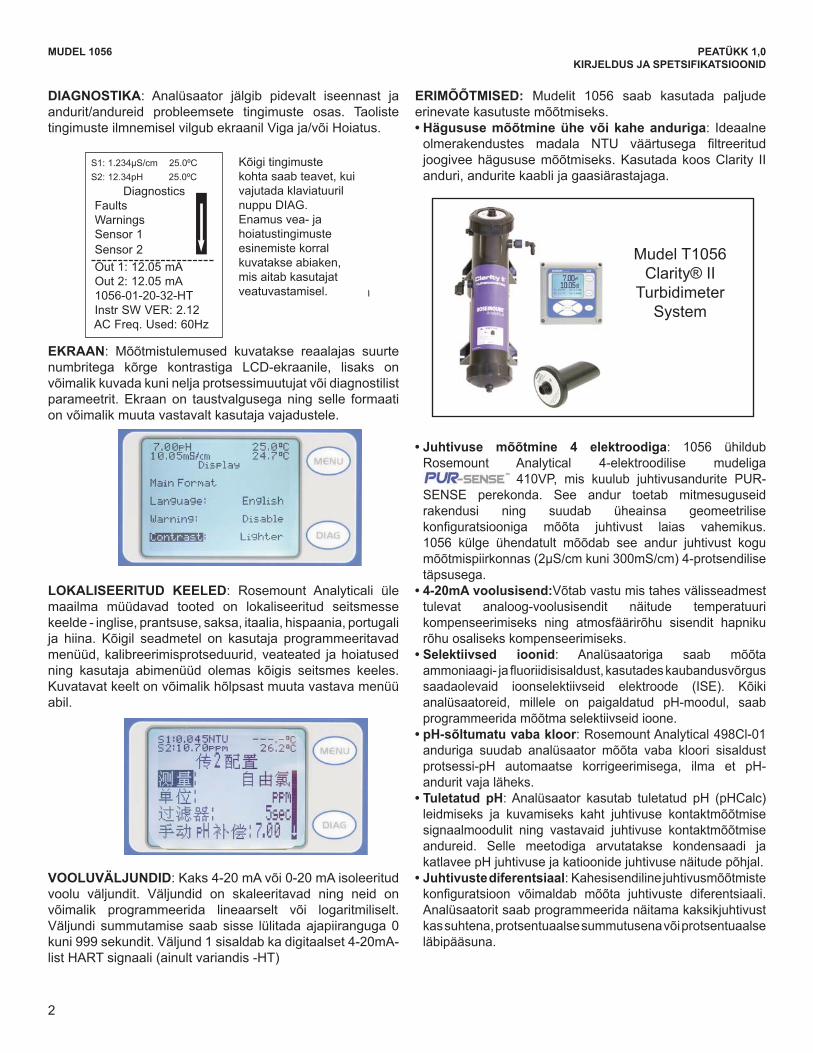
DIAGNOSTIKA: Analüsaator jälgib pidevalt iseennast ja andurit/andureid probleemsete tingimuste osas. Taoliste tingimusteilmnemiselvilgubekraanilVigaja/võiHoiatus.
EKRAAN: Mõõtmistulemused kuvatakse reaalajas suurte numbritega kõrge kontrastiga LCD-ekraanile, lisaks on võimalik kuvada kuni nelja protsessimuutujat või diagnostilist parameetrit. Ekraan on taustvalgusega ning selle formaati on võimalik muuta vastavalt kasutaja vajadustele.
LOKALISEERITUD KEELED: Rosemount Analyticali üle maailma müüdavad tooted on lokaliseeritud seitsmesse keelde - inglise, prantsuse, saksa, itaalia, hispaania, portugali ja hiina. Kõigil seadmetel on kasutaja programmeeritavad menüüd, kalibreerimisprotseduurid, veateated ja hoiatused ning kasutaja abimenüüd olemas kõigis seitsmes keeles. Kuvatavat keelt on võimalik hõlpsast muuta vastava menüü abil.
VOOLUVÄLJUNDID: Kaks 4-20 mA või 0-20 mA isoleeritud voolu väljundit. Väljundid on skaleeritavad ning neid on võimalik programmeerida lineaarselt või logaritmiliselt. Väljundi summutamise saab sisse lülitada ajapiiranguga 0 kuni 999 sekundit. Väljund 1 sisaldab ka digitaalset 4-20mA-listHARTsignaali(ainultvariandis-HT)
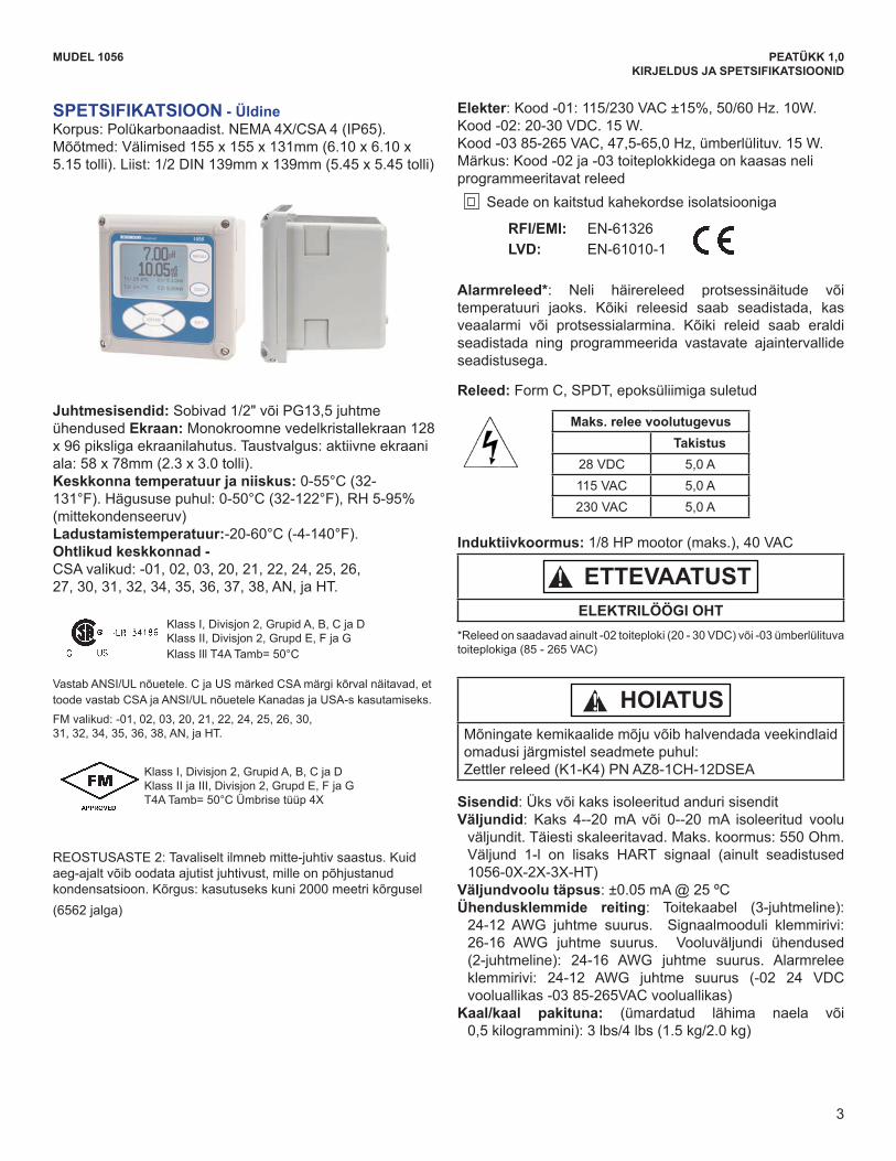
ERIMÕÕTMISED: Mudelit 1056 saab kasutada paljude erinevate kasutuste mõõtmiseks. •Hägususe mõõtmine ühe või kahe anduriga: Ideaalne olmerakendustes madala NTU väärtusega filtreeritudjoogivee hägususe mõõtmiseks. Kasutada koos Clarity II anduri, andurite kaabli ja gaasiärastajaga.
•Juhtivuse mõõtmine 4 elektroodiga: 1056 ühildub Rosemount Analytical 4-elektroodilise mudeliga
MODEL 1056 SECTION 1.0DESCRIPTION AND SPECIFICATIONS
2
DIAGNOSTICS: The analyzer continuously monitorsitself and the sensor(s) for problematic conditions.The display flashes Fault and/or Warning when theseconditions occur.
DISPLAY: The high-contrast LCD provides livemeasurement readouts in large digits and shows up tofour additional process variables or diagnosticparameters. The display is back-lit and the format canbe customized to meet user requirements.
LOCAL LANGUAGES :Rosemount Analytical extends its worldwide reach byoffering seven local languages – English, French,German, Italian, Spanish, Portuguese, and Chinese.Every unit includes user programming menus; calibrationroutines; faults and warnings; and user help screensin all seven languages. The displayed language canbe easily set and changed using the menus.
CURRENT OUTPUTS: Two 4-20 mA or 0-20 mA currentoutputs are electrically isolated. Outputs are fully scalableand can be programmed to linear or logarithmicmodes. Output dampening can be enabled with timeconstants from 0 to 999 seconds. Output 1 includesdigital signal 4-20 mA superimposed HART (option -HTonly)
SPECIAL MEASUREMENTS: The Model 1056 offersmeasuring capabilities for many applications.l Single or Dual Turbidity: Ideal in municipal appli-cations for measurement of low-NTU filtered drinkingwater. Must be used with Clarity II sensor, sensor cableand debubbler.
l 4-Electrode Conductivity:The 1056 is compat ib le wi th RosemountAnalytical 4-electrode Model 410VP in the PUR-SENSE family of conductivity sensors. This sensor supportsa wide array of applications and is capable of measuringa large range of conductivity with one geometricconfiguration. Wired to the 1056, this sensor canmeasure 2μS/cm to 300mS/cm with an accuracy of 4%of reading throughout the entire range.l 4-20mA Current Input: Accepts any analog currentinput from an external device for temperature compen-sation of measurements and atmospheric pressureinput for partial pressure correction of oxygen. l Selective Ions: The analyzer is able to measureammonia and fluoride using commercially availableion-selective electrodes. All analyzers with installed pHboards can be programmed to measure selective ions. l pH Independent Free Chlorine: With RosemountAnalytical’s 498Cl-01 sensor, the analyzer is able tomeasure free chlorine with automatic correction forprocess pH without the need for a pH sensor. l Inferential pH: The analyzer is able to derive anddisplay inferred pH (pHCalc) using two contacting con-ductivity signal boards and the appropriate contactingconductivity sensors. This method will calculate thepH of condensate and boiler water from conductivityand cation conductivity measurements. l Differential Conductivity: Dual input conductivityconfigurations can measure differential conductivity.The analyzer can be programmed to display dualconductivity as ratio, % rejection, or % passage.
S1: 1.234µS/cm 25.0ºCS2: 12.34pH 25.0ºC
DiagnosticsFaultsWarningsSensor 1Sensor 2Out 1: 12.05 mAOut 2: 12.05 mA1056-01-20-32-HTInstr SW VER: 2.12AC Freq. Used: 60Hz
Information about each conditionis quickly accessible by pressing DIAG onthe keypad. User help screens are displayed for most fault and warning conditions to assist in troubleshooting.
Model T1056Clarity® II
TurbidimeterSystem
410VP, mis kuulub juhtivusandurite PUR-SENSE perekonda. See andur toetab mitmesuguseid rakendusi ning suudab üheainsa geomeetrilise konfiguratsiooniga mõõta juhtivust laias vahemikus.1056 külge ühendatult mõõdab see andur juhtivust kogu mõõtmispiirkonnas(2μS/cmkuni300mS/cm)4-protsendilisetäpsusega.
•4-20mA voolusisend:Võtab vastu mis tahes välisseadmest tulevat analoog-voolusisendit näitude temperatuuri kompenseerimiseks ning atmosfäärirõhu sisendit hapniku rõhu osaliseks kompenseerimiseks.
•Selektiivsed ioonid: Analüsaatoriga saab mõõta ammoniaagi-jafluoriidisisaldust,kasutadeskaubandusvõrgussaadaolevaid ioonselektiivseid elektroode (ISE). Kõiki analüsaatoreid, millele on paigaldatud pH-moodul, saabprogrammeerida mõõtma selektiivseid ioone.
•pH-sõltumatu vaba kloor: Rosemount Analytical 498Cl-01 anduriga suudab analüsaator mõõta vaba kloori sisaldust protsessi-pH automaatse korrigeerimisega, ilma et pH-andurit vaja läheks.
•Tuletatud pH:Analüsaator kasutab tuletatud pH (pHCalc)leidmiseks ja kuvamiseks kaht juhtivuse kontaktmõõtmise signaalmoodulit ning vastavaid juhtivuse kontaktmõõtmise andureid. Selle meetodiga arvutatakse kondensaadi ja katlaveepHjuhtivusejakatioonidejuhtivusenäitudepõhjal.
•Juhtivuste diferentsiaal: Kahesisendiline juhtivusmõõtmiste konfiguratsioon võimaldab mõõta juhtivuste diferentsiaali.Analüsaatorit saab programmeerida näitama kaksikjuhtivust kas suhtena, protsentuaalse summutusena või protsentuaalse läbipääsuna.
MODEL 1056 SECTION 1.0DESCRIPTION AND SPECIFICATIONS
2
DIAGNOSTICS: The analyzer continuously monitorsitself and the sensor(s) for problematic conditions.The display flashes Fault and/or Warning when theseconditions occur.
DISPLAY: The high-contrast LCD provides livemeasurement readouts in large digits and shows up tofour additional process variables or diagnosticparameters. The display is back-lit and the format canbe customized to meet user requirements.
LOCAL LANGUAGES :Rosemount Analytical extends its worldwide reach byoffering seven local languages – English, French,German, Italian, Spanish, Portuguese, and Chinese.Every unit includes user programming menus; calibrationroutines; faults and warnings; and user help screensin all seven languages. The displayed language canbe easily set and changed using the menus.
CURRENT OUTPUTS: Two 4-20 mA or 0-20 mA currentoutputs are electrically isolated. Outputs are fully scalableand can be programmed to linear or logarithmicmodes. Output dampening can be enabled with timeconstants from 0 to 999 seconds. Output 1 includesdigital signal 4-20 mA superimposed HART (option -HTonly)
SPECIAL MEASUREMENTS: The Model 1056 offersmeasuring capabilities for many applications.l Single or Dual Turbidity: Ideal in municipal appli-cations for measurement of low-NTU filtered drinkingwater. Must be used with Clarity II sensor, sensor cableand debubbler.
l 4-Electrode Conductivity:The 1056 is compat ib le wi th RosemountAnalytical 4-electrode Model 410VP in the PUR-SENSE family of conductivity sensors. This sensor supportsa wide array of applications and is capable of measuringa large range of conductivity with one geometricconfiguration. Wired to the 1056, this sensor canmeasure 2μS/cm to 300mS/cm with an accuracy of 4%of reading throughout the entire range.l 4-20mA Current Input: Accepts any analog currentinput from an external device for temperature compen-sation of measurements and atmospheric pressureinput for partial pressure correction of oxygen. l Selective Ions: The analyzer is able to measureammonia and fluoride using commercially availableion-selective electrodes. All analyzers with installed pHboards can be programmed to measure selective ions. l pH Independent Free Chlorine: With RosemountAnalytical’s 498Cl-01 sensor, the analyzer is able tomeasure free chlorine with automatic correction forprocess pH without the need for a pH sensor. l Inferential pH: The analyzer is able to derive anddisplay inferred pH (pHCalc) using two contacting con-ductivity signal boards and the appropriate contactingconductivity sensors. This method will calculate thepH of condensate and boiler water from conductivityand cation conductivity measurements. l Differential Conductivity: Dual input conductivityconfigurations can measure differential conductivity.The analyzer can be programmed to display dualconductivity as ratio, % rejection, or % passage.
S1: 1.234µS/cm 25.0ºCS2: 12.34pH 25.0ºC
DiagnosticsFaultsWarningsSensor 1Sensor 2Out 1: 12.05 mAOut 2: 12.05 mA1056-01-20-32-HTInstr SW VER: 2.12AC Freq. Used: 60Hz
Information about each conditionis quickly accessible by pressing DIAG onthe keypad. User help screens are displayed for most fault and warning conditions to assist in troubleshooting.
Model T1056Clarity® II
TurbidimeterSystem
Mudel T1056Clarity®II
TurbidimeterSystem
MODEL 1056 SECTION 1.0DESCRIPTION AND SPECIFICATIONS
2
DIAGNOSTICS: The analyzer continuously monitorsitself and the sensor(s) for problematic conditions.The display flashes Fault and/or Warning when theseconditions occur.
DISPLAY: The high-contrast LCD provides livemeasurement readouts in large digits and shows up tofour additional process variables or diagnosticparameters. The display is back-lit and the format canbe customized to meet user requirements.
LOCAL LANGUAGES :Rosemount Analytical extends its worldwide reach byoffering seven local languages – English, French,German, Italian, Spanish, Portuguese, and Chinese.Every unit includes user programming menus; calibrationroutines; faults and warnings; and user help screensin all seven languages. The displayed language canbe easily set and changed using the menus.
CURRENT OUTPUTS: Two 4-20 mA or 0-20 mA currentoutputs are electrically isolated. Outputs are fully scalableand can be programmed to linear or logarithmicmodes. Output dampening can be enabled with timeconstants from 0 to 999 seconds. Output 1 includesdigital signal 4-20 mA superimposed HART (option -HTonly)
SPECIAL MEASUREMENTS: The Model 1056 offersmeasuring capabilities for many applications.l Single or Dual Turbidity: Ideal in municipal appli-cations for measurement of low-NTU filtered drinkingwater. Must be used with Clarity II sensor, sensor cableand debubbler.
l 4-Electrode Conductivity:The 1056 is compat ib le wi th RosemountAnalytical 4-electrode Model 410VP in the PUR-SENSE family of conductivity sensors. This sensor supportsa wide array of applications and is capable of measuringa large range of conductivity with one geometricconfiguration. Wired to the 1056, this sensor canmeasure 2μS/cm to 300mS/cm with an accuracy of 4%of reading throughout the entire range.l 4-20mA Current Input: Accepts any analog currentinput from an external device for temperature compen-sation of measurements and atmospheric pressureinput for partial pressure correction of oxygen. l Selective Ions: The analyzer is able to measureammonia and fluoride using commercially availableion-selective electrodes. All analyzers with installed pHboards can be programmed to measure selective ions. l pH Independent Free Chlorine: With RosemountAnalytical’s 498Cl-01 sensor, the analyzer is able tomeasure free chlorine with automatic correction forprocess pH without the need for a pH sensor. l Inferential pH: The analyzer is able to derive anddisplay inferred pH (pHCalc) using two contacting con-ductivity signal boards and the appropriate contactingconductivity sensors. This method will calculate thepH of condensate and boiler water from conductivityand cation conductivity measurements. l Differential Conductivity: Dual input conductivityconfigurations can measure differential conductivity.The analyzer can be programmed to display dualconductivity as ratio, % rejection, or % passage.
S1: 1.234µS/cm 25.0ºCS2: 12.34pH 25.0ºC
DiagnosticsFaultsWarningsSensor 1Sensor 2Out 1: 12.05 mAOut 2: 12.05 mA1056-01-20-32-HTInstr SW VER: 2.12AC Freq. Used: 60Hz
Information about each conditionis quickly accessible by pressing DIAG onthe keypad. User help screens are displayed for most fault and warning conditions to assist in troubleshooting.
Model T1056Clarity® II
TurbidimeterSystem
Kõigi tingimuste kohta saab teavet, kui vajutada klaviatuuril nuppu DIAG. Enamus vea- ja hoiatustingimuste esinemiste korral kuvatakse abiaken, mis aitab kasutajat veatuvastamisel.
3
SPETSIFIKATSIOON - ÜldineKorpus: Polükarbonaadist. NEMA 4X/CSA 4 (IP65). Mõõtmed: Välimised 155 x 155 x 131mm (6.10 x 6.10 x 5.15 tolli). Liist: 1/2 DIN 139mm x 139mm (5.45 x 5.45 tolli)
Juhtmesisendid: Sobivad 1/2" või PG13,5 juhtme ühendused Ekraan: Monokroomne vedelkristallekraan 128 x 96 piksliga ekraanilahutus. Taustvalgus: aktiivne ekraani ala: 58 x 78mm (2.3 x 3.0 tolli). Keskkonna temperatuur ja niiskus: 0-55°C (32-131°F).Hägususepuhul:0-50°C(32-122°F),RH5-95%(mittekondenseeruv) Ladustamistemperatuur:-20-60°C (-4-140°F).Ohtlikud keskkonnad - CSA valikud: -01, 02, 03, 20, 21, 22, 24, 25, 26,27,30,31,32,34,35,36,37,38,AN,jaHT.
MODEL 1056 SECTION 1.0DESCRIPTION AND SPECIFICATIONS
3
SPECIFICATIONS - GeneralEnclosure: Polycarbonate. NEMA 4X/CSA 4 (IP65).Dimensions: Overall 155 x 155 x 131mm (6.10 x 6.10x 5.15 in.). Cutout: 1/2 DIN 139mm x 139mm (5.45 x5.45 in.)
Conduit Openings: Accepts 1/2” or PG13.5 conduitfittings
Display: Monochromatic graphic liquid crystal display.128 x 96 pixel display resolution. Backlit. Activedisplay area: 58 x 78mm (2.3 x 3.0 in.).
Ambient Temperature and Humidity: 0 to 55°C(32 to 131°F). Turbidity only: 0 to 50°C (32 to122°F), RH 5 to 95% (non-condensing)
Storage Temperature Effect: -20 to 60ºC (-4 to 140°F)
Power: Code -01: 115/230 VAC ±15%, 50/60 Hz. 10W. Code -02: 20 to 30 VDC. 15 W. Code -03: 85 to 265 VAC, 47.5 to 65.0 Hz, switching.
15 W.Note: Code -02 and -03 power supplies include 4 pro-
grammable relays Equipment protected by double insulation
Alarms relays*: Four alarm relays for process meas-urement(s) or temperature. Any relay can be config-ured as a fault alarm instead of a process alarm. Eachrelay can be configured independently and each canbe programmed with interval timer settings. Relays: Form C, SPDT, epoxy sealed
Inductive load: 1/8 HP motor (max.), 40 VAC
*Relays only available with -02 power supply (20 - 30 VDC) or -03switching power supply (85 - 265 VAC)
Inputs: One or two isolated sensor inputs Outputs: Two 4-20 mA or 0-20 mA isolated current out-
puts. Fully scalable. Max Load: 550 Ohm. Output 1has superimposed HART signal (configurations1056-0X-2X-3X-HT only)
Current Output Accuracy: ±0.05 mA @ 25 ºCTerminal Connections Rating: Power connector
(3-leads): 24-12 AWG wire size. Signal board ter-minal blocks: 26-16 AWG wire size. Current outputconnectors (2-leads): 24-16 AWG wire size. Alarmrelay terminal blocks: 24-12 AWG wire size(-02 24 VDC power supply and -03 85-265VACpower supply)
Weight/Shipping Weight: (rounded up to nearest lb ornearest 0.5 kg): 3 lbs/4 lbs (1.5 kg/2.0 kg)
RFI/EMI: EN-61326LVD: EN-61010-1
Hazardous Location Approvals - Options for CSA: -01, 02, 03, 20, 21, 22, 24, 25, 26,27, 30, 31, 32, 34, 35, 36, 37, 38, AN, and HT.
Class I, Division 2, Groups A, B, C, & DClass Il, Division 2, Groups E, F, & GClass Ill T4A Tamb= 50°C
Evaluated to the ANSI/UL Standards. The ‘C’ and ‘US’ indi-cators adjacent to the CSA Mark signify that the product hasbeen evaluated to the applicable CSA and ANSI/ULStandards, for use in Canada and the U.S. respectively
Class I, Division 2, Groups A, B, C, & DClass Il & lll, Division 2, Groups E, F, & GT4A Tamb= 50°C Enclosure Type 4X
CAUTIONRISK OF ELECTRICAL SHOCK
Maximum Relay CurrentResistive
28 VDC 5.0 A115 VAC 5.0 A230 VAC 5.0 A
POLLUTION DEGREE 2: Normally only non-conductivepollution occurs. Occasionally, however, a temporaryconductivity caused by condensation must be expected.Altitude: for use up to 2000 meter (6562 ft.)
WARNINGExposure to some chemicals may degrade thesealing properties used in the following devices:Zettler Relays (K1-K4) PN AZ8-1CH-12DSEA
WARNING
Options for FM: -01, 02, 03, 20, 21, 22, 24, 25, 26, 30,31, 32, 34, 35, 36, 38, AN, and HT.
Klass I, Divisjon 2, Grupid A, B, C ja D Klass II, Divisjon 2, Grupd E, F ja G Klass Ill T4A Tamb= 50°C
Vastab ANSI/UL nõuetele. C ja US märked CSA märgi kõrval näitavad, et toode vastab CSA ja ANSI/UL nõuetele Kanadas ja USA-s kasutamiseks.FM valikud: -01, 02, 03, 20, 21, 22, 24, 25, 26, 30,31,32,34,35,36,38,AN,jaHT.
MODEL 1056 SECTION 1.0DESCRIPTION AND SPECIFICATIONS
3
SPECIFICATIONS - GeneralEnclosure: Polycarbonate. NEMA 4X/CSA 4 (IP65).Dimensions: Overall 155 x 155 x 131mm (6.10 x 6.10x 5.15 in.). Cutout: 1/2 DIN 139mm x 139mm (5.45 x5.45 in.)
Conduit Openings: Accepts 1/2” or PG13.5 conduitfittings
Display: Monochromatic graphic liquid crystal display.128 x 96 pixel display resolution. Backlit. Activedisplay area: 58 x 78mm (2.3 x 3.0 in.).
Ambient Temperature and Humidity: 0 to 55°C(32 to 131°F). Turbidity only: 0 to 50°C (32 to122°F), RH 5 to 95% (non-condensing)
Storage Temperature Effect: -20 to 60ºC (-4 to 140°F)
Power: Code -01: 115/230 VAC ±15%, 50/60 Hz. 10W. Code -02: 20 to 30 VDC. 15 W. Code -03: 85 to 265 VAC, 47.5 to 65.0 Hz, switching.
15 W.Note: Code -02 and -03 power supplies include 4 pro-
grammable relays Equipment protected by double insulation
Alarms relays*: Four alarm relays for process meas-urement(s) or temperature. Any relay can be config-ured as a fault alarm instead of a process alarm. Eachrelay can be configured independently and each canbe programmed with interval timer settings. Relays: Form C, SPDT, epoxy sealed
Inductive load: 1/8 HP motor (max.), 40 VAC
*Relays only available with -02 power supply (20 - 30 VDC) or -03switching power supply (85 - 265 VAC)
Inputs: One or two isolated sensor inputs Outputs: Two 4-20 mA or 0-20 mA isolated current out-
puts. Fully scalable. Max Load: 550 Ohm. Output 1has superimposed HART signal (configurations1056-0X-2X-3X-HT only)
Current Output Accuracy: ±0.05 mA @ 25 ºCTerminal Connections Rating: Power connector
(3-leads): 24-12 AWG wire size. Signal board ter-minal blocks: 26-16 AWG wire size. Current outputconnectors (2-leads): 24-16 AWG wire size. Alarmrelay terminal blocks: 24-12 AWG wire size(-02 24 VDC power supply and -03 85-265VACpower supply)
Weight/Shipping Weight: (rounded up to nearest lb ornearest 0.5 kg): 3 lbs/4 lbs (1.5 kg/2.0 kg)
RFI/EMI: EN-61326LVD: EN-61010-1
Hazardous Location Approvals - Options for CSA: -01, 02, 03, 20, 21, 22, 24, 25, 26,27, 30, 31, 32, 34, 35, 36, 37, 38, AN, and HT.
Class I, Division 2, Groups A, B, C, & DClass Il, Division 2, Groups E, F, & GClass Ill T4A Tamb= 50°C
Evaluated to the ANSI/UL Standards. The ‘C’ and ‘US’ indi-cators adjacent to the CSA Mark signify that the product hasbeen evaluated to the applicable CSA and ANSI/ULStandards, for use in Canada and the U.S. respectively
Class I, Division 2, Groups A, B, C, & DClass Il & lll, Division 2, Groups E, F, & GT4A Tamb= 50°C Enclosure Type 4X
CAUTIONRISK OF ELECTRICAL SHOCK
Maximum Relay CurrentResistive
28 VDC 5.0 A115 VAC 5.0 A230 VAC 5.0 A
POLLUTION DEGREE 2: Normally only non-conductivepollution occurs. Occasionally, however, a temporaryconductivity caused by condensation must be expected.Altitude: for use up to 2000 meter (6562 ft.)
WARNINGExposure to some chemicals may degrade thesealing properties used in the following devices:Zettler Relays (K1-K4) PN AZ8-1CH-12DSEA
WARNING
Options for FM: -01, 02, 03, 20, 21, 22, 24, 25, 26, 30,31, 32, 34, 35, 36, 38, AN, and HT.
Klass I, Divisjon 2, Grupid A, B, C ja DKlass II ja III, Divisjon 2, Grupd E, F ja GT4A Tamb= 50°C Ümbrise tüüp 4X
REOSTUSASTE 2: Tavaliselt ilmneb mitte-juhtiv saastus. Kuid aeg-ajalt võib oodata ajutist juhtivust, mille on põhjustanud kondensatsioon. Kõrgus: kasutuseks kuni 2000 meetri kõrgusel (6562 jalga)
Elekter:Kood-01:115/230VAC±15%,50/60Hz.10W.Kood-02:20-30VDC.15W.Kood-0385-265VAC,47,5-65,0Hz,ümberlülituv.15W.Märkus: Kood -02 ja -03 toiteplokkidega on kaasas neli programmeeritavat releed
MODEL 1056 SECTION 1.0DESCRIPTION AND SPECIFICATIONS
3
SPECIFICATIONS - GeneralEnclosure: Polycarbonate. NEMA 4X/CSA 4 (IP65).Dimensions: Overall 155 x 155 x 131mm (6.10 x 6.10x 5.15 in.). Cutout: 1/2 DIN 139mm x 139mm (5.45 x5.45 in.)
Conduit Openings: Accepts 1/2” or PG13.5 conduitfittings
Display: Monochromatic graphic liquid crystal display.128 x 96 pixel display resolution. Backlit. Activedisplay area: 58 x 78mm (2.3 x 3.0 in.).
Ambient Temperature and Humidity: 0 to 55°C(32 to 131°F). Turbidity only: 0 to 50°C (32 to122°F), RH 5 to 95% (non-condensing)
Storage Temperature Effect: -20 to 60ºC (-4 to 140°F)
Power: Code -01: 115/230 VAC ±15%, 50/60 Hz. 10W. Code -02: 20 to 30 VDC. 15 W. Code -03: 85 to 265 VAC, 47.5 to 65.0 Hz, switching.
15 W.Note: Code -02 and -03 power supplies include 4 pro-
grammable relays Equipment protected by double insulation
Alarms relays*: Four alarm relays for process meas-urement(s) or temperature. Any relay can be config-ured as a fault alarm instead of a process alarm. Eachrelay can be configured independently and each canbe programmed with interval timer settings. Relays: Form C, SPDT, epoxy sealed
Inductive load: 1/8 HP motor (max.), 40 VAC
*Relays only available with -02 power supply (20 - 30 VDC) or -03switching power supply (85 - 265 VAC)
Inputs: One or two isolated sensor inputs Outputs: Two 4-20 mA or 0-20 mA isolated current out-
puts. Fully scalable. Max Load: 550 Ohm. Output 1has superimposed HART signal (configurations1056-0X-2X-3X-HT only)
Current Output Accuracy: ±0.05 mA @ 25 ºCTerminal Connections Rating: Power connector
(3-leads): 24-12 AWG wire size. Signal board ter-minal blocks: 26-16 AWG wire size. Current outputconnectors (2-leads): 24-16 AWG wire size. Alarmrelay terminal blocks: 24-12 AWG wire size(-02 24 VDC power supply and -03 85-265VACpower supply)
Weight/Shipping Weight: (rounded up to nearest lb ornearest 0.5 kg): 3 lbs/4 lbs (1.5 kg/2.0 kg)
RFI/EMI: EN-61326LVD: EN-61010-1
Hazardous Location Approvals - Options for CSA: -01, 02, 03, 20, 21, 22, 24, 25, 26,27, 30, 31, 32, 34, 35, 36, 37, 38, AN, and HT.
Class I, Division 2, Groups A, B, C, & DClass Il, Division 2, Groups E, F, & GClass Ill T4A Tamb= 50°C
Evaluated to the ANSI/UL Standards. The ‘C’ and ‘US’ indi-cators adjacent to the CSA Mark signify that the product hasbeen evaluated to the applicable CSA and ANSI/ULStandards, for use in Canada and the U.S. respectively
Class I, Division 2, Groups A, B, C, & DClass Il & lll, Division 2, Groups E, F, & GT4A Tamb= 50°C Enclosure Type 4X
CAUTIONRISK OF ELECTRICAL SHOCK
Maximum Relay CurrentResistive
28 VDC 5.0 A115 VAC 5.0 A230 VAC 5.0 A
POLLUTION DEGREE 2: Normally only non-conductivepollution occurs. Occasionally, however, a temporaryconductivity caused by condensation must be expected.Altitude: for use up to 2000 meter (6562 ft.)
WARNINGExposure to some chemicals may degrade thesealing properties used in the following devices:Zettler Relays (K1-K4) PN AZ8-1CH-12DSEA
WARNING
Options for FM: -01, 02, 03, 20, 21, 22, 24, 25, 26, 30,31, 32, 34, 35, 36, 38, AN, and HT.
Seade on kaitstud kahekordse isolatsiooniga
Alarmreleed*: Neli häirereleed protsessinäitude või temperatuuri jaoks. Kõiki releesid saab seadistada, kas veaalarmi või protsessialarmina. Kõiki releid saab eraldi seadistada ning programmeerida vastavate ajaintervallide seadistusega.
Releed: Form C, SPDT, epoksüliimiga suletud
Maks. relee voolutugevusTakistus
28 VDC 5,0 A115 VAC 5,0 A230 VAC 5,0 A
Induktiivkoormus:1/8HPmootor(maks.),40VAC
ETTEVAATUSTESSENTIAL INSTRUCTIONSREAD THIS PAGE BEFORE PROCEEDING!
Your instrument purchase from RosemountAnalytical, Inc. is one of the finest available for yourparticular application. These instruments have beendesigned, and tested to meet many national andinternational standards. Experience indicates that itsperformance is directly related to the quality of theinstallation and knowledge of the user in operatingand maintaining the instrument. To ensure their con-tinued operation to the design specifications, per-sonnel should read this manual thoroughly beforeproceeding with installation, commissioning, opera-tion, and maintenance of this instrument. If thisequipment is used in a manner not specified by themanufacturer, the protection provided by it againsthazards may be impaired.• Failure to follow the proper instructions may
cause any one of the following situations tooccur: Loss of life; personal injury; property dam-age; damage to this instrument; and warrantyinvalidation.
• Ensure that you have received the correct modeland options from your purchase order. Verify thatthis manual covers your model and options. Ifnot, call 1-800-854-8257 or 949-757-8500 torequest correct manual.
• For clarification of instructions, contact yourRosemount representative.
• Follow all warnings, cautions, and instructionsmarked on and supplied with the product.
• Use only qualified personnel to install, operate,update, program and maintain the product.
• Educate your personnel in the proper installation,operation, and maintenance of the product.
• Install equipment as specified in the Installation section of this manual. Follow appropriate localand national codes. Only connect the product toelectrical and pressure sources specified in thismanual.
• Use only factory documented components forrepair. Tampering or unauthorized substitution ofparts and procedures can affect the performanceand cause unsafe operation of your process.
• All equipment doors must be closed and protec-tive covers must be in place unless qualified per-sonnel are performing maintenance.
Equipment protected throughout by double insulation. • Installation and servicing of this product may expose personel
to dangerous voltages. • Main power wired to separate power source must be
disconnected before servicing.• Do not operate or energize instrument with case open!• Signal wiring connected in this box must be rated at least
240 V. • Non-metallic cable strain reliefs do not provide grounding
between conduit connections! Use grounding type bushings and jumper wires.
• Unused cable conduit entries must be securely sealed by non-flammable closures to provide enclosure integrity in compliance with personal safety and environmental protectionrequirements. Unused conduit openings must be sealed with NEMA 4X or IP65 conduit plugs to maintain the ingress protection rating (NEMA 4X).
• Electrical installation must be in accordance with the NationalElectrical Code (ANSI/NFPA-70) and/or any other applicable national or local codes.
• Operate only with front panel fastened and in place. • Safety and performance require that this instrument be
connected and properly grounded through a three-wire power source.
• Proper use and configuration is the responsibility of the user.
This product generates, uses, and can radiate radio frequencyenergy and thus can cause radio communication interference.Improper installation, or operation, may increase such interfer-ence. As temporarily permitted by regulation, this unit has notbeen tested for compliance within the limits of Class A comput-ing devices, pursuant to Subpart J of Part 15, of FCC Rules,which are designed to provide reasonable protection againstsuch interference. Operation of this equipment in a residentialarea may cause interference, in which case the user at his ownexpense, will be required to take whatever measures may berequired to correct the interference.
This product is not intended for use in the light industrial,residential or commercial environments per the instru-ment’s certification to EN50081-2.
Emerson Process Management
2400 Barranca ParkwayIrvine, CA 92606 USATel: (949) 757-8500Fax: (949) 474-7250
http://www.rosemountanalytical.com
© Rosemount Analytical Inc. 2012
WARNINGRISK OF ELECTRICAL SHOCK
CAUTION
CAUTION
ELEKTRILÖÖGI OHT*Releed on saadavad ainult -02 toiteploki (20 - 30 VDC) või -03 ümberlülituva toiteplokiga (85 - 265 VAC)
HOIATUS
MODEL 1056 SECTION 1.0DESCRIPTION AND SPECIFICATIONS
3
SPECIFICATIONS - GeneralEnclosure: Polycarbonate. NEMA 4X/CSA 4 (IP65).Dimensions: Overall 155 x 155 x 131mm (6.10 x 6.10x 5.15 in.). Cutout: 1/2 DIN 139mm x 139mm (5.45 x5.45 in.)
Conduit Openings: Accepts 1/2” or PG13.5 conduitfittings
Display: Monochromatic graphic liquid crystal display.128 x 96 pixel display resolution. Backlit. Activedisplay area: 58 x 78mm (2.3 x 3.0 in.).
Ambient Temperature and Humidity: 0 to 55°C(32 to 131°F). Turbidity only: 0 to 50°C (32 to122°F), RH 5 to 95% (non-condensing)
Storage Temperature Effect: -20 to 60ºC (-4 to 140°F)
Power: Code -01: 115/230 VAC ±15%, 50/60 Hz. 10W. Code -02: 20 to 30 VDC. 15 W. Code -03: 85 to 265 VAC, 47.5 to 65.0 Hz, switching.
15 W.Note: Code -02 and -03 power supplies include 4 pro-
grammable relays Equipment protected by double insulation
Alarms relays*: Four alarm relays for process meas-urement(s) or temperature. Any relay can be config-ured as a fault alarm instead of a process alarm. Eachrelay can be configured independently and each canbe programmed with interval timer settings. Relays: Form C, SPDT, epoxy sealed
Inductive load: 1/8 HP motor (max.), 40 VAC
*Relays only available with -02 power supply (20 - 30 VDC) or -03switching power supply (85 - 265 VAC)
Inputs: One or two isolated sensor inputs Outputs: Two 4-20 mA or 0-20 mA isolated current out-
puts. Fully scalable. Max Load: 550 Ohm. Output 1has superimposed HART signal (configurations1056-0X-2X-3X-HT only)
Current Output Accuracy: ±0.05 mA @ 25 ºCTerminal Connections Rating: Power connector
(3-leads): 24-12 AWG wire size. Signal board ter-minal blocks: 26-16 AWG wire size. Current outputconnectors (2-leads): 24-16 AWG wire size. Alarmrelay terminal blocks: 24-12 AWG wire size(-02 24 VDC power supply and -03 85-265VACpower supply)
Weight/Shipping Weight: (rounded up to nearest lb ornearest 0.5 kg): 3 lbs/4 lbs (1.5 kg/2.0 kg)
RFI/EMI: EN-61326LVD: EN-61010-1
Hazardous Location Approvals - Options for CSA: -01, 02, 03, 20, 21, 22, 24, 25, 26,27, 30, 31, 32, 34, 35, 36, 37, 38, AN, and HT.
Class I, Division 2, Groups A, B, C, & DClass Il, Division 2, Groups E, F, & GClass Ill T4A Tamb= 50°C
Evaluated to the ANSI/UL Standards. The ‘C’ and ‘US’ indi-cators adjacent to the CSA Mark signify that the product hasbeen evaluated to the applicable CSA and ANSI/ULStandards, for use in Canada and the U.S. respectively
Class I, Division 2, Groups A, B, C, & DClass Il & lll, Division 2, Groups E, F, & GT4A Tamb= 50°C Enclosure Type 4X
CAUTIONRISK OF ELECTRICAL SHOCK
Maximum Relay CurrentResistive
28 VDC 5.0 A115 VAC 5.0 A230 VAC 5.0 A
POLLUTION DEGREE 2: Normally only non-conductivepollution occurs. Occasionally, however, a temporaryconductivity caused by condensation must be expected.Altitude: for use up to 2000 meter (6562 ft.)
WARNINGExposure to some chemicals may degrade thesealing properties used in the following devices:Zettler Relays (K1-K4) PN AZ8-1CH-12DSEA
WARNING
Options for FM: -01, 02, 03, 20, 21, 22, 24, 25, 26, 30,31, 32, 34, 35, 36, 38, AN, and HT.
Mõningate kemikaalide mõju võib halvendada veekindlaid omadusi järgmistel seadmete puhul:Zettlerreleed(K1-K4)PNAZ8-1CH-12DSEA
Sisendid: Üks või kaks isoleeritud anduri sisendit Väljundid: Kaks 4--20 mA või 0--20 mA isoleeritud voolu
väljundit. Täiesti skaleeritavad. Maks. koormus: 550 Ohm. Väljund 1-l on lisaks HART signaal (ainult seadistused1056-0X-2X-3X-HT)
Väljundvoolu täpsus: ±0.05 mA @ 25 ºCÜhendusklemmide reiting: Toitekaabel (3-juhtmeline): 24-12 AWG juhtme suurus. Signaalmooduli klemmirivi:26-16 AWG juhtme suurus. Vooluväljundi ühendused(2-juhtmeline): 24-16 AWG juhtme suurus. Alarmreleeklemmirivi: 24-12 AWG juhtme suurus (-02 24 VDCvooluallikas -03 85-265VAC vooluallikas)
Kaal/kaal pakituna: (ümardatud lähima naela või 0,5 kilogrammini): 3 lbs/4 lbs (1.5 kg/2.0 kg)
MUDEL 1056 PEATÜKK 1,0KIRJELDUS JA SPETSIFIKATSIOONID
MODEL 1056 SECTION 1.0DESCRIPTION AND SPECIFICATIONS
3
SPECIFICATIONS - GeneralEnclosure: Polycarbonate. NEMA 4X/CSA 4 (IP65).Dimensions: Overall 155 x 155 x 131mm (6.10 x 6.10x 5.15 in.). Cutout: 1/2 DIN 139mm x 139mm (5.45 x5.45 in.)
Conduit Openings: Accepts 1/2” or PG13.5 conduitfittings
Display: Monochromatic graphic liquid crystal display.128 x 96 pixel display resolution. Backlit. Activedisplay area: 58 x 78mm (2.3 x 3.0 in.).
Ambient Temperature and Humidity: 0 to 55°C(32 to 131°F). Turbidity only: 0 to 50°C (32 to122°F), RH 5 to 95% (non-condensing)
Storage Temperature Effect: -20 to 60ºC (-4 to 140°F)
Power: Code -01: 115/230 VAC ±15%, 50/60 Hz. 10W. Code -02: 20 to 30 VDC. 15 W. Code -03: 85 to 265 VAC, 47.5 to 65.0 Hz, switching.
15 W.Note: Code -02 and -03 power supplies include 4 pro-
grammable relays Equipment protected by double insulation
Alarms relays*: Four alarm relays for process meas-urement(s) or temperature. Any relay can be config-ured as a fault alarm instead of a process alarm. Eachrelay can be configured independently and each canbe programmed with interval timer settings. Relays: Form C, SPDT, epoxy sealed
Inductive load: 1/8 HP motor (max.), 40 VAC
*Relays only available with -02 power supply (20 - 30 VDC) or -03switching power supply (85 - 265 VAC)
Inputs: One or two isolated sensor inputs Outputs: Two 4-20 mA or 0-20 mA isolated current out-
puts. Fully scalable. Max Load: 550 Ohm. Output 1has superimposed HART signal (configurations1056-0X-2X-3X-HT only)
Current Output Accuracy: ±0.05 mA @ 25 ºCTerminal Connections Rating: Power connector
(3-leads): 24-12 AWG wire size. Signal board ter-minal blocks: 26-16 AWG wire size. Current outputconnectors (2-leads): 24-16 AWG wire size. Alarmrelay terminal blocks: 24-12 AWG wire size(-02 24 VDC power supply and -03 85-265VACpower supply)
Weight/Shipping Weight: (rounded up to nearest lb ornearest 0.5 kg): 3 lbs/4 lbs (1.5 kg/2.0 kg)
RFI/EMI: EN-61326LVD: EN-61010-1
Hazardous Location Approvals - Options for CSA: -01, 02, 03, 20, 21, 22, 24, 25, 26,27, 30, 31, 32, 34, 35, 36, 37, 38, AN, and HT.
Class I, Division 2, Groups A, B, C, & DClass Il, Division 2, Groups E, F, & GClass Ill T4A Tamb= 50°C
Evaluated to the ANSI/UL Standards. The ‘C’ and ‘US’ indi-cators adjacent to the CSA Mark signify that the product hasbeen evaluated to the applicable CSA and ANSI/ULStandards, for use in Canada and the U.S. respectively
Class I, Division 2, Groups A, B, C, & DClass Il & lll, Division 2, Groups E, F, & GT4A Tamb= 50°C Enclosure Type 4X
CAUTIONRISK OF ELECTRICAL SHOCK
Maximum Relay CurrentResistive
28 VDC 5.0 A115 VAC 5.0 A230 VAC 5.0 A
POLLUTION DEGREE 2: Normally only non-conductivepollution occurs. Occasionally, however, a temporaryconductivity caused by condensation must be expected.Altitude: for use up to 2000 meter (6562 ft.)
WARNINGExposure to some chemicals may degrade thesealing properties used in the following devices:Zettler Relays (K1-K4) PN AZ8-1CH-12DSEA
WARNING
Options for FM: -01, 02, 03, 20, 21, 22, 24, 25, 26, 30,31, 32, 34, 35, 36, 38, AN, and HT.
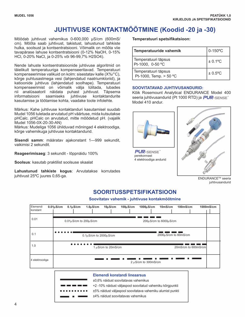
4
JUHTIVUSE KONTAKTMÕÕTMINE (Koodid -20 ja -30)
SOORITUSSPETSIFIKATSIOON Soovitatav vahemik - juhtivuse kontakmõõtmine
MUDEL 1056 PEATÜKK 1,0KIRJELDUS JA SPETSIFIKATSIOONID
Mõõdab juhtivust vahemikus 0-600,000 μS/cm (600mS/cm). Mõõta saab juhtivust, takistust, lahustunud tahkiste hulka, soolsust ja kontsentratsiooni. Võimalik on mõõta viie tavapäraselahusekontsentratsiooni(0-12%NaOH,0-15%HCl,0-20%NaCl,ja0-25%või96-99,7%H2SO4).
Nende lahuste kontsentratsioonide juhtivuse algoritmid on täielikult temperatuuriga kompenseeritavad. Temperatuuri kompenseerimisevalikuidonkolm:sisestatavkalle(X%/°C),kõrge puhtusastmega vesi (lahjendatud naatriumkloriid), ja katioonide juhtivus (lahjendatud soolhape). Temperatuuri kompenseerimist on võimalik välja lülitada, lubades nii analüsaatoril näidata puhast juhtivust. Täpsema informatsiooni saamiseks juhtivuse kontaktandurite kasutamise ja töötamise kohta, vaadake toote infolehte.
Märkus: Kahe juhtivuse kontaktanduri kasutamisel suudab Mudel1056tuletadaarvutatudpHväärtuse,midakutsutaksepHCalc.pHCalconarvutatud,mittemõõdetudpH. (vajalikMudel 1056-0X-20-30-AN) Märkus: Mudeliga 1056 ühilduvad mõningad 4 elektroodiga, kõrge vahemikuga juhtivuse kontaktandurid.
Sisendi samm: määratav ajakonstant 1—999 sekundit, vaikimisi 2 sekundit.
Reageerimisaeg:3sekundit-lõppnäidu100%
Soolsus: kasutab praktilist soolsuse skaalat
Lahustunud tahkiste kogus: Arvutatakse korrutades juhtivust 25ºC juures 0,65-ga.
Temperatuurispetsifikatsioon:
Temperatuuride vahemik 0-150ºC
Temperatuuri täpsus Pt-1000, 0-50 ºC
± 0.1ºC
Temperatuuri täpsusPt-1000, Temp. > 50 ºC
± 0.5ºC
SOOVITATAVAD JUHTIVUSANDURID:Kõik Rosemount Analytical ENDURANCE Model 400 seeria juhtivusandurid (Pt 1000 RTD) ja
MODEL 1056 SECTION 1.0DESCRIPTION AND SPECIFICATIONS
2
DIAGNOSTICS: The analyzer continuously monitorsitself and the sensor(s) for problematic conditions.The display flashes Fault and/or Warning when theseconditions occur.
DISPLAY: The high-contrast LCD provides livemeasurement readouts in large digits and shows up tofour additional process variables or diagnosticparameters. The display is back-lit and the format canbe customized to meet user requirements.
LOCAL LANGUAGES :Rosemount Analytical extends its worldwide reach byoffering seven local languages – English, French,German, Italian, Spanish, Portuguese, and Chinese.Every unit includes user programming menus; calibrationroutines; faults and warnings; and user help screensin all seven languages. The displayed language canbe easily set and changed using the menus.
CURRENT OUTPUTS: Two 4-20 mA or 0-20 mA currentoutputs are electrically isolated. Outputs are fully scalableand can be programmed to linear or logarithmicmodes. Output dampening can be enabled with timeconstants from 0 to 999 seconds. Output 1 includesdigital signal 4-20 mA superimposed HART (option -HTonly)
SPECIAL MEASUREMENTS: The Model 1056 offersmeasuring capabilities for many applications.l Single or Dual Turbidity: Ideal in municipal appli-cations for measurement of low-NTU filtered drinkingwater. Must be used with Clarity II sensor, sensor cableand debubbler.
l 4-Electrode Conductivity:The 1056 is compat ib le wi th RosemountAnalytical 4-electrode Model 410VP in the PUR-SENSE family of conductivity sensors. This sensor supportsa wide array of applications and is capable of measuringa large range of conductivity with one geometricconfiguration. Wired to the 1056, this sensor canmeasure 2μS/cm to 300mS/cm with an accuracy of 4%of reading throughout the entire range.l 4-20mA Current Input: Accepts any analog currentinput from an external device for temperature compen-sation of measurements and atmospheric pressureinput for partial pressure correction of oxygen. l Selective Ions: The analyzer is able to measureammonia and fluoride using commercially availableion-selective electrodes. All analyzers with installed pHboards can be programmed to measure selective ions. l pH Independent Free Chlorine: With RosemountAnalytical’s 498Cl-01 sensor, the analyzer is able tomeasure free chlorine with automatic correction forprocess pH without the need for a pH sensor. l Inferential pH: The analyzer is able to derive anddisplay inferred pH (pHCalc) using two contacting con-ductivity signal boards and the appropriate contactingconductivity sensors. This method will calculate thepH of condensate and boiler water from conductivityand cation conductivity measurements. l Differential Conductivity: Dual input conductivityconfigurations can measure differential conductivity.The analyzer can be programmed to display dualconductivity as ratio, % rejection, or % passage.
S1: 1.234µS/cm 25.0ºCS2: 12.34pH 25.0ºC
DiagnosticsFaultsWarningsSensor 1Sensor 2Out 1: 12.05 mAOut 2: 12.05 mA1056-01-20-32-HTInstr SW VER: 2.12AC Freq. Used: 60Hz
Information about each conditionis quickly accessible by pressing DIAG onthe keypad. User help screens are displayed for most fault and warning conditions to assist in troubleshooting.
Model T1056Clarity® II
TurbidimeterSystem
Model 410 andur.
ENDURANCETM seeria juhtivusandurid
MODEL 1056 SECTION 1.0DESCRIPTION AND SPECIFICATIONS
±0.6% of reading in recommended range
+2 to -10% of reading outside high recommended range
±5% of reading outside low recommended range
±4% of reading in recommended range
Measures conductivity in the range 0 to 600,000 μS/cm(600mS/cm). Measurement choices are conductivity,resistivity, total dissolved solids, salinity, and % concen-tration. The % concentration selection includes thechoice of five common solutions (0-12% NaOH, 0-15%HCl, 0-20% NaCl, and 0-25% or 96-99.7% H2SO4). The conductivity concentration algorithms for thesesolutions are fully temperature compensated. Threetemperature compensation options are available:manual slope (X%/°C), high purity water (dilute sodiumchloride), and cation conductivity (dilute hydrochloricacid). Temperature compensation can be disabled,allowing the analyzer to display raw conductivity. Formore information concerning the use and operation ofthe contacting conductivity sensors, refer to the productdata sheets.Note: When two contacting conductivity sensors areused, Model 1056 can derive an inferred pH valuecalled pHCalc. pHCalc is calculated pH, not directlymeasured pH. (Model 1056-0X-20-30-AN required)Note: Selected 4-electrode, high-range contactingconductivity sensors are compatible with Model 1056.Input filter: time constant 1 - 999 sec, default 2 sec.Response time: 3 seconds to 100% of final readingSalinity: uses Practical Salinity Scale
Total Dissolved Solids: Calculated by multiplyingconductivity at 25ºC by 0.65
RECOMMENDED SENSORS FOR CONDUCTIVITY:All Rosemount Analytical ENDURANCE Model 400series conductivity sensors (Pt 1000 RTD) andModel 410 sensor.
CONTACTING CONDUCTIVITY (Codes -20 and -30)
Temperature range 0-150ºC
Temperature Accuracy, Pt-1000, 0-50 ºC ± 0.1ºC
Temperature Accuracy,Pt-1000, Temp. > 50 ºC ± 0.5ºC
PERFORMANCE SPECIFICATIONS Recommended Range – Contacting Conductivity
Temperature Specifications:
ENDURANCETM series of conductivity sensors
family4-electrode sensors
Cell Constant Linearity
Cell 0.01μS/cm 0.1μS/cm 1.0μS/cm 10μS/cm 100μS/cm 1000μS/cm 10mS/cm 100mS/cm 1000mS/cmConstant
0.01
0.1
1.0
4-electrode
0.01μS/cm to 200μS/cm
0.1μS/cm to 2000μS/cm
1 μS/cm to 20mS/cm
2 μS/cm to 300mS/cm
200μS/cm to 6000μS/cm
2000μS/cm to 60mS/cm
20mS/cm to 600mS/cm
4
MODEL 1056 SECTION 1.0DESCRIPTION AND SPECIFICATIONS
2
DIAGNOSTICS: The analyzer continuously monitorsitself and the sensor(s) for problematic conditions.The display flashes Fault and/or Warning when theseconditions occur.
DISPLAY: The high-contrast LCD provides livemeasurement readouts in large digits and shows up tofour additional process variables or diagnosticparameters. The display is back-lit and the format canbe customized to meet user requirements.
LOCAL LANGUAGES :Rosemount Analytical extends its worldwide reach byoffering seven local languages – English, French,German, Italian, Spanish, Portuguese, and Chinese.Every unit includes user programming menus; calibrationroutines; faults and warnings; and user help screensin all seven languages. The displayed language canbe easily set and changed using the menus.
CURRENT OUTPUTS: Two 4-20 mA or 0-20 mA currentoutputs are electrically isolated. Outputs are fully scalableand can be programmed to linear or logarithmicmodes. Output dampening can be enabled with timeconstants from 0 to 999 seconds. Output 1 includesdigital signal 4-20 mA superimposed HART (option -HTonly)
SPECIAL MEASUREMENTS: The Model 1056 offersmeasuring capabilities for many applications.l Single or Dual Turbidity: Ideal in municipal appli-cations for measurement of low-NTU filtered drinkingwater. Must be used with Clarity II sensor, sensor cableand debubbler.
l 4-Electrode Conductivity:The 1056 is compat ib le wi th RosemountAnalytical 4-electrode Model 410VP in the PUR-SENSE family of conductivity sensors. This sensor supportsa wide array of applications and is capable of measuringa large range of conductivity with one geometricconfiguration. Wired to the 1056, this sensor canmeasure 2μS/cm to 300mS/cm with an accuracy of 4%of reading throughout the entire range.l 4-20mA Current Input: Accepts any analog currentinput from an external device for temperature compen-sation of measurements and atmospheric pressureinput for partial pressure correction of oxygen. l Selective Ions: The analyzer is able to measureammonia and fluoride using commercially availableion-selective electrodes. All analyzers with installed pHboards can be programmed to measure selective ions. l pH Independent Free Chlorine: With RosemountAnalytical’s 498Cl-01 sensor, the analyzer is able tomeasure free chlorine with automatic correction forprocess pH without the need for a pH sensor. l Inferential pH: The analyzer is able to derive anddisplay inferred pH (pHCalc) using two contacting con-ductivity signal boards and the appropriate contactingconductivity sensors. This method will calculate thepH of condensate and boiler water from conductivityand cation conductivity measurements. l Differential Conductivity: Dual input conductivityconfigurations can measure differential conductivity.The analyzer can be programmed to display dualconductivity as ratio, % rejection, or % passage.
S1: 1.234µS/cm 25.0ºCS2: 12.34pH 25.0ºC
DiagnosticsFaultsWarningsSensor 1Sensor 2Out 1: 12.05 mAOut 2: 12.05 mA1056-01-20-32-HTInstr SW VER: 2.12AC Freq. Used: 60Hz
Information about each conditionis quickly accessible by pressing DIAG onthe keypad. User help screens are displayed for most fault and warning conditions to assist in troubleshooting.
Model T1056Clarity® II
TurbidimeterSystem
perekonnast4 elektroodiga andurid
MODEL 1056 SECTION 1.0DESCRIPTION AND SPECIFICATIONS
±0.6% of reading in recommended range
+2 to -10% of reading outside high recommended range
±5% of reading outside low recommended range
±4% of reading in recommended range
Measures conductivity in the range 0 to 600,000 μS/cm(600mS/cm). Measurement choices are conductivity,resistivity, total dissolved solids, salinity, and % concen-tration. The % concentration selection includes thechoice of five common solutions (0-12% NaOH, 0-15%HCl, 0-20% NaCl, and 0-25% or 96-99.7% H2SO4). The conductivity concentration algorithms for thesesolutions are fully temperature compensated. Threetemperature compensation options are available:manual slope (X%/°C), high purity water (dilute sodiumchloride), and cation conductivity (dilute hydrochloricacid). Temperature compensation can be disabled,allowing the analyzer to display raw conductivity. Formore information concerning the use and operation ofthe contacting conductivity sensors, refer to the productdata sheets.Note: When two contacting conductivity sensors areused, Model 1056 can derive an inferred pH valuecalled pHCalc. pHCalc is calculated pH, not directlymeasured pH. (Model 1056-0X-20-30-AN required)Note: Selected 4-electrode, high-range contactingconductivity sensors are compatible with Model 1056.Input filter: time constant 1 - 999 sec, default 2 sec.Response time: 3 seconds to 100% of final readingSalinity: uses Practical Salinity Scale
Total Dissolved Solids: Calculated by multiplyingconductivity at 25ºC by 0.65
RECOMMENDED SENSORS FOR CONDUCTIVITY:All Rosemount Analytical ENDURANCE Model 400series conductivity sensors (Pt 1000 RTD) andModel 410 sensor.
CONTACTING CONDUCTIVITY (Codes -20 and -30)
Temperature range 0-150ºC
Temperature Accuracy, Pt-1000, 0-50 ºC ± 0.1ºC
Temperature Accuracy,Pt-1000, Temp. > 50 ºC ± 0.5ºC
PERFORMANCE SPECIFICATIONS Recommended Range – Contacting Conductivity
Temperature Specifications:
ENDURANCETM series of conductivity sensors
family4-electrode sensors
Cell Constant Linearity
Cell 0.01μS/cm 0.1μS/cm 1.0μS/cm 10μS/cm 100μS/cm 1000μS/cm 10mS/cm 100mS/cm 1000mS/cmConstant
0.01
0.1
1.0
4-electrode
0.01μS/cm to 200μS/cm
0.1μS/cm to 2000μS/cm
1 μS/cm to 20mS/cm
2 μS/cm to 300mS/cm
200μS/cm to 6000μS/cm
2000μS/cm to 60mS/cm
20mS/cm to 600mS/cm
4
MODEL 1056 SECTION 1.0DESCRIPTION AND SPECIFICATIONS
±0.6% of reading in recommended range
+2 to -10% of reading outside high recommended range
±5% of reading outside low recommended range
±4% of reading in recommended range
Measures conductivity in the range 0 to 600,000 μS/cm(600mS/cm). Measurement choices are conductivity,resistivity, total dissolved solids, salinity, and % concen-tration. The % concentration selection includes thechoice of five common solutions (0-12% NaOH, 0-15%HCl, 0-20% NaCl, and 0-25% or 96-99.7% H2SO4). The conductivity concentration algorithms for thesesolutions are fully temperature compensated. Threetemperature compensation options are available:manual slope (X%/°C), high purity water (dilute sodiumchloride), and cation conductivity (dilute hydrochloricacid). Temperature compensation can be disabled,allowing the analyzer to display raw conductivity. Formore information concerning the use and operation ofthe contacting conductivity sensors, refer to the productdata sheets.Note: When two contacting conductivity sensors areused, Model 1056 can derive an inferred pH valuecalled pHCalc. pHCalc is calculated pH, not directlymeasured pH. (Model 1056-0X-20-30-AN required)Note: Selected 4-electrode, high-range contactingconductivity sensors are compatible with Model 1056.Input filter: time constant 1 - 999 sec, default 2 sec.Response time: 3 seconds to 100% of final readingSalinity: uses Practical Salinity Scale
Total Dissolved Solids: Calculated by multiplyingconductivity at 25ºC by 0.65
RECOMMENDED SENSORS FOR CONDUCTIVITY:All Rosemount Analytical ENDURANCE Model 400series conductivity sensors (Pt 1000 RTD) andModel 410 sensor.
CONTACTING CONDUCTIVITY (Codes -20 and -30)
Temperature range 0-150ºC
Temperature Accuracy, Pt-1000, 0-50 ºC ± 0.1ºC
Temperature Accuracy,Pt-1000, Temp. > 50 ºC ± 0.5ºC
PERFORMANCE SPECIFICATIONS Recommended Range – Contacting Conductivity
Temperature Specifications:
ENDURANCETM series of conductivity sensors
family4-electrode sensors
Cell Constant Linearity
Cell 0.01μS/cm 0.1μS/cm 1.0μS/cm 10μS/cm 100μS/cm 1000μS/cm 10mS/cm 100mS/cm 1000mS/cmConstant
0.01
0.1
1.0
4-electrode
0.01μS/cm to 200μS/cm
0.1μS/cm to 2000μS/cm
1 μS/cm to 20mS/cm
2 μS/cm to 300mS/cm
200μS/cm to 6000μS/cm
2000μS/cm to 60mS/cm
20mS/cm to 600mS/cm
4
4 elektroodiga
Elemendi konstandi lineaarsus±0,6%näidustsoovitatavasvahemikus+2-10%näidustväljaspoolsoovitatudvahemikukõrgpunkti±5%näidustväljaspoolsoovitatavavahemikualumistpunkti±4%näidustsoovitatavasvahemikus
Elemendikonstant
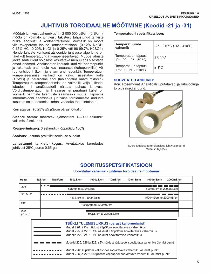
5
MODEL 1056 SECTION 1.0DESCRIPTION AND SPECIFICATIONS
Model 1μS/cm 10μS/cm 100μS/cm 1000μS/cm 10mS/cm 100mS/cm 1000mS/cm 2000mS/cm
5μS/cm to 500mS/cm
15μS/cm to 1500mS/cm
500mS/cm to 2000mS/cm
500μS/cm to 2000mS/cm
100μS/cm to 2000mS/cm
1500mS/cm to 2000mS/cm
226
242
222 (1in & 2in)
225 & 228
Measures conductivity in the range of 1 (one) μS/cm to2,000,000 μS/cm (2 S/cm), Measurement choices areconductivity, resistivity, total dissolved solids, salinity,and % concentration. The % concentration selectionincludes the choice of five common solutions (0-12%NaOH, 0-15% HCl, 0-20% NaCl, and 0-25% or96-99.7% H2SO4). The conductivity concentrationalgorithms for these solutions are fully temperaturecompensated. For other solutions, a simple-to-usemenu allows the customer to enter his own data. Theanalyzer accepts as many as five data points and fitseither a linear (two points) or a quadratic function (threeor more points) to the data. Two temperature compensationoptions are available: manual slope (X%/°C) and neutralsalt (dilute sodium chloride). Temperature compensationcan be disabled, allowing the analyzer to display rawconductivity. Reference temperature and linear temper-ature slope may also be adjusted for optimum results.For more information concerning the use and operationof the toroidal conductivity sensors, refer to the productdata sheets.
Repeatability: ±0.25% ±5 μS/cm after zero cal
Input filter: time constant 1 - 999 sec, default 2 sec.
Response time: 3 seconds to 100% of final reading
Salinity: uses Practical Salinity Scale
Total Dissolved Solids: Calculated by multiplyingconductivity at 25ºC by 0.65
Temperature Specifications:
RECOMMENDED SENSORS:All Rosemount Analytical submersion/immersion andflow-through toroidal sensors.
TOROIDAL CONDUCTIVITY (Codes -21 and -31)
Temperature range -25 to 210ºC (-13 to 410ºF)
Temperature Accuracy,Pt-100, -25 to 50 ºC ± 0.5ºC
Temperature Accuracy,Pt-100,. 50 to 210ºC ± 1ºC
PERFORMANCE SPECIFICATIONS Recommended Range - Toroidal Conductivity
Model 226: ±1% of reading ±5μS/cm in recommended rangeModels 225 & 228: ±1% of reading ±10μS/cm in recommended rangeModels 222,242: ±4% of reading in recommended range
Model 225, 226 & 228: ±5% of reading outside high recommended range
Model 226: ±5μS/cm outside low recommended rangeModels 225 & 228: ±15μS/cm outside low recommended range
High performance toroidal conductivity sensorsModels 226 and 225
LOOP PERFORMANCE (Following Calibration)
5
JUHTIVUS TOROIDAALNE MÕÕTMINE (Koodid -21 ja -31)
SOORITUSSPETSIFIKATSIOON Soovitatav vahemik - juhtivus toroidaalne mõõtmine
MUDEL 1056 PEATÜKK 1,0KIRJELDUS JA SPETSIFIKATSIOONID
Mõõdabjuhtivustvahemikus1-2000000μS/cm(2S/cm),mõõta on võimalik juhtivust, takistust, lahustunud tahkiste hulka, soolsust ja kontsentratsiooni. Võimalik on mõõta viie tavapärase lahuse kontsentratsiooni (0-12% NaOH,0-15%HCl,0-20%NaCl, ja0-25%või96-99,7%H2SO4).Nende lahuste kontsentratsioonide juhtivuse algoritmid on täielikult temperatuuriga kompenseeritavad. Muude lahuste jaoks saab klient hõlpsasti kasutatava menüü abil sisestada omad andmed. Analüsaator kasutab kuni viit andmepunkti ja rakendab andmetele kas lineaarset (kahepunktilist) või ruutfuntsiooni (kolm ja enam andmepunkti). Temperatuuri kompenseerimise valikuid on kaks: sisestatav kalle (X%/°C) ja neutraalne sool (lahjendatud naatriumkloriid).Temperatuuri kompenseerimist on võimalik välja lülitada, lubades nii analüsaatoril näidata puhast juhtivust. Võrdlustemperatuuri ja lineaarse temperatuuri kallet on võimalik parimate tulemuste saamiseks muuta. Täpsema informatsiooni saamiseks juhtivuse toroidaalsete andurite kasutamise ja töötamise kohta, vaadake toote infolehte.
Korratavus:±0,25%±5μS/cmpärast0-kalibr.
Sisendi samm: määratav ajakonstant 1—999 sekundit, vaikimisi 2 sekundit.
Reageerimisaeg:3sekundit-lõppnäidu100%
Soolsus: kasutab praktilist soolsuse skaalat
Lahustunud tahkiste kogus: Arvutatakse korrutades juhtivust 25ºC juures 0,65-ga.
Temperatuurispetsifikatsioon:
Temperatuuride vahemik -25 - 210ºC (-13 - 410ºF)
Temperatuuri täpsusPt-100, -25 - 50 ºC
± 0.5ºC
Temperatuuri täpsusPt-100,. 50 - 210ºC
± 1ºC
SOOVITATUD ANDURID:Kõik Rosemount Analyticali uputatavad ja läbivooluga toroidaalsed andurid.
Suure jõudlusega toroidaalsed juhtivusanduridMudel 226 ja 225
MODEL 1056 SECTION 1.0DESCRIPTION AND SPECIFICATIONS
Model 1μS/cm 10μS/cm 100μS/cm 1000μS/cm 10mS/cm 100mS/cm 1000mS/cm 2000mS/cm
5μS/cm to 500mS/cm
15μS/cm to 1500mS/cm
500mS/cm to 2000mS/cm
500μS/cm to 2000mS/cm
100μS/cm to 2000mS/cm
1500mS/cm to 2000mS/cm
226
242
222 (1in & 2in)
225 & 228
Measures conductivity in the range of 1 (one) μS/cm to2,000,000 μS/cm (2 S/cm), Measurement choices areconductivity, resistivity, total dissolved solids, salinity,and % concentration. The % concentration selectionincludes the choice of five common solutions (0-12%NaOH, 0-15% HCl, 0-20% NaCl, and 0-25% or96-99.7% H2SO4). The conductivity concentrationalgorithms for these solutions are fully temperaturecompensated. For other solutions, a simple-to-usemenu allows the customer to enter his own data. Theanalyzer accepts as many as five data points and fitseither a linear (two points) or a quadratic function (threeor more points) to the data. Two temperature compensationoptions are available: manual slope (X%/°C) and neutralsalt (dilute sodium chloride). Temperature compensationcan be disabled, allowing the analyzer to display rawconductivity. Reference temperature and linear temper-ature slope may also be adjusted for optimum results.For more information concerning the use and operationof the toroidal conductivity sensors, refer to the productdata sheets.
Repeatability: ±0.25% ±5 μS/cm after zero cal
Input filter: time constant 1 - 999 sec, default 2 sec.
Response time: 3 seconds to 100% of final reading
Salinity: uses Practical Salinity Scale
Total Dissolved Solids: Calculated by multiplyingconductivity at 25ºC by 0.65
Temperature Specifications:
RECOMMENDED SENSORS:All Rosemount Analytical submersion/immersion andflow-through toroidal sensors.
TOROIDAL CONDUCTIVITY (Codes -21 and -31)
Temperature range -25 to 210ºC (-13 to 410ºF)
Temperature Accuracy,Pt-100, -25 to 50 ºC ± 0.5ºC
Temperature Accuracy,Pt-100,. 50 to 210ºC ± 1ºC
PERFORMANCE SPECIFICATIONS Recommended Range - Toroidal Conductivity
Model 226: ±1% of reading ±5μS/cm in recommended rangeModels 225 & 228: ±1% of reading ±10μS/cm in recommended rangeModels 222,242: ±4% of reading in recommended range
Model 225, 226 & 228: ±5% of reading outside high recommended range
Model 226: ±5μS/cm outside low recommended rangeModels 225 & 228: ±15μS/cm outside low recommended range
High performance toroidal conductivity sensorsModels 226 and 225
LOOP PERFORMANCE (Following Calibration)
5
Mudel
(1" ja 2")
TSÜKLI TULEMUSLIKKUS (pärast kalibreerimist)Mudel226:±1%näidust±5μS/cmsoovitatavasvahemikusMudel225ja228:±1%näidust±10μS/cmsoovitatavasvahemikusMudelid222,242:±4%näidustsoovitatavasvahemikus
Mudelid225,226ja228:±5%näidustväljaspoolsoovitatavavahemikuülemistpunkti
Mudel226:±5μS/cmväljaspoolsoovitatavavahemikualumistpunktiMudel225ja228:±15μS/cmväljaspoolsoovitatavavahemikualumistpunkti
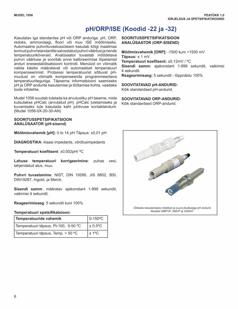
6
pH/ORP/ISE (Koodid -22 ja -32)
MUDEL 1056 PEATÜKK 1,0KIRJELDUS JA SPETSIFIKATSIOONID
KasutatavigastandardsepHvõiORPanduriga.pH,ORP,redoks, ammoniaagi, floori või muu ISE mõõtmiseks.Automaatne puhvrituvastussüteem kasutab kõigi maailmas levinud puhvristandardite salvestatud puhvri väärtusi ja nende temperatuurikõveraid. Analüsaator tuvastab mõõdetava puhvri väärtuse ja sooritab enne kalibreerimise lõpetamist anduri enesestabilisatsiooni kontrolli. Menüüst on võimalik valida käsitsi määratavat või automaatset temperatuuri kompenseerimist. Protsessi temperatuurist sõltuvat pH-muutust on võimalik kompenseerida programmeeritava temperatuuriteguriga. Täpsema informatsiooni saamiseks pHjaORPanduritekasutamisejatöötamisekohta,vaadaketoote infolehte.
Mudel1056suudabtuletadakaarvutuslikupHtaseme,midakutsutaksepHCalc (arvutatudpH).pHCalc tuletamiseks jakuvamiseks tule kasutada kaht juhtivuse kontaktandurit. (Mudel 1056-0X-20-30-AN)
SOORITUSSPETSIFIKATSIOONANALÜSAATOR (pH-sisend)
Mõõtmisvahemik [pH]:0to14pHTäpsus:±0,01pH
DIAGNOSTIKA: klaasi impedants, võrdlusimpedants
Temperatuurikoefitsent:±0,002pH/ºC
Lahuse temperatuuri korrigeerimine: puhas vesi, lahjendatud alus, muu.
Puhvri tuvastamine: NIST, DIN 19266, JIS 8802, BSI, DIN19267, Ingold, ja Merck.
Sisendi samm: määratav ajakonstant 1-999 sekundit, vaikimisi 4 sekundit.
Reageerimisaeg:5sekunditkuni100%
Temperatuurispetsifikatsioon:Temperatuuride vahemik 0-150ºC
Temperatuuri täpsus, Pt-100, 0-50 ºC ± 0.5ºC
Temperatuuri täpsus, Temp. > 50 ºC ± 1ºC
SOORITUSSPETSIFIKATSIOONANALÜSAATOR (ORP-SISEND)
Mõõtmisvahemik [ORP]: -1500 kuni +1500 mVTäpsus: ± 1 mVTemperatuurikoefitsent:±0,12mV / ºCSisendi samm: ajakonstant 1-999 sekundit, vaikimisi 4 sekundit.Reageerimisaeg: 5sekundit-lõppnäidu100%
SOOVITATAVAD pH-ANDURID:KõikstandardsedpH-andurid.
SOOVITATAVAD ORP-ANDURID:Kõik standardsed ORP-andurid.
6
MODEL 1056 SECTION 1.0DESCRIPTION AND SPECIFICATIONS
For use with any standard pH or ORP sensor.Measurement choices are pH, ORP, Redox, ammonia,fluoride or custom ISE. The automatic buffer recognitionfeature uses stored buffer values and their temperaturecurves for the most common buffer standards availableworldwide. The analyzer will recognize the value of thebuffer being measured and perform a self stabilizationcheck on the sensor before completing the calibration.Manual or automatic temperature compensation ismenu selectable. Change in pH due to process temper-ature can be compensated using a programmable tem-perature coefficient. For more information concerningthe use and operation of the pH or ORP sensors, referto the product data sheets.Model 1056 can also derive an inferred pH value calledpHCalc (calculated pH). pHCalc can be derived anddisplayed when two contacting conductivity sensors areused. (Model 1056-0X-20-30-AN)
PERFORMANCE SPECIFICATIONS -ANALYZER (pH INPUT)Measurement Range [pH]: 0 to 14 pHAccuracy: ±0.01 pHDiagnostics: glass impedance, reference impedanceTemperature coefficient: ±0.002pH/ ºCSolution temperature correction: pure water, dilute
base and custom.Buffer recognition: NIST, DIN 19266, JIS 8802, BSI,
DIN19267, Ingold, and Merck. Input filter: time constant 1 - 999 seconds, default 4
seconds.Response time: 5 seconds to 100%
Temperature Specifications:
PERFORMANCE SPECIFICATIONS -ANALYZER (ORP INPUT)Measurement Range [ORP]: -1500 to +1500 mVAccuracy: ± 1 mVTemperature coefficient: ±0.12mV / ºCInput filter: time constant 1 - 999 seconds, default 4seconds.Response time: 5 seconds to 100% of final reading
RECOMMENDED SENSORS FOR pH:All standard pH sensors. RECOMMENDED SENSORS FOR ORP:All standard ORP sensors.
Temperature range 0-150ºC
Temperature Accuracy, Pt-100, 0-50 ºC ± 0.5ºC
Temperature Accuracy, Temp. > 50 ºC ± 1ºC
pH/ORP/ISE (Codes -22 and -32)
General purpose and high performance pH sensorsModels 396PVP, 399VP and 3300HT
ÜldisekskasutamiseksmõeldudjasuurejõudlusegapHanduridMudelid396PVP,399VPja3300HT
7
Enamuse impulsiga töötavate vooluhulga anduritega kasutamiseks saab 1056 kasutaja valida vooluhulga mõõtühikuks muuhulgas GPM (gallonit minutis), GPH(gallonit tunnis), cu ft/min (kuupjalga minutis), cu ft/h (kuupjalgatunnis),LPM(liitritminutis),LPH(liitrittunnis)võim3/h (kuupmeetrit tunnist), kiiruse mõõtmiseks on kasutatav ft/sec (jalga sekundis) ja m/sek. Seadistades seadme vooluhulga mõõtmiseks, töötab see ka antud ühikutes (gallonid, liitrid, kuupmeetrid) loendurina.
Kaksik-vooluhulgainstrumenti saab seadistada %-taastumise,vooluhulgaerinevuse,vooluhulgamääravõikogu vooluhulga jaoks.
SOORITUSSPETSIFIKATSIOON
Sagedusvahemik:3kuni1000Hz
Vooluhulk: 0 — 99 999 gallon/min, l/min, m3/h, gallon/h, l/h, cu ft/min, cu ft/h.Koguvool:0 – 9,999,999,999,999 gallonit või m3,0 – 999 999 999 999 kuupjalga.
Täpsus:0.5%
Sisendisamm:määratav ajakonstant 0-999 sekundit, vaikimisi 5 sekundit.
SOOVITATUD ANDURID*
+GF+ Signet 515 Rotor-X vooluhulga andur
* Sisendi voolutugevus ei tohi ületada ±36V
Võimalik kasutada kõigi saatjate või väliste seadmetega, mille väljundvõimsus on 4-20mA või 0-20mA. Tavaliselt kasutatakse reaalajas mõõtmiste temperatuuri kompenseerimiseks (v.a ORP, hägususe ja vooluhulga puhul) ja osalise rõhu mõõtmisel pideva atmosfäärirõhu sisendi jaoks, mis on vajalik kompenseerimiseks reaalajas lahustunud hapniku mõõtmisel. Väline atmosfäärirõhu sisend lahustunud hapniku mõõtmisel lubab kompenseerida osalist rõhku, sellal kui mudel 1056 karp on täielikult suletud. (rõhu edasiandmiskomponenti lahustunud hapniku moodulil on võimalik kalibreerimiseks kasutada ainult siis, kui karp on avatud.)
Välise allikaga voolusisendit kasutatakse ka selliste uute või vanade andurite kalibreerimiseks, mis vajavad temperatuuri mõõtmist või atmosfäärirõhu sisendit (ainult lahustunud hapniku puhul).
Temperatuuri või rõhu kompenseerimiseks välise allika abil peab kasutaja programmeerima 1056 sisendi saamiseks väliselt 4-20mA vooluvõimsusega seadmelt.
Lisaks reaalaja mõõtmiste reaalajas pidevalt kompenseerimiseks, on voolusisendi moodulit võimalik kasutada ka lihtsalt välise seadme poolt mõõdetava temperatuuri või arvutatud osalise rõhu kuvamiseks.
Selle omadusega saavad tehnikud oma mugavuse järgi kasutada Mudel 1056 suuri ekraani muutujaid. Temperatuuri on võimalik kuvada nii Celsiuse kui Fahrenheiti järgi. Osalist rõhku saab näidata elavhõbedatollides, elavhõbedamillimeetrites, atm-des (atmosfäär), kPa-des (kilopascalites), bar-des või mbar-des.
Voolusisendi moodulit saab kasutada ka seadmetega, mis aktiivselt ei varusta vooluga oma 4-20mA väljundsignaali. Mudel 1056 varustab ise vooluga nii "+" kui "-" ühendusi sisendmoodulil, et võimaldada voolusisendit 4-20mA väljundiga seadmelt.
Märkus: käesoleva Mudel 1056 signaalisisendi moodul (-23, -33 mudeli valikkood) hõlmab ka vooluhulga mõõtmisfunktsiooni. Kuid selleks tuleb signaalmoodul kõigepealt seadistada mõõtma kas mA voolusisendit või vooluhulka.
SOORITUSSPETSIFIKATSIOON
Mõõtmisvahemik *[mA]: 0-20 või 20-4
Täpsus: ± 0,03mA
Sisendi samm: määratav ajakonstant 0-999 sekundit, vaikimisi 5 sekundit.
* Sisendi voolutugevus ei tohi ületada 22mA
VOOLUHULK (Kood -23 ja -33)
4-20mA voolusisend (Kood -23 ja -33)
MUDEL 1056 PEATÜKK 1,0KIRJELDUS JA SPETSIFIKATSIOONID
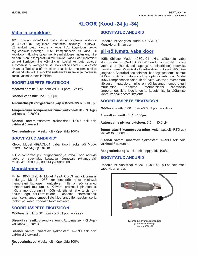
8
MODEL 1056 SECTION 1.0DESCRIPTION AND SPECIFICATIONS
Free and Total ChlorineThe 1056 is compatible with the 499ACL-01 free chlorinesensor and the 499ACL-02 total chlorine sensor. The499ACL-02 sensor must be used with the TCL totalchlorine sample conditioning system. The 1056 fullycompensates free and total chlorine readings forchanges in membrane permeability caused by temper-ature changes. For free chlorine measurements, bothautomatic and manual pH correction are available. Forautomatic pH correction select code -32 and an appropri-ate pH sensor. For more information concerning the useand operation of the amperometric chlorine sensors andthe TCL measurement system, refer to the product datasheets.
PERFORMANCE SPECIFICATIONSResolution: 0.001 ppm or 0.01 ppm – selectable Input Range: 0nA – 100μAAutomatic pH correction (requires Code -32): 6.0 to
10.0 pHTemperature compensation: Automatic (via RTD) or
manual (0-50°C). Input filter: time constant 1 - 999 sec, default 5 sec. Response time: 6 seconds to 100% of final reading
RECOMMENDED SENSORS*Chlorine: Model 499ACL-01 Free Chlorine or Model
499ACL-02 Total Residual Chlorine pH: The following pH sensors are recommended for
automatic pH correction of free chlorine readings:Models: 399-09-62, 399-14, and 399VP-09
MonochloramineThe Model 1056 is compatible with the Model 499A CL-03Monochloramine sensor. The Model 1056 fullycompensates readings for changes in membranepermeability caused by temperature changes. Becausemonochloramine measurement is not affected by pH ofthe process, no pH sensor or correction is required. Formore information concerning the use and operation of theamperometric chlorine sensors, refer to the product datasheets.
PERFORMANCE SPECIFICATIONSResolution: 0.001 ppm or 0.01 ppm – selectableInput Range: 0nA – 100μATemperature compensation: Automatic (via RTD) or
manual (0-50°C). Input filter: time constant 1 - 999 sec, default 5 sec.Response time: 6 seconds to 100% of final reading
RECOMMENDED SENSORSRosemount Analytical Model 499ACL-03 Monochloraminesensor
pH-Independent Free ChlorineThe 1056 is compatible with the Model 498CL-01 pH-independent free chlorine sensor. The Model 498CL-01sensor is intended for the continuous determination offree chlorine (hypochlorous acid plus hypochlorite ion)in water. The primary application is measuring chlorinein drinking water. The sensor requires no acid pre-treat-ment, nor is an auxiliary pH sensor required for pHcorrection. The Model 1056 fully compensates freechlorine readings for changes in membranepermeability caused by temperature. For more informationconcerning the use and operation of the amperometricchlorine sensors, refer to the product data sheets.
PERFORMANCE SPECIFICATIONSResolution: 0.001 ppm or 0.01 ppm – selectableInput Range: 0nA – 100μAAutomatic pH correction: 6.5 to 10.0 pHTemperature compensation: Automatic (via RTD) or
manual (0-50°C). Input filter: time constant 1 - 999 sec, default 5 sec.Response time: 6 seconds to 100% of final reading
RECOMMENDED SENSORSRosemount Analytical Model 498CL-01 pH independent
free chlorine sensor
CHLORINE (Code -24 and -34)
Chlorine sensors with Variopol connection and cable connection
Model 498CL-01
8
KLOOR (Kood -24 ja -34)
MUDEL 1056 PEATÜKK 1,0KIRJELDUS JA SPETSIFIKATSIOONID
Vaba ja kogukloor 1056 ühildub 499ACL-01 vaba kloori mõõtmise anduriga ja 499ACL-02 kogukloori mõõtmise anduriga. 499ACL-02 andurit peab kasutama koos TCL kogukloori proovi reguleerimissüsteemiga. 1056 kompenseerib nii vaba kui kogukloori näidud vastavalt membraani läbivuse muutustele, mille on põhjustanud temperatuuri muutumine. Vaba kloori mõõtmisel on pH korrigeerimine võimalik nii käsitsi kui automaatselt.AutomaatsepH-korrigeerimise jaoks valige kood -32 ja vastavpH-andur.Täpsemainformatsioonisaamiseksamperomeetrilisteklooriandurite ja TCL mõõtmissüsteemi kasutamise ja töötamise kohta, vaadake toote infolehte.
SOORITUSSPETSIFIKATSIOON
Mõõtevahemik: 0,001 ppm või 0,01 ppm – valitav
Sisendi vahemik:0nA–100μA
Automaatne pH korrigeerimine (vajalik Kood -32):6,0-10,0pH
Temperatuuri kompenseerimine: Automaatselt (RTD-ga) või käsitsi (0-50°C).
Sisendi samm:määratav ajakonstant 1-999 sekundit, vaikimisi 5 sekundit.
Reageerimisaeg:6sekundit-lõppnäidu100%
SOOVITATUD ANDURID* Kloor: Mudel 499ACL-01 vaba kloori jaoks või Mudel 499ACL-02 Kogu jääkkloor
pH: Automaatse ph-korrigeerimise ja vaba kloori näitude jaoks on soovitatav kasutada järgnevaid pH-andureid:Mudelid: 399-09-62, 399-14 ja 399VP-09
Monokloramiin
Mudel 1056 ühildub Mudel 499A CL-03 monokloramiini anduriga. Mudel 1056 kompenseerib näite vastavalt membraani läbivuse muutustele, mille on põhjustanud temperatuuri muutumine. Kuivõrd protsessi pH-tase eimõjuta monokloramiini mõõtmist, siis ei lähe tarvis pH-andurit ega pH-korrektsiooni. Täpsema informatsioonisaamiseks amperomeetriliste klooriandurite kasutamise ja töötamise kohta, vaadake toote infolehte.
SOORITUSSPETSIFIKATSIOON Mõõtevahemik: 0,001 ppm või 0,01 ppm – valitav
Sisendi vahemik: Sisendi vahemik: Automaatselt (RTD-ga) või käsitsi (0-50°C).
Sisendi samm: määratav ajakonstant 1—999 sekundit, vaikimisi 5 sekundit.
Reageerimisaeg:6sekundit-lõppnäidu100%
SOOVITATUD ANDURID
Rosemount Analytical Mudel 499ACL-03 Monokloramiini andur
pH-sõltumatu vaba kloor
1056 ühildub Mudel 498CL-01 pH-st sõltumatu vabakloori anduriga. Mudel 498CL-01 andur on mõeldud vees vaba kloori (hüpokloorishape ja hüpokloritioon) pidevaks tuvastamiseks. Peamiseks kasutusalaks on kloori mõõtmine joogivees. Andurit ei pea eelnevalt happega töötlema, samuti ei lähe tarvis lisapH-sensoritegapH-korrektsiooni.Mudel1056 kompenseerib vaba kloori näite vastavalt membraani läbivuse muutustele, mille on põhjustanud temperatuuri muutumine. Täpsema informatsiooni saamiseks amperomeetriliste klooriandurite kasutamise ja töötamise kohta, vaadake toote infolehte.
SOORITUSSPETSIFIKATSIOON
Mõõtevahemik: 0,001 ppm või 0,01 ppm – valitav
Sisendi vahemik:0nA–100μA
Automaatne pH-korrektsioon:6,0—10,0pH
Temperatuuri kompenseerimine: Automaatselt (RTD-ga) või käsitsi (0-50°C).
Sisendi samm: määratav ajakonstant 1—999 sekundit, vaikimisi 5 sekundit.
Reageerimisaeg:6sekundit-lõppnäidu100%
SOOVITATUD ANDURID
Rosemount Analytical Mudel 498CL-01 pH-st sõltumatuvaba kloori andur.
Klooriandurid Variopoli ühenduseja kaabliühendusega
Mudel 498CL-01
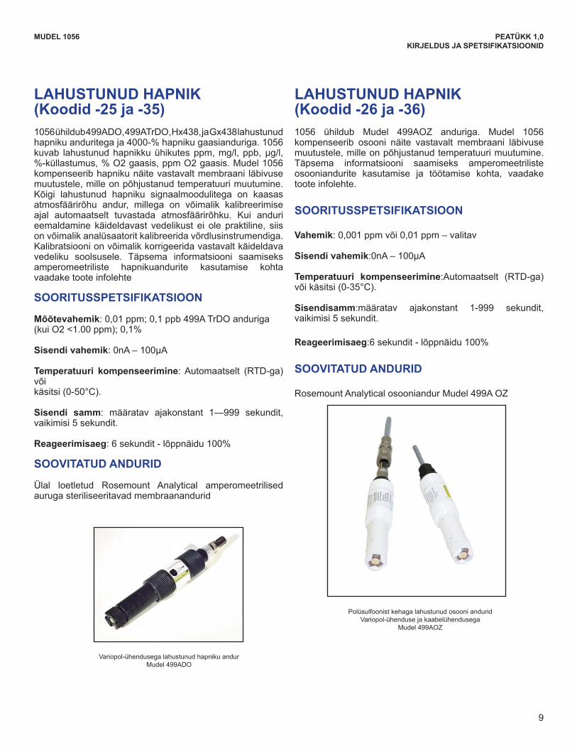
9
LAHUSTUNUD HAPNIK(Koodid -25 ja -35)1056ühildub499ADO,499ATrDO,Hx438,jaGx438lahustunudhapnikuanduritegaja4000-%hapnikugaasianduriga.1056kuvab lahustunudhapnikkuühikutesppm,mg/l, ppb,μg/l,%-küllastumus,%O2gaasis,ppmO2gaasis.Mudel1056kompenseerib hapniku näite vastavalt membraani läbivuse muutustele, mille on põhjustanud temperatuuri muutumine. Kõigi lahustunud hapniku signaalmoodulitega on kaasas atmosfäärirõhu andur, millega on võimalik kalibreerimise ajal automaatselt tuvastada atmosfäärirõhku. Kui anduri eemaldamine käideldavast vedelikust ei ole praktiline, siis on võimalik analüsaatorit kalibreerida võrdlusinstrumendiga. Kalibratsiooni on võimalik korrigeerida vastavalt käideldava vedeliku soolsusele. Täpsema informatsiooni saamiseks amperomeetriliste hapnikuandurite kasutamise kohta vaadake toote infolehte
SOORITUSSPETSIFIKATSIOON
Mõõtevahemik: 0,01 ppm; 0,1 ppb 499A TrDO anduriga(kuiO2<1.00ppm);0,1%
Sisendi vahemik:0nA–100μA
Temperatuuri kompenseerimine: Automaatselt (RTD-ga) võikäsitsi (0-50°C).
Sisendi samm: määratav ajakonstant 1—999 sekundit, vaikimisi 5 sekundit.
Reageerimisaeg:6sekundit-lõppnäidu100%
SOOVITATUD ANDURID
Ülal loetletud Rosemount Analytical amperomeetrilised auruga steriliseeritavad membraanandurid
LAHUSTUNUD HAPNIK (Koodid -26 ja -36)1056 ühildub Mudel 499AOZ anduriga. Mudel 1056 kompenseerib osooni näite vastavalt membraani läbivuse muutustele, mille on põhjustanud temperatuuri muutumine. Täpsema informatsiooni saamiseks amperomeetriliste osooniandurite kasutamise ja töötamise kohta, vaadake toote infolehte.
SOORITUSSPETSIFIKATSIOON
Vahemik: 0,001 ppm või 0,01 ppm – valitav
Sisendi vahemik:0nA–100μA
Temperatuuri kompenseerimine:Automaatselt (RTD-ga) või käsitsi (0-35°C).
Sisendisamm:määratav ajakonstant 1-999 sekundit, vaikimisi 5 sekundit.
Reageerimisaeg:6sekundit-lõppnäidu100%
SOOVITATUD ANDURID
Rosemount Analytical osooniandur Mudel 499A OZ
MUDEL 1056 PEATÜKK 1,0KIRJELDUS JA SPETSIFIKATSIOONID
MODEL 1056 SECTION 1.0DESCRIPTION AND SPECIFICATIONS
DISSOLVED OXYGEN(Codes -25 and -35)The 1056 is compatible with the 499ADO, 499ATrDO,Hx438, and Gx438 dissolved oxygen sensors and the4000 percent oxygen gas sensor. The 1056 displaysdissolved oxygen in ppm, mg/L, ppb, μg/L, % satura-tion, % O2 in gas, ppm O2 in gas. The analyzer fullycompensates oxygen readings for changes in mem-brane permeability caused by temperature changes.An atmospheric pressure sensor is included on all dis-solved oxygen signal boards to allow automatic atmos-pheric pressure determination at the time of calibration.If removing the sensor from the process liquid is imprac-tical, the analyzer can be calibrated against a standardinstrument. Calibration can be corrected for processsalinity. For more information on the use of ampero-metric oxygen sensors, refer to the product datasheets.
PERFORMANCE SPECIFICATIONSResolution: 0.01 ppm; 0.1 ppb for 499A TrDO sensor
(when O2 <1.00 ppm); 0.1%Input Range: 0nA – 100μATemperature Compensation: Automatic (via RTD) or
manual (0-50°C). Input filter: time constant 1 - 999 sec, default 5 sec.Response time: 6 seconds to 100% of final reading
RECOMMENDED SENSORSRosemount Analytical amperometric membrane and
steam-sterilizable sensors listed above
DISSOLVED OZONE (Code -26 and -36)The 1056 is compatible with the Model 499AOZ sen-sor. The 1056 fully compensates ozone readings forchanges in membrane permeability caused by temper-ature changes. For more information concerning theuse and operation of the amperometric ozone sensors,refer to the product data sheets.
PERFORMANCE SPECIFICATIONSResolution: 0.001 ppm or 0.01 ppm – selectableInput Range: 0nA – 100μATemperature Compensation: Automatic (via RTD) or
manual (0-35°C) Input filter: time constant 1 - 999 sec, default 5 sec.Response time: 6 seconds to 100% of final reading
RECOMMENDED SENSORRosemount Analytical Model 499A OZ ozone sensor
Dissolved Oxygen sensor with Variopol connectionModel 499ADO
Dissolved Ozone sensors with Polysulfone bodyVariopol connection and cable connection
Model 499AOZ
9
Variopol-ühendusega lahustunud hapniku andurMudel 499ADO
Polüsulfoonist kehaga lahustunud osooni anduridVariopol-ühenduse ja kaabelühendusega
Mudel 499AOZ
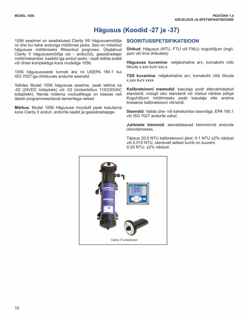
10
Hägusus (Koodid -27 ja -37)
MUDEL 1056 PEATÜKK 1,0KIRJELDUS JA SPETSIFIKATSIOONID
1056seadmel on seadistusedClarity II®hägususemõõtjanii ühe kui kahe anduriga mõõtmise jaoks. See on mõeldud hägususe mõõtmiseks filtreeritud joogivees. ÜlejäänudClarity II hägususemõõtja osi - andur(id), gaasiärastaja/mõõtmiskamber, kaablid iga anduri jaoks - saab tellida eraldi või ühise komplektiga koos mudeliga 1056.
1056 hägususseade tunneb ära nii USEPA 180.1 kui ISO 7027-ga ühilduvate andurite sisendid.
Tellides Mudel 1056 hägususe seadme, peab tellima ka -02 (24VDC toiteplokk) või -03 (ümberlülituv 115/230VAC toiteplokk). Nende mõlema vooluallikaga on kaasas neli täiesti programmeeritavat taimeritega releed.
Märkus: Mudel 1056 Hägususe moodulit peab kasutamakoos Clarity II anduri, andurite kaabli ja gaasiärastajaga.
SOORITUSSPETSIFIKATSIOON
Ühikud:Hägusus(NTU,FTUvõiFNU);koguhõljum(mg/l,ppm või ilma ühikuteta)
Hägususe kuvamine: neljakohaline arv; komakoht võib liikuda x,xxx kuni xxx,x
TSS kuvamine: neljakohaline arv; komakoht võib liikuda x,xxx kuni xxxx
Kalibratsiooni meetodid: kasutaja poolt ettevalmistatud standardi, müügil olev standardi või võetud näidise põhjal Koguhõljumi mõõtmiseks peab kasutaja ette andma lineaarse kalibratsiooni võrrandi.
Sisendid: Valida ühe- või kahekordse sisendiga, EPA 180.1 või ISO 7027 andurite vahel.
Juhtmete klemmid: eemaldatavad klemmirivid andurite ühendamiseks.
Täpsus20,0NTUkalibratsioonijärel:0-1NTU±2%näidustvõi 0,015 NTU, olenevalt sellest kumb on suurem. 0-20NTU:±2%näidust.
Turbidity (Codes -27 and -37)The 1056 instrument is available in single and dual tur-bidity configurations for the Clarity II® turbidimeter. It isintended for the determination of turbidity in filtereddrinking water. The other components of the Clarity IIturbidimeter – sensor(s), debubbler/measuring cham-ber(s), and cable for each sensor must be orderedseparately or as a complete system with the Model1056. The 1056 turbidity instrument accepts inputs from bothUSEPA 180.1 and ISO 7027-compliant sensors When ordering the Model 1056 turbidity instrument, the-02 (24VDC power supply) or the -03 (switching115/230VAC power supply) are required. Both of thesepower supplies include four fully programmable relayswith timers. Note: Model 1056 Turbidity must be used with ClarityII sensor, sensor cable and debubbler.
PERFORMANCE SPECIFICATIONSUnits: Turbidity (NTU, FTU, or FNU); total suspendedsolids (mg/L, ppm, or no units)Display resolution-turbidity: 4 digits; decimal pointmoves from x.xxx to xxx.xDisplay resolution-TSS: 4 digits; decimal point movesfrom x.xxx to xxxxCalibration methods: user-prepared standard, com-mercially prepared standard, or grab sample. For totalsuspended solids user must provide a linear calibrationequation.Inputs: Choice of single or dual input, EPA 180.1 orISO 7027 sensors.Field wiring terminals: removable terminal blocks forsensor connection.Accuracy after calibration at 20.0 NTU:0-1 NTU ±2% of reading or 0.015 NTU, whichever isgreater. 0-20 NTU: ±2% of reading.
Clarity ll Turbidimeter
MODEL 1056 SECTION 1.0DESCRIPTION AND SPECIFICATIONS
10
Clarity ll Turbidimeter
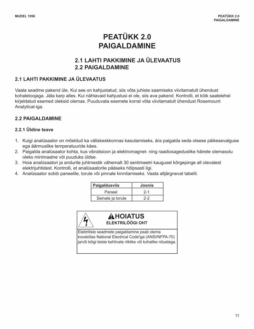
11
MUDEL 1056 PEATÜKK 2.0PAIGALDAMINE
PEATÜKK 2.0 PAIGALDAMINE
2.1 LAHTI PAKKIMINE JA ÜLEVAATUS2.2 PAIGALDAMINE
2.1 LAHTI PAKKIMINE JA ÜLEVAATUS
Vaata seadme pakend üle. Kui see on kahjustatud, siis võta juhiste saamiseks viivitamatult ühendust kohaletoojaga. Jäta karp alles. Kui nähtavaid kahjustusi ei ole, siis ava pakend. Kontrolli, et kõik saatelehel kirjeldatud esemed oleksid olemas. Puuduvata esemete korral võta viivitamatult ühendust Rosemount Analytical-iga.
2.2 PAIGALDAMINE
2.2.1 Üldine teave
1. Kuigi analüsaator on mõeldud ka väliskeskkonnas kasutamiseks, ära paigalda seda otsese päikesevalguse ega äärmuslike temperatuuride käes.
2. Paigalda analüsaator kohta, kus vibratsioon ja elektromagnet- ning raadiosageduslike häirete olemasolu oleks minimaalne või puuduks üldse.
3. Hoiaanalüsaatorijaanduritejuhtmestikvähemalt30sentimeetrikauguselkõrgepingeallolevatestelektrijuhtidest. Kontrolli, et analüsaatorile pääseks hõlpsasti ligi.
4. Analüsaator sobib paneelile, torule või pinnale kinnitamiseks. Vaata alljärgnevat tabelit.
Paigaldusviis JoonisPaneel 2-1
Seinale ja torule 2-2
ESSENTIAL INSTRUCTIONSREAD THIS PAGE BEFORE PROCEEDING!
Your instrument purchase from RosemountAnalytical, Inc. is one of the finest available for yourparticular application. These instruments have beendesigned, and tested to meet many national andinternational standards. Experience indicates that itsperformance is directly related to the quality of theinstallation and knowledge of the user in operatingand maintaining the instrument. To ensure their con-tinued operation to the design specifications, per-sonnel should read this manual thoroughly beforeproceeding with installation, commissioning, opera-tion, and maintenance of this instrument. If thisequipment is used in a manner not specified by themanufacturer, the protection provided by it againsthazards may be impaired.• Failure to follow the proper instructions may
cause any one of the following situations tooccur: Loss of life; personal injury; property dam-age; damage to this instrument; and warrantyinvalidation.
• Ensure that you have received the correct modeland options from your purchase order. Verify thatthis manual covers your model and options. Ifnot, call 1-800-854-8257 or 949-757-8500 torequest correct manual.
• For clarification of instructions, contact yourRosemount representative.
• Follow all warnings, cautions, and instructionsmarked on and supplied with the product.
• Use only qualified personnel to install, operate,update, program and maintain the product.
• Educate your personnel in the proper installation,operation, and maintenance of the product.
• Install equipment as specified in the Installation section of this manual. Follow appropriate localand national codes. Only connect the product toelectrical and pressure sources specified in thismanual.
• Use only factory documented components forrepair. Tampering or unauthorized substitution ofparts and procedures can affect the performanceand cause unsafe operation of your process.
• All equipment doors must be closed and protec-tive covers must be in place unless qualified per-sonnel are performing maintenance.
Equipment protected throughout by double insulation. • Installation and servicing of this product may expose personel
to dangerous voltages. • Main power wired to separate power source must be
disconnected before servicing.• Do not operate or energize instrument with case open!• Signal wiring connected in this box must be rated at least
240 V. • Non-metallic cable strain reliefs do not provide grounding
between conduit connections! Use grounding type bushings and jumper wires.
• Unused cable conduit entries must be securely sealed by non-flammable closures to provide enclosure integrity in compliance with personal safety and environmental protectionrequirements. Unused conduit openings must be sealed with NEMA 4X or IP65 conduit plugs to maintain the ingress protection rating (NEMA 4X).
• Electrical installation must be in accordance with the NationalElectrical Code (ANSI/NFPA-70) and/or any other applicable national or local codes.
• Operate only with front panel fastened and in place. • Safety and performance require that this instrument be
connected and properly grounded through a three-wire power source.
• Proper use and configuration is the responsibility of the user.
This product generates, uses, and can radiate radio frequencyenergy and thus can cause radio communication interference.Improper installation, or operation, may increase such interfer-ence. As temporarily permitted by regulation, this unit has notbeen tested for compliance within the limits of Class A comput-ing devices, pursuant to Subpart J of Part 15, of FCC Rules,which are designed to provide reasonable protection againstsuch interference. Operation of this equipment in a residentialarea may cause interference, in which case the user at his ownexpense, will be required to take whatever measures may berequired to correct the interference.
This product is not intended for use in the light industrial,residential or commercial environments per the instru-ment’s certification to EN50081-2.
Emerson Process Management
2400 Barranca ParkwayIrvine, CA 92606 USATel: (949) 757-8500Fax: (949) 474-7250
http://www.rosemountanalytical.com
© Rosemount Analytical Inc. 2012
WARNINGRISK OF ELECTRICAL SHOCK
CAUTION
CAUTION
HOIATUS ELEKTRILÖÖGI OHT
Elektriliste seadmete paigaldamine peab olema kooskõlas National Electrical Code'iga (ANSI/NFPA-70) ja/või kõigi teiste kehtivate riiklike või kohalike nõuetega.
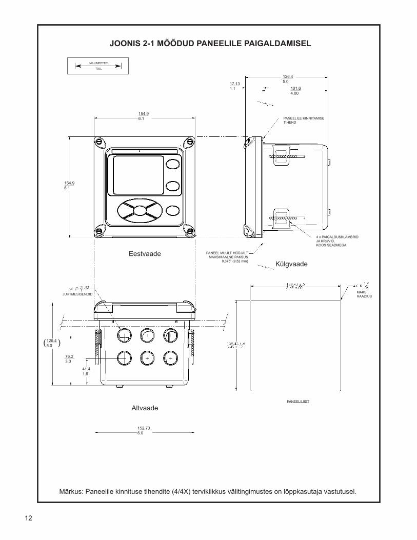
12
Bottom View
Front ViewSide View
FIGURE 2-1 PANEL MOUNTING DIMENSIONS
Note: Panel mounting seal integrity (4/4X) for outdoor applications is the responsibility of the end user.
MILLIMETERINCH
154.96.1
154.96.1
126.45.0
101.64.00
17.131.1
126.45.0 )(
76.23.0
41.41.6
152.736.0
12
JOONIS 2-1 MÕÕDUD PANEELILE PAIGALDAMISEL
Eestvaade
MILLIMEETER
TOLL
Altvaade
Märkus: Paneelile kinnituse tihendite (4/4X) terviklikkus välitingimustes on lõppkasutaja vastutusel.
Külgvaade
PANEELILE KINNITAMISE TIHEND
4 x PAIGALDUSKLAMBRID JA KRUVID, KOOS SEADMEGA
PANEEL MUULT MÜÜJALTMAKSIMAALNE PAKSUS
0,375” (9,52 mm)
MAKS. RAADIUSJUHTMESISENDID
PANEELILIIST
MILLIMEETER
TOLL
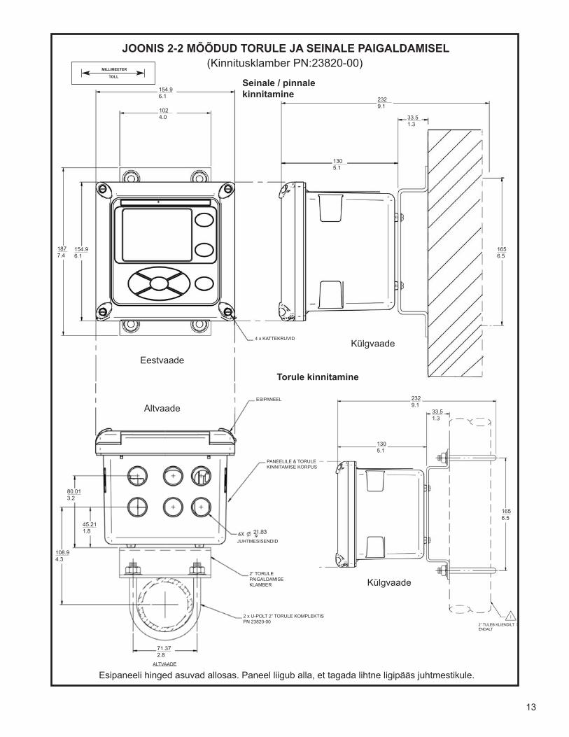
13
FIGURE 2-2 PIPE AND WALL MOUNTING DIMENSIONS (Mounting bracket PN:23820-00)
The front panel is hinged at the bottom. The panel swings down for easy access to the wiring locations.
Bottom View
Front View
Side View
Side View
Wall / Surface Mount
Pipe Mount
MILLIMETERINCH
154.96.1
1024.0
1877.4
154.96.1
2329.1
33.51.3
1305.1
1656.5
2329.1
1305.1
33.51.3
1656.5
108.94.3
45.211.8
80.013.2
71.372.8
13
JOONIS 2-2 MÕÕDUD TORULE JA SEINALE PAIGALDAMISEL(Kinnitusklamber PN:23820-00)
Eestvaade
Altvaade
Esipaneeli hinged asuvad allosas. Paneel liigub alla, et tagada lihtne ligipääs juhtmestikule.
Külgvaade
Torule kinnitamine
Külgvaade
Seinale / pinnale kinnitamine
MILLIMEETER
TOLL
4 x KATTEKRUVID
ESIPANEEL
PANEELILE & TORULEKINNITAMISE KORPUS
JUHTMESISENDID
2” TORULEPAIGALDAMISEKLAMBER
2 x U-POLT 2” TORULE KOMPLEKTIS PN 23820-00
2” TULEB KLIENDILT ENDALT
ALTVAADE
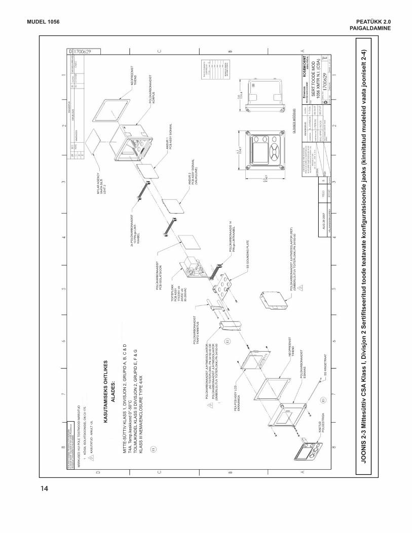
MODEL 1056 SECTION 2.0INSTALLATION
FIG
UR
E 2
-3 C
SA
Non
-Ince
ndiv
e C
lass
I, D
ivis
ion
2 C
ertif
ied
prod
uct f
or s
elec
ted
conf
igur
atio
ns (f
or a
ppro
ved
mod
els,
see
Fig
. 2-4
)
14
MUDEL 1056 PEATÜKK 2.0PAIGALDAMINE
JOO
NIS
2-3
Mitt
esüt
tiv C
SA K
lass
I, D
ivis
jon
2 Se
rtifi
tsee
ritud
tood
e te
atav
ate
konfi
gura
tsio
onid
e ja
oks
(kin
nita
tud
mud
elei
d va
ata
joon
isel
t 2-4
)
Dok
umen
t sis
alda
b R
osem
ount
Ana
lytic
alile
ku
uluv
at te
avet
nin
g se
da e
i toh
i and
a R
osem
oun
Ana
lytic
ali v
õim
alik
ele
konk
uren
tidel
e.
MÄ
RK
US
ED
: KU
I PO
LE T
EIS
TMO
OD
I MÄ
RG
ITU
D
1 K
ÕIG
IL IS
OLA
TSIO
ON
IDE
L O
N C
II 17
5.
KA
SU
TATU
D -
AIN
ULT
-UL K
ASU
TAM
ISEK
S O
HTL
IKES
A
LAD
ES:
MIT
TE-S
ÜTT
IV K
LAS
S 1
, DIV
ISJO
N 2
, GR
UP
ID A
, B, C
& D
T4A
. Tem
p.ke
skko
nd 0
°-50
°CTO
LMU
KIN
DE
L K
LAS
S II
DIV
ISJO
N 2
, GR
UP
ID E
, F &
GK
LAS
S II
I NE
MA
/EN
CLO
SU
RE
TY
PE
4/4
X
MU
UD
ATU
S
KIR
JELD
US
K
UU
PÄ
EV
VAAT
A E
CO
MY
LAR
AG
EN
CY
VAAT
A S
ILTI
LEH
T 2
NE
OP
RE
EN
IST
TIH
EN
D
PO
LÜK
AR
BO
NA
AD
IST
KO
RP
US
AN
DU
R 1
PC
B A
SS
Y S
IGN
AA
L
AN
DU
R 2
PC
B A
SS
Y S
IGN
AA
L (V
ALI
KU
LIN
E)
PO
LÜK
AR
BO
NA
AD
IS 1
4 P
IN-g
a LI
NTK
AA
BE
L
SS
GO
UN
DIN
G P
LATE
ÜLD
ISE
D M
ÕÕ
DU
DP
OLÜ
KA
RB
ON
AA
DIS
T JU
HTM
EIS
OLA
ATO
R (R
EF)
(Ü
MB
ER
LÜLI
TUV
TO
ITE
PLO
KK
) PN
341
93-0
0
2x P
OLÜ
KA
RB
ON
AA
DIS
T
10
PIN
-ga
LIN
T-
K
AA
BE
L
PO
LÜK
AR
BO
NA
AD
IST
PC
B IS
OLA
TSIO
ON
PO
LÜK
AR
BO
NA
AD
IST
TRA
FO K
INN
ITU
S
PE
A P
CB
AS
SY
LCD
E
KR
AA
NIG
A
NE
OP
RE
EN
IST
TIH
EN
D
PO
LÜK
AR
BO
NA
AD
IST
ES
IKA
AS
SS
HIN
GE
TRA
AT
KA
ETU
D
PO
LÜE
STR
IGA
PO
LÜK
AR
BO
NA
AD
IST
JUH
TME
ISO
LAAT
OR
(A
C T
OIT
EP
LOK
K).
PN
341
92-0
0 O
RP
OLÜ
KA
RB
ON
AA
DIS
T JU
HTM
EIS
OLA
ATO
R
(ÜM
BE
RLÜ
LITU
V T
OIT
EP
LOK
K) P
N 3
4193
-00
TOIT
EP
LOK
KP
CB
AS
SY
115/
230V
või
24V
DC
või
85-2
65VA
C
HE
AK
SK
IIDU
D
AU
G 2
8 20
07
VÄ
LJA
AN
DM
ISK
UU
PÄ
EV
MUUD
ATUS
KU
UP
ÄE
V
JOO
NE
STA
S
KON
TRO
LLIT
UD
FAIL
I LO
OM
ISEL
KAS
UTA
TI S
OLI
D
EDG
E’i
SER
T.TO
OD
E M
OD
10
56 X
MTR
N.I.
(CSA
)
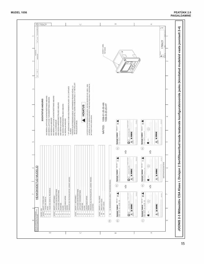
MODEL 1056 SECTION 2.0INSTALLATION
FIG
UR
E 2
-4 C
SA
Non
-Ince
ndiv
e C
lass
I, D
ivis
ion
2 C
ertif
ied
prod
uct f
or s
elec
ted
conf
igur
atio
ns
15
MUDEL 1056 PEATÜKK 2.0PAIGALDAMINE
JOO
NIS
2-3
Mitt
esüt
tiv C
SA K
lass
I, D
ivis
jon
2 Se
rtifi
tsee
ritud
tood
e te
atav
ate
konfi
gura
tsio
onid
e ja
oks
(kin
nita
tud
mud
elei
d va
ata
joon
isel
t 2-4
)
Dok
umen
t sis
alda
b R
osem
ount
Ana
lytic
alile
ku
uluv
at te
avet
nin
g se
da e
i toh
i and
a R
osem
oun
Ana
lytic
ali v
õim
alik
ele
konk
uren
tidel
e.H
EA
KS
KIID
ETU
D M
UD
ELI
DM
UD
EL
1056
KO
OD
KO
OD
KO
OD
KO
OD
GR
UP
P I T
OIT
EP
LOK
K
100
SE
ER
IA J
UH
TIV
US
E K
ON
TAK
TMÕ
ÕTM
ISE
AN
DU
RID
200
SE
ER
IA J
UH
TIV
US
E T
OR
OID
MÕ
ÕTM
ISE
AN
DU
RID
300
SE
ER
IA p
H A
ND
UR
ID40
0 S
EE
RIA
JU
HTI
VU
SE
KO
NTA
KTM
ÕÕ
TMIS
E A
ND
UR
ID49
8CL
KLO
OR
IAN
DU
R49
9A S
EE
RIA
AM
PE
RO
ME
ETR
ILIS
ED
AN
DU
RID
3000
SE
ER
IA p
H A
ND
UR
IDG
x S
EE
RIA
AM
PE
RO
ME
ETR
ILIS
ED
AN
DU
RID
Hx
SE
ER
IA p
H A
ND
UR
ID
* ‘V
P’ V
ER
SIO
ON
ID E
I SO
BI K
AS
UTA
MIS
EK
S K
LAS
S I
DIV
2 O
HTL
IKE
S
ALA
DE
S*
KA
NA
DA
ELE
KTR
IEE
SK
IRJA
DE
LE V
AS
TAM
ISE
KS
PE
AVA
D K
ÕIG
IL L
U-
BAT
UD
AN
DU
RIS
EA
DIS
TUS
TEL
OLE
MA
KA
AB
LIK
AIT
SE
D, S
.T M
ETA
LLIS
T PA
IGA
LDU
STO
RU
D.
LAH
TIS
TE E
LEK
TRO
OD
IDE
GA
AN
DU
RE
ID, N
ÄIT
EK
S M
UD
ELE
ID 4
00, 4
98C
L, 4
99A
JA M
ÕN
ED
Gx
JA H
x S
EE
RIA
AN
DU
RE
ID T
OH
IB K
AS
UTA
DA
AIN
ULT
VE
ER
OH
KE
TE,
MIT
TES
ÜTT
IVAT
E V
ED
ELI
KE
GA
.
AG
EN
CY
LAB
EL
TOP
ED
GE
NÄ
ITE
D:
1056
-01-
20-3
0-A
N
1056
-0I-2
0-20
-HT
SOO
VITA
TUD
AN
DU
RID
GR
UP
P 2
- MÕ
ÕTM
INE
I
GR
UP
P 3
- MÕ
ÕTM
INE
2
GR
UP
P 4
- VÄ
LJU
ND
IDA
NA
LOO
G 4
-20m
AH
AR
T 4-
20m
A
UL
HE
AK
SK
IIDU
GA
(AIN
ULT
TAV
AK
ES
KK
ON
NA
D)
SE
RTI
FIK
ATS
IOO
NIT
ÄH
IS
115/
230
VAC
50/
60 H
z
JUH
TIV
US
E K
ON
TAK
TMÕ
ÕTM
INE
JUH
TIV
US
E K
ON
TAK
TMÕ
ÕTM
INE
24V
DC
JUH
TIV
US
E T
OR
OID
MÕ
ÕTM
INE
JUH
TIV
US
E T
OR
OID
MÕ
ÕTM
INE
115/
230
VAC
50/
60 H
z, R
ELE
ED
EG
A
Ph/
OR
P/IS
E
Ph/
OR
P/IS
E
KLO
OR
KLO
OR
LAH
US
TUN
UD
HA
PN
IK
LAH
US
TUN
UD
HA
PN
IK
OS
OO
N
OS
OO
N
HÄ
GU
SU
S (K
UI O
N P
AIG
ALD
ATU
D, J
OO
NIS
140
0325
)
HO
IATU
S
HÄ
GU
SU
S (K
UI O
N P
AIG
ALD
ATU
D, J
OO
NIS
140
0325
)E
I ÜH
TEG
I
VÕ
I
VÕ
I
VÕ
I
VÕ
I
MU
UD
ATU
S
KIR
JELD
US
K
UU
PÄ
EV
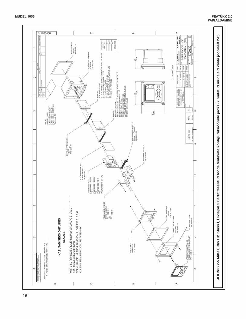
16
FIG
UR
E 2
-5 F
M N
on-In
cend
ive
Cla
ss I,
Div
isio
n 2
Cer
tifie
d pr
oduc
t for
sel
ecte
d co
nfig
urat
ions
(for
app
rove
d m
odel
s, s
ee F
ig. 2
-6)
MODEL 1056 SECTION 2.0INSTALLATION
MUDEL 1056 PEATÜKK 2.0PAIGALDAMINE
JOO
NIS
2-5
Mitt
esüt
tiv F
M K
lass
I, D
ivis
jon
5 Se
rtifi
tsee
ritud
tood
e te
atav
ate
konfi
gura
tsio
onid
e ja
oks
(kin
nita
tud
mud
elei
d va
ata
joon
isel
t 2-6
)
Dok
umen
t sis
alda
b R
osem
ount
Ana
lytic
alile
ku
uluv
at te
avet
nin
g se
da e
i toh
i and
a R
osem
oun
Ana
lytic
ali v
õim
alik
ele
konk
uren
tidel
e.
MÄ
RK
US
ED
: KU
I PO
LE T
EIS
TMO
OD
I MÄ
RG
ITU
D1
KÕ
IGIL
ISO
LATS
IOO
NID
EL
ON
CII
>100
.
KA
SUTA
MIS
EKS
OH
TLIK
ES
ALA
DES
:
MIT
TE-S
ÜTT
IV K
LAS
S 1
, DIV
ISJO
N 2
, GR
UP
ID A
, B, C
& D
T4A
. Tem
p.ke
skko
nd 0
°-50
°CTO
LMU
KIN
DE
L K
LAS
S II
DIV
ISJO
N 2
, GR
UP
ID E
, F &
GK
LAS
S II
I NE
MA
/EN
CLO
SU
RE
TY
PE
4/4
X
MU
UD
ATU
S
KIR
JELD
US
K
UU
PÄ
EV
VAAT
A E
CO
MY
LAR
A
GE
NC
Y LA
BE
LP
N92
4167
6-00
115
/230
VP
N92
4167
6-01
240
Vdc
PN
9241
676-
01 8
5-26
5 VA
CVA
ATA
LEH
T 2
NE
OP
RE
EN
IST
TIH
EN
D
PN
340
59-0
0
PO
LÜK
AR
BO
NA
AD
IST
KO
RP
US
P
N 3
4053
-00
AN
DU
R 1
PC
B A
SS
Y S
IGN
AA
LP
N 2
4203
-00
(O1.
-02
VÕ
I -03
) AM
PE
RO
ME
ETR
ILIN
E [A
] VÕ
IP
N 2
4205
-00
TOR
OID
AA
LNE
(T) V
ÕI
PN
242
07-0
0 pH
(P) V
ÕI
PN
242
15-0
0 V
ÕI P
N 2
4273
-00
JUH
TIV
US
E K
ON
TAK
TMÕ
ÕTM
INE
(C) V
ÕI
PN
242
36-0
0 H
ÄG
US
US
EA
ND
UR
2P
CB
AS
SY
SIG
NA
AL
PN
242
03-0
0 (O
1. -0
2 V
ÕI -
03) A
MP
ER
OM
EE
TRIL
INE
[A] V
ÕI
PN
242
05-0
0 TO
RO
IDA
ALN
E (T
) VÕ
IP
N 2
4207
-00
pH (P
) VÕ
IP
N 2
4215
-00
VÕ
I PN
242
73-0
0JU
HTI
VU
SE
KO
NTA
KTM
ÕÕ
TMIN
E (C
) VÕ
I P
N 2
4236
-00
HÄ
GU
SU
SE
2X P
OLÜ
KA
RB
ON
AA
DIS
10
PIN
-ga
P
N24
22S
-00
PO
LÜK
AR
BO
NA
AD
IST
PC
B IS
OLA
TSIO
ON
P
N 3
4077
-00
TOIT
EP
LOK
K A
SS
YP
N 2
4196
-00
115/
230V
VÕ
IP
N 2
4233
-00
115/
230V
VÕ
IP
N 2
4261
-00
24V
DC
VÕ
IP
N 2
4248
-00
85-2
65 V
AC
PO
LÜK
AR
BO
NA
AD
IST
TRA
FO K
INN
ITU
S
PN
340
58-0
0V
ÕI
PN
340
55-0
0
PE
A P
CB
AS
SY
LCD
E
KR
AA
NIG
A P
N 2
4194
-00
NE
OP
RE
EN
IST
TIH
EN
D
PN
340
62-0
0
PO
LÜK
AR
BO
NA
AD
IST
ES
IKA
AS
P
N 3
4054
-00
SS
HIN
GE
TRA
AT
PN
340
56-0
0
PO
LÜE
STE
RK
ATE
KO
OS
P
OLÜ
KA
RB
ON
AA
DIS
AK
NA
GA
PN
340
63-0
0
PO
LÜK
AR
BO
NA
AD
IS 1
4 P
IN-g
a LI
NTK
AA
BE
L P
N 2
4224
-00
SS
S M
AA
ND
US
PLA
AT
PN
340
60-0
0
ÜLD
ISE
D M
ÕÕ
DU
D
HE
AK
SK
IIDU
D
JAN
10.
200
8
VÄ
LJA
AN
DM
ISK
UU
PÄ
EV
MUUD
ATUS
MATE
RJAL
I
PNSH
KU
UP
ÄE
V
SK
AA
LA:
MA
SS
LEH
T 1
2-st
JOO
NE
STA
S
KON
TRO
LLIT
UD
FAIL
I LO
OM
ISEL
KAS
UTA
TI S
OLI
D
EDG
E’i
SER
T.TO
OD
E M
OD
10
56 X
MTR
N.I.
(FM
)

17
FIG
UR
E 2
-6 F
M N
on-In
cend
ive
Cla
ss I,
Div
isio
n 2
Cer
tifie
d pr
oduc
t for
sel
ecte
d co
nfig
urat
ions
MODEL 1056 SECTION 2.0INSTALLATION
MUDEL 1056 PEATÜKK 2.0PAIGALDAMINE
JOO
NIS
2-6
Mitt
esüt
tiv F
M K
lass
I, D
ivis
jon
6 Se
rtifi
tsee
ritud
tood
e te
atav
ate
konfi
gura
tsio
onid
e ja
oks
Dok
umen
t sis
alda
b R
osem
ount
Ana
lytic
alile
ku
uluv
at te
avet
nin
g se
da e
i toh
i and
a R
osem
oun
Ana
lytic
ali v
õim
alik
ele
konk
uren
tidel
e.H
EA
KS
KIID
ETU
D M
UD
ELI
DM
UD
EL
1056
KO
OD
KO
OD
KO
OD
KO
OD
GR
UP
P I T
OIT
EP
LOK
K
GR
UP
P 2
- MÕ
ÕTM
INE
I
GR
UP
P 3
- MÕ
ÕTM
INE
2
GR
UP
P 4
- VÄ
LJU
ND
IDA
NA
LOO
G 4
-20m
AH
AR
T 4-
20m
A
SE
RTI
FIK
ATS
IOO
NIT
ÄH
IS
115/
230
VAC
50/
60 H
z
JUH
TIV
US
E K
ON
TAK
TMÕ
ÕTM
INE
JUH
TIV
US
E K
ON
TAK
TMÕ
ÕTM
INE
24V
DC
JUH
TIV
US
E T
OR
OID
MÕ
ÕTM
INE
JUH
TIV
US
E T
OR
OID
MÕ
ÕTM
INE
115/
230
VAC
50/
60 H
z, R
ELE
ED
EG
A
Ph/
OR
P/IS
E
Ph/
OR
P/IS
E
KLO
OR
KLO
OR
LAH
US
TUN
UD
HA
PN
IK
LAH
US
TUN
UD
HA
PN
IK
OS
OO
N
OS
OO
N
HÄ
GU
SU
S (K
UI O
N P
AIG
ALD
ATU
D, J
OO
NIS
140
0312
)
HÄ
GU
SU
S (K
UI O
N P
AIG
ALD
ATU
D, J
OO
NIS
140
0325
)E
I ÜH
TEG
I
VÕ
IV
ÕI
100
SE
ER
IA J
UH
TIV
US
E K
ON
TAK
TMÕ
ÕTM
ISE
AN
DU
RID
200
SE
ER
IA J
UH
TIV
US
E T
OR
OID
MÕ
ÕTM
ISE
AN
DU
RID
300
SE
ER
IA p
H A
ND
UR
ID40
0 S
EE
RIA
JU
HTI
VU
SE
KO
NTA
KTM
ÕÕ
TMIS
E A
ND
UR
ID49
8CL
KLO
OR
IAN
DU
R49
9A S
EE
RIA
AM
PE
RO
ME
ETR
ILIS
ED
AN
DU
RID
3000
SE
ER
IA p
H A
ND
UR
IDG
x S
EE
RIA
AM
PE
RO
ME
ETR
ILIS
ED
AN
DU
RID
Hx
SE
ER
IA p
H A
ND
UR
ID*
‘VP
’ VE
RS
IOO
NID
EI S
OB
I KA
SU
TAM
ISE
KS
KLA
SS
I D
IV 2
O
HTL
IKE
S A
LAD
ES
* U
SA
ELE
KTR
IEE
SK
IRJA
DE
LE V
AS
TAM
ISE
KS
PE
AVA
D
KÕ
IGIL
LU
BAT
UD
AN
DU
RIS
EA
DIS
TUS
TEL
OLE
MA
KA
AB
-LI
KA
ITS
ED
, S.T
ME
TALL
IST
PAIG
ALD
US
TOR
UD
.
LAH
TIS
TE E
LEK
TRO
OD
IDE
GA
AN
DU
RE
ID, N
ÄIT
EK
S M
UD
ELE
ID
400,
498
CL,
499
A JA
MÕ
NE
D G
x JA
Hx
SE
ER
IA A
ND
UR
EID
TO
HIB
K
AS
UTA
DA
AIN
ULT
VE
ER
OH
KE
TE, M
ITTE
SÜ
TTIV
ATE
VE
DE
LIK
EG
A.
NÄ
ITE
D:
1056
-01-
20-3
0-A
N
1056
-0I-2
0-20
-HT
SOO
VITA
TUD
AN
DU
RID
*
HO
IATU
S
MU
UD
ATU
S
KIR
JELD
US
K
UU
PÄ
EV
AG
EN
CY
LAB
EL
TOP
ED
GE

18
MUDEL 1056 PEATÜKK 2,0PAIGALDAMINE
This page left blank intentionally
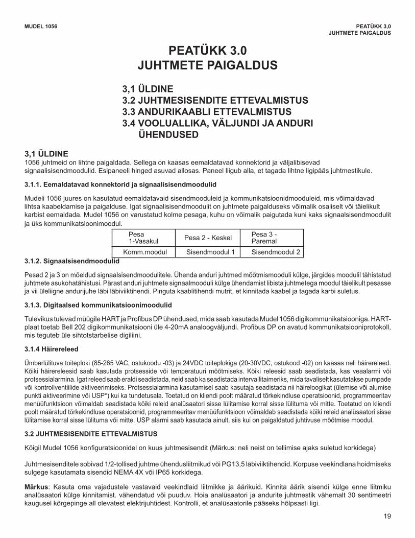
19
MUDEL 1056 PEATÜKK 3,0JUHTMETE PAIGALDUS
PEATÜKK 3.0 JUHTMETE PAIGALDUS
3,1 ÜLDINE3.2 JUHTMESISENDITE ETTEVALMISTUS3.3 ANDURIKAABLI ETTEVALMISTUS3.4 VOOLUALLIKA, VÄLJUNDI JA ANDURI
ÜHENDUSED
3,1 ÜLDINE1056 juhtmeid on lihtne paigaldada. Sellega on kaasas eemaldatavad konnektorid ja väljalibisevad signaalisisendmoodulid. Esipaneeli hinged asuvad allosas. Paneel liigub alla, et tagada lihtne ligipääs juhtmestikule.
3.1.1. Eemaldatavad konnektorid ja signaalisisendmoodulid
Mudeli 1056 juures on kasutatud eemaldatavaid sisendmooduleid ja kommunikatsioonidmooduleid, mis võimaldavad lihtsa kaabeldamise ja paigalduse. Igat signaalisisendmoodulit on juhtmete paigalduseks võimalik osaliselt või täielikult karbist eemaldada. Mudel 1056 on varustatud kolme pesaga, kuhu on võimalik paigutada kuni kaks signaalsisendmoodulit ja üks kommunikatsioonimoodul.
Pesa 1-Vasakul Pesa 2 - Keskel Pesa 3 -
ParemalKomm.moodul Sisendmoodul 1 Sisendmoodul 2
3.1.2. Signaalsisendmoodulid
Pesad 2 ja 3 on mõeldud signaalsisendmoodulitele. Ühenda anduri juhtmed mõõtmismooduli külge, järgides moodulil tähistatud juhtmete asukohatähistusi. Pärast anduri juhtmete signaalmooduli külge ühendamist libista juhtmetega moodul täielikult pesasse ja vii üleliigne andurijuhe läbi läbiviiktihendi. Pinguta kaablitihendi mutrit, et kinnitada kaabel ja tagada karbi suletus.
3.1.3. Digitaalsed kommunikatsioonimoodulid
TulevikustulevadmüügileHARTjaProfibusDPühendused,midasaabkasutadaMudel1056digikommunikatsiooniga.HART-plaattoetabBell202digikommunikatsiooniüle4-20mAanaloogväljundi.ProfibusDPonavatudkommunikatsiooniprotokoll,mis teguteb üle sihtotstarbelise digiliini.
3.1.4 Häirereleed
Ümberlülituva toiteploki (85-265 VAC, ostukoodu -03) ja 24VDC toiteplokiga (20-30VDC, ostukood -02) on kaasas neli häirereleed. Kõiki häirereleesid saab kasutada protsesside või temperatuuri mõõtmiseks. Kõiki releesid saab seadistada, kas veaalarmi või protsessialarmina. Igat releed saab eraldi seadistada, neid saab ka seadistada intervallitaimeriks, mida tavaliselt kasutatakse pumpade või kontrollventiilide aktiveerimiseks. Protsessialarmina kasutamisel saab kasutaja seadistada nii häireloogikat (ülemise või alumise punkti aktiveerimine või USP*) kui ka tundetusala. Toetatud on kliendi poolt määratud tõrkekindluse operatsioonid, programmeeritav menüüfunktsioon võimaldab seadistada kõiki releid analüsaatori sisse lülitamise korral sisse lülituma või mitte. Toetatud on kliendi poolt määratud tõrkekindluse operatsioonid, programmeeritav menüüfunktsioon võimaldab seadistada kõiki releid analüsaatori sisse lülitamise korral sisse lülituma või mitte. USP alarmi saab kasutada ainult, siis kui on paigaldatud juhtivuse mõõtmise moodul.
3.2 JUHTMESISENDITE ETTEVALMISTUS
KõigilMudel1056konfiguratsioonidelonkuusjuhtmesisendit(Märkus:nelineistontellimiseajakssuletudkorkidega)
Juhtmesisenditele sobivad 1/2-tollised juhtme ühendusliitmikud või PG13,5 läbiviiktihendid. Korpuse veekindlana hoidmiseks sulgege kasutamata sisendid NEMA 4X või IP65 korkidega.
Märkus: Kasuta oma vajadustele vastavaid veekindlaid liitmikke ja äärikuid. Kinnita äärik sisendi külge enne liitmiku analüsaatorikülgekinnitamist.vähendatudvõipuuduv.Hoiaanalüsaatori jaanduritejuhtmestikvähemalt30sentimeetrikaugusel kõrgepinge all olevatest elektrijuhtidest. Kontrolli, et analüsaatorile pääseks hõlpsasti ligi.
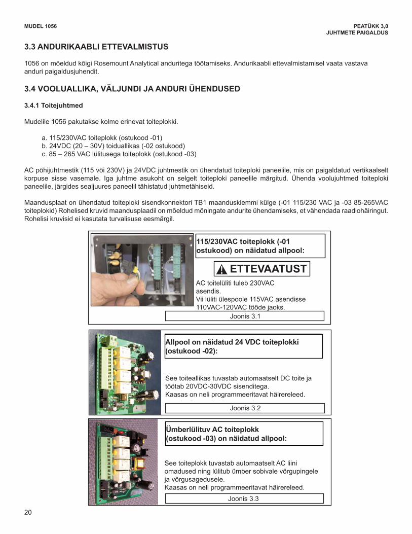
20
MUDEL 1056 PEATÜKK 3,0JUHTMETE PAIGALDUS
3.3 ANDURIKAABLI ETTEVALMISTUS
1056 on mõeldud kõigi Rosemount Analytical anduritega töötamiseks. Andurikaabli ettevalmistamisel vaata vastava anduri paigaldusjuhendit.
3.4 VOOLUALLIKA, VÄLJUNDI JA ANDURI ÜHENDUSED
3.4.1 Toitejuhtmed
Mudelile 1056 pakutakse kolme erinevat toiteplokki.
a. 115/230VAC toiteplokk (ostukood -01) b. 24VDC (20 – 30V) toiduallikas (-02 ostukood) c. 85 – 265 VAC lülitusega toiteplokk (ostukood -03)
AC põhijuhtmestik (115 või 230V) ja 24VDC juhtmestik on ühendatud toiteploki paneelile, mis on paigaldatud vertikaalselt korpuse sisse vasemale. Iga juhtme asukoht on selgelt toiteploki paneelile märgitud. Ühenda voolujuhtmed toiteploki paneelile, järgides sealjuures paneelil tähistatud juhtmetähiseid.
Maandusplaat on ühendatud toiteploki sisendkonnektori TB1 maandusklemmi külge (-01 115/230 VAC ja -03 85-265VAC toiteplokid) Rohelised kruvid maandusplaadil on mõeldud mõningate andurite ühendamiseks, et vähendada raadiohäiringut. Rohelisi kruvisid ei kasutata turvalisuse eesmärgil.
MODEL 1056 SECTION 3.0WIRING
AC Power switch shipped in the 230VACposition. Adjust switch upwards to 115VAC positionfor 110VAC – 120VAC operation.
This power supply automatically detects DC power andaccepts 20VDC to 30VDC inputs. Four programmable alarm relays are included.
Figure 3-1
Figure 3-2
This power supply automatically detects AC line condi-tions and switches to the proper line voltage and linefrequency. Four programmable alarm relays are included.
Figure 3-3
Switching AC Power Supply (-03 orderingcode) is shown below:
24VDC Power Supply (-02 ordering code)is shown below:
115/230VAC Power Supply (-01ordering code) is shown below:
20
3.3 PREPARING SENSOR CABLEThe 1056 is intended for use with all Rosemount Analytical sensors. Refer to the sensor installation instructions fordetails on preparing sensor cables.
3.4 POWER, OUTPUT, AND SENSOR CONNECTIONS3.4.1 Power wiring
Three Power Supplies are offered for Model 1056: a. 115/230VAC Power Supply (-01 ordering code) b. 24VDC (20 – 30V) Power Supply (-02 ordering code)c. 85 – 265 VAC Switching Power Supply (-03 ordering code)
AC mains (115 or 230V) leads and 24VDC leads are wired to the Power Supply board which is mounted verticallyon the left side of the main enclosure cavity. Each lead location is clearly marked on the Power Supply board.Wire the power leads to the Power Supply board using the lead markings on the board. The grounding plate is connected to the earth terminal of power supply input connector TB1 on the -01(115/230VAC) and -03 (85-265VAC) power supplies. The green colored screws on the grounding plate are intend-ed for connection to some sensors to minimize radio frequency interference. The green screws are not intendedto be used for safety purposes.
CAUTION
115/230VAC toiteplokk (-01ostukood) on näidatud allpool:
AC toitelüliti tuleb 230VACasendis.Vii lüliti ülespoole 115VAC asendisse110VAC-120VAC tööde jaoks.
Joonis 3.1
Joonis 3.2
Joonis 3.3
See toiteallikas tuvastab automaatselt DC toite ja töötab 20VDC-30VDC sisenditega.Kaasas on neli programmeeritavat häirereleed.
See toiteplokk tuvastab automaatselt AC liini omadused ning lülitub ümber sobivale võrgupingele ja võrgusagedusele.Kaasas on neli programmeeritavat häirereleed.
Allpool on näidatud 24 VDC toiteplokki (ostukood -02):
Ümberlülituv AC toiteplokk (ostukood -03) on näidatud allpool:
ETTEVAATUSTESSENTIAL INSTRUCTIONSREAD THIS PAGE BEFORE PROCEEDING!
Your instrument purchase from RosemountAnalytical, Inc. is one of the finest available for yourparticular application. These instruments have beendesigned, and tested to meet many national andinternational standards. Experience indicates that itsperformance is directly related to the quality of theinstallation and knowledge of the user in operatingand maintaining the instrument. To ensure their con-tinued operation to the design specifications, per-sonnel should read this manual thoroughly beforeproceeding with installation, commissioning, opera-tion, and maintenance of this instrument. If thisequipment is used in a manner not specified by themanufacturer, the protection provided by it againsthazards may be impaired.• Failure to follow the proper instructions may
cause any one of the following situations tooccur: Loss of life; personal injury; property dam-age; damage to this instrument; and warrantyinvalidation.
• Ensure that you have received the correct modeland options from your purchase order. Verify thatthis manual covers your model and options. Ifnot, call 1-800-854-8257 or 949-757-8500 torequest correct manual.
• For clarification of instructions, contact yourRosemount representative.
• Follow all warnings, cautions, and instructionsmarked on and supplied with the product.
• Use only qualified personnel to install, operate,update, program and maintain the product.
• Educate your personnel in the proper installation,operation, and maintenance of the product.
• Install equipment as specified in the Installation section of this manual. Follow appropriate localand national codes. Only connect the product toelectrical and pressure sources specified in thismanual.
• Use only factory documented components forrepair. Tampering or unauthorized substitution ofparts and procedures can affect the performanceand cause unsafe operation of your process.
• All equipment doors must be closed and protec-tive covers must be in place unless qualified per-sonnel are performing maintenance.
Equipment protected throughout by double insulation. • Installation and servicing of this product may expose personel
to dangerous voltages. • Main power wired to separate power source must be
disconnected before servicing.• Do not operate or energize instrument with case open!• Signal wiring connected in this box must be rated at least
240 V. • Non-metallic cable strain reliefs do not provide grounding
between conduit connections! Use grounding type bushings and jumper wires.
• Unused cable conduit entries must be securely sealed by non-flammable closures to provide enclosure integrity in compliance with personal safety and environmental protectionrequirements. Unused conduit openings must be sealed with NEMA 4X or IP65 conduit plugs to maintain the ingress protection rating (NEMA 4X).
• Electrical installation must be in accordance with the NationalElectrical Code (ANSI/NFPA-70) and/or any other applicable national or local codes.
• Operate only with front panel fastened and in place. • Safety and performance require that this instrument be
connected and properly grounded through a three-wire power source.
• Proper use and configuration is the responsibility of the user.
This product generates, uses, and can radiate radio frequencyenergy and thus can cause radio communication interference.Improper installation, or operation, may increase such interfer-ence. As temporarily permitted by regulation, this unit has notbeen tested for compliance within the limits of Class A comput-ing devices, pursuant to Subpart J of Part 15, of FCC Rules,which are designed to provide reasonable protection againstsuch interference. Operation of this equipment in a residentialarea may cause interference, in which case the user at his ownexpense, will be required to take whatever measures may berequired to correct the interference.
This product is not intended for use in the light industrial,residential or commercial environments per the instru-ment’s certification to EN50081-2.
Emerson Process Management
2400 Barranca ParkwayIrvine, CA 92606 USATel: (949) 757-8500Fax: (949) 474-7250
http://www.rosemountanalytical.com
© Rosemount Analytical Inc. 2012
WARNINGRISK OF ELECTRICAL SHOCK
CAUTION
CAUTION
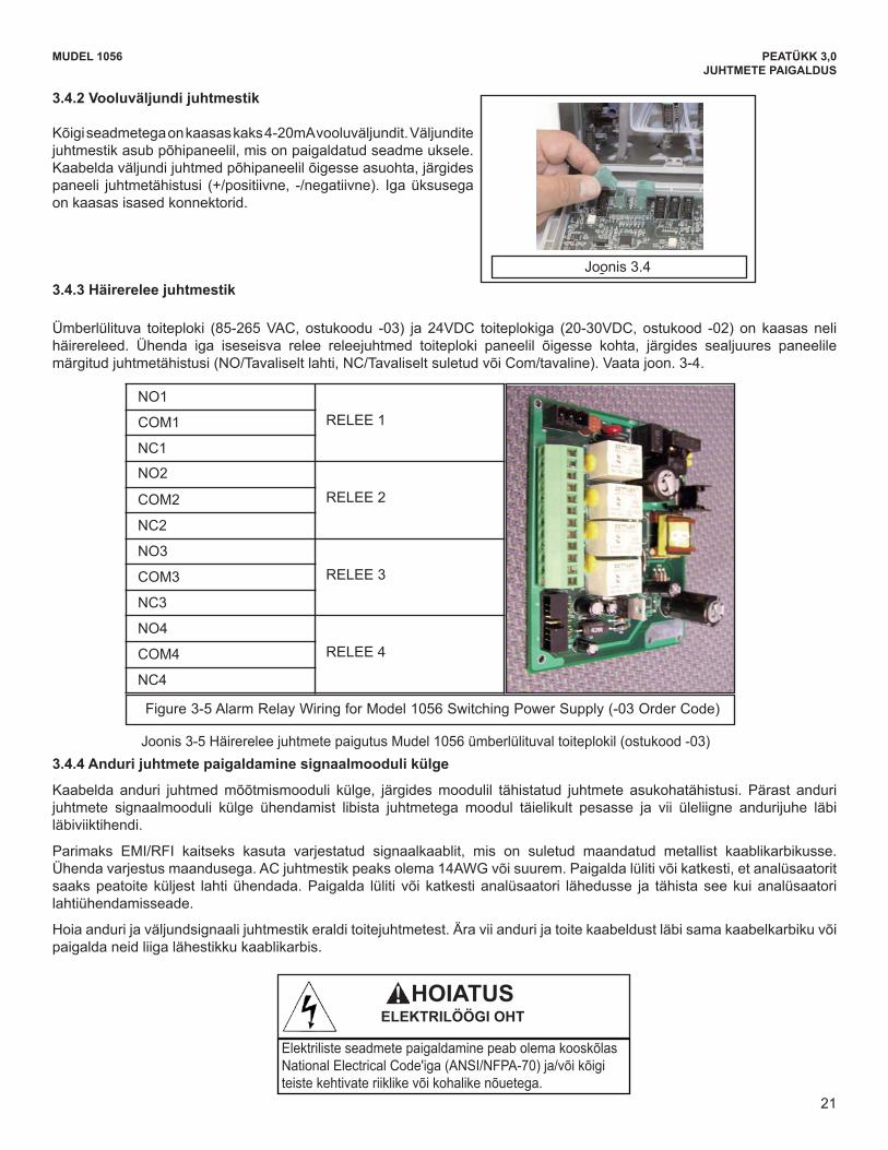
21
MUDEL 1056 PEATÜKK 3,0JUHTMETE PAIGALDUS
3.4.2 Vooluväljundi juhtmestik
Kõigi seadmetega on kaasas kaks 4-20mA vooluväljundit. Väljundite juhtmestik asub põhipaneelil, mis on paigaldatud seadme uksele. Kaabelda väljundi juhtmed põhipaneelil õigesse asuohta, järgides paneeli juhtmetähistusi (+/positiivne, -/negatiivne). Iga üksusega on kaasas isased konnektorid.
3.4.3 Häirerelee juhtmestik
Ümberlülituva toiteploki (85-265 VAC, ostukoodu -03) ja 24VDC toiteplokiga (20-30VDC, ostukood -02) on kaasas neli häirereleed. Ühenda iga iseseisva relee releejuhtmed toiteploki paneelil õigesse kohta, järgides sealjuures paneelile märgitud juhtmetähistusi (NO/Tavaliselt lahti, NC/Tavaliselt suletud või Com/tavaline). Vaata joon. 3-4.
3.4.4 Anduri juhtmete paigaldamine signaalmooduli külge
Kaabelda anduri juhtmed mõõtmismooduli külge, järgides moodulil tähistatud juhtmete asukohatähistusi. Pärast anduri juhtmete signaalmooduli külge ühendamist libista juhtmetega moodul täielikult pesasse ja vii üleliigne andurijuhe läbi läbiviiktihendi.
Parimaks EMI/RFI kaitseks kasuta varjestatud signaalkaablit, mis on suletud maandatud metallist kaablikarbikusse. Ühendavarjestusmaandusega.ACjuhtmestikpeaksolema14AWGvõisuurem.Paigaldalülitivõikatkesti,etanalüsaatoritsaaks peatoite küljest lahti ühendada. Paigalda lüliti või katkesti analüsaatori lähedusse ja tähista see kui analüsaatori lahtiühendamisseade.
Hoiaandurijaväljundsignaalijuhtmestikeralditoitejuhtmetest.Äraviiandurijatoitekaabeldustläbisamakaabelkarbikuvõipaigalda neid liiga lähestikku kaablikarbis.
MODEL 1056 SECTION 3.0WIRING
Figure 3-5 Alarm Relay Wiring for Model 1056 Switching Power Supply (-03 Order Code)
NO1
RELAY 1COM1
NC1
NO2
RELAY 2COM2
NC2
NO3
RELAY 3COM3
NC3
NO4
RELAY 4COM4
NC4
3.4.4 Sensor wiring to signal boardsWire the correct sensor leads to the measurement board using the lead locations marked directly on the board.After wiring the sensor leads to the signal board, carefully slide the wired board fully into the enclosure slot andtake up the excess sensor cable through the cable gland.
For best EMI/RFI protection use shielded output signal cable enclosed in an earth-grounded metal conduit.Connect the shield to earth ground. AC wiring should be 14 gauge or greater. Provide a switch or breaker to dis-connect the analyzer from the main power supply. Install the switch or breaker near the analyzer and label it asthe disconnecting device for the analyzer.
Keep sensor and output signal wiring separate from power wiring. Do not run sensor and power wiring in the sameconduit or close together in a cable tray.
3.4.3 Alarm relay wiringFour alarm relays are supplied with the switching power supply (85 to 265VAC, -03 order code) and the 24VDCpower supply (20-30VDC, -02 order code). Wire the relay leads on each of the independent relays to the correctposition on the power supply board using the printed lead markings (NO/Normally Open, NC/Normally Closed, orCom/Common) on the board. See Fig 3-4.
3.4.2 Current Output wiring All instruments are shipped with two 4-20mA currentoutputs. Wiring locations for the outputs are on theMain board which is mounted on the hinged door of theinstrument. Wire the output leads to the correct posi-tion on the Main board using the lead markings (+/positive,-/negative) on the board. Male mating connectors areprovided with each unit.
Figure 3.4
21
Electrical installation must be in accordance withthe National Electrical Code (ANSI/NFPA-70)and/or any other applicable national or local codes.
WARNINGRISK OF ELECTRICAL SHOCK
RELEE 1
RELEE 2
RELEE 3
RELEE 4
Joonis3-5HäirereleejuhtmetepaigutusMudel1056ümberlülituvaltoiteplokil(ostukood-03)
Joonis 3.4
ESSENTIAL INSTRUCTIONSREAD THIS PAGE BEFORE PROCEEDING!
Your instrument purchase from RosemountAnalytical, Inc. is one of the finest available for yourparticular application. These instruments have beendesigned, and tested to meet many national andinternational standards. Experience indicates that itsperformance is directly related to the quality of theinstallation and knowledge of the user in operatingand maintaining the instrument. To ensure their con-tinued operation to the design specifications, per-sonnel should read this manual thoroughly beforeproceeding with installation, commissioning, opera-tion, and maintenance of this instrument. If thisequipment is used in a manner not specified by themanufacturer, the protection provided by it againsthazards may be impaired.• Failure to follow the proper instructions may
cause any one of the following situations tooccur: Loss of life; personal injury; property dam-age; damage to this instrument; and warrantyinvalidation.
• Ensure that you have received the correct modeland options from your purchase order. Verify thatthis manual covers your model and options. Ifnot, call 1-800-854-8257 or 949-757-8500 torequest correct manual.
• For clarification of instructions, contact yourRosemount representative.
• Follow all warnings, cautions, and instructionsmarked on and supplied with the product.
• Use only qualified personnel to install, operate,update, program and maintain the product.
• Educate your personnel in the proper installation,operation, and maintenance of the product.
• Install equipment as specified in the Installation section of this manual. Follow appropriate localand national codes. Only connect the product toelectrical and pressure sources specified in thismanual.
• Use only factory documented components forrepair. Tampering or unauthorized substitution ofparts and procedures can affect the performanceand cause unsafe operation of your process.
• All equipment doors must be closed and protec-tive covers must be in place unless qualified per-sonnel are performing maintenance.
Equipment protected throughout by double insulation. • Installation and servicing of this product may expose personel
to dangerous voltages. • Main power wired to separate power source must be
disconnected before servicing.• Do not operate or energize instrument with case open!• Signal wiring connected in this box must be rated at least
240 V. • Non-metallic cable strain reliefs do not provide grounding
between conduit connections! Use grounding type bushings and jumper wires.
• Unused cable conduit entries must be securely sealed by non-flammable closures to provide enclosure integrity in compliance with personal safety and environmental protectionrequirements. Unused conduit openings must be sealed with NEMA 4X or IP65 conduit plugs to maintain the ingress protection rating (NEMA 4X).
• Electrical installation must be in accordance with the NationalElectrical Code (ANSI/NFPA-70) and/or any other applicable national or local codes.
• Operate only with front panel fastened and in place. • Safety and performance require that this instrument be
connected and properly grounded through a three-wire power source.
• Proper use and configuration is the responsibility of the user.
This product generates, uses, and can radiate radio frequencyenergy and thus can cause radio communication interference.Improper installation, or operation, may increase such interfer-ence. As temporarily permitted by regulation, this unit has notbeen tested for compliance within the limits of Class A comput-ing devices, pursuant to Subpart J of Part 15, of FCC Rules,which are designed to provide reasonable protection againstsuch interference. Operation of this equipment in a residentialarea may cause interference, in which case the user at his ownexpense, will be required to take whatever measures may berequired to correct the interference.
This product is not intended for use in the light industrial,residential or commercial environments per the instru-ment’s certification to EN50081-2.
Emerson Process Management
2400 Barranca ParkwayIrvine, CA 92606 USATel: (949) 757-8500Fax: (949) 474-7250
http://www.rosemountanalytical.com
© Rosemount Analytical Inc. 2012
WARNINGRISK OF ELECTRICAL SHOCK
CAUTION
CAUTION
HOIATUS ELEKTRILÖÖGI OHT
Elektriliste seadmete paigaldamine peab olema kooskõlas National Electrical Code'iga (ANSI/NFPA-70) ja/või kõigi teiste kehtivate riiklike või kohalike nõuetega.
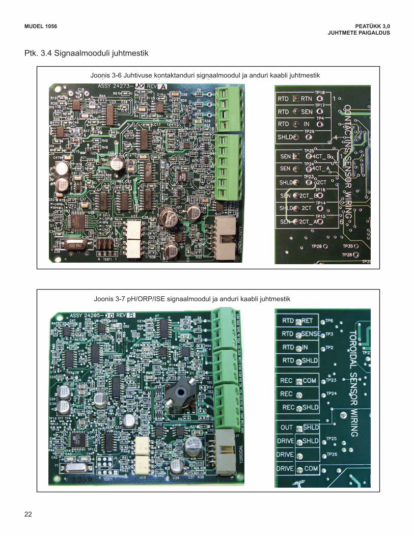
22
MUDEL 1056 PEATÜKK 3,0JUHTMETE PAIGALDUS
MODEL 1056 SECTION 3.0WIRING
Sec. 3.4 Signal board wiring
Figure 3-6 Contacting Conductivity signal board and Sensor cable leads
Figure 3-7 Toroidal Conductivity Signal board and Sensor cable leads
22
Ptk. 3.4 Signaalmooduli juhtmestik
Joonis 3-6 Juhtivuse kontaktanduri signaalmoodul ja anduri kaabli juhtmestik
Joonis3-7pH/ORP/ISEsignaalmooduljaandurikaablijuhtmestik
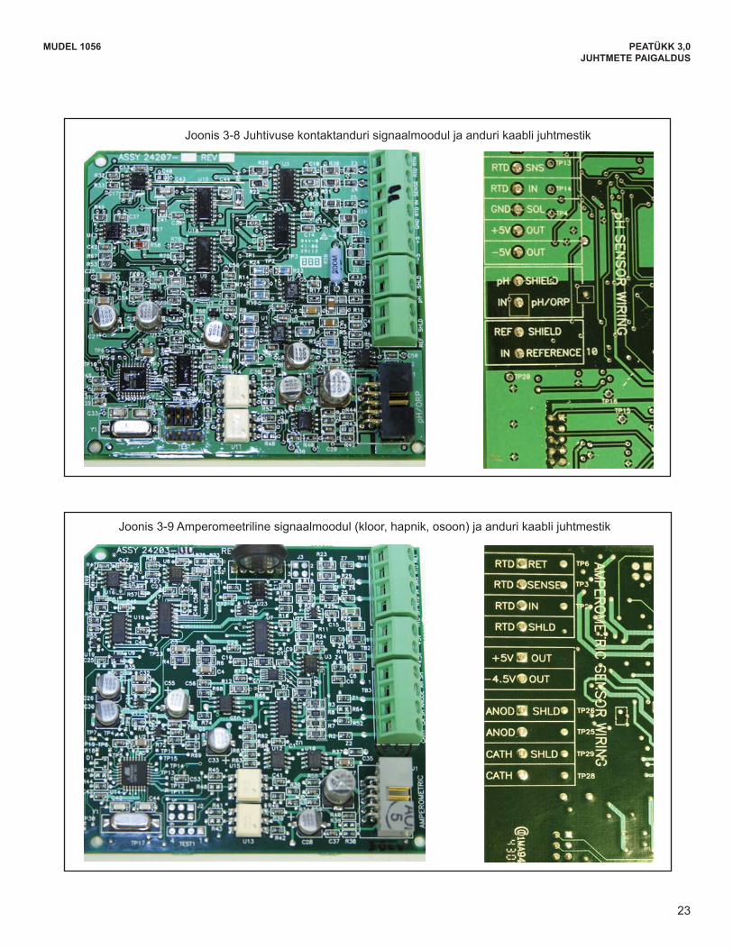
23
MUDEL 1056 PEATÜKK 3,0JUHTMETE PAIGALDUS
MODEL 1056 SECTION 3.0WIRING
Figure 3-8 pH/ORP/ISE signal board and Sensor cable leads
Figure 3-9 Amperometric signal (Chlorine, Oxygen, Ozone) board and Sensor cable leads
23
Joonis 3-8 Juhtivuse kontaktanduri signaalmoodul ja anduri kaabli juhtmestik
Joonis 3-9 Amperomeetriline signaalmoodul (kloor, hapnik, osoon) ja anduri kaabli juhtmestik
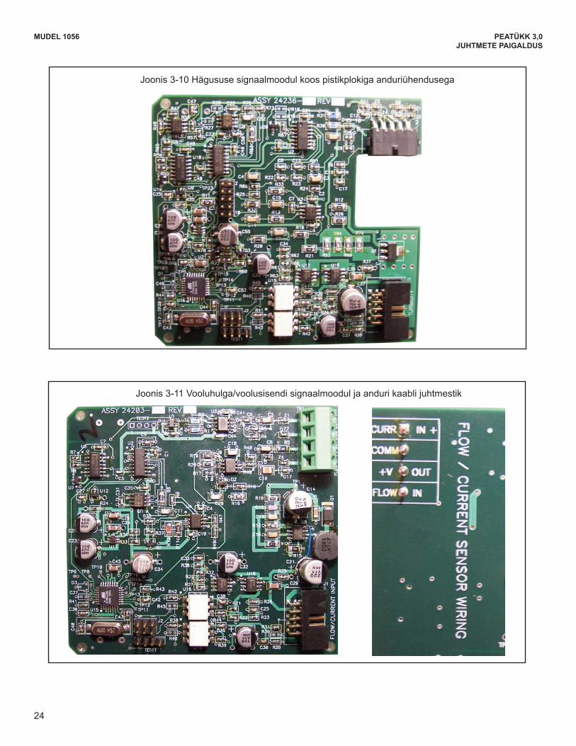
24
MODEL 1056 SECTION 3.0WIRING
Figure 3-10 Turbidity signal board with plug-in Sensor connection
Figure 3-11 Flow/Current Input signal board and Sensor cable leads
24
MUDEL 1056 PEATÜKK 3,0JUHTMETE PAIGALDUS
Joonis3-10Hägususesignaalmoodulkoospistikplokigaanduriühendusega
Joonis 3-11 Vooluhulga/voolusisendi signaalmoodul ja anduri kaabli juhtmestik
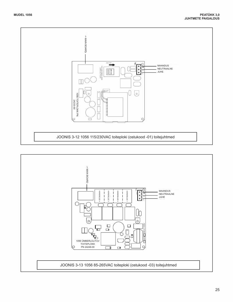
25
MODEL 1056 SECTION 3.0WIRING
FIGURE 3-12 Power Wiring for the 1056 115/230VAC Power Supply (-01 Order Code)
FIGURE 3-13 Power Wiring for the 1056 85-265 VAC Power Supply (-03 ordering code)
25
MUDEL 1056 PEATÜKK 3,0JUHTMETE PAIGALDUS
JOONIS 3-12 1056 115/230VAC toiteploki (ostukood -01) toitejuhtmed
JOONIS 3-13 1056 85-265VAC toiteploki (ostukood -03) toitejuhtmed
MAANDUS NEUTRAALNE JUHE
MAANDUS NEUTRAALNE JUHE
-> MA
IN B
OA
RD
115V K
AS
UTA
MIS
E JA
OK
S
LÜK
KA LÜ
LITI ÜLE
S
1056 TOITE
PLO
KK
PN
24233-00
-> MA
IN B
OA
RD
HÄIRERELE
E1
HÄIRERELE
E2
HÄIRERELE
E3
HÄIRERELE
E4
1056 ÜMBERLÜLITUV TOITEPLOKK PN 24248-00
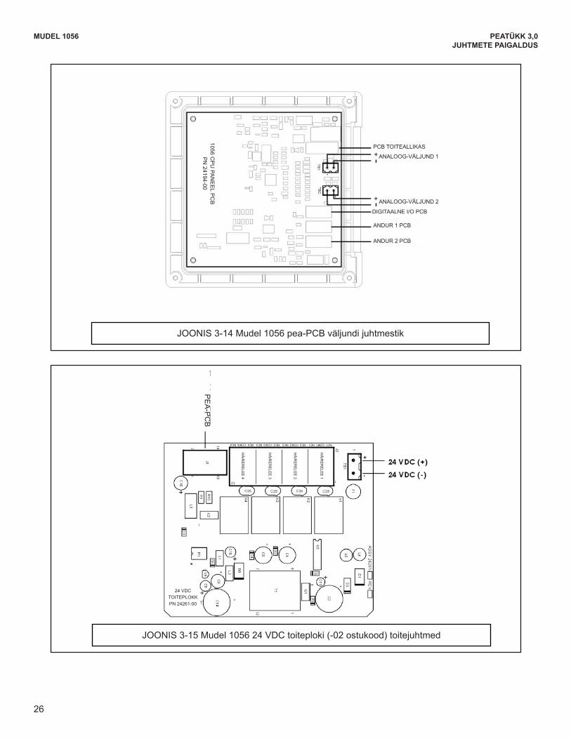
26
MODEL 1056 SECTION 3.0WIRING
FIGURE 3-14 Output Wiring for Model 1056 Main PCB
FIGURE 3-15 Power Wiring for Model 1056 24VDC Power Supply (-02 ordering code)
26
To Main P
CB
MUDEL 1056 PEATÜKK 3,0JUHTMETE PAIGALDUS
JOONIS 3-14 Mudel 1056 pea-PCB väljundi juhtmestik
JOONIS 3-15 Mudel 1056 24 VDC toiteploki (-02 ostukood) toitejuhtmed
PCB TOITEALLIKAS
ANALOOG-VÄLJUND 1
ANALOOG-VÄLJUND 2
DIGITAALNE I/O PCB
ANDUR 1 PCB
ANDUR 2 PCB
PE
A-P
CB
1056 CP
U PA
NE
EL P
CB
P
N 24194-00
HÄIRERELE
E1
HÄIRERELE
E2
HÄIRERELE
E3
HÄIRERELE
E4
24 VDC TOITEPLOKK PN 24261-00
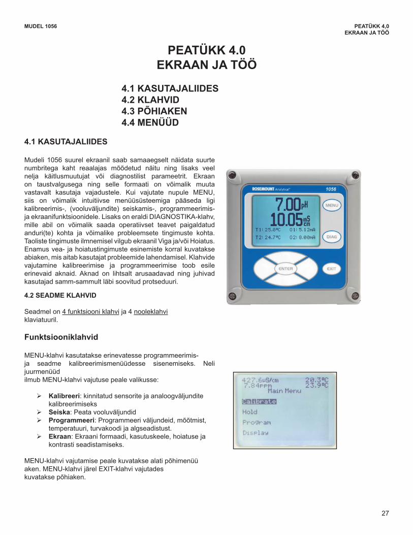
27
MODEL 1056 SECTION 4.0DISPLAY AND OPERATION
SECTION 4.0DISPLAY AND OPERATION
4.1 USER INTERFACEThe 1056 has a large display which shows two livemeasurement readouts in large digits and up to fouradditional process variables or diagnostic parametersconcurrently. The display is back-lit and the format canbe customized to meet user requirements. The intu-itive menu system allows access to Calibration, Hold (ofcurrent outputs), Programming, and Display functions bypressing the MENU button. In addition, a dedicatedDIAGNOSTIC button is available to provide access touseful operational information on installed sensor(s)and any problematic conditions that might occur. Thedisplay flashes Fault and/or Warning when these condi-tions occur. Help screens are displayed for most faultand warning conditions to guide the user in trou-bleshooting.During calibration and programming, key presses causedifferent displays to appear. The displays are self-explanatory and guide the user step-by-step throughthe procedure.
4.2 INSTRUMENT KEYPADThere are 4 Function keys and 4 Selection keys on theinstrument keypad.
Function keys: The MENU key is used to access menus for program-ming and calibrating the instrument. Four top-levelmenu items appear when pressing the MENU key:
Calibrate: calibrate attached sensors and analog outputs.
Hold: Suspend current outputs. Program: Program outputs, measurement,
temperature, security and reset. Display: Program display format, language,
warnings, and contrastPressing MENU always causes the main menu screento appear. Pressing MENU followed by EXIT causesthe main display to appear.
4.1 USER INTERFACE 4.2 KEYPAD 4.3 MAIN DISPLAY4.4 MENU SYSTEM
27
MUDEL 1056 PEATÜKK 4,0EKRAAN JA TÖÖ
PEATÜKK 4.0 EKRAAN JA TÖÖ
4.1 KASUTAJALIIDES4.2 KLAHVID4.3 PÕHIAKEN4.4 MENÜÜD
4.1 KASUTAJALIIDES
Mudeli 1056 suurel ekraanil saab samaaegselt näidata suurte numbritega kaht reaalajas mõõdetud näitu ning lisaks veel nelja käitlusmuutujat või diagnostilist parameetrit. Ekraan on taustvalgusega ning selle formaati on võimalik muuta vastavalt kasutaja vajadustele. Kui vajutate nupule MENU, siis on võimalik intuitiivse menüüsüsteemiga pääseda ligi kalibreerimis-, (vooluväljundite) seiskamis-, programmeerimis- ja ekraanifunktsioonidele. Lisaks on eraldi DIAGNOSTIKA-klahv, mille abil on võimalik saada operatiivset teavet paigaldatud anduri(te) kohta ja võimalike probleemsete tingimuste kohta. TaolistetingimusteilmnemiselvilgubekraanilVigaja/võiHoiatus.Enamus vea- ja hoiatustingimuste esinemiste korral kuvatakse abiaken, mis aitab kasutajat probleemide lahendamisel. Klahvide vajutamine kalibreerimise ja programmeerimise toob esile erinevaid aknaid. Aknad on lihtsalt arusaadavad ning juhivad kasutajad samm-sammult läbi soovitud protseduuri.
4.2 SEADME KLAHVID
Seadmel on 4 funktsiooni klahvi ja 4 nooleklahvi klaviatuuril.
Funktsiooniklahvid
MENU-klahvi kasutatakse erinevatesse programmeerimis-ja seadme kalibreerimismenüüdesse sisenemiseks. Neli juurmenüüdilmub MENU-klahvi vajutuse peale valikusse:
¾ Kalibreeri: kinnitatud sensorite ja analoogväljundite kalibreerimiseks
¾ Seiska: Peata vooluväljundid ¾ Programmeeri: Programmeeri väljundeid, mõõtmist,
temperatuuri, turvakoodi ja algseadistust. ¾ Ekraan: Ekraani formaadi, kasutuskeele, hoiatuse ja
kontrasti seadistamiseks.
MENU-klahvi vajutamise peale kuvatakse alati põhimenüüaken. MENU-klahvi järel EXIT-klahvi vajutadeskuvatakse põhiaken.
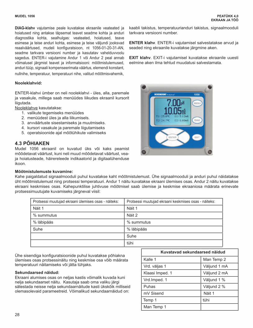
28
MUDEL 1056 PEATÜKK 4,0EKRAAN JA TÖÖ
DIAG-klahv vajutamise peale kuvatakse ekraanile veateated ja hoiatused ning antakse täpsemat teavet seadme kohta ja anduri diagnostika kohta, sealhulgas: veateated, hoiatused, teave esimese ja teise anduri kohta, esimese ja teise väljundi jooksvad reaalväärtused, mudeli konfiguratsioon, nt 1056-01-20-31-AN,seadme tarkvara versiooni number ja kasutatav vahelduvvoolu sagedus. ENTER-i vajutamine Andur 1 või Andur 2 peal annab võimalusel järgmist teavet ja informatsiooni: mõõtmistulemused, anduri tüüp, signaali kompenseerimata väärtus, elemendi konstant, nullnihe, temperatuur, temperatuuri nihe, valitud mõõtmisvahemik,
kaabli takistus, temperatuurianduri takistus, signaalmooduli tarkvara versiooni number.
ENTER klahv. ENTER-i vajutamisel salvestatakse arvud ja seaded ning ekraanile kuvatakse järgmine aken.
EXIT klahv. EXIT-i vajutamisel kuvatakse ekraanile uuesti eelmine aken ilma tehtud muudatusi salvestamata.
Nooleklahvid:
ENTER-klahvi ümber on neli nooleklahvi - üles, alla, paremale ja vasakule, millega saab menüüdes liikudes ekraanil kursorit liigutada. Nooleklahve kasutatakse:
1. valikute tegemiseks menüüdes 2. menüüdest üles ja alla liikumisels. 3. arvväärtuste sisestamiseks ja muutmiseks. 4. kursori vasakule ja paremale liigutamiseks 5. operatsioonide ajal mõõtühikute valimiseks
4.3 PÕHIAKEN Mudel 1056 ekraanil on kuvatud üks või kaks peamist mõõdetavat väärtust, kuni neli muud mõõdetavat väärtust, vea- ja hoiatusteade, häirereleede indikaatorid ja digitaalühenduse ikoon.
Mõõtmistulemuste kuvamine: Kahe paigaldatud signaalmooduli puhul kuvatakse kaht mõõtmistulemust. Ühe signaalmooduli ja anduri puhul näidatakse üht mõõtmistulemust ning protsessi temperatuuri. Andur 1 näitu kuvatakse ekraani ülemises osas. Andur 2 näitu kuvatakse ekraani keskmises osas. Kahepunktilise juhtivuse mõõtmisel saab ülemise ja keskmise ekraaniosa määrata erinevate protsessimuutujate kuvamiseks järgneval viisil:
Protsessi muutujad ekraani ülemises osas - näiteks: Protsessi muutujad ekraani keskmises osas - näiteks:Näit 1 Näit 1
%summutus Näit 2
%läbipääs %summutus
Suhe %läbipääs
Suhe
tühi
Kuvatavad sekundaarsed näidud
Kalle 1 Man Temp 2Vrd. väljas 1 Väljund 1 mAKlaasi Imped. 1 Väljund 2 mAVrd.Imped. 1 Väljund1%Puhas Väljund2%mV Sisend Näit 1Temp 1 tühiMan Temp 1
MODEL 1056 SECTION 4.0DISPLAY AND OPERATION
Selection keys: Surrounding the ENTER key, four Selection keys – up,down, right and left, move the cursor to all areas of thescreen while using the menus. Selection keys are used to:
1. select items on the menu screens 2. scroll up and down the menu lists. 3. enter or edit numeric values. 4. move the cursor to the right or left 5. select measurement units during operations
4.3 MAIN DISPLAYThe Model 1056 displays one or two primary measurementvalues, up to four secondary measurement values, afault and warning banner, alarm relay flags, and adigital communications icon.
Process measurements: Two process variables are displayed if two signal boards are installed. One process variable and process tem-perature is displayed if one signal board is installed with one sensor. The Upper display area shows the Sensor1 process reading. The Center display area shows the Sensor 2 process reading. For dual conductivity, the Upperand Center display areas can be assigned to different process variables as follows:
Process variables for Upper display- example: Process variables for Center display- example:Measure 1 Measure 1% Reject Measure 2% Pass % RejectRatio % Pass
RatioBlank
For single input configurations, the Upper display areashows the live process variable and the Center displayarea can be assigned to Temperature or blank.
Secondary values: Up to four secondary values are shown in four displayquadrants at the bottom half of the screen. All foursecondary value positions can be programmed by theuser to any display parameter available. Possiblesecondary values include:
Slope 1 Man Temp 2Ref Off 1 Output 1 mAGl Imp 1 Output 2 mARef Imp 1 Output 1 %Raw Output 2 %mV Input Measure 1Temp 1 BlankMan Temp 1
Pressing the DIAG key displays active Faults andWarnings, and provides detailed instrument informationand sensor diagnostics including: Faults, Warnings,Sensor 1 and 2 information, Out 1 and Out 2 live currentvalues, model configuration string e.g. 1056-01-20-31-AN, Instrument Software version, and AC frequencyused. Pressing ENTER on Sensor 1 or Sensor 2 pro-vides useful diagnostics and information (as applica-ble): Measurement, Sensor Type, Raw signal value,Cell constant, Zero Offset, Temperature, Temperature
Offset, selected measurement range, CableResistance, Temperature Sensor Resistance, SignalBoard software version.
The ENTER key. Pressing ENTER stores numbers andsettings and moves the display to the next screen.
The EXIT key. Pressing EXIT returns to the previousscreen without storing changes.
Displayable Secondary Values
28
Ühesisendigakonfiguratsioonidepuhulkuvataksepõhiaknaülemises osas protsessinäitu ning keskmise osa võib määrata temperatuuri näitamiseks või jätta tühjaks.
Sekundaarsed näidud: Ekraani alumises osas on neljas kastis võimalik kuvada kuni nelja sekundaarset näitu. Kasutaja saab oma valiku järgi sätestada neisse nelja sekundaarnäitude kasti ükskõik milliseid olemasolevaid parameetreid. Võimalikud sekundaarnäidud on:
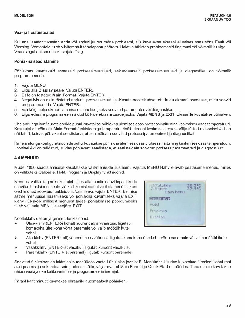
29
MUDEL 1056 PEATÜKK 4,0EKRAAN JA TÖÖ
Vea- ja hoiatusteated:
Kui analüsaator tuvastab enda või anduri juures mõne probleemi, siis kuvatakse ekraani alumises osas sõna Fault või Warning.Veateateletulebviivitamatulttähelepanupöörata.Hoiatustähistabprobleemseidtingimusivõivõimalikkuviga.Veaotsingul abi saamiseks vajuta Diag.
Põhiakna seadistamine
Põhiaknas kuvatavaid esmaseid protsessimuutujaid, sekundaarseid protsessimuutujaid ja diagnostikat on võimalik programmeerida.
1. Vajuta MENU.2. Liigu alla Display peale. Vajuta ENTER.3. Esile on tõstetud Main Format. Vajuta ENTER.4. Negatiivis on esile tõstetud andur 1 protsessimuutuja. Kasuta noolteklahve, et liikuda ekraani osadesse, mida soovid
programmeerida. Vajuta ENTER.5. Vali kõigi nelja ekraani alumise osa jaotise jaoks soovitud parameeter või diagnostika.6. Liigu edasi ja programmeeri näidud kõikide ekraani osade jaoks. Vajuta MENU ja EXIT. Ekraanile kuvatakse põhiaken.
Üheandurigakonfiguratsioonidepuhulkuvataksepõhiaknaülemisesosasprotsessinäituningkeskmisesosastemperatuuri.Kasutajal on võimalik Main Format funktsiooniga temperatuurinäit ekraani keskmisest osast välja lülitada. Joonisel 4-1 on näidatud, kuidas põhiakent seadistada, et seal näidata soovitud protsessiparameetreid ja diagnostikat.
Kaheandurigakonfiguratsioonidepuhulkuvataksepõhiaknaülemisesosasprotsessinäituningkeskmisesosastemperatuuri.Joonisel 4-1 on näidatud, kuidas põhiakent seadistada, et seal näidata soovitud protsessiparameetreid ja diagnostikat.
4.4 MENÜÜD
Mudel 1056 seadistamiseks kasutatakse valikmenüüde süsteemi. Vajutus MENU klahvile avab peataseme menüü, milles onvalikuteksCalibrate,Hold,ProgramjaDisplayfunktsioonid.
Menüüs valiku tegemiseks tuleb üles-alla noolteklahvidega liikuda soovitud funktsiooni peale. Jätka liikumist samal viisil alamenüüs, kuni oled leidnud soovitud funktsiooni. Valimiseks vajuta ENTER. Eelmise astme menüüsse naasmiseks või põhiakna kuvamiseks vajuta EXIT klahvi. Ükskõik millisest menüüst tagasi põhiaknasse pöördumiseks tuleb vajutada MENU ja seejärel EXIT.
Noolteklahvidel on järgmised funktsioonid: ¾ Üles-klahv (ENTER-i kohal) suurendab arvväärtusi, liigutab
komakoha ühe koha võrra paremale või valib mõõtühikute vahel.
¾ Alla-klahv (ENTER-i all) vähendab arvväärtusi, liigutab komakoha ühe koha võrra vasemale või valib mõõtühikute vahel.
¾ Vasakklahv (ENTER-ist vasakul) liigutab kursorit vasakule. ¾ Paremklahv (ENTER-ist paremal) liigutab kursorit paremale.
Soovitud funktsioonide leidmiseks menüüdes vaata Lühijuhise joonist B. Menüüdes liikudes kuvatakse ülemisel kahel real alati peamisi ja sekundaarseid protsessinäite, välja arvatud Main Format ja Quick Start menüüdes. Tänu sellele kuvatakse näite reaalajas ka kalibreerimise ja programmeerimise ajal.
Pärast kaht minutit kuvatakse ekraanile automaatselt põhiaken.
4.4 MENU SYSTEMModel 1056 uses a scroll and select menu system.Pressing the MENU key at any time opens the top-levelmenu including Calibrate, Hold, Program and Displayfunctions. To find a menu item, scroll with the up and down keysuntil the item is highlighted. Continue to scroll andselect menu items until the desired function is chosen.To select the item, press ENTER. To return to a previ-ous menu level or to enable the main live display,press the EXIT key repeatedly. To return immediatelyto the main display from any menu level, simply pressMENU then EXIT.
MODEL 1056 SECTION 4.0DISPLAY AND OPERATION
29
Fault and Warning banner: If the analyzer detects a problem with itself or the sensor the word Fault or Warning will appear at the bottom ofthe display. A fault requires immediate attention. A warning indicates a problematic condition or an impending fail-ure. For troubleshooting assitance, press Diag.
Formatting the Main DisplayThe main display screen can be programmed to show primary process variables, secondary process variables anddiagnostics. 1. Press MENU 2. Scroll down to Display. Press ENTER. 3. Main Format will be highlighted. Press ENTER. 4. The sensor 1 process value will be highlighted in reverse video. Press the selection keys to navigate down
to the screen sections that you wish to program. Press ENTER. 5. Choose the desired display parameter or diagnostic for each of the four display sections in the lower screen.6. Continue to navigate and program all desired screen sections. Press MENU and EXIT. The screen will
return to the main display. For single sensor configurations, the default display shows the live process measurement in the upper display areaand temperature in the center display area. The user can elect to disable the display of temperature in the cen-ter display area using the Main Format function. See Fig. 4-1 to guide you through programming the main displayto select process parameters and diagnostics of your choice. For dual sensor configurations, the default display shows Sensor 1 live process measurement in the upper displayarea and Sensor 2 live process measurement temperature in the center display area. See Fig. 4-1 to guide youthrough programming the main display to select process parameters and diagnostics of your choice.
The selection keys have the following functions: The Up key (above ENTER) increments numerical values, moves the decimal place one place to the right,
or selects units of measurement. The Down key (below ENTER) decrements numerical values, moves the decimal place one place to the
left, or selects units of measurement
The Left key (left of ENTER) moves the cursor to the left. The Right key (right of ENTER) moves the cursor to the right. To access desired menu functions, use the “Quick Reference” Figure B. During all menu displays (except maindisplay format and Quick Start), the live process measurements and secondary measurement values aredisplayed in the top two lines of the Upper display area. This conveniently allows display of the live values duringimportant calibration and programming operations. Menu screens will time out after two minutes and return to the main live display.
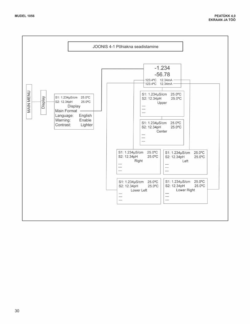
30
FIGURE 4-1 Formatting the Main Display
MODEL 1056 SECTION 4.0DISPLAY AND OPERATION
30
MUDEL 1056 PEATÜKK 4,0EKRAAN JA TÖÖ
JOONIS 4-1 Põhiakna seadistamine
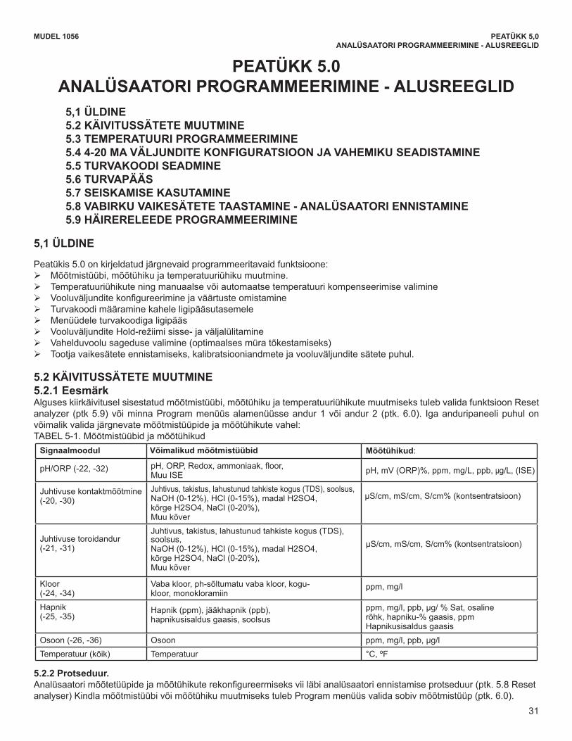
31
MUDEL 1056 PEATÜKK 5,0ANALÜSAATORI PROGRAMMEERIMINE - ALUSREEGLID
PEATÜKK 5.0 ANALÜSAATORI PROGRAMMEERIMINE - ALUSREEGLID
5,1 ÜLDINE5.2 KÄIVITUSSÄTETE MUUTMINE5.3 TEMPERATUURI PROGRAMMEERIMINE5.4 4-20 MA VÄLJUNDITE KONFIGURATSIOON JA VAHEMIKU SEADISTAMINE5.5 TURVAKOODI SEADMINE5.6 TURVAPÄÄS5.7 SEISKAMISE KASUTAMINE5.8 VABIRKU VAIKESÄTETE TAASTAMINE - ANALÜSAATORI ENNISTAMINE5.9 HÄIRERELEEDE PROGRAMMEERIMINE
5,1 ÜLDINE
Peatükis 5.0 on kirjeldatud järgnevaid programmeeritavaid funktsioone: ¾ Mõõtmistüübi, mõõtühiku ja temperatuuriühiku muutmine. ¾ Temperatuuriühikute ning manuaalse või automaatse temperatuuri kompenseerimise valimine ¾ Vooluväljunditekonfigureeriminejaväärtusteomistamine ¾ Turvakoodi määramine kahele ligipääsutasemele ¾ Menüüdele turvakoodiga ligipääs ¾ VooluväljunditeHold-režiimisisse-javäljalülitamine ¾ Vahelduvoolu sageduse valimine (optimaalses müra tõkestamiseks) ¾ Tootja vaikesätete ennistamiseks, kalibratsiooniandmete ja vooluväljundite sätete puhul.
5.2 KÄIVITUSSÄTETE MUUTMINE5.2.1 EesmärkAlguses kiirkäivitusel sisestatud mõõtmistüübi, mõõtühiku ja temperatuuriühikute muutmiseks tuleb valida funktsioon Reset analyzer (ptk 5.9) või minna Program menüüs alamenüüsse andur 1 või andur 2 (ptk. 6.0). Iga anduripaneeli puhul on võimalik valida järgnevate mõõtmistüüpide ja mõõtühikute vahel:TABEL 5-1. Mõõtmistüübid ja mõõtühikud
Signaalmoodul Võimalikud mõõtmistüübid Mõõtühikud:
pH/ORP(-22,-32) pH,ORP,Redox,ammoniaak,floor,Muu ISE pH,mV(ORP)%,ppm,mg/L,ppb,μg/L, (ISE)
Juhtivuse kontaktmõõtmine (-20, -30)
Juhtivus, takistus, lahustunud tahkiste kogus (TDS), soolsus, NaOH(0-12%),HCl(0-15%),madalH2SO4,kõrgeH2SO4,NaCl(0-20%),Muu kõver
μS/cm,mS/cm,S/cm%(kontsentratsioon)
Juhtivuse toroidandur(-21, -31)
Juhtivus, takistus, lahustunud tahkiste kogus (TDS), soolsus, NaOH(0-12%),HCl(0-15%),madalH2SO4,kõrgeH2SO4,NaCl(0-20%),Muu kõver
μS/cm,mS/cm,S/cm%(kontsentratsioon)
Kloor(-24, -34)
Vaba kloor, ph-sõltumatu vaba kloor, kogu- kloor, monokloramiin
ppm, mg/l
Hapnik(-25, -35)
Hapnik(ppm),jääkhapnik(ppb),hapnikusisaldus gaasis, soolsus
ppm,mg/l,ppb,µg/%Sat,osalinerõhk,hapniku-%gaasis,ppmHapnikusisaldusgaasis
Osoon (-26, -36) Osoon ppm,mg/l,ppb,μg/lTemperatuur (kõik) Temperatuur °C, ºF
5.2.2 Protseduur.Analüsaatorimõõtetüüpidejamõõtühikuterekonfigureermiseksviiläbianalüsaatoriennistamiseprotseduur(ptk.5.8Resetanalyser) Kindla mõõtmistüübi või mõõtühiku muutmiseks tuleb Program menüüs valida sobiv mõõtmistüüp (ptk. 6.0).
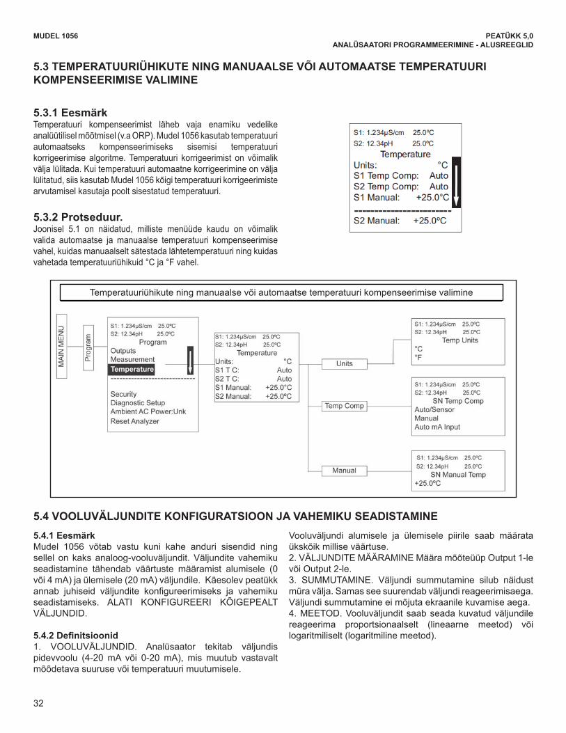
32
MODEL 1056 SECTION 5.0PROGRAMMING THE ANALYZER - BASICS
5.3.1 PurposeMost liquid analytical measurements (except ORP)require temperature compensation. The Model 1056performs temperature compensation automatically byapplying internal temperature correction algorithms.Temperature correction can also be turned off. If tem-perature correction is off, the Model 1056 uses the tem-perature entered by the user in all temperature correc-tion calculations.
5.3.2 Procedure.Follow the menu screens in Fig. 5.1 to select automaticor manual temp compensation, set the manualreference temperature, and to program temperatureunits as °C or °F.
5.4.1 PurposeThe Model 1056 accepts inputs from two sensors andhas two analog current outputs. Ranging the outputsmeans assigning values to the low (0 or 4 mA) and high(20 mA) outputs. This section provides a guide forconfiguring and ranging the outputs. ALWAYSCONFIGURE THE OUTPUTS FIRST.
5.4.2 Definitions1. CURRENT OUTPUTS. The analyzer provides a con-tinuous output current (4-20 mA or 0-20 mA) directlyproportional to the process variable or temperature.
The low and high current outputs can be set to anyvalue. 2. ASSIGNING OUTPUTS. Assign a measurement toOutput 1 or Output 2. 3. DAMPEN. Output dampening smooths out noisyreadings. It also increases the response time of theoutput. Output dampening does not affect theresponse time of the display.4. MODE. The current output can be made directlyproportional to the displayed value (linear mode) ordirectly proportional to the common logarithm of thedisplayed value (log mode).
S1: 1.234µS/cm 25.0ºCS2: 12.34pH 25.0ºC
TemperatureUnits: °CS1 Temp Comp: Auto S2 Temp Comp: Auto S1 Manual: +25.0°C
S2 Manual: +25.0ºC
Figure 5-1. Choosing Temp Units and Manual Auto Temp Compensation
5.3 CHOOSING TEMPERATURE UNITS AND AUTOMATIC/MANUAL TEMPERATURECOMPENSATION
5.4 CONFIGURING AND RANGING THE CURRENT OUTPUTS
32
MODEL 1056 SECTION 5.0PROGRAMMING THE ANALYZER - BASICS
5.4.3 Procedure: Configure Outputs.Under the Program/Outputs menu, the adjacent screenwill appear to allow configuration of the outputs. Followthe menu screens in Fig. 5-2 to configure the outputs.
5.4.4 Procedure: Assigning Measurements the Lowand High Current Outputs The adjacent screen will appear when entering theAssign function under Program/Output/Configure.These screens allow you to assign a measurement,process value, or temperature input to each output.Follow the menu screens in Fig. 5-2 to assignmeasurements to the outputs.
5.4.5 Procedure: Ranging the Current Outputs The adjacent screen will appear underProgram/Output/Range. Enter a value for 4mA and20mA (or 0mA and 20mA) for each output. Follow themenu screens in Fig. 5-2 to assign values to the out-puts.
S1: 1.234µS/cm 25.0ºCS2: 12.34pH 25.0ºC
OutputM ConfigureAssign: S1 MeasRange: 4-20mAScale: LinearDampening: 0sec
Fault Mode: FixedFault Value: 21.00mA
S1: 1.234µS/cm 25.0ºCS2: 12.34pH 25.0ºC
OutputM AssignS1 MeasurementS1 TemperatureS2 MeasurementS2 Temperature
S1: 1.234µS/cm 25.0ºCS2: 12.34pH 25.0ºC
Output RangeOM SN 4mA: 0.000µS/cmOM SN 20mA: 20.00µS/cmOM SN 4mA: 00.00pHOM SN 20mA: 14.00pH
Figure 5-2. Configuring and Ranging the Current Outputs
33
MUDEL 1056 PEATÜKK 5,0ANALÜSAATORI PROGRAMMEERIMINE - ALUSREEGLID
5.3 TEMPERATUURIÜHIKUTE NING MANUAALSE VÕI AUTOMAATSE TEMPERATUURI KOMPENSEERIMISE VALIMINE
5.3.1 Eesmärk Temperatuuri kompenseerimist läheb vaja enamiku vedelike analüütilisel mõõtmisel (v.a ORP). Mudel 1056 kasutab temperatuuri automaatseks kompenseerimiseks sisemisi temperatuuri korrigeerimise algoritme. Temperatuuri korrigeerimist on võimalik välja lülitada. Kui temperatuuri automaatne korrigeerimine on välja lülitatud, siis kasutab Mudel 1056 kõigi temperatuuri korrigeerimiste arvutamisel kasutaja poolt sisestatud temperatuuri.
5.3.2 Protseduur. Joonisel 5.1 on näidatud, milliste menüüde kaudu on võimalik valida automaatse ja manuaalse temperatuuri kompenseerimise vahel, kuidas manuaalselt sätestada lähtetemperatuuri ning kuidas vahetada temperatuuriühikuid °C ja °F vahel.
S1: 1.234µS/cm 25,0ºC S2:12,34pH25,0ºC
Temperatuur Ühikud: °C S1 Temp.komp.: Auto S2 Temp.komp.: Auto S1 Manuaalne: +25,0ºC
S2 manuaalne: +25.0ºC
5.4 VOOLUVÄLJUNDITE KONFIGURATSIOON JA VAHEMIKU SEADISTAMINE5.4.1 EesmärkMudel 1056 võtab vastu kuni kahe anduri sisendid ning sellel on kaks analoog-vooluväljundit. Väljundite vahemiku seadistamine tähendab väärtuste määramist alumisele (0 või 4 mA) ja ülemisele (20 mA) väljundile. Käesolev peatükk annab juhiseid väljundite konfigureerimiseks ja vahemikuseadistamiseks. ALATI KONFIGUREERI KÕIGEPEALT VÄLJUNDID.
5.4.2Definitsioonid1. VOOLUVÄLJUNDID. Analüsaator tekitab väljundis pidevvoolu (4-20 mA või 0-20 mA), mis muutub vastavalt mõõdetava suuruse või temperatuuri muutumisele.
Vooluväljundi alumisele ja ülemisele piirile saab määrata ükskõik millise väärtuse. 2. VÄLJUNDITE MÄÄRAMINE Määra mõõteüüp Output 1-le või Output 2-le. 3. SUMMUTAMINE. Väljundi summutamine silub näidust müra välja. Samas see suurendab väljundi reageerimisaega. Väljundi summutamine ei mõjuta ekraanile kuvamise aega. 4. MEETOD. Vooluväljundit saab seada kuvatud väljundile reageerima proportsionaalselt (lineaarne meetod) või logaritmiliselt (logaritmiline meetod).
Temperatuuriühikute ning manuaalse või automaatse temperatuuri kompenseerimise valimine

33
MODEL 1056 SECTION 5.0PROGRAMMING THE ANALYZER - BASICS
5.4.3 Procedure: Configure Outputs.Under the Program/Outputs menu, the adjacent screenwill appear to allow configuration of the outputs. Followthe menu screens in Fig. 5-2 to configure the outputs.
5.4.4 Procedure: Assigning Measurements the Lowand High Current Outputs The adjacent screen will appear when entering theAssign function under Program/Output/Configure.These screens allow you to assign a measurement,process value, or temperature input to each output.Follow the menu screens in Fig. 5-2 to assignmeasurements to the outputs.
5.4.5 Procedure: Ranging the Current Outputs The adjacent screen will appear underProgram/Output/Range. Enter a value for 4mA and20mA (or 0mA and 20mA) for each output. Follow themenu screens in Fig. 5-2 to assign values to the out-puts.
S1: 1.234µS/cm 25.0ºCS2: 12.34pH 25.0ºC
OutputM ConfigureAssign: S1 MeasRange: 4-20mAScale: LinearDampening: 0sec
Fault Mode: FixedFault Value: 21.00mA
S1: 1.234µS/cm 25.0ºCS2: 12.34pH 25.0ºC
OutputM AssignS1 MeasurementS1 TemperatureS2 MeasurementS2 Temperature
S1: 1.234µS/cm 25.0ºCS2: 12.34pH 25.0ºC
Output RangeOM SN 4mA: 0.000µS/cmOM SN 20mA: 20.00µS/cmOM SN 4mA: 00.00pHOM SN 20mA: 14.00pH
Figure 5-2. Configuring and Ranging the Current Outputs
33
MUDEL 1056 PEATÜKK 5,0ANALÜSAATORI PROGRAMMEERIMINE - ALUSREEGLID
5.4.3Protseduur:Väljunditekonfigureerimine.Kõrvalnäidatud väljundite konfigureerimise akna leiabmenüüst Program/Outputs. Väljundite konfigureerimistmenüüde abil on näidatud joonisel 5-2.
5.4.4 Protseduur: Vooluväljundite alumisele ja ülemisele piirile mõõtude määramineKõrvalnäidatud aken avaneb, kui valida Program/Output/Configure menüüs Assign. Nendes akendes on võimalikmäärata igale väljundile mõõtmise, protsessiväärtuse või temperatuuri sisend. Väljunditele mõõtude määramine menüüde abil on näidatud joonisel 5-2.
5.4.5 Protseduur: Vooluväljundite vahemiku seadistamineKõrvalnäidatud aken avaneb, kui valida Program/Output/Range. Sisesta väärtus iga väljundi 4 mA ja 20 mA jaoks (või 0 mA ja 20 mA jaoks). Väljunditele väärtuste määramine menüüde abil on näidatud joonisel 5-2.
Joonisel5-2.Vooluväljunditekonfiguratsioonjavahemikuseadistamine
S1: 1.234µS/cm 25,0ºC
S2:12,34pH25,0ºCVäljundMMäära S1 Mõõtmine S1 Temperatuur S2 Mõõtmine S2 Temperatuur
S1: 1.234µS/cm 25,0ºC S2:12,34pH25,0ºC
Väljundi vahemik OM SN 4mA: 0.000µS/cm OM SN 20mA: 20.00µS/cm OMSN4mA:00,00pHOMSN20mA:14,00pH
S1: 1.234µS/cm 25,0ºC S2:12,34pH25,0ºC
OutputMConfigureAssign: And1 mõõt. Vahem: 4-20mA Skaala: Lineaarne summutamine: 0 sek
Vearežiim:Fikseeritudveaväärtus: 21,00mA
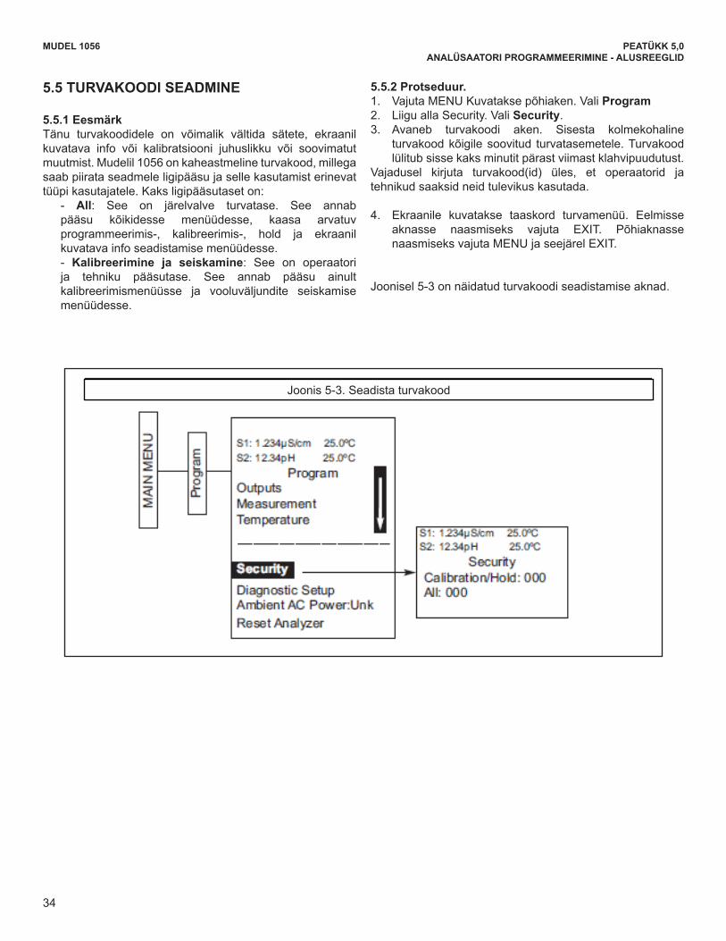
34
Figure 5-3. Setting a Security Code
MA
IN M
EN
U S1: 1.234µS/cm 25.0ºCS2: 12.34pH 25.0ºC
ProgramOutputsMeasurementTemperature
Diagnostic SetupAmbient AC Power:UnkReset Analyzer
S1: 1.234µS/cm 25.0ºCS2: 12.34pH 25.0ºC
SecurityCalibration/Hold: 000 All: 000
Security
Pro
gram
MODEL 1056 SECTION 5.0PROGRAMMING THE ANALYZER - BASICS
5.5 SETTING A SECURITY CODE
5.5.1 Purpose.The security codes prevent accidental or unwantedchanges to program settings, displays, and calibration.Model 1056 has two levels of security code to controlaccess and use of the instrument to different types ofusers. The two levels of security are:
- All: This is the Supervisory security level. It allows access to all menu functions, includingProgramming, Calibration, Hold and Display.
- Calibration/Hold: This is the operator ortechnician level menu. It allows access to
only calibration and Hold of the current outputs.
5.5.2 Procedure.1. Press MENU. The main menu screen appears.
Choose Program.
2. Scroll down to Security. Select Security. 3. The security entry screen appears. Enter a
three digit security code for each of the desiredsecurity levels. The security code takes effect
two minutes after the last key stroke.Record the security code(s) for future accessand communication to operators or techni-cians as needed.
4. The display returns to the security menu screen. Press EXIT to return to the previous screen. To return to the main display, pressMENU followed by EXIT.
Fig. 5-3 displays the security code screens.
34
MUDEL 1056 PEATÜKK 5,0ANALÜSAATORI PROGRAMMEERIMINE - ALUSREEGLID
5.5 TURVAKOODI SEADMINE
5.5.1 Eesmärk Tänu turvakoodidele on võimalik vältida sätete, ekraanil kuvatava info või kalibratsiooni juhuslikku või soovimatut muutmist. Mudelil 1056 on kaheastmeline turvakood, millega saab piirata seadmele ligipääsu ja selle kasutamist erinevat tüüpi kasutajatele. Kaks ligipääsutaset on:
- All: See on järelvalve turvatase. See annab pääsu kõikidesse menüüdesse, kaasa arvatuv programmeerimis-, kalibreerimis-, hold ja ekraanil kuvatava info seadistamise menüüdesse. - Kalibreerimine ja seiskamine: See on operaatori ja tehniku pääsutase. See annab pääsu ainult kalibreerimismenüüsse ja vooluväljundite seiskamise menüüdesse.
5.5.2 Protseduur. 1. Vajuta MENU Kuvatakse põhiaken. Vali Program2. Liigu alla Security. Vali Security.3. Avaneb turvakoodi aken. Sisesta kolmekohaline
turvakood kõigile soovitud turvatasemetele. Turvakood lülitub sisse kaks minutit pärast viimast klahvipuudutust.
Vajadusel kirjuta turvakood(id) üles, et operaatorid ja tehnikud saaksid neid tulevikus kasutada.
4. Ekraanile kuvatakse taaskord turvamenüü. Eelmisse aknasse naasmiseks vajuta EXIT. Põhiaknasse naasmiseks vajuta MENU ja seejärel EXIT.
Joonisel 5-3 on näidatud turvakoodi seadistamise aknad.
Joonis 5-3. Seadista turvakood
PE
AM
EN
ÜÜ
Pro
gram
m
S1: 1.234µS/cm 25,0ºC S2:12,34pH25,0ºC
Programm Väljundid Mõõtmistemperatuur
Turvalisus Diagnostika Sätted Keskkonn AC toide:Unk Ennista analüsaator
S1: 1.234µS/cm 25,0ºC S2:12,34pH25,0ºC
Turvalisus Kalibreerimine/Seiskamine: 000 Kõik: 000
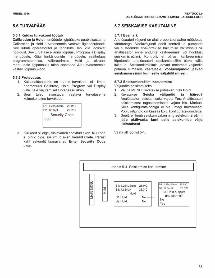
35
MODEL 1056 SECTION 5.0PROGRAMMING THE ANALYZER - BASICS
5.6 SECURITY ACCESS
5.6.1 How the Security Code WorksWhen entering the correct access code for theCalibration/Hold security level, the Calibration andHold menus are accessible. This allows operators ortechnicians to perform routine maintenance. Thissecurity level does not allow access to the Program orDisplay menus. When entering the correct access code for All securitylevel, the user has access to all menu functions, includ-ing Programming, Calibration, Hold and Display.
5.6.2 Procedure.1. If a security code has been programmed, selecting
the Calibrate, Hold, Program or Display top menuitems causes the security access screen to appear
2. Enter the three-digit security code for the appropriatesecurity level.
3. If the entry is correct, the appropriate menu screen appears. If the entry is incorrect, the Invalid Codescreen appears. The Enter Security Code screen reappears after 2 seconds.
5.7 USING HOLD
5.7.1 PurposeThe analyzer output is always proportional to measuredvalue. To prevent improper operation of systems orpumps that are controlled directly by the currentoutput, place the analyzer in hold before removingthe sensor for calibration and maintenance. Be sureto remove the analyzer from hold once calibration iscomplete. During hold, both outputs remain at the lastvalue. Once in hold, all current outputs remain onHold indefinitely.
5.7.2 Using the Hold FunctionTo hold the outputs,
1. Press MENU. The main menu screen appears.Choose Hold.
2. The Hold Outputs and Alarms? screen appears. Choose Yes to place the analyzer in hold. Choose No to take the analyzer out of hold.Note: There are no alarm relays with this configuration. Current outputs are included with allconfigurations.
3. The Hold screen will then appear and Hold will remain on indefinitely until Hold isdisabled.
See figure 5-1 below.
S1: 1.234µS/cm 25.0ºCS2: 12.34pH 25.0ºC
Security Code000
MA
IN M
EN
U
Hol
d
S1: 1.234µS/cm 25.0ºCS2: 12.34pH 25.0ºC
S1 Hold outputsand alarms?
NoYes
S1: 1.234µS/cm 25.0ºCS2: 12.34pH 25.0ºC
HoldS1 Hold: NoS2 Hold: No
Figure 5-4. Using Hold
35
MUDEL 1056 PEATÜKK 5,0ANALÜSAATORI PROGRAMMEERIMINE - ALUSREEGLID
5.6 TURVAPÄÄS
5.6.1 Kuidas turvakood töötab Calibration ja Hold menüüdele ligipääsuks peab sisestama Calibration ja Hold turvatasemele vastava ligipääsukoodi.See lubab operaatoritel ja tehnikutel läbi viia jooksvat hooldust. See turvatase ei anna ligipääsu Program ja Display menüüdele. Kõigi funktsioonide menüüdele, sealhulgas programmeerimise, kalibreerimise, Hold ja ekraanimenüüdele ligipääsuks tuleb sisestada All turvatasemele vastav ligipääsukood.
5.6.2 Protseduur. 1. Kui analüsaatorile on seatud turvakood, siis ilmub
peamenüüs Calibrate, Hold, Program või Displayvalikutele vajutamisel turvapääsu aken
2. Seal tuleb sisestada vastava turvataseme kolmekohaline turvakood.
S1: 1.234µS/cm 25,0ºC
S2:12,34pH25,0ºC
Turvakood000
3. Kui kood oli õige, siis avaneb soovitud aken. Kui kood ei olnud õige, siis ilmub aken Invalid Code. Pärast kaht sekundit taasavaneb Enter Security Code aken.
5.7 SEISKAMISE KASUTAMINE
5.7.1 EesmärkAnalüsaatori väljund on alati proportsionaalne mõõdetud väärtusega. Vooluväljundi poolt kontrollitud pumpade või süsteemide ebakorrektse käitumise vältimiseks vii analüsaator enne andurite kalibreerimist või hooldust seiskamisrežiimi. Kontrolli, et pärast kalibreerimiselõpetamist analüsaatori seiskamisrežiim oleks väljalülitatud. Seiskamisrežiimis jäävad mõlemad väljundidpidama viimasele väärtusele. Vooluväljundid jäävad seiskamisrežiimikuniselleväljalülitamiseni.
5.7.2SeiskamisrežiimikasutamineVäljundite seiskamiseks, 1. Vajuta MENU Kuvatakse põhiaken. Vali Hold.2. Kuvatakse Seiska väljundid ja häired?
Analüsaatori seiskamiseks vajuta Yes. Analüsaatori seiskamisest tagasitoomiseks vajuta No. Märkus: Selle konfiguratsiooniga ei ole ühtegi häirereleed.Vooluväljundidonkaasaskõigikonfiguratsioonidega.
3. Seejärel ilmub seiskumisaken ning seiskumisrežiimjääb aktiivseks kuni selle seiskumise välja lülitamiseni
Vaata all joonist 5-1.
Joonis 5-4. Seiskamise kasutamine
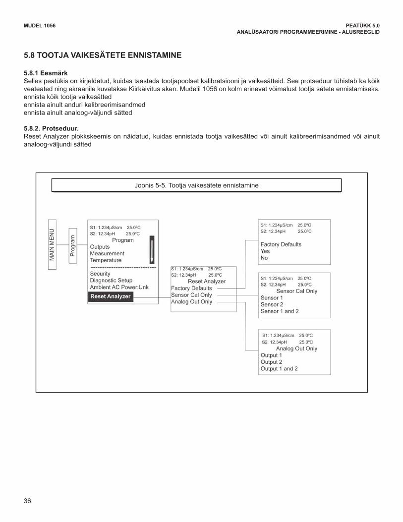
36
MODEL 1056 SECTION 5.0PROGRAMMING THE ANALYZER - BASICS
5.8 RESETTING FACTORY DEFAULT SETTINGS
5.8.1 Purpose.This section describes how to restore factory calibration and default values. The process also clears all fault messagesand returns the display to the first Quick Start screen. The Model 1056 offers three options for resetting factorydefaults.
a. reset all settings to factory defaults b. reset sensor calibration data only c. reset analog output settings only
5.8.2. Procedure.To reset to factory defaults, reset calibration data only or reset analog outputs only, follow the Reset Analyzer flowdiagram.
Figure 5-5. Resetting Factory Default Settings
36
MUDEL 1056 PEATÜKK 5,0ANALÜSAATORI PROGRAMMEERIMINE - ALUSREEGLID
5.8 TOOTJA VAIKESÄTETE ENNISTAMINE
5.8.1 EesmärkSelles peatükis on kirjeldatud, kuidas taastada tootjapoolset kalibratsiooni ja vaikesätteid. See protseduur tühistab ka kõik veateated ning ekraanile kuvatakse Kiirkäivitus aken. Mudelil 1056 on kolm erinevat võimalust tootja sätete ennistamiseks. ennista kõik tootja vaikesätted ennista ainult anduri kalibreerimisandmed ennista ainult analoog-väljundi sätted
5.8.2. Protseduur. Reset Analyzer plokkskeemis on näidatud, kuidas ennistada tootja vaikesätted või ainult kalibreerimisandmed või ainult analoog-väljundi sätted
Joonis 5-5. Tootja vaikesätete ennistamine
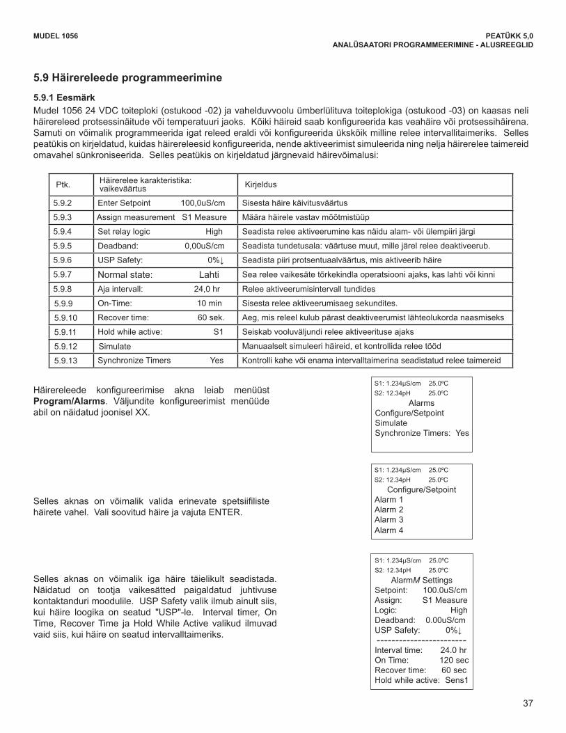
37
MUDEL 1056 PEATÜKK 5,0ANALÜSAATORI PROGRAMMEERIMINE - ALUSREEGLID
5.9 Häirereleede programmeerimine
5.9.1 Eesmärk Mudel 1056 24 VDC toiteploki (ostukood -02) ja vahelduvvoolu ümberlülituva toiteplokiga (ostukood -03) on kaasas neli häirereleedprotsessinäitudevõitemperatuurijaoks.Kõikihäireidsaabkonfigureeridakasveahäirevõiprotsessihäirena.Samutionvõimalikprogrammeeridaigatreleederaldivõikonfigureeridaükskõikmillinereleeintervallitaimeriks.Sellespeatükisonkirjeldatud,kuidashäirereleesidkonfigureerida,nendeaktiveerimistsimuleeridaningneljahäirereleetaimereidomavahel sünkroniseerida. Selles peatükis on kirjeldatud järgnevaid häirevõimalusi:
Ptk. Häirereleekarakteristika:vaikeväärtus Kirjeldus
5.9.2 Enter Setpoint 100,0uS/cm Sisesta häire käivitusväärtus
5.9.3 Assign measurement S1 Measure Määra häirele vastav mõõtmistüüp
5.9.4 SetrelaylogicHigh Seadista relee aktiveerumine kas näidu alam- või ülempiiri järgi
5.9.5 Deadband: 0,00uS/cm Seadista tundetusala: väärtuse muut, mille järel relee deaktiveerub.
5.9.6 USPSafety:0%↓ Seadista piiri protsentuaalväärtus, mis aktiveerib häire
5.9.7 Normal state: Lahti Sea relee vaikesäte tõrkekindla operatsiooni ajaks, kas lahti või kinni
5.9.8 Aja intervall: 24,0 hr Relee aktiveerumisintervall tundides
5.9.9 On-Time: 10 min Sisesta relee aktiveerumisaeg sekundites.
5.9.10 Recover time: 60 sek. Aeg, mis releel kulub pärast deaktiveerumist lähteolukorda naasmiseks
5.9.11 Holdwhileactive:S1 Seiskab vooluväljundi relee aktiveerituse ajaks
5.9.12 Simulate Manuaalselt simuleeri häireid, et kontrollida relee tööd
5.9.13 Synchronize Timers Yes Kontrolli kahe või enama intervalltaimerina seadistatud relee taimereid
5.9 Programming Alarm Relays
5.9.1 Purpose.The Model 1056 24VDC (-02 order code) and the AC switching power supply (-03 order code) provide four alarmrelays for process measurement or temperature. Each alarm can be configured as a fault alarm instead of aprocess alarm. Also, each relay can be programmed independently and each can be programmed as an intervaltimer. This section describes how to configure alarm relays, simulate relay activation, and synchronize timers forthe four alarm relays. This section provides details to program the following alarm features:
Under the Program/Alarms menu, this screen willappear to allow configuration of the alarm relays.Follow the menu screens in Fig. XX to configure theoutputs.
This screen will appear to allow selection of a specificalarm relay. Select the desired alarm and pressENTER.
This screen will appear next to allow complete pro-gramming of each alarm. Factory defaults are dis-played as they would appear for an installed contact-ing conductivity board. USP Safety only appears ifalarm logic is set to “USP”. Interval timer, On Time,Recover Time, and Hold While Active only appear ifthe alarm is configured as an Interval timer.
MODEL 1056 SECTION 5.0PROGRAMMING THE ANALYZER - BASICS
S1: 1.234µS/cm 25.0ºCS2: 12.34pH 25.0ºC
AlarmsConfigure/SetpointSimulateSynchronize Timers: Yes
S1: 1.234µS/cm 25.0ºCS2: 12.34pH 25.0ºC
Configure/SetpointAlarm 1 Alarm 2 Alarm 3 Alarm 4
S1: 1.234µS/cm 25.0ºCS2: 12.34pH 25.0ºC
AlarmM SettingsSetpoint: 100.0uS/cmAssign: S1 MeasureLogic: HighDeadband: 0.00uS/cmUSP Safety: 0%↓
Interval time: 24.0 hrOn Time: 120 secRecover time: 60 sec Hold while active: Sens1
Sec. Alarm relay feature: default Description5.9.2 Enter Setpoint 100.0uS/cm Enter alarm trigger value 5.9.3 Assign measurement S1 Measure Select alarm assignment 5.9.4 Set relay logic High Program relay to activate at High or Low reading5.9.5 Deadband: 0.00uS/cm Program the change in process value after the relay deactivates 5.9.6 USP Safety: 0%↓ Program percentage of the limit to activate the alarm 5.9.7 Normal state: Open Program relay default condition as open or closed for failsafe operation 5.9.8 Interval time: 24.0 hr Time in hours between relay activations
5.9.9 On-Time: 10 min Enter the time in seconds that the relay is activated.
5.9.10 Recover time: 60 sec Enter time after the relay deactivation for process recovery
5.9.11 Hold while active: S1 Holds current outputs during relay activation
5.9.12 Simulate Manually simulate alarms to confirm relay operation
5.9.13 Synchronize Timers Yes Control the timing of two or more relay timers set as Interval timers
37
Häirereleede konfigureerimise akna leiab menüüstProgram/Alarms. Väljundite konfigureerimist menüüdeabil on näidatud joonisel XX.
Selles aknas on võimalik valida erinevate spetsiifilistehäirete vahel. Vali soovitud häire ja vajuta ENTER.
Selles aknas on võimalik iga häire täielikult seadistada. Näidatud on tootja vaikesätted paigaldatud juhtivuse kontaktanduri moodulile. USP Safety valik ilmub ainult siis, kui häire loogika on seatud "USP"-le. Interval timer, On Time,RecoverTime jaHoldWhileActive valikud ilmuvadvaid siis, kui häire on seatud intervalltaimeriks.
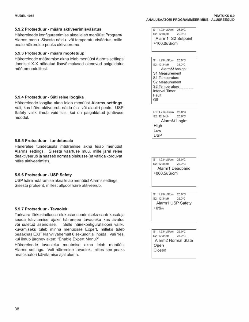
38
MODEL 1056 SECTION 5.0PROGRAMMING THE ANALYZER - BASICS
5.9.2 Procedure – Enter SetpointsUnder the Program/Alarms menu, this screen willappear to allow configuration of the alarm relays.Enter the desired value for the process measurementor temperature at which to activate an alarm event.
5.9.3 Procedure – Assign Measurement Under the Alarms Settings menu, this screen willappear to allow assignment of the alarm relays. selectan alarm assignment. Additional assignment choicesare shown in Figure X-X depending on which meas-urement board(s) is installed.
5.9.4 Procedure – Set Relay LogicUnder the Alarms Settings menu, this screen willappear to set the alarm logic. Select the desired relaylogic to activate alarms at a High reading or a Lowreading. USP Safety only appears if a contacting con-ductivity board is installed.
5.9.5 Procedure – DeadbandUnder the Alarms Settings menu, this screen willappear to program the deadband as a measurementvalue. Enter the change in the process value neededafter the relay deactivates to return to normal (andthereby preventing repeated alarm activation).
5.9.6 Procedure – USP Safety Under the Alarms Settings menu, this screen willappear to program the USP alarm setting. Enter thepercentage below the limit at which to activate thealarm.
5.9.7 Procedure – Normal state The user can define failsafe condition in software byprogramming the alarm default state to normally openor normally closed upon power up. To display thisalarm configuration item, enter the Expert menus byholding down the EXIT key for 6 seconds while in themain display mode. Select Yes upon seeing the screenprompt: “Enable Expert Menu?” Under the Alarms Settings menu, this screen willappear to set the normal state of the alarms. Select thealarm condition that is desired each time the analyzer ispowering up.
S1: 1.234µS/cm 25.0ºCS2: 12.34pH 25.0ºC
Alarm1 S2 Setpoint+100.0uS/cm
S1: 1.234µS/cm 25.0ºCS2: 12.34pH 25.0ºC
AlarmM Logic:HighLowUSP
S1: 1.234µS/cm 25.0ºCS2: 12.34pH 25.0ºC
Alarm1 Deadband+000.5uS/cm
S1: 1.234µS/cm 25.0ºCS2: 12.34pH 25.0ºC
Alarm1 USP Safety+0%i
S1: 1.234µS/cm 25.0ºCS2: 12.34pH 25.0ºC
Alarm2 Normal StateOpenClosed
S1: 1.234µS/cm 25.0ºCS2: 12.34pH 25.0ºC
AlarmM Assign:S1 Measurement S1 TemperatureS2 MeasurementS2 TemperatureInterval TimerFaultOff
38
MUDEL 1056 PEATÜKK 5,0ANALÜSAATORI PROGRAMMEERIMINE - ALUSREEGLID
5.9.2 Protseduur - määra aktiveerimisväärtus HäirereleedekonfigureerimiseaknaleiabmenüüstProgram/Alarms menu. Sisesta näidu- või temperatuuriväärtus, mille peale häirerelee peaks aktiveeruma.
5.9.3 Protseduur - määra mõõtetüüp HäirereleedemääramiseaknaleiabmenüüstAlarmssettings.Joonisel X-X näidatud lisavõimalused olenevad paigaldatud mõõtemoodulitest.
5.9.4 Protseduur - Säti relee loogika HäirereleedeloogikaaknaleiabmenüüstAlarms settings. Vali, kas häire aktiveerub näidu üla- või alapiiri peale. USP Safety valik ilmub vaid siis, kui on paigaldatud juhtivuse moodul.
5.9.5 Protseduur - tundetusala Häirerelee tundetusala määramise akna leiab menüüstAlarms settings. Sisesta väärtuse muu, mille järel relee deaktiveerub ja naaseb normaalolekusse (et vältida korduvat häire aktiveerimist).
5.9.6 Protseduur - USP Safety USP häire määramise akna leiab menüüst Alarms settings. Sisesta protsent, millest allpool häire aktiveerub.
5.9.7 Protseduur - Tavaolek Tarkvara tõrkekindlasse olekusse seadmiseks saab kasutaja seada käivitamise ajaks häirerelee tavaoleku kas avatud või suletud asendisse. Selle häirekonfiguratsiooni valikukuvamiseks tuleb minna menüüsse Expert, milleks tuleb peaaknas EXIT klahvi vähemalt 6 sekundit all hoida. Vali Yes, kui ilmub järgnev aken: “Enable Expert Menu?” Häirereleede tavaoleku muutmise akna leiab menüüstAlarms settings. Vali häirerelee tavaolek, milles see peaks analüsaatori käivitamise ajal olema.
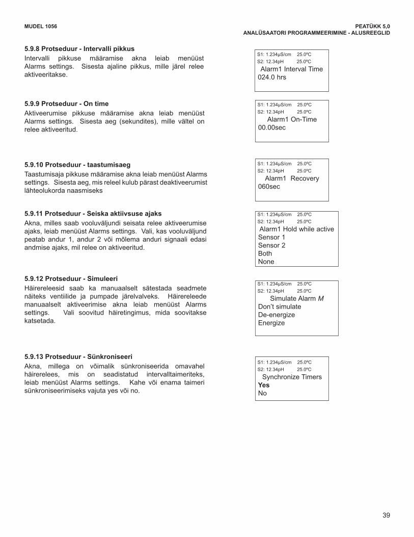
39
MODEL 1056 SECTION 5.0PROGRAMMING THE ANALYZER - BASICS
5.9.8 Procedure – Interval timeUnder the Alarms Settings menu, this screen willappear to set the interval time. Enter the fixed time inhours between relay activations.
5.9.9 Procedure – On timeUnder the Alarms Settings menu, this screen willappear to set the relay on time. Enter the time in sec-onds that the relay is activated.
5.9.10 Procedure – Recovery timeUnder the Alarms Settings menu, this screen willappear to set the relay recovery time. Enter time afterthe relay deactivation for process recovery.
5.9.11 Procedure – Hold while active Under the Alarms Settings menu, this screen willappear to program the feature that Holds the currentoutputs while alarms are active. Select to hold thecurrent outputs for Sensor 1, Sensor 2 or both sensorswhile the relay is activated.
5.9.12 Procedure – SimulateAlarm relays can be manually set for the purposes ofchecking devices such as valves or pumps. Under theAlarms Settings menu, this screen will appear to allowmanual forced activation of the alarm relays. Selectthe desired alarm condition to simulate.
5.9.13 Procedure – SynchronizeUnder the Alarms Settings menu, this screen willappear to allow Synchronization of alarms that are setto interval timers. Select yes or no to Synchronizetwo or more timers.
S1: 1.234µS/cm 25.0ºCS2: 12.34pH 25.0ºC
Alarm1 Interval Time024.0 hrs
S1: 1.234µS/cm 25.0ºCS2: 12.34pH 25.0ºC
Alarm1 On-Time00.00sec
S1: 1.234µS/cm 25.0ºCS2: 12.34pH 25.0ºC
Alarm1 Recovery 060sec
S1: 1.234µS/cm 25.0ºCS2: 12.34pH 25.0ºC
Synchronize TimersYesNo
S1: 1.234µS/cm 25.0ºCS2: 12.34pH 25.0ºC
Alarm1 Hold while activeSensor 1Sensor 2BothNone
S1: 1.234µS/cm 25.0ºCS2: 12.34pH 25.0ºC
Simulate Alarm MDon’t simulateDe-energizeEnergize
39
MUDEL 1056 PEATÜKK 5,0ANALÜSAATORI PROGRAMMEERIMINE - ALUSREEGLID
5.9.8 Protseduur - Intervalli pikkus Intervalli pikkuse määramise akna leiab menüüst Alarms settings. Sisesta ajaline pikkus, mille järel relee aktiveeritakse.
5.9.9 Protseduur - On time Aktiveerumise pikkuse määramise akna leiab menüüst Alarms settings. Sisesta aeg (sekundites), mille vältel on relee aktiveeritud.
5.9.10 Protseduur - taastumisaeg Taastumisaja pikkuse määramise akna leiab menüüst Alarms settings. Sisesta aeg, mis releel kulub pärast deaktiveerumist lähteolukorda naasmiseks
5.9.11 Protseduur - Seiska aktiivsuse ajaks Akna, milles saab vooluväljundi seisata relee aktiveerumise ajaks, leiab menüüst Alarms settings. Vali, kas vooluväljund peatab andur 1, andur 2 või mõlema anduri signaali edasi andmise ajaks, mil relee on aktiveeritud.
5.9.12 Protseduur - Simuleeri Häirereleesid saab ka manuaalselt sätestada seadmetenäiteks ventiilide ja pumpade järelvalveks. Häirereleedemanuaalselt aktiveerimise akna leiab menüüst Alarms settings. Vali soovitud häiretingimus, mida soovitakse katsetada.
5.9.13 Protseduur - Sünkroniseeri Akna, millega on võimalik sünkroniseerida omavahel häirerelees, mis on seadistatud intervalltaimeriteks, leiab menüüst Alarms settings. Kahe või enama taimeri sünkroniseerimiseks vajuta yes või no.

40
MUDEL 1056 PEATÜKK 5,0ANALÜSAATORI PROGRAMMEERIMINE - ALUSREEGLID
This page left blank intentionally
41
MUDEL 1056 PEATÜKK 3.0MÕÕTMISTE PROGRAMMEERIMINE
PEATÜKK 6.0 PROGRAMEERIMINE - MÕÕTMISED
6.1 MÕÕTMISTE KONFIGUREERIMINE - SISSEJUHATUS 6.2 pH 6.3 ORP 6.4 JUHTIVUSE KONTAKTMÕÕTMINE 6.5 JUHTIVUSE TOROIDAALNE MÕÕTMINE 6.6 KLOOR
6.6.1 VABA KLOOR 6.6.2 KOGUKLOOR 6.6.3 MONOKLORAMIIN 6.6.4 pH-st SÕLTUMATU VABA KLOOR
6.7 HAPNIK 6.8 OSOON 6,9 HÄGUSUS 6.10 VOOLUHULK 6.11 VOOLUSISEND
6.1 MÕÕTMISTE PROGRAMMEERIMINE - SISSEJUHATUS Mudel 1056 tuvastab automaatselt kõik paigaldatud mõõtmismoodulid juba esimesel käivitusel ning iga kord, kui analüsaator käivitatakse. Esialgsel käivitusel Kiirkäivituse akende sulgemise järel on mõõtmine juba võimalik, kuid võib vaja minna lisasamme, et programmeerida analüsaator sooritama soovitud mõõtmisprotseduure. Selles peatükis on kirjeldatud järgmistefunktsioonideprogrammeerimistjakonfigureerimist;
1. Mõõtmisviisi või anduritüübi valimine (kõigis alapeatükkides) 2. Eelvõimendimääramine(pH-vaataptk6.2)3. Manuaalse temperatuurikorrektsiooni võimaldamine ja lähtetemperatuuri sisestamine (kõigis alapeatükkides) 4. Näidistemperatuuri korrektsiooni võimaldamine ja temperatuuri korrigeerimiskalde sisestamine (mõningates
alapeatükkides) 5. Näitudekuvatavaeristusemääramine(pHjaamperomeetrilinemõõtmine)6. Näitude kuvatavate mõõtühikute määramine (kõigis alapeatükkides) 7. Mõõtesammu häälestamine, et hoida näidu ja väljundi varieerumine või müra kontrolli all (kõigis alapeatükkides) 8. Mõõtmisvahemiku valimine (juhtivus - vt ptk. 6.4 ja 6.5) 9. Elemendi konstandi sisestamine kontakt- või toroidanduri jaoks (vt ptk 6.4 ja 6.5)
10. Temperatuuri elemendi/RTD nihke või temperatuurikalde sisestamine (juhtivus - vt ptk 6.4) 11. Kasutuspõhise kontsentratsioonikõvera loomine (juhtivus - vt ptk 6.4 ja 6.5) 12. AutomaatsepH-korrektsioonilubaminevabakloorimõõtmisel(ptk6.6.1)
Analüsaatorikonfigureerimineigapaigaldatudmõõtmispaneelijaoksonvõimalikkummalgijärgnevalviisil:1. KasutadesResetAnalyzerfunktsiooni,millegaennistataksetootjavaikeväärtused,misjärelonvõimalikkonfigureerida
mõõtepaneel soovitud mõõtmisviisile. Analüsaatori mõõtetüüpide ja mõõtühikute rekonfigureermiseks vii läbianalüsaatori ennistamise protseduur (joonis. 5.5 Reset analyser)
2. kasutadesProgrammenüüsiderinevateprogrammeeritavatekonfiguratsioonivalikutehäälestamiseks.Soovitudkasutusviisijaokskasutadaalljärgnevaidkonfigureerimis-japrogrammeerimisjuhiseid.
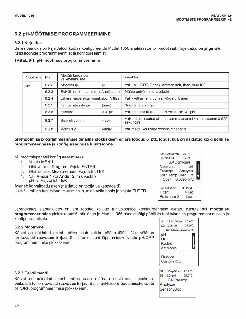
42
MUDEL 1056 PEATÜKK 3.0MÕÕTMISTE PROGRAMMEERIMINE
6.2 pH-MÕÕTMISE PROGRAMMEERIMINE
6.2.1 Kirjeldus Sellespeatükisonkirjeldatud,kuidaskonfigureeridaMudel1056analüsaatoripH-mõõtmist.Kirjeldatudonjärgmistefunktsioonideprogrammeerimistjakonfigureerimist;
TABEL 6-1. pH-mõõtmise programmeerimine
Mõõtmine Ptk. Menüü funktsioon: vaikeväärtused Kirjeldus
pH 6.2.2 Mõõtetüüp pH Vali-pH,ORP,Redox,ammoniaak,floor,muuISE
6.2.3 Eelvõimendi määramine: Analüsaator Määra eelvõimendi asukoht
6.2.4 Lahuse temperatuuri korrektsioon Väljas Vali-Väljas,eritipuhas,kõrgepH,muu
6.2.5 Temperatuuritegur (muu) Sisesta temp.tegur
6.2.6 Eristus: 0.01pH Valieristusühikuks0,01pHvõi0,1pHvõipH
6.2.7 Sisendi samm: 4 sek. Vaikesättes seatud sisendi sammu asemel vali uus samm 0-999 sekundini
6.2.8 Võrdlus Z: Madal Vali madal või kõrge võrdlusimpedants
pH-mõõtmise programmeerimise detailne plokkskeem on ära toodud 6. ptk. lõpus, kus on näidatud kõiki põhilise programmeerimisejakonfigureerimisefunktsioone.
pHmõõtmispaneelikonfigureerimiseks:1. Vajuta MENU2. Otsi valikust Program. Vajuta ENTER. 3. Otsi valikust Measurement. Vajuta ENTER. 4. Vali Andur 1 või Andur 2, mis vastab
pH-le.VajutaENTER.Avaneb kõrvaltoodu aken (näidatud on tootja vaikeseadeid). Ükskõik millise funktsiooni muutmiseks, mine selle peale ja vajuta ENTER.
Järgnevates alapunktides on ära toodud kõikide funktsioonide konfigureerimise aknad. Kasuta pH mõõtmise programmeerimise plokkskeemi 6. ptk lõpus ja Mudel 1056 aknaid kõigi põhiliste funktsioonide programmeerimiseks ja konfigureerimiseks.
6.2.2 Mõõtmine Kõrval on näidatud akent, milles saab valida mõõtmistüübi. Vaikeväärtus on kuvatud rasvases kirjas. Selle funktsiooni lõpetamiseks vaata pH/ORPprogrammeerimise plokkskeemi.
6.2.3 Eelvõimendi Kõrval on näidatud akent, milles saab määrata eelvõimendi asukoha. Vaikeväärtus on kuvatud rasvases kirjas. Selle funktsiooni lõpetamiseks vaata pH/ORPprogrammeerimiseplokkskeemi.
S1: 1.234µS/cm 25,0ºC S2:12,34pH25,0ºC
SNKonfigureeriMõõtminepHeelvõimendi: Analyzer Sol’n Temp Corr: Väljas T-koef.-0,029pH/°C
Eristus:0,01pHSamm: 4 sek Võrdlus Z: Madal
S1: 1.234µS/cm 25,0ºC S2:12,34pH25,0ºC
SNKonfigureeriAnalüsaator Andur/JBox
S1: 1.234µS/cm 25,0ºC
S2:12,34pH25,0ºCSNMõõtmistüüp pHORP Redox Ammoonium
Floor Muu ISE

43
MUDEL 1056 PEATÜKK 3.0MÕÕTMISTE PROGRAMMEERIMINE
MODEL 1056 SECTION 6.0PROGRAMMING THE MEASUREMENTS
6.2.4 Solution Temperature CorrectionThe display screen for selecting the Solutiontemperature correction algorithm is shown. The defaultvalue is displayed in bold type. Refer to the pH/ORPProgramming flow diagram to complete this function.
6.2.5 Temperature CoefficientThe display screen for entering the custom solution tem-perature coefficient is shown. The default value is dis-played in bold type. Refer to the pH/ORPProgramming flow diagram to complete this function.
6.2.6 ResolutionThe display screen for selecting 0.01pH or 0.1pH for pHdisplay resolution is shown. The default value is displayedin bold type. Refer to the pH/ORP Programming flowdiagram to complete this function.
S1: 1.234µS/cm 25.0ºCS2: 12.34pH 25.0ºC
SN Sol’n Temp Corr.Off Ultra Pure Water High pHCustom
S1: 1.234µS/cm 25.0ºCS2: 12.34pH 25.0ºC
SN Resolution 0.01pH0.1pH
S1: 1.234µS/cm 25.0ºCS2: 12.34pH 25.0ºC
SN Sol’n Temp Coeff.- 0.032pH/ºC
6.2.7 FilterThe display screen for entering the input filter value inseconds is shown. The default value is displayed inbold type. Refer to the pH/ORP Programming flow diagramto complete this function.
6.2.8 Reference ImpedenceThe display screen for selecting Low or High Referenceimpedance is shown. The default value is displayed inbold type. Refer to the pH/ORP Programming flow diagramto complete this function.
S1: 1.234µS/cm 25.0ºCS2: 12.34pH 25.0ºC
SN Reference Z LowHigh
S1: 1.234µS/cm 25.0ºCS2: 12.34pH 25.0ºC
SN Input filter04 sec
6.3 ORP MEASUREMENT PROGRAMMING
6.3.1 Description The section describes how to configure the Model 1056 analyzer for ORP measurements. The following programmingand configuration functions are covered:
Measure Sec. Menu function: default DescriptionORP 6.3.2 Measurement type: pH Select pH, ORP, Redox, Ammonia, Fluoride, Custom ISE
6.3.3 Preamp location: Analyzer Identify preamp location
6.3.4 Filter: 4 sec Override the default input filter, enter 0-999 seconds
6.3.5 Reference Z: Low Select low or high reference impedance
TABLE 6-2. ORP Measurement Programming
43
6.2.4 Lahuse temperatuuri korrigeerimine: Kõrval on näidatud akent, milles saab valida algoritmi lahuse temperatuuri korrigeerimiseks. Vaikeväärtus on kuvatud rasvases kirjas.SellefunktsioonilõpetamiseksvaatapH/ORP programmeerimise plokkskeemi.
6.2.5 Temperatuuritegur Kõrval on näidatud akent, milles saab sisestada muude lahuste temperatuuriteguri. Vaikeväärtus on kuvatud rasvases kirjas Selle funktsiooni lõpetamiseksvaatapH/ORP programmeerimise vooludiagrammi.
6.2.6 Eristus Kõrval näidatakse akent, milles saab eristusühikuks valida 0,01pH,0,1pHvõipHVaikeväärtusonkuvatudrasvases kirjas. Selle funktsiooni lõpetamiseks vaata pH/ORPprogrammeerimise plokkskeemi.
6.2.7 Sisendi samm Kõrval on näidatud akent, milles saab sisestada sisendi sammu sekundites. Vaikeväärtus on kuvatud rasvases kirjas.Selle funktsiooni lõpetamiseks vaata pH/ORPprogrammeerimise plokkskeemi.
6.2.8 Võrdlusimpedants Kõrval on näidatud akent, milles saab valida madala ja kõrge võrdlusimpedantsi vahel. Vaikeväärtus on kuvatud rasvases kirjas.SellefunktsioonilõpetamiseksvaatapH/ORP programmeerimise plokkskeemi.
6.3 ORP-MÕÕTMISE PROGRAMMEERIMINE
6.3.1 Kirjeldus Sellespeatükisonkirjeldatud,kuidaskonfigureeridaMudel1056analüsaatoriORP-mõõtmist. Kirjeldatudonjärgmistefunktsioonideprogrammeerimistjakonfigureerimist:
TABEL 6-2. ORP-mõõtmise programmeerimine
Mõõtmine Ptk. Menüü funktsioon: vaikeväärtus Kirjeldus
ORP 6.3.2 Mõõtetüüp pH Vali-pH,ORP,Redox,ammoniaak,floor,muuISE
6.3.3 Eelvõimendi määramine: Analüsaator Määra eelvõimendi asukoht
6.3.4 Sisendi samm: 4 sek. Vaikesättes seatud sisendi sammu asemel vali uus samm 0-999 sekundini
6.3.5 Võrdlus Z: Madal Vali madal või kõrge võrdlusimpedants
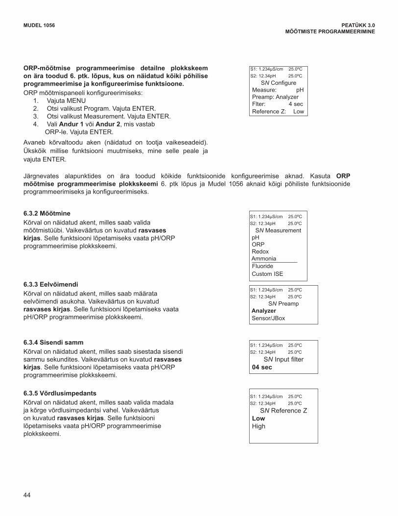
44
MODEL 1056 SECTION 6.0PROGRAMMING THE MEASUREMENTS
The following sub-sections provide you with the initial display screen that appears for each configuration function.Use the flow diagram for ORP programming at the end of Sec. 6 and the Model 1056 live screen prompts foreach function to complete configuration and programming.
6.3.2 MeasurementThe display screen for selecting the measurement isshown. The default value is displayed in bold type.Refer to the pH/ORP Programming flow diagram tocomplete this function.
6.3.3 PreampThe display screen for identifying the Preamp location isshown. The default value is displayed in bold type.Refer to the pH/ORP Programming flow diagram tocomplete this function.
6.3.4 FilterThe display screen for entering the input filter value inseconds is shown. The default value is displayed inbold type. Refer to the pH/ORP Programming flow diagramto complete this function.
A detailed flow diagram for ORP programming isprovided at the end of Sec. 6 to guide you throughall basic programming and configuration functions.To configure the ORP measurement board:
1. Press MENU2. Scroll down to Program. Press ENTER. 3. Scroll down to Measurement. Press ENTER. 4. Select Sensor 1 or Sensor 2 corresponding to
ORP. Press ENTER. The adjacent screen format will appear (factory defaultsare shown). To program any displayed function, scrollto the desired item and press ENTER.
S1: 1.234µS/cm 25.0ºCS2: 12.34pH 25.0ºC
SN PreampAnalyzerSensor/JBox
S1: 1.234µS/cm 25.0ºCS2: 12.34pH 25.0ºC
SN Input filter04 sec
6.3.5 Reference ImpedenceThe display screen for Selecting Low or high Referenceimpedance is shown. The default value is displayed inbold type. Refer to the pH/ORP Programming flow diagramto complete this function.
S1: 1.234µS/cm 25.0ºCS2: 12.34pH 25.0ºC
SN Reference Z LowHigh
S1: 1.234µS/cm 25.0ºCS2: 12.34pH 25.0ºC
SN Configure Measure: pHPreamp: Analyzer Flter: 4 secReference Z: Low
44
S1: 1.234µS/cm 25.0ºCS2: 12.34pH 25.0ºC
SN Measurement pH ORPRedoxAmmoniaFluoride Custom ISE
MUDEL 1056 PEATÜKK 3.0MÕÕTMISTE PROGRAMMEERIMINE
ORP-mõõtmise programmeerimise detailne plokkskeem on ära toodud 6. ptk. lõpus, kus on näidatud kõiki põhilise programmeerimisejakonfigureerimisefunktsioone.ORPmõõtmispaneelikonfigureerimiseks:
1. Vajuta MENU2. Otsi valikust Program. Vajuta ENTER. 3. Otsi valikust Measurement. Vajuta ENTER. 4. Vali Andur 1 või Andur 2, mis vastab
ORP-le. Vajuta ENTER. Avaneb kõrvaltoodu aken (näidatud on tootja vaikeseadeid). Ükskõik millise funktsiooni muutmiseks, mine selle peale ja vajuta ENTER.
Järgnevates alapunktides on ära toodud kõikide funktsioonide konfigureerimise aknad. Kasuta ORP mõõtmise programmeerimise plokkskeemi 6. ptk lõpus ja Mudel 1056 aknaid kõigi põhiliste funktsioonide programmeerimiseksjakonfigureerimiseks.
6.3.2 Mõõtmine Kõrval on näidatud akent, milles saab valida mõõtmistüübi. Vaikeväärtus on kuvatud rasvases kirjas.SellefunktsioonilõpetamiseksvaatapH/ORPprogrammeerimise plokkskeemi.
6.3.3 Eelvõimendi Kõrval on näidatud akent, milles saab määrata eelvõimendi asukoha. Vaikeväärtus on kuvatud rasvases kirjas. Selle funktsiooni lõpetamiseks vaata pH/ORPprogrammeerimiseplokkskeemi.
6.3.4 Sisendi samm Kõrval on näidatud akent, milles saab sisestada sisendi sammu sekundites. Vaikeväärtus on kuvatud rasvases kirjas.SellefunktsioonilõpetamiseksvaatapH/ORPprogrammeerimise plokkskeemi.
6.3.5 Võrdlusimpedants Kõrval on näidatud akent, milles saab valida madala ja kõrge võrdlusimpedantsi vahel. Vaikeväärtus on kuvatud rasvases kirjas. Selle funktsiooni lõpetamiseksvaatapH/ORPprogrammeerimiseplokkskeemi.
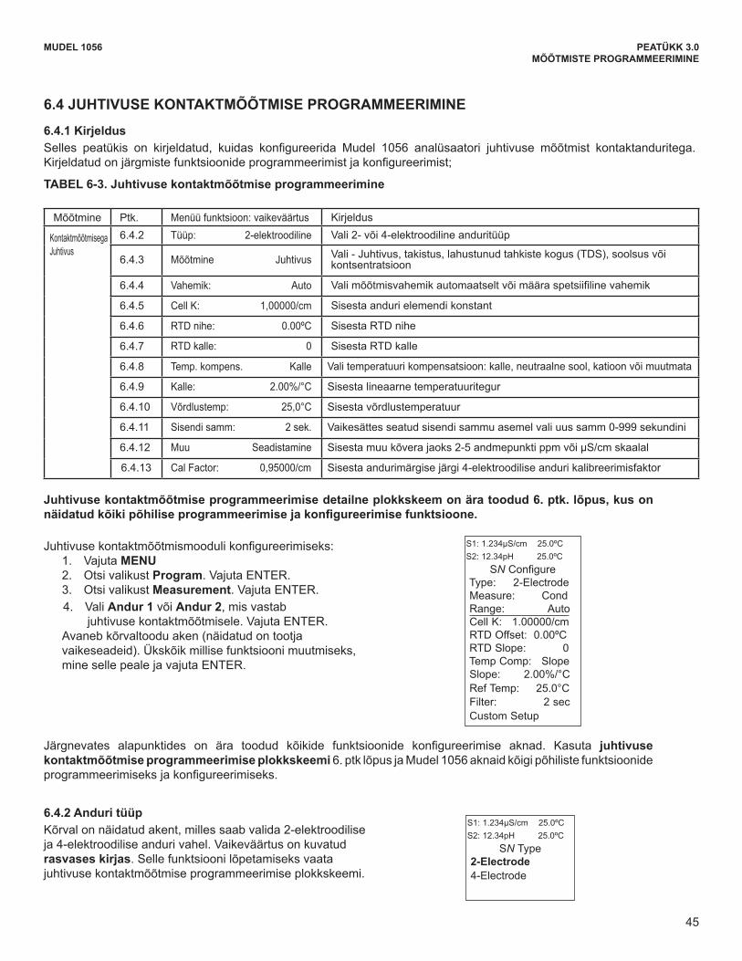
45
6.4.2 Sensor TypeThe display screen for selecting 2-Electrode or4-Electrode type sensors is shown. The default valueis displayed in bold type. Refer to the contactingconductivity Programming flow diagram to complete thisfunction.
MODEL 1056 SECTION 6.0PROGRAMMING THE MEASUREMENTS
6.4 CONTACTING CONDUCTIVITY MEASUREMENT PROGRAMMING
6.4.1 Description The section describes how to configure the Model 1056 analyzer for conductivity measurements using contactingconductivity sensors. The following programming and configuration functions are covered.
The following sub-sections provide you with the initial display screen that appears for each configuration function.Use the flow diagram for contacting conductivity programming at the end of Sec. 6 and the Model 1056 livescreen prompts for each function to complete configuration and programming.
To configure the contacting conductivity measurementboard:
1. Press MENU 2. Scroll down to Program. Press ENTER. 3. Scroll down to Measurement. Press ENTER. 4. Select Sensor 1 or Sensor 2 corresponding to
contacting conductivity. Press ENTER. The adjacent screen format will appear (factory defaultsare shown). To program any displayed function, scrollto the desired item and press ENTER.
Measure Sec. Menu function: default DescriptionContacting Conductivity
6.4.2 Type: 2-Electrode Select 2-Electrode or 4-Electrode type sensors
6.4.3 Measure: Conductivity Select Conductivity, Resistivity, TDS. Salinity or % conc
6.4.4 Range: Auto Select measurement Auto-range or specific range
6.4.5 Cell K: 1.00000/cm Enter the cell Constant for the sensor
6.4.6 RTD Offset: 0.00ºC Enter the RTD Offset
6.4.7 RTD Slope: 0 Enter the RTD Slope
6.4.8 Temp Comp: Slope Select Temp Comp: Slope, Neutral Salt, Cation or Raw
6.4.9 Slope: 2.00%/°C Enter the linear temperature coefficient
6.4.10 Ref Temp: 25.0°C Enter the Reference temp
6.4.11 Filter: 2 sec Override the default input filter, enter 0-999 seconds
6.4.12 Custom Setup Enter 2-5 data points in ppm and µS/cm for custom curves
6.4.13 Cal Factor: 0.95000/cm Enter the Cal Factor for 4-Electrode sensors from the sensor tag
S1: 1.234µS/cm 25.0ºCS2: 12.34pH 25.0ºC
SN Configure Type: 2-ElectrodeMeasure: CondRange: AutoCell K: 1.00000/cmRTD Offset: 0.00ºC RTD Slope: 0Temp Comp: SlopeSlope: 2.00%/°CRef Temp: 25.0°CFilter: 2 secCustom Setup
S1: 1.234µS/cm 25.0ºCS2: 12.34pH 25.0ºC
SN Type2-Electrode4-Electrode
TABLE 6-3. Contacting Conductivity Measurement Programming
A detailed flow diagram for contacting conductivity programming is provided at the end of Sec. 6 toguide you through all basic programming and configuration functions.
45
MUDEL 1056 PEATÜKK 3.0MÕÕTMISTE PROGRAMMEERIMINE
6.4 JUHTIVUSE KONTAKTMÕÕTMISE PROGRAMMEERIMINE
6.4.1 Kirjeldus Selles peatükis on kirjeldatud, kuidas konfigureerida Mudel 1056 analüsaatori juhtivuse mõõtmist kontaktanduritega.Kirjeldatudonjärgmistefunktsioonideprogrammeerimistjakonfigureerimist;
TABEL 6-3. Juhtivuse kontaktmõõtmise programmeerimine
Mõõtmine Ptk. Menüü funktsioon: vaikeväärtus Kirjeldus
Kontaktmõõtmisega Juhtivus
6.4.2 Tüüp: 2-elektroodiline Vali 2- või 4-elektroodiline anduritüüp
6.4.3 Mõõtmine Juhtivus Vali - Juhtivus, takistus, lahustunud tahkiste kogus (TDS), soolsus või kontsentratsioon
6.4.4 Vahemik: Auto Valimõõtmisvahemikautomaatseltvõimääraspetsiifilinevahemik
6.4.5 Cell K: 1,00000/cm Sisesta anduri elemendi konstant
6.4.6 RTD nihe: 0.00ºC Sisesta RTD nihe
6.4.7 RTD kalle: 0 Sisesta RTD kalle
6.4.8 Temp. kompens. Kalle Vali temperatuuri kompensatsioon: kalle, neutraalne sool, katioon või muutmata
6.4.9 Kalle: 2.00%/°C Sisesta lineaarne temperatuuritegur
6.4.10 Võrdlustemp: 25,0°C Sisesta võrdlustemperatuur
6.4.11 Sisendi samm: 2 sek. Vaikesättes seatud sisendi sammu asemel vali uus samm 0-999 sekundini
6.4.12 Muu Seadistamine Sisesta muu kõvera jaoks 2-5 andmepunkti ppm või µS/cm skaalal
6.4.13 Cal Factor: 0,95000/cm Sisesta andurimärgise järgi 4-elektroodilise anduri kalibreerimisfaktor
Juhtivuse kontaktmõõtmise programmeerimise detailne plokkskeem on ära toodud 6. ptk. lõpus, kus on näidatudkõikipõhiliseprogrammeerimisejakonfigureerimisefunktsioone.
Juhtivusekontaktmõõtmismoodulikonfigureerimiseks:1. Vajuta MENU 2. Otsi valikust Program. Vajuta ENTER. 3. Otsi valikust Measurement. Vajuta ENTER. 4. Vali Andur 1 või Andur 2, mis vastab juhtivuse kontaktmõõtmisele. Vajuta ENTER. Avaneb kõrvaltoodu aken (näidatud on tootja vaikeseadeid). Ükskõik millise funktsiooni muutmiseks, mine selle peale ja vajuta ENTER.
Järgnevates alapunktides on ära toodud kõikide funktsioonide konfigureerimise aknad. Kasuta juhtivuse kontaktmõõtmise programmeerimise plokkskeemi 6. ptk lõpus ja Mudel 1056 aknaid kõigi põhiliste funktsioonide programmeerimiseksjakonfigureerimiseks.
6.4.2 Anduri tüüp Kõrval on näidatud akent, milles saab valida 2-elektroodilise ja 4-elektroodilise anduri vahel. Vaikeväärtus on kuvatud rasvases kirjas. Selle funktsiooni lõpetamiseks vaata juhtivuse kontaktmõõtmise programmeerimise plokkskeemi.
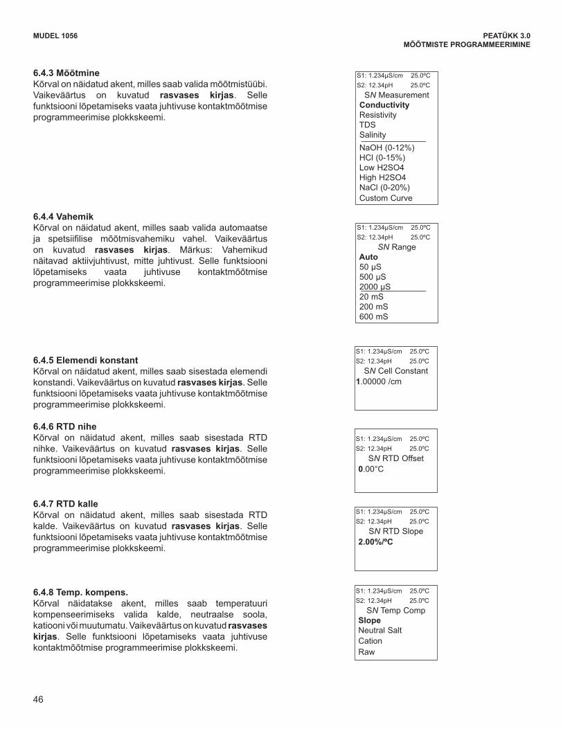
46
MODEL 1056 SECTION 6.0PROGRAMMING THE MEASUREMENTS
6.4.3 MeasureThe display screen for selecting the measurement isshown. The default value is displayed in bold type.Refer to the contacting conductivity Programming flowdiagram to complete this function.
6.4.4 RangeThe display screen for Selecting Auto-ranging or a specificrange is shown. The default value is displayed in boldtype. Note: Ranges are shown as conductance, notconductivity. Refer to the contacting conductivityProgramming flow diagram to complete this function.
S1: 1.234µS/cm 25.0ºCS2: 12.34pH 25.0ºC
SN MeasurementConductivityResistivity TDSSalinityNaOH (0-12%)HCl (0-15%)Low H2SO4 High H2SO4 NaCl (0-20%)Custom Curve
S1: 1.234µS/cm 25.0ºCS2: 12.34pH 25.0ºC
SN RangeAuto50 µS500 µS2000 µS20 mS200 mS600 mS
6.4.5 Cell ConstantThe display screen for entering a cell Constant for thesensor is shown. The default value is displayed in boldtype. Refer to the contacting conductivity Programmingflow diagram to complete this function.
S1: 1.234µS/cm 25.0ºCS2: 12.34pH 25.0ºC
SN Cell Constant 1.00000 /cm
6.4.6 RTD OffsetThe display screen for Entering the RTD Offset for thesensor is shown. The default value is displayed in boldtype. Refer to the contacting conductivity Programmingflow diagram to complete this function.
S1: 1.234µS/cm 25.0ºCS2: 12.34pH 25.0ºC
SN RTD Offset 0.00°C
6.4.7 RTD SlopeThe display screen for entering the RTD slope for thesensor is shown. The default value is displayed in boldtype. Refer to the contacting conductivity Programmingflow diagram to complete this function.
S1: 1.234µS/cm 25.0ºCS2: 12.34pH 25.0ºC
SN RTD Slope2.00%/ºC
6.4.8 Temp CompThe display screen for Selecting TemperatureCompensation as Slope, Neutral Salt, Cation or Raw isshown. The default value is displayed in bold type.Refer to the contacting conductivity Programming flowdiagram to complete this function.
S1: 1.234µS/cm 25.0ºCS2: 12.34pH 25.0ºC
SN Temp CompSlopeNeutral SaltCation Raw
46
MUDEL 1056 PEATÜKK 3.0MÕÕTMISTE PROGRAMMEERIMINE
6.4.3 MõõtmineKõrval on näidatud akent, milles saab valida mõõtmistüübi. Vaikeväärtus on kuvatud rasvases kirjas. Selle funktsiooni lõpetamiseks vaata juhtivuse kontaktmõõtmise programmeerimise plokkskeemi.
6.4.4 VahemikKõrval on näidatud akent, milles saab valida automaatse ja spetsiifilise mõõtmisvahemiku vahel. Vaikeväärtuson kuvatud rasvases kirjas. Märkus: Vahemikud näitavad aktiivjuhtivust, mitte juhtivust. Selle funktsiooni lõpetamiseks vaata juhtivuse kontaktmõõtmise programmeerimise plokkskeemi.
6.4.5 Elemendi konstantKõrval on näidatud akent, milles saab sisestada elemendi konstandi. Vaikeväärtus on kuvatud rasvases kirjas. Selle funktsiooni lõpetamiseks vaata juhtivuse kontaktmõõtmise programmeerimise plokkskeemi.
6.4.6 RTD niheKõrval on näidatud akent, milles saab sisestada RTD nihke. Vaikeväärtus on kuvatud rasvases kirjas. Selle funktsiooni lõpetamiseks vaata juhtivuse kontaktmõõtmise programmeerimise plokkskeemi.
6.4.7 RTD kalleKõrval on näidatud akent, milles saab sisestada RTD kalde. Vaikeväärtus on kuvatud rasvases kirjas. Selle funktsiooni lõpetamiseks vaata juhtivuse kontaktmõõtmise programmeerimise plokkskeemi.
6.4.8 Temp. kompens.Kõrval näidatakse akent, milles saab temperatuuri kompenseerimiseks valida kalde, neutraalse soola, katiooni või muutumatu. Vaikeväärtus on kuvatud rasvases kirjas. Selle funktsiooni lõpetamiseks vaata juhtivuse kontaktmõõtmise programmeerimise plokkskeemi.

47
6.4.13 Cal Factor Upon initial installation and power up, if 4-electrodewas selected for the sensor type in the Quick Startmenus, the user enters a Cell Constant and a “CalFactor” using the instrument keypad. The cell constantis needed to convert measured conductance toconductivity as displayed on the analyzer screen. The“Cal Factor” entry is needed increase the accuracy ofthe live conductivity readings, especially at low conduc-tivity readings below 20uS/cm. Both the Cell Constantand the “Cal Factor” are printed on the tag attached tothe 4-electrode sensor/cable.
The display screen for entering Cal Factor is shown.The default value is displayed in bold type. If necessaryafter initial installation and start-up, enter the “CalFactor” as printed on the sensor tag.
MODEL 1056 SECTION 6.0PROGRAMMING THE MEASUREMENTS
6.4.9 SlopeThe display screen for Entering the conductivity/tempSlope is shown. The default value is displayed in boldtype. Refer to the contacting conductivity Programmingflow diagram to complete this function.
S1: 1.234µS/cm 25.0ºCS2: 12.34pH 25.0ºC
SN Slope2.00 %/ºC
6.4.10 Reference TempThe display screen for manually entering the Referencetemperature is shown. The default value is displayed inbold type. Refer to the contacting conductivityProgramming flow diagram to complete this function.
S1: 1.234µS/cm 25.0ºCS2: 12.34pH 25.0ºC
SN Ref Temp(25.0ºC normal)
+25.0ºC
6.4.11 FilterThe display screen for entering the input filter value inseconds is shown. The default value is displayed inbold type. Refer to the contacting conductivityProgramming flow diagram to complete this function.
S1: 1.234µS/cm 25.0ºCS2: 12.34pH 25.0ºC
SN Input filter
02 sec
6.4.12 Custom SetupThe display screens for creating a custom curve forconverting conductivity to concentration is shown.Refer to the contacting conductivity Programmingflow diagram to complete this function.
S1: 1.234µS/cm 25.0ºCS2: 12.34pH 25.0ºC
SN Custom CurveConfigureEnter Data Points Calculate Curve
S1: 1.234µS/cm 25.0ºCS2: 12.34pH 25.0ºC
SN Cal Factor0.95000/cm
When the custom curve data entry is complete, pressENTER. The display will confirm the determination of acustom curve fit to the entered data by displaying thisscreen:
S1: 1.234µS/cm 25.0ºCS2: 12.34pH 25.0ºCSN Calculate CurveCustom curvefit completed.In Process Calrecommended.
If the custom curve fit is not completed or isunsuccessful, the display will read as follows and thescreen will return to the beginning custom curve screen.
S1: 1.234µS/cm 25.0ºCS2: 12.34pH 25.0ºCSN Calculate CurveFailure
47
MUDEL 1056 PEATÜKK 3.0MÕÕTMISTE PROGRAMMEERIMINE
6.4.13 Cal Factor Upon initial installation and power up, if 4-electrodewas selected for the sensor type in the Quick Startmenus, the user enters a Cell Constant and a “CalFactor” using the instrument keypad. The cell constantis needed to convert measured conductance toconductivity as displayed on the analyzer screen. The“Cal Factor” entry is needed increase the accuracy ofthe live conductivity readings, especially at low conduc-tivity readings below 20uS/cm. Both the Cell Constantand the “Cal Factor” are printed on the tag attached tothe 4-electrode sensor/cable.
The display screen for entering Cal Factor is shown.The default value is displayed in bold type. If necessaryafter initial installation and start-up, enter the “CalFactor” as printed on the sensor tag.
MODEL 1056 SECTION 6.0PROGRAMMING THE MEASUREMENTS
6.4.9 SlopeThe display screen for Entering the conductivity/tempSlope is shown. The default value is displayed in boldtype. Refer to the contacting conductivity Programmingflow diagram to complete this function.
S1: 1.234µS/cm 25.0ºCS2: 12.34pH 25.0ºC
SN Slope2.00 %/ºC
6.4.10 Reference TempThe display screen for manually entering the Referencetemperature is shown. The default value is displayed inbold type. Refer to the contacting conductivityProgramming flow diagram to complete this function.
S1: 1.234µS/cm 25.0ºCS2: 12.34pH 25.0ºC
SN Ref Temp(25.0ºC normal)
+25.0ºC
6.4.11 FilterThe display screen for entering the input filter value inseconds is shown. The default value is displayed inbold type. Refer to the contacting conductivityProgramming flow diagram to complete this function.
S1: 1.234µS/cm 25.0ºCS2: 12.34pH 25.0ºC
SN Input filter
02 sec
6.4.12 Custom SetupThe display screens for creating a custom curve forconverting conductivity to concentration is shown.Refer to the contacting conductivity Programmingflow diagram to complete this function.
S1: 1.234µS/cm 25.0ºCS2: 12.34pH 25.0ºC
SN Custom CurveConfigureEnter Data Points Calculate Curve
S1: 1.234µS/cm 25.0ºCS2: 12.34pH 25.0ºC
SN Cal Factor0.95000/cm
When the custom curve data entry is complete, pressENTER. The display will confirm the determination of acustom curve fit to the entered data by displaying thisscreen:
S1: 1.234µS/cm 25.0ºCS2: 12.34pH 25.0ºCSN Calculate CurveCustom curvefit completed.In Process Calrecommended.
If the custom curve fit is not completed or isunsuccessful, the display will read as follows and thescreen will return to the beginning custom curve screen.
S1: 1.234µS/cm 25.0ºCS2: 12.34pH 25.0ºCSN Calculate CurveFailure
47
6.4.9 KalleKõrval on näidatud akent, milles saab sisestada juhtivuse/temperatuuri kalde. Vaikeväärtus on kuvatud rasvases kirjas. Selle funktsiooni lõpetamiseks vaata juhtivuse kontaktmõõtmise programmeerimise plokkskeemi.
6.4.10 VõrdlustemperatuurKõrval on näidatud akent, milles saab sisestada võrdlustemperatuuri. Vaikeväärtus on kuvatud rasvases kirjas. Selle funktsiooni lõpetamiseks vaata juhtivuse kontaktmõõtmise programmeerimise plokkskeemi.
6.4.11 Sisendi sammKõrval on näidatud akent, milles saab sisestada sisendi sammu sekundites. Vaikeväärtus on kuvatud rasvases kirjas. Selle funktsiooni lõpetamiseks vaata juhtivuse kontaktmõõtmise programmeerimise plokkskeemi.
06.04.12 Muu seadistamineKõrval on näidatud akent, milles saab luua muu kõvera juhtivuse kontsentratsiooniks konverteerimise jaoks. Selle funktsiooni lõpetamiseks vaata juhtivuse kontaktmõõtmise programmeerimise plokkskeemi.
Kui muu kõvera andmed on sisestatud, siis vajuta ENTER. Kui muu kõvera andmed sobivad, siis kuvatakse selle sisestamise kinnituseks järgmine aken:
Kui muu kõvera sisestamine jäi poolikuks või see ei õnnestunud, siis kuvatakse järgmine aken ning ekraanile kuvatakse taas muu kõvera sisestamise algaken.
6.4.5 Elemendi konstantKõrval on näidatud akent, milles saab sisestada elemendi konstandi. Vaikeväärtus on kuvatud rasvases kirjas. Selle funktsiooni lõpetamiseks vaata juhtivuse kontaktmõõtmise programmeerimise plokkskeemi.
6.4.13 Kal.-faktorKui paigaldamise ja käivitamise ajal valiti 4-elektroodiline andur kiirkäivitusmenüüs, siis peab kasutaja seadme klaviatuurilt sisestama ka elemendi konstandi ja "Kal.-faktori". Elemendi konstant on vajalik mõõdetud aktiivjuhtivuse konverteerimisel analüsaatori ekraanil kuvatavaks juhtivuseks. "Kal.-faktori" sisestamine on vajalik, et suurendada juhtivuse reaalajas lugemise täpseust, eriti madala juhtivusega keskkonnas, mis on allapoole 20 uS/cm. Nii elemendi konstant kui "Kal.-faktor" on trükitud 4-elektroodilise anduri või kaabli külge kinnitatud sildile.
Kõrval on näidatud akent, milles saab sisestada kalibreerimisfaktori. Vaikeväärtus on kuvatud rasvases kirjas. Vajadusel sisesta pärast paigaldamist ja käivitust andurimärgise järgi 4-elektroodilise anduri kalibreerimisfaktor

48
MUDEL 1056 PEATÜKK 3.0MÕÕTMISTE PROGRAMMEERIMINE
MODEL 1056 SECTION 6.0PROGRAMMING THE MEASUREMENTS
6.5 TOROIDAL CONDUCTIVITY MEASUREMENT PROGRAMMING
6.5.1 Description The section describes how to configure the Model 1056 analyzer for conductivity measurements usinginductive/toroidal sensors. The following programming and configuration functions are covered.
Measure Sec. Menu function: default DescriptionToroidalconductivity
6.5.2 Model: 228 Select sensor type
6.5.3 Measure: Conductivity Select Conductivity, Resistivity, TDS, Salinity or % conc
6.5.4 Range: Auto Select measurement Auto-range or specific range
6.5.5 Cell K: 3.00000/cm Enter the cell Constant for the sensor
6.5.6 Temp Comp: Slope Select Temp Comp: Slope, Neutral Salt, or Raw
6.5.7 Slope: 2.00%/°C Enter the linear temperature coefficient
6.5.8 Ref Temp: 25.0°C Enter the Reference temp
6.5.9 Filter: 2 sec Override the default input filter, enter 0-999 seconds
6.5.10 Custom Setup Enter 2-5 data points in ppm and µS/cm for custom curves
To configure the toroidal conductivity measurementboard:
1. Press MENU2. Scroll down to Program. Press ENTER. 3. Scroll down to Measurement. Press ENTER. 4. Select Sensor 1 or Sensor 2 corresponding to
toroidal conductivity. Press ENTER. The adjacent screen format will appear (factory defaultsare shown). To program any displayed function, scrollto the desired item and press ENTER.
The following sub-sections provide you with the initial display screen that appears for each configuration function.Use the flow diagram for toroidal conductivity programming at the end of Sec. 6 and the Model 1056 livescreen prompts for each function to complete configuration and programming.
S1: 1.234µS/cm 25.0ºCS2: 12.34pH 25.0ºC
SN Configure Model: 228Measure: CondRange: Auto
Cell K: 3.00000/cmRTD Offset: 0.00ºCRTD Slope: 0Temp Comp: SlopeSlope: 2.00%/°CRef Temp: 25.0°CFilter: 2 secCustom Setup
6.5.2 Sensor Model The display screen for selecting the sensor model isshown. The default value is displayed in bold type.Refer to the toroidal conductivity Programming flowdiagram to complete this function.
S1: 1.234µS/cm 25.0ºCS2: 12.34pH 25.0ºC
SN Model228225226247
Other
TABLE 6-4. Toroidal Conductivity Measurement Programming
A detailed flow diagram for toroidal conductivity programming is provided at the end of Sec. 6 to guideyou through all basic programming and configuration functions.
48
6.5 JUHTIVUSE TOROIDAALSE MÕÕTMISE PROGRAMMEERIMINE
6.5.1 Kirjeldus Sellespeatükisonkirjeldatud,kuidaskonfigureeridaMudel1056analüsaatorijuhtivusemõõtmistinduktiiv-jatoroidanduritega.Kirjeldatudonjärgmistefunktsioonideprogrammeerimistjakonfigureerimist;
TABEL 6-4. Juhtivuse toroidaalse mõõtmise programmeerimine
Mõõtmine Ptk. Menüü funktsioon:vaikeväärtus Kirjeldus
Juhtivuse toroidaalne mõõtmine
6.5.2 Mudel: 228 Vali anduri tüüp
6.5.3 Mõõtmine Juhtivus Vali - juhtivus, takistus, lahustunud tahkiste kogus (TDS), soolsus või kontsentratsioon
6.5.4 Vahemik: Auto Valimõõtmisvahemikautomaatseltvõimääraspetsiifilinevahemik
6.5.5 Cell K: 3.00000/cm Sisesta anduri elemendi konstant
6.5.6 Temp. kompens. Kalle Vali temperatuuri kompensatsioon: kalle, neutraalne sool või muutmata
6.5.7 Kalle: 2.00%/°C Sisesta lineaarne temperatuuritegur
6.5.8 Võrdlustemp: 25.0°C Sisesta võrdlustemperatuur
6.5.9 Sisendi samm: 2 sek. Vaikesättes seatud sisendi sammu asemel vali uus samm 0-999 sekundini
6.5.10 Muu Seadistamine Sisesta muu kõvera jaoks 2-5 andmepunkti ppm või µS/cm skaalal
Juhtivuse toroidaalse mõõtmise programmeerimise detailne plokkskeem on ära toodud 6. ptk. lõpus, kus onnäidatudkõikipõhiliseprogrammeerimisejakonfigureerimisefunktsioone.
Juhtivuse toroidaalse mõõtmise mooduli konfigureerimiseks:
1. Vajuta MENU2. Otsi valikust Program. Vajuta ENTER. 3. Otsi valikust Measurement. Vajuta ENTER. 4. Vali Andur 1 või Andur 2, mis vastab juhtivuse
toroidaalsele mõõtmisele. Vajuta ENTER. Avaneb kõrvaltoodu aken (näidatud on tootja vaikeseadeid). Ükskõik millise funktsiooni muutmiseks, mine selle peale ja vajuta ENTER.
Järgnevatesalapunktidesonäratoodudkõikidefunktsioonidekonfigureerimiseaknad.Kasutajuhtivuse toroidaalse mõõtmise programmeerimise plokkskeemi 6. ptk lõpus ja Mudel 1056 aknaid kõigi põhiliste funktsioonideprogrammeerimiseksjakonfigureerimiseks.
6.5.2 Anduri mudel Kõrval on näidatud akent, milles saab valida anduri mudeli. Vaikeväärtus on kuvatud rasvases kirjas. Selle funktsiooni lõpetamiseks vaata toroidaalse juhtivuse programmeerimise plokkskeemi.
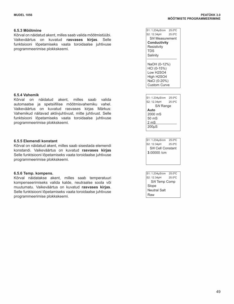
49
MUDEL 1056 PEATÜKK 3.0MÕÕTMISTE PROGRAMMEERIMINE
MODEL 1056 SECTION 6.0PROGRAMMING THE MEASUREMENTS
6.5.3 MeasureThe display screen for selecting the measurement isshown. The default value is displayed in bold type.Refer to the toroidal conductivity Programming flow diagramto complete this function.
6.5.4 RangeThe display screen for Selecting Auto-ranging or aspecific range is shown. The default value is displayedin bold type. Note: Ranges are shown as conductance,not conductivity. Refer to the toroidal conductivityProgramming flow diagram to complete this function.
6.5.5 Cell ConstantThe display screen for entering a cell Constant for thesensor is shown. The default value is displayed in boldtype. Refer to the toroidal conductivity Programmingflow diagram to complete this function.
S1: 1.234µS/cm 25.0ºCS2: 12.34pH 25.0ºC
SN Cell Constant 3.00000 /cm
S1: 1.234µS/cm 25.0ºCS2: 12.34pH 25.0ºC
SN MeasurementConductivityResistivity TDSSalinity
NaOH (0-12%)HCl (0-15%)Low H2SO4 High H2SO4 NaCl (0-20%)Custom Curve
S1: 1.234µS/cm 25.0ºCS2: 12.34pH 25.0ºC
SN RangeAuto2000 mS50 mS2 mS200µS
6.5.6 Temp CompThe display screen for Selecting TemperatureCompensation as Slope, Neutral Salt, or Raw is shown.The default value is displayed in bold type. Refer to thetoroidal conductivity Programming flow diagram to com-plete this function.
S1: 1.234µS/cm 25.0ºCS2: 12.34pH 25.0ºC
SN Temp CompSlopeNeutral SaltRaw
49
6.5.3 MõõtmineKõrval on näidatud akent, milles saab valida mõõtmistüübi. Vaikeväärtus on kuvatud rasvases kirjas. Selle funktsiooni lõpetamiseks vaata toroidaalse juhtivuse programmeerimise plokkskeemi.
6.5.4 VahemikKõrval on näidatud akent, milles saab valida automaatse ja spetsiifilise mõõtmisvahemiku vahel.Vaikeväärtus on kuvatud rasvases kirjas Märkus: Vahemikud näitavad aktiivjuhtivust, mitte juhtivust. Selle funktsiooni lõpetamiseks vaata toroidaalse juhtivuse programmeerimise plokkskeemi.
6.5.5 Elemendi konstantKõrval on näidatud akent, milles saab sisestada elemendi konstandi. Vaikeväärtus on kuvatud rasvases kirjas Selle funktsiooni lõpetamiseks vaata toroidaalse juhtivuse programmeerimise plokkskeemi.
6.5.6 Temp. kompens.Kõrval näidatakse akent, milles saab temperatuuri kompenseerimiseks valida kalde, neutraalse soola või muutumatu. Vaikeväärtus on kuvatud rasvases kirjas. Selle funktsiooni lõpetamiseks vaata toroidaalse juhtivuse programmeerimise plokkskeemi.

50
MODEL 1056 SECTION 6.0PROGRAMMING THE MEASUREMENTS
6.5.7 SlopeThe display screen for Entering the conductivity/tempSlope is shown. The default value is displayed in boldtype. Refer to the toroidal conductivity Programmingflow diagram to complete this function.
S1: 1.234µS/cm 25.0ºCS2: 12.34pH 25.0ºC
SN Slope2.00%/ºC
6.5.8 Ref TempThe display screen for manually Entering the Referencetemperature is shown. The default value is displayed inbold type. Refer to the toroidal conductivityProgramming flow diagram to complete this function.
S1: 1.234µS/cm 25.0ºCS2: 12.34pH 25.0ºC
SN Ref Temp(25.0ºC normal)
+25.0ºC
6.5.9 FilterThe display screen for entering the input filter value inseconds is shown. The default value is displayed inbold type. Refer to the toroidal conductivityProgramming flow diagram to complete this function.
S1: 1.234µS/cm 25.0ºCS2: 12.34pH 25.0ºC
SN Input filter
02 sec
6.5.10 Custom SetupThe display screens for creating custom curves for con-verting conductivity to concentration is shown. Refer tothe toroidal conductivity Programming flow diagram tocomplete this function.
S1: 1.234µS/cm 25.0ºCS2: 12.34pH 25.0ºC
SN Custom CurveConfigureEnter Data Points Calculate Curve
When the custom curve data entry is complete, pressENTER. The display will confirm the determination of acustom curve fit to the entered data by displaying thisscreen:
S1: 1.234µS/cm 25.0ºCS2: 12.34pH 25.0ºC
SN Calculate CurveCustom curvefit completed.In Process Calrecommended.
If the custom curve fit is not completed or isunsuccessful, the display will read as follows and thescreen will return to the beginning custom curve screen.
S1: 1.234µS/cm 25.0ºCS2: 12.34pH 25.0ºC
SN Calculate CurveFailure
50
MUDEL 1056 PEATÜKK 3.0MÕÕTMISTE PROGRAMMEERIMINE
6.5.7 KalleKõrval on näidatud akent, milles saab sisestada juhtivuse/temperatuuri kalde. Vaikeväärtus on kuvatud rasvases kirjas. Selle funktsiooni lõpetamiseks vaata toroidaalse juhtivuse programmeerimise plokkskeemi.
6.5.8 VõrdlustempKõrval on näidatud akent, milles saab sisestada võrdlustemperatuuri. Vaikeväärtus on kuvatud rasvases kirjas. Selle funktsiooni lõpetamiseks vaata toroidaalse juhtivuse programmeerimise plokkskeemi.
6.5.9 Sisendi sammKõrval on näidatud akent, milles saab sisestada sisendi sammu sekundites. Vaikeväärtus on kuvatud rasvases kirjas. Selle funktsiooni lõpetamiseks vaata toroidaalse juhtivuse programmeerimise plokkskeemi.
6.5.10 Muu seadistamineKõrval on näidatud akent, milles saab luua muid kõveraid juhtivuse kontsentratsiooniks konverteerimise jaoks. Selle funktsiooni lõpetamiseks vaata toroidaalse juhtivuse programmeerimise plokkskeemi.
Kui muu kõvera andmed on sisestatud, siis vajuta ENTER. Kui muu kõvera andmed sobivad, siis kuvatakse selle sisestamise kinnituseks järgmine aken:
Kui muu kõvera sisestamine jäi poolikuks või see ei õnnestunud, siis kuvatakse järgmine aken ning ekraanile kuvatakse taas muu kõvera sisestamise algaken.
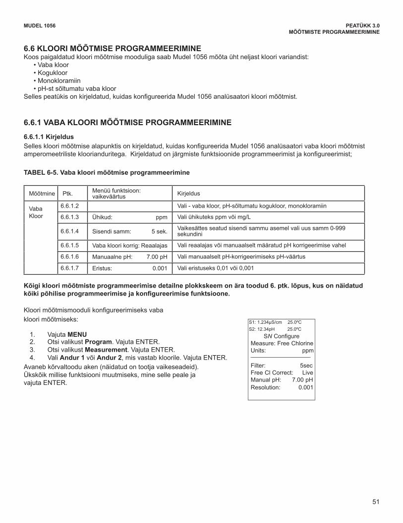
51
MODEL 1056 SECTION 6.0PROGRAMMING THE MEASUREMENTS
6.6 CHLORINE MEASUREMENT PROGRAMMINGWith a Chlorine measurement board installed, Model 1056 can measure any of four variants of Chlorine:
• Free Chlorine • Total Chlorine • Monochloramine • pH-independent Free Chlorine
The section describes how to configure the Model 1056 analyzer for Chlorine measurements.
6.6.1 FREE CHLORINE MEASUREMENT PROGRAMMING
6.6.1.1 Description This Chlorine sub-section describes how to configure the Model 1056 analyzer for Free Chlorine measurementusing amperometric chlorine sensors. The following programming and configuration functions are covered:
To configure the chlorine measurement board for freechlorine:
1. Press MENU 2. Scroll down to Program. Press ENTER. 3. Scroll down to Measurement. Press ENTER. 4. Select Sensor 1 or Sensor 2 corresponding to
chlorine. Press ENTER. The adjacent screen format will appear (factory defaultsare shown). To program any displayed function, scrollto the desired item and press ENTER.
Measure Sec. Menu function: default DescriptionFreeChlorine
6.6.1.2 Measure: Free Chlorine Select Free Chlorine, pH Ind. Free Cl. Total Cl, Monochloramine
6.6.1.3 Units: ppm Select units ppm or mg/L
6.6.1.4 Filter: 5sec Override the default input filter, enter 0-999 seconds
6.6.1.5 Free Cl Correct: Live Select Live/Continuous pH correction or Manual
6.6.1.6 Manual pH: 7.00 pH For Manual pH correction, enter the pH value
6.6.1.7 Resolution: 0.001 Select display resolution 0.01 or 0.001
S1: 1.234µS/cm 25.0ºCS2: 12.34pH 25.0ºC
SN Configure Measure: Free Chlorine Units: ppm
Filter: 5secFree Cl Correct: Live Manual pH: 7.00 pHResolution: 0.001
TABLE 6-5. Free Chlorine Measurement Programming
A detailed flow diagram for programming of all chlorine measurements is provided at the end of Sec. 6 toguide you through all basic programming and configuration functions.
51
MUDEL 1056 PEATÜKK 3.0MÕÕTMISTE PROGRAMMEERIMINE
6.6 KLOORI MÕÕTMISE PROGRAMMEERIMINE Koos paigaldatud kloori mõõtmise mooduliga saab Mudel 1056 mõõta üht neljast kloori variandist:
•Vabakloor•Kogukloor•Monokloramiin•pH-stsõltumatuvabakloor
Sellespeatükisonkirjeldatud,kuidaskonfigureeridaMudel1056analüsaatorikloorimõõtmist.
6.6.1 VABA KLOORI MÕÕTMISE PROGRAMMEERIMINE
6.6.1.1 Kirjeldus Selleskloorimõõtmisealapunktisonkirjeldatud,kuidaskonfigureeridaMudel1056analüsaatorivabakloorimõõtmistamperomeetrilistekloorianduritega.Kirjeldatudonjärgmistefunktsioonideprogrammeerimistjakonfigureerimist;
TABEL 6-5. Vaba kloori mõõtmise programmeerimine
Mõõtmine Ptk. Menüü funktsioon: vaikeväärtus Kirjeldus
VabaKloor
6.6.1.2 Vali-vabakloor,pH-sõltumatukogukloor,monokloramiin
6.6.1.3 Ühikud: ppm Vali ühikuteks ppm või mg/L
6.6.1.4 Sisendi samm: 5 sek. Vaikesättes seatud sisendi sammu asemel vali uus samm 0-999 sekundini
6.6.1.5 Vaba kloori korrig: Reaalajas ValireaalajasvõimanuaalseltmääratudpHkorrigeerimisevahel
6.6.1.6 ManuaalnepH: 7.00pH ValimanuaalseltpH-korrigeerimisekspH-väärtus
6.6.1.7 Eristus: 0.001 Vali eristuseks 0,01 või 0,001
Kõigi kloori mõõtmiste programmeerimise detailne plokkskeem on ära toodud 6. ptk. lõpus, kus on näidatud kõikipõhiliseprogrammeerimisejakonfigureerimisefunktsioone.
Kloorimõõtmismoodulikonfigureerimiseksvabakloori mõõtmiseks:
1. Vajuta MENU2. Otsi valikust Program. Vajuta ENTER. 3. Otsi valikust Measurement. Vajuta ENTER. 4. Vali Andur 1 või Andur 2, mis vastab kloorile. Vajuta ENTER.
Avaneb kõrvaltoodu aken (näidatud on tootja vaikeseadeid). Ükskõik millise funktsiooni muutmiseks, mine selle peale ja vajuta ENTER.
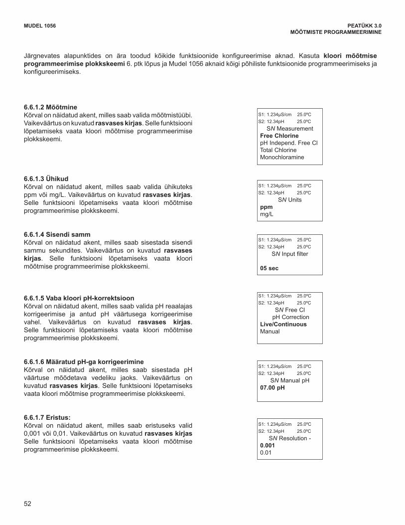
52
MODEL 1056 SECTION 6.0PROGRAMMING THE MEASUREMENTS
The following sub-sections provide you with the initial display screen that appears for each configuration function.Use the flow diagram for chlorine programming at the end of Sec. 6 and the Model 1056 live screen promptsfor each function to complete configuration and programming.
6.6.1.2 MeasureThe display screen for selecting the measurement isshown. The default value is displayed in bold type.Refer to the Chlorine Programming flow diagram tocomplete this function.
S1: 1.234µS/cm 25.0ºCS2: 12.34pH 25.0ºC
SN Measurement Free ChlorinepH Independ. Free Cl Total Chlorine Monochloramine
6.6.1.3 Units The display screen for selecting units as ppm or mg/Lis shown. The default value is displayed in bold type.Refer to the Chlorine Programming flow diagram tocomplete this function.
S1: 1.234µS/cm 25.0ºCS2: 12.34pH 25.0ºC
SN Units ppmmg/L
6.6.1.4 Filter The display screen for entering the input filter value inseconds is shown. The default value is displayed inbold type. Refer to the Chlorine Programming flowdiagram to complete this function.
S1: 1.234µS/cm 25.0ºCS2: 12.34pH 25.0ºC
SN Input filter
05 sec
6.6.1.6 Manual pH CorrectionThe display screen for manually entering the pH valueof the measured process liquid is shown. The defaultvalue is displayed in bold type. Refer to the ChlorineProgramming flow diagram to complete this function.
S1: 1.234µS/cm 25.0ºCS2: 12.34pH 25.0ºC
SN Manual pH 07.00 pH
6.6.1.7 ResolutionThe display screen for selecting display resolution as0.001 or 0.01 is shown. The default value is displayedin bold type. Refer to the Chlorine Programming flowdiagram to complete this function.
S1: 1.234µS/cm 25.0ºCS2: 12.34pH 25.0ºC
SN Resolution -0.0010.01
6.6.1.5 Free Chlorine pH CorrectionThe display screen for Selecting Live/Continuous pHcorrection or Manual pH correction is shown. Thedefault value is displayed in bold type. Refer to theChlorine Programming flow diagram to complete thisfunction.
S1: 1.234µS/cm 25.0ºCS2: 12.34pH 25.0ºC
SN Free Cl pH Correction
Live/ContinuousManual
52
MUDEL 1056 PEATÜKK 3.0MÕÕTMISTE PROGRAMMEERIMINE
6.6.1.2 MõõtmineKõrval on näidatud akent, milles saab valida mõõtmistüübi. Vaikeväärtus on kuvatud rasvases kirjas. Selle funktsiooni lõpetamiseks vaata kloori mõõtmise programmeerimise plokkskeemi.
6.6.1.3 ÜhikudKõrval on näidatud akent, milles saab valida ühikuteks ppm või mg/L. Vaikeväärtus on kuvatud rasvases kirjas. Selle funktsiooni lõpetamiseks vaata kloori mõõtmise programmeerimise plokkskeemi.
6.6.1.4 Sisendi sammKõrval on näidatud akent, milles saab sisestada sisendi sammu sekundites. Vaikeväärtus on kuvatud rasvases kirjas. Selle funktsiooni lõpetamiseks vaata kloori mõõtmise programmeerimise plokkskeemi.
6.6.1.5 Vaba kloori pH-korrektsioonKõrvalonnäidatudakent,millessaabvalidapHreaalajaskorrigeerimise ja antud pH väärtusega korrigeerimisevahel. Vaikeväärtus on kuvatud rasvases kirjas. Selle funktsiooni lõpetamiseks vaata kloori mõõtmise programmeerimise plokkskeemi.
6.6.1.6 Määratud pH-ga korrigeerimineKõrval on näidatud akent, milles saab sisestada pHväärtuse mõõdetava vedeliku jaoks. Vaikeväärtus on kuvatud rasvases kirjas. Selle funktsiooni lõpetamiseks vaata kloori mõõtmise programmeerimise plokkskeemi.
6.6.1.7 Eristus:Kõrval on näidatud akent, milles saab eristuseks valid 0,001 või 0,01. Vaikeväärtus on kuvatud rasvases kirjas Selle funktsiooni lõpetamiseks vaata kloori mõõtmise programmeerimise plokkskeemi.
Järgnevates alapunktides on ära toodud kõikide funktsioonide konfigureerimise aknad. Kasuta kloori mõõtmise programmeerimise plokkskeemi 6. ptk lõpus ja Mudel 1056 aknaid kõigi põhiliste funktsioonide programmeerimiseks ja konfigureerimiseks.
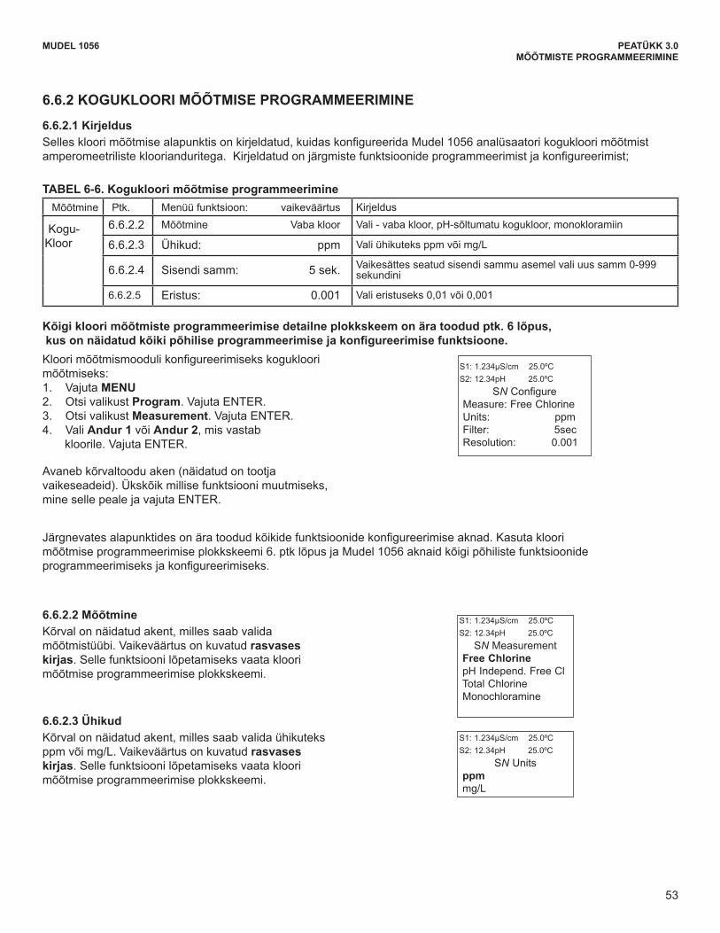
53
MODEL 1056 SECTION 6.0PROGRAMMING THE MEASUREMENTS
6.6.2.2 MeasureThe display screen for selecting the measurement isshown. The default value is displayed in bold type.Refer to the chlorine Programming flow diagram tocomplete this function.
S1: 1.234µS/cm 25.0ºCS2: 12.34pH 25.0ºC
SN Measurement Free ChlorinepH Independ. Free Cl Total Chlorine Monochloramine
6.6.2.3 Units The display screen for selecting units as ppm or mg/Lis shown. The default value is displayed in bold type.Refer to the Chlorine Programming flow diagram tocomplete this function
S1: 1.234µS/cm 25.0ºCS2: 12.34pH 25.0ºC
SN Units ppmmg/L
6.6.2 TOTAL CHLORINE MEASUREMENT PROGRAMMING
6.6.2.1 Description This Chlorine sub-section describes how to configure the Model 1056 analyzer for Total Chlorine measurement usingamperometric chlorine sensors. The following programming and configuration functions are covered:
Measure Sec. Menu function: default DescriptionTotal
Chlorine6.6.2.2 Measure: Free Chlorine Select Free Chlorine, pH Ind. Free Cl. Total Cl, Monochloramine
6.6.2.3 Units: ppm Select units ppm or mg/L
6.6.2.4 Filter: 5sec Override the default input filter, enter 0-999 seconds
6.6.2.5 Resolution: 0.001 Select 0.01 or 0.001 display resolution
To configure the chlorine measurement board for totalchlorine:1. Press MENU2. Scroll down to Program. Press ENTER. 3. Scroll down to Measurement. Press ENTER. 4. Select Sensor 1 or Sensor 2 corresponding to
chlorine. Press ENTER.
The adjacent screen format will appear (factory defaultsare shown). To program any displayed function, scrollto the desired item and press ENTER.
S1: 1.234µS/cm 25.0ºCS2: 12.34pH 25.0ºC
SN Configure Measure: Free Chlorine Units: ppmFilter: 5secResolution: 0.001
The following sub-sections provide you with the initial display screen that appears for each configuration function.Use the flow diagram for chlorine programming at the end of Sec. 6 and the Model 1056 live screen prompts foreach function to complete configuration and programming.
TABLE 6-6. Total Chlorine Measurement Programming
A detailed flow diagram for programming of all chlorine measurements is provided at the end of Sec. 6 toguide you through all basic programming and configuration functions.
53
MUDEL 1056 PEATÜKK 3.0MÕÕTMISTE PROGRAMMEERIMINE
6.6.2 KOGUKLOORI MÕÕTMISE PROGRAMMEERIMINE
6.6.2.1 Kirjeldus Selleskloorimõõtmisealapunktisonkirjeldatud,kuidaskonfigureeridaMudel1056analüsaatorikogukloorimõõtmistamperomeetrilistekloorianduritega.Kirjeldatudonjärgmistefunktsioonideprogrammeerimistjakonfigureerimist;
TABEL 6-6. Kogukloori mõõtmise programmeerimine Mõõtmine Ptk. Menüü funktsioon: vaikeväärtus Kirjeldus
Kogu-Kloor
6.6.2.2 Mõõtmine Vaba kloor Vali-vabakloor,pH-sõltumatukogukloor,monokloramiin
6.6.2.3 Ühikud: ppm Vali ühikuteks ppm või mg/L
6.6.2.4 Sisendi samm: 5 sek. Vaikesättes seatud sisendi sammu asemel vali uus samm 0-999 sekundini
6.6.2.5 Eristus: 0.001 Vali eristuseks 0,01 või 0,001
Kõigi kloori mõõtmiste programmeerimise detailne plokkskeem on ära toodud ptk. 6 lõpus, kusonnäidatudkõikipõhiliseprogrammeerimisejakonfigureerimisefunktsioone.Kloorimõõtmismoodulikonfigureerimisekskogukloorimõõtmiseks: 1. Vajuta MENU2. Otsi valikust Program. Vajuta ENTER. 3. Otsi valikust Measurement. Vajuta ENTER. 4. Vali Andur 1 või Andur 2, mis vastab
kloorile. Vajuta ENTER.
Avaneb kõrvaltoodu aken (näidatud on tootja vaikeseadeid). Ükskõik millise funktsiooni muutmiseks, mine selle peale ja vajuta ENTER.
Järgnevatesalapunktidesonäratoodudkõikidefunktsioonidekonfigureerimiseaknad.Kasutakloorimõõtmise programmeerimise plokkskeemi 6. ptk lõpus ja Mudel 1056 aknaid kõigi põhiliste funktsioonide programmeerimiseksjakonfigureerimiseks.
6.6.2.2 Mõõtmine Kõrval on näidatud akent, milles saab valida mõõtmistüübi. Vaikeväärtus on kuvatud rasvases kirjas. Selle funktsiooni lõpetamiseks vaata kloori mõõtmise programmeerimise plokkskeemi.
6.6.2.3 Ühikud Kõrval on näidatud akent, milles saab valida ühikuteks ppm või mg/L. Vaikeväärtus on kuvatud rasvases kirjas. Selle funktsiooni lõpetamiseks vaata kloori mõõtmise programmeerimise plokkskeemi.
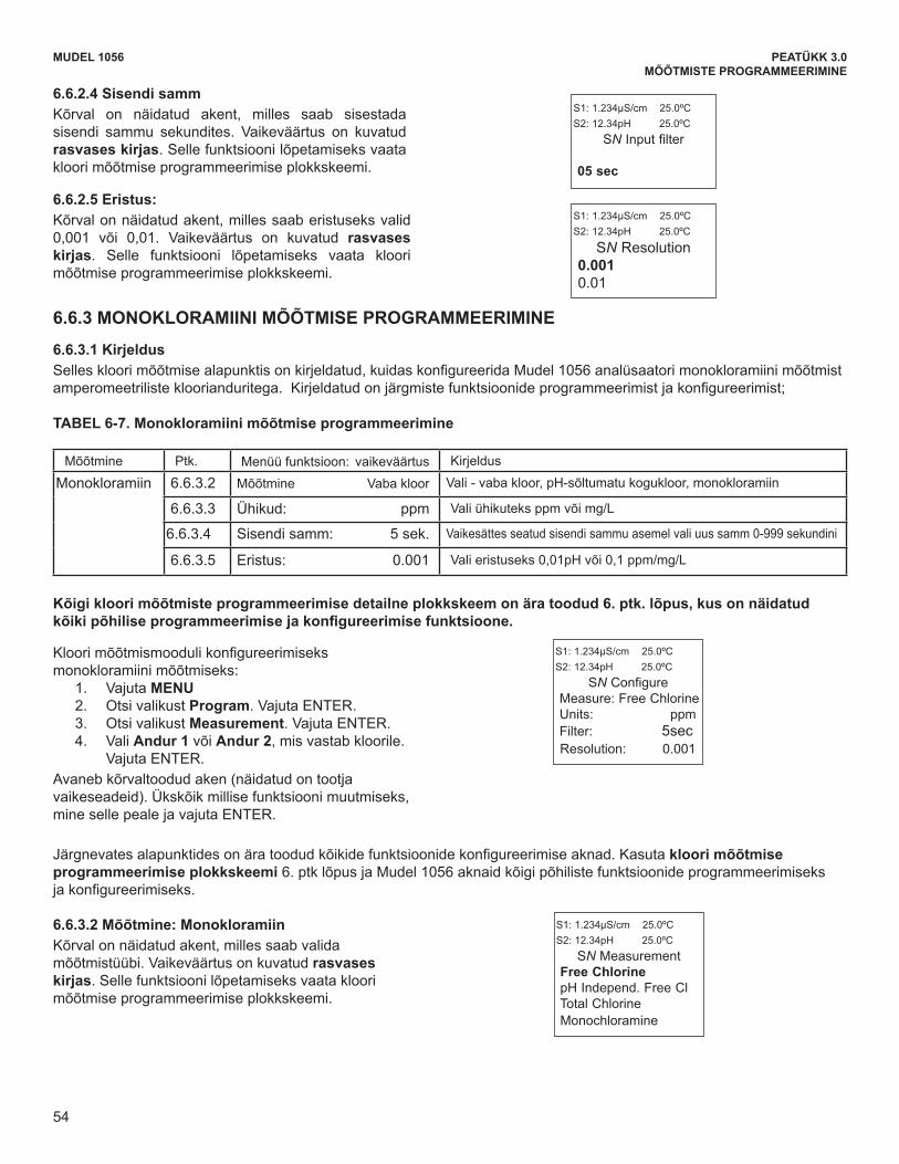
54
MUDEL 1056 PEATÜKK 3.0MÕÕTMISTE PROGRAMMEERIMINE
MODEL 1056 SECTION 6.0PROGRAMMING THE MEASUREMENTS
6.6.2.4 FilterThe display screen for entering the input filter value inseconds is shown. The default value is displayed inbold type. Refer to the Chlorine Programming flowdiagram to complete this function.
S1: 1.234µS/cm 25.0ºCS2: 12.34pH 25.0ºC
SN Input filter
05 sec
6.6.2.5 ResolutionThe display screen for selecting display resolution as0.001 or 0.01 is shown. The default value is displayedin bold type. Refer to the Chlorine Programming flowdiagram to complete this function.
S1: 1.234µS/cm 25.0ºCS2: 12.34pH 25.0ºC
SN Resolution 0.0010.01
6.6.3 MONOCHLORAMINE MEASUREMENT PROGRAMMING
6.6.3.1 Description This Chlorine sub-section describes how to configure the Model 1056 analyzer for Monochloramine measurementusing amperometric chlorine sensors. The following programming and configuration functions are covered:
To configure the chlorine measurement board formonochloramine:
1. Press MENU2. Scroll down to Program. Press ENTER. 3. Scroll down to Measurement. Press ENTER. 4. Select Sensor 1 or Sensor 2 corresponding to
chlorine. Press ENTER.
The following screen format will appear (factory defaultsare shown). To program any displayed function, scrollto the desired item and press ENTER.
Measure Sec. Menu function: default DescriptionMonochloramine 6.6.3.2 Measure: Free Chlorine Select Free Chlorine, pH Ind. Free Cl. Total Cl, Monochloramine
6.6.3.3 Units: ppm Select units ppm or mg/L
6.6.3.4 Filter: 5sec Override the default input filter, enter 0-999 seconds
6.6.3.5 Resolution: 0.001 Select 0.01pH or 0.1ppm/mg/L for display Resolution
S1: 1.234µS/cm 25.0ºCS2: 12.34pH 25.0ºC
SN Configure Measure: Free Chlorine Units: ppmFilter: 5sec Resolution: 0.001
The following sub-sections provide you with the initial display screen that appears for each configuration function.Use the flow diagram for chlorine programming at the end of Sec. 6 and the Model 1056 live screen promptsfor each function to complete configuration and programming.
6.6.3.2-Measure: MonochloramineThe display screen for selecting the measurement isshown. The default value is displayed in bold type.Refer to the Chlorine Programming flow diagram tocomplete this function.
S1: 1.234µS/cm 25.0ºCS2: 12.34pH 25.0ºC
SN Measurement Free Chlorine pH Independ. Free Cl Total Chlorine Monochloramine
TABLE 6-7. Monochloramine Measurement Programming
A detailed flow diagram for programming of all chlorine measurements is provided at the end of Sec. 6 toguide you through all basic programming and configuration functions.
54
6.6.2.4 Sisendi samm Kõrval on näidatud akent, milles saab sisestada sisendi sammu sekundites. Vaikeväärtus on kuvatud rasvases kirjas. Selle funktsiooni lõpetamiseks vaata kloori mõõtmise programmeerimise plokkskeemi.
6.6.2.5 Eristus: Kõrval on näidatud akent, milles saab eristuseks valid 0,001 või 0,01. Vaikeväärtus on kuvatud rasvases kirjas. Selle funktsiooni lõpetamiseks vaata kloori mõõtmise programmeerimise plokkskeemi.
6.6.3 MONOKLORAMIINI MÕÕTMISE PROGRAMMEERIMINE
6.6.3.1 Kirjeldus Selleskloorimõõtmisealapunktisonkirjeldatud,kuidaskonfigureeridaMudel1056analüsaatorimonokloramiinimõõtmistamperomeetrilistekloorianduritega.Kirjeldatudonjärgmistefunktsioonideprogrammeerimistjakonfigureerimist;
TABEL 6-7. Monokloramiini mõõtmise programmeerimine
Mõõtmine Ptk. Menüü funktsioon: vaikeväärtus Kirjeldus
Monokloramiin 6.6.3.2 Mõõtmine Vaba kloor Vali-vabakloor,pH-sõltumatukogukloor,monokloramiin
6.6.3.3 Ühikud: ppm Vali ühikuteks ppm või mg/L
6.6.3.4 Sisendi samm: 5 sek. Vaikesättes seatud sisendi sammu asemel vali uus samm 0-999 sekundini
6.6.3.5 Eristus: 0.001 Valieristuseks0,01pHvõi0,1ppm/mg/L
Kõigi kloori mõõtmiste programmeerimise detailne plokkskeem on ära toodud 6. ptk. lõpus, kus on näidatud kõikipõhiliseprogrammeerimisejakonfigureerimisefunktsioone.
Kloorimõõtmismoodulikonfigureerimiseksmonokloramiini mõõtmiseks:
1. Vajuta MENU2. Otsi valikust Program. Vajuta ENTER. 3. Otsi valikust Measurement. Vajuta ENTER. 4. Vali Andur 1 või Andur 2, mis vastab kloorile. Vajuta ENTER.
Avaneb kõrvaltoodud aken (näidatud on tootja vaikeseadeid). Ükskõik millise funktsiooni muutmiseks, mine selle peale ja vajuta ENTER.
Järgnevatesalapunktidesonäratoodudkõikidefunktsioonidekonfigureerimiseaknad.Kasutakloori mõõtmise programmeerimise plokkskeemi 6. ptk lõpus ja Mudel 1056 aknaid kõigi põhiliste funktsioonide programmeerimiseks jakonfigureerimiseks.
6.6.3.2 Mõõtmine: Monokloramiin Kõrval on näidatud akent, milles saab valida mõõtmistüübi. Vaikeväärtus on kuvatud rasvases kirjas. Selle funktsiooni lõpetamiseks vaata kloori mõõtmise programmeerimise plokkskeemi.
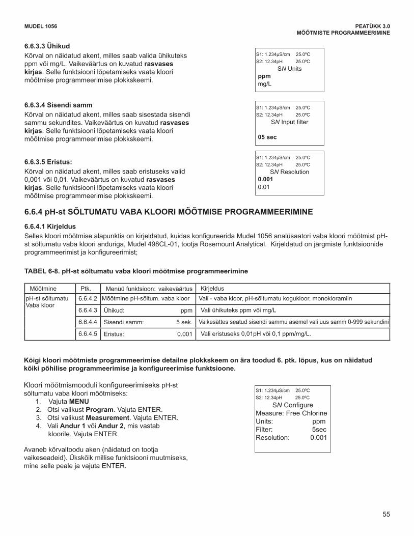
55
MUDEL 1056 PEATÜKK 3.0MÕÕTMISTE PROGRAMMEERIMINE
MODEL 1056 SECTION 6.0PROGRAMMING THE MEASUREMENTS
6.6.4 pH-INDEPENDENT FREE CHLORINE MEASUREMENT PROGRAMMING
6.6.4.1 Description This Chlorine sub-section describes how to configure the Model 1056 analyzer for Free Chlorine measurementsusing the pH-independent free chlorine sensor, Model 498CL-01, manufactured by Rosemount Analytical. The followingprogramming and configuration functions are covered:
To configure the chlorine measurement board forpH-independent free chlorine:
1. Press MENU2. Scroll down to Program. Press ENTER. 3. Scroll down to Measurement. Press ENTER. 4. Select Sensor 1 or Sensor 2 corresponding to
chlorine. Press ENTER.
The adjacent screen format will appear (factory defaultsare shown). To program any displayed function, scrollto the desired item and press ENTER.
Measure Sec. Menu function: default DescriptionpH-independentFree Chlorine
6.6.4.2 Measure: pH Indep Free Cl Select Free Chlorine, pH Ind. Free Cl. Total Cl, Monochloramine
6.6.4.3 Units: ppm Select units ppm or mg/L
6.6.4.4 Filter: 5sec Override the default input filter, enter 0-999 seconds
6.6.4.5 Resolution: 0.001 Select 0.01pH or 0.1ppm/mg/L for display Resolution
6.6.3.3 UnitsThe display screen for selecting units as ppm or mg/L isshown. The default value is displayed in bold type.Refer to the Chlorine Programming flow diagram tocomplete this function.
S1: 1.234µS/cm 25.0ºCS2: 12.34pH 25.0ºC
SN Units ppmmg/L
6.6.3.4 FilterThe display screen for entering the input filter value inseconds is shown. The default value is displayed inbold type. Refer to the Chlorine Programming flow diagramto complete this function.
S1: 1.234µS/cm 25.0ºCS2: 12.34pH 25.0ºC
SN Input filter
05 sec
6.6.3.5 ResolutionThe display screen for selecting display resolution as0.001 or 0.01 is shown. The default value is displayedin bold type. Refer to the Chlorine Programming flowdiagram to complete this function.
S1: 1.234µS/cm 25.0ºCS2: 12.34pH 25.0ºC
SN Resolution 0.0010.01
S1: 1.234µS/cm 25.0ºCS2: 12.34pH 25.0ºC
SN Configure Measure: Free Chlorine Units: ppmFilter: 5secResolution: 0.001
TABLE 6-8. pH-independent Free Chlorine Measurement Programming
A detailed flow diagram for programming of all chlorine measurements is provided at the end of Sec. 6 toguide you through all basic programming and configuration functions.
55
6.6.3.3 Ühikud Kõrval on näidatud akent, milles saab valida ühikuteks ppm või mg/L. Vaikeväärtus on kuvatud rasvases kirjas. Selle funktsiooni lõpetamiseks vaata kloori mõõtmise programmeerimise plokkskeemi.
6.6.3.4 Sisendi samm Kõrval on näidatud akent, milles saab sisestada sisendi sammu sekundites. Vaikeväärtus on kuvatud rasvases kirjas. Selle funktsiooni lõpetamiseks vaata kloori mõõtmise programmeerimise plokkskeemi.
6.6.3.5 Eristus: Kõrval on näidatud akent, milles saab eristuseks valid 0,001 või 0,01. Vaikeväärtus on kuvatud rasvases kirjas. Selle funktsiooni lõpetamiseks vaata kloori mõõtmise programmeerimise plokkskeemi.
6.6.4 pH-st SÕLTUMATU VABA KLOORI MÕÕTMISE PROGRAMMEERIMINE
6.6.4.1 Kirjeldus Selleskloorimõõtmisealapunktisonkirjeldatud,kuidaskonfigureeridaMudel1056analüsaatorivabakloorimõõtmistpH-st sõltumatu vaba kloori anduriga, Mudel 498CL-01, tootja Rosemount Analytical. Kirjeldatud on järgmiste funktsioonide programmeerimistjakonfigureerimist;
TABEL 6-8. pH-st sõltumatu vaba kloori mõõtmise programmeerimine
Mõõtmine Ptk. Menüü funktsioon: vaikeväärtus KirjelduspH-stsõltumatuVaba kloor
6.6.4.2 MõõtminepH-sõltum.vabakloor Vali-vabakloor,pH-sõltumatukogukloor,monokloramiin
6.6.4.3 Ühikud: ppm Vali ühikuteks ppm või mg/L
6.6.4.4 Sisendi samm: 5 sek. Vaikesättes seatud sisendi sammu asemel vali uus samm 0-999 sekundini
6.6.4.5 Eristus: 0.001 Valieristuseks0,01pHvõi0,1ppm/mg/L.
Kõigi kloori mõõtmiste programmeerimise detailne plokkskeem on ära toodud 6. ptk. lõpus, kus on näidatud kõikipõhiliseprogrammeerimisejakonfigureerimisefunktsioone.
KloorimõõtmismoodulikonfigureerimisekspH-stsõltumatu vaba kloori mõõtmiseks:
1. Vajuta MENU2. Otsi valikust Program. Vajuta ENTER. 3. Otsi valikust Measurement. Vajuta ENTER. 4. Vali Andur 1 või Andur 2, mis vastab
kloorile. Vajuta ENTER.
Avaneb kõrvaltoodu aken (näidatud on tootja vaikeseadeid). Ükskõik millise funktsiooni muutmiseks, mine selle peale ja vajuta ENTER.
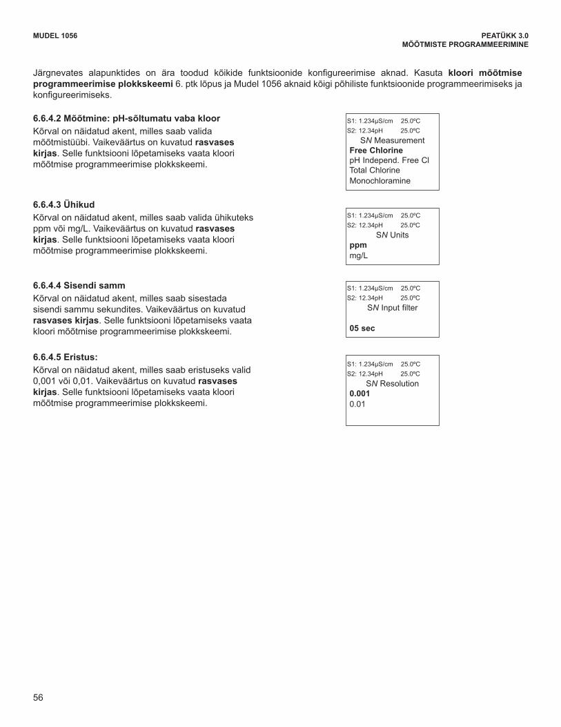
56
MODEL 1056 SECTION 6.0PROGRAMMING THE MEASUREMENTS
6.6.4.2 Measurement: pH-independent Free ChlorineThe display screen for selecting the measurement isshown. The default value is displayed in bold type.Refer to the chlorine Programming flow diagram tocomplete this function.
S1: 1.234µS/cm 25.0ºCS2: 12.34pH 25.0ºC
SN Measurement Free Chlorine pH Independ. Free Cl Total Chlorine Monochloramine
6.6.4.3 UnitsThe display screen for selecting units as ppm or mg/Lis shown. The default value is displayed in bold type.Refer to the Chlorine Programming flow diagram tocomplete this function.
S1: 1.234µS/cm 25.0ºCS2: 12.34pH 25.0ºC
SN Units ppmmg/L
6.6.4.4 FilterThe display screen for entering the input filter value inseconds is shown. The default value is displayed inbold type. Refer to the Chlorine Programming flowdiagram to complete this function.
S1: 1.234µS/cm 25.0ºCS2: 12.34pH 25.0ºC
SN Input filter
05 sec
6.6.4.5 ResolutionThe display screen for selecting display resolution as0.001 or 0.01 is shown. The default value is displayedin bold type. Refer to the Chlorine Programming flowdiagram to complete this function.
S1: 1.234µS/cm 25.0ºCS2: 12.34pH 25.0ºC
SN Resolution 0.0010.01
The following sub-sections provide you with the initial display screen that appears for each configuration function.Use the flow diagram for chlorine programming at the end of Sec. 6 and the Model 1056 live screen promptsfor each function to complete configuration and programming.
56
MUDEL 1056 PEATÜKK 3.0MÕÕTMISTE PROGRAMMEERIMINE
Järgnevates alapunktides on ära toodud kõikide funktsioonide konfigureerimise aknad. Kasuta kloori mõõtmise programmeerimise plokkskeemi 6. ptk lõpus ja Mudel 1056 aknaid kõigi põhiliste funktsioonide programmeerimiseks ja konfigureerimiseks.
6.6.4.2 Mõõtmine: pH-sõltumatu vaba kloor Kõrval on näidatud akent, milles saab valida mõõtmistüübi. Vaikeväärtus on kuvatud rasvases kirjas. Selle funktsiooni lõpetamiseks vaata kloori mõõtmise programmeerimise plokkskeemi.
6.6.4.3 Ühikud Kõrval on näidatud akent, milles saab valida ühikuteks ppm või mg/L. Vaikeväärtus on kuvatud rasvases kirjas. Selle funktsiooni lõpetamiseks vaata kloori mõõtmise programmeerimise plokkskeemi.
6.6.4.4 Sisendi samm Kõrval on näidatud akent, milles saab sisestada sisendi sammu sekundites. Vaikeväärtus on kuvatud rasvases kirjas. Selle funktsiooni lõpetamiseks vaata kloori mõõtmise programmeerimise plokkskeemi.
6.6.4.5 Eristus: Kõrval on näidatud akent, milles saab eristuseks valid 0,001 või 0,01. Vaikeväärtus on kuvatud rasvases kirjas. Selle funktsiooni lõpetamiseks vaata kloori mõõtmise programmeerimise plokkskeemi.
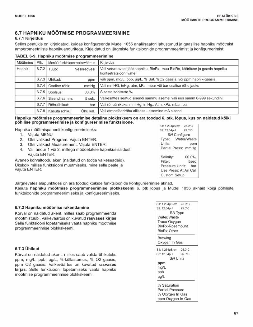
57
6.7.3 UnitsThe display screen for selecting units as ppm , mg/L,ppb, µg/L, % Saturation, %Oxygen in Gas, or ppmOxygen in Gas is shown. The default value is displayedin bold type. Refer to the Oxygen Programming flowdiagram to complete this function.
MODEL 1056 SECTION 6.0PROGRAMMING THE MEASUREMENTS
6.7.2 Oxygen Measurement applicationThe display screen for programming the measurementis shown. The default value is displayed in bold type.Refer to the Oxygen Programming flow diagram tocomplete this function.
S1: 1.234µS/cm 25.0ºCS2: 12.34pH 25.0ºC
SN Type Water/WasteTrace OxygenBioRx-RosemountBioRx-Other
BrewingOxygen In Gas
6.7 OXYGEN MEASUREMENT PROGRAMMING6.7.1 Description This section describes how to configure the Model 1056 analyzer for dissolved and gaseous oxygen measurementusing amperometric oxygen sensors. The following programming and configuration functions are covered:
To configure the Oxygen measurement board:1. Press MENU 2. Scroll down to Program. Press ENTER. 3. Scroll down to Measurement. Press ENTER. 4. Select Sensor 1 or Sensor 2 corresponding to Oxygen.
Press ENTER. The adjacent screen format will appear (factory defaults areshown). To program any displayed function, scroll to thedesired item and press ENTER.
Measure Sec. Menu function: default DescriptionOxygen 6.7.2 Type: Water/Waste Select Water/Waste, Trace. BioRx, BioRx-Other, Brew, %O2 In Gas
6.7.3 Units: ppm Select ppm, mg/L, ppb, µg/L, % Sat, %O2-Gas, ppm Oxygen-Gas
6.7.4 Partial Press: mmHg Select mm Hg, in Hg. atm, kPa, mbar or bar for Partial pressure
6.7.5 Salinity: 00.0‰ Enter Salinity as ‰
6.7.6 Filter: 5sec Override the default input filter, enter 0-999 seconds
6.7.7 Pressure Units: bar Select pressure units: mm Hg, in Hg,. Atm, kPa, mbar, bar
6.7.8 Use Press: At Air Cal Select atmospheric pressure source – internal or mA Input
S1: 1.234µS/cm 25.0ºCS2: 12.34pH 25.0ºC
SN Configure Type: Water/Waste Units: ppmPartial Press: mmHg
Salinity: 00.0‰ Filter: 5secPressure Units: barUse Press: At Air CalCustom Setup
The following sub-sections show the initial display screen that appears for each configuration function. Use theflow diagram for oxygen programming at the end of Sec. 6 and the Model 1056 live screen prompts for eachfunction to complete configuration and programming.
S1: 1.234µS/cm 25.0ºCS2: 12.34pH 25.0ºC
SN Units ppmmg/Lppbµg/L
% SaturationPartial Pressure% Oxygen In Gasppm Oxygen In Gas
TABLE 6-9. Oxygen Measurement Programming
A detailed flow diagram for oxygen programming is provided at the end of Sec. 6 to guide you through all basic pro-gramming and configuration functions.
57
MUDEL 1056 PEATÜKK 3.0MÕÕTMISTE PROGRAMMEERIMINE
6.7.3 UnitsThe display screen for selecting units as ppm , mg/L,ppb, µg/L, % Saturation, %Oxygen in Gas, or ppmOxygen in Gas is shown. The default value is displayedin bold type. Refer to the Oxygen Programming flowdiagram to complete this function.
MODEL 1056 SECTION 6.0PROGRAMMING THE MEASUREMENTS
6.7.2 Oxygen Measurement applicationThe display screen for programming the measurementis shown. The default value is displayed in bold type.Refer to the Oxygen Programming flow diagram tocomplete this function.
S1: 1.234µS/cm 25.0ºCS2: 12.34pH 25.0ºC
SN Type Water/WasteTrace OxygenBioRx-RosemountBioRx-Other
BrewingOxygen In Gas
6.7 OXYGEN MEASUREMENT PROGRAMMING6.7.1 Description This section describes how to configure the Model 1056 analyzer for dissolved and gaseous oxygen measurementusing amperometric oxygen sensors. The following programming and configuration functions are covered:
To configure the Oxygen measurement board:1. Press MENU 2. Scroll down to Program. Press ENTER. 3. Scroll down to Measurement. Press ENTER. 4. Select Sensor 1 or Sensor 2 corresponding to Oxygen.
Press ENTER. The adjacent screen format will appear (factory defaults areshown). To program any displayed function, scroll to thedesired item and press ENTER.
Measure Sec. Menu function: default DescriptionOxygen 6.7.2 Type: Water/Waste Select Water/Waste, Trace. BioRx, BioRx-Other, Brew, %O2 In Gas
6.7.3 Units: ppm Select ppm, mg/L, ppb, µg/L, % Sat, %O2-Gas, ppm Oxygen-Gas
6.7.4 Partial Press: mmHg Select mm Hg, in Hg. atm, kPa, mbar or bar for Partial pressure
6.7.5 Salinity: 00.0‰ Enter Salinity as ‰
6.7.6 Filter: 5sec Override the default input filter, enter 0-999 seconds
6.7.7 Pressure Units: bar Select pressure units: mm Hg, in Hg,. Atm, kPa, mbar, bar
6.7.8 Use Press: At Air Cal Select atmospheric pressure source – internal or mA Input
S1: 1.234µS/cm 25.0ºCS2: 12.34pH 25.0ºC
SN Configure Type: Water/Waste Units: ppmPartial Press: mmHg
Salinity: 00.0‰ Filter: 5secPressure Units: barUse Press: At Air CalCustom Setup
The following sub-sections show the initial display screen that appears for each configuration function. Use theflow diagram for oxygen programming at the end of Sec. 6 and the Model 1056 live screen prompts for eachfunction to complete configuration and programming.
S1: 1.234µS/cm 25.0ºCS2: 12.34pH 25.0ºC
SN Units ppmmg/Lppbµg/L
% SaturationPartial Pressure% Oxygen In Gasppm Oxygen In Gas
TABLE 6-9. Oxygen Measurement Programming
A detailed flow diagram for oxygen programming is provided at the end of Sec. 6 to guide you through all basic pro-gramming and configuration functions.
57
6.7 HAPNIKU MÕÕTMISE PROGRAMMEERIMINE 6.7.1 Kirjeldus Sellespeatükisonkirjeldatud,kuidaskonfigureeridaMudel1056analüsaatorilahustunudjagaasilisehapnikumõõtmistamperomeetrilistehapnikuanduritega.Kirjeldatudonjärgmistefunktsioonideprogrammeerimistjakonfigureerimist:
TABEL 6-9. Hapniku mõõtmise programmeerimine Mõõtmine Ptk. Menüü funktsioon: vaikeväärtus Kirjeldus
Hapnik 6.7.2 Tüüp: Vesi/reovesi Vali vee/reovee, jääkhapniku, BioRx, muu BioRx, käärituse ja gaasis hapniku kontsetratsiooni vahel
6.7.3 Ühikud: ppm valippm,mg/L,ppb,µg/L,%Sat,%O2gaasis,võippmhapnik-gaasis
6.7.4 Osaline rõhk: mmHg ValimmHG,inHg,atm,kPa,mbarvõibarosaliserõhujaoks
6.7.5 Soolsus: 00.0% Sisesta soolsuse ‰
6.7.6 Sisendi samm: 5 sek. Vaikesättes seatud sisendi sammu asemel vali uus samm 0-999 sekundini
6.7.7 Rõhuühikud: bar Valirõhuühikuks:mmHg,inHg,.Atm,kPa,mbar,bar
6.7.8 Kasuta rõhku: Õhu kal. Vali atmosfäärirõhu allikaks - sisemine mA sisend
Hapniku mõõtmise programmeerimise detailne plokkskeem on ära toodud 6. ptk. lõpus, kus on näidatud kõiki põhiliseprogrammeerimisejakonfigureerimisefunktsioone.
Hapnikumõõtmispaneelikonfigureerimiseks:1. Vajuta MENU 2. Otsi valikust Program. Vajuta ENTER. 3. Otsi valikust Measurement. Vajuta ENTER. 4. Vali andur 1 või 2, millega mõõdetakse hapnikusisaldust.
Vajuta ENTER. Avaneb kõrvaltoodu aken (näidatud on tootja vaikeseadeid). Ükskõik millise funktsiooni muutmiseks, mine selle peale ja vajuta ENTER.
Järgnevatesalapunktidesonäratoodudkõikidefunktsioonidekonfigureerimiseaknad.Kasuta hapniku mõõtmise programmeerimise plokkskeemi 6. ptk lõpus ja Mudel 1056 aknaid kõigi põhiliste funktsioonideprogrammeerimiseksjakonfigureerimiseks.
6.7.2 Hapniku mõõtmise rakendamine Kõrval on näidatud akent, milles saab programmeerida mõõtmistüübi. Vaikeväärtus on kuvatud rasvases kirjas Selle funktsiooni lõpetamiseks vaata hapniku mõõtmise programmeerimise plokkskeemi.
6.7.3 Ühikud Kõrval on näidatud akent, milles saab valida ühikuteks ppm, mg/L, ppb, μg/L, %-küllastumus, % O2 gaasis,ppm O2 gaasis. Vaikeväärtus on kuvatud rasvases kirjas. Selle funktsiooni lõpetamiseks vaata hapniku mõõtmise programmeerimise plokkskeemi.

58
6.7.8 Use PressureThe display screen for selecting atmospheric pressuresource. The default value is displayed in bold type.Refer to the Oxygen Programming flow diagram to com-plete this function.
S1: 1.234µS/cm 25.0ºCS2: 12.34pH 25.0ºCSN Use Pressure?
At Air CalmA Input
MODEL 1056 SECTION 6.0PROGRAMMING THE MEASUREMENTS
6.7.4 Partial PressThe display screen for selecting pressure units forPartial pressure is shown. This selection is needed ifthe specified measurement is Partial pressure. Thedefault value is displayed in bold type. Refer to theOxygen Programming flow diagram to complete thisfunction.
6.7.5 Salinity The display screen for Entering the Salinity (as partsper thousand) of the process liquid to be measured isshown. The default value is displayed in bold type.Refer to the Oxygen Programming flow diagram tocomplete this function. Enter Salinity as ‰
S1: 1.234µS/cm 25.0ºCS2: 12.34pH 25.0ºC
SN Partial Press mm Hgin HgatmkPambarbar
6.7.7 Pressure UnitsThe display screen for selecting pressure units foratmospheric pressure is shown. This selection is neededfor the display of atmospheric pressure measured bythe onboard pressure transducer on the Oxygenmeasurement board. The default value is displayed inbold type. Refer to the Oxygen Programming flowdiagram to complete this function.
S1: 1.234µS/cm 25.0ºCS2: 12.34pH 25.0ºC
Pressure Units mm Hgin HgatmkPambarbar
S1: 1.234µS/cm 25.0ºCS2: 12.34pH 25.0ºC
SN Salinity 00.0 ‰
6.7.6 FilterThe display screen for entering the input filter value inseconds is shown. The default value is displayed inbold type. Refer to the Oxygen Programming flowdiagram to complete this function.
S1: 1.234µS/cm 25.0ºCS2: 12.34pH 25.0ºC
SN Input filter
05 sec
58
MUDEL 1056 PEATÜKK 3.0MÕÕTMISTE PROGRAMMEERIMINE
6.7.4 Osaline rõhk Kõrval on näidatud akent, milles saab valida osalise rõhu ühikuid vahel. Valik osutub vajalikuks, kui mõõtmistüübiks on valitud osaline rõhk. Vaikeväärtus on kuvatud rasvases kirjas. Selle funktsiooni lõpetamiseks vaata hapniku mõõtmise programmeerimise plokkskeemi.
6.7.5 Soolsus Kõrval on näidatud akent, milles saab sisestada mõõdetava vedeliku soolsuse (osakesed tuhande osakese kohta). Vaikeväärtus on kuvatud rasvases kirjas. Selle funktsiooni lõpetamiseks vaata hapniku mõõtmise programmeerimise plokkskeemi. Sisesta soolsuse ‰.
6.7.6 Sisendi samm Kõrval on näidatud akent, milles saab sisestada sisendi sammu sekundites. Vaikeväärtus on kuvatud rasvases kirjas. Selle funktsiooni lõpetamiseks vaata hapniku mõõtmise programmeerimise plokkskeemi.
6.7.7 Rõhuühikud Kõrval on näidatud akent, milles saab valida atmosfäärirõhu ühikute vahel. See valik on vajalik, et näidata atmosfäärirõhku, mida mõõdab hapniku mõõtmismoodulil olev sisemine rõhuandur. Vaikeväärtus on kuvatud rasvases kirjas. Selle funktsiooni lõpetamiseks vaata hapniku mõõtmise programmeerimise plokkskeemi.
6.7.8 Kasuta rõhku Kõrval on näidatud akent, milles saab valida atmosfäärirõhu allika vahel. Vaikeväärtus on kuvatud rasvases kirjas. Selle funktsiooni lõpetamiseks vaata hapniku mõõtmise programmeerimise plokkskeemi.
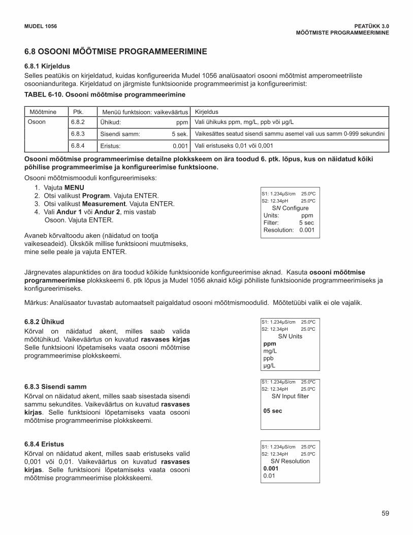
59
MODEL 1056 SECTION 6.0PROGRAMMING THE MEASUREMENTS
6.8 OZONE MEASUREMENT PROGRAMMING
6.8.1 Description This section describes how to configure the 1056 analyzer for ozone measurement using amperometric ozone sen-sors. The following programming and configuration functions are covered:
Measure Sec. Menu function: default DescriptionOzone 6.8.2 Units: ppm Select units ppm, mg/L, ppb, µg/L
6.8.3 Filter: 5sec Override the default input filter, enter 0-999 seconds
6.8.4 Resolution: 0.001 Select 0.01or 0.001 for display resolution
To configure the Ozone measurement board:1. Press MENU2. Scroll down to Program. Press ENTER. 3. Scroll down to Measurement. Press ENTER. 4. Select Sensor 1 or Sensor 2 corresponding to
Ozone. Press ENTER.
The adjacent screen format will appear (factory defaultsare shown). To program any displayed function, scroll tothe desired item and press ENTER.
S1: 1.234µS/cm 25.0ºCS2: 12.34pH 25.0ºC
SN Configure Units: ppmFilter: 5 sec Resolution: 0.001
6.8.2 UnitsThe display screen for selecting measurement units isshown. The default value is displayed in bold type.Refer to the Ozone Programming flow diagram tocomplete this function.
S1: 1.234µS/cm 25.0ºCS2: 12.34pH 25.0ºC
SN Units ppmmg/Lppbµg/L
6.8.3 FilterThe display screen for entering the input filter value inseconds is shown. The default value is displayed inbold type. Refer to the Ozone Programming flowdiagram to complete this function.
S1: 1.234µS/cm 25.0ºCS2: 12.34pH 25.0ºC
SN Input filter
05 sec
6.8.4 ResolutionThe display screen for selecting display resolution as0.001 or 0.01 is shown. The default value is displayedin bold type. Refer to the Ozone Programming flowdiagram to complete this function.
S1: 1.234µS/cm 25.0ºCS2: 12.34pH 25.0ºC
SN Resolution 0.0010.01
The following sub-sections show the initial display screen that appears for each configuration function. Use theflow diagram for ozone programming at the end of Sec. 6 and the Model 1056 live screen prompts for eachfunction to complete configuration and programming.
Note: Ozone measurement boards are detected automatically by the analyzer. No measurement selection is necessary.
TABLE 6-10. Ozone Measurement Programming
A detailed flow diagram for ozone programming is provided at the end of Sec. 6 to guide you through allbasic programming and configuration functions.
59
MUDEL 1056 PEATÜKK 3.0MÕÕTMISTE PROGRAMMEERIMINE
MODEL 1056 SECTION 6.0PROGRAMMING THE MEASUREMENTS
6.8 OZONE MEASUREMENT PROGRAMMING
6.8.1 Description This section describes how to configure the 1056 analyzer for ozone measurement using amperometric ozone sen-sors. The following programming and configuration functions are covered:
Measure Sec. Menu function: default DescriptionOzone 6.8.2 Units: ppm Select units ppm, mg/L, ppb, µg/L
6.8.3 Filter: 5sec Override the default input filter, enter 0-999 seconds
6.8.4 Resolution: 0.001 Select 0.01or 0.001 for display resolution
To configure the Ozone measurement board:1. Press MENU2. Scroll down to Program. Press ENTER. 3. Scroll down to Measurement. Press ENTER. 4. Select Sensor 1 or Sensor 2 corresponding to
Ozone. Press ENTER.
The adjacent screen format will appear (factory defaultsare shown). To program any displayed function, scroll tothe desired item and press ENTER.
S1: 1.234µS/cm 25.0ºCS2: 12.34pH 25.0ºC
SN Configure Units: ppmFilter: 5 sec Resolution: 0.001
6.8.2 UnitsThe display screen for selecting measurement units isshown. The default value is displayed in bold type.Refer to the Ozone Programming flow diagram tocomplete this function.
S1: 1.234µS/cm 25.0ºCS2: 12.34pH 25.0ºC
SN Units ppmmg/Lppbµg/L
6.8.3 FilterThe display screen for entering the input filter value inseconds is shown. The default value is displayed inbold type. Refer to the Ozone Programming flowdiagram to complete this function.
S1: 1.234µS/cm 25.0ºCS2: 12.34pH 25.0ºC
SN Input filter
05 sec
6.8.4 ResolutionThe display screen for selecting display resolution as0.001 or 0.01 is shown. The default value is displayedin bold type. Refer to the Ozone Programming flowdiagram to complete this function.
S1: 1.234µS/cm 25.0ºCS2: 12.34pH 25.0ºC
SN Resolution 0.0010.01
The following sub-sections show the initial display screen that appears for each configuration function. Use theflow diagram for ozone programming at the end of Sec. 6 and the Model 1056 live screen prompts for eachfunction to complete configuration and programming.
Note: Ozone measurement boards are detected automatically by the analyzer. No measurement selection is necessary.
TABLE 6-10. Ozone Measurement Programming
A detailed flow diagram for ozone programming is provided at the end of Sec. 6 to guide you through allbasic programming and configuration functions.
59
6.8 OSOONI MÕÕTMISE PROGRAMMEERIMINE
6.8.1 Kirjeldus Sellespeatükisonkirjeldatud,kuidaskonfigureeridaMudel1056analüsaatoriosoonimõõtmistamperomeetrilisteosoonianduritega.Kirjeldatudonjärgmistefunktsioonideprogrammeerimistjakonfigureerimist:TABEL 6-10. Osooni mõõtmise programmeerimine
Mõõtmine Ptk. Menüü funktsioon: vaikeväärtus KirjeldusOsoon 6.8.2 Ühikud: ppm Valiühikuksppm,mg/L,ppbvõiμg/L
6.8.3 Sisendi samm: 5 sek. Vaikesättes seatud sisendi sammu asemel vali uus samm 0-999 sekundini
6.8.4 Eristus: 0.001 Vali eristuseks 0,01 või 0,001
Osooni mõõtmise programmeerimise detailne plokkskeem on ära toodud 6. ptk. lõpus, kus on näidatud kõiki põhiliseprogrammeerimisejakonfigureerimisefunktsioone.Osoonimõõtmismoodulikonfigureerimiseks:
1. Vajuta MENU2. Otsi valikust Program. Vajuta ENTER. 3. Otsi valikust Measurement. Vajuta ENTER. 4. Vali Andur 1 või Andur 2, mis vastab
Osoon. Vajuta ENTER.
Avaneb kõrvaltoodu aken (näidatud on tootja vaikeseadeid). Ükskõik millise funktsiooni muutmiseks, mine selle peale ja vajuta ENTER.
Järgnevatesalapunktidesonäratoodudkõikidefunktsioonidekonfigureerimiseaknad.Kasutaosooni mõõtmise programmeerimise plokkskeemi 6. ptk lõpus ja Mudel 1056 aknaid kõigi põhiliste funktsioonide programmeerimiseks ja konfigureerimiseks.
Märkus: Analüsaator tuvastab automaatselt paigaldatud osooni mõõtmismoodulid. Mõõtetüübi valik ei ole vajalik.
6.8.2 Ühikud Kõrval on näidatud akent, milles saab valida mõõtühikud. Vaikeväärtus on kuvatud rasvases kirjas Selle funktsiooni lõpetamiseks vaata osooni mõõtmise programmeerimise plokkskeemi.
6.8.3 Sisendi samm Kõrval on näidatud akent, milles saab sisestada sisendi sammu sekundites. Vaikeväärtus on kuvatud rasvases kirjas. Selle funktsiooni lõpetamiseks vaata osooni mõõtmise programmeerimise plokkskeemi.
6.8.4 EristusKõrval on näidatud akent, milles saab eristuseks valid 0,001 või 0,01. Vaikeväärtus on kuvatud rasvases kirjas. Selle funktsiooni lõpetamiseks vaata osooni mõõtmise programmeerimise plokkskeemi.
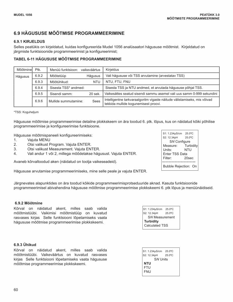
60
MUDEL 1056 PEATÜKK 3.0MÕÕTMISTE PROGRAMMEERIMINE
MODEL 1056 SECTION 6.0PROGRAMMING THE MEASUREMENTS
6.9 TURBIDITY MEASUREMENT PROGRAMMING
6.9.1 DESCRIPTION This section describes how to configure the Model 1056 analyzer for Turbidity measurements. The followingprogramming and configuration functions are covered.
A detailed flow diagram for Turbidity programming is provided at the end of Sec. 6 to guide you through all basicprogramming and configuration functions.
To configure the Turbidity measurement board: 1. Press MENU 2. Scroll down to Program. Press ENTER. 3. Scroll down to Measurement. Press ENTER. 4. Select Sensor 1 or Sensor 2 corresponding to Turbidity. Press ENTER.
The following screen format will appear (factory defaults are shown).
*TSS: Total Suspended Solids
6.9.2 Measurement The display screen for selecting the measurement isshown. The default measurement is displayed in boldtype. Refer to the Turbidity Programming flow diagramto complete this function.
6.9.3 Units The display screen for selecting the measurementunits is shown. The default value is displayed in boldtype. Refer to the Turbidity Programming flow diagramto complete this function.
To program Turbidity, scroll to the desired item and press ENTER.
The following sub-sections provide you with the initial display screen that appears for each programming routine.Use the flow diagram for Turbidity programming at the end of Sec. 6 and the live screen prompts to completeprogramming.
S1: 1.234µS/cm 25.0ºCS2: 12.34pH 25.0ºC
SN Configure Measure: Turbidity Units: NTUEnter TSS DataFilter: 20sec
Bubble Rejection: On
S1: 1.234µS/cm 25.0ºCS2: 12.34pH 25.0ºC
SN Measurement TurbidityCalculated TSS
S1: 1.234µS/cm 25.0ºCS2: 12.34pH 25.0ºC
SN Units NTUFTUFNU
Measure Sec. Menu function: default DescriptionTurbidity 6.9.2 Measurement type: Turbidity Select Turbidity or TSS calculation (estimated TSS)
6.9.3 Measurement units: NTU NTU, FTU, FNU6.9.4 Enter TSS* Data: Enter TSS and NTU data to calculate TSS based on Turbidity 6.9.5 Filter: 20 sec Override the default input filter, enter 0-999 seconds
6.9.6 Bubble Rejection: On Intelligent software algorithm to eliminate erroneous readings caused by bubble accumulation in the sample
TABLE 6-11 TURBIDITY MEASUREMENT PROGRAMMING
60
6.9 HÄGUSUSE MÕÕTMISE PROGRAMMEERIMINE
6.9.1 KIRJELDUS Sellespeatükisonkirjeldatud,kuidaskonfigureeridaMudel1056analüsaatorihägususemõõtmist.Kirjeldatudonjärgmistefunktsioonideprogrammeerimistjakonfigureerimist;
TABEL 6-11 HÄGUSUSE MÕÕTMISE PROGRAMMEERIMINE
Mõõtmine Ptk. Menüü funktsioon: vaikeväärtus Kirjeldus
Hägusus 6.9.2 Mõõtetüüp Hägusus Vali hägususe või TSS arvutamine (arvestatav TSS)
6.9.3 Mõõtühikud: NTU NTU, FTU, FNU
6.9.4 Sisesta TSS* andmed: Sisesta TSS ja NTU andmed, et arvutada hägususe põhjal TSS.
6.9.5 Sisendi samm: 20 sek. Vaikesättes seatud sisendi sammu asemel vali uus samm 0-999 sekundini
6.9.6 Mullide summutamine: Sees Intelligentne tarkvaraalgoritm vigaste näitude välistamiseks, mis võivad tekkida mullide kogunemisest proovi.
*TSS: Koguheljum
Hägususemõõtmiseprogrammeerimisedetailneplokkskeemonäratoodud6.ptk.lõpus,kusonnäidatudkõikipõhiliseprogrammeerimisejakonfigureerimisefunktsioone.
Hägususemõõtmispaneelikonfigureerimiseks:1. Vajuta MENU 2. Otsi valikust Program. Vajuta ENTER. 3. Otsi valikust Measurement. Vajuta ENTER. 4. Vali andur 1 või 2, millega mõõdetakse hägusust. Vajuta ENTER.
Avaneb kõrvaltoodud aken (näidatud on tootja vaikeseadeid).
Hägususearvutamiseprogrammeerimiseks,minesellepealejavajutaENTER.
Järgnevates alapunktides on ära toodud kõikide programmeerimisprotseduuride aknad. Kasuta funktsioonide programmeerimisel abivahendina hägususe mõõtmise programmeerimise plokkskeemi 6. ptk lõpus ja menüünäidiseid.
6.9.2 Mõõtmine Kõrval on näidatud akent, milles saab valida mõõtmistüübi. Vaikimisi mõõtmistüüp on kuvatud rasvases kirjas Selle funktsiooni lõpetamiseks vaata hägususe mõõtmise programmeerimise plokkskeemi.
6.9.3 Ühikud Kõrval on näidatud akent, milles saab valida mõõtmistüübi. Vaikeväärtus on kuvatud rasvases kirjas Selle funktsiooni lõpetamiseks vaata hägususe mõõtmise programmeerimise plokkskeemi.

61
MUDEL 1056 PEATÜKK 3.0MÕÕTMISTE PROGRAMMEERIMINE
MODEL 1056 SECTION 6.0PROGRAMMING THE MEASUREMENTS
If TSS data (Total Suspended Solids) calculation isselected, the following screen will be displayed. Referto the Turbidity programming flow diagram to completethis function.
6.9.4 Enter TSS DataThe display screen for entering TSS Data is shown.The default values are displayed. Refer to theTurbidity Programming flow diagram to complete thisfunction
Note: Based on user-entered NTU data, calculatingTSS as a straight line curve could cause TSS to gobelow zero. The following screen lets users know thatTSS will become zero below a certain NTU value.
The following illustration shows the potential for calculated TSS to go below zero
S1: 1.234µS/cm 25.0ºCS2: 12.34pH 25.0ºC
SN Units ppmmg/Lnone
S1: 1.234µS/cm 25.0ºCS2: 12.34pH 25.0ºC
SN TSS DataCalculation CompleteCalculated TSS = 0 below xxxx NTU
S1: 1.234µS/cm 25.0ºCS2: 12.34pH 25.0ºC
SN TSS DataPt1 TSS: 0.000ppm Pt1 Turbid: 0.000NTUPt2 TSS: 100.0ppm Pt2 Turbid: 100.0NTU
Calculate
61
Normal case: TSS is always a positive number when Turbidity is a positive number.
Abnormal case: TSS can be a negative number when Turbidity is a positive number.
Tavajuhul: TSS väärtus on alati positiivne, kui hägusus on positiivne.
Ebatavalisel juhul: TSS väärtus võib olla negatiivne, kui hägusus on positiivne
Kui valitakse TSS andmete arvutamine, siis kuvatakse ekraanile järgmine aken. Selle funktsiooni lõpetamiseks vaata hägususe mõõtmise programmeerimise plokkskeemi.
6.9.4 Sisesta TSS andmed Kõrval on näidatud akent, milles saab sisestada TSS andmeid. Vaikeväärtus on kuvatud. Selle funktsiooni lõpetamiseks vaata hägususe mõõtmise programmeerimise plokkskeemi.
Märkus: Kasutajapoolsete NTU andmete põhjal võib TSS-i lineaarselt arvutamine põhjustada TSS-väärtuse langemise alla nulli. Allpool on joonisel kasutajatele näidatud, kuidas teatava NTU väärtuse juures langeb TSS väärtus alla nulli.
Joonisel on näidatud, kuidas arvutatava TSS-i väärtus võib langeda alla nulli

62
MUDEL 1056 PEATÜKK 3.0MÕÕTMISTE PROGRAMMEERIMINE
MODEL 1056 SECTION 6.0PROGRAMMING THE MEASUREMENTS
When the TSS data entry is complete, press ENTER.The display will confirm the determination of a TSSstraight line curve fit to the entered NTU/turbidity databy displaying this screen:
The following screen may appear if TSS calculation isunsuccessful. Re-entry of NTU and TSS data isrequired.
6.9.5 Filter The display screen for entering the input filter value inseconds is shown. The default value is displayed inbold type. Refer to the Turbidity Programming flowdiagram to complete this function.
6.9.6 Bubble RejectionBubble rejection is an internal software algorithm thatcharacterizes turbidity readings as bubbles asopposed to true turbidity of the sample. With Bubblerejection enabled, these erroneous readings are elimi-nated from the live measurements shown on the dis-play and transmitted via the current outputs.
The display screen for selecting bubble rejection algo-rithm is shown. The default setting is displayed in boldtype. Refer to the Turbidity Programming flow diagramto complete this function.
S1: 1.234µS/cm 25.0ºCS2: 12.34pH 25.0ºC
SN TSS DataCalculationComplete
S1: 1.234µS/cm 25.0ºCS2: 12.34pH 25.0ºC
SN TSS DataData Entry Error
Press EXIT
S1: 1.234µS/cm 25.0ºCS2: 12.34pH 25.0ºC
SN Input Filter020sec
S1: 1.234µS/cm 25.0ºCS2: 12.34pH 25.0ºCSN Bubble Rejection
OnOff
62
Kui TSS andmed on sisestatud, vajuta ENTER. Kui sisestatud NTU/hägususe andmetest piisab TSS-i sirge arvutamiseks, siis kuvatakse selle sisestamise kinnituseks järgmine aken: Kõrval on näidatud akent, mis ilmub, kui TSS-i arvutamine ei õnnestunud. Sellisel juhul on vaja NTU ja TSS andmed uuesti sisestada.
6.9.5 Sisendi samm Kõrval on näidatud akent, milles saab sisestada sisendi sammu sekundites. Vaikeväärtus on kuvatud rasvases kirjas Selle funktsiooni lõpetamiseks vaata hägususe mõõtmise programmeerimise plokkskeemi.
6.9.6 Mullide summutamine Mullide summutamine on sisemise tarkvara algoritm, mis tegeliku hägususe asemel loeb hägususenäitudest välja mullid. Kui mullide summutus on sisse lülitatud, siis valenäidud elimineeritakse kuvatavate ja vooluväljundite abil edastatavate näitude hulgast.
Kõrval on näidatud akent, milles saab valida mullide summutusalgoritmi. Vaikesäte on kuvatud rasvases kirjas Selle funktsiooni lõpetamiseks vaata hägususe mõõtmise programmeerimise plokkskeemi.
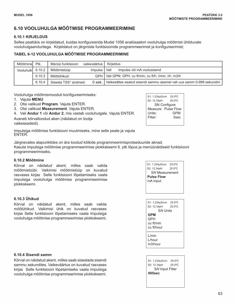
63
MUDEL 1056 PEATÜKK 3.0MÕÕTMISTE PROGRAMMEERIMINE
MODEL 1056 SECTION 6.0PROGRAMMING THE MEASUREMENTS
6.10.2 Measurement The display screen for selecting the measurement isshown. The default measurement is displayed in boldtype. Refer to the pulse flow Programming diagram tocomplete this function.
6.10.4 Filter The display screen for entering the input filter value inseconds is shown. The default value is displayed inbold type. Refer to the pulse flow Programming dia-gram to complete this function.
6.10.3 Units The display screen for selecting measurement units isshown. The default units are displayed in bold type.Refer to the pulse flow Programming diagram to com-plete this function.
6.10 FLOW MEASUREMENT PROGRAMMING
6.10.1 DESCRIPTIONThis section describes how to configure the 1056 analyzer for flow measurement when used with a compatible pulseflow sensor. The following programming and configuration functions are covered.
To configure the flow measurement board: 1. Press MENU2. Scroll down to Program. Press ENTER. 3. Scroll down to Measurement. Press ENTER. 4. Select Sensor 1 or Sensor 2 corresponding to
flow. Press ENTER.
The following screen format will appear (factory defaultsare shown).
To program pulse flow, scroll to the desired item and press ENTER.
The following sub-sections provide you with the initial display screen that appears for each programming routine.Use the diagram for pulse flow programming at the end of Sec. 6 and the live screen prompts to completeprogramming.
S1: 1.234µS/cm 25.0ºCS2: 12.34pH 25.0ºC
SN Configure Measure: Pulse Flow Units: GPMFilter: 5sec
S1: 1.234µS/cm 25.0ºCS2: 12.34pH 25.0ºC
SN Measurement Pulse FlowmA Input
S1: 1.234µS/cm 25.0ºCS2: 12.34pH 25.0ºC
SN Input Filter005sec
S1: 1.234µS/cm 25.0ºCS2: 12.34pH 25.0ºC
SN UnitsGPMGPHcu ft/mincu ft/hour
L/min L/hourm3/hour
Measure Sec. Menu function: default DescriptionFlow 6.10.2 Measurement type Pulse Flow Select Pulse Flow or mA Current Input
6.10.3 Measurement units: GPH Select GPM, GPH, cu ft/min, cu ft/hour, LPM, L/hour, m3/hr6.10.4 Enter TSS* Data: 0 Sec Override the default input filter, enter 0-999 seconds
TABLE 6-12 FLOW MEASUREMENT PROGRAMMING
63
6.10 VOOLUHULGA MÕÕTMISE PROGRAMMEERIMINE
6.10.1 KIRJELDUS Sellespeatükisonkirjeldatud,kuidaskonfigureeridaMudel1056analüsaatorivooluhulgamõõtmistühilduvatevooluhulgaanduritega.Kirjeldatudonjärgmistefunktsioonideprogrammeerimistjakonfigureerimist;
TABEL 6-12 VOOLUHULGA MÕÕTMISE PROGRAMMEERIMINE
Mõõtmine Ptk. Menüü funktsioon: vaikeväärtus Kirjeldus
Vooluhulk 6.10.2 Mõõtmistüüp Impulss Vali Impulss või mA voolusisend
6.10.3 Mõõtühikud: GPH ValiGPM,GPH,cuft/min,cuft/h,l/min,l/h,m3/h
6.10.4 Sisesta TSS* andmed: 0 sek. Vaikesättes seatud sisendi sammu asemel vali uus samm 0-999 sekundini
Vooluhulgamõõtmismoodulikonfigureerimiseks:1. Vajuta MENU2. Otsi valikust Program. Vajuta ENTER. 3. Otsi valikust Measurement. Vajuta ENTER. 4. Vali Andur 1 või Andur 2, mis vastab vooluhulgale. Vajuta ENTER. Avaneb kõrvaltoodud aken (näidatud on tootja vaikeseadeid).
Impulsiga mõõtmise funktsiooni muutmiseks, mine selle peale ja vajuta ENTER.
Järgnevates alapunktides on ära toodud kõikide programmeerimisprotseduuride aknad. Kasuta impulsiga mõõtmise programmeerimise plokkskeemi 6. ptk lõpus ja menüünäidiseid funktsiooni programmeerimiseks.
6.10.2 Mõõtmine Kõrval on näidatud akent, milles saab valida mõõtmistüübi. Vaikimisi mõõtmistüüp on kuvatud rasvases kirjas Selle funktsiooni lõpetamiseks vaata impulsiga vooluhulga mõõtmise programmeerimise plokkskeemi.
6.10.3 Ühikud Kõrval on näidatud akent, milles saab valida mõõtühikud. Vaikimisi ühik on kuvatud rasvases kirjas Selle funktsiooni lõpetamiseks vaata impulsiga vooluhulga mõõtmise programmeerimise plokkskeemi.
6.10.4 Sisendi samm Kõrval on näidatud akent, milles saab sisestada sisendi sammu sekundites. Vaikeväärtus on kuvatud rasvases kirjas Selle funktsiooni lõpetamiseks vaata impulsiga vooluhulga mõõtmise programmeerimise plokkskeemi.
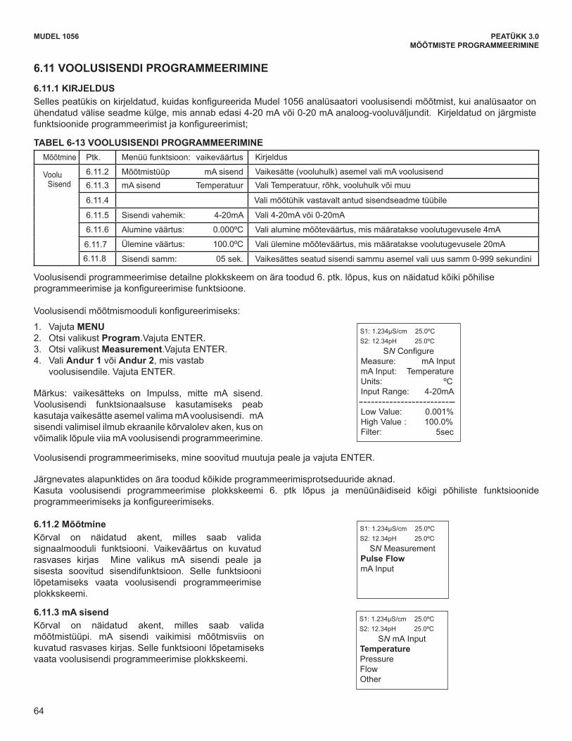
64
MUDEL 1056 PEATÜKK 3.0MÕÕTMISTE PROGRAMMEERIMINE
To configure the current input measurement board: 1. Press MENU2. Scroll down to Program. Press ENTER. 3. Scroll down to Measurement. Press ENTER. 4. Select Sensor 1 or Sensor 2 corresponding to
current input. Press ENTER.
Note that factory default is Pulse Flow not mA Input.The user must override the factory default and selectmA Input to enable the current input functionality. Uponselecting mA Input, the following menu screen willappear to allow complete programming of mA CurrentInput.
MODEL 1056 SECTION 6.0PROGRAMMING THE MEASUREMENTS
6.11 CURRENT INPUT PROGRAMMING
6.11.1 DESCRIPTIONThis section describes how to configure the Model 1056 analyzer for current input measurement when wired to anexternal device that transmits 4-20mA or 0-20mA analog current output. The following programming and configu-ration functions are covered.
6.11.2 Measurement The display screen for selecting the signal board func-tionality is shown. The default value is displayed inbold type. Scroll down to select mA Input to enablethe current input functionality. Refer to the currentinput Programming flow diagram to complete this func-tion.
6.11.3 mA Input The display screen for selecting the type of measure-ment is shown. The default measurement type for mAInput is displayed in bold type. Refer to the currentinput Programming flow diagram to complete this function.
To program current input, scroll to the desired item and press ENTER.
The following sub-sections provide you with the initial display screen that appears for each programming routine.Use the flow diagram for current input programming at the end of Sec. 6 and the live screen prompts to completeprogramming.
A detailed flow diagram for current input programming is provided at the end of Sec. 6 to guide you through allbasic programming and configuration functions.
S1: 1.234µS/cm 25.0ºCS2: 12.34pH 25.0ºC
SN Configure Measure: mA InputmA Input: Temperature Units: ºCInput Range: 4-20mA
Low Value: 0.001%High Value : 100.0%Filter: 5sec
S1: 1.234µS/cm 25.0ºCS2: 12.34pH 25.0ºC
SN Measurement Pulse FlowmA Input
S1: 1.234µS/cm 25.0ºCS2: 12.34pH 25.0ºC
SN mA InputTemperaturePressureFlowOther
Measure Sec. Menu function: default DescriptionCurrentInput
6.11.2 Measurement type mA input Override the default (Flow) and select mA current input 6.11.3 mA Input Temperature Select Temperature, Pressure, Flow or Other 6.11.4 Measurement units: ºC Select measurement units based on selected input device type 6.11.5 Input Range: 4-20mA Select 4-20mA or 0-20mA6.11.6 Low Value: 0.000ºC Enter the low measurement value to assign to 4mA
6.11.7 High Value: 100.0ºC Enter the high measurement value to assign to 20mA6.11.8 Filter: 05 sec Override the default input filter, enter 0-999 seconds
TABLE 6-13 CURRENT INPUT PROGRAMMING
64
6.11 VOOLUSISENDI PROGRAMMEERIMINE
6.11.1 KIRJELDUS Sellespeatükisonkirjeldatud,kuidaskonfigureeridaMudel1056analüsaatorivoolusisendimõõtmist,kuianalüsaatoronühendatud välise seadme külge, mis annab edasi 4-20 mA või 0-20 mA analoog-vooluväljundit. Kirjeldatud on järgmiste funktsioonideprogrammeerimistjakonfigureerimist;
TABEL 6-13 VOOLUSISENDI PROGRAMMEERIMINE Mõõtmine Ptk. Menüü funktsioon: vaikeväärtus Kirjeldus
VooluSisend
6.11.2 Mõõtmistüüp mA sisend Vaikesätte (vooluhulk) asemel vali mA voolusisend 6.11.3 mA sisend Temperatuur Vali Temperatuur, rõhk, vooluhulk või muu
6.11.4 Vali mõõtühik vastavalt antud sisendseadme tüübile
6.11.5 Sisendi vahemik: 4-20mA Vali 4-20mA või 0-20mA
6.11.6 Alumine väärtus: 0.000ºC Vali alumine mõõteväärtus, mis määratakse voolutugevusele 4mA
6.11.7 Ülemine väärtus: 100.0ºC Vali ülemine mõõteväärtus, mis määratakse voolutugevusele 20mA
6.11.8 Sisendi samm: 05 sek. Vaikesättes seatud sisendi sammu asemel vali uus samm 0-999 sekundini
Voolusisendi programmeerimise detailne plokkskeem on ära toodud 6. ptk. lõpus, kus on näidatud kõiki põhilise programmeerimisejakonfigureerimisefunktsioone.
Voolusisendimõõtmismoodulikonfigureerimiseks:
1. Vajuta MENU2. Otsi valikust Program.Vajuta ENTER. 3. Otsi valikust Measurement.Vajuta ENTER. 4. Vali Andur 1 või Andur 2, mis vastab voolusisendile. Vajuta ENTER.
Märkus: vaikesätteks on Impulss, mitte mA sisend. Voolusisendi funktsionaalsuse kasutamiseks peab kasutaja vaikesätte asemel valima mA voolusisendi. mA sisendi valimisel ilmub ekraanile kõrvalolev aken, kus on võimalik lõpule viia mA voolusisendi programmeerimine.
Voolusisendi programmeerimiseks, mine soovitud muutuja peale ja vajuta ENTER.
Järgnevates alapunktides on ära toodud kõikide programmeerimisprotseduuride aknad. Kasuta voolusisendi programmeerimise plokkskeemi 6. ptk lõpus ja menüünäidiseid kõigi põhiliste funktsioonide programmeerimiseksjakonfigureerimiseks.
6.11.2 Mõõtmine Kõrval on näidatud akent, milles saab valida signaalmooduli funktsiooni. Vaikeväärtus on kuvatud rasvases kirjas Mine valikus mA sisendi peale ja sisesta soovitud sisendifunktsioon. Selle funktsiooni lõpetamiseks vaata voolusisendi programmeerimise plokkskeemi.
6.11.3 mA sisend Kõrval on näidatud akent, milles saab valida mõõtmistüüpi. mA sisendi vaikimisi mõõtmisviis on kuvatud rasvases kirjas. Selle funktsiooni lõpetamiseks vaata voolusisendi programmeerimise plokkskeemi.
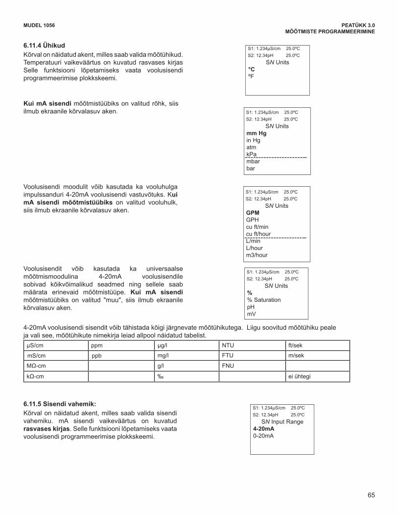
65
MUDEL 1056 PEATÜKK 3.0MÕÕTMISTE PROGRAMMEERIMINE
MODEL 1056 SECTION 6.0PROGRAMMING THE MEASUREMENTS
6.11.4 UnitsThe display screen for selecting measurement units isshown. The default value for temperature is displayed inbold type. Refer to the current input Programming flowdiagram to complete this function.
If Pressure is selected as the measurement type formA Input, the following display screen is shown:
Current input can serve as a universal measurementboard. 4-20mA current input can be accepted from anydevice and assigned to represent a wide range ofmeasurements. If Other is selected as the measure-ment type for the 4-20mA current input board, the fol-lowing display screen is shown:
6.11.5 Input Range The display screen for selecting the Input Range isshown. The default value for mA Input is displayed inbold type. Refer to the current input Programmingflow diagram to complete this function.
The current input board can also be used to accept a4-20mA current input from a pulse flow sensor. IfFlow is selected as the measurement type for the4-20mA current input board, the following displayscreen is shown:
Any of the following units can also be selected to represent the 4-20mA current input. Simply scroll down toidentify and select the desired measurement units as listed in the table below.
S1: 1.234µS/cm 25.0ºCS2: 12.34pH 25.0ºC
SN Units °CºF
S1: 1.234µS/cm 25.0ºCS2: 12.34pH 25.0ºC
SN Units %% SaturationpHmV
S1: 1.234µS/cm 25.0ºCS2: 12.34pH 25.0ºC
SN Input Range4-20mA0-20mA
S1: 1.234µS/cm 25.0ºCS2: 12.34pH 25.0ºC
SN Units mm Hgin HgatmkPambarbar
S1: 1.234µS/cm 25.0ºCS2: 12.34pH 25.0ºC
SN Units GPMGPHcu ft/mincu ft/hourL/min L/hourm3/hour
µS/cm ppm µg/L NTU ft/sec
mS/cm ppb mg/L FTU m/secMΩ-cm g/L FNUkΩ-cm ‰ none
65
6.11.4 Ühikud Kõrval on näidatud akent, milles saab valida mõõtühikud. Temperatuuri vaikeväärtus on kuvatud rasvases kirjas Selle funktsiooni lõpetamiseks vaata voolusisendi programmeerimise plokkskeemi.
Kui mA sisendi mõõtmistüübiks on valitud rõhk, siis ilmub ekraanile kõrvalasuv aken.
Voolusisendi moodulit võib kasutada ka vooluhulga impulssanduri 4-20mA voolusisendi vastuvõtuks. Kui mA sisendi mõõtmistüübiks on valitud vooluhulk, siis ilmub ekraanile kõrvalasuv aken.
Voolusisendit võib kasutada ka universaalse mõõtmismoodulina 4-20mA voolusisendile sobivad kõikvõimalikud seadmed ning sellele saab määrata erinevaid mõõtmistüüpe. Kui mA sisendi mõõtmistüübiks on valitud "muu", siis ilmub ekraanile kõrvalasuv aken.
4-20mA voolusisendi sisendit võib tähistada kõigi järgnevate mõõtühikutega. Liigu soovitud mõõtühiku peale ja vali see, mõõtühikute nimekirja leiad allpool näidatud tabelist. µS/cm ppm µg/l NTU ft/sek
mS/cm ppb mg/l FTU m/sek
MΩ-cm g/l FNU kΩ-cm ‰ ei ühtegi
6.11.5 Sisendi vahemik: Kõrval on näidatud akent, milles saab valida sisendi vahemiku. mA sisendi vaikeväärtus on kuvatud rasvases kirjas. Selle funktsiooni lõpetamiseks vaata voolusisendi programmeerimise plokkskeemi.
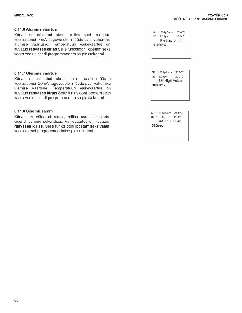
66
MUDEL 1056 PEATÜKK 3.0MÕÕTMISTE PROGRAMMEERIMINE
6.11.6 Low Value The display screen for entering the Low Value to beassigned to 4mA (or 0mA) current input is shown. Thedefault value for temperature is displayed in bold type.Refer to the current input Programming flow diagramto complete this function.
6.11.7 High Value The display screen for entering the High Value to beassigned to 20mA current input is shown. The defaultvalue for temperature is displayed in bold type. Referto the current input Programming flow diagram to com-plete this function.
6.11.8 Filter The display screen for entering the input filter value inseconds is shown. The default value is displayed inbold type. Refer to the current input Programmingdiagram to complete this function. .
MODEL 1056 SECTION 6.0PROGRAMMING THE MEASUREMENTS
S1: 1.234µS/cm 25.0ºCS2: 12.34pH 25.0ºC
SN Low Value0.000ºC
S1: 1.234µS/cm 25.0ºCS2: 12.34pH 25.0ºC
SN High Value100.0ºC
S1: 1.234µS/cm 25.0ºCS2: 12.34pH 25.0ºC
SN Input Filter005sec
66
6.11.6 Alumine väärtus Kõrval on näidatud akent, milles saab määrata voolusisendi 4mA tugevusele mõõdetava vahemiku alumise väärtuse.. Temperatuuri vaikeväärtus on kuvatud rasvases kirjas Selle funktsiooni lõpetamiseks vaata voolusisendi programmeerimise plokkskeemi.
6.11.7 Ülemine väärtus Kõrval on näidatud akent, milles saab määrata voolusisendi 20mA tugevusele mõõdetava vahemiku ülemise väärtuse. Temperatuuri vaikeväärtus on kuvatud rasvases kirjas Selle funktsiooni lõpetamiseks vaata voolusisendi programmeerimise plokkskeemi.
6.11.8 Sisendi samm Kõrval on näidatud akent, milles saab sisestada sisendi sammu sekundites. Vaikeväärtus on kuvatud rasvases kirjas. Selle funktsiooni lõpetamiseks vaata voolusisendi programmeerimise plokkskeemi.
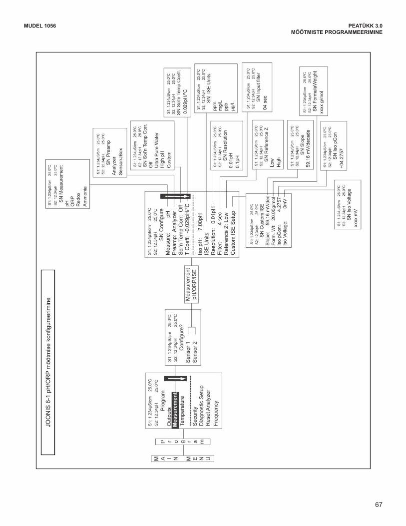
67
MUDEL 1056 PEATÜKK 3.0MÕÕTMISTE PROGRAMMEERIMINE
MODEL 1056 SECTION 6.0PROGRAMMING THE MEASUREMENTS
FIG
UR
E 6
-1 C
onfig
urin
g pH
/OR
P M
easu
rem
ents
67
JOONIS6-1pH/ORPmõõtmisekonfigureerimine
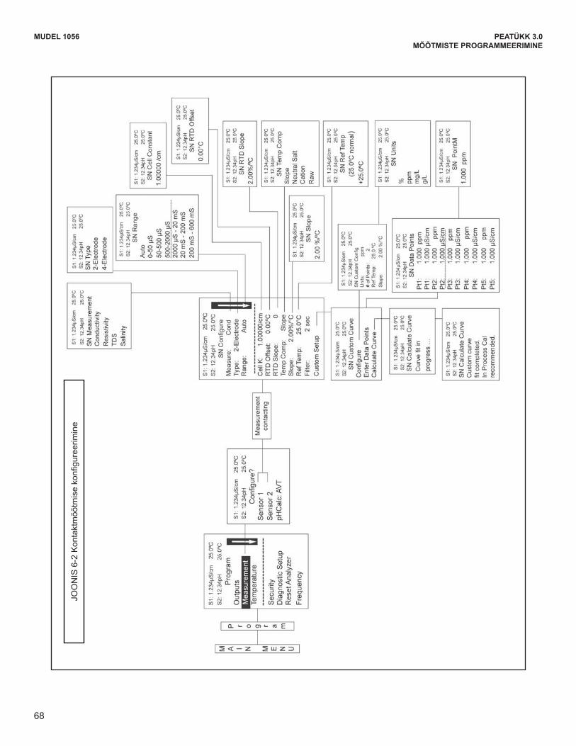
68
MODEL 1056 SECTION 6.0PROGRAMMING THE MEASUREMENTS
FIG
UR
E 6
-2 C
onfig
ure
Con
tact
ing
Mea
sure
men
ts
68
MUDEL 1056 PEATÜKK 3.0MÕÕTMISTE PROGRAMMEERIMINE
JOONIS6-2Kontaktmõõtmisekonfigureerimine

69
MODEL 1056 SECTION 6.0PROGRAMMING THE MEASUREMENTS
FIG
UR
E 6
-3 C
onfig
ure
Toro
idal
Mea
sure
men
ts
69
MUDEL 1056 PEATÜKK 3.0MÕÕTMISTE PROGRAMMEERIMINE
JOONIS6-3Toroidaalsemõõtmisekonfigureerimine
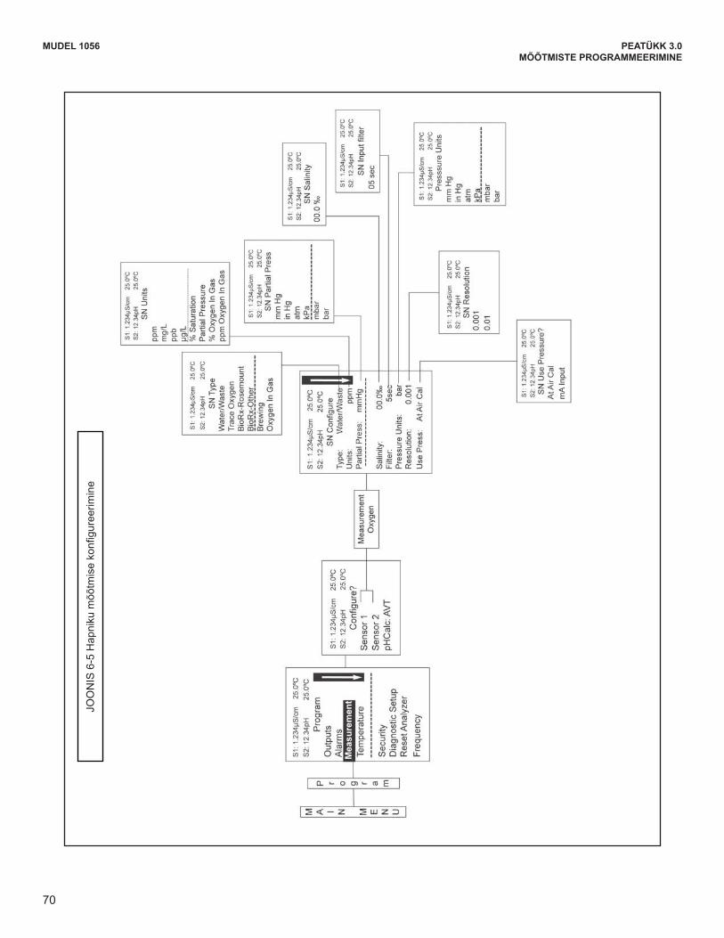
70
MODEL 1056 SECTION 6.0PROGRAMMING THE MEASUREMENTS
FIG
UR
E 6
-5 C
onfig
ure
Oxy
gen
Mea
sure
men
ts
70
MUDEL 1056 PEATÜKK 3.0MÕÕTMISTE PROGRAMMEERIMINE
JOONIS6-5Hapnikumõõtmisekonfigureerimine
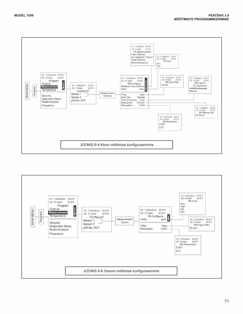
71
MODEL 1056 SECTION 6.0PROGRAMMING THE MEASUREMENTS
FIGURE 6-6 Configure Ozone Measurements
FIGURE 6-4 Configure Chlorine Measurements
71
MUDEL 1056 PEATÜKK 3.0MÕÕTMISTE PROGRAMMEERIMINE
JOONIS6-4Kloorimõõtmisekonfigureerimine
JOONIS6-6Osoonimõõtmisekonfigureerimine
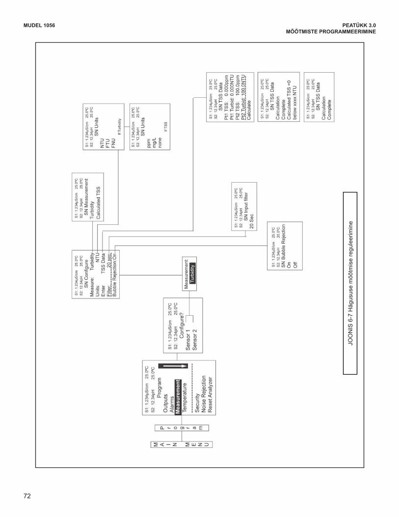
72
MODEL 1056 SECTION 6.0PROGRAMMING THE MEASUREMENTS
FIG
UR
E 6
-7 C
onfig
ure
Turb
idity
Mea
sure
men
t
72
MUDEL 1056 PEATÜKK 3.0MÕÕTMISTE PROGRAMMEERIMINE
JOONIS6-7Hägususemõõtmisereguleerimine
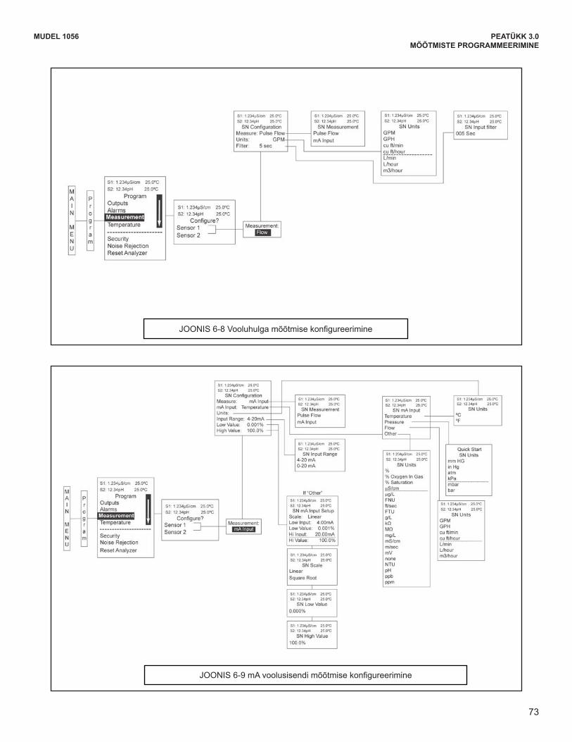
73
MODEL 1056 SECTION 6.0PROGRAMMING THE MEASUREMENTS
FIGURE 6-8 Configure Flow Measurement
FIGURE 6-9 Configure mA Current Input Measurement
73
MUDEL 1056 PEATÜKK 3.0MÕÕTMISTE PROGRAMMEERIMINE
JOONIS6-8Vooluhulgamõõtmisekonfigureerimine
JOONIS6-9mAvoolusisendimõõtmisekonfigureerimine

74
This page left blank intentionally
MUDEL 1056 PEATÜKK 3.0MÕÕTMISTE PROGRAMMEERIMINE
75
MUDEL 1056 PEATÜKK 7,0KALIBREERIMINE
PEATÜKK 7,0 KALIBREERIMINE
7.1 KALIBREERIMINE - SISSEJUHATUS 7.2 pH KALIBREERIMINE 7.3 ORP KALIBREERIMINE 7.4 JUHTIVUSE KONTAKTMÕÕTMISE KALIBREERIMINE 7.5 JUHTIVUSE TOROIDMÕÕTMISE KALIBREERIMINE 7.6 KLOORI MÕÕTMISE KALIBREERIMINE
7.6.1 VABA KLOOR 7.6.2 KOGUKLOOR 7.6.3 MONOKLORAMIIN 7.6.4 pH-st SÕLTUMATU VABA KLOOR
7.7 HAPNIKU MÕÕTMISE KALIBREERIMINE 7.8 OSOONI MÕÕTMISE KALIBREERIMINE 7.9 TEMPERATUURI MÕÕTMISE KALIBREERIMINE 7.10 HÄGUSUSE MÕÕTMISE KALIBREERIMINE 7.11 VOOLUHULGA MÕÕTMISE KALIBREERIMINE
7.1 KALIBREERIMINE - SISSEJUHATUSKalibreerimine tähendab protsessi, mille käigus häälestatakse analüsaator laboratoorse testi või taadeldud laboratoorse instrumendi järgi või ühtsustatakse see mõne muu võrdlusobjekti abil (mõne müügil oleva puhvriga).
Analüsaatori isetuvastusvõimele kuvab seade sobivad kalibreerimisaknad iga ühe- või kaheandurilise konfiguratsioonijaoks.EsmakäivituselKiirkäivitusmenüüdessaadud info võimaldab küll reaalajas mõõtmist, kuid ei taga laboratoorsete protsesside või tööprotsesside täpseid näite. Täpsete ja korratavate mõõtmiste tagamiseks peaks kõiki analüsaatoriga ühendatud andureid kõigepealt kalibreerima.
Selles peatükis on kirjeldatud järgmiste funktsioonide programmeerimistjakonfigureerimist;
1. Automaatne pH kalibreerimispuhver (pH mõõtmisekalibreerimine — Ptk.7.2)
2. Manuaalne pH kalibreerimispuhver (pH mõõtmisekalibreerimine — Ptk.7.2)
3. MäärakalibreerimisekspH-kriteeriumid(pHmõõtmisekalibreerimine — Ptk. 7.2)
4. pH, ORP ja redoksi kalibreerimine ühepunktilisestandardimisega(pHmõõtmisekalibreerimine—ptk7.2 ja 7.3)
5. Juhtivusanduri elemendi konstandi sisestamine (juhtivuse mõõtmise kalibreerimine - ptk 7.4 ja 7.5)
6. Anduri kalibreerimine juhtivusstandardiga (juhtivuse mõõtmise kalibreerimine - ptk 7.4 ja 7.5)
7. Analüsaatori kalibreerimine laboratoorse instrumendi abil (juhtivuse mõõtmise kalibreerimine - ptk 7.4)
8. Kloori-, hapniku- ja osoonianduri nullpunkti määramine (amperomeetrilise mõõtmise kalibreerimine — ptk 7.6, 7.7, 7.8)
9. Hapnikuanduri õhuga kalibreerimine (hapnikumõõtmise kalibreerimine — ptk 7.6)
10. Anduri kalibreerimine teadaoleva kontsentratsiooniga proovi abil (amperomeetrilise mõõtmise kalibreerimine — ptk 7.6, 7.7, 7.8)
11. Käitlusnäidu temperatuuri kompenseerimiseks sisesta manuaalselt võrdlustemperatuur
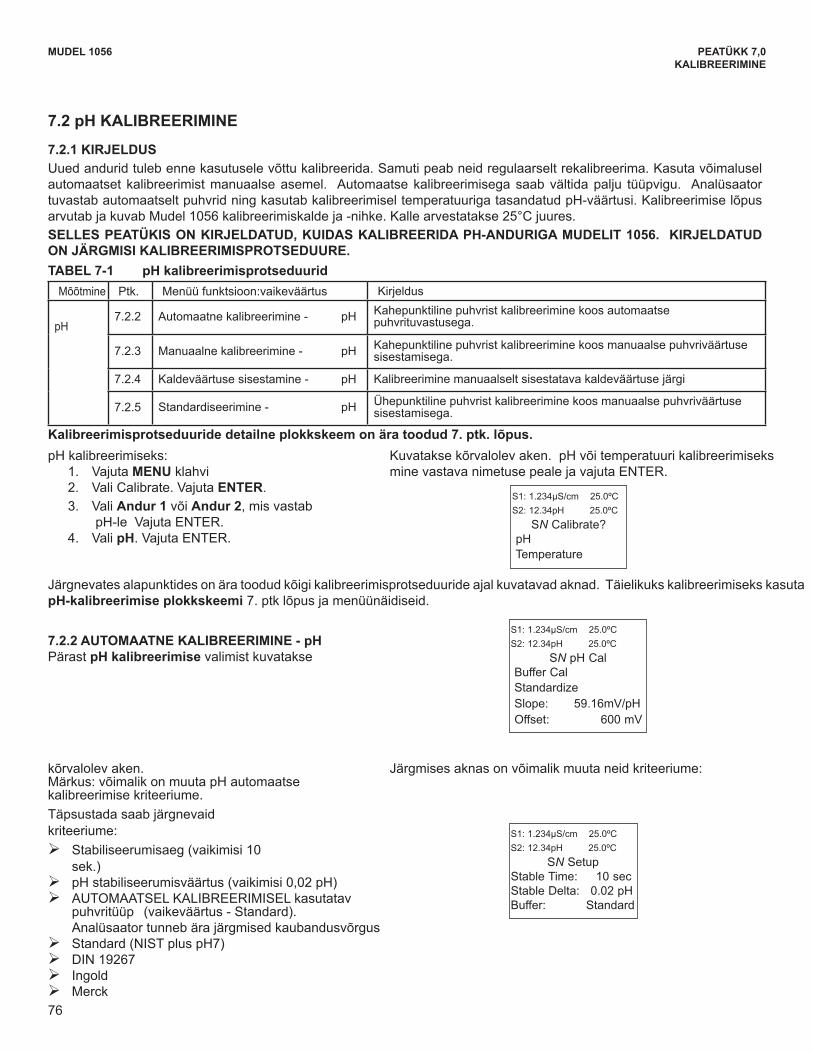
76
MUDEL 1056 PEATÜKK 7,0KALIBREERIMINE
MODEL 1056 SECTION 7.0CALIBRATION
7.2 pH CALIBRATION
7.2.1 DESCRIPTION New sensors must be calibrated before use. Regular recalibration is also necessary. Use auto calibration instead of manualcalibration. Auto calibration avoids common pitfalls and reduces errors. The analyzer recognizes the buffers and usestemperature-corrected pH values in the calibration. Once the Model 1056 successfully completes the calibration, it calcu-lates and displays the calibration slope and offset. The slope is reported as the slope at 25°C. THIS SECTION DESCRIBES HOW TO CALIBRATE THE MODEL 1056 WITH A pH SENSOR. THE FOLLOWINGCALIBRATION ROUTINES ARE COVERED.
Measure Sec. Menu function: default DescriptionpH 7.2.2 Auto Calibration - pH 2 point buffer calibration with auto buffer recognition
7.2.3 Manual Calibration - pH 2 point buffer calibration with manual buffer value entry
7.2.4 Entering A Known Slope Value - pH Slope calibration with manual entry of known slope value
7.2.5 Standardization - pH 1 point buffer calibration with manual buffer value entry
A detailed flow diagram is provided at the end of Sec. 7 to guide you through the calibration routines.
TABLE 7-1 pH Calibration Routines
To calibrate pH: 1. Press the MENU button2. Select Calibrate. Press ENTER. 3. Select Sensor 1 or Sensor 2 corresponding to
pH. Press ENTER. 4. Select pH. Press ENTER.
The following screen will appear. To calibrate pH orTemperature scroll to the desired item and pressENTER.
S1: 1.234µS/cm 25.0ºCS2: 12.34pH 25.0ºC
SN Calibrate? pHTemperature
7.2.2 AUTO CALIBRATION — pHThis screen appears after selecting pH calibration.
Note that pH auto calibration criteria can be changed.The following criteria can be adjusted: Stabilization time (default 10 sec.) Stabilization pH value (default 0.02 pH) Type of Buffer used for AUTO CALIBRATION
(default is Standard, non-commercial buffers). The following commercial buffer tables are recognizedby the analyzer: Standard (NIST plus pH7) DIN 19267 Ingold Merck
The following screen will appear to allow adjustment ofthese criteria:
S1: 1.234µS/cm 25.0ºCS2: 12.34pH 25.0ºC
SN pH CalBuffer CalStandardizeSlope: 59.16mV/pHOffset: 600 mV
S1: 1.234µS/cm 25.0ºCS2: 12.34pH 25.0ºC
SN SetupStable Time: 10 secStable Delta: 0.02 pHBuffer: Standard
The following sub-sections show the initial display screen that appears for each calibration routine. Use the flowdiagram for pH calibration at the end of Sec. 7 and the live screen prompts to complete calibration.
76
7.2 pH KALIBREERIMINE
7.2.1 KIRJELDUS Uued andurid tuleb enne kasutusele võttu kalibreerida. Samuti peab neid regulaarselt rekalibreerima. Kasuta võimalusel automaatset kalibreerimist manuaalse asemel. Automaatse kalibreerimisega saab vältida palju tüüpvigu. Analüsaator tuvastabautomaatseltpuhvridningkasutabkalibreerimiseltemperatuurigatasandatudpH-väärtusi.Kalibreerimiselõpusarvutab ja kuvab Mudel 1056 kalibreerimiskalde ja -nihke. Kalle arvestatakse 25°C juures. SELLES PEATÜKIS ON KIRJELDATUD, KUIDAS KALIBREERIDA PH-ANDURIGA MUDELIT 1056. KIRJELDATUD ON JÄRGMISI KALIBREERIMISPROTSEDUURE. TABEL 7-1 pH kalibreerimisprotseduurid
Mõõtmine Ptk. Menüü funktsioon:vaikeväärtus Kirjeldus
pH7.2.2 Automaatnekalibreerimine- pH Kahepunktiline puhvrist kalibreerimine koos automaatse
puhvrituvastusega.
7.2.3 Manuaalnekalibreerimine- pH Kahepunktiline puhvrist kalibreerimine koos manuaalse puhvriväärtuse sisestamisega.
7.2.4 Kaldeväärtusesisestamine- pH Kalibreerimine manuaalselt sisestatava kaldeväärtuse järgi
7.2.5 Standardiseerimine- pH Ühepunktiline puhvrist kalibreerimine koos manuaalse puhvriväärtuse sisestamisega.
Kalibreerimisprotseduuride detailne plokkskeem on ära toodud 7. ptk. lõpus. pHkalibreerimiseks:
1. Vajuta MENU klahvi 2. Vali Calibrate. Vajuta ENTER. 3. Vali Andur 1 või Andur 2, mis vastab
pH-leVajutaENTER.4. Vali pH. Vajuta ENTER.
Kuvataksekõrvalolevaken.pHvõitemperatuurikalibreerimiseksmine vastava nimetuse peale ja vajuta ENTER.
Järgnevates alapunktides on ära toodud kõigi kalibreerimisprotseduuride ajal kuvatavad aknad. Täielikuks kalibreerimiseks kasuta pH-kalibreerimise plokkskeemi 7. ptk lõpus ja menüünäidiseid.
7.2.2 AUTOMAATNE KALIBREERIMINE - pH Pärast pH kalibreerimise valimist kuvatakse
kõrvalolev aken. Märkus:võimalikonmuutapHautomaatsekalibreerimise kriteeriume. Täpsustada saab järgnevaid kriteeriume:
¾ Stabiliseerumisaeg (vaikimisi 10 sek.)
¾ pHstabiliseerumisväärtus(vaikimisi0,02pH) ¾ AUTOMAATSEL KALIBREERIMISEL kasutatav
puhvritüüp (vaikeväärtus - Standard). Analüsaator tunneb ära järgmised kaubandusvõrgus
¾ Standard(NISTpluspH7) ¾ DIN 19267 ¾ Ingold ¾ Merck
Järgmises aknas on võimalik muuta neid kriteeriume:
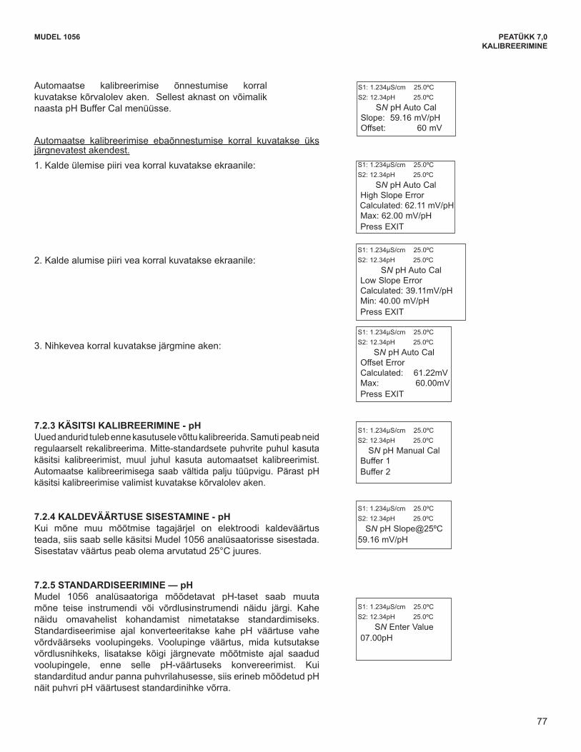
77
MODEL 1056 SECTION 7.0CALIBRATION
The following screen will appear if the auto cal issuccessful. The screen will return to the pH Buffer CalMenu.
S1: 1.234µS/cm 25.0ºCS2: 12.34pH 25.0ºC
SN pH Auto CalSlope: 59.16 mV/pH Offset: 60 mV
1. A High Slope Error will generate this screen display:
2. A Low Slope Error will generate this screen display:
S1: 1.234µS/cm 25.0ºCS2: 12.34pH 25.0ºC
SN pH Auto CalHigh Slope Error Calculated: 62.11 mV/pHMax: 62.00 mV/pH Press EXIT
3. An Offset Error will generate this screen display:
S1: 1.234µS/cm 25.0ºCS2: 12.34pH 25.0ºC
SN pH Auto CalLow Slope ErrorCalculated: 39.11mV/pHMin: 40.00 mV/pHPress EXIT
S1: 1.234µS/cm 25.0ºCS2: 12.34pH 25.0ºC
SN pH Auto CalOffset Error Calculated: 61.22mVMax: 60.00mV Press EXIT
7.2.3 MANUAL CALIBRATION — pHNew sensors must be calibrated before use. Regularrecalibration is also necessary. Use manual calibrationif non-standard buffers are being used; otherwise, useauto calibration. Auto calibration avoids common pitfallsand reduces errors.The adjacent appears after selecting Manual pH calibra-
tion.
S1: 1.234µS/cm 25.0ºCS2: 12.34pH 25.0ºC
SN pH Manual CalBuffer 1Buffer 2
7.2.5 STANDARDIZATION — pHThe pH measured by the Model 1056 analyzer can bechanged to match the reading from a second or refereeinstrument. The process of making the two readingsagree is called standardization. During standardization,the difference between the two pH values is convertedto the equivalent voltage. The voltage, called the referenceoffset, is added to all subsequent measured cell voltagesbefore they are converted to pH. If a standardized sensoris placed in a buffer solution, the measured pH will differfrom the buffer pH by an amount equivalent to thestandardization offset.
S1: 1.234µS/cm 25.0ºCS2: 12.34pH 25.0ºC
SN Enter Value07.00pH
7.2.4 ENTERING A KNOWN SLOPE VALUE — pHIf the electrode slope is known from other measure-ments, it can be entered directly in the Model 1056 ana-lyzer. The slope must be entered as the slope at 25°C.
S1: 1.234µS/cm 25.0ºCS2: 12.34pH 25.0ºC
SN pH Slope@25ºC59.16 mV/pH
The following screens may appear if the auto cal is unsuccessful.
77
MUDEL 1056 PEATÜKK 7,0KALIBREERIMINE
Automaatse kalibreerimise õnnestumise korral kuvatakse kõrvalolev aken. Sellest aknast on võimalik naastapHBufferCalmenüüsse.
Automaatse kalibreerimise ebaõnnestumise korral kuvatakse üks järgnevatest akendest.1. Kalde ülemise piiri vea korral kuvatakse ekraanile:
2. Kalde alumise piiri vea korral kuvatakse ekraanile:
3. Nihkevea korral kuvatakse järgmine aken:
7.2.3 KÄSITSI KALIBREERIMINE - pHUued andurid tuleb enne kasutusele võttu kalibreerida. Samuti peab neid regulaarselt rekalibreerima. Mitte-standardsete puhvrite puhul kasuta käsitsi kalibreerimist, muul juhul kasuta automaatset kalibreerimist. Automaatse kalibreerimisega saab vältidapalju tüüpvigu.Pärast pHkäsitsi kalibreerimise valimist kuvatakse kõrvalolev aken.
7.2.4 KALDEVÄÄRTUSE SISESTAMINE - pHKui mõne muu mõõtmise tagajärjel on elektroodi kaldeväärtus teada, siis saab selle käsitsi Mudel 1056 analüsaatorisse sisestada. Sisestatav väärtus peab olema arvutatud 25°C juures.
7.2.5 STANDARDISEERIMINE — pHMudel 1056 analüsaatoriga mõõdetavat pH-taset saab muutamõne teise instrumendi või võrdlusinstrumendi näidu järgi. Kahe näidu omavahelist kohandamist nimetatakse standardimiseks. Standardiseerimise ajal konverteeritakse kahe pH väärtuse vahevõrdväärseks voolupingeks. Voolupinge väärtus, mida kutsutakse võrdlusnihkeks, lisatakse kõigi järgnevate mõõtmiste ajal saadud voolupingele, enne selle pH-väärtuseks konvereerimist. Kuistandarditudandurpannapuhvrilahusesse,siiserinebmõõdetudpHnäitpuhvripHväärtuseststandardinihkevõrra.
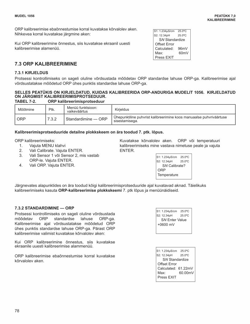
78
MODEL 1056 SECTION 7.0CALIBRATION
7.3 ORP CALIBRATION
7.3.1 DESCRIPTION For process control, it is often important to make the measured ORP agree with the ORP of a standard solution. Duringcalibration, the measured ORP is made equal to the ORP of a standard solution at a single point.
Measure Sec. Menu function: default Description
ORP 7.3.2 Standardization — ORP 1 point buffer calibration with manual buffer value entry
To calibrate ORP: 1. Press the MENU button2. Select Calibrate. Press ENTER. 3. Select Sensor 1 or Sensor 2 corresponding to
ORP. Press ENTER. 4. Select ORP. Press ENTER.
The following screen will appear. To calibrate ORP orTemperature, scroll to the desired item and pressENTER.
S1: 1.234µS/cm 25.0ºCS2: 12.34pH 25.0ºC
SN Calibrate? ORPTemperature
7.3.2 STANDARDIZATION — ORPFor process control, it is often important to make themeasured ORP agree with the ORP of a standardsolution. During calibration, the measured ORP is madeequal to the ORP of a standard solution at a singlepoint. This screen appears after selecting ORP cali-bration:
If the ORP Cal is successful, the screen will return to the
Cal sub-menu.
The following screen may appear if ORP Cal isunsuccessful.
S1: 1.234µS/cm 25.0ºCS2: 12.34pH 25.0ºC
SN Enter Value+0600 mV
S1: 1.234µS/cm 25.0ºCS2: 12.34pH 25.0ºC
SN StandardizeOffset ErrorCalculated: 61.22mVMax: 60.00mV Press EXIT
THIS SECTION DESCRIBES HOW TO CALIBRATE THE MODEL 1056 WITH AN ORP SENSOR. THE FOL-LOWING CALIBRATION ROUTINE IS COVERED.
A detailed flow diagram is provided at the end of Sec. 7 to guide you through the calibration routines.
The following sub-sections show the initial display screen that appears for each calibration routine. Use the flowdiagram for ORP calibration at the end of Sec. 7 and the live screen prompts to complete calibration.
TABLE 7-2 ORP Calibration Routine
The following screen may appear if ORP Cal is unsuccessful.An Offset Error will generate this screen display:
If the ORP Cal is successful, the screen will return to theCal sub-menu.
S1: 1.234µS/cm 25.0ºCS2: 12.34pH 25.0ºC
SN StandardizeOffset Error Calculated: 96mVMax: 60mV Press EXIT
78
MUDEL 1056 PEATÜKK 7,0KALIBREERIMINE
MODEL 1056 SECTION 7.0CALIBRATION
7.3 ORP CALIBRATION
7.3.1 DESCRIPTION For process control, it is often important to make the measured ORP agree with the ORP of a standard solution. Duringcalibration, the measured ORP is made equal to the ORP of a standard solution at a single point.
Measure Sec. Menu function: default Description
ORP 7.3.2 Standardization — ORP 1 point buffer calibration with manual buffer value entry
To calibrate ORP: 1. Press the MENU button2. Select Calibrate. Press ENTER. 3. Select Sensor 1 or Sensor 2 corresponding to
ORP. Press ENTER. 4. Select ORP. Press ENTER.
The following screen will appear. To calibrate ORP orTemperature, scroll to the desired item and pressENTER.
S1: 1.234µS/cm 25.0ºCS2: 12.34pH 25.0ºC
SN Calibrate? ORPTemperature
7.3.2 STANDARDIZATION — ORPFor process control, it is often important to make themeasured ORP agree with the ORP of a standardsolution. During calibration, the measured ORP is madeequal to the ORP of a standard solution at a singlepoint. This screen appears after selecting ORP cali-bration:
If the ORP Cal is successful, the screen will return to the
Cal sub-menu.
The following screen may appear if ORP Cal isunsuccessful.
S1: 1.234µS/cm 25.0ºCS2: 12.34pH 25.0ºC
SN Enter Value+0600 mV
S1: 1.234µS/cm 25.0ºCS2: 12.34pH 25.0ºC
SN StandardizeOffset ErrorCalculated: 61.22mVMax: 60.00mV Press EXIT
THIS SECTION DESCRIBES HOW TO CALIBRATE THE MODEL 1056 WITH AN ORP SENSOR. THE FOL-LOWING CALIBRATION ROUTINE IS COVERED.
A detailed flow diagram is provided at the end of Sec. 7 to guide you through the calibration routines.
The following sub-sections show the initial display screen that appears for each calibration routine. Use the flowdiagram for ORP calibration at the end of Sec. 7 and the live screen prompts to complete calibration.
TABLE 7-2 ORP Calibration Routine
The following screen may appear if ORP Cal is unsuccessful.An Offset Error will generate this screen display:
If the ORP Cal is successful, the screen will return to theCal sub-menu.
S1: 1.234µS/cm 25.0ºCS2: 12.34pH 25.0ºC
SN StandardizeOffset Error Calculated: 96mVMax: 60mV Press EXIT
78
ORP kalibreerimise ebaõnnestumise korral kuvatakse kõrvalolev aken. Nihkevea korral kuvatakse järgmine aken:
Kui ORP kalibreerimine õnnestus, siis kuvatakse ekraanil uuesti kalibreerimise alamenüü.
7.3 ORP KALIBREERIMINE
7.3.1 KIRJELDUS Protsessi kontrollimiseks on sageli oluline võrdsustada mõõdetav ORP standardse lahuse ORP-ga. Kalibreerimise ajal võrdsustatakse mõõdetud ORP ühes punktis standardse lahuse ORP-ga.
SELLES PEATÜKIS ON KIRJELDATUD, KUIDAS KALIBREERIDA ORP-ANDURIGA MUDELIT 1056. KIRJELDATUD ON JÄRGMIST KALIBREERIMISPROTSEDUUR. TABEL 7-2. ORP kalibreerimisprotseduur
Mõõtmine Ptk. Menüü funktsioon: vaikeväärtus Kirjeldus
ORP 7.3.2 Standardimine — ORP Ühepunktiline puhvrist kalibreerimine koos manuaalse puhvriväärtuse sisestamisega.
Kalibreerimisprotseduuride detailne plokkskeem on ära toodud 7. ptk. lõpus.
ORP kalibreerimiseks: 1. Vajuta MENU klahvi 2. Vali Calibrate. Vajuta ENTER. 3. Vali Sensor 1 või Sensor 2, mis vastab
ORP-le. Vajuta ENTER. 4. Vali ORP. Vajuta ENTER.
Kuvatakse kõrvalolev aken. ORP või temperatuuri kalibreerimiseks mine vastava nimetuse peale ja vajuta ENTER.
Järgnevates alapunktides on ära toodud kõigi kalibreerimisprotseduuride ajal kuvatavad aknad. Täielikuks kalibreerimiseks kasuta ORP-kalibreerimise plokkskeemi 7. ptk lõpus ja menüünäidiseid.
7.3.2 STANDARDIMINE — ORP Protsessi kontrollimiseks on sageli oluline võrdsustada mõõdetav ORP standardse lahuse ORP-ga. Kalibreerimise ajal võrdsustatakse mõõdetud ORP ühes punktis standardse lahuse ORP-ga. Pärast ORP kalibreerimise valimist kuvatakse kõrvalolev aken:
Kui ORP kalibreerimine õnnestus, siis kuvatakse ekraanile uuesti kalibreerimise alammenüü.
ORP kalibreerimise ebaõnnestumise korral kuvatakse kõrvalolev aken.
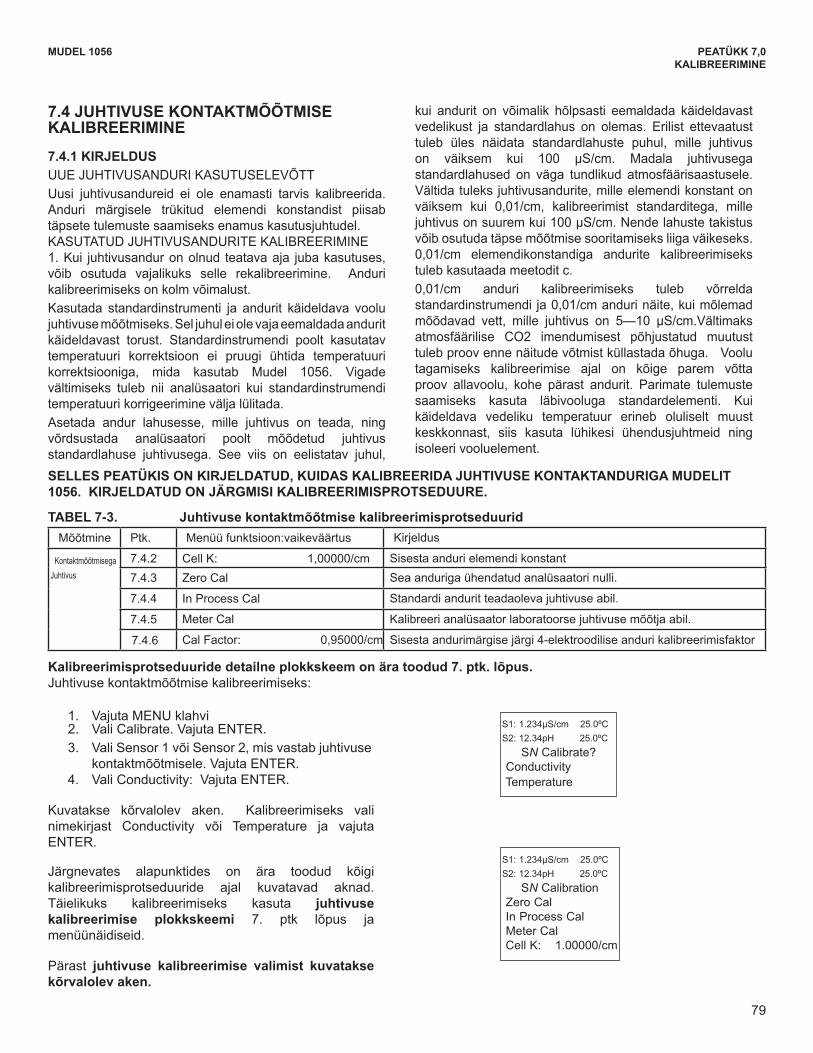
79
The following sub-sections show the initial displayscreen that appears for each calibration routine. Usethe flow diagram for Conductivity calibration at theend of Sec. 7 and the live screen prompts for each rou-tine to complete calibration.
The adjacent screen appears after selectingConductivity calibration:
MODEL 1056 SECTION 7.0CALIBRATION
To calibrate contacting conductivity: 1. Press the MENU button2. Select Calibrate. Press ENTER. 3. Select Sensor 1 or Sensor 2 corresponding to
contacting conductivity. Press ENTER. 4. Select Conductivity. Press ENTER.
The adjacent screen will appear. To calibrateConductivity or Temperature, scroll to the desired itemand press ENTER.
S1: 1.234µS/cm 25.0ºCS2: 12.34pH 25.0ºC
SN Calibrate? ConductivityTemperature
S1: 1.234µS/cm 25.0ºCS2: 12.34pH 25.0ºC
SN CalibrationZero CalIn Process CalMeter CalCell K: 1.00000/cm
7.4 CONTACTING CONDUCTIVITY CALIBRATION
7.4.1 DESCRIPTION PLACING A NEW CONDUCTIVITY SENSOR IN SERVICENew conductivity sensors rarely need calibration. The cellconstant printed on the label is sufficiently accurate for mostapplications.CALIBRATING AN IN-SERVICE CONDUCTIVITY SENSOR1. After a conductivity sensor has been in service for a periodof time, recalibration may be necessary. There are threeways to calibrate a sensor.
a. Use a standard instrument and sensor to measure theconductivity of the process stream. It is not necessary toremove the sensor from the process piping. The temperaturecorrection used by the standard instrument may not exactlymatch the temperature correction used by the Model 1056.To avoid errors, turn off temperature correction in both theanalyzer and the standard instrument.
b. Place the sensor in a solution of known conductivity andmake the analyzer reading match the conductivity of the
standard solution. Use this method if the sensor can be easilyremoved from the process piping and a standard isavailable. Be careful using standard solutions havingconductivity less than 100 µS/cm. Low conductivity standardsare highly susceptible to atmospheric contamination. Avoidcalibrating sensors with 0.01/cm cell constants againstconductivity standards having conductivity greater than 100µS/cm. The resistance of these solutions may be too low foran accurate measurement. Calibrate sensors with 0.01/cmcell constant using method c.
c. To calibrate a 0.01/cm sensor, check it against a standardinstrument and 0.01/cm sensor while both sensors aremeasuring water having a conductivity between 5 and 10µS/cm. To avoid drift caused by absorption of atmosphericcarbon dioxide, saturate the sample with air before makingthe measurements. To ensure adequate flow past the sensor during calibration,take the sample downstream from the sensor. For bestresults, use a flow-through standard cell. If the processtemperature is much different from ambient, keepconnecting lines short and insulate the flow cell.
THIS SECTION DESCRIBES HOW TO CALIBRATE THE MODEL 1056 WITH AN ATTACHED CONTACTINGCONDUCTIVITY SENSOR. THE FOLLOWING CALIBRATION ROUTINES ARE COVERED.
A detailed flow diagram is provided at the end of Sec. 7 to guide you through the calibration routines
Measure Sec. Menu function: default DescriptionContacting
Conductivity7.4.2 Cell K: 1.00000/cm Enter the cell Constant for the sensor 7.4.3 Zero Cal Zero the analyzer with the sensor attached
7.4.4 In Process Cal Standardize the sensor to a known conductivity
7.4.5 Meter Cal Calibrate the analyzer to a lab conductivity instrument
7.4.6 Cal Factor: 0.95000/cm Enter the Cal Factor for 4-Electrode sensors from the sensor tag
TABLE 7-3 Contacting Conductivity Calibration Routines
79
MUDEL 1056 PEATÜKK 7,0KALIBREERIMINE
7.4 JUHTIVUSE KONTAKTMÕÕTMISE KALIBREERIMINE
7.4.1 KIRJELDUS UUEJUHTIVUSANDURIKASUTUSELEVÕTTUusi juhtivusandureid ei ole enamasti tarvis kalibreerida. Anduri märgisele trükitud elemendi konstandist piisab täpsete tulemuste saamiseks enamus kasutusjuhtudel. KASUTATUDJUHTIVUSANDURITEKALIBREERIMINE1. Kui juhtivusandur on olnud teatava aja juba kasutuses, võib osutuda vajalikuks selle rekalibreerimine. Anduri kalibreerimiseks on kolm võimalust. Kasutada standardinstrumenti ja andurit käideldava voolu juhtivuse mõõtmiseks. Sel juhul ei ole vaja eemaldada andurit käideldavast torust. Standardinstrumendi poolt kasutatav temperatuuri korrektsioon ei pruugi ühtida temperatuuri korrektsiooniga, mida kasutab Mudel 1056. Vigade vältimiseks tuleb nii analüsaatori kui standardinstrumendi temperatuuri korrigeerimine välja lülitada. Asetada andur lahusesse, mille juhtivus on teada, ning võrdsustada analüsaatori poolt mõõdetud juhtivus standardlahuse juhtivusega. See viis on eelistatav juhul,
kui andurit on võimalik hõlpsasti eemaldada käideldavast vedelikust ja standardlahus on olemas. Erilist ettevaatust tuleb üles näidata standardlahuste puhul, mille juhtivus on väiksem kui 100 µS/cm. Madala juhtivusega standardlahused on väga tundlikud atmosfäärisaastusele. Vältida tuleks juhtivusandurite, mille elemendi konstant on väiksem kui 0,01/cm, kalibreerimist standarditega, mille juhtivus on suurem kui 100 µS/cm. Nende lahuste takistus võib osutuda täpse mõõtmise sooritamiseks liiga väikeseks. 0,01/cm elemendikonstandiga andurite kalibreerimiseks tuleb kasutaada meetodit c.0,01/cm anduri kalibreerimiseks tuleb võrrelda standardinstrumendi ja 0,01/cm anduri näite, kui mõlemad mõõdavad vett, mille juhtivus on 5—10 µS/cm.Vältimaks atmosfäärilise CO2 imendumisest põhjustatud muutust tuleb proov enne näitude võtmist küllastada õhuga. Voolu tagamiseks kalibreerimise ajal on kõige parem võtta proov allavoolu, kohe pärast andurit. Parimate tulemuste saamiseks kasuta läbivooluga standardelementi. Kui käideldava vedeliku temperatuur erineb oluliselt muust keskkonnast, siis kasuta lühikesi ühendusjuhtmeid ning isoleeri vooluelement.
SELLES PEATÜKIS ON KIRJELDATUD, KUIDAS KALIBREERIDA JUHTIVUSE KONTAKTANDURIGA MUDELIT 1056. KIRJELDATUD ON JÄRGMISI KALIBREERIMISPROTSEDUURE.
TABEL 7-3. Juhtivuse kontaktmõõtmise kalibreerimisprotseduurid Mõõtmine Ptk. Menüü funktsioon:vaikeväärtus Kirjeldus
KontaktmõõtmisegaJuhtivus
7.4.2 Cell K: 1,00000/cm Sisesta anduri elemendi konstant 7.4.3 Zero Cal Sea anduriga ühendatud analüsaatori nulli.
7.4.4 In Process Cal Standardi andurit teadaoleva juhtivuse abil.
7.4.5 Meter Cal Kalibreeri analüsaator laboratoorse juhtivuse mõõtja abil.
7.4.6 Cal Factor: 0,95000/cm Sisesta andurimärgise järgi 4-elektroodilise anduri kalibreerimisfaktor
Kalibreerimisprotseduuride detailne plokkskeem on ära toodud 7. ptk. lõpus. Juhtivuse kontaktmõõtmise kalibreerimiseks:
1. Vajuta MENU klahvi 2. Vali Calibrate. Vajuta ENTER. 3. Vali Sensor 1 või Sensor 2, mis vastab juhtivuse
kontaktmõõtmisele. Vajuta ENTER. 4. Vali Conductivity: Vajuta ENTER.
Kuvatakse kõrvalolev aken. Kalibreerimiseks vali nimekirjast Conductivity või Temperature ja vajuta ENTER.
Järgnevates alapunktides on ära toodud kõigi kalibreerimisprotseduuride ajal kuvatavad aknad. Täielikuks kalibreerimiseks kasuta juhtivuse kalibreerimise plokkskeemi 7. ptk lõpus ja menüünäidiseid.
Pärast juhtivuse kalibreerimise valimist kuvatakse kõrvalolev aken.
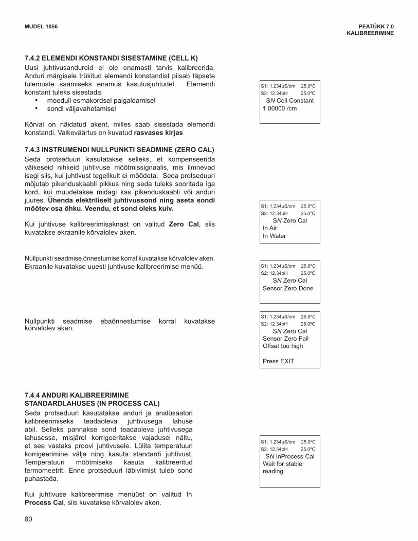
80
MUDEL 1056 PEATÜKK 7,0KALIBREERIMINE
MODEL 1056 SECTION 7.0CALIBRATION
7.4.2 ENTERING THE CELL CONSTANTNew conductivity sensors rarely need calibration. Thecell constant printed on the label is sufficiently accuratefor most applications. The cell constant should beentered:
• When the unit is installed for the first time• When the probe is replaced
The display screen for entering a cell Constant for thesensor is shown. The default value is displayed in boldtype.
7.4.3 ZEROING THE INSTRUMENTThis procedure is used to compensate for small offsetsto the conductivity signal that are present even whenthere is no conductivity to be measured. This procedureis affected by the length of extension cable and shouldalways be repeated if any changes in extension cable orsensor have been made. Electrically connect theconductivity probe as it will actually be used andplace the measuring portion of the probe in air. Besure the probe is dry.
The adjacent screen will appear after selecting ZeroCal from the Conductivity Calibration screen:
The adjacent screen will appear if zero Cal is successful.The screen will return to the conductivity Cal Menu.
The adjacent screen may appear if zero Cal is unsuccessful.
S1: 1.234µS/cm 25.0ºCS2: 12.34pH 25.0ºC
SN Cell Constant 1.00000 /cm
S1: 1.234µS/cm 25.0ºCS2: 12.34pH 25.0ºC
SN Zero CalIn AirIn Water
7.4.4 CALIBRATING THE SENSOR IN A CONDUCTIVITYSTANDARD (IN PROCESS CAL)This procedure is used to calibrate the sensor andanalyzer against a solution of known conductivity.This is done by submerging the probe in the sample ofknown conductivity, then adjusting the displayed value, ifnecessary, to correspond to the conductivity value ofthe sample. Turn temperature correction off and use theconductivity of the standard. Use a calibrated ther-mometer to measure temperature. The probe must becleaned before performing this procedure.
The adjacent screen will appear after selecting InProcess Cal from the Conductivity Calibration screen:
S1: 1.234µS/cm 25.0ºCS2: 12.34pH 25.0ºC
SN InProcess CalWait for stablereading.
S1: 1.234µS/cm 25.0ºCS2: 12.34pH 25.0ºC
SN Zero CalSensor Zero FailOffset too high
Press EXIT
S1: 1.234µS/cm 25.0ºCS2: 12.34pH 25.0ºC
SN Zero CalSensor Zero Done
80
7.4.2 ELEMENDI KONSTANDI SISESTAMINE (CELL K) Uusi juhtivusandureid ei ole enamasti tarvis kalibreerida. Anduri märgisele trükitud elemendi konstandist piisab täpsete tulemuste saamiseks enamus kasutusjuhtudel. Elemendi konstant tuleks sisestada:
• mooduli esmakordsel paigaldamisel • sondi väljavahetamisel
Kõrval on näidatud akent, milles saab sisestada elemendi konstandi. Vaikeväärtus on kuvatud rasvases kirjas
7.4.3 INSTRUMENDI NULLPUNKTI SEADMINE (ZERO CAL) Seda protseduuri kasutatakse selleks, et kompenseerida väikeseid nihkeid juhtivuse mõõtmissignaalis, mis ilmnevad isegi siis, kui juhtivust tegelikult ei mõõdeta. Seda protseduuri mõjutab pikenduskaabli pikkus ning seda tuleks sooritada iga kord, kui muudetakse midagi kas pikenduskaabli või anduri juures. Ühenda elektriliselt juhtivussond ning aseta sondi mõõtev osa õhku. Veendu, et sond oleks kuiv.
Kui juhtivuse kalibreerimisaknast on valitud Zero Cal, siis kuvatakse ekraanile kõrvalolev aken.
Nullpunkti seadmise õnnestumise korral kuvatakse kõrvalolev aken. Ekraanile kuvatakse uuesti juhtivuse kalibreerimise menüü.
Nullpunkti seadmise ebaõnnestumise korral kuvatakse kõrvalolev aken.
7.4.4 ANDURI KALIBREERIMINE STANDARDLAHUSES (IN PROCESS CAL) Seda protseduuri kasutatakse anduri ja analüsaatori kalibreerimiseks teadaoleva juhtivusega lahuse abil. Selleks pannakse sond teadaoleva juhtivusega lahusesse, misjärel korrigeeritakse vajadusel näitu, et see vastaks proovi juhtivusele. Lülita temperatuuri korrigeerimine välja ning kasuta standardi juhtivust. Temperatuuri mõõtmiseks kasuta kalibreeritud termomeetrit. Enne protseduuri läbiviimist tuleb sond puhastada.
Kui juhtivuse kalibreerimise menüüst on valitud In Process Cal, siis kuvatakse kõrvalolev aken.
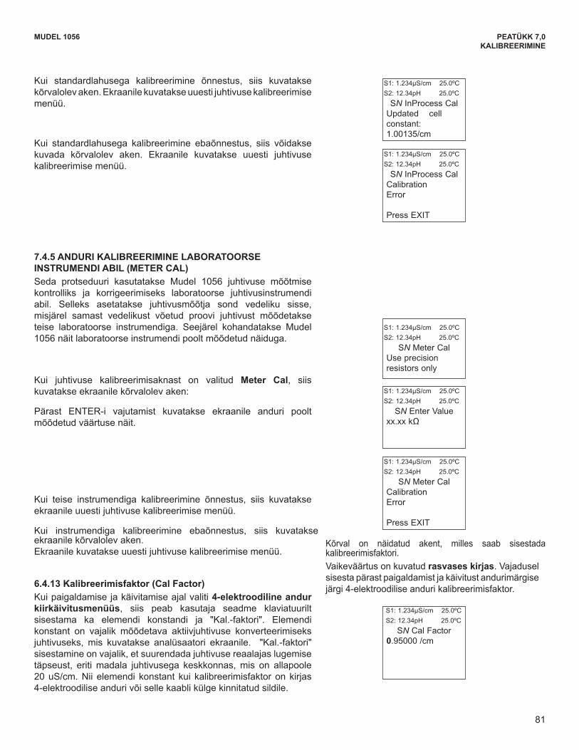
81
MUDEL 1056 PEATÜKK 7,0KALIBREERIMINE
MODEL 1056 SECTION 7.0CALIBRATION
7.4.5 CALIBRATING THE SENSOR TO A LABORATORYINSTRUMENT (METER CAL)This procedure is used to check and correct theconductivity reading of the Model 1056 using a laboratoryconductivity instrument. This is done by submerging theconductivity probe in a bath and measuring the conduc-tivity of a grab sample of the same bath water with aseparate laboratory instrument. The Model 1056 readingis then adjusted to match the conductivity reading of thelab instrument.
The adjacent screen will appear after selecting MeterCal from the Conductivity Calibration screen:
S1: 1.234µS/cm 25.0ºCS2: 12.34pH 25.0ºC
SN Meter CalUse precisionresistors only
The adjacent screen will appear if In Process Cal is suc-cessful. The screen will return to the conductivity CalMenu.
The adjacent screen may appear if In Process Cal isunsuccessful. The screen will return to the conductivityCal Men
S1: 1.234µS/cm 25.0ºCS2: 12.34pH 25.0ºC
SN InProcess CalCalibration Error
Press EXIT
S1: 1.234µS/cm 25.0ºCS2: 12.34pH 25.0ºC
SN InProcess CalUpdated cellconstant: 1.00135/cm
After pressing ENTER, the display shows the live valuemeasured by the sensor
If the meter cal is successful the screen will return to theconductivity Cal Menu.
The adjacent screen will appear if Meter Cal is unsuccessful.The screen will return to the conductivity Cal Menu.
S1: 1.234µS/cm 25.0ºCS2: 12.34pH 25.0ºC
SN Meter CalCalibration Error
Press EXIT
S1: 1.234µS/cm 25.0ºCS2: 12.34pH 25.0ºC
SN Enter Valuexx.xx kΩ
7.4.6 Cal FactorUpon initial installation and power up, if 4-electrodewas selected for the sensor type in the Quick Startmenus, the user enters a Cell Constant and a “CalFactor” using the instrument keypad. The cell constantis needed to convert measured conductance to conduc-tivity as displayed on the analyzer screen. The “CalFactor” entry is needed increase the accuracy of the liveconductivity readings, especially at low conductivityreadings below 20uS/cm. Both the Cell Constant andthe “Cal Factor” are printed on the tag attached to the4-electrode sensor/cable.
The display screen for entering Cal Factor is shown.The default value is displayed in bold type. If neces-sary after initial installation and start-up, enter the “CalFactor” as printed on the sensor tag.
S1: 1.234µS/cm 25.0ºCS2: 12.34pH 25.0ºC
SN Cal Factor 0.95000 /cm
81
Kui standardlahusega kalibreerimine õnnestus, siis kuvatakse kõrvalolev aken. Ekraanile kuvatakse uuesti juhtivuse kalibreerimise menüü.
Kui standardlahusega kalibreerimine ebaõnnestus, siis võidakse kuvada kõrvalolev aken. Ekraanile kuvatakse uuesti juhtivuse kalibreerimise menüü.
7.4.5 ANDURI KALIBREERIMINE LABORATOORSE INSTRUMENDI ABIL (METER CAL) Seda protseduuri kasutatakse Mudel 1056 juhtivuse mõõtmise kontrolliks ja korrigeerimiseks laboratoorse juhtivusinstrumendi abil. Selleks asetatakse juhtivusmõõtja sond vedeliku sisse, misjärel samast vedelikust võetud proovi juhtivust mõõdetakse teise laboratoorse instrumendiga. Seejärel kohandatakse Mudel 1056 näit laboratoorse instrumendi poolt mõõdetud näiduga.
Kui juhtivuse kalibreerimisaknast on valitud Meter Cal, siis kuvatakse ekraanile kõrvalolev aken:
Pärast ENTER-i vajutamist kuvatakse ekraanile anduri poolt mõõdetud väärtuse näit.
Kui teise instrumendiga kalibreerimine õnnestus, siis kuvatakse ekraanile uuesti juhtivuse kalibreerimise menüü.
Kui instrumendiga kalibreerimine ebaõnnestus, siis kuvatakse ekraanile kõrvalolev aken. Ekraanile kuvatakse uuesti juhtivuse kalibreerimise menüü.
6.4.13 Kalibreerimisfaktor (Cal Factor) Kui paigaldamise ja käivitamise ajal valiti 4-elektroodiline andur kiirkäivitusmenüüs, siis peab kasutaja seadme klaviatuurilt sisestama ka elemendi konstandi ja "Kal.-faktori". Elemendi konstant on vajalik mõõdetava aktiivjuhtivuse konverteerimiseks juhtivuseks, mis kuvatakse analüsaatori ekraanile. "Kal.-faktori" sisestamine on vajalik, et suurendada juhtivuse reaalajas lugemise täpseust, eriti madala juhtivusega keskkonnas, mis on allapoole 20 uS/cm. Nii elemendi konstant kui kalibreerimisfaktor on kirjas 4-elektroodilise anduri või selle kaabli külge kinnitatud sildile.
Kõrval on näidatud akent, milles saab sisestada kalibreerimisfaktori. Vaikeväärtus on kuvatud rasvases kirjas. Vajadusel sisesta pärast paigaldamist ja käivitust andurimärgise järgi 4-elektroodilise anduri kalibreerimisfaktor.
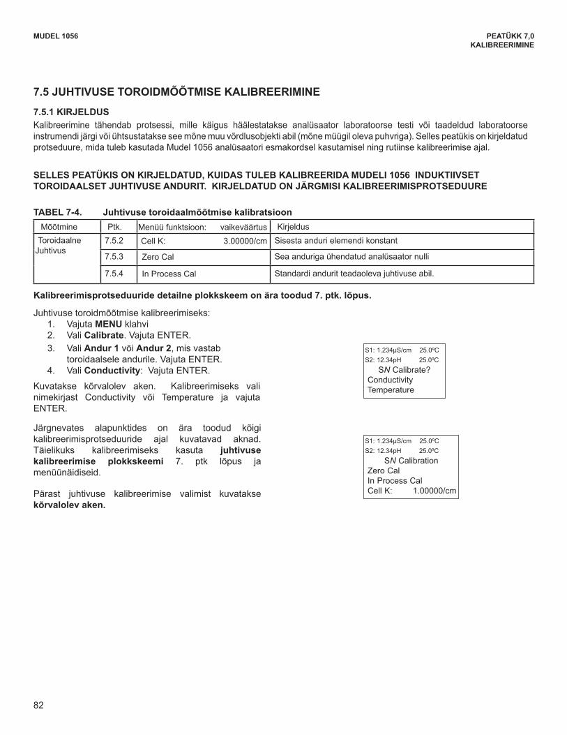
82
The following sub-sections show the initial displayscreen that appears for each calibration routine. Usethe flow diagram for Conductivity calibration at theend of Sec. 7 and the live screen prompts to completecalibration.
The adjacent screen appears after selectingConductivity calibration:
S1: 1.234µS/cm 25.0ºCS2: 12.34pH 25.0ºC
SN CalibrationZero CalIn Process CalCell K: 1.00000/cm
MODEL 1056 SECTION 7.0CALIBRATION
To calibrate toroidal conductivity: 1. Press the MENU button2. Select Calibrate. Press ENTER. 3. Select Sensor 1 or Sensor 2 corresponding to
Toroidal Conductivity. Press ENTER. 4. Select Conductivity. Press ENTER.
The adjacent screen will appear. To calibrate ToroidalConductivity or Temperature, scroll to the desired itemand press ENTER
S1: 1.234µS/cm 25.0ºCS2: 12.34pH 25.0ºC
SN Calibrate? ConductivityTemperature
Measure Sec. Calibration function: default value DescriptionToroidal
Conductivity7.5.2 Cell K: 3.00000/cm Enter the cell Constant for the sensor
7.5.3 Zero Cal Zeroing the analyzer with the sensor attached
7.5.4 In Process Cal Standardizing the sensor to a known conductivity
A detailed flow diagram is provided at the end of Sec. 7 to guide you through the calibration routines.
TABLE 7-4 Toroidal Conductivity Calibration
7.5 TOROIDAL CONDUCTIVITY CALIBRATION
7.5.1 DESCRIPTION Calibration is the process of adjusting or standardizing the analyzer to a lab test or a calibrated laboratory instru-ment, or standardizing to some known reference (such as a conductivity standard). This section contains proceduresfor the first time use and for routine calibration of the Model 1056 analyzer.
THIS SECTION DESCRIBES HOW TO CALIBRATE THE MODEL 1056 WITH AN ATTACHED INDUC-TIVE/TOROIDAL CONDUCTIVITY SENSOR. THE FOLLOWING CALIBRATION ROUTINES ARE COVERED
82
MUDEL 1056 PEATÜKK 7,0KALIBREERIMINE
7.5 JUHTIVUSE TOROIDMÕÕTMISE KALIBREERIMINE
7.5.1 KIRJELDUS Kalibreerimine tähendab protsessi, mille käigus häälestatakse analüsaator laboratoorse testi või taadeldud laboratoorse instrumendi järgi või ühtsustatakse see mõne muu võrdlusobjekti abil (mõne müügil oleva puhvriga). Selles peatükis on kirjeldatud protseduure, mida tuleb kasutada Mudel 1056 analüsaatori esmakordsel kasutamisel ning rutiinse kalibreerimise ajal.
SELLES PEATÜKIS ON KIRJELDATUD, KUIDAS TULEB KALIBREERIDA MUDELI 1056 INDUKTIIVSET TOROIDAALSET JUHTIVUSE ANDURIT. KIRJELDATUD ON JÄRGMISI KALIBREERIMISPROTSEDUURE
TABEL 7-4. Juhtivuse toroidaalmõõtmise kalibratsioonMõõtmine Ptk. Menüü funktsioon: vaikeväärtus Kirjeldus
ToroidaalneJuhtivus
7.5.2 Cell K: 3.00000/cm Sisesta anduri elemendi konstant
7.5.3 Zero Cal Sea anduriga ühendatud analüsaator nulli
7.5.4 In Process Cal Standardi andurit teadaoleva juhtivuse abil.
Kalibreerimisprotseduuride detailne plokkskeem on ära toodud 7. ptk. lõpus.
Juhtivuse toroidmõõtmise kalibreerimiseks: 1. Vajuta MENU klahvi 2. Vali Calibrate. Vajuta ENTER. 3. Vali Andur 1 või Andur 2, mis vastab toroidaalsele andurile. Vajuta ENTER. 4. Vali Conductivity: Vajuta ENTER.
Kuvatakse kõrvalolev aken. Kalibreerimiseks vali nimekirjast Conductivity või Temperature ja vajuta ENTER.
Järgnevates alapunktides on ära toodud kõigi kalibreerimisprotseduuride ajal kuvatavad aknad. Täielikuks kalibreerimiseks kasuta juhtivuse kalibreerimise plokkskeemi 7. ptk lõpus ja menüünäidiseid.
Pärast juhtivuse kalibreerimise valimist kuvatakse kõrvalolev aken.
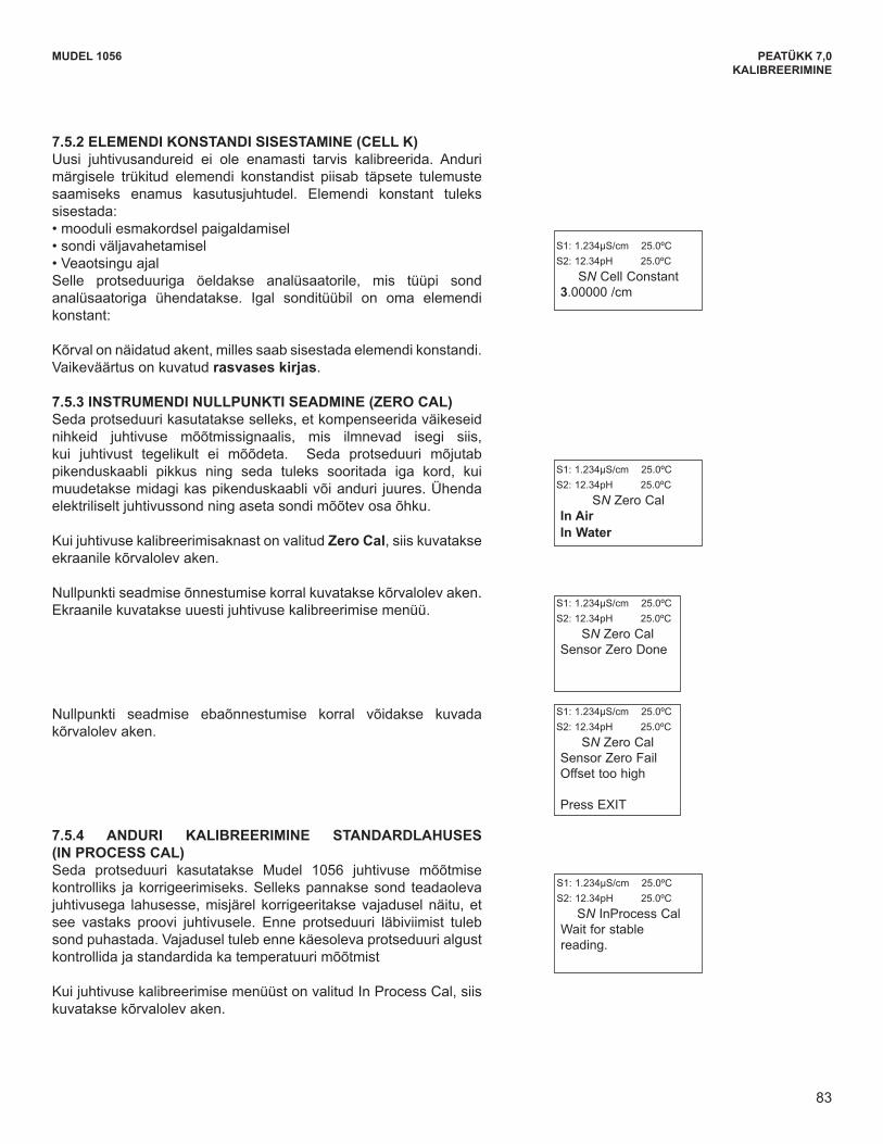
83
7.5.4 CALIBRATING THE SENSOR IN A CONDUCTIVITYSTANDARD (IN PROCESS CAL)This procedure is used to check and correct theconductivity reading of the Model 1056 to ensure thatthe reading is accurate. This is done by submerging theprobe in the sample of known conductivity, then adjustingthe displayed value, if necessary, to correspond to theconductivity value of the sample. The probe must becleaned before performing this procedure. The temper-ature reading must also be checked and standardized ifnecessary, prior to performing this procedure.
The adjacent screen will appear after selecting InProcess Cal from the Conductivity Calibration screen:
MODEL 1056 SECTION 7.0CALIBRATION
7.5.2 ENTERING THE CELL CONSTANTNew conductivity sensors rarely need calibration. Thecell constant printed on the label is sufficiently accuratefor most applications. The cell constant should beentered:• When the unit is installed for the first time• When the probe is replaced• During troubleshootingThis procedure sets up the analyzer for the probe typeconnected to the analyzer. Each type of probe has aspecific cell constant:
The display screen for entering a cell constant for thesensor is shown. The default value is displayed in boldtype.
S1: 1.234µS/cm 25.0ºCS2: 12.34pH 25.0ºC
SN Cell Constant 3.00000 /cm
7.5.3 ZEROING THE INSTRUMENTThis procedure is used to compensate for small offsetsto the conductivity signal that are present even whenthere is no conductivity to be measured. This procedureis affected by the length of extension cable and shouldalways be repeated if any changes in extension cableor sensor have been made. Electrically connect theconductivity probe as it will actually be used and placethe measuring portion of the probe in air.
The adjacent screen will appear after selecting ZeroCal from the Conductivity Calibration screen:
S1: 1.234µS/cm 25.0ºCS2: 12.34pH 25.0ºC
SN Zero CalIn AirIn Water
The adjacent screen will appear if zero Cal is successful.The screen will return to the conductivity Cal Menu.
.
The adjacent screen may appear if zero Cal is unsuccessful. S1: 1.234µS/cm 25.0ºCS2: 12.34pH 25.0ºC
SN Zero CalSensor Zero FailOffset too high
Press EXIT
S1: 1.234µS/cm 25.0ºCS2: 12.34pH 25.0ºC
SN Zero CalSensor Zero Done
S1: 1.234µS/cm 25.0ºCS2: 12.34pH 25.0ºC
SN InProcess CalWait for stablereading.
83
MUDEL 1056 PEATÜKK 7,0KALIBREERIMINE
7.5.2 ELEMENDI KONSTANDI SISESTAMINE (CELL K) Uusi juhtivusandureid ei ole enamasti tarvis kalibreerida. Anduri märgisele trükitud elemendi konstandist piisab täpsete tulemuste saamiseks enamus kasutusjuhtudel. Elemendi konstant tuleks sisestada: •mooduliesmakordselpaigaldamisel•sondiväljavahetamisel•VeaotsinguajalSelle protseduuriga öeldakse analüsaatorile, mis tüüpi sond analüsaatoriga ühendatakse. Igal sonditüübil on oma elemendi konstant:
Kõrval on näidatud akent, milles saab sisestada elemendi konstandi. Vaikeväärtus on kuvatud rasvases kirjas.
7.5.3 INSTRUMENDI NULLPUNKTI SEADMINE (ZERO CAL) Seda protseduuri kasutatakse selleks, et kompenseerida väikeseid nihkeid juhtivuse mõõtmissignaalis, mis ilmnevad isegi siis, kui juhtivust tegelikult ei mõõdeta. Seda protseduuri mõjutab pikenduskaabli pikkus ning seda tuleks sooritada iga kord, kui muudetakse midagi kas pikenduskaabli või anduri juures. Ühenda elektriliselt juhtivussond ning aseta sondi mõõtev osa õhku.
Kui juhtivuse kalibreerimisaknast on valitud Zero Cal, siis kuvatakse ekraanile kõrvalolev aken.
Nullpunkti seadmise õnnestumise korral kuvatakse kõrvalolev aken. Ekraanile kuvatakse uuesti juhtivuse kalibreerimise menüü.
Nullpunkti seadmise ebaõnnestumise korral võidakse kuvada kõrvalolev aken.
7.5.4 ANDURI KALIBREERIMINE STANDARDLAHUSES (IN PROCESS CAL) Seda protseduuri kasutatakse Mudel 1056 juhtivuse mõõtmise kontrolliks ja korrigeerimiseks. Selleks pannakse sond teadaoleva juhtivusega lahusesse, misjärel korrigeeritakse vajadusel näitu, et see vastaks proovi juhtivusele. Enne protseduuri läbiviimist tuleb sond puhastada. Vajadusel tuleb enne käesoleva protseduuri algust kontrollida ja standardida ka temperatuuri mõõtmist
Kui juhtivuse kalibreerimise menüüst on valitud In Process Cal, siis kuvatakse kõrvalolev aken.
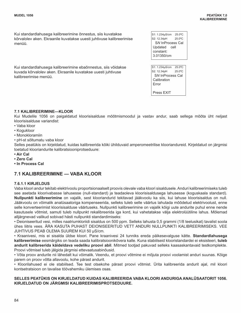
84
MODEL 1056 SECTION 7.0CALIBRATION
The following screen will appear if In Process Cal issuccessful. The screen will return to the conductivityCal Menu.
This screen may appear if In Process Cal is unsuccessful.The screen will return to the conductivity Cal Menu.
S1: 1.234µS/cm 25.0ºCS2: 12.34pH 25.0ºC
SN InProcess CalCalibration Error
Press EXIT
S1: 1.234µS/cm 25.0ºCS2: 12.34pH 25.0ºC
SN InProcess CalUpdated cellconstant: 3.01350/cm
7.6 CALIBRATION —CHLORINEWith a Chlorine measurement board and the appropriate sensor, Model 1056 can measure any of four variants ofChlorine:
• Free Chlorine • Total Chlorine • Monochloramine • pH-independent Free Chlorine
The section describes how to calibrate any compatible amperometric chlorine sensor. The following calibrationroutines are covered in the family of supported Chlorine sensors:
• Air Cal• Zero Cal• In Process Cal
7.6.1 CALIBRATION — FREE CHLORINE
7.6.1.1 DESCRIPTION A free chlorine sensor generates a current directly proportional to the concentration of free chlorine in the sam-ple. Calibrating the sensor requires exposing it to a solution containing no chlorine (zero standard) and to a solu-tion containing a known amount of chlorine (full-scale standard). The zero calibration is necessary because chlo-rine sensors, even when no chlorine is in the sample, generate a small current called the residual current. Theanalyzer compensates for the residual current by subtracting it from the measured current before converting theresult to a chlorine value. New sensors require zeroing before being placed in service, and sensors should bezeroed whenever the electrolyte solution is replaced. Either of the following makes a good zero standard:• Deionized water containing about 500 ppm sodium chloride. Dissolve 0.5 grams (1/8 teaspoonful) of tablesalt in 1 liter of water. DO NOT USE DEIONIZED WATER ALONE FOR ZEROING THE SENSOR. THECONDUCTIVITY OF THE ZERO WATER MUST BE GREATER THAN 50 μS/cm.• Tap water known to contain no chlorine. Expose tap water to bright sunlight for at least 24 hours.The purpose of the In Process calibration is to establish the slope of the calibration curve. Because stable chlorinestandards do not exist, the sensor must be calibrated against a test run on a grab sample of the process liquid.Several manufacturers offer portable test kits for this purpose. Observe the following precautions when takingand testing the grab sample.• Take the grab sample from a point as close to the sensor as possible. Be sure that taking the sample does not alterthe flow of the sample to the sensor. It is best to install the sample tap just downstream from the sensor.• Chlorine solutions are unstable. Run the test immediately after taking the sample. Try to calibrate the sensorwhen the chlorine concentration is at the upper end of the normal operating range.
THIS SECTION DESCRIBES HOW TO CALIBRATE THE MODEL 1056 WITH A FREE CHLORINE SENSOR.THE FOLLOWING CALIBRATION ROUTINES ARE COVERED.
84
MUDEL 1056 PEATÜKK 7,0KALIBREERIMINE
Kui standardlahusega kalibreerimine õnnestus, siis kuvatakse kõrvalolev aken. Ekraanile kuvatakse uuesti juhtivuse kalibreerimise menüü.
Kui standardlahusega kalibreerimine ebaõnnestus, siis võidakse kuvada kõrvalolev aken. Ekraanile kuvatakse uuesti juhtivuse kalibreerimise menüü.
7.1 KALIBREERIMINE—KLOOR Kui Mudelile 1056 on paigaldatud kloorisisalduse mõõtmismoodul ja vastav andur, saab sellega mõõta üht neljast kloorisisalduse variandist: •Vabakloor•Kogukloor•Monokloramiin•pH-stsõltumatuvabakloorSelles peatükis on kirjeldatud, kuidas kalibreerida kõiki ühilduvaid amperomeetrilise klooriandureid. Kirjeldatud on järgmisi toetatud klooriandurite kalibratsiooniprotseduure: •AirCal•ZeroCal•InProcessCal
7.1 KALIBREERIMINE — VABA KLOOR
7.6.1.1 KIRJELDUS Vaba kloori andur tekitab elektrivoolu proportsionaalselt proovis olevale vaba kloori sisaldusele. Anduri kalibreerimiseks tuleb see asetada kloorivabasse lahusesse (null-standard) ja teadaoleva kloorisisaldusega lahusesse (koguskaala standard). Nullpunkti kalibreerimine on vajalik, sest klooriandurid tekitavad jääkvoolu ka siis, kui lahuse kloorisisaldus on null. Jääkvoolu on võimalik analüsaatoriga kompenseerida, selleks tuleb selle väärtus lahutada mõõdetud elektrivoolust, enne selle konverteerimist kloorisisalduse väärtuseks. Nullpunkti kalibreerimine on vajalik kõigi uute andurite puhul enne nende kasutusele võtmist, samuti tuleb nullpunkt rekalibreerida iga kord, kui vahetatakse välja elektrolüütiline lahus. Mõlemad alljärgnevad valikud sobivad hästi nullpunkti standardimiseks: •Deioniseeritudvesi,millesnaatriumkloriidisisalduson500ppm.Sellekslahusta0,5grammi(1/8teelusikat)tavalistsoolaühes liitris vees.ÄRAKASUTAPUHASTDEIONISEERITUDVETTANDURINULLPUNKTIKALIBREERIMISEKS.VEEJUHTIVUSPEABOLEMASUUREMKUI50μS/cm.• Kraanivesi, mis ei sisalda üldse kloori. Pane kraanivesi 24 tunniks ereda päikesevalguse kätte.Standardlahusega kalibreerimise eesmärgiks on teada saada kalibratsioonikõvera kalle. Kuna stabiilseid klooristandardei ei eksisteeri, tuleb andurit kalibreerida käideldava vedeliku proovi abil. Mitmed tootjad pakuvad selleks kaasaskantavaid testkomplekte. Proovi võtmisel tuleb jälgida järgmisi ettevaatusabinõusid. •Võtaproovandurileniilähedaltkuivõimalik.Veendu,etproovivõtmineeimõjutaproovivoolamistandurisuunas.Kõigeparem on proov võtta allavoolu, kohe pärast andurit. • Kloorilahused ei ole stabiilsed. Tee test otsekohe pärast proovi võtmist. Ürita kalibreerida andurit ajal, mil kloorikontsetratsioon on tavalise töövahemiku ülemises osas.
SELLES PEATÜKIS ON KIRJELDATUD KUIDAS KALIBREERIDA VABA KLOORI ANDURIGA ANALÜSAATORIT 1056. KIRJELDATUD ON JÄRGMISI KALIBREERIMISPROTSEDUURE.

85
MODEL 1056 SECTION 7.0CALIBRATION
To calibrate free chlorine: 1. Press the MENU button2. Select Calibrate. Press ENTER. 3. Select Sensor 1 or Sensor 2 corresponding to
Free Chlorine. Press ENTER. 4. Select Free Chlorine. Press ENTER.
The adjacent screen will appear. To calibrate FreeChlorine or Temperature, scroll to the desired item andpress ENTER.
S1: 1.234µS/cm 25.0ºCS2: 12.34pH 25.0ºC
SN Calibrate? Free ChlorineTemperature
The following sub-sections show the initial displayscreen that appears for each calibration routine. Usethe flow diagram for Chlorine calibration at the endof Sec. 7 and the live screen prompts to complete cal-ibration.
The adjacent screen appears after selecting FreeChlorine calibration:
S1: 1.234µS/cm 25.0ºCS2: 12.34pH 25.0ºC
SN CalibrationZero CalIn Process Cal
7.6.1.2 ZEROING THE SENSOR.The adjacent screen will appear during Zero Cal. Besure sensor has been running in zero solution for atleast two hours before starting zero step.
The adjacent screen will appear if In Zero Cal issuccessful. The screen will return to the AmperometricCal Menu.
S1: 1.234µS/cm 25.0ºCS2: 12.34pH 25.0ºC
SN Zero Cal Sensor zero done
S1: 1.234µS/cm 25.0ºCS2: 12.34pH 25.0ºC
SN Zero CalZeroingWait
Measure Sec. Calibration function: default value DescriptionFree Chlorine 7.6.1.2 Zero Cal Zeroing the sensor in solution with zero free chlorine
7.6.1.3 In Process Cal Standardizing to a sample of known chlorine concentration
A detailed flow diagram is provided at the end of Sec. 7 to guide you through the calibration routines.
TABLE 7-5 Free Chlorine Calibration Routines
The adjacent screen may appear if In Zero Cal is unsuc-cessful. The screen will return to the Amperometric CalMenu.
S1: 1.234µS/cm 25.0ºCS2: 12.34pH 25.0ºC
SN Zero CalSensor zero failed
Press EXIT
7.6.1.3 IN PROCESS CALIBRATIONThe adjacent screen will appear prior to In Process Cal
S1: 1.234µS/cm 25.0ºCS2: 12.34pH 25.0ºC
SN InProcess CalWait for stablereading.
85
MUDEL 1056 PEATÜKK 7,0KALIBREERIMINE
TABEL 7-5. Vaba kloori mõõtmise kalibreerimisprotseduurid Mõõtmine Ptk. Menüü funktsioon: vaikeväärtus Kirjeldus
Vaba kloor 7.6.1.2 Zero Cal Anduri nullpunkti seadmine kloorivaba lahuse abil
7.6.1.3 In Process Cal Anduri standardimine teadaoleva kloorikontsentratsiooniga lahuse abil
Kalibreerimisprotseduuride detailne plokkskeem on ära toodud 7. ptk. lõpus. Vaba kloori mõõtmise kalibreerimiseks:
1. Vajuta MENU klahvi 2. Vali Calibrate. Vajuta ENTER. 3. Vali Andur 1 või Andur 2, mis vastab vabale kloorile Vajuta ENTER. 4. Vali Free Chlorine. Vajuta ENTER.
Kuvatakse kõrvalolev aken. Kalibreerimiseks vali nimekirjast Free Chlorine või Temperature ja vajuta ENTER.
Järgnevates alapunktides on ära toodud kõigi kalibreerimisprotseduuride ajal kuvatavad aknad. Täielikuks kalibreerimiseks kasuta kloori mõõtmise kalibreerimise plokkskeemi 7. ptk lõpus ja menüünäidiseid.
Pärast vaba kloori kalibreerimise valimist kuvatakse kõrvalolev aken.
7.6.1.2 ANDURI NULLPUNKTI SEADMINE (ZERO CAL) Kõrvalolev aken kuvatakse nullpunkti kalibreerimise ajal Veendu, et andur oleks olnud null-lahuses vähemalt kaks tundi enne nullpunkti määramist.
Nullpunkti määramise õnnestumise korral kuvatakse kõrvalolev aken. Ekraanile kuvatakse uuesti menüü Amperometric Cal.
Nullpunkti seadmise ebaõnnestumise korral võidakse kuvada kõrvalolev aken. Ekraanile kuvatakse uuesti menüü Amperometric Cal.
7.6.1.3 KALIBREERIMINE TEADAOLEVA KONTSENTRATSIOONIGA LAHUSE ABIL (IN PROCESS CAL) Kõrvalolev aken kuvatakse enne lahusega kalibreerimist

86
MUDEL 1056 PEATÜKK 7,0KALIBREERIMINEMODEL 1056 SECTION 7.0
CALIBRATION
7.6.2 CALIBRATION — TOTAL CHLORINE
7.6.2.1 DESCRIPTION Total chlorine is the sum of free and combined chlorine.The continuous determination of total chlorine requirestwo steps. First, the sample flows into a conditioningsystem (TCL) where a pump continuously adds aceticacid and potassium iodide to the sample. The acidlowers the pH, which allows total chlorine in the sampleto quantitatively oxidize the iodide in the reagent toiodine. In the second step, the treated sample flowsto the sensor. The sensor is a membrane-coveredamperometric sensor, whose output is proportional tothe concentration of iodine. Because the concentrationof iodine is proportional to the concentration of totalchlorine, the analyzer can be calibrated to read totalchlorine. Because the sensor really measures iodine,calibrating the sensor requires exposing it to a solutioncontaining no iodine (zero standard) and to a solutioncontaining a known amount of iodine (full-scale standard). The Zero calibration is necessary because the sensor,even when no iodine is present, generates a smallcurrent called the residual current. The analyzercompensates for the residual current by subtracting itfrom the measured current before converting the resultto a total chlorine value. New sensors require zeroingbefore being placed in service, and sensors should be
zeroed whenever the electrolyte solution is replaced.The best zero standard is deionized water.
The purpose of the In Process Calibration is toestablish the slope of the calibration curve.Because stable total chlorine standards do not exist, thesensor must be calibrated against a test run on agrab sample of the process liquid. Several manufac-turers offer portable test kits for this purpose. Observethe followingprecautions when taking and testing the grab sample: • Take the grab sample from a point as close aspossible to the inlet of the TCL sample conditioning system.Be sure that taking the sample does not alter the flowthrough the TCL.• Chlorine solutions are unstable. Run the test immedi-ately after taking the sample. Try to calibrate the sensorwhen the chlorine concentration is at the upper end ofthe normal operating range.
Note this measurement must be made using the ModelTCL total chlorine sample conditioning system.
THIS SECTION DESCRIBES HOW TO CALIBRATETHE MODEL 1056 WITH AN ATTACHED TOTALCHLORINE SENSOR. THE FOLLOWINGCALIBRATION ROUTINES ARE COVERED.
Measure Sec. Calibration function: default value DescriptionTotal Chlorine 7.6.2.2 Zero Cal Zeroing the sensor in solution with zero total chlorine
7.6.2.3 In Process Cal Standardizing to a sample of known chlorine concentration
A detailed flow diagram is provided at the end of Sec. 7 to guide you through the calibration routines.
TABLE 7- 6 Total Chlorine Calibration Routines
To calibrate total chlorine: 1. Press the MENU button2. Select Calibrate. Press ENTER. 3. Select Sensor 1 or Sensor 2 corresponding to
Total Chlorine. Press ENTER. 4. Select Total Chlorine. Press ENTER.
The adjacent screen will appear. To calibrate TotalChlorine or Temperature, scroll to the desired item andpress ENTER
S1: 1.234µS/cm 25.0ºCS2: 12.34pH 25.0ºC
SN Calibrate? Total ChlorineTemperature
If the In Process Cal is successful, the screen will returnto the Cal sub-menu.The adjacent screen may appear if In Zero Cal is unsuc-cessful. The screen will return to the Amperometric CalMenu.
S1: 1.234µS/cm 25.0ºCS2: 12.34pH 25.0ºC
SN InProcess CalCalibration Error
Press EXIT
86
MODEL 1056 SECTION 7.0CALIBRATION
7.6.2 CALIBRATION — TOTAL CHLORINE
7.6.2.1 DESCRIPTION Total chlorine is the sum of free and combined chlorine.The continuous determination of total chlorine requirestwo steps. First, the sample flows into a conditioningsystem (TCL) where a pump continuously adds aceticacid and potassium iodide to the sample. The acidlowers the pH, which allows total chlorine in the sampleto quantitatively oxidize the iodide in the reagent toiodine. In the second step, the treated sample flowsto the sensor. The sensor is a membrane-coveredamperometric sensor, whose output is proportional tothe concentration of iodine. Because the concentrationof iodine is proportional to the concentration of totalchlorine, the analyzer can be calibrated to read totalchlorine. Because the sensor really measures iodine,calibrating the sensor requires exposing it to a solutioncontaining no iodine (zero standard) and to a solutioncontaining a known amount of iodine (full-scale standard). The Zero calibration is necessary because the sensor,even when no iodine is present, generates a smallcurrent called the residual current. The analyzercompensates for the residual current by subtracting itfrom the measured current before converting the resultto a total chlorine value. New sensors require zeroingbefore being placed in service, and sensors should be
zeroed whenever the electrolyte solution is replaced.The best zero standard is deionized water.
The purpose of the In Process Calibration is toestablish the slope of the calibration curve.Because stable total chlorine standards do not exist, thesensor must be calibrated against a test run on agrab sample of the process liquid. Several manufac-turers offer portable test kits for this purpose. Observethe followingprecautions when taking and testing the grab sample: • Take the grab sample from a point as close aspossible to the inlet of the TCL sample conditioning system.Be sure that taking the sample does not alter the flowthrough the TCL.• Chlorine solutions are unstable. Run the test immedi-ately after taking the sample. Try to calibrate the sensorwhen the chlorine concentration is at the upper end ofthe normal operating range.
Note this measurement must be made using the ModelTCL total chlorine sample conditioning system.
THIS SECTION DESCRIBES HOW TO CALIBRATETHE MODEL 1056 WITH AN ATTACHED TOTALCHLORINE SENSOR. THE FOLLOWINGCALIBRATION ROUTINES ARE COVERED.
Measure Sec. Calibration function: default value DescriptionTotal Chlorine 7.6.2.2 Zero Cal Zeroing the sensor in solution with zero total chlorine
7.6.2.3 In Process Cal Standardizing to a sample of known chlorine concentration
A detailed flow diagram is provided at the end of Sec. 7 to guide you through the calibration routines.
TABLE 7- 6 Total Chlorine Calibration Routines
To calibrate total chlorine: 1. Press the MENU button2. Select Calibrate. Press ENTER. 3. Select Sensor 1 or Sensor 2 corresponding to
Total Chlorine. Press ENTER. 4. Select Total Chlorine. Press ENTER.
The adjacent screen will appear. To calibrate TotalChlorine or Temperature, scroll to the desired item andpress ENTER
S1: 1.234µS/cm 25.0ºCS2: 12.34pH 25.0ºC
SN Calibrate? Total ChlorineTemperature
If the In Process Cal is successful, the screen will returnto the Cal sub-menu.The adjacent screen may appear if In Zero Cal is unsuc-cessful. The screen will return to the Amperometric CalMenu.
S1: 1.234µS/cm 25.0ºCS2: 12.34pH 25.0ºC
SN InProcess CalCalibration Error
Press EXIT
86
Kui lahusega kalibreerimine õnnestus, siis kuvatakse ekraanile uuesti alammenüü Cal Kui null-lahusega kalibreerimine ebaõnnestus, siis võidakse kuvada kõrvalolev aken. Ekraanile kuvatakse uuesti menüü Amperometric Cal.
7.6.2 KALIBREERIMINE — KOGUKLOOR
7.6.2.1 KIRJELDUS Kogukloor tähendab vaba ja seotud kloori summat. Kogukloorisisalduse pidev mõõtmine on kaheosaline. Kõigepealt lastakse proovil voolata reguleeritavasse süsteemi (TCL), kus proovi pumbatakse pidevalt juurde äädikhapet ja kaaliumjodiidi.Hapeviib pH-tasemealla,mis lasebproovikoguklooril reageerida joodile ja kvantitatiivselt oksüdeerida kaaliumjodiidi. Teise sammuna lastakse proovil voolata üle anduri. Anduriks on membraaniga amperomeetriline andur, mille väljund vastab proportsionaalselt joodi kontsentratsioonile. Kuna joodikontsentratsioon on proportsionaalne kogukloori sisaldusele, saav analüsaatorit kalibreerida kogukloori mõõtmiseks. Kuna andur tegelikult mõõdab joodi, tuleb selle kalibreerimiseks kasutada joodivaba lahust (nullpunkti standardimine) ja teadaoleva joodikontsentratsiooniga lahust (koguskaala standardimine). Nullpunkti kalibreerimine on vajalik, sest andur tekitab jääkvoolu ka siis, kui lahuse joodisisaldus on null. Jääkvoolu on võimalik analüsaatoriga kompenseerida, selleks tuleb selle väärtus lahutada mõõdetud elektrivoolust, enne selle konverteerimist kogukloorisisalduse väärtuseks. Nullpunkti kalibreerimine on vajalik kõigi uute andurite puhul enne nende kasutusele võtmist, samuti tuleb nullpunkt rekalibreerida iga kord, kui vahetatakse välja elektrolüütiline lahus. Parim nullpunkti standard on deioniseeritud vesi.
Standardlahusega kalibreerimise eesmärgiks on teada saada kalibratsioonikõvera kalle. Kuna stabiilseid klooristandardeid ei ei eksisteeri, tuleb andurit kalibreerida käideldava vedeliku proovi abil. Mitmed tootjad pakuvad selleks kaasaskantavaid testkomplekte. Proovi võtmisel tuleb jälgida järgmisi ettevaatusabinõusid. •VõtaproovTCLproovireguleerimissüsteemisissepääsulevõimalikult lähedalt. Veendu, et proovi võtmine ei mõjuta TCL-i läbivat voolu. •Kloorilahusedeiolestabiilsed.Teetestotsekohepärastproovi võtmist. Ürita kalibreerida andurit ajal, mil kloori kontsetratsioon on tavalise töövahemiku ülemises osas.
Märkus: antud mõõtmine peab kasutama TCL kogukloori proovi reguleerimissüsteemi.
SELLES PEATÜKIS ON KIRJELDATUD, KUIDAS KALIBREERIDA ANALÜSAATORIT 1056 KOOS KOGUKLOORIANDURIGA. KIRJELDATUD ON JÄRGMISI KALIBREERIMISPROTSEDUURE.
TABEL 7-6 Kogukloori mõõtmise kalibreerimisprotseduurid Mõõtmine Ptk. Menüü funktsioon: vaikeväärtus Kirjeldus
Kogukloor 7.6.2.2 Zero Cal Anduri nullpunkti seadmine kloorivaba lahuse abil
7.6.2.3 In Process Cal Anduri standardimine teadaoleva kloorikontsentratsiooniga lahuse abil
Kalibreerimisprotseduuride detailne plokkskeem on ära toodud 7. ptk. lõpus.
Kogukloori mõõtmise kalibreerimiseks: 1. Vajuta MENU klahvi 2. Vali Calibrate. Vajuta ENTER.3. Vali Andur 1 või Andur 2, mis vastab kogukloorile. Vajuta ENTER. 4. Vali kogukloor.Vajuta ENTER.
Kuvatakse kõrvalolev aken. Kalibreerimiseks vali nimekirjast Total Chlorine või Temperature ja vajuta ENTER.
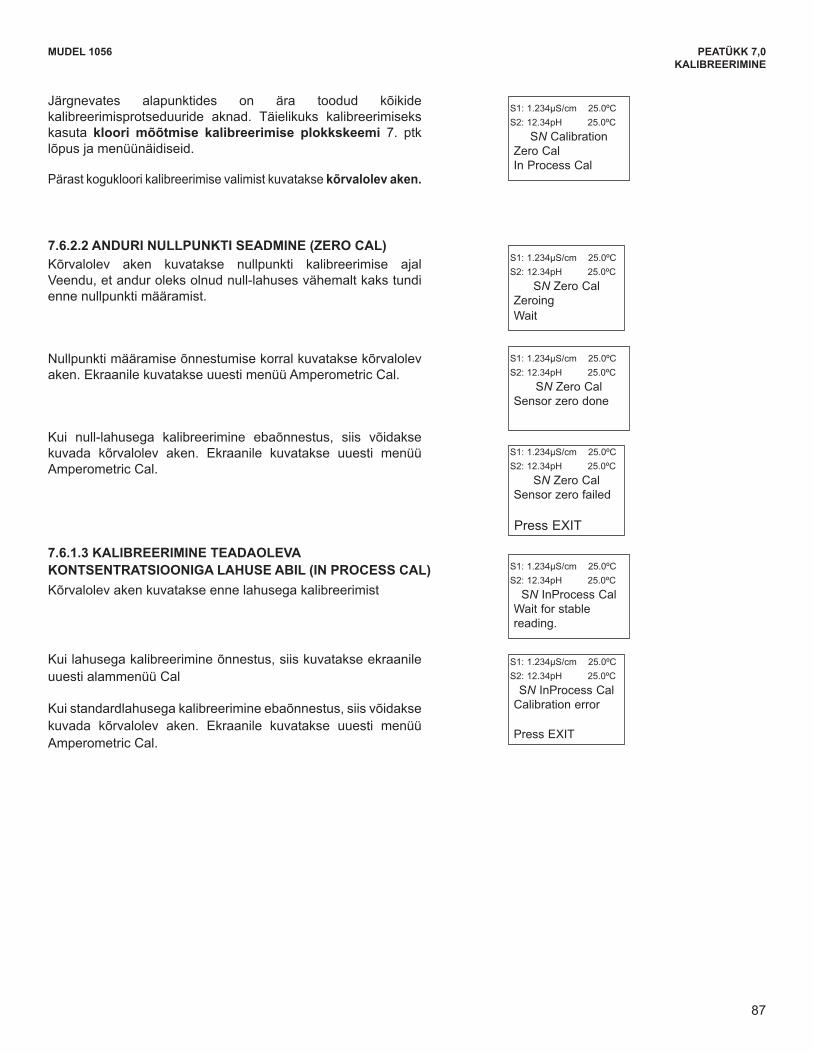
87
MUDEL 1056 PEATÜKK 7,0KALIBREERIMINE
MODEL 1056 SECTION 7.0CALIBRATION
The following sub-sections provide you with the initialdisplay screen that appears for each calibration routine.Use the flow diagram for Chlorine calibration at theend of Sec. 7 and the live screen prompts to completecalibration.
This adjacent screen appears after selecting TotalChlorine calibration:
7.6.2.2 ZEROING THE SENSOR.The adjacent screen will appear during Zero Cal. Besure sensor has been running in zero solution for atleast two hours before starting zero step.
S1: 1.234µS/cm 25.0ºCS2: 12.34pH 25.0ºC
SN Zero CalZeroingWait
S1: 1.234µS/cm 25.0ºCS2: 12.34pH 25.0ºC
SN CalibrationZero CalIn Process Cal
The adjacent screen may appear if In Zero Cal isunsuccessful. The screen will return to theAmperometric Cal Menu.
S1: 1.234µS/cm 25.0ºCS2: 12.34pH 25.0ºC
SN Zero CalSensor zero failed
Press EXIT
7.6.2.3 IN PROCESS CALIBRATIONThe adjacent screen will appear prior to In Process Cal
If the In Process Cal is successful, the screen willreturn to the Cal sub-menu.
The adjacent screen may appear if In Process Cal isunsuccessful. The screen will return to theAmperometric Cal Menu.
S1: 1.234µS/cm 25.0ºCS2: 12.34pH 25.0ºC
SN InProcess CalCalibration error
Press EXIT
S1: 1.234µS/cm 25.0ºCS2: 12.34pH 25.0ºC
SN InProcess CalWait for stablereading.
The adjacent screen will appear if In Zero Cal is suc-cessful. The screen will return to the AmperometricCal Menu.
S1: 1.234µS/cm 25.0ºCS2: 12.34pH 25.0ºC
SN Zero Cal Sensor zero done
87
Järgnevates alapunktides on ära toodud kõikide kalibreerimisprotseduuride aknad. Täielikuks kalibreerimiseks kasuta kloori mõõtmise kalibreerimise plokkskeemi 7. ptk lõpus ja menüünäidiseid.
Pärast kogukloori kalibreerimise valimist kuvatakse kõrvalolev aken.
7.6.2.2 ANDURI NULLPUNKTI SEADMINE (ZERO CAL) Kõrvalolev aken kuvatakse nullpunkti kalibreerimise ajal Veendu, et andur oleks olnud null-lahuses vähemalt kaks tundi enne nullpunkti määramist.
Nullpunkti määramise õnnestumise korral kuvatakse kõrvalolev aken. Ekraanile kuvatakse uuesti menüü Amperometric Cal.
Kui null-lahusega kalibreerimine ebaõnnestus, siis võidakse kuvada kõrvalolev aken. Ekraanile kuvatakse uuesti menüü Amperometric Cal.
7.6.1.3 KALIBREERIMINE TEADAOLEVA KONTSENTRATSIOONIGA LAHUSE ABIL (IN PROCESS CAL) Kõrvalolev aken kuvatakse enne lahusega kalibreerimist
Kui lahusega kalibreerimine õnnestus, siis kuvatakse ekraanile uuesti alammenüü Cal
Kui standardlahusega kalibreerimine ebaõnnestus, siis võidakse kuvada kõrvalolev aken. Ekraanile kuvatakse uuesti menüü Amperometric Cal.
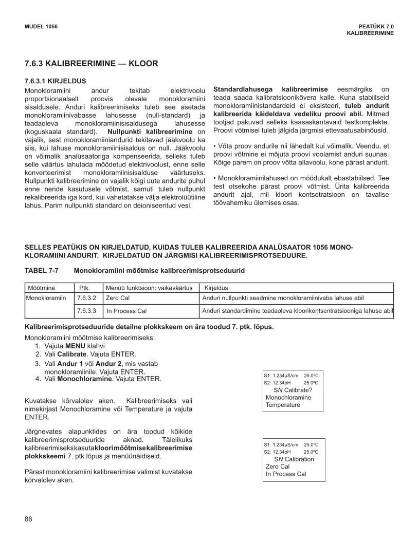
88
MODEL 1056 SECTION 7.0CALIBRATION
The following sub-sections provide you with the initialdisplay screen that appears for each calibration routine.Use the flow diagram for Chlorine calibration at theend of Sec. 7 and the live screen prompts to completecalibration.
The adjacent screen appears after selectingMonochloramine calibration:
S1: 1.234µS/cm 25.0ºCS2: 12.34pH 25.0ºC
SN CalibrationZero CalIn Process Cal
7.6.3 CALIBRATION - MONOCHLORAMINE
7.6.3.1 DESCRIPTION A monochloramine sensor generates a current directlyproportional to the concentration of monochloramine inthe sample. Calibrating the sensor requires exposing itto a solution containing no monochloramine (zerostandard) and to a solution containing a known amountof monochloramine (full-scale standard). The Zerocalibration is necessary because monochloraminesensors, even when no monochloramine is in thesample, generate a small current called the residual orzero current. The analyzer compensates for the residualcurrent by subtracting it from the measured currentbefore converting the result to a monochloramine value.New sensors require zeroing before being placed inservice, and sensors should be zeroed whenever theelectrolyte solution is replaced. The best zero standardis deionized water.
The purpose of the In Process calibration is to establishthe slope of the calibration curve. Because stablemonochloramine standards do not exist, the sensormust be calibrated against a test run on a grab sampleof the process liquid. Several manufacturers offerportable test kits for this purpose. Observe the followingprecautions when taking and testing the grab sample.
• Take the grab sample from a point as close to the sen-sor as possible. Be sure that taking the sample does notalter the flow of the sample to the sensor. It is best toinstall the sample tap just downstream from the sensor.
• Monochloramine solutions are moderately unstable.Run the test as soon as possible after taking the sam-ple. Try to calibrate the sensor when the monochlo-ramine concentration is at the upper end of the normaloperating range.
Measure Sec. Calibration function: default value DescriptionMonochloramine 7.6.3.2 Zero Cal Zeroing the sensor in solution with zero monochloramine
7.6.3.3 In Process Cal Standardizing to a sample of known chlorine concentration
A detailed flow diagram is provided at the end of Sec. 7 to guide you through the calibration routines.
To calibrate monochloramine: 1. Press the MENU button2. Select Calibrate. Press ENTER. 3. Select Sensor 1 or Sensor 2 corresponding to
Monochloramine. Press ENTER. 4. Select Monochloramine. Press ENTER.
The adjacent screen will appear. To calibrateMonochloramine or Temperature, scroll to the desireditem and press ENTER.
S1: 1.234µS/cm 25.0ºCS2: 12.34pH 25.0ºC
SN Calibrate? Monochloramine Temperature
TABLE 7-7 Monochloramine Calibration Routines
THIS SECTION DESCRIBES HOW TO CALIBRATE THE MODEL 1056 WITH AN ATTACHED MONO-CHLORAMINE SENSOR. THE FOLLOWING CALIBRATION ROUTINES ARE COVERED.
88
MUDEL 1056 PEATÜKK 7,0KALIBREERIMINE
7.6.3 KALIBREERIMINE — KLOOR
7.6.3.1 KIRJELDUS Monokloramiini andur tekitab elektrivoolu proportsionaalselt proovis olevale monokloramiini sisaldusele. Anduri kalibreerimiseks tuleb see asetada monokloramiinivabasse lahusesse (null-standard) ja teadaoleva monokloramiinisisaldusega lahusesse (koguskaala standard). Nullpunkti kalibreerimine on vajalik, sest monokloramiiniandurid tekitavad jääkvoolu ka siis, kui lahuse monokloramiinisisaldus on null. Jääkvoolu on võimalik analüsaatoriga kompenseerida, selleks tuleb selle väärtus lahutada mõõdetud elektrivoolust, enne selle konverteerimist monokloramiinisisalduse väärtuseks. Nullpunkti kalibreerimine on vajalik kõigi uute andurite puhul enne nende kasutusele võtmist, samuti tuleb nullpunkt rekalibreerida iga kord, kui vahetatakse välja elektrolüütiline lahus. Parim nullpunkti standard on deioniseeritud vesi.
Standardlahusega kalibreerimise eesmärgiks on teada saada kalibratsioonikõvera kalle. Kuna stabiilseid monokloramiinistandardeid ei eksisteeri, tuleb andurit kalibreerida käideldava vedeliku proovi abil. Mitmed tootjad pakuvad selleks kaasaskantavaid testkomplekte. Proovi võtmisel tuleb jälgida järgmisi ettevaatusabinõusid.
•Võtaproovandurileniilähedaltkuivõimalik.Veendu,etproovi võtmine ei mõjuta proovi voolamist anduri suunas. Kõige parem on proov võtta allavoolu, kohe pärast andurit.
•Monokloramiinilahusedonmõõdukaltebastabiilsed.Teetest otsekohe pärast proovi võtmist. Ürita kalibreerida andurit ajal, mil kloori kontsetratsioon on tavalise töövahemiku ülemises osas.
SELLES PEATÜKIS ON KIRJELDATUD, KUIDAS TULEB KALIBREERIDA ANALÜSAATOR 1056 MONO- KLORAMIINI ANDURIT. KIRJELDATUD ON JÄRGMISI KALIBREERIMISPROTSEDUURE.
TABEL 7-7 Monokloramiini mõõtmise kalibreerimisprotseduurid
Mõõtmine Ptk. Menüü funktsioon: vaikeväärtus KirjeldusMonokloramiin 7.6.3.2 Zero Cal Anduri nullpunkti seadmine monokloramiinivaba lahuse abil
7.6.3.3 In Process Cal Anduri standardimine teadaoleva kloorikontsentratsiooniga lahuse abil
Kalibreerimisprotseduuride detailne plokkskeem on ära toodud 7. ptk. lõpus. Monokloramiini mõõtmise kalibreerimiseks:
1. Vajuta MENU klahvi 2. Vali Calibrate. Vajuta ENTER. 3. Vali Andur 1 või Andur 2, mis vastab monokloramiinile. Vajuta ENTER. 4. Vali Monochloramine. Vajuta ENTER.
Kuvatakse kõrvalolev aken. Kalibreerimiseks vali nimekirjast Monochloramine või Temperature ja vajuta ENTER.
Järgnevates alapunktides on ära toodud kõikide kalibreerimisprotseduuride aknad. Täielikuks kalibreerimiseks kasuta kloori mõõtmise kalibreerimise plokkskeemi 7. ptk lõpus ja menüünäidiseid.
Pärast monokloramiini kalibreerimise valimist kuvatakse kõrvalolev aken.
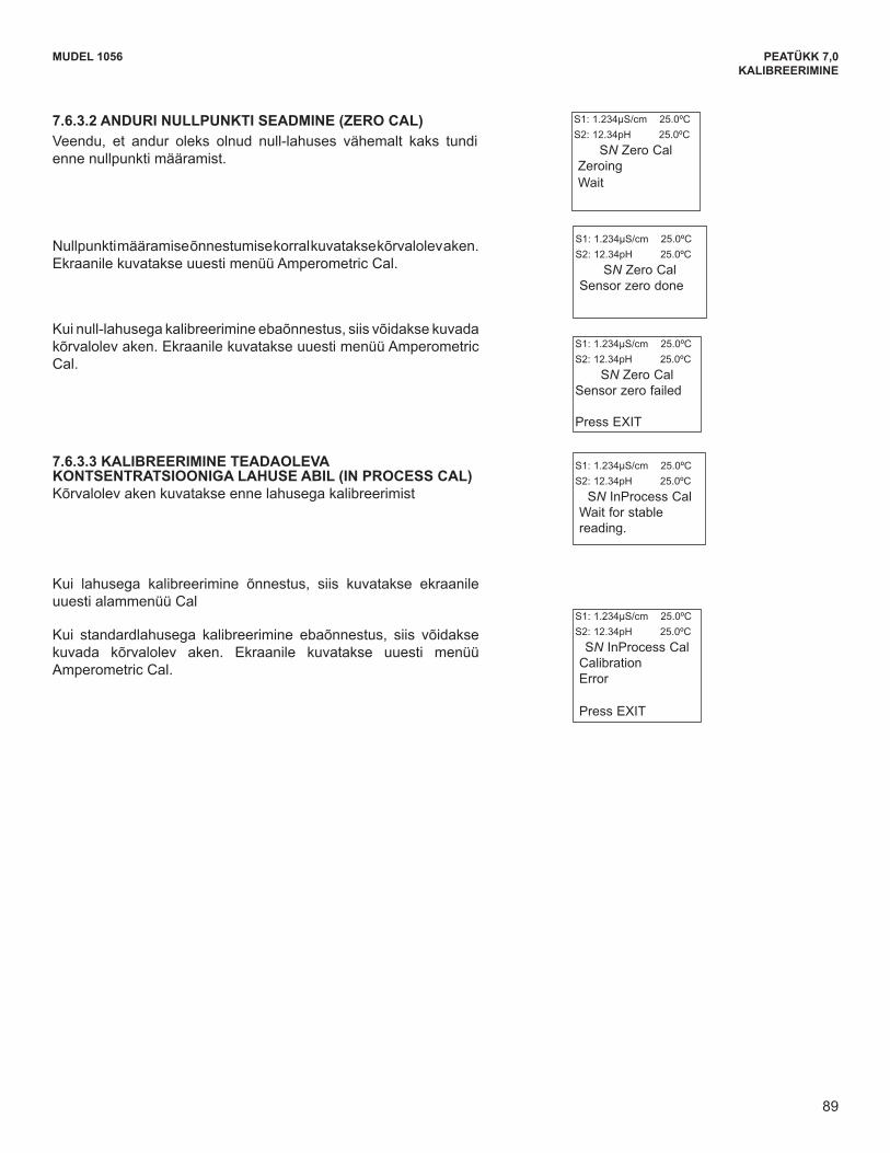
89
MODEL 1056 SECTION 7.0CALIBRATION
7.6.3.2 ZEROING THE SENSOR.The adjacent screen will appear during Zero Cal. Besure sensor has been running in zero solution for atleast two hours before starting zero step.
S1: 1.234µS/cm 25.0ºCS2: 12.34pH 25.0ºC
SN Zero CalZeroingWait
The adjacent screen may appear if In Zero Cal isunsuccessful. The screen will return to theAmperometric Cal Menu.
The adjacent screen will appear if In Zero Cal is suc-cessful. The screen will return to the AmperometricCal Menu.
S1: 1.234µS/cm 25.0ºCS2: 12.34pH 25.0ºC
SN Zero CalSensor zero failed
Press EXIT
S1: 1.234µS/cm 25.0ºCS2: 12.34pH 25.0ºC
SN Zero Cal Sensor zero done
If the In Process Cal is successful, the screen willreturn to the Cal sub-menu.
The adjacent screen may appear if In Process Cal isunsuccessful. The screen will return to theAmperometric Cal Menu.
7.6.3.3 IN PROCESS CALIBRATIONThe adjacent screen will appear prior to In Process Cal
S1: 1.234µS/cm 25.0ºCS2: 12.34pH 25.0ºC
SN InProcess CalCalibration Error
Press EXIT
S1: 1.234µS/cm 25.0ºCS2: 12.34pH 25.0ºC
SN InProcess CalWait for stablereading.
89
MUDEL 1056 PEATÜKK 7,0KALIBREERIMINE
7.6.3.2 ANDURI NULLPUNKTI SEADMINE (ZERO CAL) Veendu, et andur oleks olnud null-lahuses vähemalt kaks tundi enne nullpunkti määramist.
Nullpunkti määramise õnnestumise korral kuvatakse kõrvalolev aken. Ekraanile kuvatakse uuesti menüü Amperometric Cal.
Kui null-lahusega kalibreerimine ebaõnnestus, siis võidakse kuvada kõrvalolev aken. Ekraanile kuvatakse uuesti menüü Amperometric Cal.
7.6.3.3 KALIBREERIMINE TEADAOLEVA KONTSENTRATSIOONIGA LAHUSE ABIL (IN PROCESS CAL) Kõrvalolev aken kuvatakse enne lahusega kalibreerimist
Kui lahusega kalibreerimine õnnestus, siis kuvatakse ekraanile uuesti alammenüü Cal
Kui standardlahusega kalibreerimine ebaõnnestus, siis võidakse kuvada kõrvalolev aken. Ekraanile kuvatakse uuesti menüü Amperometric Cal.
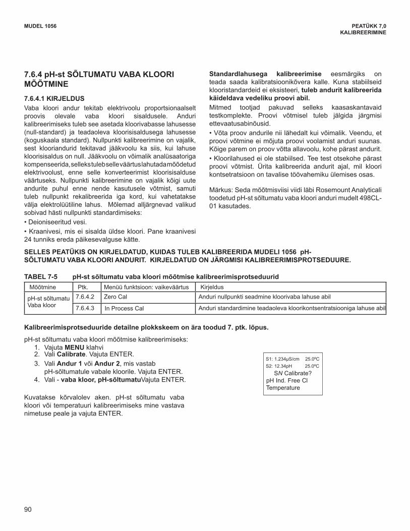
90
MUDEL 1056 PEATÜKK 7,0KALIBREERIMINEMODEL 1056 SECTION 7.0
CALIBRATION
7.6.4 pH-INDEPENDENT FREE CHLORINEMEASUREMENT
7.6.4.1 DESCRIPTION A free chlorine sensor generates a current directlyproportional to the concentration of free chlorine in thesample. Calibrating the sensor requires exposing it to asolution containing no chlorine (zero standard) and to asolution containing a known amount of chlorine (full-scale standard). The zero calibration is necessarybecause chlorine sensors, even when no chlorine is inthe sample, generate a small current called the residualcurrent. The analyzer compensates for the residualcurrent by subtracting it from the measured currentbefore converting the result to a chlorine value. Newsensors require zeroing before being placed in service,and sensors should be zeroed whenever the electrolytesolution is replaced. Either of the following makes agood zero standard:• Deionized water.• Tap water known to contain no chlorine. Expose tapwater to bright sunlight for at least 24 hours.
The purpose of the In Process calibration is toestablish the slope of the calibration curve. Becausestable chlorine standards do not exist, the sensor mustbe calibrated against a test run on a grab sample ofthe process liquid.Several manufacturers offer portable test kits for thispurpose. Observe the following precautions when takingand testing the grab sample.• Take the grab sample from a point as close to the sensoras possible. Be sure that taking the sample doesnot alter the flow of the sample to the sensor. It is bestto install the sample tap just downstream from thesensor.• Chlorine solutions are unstable. Run the test immediatelyafter taking the sample. Try to calibrate the sensorwhen the chlorine concentration is at the upper end ofthe normal operating range.
Note: This measurement is made using the model498CL-01 - pH-independent Free Chlorine sensormanufactured by Rosemount Analytical.
Measure Sec. Calibration function: default value Description
pH-independent Free Chlorine
7.6.4.2 Zero Cal Zeroing the sensor in solution with zero free chlorine
7.6.4.3 In Process Cal Standardizing to a sample of known chlorine concentration
A detailed flow diagram is provided at the end of Sec. 7 to guide you through the calibration routines.
TABLE 7- 8 pH-independent Free Chlorine Calibration Routines
To calibrate pH-independent free chlorine: 1. Press the MENU button2. Select Calibrate. Press ENTER. 3. Select Sensor 1 or Sensor 2 corresponding to
pH-independent free chlorine. Press ENTER. 4. Select pH Ind. Free Cl. Press ENTER.
The adjacent screen will appear. To calibrate pH-independentFree Chlorine or Temperature, scroll to the desired item andpress ENTER.
S1: 1.234µS/cm 25.0ºCS2: 12.34pH 25.0ºC
SN Calibrate? pH Ind. Free Cl Temperature
THIS SECTION DESCRIBES HOW TO CALIBRATE THE MODEL 1056 WITH AN ATTACHED PH-INDEPENDENT FREE CHLORINE SENSOR. THE FOLLOWING CALIBRATION ROUTINES ARE COVERED.
90
7.6.4 pH-st SÕLTUMATU VABA KLOORI MÕÕTMINE
7.6.4.1 KIRJELDUS Vaba kloori andur tekitab elektrivoolu proportsionaalselt proovis olevale vaba kloori sisaldusele. Anduri kalibreerimiseks tuleb see asetada kloorivabasse lahusesse (null-standard) ja teadaoleva kloorisisaldusega lahusesse (koguskaala standard). Nullpunkti kalibreerimine on vajalik, sest klooriandurid tekitavad jääkvoolu ka siis, kui lahuse kloorisisaldus on null. Jääkvoolu on võimalik analüsaatoriga kompenseerida, selleks tuleb selle väärtus lahutada mõõdetud elektrivoolust, enne selle konverteerimist kloorisisalduse väärtuseks. Nullpunkti kalibreerimine on vajalik kõigi uute andurite puhul enne nende kasutusele võtmist, samuti tuleb nullpunkt rekalibreerida iga kord, kui vahetatakse välja elektrolüütiline lahus. Mõlemad alljärgnevad valikud sobivad hästi nullpunkti standardimiseks: •Deioniseeritudvesi.•Kraanivesi,miseisisaldaüldsekloori.Panekraanivesi24 tunniks ereda päikesevalguse kätte.
Standardlahusega kalibreerimise eesmärgiks on teada saada kalibratsioonikõvera kalle. Kuna stabiilseid klooristandardeid ei eksisteeri, tuleb andurit kalibreerida käideldava vedeliku proovi abil. Mitmed tootjad pakuvad selleks kaasaskantavaid testkomplekte. Proovi võtmisel tuleb jälgida järgmisi ettevaatusabinõusid. •Võtaproovandurileniilähedaltkuivõimalik.Veendu,etproovi võtmine ei mõjuta proovi voolamist anduri suunas. Kõige parem on proov võtta allavoolu, kohe pärast andurit. •Kloorilahusedeiolestabiilsed.Teetestotsekohepärastproovi võtmist. Ürita kalibreerida andurit ajal, mil kloori kontsetratsioon on tavalise töövahemiku ülemises osas.
Märkus: Seda mõõtmisviisi viidi läbi Rosemount Analyticali toodetudpH-stsõltumatuvabaklooriandurimudelt498CL-01 kasutades.
SELLES PEATÜKIS ON KIRJELDATUD, KUIDAS TULEB KALIBREERIDA MUDELI 1056 pH- SÕLTUMATU VABA KLOORI ANDURIT. KIRJELDATUD ON JÄRGMISI KALIBREERIMISPROTSEDUURE.
TABEL 7-5 pH-st sõltumatu vaba kloori mõõtmise kalibreerimisprotseduurid Mõõtmine Ptk. Menüü funktsioon: vaikeväärtus Kirjeldus
pH-stsõltumatuVaba kloor
7.6.4.2 Zero Cal Anduri nullpunkti seadmine kloorivaba lahuse abil
7.6.4.3 In Process Cal Anduri standardimine teadaoleva kloorikontsentratsiooniga lahuse abil
Kalibreerimisprotseduuride detailne plokkskeem on ära toodud 7. ptk. lõpus.
pH-stsõltumatuvabakloorimõõtmisekalibreerimiseks:1. Vajuta MENU klahvi 2. Vali Calibrate. Vajuta ENTER. 3. Vali Andur 1 või Andur 2, mis vastab
pH-sõltumatulevabalekloorile.VajutaENTER.4. Vali - vaba kloor, pH-sõltumatuVajuta ENTER.
Kuvatakse kõrvalolev aken. pH-st sõltumatu vabakloori või temperatuuri kalibreerimiseks mine vastava nimetuse peale ja vajuta ENTER.

91
MUDEL 1056 PEATÜKK 7,0KALIBREERIMINE
MODEL 1056 SECTION 7.0CALIBRATION
The following sub-sections provide you with the initialdisplay screen that appears for each calibrationroutine. Use the flow diagram for Chlorinecalibration at the end of Sec. 7 and the live screenprompts to complete calibration.
The adjacent screen appears after selecting pH-inde-pendent free chlorine calibration:
7.6.4.2 ZEROING THE SENSOR.The adjacent screen will appear during Zero Cal
S1: 1.234µS/cm 25.0ºCS2: 12.34pH 25.0ºC
SN Zero CalZeroing Wait
S1: 1.234µS/cm 25.0ºCS2: 12.34pH 25.0ºC
SN CalibrationZero CalIn Process Cal
The adjacent screen may appear if In Zero Cal isunsuccessful. The screen will return to theAmperometric Cal Menu.
The adjacent screen will appear if In Zero Cal is suc-cessful. The screen will return to the AmperometricCal Menu.
S1: 1.234µS/cm 25.0ºCS2: 12.34pH 25.0ºC
SN Zero CalSensor zero failed
Press EXIT
S1: 1.234µS/cm 25.0ºCS2: 12.34pH 25.0ºC
SN Zero Cal Sensor zero done
If the In Process Cal is successful, the screen willreturn to the Cal sub-menu.
The adjacent screen may appear if In Process Cal isunsuccessful. The screen will return to theAmperometric Cal Menu.
7.6.4.3 IN PROCESS CALIBRATIONThe following screen will appear prior to In Process Cal
S1: 1.234µS/cm 25.0ºCS2: 12.34pH 25.0ºCSN InProcess Cal
Calibration Error
Press EXIT
S1: 1.234µS/cm 25.0ºCS2: 12.34pH 25.0ºC
SN InProcess CalWait for stablereading.
91
Järgnevates alapunktides on ära toodud kõikide kalibreerimisprotseduuride aknad. Täielikuks kalibreerimiseks kasuta kloori mõõtmise kalibreerimise plokkskeemi 7. ptk lõpus ja menüünäidiseid.
Pärast pH-st sõltumatu vaba kloori mõõtmise kalibreerimise valimist kuvatakse kõrvalolev aken.
7.6.4.2 ANDURI NULLPUNKTI SEADMINE (ZERO CAL) Kõrvalolev aken kuvatakse nullpunkti kalibreerimise ajal.
Nullpunkti määramise õnnestumise korral kuvatakse kõrvalolev aken. Ekraanile kuvatakse uuesti menüü Amperometric Cal.
Kui null-lahusega kalibreerimine ebaõnnestus, siis võidakse kuvada kõrvalolev aken. Ekraanile kuvatakse uuesti menüü Amperometric Cal.
7.6.4.3 KALIBREERIMINE TEADAOLEVA KONTSENTRATSIOONIGA LAHUSE ABIL (IN PROCESS CAL) Kõrvalolev aken kuvatakse enne lahusega kalibreerimist.
Kui lahusega kalibreerimine õnnestus, siis kuvatakse ekraanile uuesti alammenüü Cal
Kui standardlahusega kalibreerimine ebaõnnestus, siis võidakse kuvada kõrvalolev aken. Ekraanile kuvatakse uuesti menüü Amperometric Cal.

92
MUDEL 1056 PEATÜKK 7,0KALIBREERIMINE
7.7 KALIBREERIMINE — HAPNIK
7.7.1 KIRJELDUS Hapnikuandurtekitabelektrivooluproportsionaalseltproovislahustunud hapniku sisaldusele. Anduri kalibreerimiseks tuleb see asetada hapnikuvabasse lahusesse (null-standard) ja teadaoleva hapnikusisaldusega lahusesse (koguskaala standard). Nullpunkti kalibreerimine on vajalik, sest hapnikuandurid tekitavad jääkvoolu ka siis, kui lahuse hapnikusisaldus on null. Jääkvoolu on võimalik analüsaatoriga kompenseerida, selleks tuleb selle väärtus lahutada mõõdetud elektrivoolust, enne selle konverteerimist hapnikusisalduse väärtuseks. Nullpunkti kalibreerimine on vajalik kõigi uute andurite puhul enne nende kasutusele võtmist, samuti tuleb nullpunkt rekalibreerida iga kord, kui vahetatakse välja elektrolüütiline lahus. Soovitatav nullpunkti standardlahus on viieprotsendiline naatriumsulfaadi vesilahus, kuigi kasutada võib ka hapnikuvaba lämmastikku. 499A mudel TrDO anduril, mida kasutatakse jääkhapniku (ppb) mõõtmiseks, on väga väike jääkvool ning seda ei ole tavaliselt tarvis nullpunkti seada. 499A TrDO anduri jääkvool on hapniku puhul väiksem kui 0,5 ppb.
Standardlahusega kalibreerimise eesmärgiks on teada saada kalibratsioonikõvera kalle. Kuna atmosfäärilise hapniku lahustuvus vees temperatuuri ja õhurõhu suhtes on teada, siis on koguskaala standardiks parim valik õhuga küllastunud vesi. Kuna õhuga küllastunud vett on raske prepareerida ja kasutada, siis kasutatakse kalibreerimiseks tavaliseltõhku.Hapnikuanduriseisukohaltonõhkjaõhugaküllastunud vesi identsed. Seda sellepärast, et andur tegelikult mõõdab hapniku keemilist potentsiaali. Keemiline potentsiaal on jõud, mis sunnib hapnikumolekule hajuma proovist andurisse, misjärel on seda võimalik mõõta. Seesama jõud sunnib hapnikumolekule vees lahustuma niikaua kuni vesi on hapnikuga küllastunud. Küllastunud vee puhul on hapniku keemiline potentsiaal nii õhus kui vees võrdne.
Hapnikuandurid tekitavad elektrivoolu proportsionaalseltläbi andurimembraani tunginud hapnikumolekulide kontsentratsioonile.
Kontsentratsioon sõltub anduris oleva hapniku ja proovis oleva hapniku keemiliste potentsiaalide vahest. Elektrokeemiline reaktsioon, mis hävitab andurisse sisenevad hapnikumolekulid, hoiab andurisisese hapnikukontsentratsiooni (ja keemilise potentsiaali) võrdse nulliga. Seepärast määrab hajumismäära ja anduri tekitatava voolu ainult proovis sisalduva hapniku keemiline potentsiaal. Kalibreeritud anduri puhul määrab anduri tekitatava voolu standardis sisalduva hapniku keemiline potentsiaal. Kas andurit kalibreeritakse õhus või õhuga küllastunud vees ei ole oluline. Hapniku keemiline potentsiaal on mõlemaljuhul võrdne. Tavaliselt on üldkasutatavate ühikute (nagu lahustunud hapniku ppm) lahustuvuse arvutamise lihtsustamiseks parem kalibreerimisel kasutada veega küllastunud õhku. Standardiks on automaatne õhuga kalibreerimine. Kasutaja lihtsalt asetab anduri veega küllastunud õhku. Analüsaator mõõdab anduri tekitatud elektrivoolu. Kui vool on stabiilne, siis analüsaator salvestab selle väärtuse ning mõõdab hapnikuanduris oleva termomeetriga õhutemperatuuri. Kasutaja peab omalt poolt sisestama õhurõhu. Temperatuuri põhjal arvutab analüsaator vee küllastunud aururõhu. Järgmiseks arvutatakse kuiva õhu rõhk, lahutades aururõhu õhurõhust. Arvestades, et kuivas õhus on alati 20,95-protsendiline hapnikusisaldus, arvutab analüsaator välja hapniku osalise rõhu. Kui analüsaator teab hapniku osalist rõhku, siis kasutab see Bunseni koefitsenti, etarvutada välja atmosfäärilise hapniku vees lahustuvuse tasakaaluoleku vastavalt õhutemperatuurile. 25°C ja 760 mm Hg juures on lahustuvuse tasakaaluolek 8,24 ppm.Sageli on anduri kalibreerimiseks selle käideldavast vedelikust eemaldamine liiga keeruline. Sellise juhul on andurit võimalik kalibreerida kaasaskantava laboratoorse instrumendi abil. Laboratoorne instrument kasutab tavaliselt membraaniga amperomeetrilist andurit, mis on kalibreeritud veega küllastunud õhu abil.
SELLES PEATÜKIS ON KIRJELDATUD, KUIDAS KALIBREERIDA MUDEL 1056 HAPNIKUSENSORIT. KIRJELDATUD ON JÄRGMISI KALIBREERIMIS- PROTSEDUURE.
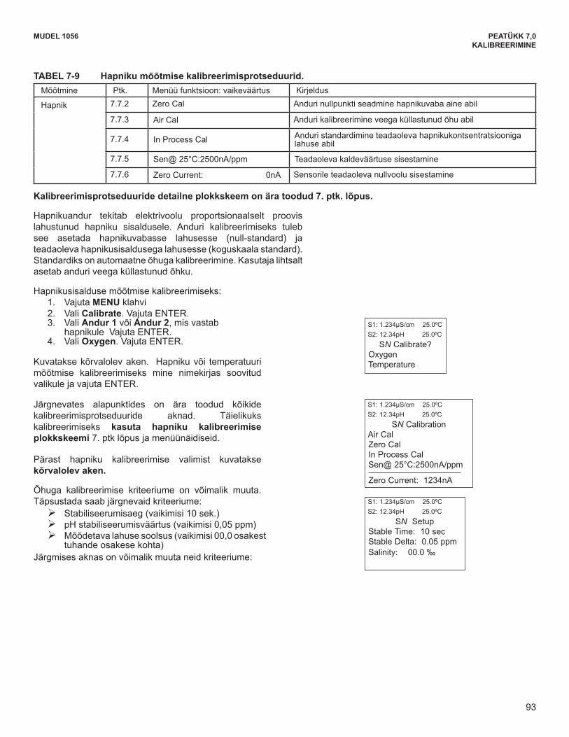
93
MODEL 1056 SECTION 7.0CALIBRATION
A detailed flow diagram is provided at the end of Sec. 7 to guide you through the calibration routines.
Oxygen sensors generate a current directly proportionalto the concentration of dissolved oxygen in the sample.Calibrating the sensor requires exposing it to a solutioncontaining no oxygen (zero standard) and to a solutioncontaining a known amount of oxygen (full-scale standard).Automatic air calibration is standard. The user simplyexposes the sensor to water-saturated air.
To calibrate oxygen: 1. Press the MENU button2. Select Calibrate. Press ENTER. 3. Select Sensor 1 or Sensor 2 corresponding to
oxygen. Press ENTER. 4. Select Oxygen. Press ENTER.
The adjacent screen will appear. To calibrate Oxygenor Temperature, scroll to the desired item and pressENTER
S1: 1.234µS/cm 25.0ºCS2: 12.34pH 25.0ºC
SN Calibrate? Oxygen Temperature
The following sub-sections provide you with the initialdisplay screen that appears for each calibration routine.Use the flow diagram for Oxygen calibration at theend of Sec. 7 and the live screen prompts for each routineto complete calibration.
The adjacent screen appears after selecting Oxygencalibration:
S1: 1.234µS/cm 25.0ºCS2: 12.34pH 25.0ºC
SN CalibrationAir CalZero CalIn Process Cal Sen@ 25°C:2500nA/ppm
Zero Current: 1234nA
Air calibration criteria can be changed. The followingcriteria can be adjusted:
Stabilization time (default 10 sec.) Stabilization pH value (default 0.05 ppm) Salinity of the solution to be measured (default
00.0 parts per thousand)The adjacent screen will appear to allow adjustment ofthese criteria”
S1: 1.234µS/cm 25.0ºCS2: 12.34pH 25.0ºC
SN SetupStable Time: 10 sec Stable Delta: 0.05 ppm Salinity: 00.0 ‰
Measure Sec. Calibration function: default value DescriptionOxygen 7.7.2 Zero Cal Zeroing the sensor in a medium with zero oxygen
7.7.3 Air Cal Calibrating the sensor in a water-saturated air sample
7.7.4 In Process Cal Standardizing to a sample of known oxygen concentration
7.7.5 Sen@ 25°C:2500nA/ppm Entering a known slope value for sensor response
7.7.6 Zero Current: 0nA Entering a known zero current for a specific sensor
TABLE 7- 9 Oxygen Calibration Routines
93
MUDEL 1056 PEATÜKK 7,0KALIBREERIMINE
TABEL 7-9 Hapniku mõõtmise kalibreerimisprotseduurid. Mõõtmine Ptk. Menüü funktsioon: vaikeväärtus Kirjeldus
Hapnik 7.7.2 Zero Cal Anduri nullpunkti seadmine hapnikuvaba aine abil
7.7.3 Air Cal Anduri kalibreerimine veega küllastunud õhu abil
7.7.4 In Process Cal Anduri standardimine teadaoleva hapnikukontsentratsiooniga lahuse abil
7.7.5 Sen@ 25°C:2500nA/ppm Teadaoleva kaldeväärtuse sisestamine
7.7.6 Zero Current: 0nA Sensorile teadaoleva nullvoolu sisestamine
Kalibreerimisprotseduuride detailne plokkskeem on ära toodud 7. ptk. lõpus.
Hapnikuandur tekitab elektrivoolu proportsionaalselt proovislahustunud hapniku sisaldusele. Anduri kalibreerimiseks tuleb see asetada hapnikuvabasse lahusesse (null-standard) ja teadaoleva hapnikusisaldusega lahusesse (koguskaala standard). Standardiks on automaatne õhuga kalibreerimine. Kasutaja lihtsalt asetab anduri veega küllastunud õhku.
Hapnikusisaldusemõõtmisekalibreerimiseks:1. Vajuta MENU klahvi 2. Vali Calibrate. Vajuta ENTER. 3. Vali Andur 1 või Andur 2, mis vastab
hapnikule Vajuta ENTER.4. Vali Oxygen. Vajuta ENTER.
Kuvataksekõrvalolevaken. Hapnikuvõi temperatuurimõõtmise kalibreerimiseks mine nimekirjas soovitud valikule ja vajuta ENTER.
Järgnevates alapunktides on ära toodud kõikide kalibreerimisprotseduuride aknad. Täielikuks kalibreerimiseks kasuta hapniku kalibreerimise plokkskeemi 7. ptk lõpus ja menüünäidiseid.
Pärast hapniku kalibreerimise valimist kuvatakse kõrvalolev aken.
Õhuga kalibreerimise kriteeriume on võimalik muuta. Täpsustada saab järgnevaid kriteeriume:
¾ Stabiliseerumisaeg (vaikimisi 10 sek.) ¾ pHstabiliseerumisväärtus(vaikimisi0,05ppm) ¾ Mõõdetava lahuse soolsus (vaikimisi 00,0 osakest
tuhande osakese kohta) Järgmises aknas on võimalik muuta neid kriteeriume:
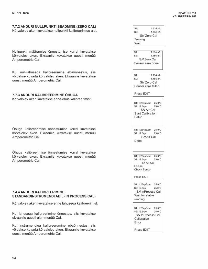
94
PEATÜKK 7,0KALIBREERIMINE
MUDEL 1056
The adjacent screen will appear if In Air Cal is suc-cessful. The screen will return to the AmperometricCal Menu.
The adjacent screen will appear if In Air Cal is suc-cessful. The screen will return to the AmperometricCal Menu.
S1: 1.234µS/cm 25.0ºCS2: 12.34pH 25.0ºC
SN Air Cal FailureCheck Sensor
Press EXIT
S1: 1.234µS/cm 25.0ºCS2: 12.34pH 25.0ºC
SN Air Cal Done
If the In Process Cal is successful, the screen willreturn to the Cal sub-menu.
The adjacent screen may appear if In Zero Cal isunsuccessful. The screen will return to theAmperometric Cal Menu.
7.7.4 CALIBRATING THE SENSOR AGAINST ASTANDARD INSTRUMENT (IN PROCESS CAL)
The adjacent screen will appear prior to In Process Cal
S1: 1.234µS/cm 25.0ºCS2: 12.34pH 25.0ºC SN InProcess Cal
Calibration Error
Press EXIT
S1: 1.234µS/cm 25.0ºCS2: 12.34pH 25.0ºC
SN InProcess CalWait for stablereading.
MODEL 1056 SECTION 7.0CALIBRATION
The adjacent screen will appear if In Zero Cal is suc-cessful. The screen will return to the AmperometricCal Menu.
S1: 1.234 nAS2: 1.456 nA
SN Zero Cal Sensor zero done
7.7.3 CALIBRATING THE SENSOR IN AIRThe adjacent screen will appear prior to Air Cal
The adjacent screen may appear if In Zero Cal isunsuccessful. The screen will return to theAmperometric Cal Menu.
S1: 1.234µS/cm 25.0ºCS2: 12.34pH 25.0ºC
SN Air CalStart CalibrationSetup
S1: 1.234 nAS2: 1.456 nA
SN Zero CalSensor zero failed
Press EXIT
7.7.2 ZEROING THE SENSOR.The adjacent screen will appear during Zero Cal
.
S1: 1.234 nAS2: 1.456 nA
SN Zero CalZeroingWait
94
7.7.2 ANDURI NULLPUNKTI SEADMINE (ZERO CAL) Kõrvalolev aken kuvatakse nullpunkti kalibreerimise ajal.
Nullpunkti määramise õnnestumise korral kuvatakse kõrvalolev aken. Ekraanile kuvatakse uuesti menüü Amperometric Cal.
Kui null-lahusega kalibreerimine ebaõnnestus, siis võidakse kuvada kõrvalolev aken. Ekraanile kuvatakse uuesti menüü Amperometric Cal.
7.7.3 ANDURI KALIBREERIMINE ÕHUGA Kõrvalolev aken kuvatakse enne õhus kalibreerimist
Õhuga kalibreerimise õnnestumise korral kuvatakse kõrvalolev aken. Ekraanile kuvatakse uuesti menüü Amperometric Cal.
Õhuga kalibreerimise õnnestumise korral kuvatakse kõrvalolev aken. Ekraanile kuvatakse uuesti menüü Amperometric Cal.
7.4.4 ANDURI KALIBREERIMINE STANDARDINSTRUMENDI ABIL (IN PROCESS CAL)
Kõrvalolev aken kuvatakse enne lahusega kalibreerimist.
Kui lahusega kalibreerimine õnnestus, siis kuvatakse ekraanile uuesti alammenüü Cal.
Kui instrumendiga kalibreerumine ebaõnnestus, siis võidakse kuvada kõrvalolev aken. Ekraanile kuvatakse uuesti menüü Amperometric Cal.
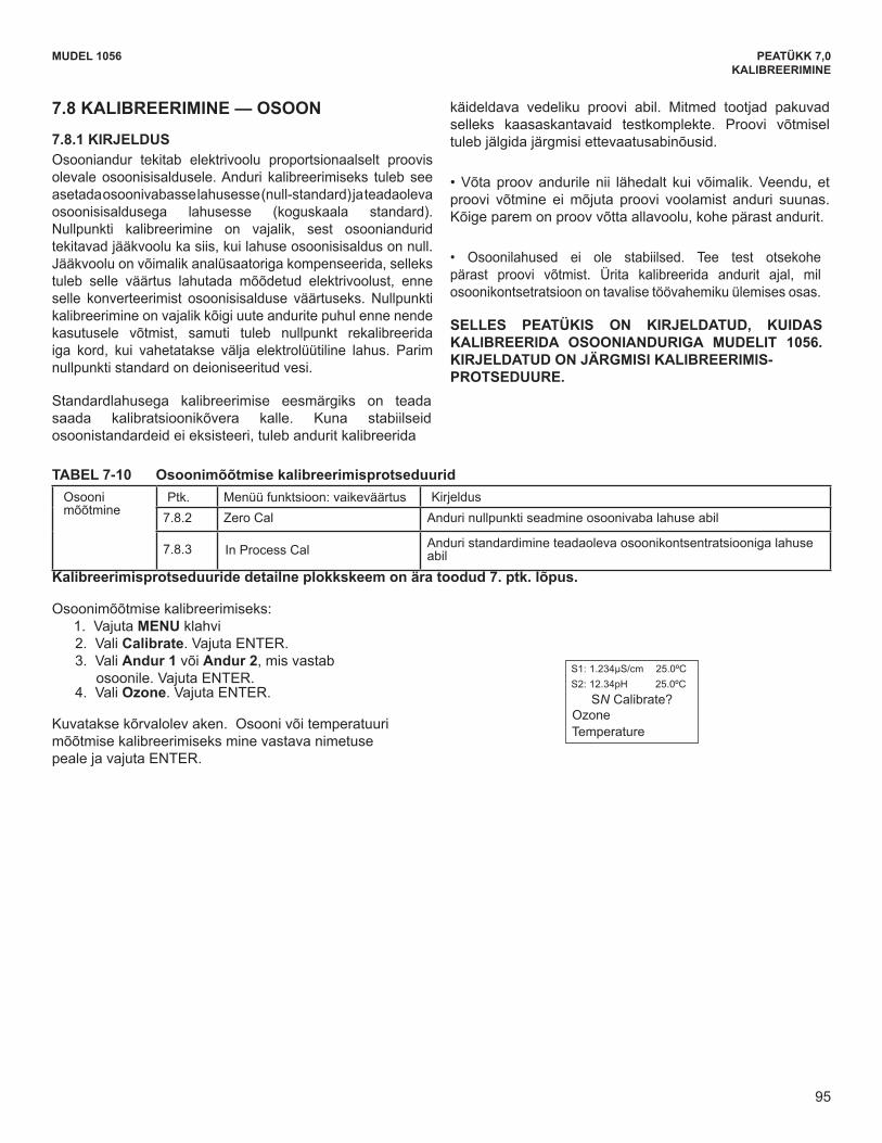
95
MUDEL 1056 PEATÜKK 7,0KALIBREERIMINE
MODEL 1056 SECTION 7.0CALIBRATION
7.8 CALIBRATION — OZONE
7.8.1 DESCRIPTION An ozone sensor generates a current directlyproportional to the concentration of ozone in the sample.Calibrating the sensor requires exposing it to a solutioncontaining no ozone (zero standard) and to a solutioncontaining a known amount of ozone (full-scalestandard). The Zero Calibration is necessary becauseozone sensors, even when no ozone is in the sample,generate a small current called the residual or zerocurrent. The analyzer compensates for the residualcurrent by subtracting it from the measured currentbefore converting the result to an ozone value. Newsensors require zeroing before being placed in service,and sensors should be zeroed whenever the electrolytesolution is replaced. The best zero standard is deionizedwater.
The purpose of the In Process Calibration is to establishthe slope of the calibration curve. Because stable ozonestandards do not exist, the sensor must be calibrated
against a test run on a grab sample of the process liquid.Several manufacturers offer portable test kits for thispurpose. Observe the following precautions when takingand testing the grab sample.• Take the grab sample from a point as close to the sensoras possible. Be sure that taking the sample does notalter the flow of the sample to the sensor. It is best toinstall the sample tap just downstream from the sensor.• Ozone solutions are unstable. Run the test immedi-ately after taking the sample. Try to calibrate the sensorwhen the ozone concentration is at the upper end of thenormal operating range.
THIS SECTION DESCRIBES HOW TO CALIBRATETHE MODEL 1056 WITH AN OZONE SENSOR. THEFOLLOWING CALIBRATION ROUTINES ARE COV-ERED.
Measure Ozone Sec. Calibration function: default value Description7.8.2 Zero Cal Zeroing the sensor in solution with zero ozone
7.8.3 In Process Cal Standardizing to a sample of known ozone concentration
A detailed flow diagram is provided at the end of Sec. 7 to guide you through the calibration routines.
TABLE 7- 10 Ozone Calibration Routines
To calibrate ozone: 1. Press the MENU button2. Select Calibrate. Press ENTER. 3. Select Sensor 1 or Sensor 2 corresponding to
ozone. Press ENTER. 4. Select Ozone. Press ENTER.
The adjacent screen will appear. To calibrate Ozone orTemperature, scroll to the desired item and pressENTER.
S1: 1.234µS/cm 25.0ºCS2: 12.34pH 25.0ºC
SN Calibrate? Ozone Temperature
95
7.8 KALIBREERIMINE — OSOON
7.8.1 KIRJELDUS Osooniandur tekitab elektrivoolu proportsionaalselt proovis olevale osoonisisaldusele. Anduri kalibreerimiseks tuleb see asetada osoonivabasse lahusesse (null-standard) ja teadaoleva osoonisisaldusega lahusesse (koguskaala standard). Nullpunkti kalibreerimine on vajalik, sest osooniandurid tekitavad jääkvoolu ka siis, kui lahuse osoonisisaldus on null. Jääkvoolu on võimalik analüsaatoriga kompenseerida, selleks tuleb selle väärtus lahutada mõõdetud elektrivoolust, enne selle konverteerimist osoonisisalduse väärtuseks. Nullpunkti kalibreerimine on vajalik kõigi uute andurite puhul enne nende kasutusele võtmist, samuti tuleb nullpunkt rekalibreerida iga kord, kui vahetatakse välja elektrolüütiline lahus. Parim nullpunkti standard on deioniseeritud vesi.
Standardlahusega kalibreerimise eesmärgiks on teada saada kalibratsioonikõvera kalle. Kuna stabiilseid osoonistandardeid ei eksisteeri, tuleb andurit kalibreerida
käideldava vedeliku proovi abil. Mitmed tootjad pakuvad selleks kaasaskantavaid testkomplekte. Proovi võtmisel tuleb jälgida järgmisi ettevaatusabinõusid.
•Võtaproovandurilenii lähedalt kui võimalik.Veendu,etproovi võtmine ei mõjuta proovi voolamist anduri suunas. Kõige parem on proov võtta allavoolu, kohe pärast andurit.
• Osoonilahused ei ole stabiilsed. Tee test otsekohepärast proovi võtmist. Ürita kalibreerida andurit ajal, mil osoonikontsetratsioon on tavalise töövahemiku ülemises osas.
SELLES PEATÜKIS ON KIRJELDATUD, KUIDAS KALIBREERIDA OSOONIANDURIGA MUDELIT 1056. KIRJELDATUD ON JÄRGMISI KALIBREERIMIS- PROTSEDUURE.
TABEL 7-10 Osoonimõõtmise kalibreerimisprotseduurid Osooni mõõtmine
Ptk. Menüü funktsioon: vaikeväärtus Kirjeldus7.8.2 Zero Cal Anduri nullpunkti seadmine osoonivaba lahuse abil
7.8.3 In Process Cal Anduri standardimine teadaoleva osoonikontsentratsiooniga lahuse abil
Kalibreerimisprotseduuride detailne plokkskeem on ära toodud 7. ptk. lõpus.
Osoonimõõtmise kalibreerimiseks: 1. Vajuta MENU klahvi 2. Vali Calibrate. Vajuta ENTER. 3. Vali Andur 1 või Andur 2, mis vastab
osoonile. Vajuta ENTER. 4. Vali Ozone. Vajuta ENTER.
Kuvatakse kõrvalolev aken. Osooni või temperatuuri mõõtmise kalibreerimiseks mine vastava nimetuse peale ja vajuta ENTER.
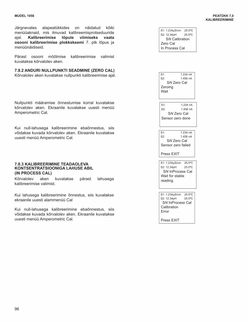
96
PEATÜKK 7,0KALIBREERIMINE
MUDEL 1056MODEL 1056 SECTION 7.0CALIBRATION
7.8.2 ZEROING THE SENSOR.The following screen will appear during Zero Cal
The following sub-sections provide you with theinitial display screen that appears for each calibrationroutine. Use the flow diagram for Ozone calibrationat the end of Sec. 7 and the live screen prompts tocomplete calibration.
The adjacent screen appears after selecting Ozonecalibration:
S1: 1.234 nAS2: 1.456 nA
SN Zero CalZeroingWait
S1: 1.234µS/cm 25.0ºCS2: 12.34pH 25.0ºC
SN CalibrationZero CalIn Process Cal
The following screen may appear if In Zero Cal isunsuccessful. The screen will return to theAmperometric Cal Menu.
The following screen will appear if In Zero Cal issuccessful. The screen will return to theAmperometric Cal Menu.
S1: 1.234 nAS2: 1.456 nA
SN Zero CalSensor zero failed
Press EXIT
S1: 1.234 nAS2: 1.456 nA
SN Zero Cal Sensor zero done
If the In Process Cal is successful, the screen willreturn to the Cal sub-menu.
The following screen may appear if In Zero Cal isunsuccessful. The screen will return to theAmperometric Cal Menu.
7.8.3 IN PROCESS CALIBRATIONThe following screen will appear after selecting InProcess Cal
S1: 1.234µS/cm 25.0ºCS2: 12.34pH 25.0ºC SN InProcess Cal
Calibration Error
Press EXIT
S1: 1.234µS/cm 25.0ºCS2: 12.34pH 25.0ºC
SN InProcess CalWait for stablereading.
96
Järgnevates alapeatükkides on näidatud kõiki menüüaknaid, mis ilmuvad kalibreemisprotseduuride ajal. Kalibreerimise lõpule viimiseks vaata osooni kalibreerimise plokkskeemi 7. ptk lõpus ja menüünäidiseid.
Pärast osooni mõõtmise kalibreerimise valimist kuvatakse kõrvalolev aken.
7.8.2 ANDURI NULLPUNKTI SEADMINE (ZERO CAL) Kõrvalolev aken kuvatakse nullpunkti kalibreerimise ajal.
Nullpunkti määramise õnnestumise korral kuvatakse kõrvalolev aken. Ekraanile kuvatakse uuesti menüü Amperometric Cal.
Kui null-lahusega kalibreerimine ebaõnnestus, siis võidakse kuvada kõrvalolev aken. Ekraanile kuvatakse uuesti menüü Amperometric Cal.
7.8.3 KALIBREERIMINE TEADAOLEVA KONTSENTRATSIOONIGA LAHUSE ABIL (IN PROCESS CAL) Kõrvalolev aken kuvatakse pärast lahusega kalibreerimise valimist.
Kui lahusega kalibreerimine õnnestus, siis kuvatakse ekraanile uuesti alammenüü Cal
Kui null-lahusega kalibreerimine ebaõnnestus, siis võidakse kuvada kõrvalolev aken. Ekraanile kuvatakse uuesti menüü Amperometric Cal.
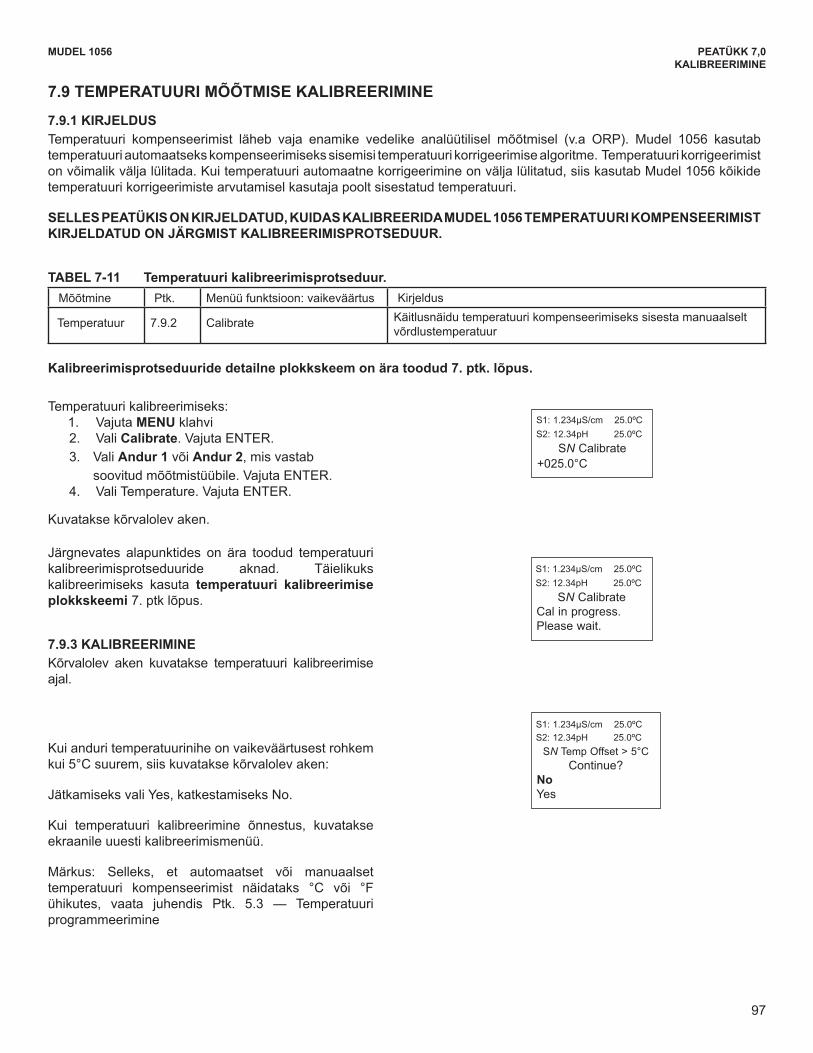
97
MUDEL 1056 PEATÜKK 7,0KALIBREERIMINE
To calibrate temperature: 1. Press the MENU button2. Select Calibrate. Press ENTER. 3. Select Sensor 1 or Sensor 2 corresponding to
the desired measurement. Press ENTER. 4. Select Temperature. Press ENTER.
The adjacent screen will appear.
Measure Sec. Calibration function: default value Description
Temperature 7.9.2 Calibrate Enter a manual reference temperature for temperature compensation of the process measurement
A detailed flow diagram is provided at the end of Sec. 7 to guide you through the calibration routines.
S1: 1.234µS/cm 25.0ºCS2: 12.34pH 25.0ºC
SN Calibrate+025.0°C
The following sub-section provides you with the initialdisplay screen that appears for temperature calibration.Use the flow diagram for Temp calibration at theend of Sec. 7 to complete calibration.
7.9.2 CALIBRATIONThe adjacent screen will appear during TemperatureCal.
If the sensor Temperature offset is greater than 5 ºCfrom the default value, the following screen willappear:
You may continue by selecting Yes or suspend thisoperation by selecting No.
If the Temp Cal is successful, the screen will return tothe Cal Menu.
Note: To select automatic or manual temp compensationor to program temperature units as °C or °F, refer toSec. 5.3 – Programming Temperature in this manual
S1: 1.234µS/cm 25.0ºCS2: 12.34pH 25.0ºC
SN Temp Offset > 5°CContinue?
NoYes
S1: 1.234µS/cm 25.0ºCS2: 12.34pH 25.0ºC
SN CalibrateCal in progress.Please wait.
TABLE 7- 11 Temperature Calibration Routine
MODEL 1056 SECTION 7.0CALIBRATION
7.9 CALIBRATING TEMPERATURE
7.9.1 DESCRIPTION Most liquid analytical measurements require temperature compensation (except ORP). The Model 1056 performstemperature compensation automatically by applying internal temperature correction algorithms. Temperature cor-rection can also be turned off. If temperature correction is off, the Model 1056 uses the manual temperature entered bythe user in all temperature correction calculations.
THIS SECTION DESCRIBES HOW TO CALIBRATE TEMPERATURE IN THE MODEL 1056 ANALYZER. THEFOLLOWING CALIBRATION ROUTINE IS COVERED.
97
7.9 TEMPERATUURI MÕÕTMISE KALIBREERIMINE
7.9.1 KIRJELDUS Temperatuuri kompenseerimist läheb vaja enamike vedelike analüütilisel mõõtmisel (v.a ORP). Mudel 1056 kasutab temperatuuri automaatseks kompenseerimiseks sisemisi temperatuuri korrigeerimise algoritme. Temperatuuri korrigeerimist on võimalik välja lülitada. Kui temperatuuri automaatne korrigeerimine on välja lülitatud, siis kasutab Mudel 1056 kõikide temperatuuri korrigeerimiste arvutamisel kasutaja poolt sisestatud temperatuuri.
SELLES PEATÜKIS ON KIRJELDATUD, KUIDAS KALIBREERIDA MUDEL 1056 TEMPERATUURI KOMPENSEERIMIST KIRJELDATUD ON JÄRGMIST KALIBREERIMISPROTSEDUUR.
TABEL 7-11 Temperatuuri kalibreerimisprotseduur. Mõõtmine Ptk. Menüü funktsioon: vaikeväärtus Kirjeldus
Temperatuur 7.9.2 Calibrate Käitlusnäidu temperatuuri kompenseerimiseks sisesta manuaalselt võrdlustemperatuur
Kalibreerimisprotseduuride detailne plokkskeem on ära toodud 7. ptk. lõpus.
Temperatuuri kalibreerimiseks: 1. Vajuta MENU klahvi 2. Vali Calibrate. Vajuta ENTER. 3. Vali Andur 1 või Andur 2, mis vastab soovitud mõõtmistüübile. Vajuta ENTER. 4. Vali Temperature. Vajuta ENTER.
Kuvatakse kõrvalolev aken.
Järgnevates alapunktides on ära toodud temperatuuri kalibreerimisprotseduuride aknad. Täielikuks kalibreerimiseks kasuta temperatuuri kalibreerimise plokkskeemi 7. ptk lõpus.
7.9.3 KALIBREERIMINE Kõrvalolev aken kuvatakse temperatuuri kalibreerimise ajal.
Kui anduri temperatuurinihe on vaikeväärtusest rohkem kui 5°C suurem, siis kuvatakse kõrvalolev aken:
Jätkamiseks vali Yes, katkestamiseks No.
Kui temperatuuri kalibreerimine õnnestus, kuvatakse ekraanile uuesti kalibreerimismenüü.
Märkus: Selleks, et automaatset või manuaalset temperatuuri kompenseerimist näidataks °C või °F ühikutes, vaata juhendis Ptk. 5.3 — Temperatuuri programmeerimine
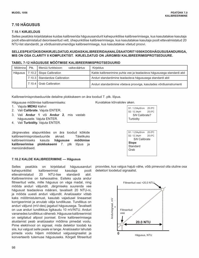
98
The following sub-sections provide you with the initialdisplay screen that appears for each calibration rou-tine. Use the flow diagram for Turbidity calibrationat the end of Sec. 7 and the live screen prompts tocomplete calibration.
MODEL 1056 SECTION 7.0CALIBRATION
7.10 TURBIDITY
7.10.1 DESCRIPTION This section describes how to calibrate the turbidity sensor against a user-prepared standard as a 2-point calibra-tion with di-ionized water, against a 20 NTU user-prepared standard as a single point calibration, and against agrab sample using a reference turbidimeter.
THIS SECTION DESCRIBES HOW TO CALIBRATE THE MODEL 1056 WITH AN ATTACHED TURBIDITYSENSOR AS PART OF THE COMPLETE CLARITY II TURBIDITY SYSTEM. THE FOLLOWING CALIBRATIONROUTINES ARE COVERED.
To calibrate Turbidity: 1. Press the MENU button2. Select Calibrate. Press ENTER. 3. Select Sensor 1 or Sensor 2 corresponding toTurbidity. Press ENTER. 4. Select Turbidity. Press ENTER.
The following screen will appear.
7.10.2 SLOPE CALIBRATION — Turbidity
This section describes how to conduct a 2-point cali-bration of the turbidity sensor against a user-prepared20NTU standard. The calibration requires two steps.First, immerse the sensor in filtered water having verylow turbidity and measure the sensor output. Next,increase the turbidity of the filtered water by a knownamount, typically 20 NTU, and measure the sensoroutput again. The analyzer takes the two measure-ments, applies a linearization correction (if necessary),and calculates the sensitivity. Sensitivity is the sensoroutput (in mV) divided by turbidity. A typical new sen-sor has a sensitivity of about 10 mV/NTU. As the sen-sor ages, the sensitivity decreases. The figure belowillustrates how turbidity calibration works. Beforebeginning the calibration, the analyzer does a darkcurrent measurement. Dark current is the signal gener-ated by the detector when no light is falling on it. Theanalyzer subtracts the dark current from the raw scat-
tered light signal and converts the result to turbidity. Inhighly filtered samples, which scatter little light, thedark current can be a substantial amount of the signalgenerated by the detector.
A detailed flow diagram is provided at the end of Sec. 7 to guide you through the calibration routines.
Measure Sec. Calibration function: default value DescriptionTurbidity 7.10.2 Slope Calibration Slope cal with pure water and a standard of known turbidity
7.10.3 Standardize Calibration Standardizing the sensor to a known turbidity
7.10.4 Grab Calibration Standardizing the sensor to a known turbidity based on areference turbidimeter
S1: 1.234µS/cm 25.0ºCS2: 12.34pH 25.0ºC
SN Calibrate?Turbidity
S1: 1.234µS/cm 25.0ºCS2: 12.34pH 25.0ºC
SN CalibrateSlopeStandardGrab
98
TABLE 7-12 TURBIDITY CALIBRATION ROUTINES
PEATÜKK 7,0KALIBREERIMINE
MUDEL 1056
The following sub-sections provide you with the initialdisplay screen that appears for each calibration rou-tine. Use the flow diagram for Turbidity calibrationat the end of Sec. 7 and the live screen prompts tocomplete calibration.
MODEL 1056 SECTION 7.0CALIBRATION
7.10 TURBIDITY
7.10.1 DESCRIPTION This section describes how to calibrate the turbidity sensor against a user-prepared standard as a 2-point calibra-tion with di-ionized water, against a 20 NTU user-prepared standard as a single point calibration, and against agrab sample using a reference turbidimeter.
THIS SECTION DESCRIBES HOW TO CALIBRATE THE MODEL 1056 WITH AN ATTACHED TURBIDITYSENSOR AS PART OF THE COMPLETE CLARITY II TURBIDITY SYSTEM. THE FOLLOWING CALIBRATIONROUTINES ARE COVERED.
To calibrate Turbidity: 1. Press the MENU button2. Select Calibrate. Press ENTER. 3. Select Sensor 1 or Sensor 2 corresponding toTurbidity. Press ENTER. 4. Select Turbidity. Press ENTER.
The following screen will appear.
7.10.2 SLOPE CALIBRATION — Turbidity
This section describes how to conduct a 2-point cali-bration of the turbidity sensor against a user-prepared20NTU standard. The calibration requires two steps.First, immerse the sensor in filtered water having verylow turbidity and measure the sensor output. Next,increase the turbidity of the filtered water by a knownamount, typically 20 NTU, and measure the sensoroutput again. The analyzer takes the two measure-ments, applies a linearization correction (if necessary),and calculates the sensitivity. Sensitivity is the sensoroutput (in mV) divided by turbidity. A typical new sen-sor has a sensitivity of about 10 mV/NTU. As the sen-sor ages, the sensitivity decreases. The figure belowillustrates how turbidity calibration works. Beforebeginning the calibration, the analyzer does a darkcurrent measurement. Dark current is the signal gener-ated by the detector when no light is falling on it. Theanalyzer subtracts the dark current from the raw scat-
tered light signal and converts the result to turbidity. Inhighly filtered samples, which scatter little light, thedark current can be a substantial amount of the signalgenerated by the detector.
A detailed flow diagram is provided at the end of Sec. 7 to guide you through the calibration routines.
Measure Sec. Calibration function: default value DescriptionTurbidity 7.10.2 Slope Calibration Slope cal with pure water and a standard of known turbidity
7.10.3 Standardize Calibration Standardizing the sensor to a known turbidity
7.10.4 Grab Calibration Standardizing the sensor to a known turbidity based on areference turbidimeter
S1: 1.234µS/cm 25.0ºCS2: 12.34pH 25.0ºC
SN Calibrate?Turbidity
S1: 1.234µS/cm 25.0ºCS2: 12.34pH 25.0ºC
SN CalibrateSlopeStandardGrab
98
TABLE 7-12 TURBIDITY CALIBRATION ROUTINES
7.10 HÄGUSUS
7.10.1 KIRJELDUS Selles peatükis kirjeldatakse kuidas kalibreerida hägususandurit kahepunktilise kalibreerimisega, kus kasutatakse kasutaja poolt ettevalmistatud deioniseeritud vett, ühepunktilise kalibreerimisega, kus kasutatakse kasutaja poolt ettevalmistatud 20 NTU-list standardit, ja võrdlusinstrumendiga kalibreerimisega, kus kasutatakse võetud proovi.
SELLES PEATÜKIS ON KIRJELDATUD, KUIDAS KALIBREERIDA ANALÜSAATORIT 1056 KOOS HÄGUSUSANDURIGA, MIS ON OSA CLARITY II KOMPLEKTIST. KIRJELDATUD ON JÄRGMISI KALIBREERIMISPROTSEDUURE.
TABEL 7-12 HÄGUSUSE MÕÕTMISE KALIBREERIMISPROTSEDUURID Mõõtmine Ptk. Menüü funktsioon: vaikeväärtus Kirjeldus
Hägusus 7.10.2 Slope Calibration Kalde kalibreerimine puhta vee ja teadaoleva hägususega standardi abil
7.10.3 Standardize Calibration Anduri standardimine teadaoleva hägususega standardi abil
7.10.4 Grab Calibration Anduri standardimine võetava prooviga, kasutades võrdlusinstrumenti
Kalibreerimisprotseduuride detailne plokkskeem on ära toodud 7. ptk. lõpus.
Hägususemõõtmisekalibreermiseks:1. Vajuta MENU klahvi 2. Vali Calibrate. Vajuta ENTER. 3. Vali Andur 1 või Andur 2, mis vastab hägususele. Vajuta ENTER. 4. Vali Turbidity. Vajuta ENTER.
Järgnevates alapunktides on ära toodud kõikide kalibreerimisprotseduuride aknad. Täielikuks kalibreerimiseks kasuta hägususe mõõtmise kalibreerimise plokkskeemi 7. ptk lõpus ja menüünäidiseid.
7.10.2 KALDE KALIBREERIMINE — Hägusus
Selles peatükis on kirjeldatud hägususanduri kahepunktilist kalibreerimist kasutaja poolt ettevalmistatud 20 NTU-lise standardi abil. Kalibreerimine on kaheosaline. Esiteks uputa andur filtreeritud vette, mille hägusus on väga madal, ningmõõda anduri väljundit. Järgmiseks suurenda vee hägusust teadaoleva määrani, tavaliselt 20 NTU-ni, ja mõõda uuesti anduri väljundit. Analüsaator võtab kaks mõõtmistulemust, kasutab vajadusel lineaarset korrigeerimist ja arvutab välja tundlikuse. Tundlikus on anduri väljund (mV-des) jagatud hägususega. Tavaliselt on uue anduri tundlikkus ligikaudu 10 mV/NTU. Anduri vananedestundlikkusväheneb.Hägususekalibreerimiston selgitatud allpool joonisel. Enne kalibreerimisega alustamist peab analüsaator mõõtma pimedat voolu. Pime elektrivool on signaal, mida detektor toodab ka siis, kui valgust selle peale ei lange. Analüsaator lahutab pimeda voolu hiljem mõõdetud valgussignaalist ja konverteerib tulemuse hägususeks. Kõrgelt filtreeritud
Kuvatakse kõrvalolev aken.
proovides, kus valgus hajub vähe, võib pimevool olla oluline osa detektori toodetud signaalist.
Hägusus,NTU
Filtreeritud vesi
Filtreeritud vesi +20,0 NTU
And
uris
igna
al, m
V
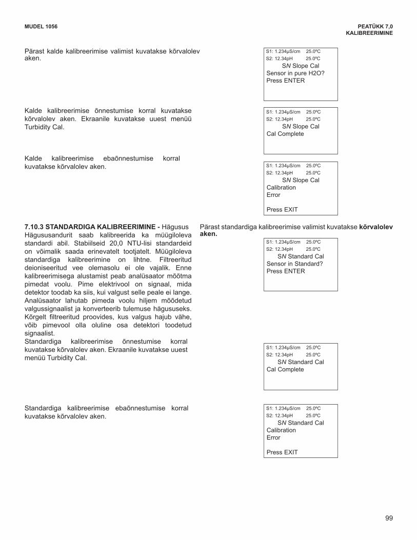
99
The following screen will appear if Standard Cal issuccessful. The screen will return to the Turbidity CalMenu.
7.10.3 STANDARDIZE CALIBRATION - Turbidity The turbidity sensor can also be calibrated against acommercial standard. Stable 20.0 NTU standards areavailable from a number of sources. Calibration using acommercial standard is simple. Filtered deionized wateris not required. Before beginning the calibration, theanalyzer does a dark current measurement. Dark cur-rent is the signal generated by the detector even whenno light is falling on it. The analyzer subtracts the darkcurrent from the raw scattered light signal and convertsthe result to turbidity. In highly filtered samples, whichscatter little light, the dark current can be a substantialamount of the signal generated by the sensor.
This screen appears after selecting Standard calibration.
The following screen may appear if Slope Cal isunsuccessful.
This screen appears after selecting Slope calibration.
MODEL 1056 SECTION 7.0CALIBRATION
The following screen will appear if Slope Cal is suc-cessful. The screen will return to the Turbidity CalMenu.
S1: 1.234µS/cm 25.0ºCS2: 12.34pH 25.0ºC
SN Slope CalSensor in pure H2O? Press ENTER
S1: 1.234µS/cm 25.0ºCS2: 12.34pH 25.0ºC
SN Slope CalCal Complete
S1: 1.234µS/cm 25.0ºCS2: 12.34pH 25.0ºC
SN Standard CalCal Complete
S1: 1.234µS/cm 25.0ºCS2: 12.34pH 25.0ºC
SN Slope CalCalibration Error
Press EXIT
S1: 1.234µS/cm 25.0ºCS2: 12.34pH 25.0ºC
SN Standard CalSensor in Standard?Press ENTER
The following screen may appear if Standard Cal isunsuccessful.
S1: 1.234µS/cm 25.0ºCS2: 12.34pH 25.0ºC
SN Standard CalCalibration Error
Press EXIT
99
MUDEL 1056 PEATÜKK 7,0KALIBREERIMINE
The following screen will appear if Standard Cal issuccessful. The screen will return to the Turbidity CalMenu.
7.10.3 STANDARDIZE CALIBRATION - Turbidity The turbidity sensor can also be calibrated against acommercial standard. Stable 20.0 NTU standards areavailable from a number of sources. Calibration using acommercial standard is simple. Filtered deionized wateris not required. Before beginning the calibration, theanalyzer does a dark current measurement. Dark cur-rent is the signal generated by the detector even whenno light is falling on it. The analyzer subtracts the darkcurrent from the raw scattered light signal and convertsthe result to turbidity. In highly filtered samples, whichscatter little light, the dark current can be a substantialamount of the signal generated by the sensor.
This screen appears after selecting Standard calibration.
The following screen may appear if Slope Cal isunsuccessful.
This screen appears after selecting Slope calibration.
MODEL 1056 SECTION 7.0CALIBRATION
The following screen will appear if Slope Cal is suc-cessful. The screen will return to the Turbidity CalMenu.
S1: 1.234µS/cm 25.0ºCS2: 12.34pH 25.0ºC
SN Slope CalSensor in pure H2O? Press ENTER
S1: 1.234µS/cm 25.0ºCS2: 12.34pH 25.0ºC
SN Slope CalCal Complete
S1: 1.234µS/cm 25.0ºCS2: 12.34pH 25.0ºC
SN Standard CalCal Complete
S1: 1.234µS/cm 25.0ºCS2: 12.34pH 25.0ºC
SN Slope CalCalibration Error
Press EXIT
S1: 1.234µS/cm 25.0ºCS2: 12.34pH 25.0ºC
SN Standard CalSensor in Standard?Press ENTER
The following screen may appear if Standard Cal isunsuccessful.
S1: 1.234µS/cm 25.0ºCS2: 12.34pH 25.0ºC
SN Standard CalCalibration Error
Press EXIT
99
Pärast kalde kalibreerimise valimist kuvatakse kõrvalolev aken.
Kalde kalibreerimise õnnestumise korral kuvatakse kõrvalolev aken. Ekraanile kuvatakse uuest menüü Turbidity Cal.
Kalde kalibreerimise ebaõnnestumise korral kuvatakse kõrvalolev aken.
7.10.3 STANDARDIGA KALIBREERIMINE - HägususHägususandurit saab kalibreerida ka müügilolevastandardi abil. Stabiilseid 20,0 NTU-lisi standardeid on võimalik saada erinevatelt tootjatelt. Müügiloleva standardiga kalibreerimine on lihtne. Filtreeritud deioniseeritud vee olemasolu ei ole vajalik. Enne kalibreerimisega alustamist peab analüsaator mõõtma pimedat voolu. Pime elektrivool on signaal, mida detektor toodab ka siis, kui valgust selle peale ei lange. Analüsaator lahutab pimeda voolu hiljem mõõdetud valgussignaalist ja konverteerib tulemuse hägususeks. Kõrgelt filtreeritud proovides, kus valgus hajub vähe,võib pimevool olla oluline osa detektori toodetud signaalist. Standardiga kalibreerimise õnnestumise korral kuvatakse kõrvalolev aken. Ekraanile kuvatakse uuest menüü Turbidity Cal.
Standardiga kalibreerimise ebaõnnestumise korral kuvatakse kõrvalolev aken.
Pärast standardiga kalibreerimise valimist kuvatakse kõrvalolev aken.
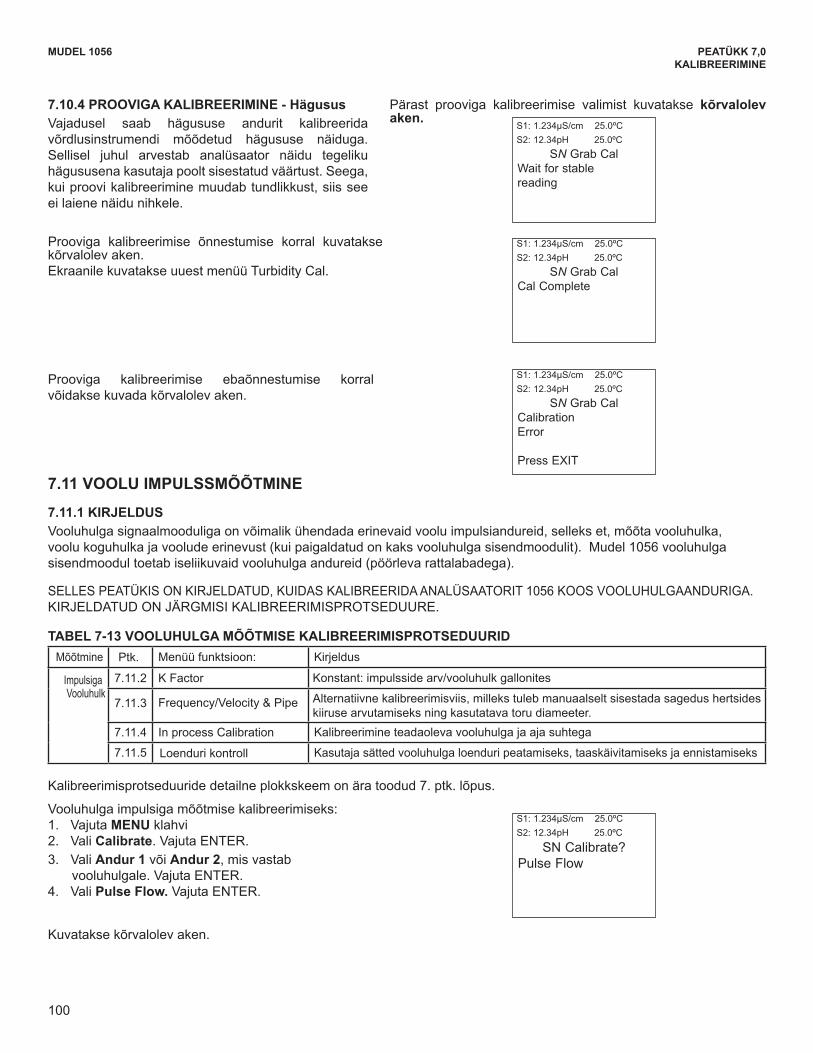
100
The following screen may appear if Grab Cal isunsuccessful.
The following screen will appear if Grab Cal is successful.The screen will return to the Turbidity Cal Menu.
7.10.4 GRAB CALIBRATION - Turbidity If desired, the turbidity sensor can be calibratedagainst the turbidity reading from another instrument.The analyzer treats the value entered by the user asthough it were the true turbidity of the sample.Therefore, grab sample calibration changes the sensi-tivity, it does not apply an offset to the reading.
This screen appears after selecting Grab calibration.
To calibrate Pulse Flow: 1. Press the MENU button2. Select Calibrate. Press ENTER. 3. Select Sensor 1 or Sensor 2 corresponding to
Flow. Press ENTER. 4. Select Pulse Flow. Press ENTER.
The following screen will appear.
A detailed flow diagram is provided at the end of Sec. 7 to guide you through the calibration routines.
MODEL 1056 SECTION 7.0CALIBRATION
7.11 PULSE FLOW
7.11.1 DESCRIPTION A variety of pulse flow sensors can be wired to the Flow signal input board to measure flow volume, total volumeand flow difference (if 2 Flow signal boards are installed). The Model 1056 Flow signal board will support flowsensors that are self-driven (powered by the rotation of the impeller paddle-wheel).
THIS SECTION DESCRIBES HOW TO CALIBRATE THE MODEL 1056 WITH AN ATTACHED FLOW SENSOR.THE FOLLOWING CALIBRATION ROUTINES ARE COVERED.
S1: 1.234µS/cm 25.0ºCS2: 12.34pH 25.0ºC
SN Grab CalWait for stablereading
S1: 1.234µS/cm 25.0ºCS2: 12.34pH 25.0ºC
SN Grab CalCal Complete
S1: 1.234µS/cm 25.0ºCS2: 12.34pH 25.0ºC
SN Grab CalCalibration Error
Press EXIT
S1: 1.234µS/cm 25.0ºCS2: 12.34pH 25.0ºC
SN Calibrate? Pulse Flow
Measure Sec. Calibration function DescriptionPulseFlow
7.11.2 K Factor A constant value representing pulses/Gal of flow
7.11.3 Frequency/Velocity & Pipe Alternate cal method – requires manual entry of frequency (Hz) per velocity and Pipe diameter used
7.11.4 In process Calibration Calibration based on known volume per unit of time 7.11.5 Totalizer Control User settings to stop, restart and reset total volume meter
TABLE 7-13 FLOW CALIBRATION ROUTINES
100
PEATÜKK 7,0KALIBREERIMINE
MUDEL 1056
The following screen may appear if Grab Cal isunsuccessful.
The following screen will appear if Grab Cal is successful.The screen will return to the Turbidity Cal Menu.
7.10.4 GRAB CALIBRATION - Turbidity If desired, the turbidity sensor can be calibratedagainst the turbidity reading from another instrument.The analyzer treats the value entered by the user asthough it were the true turbidity of the sample.Therefore, grab sample calibration changes the sensi-tivity, it does not apply an offset to the reading.
This screen appears after selecting Grab calibration.
To calibrate Pulse Flow: 1. Press the MENU button2. Select Calibrate. Press ENTER. 3. Select Sensor 1 or Sensor 2 corresponding to
Flow. Press ENTER. 4. Select Pulse Flow. Press ENTER.
The following screen will appear.
A detailed flow diagram is provided at the end of Sec. 7 to guide you through the calibration routines.
MODEL 1056 SECTION 7.0CALIBRATION
7.11 PULSE FLOW
7.11.1 DESCRIPTION A variety of pulse flow sensors can be wired to the Flow signal input board to measure flow volume, total volumeand flow difference (if 2 Flow signal boards are installed). The Model 1056 Flow signal board will support flowsensors that are self-driven (powered by the rotation of the impeller paddle-wheel).
THIS SECTION DESCRIBES HOW TO CALIBRATE THE MODEL 1056 WITH AN ATTACHED FLOW SENSOR.THE FOLLOWING CALIBRATION ROUTINES ARE COVERED.
S1: 1.234µS/cm 25.0ºCS2: 12.34pH 25.0ºC
SN Grab CalWait for stablereading
S1: 1.234µS/cm 25.0ºCS2: 12.34pH 25.0ºC
SN Grab CalCal Complete
S1: 1.234µS/cm 25.0ºCS2: 12.34pH 25.0ºC
SN Grab CalCalibration Error
Press EXIT
S1: 1.234µS/cm 25.0ºCS2: 12.34pH 25.0ºC
SN Calibrate? Pulse Flow
Measure Sec. Calibration function DescriptionPulseFlow
7.11.2 K Factor A constant value representing pulses/Gal of flow
7.11.3 Frequency/Velocity & Pipe Alternate cal method – requires manual entry of frequency (Hz) per velocity and Pipe diameter used
7.11.4 In process Calibration Calibration based on known volume per unit of time 7.11.5 Totalizer Control User settings to stop, restart and reset total volume meter
TABLE 7-13 FLOW CALIBRATION ROUTINES
100
7.10.4 PROOVIGA KALIBREERIMINE - Hägusus Vajadusel saab hägususe andurit kalibreerida võrdlusinstrumendi mõõdetud hägususe näiduga. Sellisel juhul arvestab analüsaator näidu tegeliku hägususena kasutaja poolt sisestatud väärtust. Seega, kui proovi kalibreerimine muudab tundlikkust, siis see ei laiene näidu nihkele.
Prooviga kalibreerimise õnnestumise korral kuvatakse kõrvalolev aken. Ekraanile kuvatakse uuest menüü Turbidity Cal.
Prooviga kalibreerimise ebaõnnestumise korral võidakse kuvada kõrvalolev aken.
Pärast prooviga kalibreerimise valimist kuvatakse kõrvalolev aken.
7.11 VOOLU IMPULSSMÕÕTMINE
7.11.1 KIRJELDUS Vooluhulga signaalmooduliga on võimalik ühendada erinevaid voolu impulsiandureid, selleks et, mõõta vooluhulka, voolu koguhulka ja voolude erinevust (kui paigaldatud on kaks vooluhulga sisendmoodulit). Mudel 1056 vooluhulga sisendmoodul toetab iseliikuvaid vooluhulga andureid (pöörleva rattalabadega).
SELLESPEATÜKISONKIRJELDATUD,KUIDASKALIBREERIDAANALÜSAATORIT1056KOOSVOOLUHULGAANDURIGA.KIRJELDATUD ON JÄRGMISI KALIBREERIMISPROTSEDUURE.
TABEL 7-13 VOOLUHULGA MÕÕTMISE KALIBREERIMISPROTSEDUURID Mõõtmine Ptk. Menüü funktsioon: Kirjeldus
ImpulsigaVooluhulk
7.11.2 K Factor Konstant: impulsside arv/vooluhulk gallonites
7.11.3 Frequency/Velocity & Pipe Alternatiivne kalibreerimisviis, milleks tuleb manuaalselt sisestada sagedus hertsides kiiruse arvutamiseks ning kasutatava toru diameeter.
7.11.4 In process Calibration Kalibreerimine teadaoleva vooluhulga ja aja suhtega
7.11.5 Loenduri kontroll Kasutaja sätted vooluhulga loenduri peatamiseks, taaskäivitamiseks ja ennistamiseks
Kalibreerimisprotseduuride detailne plokkskeem on ära toodud 7. ptk. lõpus.
Vooluhulga impulsiga mõõtmise kalibreerimiseks: 1. Vajuta MENU klahvi 2. Vali Calibrate. Vajuta ENTER. 3. Vali Andur 1 või Andur 2, mis vastab
vooluhulgale. Vajuta ENTER. 4. Vali Pulse Flow. Vajuta ENTER.
Kuvatakse kõrvalolev aken.
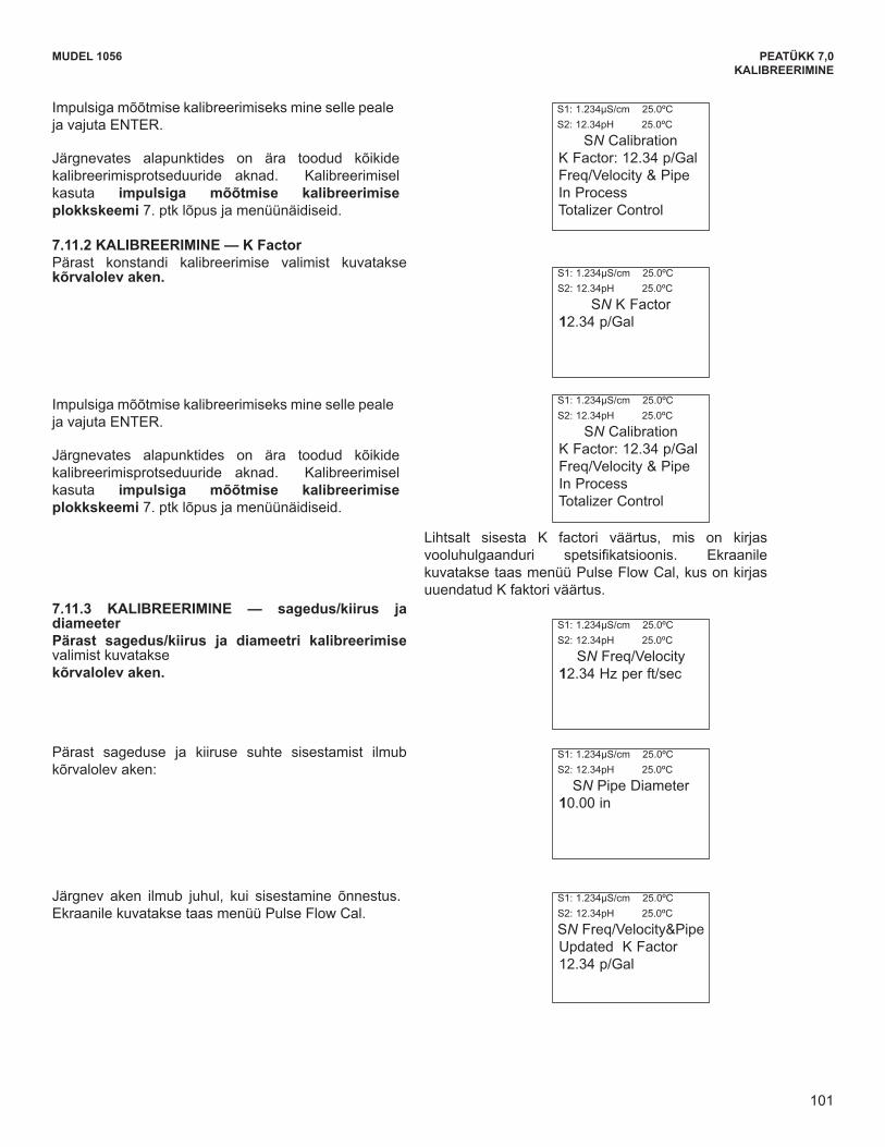
101
MODEL 1056 SECTION 7.0CALIBRATION
To calibrate Pulse Flow scroll to the desired item andpress ENTER.
The following sub-sections provide you with the initialdisplay screen that appears for each calibration rou-tine. Use the diagram for Pulse Flow calibration atthe end of Sec. 7 and the live screen prompts to com-plete calibration.
.
To calibrate Pulse Flow scroll to the desired item andpress ENTER.
The following sub-sections provide you with the initialdisplay screen that appears for each calibration rou-tine. Use the diagram for Pulse Flow calibration atthe end of Sec. 7 and the live screen prompts to com-plete calibration.
. Simply enter the know K factor provided with the flowsensor specifications. The screen will return to thePulse Flow Cal Menu and the updated K factor willappear.
7.11.3 CALIBRATION — Freq/Velocity & PipeThis screen appears after selecting Freq/Velocity &Pipe calibration.
After completing the entry of the Freq/Velocity ratio, thefollowing screen will appear:
7.11.2 CALIBRATION — K Factor This screen appears after selecting K Factor.
.
S1: 1.234µS/cm 25.0ºCS2: 12.34pH 25.0ºC
SN CalibrationK Factor: 12.34 p/Gal Freq/Velocity & PipeIn ProcessTotalizer Control
S1: 1.234µS/cm 25.0ºCS2: 12.34pH 25.0ºC
SN CalibrationK Factor: 12.34 p/Gal Freq/Velocity & PipeIn ProcessTotalizer Control
S1: 1.234µS/cm 25.0ºCS2: 12.34pH 25.0ºC
SN Freq/Velocity12.34 Hz per ft/sec
S1: 1.234µS/cm 25.0ºCS2: 12.34pH 25.0ºC
SN Pipe Diameter10.00 in
S1: 1.234µS/cm 25.0ºCS2: 12.34pH 25.0ºC
SN K Factor12.34 p/Gal
The following screen will appear if the entries are suc-cessful. The screen will return to the Pulse Flow CalMenu.
S1: 1.234µS/cm 25.0ºCS2: 12.34pH 25.0ºC
SN Freq/Velocity&PipeUpdated K Factor 12.34 p/Gal
101
MUDEL 1056 PEATÜKK 7,0KALIBREERIMINE
MODEL 1056 SECTION 7.0CALIBRATION
To calibrate Pulse Flow scroll to the desired item andpress ENTER.
The following sub-sections provide you with the initialdisplay screen that appears for each calibration rou-tine. Use the diagram for Pulse Flow calibration atthe end of Sec. 7 and the live screen prompts to com-plete calibration.
.
To calibrate Pulse Flow scroll to the desired item andpress ENTER.
The following sub-sections provide you with the initialdisplay screen that appears for each calibration rou-tine. Use the diagram for Pulse Flow calibration atthe end of Sec. 7 and the live screen prompts to com-plete calibration.
. Simply enter the know K factor provided with the flowsensor specifications. The screen will return to thePulse Flow Cal Menu and the updated K factor willappear.
7.11.3 CALIBRATION — Freq/Velocity & PipeThis screen appears after selecting Freq/Velocity &Pipe calibration.
After completing the entry of the Freq/Velocity ratio, thefollowing screen will appear:
7.11.2 CALIBRATION — K Factor This screen appears after selecting K Factor.
.
S1: 1.234µS/cm 25.0ºCS2: 12.34pH 25.0ºC
SN CalibrationK Factor: 12.34 p/Gal Freq/Velocity & PipeIn ProcessTotalizer Control
S1: 1.234µS/cm 25.0ºCS2: 12.34pH 25.0ºC
SN CalibrationK Factor: 12.34 p/Gal Freq/Velocity & PipeIn ProcessTotalizer Control
S1: 1.234µS/cm 25.0ºCS2: 12.34pH 25.0ºC
SN Freq/Velocity12.34 Hz per ft/sec
S1: 1.234µS/cm 25.0ºCS2: 12.34pH 25.0ºC
SN Pipe Diameter10.00 in
S1: 1.234µS/cm 25.0ºCS2: 12.34pH 25.0ºC
SN K Factor12.34 p/Gal
The following screen will appear if the entries are suc-cessful. The screen will return to the Pulse Flow CalMenu.
S1: 1.234µS/cm 25.0ºCS2: 12.34pH 25.0ºC
SN Freq/Velocity&PipeUpdated K Factor 12.34 p/Gal
101
Impulsiga mõõtmise kalibreerimiseks mine selle peale ja vajuta ENTER.
Järgnevates alapunktides on ära toodud kõikide kalibreerimisprotseduuride aknad. Kalibreerimisel kasuta impulsiga mõõtmise kalibreerimise plokkskeemi 7. ptk lõpus ja menüünäidiseid.
7.11.2 KALIBREERIMINE — K Factor Pärast konstandi kalibreerimise valimist kuvatakse kõrvalolev aken.
Impulsiga mõõtmise kalibreerimiseks mine selle peale ja vajuta ENTER.
Järgnevates alapunktides on ära toodud kõikide kalibreerimisprotseduuride aknad. Kalibreerimisel kasuta impulsiga mõõtmise kalibreerimise plokkskeemi 7. ptk lõpus ja menüünäidiseid.
7.11.3 KALIBREERIMINE — sagedus/kiirus ja diameeter Pärast sagedus/kiirus ja diameetri kalibreerimise valimist kuvataksekõrvalolev aken.
Pärast sageduse ja kiiruse suhte sisestamist ilmub kõrvalolev aken:
Järgnev aken ilmub juhul, kui sisestamine õnnestus. Ekraanile kuvatakse taas menüü Pulse Flow Cal.
Lihtsalt sisesta K factori väärtus, mis on kirjas vooluhulgaanduri spetsifikatsioonis. Ekraanilekuvatakse taas menüü Pulse Flow Cal, kus on kirjas uuendatud K faktori väärtus.
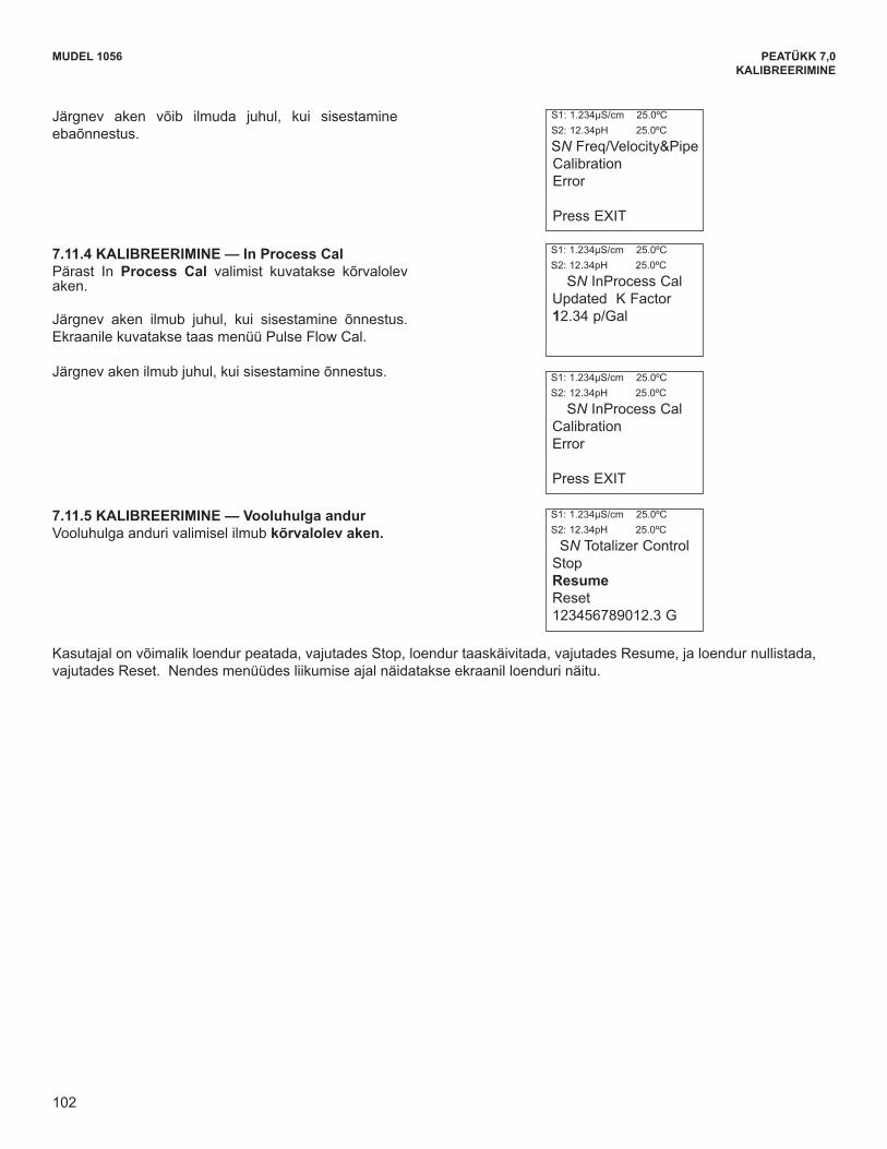
102
PEATÜKK 7,0KALIBREERIMINE
MUDEL 1056MODEL 1056 SECTION 7.0CALIBRATION
The following screen may appear if the entries areunsuccessful.
7.11.5 CALIBRATION — Totalizer Control This screen appears after selecting Totalizer Control.
7.11.4 CALIBRATION — In Process Cal This screen appears after selecting In Process Cal.
The following screen will appear if the entries are suc-cessful. The screen will return to the Pulse Flow CalMenu.
The following screen will appear if the entries are suc-cessful.
The user can suspend the totalizer by selecting Stop, re-enable the totalizer by selecting Resume and return thetotalizer volume count to zero by selecting Reset. The live totalizer volume count is displayed during thesemenu operations.
S1: 1.234µS/cm 25.0ºCS2: 12.34pH 25.0ºC
SN Freq/Velocity&PipeCalibration Error
Press EXIT
S1: 1.234µS/cm 25.0ºCS2: 12.34pH 25.0ºC
SN InProcess CalUpdated K Factor 12.34 p/Gal
S1: 1.234µS/cm 25.0ºCS2: 12.34pH 25.0ºC
SN InProcess CalCalibration Error
Press EXIT
S1: 1.234µS/cm 25.0ºCS2: 12.34pH 25.0ºC
SN Totalizer ControlStopResumeReset123456789012.3 G
102
Järgnev aken võib ilmuda juhul, kui sisestamine ebaõnnestus.
7.11.4 KALIBREERIMINE — In Process Cal Pärast In Process Cal valimist kuvatakse kõrvalolev aken.
Järgnev aken ilmub juhul, kui sisestamine õnnestus. Ekraanile kuvatakse taas menüü Pulse Flow Cal.
Järgnev aken ilmub juhul, kui sisestamine õnnestus.
7.11.5 KALIBREERIMINE — Vooluhulga andur Vooluhulga anduri valimisel ilmub kõrvalolev aken.
Kasutajal on võimalik loendur peatada, vajutades Stop, loendur taaskäivitada, vajutades Resume, ja loendur nullistada, vajutades Reset. Nendes menüüdes liikumise ajal näidatakse ekraanil loenduri näitu.
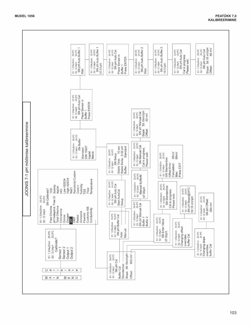
103
MUDEL 1056 PEATÜKK 7,0KALIBREERIMINE
MODEL 1056 SECTION 7.0CALIBRATION
FIG
UR
E 7
-1 C
alib
rate
pH
103
JOONIS7-1pHmõõtmisekalibreerimine
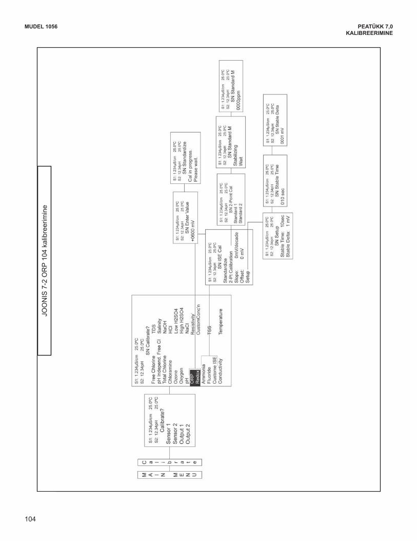
104
MODEL 1056 SECTION 7.0CALIBRATION
FIG
UR
E 7
-2 C
alib
rate
OR
P
104
PEATÜKK 7,0KALIBREERIMINE
MUDEL 1056
JOO
NIS
7-2
OR
P 10
4 ka
libre
erim
ine

105
MODEL 1056 SECTION 7.0CALIBRATION
FIG
UR
E 7
-3 C
alib
rate
Con
tact
ing
and
Toro
idal
Con
duct
ivity
105
MUDEL 1056 PEATÜKK 7,0KALIBREERIMINE
JOO
NIS
7-3
Juh
tivus
e ko
ntak
t- ja
toro
idaa
lse
mõõ
tmis
e ka
libre
erim
ine
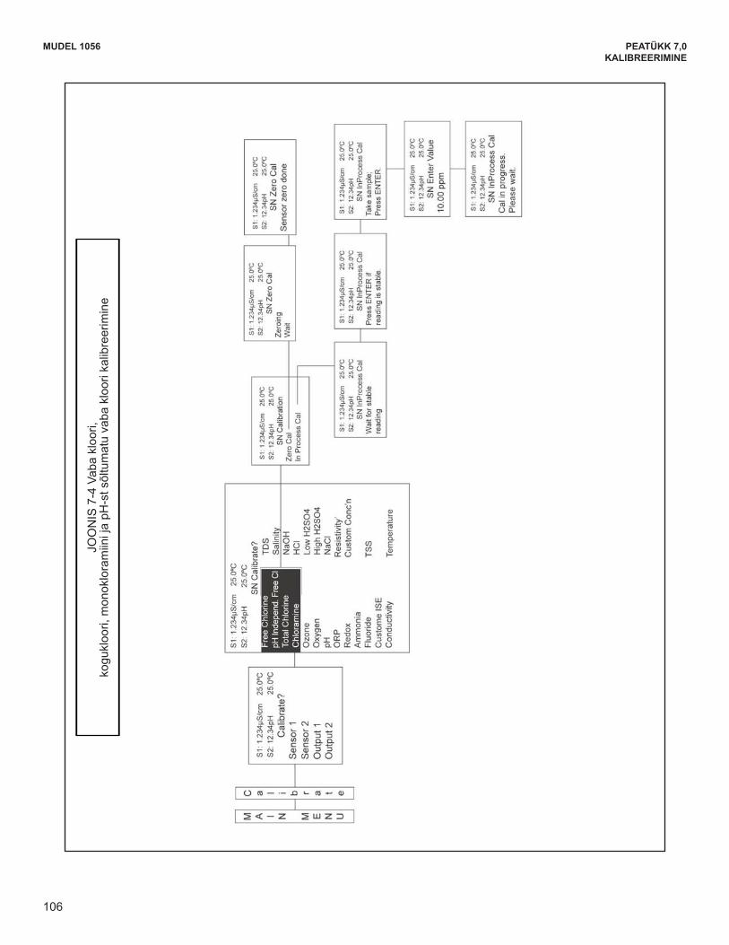
106
MODEL 1056 SECTION 7.0CALIBRATION
FIG
UR
E 7
-4 C
alib
rate
Fre
e C
hlor
ine,
Tot
al C
hlor
ine,
Mon
ochl
oram
ine,
and
pH
-inde
pend
ent F
ree
Chl
orin
e
106
PEATÜKK 7,0KALIBREERIMINE
MUDEL 1056
JOO
NIS
7-4
Vab
a kl
oori,
kogukloori,monokloramiinijapH
-stsõltumatuvabakloorikalibreerimine
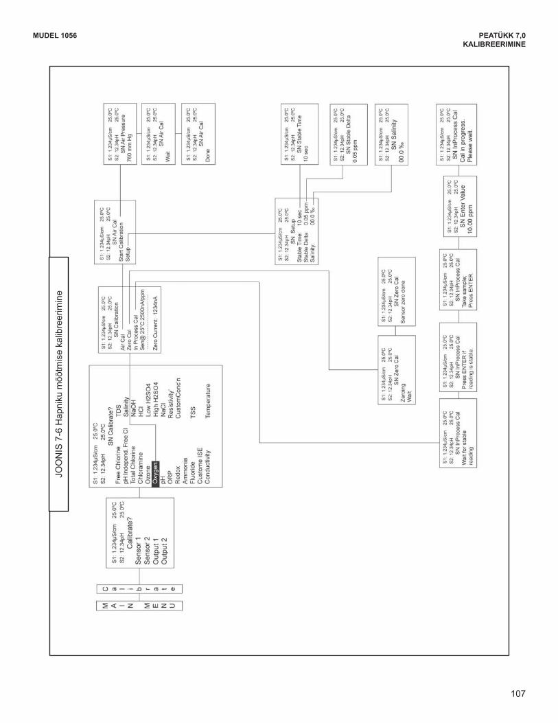
107
MODEL 1056 SECTION 7.0CALIBRATION
FIG
UR
E 7
-5 C
alib
rate
Oxy
gen
107
MUDEL 1056 PEATÜKK 7,0KALIBREERIMINE
JOONIS7-6Hapnikumõõtmisekalibreerimine
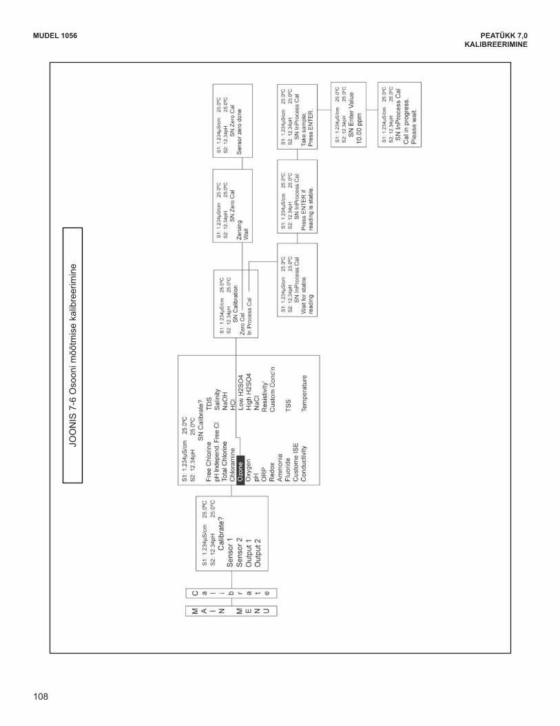
108
MODEL 1056 SECTION 7.0CALIBRATION
FIG
UR
E 7
-6 C
alib
rate
Ozo
ne
108
PEATÜKK 7,0KALIBREERIMINE
MUDEL 1056
JOO
NIS
7-6
Oso
oni m
õõtm
ise
kalib
reer
imin
e
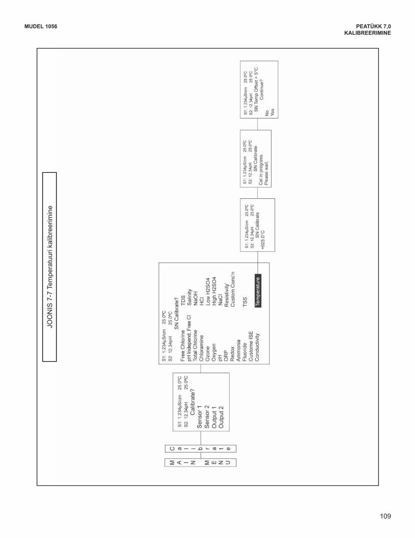
109
FIG
UR
E 7
-7 C
alib
rate
Tem
pera
ture
MODEL 1056 SECTION 7.0CALIBRATION
109
MUDEL 1056 PEATÜKK 7,0KALIBREERIMINE
JOO
NIS
7-7
Tem
pera
tuur
i kal
ibre
erim
ine
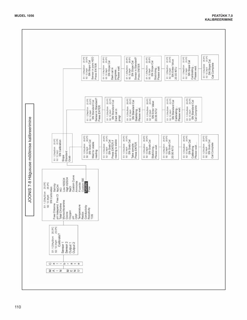
110
MODEL 1056 SECTION 7.0CALIBRATION
FIG
UR
E 7
-8 C
alib
rate
Tur
bidi
ty
110
PEATÜKK 7,0KALIBREERIMINE
MUDEL 1056
JOONIS7-8Hägususemõõtmisekalibreerimine
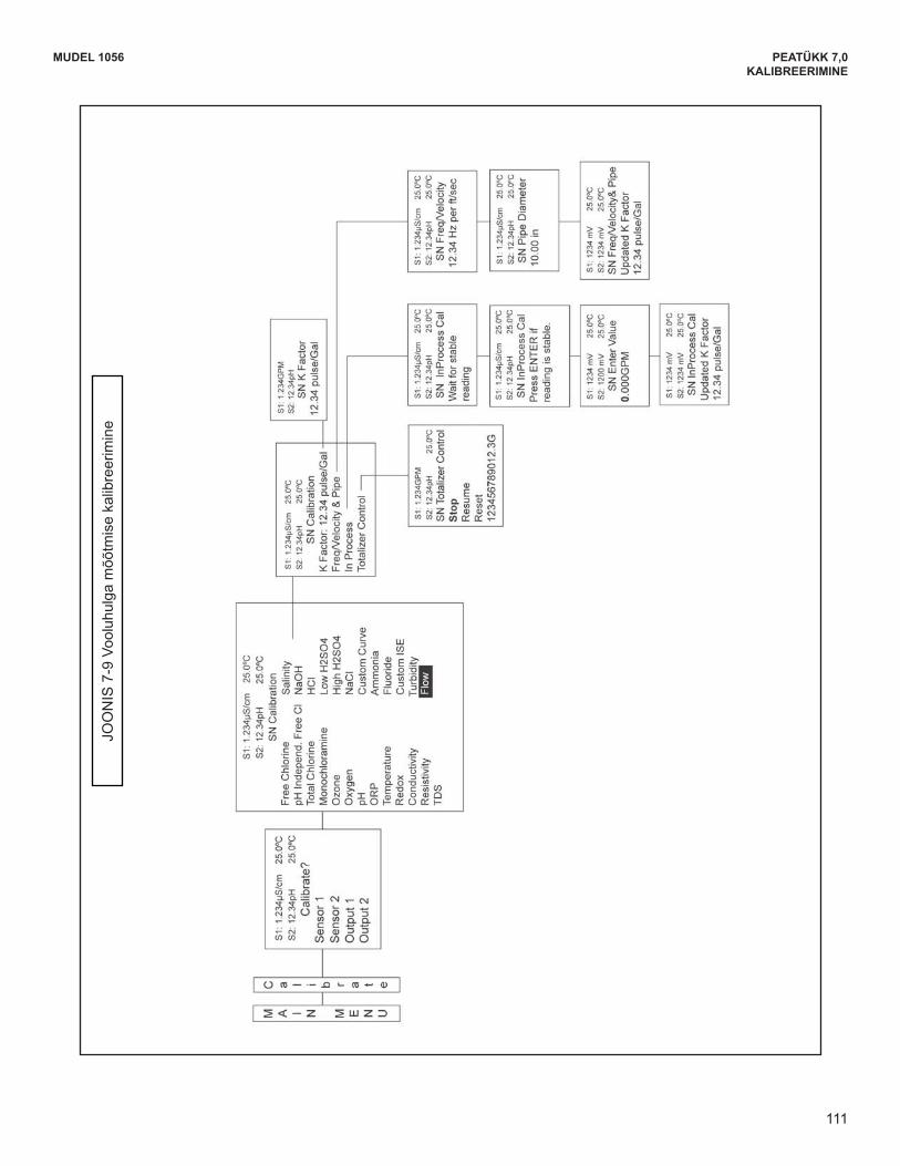
111
MODEL 1056 SECTION 7.0CALIBRATION
FIG
UR
E 7
-9 C
alib
rate
Flo
w
111
MUDEL 1056 PEATÜKK 7,0KALIBREERIMINE
JOO
NIS
7-9
Voo
luhu
lga
mõõ
tmis
e ka
libre
erim
ine
112
PEATÜKK 7,0KALIBREERIMINE
MUDEL 1056
PEATÜKK 8.0 MATERJALIDE TAGASTAMINE
17.1 ÜLDINE Seadmete remondi ja tagastamise kiirendamiseks peab kliendi ja tehase vahel toimima korrektne suhtlus. Enne toote parandusse saatmist helista numbrile (+1) 949 757 8500, et saada RMA-number (Return Materials Authorization).
17.2 GARANTIIREMONT Järgnevalt on kirjeldatud jätkuvalt garantii alla kuuluvate seadmete tagastamise protseduuri: 1. HelistaautoriseeringusaamiseksRosemountAnalytical'i.
2. Garantii kehtivuse kinnitamiseks esita tehase müügitellimuse või algse ostutellimuse number. Üksikkomponentide või alamüksuste puhul tuleb esitada seadme seerianumber.
3. Paki materjalid hoolikalt ja pane nendega kaasa saatekiri ("Letter of Transmittal") (vt Garantii). Võimalusel paki materjalid samamoodi, nagu need algselt saabusid.
4. Saada ettemakstud saatekuluga pakk järgmisele aadressile:
Emerson Process Management Rosemount Analytical 2400 Barranca Parkway Irvine, CA 92606 Tähelep: Tootja remont RMA-number Tähista pakk järgnevalt: Returned for Repair Model No.
TÄHTIS
Vt vormi "Return of Materials Request" teist alajaotust. OSHA (tööohutuseja töötervishoiu) nõuete täitmine on kohustuslik, et tagada kogu personali ohutus. Samuti on nõutavad materjalide ohutuskaardid ja tunnistused selle kohta, et seadmeid on desinfitseeritud võidetoksifitseeritud.
17.3 GARANTIIVÄLINE REMONT Järgnevalt on kirjeldatud garantiiaja ületanud seadmete remondiks tagastamise protseduuri:
1. HelistaautoriseeringusaamiseksRosemountAnalytical'i.
2. Ütle ostutellimuse number ning anna ka kontaktisiku nimi ja telefoninumber, juhuks kui vaja läheb täiendavat teavet. 3. Soorita alapeatükis 17.2 kirjeldatud sammud 3 ja 4.
MÄRKUS:
Lisainfo saamiseks teeninduse või remondi kohta võta ühendust tehasega.
113
A Worldwide Network of Sales and ServiceEmerson Process Management’s field sales offices are your source for more information on the fill line of Rosemount Analyticalproducts. Field sales personnel will work closely with you to supply technical data and application information.For more information, please contact your nearest Emerson Process Management sales office.
Immediate, Reliable Analytical Support Now there’s a way to quickly get the right answers for your liquid analytical instrumentation questions: the AnalyticalCustomer Support Center.Our staff of trained professionals is ready to provide the information you need. If you are placing an order, verifying delivery,requesting application information, or just want to contact a Rosemount Analytical representative, a call to the CustomerSupport Center will provide you with the right people, the right answers, right now.
The right people, the right answers, right now.
THE AMERICAS -HEADQUARTERS Emerson Process ManagementRosemount Analytical Inc.Liquid Center of Excellence2400 Barranca ParkwayIrvine, CA 92606Phone: +1.949.757.8500Toll Free: +1.800.854.8257Fax: +1.949.474.7250
ASIA-PACIFICEmerson Process ManagementAsia Pacific Private Ltd.1 Pandan CrescentSingapore 0512Republic of SingaporePhone: 65.777.8211Fax: 65.777.0947
EUROPEEmerson Process Management AG Blegistrasse 21 CH-6341 Baar-Walterswil Switzerland T 41.41.768.6111 T 41.41.761.8740
VISIT OUR WEBSITE ATwww.rosemountanalytical.com
GERMANYEmerson Process Management ProcessGas Analyzer Center of ExcellenceGmbH & Co. OHGIndustriestrasse 163594 HasselrothGermanyT 49.6055.884.0F 49.6055.884.20
LATIN AMERICAEmerson Process ManagementRosemount Analytical10241 West Little York, Suite #200Houston, TX 77040 USAT 713.467.6000F 713.827.3328
MIDDLE EAST AND AFRICAEmerson Process ManagementEPM BuildingP. O. Box 17033Jebe Ali Free ZoneDubai, United Arab EmiratesT 971.4.8835235F 971.4.8835312
Õiged inimesed, õiged vastused, õige ruttu.
Kohene ja usaldusväärne analüütika-alane tugi Vedelike analüüsiinstrumentide kohta tekkinud küsimuste osas võta ühendust analüütika kliendi tugikeskusega. Meie töötajad on valmis teile andma soovitud teavet. Kliendi tugikeskuses püütakse teid aidata tellimuse esitamisel, saadetise kinnitamisel, rakendusega seotud teabe küsimisel ja vajadusel Rosemount Analytical esindajaga kontakteerumisel.
Ülemaailmne müügi- ja teenusevõrk. Rosemount Analyticali toodete jaoks saab lisainformatsiooni Emerson Process Management müügiesindustest. Müügiesindajad teevad oma parima, et teavitada teid seadme tehniliste andmete ja rakendusvõimaluste kohta. Täpsema teabe saamiseks palun helistage lähimasse Emerson Process Managemendi müügiesindusse.
PÕHJA-AMEERIKA PEAKONTOREmerson Process Management Rosemount Analytical Inc. Liquid Center of Excellence 2400 Barranca Parkway Irvine, CA 92606 Telefon: +1.949.757.8500 Tasuta tel: +1.800.854.8257 Faks: +1.949.474.7250
AASIA-VAIKNE OOKEANEmerson Process Management AsiaPacificPrivateLtd.1 Pandan Crescent Singapore 0512 Singapur Telefon: 65.777.8211 Faks: 65.777.0947
EUROOPAEmerson Process Management AG Blegistrasse 21 CH-6341Baar-WalterswilŠveits Tel (+41) 41 768 6111 Tel (+41) 41 761 8740
SAKSAMAAEmerson Process Management Process Gas Analyzer Center of Excellence GmbH&Co.OHGIndustriestrasse163594HasselrothSaksamaa Tel (+49) 6055 8840 Faks: (+49) 6055 88420
Lõuna AmeerikaEmerson Process Management Rosemount Analytical 10241WestLittleYork,Suite#200Houston,TX77040USATel: (+1) 713 467 6000 Faks: (+1) 713 827 3328
LÄHIS-IDA JA AAFRIKAEmerson Process Management EPM BuildingO. Box 17033 Jebe Ali Free Zone Dubai, Araabia Ühendemiraadid Tel (+971) 4883 5235 Faks: (+971) 4883 5312
KÜLASTAGE MEIE KODULEHTEwww.rosemountanalytical.com

114
Credit Cards for U.S. Purchases Only.
The right people,the right answers,right now.
ON-LINE ORDERING NOW AVAILABLE ON OUR WEB SITEhttp://www.rosemountanalytical.com
8
Emerson Process Management
2400 Barranca ParkwayIrvine, CA 92606 USATel: (949) 757-8500Fax: (949) 474-7250
http://www.rosemountanalytical.com
© Rosemount Analytical Inc. 2012
Õiged inimesed, õiged vastused, õige ruttu.
Emerson Process Management
2400 Barranca Parkway Irvine, CA 92606 USA Tel: (949) 757-8500 Faks: (949) 474-7250 http://www.rosemountanalytical.com
© Rosemount Analytical Inc.
INTERNETITELLIMINE MEIE KODULEHEL http://www.rosemountanalytical.com
Krediitkaarte saab kasutada ainult USA ostude puhul