![[한 N' 하-] 경동사 구문의 통사적 분석: 인덱스 구구조문법적 접근 (A Syntactic Analysis of the [han N' ha-] Construction: An Indexed Phrase Structure Grammar](https://static.fdokumen.com/doc/165x107/63250387584e51a9ab0b5a2a/-n-.jpg)
주관기관 한 국 원 자 력 연 구 원 국가기술표준원 산업통상자원부
242
KAERI/RR-3752/2014 원전적용 무선망요건 국제표준 신규안 개발 (최종보고서) 주관기관 한 국 원 자 력 연 구 원 국가기술표준원 산업통상자원부
-
Upload
khangminh22 -
Category
Documents
-
view
0 -
download
0
Transcript of 주관기관 한 국 원 자 력 연 구 원 국가기술표준원 산업통상자원부

KAERI/RR-3752/2014
원전적용 무선망요건 국제표준 신규안 개발(최종보고서)
주관기관 한 국 원 자 력 연 구 원
국가기술표준원산업통상자원부

제 출 문
산업통상자원부 국가기술표준원장 귀하
본 보고서를 “원전적용 무선망요건 국제표준 신규안 개발”에 관한 산업통상자원부 국가기술표준원 학술용역사업(사업기간 : 2014년 3월 14일부터 2014년 12월 13일) 과제의 최종보고서로 제출합니다.
2014년 12월 일
주 관 기 관 : 한국원자력연구원총괄 책임자 : 구인수사업 참여자 : 홍석붕사업 참여자 : 조재완
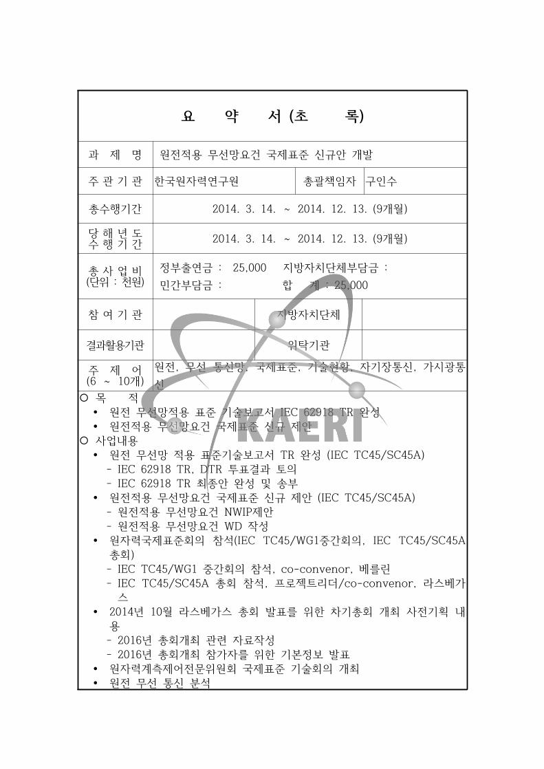
요 약 서 (초 록)
과 제 명 원전적용 무선망요건 국제표준 신규안 개발
주 관 기 관 한국원자력연구원 총괄책임자 구인수
총수행기간 2014. 3. 14. ~ 2014. 12. 13. (9개월)
당 해 년 도수 행 기 간 2014. 3. 14. ~ 2014. 12. 13. (9개월)
총 사 업 비(단위 : 천원)
정부출연금 : 25,000 지방자치단체부담금 : 민간부담금 : 합 계 : 25,000
참 여 기 관 지방자치단체
결과활용기관 위탁기관
주 제 어(6 ~ 10개)
원전, 무선 통신망, 국제표준, 기술현황, 자기장통신, 가시광통신
¡ 목 적Ÿ 원전 무선망적용 표준 기술보고서 IEC 62918 TR 완성Ÿ 원전적용 무선망요건 국제표준 신규 제안
¡ 사업내용Ÿ 원전 무선망 적용 표준기술보고서 TR 완성 (IEC TC45/SC45A)
IEC 62918 TR, DTR 투표결과 토의 IEC 62918 TR 최종안 완성 및 송부
Ÿ 원전적용 무선망요건 국제표준 신규 제안 (IEC TC45/SC45A) 원전적용 무선망요건 NWIP제안 원전적용 무선망요건 WD 작성
Ÿ 원자력국제표준회의 참석(IEC TC45/WG1중간회의, IEC TC45/SC45A총회) IEC TC45/WG1 중간회의 참석, co-convenor, 베를린 IEC TC45/SC45A 총회 참석, 프로젝트리더/co-convenor, 라스베가
스Ÿ 2014년 10월 라스베가스 총회 발표를 위한 차기총회 개최 사전기획 내
용 2016년 총회개최 관련 자료작성 2016년 총회개최 참가자를 위한 기본정보 발표
Ÿ 원자력계측제어전문위원회 국제표준 기술회의 개최Ÿ 원전 무선 통신 분석
i
목 차제1장 목표 및 내용 ----------------------------------------------------------- 1
제1절 표준 제안/제정 -------------------------------------------------------------------- 1
제2절 표준화 활동 ------------------------------------------------------------------------ 1
제3절 시험 및 분석 ---------------------------------------------------------------------- 1
제2장 추진 실적 ---------------------------------------------------------------- 2
제1절 표준 제안/제정 -------------------------------------------------------------------- 2
제2절 표준화 활동 ------------------------------------------------------------------------ 2
제3절 시험 및 분석 ---------------------------------------------------------------------- 4
제3장 과제 성과 ---------------------------------------------------------------- 5
제1절 표준 제안/제정 -------------------------------------------------------------------- 5
제2절 표준화 활동 ------------------------------------------------------------------------ 7
제3절 시험 및 분석 -------------------------------------------------------------------- 47
제4장 성과 활용 계획 ------------------------------------------------------- 49
제1절 성과 활용 방향 ------------------------------------------------------------------ 49
제2절 성과 활용 계획 ------------------------------------------------------------------ 50
붙임 1. 추진실적 현황표 ------------------------------------------------------------------ 51
i
부 록 목 차
1. 45A/947/DTR, IEC 62918 TR: Nuclear power plants - Instrumentation and
control important to safety - Technical report on use and selection of wireless
devices to be integrated in systems important to safety --------------------------- 52
2. Voting result on 45A/947/DTR --------------------------------------------------------------- 73
3. 45A/963/RVC, IEC TR 62918 ---------------------------------------------------------------- 83
4. IEC TR 62918: 2014 ---------------------------------------------------------------------------- 92
5. 신규제안-NWIP on Nuclear power plants-instrumentation and control-important
to safety-selection and use of wireless devices -------------------------------------- 101
6. 발표자료-WGA9; NWIP ------------------------------------------------------------------------ 119
7. 신규제안-WGA9 검토의견 반영 본문 ------------------------------------------------------ 124
8. 신규제안 회람-45A/994e/NP ----------------------------------------------------------------- 142
9. IEC TC45 전체 회의록 ------------------------------------------------------------------------ 160
10. ISO TC242 산티에고 회의 참석 보고서 ------------------------------------------------ 216
11. ISO TC242/WG1/P1 중간회의 참석 보고서 ------------------------------------------- 227
- 1 -
제1장 목표 및 내용
제1절 표준 제안/제정
가. 국제 표준 제정
1) 원전 무선망 적용 표준 기술보고서 문서 최종안 개발
2) 원전 무선망요건 국제표준 초안 제안 및 회람
제2절 표준화 활동
가. 국제 표준화 활동
1) IEC TC45/WG1 Terminology and classification의 Co-convener 업무
2) IEC TC45/SC45A/WGA9 Project Leader 업무
3) IEC TC45, SC45A 총회 한국수석대표
나. 국내 표준화 활동
1) 원자력 계측제어 전문위원회 소속 전문가 협의
2) 에너지심의 위원회 및 관련 국내 표준화 지원
제3절 시험 및 분석
가. 원전 무선통신 분석
1) 공중파 통신 프로토타입
2) 원전 무선 특정 요건

- 2 -
제2장 추진 실적
제1절 표준 제안/제정
가. 국제 표준 제정
1) 원전 무선망 적용 표준 기술보고서 문서 최종안 개발
가) 원전 무선망 적용 표준 기술 보고서 최종안 완성
나) 원전 무선망 적용 표준 기술 보고서 최종안 검토의견 해결
다) 원전 무선망 적용 표준 기술 보고서 발간
2) 원전 무선망요건 국제표준 초안 제안 및 회람
가) 원전 무선망 요건 국제표준 초안 작성을 위한 협의
나) 프로젝트 리더 추천 협의
다) 원전 무선망 요건 국제표준 초안 작성 및 프로젝트 리더간 협의
라) 원전 무선망 요건 국제표준 신규 제안
마) 원전 무선망 요건 국제표준 신규안 회람
제2절 표준화 활동
가. 국제 표준화 활동
1) IEC TC45/WG1 Terminology and classification의 Co-convener 업무
가) 독일 베를린 중간 회의 참석 및 진행
나) 미국 라스베가스 회의 참석 및 진행
2) IEC TC45/SC45A/WGA9 Project Leader 업무
- 3 -
가) 원전 무선망 적용 표준 기술보고서 최종안 작성
나) 원전 무선망 적용 표준 기술보고서 회람 및 송부
다) 원전 무선망 국제표준 신규제안
3) IEC TC45, SC45A 총회 한국수석대표
가) IEC TC45 CAG회의 참석 및 발표
나) IEC TC45/SC45A ad hoc 회의 참석
다) IEC TC45/SC45A 총회 및 발표
라) IEC TC45 총회 및 발표
4) ISO TC242/WG5 컨비너 수임
가) ISO TC242/WG5 사전회의 참석
나) ISO TC242/WG5 회의 참석 및 진행
다) ISO TC242 CAG회의 참석
라) ISO TC242 총회 참석 및 발표
마) ISO TC242/WG1/P1 중간회의 참석
나. 국내 표준화 활동
1) 원자력 계측제어 전문위원회
가) IEC TC45/SC45A 참가 전략회의 개최
나) NWIP심의회의 개최
2) 에너지 서비스 국내 위원회
3) 에너지심의 위원회

- 4 -
제3절 시험 및 분석
가. 원전 무선통신 분석
1) 공중파 통신 프로토타입
2) 원전 무선 특정 요건
- 5 -
제3장 과제 성과
제1절 표준 제안/제정
가. 국제 표준 제정
1) 원전 무선망 적용 표준 기술보고서 문서 최종안 개발
가) 원전 무선망 적용 표준 기술 보고서 최종안 완성
2013년 11월 21일부터 22일까지 미국 테네시 녹스빌에서 개최한 한국, 미국, 캐나다 등 전문가 6명이 최종 기술 협의를 진행하여 DTR최종 안을 확정하였다. 이 DTR최종 안을 약 70쪽 정도로 정리하고, 최종 WGA9 위원중 주도 전문가에게 최종 회람을 실시하였다. 당초 일정에 따라 2013년 12월 31일까지 최종 DTR 회람본을 WGA9 의장과 SC45A간사에게 송부하고 SC45A간사는 2014년 1월 16일에 IEC본부로 각국 회람을 위해 송부하였다.
나) 원전 무선망 적용 표준 기술 보고서 최종안 검토의견 해결
45A/947/DTR회람(첨부 1)이 2014년 1월 24일부터 2014년 3월 28일까지 진행하였으며, 그 투표결과 의견인 voting result on
45A/947/DTR(첨부 2)의 이집트, 프랑스, 이태리, 러시아, 우크라이나, 영국 및 한국의 의견에 대해 2014년 5월 16일까지 해결안을 간사에게 송부하였다.
다) 원전 무선망 적용 표준 기술 보고서 발간
45A/963/RVC, IEC TR 62918(첨부 3)과 같이 의견해결된 내용에 대해 마지막 회람을 돌렸으며, 동 회람에 대한 추가 의견이 없었으며, 동시에 저작권에 대한 프로젝트 리더와 입력을 제공한 위원들의 합의로 2014년 7월 15일 IEC TR 62918:2014(첨부 4) 초판, Nuclear power plants - Instrumentation and
- 6 -
control important to safety - Use and selection of wireless
devices to be integrated in systems important to safety 제목으로 발간되었다.
2) 원전 무선망요건 국제표준 초안 제안 및 회람
가) 원전 무선망 요건 국제표준 초안 작성을 위한 협의
당초 모스크바 회의에서 2013년 12월까지 기술보고서 회람 최종본을 완성하고 곧 2014년도 초에 무선망 원전적용 관련하여 신규 제안을 하기로 하였다. 그러나, 기술보고서가 발간되기 전에 국제표준 신규제안은 절차상 곤란하다는 WGA9 의장의 의견에 따라 기술보고서 발간 시점에 국제표준 신규 제안키로하였다. 2014년 5월 말 간사가 소속한 프랑스의 등급분류를 예로 들면서 원전 무선망 적용 국제표준은 전세계가 관심사항이므로 한, 두 국가만 국제표준 제정에 참여하는 것보다 프로젝트리더 그룹으로 추가 참여가 가능한 지 의견 교환이 있었다.
나) 프로젝트 리더 추천 협의
이메일을 통해 WGA9 의장, SC45A 간사와 한국 프로젝트리더와 협의한 결과 프랑스의 위원인 Olivier Blas를 공동 프로젝트리더로 추가하기로 합의하였다. 그리고 2014년 8월 말까지 초안 약 10-20쪽 정도 작성하여 회람하기로 하였으며, 9월 초에 라스베가스 회의를 위해 국제표준 초안(첨부 5)을 작성 송부하였다.
다) 원전 무선망 요건 국제표준 초안 작성 및 프로젝트 리더간 협의
IEC TC45/SC45A/WG9 회의 하루 전 한국 프로젝트리더, 미국 공동 프로젝트리더와 프랑스 공동 프로젝트리더가 회의하여 원전 무선망 국제표준안에 대한 기술적 관심사와 표준 안의 구조
- 7 -
를 설정하였다. 총 7장으로 범위, 참고문헌, 용어정의, 기본요건, 무선응용요건, 무선통신요건, 검증(첨부 6) 등이다. 가장 중요한 부분은 아직 무선기술의 원전 적용이 중요해지고 있으나,
안전등급이나 안전관련 기능으로 넣기는 문제가 있어 점진적 접근방안으로 범주 C 등급으로만 가능하게 한다. 범주 A와 범주 B는 절대 적용하지 못하는 요건으로 설정하기로 합의하였으며, 본문 중에도 당초 제안한 무선응용요건을 기능 적합성 분석, 성능 적합성 분석과 정정분석 등 세 절로 수정하였다.
라) 원전 무선망 요건 국제표준 신규 제안
IEC TC45/SC45A/WG9 회의에서 한국 프로젝트리더가 국제표준의 구조와 개괄적인 작성 내용을 설명하고 질의응답을 한 후 각국의 의견은 국제표준 안을 TBD를 가능하면 적게 하자는 의견이었다. 본 회의 결과를 의장이 총회 보고 내용에 추가하고 WGA9의 결정에 따라 향후 신규 제안(첨부 7)으로 진행키로 하였다.
마) 원전 무선망 요건 국제표준 신규안 회람
2014년 10월 31일자로 45A/994/NP-Nuclear power plants -
Instrumentation and control important to safety - Selection
and use of wireless devices(첨부 8)를 각 히원국 회람을 실시하였다.
제2절 표준화 활동
가. 국제 표준화 활동
1) IEC TC45/WG1 Terminology and classification의 Co-convener 업무
가) 독일 베를린 중간 회의

- 8 -
(1) 작업반 일정
(가) 진행: Anthony Richards (IEC TC45/WG1의장), In
Soo Koo (IEC TC45/WG1공동의장)
(나) 일정: 2014년 3월 24일부터 3월 28일까지(오전 9시부터 오후 5시까지)
(다) 참석전문가: 미국, 중국, 프랑스, 한국, 영국, 독일, 러시아, 스웨덴 등 9명의 각국 대표가 참석하였다.
(2) 회의 내용
(가) 개회
회의 주제에 대한 이견을 확인하고, 참석 각국의 대표들을 각자 소개하였다.
(나) 2013년 6월 모스크바에서 개최한 총회 결과에 대한 토의
(다) 러시아 기술보고서 안 토의
러시아 용어로 작성한 용어집과 국제 용어집의 차이가 있어 IEV395발간이후 용어에 대한 정의를 기술보고서를 통해 정리하는 작업을 시작하였다.
(라) Low energy fusion reaction에 대해 독일의 Roos박사가 발표 및 용어 정의
(마) 차기회의 개최지 소개
차기 회의는 2016년 3월 3일부터 11일까지 한국의 경주에서 개최 할 것임을 알리고, 차기 라스베가스 총회에서 보다 확정적인 내용을 소개할 것이다.
- 9 -
나) 미국 라스베가스 회의
(1) 작업반 일정
(가) 진행: Anthony Richards (IEC TC45/WG1의장), In
Soo Koo (IEC TC45/WG1공동의장)
(나) 일정: 2014년 10월 2일부터 10월 3일까지(오전 9시부터 오후 5시까지)
(다) 참석전문가: 미국, 일본, 캐나다, 한국, 영국, 독일, 러시아, 스웨덴 등 8개국의 수석대표를 중심으로 11명의 전문가가 참석하였다.
(2) 회의 내용
(가) 개회
회의 주제에 대한 이견을 확인하고, 참석 각국의 대표들을 각자 소개하였다.
(나) 참석 위원 update
매번 회의때마다 영국과 한국의 공동의장들은 실제로 참석하는 위원외에는 명단에서 정리해주길 부탁했다.
어떤 경우에는 수년 전 은퇴하신 선배의 이름이 아직도 올라 있다. 본 명단을 삭제하거나 삽입하는 권한은 각국의 국가표준위원회이므로 각국 수석대표에게 각국의 WG1명단을 정리해주시길 부탁했다.
(다) 차기회의 개최지 소개
차기 회의는 2016년 3월 3일부터 11일까지 한국의 경주에서 개최 할 것임을 알리고, 현재의 교통수단 및 주위 기술견학 및 관광에 대해 설명하였고, 동시에 향
- 10 -
후 일정을 잠정적으로 제시하였다.
(라) 국제원자력기구의 지식경영 업무 소개
국제원자력기구의 존 그래비스는 수년 전부터 지식경영팀을 맡고 있으며 동 기구의 용어 등을 정의하므로서 기술의 과거, 현재, 미래를 추론하여 현재를 비롯한 미래흐름을 예측하는 빅데이터 개념의 업무를 진행하고자 하였다.
각 기술사전에 있는 용어의 정의와 분류를 통해 마치 INIS처럼 구조를 재편하여 데이터 마이닝 기법 등 최신 자료처리에서 정보추출기법을 사용하여 미래기술 등을 예견코자한다. 이에 용어 및 등급 작업반이 국제원자력기구를 지원하는 관련 작업을 수행키로 하였다.
(마) 러시아 기술보고서 안 토의
러시아 용어로 작성한 용어집과 국제 용어집의 차이가 있어 IEV395발간이후 용어에 대한 정의를 기술보고서를 통해 정리한다. 이 기술보고서 개발은 작업반의 미래 업무를 설정하는 내용을 위주로 수행중이나, 금번 회의에서는 시간제약으로 국제원자력기구 지원을 주로 논의하였다.
(바) ISO 리에종 보고
ISO TC85/WG1의 용어 개발상황을 보고하고, 현재 IEC TC45/WG1과 중복되거나 분석업무가 필요한 일은 없음을 보고했다.
2) IEC TC45/SC45A/WGA9 Project Leader 업무
가) 원전 무선망 적용 표준 기술보고서 최종안 작성

- 11 -
2014년도 1월부터 3월까지 최종 기술보고서 안에 대한 각국 검토의견에 대한 해결을 이멜을 통해서 협의한 후 최종 기술보고서를 완성하였다.
나) 원전 무선망 적용 표준 기술보고서 회람 및 송부
검토의견 해결한 기술보고서 최종안을 SC45A와 IEC본부에서 검토 한 후 저작권 관련 의견을 합의하였다. 기술보고서는 2014년 7월 발간되었다.
다) 원전 무선망 국제표준 신규제안
2014년 5월에 프로젝트리더로서 국제표준 신규제안을 시도하였으나 절차상 2014년 7월부터 본격적인 시작을 하였다.
미국의 프로젝트리더와 프랑스 프로젝트리더의 추가 참여로 세명의 전문가가 함께 원전 무선망 국제표준을 개발할 것이다.
2015년 2월까지 신규제안에 대한 투표가 진행중이다.
3) IEC TC45, SC45A 총회 한국수석대표
가) IEC TC45 CAG회의 참석
(1) 자문회의 일정
(가) 진행: Sergey Shumov (IEC TC45 간사), Morgan Cox
(IEC TC45 위원장)
(나) 일정: 2014년 10월 7일(오후5시부터 7시까지)
(다) 참석전문가: 원자력계측 기술위원회 위원장, 간사와 작업반 의장, 각국 수석대표 등 12개국 24명의 CAG위원이 참석하였다. 이 회의는 원자력계측 기술위원회 회의를 잘 진행할 수 있도록 현재 진행중인 IEC TC45관련

- 12 -
향후 업무전략 등을 논의하여 위원장에게 권고하고 회의 종료시 위원회에 보고하는 자문성격의 회의체이다.
(2) 자문회의 내용
(가) 회의 개최선언
용어 및 등급 작업빈인 WG1 의장인 Anthony
Richards가 회의를 시작을 선언하고, 자문회의 참석자 소개를 간단히 했다. 회의 의제 초안에 대한 승인에 동의하므로서 공식적인 자문회의가 진행되었다.
(나) 위원장 발표
일반 대중의 원자력 에너지와 방사선에 대한 오해에 원자력 전문가가 관심을 가져야 한다는 것이다. 인간에의 방사선 영향이 문턱이론이 없는 선형에 대한 잘못된 개념을 설파했다. 위원장은 결론으로 이산화탄소를 발생하지 않는 녹색한경 해결 방안인 원자력 발전,
연료가 다른 에너지 원에 비해 싸고 또 매우 많이 매장량이 존재한다는 것이다. 그리고 방사선은 안전 한계내에서 이용하면 매우 안전하다는 것이다.
(다) IEC 본부의 담당관인 Charles Jacquemart의 IEC 현황 소개
향후 도래할 세계표준의 날과 관련하여 1954년에 개발하였으며 그 연장선상에서 현재도 유용한 8개 표준화 계율을 참석 위원들에게 상기시키고, 국제무역기구에 관한 국제표준 개발의 다섯 원직인 1) 투명성, 2)
개방성, 3) 공정성과 합의성, 4) 효율성과 관련성, 5)
일관성 등을 설명하였다. IEC와 ISO는 세계 각국이 인정하고 또 사용하는 국제표준의 개발이 회원국 전체
- 13 -
의 합의를 바탕에 둔다는 것이다.
(라) 선형가속기 응용
중국 대표인 쟈오 첸은 8월말에 회람시킨 전자선형가속기를 산업용 비파괴시험 기기로 사용하는 내용의 신규제안을 발표하였다. 그 필요성, 적용 범위, 오늘의 세계 사용현황, 중국의 경험 등이었다. 중국은 이 과제에 전문가 참여를 요청하였고 동시에 이 신규과제를 지원해주길 호소하였다.
(마) 원자력 계측과 나노기술
미국의 Mark Hoover가 첨단 원자력 계측에 나노기술 적용과 나노기술으로에 원자력계측에 관해 발표하였으며, 특히 원자력발전소에 나노기술의 접목을 설명하였다. 동시에 표준 검토와 미래 기획에 대한 주요 질의를 제안하였다.
(바) 원자력 로봇기술
한국수석대표인 구인수는 후쿠시마 사고 등 극한 사고 환경, 향후 고 방사선 환경에서의 제염, 해체 등에 어쩔 수 없이 사용해야하는 로봇기술의 표준화 관계를 설명하고 특히 방사선 환경에 인증된 로봇기술의 적용, 사람이 접근 할 수 없는 환경 등 미래 로봇기술의 원자력 적용을 위한 표준화가 현존 IEC TC45/SC45A,
SC45B, ISO TC85/SC5, SC6 등과 연계하면서 최신 로봇기술의 원자력 적용을 위한 표준들을 개발해야함을 설명하였다.
(사) 용어 및 등급 작업반 보고
10월 2일부터 3일까지 개최한 용어 및 등급 작업반인
- 14 -
WG1의 회의 내용을 의장인 A. Richards가 설명하고 향후 진행할 계획에 대해 설명하였다. 동시에 국제원자력기구의 지식경영팀이 제안한 과제를 지원하기로 하고 내년 4월 회의를 예정하고 이는 TC45의 작업을 원자력 사회에 알리는 데 기여할 것이다.
(아) 차기 회의 장소와 기간
차기 회의는 2016년 3월 3일부터 11일까지 한국의 경주에서 개최 할 것임을 알리고, 현재의 교통수단 및 주위 기술견학 및 관광에 대해 설명하였고, 동시에 향후 일정을 잠정적으로 제시하였다.
나) IEC TC45/SC45A ad hoc 회의 참석
(1) 특별회의 일정
(가) 진행: J. P. Bouard (IEC TC45/SC45A 간사), Garry
Johnson (IEC TC45/SC45A 위원장)
(나) 일정: 2014년 10월 6일부터 10월 7일까지(오전 7시부터 9시까지)
(다) 참석전문가: 원자력시설 계측제어전기 산하위원회 위원장, 간사와 작업반 의장, 각국 수석대표 등 약 20명 정도가 참석하였다. 이 회의는 각 작업반 회의를 잘 진행할 수 있도록 관련 업무 지침과 문제점을 조정하는 회의 성격으로 보통 식전에 개최하였다.
(2) 특별회의 내용
(가) 용어 및 문서구조
본 위원회의 명칭이 원자력시설 계측제어 산하위원회에서 원자력시설 계측제어전기 산하위원회로 변경하므로서 관련 내용을 회원국 회람을 실시하였다. 특히 용어

- 15 -
및 문서 구조에 있어서 보안과 전기계통의 추가로 향후 서로 관련하는 용어와 문서 구조에 대해 각 작업반에서 토의 해주길 요청하였다. 지난 70년대에 체결한 국제원자력기구와의 협력 관계를 위해 2014년 5월에 국제원자력기구 원자력보안 관련 담당관과 산하위원회가 회동하여 서로 연락관을 두기로 합의하고, 산하위원회 문서의 보안분야에서의 용어 정의에 대한 전략에 대해 현행을 보다 확장하기로 했으며, 국제원자력기구의상위 안전과 보안 원칙을 따르기로 했다. 2014년 9월 각 작업반 의장과 각국 수석대표가 간사에게 주요 현안에 대한 메일을 송부하였고, 각 작업반과 각 회원국 입장에서 1) 산하기술위원회의 표준 명칭은, 2) IEC 61513개정 가능성, 3)산하기술위원회 소관 표준의 개정을 통한 일치화, 4) 디지털계통의 정의 등과 같은 논의를 요청하였다.
(나) 이동형 전기기기 표준개발
후쿠시마 사고이후 지난 칼스루에 회의에서 “plug and
operate”개념의 이동형 발전기 설치에 대한 ISO TC85
의 요청이 있었으며, 2012년 여름 ISO/TC85/SC6에서 원전 비상시에 타 원전의 발전기를 이동하여 비상 원전에 투입하는 개념 관련 표준 시방 개발을 계획 했다.
이중 전기분야는 본 산하위원회가 수행하기로 결정하였으며, 공동 개발로 귀결하였다.모스크바 회의에서는 ISO/IEC지침에 따라 개발할 것으로 결정하였으며, 지난 2014년 6월 ISO/TC85 기술위원회가 신규과제를 통과시키고 실질적인 문서 개발에 돌입함에 따라 간사는 WGA3, WGA11에게 관련 신규과제와 다른 관련 문서를 회람시켰다.
(다) 1일차 특별회의 보고
l 표준문서 제목의 정의를 3부분으로 나누어 첫 부분은 “Nuclear power plants" and "Nuclear facilities,
- 16 -
두 번째 부분은 "Instrumentation systems important
to safety", “Instrumentation and control systems
important to safety”, “Instrumentation, control and
electrical systems important to safety”,
"Instrumentation and control systems", “Control
rooms”, "Electrical systems" 세 번째 부분은 Free,
short and concise로 표기를 통일하기로 하였다.
l IEC TC45/SC45A 용어는 국제원자력기구 안전 및 보안 용어와 일치하기로 하는 정책을 재확인 하였다.
l 전기계통의 업무 추가에 따라 간사는 IEC 61513을 추가 보완하기를 원하였으나, IEC 61513만으로는 보안, 전기계통 등을 모두 포괄하지 않음을 일부 국가에서 제시하였다.
l IEC-IEEE 표준문서 조화원칙에 보안관련 국제원자력기구 문서를 표기하도록 한다.
l “Digital systems”에 대한 정의를 WGA3가 주관하고 WGA7과 WGA9이 필요성을 입력하고, 이는 IEC
62671를 기반에 둘 것을 요청하였다.
l 이동형 전원공급장치에 대한 ISO TC85가 신규문서 제정에 돌입함에 따라 IEC TC45/SC45A에서 문서제정을 위한 프로젝트리더를 요청하였다.
(라) 총회에 대한 권고사항
상기 6개항에 대해 총회에서 논의되기를 요청하였다.
다) IEC/IEEE 공동 회의
(1) 공동회의 일정
(가) 진행: J. P. Bouard (IEC TC45/SC45A 간사), Garry
Johnson (IEC TC45/SC45A 위원장)

- 17 -
(나) 일정: 2014년 10월 2일부터 10월 3일까지
(다) 참석전문가: 기술위원회 위원장, 간사와 중국, 핀랜드,
프랑스, 독일, 일본, 한국, 스페인, 스웨덴, 미국 등 9
개국 전문가와 IEEE 위원, 국제원자력기구 담당관 등 35명의 전문가가 참석하였다.
(2) 공동회의 내용
(가) IEEE 1082, Guide for Incorporating Human Action
Reliability Analysis for Nuclear Power Generating
Stations 문서를 IEC 문서로 추인가능성에 대해 IEEE
의 J. Hazz가 초안이 가용하면 IEC 프로젝트리더인 T. Parson에게 송부하기로 하고, 본 회의에서 결정을 보류하였다.
(나) 조건감시에 관한 IEC/IEEE 62582-5와 IEC/IEEE
62582-2의 추록에 대한 논의는 62582-5 문서는 FDIS의 완결본을 IEEE로 송부하여 IEEE의 투표를 거친 후 IEC내의 FDIS 승인을 위한 회람을 시작할 것이며, 추록에 대해서는 라스베가스 회의 후 IEEE와 IEC에서 동시에 회람시키기로 하였다.
(다) IEC/IEEE 323-60780, 전기기기 검증에 관한 논의
l IEC와 IEEE가 공동 진행하는 Harmonization
project로서 국내에서 발생한 기기검증 성적서 위조건과 관계되는 표준문건이며, 전기기기 검증이란 용어는 원자력 계측제어 기기전부에 대한 기기검증 요건으로 해석되나, 현재 제목은 전기 기기에 대한 기기검증 만으로 되어있는 것으로 이해할 소지가 있다. 따라서 전자기기에 대한 기기검증을 포함 하도록 제목을 수정 제안하였다.
l 유사성을 가진 기기의 분석 (Analysis based on
similarity)의 경우에 기기의 유사성에 대한 모호성이 존재하여 이에 대한 정의를 추가, 심도 있는 내용으
- 18 -
로 요건의 정리하였다.
l 6.2절의 제목이 “Reassessing qualified life”로 평가된 수명에 대한 재평가가 아닌 수명연장을 위한 요건이 강하므로 “Extend qualified life“로 수정이 제안하였다.
l 6.2.3절의 “Sampling”은 이전의 Type testing과 유사하므로 수정하기로 제안하였다.
l 열적 노화(thermal aging)의 100시간 요건은 구제적인 근거에 의함이 아니고, 현실적으로 벌어지는 기기공급자들의 경비절감 차원에서 발생하는 기기검증 노화 시험의 문제점을 근본적으로 제거하기 위한 노력으로 인정하였다.
l 최소 여유(minimum margin)는 엔지니어링 판단으로 인정하기로 하였다.
l 공통원인고장 대비 랜덤고장에 대한 논의는 공통원인고장과 랜덤고장에 대한 요건을 고려해야 한다는 주장에 대해 IEC/IEEE-323/60780은 단지 기기검증에만 충실한 표준으로 범위를 국한하고 그 이외에 사항은 타 표준 문건에서 이미 언급하고 있거나 다루도록 조치하기로 공감하였다.
l 일반적 의견으로 IEC/IEEE-323/60780은 미국의 10
CFR 50 Appendix B의 원자력프로그램 하에서 제작된 기기에 대한 기기검증이 아니라, 표준에 익숙하지 않은 사용자나 규제가 강하지 않은 국가의 경우에는 원자력프로그램에 따라 개발되지 않은 장비,
즉 Non-basic Item에 대한 기기검증으로 오해할 여지가 있다는 의견이 있었으나, 하지만 일반 산업의 기기에 대한 원자력 적용은 상용등급지정(commercial grade items dedication)이라는 주제로 작업반 WGA7에서 논의할 것이므로 본 표준협의에
- 19 -
서는 제외키로 하였다.
l 향후일정은 2014년 11월 초 CDV를 회람시키고 동시에 프랑스어 판을 준비하기로 하였으며, 2014년 12월 공동프로젝트팀을 형성하고 IEC전문가를 2015
년 2월 참가키로하였다. 세부일정은 첨부 회의록을 참조하며 최종으로 2015년 7월 중순에 FDIS를 작성하여 IEC 본부로 송부할 계획이다.
(라) IEEE 497, 사고 후 감시계통 요건에 대한 문서의 IEC 문서로 추인할 가능성에 대한 논의는 IEC와 IEEE간의 중대사고와 관련한 사고 후 감시계통 요건에 대한 dual logo 표준에 대한 작업을 진행하고 있으나, IEC 측의 거절로 합의점을 찾는데 많은 어려움이 있어 보인다. IEC는 자신들의 영역에 대한 IEEE의 접근을 거부하는 것으로 판단되며, IEEE는 IEEE-497
이 미국 중심 일변도가 아니라 점점 세계화되고 있다고 강조하고 있지만, 여전이 IEC의 거부반응이 있는 것으로 판단된다.
라) 특수 공정 계측 및 방사선 감시 작업반
(1) 작업반 회의 일정
(가) 진행: Hirotaka Sakai (IEC TC45/SC45A/WGA5 의장)
(나) 일정: 2014년 10월 6일부터 10월 7일까지
(다) 참석전문가: 기술위원회 위원장, 간사와 중국, 핀랜드,
프랑스, 독일, 일본, 한국, 스페인, 스웨덴, 미국 등 9
개국 전문가와 IEEE 위원, 국제원자력기구 담당관 등 35명의 전문가가 참석하였다.
(2) 작업반 회의 내용
(가) IEC 62705 Nuclear power plants - Instrumentation
and control-Radiation monitoring systems:
- 20 -
Characteristics and test methods
핀랜드 전문가 검토의견이 3개가 있었으나 대체로 발간단계에서는 원칙에 따라 기술적 검토의견을 제시할 수 없는데도 기술적 내용을 이견으로 제시했으므로 프로젝트리더가 의견 반영을 할 수 없음을 알렸다. 이와 같이 표준문서 제정의 각 단계마다 원칙에 따라 의견 반영이 불가하므로 기술적 견해는 늦어도 CDV단계를 놓치지 않도록 주의해야 한다.
(나) IEC 61250, Nuclear power plants - Instrumentation
important to safety – Detection of leakage in coolant
systems
l 부록 표에서의 capability 정도 표기방법을 A, B, C에서 High, Middle, Low로 변경하였다.
l RCAS 또는 RCSAS에 대한 용어 정의는 기본 원칙상으로 국제원자력기구 용어에 명시된 새로운 용어인 RCSAS적용에 대한 논의가 있었으나, 본 표준문서 범위와는 다른 의미이므로 본 표준문서에 따라 용어 정의를 내리고 그 내용을 국제원자력기구와 용어에 대한 이견을 처리하기로 하였다. 따라서, 새 용어는 정의를 정리하여 공식절차를 밟을 것이다.
l CD회람에 대한 검토의견을 회의 중 해소하고, 협의한 의견을 반영하여 2015년 5월까지 CDV문서 회람을 완료하기로 결정하였다.
(다) 기존 표준문서 개정을 회의 중에 검토하여, 우선순위가 높은 4개 문서의 개정을 진행하기로 했으나,
l IEC 60910, Containment monitoring instrumentation
for early detection of developing deviations from
normal operation in light water reactors은 전문가를 찾지 못해 보류하고,

- 21 -
l IEC 61343, Nuclear reactor instrumentation -
Boiling light water reactors (BWR) - Measurements
in the reactor vessel for monitoring adequate
cooling within the core는 비등경수로인 관계로 관련국인 스웨덴 전문가가 맡기로 잠정 결정하고,
l 다음 두 문서는 WGA5와 WGB9합동회의와 연계하여 일본 전문가가 맡기로 했다. IEC 61031, Design,
location and application criteria for installed area
gamma radiation dose rate monitoring equipment
for use in nuclear power plants during normal
operation and anticipated operational occurrences와 IEC 61504, Nuclear power plants - Instrumentation
and control systems important to safety -
Plant-wide radiation monitoring 등 2건이다.
l 후쿠시마 사고 반영 후속조치로 Spent fuel pool
monitoring 관련 신규 문서는 위원장인 미국의 Gary
Johnson이 프로젝트리더를 맡기로 하였다.
(3) IEC TC45/SC45A/WG5와 IEC TC45/SC45B/WG9과 합동 실무 작업반 회의 내용
방사선 감시계통에 대해 합동회의를 개최하여 WGA5의 IEC 61031, Design, location and application criteria for installed area gamma radiation dose rate monitoring equipment for use in nuclear power plants during normal operation and anticipated operational occurrences와 IEC 61504, Nuclear power plants - Instrumentation and control systems important to safety - Plant-wide radiation monitoring 등 두 표준문서와 WGB9의 IEC 61559-1와 IEC 61559-2 등 두 표준문서의 합치문제를 논의하고 61504와 61559-2를 하나의 표준문서로 합치는 방안으로 협의하고, 61559-1은 등급이나 범주가 상이하므로 그대로 존치하기로 하였다.
마) 원자로 안전계통 전기기기의 신뢰도 작업반
- 22 -
(1) 작업반 회의 일정
(가) 진행: Nick Wall (IEC TC45/SC45A/WGA7 의장)
(나) 일정: 2014년 10월 8일부터 10월 10일까지
(가) 참석전문가: 기술위원회 위원장, 간사와 스웨덴, 스위스, 미국, 프랑스, 독일, 한국, 영국, 카나다, 일본 등 9
개국 전문가 43명이 참석하였다.
(2) 작업반 회의 내용
(가) IEC 62709, Nuclear power plants – Instrumentation,
control and electrical systems important to safety – Seperation
프로젝트리더는 독일의 Geissler이며 2015년 12월까지 CD단계로 진행함을 목표로한다. 2014년 11월까지 IEC 본부로 RR보고서를 송부하고 CD초안을 2015년 6월까지 준비한다. 작업반 검토의견을 2015년 11월까지 반영하여 2016년 1월까지 CD로서 각국 회람을 진행한다. CD검토의견 해결을 2016년 3월 한국회의에서 진행하고 결과로 CDV로 진행하는 내용이다.
개정 원칙에 대해 동의하고 작업반 내 전문가를 프로젝트 개발업무로 조정한다. WGA3와 WGA11 내부 문서를 의장이 프로젝트리더에게 배포한다.
(나) IEC 61226, Nuclear power plants – Instrumentation,
control and electrical systems important to safety – Categorization of instrumentation, control and
electrical functions
프로젝트리더는 프랑스의 Barbaud이며, 2015년 2월까지 다음 단계인 CD로 진행할 것이다.
문서 제목에 대한 각국의 의견을 협의하였으며 많은 부분을 해소하였다. 주요 내용은 전기계통의 정의, 전
- 23 -
기계통의 기능, 전기와 계측제어계통에 공히 적용할 요건 정립의 수단 등에 대해 심도있는 토의를 진행하였다. 전기계통의 정의와 기능에 대한 불확실성이 공용 수단에 대한 영향을 줄 수 있다. 따라서 범주의 등급으로의 매핑은 상위준위의 원직을 유지해야 한다.
(다) IEC 62808, Nuclear power plants – Instrumentation,
control and electrical systems important to safety – Design and qualification of isolation devices
프로젝트리더는 미국의 Seaman이며, 2015년 3월까지 FDIS 단계로 진행하며, 기술적 현안 해결은 이미 종료되었다.
(라) TR for FMEA
프로젝트리더는 미국의 Smith이며 2014년 12월까지 DTR단계로 진행하기로 결정하였으며 투표를 위해 IEC본부로 송부한다.
회원국에서 사용하는 고장모드영향분석 방법론 간의 유사성과 차별성을 서술하는 추가절을 삽입할 것을 협의할 것이다.
(마) CGID NWIP 안건회의
하드웨어 상용부품 등급화 및 소프트웨어 상용부품 등급화 분석 결과 및 신규프로젝트 제안을 발표하고, 관련 표준 문건의 재구성 및 재편이 anization 필요함을 제안
확인 및 검증(Verification and validation)을 별도의 주제로 정하여 표준화 진행을 하고, 본 업무를 진행 중인 기관에 Certification을 주는 방법을 설정하고, CC3
문건을 위주로 회의 진행, “CGID 및 Software
verification and validation” 주제 발표
모스크바에서 상용부품 등급화 신규과제 제안이 있은

- 24 -
이후, 독일에서도 Teleperm-XS에 대한 시스템의 등급화에 대한 기술보고서를 WGA3에 제안하였으며,
WGA7에서 제안한 한국의 상용부품 신규과제에 대한 내용상의 동일성 으로 WGA3, WGA7 의장간의 협의 후 간사인 J. P. Bouard, 한국 수석대표 간의 향후 방향을 토의한 결과 한국의 신규과제 제안자를 기술보고서 작성의 공동 프로젝트리더로 임명하고 최대한 신속한 기술보고서를 완성한 후 바로 국제표준화를 진행키로 하였다. 기술보고서 완결 예상 시점인 2016년 3월 정도에 한국이 제안한 신규과제를 fast track으로 진행하자는 의견으로 수렴됨. 단, 현 시점에서부터 기술보고서가 완료되는 시점사이에 충분한 분석과 신규과제 초안을 준비하는 것으로 의견이 모아졌다.
상용부품 등급화 과제의 완결을 위해 제안된 소프트웨어 확인검증 표준이 60880, 62138에 기술되어 있는 Category A, B, C에 대한 소프트웨어 개발 공정과 소프트웨어 확인검증 공정을 분리하여 구성하고, 소프트웨어 확인검증을 보완하여 추가하지는 의견에 대하여 국내에서 협의를 진행한 후 추가적인 의견교환을 상용부품 등급화 기술보고서 진행과 함께 프로젝트리더들 사이에 의견 합의를 봐야 할 것이다.
바) 계측 계통 작업반
(1) 작업반 회의 일정
(가) 진행: Edward Quinn (IEC TC45/SC45A/WGA9 의장)
(나) 일정: 2014년 10월 7일부터 10월 10일까지
(다) 참석전문가: 기술위원회 위원장, 간사와 스웨덴, 스위스, 미국, 프랑스, 독일, 한국, 영국, 카나다, 일본 등 10개국 전문가 45명이 참석하였다.
회의는 2014년 10월 7일부터 10월 10일까지 개최되
- 25 -
었으며, 작업반 위원장, 산하 기술위원회 위원장, 간사 등을 비롯하여 일본, 스위스, 미국, 프랑스, 독일, 스페인, 스웨덴, 영국, 한국, 캐나다 등 10개 회원국과 국제원자력기구 등 45명의 전문가가 참여하였다.
(2) 작업반 회의 내용
(가) IEC 62003, Nuclear power plants - Instrumentation
and control systems - Requirements for
electromagnetic compatibility testing개정
프로젝트 리더는 미국의 Kiger과 Wood 박사가 진행하였으며, EMI/EMC에 대한 적용범위를 전기계통 포함에 대한 논의후 제목과 적용범위에 대한 원칙을 설정하고 적용 참고문서에 대한 변경과 IAEA안전원칙과 관련 용어를 정의한다.
최근 기술보고서가 발간된 무선 적용에 대한 내용을 반영한다. 다음 단계인 CD로 진행하며, 공식 일정으로 2015
년 9월까지 완료하므로 간사로 문서 송부는 2015년 8월까지 완성한다. 문서 작성 일정상 한다. 2015년 6월 경 유럽(잠정적으로 파리)에서 중간회의를 개최한다.
회의 결과에서 회원국 수석대표에게 작업반 WGA3에 전문인력 보강을 해야함을 인지하고, EMI/RFI 전문가 참여를 요청하였다. 전기계통 추가로 인한 작업반 WGA11과 조정을 요청하였다.
각국의 수석대표에게 일반 시험 요건과 시험 준위에 대한 준비를 요청하였다.
(나) IEC 62645, Nuclear power plants - Instrumentation
and control systems - Requirements for security
program for computer based systems
프로젝트 리더는 미국의 Quinn, 프랑스의 Pietre-Cambacedes와 미국의 Hardin이며, 2014년 8월에

- 26 -
발간되었으나 오류 발견으로 인해, 문서 개정 원칙 초안을 검토하였으며, 참조문서, 일반 개념과 경험, 표준의 구조, 부록, 범위, 용어 등이 논의 되었다. 특히 각국의 전문가 요청이 있었다.
(다) IEC 62859, Nuclear power plants - Instrumentation
and control systems – Requirements for
coordinating safety and cybersecurity
2015년 5월 간사에게 CD2를 보내고, 2015년 6월 간사는 각국에 회람한다.
(라) IEC-IEEE 60780-323, Nuclear Power Plants – Electrical equipment of the safety system 보고
IEEE 프로젝트리더는 미국의 Konnick이며, IEC 공동 프로젝트리더는 프랑스의 Hamidi-Georges이다. 내용은 3
장 2절을 참조한다.
(마) IEC/TR 62918, Nuclear power plants -
Instrumentation and control systems – Use and
selection of wireless devices to be integrated in
systems important to safety
국제표준 기술보고서는 지난 5월의 회람 결과 해결을 하므로서 2014년 7월에 발간되었다. 발간과 함께 바로 국제표준화 작업에 돌입하였으며, 지난 9월초까지 한국위원회를 통해 신규과제제안을 공식으로 보낸바 있다. 그러나 프랑스와 간사의 이견으로 인해 금번 회의기간 중 프로젝트리더간의 회의를 통해 공통안을 준비하고 준비한 공통안을 회의때 발표한 후 이견을 반영하여 간사가 정리 각 회원국에 회람시키기로 하였다. 프로젝트리더는 한국과 미국의 Kiger, 프랑스의 Blas 등 3명이 함께 만들어가는 표준문서가 될 것이다. 일정은 2월까지 각국 회람, 2015
년 9월까지 WD, 2016년 6월 CD, 2017sus 12월 CDV로 진행할 계획이다.

- 27 -
(바) TC65 연락관 보고서
자동화 기술위원회인 IEC TC65 리에종으로 문서 개정 현황, 응용에 관한 논의, 신규 ad hoc 작업반, 국제원자력기구와 브릿징 등에 대해 발표하였다.
사) 전기 계통 작업반
(1) 작업반 회의 일정
(가) 진행: Lars Fredlund (IEC TC45/SC45A/WGA11 의장)
(나) 일정: 2014년 10월 6일부터 10월 8일까지
(다) 참석전문가: 기술위원회 위원장, 간사 및 각국 전문가
(2) 작업반 회의 내용
(가) IEC 62855에 대한 참가국의 코멘트를 토의하여 합의점을 도출함
이 기술표준의 범위는 전력계통 해석에 역점을 두고, 각 확인분석에 따른 허용기준 개발이 필요하며, 설계기준에 관한 사항을 부록으로 처리한다.
(나) 용어는 국제원자력기구의 용어로 통일하며, 범위를 IAEA DS-430의 범위로 유지키로 하므로서, IAEA DS-430의 범위를 벗어난 불필요한 기술내용을 삭제하였다.
요건과 수락기준 등의 용어 선택과 해석 프로그램의 확인검증기준을 논하였다.
(다) 현 의장인 Lars가 사임함에 따라 새로운 의장을 선출할 예정이다.
(라) 이동형 장비에 대한 ISO의 제안이 있었으나, 참석의원은 추가정보를 요청하였다.
(마) WG11위원 중 두명이 WGA3, 7에서 진행중인 IEC
60709 개정에 참석하고, WG11은 IEC 61226 개정에

- 28 -
도 참여할 예정이다.
(바) IEC 61225에 대한 검토가 있었고, 개정 필요성이 있고, 개정 방향에 대한 문서작성이 필요함. IEC 절차에 따라 개정 진행 예정
(사) 원전 전력계통에 대한 최상위 IEC 표준이 필요함에 따라 그러한 문서를 만들기 위한 팀을 만들어 진행예정,
참조 표준은 IEC 61513을 선정
아) IEC TC45/SC45A 총회
(1) 총회 일정
(가) 진행: G. L. Johnson (IEC TC45/SC45A 위원장), J.P.
Bouard (IEC TC45/SC45A간사)
(나) 일정: 2014년 10월 10일
(다) 참석전문가: 기술위원회 위원장, 간사와 12개국의 수석대표와 대표 등 스웨덴, 스위스, 미국, 프랑스, 독일,
한국, 영국, 카나다, 일본 등 10개국 전문가 60명이 참석하였다.
(2) 총회 내용
(가) 2013년 모스크바 회의록의 추인
모스크바 총회는 12개국의 55명의 대표들이 참가하였다.
(나) 일반항목논의
① 모스크바 총회 이후 발간된 문서
2건의 표준문서와 1건의 기술보고서(프로젝트리더; 구인수, 하쉬미안)이 발간되었다.
② 문서구조와 용어에 대한 이력 설명
- 29 -
③ IEC TC45/SC45A의 IAEA 공식참여, IEEE-NPEC,
CENELEC, OECD, ISO TC85 협력 현황
(다) 각 작업반 업무내용 발표
WGA2, WGA3, WGA5, WGA7, WGA8, WGA9, WGA10,
WGA11이 순차적으로 회의기간종 진행한 업무 요약을 발표하였다.
특히 한국과 관련한 상용부품등급화의 기술보고서 작성에 한국의 손광영을 공동 프로젝트리더가 되었음을 재확인하고, 무선 NWIP가 협의를 완성하고 회람될것임을 결정하였다.
(라) 용어
원전 계측제어분야는 용어를 국제원자력기구 용어를 원칙적으로 사용함을 공인하였다.
(마) 리에종 보고
SC45B, IEC TC65 리에종이 현황을 발표하였다.
(바) 차기회의 소개
차기회의는 한국경주에서 3월 3일부터 3월 11일까지 개최함을 알렸다.
자) IEC TC45 총회
(1) 직속 작업반 및 일반사항 보고
(가) 모스크바 회의록 추인
2013년 6월 28일 러시아 모스크바에서 열린 전 총회 회의록에 대한 추인이다. 지난 회의 이후 회의록에 대한 이견이 없어 그대로 통과 시켰다.
(나) 모스크바 회의이후 진행사항 보고
- 30 -
지난해 모스크바 총회이후 발간한 문서는 IEC/TC45에서 원자력계측 용어집인 IEC 60050-395(2014) 1건,
IEC/TC45/SC45에서 무선응용 기술보고서인 IEC
TR62918 Ed.1.0(2014-07), 방사선감시계통인 IEC
62705 Ed.1.0(2014-07), 보안프로그램 요건인 IEC
62645 Ed.1.0(2014-08) 등 3건, IEC TC45/SC45B에서 5건 등 총 9건이며, 이중 1건이 한국 프로젝트리더의 완성품 이며, 전체 기술위원회의 약 11%에 해당하고, 원자력 계측제어전기 산하위원히만 보면 약 33%
의 실적이다.
(다) WG1보고
이 작업반은 원자력 계측 기술위원회의 운영위원회 성격을 겸하고 있어서, 항상 기술위원회 전체에 대한 협의를 많이 진행한다. 본 작업반의 구성은 상시 참여하는 위원으로 기술위원회 위원장인 미국의 Morgan
Cox, 전 의장인 독일의 Gerhard Roos, 현 의장인 Anthony Richard, 기술위원회 간사인 러시아의 Sergei
Shumov, 스웨덴의 은퇴 전문가인 Jan Tuszynski, 일본의 은퇴 전문가인 Yosio Hino, IAEA 지식경영 Head인 캐나다의 John de Grosbois, 원자력계측제어전기 산하기술위원회 위원장인 Gary Johnson, 미국의 Mark Hoover와 Michel Unterweger 그리고 한국 수석대표이자 본 작업반 공동의장인 구인수가 참석하였다.
이 작업반은 반드시 중간회의를 개최하여 총회 후 다음 총회 열기 전에 관련 진행 사항을 점검하고 기술위원회 운영에 관련한 중요 의사를 확인한다.
(라) WG9보고
방사선 검출기와 시스템을 다루며 5개국에서 5명의 전문가가 참석하였으며, 한국은 한국표준과학연구원의 박태순 박사가 참여하였다. 2014년 10월 9일 작업반 회의를 진행하였으며, 신틸레이터 관련인 IEC 60412
- 31 -
Ed.3.0을 완성하였으며, 향후 문서유지에 대한 검토를 진행한다.
(마) 신규제안 회람
중국이 제안한 산업의 비파괴시험 기기-전자선형가속기 관련 표준개발에 대해 회람이 돌고 있는 바, 2014
년 12월 5일까지 투표를 요청하면서 신규 작업반 구성을 제안하였다.
(바) 2014년도 1906년상 수상명단
IEC산하 각 기술위원회 수상자 명단을 회람하고, 금번 2014년도 IEC TC45의 수상자는 SC45A 2명, SC45B
2명, 총 4명이 기술위원회에서 확정되었다. 특히 Arndt
Lindner은 IEC 61500 개발시 담당 의장이었으며, 약 10년 이상의 의장직무 봉사로 수상하게 되었다. 다음부터는 의장이 독일에서 교체할 것임을 알렸다.
(사) IEC본부 발표
그 동안 변경된 ISO/IEC 지침에 대한 소개를 하고, 국제표준화의 원칙 등을 설명하였다. 향후 도래할 세계표준의 날과 관련하여 1954년에 개발하였으며 그 연장선상에서 현재도 유용한 8개 표준화 계율을 참석 위원들에게 상기시키고, 국제무역기구에 관한 국제표준 개발의 다섯 원직인 1) 투명성, 2) 개방성, 3) 공정성과 합의성, 4) 효율성과 관련성, 5) 일관성 등을 설명하였다. IEC와 ISO는 세계 각국이 인정하고 또 사용하는 국제표준의 개발이 회원국 전체의 합의를 바탕에 둔다는 것이다. 특히 개인일정상 회의 초두에 발표하고 귀임하였다.
(2) 산하 기술위원회 업무진행 보고
(가) 원자력계측 기술위원회 직속 업무 보고
(나) 원자력 계측제어전기 산하위원회 보고

- 32 -
(다) 방사선계측기기 산하위원회 보고
2014년 10월 6일부터 9일까지 개최하였으며, 산하위원회 총회는 10월 10일에 개최하였다. 총 13개국에서 26명의 전문가가 참여하였으며, 모스크바 회의 이후로 5건의 국제표준 발간을 하였다. 7개 작업반, 프로젝트 팀과 ad hoc에서 9개의 문서가 진행중이며, 현재 바간된 문서는 55건이다.
WGB14는 업무가 거의 없어 해체하고, PT62945가 WGB17로 변환될 것이다.
(라) 리에종 현황
2014년 6월에 개최된 오스트리아 비엔나의 국제원자력기구에서 IACRS와 IAEA /RASCC 참가 결과를 발표하였다.
(3) 원자력계측 기술위원회 전략과 미래
(가) 전략적 경영계획과 발간물 안전성
2014년 9월 5일까지 회람한 결과에 따라 결정한 전략적 경영계획을 이견없이 통과 시켰다.
(나) 차기회의 소개
차기 회의는 2016년 3월 3일부터 11일까지 한국의 경주에서 개최 할 것임을 알리고, 현재의 교통수단 및 주위 기술견학 및 관광에 대해 설명하였고, 동시에 향후 일정을 잠정적으로 제시하였다.
4) ISO TC242/WG5 컨비너 수임
가) ISO TC242/WG5 사전회의
(1) 회의일정
(가) 진행: ISO TC242 간사

- 33 -
(나) 일정: 2014년 6월 8일(일)
(다) 참석자: TC242의장, 간사, 한국대표단장, WG5컨비너대행, 한국대표 전체
(2) 회의내용(가) 논의 사항:
① 컨비너 변경에 따른 행정처리② 컨비너와 프로젝트 리더 분리 수행에 대한 업무 역
할 분담③ 착수회의 회의 주제에 대한 간사의 협조 내용④ 발의기관인 COPOLCO의 참여를 위한 리에종 요청
절차 협의(나) 참석 의견
① 당초 예견했던 분위기와 아주 다르게 처음 참석한 WG5의 한국 참여자에게 향후 업무 수행에 대한 협조적으로 회의를 진행함
② 한국의 주도적 역할 수행에 긍정적으로 지원하기로 했으나 근본적으로 외부기관인 COPOLCO제안이므로 프로젝트 수행에 도움을 주는 정도임
③ 따라서 향후 업무 확장에는 신중할 필요가 있을 것임
(다) 향후 계획① 본 회의인 WG5 착수회의 준비 및 진행
나) ISO TC242/WG5 회의(1) 회의일정
(가) 진행: ISO TC242/WG5, 의장,
(나) 일정: 2014년 6월 9일(월)-10일(화)
(다) 참석자: 6개국 13명, Consumer International 1명(2) 회의내용
(가) 논의 사항:
① 각 전문가 자기소개 및 회의 주제 확정
********

- 34 -
② ISO TC242 기술위원회의 국제표준 개발절차 소개③ WG5 생성에 대한 투표결과 검토④ WG5 의장 및 공동의장 변경에 대해 한국의 김재
옥의 개인적인 사유로 불참하고 말레이의 공동의장 연락 불가로 참여하지 않음을 공지하고 한국의 기술표준원 지정으로 구인수가 의장 대행함을 공지.
WG5의장 변경은 총회에서 TC242결정할 것임을 알림.
⑤ WG5의 Title에 대한 토의에서 TMB결정사항으로 TC242의 WG으로 지정되었으므로 에너지경영의 부합성 논의는 의미 없음을 전달하고 title은 TC242에서 “Energy Service”로 결정하였음을 공지함.
⑥ WG5의 scope논의에서 현재는 처음 착수회의이므로 신규제안한 프로젝트를 완성하는 데 집중하기로 의견을 모음.
⑦ 표준문서 제목을 “Activities relating to energy
services - Guidelines for the assessment and for
the improvement of the energy services to
users”로 결정.
⑧ 표준문서 목차 결정을 위한 회의- Introduction
- 1. Scope
- 2. Terms and definitions
- 3. Components of the service relating to users’
needs and expectations
- 4. Guidelines for satisfying users’ needs and
expectations
- 5. Assessment criteria for service to users
- 6. Energy services assessment methodology
- 35 -
- 7. Performance indicators
- 8. Performance improvement
⑨ 표준문서 번호를 ISO/NP 50007로 확정⑩ ISO/WD 50007작성 일정 협의
- 1차 입력준비: 2014년 6월말- 1차 WD준비 및 회람: 2014년 7월말- 1차 WG5 전문가 검토의견: 2014년 8월말- 1차 검토의견 해결: 2014년 9월말- 2차 WD준비 및 회람: 2014년 10월말- 2차 WG5 전문가 검토의견: 2014년 11월말- 2차 검토의견 해결: 2014년 12월말- 최종 WD준비 및 회람: 2015년 2월말- 최종 WD 검토의견: 2015년 4월말- 최종 WD 검토의견 해결 내용 TC242
Secretariat에 송부: 2015년 5월말⑪ 향후계획
- 당분간 WG5는 ISO 50007 준비에 전력할 예정임.
- Terminology 입력을 WG5는 ISO 50007의 CD단계에 제공할 예정임.
(나) 참석 의견:
① 당초 지난 4-5년 동안 표준문서 작업을 진행 못했던 한국이 회의장에 나타나서 본격적으로 WG활동을 시작하므로서 그 동안의 한국에 대한 부정적 시각이 매우 긍정적으로 변화 하였음.
② TC242에서는 WG5의 착수회의를 지원하기 위해 위원장과 간사가 첫날 회의 내내 같이 방향, 절차,
방법 등을 조언하였으며, 회의 진행에 아주 긍정적 이었음.
③ 특히 회의를 위해 참석한 Consumer International
- 36 -
은 전날 COPOLCO 리에종 요청을 하였는데 바로 착수회의에 참가해서 아주 좋은 분위기 였음. 따라서 WG5의 Category D Liaison 요청은 TC242 위원회에 아주 적절했음. 국제표준개발단계에서 한국의 소비자 모임에 대한 연락은 Liaison인 Consumer International을 통해 공식적으로 처리될 것임.
(다) 향후 계획:
① 국내 ISO 50007 프로젝트리더인 가천대 김진호 교수를 중심으로 회의에서 약속한 일정대로 진행되도록 지원하며, 필요하면 관련 Web-meeting이 가능하도록 조정함.
② 가천대를 중심으로 WD 검토의견 접수 즉시 국내 회의를 개최하여 처리하도록 지원함.
다) ISO TC242 CAG회의(1) 회의일정
(가) 진행: Roland Risser, ISO TC242 위원장(나) 일정: 2014년 6월 9일(다) 참석자: 위원장, 간사, 각 WG의장, 공동의장
(2) 회의내용(가) 논의사항
① 지난 총회 회의록 검토 및 의견 개진② 국제표준문서 발행 절차 개정, ISO/IEC Directives
part 1
③ 각 working group별로 현재 발행된 문서, 진행 중인 문서와 계획 중인 문서 현황을 설명
④ ISO 본부의 secretariat와 Web meeting을 통한 회의
⑤ 금요일 workshop에 대한 참가요청(나) 참석 의견
- 37 -
① 처음 참석하는 회의에서 신설 working group 활동 순서를 공지함.
라) ISO TC242 총회(1) 회의일정
(가) 진행: Roland Risser, ISO TC242 위원장(나) 일정: 2014년 6월 12일(다) 참석자: 위원장, 간사, 각 WG의장, 공동의장
(2) 회의내용(가) 논의사항
① 각 WG의 회의내용 보고② 회의 결정사항
- ISO 50003은 개정된 ISO 기본 개발절차에 따라 FDIS단계를 생략키로함.
- ISO/FDIS 50004는 발간 전에 FDIS단계를 거치기로함.
- ISO/FDIS 50006은 발간 전에 FDIS단계를 거치기로함.
- ISO/CD3 17747은 CD3단계로 진행함.
- International Accreditation Forum(IAF)을 Category A liaison으로 등재함.
- Consumers International을 WG5 분야를 위해 Category D Liaison으로 등재함.
- WG1내에 프로젝트 그룹을 발족하고 이 그룹은 ISO 50001 향후 개정을 위한 사전작업을 수행함.
- WG6, Data for Energy Management Systems
가 NWIP인 “Building system energy data
exchange - a systematic approach to
evaluating the energy use, energy
consumption, energy efficiency and other
- 38 -
factors used to manage the building energy”
개발하기로 하고 향후 3년간의 Convenor로 미국의 Dan Manole을 지명함.
- 향후 3년간 ISO/TC 242의 WG Convenor을 다음과 같이 지명함.
ü WG1 – Deann Desai (US)
ü WG2 – Alberto Fossa (Brazil) and Fabian
Allard (Canada)
ü JWG3 – Gustav Radloff (South Africa) and
Jochen Poremski* (Germany) *Subject to
confirmation by ISO/TC 257
ü WG4 – Martin Fry (UK) and Akira Ishihara
(Japan)
ü WG5 – In Soo Koo (Korea) and Elmi Anas
(Malaysia)
- 차기년도인 9차 ISO TC242 총회를 멕시코에서 열기로 멕시코 대표인 Dirección General de
Normas (DGN)와 해결함.
- 2017년도에는 스웨덴에서 열기로 잠정합의함.
(나) 참석 의견① 향후 표준문서 개발은 개정된 지침에 따라 기본 절
차인 NWIP, DIS, 발간, 검토 등의 단계로 진행하고 각 기술위원회의 결정에 따라 PWI, WD, CD,
FDIS단계를 거칠 것이다. 각 표준문서는 전체 개발 기간중 한 번에 한해 9개월 연장이 되며 이를 초과하면 문서개발이 폐기될 수 있다.
② 각 기술위원회의 위원장은 최대 9년 임기이며, 각 WG convenor은 임기가 3년이나 연임 제한은 없다.
③ WG5이 참가한 첫 회의로서 에너지 효율과 에너지
- 39 -
서비스에 대한 정의를 향후 표준문서 개발과 함께 정의해야할 주요 terminology임.
④ 에너지 서비스 분야의 첫 문서의 각 용어 정리는 CD단게에서 정리할 것임.
(다) 향후 계획① 다음 회의 전까지 WG5의 ISO/NP 50007은 적어도
ISO/CD 50007로 진행해야 한다.
마) ISO TC242/WG1/P1 중간회의(1) 회의일정
(가) 진행: ISO TC242 간사, WG1 의장(나) 일정: 2014년 10월 27일부터 10월 29일까지(다) 참석자: 13개국가와 UNIDO, 22명
(2) 회의내용(가) 논의사항
① Review input on what is "easy" to use from the
High Level Structure“(N128)
칠레 산티애고 회의에서 도출한 “easy”항목을 HLS에 병합한다. 먼저 각 회의내용 중 녹색은 현 ISO 50001의 추가사항, 붉은 색은 변경 고려사항,
보라색은 새로운 개념, 청색은 노트 등을 의미하는 것으로 약속하고, 논의를 시작함. 가장 먼저 서술이 가능한 절로 5.2절의 정책, 7.5절의 문서정보,
9.2절의 내부감사, 9.3절의 경영검토 등으로 논의를 시작함.
5.2 Policy
Top management shall establish an energy policy that:
a) is appropriate to the purpose of the organization
b) is appropriate to the nature and scale of the organization's energy use and energy
consumption;
{Check context of the organization to see if item b) is still needed}
c) provides a framework for setting energy objectives and energy targets;
- 40 -
d) provides information and resources for achieving energy objectives and energy
targets;
e) includes a commitment to satisfy applicable requirements related to energy use,
energy consumption and energy efficiency;
f) includes a commitment to continual improvement of the energy management
system;
g) includes a commitment to continual improvement in energy performance;
h) states the organization's commitment to achieving energy performance
improvement;
i) supports the purchase of energy-efficient products and services, and design for
energy performance improvement.
The energy policy shall:
— be available as documented information;
— be communicated within the organization;
— be available to interested parties, as appropriate;
— is regularly reviewed and updated as necessary.
The organization shall retain documented information on the communication of the policy
to interested parties.
Do we really need a record of the policy to be required? Is this based on the size of the
organization and therefore should be determined by the organization under 7.5
documented information?
{Check management review which should have the entire system reviewed and updated
and check to see if this is still necessary. Notes to clarify when a review is necessary
and how often it should be reviewed (annex opportunity) }
7.5 Documented information
7.5.1 General
The organization’s energy management system shall include:
a) documented information required by this International Standard;
b) documented information determined by the organization as being necessary for
the effectiveness of the energy management system;
NOTE The extent of documented information for a energy management system can
differ from one organization to another due to:
— the size of organization and its type of activities, processes, products and services;
— the complexity of processes and their interactions;
— the competence of persons.
7.5.2 Creating and updating
- 41 -
When creating and updating documented information the organization shall ensure
appropriate:
— identification and description (e.g. a title, date, author, or reference number);
— format (e.g. language, software version, graphics) and media (e.g. paper,
electronic);
— review and approval for suitability and adequacy.
7.5.3 Control of documented information
Documented information required by the energy management system and by this
International Standard shall be controlled to ensure:
a) it is available and suitable for use, where and when it is needed;
b) it is adequately protected (e.g. from loss of confidentiality, improper use, or loss
of integrity).
For the control of documented information, the organization shall address the following
activities, as applicable:
— distribution, access, retrieval and use;
— storage and preservation, including preservation of legibility;
— control of changes (e.g. version control);
— retention and disposition.
Documented information of external origin determined by the organization to be necessary
for the planning and operation of the energy management system shall be identified, as
appropriate, and controlled.
NOTE Access can imply a decision regarding the permission to view the documented
information only, or the permission and authority to view and change the documented
information.
7.5.4 Energy performance documented information
The organization shall demonstrate conformity to the requirements of its EnMS and of this
International Standard, and the energy performance results achieved.
9.2 Evaluation of legal and other requirements
At planned intervals, the organization shall evaluate compliance with legal
requirements and other requirements to which it subscribes related to its energy use
and consumption.
Retain documented information of the results of the evaluations of compliance.
9.3 Internal audit
9.3.1 The organization shall conduct internal audits at planned intervals to provide
information on whether the energy management system:
a) conforms to:
- 42 -
— the organization’s own requirements for its energy management system;
— the energy objectives and energy targets established by the organization ;
— the requirements of this International Standard;
b) is effectively implemented and maintained, and
c) improves energy performance.
Does this cause confusion with energy audits with EnMS audits,
9.3.2 The organization shall:
a) plan, establish, implement and maintain an audit programme(s) including the
frequency, methods, responsibilities, planning requirements and reporting, which shall take
into consideration the importance of the processes concerned and the results of previous
audits;
b) define the audit criteria and scope for each audit;
c) select auditors and conduct audits to ensure objectivity and the impartiality of the
audit process;
d) ensure that the results of the audits are reported to relevant management;
e) retain documented information as evidence of the implementation of the audit
programme and the audit results.
② Review of input from NMB on editorial issues
for ISO 50001(N132)
각국 검토의견을 유형별로 정리하여 editorial 관련 45개 항목, implementation 60개 항목, 새 개념 38개 항목으로 분류하였으며, 이중 editorial 관련 45개 항목을 우선 논의하였다. 의견으로 제시한 정보를 검토하여 개념을 정립하여 기술위원회에 권고할 예정이다. 이번 회의에서 각 의견을 반영하고 미진한 부분은 웨비나를 통해 회의를 계속할 것이다. 이 업무는 2015년 6월 멕시코 회의 준비를 위해 늦어도 2015년 3월까지 완료할 예정이다.
ISO/TMB Joint Technical Coordination Group
concept document to support of annex SL문서의 Annex SL concepts document를 간략히 검토하고, implementation 60개 항목, 새 개념 38개 항목에 대해 논의하였다.
- 43 -
회의 내용을 반영한 PWI draft로 ISO50001과 HLS를 10월 29일자로 완성하였다. 이와함께 ISO
50001:2011과 HLS PWI의 연관관계를 비교한 내용과 HLS PWI와 ISO 50001:2011의 구조를 비교한 표를 완성하였다.
③ Next steps and objectives for the March
meeting
(나) 향후 계획① 2015년 6월 멕시코 정기회의를 위해 늦어도 5월까
지 회람의견이 프로젝트리더에게 도착해야 하므로,
가장 늦은 일정으로 2015년 3월까지 금번회의에서 미진한 논의를 끝내야 한다.
② 당초 의장인 딘은 3월초 face-to-face회의를 요청하였으나, WG5는 회람 일정상 회의 전에 계획한 2
월이후는 참석하기 곤란함을 첫날 개진하였고, 최종 회의 결정을 각 참여 위원사이에 논의한 결과 둘 내지 세차례의 인터넷 컨퍼런스인 웨비나를 이용하여 3월초에 진행하기로 결론지었다.
나. 국내 표준화 활동
1) 원자력 계측제어 전문위원회
가) 1차회의
(1) 일자: 2014년 2월 18일
(2) 장소: 한국원자력안전기술원
(3) 회의내용
(가) 한국 프로젝트 리더 국제표준문서 현황 및 토의① IEC 60744, Nuclear power plants - Instrumentation
- 44 -
and control important to safety – Safety logic
assemblies: Characteristics and test methods
(손광영)
② IEC 62765, Nuclear power plants - Instrumentation
and control important to safety - Management of
ageing of sensors and transmitters (주운표)
③ IEC/TR 62918, Nuclear power plants -
Instrumentation and control important to safety -
Technical report on use and selection of wireless
devices to be integrated in systems important to
safety (구인수)
(나) 한국 제안 프로젝트 검토① Preliminary Report on CGI (Commercial Grade Item)
Dedication (손광영)
② 밀봉선원추적감시 (박태순/구인수)
(다) 향후 중기 프로젝트 협의 (구인수)
① 무선응용② SMR, 제4세대 원전 관련 현안③ 원격무인자동 제어 및 감시
(라) 2016년 IEC TC45, SC45A, SC45B 경주개최 추진방안 (구인수)
(마) 전문위원 변경
나) 2014년도 IEC국제표준회의 참가 전략회의
(1) 일자: 2014년 8월 11일
(2) 장소: 대전 레전드 호텔 회의실
(3) 회의내용
(가) IEC TC45/SC45A 현황 및 향후 추진계획협의

- 45 -
① WGA2: 한국이 추진중인 60744문서 개정 현황② WGA3: 한국이 추진중인 위해도분석 기술보고서
작성현황③ WGA5: 사고후 감시 요건 등에 대한 한국의 추가
의견④ WGA7: 한국이 신규안으로 제안한 CGID작성 현황⑤ WGA8: 비상대응 관련 원격비상제어실 요건에 대
한 한국 의견⑥ WGA9: 원전 무선응용에 대한 기술보고서 완성 및
국제표준화 추진 계획⑦ WGA10: 압력전송기 국제표준 추진현황 및 후속
신규제안으로 RTD갱년관리 방안⑧ WGA11: 전기계통 관련 역무에 기기검증 관련 업
무 포함으로 신규 전문가 투입 필요(나) 전략적 추진 내용
① 추진중인 국제표준 문서의 다음 단계 진입을 위해 금번 라스베가스 회의에서 기술적 배경 준비작업 철저 요망
② 위해도 분석 기술보고서는 해당 위원장과 추가 협의를 금번 총회기간내에 추진하여 무리없이 기술보고서가 진행되도록 노력할 필요 있음
③ CGID신규안의 무리없는 진행을 위해 늦어도 8월말까지 NWIP를 작성 제출할 것.
④ 비상대응 원격제어실에 대한 한국의 의견을 추가로 도출하고, 동시에 스마트 관련인 SMR용 다수 원자로 동시 제어에 대한 신규제안을 금번 회의에서 전략적으로 도출 협의
⑤ 무선 원전 적용 신규 국제표준을 위한 NWIP를 9
월 초까지 회람 시킬 것.
⑥ 갱년관리의 신규안을 회의시 협의 진행하기 위해
- 46 -
사전에 위원장과 간사에게 내용 송부 필요⑦ 2016년도 3월 경주 개최 차기 IEC TC45회의를 위
해 금번 회기 동안에 소개 내용 9월 초까지 마련 필요
다) 라스베가스 총회 후속 대응전략 회의
(1) 일자: 2014년 11월 25일
(2) 장소: 한국원자력안전기술원
(3) 회의내용
① WGA2 활동내용; 보호계통 개정 현황(손광영)
② WGA3 활동내용; 위해도분석 기술보고서 현황(이장수),
통신망요건 개정(구인수)
③ WGA7 활동내용; CGID 기술보고서 현황(손광영)
④ WGA9 활동내용; 무선국제표준 현황(구인수)
⑤ WGA10 활동내용; 압력전송기 갱년관리 현황(주운표),
온도계측 신규제안(주운표/채명은)
⑥ WGA 5, 8, 11활동내용⑦ Ad-hoc
⑧ TC 45/CAG 회의 ⑨ 2016년 3월 경주회의 대처방안 협의⑩ 한국프로젝트 리더의 추진전략(특히 한국원자력산업의
유럽권 진출과 관련한 전략 ) Project group 신규신청에 관한 전략토의(기표원 차기년도 계획입력)
⑪ 전문가초청 안 협의
라) 한중일 표준협의체, 한중, 한일 양자회의 참석, 2014년 7월 2일
2) 에너지 서비스 국내 위원회
- 47 -
가) 에너지 서비스 국내 전략 사전회의
나) 에너지 서비스 초안 작성 회의
다) ISO WD1 50007 작성 회의
라) ISO WD1 50007 검토의견 반영 회의
마) ISO WD2 50007 작성회의
3) 에너지심의 위원회
가) 에너지기술심의회 2014년 9월 29일
나) 에너지기술심의회 2014년 12월 19일
제3절 시험 및 분석
가. 원전 무선통신 분석
1) 공중파 통신 프로토타입
공중파 통신을 원전 현장에 적용하는 것은 원전 안전성 확보 측면에서 매우 신중히 결정해야 한다. WiFi와 같은 범용성이 있는 매체를 원전 내부에 적용하는 데는 상당한 보안 문제가 따른다.
따라서, 원전 내 설치하는 WiFi 단말은 민감기기에서 무선 전력 세력을 규정에서 정하는 전계 이하가 되도록 안전 지역을 설정해야 한다. 특히, 무선에 대한 방호 측면에서 보면 사이버 보안, 전자파 보안 등 최근의 위해요소에 대한 충분한 기술적 대비를 고려하여 설치 해야할 것이다.
2) 원전 무선 특정 요건
무선 국제표준은 크게 기본요건과 무선응용요건, 무선통신요건, 검증 등에 대해 기준을 설정해야 한다.

- 48 -
기본요건은 원전의 민감기기에 영향이 없도록 사용하는 기기를 비안전 등급 이하로 제한해야하며, 사이버 보안에 대한 대처방안이 필히 마련되어야 한다.
무선응용요건은 원전에 사용하려는 무선응용 형태에 따른 사전에 기능적 적합성 분석을 수행하고, 설치 예정인 무선망과 기기에 대해 망 구조, 프로토콜, 토폴로지, AP, 형상 등 무선망 운용과 관련한 제반 요소에 대한 성능 적합성 분석을 실시한다. 기능적 적합성과 성능적 적합성이 서로 부합하도록 현장 조사 등을 통해 정정 분석이 후행으로 필요할 것이다.
무선통신요건은 크게 망, 시간, 대역폭, 커버리지, 전원, 보안, 가용성, 고장관리 등의 요건을 마련해야 하며, 원전 내부에 설치되므로 관련 기기검증에 대한 기준을 엄격히 부합해야 할 것이다.
- 49 -
제4장 성과 활용 계획
제1절 성과 활용 방향
가. 원자력 계측
2014년도에 한국원자력연구원 주도로 유럽지역의 네델란드 델프트공대 연구용 원자로에 냉중성자장치를 설치하는 사업을 최종 낙찰되었다. 이를 기반으로 이제 한국은 유럽지역 또는 유럽권역에 원자로를 수출할 수 있는 능력을 인정받은 셈이다.
원자력국제표준인 IEC TC45, SC45A, SC45B는 이런 원자력 시장을 확보할 수 있는 주요 도구이며, 일부 요건은 유럽권역의 인허가 규제요건과 아주 밀접한 관계에 있다. 그 동안 원전 계측제어전기 관련분야 국제표준화는 이제 표준화 수행업무 전체중 약 30%를 점할 정도로 물량면에는 신장하였으나 이제는 실질적으로 한국 원자력 산업에 경제적인 이득이 될 수 있는 모델을 개발해야 할 필요가 있다.
따라서 향후 유럽권역에 수출가능 대상인 네델란드의 팔라스 연구로, 핀란드의 오킬루토 원전 입찰 등을 지원 가능하도록 본격적인 국제표준화 활동을 할 것이다.
나. 에너지 서비스
COPOLCO에서 에너지 서비스에 대한 국제표준을 제안한 지 많은 시간이 흘렀으나 한국이 처리를 지연하고 있던 항목이었다.
소규모 에너지 사용자의 권익 측면에서 제안되었으며 대부분의 선진국은 이미 마련된 제도이므로 국제표준에 대해 회의적이었다. 그러나, 상하수도 서비스와 같이 에너지 서비스도 필요함에 따라 한국 수임의 WG 의장과 프로젝트리더를 구분하여 표준개
- 50 -
발을 시작하였다. 에너지 서비스 관련 국제표준의 개발을 진행하면서 한국이 추구하는 IT화란 개념에 부합시키면 향후 스마트 에너지 서비스란 개념이 성안이 된다. 따라서 중기적으로 에너지 서비스의 IT접목을 추구할 것이다.
제2절 성과 활용 계획
가. 원자력 계측
1) 유럽권역 수출시장 진입을 지원하는 국제표준 업무 수행
2) 실질적인 비즈니스 모델을 가지는 국제표준 업무 수행
3) 제염, 해체와 사고대응을 위한 원자력 로봇 시스템 표준화 기술위원회 추진
나. 에너지 서비스
1) 에너지 서비스 국제표준인 ISO CD 50007을 완성
2) 에너지 서비스와 IT기술을 융합한 서비스 비즈니스 모델 개발
3) 스마트 에너지 서비스 관련 국제표준화 업무 시작

- 51 -
붙임1. 추진실적현황표
기간 : 2014.3.14. ~ 2014.12.13.
연 도 1차년도( 2014년) 총계
구 분 단 위
장비
구축건 수 EA/SET
금 액 백만원
활용
기 관 수 수
의뢰건수 건수
시 간 시간
수 익 금 천원
교육워크샵세미나
개설과정 수
참석인원 명
교육시간 시간
교재제작 종
정보활동정보이용
수요조사 EA/SET
시스템개발 건
정보제공 천회
전자상거래실적 건
표준제안/제정 건 2/1 2/1
국제표준화활동 건 4 4
기술이전국제협력기술지도
국제협약 건
공동연구 건
기술이전 건
기술지도 건
논문/특허발표논문 건
특허출원/등록 건
전용공간 ㎡
수익금
발생액
집행액
적립금

FORM DTR (IEC) 2009-01-09
® Registered trademark of the International Electrotechnical Commission
45A/947/DTR
DRAFT TECHNICAL REPORT
Project number IEC 62918 TR Ed.1
IEC/TC or SC 45A
Secretariat France (J.P. Bouard)
Distributed on 2014-01-24
Voting terminates on 2014-03-28
Also of interest to the following committees /
Supersedes document /
Functions concerned
Safety EMC Environment Quality assurance
THIS DOCUMENT IS STILL UNDER STUDY AND SUBJECT TO CHANGE. IT SHOULD NOT BE USED FOR REFERENCE PURPOSES.
RECIPIENTS OF THIS DOCUMENT ARE INVITED TO SUBMIT, WITH THEIR COMMENTS, NOTIFICATION OF ANY RELEVANT PATENT RIGHTS OF WHICH THEY ARE AWARE AND TO PROVIDE SUPPORTING DOCUMENTATION.
Title IEC 62918 TR: Nuclear power plants - Instrumentation and control important to safety -Technical report on use and selection of wireless devices to be integrated in systems important to safety
Introductory note: The development of this draft was discussed at previous meetings of SC 45A in the context of WG A9: see documents 45A/874/RM (Karlsruhe, 2012-03) and 45A/932/RM (Moscow, 2013-06). The draft is now circulated as an IEC DTR according to the decision taken at the SC 45A meeting in Moscow (2013-06). The draft was developed under the leadership of Mr. KOO (Rep of Korea) and Mr. HASHEMIAN (US).
Copyright © 2014 International Electrotechnical Commission, IEC. All rights reserved. It is permitted to download this electronic file, to make a copy and to print out the content for the sole purpose of preparing National Committee positions. You may not copy or "mirror" the file or printed version of the document, or any part of it, for any other purpose without permission in writing from IEC.
®
Mr. KOO (Rep of Korea)
62918 TR/Ed1/DTR IEC(E) – 1 –
CONTENTS 1
2
FOREWORD ........................................................................................................................... 5 3 INTRODUCTION ..................................................................................................................... 7 4 1 Scope .............................................................................................................................. 9 5 2 References ...................................................................................................................... 9 6 3 Terms and definitions .................................................................................................... 10 7 4 Motivation ...................................................................................................................... 23 8 5 Generic Applications ...................................................................................................... 25 9 6 Technology .................................................................................................................... 29 10
6.1 Wireless Basics ............................................................................................... 29 11 6.2 Industrial Wireless Sensor Networks ................................................................ 32 12 6.3 Radio Frequency .............................................................................................. 33 13
6.3.1 Applications .................................................................................... 33 14 6.3.2 802.11 (Wi-Fi), 802.15.1 (Bluetooth), 802.15.4 (sensors) ................ 36 15
6.4 Satellite Leased Channels and VSAT ............................................................... 38 16 6.5 Satellite Leased Channels and VSAT ............................................................... 39 17 6.6 Magnetic Field Communications ....................................................................... 40 18 6.7 Visual Light Communication (VLC) ................................................................... 40 19 6.8 Acoustic communication................................................................................... 41 20 6.9 Asset Tracking Utilizing IEEE 802.11 – Focus on Received Signal 21
Strength ........................................................................................................... 41 22 6.10 Asset Tracking (RFID/RTLS): ISO/IEC 24730, ISO/IEC JTC 1/SC 23
31/WG5 ........................................................................................................... 43 24 7 Current Wireless Technology Implementations .............................................................. 44 25
7.1 Comanche Peak Nuclear Generating Station.................................................... 44 26 7.2 Arkansas Nuclear One (ANO) Nuclear Power Plant .......................................... 45 27 7.3 Diablo Canyon Nuclear Power Plant ................................................................. 46 28 7.4 Farley Nuclear Power Plant .............................................................................. 47 29 7.5 San Onofre Nuclear Generating Station ........................................................... 47 30 7.6 South Texas Project Electric Generating Station .............................................. 48 31 7.7 High Flux Isotope Reactor (HFIR), Oak Ridge, TN ........................................... 48 32
8 Considerations .............................................................................................................. 50 33 8.1 Myths Regarding Wireless Technology............................................................. 50 34 8.2 Wireless Deployment Challenges ..................................................................... 51 35 8.3 Coexistence of 802.11 and 802.15.4 ................................................................ 52 36 8.4 Signal Propagation........................................................................................... 53 37 8.5 Lessons Learned from Wireless Implementations ............................................. 54 38
8.5.1 General .......................................................................................... 54 39 8.5.2 Comanche Peak Implementation ..................................................... 55 40
9 Concerns ....................................................................................................................... 55 41 9.1 Common reliability and security concerns for wired media and wireless 42
media .............................................................................................................. 55 43 9.2 Reliability and security concerns that are more of an issue for wired 44
systems ........................................................................................................... 55 45 9.3 Reliability and security concerns that are more of an issue for wireless 46
systems ........................................................................................................... 56 47 10 Standards ...................................................................................................................... 56 48
– 2 – 62918 TR/Ed1/DTR IEC(E)
10.1 Nuclear Standards ........................................................................................... 56 49 10.1.1 General .......................................................................................... 56 50 10.1.2 IEEE Std. 603-1998 ........................................................................ 56 51 10.1.3 IEEE Std. 7-4.3.2-2003 ................................................................... 58 52 10.1.4 IEC 61500 ...................................................................................... 58 53
10.2 Other Safety-Related Standards and Guidelines .............................................. 58 54 10.2.1 IEC 61784-3 ................................................................................... 58 55 10.2.2 VTT Research Notes 2265 .............................................................. 60 56 10.2.3 European Workshop on Industrial Computer Systems—57
Technical Committee 7 (EWICS TC7) ............................................. 60 58 11 Conclusions ................................................................................................................... 61 59
11.1 Issues for wireless application to NPP ............................................................. 61 60 11.2 Recommendations ........................................................................................... 61 61
Annex A (informative) Use of 5GHz in the World .................................................................. 62 62 Annex B (informative) Synopses of Wireless Technologies .................................................. 63 63
B.1 802.11 ............................................................................................................. 63 64 B.2 ISO 14443 Near Field Communications (NFC) ................................................ 68 65 B.3 Real Details of Mesh Networking ..................................................................... 71 66 B.4 Not all Mesh Networks are Created Equal – Latency and Indeterminism in 67
Mesh Networks ................................................................................................ 74 68 B.5 ISA100.11a – “Mesh - When You Need It - Networking” ................................... 75 69 B.6 Security by Non-Routing Edge Nodes .............................................................. 77 70 B.7 Multiple Protocols across an ISA100.11a Transport Network ............................ 78 71 B.8 Device and Network Provisioning Methods ....................................................... 80 72
Bibliography .......................................................................................................................... 82 73 74 Figure 1 – Cost comparison - wired versus wireless for an extensive building 75 automation system ................................................................................................................ 23 76 Figure 2 – Wired vs. wireless sensors ................................................................................... 24 77 Figure 3 – Wireless is used in nuclear power plants .............................................................. 24 78 Figure 4 – Possible application areas for wireless instrumentation in a nuclear power 79 plant ..................................................................................................................................... 25 80 Figure 5 – The bandwidth requirements for a variety of applications and the associated 81 wireless technology that can support such requirements is shown ........................................ 26 82 Figure 6 – Structured fabric design of layered wireless for an industrial facility ..................... 27 83 Figure 7 – Inexpensive wireless sensors were deployed in a fossil-fuel plant ........................ 28 84 Figure 8 – Industrial Wireless relative to the Purdue model (source: Shell Global 85 Solutions) ............................................................................................................................. 30 86 Figure 9 – Functional hierarchy ............................................................................................. 31 87 Figure 10 – A simplified diagram of a generic wireless sensor design ................................... 32 88 Figure 11 – Standard compliant network ............................................................................... 33 89 Figure 12 – The 802.15.1 (Bluetooth) frequency channels in the 2450 MHz range ................ 37 90 Figure 13 – The 802.15.4 frequency channels in the 2450 MHz range .................................. 37 91 Figure 14 – The overlapping channel assignments for 802.11 operation in the 2400 92 MHz range ............................................................................................................................ 37 93 Figure 15 – 802.11n dual stream occupies 44MHz of bandwidth. Dual stream 802.11n 94 in the 2.4 GHz band is shown ............................................................................................... 38 95 Figure 16 – VSAT Mini-Hub Network Configuration ............................................................... 40 96
62918 TR/Ed1/DTR IEC(E) – 3 –
Figure 17 – Spatial resolution is provided in multiple axes only if the tag (target in this 97 Figure) is in communications with multiple APs. .................................................................... 42 98 Figure 18 – ISO 24730-2 architecture. .................................................................................. 43 99 Figure 19 – Wireless vibration system at ANO. ..................................................................... 46 100 Figure 20 – ANO Wireless Tank Level System. ..................................................................... 47 101 Figure 21 – Installation of Accelerometers on ORNL HFIR Cold Source Expansion 102 Engines (9-2010). ................................................................................................................. 49 103 Figure 22 – Cold Source Expansion Engine Monitoring System Software. ............................. 49 104 Figure 23 – Installation of Permanent Wireless Monitoring System at ORNL HFIR 105 Cooling Tower (8-2011). ....................................................................................................... 50 106 Figure 24 – System Commissioned in August 2011. .............................................................. 50 107 Figure 25 – Identification of Containment in a Nuclear Facility. ............................................. 52 108 Figure 26 – Non-overlapping 802.11b/g channels and 802.15.4 channels. ............................ 53 109 Figure 27 – Spectral analysis of Wi-Fi traffic for the case where (a) minimal wi-fi 110 channel “usage” and (b) streaming video transfer across Wi-Fi channel 7 are analyzed. ....... 53 111 Figure 28 – Multipath is exemplified in this indoor environment as the signal from 112 Source (S) to Origin (O) may take many paths. ..................................................................... 54 113 Figure B.1 – simplified diagram of a generic wireless sensor design. .................................... 69 114 Figure B.1 – The Open Systems Interconnection (OSI) model defines the end-to-end 115 communications means and needs for a wireless field transmitter to securely 116 communicate with a distributed control system (DCS). .......................................................... 70 117 Figure A.1 – Operating frequencies for an IEEE 802.15.4 radio are 868 MHz, 902-926 118 MHz and 2405-2485 MHz. The worldwide license-free band at 2400 MHz is shown. ............. 70 119 Figure A.1 – Networking topologies take many forms with associated levels of 120 complexity required for robust fault-tolerant data transport. .................................................. 71 121 Figure B.1 – Typical mesh network diagram .......................................................................... 71 122 Figure B.1 – Requirement for mesh-networking communication of Figure B.5’s 123 topology. ............................................................................................................................... 72 124 Figure B.1 – RF footprint map for a mesh network gateway and four nodes. ......................... 73 125 Figure B.1 – The connectivity diagram for Figure B.5’s RF footprint coverage map. .............. 73 126 Figure B.1 – Representation of the latency and indeterminism that it takes for a 127 message to be transported through a mesh network that relies on time 128 synchronization. .................................................................................................................... 75 129 Figure B.1 – The technical specifications associated with ISA100.11a end at the 130 gateway. The area shaded falls within the Backhaul Work Group, ISA100.15. ....................... 76 131 Figure B.1 – ISA100.11a utilizes the best topology for the application, in this case, a 132 star. 76 133 Figure B.1 – ISA100.11a allow for the deployment of multiple “hub and spoke” network 134 elements with high speed interconnection to a gateway. ....................................................... 76 135 Figure B.1 – The ISA100.11a network deployed at Arkema was a logical mix of 136 wireless field transmitters and an ISA100.15 backhaul network. ............................................ 77 137 Figure B.1 – Networks deployed at neighbouring facilities will not “cross-talk” if non-138 routing nodes are deployed along the periphery of each facility. ........................................... 78 139 Figure B.1 – IEEE 802.15.4 specifies the following data frame structure. .............................. 78 140 Figure B.1 – The technical specifications associated with ISA100.11a end at the 141 gateway. ............................................................................................................................... 79 142 Figure B.1 – Multiple protocols may be transported through an ISA100.11a network. ............ 79 143 Figure B.1 – State transition diagram showing various paths to joining a secured 144 network ................................................................................................................................. 81 145
52
– 4 – 62918 TR/Ed1/DTR IEC(E)
146 Table 1 – List of “industrial” radio technology standards and their candidate 147 applications .......................................................................................................................... 34 148 Table 2 – Cellular telephony frequencies in the US ............................................................... 35 149 Table 3 – GSM frequency bands, channel numbers assigned by the ITU .............................. 36 150 Table 4 – Specific Uses of Wireless Technologies in the Nuclear Industry. ........................... 44 151 Table A.1 – The use of the 5 GHz in the America, Asia/Pacific, and Europe .......................... 62 152
153
154
155
62918 TR/Ed1/DTR IEC(E) – 5 –
INTERNATIONAL ELECTROTECHNICAL COMMISSION 156
____________ 157
158 Nuclear Power Plants - Instrumentation and control important to safety - 159
Technical report on use and selection of wireless devices to be integrated 160 in systems important to safety 161
162 FOREWORD 163
1) The International Electrotechnical Commission (IEC) is a worldwide organization for standardization comprising 164 all national electrotechnical committees (IEC National Committees). The object of IEC is to promote 165 international co-operation on all questions concerning standardization in the electrical and electronic fields. To 166 this end and in addition to other activities, IEC publishes International Standards, Technical Specifications, 167 Technical Reports, Publicly Available Specifications (PAS) and Guides (hereafter referred to as “IEC 168 Publication(s)”). Their preparation is entrusted to technical committees; any IEC National Committee interested 169 in the subject dealt with may participate in this preparatory work. International, governmental and non-170 governmental organizations liaising with the IEC also participate in this preparation. IEC collaborates closely 171 with the International Organization for Standardization (ISO) in accordance with conditions determined by 172 agreement between the two organizations. 173
2) The formal decisions or agreements of IEC on technical matters express, as nearly as possible, an international 174 consensus of opinion on the relevant subjects since each technical committee has representation from all 175 interested IEC National Committees. 176
3) IEC Publications have the form of recommendations for international use and are accepted by IEC National 177 Committees in that sense. While all reasonable efforts are made to ensure that the technical content of IEC 178 Publications is accurate, IEC cannot be held responsible for the way in which they are used or for any 179 misinterpretation by any end user. 180
4) In order to promote international uniformity, IEC National Committees undertake to apply IEC Publications 181 transparently to the maximum extent possible in their national and regional publications. Any divergence 182 between any IEC Publication and the corresponding national or regional publication shall be clearly indicated in 183 the latter. 184
5) IEC itself does not provide any attestation of conformity. Independent certification bodies provide conformity 185 assessment services and, in some areas, access to IEC marks of conformity. IEC is not responsible for any 186 services carried out by independent certification bodies. 187
6) All users should ensure that they have the latest edition of this publication. 188 7) No liability shall attach to IEC or its directors, employees, servants or agents including individual experts and 189
members of its technical committees and IEC National Committees for any personal injury, property damage or 190 other damage of any nature whatsoever, whether direct or indirect, or for costs (including legal fees) and 191 expenses arising out of the publication, use of, or reliance upon, this IEC Publication or any other IEC 192 Publications. 193
8) Attention is drawn to the Normative references cited in this publication. Use of the referenced publications is 194 indispensable for the correct application of this publication. 195
9) Attention is drawn to the possibility that some of the elements of this IEC Publication may be the subject of 196 patent rights. IEC shall not be held responsible for identifying any or all such patent rights. 197
The main task of IEC technical committees is to prepare International Standards. However, a 198 technical committee may propose the publication of a technical report when it has collected 199 data of a different kind from that which is normally published as an International Standard, for 200 example "state of the art". 201
IEC/TR 62XXX, which is a technical report, has been prepared by subcommittee 45A: 202 Instrumentation, control and electrical systems of nuclear facilities, of IEC technical 203 committee 45: Nuclear instrumentation 204
The text of this technical report is based on the following documents: 205
Enquiry draft Report on voting
45A/XX/DTR 45A/XX/RVC
206 Full information on the voting for the approval of this technical report can be found in the 207 report on voting indicated in the above table. 208
– 6 – 62918 TR/Ed1/DTR IEC(E)
This publication has been drafted in accordance with the ISO/IEC Directives, Part 2. 209
The committee has decided that the contents of this publication will remain unchanged until 210 the stability date indicated on the IEC web site under "http://webstore.iec.ch" in the data 211 related to the specific publication. At this date, the publication will be 212
reconfirmed, 213
withdrawn, 214
replaced by a revised edition, or 215
amended. 216
217
The National Committees are requested to note that for this publication the stability date 218 is 2018. 219
THIS TEXT IS INCLUDED FOR THE INFORMATION OF THE NATIONAL COMMITTEES AND WILL BE 220 DELETED AT THE PUBLICATION STAGE. 221
222
223
62918 TR/Ed1/DTR IEC(E) – 7 –
INTRODUCTION 224
a) Technical background, main issues and organisation of the Standard 225
The ad hoc meeting of the IEC Technical Working Group on Nuclear Power Plant Control and 226 Instrumentation, held in Yokohama in May 2009, resulted in the recommendation to develop a 227 technical report addressing the applicability of incorporating wireless technology throughout 228 nuclear power plant systems, regardless of the categorizations such as non-safety, Important 229 to Availability and Important to Safety. 230
This technical report address this recommendation and one of its main objective is to pave the 231 way for the development of a standard on the topic. The technical report address concerns 232 regarding the application, safety and security of integrating wireless technologies into the 233 systems of nuclear power plants. Its reviews the motivation for use of wireless applications in 234 nuclear power plants, wireless technology considerations, and the feasibility of incorporating 235 wireless technology in nuclear power plants. 236
It is intended that the Standard be used by operators of NPPs (utilities), systems evaluators 237 and by licensors. 238
b) Situation of the current Technical Report in the structure of the IEC SC45A standard 239 series 240
IEC 62XXX as a technical report is a fourth level IEC SC45A document. 241
For more details on the structure of the IEC SC45A standard series, see the paragraph d) of 242 this introduction. 243
c) Recommendations and limitations regarding the application of the Technical Report 244
It is important to note that a technical report is entirely informative in nature. It gathers data 245 collected from different origins and it establishes no requirements. 246
d) Description of the structure of the IEC SC45A standard series and relationships with 247 other IEC documents and other bodies’ documents (IAEA, ISO) 248
The top-level document of the IEC SC45A standard series is IEC 61513. It provides general 249 requirements for I&C systems and equipment that are used to perform functions important to 250 safety in NPPs. IEC 61513 structures the IEC SC45A standard series. 251
IEC 61513 refers directly to other IEC SC45A standards for general topics related to 252 categorization of functions and classification of systems, qualification, separation of systems, 253 defence against common cause failure, software aspects of computer-based systems, 254 hardware aspects of computer-based systems, and control room design. The standards 255 referenced directly at this second level should be considered together with IEC 61513 as a 256 consistent document set. 257
At a third level, IEC SC45A standards not directly referenced by IEC 61513 are standards 258 related to specific equipment, technical methods, or specific activities. Usually these 259 documents, which make reference to second-level documents for general topics, can be used 260 on their own. 261
A fourth level extending the IEC SC45 standard series, corresponds to the Technical Reports 262 which are not normative. 263
IEC 61513 has adopted a presentation format similar to the basic safety publication 264 IEC 61508 with an overall safety life-cycle framework and a system life-cycle framework. 265
53
– 8 – 62918 TR/Ed1/DTR IEC(E)
Regarding nuclear safety, it provides the interpretation of the general requirements of 266 IEC 61508-1, IEC 61508-2 and IEC 61508-4, for the nuclear application sector, regarding 267 nuclear safety. In this framework IEC 60880 and IEC 62138 correspond to IEC 61508-3 for 268 the nuclear application sector. IEC 61513 refers to ISO as well as to IAEA GS-R-3 and IAEA 269 GS-G-3.1 and IAEA GS-G-3.5 for topics related to quality assurance (QA). 270
The IEC SC45A standards series consistently implements and details the principles and basic 271 safety aspects provided in the IAEA code on the safety of NPPs and in the IAEA safety series, 272 in particular the Requirements SSR-2/1, establishing safety requirements related to the 273 design of Nuclear Power Plants, and the Safety Guide NS-G-1.3 dealing with instrumentation 274 and control systems important to safety in Nuclear Power Plants. The terminology and 275 definitions used by SC45A standards are consistent with those used by the IAEA. 276
NOTE - It is assumed that for the design of I&C systems in NPPs that implement conventional safety functions 277 (e.g. to address worker safety, asset protection, chemical hazards, process energy hazards) international or 278 national standards would be applied, that are based on the requirements of such a standard such as IEC 61508. 279
280
62918 TR/Ed1/DTR IEC(E) – 9 –
Nuclear Power Plants - Instrumentation and control important to safety - 281 Technical report on use and selection of wireless devices to be integrated 282
in systems important to safety 283
284
1 Scope 285
This Technical Report describes the state of wireless technology for industrial applications in 286 fossil and chemical plants and discusses the specific issues to be addressed in order to apply 287 wireless technologies to nuclear power plants. 288
The review of the technology behind wireless communication and the status of existing 289 implementations are described in Sections 7 and 8, respectively. Issues associated with 290 wireless implementations in nuclear facilities are discussed in Section 10, and final 291 conclusions are presented in Section 12 of this document. 292
2 References 293
The following documents are referenced in this document. For dated references, only the 294 edition cited applies. For undated references, the latest edition of the referenced document 295 (including any amendments) applies. 296
IEC 60780, Nuclear power plants – Electrical equipment of the safety system – Qualification 297
IEC 60880, Nuclear power plants – Instrumentation and control systems important to safety – 298 Software aspects for computer-based systems performing category A functions 299
IEC 60987, Nuclear power plants – instrumentation and control important to safety – 300 Hardware design requirements for computer-based systems 301
IEC 61000 standard series, Electromagnetic compatibility 302
IEC 61226, Nuclear power plants – Instrumentation and control important to safety – 303 Classification of instrumentation and control functions 304
IEC 61508, Functional safety of electrical/electronic/programmable electronic safety – related 305 systems 306
IEC 61513, Nuclear power plants – instrumentation and control for systems important to 307 safety – general requirements for systems 308
IEC 62138, Nuclear power plants – instrumentation and control important for safety – software 309 aspects for computer-based systems performing category B or C functions 310
IEC 62657, Industrial Communication Networks-Wireless Communication Network 311
IEC/PAS 62734, Industrial Communication Networks-Fieldbus Specifications –Wireless 312 Systems for Industrial Automation: Process Control and Related Applications (Based on ISA 313 100.11a) 314
IAEA NS-G-1.3, Instrumentation and control systems important to safety in nuclear power 315 plants 316
IAEA GS-R-3, The Management System for Facilities and Activities 317
– 10 – 62918 TR/Ed1/DTR IEC(E)
IAEA GS-G-3.1, Application of the Management System for Facilities and Activities 318
IAEA GS-G-3.5, The Management System for Nuclear Installations 319
ISO/IEC 15149, Information technology – Telecommunication and information exchange 320 between systems – Magnetic field area network (MFAN) 321
IEC 62827CD, Management Protocol of Wireless Power Transfer for Multi-devices 322
3 Terms and definitions 323
For the purpose of this document, the following terms and definitions apply. 324
3.1 325 Access 326 The ability and means to communicate with or otherwise interact with a system in order to use 327 system resources. 328
3.2 329 Access Control 330 The protection of system resources against unauthorized access; a process by which use of 331 system resources is regulated according to a security policy and is permitted by only 332 authorized entities (users, programs, processes, or other systems) according to that policy. 333
3.3 334 Application 335 A software program that performs specific functions initiated by a user command or a process 336 event and that can be executed without access to system control, monitoring, or 337 administrative privileges. 338
3.4 339 Asset 340 A physical or logical, tangible or intangible, entity owned by or under the custodial duties of 341 an organization, having either a perceived or an actual value to the organization. Assets may 342 be people, facilities, materials, equipment, information, business reputation, activities, or 343 operations. 344
3.5 345 Attack 346 An intelligent act that is a deliberate attempt (especially in the sense of a method or 347 technique) to evade security services and violate the security policy of a system in order to 348 gain unauthorized access to a system’s services, resources, or information, or the attempt to 349 compromise an industrial control system’s integrity, availability, or confidentiality. 350
3.6 351 Authenticate 352 To verify the identity of a user, user device, or other entity; or the integrity of data stored, 353 transmitted, or otherwise exposed to unauthorized modification in an information system; or to 354 establish the validity of a transmission. 355
3.7 356 Availability 357 The degree to which a system, subsystem, or equipment is in a specified operable and 358 committable state at the start of a mission. 359
62918 TR/Ed1/DTR IEC(E) – 11 –
3.8 360 Bandwidth 361 The difference between the upper and lower frequencies in a continuous set of frequencies. 362 Bandwidth sometimes is incorrectly used to express the available throughput of a channel. 363 Bandwidth and throughput are related but they are not the same. 364
3.9 365 Bluetooth® 366 A short-range wireless protocol developed to create cable-less connections between devices. 367 Bluetooth is a registered trademark of Bluetooth SIG, Inc. 368
3.10 369 Border 370 The edge or boundary of a physical or logical security zone. 371
3.11 372 Boundary 373 Software, hardware, or other physical barrier that limits access to a system or part of a 374 system. 375
3.12 376 Boundary protection 377 The methods to protect or isolate the perimeters of industrial control systems from information 378 technology (IT) business systems and outside internet-capable systems. 379
3.13 380 Business network 381 An organization’s data communications network used for general purpose business activities, 382 typically connecting a wide variety of noncritical assets and users. Sometimes referred to as 383 the Office Domain or the Enterprise Domain and typically segregated from the plant 384 automation networks, also known as (a.k.a.) the Process Control Domain. 385
3.14 386 Channel 387 A specific communication link established within a communication conduit. 388
3.15 389 Ciphertext 390 Data that have been transformed by encryption so that its semantic information content (i.e., 391 its meaning) is no longer intelligible or directly available. 392
3.16 393 Client 394 A device or application receiving or requesting services or information from a server 395 application. 396
3.17 397 Co-existence 398 The cooperative arrangement for sharing a resource. 399
3.18 400 Communication System 401 Arrangement of hardware, software, and propagation media to allow the transfer of messages 402 (ISO/IEC 7498 application layer service data units) from one application to another. 403
54

– 12 – 62918 TR/Ed1/DTR IEC(E)
3.19 404 Communications Protocol 405 A set of standard rules for data representation, signaling, authentication and error detection 406 required to send information over a communications channel. 407
3.20 408 Conduit 409 The logical grouping of communication assets that protects the security of the channels it 410 contains. 411
3.21 412 Confidentiality 413 The assurance that information is not disclosed to unauthorized individuals, processes, or 414 devices. 415
3.22 416 Consequence 417 The result that occurs from a security incident. 418
3.23 419 Contingency 420 A plan for how an organization will resume partially or completely interrupted critical 421 function(s) within a predetermined time after a disaster or disruption. 422
3.24 423 Control Network 424 A time-critical network typically connected to control equipment that controls physical 425 processes. 426
3.25 427 Control System 428 A set of control equipment and software acting in concert that manages the behavior of other 429 devices. 430
3.26 431 Countermeasure 432 An action, device, procedure, or technique that reduces a threat, a vulnerability, or an attack 433 by eliminating or preventing it, by minimizing the harm it can cause, or by discovering and 434 reporting it so that corrective action can be taken. Note: The term “control” is also used to 435 describe this concept in some contexts. The term countermeasure has been chosen to avoid 436 confusion with the word control in the context of “process control.” 437
3.27 438 Cryptographic Algorithm 439 An algorithm based upon the science of cryptography, including encryption algorithms, 440 cryptographic hash algorithms, digital signature algorithms, and key agreement algorithms. 441
3.28 442 Cryptographic Boundary 443 A logical container where all the relevant security components of an industrial control system 444 that employ cryptography reside. It includes the processing hardware, data, and memory as 445 well as other critical components. 446
3.29 447 Cryptographic Key (key) 448 A parameter used in conjunction with a cryptographic algorithm that defines the 449 transformation of plaintext data into ciphertext data, the transformation of ciphertext data into 450 plaintext data, a digital signature computed from data, the verification of a digital signature 451
62918 TR/Ed1/DTR IEC(E) – 13 –
computed from data, an authentication code computed from data, or an exchange agreement 452 of a shared secret. 453
3.30 454 Cryptographic Module 455 The set of hardware, software, or firmware that implements an approved security function(s) 456 (including cryptographic algorithms and key generation) and is contained within the 457 cryptographic boundary. 458
3.31 459 Cryptography 460 The study of mathematical techniques related to aspects of information security, such as 461 confidentiality, data integrity, entity authentication, and data origin authentication. 462
3.32 463 Cyber 464 Of, relating to, or involving computers or computer networks. 465
3.33 466 Cyber Attack 467 The exploitation of software vulnerabilities of IT-based control components. 468
3.34 469 Cybersecurity 470 The protection of digital systems and their support systems from threats of physical or 471 cyberspace attack by adversaries who wish to disable or manipulate them, or access by 472 adversaries who want to obtain, corrupt, damage, or destroy sensitive information. This is an 473 aspect of information security. 474
3.35 475 Cybersecurity Incident 476 Any malicious act or suspicious event that compromises or was an attempt to compromise the 477 electronic security perimeter or physical security perimeter of a critical cyber asset, or 478 disrupts or was an attempt to disrupt the operation of a critical cyber asset. 479
3.36 480 Decryption 481 The process of changing ciphertext into plaintext using a cryptographic algorithm and 482 cryptographic key. (See also encryption.) 483
3.37 484 Defense in Depth 485 A provision of multiple security protections, especially in layers, with the intent to delay or 486 prevent an attack. 487
3.38 488 Demilitarized Zone (DMZ) 489 A perimeter network segment that is logically between internal and external networks. Its 490 purpose is to enforce the internal network’s policy for external information exchange and to 491 provide external, non-trusted sources with restricted access to releasable information while 492 shielding the internal networks from outside attacks. 493
3.39 494 Denial of Service 495 The prevention or interruption of authorized access to a system resource or the delaying of 496 system operations and functions. (See interruption.) 497
– 14 – 62918 TR/Ed1/DTR IEC(E)
3.40 498 Digital Signature 499 The result of a cryptographic transformation of data which, when properly implemented, 500 provides the services of origin authentication, data integrity, and signer non-repudiation. 501
3.41 502 Distributed Control System (DCS) 503 A type of control system in which the system elements are dispersed but operated in a 504 coupled manner. A DCS is similar to a supervisory control and data acquisition (SCADA) 505 system except that a DCS is usually located within a more confined area (such as a factory). 506 It uses a high-speed communications medium, which is usually a separate wire (network) from 507 the factory’s primary local area network (LAN). A significant amount of closed-loop control can 508 reside in the DCS. 509
3.42 510 Domain 511 An environment or context that is defined by a security policy, security model, or security 512 architecture to include a set of system resources and the set of system entities that have the 513 right to access the resources. 514
3.43 515 Domain Name 516 An abstraction of internet protocol (IP) addresses within a domain using more easily 517 remembered names. 518
3.44 519 Eavesdropping 520 Monitoring or recording communicated information by unauthorized parties. 521
3.45 522 Electromagnetic Compatibility (EMC) 523 The capacity of electrical equipment or a system to function satisfactorily in its 524 electromagnetic (EM) surroundings without radiating EM disturbance variables that are 525 unacceptable for other equipment in these surroundings. Requirements are balanced with 526 regard to interface transmission and immunity in case of EMC. 527
3.46 528 Encryption 529 The cryptographic transformation of data (called plaintext) into a form (called ciphertext) that 530 conceals the data’s original meaning to prevent it from being identified or used by outsiders. 531 Decryption is the corresponding reversal process. 532
3.47 533 Enterprise 534 A business entity that produces or transports products or operates and maintains 535 infrastructure services. 536
3.48 537 Enterprise System 538 A collection of IT elements (for example, hardware, software, and services) installed with the 539 intent to facilitate an organization’s business process or processes. 540
3.49 541 Entity 542 Users, programs, processes, or other systems. 543
62918 TR/Ed1/DTR IEC(E) – 15 –
3.50 544 File Transfer Protocol (FTP) 545 A standard for transferring files over the internet. FTP programs and utilities are used to 546 upload and download web pages, graphics, and other files from a local hard drive to a remote 547 server that allows FTP access. 548
3.51 549 Firewall 550 An inter-network connection device that restricts data communication traffic between two 551 connected networks. A firewall may be either an application installed on a general-purpose 552 computer or a dedicated platform (appliance) that forwards or rejects/drops packets on a 553 network. Firewalls typically define zone borders and generally have rules restricting what 554 ports are open. 555
3.52 556 Firmware 557 The programs or instructions permanently (or semi-permanently) stored in hardware memory 558 devices (usually read-only). 559
3.53 560 Gateway 561 A protocol translation/mapping device that interconnects networks with different network 562 protocol technologies by performing the required protocol conversions. 563
3.54 564 Geographic Site 565 A subset of an enterprise’s physical, geographic, or logical group of assets. Note: A 566 geographic site may contain areas, manufacturing lines, process cells, process units, control 567 centers, and vehicles and may be connected to other sites by a wide area network. 568
3.55 569 Industrial Automation and Control Systems 570 A collection of personnel, hardware, and software that can affect or influence the safe, 571 secure, and reliable operation of an industrial process. Note: These systems include, but are 572 not limited to: 573
industrial control systems, including DCSs, programmable logic controllers (PLCs), 574 remote terminal units (RTUs), intelligent electronic devices, supervisory control and 575 data acquisition (SCADA), networked electronic sensing and control, and monitoring 576 and diagnostic systems. (In this context, process control systems include basic process 577 control system and safety-instrumented system [SIS] functions, whether they are 578 physically separate or integrated.) 579
associated information systems such as advanced or multivariable control, online 580 optimizers, dedicated equipment monitors, graphical interfaces, process historians, 581 manufacturing execution systems, and plant information management systems 582
associated internal, human, network, or machine interfaces used to provide control, 583 safety, and manufacturing operations functionality to continuous, batch, discrete, and 584 other processes 585
3.56 586 Information Security 587 The protection of information and industrial control systems from unauthorized access, use, 588 disclosure, disruption, modification, or destruction in order to provide availability, integrity, 589 and confidentiality. 590
55
– 16 – 62918 TR/Ed1/DTR IEC(E)
3.57 591 Information Technology (IT) 592 Any equipment or interconnected system or subsystem of equipment that is used in the 593 automatic acquisition, storage, manipulation, management, movement, control, display, 594 switching, interchange, transmission, or reception of data or information by the organization. 595 IT includes computers, data, information, ancillary equipment, software, firmware, and similar 596 procedures, services (including support services), and related resources. 597
3.58 598 Insider 599 An authorized entity that has approved access to resources that the public does not (see 600 outsider). 601
3.59 602 Integrity 603 The quality of a system reflecting the logical correctness and reliability of the operating 604 system, the logical completeness of the hardware and software implementing the protection 605 mechanisms, and the consistency of the data structures and occurrence of the stored data 606
NOTE - In a formal security mode, integrity is often interpreted more narrowly to mean protection against 607 unauthorized modification or destruction of information. 608
609 3.60 610 Interchangeability 611 The ability to replace devices from the same or different manufacturers based on the same 612 technology and standards, such that they can be interchanged without a loss of functionality. 613
3.61 614 Industrial, Scientific and Medical (ISM) Band 615 The section of radio spectrum allocated by the International Telecommunication Union (ITU) 616 and many national regulators to ISM use. Radio communication systems that use these 617 frequency bands are typically free for use but typically operate under a “license- exempt” 618 regime that sets limits on power, spectrum spreading techniques, or duty cycles. Any device 619 that transmits in the ISM bands must be “type-approved.” 620
3.62 621 Interoperability 622 Interoperability is the ability of diverse systems and organizations to work together (inter-623 operate). 624
3.63 625 Interruption 626 A degradation or disruption of expected service levels due to random error, unanticipated 627 overload, wear and tear, breakdown, bad weather, or conscious attack. Most are commonly 628 known as denial-of-service or distributed denial-of-service if multiple attackers are involved. 629
3.64 630 Intrusion 631 The malicious unauthorized act of compromising a system. 632
3.65 633 Intrusion Detection System (IDS) 634 A type of security management service for computers and networks. An intrusion detection 635 system (IDS) monitors, gathers, and analyzes information from various areas within a device 636 or a network to identify possible security breaches, including intrusions and misuse. 637
62918 TR/Ed1/DTR IEC(E) – 17 –
3.66 638 Internet Protocol (IP) 639 A connectionless protocol used to deliver packets from one host to another on a packet-640 switched internetwork by use of addresses. 641
3.67 642 IP Address 643 The assigned address of a computer or device used for identification and communication 644 using the IP and other protocols. 645
3.68 646 IP Security (IPSec) 647 A set of protocols developed by the Internet Engineering Task Force (IETF) to support the 648 secure exchange of packets at the IP layer. IPSec has been deployed widely to implement 649 Virtual Private Networks (VPNs). IPSec supports two encryption modes: Transport and 650 Tunnel. Transport mode encrypts only the data portion (payload) of each packet but leaves 651 the header untouched. The more secure Tunnel mode encrypts both the header and the 652 payload. On the receiving side, an IPSec-compliant device decrypts each packet. 653
3.69 654 Jitter 655 Variability in the latency of a signal. 656
3.70 657 Key Management 658 The process of handling and controlling cryptographic keys and related material (such as 659 initialization values and passwords) during their life cycle in a cryptographic system, including 660 ordering, generating, distributing, storing, loading, escrowing, archiving, auditing, and 661 destroying the keys and related material. 662
3.71 663 Malware 664 Malicious software developed to cause harm or undesirable effects to a computer or device. 665
3.72 666 Media 667 The physical interconnection between devices attached to a network. 668
3.73 669 Mobile devices 670 Devices intended to operate at various locations and while in motion. 671
3.74 672 Monitoring 673 The act of observing, carrying out surveillance on, or recording the presence of individuals for 674 the purpose of maintaining and improving procedural standards and security. The act of 675 detecting the presence of unauthorized personnel, sounds, or visual signals, and the 676 measurement thereof with appropriate measuring instruments. 677
3.75 678 OLE for Process Control (OPC) 679 OLE is an acronym for Object Linking and Embedding. A set of specifications for the 680 exchange of information in a process control environment. 681
3.76 682 Open Systems Interconnection (OSI) 683 A connection between one communication system and another using a standard protocol. 684
– 18 – 62918 TR/Ed1/DTR IEC(E)
3.77 685 Outsider 686 An unauthorized entity that does not have approved access to resources (see insider). 687
3.78 688 Packet 689 A collection of data created for transmittal across a network. The data include the data 690 needing transmission, along with control data needed to direct the data properly to its 691 destination. 692
3.79 693 Parity 694 A simple error-detection technique that uses an extra check bit for blocks of data. Parity can 695 be either “even” or “odd” by specifying that the total number of 1’s is either even or odd. 696
3.80 697 Password 698 A string of characters (letters, numbers, and other symbols) used by a system to distinguish 699 between genuine and unauthorized users. Genuine users are expected to remember 700 passwords and not disclose or make record of passwords. 701
3.81 702 Patch 703 An update for software created to fix bugs and errors or extend capability. 704
3.82 705 Penetration 706 A successful, unauthorized access to a protected system resource. 707
3.83 708 Penetration Testing 709 A test methodology in which assessors, working under specific constraints, attempt to 710 circumvent the security features of an information system. 711
3.84 712 Phishing 713 An attempt (usually random) to acquire information such as usernames, passwords, credit 714 card details, business information, or other sensitive information, by masquerading as a 715 trustworthy entity in an electronic communication or by trickery and deceit. 716
3.85 717 Physical Security 718 Measures intended to improve protection by means such as fencing, locks, vehicle barriers, 719 area lighting, surveillance systems, guards, dogs, IDS’s, alarms, access controls, vehicle 720 control and housekeeping. 721
3.86 722 Physical Security Perimeter 723 An actual or imaginary line around a geographical area within which a compromise through 724 physical attack is less likely to be attempted or to be successful. 725
3.87 726 Plaintext 727 Un-encoded data that is input to and transformed by an encryption process, or that is output 728 by a decryption process 729
62918 TR/Ed1/DTR IEC(E) – 19 –
3.88 730 Port 731 A logical entry or exit point. 732
3.89 733 Private Key 734 A cryptographic key, used with a key cryptographic algorithm, that is uniquely associated with 735 an entity, shared with authorized users but is not made public. 736
3.90 737 Privilege 738 An authorization or set of authorizations to perform specific functions, especially in the 739 context of a computer operating system. Examples of functions controlled through privilege 740 include acknowledging alarms, changing set points, and modifying control algorithms. 741
3.91 742 Process 743 A series of operations performed. 744
3.92 745 Process Control 746 Process control is a statistics and engineering discipline that deals with architectures, 747 mechanisms, and algorithms for maintaining the output of a specific process within a desired 748 range. 749
3.93 750 Protocol 751 A set of rules (i.e., formats and procedures) used for communications. 752
3.94 753 Public Key 754 A cryptographic key used within a public key infrastructure (PKI) that is uniquely associated 755 with an entity and that may be made public since the key is useless to unauthorized users. 756
3.95 757 Public Key Infrastructure (PKI) 758 A framework established to issue, maintain, and revoke public key certificates. 759
3.96 760 Reliability 761 The ability of a system to perform a required function under stated conditions for a specified 762 period. 763
3.97 764 Remote Access 765 Access from outside the perimeter. 766
3.98 767 Resource 768 Computers, data, information, ancillary equipment, software, firmware, and similar 769 procedures, services (including support services), and related entities of value to the owner. 770
3.99 771 Risk 772 The expectation of loss expressed as the probability that a particular threat will exploit a 773 particular vulnerability with a particular consequence. 774
56
– 20 – 62918 TR/Ed1/DTR IEC(E)
3.100 775 Risk Assessment 776 The process of systematically identifying potential vulnerabilities to valuable system 777 resources and threats to those resources; quantifying loss exposures and consequences 778 based on probability of occurrence; and [optionally] recommending how to allocate resources 779 to countermeasures to minimize total exposure. 780
3.101 781 Risk Management 782 The process of identifying and applying countermeasures commensurate with the value of 783 assets protected, based on a risk assessment. 784
3.102 785 Role 786 A set of transactions that a user or set of users can perform within the context of an 787 organization. 788
3.103 789 Safety 790 Freedom from unacceptable risk. 791
3.104 792 Role-based Access Control 793 A form of identity-based access control where the identified and controlled system entities are 794 functional positions in an organization or process. 795
3.105 796 Secret 797 The condition of information being protected from being known by any system entities except 798 those intended to know it. 799
3.106 800 Security 801 The measures taken to protect a system against unauthorized access. 802
3.107 803 Security Architecture 804 A plan and set of principles that describe the security services that a system is required to 805 provide to meet the needs of its users, the system elements required to implement the 806 services, and the performance levels required in the elements to deal with the threat 807 environment. Note: In this context, security architecture would be an architecture to protect 808 the control network from intentional or unintentional security events. 809
3.108 810 Security Audit 811 A review and examination to determine the adequacy of system controls. 812
3.109 813 Security Components 814 Assets such as firewalls, authentication modules, or encryption software used to improve the 815 security performance of an industrial automation and control system. 816
3.110 817 Security function 818 A function of a zone or conduit to prevent unauthorized electronic intervention that can impact 819 or influence the normal functioning of devices and systems within the zone or conduit. 820
62918 TR/Ed1/DTR IEC(E) – 21 –
3.111 821 Security Incident 822 An adverse event in a system or network or the threat of the occurrence of such an event. 823 Note: The term “near miss” is sometimes used to describe an event that could have been an 824 incident under slightly different circumstances. 825
3.112 826 Security Level 827 A level corresponding to the required effectiveness of countermeasures and inherent security 828 properties of devices and systems for a zone or conduit based on assessment risk for the 829 zone or conduit. 830
3.113 831 Security Perimeter 832 The boundary—logical or physical—of the domain in which a security policy or security 833 architecture applies (i.e., the boundary of the space in which security services protect system 834 resources). 835
3.114 836 Security Plan 837 A document that describes how an organization intends to address security issues and related 838 events. 839
3.115 840 Security Policies 841 The set of rules that specify or regulate how a system or organization provides security 842 services to protect its assets. Policies are typically stated in technology-independent terms. 843
3.116 844 Security Practices 845 The means of capturing experiences and activities that helps to ensure system protection and 846 reduce potential manufacturing and control systems compromise. Subject areas include 847 physical security, procedures, organization, design, and programming. Security practices 848 include the actual steps needed to ensure system protection. 849
3.117 850 Security Procedures 851 A set of definitions for exact implementation and execution of security practices and policies. 852 They are implemented through personnel training and actions using currently available and 853 installed technology (such as disconnecting modems). Procedures and contained criteria also 854 include more technology-dependent system requirements that need careful analysis, design, 855 planning, and coordinated installation and implementation. 856
3.118 857 Security Services 858 Mechanisms used to provide confidentiality, data integrity, authentication, or nonrepudiation 859 of information. 860
3.119 861 Security Zone 862 A grouping of logical or physical assets that share common security requirements. 863
3.120 864 Server 865 A device or application that provides information or services to client applications and 866 devices. 867
– 22 – 62918 TR/Ed1/DTR IEC(E)
3.121 868 Standard 869 A reference established by authority, custom, or general consent as a model or example. 870
3.122 871 Supervisory control 872 A general term for control of many individual controllers or control loops, whether by a human 873 or an automatic control system. 874
3.123 875 Supply chain protection 876 A system of organizations, people, activities, information, and/or resources that provides 877 products or services. 878
3.124 879 System 880 Interacting, interrelated, or interdependent elements forming a complex whole. 881
3.125 882 Threat 883 Any circumstance or event with the potential to adversely impact organizational operations. 884
3.126 885 Trustworthiness 886 The likelihood that an entity will behave as expected. In the context of industrial automation, 887 attributes of trustworthiness include reliability, security, and resiliency. 888
3.127 889 User 890 A person, organization entity, or automated process that accesses a system, whether 891 authorized to do so or not. 892
3.128 893 Virtual Private Network (VPN) 894 A VPN extends a private network and the resources contained in the network across public 895 networks like the Internet. It enables a host computer to send and receive data across shared 896 or public networks as if it were a private network, with all the functionality, security and 897 management policies of the private network. 898
3.129 899 Virus 900 A self-replicating or self-reproducing program that spreads by inserting copies of itself into 901 other executable code or documents. 902
3.130 903 Vulnerability 904 A flaw or weakness in a system’s design, implementation, or operation and management that 905 could be exploited to violate the system’s security policy. 906
3.131 907 Wide area network (WAN) 908 A communications network designed to connect computers, networks, and other devices over 909 a large distance, such as across the country or world. 910
62918 TR/Ed1/DTR IEC(E) – 23 –
4 Motivation 911
Aging nuclear power plant equipment and systems can benefit from additional instrumentation 912 to detect and prevent equipment faults. Installing wired sensors into existing plant can be 913 costly, cumbersome, and time consuming. In addition, as shown in Figure 1 – Cost 914 comparison - wired versus wireless for an extensive building automation system, the cost of 915 installing wired sensor is often higher than the actual sensor itself [1-PF – IEC ISA100 WG8 916 WirelessUserGuide_22Mar13_BK_WM.docx]. A wireless sensor network can eliminate cost of 917 installing wires for the transmission of sensed data. 918
919
920 Figure 1 – Cost comparison - wired versus wireless for an extensive building 921
automation system 922
In many instances, a sensor network may be installed in one area of a facility while 923 the sensor readings are to be used somewhere else at the facility (i.e., not within the 924 RF coverage of the sensor network). In such a situation, some form of backhaul 925 network is to be used to get the readings from point A to point B. Both nuclear and 926 traditional fossil power plants have found it financially beneficial to use the same 927 backhaul for the transport of differing types of information (such as security video, 928 sensor readings (from instrumentation), and voice). Such "triple play" usage may 929 further enhance the return on investment (ROI) associated with any or all aspects of 930 such a wireless installation. Wireless enhances facility maintainability since wireless 931 devices are easily upgraded or replaced without major infrastructure impact as 932 technology and or needs change. Figure 2 – Wired vs. wireless sensors gives a general 933 comparison of wired versus wireless installation costs of a plant-wide Voice over 934 Internet Protocol (VoIP) over WLAN communication network. 935
The general application of wireless technologies in power generation facilities - and in 936 particular nuclear power plants - is far from static. In a 2009 article [3], the results of 937 a survey yielded the wireless usage assessment, shown here as Figure 3 – Wireless is 938 used in nuclear power plants. 939
57
– 24 – 62918 TR/Ed1/DTR IEC(E)
$0
$50,000
$100,000
$150,000
$200,000
$250,000
$300,000
$350,000
Wireless Wired
Administration
Engineering
Installation
Material
940 Figure 2 – Wired vs. wireless sensors 941
942
943 Figure 3 – Wireless is used in nuclear power plants 944
945 946
Furthermore, this article related the wide range of possible applications of wireless technology 947 within the nuclear power plant setting. The associated graphic is presented as Figure 4 – 948 Possible application areas for wireless instrumentation in a nuclear power plant 949
. 950
In 2006, a study ascertained the state of the art in wireless technology and the implications 951 for nuclear power facilities. The resulting document, Assessment of Wireless Technologies 952 and their Application at Nuclear Facilities [NUREG/CR-6882], presented a broad ranging 953 examination of areas where wireless systems could benefit nuclear facilities. The following 954 text, extracted from the report, sets the stage: 955
62918 TR/Ed1/DTR IEC(E) – 25 –
As the nuclear power industry moves to upgrade many of its older electronic systems, 956 wireless technology may become an attractive alternative to wired systems. One of the 957 largest costs in upgrading systems at nuclear facilities is the cost of running cables in 958 this environment. When cost is considered, the perceived benefit of deploying wireless 959 technology becomes clear. The benefits of using wireless systems in nuclear facilities 960 could expand the argument for cost savings to include the possibility of ubiquitous 961 (ever-present) sensing. To deploy an extensive number of sensors in the current 962 nuclear environment would be cost-prohibitive because of cabling costs. However with 963 wireless technology, additional types of sensors could be deployed to provide a more in-964 depth understanding of the area or process being monitored. In addition, the number of 965 sensors of any given type could be increased, thereby improving redundancy. Also, with 966 wireless technology, diversity in the types of sensors could be used to improve 967 reliability. 968
969
A specific tenor of that report is summarized in the following statement: 970
There could also be safety benefits. 971
972
973 Figure 4 – Possible application areas for wireless instrumentation in a nuclear power 974
plant 975
In conclusion, the motivation for use of wireless technologies is strong, with several 976 applications already seeing use in nuclear power plants currently. It is likely that the current 977 pace of technology deployment will at least continue and may accelerate in the near term. 978 This technical report includes information important to technology adopters and current users 979 by showcasing the current technologies and applications available in this growing field. 980
5 Generic Applications 981
The deployment and value of industrial wireless is based two broad application classes; those 982 requiring mobility and those derived from the reduced cost of attachment – not having to run 983 the wire. Such applications are best served by differing wireless technologies, typically based 984
– 26 – 62918 TR/Ed1/DTR IEC(E)
on response time and bandwidth requirements. An unscientific1 mapping of applications-bandwidth-985 wireless technology is presented as Figure 5 – The bandwidth requirements for a variety of 986 applications and the associated wireless technology that can support such requirements is 987 shown 988
. The diagram is meant to depict the (approximate) upper boundary of the delivered bandwidth for 989 the shown technologies. 990
The diagram illustrates that, in the case of wireless sensor networks using 802.15.4-RF 991 underpinnings, the bandwidth for the transmission is on the order of 256 kbps, less than 992 optimal for video transmission. Similarly, the sensor networks are configured with typically up 993 to 50 wireless field transmitters per gateway. The aggregate output bandwidth from the 994 gateway is beyond the limits for efficient 802.15.4 transport and is more applicable for 802.11, 995 802.16 or similar backhaul technologies. 996
At the plant this results in a structured fabric design as depicted in Figure 6 – Structured 997 fabric design of layered wireless for an industrial facility . The small circles on the fabric 998 layers represent an RF footprint originating from, for example, a 100mW output, 999 omnidirectional antenna transceiver 802.15.4 or 802.11 device. The primary purpose of the 1000 diagram is to illustrate how a layer of wireless sensor devices are intertwined with a layer 1001 gateway device which, in turn, may communicate with an 802.11-based dense RF footprint 1002 which comprises the network fabric that mobility applications require. 1003
1004
Figure 5 – The bandwidth requirements for a variety of applications and the associated 1005 wireless technology that can support such requirements is shown 1006
————————— 1 “Unscientific” in the sense that this is not an all-inclusive list of candidate RF technologies. Also note that, for
example, the bandwidth for 802.11 is depicted as roughly 1Mbps to 200+Mbps. The actual bandwidth may be as low as essentially 0Mbps. Similar variations in the depiction of applicable bandwidths for the other technologies exist.
62918 TR/Ed1/DTR IEC(E) – 27 –
1007
Figure 6 – Structured fabric design of layered wireless for an industrial facility 1008
Using a designed solution – versus haphazard deployment – the result is an industrial site 1009 that may have a wide assortment of wireless technologies operating side-by-side at the plant 1010 with minimal (if any) RF coexistence. 1011
In existing nuclear power plants, it may be impossible, impractical, or cost-prohibitive to add 1012 new sensors if they are to be hardwired to a monitoring location. Furthermore, the perception 1013 is that the cost and difficulty in hardwiring new sensors in a nuclear power plant is often not 1014 worth the benefits that can be gleaned from additional condition monitoring. As such, 1015 advanced predictive maintenance techniques have not served the industry as well as would 1016 be possible. Wireless sensors will help resolve this issue. Additionally, wireless technology for 1017 extending the plant network has shown promise in the U.S. nuclear industry resulting in 1018 improved dissemination of information and overall personnel efficiency. 1019
Voice communications can include the use of two-way radios, Voice over Internet Protocol 1020 (VoIP) telephony, etc. VoIP phones are becoming more prevalent in some nuclear industries 1021 offer a great degree of flexibility for voice communications throughout the plant. 1022
Communications include the use of laptops or PDAs for the upload of data to the plant 1023 network, general network access, and data communications. Typically, Wi-Fi 802.11 networks 1024 are used for this purpose with strategically placed access points in necessary locations. 1025
There are several nuclear plants which are using wireless sensors for asset condition 1026 monitoring. This can include wireless vibration sensors for traditional condition monitoring of 1027 rotating equipment, facilities monitoring, and more. This is seen as one of the most beneficial 1028 uses of wireless technology in the nuclear power industry. As an example of test relating to 1029 the in-service inspection in nuclear power plants, it is required that many sensors are 1030 temporarily installed for gathering the data for plant integrity checks in the case of the integral 1031 leak rate test. 1032
The wireless smart transmitter composed of a RF transmitter at 424MHz, a sufficient battery 1033 power supplies, RTD and humidity sensors and enclosures has been used in the integrated 1034 leak rate tests at nuclear power plants, with its specific ad hoc communication network. Each 1035 test has been successfully performed at pressurized water reactors. 1036
In certain facilities, wireless cameras are being used for physical security purposes, analog 1037 gauge readings, personnel monitoring and so on. This has proven to be a simple and effective 1038
58

– 28 – 62918 TR/Ed1/DTR IEC(E)
use of the technology. Specifically, it is obvious to help reducing operators’ workload for the 1039 periodic recording of any local panel indication. 1040
Wireless personnel dosimeters have become fairly conventional in some nuclear power 1041 industry. There are some plants that use wireless controls for crane operation. 1042
One site has placed wireless pressure transmitters on the HP turbine to monitor its 1043 performance as a baseline for comparison to a new turbine which will be installed in the 1044 future. Entergy Nuclear adopted the wireless technology at its River Bend Nuclear Station and 1045 saved $4 million US in the process. The traditional system would have been to install fiber 1046 optic cables. The move to wireless, the cost of the project dropped from an initial projection of 1047 $7 to $3 million US. 1048
River bend is one of the first nuclear power plants to implement wireless technology for the 1049 continuity of a power project. The closed network that River Bend is using for indication and 1050 control is the Motorola canopy advantage wireless data network. The system operates at an 1051 unlicensed bandwidth and offers a 128-bit encryption algorithm. The project was designed 1052 with multiple, redundant secure networks to ensure high reliability. Snow and heavy rains 1053 have not affected on signal reliability. Over the years, optical fibers largely replaced copper 1054 wire communications in core networks and now fiber optics are being replaced by wireless 1055 technology. 1056
There have been numerous case studies presenting all sorts of information regarding the use 1057 of wireless sensors in a utility environment. For example, the situation described in [7] - while 1058 titled as only pertaining to fossil-fueled power plants - is indicative of the deployment 1059 strategies and application areas for wireless sensors, systems and networks. A diagram 1060 showing the deployed wireless system is presented as Figure 7 – Inexpensive wireless 1061 sensors were deployed in a fossil-fuel plant 1062
. 1063
1064
1065 1066
Figure 7 – Inexpensive wireless sensors were deployed in a fossil-fuel plant 1067
62918 TR/Ed1/DTR IEC(E) – 29 –
6 Technology 1068
6.1 Wireless Basics 1069
The pervasive use of wireless technology in nuclear power plants is inevitable. The 1070 technology is maturing at an extremely rapid pace due to the commercial market explosion 1071 over the last few decades of wireless-based products for personal and home use. This 1072 personal, widespread usage has generated a huge commercial wireless market with a never-1073 ending list of new product offerings from very large corporations. This competitiveness has 1074 caused the wireless component technologies to standardize and improve in terms of 1075 reliability, security, and power management, which are the basic functional needs for use in 1076 the industrial markets. 1077
Wireless communication is the transfer of information over a distance without the use of 1078 electric wires or conductors. How does it actually work? In its simplest form, a source device 1079 creates EM waves that travel through air at close to the speed of light to reach a destination 1080 device. The source device can be any wire or conducting object (such as an antenna) that 1081 conducts alternating current creating EM radiation or “waves” propagated at the same 1082 frequency as the electric current. The wave is characterized by the wavelength and 1083 frequency, which are inversely proportional, so the shorter the wavelength, the higher the 1084 frequency. Thus, the wavelength for a 900 megahertz (MHz) device is longer than that of a 1085 2.4 gigahertz (GHz) device. In general, signals with longer wavelengths travel a greater 1086 distance and penetrate through and around objects better than signals with shorter 1087 wavelengths. An interesting artefact is that the closer the frequency is to visible light, the 1088 more it behaves like visible light. For that reason, 900MHz radio has better barrier-penetrating 1089 properties than 2.4GHz. As a general rule, the higher the frequency, the shorter the range, 1090 but the higher the available throughput so trade-offs are inevitable. 1091
It is well understood that the further a receiver is from a transmitter, the less they received 1092 signal strength. This fundamental principle is based on the 1/r2 EM field law (sometimes 1093 referred to as the inverse square-law). In terms of communication systems, this means that 1094 the received signal strength (RSS) follows, for a line of site instance, 1095
1096
where R is the receiver-transmitter separation distance. 2 1097
Data are modulated or coded using conventional binary data (1s and 0s) onto an RF carrier. 1098 The wireless information is transmitted as a radio message using these 1s and 0s to 1099 represent the payload or actual message, plus additional data that control the message 1100 handling and/or the synchronization. 1101
All industrial communication networks, whether wired or wireless, must interconnect to other 1102 systems where sensor data are displayed, recorded, or fed back into control loops. In a world 1103 without wireless systems, the multi-level Purdue architecture reference model (shown in 1104 Figure 8 – Industrial Wireless relative to the Purdue model (source: Shell Global Solutions) ) 1105 helped distinguish between categories of systems and their networks. However, in the de-1106 parameterized wireless world, all systems share the same medium, often all in the same ISM 1107 band, and often geographically overlapping, and thus competing. The prime destination of 1108 wirelessly captured data from wireless systems in plants is also not clearly map-able on the 1109 Purdue model. In the wired world, it is common to look at DCS or SCADA systems as the 1110 landing point for all plant sensor data: a tag and an entry in the plant historian, with asset 1111 management and maintenance systems accessing plant instrument diagnostics via the DCS. 1112 Wireless systems; however, tend to produce data that is occasionally relevant to operators 1113
————————— 2 In general situations, the received signal strength decreases as 1/Rn.
– 30 – 62918 TR/Ed1/DTR IEC(E)
but more often relevant to optimization and maintenance staff or systems. Those applications 1114 reside more on the business networks and increasingly with third party contractors, i.e., on 1115 the internet. 1116
1117
Figure 8 – Industrial Wireless relative to the Purdue model (source: Shell Global 1118 Solutions) 1119
Cyber security brings an additional challenge. Relative to Purdue, domain segregation was 1120 straightforward in the wired world, with firewalls between office and plant automation networks 1121 and firewalls between office networks and the internet. Disruptive perimeter-less wireless 1122 undermines that classical line of defense. Wireless offers the opportunity to provide sensor 1123 data at all levels of the Purdue model, with minimal deployment complexity while maintaining 1124 the appropriate level of cyber security. Figure 9 – Functional hierarchy 1125
provides a traditional view of the Purdue model while Figure 8 – Industrial Wireless relative to 1126 the Purdue model (source: Shell Global Solutions) shows the migration to a new architectural 1127 model in which all types of in-plant wireless systems can easily be mapped for access by 1128 users and uses. At the same time, Figure 9 – Functional hierarchy 1129
gives guidance on how to maintain domain segregation between internet, business, and plant 1130 networks without prohibiting wireless systems to receive or deliver data to the internet, the 1131 office, or the plant automation resident systems. 1132
Wireless systems are either providers of wireless connectivity or users of that connectivity. 1133 Connectivity providers are, for example, plant-wide WiFi™ access points or cell phone towers. 1134 Connectivity users can be wireless sensors, tablet personal computers (PCs), video cameras, 1135 people-tracking and -tracing systems, or in-field wired control or safeguarding loops that can 1136 only be diagnosed and configured over wireless. Connectivity users are also tunnels that may 1137 be used within 1138 between an offshore production platform and a satellite wellhead. Sometimes, a single field 1139 device can act as both a connectivity provider and a connectivity user. Mesh-to-the-edge 1140 wireless sensor networks are an example. 1141
62918 TR/Ed1/DTR IEC(E) – 31 –
1142
Figure 9 – Functional hierarchy 1143
Walking counterclockwise (CCW) around the diagram (Figure 10 – A simplified diagram of a 1144 generic wireless sensor design 1145
), the top left component is the Sensor. In the process arena, this tends to be of the 1146 temperature, pressure, vibration, etc. variety. The generic design makes no distinction is the 1147 sensor is “intrinsic” (on the board) or “extrinsic” (cabled to the board). Continuing CCW, the 1148 auxiliary circuitry block may support the sensor – perhaps as an Application Specific 1149 Integrated Circuit (ASIC). The details of the circuitry are tightly coupled to the sensor and 1150 manufacturer’s design. Power for the wireless sensor comes from the Power System (PS) 1151 block. The PS may simply be a battery or it may involve an energy/power harvesting function 1152 with associated storage means. 1153
At this point we have described a generic sensor, or field transmitter, design with no details of 1154 the wireless functions. 1155
Continuing the CCW walkabout, the core component of the wireless transport method is seen, 1156 namely, the RF Transceiver – the radio. A wide array of arcane operational and performance 1157 matters come into play with the RF transceiver, including modulation format, operating 1158 frequency, transmit power, receiver sensitivity – the list goes on and on. Obviously, wireless 1159 sensors (field transmitters) have been around for years. In the old days, the transceiver was 1160 coupled to complex hybrid (analog + digital) circuitry to achieve the (somewhat) stable 1161 wireless transmission. 1162
1163
59
– 32 – 62918 TR/Ed1/DTR IEC(E)
1164 Figure 10 – A simplified diagram of a generic wireless sensor design 1165
6.2 Industrial Wireless Sensor Networks 1166
In this section, field edge devices and the network that provides connectivity for them are 1167 detailed. 1168
Figure 11 – Standard compliant network depicts the communication areas addressed by 1169 ISA100.11a – now IEC62734 – or IEC62591 (formally referred to as WirelessHART® 1170 standards, as well as those areas [shaded in blue] that are not in the scope of these 1171 standards). In Figure 11 – Standard compliant network , circular objects represent field 1172 devices (sensors, valves, actuators, etc.), and rectangular objects represent infrastructure 1173 devices that communicate to other network devices via an interface to the infrastructure 1174 backbone network. A backbone is a data network (preferably high data rate) not defined by 1175 this standard. This backbone could be an industrial Ethernet, IEEE 802.11, or any other 1176 network within the facility interfacing to the plants network. A complete network, as defined in 1177 this standard, includes all components and protocols required to route secure traffic, manage 1178 network resources, and integrate with host systems. A complete network consists of one or 1179 more field networks connectable to a plant network via an infrastructure device. A field 1180 network consists of a collection of field devices that wirelessly communicate using a protocol 1181 stack defined by this standard. As shown in Figure 11 – Standard compliant network , some 1182 field devices may have routing capabilities, enabling them to forward messages from other 1183 devices. 1184
1185
62918 TR/Ed1/DTR IEC(E) – 33 –
1186 Figure 11 – Standard compliant network 1187
Characteristics of a wireless industrial sensor network (WISN) include: 1188
a) Scalable 1189 b) Extensible 1190 c) Support for simple operation 1191 d) Unlicensed operation 1192 e) Robustness in the presence of interference and with non-WISNs 1193 f) Determinism or contention-free media access 1194 g) Self-organizing network with support for redundant communications from field device to 1195
plant network 1196 h) IP-compatible network layer 1197 i) Coexistence with other 5 wireless devices in the industrial workspace 1198 j) Security, including data integrity, encryption, data authenticity, replay protection, and 1199
delay protection 1200 k) System management of all communication devices 1201 l) Support for application processes using standard objects 1202 m) Support for tunneling, i.e., transporting other protocols through the wireless network 1203
1204 6.3 Radio Frequency 1205
6.3.1 Applications 1206
The deployment and value of industrial wireless is based two broad application classes: those 1207 enabling personnel mobility and those derived from the reduced cost of installation (e.g., not 1208 having to run wires). 1209
– 34 – 62918 TR/Ed1/DTR IEC(E)
Enabling process operators to traverse the facility while staying connected to plant 1210 information systems enables operators to be more efficient in their work as well as providing 1211 stationary operators with a more precise understanding of what is happening in different parts 1212 of the facility. While in the field, plant personnel can receive real-time alarms, alerts, process 1213 displays, streaming video, voice communication, and have full access to enterprise 1214 applications that track and locate material, equipment, staff, visitors, contractors, and first 1215 responders. 1216
Enabling process operators to traverse the facility while staying connected to plant 1217 information systems enables operators to be more efficient in their work as well as providing 1218 stationary operators with a more precise understanding of what is happening in different parts 1219 of the facility. While in the field, plant personnel can receive real-time alarms, alerts, process 1220 displays, streaming video, voice communication, and have full access to enterprise 1221 applications that track and locate material, equipment, staff, visitors, contractors, and first 1222 responders. 1223
Since most plants operate under a fixed budget, reducing installation and maintenance costs 1224 provides additional resources to increase the number of measurement points within a 1225 process. Additional process measurements can improve process efficiency and optimization, 1226 saving resources, energy and increasing throughput. Added condition monitoring 1227 measurements can dramatically increase maintenance efficiency, reducing equipment costs 1228 and preventing downtime due to asset failures. The industrial facility of the future is built on 1229 having a complete understanding of what is happening within that facility and wireless 1230 sensors/communications are the most cost effective means of providing that understanding. 1231
The standards applicable to wireless technologies are presented in Table 1 – List of 1232 “industrial” radio technology standards and their candidate applications 1233
. The table lists the standard, its common name, the frequency range, whether or not the 1234 system/elements use an unlicensed (ISM; Industrial, Scientific and Medical) radio band as 1235 defined by ITU-T and the typical application of the technology. 1236
Table 1 – List of “industrial” radio technology standards and their candidate 1237 applications 1238
Number “Common” Name
Operational Frequency
Unlicensed
(Yes/No) Typical Application
802.11 a-z Wi-Fi 2.4 GHz, 5.7 GHz Yes Wireless LAN 802.15.1 Bluetooth 2.4 GHz Yes Wireless PAN 802.15.3 WiMedia ~5 GHz * High data rate, short distance
802.15.4 ZigBee/ISA100.11a/WiHART 2.4 GHz Yes Low rate industrial sensors
802.15.4a “chirped” 2.4 GHz Yes Low rate sensors and position
Sat Comm Satellite
Communications
Ku, K, Ka bands (12-40 GHz) No Broadband, data transport
802.16 WiMAX (WiBro)
2-11 GHz, 10-60 GHz No Broadband wireless
802.20 MBWA <3.5 GHz No IP-based data transport
1451 Sensors 900 MHz, 2.4 GHz Yes Sensor transport using 802.15.4 and 802.11
1901 RuBee 135 kHz Yes location
Wi-Di Wireless Display 5.7 GHz Yes HD displays using 802.11n
RF SCADA Wireless SCADA <1 GHz No/Yes SCADA transport
FRS/GMRS Walkie-Talkies 27, 49, 462-467 Yes/No Personal communication
62918 TR/Ed1/DTR IEC(E) – 35 –
Number “Common” Name
Operational Frequency
Unlicensed
(Yes/No) Typical Application
PMR446(Europe)
MHz, 446 MHz (E)
IS95/IS136/others (cellular) CDMA/TDMA See Chart 1 No Telephony
3GPP TS 45.005 GSM See Chart 2 No Telephony ISO 18000-7 DASH7 433 MHz Yes Wireless sensors, RFID
ISO/IEC 14443 Near Field
Communications
13.56 MHz Yes Short distance (10cm) data transfer
UWB Wireless USB 3.1 – 10.6 GHz Yes* High data rate, <10m Wireless HD 60 GHz Yes High def transmission
WHDI Wireless Home
Display Interface
5.7 GHz Yes Up to 3 Gbps, short distance
1239 When implementing wireless technologies one of the important considerations is the 1240 communication frequency range and what, if any, co-existence concerns may be created. The 1241 vast majority of wireless sensor networks (field transmitters) rely on radios that operate in the 1242 Industrial, Scientific, and Medical (ISM) license-free frequency bands. The International 1243 Telecommunications Union (ITU) specifies the ISM frequency bands available for use 1244 throughout the world in sections 5.138, 5.150 and 5.280 of the Radio Regulations. 1245
Perhaps the most prevalent use of wireless technology at industrial facilities is associated 1246 with cellphones. There are significant differences between cellular systems operating in the 1247 US and the rest of the world. Even within an individual country there are multiple cellular 1248 technologies operating at multiple frequencies. The cellular systems and their associated 1249 operating frequencies for the US are presented in Table 2 – Cellular telephony frequencies in 1250 the US 1251
. The Global System for Mobile Communications (GSM) is the most prevalent mobile 1252 telephony technology deployed around the world (~80% of all cellular systems deployed are 1253 GSM). GSM may operate in a wide variety of frequencies presented in Table 3 – GSM 1254 frequency bands, channel numbers assigned by the ITU 1255
. 1256
Table 2 – Cellular telephony frequencies in the US 1257
Current / Planned Technologies Frequency (MHz)
SMR iDEN 806-824 and 851-869
AMPS, GSM, IS-95 (CDMA), IS-136 (D-AMPS), 3G 824-849, 869-894, 896-901, 935-940
GSM, IS-95 (CDMA), IS-136 (D-AMPS), 3G 1850-1910 and 1930-1990
3G, 4G, MediaFlo, DVB-H 698-806
Unknown 1392-1395 and 1432-1435
3G, 4G 1710-1755 and 2110-2170
4G 2500-2690
1258
60
– 36 – 62918 TR/Ed1/DTR IEC(E)
Table 3 – GSM frequency bands, channel numbers assigned by the ITU 1259
System Band Uplink (MHz) Downlink (MHz) Channel number
T-GSM-380 380 380.2–389.8 390.2–399.8 dynamic
T-GSM-410 410 410.2–419.8 420.2–429.8 dynamic
GSM-450 450 450.4–457.6 460.4–467.6 259–293
GSM-480 480 478.8–486.0 488.8–496.0 306–340
GSM-710 710 698.0–716.0 728.0–746.0 dynamic
GSM-750 750 747.0–762.0 777.0–792.0 438–511
T-GSM-810 810 806.0–821.0 851.0–866.0 dynamic
GSM-850 850 824.0–849.0 869.0–894.0 128–251
P-GSM-900 900 890.2–914.8 935.2–959.8 1–124
E-GSM-900 900 880.0–914.8 925.0–959.8 975–1023, 0-124
R-GSM-900 900 876.0–914.8 921.0–959.8 955–1023, 0-124
T-GSM-900 900 870.4–876.0 915.4–921.0 dynamic
DCS-1800 1800 1710.2–1784.8 1805.2–1879.8 512–885
PCS-1900 1900 1850.0–1910.0 1930.0–1990.0 512–810 1260 6.3.2 802.11 (Wi-Fi), 802.15.1 (Bluetooth), 802.15.4 (sensors) 1261
A wealth of information pertaining to radios compliant with IEEE standards 802.11, 802.15.1, 1262 and 802.15.4 - excluding, personal communications devices, the most prevalent radio 1263 technologies found at nuclear power plants - is available online (e.g., 1264 www.wikipedia.org/wiki/802.11). The following information is provided as an overarching 1265 guide to these radio technologies. 1266
In standards-compliant wireless operation, most devices have gravitated to using either an 1267 IEEE 802.15.4-compliant wireless channel or an IEEE 802.11b/g compliant channel. Please 1268 note that not all of the exhibited devices operated under IEEE-compliance, rather they could 1269 be running their own protocol (etc) and be broadcasting in the ISM bands (the beauty of an 1270 unlicensed wireless). The result is easy to predict, namely numerous 1271 sensors/instruments/transmitters all attempting to operate in the same 2400 MHz channels 1272 resulting is considerable congestion and coexistence issues. The principal ISM radio 1273 transceivers encountered in industrial settings are based on 802.15.1, 802.15.4, and 802.11. 1274
The 2400 MHz channel assignments for 802.15.1 are shown in Figure 12 – The 802.15.1 1275 (Bluetooth) frequency channels in the 2450 MHz range 1276
. 1277
Figure 13 – The 802.15.4 frequency channels in the 2450 MHz range 1278
shows the channel assignments for 802.15.4 while the 2400 MHz frequencies associated with 1279 802.11 are shown in Figure 14 – The overlapping channel assignments for 802.11 operation 1280 in the 2400 MHz range . 1281
62918 TR/Ed1/DTR IEC(E) – 37 –
1282 Figure 12 – The 802.15.1 (Bluetooth) frequency channels in the 2450 MHz range 1283
1284 1285
1286 1287
Figure 13 – The 802.15.4 frequency channels in the 2450 MHz range 1288
1289 1290 1291
1292
1293 1294
1295 Figure 14 – The overlapping channel assignments for 802.11 operation in the 2400 MHz 1296
range 1297
The situation for 802.11 in industrial settings warrants further examination. The IT 1298 departments at many, if not all, organizations has or is contemplating deploying 802.11 (Wi-1299 Fi) networks in support of a wide range of applications that cross multiple business units (e.g., 1300 video surveillance, mobile operator support, etc). From a frequency perspective, 802.11b/g 1301 utilizes the 22 MHz channels that are listed in Figure 15 – 802.11n dual stream occupies 1302 44MHz of bandwidth. Dual stream 802.11n in the 2.4 GHz band is shown 1303
– 38 – 62918 TR/Ed1/DTR IEC(E)
. A higher data/throughput rate is achieved in 802.11n. 802.11n provides an option to double 1304 the bandwidth per channel to 40 MHz. [802.11n operating in the 20 MHz bandwidth is 1305 frequently referred to as single stream. The 40 MHz situation is referred to as dual stream 1306 and provides approximately twice the data/throughput rate of single stream 802.11n.] 1307 802.11n defines operation in the 2.4 and 5.7 GHz bands. However, when in 2.4 GHz 1308 enabling the dual stream option takes up to 82% of the unlicensed band, which in many areas 1309 may prove to be unfeasible. 1310
The 802.11n specification calls for requiring one main 20 MHz channel as well as an adjacent 1311 channel spaced ±20 MHz away. The main channel is used for communications with clients 1312 incapable of 40 MHz mode. When in 40 MHz mode the center frequency is actually the mean 1313 of the main and auxiliary channel. 802.11n may operate in a “single stream” (20MHz plus 1314 tones) bandwidth channel or “dual stream” (40MHzplus tones) bandwidth channel. The 1315 802.11n “dual stream” situation is shown in Figure 15 – 802.11n dual stream occupies 44MHz 1316 of bandwidth. Dual stream 802.11n in the 2.4 GHz band is shown 1317
. 1318
1319 Figure 15 – 802.11n dual stream occupies 44MHz of bandwidth. Dual stream 802.11n in 1320
the 2.4 GHz band is shown 1321
The industrial wireless sensor usage of battery-powered 802.15.4-based devices is based on 1322 low duty cycle operation with data readings delivered every few seconds, few minutes or even 1323 every few hours. This leads to bursty traffic that is infrequent. 1324
The coexistence implications for co-channel interference of 802.11 and 802.15.4 signals are 1325 asymmetrical. Per the IEEE standards, a properly operating 802.15.4 transceiver must not 1326 interfere with 802.11 – therefore there is no impact of a sensor network on an 802.11 Wi-Fi 1327 network. In the case of an 802.11 transceiver that is in the RF “proximity” of an 802.15.4 1328 transceiver – again per the IEEE standards – the 802.15.4 is to use CCA to ascertain if there 1329 is an interfering signal. If there is, then the device is to wait a (pseudo) random amount of 1330 time and check the channel again, or move to a different 802.15.4 channel and again check 1331 CCA, or some combination of both actions. This arena is of intense academic research. 1332
The probability of 802.11 broadcasting when an 802.15.4 transceiver is set to transmit is 1333 multivariate with a complete description outside of the bounds of this paper 3. A simple rule of 1334 thumb is that 802.11 channel is less active if video is not being streamed. 1335
6.4 Satellite Leased Channels and VSAT 1336
A satellite circuit has five elements - two terrestrial end points, an uplink, a downlink, and a 1337 satellite repeater circling the earth either in geosynchronous orbit at 22,241 miles above the 1338
————————— 3 Readers interested in further details of models used to predict 802.15.4 (CSMA-CA) performance in the presence
of 802.11 signals – and verification studies of such models – should visit the communications and multimedia protocol section of www.prismmodelchecker.org.
62918 TR/Ed1/DTR IEC(E) – 39 –
equator, or in low-earth orbits (LEOs) that travel faster than the earth’s rotation and do not 1339 appear “stationary” over a specific location on earth, but suffer from less of a communications 1340 delay. Usually each LEO communicates with a network of LEOs that have been positioned to 1341 provide continuing coverage. 1342
6.5 Satellite Leased Channels and VSAT 1343
A satellite circuit has five elements - two terrestrial end points, an uplink, a downlink, and a 1344 satellite repeater circling the earth either in geosynchronous orbit at 22,241 miles above the 1345 equator, or in low-earth orbits (LEOs) that travel faster than the earth’s rotation and do not 1346 appear “stationary” over a specific location on earth, but suffer from less of a communications 1347 delay. Usually each LEO communicates with a network of LEOs that have been positioned to 1348 provide continuing coverage. 1349
Satellites employ several techniques to increase the traffic carrying capacity and to provide 1350 access, namely: FDMA (frequency division multiple access), TDMA (time division multiple 1351 access), and DAMA (demand assigned multiple access). 1352
The primary technical issue with geosynchronous satellite communications is the ¼ second 1353 time delay between two earth stations. Data communication circuits can experience 1354 unacceptably low throughput via a satellite if they use a block transmission protocol that 1355 requires a station to transmit a new block only after the receiver acknowledges the preceding 1356 block. Most protocols used with satellites now get around this problem either by sending very 1357 large blocks or by allowing multiple blocks to be transmitted before expecting 1358 acknowledgments. 1359
A secondary issue is the “eclipsing” of the geosynchronous satellites twice a year in spring 1360 and autumn as the earth blocks the sun from providing power to the satellites. In addition, 1361 strong solar geomagnetic activity can disrupt communications and even drop satellites out of 1362 their normal orbits. 1363
Several satellite-based services are available. The one most often used by utilities is called 1364 Very Small Aperture Terminal (VSAT) that uses a very small transmitting antenna (0.6 to 3.8 1365 meter), and is star-connected with a hub at the center of the network and with dedicated lines 1366 running to the host computer (Figure 16 – VSAT Mini-Hub Network Configuration 1367
). The hub has a large antenna aimed at the satellite. The hub is very expensive and is 1368 usually owned by the VSAT vendor. TDMA and spread spectrum technologies are the most 1369 common ways of allocating access to the hub by the VSATS. VSAT provides bandwidth as 1370 high as T1/E1 or as low as what the customer needs for video, voice and data, typically 9.6 1371 kbps. 1372
These VSAT systems are particularly cost-beneficial for accessing low volumes, but important 1373 data which is spread over wide territories. Rural coops or utilities with substations in very 1374 remote areas find VSAT systems particularly beneficial. They can also serve as backup 1375 communications for very critical systems, particularly in locations that might be affected by 1376 widespread terrestrial disasters, such as hurricanes and earthquakes. 1377
61
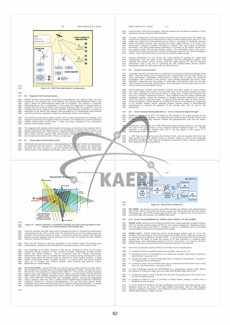
– 40 – 62918 TR/Ed1/DTR IEC(E)
1378 Figure 16 – VSAT Mini-Hub Network Configuration 1379
1380
6.6 Magnetic Field Communications 1381
Another wireless communication technology for consideration uses magnetic fields, not radio 1382 frequencies. The magnetic field is the distance from radiating electromagnetic fields to the 1383 point at which the electromagnetic fields start to propagate. This distance is expressed 1384 mathematically as l/2p (l: wavelength). In this range, the magnitude of magnetic fields is 1385 stronger than that of electric fields, so the strength of electric fields can be ignored. Thus, the 1386 characteristics of the magnetic field are dominant. Using Maxwell’s equations to construct a 1387 description of the electric and magnetic field generated by an infinitesimally small constant 1388 current loop element, expressed in spherical coordinated results in the following. 1389
The wireless communication system usually uses a current loop antenna for radiating a low 1390 frequency signal and uses magnetic fields as a medium. This enables the system to provide a 1391 reliable communication service even in water and metal, compared to the conventional 1392 wireless communication systems. 1393
The magnetic field wireless communication technology can be done in the magnetic field in 1394 several hundreds of KHz frequency band. The permeability of magnetic fields in water is the 1395 almost same as that of air. Thus, there is no difference between the attenuation rate in air and 1396 that in water. And the magnetic field communication system can receive magnetic energy 1397 even though surrounded by metal, if there is a slight gap. 1398
6.7 Visual Light Communication (VLC) 1399
Visible light communication (VLC) is characterized by a “line of sight” transfer of data between 1400 the transmitter and the receiver. The LED Standard document defines the relationship, 1401 necessity and basic structure of the LED interface between illumination and visible light 1402 communication. This standard specification plays a key role in supporting the visible light 1403
62918 TR/Ed1/DTR IEC(E) – 41 –
communication using LED illumination. And this standard will contribute to activation of many 1404 application services using the LED illumination. 1405
The Basic configuration of the light location information service model using VLC defines the 1406 scope of the function and the requirements for indoor location based service using VLC. This 1407 model also defines the location-based service which is composed of navigation services, 1408 indoor information services, push services and public safety services in an indoor VLC 1409 environment. Location or position information is obtained from each unique ID assigned 1410 illumination. VLC using location-based information is composed of two system models: one-1411 way passive system and two-way dynamic system. This specification plays a key role in 1412 supporting the location-based service industry development using the VLC, and the navigation 1413 service, indoor information service, push service and public safety service. 1414
Lighting identification for VLC defines the visible lighting ID standard for visible light 1415 communication and the object of the management and the management method. This 1416 standard also defines various services using the visible lighting ID. And this standard 1417 specification plays a key role in supporting the LBS (location-based service) industry 1418 development using the visible lighting ID, and other services. 1419
6.8 Acoustic communication 1420
Underwater acoustic communication is a technique of sending and receiving messages below 1421 water. There are several ways of employing such communication but the most common is 1422 using hydrophones. Underwater communication is difficult due to factors like multi-path 1423 propagation, time variations of the channel, small available bandwidth and strong signal 1424 attenuation, especially over long ranges. In underwater communication there are low data 1425 rates compared to terrestrial communication, since underwater communication uses acoustic 1426 waves instead of electromagnetic waves. 1427
Earlier underwater acoustic communication systems have been relying on scalar sensors 1428 only, which measure the pressure of the acoustic field. Vector sensors measure the scalar 1429 and vector components of the acoustic field in a single point in space and, therefore, can 1430 serve as a compact multichannel receiver. This is different from the existing multichannel 1431 underwater receivers, which are composed of spatially separated pressure-only sensors, 1432 which may result in large-size arrays. In general, there are two types of vector sensors: 1433 inertial and gradient. Inertial sensors truly measure the velocity or acceleration by responding 1434 to the acoustic medium motion, whereas gradient sensors employ a finite-difference 1435 approximation to estimate the gradients of the acoustic field such as velocity and 1436 acceleration. 1437
6.9 Asset Tracking Utilizing IEEE 802.11 – Focus on Received Signal Strength 1438
Numerous techniques for RTLS are based on the strength of the signal received by the 1439 asset’s attached radio changing – and associating that received signal strength variation with 1440 a change in the separation distance between the gateway/access point and the asset’s 1441 receiver. 1442
Infrastructure requirements for a WiFi RSSI-based asset tracking system are not dissimilar 1443 from that of any typical Data or Voice deployed Wireless Network (Figure 17 – Spatial 1444 resolution is provided in multiple axes only if the tag (target in this Figure) is in 1445 communications with multiple APs. 1446
). WiFi Tags are managed as any other Wireless Client, with the exception that Voice and 1447 Data solutions are given network priority to maintain Quality of Service and Production 1448 Application availability. WiFi Tags are maintained on separate VLANs to maintain separation 1449 from production Wireless Applications. 1450
– 42 – 62918 TR/Ed1/DTR IEC(E)
1451 Figure 17 – Spatial resolution is provided in multiple axes only if the tag (target in this 1452
Figure) is in communications with multiple APs. 1453
There are solutions that offer state-of-the art deployment tools for verifying the infrastructure 1454 requirements are met, and in cases where the requirements are not met, problem areas are 1455 indicated with resolution options provided. It should be noted that a typical VoIP Wireless 1456 Network provides excellent location granularity and at least one solution provides software 1457 clients for tracking VoIP phones. 1458
While the RF footprint is obviously dependent on the transmit power and antenna gain 1459 (directionality), the typical indoor specified WiFi-compliant range is on the order of ~50m. 1460
One advantage of the RSSI solutions is that the RF coverage for RTLS can be easily 1461 determined through utilization of the ‘Location Coverage’ visualization provided through 1462 specific Site Survey products. This in conjunction with the ‘network requirements’ 1463 visualizations make it easy to visualize and report on areas of strong coverage and to also 1464 identify areas where the network might be improved for RTLS location accuracy, if asset 1465 location requirements dictate increased accuracy. In essence some site survey products 1466 allow you to manage your wireless network, while reporting and planning location 1467 performance for asset tracking. 1468
ISO 24730-2 MODE: Various WiFi-tags are multi-use in the context that they may also deliver 1469 tag information via schemes that are not specifically IEEE 802.11-based. Of particular note is 1470 ISO 24730-2. This standard is a superset of the ANSI 371.1 Time-of-arrival location derivation 1471 protocol which was designed for asset tracking. When using this protocol, the tag transmits 1472 0dBm “blinks” with a 60MHz bandwidth using a DSSS modulated 2.4GHz ISM band carrier 1473 (this is NOT IEEE 802.11-based WiFi, but a proprietary system). Tags can be programmed 1474 using a magnetic data link, with a 2.4GHz On-Off Keyed/Frequency-Shift-Key (OOK/FSK) 1475 modulation scheme for command acknowledgement. The tag also sends specific DSSS-1476 modulated signals when receiving signals from a magnetic choke-point transmitter. A network 1477 architecture depicting this situation is provided as Figure 18 – ISO 24730-2 architecture. 1478
. 1479
62918 TR/Ed1/DTR IEC(E) – 43 –
1480 Figure 18 – ISO 24730-2 architecture. 1481
EPC MODE: The electronic product code (EPC) activities are related to the aforementioned 1482 ISO 24730-2 effort in the sense that various vendors are offering products that may support 1483 WiFi-based tags, ISO 24730-2 based tags and EPC tags. Of specific note is that many bur 1484 not all EPC tags communicate in the 868/900 MHz band. 1485
6.10 Asset Tracking (RFID/RTLS): ISO/IEC 24730, ISO/IEC JTC 1/SC 31/WG5 1486
ISO/IEC 24730: defines two air interface protocols and a single application program interface 1487 (API) for real-time locating systems (RTLS) for use in asset management. Marketing material 1488 from this group states that 24730 is intended to allow for compatibility and to encourage 1489 interoperability of products for the growing RTLS market. 1490
ISO/IEC 24730: ISO/IEC 24730 has specific details already defined, such as “To be fully 1491 compliant with this standard, RTLS must comply with ISO/IEC 24730-1:2006 and at least one 1492 air interface protocol defined in ISO/IEC 24730”. In the 24730 parlance, RTLS are wireless 1493 systems with the ability to locate the position of an item anywhere in a defined space 1494 (local/campus, wide area/regional, global) at a point in time that is, or is close to, real time. 1495 Position is derived by measurements of the physical properties of the radio link. 1496
They have conceptually organized RTLS functionality into four classifications: 1497
1) Locating an asset via satellite (requires line-of-sight) - accuracy to 10 m. 1498 2) Locating an asset in a controlled area, e.g. warehouse, campus, airport (area of interest is 1499
instrumented) - accuracy to 3 m. 1500 3) Locating an asset in a more confined area (area of interest is instrumented) - accuracy to 1501
<1 m (typically tens of centimeters). 1502 4) Locating an asset over a terrestrial area using a terrestrial mounted receiver over a wide 1503
area, e.g. cell phone towers - accuracy to 200 m. 1504
In trying to delineate between the RFID-BASED (i.e., portal-based) method, 24730 defines 1505 two methods of locating an object which are really RFID-BASED rather than RTLS: 1506
1) Locating an asset by virtue of the fact that the asset has passed point A at a certain time 1507 and has not passed point B. 1508
2) Locating an asset by virtue of providing a homing beacon whereby a person with a 1509 handheld can find an asset. 1510
In (2) the method of location is through identification and location, generally through multi-1511 lateration using one (or more of) of these different techniques: Time of Flight Ranging 1512 Systems, Amplitude Triangulation, Time Difference of Arrival (TDOA), Cellular Triangulation, 1513 Satellite Multi-lateration, Angle of Arrival. 1514
62
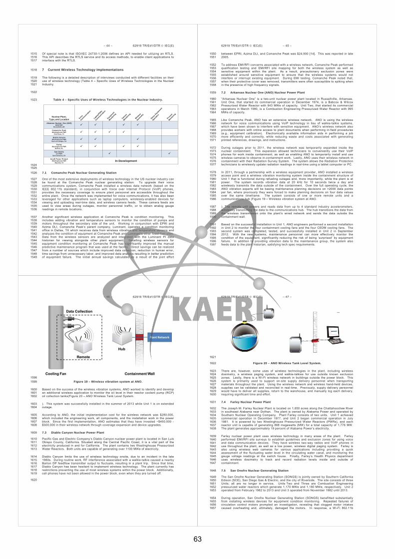
– 44 – 62918 TR/Ed1/DTR IEC(E)
Of special note is that ISO/IEC 24730-1:2006 defines an API needed for utilizing an RTLS. 1515 This API describes the RTLS service and its access methods, to enable client applications to 1516 interface with the RTLS. 1517
7 Current Wireless Technology Implementations 1518
The following is a detailed description of interviews conducted with different facilities on their 1519 use of wireless technology (Table 4 – Specific Uses of Wireless Technologies in the Nuclear 1520 Industry. 1521
1522
Table 4 – Specific Uses of Wireless Technologies in the Nuclear Industry. 1523
Nuclear Plant,Type, and Location
Arkansas Nuclear One (ANO)B&W PWR
Russellville, AR
Comanche PeakWestinghouse PWR
Glen Rose, TX
Diablo CanyonWestinghouse PWRSan Luis Obispo, CA
FarleyWestinghouse PWR
Dothan, AL
San OnofreC-E PWR
San Clemente, CA
South Texas ProjectWestinghouse PWR
Bay City, TXIn Development
1524 1525
7.1 Comanche Peak Nuclear Generating Station 1526
One of the most extensive deployments of wireless technology in the US nuclear industry can 1527 be found at the Comanche Peak nuclear generating station. To upgrade their voice 1528 communications system, Comanche Peak installed a wireless data network (based on the 1529 IEEE 802.11b standard), in conjunction with Voice over Internet Protocol (VoIP) phones, 1530 provides the necessary coverage to ensure plant personnel are accessible throughout the 1531 entire plant. Once the network was implemented for voice communications, it has also been 1532 leveraged for other applications such as laptop computers, wirelessly-enabled devices for 1533 viewing and uploading real-time data, and wireless camera feeds. These camera feeds are 1534 used to view areas during outages, monitor personnel traffic, or to obtain analog gauge 1535 readings in remote locations. 1536
Another significant wireless application at Comanche Peak is condition monitoring. This 1537 includes adding vibration and temperature sensors to monitor the condition of pumps and 1538 motors throughout the secondary side of the unit. Working in conjunction with EPRI and 1539 Azima DLI, Comanche Peak’s parent company, Luminant, operates a condition monitoring 1540 office in Dallas, TX which receives data from wireless vibration and temperature sensors and 1541 analyzes the condition of equipment at Comanche Peak and Luminant’s other fossil fuel sites. 1542 Data from the wireless sensors are analyzed and integrated with the Luminant PI data 1543 historian for viewing alongside other plant equipment. Installing wireless sensors for 1544 equipment condition monitoring at Comanche Peak has significantly improved the manual 1545 predictive maintenance program that was used at the facility. Direct savings can be realized 1546 from a number of sources which include improved data collection, reduction in human error, 1547 time savings from unnecessary labor, and improved data analysis resulting in better prediction 1548 of equipment failure. The initial annual savings calculated as a result of the joint effort 1549
62918 TR/Ed1/DTR IEC(E) – 45 –
between EPRI, Azima DLI, and Comanche Peak was $24,900 [14]. This was reported in late 1550 2005. 1551
To address EMI/RFI concerns associated with a wireless network, Comanche Peak performed 1552 qualification testing and EMI/RFI site mapping for both the wireless system as well as 1553 sensitive equipment within the plant. As a result, precautionary exclusion zones were 1554 established around sensitive equipment to ensure that the wireless systems would not 1555 interfere or interrupt existing equipment. During EMI testing, Comanche Peak noted that, 1556 when their protective cover was removed, transmitters were often susceptible to spiking when 1557 in the presence of high frequency signals. 1558
7.2 Arkansas Nuclear One (ANO) Nuclear Power Plant 1559
“Arkansas Nuclear One” is a two-unit nuclear power plant located in Russellville, Arkansas. 1560 Unit One, that started its commercial operation in December 1974, is a Babcox & Wilcox 1561 Pressurized Water Reactor with 843 MWe of capacity. Unit Two, that started its commercial 1562 operations in March 1980, is a Combustion Engineering Pressurized Water Reactor with 995 1563 MWe of capacity. 1564
Like Comanche Peak, ANO has an extensive wireless network. ANO is using the wireless 1565 network for voice communications using VoIP technology in lieu of walkie-talkie systems, 1566 which have been shown to interfere with sensitive equipment. ANO’s wireless network also 1567 provides workers with online access to plant documents when performing in-field procedures 1568 (e.g., equipment calibration). Electronically available information aids in performing a job 1569 more efficiently and correctly, while reducing waste and costs associated with generating 1570 printed references, drawings, and instructions. 1571
During outages prior to 2011, the wireless network was temporarily expanded inside the 1572 nuclear containment. This expansion allowed technicians to conveniently use their VoIP 1573 phones for work inside containment, as well as enabling ANO to temporarily install and use 1574 wireless cameras to observe in-containment work. Lastly, ANO uses their wireless network in 1575 containment with their Radiation Survey System. The system allows the Radiation Protection 1576 technicians to wirelessly update radiation readings in real-time using a tablet computer or PC. 1577
In 2011, through a partnership with a wireless equipment provider, ANO installed a wireless 1578 access point and a wireless vibration monitoring system inside the containment structure of 1579 Unit 1 that is functional during refueling outages and, more importantly, while the plant is at 1580 power. The system records vibration data at 20 kHz for 10 seconds twice a day and 1581 wirelessly transmits the data outside of the containment. Over the full operating cycle, the 1582 ANO vibration experts will be basing maintenance planning decisions on >2000 data points 1583 per fan, where previously they were forced to make planning decisions on four data values 1584 over the same timeframe. The system consists of one or more remote units and a 1585 communications hub (Figure 19 – Wireless vibration system at ANO. 1586
). The remote unit powers and reads data from up to 4 standard industry accelerometers, 1587 wirelessly transmitting the data to the communications hub. The hub transitions the data from 1588 the wireless transmission onto the plant’s wired network and sends the data outside the 1589 containment wall. 1590
Based on the successful installation in Unit 1, ANO engineers performed a second installation 1591 in Unit 2 to monitor the four containment cooling fans and the four CEDM cooling fans. The 1592 second system was completed, tested, and successfully installed in Unit 2 in September 1593 2012. With the new systems, maintenance personnel can more effectively monitor the 1594 condition of the equipment, significantly reducing the risk of being ‘surprised’ by equipment 1595 failure. In addition to providing vibration data to the maintenance group, the system also 1596 feeds data to the plant historian, satisfying tech spec requirements. 1597
– 46 – 62918 TR/Ed1/DTR IEC(E)
1598 Figure 19 – Wireless vibration system at ANO. 1599
Based on the success of the wireless vibration systems, ANO worked to identify and develop 1600 an additional wireless application to monitor the oil level in their reactor coolant pump (RCP) 1601 oil collection tanks(Figure 20 – ANO Wireless Tank Level System. 1602
). This system was successfully installed in the summer of 2013 while Unit 1 is on extended 1603 outage. 1604
According to ANO, the initial implementation cost for the wireless network was $280,000, 1605 which included the engineering work, all components, and the installation work in the power 1606 block. Since the first implementation, ANO estimates that they have invested ~$450,000 - 1607 $500,000 in their wireless network through coverage expansion and device upgrades. 1608
7.3 Diablo Canyon Nuclear Power Plant 1609
Pacific Gas and Electric Company’s Diablo Canyon nuclear power plant is located in San Luis 1610 Obispo County, California. Situated along the Central Pacific Coast, it is a vital part of the 1611 electricity produced in and for California. The plant contains two Westinghouse Pressurized 1612 Water Reactors. Both units are capable of generating over 1100 MWe of electricity. 1613
Diablo Canyon limits the use of wireless technology onsite, due to an incident in the late 1614 1980s. During routine work, RF interference associated with a walkie-talkie caused a nearby 1615 Barton DP feedflow transmitter output to fluctuate, resulting in a plant trip. Since that time, 1616 Diablo Canyon has been hesitant to implement wireless technology. The plant currently has 1617 restrictions preventing the use of most wireless systems within the power block. Additionally, 1618 cell phones have not been allowed in the power block, even when they are turned off. 1619
1620
62918 TR/Ed1/DTR IEC(E) – 47 –
1621
Figure 20 – ANO Wireless Tank Level System. 1622
There are, however, some uses of wireless technologies in the plant, including wireless 1623 dosimetry, a wireless paging system, and walkie-talkies for use outside known exclusion 1624 zones. Lastly, there is a Wi-Fi wireless network in buildings outside the power block. This 1625 system is primarily used to support on-site supply delivery personnel when transporting 1626 materials throughout the plant. Using the wireless network and wireless hand-held devices, 1627 supplies can be validated and reconciled in real-time. Previously, supply delivery personnel 1628 would have to deliver all supplies, return to the warehouse, and manually log each delivery, 1629 requiring significant time and effort. 1630
7.4 Farley Nuclear Power Plant 1631
The Joseph M. Farley Nuclear Plant is located on 1,850 acres along the Chattahoochee River 1632 in southeast Alabama near Dothan. The plant is owned by Alabama Power and operated by 1633 Southern Nuclear Operating Company. Plant Farley consists of two units. Unit 1 achieved 1634 commercial operation in December 1977, and Unit 2 began commercial operation in July 1635 1981. It is powered by two Westinghouse Pressurized Water Reactors (PWRs), and each 1636 reactor unit is capable of generating 888 megawatts (MW) for a total capacity of 1,776 MW. 1637 The plant generates approximately 19 percent of Alabama Power’s electricity. 1638
Farley nuclear power plant uses wireless technology in many areas of the plant. Farley 1639 performed EMI/RFI site surveys to establish guidelines and exclusion zones for using voice 1640 and data communication devices. They have wireless two-way radios and VoIP phones in 1641 use throughout the plant, as well as a low power, wireless digital paging system. Farley is 1642 also using wireless web cameras for various applications including providing a quick 1643 assessment of the fluctuating water level in the circulating water canal, and monitoring the 1644 gauge voltage readings at the switch house. Finally, Farley’s Health Physics department 1645 uses wireless dosimetry to track and record radiation levels inside and outside of 1646 containment. 1647
7.5 San Onofre Nuclear Generating Station 1648
The San Onofre Nuclear Generating Station (SONGS) is jointly owned by Southern California 1649 Edison (SCE), San Diego Gas & Electric, and the city of Riverside. The site consists of three 1650 Units; all are no longer in service. Units Two and Three are Combustion Engineering 1651 pressurized water reactors which generate 1,170 MWe and 1,180 MWe, respectively. Unit 2 1652 operated from February 1982 to 2013 and Unit 3 operated from November 1982 until 2013. 1653
During operation, San Onofre Nuclear Generating Station (SONGS) benefitted substantially 1654 from installing wireless devices for equipment condition monitoring. Repeated failures of 1655 circulation control motors prompted an investigation, revealing that clogged motor intakes 1656 caused overheating and, ultimately, damaged the motors. In response, a Wi-Fi 802.11b 1657
63

– 48 – 62918 TR/Ed1/DTR IEC(E)
network was installed to communicate data from condition monitoring sensors. The system 1658 provides the plant with enough forewarning to plan repairs or replace these motors, if needed, 1659 during an outage or low power operations. Since the wireless installation was deployed in 1660 2003, not a single pump has failed during plant operations, significantly reducing expensive 1661 downtime, as well as the cost of maintenance for these motor-pump sets. Furthermore, the 1662 plant has seen a 60% reduction in labor costs associated with maintenance on the motor 1663 pump systems due to the ability to schedule motor repair and replacement. 1664
To address cyber security concerns, the plant used several methods to protect the data on 1665 the wireless network. Specialized wireless bridges are employed which use proprietary 1666 encryption and authentication protocols. In addition, an Access Control List (ACL) limits 1667 network access to only approved personnel, while MAC address filtering monitors the 1668 devices/platforms trying to access the network. Lastly, the IT department uses static IP 1669 addresses for all network clients, essentially reserving access for only pre-approved 1670 equipment. 1671
7.6 South Texas Project Electric Generating Station 1672
The South Texas Project (STP) Electric Generating Station is a two-unit nuclear power plant 1673 located near Bay City, Texas. Unit One, which was brought on-line in August 1988, is a four-1674 loop Westinghouse Pressurized Water Reactor with ~1350 MWe of capacity. Unit Two, which 1675 was brought on-line in June 1989, is also a four-loop Westinghouse Pressurized Water 1676 Reactor with ~1350 MWe of capacity. A license application for two additional Advanced 1677 Boiling Water Reactors was submitted in September 2007 which would eventually be Unit 1678 Three and Unit Four of the facility. 1679
The South Texas Project site currently uses radios and pagers typical in most other nuclear 1680 facilities and currently allows the use of cell phones and blackberry devices onsite. Due to 1681 the location and structure of the Reactor Building, however, there is a lack of coverage for 1682 personal cell phone and blackberry devices. In addition, they extensively use wireless 1683 dosimeters for personnel and area/process radiation monitoring. These radiation monitoring 1684 devices use different radio transmitters/antennae than the Wi-Fi 802.11 backbone being 1685 implemented at STP. 1686
South Texas has made significant progress in the installation of an 802.11 wireless backbone 1687 at the facility. There are ~125 access points in all administrative buildings which include the 1688 Turbine Building, Isolation Valve Cubicles, Diesel Building, Fuel Handling Buildings, Electrical 1689 Auxiliary, and Reactor Building. By the end of 2009, more than 300 access points will be 1690 installed. Like Arkansas Nuclear One, this will not just be on the plant campus or secondary 1691 side of the plant but will include the power block as well. 1692
The applications will be similar to Arkansas Nuclear One and will most likely be used for voice 1693 and data communications. The plan is to also temporarily extend this wireless network inside 1694 containment during outages. The program is in the beginning stages so multiple applications 1695 have not yet been implemented; however, several have already been envisioned. Some of 1696 these include VoIP phones, plant network access in isolated areas using tablet PCs, 1697 paperless gauge calibration, and wireless data transmission from plant personnel in the field. 1698 For the latter example, an application is envisioned where data that is currently logged into a 1699 performance monitoring database via handheld PC docking stations could be uploaded to the 1700 plant network using a wirelessly-enabled handheld PC. Information like temperature, level, 1701 and flow gauge readings could be uploaded in real-time to the plant computer from anywhere 1702 in the plant. Additionally, STP plans to investigate fire detection using IP cameras to augment 1703 resources for fire watch. Lastly, in the summer of 2009, STP deployed IP cameras in their 1704 auxiliary feed-pump cubicles for elevated temperature monitoring. 1705
7.7 High Flux Isotope Reactor (HFIR), Oak Ridge, TN 1706
In an application at Oak Ridge National Laboratory’s High Flux Isotope Reactor (ORNL HFIR), 1707 the portable version has been installed as a permanent system. It monitors multiple test 1708 points on four cold source expansion engines (Stirling-type engines) that are vital for 1709
62918 TR/Ed1/DTR IEC(E) – 49 –
maintaining the cryogenic temperature of the neutron cold source (Erreur ! Source du renvoi 1710 introuvable.). 1711
Figure 21 – Installation of Accelerometers on ORNL HFIR Cold Source Expansion 1712 Engines (9-2010). 1713
Erreur ! Source du renvoi introuvable. 1714
Figure 22 – Cold Source Expansion Engine Monitoring System Software. 1715
The monitoring system routinely collects data every four hours, performing real-time 1716 calculation of vibration acceleration RMS, skew, and kurtosis. These parameters are 1717 automatically trended and displayed for cold source operators,Erreur ! Source du renvoi 1718 introuvable.. The operators and system engineer use this data and other process 1719 parameters such as temperature and pressure to make informed decisions regarding the 1720 health of the engines and when to schedule repairs. 1721
The operators and system engineer use this data and other process parameters such as 1722 temperature and pressure to make informed decisions regarding the health of the engines and 1723 when to schedule repairs. 1724
ORNL installed the permanent configuration of the wireless vibration system at ORNL’s HFIR 1725 cooling tower. The cooling tower fan motors have been problematic for close to a decade and 1726 the gearboxes (which may provide valuable diagnostic information) have not been previously 1727 monitored, as they are inaccessible during tower operation (Figure 23 – Installation of 1728 Permanent Wireless Monitoring System at ORNL HFIR Cooling Tower (8-2011). 1729
). The system provides automated periodic monitoring, data collection on demand, trending of 1730 vibration parameters and bearing noise, and delivery of data and trends to the desktop of 1731 HFIR’s condition monitoring expert (Figure 24). 1732
1733
– 50 – 62918 TR/Ed1/DTR IEC(E)
Figure 23 – Installation of Permanent Wireless Monitoring System at ORNL HFIR 1734 Cooling Tower (8-2011). 1735
1736 Figure 24 – System Commissioned in August 2011. 1737
8 Considerations 1738
8.1 Myths Regarding Wireless Technology 1739
There are a number of common myths about utilizing wireless technologies within nuclear 1740 power plants. Most notable ones are: 1741
The radiation in a nuclear power plant will damage the microelectronic chips onboard the 1742 wireless sensors and modules or temporarily render them useless; 1743
The radiation field will ionize the air media so that the electromagnetic waveforms will no 1744 longer prorogate; 1745
The transmitted electromagnetic waves from a wireless sensor transmitter may interfere 1746 with sensitive equipment in the plant causing a false trip; and 1747
The background electromagnetic noise emitted from major plant electrical systems, such 1748 as motors, pumps, or electric relay contacts, will make the wireless sensor network 1749 inoperable. 1750
Even though these are legitimate concerns, extensive studies have been conducted to 1751 demonstrate these concerns are unfounded. 1752
It is true that the radiation level in certain parts of a nuclear power plant can be higher than 1753 ambient level. However, during normal plant operation, the radiation has relatively mild effects 1754 to the electronics onboard the sensor nodes. With proper shielding, wireless sensor nodes 1755 can safely operate within a nuclear power plant. 1756
However, in the event of an accident, the radiation level could increase significantly. In such 1757 situations, the sensor nodes could be damaged with time. Hence, if wireless sensor nodes are 1758 intended for post-accident applications, proper protection mechanisms should be utilized. 1759
Radiation can be divided into two types: ionizing radiation and non-ionizing radiation. The 1760 ionizing radiation includes x- -ionizing radiation is 1761 related to those in radio waves and wireless sensor transmitting signals. It is true that both 1762 types of radiations carry energy, but they are often at different spectrum range. Experimental 1763 studies have been carried out within hot cells to investigate the interplay of these two types of 1764 radiations. It is concluded that, at extremely high levels of radiation, the ionizing radiation 1765 does have limited influence on the propagation of the non-ionizing radiation. However, during 1766 normal operation of a nuclear power plant, or even during a limited scale accident, the 1767 radiation would not normally reach to the level that the ionizing radiation can have significant 1768 influence on the propagation properties of the non-ionizing radiation, i.e. the radio waves 1769 between wireless sensor nodes. 1770
62918 TR/Ed1/DTR IEC(E) – 51 –
It is true that there are many sensitive instruments within nuclear power plants. Some may not 1771 be completely shielded from the influence of electromagnetic interference. However, a typical 1772 transmitting power level of a wireless sensor node is at milli-watt level. Such low level of radio 1773 wave has no effects to any safety system equipment, because the power decays at a rate 1774 inversely proportional to the quadratic power of the distance of the emitting site. However, 1775 one has to be extremely careful if walkie-talkie types of communication devices are used in 1776 the plant, as their emitting power is typically rated at 0.5 Watt. They could have significant 1777 influence to the sensitive equipment if placed sufficiently close to the equipment. 1778
In any industrial environment, no except to nuclear power plants, there are electromagnetic 1779 pollutions emitted by equipment, such as electric machines, relay contacts and power tools. 1780 Furthermore, extensive use of digital control systems also contributes to potential emission of 1781 high frequency noise from switching actions. Several experimental studies have demonstrated 1782 that the spectrum of the noise from those emitting sources are typically much lower than 2.4 1783 GHz central frequency used by most of the wireless sensor nodes. Therefore, such noise has 1784 little impact to the operation of wireless sensor node systems. 1785
8.2 Wireless Deployment Challenges 1786
While there are numerous instances of wireless sensors and systems being used in a utility 1787 environment, there are challenges in wide spread adoption - and secure deployment and 1788 integration - of wireless sensor technology in power plants. Some of these limitations are 1789 listed as follows: 1790
Cyber security 1791
Barrier penetration capability 1792
Power requirements 1793
Bandwidth requirements 1794
Plug and Play capability 1795
Multiple standards 1796
Interoperability 1797
Compatibility 1798
The questions may seem daunting - even intimidating - but are worthwhile having vendors 1799 complete thereby allowing IT to determine the security "rankings" of the sensors, systems, 1800 and networks. As a reminder, apart from the financial incentive, there are several key 1801 objectives for deploying a wireless sensor network in a NPP, namely: 1802
Uptime improvement 1803
Improved utilization of assets (including people) 1804
Impact/backup on safety systems 1805
Improving quality assurance with on-line, continuous monitoring/qualification 1806
Enhanced accountability 1807
Enhanced automation of non-critical functions 1808
Expert system support – event driven 1809
Knowledge management – capture wisdom (implemented as an expert system) 1810
Life cycle cost management 1811
Improved job satisfaction or less frustration. 1812
However, wireless sensor networks in nuclear power plants pose a unique challenge. The 1813 commercially available devices are not radiation hardened. RF devices cannot be enclosed in 1814 a lead box (Faraday cage). The antenna should be mounted outside the protective shell for 1815 the electronics to minimize exposure to radiation. Depending on the placement of the wireless 1816
64
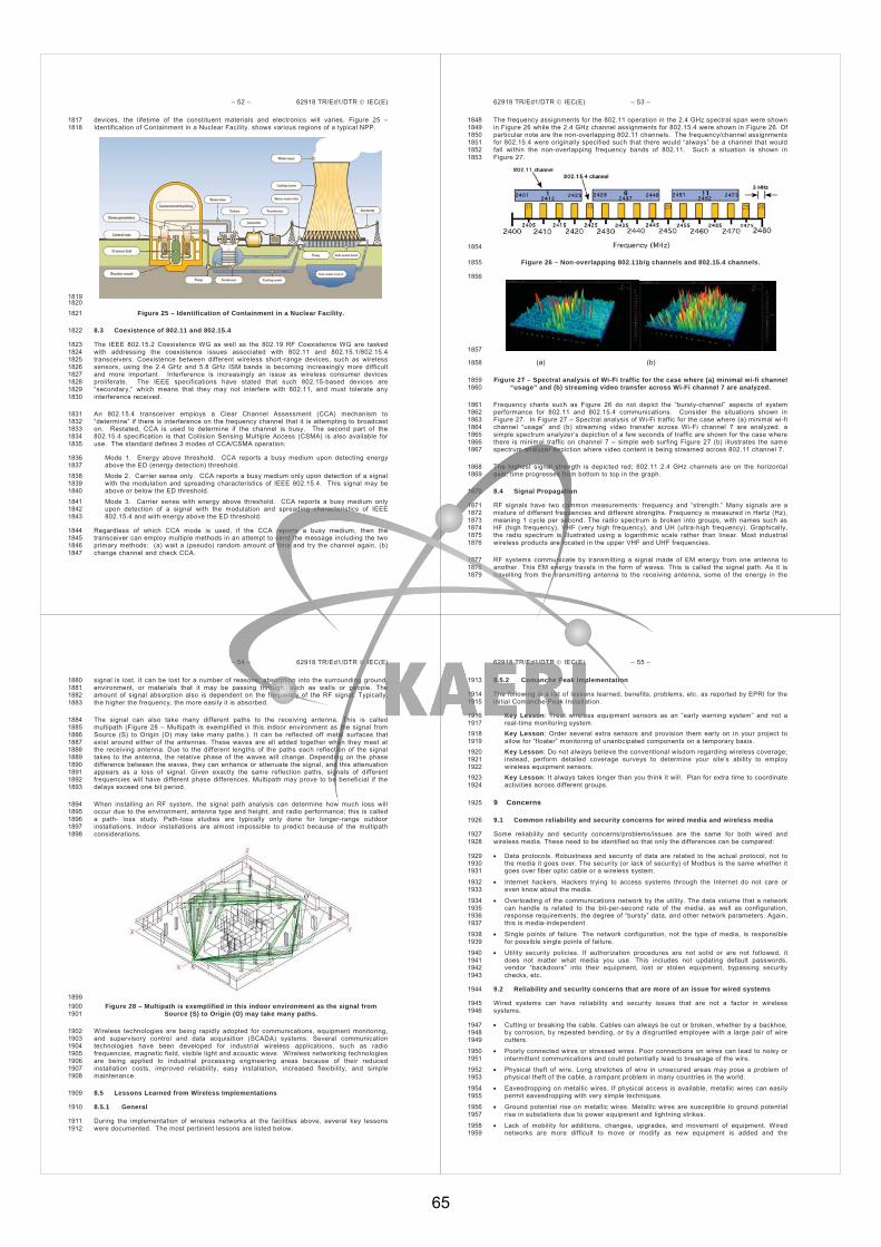
– 52 – 62918 TR/Ed1/DTR IEC(E)
devices, the lifetime of the constituent materials and electronics will varies. Figure 25 – 1817 Identification of Containment in a Nuclear Facility. shows various regions of a typical NPP. 1818
1819 1820
Figure 25 – Identification of Containment in a Nuclear Facility. 1821
8.3 Coexistence of 802.11 and 802.15.4 1822
The IEEE 802.15.2 Coexistence WG as well as the 802.19 RF Coexistence WG are tasked 1823 with addressing the coexistence issues associated with 802.11 and 802.15.1/802.15.4 1824 transceivers. Coexistence between different wireless short-range devices, such as wireless 1825 sensors, using the 2.4 GHz and 5.8 GHz ISM bands is becoming increasingly more difficult 1826 and more important. Interference is increasingly an issue as wireless consumer devices 1827 proliferate. The IEEE specifications have stated that such 802.15-based devices are 1828 “secondary,” which means that they may not interfere with 802.11, and must tolerate any 1829 interference received. 1830
An 802.15.4 transceiver employs a Clear Channel Assessment (CCA) mechanism to 1831 “determine” if there is interference on the frequency channel that it is attempting to broadcast 1832 on. Restated, CCA is used to determine if the channel is busy. The second part of the 1833 802.15.4 specification is that Collision Sensing Multiple Access (CSMA) is also available for 1834 use. The standard defines 3 modes of CCA/CSMA operation: 1835
Mode 1. Energy above threshold. CCA reports a busy medium upon detecting energy 1836 above the ED (energy detection) threshold. 1837
Mode 2. Carrier sense only. CCA reports a busy medium only upon detection of a signal 1838 with the modulation and spreading characteristics of IEEE 802.15.4. This signal may be 1839 above or below the ED threshold. 1840
Mode 3. Carrier sense with energy above threshold. CCA reports a busy medium only 1841 upon detection of a signal with the modulation and spreading characteristics of IEEE 1842 802.15.4 and with energy above the ED threshold. 1843
Regardless of which CCA mode is used, if the CCA reports a busy medium, then the 1844 transceiver can employ multiple methods in an attempt to send the message including the two 1845 primary methods: (a) wait a (pseudo) random amount of time and try the channel again, (b) 1846 change channel and check CCA. 1847
62918 TR/Ed1/DTR IEC(E) – 53 –
The frequency assignments for the 802.11 operation in the 2.4 GHz spectral span were shown 1848 in Figure 26 while the 2.4 GHz channel assignments for 802.15.4 were shown in Figure 26. Of 1849 particular note are the non-overlapping 802.11 channels. The frequency/channel assignments 1850 for 802.15.4 were originally specified such that there would “always” be a channel that would 1851 fall within the non-overlapping frequency bands of 802.11. Such a situation is shown in 1852 Figure 27. 1853
1854
Figure 26 – Non-overlapping 802.11b/g channels and 802.15.4 channels. 1855
1856
1857
(a) (b) 1858
Figure 27 – Spectral analysis of Wi-Fi traffic for the case where (a) minimal wi-fi channel 1859 “usage” and (b) streaming video transfer across Wi-Fi channel 7 are analyzed. 1860
Frequency charts such as Figure 26 do not depict the “bursty-channel” aspects of system 1861 performance for 802.11 and 802.15.4 communications. Consider the situations shown in 1862 Figure 27. In Figure 27 – Spectral analysis of Wi-Fi traffic for the case where (a) minimal wi-fi 1863 channel “usage” and (b) streaming video transfer across Wi-Fi channel 7 are analyzed. a 1864 simple spectrum analyzer’s depiction of a few seconds of traffic are shown for the case where 1865 there is minimal traffic on channel 7 – simple web surfing Figure 27 (b) illustrates the same 1866 spectrum analyzer depiction where video content is being streamed across 802.11 channel 7. 1867
The highest signal strength is depicted red; 802.11 2.4 GHz channels are on the horizontal 1868 axis; time progresses from bottom to top in the graph. 1869
8.4 Signal Propagation 1870
RF signals have two common measurements: frequency and “strength.” Many signals are a 1871 mixture of different frequencies and different strengths. Frequency is measured in Hertz (Hz), 1872 meaning 1 cycle per second. The radio spectrum is broken into groups, with names such as 1873 HF (high frequency), VHF (very high frequency), and UH (ultra-high frequency). Graphically, 1874 the radio spectrum is illustrated using a logarithmic scale rather than linear. Most industrial 1875 wireless products are located in the upper VHF and UHF frequencies. 1876
RF systems communicate by transmitting a signal made of EM energy from one antenna to 1877 another. This EM energy travels in the form of waves. This is called the signal path. As it is 1878 travelling from the transmitting antenna to the receiving antenna, some of the energy in the 1879
– 54 – 62918 TR/Ed1/DTR IEC(E)
signal is lost. It can be lost for a number of reasons: absorption into the surrounding ground, 1880 environment, or materials that it may be passing through, such as walls or people. The 1881 amount of signal absorption also is dependent on the frequency of the RF signal. Typically, 1882 the higher the frequency, the more easily it is absorbed. 1883
The signal can also take many different paths to the receiving antenna. This is called 1884 multipath (Figure 28 – Multipath is exemplified in this indoor environment as the signal from 1885 Source (S) to Origin (O) may take many paths.). It can be reflected off metal surfaces that 1886 exist around either of the antennas. These waves are all added together when they meet at 1887 the receiving antenna. Due to the different lengths of the paths each reflection of the signal 1888 takes to the antenna, the relative phase of the waves will change. Depending on the phase 1889 difference between the waves, they can enhance or attenuate the signal, and this attenuation 1890 appears as a loss of signal. Given exactly the same reflection paths, signals of different 1891 frequencies will have different phase differences. Multipath may prove to be beneficial if the 1892 delays exceed one bit period. 1893
When installing an RF system, the signal path analysis can determine how much loss will 1894 occur due to the environment, antenna type and height, and radio performance; this is called 1895 a path- loss study. Path-loss studies are typically only done for longer-range outdoor 1896 installations. Indoor installations are almost impossible to predict because of the multipath 1897 considerations. 1898
1899 Figure 28 – Multipath is exemplified in this indoor environment as the signal from 1900
Source (S) to Origin (O) may take many paths. 1901
Wireless technologies are being rapidly adopted for communications, equipment monitoring, 1902 and supervisory control and data acquisition (SCADA) systems. Several communication 1903 technologies have been developed for industrial wireless applications, such as radio 1904 frequencies, magnetic field, visible light and acoustic wave. Wireless networking technologies 1905 are being applied to industrial processing engineering areas because of their reduced 1906 installation costs, improved reliability, easy installation, increased flexibility, and simple 1907 maintenance. 1908
8.5 Lessons Learned from Wireless Implementations 1909
8.5.1 General 1910
During the implementation of wireless networks at the facilities above, several key lessons 1911 were documented. The most pertinent lessons are listed below. 1912
62918 TR/Ed1/DTR IEC(E) – 55 –
8.5.2 Comanche Peak Implementation 1913
The following is a list of lessons learned, benefits, problems, etc. as reported by EPRI for the 1914 initial Comanche Peak Installation. 1915
Key Lesson: Treat wireless equipment sensors as an “early warning system” and not a 1916 real-time monitoring system. 1917
Key Lesson: Order several extra sensors and provision them early on in your project to 1918 allow for “floater” monitoring of unanticipated components on a temporary basis. 1919
Key Lesson: Do not always believe the conventional wisdom regarding wireless coverage; 1920 instead, perform detailed coverage surveys to determine your site’s ability to employ 1921 wireless equipment sensors. 1922
Key Lesson: It always takes longer than you think it will. Plan for extra time to coordinate 1923 activities across different groups. 1924
9 Concerns 1925
9.1 Common reliability and security concerns for wired media and wireless media 1926
Some reliability and security concerns/problems/issues are the same for both wired and 1927 wireless media. These need to be identified so that only the differences can be compared: 1928
Data protocols. Robustness and security of data are related to the actual protocol, not to 1929 the media it goes over. The security (or lack of security) of Modbus is the same whether it 1930 goes over fiber optic cable or a wireless system. 1931
Internet hackers. Hackers trying to access systems through the Internet do not care or 1932 even know about the media. 1933
Overloading of the communications network by the utility. The data volume that a network 1934 can handle is related to the bit-per-second rate of the media, as well as configuration, 1935 response requirements, the degree of “bursty” data, and other network parameters. Again, 1936 this is media-independent. 1937
Single points of failure. The network configuration, not the type of media, is responsible 1938 for possible single points of failure. 1939
Utility security policies. If authorization procedures are not solid or are not followed, it 1940 does not matter what media you use. This includes not updating default passwords, 1941 vendor “backdoors” into their equipment, lost or stolen equipment, bypassing security 1942 checks, etc. 1943
9.2 Reliability and security concerns that are more of an issue for wired systems 1944
Wired systems can have reliability and security issues that are not a factor in wireless 1945 systems. 1946
Cutting or breaking the cable. Cables can always be cut or broken, whether by a backhoe, 1947 by corrosion, by repeated bending, or by a disgruntled employee with a large pair of wire 1948 cutters. 1949
Poorly connected wires or stressed wires. Poor connections on wires can lead to noisy or 1950 intermittent communications and could potentially lead to breakage of the wire. 1951
Physical theft of wire. Long stretches of wire in unsecured areas may pose a problem of 1952 physical theft of the cable, a rampant problem in many countries in the world. 1953
Eavesdropping on metallic wires. If physical access is available, metallic wires can easily 1954 permit eavesdropping with very simple techniques. 1955
Ground potential rise on metallic wires. Metallic wires are susceptible to ground potential 1956 rise in substations due to power equipment and lightning strikes. 1957
Lack of mobility for additions, changes, upgrades, and movement of equipment. Wired 1958 networks are more difficult to move or modify as new equipment is added and the 1959
65
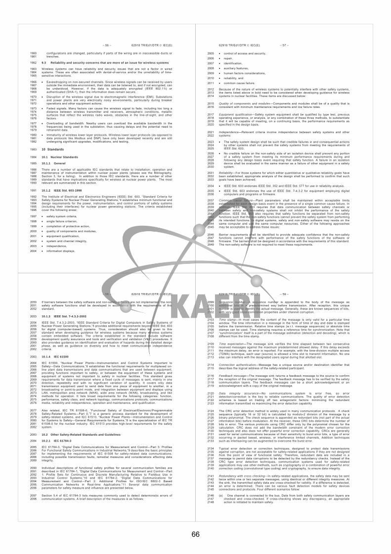
– 56 – 62918 TR/Ed1/DTR IEC(E)
configurations are changed, particularly if parts of the wiring are in inaccessible ducts or 1960 trenches. 1961
9.3 Reliability and security concerns that are more of an issue for wireless systems 1962
Wireless systems can have reliability and security issues that are not a factor in wired 1963 systems. These are often associated with denial-of-service and/or the unreliability of time-1964 sensitive interactions. 1965
Eavesdropping on non-secured channels. Since wireless signals can be received by users 1966 outside the immediate environment, their data can be listened to, and if not encrypted, can 1967 be understood. However, if the data is adequately encrypted (IEEE 802.11i) or 1968 authenticated (SHA-1), then the information does remain secure. 1969
Disruption of the wireless signal due to electromagnetic interference (EMI). Substations 1970 and power plants are very electrically noisy environments, particularly during breaker 1971 operations and other equipment actions. 1972
Faded signals. Many factors can cause the wireless signal to fade, including too long a 1973 distance between wireless transmitter and receivers, atmospheric conditions, metallic 1974 surfaces that reflect the wireless radio waves, obstacles in the line-of-sight, and other 1975 factors. 1976
Overloading of bandwidth. Nearby users can overload the available bandwidth in the 1977 frequencies being used in the substation, thus causing delays and the potential need to 1978 retransmit data. 1979
Immaturity of wireless lower layer protocols. Wireless lower layer protocols (as opposed to 1980 data protocols like Modbus and DNP) have only been developed recently and are still 1981 undergoing significant upgrades, modifications, and testing. 1982
10 Standards 1983
10.1 Nuclear Standards 1984
10.1.1 General 1985
There are a number of applicable IEC standards that relate to installation; operation and 1986 maintenance of instrumentation within nuclear power plants (please see the Bibliography, 1987 Section 3, for a listing). In addition to those IEC standards, there are a number of other 1988 standards that have implications specifically for wireless at nuclear power plants. The most 1989 relevant are summarized in this section. 1990
10.1.2 IEEE Std. 603-1998 1991
The Institute of Electrical and Electronics Engineers (IEEE) Std. 603, “Standard Criteria for 1992 Safety Systems for Nuclear Power Generating Stations,”4 establishes minimum functional and 1993 design requirements for the power, instrumentation, and control portions of safety systems 1994 (including their interfaces) for nuclear power generating stations. The criteria established 1995 cover the following areas: 1996
safety system criteria, 1997
single failure criterion, 1998
completion of protective action, 1999
quality of components and modules, 2000
equipment qualification, 2001
system and channel integrity, 2002
independence, 2003
information displays, 2004
62918 TR/Ed1/DTR IEC(E) – 57 –
control of access and security, 2005
repair, 2006
identification, 2007
auxiliary features, 2008
human factors considerations, 2009
reliability, and 2010
common cause failure. 2011
Because of the nature of wireless systems to potentially interfere with other safety systems, 2012 the items listed above in bold need to be considered when developing guidance for wireless 2013 systems in nuclear facilities. These items are discussed below: 2014
Quality of components and modules—Components and modules shall be of a quality that is 2015 consistent with minimum maintenance requirements and low failure rates. 2016
Equipment qualification—Safety system equipment shall be qualified by type test, previous 2017 operating experience, or analysis, or any combination of these three methods, to substantiate 2018 that it will be capable of meeting, on a continuing basis, the performance requirements as 2019 specified in the design basis. 2020
Independence—Relevant criteria involve independence between safety systems and other 2021 systems: 2022
The safety system design shall be such that credible failures in and consequential actions 2023 by other systems shall not prevent the safety systems from meeting the requirements of 2024 IEEE Std. 603. 2025
No credible failure on the non-safety side of an isolation device shall prevent any portion 2026 of a safety system from meeting its minimum performance requirements during and 2027 following any design basis event requiring that safety function. A failure in an isolation 2028 device shall be evaluated in the same manner as a failure of other equipment in a safety 2029 system. 2030
Reliability—For those systems for which either quantitative or qualitative reliability goals have 2031 been established, appropriate analysis of the design shall be performed to confirm that such 2032 goals have been achieved. 2033
IEEE Std. 603 endorses IEEE Std. 352 and IEEE Std. 577 for use in reliability analysis. 2034
IEEE Std. 603 endorses the use of IEEE Std. 7-4.3.2 for equipment employing digital 2035 computers and programs or firmware. 2036
Common cause failure—Plant parameters shall be maintained within acceptable limits 2037 established for each design basis event in the presence of a single common cause failure. In 2038 addition, IEEE Std. 603 requires that data communication between safety channels or 2039 between safety and non-safety systems shall not inhibit the performance of the safety 2040 function. IEEE Std. 603 also requires that safety functions be separated from non-safety 2041 functions such that the non-safety functions cannot prevent the safety system from performing 2042 its intended functions. In digital systems, safety and non-safety software may reside on the 2043 same computer and use the same computer resources. Either of the following approaches 2044 may be acceptable to address these issues: 2045
Barrier requirements shall be identified to provide adequate confidence that the non-safety 2046 functions cannot interfere with performance of the safety functions of the software or 2047 firmware. The barriers shall be designed in accordance with the requirements of this standard. 2048 The non-safety software is not required to meet these requirements. 2049
– 58 – 62918 TR/Ed1/DTR IEC(E)
If barriers between the safety software and non-safety software are not implemented, the non-2050 safety software functions shall be developed in accordance with the requirements of this 2051 standard. 2052
10.1.3 IEEE Std. 7-4.3.2-2003 2053
IEEE Std. 7.4.3.2-2003, “IEEE Standard Criteria for Digital Computers in Safety Systems of 2054 Nuclear Power Generating Stations,”5 provides additional requirements beyond IEEE Std. 603 2055 for digital (computer-based) systems. Thus, consideration should also be given to this 2056 standard when developing guidance for wireless systems because many wireless systems 2057 contain embedded software. The criteria established in the standard include software 2058 development quality assurance and tools and verification and validation (V&V) procedures. It 2059 also provides guidance on identification and evaluation of hazards during the detailed design 2060 phase, as well as guidance on diversity and how to meet communication independence 2061 criteria. 2062
10.1.4 IEC 61500 2063
IEC 61500, “Nuclear Power Plants—Instrumentation and Control Systems Important to 2064 Safety—Data Communications,”6 establishes the functional requirements for multiplexed on-2065 line plant data transmissions and data communications that are used between equipment, 2066 providing functions important to safety, or between the equipment of these systems and 2067 equipment of systems not important to safety in nuclear facilities. This standard gives 2068 requirements for data transmission where a fixed cycle of messages is sent, mainly in one 2069 direction, repeatedly and with no significant variation of quantity. It covers only data 2070 transmission equipment used to send data from one piece of equipment to another, in a 2071 broadcasting or point-to-point mode, and integration between equipment and displays using 2072 LAN, metropolitan area network (MAN), wide area network (WAN), broadcasting, and like 2073 methods for operation. It lists broad requirements for the following categories: function, 2074 performance, safety class, and network topology; communications protocols, communications 2075 media, reliability and independence, operation and maintenance, and qualification. 2076
Also related, IEC TR 61508-0, “Functional Safety of Electrical/Electronic/Programmable 2077 Safety-Related Systems—Part 0,”7 is a generic process standard for the development of 2078 safety-related systems, and IEC 61513, “Nuclear Power Plants—Instrumentation and Control 2079 for Systems to Safety—General Requirements for Systems,”8 is the specialization of IEC TR 2080 61508-0 for the nuclear industry. IEC 61513 provides high-level requirements for the safety 2081 system. 2082
10.2 Other Safety-Related Standards and Guidelines 2083
10.2.1 IEC 61784-3 2084
IEC 61784-3, “Digital Data Communications for Measurement and Control—Part 3: Profiles 2085 For Functional Safety Communications in Industrial Networks,”9 describes the basic principles 2086 for implementing the requirements of IEC 61508 for safety-related data communications, 2087 including possible transmission faults, remedial measures and considerations affecting data 2088 integrity. 2089
Individual descriptions of functional safety profiles for several communication families are 2090 described in IEC 61784-1, “Digital Data Communications for Measurement and Control—Part 2091 1: Profile Sets for Continuous and Discrete Manufacturing Relative to Fieldbus Use in 2092 Industrial Control Systems,”10 and IEC 61784-2, “Digital Data Communications for 2093 Measurement and Control—Part 2: Additional Profiles for ISO/IEC 8802-3 Based 2094 Communication Networks in Real-time Applications.”11 Several data communication 2095 parameters for safety measure and influence are presented below. 2096
Section 5.4 of IEC 61784-3 lists measures commonly used to detect deterministic errors of 2097 communication systems. A brief description of the measures is as follows: 2098
62918 TR/Ed1/DTR IEC(E) – 59 –
Sequence number—A sequence number is appended to the body of the message as 2099 additional bits in a predetermined way before transmission. After reception, this unique 2100 number is used to identify the actual message. Generally, these are known sequences of bits, 2101 with very good cross-correlation properties under channel corruption. 2102
Time stamp—In most cases the content of the message is only valid for a particular time 2103 window. The time information in a message in the form of time of day and date is stamped 2104 before the transmission. Relative time stamps (w.r.t. message sequences) or absolute time 2105 stamps can be used. Time stamping requires a reference time for synchronization. Note that 2106 “synchronization” itself is a part of the message estimation (detection and decoding), which is 2107 different from the time stamp. 2108
Time expectation—The message sink verifies the time elapsed between two consecutive 2109 received messages against the maximum predetermined allowed delay. If this delay exceeds 2110 the maximum delay, an error is reported. For example, with the time-division multiple access 2111 (TDMA) technique, each user (source) is allowed a time slot to transmit information. No one 2112 else can interfere with the designated users signal during that allotted slot. 2113
Connection authentication—Message has a unique source and/or destination identifier that 2114 describes the logical address of the safety-related participant. 2115
Feedback message—The message sink returns a feedback message to the source to confirm 2116 the reception of the original message. The feedback message has to be verified by the safety 2117 communication layers. The feedback messages can be a short acknowledgement or an 2118 acknowledgment with a copy of the original message. 2119
Data integrity assurance—No communications system is error free, so error 2120 detection/correction is the key to reliable communications. The quality of error detection 2121 schemes is based on trading off two antagonistic factors: minimizing the redundant 2122 information transmitted vs maximizing the error detection capability. 2123
The CRC error detection method is widely used in many communication protocols. A check 2124 sequence (typically 16 or 32 bit) is calculated by modulo-2 division of the message by a 2125 binary polynomial. The check sequence is appended as redundant bits (not part of the actual 2126 information bits) before modulation. At the receiver, these CRC bits determine the number of 2127 bits in error. The various protocols using CRC differ only by the polynomial chosen for the 2128 calculation. CRC does not add the bandwidth constraint of the modern error correction 2129 techniques and also does not offer powerful error correction capability. CRCs are generally 2130 used for serial communications because of their sensitivity to burst error bits, a type of error 2131 occurring in packet based, wireless, or interference limited channels. Addition techniques 2132 such as interleaving can be augmented to overcome the burst error. 2133
Typical error detection or correction techniques, designed to protect data transmissions 2134 against corruption, are not acceptable for safety-related applications if they are not designed 2135 from the point of view of functional safety. Therefore, redundant data are included in a 2136 message to permit data corruptions to be detected by the redundancy checks. Instead of the 2137 CRC type error detection techniques, communication systems used for safety-related 2138 applications may use other methods, such as cryptography or a combination of powerful error 2139 correction coding (convolutional type coding) and cryptography, to ensure data integrity. 2140
Redundancy with cross checking—In safety-related applications, the safety data may be sent 2141 twice within one or two separate messages, using identical or different integrity measures. At 2142 the sink, the transmitted safety data are cross-checked for validity. If a difference is detected, 2143 an error is determined. There can be various fault detection models for safety devices 2144 connections and protocols. Four different scenarios follow: 2145
(a) One channel is connected to the bus. Data from both safety communication layers are 2146 checked and cross-checked. If cross-checking shows any discrepancy, an appropriate 2147 action is initiated to maintain safety. 2148
66

– 60 – 62918 TR/Ed1/DTR IEC(E)
(b) All safety communication layers, transmission layers, and transmission media exist 2149 twice. Note that transmission layers and transmission media can be of different types. 2150
(c) Everything is the same as in (b) except with one transmission medium. 2151 (d) Similar to the model in (a) except both safety communication layers can access the 2152
transmission layers independently. 2153
Different data integrity assurance systems—If safety-relevant (SR) and non-safety-relevant 2154 (NSR) data are transmitted using the same transmission medium, different data integrity 2155 assurance systems should be used, and more importantly better encoding should be used for 2156 SR transmission to make sure that NSR information cannot influence any safety function in a 2157 SR receiver. 2158
The safety measures outlined in Sect. 5.4 of IEC 61784-3 can be related to the set of possible 2159 errors defined in Sect. 5.3. Each safety measure can provide protection against one or more 2160 errors in the transmission. The evaluation process is to demonstrate that there are one or 2161 more corresponding safety measures for the defined possible errors in accordance. 2162
10.2.2 VTT Research Notes 2265 2163
VTT Research Notes 2265, “Safety of Digital Communications in Machines,”12 covers safety 2164 related serial communications in machine automation. The message error types relating to 2165 serial mode data transmission and their remedies are derived from other safety-related 2166 communication standards, as many of these parameters are also presented in Sect. 4.1.4 of 2167 IEC 61874-3. Although most of the safety bus solutions are commercially available, additional 2168 safety bus solutions from standards are also suggested in the report. Each bus solution has 2169 its own merits and poses specific challenges for safety applications. Hence, a thorough safety 2170 analysis and testing are required when using a bus for safety applications. There is a 2171 tendency to integrate multiple buses and even integrating the normal bus with the safety bus 2172 to improve the overall performance. The safety bus and the normal bus should be separated 2173 for the following reasons. If the system changes from time to time for different application 2174 purposes, the validation of the integrated system is quite cumbersome and risky. Individual 2175 sanity checks and “what if” analyses are much more tractable for separated systems where 2176 the normal bus and the safety bus are isolated. Also, any new addition or modification of the 2177 system changes the overall safety requirement, which then should be reevaluated as if it were 2178 a new system. 2179
A generic safety analysis tool for bus-based communication systems at various signal 2180 levels was developed for the VTT report. The tool consists of a test flowchart, a 2181 database consisting of possible safety failure causes, and various action items in 2182 stages. This tool is a general procedural methodology that can be adapted for the 2183 analysis of safety buses in power plants. 2184
10.2.3 European Workshop on Industrial Computer Systems—Technical Committee 7 2185 (EWICS TC7) 2186
The EWICS TC7 report, “Guideline on Achieving Safety in Distributed Systems,”13 2187 concentrates on industrial systems that may suffer catastrophic consequences if their safety-2188 critical, distributed systems fail. This report provides guidance on achieving safety in 2189 industrial computer-based distributed systems over the system life cycle. The focus of the 2190 EWICS TC7 report is exclusively on those aspects of distributed computer systems that 2191 influence the safety of the system. Distribution may result from different design 2192 considerations, such as redundancy or diversity, functional partitioning, adaptation to a 2193 geographically distributed process, and an increase of system time response through local 2194 intelligence at system peripheral levels. Diversity and functional partitioning result in better 2195 safety performance. Distributed processes and longer system time response increase 2196 complexity of the system. This increase in complexity and underlying functionality leads to an 2197 increase in failure modes that also have to be considered within the system safety analysis. 2198 Many of these safety properties are applicable to communication systems in nuclear facilities. 2199
62918 TR/Ed1/DTR IEC(E) – 61 –
The EWICS TC 7 report presents various aspects of the basic activities of distributed systems 2200 throughout the life cycle, for example, safety analysis, system requirements specification, 2201 system design, hardware design, software design, software implementation, integration, 2202 installation, operation, maintenance and modification, and replacement. Some generic 2203 aspects of distributed systems that may have an impact on safety are also listed. These are 2204 security, project management, verification and validation, assessment, and human factors. 2205 Safety aspects, constraints, qualities, and guidelines are listed for each of these parameters. 2206
11 Conclusions 2207
11.1 Issues for wireless application to NPP 2208
As a result of the analysis that has been done so far, the following issue should be discussed 2209 and considered to pick the requirements for wireless application into Nuclear Power Plants. 2210
a) The Communication media selection 2211 b) The communication protocol selection 2212 c) The dynamic topology in relation to network security 2213 d) In-line, on-line, off-line real time monitoring of network itself 2214 e) The security for physical as well as information 2215 f) Coexistence management in wireless world 2216 g) Failure management and recovery requirements 2217 h) Power supply consumption management requirements 2218 i) Equipment qualification in the world of nature, i.e. dust, sand, moving objects etc. 2219 j) Close-loop real-time control performance requirements through jitter, or delay 2220 2221 11.2 Recommendations 2222
The wireless applications to nuclear facilities may be required to meet following items either 2223 normal state or accident case. 2224
Categorization 2225
Availability and reliability 2226
Real-time 2227
Co-existence 2228
Interoperability 2229
Equipment and component 2230
Frequency 2231
Security 2232
Power supply 2233
Failure management 2234
Control application 2235
This report has provided a complete and thorough background on the application of wireless 2236 technologies to Nuclear facilities. After a careful review of the material in this report, it is 2237 expected that the reader will conclude that wireless technologies are appropriate for use in 2238 Nuclear Power Plants and that applications and standards are in place to help guide in the 2239 deployment of these technologies at nuclear facilities. 2240
– 62 – 62918 TR/Ed1/DTR IEC(E)
Annex A 2241 (informative) 2242
2243 Use of 5GHz in the World 2244
The fragmented nature and jurisdictional differences of operation in the 5 GHz region are 2245 illustrated in Table A.1. 2246
Table A.1 – The use of the 5 GHz in the America, Asia/Pacific, and Europe 2247
Spectrum (GHz) --> 5.03 – 5.09 5.15 – 5.25 5.25 – 5.35 5.470 - 5.725 5.725 –
5.825/5.850
Bandwidth--> 60 MHz 100 MHz 100 MHz 255 MHz 100 – 125 MHz
Argentina Indoor/Outdoor Indoor/Outdoor
Brazil Indoor/Outdoor
Canada Indoor Indoor/Outdoor Indoor/Outdoor
Columbia Indoor Indoor/Outdoor Indoor/Outdoor
Mexico Indoor Indoor Indoor/Outdoor
USA Indoor Indoor/Outdoor Indoor/Outdoor
Australia Indoor Indoor Indoor/Outdoor
China Indoor/Outdoor (125 MHz)
Hong Kong Indoor Indoor Indoor/Outdoor (125 MHz)
Japan Indoor /Outdoor Indoor Indoor/Outdoor
Korea Indoor/Outdoor
New Zealand Indoor Indoor Indoor/Outdoor (125 MHz)
Singapore Indoor /Outdoor Indoor/Outdoor
(125 MHz)
Taiwan Indoor Indoor/Outdoor
Austria Indoor Indoor
Belgium Indoor Indoor
Denmark Indoor Indoor Indoor/Outdoor
Finland Indoor Indoor Indoor/Outdoor
France Indoor Indoor
Germany Indoor Indoor Indoor/Outdoor
Italy Indoor Indoor Indoor/Outdoor
Netherlands Indoor Indoor Indoor/Outdoor
Norway Indoor Indoor Indoor/Outdoor
Portugal Indoor Indoor Indoor/Outdoor
Switzerland Indoor
UK Indoor Indoor Indoor/Outdoor 2248 2249
62918 TR/Ed1/DTR IEC(E) – 63 –
Annex B 2250 (informative) 2251
2252 Synopses of Wireless Technologies 2253
The information presented in Appendix B is based in large part on Wikipedia entries 2254 (www.wikipedia.org). 2255
B.1 802.11 2256
While devices using the 802.11b standard appear quite successful, these wireless standards 2257 come in several varieties with similar data layer protocols, for example: 2258
802.11b is an IEEE standard (ratified in 1999) for high-speed wireless LAN/MAN operating on 2259 three non-overlapping or 11 overlapping 5 MHz-wide channels in the 2.4 GHz ISM band. 2260 Devices following this standard use the same frequency spectrum as Bluetooth devices, but 2261 employ a different modulation technique. The essential technical requirements include: 2262
Data rate per channel: 11 Mb/sec maximum 2263
Operating frequencies: 2.40 - 2.4835 GHz ISM band 2264
Modulation method: Direct-Sequence Spread Spectrum (DSSS) 2265
Nominal ERP of +10 to +20 dBm, typically 15 dBm 2266
Medium range, typically 30 meters (100 meters with +20 dBm transmitter) 2267
Supported stations: Up to 256 per Access Point, roaming between APs 2268
802.11a is an IEEE standard (ratified in 1999) for high-speed wireless LAN/MAN operating in 2269 the in the 5 GHz band. Devices conforming to this standard are likely to be more expensive 2270 than 802.11b. Exact spectrum allocations vary from country to country/region. The essential 2271 characteristics include: 2272
Data rate: 54 Mb/sec maximum 2273
Operating frequencies include 5.15-5.35 GHz UNII band in U.S., 5.47-5.725 GHz in 2274 Europe, 5.725-5.85 GHz ISM 2275
Modulation: Orthogonal Frequency Division Multiplex (OFDM) 2276
Nominal ERP of +16dBm +6dBi antenna 2277
Medium range, typically 30 meters 2278
Supported stations: Up to 256 per Access Point, roaming between APs 2279
Channel Capacity: Up to 12 non-overlapping 54Mb/s networks 2280
802.11g is an IEEE standard compatible with 802.11b, but with a much higher data rate. 2281 Essential technical criteria include: 2282
Data rate: 54 Mb/sec maximum 2283
Operating frequencies: 2.40 - 2.4835 GHz ISM band 2284
Modulation: Orthogonal Frequency Division Multiplex (OFDM) 2285
Nominal ERP of +10 to +20 dBm, typically 15 dBm 2286
Medium range, typically 30 meters (100 meters with +20 dBm transmitter) 2287
Supported stations: up to 256 per Access Point, roaming between APs 2288
Channel Capacity: 3 overlapping 54 Mb/s networks on channels 1,6, and 11 2289
Seen as an easier migration path than 802.11a. 2290
67
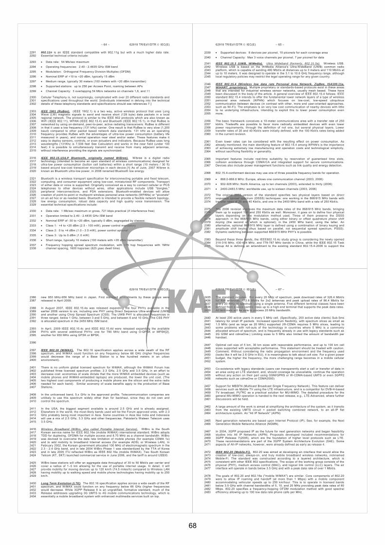
– 64 – 62918 TR/Ed1/DTR IEC(E)
802.11n is an IEEE standard compatible with 802.11g but with a much higher data rate. 2291 Essential technical criteria include: 2292
Data rate: 54 Mb/sec maximum 2293
Operating frequencies: 2.40 - 2.4835 GHz ISM band 2294
Modulation: Orthogonal Frequency Division Multiplex (OFDM) 2295
Nominal ERP of +10 to +20 dBm, typically 15 dBm 2296
Medium range, typically 30 meters (100 meters with +20 dBm transmitter) 2297
Supported stations: up to 256 per Access Point, roaming between APs 2298
Channel Capacity: 3 overlapping 54 Mb/s networks on channels 1,6, and 11 2299
Cellular Telephony is, not surprisingly, complicated with over 20 different radio standards and 2300 specifications used throughout the world. [Individuals interested in delving into the technical 2301 details of these telephony standards and specifications should see references 7.] 2302
IEEE 1901 (RuBee). (IEEE 1902.1) is a two way, active wireless protocol that uses Long 2303 Wave (LW) magnetic signals to send and receive short (128 byte) data packets in a local 2304 regional network. The protocol is similar to the IEEE 802 protocols which are also known as 2305 WiFi (IEEE 802.11), WPAN (IEEE 802.15.4) and Bluetooth (IEEE 802.15.1), in that RuBee is 2306 networked by using on-demand, peer-to-peer, active radiating transceivers. RuBee is different 2307 in that it uses a low frequency (131 kHz) carrier. One result is that RuBee is very slow (1,200 2308 baud) compared to other packet based network data standards. 131 kHz as an operating 2309 frequency provides RuBee with the advantages of ultra-low power consumption (battery life 2310 measured in years), and normal operation near steel and/or water. These features make it 2311 easy to deploy sensors, controls, or even actuators and indicators. Because RuBee uses long 2312 wavelengths (131Khz is 7,508 feet See Calculator) and works in the near field (under 100 2313 feet) it is possible to simultaneously transmit and receive from many adjacent antennas, 2314 without interference providing the signals are synchronized. 2315
IEEE 802.15.1(ULP Bluetooth, originally named WiBree). Wibree is a digital radio 2316 technology (intended to become an open standard of wireless communications) designed for 2317 ultra-low power consumption (button cell batteries) within a short range (10 meters / 30 ft) 2318 based around low-cost transceiver microchips in each device.[1] As of June, 2007 Wibree is 2319 known as Bluetooth ultra-low power, in 2008 renamed Bluetooth low energy. 2320
Bluetooth is a wireless transport specification for interconnecting portable and fixed telecom, 2321 computing, and consumer equipment using low-cost, miniaturized RF components. Transport 2322 of either data or voice is supported. Originally conceived as a way to connect cellular or PCS 2323 telephones to other devices without wires, other applications include USB "dongles," 2324 peripheral interconnections, and PDA extensions. Bluetooth-enabled devices will allow 2325 creation of point-to-point or multipoint wireless personal area networks (WPANs) or "piconets" 2326 on an ad hoc or as needed basis. Bluetooth is intended to provide a flexible network topology, 2327 low energy consumption, robust data capacity and high quality voice transmission. The 2328 essential technical specifications include: 2329
Data rate: 1 Mb/sec maximum or gross, 721 kbps practical (if interference free) 2330
Operation limited to 2.40 - 2.4835 GHz ISM band 2331
Nominal ERP of -30 to +20 dBm, typically 0 dBm, segregated by classes: 2332
Class 1: +4 to +20 dBm (2.5 - 100 mW), power control mandatory 2333
Class 2: 0 to +4 dBm (1.0 - 2.5 mW), power control optional 2334
Class 3: Up to 0 dBm (1.0 mW) 2335
Short range, typically 10 meters (100 meters with +20 dBm transmitter) 2336
Frequency hopping spread spectrum modulation, with >75 hop frequencies with 1MHz 2337 channel spacing, 1600 hops/sec (625 μsec dwell time) 2338
62918 TR/Ed1/DTR IEC(E) – 65 –
Supported devices: 8 devices per piconet, 10 piconets for each coverage area 2339
Channel Capacity: Max 3 voice channels per piconet, 7 per piconet for data 2340
IEEE 802.15.3 (UWB, WiMedia). Ultra Wideband (formerly, 802.15.3a). Wireless USB. 2341 Wireless USB is based on the WiMedia Alliance's Ultra-WideBand (UWB) common radio 2342 platform, which is capable of sending 480 Mbit/s at distances up to 3 meters and 110 Mbit/s at 2343 up to 10 meters. It was designed to operate in the 3.1 to 10.6 GHz frequency range, although 2344 local regulatory policies may restrict the legal operating range for any given country. 2345
IEEE 802.15.4 (Wireless low data rate Personal Area Network, ZigBee, ISA100.11a, 2346 WiHART, proprietary). Multiple proprietary or standards-based protocols exist in these areas 2347 that are intended for industrial wireless sensor networks, usually mesh based. These have 2348 been discussed in the body of the article. A general overview of IEEE 802.15.4 follows: IEEE 2349 standard 802.15.4 intends to offer the fundamental lower network layers of a type of wireless 2350 personal area network (WPAN) which focuses on low-cost, low-speed ubiquitous 2351 communication between devices (in contrast with other, more end user-oriented approaches, 2352 such as Wi-Fi). The emphasis is on very low cost communication of nearby devices with little 2353 to no underlying infrastructure, intending to exploit this to lower power consumption even 2354 more. 2355
The basic framework conceives a 10-meter communications area with a transfer rate of 250 2356 kbit/s. Tradeoffs are possible to favor more radically embedded devices with even lower 2357 power requirements, through the definition of not one, but several physical layers. Lower 2358 transfer rates of 20 and 40 Kbit/s were initially defined, with the 100 Kbit/s rates being added 2359 in the current revision. 2360
Even lower rates can be considered with the resulting effect on power consumption. As 2361 already mentioned, the main identifying feature of 802.15.4 among WPAN's is the importance 2362 of achieving extremely low manufacturing and operation costs and technological simplicity, 2363 without sacrificing flexibility or generality. 2364
Important features include real-time suitability by reservation of guaranteed time slots, 2365 collision avoidance through CSMA/CA and integrated support for secure communications. 2366 Devices also include power management functions such as link quality and energy detection. 2367
802.15.4-conformant devices may use one of three possible frequency bands for operation. 2368
868.0-868.6 MHz: Europe, allows one communication channel (2003, 2006) 2369
902-928 MHz: North America, up to ten channels (2003), extended to thirty (2006) 2370
2400-2483.5 MHz: worldwide use, up to sixteen channels (2003, 2006) 2371
The original 2003 version of the standard specifies two physical layers based on direct 2372 sequence spread spectrum (DSSS) techniques: one working in the 868/915 MHz bands with 2373 transfer rates of 20 and 40 Kbit/s, and one in the 2450 MHz band with a rate of 250 Kbit/s. 2374
The 2006 revision improves the maximum data rates of the 868/915 MHz bands, bringing 2375 them up to support 100 and 250 Kbit/s as well. Moreover, it goes on to define four physical 2376 layers depending on the modulation method used. Three of them preserve the DSSS 2377 approach: in the 868/915 MHz bands, using either binary or offset quadrature phase shift 2378 keying (the second of which is optional); in the 2450 MHz band, using the latter. An 2379 alternative, optional 868/915 MHz layer is defined using a combination of binary keying and 2380 amplitude shift keying (thus based on parallel, not sequential spread spectrum, PSSS). 2381 Dynamic switching between supported 868/915 MHz PHY's is possible. 2382
Beyond these three bands, the IEEE802.15.4c study group is considering the newly opened 2383 314-316 MHz, 430-434 MHz, and 779-787 MHz bands in China, while the IEEE 802.15 Task 2384 Group 4d is defining an amendment to the existing standard 802.15.4-2006 to support the 2385
– 66 – 62918 TR/Ed1/DTR IEC(E)
new 950 MHz-956 MHz band in Japan. First standard amendments by these groups were 2386 released in April 2009. 2387
In August 2007, IEEE 802.15.4a was released expanding the four PHYs available in the 2388 earlier 2006 version to six, including one PHY using Direct Sequence Ultra-wideband (UWB) 2389 and another using Chirp Spread Spectrum (CSS). The UWB PHY is allocated frequencies in 2390 three ranges: below 1 GHz, between 3 and 5 GHz, and between 6 and 10 GHz. The CSS PHY 2391 is allocated spectrum in the 2450 MHz ISM band. 2392
In April, 2009 IEEE 802.15.4c and IEEE 802.15.4d were released expanding the available 2393 PHYs with several additional PHYs: one for 780 MHz band using O-QPSK or MPSK[2], 2394 another for 950 MHz using GFSK or BPSK. 2395
2396
IEEE 802.16 (WiMAX). The 802.16 specification applies across a wide swath of the RF 2397 spectrum, and WiMAX could function on any frequency below 66 GHz (higher frequencies 2398 would decrease the range of a Base Station to a few hundred meters in an urban 2399 environment). 2400
There is no uniform global licensed spectrum for WiMAX, although the WiMAX Forum has 2401 published three licensed spectrum profiles: 2.3 GHz, 2.5 GHz and 3.5 GHz, in an effort to 2402 decrease cost: economies of scale dictate that the more WiMAX embedded devices (such as 2403 mobile phones and WiMAX-embedded laptops) are produced, the lower the unit cost. (The 2404 two highest cost components of producing a mobile phone are the silicon and the extra radio 2405 needed for each band). Similar economy of scale benefits apply to the production of Base 2406 Stations. 2407
In the unlicensed band, 5.x GHz is the approved profile. Telecommunication companies are 2408 unlikely to use this spectrum widely other than for backhaul, since they do not own and 2409 control the spectrum. 2410
In the USA, the biggest segment available is around 2.5 GHz and is already assigned. 2411 Elsewhere in the world, the most-likely bands used will be the Forum approved ones, with 2.3 2412 GHz probably being most important in Asia. Some countries in Asia like India and Indonesia 2413 will use a mix of 2.5 GHz, 3.3 GHz and other frequencies. Pakistan's Wateen Telecom uses 2414 3.5 GHz. 2415
Wireless Broadband (WiBro, also called Portable Internet Service). WiBro is the South 2416 Korean service name for IEEE 802.16e (mobile WiMAX) international standard. WiBro adopts 2417 TDD for duplexing, OFDMA for multiple access and 8.75 MHz as a channel bandwidth. WiBro 2418 was devised to overcome the data rate limitation of mobile phones (for example CDMA 1x) 2419 and to add mobility to broadband Internet access (for example ADSL or Wireless LAN). In 2420 February 2002, the Korean government allocated 100 MHz of electromagnetic spectrum in the 2421 2.3 - 2.4 GHz band, and in late 2004 WiBro Phase 1 was standardized by the TTA of Korea 2422 and in late 2005 ITU reflected WiBro as IEEE 802.16e (mobile WiMAX). Two South Korean 2423 Telcom (KT, SKT) launched commercial service in June 2006, and the tariff is around US$30. 2424
WiBro base stations will offer an aggregate data throughput of 30 to 50 Mbit/s per carrier and 2425 cover a radius of 1–5 km allowing for the use of portable internet usage. In detail, it will 2426 provide mobility for moving devices up to 120 km/h (74.5 miles/h) compared to Wireless LAN 2427 having mobility up to walking speed and mobile phone technologies having mobility up to 250 2428 km/h. 2429
Long Term Evolution (LTE). The 802.16 specification applies across a wide swath of the RF 2430 spectrum, and WiMAX could function on any frequency below 66 GHz (higher frequencies 2431 would decrease. While 3GPP Release 8 is an ungratified, formative standard, much of the 2432 Release addresses upgrading 3G UMTS to 4G mobile communications technology, which is 2433 essentially a mobile broadband system with enhanced multimedia services built on top. 2434
62918 TR/Ed1/DTR IEC(E) – 67 –
The standard includes: For every 20 MHz of spectrum, peak download rates of 326.4 Mbit/s 2435 for 4x4 antennas, 172.8 Mbit/s for 2x2 antennas and peak upload rates of 86.4 Mbit/s for 2436 every 20 MHz of spectrum using a single antenna. Five different terminal classes have been 2437 defined from a voice centric class up to a high end terminal that supports the peak data rates. 2438 All terminals will be able to process 20 MHz bandwidth. 2439
At least 200 active users in every 5 MHz cell. (Specifically, 200 active data clients) Sub-5ms 2440 latency for small IP packets Increased spectrum flexibility, with spectrum slices as small as 2441 1.5 MHz (and as large as 20 MHz) supported (W-CDMA requires 5 MHz slices, leading to 2442 some problems with roll-outs of the technology in countries where 5 MHz is a commonly 2443 allocated amount of spectrum, and is frequently already in use with legacy standards such as 2444 2G GSM and cdmaOne.) Limiting sizes to 5 MHz also limited the amount of bandwidth per 2445 handset. 2446
Optimal cell size of 5 km, 30 km sizes with reasonable performance, and up to 100 km cell 2447 sizes supported with acceptable performance. This statement should be treated with caution. 2448 Comment: Without considering the radio propagation environment and the frequency used 2449 (looks like it will be 2.6 GHz in EU), it is meaningless to talk about cell size. For a given power 2450 budget, the higher the frequency, the more challenging range becomes in a mobile cellular 2451 system. 2452
Co-existence with legacy standards (users can transparently start a call or transfer of data in 2453 an area using an LTE standard, and, should coverage be unavailable, continue the operation 2454 without any action on their part using GSM/GPRS or W-CDMA-based UMTS or even 3GPP2 2455 networks such as cdmaOne or CDMA2000) 2456
Support for MBSFN (Multicast Broadcast Single Frequency Network). This feature can deliver 2457 services such as Mobile TV using the LTE infrastructure, and is a competitor for DVB-H-based 2458 TV broadcast. PU2RC as a practical solution for MU-MIMO. The detailed procedure for the 2459 general MU-MIMO operation is handed to the next release, e.g., LTE-Advanced, where further 2460 discussions will be held. 2461
A large amount of the work is aimed at simplifying the architecture of the system, as it transits 2462 from the existing UMTS circuit + packet switching combined network, to an all-IP flat 2463 architecture system. An "All IP Network" (AIPN) 2464
Next generation networks are based upon Internet Protocol (IP). See, for example, the Next 2465 Generation Mobile Networks Alliance (NGMN). 2466
In 2004, 3GPP proposed IP as the future for next generation networks and began feasibility 2467 studies into All IP Networks (AIPN). Proposals developed included recommendations for 2468 3GPP Release 7(2005), which are the foundation of higher level protocols such as LTE. 2469 These recommendations are part of the 3GPP System Architecture Evolution (SAE). Some 2470 aspects of All-IP networks, however, were already defined as early as release 4. 2471
IEEE 802.20 (Mobile-Fi). 802.20 was aimed at developing an interface that would allow the 2472 creation of low-cost, always-on, and truly mobile broadband wireless networks, nicknamed 2473 Mobile-Fi. The standard was constructed according to a layered architecture, which is 2474 consistent with other IEEE 802 specifications. The scope of the working group consists of the 2475 physical (PHY), medium access control (MAC), and logical link control (LLC) layers. The air 2476 interface will operate in bands below 3.5 GHz and with a peak data rate of over 1 Mbit/s. 2477
The goals of 802.20 and 802.16e ("mobile WiMAX") are similar. Core components of 802.20 2478 were to allow IP roaming and handoff (at more than 1 Mbps) with a mobile component 2479 accommodating vehicular speeds up to 250 km/hour. This is to operate in licensed bands 2480 below 3.5 GHz with channel bandwidths of 5, 10, and 20 MHz providing peak data rates of 80 2481 Mbps. 802.20 specifies a frequency-hopping OFDM modulation method with good spectral 2482 efficiency allowing up to 100 low data rate phone calls per MHz. 2483
68

– 68 – 62918 TR/Ed1/DTR IEC(E)
IEEE 802.20 has been wracked by allegations of dominance and lack of transparency of the 2484 process. Many feel that this was since from the start Qualcomm saw ArrayComm’s iBurst 2485 “standard” – upon which 802.20 is based - and its standardization as 802.20 as a competitive 2486 threat; they did all they could to thwart the progress of the standard. The dominance charges 2487 caused IEEE 802 Executive Committee suspending 802.20, then establishing an 802.20 2488 Oversight Committee which after looking at the voting rights and records changed the voting 2489 mechanics from an individual voting member to an entity based system. With some of those 2490 procedural issues possibly again being an issue the IEEE 802 management groups took this 2491 proactive step in another attempt to secure the IEEE process for this particular standard. 2492
The IEEE approved 802.20-2008, Physical and Media Access Specification on 12 June 2008. 2493
B.2 ISO 14443 Near Field Communications (NFC) 2494
Like ISO/IEC 14443, NFC communicates via magnetic field induction, where two loop antennas are 2495 located within each other's near field, effectively forming an air-core transformer. It operates within the 2496 globally available and unlicensed radio frequency ISM band of 13.56 MHz, with a bandwidth of 14 kHz. 2497
Working distance with compact standard antennas: up to 20 cm 2498
Supported data rates: 106, 212, 424 or 848 Kbit/s 2499
There are two modes: 2500
Passive Communication Mode: The Initiator device provides a carrier field and the target 2501 device answers by modulating existing field. In this mode, the Target device may draw its 2502 operating power from the Initiator-provided electromagnetic field, thus making the Target 2503 device a transponder. Active Communication Mode: Both Initiator and Target device 2504 communicate by alternately generating their own field. A device deactivates its RF field while 2505 it is waiting for data. In this mode, both devices typically need to have a power supply. 2506
Wireless High Definition (Wireless HD). The Wireless HD specification is based on the 2507 7GHz of continuous bandwidth around the 60GHz radio frequency and allows for 2508 uncompressed, digital transmission of full HD video and audio and data signals, essentially 2509 making it equivalent, in theory, to wireless HDMI. The specification has been designed and 2510 optimized for wireless display connectivity, achieving in its first generation implementation 2511 high-speed rates from 4 Gbit/s for the CE, PC, and portable device segments. Its core 2512 technology promotes theoretical data rates as high as 25 Gbit/s (compared to 10.2-Gbit/s for 2513 HDMI 1.3), permitting it to scale to higher resolutions, color depth, and range. 2514
Wireless Home Display Interface (WHDI). WHDI uses 20/40 MHz of bandwidth in the 5 GHz 2515 unlicensed band, offering lossless video and achieving equivalent video data rates of up to 2516 3Gbit/s. 2517
Comparison of Wireless Sensor Networks Based on 802.15.4 Transceivers. Much has 2518 been stated in the popular press of the fact that ISA100.11a, Wireless HART, ZigBee and 2519 various proprietary systems all rely on the IEEE 802.15.4-2006 radio transceiver. Frequently, 2520 such articles then state how if it’s the same radio, then the integration between these devices 2521 should be very easy. The situation isn’t quite that simple. Consider the generic wireless 2522 sensor (field transmitter) design shown in Figure B.1 – simplified diagram of a generic 2523 wireless sensor design. 2524
. 2525
62918 TR/Ed1/DTR IEC(E) – 69 –
2526 Figure B.1 – simplified diagram of a generic wireless sensor design. 2527
Walking counterclockwise (CCW) around the diagram, the top left component is the Sensor. In 2528 the process arena, this tends to be of the temperature, pressure, vibration, etc. variety. The 2529 generic design makes no distinction is the sensor is “intrinsic” (on the board) or “extrinsic” 2530 (cabled to the board). Continuing CCW, the auxiliary circuitry block may support the sensor – 2531 perhaps as an Application Specific Integrated Circuit (ASIC). The details of the circuitry are 2532 tightly coupled to the sensor and manufacturer’s design. Power for the wireless sensor comes 2533 from the Power System (PS) block. The PS may simply be a battery or it may involve an 2534 energy/power harvesting function with associated storage means. 2535
At this point we have described a generic sensor, or field transmitter, design with no details of 2536 the wireless functions. 2537
Continuing the CCW walkabout, the core component of the wireless transport method is seen, 2538 namely, the RF Transceiver – the radio. A wide array of arcane operational and performance 2539 matters come into play with the RF transceiver, including modulation format, operating 2540 frequency, transmit power, receiver sensitivity – the list goes on and on. Obviously, wireless 2541 sensors (field transmitters) have been around for years. In the old days, the transceiver was 2542 coupled to complex hybrid (analog+digital) circuitry to achieve the (somewhat) stable wireless 2543 transmission. 2544
2.a. Wireless Sensors – Circa 2010 2545
This standard defines service access points (SAPs) throughout the protocol layers to allow. 2546
Modern devices achieve a high degree of performance and flexibility by adopting networking 2547 functionality and tightly tying the transceiver to the Microcontroller. As previously mentioned, 2548 ISA100.11a, WiHART (HART 7.1), ZigBee and other proprietary methods use the 2006 2549 version of an IEEE 802.15.4 radio. This radio is flexible in terms of power, frequency, and – 2550 perhaps most importantly – in how it integrates with the wireless sensor’s Microcontroller. 2551 While seemingly complicated, by adopting the design rules associated with the Open Systems 2552 Interconnection model (OSI), shown in Figure B.2, a compartmentalization of performance 2553 functions are logically defined. The goal of the component blocks of Figure B.1 – simplified 2554 diagram of a generic wireless sensor design. 2555
’s generic wireless sensor are to perform these functions. 2556
– 70 – 62918 TR/Ed1/DTR IEC(E)
2557 Figure B.1 – The Open Systems Interconnection (OSI) model defines the end-to-end 2558
communications means and needs for a wireless field transmitter to securely 2559 communicate with a distributed control system (DCS). 2560
The situation may seem complicated, but in reality, by defining how the OSI layers are to 2561 communicate with each other – through Application Programming Interface (API) descriptors – 2562 different groups, different vendors may bring their specialty in a certain layer. 2563
Returning to Figure B.1, the generic wireless sensor design as applied to ISA100.11a, 2564 WiHART (HART 7.1), and ZigBee stipulates that an IEEE 802.15.4 radio be used. In addition, 2565 while the 802.15.4 radio could be operated at a number of different frequencies, see Figure 2566 B.3, only the 2450 (+/-) MHz frequency range is available – license free – worldwide. 2567
2568 Figure A.1 – Operating frequencies for an IEEE 802.15.4 radio are 868 MHz, 902-926 MHz 2569
and 2405-2485 MHz. The worldwide license-free band at 2400 MHz is shown. 2570
The selection of the IEEE 802.15.4 radio dictates which frequency bands are “available” for 2571 use. The ISA100.11a standard stipulates that the radio must operate in the 2400 MHz band. 2572
2.b. Network Topologies – Circa 2010 2573
In olden times, field transmitters were directly connected to an input/output (I/O) box. The 2574 signal transmission could be via pressure variations (3-15PSI) or electrical signaling, of many 2575 varieties but typically via variations in current (4-20 mA) or voltage (0-5V, 0-10V, etc.). The 2576
62918 TR/Ed1/DTR IEC(E) – 71 –
logistics associated with wiring thousands or tens of thousands of devices led to network 2577 developments where the field transmitters could (somehow) share a common transport 2578 medium. This idea, in turn, led to a wide variety of network designs and protocols with the 2579 vast majority being proprietary. Field transmitters (devices) would have identifiers that were 2580 transmitted within the data frame allowing those network elements with some level of 2581 intelligence to sort out the readings and process/transport them accordingly. Improvements in 2582 network protocols and the robustness requirement of minimal or even zero, single points of 2583 failure led to the variety of network topologies used today. Figure B.4 provides a graphical 2584 representation of such network topologies. 2585
2586 Figure A.1 – Networking topologies take many forms with associated levels of 2587
complexity required for robust fault-tolerant data transport. 2588
B.3 Real Details of Mesh Networking 2589
There is a vast amount of “how mesh networks work” information circulating in the ether. In 2590 the context of an industrial setting, it isn’t always so simple as to just move the wireless 2591 transmitters around to get better coverage - a frequent “fix” by academia and various vendors 2592 – but rather the sensors need to be at specific locations to provide useful information to the 2593 process engineer. A typical mesh network topological diagram is shown in Figure B.5. In the 2594 situation shown, each node is able to communicate with each other node. 2595
2596 Figure B.1 – Typical mesh network diagram 2597
While Figure B.5 is a nice diagram for discussion purposes indicating that each node can 2598 communicate with every other node, the reality is that this would require each node to project 2599 its RF signal over every other node. Assuming circular radiation patterns and that each 2600
69

– 72 – 62918 TR/Ed1/DTR IEC(E)
wireless sensor transmits at the same power with the same omnidirectional antenna, the 2601 footprint scenario is as shown in Figure B.6. 2602
2603 Figure B.1 – Requirement for mesh-networking communication of Figure B.5’s topology. 2604
While Figures B.5 and B.6 show the principles of mesh networks, the reality of industrial 2605 wireless sensors operating in mesh network topologies is slightly different. Consider the 2606 following situation: the circles shown in Figure B.6 represent the idealized RF “footprint” of 2607 each radio-enable device. The “canyons of metal” and general reflective surfaces found 2608 throughout an industrial site can significantly vary the actual RF footprint from circular. The 2609 implications on the mesh requiring overlapping RF footprints when they may vary significantly 2610 from circular – and from each other - are: from an industrial deployment perspective, a fully-2611 integrated mesh, as shown in Figure B.5 therefore requires a number of transmitters to be 2612 located in (relatively) close proximity. 2613
The more realistic deployment scenario involves a cloud or cluster of wireless field 2614 transmitters that are controlled by a wireless gateway device. The gateway serves multiple 2615 roles, including: 2616
(1) coordinating the mesh routing table, 2617 (2) keeping track of the data transmission and network timing functions, 2618 (3) the network security (frequently working with a companion security manager), and 2619 (4) administration of any frequency channel “blacklisting/whitelisting”. 2620
The practical situation is that as shown in Figure B.7 – a gateway and four nodes that, for this 2621 illustration, have been deployed in the industrial site resulting in the RF footprints shown. 2622
62918 TR/Ed1/DTR IEC(E) – 73 –
2623 Figure B.1 – RF footprint map for a mesh network gateway and four nodes. 2624
Similar to Figures B.5 and B.6, the Figure B.7 diagram is meant to show how the radio 2625 transceiver (gateway/node) must be within the RF footprint of its neighbors to be able to 2626 communicate with them. In Figure B.7’s case, the Gateway can only communicate with Node 2627 #1. Node #1 lies within the RF footprint of the Gateway, Node #2 and Node #4 and is 2628 therefore – from an RF “coverage” perspective – able to relay messages from those 2629 neighbors. The associated mesh network connectivity diagram is shown in Figure B.8 (which 2630 is quite different from the idealized situation of Figure B.5). 2631
2632 Figure B.1 – The connectivity diagram for Figure B.5’s RF footprint coverage map. 2633
Please note that in this hypothetical deployment scenario, this is a non-robust 2634 communications network for a catastrophic network failure will happen if the link between the 2635 Gateway and Node #1 fails. The single-point of failure may be alleviated by moving the 2636 Gateway or the Nodes – a situation that the RF engineer may suggest, but that may not be 2637 feasible due to the actual locations of where the measurements are to be made. 2638
– 74 – 62918 TR/Ed1/DTR IEC(E)
B.4 Not all Mesh Networks are Created Equal – Latency and Indeterminism in 2639 Mesh Networks 2640
The mesh network diagrams of Figure B.5 and B.7 show how there isn’t a single path of 2641 communications through a mesh network and therefore is no single point of failure (except for 2642 the gateway). This is one of the key attributes of mesh networking, however, in establishing 2643 and maintaining a mesh network some rules must be adopted – and abided with. At least 40 2644 different mesh networking “rules” have been devised by industry and academia. Many of 2645 these rules are associated with placing an emphasis on, for example: 2646
(a) battery-operated lifetime, 2647 (b) algorithmic ease - in terms of computational complexity in the node firmware, 2648 (c) security/authentication/encryption of over the air traffic, 2649 (d) latency (data transport) minimization. 2650
Each of these are noble causes but lead to substantially different “mesh networks” that, when 2651 implemented, do not allow interoperability. 2652
Consider the mesh network shown in Figure B.8 and how a message (data) is transported 2653 through the network to the gateway. A philosophy used by a very prominent mesh networking 2654 group is that the devices are always in listening mode. Therefore when a node needs to 2655 transmit it’s message to it’s neighbors and on to the gateway, it checks if the communications 2656 channel (radio frequency) is busy (by monitoring the Received Signal Strength (RSS) value 2657 within its circuitry). If the channel is available it passes the message on to its neighbors (and 2658 so on) – the data transport (latency) is minimized. However, with listening taking a sizable 2659 percentage of the power as transmitting does, the batter-operated lifetime is relatively short 2660 (days, maybe months). Once again, the nodes are always listening, so if a message to be 2661 forwarded pops up, the node will concatenate that message with any other messages (traffic) 2662 and broadcast it to the nodes in proximity. 2663
A very different mesh networking philosophy views the aforementioned scenario as 2664 consuming too much power listening – for probably infrequent messages – and looks to 2665 minimize listening and thereby increase battery-operated lifetime. In this scenario, the nodes 2666 in Figure B.5 or B.8 have time-synchronized precise clocks onboard and wake up at 2667 prescribed intervals. In essence, the nodes then check to see if there are any messages to 2668 transmit and/or receive, perform that data transfer/reception (if necessary), and then go back 2669 to sleep. By using this scheme, as the duty cycle is typically reduced to ~1% and, given 2670 realistic batteries, the operational lifetime may be extended to over a year. In this time-2671 synchronized mesh protocol method the data is transmitted from node-to-node with each 2672 clocking interval. Again referencing Figure B.8, consider a message that originates in Node 2. 2673 Depending on the network’s routing table, the message may take the Node 2 Node 1 2674 Gateway path (2 hops) or it could take the Node 2 Node 3 Node 4 Node 1 Gateway 2675 path (4 hops). 2676
While the Node 2 message may be time-stamped, the latency in getting the message from 2677 Node 2 to the Gateway – and beyond – is indeterminate. In a realistic situation where the 2678 nodes wake up once every 15 seconds, this means that the message may take 30 seconds to 2679 arrive at the gateway or 60 seconds to arrive at the gateway. The indeterminism comes from 2680 the message being able to take Paths (a), (b) or (c). The mesh networking algorithm being 2681 used in the nodes will dictate path variability. 2682
62918 TR/Ed1/DTR IEC(E) – 75 –
2683 (a) (b) (c) 2684
Figure B.1 – Representation of the latency and indeterminism that it takes for a 2685 message to be transported through a mesh network that relies on time synchronization. 2686
B.5 ISA100.11a – “Mesh - When You Need It - Networking” 2687
The core networking tenet in ISA100.11a is to minimize the message latency. This means 2688 deploy a network topology that allows the wireless field transmitter to get to a high speed, 2689 low-latency backhaul network as quickly as possible. Figure B.10 illustrates the network 2690 topology for the ISA100.11a system. In most instances, the End User community (ISA100.8) 2691 is showing that a connection to some form of backhaul network is highly advantageous. The 2692 definitions for such a backhaul network are delivered by ISA100.15. 2693
Figure B.10 depicts the communication areas addressed by ISA100.11a, as well as those 2694 areas (shaded in blue) that are not in scope of this standard. In Figure B.10, circular objects 2695 represent field devices (sensors, valves, actuators, etc.) and rectangular objects represent 2696 infrastructure devices that communicate to other network devices via an interface to the 2697 network infrastructure backbone network. A backbone is a data network (preferably high data 2698 rate) that is being defined by ISA100.15. This backbone could be an industrial Ethernet 2699 (802.3), Wi-Fi (802.11), WiMAX (802.16) or any other network within the facility interfacing to 2700 the plant’s network. 2701
2702
70
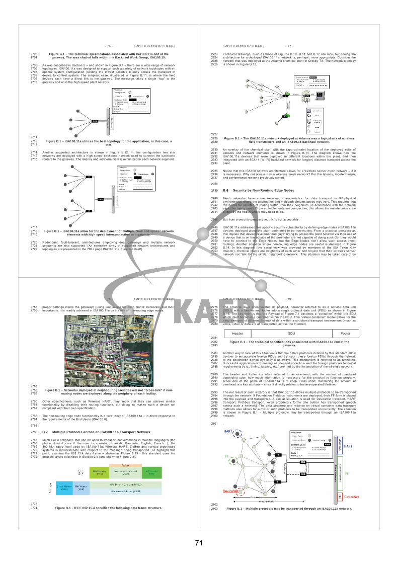
– 76 – 62918 TR/Ed1/DTR IEC(E)
Figure B.1 – The technical specifications associated with ISA100.11a end at the 2703 gateway. The area shaded falls within the Backhaul Work Group, ISA100.15. 2704
As was described in Section 2 – and shown in Figure B.4 – there are a wide range of network 2705 topologies. ISA100.11a was designed to support such a variety of network topologies with eh 2706 optimal system configuration yielding the lowest possible latency across the transport of 2707 device to control system. The simplest case, illustrated in Figure B.11, is where the field 2708 devices each have a direct link to the gateway. The message takes a single “hop” to the 2709 gateway and onto the high speed plant network. 2710
2711 Figure B.1 – ISA100.11a utilizes the best topology for the application, in this case, a 2712
star. 2713
Another supported architecture is shown in Figure B.12. In this configuration two star 2714 networks are deployed with a high speed backbone network used to connect the backbone 2715 routers to the gateway. The latency and indeterminism is minimized in each network segment. 2716
2717 Figure B.1 – ISA100.11a allow for the deployment of multiple “hub and spoke” network 2718
elements with high speed interconnection to a gateway. 2719
Redundant, fault-tolerant, architectures employing dual gateways and multiple network 2720 segments are also supported. [An extensive array of supported network architectures and 2721 topologies are presented in the 700+ page ISA100.11a Standard itself]. 2722
62918 TR/Ed1/DTR IEC(E) – 77 –
Technical drawings, such as those of Figures B.10, B.11 and B.12 are nice, but seeing the 2723 architecture for a deployed ISA100.11a network is, perhaps, more appropriate. Consider the 2724 network that was deployed at the Arkema chemical plant in Crosby TX. The network topology 2725 is shown in Figure B.13. 2726
2727 Figure B.1 – The ISA100.11a network deployed at Arkema was a logical mix of wireless 2728
field transmitters and an ISA100.15 backhaul network. 2729
An overlay of the chemical plant with the (approximate) location of the deployed suite of 2730 sensors and network elements is shown in Figure B.14. The diagram shows how the 2731 ISA100.11a devices that were deployed in different locations within the plant, and then 2732 integrated with an 802.11 (Wi-Fi) backhaul network for long(er) distance transport across the 2733 plant. 2734
Notice that this ISA100 network architecture allows for a wireless sensor mesh network – if it 2735 is necessary. Why not always has a wireless mesh network? For the latency, indeterminism, 2736 and performance reasons previously stated. 2737
2738
B.6 Security by Non-Routing Edge Nodes 2739
Mesh networks have some excellent characteristics for data transport in RF/physical 2740 environments where the attenuation and multipath circumstances may vary. This requires that 2741 the nodes be capable of routing traffic from their neighbors (in accordance with the network 2742 algorithm being used). From an implementation perspective, this allows the maintenance crew 2743 to deploy the nodes where they need to be. 2744
But from a security perspective, this is not acceptable. 2745
ISA100.11a addressed this specific security vulnerability by defining edge nodes (ISA100.11a 2746 devices deployed along the plant perimeter) to be non-routing. From a practical perspective, 2747 this implies that devices/systems/”bad guys” trying to access the plant network via their use of 2748 a device that is on the outside of the perimeter are not capable of doing such (for they would 2749 have to connect to the Edge Nodes, but the Edge Nodes don’t allow such access (non-2750 routing). Another situation where non-routing edge nodes are useful is depicted in Figure 2751 B.14. In this diagram (the aerial view was provided by members of the ISA Texas City 2752 chapter), chemical plants are neighbors of each other and require that their wireless sensor 2753 network not “talk to” the similar neighboring network. This situation may be taken care of by 2754
– 78 – 62918 TR/Ed1/DTR IEC(E)
proper settings inside the gateways (using unique IDs for each plants’ networks), but more 2755 importantly, it is readily achieved in ISA100.11a by the use of non-routing edge nodes. 2756
2757 Figure B.1 – Networks deployed at neighbouring facilities will not “cross-talk” if non-2758
routing nodes are deployed along the periphery of each facility. 2759
Other specifications, such as Wireless HART, may imply that they can achieve similar 2760 functionality by disabling their routing functions, but doing so makes such a device not 2761 compliant with their own specification. 2762
The non-routing edge node functionality is a core tenet of ISA100.11a – in direct response to 2763 the requirements of the End Users (ISA100.8). 2764
2765
B.7 Multiple Protocols across an ISA100.11a Transport Network 2766
Much like a cellphone that can be used to transport conversations in multiple languages (the 2767 phone doesn’t care if the user is speaking Spanish, Mandarin, English, French…), the 2768 802.15.4 radio itself used by ISA100.11a, Wireless HART, ZigBee and various proprietary 2769 systems is indiscriminate with respect to the message being transported. To highlight this 2770 point, examine the 802.15.4 data frame – shown as Figure B.15 - this standard uses the 2771 protocol layers described in Section 2.a (and shown in Figure 2.2). 2772
2773 Figure B.1 – IEEE 802.15.4 specifies the following data frame structure. 2774
62918 TR/Ed1/DTR IEC(E) – 79 –
The protocol layer encapsulates its payload, hereafter referred to as a service data unit 2775 (SDU), with a header and footer into a single protocol data unit (PDU) as shown in Figure 2776 B.16. The key point is that the Payload of Figure 7.1 becomes a “container” within the SDU 2777 which itself becomes a container within the PDU. This “virtual container” model allows for the 2778 easy transport of different formats of data within a structured transport environment (much as 2779 voice, video or data are all transported across the Internet). 2780
2781 Figure B.1 – The technical specifications associated with ISA100.11a end at the 2782
gateway. 2783
Another way to look at this situation is that the native protocols defined by this standard allow 2784 devices to encapsulate foreign PDUs and transport these foreign PDUs through the network 2785 to the destination device (typically a gateway). This mechanism is referred to as tunneling. 2786 Successful application of tunneling will depend upon how well the foreign protocols technical 2787 requirements (e.g., timing, latency, etc.) are met by the instantiation of the wireless network. 2788
The header and footer are often referred to as overhead, with the amount of overhead 2789 depending upon how much information is necessary for the protocol to function properly. 2790 Since one of the goals of ISA100.11a is to keep PDUs short, minimizing the amount of 2791 overhead is a key attribute – since it directly relates to battery-operated lifetime. 2792
The net result of such wizardry is that ISA100.11a allows multiple protocols to be transported 2793 through the network. If Foundation Fieldbus instruments are deployed, their FF form is placed 2794 into the payload and transported. A similar situation is used for DeviceNet transport, HART 2795 transport, Profibus transport, even proprietary forms [the author has transported speech 2796 across such a network]. The data structure and reliance on virtual container data transport 2797 methods also allows for a mix of such protocols to be transported concurrently. The situation 2798 is shown in Figure B.1 – Multiple protocols may be transported through an ISA100.11a 2799 network. 2800
. 2801
2802 Figure B.1 – Multiple protocols may be transported through an ISA100.11a network. 2803
71

– 80 – 62918 TR/Ed1/DTR IEC(E)
B.8 Device and Network Provisioning Methods 2804
The End Users requested that ISA100.11a meet their needs for a variety of secure 2805 provisioning methods. In response the technical gurus worked with sister organization ISA99 2806 (Control System Security) to architect secure network elements to provide this capability. The 2807 result is a dizzying array of intersecting security methodologies aligned into the Standard. 2808 While those most interested in this aspect should refer to the 119 pages that comprise the 2809 Security and Provisioning sections of the Standard, the guiding State diagram for provisioning 2810 devices is shown in the following Figure B.1 – State transition diagram showing various paths 2811 to joining a secured network 2812
. 2813
Under the ISA100.11a hood are the following End User provisioning methods: 2814
Provisioning over-the-air using pre-installed join keys. 2815
Provisioning using out of band mechanisms. 2816
Provisioning over-the-air using PKI certificates. 2817
Provisioning over-the-air using dual role advertisement routers. 2818
Provisioning backbone devices. 2819
The net result is a system that allows the End User to choose from a number of secure 2820 provisioning methods based on the method(s) that best align with their business practices. 2821
2822
62918 TR/Ed1/DTR IEC(E) – 81 –
Figure B.1 – State transition diagram showing various paths to joining a secured 2823 network 2824
– 82 – 62918 TR/Ed1/DTR IEC(E)
Bibliography 2825
1. O’Hara, Bob, The IEEE 802.11 Handbook: A Designer's Companion. 2826 2. Gast, Matthew, 802.11 Wireless Networks: The Definitive Guide (O'Reilly Networking). 2827 3. Report to NIST on the Smart Grid Interoperability Standards Roadmap, Prepared for NIST 2828
by EPRI under Contract No. SB1341-09-CN-0031—Deliverable 7, June 2009. 2829 4. Agar, Jon, Constant Touch: A Global History of the Mobile Phone, 2004 ISBN 1840465417 2830 5. Ahonen, Tomi, m-Profits: Making Money with 3G Services, 2002, ISBN 0-470-84775-1 2831 6. Ahonen, Kasper and Melkko, 3G Marketing 2004, ISBN 0-470-85100-7 2832 7. Fessenden, R. A. (1908). "Wireless Telephony". Annual Report of The Board Of Regents 2833
Of The Smithsonian Institution: 161–196. Retrieved 2009-08-07. 2834 8. C. A. Balanis, Antenna Theory Analysis and Design, Second Edition, John Wiley & Sons, 2835
Inc., New York, 1997. 2836 9. W. L. Stutzman and G. A. Thiele, Antenna Theory and Design, Second Edition, John Wiley 2837
& Sons, Inc., New York, 1997 2838 10. H. Mott, Antennas for Radar and Communications, John Wiley & Sons, Inc., New York, 2839
1992, pp. 115-180. 2840 11. D. K. Cheng, Field and Wave Electromagnetics, Addison Wesley, Reading, 2841
Massachusetts, 1989, p. 84. 2842 12. http://www.ce-mag.com/archive/01/05/lansford.html 2843
2844
_____________ 2845
72
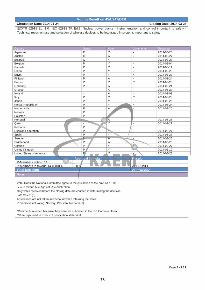
Page 1 of 11
Voting Result on 45A/947/DTR Circulation Date: 2014-01-24 Closing Date: 2014-03-28IEC/TR 62918 Ed. 1.0 IEC 62918 TR Ed.1: Nuclear power plants - Instrumentation and control important to safety - Technical report on use and selection of wireless devices to be integrated in systems important to safety
Country Status Vote Comments Received Argentina P Y - 2014-03-28 Austria O A - 2014-03-27 Belarus O Y - 2014-03-28 Belgium P Y - 2014-03-04 Canada P Y - 2014-03-11 China P Y - 2014-03-25 Egypt P Y Y 2014-03-22 Finland P A - 2014-03-24 France P Y Y 2014-03-25 Germany P A - 2014-03-24 Greece - A - 2014-03-27 Ireland - A - 2014-03-03 Italy P Y Y 2014-03-26 Japan P Y - 2014-03-26 Korea, Republic of P Y Y 2014-03-24 Netherlands P A - 2014-03-20 Norway P Pakistan P Portugal - A - 2014-03-28 Qatar - Y - 2014-03-23 Romania P Russian Federation P Y - 2014-03-27 Spain P Y - 2014-03-27 Sweden P A - 2014-03-25 Switzerland P A - 2014-03-20 Ukraine P Y Y 2014-03-27 United Kingdom P Y Y 2014-03-19 United States of America P Y - 2014-03-28
Approval Criteria Result P-Members voting: 14 P-Members in favour: 14 = 100% 50% APPROVEDFinal Decision: APPROVED Notes
Vote: Does the National Committee agree to the circulation of the draft as a TR: Y = In favour; N = Against; A = Abstention. Only votes received before the closing date are counted in determining the decision. Late Votes: (0). Abstentions are not taken into account when totalizing the votes. P-members not voting: Norway; Pakistan; Romania(3).
*Comments rejected because they were not submitted in the IEC Comment form. **Vote rejected due to lack of justification statement.
73
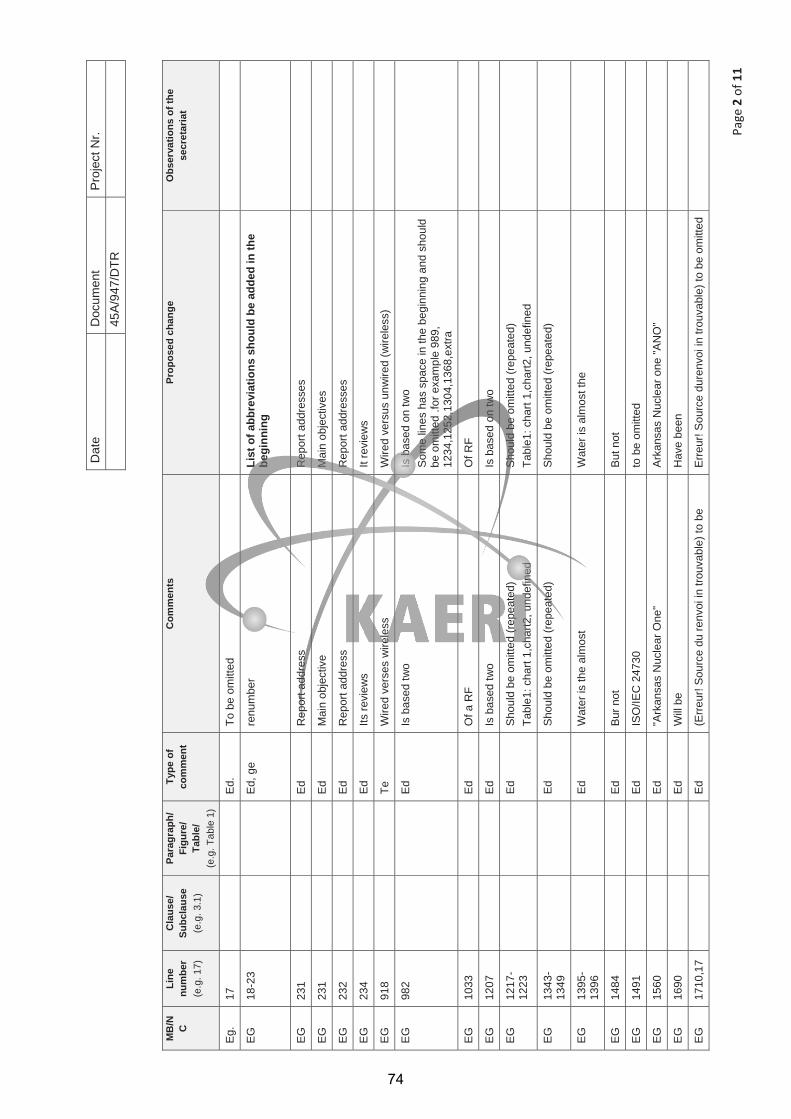
Page
2of
11
Dat
e D
ocum
ent
Pro
ject
Nr.
45
A/9
47/D
TR
MB
/N CLi
nenu
mbe
r (e
.g. 1
7)
Cla
use/
Subc
laus
e (e
.g. 3
.1)
Para
grap
h/Fi
gure
/Ta
ble/
(e
.g. T
able
1)
Type
of
com
men
t C
omm
ents
Pr
opos
ed c
hang
e O
bser
vatio
ns o
f the
se
cret
aria
t
Eg.
17
E
d.
To b
e om
itted
EG
18
-23
Ed,
ge
renu
mbe
r Li
st o
f abb
revi
atio
ns s
houl
d be
add
ed in
the
begi
nnin
g
EG
23
1
E
d R
epor
t add
ress
R
epor
t add
ress
es
EG
23
1
E
d M
ain
obje
ctiv
e M
ain
obje
ctiv
es
EG
23
2
E
d R
epor
t add
ress
R
epor
t add
ress
es
EG
23
4
E
d Its
revi
ews
It re
view
s
EG
91
8
Te
W
ired
vers
es w
irele
ss
Wire
d ve
rsus
unw
ired
(wire
less
)
EG
98
2
E
d Is
bas
ed tw
o Is
bas
ed o
n tw
o S
ome
lines
has
spa
ce in
the
begi
nnin
g an
d sh
ould
be
om
itted
.for
exa
mpl
e 98
9,
1234
,125
2,13
04,1
368,
extra
EG
10
33
Ed
Of a
RF
Of R
F
EG
12
07
Ed
Is b
ased
two
Is b
ased
on
two
EG
1217
-12
23
Ed
Shou
ld b
e om
itted
(rep
eate
d)
Tabl
e1: c
hart
1,ch
art2
, und
efin
ed
Sho
uld
be o
mitt
ed (r
epea
ted)
Ta
ble1
: cha
rt 1,
char
t2, u
ndef
ined
EG
1343
-13
49
Ed
Shou
ld b
e om
itted
(rep
eate
d)
Shou
ld b
e om
itted
(rep
eate
d)
EG
1395
-13
96
Ed
Wat
er is
the
alm
ost
Wat
er is
alm
ost t
he
EG
14
84
Ed
Bur
not
B
ut n
ot
EG
14
91
Ed
ISO
/IEC
247
30
to b
e om
itted
EG
15
60
Ed
"Ark
ansa
s N
ucle
ar O
ne"
Ark
ansa
s N
ucle
ar o
ne "A
NO
"
EG
16
90
Ed
Will
be
Hav
e be
en
EG
17
10,1
7
E
d (E
rreur
! Sou
rce
du re
nvoi
in tr
ouva
ble)
to b
e E
rreur
! Sou
rce
dure
nvoi
in tr
ouva
ble)
to b
e om
itted
74

Page
3of
11
MB
/N CLi
nenu
mbe
r (e
.g. 1
7)
Cla
use/
Subc
laus
e (e
.g. 3
.1)
Para
grap
h/Fi
gure
/Ta
ble/
(e
.g. T
able
1)
Type
of
com
men
t C
omm
ents
Pr
opos
ed c
hang
e O
bser
vatio
ns o
f the
se
cret
aria
t
11,1
714
,171
8 om
itted
Figu
res
21,2
2 ar
e no
t ref
eren
ced
Figu
res
21,2
2 ar
e no
t ref
eren
ced
EG
18
17
Ed
Ele
ctro
nics
will
var
ies
R
efer
ence
s ar
e no
t pro
perly
cite
d E
lect
roni
cs v
arie
s
Ref
eren
ces
are
not p
rope
rly c
ited
EG
22
09
Ed
The
follo
win
g is
sue
The
follo
win
g is
sues
FR 1
ge
We
note
d th
e lo
ng li
st o
f ter
ms
defin
ed. W
e ca
n su
ppos
e so
me
of th
ose
term
s an
d de
finiti
ons
wer
e ex
tract
ed fr
om p
ublis
hed
stan
dard
s (IS
O,
IEC
, IA
EA
, IE
EE, I
SA
…),
it w
ill b
e go
od to
hav
e th
e or
igin
of t
he te
rms
and
defin
ition
s gi
ven
in
orde
r to
chec
k if
they
bel
ongs
to d
iffer
ent
stan
dard
fam
ilies
and
to e
ase
the
iden
tific
atio
n of
po
ssib
le in
cons
iste
ncie
s be
twee
n th
e di
ffere
nt
term
inol
ogy
prop
er to
eac
h st
anda
rd fa
mily
.
If a
stan
dard
is to
be
prop
osed
on
the
tech
nica
l to
pic
the
list o
f ter
ms
will
hav
e to
be
dras
tical
ly
redu
ced,
in p
artic
ular
gen
eric
or t
oo g
ener
al
term
s w
ill h
ave
to b
e su
ppre
ssed
.
Add
the
refe
renc
e of
orig
in s
tand
ard,
if a
ny.
FR 2
te
The
TR d
oes
not i
nclu
de re
com
men
datio
ns a
nd
requ
irem
ents
that
cou
ld b
e in
clud
ed in
the
final
IE
C s
tand
ard.
Ple
ase
see
Ann
ex 0
1 ap
pend
ed to
this
form
for a
lis
t of r
ecom
men
datio
ns a
nd re
quire
men
ts th
at w
e su
gges
t.
Fren
ch n
atio
nal c
omm
ittee
is re
ady
to le
ad o
r at
leas
t co-
lead
a fu
ture
pro
ject
of s
tand
ard
on
this
topi
c.
FR 3
48
4-48
7
3.37
te
Th
e D
efen
se In
Dep
th d
efin
ition
pre
sent
ed h
ere
is n
ot a
pplic
able
to th
e nu
clea
r ind
ustry
, but
mos
t pr
obab
ly to
the
IT in
dust
ry.
IEC
615
13 d
efin
ition
sho
uld
be u
sed
inst
ead.
Def
ense
in D
epth
The
appl
icat
ion
of m
ore
than
one
pro
tect
ive
mea
sure
for a
giv
en s
afet
y ob
ject
ive,
suc
h th
at th
e ob
ject
ive
is a
chie
ved
even
if o
ne o
f the
pro
tect
ive
mea
sure
s fa
ils.
75
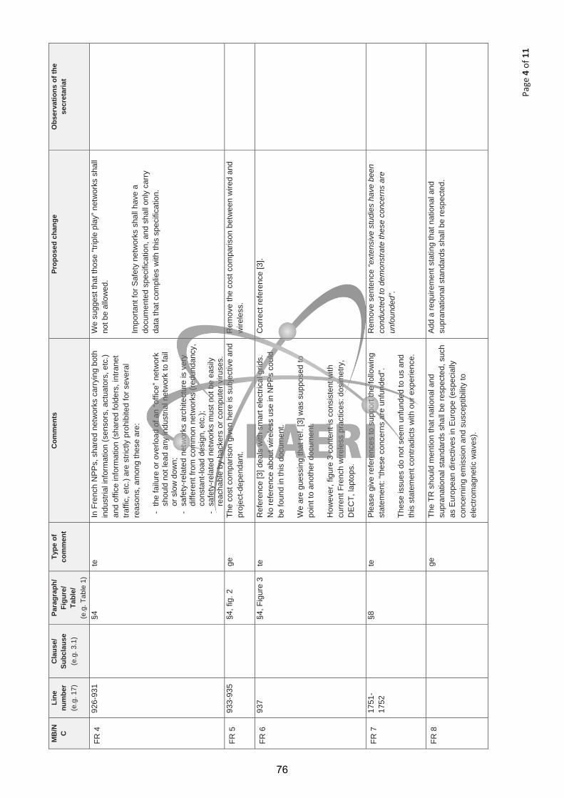
Page
4of
11
MB
/N CLi
nenu
mbe
r (e
.g. 1
7)
Cla
use/
Subc
laus
e (e
.g. 3
.1)
Para
grap
h/Fi
gure
/Ta
ble/
(e
.g. T
able
1)
Type
of
com
men
t C
omm
ents
Pr
opos
ed c
hang
e O
bser
vatio
ns o
f the
se
cret
aria
t
FR 4
92
6-93
1
§4
te
In F
renc
h N
PP
s, s
hare
d ne
twor
ks c
arry
ing
both
in
dust
rial i
nfor
mat
ion
(sen
sors
, act
uato
rs, e
tc.)
and
offic
e in
form
atio
n (s
hare
d fo
lder
s, in
trane
t tra
ffic,
etc
.) ar
e st
rictly
pro
hibi
ted
for s
ever
al
reas
ons,
am
ong
thes
e ar
e:
- th
e fa
ilure
or o
verlo
ad o
f an
“offi
ce” n
etw
ork
shou
ld n
ot le
ad a
ny in
dust
rial n
etw
ork
to fa
il or
slo
w d
own;
-
safe
ty-re
late
d ne
twor
ks a
rchi
tect
ure
is v
ery
diffe
rent
from
com
mon
net
wor
ks (r
edun
danc
y,
cons
tant
-load
des
ign,
etc
.);
- sa
fety
-rela
ted
netw
orks
mus
t not
be
easi
ly
reac
habl
e by
hac
kers
or c
ompu
ter v
iruse
s.
We
sugg
est t
hat t
hose
“trip
le p
lay”
net
wor
ks s
hall
not b
e al
low
ed.
Impo
rtant
for S
afet
y ne
twor
ks s
hall
have
a
docu
men
ted
spec
ifica
tion,
and
sha
ll on
ly c
arry
da
ta th
at c
ompl
ies
with
this
spe
cific
atio
n.
FR 5
93
3-93
5
§4, f
ig. 2
ge
Th
e co
st c
ompa
rison
giv
en h
ere
is s
ubje
ctiv
e an
d pr
ojec
t-dep
enda
nt.
Rem
ove
the
cost
com
paris
on b
etw
een
wire
d an
d w
irele
ss.
FR 6
93
7
§4, F
igur
e 3
te
Ref
eren
ce [3
] dea
ls w
ith s
mar
t ele
ctric
al g
rids.
N
o re
fere
nce
abou
t wire
less
use
in N
PP
s co
uld
be fo
und
in th
is d
ocum
ent.
We
are
gues
sing
that
ref.
[3] w
as s
uppo
sed
to
poin
t to
anot
her d
ocum
ent.
How
ever
, fig
ure
3 co
nten
t is
cons
iste
nt w
ith
curre
nt F
renc
h w
irele
ss p
ract
ices
: dos
imet
ry,
DE
CT,
lapt
ops.
Cor
rect
refe
renc
e [3
].
FR 7
17
51-
1752
§8
te
Ple
ase
give
refe
renc
es to
sup
port
the
follo
win
g st
atem
ent:
“thes
e co
ncer
ns a
re u
nfun
ded”
.
Thes
e is
sues
do
not s
eem
unf
unde
d to
us
and
this
sta
tem
ent c
ontra
dict
s w
ith o
ur e
xper
ienc
e.
Rem
ove
sent
ence
“ext
ensi
ve s
tudi
es h
ave
been
co
nduc
ted
to d
emon
stra
te th
ese
conc
erns
are
un
foun
ded”
.
FR 8
ge
The
TR s
houl
d m
entio
n th
at n
atio
nal a
nd
supr
anat
iona
l sta
ndar
ds s
hall
be re
spec
ted,
suc
h as
Eur
opea
n di
rect
ives
in E
urop
e (e
spec
ially
co
ncer
ning
em
issi
on a
nd s
usce
ptib
ility
to
elec
trom
agne
tic w
aves
).
Add
a re
quire
men
t sta
ting
that
nat
iona
l and
su
pran
atio
nal s
tand
ards
sha
ll be
resp
ecte
d.
76

Page
5of
11
MB
/N CLi
nenu
mbe
r (e
.g. 1
7)
Cla
use/
Subc
laus
e (e
.g. 3
.1)
Para
grap
h/Fi
gure
/Ta
ble/
(e
.g. T
able
1)
Type
of
com
men
t C
omm
ents
Pr
opos
ed c
hang
e O
bser
vatio
ns o
f the
se
cret
aria
t
GB
Gen
eral
Th
e D
raft
Tech
nica
l Rep
ort p
rovi
des
a co
mpr
ehen
sive
revi
ew o
f wire
less
net
wor
ks, t
heir
char
acte
ristic
s, th
eir p
oten
tial b
enef
its a
nd
disa
dvan
tage
s.
The
UK
sup
ports
the
publ
icat
ion
of th
is D
raft
Tech
nica
l Rep
ort b
ut w
ould
like
to s
ubm
it th
e fo
llow
ing
com
men
ts.
GB
Tech
nica
l Th
e do
cum
ent w
ould
be
impr
oved
by
the
addi
tion
of a
sho
rt di
scus
sion
of t
he p
robl
ems
caus
ed b
y th
e ra
pid
evol
utio
n of
the
wire
less
sta
ndar
ds.
For
NP
P, t
his
has
been
a s
igni
fican
t pro
blem
for
utilit
ies
whi
ch a
dopt
ed th
e ea
rly s
tand
ards
.
Add
a s
hort
sect
ion
disc
ussi
ng th
e pr
oble
ms
caus
ed b
y th
e ra
pid
deve
lopm
ent o
f wire
less
st
anda
rds.
Thi
s co
uld
be a
dded
to s
ectio
n 8
(Con
side
ratio
ns) o
r Ann
ex B
(Wire
less
Te
chno
logi
es).
GB
Edi
toria
l Th
e re
port
shou
ld b
e ed
ited
to re
mov
e th
e m
inor
fo
rmat
ting
and
typo
grap
hica
l er
rors
, suc
h as
line
sp
acin
g (E
g on
line
s 11
25, 1
129
and
1145
)
Edi
t to
docu
men
t to
corr
ect t
he m
inor
form
attin
g an
d ty
pogr
aphi
cal e
rrors
.
GB
Edi
toria
l Th
e sp
ellin
g of
wor
ds s
houl
d be
cor
rect
ed to
the
Eng
lish
spel
ling.
C
orre
ct th
e sp
ellin
g of
wor
ds s
uch
as:
"Org
aniz
atio
n" s
houl
d am
ende
d to
"or
gani
satio
n"
IT
ge
Th
e do
cum
ent i
s go
od.
How
ever
we
note
that
the
wire
less
tech
nolo
gy
shou
ld b
e us
ed w
ith c
autio
n in
sys
tem
s im
porta
nt
to s
afet
y, s
uch
as th
e co
ntro
l sys
tem
by
bars
in
the
nucl
ear r
eact
or c
ore
of th
e N
PP
.
KR
1276
-12
79
1368
14
47
ed
Inde
nt p
robl
em
Or
Pag
e nu
mbe
r and
Fig
ure
num
ber
Nee
d fix
ing
or c
orre
ctin
g
77
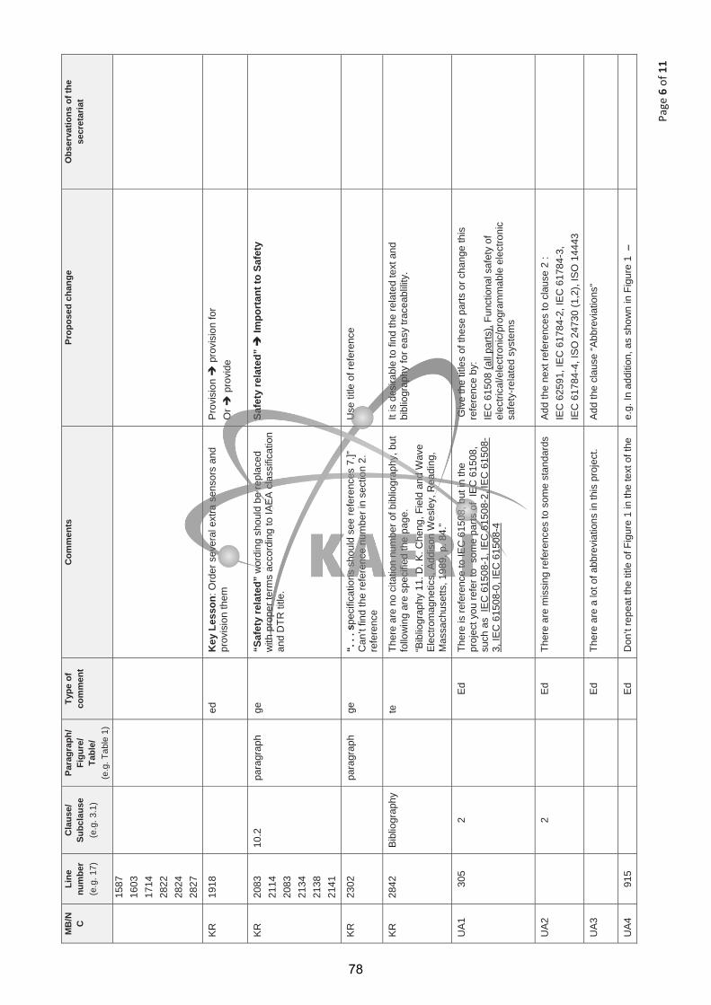
Page
6of
11
MB
/N CLi
nenu
mbe
r (e
.g. 1
7)
Cla
use/
Subc
laus
e (e
.g. 3
.1)
Para
grap
h/Fi
gure
/Ta
ble/
(e
.g. T
able
1)
Type
of
com
men
t C
omm
ents
Pr
opos
ed c
hang
e O
bser
vatio
ns o
f the
se
cret
aria
t
1587
16
03
1714
28
22
2824
28
27
KR
1918
ed
K
ey L
esso
n: O
rder
sev
eral
ext
ra s
enso
rs a
nd
prov
isio
n th
em
Prov
isio
n p
rovi
sion
for
Or
pro
vide
KR
20
83
2114
20
83
2134
21
38
2141
10.2
pa
ragr
aph
ge
“Saf
ety
rela
ted”
wor
ding
sho
uld
be re
plac
ed
with
pro
per t
erm
s ac
cord
ing
to IA
EA
cla
ssifi
catio
n an
d D
TR ti
tle.
Safe
ty re
late
d”
Impo
rtan
t to
Safe
ty
KR
23
02
pa
ragr
aph
ge
“. .
. spe
cific
atio
ns s
houl
d se
e re
fere
nces
7.]”
C
an’t
find
the
refe
renc
e nu
mbe
r in
sect
ion
2.
refe
renc
e
Use
title
of r
efer
ence
KR
2842
Bi
blio
grap
hy
te
Ther
e ar
e no
cita
tion
num
ber o
f bib
liogr
aphy
, but
fo
llow
ing
are
spec
ified
the
page
. “B
iblio
grap
hy 1
1. D
. K. C
heng
, Fie
ld a
nd W
ave
Ele
ctro
mag
netic
s, A
ddis
on W
esle
y, R
eadi
ng,
Mas
sach
uset
ts, 1
989,
p. 8
4.”
It is
des
irabl
e to
find
the
rela
ted
text
and
bi
blio
grap
hy fo
r eas
y tra
ceab
lility
.
UA
1 30
5 2
E
d Th
ere
is re
fere
nce
to IE
C 6
1508
, but
in th
e pr
ojec
t you
refe
r to
som
e pa
rts o
f IE
C 6
1508
, su
ch a
s IE
C 6
1508
-1, I
EC
615
08-2
, IE
C 6
1508
-3,
IEC
615
08-0
, IE
C 6
1508
-4
Giv
e th
e tit
les
of th
ese
parts
or c
hang
e th
is
refe
renc
e by
: IE
C 6
1508
(all
parts
), Fu
nctio
nal s
afet
y of
el
ectri
cal/e
lect
roni
c/pr
ogra
mm
able
ele
ctro
nic
safe
ty-r
elat
ed s
yste
ms
UA
2
2
Ed
Ther
e ar
e m
issi
ng re
fere
nces
to s
ome
stan
dard
s A
dd th
e ne
xt re
fere
nces
to c
laus
e 2
: IE
C 6
2591
, IE
C 6
1784
-2, I
EC
617
84-3
, IE
C 6
1784
-4, I
SO
247
30 (1
,2),
ISO
144
43
UA
3
Ed
Ther
e ar
e a
lot o
f abb
revi
atio
ns in
this
pro
ject
. A
dd th
e cl
ause
“Abb
revi
atio
ns”
UA4
91
5 Ed
Don
’t re
peat
the
title
of F
igur
e 1
in th
e te
xt o
f the
e.
g. In
add
ition
, as
show
n in
Fig
ure
1 –
78
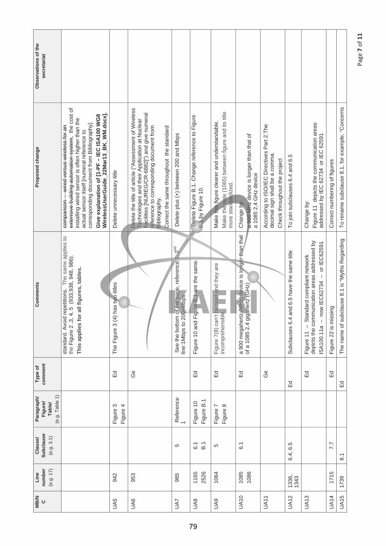
Page
7of
11
MB
/N CLi
nenu
mbe
r (e
.g. 1
7)
Cla
use/
Subc
laus
e (e
.g. 3
.1)
Para
grap
h/Fi
gure
/Ta
ble/
(e
.g. T
able
1)
Type
of
com
men
t C
omm
ents
Pr
opos
ed c
hang
e O
bser
vatio
ns o
f the
se
cret
aria
t
stan
dard
. Avo
id re
petit
ions
. Th
e sa
me
appl
ies
to
the
Figu
re 2
,3, 4
, 5 (
933,
938,
948
, 986
).
This
app
lies
for a
ll fig
ures
, tab
les.
com
paris
on -
wire
d ve
rsus
wire
less
for a
n ex
tens
ive
build
ing
auto
mat
ion
syst
em,
the
cost
of
inst
allin
g w
ired
sens
or is
ofte
n hi
gher
than
the
actu
al s
enso
r its
elf [
num
eral
refe
renc
e to
co
rresp
ondi
ng d
ocum
ent f
rom
Bib
liogr
aphy
]. G
ive
expl
anat
ion
of [1
-PF
– IE
C IS
A10
0 W
G8
Wire
less
Use
rGui
de_2
2Mar
13_B
K_W
M.d
ocx]
.
UA5
94
2
Figu
re 3
Fi
gure
4
Ed
The
Figu
re 3
(4) h
as tw
o tit
les
Del
ete
unne
cess
ary
title
UA
6 95
3
G
e
Del
ete
the
title
of a
rticl
e (“A
sses
smen
t of W
irele
ss
Tech
nolo
gies
and
thei
r App
licat
ion
at N
ucle
ar
Faci
litie
s [N
UR
EG
/CR
-688
2]”)
and
give
num
eral
re
fere
nce
to c
orre
spon
ding
doc
umen
t fro
m
Bibl
iogr
aphy
. C
orre
ct th
e sa
me
thro
ugho
ut t
he s
tand
ard
UA7
98
5 5
Ref
eren
ce
1
See
the
botto
m o
f the
pag
e, re
fere
nce
1, 2
nd
line:
1Mbp
s to
200
+Mbp
s D
elet
e pl
us (+
) bet
wee
n 20
0 an
d M
bps
UA
8 11
65
2526
6.
1 B
.1Fi
gure
10
Figu
re B
.1
Ed
Figu
re 1
0 an
d Fi
gure
B.1
are
the
sam
e.
Del
ete
Figu
re B
.1. C
hang
e re
fere
nce
to F
igur
e B
.1 b
y Fi
gure
10.
UA
9 10
64
5Fi
gure
7
Figu
re 8
Ed
Figu
re 7
(8) c
an’t
be re
ad a
nd th
ey a
re
inco
mpr
ehen
sibl
e.M
ake
this
figu
re c
lear
er a
nd u
nder
stan
dabl
e.
Mak
e th
e no
te (1
065)
bet
wee
n fig
ure
and
its ti
tle
mor
e st
anda
rdiz
ed.
UA1
0 10
85
1086
6.
1
Ed
a 90
0 m
egah
ertz
(MH
z) d
evic
e is
long
er th
an th
at
of a
108
5 2.
4 gi
gahe
rtz (G
Hz)
C
hang
e by
: a
900
MH
z de
vice
is lo
nger
than
that
of
a
1085
2,4
GH
z de
vice
UA
11
G
e A
ccor
ding
to IS
O/IE
C D
irect
ives
Par
t 2.T
he
deci
mal
sig
n sh
all b
e a
com
ma.
C
heck
thro
ugho
ut th
e pr
ojec
t
UA1
2 13
36,
1343
6.
4, 6
.5
E
d S
ubcl
ause
s 6.
4 an
d 6.
5 ha
ve th
e sa
me
title
To
join
sub
clau
ses
6.4
and
6.5
UA1
3
Ed
Fi
gure
11
– S
tand
ard
com
plia
nt n
etw
ork
de
pict
s th
e co
mm
unic
atio
n ar
eas
addr
esse
d by
IS
A10
0.11
a –
now
IEC
6273
4 –
or I
EC
6259
1
Cha
nge
by:
Figu
re 1
1 d
epic
ts th
e co
mm
unic
atio
n ar
eas
addr
esse
d by
IEC
627
34 o
r IE
C 6
2591
UA
14
1715
7.
7 E
d
Figu
re 2
2 is
mis
sing
C
orre
ct n
umbe
ring
of fi
gure
s
UA1
5 17
39
8.1
E
d Th
e na
me
of s
ubcl
ause
8.1
is “M
yths
Reg
ardi
ng
To re
nam
e su
bcla
use
8.1,
for e
xam
ple,
“Con
cern
s
79
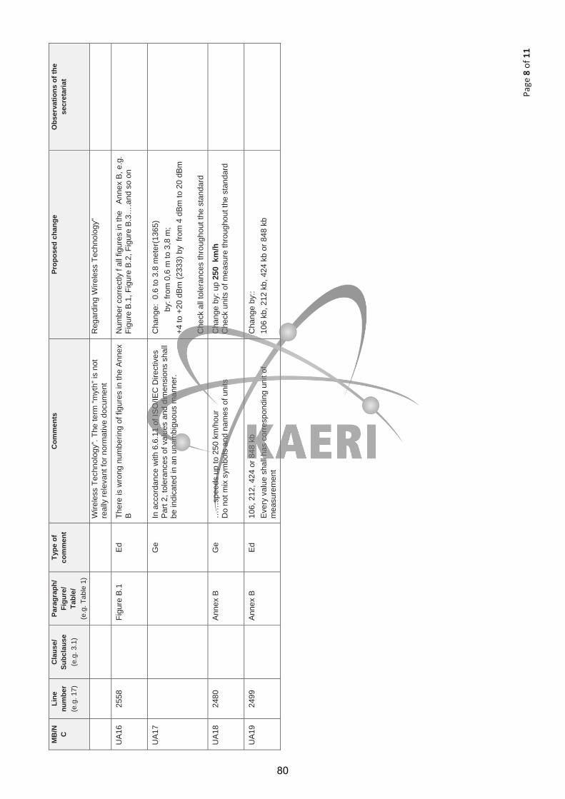
Page
8of
11
MB
/N CLi
nenu
mbe
r (e
.g. 1
7)
Cla
use/
Subc
laus
e (e
.g. 3
.1)
Para
grap
h/Fi
gure
/Ta
ble/
(e
.g. T
able
1)
Type
of
com
men
t C
omm
ents
Pr
opos
ed c
hang
e O
bser
vatio
ns o
f the
se
cret
aria
t
Wire
less
Tec
hnol
ogy”
. The
term
“myt
h” is
not
re
ally
rele
vant
for n
orm
ativ
e do
cum
ent
Reg
ardi
ng W
irele
ss T
echn
olog
y”
UA1
6 25
58
Figu
re B
.1
EdTh
ere
is w
rong
num
berin
g of
figu
res
in th
e A
nnex
B
Num
ber c
orre
ctly
f al
l fig
ures
in th
e A
nnex
B, e
.g.
Figu
re B
.1, F
igur
e B
.2, F
igur
e B
.3…
.and
so
on
UA
17
G
e In
acc
orda
nce
with
6.6
.11
of IS
O/IE
C D
irect
ives
P
art 2
, tol
eran
ces
of v
alue
s an
d di
men
sion
s sh
all
be in
dica
ted
in a
n un
ambi
guou
s m
anne
r.
Cha
nge:
0.6
to 3
.8 m
eter
(136
5)
b
y: fr
om 0
,6 m
to 3
,8 m
; +4
to +
20 d
Bm
(233
3) b
y fr
om 4
dB
m to
20
dBm
Che
ck a
ll to
lera
nces
thro
ugho
ut th
e st
anda
rd
UA1
8 24
80
An
nex
B
Ge
……
spee
ds u
p to
250
km
/hou
r D
o no
t mix
sym
bols
and
nam
es o
f uni
ts
Cha
nge
by: u
p 25
0 k
m/h
C
heck
uni
ts o
f mea
sure
thro
ugho
ut th
e st
anda
rd
UA1
9 24
99
An
nex
B
Ed
106,
212
, 424
or 8
48 k
b E
very
val
ue s
hall
has
corre
spon
ding
uni
t of
mea
sure
men
t
Cha
nge
by::
10
6 kb
, 212
kb,
424
kb
or 8
48 k
b
80
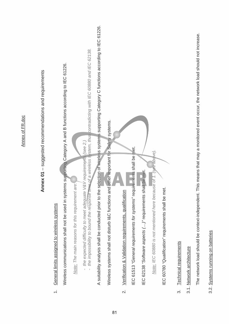
Ann
ex o
f FR
.doc
Ann
ex 0
1 –
sugg
este
d re
com
men
datio
ns a
nd re
quire
men
ts
1.
Gen
eral
lim
its a
ssig
ned
to w
irele
ss s
yste
ms
Wire
less
com
mun
icat
ions
sha
ll no
t be
used
in s
yste
ms
supp
ortin
g C
ateg
ory
A a
nd B
func
tions
acc
ordi
ng to
IEC
612
26.
Not
e: T
he m
ain
reas
ons
for t
his
requ
irem
ent a
re:
-th
e ex
pect
ed d
iffic
ulty
to m
eet a
dequ
ate
V&
V re
quire
men
ts (s
ee 2
.) -
the
impo
ssib
ility
to b
ound
the
resp
onse
tim
e of
a w
irele
ss s
yste
m, t
hus
cont
radi
ctin
g w
ith IE
C 6
0880
and
IEC
621
38.
A s
uita
bilit
y an
alys
is s
hall
be c
ondu
cted
prio
r to
the
sele
ctio
n of
wire
less
sys
tem
s su
ppor
ting
Cat
egor
y C
func
tions
acc
ordi
ng to
IEC
612
26.
Wire
less
sys
tem
s sh
all n
ot d
istu
rb I&
C fu
nctio
ns a
nd o
ther
Impo
rtant
for S
afet
y sy
stem
s.
2.
Ver
ifica
tion
& V
alid
atio
n re
quire
men
ts, q
ualif
icat
ion
IEC
615
13 “G
ener
al re
quire
men
ts fo
r sys
tem
s” re
quire
men
ts s
hall
be m
et.
IEC
621
38 “S
oftw
are
aspe
cts
(…)”
requ
irem
ents
sha
ll be
met
.
Not
e: IE
C 6
0880
is n
ot m
entio
ned
here
bec
ause
of 1
. (se
e ab
ove)
.
IEC
607
80 “Q
ualif
icat
ion”
requ
irem
ents
sha
ll be
met
.
3.
Tech
nica
l req
uire
men
ts
3.1.
Net
wor
k ar
chite
ctur
e
The
netw
ork
load
sho
uld
be c
onte
xt-in
depe
nden
t. Th
is m
eans
that
may
a m
onito
red
even
t occ
ur, t
he n
etw
ork
load
sho
uld
not i
ncre
ase.
3.2.
Sys
tem
s ru
nnin
g on
bat
terie
s
81

Rem
ote
devi
ces
runn
ing
on b
atte
ries
shal
l be
phys
ical
ly re
acha
ble
in o
rder
to b
e ab
le to
repl
ace
a de
fect
ive
or d
isch
arge
d ba
ttery
. If t
his
is n
ot p
ossi
ble,
the
batte
ry
capa
city
sha
ll be
pro
perly
dim
ensi
oned
to la
st a
suf
ficie
nt ti
me,
acc
ordi
ng to
the
syst
em s
peci
ficat
ion.
Bat
tery
leve
l of r
emot
e de
vice
s ru
nnin
g on
bat
terie
s sh
all m
onito
red.
3.3.
Ele
ctro
Mag
netic
Com
patib
ility
(EM
C)
Any
wire
less
dev
ice
shal
l be
inst
alle
d at
leas
t 30
cent
imet
ers
(1 fo
ot) a
way
from
impo
rtant
for s
afet
y eq
uipm
ents
.
An
impa
ct a
naly
sis
rega
rdin
g E
MC
sha
ll be
con
duct
ed p
rior t
o th
e on
-site
inst
alla
tion
of th
e sy
stem
.
Not
e: T
hese
requ
irem
ents
inte
nd to
pro
tect
impo
rtant
for s
afet
y sy
stem
s an
d ke
y co
ntro
l sys
tem
s fro
m e
lect
rom
agne
tic w
aves
em
itted
by
the
wire
less
dev
ice.
3.4.
Irra
diat
ion
An
impa
ct a
naly
sis
rega
rdin
g be
havi
or u
nder
irra
diat
ion
shal
l be
cond
ucte
d pr
ior t
o th
e on
-site
inst
alla
tion
of th
e sy
stem
.
4.
Com
pute
r sec
urity
Req
uire
men
ts o
f IE
C 6
2645
“Req
uire
men
ts fo
r sec
urity
pro
gram
mes
for c
ompu
ter-
base
d sy
stem
s” s
hall
be m
et.
Enc
rypt
ion
shou
ld b
e us
ed fo
r wire
less
com
mun
icat
ions
. The
enc
rypt
ion
met
hods
– o
r lac
k of
enc
rypt
ion
– sh
all b
e co
nsis
tent
with
IEC
615
13 o
vera
ll se
curit
y pl
an.
Aut
hent
icat
ion
of a
ll m
essa
ges
shou
ld b
e us
ed. T
he a
uthe
ntic
atio
n pr
oces
s –
or la
ck o
f aut
hent
icat
ion
– sh
all b
e co
nsis
tent
with
IEC
615
13 o
vera
ll se
curit
y pl
an.
5.
Sol
utio
n du
rabi
lity
Wire
less
pro
toco
ls u
sing
a d
ocum
ente
d st
anda
rd s
houl
d be
pre
ferr
ed
82
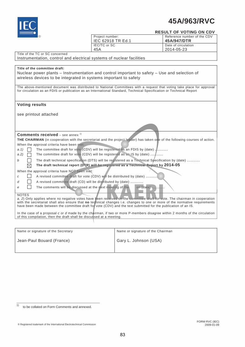
FORM RVC (IEC) 2009-01-09 ® Registered trademark of the International Electrotechnical Commission
45A/963/RVC
RESULT OF VOTING ON CDV Project number:
IEC 62918 TR Ed.1 Reference number of the CDV 45A/947/DTR
IEC/TC or SC 45A
Date of circulation 2014-05-23
Title of the TC or SC concerned Instrumentation, control and electrical systems of nuclear facilities Title of the committee draft: Nuclear power plants – Instrumentation and control important to safety – Use and selection of wireless devices to be integrated in systems important to safety The above-mentioned document was distributed to National Committees with a request that voting take place for approval for circulation as an FDIS or publication as an International Standard, Technical Specification or Technical Report
Voting results see printout attached
Comments received – see annex 1)
THE CHAIRMAN (in cooperation with the secretariat and the project leader) has taken one of the following courses of action. When the approval criteria have been met: a.1) a.2)
The committee draft for vote (CDV) will be registered as an FDIS by (date) .......... The committee draft for vote (CDV) will be registered as an IS by (date) ..........
b
The draft technical specification (DTS) will be registered as a Technical Specification by (date) .......... The draft technical report (DTR) will be registered as a Technical Report by 2014-05
When the approval criteria have NOT been met: c A revised committee draft for vote (CDV) will be distributed by (date) .......... d A revised committee draft (CD) will be distributed by (date) .......... e The comments will be discussed at the next meeting of the on (date) .......... NOTES a. 2) Only applies where no negative votes have been received on the committee draft for vote. The chairman in cooperation with the secretariat shall also ensure that no technical changes i.e. changes to one or more of the normative requirements have been made between the committee draft for vote (CDV) and the text submitted for the publication of an IS. In the case of a proposal c or d made by the chairman, if two or more P-members disagree within 2 months of the circulation of this compilation, then the draft shall be discussed at a meeting. Name or signature of the Secretary Jean-Paul Bouard (France)
Name or signature of the Chairman Gary L. Johnson (USA)
1) to be collated on Form Comments and annexed.
®
83
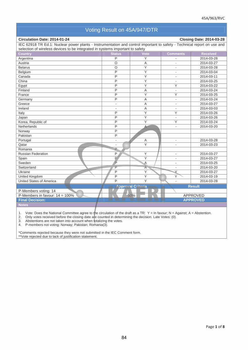
45A/963/RVC
Page 1 of 8
Voting Result on 45A/947/DTR
Circulation Date: 2014-01-24 Closing Date: 2014-03-28 IEC 62918 TR Ed.1: Nuclear power plants - Instrumentation and control important to safety - Technical report on use and selection of wireless devices to be integrated in systems important to safety
Country Status Vote Comments Received Argentina P Y - 2014-03-28 Austria O A - 2014-03-27 Belarus O Y - 2014-03-28 Belgium P Y - 2014-03-04 Canada P Y - 2014-03-11 China P Y - 2014-03-25 Egypt P Y Y 2014-03-22 Finland P A - 2014-03-24 France P Y Y 2014-03-25 Germany P A - 2014-03-24 Greece - A - 2014-03-27 Ireland - A - 2014-03-03 Italy P Y Y 2014-03-26 Japan P Y - 2014-03-26 Korea, Republic of P Y Y 2014-03-24 Netherlands P A - 2014-03-20 Norway P Pakistan P Portugal - A - 2014-03-28 Qatar - Y - 2014-03-23 Romania P Russian Federation P Y - 2014-03-27 Spain P Y - 2014-03-27 Sweden P A - 2014-03-25 Switzerland P A - 2014-03-20 Ukraine P Y Y 2014-03-27 United Kingdom P Y Y 2014-03-19 United States of America P Y - 2014-03-28
Approval Criteria Result P-Members voting: 14 P-Members in favour: 14 = 100% 50% APPROVED Final Decision: APPROVED
Notes 1. Vote: Does the National Committee agree to the circulation of the draft as a TR: Y = In favour; N = Against; A = Abstention. 2. Only votes received before the closing date are counted in determining the decision. Late Votes: (0). 3. Abstentions are not taken into account when totalizing the votes. 4. P-members not voting: Norway; Pakistan; Romania(3). *Comments rejected because they were not submitted in the IEC Comment form. **Vote rejected due to lack of justification statement.
84

45A/
963/
RVC
Page
2 o
f 8
Dat
e D
ocum
ent
Pro
ject
Nr.
2014
-04-
15
45A/
947/
DTR
IE
C 6
2918
TR
Ed.
1
MB
/NC
Li
ne
num
ber
(e.g
. 17)
Cla
use/
Su
bcla
use
(e.g
. 3.1
)
Para
grap
h/
Figu
re/ T
able
/ (e
.g. T
able
1)
Type
of
com
men
t C
omm
ents
Pr
opos
ed c
hang
e O
bser
vatio
ns o
f the
Se
cret
aria
t agr
eed
with
the
Proj
ect L
eade
d E
gypt
1
17
Ed.
To
be
omitt
ed
A
ccep
ted.
E
gypt
2
18-2
3
E
d, g
e re
num
ber
List
of a
bbre
viat
ions
sho
uld
be a
dded
in th
e be
ginn
ing
Acc
epte
d.
Egy
pt 3
23
1
E
d R
epor
t add
ress
R
epor
t add
ress
es
Acc
epte
d.
Egy
pt 4
23
1
E
d M
ain
obje
ctiv
e M
ain
obje
ctiv
es
Acc
epte
d.
Egy
pt 5
23
2
E
d R
epor
t add
ress
R
epor
t add
ress
es
Acc
epte
d.
Egy
pt 6
23
4
E
d Its
revi
ews
It re
view
s A
ccep
ted.
E
gypt
7
918
Te
Wire
d ve
rses
wire
less
W
ired
vers
us u
nwire
d (w
irele
ss)
Wire
less
is "d
ata
are
trans
ferr
ed w
ithou
t the
use
of
wire
s” a
t com
pute
r ne
twor
k te
chno
logy
are
a in
E
lect
rope
dia.
The
re is
no
defin
ition
on
unw
ired
in
elec
trope
dia.
So
“wire
d vs
w
irele
ss” i
s ac
cept
ed.
Egy
pt 8
98
2
E
d Is
bas
ed tw
o
Is b
ased
on
two
Som
e lin
es h
as s
pace
in th
e be
ginn
ing
and
shou
ld b
e om
itted
.for
exa
mpl
e 98
9,
1234
,125
2,13
04,1
368,
extra
Acc
epte
d.
Egy
pt 9
10
33
Ed
Of a
RF
Of R
F “o
f an
RF”
is c
orre
ct.
Egy
pt
10
1207
E
d Is
bas
ed tw
o Is
bas
ed o
n tw
o A
ccep
ted.
Egy
pt
11
1217
-12
23
Ed
Sho
uld
be o
mitt
ed (r
epea
ted)
Ta
ble1
: cha
rt 1,
char
t2, u
ndef
ined
S
houl
d be
om
itted
(rep
eate
d)
Tabl
e1: c
hart
1,ch
art2
, und
efin
ed
Acc
epte
d
Egy
pt
12
1343
-13
49
Ed
Sho
uld
be o
mitt
ed (r
epea
ted)
S
houl
d be
om
itted
(rep
eate
d)
Acc
epte
d.
Egy
pt
13
1395
-13
96
Ed
Wat
er is
the
alm
ost
Wat
er is
alm
ost t
he
Acc
epte
d.
Egy
pt
14
1484
E
d B
ur n
ot
But
not
A
ccep
ted.
Egy
pt
15
1491
E
d IS
O/IE
C 2
4730
to
be
omitt
ed
Acc
epte
d.
Egy
pt
16
1560
E
d "A
rkan
sas
Nuc
lear
One
" A
rkan
sas
Nuc
lear
one
"AN
O"
Acc
epte
d.
Egy
pt
17
1690
E
d W
ill be
H
ave
been
N
ot a
ccep
ted
Egy
pt
18
1710
,171
1,17
14,1
718
Ed
(Err
eur!
Sou
rce
du re
nvoi
in tr
ouva
ble)
to b
e om
itted
Fi
gure
s 21
,22
are
not r
efer
ence
d E
rreu
r! S
ourc
e du
renv
oi in
trou
vabl
e) to
be
omitt
ed
Figu
res
21,2
2 ar
e no
t ref
eren
ced
Acc
epte
d.
Egy
pt
19
1817
E
d E
lect
roni
cs w
ill v
arie
s
Ref
eren
ces
are
not p
rope
rly c
ited
Ele
ctro
nics
var
ies
R
efer
ence
s ar
e no
t pro
perly
cite
d A
ccep
ted.
Egy
pt
2209
E
d Th
e fo
llow
ing
issu
e Th
e fo
llow
ing
issu
es
Acc
epte
d.
85
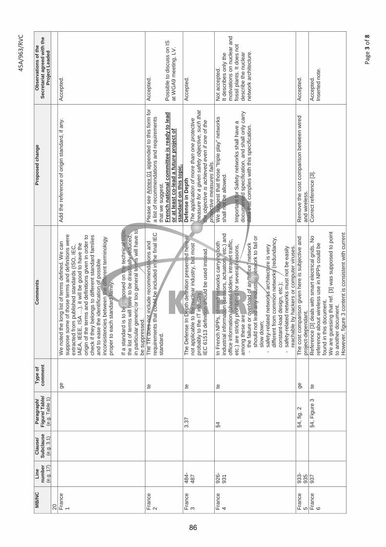
45A/
963/
RVC
Page
3 o
f 8
MB
/NC
Li
ne
num
ber
(e.g
. 17)
Cla
use/
Su
bcla
use
(e.g
. 3.1
)
Para
grap
h/
Figu
re/ T
able
/ (e
.g. T
able
1)
Type
of
com
men
t C
omm
ents
Pr
opos
ed c
hang
e O
bser
vatio
ns o
f the
Se
cret
aria
t agr
eed
with
the
Proj
ect L
eade
d 20
Fr
ance
1
ge
W
e no
ted
the
long
list
of t
erm
s de
fined
. We
can
supp
ose
som
e of
thos
e te
rms
and
defin
ition
s w
ere
extra
cted
from
pub
lishe
d st
anda
rds
(ISO
, IE
C,
IAE
A, I
EE
E, I
SA
…),
it w
ill b
e go
od to
hav
e th
e or
igin
of t
he te
rms
and
defin
ition
s gi
ven
in o
rder
to
chec
k if
they
bel
ongs
to d
iffer
ent s
tand
ard
fam
ilies
and
to e
ase
the
iden
tific
atio
n of
pos
sibl
e in
cons
iste
ncie
s be
twee
n th
e di
ffere
nt te
rmin
olog
y pr
oper
to e
ach
stan
dard
fam
ily.
If a
stan
dard
is to
be
prop
osed
on
the
tech
nica
l top
ic
the
list o
f ter
ms
will
hav
e to
be
dras
tical
ly re
duce
d,
in p
artic
ular
gen
eric
or t
oo g
ener
al te
rms
will
hav
e to
be
sup
pres
sed.
Add
the
refe
renc
e of
orig
in s
tand
ard,
if a
ny.
Acc
epte
d.
Fran
ce
2
te
The
TR d
oes
not i
nclu
de re
com
men
datio
ns a
nd
requ
irem
ents
that
cou
ld b
e in
clud
ed in
the
final
IEC
st
anda
rd.
Ple
ase
see
Ann
ex 0
1 ap
pend
ed to
this
form
for
a lis
t of r
ecom
men
datio
ns a
nd re
quire
men
ts
that
we
sugg
est.
Fren
ch n
atio
nal c
omm
ittee
is re
ady
to le
ad
or a
t lea
st c
o-le
ad a
futu
re p
roje
ct o
f st
anda
rd o
n th
is to
pic.
Acc
epte
d.
Pos
sibl
e to
dis
cuss
on
IS
at W
GA9
mee
ting,
LV
.
Fran
ce
3 48
4-48
7
3.37
te
Th
e D
efen
se In
Dep
th d
efin
ition
pre
sent
ed h
ere
is
not a
pplic
able
to th
e nu
clea
r ind
ustry
, but
mos
t pr
obab
ly to
the
IT in
dust
ry.
IEC
615
13 d
efin
ition
sho
uld
be u
sed
inst
ead.
Def
ense
in D
epth
Th
e ap
plic
atio
n of
mor
e th
an o
ne p
rote
ctiv
e m
easu
re fo
r a g
iven
saf
ety
obje
ctiv
e, s
uch
that
th
e ob
ject
ive
is a
chie
ved
even
if o
ne o
f the
pr
otec
tive
mea
sure
s fa
ils.
Acc
epte
d.
Fran
ce
4 92
6-93
1
§4
te
In F
renc
h N
PPs
, sha
red
netw
orks
car
ryin
g bo
th
indu
stria
l inf
orm
atio
n (s
enso
rs, a
ctua
tors
, etc
.) an
d of
fice
info
rmat
ion
(sha
red
fold
ers,
intra
net t
raffi
c,
etc.
) are
stri
ctly
pro
hibi
ted
for s
ever
al re
ason
s,
amon
g th
ese
are:
-
the
failu
re o
r ove
rload
of a
n “o
ffice
” net
wor
k sh
ould
not
lead
any
indu
stria
l net
wor
k to
fail
or
slow
dow
n;
- sa
fety
-rel
ated
net
wor
ks a
rchi
tect
ure
is v
ery
diffe
rent
from
com
mon
net
wor
ks (r
edun
danc
y,
cons
tant
-load
des
ign,
etc
.);
- sa
fety
-rel
ated
net
wor
ks m
ust n
ot b
e ea
sily
re
acha
ble
by h
acke
rs o
r com
pute
r viru
ses.
We
sugg
est t
hat t
hose
“trip
le p
lay”
net
wor
ks
shal
l not
be
allo
wed
. Im
porta
nt fo
r Saf
ety
netw
orks
sha
ll ha
ve a
do
cum
ente
d sp
ecifi
catio
n, a
nd s
hall
only
car
ry
data
that
com
plie
s w
ith th
is s
peci
ficat
ion.
Not
acc
epte
d.
It de
scrib
es o
nly
the
mot
ivat
ions
on
nucl
ear a
nd
foss
il pl
ants
. It d
oes
not
desc
ribe
the
nucl
ear
netw
ork
arch
itect
ure.
Fran
ce
5 93
3-93
5
§4, f
ig. 2
ge
Th
e co
st c
ompa
rison
giv
en h
ere
is s
ubje
ctiv
e an
d pr
ojec
t-dep
enda
nt.
Rem
ove
the
cost
com
paris
on b
etw
een
wire
d an
d w
irele
ss.
Acc
epte
d.
Fran
ce
6 93
7
§4, F
igur
e 3
te
Ref
eren
ce [3
] dea
ls w
ith s
mar
t ele
ctric
al g
rids.
No
refe
renc
e ab
out w
irele
ss u
se in
NP
Ps
coul
d be
fo
und
in th
is d
ocum
ent.
We
are
gues
sing
that
ref.
[3] w
as s
uppo
sed
to p
oint
to
ano
ther
doc
umen
t. H
owev
er, f
igur
e 3
cont
ent i
s co
nsis
tent
with
cur
rent
Cor
rect
refe
renc
e [3
]. A
ccep
ted.
In
serte
d no
te.
86
45A/
963/
RVC
Page
4 o
f 8
MB
/NC
Li
ne
num
ber
(e.g
. 17)
Cla
use/
Su
bcla
use
(e.g
. 3.1
)
Para
grap
h/
Figu
re/ T
able
/ (e
.g. T
able
1)
Type
of
com
men
t C
omm
ents
Pr
opos
ed c
hang
e O
bser
vatio
ns o
f the
Se
cret
aria
t agr
eed
with
the
Proj
ect L
eade
d Fr
ench
wire
less
pra
ctic
es: d
osim
etry
, DE
CT,
la
ptop
s.
Fran
ce
7 17
51-
1752
§8
te
Ple
ase
give
refe
renc
es to
sup
port
the
follo
win
g st
atem
ent:
“thes
e co
ncer
ns a
re u
nfun
ded”
. Th
ese
issu
es d
o no
t see
m u
nfun
ded
to u
s an
d th
is
stat
emen
t con
tradi
cts
with
our
exp
erie
nce.
Rem
ove
sent
ence
“ext
ensi
ve s
tudi
es h
ave
been
con
duct
ed to
dem
onst
rate
thes
e co
ncer
ns
are
unfo
unde
d”.
Not
acc
epte
d.
It de
scrib
es o
nly
the
mot
ivat
ions
on
nucl
ear a
nd
foss
il pl
ants
. It d
oes
not
desc
ribe
the
nucl
ear
netw
ork
arch
itect
ure.
Fr
ance
8
ge
Th
e TR
sho
uld
men
tion
that
nat
iona
l and
su
pran
atio
nal s
tand
ards
sha
ll be
resp
ecte
d, s
uch
as
Eur
opea
n di
rect
ives
in E
urop
e (e
spec
ially
co
ncer
ning
em
issi
on a
nd s
usce
ptib
ility
to
elec
trom
agne
tic w
aves
).
Add
a re
quire
men
t sta
ting
that
nat
iona
l and
su
pran
atio
nal s
tand
ards
sha
ll be
resp
ecte
d.
Acc
epte
d.
Italy
1
ge
Th
e do
cum
ent i
s go
od.
How
ever
we
note
that
the
wire
less
tech
nolo
gy
shou
ld b
e us
ed w
ith c
autio
n in
sys
tem
s im
porta
nt to
sa
fety
, suc
h as
the
cont
rol s
yste
m b
y ba
rs in
the
nucl
ear r
eact
or c
ore
of th
e N
PP
.
A
ccep
ted.
Kor
ea
(Rep
of)
1
1276
-12
79
1368
14
47
1587
16
03
1714
28
22
2824
28
27
ed
Inde
nt p
robl
em
Or
Pag
e nu
mbe
r and
Fig
ure
num
ber
Nee
d fix
ing
or c
orre
ctin
g A
ccep
ted.
Kor
ea
(Rep
of)
2
1918
ed
K
ey L
esso
n: O
rder
sev
eral
ext
ra s
enso
rs a
nd
prov
isio
n th
em
Pro
visi
on
pro
visi
on fo
r O
r p
rovi
de
Acc
epte
d.
Kor
ea
(Rep
of)
3
2083
21
14
2083
21
34
2138
21
41
10.2
pa
ragr
aph
ge
“Saf
ety
rela
ted”
wor
ding
sho
uld
be re
plac
ed w
ith
prop
er te
rms
acco
rdin
g to
IAEA
cla
ssifi
catio
n an
d D
TR ti
tle.
Safe
ty re
late
d”
Impo
rtan
t to
Safe
ty
Acc
epte
d.
Kor
ea
(Rep
of)
4
2302
para
grap
h ge
“.
. . s
peci
ficat
ions
sho
uld
see
refe
renc
es 7
.]” C
an’t
find
the
refe
renc
e nu
mbe
r in
sect
ion
2. re
fere
nce
Use
title
of r
efer
ence
A
ccep
ted.
Kor
ea
(Rep
of)
5
2842
B
iblio
gra
phy
te
Th
ere
are
no c
itatio
n nu
mbe
r of b
iblio
grap
hy, b
ut
follo
win
g ar
e sp
ecifi
ed th
e pa
ge.
“Bib
liogr
aphy
11.
D. K
. Che
ng, F
ield
and
Wav
e E
lect
rom
agne
tics,
Add
ison
Wes
ley,
Rea
ding
, M
assa
chus
etts
, 198
9, p
. 84.
”
It is
des
irabl
e to
find
the
rela
ted
text
and
bi
blio
grap
hy fo
r eas
y tra
ceab
lility
. A
ccep
ted.
Rus
sian
Fe
d. 1
20
2 Fo
rew
ord
E
IE
C/T
R 6
2XX
X…
To w
rite
as fo
llow
s: I
EC
/TR
629
18…
A
ccep
ted.
87

45A/
963/
RVC
Page
5 o
f 8
MB
/NC
Li
ne
num
ber
(e.g
. 17)
Cla
use/
Su
bcla
use
(e.g
. 3.1
)
Para
grap
h/
Figu
re/ T
able
/ (e
.g. T
able
1)
Type
of
com
men
t C
omm
ents
Pr
opos
ed c
hang
e O
bser
vatio
ns o
f the
Se
cret
aria
t agr
eed
with
the
Proj
ect L
eade
d R
ussi
an
Fed.
2
237
Intro
duc-
tion
E
It
is in
tend
ed th
at th
e S
tand
ard…
To
writ
e as
follo
ws:
It is
inte
nded
that
the
Tech
nica
l Rep
ort…
A
ccep
ted.
Rus
sian
Fe
d. 3
24
1 In
trodu
c-tio
n
E
IEC
62X
XX…
To
writ
e as
follo
ws:
IEC
/TR
629
18…
A
ccep
ted.
Rus
sian
Fe
d. 4
29
3 –
322
2
G
Sec
tion
2 do
es n
ot c
onta
in d
ated
refe
renc
es. A
s a
cons
eque
nce,
the
user
s w
ill b
e as
sign
ed w
ith a
n ad
ditio
nal c
once
rn: t
o ch
eck
whe
ther
or n
ot th
e do
cum
ent t
hey
use
is it
s la
test
edi
tion.
It is
nec
essa
ry to
giv
e, w
here
pos
sibl
e, th
e da
ted
refe
renc
es. I
n an
y ca
se, t
he d
ated
re
fere
nces
sho
uld
be g
iven
whe
n th
e va
lidity
da
te o
f the
refe
renc
ed d
ocum
ent i
s cl
ose
to
such
dat
e of
the
Tech
nica
l Rep
ort.
Acc
epte
d.
Rus
sian
Fe
d. 5
31
1 2
E
Th
e st
anda
rd w
ith th
e gi
ven
desi
gnat
ion
(IEC
626
57) i
s ab
sent
. To
giv
e th
e co
rrec
t des
igna
tion
of th
e st
anda
rd:
IEC
626
57-2
. A
ccep
ted.
Rus
sian
Fe
d. 6
29
3 –
322
2
T
To a
dd th
e fo
llow
ing
serie
s of
pub
licat
ions
, de
velo
ped
in T
C 6
5, to
the
list o
f ref
eren
ces:
IE
C 6
2443
“Ind
ustri
al c
omm
unic
atio
n ne
twor
ks
- Net
wor
k an
d sy
stem
sec
urity
”
Not
acc
epte
d. S
ome
indu
stria
l com
mun
icat
ion
netw
ork
s ar
e re
fere
nced
in
bibl
iogr
aphy
. R
ussi
an
Fed.
7
293
– 32
2 2
T
An
impo
rtant
IAE
A g
uida
nce
is a
bsen
t am
ong
the
refe
renc
es.
To a
dd th
e fo
llow
ing
docu
men
t to
the
list o
f re
fere
nces
: IA
EA
NS
-G-1
.1 «
Softw
are
for
com
pute
r bas
ed s
yste
ms
impo
rtant
to s
afet
y in
nu
clea
r pow
er p
lant
s».
Not
acc
epte
d.
Rus
sian
Fe
d. 8
32
3 –
910
3
E
All
term
s an
d th
eir d
efin
ition
s sh
ould
be
star
ted
with
lo
wer
case
lette
rs.
To c
hang
e th
e st
yle
of fi
rst l
ette
rs in
term
s an
d de
finiti
ons
from
cap
ital t
o lo
wer
case
. A
ccep
ted.
Rus
sian
Fe
d. 9
3.5
and
3.33
T Te
rms
3.5
“atta
ck” a
nd 3
.33
“cyb
er a
ttack
” are
ov
erla
ppin
g w
ith e
ach
othe
r. To
del
ete
term
3.3
3 “c
yber
atta
ck”.
Acc
epte
d.
Rus
sian
Fe
d. 1
0 47
0 –
474
and
490
– 49
3
3.34
and
3.
38
E
, T
A d
efin
ition
sho
uld
cons
ist o
f onl
y on
e se
nten
ce.
To g
ive
the
seco
nd s
ente
nces
as
note
s.
Del
eted
.
Rus
sian
Fe
d. 1
1 13
36 –
13
42
6.4
E
, T
The
title
and
con
tent
of 6
.4 re
peat
s th
e tit
le a
nd
cont
ent o
f 6.5
. To
del
ete
sub-
clau
se 6
.4.
Acc
epte
d.
Rus
sian
Fe
d. 1
2 13
82 –
13
93
6.6
E
, T
The
first
two
para
grap
hs o
f sub
clau
se a
re o
f a
gene
ral n
atur
e an
d ar
e no
t obl
igat
ory
for t
he
Tech
nica
l Rep
ort.
To d
elet
e th
e fir
st tw
o pa
ragr
aphs
of s
ubcl
ause
6.
6.
Not
acc
epte
d.
The
first
two
para
grap
hs
are
desc
ribed
the
basi
c ch
arac
teris
tics.
U
krai
ne1
305
2
Ed
Ther
e is
refe
renc
e to
IEC
615
08, b
ut in
the
proj
ect
you
refe
r to
som
e pa
rts o
f IE
C 6
1508
, suc
h as
IE
C
6150
8-1,
IEC
615
08-2
, IE
C 6
1508
-3, I
EC
615
08-0
, IE
C 6
1508
-4
Giv
e th
e tit
les
of th
ese
parts
or c
hang
e th
is
refe
renc
e by
: IE
C 6
1508
(all
parts
), Fu
nctio
nal s
afet
y of
el
ectri
cal/e
lect
roni
c/pr
ogra
mm
able
ele
ctro
nic
safe
ty-r
elat
ed s
yste
ms
Acc
epte
d.
Ukr
aine
2
2
Ed
Ther
e ar
e m
issi
ng re
fere
nces
to s
ome
stan
dard
s A
dd th
e ne
xt re
fere
nces
to c
laus
e 2
: IE
C 6
2591
, IE
C 6
1784
-2, I
EC
617
84-3
, IE
C 6
1784
-4, I
SO
247
30 (1
,2),
ISO
144
43
Acc
epte
d.
Ukr
aine
3
Ed
Ther
e ar
e a
lot o
f abb
revi
atio
ns in
this
pro
ject
.
Add
the
clau
se “A
bbre
viat
ions
”
Acc
epte
d.
Ukr
aine
4 91
5
E
d D
on’t
repe
at th
e tit
le o
f Fig
ure
1 in
the
text
of t
he
stan
dard
. Avo
id re
petit
ions
. Th
e sa
me
appl
ies
to
e.g.
In a
dditi
on, a
s sh
own
in F
igur
e 1
–
com
paris
on -
wire
d ve
rsus
wire
less
for a
n A
ccep
ted.
88
45A/
963/
RVC
Page
6 o
f 8
MB
/NC
Li
ne
num
ber
(e.g
. 17)
Cla
use/
Su
bcla
use
(e.g
. 3.1
)
Para
grap
h/
Figu
re/ T
able
/ (e
.g. T
able
1)
Type
of
com
men
t C
omm
ents
Pr
opos
ed c
hang
e O
bser
vatio
ns o
f the
Se
cret
aria
t agr
eed
with
the
Proj
ect L
eade
d th
e Fi
gure
2 ,3
, 4, 5
(93
3,93
8, 9
48, 9
86).
Th
is a
pplie
s fo
r all
figur
es, t
able
s.
exte
nsiv
e bu
ildin
g au
tom
atio
n sy
stem
, th
e co
st
of in
stal
ling
wire
d se
nsor
is o
ften
high
er th
an
the
actu
al s
enso
r its
elf [
num
eral
refe
renc
e to
co
rres
pond
ing
docu
men
t fro
m B
iblio
grap
hy].
Giv
e ex
plan
atio
n of
[1-P
F –
IEC
ISA
100
WG
8 W
irele
ssU
serG
uide
_22M
ar13
_BK
_WM
.doc
x].
Ukr
aine
5 94
2
Figu
re 3
Fi
gure
4
Ed
The
Figu
re 3
(4) h
as tw
o tit
les
Del
ete
unne
cess
ary
title
A
ccep
ted.
Ukr
aine
6 95
3
G
e
Del
ete
the
title
of a
rticl
e (“
Asse
ssm
ent o
f W
irele
ss T
echn
olog
ies
and
thei
r App
licat
ion
at
Nuc
lear
Fac
ilitie
s [N
UR
EG
/CR
-688
2]”)
and
give
nu
mer
al re
fere
nce
to c
orre
spon
ding
doc
umen
t fro
m B
iblio
grap
hy.
Cor
rect
the
sam
e th
roug
hout
the
sta
ndar
d
Acc
epte
d.
Ukr
aine
7
985
5 R
efer
ence
1
S
ee th
e bo
ttom
of t
he p
age,
refe
renc
e 1,
2nd
lin
e:1M
bps
to 2
00+M
bps
Del
ete
plus
(+) b
etw
een
200
and
Mbp
s A
ccep
ted.
Ukr
aine
8
1165
25
26
6.1
B.1
Fi
gure
10
Figu
re B
.1
Ed
Figu
re 1
0 an
d Fi
gure
B.1
are
the
sam
e.
D
elet
e Fi
gure
B.1
. Cha
nge
refe
renc
e to
Fig
ure
B.1
by
Figu
re 1
0.
Acc
epte
d.
Ukr
aine
9 10
64
5 Fi
gure
7
Figu
re 8
E
d Fi
gure
7(8
) can
’t be
read
and
they
are
in
com
preh
ensi
ble.
M
ake
this
figu
re c
lear
er a
nd u
nder
stan
dabl
e.
Mak
e th
e no
te (1
065)
bet
wee
n fig
ure
and
its
title
mor
e st
anda
rdiz
ed.
Acc
epte
d.
Ukr
aine
10
1085
10
86
6.1
E
d a
900
meg
aher
tz (M
Hz)
dev
ice
is lo
nger
than
that
of
a 10
85 2
.4 g
igah
ertz
(GH
z)
Cha
nge
by:
a 90
0 M
Hz
devi
ce is
long
er th
an th
at o
f
a 10
85 2
,4 G
Hz
devi
ce
Acc
epte
d.
Ukr
aine
11
G
e
Acc
ordi
ng to
ISO
/IEC
Dire
ctiv
es P
art 2
.The
de
cim
al s
ign
shal
l be
a co
mm
a.
Che
ck th
roug
hout
the
proj
ect
Acc
epte
d.
Ukr
aine
12
1336
, 13
43
6.4,
6.5
Ed
Sub
clau
ses
6.4
and
6.5
have
the
sam
e tit
le
To jo
in s
ubcl
ause
s 6.
4 an
d 6.
5 A
ccep
ted.
Ukr
aine
13
E
d
Figu
re 1
1 –
Sta
ndar
d co
mpl
iant
net
wor
k
depi
cts
the
com
mun
icat
ion
area
s ad
dres
sed
by
ISA
100.
11a
– n
ow IE
C62
734
– o
r IE
C62
591
Cha
nge
by:
Figu
re 1
1 d
epic
ts th
e co
mm
unic
atio
n ar
eas
addr
esse
d by
IEC
627
34 o
r IE
C 6
2591
Acc
epte
d.
Ukr
aine
14
1715
7.
7
Ed
Fi
gure
22
is m
issi
ng
Cor
rect
num
berin
g of
figu
res
A
ccep
ted.
Ukr
aine
15
1739
8.
1
Ed
The
nam
e of
sub
clau
se 8
.1 is
“Myt
hs R
egar
ding
W
irele
ss T
echn
olog
y”. T
he te
rm “m
yth”
is n
ot re
ally
re
leva
nt fo
r nor
mat
ive
docu
men
t
To re
nam
e su
bcla
use
8.1,
for e
xam
ple,
“C
once
rns
Reg
ardi
ng W
irele
ss T
echn
olog
y”
Acc
epte
d.
Ukr
aine
16
2558
Figu
re B
.1
Ed
Ther
e is
wro
ng n
umbe
ring
of fi
gure
s in
the
Ann
ex B
Num
ber c
orre
ctly
f al
l fig
ures
in th
e A
nnex
B,
e.g.
Fi
gure
B.1
, Fig
ure
B.2
, Fig
ure
B.3
….a
nd s
o on
Acc
epte
d.
Ukr
aine
17
G
e In
acc
orda
nce
with
6.6
.11
of IS
O/IE
C D
irect
ives
Par
t 2,
tole
ranc
es o
f val
ues
and
dim
ensi
ons
shal
l be
indi
cate
d in
an
unam
bigu
ous
man
ner.
Cha
nge:
0.6
to 3
.8 m
eter
(136
5)
b
y: fr
om 0
,6 m
to 3
,8 m
; +4
to +
20 d
Bm (2
333)
by
from
4 d
Bm
to 2
0
Acc
epte
d.
89
45A/
963/
RVC
Page
7 o
f 8
MB
/NC
Li
ne
num
ber
(e.g
. 17)
Cla
use/
Su
bcla
use
(e.g
. 3.1
)
Para
grap
h/
Figu
re/ T
able
/ (e
.g. T
able
1)
Type
of
com
men
t C
omm
ents
Pr
opos
ed c
hang
e O
bser
vatio
ns o
f the
Se
cret
aria
t agr
eed
with
the
Proj
ect L
eade
d
dBm
C
heck
all
tole
ranc
es th
roug
hout
the
stan
dard
U
krai
ne18
24
80
A
nnex
B
Ge
……
spee
ds u
p to
250
km
/hou
r D
o no
t mix
sym
bols
and
nam
es o
f uni
ts
Cha
nge
by: u
p 25
0 k
m/h
C
heck
uni
ts o
f mea
sure
thro
ugho
ut th
e st
anda
rd
Acc
epte
d.
Ukr
aine
19
2499
Ann
ex B
E
d 10
6, 2
12, 4
24 o
r 848
kb
Eve
ry v
alue
sha
ll ha
s co
rresp
ondi
ng u
nit o
f m
easu
rem
ent
Cha
nge
by::
10
6 kb
, 212
kb,
424
kb
or 8
48 k
b A
ccep
ted.
UK
1
G
ener
al
The
Dra
ft Te
chni
cal R
epor
t pro
vide
s a
com
preh
ensi
ve re
view
of w
irele
ss n
etw
orks
, the
ir ch
arac
teris
tics,
thei
r pot
entia
l ben
efits
and
di
sadv
anta
ges.
Th
e U
K s
uppo
rts th
e pu
blic
atio
n of
this
Dra
ft Te
chni
cal R
epor
t but
wou
ld li
ke to
sub
mit
the
follo
win
g co
mm
ents
.
A
ccep
ted.
UK
2
Te
chni
cal
The
docu
men
t wou
ld b
e im
prov
ed b
y th
e ad
ditio
n of
a
shor
t dis
cuss
ion
of th
e pr
oble
ms
caus
ed b
y th
e ra
pid
evol
utio
n of
the
wire
less
sta
ndar
ds.
For N
PP
, th
is h
as b
een
a si
gnifi
cant
pro
blem
for u
tiliti
es w
hich
ad
opte
d th
e ea
rly s
tand
ards
.
Add
a s
hort
sect
ion
disc
ussi
ng th
e pr
oble
ms
caus
ed b
y th
e ra
pid
deve
lopm
ent o
f wire
less
st
anda
rds.
Thi
s co
uld
be a
dded
to s
ectio
n 8
(Con
side
ratio
ns) o
r Ann
ex B
(Wire
less
Te
chno
logi
es).
Acc
epte
d.
UK
3
E
dito
rial
The
repo
rt sh
ould
be
edite
d to
rem
ove
the
min
or
form
attin
g an
d ty
pogr
aphi
cal
erro
rs, s
uch
as li
ne
spac
ing
(Eg
on li
nes
1125
, 112
9 an
d 11
45)
Edi
t to
docu
men
t to
corr
ect t
he m
inor
form
attin
g an
d ty
pogr
aphi
cal e
rrors
. A
ccep
ted.
UK
4
E
dito
rial
The
spel
ling
of w
ords
sho
uld
be c
orre
cted
to th
e E
nglis
h sp
ellin
g.
Cor
rect
the
spel
ling
of w
ords
suc
h as
: "O
rgan
izat
ion"
sho
uld
amen
ded
to
"org
anis
atio
n"
Acc
epte
d.
90

An
nex
of F
ranc
e.do
c
Ann
ex 0
1 –
sugg
este
d re
com
men
datio
ns a
nd re
quire
men
ts
1.
Gen
eral
lim
its a
ssig
ned
to w
irele
ss s
yste
ms
Wire
less
com
mun
icat
ions
sha
ll no
t be
used
in s
yste
ms
supp
ortin
g C
ateg
ory
A an
d B
func
tions
acc
ordi
ng to
IEC
612
26.
Not
e: T
he m
ain
reas
ons
for t
his
requ
irem
ent a
re:
- th
e ex
pect
ed d
iffic
ulty
to m
eet a
dequ
ate
V&
V re
quire
men
ts (s
ee 2
.) -
the
impo
ssib
ility
to b
ound
the
resp
onse
tim
e of
a w
irele
ss s
yste
m, t
hus
cont
radi
ctin
g w
ith IE
C 6
0880
and
IEC
621
38.
A su
itabi
lity
anal
ysis
sha
ll be
con
duct
ed p
rior t
o th
e se
lect
ion
of w
irele
ss s
yste
ms
supp
ortin
g C
ateg
ory
C fu
nctio
ns a
ccor
ding
to IE
C 6
1226
. W
irele
ss s
yste
ms
shal
l not
dis
turb
I&C
func
tions
and
oth
er Im
porta
nt fo
r Saf
ety
syst
ems.
2.
Ve
rific
atio
n &
Valid
atio
n re
quire
men
ts, q
ualif
icat
ion
IEC
615
13 “G
ener
al re
quire
men
ts fo
r sys
tem
s” re
quire
men
ts s
hall
be m
et.
IEC
621
38 “S
oftw
are
aspe
cts
(…)”
requ
irem
ents
sha
ll be
met
. N
ote:
IEC
608
80 is
not
men
tione
d he
re b
ecau
se o
f 1. (
see
abov
e).
IEC
607
80 “Q
ualif
icat
ion”
requ
irem
ents
sha
ll be
met
. 3.
Te
chni
cal r
equi
rem
ents
3.
1. N
etw
ork
arch
itect
ure
The
netw
ork
load
sho
uld
be c
onte
xt-in
depe
nden
t. Th
is m
eans
that
may
a m
onito
red
even
t occ
ur, t
he n
etw
ork
load
sho
uld
not i
ncre
ase.
3.
2. S
yste
ms
runn
ing
on b
atte
ries
Rem
ote
devi
ces
runn
ing
on b
atte
ries
shal
l be
phys
ical
ly re
acha
ble
in o
rder
to b
e ab
le to
repl
ace
a de
fect
ive
or d
isch
arge
d ba
ttery
. If t
his
is n
ot p
ossi
ble,
the
batte
ry c
apac
ity s
hall
be p
rope
rly d
imen
sion
ed to
last
a s
uffic
ient
tim
e, a
ccor
ding
to th
e sy
stem
spe
cific
atio
n.
Batte
ry le
vel o
f rem
ote
devi
ces
runn
ing
on b
atte
ries
shal
l mon
itore
d.
3.3.
Ele
ctro
Mag
netic
Com
patib
ility
(EM
C)
Any
wire
less
dev
ice
shal
l be
inst
alle
d at
leas
t 30
cent
imet
ers
(1 fo
ot) a
way
from
impo
rtant
for s
afet
y eq
uipm
ents
. An
impa
ct a
naly
sis
rega
rdin
g E
MC
sha
ll be
con
duct
ed p
rior t
o th
e on
-site
inst
alla
tion
of th
e sy
stem
. N
ote:
The
se re
quire
men
ts in
tend
to p
rote
ct im
porta
nt fo
r saf
ety
syst
ems
and
key
cont
rol s
yste
ms
from
ele
ctro
mag
netic
wav
es e
mitt
ed b
y th
e w
irele
ss
devi
ce.
3.4.
Irra
diat
ion
An im
pact
ana
lysi
s re
gard
ing
beha
vior
und
er ir
radi
atio
n sh
all b
e co
nduc
ted
prio
r to
the
on-s
ite in
stal
latio
n of
the
syst
em.
4.
Com
pute
r sec
urity
R
equi
rem
ents
of I
EC 6
2645
“Req
uire
men
ts fo
r sec
urity
pro
gram
mes
for c
ompu
ter-
base
d sy
stem
s” s
hall
be m
et.
Encr
yptio
n sh
ould
be
used
for w
irele
ss c
omm
unic
atio
ns. T
he e
ncry
ptio
n m
etho
ds –
or l
ack
of e
ncry
ptio
n –
shal
l be
cons
iste
nt w
ith IE
C 6
1513
ove
rall
secu
rity
plan
. Au
then
ticat
ion
of a
ll m
essa
ges
shou
ld b
e us
ed. T
he a
uthe
ntic
atio
n pr
oces
s –
or la
ck o
f aut
hent
icat
ion
– sh
all b
e co
nsis
tent
with
IEC
615
13 o
vera
ll se
curit
y pl
an.
5.
Solu
tion
dura
bilit
y W
irele
ss p
roto
cols
usi
ng a
doc
umen
ted
stan
dard
sho
uld
be p
refe
rred
.
91
IEC TR 62918 Edition 1.0 2014-07
TECHNICAL REPORT
Nuclear power plants – Instrumentation and control important to safety – Use and selection of wireless devices to be integrated in systems important to safety
INTERNATIONAL ELECTROTECHNICAL COMMISSION XB ICS 27.120.20
PRICE CODE
ISBN 978-2-8322-1750-4
® Registered trademark of the International Electrotechnical Commission
®
Warning! Make sure that you obtained this publication from an authorized distributor.
colourinside
This is a preview - click here to buy the full publication
92
– 2 – IEC 62918:2014 IEC 2014
CONTENTS
FOREWORD ........................................................................................................................... 5 INTRODUCTION ..................................................................................................................... 7 1 Scope .............................................................................................................................. 9 2 Normative references ...................................................................................................... 9 3 Terms and definitions ...................................................................................................... 9 4 Motivation ...................................................................................................................... 11 5 Generic applications ...................................................................................................... 13 6 Technology .................................................................................................................... 16
6.1 Wireless basics ..................................................................................................... 16 6.2 Industrial wireless sensor networks ....................................................................... 19 6.3 Radio frequency .................................................................................................... 20
6.3.1 Applications ................................................................................................... 20 6.3.2 802.11 (Wi-Fi), 802.15.1 (Bluetooth), 802.15.4 (sensors) ............................... 23
6.4 Satellite leased channels and VSAT ...................................................................... 25 6.5 Magnetic field communications ............................................................................. 26 6.6 Visual light communication (VLC) .......................................................................... 27 6.7 Acoustic communication........................................................................................ 27 6.8 Asset tracking utilizing IEEE 802.11 – Focus on received signal strength .............. 28 6.9 Asset tracking (RFID/RTLS): ISO 24730 ............................................................... 29
7 Current wireless technology implementations ................................................................ 30 7.1 General ................................................................................................................. 30 7.2 Comanche Peak nuclear generating station .......................................................... 30 7.3 Arkansas Nuclear One (ANO) nuclear power plant ................................................ 31 7.4 Diablo Canyon nuclear power plant ....................................................................... 32 7.5 Farley nuclear power plant .................................................................................... 33 7.6 San Onofre nuclear generating station .................................................................. 33 7.7 South Texas project electric generating station ..................................................... 34 7.8 High Flux Isotope Reactor (HFIR), Oak Ridge, TN ................................................ 34
8 Considerations .............................................................................................................. 36 8.1 General ................................................................................................................. 36 8.2 Concerns regarding wireless technology ............................................................... 36 8.3 Wireless deployment challenges ........................................................................... 37 8.4 Coexistence of 802.11 and 802.15.4 ..................................................................... 38 8.5 Signal propagation ................................................................................................ 40 8.6 Lessons learned from wireless implementations .................................................... 41
8.6.1 General ......................................................................................................... 41 8.6.2 Comanche Peak implementation .................................................................... 41
9 Concerns ....................................................................................................................... 42 9.1 Common reliability and security concerns for wired media and wireless
media.................................................................................................................... 42 9.2 Reliability and security concerns that are more of an issue for wired systems ....... 42 9.3 Reliability and security concerns that are more of an issue for wireless
systems ................................................................................................................ 42 10 Standards ...................................................................................................................... 43
10.1 Nuclear standards ................................................................................................. 43
This is a preview - click here to buy the full publication
93

IEC 62918:2014 IEC 2014 – 3 –
10.1.1 General ......................................................................................................... 43 10.1.2 IEEE Std. 603-1998 ....................................................................................... 43 10.1.3 IEEE Std. 7-4.3.2-2003 .................................................................................. 44 10.1.4 IEC 61500 ..................................................................................................... 44
10.2 Other safety-related standards and guidelines ...................................................... 45 10.2.1 IEC 61784-3 .................................................................................................. 45 10.2.2 VTT research notes 2265............................................................................... 46 10.2.3 European Workshop on Industrial Computer Systems – Technical
Committee 7 (EWICS TC7) ............................................................................ 47 11 Conclusions ................................................................................................................... 47
11.1 Issues for wireless application to NPP .................................................................. 47 11.2 Recommendations ................................................................................................ 48
Annex A (informative) Use of 5 GHz in the world .................................................................. 50 Annex B (informative) Synopses of wireless technologies .................................................... 51
B.1 802.11 .................................................................................................................. 51 B.2 ISO 14443 Near Field Communications (NFC) ...................................................... 56 B.3 Real details of mesh networking ........................................................................... 59 B.4 Not all mesh networks are created equal – Latency and indeterminism in
mesh networks ...................................................................................................... 62 B.5 ISA100.11a – “Mesh – When You Need It – Networking” ....................................... 63 B.6 Security by non-routing edge nodes ...................................................................... 66 B.7 Device and network provisioning methods ............................................................. 67
Bibliography .......................................................................................................................... 69 Figure 1 – Cost comparison – Wired versus wireless for an extensive building automation system ................................................................................................................ 12 Figure 2 – Wireless use in nuclear power plants ................................................................... 12 Figure 3 – Possible application areas for wireless instrumentation in a nuclear power plant ..................................................................................................................................... 13 Figure 4 – Bandwidth requirements for a variety of applications and the associated wireless technology that can support such requirements ....................................................... 14 Figure 5 – Structured fabric design of layered wireless for an industrial facility .................... 15 Figure 6 – Inexpensive wireless sensors in a fossil-fuel plant ................................................ 16 Figure 7 – Functional hierarchy ............................................................................................. 18 Figure 8 – Simplified diagram of a generic wireless sensor design ........................................ 19 Figure 9 – Standard compliant network ................................................................................. 20 Figure 10 – 802.15.1 (Bluetooth) frequency channels in the 2 450 MHz range ...................... 23 Figure 11 – 802.15.4 frequency channels in the 2 450 MHz range ........................................ 24 Figure 12 – Overlapping channel assignments for 802.11 operation in the 2 400 MHz range .................................................................................................................................... 24 Figure 13 – 802.11n dual stream occupies 44 MHz of bandwidth. Dual stream 802.11n in the 2,4 GHz band .............................................................................................................. 25 Figure 14 – VSAT mini-hub network configuration ................................................................. 26 Figure 15 – Spatial resolution is provided in multiple axes only if the tag (target in this Figure) is in communications with multiple APs ..................................................................... 28 Figure 16 – ISO 24730-2 architecture ................................................................................... 29 Figure 17 – Wireless vibration system at ANO ...................................................................... 32 Figure 18 – ANO wireless tank level system ......................................................................... 33
This is a preview - click here to buy the full publication
94

– 4 – IEC 62918:2014 IEC 2014
Figure 19 – Installation of accelerometers on ORNL HFIR cold source expansion engines (9-2010) ................................................................................................................... 35 Figure 20 – Cold source expansion engine monitoring system software ................................ 35 Figure 21 – Installation of permanent wireless monitoring system at ORNL HFIR cooling tower (8-2011) .......................................................................................................... 36 Figure 22 – System commissioned in August 2011 ............................................................... 36 Figure 23 – Identification of containment in a nuclear facility ................................................ 38 Figure 24 – Non-overlapping 802.11b/g channels and 802.15.4 channels ............................. 39 Figure 25 – Spectral analysis of Wi-Fi traffic for the case where a) minimal wi-fi channel “usage” and b) streaming video transfer across Wi-Fi channel 7 are analyzed ......... 39 Figure 26 – Multipath is exemplified in this indoor environment as the signal from Source (S) to Origin (O) may take many paths ...................................................................... 41 Figure B.1 – The Open Systems Interconnection (OSI) model defines the end-to-end communications means and needs for a wireless field transmitter to securely communicate with a distributed control system (DCS) ........................................................... 57 Figure B.2 – Operating frequencies for an IEEE 802.15.4 radio are 868 MHz, 902-926 MHz and 2 405-2 485 MHz. The worldwide license-free band at 2400 MHz is shown ................................................................................................................................... 58 Figure B.3 – Networking topologies take many forms with associated levels of complexity required for robust fault-tolerant data transport .................................................... 58 Figure B.4 – Typical mesh network diagram .......................................................................... 59 Figure B.5 – Requirement for mesh-networking communication of Figure B.4’s topology ....... 60 Figure B.6 – RF footprint map for a mesh network gateway and four nodes .......................... 61 Figure B.7 – The connectivity diagram for Figure B.6’s RF footprint coverage map ............... 61 Figure B.8 – Representation of the latency and indeterminism that it takes for a message to be transported through a mesh network that relies on time synchronization ....... 63 Figure B.9 – The technical specifications associated with ISA100.11a end at the gateway. The area shaded falls within the Backhaul Work Group, ISA100.15 ........................ 64 Figure B.10 – ISA100.11a utilizes the best topology for the application, in this case, a star 64 Figure B.11 – ISA100.11a allows for the deployment of multiple “hub and spoke” network elements with high speed interconnection to a gateway ........................................... 65 Figure B.12 – The ISA100.11a network deployed at Arkema was a logical mix of wireless field transmitters and an ISA100.15 backhaul network ............................................. 65 Figure B.13 – Networks deployed at neighbouring facilities will not “cross-talk” if non-routing nodes are deployed along the periphery of each facility ............................................ 66 Figure B.14 – State transition diagram showing various paths to joining a secured network ................................................................................................................................. 68 Table 1 – List of “industrial” radio technology standards and their candidate applications .......................................................................................................................... 21 Table 2 – Cellular telephony frequencies in the US ............................................................... 22 Table 3 – GSM frequency bands, channel numbers assigned by the ITU .............................. 23 Table 4 – Specific uses of wireless technologies in the nuclear industry ............................... 30 Table A.1 – Use of 5 GHz in America, Asia/Pacific, and Europe ............................................ 50
This is a preview - click here to buy the full publication
95

IEC 62918:2014 IEC 2014 – 5 –
INTERNATIONAL ELECTROTECHNICAL COMMISSION
____________
NUCLEAR POWER PLANTS –
INSTRUMENTATION AND CONTROL IMPORTANT TO SAFETY – USE AND SELECTION OF WIRELESS DEVICES TO BE INTEGRATED IN SYSTEMS IMPORTANT TO SAFETY
FOREWORD
1) The International Electrotechnical Commission (IEC) is a worldwide organization for standardization comprising all national electrotechnical committees (IEC National Committees). The object of IEC is to promote international co-operation on all questions concerning standardization in the electrical and electronic fields. To this end and in addition to other activities, IEC publishes International Standards, Technical Specifications, Technical Reports, Publicly Available Specifications (PAS) and Guides (hereafter referred to as “IEC Publication(s)”). Their preparation is entrusted to technical committees; any IEC National Committee interested in the subject dealt with may participate in this preparatory work. International, governmental and non-governmental organizations liaising with the IEC also participate in this preparation. IEC collaborates closely with the International Organization for Standardization (ISO) in accordance with conditions determined by agreement between the two organizations.
2) The formal decisions or agreements of IEC on technical matters express, as nearly as possible, an international consensus of opinion on the relevant subjects since each technical committee has representation from all interested IEC National Committees.
3) IEC Publications have the form of recommendations for international use and are accepted by IEC National Committees in that sense. While all reasonable efforts are made to ensure that the technical content of IEC Publications is accurate, IEC cannot be held responsible for the way in which they are used or for any misinterpretation by any end user.
4) In order to promote international uniformity, IEC National Committees undertake to apply IEC Publications transparently to the maximum extent possible in their national and regional publications. Any divergence between any IEC Publication and the corresponding national or regional publication shall be clearly indicated in the latter.
5) IEC itself does not provide any attestation of conformity. Independent certification bodies provide conformity assessment services and, in some areas, access to IEC marks of conformity. IEC is not responsible for any services carried out by independent certification bodies.
6) All users should ensure that they have the latest edition of this publication.
7) No liability shall attach to IEC or its directors, employees, servants or agents including individual experts and members of its technical committees and IEC National Committees for any personal injury, property damage or other damage of any nature whatsoever, whether direct or indirect, or for costs (including legal fees) and expenses arising out of the publication, use of, or reliance upon, this IEC Publication or any other IEC Publications.
8) Attention is drawn to the Normative references cited in this publication. Use of the referenced publications is indispensable for the correct application of this publication.
9) Attention is drawn to the possibility that some of the elements of this IEC Publication may be the subject of patent rights. IEC shall not be held responsible for identifying any or all such patent rights.
The main task of IEC technical committees is to prepare International Standards. However, a technical committee may propose the publication of a technical report when it has collected data of a different kind from that which is normally published as an International Standard, for example "state of the art".
IEC TR 62918, which is a technical report, has been prepared by subcommittee 45A: Instrumentation, control and electrical systems of nuclear facilities, of IEC technical committee 45: Nuclear instrumentation.
This is a preview - click here to buy the full publication
96
– 6 – IEC 62918:2014 IEC 2014
The text of this technical report is based on the following documents:
Enquiry draft Report on voting
45A/947/DTR 45A/963/RVC
Full information on the voting for the approval of this technical report can be found in the report on voting indicated in the above table.
This publication has been drafted in accordance with the ISO/IEC Directives, Part 2.
The committee has decided that the contents of this publication will remain unchanged until the stability date indicated on the IEC web site under "http://webstore.iec.ch" in the data related to the specific publication. At this date, the publication will be
reconfirmed,
withdrawn,
replaced by a revised edition, or
amended.
A bilingual version of this publication may be issued at a later date.
IMPORTANT – Le logo "colour inside" qui se trouve sur la page de couverture de cette publication indique qu'elle contient des couleurs qui sont considérées comme utiles à une bonne compréhension de son contenu. Les utilisateurs devraient, par conséquent, imprimer cette publication en utilisant une imprimante couleur.
This is a preview - click here to buy the full publication
97
IEC 62918:2014 IEC 2014 – 7 –
INTRODUCTION
a) Technical background, main issues and organisation of the Standard The ad hoc meeting of the IEC Technical Working Group on Nuclear Power Plant Control and Instrumentation, held in Yokohama in May 2009, resulted in the recommendation to develop a technical report addressing the applicability of incorporating wireless technology throughout nuclear power plant systems, regardless of the categorizations such as non-safety, important to availability and important to safety. This technical report addresses this recommendation and one of its main objectives is to pave the way for the development of a standard on the topic. The technical report addresses concerns regarding the application, safety and security of integrating wireless technologies into the systems of nuclear power plants. It reviews the motivation for use of wireless applications in nuclear power plants, wireless technology considerations, and the feasibility of incorporating wireless technology in nuclear power plants. It is intended that this Technical Report be used by operators of NPPs (utilities), systems evaluators and by licensors.
b) Situation of the current Technical Report in the structure of the IEC SC 45A standard series IEC 62918 as a technical report is a fourth level IEC SC 45A document. For more details on the structure of the IEC SC 45A standard series, see item d) of this introduction.
c) Recommendations and limitations regarding the application of this Technical Report It is important to note that a technical report is entirely informative in nature. It gathers data collected from different origins and it establishes no requirements.
d) Description of the structure of the IEC SC 45A standard series and relationships with other IEC documents and other bodies’ documents (IAEA, ISO) The top-level document of the IEC SC 45A standard series is IEC 61513. It provides general requirements for I&C systems and equipment that are used to perform functions important to safety in NPPs. IEC 61513 structures the IEC SC 45A standard series. IEC 61513 refers directly to other IEC SC 45A standards for general topics related to categorization of functions and classification of systems, qualification, separation of systems, defence against common cause failure, software aspects of computer-based systems, hardware aspects of computer-based systems, and control room design. The standards referenced directly at this second level should be considered together with IEC 61513 as a consistent document set. At a third level, IEC SC 45A standards not directly referenced by IEC 61513 are standards related to specific equipment, technical methods, or specific activities. Usually these documents, which make reference to second-level documents for general topics, can be used on their own. A fourth level extending the IEC SC 45A standard series, corresponds to the Technical Reports which are not normative. IEC 61513 has adopted a presentation format similar to the basic safety publication IEC 61508 with an overall safety life-cycle framework and a system life-cycle framework. Regarding nuclear safety, it provides the interpretation of the general requirements of IEC 61508-1, IEC 61508-2 and IEC 61508-4, for the nuclear application sector, regarding nuclear safety. In this framework IEC 60880 and IEC 62138 correspond to IEC 61508-3 for the nuclear application sector. IEC 61513 refers to ISO as well as to IAEA GS-R-3 and IAEA GS-G-3.1 and IAEA GS-G-3.5 for topics related to quality assurance (QA). The IEC SC 45A standards series consistently implements and details the principles and basic safety aspects provided in the IAEA code on the safety of NPPs and in the IAEA safety series, in particular the Requirements SSR-2/1, establishing safety requirements related to the design of Nuclear Power Plants, and the Safety Guide NS-G-1.3 dealing with instrumentation and control systems important to safety in Nuclear Power Plants. The
This is a preview - click here to buy the full publication
98

– 8 – IEC 62918:2014 IEC 2014
terminology and definitions used by SC 45A standards are consistent with those used by the IAEA.
NOTE It is assumed that for the design of I&C systems in NPPs that implement conventional safety functions (e.g. to address worker safety, asset protection, chemical hazards, process energy hazards) international or national standards would be applied, that are based on the requirements of a standard such as IEC 61508.
This is a preview - click here to buy the full publication
99

IEC 62918:2014 IEC 2014 – 9 –
NUCLEAR POWER PLANTS – INSTRUMENTATION AND CONTROL IMPORTANT TO SAFETY –
USE AND SELECTION OF WIRELESS DEVICES TO BE INTEGRATED IN SYSTEMS IMPORTANT TO SAFETY
1 Scope
This Technical Report describes the state of wireless technology for industrial applications in fossil and chemical plants and discusses the specific issues to be addressed in order to apply wireless technologies to nuclear power plants.
The review of the technology behind wireless communication and the status of existing implementations are described in Clauses 7 and 8, respectively. Issues associated with wireless implementations in nuclear facilities are discussed in Clause 10, and final conclusions are presented in Clause 11 of this Technical Report.
2 Normative references
The following documents, in whole or in part, are normatively referenced in this document and are indispensable for its application. For dated references, only the edition cited applies. For undated references, the latest edition of the referenced document (including any amendments) applies.
IEC 61508 (all parts), Functional safety of electrical/electronic/programmable electronic safety-related systems
IEC 61513, Nuclear power plants – Instrumentation and control for systems important to safety – General requirements for systems
IEC 62591, Industrial communication networks – Wireless communication network and communication profiles – WirelessHART™
IEC PAS 62734, Industrial communication networks – Fieldbus specifications – Wireless systems for industrial automation: process control and related applications (Based on ISA 100.11a)
3 Terms and definitions
For the purposes of this document, the following terms and definitions apply.
3.1 access control protection of system resources against unauthorized access; a process by which use of system resources is regulated according to a security policy and is permitted by only authorized entities (users, programs, processes, or other systems) according to that policy
3.2 authenticate verify the identity of a user, user device, or other entity, or the integrity of data stored, transmitted, or otherwise exposed to unauthorized modification in an information system, or to establish the validity of a transmission
This is a preview - click here to buy the full publication
100

® Registered trademark of the International Electrotechnical Commission FORM NP (IEC)
2009-06-01
[Document reference]
NEW WORK ITEM PROPOSAL Proposer
KATS Date of proposal
TC/SC SC45A
Secretariat J.P. BOUARD
Date of circulation Sep 3, 2014
Closing date for voting
A proposal for a new work item within the scope of an existing technical committee or subcommittee shall be submitted to the Central Office. The proposal will be distributed to the P-members of the technical committee or subcommittee for voting on the introduction of it into the work programme, and to the O-members for information. The proposer may be a National Committee of the IEC, the secretariat itself, another technical committee or subcommittee, an organization in liaison, the Standardization Management Board or one of the advisory committees, or the General Secretary. Guidelines for proposing and justifying a new work item are given in ISO/IEC Directives, Part 1, Annex C (see extract overleaf). This form is not to be used for amendments or revisions to existing publications.
The proposal (to be completed by the proposer) Title of proposal Nuclear power plants-instrumentation and control-important to safety-selection and use of wireless devices
Standard Technical Specification Scope (as defined in ISO/IEC Directives, Part 2, 6.2.1) This International Standard establishes requirement relevant for selection and integration wireless devices to I&C systems important to safety used in nuclear power plants. This standard applies to the I&C of new nuclear power plants and to backfit of I&C in existing plants.
Purpose and justification, including the market relevance, whether it is a proposed horizontal standard (Guide 108)1) and relationship to Safety (Guide 104), EMC (Guide 107), Environmental aspects (Guide 109) and Quality assurance (Guide 102) . (attach a separate page as annex, if necessary) Wireless technology has matured and is increased installation in nuclear power plants. IEC TR 62918:2014 has issued as the technical report on the current deployment of wireless communication systems in nuclear industries. This standards will provide the requirements for I&C systems deploying wireless devices, application area and wireless communication systems. Target date for first CD Dec 2017 for IS/ TS Dec 2017 Estimated number of meetings 4 Frequency of meetings: 1 per year Date and place of first meeting:
Oct 6, 2014 Proposed working methods E-mail Collaboration tools Relevant documents to be considered IEC 61513(General requirements), IEC 61508(Safety lifecycle framework), IEC 61500(Data communication for cat A functions), IEC 60880 and 62138(Software), IAEA GS-R-3, IAEA GS-G-3.1 and 3.5(QA), IAEA NS-G-1.3(I&C guide) Relationship of project to activities of other international bodies
Liaison organizations
Need for coordination within ISO or IEC
Preparatory work Ensure that all copyright issues are identified. Check one of the two following boxes A draft is attached for comment* An outline is attached* Recipients of this document are invited to submit, with their comments, notification of any relevant patent rights of which
they are aware and to provide supporting documentation. We nominate a project leader as follows in accordance with ISO/IEC Directives, Part 1, 2.3.4 (name, address, fax and e-mail): , [email protected], [email protected]
1) Other TC/SCs are requested to indicate their interest, if any, in this NP to the TC/SC secretary.
®
Copyright © 2014 International Electrotechnical Commission, IEC. All rights reserved. It is permitted to download this electronic file, to make a copy and to print out the content for the sole purpose of preparing National Committee positions. You may not copy or "mirror" the file or printed version of the document, or any part of it, for any other purpose without permission in writing from IEC.
101
********
Concerns known patented items (see ISO/IEC Directives, Part 2) Name and/or signature of the proposer Yes. If yes, provide full information as an annex no InSoo KOO, Hash HASHEMIAN, Olivier
BLAS Comments and recommendations from the TC/SC officers 1) Work allocation
Project team New working group Existing working group no: WGA9 2) Draft suitable for direct submission as
CD CDV/ DTS 3) General quality of the draft (conformity to ISO/IEC Directives, Part 2)
Little redrafting needed Substantial redrafting needed no draft (outline only) 4) Relationship with other activities In IEC In other organizations 5) Proposed horizontal standard
1)
Remarks from the TC/SC officers
1) Other TC/SCs are requested to indicate their interest, if any, in this NP to the TC/SC secretary.
Approval criteria:
Approval of the work item by a simple majority of the P-members voting; At least 4 P-members in the case of a committee with 16 or fewer P-members, or at least 5 P-members in the case of committees with
more than 17 P-members, have nominated or confirmed the name of an expert and approved the new work item proposal.
Elements to be clarified when proposing a new work item
Title Indicate the subject matter of the proposed new standard or technical specification. Indicate whether it is intended to prepare a standardor a technical specification. Scope Give a clear indication of the coverage of the proposed new work item and, if necessary for clarity, exclusions. Indicate whether the subject proposed relates to one or more of the fields of safety, EMC, the environment or quality assurance. Purpose and justification Give details based on a critical study of the following elements wherever practicable. a) The specific aims and reason for the standardization activity, with particular emphasis on the aspects of standardization to be
covered, the problems it is expected to solve or the difficulties it is intended to overcome. b) The main interests that might benefit from or be affected by the activity, such as industry, consumers, trade, governments,
distributors. c) Feasibility of the activity: Are there factors that could hinder the successful establishment or general application of the standard? d) Timeliness of the standard to be produced: Is the technology reasonably stabilized? If not, how much time is likely to be
available before advances in technology may render the proposed standard outdated? Is the proposed standard required as a basis for the future development of the technology in question?
e) Urgency of the activity, considering the needs of the market (industry, consumers, trade, governments etc.) as well as other fields or organizations. Indicate target date and, when a series of standards is proposed, suggest priorities.
f) The benefits to be gained by the implementation of the proposed standard; alternatively, the loss or disadvantage(s) if no standard is established within a reasonable time. Data such as product volume of value of trade should be included and quantified.
g) If the standardization activity is, or is likely to be, the subject of regulations or to require the harmonization of existing regulations, this should be indicated.
If a series of new work items is proposed, the purpose and justification of which is common, a common proposal may be drafted including all elements to be clarified and enumerating the titles and scopes of each individual item. Relevant documents List any known relevant documents (such as standards and regulations), regardless of their source. When the proposer considers that an existing well-established document may be acceptable as a standard (with or without amendments), indicate this with appropriate justification and attach a copy to the proposal. Cooperation and liaison List relevant organizations or bodies with which cooperation and liaison should exist. Preparatory work Indicate the name of the project leader nominated by the proposer.
102

IEC NP 6XXXX IEC:2014 – 1 –
CONTENTS
FOREWORD......................................................................................................................... 3
INTRODUCTION ................................................................................................................... 5
1 Scope ............................................................................................................................ 7
2 Normative references..................................................................................................... 7
3 Terms and definitions .................................................................................................... 8
4 Fundamental requirements .......................................................................................... 10
4.1 Safety classification ............................................................................................ 10 4.2 Physical seperation and isolation ......................................................................... 10 4.3 Computer security ............................................................................................... 10 4.4 Integration .......................................................................................................... 10 4.5 Quality assurance ............................................................................................... 10 4.6 Documentation .................................................................................................... 10 4.7 Qualification ........................................................................................................ 10
5 Wireless application requirements ................................................................................ 10
5.1 Plant-wide applications ........................................................................................ 10 5.2 Monitoring applications ........................................................................................ 11 5.3 Suitability and correctness analysis ..................................................................... 11
General ....................................................................................................... 11 5.3.1 Suitability analysis input data and pre-requisite ............................................ 11 5.3.2 Correctness analysis .................................................................................... 11 5.3.3
6 Wireless communication requirements ......................................................................... 11
6.1 Network requirements ......................................................................................... 11 6.2 Timing requirements ............................................................................................ 11 6.3 Bandwidth requirements ...................................................................................... 11 6.4 Radio coverage requirements .............................................................................. 11 6.5 Power supply requirements ................................................................................. 12
Continuous service ...................................................................................... 12 6.5.1 Systems running on batteries ....................................................................... 12 6.5.2
6.6 Security requirements ......................................................................................... 12 Computer security ........................................................................................ 12 6.6.1 Physical security .......................................................................................... 12 6.6.2 HPEM security ............................................................................................. 12 6.6.3
6.7 Avilability requirements ....................................................................................... 12 6.8 Failure management............................................................................................ 13
Network architecture .................................................................................... 13 6.8.1 Network monitoring ...................................................................................... 13 6.8.2 Device self-monitoring .................................................................................. 13 6.8.3 Solution durability ........................................................................................ 13 6.8.4
7 Qualification ................................................................................................................ 13
7.1 Hardware qualification ......................................................................................... 13 Environmental qualification .......................................................................... 13 7.1.1 Electromagnetic compatibility (EMC) requirements ........................................ 13 7.1.2 Radiation qualification .................................................................................. 14 7.1.3
7.2 Software qualification .......................................................................................... 14 Annex A (informative/normative) Annex title ...................................................................... 15
103

– 2 – IEC NP 6XXXX IEC:2014
A.1 First annex heading (optional) ............................................................................. 15 Bibliography ....................................................................................................................... 16
104
IEC NP 6XXXX IEC:2014 – 3 –
INTERNATIONAL ELECTROTECHNICAL COMMISSION
____________
NUCLEAR POWER PLANTS – INSTRUMENTATION AND CONTROL IMPORTANT TO SAFETY – SELECTION AND USE OF WIRELESS DEVICES
FOREWORD
1) The International Electrotechnical Commission (IEC) is a worldwide organization for standardization comprising all national electrotechnical committees (IEC National Committees). The object of IEC is to promote international co-operation on all questions concerning standardization in the electrical and electronic fields. To this end and in addition to other activities, IEC publishes International Standards, Technical Specifications, Technical Reports, Publicly Available Specifications (PAS) and Guides (hereafter referred to as “IEC Publication(s)”). Their preparation is entrusted to technical committees; any IEC National Committee interested in the subject dealt with may participate in this preparatory work. International, governmental and non-governmental organizations liaising with the IEC also participate in this preparation. IEC collaborates closely with the International Organization for Standardization (ISO) in accordance with conditions determined by agreement between the two organizations.
2) The formal decisions or agreements of IEC on technical matters express, as nearly as possible, an international consensus of opinion on the relevant subjects since each technical committee has representation from all interested IEC National Committees.
3) IEC Publications have the form of recommendations for international use and are accepted by IEC National Committees in that sense. While all reasonable efforts are made to ensure that the technical content of IEC Publications is accurate, IEC cannot be held responsible for the way in which they are used or for any misinterpretation by any end user.
4) In order to promote international uniformity, IEC National Committees undertake to apply IEC Publications transparently to the maximum extent possible in their national and regional publications. Any divergence between any IEC Publication and the corresponding national or regional publication shall be clearly indicated in the latter.
5) IEC itself does not provide any attestation of conformity. Independent certification bodies provide conformity assessment services and, in some areas, access to IEC marks of conformity. IEC is not responsible for any services carried out by independent certification bodies.
6) All users should ensure that they have the latest edition of this publication.
7) No liability shall attach to IEC or its directors, employees, servants or agents including individual experts and members of its technical committees and IEC National Committees for any personal injury, property damage or other damage of any nature whatsoever, whether direct or indirect, or for costs (including legal fees) and expenses arising out of the publication, use of, or reliance upon, this IEC Publication or any other IEC Publications.
8) Attention is drawn to the Normative references cited in this publication. Use of the referenced publications is indispensable for the correct application of this publication.
9) Attention is drawn to the possibility that some of the elements of this IEC Publication may be the subject of patent rights. IEC shall not be held responsible for identifying any or all such patent rights.
International Standard IEC XXXXX has been prepared by subcommittee 45A: Instrumentation, control and electrical systems of nuclear facilities, of IEC technical committee 45:Nuclear instrumentation.
The text of this standard is based on the following documents:
FDIS Report on voting
45A/XX/FDIS 45A/XX/RVD
Full information on the voting for the approval of this standard can be found in the report on voting indicated in the above table.
This publication has been drafted in accordance with the ISO/IEC Directives, Part 2.
105
– 4 – IEC NP 6XXXX IEC:2014
The committee has decided that the contents of this publication will remain unchanged until the stability date indicated on the IEC web site under "http://webstore.iec.ch" in the data related to the specific publication. At this date, the publication will be
reconfirmed,
withdrawn,
replaced by a revised edition, or
amended.
The National Committees are requested to note that for this publication the stability date is 20XX.
THIS TEXT IS INCLUDED FOR THE INFORMATION OF THE NATIONAL COMMITTEES AND WILL BE DELETED AT THE PUBLICATION STAGE.
106
IEC NP 6XXXX IEC:2014 – 5 –
INTRODUCTION
a) Technical background, main issues and organisation of the Standard
The ad hoc meeting of the IEC Technical Working Group on Nuclear Power Plant Control and Instrumentation, held in Yokohama in May 2009, resulted in the recommendation to develop a technical report about the current integration of wireless devices in I&C systems used nuclear power plant systems, with the view to decide if a standard can be developed to guide the selection and integration of wireless devices in I&C systems important to safety used in NPP.
IEC TR 62918 was developed to fulfil this request. WGA9 is planned to develop its associate international standards subsequent to the IEC TR 62918. This document is providing for WGA9 meeting at Las Vegas in 2014.
It is intended that this International Standard be used by operators of NPPs (utilities), systems evaluators and by licensors.
b) Situation of the current Standard in the structure of the IEC SC45A standard series
IEC 62XXX is a third level IEC/SC45A document covering the selection and rules of integration of wireless devices in I&C systems important to safety used in nuclear power plants.
For more details on the structure of the IEC SC45A standard series, see item d) of this introduction.
c) Recommendations and limitations regarding the application of the Standard
It is important to note that a technical report is entirely informative in nature. It gathers data collected from different origins and it establishes no requirements.
This Standard supply more particularly recommendations for the following aspects.
To be written later …
To ensure that the Standard will continue to be relevant in future years, the emphasis has been placed on issues of principle, rather than specific technologies.
d) Description of the structure of the IEC SC45A standard series and relationships with other IEC documents and other bodies’ documents (IAEA, ISO)
The top-level document of the IEC SC45A standard series is IEC 61513. It provides general requirements for I&C systems and equipment that are used to perform functions important to safety in NPPs. IEC 61513 structures the IEC SC45A standard series.
IEC 61513 refers directly to other IEC SC45A standards for general topics related to categorization of functions and classification of systems, qualification, separation of systems, defence against common cause failure, software aspects of computer-based systems, hardware aspects of computer-based systems, and control room design. The standards referenced directly at this second level should be considered together with IEC 61513 as a consistent document set.
At a third level, IEC SC45A standards not directly referenced by IEC 61513 are standards related to specific equipment, technical methods, or specific activities. Usually these documents, which make reference to second-level documents for general topics, can be used on their own.
107
– 6 – IEC NP 6XXXX IEC:2014
A fourth level extending the IEC SC45 standard series, corresponds to the Technical Reports which are not normative.
IEC 61513 has adopted a presentation format similar to the basic safety publication IEC 61508 with an overall safety life-cycle framework and a system life-cycle framework. Regarding nuclear safety, it provides the interpretation of the general requirements of IEC 61508-1, IEC 61508-2 and IEC 61508-4, for the nuclear application sector, regarding nuclear safety. In this framework IEC 60880 and IEC 62138 correspond to IEC 61508-3 for the nuclear application sector. IEC 61513 refers to ISO as well as to IAEA GS-R-3 and IAEA GS-G-3.1 and IAEA GS-G-3.5 for topics related to quality assurance (QA).
The IEC SC45A standards series consistently implements and details the principles and basic safety aspects provided in the IAEA code on the safety of NPPs and in the IAEA safety series, in particular the Requirements SSR-2/1, establishing safety requirements related to the design of Nuclear Power Plants, and the Safety Guide NS-G-1.3 dealing with instrumentation and control systems important to safety in Nuclear Power Plants. The terminology and definitions used by SC45A standards are consistent with those used by the IAEA.
NOTE - It is assumed that for the design of I&C systems in NPPs that implement conventional safety functions (e.g. to address worker safety, asset protection, chemical hazards, process energy hazards) international or national standards would be applied, that are based on the requirements of such a standard such as IEC 61508.
108
IEC NP 6XXXX IEC:2014 – 7 –
NUCLEAR POWER PLANTS – INSTRUMENTATION AND CONTROL IMPORTANT TO SAFETY – SELECTION AND USE OF WIRELESS DEVICES
1 Scope
This International Standard establishes requirement relevant for selection and integration wireless devices to I&C systems important to safety used in nuclear power plants.
This standard applies to the I&C of new nuclear power plants and to backfit of I&C in existing plants.
This standard restricts the use of wireless devices to systems supporting category C functions according to IEC 61226, excluding explicitly their use for categories A and B.
Section 4 describes the fundamental requirements of I&C systems for wireless devices. Section 5 specifies the application specific requirements in the plants. Section 6 describes the requirements for the selection and use of wireless devices or wireless communication systems. Section 7 describes the requirements for the qualification of wireless devices and its environment.
2 Normative references
The following documents, in whole or in part, are normatively referenced in this document and are indispensable for its application. For dated references, only the edition cited applies. For undated references, the latest edition of the referenced document (including any amendments) applies.
IEC 61226, Nuclear power plants - Instrumentation and control important to safety - Classification of instrumentation and control functions
IEC 61513, Nuclear power plants - Instrumentation and control important to safety - General requirements for systems
IEC 62138, Nuclear power plants - Instrumentation and control important for safety - Software aspects for computer-based systems performing category B or C functions
IEC 60780, Nuclear power plants - Electrical equipment of the safety system - Qualification
IEC 60709, Nuclear power plants - Instrumentation and control systems important to safety - Separation
IEC 62645, Nuclear power plants - Instrumentation and control systems - Requirements for security programmes for computer-based systems
IEC 60987, Nuclear power plants - Instrumentation and control important to safety - Hardware design requirements for computer-based systems
IEC 62671, Nuclear power plants - Instrumentation and control important to safety - Selection and use of industrial digital devices of limited functionality
IEC 61000 series, Electromagnetic compatibility (EMC)
109

– 8 – IEC NP 6XXXX IEC:2014
3 Terms and definitions
For the purposes of this document, the following terms and definitions apply.
3.1 Category of an I&C function One of three possible safety assignments (A, B, C) of I&C functions resulting from considerations of the safety relevance of the function to be performed. An unclassified assignment may be made if the function has no importance to safety
Note 1 to entry: See also "class of an I&C system", "I&C function".
Note 2 to entry: IEC 61226 defines categories of I&C functions. To each category there corresponds a set of requirements applicable on both the I&C function (concerning its specification, design, implementation, verification and validation) and the whole chain of items which are necessary to implement the function (concerning the properties and the related qualification) regardless of how these items are distributed in a number of interconnected I&C systems. For more clarity, this standard defines categories of I&C functions and classes of I&C systems and establishes a relation between the category of the function and the minimal required class for the associated systems and equipment.
[SOURCE: IEC 61513, 3.4]
3.2 Class of an I&C system One of three possible assignments (1,2,3) of I&C systems important to safety resulting from consideration of their requirement to implement I&C functions of different safety importance. An unclassified assignment is made if the I&C system does not implement functions important to safety
Note 1 to entry: See also "category of an I&C function", "system important to safety", "safety systems".
[SOURCE: IEC 61513, 3.6]
3.3 I&C system System, based on electrical and/or electronic and/or programmable electronic technology, performing I&C functions as well as service and monitoring functions related to the operation of the system itself.
The term is used as a general term which encompasses all elements of the system such as internal power supplies, sensors and other input devices, data highways and other communication paths, interfaces to actuators and other output devices (see NOTE 2). The different functions within a system may use dedicated or shared resources.
Note 1 to entry: See also "system, I&C function".
Note 2 to entry: The elements included in a specific I&C system are defined in the specification of the boundaries of the system.
Note 3 to entry: According to their typical functionality, IAEA distinguishes between automation and control systems, HMI systems, interlock systems and protection systems.
[SOURCE: IEC 61513, 3.29]
3.4 Item important to safety an item that is part of a safety group and/or whose malfunction or failure could lead to radiation exposure of the site personnel or members of the public.
Items important to safety include:
a) Those structures, systems and components whose malfunction or failure could lead to undue radiation exposure of the site personnel or members of the public.
110

IEC NP 6XXXX IEC:2014 – 9 –
b) Those structures, systems and components that prevent anticipated operational occurrences from leading to accident conditions
c) Those features which are provided to mitigate the consequences of malfunction or failure of structures, systems or components.
[SOURCE: IAEA Safety Glossary, 2007 Edition]
3.5 safety system system important to safety, provided to ensure the safe shutdown of the reactor and the residual heat removal from the core, or to limit the consequences of anticipated operational occurrences and design basis accident [SOURCE: IAEA Safety Glossary, 2007 Edition]
3.6 safety related system system important to safety that is not part of a safety system. [SOURCE: IAEA Safety Glossary, 2007 Edition]
3.7 quality assurance function of a management system that provides confidence that specific requirements will be fulfilled. [IAEA Safety Glossary, 2007 Edition]
NOTE This definition is compatible with that of ISO 8402:1994, 3.5 [7].
3.8 redundancy provision of alternative (identical or diverse) structures, systems or components, so that any one can perform the required function regardless of the state of operation or failure of any other. [IAEA Safety Glossary, 2007 Edition] 3.9 security protection of information and data so that unauthorized persons or systems cannot read or modify them and authorized persons or systems are not denied access to them
[ISO/IEC 12207:2008, 4.39]
111
– 10 – IEC NP 6XXXX IEC:2014
4 Fundamental requirements
4.1 Safety classification
The wireless devices shall be limited to use in I&C systems supporting category C functions and shall not be used in I&C systems supporting catgory A and B functions.
The class of wireless communication systems shall be defined to support and implement the I&C category C functions.
4.2 Physical seperation and isolation
The wireless communication systems shall be electrically isolated and physically seperated from wired communication channels of I&C systems supporting category A and B functions.
The wireless communication systems for category C functions shall be designed such that any fault is not propagated to wired communication channels in I&C systems performing category A and B functions.
4.3 Computer security
Wireless communications shall not be used in systems that have been assigned an S1 or S2 security degree according to IEC 62645.
Wireless devices shall not have control function over the main actuators and regulators of the plant.
4.4 Integration
IEC 61513 requirements shall be met.
4.5 Quality assurance
To be written later
4.6 Documentation
To be written later
4.7 Qualification
An environmental qualification according to IEC 60987 chapter 5.4 and IEC 60780 shall be performed. To be completed.
5 Wireless application requirements
5.1 Plant-wide applications
The wireless communication system should cover the appropriate area where the plant staffs may travel.
112
IEC NP 6XXXX IEC:2014 – 11 –
Power consumption of the wireless communication equipment which the plant staffs carry should be minimised to reduce the battries and to prolong the battery life.
5.2 Monitoring applications
When the wireless communication devices are implementing a monitoring function, latency and or jitter of the wireless device is a critical parameter to gether its data.
Timing requirements such as latency, synchronization accuracy should be considered.
5.3 Suitability and correctness analysis
The EMI/RFI environment for intended application is characterized so that the coverage area for applications shall be diefined.
General 5.3.1
To be written later
Suitability analysis input data and pre-requisite 5.3.2
To be written later
Correctness analysis 5.3.3
To be written later
6 Wireless communication requirements
6.1 Network requirements
Network archetecture shall be selected appropriate wireless protocol, network topology, access point locations and network configuration regarding to the intended applications.
6.2 Timing requirements
The delay due to the wireless communication systems should be less than the value required in I&C systems response.
When an application requires results in a bounded time, the wireless communication systems should be a real-time system.
6.3 Bandwidth requirements
It is required to define the data traffic characteristics of a wireless communication system used in I&C systems.
On the periodic data, the data should be defined bandwidth requirements both deterministic and predictable.
On the aperiodic data, the actual bit rate and timing performance of the wireless communication should be defined.
6.4 Radio coverage requirements
The access point location shall be defined through the results of coverage mapping and/or EMI/RFI site survey.
113
– 12 – IEC NP 6XXXX IEC:2014
The communication system coverage demands for the intended application shall be identified.
Exclusive zone to I&C systems performing category A and B functions shall be defined.
Radiated power should be adjusted to support exclusive zone defined.
6.5 Power supply requirements
Continuous service 6.5.1
The wireless communication systems are typically required uninterrupted service. The power supply units for wireless communication systems should be redundant.
Systems running on batteries 6.5.2
Remote devices running on batteries shall be physically reachable in order to be able to replace a defective or discharged battery. If this is not possible, the battery capacity shall be properly dimensioned to last a sufficient time, according to the system specification.
Battery level of remote devices running on batteries shall be monitored.
6.6 Security requirements
Computer security 6.6.1
Requirements of IEC 62645 “Requirements for security programmes for computer-based systems” shall be met.
Encryption should be used for wireless communications. The encryption methods – or lack of encryption – shall be consistent with IEC 61513 overall security plan.
Authentication of all messages should be used. The authentication process – or lack of authentication – shall be consistent with IEC 61513 overall security plan.
The site topology shall be considered when evaluating cyber security and writing the security plan. Note: One must bear in mind that a network connection may be achieved from a remote location using specialized and / or modified devices, such as directional antennas, and / or higher-than-usual power outputs, etc.
Physical security 6.6.2
Media access may be physically limited using alternative media such as:
- Visible Light Communications (VLC); - Infrared communication; - Acoustics.
Wireless devices shall be protected by physical measures so as they are not tampered with.
HPEM security 6.6.3
On a specific installation area for wireless device in a plant, EMP and intentional EMI should be consedered to mitigate or protect.
6.7 Avilability requirements
Availability of the wireless communication systems shall meet with the requirements of the application.
114

IEC NP 6XXXX IEC:2014 – 13 –
The communication protocol shall provide reliable data communication.
6.8 Failure management
Network architecture 6.8.1
The network load should be context-independent. This means that may a monitored event occur; the network load should not increase.
Note: a true context-independent design is a difficult thing to achieve, thus a context-independent application layer is sufficient.
Network monitoring 6.8.2
The network administrator or an IT staff member shall be able to monitor: - the network status: load, transmission error rate, packet losses, latency; - the comprehensive list of devices connected to the network; - the network logs, including failed connections (unauthorized connection attempts, etc.); - for each device:
o its self-monitored variables (see 6.8.3), o its characteristics (software version…), o its physical location.
Device self-monitoring 6.8.3
The wireless device shall be able to monitor and transmit: - the power supply status; - the battery status (if applicable); - the wireless signal quality (uplink and downlink).
Solution durability 6.8.4
Wireless protocols using a documented standard should be preferred.
7 Qualification
IEC NP 6XXXX, recommended guidelines for commercial grade item dedication for I&C systems should be met.
7.1 Hardware qualification
Environmental qualification 7.1.1
An environmental qualification according to IEC 60987 shall be performed.
Electromagnetic compatibility (EMC) requirements 7.1.2
Any wireless device shall be installed at the pre-defined distance away from equipments important to safety. Additional distance may be required based upon the output power of the wireless device and the susceptibility of the nearby plant equipments.
An impact analysis regarding EMC shall be conducted prior to the on-site installation of the system.
115
– 14 – IEC NP 6XXXX IEC:2014
The impact analysis can include system reviews and evaluations in combination with laboratory/on-site testing, such as:
- Review of EMC test reports of nearby plant equipments; - Determination of exclusion zones based on industry guidance; - Characterization of Electromagnetic Environment; - Immunity testing of wireless devices; - Immunity testing of nearby plan equipment during maintenance programs.
Note: These requirements intend to protect systems important to safety and key control systems from electromagnetic waves emitted by the wireless device.
Radiation qualification 7.1.3
An impact analysis regarding behavior under specific irradiation level shall be conducted prior to the on-site installation of the system.
7.2 Software qualification
IEC 62138 requirements shall be met.
IEC 60780 requirements shall be met.
116

IEC NP 6XXXX IEC:2014 – 15 –
Annex A (informative/normative)
Annex title
A.1 First annex heading (optional)
117

– 16 – IEC NP 6XXXX IEC:2014
Bibliography
IEC TR 62918:2014, Nuclear power plants – Instrumentation and control important to safety – Use and selection of wireless devices to be integrated in systems important to safety
118
Nuclear power plants – instrumentation and control – important to safety – selection and use of
wireless devices
InSoo KOO/Chad KIGER/Olivier BLASOctober 9, 2014
Background
• Establishes requirements relevant for selection andintegration of wireless devices to I&C systems important tosafety used in nuclear power plants
• Focuses on general principles rather than specifictechnologies
• Applies to new builds and existing plants
• Builds on IEC TR 62918
119

Table of Contents
• Scope
• Normative References
• Terms and definitions
• Fundamental Requirements
• Wireless Application Requirements
• Wireless Communication Requirements
• Qualification
Scope
• This standard applies to the I&C of new nuclear powerplants and to backfit of I&C in existing plants.
• This standard restricts the use of wireless devices tosystems supporting category C functions according to IEC61226, excluding explicitly their use for categories A and B.
120
Normative references• IEC 61226, Nuclear power plants - Instrumentation and control important to safety -
Classification of instrumentation and control functions
• IEC 61513, Nuclear power plants - Instrumentation and control important to safety - Generalrequirements for systems
• IEC 62138, Nuclear power plants - Instrumentation and control important for safety -Software aspects for computer-based systems performing category B or C functions
• IEC 60780, Nuclear power plants - Electrical equipment of the safety system - Qualification
• IEC 60709, Nuclear power plants - Instrumentation and control systems important to safety -Separation
• IEC 62645, Nuclear power plants - Instrumentation and control systems - Requirements forsecurity programmes for computer-based systems
• IEC 60987, Nuclear power plants - Instrumentation and control important to safety -Hardware design requirements for computer-based systems
• IEC 62671, Nuclear power plants - Instrumentation and control important to safety -Selection and use of industrial digital devices of limited functionality
• IEC 61000 series, Electromagnetic compatibility (EMC)
Fundamental Requirements
• Safety Classification – Restricted to Cat C
• Physical Separation and isolation – exclusion distance
• Computer Security – Restricted to S3, S4, S5, IEC62645
• Integration; IEC6513
• Quality Assurance
• Documentation
• Qualification; IEC60987
121

Wireless Application Requirements
• Functional suitability analysis– Internet telephony, mobile devices, dosimetry, condition
monitoring,…
• Performance suitability analysis– Wireless infrastructure; protocol, topology, AP, configuration,…
• Correctness analysis– Review of EM history, coverage, EMI sources, site survey
Wireless Communication Requirements
• Network
• Timing
• Bandwidth
• Radio coverage
• Power supply
• Security
• Availability
• Failure management
122

Qualification
• Hardware– Environmental
– EMC
– Radiation
• Software
Schedule
• NWIP Target Date – February 2015
• WD Target Date – September 2015
• First CD Target Date – June 2016
• CDV Target Date – December 2017
123
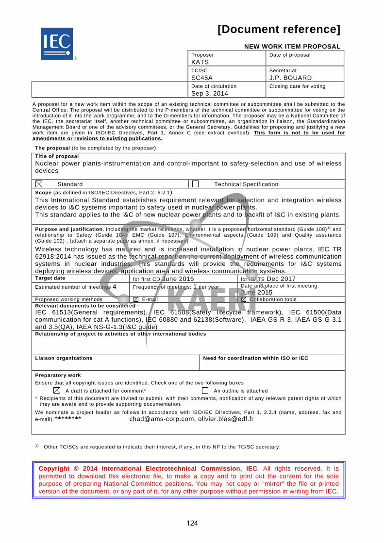
[Document reference]
NEW WORK ITEM PROPOSAL Proposer
KATS Date of proposal
TC/SC SC45A
Secretariat J.P. BOUARD
Date of circulation Sep 3, 2014
Closing date for voting
A proposal for a new work item within the scope of an existing technical committee or subcommittee shall be submitted to the Central Office. The proposal will be distributed to the P-members of the technical committee or subcommittee for voting on the introduction of it into the work programme, and to the O-members for information. The proposer may be a National Committee of the IEC, the secretariat itself, another technical committee or subcommittee, an organization in liaison, the Standardization Management Board or one of the advisory committees, or the General Secretary. Guidelines for proposing and justifying a new work item are given in ISO/IEC Directives, Part 1, Annex C (see extract overleaf). This form is not to be used for amendments or revisions to existing publications.
The proposal (to be completed by the proposer) Title of proposal Nuclear power plants-instrumentation and control-important to safety-selection and use of wireless devices
Standard Technical Specification Scope (as defined in ISO/IEC Directives, Part 2, 6.2.1) This International Standard establishes requirement relevant for selection and integration wireless devices to I&C systems important to safety used in nuclear power plants. This standard applies to the I&C of new nuclear power plants and to backfit of I&C in existing plants.
Purpose and justification, including the market relevance, whether it is a proposed horizontal standard (Guide 108)1) and relationship to Safety (Guide 104), EMC (Guide 107), Environmental aspects (Guide 109) and Quality assurance (Guide 102) . (attach a separate page as annex, if necessary) Wireless technology has matured and is increased installation in nuclear power plants. IEC TR 62918:2014 has issued as the technical report on the current deployment of wireless communication systems in nuclear industries. This standards will provide the requirements for I&C systems deploying wireless devices, application area and wireless communication systems. Target date for first CD June 2016 for IS/ TS Dec 2017 Estimated number of meetings 4 Frequency of meetings: 1 per year Date and place of first meeting:
June 2015 Proposed working methods E-mail Collaboration tools Relevant documents to be considered IEC 61513(General requirements), IEC 61508(Safety lifecycle framework), IEC 61500(Data communication for cat A functions), IEC 60880 and 62138(Software), IAEA GS-R-3, IAEA GS-G-3.1 and 3.5(QA), IAEA NS-G-1.3(I&C guide) Relationship of project to activities of other international bodies
Liaison organizations
Need for coordination within ISO or IEC
Preparatory work Ensure that all copyright issues are identified. Check one of the two following boxes A draft is attached for comment*
An outline is attached * Recipients of this document are invited to submit, with their comments, notification of any relevant patent rights of which
they are aware and to provide supporting documentation. We nominate a project leader as follows in accordance with ISO/IEC Directives, Part 1, 2.3.4 (name, address, fax and e-mail): [email protected], [email protected]
1) Other TC/SCs are requested to indicate their interest, if any, in this NP to the TC/SC secretary.
®
Copyright © 2014 International Electrotechnical Commission, IEC. All rights reserved. It is permitted to download this electronic file, to make a copy and to print out the content for the sole purpose of preparing National Committee positions. You may not copy or "mirror" the file or printed version of the document, or any part of it, for any other purpose without permission in writing from IEC.
124
********

Concerns known patented items (see ISO/IEC Directives, Part 2) Name and/or signature of the proposer Yes. If yes, provide full information as an annex no InSoo KOO, Chad KIGER, Olivier BLAS
Comments and recommendations from the TC/SC officers 1) Work allocation
Project team New working group Existing working group no: WGA9 2) Draft suitable for direct submission as
CD CDV/ DTS 3) General quality of the draft (conformity to ISO/IEC Directives, Part 2)
Little redrafting needed Substantial redrafting needed no draft (outline only) 4) Relationship with other activities In IEC In other organizations 5) Proposed horizontal standard
1)
Remarks from the TC/SC officers
1) Other TC/SCs are requested to indicate their interest, if any, in this NP to the TC/SC secretary.
Approval criteria:
• Approval of the work item by a simple majority of the P-members voting; • At least 4 P-members in the case of a committee with 16 or fewer P-members, or at least 5 P-members in the case of committees with
more than 17 P-members, have nominated or confirmed the name of an expert and approved the new work item proposal.
Elements to be clarified when proposing a new work item
Title Indicate the subject matter of the proposed new standard or technical specification. Indicate whether it is intended to prepare a standardor a technical specification. Scope Give a clear indication of the coverage of the proposed new work item and, if necessary for clarity, exclusions. Indicate whether the subject proposed relates to one or more of the fields of safety, EMC, the environment or quality assurance. Purpose and justification Give details based on a critical study of the following elements wherever practicable. a) The specific aims and reason for the standardization activity, with particular emphasis on the aspects of standardization to be
covered, the problems it is expected to solve or the difficulties it is intended to overcome. b) The main interests that might benefit from or be affected by the activity, such as industry, consumers, trade, governments,
distributors. c) Feasibility of the activity: Are there factors that could hinder the successful establishment or general application of the standard? d) Timeliness of the standard to be produced: Is the technology reasonably stabilized? If not, how much time is likely to be
available before advances in technology may render the proposed standard outdated? Is the proposed standard required as a basis for the future development of the technology in question?
e) Urgency of the activity, considering the needs of the market (industry, consumers, trade, governments etc.) as well as other fields or organizations. Indicate target date and, when a series of standards is proposed, suggest priorities.
f) The benefits to be gained by the implementation of the proposed standard; alternatively, the loss or disadvantage(s) if no standard is established within a reasonable time. Data such as product volume of value of trade should be included and quantified.
g) If the standardization activity is, or is likely to be, the subject of regulations or to require the harmonization of existing regulations, this should be indicated.
If a series of new work items is proposed, the purpose and justification of which is common, a common proposal may be drafted including all elements to be clarified and enumerating the titles and scopes of each individual item. Relevant documents List any known relevant documents (such as standards and regulations), regardless of their source. When the proposer considers that an existing well-established document may be acceptable as a standard (with or without amendments), indicate this with appropriate justification and attach a copy to the proposal. Cooperation and liaison List relevant organizations or bodies with which cooperation and liaison should exist. Preparatory work Indicate the name of the project leader nominated by the proposer.
125
CONTENTS
FOREWORD......................................................................................................................... 3
INTRODUCTION ................................................................................................................... 5
1 Scope ............................................................................................................................ 7
2 Normative references..................................................................................................... 7
3 Terms and definitions .................................................................................................... 8
4 Fundamental requirements .......................................................................................... 10
4.1 Safety classification ............................................................................................ 10 4.2 Physical seperation and isolation ......................................................................... 10 4.3 Computer security ............................................................................................... 10 4.4 Integration .......................................................................................................... 10 4.5 Quality assurance ............................................................................................... 10 4.6 Documentation .................................................................................................... 10 4.7 Qualification ........................................................................................................ 10
5 Wireless application requirements ................................................................................ 10
5.1 Functional suitability analysis .............................................................................. 10 5.1.1 Plant-wide applications ................................................................................ 10 5.1.2 Monitoring applications ................................................................................ 11
5.2 Performance suitability analysis ........................................................................... 11 5.3 Correctness analysis ........................................................................................... 11
6 Wireless communication requirements ......................................................................... 11
6.1 Network requirements ......................................................................................... 11 6.2 Timing requirements ............................................................................................ 11 6.3 Bandwidth requirements ...................................................................................... 11 6.4 Radio coverage requirements .............................................................................. 11 6.5 Power supply requirements ................................................................................. 12
6.5.1 Continuous service ...................................................................................... 12 6.5.2 Systems running on batteries ....................................................................... 12
6.6 Security requirements ......................................................................................... 12 6.6.1 Computer security ........................................................................................ 12 6.6.2 HPEM security ............................................................................................. 12
6.7 Avilability requirements ....................................................................................... 12 6.8 Failure management............................................................................................ 12
6.8.1 Network architecture .................................................................................... 12 6.8.2 Network monitoring ...................................................................................... 12 6.8.3 Device self-monitoring .................................................................................. 13 6.8.4 Solution durability ........................................................................................ 13
7 Qualification ................................................................................................................ 13
7.1 Hardware qualification ......................................................................................... 13 7.1.1 Environmental qualification .......................................................................... 13 7.1.2 Electromagnetic compatibility (EMC) requirements ........................................ 13 7.1.3 Radiation qualification .................................................................................. 13
7.2 Software qualification .......................................................................................... 14 Annex A (informative/normative) Annex title ...................................................................... 15
A.1 First annex heading (optional) ............................................................................. 15 Bibliography ....................................................................................................................... 16
126

127
INTERNATIONAL ELECTROTECHNICAL COMMISSION
____________
NUCLEAR POWER PLANTS – INSTRUMENTATION AND CONTROL IMPORTANT TO SAFETY – SELECTION AND USE OF WIRELESS DEVICES
FOREWORD
1) The International Electrotechnical Commission (IEC) is a worldwide organization for standardization comprising all national electrotechnical committees (IEC National Committees). The object of IEC is to promote international co-operation on all questions concerning standardization in the electrical and electronic fields. To this end and in addition to other activities, IEC publishes International Standards, Technical Specifications, Technical Reports, Publicly Available Specifications (PAS) and Guides (hereafter referred to as “IEC Publication(s)”). Their preparation is entrusted to technical committees; any IEC National Committee interested in the subject dealt with may participate in this preparatory work. International, governmental and non-governmental organizations liaising with the IEC also participate in this preparation. IEC collaborates closely with the International Organization for Standardization (ISO) in accordance with conditions determined by agreement between the two organizations.
2) The formal decisions or agreements of IEC on technical matters express, as nearly as possible, an international consensus of opinion on the relevant subjects since each technical committee has representation from all interested IEC National Committees.
3) IEC Publications have the form of recommendations for international use and are accepted by IEC National Committees in that sense. While all reasonable efforts are made to ensure that the technical content of IEC Publications is accurate, IEC cannot be held responsible for the way in which they are used or for any misinterpretation by any end user.
4) In order to promote international uniformity, IEC National Committees undertake to apply IEC Publications transparently to the maximum extent possible in their national and regional publications. Any divergence between any IEC Publication and the corresponding national or regional publication shall be clearly indicated in the latter.
5) IEC itself does not provide any attestation of conformity. Independent certification bodies provide conformity assessment services and, in some areas, access to IEC marks of conformity. IEC is not responsible for any services carried out by independent certification bodies.
6) All users should ensure that they have the latest edition of this publication.
7) No liability shall attach to IEC or its directors, employees, servants or agents including individual experts and members of its technical committees and IEC National Committees for any personal injury, property damage or other damage of any nature whatsoever, whether direct or indirect, or for costs (including legal fees) and expenses arising out of the publication, use of, or reliance upon, this IEC Publication or any other IEC Publications.
8) Attention is drawn to the Normative references cited in this publication. Use of the referenced publications is indispensable for the correct application of this publication.
9) Attention is drawn to the possibility that some of the elements of this IEC Publication may be the subject of patent rights. IEC shall not be held responsible for identifying any or all such patent rights.
International Standard IEC XXXXX has been prepared by subcommittee 45A: Instrumentation, control and electrical systems of nuclear facilities, of IEC technical committee 45:Nuclear instrumentation.
The text of this standard is based on the following documents:
FDIS Report on voting
45A/XX/FDIS 45A/XX/RVD
Full information on the voting for the approval of this standard can be found in the report on voting indicated in the above table.
This publication has been drafted in accordance with the ISO/IEC Directives, Part 2.
128

The committee has decided that the contents of this publication will remain unchanged until the stability date indicated on the IEC web site under "http://webstore.iec.ch" in the data related to the specific publication. At this date, the publication will be
• reconfirmed,
• withdrawn,
• replaced by a revised edition, or
• amended.
The National Committees are requested to note that for this publication the stability date is 20XX.
THIS TEXT IS INCLUDED FOR THE INFORMATION OF THE NATIONAL COMMITTEES AND WILL BE DELETED AT THE PUBLICATION STAGE.
129

INTRODUCTION
a) Technical background, main issues and organisation of the Standard
The ad hoc meeting of the IEC Technical Working Group on Nuclear Power Plant Control and Instrumentation, held in Yokohama in May 2009, resulted in the recommendation to develop a technical report about the current integration of wireless devices in I&C systems used nuclear power plant systems, with the view to decide if a standard can be developed to guide the selection and integration of wireless devices in I&C systems important to safety used in NPP.
IEC TR 62918 was developed to fulfil this request. WGA9 is planned to develop its associate international standards subsequent to the IEC TR 62918. This document is providing for WGA9 meeting at Las Vegas in 2014.
It is intended that this International Standard be used by operators of NPPs (utilities), systems evaluators and by licensors.
b) Situation of the current Standard in the structure of the IEC SC45A standard series
IEC 62XXX is a third level IEC/SC45A document covering the selection and rules of integration of wireless devices in I&C systems important to safety used in nuclear power plants.
For more details on the structure of the IEC SC45A standard series, see item d) of this introduction.
c) Recommendations and limitations regarding the application of the Standard
It is important to note that a technical report is entirely informative in nature. It gathers data collected from different origins and it establishes no requirements.
This Standard supply more particularly recommendations for the following aspects.
To be written later …
To ensure that the Standard will continue to be relevant in future years, the emphasis has been placed on issues of principle, rather than specific technologies.
d) Description of the structure of the IEC SC45A standard series and relationships with other IEC documents and other bodies’ documents (IAEA, ISO)
The top-level document of the IEC SC45A standard series is IEC 61513. It provides general requirements for I&C systems and equipment that are used to perform functions important to safety in NPPs. IEC 61513 structures the IEC SC45A standard series.
IEC 61513 refers directly to other IEC SC45A standards for general topics related to categorization of functions and classification of systems, qualification, separation of systems, defence against common cause failure, software aspects of computer-based systems, hardware aspects of computer-based systems, and control room design. The standards referenced directly at this second level should be considered together with IEC 61513 as a consistent document set.
At a third level, IEC SC45A standards not directly referenced by IEC 61513 are standards related to specific equipment, technical methods, or specific activities. Usually these documents, which make reference to second-level documents for general topics, can be used on their own.
130

A fourth level extending the IEC SC45 standard series, corresponds to the Technical Reports which are not normative.
IEC 61513 has adopted a presentation format similar to the basic safety publication IEC 61508 with an overall safety life-cycle framework and a system life-cycle framework. Regarding nuclear safety, it provides the interpretation of the general requirements of IEC 61508-1, IEC 61508-2 and IEC 61508-4, for the nuclear application sector, regarding nuclear safety. In this framework IEC 60880 and IEC 62138 correspond to IEC 61508-3 for the nuclear application sector. IEC 61513 refers to ISO as well as to IAEA GS-R-3 and IAEA GS-G-3.1 and IAEA GS-G-3.5 for topics related to quality assurance (QA).
The IEC SC45A standards series consistently implements and details the principles and basic safety aspects provided in the IAEA code on the safety of NPPs and in the IAEA safety series, in particular the Requirements SSR-2/1, establishing safety requirements related to the design of Nuclear Power Plants, and the Safety Guide NS-G-1.3 dealing with instrumentation and control systems important to safety in Nuclear Power Plants. The terminology and definitions used by SC45A standards are consistent with those used by the IAEA.
NOTE - It is assumed that for the design of I&C systems in NPPs that implement conventional safety functions (e.g. to address worker safety, asset protection, chemical hazards, process energy hazards) international or national standards would be applied, that are based on the requirements of such a standard such as IEC 61508.
131
NUCLEAR POWER PLANTS – INSTRUMENTATION AND CONTROL IMPORTANT TO SAFETY – SELECTION AND USE OF WIRELESS DEVICES
1 Scope
This International Standard establishes requirement relevant for selection and integration wireless devices to I&C systems important to safety used in nuclear power plants.
This standard applies to the I&C of new nuclear power plants and to backfit of I&C in existing plants.
This standard restricts the use of wireless devices to systems supporting category C functions according to IEC 61226, excluding explicitly their use for categories A and B.
Section 4 describes the fundamental requirements of I&C systems for wireless devices. Section 5 specifies the application specific requirements in the plants. Section 6 describes the requirements for the selection and use of wireless devices or wireless communication systems. Section 7 describes the requirements for the qualification of wireless devices and its environment.
2 Normative references
The following documents, in whole or in part, are normatively referenced in this document and are indispensable for its application. For dated references, only the edition cited applies. For undated references, the latest edition of the referenced document (including any amendments) applies.
IEC 61226, Nuclear power plants - Instrumentation and control important to safety - Classification of instrumentation and control functions
IEC 61513, Nuclear power plants - Instrumentation and control important to safety - General requirements for systems
IEC 62138, Nuclear power plants - Instrumentation and control important for safety - Software aspects for computer-based systems performing category B or C functions
IEC 60780, Nuclear power plants - Electrical equipment of the safety system - Qualification
IEC 60709, Nuclear power plants - Instrumentation and control systems important to safety - Separation
IEC 62645, Nuclear power plants - Instrumentation and control systems - Requirements for security programmes for computer-based systems
IEC 60987, Nuclear power plants - Instrumentation and control important to safety - Hardware design requirements for computer-based systems
IEC 62671, Nuclear power plants - Instrumentation and control important to safety - Selection and use of industrial digital devices of limited functionality
IEC 61000 series, Electromagnetic compatibility (EMC)
132
3 Terms and definitions
For the purposes of this document, the following terms and definitions apply.
3.1 Category of an I&C function One of three possible safety assignments (A, B, C) of I&C functions resulting from considerations of the safety relevance of the function to be performed. An unclassified assignment may be made if the function has no importance to safety
Note 1 to entry: See also "class of an I&C system", "I&C function".
Note 2 to entry: IEC 61226 defines categories of I&C functions. To each category there corresponds a set of requirements applicable on both the I&C function (concerning its specification, design, implementation, verification and validation) and the whole chain of items which are necessary to implement the function (concerning the properties and the related qualification) regardless of how these items are distributed in a number of interconnected I&C systems. For more clarity, this standard defines categories of I&C functions and classes of I&C systems and establishes a relation between the category of the function and the minimal required class for the associated systems and equipment.
[SOURCE: IEC 61513, 3.4]
3.2 Class of an I&C system One of three possible assignments (1,2,3) of I&C systems important to safety resulting from consideration of their requirement to implement I&C functions of different safety importance. An unclassified assignment is made if the I&C system does not implement functions important to safety
Note 1 to entry: See also "category of an I&C function", "system important to safety", "safety systems".
[SOURCE: IEC 61513, 3.6]
3.3 I&C system System, based on electrical and/or electronic and/or programmable electronic technology, performing I&C functions as well as service and monitoring functions related to the operation of the system itself.
The term is used as a general term which encompasses all elements of the system such as internal power supplies, sensors and other input devices, data highways and other communication paths, interfaces to actuators and other output devices (see NOTE 2). The different functions within a system may use dedicated or shared resources.
Note 1 to entry: See also "system, I&C function".
Note 2 to entry: The elements included in a specific I&C system are defined in the specification of the boundaries of the system.
Note 3 to entry: According to their typical functionality, IAEA distinguishes between automation and control systems, HMI systems, interlock systems and protection systems.
[SOURCE: IEC 61513, 3.29]
3.4 Item important to safety an item that is part of a safety group and/or whose malfunction or failure could lead to radiation exposure of the site personnel or members of the public.
Items important to safety include:
a) Those structures, systems and components whose malfunction or failure could lead to undue radiation exposure of the site personnel or members of the public.
133

b) Those structures, systems and components that prevent anticipated operational occurrences from leading to accident conditions
c) Those features which are provided to mitigate the consequences of malfunction or failure of structures, systems or components.
[SOURCE: IAEA Safety Glossary, 2007 Edition]
3.5 safety system system important to safety, provided to ensure the safe shutdown of the reactor and the residual heat removal from the core, or to limit the consequences of anticipated operational occurrences and design basis accident [SOURCE: IAEA Safety Glossary, 2007 Edition]
3.6 safety related system system important to safety that is not part of a safety system. [SOURCE: IAEA Safety Glossary, 2007 Edition]
3.7 quality assurance function of a management system that provides confidence that specific requirements will be fulfilled. [IAEA Safety Glossary, 2007 Edition]
NOTE This definition is compatible with that of ISO 8402:1994, 3.5 [7].
3.8 redundancy provision of alternative (identical or diverse) structures, systems or components, so that any one can perform the required function regardless of the state of operation or failure of any other. [IAEA Safety Glossary, 2007 Edition] 3.9 security protection of information and data so that unauthorized persons or systems cannot read or modify them and authorized persons or systems are not denied access to them
[ISO/IEC 12207:2008, 4.39]
134
4 Fundamental requirements
4.1 Safety classification
The wireless devices shall be limited to use in I&C systems supporting category C functions and shall not be used in I&C systems supporting catgory A and B functions.
The class of wireless communication systems shall be defined to support and implement the I&C category C functions.
4.2 Physical seperation and isolation
The wireless communication systems shall be electrically isolated and physically seperated from wired communication channels of I&C systems supporting category A and B functions.
The wireless communication systems for category C functions shall be designed such that any fault is not propagated to wired communication channels in I&C systems performing category A and B functions.
4.3 Computer security
Wireless communications shall not be used in systems that have been assigned an S1 or S2 security degree according to IEC 62645.
Wireless devices shall not have control function over the main actuators and regulators of the plant.
4.4 Integration
IEC 61513 requirements shall be met.
4.5 Quality assurance
To be written later
4.6 Documentation
To be written later
4.7 Qualification
An environmental qualification according to IEC 60987 chapter 5.4 and IEC 60780 shall be performed. To be completed.
5 Wireless application requirements
5.1 Functional suitability analysis
Plant-wide applications 5.1.1
Internet tele-phony, mobile devices,…
135
Monitoring applications 5.1.2
Dosimetry, condition monitoring,…
5.2 Performance suitability analysis
Standard protocol, network topology, AP location, network configuration,….
5.3 Correctness analysis
Review of EM history
Identify EMI/RFI sources
Site survey
6 Wireless communication requirements
6.1 Network requirements
Network archetecture shall be selected appropriate wireless protocol, network topology, access point locations and network configuration regarding to the intended applications.
6.2 Timing requirements
The delay due to the wireless communication systems should be less than the value required in I&C systems response.
When an application requires results in a bounded time, the wireless communication systems should be a real-time system.
6.3 Bandwidth requirements
It is required to define the data traffic characteristics of a wireless communication system used in I&C systems.
On the periodic data, the data should be defined bandwidth requirements both deterministic and predictable.
On the aperiodic data, the actual bit rate and timing performance of the wireless communication should be defined.
6.4 Radio coverage requirements
The access point location shall be defined through the results of coverage mapping and/or EMI/RFI site survey.
The communication system coverage demands for the intended application shall be identified.
Exclusive zone to I&C systems performing category A and B functions shall be defined.
Radiated power should be adjusted to support exclusive zone defined.
136
6.5 Power supply requirements
Continuous service 6.5.1
The wireless communication systems are typically required uninterrupted service. The power supply units for wireless communication systems should be redundant.
Systems running on batteries 6.5.2
Remote devices running on batteries shall be physically reachable in order to be able to replace a defective or discharged battery. If this is not possible, the battery capacity shall be properly dimensioned to last a sufficient time, according to the system specification.
Battery level of remote devices running on batteries shall be monitored.
6.6 Security requirements
Computer security 6.6.1
Requirements of IEC 62645 “Requirements for security programmes for computer-based systems” shall be met.
Encryption should be used for wireless communications. The encryption methods – or lack of encryption – shall be consistent with IEC 61513 overall security plan.
Authentication of all messages should be used. The authentication process – or lack of authentication – shall be consistent with IEC 61513 overall security plan.
The site topology shall be considered when evaluating cyber security and writing the security plan. Note: One must bear in mind that a network connection may be achieved from a remote location using specialized and / or modified devices, such as directional antennas, and / or higher-than-usual power outputs, etc.
HPEM security 6.6.2
On a specific installation area for wireless device in a plant, EMP and intentional EMI should be consedered to mitigate or protect.
6.7 Avilability requirements
Availability of the wireless communication systems shall meet with the requirements of the application.
The communication protocol shall provide reliable data communication.
6.8 Failure management
Network architecture 6.8.1
The network load should be context-independent. This means that may a monitored event occur; the network load should not increase.
Note: a true context-independent design is a difficult thing to achieve, thus a context-independent application layer is sufficient.
Network monitoring 6.8.2
The network administrator or an IT staff member shall be able to monitor:
137
- the network status: load, transmission error rate, packet losses, latency; - the comprehensive list of devices connected to the network; - the network logs, including failed connections (unauthorized connection attempts, etc.); - for each device:
o its self-monitored variables (see 6.7.3), o its characteristics (software version…), o its physical location.
Device self-monitoring 6.8.3
The wireless device shall be able to monitor and transmit: - the power supply status; - the battery status (if applicable); - the wireless signal quality (uplink and downlink).
Solution durability 6.8.4
Wireless protocols using a documented standard should be preferred.
7 Qualification
7.1 Hardware qualification
Environmental qualification 7.1.1
An environmental qualification according to IEC 60987 shall be performed.
Electromagnetic compatibility (EMC) requirements 7.1.2
Any wireless device shall be installed at the pre-defined distance away from equipments important to safety. Additional distance may be required based upon the output power of the wireless device and the susceptibility of the nearby plant equipments.
An impact analysis regarding EMC shall be conducted prior to the on-site installation of the system.
The impact analysis can include system reviews and evaluations in combination with laboratory/on-site testing, such as:
- Review of EMC test reports of nearby plant equipments; - Determination of exclusion zones based on industry guidance; - Characterization of Electromagnetic Environment; - Immunity testing of wireless devices; - Immunity testing of nearby plan equipment during maintenance programs.
Note: These requirements intend to protect systems important to safety and key control systems from electromagnetic waves emitted by the wireless device.
Radiation qualification 7.1.3
An impact analysis regarding behavior under specific irradiation level shall be conducted prior to the on-site installation of the system.
138

7.2 Software qualification
IEC 62138 requirements shall be met.
139

Annex A (informative/normative)
Annex title
A.1 First annex heading (optional)
140

Bibliography
IEC TR 62918:2014, Nuclear power plants – Instrumentation and control important to safety – Use and selection of wireless devices to be integrated in systems important to safety
141

® Registered trademark of the International Electrotechnical Commission FORM NP (IEC)
2009-06-01
45A/994/NP
NEW WORK ITEM PROPOSAL Proposer KOREA
Date of proposal 2014-10
TC/SC SC45A
Secretariat France (J.P. BOUARD)
Date of circulation 2014-10-31
Closing date for voting 2015-02-06
A proposal for a new work item within the scope of an existing technical committee or subcommittee shall be submitted to the Central Office. The proposal will be distributed to the P-members of the technical committee or subcommittee for voting on the introduction of it into the work programme, and to the O-members for information. The proposer may be a National Committee of the IEC, the secretariat itself, another technical committee or subcommittee, an organization in liaison, the Standardization Management Board or one of the advisory committees, or the General Secretary. Guidelines for proposing and justifying a new work item are given in ISO/IEC Directives, Part 1, Annex C (see extract overleaf). This form is not to be used for amendments or revisions to existing publications.
The proposal (to be completed by the proposer) Title of proposal Nuclear power plants - Instrumentation and control important to safety - Selection and use of wireless devices
Standard Technical Specification Scope (as defined in ISO/IEC Directives, Part 2, 6.2.1) This International Standard establishes requirement relevant for selection and integration wireless devices to I&C systems important to safety used in nuclear power plants. This standard applies to the I&C of new nuclear power plants and to backfit of I&C in existing plants.
Purpose and justification, including the market relevance, whether it is a proposed horizontal standard (Guide 108) 1) and relationship to Safety (Guide 104), EMC (Guide 107), Environmental aspects (Guide 109) and Quality assurance (Guide 102) . (attach a separate page as annex, if necessary) Wireless technology has matured and is increased installation in nuclear power plants. IEC TR 62918:2014 has issued as the technical report on the current deployment of wireless communication systems in nuclear industries. This standards will provide the requirements for I&C systems deploying wireless devices, application area and wireless communication systems. Target date for first CD Dec 2015 for IS Dec 2017
Estimated number of meetings 4 Frequency of meetings: 1 per year Date and place of first meeting: Oct 6, 2014
Proposed working methods E-mail Collaboration tools Relevant documents to be considered IEC 61513(General requirements), IEC 61508(Safety lifecycle framework), IEC 61500(Data communication for cat A functions), IEC 60880 and 62138(Software), IAEA GS-R-3, IAEA GS-G-3.1 and 3.5(QA), IAEA NS-G-1.3(I&C guide) Relationship of project to activities of other international bodies / Liaison organizations /
Need for coordination within ISO or IEC /
Preparatory work Ensure that all copyright issues are identified. Check one of the two following boxes A draft is attached for comment*
An outline is attached * Recipients of this document are invited to submit, with their comments, notification of any relevant patent rights of which they
are aware and to provide supporting documentation. We nominate a project leader as follows in accordance with ISO/IEC Directives, Part 1, 2.3.4 (name, address, fax and e-mail):
[email protected], [email protected]
1) Other TC/SCs are requested to indicate their interest, if any, in this NP to the TC/SC secretary.
Copyright © 2014 International Electrotechnical Commission, IEC. All rights reserved. It is permitted to download this electronic file, to make a copy and to print out the content for the sole purpose of preparing National Committee positions. You may not copy or "mirror" the file or printed version of the document, or any part of it, for any other purpose without permission in writing from IEC.
®
142
********
ii 45A/994/NP
Concerns known patented items (see ISO/IEC Directives, Part 2) Name and/or signature of the proposer Yes. If yes, provide full information as an annex no Seong, Si-Heon, Administrator KATS
Comments and recommendations from the TC/SC officers 1) Work allocation
Project team New working group Existing working group no: WG9 2) Draft suitable for direct submission as
CD CDV/ DTS 3) General quality of the draft (conformity to ISO/IEC Directives, Part 2)
Little redrafting needed Substantial redrafting needed no draft (outline only) 4) Relationship with other activities In IEC / In other organizations /
5) Proposed horizontal standard 1) Other TC/SCs are requested to indicate their interest, if any, in this NP to the TC/SC secretary.
Remarks from the TC/SC officers The draft annexed to this proposal was presented during the October 2014 IEC SC 45A WG A9 meeting held in Las Vegas. IEC WG A9 experts discussed the proposal and supported its circulation to IEC NCs for approval, see the minutes of the 2014 IEC SC 45A plenary meeting (45A/992/RM). During the discussions held, some comments were formulated, see the report of the October 2014 IEC SC 45A WG A9 meeting. Those comments will be taken into acount for the preparation of the CD if the project is approved by the IEC NCs.
Considering the conclusions of IEC TR 62918 and the discussions held during the October 2014 IEC SC 45A WG A9 meeting and the recommendations made during the 2014 IEC SC 45A plenary meeting, IEC SC 45A officers fully support this proposal.
Approval criteria:
• Approval of the work item by a simple majority of the P-members voting; • At least 4 P-members in the case of a committee with 16 or fewer P-members, or at least 5 P-members in the case of committees with
more than 17 P-members, have nominated or confirmed the name of an expert and approved the new work item proposal. Elements to be clarified when proposing a new work item
Title Indicate the subject matter of the proposed new standard or technical specification. Indicate whether it is intended to prepare a standardor a technical specification. Scope Give a clear indication of the coverage of the proposed new work item and, if necessary for clarity, exclusions. Indicate whether the subject proposed relates to one or more of the fields of safety, EMC, the environment or quality assurance. Purpose and justification Give details based on a critical study of the following elements wherever practicable. a) The specific aims and reason for the standardization activity, with particular emphasis on the aspects of standardization to be
covered, the problems it is expected to solve or the difficulties it is intended to overcome. b) The main interests that might benefit from or be affected by the activity, such as industry, consumers, trade, governments,
distributors. c) Feasibility of the activity: Are there factors that could hinder the successful establishment or general application of the standard? d) Timeliness of the standard to be produced: Is the technology reasonably stabilized? If not, how much time is likely to be
available before advances in technology may render the proposed standard outdated? Is the proposed standard required as a basis for the future development of the technology in question?
e) Urgency of the activity, considering the needs of the market (industry, consumers, trade, governments etc.) as well as other fields or organizations. Indicate target date and, when a series of standards is proposed, suggest priorities.
f) The benefits to be gained by the implementation of the proposed standard; alternatively, the loss or disadvantage(s) if no standard is established within a reasonable time. Data such as product volume of value of trade should be included and quantified.
g) If the standardization activity is, or is likely to be, the subject of regulations or to require the harmonization of existing regulations, this should be indicated.
If a series of new work items is proposed, the purpose and justification of which is common, a common proposal may be drafted including all elements to be clarified and enumerating the titles and scopes of each individual item. Relevant documents List any known relevant documents (such as standards and regulations), regardless of their source. When the proposer considers that an existing well-established document may be acceptable as a standard (with or without amendments), indicate this with appropriate justification and attach a copy to the proposal. Cooperation and liaison List relevant organizations or bodies with which cooperation and liaison should exist. Preparatory work Indicate the name of the project leader nominated by the proposer.
143
IEC NP 6XXXX IEC 2014 – 1 – 45A/994/NP
CONTENTS
FOREWORD ........................................................................................................................... 3
INTRODUCTION ..................................................................................................................... 5
Scope ..................................................................................................................................... 7
Normative references .............................................................................................................. 7
Terms and definitions ............................................................................................................. 8
Fundamental requirements ................................................................................................... 10
4.1 Safety classification .............................................................................................. 10 4.2 Physical seperation and isolation .......................................................................... 10 4.3 Computer security ................................................................................................. 10 4.4 Integration ............................................................................................................ 10 4.5 Quality assurance ................................................................................................. 10 4.6 Documentation ...................................................................................................... 10 4.7 Qualification .......................................................................................................... 10
Wireless application requirements ........................................................................................ 10
5.1 Plant-wide applications ......................................................................................... 10 5.2 Monitoring applications ......................................................................................... 11 5.3 Suitability and correctness analysis ...................................................................... 11
5.3.1 General ......................................................................................................... 11 5.3.2 Suitability analysis input data and pre-requisite ............................................. 11 5.3.3 Correctness analysis ..................................................................................... 11
Wireless communication requirements .................................................................................. 11
6.1 Network requirements ........................................................................................... 11 6.2 Timing requirements ............................................................................................. 11 6.3 Bandwidth requirements ....................................................................................... 11 6.4 Radio coverage requirements ............................................................................... 11 6.5 Power supply requirements ................................................................................... 12
6.5.1 Continuous service ........................................................................................ 12 6.5.2 Systems running on batteries......................................................................... 12
6.6 Security requirements ........................................................................................... 12 6.6.1 Computer security ......................................................................................... 12 6.6.2 Physical security ............................................................................................ 12 6.6.3 HPEM security ............................................................................................... 12
6.7 Avilability requirements ......................................................................................... 12 6.8 Failure management ............................................................................................. 13
6.8.1 Network architecture ...................................................................................... 13 6.8.2 Network monitoring ........................................................................................ 13 6.8.3 Device self-monitoring ................................................................................... 13 6.8.4 Solution durability .......................................................................................... 13
Qualification ......................................................................................................................... 13
7.1 Hardware qualification .......................................................................................... 13 7.1.1 Environmental qualification ............................................................................ 13 7.1.2 Electromagnetic compatibility (EMC) requirements ........................................ 13 7.1.3 Radiation qualification ................................................................................... 14
7.2 Software qualification ............................................................................................ 14 Annex A (informative/normative) Annex title ........................................................................ 15
144

45A/994/NP – 2 – IEC NP 6XXXX IEC 2014
A.1 First annex heading (optional) ............................................................................... 15 Bibliography .......................................................................................................................... 16
145

IEC NP 6XXXX IEC 2014 – 3 – 45A/994/NP
INTERNATIONAL ELECTROTECHNICAL COMMISSION 1
____________ 2
3
NUCLEAR POWER PLANTS – 4
INSTRUMENTATION AND CONTROL IMPORTANT TO SAFETY – 5
SELECTION AND USE OF WIRELESS DEVICES 6
7
8
9
FOREWORD 10
1) The International Electrotechnical Commission (IEC) is a worldwide organization for standardization comprising 11 all national electrotechnical committees (IEC National Committees). The object of IEC is to promote 12 international co-operation on all questions concerning standardization in the electrical and electronic fields. To 13 this end and in addition to other activities, IEC publishes International Standards, Technical Specifications, 14 Technical Reports, Publicly Available Specifications (PAS) and Guides (hereafter referred to as “IEC 15 Publication(s)”). Their preparation is entrusted to technical committees; any IEC National Committee interested 16 in the subject dealt with may participate in this preparatory work. International, governmental and non-17 governmental organizations liaising with the IEC also participate in this preparation. IEC collaborates closely 18 with the International Organization for Standardization (ISO) in accordance with conditions determined by 19 agreement between the two organizations. 20
2) The formal decisions or agreements of IEC on technical matters express, as nearly as possible, an international 21 consensus of opinion on the relevant subjects since each technical committee has representation from all 22 interested IEC National Committees. 23
3) IEC Publications have the form of recommendations for international use and are accepted by IEC National 24 Committees in that sense. While all reasonable efforts are made to ensure that the technical content of IEC 25 Publications is accurate, IEC cannot be held responsible for the way in which they are used or for any 26 misinterpretation by any end user. 27
4) In order to promote international uniformity, IEC National Committees undertake to apply IEC Publications 28 transparently to the maximum extent possible in their national and regional publications. Any divergence 29 between any IEC Publication and the corresponding national or regional publication shall be clearly indicated in 30 the latter. 31
5) IEC itself does not provide any attestation of conformity. Independent certification bodies provide conformity 32 assessment services and, in some areas, access to IEC marks of conformity. IEC is not responsible for any 33 services carried out by independent certification bodies. 34
6) All users should ensure that they have the latest edition of this publication. 35
7) No liability shall attach to IEC or its directors, employees, servants or agents including individual experts and 36 members of its technical committees and IEC National Committees for any personal injury, property damage or 37 other damage of any nature whatsoever, whether direct or indirect, or for costs (including legal fees) and 38 expenses arising out of the publication, use of, or reliance upon, this IEC Publication or any other IEC 39 Publications. 40
8) Attention is drawn to the Normative references cited in this publication. Use of the referenced publications is 41 indispensable for the correct application of this publication. 42
9) Attention is drawn to the possibility that some of the elements of this IEC Publication may be the subject of 43 patent rights. IEC shall not be held responsible for identifying any or all such patent rights. 44
International Standard IEC XXXXX has been prepared by subcommittee 45A: Instrumentation, 45 control and electrical systems of nuclear facilities, of IEC technical committee 45:Nuclear 46 instrumentation. 47
The text of this standard is based on the following documents: 48
FDIS Report on voting
45A/XX/FDIS 45A/XX/RVD
49 Full information on the voting for the approval of this standard can be found in the report on 50 voting indicated in the above table. 51
This publication has been drafted in accordance with the ISO/IEC Directives, Part 2. 52
146

45A/994/NP – 4 – IEC NP 6XXXX IEC 2014
The committee has decided that the contents of this publication will remain unchanged until 53 the stability date indicated on the IEC web site under "http://webstore.iec.ch" in the data 54 related to the specific publication. At this date, the publication will be 55
• reconfirmed, 56
• withdrawn, 57
• replaced by a revised edition, or 58
• amended. 59
60
The National Committees are requested to note that for this publication the stability date 61 is 20XX. 62
THIS TEXT IS INCLUDED FOR THE INFORMATION OF THE NATIONAL COMMITTEES AND WILL BE DELETED 63 AT THE PUBLICATION STAGE. 64
65 66
147
IEC NP 6XXXX IEC 2014 – 5 – 45A/994/NP
INTRODUCTION 67
a) Technical background, main issues and organisation of the Standard 68
The ad hoc meeting of the IEC Technical Working Group on Nuclear Power Plant Control and 69 Instrumentation, held in Yokohama in May 2009, resulted in the recommendation to develop a 70 technical report about the current integration of wireless devices in I&C systems used nuclear 71 power plant systems, with the view to decide if a standard can be developed to guide the 72 selection and integration of wireless devices in I&C systems important to safety used in NPP. 73
IEC TR 62918 was developed to fulfil this request. WGA9 is planned to develop its associate 74 international standards subsequent to the IEC TR 62918. This document is providing for 75 WGA9 meeting at Las Vegas in 2014. 76
It is intended that this International Standard be used by operators of NPPs (utilities), systems 77 evaluators and by licensors. 78
b) Situation of the current Standard in the structure of the IEC SC45A standard series 79
IEC 62XXX is a third level IEC/SC45A document covering the selection and rules of 80 integration of wireless devices in I&C systems important to safety used in nuclear power 81 plants. 82
For more details on the structure of the IEC SC45A standard series, see item d) of this 83 introduction. 84
c) Recommendations and limitations regarding the application of the Standard 85
It is important to note that a technical report is entirely informative in nature. It gathers data 86 collected from different origins and it establishes no requirements. 87
This Standard supply more particularly recommendations for the following aspects. 88
To be written later … 89
To ensure that the Standard will continue to be relevant in future years, the emphasis has 90 been placed on issues of principle, rather than specific technologies. 91
d) Description of the structure of the IEC SC45A standard series and relationships with 92 other IEC documents and other bodies’ documents (IAEA, ISO) 93
The top-level document of the IEC SC45A standard series is IEC 61513. It provides general 94 requirements for I&C systems and equipment that are used to perform functions important to 95 safety in NPPs. IEC 61513 structures the IEC SC45A standard series. 96
IEC 61513 refers directly to other IEC SC45A standards for general topics related to 97 categorization of functions and classification of systems, qualification, separation of systems, 98 defence against common cause failure, software aspects of computer-based systems, 99 hardware aspects of computer-based systems, and control room design. The standards 100 referenced directly at this second level should be considered together with IEC 61513 as a 101 consistent document set. 102
At a third level, IEC SC45A standards not directly referenced by IEC 61513 are standards 103 related to specific equipment, technical methods, or specific activities. Usually these 104 documents, which make reference to second-level documents for general topics, can be used 105 on their own. 106
148
45A/994/NP – 6 – IEC NP 6XXXX IEC 2014
A fourth level extending the IEC SC45 standard series, corresponds to the Technical Reports 107 which are not normative. 108
IEC 61513 has adopted a presentation format similar to the basic safety publication 109 IEC 61508 with an overall safety life-cycle framework and a system life-cycle framework. 110 Regarding nuclear safety, it provides the interpretation of the general requirements of 111 IEC 61508-1, IEC 61508-2 and IEC 61508-4, for the nuclear application sector, regarding 112 nuclear safety. In this framework IEC 60880 and IEC 62138 correspond to IEC 61508-3 for 113 the nuclear application sector. IEC 61513 refers to ISO as well as to IAEA GS-R-3 and IAEA 114 GS-G-3.1 and IAEA GS-G-3.5 for topics related to quality assurance (QA). 115
The IEC SC45A standards series consistently implements and details the principles and basic 116 safety aspects provided in the IAEA code on the safety of NPPs and in the IAEA safety series, 117 in particular the Requirements SSR-2/1, establishing safety requirements related to the 118 design of Nuclear Power Plants, and the Safety Guide NS-G-1.3 dealing with instrumentation 119 and control systems important to safety in Nuclear Power Plants. The terminology and 120 definitions used by SC45A standards are consistent with those used by the IAEA. 121
NOTE - It is assumed that for the design of I&C systems in NPPs that implement conventional safety functions 122 (e.g. to address worker safety, asset protection, chemical hazards, process energy hazards) international or 123 national standards would be applied, that are based on the requirements of such a standard such as IEC 61508. 124
125
126
149
IEC NP 6XXXX IEC 2014 – 7 – 45A/994/NP
NUCLEAR POWER PLANTS – INSTRUMENTATION AND CONTROL 127
IMPORTANT TO SAFETY – SELECTION AND USE OF WIRELESS DEVICES 128
129
Scope 130
This International Standard establishes requirement relevant for selection and integration 131 wireless devices to I&C systems important to safety used in nuclear power plants. 132
This standard applies to the I&C of new nuclear power plants and to backfit of I&C in existing 133 plants. 134
This standard restricts the use of wireless devices to systems supporting category C functions 135 according to IEC 61226, excluding explicitly their use for categories A and B. 136
Section 4 describes the fundamental requirements of I&C systems for wireless devices. 137 Section 5 specifies the application specific requirements in the plants. Section 6 describes the 138 requirements for the selection and use of wireless devices or wireless communication 139 systems. Section 7 describes the requirements for the qualification of wireless devices and its 140 environment. 141
Normative references 142
The following documents, in whole or in part, are normatively referenced in this document and 143 are indispensable for its application. For dated references, only the edition cited applies. For 144 undated references, the latest edition of the referenced document (including any 145 amendments) applies. 146
IEC 61226, Nuclear power plants - Instrumentation and control important to safety - 147 Classification of instrumentation and control functions 148
IEC 61513, Nuclear power plants - Instrumentation and control important to safety - General 149 requirements for systems 150
IEC 62138, Nuclear power plants - Instrumentation and control important for safety - Software 151 aspects for computer-based systems performing category B or C functions 152
IEC 60780, Nuclear power plants - Electrical equipment of the safety system - Qualification 153
IEC 60709, Nuclear power plants - Instrumentation and control systems important to safety - 154 Separation 155
IEC 62645, Nuclear power plants - Instrumentation and control systems - Requirements for 156 security programmes for computer-based systems 157
IEC 60987, Nuclear power plants - Instrumentation and control important to safety - Hardware 158 design requirements for computer-based systems 159
IEC 62671, Nuclear power plants - Instrumentation and control important to safety - Selection 160 and use of industrial digital devices of limited functionality 161
IEC 61000 series, Electromagnetic compatibility (EMC) 162
163
150
45A/994/NP – 8 – IEC NP 6XXXX IEC 2014
Terms and definitions 164
For the purposes of this document, the following terms and definitions apply. 165
3.1 166 Category of an I&C function 167 One of three possible safety assignments (A, B, C) of I&C functions resulting from 168 considerations of the safety relevance of the function to be performed. An unclassified 169 assignment may be made if the function has no importance to safety 170
Note 1 to entry: See also "class of an I&C system", "I&C function". 171
Note 2 to entry: IEC 61226 defines categories of I&C functions. To each category there corresponds a set of 172 requirements applicable on both the I&C function (concerning its specification, design, implementation, verification 173 and validation) and the whole chain of items which are necessary to implement the function (concerning the 174 properties and the related qualification) regardless of how these items are distributed in a number of 175 interconnected I&C systems. For more clarity, this standard defines categories of I&C functions and classes of I&C 176 systems and establishes a relation between the category of the function and the minimal required class for the 177 associated systems and equipment. 178
[SOURCE: IEC 61513, 3.4] 179
3.2 180 Class of an I&C system 181 One of three possible assignments (1,2,3) of I&C systems important to safety resulting from 182 consideration of their requirement to implement I&C functions of different safety importance. 183 An unclassified assignment is made if the I&C system does not implement functions important 184 to safety 185
Note 1 to entry: See also "category of an I&C function", "system important to safety", "safety systems". 186
[SOURCE: IEC 61513, 3.6] 187
3.3 188 I&C system 189 System, based on electrical and/or electronic and/or programmable electronic technology, 190 performing I&C functions as well as service and monitoring functions related to the operation 191 of the system itself. 192
The term is used as a general term which encompasses all elements of the system such as 193 internal power supplies, sensors and other input devices, data highways and other 194 communication paths, interfaces to actuators and other output devices (see NOTE 2). The 195 different functions within a system may use dedicated or shared resources. 196
Note 1 to entry: See also "system, I&C function". 197
Note 2 to entry: The elements included in a specific I&C system are defined in the specification of the boundaries 198 of the system. 199
Note 3 to entry: According to their typical functionality, IAEA distinguishes between automation and control 200 systems, HMI systems, interlock systems and protection systems. 201
[SOURCE: IEC 61513, 3.29] 202
3.4 203 Item important to safety 204 an item that is part of a safety group and/or whose malfunction or failure could lead to 205 radiation exposure of the site personnel or members of the public. 206
Items important to safety include: 207
a) Those structures, systems and components whose malfunction or failure could lead to 208 undue radiation exposure of the site personnel or members of the public. 209
151

IEC NP 6XXXX IEC 2014 – 9 – 45A/994/NP
b) Those structures, systems and components that prevent anticipated operational 210 occurrences from leading to accident conditions 211
c) Those features which are provided to mitigate the consequences of malfunction or failure of 212 structures, systems or components. 213
[SOURCE: IAEA Safety Glossary, 2007 Edition] 214
3.5 215 safety system 216
system important to safety, provided to ensure the safe shutdown of the reactor and the 217 residual heat removal from the core, or to limit the consequences of anticipated operational 218 occurrences and design basis accident 219
[SOURCE: IAEA Safety Glossary, 2007 Edition] 220
3.6 221 safety related system 222
system important to safety that is not part of a safety system. 223
[SOURCE: IAEA Safety Glossary, 2007 Edition] 224
3.7 225 quality assurance 226
function of a management system that provides confidence that specific requirements will be 227 fulfilled. 228
[IAEA Safety Glossary, 2007 Edition] 229
NOTE This definition is compatible with that of ISO 8402:1994, 3.5 [7]. 230
3.8 231 redundancy 232 provision of alternative (identical or diverse) structures, systems or components, so that any one can 233 perform the required function regardless of the state of operation or failure of any other. 234 235 [IAEA Safety Glossary, 2007 Edition] 236 237
3.9 238 security 239
protection of information and data so that unauthorized persons or systems cannot read or 240 modify them and authorized persons or systems are not denied access to them 241
[ISO/IEC 12207:2008, 4.39] 242
243
152
45A/994/NP – 10 – IEC NP 6XXXX IEC 2014
Fundamental requirements 244
4.1 Safety classification 245
The wireless devices shall be limited to use in I&C systems supporting category C functions 246 and shall not be used in I&C systems supporting catgory A and B functions. 247
The class of wireless communication systems shall be defined to support and implement the 248 I&C category C functions. 249
4.2 Physical seperation and isolation 250
The wireless communication systems shall be electrically isolated and physically seperated 251 from wired communication channels of I&C systems supporting category A and B functions. 252
The wireless communication systems for category C functions shall be designed such that any 253 fault is not propagated to wired communication channels in I&C systems performing category 254 A and B functions. 255
4.3 Computer security 256
Wireless communications shall not be used in systems that have been assigned an S1 or S2 257 security degree according to IEC 62645. 258
Wireless devices shall not have control function over the main actuators and regulators of the 259 plant. 260
4.4 Integration 261
IEC 61513 requirements shall be met. 262
4.5 Quality assurance 263
To be written later 264
4.6 Documentation 265
To be written later 266
4.7 Qualification 267
An environmental qualification according to IEC 60987 chapter 5.4 and IEC 60780 shall be 268 performed. 269
To be completed. 270
Wireless application requirements 271
5.1 Plant-wide applications 272
The wireless communication system should cover the appropriate area where the plant staffs 273 may travel. 274
153
IEC NP 6XXXX IEC 2014 – 11 – 45A/994/NP
Power consumption of the wireless communication equipment which the plant staffs carry 275 should be minimised to reduce the battries and to prolong the battery life. 276
5.2 Monitoring applications 277
When the wireless communication devices are implementing a monitoring function, latency 278 and or jitter of the wireless device is a critical parameter to gether its data. 279
Timing requirements such as latency, synchronization accuracy should be considered. 280
5.3 Suitability and correctness analysis 281
The EMI/RFI environment for intended application is characterized so that the coverage area 282 for applications shall be diefined. 283
5.3.1 General 284
To be written later 285
5.3.2 Suitability analysis input data and pre-requisite 286
To be written later 287
5.3.3 Correctness analysis 288
To be written later 289
Wireless communication requirements 290
6.1 Network requirements 291
Network archetecture shall be selected appropriate wireless protocol, network topology, 292 access point locations and network configuration regarding to the intended applications. 293
6.2 Timing requirements 294
The delay due to the wireless communication systems should be less than the value required 295 in I&C systems response. 296
When an application requires results in a bounded time, the wireless communication systems 297 should be a real-time system. 298
6.3 Bandwidth requirements 299
It is required to define the data traffic characteristics of a wireless communication system 300 used in I&C systems. 301
On the periodic data, the data should be defined bandwidth requirements both deterministic 302 and predictable. 303
On the aperiodic data, the actual bit rate and timing performance of the wireless 304 communication should be defined. 305
6.4 Radio coverage requirements 306
The access point location shall be defined through the results of coverage mapping and/or 307 EMI/RFI site survey. 308
154
45A/994/NP – 12 – IEC NP 6XXXX IEC 2014
The communication system coverage demands for the intended application shall be identified. 309
Exclusive zone to I&C systems performing category A and B functions shall be defined. 310
Radiated power should be adjusted to support exclusive zone defined. 311
6.5 Power supply requirements 312
6.5.1 Continuous service 313
The wireless communication systems are typically required uninterrupted service. The power 314 supply units for wireless communication systems should be redundant. 315
6.5.2 Systems running on batteries 316
Remote devices running on batteries shall be physically reachable in order to be able to 317 replace a defective or discharged battery. If this is not possible, the battery capacity shall be 318 properly dimensioned to last a sufficient time, according to the system specification. 319
Battery level of remote devices running on batteries shall be monitored. 320
6.6 Security requirements 321
6.6.1 Computer security 322
Requirements of IEC 62645 “Requirements for security programmes for computer-based 323 systems” shall be met. 324
Encryption should be used for wireless communications. The encryption methods – or lack of 325 encryption – shall be consistent with IEC 61513 overall security plan. 326
Authentication of all messages should be used. The authentication process – or lack of 327 authentication – shall be consistent with IEC 61513 overall security plan. 328
The site topology shall be considered when evaluating cyber security and writing the security 329 plan. 330
Note: One must bear in mind that a network connection may be achieved from a remote location using specialized 331 and / or modified devices, such as directional antennas, and / or higher-than-usual power outputs, etc. 332
6.6.2 Physical security 333
Media access may be physically limited using alternative media such as: 334
- Visible Light Communications (VLC); 335 - Infrared communication; 336 - Acoustics. 337
Wireless devices shall be protected by physical measures so as they are not tampered with. 338
6.6.3 HPEM security 339
On a specific installation area for wireless device in a plant, EMP and intentional EMI should 340 be consedered to mitigate or protect. 341
6.7 Avilability requirements 342
Availability of the wireless communication systems shall meet with the requirements of the 343 application. 344
155
IEC NP 6XXXX IEC 2014 – 13 – 45A/994/NP
The communication protocol shall provide reliable data communication. 345
6.8 Failure management 346
6.8.1 Network architecture 347
The network load should be context-independent. This means that may a monitored event 348 occur; the network load should not increase. 349
Note: a true context-independent design is a difficult thing to achieve, thus a context-independent application layer 350 is sufficient. 351
6.8.2 Network monitoring 352
The network administrator or an IT staff member shall be able to monitor: 353 - the network status: load, transmission error rate, packet losses, latency; 354 - the comprehensive list of devices connected to the network; 355 - the network logs, including failed connections (unauthorized connection attempts, etc.); 356 - for each device: 357
o its self-monitored variables (see 6.8.3), 358 o its characteristics (software version…), 359 o its physical location. 360
6.8.3 Device self-monitoring 361
The wireless device shall be able to monitor and transmit: 362 - the power supply status; 363 - the battery status (if applicable); 364 - the wireless signal quality (uplink and downlink). 365
366
6.8.4 Solution durability 367
Wireless protocols using a documented standard should be preferred. 368
Qualification 369
IEC NP 6XXXX, recommended guidelines for commercial grade item dedication for I&C 370 systems should be met. 371
7.1 Hardware qualification 372
7.1.1 Environmental qualification 373
An environmental qualification according to IEC 60987 shall be performed. 374
7.1.2 Electromagnetic compatibility (EMC) requirements 375
Any wireless device shall be installed at the pre-defined distance away from equipments 376 important to safety. Additional distance may be required based upon the output power of the 377 wireless device and the susceptibility of the nearby plant equipments. 378
An impact analysis regarding EMC shall be conducted prior to the on-site installation of the 379 system. 380
156

45A/994/NP – 14 – IEC NP 6XXXX IEC 2014
The impact analysis can include system reviews and evaluations in combination with 381 laboratory/on-site testing, such as: 382
- Review of EMC test reports of nearby plant equipments; 383 - Determination of exclusion zones based on industry guidance; 384 - Characterization of Electromagnetic Environment; 385 - Immunity testing of wireless devices; 386 - Immunity testing of nearby plan equipment during maintenance programs. 387
388 Note: These requirements intend to protect systems important to safety and key control systems from 389 electromagnetic waves emitted by the wireless device. 390
7.1.3 Radiation qualification 391
An impact analysis regarding behavior under specific irradiation level shall be conducted prior 392 to the on-site installation of the system. 393
7.2 Software qualification 394
IEC 62138 requirements shall be met. 395
IEC 60780 requirements shall be met. 396
397
398
399
157
IEC NP 6XXXX IEC 2014 – 15 – 45A/994/NP
Annex A 400
(informative/normative) 401
402
Annex title 403
A.1 First annex heading (optional) 404
405
158

45A/994/NP – 16 – IEC NP 6XXXX IEC 2014
Bibliography 406
IEC TR 62918:2014, Nuclear power plants – Instrumentation and control important to safety – 407 Use and selection of wireless devices to be integrated in systems important to safety 408
159
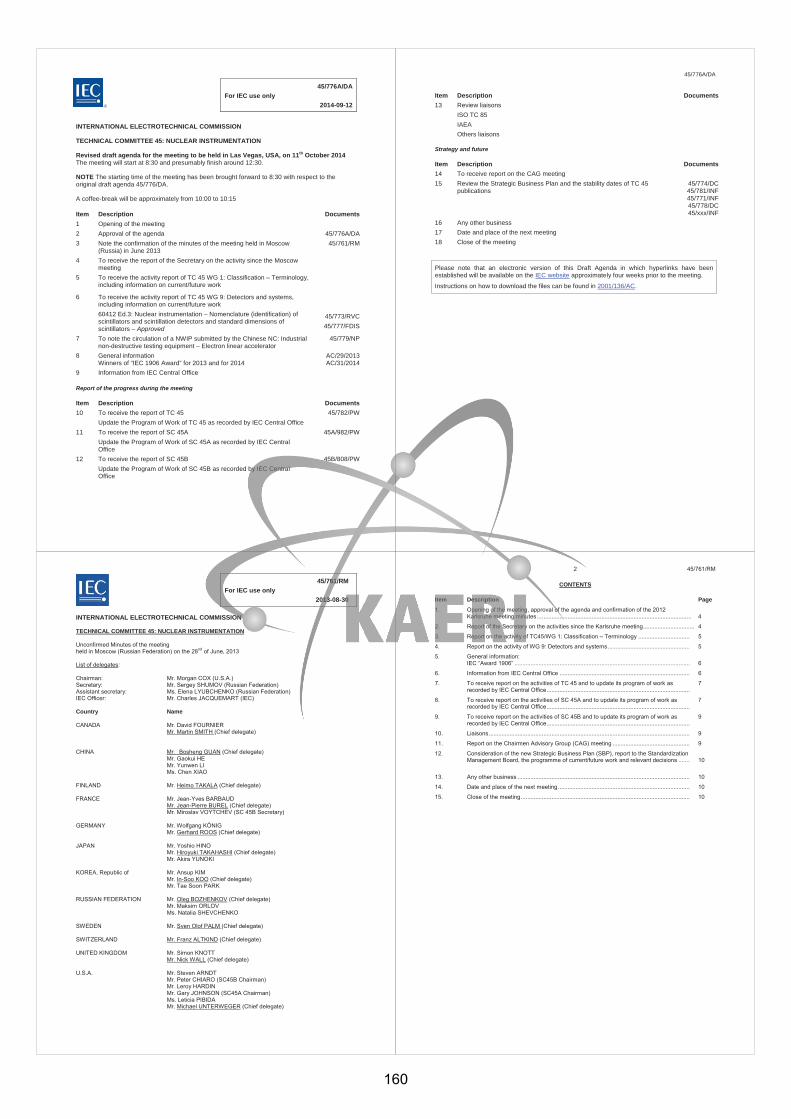
45/776A/DA For IEC use only 2014-09-12
INTERNATIONAL ELECTROTECHNICAL COMMISSION
TECHNICAL COMMITTEE 45: NUCLEAR INSTRUMENTATION
Revised draft agenda for the meeting to be held in Las Vegas, USA, on 11th October 2014 The meeting will start at 8:30 and presumably finish around 12:30.
NOTE The starting time of the meeting has been brought forward to 8:30 with respect to the original draft agenda 45/776/DA.
A coffee-break will be approximately from 10:00 to 10:15
Item Description Documents 1 Opening of the meeting 2 Approval of the agenda 45/776A/DA 3 Note the confirmation of the minutes of the meeting held in Moscow
(Russia) in June 2013 45/761/RM
4 To receive the report of the Secretary on the activity since the Moscow meeting
5 To receive the activity report of TC 45 WG 1: Classification – Terminology, including information on current/future work
6 To receive the activity report of TC 45 WG 9: Detectors and systems, including information on current/future work 60412 Ed.3: Nuclear instrumentation – Nomenclature (identification) of scintillators and scintillation detectors and standard dimensions of scintillators – Approved
45/773/RVC 45/777/FDIS
7 To note the circulation of a NWIP submitted by the Chinese NC: Industrial non-destructive testing equipment – Electron linear accelerator
45/779/NP
8 General information Winners of “IEC 1906 Award” for 2013 and for 2014
AC/29/2013 AC/31/2014
9 Information from IEC Central Office
Report of the progress during the meeting Item Description Documents 10 To receive the report of TC 45
Update the Program of Work of TC 45 as recorded by IEC Central Office 45/782/PW
11 To receive the report of SC 45A Update the Program of Work of SC 45A as recorded by IEC Central Office
45A/982/PW
12 To receive the report of SC 45B Update the Program of Work of SC 45B as recorded by IEC Central Office
45B/808/PW
®
45/776A/DA
Item Description Documents 13 Review liaisons
ISO TC 85 IAEA Others liaisons
Strategy and future Item Description Documents 14 To receive report on the CAG meeting 15 Review the Strategic Business Plan and the stability dates of TC 45
publications 45/774/DC 45/781/INF 45/771/INF 45/778/DC 45/xxx/INF
16 Any other business 17 Date and place of the next meeting 18 Close of the meeting
Please note that an electronic version of this Draft Agenda in which hyperlinks have been established will be available on the IEC website approximately four weeks prior to the meeting.
Instructions on how to download the files can be found in 2001/136/AC.
45/761/RM For IEC use only 2013-08-30
INTERNATIONAL ELECTROTECHNICAL COMMISSION TECHNICAL COMMITTEE 45: NUCLEAR INSTRUMENTATION Unconfirmed Minutes of the meeting held in Moscow (Russian Federation) on the 28nd of June, 2013 List of delegates: Chairman: Mr. Morgan COX (U.S.A.) Secretary: Mr. Sergey SHUMOV (Russian Federation) Assistant secretary: Ms. Elena LYUBCHENKO (Russian Federation) IEC Officer: Mr. Charles JACQUEMART (IEC) Country Name CANADA Mr. David FOURNIER Mr. Martin SMITH (Chief delegate) CHINA Mr. Bosheng GUAN (Chief delegate) Mr. Gaokui HE Mr. Yunwen LI Ms. Chen XIAO FINLAND Mr. Heimo TAKALA (Chief delegate) FRANCE Mr. Jean-Yves BARBAUD Mr. Jean-Pierre BUREL (Chief delegate) Mr. Miroslav VOYTCHEV (SC 45B Secretary) GERMANY Mr. Wolfgang KÖNIG Mr. Gerhard ROOS (Chief delegate) JAPAN Mr. Yoshio HINO
Mr. Hiroyuki TAKAHASHI (Chief delegate) Mr. Akira YUNOKI KOREA, Republic of Mr. Ansup KIM Mr. In-Soo KOO (Chief delegate) Mr. Tae Soon PARK RUSSIAN FEDERATION Mr. Oleg BOZHENKOV (Chief delegate) Mr. Maksim ORLOV Ms. Natalia SHEVCHENKO SWEDEN Mr. Sven Olof PALM (Chief delegate) SWITZERLAND Mr. Franz ALTKIND (Chief delegate) UNITED KINGDOM Mr. Simon KNOTT Mr. Nick WALL (Chief delegate) U.S.A. Mr. Steven ARNDT Mr. Peter CHIARO (SC45B Chairman) Mr. Leroy HARDIN Mr. Gary JOHNSON (SC45A Chairman) Ms. Leticia PIBIDA Mr. Michael UNTERWEGER (Chief delegate)
2 45/761/RM
CONTENTS Item Description Page
1. Opening of the meeting, approval of the agenda and confirmation of the 2012 Karlsruhe meeting minutes ................................................................................................
4
2. Report of the Secretary on the activities since the Karlsruhe meeting ................................. 4
3. Report on the activity of TC45/WG 1: Classification – Terminology ................................ 5
4. Report on the activity of WG 9: Detectors and systems ................................................... 5
5. General information: IEC “Award 1906” .............................................................................................................
6
6. Information from IEC Central Office ................................................................................. 6
7. To receive report on the activities of TC 45 and to update its program of work as recorded by IEC Central Office .........................................................................................
7
8. To receive report on the activities of SC 45A and to update its program of work as recorded by IEC Central Office .........................................................................................
7
9. To receive report on the activities of SC 45B and to update its program of work as recorded by IEC Central Office .........................................................................................
9
10. Liaisons ............................................................................................................................. 9
11. Report on the Chairmen Advisory Group (CAG) meeting ................................................ 9
12. Consideration of the new Strategic Business Plan (SBP), report to the Standardization Management Board, the programme of current/future work and relevant decisions .......
10
13. Any other business ........................................................................................................... 10
14. Date and place of the next meeting .................................................................................. 10
15. Close of the meeting ......................................................................................................... 10
160
3 45/761/RM
1. OPENING OF THE MEETING, APPROVAL OF THE AGENDA AND CONFIRMATION OF THE 2012 KARLSRUHE MEETING MINUTES
Mr. Cox, Chairman of TC 45, welcomed all delegates of the IEC National Committees participating in the meeting. On his proposal all the participants introduced themselves. Accordingly the list of the delegates of TC 45 was prepared by the secretariat. Mr. Cox informed the delegates that Ms. Shevchenko retired as TC 45 Assistant Secretary. Mr. Jacquemart, the IEC Technical Officer, gave a short presentation devoted to Ms. Shevchenko. He briefly described 18 years of her activity as the Assistant Secretary. He noted that during all the years Natalia has always been helpful and committed; she has done a lot for the proper functioning of the TC 45 Secretariat and for the progress of all projects. Mr. Jacquemart gave Mrs. Shevchenko a gratifying letter of the IEC Secretary General, as well as a personal gift. On behalf of all the delegates present, Mr. Jacquemart expressed his gratitude to Mrs. Shevchenko for her 18-year activity as the Assistant Secretary and wished success to Ms. Lyubchenko, who was recently appointed to this position and replaced (substituted) Ms. Shevchenko. The delegates expressed their support of these words with the applause. The Chairman declared the 43rd Meeting of IEC TC 45 open. The participants approved the Draft Agenda, document 45/751A/DA. Also they confirmed the 2012 Karlsruhe meeting minutes without comments.
2. REPORT OF THE SECRETARY ON THE ACTIVITIES SINCE THE KARLSRUHE MEETING
Mr. Shumov, Secretary of TC 45, presented information connected with the activities of TC45 and its subcommittees since the last meeting in Karlsruhe (Germany, March 2012). In particular, he showed data characterizing the involvement of different national committees into the international standards development process. Also it was reported about the fulfilment of key decisions taken at the Karlsruhe meeting, and changes made since that time.
One of the decisions concerns lessons learned from the Fukushima events. The various working groups of SC 45A spent considerable time in examining the impact on standardization work following the events in the nuclear power plants of Fukushima. In the frame of these discussions, invaluable input was provided by the Japanese delegation. It was concluded that certain standards of SC 45A required early revisions, that some on-going projects needed new orientations, and that there was an urgent need for new standards in SC 45A. In this context extensive discussions take place in the frame of a category A liaison with the IAEA (International Atomic Energy Agency), and more specifically with its NUSSC (Nuclear Safety Standards Committee) program.
One more decision was connected with the cooperation between SC 45A and IEEE NPEC (Nuclear Power Engineering Committee). Since the 2012 Karlsruhe meeting, IEC/SC45A and IEEE/NPEC collaborated on the development of 3 documents. The fourth dual logo document corresponding to IEC/IEEE 62582 parts 3 was published in November 2012 by the IEC/CO. July 2012 and January 2013, IEC/SC45A Chairman participated to the IEEE/NPEC meetings. At the end of the Moscow meeting it was noted that all the efforts are done on the IEC/SC45A side as well as on the IEEE/NPEC side for the started project progress to success. Speaking about the changes, it should be noted a revision of the scope of SC 45B in order to better reflect its activities. The corresponding questionnaire was circulated between TC45 members, and the change of SC45B scope was approved by them in August 2012.
Totally 11 documents were published within TC 45, by its subcommittees, since the Karlsruhe meeting. 26 projects are currently under development within TC45 and its subcommittees.
The report of Secretary was approved.
4 45/761/RM
3. REPORT ON THE ACTIVITY OF TC45/WG 1: CLASSIFICATION – TERMINOLOGY Mr. Roos, the convener of Working Group 1, reported on the meeting of this working group, which took place on June 24, 2013 and was attended by 11 members and 1 guest representing 8 countries. Mr. Roos reported on the positive results of the FDIS voting and the work on the comments. The publication of IEV 395 is expected in the near future. At the same time, WG 1 sees the necessity of an amendment of IEV 395 soon after the publication. It would be preferable if amendments could be done in the form of a database and no longer in the form of single documents. For the amendment WG 1 would also collect and consider all definitions of TC 45, SC 45 A and SC 45B. WG 1 would consider it helpful to have official liaisons from SC 45A and SC 45B as in the past. WG 1 discussed the preliminary draft of Technical report: “Terms of applied metrology of measurements of ionizing radiation in the field of nuclear instrumentation” supplied by the project leader. Work on the preliminary draft of this Technical report could start during an intermediate meeting early in 2014. Mr. Roos explained that there will be need for a new convenor for WG 1 from 2014 on, due to a shift in his line of work and the resulting need to step back as convenor of WG 1 as already announced at the end of 2012. He plans to remain a member of WG 1 and as the chief delegate from Germany. WG 1 expressed its hope that the present co-convenor, Anthony Richards, remains as convenor of WG 1. Anthony Richards accepted the proposal. In Soo Koo accepted the proposal to be the new co-convenor of WG 1. Next meetings of TC45/WG1 are planned for March 2014 (Berlin, Germany) and October 2014 (Las Vegas, USA). The report of Mr. ROOS was approved. The delegates also approved the appointment of Mr. Antony RICHARDS and Mr. In-Soo KOO correspondingly as the new convenor and co-convenor of TC45/WG1.
4. CONSIDERATION OF THE REPORT ON THE ACTIVITY OF WG9: DETECTORS AND SYSTEMS Mr. Unterweger, the Working Group 9 (WG9) convener, presented the report on the activity of this Working Group. The working group met on 26 June 2013. The meeting was attended by 11 experts from 8 countries and by a guest representing EC-JRC. The participants reviewed the membership of WG9. National committees will be advised and asked to suggest replacements, additions or removal of members. The participants considered CD on project 60412 Ed. 3: Nomenclature and dimensions of scintillators. Yuliya Danylenko from Ukraine discussed comments on CD and will prepare version to be issued as CDV. Jan Paepen from IRMM (EC-JRC) presented a proposal for a data output standard based on list-mode data format. Yoshio Hino commented favourably on incorporating such a standard under WG9. It was carried out general review of IEC publications for which WG9 has maintenance responsibility. Japan and Korea will look for experts to be a project leader for IEC 62346 Test procedure for wideband gap semiconductor detectors, such as CdZTe, of ionizing radiation. If no one is found, the project will be withdrawn. Next meeting will take place in October 2014 in Las Vegas, USA. The report of Mr. Unterweger was approved.
5 45/761/RM
5. GENERAL INFORMATION: IEC “1906 Award” Mr. Shumov informed the delegates that, on the nomination of TC45, the following experts were awarded in 2012 with IEC “1906 Award”:
1) Mr. David FOURNIER (Canada) for leading the development of IEC 62671 (Nuclear power plants – Instrumentation and control important to safety - Selection and use of industrial digital devices of limited functionality) with a level of personal involvement without which this particular controversial project would not have reached the current approval stage.
2) Mr. Jean GASSINO (France) for leading the development of IEC 62566 (Nuclear power plants – Instrumentation and control important to safety - Development of HDL-programmed integrated circuits for systems performing category A functions) with a level of personal involvement without which this particular project on this new topic would not have been published.
The following experts were nominated for this award in 2013:
1) Mr. Peter AMBROSI (Germany) for his efforts as the Convener of WG 8 of SC45B. In addition to his excellent leadership of Working Group B8, Dr. Ambrosi has been the PL of IEC 60846-1 (2009), IEC 61526 Ed.3 (2010) and IEC/TS 62743 (2012).
2) Mrs. Yuliya DANYLENKO (Ukraine) for her many efforts in the leadership of two projects, one of which, IEC 61435 on highly purified germanium detectors, has reached the approved FDIS stage, and another one, IEC 60412 on the identification of scintillation detectors, is at the approved CD stage.
3) Mr. In-Soo KOO (Korea, Rep. of) for IEC 61500 and currently preparing a Technical Report on wireless to pave the way for development of a standard on this topic, was the first member of the Korean National Committee to undertake leadership for a SC45A project. As the Korean Chief Delegate for many years, he has actively and competently developed the level of Korean participation to the point where Korean delegates now actively participate in all SC45A working groups and Korean experts are taking the lead in development of three documents.
4) Mrs. Leticia PIBIDA (USA) for her efforts as the Convener of WG 15 of SC45B. This particular WG has been very busy addressing many different standards that define requirements for instrumentation used in the critical and important process of detecting illicit radioactive materials at national and international borders. In addition to her role as Convener of WG B15, Dr. Pibida has been very much involved in all illicit tracking detection standardization efforts and the PL of IEC 62577 (2012) and IEC 62694 (CDV).
5) Mr. Gerhard ROOS (Germany) for leading the development of IEC 60050-395: International Electrotechnical Vocabulary, Part 395: Nuclear Instrumentation: Physical phenomena, basic concepts, instruments, systems, equipment and detectors with a level of personal involvement without which this particular project would not have reached the current stage. The FDIS on this project has been approved, and the standard will soon be published.
The delegates greeted this information with applause.
6. INFORMATION FROM IEC CENTRAL OFFICE Mr. Jacquemart, the IEC Technical Officer, gave the presentation on behalf of IEC Central Office. Mr. Jacquemart presented information on performance of TC45, SC45A and SC45B since the Karlsruhe meeting (March 2012). He characterized it as an excellent performance and needed to be reported to the SMB. Mr. Jacquemart pointed out that 16 international standards developed in SC45A have recently been translated into Russian and are available as such from the IEC webstore. The reporter also mentioned that both subcommittees of TC45, SC45A and SC45B, were formed 50 years ago with the titles, correspondingly, “Reactor instrumentation” and “Health physics – Radioprotection”. In connection with this jubilee Mr. Jacquemart expressed best wishes to SC45A and SC45B on behalf of IEC Central Office. Mr. Jacquemart gave brief information about the IEC activities; in particular he presented some figures, characterizing these activities, the structure of IEC, hot topics in IEC, new IEC homepage launched in 2013 etc.
6 45/761/RM
Mr. Jacquemart informed the delegates about new editions of IEC/ISO Directives and about the main changes compare to the previous editions. Mr. Jacquemart answered the questions of delegates. The presentation slides of are available on the IEC website (see 45/758/MTG).
7. REPORT ON THE ACTIVITIES OF TC45 AND UPDATE ITS PROGRAMME OF WORK Mr. Shumov, TC45 secretary, pointed out that presently there are two projects under development in TC45 Program of Work. The situation with these projects was reported by Mr. Roos (WG1 convenor) and Mr. Unterweger (WG9 convenor). Following the decisions made during the meeting the program of work will be updated and attached to the report to the SMB, stated the secretary.
8. REPORT ON THE ACTIVITIES OF SC45A: INSTRUMENTATION AND CONTROL OF NUCLEAR FACILITIES
Mr. Johnson, the SC45A Chairman, presented the information about the following key topics and action items addressed by SC45A at its Moscow plenary meeting. IEC/SC45A recommendation to IEC/TC45 concerning the implementation of the proposals of modification of IEC/SC45A title and scope On 25th of February 2013, IEC/SC45A held an ad’hoc meeting. During that ad’hoc meeting considering that a majority of National Committees expressing their positions supported the proposed modifications of IEC/SC45A title and scope, IEC/SC45A experts recommended IEC/SC45A take provisions to implement the proposed modifications. IEC/SC45A accepted the recommendation during its plenary meeting held the 27th
June 2013. In consequence IEC/SC45A recommends IEC/TC45 that the proposed modifications be implemented after the Moscow meeting, see attached to this report the proposed modified title and scope for IEC/SC45A. Taking into account the lessons learned during the Fukushima accident The lessons learned from the Fukushima accident have to be taken into account at the level of IEC/SC45A standards. The taking into account of those lessons has to be done during the revision of the existing standards and in the frame of the development of new standards. During the 2012 Karlsruhe WGA meetings the IEC/SC45A experts made the following recommendations which were adopted by IEC/SC45A during its plenary meeting: In 2 projects in development in 2012-2013, some requirements were to be added or modified; 16 IEC/SC45A published standards were to be reviewed in detail to confirm their revisions already
foreseen in Karlsruhe to take into account the lessons learned in Fukushima; Proposals for 10 new standards and one TR were identified.
Since then on IEC/SC45A experts worked on the adopted recommendations and at the end of the Moscow meeting, IEC/SC45A noted that every recommendations related to the lessons learned during the Fukushima accident are now integrated in the overall IEC/SC45A work programme and forecast. The development of one new standard on pressure transmitters was approved just before the Moscow meeting. At the end of the Moscow meeting the decisions concerning the launching in 2013 of 5 revisions of published standards, and the circulation of a proposal of NP for ERC before end 2013 are taken. IEC/SC45A collaboration with IEEE/NPEC Since 2003, the principle of collaboration between IEC/SC45A and IEEE/NPEC is accepted. A formal category D liaison was set up between the WGA9 of the IEC/SC45A and the IEEE/NPEC, for more details concerning the history of this collaboration and the results achieved see the reports of previous IEC/SC45A plenary meetings. Since the 2012 Karlsruhe meeting, IEC/SC45A and IEEE/NPEC collaborated on the development of 3 documents.
161
7 45/761/RM
At the end of the Moscow meeting it was noted that all the efforts are done on the IEC/SC45A side as well as on the IEEE/NPEC side for the started project progress to success. One possible additional project was discussed during the Moscow meeting. CENELEC, European implementation of IEC/SC45A standards 2010-2012, the national implementations of European endorsements of IEC 60880, IEC 60987, IEC 62138 IEC 60709, IEC 60964, IEC 61226, IEC 62340, IEC 60709, IEC 60965, IEC 61500, 61513 and IEC 61772 were published in the 33 European countries members of CENELEC. The European endorsements of IEC 62566 and IEC 61839 were launched beginning 2013. The publication as national standards of those European endorsements of IEC/SC45A standards in 33 European countries is foreseen before mid 2014. It is reminded that EN standards (European standards) are a means for the uniform implementation of International standards, throughout Western Europe. The activation of CLC/TC45AX is real opportunity for IEC/SC45A to see its documents endorsed and used all over Europe. OECD, IEC/SC45A participation to the MDEP project The Multinational Design Evaluation Programme (MDEP) is a multinational initiative under NEA/OECD (Nuclear Energy Agency of the Organization for Economic Co-operation and Development) to develop innovative approaches to leverage the resources and knowledge of mature, experienced national regulatory authorities who are, or will shortly be, undertaking the review of new reactor power plant designs. The MDEP programme incorporates a broad range of activities including, increasing multinational convergence of codes, standards, and safety goals. The MDEP Programme structure includes the issue specific Digital Instrumentation and Control Working Group (DICWG), which includes members from; Canada, China, Finland, France, IAEA, India, Japan, Korea, Russian Federation, South Africa, the United Kingdom and the United States. Members from Sweden may participate in the future. The IEEE and IEC are invited participants. IEC/SC45A Chairman and Secretary take part to MDEP/DICWG meetings as representative of the Sub-Committee. IEC/SC45A Secretary takes regularly part to MDEP/DICWG meetings as representative of the Subcommittee since 2010. Six positions on simplicity, software tools, Communications, V&V, HDL devices and cybersecurity, prepared by MDEP/DICWG are now available on the OECD website. IEC/SC45A standards are listed in all those positions. OECD/MDEP Chairman, Mr. Dan SANTOS (US) attended IEC/IEEE common project meeting held in Moscow and presented the MDEP/DICWG activities. Availability of the Russian versions of the IEC/SC45A standards on the IEC webstore Russian is one of the three official languages of the IEC. Up to the end of the 80’s, during the soviet era, the IEC standards used to be delivered by the Russian National Committee to IEC Central Office for sale. Since the 90’s, the Russian versions of the IEC standards were no more available for sale in the IEC. Since 2009 discussions were held between the IEC CO and the Russian National Committee to find an agreement to have the IEC standards again delivered by the Russian National Committee to the IEC CO for sale on its webstore. End 2012, the first versions of IEC standards in Russian language were available for sale and beginning 2013. Now 17 IEC/SC45A standards in Russian language are available on the IEC website. Performance of SC45A since Karlsruhe The SC45A portfolio since Karlsruhe comprised 19 projects going on in parallel during this period and roughly 67 published documents to be maintained Today, we have 14 projects of document still currently in progress.
8 45/761/RM
4 IEC standards and 1 IEC/IEEE standards were published since the Karlsruhe plenary meeting (for information 5 publications were announced in Karlsruhe and 4 in Seattle). At the moment the current project status is:
No document at final stage (FDIS), 1 documents at inquiry stage (CDV), 7 are at CD stage, 5 are at WD stage, 1 is at NP stage.
Decisions:
1. The report of Mr. Johnson was approved. 2. TC45 secretariat to prepare and to circulate between TC45 members a questionnaire concerning the
modification of SC45A title and scope.
9. REPORT ON THE ACTIVITIES OF SC45B: RADIATION PROTECTION INSTRUMENTATION Mr. Chiaro, the Chairman of SC45B, presented information on the following key topics: Published and working documents 6 new International Standards have been published since the last meeting in Karlsruhe. 11 working documents are in progress within the 7 WGs, PTs and AHGs of SC 45B. There are currently in force 55 standards issued from SC 45B. New WGs and PT :
B16 Contamination Meters and Monitors; B17 X-ray computed tomography(CT) security-screening systems (pending); PT Semi-empirical method for performance evaluation of detection and radionuclide identification
(pending). Liaisons and conference participations The SC 45B is well presented at the international meetings in the field of radiation protection. For the last 15 months the SC 45B officers participated in the following meetings where SC 45B activities were presented: ISO/TC85/SC2, 2013-04, Vienna, IAEA (Austria); IACRS meeting, 2012-11, Vienna, IAEA (Austria); IAEA-RASSC meeting, 2012-11, Vienna, IAEA (Austria).
Next meeting SC45B wishes to meet at the next TC45 meeting tentatively scheduled in Las Vegas, US in October 2014. Possible schedule for this SC45B meeting based on 4 days of WG/PT meetings and 1 day for Plenary meeting. The report of Mr. Chiaro was approved.
10. LIAISONS
Many aspects of TC45/SC45A/SC45B liaison with ISO/TC 85 “Nuclear energy, nuclear technologies, and radiological protection”, IEEE, CENELEC, NEA/OECD (Nuclear Energy Agency of the Organization for Economic Co-operation and Development) were discussed within the framework of the previous items of the agenda.
11. REPORT ON THE CHAIRMEN’S ADVISORY GROUP (CAG or AG15) MEETING Mr. Shumov, the Secretary of IEC/TC45, briefly informed the delegates on the CAG meeting that took place on June 25, 2013. The meeting was attended by 21 participants from 8 countries, as well as by Mr. Jacquemart, the Technical Officer of IEC. The meeting was mainly devoted to an issue of conformity in different aspects of this term. The following participants made their presentations on this subject: Mr. COX (IEC/TC45 Chairman, USA). The presentation was called “Conformance or conformity with
9 45/761/RM
standards”, and it was stated in it that an ultimate conformance success possible for standards is 1) regulatory inclusion of referenced IEC standards ; 2) delivery of relevant manufactured instruments that are meant to comply with those standards materials; and 3) employment of those instruments to the maximum effect. Mr. UNTERWEGER (USA) presented to the meeting participants information concerning the situation with the US standardization system in the field of nuclear instrumentation and its relationships with the standards of TC45/SC45A/SC45B. It was stated that a good cooperation has been established between the US standardization organizations and IEC. It was also mentioned that many US standard become basis for the development of IEC standards. Mr. BOUARD (France), the secretary of SC45A, reported about the Conformity to standards at European level in the nuclear sector. Mr. YUNOKI (Japan) gave the presentation on Relationships between the Japanese and IEC standards. Mr. SHUMOV (Russia), Secretary of TC45, gave a presentation in which a possibility was considered of the inclusion of IEC TC45/SC45A/SC45B standards into the IEC conformity assessment system. A proposal was formulated on the formation of an Ad Hoc group with the purpose of the elaboration and substantiation of the plans for further activities in this direction. Mr. Chiaro (USA), SC45B Chairman, Mr. Bouard (France), Mr. Jacquemart (IEC CO), Mr. Roos (Germany), Mr. Johnson (USA), SC45A Chairman, and other participants took part in the discussions. The common opinion was that there is no sense in such inclusion for several reasons. The main two of them are as follows: 1) the procedure of the third-party conformity assessment is very expensive and is effectively applied only when a wide world market exists for products covered by IEC standards, that is not the case for TC45/SC45A/SC45B standards; 2) According to ISO/IEC Directives the two types of activities existing within IEC, namely standard development and conformity assessment, should be absolutely independent from each other. As TC45 and its subcommittees are involved into standard development, it is impossible for them to formally develop conformity assessment systems.
The presentation slides of are available on the IEC website (see 45/758/MTG).
12. CONSIDERATION OF THE STRATEGIC BUSINES PLAN (SBP)
Mr. Shumov, the secretary of TC45, informed the participants that the draft of the SBP document was circulated between national committees in March 2013 (document 45/752/DC). Totally 16 countries expressed their positive opinion on this document, among them 12 P-members, 2 O-members and 2 non-members of TC45 (document 45/757/INF). No comments were received from 9 P-members and 10 O-members of TC45.
Mr. Shumov proposed to approve the circulated version of the Strategic Business Plan.
The secretary’s proposal was approved by the delegates.
The approved version of SBP is given in the Annex.
13. ANY OTHER BUSINESS
None.
14. DATE AND PLACE OF THE NEXT MEETING
Mr. Cox, the TC45 Chairman, informed the delegates that the next meeting of TC45/SC45A/SC45B and their working groups will take place in Las Vegas, U.S.A., in October, 2014. The exact dates of the meeting will be provided later. The following advantages of this place of the meeting were indicated among other ones: 1) a cheap hotel accommodation for the participants of the meetings; 2) all the participants will live in the same hotel, and in that hotel the meeting rooms will also be provided; 3) a variety of cultural and sightseeing programs can be offered to participants and accompanying persons.
The 2016 meeting (after Las Vegas) of TC45/SC45A/SC45B and their working groups will be in Gyungju, Republic of Korea in March, 2016. The meeting after Korea will be in China, 2017.
15. CLOSURE OF THE MEETING
10 45/761/RM
Mr. Cox thanked the Russian National Committee, the administration of “VNIIAES”, JSC and all the persons participated in the preparation and conducting the meeting for their hospitality and facilities provided for the meeting that very much contributed to its success.
The Chairman also thanked the delegates of national committees and all the participants for their contributions toward the success of the TC 45 meeting and declared the 2013 IEC TC 45 meeting closed.
162
Form SBP (IEC) 2008-11-07 1/11
ANNEX A
TC 45 : Nuclear instrumentation SC 45A : Instrumentation and control of nuclear facilities SC 45B : Radiation protection instrumentation A Background
Technical Committee 45, established in 1959, produces and maintains standards for instrumentation, systems and equipment for many nuclear applications including nuclear energy and the nuclear fuel cycle, industrial and commercial uses of ionizing radiation, safeguarding special nuclear materials, and environmental and radiation protection.
TC 45 is responsible for the standardization of nuclear instrumentation that includes relevant terminology and classification, detectors of ionizing radiations and systems based on these detectors and the commercial applications of nuclear instrumentation technologies.
SC45A is responsible for the standardization of activities related to electronic and electrical functions and associated systems and equipment used in instrumentation and control (I&C) systems and electrical systems of nuclear facilities. These activities include nuclear power plants, the entire nuclear fuel cycle from mining to processing, reprocessing, and interim and final repositories for spent fuel and nuclear waste.
SC 45B is responsible for standardization activities covering all aspects of radiation protection instrumentation, including that for the measurement under both normal and accident conditions of external and internal individual exposure and exposure rates, in the workplace, in effluents, the environment and including foodstuffs. SC45B is also responsible for the development of standards that are applicable to the detection and identification of illicit trafficking of radioactive material.
In addition, SC45A and SC45B are together responsible for standards related to the safeguarding of special nuclear materials, SC45A by the safe use of instrumentation and controls throughout the nuclear fuel cycle, and SC45B with standards for monitoring for the management, storage and movement of special nuclear materials in all forms.
B Business Environment B.1 General
The activity of TC45 can be presented in several segments:
- instrumentation and control systems and electrical systems for the safe generation of electricity from nuclear energy;
- radiation protection instrumentation for personnel and for the environment;
- instrumentation for industrial and commercial uses of nuclear technology, and
- instrumentation for the safeguarding of special nuclear materials, including during nuclear fuel manufacture, storage and processing.
Instrumentation and control for nuclear energy generation:
STRATEGIC BUSINESS PLAN (SBP)
IEC/TC or SC TC 45/SC 45A/SC 45B
Secretariat Russian Federation
Date 2013-08
Form SBP (IEC) 2008-11-07 2/11
The business environment for nuclear power generation is currently changing and imposes some challenges:
- The resurgence of nuclear power worldwide has been tempered and even delayed by two factors:
the nuclear accident at Fukushima in March 2011 and the recently discovered natural abundance
of natural gas by “fracking” or horizontal drilling at least in the United States. For example, Japan is
reevaluating their use of nuclear power, and Germany appears to be shutting down their nuclear
power plants in favour of solar, wind and imported nuclear power. Local politics will play a major
role for nuclear power in both Germany and Japan over the next ten years.
- new nuclear power reactor designs must be reviewed and approved before licensing;
- nuclear utilities must have the assets and regulatory approvals in order to proceed with the construction of new power plants;
- expanded new energy needs are connected to the economies of established nuclear countries (such as, China, India, Brazil, Russia, Argentina, Pakistan and others) as well as new countries including Vietnam, Lithuania, United Arab Emirates.
- management and refurbishment of aging reactors that are reaching their initial design life and are subjected to life extension programmes determined by routine safety reviews, lessons learned and the implementation of new technical standards;
- decommissioning, where some older reactors will be entirely dismantled;
- the management, transportation and storage of nuclear fuel and special nuclear material, and
-safe management of spent nuclear fuel that includes transportation from power reactor sites to nuclear storage and repository facilities;
- additionally, new aspects (i.e. "loss of infrastructure") are being discussed after the Fukushima accident in March 2011, and the need for additional standards might arise from that throughout the nuclear fuel cycle;
- security and cyber security standards are being developed
Radiation protection instrumentation for personnel and environment:
The increased use of nuclear and radiation technologies for meeting industrial and social needs causes the rise of safety expectations to protect people and the environment, in particular:
- safety or ecology related events may have wide repercussions transcending international boundaries (e.g. the Chernobyl and Fukushima events). Nations must combine their efforts to raise the safety of their nuclear facilities to consistent levels;
- credible radiological measurements using appropriate radiation instrumentation are addressed.
Instrumentation for the safe commercial uses of ionizing radiation and nuclear technology:
-Ionizing radiation is finding more widespread uses in the fields of non-destructive testing for materials and structures, for gauging moisture, liquid levels and other material thickness and density, flaw and void detection, for industrial imaging, in the irradiation of a variety of
Form SBP (IEC) 2008-11-07 3/11
foods, in the sterilization of all types of medical supplies, and in the uses of radiation for the diagnosis and treatment of a variety of diseases. The Technical Committee through the Subcommittees emphasize the safe applications of radiation and nuclear technology.
Instrumentation for safeguarding of special nuclear materials such as Plutonium and Uranium:
- SC45A takes into account an issue of safeguarding of special nuclear materials in the standards on nuclear fuel cycle that are developed in this subcommittee.
-SC45B through its working groups develops instrumentation standards to detect illicit trafficking activities that helps prevent radioactive material being used by potential terrorists.
- Working groups in SC 45B continue to develop and maintain contemporary standards for airborne and environmental monitoring; for portable radiation detection instruments; for monitoring radon and radon progeny; and for radiation dosimeters used by personnel and in the environment.
- SC45B through its working groups develops standards on radiation systems for the screening of persons and cargo/vehicles for security and the carrying of any kind of illicit items at the airports, seaports and other border control check points.
There are many companies dealing with the aforesaid businesses, including many major international companies as well as a large number of system and equipment manufacturers and suppliers from around the world.
B.2 Market demand
Who are the customers of the existing and future publications developed by the TC/SC
The customers are typically designers and manufacturers of instruments, control and protection systems and equipment, users, nuclear operators, regulators, legislators, and testing organisations, the many commercial and industrial users of radionuclides (many users of non-destructive testing (NDT) or non-destructive examination (NDE)).
Are the TC/SC publications widely used at the regional/national level
The published IEC standards are widely used as a basis for national or regional standards and in procurement efforts.
Discussion and efforts are underway to improve conformance between IEC standards, national and regional standards and operational measures or practices.
European Committee for Electrotechnical Standardization (CENELEC) has set up Technical Committees CLC/TC45AX and CLC/TC45B for monitoring the work of TC45 and its SCs and endorsing IEC standards produced by TC45 and its SCs as European standards (EN). Since 2003, CLC/TC45B endorsed as EN, two IEC/TC45 standards and eighteen IEC/SC45B standards with others in progress. CLC/TC45B prepared common modifications of the EN, if any, and introduced them in the maintenance of the respective IEC/TC45 or IEC/SC45B standards. Since 2007, CLC/TC45AX endorsed as EN twelve IEC/SC45A standards without modifications, and others are in progress. All those EN are now implemented as national standards in the 31 European countries member of CENELEC.
Japanese industrial standards are coordinated with IEC TC 45/45A/45B standards on request of the authorities.
Many IEC standards are adopted as British standards.
Form SBP (IEC) 2008-11-07 4/11
Germany has decided to translate some standards into IEC DIN Standards.
Russia has directly implemented some IEC standards.
In the USA, some IEC TC45 standards and most of the IEC TC45 terminology are increasingly used by reference in ANSI N42 Standards.
Rep. of Korea has translated about 60 IEC standards published by TC45 and its subcommittees into Korean national standards (KS).
Are they supporting regulation or used as the basis for contracts
In Europe, at national level, at least ten IEC/SC45A standards are referenced through their EN endorsement by different European countries in the licensing documents and procedures ( IEC 61513, IEC 61226, IEC 60987, IEC 62138, IEC 62340, IEC 60709, IEC 60964, IEC 61500, IEC 61771, IEC 60965).
Korea Institute of Nuclear Safety (KINS), the regulation research institute of Rep. of Korea, has started to incorporate IEC TC45 standards into Korean nuclear regulatory standards.
Some IEC standards are used by reference in American National Standards Institute (ANSI) N42 in the development of US instrument standards. Conversely some ANSI N42 standards are referenced in some IEC standards.
Export contracts from the USA use IEC standards. In addition, an encreasing number of IEC standards are referenced by the US Department of Energy, US Nuclear Regulatory Commission and US Department of Homeland Security.
IEC standards are specifically used as reference and technical basis for documents published by the IAEA related to the detection of illicit trafficking of radioactive materials.
Which are the competing standards developed by other organizations
TC 45 is the only worldwide body developing international instrumentation and control standards for the nuclear and nuclear power industries and for other industries using nuclear measuring techniques. TC 45 and its Subcommittees develop standards for the design, construction, performance, testing and calibration of radiation detection instrumentation for all applications. These standards are complementary to ISO/TC 85 standards for the use of such instrumentation. Other relevant organisations, such as the IAEA, are concerned with the establishment and regulation of safety principles and the IAEA also publishes reports on engineering practice.
Given below are brief characterizations of relationships between IEC/TC45 and other international organisations working in related areas.
IAEA: Close liaison has always been maintained between TC 45 and the IAEA. Some of the first work done by SC 45A was to generate a number of important documents (particularly IEC 60231) which codified the basic principles of reactor instrumentation safety. In the early 1970's, the IAEA amalgamated these into a set of formal Safety Guides. It was then appreciated that overlap between the two bodies had to be avoided, and in 1981 an agreement setting out the respective fields of interest was drawn up. According to this agreement IEC/SC45A took the commitment to implement in technical details the IAEA safety principles relevant for I&C. IEC/SC45A standards use only the IAEA safety glossary. IEC/SC45A maintains close relationships with the IAEA : participating to the NUSSC (Nuclear Safety Standards Committee), participating to the I&C Technical Working Group of the Nuclear Division of the IAEA and taking part to the IAEA meetings on cyber security. Recently the IAEA and SC45B have reactivated their liaison A status and are now fully
163
Form SBP (IEC) 2008-11-07 5/11
reporting and harmonising their work. SC45B is now an official member of the IAEA Radiation Safety Standards Committee (RASSC), which is responsible for the revision of the Basic Safety Standard.
ISO: TC45 has a liaison relationship with ISO/TC85 “Nuclear energy”. This cooperation covers terminology and classification in the nuclear field and some other fields of standardization. IEC/TC45/SC45B has started to regularly attend ISO/TC85/SC2 meetings to address any potential overlapping or contradictory issues related to radiation protection standards that are common for both SCs.
A better use of IEEE nuclear power standards, and generic software engineering standards from IEEE or IEC/ISO JTG1 should be considered. To that end, a liaison of D category has been established between WGA9 and IEEE/NPEC (Nuclear Power Engineering Committee).
CENELEC: TC45, SC45A and SC45B standards are circulated by CENELEC after a case by case review with minor modifications; the procedure regarding SC45A standards is just being developed. The TC45 and SC45B standards can be endorsed with modifications. These modifications are supplied as comments for the next revision of IEC standards. The SC45A standards are endorsed without modifications.
ISA: a category D liaison between ISA67 “International Society of Automation/Nuclear power standards” and IEC/SC45A/WG9 “Instrumentation and control of nuclear facilities/Instrumentation systems” has been established.
B.3 Trends in technology
The rapid change in electronics, information and communications, and other technologies will continue to impact the future work of TC45 particularly in areas such as:
- new types of reactors including advanced gas-cooled reactors, small modular reactors and reactors with increased power capability. These types of reactors are being constructed in some countries and new types of Instrumentation&Control Systems will be required for these reactors;
- hardware, software, systems, and COTS (Commercial Off The Shelf) items;
- an increasing need for cyber security for nuclear power instrumentation and control;
- information exchange (between instruments and control rooms, radio-links, exchange formats);
- the internet impacts all industries and might need a specific approach for nuclear applications;
- the wide use of X-ray installations in different areas;
B.4 Market trends
The main trends that will impact our future work are:
- the worldwide need for nuclear power with contemporary matching standards;
- the globalization of the nuclear market;
- the merging of key-players and consortia: manufacturers, utilities etc.;
Form SBP (IEC) 2008-11-07 6/11
- Latest events, connected with the accident at Fukushima NPP in Japan, negatively impact the nuclear technologies market. Nevertheless, some decrease of the market seems to be of temporary character since the increasing worldwide need in electrical power could not be satisfied without the development of nuclear industry.
B.5 Ecological environment
Nuclear power provides beneficial effects for the environment including delivery of safe, clean and economical electrical energy, and, when normally operating, the nuclear power generating facilities contribute little or no pollution to the environment.
At the same time, in the emergency and recovery situation after the NPP accident, the decontamination procedure over a wide area in the surrounding environment is urgently required. The radiation monitoring under such high background shall be considered and the exposure control of personnel and inhabitants is also quite important.
In comparison with bulk markets, relatively few individual devices are manufactured under TC 45 standards, and their manufacture, existence and disposal has negligible adverse impact on the environment. Their function, however, is aimed directly at the environment protection.
C System approach aspects
TC 45 will actively continue to cooperate with other organizations both within IEC and outside this organization. A system approach to this activity is in the focus of our committee. The table shown below reflects the relationships between TC 45 and other organizations with the indication of the role of our committee in respect to these organizations (role of a customer or a supplier):
Component committees (IEC TC45 – role of a customer)
IEC/TC1 Terminology
IEC/TC77 Electromagnetic compatibility IAEA International Atomic Energy
Agency ICRP International Commission on
Radiological Protection ICRU International Commission on
Radiation Units and Measurements
ISO/TC85 Nuclear energy, nuclear technologies and radiological protection
System committees (IEC TC45 – role of a supplier)
IEC/TC1 Terminology
CENELEC/TC45 Nuclear Instrumentation CENELEC/TC45A Instrumentation and Control of
nuclear Facility CENELEC/TC45B Radiation Protection
Instrumentation ISO/TC85 Nuclear energy, nuclear
technologies and radiological protection
Other committees IEC/TC8 Systems aspects for electrical energy supply
IEC/TC35 Primary cells and batteries IEC/TC56 Dependability IEC/SC62C Equipment for radiotherapy,
nuclear medicine and radiation
Form SBP (IEC) 2008-11-07 7/11
dosimetry IEC/TC65 Industrial-process
measurement, control and automation
IEC/TC112 Evaluation and qualification of electrical insulating materials and systems
IEEE-NPEC Institute of Electrical and Electronic Engineers - Nuclear Power Engineering Committee
ISA67 International Society of Automation/Nuclear power standards
Liaison established:
TC45: ISO/TC 85; IAEA; CENELEC; IEC/TC1.
SC45A: IEC/TC 65; IEC/TC 56; IEC/TC77; IAEA; ICRP; ICRU; ISA.
SC45B: ISO (TC 85/SC 2 - TC 85/SC 5); EFOMP; IAEA; ICRP; ICRU; OIML/TC 15; WHO; IACRS; EC.
A liaison of D category has been established between WGA9 and IEEE/NPEC, as well as between WGA9 and ISA67.
D Objectives and strategies (3 to 5 years)
The TC 45 Committee Advisory Group (CAG), a TC consultative body, has been set up with First National Delegates and TC/SC officers in order to improve the committee's activity coordination and the liaison strategy. The CAG reviews the SBP at each meeting. The CAG also advises WGs on NWIPs and shares common management issues in order to have a better overall alignment of the activities.
The following recommendations were elaborated for TC45 strategy during the CAG meeting in Yokohama (Japan, 2009) and updated in Seattle (USA, 2010) and Karlsruhe (2012):
We should continue to be driven by technology needs and recommendations of other authorities, such as the IAEA.
We should be alert to standards developed by US organizations, for example a standard for robustness tests, that are important and can be transformed into IEC standards.
We shall be cognizant to standardization as connected with non-proliferation and illicit trafficking of nuclear and radioactive materials and produce standards useful for all participating countries.
We are aware that new types of reactors, advanced gas-cooled reactors, small modular reactors and other higher power and lower power reactors are being constructed in several countries. Attention should be paid to the development of standards covering I&C systems and radiation monitoring systems for these types of reactors.
In recognition that IEC standards are used by a wide circle of experts, we need to ensure that our standards are not just developed for a limited group of specialists.
The Fukushima accident is to be analyzed and the experience gained should be taken into account in our publications, both new and revised ones.
Form SBP (IEC) 2008-11-07 8/11
At international level, we are doing our best to interact with organizations (IAEA, IEEE, ISA) and we are also doing our best to implement in all regions collaboration in different ways.
We consider the translation of IEC/SC45A standards in Russian of the utmost importance for their distribution in Russia and the other states belonging to the Independent States Community.
The implementation of 12 IEC/SC45A as European Standards (EN) and their distribution as national standards in 31 European Countries is to be noted and that will be pursued.
We consider also as a very important sign the improvement of participation of representatives of Asian countries in 45A activities.
E Action plan
The IAEA has officially accepted the nomination of the IEC/SC45A Secretary for the participation in the activities of Nuclear Safety Standards Committee (NUSSC). This participation will allow the IEC/SC45A to be directly informed of the development, review and revision of IAEA safety standards and to formulate observations on those projects.
TC45, SC45A and SC45B will continue reviewing the various National and International reports following the events at the Fukushima Nuclear Power Plants in 2010 and identify the need for new and revised IEC standards.
Subcommittee 45A has included into its Work Program the development of several standards jointly with the IEEE organization, in particular a standard on equipment qualification using robustness tests.
The review of 5 standards will start within SC 45A in 2013 as a consequence of Fukushima accident analysis. Six standards and one Technical Report are being currently reviewed. There are ideas on the development of 11 new international standards.
The participation of representatives of Asia in SC 45A activities is improving: presently there are 2 Japanese Convenors, 3 Korean Project Leaders, more Chinese experts taking part to our meetings and soon perhaps Pakistanis and Indians experts will be taking active part and responsibilities.
Subcommittees SC45A and SC45B have included into their Work Program a series of standards for equipment intended for safeguarding of radioactive and nuclear materials. SC45A takes this issue into account through a series of projects connected with the nuclear fuel cycle. SC45B is developing a series of standards connected with the detection and identification of illicit trafficking of radioactive and nuclear materials (e.g. 62618, 62694 and 62755 in WG in WG B15).
In addition to the new projects, TC 45/SC45A/SC45B WGs will be occupied with the maintenance of issued standards and documents.
TC 45 is currently working on 2 projects, SC 45A – on 12 projects and SC 45B – on 11 projects.
During one year, between 5 and 15 NWIPs may be suggested, based on our previous experiences.
To follow a work and maintenance program so that developed documents and revised standards would be adopted by industry
164

Form SBP (IEC) 2008-11-07 9/11
To recruit additional members to WGs, especially from the nuclear utilities, development and manufacturing companies, legislative and regulatory authorities.
SC 45B will reactivate the former WG B7 on Contamination Monitors and Meters. This WG will revise old standards and will developed new standards within the context of the Fukushima nuclear accident.
SC 45B will revise the 9 illicit trafficking detection standards developed by WG B15 and taking into account the experience of the different testing programs (ITRAP+10 etc.).
SC 45B will start new projects on computer tomography (CT) X-rays security systems.
F Useful links to IEC web site IEC/TC45 dashboard (enter 45) giving access to Membership, TC/SC Officers, Scope, Liaisons, WG/MT/PT structure, Publications issued and Work and Maintenance Programmes and similar information for SCs. Name or signature of the secretary Sergey SHUMOV
Guidelines for the preparation of Strategic Business Plan
Purpose of the Strategic Business Plan
The extension of formal business planning to IEC Technical Committees (IEC/TCs) is an important measure which forms part of a major review of business. The aim is to align the IEC work programme with expressed business environment needs and trends and to allow IEC/TCs to prioritize among different projects, to identify the benefits expected from the availability of International Standards, and to ensure adequate resources for projects throughout their development.
The Strategic Business Plan is a document which is not only directed to IEC internal audience (i.e., the TC itself and the Standardization Management Board). It is also intended to provide executive information to managerial levels in industry (who are not familiar with standardization work in detail) about the domain of activity, the mission and the specific tasks of the TC. The SBP shall be attracting the interest of new experts and provide rationale to industry management why it is important for an individual enterprise to participate (or continue participation) in this particular TC. This is of specific importance in areas where different specification developing organisations are drafting competing documents on a subject.
The SBP shall be an appetizer for new participants in the work; therefore, IEC specific terminology such as abbreviations/acronyms shall be avoided.
The following Guidelines contain the minimum requirements for the information to be given in the SBP. Taking into account the wide spectrum of IEC Technical Committees, some of the aspects mentioned are suggestions which need to be answered as applicable. For an individual TC it may also be appropriate to provide additional or other information relevant to its specific area.
Title of TC (+ SCs)
Titles of parent TC and SCs (if appropriate) should be included in this section.
A Background Description of the TC/SCs field of activity with basic/group safety functions where
45/761/RM
10
applicable, noting that in Section F there will be a link to the TC/SC home page for the most recent version of the scope therefore it is normally not appropriate to just copy and paste the scope(s). TCs having SCs shall reasonably summarize their field of activity. A short, succinct history of setting-up of the TC/SC may be given, where appropriate.
B Business environment B.1 General Appreciation of the current most important technical, industrial and economic indicators in the
sphere of activity of the TC/SC. Examples of indicators to be covered in this section:
Total worldwide sales, broken down by the major geographical regions over the last years where applicable
Major companies, test houses etc. (multi-nationals as well as SMEs) giving an indication of the market size
This section should distinguish between those aspects of the business environment that will influence the work of the TC/SC but over which the TC has little or no control (i.e. the external environment) and those aspects that the TC/SC may well be able to influence to a significant extent (i.e. the internal environment)
B.2 Market demand Information on the market demand for the TC/SC’s publications should include the answers to
the following questions: Who are the customers of the issued and future publications developed by the TC/SC
(manufacturers, planners, installers, test houses, authorities, etc.) In the case of TC/SCs with essentially a “horizontal” scope, then there should be breakdown of which product TC/SCs are using their publications – this could be for example a list of those product TC/SCs citing their publications in their normative references.
Are the TC/SC publications widely used at the regional/national level Are they supporting regulation or used as the basis for contracts Are the TC/SC publications used for IEC schemes Note: This item will be relevant to a
limited number of TCs working in areas where IEC schemes are offering their services. IEC staff responsible for these activities should be contacted to determine details.
Which are the competing standards developed by other organizations
B.3 Trends in technology A short summary of the trends in technology and their impact on the future work of the TC/SC.
This summary will provide the basis for the road mapping required in Section D.
B.4 Market trends Estimates of market trends and again an assessment as to the impact on the future work of
the TC/SC. This summary will provide the basis for the road mapping required in Section D.
B.5 Ecological environment Environmental impact (resource consumption, energy consumption, pollution, waste
generation, etc.) over the whole life cycle of the product from material procurement to end of life.
C System approach aspects (Reference - AC/37/2006)
This should not only be restricted to the customer/supplier relationships with other TC/SCs indicating types of co-operation (e.g. liaisons, joint working groups) but be of a more generic nature.
D Objectives and strategies The TC/SC should define a limited number of objectives to be achieved during the next period
– 3-5 years - taking into account the information given in Section B. This may include mention of significant maintenance work, response to new developments in technology etc. (i.e. road
45/761/RM
11
mapping style rather than detailed project planning on new subjects is expected here). The TC/SC should ensure that these objectives are achievable and not limited by external
factors over which they have little or no control. Strategies should be identified for achieving the defined objectives.
E Action plan This should outline a clear plan of action, including milestones in order to meet in a timely
manner the defined objectives.
F Useful links to IEC website IEC/CO will create a hyperlink to the TC home page for further information on the Membership, TC/SC Officers, Scope, Liaisons, WG/MT/PT structure, Publications issued and Work and Maintenance Programmes and similar information of SCs, if any.
1/2
For IEC use only 45 (Moscow/Secretariat) 6 October 2014 INTERNATIONAL ELECTROTECHNICAL COMMISSION TECHNICAL COMMITTEE No. 45: NUCLEAR INSTRUMENTATION IEC Publications of TC 45, SC 45A and SC 45B issued between the Meetings in Moscow (June 2013) and Las Vegas (October 2014)
____________
- TC 45 –
IEC 60050-395 (2014)
Nuclear instrumentation: Physical phenomena, basic concepts, instruments, systems, equipment and detectors
- SC 45A -
IEC TR 62918 Ed. 1.0 (2014-07)
Nuclear power plants - Instrumentation and control important to safety – Use and selection of wireless devices to be integrated in systems important to safety
IEC 62705 Ed. 1.0 (2014-07)
Nuclear power plants - Control rooms – Radiation monitoring systems (RMS): Characteristics and lifecycle
IEC 62645 Ed.1.0 (2014-08)
Nuclear power plants - Instrumentation and control important to safety - Requirements for security programmes for computer-based systems
- SC45B -
IEC 62709 Ed. 1.0 (2014-02)
Radiation protection instrumentation – Security screening of humans – Measuring the imaging performance of X-ray systems
IEC 62694 Ed. 1.0 (2014-03)
Radiation protection instrumentation – Backpack-type radiation detector (BRD) for the detection of illicit trafficking of radioactive material
IEC 62577 Ed. 2.0 (2014-07)
Radiation protection instrumentation – Radon and radon decay product measuring instruments – Part 2: Specific requirements for 222Rn and 220Rn measuring instruments
IEC 61005 Ed. 3.0 (2014-07)
Radiation protection instrumentation – Neutron ambient dose equivalent (rate) meters
IEC 60860 Ed. 2.0 (2014-06)
Radiation protection instrumentation – Warning equipment for criticality accidents
165

IEC/TC45/WG1 – Meeting held in Las Vegas, October 2014
Page 1
45 (Las Vegas/Chairman WG 1) 7 4 October, 4th 2014
INTERNATIONAL ELECTROTECHNICAL COMMISSION TECHNICAL COMMITTEE N° 45: NUCLEAR INSTRUMENTATION
WORKING GROUP 1: TERMINOLOGY - CLASSIFICATION
Report to TC 45 on the activities of WG 1 during the meeting held in Las Vegas (USA) on October, 2nd and 3rd 2014
---------------------
Participants:
11 experts from 8 countries took part:
Mr. M. Cox (USA)
Mr. Y. Hino (Japan)
Mr. J. de Grosbois (Canada, IAEA)
Mr. M. Hoover (USA)
Mr. G. Johnson (USA)
Mr. I.S. Koo (Korea)
Mr. T. Martinson (USA)
Mr. A. Richards (UK, Convenor)
Mr. G. Roos (Germany)
Mr. S. Shumov (Russia)
Mr. J. Tuszynski (Sweden)
IEC/TC45/WG1 – Meeting held in Las Vegas, October 2014
Page 2
1. OPENING OF THE MEETING Anthony Richards, convenor of WG1, opened the meeting.
The meeting started with a short introduction of all members of WG 1.
2. APPROVAL OF THE AGENDA The draft agenda was approved.
3. CONFIRMATION OF THE MINUTES OF THE MEETING HELD IN BERLIN (GERMANY), MARCH 2014
The minutes were confirmed without changes.
4. UPDATE OF MEMBERSHIP OF WG 1 It was decided that the full membership list contains many members who are not actively involved. The way forward would be to have the membership list divided into active and non-active members. The convenor will distribute a revised list.
5. REPORT FROM IN SOO KOO ON THE MEETING IN KOREA IN 2016 In Soo Koo gave revised dates for the Meeting in Korea, which were 3rd to the 11th of March, 2016. The meeting will be held in Hyundai Hotel in Gyeongju. He will organize visits including 6 NPPs.
6. REPORTS FROM OTHER MEMBERS ON WORK IN THEIR COUNTRIES John de Grosbois from IAEA presented an outline of the planned creation of an international repository for terms and taxonomy. He invited WG 1 to participate in creating that repository and supplying data to it which would widen the involvement of WG 1 in the nuclear field. WG 1 talked about the connection of the repository to the work of TC 45 and its subcommittees. This subject will be further discussed at the next meeting of WG 1 scheduled for April in 2015. WG 1 realizes that future involvement of IAEA would increase the awareness of the nuclear community of the work of TC 45.
7. SERGEY SHUMOV: DRAFT TECHNICAL REPORT “TERMS OF METROLOGY” The WG considered a list of terms prepared by the Russian members. It was decided that – in view of the future work of the WG – to delay pursuing this at the moment.
8. REPORT FROM A. RICHARDS ABOUT ISO TERMINOLOGY WORK Tony Richards reported that ISO TC 85 WG 1 is reviewing terms related to nuclear technology. There is no overlap to the scope of TC 45 WG 1 at present. Tony will report back at the next meeting on the further work of ISO TC 85 WG 1.
9. ANY OTHER BUSINESS Morgan Cox stated that WG 1 needs more knowledgeable members from SC 45A and SC 45B working groups.
It was suggested that the title of Working Group 1 to “Terminology and Taxonomy”. The WG may discuss this further at the next meeting.
IEC/TC45/WG1 – Meeting held in Las Vegas, October 2014
Page 3
WG 1 at future meetings is planning to consider lists of terms from SC 45A, SC 45B and TC 45 with a view to harmonize these terms and incorporate where appropriate into a new chapter 396 of IEV 60050.
It was suggested to consider using a “Wiki-Approach” or “Video-Conferences” to speed up the work and save time and money. This may be discussed at the next meeting of WG 1.
10. DATES AND PLACES OF THE WG 1 NEXT MEETINGS April 2015 Vienna, Austria (potential intermediate meeting)
October 2015 Las Vegas, USA (potential intermediate meeting)
March 2016 Gyeongju, Korea (TC 45 meeting)
11. CLOSURE OF THE MEETING Anthony Richards thanked all the participants for their kind co-operation and closed the meeting.The working group thanks Morgan Cox, Ted Quinn and the US National Committee for the perfect local organization, their great hospitality and for the very warm welcome.
FORM RVC (IEC) 2009-01-09 ® Registered trademark of the International Electrotechnical Commission
45/773/RVC
RESULT OF VOTING ON CDV Project number: IEC 60412 Ed.3
Reference number of the CDV 45/767/CDV
IEC/TC or SC 45
Date of circulation 2014-04-25
Title of the TC or SC concerned Nuclear instrumentation Title of the committee draft: Nuclear instrumentation – Nomenclature (identification) of scintillators and scintillation detectors and standard dimensions of scintillators The above-mentioned document was distributed to National Committees with a request that voting take place for approval for circulation as an FDIS or publication as an International Standard, Technical Specification or Technical Report
Voting results see printout attached
Comments received – see annex 1)
THE CHAIRMAN (in cooperation with the secretariat and the project leader) has taken one of the following courses of action. When the approval criteria have been met: a.1) a.2)
The committee draft for vote (CDV) will be registered as an FDIS by 2014-06 The committee draft for vote (CDV) will be registered as an IS by (date) ..........
b
The draft technical specification (DTS) will be registered as a Technical Specification by (date) .......... The draft technical report (DTR) will be registered as a Technical Report by (date) ..........
When the approval criteria have NOT been met: c A revised committee draft for vote (CDV) will be distributed by (date) .......... d A revised committee draft (CD) will be distributed by (date) .......... e The comments will be discussed at the next meeting of the on (date) .......... NOTES a. 2) Only applies where no negative votes have been received on the committee draft for vote. The chairman in cooperation with the secretariat shall also ensure that no technical changes i.e. changes to one or more of the normative requirements have been made between the committee draft for vote (CDV) and the text submitted for the publication of an IS. In the case of a proposal c or d made by the chairman, if two or more P-members disagree within 2 months of the circulation of this compilation, then the draft shall be discussed at a meeting. Name or signature of the Secretary Sergey SHUMOV
Name or signature of the Chairman Morgan COX
1) to be collated on Form Comments and annexed.
®
166
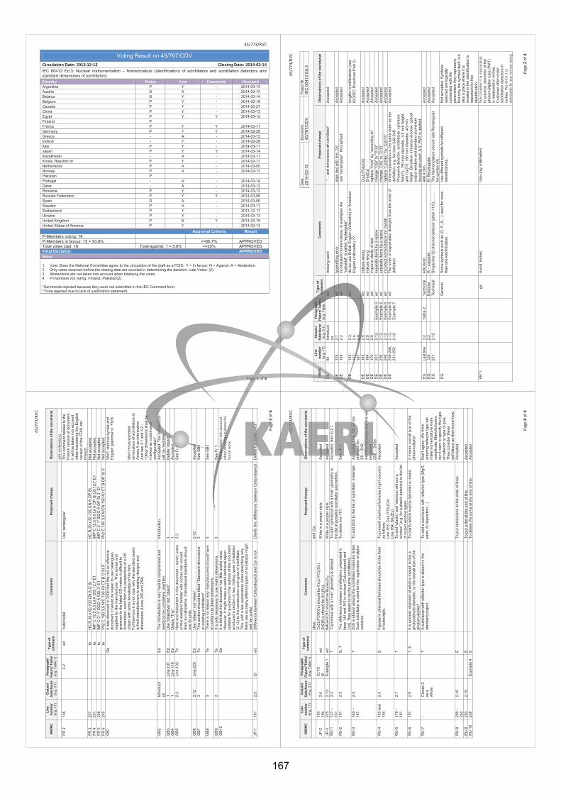
45/773/RVC
Page 1 of 4
Voting Result on 45/767/CDV Circulation Date: 2013-12-13 Closing Date: 2014-03-14 IEC 60412 Ed.3: Nuclear instrumentation – Nomenclature (identification) of scintillators and scintillation detectors and standard dimensions of scintillators
Country Status Vote Comments Received Argentina P Y - 2014-03-13 Austria O A - 2014-03-13 Belarus O Y - 2014-03-14 Belgium P Y - 2014-02-18 Canada P Y - 2014-02-27 China P Y - 2014-03-13 Egypt P Y Y 2014-03-12 Finland P France P Y Y 2014-03-11 Germany P Y Y 2014-02-26 Greece - A - 2014-03-13 Ireland - Y - 2014-02-28 Italy P Y - 2014-03-11 Japan P Y Y 2014-03-14 Kazakhstan - A - 2014-03-11 Korea, Republic of P Y - 2014-02-17 Netherlands P A - 2014-03-05 Norway P A - 2014-03-13 Pakistan P Portugal - A - 2014-03-14 Qatar - A - 2014-03-12 Romania P Y - 2014-03-13 Russian Federation P Y Y 2014-03-06 Spain O A - 2014-03-06 Sweden P A - 2014-03-11 Switzerland P Y - 2013-12-17 Ukraine P Y - 2014-03-13 United Kingdom P N Y 2014-03-10 United States of America P Y - 2014-03-14
Approval Criteria Result P-Members voting: 16 P-Members in favour: 15 = 93.8% >=66.7% APPROVED Total votes cast: 18 Total against: 1 = 5.6% <=25% APPROVED Final Decision: APPROVED
Notes 1. Vote: Does the National Committee agree to the circulation of the draft as a FDIS: Y = In favour; N = Against; A = Abstention. 2. Only votes received before the closing date are counted in determining the decision. Late Votes: (0). 3. Abstentions are not taken into account when totalizing the votes. 4. P-members not voting: Finland; Pakistan(2). *Comments rejected because they were not submitted in the IEC Comment form. **Vote rejected due to lack of justification statement.
45
/773
/RVC
Page
2 o
f 4
Dat
e D
ocum
ent
Pro
ject
Nr.
2014
-03-
12
45/7
67/C
DV
IE
C 6
0412
Ed.
3
MB
/NC
Li
ne
num
ber
(e.g
. 17)
Cla
use/
Su
bcla
use
(e.g
. 3.1
)
Para
grap
h/
Figu
re/ T
able
/ (e
.g. T
able
1)
Type
of
com
men
t C
omm
ents
Pr
opos
ed c
hang
e O
bser
vatio
ns o
f the
sec
reta
riat
DE
84
In
trodu
cti
on
ed
m
issi
ng w
ord
“… a
nd d
imen
sion
s of
sci
ntill
ator
” A
ccep
ted
DE
12
5 2.
1
ed
type
setti
ng e
rror
al
ign
text
with
line
124
A
ccep
ted
DE
12
8 2.
2
ed
inco
nsis
tent
nom
encl
atur
e; in
exa
mpl
es th
e “c
uboi
dal”
is c
alle
d “r
ecta
ngul
ar”
use
“rect
angu
lar”
thr
ough
out
Acc
epte
d
DE
13
2,
137,
18
7
2.3,
2.
4,
2.9
ed
do
we
use
Brit
ish
Eng
lish
(milli
met
re) o
r Am
eric
an
Eng
lish
(milli
met
er) ?
?
leng
ths
in m
illim
etre
s (s
ee
ISO
/IEC
Dire
ctiv
es P
art 2
)
DE
16
3 2.
5
ed
indi
ces
wro
ng
Cs 2
LiYC
l 6(C
e)
Acc
epte
d D
E
164
2.5
ed
in
dice
s w
rong
S
rI 2(E
u)
Acc
epte
d D
E
170
2.5
ed
im
prov
e cl
arity
of t
ext
repl
ace
“from
” by
“acc
ordi
ng to
” A
ccep
ted
DE
23
1 2.
12
Exa
mpl
e 3
ed
sepa
rate
item
s by
a s
pace
ch
ange
“OS
t” to
“O S
t” A
ccep
ted
DE
23
6 2.
12
Exa
mpl
e 4
ed
sepa
rate
item
s by
a s
pace
ch
ange
“OS
t” to
“O S
t” A
ccep
ted
DE
24
6 2.
12
Exa
mpl
e 6
ed
inco
rrect
nom
encl
atur
e fo
r cry
stal
re
plac
e “C
sI(N
a)” b
y “C
sI(T
l)”
Acc
epte
d D
E
246-
248,
25
1-25
2 2.
12,
2.12
E
xam
ple
6,
Exa
mpl
e 7
ed
The
orde
r of e
xpla
natio
n di
verg
es fr
om th
e or
der o
f de
finiti
on
Writ
e ex
plan
atio
n in
the
sam
e or
der a
s th
e de
finiti
on, e
.g. f
or li
nes
246-
248:
P
hosw
ich
dete
ctor
, sci
ntilla
tors
: cyl
inde
rs
NaI
(Tl),
190
mm
dia
met
er, 3
.5 m
m h
eigh
t, an
d C
sI(T
l): 1
90 m
m d
iam
eter
, 40
mm
he
ight
. Ber
ylliu
m e
ntra
nce
win
dow
, opt
ical
ou
tput
win
dow
and
sta
ndar
d al
umin
ium
ho
usin
g ar
e us
ed. A
5” P
MT
is a
pplie
d.
Acc
epte
d
EG
La
st li
ne
3.2
Tabl
e 2
Tech
nica
l 40
0.0m
m
406.
4 m
m
Acc
epte
d E
G
128
2.2
E
dito
rial
R –
cub
oida
l R
- Rec
tang
ular
A
ccep
ted
EG
25
1 2.
12
Te
chni
cal
Sin
gle-
line
32 c
hann
el d
etec
tor (
pitc
h =1
,6),.
......
...
The
Nom
encl
atur
e sh
ould
add
Rec
tang
ular
fo
r sym
bol (
R).
Acc
epte
d
EG
Gen
eral
S
ome
sym
bols
suc
h as
(C, P
, A,..
.) us
ed fo
r mor
e th
an o
ne id
entif
icat
ion.
U
se d
iffer
ent s
ymbo
ls fo
r diff
eren
t id
entif
icat
ions
. N
ot a
ccep
ted.
Sym
bols
se
lect
ed a
re lo
gica
lly
conn
ecte
d w
ith th
e pa
ram
eter
s th
ey re
pres
ent.
Not
onl
y th
e sy
mbo
l its
elf,
but
also
a p
lace
whe
re it
is
loca
ted
in th
e id
entif
icat
ion
is
impo
rtant
for t
his
iden
tific
atio
n.
FR 1
ge
Avo
id ‘i
nche
s’
Use
onl
y ‘m
illim
eter
s’
We
cons
ider
it is
impr
actic
al.
In p
ract
ice,
dia
met
er o
f the
ph
otom
ultip
lier t
ube
(PM
T)
is m
easu
red
in in
ches
. C
usto
mer
ofte
n or
der
scin
tilla
tion
dete
ctor
s in
in
ches
. We
thin
k it
is
advi
sabl
e to
use
inch
es a
long
45/7
73/R
VC
Page
3 o
f 4
MB
/NC
Li
ne
num
ber
(e.g
. 17)
Cla
use/
Su
bcla
use
(e.g
. 3.1
)
Para
grap
h/
Figu
re/ T
able
/ (e
.g. T
able
1)
Type
of
com
men
t C
omm
ents
Pr
opos
ed c
hang
e O
bser
vatio
ns o
f the
sec
reta
riat
with
milli
met
ers.
FR
2
136
2.
2 ed
‘c
ubic
oïda
l’ U
se ‘r
ecta
ngul
ar’
This
com
men
t rel
ates
to th
e Fr
ench
ver
sion
of d
ocum
ent.
It w
ill b
e ta
ken
into
acc
ount
w
hen
trans
latin
g th
e E
nglis
h ve
rsio
n of
the
FDIS
into
Fr
ench
. FR
3
227
te
HC
R 3
0 x
50 1
00 C
N A
O S
t H
C R
30
x 50
100
CN
A O
P S
t N
ot a
ccep
ted.
FR
4
231
te
IMP
C 1
2,5
6,5
Lil A
OS
t 12.
7 E
1 IM
P C
12,
5 6,
5 Li
l A O
P S
t LB
12.7
E1
Not
acc
epte
d.
FR 5
23
6
te
IM
P C
2“ 1
“ BG
O A
OS
t 3“ E
1 IM
P C
2“ 1
“ BG
O A
OP
St 3
“ E1
Not
acc
epte
d.
FR 6
24
5
te
P
h2 C
190
3,5
N/C
190
40
CT
B O
St 5
“ P
h2 C
190
3,5
N/C
N 1
90 4
0 C
T B
OP
St 5
“ N
ot a
ccep
ted.
G
B1
G
e It
was
obs
erve
d in
200
6 th
at th
is n
ot a
n ef
fect
ive
docu
men
t; it
wou
ld b
e ea
sier
to u
se c
atal
ogue
s su
pplie
d by
the
man
ufac
ture
r. Th
e sy
ntax
and
gr
amm
ar in
the
late
st C
D m
akes
it d
iffic
ult t
o un
ders
tand
, eve
n fro
m th
e pe
rspe
ctiv
e of
a U
K
citiz
en w
ith s
ome
know
ledg
e of
the
field
. Fu
rther
mor
e it
is n
ot c
lear
why
the
stan
dard
see
ks
to li
mit
man
ufac
ture
rs to
exi
stin
g de
sign
s an
d di
men
sion
s (L
ines
255
and
259
).
W
e’ll
impr
ove
synt
ax a
nd
Eng
lish
gram
mar
in F
DIS
W
e’ll
mov
e st
anda
rd
dim
ensi
ons
of s
cint
illato
rs to
A
nnex
A a
s in
form
ativ
e.
And
see
3.1
and
3.2
: “O
ther
dim
ensi
ons
shal
l be
mar
ked
as c
usto
miz
ed
conf
igur
atio
n”
GB
2
Intro
duct
ion
Ed
The
intro
duct
ion
is v
ery
hard
to c
ompr
ehen
d an
d ne
eds
to b
e co
mpl
etel
y re
writ
ten.
In
trodu
ctio
n A
ccep
ted.
The
intro
duct
ion
will
be
rew
ritte
n.
GB
3
1 Li
ne 1
07
Ed
Use
"Obj
ectiv
e" n
ot "o
bjec
t" 1
Del
ete
“obj
ect”
GB
4
1 Li
ne 1
10
Ed
Del
ete
"The
" 1
Acc
epte
d G
B5
2.
3 Li
ne 1
32
Te
Her
e an
d el
sew
here
in th
e do
cum
ent –
sur
ely
user
s of
this
sta
ndar
d fa
milia
r with
inch
es c
an c
onve
rt th
em to
milli
met
res.
Inte
rnat
iona
l sta
ndar
ds s
houl
d us
e S
I uni
ts.
2.3
See
Fr 1
GB
6
2.12
Li
ne 2
20
Ed
Use
"whe
re" n
ot "w
hen"
. 2.
12
Acc
epte
d G
B7
3
Te
Th
is s
ectio
n sh
ould
be
title
d "S
tand
ard
dim
ensi
ons
of e
xist
ing
scin
tilla
tors
". 3
See
GB
1
GB
8
3
Te
Ther
e is
no
reas
on w
hy m
anuf
actu
rers
sho
uld
have
to
con
form
to th
ese
dim
ensi
ons.
3
See
GB
1
GB
9
3
Te
It is
onl
y ne
cess
ary
to u
se m
etric
dim
ensi
ons.
3
See
Fr 1
G
B10
Ge
It is
felt
that
this
doc
umen
t has
littl
e us
eful
val
ue.
How
ever
, it m
ight
mak
e a
usef
ul te
chni
cal r
epor
t su
itabl
e fo
r gui
danc
e if
the
auth
ors
of th
e do
cum
ent
prod
uced
a s
ectio
n or
two,
link
ing
type
s of
radi
atio
n (2
.12)
to th
e co
nstru
ctio
n an
d ty
pes
of s
cint
illato
r.
This
, with
a fe
w e
xpla
nato
ry n
otes
des
crib
ing
why
th
ere
are
so m
any
diffe
rent
type
s of
sci
ntilla
tor m
ight
w
ell b
e us
eful
.
W
ill be
take
n in
to a
ccou
nt
whe
n dr
awin
g up
pla
ns fo
r fu
ture
wor
k.
JP-1
16
1 2.
5 C
I ed
D
iffer
ence
bet
wee
n C
sI(u
ndop
ed) a
nd C
sI is
not
C
larif
y th
e di
ffere
nce
betw
een
CsI
(und
oped
) D
elet
e C
sI (u
ndop
ed)
45/7
73/R
VC
Page
4 o
f 4
MB
/NC
Li
ne
num
ber
(e.g
. 17)
Cla
use/
Su
bcla
use
(e.g
. 3.1
)
Para
grap
h/
Figu
re/ T
able
/ (e
.g. T
able
1)
Type
of
com
men
t C
omm
ents
Pr
opos
ed c
hang
e O
bser
vatio
ns o
f the
sec
reta
riat
clea
r. an
d C
sI.
JP-2
16
3 16
4 2.
5 C
LYC
S
I ed
C
s2Li
YCl6
(Ce)
sho
uld
be C
s 2Li
YCl 6(
Ce)
. S
rl2(E
u) s
houl
d be
Srl 2
(Eu)
. W
rite
in a
pro
per s
tyle
. A
ccep
ted
JP-3
22
5 2.
12
Exa
mpl
e 1
ed
Bi4
Ge3
O12
sho
uld
be B
i 4Ge 3
O12
. W
rite
in a
pro
per s
tyle
. A
ccep
ted
RU
-1
127
– 13
1 2.
2
T “C
ylin
dric
al w
ith a
hol
e” g
eom
etry
is a
bsen
t.
To a
dd “c
ylin
dric
al w
ith a
hol
e” g
eom
etry
to
the
list o
f pos
sibl
e sc
intil
lato
r geo
met
ries.
A
ccep
ted.
Add
to 2
.1
RU
-2
161
2.5
E
, T
The
diffe
renc
e be
twee
n sc
intil
laat
ors
pres
ente
d in
lin
es 1
44 a
nd 1
61 is
unc
lear
[CsI
(und
oped
) and
C
sI].
They
see
m to
be
the
sam
e sc
intil
lato
rs.
To d
elet
e lin
e 16
1.
See
JP
-1
RU
-3
140
– 16
7
2.5
T
ZnS
is a
bsen
t am
ong
the
scin
tilla
tor m
ater
ials
list
ed.
Suc
h sc
intil
lato
r is
used
for t
he re
gist
ratio
n of
alp
ha
radi
atio
n.
To a
dd Z
nS to
the
list o
f sci
ntilla
tor m
ater
ials
. A
ccep
ted.
Lin
e 15
6 w
ill b
e ch
ange
d fo
r: ZS
– Z
nS;
And
the
follo
win
g ne
w li
ne w
ill
be a
dded
: ZS
E –
ZnS
e R
U-4
16
3 an
d 16
4 2.
5
E
Figu
res
in c
hem
ical
form
ulas
sho
uld
be in
the
form
of
sub
scrip
ts.
To p
rese
nt c
hem
ical
form
ulas
(rig
ht c
olum
n)
as fo
llow
s:
Line
163
: Cs 2
LiYC
l 6(C
e)
Line
164
: SrI 2
(Eu)
Acc
epte
d
RU
-5
179
– 18
1
2.7
T
To
add
“pla
stic
” and
“det
ecto
r with
out a
w
indo
w” (
e.g.
for a
pla
stic
det
ecto
r) to
the
list
of o
utpu
t win
dow
type
s.
Acc
epte
d
RU
-6
187
2.9
T,
E
It is
unc
lear
, dia
met
er o
f wha
t is
mea
nt: i
s th
is a
ph
otoc
atho
de d
iam
eter
, or t
he o
vera
ll si
ze o
f the
ph
otom
ultip
lier?
To c
larif
y w
hich
exa
ctly
dia
met
er is
mea
nt.
It m
eans
ove
rall
size
of t
he
phot
omul
tiplie
r
RU
-7
- C
laus
e 2
as a
w
hole
.
T
A s
ubcl
ause
with
refle
ctor
type
is a
bsen
t in
the
stan
dard
pro
ject
. To
add
a s
ubcl
ause
with
refle
ctor
type
(MgO
, pa
int,
Al d
epos
ition
…)
Don
’t ag
ree.
We
thin
k en
terin
g re
flect
or ty
pe w
ill
mak
e no
men
clat
ure
mor
e co
mpl
icat
e. M
anuf
actu
rers
do
n’t w
ant t
o sp
ecify
the
type
of
refle
ctor
or t
ype
of g
lue.
Th
ey c
onsi
der t
hese
de
finiti
ons
as th
eir k
now
-how
. R
U-8
20
0 –
202
2.
10
E
To p
ut s
emic
olon
s at
the
ends
of l
ines
. A
ccep
ted
RU
-9
203
2.10
E
To
put
a d
ot a
t the
end
of l
ine.
A
ccep
ted
RU
-10
236
E
xam
ple
4 E
To d
elet
e th
e co
ma
at th
e en
d of
line
. A
ccep
ted
167
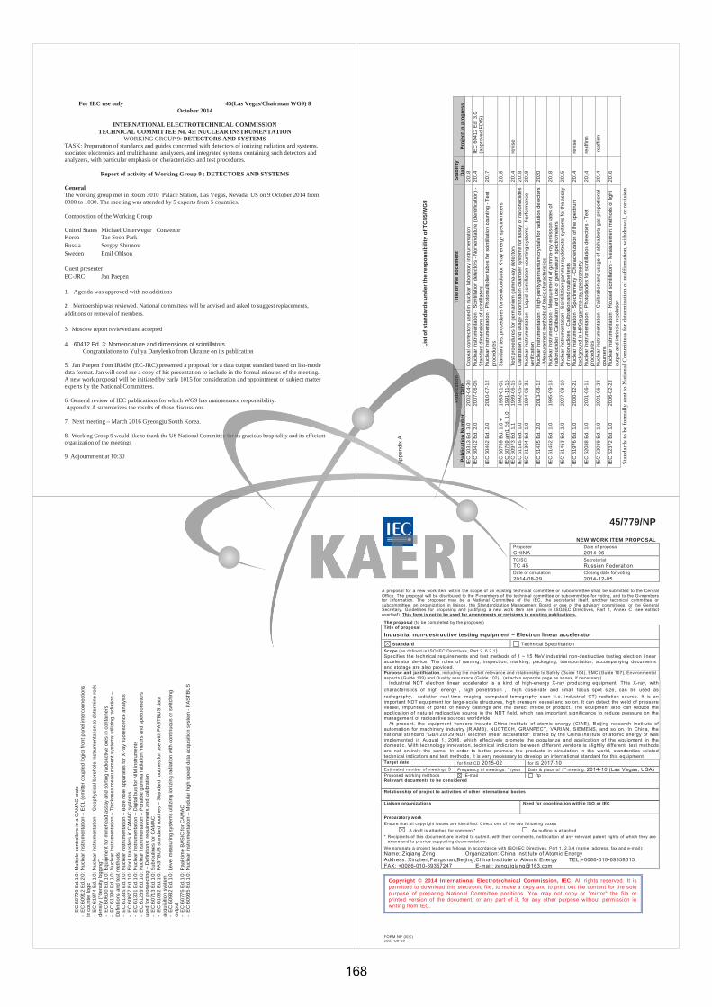
For IEC use only 45(Las Vegas/Chairman WG9) 8 October 2014
INTERNATIONAL ELECTROTECHNICAL COMMISSION TECHNICAL COMMITTEE No. 45: NUCLEAR INSTRUMENTATION
WORKING GROUP 9: DETECTORS AND SYSTEMS TASK: Preparation of standards and guides concerned with detectors of ionizing radiation and systems, ssociated electronics and multichannel analyzers, and integrated systems containing such detectors and analyzers, with particular emphasis on characteristics and test procedures.
Report of activity of Working Group 9 : DETECTORS AND SYSTEMS
General The working group met in Room 3010 Palace Station, Las Vegas, Nevada, US on 9 October 2014 from 0900 to 1030. The meeting was attended by 5 experts from 5 countries.
Composition of the Working Group
United States Michael Unterweger Convenor Korea Tae Soon Park Russia Sergey Shumov Sweden Emil Ohlson
Guest presenter EC-JRC Jan Paepen
1. Agenda was approved with no additions
2. Membership was reviewed. National committees will be advised and asked to suggest replacements, additions or removal of members.
3. Moscow report reviewed and accepted 4. 60412 Ed. 3: Nomenclature and dimensions of scintillators Congratulations to Yuliya Danylenko from Ukraine on its publication
5. Jan Paepen from IRMM (EC-JRC) presented a proposal for a data output standard based on list-mode data format. Jan will send me a copy of his presentation to include in the formal minutes of the meeting. A new work proposal will be initiated by early 1015 for consideration and appointment of subject matter experts by the National Committees.
6. General review of IEC publications for which WG9 has maintenance responsibility. Appendix A summarizes the results of these discussions.
7. Next meeting – March 2016 Gyeongju South Korea.
8. Working Group 9 would like to thank the US National Committee for its gracious hospitality and its efficient organization of the meetings
9. Adjournment at 10:30
App
endi
x A
List
of s
tand
ards
und
er th
e re
spon
sibi
lity
of T
C45
/WG
9
Publ
icat
ion
Num
ber
Publ
icat
ion
Dat
e Ti
tle o
f the
doc
umen
t St
abili
ty
Dat
e Pr
ojec
t in
prog
ress
IE
C 6
0313
Ed.
3.0
20
02-0
4-30
C
oaxi
al c
onne
ctor
s us
ed in
nuc
lear
labo
rato
ry in
stru
men
tatio
n 20
18
IE
C 6
0412
Ed.
2.0
20
07-0
6-05
N
ucle
ar in
stru
men
tatio
n - S
cint
illat
ion
dete
ctor
s - N
omen
clat
ure
(iden
tific
atio
n) -
Sta
ndar
d di
men
sion
s of
sci
ntill
ator
s20
14
IEC
604
12 E
d. 3
.0
(app
rove
d FD
IS)
IEC
604
62 E
d. 2
.0
2010
-07-
12
Nuc
lear
inst
rum
enta
tion
- Pho
tom
ultip
lier t
ubes
for s
cint
illatio
n co
untin
g - T
est
proc
edur
es20
17
IEC
607
59 E
d. 1
.0 +
IE
C 6
0759
am
1 Ed
. 1.0
1983
-01-
01
1991
-11-
15
Stan
dard
test
pro
cedu
res
for s
emic
ondu
ctor
X-r
ay e
nerg
y sp
ectro
met
ers
2018
IEC
609
73 E
d. 1
.1
1989
-06-
15
Test
pro
cedu
res
for g
erm
aniu
m g
amm
a-ra
y de
tect
ors
2014
re
vise
IE
C 6
1145
Ed.
1.0
19
92-0
5-15
C
alib
ratio
n an
d us
age
of io
niza
tion
cham
ber s
yste
ms
for a
ssay
of r
adio
nucl
ides
2018
IEC
613
04 E
d. 1
.0
1994
-05-
31
Nuc
lear
inst
rum
enta
tion
- Liq
uid-
scin
tilla
tion
coun
ting
syst
ems
- Per
form
ance
ve
rific
atio
n 20
18
IEC
614
35 E
d. 2
.0
2013
-08-
12
Nuc
lear
inst
rum
enta
tion
- Hig
h-pu
rity
germ
aniu
m c
ryst
als
for r
adia
tion
dete
ctor
s - M
easu
rem
ent m
etho
ds o
f bas
ic c
hara
cter
istic
s20
20
IEC
614
52 E
d. 1
.0
1995
-09-
13
Nuc
lear
inst
rum
enta
tion
- Mea
sure
men
t of g
amm
a-ra
y em
issi
on ra
tes
of
radi
onuc
lides
- C
alib
ratio
n an
d us
e of
ger
man
ium
spe
ctro
met
ers
2018
IEC
614
53 E
d. 2
.0
2007
-08-
10
Nuc
lear
inst
rum
enta
tion
- Sci
ntill
atio
n ga
mm
a ra
y de
tect
or s
yste
ms
for t
he a
ssay
of
radi
onuc
lides
- C
alib
ratio
n an
d ro
utin
e te
sts
2015
IEC
619
76 E
d. 1
.0
2000
-12-
21
Nuc
lear
inst
rum
enta
tion
- Spe
ctro
met
ry -
Cha
ract
eriz
atio
n of
the
spec
trum
ba
ckgr
ound
in H
PGe
gam
ma-
ray
spec
trom
etry
20
14
revi
se
IEC
620
88 E
d. 1
.0
2001
-06-
11
Nuc
lear
inst
rum
enta
tion
- Pho
todi
odes
for s
cint
illat
ion
dete
ctor
s - T
est
proc
edur
es
2014
re
affir
m
IEC
620
89 E
d. 1
.0
2001
-06-
28
Nuc
lear
inst
rum
enta
tion
- Cal
ibra
tion
and
usag
e of
alp
ha/b
eta
gas
prop
ortio
nal
coun
ters
2014
re
affir
m
IEC
623
72 E
d. 1
.0
2006
-02-
23
Nuc
lear
inst
rum
enta
tion
- Hou
sed
scin
tilla
tors
- M
easu
rem
ent m
etho
ds o
f lig
ht
outp
ut a
nd in
trins
ic re
solu
tion
2016
Stan
dard
s to
be fo
rmal
ly se
nt to
Nat
iona
l Com
mitt
ees f
or d
eter
min
atio
n of
reaf
firm
atio
n, w
ithdr
awal
, or r
evis
ion
- IEC
607
29 E
d.1.
0: M
ultip
le c
ontro
llers
in a
CAM
AC c
rate
- I
EC 6
0912
Ed.
2.0:
Nuc
lear
inst
rum
enta
tion
– EC
L (e
mitt
er c
oupl
ed lo
gic)
fron
t pan
el in
terc
onne
ctio
ns
in c
ount
er lo
gic
- IEC
618
74 E
d.1.
0: N
ucle
ar in
stru
men
tatio
n –
Geo
phys
ical
bor
ehol
e in
stru
men
tatio
n to
det
erm
ine
rock
de
nsity
(“de
nsity
logg
ing”
) - I
EC 6
0600
Ed.
1.0:
Equ
ipm
ent f
or m
ineh
ead
assa
y an
d so
rting
radi
oact
ive
ores
in c
onta
iner
s - I
EC 6
1336
Ed.
1.0:
Nuc
lear
inst
rum
enta
tion
– Th
ickn
ess
mea
sure
men
t sys
tem
s ut
ilizi
ng ra
diat
ion
– D
efin
ition
s an
d te
st m
etho
ds
- IEC
613
35 E
d.1.
0: N
ucle
ar in
stru
men
tatio
n –
Bore
hol
e ap
para
tus
for X
-ray
fluo
resc
ence
ana
lysi
s - I
EC 6
0677
Ed.
1.0:
Blo
ck tr
ansf
ers
in C
AMAC
sys
tem
s - I
EC 6
1301
Ed.
1.0:
Nuc
lear
inst
rum
enta
tion
– D
igita
l bus
for N
IM in
stru
men
ts
- IEC
612
39 E
d.1.
0: N
ucle
ar in
stru
men
tatio
n –
Porta
ble
gam
ma
radi
atio
n m
eter
s an
d sp
ectro
met
ers
used
for p
rosp
ectin
g –
Def
initi
ons,
requ
irem
ents
and
cal
ibra
tion
- IEC
607
13 E
d.1.
0: S
ubro
utin
es fo
r CAM
AC
- IEC
610
52 E
d.1.
0: F
ASTB
US
stan
dard
rout
ines
– S
tand
ard
rout
ines
for u
se w
ith F
ASTB
US
data
ac
quis
ition
sys
tem
- I
EC 6
0982
Ed.
1.0:
Lev
el m
easu
ring
syst
ems
utiliz
ing
ioni
zing
radi
atio
n w
ith c
ontin
uous
or s
witc
hing
ou
tput
- I
EC 6
0775
Ed.
1.0:
Raa
l-tim
e BA
SIC
for C
AMAC
- I
EC 6
0935
Ed.
1.0:
Nuc
lear
inst
rum
enta
tion
– M
odul
ar h
igh
spee
d da
ta a
cqui
sitio
n sy
stem
- FA
STBU
S
FORM NP (IEC) 2007-08-09
45/779/NP
NEW WORK ITEM PROPOSAL Proposer CHINA
Date of proposal 2014-06
TC/SCTC 45
SecretariatRussian Federation
Date of circulation 2014-08-29
Closing date for voting 2014-12-05
A proposal for a new work item within the scope of an existing technical committee or subcommittee shall be submitted to the Central Office. The proposal will be distributed to the P-members of the technical committee or subcommittee for voting, and to the O-members for information. The proposer may be a National Committee of the IEC, the secretariat itself, another technical committee or subcommittee, an organization in liaison, the Standardization Management Board or one of the advisory committees, or the General Secretary. Guidelines for proposing and justifying a new work item are given in ISO/IEC Directives, Part 1, Annex C (see extract overleaf). This form is not to be used for amendments or revisions to existing publications.
The proposal (to be completed by the proposer) Title of proposal
Industrial non-destructive testing equipment – Electron linear accelerator Standard Technical Specification
Scope (as defined in ISO/IEC Directives, Part 2, 6.2.1) Specifies the technical requirements and test methods of 1 ~ 15 MeV industrial non-destructive testing electron linear accelerator device. The rules of naming, inspection, marking, packaging, transportation, accompanying documents and storage are also provided. Purpose and justification, including the market relevance and relationship to Safety (Guide 104), EMC (Guide 107), Environmental aspects (Guide 109) and Quality assurance (Guide 102) . (attach a separate page as annex, if necessary)
Industrial NDT electron linear accelerator is a kind of high-energy X-ray producing equipment. This X-ray, with characteristics of high energy high penetration high dose-rate and small focus spot size, can be used as radiography, radiation real-time imaging, computed tomography scan (i.e. industrial CT) radiation source. It is an important NDT equipment for large-scale structures, high pressure vessel and so on. It can detect the weld of pressure vessel, impurities or pores of heavy castings and the defect inside of product. The equipment also can reduce the application of natural radioactive source in the NDT field, which has important significance to reduce pressure on the management of radioactive sources worldwide.
At present, the equipment vendors include China institute of atomic energy (CIAE), Beijing research institute of automation for machinery industry (RIAMB), NUCTECH, GRANPECT, VARIAN, SIEMENS, and so on. In China, the national standard "GB/T20129 NDT electron linear accelerator" drafted by the China institute of atomic energy of was implemented in August 1, 2006, which effectively promote the popularize and application of the equipment in the domestic. With technology innovation, technical indicators between different vendors is slightly different, test methods are not entirely the same. In order to better promote the products in circulation in the world, standardize related technical indicators and test methods, it is very necessary to develop an international standard for this equipment Target date for first CD 2015-02 for IS 2017-10 Estimated number of meetings 3 Frequency of meetings: 1/year Date & place of 1st meeting: 2014-10 (Las Vegas, USA) Proposed working methods E-mail ftp Relevant documents to be considered
Relationship of project to activities of other international bodies Liaison organizations
Need for coordination within ISO or IEC
Preparatory work Ensure that all copyright issues are identified. Check one of the two following boxes A draft is attached for comment* An outline is attached * Recipients of this document are invited to submit, with their comments, notification of any relevant patent rights of which they are
aware and to provide supporting documentation. We nominate a project leader as follows in accordance with ISO/IEC Directives, Part 1, 2.3.4 (name, address, fax and e-mail): Name: Ziqiang Zeng Organization: China Institute of Atomic Energy Address: Xinzhen,Fangshan,Beijing,China Institute of Atomic Energy TEL:+0086-010-69358615 FAX: +0086-010-69357247 E-mail: [email protected]
Copyright © 2014 International Electrotechnical Commission, IEC. All rights reserved. It is permitted to download this electronic file, to make a copy and to print out the content for the sole purpose of preparing National Committee positions. You may not copy or "mirror" the file or printed version of the document, or any part of it, for any other purpose without permission in writing from IEC.
168
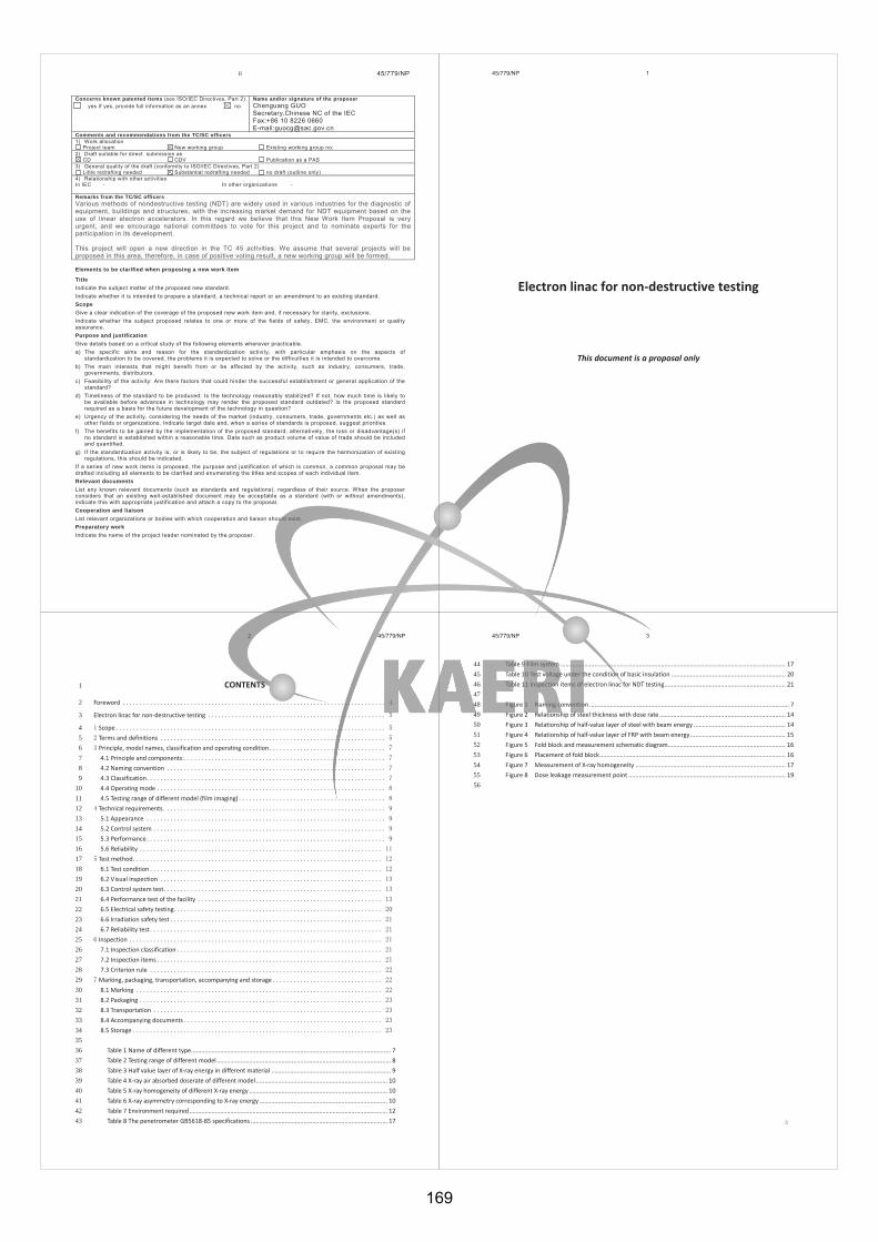
ii 45/779/NP
Concerns known patented items (see ISO/IEC Directives, Part 2) Name and/or signature of the proposer
yes If yes, provide full information as an annex no Chenguang GUO Secretary,Chinese NC of the IEC Fax:+86 10 8226 0660 E-mail:[email protected]
Comments and recommendations from the TC/SC officers 1) Work allocation
Project team New working group Existing working group no: 2) Draft suitable for direct submission as
CD CDV Publication as a PAS 3) General quality of the draft (conformity to ISO/IEC Directives, Part 2)
Little redrafting needed Substantial redrafting needed no draft (outline only) 4) Relationship with other activities In IEC - In other organizations - Remarks from the TC/SC officers Various methods of nondestructive testing (NDT) are widely used in various industries for the diagnostic of equipment, buildings and structures, with the increasing market demand for NDT equipment based on the use of linear electron accelerators. In this regard we believe that this New Work Item Proposal is very urgent, and we encourage national committees to vote for this project and to nominate experts for the participation in its development. This project will open a new direction in the TC 45 activities. We assume that several projects will be proposed in this area, therefore, in case of positive voting result, a new working group will be formed. Elements to be clarified when proposing a new work item
Title Indicate the subject matter of the proposed new standard. Indicate whether it is intended to prepare a standard, a technical report or an amendment to an existing standard. Scope Give a clear indication of the coverage of the proposed new work item and, if necessary for clarity, exclusions. Indicate whether the subject proposed relates to one or more of the fields of safety, EMC, the environment or quality assurance. Purpose and justification Give details based on a critical study of the following elements wherever practicable. a) The specific aims and reason for the standardization activity, with particular emphasis on the aspects of
standardization to be covered, the problems it is expected to solve or the difficulties it is intended to overcome. b) The main interests that might benefit from or be affected by the activity, such as industry, consumers, trade,
governments, distributors. c) Feasibility of the activity: Are there factors that could hinder the successful establishment or general application of the
standard? d) Timeliness of the standard to be produced: Is the technology reasonably stabilized? If not, how much time is likely to
be available before advances in technology may render the proposed standard outdated? Is the proposed standard required as a basis for the future development of the technology in question?
e) Urgency of the activity, considering the needs of the market (industry, consumers, trade, governments etc.) as well as other fields or organizations. Indicate target date and, when a series of standards is proposed, suggest priorities.
f) The benefits to be gained by the implementation of the proposed standard; alternatively, the loss or disadvantage(s) if no standard is established within a reasonable time. Data such as product volume of value of trade should be included and quantified.
g) If the standardization activity is, or is likely to be, the subject of regulations or to require the harmonization of existing regulations, this should be indicated.
If a series of new work items is proposed, the purpose and justification of which is common, a common proposal may be drafted including all elements to be clarified and enumerating the titles and scopes of each individual item. Relevant documents List any known relevant documents (such as standards and regulations), regardless of their source. When the proposer considers that an existing well-established document may be acceptable as a standard (with or without amendments), indicate this with appropriate justification and attach a copy to the proposal. Cooperation and liaison List relevant organizations or bodies with which cooperation and liaison should exist. Preparatory work Indicate the name of the project leader nominated by the proposer.
45/779/NP 1
Electron linac for non-destructive testing
This document is a proposal only
2 45/779/NP
CONTENTS 1
Foreword 2
Electron linac for non-destructive testing 3
Scope 4 Terms and definitions 5 Principle, model names, classification and operating condition 6
4.1 Principle and components: 7 4.2 Naming convention 8 4.3 Classification 9 4.4 Operating mode 10 4.5 Testing range of different model (film imaging) 11
Technical requirements. 12 5.1 Appearance 13 5.2 Control system 14 5.3 Performance 15 5.6 Reliability 16
Test method 17 6.1 Test condition 18 6.2 Visual inspection 19 6.3 Control system test 20 6.4 Performance test of the facility 21 6.5 Electrical safety testing 22 6.6 Irradiation safety test 23 6.7 Reliability test 24
Inspection 25 7.1 Inspection classification 26 7.2 Inspection items 27 7.3 Criterion rule 28
Marking, packaging, transportation, accompanying and storage 29 8.1 Marking 30 8.2 Packaging 31 8.3 Transportation 32 8.4 Accompanying documents 33 8.5 Storage 34
35 Table 1 Name of different type ..................................................................................................................... 7 36 Table 2 Testing range of different model ...................................................................................................... 8 37 Table 3 Half value layer of X-ray energy in different material ...................................................................... 9 38 Table 4 X-ray air absorbed doserate of different model ............................................................................. 10 39 Table 5 X-ray homogeneity of different X-ray energy ................................................................................. 10 40 Table 6 X-ray asymmetry corresponding to X-ray energy ........................................................................... 10 41 Table 7 Environment required .................................................................................................................... 12 42 Table 8 The penetrometer GB5618-85 specifications ................................................................................ 17 43
45/779/NP 3
Table 9 Film system .................................................................................................................................... 17 44 Table 10 Test voltage under the condition of basic insulation ................................................................... 20 45 Table 11 Inspection items of electron linac for NDT testing ....................................................................... 21 46
47 Figure 1 Naming convention ..................................................................................................................... 7 48 Figure 2 Relationship of steel thickness with dose rate .......................................................................... 14 49 Figure 3 Relationship of half-value layer of steel with beam energy ...................................................... 14 50 Figure 4 Relationship of half-value layer of FRP with beam energy ........................................................ 15 51 Figure 5 Fold block and measurement schematic diagram ..................................................................... 16 52 Figure 6 Placement of fold block ............................................................................................................. 16 53 Figure 7 Measurement of X-ray homogeneity ........................................................................................ 17 54 Figure 8 Dose leakage measurement point ............................................................................................ 19 55 56
169

4 45/779/NP
Foreword 57
Electron linear accelerator is a kind of high-energy X-ray producing equipment. This X-ray, with characteristics 58 of high energy, high penetration, high doserate and small focus spot size, can be used as Industrial NDT 59 radiography, radiation real-time imaging, and computed tomography scan (i.e. industrial CT) radiation source. 60 It can detect the weld of pressure vessel, impurities or pores of heavy castings and the defect inside of 61 product. The equipment also can reduce the application of natural radioactive source in the NDT field, which 62 has important significance to reduce pressure on the management of radioactive sources worldwide. 63
Annex A is normative, annex B is informative. 64
45/779/NP 5
Electron linac for non-destructive testing 65
Scope 66
The standard gives the guidelines for electron linear accelerator equipment for non-destructive testing, 67 including the rules of naming, technical requirements, test methods, inspection, marking, packaging, 68 transportation, accompanying documents and storage. 69 It is applicable to 1 ~ 15MeV non-destructive testing electron linear accelerator device(hereinafter referred 70 to as the "device "). 71
Terms and definitions 72
For the purposes of this document, the following terms and definitions apply. 73 2.1 74 linear electron accelerator 75 LINAC 76 an apparatus for producing high energy electrons by accelerating them along a waveguide. The electrons, 77 strike a target to produce X-rays 78 79 [SOURCE: ISO 5576:1997(en), 2.84] 80 81 2.2 82 X-rays 83 penetrating electromagnetic radiation, within the approximate wavelength range of 1 nm to 0,000 1 nm, 84 produced when high velocity electrons impinge on a metal target 85 86 [ISO 5576:1997(en), 2.129] 87
88 2.3 89 X-ray beam energy 90 max energy of X-ray with continuous spectrum 91 E 92 MeV 93
94 2.4 95 wedge X-ray field 96 X-radiation field with a dose distribution that changes approximately linearly with distance from the beam 97 edge along a line perpendicular to and passing through the radiation beam axis 98 99 [SOURCE: IEC 60976, ed. 2.0 (2007-10), 3.32] 100
101
6 45/779/NP
2.5 102 half-value layer 103 HVL 104 the thickness of specified material which, when introduced into the beam of X- or gamma radiation, reduces 105 its intensity by a half. Symbol is d1/2, the unit is mm 106 107 [ISO 5576:1997(en), 2.68] 108 109 2.7 110 X-ray beam focal spot size 111 the dimension across the focal spot of an accelerating tube, measured parallel to the plane of the film or the 112 fluorescent screen 113 d 114 mm 115
116 2.8 117 X-ray beam homogeneity 118 a ratio of dose rate in circumference to the one at central axis 1m away from target, where the measuring point is 119 at the vertical plane in an angle with central axis 120 121 2.9 122 X-ray beam dose rate 123 volume of ionization caused by x-ray in the air per unit time at 1m away from target 124 d 125 Gy/min 126 127 2.10 128 X-ray beam symmetry 129 in percentage, a ratio of difference value to mean value between maximum and minimum of dose rate at the 130 point and symmetrical point in the circumference, where the measuring point is at the plane vertical with 131 central axis in a angle with central axis 132 133 2.11 134 photographic sensitivity 135 in percentage, a ratio of minimal size of defect that can be observed in the film to the thickness of work piece 136 137 2.12 138 leakage dose rate 139 a ratio of dose rate at sphere (beyond x-ray field) to the one at axis 1m away from target, where center of 140 sphere is target and radius is 1m 141 142 2.13 143 X-ray head 144 That part of an X-ray installation that contains the accelerating tube in its shield 145 146 2.14 147
45/779/NP 7
dual energy accelerator 148 accelerator with two different energy levels which can work at three mods: signal low energy mode, signal 149 high energy mode and pulse to pulse energy switching mode 150 151
Principle, model names, classification and operating condition 152
3.1 Principle and components: 153 Principle of electron linear accelerator for nondestructive testing: electron gun is the equipment that produce 154 electrons when the cathode is heated by filament. Electron beam enter the accelerating tube under high 155 electric field and are accelerated by the microwave field. X-ray is produced when electron beam with high 156 energy bomb the target. Electron Beam gains energy from microwave field in Accelerating tube. Microwave 157 power source is magnetron or klystron and electron is produced by electron gun. High voltage pulse, which is 158 produced by modulator, is essential to magnetron and electron gun. To avoid reflection of microwave power 159 and absorb rest of microwave energy, a four-terminal ring device is mounted between accelerating tube and 160 magnetron. Constant temperature water cooling chiller is use to ensure the normal running of the accelerator 161 because magnetron, accelerating tube, four-terminal ring device, target and waveguide ceramic window 162 generate heat at runtime. 163 Electron linear accelerator for nondestructive testing consists of the following components. 164 a) X-ray head 165 b) modulator 166 c) temperature control unit(TCU) 167 d) control system 168 e) power distribution cabinet 169 f) safety interlock system 170 g) interconnecting cables (X-ray head to modulator, modulator to console) and hoses (TCU to X-ray head) 171 NOTE Crane system can be customized according to the customers’ demands. 172
173 3.2 Naming convention 174
The rules of naming is showed in figure 1 175
XX- XX D / XXX 176 177 Max X-ray dose-rate 178 X-ray energy (D: dual energy, blank: single energy) 179
= Model 180
Figure 1 Naming convention 181
3.3 Classification 182
Table 1 Name of different type 183
Model specification
Note X-ray energy MeV
Max X-ray dose rate Gy/min
XX-2/200 2 2 Single energy type
170
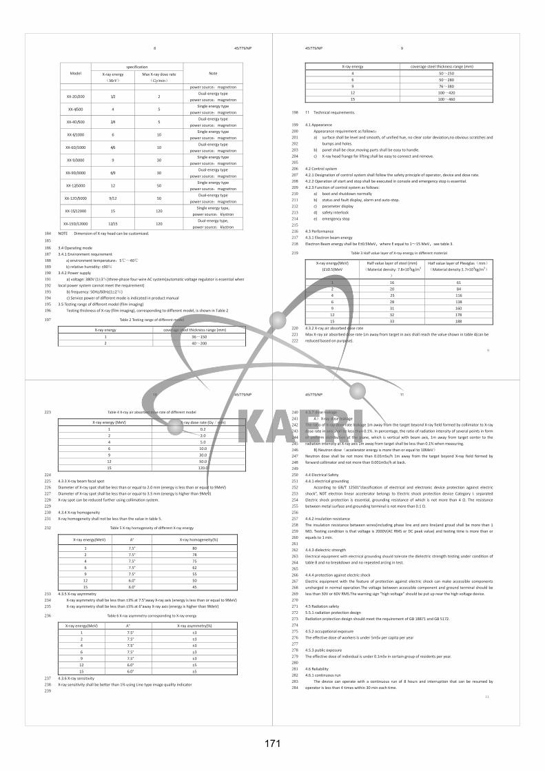
8 45/779/NP
Model specification
Note X-ray energy MeV
Max X-ray dose rate Gy/min
power source magnetron
XX-2D/200 1/2 2 Dual-energy type
power source magnetron
XX-4/500 4 5 Single energy type
power source magnetron
XX-4D/500 2/4 5 Dual-energy type
power source magnetron
XX-6/1000 6 10 Single energy type
power source magnetron
XX-6D/1000 4/6 10 Dual-energy type
power source magnetron
XX-9/3000 9 30 Single energy type
power source magnetron
XX-9D/3000 6/9 30 Dual-energy type
power source magnetron
XX-12/5000 12 50 Single energy type
power source magnetron
XX-12D/5000 9/12 50 Dual-energy type
power source magnetron
XX-15/12000 15 120 Single energy type,
power source klystron
XX-15D/12000 12/15 120 Dual-energy type,
power source klystron NOTE Dimension of X-ray head can be customized. 184
185
3.4 Operating mode 186 3.4.1 Environment requirement 187
a) environment temperature 5 40 188 b) relative humidity 189
3.4.2 Power supply 190 a) voltage: 380V (1 3 )three-phase four-wire AC system(automatic voltage regulator is essential when 191
local power system cannot meet the requirement) 192 b) frequency: 50Hz/60Hz(1 2 ) 193 c) Service power of different mode is indicated in product manual 194
3.5 Testing range of different model (film imaging) 195 Testing thickness of X-ray (film imaging), corresponding to different model, is shown in Table 2 196
Table 2 Testing range of different model 197
X-ray energy coverage steel thickness range (mm)
1 36 150 2 40 200
45/779/NP 9
X-ray energy coverage steel thickness range (mm)
4 50 250 6 50 280 9 76 380
12 100 420 15 100 460
Technical requirements. 198
4.1 Appearance 199 Appearance requirement as follows 200 a) surface shall be level and smooth, of unified hue, no clear color deviation,no obvious scratches and 201
bumps and holes. 202 b) panel shall be clear,moving parts shall be easy to handle. 203 c) X-ray head frange for lifting shall be easy to connect and remove. 204
205 4.2 Control system 206 4.2.1 Designation of control system shall follow the safety principle of operator, device and dose rate. 207 4.2.2 Operation of start and stop shall be executed in console and emergency stop is essential. 208 4.2.3 Function of control system as follows: 209
a) boot and shutdown normally 210 b) status and fault display, alarm and auto-stop. 211 c) parameter display 212 d) safety interlock 213 e) emergency stop 214
215 4.3 Performance 216 4.3.1 Electron beam energy 217 Electron Beam energy shall be E±0.5MeV where E equal to 1 15 MeV see table 3. 218
Table 3 Half value layer of X-ray energy in different material 219
X-ray energy(MeV) (E±0.5)MeV
Half value layer of steel (mm) Material density: 7.8×10³kg/m3
Half value layer of Plexiglas mm Material density:1.7×10³kg/m3
1 16 61 2 20 84 4 25 116 6 28 138 9 31 160
12 32 178 15 33 188
4.3.2 X-ray air absorbed dose rate 220 Max X-ray air absorbed dose rate 1m away from target in axis shall reach the value shown in table 4(can be 221 reduced based on purpose). 222
10 45/779/NP
Table 4 X-ray air absorbed dose rate of different model 223
X-ray energy (MeV) X-ray dose rate (Gy min)
1 0.2 2 2.0 4 5.0 6 10.0 9 30.0
12 50.0 15 120.0
224 4.3.3 X-ray beam focal spot 225 Diameter of X-ray spot shall be less than or equal to 2.0 mm (energy is less than or equal to 9MeV) 226 Diameter of X-ray spot shall be less than or equal to 3.5 mm (energy is higher than 9MeV) 227 X-ray spot can be reduced further using collimation system. 228 229 4.3.4 X-ray homogeneity 230 X-ray homogeneity shall not be less than the value in table 5. 231
Table 5 X-ray homogeneity of different X-ray energy 232
X-ray energy(MeV) A° X-ray homogeneity(%)
1 7.5° 80 2 7.5° 78 4 7.5° 75 6 7.5° 62 9 7.5° 55
12 6.0° 50 15 6.0° 45
4.3.5 X-ray asymmetry 233 X-ray asymmetry shall be less than ±3% at 7.5°away X-ray axis (energy is less than or equal to 9MeV) 234 X-ray asymmetry shall be less than ±5% at 6°away X-ray axis (energy is higher than 9MeV) 235
Table 6 X-ray asymmetry corresponding to X-ray energy 236
X-ray energy(MeV) A° X-ray asymmetry(%)
1 7.5° ±3 2 7.5° ±3 4 7.5° ±3 6 7.5° ±3 9 7.5° ±3
12 6.0° ±5 15 6.0° ±5
4.3.6 X-ray sensitivity 237 X-ray sensitivity shall be better than 1% using Line type image quality indicator 238 239
45/779/NP 11
4.3.7 dose leakage 240 A X-ray dose leakage 241
The ratio of X-ray dose rate leakage 1m away from the target beyond X-ray field formed by collimator to X-ray 242 dose rate in axis shall be less than 0.1%. In percentage, the ratio of radiation intensity of several points in form 243 of uniform distribution at the plane, which is vertical with beam axis, 1m away from target center to the 244 radiation intensity at X-ray axis 1m away from target shall be less than 0.1% when measuring. 245
B) Neutron dose accelerator energy is more than or equal to 10MeV 246 Neutron dose shall be not more than 0.01mSv/h 1m away from the target beyond X-ray field formed by 247 forward collimator and not more than 0.001mSv/h at back. 248 249 4.4 Electrical Safety 250 4.4.1 electrical grounding 251
According to GB/T 12501”classification of electrical and electronic device protection against electric 252 shock”, NDT electron linear accelerator belongs to Electric shock protection device Category I. separated 253 Electric shock protection is essential, grounding resistance of which is not more than 4 254
255 256
4.4.2 insulation resistance 257 The insulation resistance between wires(including phase line and zero line)and groud shall be more than 1 258
. Testing condition is that voltage is 2000V(AC RMS or DC peak value) and testing time is more than or 259 equels to 1 min. 260 261 4.4.3 dielectric strength 262 Electrical equipment with electrical grounding should tolerate the dielectric strength testing under condition of 263 table 8 and no breakdown and no repeated arcing in test. 264 265 4.4.4 protection against electric shock 266 Electric equipment with the feature of protection against electric shock can make accessible components 267 uncharged in normal operation.The voltage between accessible component and ground terminal should be 268 less than 30V or 60V RMS.The warning sign ”high voltage” should be put up near the high voltage device. 269 270 4.5 Radiation safety 271 5.5.1 radiation protection design 272 Radiation protection design should meet the requirement of GB 18871 and GB 5172. 273 274 4.5.2 occupational exposure 275 The effective dose of workers is under 5mSv per capita per year 276 277 4.5.3 public exposure 278 The effective dose of individual is under 0.1mSv in certain group of residents per year. 279 280 4.6 Reliability 281 4.6.1 continuous run 282
The device can operate with a continuous run of 8 hours and interruption that can be resumed by 283 operator is less than 4 times within 30 min each time. 284
171
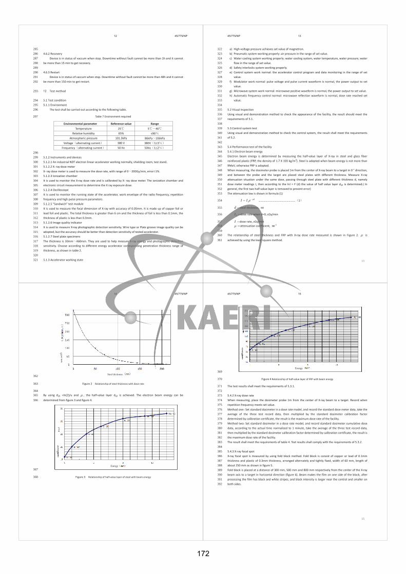
12 45/779/NP
285 4.6.2 Recovery 286
Device is in status of vaccum when stop. Downtime without fault cannot be more than 1h and it cannot 287 be more than 15 min to get recovery. 288
289 4.6.3 Restart 290
Device is in status of vaccum when stop. Downtime without fault cannot be more than 48h and it cannot 291 be more than 150 min to get restart. 292
Test method 293
5.1 Test condition 294 5.1.1 Environment 295
The test shall be carried out according to the following table. 296
Table 7 Environment required 297
Environmental parameter Reference value Range Temperature 25 5 40
Relative humidity 65% Atmospheric pressure 101.3kPa 86kPa 106kPa
Voltage alternating current 380 V 380V 1 3 Frequency alternating current 50 Hz 50Hz 1 2
298 5.1.2 Instruments and devices 299 5.1.2.1 An industrial NDT electron linear accelerator working normally, shielding room, test stand. 300 5.1.2.2 X- ray dose meter 301 X- ray dose meter is used to measure the dose rate, with range of 0 200Gy/min, error 1%. 302 5.1.2.3 Ionization chamber 303 It is used to monitor the X-ray dose rate and is calibrated by X- ray dose meter. The ionization chamber and 304 electronic circuit measurement to determine the X ray exposure dose. 305 5.1.2.4 Oscilloscope 306 It is used to monitor the running state of the accelerator, work envelope of the radio frequency, repetition 307 frequency and high pulse pressure parameters. 308 5.1.2.5 “Sandwich” test module 309 It is used to measure the focal dimension of X-ray with accuracy of 0.05mm. It is made up of copper foil or 310 lead foil and plastic. The total thickness is greater than 6 cm and the thickness of foil is less than 0.1mm, the 311 thickness of plastic is less than 0.3mm. 312 5.1.2.6 Image quality indicator 313 It is used to measure X-ray photographic detection sensitivity. Wire type or Plate groove image quality can be 314 adopted, but the accuracy should be better than detection sensitivity of tested accelerator. 315 5.1.2.7 Steel plate specimens 316 The thickness is 30mm 460mm. They are used to help measure X-ray energy and photographic detection 317 sensitivity. Choose according to different energy accelerator corresponding penetration thickness range of 318 thickness, as shown in table 2. 319 320 5.1.3 Accelerator working state 321
45/779/NP 13
a) High-voltage pressure achieves set value of magnetron. 322 b) Pneumatic system working properly: air pressure in the range of set value. 323 c) Water cooling system working properly: water cooling system, water temperature, water pressure, water 324
flow in the range of set value. 325 d) Safety interlocks system working properly. 326 e) Control system work normal: the accelerator control program and data monitoring in the range of set 327
value. 328 f) Modulator work normal: pulse voltage and pulse current waveform is normal, the power output to set 329
value. 330 g) Microwave system work normal: microwave positive waveform is normal, the power output to set value. 331 h) Automatic frequency control normal: microwave reflection waveform is normal, dose rate reached set 332
value. 333 334
5.2 Visual inspection 335 Using visual and demonstration method to check the appearance of the facility, the result should meet the 336 requirements of 5.1. 337 338 5.3 Control system test 339 Using visual and demonstration method to check the control system, the result shall meet the requirements 340 of 5.2. 341 342 5.4 Performance test of the facility 343 5.4.1 Electron beam energy 344 Electron beam energy is determined by measuring the half-value layer of X-ray in steel and glass fiber 345 reinforced plastic (FRP, the density of 1.7 X 10³ kg/m3). Steel is adopted when beam energy is not more than 346 9MeV, otherwise FRP is adopted. 347 When measuring, the dosimeter probe is placed 1m from the center of X-ray beam to a target in 0 ° direction, 348 and between the probe and the target are placed steel plates with different thickness. Measure X-ray 349 attenuation situation under the same dose, passing through steel plate with different thickness d, namely 350 dose meter readings I, then according to the lnI = F (d) the value of half value layer d1/2 is determined.( In 351 general, the first two half-value layer is removed to prevent error) 352 The attenuation law is shown in formula (1) 353
deII 0 …………………………………………… 1 354
d —steel thickness, 355
0I —dose rate when d=0, cGy/min 356
I —dose rate, cGy/min 357 —attenuation coefficient, -1 358
359 The relationship of steel thickness and FRP with X-ray dose rate measured is shown in Figure 2. is 360 achieved by using the least square method. 361
14 45/779/NP
Dose rate
Steel thickness 362
Figure 2 Relationship of steel thickness with dose rate363
364 By using d1/2 =ln(2)/u and , the half-value layer d1/2 is achieved. The electron beam energy can be 365 determined from figure 3 and figure 4. 366
Half
-value layer
Energy 367
Figure 3 Relationship of half-value layer of steel with beam energy 368
45/779/NP 15
Half
-value layer
Energy 369
Figure 4 Relationship of half-value layer of FRP with beam energy 370
The test results shall meet the requirements of 5.3.1. 371 372 5.4.2 X-ray dose rate 373 When measuring, place the dosimeter probe 1m from the center of X-ray beam to a target. Record when 374 repetition frequency meets set value. 375 Method one Set standard dosimeter in a dose rate model, and record the standard dose meter data, take the 376 average of the three test record data, then multiplied by the standard dosimeter calibration factor 377 determined by calibration certificate, the result is the maximum dose rate of the facility. 378 Method two: Set standard dosimeter in a dose rate model, and record standard dosimeter cumulative dose 379 data, according to the actual time normalized to 1 minute, take the average of the three test record data, 380 then multiplied by the standard dosimeter calibration factor determined by calibration certificate, the result is 381 the maximum dose rate of the facility. 382 The result shall meet the requirements of table 4. Test results shall comply with the requirements of 5.3.2. 383 384 5.4.3 X-ray focal spot 385 X-ray focal spot is measured by using fold block method. Fold block is consist of copper or lead of 0.1mm 386 thickness and plastic of 0.3mm thickness, arranged alternately and tightly fixed, width of 60 mm, length of 387 about 250 mm as shown in figure 5. 388 Fold block is placed at a distance of 300 mm, 500 mm and 800 mm respectively from the center of the X-ray 389 beam axis to a target in horizontal direction (figure 6). Beam makes the film on one side of the block, after 390 processing the film has black and white stripes, and black intensity is larger near the central and smaller on 391 both sides. 392
172
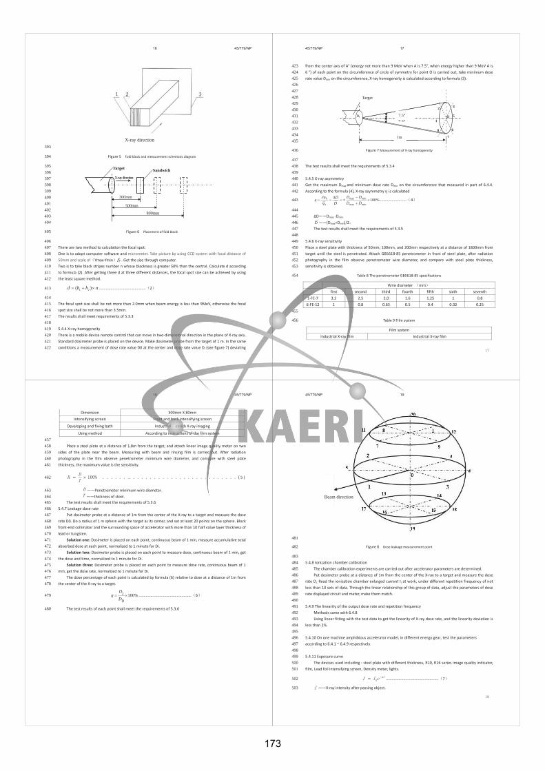
16 45/779/NP
X-ray direction 393
Figure 5 Fold block and measurement schematic diagram 394
395 396 397 398 399 400 401 402 403 404
Figure 6 Placement of fold block405
406 There are two method to calculation the focal spot: 407 One is to adopt computer software and micrometer. Take picture by using CCD system with focal distance of 408 50mm and scale of Ymax-Ymin /5 . Get the size through computer. 409 Two is to take black stripes number n whose blackness is greater 50% than the central. Calculate d according 410 to formula (2). After getting three d at three different distances, the focal spot size can be achieved by using 411 the least square method. 412
nhhd )( 21 ………………………………………… 2 413
414 The focal spot size shall be not more than 2.0mm when beam energy is less than 9MeV, otherwise the focal 415 spot size shall be not more than 3.5mm. 416 The results shall meet requirements of 5.3.3 417
418 5.4.4 X-ray homogeneity 419 There is a mobile device remote control that can move in two-dimensional direction in the plane of X-ray axis. 420 Standard dosimeter probe is placed on the device. Make dosimeter probe from the target of 1 m. In the same 421 conditions a measurement of dose rate value D0 at the center and dose rate value Di (see figure 7) deviating 422
Target Sandwich
300mm
500mm
800mm
X-ray direction
45/779/NP 17
1
3 4
5
6
7
2
from the center axis of A° (energy not more than 9 MeV when A is 7.5°, when energy higher than 9 MeV A is 423 6 °) of each point on the circumference of circle of symmetry for point O is carried out, take minimum dose 424 rate value Dmin on the circumference, X-ray homogeneity is calculated according to formula (3). 425
426 427 428 429 430 431 432 433 434 435
Figure 7 Measurement of X-ray homogeneity 436
437 The test results shall meet the requirements of 5.3.4 438 439 5.4.5 X-ray asymmetry 440 Get the maximum Dmax and minimum dose rate Dmin on the circumference that measured in part of 6.4.4. 441 According to the formula (4), X-ray asymmetry is calculated 442
%100minmax
minmax
DDDD
DD
h
h ……………………… 4 443
444 D——Dmax -Dmin 445
D ——(Dmax+Dmin)/2 446 The test results shall meet the requirements of 5.3.5 447 448
5.4.6 X-ray sensitivity 449 Place a steel plate with thickness of 50mm, 100mm, and 200mm respectively at a distance of 1800mm from 450 target until the steel is penetrated. Attach GB5618-85 penetrometer in front of steel plate, after radiation 451 photography in the film observe penetrometer wire diameter, and compare with steel plate thickness, 452 sensitivity is obtained. 453
Table 8 The penetrometer GB5618-85 specifications 454
Wire diameter mm first second third fourth fifth sixth seventh
1-FE-7 3.2 2.5 2.0 1.6 1.25 1 0.8 6-FE-12 1 0.8 0.63 0.5 0.4 0.32 0.25
455
Table 9 Film system 456
Film system Industrial X-ray film Industrial X-ray film
O
8
7.5° 7 5°
1m
Target
18 45/779/NP
Dimension 300mm X 80mm Intensifying screen Front and back intensifying screen
Developing and fixing bath Industrial enrich X-ray imaging
Using method According to instructions of the film system 457 Place a steel plate at a distance of 1.8m from the target, and attach linear image quality meter on two 458
sides of the plate near the beam. Measuring with beam and rinsing film is carried out. After radiation 459 photography in the film observe penetrometer minimum wire diameter, and compare with steel plate 460 thickness, the maximum value is the sensitivity. 461
. ( 5 ) 462
——Penetrometer minimum wire diameter. 463 ——thickness of steel. 464
The test results shall meet the requirements of 5.3.6 465 5.4.7 Leakage dose rate 466
Put dosimeter probe at a distance of 1m from the center of the X-ray to a target and measure the dose 467 rate D0. Do a radius of 1 m sphere with the target as its center, and set at least 20 points on the sphere. Block 468 front-end collimator and the surrounding space of accelerator with more than 10 half value layer thickness of 469 lead or tungsten. 470
Solution one: Dosimeter is placed on each point, continuous beam of 1 min, measure accumulative total 471 absorbed dose at each point, normalized to 1 minute for Di. 472
Solution two: Dosimeter probe is placed on each point to measure dose, continuous beam of 1 min, get 473 the dose and time, normalized to 1 minute for Di. 474
Solution three: Dosimeter probe is placed on each point to measure dose rate, continuous beam of 1 475 min, get the dose rate, normalized to 1 minute for Di. 476
The dose percentage of each point is calculated by formula (6) relative to dose at a distance of 1m from 477 the center of the X-ray to a target. 478
%1000DiD
……………………………………………… 6 479
The test results of each point shall meet the requirements of 5.3.6 480
45/779/NP 19
Beam direction
481
Figure 8 Dose leakage measurement point 482
483 5.4.8 Ionization chamber calibration 484
The chamber calibration experiments are carried out after accelerator parameters are determined. 485 Put dosimeter probe at a distance of 1m from the center of the X-ray to a target and measure the dose 486
rate Di, Read the ionization chamber enlarged current Ii at work, under different repetition frequency of not 487 less than 10 sets of data. Through the linear relationship of this group of data, adjust the parameters of dose 488 rate displayed circuit and meter, make them match. 489
490 5.4.9 The linearity of the output dose rate and repetition frequency 491
Methods same with 6.4.8 492 Using linear fitting with the test data to get the linearity of X-ray dose rate, and the linearity deviation is 493
less than 2%. 494 495
5.4.10 On one machine amphibious accelerator model, in different energy gear, test the parameters 496 according to 6.4.1 ~ 6.4.9 respectively. 497
498 5.4.11 Exposure curve 499
The devices used including : steel plate with different thickness, R10, R16 series image quality indicator, 500 film, Lead foil intensifying screen, Density meter, lights. 501
……………………………………………… 7 502
——X-ray intensity after passing object. 503
173
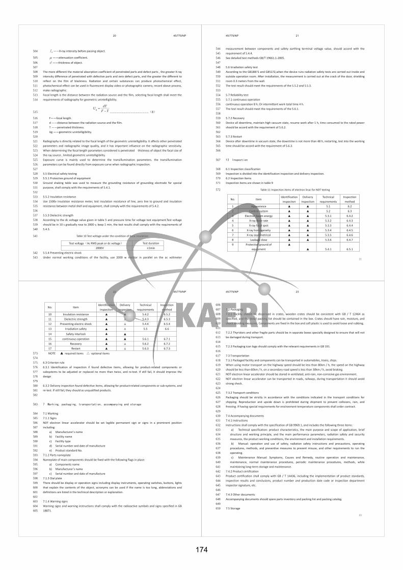
20 45/779/NP
——X-ray intensity before passing object. 504
——attenuation coefficient. 505 ——thickness of object. 506
507 The more different the material absorption coefficient of penetrated parts and defect parts , the greater X-ray 508 intensity difference of penetrated with defective parts and zero defect parts, and the greater the different to 509 reflect on the film of blackness. Radiation and certain substances can produce photochemical effect, 510 photochemical effect can be used in fluorescent display video or photographic camera, record above process, 511 make radiographic. 512 Focal length is the distance between the radiation source and the film, selecting focal length shall meet the 513 requirements of radiography for geometric unintelligibility. 514
TFdT
Ug……………………………………………… 8 515
F——focal length. 516 d ——distance between the radiation source and the film. 517 T ——penetrated thickness. 518 Ug ——geometric unintelligibility. 519 520
Radiography is directly related to the focal length of the geometric unintelligibility. It affects other penetrated 521 parameters and radiographic image quality, and it has important influence on the radiographic sensitivity. 522 When determining the focal length parameters considered is penetrated thickness of object the facal size of 523 the ray source , limited geometric unintelligibility. 524 Exposure curve is mainly used to determine the transillumination parameters. the transillumination 525 parameters can be found directly from exposure curve when radiographic inspection. 526
527 5.5 Electrical safety testing 528 5.5.1 Protective ground of equipment 529 Ground shaking table was used to measure the grounding resistance of grounding electrode for special 530 purpose, shall comply with the requirements of 5.4.1. 531 532 5.5.2 Insulation resistance 533 Use 1500v insulation resistance meter, test insulation resistance of line, zero line to ground and insulation 534 resistance between metal shell and equipment, shall comply with the requirements of 5.4.2. 535 536 5.5.3 Dielectric strength 537 According to the dc voltage value given in table 5 and pressure time for voltage test equipment.Test voltage 538 should be in 10 s gradually rose to 2000 v, keep 1 min, the test results shall comply with the requirements of 539 5.4.3. 540
Table 10 Test voltage under the condition of basic insulation 541
Test voltage Ac RMS peak or dc voltage Test duration 2000V
5.5.4 Preventing electric shock 542 Under normal working conditions of the facility, use 2000 w resistor in parallel on the ac voltmeter 543
45/779/NP 21
measurement between components and safety earthing terminal voltage value, should accord with the 544 requirement of 5.4.4. 545 See detailed test methods GB/T 19661.1-2005. 546
547 5.6 Irradiation safety test 548 According to the GB18871 and GB5172,when the device runs radiation safety tests are carried out inside and 549 outside operation room. After installation, the measurement is carried out at the crack of the door, shielding 550 room 0.3 meters from the wall. 551 The test result should meet the requirements of the 5.5.2 and 5.5.3. 552
553 5.7 Reliability test 554 5.7.1 continuous operation 555 continuous operation 8 h; Or intermittent work total time 4 h. 556 The test result should meet the requirements of the 5.6.1. 557
558 5.7.2 Recovery 559 Device all downtime, maintain high vacuum state, resume work after 1 h, time consumed to the rated power 560 should be accord with the requirement of 5.6.2. 561
562 5.7.3 Restart 563 Device after downtime in vacuum state, the downtime is not more than 48 h, restarting, test into the working 564 time should be accord with the requirement of 5.6.3. 565
566
567
6.1 Inspection classification 568 Inspection is divided into the identification inspection and delivery inspection. 569 6.2 Inspection items 570 Inspection items are shown in table 9 571
Table 11 Inspection items of electron linac for NDT testing 572
No. Item Identification
inspection Delivery
inspection Technical
requirements Inspection
method 1 Appearance 5.1 6.2 2 Control system 5.2 6.3 3 Electron beam energy 5.3.1 6.4.2 4 X-ray dose rate 5.3.2 6.4.3 5 X-ray facal spot 5.3.3 6.4.4 6 X-ray homogeneity 5.3.4 6.4.5 7 X-ray asymmetrical 5.3.5 6.4.6 8 Leakage dose 5.3.6 6.4.7 9 Protective ground of
equipment
5.4.1 6.5.1
22 45/779/NP
No. Item Identification
inspection Delivery
inspection Technical
requirements Inspection
method 10 Insulation resistance 5.4.2 6.5.2 11 Dielectric strength 5.4.3 6.5.3 12 Preventing electric shock 5.4.4 6.5.4 13 Irradiation safety 5.5 6.6
14 Safety interlock 15 continuous operation 5.6.1 6.7.1 16 Recovery 5.6.2 6.7.2 17 Restart 5.6.3 6.7.3 NOTE required items optional items 573 574
6.3 Criterion rule 575 6.3.1 Identification of inspection if found defective items, allowing for product-related components or 576 subsystems to be adjusted or replaced no more than twice, and re-test. If still fail, it should improve the 577 design 578
579 6.3.2 Delivery inspection found defective items, allowing for product-related components or sub-systems, and 580 re-test. If still fail, they should as unqualified products. 581
582
583
7.1 Marking 584 7.1.1 Signs 585 NDT electron linear accelerator should be set legible permanent sign or signs in a prominent position 586 including: 587
a) Manufacturer's name 588 b) Facility name 589 c) Facility type 590 d) Serial number and date of manufacture 591 e) Product standard No. 592
7.1.2 Parts nameplate 593 Nameplate of main components should be fixed with the following flags in place: 594
a) Components name 595 b) Manufacturer’s name 596 c) Serial number and date of manufacture 597
7.1.3 Dial plate 598 There should be display or operation signs including display instruments, operating switches, buttons, lights 599 that explain the contents of the object, acronyms can be used if the name is too long, abbreviations and 600 definitions are listed in the technical description or explanation. 601 602 7.1.4 Warning signs 603 Warning signs and warning instructions shall comply with the radioactive symbols and signs specified in GB 604 18871. 605
45/779/NP 23
606 7.2 Packaging 607 7.2.1 Facility should be dispensed in crates, wooden crates should be consistent with GB / T 12464 as 608 specified, and the detail packing list should be contained in the box. Crates should have rain, moisture, and 609 shock avoiding measures. Components are fixed in the box and soft plastic is used to avoid loose and rubbing. 610 611 7.2.2 Thyristors and other fragile parts should be in separate boxes specially designed to ensure that will not 612 be damaged during transport. 613 614 7.2.3 Packaging icon logo should comply with the relevant requirements in GB 191. 615 616 7.3 Transportation 617 7.3.1 Packaged facility and components can be transported in automobiles, trains, ships. 618 When using motor transport on the highway speed should be less than 80km / h, the speed on the highway 619 should be less than 60km / h, on a secondary road speed is less than 30km / h, avoid braking. 620 NDT electron linear accelerator should be stored in ventilated, anti-rain, non-corrosive gas environment. 621 NDT electron linear accelerator can be transported in roads, railways, during transportation it should avoid 622 strong shock. 623 624 7.3.2 Transport conditions 625 Packaging should be strictly in accordance with the conditions indicated in the transport conditions for 626 shipping. Reproduction and upside down is prohibited during shipment to prevent collisions, rain, and 627 freezing. If having special requirements for environment temperature components shall order contract. 628 629 7.4 Accompanying documents 630 7.4.1 Instructions 631 Instructions shall comply with the specification of GB 9969.1, and includes the following three items: 632
a) Technical specification: product characteristics, the main purpose and scope of application, brief 633 structure and working principle, and the main performance parameters, radiation safety and security 634 measures, the product working conditions, the environment and installation requirements. 635 b) Manual: operation and use of safety, radiation safety instructions and precautions, operating 636
procedures, methods, and preventive measures to prevent misuse, and other requirements to run the 637 operating. 638 c) Maintenance Manual: Symptoms, Causes and Remedy, routine operation and maintenance, 639
maintenance, normal maintenance procedures, periodic maintenance procedures, methods, while 640 maintaining long-term storage and maintenance. 641
7.4.2 Product certification 642 Product certification shall comply with GB / T 14436, including the implementation of product standards, 643 inspection results and conclusions, product number and production date code or inspection department 644 inspector signature, etc. 645 646 7.4.3 Other documents 647 Accompanying documents should spare parts inventory and packing list and packing catalog. 648 649 7.5 Storage 650
174
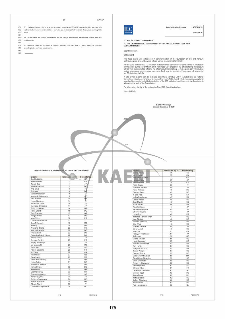
24 45/779/NP
7.5.1 Packaged products should be stored at ambient temperature 0 40 , relative humidity less than 90%, 651 well-ventilated room. Room should be no corrosive gas, no strong effect vibration, shock waves and magnetic 652 fields. 653 654 7.5.2 When there are special requirements for the storage environment, environment should meet the 655 requirements. 656 657 7.5.3 Klystron tubes and the like that need to maintain a vacuum state, a regular vacuum is operated 658 according to the technical requirements. 659 660 661
Administrative Circular AC/29/2013 2013-08-16
TO ALL NATIONAL COMMITTEESTO THE CHAIRMEN AND SECRETARIES OF TECHNICAL COMMITTEES AND SUBCOMMITTEES
Dear Sir/Madam,
1906 Award
The 1906 award was established in commemoration of the foundation of IEC and honours technical experts around the world whose work is fundamental to the IEC.
For the 2013 nominations, TC chairmen and secretaries were invited to send names of candidates for the award by the end of March 2013. Nominees were chosen by TC officers taking into account advice from subcommittee officers. TC officers could nominate up to five experts per TC including project leaders and working group conveners. Each year a maximum of five awards will be granted per TC, including its SCs.
A total of 165 experts from 58 technical committees (ISO/IEC JTC 1 included) and 25 National Committees have been nominated to receive this year’s 1906 Award, which recognizes exceptional recent achievements related to the activities of the IEC and which contribute in a significant way to advancing the work of the Commission.
For information, the list of the recipients of the 1906 Award is attached.
Yours faithfully,
F.W.P. Vreeswijk General Secretary & CEO
Annex
/ICH
2 / 5 AC/29/2013
LIST OF EXPERTS NOMINATED IN 2013 FOR THE 1906 AWARD
Experts Nominated by TC Dependency Jan Obdr lek 1 CZ Jean Schwob 1 FR Tetsuji Oda 1 JP Martin Kaufhold 2 DE Arto Sirviö 3 FI Rolf Apel 8 DE Marco Predonzan 9 IT Masayuki Matsumoto 9 JP Axel Kramer 14 DE Hasse Nordman 14 FI Katsutoshi Toda 14 JP Yukiyasu Shirasaka 14 JP Philip Hopkinson 14 US Heike Brandt 15 DE Paul Sheridan 15 GB Ansgar Müller 17 DE Marc Vittoz 17 FR Costantino Passera 17 IT John R.Kovacik 17 US Jeff Eby 18 US Wanrong Zhang 22 CN Marcus Haeusler 22 DE Preben Holm 22 DK Flemming Brinch Nielsen 22 DK Hiroshi Inoue 22 JP Bernard Cantini 23 FR Shigeji Shinomiya 23 JP Ian Mcdonald 23 US Peter Mair 26 AT Patrick Couderc 26 FR Yu Zeng 27 CN Neil Malone 27 GB Einar Laukli 29 NO Victor Nedzelnitsky 29 US Heino Bothe 31 DE Edward M. Briesch 31 US Norbert Stein 32 DE John Leach 32 US Etienne Savary 33 CH Gunnar Ingeström 33 SE Kenji Sugiyama 34 JP Torbjorn Andersson 34 SE Robert Nachtrieb 34 US Alberto Pigini 36 IT Christiaan Engelbrecht 36 NL
3 / 5 AC/29/2013
Experts Nominated by TC Dependency Igor Gutman 36 SE Yang Zhao 37 CN Nicholas Kokkinos 37 GR Hidetaka Sato 37 JP Beat Bertschi 38 CH Paolo Mazza 38 IT Masahiro Tambo 40 JP Peter Ambrosi 45 DE Gerhard Roos 45 DE In-Soo Koo 45 KR Yuliya Danylenko 45 UA Leticia Pibida 45 US John Morelli 46 US Frank Straka 46 US Kouji Ichikawa 47 JP Hirofumi Nakajima 47 JP Chiemi Ishiyama 47 JP Hojun Ryu 47 KR Jamshed Namdar Khan 47 US Uwe Blosfeld 48 DE Vincent Pascucci 48 US Eike Walz 48 US Masako Tanaka 49 JP Dieter Jundt 49 US Ying Cui 51 CN Nobuyuki Hiratsuka 51 JP Jeff Jones 56 GB Milena Krasich 56 US Hyuk-Soo Jang 57 KR Edward Dobrowolski 57 US Kurt Hunter 57 US Margaret Goodrich 57 US James Waight 57 US Gerhard Fuchs 59 DE Martha Hecht Aguilar 59 MX Sten-Hakan Almström 59 SE Ernst Grunewald 59 US Antony H. Hardaway 59 US Geoffrey Booth 61 AU Christian Rey 61 FR Dinand van Aalderen 61 NL Michael Sippl 62 DE Janos Barsai 62 HU Jeff Eggleston 62 US Jeffrey Silberberg 62 US Jochim Koch 62 DE Rob Hekkenberg 62 NL
175

4 / 5 AC/29/2013
Experts Nominated by TC Dependency Reinhard Hirtler 64 AT James Keogh 64 IE Chung Young-ki 64 KR Zdobyslaw Flisowski 64 PL Hubert Kirrmann 65 CH Daehyun Kwon 65 KR Gerold Widmer 72 CH Lewis Price 72 GB Dik Kok 72 NL Lee Collins 76 AU Yuichi Hashishin 76 JP Anna-Karin Holmer 76 SE Sheldon Zimmerman 76 US Jay Parkinson 76 US Armin Kaelin 77 CH Claudia Imposimato 77 IT Shinobu Ishigami 77 JP Mark King 77 US Hannu Peiponen 80 FI David Blevins 80 US François Caloz 86 CH Hideki Isono 86 JP Hiroshi Nakamura 86 JP Elaina Finger 86 US Sriraman Kannan 86 US Marvin C. Ziskin 87 US Arno Bergmann 88 DE Kimon Argyriadis 88 DE Bo Søndergaard 88 DK Troels Stybe Sørensen 88 DK Dan Brake 88 US Hitoshi Kitaguchi 90 JP Hiroshi Nishikawa 91 JP Tsuyoshi Yamamoto 91 JP Min-su Lee 91 KR JaeKeun Kwak 91 KR Peter Walthers 94 US Philippe Alibert 95 FR Andrea Bonetti 95 SE Yves Boudou 96 FR Ulrike Haltrich 100 DE Jürgen Stauder 100 FR Motoharu Suda 100 JP Takeshi Matsushita 100 JP Kwang-Soon Choi 100 KR Yuko Yasutake 105 JP Philip Chadwick 106 GB
5 / 5 AC/29/2013
Experts Nominated by TC Dependency Antonio Faraone 106 US Josephine Vann 107 GB Xiaohua Li 110 CN Hidefumi Yoshida 110 JP Kuendong Ha 110 KR Nam Kim 110 KR Hyoung-Bin Park 110 KR Heico Hinrichs 111 DE Richard Smith 111 GB Miyuki Takenaka 111 JP Jaehak Jung 111 KR Stan Piorek 111 US Gunther Baumgarten 112 DE Yasuhiro Tanaka 112 JP Maria Augusta Martins 112 PT Ha-Jin Lee 113 KR Lynn Davis 113 US Frank Deter CISPR DE Kunihiro Kawasaki CISPR JP Ronald Storrs CISPR SE David Arnett CISPR US Richard Hodgkinson ISO/IEC JTC1 GB Sprague Ackley ISO/IEC JTC1 US Jutta Treviranus ISO/IEC JTC1 CA Yuan Yuan ISO/IEC JTC1 CN Young-Bin Kwon ISO/IEC JTC1 KR
International Electrotechnical Commission I 3, rue de Varembe I PO Box 131 I CH-1211 Geneva 20 I Switzerland Tel.: +41 22 919 02 11 I Fax: +41 22 919 03 00 I [email protected] I www.iec.ch
AC/31/2014
Administrative Circular 2014-07-18
TO ALL NATIONAL COMMITTEES
TO THE CHAIRMEN AND SECRETARIES OF TECHNICAL COMMITTEES AND SUBCOMMITTEES
TO ALL CONFORMITY ASSESSMENT SYSTEMS CHAIRMEN
1906 Award
Dear Sir/Madam,
The 1906 Award was established in commemoration of the foundation of IEC and honours technical experts in standardization and conformity assessment from around the world whose work is fundamental to the IEC.
For the 2014 nominations, TC chairmen and secretaries and CA Systems' chairmen were invited to send names of candidates for the Award by the end of March 2014. Nominees were chosen by TC officers taking into account advice from subcommittee officers, and by CA Systems' chairmen taking into account advice from their respective CA communities. TC officers could nominate up to five experts per TC including project leaders and working group conveners, and CA Systems' chairmen - up to five experts per System including its subcommittees.
A total of 151 experts from 50 technical committees (ISO/IEC JTC 1 included) and 11 experts from CA Systems from 21 National Committees, have been nominated to receive this year's 1906 Award, which recognizes exceptional recent achievements related to the activities of the IEC and which contribute in a significant way to advancing the work of the Commission.
For information, the lists of the recipients of the 1906 Award from TCs and from CA Systems are attached.
Yours faithfully, F.W.P. Vreeswijk General Secretary & CEO Annexes: 1. List of TC experts awarded in 2014 the 1906 Award 2. List of CA Systems experts awarded in 2014 the 1906 Award ich
2 / 6 AC/31/2014
Annex 1. LIST OF TC EXPERTS AWARDED IN 2014 THE 1906 AWARD
Expert nominated by TC Dependency Martin Doppelbauer 2 DE Haruhiro Saito 3 JP Danny A. Burggraeve 4 CA Gilbert Grosse 4 DE Pablo Llosa 4 DE Jin Wang 9 CN Gernot Hans 9 DE Ulrich Feucht 9 DE Roger Short 9 GB Koichiro Kasahara 9 JP Thomas Schaub 13 CH Milan Kozole 13 SI Tom Eland 15 GB Silvio Stangherlin 17 CH Dirk Kunze 17 DE Mitsuru Toyoda 17 JP Herbert K. Giess 21 CH Chris Ford 21 GB Jürgen Bliesner 22 DE Ole Albert Nielsen 22 DK Daniel Gonzalez 22 FR Michael Kenneth Evans 22 GB Gearoid Sean O'Heidhin 22 GB Jean-Marc Blanc 25 CH Paul Gérôme 25 CH Erik Jacobson 25 DE Jean Schwob 25 FR Luigi Serrantoni 26 IT Michel Lecollinet 29 FR Ulrich Johannsmeyer 31 DE Mark Coppler 31 US Andreas Scholtz 34 DE Ingo Arnrich 34 DE Frédéric Guiraud 34 FR Norbert Mikli 36 DE Toshiyuki Nakachi 36 JP Dan Windmar 36 SE Peter Bobert 37 DE Gilles Sirmain 37 FR Yasuharu Yamada 37 JP Ruthard Minkner 38 CH
176
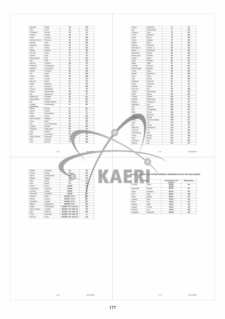
3 / 6 AC/31/2014
Miroslav Poljak 38 HR Willi Furer 40 CH Toshiatsu Suzuki 40 JP Akihiko Ikazaki 40 JP Arndt Lindner 45 DE Anthony Friend Parsons 45 GB Andrew Tyler 45 GB Radoslav Radev 45 US Arne Ernbo 46 SE Patrick Sullivan 47 DE Jun-Ichi Ohno 47 JP Yakichi Higo 47 JP Byoung Nam Lee 47 KR Jae Park 47 US Kei-Ichi Yasuda 48 JP Hidetoshi Kurebayashi 51 JP Andreas Levermann 55 DE Joffrey Smitham 56 GB Dai Davis 56 GB Lesley Walls 56 GB Jean Goulet 57 CA Maurizio Monti 57 FR André Maizener 57 FR John Newbury 57 GB Yasuro Shobatake 57 JP Rainer Stamminger 59 DE Jun Nakamura 59 JP Michiel A.A. Schallig 59 NL Klaus-Dieter Fischer 61 DE Per Dalgas-Madsen 61 DK Chettiar Palaniappa
Sockalingam 61 MY
Albert Enting 61 NL Danilo Kraner 61 SI Peter Kerschhofer 62 AT Georg Frese 62 DE Hans-Joachim Selbach 62 DE Hans Sethi 62 GB Jos van Vroonhoven 62 NL Ludwig Winkel 65 DE Takaharu Matsumoto 65 JP Taro Harima 65 JP Bob Lounsbury 65 US David Charles Delaquila 72 US Ralf Heinrich 77 DE John Sinclair 77 GB
4 / 6 AC/31/2014
Georg Hedderich 77 JP Edl Schamiloglu 77 US Chaowu Chen 79 CN Frank Rottmann 79 DE Hans Busch 79 DE Farzin Aghdasi 79 US Stefan Steier 80 SE Monika Patterson 85 DE Nicholas G. Paulter, Jr. 85 US Bernd Horrmeyer 86 DE Michael D. Kinard 86 US Peter Louis Pondillo 86 US Casey Shaar 86 US Greg Sandels 86 US Miwa Naito 87 JP Christer Eriksson 88 DK Peter Hauge Madsen 88 DK Paula Gade 88 DK Alistair MacKinnon 88 GB Paul Veers 88 US Udo Welzel 91 DE Hidetaka Okamoto 91 JP Kunio Takahara 91 JP Satoshi Kojima 91 JP Hyun Ho Kim 91 KR Jürgen Steinhäuser 94 DE Peter Sieper 99 DE Yoshio Ohashi 100 JP Shuichi Matsumura 100 JP Noboru Hanaguchi 100 JP Munhwan Han 100 KR Lee Atkinson 100 US Nils Chmielewski 105 CH Mike Wood 106 AU Jafar Keshvari 106 FI Isabelle Magne 106 FR Johan Van Der Sanden 106 NL Jing Xie 110 CN Kei Hyodo 110 JP Masahiro Kawashima 110 JP Jang Jin Yoo 110 KR Jae-Hyeung Park 110 KR Liang Zhang 111 CN Isao Endou 111 JP Jae Woo Kim 111 KR Sophia Lau 111 US
5 / 6 AC/31/2014
Robert Friedman 111 US Yewen Zhang 112 CN Bernd Komanschek 112 DE Nathan Magee 112 US Mike Smith 121 CA Axel Bauer 121 DE Thilo A. Kootz CISPR DE Yoshimitsu Hiratomo CISPR JP Kunihiro Osabe CISPR JP Yasutoshi Yoshioka CISPR JP Richard Rees ISO/IEC JTC 1 GB Motoei Azuma ISO/IEC JTC 1 JP Toshihiko Inagaki ISO/IEC JTC 1 JP Mikael Hjalmarson ISO/IEC JTC 1 SE Dieter Schicketanz ISO/IEC JTC 1/SC 25 DE Hans-Joachim Langels ISO/IEC JTC 1/SC 25 DE Alan Flatman ISO/IEC JTC 1/SC 25 GB Tuvia Liberman ISO/IEC JTC 1/SC 25 IL David C. Hess ISO/IEC JTC 1/SC 25 US
6 / 6 AC/31/2014
Annex 2. LIST OF CA SYSTEMS EXPERTS AWARDED IN 2014 THE 1906 AWARD
Expert nominated by CA System
Dependency
Timothy Duffy IECEx IECEE
US
Alexander Zalogin IECEx RU
Vitaly Grudtsyn IECEx RU John Allen IECEx GB Heinz Berger IECEx CH Juyong Wan IECQ CN Chris Yau IECQ US Stanley Salot IECQ US Joseph Cheng IECQ US Ki-Suek Lee IECQ KR Wolfgang Niedziella IECEE DE
177
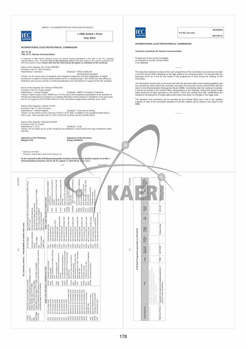
1 / 1 AC/1A/2014
ANNEX 2 TO ADMINISTRATIVE CIRCULAR AC/1A/2014
« 1906 Award » Form Year 2014
INTERNATIONAL ELECTROTECHNICAL COMMISSION IEC TC 45 Title of TC: Nuclear Instrumentation A maximum of five names selected among all experts having participated in the work of the TC, including subcommittees if any. The tribute (one or two sentences only) should give details of the specific contribution for which the award is made. Please note that this short tribute will appear as submitted on the certificate. Name of the Awardee: Mr. Arndt LINDNER Function in the TC: WG Convenor Dependency1: Germany Employer2: ISTec (Institut für Sicherheitstechnologie) Tribute: For his many years of energetic and competent leadership of WGA3 (Application of digital processors to safety in nuclear power plants) and for co-leading project IEC 61500 ed2 with efficiency, dedication and success and for is continued dedication and commitment in support of the IEC activities.
Name of the Awardee: Mr. Anthony PARSONS Function in the TC: Project leader Dependency1: United Kingdom Employer2: AMEC in Knutford, Chesshire Tribute: Project Leader of IEC 60965 ed.2: For his active and competent participation to the activities of WGA8 and particularly for leading or co-leading efficiently several projects of standards in the past years and for his support to IEC/SC45A Officers for the committee reorganisation activities since 2010.
Name of the Awardee: Andrew TYLER Function in the TC: WG Convenor Dependency1: United Kingdom Employer2: University of Stirling Tribute: For his efforts as the Convenor of WG 5 of SC 45B. In addition to his excellent leadership of WG 5, prof. Tyler has been the PL of IEC 61275 Ed.2 (2013) and IEC 62438 (2010).
Name of the Awardee: Radoslav RADEV Function in the TC: Expert Dependency1: U.S.A. Employer2: LLNL Tribute: For his efforts as PL of IEC 61005 (to be published in 2014) and for his long contribution within WG B15.
Signature of the Chairman Signature of the Secretary Morgan COX Sergey SHUMOV 1 National Committee 2 Company, organization, government agency, etc. To be returned to Ms R-M Neuenschwander ([email protected]) for all CA System experts or to Mrs I. Choumiatchkina ([email protected]) for all TC experts by 2014-03-31 at the latest.
45/782/PW For IEC use only 2014-09-12
INTERNATIONAL ELECTROTECHNICAL COMMISSION Technical committee 45: Nuclear instrumentation Programme of work of the Committee, as recorded by the IEC Central Office in its database
---------- The document attached consists of the work programme of the Committee concerned as recorded in the IEC Central Office database on the date noted on the computer listing. It is intended that this document serve as a tool for the review of the programme of work during the meeting of the Committee. The Secretariat should mark up the document with the decisions taken at the meeting together with any corrections which need to be recorded, and return the document to the Central Office with the report to the Standardization Management Board (SMB), immediately after the meeting (if possible, it should be handed to the Central Office representative at the meeting). Noting that project target dates should be at least equivalent to the month in which the meeting was held. Justifications are needed for all extensions of target dates where there have been no changes in the stage code. The decisions and corrections will be recorded by the Central Office and a link to the updated program of work of the committee available on the IEC website will be added to the report to the SMB.
----------
2/
3 45
/782
/PW
IEC
CEN
TRA
L O
FFIC
E -
PR
OG
RAM
ME
OF
WO
RK
FO
R T
C/S
C
TC/S
C
Tech
nica
l or s
ubco
mm
ittee
con
cern
ed
proj
ect
Proj
ect N
umbe
r cor
resp
ondi
ng to
pub
licat
ion
num
ber
init
Proj
ect i
nitia
tion
date
(YYY
Y-M
M)
Mod
N
umbe
r of e
xten
sion
s of
targ
et d
ates
N
ext S
tage
Ta
rget
dat
e fo
r nex
t sta
ge (Y
YYY
-MM
) / n
umbe
r of u
pdat
es
Fcst
Pub
l Fo
reca
st p
ublic
atio
n da
te b
ased
on
the
adva
ncem
ent o
f the
pro
ject
and
the
rem
aini
ng s
tage
s to
be
com
plet
ed
R. P
ub S
tage
R
eque
sted
targ
et d
ate
for p
ublis
hed
stan
dard
in R
VN o
r For
m
RR
(YY
YY
-MM
) do
cum
ent r
efer
ence
C
urre
nt d
ocum
ent r
efer
ence
st
atus
C
urre
nt p
roje
ct s
tatu
s (s
ee b
elow
) C
urre
nt s
tage
D
ate
whe
n cu
rren
t sta
tus
was
reac
hed
(YY
YY-
MM
) tit
le
Title
of t
he p
roje
ct (E
nglis
h)
Proj
ect L
eade
r N
ame
of p
roje
ct le
ader
D
ate
Tim
e D
ate
of p
rinto
ut
Stag
e co
des
deco
ded
in a
lpha
betic
al o
rder
St
age
code
s de
code
d in
logi
cal o
rder
1C
D
1st C
omm
ittee
Dra
ft 2C
D
2nd
Com
mitt
ee D
raft
3CD
3r
d C
omm
ittee
Dra
ft 4C
D
4th
Com
mitt
ee D
raft
5CD
5t
h C
omm
ittee
Dra
ft 6C
D
6th
Com
mitt
ee D
raft
7CD
7t
h C
omm
ittee
Dra
ft 8C
D
8th
Com
mitt
ee D
raft
9CD
9t
h C
omm
ittee
Dra
ft A
2CD
A
ppro
ved
for 2
nd C
omm
ittee
Dra
ft A
3CD
A
ppro
ved
for 3
rd C
omm
ittee
Dra
ft A
4CD
A
ppro
ved
for 4
th C
omm
ittee
Dra
ft A
5CD
A
ppro
ved
for 5
th C
omm
ittee
Dra
ft A
6CD
A
ppro
ved
for 6
th C
omm
ittee
Dra
ft A
7CD
A
ppro
ved
for 7
th C
omm
ittee
Dra
ft A
8CD
A
ppro
ved
for 8
th C
omm
ittee
Dra
ft A
9CD
A
ppro
ved
for 9
th C
omm
ittee
Dra
ft A
CD
V
Dra
ft ap
prov
ed fo
r Com
mitt
ee
D
raft
with
Vot
e A
DIS
A
ppro
ved
for D
IS c
ircul
atio
n A
MW
A
ppro
ved
Mai
nten
ance
Wor
k A
PU
B
Dra
ft ap
prov
ed fo
r pub
licat
ion
AN
W
App
rove
d N
ew W
ork
BP
UB
P
ublic
atio
n be
ing
prin
ted
CA
N
Dra
ft ca
ncel
led
CC
DV
D
raft
circ
ulat
ed a
s C
omm
ittee
Dra
ft w
ith
Vot
e C
DIS
D
raft
circ
ulat
ed a
s D
IS
CD
M
Com
mitt
ee D
raft
to b
e di
scus
sed
at
mee
ting
CD
TR
Circ
ulat
ed d
raft
Tech
nica
l Rep
ort
CD
TS
Circ
ulat
ed d
raft
Tech
nica
l Spe
cific
atio
n C
DP
AS
Circ
ulat
ed d
raft
for P
ublic
ly A
vaila
ble
Spe
cific
atio
n C
DV
M
CD
V to
be
disc
usse
d at
mee
ting
DE
C
Dra
ft at
edi
ting
chec
k N
AD
IS
Dra
ft re
turn
ed to
TC
/SC
afte
r FD
IS
NC
D
Dra
ft no
t app
rove
d un
der
Com
mitt
ee
Dra
ft w
ith v
ote
PN
W
Pro
pose
d N
ew W
ork
PP
UB
P
ublic
atio
n is
sued
PW
I P
oten
tial n
ew w
ork
item
R
DIS
Te
xt fo
r DIS
rece
ived
and
Reg
iste
red
WPU
B P
ublic
atio
n w
ithdr
awn
PWI
Pot
entia
l new
wor
k ite
m
PN
W
Pro
pose
d N
ew W
ork
AN
W
App
rove
d N
ew W
ork
AM
W
App
rove
d M
aint
enan
ce W
ork
1CD
1s
t Com
mitt
ee D
raft
A2C
D
App
rove
d fo
r 2nd
Com
mitt
ee D
raft
2CD
2n
d C
omm
ittee
Dra
ft A
3CD
A
ppro
ved
for 3
rd C
omm
ittee
Dra
ft 3C
D
3rd
Com
mitt
ee D
raft
A4C
D
App
rove
d fo
r 4th
Com
mitt
ee D
raft
4CD
4t
h C
omm
ittee
Dra
ft A
5CD
A
ppro
ved
for 5
th C
omm
ittee
Dra
ft 5C
D
5th
Com
mitt
ee D
raft
A6C
D
App
rove
d fo
r 6th
Com
mitt
ee D
raft
6CD
6t
h C
omm
ittee
Dra
ft A
7CD
A
ppro
ved
for 7
th C
omm
ittee
Dra
ft 7C
D
7th
Com
mitt
ee D
raft
A8C
D
App
rove
d fo
r 8th
Com
mitt
ee D
raft
8CD
8t
h C
omm
ittee
Dra
ft A
9CD
A
ppro
ved
for 9
th C
omm
ittee
Dra
ft 9C
D
9th
Com
mitt
ee D
raft
CD
TR
Circ
ulat
ed d
raft
Tech
nica
l Rep
ort
CD
TS
Circ
ulat
ed d
raft
Tech
nica
l Spe
cific
atio
n
CD
PA
S C
ircul
ated
dra
ft P
ublic
ly A
vaila
ble
Spe
cific
atio
n C
DM
C
omm
ittee
Dra
ft to
be
disc
usse
d at
m
eetin
g
AC
DV
D
raft
appr
oved
for C
omm
ittee
Dra
ft
with
Vot
e
CC
DV
D
raft
circ
ulat
ed a
s C
omm
ittee
Dra
ft
with
Vot
e A
DIS
A
ppro
ved
for D
IS c
ircul
atio
n C
DV
M
CD
V to
be
disc
usse
d at
mee
ting
NA
DIS
D
raft
not a
ppro
ved
unde
r Com
mitt
ee
Dra
ft w
ith v
ote
AD
ISS
B
FDIS
man
uscr
ipt s
ubco
ntra
cted
to
CO
D
EC
D
raft
at e
ditin
g ch
eck
RD
IS
Text
for D
IS re
ceiv
ed a
nd re
gist
ered
C
DIS
D
raft
circ
ulat
ed a
s D
IS
AP
UB
D
raft
appr
oved
for p
ublic
atio
n N
CD
D
raft
retu
rned
to T
C/S
C a
fter F
DIS
C
AN
D
raft
canc
elle
d B
PU
B
Pub
licat
ion
bein
g pr
inte
d P
PU
B
Pub
licat
ion
issu
ed
WPU
B P
ublic
atio
n w
ithdr
awn
3/
3 45
/782
/PW
TC45
Wor
k Pr
ogra
mm
e ge
nera
ted
on 2
014-
09-0
9
Proj
ect R
efer
ence
Ti
tle
Stag
e D
ocum
ent
Ref
eren
ce
Wor
king
G
roup
Pr
ojec
t Le
ader
In
it.
Dat
e C
urre
nt
Stag
e N
ext
Stag
e M
od
Fore
cast
Pu
blic
atio
n D
ate
IEC
604
12 E
d.3
Nuc
lear
inst
rum
enta
tion
– N
omen
clat
ure
(iden
tific
atio
n) o
f sci
ntill
ator
s an
d sc
intil
latio
n de
tect
ors
and
stan
dard
dim
ensi
ons
of
scin
tilla
tors
– A
ppro
ved
BPU
B
45/7
80/R
VD
9 Y.
Dan
ylen
ko
2012
-09
2014
-09
2014
-09
no
2014
-10
PNW
45-
779
Ed.1
In
dust
rial n
on-d
estru
ctiv
e te
stin
g eq
uipm
ent –
El
ectro
n lin
ear a
ccel
erat
or
PNW
45
/779
/NP
Ziqi
ang
Zeng
2014
-08
2015
-01
no
2017
-10
178
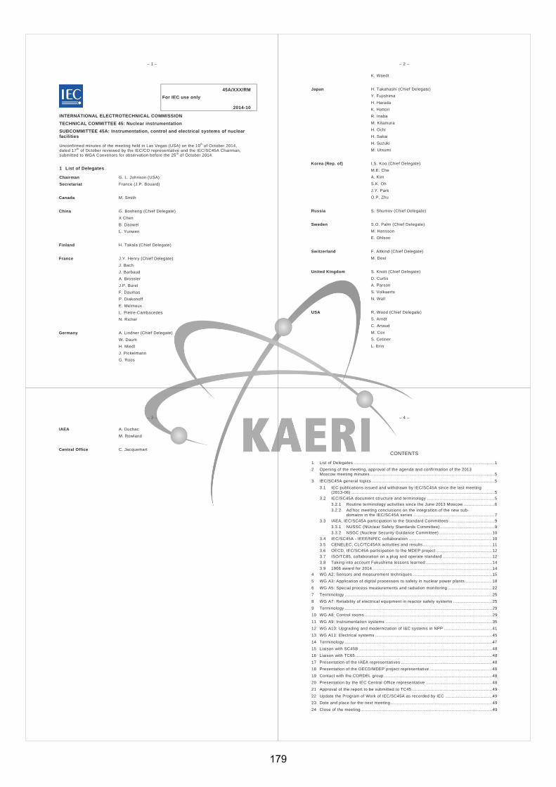
– 1 –
45A/XXX/RM For IEC use only
2014-10
INTERNATIONAL ELECTROTECHNICAL COMMISSION TECHNICAL COMMITTEE 45: Nuclear instrumentation SUBCOMMITTEE 45A: Instrumentation, control and electrical systems of nuclear facilities
Unconfirmed minutes of the meeting held in Las Vegas (USA) on the 10th of October 2014, dated 17th of October reviewed by the IEC/CO representative and the IEC/SC45A Chairman, submitted to WGA Convenors for observation before the 25th of October 2014.
1 List of Delegates
Chairman G. L. Johnson (USA) Secretariat France (J.P. Bouard)
Canada M. Smith
China G. Bosheng (Chief Delegate) X Chen B. Daowei L. Yunwen
Finland H. Takala (Chief Delegate)
France J.Y. Henry (Chief Delegate) J. Bach J. Barbaud A. Brossier J.P. Burel F. Daumas P. Diakonoff E. Melmoux L. Pietre-Cambacedes N. Richer
Germany A. Lindner (Chief Delegate) W. Daum H. Miedl J. Pickelmann G. Roos
– 2 –
K. Waedt
Japan H. Takahashi (Chief Delegate) Y. Fujishima H. Harada K. Hattori R. Inaba M. Kitamura H. Ochi H. Sakai H. Suzuki M. Utsumi
Korea (Rep. of) I.S. Koo (Chief Delegate) M.E. Che A. Kim S.K. Oh J.Y. Park O.P. Zhu
Russia S. Shumov (Chief Delegate)
Sweden S.O. Palm (Chief Delegate) M. Hansson E. Ohlson
Switzerland F. Altkind (Chief Delegate) M. Dost
United Kingdom S. Knott (Chief Delegate) D. Curtis A. Parson S. Volkaerts N. Wall
USA R. Wood (Chief Delegate) S. Arndt C. Artaud M. Cox S. Cetiner L. Erin
– 3 –
IAEA A. Duchac M. Rowland
Central Office C. Jacquemart
– 4 –
CONTENTS
1 List of Delegates ............................................................................................................ 12 Opening of the meeting, approval of the agenda and confirmation of the 2013
Moscow meeting minutes ................................................................................................ 53 IEC/SC45A general topics .............................................................................................. 5
3.1 IEC publications issued and withdrawn by IEC/SC45A since the last meeting (2013-06) .............................................................................................................. 5
3.2 IEC/SC45A document structure and terminology .................................................... 53.2.1 Routine terminology activities since the June 2013 Moscow ........................ 63.2.2 Ad’hoc meeting conclusions on the integration of the new sub-
domains in the IEC/SC45A series ............................................................... 73.3 IAEA, IEC/SC45A participation to the Standard Committees ................................... 9
3.3.1 NUSSC (NUclear Safety Standards Committee) .......................................... 93.3.2 NSGC (Nuclear Security Guidance Committee) ......................................... 10
3.4 IEC/SC45A - IEEE/NPEC collaboration ................................................................ 103.5 CENELEC, CLC/TC45AX activities and results ..................................................... 113.6 OECD, IEC/SC45A participation to the MDEP project ........................................... 123.7 ISO/TC85, collaboration on a plug and operate standard ...................................... 123.8 Taking into account Fukushima lessons learned ................................................... 143.9 1906 award for 2014 ............................................................................................ 14
4 WG A2: Sensors and measurement techniques ............................................................. 155 WG A3: Application of digital processors to safety in nuclear power plants ..................... 186 WG A5: Special process measurements and radiation monitoring .................................. 227 Terminology ................................................................................................................. 258 WG A7: Reliability of electrical equipment in reactor safety systems .............................. 259 Terminology ................................................................................................................. 2910 WG A8: Control rooms .................................................................................................. 2911 WG A9: Instrumentation systems .................................................................................. 3512 WG A10: Upgrading and modernization of I&C systems in NPP ..................................... 4113 WG A11: Electrical systems .......................................................................................... 4514 Terminology ................................................................................................................. 4715 Liaison with SC45B ...................................................................................................... 4816 Liaison with TC65 ......................................................................................................... 4817 Presentation of the IAEA representatives ...................................................................... 4818 Presentation of the OECD/MDEP project representative ................................................ 4819 Contact with the CORDEL group ................................................................................... 4820 Presentation by the IEC Central Office representative ................................................... 4821 Approval of the report to be submitted to TC45 .............................................................. 4922 Update the Program of Work of IEC/SC45A as recorded by IEC .................................... 4923 Date and place for the next meeting .............................................................................. 4924 Close of the meeting ..................................................................................................... 49
179
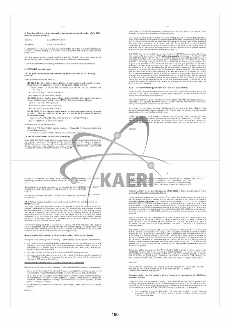
– 5 –
2 Opening of the meeting, approval of the agenda and confirmation of the 2013 Moscow meeting minutes
Chairman G. L. JOHNSON (USA)
Secretariat France (J.P. BOUARD)
55 delegates, one liaison (IAEA) and IEC Central Office other than IEC/SC45A attended the IEC/SC45A plenary meeting, 12 countries were represented and we thank them for their participation.
One item concerning the contact established with the CORDEL group was added to the revised agenda 45A/971A/DA issued mid September 2014 which was approved.
The minutes of the Moscow meeting, 45A/932/RM, were approved without modification.
3 IEC/SC45A general topics
3.1 IEC publications issued and withdrawn by IEC/SC45A since the last meeting (2013-06)
Published after the Moscow meeting:
IEC 62645 Ed. 1.0 : Nuclear power plants - Instrumentation and control systems - Requirements for security programmes for computer-based systems
Project Leaders: Mr. QUINN and Mr. Hardin (USA) and Mr. PIETRE-CAMBACEDES (France),
Circulation of 45A/771A/RVN: 2010-04-16 IEC 62645 Ed. 1.0 publication: 2014-08
IEC 62705 Ed. 1.0 : Nuclear power plants - Instrumentation and control important to safety - Radiation monitoring systems (RMS): Characteristics and lifecycle
Project Leader: Mr. SAKAÏ (Japan), Circulation of 45A/825/RVN: 2010-10-01 IEC 62705 Ed. 1.0 publication: 2014-07 IEC TR 62918 Ed. 1.0 : Nuclear power plants - Instrumentation and control important
to safety - Use and selection of wireless devices to be integrated in systems important to safety
Project Leaders: Mr. KOO (Rep. of Korea) and Mr. HASHEMIAN (USA), IEC TR 62918 Ed. 1.0 publication: 2014-07
Withdrawn after the Moscow meeting:
IEC 61510 TR Ed.1: RBMK nuclear reactors - Proposals for instrumentation and control improvements Circulation of 45A/934/RR for information and comments: 2013-07-19
3.2 IEC/SC45A document structure and terminology
Since 2003, IEC/SC45A started to harmonize its terminology and presentation document, for more details concerning the history of this harmonization see the reports of previous IEC/SC45A plenary meetings and more particularly those of the Lyon, London, Yokohama, Seattle, Karlsruhe and Moscow meetings, referenced 45A/643A/RM, 45A/703/RM, 45A/782/RM, 45A/828/RM, 45A/874/RM and 45A/932/RM.
– 6 –
Since 2004, all IEC/SC45A documents published abide by those rules for the format of the titles and the integration of the harmonized introduction.
Since 2009, as announced during the Yokohama meeting, IEC/SC45A terminology reached a stage of stabilization, meaning that the vast majority of the terms and definitions were abiding by our terminology policy, the recurrent task concerning the harmonization of the remaining few ones being considered as a routine task. The recent IEC/SC45A scope extension challenged this stabilized state and a special effort is to be done in the coming years to guarantee it on the new scope including now the security and the electrical systems domains and terminologies, see 45A/959/INF and the paragraph 3.2.2.
IEC/SC45A Secretary reminded the experts that the first IEC/SC45A terminology objective is now to use as far as possible the IAEA safety and security terminology in the frame of IEC standards development as well as in the frame of IEC/IEEE standards development. As a subsequent principle, we adopt directly those definitions in our documents. If an IAEA definition is not totally satisfying for its direct use in IEC/SC45A documents, we integrate the original IAEA definition in our documents and add a note to give precisions or introduce nuances. If an IAEA term definition cannot be used in our IEC/SC45A documents, we define the term in our IEC/SC45A documents and we associate to this definition a note drawing the attention of the reader on the fact that the definition is different from the IAEA one and we give the reasons explaining the discrepancy. If an IAEA term definition is deemed not correct or it is deemed necessary to have it modified, a proposal of the modified definition is to be prepared with due justifications and transmitted to the IEC/SC45A Secretary who will transmit it to the IAEA for consideration during the next reviews of the IAEA Safety and Security Glossaries. The second objective of our IEC/SC45A terminology policy is the use as far as possible of existing IEV definitions for generic terms in the electrotechnical domain and ISO terms in the other domains.
3.2.1 Routine terminology activities since the June 2013 Moscow
During the 2013 Moscow meeting, WGs worked accordingly to IEC/SC45A policy on the last “not harmonized” terms. The results obtained were consolidated by IEC/SC45A Secretariat shortly after the meeting, see 45A/959/INF.
The updated definitions given in DS431 have to be considered when developing IEC/SC45A standards. Those updated definitions will be considered for the next revision of the IAEA Safety Glossary which is foreseen in a near future.
To prepare the Las Vegas meeting, IEC/SC45A Secretariat sent in June 2014 the WG Convenors the lists of terms pre assigned to their WG and some theme term lists, with explicit aims to discuss the last “not harmonized” terms.
During the meeting, WGs worked accordingly to IEC/SC45A policy on the last “not harmonized” terms. The results obtained were included in WG reports to IEC/SC45A. They will be consolidated by IEC/SC45A Secretariat shortly after the meeting. IEC/SC45A Secretariat will enforce the consolidated decisions when checking the documents at CDV level.
Decision:
– 7 –
IEC/SC45A Secretariat will send WGA Convenors the consolidated terminology decisions and the updated IEC/SC45A term list by February 2015.
Consolidated terminology decisions to be enforced by the IEC/SC45A Secretariat as soon as available in IEC projects as well as in IEC/IEEE projects.
IEC/SC45A Secretariat will send TC45/WG1 the consolidated terminology by April 2015.
Sec. : 2015-02
Sec. : 2015-02
Sec. : 2015-04
3.2.2 Ad’hoc meeting conclusions on the integration of the new sub-domains in the IEC/SC45A series April 2014, IEC/SC45A Secretary circulated 45A/959/INF to draw the attention of the IEC National Committees and the experts on the fact that a terminology and document structure reviews subsequent to the recent coverage of new subjects by IEC/SC45A, namely security and electrical systems, were necessary and an ad’hoc meeting was to be planned in conjunction with the IEC/SC45A October 2014 Las Vegas meeting to discuss the matter. September 2014, IEC/SC45A sent several mails to WGA Convenors and heads of national delegation on particular issues to be considered during the ad’hoc meeting for they start working on them at WGA and national level.
The ad’hoc meeting was held on Tuesday 7th of October, the WGA Convenors, the Heads of national delegations and the experts willing to attended the meeting. The conclusions of the discussions were captured by the IEC/SC45A Secretary and validated by the IEC/SC45A Chairman and the WGA Convenors, see 45A (Las Vegas/AG) 12.
Recommendation of extension of the terminology policy to the security domain
During the ad’hoc meeting held on Tuesday 7th of October IEC/SC45A experts recommended:
that the IEC/SC45A terminology policy be extended to the security domain for IEC/SC45A standards use IAEA safety and security terminology consistently and coherently to implement in its detailed International Standards the high level safety and security principles developed by the IAEA ;
that this extension be reflected in the minutes of the IEC plenary meetings;
that this extension be taken into account in the revision of the harmonized introduction of the IEC/SC45A standards, considering this proposal of revision will be submitted for approval to IEC National Committees.
Recommendation for the format of the titles of IEC/SC45A standards
During the ad’hoc meeting held on Tuesday 7th of October IEC/SC45A experts recommended:
to use for the first parts of the titles only "Nuclear power plants" and "Nuclear facilities" (it was noted that “Nuclear facilities” should be used with precautions and justifications) ;
to use only for the second parts of the titles "Instrumentation systems important to safety", “Instrumentation and control systems important to safety”, “Instrumentation, control and electrical systems important to safety”, "Instrumentation and control systems", “Control rooms”, "Electrical systems";
to allow the third part of the title to be free for the Project Leader, given that it is short and concise.
Decision :
– 8 –
If in the coming 2 two months no objection is raised by an IEC National Committee, the IEC/SC45A Secretariat will implement the two recommendation of the ad’hoc group related to extension of the terminology policy to the security domain and to the format of the titles of IEC/SC45A standards.
Sec.: 2014-12
Recommendation for the possible revision of IEC 61513 to better take into account the electrical systems and the security domain
During the ad’hoc meeting held on Tuesday 7th of October IEC/SC45A experts indicated that if we take these evolutions of domain into account in a revision of IEC 61513, this revision cannot be simple and limited, and considering the importance of IEC 61513 it will represent an actual risk for IEC/SC45A. So after discussion it appeared that the preferred solution of the experts would be to develop a new general requirements standard for electrical systems and to position it in the IEC/SC45A document pyramid at the same level as IEC 61513. During the discussion the experts envisaged also the possibility to position IEC 62645 (computer security program) at same level as IEC 61513 and the future electrical systems general requirements standard.
Experts indicated that the development of a “short chapeau standard” above those entry standards may be necessary in order to reference them and introduce them (To ease the understanding of this paragraph we will consider this chapeau document is a level 0 document, and the sub-domains entry standards are level 1 documents of IEC/SC45A standards series).
IEC/SC45A experts attending the ad’hoc meeting held the 7th of October 2014 recommended that this proposal be evaluated in two steps, a first evaluation before the IEC/SC45A plenary meeting to be held on the 10th of October 2014 to consolidate the recommendation to be made during that plenary meeting to IEC/SC45A, followed by a more detailed evaluation of the options before May 2015 with production of an evaluation report of 4 pages to be sent to IEC National Committee for comment/approval. During the IEC/SC45A plenary meeting nobody raised objection concerning the orientations taken during the 7th October ad’hoc meeting and in particular the possible development of a new general requirements standard for electrical systems.
During the ad’hoc meeting held the 7th of October 2014 a group of senior experts was established to study the issue and make a recommendation. The group chaired by G. JOHNSON (US) comprises D. CURTIS and N. WALL (UK), H. HARRADA (Japan), G. ROOS and W. GEISSLER (Germany), L. PIETRE-CAMBACERES and J.M. HAURE (France), S. JOHANSSON (Sweden) and A. DUCHAC (IAEA), see also 45A(Las Vegas/Secretariat)12.
Decision :
The IEC/SC45A Secretariat will prepare a DC to circulate the report prepared by the senior experts group to be circulated to IEC National Committee for comment and approval.
Sec. :2015-05
Recommendation for the revision of the harmonized introduction of IEC/SC45A standards revision
During the ad’hoc meeting held on Tuesday 7th of October IEC/SC45A experts agreed on the following principles for the revision of the harmonized introduction of IEC/SC45A standards. The revision will introduce limited modifications to reflect the scope extension and the use of IAEA terminology to implement the safety and security high principles of the Agency:
First sentence, a change shall reflect the respective positions of the “chapeau document”, IEC 61513, IEC 62645 and the future electrical systems general requirements standard.
180
– 9 –
Second paragraph (about the level 2 documents) indicate the generic topics covered (or to be covered) by the level 2 document(s) for the electrical systems and the security domain, if any.
Sixth paragraph about the IAEA documents, change for "The IEC SC45A standards series consistently implements and details the principles and basic safety and security aspects provided in the IAEA code on the safety and security of NPPs and in the IAEA safety and security series, in particular for safety, the Requirements SSR-2/1, establishing safety requirements related to the design of Nuclear Power Plants, and the Safety Guide SG-XX (ex-DS431) and SSG-34 dealing with instrumentation, control and electrical systems important to safety in Nuclear Power Plants and in particular for security the implementing guide NSS17."
to explain the relationships of our security documents with the IEC and ISO security documents add the following sentence “At level 2, IEC 62645 is the entry document for the IEC/SC45A security standards. It builds upon the valid high level principles and main concepts of ISO/IEC 27001 and 27002, adapts them and completes them to fit the nuclear context and coordinates closely with the IEC 62443”.
IEC/SC45A experts attending the ad’hoc meeting recommended that after the proposal of evolution of the structure of the IEC/SC45A high level documents be validated by IEC National Committees and before end 2015 (see previous recommendation):
IEC/SC45A Secretary with the WG Convenor draft the successive revisions of the harmonized introduction reflecting the evolution of the situation,
WG Convenors have it circulated in their WG for comments ;
then once review in WGAs, IEC/SC45A Secretary have it circulated to IEC National Committees for comments and approval.
Decision :
After the proposal of evolution of the structure of the IEC/SC45A high level documents has been validated by IEC National Committees and before end 2015, the IEC/SC45A Secretariat will implement the recommendation concerning the revision of the harmonized introduction of IEC/SC45A standards revision.
Sec.: 2015-12
3.3 IAEA, IEC/SC45A participation to the Standard Committees
3.3.1 NUSSC (NUclear Safety Standards Committee)
IEC/SC45A Secretary, representing IEC, participated to the 36th NUSSC meeting held in October 2013 and to the 37th NUSCC meeting held in July 2014.
For the 36th NUSSC meeting the IEC/SC45A Secretary submitted a consolidated compilation of comments formulated by IEC/SC45A experts on the draft DS431 (Safety Guide on I&C important to safety). Considering the draft was circulating for Member States comments till December 2013, the project was not discussed.
During that 36th NUSSC meeting the transmission to CSS of DS430: Safety Guide on electrical systems was also confirmed by NUSSC members. This D430 Safety Guide will be the basic document used by WGA11 to develop IEC/SC45A standards on electrical systems.
For the 37th NUSSC meeting the IEC/SC45A Secretary submitted one comment supporting the DS431 draft for its transmission to CSS and publication. IEC/SC45A Secretary also submitted detailed comments on NST036 (Security of instrumentation and control systems at nuclear facilities).
– 10 –
During that 37th NUSCC meeting after discussions NUSCC members decided to approve the DS431 draft and to transmit it to CSS for publication. When published, this D431 Safety Guide will be the basic document used by IEC/SC45A to develop its standards.
IEC/SC45A Secretary reminded the experts that SSG-30: Safety Guide on Safety Classification of SSCs in NPPs and SSG-34 on electrical systems are now published and have to be taken into account for the development of IEC/SC45A standards.
3.3.2 NSGC (Nuclear Security Guidance Committee)
Considering the context of collaboration established since the 70’s between the IAEA and the IEC/SC45A, and the recent security activities developing in IEC/SC45A, a meeting between officers of IAEA Division of Nuclear Security (NSNS) and IEC/SC45A was held on 22nd of May 2014 in the frame of the existing category A liaison established between the IAEA and the IEC/SC45A. This meeting was held, in Vienna (Austria) with the objective to define the plan for NSNS/IEC collaboration on nuclear security activities related to nuclear instrumentation and control, see 45A/965/INF.
During the meeting NSNS and IEC/SC45A identified the following activities in which cooperation may be pursued:
IEC/SC45A use of IAEA safety and security terminology to implement in its detailed International Standards the high level security principles developed by the IAEA.
NSNS representation at IEC/SC45A meetings and events.
IEC/SC45A representation as an observer at NSNS meetings and events including the Nuclear Security Guidance Committee meetings.
Participation of the IEC in the 2015 IAEA International Computer Security Conference.
This collaboration will provide for enhanced and consistent bridging with the IEC and ISO generic security standards through IEC SC 45A which maintains liaisons with the relevant IEC and ISO Technical Committees.
Summer 2014, IEC/SC45A Secretary applied to be accepted as observer at the NSGC meeting. The application was accepted by NSGC members.
Decision:
The IEC/SC45A Secretary will continue to pursue active liaison with IAEA. The IEC/SC45A Secretary will attend the future NUSCC and NSGC meetings.
The IEC/SC45A Secretary will attend the next IAEA TWG-NPPIC(Technical Working Group on Nuclear Power Plant Instrumentation and Control) to be held in 2015 and will participate actively to the international conference organized by the Agency on computer security.
After having reviewed the results of terminology activities in WGs, the Secretariat will send the IAEA/NUSSC and NSGC proposals of evolutions for the IAEA safety and security glossaries, if any.
Sec. :2014-2016
Sec:2015
Sec. : 2014-2016
3.4 IEC/SC45A - IEEE/NPEC collaboration
Since 2003, the principle of collaboration between IEC/SC45A and IEEE/NPEC for mutually accepted projects is accepted. A formal category D liaison was set up between the WGA9 of the IEC/SC45A and the IEEE/NPEC, for more details concerning the history of this collaboration and the results achieved see the reports of previous IEC/SC45A plenary meetings and more particularly the ones of the Lyon, London, Yokohama, Seattle, Karlsruhe and Moscow meetings, referenced 45A/643A/RM, 45A/703/RM, 45A/782/RM, 45A/828/RM,
– 11 –
45A/874/RM and 45A/932/RM. Concerning the events related to this collaboration which took place just before the Moscow meeting see 45A/974/INF.
Since the 2013 Moscow meeting, IEC/SC45A and IEEE/NPEC collaborated on the development of 4 documents, see the reports of WGA8, WGA9 and WGA10, see paragraphs 8, 9 and 10 of the minutes of this meeting.
July 2014, in order to allow National Committees to prepare the Moscow meeting, IEC/SC45A Officers and the IEC/CO representative made the review of the information available at Secretariat level concerning each project launched or considered in the frame of the IEC/IEEE collaboration, prepared and circulated an information letter, see 45A/974/INF. The aim of this information letter is, to fulfil the commitment taken by IEC/SC45A Officers at each plenary meeting since the collaboration started, to inform IEC National Committees about this collaboration on a factual, open and transparent manner.
The IEC/IEEE joint project meeting was held the 2nd and the 3rd of October, 5 projects are active and no blocking point is identified, see the report of the meeting referenced 45A(Las Vegas/Secretariat)13 and the Las Vegas reports of the WGAs under which responsibility those projects are developed.
Decision:
IEC/SC45A Chairman and the Secretary will continue to pursue active liaison with IEEE/NPEC.
The Chairman and/or the Secretary will attend the IEEE/NPEC meetings.
IEC/SC45A Chairman and Secretary will keep the IEC/SC45A Chief Delegates, WGA Convenors and National Committees informed of the collaboration between IEC/SC45A and IEEE/NPEC.
Chair&Sec:
2014-2016
3.5 CENELEC, CLC/TC45AX activities and results
Concerning the history of the activation and the activities of CLC/TC45AX see the minutes of the Lyon, London, Yokohama, Seattle, Karlsruhe and Moscow meetings, referenced 45A/643A/RM, 45A/703/RM, 45A/782/RM, 45A/828/RM, 45A/874/RM and 45A/932/RM.
Between 2010 and 2013, the national implementations of IEC 60880, IEC 60987, IEC 62138, IEC 60709, IEC 60964, IEC 61226, IEC 60671, IEC 60965, IEC 61500 IEC 62340 IEC 61513 and IEC 61772 were published without modification in the 33 European countries that are members of CENELEC (European standardization organization for the electrotechnical domain).
Summer 2014, the national implementations of IEC 62566 and IEC 61839 were published without modification in the 33 European countries that are members of CENELEC.
The European endorsements of IEC 60987 (including the amendment 1) and IEC 62441 were launched mid 2014. The publication as national standards of those European implementations of IEC/SC45A standards in 33 European countries is foreseen before end 2015.
It is reminded that EN standards (European standards) are a means for the uniform implementation of International standards, throughout Western Europe. The activation of CLC/TC45AX is real opportunity for IEC/SC45A to see its documents endorsed and used all over Europe.
A closer link between IEC/SC45A and CLC/TC45AX seems not necessary; the relationship between IEC/SC45A and CLC/TC45AX is managed through the existing agreements signed between the IEC and the CENELEC. Secretariat of CLC/TC45AX is France (J.P. BOUARD).
– 12 –
When needed, the information will be given to IEC/SC45A by its Secretary during the regular IEC/SC45A plenary meeting.
3.6 OECD, IEC/SC45A participation to the MDEP project
The Multinational Design Evaluation Programme (MDEP) is a multinational initiative under NEA/OECD (Nuclear Energy Agency of the Organization for Economic Co-operation and Development) to develop innovative approaches to leverage the resources and knowledge of mature, experienced national regulatory authorities who are, or will shortly be, undertaking the review of new reactor power plant designs. The MDEP programme incorporates a broad range of activities including, increasing multinational convergence of codes, standards, and safety goals.
The MDEP Programme structure includes the issue specific Digital Instrumentation and Control Working Group (DICWG), which includes members from; Canada, China, Finland, UAE, France, India, IAEA, Japan, Korea, the Russian Federation, South Africa, Sweden, the United Kingdom and the United States. The IEEE and IEC are invited participants to the meetings.
IEC/SC45A Secretary takes regularly part to MDEP/DICWG meetings as representative of the Subcommittee and attended in particular the meetings held in December 2013, in March 2014 and in July 2014. Nine generic common positions are now available on the OECD website: on treatment of CCF caused by software, on software tools, on V&V throughout the life cycle of digital systems, on communication independence, on simplicity in design, on HDL devices, and on the impact of cybersecurity features on digital I&C safety systems, on digital I&C safety systems pre-installation and initial on-site testing and on the use of automatic testing in digital I&C safety systems as part of the surveillance testing.
IEC/SC45A Chairman took part to the third MDEP conference where he presented the Sub-Committee activities and took part to panel discussions.
OECD/MDEP/DICWG Chairman, Ms. Deanna J. ZHANG (US), attended IEC/IEEE common project meeting held in Las Vegas. OECD/MDEP/DICWG Chairman, presented the MDEP/DICWG activities to WGA3, her presentation is to be found in the meeting folder 45A/XXX/MTG on the IEC website.
Decision:
The Chairman of IEC/SC45A and/or the Secretary will continue to pursue active liaison with OECD/NEA and with OECD/MDEP/DICWG.
Chair&Sec:
2014-2016
3.7 ISO/TC85, collaboration on a plug and operate standard
During the IEC/SC45A technical meetings related to the Fukushima events held in Karlsruhe in February and March 2012, IEC/SC45A experts identified the need for IEC/SC45A to develop a standard “plug and operate” to ease the use of equipment sent by other NPP in case of emergency, see in 45A/874/RM the list of new projects to be launched next in paragraph 3.10.
Summer 2012, IEC/SC45A Secretary was informed that ISO/TC85/SC6 was planning to develop technical specifications for connection of mobile equipment for emergency intervention on nuclear installations. This ISO standard should comprises several parts, the first one to cover generic aspects and other ones to cover more specific sub domains (high voltage, low voltage, water, compressed air …). As electrical equipment is to be covered by this ISO standard, IEC/SC45A Secretary took contact with ISO/TC85 Secretary to remind ISO that the electrical domain is IEC.
181
– 13 –
Spring 2013, after several contacts and discussions between the Secretariats, it was proposed ISO/TC85 and IEC/SC45A collaborate in order to develop the electrical part of the standard to establish technical specifications for connection of mobile equipment for emergency intervention on nuclear installations. It was proposed to establish this collaboration in order to avoid conflicting requirements be established in ISO standards and IEC standards for the same products and the development of the common ISO/IEC requirements be as cost effective as possible.
May 2013, IEC/SC45A Secretary circulated to National Committees the information letter 45A/929/INF, to which was attached a NWIP under development in ISO/TC85/SC6 with a provisional draft. In this information letter P-members, were invited to appoint national experts to debate on this issue during the Moscow meeting.
The question was tabled during the ad’hoc meeting held the 25th of June 2013. IEC/SC45A experts attending recommended that once a more detailed NWIP will have been submitted by ISO/TC85/SC6, the IEC/SC45A Secretary prepare with the help of IEC/CO and circulate a DC in order to allow the National Committees to indicate whether or not they support the launching of this collaboration with ISO/TC85 for the development of an ISO/IEC standard to cover the topic of portable electrical equipment, see 45A(Moscow/AG)12.
End June 2014, IEC/SC45A Secretary was informed that the NWIP was approved in ISO/TC85 and the project of development of the standard starting.
September 2014, IEC/SC45A Secretary got the approved NWIP and the proposal for ISO/TC85 that IEC/SC45A developed the electrical part of the standard. IEC/SC45A Secretary circulated the NWIP and other related documents to WGA3 and WGA11 Convenors as preparatory documents for the Las Vegas meeting.
IEC/SC45A experts attending the ad’hoc meeting held the 7th of October 2014 noted that the proposal made by ISO/TC85 that IEC/SC45A develops the electrical part of the standard is in line with the recommendation they made during the June 2013 meeting.
IEC/SC45A experts attending the ad’hoc meeting held on the 7th of October 2014 recommended that IEC/SC45A Secretary collects specific information and ISO documentation on the project (scope and approximate size of the expected contribution from SC 45A), thus allowing SC 45A to take informed decisions on possible approaches; once this information / documentation is available, he coordinates with IEC/CO and IEC/SC45A Chairman to define the mode of cooperation to be adopted for this collaboration and to prepare a DC to be submitted to National Committees to approve this proposal of collaboration for the development of this ISO standard comprising an ISO/IEC part covering electrical portable equipment and to appoint experts to take part to this project, see 45A(Las Vegas/Secretariat)12.
IEC/SC45A Secretary recommended the IEC/SC45A experts draw the attention of their National Committees on the need to have a Project Leader and experts appointed to fulfill usual project approval criteria (simple majority of National Committees approving the project and 5 experts appointed by those supporting National Committees).
IEC/CO representative indicated that a liaison existing between the IEC/SC45A and ISO/TC85 ; ISO/TC85 drafts can be available for IEC/SC45A expert who can comment on them through the liaison.
Decision :
– 14 –
The Secretary of IEC/SC45A and the will continue to pursue the discussion with ISO/TC85 to set up the collaboration frame.
Once the required information/documentation from ISO TC85 is available, the IEC/SC45A Secretary will prepare a DC with with the support of the IEC/SC45A Chairman and of the IEC/CO and circulate it taking into account the recommendations formulated by experts during the 25th June ad’hoc meeting held in Moscow in June 2013 and the discussions held in Las Vegas.
Sec: 2014-2016
Sec: 2014-12 (Once the required information/documentation is available)
3.8 Taking into account Fukushima lessons learned
The lessons learned from the Fukushima accident have to be taken into account at the level of IEC/SC45A standards. The taking into account of those lessons has to be done during the revision of the existing standards and in the frame of the development of new standards.
For the 2012 Karlsruhe meeting, starting from the analyses of the lessons learned during the Fukushima events, IEC/SC45A produced a report, 45A_Karlsruhe_ChairWGA2_11A, on the consequences on the I&C. In particular the issue of “hardened instrumentation” was considered in this document. This report was presented to the IAEA during the 33rd NUSSC meeting held in July 2012, see also paragraph 3.4. During the 2012 Karlsruhe WGA meetings the IEC/SC45A experts identified the actions to be launched in paragraph 3.10 of 45A/874/RM.
June 2013 during the Moscow meeting, IEC/SC45A working groups reported that every recommendations related to the lessons learned during the Fukushima accident were now integrated in the overall IEC/SC45A work programme and forecast and would be implemented in the future, taking into account in particular the resources available and the balance of the WGA workloads.
September 2014, the approval of the project of development of a standard to cover the topic of Emergency Response Center was announced, see paragraph 8 of those minutes and the development of a standard in collaboration with ISO to cover electrical mobile equipment is started, see paragraph 3.7.
During the IEC/IEEE joint projects meeting held the 2nd and 3rd of October 2014, experts attending recommended effort be done concerning the possible endorsement of IEEE 497, see 45A(Las Vegas/Secretariat)13.
During the WGA5, a NIWP on instrumentation for spent fuel was proposed to be launched in the coming months, see WGA5 report.
3.9 1906 award for 2014
The 1906 awards were established in commemoration of the foundation of IEC and honors technical experts around the world whose work is fundamental to the IEC.
For 2014, two IEC/SC45A experts, Mr. A. LINDNER (Germany) and Mr. A. PARSON (UK) had been nominated to receive the 1906 awards which recognizes recent achievements related to our activities, which contributes in a significant way to advancing the work of IEC/SC45A.
The tributes associated with the nominations read as follows:
Mr. A. LINDNER ( Germany, WGA3 Convenor and Co-Project Leader of IEC 61500 ed.2) : For his many years of energetic and competent leadership of WGA3 (Application of digital processors to safety in nuclear power plants) and for co-leading project IEC 61500 ed2 with efficiency, dedication and success and for his continued dedication and commitment in support of the IEC activities.
– 15 –
Mr. A. PARSON (UK, WGA8 expert, Project Leader of IEC 60965 ed.2) : For his active and competent participation to the activities of WGA8 and particularly for leading or co-leading efficiently several projects of standards in the past years and for his support to IEC/SC45A Officers for the committee reorganisation activities since 2010.
4 WG A2: Sensors and measurement techniques
A Convenor Mr. MELMOUX (France) and 22 experts attended the WGA2 meeting.
June 2013, French National Committee announced that Mr. BUREL will retire after the 2013 Moscow meeting and proposed Mr. MELMOUX (France) to fill in for him as WGA2 Convenor. No objection was raised by National Committees in the two months following the Moscow meeting concerning the appointment of Mr. MELMOUX. IEC/SC45A Secretary appointed Mr. MELMOUX and the IEC website was updated accordingly.
No WGA2 intermediate meeting was held since the 2013 Moscow meeting.
Project of IEC 60744 Ed. 2.0 publication 45A/969A/CC : Nuclear power plants – Instrumentation and control important to
safety - Safety logic assemblies : Characteristics and test methods Project Leader: Mr. K.Y. SOHN (Rep. of Korea) Mr. JP BUREL (France).
45A/921A/CC circulation: 2014-01-17 Closure of 45A/946/CD circulation for comments: 2014-04-18 45A/969A/CC circulation: 2014-08-29
Considering the discussions held during the 2013 Moscow meeting, WGA2 recommended that a third CD be prepared and circulated to National Committees for comments.
The Project Leader took consensually the discussions held in Moscow and updated the compilation of comments formulated on the second CD, see 45A/921A/CC.
Then according to WGA2 recommendations the Project Leader prepared the third CD which circulated from January 2014 till April 2014. The comments formulated on the third CD were considered by the Project Leader who prepared in March 2013 a filled in compilation of comments and an updated draft. When circulating the compilation of comments the IEC/SC45A Secretary draw the attention of the Project Leader and of the WGA2 experts on the necessity to respect the scope of the document, the scope of the working group in which the document is developed and the utmost importance of the consistency of the developed drafts with high level IEC/SC45A standards, in particular IEC 61513 and IEC 61226.
During the Las Vegas meeting, J.P. BUREL (France) proposed to support the Project Leader to take into account the comments related to the scope and to the interaction with IEC/SC45A high level standards. Together they proposed WGA2 for this project a new table of contents and additional information to be included in the document.
Considering the discussions held during the Las Vegas meeting, WGA2 recommended that a that the draft be modified to reflect the Las Vegas exchanges and circulated to WGA2 experts in order to check it respects the scope of the project, of WGA2, the IEC/SC45A terminology policy and it references consistently high level IEC/SC45A standards. After this circulation and checking, WGA2 recommended a CD4 be prepared and circulated before the next meeting.
UK delegates questioned way IEC/SC45A Secretariat took into the comments formulated on the CD3 and the decision to prepare a CD4. IEC/SC45A Secretariat answered the respect of the scope of the project, of the scope of WGA2, of the IEC/SC45A terminology policy and associated IAEA safety principles justified his position.
– 16 –
Decision:
The answered compilation of comments 45A/969A/CC will be updated and sent to IEC/SC45A Secretary for circulation to National Committees in June 2015.
The CD4 will be circulated to National Committees for comments and approval by September 2015 for three months.
The date of circulation of the CD4 is based on the reception of the document in June 2015 at the Secretariat.
Pr.Lead.: 2015-06
Sec. : 2015-09
Pr.Lead.: 2015-06
Project of IEC 60772 Ed. 2.0 publication 45A/986/CC : Nuclear Power Plants - Instrumentation important to safety - Electrical
penetration assemblies in containment structures Project Leader: Mr. WABER (Germany)
Closure of 45A/966/CD circulation for comments: 2014-09-05 45A/986/CC circulation: 2014-09-12
Considering the discussions held during the 2013 Moscow meeting, WGA2 recommended that a CD be prepared and circulated to National Committees for comments.
According to WGA2 recommendations the Project Leader prepared a CD. The CD circulated from May 2014 till September 2014. When transmitted to IEC/SC45A Secretariat for circulation, the Secretary noted that some regional standards were referred to in the draft and requested that either international equivalent standards be referred to or if none are available other standards originating from other regions be also referred to.
Mid September 2014, an unanswered compilation of comments was circulated to WGA2 experts and to IEC National Committees as preparatory information for the Las Vegas meeting. One week before the meeting the Project Leader circulated his proposals of answer to comment to WGA2 experts.
Considering the discussions held during the Las Vegas meeting and that there was not sufficient time to consider in a proper way all comments which were to be discussed, WGA2 recommended that an intermediary meeting dedicated to this project be held beginning 2015 to answer all the comments and that a second CD be prepared and circulated before the next meeting. The dedicated meeting will be organized by the project Leader in January 2015.
Decision:
The answered compilation of comments 45A/986A/CC will be sent to IEC/SC45A Secretary for circulation to National Committees in February 2015.
The CD2 will be circulated to National Committees for comments and approval by June 2015.
The date of circulation of the CD2 is based on the reception of the document in May 2015 at the Secretariat.
Pr.Lead.: 2015-02
Sec. : 2015-06
Pr.Lead.: 2015-05
Project of IEC 62887 Ed. 1.0 publication 45A/936/RVN: Nuclear power plants - Instrumentation important to safety – Pressure
transmitters
182
– 17 –
Project Leaders : Mr FABRO (France) replacing Mrs. SAUZET (France) Closure of 45A/936/RVN circulation for voting: 2013-08-09
During the Moscow meeting, WGA2 recommended that a CD be prepared and circulated to National Committees for comments for beginning 2014.
Mrs. SAUZET having left her company, a new Project Leader was to be found. Summer 2014, Mr. FABRO was appointed. He produced for the Las Vegas meeting a working draft which was circulated as preparatory information beginning September 2014 and presented during the meeting.
Considering the discussions held during the Las Vegas meeting, WGA2 recommended that the draft be updated to reflect the Las Vegas exchanges and circulated as a CD before the next meeting.
Decision:
The CD will be circulated to National Committees for comments by June 2015.
The date of circulation of the CD is based on the reception of the document in May 2015 at the Secretariat.
Sec. : 2015-06
Pr.Lead.: 2015-05
Maintenance of standards
According to 45A/970/DC circulated to National Committees, the reviews of the IEC 60231 series, IEC 60515, IEC 60737, IEC 60988 and IEC 62651 were carried out during this meeting. WGA2 took into account the comments formulated by National Committees concerning the maintenance of those standards, see 45A/980/INF, and recommended that:
IEC 60231 (1967) and its seven supplements be kept frozen, because as it is indicated on the IEC website even if the IEC 60231 series of standards is no longer up-to-date and will not be updated, these standards are maintained available for bibliographical purposes and because they were used in the past for the design of nuclear power plants which are still in operation.
IEC 60231 (1967) and its seven supplements, IEC 60737 (2010), IEC 60988 (2009) and IEC 62651(2013), be kept with stability dates equal to 2020.
IEC 60515 (2007) be kept with stability dates equal to 2018.
Decision :
Accordingly to WGA2 recommendations, the IEC/SC45A Secretariat and the IEC/CO will assure the circulation of the RR (confirmations) concerning IEC 60231 (1967) and its seven supplements, IEC 60568 (2007), IEC 60737 (2010), IEC 60988 (2009) and IEC 62651(2013) for December 2014.
The IEC/SC45A Secretary will update the IEC/SC45A maintenance policy to be annexed to the IEC/TC45 SBP for December 2014.
Sec. : 2014-12
Sec.: 2014-12
Consideration on future work and update of the WGA2 work forecast
June 2014, IEC/SC45A Secretariat transmitted the WG Convenors the updated IEC/SC45A work forecast to prepare the Las Vegas meeting.
– 18 –
Concerning the IEC/SC45A work forecast, WGA2 identified the following 3 first PWIs (new standards or revisions) and but no possible NC/PL proposers were identified to be able to propose them in the 3 coming year if necessary:
– Seismic instrumentation standard to be proposed by the XX NC/PL, – Boron concentration instrumentation standard to be proposed by the XX NC/PL, – Reactor pressure level instrumentation standard to proposed by the XX NC/PL,
and the 5 additional PWIs (new standards or revisions) to be considered later:
– H2 instrumentation, – Spent fuel instrumentation, – SMR instrumentation – Measurement cables characteristics. – Fast breeder reactors specific sensors
Decision:
IEC/SC45A Secretariat will have the IEC/SC45A work forecast updated by January 2015 and circulated to Convenors and Chief Delegates.
Sec. : 2015-01
Terminology
Concerning terminology, WGA2 reviewed all the terms it is responsible of.
No pending discrepancies were identified concerning terms defined by the IAEA in the safety glossary.
Alignment of terms according to WGA2 decisions taken during previous meetings will have to be done when revising IEC 60515, 60568, 61224, 61468, 61502, 62397.
No particular issue is identified for WGA2 concerning terminology.
Intermediate WGA2 meeting before next plenary meeting
An WGA2 intermediate meeting dedicated to project IEC 60772 Ed. 2.0 is planned.
5 WG A3: Application of digital processors to safety in nuclear power plants
Considering their agendas WGA3 and WGA7 decided to meet one after another in order to allow the maximum number of experts to participate to their respective discussions.
A Convenor Mr. LINDNER (Germany) and 35 experts attended the WGA3 meeting.
No WGA3 intermediate meeting was held since the 2013 Moscow meeting.
German Head of Delegation announced on behalf of the German National Committee that Mr. LINDNER will step down from WGA3 Convenorship after this meeting and proposed Mr. MIEDL (Germany) to fill in for him as WGA3 Convenor.
IEC/SC45A Chairman thanked Mr. LINDNER who took part to IEC/SC45A activities more than 10 years as expert and as WGA3 Convenor. During those years, Mr. LINDNER co-led the development of IEC/SC45A standards and received the IEC 1906 award in 2014.
– 19 –
If no objection is raised by National Committees in the two coming months concerning the appointment of Mr. MIEDL, IEC/SC45A Secretary will have Mr. MIEDL appointed and the IEC website updated accordingly.
Project of IEC 62138 Ed. 2.0 publication 45A/984/CC: Nuclear power plants - Instrumentation and control important for safety
- Software aspects for computer-based systems performing category B or C functions Project Leader: Mr. RICHER (France).
45A/939/RR circulation: 2013-10-11 Closure of 45A/962/CD circulation for comments: 2014-09-05 45A/984/CC circulation: 2014-09-12
During the 2013 Moscow meeting, Mr. N. RICHER was appointed Project Leader for the revision of IEC 62138 and it was agreed revision principles presented and discussed during the meeting will circulate just after meeting and a CD will circulate in June 2014.
The Project Leader took consensually the discussions held in Moscow and updated the revision principles which circulated annexed to the RR in October 2013, then he prepared a CD which circulated from May till September 2014.
Mid September 2014, an unanswered compilation of comments was circulated to WGA3 experts and to IEC National Committees as preparatory information for the Las Vegas meeting. One week before the meeting the Project Leader circulated his proposals of answer to comment to WGA3 experts.
Considering the discussions held during the Las Vegas meeting, WGA3 recommended that the updated CC and a CD2 be prepared to reflect the Las Vegas exchanges and circulated.
Decision:
The answered compilation of comments 45A/984A/CC will be sent to IEC/SC45A Secretary for circulation to National Committees in February 2015.
The CD2 will be circulated to National Committees for comments and approval by March 2015 for three months..
The date of circulation of the CD2 is based on the reception of the document in February 2015 at the Secretariat.
Pr.Lead.: 2015-02
Sec. : 2015-03
Pr.Lead.: 2015-02
Project of a Technical Report on Platform qualification 45A/932/RM: Nuclear power plants - Instrumentation and control important to safety
– Platform qualification Project Leaders: Mr. MIEDL (Germany) and Mr. SOHN (Rep. of Korea)
During the 2013 Moscow meeting, the discussions held considered the opportunity to develop a technical report on I&C platform qualification and the German National Committee proposed to lead the project.
September 2014, the Project Leader circulated a first working draft as preparatory information for the Las Vegas meeting.
Considering the discussions held during the 2014 Las Vegas meeting, WGA3 recommended a DC be prepared to collect comments and information from National Committees. IEC/SC45A
– 20 –
Secretariat reminded the experts that the goal of IEC/SC45A is to develop International Standards, so each Technical Report developed in IEC/SC45A has to comprise a paragraph indicating if the development of a standard can be launch without delay and give guidance for its development, or if it is deemed it is not possible it has to identify the grounds preventing the development of the standard to evaluate in the future if they still exist.
Considering the overlaps between the project presented by Mr SOHN (Rep. of Korea) in WGA7 it was proposed he acts as co Project Leader for the development of this technical report. The German Project Leader accepted the proposal, see also the report of WGA7.
WGA3 recommended if possible the DTR be prepared and circulated before the next meeting for the possible NWIP already prepared by the Korean experts related to the same subject can be updated and possibly circulated after the 2016 meeting.
Decision:
A DC will be circulated in June 2015.
The date of circulation of the DC is based on the reception of the document in May 2015 at the Secretariat.
Sec. : 2015-06
Pr.Lead.: 2015-05
Project of a Technical Report on hazard analysis 45A/932/RM: Nuclear power plants - Instrumentation and control important to safety
– Hazard analysis Project Leader: Mr. Jang-Soo LEE (Rep. of Korea)
During the 2013 Moscow meeting, the discussions held considered the opportunity to develop a technical report on hazard analysis and the Korean National Committee proposed to lead the project.
September 2014, the Project Leader circulated a first working draft as preparatory information for the Las Vegas meeting.
Considering the discussions held during the 2014 Las Vegas meeting, WGA3 recommended a DC be prepared to collect comments and information from National Committees.
Decision:
A DC will be circulated in March 2015.
The date of circulation of the DC is based on the reception of the document in February 2015 at the Secretariat.
Sec. : 2015-03
Pr.Lead.: 2015-02
Maintenance of standards
According to 45A/970/DC circulated to National Committees, the reviews of the IEC 60880, and IEC 61500 were carried out during this meeting. WGA3 took into account the comments formulated by National Committees concerning the maintenance of those standards, see 45A/980/INF, and recommended that:
IEC 60880 (2006) be kept with stability dates equal to 2017.
IEC 61500 be revised the schedule determined after the Las Vegas meeting. Dr KOO (Rep. of Korea) and T. PARSON (UK) will co lead this limited revision.
Decision :
183
– 21 –
Accordingly to WGA3 recommendations, the IEC/SC45A Secretariat and the IEC/CO will assure the circulation of the RR (confirmations) concerning IEC 60880 (2006) for December 2014.
Accordingly to WGA3 recommendations, the IEC/SC45A Secretariat and the IEC/CO will assure the circulation of the RR concerning the revision of IEC 61500 for February 2016.
The date of circulation of the RR to intiate the revision of IEC61500 is based on the reception of name of the project and the principles of revision in January 2016 at the Secretariat.
The IEC/SC45A Secretary will update the IEC/SC45A maintenance policy to be annexed to the IEC/TC45 SBP for December 2014.
Sec. : 2014-12
Sec. :2016-02
Sec.: 2016-01
Sec.: 2014-12
Consideration on future work and update of the WGA3 work forecast
June 2014, IEC/SC45A Secretariat transmitted the WG Convenors the updated IEC/SC45A work forecast to prepare the Las Vegas meeting. Concerning the IEC/SC45A work forecast, WGA3 identified the following 3 first PWIs (new standards or revisions) and possible NC/PL proposers and:
– IEC 61513 could be considered for integration of limited modifications related to security, revision of principles to be proposed and a PL to be found,
– IEC 60880 could be considered for alignment with IEC 62138 once revised, revision of principles to be proposed and a PL to be found,
– HDL-Standard for class 2 and 3 systems to be proposed by a PL to be found,
and the additional PWI (new standards or revisions) to be considered later:
– a standard to cover the gaps for Cat B/C Communications,
Decision:
IEC/SC45A Secretariat will have the IEC/SC45A work forecast updated by January 2015 and circulated to Convenors and Chief Delegates.
Sec. : 2015-01
Terminology
Spring 2014 when preparing the IEC 62645 FDIS, IEC/SC45A Secretary identified the need to introduce in IEC/SC45A glossary a definition for “digital systems”. He proposed WGA3 Convenor and experts to start a brainstorming on the terms family related to digital systems and to review the results obtained during the Las Vegas with WGA7 and WGA9.
IEC/SC45A experts attending the 7th October ad’hoc meeting recommended that the brainstorming continues after the Las Vegas meeting and that the WGA3 Convenor prepares a document describing the topology of this term family, with their definitions for May 2015. IEEE relevant terms and definitions are to be considered during the brainstorming, keeping in mind the importance of the harmonization between the organizations. IEC/SC45A Secretary highlighted the importance of this activity and invited the experts to work steadily on this issue but to take the time needed to reach a stabilised and sustainable position (for a long time). IEC/SC45A Secretary will circulate this document for comments to IEC NCs.
IEC/SC45A experts recommended the note of IEC 61513 related to digital systems be corrected to take into account this new definitions.
– 22 –
Decision:
IEC/SC45A Secretariat will prepare with the WGA3 proposal a DC to be circulated to IEC NCs for comment and approval by June 2015 .
Sec. : 2015-06
Else concerning terminology, WGA3 reviewed the terms it is responsible of. No particular issue is identified for WGA3 concerning terminology.
No pending discrepancies were identified concerning terms defined by the IAEA in the safety glossary and DS431. Alignment according to WGA3 decisions taken during previous meetings concerning terminology will have to be done when revising IEC 60880 and IEC 61513.
Intermediate WGA3 meeting before next plenary meeting
WGA3 intermediate meeting is planned and it will be an e-meeting meeting.
6 WG A5: Special process measurements and radiation monitoring
A Convenor Mr. SAKAI (Japan) and 11 experts attended the WGA5 meeting.
No intermediate meeting was held since the 2013 Moscow meeting.
Project of IEC 62705 Ed 1.0 publication 45A/973/RVD : Nuclear Power Plants - Instrumentation and control important to
safety – Radiation Monitoring Systems (RMS) : Characteristics and test methods Project Leader: Mr. SAKAï (Japan)
45A/922A/CC circulation: 2013-08-09 Closure of 45A/937/CDV circulation for comments and voting: 2014-01-24
Positive result of voting, 45A/948/RVC, circulation: 2014-02-07 IEC CO result: P-members voting: 15; P-members in favour: 15(100%) P-members not voting: Egypt, Pakistan Closure of 45A/960/FDIS circulation for vote: 2014-07-04
Positive result of voting, 45A/973/RVD circulation: 2014-07-11 IEC CO result: P-members voting: 17; P-members in favour: 16(94,1%), P_member against: Finland, P-members not voting: Egypt, Pakistan.
Considering the discussions held during the 2013 Moscow meeting, WGA5 recommended that the compilation of comments on the circulated CD and the proposal of CDV be updated to reflect the Moscow exchanges and circulated to National Committees for vote and comments for fall 2013.
According to the WGA5 recommendations, the Project Leader updated the compilation of comment and prepared the CDV which started its circulation in October 2013. The CDV was approved in March 2014. The Project Leader answered consensually the comments formulated by National Committees on the CDV and taking them into account prepared a FDIS. The FDIS started its circulation in May 2014 and was approved in July 2014.
IEC 62705 Ed. 1.0 was published in July 2014.
Project of IEC 61250 Ed. 2.0 publication 45A/930/CC : Nuclear Power Plants – Instrumentation and control important to safety
– Detection of leakage in coolant systems Project Leader: Mr. UTSUMI (Japan)
– 23 –
45A/930/CC circulation: 2013-05-24
During the 2013 Moscow meeting, WGA5 recommended that the compilation of comments and the first CD be updated to reflect the Moscow exchanges and circulated to National Committees as second CD comments for October 2013.
No document was sent to IEC/SC45A Secretariat for circulation.
Considering the discussions held during the 2014 Las Vegas meeting, WGA5 recommended that the compilation of comments and the first CD be updated to reflect the Moscow and Las Vegas exchanges and circulated to National Committees as CDV for comments and approval.
Decision :
The updated CC on 45A/912/CD will be circulated to National Committees by May 2015
IEC/SC45A will have the CDV circulated for three months to IEC National Committees for comments and approval by August 2015.
The date of circulation of the CDV is based on the reception of the document in May 2015 at the Secretariat.
Sec. : 2015-05
Sec. : 2015-08
Pr.Lead.: 2015-05
Maintenance of standards
According to 45A/970/DC circulated to National Committees, the reviews of the IEC 60768 (2009), IEC 60910 (1988), IEC 60911 (1987), IEC 61031 (1990), IEC 61343 (1996) and IEC 61504 (2000) were carried out during this meeting. WGA5 took into account the comments formulated by National Committees concerning the maintenance of those standards, see 45A/980/INF, and recommended that:
IEC 60910 (1988), IEC 61343 (1996) be kept with stability dates equal to 2016.
IEC 60768 (2009), IEC 60911 (1987) be kept with stability dates equal to 2019.
IEC 61031 (1990), Design, location and application criteria for installed area gamma radiation dose rate monitoring equipment for use in nuclear power plants during normal operation and anticipated operational occurrences be revised:
- the Project Leader of the revision will be Mr. NISHIZAWA (Japan), - a WD is expected for 2015-06, a CD is expected for 2015-12, a CDV for 2016-12, a
FDIS for 2017-10, - the publication of the revision is expected for 2017-12
IEC 61504 Ed. 1.0 (2000), Nuclear power plants - Instrumentation and control systems important to safety - Plant-wide radiation monitoring be revised
- the Project Leader of the revision will be Mr. SAKAI (Japan), - a WD is expected for 2015-06, a CD is expected for 2015-12, a CDV for 2016-12, a
FDIS for 2017-10, - the publication of the revision is expected for 2017-12
Decision :
– 24 –
Accordingly to WGA5 recommendations, the IEC/SC45A Secretariat and the IEC/CO will assure the circulation of the RR (confirmations) concerning IEC 60768 (2009), IEC 60910 (1988), IEC 60911 (1987), IEC 61343 (1996) for December 2014.
Accordingly to WGA5 recommendations, the IEC/SC45A Secretariat and the IEC/CO will assure the circulation of the RR concerning the revision of IEC 61031 for June 2015.
The date of circulation of the RR to initiate the revision of IEC 61031 is based on the reception of the principles of revision in May 2015 at the Secretariat.
Accordingly to WGA5 recommendations, the IEC/SC45A Secretariat and the IEC/CO will assure the circulation of the RR concerning the revision of IEC 61504 for June 2015.
The date of circulation of the RR to initiate the revision of IEC 61504 is based on the reception of the principles of revision in May 2015 at the Secretariat.
The IEC/SC45A Secretary will update the IEC/SC45A maintenance policy to be annexed to the IEC/TC45 SBP for December 2014.
Sec. : 2014-12
Sec. :2015-06
Sec.: 2015-05
Sec.: 2015-06
Sec. : 2015-05
Sec.: 2014-12
Consideration on future work and update of the WGA5 work forecast
Following the discussions held during the meeting, WGA5 recommended a new standard for the spent fuel pool monitoring is developed. Mr. JOHNSON (US) will be a Project Leader of this project unless another candidate comes forward.
IEC/SC45A Secretary recommended for that for each of those projects a draft representing 75% of the first WD be circulated for observation in WGA10 at least for four weeks and the observations formulated, if any, be taken into account before the NWIP is sent to the IEC/SC45A Secretary.
Decision :
IEC/SC45A Secretariat and the IEC/CO will assure the circulation of the NWIP on spent fuel pool monitoring by April 2015.
The date of circulation of the NWIP is based on the reception of the NWIP with a draft representing 75% of the first WD annexed to it, at the Secretariat in March 2015.
Sec. : 2015-04
Sec.: 2015-03
June 2014, IEC/SC45A Secretariat transmitted the WG Convenors the updated IEC/SC45A work forecast to prepare the Las Vegas meeting. Concerning the IEC/SC45A work forecast, WGA5 identified the following 3 first PWIs (new standards or revisions) and possible NC/PL proposers and:
IEC 61343 revision, principles of revision the proposer to be confirmed,
containment monitoring standard but no proposer is identified,
IEC 60910 revision but no proposer is identified,,
and the 6 additional PWIs (new standards or revisions) to be considered later:
184
– 25 –
Measurements to be available in the ERC
Offsite environmental measures,
IEC 61031 revision,
IEC 60951 -1 to 4 revisions.
Decision:
IEC/SC45A Secretariat will have the IEC/SC45A work forecast updated by January 2015 and circulated to Convenors and Chief Delegates.
Sec. : 2015-01
Terminology
No particular issue is identified for WGA5 concerning terminology.
Intermediate WGA5 meeting before next plenary meeting
No WGA5 intermediate meeting is planned.
7 WG A7: Reliability of electrical equipment in reactor safety systems
Considering their agendas WGA3 and WGA7 decided to meet one after another in order to allow the maximum number of experts to participate to their respective discussions.
A Convenor Mr. WALL (UK) and 42 experts attended the WGA7 meeting.
No intermediate meeting was held since the 2013 Moscow meeting.
During the 2013 Moscow meeting the Convenor and the experts recognized that the title and scope of the WGA7 should be reviewed for example to include CCF and defense in depth. However, it was also noted that it shall take place following the completion of the revision of the title and scope of SC45A and the confirmation of WGA11. During the 2014 Las Vegas meeting draft name and scope were proposed; these were modified during discussion and will be reviewed and circulated to the working group members for comment by December 2014.
Decision:
IEC/SC45A Secretariat will prepare a DC to be circulated to IEC National Committees for comment and approval in January 2015
Sec. : 2015-01
Project of IEC 60709 Ed. 3.0 publication 45A/932/RM : Nuclear Power Plants – Instrumentation, control and electrical systems
important to safety – Separation Project Leader: Mr. GEISSLER (Germany)
During the 2013 Moscow meeting WGA7 recommended IEC 60709 (2004) be revised and it was envisaged the Project Leader of the revision will be proposed by the French National Committee before mid 2014. After the meeting the French and German experts discussed and agreed a German Project Leader be appointed by his National Committee.
Summer 2014, the Project Leader prepared a proposal of principles of revision which was circulated in September as preparatory information for the Las Vegas meeting.
– 26 –
Considering the discussions held during the 2014 Las Vegas meeting, WGA7 recommended that the principles of revision be updated and circulated with the RR after the meeting to initiate the revision. WGA7 recommended a CD be prepared and circulated before the next meeting.
Decision:
The RR to initiate the IEC 60709 revision will be circulated to National Committees by November 2014.
The CD will be circulated to National Committees by November 2015.
The date of circulation of the CD is based on the reception of the document in October 2015 at the Secretariat.
Sec. : 2014-11
Sec. : 2015-11
Pr.Lead.: 2015-10
Project of IEC 61226 Ed. 4.0 publication 45A/958/RR : Nuclear Power Plants – Instrumentation, control and electrical systems
important to safety – Categorisation of instrumentation, control and electrical functions Project Leader: Mr. BARBAUD (France)
45A/958/RR circulation: 2014-03-28
During the 2013 Moscow meeting considering that it was necessary to maintain consistency with IAEA publication SR 2/1 and the forthcoming publications of DS 367 (categorisation and Classification), DS 431 (I&C replacement for NSG 1.1 and 1.3), and SSG-34 (NSG 1.8 replacement), WGA7 recommended the IEC 61226 (2009) be revised. Mr. BARBAUD volunteered to take the position of Project Leader for this revision and proposed to develop the principles of revision and to supply a first draft for the Las Vegas meeting.
According to the recommendations and the commitment taken the Project Leader circulated in February 2014 for comments to WGA7 experts his proposal of principles of revision. Those principles of revision were finalized and annexed to 45A/958/RR which circulated in March 2014. The Project Leader developed a first working draft of the revision, which was circulated to WGA7 experts in September 2014 as preparatory information for the Las Vegas meeting.
Considering the discussions held during the 2014 Las Vegas meeting, WGA7 recommended the draft be updated to reflect the Las Vegas exchanges and a CD circulates before the next meeting.
Decision:
The CD will be circulated to National Committees by February 2015.
The date of circulation of the CD is based on the reception of the document in January 2015 at the Secretariat.
Sec. : 2015-02
Pr.Lead.: 2015-01
Project of IEC 62808 Ed. 1.0 publication 45A/925/CC : Nuclear power plants – I&C systems important to safety – Design and
qualification of isolation devices Project Leader: Mr. SEAMAN (USA)
45A/925A/CC circulation: 2013-11-15 Closure of 45A/944/CDV circulation for comments and voting: 2014-05-09 Positive result of voting, 45A/968/RVC, circulation: 2014-06-13 IEC CO result: P-members voting: 17; P-members in favour: 17(100%) P-members not voting: Pakistan, Ukraine
– 27 –
During the 2013 Moscow meeting, WGA7 recommended that the compilation of comments formulated on the circulated CD and the proposal of CDV be updated to reflect the Moscow exchanges and circulated to National Committees for vote and comments for beginning 2014.
According to the WGA7 recommendations the Project Leader circulated in November 2013 the updated compilation of comments and sent the IEC/SC45A Secretariat the CDV which circulated from February to May 2014. The CDV was approved, the Project answered consensually the comments formulated and the RVC circulated in June 2014. The Project Leader prepared a proposal of FDIS which was circulated to WGA7 experts as preparatory information for the Las Vegas meeting.
Considering the discussions held during the 2014 Las Vegas meeting, WGA7 recommended the FDIS circulates before the next meeting.
Decision:
The FDIS will be circulated to National Committees by March 2015.
The date of circulation of the FDIS is based on the reception of the document in December 2014 at the Secretariat.
Sec. : 2015-03
Pr.Lead.: 2014-12
Project of a Technical Report on FMEA 45A/979/INF : Nuclear power plants - Instrumentation and control important to
safety – Use of FMEA in NPP (Comments formulated on 45A/972/DC) Project Leader: S. SMITH (USA)
Closure of 45A/972/DC circulation for comments: 2014-07-04 45A/979/INF circulation: 2014-09-12
During the 2013 Moscow meeting, WGA7 recommended more contributions be sent to the Project Leader to allow the preparation of a DTR.
Summer 2014, the Project Leader prepared a DC which was circulated in July 2014 to obtain more information from the national experts. The answers of the IEC National Committees were circulated as preparatory information for the Las Vegas meeting in September 2014.
Considering the discussions held during the 2014 Las Vegas meeting, WGA7 recommended that draft be updated and circulated as a DTR after the meeting.
Decision:
A DTR will be circulated in February 2015.
The date of circulation of the DTR is based on the reception of the document in December 2014 at the Secretariat.
Pr.Lead.: 2015-02
Sec. : 2014-12
Maintenance of standards
According to 45A/970/DC circulated to National Committees, the review of IEC/TR 61838 (2009) was carried out during this meeting. WGA7 took into account the comments formulated by National Committees concerning the maintenance of this standard, see 45A/980/INF, and recommended that:
IEC/TR 61838 (2009) be kept with stability dates equal to 2017.
Decision :
– 28 –
Accordingly to WGA7 recommendations, the IEC/SC45A Secretariat and the IEC/CO will assure the circulation of the RR (confirmations) concerning IEC/TR 61838 (2009) for December 2014.
The IEC/SC45A Secretary will update the IEC/SC45A maintenance policy to be annexed to the IEC/TC45 SBP for December 2014.
Sec. : 2014-12
Sec.: 2014-12
Consideration on future work and update of the WGA7 work forecast
Mr SOHN (Rep. of Korea) transmitted before the Las Vegas meeting a NWIP to WGA7 on commercial grade item dedication and presented it during the WGA7 Las Vegas meeting. The proposed work appeared to WGA7 experts closely related to the work currently being undertaken in WGA3 on platform validation where a TR was being developed because of the lack of consensus on the topic. WGA7 experts agreed the best approach would be to transfer this development to WGA3; the convener of WGA3 accepted this proposal and accepted also Mr. SOHN co-lead the project.
Considering the discussion held during the Las Vegas meeting, WGA7 recommended to transfer the work to WGA3 to be undertaken in conjunction with the TR preparation on.
Decision:
IEC/SC45A Secretariat will transfer the work to WGA3 and Mr. SOHN will be appointed co Project Leader for the project of development of the TR on qualification platform
Sec. : 2014-10
Following the discussions held during the meeting a project will be launched before the next meeting on diversity. The draft scope and document structure will be circulated in the working group. The NWIP will be sent to the IEC/SC45A Secretariat by the US/UK NC for circulation to National Committees by October 2015. The use of joint project leaders is being considered on account of the scope of the work and need for electrical and Control and instrumentation expertise.
IEC/SC45A Secretary recommended for that for each of those projects a draft representing 75% of the first WD be circulated for observation in WGA7 at least for four weeks and the observations formulated, if any, be taken into account before the NWIP is sent to the IEC/SC45A Secretary.
Decision :
IEC/SC45A Secretariat and the IEC/CO will assure the circulation of the NWIP on diversity by October 2015.
The date of circulation of the NWIP is based on the reception of the NWIP with a draft representing 75% of the first WD annexed to it, at the Secretariat in September 2015.
Sec. : 2015-10
Sec.: 2015-09
June 2014, IEC/SC45A Secretariat transmitted the WG Convenors the updated IEC/SC45A work forecast to prepare the Las Vegas meeting. Concerning the IEC/SC45A work forecast, WGA7 identified the following 3 first PWIs (new standards or revisions) for which proposers are looked for:
Reliability analysis,
185
– 29 –
Reliability verification (Class 1),
Validation tools,
and the 3 additional PWIs (new standards or revisions) to be considered later:
Single Failure Criterion application
Reliability claims for systems in combinations
Defence in Depth
Decision:
IEC/SC45A Secretariat will have the IEC/SC45A work forecast updated by January 2015 and circulated to Convenors and Chief Delegates.
Sec. : 2015-01
Terminology
No particular issue is identified for WGA7 concerning terminology. However a full review is required against the recent IAEA publications e.g. SSG 30 and SSG 33. This will be undertaken by March 2015 and the results will be presented for the next meeting.
Intermediate WGA7 meeting before next plenary meeting
No WGA7 intermediate meeting is planned.
8 WG A8: Control rooms
A Convenor Mr. GOFUKU (Japan) and 14 experts attended the WGA8 meeting.
No intermediate meeting was held since the 2013 Moscow meeting.
Project of IEC 60965 Ed. 3.0 publication : 45A/976/CC: Nuclear Power Plants – Control rooms – Supplementary control points
for reactor shutdown without access to the main control room IEC Project Leader: Mr. PARSON (UK)
45A/951/RR circulation: 2014-02-14 Closure of 45A/952/CD circulation for comments: 2014-05-16 45A/976/CC circulation: 2014-08-29 During the 2013 Moscow meeting considering the lessons learned from TEPCO Fukushima Daiichi accident WGA8 recommended a revision be launched for IEC 60965. Mr. PARSON (UK) volunteered to be Project Leader. WGA8 recommended the comments formulated during the circulation of the FDIS of the published version are taken into account and a CD be circulated before the Las Vegas meeting.
According to the WGA8 recommendations the Project Leader prepared principles of revision which were annexed to the RR which circulated in February 2014 and prepared a CD which circulated for comments from February till May 2014. The Project Leader answered consensually the compilation of comments formulated by IEC National Committees on the circulated CD, see 45A/976/CC.
Considering the discussions held during the 2014 Las Vegas meeting, WGA8 recommended that compilation of comment and the CD be updated and circulated as a CDV before the meeting next meeting for the comments formulated on it be discussed there.
– 30 –
Considering one of the comments received, WGA8 took the position that it would be beneficial to more closely align the standard with the terminology adopted by the IAEA Safety Guide for design (SSR-2/1). WGA8 therefore recommended that the title is amended to refer to “Supplementary Control Room” in place of “Supplementary Control Points”. It was noted however that, whilst this constituted a change in emphasis within the standard, designs of existing NPPs based on more than one supplementary control point would still be permitted. IEC/SC45A accepted the recommendation. If no objection is raised by National Committees in the two coming months concerning this proposal, IEC/SC45A Secretary will implement it.
Decision:
The answered compilation of comments 45A/976A/CC will be sent to IEC/SC45A Secretary for circulation to National Committees in March 2015.
The CDV will be circulated to National Committees for comments and approval by June 2015 for three months.
The date of circulation of the CDV is based on the reception of the document in March 2015 at the Secretariat.
Pr.Lead.: 2015-03
Sec. : 2015-06
Pr.Lead.: 2015-03
Project of IEC 62646 Ed. 2.0 publication : 45A/983/CC: Nuclear Power Plants – Control rooms – Computer based procedures
IEC Project Leader: Mr. BLAS replacing Mr. DALL’AGNOL (France) 45A/956/RR circulation: 2014-03-21 Closure of 45A/957/CD circulation for comments: 2014-06-17 45A/983/CC circulation: 2014-09-12 During the 2013 Moscow meeting considering the lessons learned from TEPCO Fukushima Daiichi accident WGA8 recommended an amendment or a full revision of IEC 62646 be prepared by the Project Leader of the first edition, Mr. DALL’AGNOL (France). The new version of IEC 62646 has to be prepared taking into account the late comments from the national committee of Canada.
According to the WGA8 recommendations the Project Leader prepared principles of revision for a full revision which were annexed to the RR which circulated in March 2014 and prepared a CD which was circulated for comments from March till June 2014. September 2014, the answered compilation of comments formulated by IEC National Committees on the CD was circulated as preparatory information for the Las Vegas meeting.
Considering the discussions held during the 2014 Las Vegas meeting, WGA8 recommended that compilation of comment and the CD be updated and circulated as a CDV before the next meeting for the comments formulated on it can be discussed.
Decision:
The answered compilation of comments 45A/983A/CC will be sent to IEC/SC45A Secretary for circulation to National Committees in July 2015.
The CDV will be circulated for 3 months to National Committees for comments and approval by October 2015.
The date of circulation of the CDV is based on the reception of the document in July 2015 at the Secretariat.
Pr.Lead.: 2015-07
Sec. : 2015-10
Pr.Lead.: 2015-07
Project IEC 62954 Ed. 1.0 publication
– 31 –
45A/981/RVN: Nuclear power plants – Control rooms - Requirements for Emergency Response Center (ERC) Project Leaders : Mr. PARSON (UK) and Mr. BLAS replacing Mr. DALL’AGNOL (France) Closure of 45A/967/NP circulation for voting: 2014-09-05 Positive result of voting on NWIP: 45A/981/RVN: 2014-09-12 IEC CO result: P-members voting: 12 P-members approving the NWIP: 12(100%),
P-members approving the proposal and ready to participate in development :5
During the 2012 Karlsruhe meeting the need for development of a new standard to cover emergency response centre was discussed in the frame of the lessons learned from TEPCO Fukushima Daiichi accident. Beginning 2013, Mr DALL’AGNOL and Mr PARSON worked on a proposal of NWIP which was circulated in May 2013 as preparatory information for the 2013 Moscow meeting. The proposal was presented during the 2013 Moscow meeting and following the discussions held, WGA8 recommended the NWIP be launched before the Las Vegas meeting.
According to the recommendations made in Moscow the Project Leaders prepared a NWIP which circulated from May till September 2014. The NWIP was approved and the RVN circulated in September 2014 as preparatory information for the Las Vegas meeting.
Considering the discussions held during the 2014 Las Vegas meeting, WGA8 recommended that the compilation of comments formulated on the NWIP be updated and circulated with a CD before next meeting for the comments formulated on it be discussed there.
Various comments raised by National Committees in response to the NWIP were intended to clarify the scope of the proposed standard. These comments were discussed by the WG and the following conclusions achieved:
The scope should align with that of the relevant IAEA guidance, as given in SSR-2/1 (currently under revision as DS462) and DS457;
The scope should address the three functional facilities related to Emergency Response that are addressed by the IAEA guidance (i.e. the ERC, TSC and OSC);
The scope should be limited to such facilities that are on or near the NPP site. The scope should exclude activities in the scope of local response authorities;
The requirements should be defined in terms of the functions that are to be performed;
The standard should address the way in which the functions are invoked in response to different severities of incident / accident and any responsibilities that would be transferred from the MCR to the Emergency Response facilities
The scope should include consideration of the requirements for environment control, lighting, power supplies, access control etc. as needed to enable the Emergency Response functions to be performed;
The only “controls” that should be provided are those that relate to the services that provide the above mentioned ventilation, lighting, power supplies, access control etc;
The standard should recognize that a wide range of National situations exist regarding the structure and arrangements for the off-site Emergency Response support;
If no objection is raised by National Committees in the two coming months concerning this proposal, the project leaders will use the above clarification of the scope as the basis for preparing a new draft.
Decision:
– 32 –
The answered compilation of comments 45A/981A/RVN will be updated and sent to IEC/SC45A Secretary for circulation to National Committees in October 2015.
The CD will be circulated to National Committees for comments and approval by November 2015.
The date of circulation of the CD is based on the reception of the document in October 2015 at the Secretariat.
Pr.Lead.: 2015-10
Sec. : 2015-11
Pr.Lead.: 2015-10
Project of endorsement of IEEE 1082 as an IEC/IEEE standard 45A/974/INF : Las Vegas meeting preparatory information concerning the IEC/IEEE
projects in development IEC Project Leader: Mr. PARSON (UK)
Closure of 45A/785/Q circulation for answer: 2009-12-18 45A/801/RQ circulation: 2010-04-02 45A/871/INF circulation: 2012-02-10 45A/923/INF circulation: 2013-04-26 45A/950/INF circulation: 2014-02-07 45A/974/INF, Las Vegas meeting preparatory information concerning the IEC/IEEE
projects in development (since the 2013 Moscow meeting) : 2014-07-18
During the 2009 Yokohama meeting it was proposed that IEEE 1082-1997 be endorsed as dual logo document in the frame of the first agreement signed between the IEC and the IEEE in 2002, given some issues are resolved. These issues are:
– Clarification of normative or informative nature of references – Editorial issues related to title and terminology – Possible addition of more recent references – Identification of suitable IEC document type that is equivalent to IEEE Guide.
Mr. PARSON (UK) was appointed IEC Project Leader for this endorsement.
March 2010, taking consensually into account the comments formulated the IEC Project Leader produced a modified (marked-up) version of IEEE 1082 to be proposed to the IEEE.
April 2010, given no explicit opposition to the endorsement was formulated by the National Committees commenting on 45A/785/Q and that in any case the document will have to be approved formally by National Committees before adoption as dual logo document, the IEC/SC45A/WGA8 proposals of modifications were submitted to IEEE/NPEC/SC5 for review.
May 2010, IEC/SC45A received the results of the IEEE/NPEC/SC5 review of IEC/SC45A/WGA8 proposals of modifications reading that they represented no substantial change to the content or the original intent of the standard, and as such should be endorsed by the IEEE.
September 2010, Mr. FLEGER, IEEE/NPEC/SC5 Chair, informed the IEC Project Leader that the decision was taken by IEEE/NPEC to revise IEEE 1082 taking into account the comments sent by IEC/SC45A/WGA8 with the objective to have the revision endorsed as IEC/IEEE standard.
186
– 33 –
Mid January 2011, the IEC/SC45A Secretary and Chairman were invited to the IEEE/NPEC meeting held in Scottdale (Arizona, USA), during that meeting the PAR for the revision of IEEE 1082 was approved for submission but apparently not submitted after the meeting.
January 2012, the IEC/SC45A Secretary and Chairman invited to the IEEE/NPEC meeting held in San-Antonio (Texas, USA) were informed the PAR to initiate the IEEE 1082 revision was to be circulated after the San Antonio meeting and that no particular difficulty was foreseen for the time being to integrate the IEC/SC45A/WGA8 proposals of modifications, see 45A/871/INF.
January 2013, the IEC/SC45A Secretary was informed by Mr. FLEGER, IEEE/NPEC/SC5 Chair that the revision work progressed in IEEE/NPEC/SC5 and when more information will be available it will be sent to IEC/SC45A, see 45A/923/INF.
January 2014, the IEC/SC45A Secretary was informed by Mr. FLEGER, IEEE/NPEC/SC5 Chair that the revision work progressed in IEEE/NPEC/SC5 and a report related to the project was sent. IEC/SC45A circulated this information to IEC National Committees, see 45A/950/INF and 45A/974/INF.
WGA8 will then receive informal copies of the draft revision prepared by IEEE/NPEC/SC5 for information to check the taking into account of the IEC/SC45A/WGA8 proposals of modifications and to check the other modifications introduced in the revision do not prevent the endorsement of the revised IEEE 1082 in IEC. Upon completion of the IEEE revision process, the intent is to have the revised version proposed by IEEE endorsed as a dual logo IEC/IEEE document. At that stage, National Committees will be asked to approve the adoption.
During the IEC/IEEE joint projects meeting IEEE representative, J HAASZ, indicated that once a draft will be available for this revision it will be transmitted to the IEC Project Leader, Tony PARSON, for information, see 45A(Las Vegas/Secretariat)12
Maintenance of standards
Concerning IEC 60964 Ed. 2 (2009), Nuclear power plants – Control rooms – Design, following the agreement in the Moscow meeting that the standard should be reviewed by Mr. Andre DALL’AGNOL and Mr. Akio GOFUKU, Mr. Akio GOFUKU reported the review results. After discussion, the WGA8 agreed to propose an amendment of the standard.
The WGA8 recommended that a project should be initiated for an amendment of IEC 60964 based on the above principles of revision be developed:
The term “task” should be replaced by “function”, “I&C function”, or “operator task”, as appropriate.
The role, functional capability, robustness and integrity of supporting services for the MCR should be clarified to promote its continued use at the time of a design extension condition.
The standard should reflect the requirements of any relevant IAEA safety guides or IEC SC45A standards that have been published or revised since the edition 2 was developed.
The designated Project Leader for the revision is Ms. CORRALES (ES), a WD is expected for 2014-12, a CD is expected for 2015-06, a CDV for 2016-06, a FDIS for 2017-06, the publication of the amendment is expected for 2017-12.
According to 45A/970/DC circulated to National Committees, the reviews of the IEC 60960 (1998), IEC 61227 (2008), IEC 61771 (1995), IEC 61772 (2009), IEC 61839 (2000) and IEC 62241(2004) were carried out during this meeting. WGA8 took into account the comments formulated by National Committees concerning the maintenance of those standards, see 45A/980/INF.
Concerning IEC 60960 (1998), Functional design criteria for a safety parameter display system for nuclear power stations, following the recommendation formulated in the Moscow meeting that the standard was reviewed. Taking into account the discussions held during the
– 34 –
Las Vegas meeting, the WGA8 recommended further research be conducted and maintenance date for the standard should be extended to 2016.
Concerning IEC 62241 Ed. 1.0 (2004), Nuclear power plants - Main control room – Alarm functions and presentation, following the recommendation formulated in the Moscow meeting the standard was reviewed and WGA8 recommended that the maintenance date for the standard should be extended to 2016.
Concerning IEC 61771 Ed. 1.0 (1995), Nuclear power plants - Main control-room - Verification and validation of design, WGA8 recommended that the standard is revised. The designated Project Leader for the revision is Ms. Cristina Corrales (ES), principle of revision are expected for 2015-04, a WD for 2015-06, a CD is expected for 2015-11, a CDV for 2016-09, a FDIS for 2017-09, the publication of the amendment is expected for 2018-03.
Concerning IEC 61839 Ed. 1.0 (2000), Nuclear power plants - Design of control rooms - Functional analysis and assignment, following the recommendation formulated in the Moscow meeting the standard was reviewed and WGA8 recommended that the maintenance date for the standard should be extended to 2016.
WGA8 recommended IEC 61227 (2008), IEC 61772 (2009) be kept with stability dates equal to 2016.
Decision :
Accordingly to WGA8 recommendations, the IEC/SC45A Secretariat and the IEC/CO will assure the circulation of the RR (confirmations) concerning IEC 60960 (1998), IEC 61227 (2008), IEC 61772 (2009), IEC 61839 (2000) and IEC 62241(2004) for December 2014.
Accordingly to WGA8 recommendations, the IEC/SC45A Secretariat and the IEC/CO will assure the circulation of the RR concerning the amendment of IEC 60964 and revision of IEC 61771 for June 2015.
The date of circulation of the RR to initiate the revision of IEC61771 is based on the reception of the principles of revision in June 2015 at the Secretariat.
The IEC/SC45A Secretary will update the IEC/SC45A maintenance policy to be annexed to the IEC/TC45 SBP for December 2014.
Sec. : 2014-12
Sec. :2015-06
Sec.: 2015-06
Sec.: 2014-12
Consideration on future work and update of the WGA8 work forecast
June 2014, IEC/SC45A Secretariat transmitted the WG Convenors the updated IEC/SC45A work forecast to prepare the Las Vegas meeting. Concerning the IEC/SC45A work forecast, WGA8 identified the following PWI (new standards or revisions) and possible NC/PL proposers and:
combinatory and sequential control automation standard, to be proposed by the German NC with proposed PL Mr. HESSLER,
and the 3 additional PWIs (new standards or revisions) to be considered later:
Guideline for development of an operational basis document for design
project of synopsis of IEC 60694 and other international HFE-related standards,
Modular reactor control room standard
Decision:
– 35 –
IEC/SC45A Secretariat will have the IEC/SC45A work forecast updated by January 2015 and circulated to Convenors and Chief Delegates.
Sec. : 2015-01
Terminology
No particular issue is identified for WGA8 concerning terminology.
Intermediate WGA8 meeting before next plenary meeting
No WGA8 intermediate meeting is planned.
9 WG A9: Instrumentation systems
A Convenor Mr. QUINN (USA) and 44 experts attended the WGA9 meeting.
No intermediate meeting was held since the 2013 Moscow meeting.
Project of IEC 62003 Ed. 2.0 publication 45A/988/RR : Nuclear power plants - Instrumentation and control important to safety
- Requirements for electromagnetic compatibility testing Project Leader: Mr. KRIGER and Mr. WOOD (US).
45A/988/RR circulation: 2014-09-19
During the 2013 Moscow meeting, WGA9 recommended IEC 62003 be revised and the US delegation proposed to lead the project.
Mr. Chad KRIGER (US) volunteered for that task and prepared a draft of revision principles which circulated in WGA9 during summer 2014. He took consensually into account the comments formulated and finalized the principles of revision which were annexed to the RR which circulated at the eve of the Las Vegas meeting.
Considering the discussions held during the 2014 Las Vegas meeting, WGA9 recommended that the CD be prepared and circulated for fall 2015.
Decision:
The CD will be circulated to National Committees for comments and approval by September 2015 for three months.
The date of circulation of the CD is based on the reception of the document in August 2015 at the Secretariat.
Sec. : 2015-09
Pr.Lead.: 2015-08
Project IEC 62645 Ed. 1.0 publication 45A/989/Q: Nuclear Power Plants – Instrumentation and control systems –
Requirements for security programmes for computer-based systems Project Leaders : Mr. QUINN (US) and Mr. HARDIN (US) and Mr. PIETRE-CAMBACEDES
(France) Positive result of voting, 45A/918A/RVC, circulation: 2014-03-14 IEC CO result: P-members voting: 19; P-members in favour: 15(78,9%) P-members against: Germany, Switzerland, Sweden, UK, P-member not voting: Egypt. Closure of 45A/961/FDIS circulation for vote: 2014-07-25
Positive result of voting, 45A/975/RVD circulation: 2014-08-01
– 36 –
IEC CO result: P-members voting: 15; P-members in favour: 13(86,7%), P_member against: Germany and UK (11,8%), P-members not voting: Egypt, Romania.
Closure of 45A/989/Q circulation for vote: 2014-10-31
During the 2013 Moscow meeting, considering the comments formulated on the CDV and the discussions held, WGA9 recommended that an updated RVC and a FDIS be prepared and circulated first in WGA9 to experts to check the taking into account of the comments and then circulated to National Committees for vote given there is no problem beginning 2014.
According to the recommendations the Project Leaders circulated the documents to WGA9 experts and then to IEC National Committees. The FDIS started its circulation in May 2014 and was approved in July 2014.
IEC 62645 Ed. 1.0 was published in July 2014. An error was introduced at last stage of preparation of the document, detected and a corrigendum is currently in preparation a related questionnaire, 45A/989/Q, is currently circulated to get the approval of the IEC National Committees and corrigendum if approved end October 2014 it should be published in the coming weeks. As agreed during the discussions held at last stage of development of IEC 62645 edition 1, its publication was motivated by the willingness to capture the results of five years of discussions and as stated in its introduction its revision was to be launched quickly. The stability date for IEC 62645 was set up to 2015. Considering the discussions held during the Las Vegas meeting WGA9 recommended IEC 62645 be revised:
- Mr. QUINN and Mr. PIETRE-CAMBACEDES will co-lead the revision and UK or Germany may also appoint a co-leader
- a WD is expected for 2015-09, a CD is expected for 2016-04, a CDV for 2017-10, a FDIS for 2017-04,
- the publication of the revision is expected for 2017-08
Decision :
The IEC/SC45A Secretariat and the IEC/CO will assure the circulation of the RR concerning the revision of IEC 62645 for May 2015.
The date of circulation of the RR to initiate the revision of IEC62645 is based on the reception of the principles of revision in April 2015 at the Secretariat.
The IEC/SC45A Secretary will update the IEC/SC45A maintenance policy to be annexed to the IEC/TC45 SBP for December 2014.
Sec. : 2015-05
Sec. :2015-04
Sec.: 2014-12
Project IEC 62859 Ed. 1.0 publication 45A/909/RVN: Nuclear power plants - Instrumentation and control systems -
Requirements for coordinating safety and cybersecurity Project Leaders : Mr. PIETRE-CAMBACEDES (France)
Closure of 45A/955A/CD circulation for comments: 2014-08-15 45A/977/CC circulation: 2014-08-29
During the Moscow meeting, WGA9 recommended that the proposal of CD be updated to reflect the Moscow exchanges and circulated to National Committees for comments for beginning 2014.
According to the recommendations the Project Leader prepared a CD for it circulates once the discussions on the project IEC 62645 are over. A first version of the CD was circulated in March 2014, but it appeared that it corresponded to an outdated file. A second version of the CD based on the file with the latest updates was circulated and the deadline for comments
187
– 37 –
was extended in consequence. This second version of the first CD circulated from June till August 2014. The unanswered compilation of comments was circulated to IEC National Committees in August 2014 and the Project Leader circulated an answered compilation of comments to WGA9 experts as preparatory information for the Las Vegas meeting in September 2014.
Considering the discussions held during the 2014 Las Vegas meeting, WGA9 recommended that the compilation of comments formulated on the CD be updated and circulated with a CD2 for mid 2015.
Decision:
The answered compilation of comments 45A/977A/CC will be sent to IEC/SC45A Secretary for circulation to National Committees in May 2015.
The CD2 will be circulated to National Committees for comments and approval by June 2015 for three months.
The date of circulation of the CD2 is based on the reception of the document in May 2015 at the Secretariat.
Pr.Lead.: 2015-05
Sec. : 2015-06
Pr.Lead.: 2015-05
Project of IEC/IEEE 60780-323 Ed. 1.0 publication 45A/953A/CC : Nuclear facilities - Electrical equipment important to safety –
Qualification IEEE Project Leaders: Mr KONNICK (USA)
IEC co-Project Leader: Mr. HAMIDI-GEORGE (France) 45A/917C/CC circulation: 2013-10-11 Closure of 45A/940/CD circulation for comments: 2014-01-17 45A/942/INF circulation: 2013-08-11 45A/953A/CC circulation: 2014-04-18 45A/974/INF, Moscow Las Vegas meeting preparatory information concerning the
IEC/IEEE projects in development (since the 2012 Karlsruhe meeting) : 2014-07-18
For details concerning the history of project IEC/IEEE 60780-323 Ed.1.0 see the reports of previous IEC/SC45A plenary meetings and more particularly the ones of the Yokohama, Seattle, Karlsruhe and Moscow meetings, referenced 45A/782/RM, 45A/828/RM, 45A/874/RM and 45A/932/RM. Concerning the events which took place just before the Las Vegas meeting see 45A/974/INF.
During the IEC IEEE joint projects meeting held in 2013 in Moscow, IEEE Project leader presented the new orientations proposed by IEEE/NPEC/SC2 Chairman and IEC co Project Leader presented a modified draft integrating comments formulated by IEC National Committees and IEEE/NPEC. During that meeting it was proposed a second CD be prepared based on the structure of IEEE 323 integrating the relevant content of the first CD circulated. After discussion it was recommended that the IEEE Project Leader and the IEC co Project Leader prepare a document of explanations to be circulated with the second CD to analyze its conformity with the principles of revision on the basis of which the IEC National Committees approved the launching of this common project, see 45A/793/Q. IEEE Project Leader and IEC co Project Leader recommended an ultimate effort be done in order to produce a CDV for fall 2014.
According to the recommendations confirmed by WGA9 the IEEE Project Leader and the IEC co Project Leader prepared the document of explanations and the second CD which circulated in October 2013. The second CD ended its circulation in January 2014. The IEEE Project
– 38 –
Leader and the IEC co Project Leader took consensually into account the comments formulated by IEC National Committees and IEEE experts and prepared an answered compilation of comments which was circulated in April 2014.
Taking into account the comments formulated by IEC National Committees and IEEE experts, the IEEE Project Leader and the IEC co Project Leader prepared a draft which was presented and accepted by SC2 before the May 2014 SC2.1 meeting during which the decision was taken for the CDV be prepared on the basis of the draft presented.
June 2014, IEC/SC45A and IEEE confirmed the objective to have the CDV circulated in IEC for vote and comment closing in January 2015 and circulated for ballot in parallel in IEEE; the ultimate objective being the publication of IEC/IEEE 60780-323 in 2015, see 45A/974/INF.
During the IEC/IEEE joint project meeting held the 2nd and 3rd of October 2014 in Las Vegas, the IEEE Project Leader and the IEC co Project Leader presented the technical aspects related to CDV and they agreed on the following points:
Concerning organisational aspect IEC and IEEE project leads agreed on the following steps:
Beginning November 2014, IEC/SC45A Secretary will start the circulation of the CDV to IEC NC (5 months corresponding to: 2 months circulation of the EN version of the CDV for translation to IEC NC willing to in their national language and 3 months circulation of the (EN+FR) version to IEC NC for comments and vote). During the 2 first months of the circulation of the EN CD, IEC/SC45A Secretary will prepare the FR version of the CDV.
Beginning November 2014, parallel to the circulation of the EN CDV in the IEC, EN CDV will be circulated in IEEE for ballot.
Beginning December 2014, IEC/SC45A Secretary will take contact with the IEC experts appointed by the IEC NC to initially set up the JPT (Joint Project Team) when the project started, see paragraph 3 of 45A/797/RQ. In case some of the appointed IEC experts are no more taking part to the JPT activities, IEC/SC45A Secretary will take contact with the IEC NC to propose them the appointment of a new expert. The objective is to have an updated list of the IEC experts taking part to the JPT for February 2015.
Beginning January 2015, IEEE project leader, Robert KONNICK, will compile the IEEE comments under IEC format and send them to IEC secretary. He will propose IEEE-experts to join the JPT.
Mid April 2015, technical comments and votes expressed by IEC NC will be gathered with the IEEE comments transmitted in January 2015 and the unanswered compilation of comments will be circulated to IEC NC as well as sent to IEEE representatives and JPT experts for information.
Mid May 2015, IEEE and IEC project leads will propose resolution of comments. This answered compilation of comments will be circulated to IEC NC as well as sent to IEEE representatives and JPT experts for information without delay.
End May 2015, JPT expert will have sent back to IEEE and IEC project leads their observations on the answered compilation of comments. Each JPT expert shall identify from his point of view in the answered compilation of comments the potential conflicting points.
7th of June 2015, on the basis of this feedback, IEEE and IEC project leads will decides if a technical meeting with JPT is needed to solve remaining issue. If needed, this technical meeting will be held by end June 2015 in Paris (? cf IEEE mail). The IEC project lead will organize the meeting taking the date of the 26th of June for the start of the meeting to allow experts to anticipate their preparation for the participation to this meeting. The objective of the meeting is to resolve all comments and a proposal of FDIS draft be available for transmission to IEC/SC45A secretary with agreement of the JPT.
– 39 –
Mid July 2015 IEC Secretary will have prepare FDIS and will send it to IEC/CO to start the last editorial preparation in collaboration with IEEE with the objective to have this FDIS approved by IEC IEEE.
The version of the CDV to be used to prepare the circulations in IEC and IEEE was transmitted to the IEC/SC45A Secretary.
During the IEC/SC45A plenary meeting WGA9 confirmed the final objective to have the IEC/IEEE 60780-323 published end 2015.
Decision:
IEC/SC45A Secretary will start implementing all the recommendations of IEC and IEEE Project Leaders confirmed by WGA9 just after the Las Vegas meeting.
Sec. : 2015-10
Project of publication of IEC/TR 62918 Ed. 1.0 and proposal of development of a standard on selection and use of wireless devices in NPP
45A/963/RVC : Nuclear power plants - Instrumentation and control important to safety – Selection and use of wireless devices in NPP Project Leaders: Mr. KOO (Rep of Korea) and Mr. HASHEMIAN (US)
Closure of 45A/947/DTR circulation for comments and voting: 2014-03-28 Positive result of voting, 45A/963/RVC, circulation: 2014-05-23 IEC CO result: P-members voting: 14; P-members in favour : 14(100%) P-member not voting: Norway, Pakistan and Romania.
During the Moscow meeting, WGA9 recommended a DTR be prepared taking into account the comments formulated on the WD and circulated to National Committees for comment for November 2013.
According to the recommendation the Project Leaders prepared the DTR which circulated from January till March 2014. The DTR was approved and the RVC circulated in May 2014. French experts supplied comments on the DTR indicating they will support the preparation of standard on the topic.
IEC/TR 62918 Ed. 1.0 was published in July 2014.
Summer 2014, Korean, US and French experts prepared a proposal of NWIP with a draft attached which was circulated to WGA9 expert as preparatory information for the Las Vegas meeting.
Considering the discussions held during the Las Vegas meeting, WGA9 recommended that the NWIP be circulated.
Decision:
The NWIP will be circulated in October 2014 with the support of the IEC/SC45A Secretary who will indicate that the discussions held during the Las Vegas meeting have to be taken into account to prepare a CD which if the project is approved could be circulated in September 2015.
Sec. : 2014-10
Project of a possible endorsement of the revision of IEEE 497 standard as an IEC/IEEE dual logo standard
– 40 –
45A/974/INF : Las Vegas meeting preparatory information concerning the IEC/IEEE projects in development (since the 2013 Moscow meeting)
45A/974/INF circulation: 2014-07-18
For details concerning the history of this project of common revision of IEEE 497, see the reports of previous IEC/SC45A plenary meetings and more particularly the ones of the Seattle, Karlsruhe and Moscow meetings, referenced 45A/828/RM, 45A/874/RM and 45A/932/RM. Concerning the events which took place just before the 2014 Las Vegas meeting see 45A/974/INF.
During the June 2013 Moscow meeting, a discussion was held in WGA9 to which IEC/SC45A Chairman and Secretary took part with and Dr. Wolfgang KONIG (IEEE). The approach was discussed on how best to move forward. IEC/SC45A Secretary proposed the IEEE/NPEC develops its revision on its own sending the IEC/SC45A Secretariat the project drafts. It was proposed IEC/SC45A have those draft circulated to National Committee as DC, and the comments formulated by National Committees be circulated as INF letter. IEEE/NPEC will receive those comments for information. This proposal of definition of a new path for collaboration with IEEE was to be discussed with IEC/CO.
April 2014, the IEEE/NPEC/SC 6 after discussion with the IEEE central office and the Nuclear Power Engineering Committee informed the IEC/SC45A Chairman that the first full draft of IEEE 497 could be available for IEC consideration early September 2014.
July 2014, IEC/CO, IEC/SC45A Chairman and Secretary discussed the possibility to have the project progressing toward endorsement by IEC of the revised IEEE 497. IEC Central Office questioned the plan to circulate IEEE drafts to IEC national committees for comments for the purpose of their improvement and provided background information justifying this policy, also practiced with other organizations. In order to have the project progressing it was envisaged that the IEC/SC45A Secretariat supported by IEC/SC45A experts who participate to IEEE/NPEC/SC6 activities, address the comments formulated by IEC National Committees on IEEE 497 published in 2010 and update 45A/864/INF, based on the draft of revision of IEEE 497 developed in IEEE/NPEC/SC6, if IEEE accepts its document be used for that.
During the IEC/IEEE joint project meeting held the 2nd and 3rd of October 2014 in Las Vegas, the experts attending recommended, IEC/SC45A Secretary supported by Dr Wolfgang KONIG and Mr Jean BARBAUD (Project Leader for the revision of IEC 61226 currently going on) prepares for mid December 2014 an updated version of 45A/864/INF in order to inform IEC NC of the effort already done by IEEE/NPEC/SC6 during this revision of IEEE 497 and on the way the issues identified in 45A/864/INF were addressed. This objective of this update of 45A/864/INF is that the IEC NC have the maximum of valid information if the IEEE decided upon completion of the revision of IEEE 497 to submit it to IEC for endorsement as dual logo standard in the frame of the agreement AC/138/2002.
During the IEC/SC45A plenary meeting WGA9 confirmed the recommendations drafted in the minutes of the IEC/IEEE joint projects meeting, see 45A(Las Vegas/Secretariat)13
Decision :
IEC/SC45A Secretary will have 45A/864/INF updated and circulated to IEC National Committees according to the recommendations formulated during the IEC/IEEE joint projects meeting held in Las Vegas.
Sec.: 2014-12
Maintenance of standards
Concerning the revision of IEC 62645 see above the last paragraph related to the project of publication of IEC 62645 edition 1.0.
Consideration on future work and update of the WGA9 work forecast
188
– 41 –
As indicated in the paragraph related IEC/TR 62918 to a NWIP will be circulated just after the Las Vegas meeting to develop a standard on the selection and use of wireless devices in NPP.
Following the discussions held during the Las Vegas meeting, WGA9 recommended the project of standard on security controls be developed with two co project leaders, one from the US, Dr. CETINER, and one from Europe in order to lead incorporation of the IEC control documents (IEC 27000 series and IEC 62443 series).
Decision:
If a co Project Leader from Europe is found, the NWIP will be sent by the US NC to the IEC/SC45A Secretariat for circulation to National Committees by January 2015.
The IEC/SC45A Secretariat will circulate the NWIP by February 2015.
US. NC : 2015-01
Sec. : 2015-02
Concerning the IEC/SC45A work forecast, WGA9 identified the following 3 first PWIs (new standards or revisions) to be launched in the coming 3 years:
– Fukushima: Accident Monitoring but no proposer identified (IEEE497), – Computer security : Supply Chain Cybersecurity but no proposer is identified, – Computer Security: TR on models to be proposed by the Russian NC,
and the 3 additional PWIs (new standards or revisions) to be considered later:
– Gaps: EMP – Computer Security: Methods – Computer security : Risk Management – Technical Report - Review of Available Methods – Computer security : Cybersecurity Monitoring – Computer security : Demonstration of Effectiveness of security degrees/zones) including
testing and auditing – accreditation
Decision:
IEC/SC45A Secretariat will have the IEC/SC45A work forecast updated by January 2015 and circulated to Convenors and Chief Delegates.
Sec. : 2015-01
Terminology
The revision of IEC 62645 will probably involve security related terminology for submittal to the SC45A working group on terminology.
In addition, WGA9 needs to incorporate the terminology from WGA3 on computer based systems.
Intermediate WGA9 meeting before next plenary meeting
The possibility of an WGA9 intermediate meeting spring 2015 was discussed.
10 WG A10: Upgrading and modernization of I&C systems in NPP
A Convenor Mr. ARTAUD (USA) and 26 experts attended the WGA10 meeting.
– 42 –
IEC/IEEE 62582 IEC Project Leader, Mr. SPANG (Sweden) attended in May 2014 the IEEE/NPEC/SC2.1 meeting held in Clearwater (Florida).
Project of IEC/IEEE 62582 part 5 Ed. 1.0 publication 45A/978/RVC : Nuclear Power Plants – Instrumentation and control important to
safety – Electrical equipment condition monitoring methods, Part 5 : Optical time domain reflectometry IEC Project Leader: Mr. SPANG (Sweden), IEEE co-Project Leader: Mr. WHITE (USA)
45A/915A/CC circulation: 2013-11-13 Closure of 45A/945/CDV circulation for comments and voting: 2014-05-09 Positive result of voting, 45A/978/RVC, circulation: 2014-08-29 IEC CO result: P-members voting: 17; P-members in favour: 17(100%) P-member not voting: Pakistan. 45A/974/INF, Las Vegas meeting preparatory information concerning the IEC/IEEE
projects in development (since the 2013 Moscow meeting) : 2014-07-18
During the Moscow meeting, WGA10 recommended that a CDV for part 5 be prepared and circulated to National Committees for summer 2013.
According to the recommendation, the IEC Project Leader prepared a draft of CDV for part 5 for October 2013. This CDV circulated to IEC National Committees from February till May 2014. The CDV for part 5 was approved and the RVC including the IEEE comments circulated in August 2014.
During the IEC/IEEE joint project meeting held the 2nd and 3rd of October 2014 in Las Vegas, the IEC Project Leader presented the comments formulated on the CDV and his proposal of FDIS and recommended its circulation.
During the IEC/SC45A plenary meeting WGA10 confirmed the FDIS was to be prepared and circulated.
Decision :
The updated 45A/978A/RVC will be circulated to National Committees by February 2015 with the FDIS for part 5, which will circulate two months for approval.
Sec. : 2014-12
Project of publication of an amendment for IEC/IEEE 62582 part 2 Ed. 1.0 45A/974/INF : Las Vegas meeting preparatory information concerning the IEC/IEEE
projects in development (since the 2013 Moscow meeting) IEC Project Leader: Mr. SPANG (Sweden), IEEE co-Project Leader: Mr. WHITE (USA)
45A/974/INF, Las Vegas meeting preparatory information concerning the IEC/IEEE projects in development (since the 2013 Moscow meeting) : 2014-07-18
October 2013, IEC project leader informed IEC/SC45A Secretariat that mid 2013 an error was found in part 2 and proposed an amendment is prepared. IEC/CO advised IEC/SC45A to prepare a questionnaire to get formal approval of the IEC/NCs and to coordinate with IEEE. 45A/941/Q circulated requesting the IEC National Committees answer December 2013. IEC National Committees approval of the proposal was circulated in February 2014.
September 2014, IEEE informed the IEC/SC45A Secretariat that they approved the proposal
– 43 –
During the IEC IEEE joint projects meeting held the 2nd and 3rd of October 2014 in Las Vegas, the IEC Project Leader presented the proposal of amendment and recommended its circulation as CDV.The final technical details were discussed during the WGA10 meeting.
During the IEC/SC45A plenary meeting WGA10 confirmed the CDV for the amendment of part 2 was to be prepared and circulated.
Decision :
The CDV will be circulated to National Committees for comments and vote by January 2015 for three months.
The date of circulation of the CDV for the amendment of part 2 is based on the reception of the document in October 2014 at the Secretariat.
Sec. : 2015-01
Pr.Lead.: 2014-10
Project of IEC 62765-1 Ed. 1.0 publication 45A/987/RVC : Nuclear power plants - Instrumentation and control important to
safety – Management of aging of sensors and transmitters – Part 1: Pressure transmitters Project Leader: Mr. O.P. ZHU (Rep. of Korea)
45A/927A/CC circulation: 2014-03-21 Closure of 45A/954/CDV circulation for comments and voting: 2014-09-05 Positive result of voting, 45A/987/RVC, circulation: 2014-09-12 IEC CO result: P-members voting: 16; P-members in favour: 16(100%) P-member not voting: Egypt, Romania.
During the Moscow meeting, WGA10 recommended that the compilation of comments on the CD and the proposal of CDV be updated to reflect the Moscow exchanges and circulated to National Committees for vote and comments for beginning 2014.
According to the recommendations the Project Leader updated the compilation of comments which circulated in March 2014 and prepared a CDV which was circulated for vote and comments from May till September 2014. September 2014, the unanswered compilation of comments formulated by IEC National Committees on the CDV was circulated as preparatory information for the Las Vegas meeting.
Considering the discussions held during the 2014 Las Vegas meeting, WGA10 recommended that the compilation of comments and the CDV be updated to reflect the Las Vegas exchanges and circulated as a FDIS.
Decision:
The answered compilation of comments 45A/987A/RVC will be sent to IEC/SC45A Secretary for circulation to National Committees in January 2015.
The FDIS will be circulated to National Committees for comments and approval by January 2015.
The date of circulation of the FDIS is based on the reception of the document in November 2014 at the Secretariat.
Pr.Lead.: 2015-01
Sec. : 2015-01
Pr.Lead.: 2014-11
Maintenance of standards
According to 45A/970/DC circulated to National Committees, the reviews of the IEC 62465 (2010) and IEC/IEEE 62582-3 (2012) were carried out during this meeting. WGA10 took into
– 44 –
account the comments formulated by National Committees concerning the maintenance of those standards, see 45A/980/INF, and recommended that:
IEC 62465 (2010) be kept with stability dates equal to 2018.
IEC/IEEE 62582-3 (2012) be kept with stability dates equal to 2019.
Decision :
Accordingly to WGA10 recommendations, the IEC/SC45A Secretariat and the IEC/CO will assure the circulation of the RR (confirmations) concerning IEC 62465 (2010) and IEC/IEEE 62582-3 (2012) for December 2014.
The IEC/SC45A Secretary will update the IEC/SC45A maintenance policy to be annexed to the IEC/TC45 SBP for December 2014.
Sec. : 2014-12
Sec.: 2014-12
Consideration on future work and update of the WGA10 work forecast
Following the discussions held during the meeting the following important subjects for which projects will be launched before the next meeting were identified:
IEC/IEEE 62582-6 NWIP – Nuclear Power Plants – I&C Systems Important to Safety – Electrical equipment condition monitoring methods - Part 6: Insulation Resistance during DBE. The NWIP will be sent to the IEC/SC45A Secretariat for circulation to National Committees by 2015-06. Mr. SPANG (Sweden) has volunteered to be Project Leader.
IEC 62765-2 NWIP – Nuclear Power Plants – I&C Systems Important to Safety – Management of aging of sensors and transmitters – Part 2: Temperature Sensors. The NWIP will be sent to the IEC/SC45A Secretariat by the Korean NC for circulation to National Committees by 2014-11. Mr. ZHU (Korea) has volunteered to be Project Leader.
IEC/SC45A Secretary recommended for that for each of those projects a draft representing 75% of the first WD be circulated for observation in WGA10 at least for four weeks and the observations formulated, if any, be taken into account before the NWIP is sent to the IEC/SC45A Secretary.
Decision :
IEC/SC45A Secretariat and the IEC/CO will assure the circulation of the NWIP on Insulation Resistance by June 2015.
The date of circulation of the NWIP is based on the reception of the NWIP with a draft representing 75% of the first WD annexed to it, at the Secretariat in May 2015.
Sec. : 2015-06
Sec.: 2015-05
Decision :
IEC/SC45A Secretariat and the IEC/CO will assure the circulation of the NWIP management of aging of temperature sensors by June 2015.
The date of circulation of the NWIP is based on the reception of the NWIP with a draft representing 75% of the first WD annexed to it, at the Secretariat in May 2015.
Sec. : 2015-02
Sec.: 2015-01
189
– 45 –
June 2014, IEC/SC45A Secretariat transmitted the WG Convenors the updated IEC/SC45A work forecast to prepare the Las Vegas meeting. Concerning the IEC/SC45A work forecast, WGA10 identified the following 3 first PWIs (new standards or revisions) for which no proposer is identified:
One of the additional condition monitoring standards (62582),
Management of aging of sensors and transmitters – Part 3: Neutron Sensors
Management of aging of nuclear power plant electronics standard,
and the 4 additional PWIs (new standards or revisions) to be considered later:
Additional condition monitoring standard (62582) on dielectric methods (dissipation factor)
Additional condition monitoring standard on electrical methods (TDR, FDR, LIRA)
Management of aging of nuclear power plant connectors standard
Obsolescence management for digital and programmable I&C in nuclear power plant
Decision:
IEC/SC45A Secretariat will have the IEC/SC45A work forecast updated by January 2015 and circulated to Convenors and Chief Delegates.
Sec. : 2015-01
Terminology
WGA10 reviewed the definitions of its standards in development and confirmed that they are compliant with the IEC/SC45A terminology policy and that there are no discrepancies with existing IEC/SC45A standards.
Only one issue was identified concerning terminology related to the term “calibration” and IEC 62765-1 (Management of aging of pressure transmitters). The issue will be considered by the Secretariat during the preparation of the FDIS.
Intermediate WGA10 meeting before next plenary meeting
The possibility of an intermediary meeting in Europe with other WGs to share experts in the development of IEC 62765-2 (Management of Aging of Temperature Sensors) standard was discussed.
Decision:
IEC/SC45A Secretary will investigate the possibility to have it simply organized (room reservations in France).
Sec. : 2014-11
11 WG A11: Electrical systems
A Convenor Mr. FREDLUND (Sweden) and experts attended the WGA11 meeting.
24th of June June 2013, IEC/SC45A Secretary received a mail from the Swedish National Head of Delegation proposing on behalf of the Swedish National Committee Mr. FREDLUND as WGA11 Convenor. As no objection was raised by National Committees in the two months following the Moscow meeting, IEC/SC45A Secretariat appointed Mr. FREDLUND as WGA11 Convenor and requested the IEC/CO the IEC website be updated accordingly.
During the Las Vegas IEC/SC45A plenary meeting Swedish Head of Delegation announced on behalf of the Swedish National Committee that Mr. FREDLUND will step down from WGA11
– 46 –
Convenorship after this meeting and proposed Mrs. JOHANSSON (Sweden) to fill in for him as WGA11 Convenor.
IEC/SC45A Chairman thanked Mr. FREDLUND who set up WGA11 and led the development of its first standard IEC 62855.
If no objection is raised by National Committees in the two coming months concerning the appointment of Mrs. JOHANSSON, IEC/SC45A Secretary will have Mrs. JOHANSSON appointed and the IEC website updated accordingly.
Project of IEC 62855 Ed. 1.0 publication 45A/985/CC : Nuclear power plants – Electrical systems – Electrical Power System
Analyses Project Leader: Mr. FREDLUND (Sweden)
Closure of 45A/964/CD circulation for comments: 2014-09-05 45A/985/CC circulation: 2014-09-12
During the Moscow meeting, WGA11 recommended the proposal of CD be updated to reflect the Moscow exchanges and circulated to National Committees for comments.
According to the recommendations the Project Leader prepared a CD which circulated from May till September 20104. September 2014 an unanswered compilation of comments was circulated to WGA11 experts and to IEC National Committees as preparatory information.
Considering the discussions held during the 2014 Las Vegas meeting, WGA11 recommended that the compilation of comments and the CD be updated to reflect the Las Vegas exchanges. An intermediary meeting is foreseen to prepare a CDV to be circulated fall 2015.
Decision:
The answered compilation of comments 45A/985A/CC will be sent to IEC/SC45A Secretary for circulation to National Committees in May 2015.
The CDV will be circulated to National Committees for comments and approval by September 2015 for three months.
The date of circulation of the CDV is based on the reception of the document in May 2015 at the Secretariat.
Pr.Lead.: 2015-05
Sec. : 2015-09
Pr.Lead.: 2015-05
Maintenance of standards
According to 45A/970/DC circulated to National Committees, the review of the IEC 61225 (2005) was carried out during this meeting. WGA11 took into account the comments formulated by National Committees concerning the maintenance of those standards, see 45A/980/INF, and recommended that:
IEC 61225 be revised in a near future and the decision is to set up the maintenance dated to 2016.
Decision :
– 47 –
Accordingly to WGA10 recommendations, the IEC/SC45A Secretariat and the IEC/CO will assure the circulation of the RR (confirmations) concerning IEC 61225 for December 2014.
The IEC/SC45A Secretary will update the IEC/SC45A maintenance policy to be annexed to the IEC/TC45 SBP for December 2014.
Sec. :2014-12
Sec.: 2014-12
Consideration on future work and update of the WGA11 work forecast
The need for a top document for IEC standards related to electrical systems in NPP was discussed. The conclusion was that this document will be helpful and a small task force was created to draw up the structure of such a document, based on IEC61513. This will then be discussed within WGA11 before writing a NWIP.
June 2014, IEC/SC45A Secretariat transmitted the WG Convenors the updated IEC/SC45A work forecast to prepare the Las Vegas meeting. Concerning the IEC/SC45A work forecast, WGA10 identified the following 2 first PWIs (new standards or revisions) ; no proposer is identified:
General requirements for electrical systems,
interruptible AC network design basis standard which can parallel the IEC 61225,
Prevention measures regarding loss of power supply standard,
and the 6 additional PWIs (new standards or revisions) to be considered later:
Grid interaction analysis standard,
Coordination with transmission
Nuclear unique electrical protection
Hazard assessment
Protective device setpoints
Isolation devices – Electrical, Coordination between NPP and transmission
Terminology
During the IEC/SC45A plenary it appeared that the definitions for electrical systems as to be elaborated. It was noted that the purpose of this definition(s) will be to define clearly the scopes of the IEC/SC45A standards what they cover and what they do not cover. IEC/SC45A Secretary proposed the WGA11 animate the debate to establish those definitions setting up a group comprising at least the WGA Convenors. The objective being the definitions be available before the next meeting.
Decision :
IEC/SC45A Secretary will circulate the proposals of definitions to IEC National Committees for comment and approval by January 2016.
WGA11 Convenor will send the IEC/SC45A Secretary the proposal of definitions by December 2015.
Sec. :2016-01
Sec.: 2015-12
Intermediate WGA11 meeting before next plenary meeting
– 48 –
A WGA11 intermediate meeting is planned before the next IEC/SC45A meeting, the location is not defined.
12 Liaison with SC45B
According to the 2012 Karlsruhe meeting recommendation, WG A5 Convenor liaised with SC45B Convenors and coordinates their schedules in order radiation monitor specialists in SC45B can participate to WGA5 meeting and to SC45B meetings. WGA5 and WGB9 jointly reviewed IEC 61504 and 61559-2. WGA5 and WGB9 members concluded to integrate them into one standard. Firstly, The applicable requirements of IEC 61559-2 will be incorporated into the revised edition of IEC 61504, and the gap analysis between IEC 61504 and IEC 61559-2 will be done during the revision of IEC 61504. IEC 61559-2 will be withdrawn following the revision of IEC 61504.
13 Liaison with TC65
According to the 2013 Moscow meeting recommendation, Mr. PIETRE-CAMBACEDES liaised with TC65 Convenors and experts on security activities and presented his report to WGA9, see 45A(Las Vegas/Chairman WGA9)8.
14 Presentation of the IAEA representatives
Mr. DUCHAC and Mr. ROWLAND presented the IAEA safety and security activities during the Las Vegas IEC/SC45A plenary meeting. The IAEA presentations are available on the IEC website (see 45A/XXX/MTG).
15 Presentation of the OECD/MDEP project representative
Ms. ZHANG presented the OECD/MDEP/DICWG activities during the WGA3 meeting. Ms. ZHANG presentation is available on the IEC website (see 45A/XXX/MTG).
16 Contact with the CORDEL group
IEC/SC45A Secretary indicated the experts that a contact was established with the CORDEL (Cooperation in Reactor Design Evaluation and Licensing) group of WNA (World Nuclear Association) and that discussions are foreseen to establish a liaison. Mr. PICKELMANN from the German National delegation taking part to the CORDEL group gave information concerning the activities of this group.
Decision :
IEC/SC45A Secretary will send CORDEL the information relevant to request the establishment of a liaison
Sec.: 2015-12
17 Presentation by the IEC Central Office representative
Mr. JACQUEMART presented information on what occurred during the past two years concerning the IEC policy and procedures. The presentation slides of the IEC representative are available on the IEC website (see 45A/XXX/MTG).
In order to answer questions raised by UK delegates concerning the application of recent ISO/IEC procedures modifications in IEC/SC45A, the Secretariat answered that:
190

– 49 –
It was agreed that the FDIS stage will never be skipped in IEC/SC45A even if all the votes on CDV are positive and if there is no technical comment,
It was agreed that in IEC/SC45A the CDs will be generally circulated for 3 months, but if a 2 months circulation can allow to have the comments for an IEC SC 45A plenary or WG meeting than it can exceptionally be used on request of the IEC/SC45A Secretary in consultation with the WGA Convenor/Project Leader,
concerning appointments and changes of WGA Convenors, as the related responsibility fully rests with IEC/SC45A, IEC/SC45A Secretary proposes to consider that once appointed the WGA Convenors are implicitly and tacitly reconfirmed, unless an IEC National Committee raises an objection 2 months prior the next plenary meeting following the three year term of a WGA Convenor .
18 Approval of the report to be submitted to TC45
The IEC/SC45A Chairman will present an executive summary on its activities to TC45 on 11th
of October 2014, see 45(Las Vegas/Chair45A)11.
19 Update the Program of Work of IEC/SC45A as recorded by IEC
The program of IEC/SC45A, 45A/982/PW, to be updated is to be found on the IEC website.
20 Date and place for the next meeting
Next meeting will be hosted by the Korean National Committee from the 3rd till the 11th of March 2016 in Gyungju city (Rep.of Korea).
21 Close of the meeting
IEC/SC45A Chairman expressed on behalf of the IEC/SC45A experts the pleasure we had to meet here in Las Vegas. The facilities and meeting support at Palace Station Hotel were very good. Las Vegas is a pleasant city.
IEC/SC45A wants also to take this occasion to thank the US people for their great hospitality.
NOTE: All presentations and reports made at the plenary meeting are available on the IEC document server under reference 45A/XXX/MTG.
_____________________
45A/982/PW For IEC use only 2014-09-12
INTERNATIONAL ELECTROTECHNICAL COMMISSION Subcommittee 45A: Instrumentation, control and electrical systems of nuclear facilities Programme of work of the Committee, as recorded by the IEC Central Office in its database
---------- The document attached consists of the work programme of the Committee concerned as recorded in the IEC Central Office database on the date noted on the computer listing. It is intended that this document serve as a tool for the review of the programme of work during the meeting of the Committee. The Secretariat should mark up the document with the decisions taken at the meeting together with any corrections which need to be recorded, and return the document to the Central Office with the report to the Standardization Management Board (SMB), immediately after the meeting (if possible, it should be handed to the Central Office representative at the meeting). Noting that project target dates should be at least equivalent to the month in which the meeting was held. Justifications are needed for all extensions of target dates where there have been no changes in the stage code. The decisions and corrections will be recorded by the Central Office and a link to the updated program of work of the committee available on the IEC website will be added to the report to the SMB.
----------
2/
4 45
A/9
82/P
W
IEC
CEN
TRA
L O
FFIC
E -
PR
OG
RAM
ME
OF
WO
RK
FO
R T
C/S
C
TC/S
C
Tech
nica
l or s
ubco
mm
ittee
con
cern
ed
proj
ect
Proj
ect N
umbe
r cor
resp
ondi
ng to
pub
licat
ion
num
ber
init
Proj
ect i
nitia
tion
date
(YYY
Y-M
M)
Mod
N
umbe
r of e
xten
sion
s of
targ
et d
ates
N
ext S
tage
Ta
rget
dat
e fo
r nex
t sta
ge (Y
YY
Y-M
M) /
num
ber o
f upd
ates
Fc
st P
ubl
Fore
cast
pub
licat
ion
date
bas
ed o
n th
e ad
vanc
emen
t of t
he p
roje
ct a
nd th
e re
mai
ning
sta
ges
to b
e co
mpl
eted
R. P
ub S
tage
R
eque
sted
targ
et d
ate
for p
ublis
hed
stan
dard
in R
VN o
r For
m
RR
(YY
YY
-MM
) do
cum
ent r
efer
ence
C
urre
nt d
ocum
ent r
efer
ence
st
atus
C
urre
nt p
roje
ct s
tatu
s (s
ee b
elow
) C
urre
nt s
tage
D
ate
whe
n cu
rren
t sta
tus
was
reac
hed
(YY
YY-
MM
) tit
le
Title
of t
he p
roje
ct (E
nglis
h)
Proj
ect L
eade
r N
ame
of p
roje
ct le
ader
D
ate
Tim
e D
ate
of p
rinto
ut
Stag
e co
des
deco
ded
in a
lpha
betic
al o
rder
St
age
code
s de
code
d in
logi
cal o
rder
1C
D
1st C
omm
ittee
Dra
ft 2C
D
2nd
Com
mitt
ee D
raft
3CD
3r
d C
omm
ittee
Dra
ft 4C
D
4th
Com
mitt
ee D
raft
5CD
5t
h C
omm
ittee
Dra
ft 6C
D
6th
Com
mitt
ee D
raft
7CD
7t
h C
omm
ittee
Dra
ft 8C
D
8th
Com
mitt
ee D
raft
9CD
9t
h C
omm
ittee
Dra
ft A
2CD
A
ppro
ved
for 2
nd C
omm
ittee
Dra
ft A
3CD
A
ppro
ved
for 3
rd C
omm
ittee
Dra
ft A
4CD
A
ppro
ved
for 4
th C
omm
ittee
Dra
ft A
5CD
A
ppro
ved
for 5
th C
omm
ittee
Dra
ft A
6CD
A
ppro
ved
for 6
th C
omm
ittee
Dra
ft A
7CD
A
ppro
ved
for 7
th C
omm
ittee
Dra
ft A
8CD
A
ppro
ved
for 8
th C
omm
ittee
Dra
ft A
9CD
A
ppro
ved
for 9
th C
omm
ittee
Dra
ft A
CD
V
Dra
ft ap
prov
ed fo
r Com
mitt
ee
D
raft
with
Vot
e A
DIS
A
ppro
ved
for D
IS c
ircul
atio
n A
MW
A
ppro
ved
Mai
nten
ance
Wor
k A
PU
B
Dra
ft ap
prov
ed fo
r pub
licat
ion
AN
W
App
rove
d N
ew W
ork
BP
UB
P
ublic
atio
n be
ing
prin
ted
CA
N
Dra
ft ca
ncel
led
CC
DV
D
raft
circ
ulat
ed a
s C
omm
ittee
Dra
ft w
ith
Vot
e C
DIS
D
raft
circ
ulat
ed a
s D
IS
CD
M
Com
mitt
ee D
raft
to b
e di
scus
sed
at
mee
ting
CD
TR
Circ
ulat
ed d
raft
Tech
nica
l Rep
ort
CD
TS
Circ
ulat
ed d
raft
Tech
nica
l Spe
cific
atio
n C
DP
AS
Circ
ulat
ed d
raft
for P
ublic
ly A
vaila
ble
Spe
cific
atio
n C
DV
M
CD
V to
be
disc
usse
d at
mee
ting
DE
C
Dra
ft at
edi
ting
chec
k N
AD
IS
Dra
ft re
turn
ed to
TC
/SC
afte
r FD
IS
NC
D
Dra
ft no
t app
rove
d un
der
Com
mitt
ee
Dra
ft w
ith v
ote
PN
W
Pro
pose
d N
ew W
ork
PP
UB
P
ublic
atio
n is
sued
PW
I P
oten
tial n
ew w
ork
item
R
DIS
Te
xt fo
r DIS
rece
ived
and
Reg
iste
red
WPU
B P
ublic
atio
n w
ithdr
awn
PWI
Pot
entia
l new
wor
k ite
m
PN
W
Pro
pose
d N
ew W
ork
AN
W
App
rove
d N
ew W
ork
AM
W
App
rove
d M
aint
enan
ce W
ork
1CD
1s
t Com
mitt
ee D
raft
A2C
D
App
rove
d fo
r 2nd
Com
mitt
ee D
raft
2CD
2n
d C
omm
ittee
Dra
ft A
3CD
A
ppro
ved
for 3
rd C
omm
ittee
Dra
ft 3C
D
3rd
Com
mitt
ee D
raft
A4C
D
App
rove
d fo
r 4th
Com
mitt
ee D
raft
4CD
4t
h C
omm
ittee
Dra
ft A
5CD
A
ppro
ved
for 5
th C
omm
ittee
Dra
ft 5C
D
5th
Com
mitt
ee D
raft
A6C
D
App
rove
d fo
r 6th
Com
mitt
ee D
raft
6CD
6t
h C
omm
ittee
Dra
ft A
7CD
A
ppro
ved
for 7
th C
omm
ittee
Dra
ft 7C
D
7th
Com
mitt
ee D
raft
A8C
D
App
rove
d fo
r 8th
Com
mitt
ee D
raft
8CD
8t
h C
omm
ittee
Dra
ft A
9CD
A
ppro
ved
for 9
th C
omm
ittee
Dra
ft 9C
D
9th
Com
mitt
ee D
raft
CD
TR
Circ
ulat
ed d
raft
Tech
nica
l Rep
ort
CD
TS
Circ
ulat
ed d
raft
Tech
nica
l Spe
cific
atio
n
CD
PA
S C
ircul
ated
dra
ft P
ublic
ly A
vaila
ble
Spe
cific
atio
n C
DM
C
omm
ittee
Dra
ft to
be
disc
usse
d at
m
eetin
g
AC
DV
D
raft
appr
oved
for C
omm
ittee
Dra
ft
with
Vot
e
CC
DV
D
raft
circ
ulat
ed a
s C
omm
ittee
Dra
ft
with
Vot
e A
DIS
A
ppro
ved
for D
IS c
ircul
atio
n C
DV
M
CD
V to
be
disc
usse
d at
mee
ting
NA
DIS
D
raft
not a
ppro
ved
unde
r Com
mitt
ee
Dra
ft w
ith v
ote
AD
ISS
B
FDIS
man
uscr
ipt s
ubco
ntra
cted
to
CO
D
EC
D
raft
at e
ditin
g ch
eck
RD
IS
Text
for D
IS re
ceiv
ed a
nd re
gist
ered
C
DIS
D
raft
circ
ulat
ed a
s D
IS
AP
UB
D
raft
appr
oved
for p
ublic
atio
n N
CD
D
raft
retu
rned
to T
C/S
C a
fter F
DIS
C
AN
D
raft
canc
elle
d B
PU
B
Pub
licat
ion
bein
g pr
inte
d P
PU
B
Pub
licat
ion
issu
ed
WPU
B P
ublic
atio
n w
ithdr
awn
3/
4 45
A/9
82/P
W
SC
45A
Wor
k P
rogr
amm
e ge
nera
ted
on 2
014-
09-1
0
Proj
ect
Ref
eren
ce
Title
St
age
Doc
umen
t R
efer
ence
W
orki
ng
Gro
up
Proj
ect
Lead
er
Init.
D
ate
Cur
rent
St
age
Nex
t St
age
Mod
Fo
reca
st
Publ
icat
ion
Dat
e
IEC
607
44 E
d.2
Nuc
lear
pow
er p
lant
s - I
nstru
men
tatio
n an
d co
ntro
l im
porta
nt to
saf
ety
- Saf
ety
logi
c as
sem
blie
s:
Cha
ract
eris
tics
and
test
met
hods
CD
M
45A
/946
/CD
2
K. S
ohn
2011
-11
2014
-06
2014
-11
no
2014
-05
IEC
607
72 E
d.2
Nuc
lear
pow
er p
lant
s - I
nstru
men
tatio
n im
porta
nt to
sa
fety
- E
lect
rical
pen
etra
tion
asse
mbl
ies
in
cont
ainm
ent s
truct
ures
CD
M
45A
/966
/CD
2
P. W
aber
20
12-1
2 20
14-0
9 20
14-1
1 no
20
16-0
6
IEC
609
65 E
d.3
Nuc
lear
pow
er p
lant
s - C
ontro
l roo
ms
- S
uppl
emen
tary
con
trol p
oint
s fo
r rea
ctor
shu
tdow
n w
ithou
t acc
ess
to th
e m
ain
cont
rol r
oom
CD
M
45A
/952
/CD
8
T. P
arso
n 20
14-0
2 20
14-0
8 20
14-1
1 no
20
16-0
6
IEC
612
26 E
d.4
Nuc
lear
pow
er p
lant
s - I
nstru
men
tatio
n, c
ontro
l and
el
ectri
cal s
yste
ms
impo
rtant
to s
afet
y -
Cat
egor
isat
ion
of in
stru
men
tatio
n, c
ontro
l and
el
ectri
cal f
unct
ions
AM
W
45A
/958
/RR
7
J. B
arba
ud
2014
-03
2014
-03
2014
-12
no
2017
-06
IEC
612
50 E
d.2
Nuc
lear
pow
er p
lant
s - I
nstru
men
tatio
n an
d co
ntro
l im
porta
nt to
saf
ety
- Det
ectio
n of
leak
age
in c
oola
nt
syst
ems
CD
M
45A
/912
/CD
5
M. U
tsum
i 20
13-0
2 20
13-0
5 20
13-1
0 ye
s 20
16-0
6
IEC
621
38 E
d.2
Nuc
lear
pow
er p
lant
s - I
nstru
men
tatio
n an
d co
ntro
l im
porta
nt to
saf
ety
- Sof
twar
e as
pect
s fo
r com
pute
r-ba
sed
syst
ems
perfo
rmin
g ca
tego
ry B
or C
fu
nctio
ns
CD
M
45A
/962
/CD
3
N. R
iche
r 20
13-1
0 20
14-0
9 20
14-1
1 no
20
16-0
2
IEC
626
46 E
d.2
Nuc
lear
pow
er p
lant
s - C
ontro
l roo
ms
- Com
pute
r ba
sed
proc
edur
es
CD
M
45A
/957
/CD
8
A. D
all'A
gnol
20
14-0
3 20
14-0
9 20
14-1
1 no
20
17-0
2
IEC
627
65-1
Ed.
1 N
ucle
ar p
ower
pla
nts
- Ins
trum
enta
tion
and
cont
rol
impo
rtant
to s
afet
y - M
anag
emen
t of a
gein
g of
se
nsor
s an
d tra
nsm
itter
s - P
art 1
: Pre
ssur
e tra
nsm
itter
s
AD
IS
45A
/954
/CD
V
10
O.-P
. Zhu
20
11-1
1 20
14-0
9 20
15-0
2 no
20
15-0
7
IEC
628
08 E
d.1
Nuc
lear
pow
er p
lant
s - I
nstru
men
tatio
and
con
trol
syst
ems
impo
rtant
to s
afet
y - D
esig
n an
d qu
alifi
catio
n of
isol
atio
n de
vice
s
AD
IS
45A
/944
/CD
V
7 S
. Sea
man
20
12-0
6 20
14-0
6 20
14-1
2 no
20
15-0
5
IEC
628
55 E
d.1
Nuc
lear
pow
er p
lant
s - E
lect
rical
sys
tem
s -
Ele
ctric
al p
ower
sys
tem
ana
lysi
s C
DM
45
A/9
64/C
D
11
L. F
redl
und
2013
-01
2014
-09
2014
-11
no
2016
-06
191
4/
4 45
A/9
82/P
W
Proj
ect
Ref
eren
ce
Title
St
age
Doc
umen
t R
efer
ence
W
orki
ng
Gro
up
Proj
ect
Lead
er
Init.
D
ate
Cur
rent
St
age
Nex
t St
age
Mod
Fo
reca
st
Publ
icat
ion
Dat
e
IEC
628
59 E
d.1
Nuc
lear
pow
er p
lant
s - I
nstru
men
tatio
n an
d co
ntro
l sy
stem
s - R
equi
rem
ents
for c
oord
inat
ing
safe
ty a
nd
cybe
rsec
urity
CD
M
45A
/955
A/C
D
9 L.
Pie
tre-
Cam
bace
des
2013
-02
2014
-08
2014
-11
no
2016
-06
IEC
628
87 E
d.1
Nuc
lear
Pow
er P
lant
s - I
nstru
men
tatio
n im
porta
nt to
sa
fety
- P
ress
ure
trans
mitt
ers
AN
W
45A
/919
/NP
2
N. S
auze
t 20
13-0
8 20
13-0
8 20
14-0
3 no
20
16-0
9
IEC
629
54 E
d.1
Nuc
lear
pow
er p
lant
s - C
ontro
l roo
ms
- R
equi
rem
ents
for E
mer
genc
y R
espo
nse
Cen
tre
(ER
C)
AN
W
45A
/967
/NP
8
T. P
arso
ns/A
. D
all’A
gnol
/0. B
las
2014
-09
2014
-09
2015
-09
no
2018
-03
IEC
/IEE
E 6
0780
-323
Ed.
1 N
ucle
ar fa
cilit
ies
- Ele
ctric
al e
quip
men
t im
porta
nt to
sa
fety
- Q
ualif
icat
ion
AC
DV
45
A/9
40/C
D
9 R
. Woo
d 20
10-0
3 20
14-0
3 20
14-0
8 no
20
15-1
2
IEC
/IEE
E 6
2582
-5 E
d.1
Nuc
lear
pow
er p
lant
s - I
nstru
men
tatio
n an
d co
ntro
l im
porta
nt to
saf
ety
- Ele
ctric
al e
quip
men
t con
ditio
n m
onito
ring
met
hods
- P
art 5
: Opt
ical
tim
e do
mai
n re
flect
omet
ry
AD
IS
45A
/945
/CD
V
10
Mr.
Spa
ng
2008
-09
2014
-08
2014
-12
no
2015
-05
PWI 4
5A-6
Ed.
1 O
bsol
esce
nce
man
agem
ent f
or d
igita
l and
pr
ogra
mm
able
I&am
p;C
in n
ucle
ar p
ower
pla
nt
PWI
2002
-10
no
PWI 4
5a-3
Ed.
1 M
anag
emen
t of a
ging
of n
ucle
ar p
ower
pla
nt
conn
ecto
rs
PWI
2002
-10
no
PWI 4
5a-4
Ed.
1 M
anag
emen
t of a
ging
of n
ucle
ar p
ower
pla
nt re
lays
PW
I
20
02-1
0
no
PWI 4
5a-5
Ed.
1 M
anag
emen
t of a
ging
of n
ucle
ar p
ower
pla
nt
elec
troni
cs
PWI
2002
-10
no
Not for reproduction Original : English
45(Las Vegas/Chairman SC45B)October 2014
1
INTERNATIONAL ELECTROTECHNICAL COMMISSION TECHNICAL COMMITTEE N°45: NUCLEAR INSTRUMENTATION SUB-COMMITTEE N°45B: RADIATION PROTECTION INSTRUMENTATION
Activity report of SC 45B to TC45
1 Report on Las Vegas meetings
The Working Groups and Project Teams of the Sub Committee met in Las Vegas, US from 6 to 9 October 2014. The Convenor’s reported on their work at a meeting of the Sub Committee on 10 October. The Sub Committee meeting was attended by 26 delegates from 13 countries and one international organization.
2 Published and working documents
5 new International Standards have been published since the last meeting in Moscow.
9 working documents are in progress within the 7 WGs, PTs and AHGs of SC 45B.
There are currently in force 55 standards issued from SC 45B.
3 SC 45B standard production since the meeting in Moscow, June 2013
IECnumber PL WG Title Publication
date
62709 S. Smith and L. Hudson 15 Radiation protection instrumentation – Measuring the Imaging
Performance of X-ray Systems for Security Screening of Humans 02/2014
62694 L. Pibida and P. Chiaro 15
Radiation protection instrumentation – Backpack-type radiation detector (BRD) for detection of illicit trafficking of radioactive material
03/2014
60860Ed. 2 M. Voytchev 9 Radiation protection instrumentation – Warning equipment for
criticality accidents 06/2014
61577-2Ed. 2 Sh. Tokonami 10
Radiation protection instrumentation - Radon and radon decay product measuring instruments - Part 2: Specific requirements on radon measuring instruments
07/2014
61005Ed. 3 R. Radev 8 Radiation protection instrumentation - Neutron ambient dose
equivalent (rate) meters 07/2014
4 Disbanding WG and creating new WG
WG B14 “Passive dosimetry systems” will be disbanded due to less activitiy and its scope will be transferred to WG B8 “Pocket active electronic dose equivalent, and dose equivalent rate monitors”. The new title of WG B8 will be “Radiation protection dose equivalent (rate) meters and active and passive dosimetry systems”
PT 62945 will be converted to a WG B17 “Security inspection systems using active interrogation with radiation”
Not for reproduction Original : English
45(Las Vegas/Chairman SC45B)October 2014
2
Creation of a PT 62957-1 Semi-empirical method for performance evaluation of detection and radionuclide identification
5 Liaisons and conference participations
The SC 45B is well presented at the international meetings in the field of radiation protection. For the last 15 months the SC 45B officers participated in the following meetings where SC 45B activities were presented:
- IACRS and IAEA/RASCC meetings, 2014-06, AIEA (Vienne, Austria).
6 Next meeting
SC45B wishes to meet at the next TC45 meeting tentatively scheduled in Rep. of Korea in March 2016.
Possible schedule for this SC45B meeting based on 4 days of WG/PT meetings (Monday through Thursday) and 1 day for SC meeting (Friday):
7 Acknowledgements
On behalf of SC45B, I wish to express our thanks to the US National Committee for their hospitality and for the excellent facilities made available for our meetings.
45B/808/PW For IEC use only 2014-09-12
INTERNATIONAL ELECTROTECHNICAL COMMISSION Subcommittee 45B: Radiation protection instrumentation Programme of work of the Committee, as recorded by the IEC Central Office in its database
---------- The document attached consists of the work programme of the Committee concerned as recorded in the IEC Central Office database on the date noted on the computer listing. It is intended that this document serve as a tool for the review of the programme of work during the meeting of the Committee. The Secretariat should mark up the document with the decisions taken at the meeting together with any corrections which need to be recorded, and return the document to the Central Office with the report to the Standardization Management Board (SMB), immediately after the meeting (if possible, it should be handed to the Central Office representative at the meeting). Noting that project target dates should be at least equivalent to the month in which the meeting was held. Justifications are needed for all extensions of target dates where there have been no changes in the stage code. The decisions and corrections will be recorded by the Central Office and a link to the updated program of work of the committee available on the IEC website will be added to the report to the SMB.
----------
192

2/
3 45
B/8
08/P
W
IEC
CEN
TRA
L O
FFIC
E -
PR
OG
RAM
ME
OF
WO
RK
FO
R T
C/S
C
TC/S
C
Tech
nica
l or s
ubco
mm
ittee
con
cern
ed
proj
ect
Proj
ect N
umbe
r cor
resp
ondi
ng to
pub
licat
ion
num
ber
init
Proj
ect i
nitia
tion
date
(YYY
Y-M
M)
Mod
N
umbe
r of e
xten
sion
s of
targ
et d
ates
N
ext S
tage
Ta
rget
dat
e fo
r nex
t sta
ge (Y
YYY
-MM
) / n
umbe
r of u
pdat
es
Fcst
Pub
l Fo
reca
st p
ublic
atio
n da
te b
ased
on
the
adva
ncem
ent o
f the
pro
ject
and
the
rem
aini
ng s
tage
s to
be
com
plet
ed
R. P
ub S
tage
R
eque
sted
targ
et d
ate
for p
ublis
hed
stan
dard
in R
VN o
r For
m
RR
(YY
YY
-MM
) do
cum
ent r
efer
ence
C
urre
nt d
ocum
ent r
efer
ence
st
atus
C
urre
nt p
roje
ct s
tatu
s (s
ee b
elow
) C
urre
nt s
tage
D
ate
whe
n cu
rren
t sta
tus
was
reac
hed
(YY
YY-
MM
) tit
le
Title
of t
he p
roje
ct (E
nglis
h)
Proj
ect L
eade
r N
ame
of p
roje
ct le
ader
D
ate
Tim
e D
ate
of p
rinto
ut
Stag
e co
des
deco
ded
in a
lpha
betic
al o
rder
St
age
code
s de
code
d in
logi
cal o
rder
1C
D
1st C
omm
ittee
Dra
ft 2C
D
2nd
Com
mitt
ee D
raft
3CD
3r
d C
omm
ittee
Dra
ft 4C
D
4th
Com
mitt
ee D
raft
5CD
5t
h C
omm
ittee
Dra
ft 6C
D
6th
Com
mitt
ee D
raft
7CD
7t
h C
omm
ittee
Dra
ft 8C
D
8th
Com
mitt
ee D
raft
9CD
9t
h C
omm
ittee
Dra
ft A
2CD
A
ppro
ved
for 2
nd C
omm
ittee
Dra
ft A
3CD
A
ppro
ved
for 3
rd C
omm
ittee
Dra
ft A
4CD
A
ppro
ved
for 4
th C
omm
ittee
Dra
ft A
5CD
A
ppro
ved
for 5
th C
omm
ittee
Dra
ft A
6CD
A
ppro
ved
for 6
th C
omm
ittee
Dra
ft A
7CD
A
ppro
ved
for 7
th C
omm
ittee
Dra
ft A
8CD
A
ppro
ved
for 8
th C
omm
ittee
Dra
ft A
9CD
A
ppro
ved
for 9
th C
omm
ittee
Dra
ft A
CD
V
Dra
ft ap
prov
ed fo
r Com
mitt
ee
D
raft
with
Vot
e A
DIS
A
ppro
ved
for D
IS c
ircul
atio
n A
MW
A
ppro
ved
Mai
nten
ance
Wor
k A
PU
B
Dra
ft ap
prov
ed fo
r pub
licat
ion
AN
W
App
rove
d N
ew W
ork
BP
UB
P
ublic
atio
n be
ing
prin
ted
CA
N
Dra
ft ca
ncel
led
CC
DV
D
raft
circ
ulat
ed a
s C
omm
ittee
Dra
ft w
ith
Vot
e C
DIS
D
raft
circ
ulat
ed a
s D
IS
CD
M
Com
mitt
ee D
raft
to b
e di
scus
sed
at
mee
ting
CD
TR
Circ
ulat
ed d
raft
Tech
nica
l Rep
ort
CD
TS
Circ
ulat
ed d
raft
Tech
nica
l Spe
cific
atio
n C
DP
AS
Circ
ulat
ed d
raft
for P
ublic
ly A
vaila
ble
Spe
cific
atio
n C
DV
M
CD
V to
be
disc
usse
d at
mee
ting
DE
C
Dra
ft at
edi
ting
chec
k N
AD
IS
Dra
ft re
turn
ed to
TC
/SC
afte
r FD
IS
NC
D
Dra
ft no
t app
rove
d un
der
Com
mitt
ee
Dra
ft w
ith v
ote
PN
W
Pro
pose
d N
ew W
ork
PP
UB
P
ublic
atio
n is
sued
PW
I P
oten
tial n
ew w
ork
item
R
DIS
Te
xt fo
r DIS
rece
ived
and
Reg
iste
red
WPU
B P
ublic
atio
n w
ithdr
awn
PWI
Pot
entia
l new
wor
k ite
m
PN
W
Pro
pose
d N
ew W
ork
AN
W
App
rove
d N
ew W
ork
AM
W
App
rove
d M
aint
enan
ce W
ork
1CD
1s
t Com
mitt
ee D
raft
A2C
D
App
rove
d fo
r 2nd
Com
mitt
ee D
raft
2CD
2n
d C
omm
ittee
Dra
ft A
3CD
A
ppro
ved
for 3
rd C
omm
ittee
Dra
ft 3C
D
3rd
Com
mitt
ee D
raft
A4C
D
App
rove
d fo
r 4th
Com
mitt
ee D
raft
4CD
4t
h C
omm
ittee
Dra
ft A
5CD
A
ppro
ved
for 5
th C
omm
ittee
Dra
ft 5C
D
5th
Com
mitt
ee D
raft
A6C
D
App
rove
d fo
r 6th
Com
mitt
ee D
raft
6CD
6t
h C
omm
ittee
Dra
ft A
7CD
A
ppro
ved
for 7
th C
omm
ittee
Dra
ft 7C
D
7th
Com
mitt
ee D
raft
A8C
D
App
rove
d fo
r 8th
Com
mitt
ee D
raft
8CD
8t
h C
omm
ittee
Dra
ft A
9CD
A
ppro
ved
for 9
th C
omm
ittee
Dra
ft 9C
D
9th
Com
mitt
ee D
raft
CD
TR
Circ
ulat
ed d
raft
Tech
nica
l Rep
ort
CD
TS
Circ
ulat
ed d
raft
Tech
nica
l Spe
cific
atio
n
CD
PA
S C
ircul
ated
dra
ft P
ublic
ly A
vaila
ble
Spe
cific
atio
n C
DM
C
omm
ittee
Dra
ft to
be
disc
usse
d at
m
eetin
g
AC
DV
D
raft
appr
oved
for C
omm
ittee
Dra
ft
with
Vot
e
CC
DV
D
raft
circ
ulat
ed a
s C
omm
ittee
Dra
ft
with
Vot
e A
DIS
A
ppro
ved
for D
IS c
ircul
atio
n C
DV
M
CD
V to
be
disc
usse
d at
mee
ting
NA
DIS
D
raft
not a
ppro
ved
unde
r Com
mitt
ee
Dra
ft w
ith v
ote
AD
ISS
B
FDIS
man
uscr
ipt s
ubco
ntra
cted
to
CO
D
EC
D
raft
at e
ditin
g ch
eck
RD
IS
Text
for D
IS re
ceiv
ed a
nd re
gist
ered
C
DIS
D
raft
circ
ulat
ed a
s D
IS
AP
UB
D
raft
appr
oved
for p
ublic
atio
n N
CD
D
raft
retu
rned
to T
C/S
C a
fter F
DIS
C
AN
D
raft
canc
elle
d B
PU
B
Pub
licat
ion
bein
g pr
inte
d P
PU
B
Pub
licat
ion
issu
ed
WPU
B P
ublic
atio
n w
ithdr
awn
3/
3 45
B/8
08/P
W
SC45
B W
ork
Prog
ram
me
gene
rate
d on
201
4-09
-09
Proj
ect R
efer
ence
Ti
tle
Stag
e D
ocum
ent
Ref
eren
ce
Wor
king
G
roup
Pr
ojec
t Le
ader
In
it.
Dat
e C
urre
nt
Stag
e N
ext
Stag
e M
od
Fore
cast
Pu
blic
atio
n D
ate
IEC
608
46-2
Ed.
2 R
adia
tion
prot
ectio
n in
stru
men
tatio
n - A
mbi
ent
and/
or d
irect
iona
l dos
e eq
uiva
lent
(rat
e) m
eter
s an
d/or
mon
itors
for b
eta,
X a
nd g
amm
a ra
diat
ion
- Par
t 2: H
igh
rang
e be
ta a
nd p
hoto
n do
se a
nd
dose
rate
por
tabl
e in
stru
men
ts fo
r em
erge
ncy
radi
atio
n pr
otec
tion
purp
oses
ADIS
45
B/78
5/C
DV
8
J. R
otun
da
2014
-01
2014
-07
2015
-02
no
2015
-07
IEC
610
17 E
d.1
Rad
iatio
n pr
otec
tion
inst
rum
enta
tion
- Tr
ansp
orta
ble,
mob
ile o
r ins
talle
d eq
uipm
ent t
o m
easu
re p
hoto
n ra
diat
ion
for e
nviro
nmen
tal
mon
itorin
g
ADIS
45
B/77
9/C
DV
5
T. N
akam
ura
2012
-06
2014
-05
2015
-02
no
2015
-07
IEC
615
63 E
d.2
Rad
iatio
n pr
otec
tion
inst
rum
enta
tion
Equ
ipm
ent
for m
easu
ring
spec
ific
activ
ity o
f gam
ma-
emitt
ing
radi
onuc
lides
in fo
odst
uffs
1CD
45
B/80
3/C
D
16
A. Y
unok
i 20
13-0
9 20
14-0
6 20
14-1
0 no
20
16-0
9
IEC
623
27 E
d.2
Rad
iatio
n pr
otec
tion
inst
rum
enta
tion
- Han
d-he
ld
inst
rum
ents
for t
he d
etec
tion
and
iden
tific
atio
n of
ra
dion
uclid
es a
nd fo
r the
est
imat
ion
of a
mbi
ent
dose
equ
ival
ent r
ate
from
pho
ton
radi
atio
n
1CD
45
B/80
0/C
D
15
P. C
hiar
o 20
14-0
6 20
14-0
6 20
14-1
0 no
20
17-0
6
IEC
624
01 E
d.2
Rad
iatio
n pr
otec
tion
inst
rum
enta
tion
- Ala
rmin
g Pe
rson
al R
adia
tion
Dev
ices
(PR
D) f
or d
etec
tion
of il
licit
traffi
ckin
g of
radi
oact
ive
mat
eria
l
1CD
45
B/80
5/C
D
15
M. V
oytc
hev
2014
-06
2014
-06
2014
-11
no
2017
-06
IEC
629
45 E
d.1
Eval
uatin
g th
e im
age
qual
ity o
f X-r
ay C
ompu
ted
Tom
ogra
phy
(CT)
sec
urity
-scr
eeni
ng s
yste
ms
ANW
45
B/78
9/N
P
PT 6
2945
L.
Hud
son
2014
-06
2014
-06
2014
-06
no
2017
-08
IEC
/TR
624
61 E
d.2
Rad
iatio
n pr
otec
tion
inst
rum
enta
tion
- D
eter
min
atio
n of
unc
erta
inty
in m
easu
rem
ent
CD
TR
45B/
783/
DTR
PT
624
61
R. B
ehre
ns
2014
-01
2014
-01
2014
-06
no
2014
-11
PNW
45B
-796
Ed.
1 R
adia
tion
inst
rum
enta
tion
- Sem
i-em
piric
al
met
hod
for p
erfo
rman
ce e
valu
atio
n of
det
ectio
n an
d ra
dion
uclid
e id
entif
icat
ion
- Par
t 1:
Perfo
rman
ce e
valu
atio
n of
the
inst
rum
ents
, fe
atur
ing
radi
onuc
lide
iden
tific
atio
n in
sta
tic m
ode
PNW
45
B/79
6/N
P
L.
Ooi
/M.
May
orov
2014
-05
2014
-10
no
2017
-03
PNW
45B
-802
Ed.
1 Bo
ttle/
can
liqui
d X
-ray
insp
ectio
n sy
stem
PN
W
45B/
802/
NP
Keju
n Ka
ng
20
14-0
6 20
14-1
1 no
20
17-0
6
For IEC use only 45(Las Vegas/Chairman) 14 October 2014
IEC INTERNATIONAL ELECTROTECHNICAL COMMISSION TECHNICAL COMMITTEE 45: Nuclear Instrumentation
Chairmen’s Advisory Group (AG 15) meeting Tuesday, October 07, 2014*
AGENDA
17:10 17:20 Opening of the meeting, roll-call Morgan Cox (USA), all
17:20 17:25 Opening speech by TC45 Chairman Morgan Cox (USA)
17:25 17:35 Information from IEC Central Office Charles Jacquemart (IEC)
17:35 17:50 Industrial non-destructive testing equipment - Electron linear accelerator
Ziqiang Zeng (China)
17:50 18:05 Nanotechnology Opportunities to Advance Nuclear Instrumentation and Nuclear Instrumentation for Nanotechnology
Mark Hoover (USA)
18:05 18:20 “Nuclear Energy Sector Glossary Initiative” John DeGrosbois (IAEA)
18:20 18:30 Round table – free discussions of the aforementioned issues
All
18:30 18:40 Any other business All
18:40 Adjourn Attendance : Chairmen and Secretaries of TC 45/45A/45B; Conveners of TC 45/45A/45B WGs, First National Delegates.
* The meeting will start at 17:10 in salon A.
IEC/TC45/WG1 – Meeting held in Las Vegas, October 2014
Page 1
45 (Las Vegas/Chairman) 15 4 October, 4th 2014
INTERNATIONAL ELECTROTECHNICAL COMMISSION TECHNICAL COMMITTEE N° 45: NUCLEAR INSTRUMENTATION
CHAIRMAN ADVISORY GROUP (AG 15)
Report to TC 45 on the meeting held on activities of WG 1 during the meeting held in Las Vegas (USA) on October 7, 2014
---------------------
Participants:
24 CAG members from 12 countries took part in the meeting:
Mr. M. Cox (USA)
Charles Jacquemart (IEC CO)
Tony Rachards (UK)
Gerhard Roos (Germany)
Simon Knott (UK)
Clark Artaud (USA)
Giuliano Sciochetti (Italy)
Mike Unterweger (USA)
Peter Chiaro (USA)
Martin Smith (Canada)
Rolf Behrens (Germany)
Hiroyuki Takahashi (Japan)
Sven-Olof Palm (Sweden)
Leticia Pibida (USA)
Guan Bosheng (China)
Xiao Chen (China)
Akira Yunoki (Japan)
Mark Hoover (USA)
Mr. Y. Hino (Japan)
In Soo Koo (Korea, Rep.of)
Sergey Shumov (Russia)
Jean-Paul Bouard (France)
Ted Quinn (USA)
Nick Wall (UK)
193
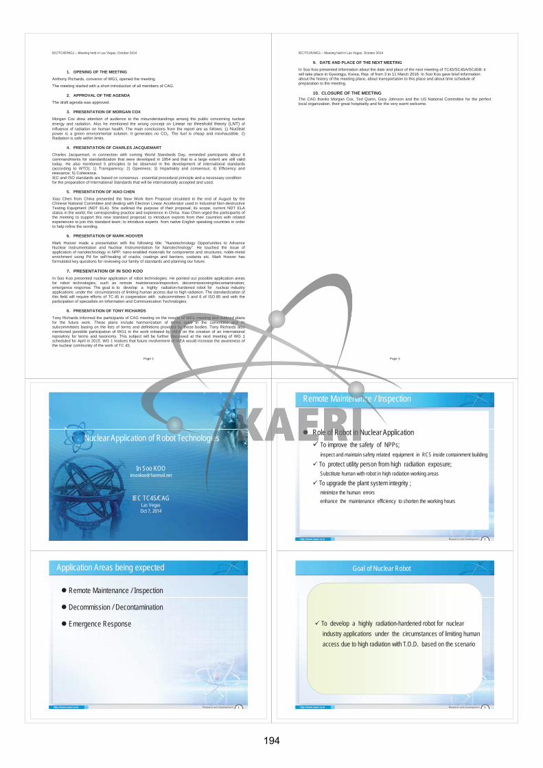
IEC/TC45/WG1 – Meeting held in Las Vegas, October 2014
Page 2
1. OPENING OF THE MEETING Anthony Richards, convenor of WG1, opened the meeting.
The meeting started with a short introduction of all members of CAG.
2. APPROVAL OF THE AGENDA The draft agenda was approved.
3. PRESENTATION OF MORGAN COX Morgan Cox drew attention of audience to the misunderstandings among the public concerning nuclear energy and radiation. Also he mentioned the wrong concept on Linear no threshold theory (LNT) of influence of radiation on human health. The main conclusions from the report are as follows: 1) Nuclearpower is a green environmental solution. It generates no CO2. The fuel is cheap and inexhaustible. 2) Radiation is safe within limits.
4. PRESENTATION OF CHARLES JACQUEMART Charles Jacquemart, in connection with coming World Standards Day, reminded participants about 8 commandments for standardization that were developed in 1954 and that to a large extent are still valid today. He also mentioned 5 principles to be observed in the development of international standards (according to WTO): 1) Transparency; 2) Openness; 3) Impartiality and consensus; 4) Efficiency and relevance; 5) Coherence. IEC and ISO standards are based on consensus - essential procedural principle and a necessary condition for the preparation of International Standards that will be internationally accepted and used.
5. PRESENTATION OF XIAO CHEN Xiao Chen from China presented the New Work Item Proposal circulated in the end of August by the Chinese National Committee and dealing with Electron Linear Accelerator used in Industrial Non-destructive Testing Equipment (NDT ELA). She outlined the purpose of their proposal; its scope; current NDT ELA status in the world; the corresponding practice and experience in China. Xiao Chen urged the participants of the meeting to support this new standard proposal; to introduce experts from their countries with related experiences to join this standard team; to introduce experts from native English speaking countries in order to help refine the wording.
6. PRESENTATION OF MARK HOOVER Mark Hoover made a presentation with the following title: "Nanotechnology Opportunities to Advance Nuclear Instrumentation and Nuclear Instrumentation for Nanotechnology". He touched the issue of application of nanotechnology in NPP: nano-enabled materials for components and structures; noble-metal enrichment using Pd for self-healing of cracks; coatings and barriers; coolants etc. Mark Hoover has formulated key questions for reviewing our family of standards and planning our future.
7. PRESENTATION OF IN SOO KOO In Soo Koo presented nuclear application of robot technologies. He pointed out possible application areas for robot technologies, such as remote maintenance/inspection; decommissioning/decontamination;emergence response. The goal is to develop a highly radiation-hardened robot for nuclear industry applications under the circumstances of limiting human access due to high radiation. The standardization of this field will require efforts of TC 45 in cooperation with subcommittees 5 and 6 of ISO 85 and with the participation of specialists on Information and Communication Technologies.
8. PRESENTATION OF TONY RICHARDS Tony Richards informed the participants of CAG meeting on the results of WG1 meeting and outlined plans for the future work. These plans include harmonization of terms used in the committee and its subcommittees basing on the lists of terms and definitions provided by these bodies. Tony Richards also mentioned possible participation of WG1 in the work initiated by IAEA on the creation of an international repository for terms and taxonomy. This subject will be further discussed at the next meeting of WG 1 scheduled for April in 2015. WG 1 realizes that future involvement of IAEA would increase the awareness of the nuclear community of the work of TC 45.
IEC/TC45/WG1 – Meeting held in Las Vegas, October 2014
Page 3
9. DATE AND PLACE OF THE NEXT MEETING In Soo Koo presented information about the date and place of the next meeting of TC45/SC45A/SC45B: it will take place in Gyeongju, Korea, Rep. of from 3 to 11 March 2016. In Soo Koo gave brief information about the history of the meeting place, about transportation to this place and about time schedule of preparation to the meeting.
10. CLOSURE OF THE MEETING The CAG thanks Morgan Cox, Ted Quinn, Gary Johnson and the US National Committee for the perfect local organization, their great hospitality and for the very warm welcome.
0
Nuclear Application of Robot Technologies
In Soo [email protected]
IEC TC45/CAGLas VegasOct 7, 2014
Application Areas being expected
1
Remote Maintenance / Inspection
Decommission / Decontamination
Emergence Response
2
Remote Maintenance / Inspection
Role of Robot in Nuclear Application
To improve the safety of NPPs;inspect and maintain safety related equipment in RCS inside containment building
To protect utility person from high radiation exposure;Substitute human with robot in high radiation working areas
To upgrade the plant system integrity ;minimize the human errors
enhance the maintenance efficiency to shorten the working hours
Goal of Nuclear Robot
To develop a highly radiation-hardened robot for nuclear
industry applications under the circumstances of limiting human
access due to high radiation with T.O.D. based on the scenario
To develop a highly radiation-hardened robot for nuclear
industry applications under the circumstances of limiting human
access due to high radiation with T.O.D. based on the scenario
3
194
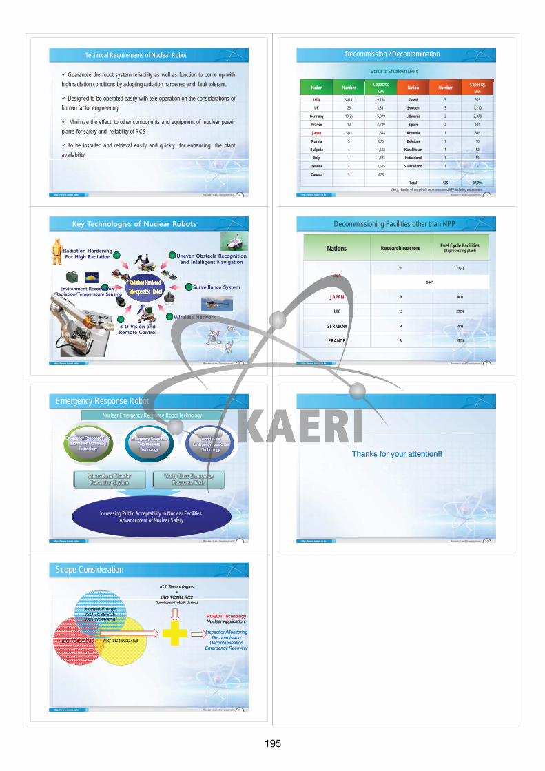
Technical Requirements of Nuclear Robot
Guarantee the robot system reliability as well as function to come up with
high radiation conditions by adopting radiation hardened and fault tolerant.
Designed to be operated easily with tele-operation on the considerations of
human factor engineering
Minimize the effect to other components and equipment of nuclear power
plants for safety and reliability of RCS
To be installed and retrieval easily and quickly for enhancing the plant
availability
4
5
6
Nation NumberCapacity,
MWeNation Number
Capacity, MWe
USA 28(14) 9,764 Slovak 3 909
UK 26 3,301 Sweden 3 1,210
Germany 19(2) 5,879 Lithuania 2 2,370
France 12 3,789 Spain 2 621
Japan 5(1) 1,618 Armenia 1 376
Russia 5 876 Belgium 1 10
Bulgaria 4 1,632 Kazakhstan 1 52
Italy 4 1,423 Netherland 1 55
Ukraine 4 3,515 Switzerland 1 6
Canada 3 478
Total 125 37,794(No.) : Number of completely decommissioned NPP including entombment
Status of Shutdown NPPs
Decommission / Decontamination
7
Nations Research reactors Fuel Cycle Facilities(Reprocessing plant)
USA10 73(?)
944*
JAPAN 9 4(1)
UK 13 27(5)
GERMANY 9 2(1)
FRANCE 8 15(3)
Decommissioning Facilities other than NPP
8
Increasing Public Acceptability to Nuclear Facilities Advancement of Nuclear Safety
International Disaster Preventing System
World Class EmergencyResponse Tech.
Emergency Response Robot
Nuclear Emergency Response Robot Technology
9
Scope Consideration
IEC TC45/SC45AIEC TC45/SC45A IEC TC45/SC45BIEC TC45/SC45B
Nuclear EnergyISO TC85/SC5ISO TC85/SC6
Nuclear EnergyISO TC85/SC5ISO TC85/SC6
ICT Technologies+
ISO TC184 SC2Robotics and robotic devices
ICT Technologies+
ISO TC184 SC2Robotics and robotic devices
ROBOT TechnologyNuclear Application;
Inspection/MonitoringDecommission
DecontaminationEmergency Recovery
ROBOT TechnologyNuclear Application;
Inspection/MonitoringDecommission
DecontaminationEmergency Recovery
10
Thanks for your attention!!Thanks for your attention!!
195
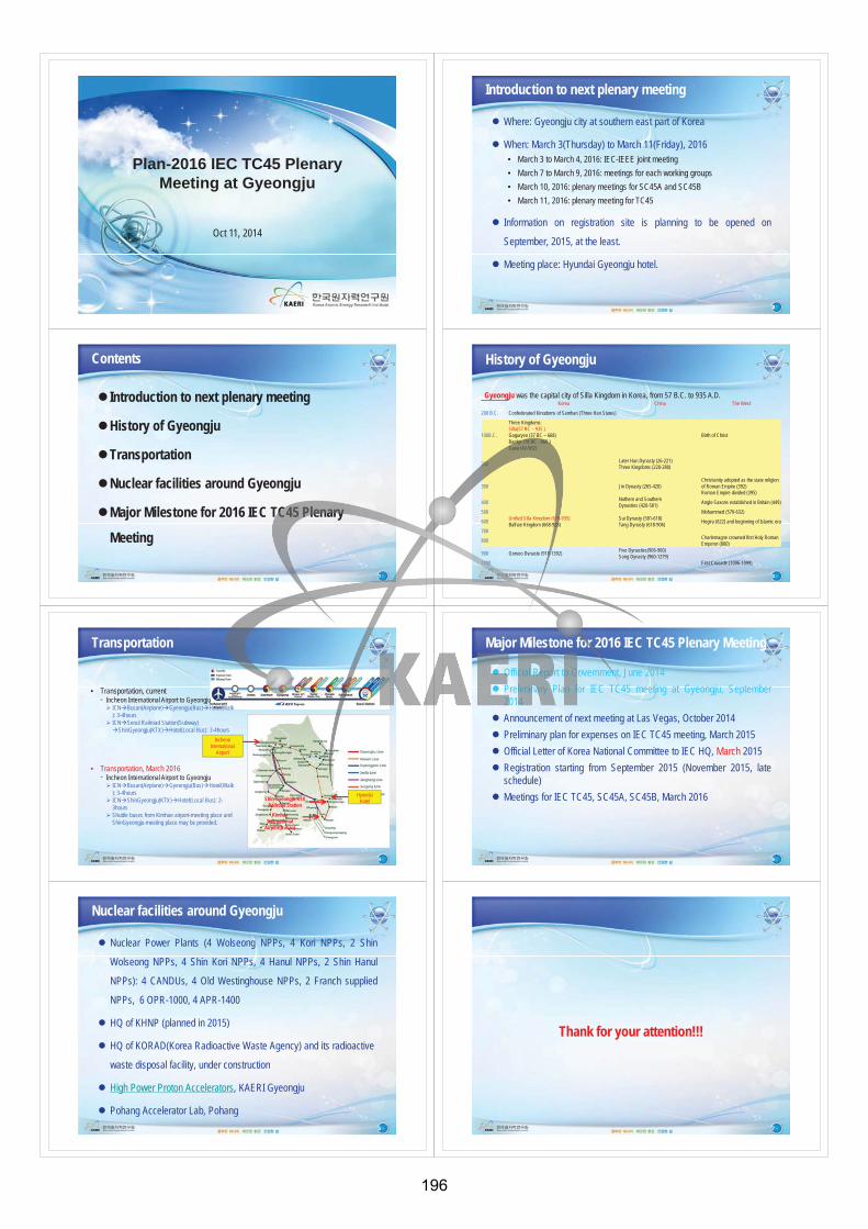
Oct 11, 2014
Plan-2016 IEC TC45 Plenary Meeting at Gyeongju
Contents
Introduction to next plenary meeting
History of Gyeongju
Transportation
Nuclear facilities around Gyeongju
Major Milestone for 2016 IEC TC45 Plenary
Meeting
Introduction to next plenary meeting
Where: Gyeongju city at southern east part of Korea
When: March 3(Thursday) to March 11(Friday), 2016• March 3 to March 4, 2016: IEC-IEEE joint meeting
• March 7 to March 9, 2016: meetings for each working groups
• March 10, 2016: plenary meetings for SC45A and SC45B
• March 11, 2016: plenary meeting for TC45
Information on registration site is planning to be opened on
September, 2015, at the least.
Meeting place: Hyundai Gyeongju hotel.
History of Gyeongju
Korea China The West
200 B.C. Confederated Kingdoms of Samhan (Three Han States)
100B.C.
Three Kingdoms:Silla(57 BC – 935 )Goguryeo (37 BC – 668)Baekje (18 BC - 660 )Gaya (42-562)
Birth of Christ
200Later Han Dynasty (26-221)Three Kingdoms (220-280)
300 Jin Dynasty (265-420)Christianity adopted as the state religion of Roman Empire (392)Roman Empire divided (395)
400Nothern and SouthernDynasties (420-581)
Anglo-Saxons established in Britain (449)
500 Mohammed (570-632)
600Unified Silla Kingdom (676-935)Balhae Kingdom (668-928)
Sui Dynasty (581-618)Tang Dynasty (618-906)
Hegira (622) and beginning of Islamic era
700
800Charlemagne crowned first Holy Roman Emperor (800)
900 Goryeo Dynasty (918-1392)Five Dynasties(906-960)Song Dynasty (960-1279)
1000 First Crusade (1096-1099)
Gyeongju was the capital city of Silla Kingdom in Korea, from 57 B.C. to 935 A.D.
Transportation
• Transportation, currentIncheon International Airport to Gyeongju
ICN Busan(Airplane) Gyeongju(Bus) Hotel(Walk): 3-4hoursICN Seoul Railroad Station(Subway)
ShinGyeongju(KTX) Hotel(Local Bus): 3-4hours
• Transportation, March 2016Incheon International Airport to Gyeongju
ICN Busan(Airplane) Gyeongju(Bus) Hotel(Walk): 3-4hoursICN ShinGyeongju(KTX) Hotel(Local Bus): 2-3hoursShuttle buses from Kimhae airport-meeting place and ShinGyeongju-meeting place may be provided.
IncheonInternational
Airport
HyundaiHotelShin-Gyeongju KTX
Railroad Station
KimhaeInternational
Airport(Busan)
Nuclear facilities around Gyeongju
Nuclear Power Plants (4 Wolseong NPPs, 4 Kori NPPs, 2 Shin
Wolseong NPPs, 4 Shin Kori NPPs, 4 Hanul NPPs, 2 Shin Hanul
NPPs): 4 CANDUs, 4 Old Westinghouse NPPs, 2 Franch supplied
NPPs, 6 OPR-1000, 4 APR-1400
HQ of KHNP (planned in 2015)
HQ of KORAD(Korea Radioactive Waste Agency) and its radioactive
waste disposal facility, under construction
High Power Proton Accelerators, KAERI Gyeongju
Pohang Accelerator Lab, Pohang
Major Milestone for 2016 IEC TC45 Plenary Meeting
Official Report to Government, June 2014
Preliminary Plan for IEC TC45 meeting at Gyeongju, September2014
Announcement of next meeting at Las Vegas, October 2014
Preliminary plan for expenses on IEC TC45 meeting, March 2015
Official Letter of Korea National Committee to IEC HQ, March 2015
Registration starting from September 2015 (November 2015, lateschedule)
Meetings for IEC TC45, SC45A, SC45B, March 2016
Thank for your attention!!!
196

® Registered trademark of the International Electrotechnical Commission
45/774/DC For IEC use only 2014-06-06
INTERNATIONAL ELECTROTECHNICAL COMMISSION TECHNICAL COMMITTEE 45: NUCLEAR INSTRUMENTATION Strategic Business Plan (SBP) 1. Background At the latest meeting held in Moscow (Russian Federation) in June 2013, TC 45 approved its Strategic Business Plan (SBP). The new version of the SBP takes into account strategic ideas expressed during the Moscow meeting and the development of those ideas within the months after that meeting. Two new working groups were formed within subcommittees 45A and 45B. In this regard and in connection with the decisions taken at the Moscow meeting, objectives and strategies (part D) as well as a plan for their implementation (part E) were developed. This also resulted in the change of the title of subcommittee 45A. In addition, information concerning the liaison with other organizations was specified, and statistical data were updated. Several editorial corrections, facilitating the perception of document, were introduced. 2. Action National committees are invited to review the SBP and submit comments well in advance of the meeting in Las Vegas (USA) by
2014-09-05 at the latest using the IEC electronic commenting / voting system.
NOTE: When preparing their national inputs national committees are requested to consult their delegates of the parent committee 45, as well as those of both subcommittees SC 45A and SC 45B. Annex: TC 45 Strategic Business Plan.
®
45/774/DC
Form SBP (IEC) 2008-11-07 1/11
TC 45 : Nuclear instrumentation SC 45A : Instrumentation, control and electrical systems of nuclear facilities SC 45B : Radiation protection instrumentation A Background
Technical Committee 45, established in 1959, produces and maintains standards for instrumentation, systems and equipment for many nuclear applications including nuclear energy and the nuclear fuel cycle, industrial and commercial uses of ionizing radiation, safeguarding special nuclear materials, and environmental and radiation protection.
TC 45 is responsible for the standardization of nuclear instrumentation that includes relevant terminology and classification, detectors of ionizing radiations and systems based on these detectors and the commercial applications of nuclear instrumentation technologies.
SC45A is responsible for the standardization of activities related to electronic and electrical functions and associated systems and equipment used in instrumentation, control and electrical systems of nuclear facilities. These activities include nuclear power plants, the entire nuclear fuel cycle from mining to processing, reprocessing, and interim and final repositories for spent fuel and nuclear waste.
SC 45B is responsible for standardization activities covering all aspects of radiation protection instrumentation, including that for the measurement under both normal and accident conditions of external and internal individual exposure and exposure rates, radiation characteristics in the workplace, in effluents, the environment and including foodstuffs. SC45B is also responsible for the development of standards that are applicable to the detection and identification of illicit trafficking of radioactive material.
In addition, SC45A and SC45B are together responsible for standards related to the safeguarding of special nuclear materials, SC45A by the safe use of instrumentation and controls throughout the nuclear fuel cycle, and SC45B with standards for monitoring for the management, storage and movement of special nuclear materials in all forms.
B Business Environment B.1 General
The activity of TC45 can be presented in several segments:
- instrumentation, control and electrical systems for the safe generation of electricity from nuclear energy;
- radiation protection instrumentation for personnel and for the environment;
- instrumentation for industrial and commercial uses of nuclear technology, and
- instrumentation for the safeguarding of special nuclear materials, as well as instrumentation used during nuclear fuel manufacture, storage and processing.
STRATEGIC BUSINESS PLAN (SBP)
IEC/TC or SC TC 45/SC 45A/SC 45B
Secretariat Russian Federation
Date 2014-06-
45/774/DC
Form SBP (IEC) 2008-11-07 2/11
Instrumentation and control for nuclear energy generation:
The business environment for nuclear power generation is currently changing and imposes some challenges:
- The resurgence of nuclear power worldwide has been tempered and even delayed by two factors:
the nuclear accident at Fukushima in March 2011 and the recently discovered natural abundance
of natural gas by “fracking” or horizontal drilling at least in the United States. For example, Japan is
reevaluating their use of nuclear power, and Germany appears to be shutting down their nuclear
power plants in favour of solar, wind and imported nuclear power. Local politics will play a major
role for nuclear power in both Germany and Japan over the next ten years.
- new nuclear power reactor designs must be reviewed and approved before licensing;
- nuclear utilities must have the assets and regulatory approvals in order to proceed with the construction of new power plants;
- expanded new energy needs are connected to the economies of established nuclear countries (such as, China, India, Brazil, Russia, Argentina, Pakistan and others) as well as new countries including Vietnam, Lithuania, United Arab Emirates.
- management and refurbishment of aging reactors that are reaching their initial design life and are subjected to life extension programmes determined by routine safety reviews, lessons learned and the implementation of new technical standards;
- decommissioning, where some older reactors will be entirely dismantled;
- the management, transportation and storage of nuclear fuel and special nuclear material, and
-safe management of spent nuclear fuel that includes transportation from power reactor sites to nuclear storage and repository facilities;
- additionally, new aspects (i.e. "loss of infrastructure") are being discussed after the Fukushima accident in March 2011, and the need for additional standards might arise from that throughout the nuclear fuel cycle;
- security and cyber security standards are being developed
Radiation protection instrumentation for personnel and environment:
The increased use of nuclear and radiation technologies for meeting industrial and social needs causes the rise of safety expectations to protect people and the environment, in particular:
- safety or ecology related events may have wide repercussions transcending international boundaries (e.g. the Chernobyl and Fukushima events). Nations must combine their efforts to raise the safety of their nuclear facilities to consistent levels;
- credible radiological measurements using appropriate radiation instrumentation are addressed.
Instrumentation for the safe commercial uses of ionizing radiation and nuclear technology:
45/774/DC
Form SBP (IEC) 2008-11-07 3/11
-Ionizing radiation is finding more widespread uses in the fields of non-destructive testing for materials and structures, for gauging moisture, liquid levels and other material thickness and density, flaw and void detection, for industrial imaging, in the irradiation of a variety of foods, in the sterilization of all types of medical supplies, and in the uses of radiation for the diagnosis and treatment of a variety of diseases. The Technical Committee through the Subcommittees emphasize the safe applications of radiation and nuclear technology.
Instrumentation for safeguarding of special nuclear materials such as Plutonium and Uranium:
- SC45A takes into account an issue of safeguarding of special nuclear materials in the standards on nuclear fuel cycle that are developed in this subcommittee.
-SC45B through its working groups develops instrumentation standards to detect illicit trafficking activities that helps prevent radioactive material being used by potential terrorists.
- Working groups in SC 45B continue to develop and maintain contemporary standards for airborne and environmental monitoring; for portable radiation detection instruments; for monitoring radon and radon progeny; and for radiation dosimeters used by personnel and in the environment.
- SC45B through its working groups develops standards on radiation systems for the screening of persons and cargo/vehicles for security and the carrying of any kind of illicit items at the airports, seaports and other border control check points.
There are many companies dealing with the aforesaid businesses, including many major international companies as well as a large number of system and equipment manufacturers and suppliers from around the world.
B.2 Market demand
Who are the customers of the existing and future publications developed by the TC/SC?
The customers are typically designers and manufacturers of instruments, control and protection systems and equipment, users, nuclear operators, regulators, legislators, and testing organisations, the many commercial and industrial users of radionuclides (many users of non-destructive testing (NDT) or non-destructive examination (NDE)).
Are the TC/SC publications widely used at the regional/national level?
The published IEC standards are widely used as a basis for national or regional standards and in procurement efforts.
Discussion and efforts are underway to improve conformance between IEC standards, national and regional standards and operational measures or practices.
European Committee for Electrotechnical Standardization (CENELEC) has set up Technical Committees CLC/TC45AX and CLC/TC45B for monitoring the work of TC45 and its SCs and endorsing IEC standards produced by TC45 and its SCs as European standards (EN). Since 2004, CLC/TC45B endorsed as EN two IEC/TC45 standards and eighteen IEC/SC45B standards with others in progress. CLC/TC45B prepared common modifications of the EN, if any, and introduced them in the maintenance of the respective IEC/TC45 or IEC/SC45B standards. Since 2007, CLC/TC45AX endorsed as EN twelve IEC/SC45A standards without modifications, and others are in progress. All those EN are now implemented as national standards in the 33 European countries member of CENELEC.
197
45/774/DC
Form SBP (IEC) 2008-11-07 4/11
Japanese industrial standards are coordinated with IEC TC 45/45A/45B standards on request of the authorities.
Many IEC standards are adopted as British standards.
Germany has decided to translate some standards into IEC DIN Standards.
Russia has directly implemented some IEC standards.
In the USA, some IEC TC45 standards and most of the IEC TC45 terminology are increasingly used by reference in ANSI N42 Standards.
Rep. of Korea has translated about 60 IEC standards published by TC45 and its subcommittees into Korean national standards (KS).
Are they supporting regulation or used as the basis for contracts?
In Europe, at national level, at least twelve IEC/SC45A standards are referenced through their EN endorsement by different European countries in the licensing documents and procedures (IEC 61513, IEC 61226, IEC 60987, IEC 60880, IEC 62138, IEC 62340, IEC 60709, IEC 60964, IEC 61500, IEC 61671, IEC 60965, IEC 61772).
Korea Institute of Nuclear Safety (KINS), the regulation research institute of Rep. of Korea, has started to incorporate IEC TC45 standards into Korean nuclear regulatory standards.
Some IEC standards are used by reference in American National Standards Institute (ANSI) N42 in the development of US instrument standards. Conversely some ANSI N42 standards are referenced in some IEC standards.
Export contracts from the USA use IEC standards. In addition, an encreasing number of IEC standards are referenced by the US Department of Energy, US Nuclear Regulatory Commission and US Department of Homeland Security.
IEC standards are specifically used as reference and technical basis for documents published by the IAEA related to the detection of illicit trafficking of radioactive materials.
Which are the competing standards developed by other organizations?
TC 45 is the only worldwide body developing international standards for the nuclear and nuclear power industries and for other industries using nuclear measuring techniques. TC 45 and its Subcommittees develop standards for the design, construction, performance, testing and calibration of radiation detection instrumentation for all applications. These standards are complementary to ISO/TC 85 standards for the use of such instrumentation. Other relevant organisations, such as the IAEA, are concerned with the establishment and regulation of safety principles and the IAEA also publishes reports on engineering practice.
Given below are brief characterizations of relationships between IEC/TC45 and other international organisations working in related areas.
IAEA: Close liaison has always been maintained between TC 45 and the IAEA. Some of the first work done by SC 45A was to generate a number of important documents (particularly IEC 60231) which codified the basic principles of reactor instrumentation safety. In the early 1970's, the IAEA amalgamated these into a set of formal Safety Guides. It was then appreciated that overlap between the two bodies had to be avoided, and in 1981 an agreement setting out the respective fields of interest was drawn up. According to this agreement IEC/SC45A took the commitment to implement in technical details the IAEA safety principles relevant for I&C. IEC/SC45A standards use terms of the IAEA safety
45/774/DC
Form SBP (IEC) 2008-11-07 5/11
glossary. IEC/SC45A maintains close relationships with the IAEA : participating to the NUSSC (Nuclear Safety Standards Committee), participating to the I&C Technical Working Group of the Nuclear Division of the IAEA and taking part to the IAEA meetings on cyber security. Recently the IAEA and SC45B have reactivated their liaison A status and are now fully reporting and harmonising their work. SC45B is now an official member of the IAEA Radiation Safety Standards Committee (RASSC), which is responsible for the revision of the Basic Safety Standard.
ISO: TC45 has a liaison relationship with ISO/TC85 “Nuclear energy”. This cooperation covers terminology and classification in the nuclear field and some other fields of standardization. IEC/TC45/SC45B has started to regularly attend ISO/TC85/SC2 meetings to address any potential overlapping or contradictory issues related to radiation protection standards that are common for both SCs.
A better use of IEEE nuclear power standards, and generic software engineering standards from IEEE or IEC/ISO JTG1 should be considered. To that end, a liaison of D category has been established between WGA9 and IEEE/NPEC (Nuclear Power Engineering Committee).
CENELEC: TC45, SC45A and SC45B standards endorsement as EN standards is considered by CENELEC after a case by case review of each standard. The TC45 and SC45B standards can be endorsed with modifications. These modifications are supplied as comments for the next revision of IEC standards. The SC45A standards are endorsed without modifications.
ISA: a category D liaison between ISA67 “International Society of Automation/Nuclear power standards” and IEC/SC45A/WG9 “Instrumentation and control of nuclear facilities/Instrumentation systems” has been established.
B.3 Trends in technology
The rapid change in electronics, information and communications, and other technologies will continue to impact the future work of TC45 particularly in areas such as:
- new types of reactors including advanced gas-cooled reactors, small modular reactors and reactors with increased power capability. These types of reactors are being constructed in some countries and new types of instrumentation, control and electrical systems will be required for these reactors;
- hardware, software, systems, and COTS (Commercial Off The Shelf) items;
- an increasing need for cybersecurity for nuclear power instrumentation and control;
- information exchange (between instruments and control rooms, radio-links, exchange formats);
- the internet impacts all industries and might need a specific approach for nuclear applications;
- the wide use of X-ray installations in different areas;
B.4 Market trends
The main trends that will impact our future work are:
- the worldwide need for nuclear power with contemporary matching standards;
45/774/DC
Form SBP (IEC) 2008-11-07 6/11
- the globalization of the nuclear market;
- the merging of key-players and consortia: manufacturers, utilities etc.;
- latest events, connected with the accident at Fukushima NPP in Japan, negatively impact the nuclear technologies market. Nevertheless, some decrease of the market seems to be of temporary character since the increasing worldwide need in electrical power could not be satisfied without the development of nuclear industry.
B.5 Ecological environment
Nuclear power provides beneficial effects for the environment including delivery of safe, clean and economical electrical energy, and, when normally operating, the nuclear power generating facilities contribute little or no pollution to the environment.
At the same time, in the emergency and recovery situation after the NPP accident, the decontamination procedure over a wide area in the surrounding environment is urgently required. The radiation monitoring under such high background shall be considered and the exposure control of personnel and inhabitants is also quite important.
In comparison with bulk markets, relatively few individual devices are manufactured under TC 45 standards, and their manufacture, existence and disposal has negligible adverse impact on the environment. Their function, however, is aimed directly at the environment protection.
C System approach aspects
TC 45 will actively continue to cooperate with other organizations both within IEC and outside this organization. A system approach to this activity is in the focus of our committee. The table shown below reflects the relationships between TC 45 and other organizations with the indication of the role of our committee in respect to these organizations (role of a customer or a supplier):
Component committees (IEC TC45 – role of a customer)
IEC/TC1 Terminology
IEC/TC77 Electromagnetic compatibility IAEA International Atomic Energy
Agency ICRP International Commission on
Radiological Protection ICRU International Commission on
Radiation Units and Measurements
ISO/TC85 Nuclear energy, nuclear technologies and radiological protection
System committees (IEC TC45 – role of a supplier)
IEC/TC1 Terminology
CLC/TC45B Nuclear Instrumentation CLC/TC45AX Instrumentation, Control and
Electrical System of nuclear Facility
CLC/TC45B Radiation Protection Instrumentation
ISO/TC85 Nuclear energy, nuclear technologies and radiological protection
Other committees IEC/TC8 Systems aspects for electrical
45/774/DC
Form SBP (IEC) 2008-11-07 7/11
energy supply IEC/TC35 Primary cells and batteries IEC/TC56 Dependability IEC/SC62C Equipment for radiotherapy,
nuclear medicine and radiation dosimetry
IEC/TC65 Industrial-process measurement, control and automation
IEC/TC112 Evaluation and qualification of electrical insulating materials and systems
IEEE-NPEC Institute of Electrical and Electronic Engineers - Nuclear Power Engineering Committee
ISA67 International Society of Automation/Nuclear power standards
Liaison established:
TC45: ISO/TC 85; IAEA; CENELEC; IEC/TC1; ISO/IEC JTC 1; ICRP; ICRU; WHO.
SC45A: IEC/TC 65; IEC SC 65A; IEC/TC 56; IEC/TC77; IEC/SC 77C; IEC/TC 112; IAEA; ICRP; ICRU; OECD/NEA; IEEE/NPEC.
SC45B: ISO (TC 85/SC 2 - TC 85/SC 5); EFOMP; IAEA; ICRP; ICRU; OIML/TC 15; WHO; IACRS; EC.A liaison of D category has been established between WGA9 and IEEE/NPEC, as well as between WGA9 and ISA67.
D Objectives and strategies (3 to 5 years)
The TC 45 Committee Advisory Group (CAG), a TC consultative body, has been set up with First National Delegates and TC/SC officers in order to improve the committee's activity coordination and the liaison strategy. The CAG reviews the SBP at each meeting. The CAG also advises WGs on NWIPs and shares common management issues in order to have a better overall alignment of the activities.
The following recommendations were elaborated for TC45 strategy during the CAG meeting in Seattle (USA, 2010) and updated in Karlsruhe (Germany, 2012) and Moscow (Russian Federation, 2013):
We should continue to be driven by technology needs and recommendations of other authorities, such as the IAEA.
We should be alert to standards developed by US organizations, for example a standard for robustness tests, that are important and can be transformed into IEC standards.
We shall be cognizant to standardization as connected with non-proliferation and illicit trafficking of nuclear and radioactive materials and produce standards useful for all participating countries.
We are aware that new types of reactors, advanced gas-cooled reactors, small modular reactors and other higher power and lower power reactors are being constructed in several countries. Attention should be paid to the development of standards covering I&C systems and radiation monitoring systems for these types of reactors.
198
45/774/DC
Form SBP (IEC) 2008-11-07 8/11
The creation of a new working group (WG A11 “Electrical systems”) within SC 45A has triggered considerable extension of the scope of SC 45A: the title and scope of this subcommittee has been revised. It is anticipated that the new Working Group will coordinate its activities with other IEC technical committees where necessary.
The creation of a new working group (WG B16 “Contamination meters and monitors”) within SC 45B will result in the development of a series of new standards and in the maintenance of several published standards in this field.
The Fukushima accident is to be analyzed and the experience gained should be taken into account in our publications, both new and revised ones.
At international level, we are doing our best to interact with organizations (IAEA, IEEE, ISA) and we are also doing our best to implement in all regions collaboration in different ways.
Work on harmonization and unification of terms used in the standards of TC 45, SC 45A, SC 45B should be continued.
We consider the translation of IEC/SC45A standards in Russian of the utmost importance for their distribution in Russia and the other states belonging to the Independent States Community.
We should receive regularly information from the national committees on the implementation of our standards in order to be able to timely make adjustments to activities on the development and maintenance of international standards. The implementation of 12 IEC/SC45A, 18 of IEC/SC45B and 2 of IEC/TC45 standards as European Standards (EN) and their distribution as national standards in 31 European Countries is to be noted and that will be pursued.
Increasing use of computers in I&C systems of nuclear facilities would require the development of a series of new standards, such as standards for cyber security, data format, etc.
We consider also as a very important sign the improvement of participation of representatives of Asian countries in SC 45A activities.
E Action plan
The IAEA has officially accepted the nomination of the IEC/SC45A Secretary for the participation in the activities of Nuclear Safety Standards Committee (NUSSC). This participation will allow the IEC/SC45A to be directly informed of the development, review and revision of IAEA safety standards and to formulate observations on those projects.
TC45, SC45A and SC45B will continue reviewing the various National and International reports following the events at the Fukushima Nuclear Power Plants in 2010 and identify the need for new and revised IEC standards.
Subcommittee 45A has included into its Work Program the development of several standards jointly with the IEEE organization, in particular a standard on equipment qualification using robustness tests. At the end of the Moscow meeting it was noted that all the efforts are done on the IEC SC 45A side as well as on the IEEE/NPEC side for the started project progress to success.
45/774/DC
Form SBP (IEC) 2008-11-07 9/11
Six standards and one Technical Report are being currently reviewed as a consequence of Fukushima accident analysis. There are ideas on the development of 11 new international standards.
The participation of representatives of Asia in SC 45A activities is improving: presently there are 2 Japanese Convenors, 3 Japanese Project Leaders, 4 Korean Project Leaders, more Chinese experts taking part to our meetings and soon perhaps Pakistanis and Indians experts will be taking active part and responsibilities. It should be noted the increased activity of Egyptian experts in the development of TC 45/SC 45A/SC 45B standards though sending their comments.
Subcommittees SC45A and SC45B have included into their Work Program a series of standards for equipment intended for safeguarding of radioactive and nuclear materials. SC45A takes this issue into account through a series of projects connected with the nuclear fuel cycle. SC45B developed in 2013 a series of standards connected with the detection and identification of illicit trafficking of radioactive and nuclear materials (e.g. IEC 62618, IEC 62694 and IEC 62755 in WG B15).
In addition to the new projects, TC 45/SC45A/SC45B WGs will be occupied with the maintenance of issued standards and documents.
TC 45 is currently working on 2 projects, SC 45A – on 17 projects and SC 45B – on 10 projects.
During one year, between 5 and 15 NWIPs may be suggested, based on our previous experiences.
To follow a work and maintenance program so that developed documents and revised standards would be adopted by industry
To recruit additional members to WGs, especially from the nuclear utilities, development and manufacturing companies, legislative and regulatory authorities.
Newly formed WG B16 “Contamination monitors and meters” has started its activities on the revision of several standards and on the development of a new standard within the context of the Fukushima nuclear accident.
The development of a standard with the requirements for coordinating safety and cybersecurity has started within SC 45A.
The technical report on terms used in nuclear instrumentation metrology will be developed; the revision of part 395 of IEV, taking into account new inputs of both subcommittees, will be considered.
Preparation of standards in languages other than English and French, including standards in Russian language, will be continued.
A proposal for data output standard based on list-mode data format was presented at Moscow meeting. This standard will be developed within TC 45 WG 9.
SC 45B will revise the 9 illicit trafficking detection standards developed by WG B15 and taking into account the experience of the different testing programs (ITRAP+10 etc.).
SC 45B is planning to start new projects on computer tomography (CT) X-rays security systems. A new work item for the development of a standard to address the image quality of X-ray Computed Tomography (CT) security-screening systems has been started.
45/774/DC
Form SBP (IEC) 2008-11-07 10/11
F Useful links to IEC web site IEC/TC45 dashboard giving access to Membership, TC/SC Officers, Scope, Liaisons, WG/MT/PT structure, Publications issued and Work and Maintenance Programmes and similar information for SCs. Name or signature of the secretary Sergey SHUMOV
® Registered trademark of the International Electrotechnical Commission
45/781/INF For IEC use only 2014-09-12
INTERNATIONAL ELECTROTECHNICAL COMMISSION
TECHNICAL COMMITTEE 45: NUCLEAR INSTRUMENTATION Compilation of comments on document 45/774/DC: Strategic Business Plan (SBP) The above mentioned document was circulated to National Committees in June 2014. 4 countries provided their comments, and the report of these comments and the compilation of comments received are annexed. The SBP document and the national comments received will be discussed at the TC 45 plenary meeting, which will take place in Las Vegas (USA) on Saturday, October 11, 2014.
Annex mentioned
®
199

45/781/INF
Page 1 of 2
Report of Comments on 45/774/DC
Circulation Date: 2014-06-06 Closing Date: 2014-09-05 Strategic Business Plan (SBP)
Country Status Comments Received Argentina P N 2014-09-05 Austria O N 2014-09-05 Belarus O Belgium P N 2014-08-14 Bulgaria O Canada P N 2014-08-27 China P N 2014-09-05 Czech Republic O Denmark O Egypt P Finland P N 2014-09-02 France P Y 2014-08-12 Germany P Y 2014-08-22 India O Iran O Ireland - N 2014-07-29 Israel O Italy P N 2014-09-05 Japan P Y 2014-09-05 Korea, Republic of P N 2014-06-13 Netherlands P N 2014-08-19 New Zealand O Norway P Pakistan P N 2014-09-05 Poland O Portugal - N 2014-09-05 Romania P Russian Federation P N 2014-08-29 Serbia O Slovakia O Spain O Sweden P Switzerland P N 2014-09-04 Ukraine P N 2014-07-23 United Kingdom P Y 2014-09-04 United States of America P
P-members O-members Non-members Total Y : comments received 4 0 0 4 N : no comments 12 1 2 15 - : no response 5 12 0 17
Notes P-members with no response: Egypt; Norway; Romania; Sweden; United States of America
45/7
81/I
NF
Page
2 o
f 2
Dat
e D
ocum
ent
Pro
ject
Nr.
2014
-08-
12
45/7
74/D
C
-
MB
/NC
Li
ne
num
ber
(e.g
. 17)
Cla
use/
Su
bcla
use
(e.g
. 3.1
)
Para
grap
h/
Figu
re/ T
able
/ (e
.g. T
able
1)
Type
of
com
men
t C
omm
ents
Pr
opos
ed c
hang
e O
bser
vatio
ns o
f the
se
cret
aria
t
DE
Th
e G
erm
an N
C a
gree
s to
the
draf
t Stra
tegi
c B
usin
ess
Pla
n (S
PB
) as
circ
ulat
ed u
nder
do
cum
ent n
umbe
r IE
C 4
5/77
4/D
C.
Ta
ken
into
acc
ount
FR
The
Fren
ch N
atio
nal C
omm
ittee
sug
gest
s to
sh
orte
n th
is d
ocum
ent,
whi
ch c
onta
ins
sect
ions
th
at a
re n
ot re
leva
nt to
a B
usin
ess
Plan
W
ill be
con
side
red
at th
e TC
45 p
lena
ry m
eetin
g in
La
s V
egas
GB
Gen
eral
Th
e TC
45 S
trate
gic
Bus
ines
s P
lan
is w
ell w
ritte
n an
d ha
s in
corp
orat
ed th
e co
mm
ents
mad
e at
the
Mos
cow
mee
ting
(201
0).
Ta
ken
into
acc
ount
GB
C -
Tabl
e
Edi
toria
l O
n pa
ge 6
, the
tabl
e in
sec
tion
C c
onta
ins
two
entri
es fo
r CLC
/TC
45B
.
It is
sug
gest
ed th
at th
e fir
st e
ntry
(on
line
8 of
the
tabl
e) s
houl
d re
ad "C
LC/T
C45
." P
leas
e se
e ob
serv
atio
n of
th
e Fr
ench
com
men
t
JP-1
6
B.5
2nd
par
agra
ph
In
-take
of r
adio
activ
e m
ater
ial s
hall
be c
ontro
lled
as w
ell a
s ra
diat
ion
expo
sure
to p
erso
nnel
and
in
habi
tant
s.
Add
the
follo
win
g se
nten
ce a
t the
end
of t
he
para
grap
h; F
urth
erm
ore,
in-ta
ke o
f rad
ioac
tive
mat
eria
l sha
ll be
con
trolle
d as
wel
l as
radi
atio
n ex
posu
re to
per
sonn
el a
nd in
habi
tant
s.
Ple
ase
see
obse
rvat
ion
of
the
Fren
ch c
omm
ent
JP-2
6
B.5
3rd
par
agra
ph
It
is d
iffic
ult t
o un
ders
tand
wha
t thi
s pa
ragr
aph
inte
nds
to d
escr
ibe.
Ple
ase
desc
ribe
plai
n.
Ple
ase
see
obse
rvat
ion
of
the
Fren
ch c
omm
ent
JP-3
9
E
12th
item
A s
tand
ard
to b
e de
velo
ped
by th
e W
GB
16
shou
ld c
ontri
bute
to re
cove
ry fr
om th
e Fu
kush
ima
nucl
ear a
ccid
ent.
Add
“rec
over
y” to
the
last
sen
tenc
e.
Ple
ase
see
obse
rvat
ion
of
the
Fren
ch c
omm
ent
® Registered trademark of the International Electrotechnical Commission
45/771/INF For IEC use only 2013-12-20
INTERNATIONAL ELECTROTECHNICAL COMMISSION TECHNICAL COMMITTEE 45: NUCLEAR INSTRUMENTATION Compilation of comments on document 45/768/DC: Maintenance of old standards having a stability date of 2013 The above mentioned document was circulated for National Committees on 2013-10-11. It was proposed in this document to reconfirm till 2016 five old standards having a stability date of 2013. Totally 18 responses have been received: 14 – from P-members; 1 – from O-member and 3 – from non-members. Six comments from six P-members were positive. No negative comments have been received. Conclusion: All comments received are in favour of extending the stability periods; the stability dates for these standards will therefore be updated as proposed. The report of comments and the compilation of comments are given in the annex. Annex mentioned
®
45/771/INF
Report of Comments on 45/768/DC
Circulation Date: 2013-10-11 Closing Date: 2013-12-13 Maintenance of old standards having a stability date of 2013
Country Status Comments Received Argentina P N 2013-12-03 Austria O N 2013-12-11 Belarus O Belgium P N 2013-11-19 Bulgaria O Canada P N 2013-12-10 China P N 2013-12-13 Czech Republic O Denmark O Egypt P Finland P N 2013-12-12 France P Y 2013-12-03 Germany P Y 2013-12-09 Greece - N 2013-12-13 India O Iran O Ireland - N 2013-12-04 Israel O Italy P Y 2013-12-05 Japan P Y 2013-12-13 Korea, Republic of P N 2013-11-21 Netherlands P N 2013-12-09 New Zealand O Norway P Pakistan P Poland O Portugal - N 2013-12-13 Romania P Russian Federation P Y 2013-12-06 Serbia O Slovakia O Spain O Sweden P Switzerland P Ukraine P N 2013-12-12 United Kingdom P Y 2013-12-12 United States of America P
P-members O-members Non-members Total Y : comments received 6 0 0 6 N : no comments 8 1 3 12 - : no response 7 12 0 19
Notes P-members with no response: Egypt; Norway; Pakistan; Romania; Sweden; Switzerland; United States of America
200
45/7
71/IN
F
Dat
e D
ocum
ent
Pro
ject
Nr.
2013
-12-
03
45/7
68/D
C
- M
B/N
C
Line
num
ber
(e.g
. 17)
C
laus
e/
Subc
laus
e (e
.g. 3
.1)
Para
grap
h/
Figu
re/ T
able
/ (e
.g. T
able
1)
Type
of
com
men
t C
omm
ents
Pr
opos
ed c
hang
e O
bser
vatio
ns o
f the
se
cret
aria
t
DE
ge
Th
e G
erm
an n
atio
nal c
omm
ittee
agr
ees
with
the
reco
nfirm
atio
n of
all
5 st
anda
rds
till 2
016:
- I
EC
604
98 E
d.1.
0 (1
975-
01)
- IE
C 6
0692
Ed.
2.0
(199
9-11
) - I
EC
607
39 E
d.1.
0 (1
983-
01)
- IE
C 6
0808
Ed.
1.0
(198
5-09
) - I
EC
623
72 E
d.1.
0 (2
006-
02)
FR
Fren
ch N
atio
nal C
omm
ittee
agr
ees
with
the
prop
osal
to re
conf
irm fi
ve s
tand
ards
till
2016
:
IEC
604
98 E
d1, I
EC
606
92 E
d2, I
EC
607
39 E
d1,
IEC
608
08 E
D1,
IEC
623
71 E
d1
GB
Ge
No
mem
bers
of t
he U
K N
atio
nal C
omm
ittee
hav
e ex
pres
sed
any
obje
ctio
n to
the
prop
osed
re
conf
irmat
ion
until
201
6 of
the
follo
win
g st
anda
rds:
-
IEC
604
98 E
d.1.
0 (1
975-
01)
IEC
606
92 E
d.2.
0 (1
999-
11)
IEC
607
39 E
d.1.
0 (1
983-
01)
IEC
608
08 E
d.1.
0 (1
985-
09)
IEC
623
72 E
d.1.
0 (2
006-
02)
IT
ge
IT
NC
is in
favo
ur o
f rec
onfir
min
g th
e st
anda
rds
till
2016
.
JP
Gen
eral
ge
Ja
pane
se N
atio
nal C
omm
ittee
agr
ees
to re
conf
irm
thes
e st
anda
rds
till 2
016
in o
rder
to p
rovi
de ti
me
nece
ssar
y fo
r mak
ing
a w
ell-g
roun
ded
deci
sion
re
gard
ing
the
mai
nten
ance
of t
hese
sta
ndar
ds.
RU
-
- -
ge
The
Rus
sian
NC
sup
ports
the
prop
osed
co
nfirm
atio
n til
l 201
6 of
5 o
ld s
tand
ards
list
ed in
45
/768
/DC
and
hav
ing
a st
abilit
y da
te o
f 201
3.
-
® Registered trademark of the International Electrotechnical Commission
45/778/DC For IEC use only 2014-07-18
INTERNATIONAL ELECTROTECHNICAL COMMISSION TECHNICAL COMMITTEE 45: NUCLEAR INSTRUMENTATION
Maintenance of standards having a stability date of 2014
1. Background A stability date is now associated with any published IEC document and displayed on the IEC website. The stability period is the period over which a publication remains unchanged. The TC in charge of these documents shall organise its maintenance review one or two years before the stability date in order to decide whether the document is to be confirmed, revised, or withdrawn. For the 2014 IEC TC45 meeting to be held in Las Vegas (USA), National Committees are invited to review the following standards:
- IEC 60973 Ed.1.0: Test procedures for germanium gamma-ray detectors - IEC 60729 Ed.1.0: Multiple controllers in a CAMAC crate - IEC 60912 Ed.2.0: Nuclear instrumentation – ECL (emitter coupled logic) front panel interconnections
in counter logic - IEC 62088 Ed.1.0: Nuclear instrumentation – Photodiodes for scintillation detectors – Test procedures - IEC 61976 Ed.1.0: Nuclear instrumentation – Spectrometry – Characterization of the spectrum
background in HPGe gamma-ray spectrometry - IEC 61874 Ed.1.0: Nuclear instrumentation – Geophysical borehole instrumentation to determine rock
density (“density logging”) - IEC 62089 Ed.1.0: Nuclear instrumentation – Calibration and usage of alpha/beta proportional counters - IEC 60600 Ed.1.0: Equipment for minehead assay and sorting radioactive ores in containers - IEC 61336 Ed.1.0: Nuclear instrumentation – Thickness measurement systems utilizing radiation –
Definitions and test methods - IEC 61335 Ed.1.0: Nuclear instrumentation – Bore hole apparatus for X-ray fluorescence analysis - IEC 60677 Ed.1.0: Block transfers in CAMAC systems - IEC 61301 Ed.1.0: Nuclear instrumentation – Digital bus for NIM instruments - IEC 61239 Ed.1.0: Nuclear instrumentation – Portable gamma radiation meters and spectrometers
used for prospecting – Definitions, requirements and calibration - IEC 60713 Ed.1.0: Subroutines for CAMAC - IEC 61052 Ed.1.0: FASTBUS standard routines – Standard routines for use with FASTBUS data
acquisition system - IEC 60982 Ed.1.0: Level measuring systems utilizing ionizing radiation with continuous or switching
output - IEC 60775 Ed.1.0: Raal-time BASIC for CAMAC - IEC 60935 Ed.1.0: Nuclear instrumentation – Modular high speed data acquisition system - FASTBUS
The relevant working groups can make proposals about these standards at their meetings in Las Vegas, 2014, and submit them to the TC 45 plenary meeting for endorsement. 2. Action National Committees are invited to express their opinions regarding the proposed action and communicate their views and comments using the IEC electronic voting / commenting system
by 2014-09-19 at the latest In case that the view of a National Committee is a revision, that national committee is invited to express its willingness to participate in the development of the revision project, to appoint expert(s) for its development and if possible a project leader.
______________
®
45A(Las Vegas/Secretariat)1A For IEC use only 2014-10
INTERNATIONAL ELECTROTECHNICAL COMMISSION
TECHNICAL COMMITTEE 45: Nuclear instrumentation
SUBCOMMITTEE 45A: Instrumentation, control and electrical systems of nuclear facilities
List of documents issued for the SC 45A meeting in Las Vegas (USA)
45A (Las Vegas/Secretariat) 1 List of documents issued for the IEC/SC 45A meeting in Las Vegas (USA)
45A (Las Vegas/Secretariat) 2 List of delegates attending the meeting of IE/CSC 45A on 10th of October 2014
45A (Las Vegas/Chairman WGA2) 3 Activity report of working group A2
45A (Las Vegas/Chairman WGA3) 4 Activity report of working group A3
45A (Las Vegas/Chairman WGA5) 5 Activity report of working group A5
45A (Las Vegas/Chairman WGA7) 6 Activity report of working group A7
45A (Las Vegas/Chairman WGA8) 7 Activity report of working group A8
45A (Las Vegas/Chairman WGA9) 8 Activity report of working group A9
45A (Las Vegas/Chairman WGA10) 9 Activity report of working group A10
45A (Las Vegas/Chairman WGA11) 10 Activity report of working group A11
45A (Las Vegas/Secretariat) 11 Agenda of the SC45A Ad’hoc meeting
45A (Las Vegas/ Secretariat) 12 Report of the ad’hoc meeting on the IEC/SC45A terminology and document structure
45A (Las Vegas/Secretariat) 13 Report of the IEC/IEEE joint projects meeting
45A(Las Vegas/Chairman WGA2)3For IEC use only
2014-10
INTERNATIONAL ELECTROTECHNICAL COMMISSION TECHNICAL COMMITTEE 45: Nuclear instrumentation SUBCOMMITTEE 45A: Instrumentation, control and electrical systems of nuclear facilities
WORKING GROUP A2: Sensors and measurement techniques
Activity report of Working Group A2
1 Meeting dates: October 6-7, 2014
2 Experts attending the meeting
23 experts from 6 countries attended the meeting
• AKIYAMA Michiaki (Japan) • BARBAUD Jean-Yves (France) • BOUARD Jean-Paul (France) • BRÖCKER David (Germany) • BROSSIER Anh (France) • BUREL Jean-Pierre (France) • CHANG HWAN Cho (Korea) • DIAKONOFF Pierre (France) • FABBRO Hervé (France) • FRITZ Oliver (Germany) • GLEASON Patrick (USA) • GLEASON James (USA) • HATTORI Kanako (Japan) • LE CAM Serge (France) • MELMOUX Eric (France) ) – Convenor • MONTHEARD Marc (France) • QUINN Ted (USA) • RICHER Nicolas (France) • SOHN Kwang-Young (Korea) • UTSUMI Masafumi (Japan) • VOLKAERTS Steve (UK) • WABER Peter (Germany) • ZHU Oon-Pyo (Korea)
3 Approval of the agenda
The agenda was approved
201
4 Discussion of the projects
4.1 Project of IEC 62887 Ed. 1.0 publication, Nuclear Power Plants - Instrumentation important to safety - Pressure transmitters
Project leader: Mr. FABBRO (France)
Reference of the discussed documents: 45A/936/RVN – WD1
Decision: The project leader will issue a CD.
Next stage: CD
Official IEC target date of the next stage: 06/15
Due date for sending this next stage document to the Secretariat: 05/15
WG internal detailed scheduling: No intermediate meeting
Discussion: Experts have improved the working draft to take into account the remarks of the experts during the meeting . Main point : on qualification related to Industrial products and nuclear applications
4.2 Project of IEC 60772 Ed. 2.0 publication, Nuclear Power Plants - Instrumentation important to safety - Electrical penetration assemblies in containment structures
Project leader: Mr. WABER (Germany)
Reference of the discussed documents: 45A/966/CD, 45A/986/CC
Decision: Review of the CD1 is not finished yet – Intermediate meeting will be organized by the project leader. For the sake of improving the progress of the revision of the standard a dedicated expert group will be established. The group will consist of experts from U.S., U.K., France and from manufacturers.
Next stage: CD2
Official IEC target date of the next stage: 06/15
Due date for sending this next stage document to the Secretariat: 05/15
WG internal detailed scheduling: Intermediate meeting by 02/15
Discussions:
• Materials – and their characteristics – consensus related to a detailed description is in progress
• Fire resistance
• On-going qualification and reference to IEC 60780
• Dielectric strength tests
• Decontamination capability
• Thermal ageing
4.3 Project of IEC 60744 Ed. 2.0 publication, Nuclear power plants – Instrumentation and control important to safety – Safety logic assemblies: Characteristics and test methods
Project leader: Mr. K.Y. SOHN (Korea Rep. of)
Reference of the discussed documents: 45A/969/CC - 45A/946/CD
Decision: The project leader will issue a revised CD.
Next stage: CD4
Official IEC target date of the next stage: 09/15
Due date for sending this next stage document to the Secretariat: 06/15
WG internal detailed scheduling: No intermediate meeting but common work by e-mail
Discussion: The project leader has presented a revised table of content to address the comments from national committees. .
5 Maintenance of standards
WGA2 took into account the comments formulated by National Committees, and recommended that
• IEC 60231 : “General principles of nuclear reactor instrumentation” and its supplements shall be confirmed as Technical Reports and not standards. The reason is that these documents are valuable for historical reasons.
• IEC 60515 Ed. 2.0 (2007), “Nuclear power plants - Instrumentation important to safety - Radiation detectors - Characteristics and test methods”. be kept with a stability date equal to 2018,
• IEC 60737 Ed. 2.0 (2010), “Nuclear power plants - Instrumentation important to safety - Temperature sensors (in-core and primary coolant circuit) - Characteristics and test methods” . be kept with a stability date equal to 2019
• IEC 60988 Ed. 2.0 (2009),” Nuclear power plants - Instrumentation important to
safety - Acoustic monitoring systems for detection of loose parts: characteristics, design criteria and operational procedures” be kept with a stability date equal to 2019
• IEC 62651 Ed. 1.0 (2013), Nuclear power plants - Instrumentation important to safety - Thermocouples: characteristics and test methods be kept with a stability date equal to 2019
6 Consideration on future work and update of the WGA2 work forecast
Following the discussions held during the WGA2 meeting identified the following important subjects:
Cables and terminations (connectors and terminals) for I&C purposes This subject seems important but needs to be supported by specialists from both sides manufacturers and architect engineers not yet identified.
A new IAEA Tecdoc related to the qualification of I&C-equipment under accident conditions should be considered as a basis for future standards and the revision of the existing ones.
Specific sensors for Fast Breeder Reactor shall be considered for Generation IV projects.
7 Terminology
Concerning terminology, WGA2 reviewed all the terms it is responsible of.
No pending discrepancies were identified concerning terms defined by the IAEA in the safety glossary.
Alignment of terms according to WGA2 decisions taken during previous meetings will have to be done when revising IEC 60515, 60568, 61224, 61468, 61502, 62397.
No particular issue is identified for WGA2 concerning terminology.
8 Any other business
No other business
9 Closing of the meeting.
The WGA2 thanks the US National Committee for its kind hospitality, its so efficient organization and to give us a chance to make “Bingo”.
202
45A(Las Vegas/Chairman WGA3)4For IEC use only
2014-10
INTERNATIONAL ELECTROTECHNICAL COMMISSION TECHNICAL COMMITTEE 45: Nuclear instrumentation SUBCOMMITTEE 45A: Instrumentation, control and electrical systems of nuclear facilities
WORKING GROUP A3: Application of digital processors to safety in nuclear power plants
Activity report of Working Group A3
1 Meeting dates: October 6-7, 2014
2 Experts attending the meeting
Adkins, Jack, US Altkind, Franz, Switzerland Arndt, Steven, US
Bach, Julien, France Bi, Daowei, China Bruneliere, Hervé, France
Bühler, Cornelia, Germany Daumas, Frederic, France
Dost, Michael, Switzerland Duchac, Alexander, IAEA Eriksson, Karl Erik, Sweden
Falaix, Julien, France Fournier, David, Canada Gustafson, Eva, Sweden
Hannson, Matthias, Sweden Harada, Hideo, Japan
Harrison, Martin, UK Johnson, Garry, US Kakunda, Bishara, US
Kim, Ansup; Korea, Rep. of Erin, Lary, US Lee, Jang Soo, Korea, Rep.of
Lindner, Arndt, Germany Miedl, Horst, Lindner
Moum, Greg, Canada Pickelmann, Johannes, Germany
Richer, Nicolas, France
Seeman, Steven, US Smith, Sean, US Takala, Heimo, Finland
Tate, Richard, UK Tuszynski, Jan, Sweden Waedt, Karl, Germany
Wall, Nick, UK White, Simon, UK
Wood, Richard, US Zhang, Deanna, US 36 participants from 11 countries and the IAEA took part in the WGA3 meeting.
3 Approval of the agenda
Agenda was approved with small modifications. Discussion of ad hoc meeting (Monday morning) and short MDEP presentation (Tuesday morning) have been included. Additionally, discussion of the draft TRs was restricted to the morning session on Tuesday and the afternoon session was used for further discussion of IEC 62138,
4 Discussion of the projects
4.1 Project of IEC 62138 Ed. 2.0 publication, Nuclear power plants - Instrumentation and control important for safety - Software aspects for computer-based systems performing category B or C functions
Project leader: Mr. RICHER (France)
Reference of the discussed documents: 45A/962/CD, 45A/984/CC
Decision: A CD2 will be prepared, Thus, the time schedule is to be slightly adjusted.
Next stage: CD2
Official IEC target date of the next stage: 03/2015
Due date for sending this next stage document to the Secretariat: .02/2015
WG internal detailed scheduling: CD2 02/2015 Intermediate Meeting 07/2015 CDV 10/2015 FDIS 10/2016
Discussion: All relevant comments have been discussed. Most issues have been resolved. A few comments will be resolved by reformulating of the text for CD2. In some cases the staggered approach for software performing category A, B, and C functions must be checked against IEC 60880.
4.2 Project of publication of an IEC/TR for I&C platform qualification
Project leader: Mr. MIEDL (Germany)
Reference of the discussed documents: WD circulated before the meeting
Decision: The DC will be prepared.
Next stage: DC
Official IEC target date of the next stage: 04/2015
Due date for sending this next stage document to the Secretariat: 03/2015
WG internal detailed scheduling: Next revision of WD 12/2014 for circulation in the WGA3.
Discussion: The WD was discussed. Uncertainties have been clarified. Some hints to improve the draft have been given. Additionally some written comments have been announced.
4.3 Project of publication of an IEC/TR for hazard analysis
Project leader: Mr. J.S LEE (Rep. of Korea)
Reference of the discussed documents: WD to prepare the DTR on HA of I&C, Rev, 1, September 2014
Decision: The DC will be prepared.
Next stage: DC
Official IEC target date of the next stage: 03/2015
Due date for sending this next stage document to the Secretariat: 02/2015
WG internal detailed scheduling: Next revision of WD 12/2014. DC; 03/2015 DTR; 12/2015 Publication: 03/2016
Discussion: The project leader presented the draft technical report and gave a detailed overview about the content. The WG recognized the huge effort spent by the project leader to prepare the WD.
5 Maintenance of standards
WGA3 took into account the comments formulated by National Committees, see 45A/980/INF, and recommended that IEC 60880 Ed. 2.0 (2006), Nuclear power plants - Instrumentation and control systems important to safety - Software aspects for computer-based systems performing category A functions, be kept with a stability date equal to 2017.
WGA3 took into account the comments formulated by National Committees, see 45A/980/INF, and recommended that IEC 61500 Ed. 2.0 (2009), Nuclear power plants - Instrumentation and control important to safety - Data communication in systems performing category A functions, be revised:
- the Project Leader of the revision is not yet nominated.
- the revision schedule will be fixed after a project leader is nominated.
6 Consideration on future work and update of the WGA3 work forecast
Concerning the IEC/SC45A work forecast, WGA3 identifies that IEC 60880 should be checked for need of revision after publication of IEC 62138.
7 Terminology
The issue of correct terminology for equipment based on processors, FPGAs, etc. was discussed. Following the decision taken at the ad hoc meeting, a taxonomy of the terms will be prepared by the convenor of WGA3, taking into account the need for general terms covering the complete technology as well as the need for distinction of different types of equipment. WGA3 members will support the activities.
Concerning terminology, WGA3 reviewed the terms it is responsible of. No particular issue is identified for WGA3 concerning terminology.
No pending discrepancies were identified concerning terms defined by the IAEA in the safety glossary and DS431. Alignment according to WGA3 decisions taken during previous meetings concerning terminology will have to be done when revising IEC 60880 and IEC 61513.
8 Any other business
On Tuesday morning a presentation entitled “Multinational Design Evaluation Program (MDEP) - Digital I&C Working Group (DICWG)” was given by the Interim Chair of DICWG. The presentation shows the importance of IEC/SC45A standards for MDEP. The PowerPoint slides will be circulated in WGA3.
9 Closing the meeting.
The meeting was closed on Tuesday October 7, 2014. The working group would like to thank the National Committee of the U.S.A for the excellent organization of the meeting, for their great hospitality and for very warm welcome.
203

45A(Las Vegas/SC45A Secretariat)5For IEC use only
2014-10
INTERNATIONAL ELECTROTECHNICAL COMMISSION TECHNICAL COMMITTEE 45: Nuclear instrumentation SUBCOMMITTEE 45A: Instrumentation, control and electrical systems of nuclear facilitiesWORKING GROUP A5: Special process measurements and radiation monitoring
Activity report of Working Group A5
1 Meeting dates: October 6-7, 2014
2 Experts attending the meeting
Twelve experts from six counties were joined. Sakai, Hirotaka(JP, Convenor) Koenig , Wolfgang(DE)
Fujishima, Yasutake (JP) Nishizawa, Hiroshi (JP)
Suzuki, Hirotsugu (JP) Takahashi, Hiroyuki (JP) Utsumi, Masafumi (JP)
Park, Je Yun(KR) Ohlson, Emil (SE) Curtis, Dave (UK)
Pearce, Robin (UK) Johnson, Gary (US)
3 Approval of the agenda
Agenda was approved.
4 Discussion of the projects
4.1 Project of IEC 62705 Ed. 1.0 publication, Nuclear power plants - Instrumentation and control important to safety – Radiation Monitoring Systems (RMS) : Characteristics and test methods
Project leader: Mr. SAKAI (Japan)
Reference of the discussed documents: 45A/960/FDIS,45A/973/RVD
It was reported that IEC 62705 was published in July 2014.
4.2 Project of IEC 61250 Ed. 2.0 publication, Nuclear power plants - Instrumentation important to safety – Detection of leakage in coolant systems
Project leader: M. UTSUMI (Japan)
Reference of the discussed documents: 45A/912/CD, 45A/930/CC
Decision: The CDV document is prepared by the project leader.
Next stage: CDV
Official IEC target date of the next stage: 05/15(mm/yy)
There are several comments for CD. The comments are confirmed during the meeting and the project leader was reflecting the comments on the working draft for CDV. It was planned that the working group draft will be circulated within the Working Group internally on 11/14. The WG members should send comments to the project leader until 03/15. The CDV document will be sent to Secretariat on 05/15. In the next meeting, the comments for this CDV will be discussed.
5 Maintenance of standards
WGA5 took into account the comments formulated by National Committees, see 45A/980/INF. There are 6 standards to be maintained by WGA5. All of them needs revision and 4 of them have high priority for the revision. Two projects can be launched soon, because the candidates of the project leader have been already provided. However, there is no candidate to be a project leader for remaining standards in this meeting. The WG members reached the conclusion that additional specialists, especially from special instrumentation areas, are highly required in this Working Group to perform the revision of all highly prioritized standards.
The revision schedules for the standards prioritized high without the candidate of project leader, and the standards not prioritized high will be discussed in the next meeting again.
<High Priority>
IEC 61031 (1990), Design, location and application criteria for installed area gamma radiation dose rate monitoring equipment for use in nuclear power plants during normal operation and anticipated operational occurrences:
- the Project Leader of the revision will be Mr.Hiroshi NISHIZAWA (JP), - a WD is expected for 2015-06, a CD is expected for 2015-12, a CDV for 2016-12, a
FDIS for 2017-10,
- the publication of the revision is expected for 2017-12
IEC 61504 Ed. 1.0 (2000), Nuclear power plants - Instrumentation and control systems important to safety - Plant-wide radiation monitoring
- the Project Leader of the revision will be Mr. Hirotaka SAKAI (JP), - a WD is expected for 2015-06, a CD is expected for 2015-12, a CDV for 2016-12, a
FDIS for 2017-10,
the publication of the revision is expected for 2017-12
This standard should be revised considering the differences from IEC 61559-2 “Radiation in nuclear facilities – Centralized System for continuous monitoring of radiation and/or levels of radioactivity – Part 2: Requirements for discharge, environmental, accident or post accident
monitoring functions” which is SC45B standard. WGA5 and WGB9 proposed to integrate both standards into one standard.
IEC 60910 Ed. 1.0 (1988), Containment monitoring instrumentation for early detection of developing deviations from normal operation in light water reactors
This standard should be revised with high priority, however there is no candidate of the project leader.
IEC 61343 (1996), Nuclear reactor instrumentation - Boiling light water reactors (BWR) - Measurements in the reactor vessel for monitoring adequate cooling within the core
Mr. Ohlson (SE) will consider to take the leadership in this project to check if his organization will support him.
<Not High Priority>
IEC 60768 Ed. 2.0 (2009), Nuclear power plants - Instrumentation important to safety - Equipment for continuous in-line or on-line monitoring of radioactivity in process streams for normal and incident conditions
IEC 60911 Ed. 1.0 (1987), Measurements for monitoring adequate cooling within the core of pressurized light water reactors
6 Consideration on future work and update of the WGA5 work forecast
It is proposed that a new standard for the spent fuel pool monitoring is required. WGA5 members agreed that this standard should be developed. Mr. Gary Johnson (USA) will be a Project Leader of this project unless other candidate comes forward.
7 Terminology
No particular issue is identified for WGA5 concerning terminology.
8 Any other business
Liaison with SC45B
WGA5 and WGB9 jointly reviewed IEC 61504 and 61559-2. WGA5 and WGB9 members concluded to integrate them into one standard. Firstly, The applicable requirements of IEC 61559-2 will be incorporated into the revised edition of IEC 61504, and the gap analysis between IEC 61504 and IEC 61559-2 will be done during the revision of IEC 61504. IEC 61559-2 will be withdrawn following the revision of IEC 61504.
9 Closing of the meeting.
The members of the Working Group wish to thank the members of the US national committee and the citizens of Las Vegas for their excellent hospitality.
45A(Las Vegas/Chairman WGA7)6For IEC use only
2014-10
INTERNATIONAL ELECTROTECHNICAL COMMISSION TECHNICAL COMMITTEE 45: Nuclear instrumentation SUBCOMMITTEE 45A: Instrumentation, control and electrical systems of nuclear facilitiesWORKING GROUP A7: Reliability of electrical Equipment in reactor safety systems
Activity report of Working Group A7
1 Meeting dates: October 8-10, 2014
2 Experts attending the meeting
204
3 Approval of the agenda
The agenda was approved by the working group members
4 Discussion of the projects
4.1 Project of IEC 60709 Ed 4.0 publication, Nuclear power plants - Instrumentation, control and electrical systems important to safety - Separation
Project leader: Mr. GEISSLER (Germany)
Reference of the discussed documents: 45A/932/RM
Decision: To proceed with the project
Next stage: CD
Official IEC target date of the next stage: December 2015
Due date for sending this next stage document to the Secretariat: RR in November 2014
WG internal detailed scheduling: The RR will be sent to CO in November 2014. A draft CD will be circulated to the working group in July 2015 for a response by the end of November 2015. The CD will then be circulated via CO in December for a two moth circulation. The comment and a CDV will be prepared as part of the next meeting in March 2016 in Korea.
Discussion: The principles of revision prepared by the project leader were reviewed and agreed. The working arrangements agreed were for the experts in WGA7 to develop the project and the convener would distribute the internal material to members of WGA3 and WGA11 via their respective conveners.
4.2 Project of IEC 61226 Ed 4.0 publication, Nuclear power plants - Instrumentation, control and electrical systems important to safety - Categorisation of instrumentation, control and electrical functions
Project leader: Mr. BARBAUD (France)
Reference of the discussed documents: 45A/958/RR
Decision: The work will proceed to CD
Next stage: CD
Official IEC target date of the next stage: February 2015
Due date for sending this next stage document to the Secretariat: January 2015
WG internal detailed scheduling: The comments on the CD will be reviewed on receipt, mid 2015, and a decision will be made either to prepare a draft CDV for discussion at the next meeting or, if the comments are straight forward, to prepare a CDV for formal circulation for comment and vote prior so the outcome could be discussed at the next meeting.
Discussion: The title was discussed and a revision proposed to remove the repetition. The comments on the draft revision that had been prepared and circulated to national committees were reviewed and many resolved. There were extensive discussions held on 1) definition of electrical system, 2) function of the electrical system, 3) the means of making the requirements applicable to both Electrical and I&C systems. Uncertainty about items 1) and 2) had an adverse impact on discussion of 3). The mapping of category to class is retained in the standard but the content of clause 7 the high level principles placed under review. It was proposed they be placed in a normative annex and transferred to 61513 and its electrical equivalent at some future stage; this is dependent on the development path chosen for the two standards and the time scale for implementation.
4.3 Project of IEC 62808 Ed. 1.0 publication, Nuclear power plants – I&C systems important to safety – Design and qualification of isolation devices
Project Leader: Mr. SEAMAN (USA)
Reference of the discussed documents: 45A/944/CDV, 45A/968/RVC
Decision: To continue with the project
Next stage: FDIS
Official IEC target date of the next stage: March 2015
Due date for sending this next stage document to the Secretariat: December 2014
WG internal detailed scheduling: There is no internal action to be taken
Discussion: The comments provided on the CDV were discussed and the changes agreed. The main change was the removal of the normative requirements that were copied in from the parent standard IEC 60709.
4.4 Project of publication of a TR for FMEA Project Leader: Mr. S. SMITH (USA)
Reference of the discussed documents: 45A/899/DC, 45A/972/DC 45A/916/INF
Decision: To complete the DTR
Next stage: DTR
Official IEC target date of the next stage: December 2014
Due date for sending this next stage document to the secretariat: January 2015
WG internal detailed scheduling: A revised draft will be circulated to the working group end of October for comment to be returned by the end of November. The DTR will be sent to CO by end December
Discussion: The comments on the document were discussed. The project leader highlighted the lack of material due to the proprietary nature of the information and the consequent inability to develop a standard at this time. The suggestion for a chapter 9 was considered. The additional chapter would similarities and differences in the way FMEA methods are used across member nations. It was agreed that the current work should be completed to provide a baseline. An outline of the proposed questionnaire would be prepared from this baseline and circulated before the next meeting in order that it can be completed with working group member input at the next meeting. It was agreed the DTR should be finalized following internal circulation to form a baseline. The convener agreed to supply a standard template and introduction via the secretariat.
5 Maintenance of standards
WGA7 took into account the comments formulated by National Committees, see 45A/XXX/INF, and recommended that IEC/TR 61838 Ed. 1.0 (2009), Nuclear power plants - Instrumentation and control important to safety - Use of probabilistic safety assessment for the classification of functions, be kept with a stability date equal to 2017.
The stability date of IEC 60671 was agreed to be maintained as 2017.
6 Consideration on future work and update of the WGA7 work forecast
Project of publication of a standard on Commercial Grade Item dedication
Decision: To transfer the work to WGA3 to be undertaken in conjunction with the TR preparation on
Discussion: Mr Sohn made a presentation on commercial grade item dedication and the outcome of a review of the SC45A and other related standards and some suggestions were outlined for the way ahead in respect of form and content of SC45A standards. The proposed work appeared closely related to the work currently being undertaken in WGA3 on platform validation where a TR was being developed because of the lack of consensus. It was agreed the best approach would be to transfer this development to WGA3; the convener of WGA3 accepted this proposal.
Following the discussions held during the meeting WGA7 identified the following subjects for which NWIP will be launched before the next meeting.
Project of publication of a standard on Diversity
• The draft scope and document structure will be circulated in the working group. The xxx NWIP will be sent to the IEC/SC45A Secretariat by the US/UK NC for circulation to National Committees by October 2015.
The use of joint project leaders is being considered on account of the scope of the work and need for electrical and Control and instrumentation expertise.
Concerning the IEC/SC45A work forecast, WGA7 identified the following 3 first PWIs (new standards or revisions) and possible NC/PL proposers and:
Four additional PWIs (new standards or revisions) were considered:
• Reliability verification (Class 1)
• Validation tools
• Single Failure Criterion application
• Reliability claims for systems in combinations and a fifth was added
• Defence in Depth
A draft scope will be prepared for the next meeting in Korea.
7 Terminology
No particular issue is identified for WGA7 concerning terminology. However a full review is required against the recent IAEA publications e.g. SSG 30 and SSG 33. This will be undertaken by March 2015
8 Any other business
The working group had been actioned to review their name and scope in the light of the formation of WGA11. A draft name and scope were proposed; these were modified during discussion and will be reviewed and circulated to the working group members for comment by December 2014. The output will be forwarded to the Secretariat and the Central Office for consideration.
9 Closing of the meeting.
The convener took the opportunity to thank the committee for the support and constructive approach to the matters placed before them.
The working group took the opportunity to thank their US hosts for the invitation and for their support of the meeting in Las Vegas
205
45A(Las Vegas/Chairman WGA8)7For IEC use only
2014-10
INTERNATIONAL ELECTROTECHNICAL COMMISSION TECHNICAL COMMITTEE 45: Nuclear instrumentation SUBCOMMITTEE 45A: Instrumentation, control and electrical systems of nuclear facilities
WORKING GROUP A8: Control rooms
Activity report of Working Group A8
1 Meeting dates: October 6-7, 2014
2 Experts attending the meeting
15 experts from 9 countries and one international institute attended the meeting. Franz Altkind (CH) Oliver Blas (FR) Jean-Paul Bouard (FR) Cristina Corrales (ES) Michael Dost (CH) Alexander Duchac (IAEA) Timo Freitag (DE) John F. de Grosbois (CA) Ryuta Inaba (JP) Hyun-Chul Lee (KR) Tony Parsons (UK) Gerhard Roos (DE) Julio Mendez Salguero (ES) Emil Ohlson (SE) Akio Gofuku (JP, Convener)
3 Approval of the agenda
The agenda was approved.
4 Discussion of the projects
4.1 Project of IEC 62646 Ed. 2.0 publication, Nuclear Power Plants - Control Rooms - Computer based procedures
Project leader: Mr. Andre DALL’AGNOL (France), now replaced by Mr Olivier BLAS (France)
References of the discussed documents: 45A/951/RR, 45A/952/CD, Comments to 45A/957/CD by project leader circulated to WG members on Sept. 10, 2014 (JSP).
Decision: Go to next stage.
Next stage: CDV.
Official IEC target date for the next stage: 31/12/2015
Due date for sending this next stage document to the Secretariat: 30/09/2015
WG internal detailed scheduling: The revised standard will be circulated by the project leader to WG members by the end of January, 2015. The WG members will make comments by the end of March, 2015. The project leaders will then incorporate the WG comments and make a revised draft available for circulation to National Committees by the end of September 2015.
Discussion: Since the original project leader could not attend this meeting, Mr. Oliver Blas presented the original project leader’s responses to the National Committee comments on the CD. The WG then discussed the proposed text modifications arising from these comments.
After the discussions on the draft edition 2 standard, Ms. Cristina CORRALES presented feedback based on her experience of CBP application.
4.2 Project of IEC 60965 Ed. 3.0 publication, Nuclear power plants - Supplementary control points for reactor shutdown without access to the main control room
Project leader: Mr. Tony PARSONS (UK)
References of the discussed documents: 45A/951/RR, 45A/952/CD, 45A/976/CC
Decision: Go to next stage.
Next stage: CDV.
Official IEC target date for the next stage: 31/05/2015.
Due date for sending this next stage document to the Secretariat: 28/02/2015.
WG internal detailed scheduling: The project leader will circulate the revised version within the WG by the end of October, 2014. The WG members will return any comments by the end of December, 2014. The project leader will then submit the revised version, addressing the comments from WG members, by the end of February, 2015.
Discussion: The WG discussed the major comments received from National Committees on the CD. Arising from one of the comments received, a decision was taken within the WG that it would be beneficial to more closely align the standard with the terminology adopted by the IAEA Safety Guide for design (SSR-2/1). The WG therefore recommends that the title is amended to refer to “Supplementary Control Room” in place of “Supplementary Control Points”. It was noted however that, whilst this constituted a change in emphasis within the standard, designs of existing NPPs based on more than one supplementary control point would still be permitted.
4.3 Project of IEC 62954 Ed. 1.0 publication, Nuclear power plants - Control rooms - Requirements for Emergency Response Centre (ERC)
Project leader: Mr. Tony PARSONS (UK) and Mr. Andre DALL’AGNOL (France), now replaced by Mr Olivier BLAS (France),
Reference of the discussed documents: 45A/967/NP, 45A/981/RVN
Decision: Revised draft will be circulated for comment by the WG before preparing the CD.
Next stage: CD.
Official IEC target date for the next stage: 31/12/2015
Due date for sending this next stage document to the Secretariat: 30/11/2015
WG internal detailed scheduling: The revised draft will be circulated by the project leaders to WG members by the end of May, 2015. The WG members will make comments by the end of August, 2015. The project leaders will incorporate WG comments and make a revised draft available by the end of November 2015 for circulation to National Committees.
Discussion: Various comments raised by National Committees in response to the NWIP were intended to clarify the scope of the proposed standard. These comments were discussed by the WG and the following conclusions achieved:
• The scope should be aligned with that of the relevant IAEA guidance, as given in SSR-2/1 (currently under revision as DS462) and DS457;
• The scope should address the three functional facilities related to Emergency Response that are addressed by the IAEA guidance (i.e. the ERC, TSC and OSC);
• The scope should be limited to such facilities that are on or near the NPP site. The scope should exclude activities in the scope of local response authorities;
• The requirements should be defined in terms of the functions that are to be performed;
• The standard should address the way in which the functions are invoked in response to different severities of incident / accident and any responsibilities that would be transferred from the MCR to the Emergency Response facilities
• The scope should include consideration of the requirements for environment control, lighting, power supplies, access control etc. as needed to enable the Emergency Response functions to be performed;
• The only “controls” that should be provided are those that relate to the services that provide the above mentioned ventilation, lighting, power supplies, access control etc;
• The standard should recognize that a wide range of National situations exist regarding the structure and arrangements for the off-site Emergency Response support;
The WG agreed that the project leaders should use the above clarification of the scope as the basis for preparing a new draft for more detailed consideration by the WG.
4.4 Project of endorsement of IEEE 1082-1997 as an IEC/IEEE standard
Project leader: Mr. Tony PARSONS (UK)
Reference of the discussed documents: 45A/950/INF
Next stage: Receive IEEE revised draft for WG consideration.
Discussion: The dates are driven by the IEEE revision process. No action is possible until the IEEE revised draft has been received.
5 Maintenance review of standards
a) IEC 60964 Ed. 2 (2009), Nuclear power plants – Control rooms – Design: Following the agreement in the Moscow meeting that the standard should be reviewed by Mr. Andre DALL’AGNOL and Mr. Akio GOFUKU, Mr. Akio GOFUKU reported the review results. After discussion, the WG agreed to propose an amendment of the standard.
The WG agreed that the following principles of revision should be adopted for the amendment: - The term “task” should be replaced by “function”, “I&C function”, or “operator task”, as appropriate.
- The role, functional capability, robustness and integrity of supporting services for the MCR should be clarified to promote its continued use at the time of a design extension condition.
- The standard should reflect the requirements of any relevant IAEA safety guides or IEC SC45A standards that have been published or revised since the edition 2 was developed.
The designated Project Leader for the revision is Ms. Cristina Corrales (ES). Next step: The WG recommends to SC45A that a project should be initiated for an amendment of IEC 60964 based on the above principles of revision. Note: After the amendment has been issued and the first draft of the IAEA proposed new Safety Guide on Human Factors Engineering is available, the WG anticipates that the standard will require a major review and potential further revision. This is noted as part of the planning of the future work programme for the WG.
b) IEC 60960 (1998), Functional design criteria for a safety parameter display system for nuclear power stations:
Following the agreement in the Moscow meeting that the standard should be reviewed by Mr. Masashi KITAMURA and Mr. Timo FREITAG, Mr. Ryuta INABA and Mr. Timo FREITAG presented the review results.
In the ensuing discussion, the WG recognized the need to conduct further research in order to establish the best way of revising this standard. Mr. Ryuta INABA will prepare a document to explain the options for revision of the standard and will circulate this to the WG members by the end of November, 2014. The WG members will provide comments and further input with a view to achieving an informed decision on whether to propose a revision of the standard at the next meeting in March 2016. The WG therefore recommends that the maintenance date for the standard should be extended to that of the next meeting.
c) IEC 62241 Ed. 1.0 (2004), Nuclear power plants - Main control room - Alarm functions and presentation:
Following the agreement in the Moscow meeting that the standard should be reviewed by Mr. Tadahiro YUDATE, Mr. Ryuta INABA presented the review results. After discussion, the WG decided that draft principles of revision will be prepared by the end of December, 2014 and these will be circulated to WG members. The final decision on whether to propose a revision of the standard will be made in the next meeting. The WG therefore recommends that the maintenance date for the standard should be extended to that of the next meeting.
d) IEC 61771 Ed. 1.0 (1995), Nuclear power plants - Main control-room - Verification and validation of design:
Following the agreement in the Moscow meeting that the standard should be reviewed by Ms. Cristina CORRALES, she presented the review results. After discussion, the WG decided that the standard should be revised. The principles of revision for the corresponding proposed new work item will be prepared by the end of April, 2015. The designated Project Leader for the revision is Ms. Cristina CORRALES (ES). The WG therefore recommends to SC45A that a project is initiated in April 2015 for the revision of IEC 61771.
e) IEC 61839 Ed. 1.0 (2000), Nuclear power plants - Design of control rooms - Functional analysis and assignment:
Following the agreement in the Moscow meeting that the standard should be reviewed by Mr. Christian HESSLER, Mr. Timo FREITAG presented the review results. After the discussion, the WG decided that the material presented should be circulated for more detailed consideration by the WG. The WG will provide comments to Mr. Freitag by the end of June, 2015, and Mr. Freitag will summarise the key points for discussion at the next meeting. The WG therefore recommends that the maintenance date for the standard should be extended to that of the next meeting.
206

6 Maintenance of standards
WGA8 took into account the comments formulated by National Committees, see 45A/980/INF, and decided that IEC 61227 Ed. 2.0 (2008), Nuclear power plants - Control rooms - Operator controls, should be reviewed to establish whether a revision is needed. This will be undertaken by Mr. Hyun-Chul LEE and the results will be discussed in the next meeting.
WGA8 took into account the comments formulated by National Committees, see 45A/980/INF, and decided that IEC 61772 Ed. 2.0 (2009), Nuclear power plants - Control rooms - Application of visual display units (VDUs), should be reviewed to establish whether a revision is needed. This will be undertaken by Mr. Akio GOFUKU and the results will be discussed in the next meeting.
7 Consideration on future work and update of the WGA8 work forecast
a. Guideline for combinatory and sequential control automation
The WG decided to keep the item as a candidate for a NWIP.
The two main aspects of this standard are intended to be the following: - Provide guidance on technical realization of combinatory and sequential control
automation;
- Provide guidance on Human Factors considerations for the design of automation/semi automation (e.g. feedback, controllability, awareness).
It was noted that the title may need to be adapted to reflect those aspects.
b. Guideline for development of an operational basis document for design
The WG decided to keep the item as a candidate for a NWIP.
c. Synopsis of IEC 60964 and other international HFE-related standards
The WG decided that this item should be considered at the time of a future major revision of IEC 60964 (see item 5a above)
d. Technical report for describing different control locations, functions and their relationships
The WG decided that this item should be deleted because the content will be considered in the project of ERC (see 4.3 above)
e. New work of control room for small modular reactors
WGA8 decided to keep the item as a candidate for a NWIP.
8 Terminology
There were no terms to be reviewed.
9 Any other business
It was noted that André DALL’AGNOL is unlikely to attend future meetings of the WG. The WG members wished to record that André had provided good support to the work of the WG in the preceding years.
10 Closing the meeting.
The working group would like to express sincere thanks to the American National Committee for their kind hospitality in the well-organized meeting place and facilities.
45A(Las Vegas/Chairman WGA9)8For IEC use only
2014-10
INTERNATIONAL ELECTROTECHNICAL COMMISSION TECHNICAL COMMITTEE 45: Nuclear instrumentation SUBCOMMITTEE 45A: Instrumentation, control and electrical systems of nuclear facilities
WORKING GROUP A9: Instrumentation systems
Activity report of Working Group A9
1 Meeting dates: October 7-10, 2014
2 Experts attending the meeting
45 experts from 10 countries attended the meeting including six new members coming for the first time to IEC (See picture in Figure 1)
• AKIYAMA, Michiaki (Japan) • ALTKIND, Franz (Switzerland) • ARNDT, Steve (USA) • BLAS, Oliver (France) • BOUARD, Jean-Paul (France) Secretariat, SC45A • BROSSIER, Ann (France) • BUHLER, Cornelia (Germany) • BUREL, Jean-Pierre (France) • CETINER, Sacit (USA) • CHANNARASAPPA, Suresh (USA) • CORRALES, Cristina (SPAIN) • COX, Morgan (USA) • DIAKONOFF, Pierre (FRANCE) • ERIN, Larry (USA) • GUSTAVSSON, Eva (Sweden) • HARADA, Hideo (JAPAN) • HARRISON, Martin (U.K.) • JOHNSON, Gary (USA) Chairman, SC45A • KAKUNDA, Bishara (USA) • KIGER, Chad (USA) • KOO, In Soo (Korea) • KONIG, Wolfgang (Germany) • KNOTT, Simon (U.K.) • LEE, Jang Soo (Korea) • LINDNER, Arndt (Germany) • MELMOUX, Eric (France) • MENDEZ, Julio (Spain) • MOUM, Greg (Canada) • OCHI, Hitoshi (JAPAN) • PIETRE-CAMBACEDES, Ludovic (France) • QUINN, Edward (USA) – Convenor
• ROWLAND, Michael (IAEA) • RYUTA, Inaba (Japan) • SMITH, Sean (USA) • TAKALA, Heimo (Sweden) • TUSZYNSKI,Jan (Sweden) • UTSUMI, Masafumi (Japan) • VICTOR, Christopher (USA) • VOLKAERTS, Steve (U.K.) • WABER, Peter (Germany) • WAEDT, Karl (Germany) • WALTER, Thomas (Germany) • WEISS, Joseph (USA) • WOOD, Richard (USA) • ZHANG, Deanna (USA)
3 Approval of the agenda
The agenda has been approved.
4 Discussion of the projects
4.1 Project of IEC 62003 ed. 2.0 publication, Nuclear power plants - Instrumentation and control important to safety - Requirements for electromagnetic compatibility testing
Project leaders: Mr. KIGER and WOOD (US)
Reference of the discussed documents: IEC 62003 Principles of Revision circulated four weeks before the Las Vegas Meeting.
Decision: To submit the Principles of Revision to the Secretariat for approval to start the revision process.
Next stage: CD
Official IEC target date of the next stage: September, 2015
Due date for sending this next stage document to the secretariat: August, 2015
WG internal detailed scheduling: Working Draft scheduled by the April, 2015 with the potential of a mid-cycle meeting in June, 2015 in Europe, if possible. (To be scheduled with the WG members)
Discussion: The major points in the Principles of Revision for IEC 62003 were reviewed by the Task Leaders with the WG and reached agreement to proceed with the following action items:
• Request to the Chief Delegates of participating countries to provide an EMI/RFI expert to support the Working Group and the Revision process.
• Request to coordinate with WGA11 on the correct scoping for adding electrical equipment to the scope of IEC 62003.
• Request to the Chief Delegates of participating countries to provide their general test requirements and levels to formulate a generic set or recommended test levels
207
• Communicate with Liaisons from TC77 and CISPR to identify areas where existing IEC standards can be extended/modified to accommodate the concerns of the nuclear industry if necessary
4.2 Project of IEC 62645 ed. 1.0 publication, Nuclear Power Plants – Instrumentation and control systems – Requirements for security programmes for computer-based systems
Project leaders: Mr. QUINN (U.S.), Mr. PIETRE-CAMBACEDES (France) and Mr. HARDIN (U.S.)
Reference of the discussed documents: first draft proposal of IEC 62645 Principles of Revision issued two weeks before the Las Vegas Meeting to WG members.
IEC 62645 has been published in August, 2014.
A “draft” Principles of Revision document was prepared and reviewed internal to the Working Group for started a revision to IEC 62645.
The identified needed changes discussed were related to:
• Changes in normative references (in particular, 2013 editions of ISO/IEC 27001 and 2 and better integration with other SC45A documents)
• Generic concepts / practices (in particular, security levels, protection of legacy systems, audit and risk assessment, wireless – in coordination with the NP dedicated on wireless)
• Structure of the standard (phases of Clause 6, content and structure of Clause 7, identification of normative elements)
• Annexes
• Scope (clarification of how electrical systems are covered, potential integration of non-malicious actions degrading cybersecurity)
• Terminology (consistency with IAEA and other SC45A documents)
An updated version of the draft will be distributed to the WG experts end of Oct, for comments before end of Nov.
Leadership for this revision has been discussed: Mr QUINN and Mr PIETRE-CAMBACEDES volunteer to co-lead; UK or Germany may also appoint a co-leader (experts will investigate with their national committees).
All participating countries are requested to appoint contributing experts.
4.3 Project of IEC 62859 ed. 1.0 publication, Nuclear power plants - Instrumentation and control systems - Requirements for coordinating safety and cybersecurity
Project leaders: Mr. PIETRE-CAMBACEDES (France)
Reference of the discussed documents: 45A/955A/CD, 45A/977/CC
Decision: The draft will be updated following the meeting in order to prepare a CD2 (submission to the secretariat in May 2014).
Next stage: CD2
Official IEC target date of the next stage: 06/2014
Due date for sending this next stage document to the secretariat: 05/2014
Discussion: All the comments have been discussed and have found appropriate resolutions (some of them – in particular those on scope and terminology – need to be solved in the frame of IEC 62645 revision).
4.4 Project of IEC/IEEE 60780-323 publication, Nuclear facilit ies - Electrical equipment important to safety – Qualification
IEEE Project leader: Mr. KONNICK (US)
IEC co-Project Leader: MR. HAMIDI-GEORGES (France)
SEE ATTACHMENT 1, PARAGRAPH (5) FOR THE RESULTS FROM THE IEC/IEEE MEETINGS ON OCTOBER 2 AND 3.
4.5 Project of IEC/TR 62918 Ed. 1.0 publication, Nuclear power plants – Instrumentation and control important to safety – Use and selection of wireless devices to be integrated in systems important to safety
Project leaders: Mr. KOO (Rep of Korea), Mr. KIGER (US) and Mr. BLAS (France)
Reference of the discussed documents: 45A/947/DTR, 45A/963/RVC
IEC 62918 was published in July 2014.
Reference of the discussed documents: Draft NWIP
Decision: The Working Group support moving forward with this standard and NWIP by the Korean National Committee.
Next stage: NWIP
Official IEC target date of the next stage: February, 2015 for NWIP submittal to the Secretariat.
Due date for sending this next stage document to the secretariat: January, 2015
WG internal detailed scheduling:
• Working Draft September, 2015
• First CD – June, 2016
• CDV – December, 2017
Discussion: the WG went over the draft outline and agreed with the outline and scope.
Specific points:
• Need to clearly define the scope of the wireless technologies to be covered.
• Need to determine how we will handle security --- recommendation was to include wireless specific security details in this document.
The Task Leaders requested the national committees to assign experts and advise to the Task Leaders.
4.6 IEEE revision of IEEE 497 standard, published in 2010, with the objective of preparing its proposal to be endorsed as an IEC/IEEE dual logo publication
IEC Project Leader: Mr. KONIG (Germany)
SEE ATTACHMENT 1 ---- PARAGRAPH (6) FOR THE RESULTS FROM THE IEC/IEEE MEETINGS ON OCTOBER 2 AND 3.
4.7 TC65 Liaison Report (L. PIETRE-CAMBECEDES (FRANCE)
• Update on status of the document : Overview and update of the status of the IEC 62443 series has been provided. Special attention will be dedicated to IEC 62443-1-1 ed. 2 (soon CD), IEC 62443-2-1 ed. 2 (soon CDV) and IEC 62443-3-2 (CDV soon).
• Discussion about the application: It has been reaffirmed that IEC 62443 documents are not directly applicable to NPP I&C systems, regardless of their position and status in the plant (meaning that I&C systems in conventional parts, important to safety and non-important to safety, are to comply with IEC 62645, when it comes to cybersecurity, not IEC 62443)
• New Ad-hoc WG (TC65AHG1): TC65 circulated in July 2014 a draft for comment and call for experts on the creation of an ad-hoc group on a framework toward coordinating safety and security. A status of the work on IEC 62859 made with SC45A has been provided in reply. The group creation has been approved: TC65AHG1 will meet for the first time in Germany, Oct 28, 2014. The AHG1 convenor, Mr. Kouji Demachi, will present an overview of the present draft (CD1) at the meeting.
• Bridging with the IAEA: As a consequence of the newly established collaboration between IAEA and IEC SC45A (45A/965/INF), and its “bridging” mission with the other IEC/ISO committees on cybersecurity, the information of this liaison may be shared with the IAEA
5 Consideration on future work and update of the WGA9 work forecast
See Figure 2 on the prioritization of daughter standards WGA9 is considering for submittal of NWIPs to start each individual task with priority on the following: (GREEN MEANS PRIORITY TO DEVELOP)
• Security Controls Standard
• Vendor Supply Chain – Cyber Security Guidelines – Technical Report
A NWIP on Security Controls was prepared by the U.S. National Committee and reviewed by the members of the WGA9. It addresses the application of security controls as a daughter document to IEC 62645. The U.S. convenor proposes Dr. Sacit Cetiner (US) as a Co-Task Leader and to ask for a Co-Task Leader from outsider of the U.S. to lead incorporation of the IEC control documents (IEC 27000 series and IEC 62443 series) which are not methods included in the U.S. process.
6 Terminology
The revision of IEC 62645 will probably involve security related terminology for submittal to the SC45A working group on terminology.
In addition, WGA9 needs to incorporate the terminology from WGA3 on computer based systems.
7 Any other business
No other business.
8 Closing of the meeting.
The WGA9 thanks the U.S. National Delegation for its kind and warm hospitality and its helpful and efficient organization.
SEE ATTACHMENT 1 – IEC/IEEE COORDINATION MEETING MINUTES OCT 2 & 3, 2014
208
FIGURE 1 - ATTENDEES TO IEC SC45A WGA9 MEETING
FIGURE 2- PROPOSED FAMILY OF IEC STANDARDS ON CYBER SECURITY
IEC 62645 Ed. 1 Requirements for Security Programmes for Computer-Based Systems
IEC 62859 Ed. 1 Requirements for Coordinating Safety and Cybersecurity
IEC NWIP Modeling –RECOMMENDED AS TECHNICAL REPORT
IEC NWIP on Security ControlsIEC NWIP Risk Management – Technical Report - Review of Available Methods
IEC NWIP Design Basis Threat (DBT) (Leave time for IAEA Guideline to complete) – NOT RECOMMENDED
IEC NWIP Demonstration of Effectiveness of security degrees/zones) including TESTING AND AUDITING -- ACCREDITATION
IEC NWIP Supply Chain Cybersecurity
IEC NWIP Cybersecurity Monitoring
45A(Las Vegas/Secretariat)13
For IEC use only
2014-10
INTERNATIONAL ELECTROTECHNICAL COMMISSION TECHNICAL COMMITTEE 45: Nuclear instrumentation SUBCOMMITTEE 45A: Instrumentation, control and electrical systems of nuclear facilities
IEC/IEEE joint projects meeting – October 2nd and 3rd, 2014
9 List of Delegates
Chairman G. L. Johnson (USA)
Secretariat France (J.P. Bouard)
China G. Bosheng
X Chen B. Daowei L. Yunwen
Finland H. Takala
France J.P. Burel
A. Brossier
P. Diakonoff K. Hamidi-George E. Melmoux
Germany W. Daum
W. Koenig B. Komanschek
P. Waber
ATTACHMENT 1
Japan M. Akiyama
H. Ochi M. Utsumi
Korea (Rep. of) I.S. Koo
J.Park K.Y Sohn
Spain C. Corrales
Sweden S.O. Palm K. Spang
USA B. Kakunda
R. Konick R. Mathew R. Wood
IEEE S. Aggarwal
J. Haaz J. Gleason
J. White M. Zaman
IAEA A. Duchac
209
CONTENTS
1 List of Delegates ...................................................................................................... 92 Opening of the meeting, approval of the agenda ........................................................ 123 Possible endorsement IEEE 1082 ............................................................................ 13
4 IEC/IEEE 62585-5 and amendment of IEC/IEEE 62585-2 ........................................... 135 IEC/IEEE 60780-323 ............................................................................................... 136 Possible endorsement of IEEE 497........................................................................... 14
10 Opening of the meeting, approval of the agenda
Chairman G. L. JOHNSON (USA)
Secretariat France (J.P. BOUARD)
IEC/SC45A Chairman welcomed all the IEC/SC45A and IEEE/NPEC experts.
IEC/SC45A Secretary reminded the experts that according to the ISO/IEC procedures only the IEC experts appointed by their IEC National Committee or appointed representatives of organizations having established a liaison with the IEC/SC45A can attend the IEC meetings. This meeting is held aside the regular IEC/SC45A Working Group meetings to concentrate in a two days meeting all the technical and organizational discussions on all the IEC/IEEE joint projects. It facilitates the monitoring and the management of the collaboration activities for the IEC/SC45A officers and the IEEE and IEEE/NPEC representatives. It does not oblige IEEE/NPEC experts who are only interested by those IEC/IEEE joints projects to stay the full meeting week.
IEC/SC45A Secretary indicated to the IEC Project Leaders and IEC co Project Leaders of IEC/IEEE joint projects that they have to report about the progress of their project in the IEC/SC45A Working Group under which responsibility the project is managed and that this information has to be integrated in the Working Group report.
IEC/SC45A Secretary draw the attention of the experts on 45A/974/INF which was circulated to IEC National Committees to inform them about the IEC/IEEE joint projects progresses as IEC/SC45A Officers committed to at the beginning of this collaboration.
This report of the IEC/IEEE joint projects meeting will be focused on organizational aspects for the technical aspects, if any, refer to the relevant Working Group reports.
IEC/SC45A Secretariat reminded the experts he prepared a draft agenda and circulated it by email to all IEC/SC45A experts the 5th of September 2014. All the relevant documents to prepare the meeting were attached to the email.
The agenda approved at the beginning of the meeting read:
2nd of October 2014
10:00 Opening of the meeting (Chair and Sec)
10:15 Possible endorsement of IEEE 1082, 45A/950/INF and 45A/974/INF (Sec)
10:45 IEC/IEEE 62585-5 and amendment of IEC/IEEE 62585-2, 45A/945/CDV, 45A/978/RVC,45A/941/Q, 45A/949/RQ and 45A/974/INF (Kjell Spang and J. White)
12:00 Break for lunch
14:00 IEC/IEEE 60780-323, see45A/940/CD, 45A/942/INF, 45A/953A/CC, draft of CDV attached and 45A/974/INF (R. Konnick and K. Hamidi-Georges)
17:00 End of the meeting day
3rd of October 2014
09:00 IEC/IEEE 60780-323 (Cont'd), (R. Konnick and K. Hamidi-Georges)
12:00 Break for lunch
14:00 Possible endorsement of IEEE 497, 45A/864/INF and 45A/974/INF (Chair, Sec and W. Konig)
16:00 End of the meeting
11 Possible endorsement IEEE 1082
IEC/SC45A Secretary presented one slide on this project reminding the principles adopted to prepare this possible endorsement using the IEC/IEEE agreement, see slides in the Las Vegas meeting folder.
IEEE/NPEC/SC5 sent in January 2014 a report which was circulated for information to IEC National Committees. When the endorsement of the revision IEEE 1082 was envisaged in 2009, IEC/SC45A and IEEE/NPEC agreed on the possibility of transmission for information of informal copies of the revision drafts to IEC experts. IEEE representative, J HAAZ, indicated that once a draft will be available for this revision it will be transmitted to the IEC Project Leader, Tony PARSON, for information.
The possible submission of the revision IEEE 1082 upon its completion using the first agreement AC/138/2002 being on IEEE initiative no decision concerning this project was to be taken during this meeting.
12 IEC/IEEE 62585-5 and amendment of IEC/IEEE 62585-2
IEC Project Leader, Kjell SPANG (Sweden) reported for those two projects, see the slides in the meeting folder of the Las Vegas meeting.
Concerning the IEC/IEEE 62585-5 it was confirmed that just after the meeting the IEC/SC45A Secretary will have to incorporate in the tracked modifications version of the CDV already sent by Kjell SPANG all the modifications introduced by IEC for the production of the FDIS to be circulated to IEC National Committees. This tracked modifications version of the FDIS will be sent with the clean version to IEEE for they circulate it for a 10 days ballot. After the end of this 10 days ballot in IEEE the FDIS will start its circulation in IEC for approval.
Concerning the amendment of part 2, a discussion is to be held in WGA10 during the Las Vegas meeting in order to recommend which is the best solution for the modification of the figures and then the CDV of the amendment is to be prepared by the IEC Project Leader, sent to the IEC/SC45A Secretary and who will send it to IEEE for a parallel circulation in IEC and in IEEE just after the Las Vegas meeting.
13 IEC/IEEE 60780-323
IEEE Project Leader, Robert KONNICK (USA) and IEC co Project Leader, Karim HAMIDI-GEORGES (France) reported for this project, the full report, including technical aspects, they drafted together will be annexed to the WGA9 report and presented during IEC/SC45A plenary meeting to be held on 10th of October 2014.
Concerning organisational aspect IEC and IEEE project leads agreed on the following steps:
• Beginning November 2014, IEC/SC45A Secretary will start the circulation of the CDV to IEC NC (5 months corresponding to: 2 months circulation of the EN version of the CDV for translation to IEC NC willing to in their national language and 3 months circulation of the (EN+FR) version to IEC NC for comments and vote). During the 2 first months of the circulation of the EN CD, IEC/SC45A Secretary will prepare the FR version of the CDV.
• Beginning November 2014, parallel to the circulation of the EN CDV in the IEC, EN CDV will be circulated in IEEE for ballot.
• Beginning December 2014, IEC/SC45A Secretary will take contact with the IEC experts appointed but the IEC NC to initially set up the JPT (Joint Project Team) when the project started, see paragraph 3 of 45A/797/RQ. In case some of the appointed IEC experts are no more taking part to the JPT activities, IEC/SC45A Secretary will take contact with the IEC NC to propose them the appointment of a new expert. The objective is to have an updated list of the IEC experts taking part to the JPT for February 2015.
• Beginning January 2015, IEEE project leader, Robert KONNICK, will compile the IEEE comments under IEC format and send them to IEC secretary technical comments. He will propose three referent IEEE-experts to join the JPT.
• Mid April 2015, technical comments and votes expressed by IEC NC will be gathered with the IEEE comments transmitted in January 2015 and the unanswered compilation of comments will be circulated to IEC NC as well as sent to IEEE representatives and JPT experts for information.
• Mid May 2015, IEEE and IEC project leads will propose resolution of comments. This answered compilation of comments will be circulated to IEC NC as well as sent to IEEE representatives and JPT experts for information without delay.
• End May 2015, JPT expert will have sent back to IEEE and IEC project leads their observations on the answered compilation of comments. Each JPT expert shall identify from his point of view in the answered compilation of comments the potential conflicting points.
• 7th of June 2015, on the basis of this feedback, IEEE and IEC project leads will decides if a technical meeting with JPT is needed to solve remaining issue. If needed, this technical meeting will be hold by end June 2015 in Paris. The IEC project lead will organize the meeting taking the date of the 26th of June for the start of the meeting to allow experts to anticipate their preparation for the participation to this meeting. The objective of the meeting is to resolve all comments and a proposal of FDIS draft be available for transmission to IEC/SC45A secretary with agreement of the JPT.
• Mid July 2015 IEC Secretary will have prepare FDIS and will send it to IEC/CO to start the last editorial preparation in collaboration with IEEE with the objective to have this FDIS approved by IEC IEEE.
14 Possible endorsement of IEEE 497
IEC/SC45A Secretary presented two slides on this project reminding the principles adopted to prepare this possible endorsement using the IEC/IEEE agreement, see slides annexed to this report. In order to justify this policy practiced in IEC, the IEC/SC45A Secretary provided supporting information, which had originally been prepared by the IEC Technical Officer.
Dr Wolfang KONIG taking part to IEC/SC45A activities as well as to IEC/NPEC/SC6 activities, participating in particular to the development of the revision of IEEE 497, presented information related to the current status of the revision which addresses some issues identified by IEC NC when the IEEE 497-2010 was circulated in 2010 for review, see 45A/864/INF.
210

After discussion, the experts attending the IEC/IEEE joint projects meeting recommended, IEC/SC45A Secretary supported by Dr Wolfgang KONIG and Mr Jean BARBAUD (Project Leader for the revision of IEC 61226 currently going on) prepares for mid December 2014 an updated version of 45A/864/INF in order to inform IEC NC of the effort already done by IEEE/NPEC/SC6 during this revision of IEEE 497 and on the way the issues identified in 45A/864/INF were addressed. This objective of this update of 45A/864/INF is that the IEC NC have the maximum of valid information if the IEEE decided upon completion of the revision of IEEE 497 to submit it to IEC for endorsement as dual logo standard in the frame of the agreement AC/138/2002.
45A(Las Vegas/Chairman WGA10)9For IEC use only
2014-10
INTERNATIONAL ELECTROTECHNICAL COMMISSION TECHNICAL COMMITTEE 45: Nuclear instrumentation SUBCOMMITTEE 45A: Instrumentation, control and electrical systems of nuclear facilitiesWORKING GROUP A10: Upgrading and modernization of instrumentation and control systems in NPP
Activity report of Working Group A10
1 Meeting dates: October 6- 7 and 9, 2014
2 Experts attending the meeting
Mr. Artaud (USA) – Convenor Mr. Bi (China) Ms. Brossier (France) Mr. Che (Korea) Mr. De Grosbois (Canada) Mr. Daum (Germany) Mr. Diakonoff (France) Mr. P. Gleason (USA) Mr. J. Gleason (USA) Mr. Hamidi-Georges (France) Mr. Hansson (Sweden) Mr. Kato (Japan) Mr. Kiger (USA) Mr. Knott (UK) Mr. Komanschek (Germany), TC 112 Mr. Konnik (USA), IEEE SC 2 Vice Chair Mr. Koo (Korea) Mr. Maldavid (US) Mr. Ochi (Japan) Mr. Oh (Korea) Mr. Palm (Sweden) Mr. J.Y. Park (Korea) Mr. Spang (Sweden) Mr. Tengler (IEEE liaison) Mr. Waber (Germany) Mr. Walter (Germany) Mr. Zhu (Korea)
3 Approval of the agenda
The agenda was approved and executed without change.
4 Discussion of the projects
4.1 Project of IEC/IEEE 62582 - Nuclear power plants – Instrumentation and control important to safety – Electrical equipment condition monitoring methods – Part 2: Indenter Modulus
IEC Project leader: Mr. SPANG (Sweden)
IEEE co-Project leader: Mr. WHITE (US)
Reference of the discussed documents: Published standard, errors and proposed changes
Decision: Make corrections to document and submit amendment to standard
Next stage: CDV
Official IEC target date of the next stage: 2015-01
Due date for sending this next stage document to the secretariat: 2014-10
4.2 Project of IEC/IEEE 62582 - Nuclear power plants – Instrumentation and control important to safety – Electrical equipment condition monitoring methods – Part 5: Optical Time Domain Reflectometer (OTDR)
IEC Project leader: Mr. SPANG (Sweden)
IEEE co-Project leader: Mr. WHITE (US)
Reference of the discussed documents: 45A/945/CDV, RVC
Decision: Compilation of comments from IEEE & IEC on CDV addressed and proposed FDIS submitted to Secretariat
Next stage: FDIS
4.3 Project of IEC 62765-1 Ed. 1.0 publication - Nuclear power plants – Instrumentation and control important to safety – Management of aging of sensors and transmitters – Part 1: Pressure transmitters
IEC Project leader: Mr. ZHU (Republic of Korea)
Reference of the discussed documents: 45A/954/CDV, RVC/CC, Proposed FDIS
Decision: Project Leader to revise and reorganize CDV document as discussed during the meeting.
Next stage: FDIS
Official IEC target date of the next stage: 2015-02
Due date for sending this next stage document to the secretariat: 2014-11
WG internal detailed scheduling:
2014-10 Revise and reorganize existing CDV document.
2014-10 Updated document to be circulated to the WG experts.
2014-11 WG Experts to provide comments to Project Leader.
2014-11 Project Leader to issue document to the SC45A Secretary for circulation as a FDIS.
2015-01 FDIS
Discussion: WG reached consensus on country comments and reorganized document.
5 Maintenance of standards
WGA10 took into account the comments formulated by National Committees, see 45A/XXX/INF, and recommended that IEC 62465 Ed. 1.0 (2010), Nuclear power plants - Instrumentation and control important to safety - Management of ageing of electrical cabling systems, be kept with a stability date equal to 2018.
WGA10 took into account the comments formulated by National Committees, see 45A/XXX/INF, and recommended that IEC/IEEE 62582-3 Ed. 1.0 (2012), Nuclear power plants - Instrumentation and control important to safety - Electrical equipment condition monitoring methods - Part 3: Elongation at break, be kept with a stability date equal to 2019.
6 Consideration on future work and update of the WGA10 work forecast
Two additional new potential work items were proposed during the meeting:
IEC/IEEE 62582-6 NWIP – Nuclear Power Plants – I&C Systems Important to Safety – Electrical equipment condition monitoring methods - Part 6: Insulation Resistance during DBE The NWIP will be sent to the IEC/SC45A Secretariat for circulation to National Committees by 2015-06. Mr. Spang (Sweden) has volunteered to be Project Leader.
IEC 62765-2 NWIP – Nuclear Power Plants – I&C Systems Important to Safety – Management of aging of sensors and transmitters – Part 2: Temperature Sensors The NWIP will be sent to the IEC/SC45A Secretariat by the Korean NC for circulation to National Committees by 2014-11. Mr. Zhu (Korea) has volunteered to be Project Leader.
Concerning IEC/SC45A work forecast, WGA10 identified the following three PWIs that could be launched over the next three years:
• One of the additional condition monitoring standards (62582),
• Management of aging of sensors and transmitters – Part 3: Neutron Sensors
• Management of aging of nuclear power plant electronics standard,
and the additional PWIs to be considered later:
• Additional condition monitoring standard (62582) on dielectric methods (dissipation factor)
• Additional condition monitoring standard on electrical methods (TDR, FDR, LIRA)
• Management of aging of nuclear power plant connectors standard
• Obsolescence management for digital and programmable I&C in nuclear power plant
7 Terminology
WGA10 reviewed the definitions of our standards in development and confirmed that they are compliant with the IEC/SC45A terminology policy and that there are no discrepancies with existing IEC/SC45A standards.
Only one issue was identified for WGA10 concerning terminology regarding IEC 62765-1 (Management of aging of pressure transmitters). The CDV references EV 394:2007 (IEC 60050-394:2007) which was recently replaced by 60050-395:2014 and which no longer uses the following terms: “accuracy of measurement”, “calibration”, “commissioning test”, “routine test”, “type test”, “verification”. IEC 62765-1 or other standard should now be baseline document for those definitions and properly cross referenced,
211
8 Any other business
Discussed possible interim Meeting in Europe with other WGs to share experts in the development of IEC 62765-2 (Management of Aging of Temperature Sensors) standard.
9 Closing the meeting
The meeting was officially closed on 2014-10-09. The Working Group members would like to thank the United States National Committee for the excellent meeting arrangements, support, and hospitality during the meeting.
45A(Las Vegas/Chairman WGA11)10For IEC use only
2014-10
INTERNATIONAL ELECTROTECHNICAL COMMISSION TECHNICAL COMMITTEE 45: Nuclear instrumentation SUBCOMMITTEE 45A: Instrumentation, control and electrical systems of nuclear facilities
WORKING GROUP A11: Electrical systems
Activity report of Working Group A11
1 Work report from the Las Vegas meeting 2014-10-06—09
. 1) Comments from NC on the CD of IEC 62855 (analyses of electrical power systems)
circulated earlier this year were reviewed and a solution to each comment was resolved.
The plan going forward after this meeting is: Comment resolution and changes implemented (end of Oct 2014)
Editing (mid Dec 2014)
Review by WGA11 members (Jan – Feb 2015) Meeting Feb/March 2015 (location not decided yet) with the objective to have a CDV ready by March 31 2015
2) The current convener of WGA11 will resign after this meeting. After discussions within the group, the Swedish NC will be asked to propose a new convener.
3) The ISO proposal on mobile equipment was discussed. The WG needs more information to provide an opinion on the proposal.
4) Two WGA11 members participated in the discussion on revising IEC60709. They will continue to participate together with WGA3 and 7 in the revision. The rest of WGA11 will be requested to review the CD when it is issued.
5) WGA11 members also took part in the discussion on revising IEC61226. WGA11 will follow the work on IEC61226 and review the CD when issued.
6) IEC 61225 was reviewed briefly. It is the opinion of WGA11 that it needs to be revised and a document on principles for revision will be written. After approval within WGA11 this will be processed according to IEC procedures.
7) The need for a top document for IEC standards related to electrical systems in NPP was discussed. The conclusion was that this document will be helpful and a small task force was created to draw up the structure of such a document, based on IEC61513. This will then be discussed within WGA11 before writing a NWIP.
1/1
45A(Las Vegas /Secretariat)11 For IEC use only 2014-07
INTERNATIONAL ELECTROTECHNICAL COMMISSION TECHNICAL COMMITTEE 45: Nuclear instrumentationSUBCOMMITTEE 45A: Instrumentation, control and electrical systems of nuclear facilities
Agenda for a IEC/SC45A Ad’hoc meeting to be held in Las Vegas (USA) on 6th
of October 2014 from 800 AM to 900 AM.
Attendance: National Committees, First Delegates and WGA Convenors
1. Review of the main decisions made at the SC 45A Moscow meeting (45A/932/RM), and for which progress will be reported on by the WG Convenors at the plenary meeting on the 10th of October 2014 (schedule from 13:30 till 18:00).
2. Terminology and structure of IEC/SC45A series of documents – Integration of the security and electrical domains
3. IAEA/IEC-SC45A collaboration
4. IEEE-NPEC/IEC-SC45A collaboration
5. Integration of the post-Fukushima activities in the work program
6. Additional points
1
45A(Las Vegas/Secretariat)12 1 For IEC use only
2014-10
INTERNATIONAL ELECTROTECHNICAL COMMISSION TECHNICAL COMMITTEE 45: Nuclear instrumentation SUBCOMMITTEE 45A: Instrumentation, control and electrical systems of nuclear facilities
Ad hoc meeting – October 7th, 2014 – 4 issues related to IEC/SC45A scope extension and one issue related to the collaboration with ISO/TC85
1 Background
IEC/SC45A terminology and document structure
April 2014, IEC/SC45A Secretary circulated 45A/959/INF to draw the attention of the IEC National Committees and the experts on the fact that a review subsequent to the recent coverage of new subjects by IEC/SC45A, namely security and electrical systems, was necessary and an ad’hoc meeting was to be planned in conjunction with the IEC/SC45A October 2014 Las Vegas meeting to discuss the matter.
May 2014, considering the context of collaboration established since the 70’s between the IAEA and the IEC/SC45A, and the recent security activities developing in IEC/SC45A, officers of IAEA Division of Nuclear Security (NSNS) and IEC/SC45A held a meeting in the frame of the existing category A liaison established between the IAEA and the IEC/SC45A, see 45A/965/INF. During the meeting NSNS and IEC/SC45A identified the need for IEC/SC45A to extend its current terminology policy to the security domain for IEC/SC45A standards use IAEA safety and security terminology to implement in its detailed International Standards the high level safety and security principles developed by the IAEA.
September 2014, IEC/SC45A Secretary sent several mails containing proposals to WGA Convenors and heads of national delegation on the particular following issues to be considered during the ad’hoc meeting for they start working on them at WGA and national level:
• IEC/SC45A standard titles,
• Possible IEC 61513 revision,
• Harmonized introduction of IEC/SC45A standards revision,
• Digital system definition, Collaboration with ISO/TC85 for the development of an ISO/IEC standard for portable electrical equipment
During the IEC/SC45A technical meetings related to the Fukushima events held in Karlsruhe in February and March 2012, IEC/SC45A experts identified the need for IEC/SC45A to develop a standard on “plug and operate” to ease the use of electrical equipment sent by other NPP in case of emergency”, see 45A/874/RM.
Summer 2012, IEC/SC45A Secretary got the information that ISO/TC85/SC6 was planning to develop technical specifications for connection of mobile equipment for emergency intervention on nuclear installations. This ISO standard should comprise several parts in particular one for electrical system. IEC/SC45A reacted to block the situation and give the opportunity to IEC/SC45A to participate in order to avoid different requirements being established in ISO
212

2
standards and IEC standards for the same products and the development of the common ISO/IEC requirements be as cost effective as possible.
May 2013, IEC/SC45A circulated 45A/929/INF in order that National Committees be informed and experts can express their view concerning this possible collaboration prior to a DC being prepared to get the approval of the National Committees on this topic.
During the June 2013 meeting held in Moscow, IEC/SC45A experts attending the meeting recommended that for the general part (part 1) of the ISO standard covering portable equipment, work be conducted under “Mode 2 – Contributive relation” of ISO/IEC Directives. In that mode of collaboration, ISO should take the lead of the work and the IEC/SC45A should make written contributions where considered appropriate during the progress of this work. This relation also includes the exchange of full information and that for the electrical part of this standard a joint ISO/IEC standard be developed under the leadership of IEC/SC45A.
End June 2014, IEC/SC45A Secretary was informed that the NWIP was approved in ISO/TC85 and the project of development of the standard starting.
September 2014, IEC/SC45A Secretary received the approved NWIP and the proposal of ISO/TC85 that IEC/SC45A develop the electrical part of the standard. IEC/SC45A Secretary circulated the NWIP and other related documents to WGA3 and WGA11 Convenors as preparatory documents for the Las Vegas meeting.
2 7th October 2014 ad’hoc meeting report
The slides annexed to this report were presented to the IEC/SC45A experts attending the meeting. IEC/SC45A experts were reminded that for each of the issues to be discussed information documents were circulated to experts prior the meeting in order for National debates to establish national positions and identify in particular points which could be controversial. IEC/SC45A Secretary asked the experts to focus their interventions on those last points in order to let the maximum time to discuss those controversial points and draft corresponding recommendations.
3 Recommendations to be presented to IEC/SC45A during its 10th
October 2014 plenary meeting
Recommendation of extension of the terminology to the security domain
IEC/SC45A experts attending the ad’hoc meeting recommended:
• that the IEC/SC45A terminology policy be extended to the security domain for IEC/SC45A standards use IAEA safety and security terminology consistently and coherently to implement in its detailed International Standards the high level safety and security principles developed by the IAEA ;
• that this extension be reflected in the minutes of the IEC plenary meetings;
• that this extension be taken into account in the revision of the harmonized introduction of the IEC/SC45A standards, considering this proposal of revision will be submitted for approval to IEC National Committees.
Recommendation for the format of the title of IEC/SC45A standards
IEC/SC45A experts attending the ad’hoc meeting recommended:
• to use for the first parts of the titles only "Nuclear power plants" and "Nuclear facilities" (it was noted that “Nuclear facilities” should be used with precautions and justifications) ;
• to use only for the second parts of the titles "Instrumentation systems important to safety", “Instrumentation and control systems important to safety”, “Instrumentation, control and electrical systems important to safety”, "Instrumentation and control systems", “Control rooms”, "Electrical systems";
• to allow the third part of the title to be free for the Project Leader, given that it is short and concise.
3
Recommendation for the possible revision of IEC 61513 to better take into account the electrical systems and the security domain
IEC/SC45A experts attending the ad’hoc meeting indicated that to take these evolutions into account in IEC 61513, its revision cannot be limited to minor changes and so the preferred solution would be to position at the same level IEC 61513, the future electrical systems general requirements standard to be developed and possibly IEC 62645. Also, a “short chapeau standard” above those three sub-domains entry standards may be necessary in order to reference them and introduce them. To ease the understanding of this document we will consider this chapeau document as level 0, and the three sub-domains entry standards are level 1 of IEC/SC45A standards series.
IEC/SC45A experts attending the ad’hoc meeting recommended that this proposal is evaluated in two steps, a first evaluation before the IEC/SC45A plenary meeting to be held on the 10th of October 2014 to consolidate the recommendation to be made during that plenary meeting to IEC/SC45A, followed by a more detailed evaluation of the options before May 2015 with production of an evaluation report of 4 pages to be sent to IEC National Committee for comment/approval.
IEC/SC45A experts recommended that the alternative of keeping IEC62645 under IEC 61513 be also evaluated.
During the current ad’hoc meeting a group of senior experts was setup to investigate and validate the different solutions, their advantages and their drawbacks before taking final decision. The group chaired by G. Johnson (US) comprises D. Curtis and N. Wall (UK), H. Harrada (Japan), G. Roos and W. Geissler (Germany), L. Pietre-Cambacedes and J.M. Haure (France), S. Johansson (Sweden) and A. Duchac (IAEA).
It was noted that in the case this proposal is adopted, a minor revision of IEC 61513 will nevertheless be necessary to clarify the links between the IEC 61513 and the IEC 62645, that can just be an amendment.
Recommendation for the revision of the harmonized introduction of IEC/SC45A standards revision
IEC/SC45A experts attending the ad’hoc meeting agreed on the following principles for the revision of the harmonized introduction of IEC/SC45A standards. The revision will introduce limited modifications to reflect the scope extension and the use of IAEA terminology to implement the safety and security high principles of the Agency:
• First sentence, a change shall reflect the respective positions of the “chapeau document”, IEC 61513, IEC 62645 and the future electrical systems general requirements standard.
• Second paragraph (about the level 2 documents) indicate the generic topics covered (or to be covered) by the level 2 document(s) for the electrical systems and the security domain, if any.
• Sixth paragraph about the IAEA documents, change for "The IEC SC45A standards series consistently implements and details the principles and basic safety and securityaspects provided in the IAEA code on the safety and security of NPPs and in the IAEA safety and security series, in particular for safety, the Requirements SSR-2/1, establishing safety requirements related to the design of Nuclear Power Plants, and the Safety Guide SG-XX (ex-DS431) and SSG-34 dealing with instrumentation, control and electrical systems important to safety in Nuclear Power Plants and in particular for security the implementing guide NSS17."
• to explain the relationships of our security documents with the IEC and ISO security documents add the following sentence “At level 2, IEC 62645 is the entry document for the IEC/SC45A security standards. It builds upon the valid high level principles and main concepts of ISO/IEC 27001 and 27002, adapts them and completes them to fit the nuclear context and coordinates closely with the IEC 62443”.
4
IEC/SC45A experts attending the ad’hoc meeting recommended that after the proposal of evolution of the structure of the IEC/SC45A high level documents has been validated by IEC National Committees and before end 2015 (see previous recommendation):
• IEC/SC45A Secretary with the WG Convenor draft the successive revisions of the harmonized introduction reflecting the evolution of the situation,
• WG Convenors have it circulated in their WG for comments ;
• then once review in WGAs, IEC/SC45A Secretary have it circulated to IEC National Committees for comments and approval.
Recommendation for the definition of digital systems
IEC/SC45A experts attending the ad’hoc meeting recommended that brainstorming continues during the Las Vegas meeting (and if necessary after) and that the WGA3 Convenor prepares a document describing the topology of this term family, with their definitions for February 2015 (or even May if necessary). IEEE relevant terms and definitions are to be considered during the brainstorming, keeping in mind the importance of the harmonization between the organizations. IEC/SC45A Secretary highlighted the importance of this activity and invited the experts to work steadily on this issue but to take the time needed to reach a stabilised and sustainable position (for a long time).
IEC/SC45A Secretary will circulate this document for comments to IEC NCs.
IEC/SC45A experts recommended the note of IEC 61513 related to digital systems be corrected to take into account this new definitions.
Recommendation related to the collaboration with ISO for the development of an ISO/IECstandard for electrical portable equipment
IEC/SC45A experts attending the ad’hoc meeting noted that the proposal made by ISO/TC85 that IEC/SC45A develops the electrical part of the standard is in line with the recommendation they made during the June 2013 meeting.
IEC/SC45A experts attending the ad’hoc meeting recommended that IEC/SC45A Secretary collects specific information and ISO documentation on the project (scope and approximate size of the expected contribution from SC 45A), thus allowing SC 45A to take informed decisions on possible approaches; once this information / documentation is available, he coordinates with IEC/CO and IEC/SC45A Chairman to define the mode of cooperation to be adopted for this collaboration and to prepare a DC to be submitted to National Committees to approve this proposal of collaboration for the development of this ISO standard comprising an ISO/IEC part covering electrical portable equipment and to appoint experts to take part to this project.
IEC/SC45A Secretary recommended the IEC/SC45A experts draw the attention of their National Committees on the need to have a Project Leader and experts appointed to fulfill usual project approval criteria (simple majority of National Committees approving the project and 5 experts appointed by those supporting National Committees).
.
5
Annex A : Slides presented by the IEC/SC45A Secretary
Ad’hoc meeting, Las Vegas (US), 7th October 2014
1/9
2014 hot points and recommendations to draft
Jean-Paul BOUARDIEC/SC45A Secretary
Ad’hoc meeting, Las Vegas (US), 7th October 2014
2/9
IEC/SC45A standards titles …3 parts titles
Limit the diversity of titles in order to allow identification of standard sub-series
First part : "Nuclear power plants" and "Nuclear facilities"
Second part : "Instrumentation systems important to safety", “Instrumentation and control systems important to safety”, “Instrumentation, control and electrical systems important to safety”, "Instrumentation and control systems", “Control rooms”, "Electrical systems"
Third part : Free, short and concise
Ad’hoc meeting, Las Vegas (US), 7th October 2014
3/9
Extension of the IEC/SC45A terminology policy …
To be consistent and coherent : same principles to be applied for safety and security To use in priority IAEA safety and security terminologiesTo identify the discrepancies between safety and security glossariesTo check that the I&C terminology is coherent and consistent with the electrical terminology (common level one and two documents will be a guarantee for that …)
Ad’hoc meeting,
Las Vegas (US), 7th October 20144/9
Revision of IEC 61513 (1/2) …Current situation, IEC 61513 (General requirements for systems) is the entry document of IEC/SC45A standards series explicitly only related to I&C systems
IEC 61513 is the nuclear sector application for I&C of the generic IEC 61508 parts 1, 2 and 4 which generically covers also electrical systems(‘Electrical/Electonic/Programmable Electronic (E/E/PE)’)
Electrical systems need to have applicable general requirements
In any case 45A will have to use as basis the IEC 61508 to establish general system requirements for electrical systems
Also better anchor security and IEC 62645 in the revised IEC 61513
Ad’hoc meeting, Las Vegas (US), 7th October 2014
5/9
Revision of IEC 61513 (2/2) …
Proposal of a limited revision (an amendment) based on a systematic approach : change all the “I&C systems” by the “I&C or electrical systems (I&C/E systems)” and to reduce to what is strictly needed the 2 paragraphs on security making a simple reference to IEC 62645
Need to validate the acceptance of the approach and to review of the relevancy of all the changes to limit them to the generic requirements … 100 pages
MRD was set up to 2018 in Moscow … we will have to prepare a DC to IEC NCs to explain the situation
Ad’hoc meeting,
Las Vegas (US), 7th October 20146/9
Revision of the 4th paragraph of the harmonized introduction of the IEC/SC45A standards …
Limited revision to reflect the current situation, see the previous slidesPrinciples of revision to be agreedDraft to be produced by IEC/SC45A Secretary and WGA ConvenorsDraft shall take into account the fact that the situation will evolve in the coming yearsReviewed by IEC/SC45A experts in their WGAsSubmitted for comment and approval to IEC/NCs
213
6
Ad’hoc meeting, Las Vegas (US), 7th October 2014
7/9
Principles of revision of the 4th paragraph of the harmonized introduction of the IEC/SC45A standards …
First sentence, change "I&C systems and equipment" by "Instrumentation and control systems or electrical systems (I&C/E systems)"Second paragraph (about the 2 level documents) indicate the generic topics covered (or to be covered) by the level 2 document(s) for the electrical systems and the IEC 62645.Sixth paragraph about the IAEA documents, change for "The IEC SC45A standards series consistently implements and details the principles and basic safety and security aspects provided in the IAEA code on the safety and security of NPPs and in the IAEA safety and security series, in particular for safety, the Requirements SSR-2/1, establ ishing safety requirements related to the design of Nuclear Power Plants, and the Safety Guide SG-XX (ex-DS431) and SSG-34 dealing with instrumentation, control and electrical systems important to safety in Nuclear Power Plants and in particular for security the implementing guide NSS17."Add the following sentence “At level 2, IEC 62645 is the entry document for the IEC/SC45A security standards. It builds upon the valid high level principles and main concepts of ISO/IEC 27001 and 27002, adapts them and completes them to fit the nuclear context and coordinates closely with the IEC 62443”.Prepare draft or drafts to take into account the evolving situation
Ad’hoc meeting,
Las Vegas (US), 7th October 20148/9
Definition for digital systems …
To be managed by A3To take into account the needs of A7 and A9Based on the definition used in IEC 62671Digital systems: device whose implementation is based on operations performed using signals with defined, discrete levels or contains defined, discrete internal states and makes transitions between those statesA note to correct in IEC 61513
Ad’hoc meeting, Las Vegas (US), 7th October 2014
9/9
Collaboration with ISO on mobile equipment std …
Recommendation of IEC/SC45A in Karlsruhe in 2012 to develop a plug and operate standard, 45A/874/RM2013 Moscow recommendation of IEC/SC45A accepted by ISO for IEC/SC45A drafts the electrical partISO NWIP approved ; supporting countries :US, France, Russia, South Korea, IranDefine with IEC/CO the collaboration organisationDC to get the support of the NCs for the development of the electrical part by IEC/SC45A and appointment of expertsNeed for an IEC/SC45A Project Leader appointment
1
45A(Las Vegas/Secretariat)13
For IEC use only
2014-10
INTERNATIONAL ELECTROTECHNICAL COMMISSION TECHNICAL COMMITTEE 45: Nuclear instrumentation SUBCOMMITTEE 45A: Instrumentation, control and electrical systems of nuclear facilities
IEC/IEEE joint projects meeting – October 2nd and 3rd, 2014
1 List of Delegates
Chairman G. L. Johnson (USA) Secretariat France (J.P. Bouard)
China G. Bosheng
X Chen B. Daowei L. Yunwen
Finland H. Takala
France J.P. Burel A. Brossier
P. Diakonoff K. Hamidi-George E. Melmoux
Germany W. Daum
W. Koenig B. Komanschek
P. Waber
Japan M. Akiyama H. Ochi M. Utsumi
2
Korea (Rep. of) I.S. Koo J.Park K.Y Sohn
Spain C. Corrales
Sweden S.O. Palm
K. Spang
USA B. Kakunda
R. Konick R. Mathew
R. Wood
IEEE S. Aggarwal
J. Haaz J. Gleason
J. White M. Zaman
IAEA A. Duchac
3
CONTENTS
1 List of Delegates ...................................................................................................... 12 Opening of the meeting, approval of the agenda .......................................................... 43 Possible endorsement IEEE 1082 .............................................................................. 5
4 IEC/IEEE 62585-5 and amendment of IEC/IEEE 62585-2 ............................................. 55 IEC/IEEE 60780-323 ................................................................................................. 56 Possible endorsement of IEEE 497 ............................................................................ 6
214

4
2 Opening of the meeting, approval of the agenda
Chairman G. L. JOHNSON (USA)
Secretariat France (J.P. BOUARD)
IEC/SC45A Chairman welcomed all the IEC/SC45A and IEEE/NPEC experts.
IEC/SC45A Secretary reminded the experts that according to the ISO/IEC procedures only the IEC experts appointed by their IEC National Committee or appointed representatives of organizations having established a liaison with the IEC/SC45A can attend the IEC meetings. This meeting is held aside the regular IEC/SC45A Working Group meetings to concentrate in a two days meeting all the technical and organizational discussions on all the IEC/IEEE joint projects. It facilitates the monitoring and the management of the collaboration activities for the IEC/SC45A officers and the IEEE and IEEE/NPEC representatives. It does not oblige IEEE/NPEC experts who are only interested by those IEC/IEEE joints projects to stay the full meeting week.
IEC/SC45A Secretary indicated to the IEC Project Leaders and IEC co Project Leaders of IEC/IEEE joint projects that they have to report about the progress of their project in the IEC/SC45A Working Group under which responsibility the project is managed and that this information has to be integrated in the Working Group report.
IEC/SC45A Secretary draw the attention of the experts on 45A/974/INF which was circulated to IEC National Committees to inform them about the IEC/IEEE joint projects progresses as IEC/SC45A Officers committed to at the beginning of this collaboration.
This report of the IEC/IEEE joint projects meeting will be focused on organizational aspects for the technical aspects, if any, refer to the relevant Working Group reports.
IEC/SC45A Secretariat reminded the experts he prepared a draft agenda and circulated it by email to all IEC/SC45A experts the 5th of September 2014. All the relevant documents to prepare the meeting were attached to the email.
The agenda approved at the beginning of the meeting read:
2nd of October 2014
10:00 Opening of the meeting (Chair and Sec)
10:15 Possible endorsement of IEEE 1082, 45A/950/INF and 45A/974/INF (Sec)
10:45 IEC/IEEE 62585-5 and amendment of IEC/IEEE 62585-2, 45A/945/CDV, 45A/978/RVC,45A/941/Q, 45A/949/RQ and 45A/974/INF (Kjell Spang and J. White)
12:00 Break for lunch
14:00 IEC/IEEE 60780-323, see45A/940/CD, 45A/942/INF, 45A/953A/CC, draft of CDV attached and 45A/974/INF (R. Konnick and K. Hamidi-Georges)
17:00 End of the meeting day
3rd of October 2014
09:00 IEC/IEEE 60780-323 (Cont'd), (R. Konnick and K. Hamidi-Georges)
12:00 Break for lunch
14:00 Possible endorsement of IEEE 497, 45A/864/INF and 45A/974/INF (Chair, Sec and W. Konig)
16:00 End of the meeting
5
3 Possible endorsement IEEE 1082
IEC/SC45A Secretary presented one slide on this project reminding the principles adopted to prepare this possible endorsement using the IEC/IEEE agreement, see slides in the Las Vegas meeting folder.
IEEE/NPEC/SC5 sent in January 2014 a report which was circulated for information to IEC National Committees. When the endorsement of the revision IEEE 1082 was envisaged in 2009, IEC/SC45A and IEEE/NPEC agreed on the possibility of transmission for information of informal copies of the revision drafts to IEC experts. IEEE representative, J HAAZ, indicated that once a draft will be available for this revision it will be transmitted to the IEC Project Leader, Tony PARSON, for information.
The possible submission of the revision IEEE 1082 upon its completion using the first agreement AC/138/2002 being on IEEE initiative no decision concerning this project was to be taken during this meeting.
4 IEC/IEEE 62585-5 and amendment of IEC/IEEE 62585-2
IEC Project Leader, Kjell SPANG (Sweden) reported for those two projects, see the slides in the meeting folder of the Las Vegas meeting.
Concerning the IEC/IEEE 62585-5 it was confirmed that just after the meeting the IEC/SC45A Secretary will have to incorporate in the tracked modifications version of the CDV already sent by Kjell SPANG all the modifications introduced by IEC for the production of the FDIS to be circulated to IEC National Committees. This tracked modifications version of the FDIS will be sent with the clean version to IEEE for they circulate it for a 10 days ballot. After the end of this 10 days ballot in IEEE the FDIS will start its circulation in IEC for approval.
Concerning the amendment of part 2, a discussion is to be held in WGA10 during the Las Vegas meeting in order to recommend which is the best solution for the modification of the figures and then the CDV of the amendment is to be prepared by the IEC Project Leader, sent to the IEC/SC45A Secretary and who will send it to IEEE for a parallel circulation in IEC and in IEEE just after the Las Vegas meeting.
5 IEC/IEEE 60780-323
IEEE Project Leader, Robert KONNICK (USA) and IEC co Project Leader, Karim HAMIDI-GEORGES (France) reported for this project, the full report, including technical aspects, they drafted together will be annexed to the WGA9 report and presented during IEC/SC45A plenary meeting to be held on 10th of October 2014.
Concerning organisational aspect IEC and IEEE project leads agreed on the following steps:
• Beginning November 2014, IEC/SC45A Secretary will start the circulation of the CDV to IEC NC (5 months corresponding to: 2 months circulation of the EN version of the CDV for translation to IEC NC willing to in their national language and 3 months circulation of the (EN+FR) version to IEC NC for comments and vote). During the 2 first months of the circulation of the EN CD, IEC/SC45A Secretary will prepare the FR version of the CDV.
• Beginning November 2014, parallel to the circulation of the EN CDV in the IEC, EN CDV will be circulated in IEEE for ballot.
• Beginning December 2014, IEC/SC45A Secretary will take contact with the IEC experts appointed by the IEC NC to initially set up the JPT (Joint Project Team) when the project started, see paragraph 3 of 45A/797/RQ. In case some of the appointed IEC experts are no more taking part to the JPT activities, IEC/SC45A Secretary will take contact with the IEC NC to propose them the appointment of a new expert. The objective is to have an updated list of the IEC experts taking part to the JPT for February 2015.
6
• Beginning January 2015, IEEE project leader, Robert KONNICK, will compile the IEEE comments under IEC format and send them to IEC secretary. He will propose IEEE-experts to join the JPT.
• Mid April 2015, technical comments and votes expressed by IEC NC will be gathered with the IEEE comments transmitted in January 2015 and the unanswered compilation of comments will be circulated to IEC NC as well as sent to IEEE representatives and JPT experts for information.
• Mid May 2015, IEEE and IEC project leads will propose resolution of comments. This answered compilation of comments will be circulated to IEC NC as well as sent to IEEE representatives and JPT experts for information without delay.
• End May 2015, JPT expert will have sent back to IEEE and IEC project leads their observations on the answered compilation of comments. Each JPT expert shall identify from his point of view in the answered compilation of comments the potential conflicting points.
• 7th of June 2015, on the basis of this feedback, IEEE and IEC project leads will decides if a technical meeting with JPT is needed to solve remaining issue. If needed, this technical meeting will be held by end June 2015 in Paris (? cf IEEE mail). The IEC project lead will organize the meeting taking the date of the 26th of June for the start of the meeting to allow experts to anticipate their preparation for the participation to this meeting. The objective of the meeting is to resolve all comments and a proposal of FDIS draft be available for transmission to IEC/SC45A secretary with agreement of the JPT.
• Mid July 2015 IEC Secretary will have prepare FDIS and will send it to IEC/CO to start the last editorial preparation in collaboration with IEEE with the objective to have this FDIS approved by IEC IEEE.
6 Possible endorsement of IEEE 497
IEC/SC45A Secretary presented two slides on this project reminding the principles adopted to prepare this possible endorsement using the IEC/IEEE agreement, see slides annexed to this report. In order to justify this policy practiced in IEC, the IEC/SC45A Secretary provided supporting information, which had originally been prepared by the IEC Technical Officer.
Dr Wolfang KONIG taking part to IEC/SC45A activities as well as to IEC/NPEC/SC6 activities, participating in particular to the development of the revision of IEEE 497, presented information related to the current status of the revision which addresses some issues identified by IEC NC when the IEEE 497-2010 was circulated in 2010 for review, see 45A/864/INF.
After discussion, the experts attending the IEC/IEEE joint projects meeting recommended, IEC/SC45A Secretary supported by Dr Wolfgang KONIG and Mr Jean BARBAUD (Project Leader for the revision of IEC 61226 currently going on) prepares for mid December 2014 an updated version of 45A/864/INF in order to inform IEC NC of the effort already done by IEEE/NPEC/SC6 during this revision of IEEE 497 and on the way the issues identified in 45A/864/INF were addressed. This objective of this update of 45A/864/INF is that the IEC NC have the maximum of valid information if the IEEE decided upon completion of the revision of IEEE 497 to submit it to IEC for endorsement as dual logo standard in the frame of the agreement AC/138/2002.
215

※ 귀국 후 10일 이내에 국가기술표준원 담당과로 이메일 송부 요망
국제표준화회의 참석 결과보고서
ISO/TC242 Energy Management
(에너지 경영)
키워드(최대 5개): 에너지 경영, 에너지 성능, 에너지 효율, 에너지 서
비스
날짜(제출일): 2014 년 6 월 18 일
소속: 한국원자력연구원
직위: 책임연구원
성명: 구인수
이메일:
216
********

1. 회의 개요
1) 목적
¡ ISO TC242 국제표준화 회의 참석, WG5 에너지서비스 착수회의 및
WG5의장 수임
2) 분야(회의명): 제8차 ISO/TC 242 국제표준화회의
3) 기간: 2014.06.07.~13(6박7일)
4) 장소: 칠레, 산티에고, Marina Las Condes 호텔
5) 주최: Instituto Nacional de Normalización (INN) 및 Agencia Chilena de Eficiencia Energética (AChEE)
6) 규모: 20개국, 약 80명 참석
7) 한국대표단: 총 7명(한국대표: 6명, WG5컨비너: 1명)
성 명 소속 직위 대표단 내 담당역할
구인수 한국원자력연구원 책임연구원 WG5 컨비너
허영준 에너지관리공단 부장 TC242 한국수석대표
김인수 가천대학교 교수 WG5, WG1 한국대표
김진호 가천대학교 교수 WG5 프로젝트 리더
노경완 에너지관리공단 과장 WG2 한국대표
박주면 ㈜에코센스 이사 WG5 한국대표
권원정 ㈜에코센스 주임 WG5 한국대표
217
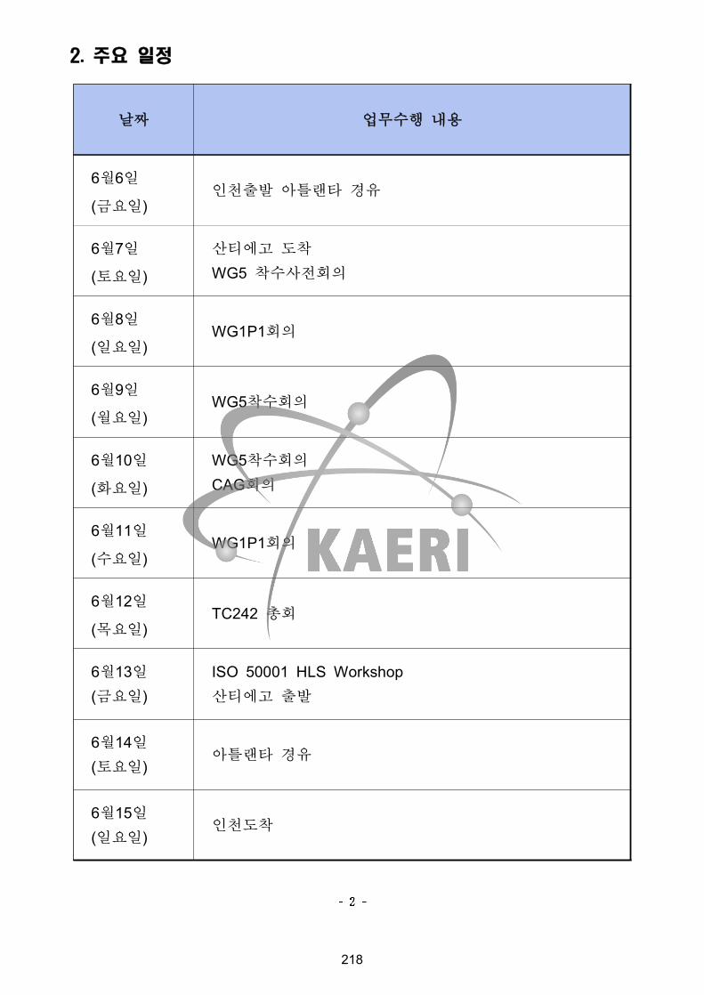
2. 주요 일정
날짜 업무수행 내용
6월6일
(금요일)인천출발 아틀랜타 경유
6월7일
(토요일)
산티에고 도착
WG5 착수사전회의
6월8일
(일요일)WG1P1회의
6월9일
(월요일)WG5착수회의
6월10일
(화요일)
WG5착수회의
CAG회의
6월11일
(수요일)WG1P1회의
6월12일
(목요일)TC242 총회
6월13일(금요일)
ISO 50001 HLS Workshop산티에고 출발
6월14일(토요일)
아틀랜타 경유
6월15일(일요일)
인천도착
218
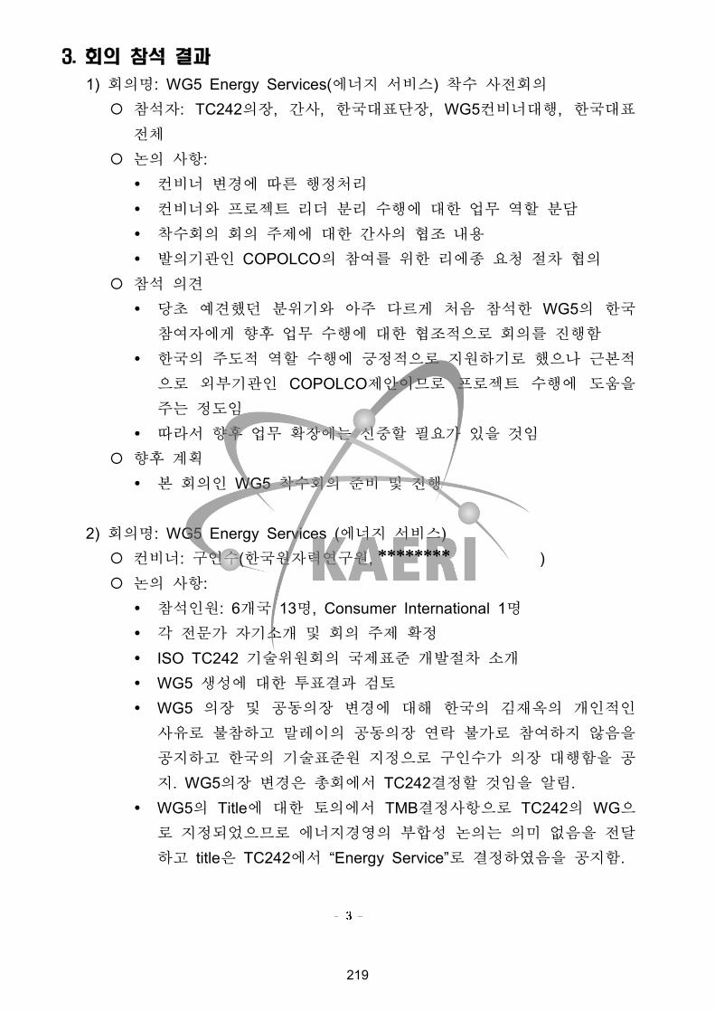
3. 회의 참석 결과
1) 회의명: WG5 Energy Services(에너지 서비스) 착수 사전회의
¡ 참석자: TC242의장, 간사, 한국대표단장, WG5컨비너대행, 한국대표
전체
¡ 논의 사항:Ÿ 컨비너 변경에 따른 행정처리
Ÿ 컨비너와 프로젝트 리더 분리 수행에 대한 업무 역할 분담
Ÿ 착수회의 회의 주제에 대한 간사의 협조 내용
Ÿ 발의기관인 COPOLCO의 참여를 위한 리에종 요청 절차 협의
¡ 참석 의견
Ÿ 당초 예견했던 분위기와 아주 다르게 처음 참석한 WG5의 한국
참여자에게 향후 업무 수행에 대한 협조적으로 회의를 진행함
Ÿ 한국의 주도적 역할 수행에 긍정적으로 지원하기로 했으나 근본적
으로 외부기관인 COPOLCO제안이므로 프로젝트 수행에 도움을
주는 정도임
Ÿ 따라서 향후 업무 확장에는 신중할 필요가 있을 것임
¡ 향후 계획
Ÿ 본 회의인 WG5 착수회의 준비 및 진행
2) 회의명: WG5 Energy Services (에너지 서비스)¡ 컨비너: 구인수(한국원자력연구원, )¡ 논의 사항:
Ÿ 참석인원: 6개국 13명, Consumer International 1명Ÿ 각 전문가 자기소개 및 회의 주제 확정
Ÿ ISO TC242 기술위원회의 국제표준 개발절차 소개
Ÿ WG5 생성에 대한 투표결과 검토
Ÿ WG5 의장 및 공동의장 변경에 대해 한국의 김재옥의 개인적인
사유로 불참하고 말레이의 공동의장 연락 불가로 참여하지 않음을
공지하고 한국의 기술표준원 지정으로 구인수가 의장 대행함을 공
지. WG5의장 변경은 총회에서 TC242결정할 것임을 알림.Ÿ WG5의 Title에 대한 토의에서 TMB결정사항으로 TC242의 WG으
로 지정되었으므로 에너지경영의 부합성 논의는 의미 없음을 전달
하고 title은 TC242에서 “Energy Service”로 결정하였음을 공지함.
219
********

Ÿ WG5의 scope논의에서 현재는 처음 착수회의이므로 신규제안한
프로젝트를 완성하는 데 집중하기로 의견을 모음.Ÿ 표준문서 제목을 “Activities relating to energy services -
Guidelines for the assessment and for the improvement of the energy services to users”로 결정.
Ÿ 표준문서 목차 결정을 위한 회의
- Introduction- 1. Scope- 2. Terms and definitions- 3. Components of the service relating to users’ needs and
expectations- 4. Guidelines for satisfying users’ needs and expectations- 5. Assessment criteria for service to users- 6. Energy services assessment methodology- 7. Performance indicators- 8. Performance improvement
Ÿ 표준문서 번호를 ISO/NP 50007로 확정
Ÿ ISO/WD 50007작성 일정 협의
- 1차 입력준비: 2014년 6월말
- 1차 WD준비 및 회람: 2014년 7월말
- 1차 WG5 전문가 검토의견: 2014년 8월말
- 1차 검토의견 해결: 2014년 9월말
- 2차 WD준비 및 회람: 2014년 10월말
- 2차 WG5 전문가 검토의견: 2014년 11월말
- 2차 검토의견 해결: 2014년 12월말
- 최종 WD준비 및 회람: 2015년 2월말
- 최종 WD 검토의견: 2015년 4월말
- 최종 WD 검토의견 해결 내용 TC242 Secretariat에 송부: 2015년 5월말
Ÿ 향후계획
- 당분간 WG5는 ISO 50007 준비에 전력할 예정임.- Terminology 입력을 WG5는 ISO 50007의 CD단계에 제공할 예
정임.
220

¡ 참석 의견:Ÿ 당초 지난 4-5년 동안 표준문서 작업을 진행 못했던 한국이 회의
장에 나타나서 본격적으로 WG활동을 시작하므로서 그 동안의 한
국에 대한 부정적 시각이 매우 긍정적으로 변화 하였음.Ÿ TC242에서는 WG5의 착수회의를 지원하기 위해 위원장과 간사가
첫날 회의 내내 같이 방향, 절차, 방법 등을 조언하였으며, 회의
진행에 아주 긍정적 이었음.Ÿ 특히 회의를 위해 참석한 Consumer International은 전날
COPOLCO 리에종 요청을 하였는데 바로 착수회의에 참가해서 아
주 좋은 분위기 였음. 따라서 WG5의 Category D Liaison 요청은
TC242 위원회에 아주 적절했음. 국제표준개발단계에서 한국의 소
비자 모임에 대한 연락은 Liaison인 Consumer International을 통
해 공식적으로 처리될 것임.
¡ 향후 계획:Ÿ 국내 ISO 50007 프로젝트리더인 가천대 김진호 교수를 중심으로
회의에서 약속한 일정대로 진행되도록 지원하며, 필요하면 관련
Web-meeting이 가능하도록 조정함.Ÿ 가천대를 중심으로 WD 검토의견 접수 즉시 국내 회의를 개최하여
처리하도록 지원함.
3) 회의명:: WG1P1 Guidance¡ 컨비너: Deann Desai (조지아텍, [email protected])¡ 논의사항
Ÿ Discussion on circulated documentsOn the basis of the comments circulated (N0111) and supporting documents were updated and circulated each day of the meeting as N0112, N0115, N0116, N0117,N0118, N0119, N0120, N0121, and N0122.
Ÿ Comments resolutionThe group successfully worked through all 709 of the comments received and the resolutions to the comments were posted as ISO/TC 242 N
¡ 참석 의견
221

Ÿ General AgreementsWG 1 P1 agrees to update the text on EnPIs and baselines based on thediscussion with WG 2. The experts did not agree to use the phrase energyvalue" due to the audience for ISO 50004 – so energy consumption was retained as the first type of EnPI.WG 1 P1 agrees to review Annex A from DIS ISO 50006 for potential use in supporting the EnPI and Baseline sections.WG 1members are invited to review the working documents from 11 June2014, prior to the release of the FDIS and provide any additional editorialinput by the end of June 2014.WG 1 P1 agrees to recommend to TC 242 that the document is ready to move forward to FDIS stage for ballot and comment.
¡ 향후 계획
Ÿ Schedule of activitiesCirculate the working documents including the draft final draft international standard (FDIS) by of 13 June 2014.Submit a recommendation to move to FDIS for ISO 50004 to TC 242 in plenary on 12 June 2014.Circulate the document as an FDIS for ballot and comment through ISO/CS and TC 242 Secretariat the first week of July 2014 with anticipated publication in September/ October 2014.․
4) 회의명: Chair Advisory Group 회의 (의장자문그룹회의)
¡ Chair: Roland Risser (미국 DoE, [email protected])¡ 논의 사항
Ÿ 지난 총회 회의록 검토 및 의견 개진
Ÿ 국제표준문서 발행 절차 개정, ISO/IEC Directives part 1Ÿ 각 working group별로 현재 발행된 문서, 진행 중인 문서와 계획
중인 문서 현황을 설명
Ÿ ISO 본부의 secretariat와 Web meeting을 통한 회의
222
Ÿ 금요일 workshop에 대한 참가요청
¡ 참석 의견
Ÿ 처음 참석하는 회의에서 신설 working group 활동 순서를 공지함.
5) 회의명: TC242 Plenary Meeting (에너지 경영 기술위원회 총회)¡ Chair: Roland Risser (미국 DoE, [email protected])¡ 논의 사항
Ÿ 각 WG의 회의내용 보고
Ÿ 회의 결정사항
- ISO 50003은 개정된 ISO 기본 개발절차에 따라 FDIS단계를 생
략키로함.- ISO/FDIS 50004는 발간 전에 FDIS단계를 거치기로함.- ISO/FDIS 50006은 발간 전에 FDIS단계를 거치기로함.- ISO/CD3 17747은 CD3단계로 진행함.- International Accreditation Forum(IAF)을 Category A liaison으로
등재함.- Consumers International을 WG5 분야를 위해 Category D
Liaison으로 등재함.- WG1내에 프로젝트 그룹을 발족하고 이 그룹은 ISO 50001 향후 개정을 위한 사전작업을 수행함.
- WG6, Data for Energy Management Systems가 NWIP인
“Building system energy data exchange - a systematic approach to evaluating the energy use, energy consumption, energy efficiency and other factors used to manage the building energy”개발하기로 하고 향후 3년간의 Convenor로 미
국의 Dan Manole을 지명함.
- 향후 3년간 ISO/TC 242의 WG Convenor을 다음과 같이
지명함.
ü WG1 – Deann Desai (US)
ü WG2 – Alberto Fossa (Brazil) and Fabian Allard (Canada)
223
ü JWG3 – Gustav Radloff (South Africa) and Jochen Poremski* (Germany) *Subject to confirmation by ISO/TC 257
ü WG4 – Martin Fry (UK) and Akira Ishihara (Japan)
ü WG5 – In Soo Koo (Korea) and Elmi Anas (Malaysia)
- 차기년도인 9차 ISO TC242 총회를 멕시코에서 열기로 멕시코
대표인 Dirección General de Normas (DGN)와 해결함.
- 2017년도에는 스웨덴에서 열기로 잠정합의함.
¡ 참석 의견
Ÿ 향후 표준문서 개발은 개정된 지침에 따라 기본 절차인 NWIP, DIS, 발간, 검토 등의 단계로 진행하고 각 기술위원회의 결정에
따라 PWI, WD, CD, FDIS단계를 거칠 것이다. 각 표준문서는 전
체 개발 기간중 한 번에 한해 9개월 연장이 되며 이를 초과하면
문서개발이 폐기될 수 있다.Ÿ 각 기술위원회의 위원장은 최대 9년 임기이며, 각 WG convenor은
임기가 3년이나 연임 제한은 없다.Ÿ WG5이 참가한 첫 회의로서 에너지 효율과 에너지 서비스에 대한
정의를 향후 표준문서 개발과 함께 정의해야할 주요 terminology임.
Ÿ 에너지 서비스 분야의 첫 문서의 각 용어 정리는 CD단게에서 정
리할 것임.¡ 향후 계획
Ÿ 다음 회의 전까지 WG5의 ISO/NP 50007은 적어도 ISO/CD 50007로 진행해야 한다.
224
4. 종합 결과
1) 주요 성과
¡ WG5 착수회의 진행과 WG5 의장 수임으로 WG5의 조직과 업무는 차
질없이 진행됨.
¡ WG5 외부 기관 연계인 Liaison D로 Consumers International이 수락
되므로 한국의 소비자모임과 연계는 국제표준이 완성될 때 까지는
Liaison을 통해 보고될 예정임.
¡ ISO/NP 50007로 명명된 국제표준문서 개발을 위해 착수 시점에 목차
확정 및 Scope에 대한 outline를 완성함.
2) 향후 계획
¡ ISO/NP 50007의 국제표준문서 개발을 위해 국내 WG5 위원들께서
관련 입력 마련, 검토 등의 업무가 계획된 일정에 차질이 없게 노력해
야 함.
3) 평가 및 건의사항(중요)
¡ 우려하였던 WG5의 생성과 업무 진행을 위한 국제 조직화를 완성
했으므로 향후 국제표준문서 개발에 집속할 수 있는 환경을 마련
하였음. 따라서 금번 한국 대표단의 회의 참여는 조금은 늦었으나
적절하게 대처함으로서 한국의 국제표준화 능력을 이정받을 수
있는 중요한 기회였음.
¡ ISO/IEC 표준문서개발절차를 기존의 PWI-NWIP-WD-CD-DIS-FDIS 등의 개발단계를 기본단계로 NWIP-DIS-발간-검토 등의 절차로 진행하고
기술위원회의 결정에 따라 선택적으로 PWI, WD, CD, FDI단계를 거치
는 것으로 변경됨에 따라 향후 ISO국제표준문서의 개발은 상당히 빨
리 진행될 것으로 판단함.
4) 차기 회의 일정: ‘15.06.DD~DD, 멕시코, 칸쿤(예상)
225

첨부문서:
1. TC242 Agenda (첨부 파일 91-)
2. TC242 회의록 (첨부 파일 92-)
3. WG5 Agenda (첨부 파일 93-)
4. WG5 회의록 (첨부 파일 94-)
5. ISO 개정 지침 (첨부 파일 95-)
6. UNIDO발표자료 (첨부 파일 96-)
※ 담당자 검토의견(후속조치 등) * 국가기술표준원 담당자 작성란
◦
◦
226
※ 귀국 후 10일 이내에 국가기술표준원 담당과로 이메일 송부 요망
국제표준화회의 참석 결과보고서
ISO/TC242 Energy Management
(에너지 경영)
키워드(최대 5개): 에너지 경영, 에너지 성능, 에너지 효율, 에너지 서
비스
날짜(제출일): 2014 년 11 월 5 일
소속: 한국원자력연구원
직위: 책임연구원
성명: 구인수
이메일:
227
********

1. 회의 개요
1) 목적
¡ ISO TC242 에너지경영 기술위원회 WG1P3중간회의 참석, WG5 에너지서비스 연계업무 수행
2) 분야(회의명): ISO TC 242/WG1P3 중간회의
3) 기간: 2014.10.27.~10.29(2박3일)
4) 장소: 영국 런던 BSI 회의실
5) 주최: BSI
6) 규모: 13개국과 UNIDO, 22명 참석
7) 한국대표단: 총 2명(한국대표: 1명, WG5컨비너: 1명)
성 명 소속 직위 대표단 내 담당역할
구인수 한국원자력연구원 책임연구원 TC242/WG5 컨비너
김선경 에너지관리공단 대리 TC242/WG1P3 한국대표
228
2. 주요 일정
날짜 업무수행 내용
10월26일
(일요일)- 인천출발 런던도착(KE907)
10월27일
(월요일)
- Review goals of the meeting- Review input on what is "easy" to use from the High
Level Structure“(N128)- Review of input from NMB on editorial issues for ISO
50001(N131)
10월28일
(화요일)
- Review input from NMB for items that need to be clarified for implementation or maintenance of ISO 50001(N132)
10월29일
(수요일)
- Review of input from NMB for Workshop in Chile(N135, N137, N138)
- Next steps and objectives for the March meeting
10월30일
(목요일)- 런던출발(KE908)
10월31일
(금요일)- 인천도착
229
3. 회의 참석 결과
1) Review input on what is "easy" to use from the High Level Structure“(N128)
칠레 산티애고 회의에서 도출한 “easy”항목을 HLS에 병합한다. 먼저 각
회의내용 중 녹색은 현 ISO 50001의 추가사항, 붉은 색은 변경 고려사
항, 보라색은 새로운 개념, 청색은 노트 등을 의미하는 것으로 약속하고, 논의를 시작함.가장 먼저 서술이 가능한 절로 5.2절의 정책, 7.5절의 문서정보, 9.2절의
내부감사, 9.3절의 경영검토 등으로 논의를 시작함.
5.2 PolicyTop management shall establish an energy policy that:a) is appropriate to the purpose of the organizationb) is appropriate to the nature and scale of the organization's energy use and energy consumption;{Check context of the organization to see if item b) is still needed}c) provides a framework for setting energy objectives and energy targets;d) provides information and resources for achieving energy objectives and energy targets;e) includes a commitment to satisfy applicable requirements related to energy use, energy consumption and energy efficiency;f) includes a commitment to continual improvement of the energy management system;g) includes a commitment to continual improvement in energy performance;h) states the organization's commitment to achieving energy performance improvement;i) supports the purchase of energy-efficient products and services, and design for energy performance improvement.The energy policy shall:— be available as documented information;— be communicated within the organization;— be available to interested parties, as appropriate;— is regularly reviewed and updated as necessary. The organization shall retain documented information on the communication of the policy to interested parties. Do we really need a record of the policy to be required? Is this based on the size of the organization and therefore should be determined by the organization under 7.5 documented information?{Check management review which should have the entire system reviewed and updated and check to see if this is still necessary. Notes to clarify when a review is necessary and how often it should be reviewed (annex opportunity) }7.5 Documented information7.5.1 GeneralThe organization’s energy management system shall include:a) documented information required by this International Standard;b) documented information determined by the organization as being necessary for the effectiveness of the energy management system;NOTE The extent of documented information for a energy management system can differ from one organization to another due to:— the size of organization and its type of activities, processes, products and services;— the complexity of processes and their interactions;— the competence of persons.7.5.2 Creating and updatingWhen creating and updating documented information the organization shall ensure appropriate:— identification and description (e.g. a title, date, author, or reference number);
230
— format (e.g. language, software version, graphics) and media (e.g. paper, electronic);— review and approval for suitability and adequacy.7.5.3 Control of documented informationDocumented information required by the energy management system and by this International Standard shall be controlled to ensure:a) it is available and suitable for use, where and when it is needed;b) it is adequately protected (e.g. from loss of confidentiality, improper use, or loss of integrity).For the control of documented information, the organization shall address the following activities, as applicable:— distribution, access, retrieval and use;— storage and preservation, including preservation of legibility;— control of changes (e.g. version control);— retention and disposition.Documented information of external origin determined by the organization to be necessary for the planning and operation of the energy management system shall be identified, as appropriate, and controlled.NOTE Access can imply a decision regarding the permission to view the documented information only, or the permission and authority to view and change the documented information.7.5.4 Energy performance documented informationThe organization shall demonstrate conformity to the requirements of its EnMS and of this International Standard, and the energy performance results achieved.9.2 Evaluation of legal and other requirementsAt planned intervals, the organization shall evaluate compliance with legal requirements and other requirements to which it subscribes related to its energy use and consumption.
Retain documented information of the results of the evaluations of compliance.9.3 Internal audit9.3.1 The organization shall conduct internal audits at planned intervals to provide information on whether the energy management system:a) conforms to:— the organization’s own requirements for its energy management system;— the energy objectives and energy targets established by the organization ;— the requirements of this International Standard;b) is effectively implemented and maintained, and c) improves energy performance.Does this cause confusion with energy audits with EnMS audits,9.3.2 The organization shall:a) plan, establish, implement and maintain an audit programme(s) including the frequency, methods, responsibilities, planning requirements and reporting, which shall take into consideration the importance of the processes concerned and the results of previous audits;b) define the audit criteria and scope for each audit;c) select auditors and conduct audits to ensure objectivity and the impartiality of the audit process;d) ensure that the results of the audits are reported to relevant management;e) retain documented information as evidence of the implementation of the audit programme and the audit results.
2) Review of input from NMB on editorial issues for ISO 50001(N132)
각국 검토의견을 유형별로 정리하여 editorial 관련 45개 항목, implementation 60개 항목, 새 개념 38개 항목으로 분류하였으며, 이중
editorial 관련 45개 항목을 우선 논의하였다. 의견으로 제시한 정보를 검
토하여 개념을 정립하여 기술위원회에 권고할 예정이다. 이번 회의에서
각 의견을 반영하고 미진한 부분은 웨비나를 통해 회의를 계속할 것이
231
다. 이 업무는 2015년 6월 멕시코 회의 준비를 위해 늦어도 2015년 3월까지 완료할 예정이다.
3) Review input from NMB for items that need to be clarified for implementation or maintenance of ISO 50001(N135) and Review of input from NMB for Workshop in Chile(N137, N138)
ISO/TMB Joint Technical Coordination Group concept document to support of annex SL문서의 Annex SL concepts document를 간략히 검
토하고, implementation 60개 항목, 새 개념 38개 항목에 대해 논의하였
다.회의 내용을 반영한 PWI draft로 ISO50001과 HLS를 10월 29일자로 완
성하였다. 이와함께 ISO 50001:2011과 HLS PWI의 연관관계를 비교한
내용과 HLS PWI와 ISO 50001:2011의 구조를 비교한 표를 완성하였다.
4) Next steps and objectives for the March meeting
¡ 향후 계획
Ÿ 2015년 6월 멕시코 정기회의를 위해 늦어도 5월까지 회람의견이
프로젝트리더에게 도착해야 하므로, 가장 늦은 일정으로 2015년 3월까지 금번회의에서 미진한 논의를 끝내야 한다.
Ÿ 당초 의장인 딘은 3월초 face-to-face회의를 요청하였으나, WG5는
회람 일정상 회의 전에 계획한 2월이후는 참석하기 곤란함을 첫날
개진하였고, 최종 회의 결정을 각 참여 위원사이에 논의한 결과
둘 내지 세차례의 인터넷 컨퍼런스인 웨비나를 이용하여 3월초에
진행하기로 결론지었다.
232
4. 종합결과
1) 주요 성과
¡ JTCG에서 지침서 관련 문서의 High Level Structure에 따른 ISO 50001 개정 사전 준비 작업이 신규 작업 문서에 미칠 영향을 파악하
였다. 특히 WG5의 개발중인 문서 ISO 50007의 문서 구조에 대한 평
가를 실시할 예정이다.
2) 향후 계획
¡ ISO TC242 한국위원회와 협의하여 향후 개정할 표준 문서의 영향을
감안하여 한국대표의 적극적인 참여가 필요하다.
¡ 현재 WG5에서 개발중인 ISO 50007 표준문서의 구조와 working draft작성을 검토하고 다음 정기회의 준비를 위해 2015년 3월까지 최종 안
을 완료토록 한다.
¡ ISO 50001:20XX 개발 일정은 2015년 정기회의시 PWI에 대한 결정, 2016년 CD 또는 CD1, CD2로 진행하고 2017년에 DIS 안을 완료한다.
3) 평가 및 건의사항
¡ High Level Structure로 개정하는 표준문서가 우리나라 관련 표준 적용
및 시행하는 경우 우리나라 산업에 미치는 영향을 평가해야 할 것으로
판단된다. 만약 지침서가 인증 등의 업무에 관련할 경우 우리나라의
현황을 개정작업시에 반영하여 미리 대비해야할 것이다.
4) 차기 중간 회의 일정: 없음
233
첨부문서:
1. JTCG Concept document to support of Annex SL
2. ISO 50001 Survey - collated
3. Draft PWI for ISO 50001 and HLS
4. ISO 50001:2011과 HLS제안 비교표
※ 담당자 검토의견(후속조치 등) * 국가기술표준원 담당자 작성란
◦
◦
234
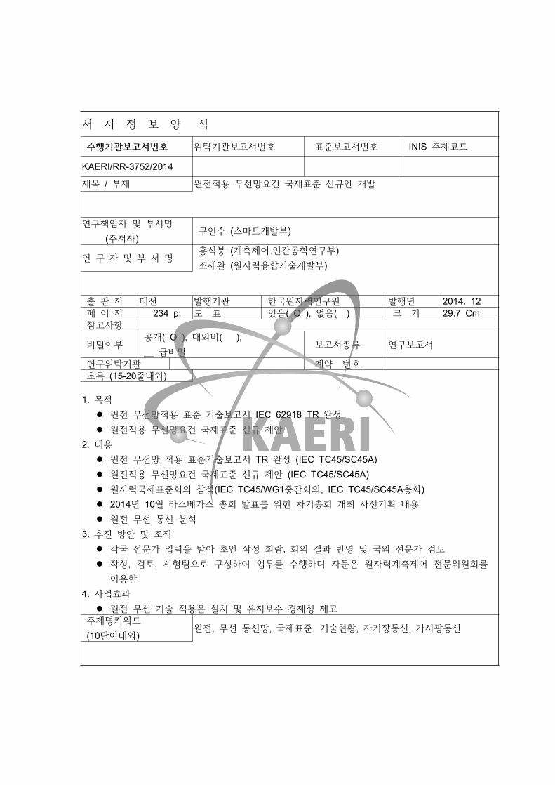
서 지 정 보 양 식
수행기관보고서번호 위탁기관보고서번호 표준보고서번호 INIS 주제코드
KAERI/RR-3752/2014
제목 / 부제 원전적용 무선망요건 국제표준 신규안 개발
연구책임자 및 부서명 (주저자)
구인수 (스마트개발부)
연 구 자 및 부 서 명 홍석붕 (계측제어․인간공학연구부) 조재완 (원자력융합기술개발부)
출 판 지 대전 발행기관 한국원자력연구원 발행년 2014. 12 페 이 지 234 p. 도 표 있음( O ), 없음( ) 크 기 29.7 Cm 참고사항
비밀여부 공개( O ), 대외비( ), __ 급비밀 보고서종류 연구보고서
연구위탁기관 계약 번호 초록 (15-20줄내외)
1. 목적l 원전 무선망적용 표준 기술보고서 IEC 62918 TR 완성l 원전적용 무선망요건 국제표준 신규 제안
2. 내용l 원전 무선망 적용 표준기술보고서 TR 완성 (IEC TC45/SC45A)l 원전적용 무선망요건 국제표준 신규 제안 (IEC TC45/SC45A)l 원자력국제표준회의 참석(IEC TC45/WG1중간회의, IEC TC45/SC45A총회)l 2014년 10월 라스베가스 총회 발표를 위한 차기총회 개최 사전기획 내용l 원전 무선 통신 분석
3. 추진 방안 및 조직l 각국 전문가 입력을 받아 초안 작성 회람, 회의 결과 반영 및 국외 전문가 검토l 작성, 검토, 시험팀으로 구성하여 업무를 수행하며 자문은 원자력계측제어 전문위원회를
이용함4. 사업효과
l 원전 무선 기술 적용은 설치 및 유지보수 경제성 제고 주제명키워드 (10단어내외)
원전, 무선 통신망, 국제표준, 기술현황, 자기장통신, 가시광통신

BIBLIOGRAPHIC INFORMATION SHEET Performing Org.Report No.
Sponsoring Org. Report No.
Standard Report No.
INIS Subject Code
KAERI/RR-3752/2014
Title / Subtitle Development of new proposal for international standard of wireless requirements applied in nuclear power plants
Project Manager and Department(or Main Author)
I. S. Koo (SMART Development Division)
Researcher and Department
S. B. Hong (I&C and Human Factors Division) J. W. Cho (Fusion Technology Division)
Pub l ic a t ion Place Taejon Publisher KAERI P u b l i c a t i o n
Date 2014. 12
Page 234 p. Ill. & Tab. Yes( O ), No ( ) Size 29.7 CmNote
Open Open( O ), Restricted( ), ___Class Document Report Type Research Report
Sponsoring Org. Contract No.Abstract(15-20 Lines)
1. Purposel Develpoment of IEC technical report on wireless device, IEC TR 62918l New proposal for international standard of wireless requirements applied in nuclear
power plants2. Contents
l Develpoment of IEC technical report on wireless devicel New proposal for international standard of wireless requirements applied in nuclear
power plantsl Intermediate meeting of IEC TC45/WG1 and Plenary meeting of IEC TC45l Planning on 2016 plenary meeting of IEC TC45 at Gyungjul Analysis on wireless application in NPP
3. Implementation methodsl Preparation of first draft with experts group, its circulation, discussions on the results
of the circulationl Organizing three teams such as preparation, reviews and experiment
4. Resultsl Maintenance cost will be reduced with application of the wireless technologies in
nuclear power plants
Subject Keywords (About 10 words)
Nuclear power plants, wireless communications, international standard, state of the art on wireless in NPP, magnetic field communication, visible light communications
1. 이 보고서는 산업통상자원부 국가기술표준원에서 시행한 학술용역 사업의
최종보고서이다.
2. 이 수행내용을 대외적으로 발표할 때에서는 반드시 산업통상자원부 국가기술
표준원에서 시행한 학술용역 사업의 결과임을 밝혀야 한다.