sdm-usb-qs-s
7
SDM-USB-QS-S USB MODULE DATA GUIDE WIRELESS MADE SIMPLE Revised 1/14/05 DESCRIPTION The Linx QS Series USB module allows the rapid addition of USB to virtually any device. Housed in a compact SMD package the QS module provides a complete solution for converting between USB and logic level serial sources. The module can be directly connected to v irtually any serial device including microprocessors, RS232/RS485 level converters, or Linx wireless RF modules. The QS module is completely self contained and requires no external components, (except a USB jack) and includes all necessary firmware and drivers, freeing the designer from complicated programming. Power can be supplied externally or from the USB bus. Both USB 1.1 and USB 2.0 are supported at data rates to 3Mbps. Figure 1: Packag e Dimensions 0.125" 0.630" LOT 10000 SDM-USB-QS-S USB MODULE 0.812" Interface / Upgrade Legacy Peripherals Interfacing Microcontrollers To USB USB-to-RS232 / RS485 Converters Interfacing RF Modules To USB USB Smart Card Readers USB Modems Robotics USB Instrumentation USB Game Controllers USB-to-Serial Converter Cables APPLICATIONS INCLUDE Single Chip USB-to-Asynchronous Serial Data Conversion Low-Cost 3Mbps baud rate Supports Low-Speed USB Full Handshaking Support for RS232 and RS485 Bus-or-Self Powered VID, PID, Serial Number, and Descriptors Programmed via USB No External Components Needed (Except a USB Jack) Compact Surface-mount Package Drivers and Firmware Included Supports Windows 98/2000/ME/XP USB 1.1 and 2.0 Compatible FEATURES PART # DESCRIPTION SDM- USB- QS-S USB Module MDEV-USB-QS Mas ter Dev el opmen t Ki t ORDERING INFORMATION INTERFACE MODULE QS SERIES
-
Upload
hermano-correa-fomi -
Category
Documents
-
view
218 -
download
0
Transcript of sdm-usb-qs-s
7/27/2019 sdm-usb-qs-s
http://slidepdf.com/reader/full/sdm-usb-qs-s 1/7
SDM-USB-QS-S USB MODULE DATA GUIDE
WIRELESS MADE SIMPLE
Revised 1/14/05
DESCRIPTION
The Linx QS Series USB module allows the rapid
addition of USB to virtually any device. Housed ina compact SMD package the QS module
provides a complete solution for converting
between USB and logic level serial sources. Themodule can be directly connected to virtually any
serial device including microprocessors,RS232/RS485 level converters, or Linx wireless
RF modules. The QS module is completely self
contained and requires no external components,(except a USB jack) and includes all necessary
firmware and drivers, freeing the designer fromcomplicated programming. Power can be
supplied externally or from the USB bus. BothUSB 1.1 and USB 2.0 are supported at data rates
to 3Mbps.
Figure 1: Package Dimensions
0.125"
0.630"
LOT 10000
SDM-USB-QS-S
USB MODULE
0.812"
Interface / Upgrade Legacy Peripherals Interfacing Microcontrollers To USB USB-to-RS232 / RS485 Converters Interfacing RF Modules To USB USB Smart Card Readers USB Modems Robotics
USB Instrumentation USB Game Controllers USB-to-Serial Converter Cables
APPLICATIONS INCLUDE
Single Chip USB-to-AsynchronousSerial Data Conversion
Low-Cost
3Mbps baud rate
Supports Low-Speed USB
Full Handshaking Support forRS232 and RS485
Bus-or-Self Powered
VID, PID, Serial Number, andDescriptors Programmed via USB
No External Components Needed(Except a USB Jack)
Compact Surface-mount Package
Drivers and Firmware Included
Supports Windows 98/2000/ME/XP
USB 1.1 and 2.0 Compatible
FEATURES
PART # DESCRIPTION
SDM-USB-QS-S USB ModuleMDEV-USB-QS Master Development Kit
ORDERING INFORMATION
INTERFACE MODULE
QS SERIES
7/27/2019 sdm-usb-qs-s
http://slidepdf.com/reader/full/sdm-usb-qs-s 2/7
Page 3Page 2
ELECTRICAL SPECIFICATIONS
*CAUTION*This product incorporates numerous static-sensitive components.Always wear an ESD wrist strap and observe proper ESD handling
procedures when working with this device. Failure to observe thisprecaution may result in module damage or failure.
USBDP
USBDM
GND DSR
DATA_IN
DATA_OUT
RTSCTS
DTR
TX_IND
VCC
SUSP_IND
RX_IND
485_TX
RI
DCD
1
2
3
4
5
67
8 9
1011
12
13
14
15
16
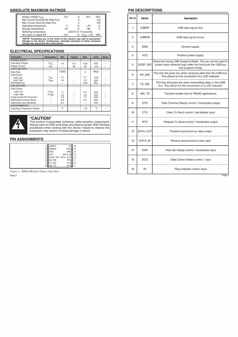
Figure 2: SDM-USB-QS-S Pinout (Top View)
ABSOLUTE MAXIMUM RATINGS
Supply voltage VCC -0.5 to +6.0 VDC
Max Current Sourced By Data Pins 2 mA
Max Current Sunk By Data Pins 4 mA
Operating temperature 0 to +70 °C
Storage temperature -40 to +90 °C
Soldering temperature +225°C for 10 secondsAny input or output Pin -0.5 to VCC + 0.5 VDC
*NOTE* Exceeding any of the limits of this section may lead to permanentdamage to the device. Furthermore, extended operation at these maximumratings may reduce the life of this device.
Parameter Designation Min. Typical Max. Units Notes
POWER SUPPLY
Operating Voltage VCC 4.4 5.0 5.26 VDC –Supply Current ICC – 26 28 mA –
UART SECTION
Data Rate – 0.0003 – 3 Mbps –
Data Output
Logic Low VOL 0.1 – 0.7 VDC –
Logic High VOH 4.4 – 4.9 VDC –
EEPROM Size – – 1024 Bits –
USB SECTION
Data Output
Logic Low UVOL 0 – 0.3 VDC –Logic High UVOH 2.8 – 3.6 VDC –
Single Ended RX Threshold – 0.8 – 2.0 VDC –
Differential Common Mode – 0.8 – 2.5 VDC –
Differential Input Sensitivity – 0.2 – – VDC –
ENVIRONMENTAL
Operating Temperature Range – 0 – +70 °C –
PIN ASSIGNMENTS
Pin #
Name
Description
1 USBDP USB data signal plus.
2 USBDM USB data signal minus.
3 GND Ground supply.
4 VCC Positive power supply.
5 SUSP_IND
Goes low during USB Suspend Mode. This pin can be used to
power down external logic when the host puts the USB businto suspend mode.
6 RX_INDThis line will pulse low when receiving data from the USB bus.
This allows for the connection of a LED indicator.
7 TX_INDThis line will pulse low when transmitting data on the USB
bus. This allows for the connection of a LED indicator.
8 485_TX Transmit enable line for RS485 applications.
9 DTR Data Terminal Ready control / handshake output
10 CTS Clear To Send control / handshake input
11 RTS Request To Send control / handshake output
12 DATA_OUT Transmit asynchronous data output
13 DATA_IN Receive asynchronous data input
14 DSR Data Set Ready control / handshake input
15 DCD Data Carrier Detect control / input
16 RI Ring Indicator control input
PIN DESCRIPTIONS

7/27/2019 sdm-usb-qs-s
http://slidepdf.com/reader/full/sdm-usb-qs-s 3/7
7/27/2019 sdm-usb-qs-s
http://slidepdf.com/reader/full/sdm-usb-qs-s 4/7
7/27/2019 sdm-usb-qs-s
http://slidepdf.com/reader/full/sdm-usb-qs-s 5/7
7/27/2019 sdm-usb-qs-s
http://slidepdf.com/reader/full/sdm-usb-qs-s 6/7
7/27/2019 sdm-usb-qs-s
http://slidepdf.com/reader/full/sdm-usb-qs-s 7/7
LINX TECHNOLOGIES, INC.575 S.E. ASHLEY PLACE
GRANTS PASS, OR 97526
PHONE: (541) 471-6256FAX: (541) 471-6251http://www.linxtechnologies.com
U.S. CORPORATE HEADQUARTERS:
Linx Technologies is continually striving to improve the quality and function of its products; for
this reason, we reserve the right to make changes without notice. The information contained in
this Data Sheet is believed to be accurate as of the time of publication. Specifications are basedon representative lot samples. Values may vary from lot to lot and are not guaranteed. Linx
Technologies makes no guarantee, warranty, or representation regarding the suitability or
legality of any product for use in a specific application. None of these devices is intended for
use in applications of a critical nature where the safety of life or property is at risk. The user
assumes full liability for the use of product in such applications. Under no conditions will Linx
Technologies be responsible for losses arising from the use or failure of the device in any
application, other than the repair, replacement, or refund limited to the original product purchase
price. Some devices described in this publication are patented. Under no circumstances shall
any user be conveyed any license or right to the use or ownership of these patents.
Disclaimer
WIRELESS MADE SIMPLE
© 2005 by Linx Technologies, Inc. The stylizedLinx logo, Linx, and “Wireless made Simple”are the trademarks of Linx Technologies, Inc.Printed in U.S.A.