
Manuale Mynute Csi_ing
57
Mynute C.S.I. T E C H N I C A L M A N U A L TECHNICAL MANUAL
-
Upload
anonymous-vwlcr439 -
Category
Documents
-
view
257 -
download
3
Transcript of Manuale Mynute Csi_ing

7/27/2019 Manuale Mynute Csi_ing
http://slidepdf.com/reader/full/manuale-mynute-csiing 1/56
Mynute C.S.I.
T E C H N
I C A L M A
N U A L TECHNICAL MANUAL
7/27/2019 Manuale Mynute Csi_ing
http://slidepdf.com/reader/full/manuale-mynute-csiing 2/56
T E C H N I C A L M A
N U A L
7/27/2019 Manuale Mynute Csi_ing
http://slidepdf.com/reader/full/manuale-mynute-csiing 3/56
3
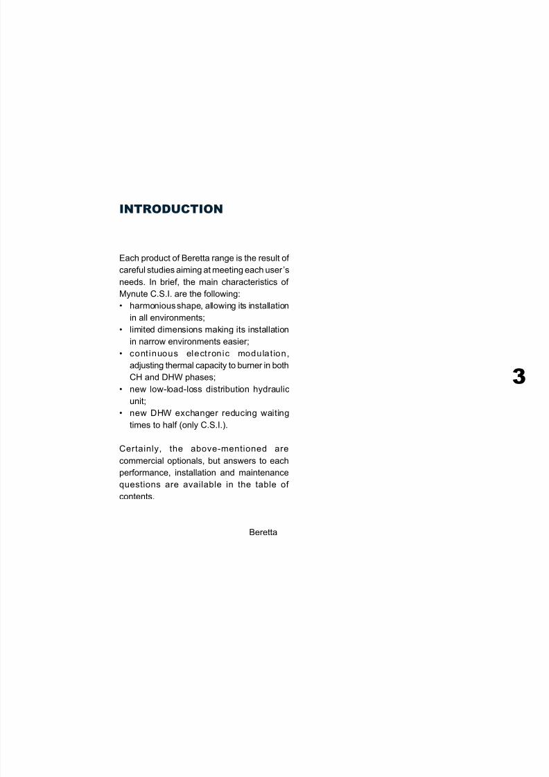
INTRODUCTION
Each product of Beretta range is the result of
careful studies aiming at meeting each user’sneeds. In brief, the main characteristics of
Mynute C.S.I. are the following:
• harmonious shape, allowing its installation
in all environments;
• limited dimensions making its installation
in narrow environments easier;
• cont inuous electronic modulat ion,
adjusting thermal capacity to burner in both
CH and DHW phases;
• new low-load-loss distribution hydraulic
unit;
• new DHW exchanger reducing waiting
times to half (only C.S.I.).
Certainly, the above-mentioned are
commercial optionals, but answers to each
performance, installation and maintenance
questions are available in the table of
contents.
Beretta
7/27/2019 Manuale Mynute Csi_ing
http://slidepdf.com/reader/full/manuale-mynute-csiing 4/56
T E C H N I C A L M A
N U A L
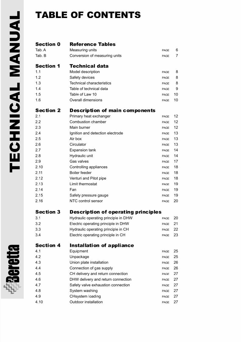
Section 0 Reference TablesTab. A Measuring units PAGE 6
Tab. B Conversion of measuring units PAGE 7
Section 1 Technical data1.1 Model description PAGE 8
1.2 Safety devices PAGE 8
1.3 Technical characteristics PAGE 8
1.4 Table of technical data PAGE 9
1.5 Table of Law 10 PAGE 10
1.6 Overall dimensions PAGE 10
Section 2 Description of main components2.1 Primary heat exchanger PAGE 12
2.2 Combustion chamber PAGE 12
2.3 Main burner PAGE 12
2.4 Ignition and detection electrode PAGE 13
2.5 Air box PAGE 13
2.6 Circulator PAGE 13
2.7 Expansion tank PAGE 14
2.8 Hydraulic unit PAGE 14
2.9 Gas valves PAGE 17
2.10 Controlling appliances PAGE 18
2.11 Boiler feeder PAGE 18
2.12 Venturi and Pitot pipe PAGE 182.13 Limit thermostat PAGE 19
2.14 Fan PAGE 19
2.15 Safety pressure gauge PAGE 19
2.16 NTC control sensor PAGE 20
Section 3 Description of operating principles3.1 Hydraulic operating principle in DHW PAGE 20
3.2 Electric operating principle in DHW PAGE 21
3.3 Hydraulic operating principle in CH PAGE 22
3.4 Electric operating principle in CH PAGE 23
Section 4 Installation of appliance4.1 Equipment PAGE 25
4.2 Unpackage PAGE 25
4.3 Union plate installation PAGE 26
4.4 Connection of gas supply PAGE 26
4.5 CH delivery and return connection PAGE 27
4.6 DHW delivery and return connection PAGE 27
4.7 Safety valve exhaustion connection PAGE 27
4.8 System washing PAGE 27
4.9 CHsystem loading PAGE 27
4.10 Outdoor installation PAGE 27
TABLE OF CONTENTS
7/27/2019 Manuale Mynute Csi_ing
http://slidepdf.com/reader/full/manuale-mynute-csiing 5/56

7/27/2019 Manuale Mynute Csi_ing
http://slidepdf.com/reader/full/manuale-mynute-csiing 6/56
T E C H N I C A L M A
N U A L
Tab. AMeasuring units
DIMENSION UNIT DESCRIPTION
SECTION 0Reference tables
Heating power W Watt
kW kiloWatt
kcal/h kilocalories/hour
Electric power W Watt
Supply voltage V Volt alternate current
Vdc Volt direct current
Electric frequency Hz Hertz
Pressure bar bar
mbar millibar Atm Atmospheremm C.A. millimetres in colums
of water
Temperature °C degree centigrade (celsius)
Elettric current A Ampere
Time s secondmin minute
h hour
Volume l litre
Mass kg kilogram
Capacity l/min litre/minute
l/h litre/hour
Lenght mm millimetrem metre
Velocity m/s metres/second
m/min metres/minute
Angular velocity g/min revolutions/minute
Electric resistance ý ohm
k ý kilo ohm
7/27/2019 Manuale Mynute Csi_ing
http://slidepdf.com/reader/full/manuale-mynute-csiing 7/56
7
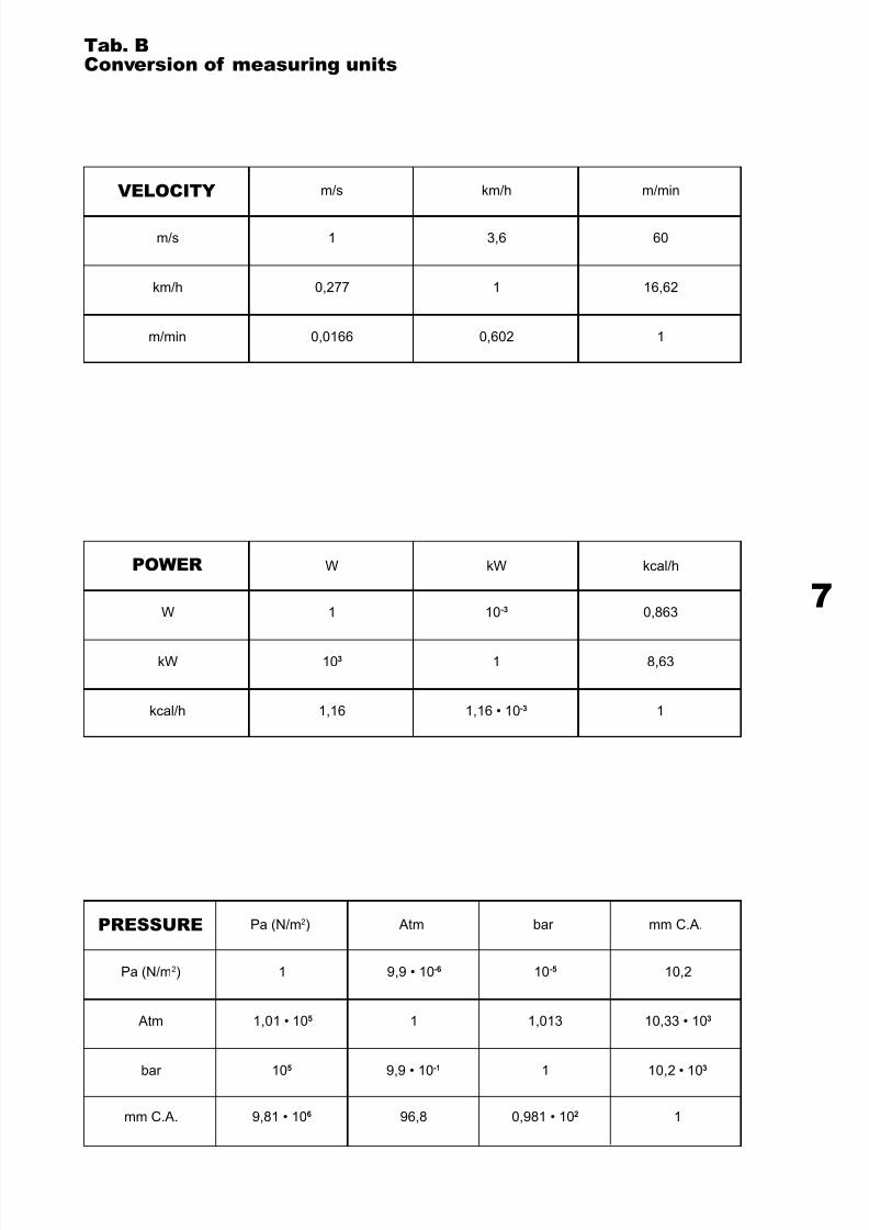
Tab. BConversion of measuring units
m/s km/h m/min
1 3,6 60
0,277 1 16,62
0,0166 0,602 1
m/s
km/h
m/min
W kW kcal/h
1 10-3 0,863
103 1 8,63
1,16 1,16 • 10-3 1
W
kW
kcal/h
Pa (N/m2) Atm bar
1 9,9 • 10-6 10-5
1,01 • 105 1 1,013
10
5
9,9 • 10
-1
1
Pa (N/m2)
Atm
bar
mm C.A.
10,2
10,33 • 103
10,2 • 10
3
9,81 • 106 96,8mm C.A. 10,981 • 102
VELOCITY
POWER
PRESSURE
7/27/2019 Manuale Mynute Csi_ing
http://slidepdf.com/reader/full/manuale-mynute-csiing 8/56
T E C H N I C A L M A
N U A L
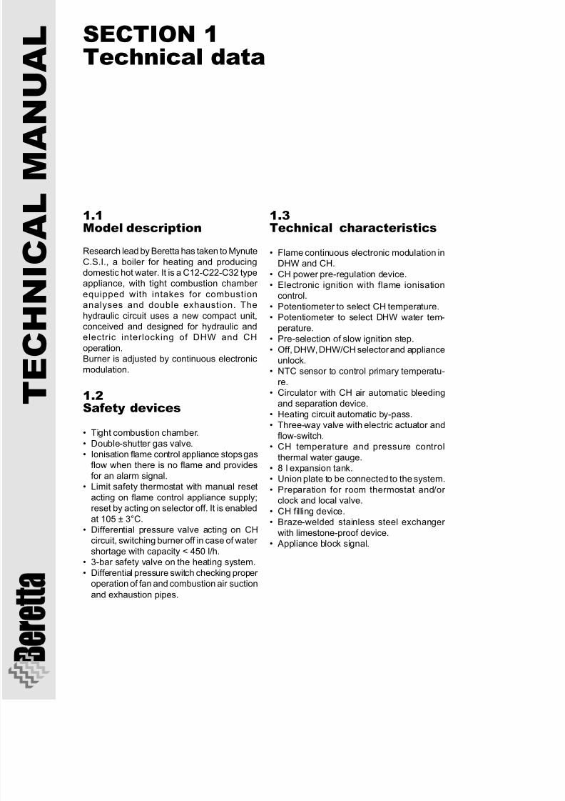
1.1Model description
Research lead by Beretta has taken to Mynute
C.S.I., a boiler for heating and producingdomestic hot water. It is a C12-C22-C32 type
appliance, with tight combustion chamber equipped with intakes for combustionanalyses and double exhaustion. The
hydraulic circuit uses a new compact unit,conceived and designed for hydraulic andelectric interlocking of DHW and CH
operation.Burner is adjusted by continuous electronic
modulation.
1.2Safety devices
• Tight combustion chamber.
• Double-shutter gas valve.• Ionisation flame control appliance stops gas
flow when there is no flame and provides
for an alarm signal.• Limit safety thermostat with manual reset
acting on flame control appliance supply;reset by acting on selector off. It is enabled
at 105 ± 3°C.• Differential pressure valve acting on CH
circuit, switching burner off in case of water
shortage with capacity < 450 l/h.
• 3-bar safety valve on the heating system.• Differential pressure switch checking proper
operation of fan and combustion air suction
and exhaustion pipes.
SECTION 1Technical data
1.3Technical characteristics
• Flame continuous electronic modulation inDHW and CH.
• CH power pre-regulation device.• Electronic ignition with flame ionisation
control.
• Potentiometer to select CH temperature.• Potentiometer to select DHW water tem-
perature.• Pre-selection of slow ignition step.
• Off, DHW, DHW/CH selector and applianceunlock.
• NTC sensor to control primary temperatu-
re.• Circulator with CH air automatic bleeding
and separation device.• Heating circuit automatic by-pass.• Three-way valve with electric actuator and
flow-switch.• CH temperature and pressure control
thermal water gauge.• 8 l expansion tank.• Union plate to be connected to the system.
• Preparation for room thermostat and/or clock and local valve.
• CH filling device.• Braze-welded stainless steel exchanger
with limestone-proof device.• Appliance block signal.
7/27/2019 Manuale Mynute Csi_ing
http://slidepdf.com/reader/full/manuale-mynute-csiing 9/56
9
Nominal heating capacity kWkcal/h
Nominal heating power kW
kcal/h
Reduced heating capacity CH kWkcal/h
Reduced heating power CH kW
kcal/h
Reduced heating capacity DHW kWkcal/h
Reduced heating power DHW kW
kcal/h
Electric power WSupply voltage V
Hz
CH operation - H2O max pressure bar
Max. temperature °C
EDHW operation - H2O max pressure bar Hot water quantity with 39 °C Ðt l/min
DHW minimum pressure bar
Selection field of DHW temperature °CSelection field of CH water temperature °CDHW minimum capacity l/min
L.P.G. nominal pressure (G 20) mbar
Liquid G.P.L. nominal pressure (G 30 - G 31) mbar
Pump: maximum head available for the system mbar at capacity l/h
Membrane expansion tank at capacity l
Hydraulic connections;
DHW input - output Ø”
CH input- output ؔgas ؔ
Air suction - fumes exhaustion concentric pipes Ø mm
Maximum horizontal length m
Maximum vertical length m
Double system m Air fume separator m
Loss for elbow addition m
Wall crossing hole Ø mmFume capacity Nm3/h (max)
Air capacity Nm3/h (max)
Residual head (85-cm pipe) mbar
Residual head (tubeless boiler only) mbar Maximum CO without air p.p.m.
NOx s.a. p.p.m.
CO2
%
Minimum CO without air p.p.m.
NOx without air p.p.m.CO
2%
Boiler dimensions mm (H)
mm (L)
mm (P)Boiler weight kg
26,3
22.600
23,7
20.400
11,29.650
9,3
8.0009,8
8.450
8,1
6.950
125230
50
3
906
8
0,15
40÷7045÷86
2
20
29-37
380800
8
1/2”3/4”
3/4”
60-1003,4
5,25*
20+20**18+18**
0,8
10556,4
53,7
0,2
0,3580
130
5,5
150100
1,8
840
450
32244
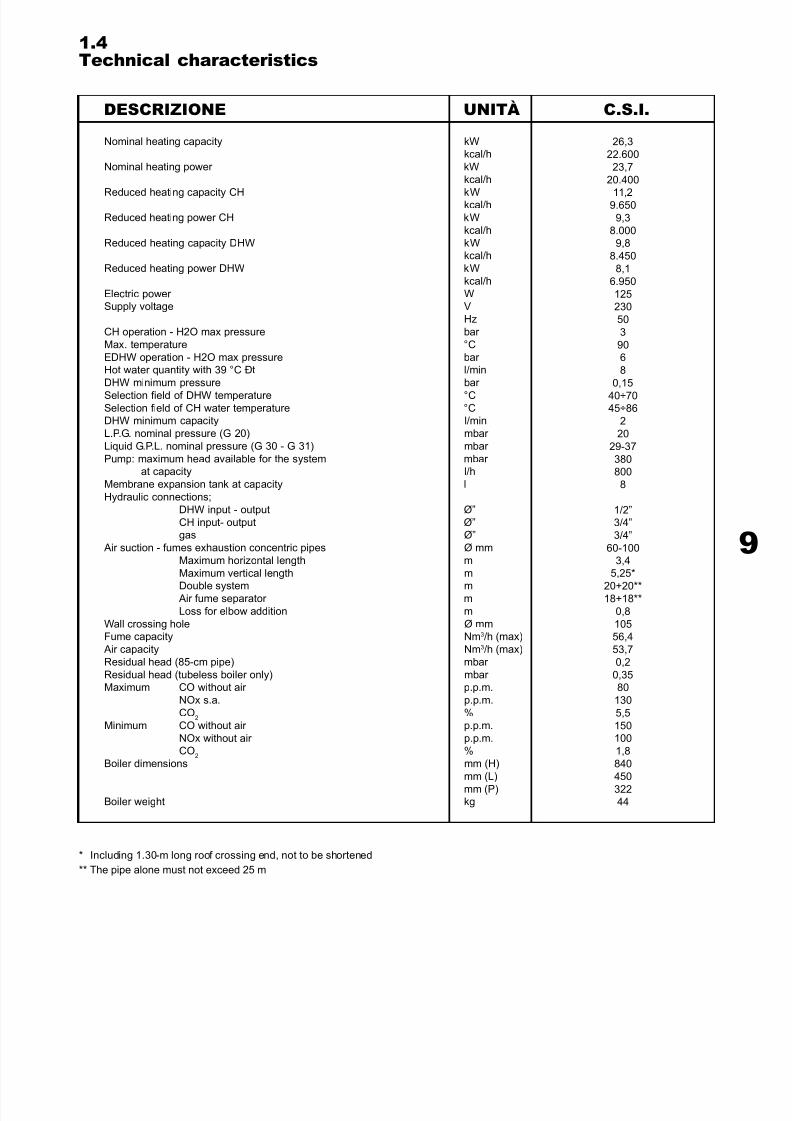
1.4Technical characteristics
DESCRIZIONE
* Including 1.30-m long roof crossing end, not to be shortened
** The pipe alone must not exceed 25 m
UNITÀ C.S.I.
7/27/2019 Manuale Mynute Csi_ing
http://slidepdf.com/reader/full/manuale-mynute-csiing 10/56
T E C H N I C A L M A
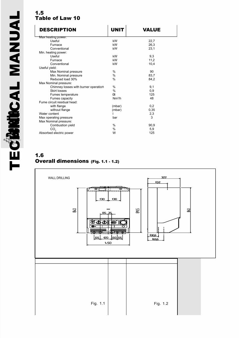
N U A L 1.5
Table of Law 10
Max heating power:
Useful kWFurnace kW
Conventional kW
Min. heating power:
Useful kW
Furnace kWConventional kW
Useful yield:
Max Nominal pressure %
Min. Nominal pressure %Reduced load 30% %
Max Nominal pressure:
Chimney losses with burner operation %
Skirt losses %Fumes temperature Ðt
Fumes capacity Nm3/h
Fume circuit residual head:
with flange (mbar)without flange (mbar)
Water content l
Max operating pressure bar Max Nominal pressure:
Combustion yield %CO
2%
Absorbed electric power W
22,7
26,323,1
9,3
11,210,4
90
83,784,2
9,1
0,9
12548
0,2
0,352,3
3
90,95,9
125
DESCRIPTION
1.6Overall dimensions (Fig. 1.1 - 1.2)
Fig. 1.1 Fig. 1.2
UNIT VALUE
WALL DRILLING
7/27/2019 Manuale Mynute Csi_ing
http://slidepdf.com/reader/full/manuale-mynute-csiing 11/56
11
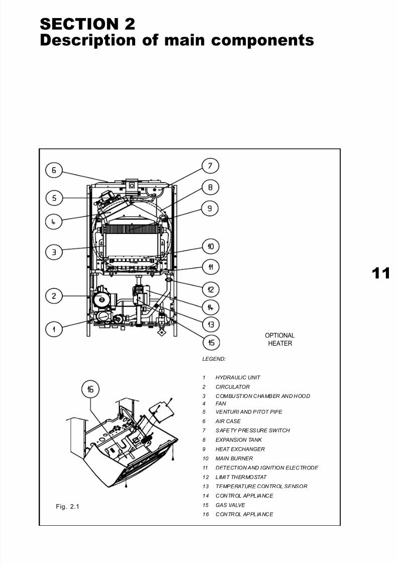
SECTION 2Description of main components
Fig. 2.1
LEGEND:
1 HYDRAULIC UNIT
2 CIRCULATOR
3 COMBUSTION CHAMBER AND HOOD4 FAN
5 VENTURI AND PITOT PIPE
6 AIR CASE
7 SAFETY PRESSURE SWITCH
8 EXPANSION TANK
9 HEAT EXCHANGER
10 MAIN BURNER
11 DETECTION AND IGNITION ELECTRODE
12 LIMIT THERMOSTAT
13 TEMPERATURE CONTROL SENSOR
14 CONTROL APPLIANCE
15 GAS VALVE
16 CONTROL APPLIANCE
OPTIONALHEATER

7/27/2019 Manuale Mynute Csi_ing
http://slidepdf.com/reader/full/manuale-mynute-csiing 12/56
T E C H N I C A L M A
N U A L 2.1
Primary heat exchanger (Fig. 2.2)
The primary heat exchanger consists of an
oval-section coil with two pipes, located inside
a laminar pack increasing its heat exchange
surface.
Considering heat exchange intensity,
turbulators are located inside pipes to preventboth local water boiling and fluid layering and
also to prevent that exchange surface is not
fully used.
Shape of laminar pack is strictly connected
to the above; its density (distance between
sheets) allows to improve exchange surface,
without affecting fumes velocity (remember
that fumes flow is perpendicular to
exchanger), thus limiting load losses which
would affect exchanger yield. The transfer of
heat generated by combustion is performed
by heat exchange between fumes and
primary fluid flowing in the coil.The exchanger is fully coated by a lead-tin
alloy protecting it against corrosion.
Fig. 2.2
2.2Combustion chamber (Fig. 2.3)
The combustion chamber consists of a
properly curved sheet structure so that
ceramic-fibre insulating slabs can be inserted,
in contact with the inner surface. This material
has an operating temperature of about
1200°C and a melting point of about 1700°C.
For this reason, it is not affected by direct
contact with burner flame; in common use, it
is only affected by wrong mechanicaloperations.
Fig. 2.3
2.3Main burner (Fig. 2.4)
It consists of a series of stainless steel drilled
ramps, joined and properly spaced. Gas from
the valve flows through nozzles, then through
burner Venturi pipes, where it is mixed with
primary air; then, it flows out of ramps through
several openings and is burned. Air taken into
combustion chamber is used as secondary
air. Primary air is automatically dispensed
following nozzle diameter and it is not
necessary to adjust it during installation. The
routine maintenance of burner only requires
routine cleaning of gas outputs (nozzles)
when dirty. When obstructing burner nozzle,
also partially, different types of impurities
(putty, Teflon, spider webs, etc.) can provoke
bad combustion, with long and smoky flame.
Fig. 2.4
7/27/2019 Manuale Mynute Csi_ing
http://slidepdf.com/reader/full/manuale-mynute-csiing 13/56
13
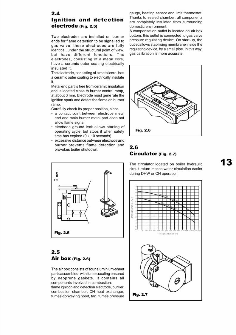
2.4Ignition and detectionelectrode (Fig. 2.5)
Two electrodes are installed on burner ends for flame detection to be signalled togas valve; these electrodes are fully
identical, under the structural point of view,but have di f ferent funct ions. The
electrodes, consisting of a metal core,have a ceramic outer coating electrically
insulated it.
The electrode, consisting of a metal core, has
a ceramic outer coating to electrically insulateit.
Metal end part is free from ceramic insulationand is located close to burner central ramp,at about 3 mm. Electrode must generate the
ignition spark and detect the flame on burner ramp.
Carefully check its proper position, since:• a contact point between electrode metal
end and main burner metal part does notallow flame signal
• electrode ground leak allows starting of
operating cycle, but stops it when safetytime has expired (9 ÷ 10 seconds)
• excessive distance between electrode andburner prevents flame detection andprovokes boiler shutdown.
Fig. 2.5
2.5Air box (Fig. 2.6)
The air box consists of four aluminium-sheet
parts assembled, with fumes sealing ensuredby neoprene gaskets. It contains all
components involved in combustion:flame ignition and detection electrode, burner,
combustion chamber, CH heat exchanger,fumes-conveying hood, fan, fumes pressure
gauge, heating sensor and limit thermostat.Thanks to sealed chamber, all componentsare completely insulated from surrounding
domestic environment. A compensation outlet is located on air box
bottom; this outlet is connected to gas valvepressure regulating device. On start-up, theoutlet allows stabilising membrane inside the
regulating device, by a small pipe. In this way,gas calibration is more accurate.
Fig. 2.6
2.6Circulator (Fig. 2.7)
The circulator located on boiler hydraulic
circuit return makes water circulation easier
during DHW or CH operation.
Fig. 2.7
7.0
6.5
6.0
5.5
5.0
4.5
4.0
3.5
3.0
2.5
2.0
1.5
1.0
0.5
0.00 100 200 300 400 500 600 700 800 900 1000 1100 1200 1300 1400 1500
R E S I D U A L H E A D ( m C . A . )
SYSTEM CAPACITY (l/h)
H I G H - H E A D C I R C U L A T O R
S E R I A L C I R C U L A T O R
7/27/2019 Manuale Mynute Csi_ing
http://slidepdf.com/reader/full/manuale-mynute-csiing 14/56
T E C H N I C A L M A
N U A L
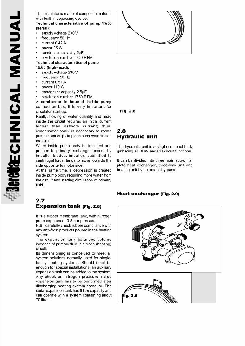
2.7Expansion tank (Fig. 2.8)
It is a rubber membrane tank, with nitrogen
pre-charge under 0.8-bar pressure.N.B.: carefully check rubber compliance with
any anti-frost products poured in the heatingsystem.
The expansion tank balances volume
increase of primary fluid in a close (heating)circuit.
Its dimensioning is conceived to meet allsystem solutions normally used for single-
family heating systems. Should it not beenough for special installations, an auxiliaryexpansion tank can be added to the system.
Any check on ni trogen pressure insideexpansion tank has to be performed after
discharging heating system pressure. Theserial expansion tank has 8 litre capacity andcan operate with a system containing about
70 litres.
Fig. 2.8
2.8Hydraulic unit
The hydraulic unit is a single compact bodygathering all DHW and CH circuit functions.
It can be divided into three main sub-units:plate heat exchanger, three-way unit and
heating unit by automatic by-pass.
Heat exchanger (Fig. 2.9)
Fig. 2.9
The circulator is made of composite material
with built-in degassing device.
Technical characteristics of pump 15/50
(serial):
• supply voltage 230 V
• frequency 50 Hz
• current 0.42 A
• power 95 W
• condenser capacity 2µF
• revolution number 1700 RPM
Technical characteristics of pump
15/60 (high-head):
• supply voltage 230 V
• frequency 50 Hz
• current 0.51 A
• power 110 W
• condenser capacity 2.5µF
• revolution number 1750 RPM
A condenser is ho used insi de pump
connection box; it is very important for
circulator start-up.
Really, flowing of water quantity and head
inside the circuit requires an initial currenthigher than network current; thus,
condensator spark is necessary to rotate
pump motor on pickup and push water inside
the circuit.
Water inside pump body is circulated and
pushed to primary exchanger access by
impeller blades; impeller, submitted to
centrifugal force, tends to move towards the
side opposite to motor side.
At the same time, a depression is created
inside pump body requiring more water from
the circuit and starting circulation of primaryfluid.
7/27/2019 Manuale Mynute Csi_ing
http://slidepdf.com/reader/full/manuale-mynute-csiing 15/56
15
1) Plate exchanger: it is braze welded,
consisting of a series of plates made of
stainless steel AISI 316, alternated with
copper plates. Each plate has beads (fluid
running channels) located in opposite
directions. Counter-current fluid flowing
makes heat exchange easier.
Contact points between two plates in
sequence are braze welded so that the whole
unit is involved in heat exchange
and a solid structure is obtained,able to resist to pressures up to
30 bars and temperatures about
180 °C. Duct system obtained in
this way allows fluid flowing (by
turbulent motion) ensuring an
optimal heat exchange.
Benefits of plate exchanger:
• limited dimensions, allowing,
with equal thermal flow, space
savings up to 90%, in some
cases, with respect to other solutions
• resistance to very high
pressures
• very low weight, al lowing
implementation of lighter hydraulic circuit
• higher breaking resistance in case of fluid
freezing, thanks to several inner welds.
2) Capacity limiting device: the capacity
limiting device reduces input water inflow to
secondary exchanger; it has a 8 l/min
calibration, thus it is white.
3) Check valve: located on primary water
input, it separates DHW exchanger from
primary circuit while heating. It consists of
a shutter and a 28-g pre-loaded spring.
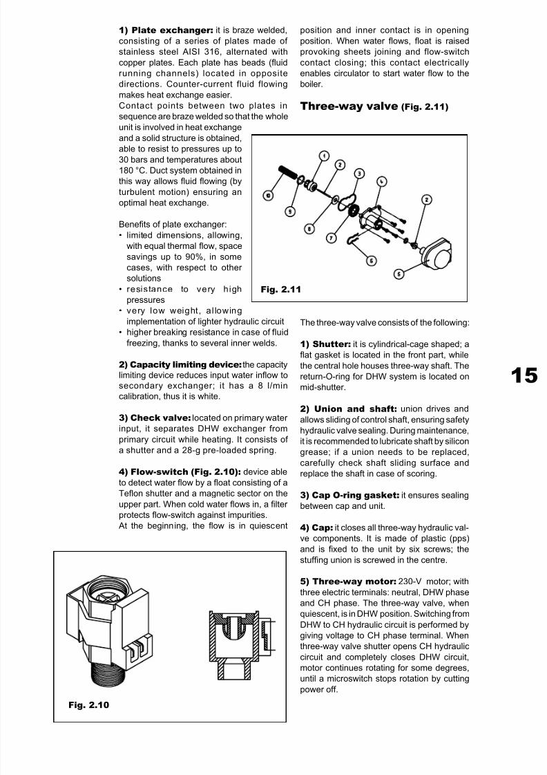
4) Flow-switch (Fig. 2.10): device able
to detect water flow by a float consisting of a
Teflon shutter and a magnetic sector on the
upper part. When cold water flows in, a filter
protects flow-switch against impurities.
At the beginning, the flow is in quiescent
Fig. 2.10
position and inner contact is in opening
position. When water flows, float is raised
provoking sheets joining and flow-switch
contact closing; this contact electrically
enables circulator to start water flow to the
boiler.
Three-way valve (Fig. 2.11)
Fig. 2.11
The three-way valve consists of the following:
1) Shutter: it is cylindrical-cage shaped; a
flat gasket is located in the front part, while
the central hole houses three-way shaft. The
return-O-ring for DHW system is located on
mid-shutter.
2) Union and shaft: union drives andallows sliding of control shaft, ensuring safety
hydraulic valve sealing. During maintenance,
it is recommended to lubricate shaft by silicon
grease; if a union needs to be replaced,
carefully check shaft sliding surface and
replace the shaft in case of scoring.
3) Cap O-ring gasket: it ensures sealing
between cap and unit.
4) Cap: it closes all three-way hydraulic val-
ve components. It is made of plastic (pps)
and is fixed to the unit by six screws; the
stuffing union is screwed in the centre.
5) Three-way motor: 230-V motor; with
three electric terminals: neutral, DHW phase
and CH phase. The three-way valve, when
quiescent, is in DHW position. Switching from
DHW to CH hydraulic circuit is performed by
giving voltage to CH phase terminal. When
three-way valve shutter opens CH hydraulic
circuit and completely closes DHW circuit,
motor continues rotating for some degrees,
until a microswitch stops rotation by cuttingpower off.
7/27/2019 Manuale Mynute Csi_ing
http://slidepdf.com/reader/full/manuale-mynute-csiing 16/56
T E C H N I C A L M A
N U A L
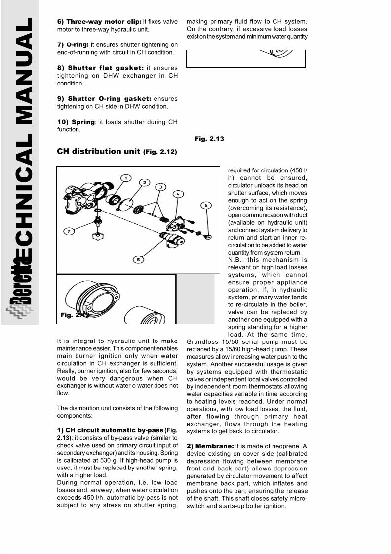
CH distribution unit (Fig. 2.12)
It is integral to hydraulic unit to make
maintenance easier. This component enablesmain burner ignition only when water circulation in CH exchanger is sufficient.
Really, burner ignition, also for few seconds,would be very dangerous when CH
exchanger is without water o water does notflow.
The distribution unit consists of the followingcomponents:
1) CH circuit automatic by-pass (Fig.
2.13): it consists of by-pass valve (similar tocheck valve used on primary circuit input of secondary exchanger) and its housing. Spring
is calibrated at 530 g. If high-head pump isused, it must be replaced by another spring,
with a higher load.
During normal operation, i.e. low loadlosses and, anyway, when water circulation
exceeds 450 l/h, automatic by-pass is notsubject to any stress on shutter spring,
Fig. 2.12
making primary fluid flow to CH system.On the contrary, if excessive load lossesexist on the system and minimum water quantity
required for circulation (450 l/h) cannot be ensured,
circulator unloads its head on
shutter surface, which movesenough to act on the spring
(overcoming its resistance),open communication with duct
(available on hydraulic unit)and connect system delivery to
return and start an inner re-circulation to be added to water quantity from system return.
N.B.: this mechanism isrelevant on high load losses
systems, which cannotensure proper appliance
operation. If, in hydraulicsystem, primary water tendsto re-circulate in the boiler,
valve can be replaced byanother one equipped with aspring standing for a higher
load. At the same time,Grundfoss 15/50 serial pump must be
replaced by a 15/60 high-head pump. Thesemeasures allow increasing water push to thesystem. Another successful usage is given
by systems equipped with thermostaticvalves or independent local valves controlled
by independent room thermostats allowingwater capacities variable in time according
to heating levels reached. Under normaloperations, with low load losses, the fluid,after f lowing through primary heat
exchanger, flows through the heatingsystems to get back to circulator.
2) Membrane: it is made of neoprene. Adevice existing on cover side (calibrated
depression flowing between membranefront and back part) allows depression
generated by circulator movement to affect
membrane back part, which inflates andpushes onto the pan, ensuring the release
of the shaft. This shaft closes safety micro-switch and starts-up boiler ignition.
Fig. 2.13
6) Three-way motor clip: it fixes valve
motor to three-way hydraulic unit.
7) O-ring: it ensures shutter tightening on
end-of-running with circuit in CH condition.
8) Shutter flat gasket: it ensures
tightening on DHW exchanger in CH
condition.
9) Shutter O-ring gasket: ensurestightening on CH side in DHW condition.
10) Spring: it loads shutter during CH
function.
7/27/2019 Manuale Mynute Csi_ing
http://slidepdf.com/reader/full/manuale-mynute-csiing 17/56
17
3) Pan with shaft and spring: a pan,located on membrane outer side, with controlshaft housing in its centre, allows to transfer
strength applied onto the membrane by water circulating inside primary circuit. This pan
develops on the whole surface in order toconstantly exploit strength applied andtransfer it to the shaft, which is driven by head
union screwed into the cap. To make shaftsliding easier, a spherical housing is located
in the pan centre and the shaft coupling endis a semi-sphere; in this way an articulation
is obtained, allowing, independently of mem-brane position, free sliding inside the union. A spring is located between cap and pan
making membrane positioning easier, whenquiescent, with boiler off (circulator stopped).
During maintenance, it is recommended tolubricate shaft with silicon grease and, if aunion needs to be replaced, to carefully check
shaft sliding surface and replace it in case of scoring.
4) Cover: it houses membrane tighteningside. Depression outlet is located inside it by
machining in the unit. The external part hasa threaded blind hole to fix safety micro-
switch.
5) Union: it drives and allows control shaftsliding, ensuring sealing of safety hydraulicvalve. Union is different from three-way val-
ve union, as it has a flat-head end.
6) Safety valve: it protects hydraulic circuiton heating side from any overpressure
provoked by fluid volume increase in thecircuit. The safety valve switches main burner off when steam produced obstructs or
excessively slows water flow. With referenceto standard concerning product indu-strialisation, safety valves used on appliances
with potentiality < 34.8 kW open at 3-bar pressure.
7) Filling cock: it connects DHW circuitwith CH circuit to load or top them up.
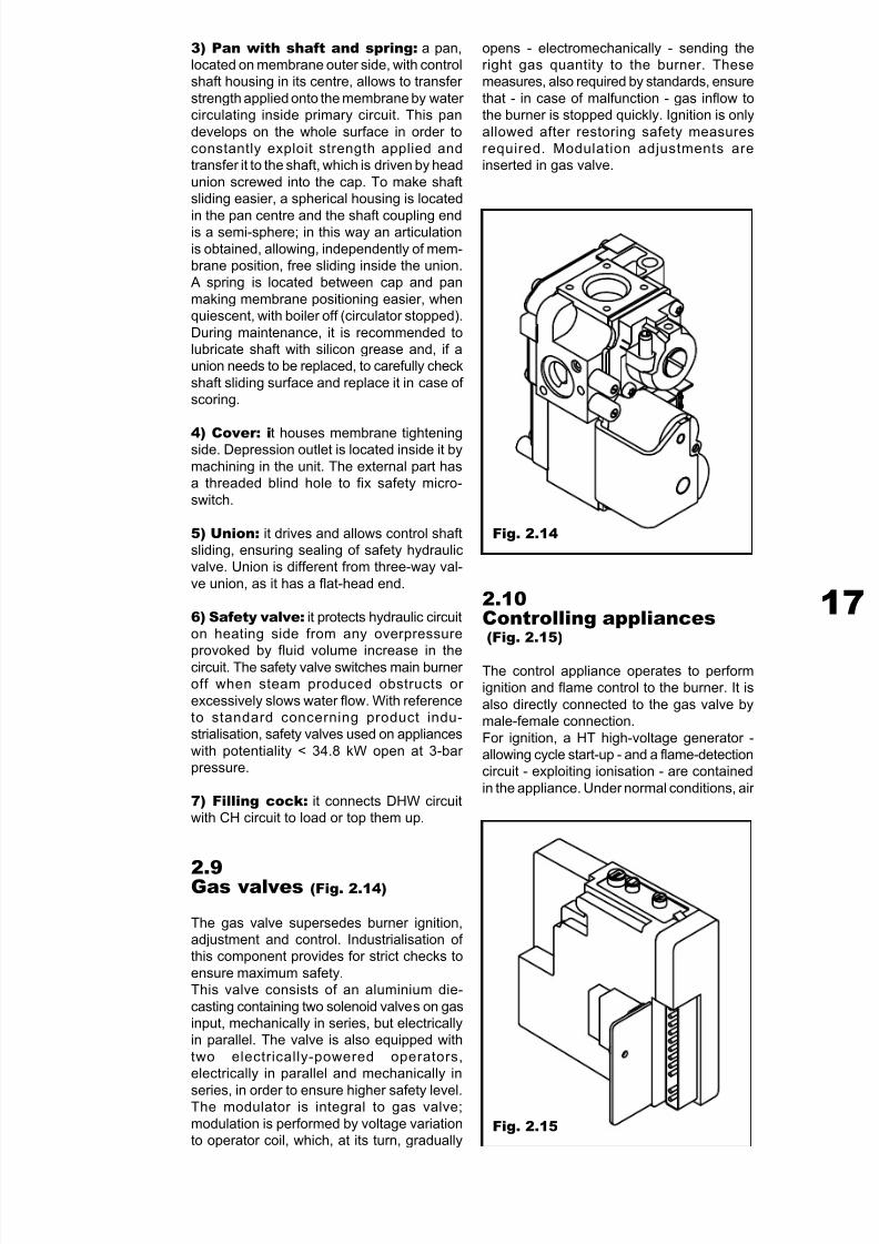
2.9Gas valves (Fig. 2.14)
The gas valve supersedes burner ignition,adjustment and control. Industrialisation of this component provides for strict checks to
ensure maximum safety.This valve consists of an aluminium die-
casting containing two solenoid valves on gasinput, mechanically in series, but electricallyin parallel. The valve is also equipped with
two electrically-powered operators,electrically in parallel and mechanically in
series, in order to ensure higher safety level.The modulator is integral to gas valve;
modulation is performed by voltage variationto operator coil, which, at its turn, gradually
Fig. 2.14
opens - electromechanically - sending theright gas quantity to the burner. Thesemeasures, also required by standards, ensure
that - in case of malfunction - gas inflow tothe burner is stopped quickly. Ignition is only
allowed after restoring safety measuresrequired. Modulation adjustments areinserted in gas valve.
2.10Controlling appliances(Fig. 2.15)
The control appliance operates to performignition and flame control to the burner. It is
also directly connected to the gas valve bymale-female connection.
For ignition, a HT high-voltage generator -allowing cycle start-up - and a flame-detectioncircuit - exploiting ionisation - are contained
in the appliance. Under normal conditions, air
Fig. 2.15
7/27/2019 Manuale Mynute Csi_ing
http://slidepdf.com/reader/full/manuale-mynute-csiing 18/56
T E C H N I C A L M A
N U A L
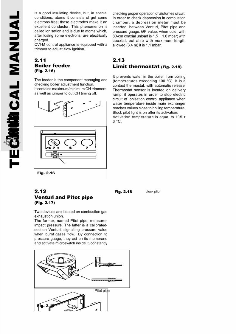
Fig. 2.16
2.12Venturi and Pitot pipe(Fig. 2.17)
Two devices are located on combustion gasexhaustion union.The former, named Pitot pipe, measures
impact pressure. The latter is a calibrated-section Venturi, signalling pressure value
when burnt gases flow. By connection topressure gauge, they act on its membraneand activate microswitch inside it, constantly
venturi
Pitot pipe
Fig. 2.17
2.13Limit thermostat (Fig. 2.18)
It prevents water in the boiler from boiling(temperatures exceeding 100 °C). It is a
contact thermostat, with automatic release.Thermostat sensor is located on delivery
ramp; it operates in order to stop electriccircuit of ionisation control appliance whenwater temperature inside main exchanger
reaches values close to boiling temperature.Block pilot light is on after its activation.
Activat ion temperature is equal to 105 ±3 °C.
Fig. 2.18
2.11Boiler feeder (Fig. 2.16)
The feeder is the component managing andchecking boiler adjustment function.It contains maximum/minimum CH trimmers,
as well as jumper to cut CH timing off.
block pilot
is a good insulating device, but, in special
conditions, atoms it consists of get someelectrons free; these electrodes make it an
excellent conductor. This phenomenon iscalled ionisation and is due to atoms which,after losing some electrons, are electrically
charged.CVI-M control appliance is equipped with a
trimmer to adjust slow ignition.
checking proper operation of air/fumes circuit.In order to check depression in combustionchamber, a depression meter must be
inserted, between Venturi, Pitot pipe and
pressure gauge. ÐP value, when cold, with
80-cm coaxial unload is 1.5 ÷ 1.6 mbar; with
coaxial, but also with maximum lengthallowed (3.4 m) it is 1.1 mbar.

7/27/2019 Manuale Mynute Csi_ing
http://slidepdf.com/reader/full/manuale-mynute-csiing 19/56
19
2.14Fan (Fig. 2.19)
Expressly conceived for this type of appliance, it is completely silent and highlyperforming. The steel impeller is dynamically
balanced and directly connected to drivingshaft by a galvanised steel hub and a
hexagonal-head screw.Routine checks of internal impeller cleaning andmotor external parts, together with normal
maintenance on the boiler, ensure long-termoperation. Replace in case of mechanical
noises due to dragging or contact with externalcase.
Technical characteristics of fan FIMEGR0005:
• power voltage 240 V.• frequency 50 Hz.
• motor revolution number when impeller isoff 2250 RPM
• motor revolution number when impeller is
on 1850 RPM.
Fig. 2.19
2.15Safety pressure gauge(Fig. 2.20)
It is used for boiler control and safety, as itensure fan and fume exhaustion properly
operation. It consists of a silicon-rubber membrane, inside a double case. In caseof malfunction, by pressure change, the
membrane act ivates a microswitch,interrupting gas delivery from gas valve
main shutter.Calibration:
ON (contacts C-NO) 0.75 - 1.05 mbar-increasing pressureOFF (contacts C-NC) 0,8 - 0,65 mbar-
decreasing pressureCalibration field used:
40°C to 88°C.Two-wire electric connection sends an electricsignal to the board; this signal allows checking
fan efficiency and state in any moment.
Fig. 2.20
7/27/2019 Manuale Mynute Csi_ing
http://slidepdf.com/reader/full/manuale-mynute-csiing 20/56
T E C H N I C A L M A
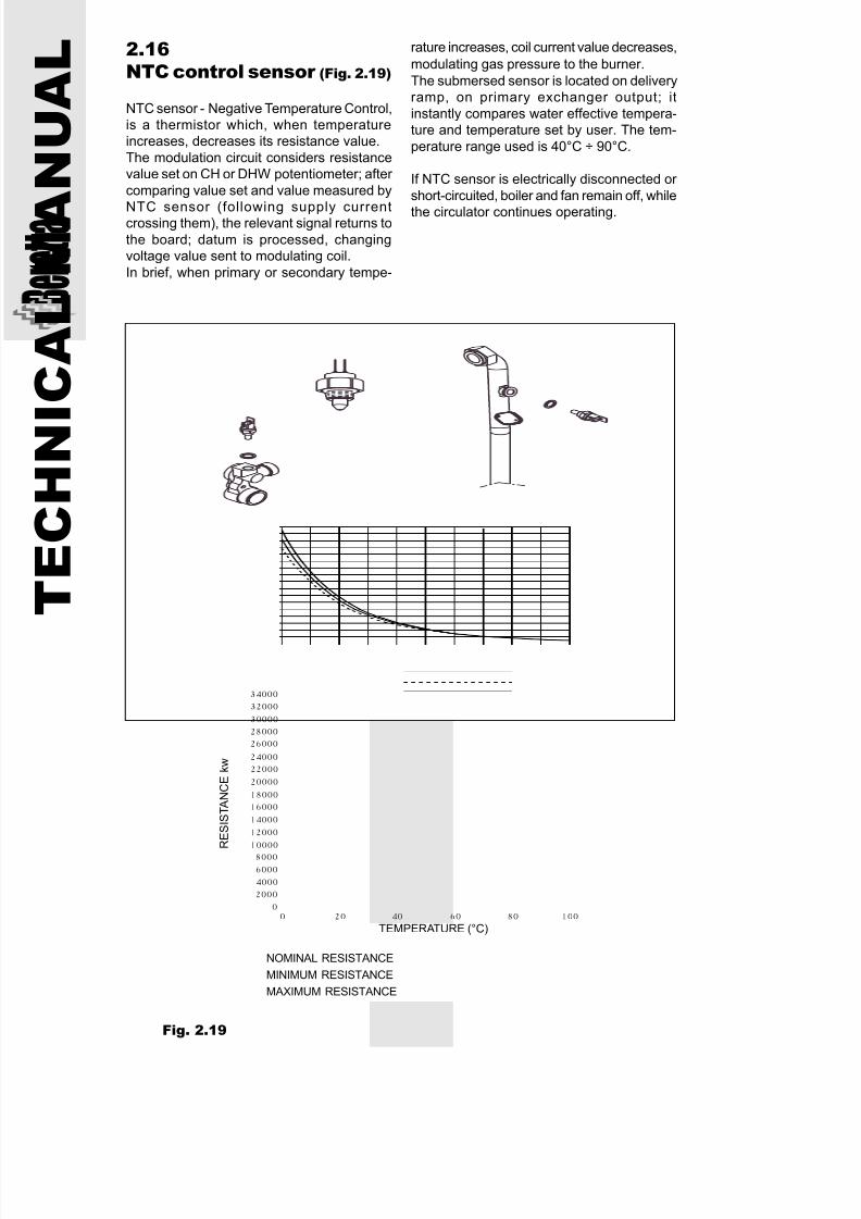
N U A L 2.16
NTC control sensor (Fig. 2.19)
NTC sensor - Negative Temperature Control,is a thermistor which, when temperatureincreases, decreases its resistance value.
The modulation circuit considers resistancevalue set on CH or DHW potentiometer; after
comparing value set and value measured by
NTC sensor (following supply currentcrossing them), the relevant signal returns to
the board; datum is processed, changingvoltage value sent to modulating coil.
In brief, when primary or secondary tempe-
rature increases, coil current value decreases,
modulating gas pressure to the burner.
The submersed sensor is located on deliveryramp, on primary exchanger output; it
instantly compares water effective tempera-ture and temperature set by user. The tem-
perature range used is 40°C ÷ 90°C.
If NTC sensor is electrically disconnected or
short-circuited, boiler and fan remain off, while
the circulator continues operating.
0 20 40 60 80 100
2000
4000
60008000
10000
12000
14000
16000
18000
20000
22000
24000
26000
28000
30000
32000
34000
0
RES ISTENZA NOMINALE
RES ISTENZA MINIMA
RES ISTENZA MAS S IMA
TEMP ERATUR A (°C)
Fig. 2.19
NOMINAL RESISTANCE
MINIMUM RESISTANCE
MAXIMUM RESISTANCE
R E S I S T A N C E
k w
TEMPERATURE (°C)
7/27/2019 Manuale Mynute Csi_ing
http://slidepdf.com/reader/full/manuale-mynute-csiing 21/56
21
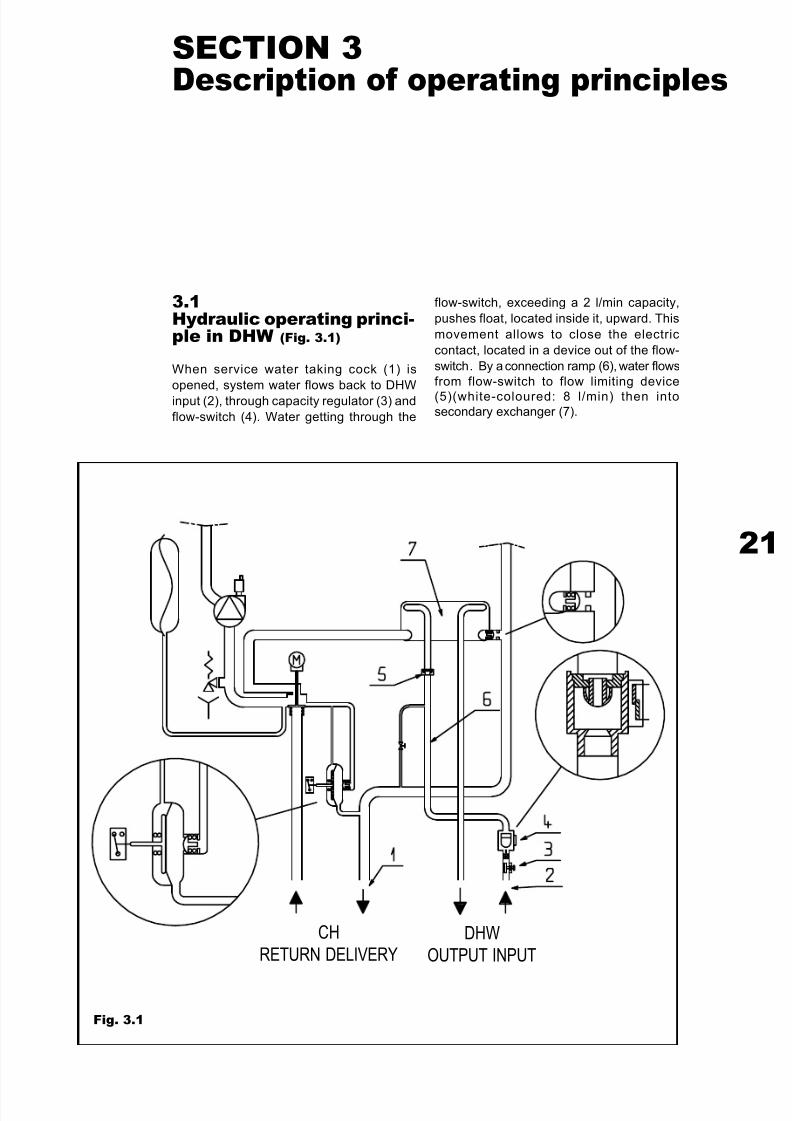
3.1Hydraulic operating princi-ple in DHW (Fig. 3.1)
When service water taking cock (1) is
opened, system water flows back to DHW
input (2), through capacity regulator (3) and
flow-switch (4). Water getting through the
SECTION 3Description of operating principles
Fig. 3.1
flow-switch, exceeding a 2 l/min capacity,
pushes float, located inside it, upward. This
movement allows to close the electric
contact, located in a device out of the flow-
switch. By a connection ramp (6), water flows
from flow-switch to flow limiting device
(5)(white-coloured: 8 l/min) then intosecondary exchanger (7).
CH
RETURN DELIVERY
DHW
OUTPUT INPUT
7/27/2019 Manuale Mynute Csi_ing
http://slidepdf.com/reader/full/manuale-mynute-csiing 22/56
T E C H N I C A L M A
N U A L 3.2
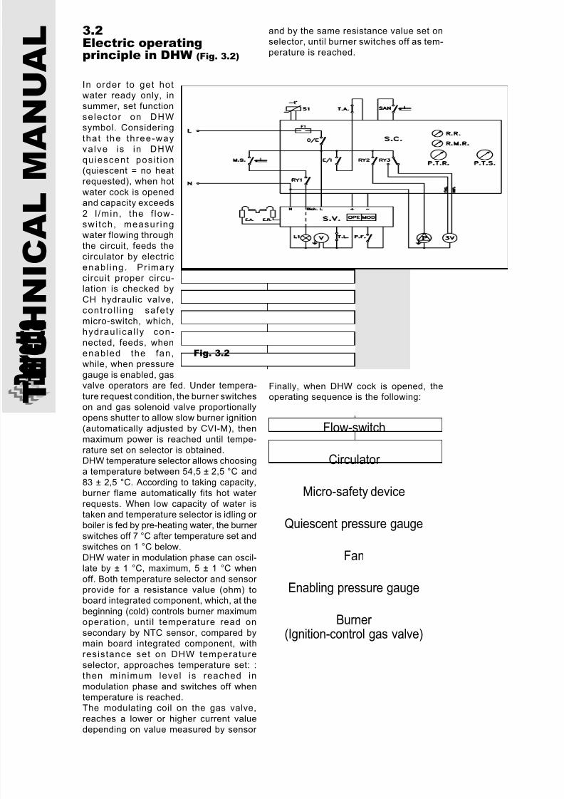
Electric operatingprinciple in DHW (Fig. 3.2)
In order to get hotwater ready only, insummer, set function
selector on DHWsymbol. Considering
that the three-wayvalve is in DHW
quiescent posi t ion(quiescent = no heatrequested), when hot
water cock is openedand capacity exceeds
2 l /min, the f low-swi tch, measur ingwater flowing through
the circuit, feeds thecirculator by electric
enabl ing. Pr imary
circuit proper circu-lation is checked by
CH hydraulic valve,contro l l ing safety
micro-switch, which,hydraul ica l ly con-
nected, feeds, whenenabled the fan,while, when pressure
gauge is enabled, gasvalve operators are fed. Under tempera-
ture request condition, the burner switcheson and gas solenoid valve proportionally
opens shutter to allow slow burner ignition(automatically adjusted by CVI-M), thenmaximum power is reached until tempe-
rature set on selector is obtained.DHW temperature selector allows choosinga temperature between 54,5 ± 2,5 °C and
83 ± 2,5 °C. According to taking capacity,burner flame automatically fits hot water
requests. When low capacity of water istaken and temperature selector is idling or boiler is fed by pre-heating water, the burner
switches off 7 °C after temperature set andswitches on 1 °C below.
DHW water in modulation phase can oscil-late by ± 1 °C, maximum, 5 ± 1 °C when
off. Both temperature selector and sensor provide for a resistance value (ohm) toboard integrated component, which, at the
beginning (cold) controls burner maximumoperation, unti l temperature read on
secondary by NTC sensor, compared bymain board integrated component, withresistance set on DHW temperature
selector, approaches temperature set: :then minimum level is reached in
modulation phase and switches off when
temperature is reached.The modulating coil on the gas valve,
reaches a lower or higher current valuedepending on value measured by sensor
Fig. 3.2
and by the same resistance value set onselector, until burner switches off as tem-perature is reached.
Flow-switch
Circulator
Micro-safety device
Quiescent pressure gauge
Fan
Enabling pressure gauge
Burner (Ignition-control gas valve)
Finally, when DHW cock is opened, theoperating sequence is the following:
7/27/2019 Manuale Mynute Csi_ing
http://slidepdf.com/reader/full/manuale-mynute-csiing 23/56
23
Fig. 3.3
CH
RETURN DELIVERY
DHW
OUTPUT INPUT
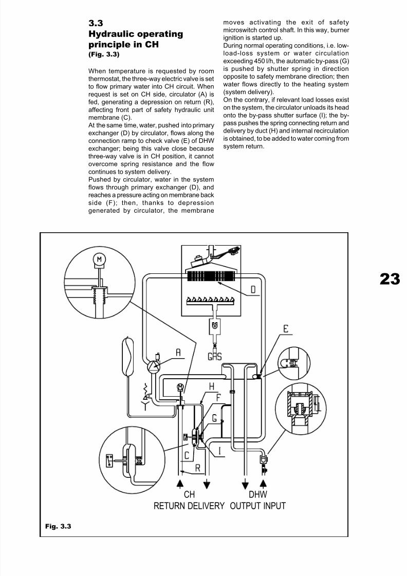
3.3Hydraulic operatingprinciple in CH(Fig. 3.3)
When temperature is requested by roomthermostat, the three-way electric valve is setto flow primary water into CH circuit. When
request is set on CH side, circulator (A) is
fed, generating a depression on return (R),affecting front part of safety hydraulic unitmembrane (C). At the same time, water, pushed into primary
exchanger (D) by circulator, flows along theconnection ramp to check valve (E) of DHW
exchanger; being this valve close becausethree-way valve is in CH position, it cannotovercome spring resistance and the flow
continues to system delivery.Pushed by circulator, water in the system
flows through primary exchanger (D), andreaches a pressure acting on membrane back
side (F); then, thanks to depressiongenerated by circulator, the membrane
moves activating the exit of safetymicroswitch control shaft. In this way, burner ignition is started up.
During normal operating conditions, i.e. low-load-loss system or water circulation
exceeding 450 l/h, the automatic by-pass (G)is pushed by shutter spring in directionopposite to safety membrane direction; then
water flows directly to the heating system(system delivery).
On the contrary, if relevant load losses existon the system, the circulator unloads its head
onto the by-pass shutter surface (I); the by-pass pushes the spring connecting return anddelivery by duct (H) and internal recirculation
is obtained, to be added to water coming fromsystem return.
7/27/2019 Manuale Mynute Csi_ing
http://slidepdf.com/reader/full/manuale-mynute-csiing 24/56
T E C H N I C A L M A
N U A L 3.4
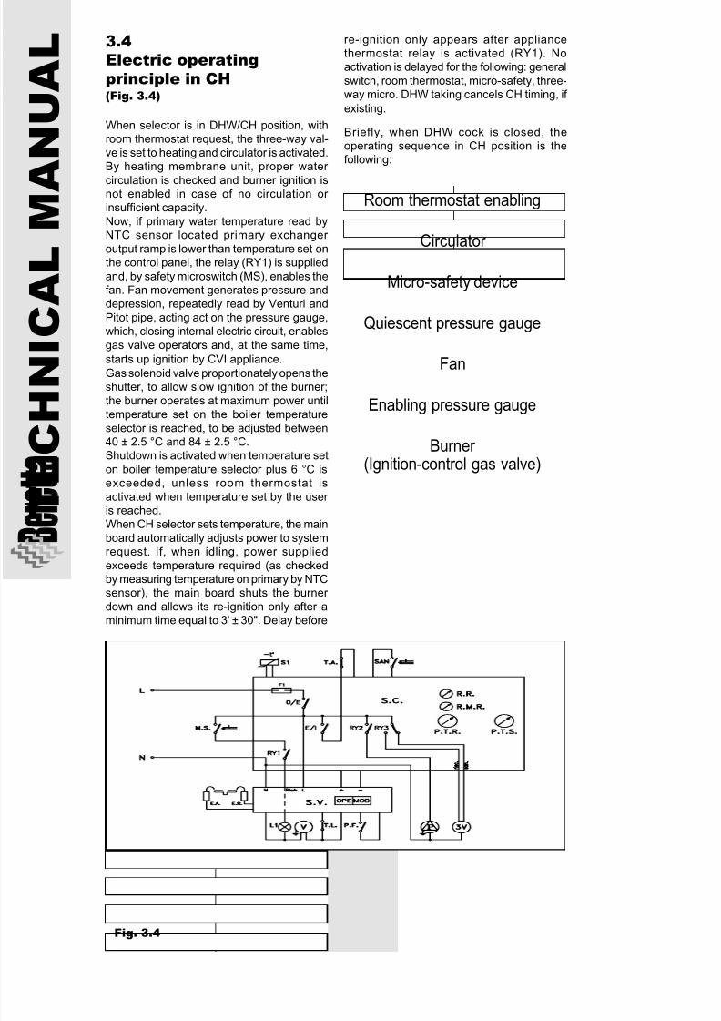
Electric operatingprinciple in CH(Fig. 3.4)
When selector is in DHW/CH position, withroom thermostat request, the three-way val-
ve is set to heating and circulator is activated.By heating membrane unit, proper water
circulation is checked and burner ignition isnot enabled in case of no circulation or insufficient capacity.
Now, if primary water temperature read byNTC sensor located primary exchanger
output ramp is lower than temperature set onthe control panel, the relay (RY1) is supplied
and, by safety microswitch (MS), enables thefan. Fan movement generates pressure anddepression, repeatedly read by Venturi and
Pitot pipe, acting act on the pressure gauge,which, closing internal electric circuit, enables
gas valve operators and, at the same time,
starts up ignition by CVI appliance.Gas solenoid valve proportionately opens theshutter, to allow slow ignition of the burner;
the burner operates at maximum power untiltemperature set on the boiler temperature
selector is reached, to be adjusted between40 ± 2.5 °C and 84 ± 2.5 °C.Shutdown is activated when temperature set
on boiler temperature selector plus 6 °C isexceeded, unless room thermostat is
activated when temperature set by the user is reached.When CH selector sets temperature, the main
board automatically adjusts power to systemrequest. If, when idling, power supplied
exceeds temperature required (as checkedby measuring temperature on primary by NTCsensor), the main board shuts the burner
down and allows its re-ignition only after aminimum time equal to 3' ± 30". Delay before
re-ignition only appears after appliancethermostat relay is activated (RY1). Noactivation is delayed for the following: general
switch, room thermostat, micro-safety, three-way micro. DHW taking cancels CH timing, if
existing.
Briefly, when DHW cock is closed, theoperating sequence in CH position is thefollowing:
Fig. 3.4
Room thermostat enabling
Circulator
Micro-safety device
Quiescent pressure gauge
Fan
Enabling pressure gauge
Burner (Ignition-control gas valve)

7/27/2019 Manuale Mynute Csi_ing
http://slidepdf.com/reader/full/manuale-mynute-csiing 25/56
25
4.1Equipment
When delivered, this appliance is packed in
a cardboard box, with wide holes for
transportation.
It contains: warranty, instruction manual, pre-
installation template, connection kit.
The fumes exhaustion kit is delivered in se-
parate packages (optional).
4.2Unpackage
Place the package on the floor, with writing
oriented upward. Open both sides of the box.
Do not use a knife.
SECTION 4Installation of appliance
Fig. 4.1
Remove the package by placing the frame
on a support plane. Remove two polystyrene
blocks above and under the boiler. Remove
the template from the polystyrene block which
protects the panels.
Take out the box containing the installation
kit in polystyrene lower side, as well as the
cover for boiler unions.
The installation kit (Fig. 4.1) contains:
• installation template, to show fastening
holes posi t ion of upper and lower
supports.
• connecting unions: 2 CH water elbows, 2
DHW elbows (only C.S.I.), 2 biconic
unions 3/4", 2 biconic unions 1/2", 1 gas
cock, 1 DHW cock, water and gas seals.
CH DELIVERY 3/4”
CH RETURN 3/4”
HOT WATER 1/2”
COLD WATER 1/2”
CH COCKS (UPON REQUEST)
7/27/2019 Manuale Mynute Csi_ing
http://slidepdf.com/reader/full/manuale-mynute-csiing 26/56
T E C H N I C A L M A
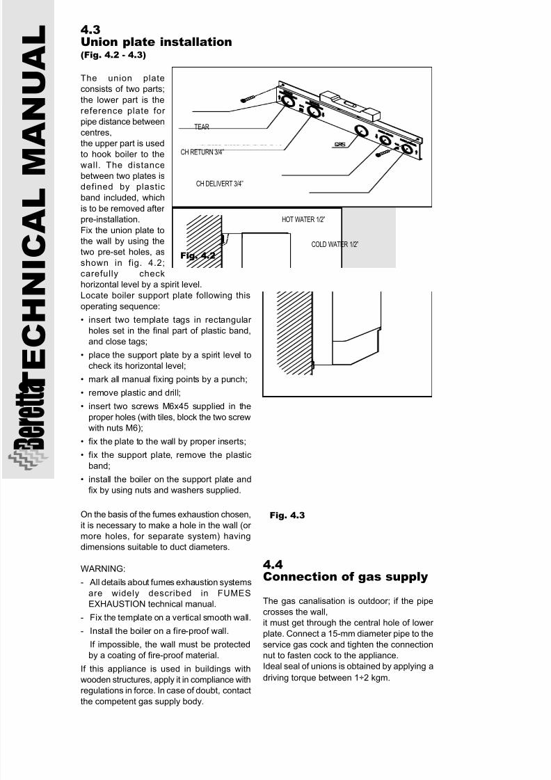
N U A L 4.3
Union plate installation(Fig. 4.2 - 4.3)
The union plate
consists of two parts;
the lower part is the
reference plate for
pipe distance between
centres,the upper part is used
to hook boiler to the
wall. The distance
between two plates is
defined by plastic
band included, which
is to be removed after
pre-installation.
Fix the union plate to
the wall by using the
two pre-set holes, as
shown in fig. 4.2;
carefully checkhorizontal level by a spirit level.
Locate boiler support plate following this
operating sequence:
• insert two template tags in rectangular
holes set in the final part of plastic band,
and close tags;
• place the support plate by a spirit level to
check its horizontal level;
• mark all manual fixing points by a punch;
• remove plastic and drill;
• insert two screws M6x45 supplied in theproper holes (with tiles, block the two screw
with nuts M6);
• fix the plate to the wall by proper inserts;
• fix the support plate, remove the plastic
band;
• install the boiler on the support plate and
fix by using nuts and washers supplied.
On the basis of the fumes exhaustion chosen,
it is necessary to make a hole in the wall (or
more holes, for separate system) having
dimensions suitable to duct diameters.
WARNING:
- All details about fumes exhaustion systems
are widely described in FUMES
EXHAUSTION technical manual.
- Fix the template on a vertical smooth wall.
- Install the boiler on a fire-proof wall.
If impossible, the wall must be protected
by a coating of fire-proof material.
If this appliance is used in buildings with
wooden structures, apply it in compliance withregulations in force. In case of doubt, contact
the competent gas supply body.
Fig. 4.2
Fig. 4.3
4.4Connection of gas supply
The gas canalisation is outdoor; if the pipe
crosses the wall,
it must get through the central hole of lower
plate. Connect a 15-mm diameter pipe to the
service gas cock and tighten the connection
nut to fasten cock to the appliance.
Ideal seal of unions is obtained by applying a
driving torque between 1÷2 kgm.
TEAR
CH RETURN 3/4”
CH DELIVERT 3/4”
HOT WATER 1/2”
COLD WATER 1/2”

7/27/2019 Manuale Mynute Csi_ing
http://slidepdf.com/reader/full/manuale-mynute-csiing 27/56
27
4.5CH delivery and returnconnection(Fig. 4.4)
Connect CH pipes to 3/4" unions, delivery on
the right side, return on the left side of the
system. Fix nuts at a driving torque between
1÷2 kgm.
4.6DHW delivery and returnconnection (Fig. 4.4)
Connect DHW pipes to 1/2" unions, connect
loading cock on cold water inlet (supplied).
Fix nuts at a driving torque between 1÷2
kgm.
Fig. 4.4
4.7Safety valve exhaustionconnection
The safety valve, regulated at 3 bars, is builtinto circulator suction union. It is
recommended to set, under the safety valve,
a water collection connection with its bleed,
in case of leak due to overpressure.
This valve is also equipped with 1/2" threaded
outlet to connect an exhaust pipe.
During connection, check exhaustion position
allows water drain, also hot water, without any
damage or problems. Anyway, this drain
system must be located in a clearly visible
position.
4.8System washing
Close CH system cocks, if existing, as well
as cold water inlet cock.
If no system cock exists, close water general
cock, take a water supply pipe and connect
to CH return; then, locate a drain duct on CH
delivery, start water flow and let it leak until
clean water starts leaking.
Empty the system by bleeding caps in the
lower parts, close caps and connect system
cocks or ramps.
Load CH system.
4.9CH system loading
The expansion tank (8 - Fig. 2.1) is loaded
before at 0.8-mbar pressure and is
dimensioned to meet water volume in CH
circuit accounting for about 70 l. System is tobe filled at about 1 bar.
Anyway, do not exhaust nitrogen from CH
expansion tank. System cold filling
is to be performed by its cock, checking on
thermal water gauge that pressure is kept at
about 1 bar.
4.10Outdoor installation
This boiler is not designed for outdoor installation without any cover, but this
installation can be performed if special
measures are adopted.
Do not definitely submit the boiler to
atmospheric agents, such as wind, humidity,
frost, which could seriously affect its
operation.
In case of improper installation, warranty is
automatically invalidated.
Anyway, for outdoor installations a cover
technical area must be set for protection.
NUT
NUT
COPPER PIPE
NIPPLE
PIPE FASTENER
WASHER
SYSTEM
7/27/2019 Manuale Mynute Csi_ing
http://slidepdf.com/reader/full/manuale-mynute-csiing 28/56
T E C H N I C A L M A
N U A L
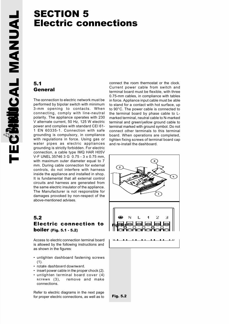
5.2Electric connection toboiler (Fig. 5.1 - 5.2)
Access to electric connection terminal board
is allowed by the following instructions andas shown in the figures:
• untighten dashboard fastening screws(1).
• rotate dashboard downward.• insert power cable in the proper chock (2).• unt ighten terminal board cover (4)
screws (3), remove and make
connections.
Refer to electric diagrams in the next pagefor proper electric connections, as well as to
connect the room thermostat or the clock.Current power cable from switch and
terminal board must be flexible, with three0.75-mm cables, in compliance with tablesin force. Appliance input cable must be able
to stand for a contact with hot surface, upto 90°C. The power cable is connected to
the terminal board by phase cable to L-marked terminal, neutral cable to N-marked
terminal and green/yellow ground cable toterminal marked with ground symbol. Do notconnect other terminals to this terminal
board. When operations are completed,tighten fixing screws of terminal board cap
and re-install the dashboard.
Fig. 5.1
Fig. 5.2
5.1General
The connection to electric network must be
performed by bipolar switch with minimum3-mm opening to contacts. When
connect ing, comply with l ine-neutralpolarity. The appliance operates with 230V alternate current, 50 Hz, 125 W electric
power and complies with standard CEI 61-1 EN 60335-1. Connection with safe
grounding is compulsory, in compliancewith regulations in force. Using gas or water pipes as electr ic appl iances
grounding is strictly forbidden. For electricconnection, a cable type IMQ HAR H05V
V-F UNEL 35746 3 G 0.75 - 3 x 0.75 mm,with maximum outer diameter equal to 7
mm. During cable connection for external
controls, do not interfere with harnessinside the appliance and installed in shop.
It is fundamental that all external controlcircuits and harness are generated from
the same electric insulator of the appliance.The Manufacturer is not responsible for damages provoked by non-respect of the
above-mentioned advises.
SECTION 5Electric connections
7/27/2019 Manuale Mynute Csi_ing
http://slidepdf.com/reader/full/manuale-mynute-csiing 29/56
29
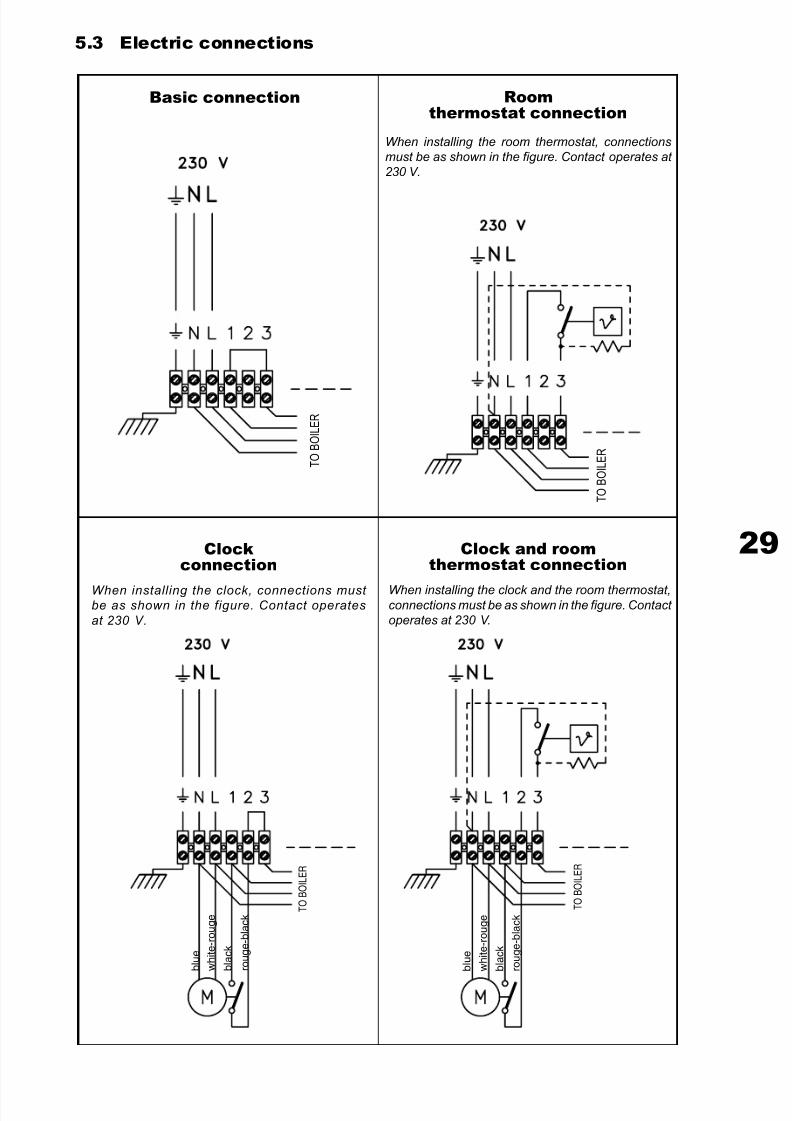
5.3 Electric connections
Basic connection
When installing the clock, connections must be as shown in the figure. Contact operates
at 230 V.
When installing the room thermostat, connections
must be as shown in the figure. Contact operates at
230 V.
When installing the clock and the room thermostat,connections must be as shown in the figure. Contact
operates at 230 V.
Roomthermostat connection
Clockconnection
Clock and roomthermostat connection
T O B
O I L E R
T O B
O I L E R
T O B
O I L E R
T O B
O I L E R
b l u e
w h i t e - r o u g e
b l a c k
r o u g e - b l a c k
b l u e
w h i t e - r o u g e
b l a c k
r o u g e - b l a c k
7/27/2019 Manuale Mynute Csi_ing
http://slidepdf.com/reader/full/manuale-mynute-csiing 30/56
T E C H N I C A L M A
N U A L
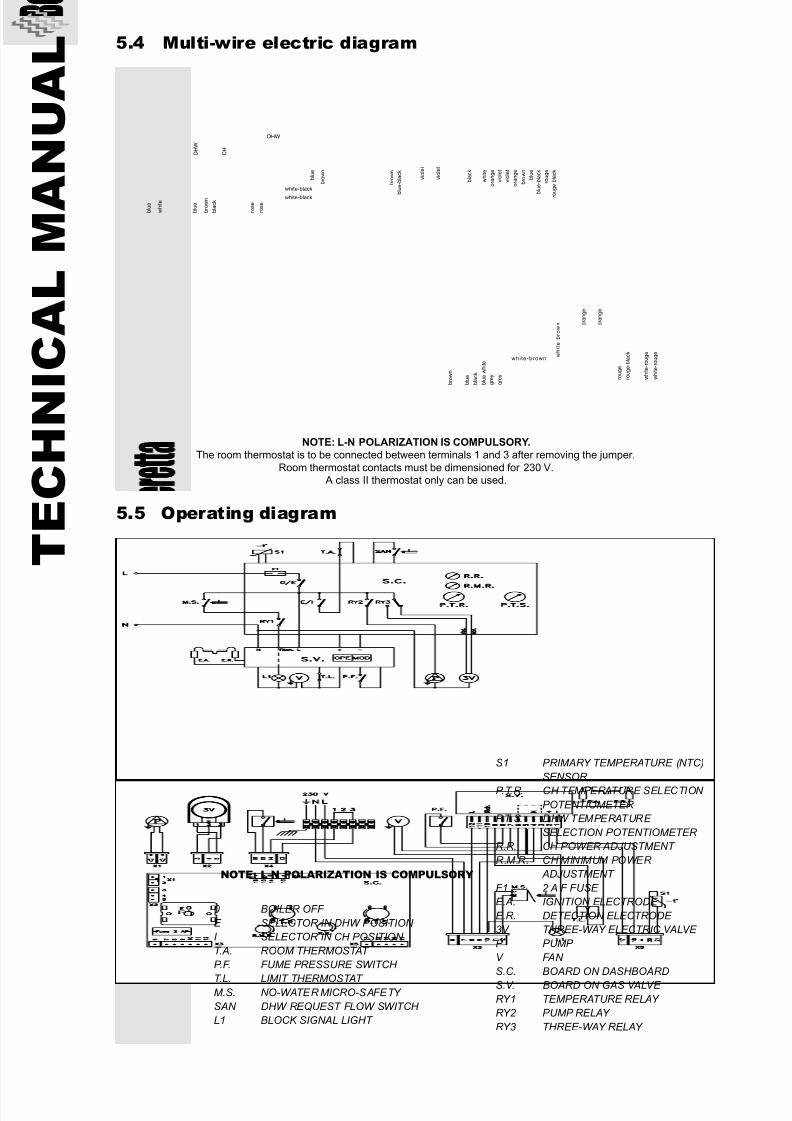
NOTE: L-N POLARIZATION IS COMPULSORY
0 BOILER OFF
E SELECTOR IN DHW POSITION
I SELECTOR IN CH POSITION
T.A. ROOM THERMOSTAT
P.F. FUME PRESSURE SWITCH
T.L. LIMIT THERMOSTAT M.S. NO-WATER MICRO-SAFETY
SAN DHW REQUEST FLOW SWITCH
L1 BLOCK SIGNAL LIGHT
S1 PRIMARY TEMPERATURE (NTC)
SENSOR
P.T.R. CH TEMPERATURE SELECTION
POTENTIOMETER
P.T.S. DHW TEMPERATURE
SELECTION POTENTIOMETER
R.R. CH POWER ADJUSTMENT
R.M.R. CH MINIMUM POWER
ADJUSTMENT
F1 2 A F FUSE
E.A. IGNITION ELECTRODE
E.R. DETECTION ELECTRODE
3V THREE-WAY ELECTRIC VALVE
P PUMP
V FAN
S.C. BOARD ON DASHBOARD
S.V. BOARD ON GAS VALVE
RY1 TEMPERATURE RELAY
RY2 PUMP RELAY
RY3 THREE-WAY RELAY
NOTE: L-N POLARIZATION IS COMPULSORY.
The room thermostat is to be connected between terminals 1 and 3 after removing the jumper.
Room thermostat contacts must be dimensioned for 230 V. A class II thermostat only can be used.
5.4 Multi-wire electric diagram
5.5 Operating diagram
b l u e
b r o w n
b l u e
w h i t e
b l u e
b r o w n
b l a c k
D H W
C H
white-black
white-black
DHW
b r o w n
b l u e - b l a c k
v i o l e t
v i o l e t
b l a c k
w h i t e
o r a n g e
v i o l e t
v i o l e t
o r a n g e
b r o w n
b l u e
b l u e - b l a c k
r o u g e
r o u g e - b l a c k
o r a n g e
o r a n g e
r o u g e
r o u g e - b l a c k
w h i t e - r o u g e
w h i t e - r o u g e w
h i t e - b r o w n
white-brown
b r o w n
b l u e
b l a c k
b l u e w h i t e
g r e y
g r e y
r o s e
r o s e
7/27/2019 Manuale Mynute Csi_ing
http://slidepdf.com/reader/full/manuale-mynute-csiing 31/56
31
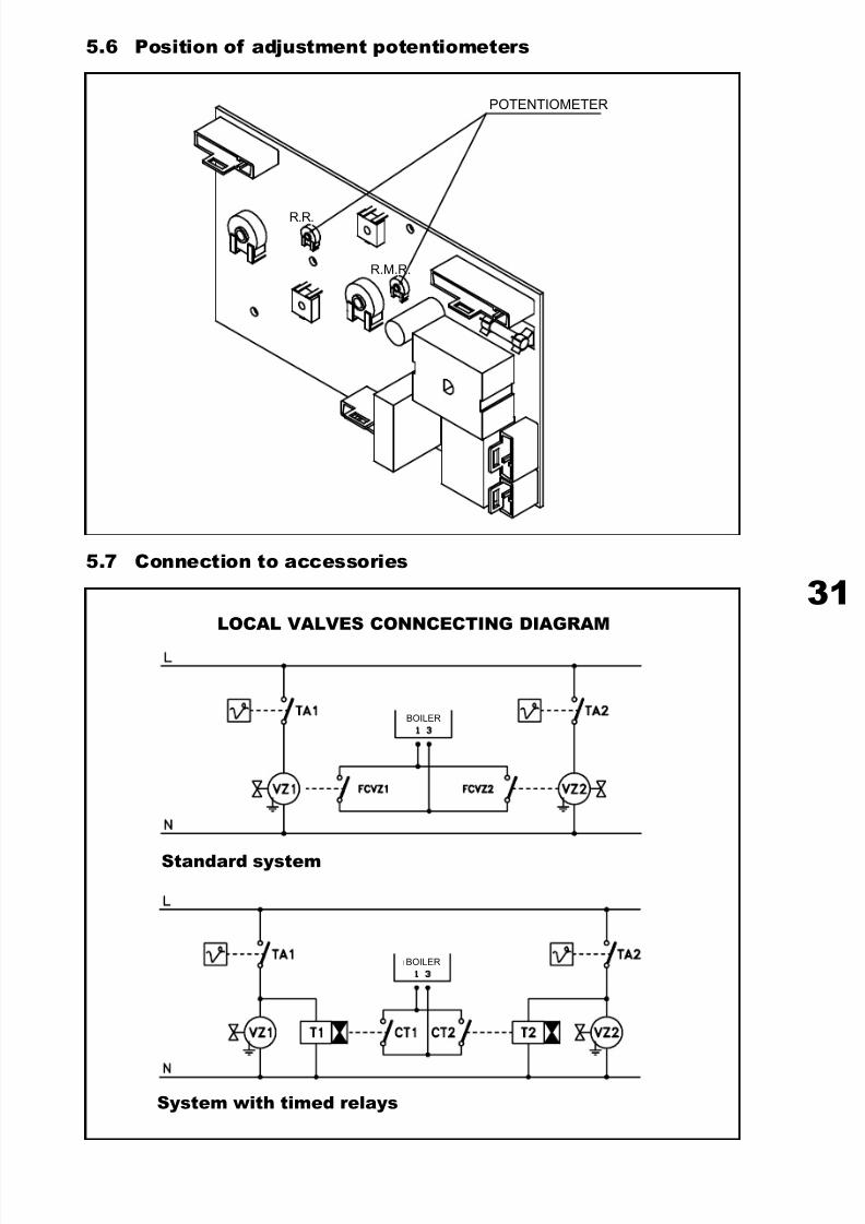
5.6 Position of adjustment potentiometers
R.R.
R.M.R.
5.7 Connection to accessories
LOCAL VALVES CONNCECTING DIAGRAM
Standard system
System with timed relays
POTENTIOMETER
BOILER
BOILER
7/27/2019 Manuale Mynute Csi_ing
http://slidepdf.com/reader/full/manuale-mynute-csiing 32/56
T E C H N I C A L M A
N U A L
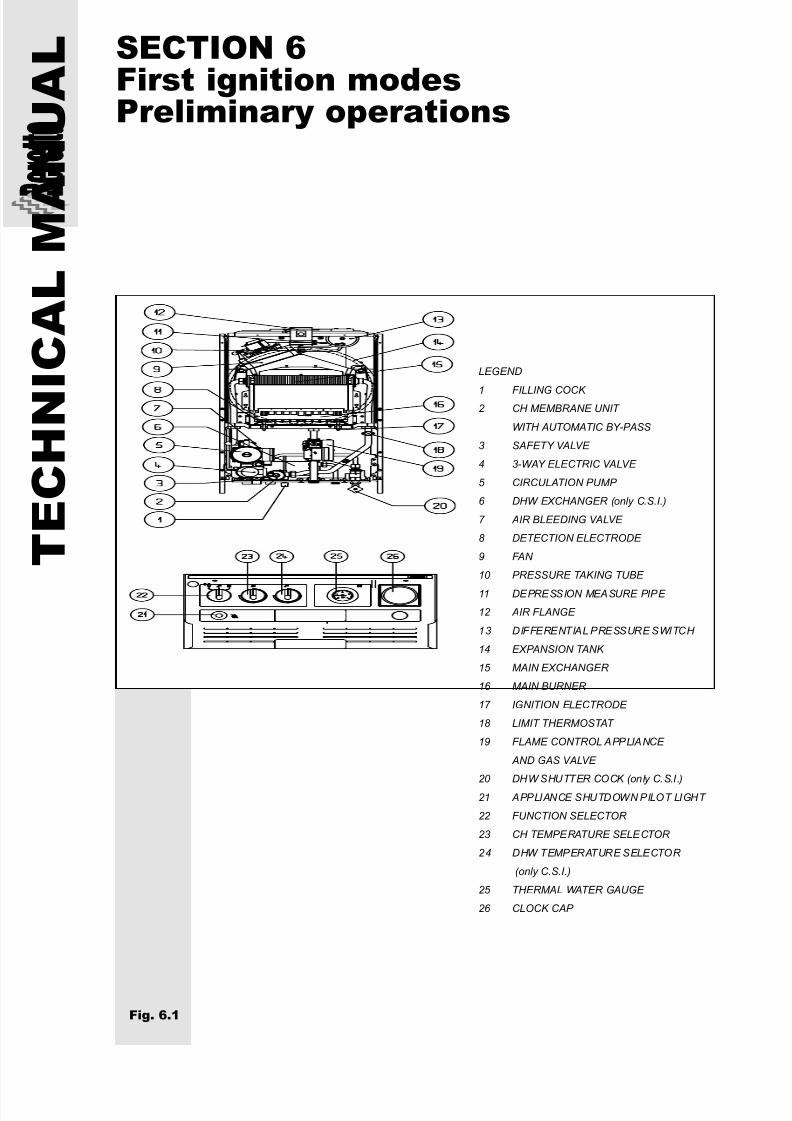
LEGEND
1 FILLING COCK 2 CH MEMBRANE UNIT
WITH AUTOMATIC BY-PASS
3 SAFETY VALVE
4 3-WAY ELECTRIC VALVE
5 CIRCULATION PUMP
6 DHW EXCHANGER (only C.S.I.)
7 AIR BLEEDING VALVE
8 DETECTION ELECTRODE
9 FAN
10 PRESSURE TAKING TUBE
11 DEPRESSION MEASURE PIPE
12 AIR FLANGE
13 DIFFERENTIAL PRESSURE SWITCH
14 EXPANSION TANK
15 MAIN EXCHANGER
16 MAIN BURNER
17 IGNITION ELECTRODE
18 LIMIT THERMOSTAT
19 FLAME CONTROL APPLIANCE
AND GAS VALVE
20 DHW SHUTTER COCK (only C.S.I.)
21 APPLIANCE SHUTDOWN PILOT LIGHT
22 FUNCTION SELECTOR
23 CH TEMPERATURE SELECTOR
24 DHW TEMPERATURE SELECTOR
(only C.S.I.)
25 THERMAL WATER GAUGE
26 CLOCK CAP
Fig. 6.1
SECTION 6First ignition modesPreliminary operations
7/27/2019 Manuale Mynute Csi_ing
http://slidepdf.com/reader/full/manuale-mynute-csiing 33/56
33
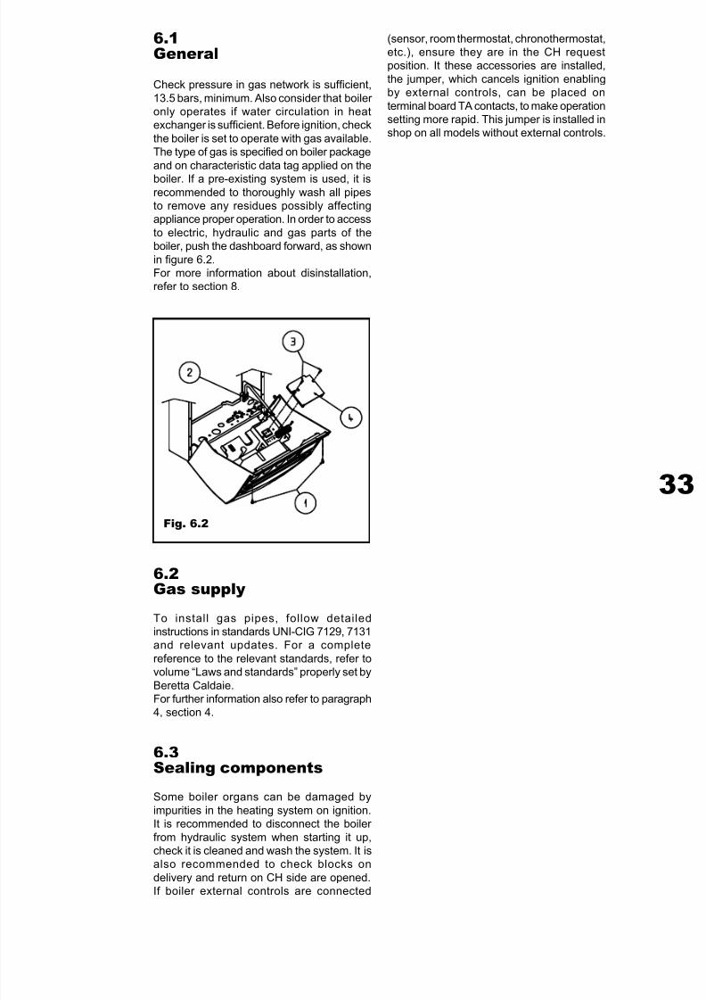
6.1General
Check pressure in gas network is sufficient,
13.5 bars, minimum. Also consider that boiler only operates if water circulation in heatexchanger is sufficient. Before ignition, check
the boiler is set to operate with gas available.The type of gas is specified on boiler package
and on characteristic data tag applied on the
boiler. If a pre-existing system is used, it isrecommended to thoroughly wash all pipesto remove any residues possibly affectingappliance proper operation. In order to access
to electric, hydraulic and gas parts of theboiler, push the dashboard forward, as shown
in figure 6.2.For more information about disinstallation,refer to section 8.
6.2Gas supply
To install gas pipes, follow detailedinstructions in standards UNI-CIG 7129, 7131and relevant updates. For a complete
reference to the relevant standards, refer tovolume “Laws and standards” properly set by
Beretta Caldaie.
For further information also refer to paragraph4, section 4.
6.3Sealing components
Some boiler organs can be damaged by
impurities in the heating system on ignition.It is recommended to disconnect the boiler
from hydraulic system when starting it up,check it is cleaned and wash the system. It isalso recommended to check blocks on
delivery and return on CH side are opened.If boiler external controls are connected
Fig. 6.2
(sensor, room thermostat, chronothermostat,etc.), ensure they are in the CH requestposition. It these accessories are installed,
the jumper, which cancels ignition enablingby external controls, can be placed on
terminal board TA contacts, to make operationsetting more rapid. This jumper is installed inshop on all models without external controls.
7/27/2019 Manuale Mynute Csi_ing
http://slidepdf.com/reader/full/manuale-mynute-csiing 34/56
T E C H N I C A L M A
N U A L
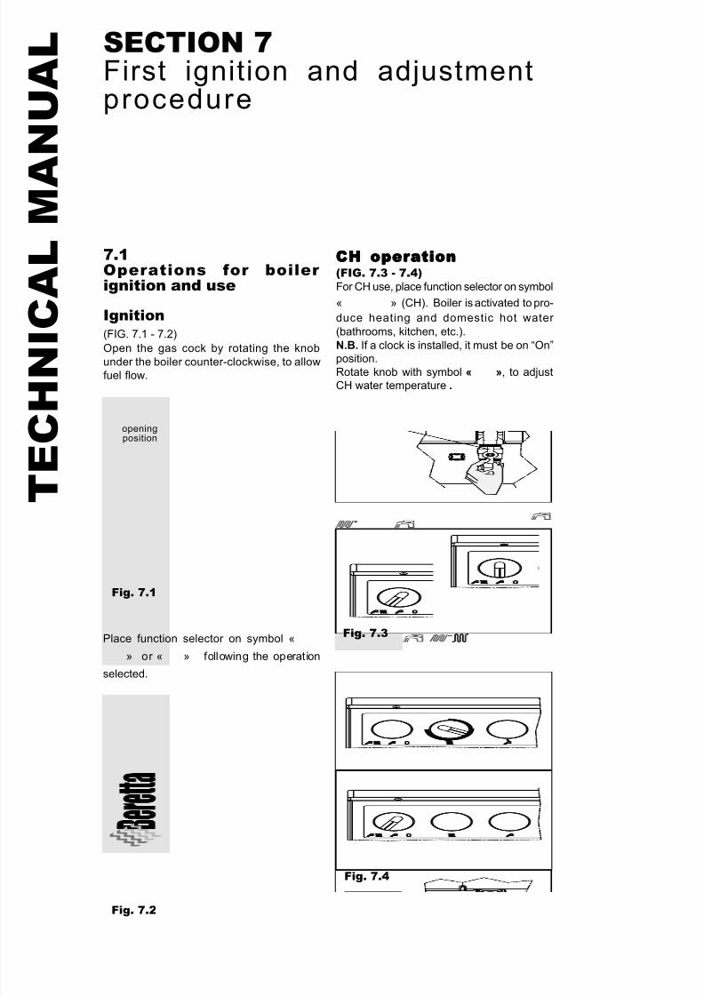
7.1Operations for boiler ignition and use
Ignition(FIG. 7.1 - 7.2)
Open the gas cock by rotating the knobunder the boiler counter-clockwise, to allow
fuel flow.
SECTION 7First ignition and adjustmentprocedure
Fig. 7.1
Place function selector on symbol «
» or « » following the operation
selected.
Fig. 7.2
CH operationCH operationCH operationCH operationCH operation(FIG. 7.3 - 7.4)For CH use, place function selector on symbol
« » (CH). Boiler is activated to pro-
duce heating and domestic hot water
(bathrooms, kitchen, etc.).
N.B. If a clock is installed, it must be on “On”position.
Rotate knob with symbol « », to adjustCH water temperature .
Fig. 7.3
Fig. 7.4
openingposition
7/27/2019 Manuale Mynute Csi_ing
http://slidepdf.com/reader/full/manuale-mynute-csiing 35/56
35
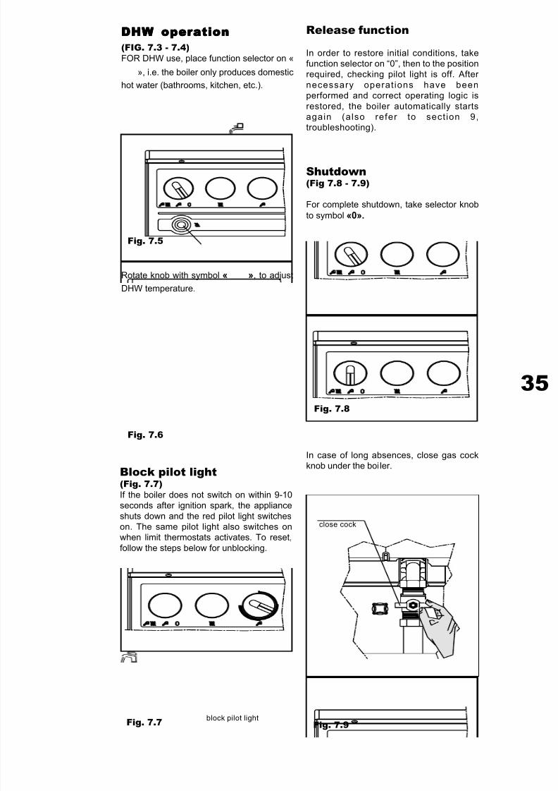
DHW operationDHW operationDHW operationDHW operationDHW operation(FIG. 7.3 - 7.4)FOR DHW use, place function selector on «
», i.e. the boiler only produces domestic
hot water (bathrooms, kitchen, etc.).
Fig. 7.5
Rotate knob with symbol « », to adjustDHW temperature.
Fig. 7.6
Block pilot light(Fig. 7.7)If the boiler does not switch on within 9-10seconds after ignition spark, the appliance
shuts down and the red pilot light switcheson. The same pilot light also switches onwhen limit thermostats activates. To reset,
follow the steps below for unblocking.
Release function
In order to restore initial conditions, takefunction selector on “0”, then to the positionrequired, checking pilot light is off. After
necessary operat ions have beenperformed and correct operating logic is
restored, the boiler automatically startsagain (also refer to sect ion 9,troubleshooting).
Shutdown(Fig 7.8 - 7.9)
For complete shutdown, take selector knob
to symbol «0».
Fig. 7.8
In case of long absences, close gas cockknob under the boiler.
Fig. 7.9Fig. 7.7 block pilot light
close cock
7/27/2019 Manuale Mynute Csi_ing
http://slidepdf.com/reader/full/manuale-mynute-csiing 36/56
T E C H N I C A L M A
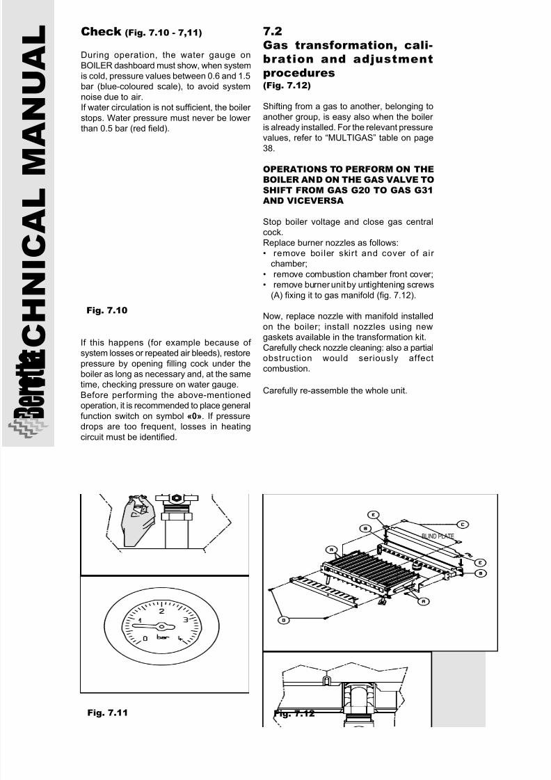
N U A L Check (Fig. 7.10 - 7,11)
During operation, the water gauge on
BOILER dashboard must show, when systemis cold, pressure values between 0.6 and 1.5bar (blue-coloured scale), to avoid system
noise due to air.If water circulation is not sufficient, the boiler
stops. Water pressure must never be lower than 0.5 bar (red field).
Fig. 7.10
Fig. 7.11
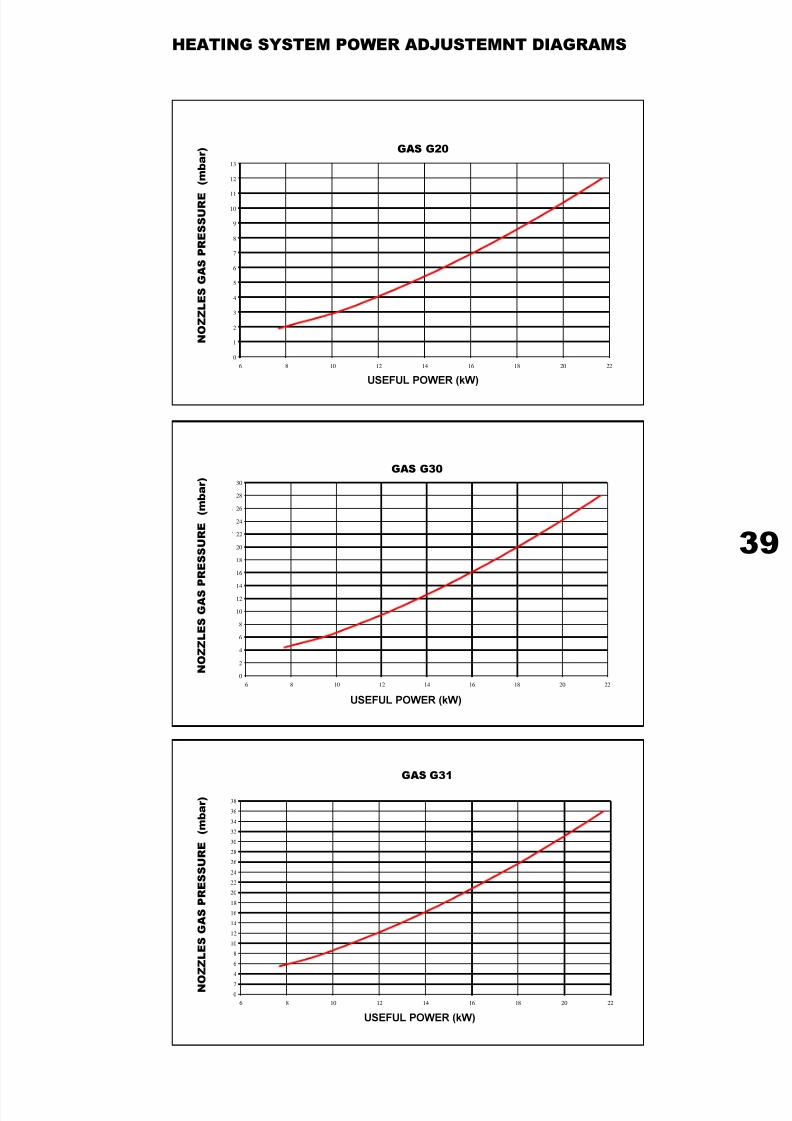
7.2Gas transformation, cali-bration and adjustmentprocedures(Fig. 7.12)
Shifting from a gas to another, belonging to
another group, is easy also when the boiler is already installed. For the relevant pressure
values, refer to “MULTIGAS” table on page38.
OPERATIONS TO PERFORM ON THEBOILER AND ON THE GAS VALVE TOSHIFT FROM GAS G20 TO GAS G31AND VICEVERSA
Stop boiler voltage and close gas centralcock.
Replace burner nozzles as follows:• remove boiler skirt and cover of air
chamber;
• remove combustion chamber front cover;• remove burner unit by untightening screws
(A) fixing it to gas manifold (fig. 7.12).
Now, replace nozzle with manifold installed
on the boiler; install nozzles using newgaskets available in the transformation kit.
Carefully check nozzle cleaning: also a partialobstruction would seriously affectcombustion.
Carefully re-assemble the whole unit.
Fig. 7.12
If this happens (for example because of system losses or repeated air bleeds), restore
pressure by opening filling cock under theboiler as long as necessary and, at the sametime, checking pressure on water gauge.
Before performing the above-mentioned
operation, it is recommended to place generalfunction switch on symbol «0». If pressuredrops are too frequent, losses in heating
circuit must be identified.
BLIND PLATE
7/27/2019 Manuale Mynute Csi_ing
http://slidepdf.com/reader/full/manuale-mynute-csiing 37/56
37
If shifting is to LPG, remove propagationdeflector on burner unit. Refer to fig. 6.19 and
act as follows:
a) Gas propagation front grid:• place grid on the burner and fasten by
screws (D) available;• insert plates (C) in grid slots, in
correspondence with ignition and
detection electrodes;
• re-install the burner and tighten four screws (A).
b) Air protection rear grid:
• untighten manifold upper screws (B);• insert grid between manifold and air
case;• rotate grid by 90° and locate so that slots
(E) are inserted between heads of screws (B) and manifold;
• tighten screws (B).
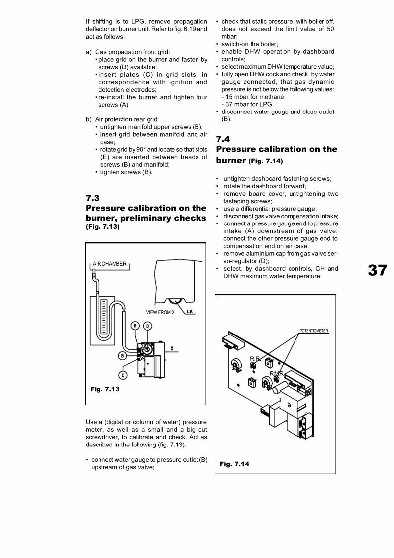
7.3Pressure calibration on theburner, preliminary checks(Fig. 7.13)
Fig. 7.13
Use a (digital or column of water) pressure
meter, as well as a small and a big cutscrewdriver, to calibrate and check. Act as
described in the following (fig. 7.13).
• connect water gauge to pressure outlet (B)upstream of gas valve;
• check that static pressure, with boiler off,does not exceed the limit value of 50mbar;
• switch-on the boiler;• enable DHW operation by dashboard
controls;• select maximum DHW temperature value;• fully open DHW cock and check, by water
gauge connected, that gas dynamicpressure is not below the following values:
- 15 mbar for methane- 37 mbar for LPG
• disconnect water gauge and close outlet(B).
7.4Pressure calibration on theburner (Fig. 7.14)
• untighten dashboard fastening screws;• rotate the dashboard forward;
• remove board cover, untightening twofastening screws;
• use a differential pressure gauge;• disconnect gas valve compensation intake;• connect a pressure gauge end to pressure
intake (A) downstream of gas valve;connect the other pressure gauge end to
compensation end on air case;• remove aluminium cap from gas valve ser-
vo-regulator (D);
• select, by dashboard controls, CH andDHW maximum water temperature.
Fig. 7.14
R.R.
R.M.R.
AIR CHAMBER
POTENTIOMETER
VIEW FROM X
7/27/2019 Manuale Mynute Csi_ing
http://slidepdf.com/reader/full/manuale-mynute-csiing 38/56
T E C H N I C A L M A
N U A L
Liquid gas
PARAMETERSpropane
(G 31)butane(G 30)
Methane(G 20)
Lower Wobbe index
(at 15°C-1013 mbar)
Supply nominal pressure
mbar (mm H2O)
Supply minimum pressure
mbar (mm H2O)
Main burner:
10 nozzles Ø mm.
CH maximum gas capacity m3/h
kg/h
DHW maximum gas capacity m3/h
kg/h
CH minimum gas capacity m3/h
kg/h
DHW minimum gas capacity m3/h
kg/h
Slow ignition calibration pressure mbar (mm C.A.)
Maximum pressure downstream CH valve mbar (mm C.A.)
Maximum pressure downstream DHW valve mbar (mm C.A.)
Minimum pressure downstream CH valve mbar (mm C.A.)
Minimum pressure downstream DHW valve mbar (mm C.A.)
80,90
29 (295,7)
0,77
2,19
2,19
0,93
0,81
16,7 (170)
28,0 (286)
28,0 (286)
5,0 (51)
3,8 (39)
45,70
20 (203,9)
13,5 (137,7)
1,35
2,78
2,78
1187
1,04
4,0 (41)
10,1 (103)
10,1 (103)
1,85 (19)
1,45 (15)
70,90
37 (377,3)
0,77
2,15
2,15
0,92
0,80
16,7 (170)
36,0 (367)
36,0 (367)
6,5 (66)
5,1 (52)
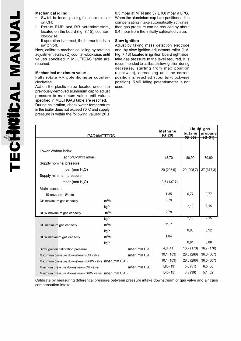
Calibrate by measuring differential pressure between pressure intake downstream of gas valve and air case
compensation intake.
Mechanical idling
• Switch boiler on, placing function selector on CH;
• Rotate RMR and RR potentiometers,located on the board (fig. 7.15), counter-
clockwise.If operation is correct, the burner tends toswitch off.
Now, calibrate mechanical idling by rotatingadjustment screw (C) counter-clockwise, until
values specified in MULTIGAS table arereached.
Mechanical maximum value
Fully rotate RR potentiometer counter-
clockwise. Act on the plastic screw located under the
previously-removed aluminium cap to adjustpressure to maximum value until valuesspecified in MULTIGAS table are reached.
During calibration, check water temperaturein the boiler does not exceed 70°C and supply
pressure is within the following values: 20 ±
0.3 mbar at MTN and 37 ± 0.8 mbar a LPG.When the aluminium cap is re-positioned, thecompensating intake automatically activates;
then gas pressure can be reduced by about0.4 mbar from the initially calibrated value.
Slow ignition
Adjust by taking mass detection electrode
and, by slow ignition adjustment roller (L.A.Fig. 7.13) located in ignition board right side,
take gas pressure to the level required. It isrecommended to calibrate slow ignition during
decrease, starting from max position(clockwise), decreasing until the correctposition is reached (counter-clockwise
position). RMR idling potentiometer is notused.
7/27/2019 Manuale Mynute Csi_ing
http://slidepdf.com/reader/full/manuale-mynute-csiing 39/56
39
HEATING SYSTEM POWER ADJUSTEMNT DIAGRAMS
0
1
2
3
4
5
6
7
8
9
10
11
12
13
6 8 10 12 14 16 18 20 22
0
2
4
6
8
10
12
14
16
18
20
22
24
26
28
30
6 8 10 12 14 16 18 20 22
Ã
Ã
Ã
0
2
4
6
8
10
12
14
16
18
20
22
24
26
28
30
32
34
36
38
6 8 10 12 14 16 18 20 22
N O Z Z L E S G A S P R E S S U R E
( m b a r )
N O Z Z L E S G A S
P R E S S U R E
( m b a r )
N O
Z Z L E S G A S P R E S S U R E
( m b a r )
GAS G20
USEFUL POWER (kW)
GAS G30
USEFUL POWER (kW)
GAS G31
USEFUL POWER (kW)
7/27/2019 Manuale Mynute Csi_ing
http://slidepdf.com/reader/full/manuale-mynute-csiing 40/56
T E C H N I C A L M A
N U A L
8.1General checks
This boiler is to be delivered to the user only
after the first starting and the relevant checks
have been performed by qualified personnel.
In particular:
a) installation must comply with standards
UNI-CIG 7129-7131 and amendments
thereof (for gas system part) and with
standards CEI for electric components;
b) fumes exhaustion duct and the final part
must be installed in compliance with
instructions, in particular, with boiler on,
no combustion product can leak from any
seal.
For further information on types and
standards concerning fume exhausts,refer to FUME EXHAUSTION manual;
c) connect the boiler to 230 V, 50 Hz electric
supply by bipolar switch with minimum
3-mm contact opening; electric power
absorbed accounts for 125 W;
d) the safety valve inside the boiler must
never be blocked: activated it shortly for
this check;
e) after opening gas general cock, check no
leak has occurred on seals;
f) rotate function selector to CH functionand check room thermostat, programmer
and chronothermostat are enabled. If the
burner is not switched on, read section 9
(troubleshooting).
8.2Maintenance
In order to ensure boiler constant efficiency,
it is recommended to check its operation
regularly.
SECTION 8Maintenance
8.3Removal of boiler skirt(Fig. 8.1)
Remove two screws fastening the skirt and
extract it upwards.
Fig. 8.1
The frequency of these checks will depend
on installation and use conditions.
Perform routine maintenance once a year.
Before starting maintenance, disconnect main
power supply and boiler current intake (if
required); if an electric contact is used,
remove the safety fuse. Close gas supply
cock upstream of the boiler.

7/27/2019 Manuale Mynute Csi_ing
http://slidepdf.com/reader/full/manuale-mynute-csiing 41/56
41
8.4Removal of air box frontcover (Fig. 8.2)
Remove front cover by untightening six
fastening screws. Inspect box seal; replace
it if damaged or worn.
Fig. 8.2
8.5Burner and ignition anddetection electrodes(Fig. 8.3 - 8.4)
Remove cover from combustion chamber by
untightening five screws (fig. 8.2). Untighten
the nut fixing the connection ramp between
gas valve and burner. Remove four screws
fastening the burner (fig.8.3) which is tilted
forward: extract and carefully place it on the
combustion chamber.
Fig. 8.3
Fig. 8.4
Untighten electrode fastening screws and
remove them carefully (fig. 8.4). Check
electric connections on control and regulation
appliances, with reference to electric
diagrams shown in section 5. Assemble following the reverse process.
8.6Burner nozzles(Fig. 8.5)
Brass nozzles are used and have different
sections, following the type of gas delivered:
MTN 1.35 mm - LPG 0.80 mm.
Transformation from a gas family to another one can be easily performed, also with boiler
installed.
Disinstall the burner as previously described.
Take the burner out to have access to gas
ramp and nozzles (fig. 8.5). Nozzles can be
easily replaced with manifold installed on the
boiler; install new seals available.
Carefully check that nozzles are not
obstructed, even partially, as this would affect
combustion.
Carefully re-install.
After insta lla tion, test sealing of all gas
connections.
Fig. 8.5
7/27/2019 Manuale Mynute Csi_ing
http://slidepdf.com/reader/full/manuale-mynute-csiing 42/56
T E C H N I C A L M A
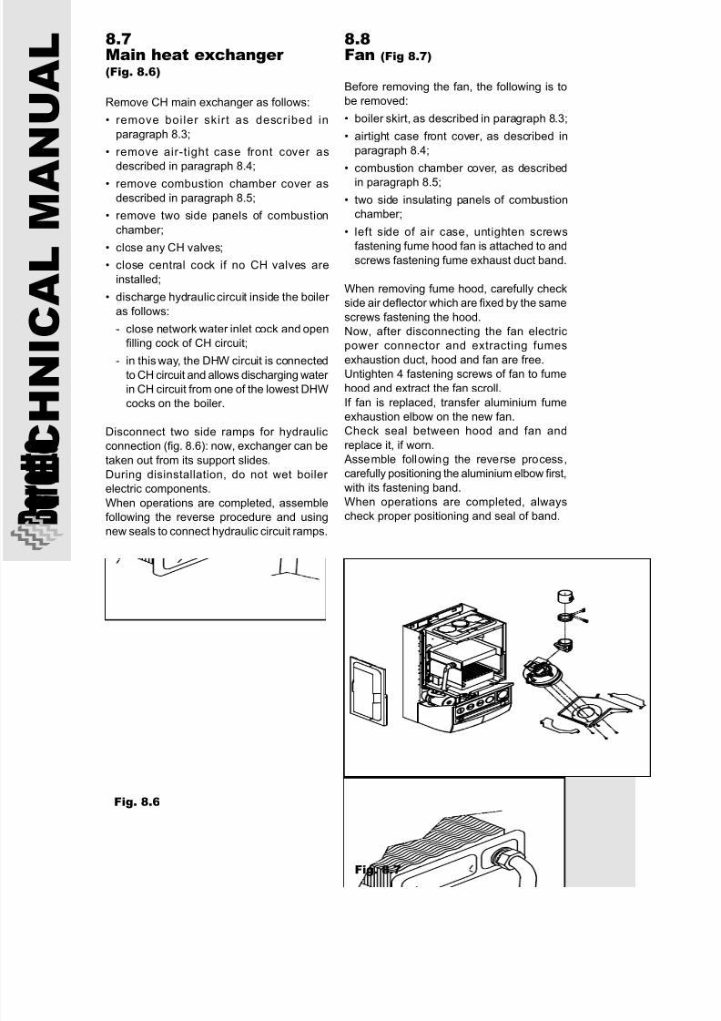
N U A L 8.7
Main heat exchanger (Fig. 8.6)
Remove CH main exchanger as follows:
• remove boiler skirt as described in
paragraph 8.3;
• remove air-tight case front cover as
described in paragraph 8.4;
• remove combustion chamber cover as
described in paragraph 8.5;
• remove two side panels of combustion
chamber;
• close any CH valves;
• close central cock if no CH valves are
installed;
• discharge hydraulic circuit inside the boiler
as follows:
- close network water inlet cock and open
filling cock of CH circuit;
- in this way, the DHW circuit is connectedto CH circuit and allows discharging water
in CH circuit from one of the lowest DHW
cocks on the boiler.
Disconnect two side ramps for hydraulic
connection (fig. 8.6): now, exchanger can be
taken out from its support slides.
During disinstallation, do not wet boiler
electric components.
When operations are completed, assemble
following the reverse procedure and using
new seals to connect hydraulic circuit ramps.
Fig. 8.6
8.8Fan (Fig 8.7)
Before removing the fan, the following is to
be removed:
• boiler skirt, as described in paragraph 8.3;
• airtight case front cover, as described in
paragraph 8.4;
• combustion chamber cover, as described
in paragraph 8.5;
• two side insulating panels of combustion
chamber;
• left side of air case, untighten screws
fastening fume hood fan is attached to and
screws fastening fume exhaust duct band.
When removing fume hood, carefully check
side air deflector which are fixed by the same
screws fastening the hood.
Now, after disconnecting the fan electric
power connector and extracting fumes
exhaustion duct, hood and fan are free.Untighten 4 fastening screws of fan to fume
hood and extract the fan scroll.
If fan is replaced, transfer aluminium fume
exhaustion elbow on the new fan.
Check seal between hood and fan and
replace it, if worn.
Assemble following the reverse process,
carefully positioning the aluminium elbow first,
with its fastening band.
When operations are completed, always
check proper positioning and seal of band.
Fig. 8.7
7/27/2019 Manuale Mynute Csi_ing
http://slidepdf.com/reader/full/manuale-mynute-csiing 43/56
43
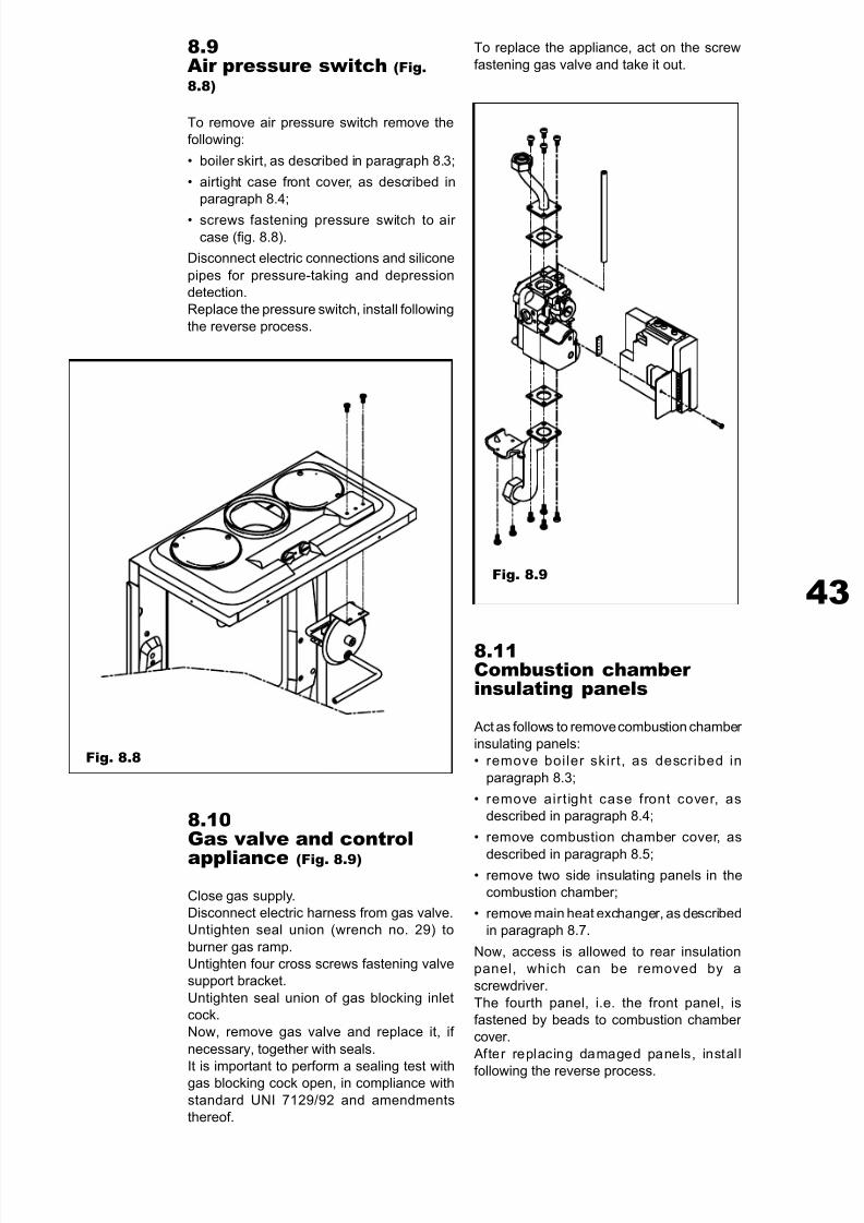
8.9Air pressure switch (Fig.8.8)
To remove air pressure switch remove the
following:
• boiler skirt, as described in paragraph 8.3;
• airtight case front cover, as described in
paragraph 8.4;
• screws fastening pressure switch to air
case (fig. 8.8).
Disconnect electric connections and silicone
pipes for pressure-taking and depression
detection.
Replace the pressure switch, install following
the reverse process.
Fig. 8.8
8.10Gas valve and control
appliance (Fig. 8.9)
Close gas supply.
Disconnect electric harness from gas valve.
Untighten seal union (wrench no. 29) to
burner gas ramp.
Untighten four cross screws fastening valve
support bracket.
Untighten seal union of gas blocking inlet
cock.
Now, remove gas valve and replace it, if
necessary, together with seals.
It is important to perform a sealing test withgas blocking cock open, in compliance with
standard UNI 7129/92 and amendments
thereof.
Fig. 8.9
8.11Combustion chamber insulating panels
Act as follows to remove combustion chamber
insulating panels:
• remove boiler skirt, as described in
paragraph 8.3;
• remove airt ight case front cover, as
described in paragraph 8.4;
• remove combustion chamber cover, as
described in paragraph 8.5;• remove two side insulating panels in the
combustion chamber;
• remove main heat exchanger, as described
in paragraph 8.7.
Now, access is allowed to rear insulation
panel, which can be removed by a
screwdriver.
The fourth panel, i.e. the front panel, is
fastened by beads to combustion chamber
cover.
After replacing damaged panels, instal l
following the reverse process.
To replace the appliance, act on the screw
fastening gas valve and take it out.
7/27/2019 Manuale Mynute Csi_ing
http://slidepdf.com/reader/full/manuale-mynute-csiing 44/56
T E C H N I C A L M A
N U A L 8.12
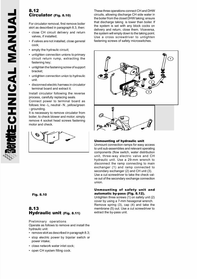
Circulator (Fig. 8.10)
For circulator removal, first remove boiler
skirt as described in paragraph 8.3, then:
• close CH circuit delivery and return
valves, if installed;
• if valves are not installed, close general
cock;
• empty the hydraulic circuit;
• untighten connection unions to primary
circuit return rump, extracting the
fastening key;
• untighten the fastening screw of support
bracket;
• untighten connection union to hydraulic
unit.
• disconnect electric harness in circulator
terminal board and extract it.
Install circulator following the reverse
process, carefully replacing seals.Connect power to terminal board as
follows: line - L, neutral - N , yellow/green
- grounding.
It is necessary to remove circulator from
boiler, to check blower and motor; simply
remove 4 socket head screws fastening
motor and check.
Fig. 8.10
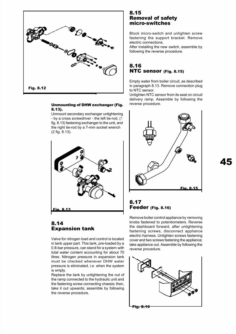
8.13Hydraulic unit (Fig. 8.11)
Preliminary operations
Operate as follows to remove and install thehydraulic unit:
• remove skirt as described in paragraph 8.3;
• stop electric power by bipolar switch or power intake;
• close network water inlet cock;
• open CH system filling cock.
Fig. 8.11
These three operations connect CH and DHWcircuits, allowing discharge CH side water inthe boiler from the closet DHW taking; ensure
that discharge taking is lower than boiler. If the system is set with any block cocks on
delivery and return, close them. Viceversa,the system will empty down to the taking point.Use a cross screwdriver to untighten
fastening screws of safety microswitches.
Unmounting of hydraulic unitUnmount connection ramps for easy access
to unit sub-assemblies and relevant operatingcomponents (flow switch, water distributionunit, three-way electric valve and CH
hydraulic unit. Use a 29-mm wrench todisconnect the ramp connecting to main
exchanger (1) and ramp connected tosecondary exchanger (2) and CH unit (3).Use a cut screwdriver to take the check val-
ve out of the secondary exchange connectionunion.
Unmounting of safety unit andautomatic by-pass (Fig. 8.12).Untighten three screws (1) on safety unit (2)cover by using a 7-mm hexagonal wrench.
Remove spring (3), cap (4) and take themembrane (5) out. Use a cut screwdriver toextract the by-pass unit.
7/27/2019 Manuale Mynute Csi_ing
http://slidepdf.com/reader/full/manuale-mynute-csiing 45/56
45
Fig. 8.12
Fig. 8.13
8.14Expansion tank
Valve for nitrogen load and control is locatedin tank upper part. This tank, pre-loaded by a0.8-bar pressure, can stand for a system with
total water content accounting for about 70litres. Nitrogen pressure in expansion tank
must be checked whenever DHW water pressure is eliminated, i.e. when the systemis empty.
Replace the tank by untightening the nut of the ramp connected to the hydraulic unit and
the fastening screw connecting chassis; then,take it out upwards; assemble by following
the reverse procedure.
1
2
8.15Removal of safetymicro-switches
Block micro-switch and untighten screw
fastening the support bracket. Removeelectric connections.
After installing the new switch, assemble byfollowing the reverse procedure.
8.16NTC sensor (Fig. 8.15)
Empty water from boiler circuit, as describedin paragraph 8.13. Remove connection plug
to NTC sensor.Untighten NTC sensor from its seat on circuit
delivery ramp. Assemble by following thereverse procedure.
Fig. 8.15
8.17Feeder (Fig. 8.16)
Remove boiler control appliance by removing
knobs fastened to potentiometers. Reversethe dashboard forward, after untightening
fastening screws, disconnect appliance
electric harness. Untighten screws fasteningcover and two screws fastening the appliance;
take appliance out. Assemble by following thereverse procedure.
Fig. 8.16
Unmounting of DHW exchanger (Fig.8.13).Unmount secondary exchanger untightening
- by a cross screwdriver - the left tie-rod, (1fig. 8.13) fastening exchanger to the unit, and
the right tie-rod by a 7-mm socket wrench(2 fig. 8.13).
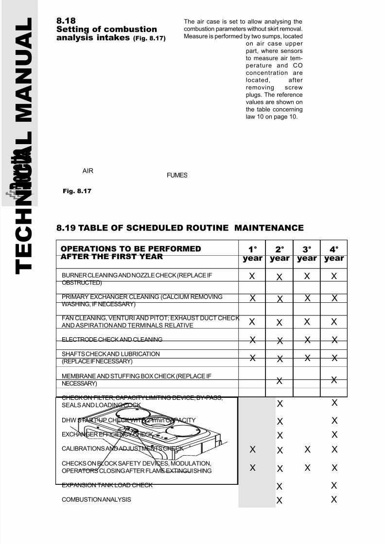
7/27/2019 Manuale Mynute Csi_ing
http://slidepdf.com/reader/full/manuale-mynute-csiing 46/56
T E C H N I C A L M A
N U A L 8.18
Setting of combustionanalysis intakes (Fig. 8.17)
The air case is set to allow analysing thecombustion parameters without skirt removal.
Measure is performed by two sumps, locatedon air case upper
part, where sensorsto measure air tem-perature and CO
concentration arelocated, after
removing screw
plugs. The referencevalues are shown on
the table concerninglaw 10 on page 10.
Fig. 8.17
8.19 TABLE OF SCHEDULED ROUTINE MAINTENANCE
OPERATIONS TO BE PERFORMEDAFTER THE FIRST YEAR
1°year
2°year
3°year
BURNER CLEANING AND NOZZLE CHECK (REPLACE IFOBSTRUCTED)
PRIMARY EXCHANGER CLEANING (CALCIUM REMOVINGWASHING, IF NECESSARY)
FAN CLEANING, VENTURI AND PITOT; EXHAUST DUCT CHECK AND ASPIRATION AND TERMINALS RELATIVE
ELECTRODE CHECK AND CLEANING
SHAFTS CHECK AND LUBRICATION(REPLACE IF NECESSARY)
MEMBRANE AND STUFFING BOX CHECK (REPLACE IF
NECESSARY)
CHECK ON FILTER, CAPACITY LIMITING DEVICE, BY-PASS,
SEALS AND LOADING COCK
DHW START-UP CHECK WITH 2 l/min CAPACITY
EXCHANGER EFFICIENCY CHECK
CALIBRATIONS AND ADJUSTMENTS CHECK
CHECKS ON BLOCK SAFETY DEVICES, MODULATION,
OPERATORS CLOSING AFTER FLAME EXTINGUISHING
X X X
EXPANSION TANK LOAD CHECK
COMBUSTION ANALYSIS
4°year
FUMES AIR
X
X X XX
X X XX
X X XX
X X XX
X X
X X
X X
X X
X X
X X
X X XX
X X XX
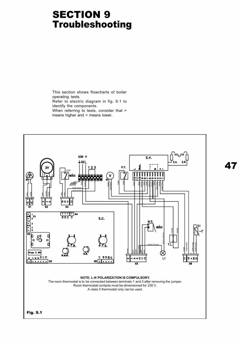
7/27/2019 Manuale Mynute Csi_ing
http://slidepdf.com/reader/full/manuale-mynute-csiing 47/56
47
SECTION 9Troubleshooting
This section shows flowcharts of boiler
operating tests.Refer to electric diagram in fig. 9.1 toidentify the components.
When referring to tests, consider that >means higher and < means lower.
Fig. 9.1
NOTE: L-N POLARIZATION IS COMPULSORY.
The room thermostat is to be connected between terminals 1 and 3 after removing the jumper.
Room thermostat contacts must be dimensioned for 230 V.
A class II thermostat only can be used.
b l u e
b r o w n
b l u e
w h i t e
b l u e
b r o w n
b l a c k
D H W
C H
white-black
white-black
DHW
b r o w n
b l u e - b l a c k
v i o l e t
v i o l e t
b l a c k
w h i t e
o r a n g e
v i o l e t
v i o l e t
o r a n g e
b r o w n
b l u e
b l u e - b l a c k
r o u g e
r o u g e - b l a c k
o r a n g e
o r a n g e
r o u g e
r o u g e - b l a c k
w h i t e - r o u g e
w h i t e - r o u g e w
h i t e
- b r o w n
white-brown
b r o w n
b l u e
b l a c k
b l u e w h i t e
g r e y
g r e y
r o s e
r o s e
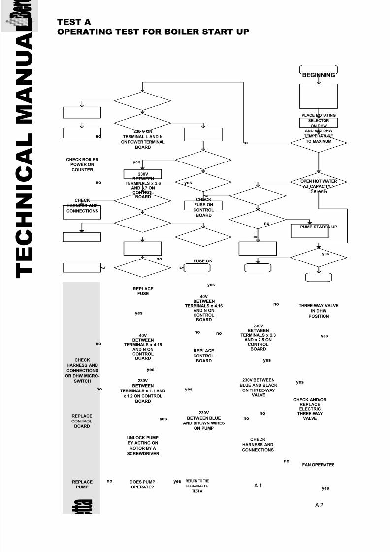
7/27/2019 Manuale Mynute Csi_ing
http://slidepdf.com/reader/full/manuale-mynute-csiing 48/56
T E C H N I C A L M A
N U A L TEST A
OPERATING TEST FOR BOILER START UP
BEGINNING
PLACE ROTATING
SELECTOR
ON DHW
AND SET DHW
TEMPERATURE
TO MAXIMUM
OPEN HOT WATER
AT CAPACITY >
2.5 l/min
noPUMP STARTS UP
THREE-WAY VALVE
IN DHW
POSITION
no
40VBETWEEN
TERMINALS x 4.16AND N ONCONTROL
BOARD
no
yes
no
no
A 2
A 1
CHECK
HARNESS AND
CONNECTIONS
OR DHW MICRO-
SWITCH
230VBETWEEN
TERMINALS x 2.3AND x 2.5 ON
CONTROLBOARD
CHECK
HARNESS AND
CONNECTIONS
FAN OPERATES
DOES PUMPOPERATE?REPLACEPUMP
yes
yes
no
no
no
yes
REPLACEFUSE
CHECK
FUSE ON
CONTROL
BOARD
230VBETWEEN
TERMINALS x 3.6AND 3.7 ON
CONTROLBOARD
230 V ON
TERMINAL L AND N
ON POWER TERMINAL
BOARD
CHECK BOILER
POWER ON
COUNTER
CHECK
HARNESS AND
CONNECTIONS
FUSE OK
yes
yes40VBETWEEN
TERMINALS x 4.15AND N ONCONTROL
BOARD
no
yes RETURN TO THE
BEGIN-NING OF
TEST A
230V BETWEEN
BLUE AND BLACKON THREE-WAYVALVE
yes
CHECK AND/ORREPLACEELECTRIC
THREE-WAYVALVE
230V
BETWEENTERMINALS x 1.1 AND
x 1.2 ON CONTROL
BOARD
nono
yes
yes
REPLACE
CONTROL
BOARD
REPLACE
CONTROL
BOARD
UNLOCK PUMP
BY ACTING ON
ROTOR BY A
SCREWDRIVER
230V
BETWEEN BLUE
AND BROWN WIRES
ON PUMP
no
yes
yes
no
yes
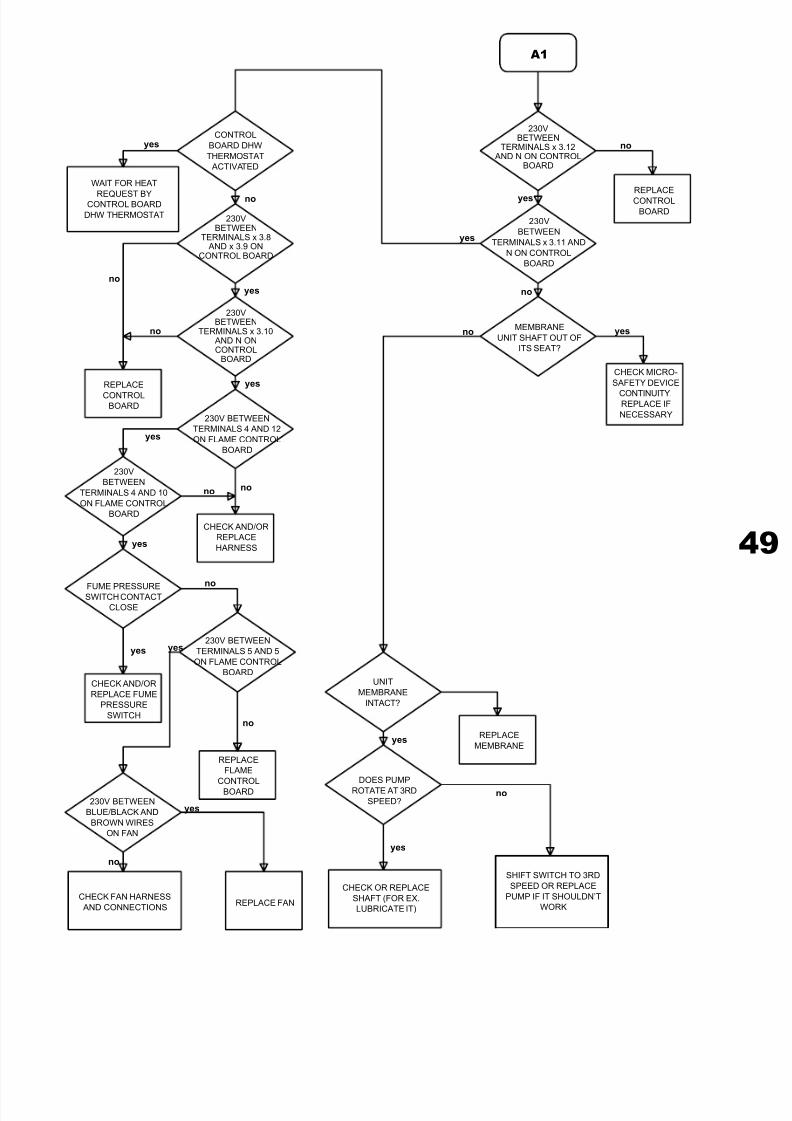
7/27/2019 Manuale Mynute Csi_ing
http://slidepdf.com/reader/full/manuale-mynute-csiing 49/56
49
A1
CONTROL
BOARD DHW
THERMOSTAT
ACTIVATED
230VBETWEEN
TERMINALS x 3.8 AND x 3.9 ON
CONTROL BOARD
WAIT FOR HEAT
REQUEST BYCONTROL BOARD
DHW THERMOSTAT
MEMBRANE
UNIT SHAFT OUT OF
ITS SEAT?
CHECK MICRO-
SAFETY DEVICE
CONTINUITY,REPLACE IF
NECESSARY
230V
BETWEEN
TERMINALS x 3.11 AND
N ON CONTROL
BOARD
CHECK AND/OR
REPLACE
HARNESS
230VBETWEEN
TERMINALS x 3.12 AND N ON CONTROL
BOARD
REPLACE
CONTROL
BOARD
no
yes
no
yes
yes
no
yesno
no
yes
no
yes
yes
no
no
no
REPLACE
FLAME
CONTROL
BOARD
CHECK FAN HARNESS
AND CONNECTIONSREPLACE FAN
no
230VBETWEEN
TERMINALS x 3.10 AND N ONCONTROL
BOARD
yes
230V BETWEEN
TERMINALS 4 AND 12
ON FLAME CONTROL
BOARD
yes
UNIT
MEMBRANE
INTACT?
FUME PRESSURESWITCH CONTACT
CLOSE
230V
BETWEEN
TERMINALS 4 AND 10
ON FLAME CONTROL
BOARD
CHECK AND/OR
REPLACE FUME
PRESSURE
SWITCH
230V BETWEEN
TERMINALS 5 AND 5
ON FLAME CONTROL
BOARD
yes
no
yes230V BETWEEN
BLUE/BLACK AND
BROWN WIRES
ON FAN
yes
yes
no
DOES PUMP
ROTATE AT 3RD
SPEED?
REPLACE
MEMBRANE
SHIFT SWITCH TO 3RD
SPEED OR REPLACE
PUMP IF IT SHOULDN’T
WORK
CHECK OR REPLACE
SHAFT (FOR EX.
LUBRICATE IT)
REPLACE
CONTROLBOARD

7/27/2019 Manuale Mynute Csi_ing
http://slidepdf.com/reader/full/manuale-mynute-csiing 50/56
T E C H N I C A L M A
N U A L A 2
IGNITION
ELECTRODE
SPARK
IGNITION
BLOCK AFTER
IGNITION
END
MECHANICAL
OPENING OF
GAS VALVE
CONTROLS?
CHECK AND/OR
REPLACE
PRESSURE
SWITCH AND/OR
CONNECTIONS
REPLACE
PRESSURE
SWITCH
VENTURI AND
SILICONE PIPES ARE
CLEAN
SWITCHESPRESSURE SWITCH
CONTACT
REPLACE
FLAME
CONTROL
APPLIANCE
THERE ARE 230 VBETWEEN
TERMINALS 7 AND NON FLAME CONTROL
BOARD
yes
no
no
CHECK
AND/ORREPLACE
FLAME
CONTROL UNIT
IS IGNITION
ELECTRODE
TERMINAL POWERED?
ATTENTION:
10 kV PRESENT
CHECK AND/OR
CLEAN
no
no
yes
no
yes
yes
nono
yesyes
yes
yes
no
no
no
yes
noyes
A 3
THERE ARE230 V BETWEEN
TERMINALS 8 AND N ONFLAME CONTROL
BOARD
CHECK AND/OR
REPLACE
IGNITION
ELECTRODE
no
no
yes
yes
DEPRESSIONBETWEEN VENTURI AND
PITOT PIPE IS > 11 mmCOLUMN OF
WATER
CHECK FUME
EXHAUSTION
AND FAN
GAS
PRESSURE ON
INPUT EXCEED
13.7 BARS
WARN
USER
FLAME CONTROL
APPLIANCE OK?
REPLACE
FLAME
CONTROL
APPLIANCE
REPLACE GAS
VALVE
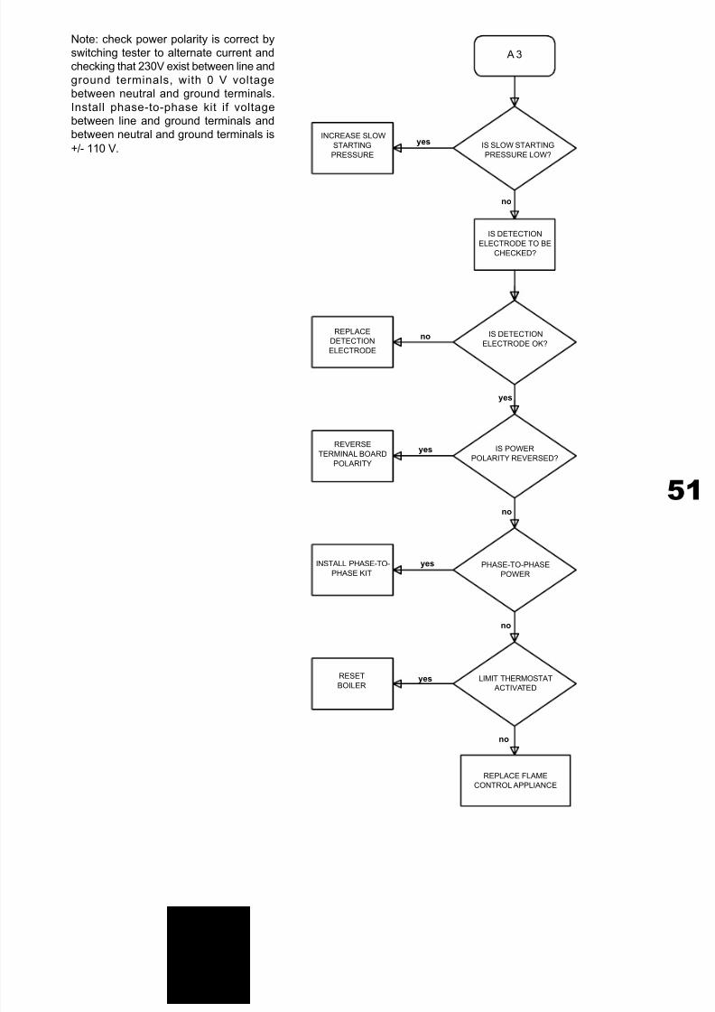
7/27/2019 Manuale Mynute Csi_ing
http://slidepdf.com/reader/full/manuale-mynute-csiing 51/56
51
IS SLOW STARTING
PRESSURE LOW?
no
IS DETECTION
ELECTRODE TO BE
CHECKED?
REPLACE
DETECTION
ELECTRODE
yes
no IS DETECTION
ELECTRODE OK?
REVERSE
TERMINAL BOARD
POLARITY
INSTALL PHASE-TO-
PHASE KIT
IS POWER
POLARITY REVERSED?
RESET
BOILER
no
yes
no
yes
no
A 3
yes
yes
PHASE-TO-PHASE
POWER
LIMIT THERMOSTAT
ACTIVATED
REPLACE FLAME
CONTROL APPLIANCE
Note: check power polarity is correct byswitching tester to alternate current andchecking that 230V exist between line and
ground terminals, with 0 V voltagebetween neutral and ground terminals.
Install phase-to-phase kit if voltagebetween line and ground terminals andbetween neutral and ground terminals is
+/- 110 V.
INCREASE SLOW
STARTING
PRESSURE

7/27/2019 Manuale Mynute Csi_ing
http://slidepdf.com/reader/full/manuale-mynute-csiing 52/56
T E C H N I C A L M A
N U A L
SELECT DHW MODEWITH MAXIMUM DHW
TEMPERATURE
yes
no
no
yes
no
TEST BBOILER OPERATION IN DHW MODE
OPEN
HOT WATER
COCK
BURNER
SWITCHES ON
CHECK
BOILER
BY TEST A
VOLTAGE
ON TERMINALS
1 AND 2 ON
FLAME CONTROL
BOARD
IS > 10 Vdc
VOLTAGE > 10Vdc
ON TERMINALS x 5.17
AND x 5.18 ON
CONTROL BOARD
REPLACE
CONTROL
BOARD
REPLACE
HARNESS AND
CONNECTIONS
yes
no
yesWAIT UNTIL VOLTAGE
ON TERMINALS 1
AND 2 OF FLAME
CONTROL BOARD
IS < 1.2 V
VOLTAGE
ON TERMINALS
1 AND 2 OF
FLAME CONTROL
BOARD IS < 1.2 V
yes
no
TAKE DHW
TO MINIMUM
TEMPERATURE
PRIMARY
TEMPERATURE
> 80°C
REPLACE NTC
SENSOR
no
yes
yes
REPLACE
CONTROL
BOARD
NTC SENSOR OK
no
no
yesyes
BURNER
AND FAN
SWITCH OFF
B1
WAIT UNTIL
PRIMARY TEM-
PERATURE
IS > 40°C
PRIMARY
TEMPERATURE
IS HIGHER THAN
40°C
REPLACE
CONTROLBOARD
BEGINNING
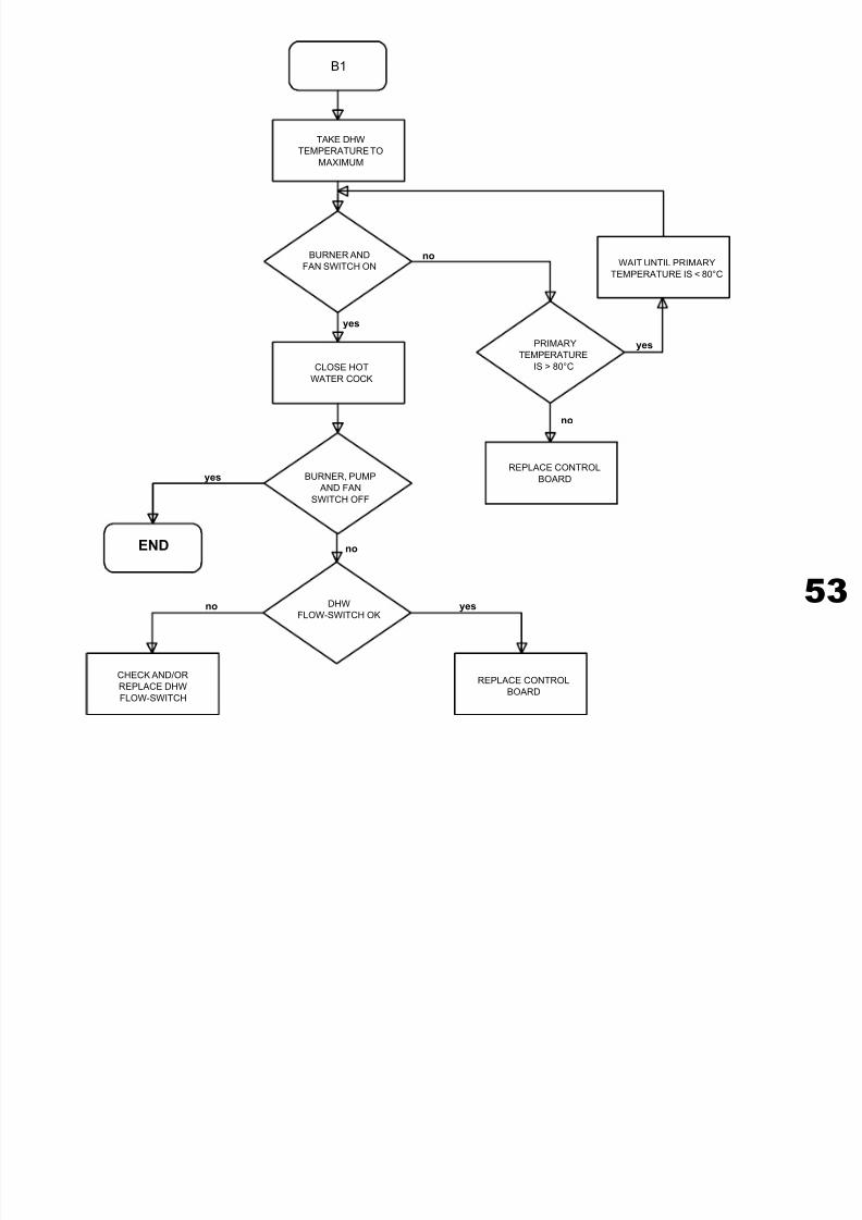
7/27/2019 Manuale Mynute Csi_ing
http://slidepdf.com/reader/full/manuale-mynute-csiing 53/56
53
B1
TAKE DHW
TEMPERATURE TO
MAXIMUM
no
yes
yes
yes
yes
no
BURNER AND
FAN SWITCH ON WAIT UNTIL PRIMARY
TEMPERATURE IS < 80°C
PRIMARY
TEMPERATURE
IS > 80°C
REPLACE CONTROL
BOARD
CLOSE HOT
WATER COCK
BURNER, PUMP
AND FAN
SWITCH OFF
noEND
DHW
FLOW-SWITCH OK
CHECK AND/OR
REPLACE DHW
FLOW-SWITCH
REPLACE CONTROL
BOARD
no
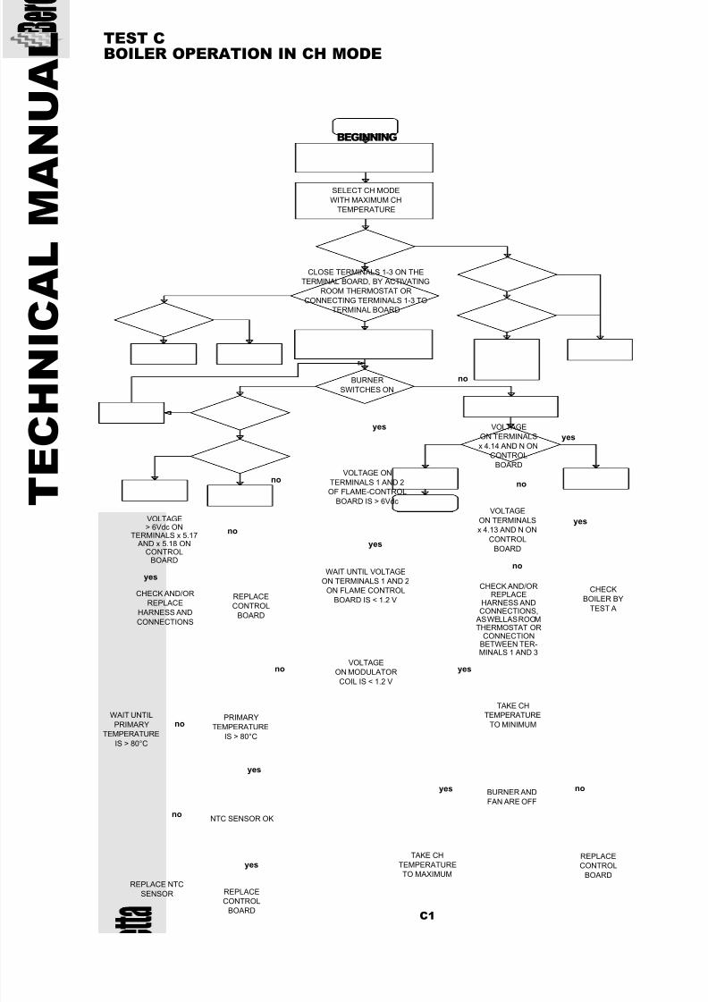
7/27/2019 Manuale Mynute Csi_ing
http://slidepdf.com/reader/full/manuale-mynute-csiing 54/56
T E C H N I C A L M A
N U A L TEST C
BOILER OPERATION IN CH MODE
BEGINNING
no
yes
yes
no
yesno
no
yes
BURNER
SWITCHES ON
SELECT CH MODE
WITH MAXIMUM CH
TEMPERATURE
CLOSE TERMINALS 1-3 ON THE
TERMINAL BOARD, BY ACTIVATING
ROOM THERMOSTAT OR
CONNECTING TERMINALS 1-3 TO
TERMINAL BOARD
VOLTAGE
ON TERMINALS
x 4.14 AND N ON
CONTROL
BOARDVOLTAGE ON
TERMINALS 1 AND 2
OF FLAME-CONTROL
BOARD IS > 6Vdc
VOLTAGE
ON TERMINALS
x 4.13 AND N ON
CONTROL
BOARD
CHECK
BOILER BY
TEST A
CHECK AND/ORREPLACE
HARNESS ANDCONNECTIONS,
AS WELL AS ROOMTHERMOSTAT OR
CONNECTIONBETWEEN TER-MINALS 1 AND 3
yes
VOLTAGE
> 6Vdc ONTERMINALS x 5.17
AND x 5.18 ONCONTROL
BOARD
CHECK AND/OR
REPLACE
HARNESS AND
CONNECTIONS
REPLACE
CONTROL
BOARD
WAIT UNTIL VOLTAGE
ON TERMINALS 1 AND 2
ON FLAME CONTROL
BOARD IS < 1.2 V
VOLTAGE
ON MODULATOR
COIL IS < 1.2 V
TAKE CH
TEMPERATURE
TO MINIMUM
noyes
REPLACE
CONTROL
BOARD
BURNER AND
FAN ARE OFF
TAKE CH
TEMPERATURE
TO MAXIMUM
C1
no
no
no
yes
yes
PRIMARY
TEMPERATURE
IS > 80°C
WAIT UNTIL
PRIMARY
TEMPERATURE
IS > 80°C
REPLACE NTC
SENSOR
NTC SENSOR OK
REPLACE
CONTROL
BOARD
no
yes
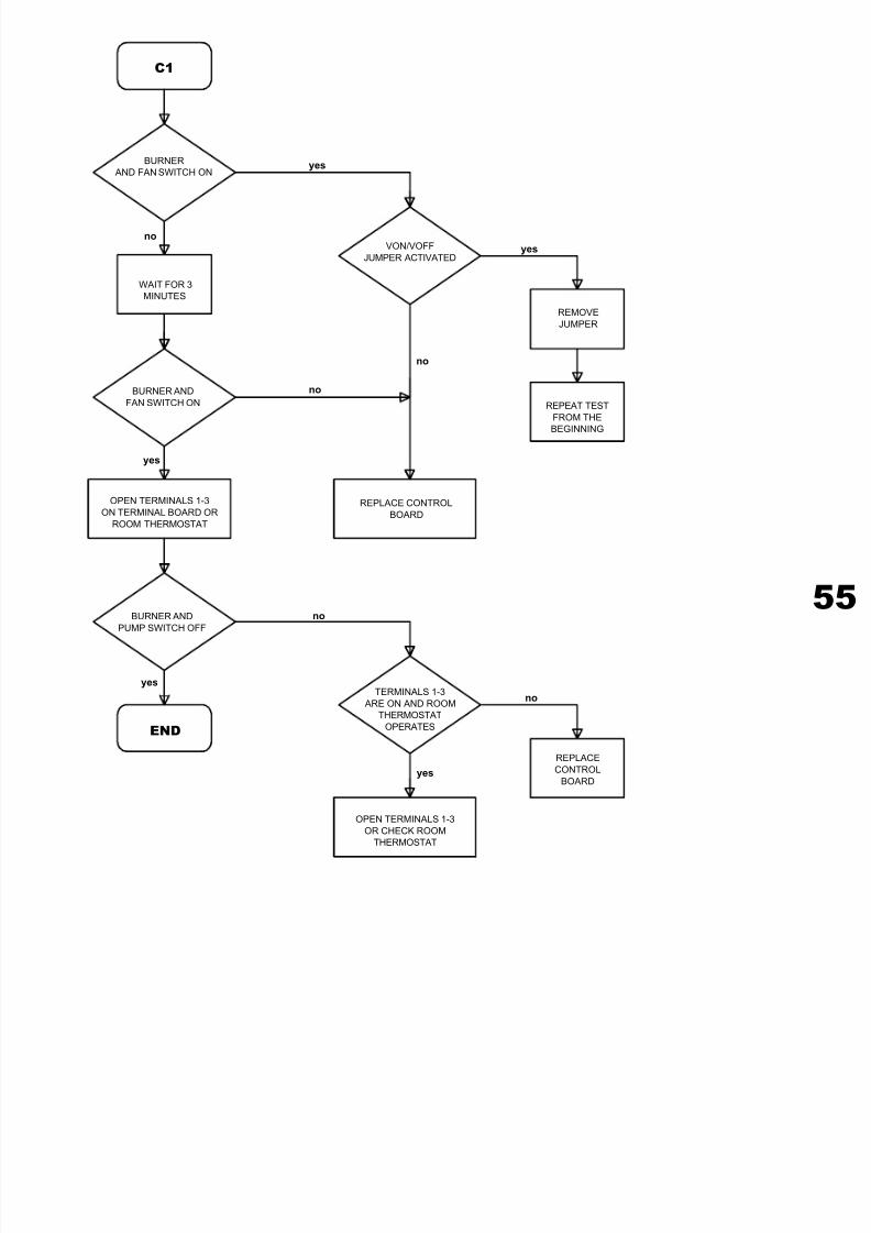
7/27/2019 Manuale Mynute Csi_ing
http://slidepdf.com/reader/full/manuale-mynute-csiing 55/56
55
BURNER
AND FAN SWITCH ONyes
C1
yes
no
no
WAIT FOR 3
MINUTES
BURNER AND
FAN SWITCH ON
VON/VOFF
JUMPER ACTIVATED
no
REPLACE CONTROL
BOARD
REPEAT TEST
FROM THE
BEGINNING
REMOVE
JUMPER
OPEN TERMINALS 1-3
ON TERMINAL BOARD OR
ROOM THERMOSTAT
no
no
yes
END
TERMINALS 1-3
ARE ON AND ROOM
THERMOSTAT
OPERATES
OPEN TERMINALS 1-3
OR CHECK ROOM
THERMOSTAT
BURNER AND
PUMP SWITCH OFF
REPLACE
CONTROL
BOARD
yes
yes

7/27/2019 Manuale Mynute Csi_ing
http://slidepdf.com/reader/full/manuale-mynute-csiing 56/56
0 7 / 0 0


![Manuale 1-1 Refrigeratori RC160 _3 12 011 2_Ita-Ing-Ted[1]](https://static.fdokumen.com/doc/165x107/55cf9466550346f57ba1bca8/manuale-1-1-refrigeratori-rc160-3-12-011-2ita-ing-ted1.jpg)