Kuliah 3 B3 S2 Teknik SS · Diff tS/ST hiDifferent S/S Techniques Waste Component Treatment Type...
37
Teknik Solidifikasi/Stabilisasi Teknik Solidifikasi/Stabilisasi
Transcript of Kuliah 3 B3 S2 Teknik SS · Diff tS/ST hiDifferent S/S Techniques Waste Component Treatment Type...

Teknik Solidifikasi/StabilisasiTeknik Solidifikasi/Stabilisasi

StabilisasiStabilisasi• Stabilisasi adalah proses penambahan bahan aditif
yang bertujuan untuk mengurangi sifat beracunlimbah, dengan cara mengubah limbah dan komponenberbahayanya ke bentuk yang dapat mengurangi lajuy y y g p g g jmigrasi kontaminan ke lingkungan, atau mengurangisifat beracun limbah.
• Dalam proses stabilisasi ditambahkan bahan2 yangDalam proses stabilisasi ditambahkan bahan2 yang memiliki sifat:– memperbaiki karakteristik fisik limbah dan mempermudahpenanganannya;penanganannya;
– mengurangi luas permukaan limbah;– mengurangi kelarutan polutan yang terkandung dalamlimbah;limbah;
– mengurangi sifat beracun kontaminan

SolidifikasiSolidifikasi
• solidifikasi adalah proses ditambahkannya bahanp yyang dapat memadatkan limbah agar terbentukmassa limbah yang padat. Bahan yang ditambahkan merupakan bahan yang dapat :ditambahkan merupakan bahan yang dapat :– menaikkan kekuatan fisik limbah– mengurangi kompresibilitas limbah– mengurangi permeabilitas limbah
– solidifikasi dapat memperbaiki kekuatan dankompresibilitas limbah, sehingga mengurangi lajukompresibilitas limbah, sehingga mengurangi lajupenyebaran kontaminan ke lingkungan, sertameningkatkan kestabilan limbah agar tidak mengganggulingkungan.lingkungan.

Tujuan S/STujuan S/S
• mengkonversi limbah beracun menjadi massamengkonversi limbah beracun menjadi massayang:– inert– inert, – memiliki daya leaching rendah, kekuatan mekanik yang cukup agar aman untuk di– kekuatan mekanik yang cukup agar aman untuk dibuang ke landfill limbah B3.

Karakteristik Produk S/SKarakteristik Produk S/S
• stabil;stabil;• mampu menahan beban;
l h d k di i b h d k i• toleran terhadap kondisi basah dan keringyang silih berganti;
• permeabilitas rendah;• tidak menghasilkan lindi yang berkualitasg y gburuk

Kriteria bahan aditifKriteria bahan aditif
• dapat memperbaiki karakteristik fisik limbah;dapat memperbaiki karakteristik fisik limbah;• mengurangi luas permukaan limbah;
i k l l d• mengurangi kelarutan polutan yang terdapatdalam limbah;
• mengurangi toksisitas kontaminan.

Jenis aditifJenis aditif
• bahan pencampur: gipsum pasir lempungbahan pencampur: gipsum, pasir, lempung, abu terbang;
• bahan perekat/pengikat: semen kapur tanah• bahan perekat/pengikat: semen, kapur, tanahliat, dl;

Prosedur S/SProsedur S/S• limbah B3 harus ditentukan karakteristiknya terlebih dahulu
guna menentukan komposisi bahan‐bahan yang perluditambahkan;
• setelah S/S diaplikasikan, dilakukan uji TCLP terhadap hasilolahan tersebut untuk mengukur konsentrasi parameter dalam lindi (extract/eluate). Hasil uji TCLP sebagaimanadimaksud, kadarnya tidak boleh melewati nilai baku mutu;
• hasil stabilisasi selanjutnya diuji kuat tekan (compressive strength); nilai tekanan minimum sebesar 10 ton/m2, dandan lolos uji paint filter test.
• hasil stabilisasi yang memenuhi persyaratan baku mutuTCLP, nilai uji kuat tekan dan paint filter test harus ditimbundi tempat penimbunan (landfill) B3

Teknik S/S dilakukan untuk:Teknik S/S dilakukan untuk:
• stabilisasi limbah cair B3 sebelum dibuang kestabilisasi limbah cair B3 sebelum dibuang kelandfill;
• remediasi lahan lahan yang terkontaminasi• remediasi lahan‐lahan yang terkontaminasi limbah B3.

Classification of S/S technologyClassification of S/S technology
1. chemical processes:. c e ca p ocesses:1. cement‐based process, 2. pozzolan‐based processes, 3. lime‐based processes
2. physical processes:1. macroencapsulation/containerization 2. non‐chemical microencapsulation; 3 th l3. thermal processes:
1. thermoplastic polymer encapsulation2. vitrification.


CementCement
• Composition:Co pos t o :– 67% CaO (C), – 22% SiO2 (S), – 5% Al2O3 (A), 3% Fe2O3 (F), – and 3% other components.
• It normally contains four major phases: – alite (50–70% Ca3SiO5 or “C3S”), b lit (15 30% C 2SiO4 “C2S”)– belite (15–30% Ca2SiO4 or “C2S”),
– aluminite (5–10% Ca3Al2O6 or “C3A”), and – ferrite (5–15% Ca4Al2Fe2O10 or “C4AF”)– ferrite (5–15% Ca4Al2Fe2O10 or C4AF )

RAW MATERIALS of CEMENTThe fundamental chemical compounds to produce cement clinker are:
Lime (CaO) Silica (SiO2)( 2)Alumina (Al2O3) Iron Oxide (Fe2O3)
R t i l d i th d ti f li k tRaw materials used in the production of clinker cement
Fly ash: by-product of burning finely grounded coal either for industrial application or in
(Macfadyen, 2006)
(Hoffman, 2006)
y y p g y g ppthe production of electricity

S/S technology using cementS/S technology using cement
1 Chemical fixation of contaminants by1. Chemical fixation of contaminants by interactions between the hydration products of cement and the contaminantsof cement and the contaminants,
2. Physical adsorption of contaminants on the surface of cement hydration products orsurface of cement hydration products, or
3. Physical encapsulation of contaminated ilwaste or soil.

Schemes of S/S processing with cement
• In‐drum processing — The S/S binders are added to the waste t i d i d th t i Th t bi d t i icontained in a drum or other container. The waste‐binder matrix is
normally disposed of in the drum after mixing and setting. • In‐plant processing — A plant and/or process is specifically
designed for solidifying and stabilizing bulk waste materials Thedesigned for solidifying and stabilizing bulk waste materials. The process may be used to manage wastes from an internal industrial operation, or a plant may be specifically built and operated to solidify and stabilize wastes from external sources.
• Mobile plant (ex situ) processing — In this scheme, the processing equipment, which is either mobile or can be easily transported, is set up site to site.
• In situ processing Binders or solidifying/stabilizing materials are• In‐situ processing — Binders or solidifying/stabilizing materials are injected directly to a lagoon or soil subsurface to promote the solidification/stabilization of the contaminated sludge or soil.

In‐drum processingIn drum processing• Toxic and hazardous liquids and sludges are often disposed on‐site
i din drums. • In‐drum S/S methods aim to utilize these existing drums as both a
mixing vessel and storage container for hazardous waste. • Typical in drum mixing processes involve the following steps:• Typical in‐drum mixing processes involve the following steps:
– Evaluation/identification of contents in each drum– Evaluation of drum condition and head space– Preparation of materials handling location including concrete pad or– Preparation of materials handling location, including concrete pad or
gravel surface, chemical storage, and mixing equipment– Addition and mixing of S/S chemicals using mixers or propeller s– Placement of drums in a secure area for curing– Addition of inert material to any remaining head space and
replacement of top to each drum– Final disposal of drums

In‐situ treatmentIn situ treatment
• The procedure for an in‐situ treatment process e p ocedu e o a s tu t eat e t p ocessmay utilizes the existing lagoon as a mixing area.
• The follow steps are typical for p ypstabilization/solidification of waste in‐situ:– Addition of reagent, such as kiln dust or flyash, using
h i l ti li timechanical or pneumatic application.– Mixing with backhoe or excavator until stabilization/begins./ g
– Setting/gelling for 24‐48 hours.– Off‐gas treatment to collect hazardous vapors

In‐situ S/SIn situ S/S

In‐situ S/S /
mixing, withwith single auger.

Mobile mixing, ex‐situMobile mixing, ex situ• Wastes are physically removed from their location using pumping or construction
equipment mechanically mixed with reagents and deposited into a preparedequipment, mechanically mixed with reagents, and deposited into a prepared disposal site.
• This method is best suited for liquids and highly liquid sludges that can be pumped. Special equipment may be used to employ the mobile mixing method on high solids content sludges and soilshigh solids content sludges and soils.
• Mobile mixing plant S/S typically requires the following project sequencing:– Excavation to remove contaminated waste– Classification of wastes– Mobile plant setup and mixingMobile plant setup and mixing– Preparation of remedial site for installation of mobile system, including necessary
utilities/electricity– Preparation of final disposal site– Installation of raw and treated waste handling systems, including pumps or construction
equipmentequipment– Screening of wastes to remove particles too large for treatment (typically 2 inches or greater
in diameter)– Mixing of binding agents, water, and waste– Off‐gas treatment to collect hazardous vaporsg p– Final Disposal

Area mixing, ex‐situArea mixing, ex situ
• Waste is placed in a layer over the disposalWaste is placed in a layer over the disposal area in 2"‐24" thicknesses and is then overlaid with a layer of reagentswith a layer of reagents.
• The two layers are then lifted and turned with a mechanized vehicle similar to tillinga mechanized vehicle, similar to tilling.
• The mixture is air dried or compacted. • Additional waste/reagent layers may be added up to the determined final material height.

Area mixingArea mixingArea mixing provides an economical method for S/S of waste liquids and sludges without the use of conventional stationary mixing equipmentsludges without the use of conventional, stationary mixing equipment. The steps are:1. Selection/preparation of treatment area2 Excavation and transport of waste2. Excavation and transport of waste3. Spreading of waste in desired thickness over disposal area using
construction equipment4. Spreading of required amounts of reagents over waste5. Mixing of materials using high‐speed rotary mixer6. Compaction of mixed layer7. Repeat steps 2‐7 until allowable solidified waste height has been
attainedattained8. The final layer is covered with earth and seeded as a final cap., or the
waste may be removed to another disposal site.
Ex‐situ area mixingEx situ area mixing

Polymer S/S technologyPolymer S/S technology• USEPA : "polymer S/S technologies process waste at relatively low temperature by
combining or surrounding wastes with liquid polymers Cooling or curing of thecombining or surrounding wastes with liquid polymers. Cooling or curing of the polymer then produces a solidified final waste form product".
• Polymer S/S can be applied for either microencapsulation or macroencapsulation; also can be accomplished ex situ or in situ.
• USEPA divided polymers into two categories:• USEPA divided polymers into two categories: – Thermoplastic . Thermoplastic binders can be melt to a flowable state when heated and
harden to a solid when cooled– Thermosetting. Thermosetting binders require the combination of several ingredients to
polymerize and harden (irreversible)• When the waste particles are small solid particles (< 60 mm) and homogeneously
distributed, the organic polymer matrix is known as microencapsulation. • In microencapsulation, individual waste particles are fully surrounded and
encapsulated by the polymer matrix. • When the waste particles are large (> 60 mm), clean polymer can be placed
around the waste and this process is usually called macroencapsulation. USEPA has identified macroencapsulation as the best demonstrated available technology (BDAT)

Polymer S/S technologyPolymer S/S technology• Both thermoplastic polymers and organic polymers are
hydrophobic after curing and thus resist leaching. • This property makes polymers ideal for trapping highly
toxic metals and organic compounds.toxic metals and organic compounds.• Organic polymer microencapsulation, specifically, is a
useful method to encapsulate waste because it is well‐suited for many types of applications including liquidsuited for many types of applications, including liquid waste solidification; it exhibits a high degree of impermeability, and can quickly attain physical strengthstrength.
• Polymer materials: urea formaldehyde, polyester resin PETE

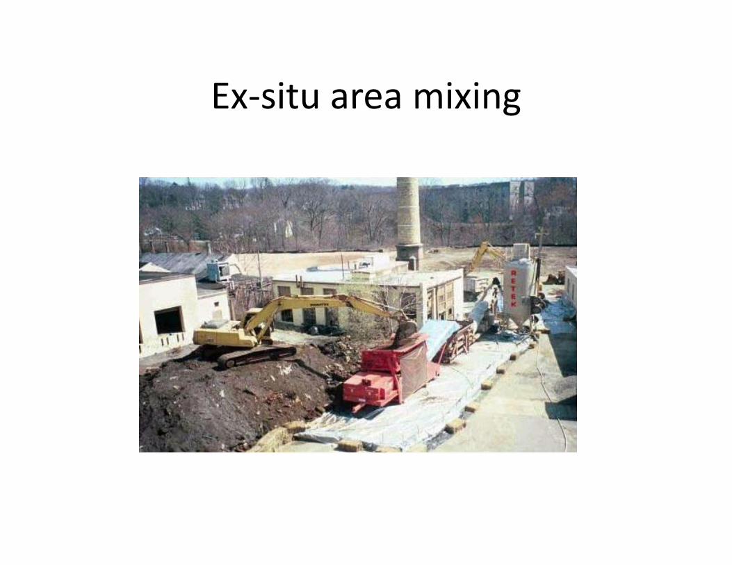
VitrificationVitrification• Dilakukan pencairan dan peleburan bahan pada suhu > 1600oC, yang diikuti
dengan pendinginan cepat, sehingga terbentuk padatan amorf, non kristalin. g p g p , gg p ,• Digunakan pada lahan yang terkontaminasi, baik in situmaupun in plant. Dengan
vitrifikasi, struktur limbah menjadi lebih stabil dan berkurang laju migrasinya kelingkungan sekitar.
• Vitrifikasi in situ: Arus listrik dialirkan ke dalam tanah, hingga menimbulkan panas.Vitrifikasi in situ: Arus listrik dialirkan ke dalam tanah, hingga menimbulkan panas. Akibatnya tanah akan mencair, menjadi massa lelehan yang bersifat lebih konduktifdan menjadi medium transfer panas yang terus mengembang.
• Proses vitrifikasi diawali dengan memasang lapisan grafit dan gelas padapermukaan tanah, dengan elektroda yang diletakkan pada keempat siisi yang lebarnya 8 m dengan kedalaman yang dikehendaki. Selanjutnya dilakukanpemanasan dengan aliran listrik, yang mengakibatkan terjadinya pelelehan tanahyang terkontaminasi, yang kemudian membentuk gelas amorf.
• Tanah meleleh dengan laju 3‐6 ton/jam, dengan kecepatan leleh 2.5‐5 cm/jam. P d t h ik b h ik d t i bikPada saat suhu naik, bahan organik menguap dan terurai secara anaerobikmenjadi unsur‐unsurnya. Gas‐gas tersebut bergerak perlahan menuju permukaantanah yang mencair. Di permukaan tanah gas‐gas tersebut akan terbakar denganbantuan oksigen. Sedangkan polutan yang tidak menguap akan terikat di dalamtanah yang telah berubah menjadi gelastanah yang telah berubah menjadi gelas

Kapsulasi makroKapsulasi makro
• Limbah B3 dibungkus dalam kapsul pembungkusba 3 d bu g us da a apsu pe bu g usyang bersifat inert dan kedap air. Bahanpembungkus dapat berupa campuran fiberglass,
k d d l hresin epoksida, dan resin polyurethane. Campuran tersebut disemprotkan pada dindingkontainer limbah sehingga terbentuk jaket yangkontainer limbah, sehingga terbentuk jaket yang melindungi limbah tersebut dari pelindian dantekanan‐tekanan mekanik. Semen kadang‐kadangg gdigunakan pula untuk membentuk kapsul makropada limbah laboratorium.
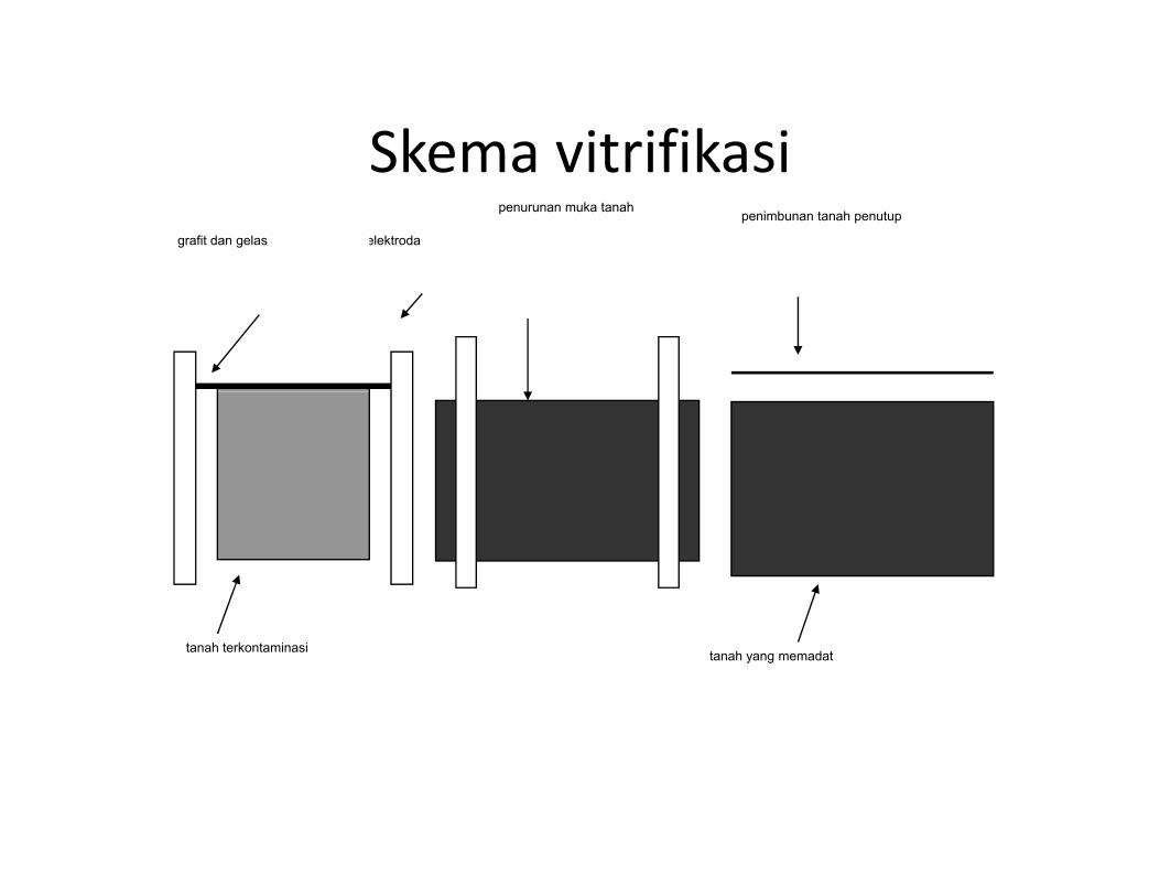
Skema vitrifikasiSkema vitrifikasielektrodagrafit dan gelas
penimbunan tanah penutuppenurunan muka tanah
tanah yang memadattanah terkontaminasi

Skema vitrifikasiSkema vitrifikasi

Compatibility of Selected Waste Categories with Diff t S/S T h iDifferent S/S Techniques
Waste Component
Treatment TypeCement-Based Pozzolan-Based Thermoplastic
Mi l iSurface
E l iComponent Cement Based Pozzolan Based Microencapsulation EncapsulationORGANICS
Organic solvents and oils
May impede setting, may escape as vapor
May impede setting, may escape
as vaporOrganics may
vaporize on heatingMust first be
absorbed on solid matrixp
Solid organics (e.g., plastics, resins, tars)
Good-often increases durability
Good-often increases durability
Possible use as binding agent in
this system
Compatible-many encapsulation
materials are plasticINORGANICS
C b t li dAcid wastes Cement will neutralize
acidsCompatible, will neutralize acids
Can be neutralized before
incorporationCan be neutralized
before incorporation
SulfatesMay retard setting and cause spalling unless Compatible
May dehydrate and rehydrate causing Compatible
special cement is used splitting
HalidesEasily leached from cement, may retard
setting
May retard set, most are easily
leachedMay dehydrate and
rehydrate Compatible
Heavy metals Compatible Compatible Compatible Compatibley p p p pRadioactive
materials Compatible Compatible Compatible Compatible

Contoh aplikasi remediasi tanah dg S/STempat Kontaminan Bahan pengikat %
Midwest US Plating Company
Cu, Cr. Ni Semen portland 20CompanyAlaska refinery Minyak Semen portland dan
bahan aditif khusus>50,
bervariasi
Kentucky Vinil klorida dan etilena Semen portland dan >25%, Kentucky diklorida bahan aditif khusus bervariasiNortheast Refinery Lumpur minyak, Pb, Cr, As Abu terbang dengan
kadar CaO tinggi 15-30%
Velsicol Chemical
Pestisida dan resin, 45% komponen organik
Semen portland, abudan bahan aditif khusus
5-15%, bervariasi
Amoco Minyak dan sampah Bahan aditif khususWood Rivery p
mengandung Cd, Cr, Pb Bahan aditif khusus -
Vickery, Ohio
Limbah asam, 500 ppm PCB, dioksin Kapur dan abu terbang 15% CaO +
5% fly ashMetaplating, Wisconsin
9500 ppm Al, 750 ppm Ni, 220 ppm Cr, 2000 ppm Cu Kapur 10-25

Uji TCLP (T i i Ch i i L hi P d )(Toxicity Characteristic Leaching Procedure)
• Uji TCLP adalah metoda analisis guna menentukan mobilitasUji TCLP adalah metoda analisis guna menentukan mobilitaskontaminan organik atau anorganik yang ada dalam limbah B3
• Prosedur mengikuti metoda US EPA 1311 : – Limbah dihancurkan dan diayak dengan saringan 9.5 mm.– Hasil ayakan dicampur dengan larutan asam asetat pH 2.88 + 0 05 pada rasio berat larutan : padatan 20:1+ 0.05 pada rasio berat larutan : padatan 20:1.
– Campuran diagitasi selama 18 jam pada 30 rpm, suhu22oC, kemudian disaring dengan filter fiber glass berukuran0.6‐0.8 um
– Kandungan kontaminan pada filtrat diuji dengan metodayang sesuaiyang sesuai
32

Uji TCLP (lanjutan)Uji TCLP (lanjutan)
• Pengujian limbah dengan kadar bahan organik yangPengujian limbah dengan kadar bahan organik yangmudah menguap dilakukan dengan prosedur khusus,dengan wadah berbentuk silinder yang diisi penuhdan tertutup rapat selama proses agitasi.
• Hasil pengujian kadar kontaminan dibandingkandengan baku mutu uji TCLP guna menentukan sifatb b h / d k l b h d ( hberbahaya/tidaknya limbah yang diuji. (LihatLampiran III PP No. 101/2014)
33

Metoda analisis limbah B3 padak kekstrak Uji TCLP
• Total logam berat: Spektrofotometri SerapanTotal logam berat: Spektrofotometri SerapanAtom (AAS)
• Nitrat nitrit: spektrofotometri• Nitrat‐nitrit: spektrofotometri• Sianida: spektrofotometri• Komponen organik (organoklorin, keton, alkana): gas kromatografi
34

Botol ekstraksi untuk uji TCLPBotol ekstraksi untuk uji TCLPRA-119 Borosilicate Glass BottleB l i i k li b h ik dBotol ini untuk limbah organik dananorganik mudah menguap, bermulutlebar (100 mm), tebal, bebas logamberat, bertutup dengan lapisan teflon.berat, bertutup dengan lapisan teflon.
RA-202 Plastic Extraction Bottle
35
Botol polyethylene bermulut lebar(100mm), untuk ekstraksi pd uji TCLP l

Contoh agitator untuk ekstraksi padauji TCLP
DC 20S 4 Pl A i i h l i36
DC‐20S 4‐Place Agitator with plastic bottles for inorganics extraction

Paint filter testPaint filter test
• Uji ini mengukur ada/tidaknya cairan bebasUji ini mengukur ada/tidaknya cairan bebasyang terkandung pada limbah B3 yang diuji.
• Dapat dilakukan terhadap limbah B3 yangDapat dilakukan terhadap limbah B3 yang belum diolah, ataupun yang telah distabilisasi.
• Limbah ditempatkan pada saringan cat baku.Limbah ditempatkan pada saringan cat baku. Apabila dalam 5 menit ada cairan yang lolos, limbah B3 dinyatakan mengandung cairan, dan diharuskan diolah terlebih dahulusebelum dibuang ke landfill.