
Introduction to Plc 01
37
-
Upload
muhammad-ikhsan-al-fatih -
Category
Documents
-
view
246 -
download
1
description
plc
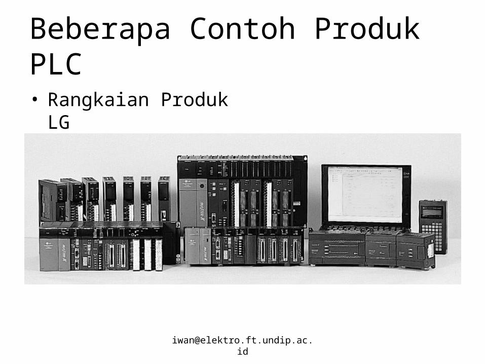
Transcript of Introduction to Plc 01
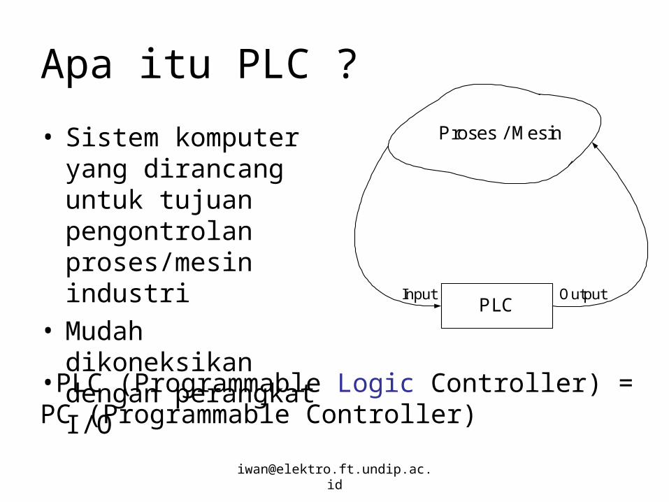
Apa itu PLC ?
• Sistem komputer yang dirancang untuk tujuan pengontrolan proses/mesin industri
• Mudah dikoneksikan dengan perangkat I/O
Proses / Mesin
PLCInput Output
•PLC (Programmable Logic Controller) = PC (Programmable Controller)
Sejarah PLC
• Dikembangkan sekitar tahun 1968 oleh GM (General Motor)
• Ditujukan untuk menggantikan kontrol relay yang tidak efisien dan high cost
• Berbasis komponen Solid State (semikonduktor)
• Secara fungsional kemampuannya terbatas pada operasi kontrol relay
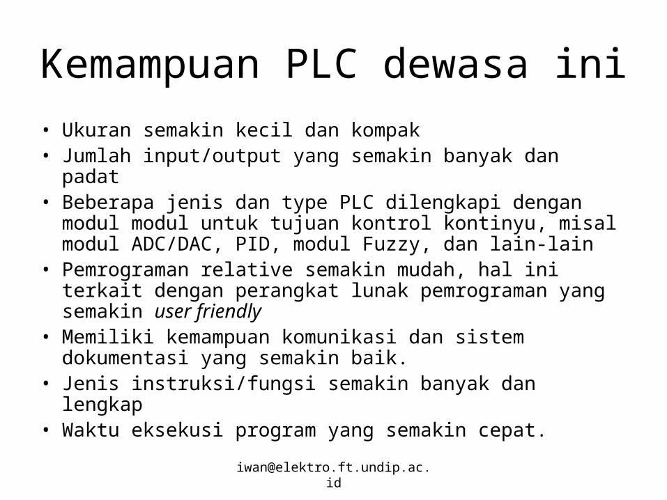
Kemampuan PLC dewasa ini
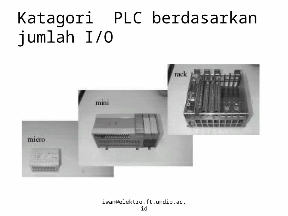
• Ukuran semakin kecil dan kompak• Jumlah input/output yang semakin banyak dan padat• Beberapa jenis dan type PLC dilengkapi dengan modul
modul untuk tujuan kontrol kontinyu, misal modul ADC/DAC, PID, modul Fuzzy, dan lain-lain
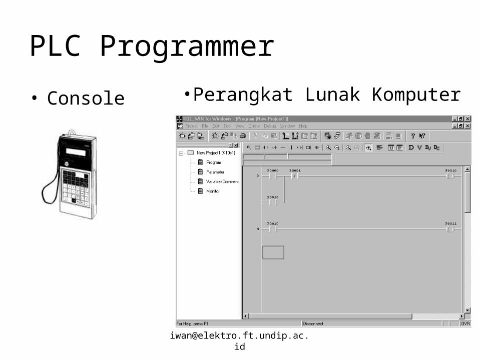
• Pemrograman relative semakin mudah, hal ini terkait dengan perangkat lunak pemrograman yang semakin user friendly
• Memiliki kemampuan komunikasi dan sistem dokumentasi yang semakin baik.
• Jenis instruksi/fungsi semakin banyak dan lengkap • Waktu eksekusi program yang semakin cepat.
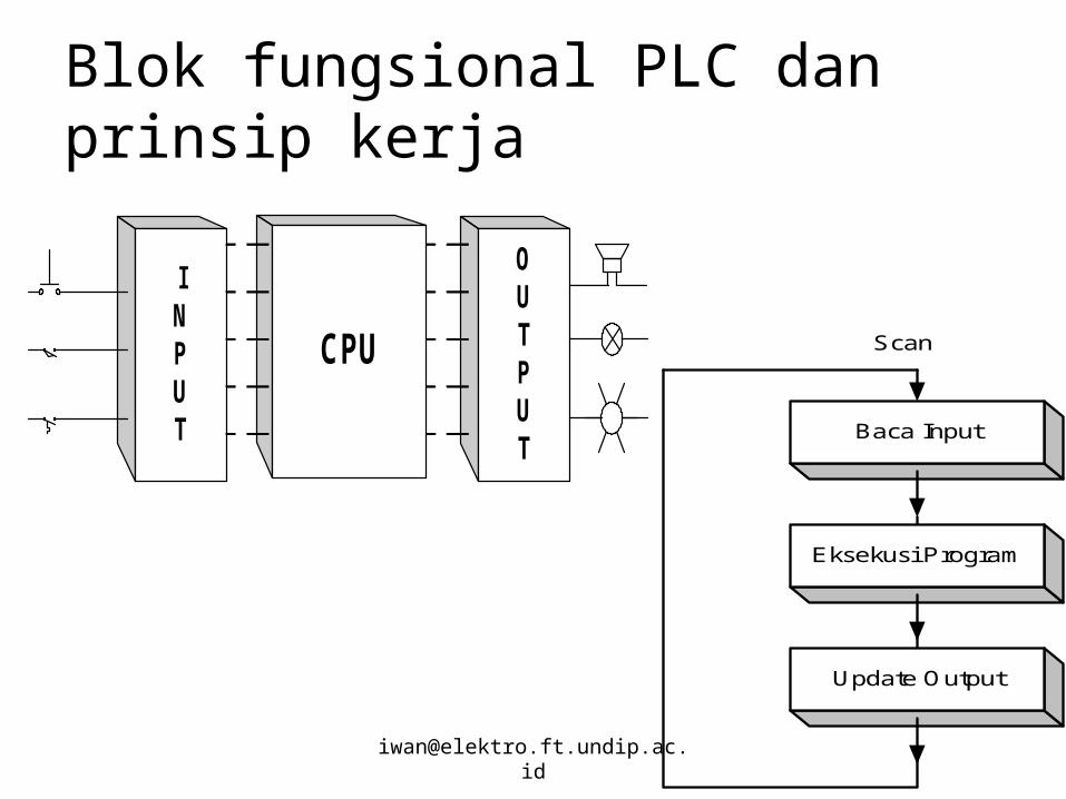
Blok fungsional PLC dan prinsip kerja
CPU
OUTPUT
INPUT
Scan
Baca Input
Eksekusi Program
Update Output
Perbandingan PLC dengan Kontrol Relay
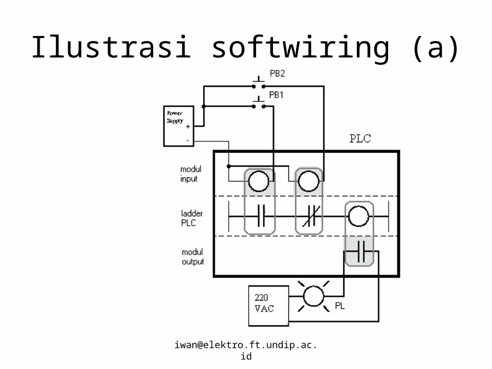
• Bersifat softwire artinya fungsi kontrol dapat secara mudah diubah dengan mengganti program secara software.
• Implementasi proyek cepat
• Pengkabelan relative sederhana dan rapi
• Monitoring proses terintegrasi.
Diagram Ladder (Hardwired/Elektromekanis)• Dikenal juga sebagai single line diagram:
Sebuah metoda untuk menggambarkan proses industri yang umumnya berjalan secara sekuensial
• Memperlihatkan interkoneksi perangkat keras pengontrolan dengan menggunakan simbol-simbol standar kelistrikan
• Bentuknya mirip dengan tangga (ladder)
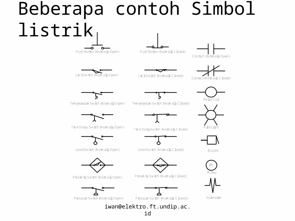
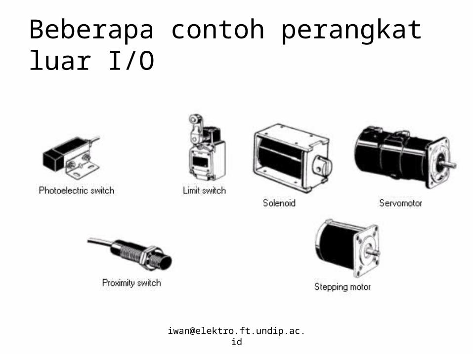
Beberapa contoh Simbol listrik
Limit Switch (Normally Open) Limit Switch (Normally Closed)
Time Delay Switch (Normally Open)Time DelaySwitch (Normally Closed)
Temperature Switch (Normally Open) Temperature Switch (Normally Closed)
Level Switch (Normally Open) Level Switch (Normally Closed)
Proximity Switch (Normally Open) Proximity Switch (Normally Closed)
Push Button (Normally Open) Push Button (Normally Closed)
Pressure Switch (Normally Open) Pressure Switch (Normally Closed))
Contact (Normally Open)
Contact (Normally Closed)
Relay Coil
Pilot Light
Buzzer
M
Motor
Solenoide
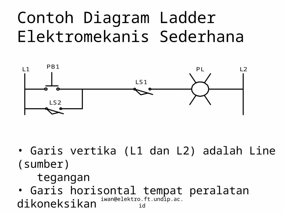
Contoh Diagram Ladder Elektromekanis Sederhana
PB1 PL
LS1
L2L1
LS2
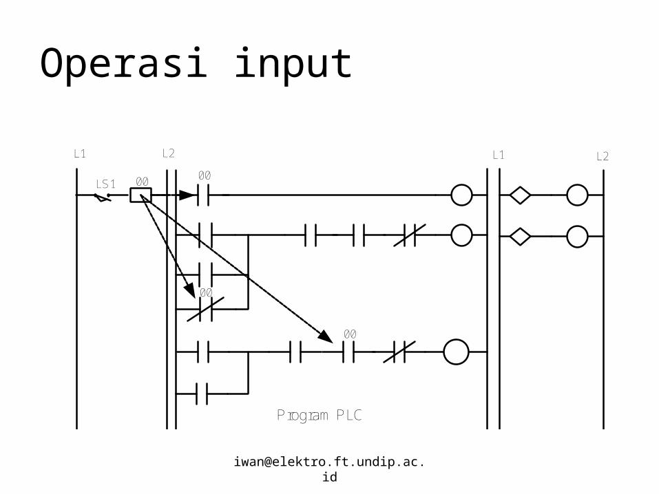
• Garis vertika (L1 dan L2) adalah Line (sumber) tegangan• Garis horisontal tempat peralatan dikoneksikan
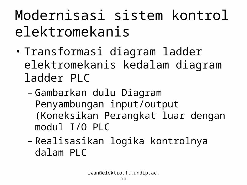
Modernisasi sistem kontrol elektromekanis• Transformasi diagram ladder
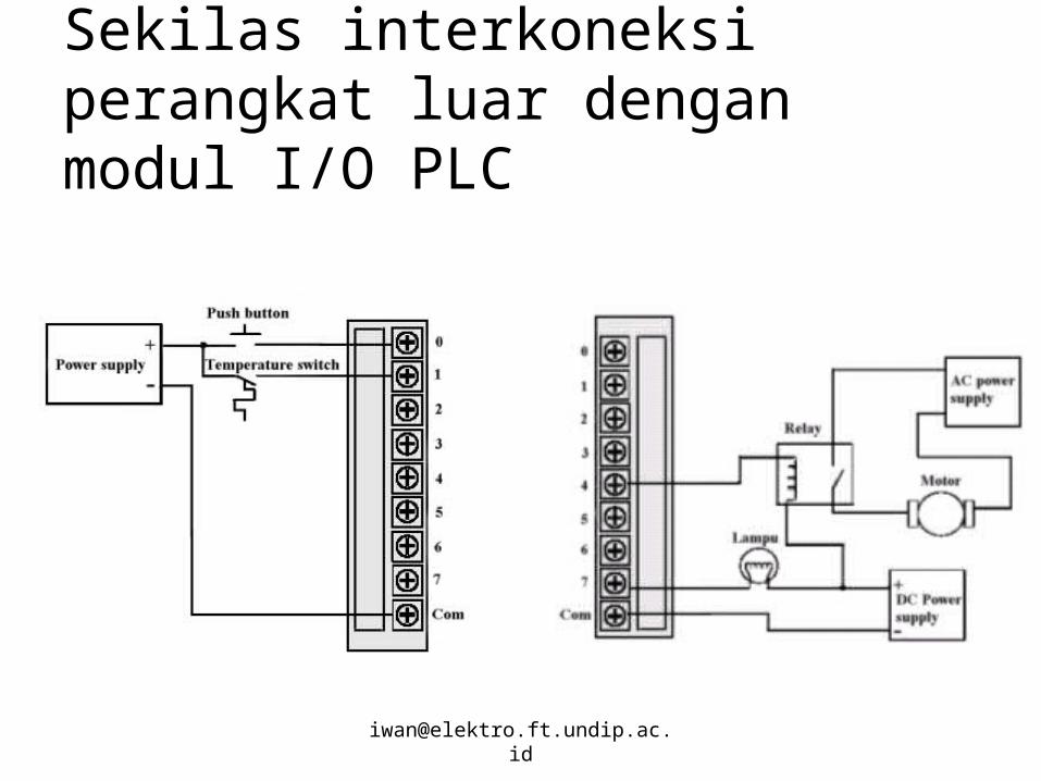
elektromekanis kedalam diagram ladder PLC– Gambarkan dulu Diagram Penyambungan
input/output (Koneksikan Perangkat luar dengan modul I/O PLC
– Realisasikan logika kontrolnya dalam PLC
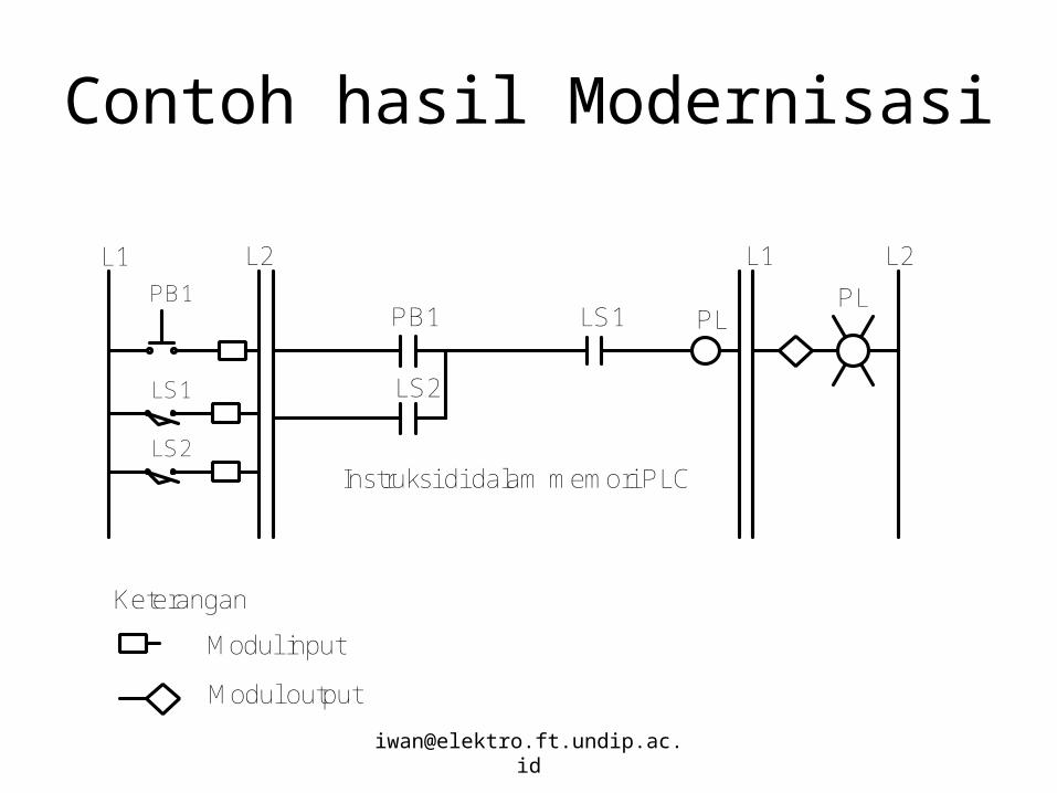
Contoh hasil Modernisasi
PL
L2
LS1
L1 L2
PL
L1
PB1PB1
Instruksi di dalam memori PLCLS2
LS1 LS2
Modul input
Keterangan
Modul output
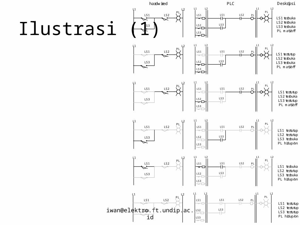
Ilustrasi (1)PL
L2
LS3
LS2
L1 L2
LS2
LS3
PLL1
PL
LS3
LS2
L2L1
LS1 LS1 LS1
PL
L2
LS3
LS2
L1 L2
LS2
LS3
PLL1
PL
LS3
LS2
L2L1
LS1 LS1 LS1
PL
L2
LS3
LS2
L1 L2
LS2
LS3
PLL1
PL
LS3
LS2
L2L1
LS1 LS1 LS1
PL
L2
LS3
LS2
L1 L2
LS2
LS3
PLL1
PL
LS3
LS2
L2L1
LS1 LS1 LS1
PL
L2
LS3
LS2
L1 L2
LS2
LS3
PLL1
PL
LS3
LS2
L2L1
LS1 LS1 LS1
PL
L2
LS3
LS2
L1 L2
LS2
LS3
PLL1
PL
LS3
LS2
L2L1
LS1 LS1 LS1
LS1 terbukaLS2 terbukaLS3 terbukaPL mati/off
LS1 tertutupLS2 terbukaLS3 terbukaPL mati/off
LS1 tertutupLS2 terbukaLS3 tertutupPL mati/off
LS1 tertutupLS2 tertutupLS3 terbukaPL hidup/on
LS1 terbukaLS2 tertutupLS3 terbukaPL hidup/on
LS1 tertutupLS2 tertutupLS3 tertutupPL hidup/on
PLC Deskripsihardwired
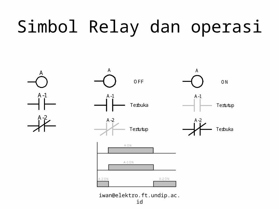
Simbol Relay dan operasi
A
A-1
A-2
A
A-1
A-2
ON
Tertutup
Terbuka
A
A-1
A-2
OFF
Terbuka
Tertutup
A ON
A-2 ON
A-1 ON
A-2 ON

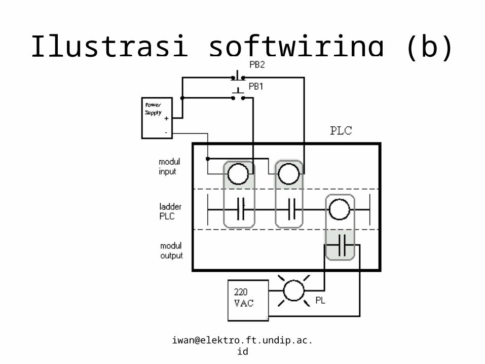
Ilustrasi (2)PLPB2PB1 L2L1
Hardwiring
PL
L2
PB2
L1 L2
PB2
PLL1
PB1PB1
PL
L2
PB2
L1 L2
PB2
PLL1
PB1PB1
(a)
(b)
Program PLC
Program PLC
Softwiring
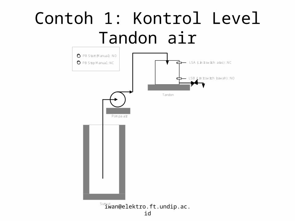
Contoh 1: Kontrol Level Tandon air
Tandon
Sumur
Pompa air
PB Start (Manual) : NO
PB Stop Manual : NC LSA (Limit switch atas) : NC
LSB (Limit switch bawah) : NO
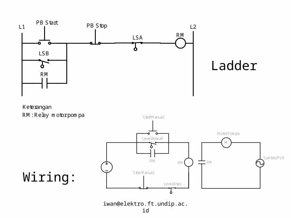
RM
RM
LSA
LSB
L2L1 PB StopPB Start
RM: Relay motor pompa
Keterangan
M
Motor Pompa
Sumber PLN
Level Atas
Level Bawah
Start Manual
Stop Manual
RMRM RM
Ladder
Wiring:
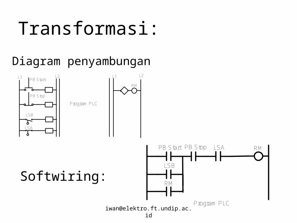
Transformasi:
L2 L1PB Start
PB Stop
L2L1
LSB
LSA
RM
Program PLC
Diagram penyambungan
PB Start PB Stop LSA
LSB
RM
RM
Program PLC
Softwiring:
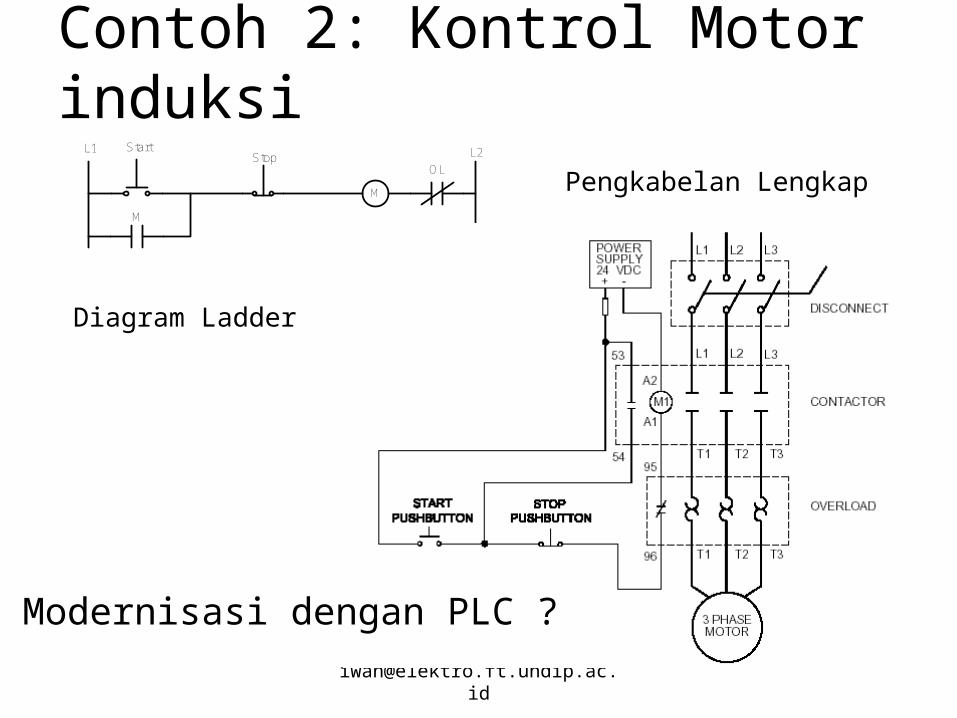
Contoh 2: Kontrol Motor induksiStart L2L1
Stop
M
OL
M
Diagram Ladder
Pengkabelan Lengkap
Modernisasi dengan PLC ?
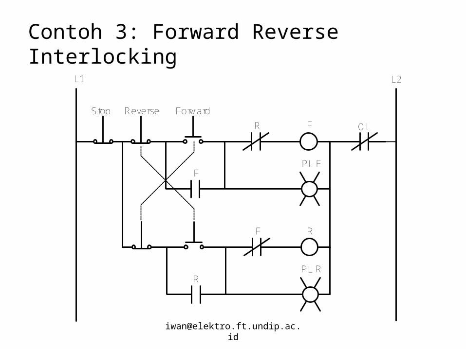
Contoh 3: Forward Reverse Interlocking
Stop
F
L2L1
Reverse Forward
F
R
PL F
R
RF
PL R
OL
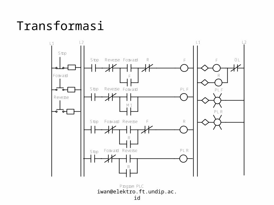
Transformasi
Stop F F
Stop
Forward
L1 L2L2L1
Program PLC
Reverse
Reverse Forward
F
R
Reverse Forward
M1
Stop PL F
Forward Reverse
R
F
Forward Reverse
R
Stop
Stop
R
PL R
R
PL F
PL R
OL
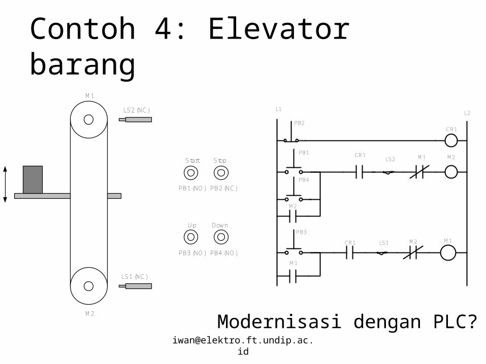
Contoh 4: Elevator barang
Start Stop
Up Down
M1
M2
PB1 (NO)
LS2 (NC)
PB2 (NC)
PB3 (NO) PB4 (NO)
LS1 (NC)
PB1
PB2
PB3
LS2 M1 M2
M2
CR1
CR1
CR1
M1
LS1
PB4
M2 M1
L2L1
Modernisasi dengan PLC?
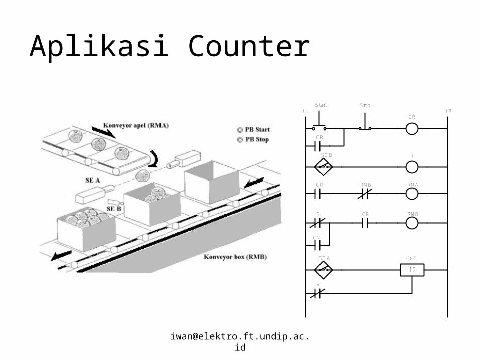
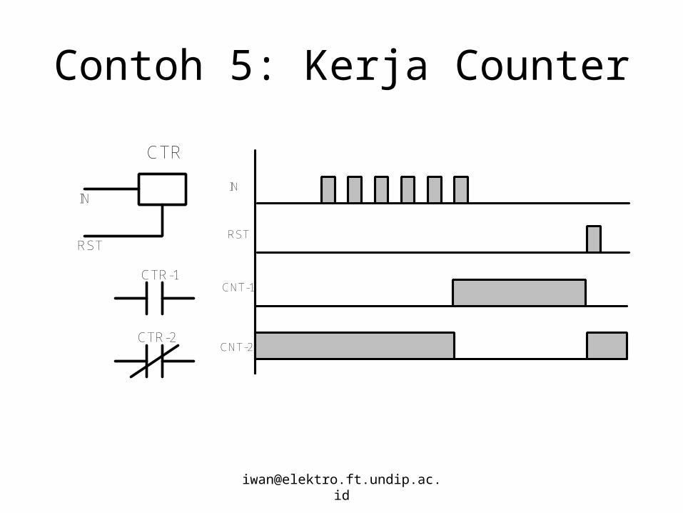
Aplikasi Counter
CR
CR
Start Stop
SE B R
R
RMBCR RMA
CR
12
SE A CNT
RMB
CNT
R
L2L1
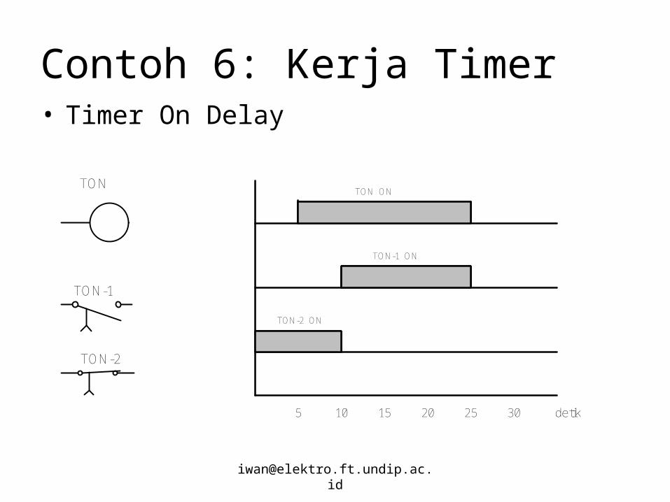
Contoh 6: Kerja Timer• Timer On Delay
TON
TON-1
TON-2
detik5 10 15 20 25 30
TON ON
TON-1 ON
TON-2 ON
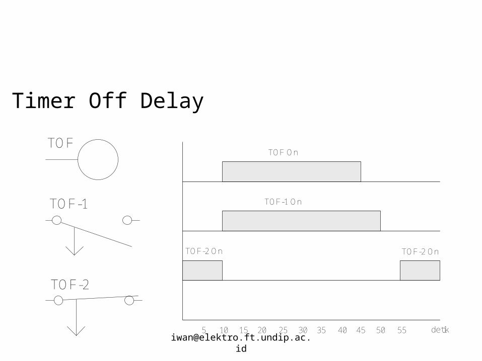
TOF
TOF-1
TOF-2
Timer Off Delay
5 10 15 20 25 30 35 40 45 50 55 detik
TOF On
TOF-1 On
TOF-2 On TOF-2 On
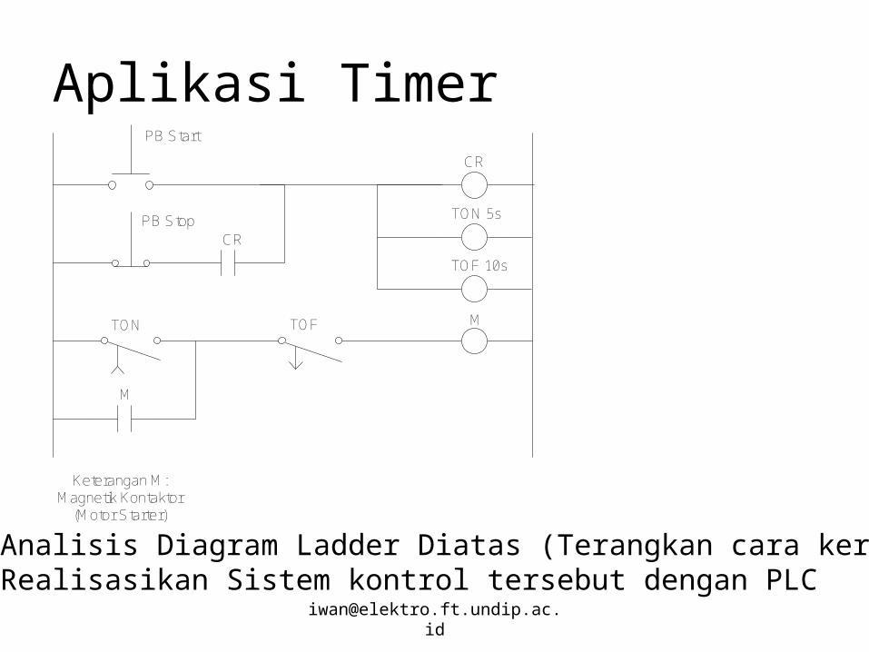
Aplikasi TimerCR
TON 5s
TOF 10s
M
M
TON TOF
CR
PB Start
PB Stop
Keterangan M:Magnetik Kontaktor
(Motor Starter)
•Analisis Diagram Ladder Diatas (Terangkan cara kerjanya)•Realisasikan Sistem kontrol tersebut dengan PLC
Problem
• Rancanglah diagram ladder untuk mengontrol sebuah Lampu sehingga berkedap kedip setiap selang waktu 5 detik

![Teori pendukung [introduction to algoritm]](https://static.fdokumen.com/doc/165x107/5596c49a1a28ab46408b4585/teori-pendukung-introduction-to-algoritm.jpg)