
04 05 Paralel
29
1 KONVERSI TENAGA LISTRIK 1: Klasifikasi mesin-mesin listrik dan konstruksi 2: Generator sinkron: proses terbangkitnya EMF dan macam- macam generator sinkron 3: Generator sinkron: berbeban, kerugian tegangan, diagram vektor untuk pf. lagging, pf. leading 4: Generator sinkron: menentukan voltage regulator dengan metode EMF dan karakteristik 5: Generator sinkron: kerja paralel 6: Motor sinkron: metode start dan pengaruh perubahan arus eksitasi 7: Motor sinkron: torque dan contoh soal
-
Upload
esthi-kusuma -
Category
Documents
-
view
28 -
download
0
Transcript of 04 05 Paralel
7/16/2019 04 05 Paralel
http://slidepdf.com/reader/full/04-05-paralel 1/29
1
KONVERSI TENAGA LISTRIK
1: Klasifikasi mesin-mesin listrik dan konstruksi 2: Generator sinkron: proses terbangkitnya EMF dan macam-
macam generator sinkron
3: Generator sinkron: berbeban, kerugian tegangan, diagramvektor untuk pf. lagging, pf. leading
4: Generator sinkron: menentukan voltage regulator denganmetode EMF dan karakteristik
5: Generator sinkron: kerja paralel
6: Motor sinkron: metode start dan pengaruh perubahan aruseksitasi
7: Motor sinkron: torque dan contoh soal
7/16/2019 04 05 Paralel
http://slidepdf.com/reader/full/04-05-paralel 2/29
2
References
1. Chapman, S. J, ‘Electric Machinery Fundamentals’,
McGraw-Hill, 2005
2. Theraja, B. L., ‘Electrical Technology’, S. Chand &
Company Ltd., 1978.
3. Karady, G., ‘Lecture Notes on Synchronous Generator’,
www.eas.asu.edu/~karady/360_pp.html.
3. Zuhal

7/16/2019 04 05 Paralel
http://slidepdf.com/reader/full/04-05-paralel 3/29
3
Examples: Loaded Synch. Generators
Ex 32-14 32-16

7/16/2019 04 05 Paralel
http://slidepdf.com/reader/full/04-05-paralel 4/29
4
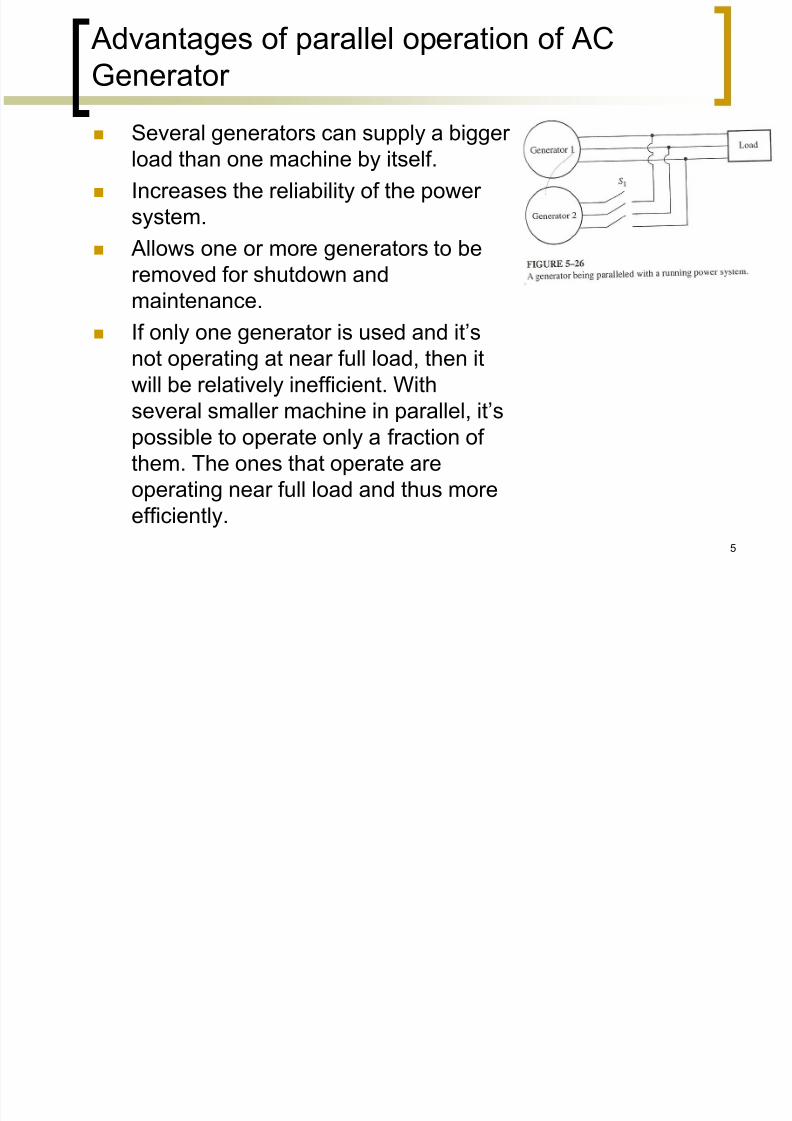
Parallel operation of AC Generator [1]
In today’s world, an isolated synchronous generator supplying its own load independently of other
generators is very rare.
Such a situation is found in only a few applications
such as emergency generators. For all usual generator applications, there is more
than one generator operating in parallel.
An extreme example of this is the US power grid, in
which literally thousands of generators share theloads on the system.
7/16/2019 04 05 Paralel
http://slidepdf.com/reader/full/04-05-paralel 5/29
5
Advantages of parallel operation of AC
Generator
Several generators can supply a bigger load than one machine by itself.
Increases the reliability of the power
system.
Allows one or more generators to be
removed for shutdown andmaintenance.
If only one generator is used and it’s
not operating at near full load, then it
will be relatively inefficient. With
several smaller machine in parallel, it’spossible to operate only a fraction of
them. The ones that operate are
operating near full load and thus more
efficiently.

7/16/2019 04 05 Paralel
http://slidepdf.com/reader/full/04-05-paralel 6/29
6
The conditions required for paralleling
G2 is about to be paralleled with G1 byclosing the switch S1.
If S1 is closed arbitrarily at some
moment, the generators are liable to be
severely damaged, & the load may lose
power. If the voltages are not exactly the
same in each conductor being tied
together, there will be a very large
current flow when the switch is
closed.
7/16/2019 04 05 Paralel
http://slidepdf.com/reader/full/04-05-paralel 7/29
7
The conditions required for paralleling
To avoid this problem, each of the three phases must have
exact ly th e same vo ltage
magn i tude and phase angle as
the conductor to which it is
connected.
-> The voltage in phase a must
be exactly the same as the
voltage in phase a’, & so forth for
phases b-b’, and c-c’
7/16/2019 04 05 Paralel
http://slidepdf.com/reader/full/04-05-paralel 8/29
8
The conditions required for paralleling
To achieve this match, the following paral lel ing condi t ions must be met:
The rms line voltages of the two generators must be
equal.
The two generators must have the same phasesequence.
The phase angles of the two a phases must be
equal.
**The frequency of the oncoming generator must bethe same with the line frequency.

7/16/2019 04 05 Paralel
http://slidepdf.com/reader/full/04-05-paralel 9/29
9
The conditions required for paralleling
To achieve this match, the following paral lel ing condi t ions must be met:
The rms line voltages of the two generators must be
equal.
The two generators must have the same phasesequence.
The phase angles of the two a phases must be
equal.
**The frequency of the oncoming generator , mustbe slightly higher than the new frequency of the
running system.
So that when it’s connected, it will come on the line
supplying power as a generator, instead of consuming it
as a motor would.

7/16/2019 04 05 Paralel
http://slidepdf.com/reader/full/04-05-paralel 10/29
10
*Synchronizing of Alternators [2]
First, it’s necessary that the incoming alternator’sphases are connected in the proper order (R’, S’, T’
and not R’, T’, S’).
Then it’s needed to synchronize each phase. (It’snecessary to synchronize one phase only, the other
two phases will then be synchronized
automatically.)
7/16/2019 04 05 Paralel
http://slidepdf.com/reader/full/04-05-paralel 11/29
*Checking phase sequence
Can be checked through different ways: Alternately connect a small induction motor to the terminals
of each of the two generators. If the motor rotates in the same direction each time -> phase
sequence is the same. Otherwise, phase sequence differs -> two of the conductors of the
incoming generator must be reversed.
phase rotation check hyoki 3123
11
7/16/2019 04 05 Paralel
http://slidepdf.com/reader/full/04-05-paralel 12/29
*Checking phase sequence
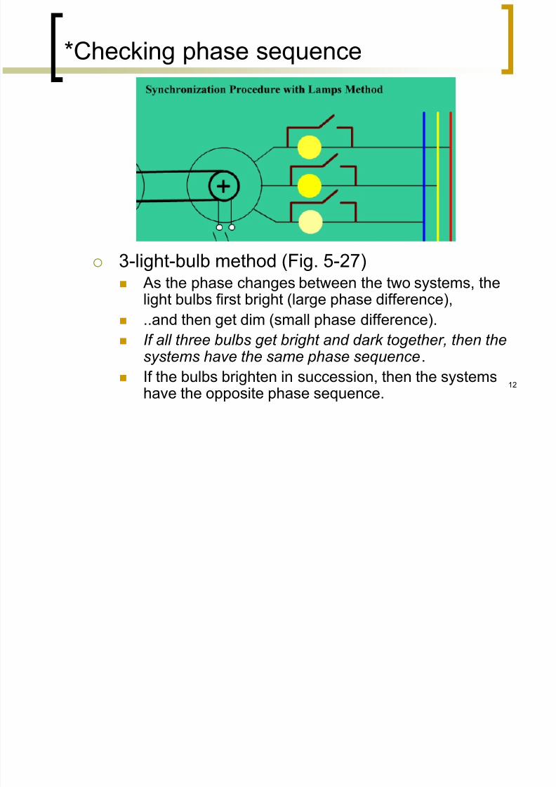
3-light-bulb method (Fig. 5-27) As the phase changes between the two systems, the
light bulbs first bright (large phase difference),
..and then get dim (small phase difference).
If all three bulbs get bright and dark together, then thesystems have the same phase sequence.
If the bulbs brighten in succession, then the systems
have the opposite phase sequence. 12

7/16/2019 04 05 Paralel
http://slidepdf.com/reader/full/04-05-paralel 13/29
*Checking whether the systems are in
phase
Bulb method Dark method (like the previous slide)
R to R’, S to S’, T to T’
Bright method
R to S’, S to T’, T to R’
Bright-dark method see next slide
http://msdaif.googlepages.com/Synchronization.swf
http://weh.maritime.edu/synchro/
13

7/16/2019 04 05 Paralel
http://slidepdf.com/reader/full/04-05-paralel 14/29
14
Method ‘2 bright, 1 dark’ [2] (1)
3 lamps are used, but they are deliberatelyconnected asymmetrically.
S
S
T
T
T’ S’
S’ T’ T S
R’

7/16/2019 04 05 Paralel
http://slidepdf.com/reader/full/04-05-paralel 15/29
15
Method ‘2 bright, 1 dark’ (2)
This transposition of 2 lamps is suggested bySiemens & Halske to help to indicate whether theincoming machine is running too fast or too slow.
If lamps were connected symmetrically, they woulddark out or glow up simultaneously.**
S
S
T
TT’ S’
S’ T’ T S
R’
7/16/2019 04 05 Paralel
http://slidepdf.com/reader/full/04-05-paralel 16/29
16
Method ‘2 bright, 1 dark’ (3)
S
T
T’
S’
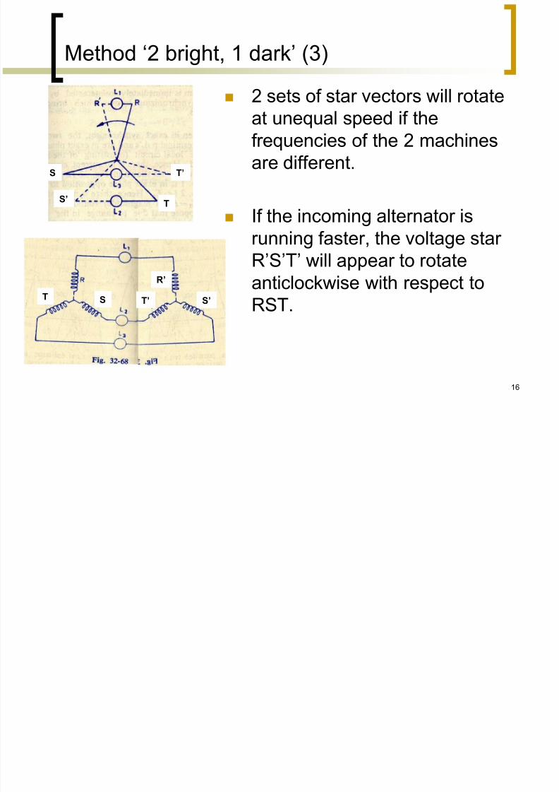
2 sets of star vectors will rotateat unequal speed if the
frequencies of the 2 machines
are different.
If the incoming alternator is
running faster, the voltage star
R’S’T’ will appear to rotate
anticlockwise with respect to
RST.S’ T’ T S
R’

7/16/2019 04 05 Paralel
http://slidepdf.com/reader/full/04-05-paralel 17/29
17
Faster incoming alternator
S
T
T’
S’
Voltage across L1 is RR’. It’s seen increasing from
zero.
Voltage across L2 is S’Twhich is decreasing.
Voltage across L3 is ST’
which is increasing.
Here, the lamps will light upone after the other in the
order 2, 3, 1 or 1, 2, 3.

7/16/2019 04 05 Paralel
http://slidepdf.com/reader/full/04-05-paralel 18/29
18
Slower incoming alternator
S
T
T’
S’
If the incoming machine is slower; The star R’S’T’ will appear to
rotating clockwise relative to RST.
Voltage across L2 is S’T which is
increasing. Voltage across L3 is ST’ which is
decreasing.
Here, the lamps will light up
one after the other in theorder 3, 2, 1.
7/16/2019 04 05 Paralel
http://slidepdf.com/reader/full/04-05-paralel 19/29
19
S
T
T’
S’
S
T
T’
S’
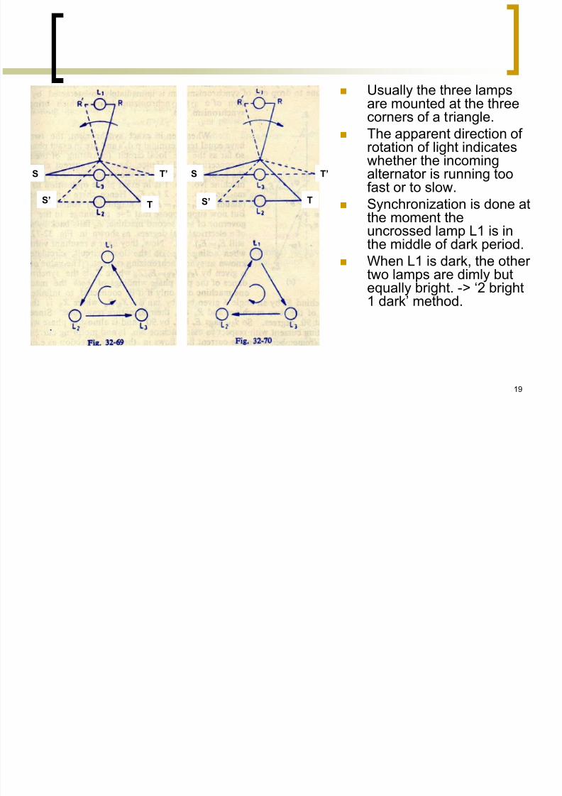
Usually the three lampsare mounted at the threecorners of a triangle.
The apparent direction of rotation of light indicateswhether the incomingalternator is running toofast or to slow.
Synchronization is done atthe moment theuncrossed lamp L1 is inthe middle of dark period.
When L1 is dark, the other two lamps are dimly butequally bright. -> ‘2 bright1 dark’ method.
7/16/2019 04 05 Paralel
http://slidepdf.com/reader/full/04-05-paralel 20/29
20
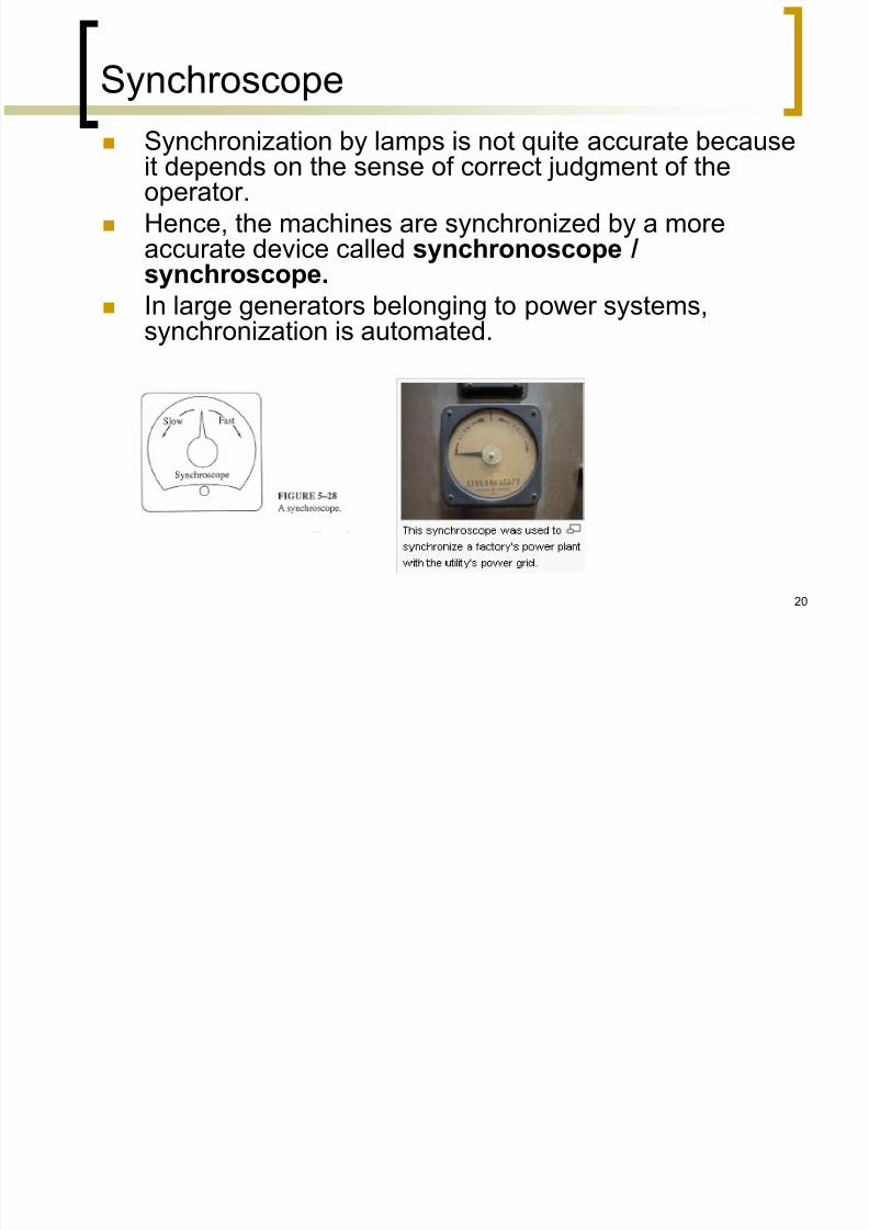
Synchroscope
Synchronization by lamps is not quite accurate becauseit depends on the sense of correct judgment of theoperator.
Hence, the machines are synchronized by a moreaccurate device called synchronoscope /synchroscope.
In large generators belonging to power systems,synchronization is automated.

7/16/2019 04 05 Paralel
http://slidepdf.com/reader/full/04-05-paralel 21/29
21

7/16/2019 04 05 Paralel
http://slidepdf.com/reader/full/04-05-paralel 22/29
22
Synchronizing Current [2]
Once synchronized properly, two alternatorscontinue to run in synchronism.
Any tendency on the part of one to drop out of
synchronism is immediately counteracted by the
production of a synchronizing torque which brings itback to synchronism.
7/16/2019 04 05 Paralel
http://slidepdf.com/reader/full/04-05-paralel 23/29
23
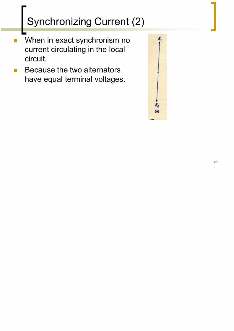
Synchronizing Current (2)
When in exact synchronism nocurrent circulating in the local
circuit.
Because the two alternators
have equal terminal voltages.

7/16/2019 04 05 Paralel
http://slidepdf.com/reader/full/04-05-paralel 24/29
24
Synchronizing Current [2]
Now suppose that due tochange in the speed of the 2nd
machine, E2 falls back by a
phase angle of α electrical
degrees

7/16/2019 04 05 Paralel
http://slidepdf.com/reader/full/04-05-paralel 25/29
25
Now they have a resultant voltage Er which circulates a current ->
synchronizing current, Isy.
It can be seen that Isy is generating
current with respect to alternator 1 andmotoring current with respect to
alternator 2.
This current Isy sets up a
synchronizing torque which tends toretard the generating machine
(alternator 1) and accelerates the
motoring machine (alternator 2).

7/16/2019 04 05 Paralel
http://slidepdf.com/reader/full/04-05-paralel 26/29
26
Similarly, if E2 tends to advance inphase:
Isy is being the generating current for
no. 2, tends to retard it and being
motoring current for no. 1, tends to
accelerate it.
Hence, any departure from
synchronism results in the
production of a synchronizingcurrent Isy which sets up
synchronizing torque.

7/16/2019 04 05 Paralel
http://slidepdf.com/reader/full/04-05-paralel 27/29
27

7/16/2019 04 05 Paralel
http://slidepdf.com/reader/full/04-05-paralel 28/29
**In the case of two generators operating
together:
Pload = PG1 + PG2 (+…) Power sharing
28
7/16/2019 04 05 Paralel
http://slidepdf.com/reader/full/04-05-paralel 29/29
Electrical Degree
A unit of measurement of time as applied to alternating
current. One complete cycle =360 electrical degrees. One
cycle in a rotating electric machine is accomplished when the
rotating field moves from one pole to the next pole of the samepolarity. There are 360 electrical degrees in this time period.
Therefore, in a two pole machine there are 360 degrees in one
revolution, and the electrical and mechanical degrees are
equal. In a machine with more than two poles, the number of
electrical degrees per revolution is obtained by multiplying the
number of pairs of poles by 360.
29