· 14679_GenNotes_01.dgn 1/13/2010 9:14:04 PM I N I T I A L D e s ig n D e s ig n e d B y C h e c...
26
14679_GenNotes_01.dgn 1/13/2010 9:14:04 PM I NI TI AL Des i gn Des i gn ed By Ch eck ed By DATE DATE DATE I NI TI AL I NI TI AL Det ail Qu an titi es Det ail ed By Ch eck ed By Ch eck ed By Qu an titi es By J SM TRJ BJ A RGA BJ A AML 10/09 10/09 10/09 10/09 10/09 10/09 999 18TH STREET, SUITE 2600 DENVER, CO 80202 PHONE: 303-297-2976 FAX: 303-297-2693 Phone: 303-972-9112 FAX: 303-972-9114 Colorado Department of Transportation Region 6 RLB 8833 South Wadsworth Court Littleton, CO 80128 GENERAL NOTES DESIGN DATA CROSS REFERENCE DRAWING NUMBER (IF BLANK, REFERENCE IS TO SAME SHEET) BXX XX SECTION OR DETAIL IDENTIFICATION FOR BURIED UTILITY INFORMATION UTILITY NOTIFICATION CENTER OF COLORADO (UNCC) www.uncc.org (or 1-800-922-1987) THREE (3) BUSINESS DAYS BEFORE YOU DIG CALL 811 BRIDGE DESCRIPTION INDEX OF DRAWINGS THE FOLLOWING TABLE GIVES THE MINIMUM LAP SPLICE LENGTH FOR EPOXY COATED REINFORCING BARS PLACED IN ACCORDANCE WITH SUBSECTION 602.06. THESE SPLICE LENGTHS SHALL BE INCREASED BY 25% FOR BARS SPACED AT LESS THAN 6" ON CENTER. BAR SIZE #4 #5 #6 #7 #8 #9 #10 #11 SPLICE LENGTH FOR CLASS D CONCRETE 1’-3" 1’-7" 2’-5" 2’-10" 3’-8" 4’-8" 5’-11" 7’-3" WHEN THE CONTRACTOR ELECTS TO SUBSTITUTE EPOXY COATED REINFORCEMENT FOR BLACK REINFORCING BARS, THE MINIMUM LAP SPLICE SHALL BE AS DESCRIBED ABOVE. THE FOLLOWING TABLE GIVES THE MINIMUM LAP SPLICE LENGTH FOR BLACK REINFORCING BARS PLACED IN ACCORDANCE WITH SUBSECTION 602.06. THESE SPLICE LENGTHS SHALL BE INCREASED BY 25% FOR BARS SPACED AT LESS THAN 6" ON CENTER. BAR SIZE #4 #5 #6 #7 #8 #9 #10 #11 SPLICE LENGTH FOR CLASS D CONCRETE 1’-1" 1’-4" 1’-7" 1’-11" 2’-6" 3’-1" 3’-11" 4’-10" THE ABOVE SPLICE LENGTHS SHALL BE INCREASED BY 20 PERCENT FOR 3 BAR BUNDLES AND 33 PERCENT FOR 4 BAR BUNDLES. THE ABOVE SPLICE LENGTHS MAY BE REDUCED BY 20% WHEN 3" OF CLEAR COVER EXISTS AND BAR SPACING IS 6" OR GREATER ON CENTER. 1 - SIMPLE SPAN (125’-0") BRIDGE, CONCRETE SLAB AND GIRDER, PRESTRESSED, OVER ERICKSON BLVD. 36’-0" ROADWAY CURB-TO-CURB, NO SKEW, 1’-6" BRIDGE RAIL TYPE 7 (SPECIAL) EXCEPT AS SHOWN IN THE PLANS, STRUCTURE EXCAVATION AND BACKFILL SHALL BE IN ACCORDANCE WITH M-206-2 FOR BRIDGES. EXPANSION JOINT MATERIAL SHALL MEET AASHTO SPECIFICATION M213. A COLORED STRUCTURAL CONCRETE STAIN FINISH WILL BE REQUIRED, AS SHOWN ON THE PLANS, ON EXPOSED CONCRETE SURFACES. THE COLORS SHALL BE FLESH, EQUIVALENT TO FEDERAL STANDARD 595B COLOR NO. 31667, AND MEDIUM BROWN, EQUIVALENT TO FEDERAL STANDARD 595B COLOR NO. 30219. COLORS ARE TO BE SELECTED FROM TEST PANELS PROVIDED BY THE CONTRACTOR. THE FOLLOWING STRUCTURAL STEEL SHALL BE AASHTO M270 GRADE 36 (ASTM A-36): DIAPHRAGMS, EXPANSION DEVICES AND BEARING PLATES. AASHTO M-222 (ASTM A-588) MAY BE SUBSTITUTED FOR M270 GRADE 50 (ASTM A-572) AT NO ADDITIONAL COST TO THE PROJECT. ALL BOLTS SHALL BE " DIAMETER, HIGH STRENGTH, UNLESS OTHERWISE NOTED. LEVELING PADS ARE UNLAMINATED BEARINGS. THEY SHALL BE CUT OR MOLDED FROM AASHTO ELASTOMER GRADE 3, 4, OR 5 AS DESCRIBED IN TABLES 705-1 AND 705-2 WITH A DUROMETER (SHORE "A") HARDNESS OF 60. GRADE 60 REINFORCING STEEL IS REQUIRED. ALL REINFORCING STEEL SHALL BE EPOXY COATED UNLESS OTHERWISE NOTED. N DENOTES NON COATED REINFORCING STEEL. ALL THE PROVISIONS FOR BRIDGE DECK CONCRETE SHALL ALSO APPLY TO APPROACH SLAB CONCRETE. AASHTO LRFD BRIDGE DESIGN SPECIFICATIONS, 4TH EDITION WITH 2009 INTERIM REVISIONS DESIGN METHOD: LOAD AND RESISTANCE FACTOR DESIGN LIVE LOAD: HL-93 (DESIGN TRUCK OR TANDEM, AND DESIGN LANE LOAD), COLORADO PERMIT VEHICLE DEAD LOAD: ASSUMES 36 LBS. PER SQ. FT. FOR BRIDGE DECK OVERLAY ASSUMES 5 LBS. PER SQ. FT. FOR PERMANENT DECK FORMS REINFORCED CONCRETE: CLASS D CONCRETE: f’c = 4,500 psi REINFORCING STEEL: fy = 60,000 psi THE CONTRACTOR SHALL BE RESPONSIBLE FOR THE STABILITY OF THE STRUCTURE DURING CONSTRUCTION. E.F. = EACH FACE F.F. = FAR FACE N.F. = NEAR FACE E.S. = EACH SIDE A.S. = AS SHOWN PERMANENT DECK FORMS ARE OPTIONAL AND MAY BE STEEL OR PRECAST. FOR STRUCTURE NUMBER INSTALLATION, SEE STANDARD S-614-12. STATIONS, ELEVATIONS, AND DIMENSIONS CONTAINED IN THESE PLANS ARE CALCULATED FROM A RECENT FIELD SURVEY. THE CONTRACTOR SHALL VERIFY ALL DEPENDENT DIMENSIONS IN THE FIELD BEFORE ORDERING OR FABRICATING ANY MATERIAL. THE INFORMATION SHOWN ON THESE PLANS CONCERNING THE TYPE AND LOCATION OF UNDERGROUND UTILITIES IS NOT GUARANTEED TO BE ACCURATE OR ALL INCLUSIVE. THE CONTRACTOR IS RESPONSIBLE FOR MAKING HIS OWN DETERMINATION AS TO THE TYPE AND LOCATION OF UNDERGROUND UTILITIES AS MAY BE NECESSARY TO AVOID DAMAGE THERETO. THE CONTRACTOR SHALL CONTACT THE UTILITY NOTIFICATION CENTER OF COLORADO AT 1-800-922-1987 AT LEAST 2 DAYS (NOT INCLUDING THE DAY OF NOTIFICATION) PRIOR TO ANY EXCAVATION OR OTHER EARTHWORK. PRECAST PRESTRESSED CONCRETE: CLASS PS CONCRETE f’c = (SEE DETAILS) f’s = 270,000 psi BJ All en 9: 14: 04 PM M:\TRN\07- 100- 311 - 12\14679\Br i dge\Dr awi ngs \Er i ck s on Br i dge\14679_Gen Not es _01 . dgn F-16-WY Numbers Structure No Revisions: Revised: Void: Sheet Subset: Detailer: Designer: Bridge R. Artman A. Leifheit 17679 ES6 0852-103 Sheet Number Subset Sheets: B1 of B26 Init. Comments Date: Sheet Revisions As Constructed 1/13/2010 Print Date: Horiz. Scale: 1:1 14679_GenNotes_01.dgn Vert. Scale: As Noted Unit Leader MH Project No./Code FLYOVER RAMP OVER ERICKSON GENERAL NOTES File Name: Unit Information 0224 SHEET NO. B1 B2 B3 B4 B5 B6 B7 B8 B9 B10 B11 B12 B13 B14 B15 B16 B17 B18 B19 B20 B21 B22 B23 B24 B25 B26 TITLE GENERAL NOTES SUMMARY OF QUANTITIES GENERAL LAYOUT ENGINEERING GEOLOGY CONSTRUCTION AND FOUNDATION LAYOUT PILE DETAILS ABUTMENT 1 DETAILS ABUTMENT 2 DETAILS WINGWALL DETAILS DECK REINFORCING PLAN & SECTION BT63 GIRDER DETAILS (1 OF 2) BT63 GIRDER DETAILS (2 OF 2) PRECAST PANEL DECK FORM (1 OF 2) PRECAST PANEL DECK FORM (2 OF 2) LIGHTING DETAILS BRIDGE RAIL TYPE 7 (SPECIAL) (1 OF 2) BRIDGE RAIL TYPE 7 (SPECIAL) (2 OF 2) FENCE CHAIN LINK (SPECIAL) (36 INCH SPLASH GUARD) APPROACH SLAB DETAILS (1 OF 2) APPROACH SLAB DETAILS (2 OF 2) BRIDGE EXPANSION DEVICE (0-4 INCH) (1 OF 2) BRIDGE EXPANSION DEVICE (0-4 INCH) (2 OF 2) MECHANICALLY STABILIZED BACKFILL SLOPE PAVING DETAILS BRIDGE DECK ELEVATIONS (1 OF 2) BRIDGE DECK ELEVATIONS (2 OF 2)
Transcript of · 14679_GenNotes_01.dgn 1/13/2010 9:14:04 PM I N I T I A L D e s ig n D e s ig n e d B y C h e c...
14679_GenNotes_01.dgn 1/13/2010 9:14:04 PM
INITIA
L
Desig
n
Desig
ned
By
Checked
By
DA
TE
DA
TE
DA
TE
INITIA
LINITIA
L
Detail
Quantities
Detailed
By
Checked
By
Checked
By
Quantities
By
JS
M
TRJ
BJ
A
RG
A
BJ
A
AM
L10/09
10/09
10/09
10/09
10/09
10/09
999 18TH STREET, SUITE 2600
DENVER, CO 80202
PHONE: 303-297-2976
FAX: 303-297-2693
Phone:303-972-9112 FAX:303-972-9114
Colorado Department of Transportation
Region 6 RLB
8833 South Wadsworth Court
Littleton, CO 80128
GENERAL NOTES
DESIGN DATA
CROSS REFERENCE DRAWING NUMBER
(IF BLANK, REFERENCE IS TO SAME SHEET)
BXX
XX
SECTION OR DETAIL IDENTIFICATION
FOR BURIED UTILITY INFORMATION
UTILITY NOTIFICATION
CENTER OF COLORADO (UNCC)
www.uncc.org
(or 1-800-922-1987)
THREE (3) BUSINESS DAYS
BEFORE YOU DIG
CALL 811
BRIDGE DESCRIPTION
INDEX OF DRAWINGS
THE FOLLOWING TABLE GIVES THE MINIMUM LAP SPLICE LENGTH FOR EPOXY COATED
REINFORCING BARS PLACED IN ACCORDANCE WITH SUBSECTION 602.06. THESE SPLICE
LENGTHS SHALL BE INCREASED BY 25% FOR BARS SPACED AT LESS THAN 6" ON CENTER.
BAR SIZE #4 #5 #6 #7 #8 #9 #10 #11
SPLICE LENGTH FOR
CLASS D CONCRETE 1’-3" 1’-7" 2’-5" 2’-10" 3’-8" 4’-8" 5’-11" 7’-3"
WHEN THE CONTRACTOR ELECTS TO SUBSTITUTE EPOXY COATED REINFORCEMENT FOR
BLACK REINFORCING BARS, THE MINIMUM LAP SPLICE SHALL BE AS DESCRIBED ABOVE.
THE FOLLOWING TABLE GIVES THE MINIMUM LAP SPLICE LENGTH FOR BLACK REINFORCING
BARS PLACED IN ACCORDANCE WITH SUBSECTION 602.06. THESE SPLICE LENGTHS SHALL
BE INCREASED BY 25% FOR BARS SPACED AT LESS THAN 6" ON CENTER.
BAR SIZE #4 #5 #6 #7 #8 #9 #10 #11
SPLICE LENGTH FOR
CLASS D CONCRETE 1’-1" 1’-4" 1’-7" 1’-11" 2’-6" 3’-1" 3’-11" 4’-10"
THE ABOVE SPLICE LENGTHS SHALL BE INCREASED BY 20 PERCENT FOR 3 BAR BUNDLES
AND 33 PERCENT FOR 4 BAR BUNDLES.
THE ABOVE SPLICE LENGTHS MAY BE REDUCED BY 20% WHEN 3" OF CLEAR COVER
EXISTS AND BAR SPACING IS 6" OR GREATER ON CENTER.
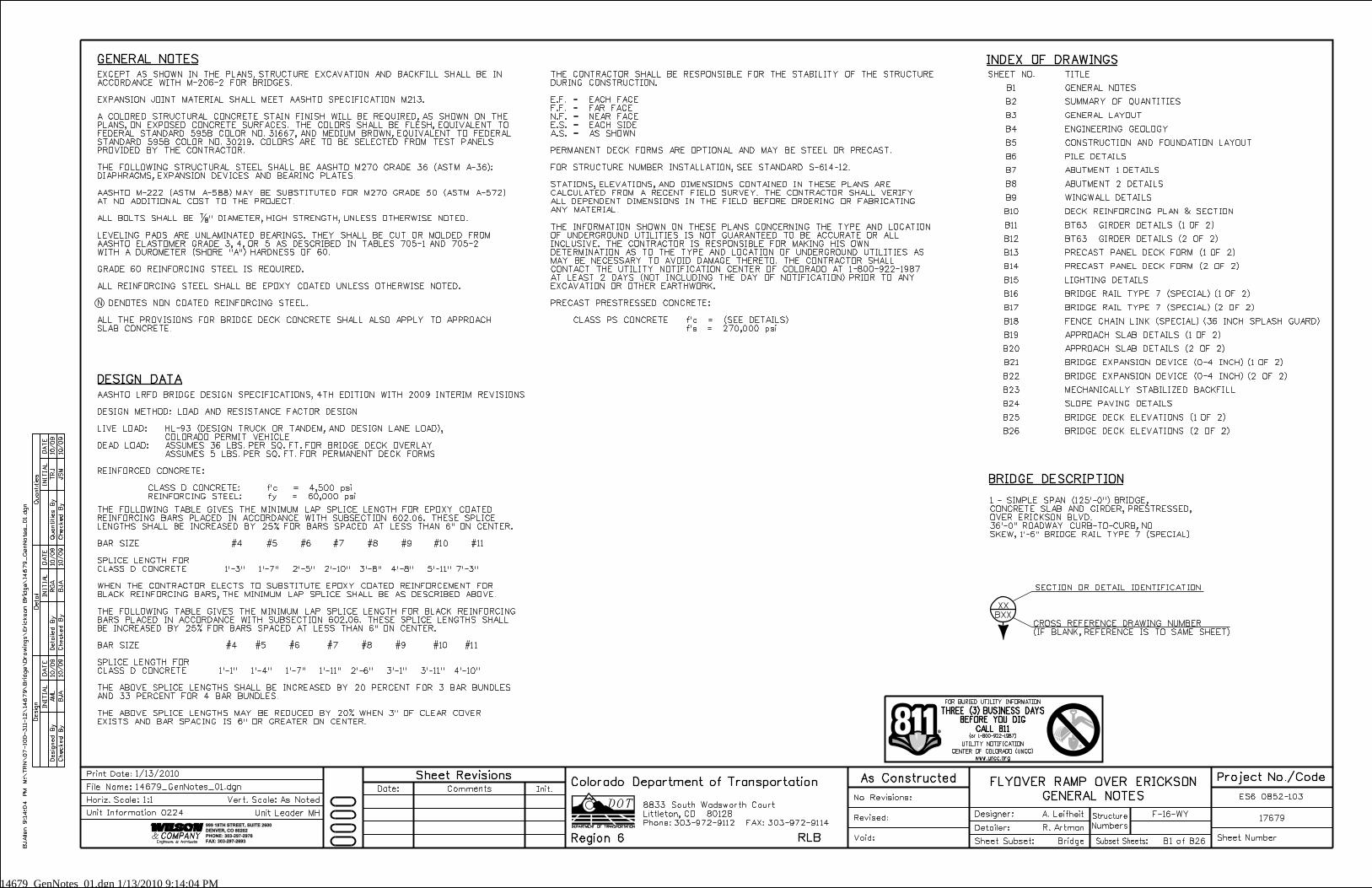
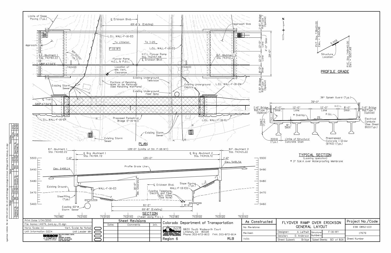
1 - SIMPLE SPAN (125’-0") BRIDGE,
CONCRETE SLAB AND GIRDER, PRESTRESSED,
OVER ERICKSON BLVD.
36’-0" ROADWAY CURB-TO-CURB, NO
SKEW, 1’-6" BRIDGE RAIL TYPE 7 (SPECIAL)
EXCEPT AS SHOWN IN THE PLANS, STRUCTURE EXCAVATION AND BACKFILL SHALL BE IN
ACCORDANCE WITH M-206-2 FOR BRIDGES.
EXPANSION JOINT MATERIAL SHALL MEET AASHTO SPECIFICATION M213.
A COLORED STRUCTURAL CONCRETE STAIN FINISH WILL BE REQUIRED, AS SHOWN ON THE
PLANS, ON EXPOSED CONCRETE SURFACES. THE COLORS SHALL BE FLESH, EQUIVALENT TO
FEDERAL STANDARD 595B COLOR NO. 31667, AND MEDIUM BROWN, EQUIVALENT TO FEDERAL
STANDARD 595B COLOR NO. 30219. COLORS ARE TO BE SELECTED FROM TEST PANELS
PROVIDED BY THE CONTRACTOR.
THE FOLLOWING STRUCTURAL STEEL SHALL BE AASHTO M270 GRADE 36 (ASTM A-36):
DIAPHRAGMS, EXPANSION DEVICES AND BEARING PLATES.
AASHTO M-222 (ASTM A-588) MAY BE SUBSTITUTED FOR M270 GRADE 50 (ASTM A-572)
AT NO ADDITIONAL COST TO THE PROJECT.
ALL BOLTS SHALL BE �" DIAMETER, HIGH STRENGTH, UNLESS OTHERWISE NOTED.
LEVELING PADS ARE UNLAMINATED BEARINGS. THEY SHALL BE CUT OR MOLDED FROM
AASHTO ELASTOMER GRADE 3, 4, OR 5 AS DESCRIBED IN TABLES 705-1 AND 705-2
WITH A DUROMETER (SHORE "A") HARDNESS OF 60.
GRADE 60 REINFORCING STEEL IS REQUIRED.
ALL REINFORCING STEEL SHALL BE EPOXY COATED UNLESS OTHERWISE NOTED.
N DENOTES NON COATED REINFORCING STEEL.
ALL THE PROVISIONS FOR BRIDGE DECK CONCRETE SHALL ALSO APPLY TO APPROACH
SLAB CONCRETE.
AASHTO LRFD BRIDGE DESIGN SPECIFICATIONS, 4TH EDITION WITH 2009 INTERIM REVISIONS
DESIGN METHOD: LOAD AND RESISTANCE FACTOR DESIGN
LIVE LOAD: HL-93 (DESIGN TRUCK OR TANDEM, AND DESIGN LANE LOAD),
COLORADO PERMIT VEHICLE
DEAD LOAD: ASSUMES 36 LBS. PER SQ. FT. FOR BRIDGE DECK OVERLAY
ASSUMES 5 LBS. PER SQ. FT. FOR PERMANENT DECK FORMS
REINFORCED CONCRETE:
CLASS D CONCRETE: f’c = 4,500 psi
REINFORCING STEEL: fy = 60,000 psi
THE CONTRACTOR SHALL BE RESPONSIBLE FOR THE STABILITY OF THE STRUCTURE
DURING CONSTRUCTION.
E.F. = EACH FACE
F.F. = FAR FACE
N.F. = NEAR FACE
E.S. = EACH SIDE
A.S. = AS SHOWN
PERMANENT DECK FORMS ARE OPTIONAL AND MAY BE STEEL OR PRECAST.
FOR STRUCTURE NUMBER INSTALLATION, SEE STANDARD S-614-12.
STATIONS, ELEVATIONS, AND DIMENSIONS CONTAINED IN THESE PLANS ARE
CALCULATED FROM A RECENT FIELD SURVEY. THE CONTRACTOR SHALL VERIFY
ALL DEPENDENT DIMENSIONS IN THE FIELD BEFORE ORDERING OR FABRICATING
ANY MATERIAL.
THE INFORMATION SHOWN ON THESE PLANS CONCERNING THE TYPE AND LOCATION
OF UNDERGROUND UTILITIES IS NOT GUARANTEED TO BE ACCURATE OR ALL
INCLUSIVE. THE CONTRACTOR IS RESPONSIBLE FOR MAKING HIS OWN
DETERMINATION AS TO THE TYPE AND LOCATION OF UNDERGROUND UTILITIES AS
MAY BE NECESSARY TO AVOID DAMAGE THERETO. THE CONTRACTOR SHALL
CONTACT THE UTILITY NOTIFICATION CENTER OF COLORADO AT 1-800-922-1987
AT LEAST 2 DAYS (NOT INCLUDING THE DAY OF NOTIFICATION) PRIOR TO ANY
EXCAVATION OR OTHER EARTHWORK.
PRECAST PRESTRESSED CONCRETE:
CLASS PS CONCRETE f’c = (SEE DETAILS)
f’s = 270,000 psi
BJ
Allen 9:1
4:0
4
PM
M:\
TR
N\
07-100-3
11-12\
14
67
9\
Brid
ge\
Dra
win
gs\
Eric
kson
Brid
ge\
14
67
9_
Gen
Notes_
01.d
gn
F-16-WY
Numbers
Structure
No Revisions:
Revised:
Void: Sheet Subset:
Detailer:
Designer:
Bridge
R. Artman
A. Leifheit17679
ES6 0852-103
Sheet NumberSubset Sheets: B1 of B26
Init.CommentsDate:
Sheet Revisions As Constructed
1/13/2010Print Date:
Horiz. Scale:1:1
14679_GenNotes_01.dgn
Vert. Scale: As Noted
Unit Leader MH
Project No./CodeFLYOVER RAMP OVER ERICKSON
GENERAL NOTESFile Name:
Unit Information 0224
SHEET NO.
B1
B2
B3
B4
B5
B6
B7
B8
B9
B10
B11
B12
B13
B14
B15
B16
B17
B18
B19
B20
B21
B22
B23
B24
B25
B26
TITLE
GENERAL NOTES
SUMMARY OF QUANTITIES
GENERAL LAYOUT
ENGINEERING GEOLOGY
CONSTRUCTION AND FOUNDATION LAYOUT
PILE DETAILS
ABUTMENT 1 DETAILS
ABUTMENT 2 DETAILS
WINGWALL DETAILS
DECK REINFORCING PLAN & SECTION
BT63 GIRDER DETAILS (1 OF 2)
BT63 GIRDER DETAILS (2 OF 2)
PRECAST PANEL DECK FORM (1 OF 2)
PRECAST PANEL DECK FORM (2 OF 2)
LIGHTING DETAILS
BRIDGE RAIL TYPE 7 (SPECIAL) (1 OF 2)
BRIDGE RAIL TYPE 7 (SPECIAL) (2 OF 2)
FENCE CHAIN LINK (SPECIAL) (36 INCH SPLASH GUARD)
APPROACH SLAB DETAILS (1 OF 2)
APPROACH SLAB DETAILS (2 OF 2)
BRIDGE EXPANSION DEVICE (0-4 INCH) (1 OF 2)
BRIDGE EXPANSION DEVICE (0-4 INCH) (2 OF 2)
MECHANICALLY STABILIZED BACKFILL
SLOPE PAVING DETAILS
BRIDGE DECK ELEVATIONS (1 OF 2)
BRIDGE DECK ELEVATIONS (2 OF 2)
14679_SumApproxQuant_01.dgn 1/13/2010 9:14:32 PM
INITIA
L
Desig
n
Desig
ned
By
Checked
By
DA
TE
DA
TE
DA
TE
INITIA
LINITIA
L
Detail
Quantities
Detailed
By
Checked
By
Checked
By
Quantities
By
JS
M
TRJ
JS
M
RG
A
JS
M
TRJ
10/09
10/09
10/09
10/09
10/09
10/09
999 18TH STREET, SUITE 2600
DENVER, CO 80202
PHONE: 303-297-2976
FAX: 303-297-2693
Phone:303-972-9112 FAX:303-972-9114
Colorado Department of Transportation
Region 6 RLB
8833 South Wadsworth Court
Littleton, CO 80128
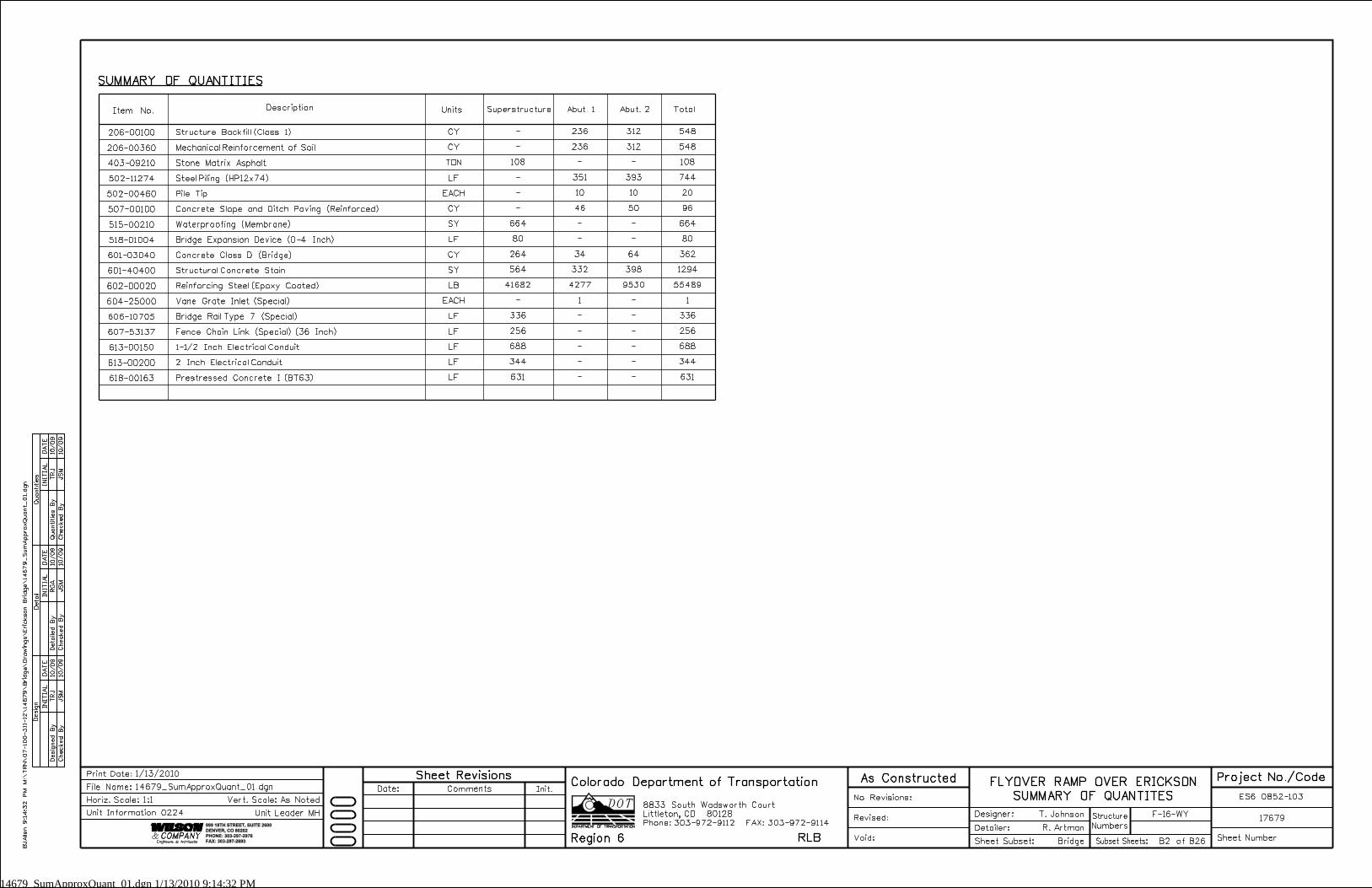
Description Units TotalAbut. 1Superstructure Abut. 2Item No.
SUMMARY OF QUANTITIES
CY
CY
TON
LF
EACH
CY
SY
LF
CY
SY
LB
EACH
LF
LF
LF
LF
LF
-
-
108
-
-
-
664
80
264
564
41682
-
336
256
688
344
631
236
236
-
351
10
46
-
-
34
332
4277
1
-
-
-
-
-
312
312
-
393
10
50
-
-
64
398
9530
-
-
-
-
-
-
548
548
108
744
20
96
664
80
362
1294
55489
1
336
256
688
344
631
206-00100
206-00360
403-09210
502-11274
502-00460
507-00100
515-00210
518-01004
601-03040
601-40400
602-00020
604-25000
606-10705
607-53137
613-00150
613-00200
618-00163
Structure Backfill (Class 1)
Mechanical Reinforcement of Soil
Stone Matrix Asphalt
Steel Piling (HP12x74)
Pile Tip
Concrete Slope and Ditch Paving (Reinforced)
Waterproofing (Membrane)
Bridge Expansion Device (0-4 Inch)
Concrete Class D (Bridge)
Structural Concrete Stain
Reinforcing Steel (Epoxy Coated)
Vane Grate Inlet (Special)
Bridge Rail Type 7 (Special)
Fence Chain Link (Special) (36 Inch)
1-1/2 Inch Electrical Conduit
2 Inch Electrical Conduit
Prestressed Concrete I (BT63)
BJ
Allen 9:1
4:3
2
PM
M:\
TR
N\
07-100-311-12\
14
67
9\
Brid
ge\
Dra
win
gs\
Eric
kson
Brid
ge\
14
67
9_
Su
mApprox
Quant_
01.d
gn
F-16-WY
Numbers
Structure
No Revisions:
Revised:
Void: Sheet Subset:
Detailer:
Designer:
Bridge
R. Artman
T. Johnson17679
ES6 0852-103
Sheet NumberSubset Sheets: B2 of B26
Init.CommentsDate:
Sheet Revisions As Constructed
1/13/2010Print Date:
Horiz. Scale:1:1
14679_SumApproxQuant_01.dgn
Vert. Scale: As Noted
Unit Leader MH
Project No./CodeFLYOVER RAMP OVER ERICKSON
SUMMARY OF QUANTITESFile Name:
Unit Information 0224
39’-
0"
Rail T
ype 7
1’-
6"
Brid
ge
Rail T
ype 7
1’-
6"
Brid
ge
Shldr.
8’-
0"
Lane
12’-
0"
Lane
12’-
0"
4’-
0" Shldr.
125’-0"1’-6" 1’-6"
39’-0"
69’-8"˛ (Existing)
128’-0" (Limits of Str. F-16-WY)
Min.
Cle
arance
16’-
6"
Rail Type 7
1’-6" Bridge
Shldr.
4’-0"
Shldr.
8’-0"
Lane
12’-0"
Lane
12’-0"
Rail Type 7
1’-6" Bridge
69’-8" (Existing)
8’-6"61’-2"
Phone:303-972-9112 FAX:303-972-9114
Colorado Department of Transportation
Region 6 RLB
8833 South Wadsworth Court
Littleton, CO 80128
Existing Storm
Sewer
Existing Storm
Sewer
Ò Trail
S88^47’34"E
S88^47’34"E
PLAN
Ò Brg. Abutment 1
Sta. 741+94.72
Ò Brg. Abutment 2
Sta. 743+19.72
Profile Grade Line
B.F. Abutment 1
Sta. 741+93.22
B.F. Abutment 2
Sta. 743+21.22
Elev. 5491.54
Elev. 5485.14
(Typ.)
Approach Slab
Approach Slab
B.F. Abutment 1
Sta. 741+93.22
B.F. Abutment 2
Sta. 743+21.22
P.G.L.
2%
8"
Deck
SECTION
TYPICAL SECTION(Looking Upstation)
PV
T
Sta.
738
+10.0
0
Ele
v.
= 54
65.9
8
PROFILE GRADE
Structure
Location
5500
5490
5480
5470
5460
5500
5490
5480
5470
5460
Ò Erickson Blvd.
Location of
Min. Vert.
Clearance
742+00 743+00
F
F
2
1Slope Paving(Typ.)
(Taken along P.G.L.)
Steel Piling
(Typ.)
Ò Erickson Blvd.
31667
(T
yp.)
30219
(Typ.)
H.C.L.
36" Splash Guard (Typ.)
742+00741+80 742+20 742+40 742+80 743+00 743+20 743+40
Limits of Slope
Paving (Typ.)
Flyover Ramp
H.C.L. & P.G.L.
* Overlay
Prestressed
Concrete I Girder
(BT63) (Typ.)
Existing Storm
Sewer
Existing Underground
Fiber Optic
Existing Underground
Electric
To Littleton To I-25
Existing Underground
Television
5.00
%
F-16-WY
JS
M
TRJ
BJ
A
RG
A
BJ
A
AM
L10/09
10/09
10/09
10/09
10/09
10/09
INITIA
L
Desig
n
Desig
ned
By
Checked
By
DA
TE
DA
TE
DA
TE
INITIA
LINITIA
L
Detail
Quantities
Detailed
By
Checked
By
Checked
By
Quantities
By
Existing Telephone,Electric and Fiber
Optic Utilies(See Note)
(Special)
(Special)
(Special) (Special)
Existing 60"ß
Storm Sewer
999 18TH STREET, SUITE
2600
DENVER, CO 80202
PHONE: 303-297-2976
FAX: 303-297-2693
L.O.L. WALL-F-16-EQ
L.O.L. WALL-F-16-EL
L.O.L. WALL-F-16-EM
WALL-F-16-EO WALL-F-16-EQ
Proposed Pedestrian
Bridge (F-16-WZ)
* 3" S.M.A. over Waterproofing Membrane
H.C.L. Flyover Ramp
Sta. 742+57.48
Ò Erickson Blvd.
Limits of Structural
Concrete Stain
PV
C
Sta.
74
6+4
0.0
0
Ele
v.
= 5507.4
8
L.O.L. WALL-F-16-EO
L.O.L. WALL-F-16-EP
Existing Ground
rgart
man 1:3
0:5
3
PM
M:\
TR
N\
07-100-3
11-12\
14
67
9\
Brid
ge\
Dra
win
gs\
Eric
kson
Brid
ge\
14
67
9_
Gen
Lay_
01.d
gn
F-16-WY
Numbers
Structure
No Revisions:
Revised:
Void: Sheet Subset:
Detailer:
Designer:
Bridge
D. Anderson
A. Leifheit17679
ES6 0852-103
Sheet NumberSubset Sheets: B3 of B26
Init.CommentsDate:
Sheet Revisions As Constructed
1/14/2010Print Date:
Horiz. Scale:1:1
14679_GenLay_01.dgn
Vert. Scale: As Noted
Unit Leader MH
Project No./CodeFLYOVER RAMP OVER ERICKSON
GENERAL LAYOUTFile Name:
Unit Information 0224
Electrical
Conduits
(See Sheet
B10)(Typ.)
Portions of RetainingWalls to be Removed(See Retaining Wall Plans)
54
65
54
65
5465
54
65
54
65
54
65
5470
5470
54
70
5470
5470
5470
5475
54
65
54
70
INITIA
L
Desig
n
Desig
ned
By
Checked
By
DA
TE
DA
TE
DA
TE
INITIA
LINITIA
L
Detail
Quantities
Detailed
By
Checked
By
Checked
By
Quantities
By
TM
S
TM
S
TM
S
RG
A
TM
S
BJ
A10/09
10/09
10/09
10/09
10/09
10/09
999 18TH STREET, SUITE 2600
DENVER, CO 80202
PHONE: 303-297-2976
FAX: 303-297-2693
Phone:303-972-9112 FAX:303-972-9114
Colorado Department of Transportation
Region 6 RLB
8833 South Wadsworth Court
Littleton, CO 80128
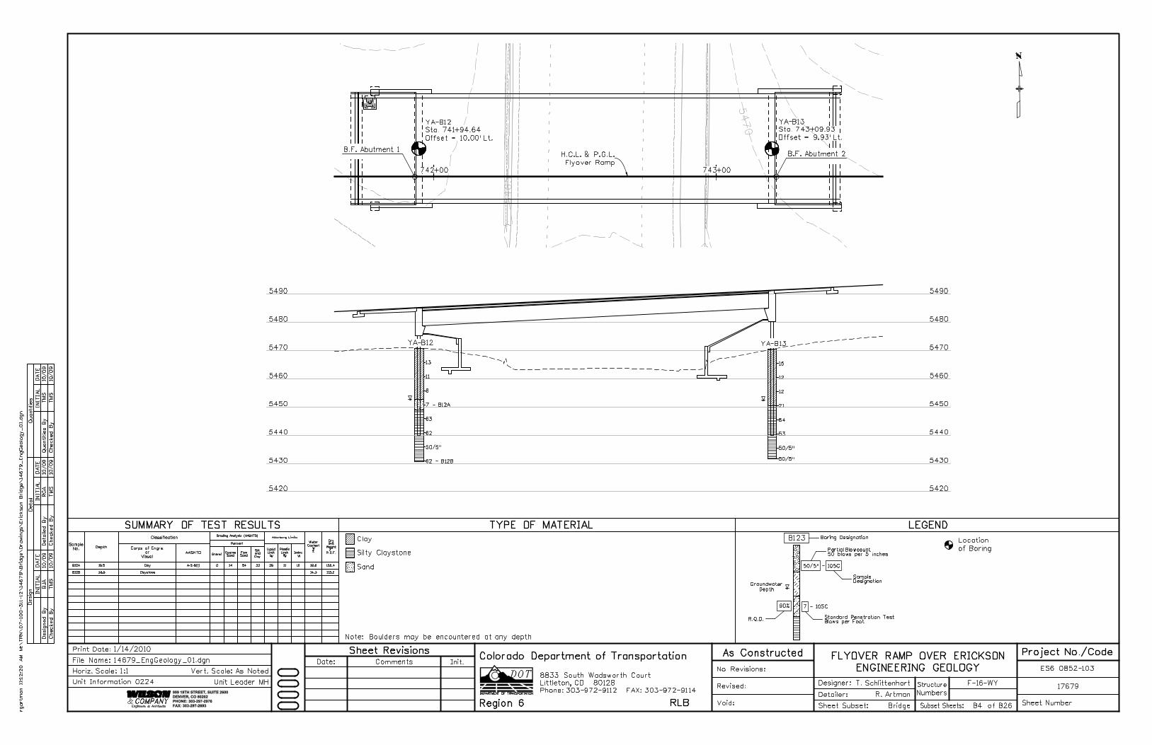
Note: Boulders may be encountered at any depth
Gravel
Depth
Classification
AASHTO Coarse
Sand
Fine
Sand
Silt
and
Clay
Percent
Grading Analysis (AASHTO)Atterberg Limits
Liquid
Limit
L
Plastic
Limit
P W
Water
Content
W
%
Dry
Unit
Weight
P.C.F.
W W
Sample
No. Corps of Engrs.
or
Visual
TYPE OF MATERIAL LEGENDSUMMARY OF TEST RESULTS
50/5" - 105C
90% 7 - 105C
Standard Penetration TestBlows per Foot
Boring DesignationB123
Groundwater
Depth
SampleDesignation
Partial Blowcount50 blows per 5 inches
Location
of Boring
R.Q.D.
Clay
Silty Claystone
5490
5480
5470
5460
5450
5440
5430
5420
5490
5480
5470
5460
5450
5440
5430
5420
YA-B12 YA-B13
YA-B12 YA-B13
Sta. 741+94.64
Offset = 10.00’ Lt.
Sta. 743+09.93
Offset = 9.93’ Lt.
742+00 743+00
H.C.L. & P.G.L.
Flyover Ramp
13
11
8
63
62
7 - B12A
50/5"
62 - B12B
15
12
12
21
64
53
50/5"
50/5"
B12A 19.5 Clay A-2-6(1) 29 11 19.8
B12B 39.5 Claystone 14.3 113.2
Index
183254140 105.4 Sand
B.F. Abutment 1B.F. Abutment 2
rgart
man 11:1
2:2
0
AM
M:\
TR
N\
07-100-3
11-12\
14
67
9\
Brid
ge\
Dra
win
gs\
Eric
kson
Brid
ge\
14
67
9_
Eng
Geolo
gy_
01.d
gn
F-16-WY
Numbers
Structure
No Revisions:
Revised:
Void: Sheet Subset:
Detailer:
Designer:
Bridge
R. Artman
T. Schlittenhart17679
ES6 0852-103
Sheet NumberSubset Sheets: B4 of B26
Init.CommentsDate:
Sheet Revisions As Constructed
1/14/2010Print Date:
Horiz. Scale:1:1
14679_EngGeology_01.dgn
Vert. Scale: As Noted
Unit Leader MH
Project No./CodeFLYOVER RAMP OVER ERICKSON
ENGINEERING GEOLOGYFile Name:
Unit Information 0224
54
65
54
65
54
65
54
65
5470
5470
54
70
5470
5475
125’-0"
1’-6"
1’-6"
2’-
1"
7’-
11"
7’-
11"
7’-
11"
5’-
10"
1’-
6"
8’-
0"
28’-
0"
1’-
6"
39’-
0"
125’-0"
5.2
5’ = 2
6.2
5’
(5) S
pa.
@
5.2
5’ = 2
6.2
5’
(5) S
pa.
@
166’-6"
17’-0" 24’-6"62’-6"62’-6"
18’-3"
(Typ.)
2.1
3’
2.1
3’
2.2
5’
23.00’
2.2
5’
5.2
5’
3.1
2’
25’-9"
5.2
5’
3.1
2’
2.1
3
30’-0" (Typ.)
(T
yp.)
3’-
11�
"
127’-0" Limits of 36" Splash Guard (Typ.)
168’-0" Limits of Bridge Rail Type 7 (Special) (Typ.)
15.50’
2.1
3’
Phone:303-972-9112 FAX:303-972-9114
Colorado Department of Transportation
Region 6 RLB
8833 South Wadsworth Court
Littleton, CO 80128
S88^47’34"E
Ò Brg. Abut. 1
Sta. 741+94.72
Ò Brg. Abut. 2
Sta. 743+19.72
742+00 743+00
G1
G2
G3
G4
G5
(Typ.)
742+00 743+00
S88^47’34"E
Ò Brg. Abut. 2
Sta. 743+19.72
Ò Brg. Abut. 1
Sta. 741+94.72
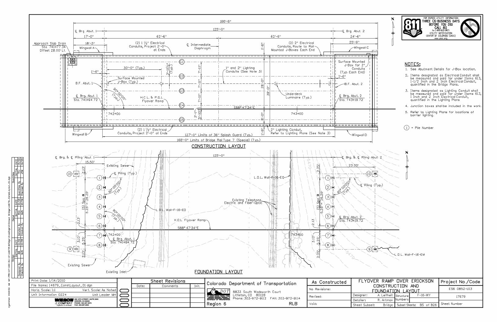
CONSTRUCTION LAYOUT
FOUNDATION LAYOUT
Ò Brg. Abut. 2
Ò Intermediate
Diaphragm
Ò Brg. Abut. 1
999 18TH STREET, SUITE 2600
DENVER, CO 80202
PHONE: 303-297-2976
FAX: 303-297-2693
B.F. Abut. 2B.F. Abut. 1
Wingwall B
Wingwall A
Wingwall D
Wingwall C
Existing Telephone,Electric and Fiber-Optic
Ò Piling (Typ.)
(Typ.)
Ò Brg. & Ò Piling Abut. 2Ò Brg. & Ò Piling Abut. 1
H.C.L. Flyover Ramp
H.C.L. & P.G.L.
Flyover Ramp
Existing Sewer
Existing Sewer
Existing Inlet
Ò Piling (Typ.)
NOTES:
FOR BURIED UTILITY INFORMATION
UTILITY NOTIFICATION
CENTER OF COLORADO (UNCC)
www.uncc.org
(or 1-800-922-1987)
THREE (3) BUSINESS DAYS
BEFORE YOU DIG
CALL 811
JS
M
TRJ
MJ
N
RG
A
MJ
N
AM
L10/09
10/09
10/09
10/09
10/09
10/09
INITIA
L
Desig
n
Desig
ned
By
Checked
By
DA
TE
DA
TE
DA
TE
INITIA
LINITIA
L
Detail
Quantities
Detailed
By
Checked
By
Checked
By
Quantities
By
(Typ.)
1
2
3
4
5
6
7
8
9
10
Approach Slab Drain
Sta. 741+77.34
Offset 28.00’ Lt.
1
2
3
4
5
6
7
8
10
9
1 = Pile Number
Underdeck
Luminaire (Typ.)
(2) 1 �" Electrical
Conduits, Project 2’-0" at Ends
L.O.L. Wall-F-16-EM
Surface Mounted
J-Box (Typ.)
rgart
man 11:1
0:2
2
AM
M:\
TR
N\
07-100-3
11-12\
14
67
9\
Brid
ge\
Dra
win
gs\
Eric
kson
Brid
ge\
14
67
9_
ConstLayout_
01.d
gn
F-16-WY
Numbers
Structure
No Revisions:
Revised:
Void: Sheet Subset:
Detailer:
Designer:
Bridge
R. Artman
A. Leifheit17679
ES6 0852-103
Sheet NumberSubset Sheets: B5 of B26
Init.CommentsDate:
Sheet Revisions As Constructed
1/14/2010Print Date:
Horiz. Scale:1:1
14679_ConstLayout_01.dgn
Vert. Scale: As Noted
Unit Leader MH
Project No./CodeFLYOVER RAMP OVER ERICKSON
CONSTRUCTION AND
FOUNDATION LAYOUT
File Name:
Unit Information 0224
L.O.L. Wall-F-16-EO
L.O.L. Wall-F-16-EQ
2" Lighting Conduit,
Refer to Lighting Plans (See Note 3)
(2) 1 �" Electrical
Conduits, Project 2’-0"
at Ends
(2) 2" Electrical
Conduits, Route to Rail
Mounted J-Boxes Each End
Surface Mounted
J-Box for 2"
Conduits
(Typ. Each End)
1" and 2" Lighting
Conduits (See Note 3)See Abutment Details for J-Box location.
Items designated as Electrical Conduit shall
be measured and paid for under Items 613,
1-1/2 Inch and 2 Inch Electrical Conduit,
quantified in the Bridge Plans.
Items designated as Lighting Conduit shall
be measured and paid for under Items 613,
1 Inch and 2 Inch Electrical Conduit,
quantified in the Lighting Plans.
Junction boxes shall be included in the work.
Refer to Lighting Plans for locations of
barrier lighting.
1.
2.
3.
4.
5.
14679_PileDet_01.dgn 1/13/2010 9:21:35 PM
3"
(T
yp.)
6"
30^
Eq.
Eq.
INITIA
L
Desig
n
Desig
ned
By
Checked
By
DA
TE
DA
TE
DA
TE
INITIA
LINITIA
L
Detail
Quantities
Detailed
By
Checked
By
Checked
By
Quantities
By
JS
M
TRJ
MJ
N
RG
A
MJ
N
BJ
A10/09
10/09
10/09
10/09
10/09
10/09
999 18TH STREET, SUITE 2600
DENVER, CO 80202
PHONE: 303-297-2976
FAX: 303-297-2693
Phone:303-972-9112 FAX:303-972-9114
Colorado Department of Transportation
Region 6 RLB
8833 South Wadsworth Court
Littleton, CO 80128
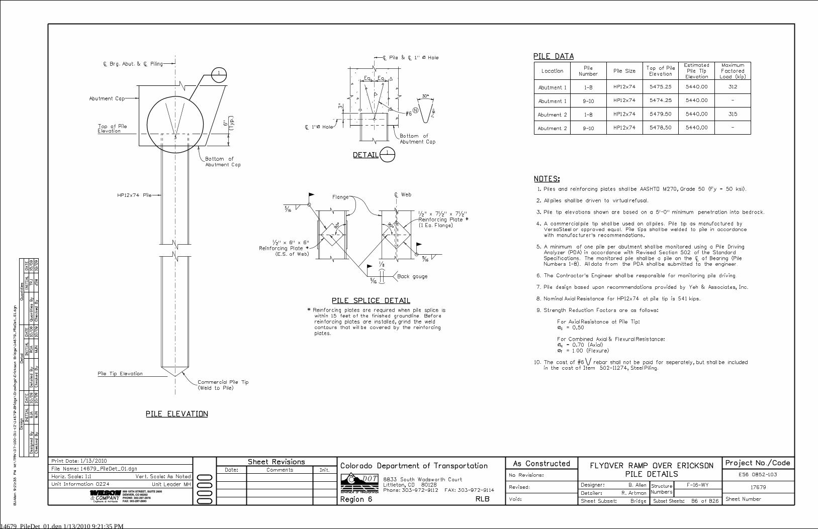
Location
HP12x74
1
DETAIL
PILE DATA
PILE ELEVATION
Ò Web
�
�
�
Flange
PILE SPLICE DETAIL
Abutment Cap
Top of PileElevation
5475.25
Pile SizeTop of Pile
Elevation
HP12x74 5474.25 -Abutment 1
Abutment 1
Commercial Pile Tip
(Weld to Pile)
HP12x74 Pile
#6
1’-
6"N
Ò Pile & Ò 1" ß Hole
Bottom of
Abutment Cap
Ò Brg. Abut. & Ò Piling
Pile Tip Elevation
5440.00
5440.00
Maximum
Factored
Load (kip)
Pile
Number
1-8
9-10
HP12x74 5479.50
HP12x74 5478.50 -Abutment 2
Abutment 2 5440.00
5440.00
1-8
9-10
Back gouge
�
�" x 6" x 6"
Reinforcing Plate *
(E.S. of Web)
�" x 7�" x 7�"
Reinforcing Plate *
(1 Ea. Flange)
Estimated
Pile Tip
Elevation
312
315
* Reinforcing plates are required when pile splice is
within 15 feet of the finished groundline. Before
reinforcing plates are installed, grind the weld
contours that will be covered by the reinforcing
plates.
1
Bottom of
Abutment Cap
BJ
Allen 9:2
1:3
5
PM
M:\
TR
N\
07-100-311-12\
14
67
9\
Brid
ge\
Dra
win
gs\
Eric
kson
Brid
ge\
14
67
9_
Pile
Det_
01.d
gn
F-16-WY
Numbers
Structure
No Revisions:
Revised:
Void: Sheet Subset:
Detailer:
Designer:
Bridge
R. Artman
B. Allen17679
ES6 0852-103
Sheet NumberSubset Sheets: B6 of B26
Init.CommentsDate:
Sheet Revisions As Constructed
1/13/2010Print Date:
Horiz. Scale:1:1
14679_PileDet_01.dgn
Vert. Scale: As Noted
Unit Leader MH
Project No./CodeFLYOVER RAMP OVER ERICKSON
PILE DETAILSFile Name:
Unit Information 0224
Ò 1"ß Hole
NOTES:
c
c
f
Piles and reinforcing plates shall be AASHTO M270, Grade 50 (Fy = 50 ksi).
All piles shall be driven to virtual refusal.
Pile tip elevations shown are based on a 5’-0" minimum penetration into bedrock.
A commercial pile tip shall be used on all piles. Pile tip as manufactured by
VersaSteel or approved equal. Pile tips shall be welded to pile in accordance
with manufacturer’s recommendations.
A minimum of one pile per abutment shall be monitored using a Pile Driving
Analyzer (PDA) in accordance with Revised Section 502 of the Standard
Specifications. The monitored pile shall be a pile on the Ò of Bearing (Pile
Numbers 1-8). All data from the PDA shall be submitted to the engineer.
The Contractor’s Engineer shall be responsible for monitoring pile driving.
Pile design based upon recommendations provided by Yeh & Associates, Inc.
Nominal Axial Resistance for HP12x74 at pile tip is 541 kips.
Strength Reduction Factors are as follows:
For Axial Resistance at Pile Tip:
ß = 0.50
For Combined Axial & Flexural Resistance:
ß = 0.70 (Axial)
ß = 1.00 (Flexure)
The cost of #6 rebar shall not be paid for seperately, but shall be included
in the cost of Item 502-11274, Steel Piling.
1.
2.
3.
4.
5.
6.
7.
8.
9.
10.
14679_Abutment1Det_01.dgn 1/13/2010 9:22:18 PM
1’-0" 30’-0"10’-0" 1’-0"
42’-0"
2’-
9"
1’-
3"
1’-
6"
5.833’ 7.917’7.917’7.917’2.083’
1’-6"
1’-6"
Seat (Typ.)
Level Brg.
1’-6" 1’-3"
2’-9"
Clr.
3"
Clr.
2"
(Typ.)
3" Clr.
(Typ.)
3" Clr.
6�"
Proj.
2’-
0"
Min
6"
3’-
6�
"
3’-
3�
"
(Typ.)
1’-6"
3"
3’-
4" (
Min.)
Varies
3"
and
Grout Pad
2" Levelin
gHaunch
3�
"
Deck
8"
Eq. Spa.
(6) #5
6’-
4�
"
BT63
Gir
der
5’-
3"
1’-0"
Clr.
3"(Typ.)
1’-4"
6"
6’-
4�
"
(Min.)
2’-0"
(Min.)
2’-
0"
Trim Leg
@ Girder
Locations
1’-
6"
Min.
Lap
INITIA
L
Desig
n
Desig
ned
By
Checked
By
DA
TE
DA
TE
DA
TE
INITIA
LINITIA
L
Detail
Quantities
Detailed
By
Checked
By
Checked
By
Quantities
By
JS
M
TRJ
MJ
N
RG
A
MJ
N
BJ
A10/09
10/09
10/09
10/09
10/09
10/09
Phone:303-972-9112 FAX:303-972-9114
Colorado Department of Transportation
Region 6 RLB
8833 South Wadsworth Court
Littleton, CO 80128
999 18TH STREET, SUITE 2600
DENVER, CO 80202
PHONE: 303-297-2976
FAX: 303-297-2693
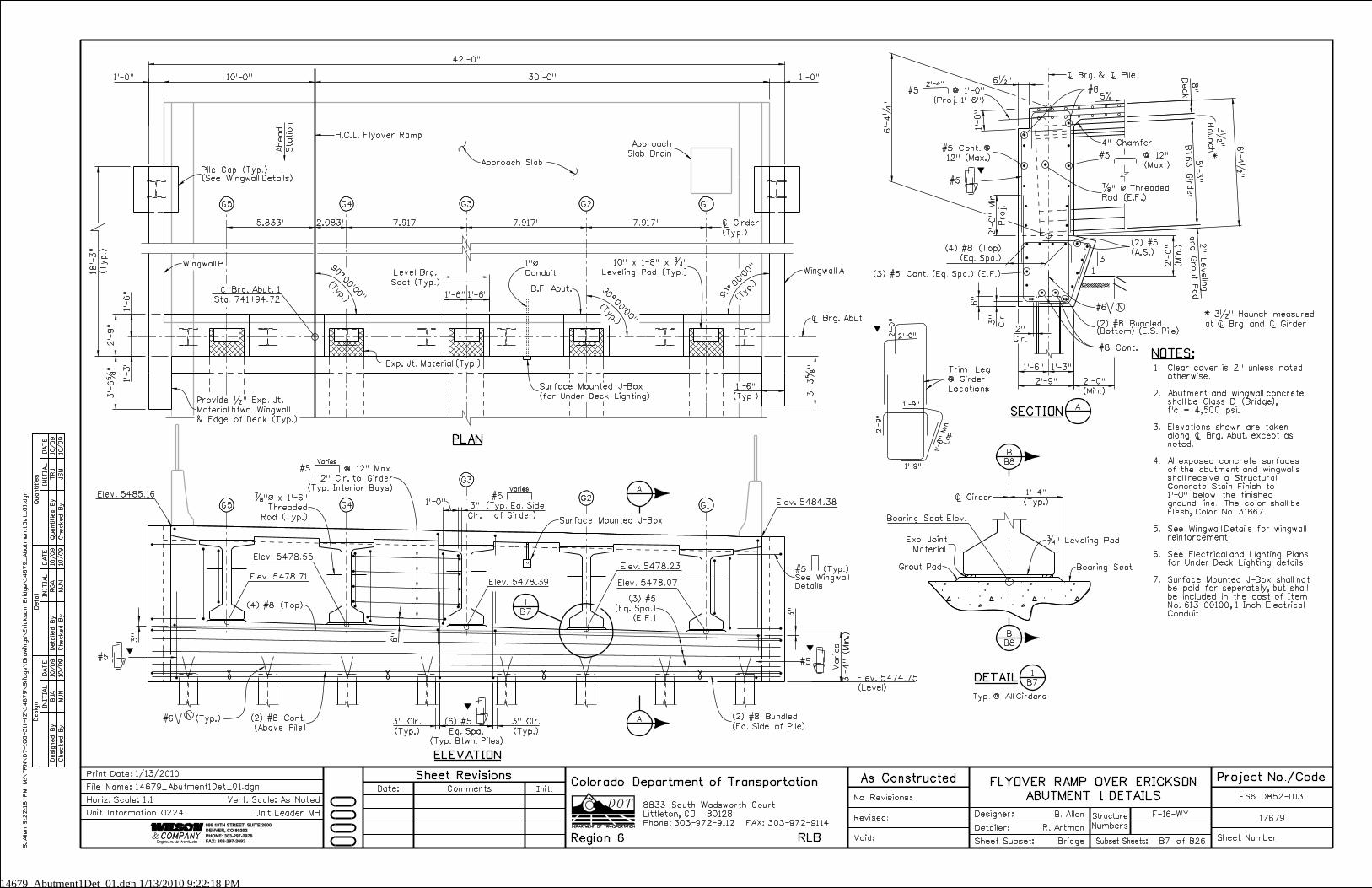
Ò Girder
(Typ.)
G1
B.F. Abut.
G2G3G4G5
Ò Brg. Abut. 1
Sta. 741+94.72
(Typ.)
Ahead
Statio
n
(Typ.)
PLAN
ELEVATION
G1G2
G3
G4G5
Elev. 5478.71
Elev. 5478.55
Elev. 5478.39
Elev. 5478.23
Elev. 5478.07
Elev. 5474.75
(Level)
NOTES:
Ò Brg. & Ò Pile
H.C.L. Flyover Ramp
Ò Brg. Abut
1’-
0"
3
1
#8
Wingwall BWingwall A
4" Chamfer
(4) #8 (Top)
(2) #8 Bundled(Bottom) (E.S. Pile)
10" x 1-8" x �"
Leveling Pad (Typ.)
Elev. 5485.16
Elev. 5484.38
(4) #8 (Top)
(Eq. Spa.)
Approach
Slab Drain
2’-4"
�" ß Threaded
Rod (E.F.)
5%
Approach Slab
A
A
1
B7
ASECTION
*
#6* 3�" Haunch measured
at Ò Brg. and Ò Girder
18’-
3"
(Typ.)
(Typ. Btwn. Piles)
#5 #5
(2) #8 Bundled
(Ea. Side of Pile)
(2) #8 Cont.
(Above Pile)
#5
#5 @ 1’-0"
(Proj. 1’-6")
#5 @ 12"
(Max.)
(2) #5
(A.S.)
#5 Cont. @
12" (Max.)
Ò Girder
Bearing Seat
�" Leveling Pad
B7DETAIL
1
Bearing Seat Elev.
(3) #5 Cont. (Eq. Spa.) (E.F.)
(Typ. Ea. Side
of Girder)
Varies
#5
(3) #5
(Eq. Spa.)
(E.F.)
#5 @ 12" Max.
2" Clr. to Girder
(Typ. Interior Bays)
Varies
Surface Mounted J-Box
Surface Mounted J-Box
(for Under Deck Lighting)
#5 (Typ.)
See Wingwall
Details
(Typ.)
N
1"ß
Conduit
Clear cover is 2" unless noted
otherwise.
Abutment and wingwall concrete
shall be Class D (Bridge),
f’c = 4,500 psi.
Elevations shown are taken
along Ò Brg. Abut. except as
noted.
All exposed concrete surfaces
of the abutment and wingwalls
shall receive a Structural
Concrete Stain Finish to
1’-0" below the finished
ground line. The color shall be
Flesh, Color No. 31667.
See Wingwall Details for wingwall
reinforcement.
See Electrical and Lighting Plans
for Under Deck Lighting details.
Surface Mounted J-Box shall not
be paid for seperately, but shall
be included in the cost of Item
No. 613-00100, 1 Inch Electrical
Conduit.
1.
2.
3.
4.
5.
6.
7.
Exp. Joint
Material
Grout Pad
B8
B
B8
B
Typ. @ All Girders
#8 Cont.
Pile Cap (Typ.)
(See Wingwall Details)
Provide �" Exp. Jt.
Material btwn. Wingwall
& Edge of Deck (Typ.)
#6 (Typ.) N
Exp. Jt. Material (Typ.)
2’-0"2’-
0"
2’-
9"
1’-9"
1’-9"
BJ
Allen 9:2
2:1
8
PM
M:\
TR
N\
07-100-311-12\
14
67
9\
Brid
ge\
Dra
win
gs\
Eric
kson
Brid
ge\
14
67
9_
Abut
ment1Det_
01.d
gn
F-16-WY
Numbers
Structure
No Revisions:
Revised:
Void: Sheet Subset:
Detailer:
Designer:
Bridge
R. Artman
B. Allen17679
ES6 0852-103
Sheet NumberSubset Sheets: B7 of B26
Init.CommentsDate:
Sheet Revisions As Constructed
1/13/2010Print Date:
Horiz. Scale:1:1
14679_Abutment1Det_01.dgn
Vert. Scale: As Noted
Unit Leader MH
Project No./CodeFLYOVER RAMP OVER ERICKSON
ABUTMENT 1 DETAILSFile Name:
Unit Information 0224
�"ß x 1’-6"
Threaded
Rod (Typ.)
14679_Abutment2Det_01.dgn 1/13/2010 9:22:56 PM
1’-3"30’-0" 10’-0"1’-3"
42’-6"
5.833’7.917’ 7.917’ 7.917’ 2.083’
1’-6" 1’-3"
2’-9"
Clr.
2"
(Typ.)
3" Clr.
(Typ.)
3" Clr.
6�"
Proj.
2’-
0"
Min
6"
4’-
0�
"
3’-
9�
"
5’-
3"
Min.
Varies
3"
3"
Haunch
3�
"Deck
8"
and
Grout Pad
2" Leveling
2’-
9"
1’-
6"
1’-
3"
Eq. Spa.
(6) #5
6’-
4�
"
1’-0"
Clr.
3"
Seat (Typ.)
Level Brg.
1’-6"
1’-6"
6’-
4�
"
1’-
0"
BT63
Gir
der
5’-
3"
(B
ott.)
3"
Clr.
6"
(Min.)
2’-
0"
(Min.)
2’-0"
(Typ.)
1’-9"
(Typ.)
8"
Ò
Brg.
1�
"
@
2’-0"
1’-
6"
Min.
Lap
Trim Leg
@ Girder
Locations
INITIA
L
Desig
n
Desig
ned
By
Checked
By
DA
TE
DA
TE
DA
TE
INITIA
LINITIA
L
Detail
Quantities
Detailed
By
Checked
By
Checked
By
Quantities
By
MJ
N
BJ
A
MJ
N
RG
A
MJ
N
BJ
A10/09
10/09
10/09
10/09
10/09
10/09
Phone:303-972-9112 FAX:303-972-9114
Colorado Department of Transportation
Region 6 RLB
8833 South Wadsworth Court
Littleton, CO 80128
999 18TH STREET, SUITE 2600
DENVER, CO 80202
PHONE: 303-297-2976
FAX: 303-297-2693
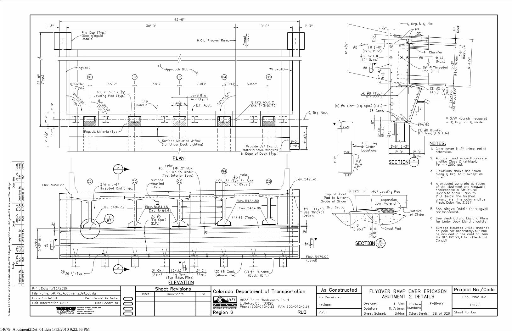
Ò Girder
(Typ.)
G5
B.F. Abut.
G4G3G2G1
Ò Brg. Abut. 2
Sta. 743+19.72
Ahead
Statio
n
PLAN
ELEVATION
G1 G2 G3 G5
Elev. 5484.96
Elev. 5484.80
Elev. 5484.64
Elev. 5484.48Elev. 5484.32
Elev. 5479.00
(Level)
Ò Brg. & Ò Pile
3
1
#8
4" Chamfer
(2) #8 Bundled
(Bott.) (E.F.)
Wingwall DWingwall C
10" x 1’-8" x �"
Leveling Pad (Typ.)
H.C.L. Flyover Ramp
Ò Brg. Abut
Elev. 5490.63
Elev. 5491.41
#5 @ 1’-0"
(Proj. 1’-6")
2’-4"
(4) #8 (Top)
(Eq. Spa.)
5%
25’-
9"
(T
yp.)
A
A
1
B7
ASECTION
*
* 3�" Haunch measured
at Ò Brg. and Ò Girder
#5
#6 (Typ.)
(Typ. Btwn. Piles)
G4
(Typ. Ea. Side
of Girder)
#5
(2) #8 Cont.
(Above Pile)
(4) #8 (Top)
(2) #5
(A.S.)
#5 @ 12"
(Max.)
#5 Cont. @
12" (Max.)
#5 �" ß Threaded
Rod (E.F.)
(5) #5 Cont. (Eq. Spa.) (E.F.)
(2) #8 Bundled(Bottom) (E.S. Pile)
#6
(Typ.)
Approach Slab
#5
(5) #5
(Eq. Spa.)
(E.F.)
#8 (Typ.)
See Wingwall
Details
Pile Cap (Typ.)
(See Wingwall
Details)
(Typ.)
N
N
#5 @ 12" Max.
2" Clr. to Girder
(Typ. Interior Bays)
NOTES:
Surface
Mounted
J-Box
Surface Mounted J-Box
(for Under Deck Lighting)
1"ß
Conduit
Clear cover is 2" unless noted
otherwise.
Abutment and wingwall concrete
shall be Class D (Bridge),
f’c = 4,500 psi.
Elevations shown are taken
along Ò Brg. Abut. except as
noted.
All exposed concrete surfaces
of the abutment and wingwalls
shall receive a Structural
Concrete Stain Finish to
1’-0" below the finished
ground line. The color shall be
Flesh, Color No. 31667.
See Wingwall Details for wingwall
reinforcement.
See Electrical and Lighting Plans
for Under Deck Lighting details.
Surface Mounted J-Box shall not
be paid for separately, but shall
be included in the cost of Item
No. 613-00100, 1 Inch Electrical
Conduit.
1.
2.
3.
4.
5.
6.
7.
B7
BSECTION
Ò Brg. �" Leveling PadTop of Grout
Pad to Match
Grade of Girder
Grout Pad
Expansion
Joint Material
Bottom
of Girder
Brg. Seat
Provide �" Exp. Jt.
Material btwn. Wingwall
& Edge of Deck (Typ.)
2’-
0"
2’-
9"
1’-9"
1’-9"
Varies
Varies
#8 Cont.
Exp. Jt. Material (Typ.)
F-16-WY
Numbers
Structure
No Revisions:
Revised:
Void: Sheet Subset:
Detailer:
Designer:
Bridge
R. Artman
B. Allen17679
ES6 0852-103
Sheet NumberSubset Sheets: B8 of B26
Init.CommentsDate:
Sheet Revisions As Constructed
1/13/2010Print Date:
Horiz. Scale:1:1
14679_Abutment2Det_01.dgn
Vert. Scale: As Noted
Unit Leader MH
Project No./CodeFLYOVER RAMP OVER ERICKSON
ABUTMENT 2 DETAILSFile Name:
Unit Information 0224
BJ
Allen 9:2
2:5
6
PM
M:\
TR
N\
07-100-3
11-12\
14
67
9\
Brid
ge\
Dra
win
gs\
Eric
kson
Brid
ge\
14
67
9_
Abut
ment2
Det_
01.d
gn
�"ß x 1’-6"
Threaded Rod (Typ.)
14679_WingwallDet_1.dgn 1/13/2010 9:24:09 PM
1’-6"
1’-0"
(11) #4 @ 1’-6" (Max.) (18) #4 @ 1’-4" (Max.)
1’-3"
1’-0"
(Typ.)
3’-
0"
(Typ.)
3’-0"
1’-0"
(Typ.)
3’-0"
(Typ.)
3’-
0"
1’-6"
#4
@ 1’-
4" (
Max.)
#4
@ 1’-
6" (
Max.)
2�
"
3" 6" 6"9"9" 3"
1’-
0"
6"
Clr.
3"
1’-
4"
6"
#4
@
1’-
6" (
Max.)
#4
@ 1’-
4" (
Max.)
1’-
0"
1’-
3"
1’-0"
12" (N.F.)
(3) #4 @
(2) #4 @ 12"
(2) #4 @ 12"
1’-0"
12" (N.F.)
(3) #4 @
(Typ.)
2" Clr.
(Bott.)
3"
Clr.
(Bott.)
3"
Clr.
(Typ.)
2" Clr.
#4 (N.F.)
#4
(3) #4 (N.F.)
(2) #4
(2) #4
(3) #4 (N.F.)
#4
#4 (N.F.)
#5
@
6" (
Max.)
#8
@ 6" (
Max.)
INITIA
L
Desig
n
Desig
ned
By
Checked
By
DA
TE
DA
TE
DA
TE
INITIA
LINITIA
L
Detail
Quantities
Detailed
By
Checked
By
Checked
By
Quantities
By
JS
M
TRJ
BJ
A
RG
A
MJ
N
TRJ
10/09
10/09
10/09
10/09
10/09
10/09
Phone:303-972-9112 FAX:303-972-9114
Colorado Department of Transportation
Region 6 RLB
8833 South Wadsworth Court
Littleton, CO 80128
999 18TH STREET, SUITE 2600
DENVER, CO 80202
PHONE: 303-297-2976
FAX: 303-297-2693
(2) #6
#4 @ 1’-6" (Max.)
(2) #5
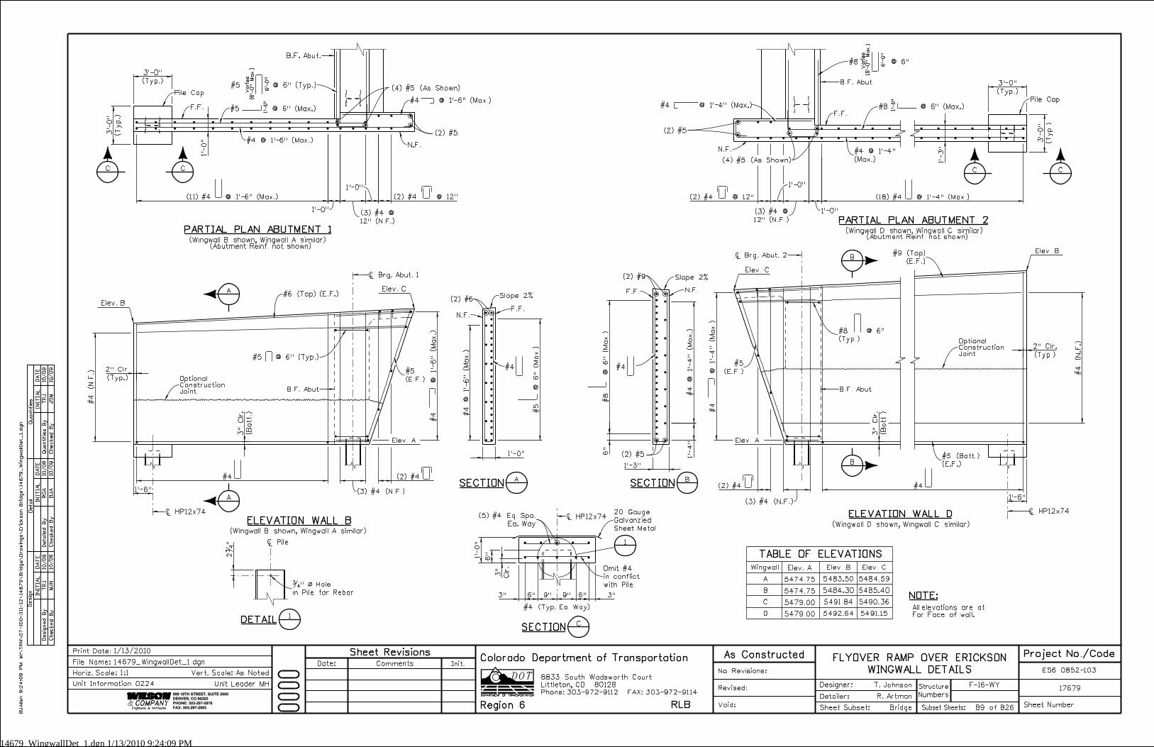
Elev. A
#6 (Top) (E.F.)
B.F. Abut
(2) #5
#4 @ 1’-4"
(Max.)
Elev. A
Wingwall
A
B
C
D
TABLE OF ELEVATIONS
Ò Brg. Abut. 1
1’-
6"
1’-
6"
Ò HP12x74
Ò Brg. Abut. 2
Ò HP12x74
#5
(E.F.)
#9 (Top)
(E.F.)
Ò Pile
�" ß Hole
in Pile for Rebar
Ò HP12x74
#4 (Typ. Ea. Way)
20 Gauge
Galvanzied
Sheet Metal
(2) #5
(2) #9
B.F. Abut
#5 (Bott.)
(E.F.)
Elev. A
5474.75
5474.75
5479.00
5479.00
Elev. B
5483.50
5484.30
5491.84
5492.64
A
ASECTION
A
BSECTION
B
B
(5) #4 Eq. Spa.
Ea. Way
N.F.F.F.
F.F. N.F.
OptionalConstructionJoint
OptionalConstructionJoint
Elev. C
5484.59
5485.40
5490.36
5491.15
Elev. B
Slope 2%
Slope 2%
(4) #5 (As Shown)
(4) #5 (As Shown)
PARTIAL PLAN ABUTMENT 1PARTIAL PLAN ABUTMENT 2
Pile Cap
B.F. Abut.
(Wingwall B shown, Wingwall A similar)(Abutment Reinf. not shown)
#5 @ 6" (Typ.)
N.F.
F.F.
N.F.
Pile Cap
B.F. Abut.
F.F.
(Wingwall D shown, Wingwall C similar)(Abutment Reinf. not shown)
#8 @ 6"
(Typ.)
6’-
0"
6’-
0"
#8 @ 6"
Varies
(6’-
0"
Max.)
C
C
C
C
CSECTION
1
DETAIL
1
Omit #4
in conflict
with Pile
#5
(E.F.)#4 #4
ELEVATION WALL DELEVATION WALL B
#4 @ 1’-4" (Max.)
Varies
(6’-
0"
Max.)
#5 @ 6" (Max.) #8 @ 6" (Max.)
(Wingwall B shown, Wingwall A similar)
(Wingwall D shown, Wingwall C similar)
BJ
Allen 9:2
4:0
9
PM
M:\
TR
N\
07-100-3
11-12\
14
67
9\
Brid
ge\
Dra
win
gs\
Eric
kson
Brid
ge\
14
67
9_
Win
gwallDet_
1.d
gn
F-16-WY
Numbers
Structure
No Revisions:
Revised:
Void: Sheet Subset:
Detailer:
Designer:
Bridge
R. Artman
T. Johnson17679
ES6 0852-103
Sheet NumberSubset Sheets: B9 of B26
Init.CommentsDate:
Sheet Revisions As Constructed
1/13/2010Print Date:
Horiz. Scale:1:1
14679_WingwallDet_1.dgn
Vert. Scale: As Noted
Unit Leader MH
Project No./CodeFLYOVER RAMP OVER ERICKSON
WINGWALL DETAILSFile Name:
Unit Information 0224
NOTE:
All elevations are at
Far Face of wall.
Elev. C
#5 @ 6" (Typ.)
Elev. B
Elev. C
#4 @ 1’-6" (Max.)
14679_SuperStrDet_01.dgn 1/13/2010 9:25:43 PM
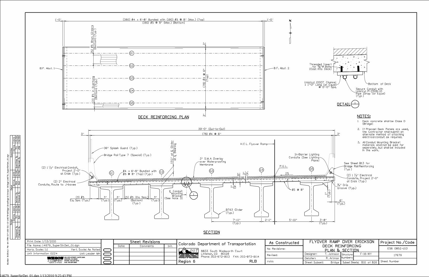
3"
3"
(Top)
(7
8) #4
@ 6"
(Botto
m) (Typ.)
(5) #5
Btw
n.
Gir
ders
(B
otto
m) (Typ.)
(3) #5 in
Overhang
(Typ.)
3"
(Typ.)
3"
(Typ.)
3"
1’-0"
3" (78) #4 @ 6" 3"
39’-0" (Out-to-Out)
(Bottom)
(5) #5 (Eq. Spa.)
Eq. Spa. (Typ.)
(3) #5
(Typ.)
6"
(T
yp.)
1"
at Ò
Bearin
g
11�
" at Ò
Gir
der
1’-0"
(190) #5 @ 8" (Max.) (Bottom)
(380) #4 x 6’-8" Bundled with (190) #5 @ 8" (Max.) (Top)
(Typ.)
3’-8"
(Typ.)
7’-11"
2’-1"
5’-10"INITIA
L
Desig
n
Desig
ned
By
Checked
By
DA
TE
DA
TE
DA
TE
INITIA
LINITIA
L
Detail
Quantities
Detailed
By
Checked
By
Checked
By
Quantities
By
JS
M
TRJ
BJ
A
RG
A
BJ
A
TRJ
10/09
10/09
10/09
10/09
10/09
10/09
999 18TH STREET, SUITE 2600
DENVER, CO 80202
PHONE: 303-297-2976
FAX: 303-297-2693
Phone:303-972-9112 FAX:303-972-9114
Colorado Department of Transportation
Region 6 RLB
8833 South Wadsworth Court
Littleton, CO 80128
G1
G2
G3
G4
G5
DECK REINFORCING PLAN
G1G2
G3G4
G5
(Typ.)
BT63 Girder
(Typ.)
#5 @ 8"
2"
Clr.
8"
1"
Clr.
SECTION
B.F. Abut. 2B.F. Abut. 1
36" Splash Guard (Typ.)
NOTES:
#4 x 6’-8" Bundled with
#5 @ 8" (Top) (Typ.)
Bridge Rail Type 7 (Special) (Typ.)
3" S.M.A. Overlay
over Waterproofing
Membrane
�" Drip
Groove (Typ.)
2%
See Sheet B13 for
Bridge Rail Reinforcing
(Typ.)
1
Unistrut 1000T Channelx 1’-0" Long (or Equal)
@ 5’-0" Spa.
DETAIL
1
Bottom of Deck
H.C.L. Flyover Ramp
P.G.L.
1.
2.
3.
(2) 1 �" Electrical
Conduits, Project 2’-0"
at Ends (Typ.)
BJ
Allen 9:2
5:4
3
PM
M:\
TR
N\
07-100-311-12\
14
67
9\
Brid
ge\
Dra
win
gs\
Eric
kson
Brid
ge\
14
67
9_
SuperStr
Det_
01.d
gn
F-16-WY
Numbers
Structure
No Revisions:
Revised:
Void: Sheet Subset:
Detailer:
Designer:
Bridge
R. Artman
T. Johnson17679
ES6 0852-103
Sheet NumberSubset Sheets: B10 of B26
Init.CommentsDate:
Sheet Revisions As Constructed
1/13/2010Print Date:
Horiz. Scale:1:1
14679_SuperStrDet_01.dgn
Vert. Scale: As Noted
Unit Leader MH
Project No./CodeFLYOVER RAMP OVER ERICKSON
DECK REINFORCING
PLAN & SECTION
File Name:
Unit Information 0224
(2) 1 �" Electrical Conduit,
Project 2’-0"
at Ends (Typ.)
(2) 2" Electrical
Conduits, Route to J-boxes
In-Barrier Lighting
Conduits (See Lighting
Plans)
Ò ConduitMounting Bracket
(See Note 3)
Threaded Insertfor �"ß Bolts
(Cast into Deck)
Secure Conduit withUnistrut P-2558-10Pipe Strap (or Equal)(Typ.)
Deck concrete shall be Class D
(Bridge).
If Precast Deck Panels are used,
the Contractor shall submit an
alternate method of attaching
electrical conduit as required.
All Conduit Mounting Bracket
materials shall not be paid for
seperately, but shall be included
in the work.
14679_Prestr_I_Girder_01.dgn 1/13/2010 9:26:24 PM
3’-7"
1’-4" 2"
2"
7"
10"
6"
6�
"
2’-3"
3’-
7"
5’-
3"
11 Spa. 11 Spa.
5"
0.5L
Lh
6"
1’-
1�
"6"
2’-
1�
"
1’-0"
1’-6"
3"3"
2�"
1�" Cl. (Typ.)
INITIA
L
Desig
n
Desig
ned
By
Checked
By
DA
TE
DA
TE
DA
TE
INITIA
LINITIA
L
Detail
Quantities
Detailed
By
Checked
By
Checked
By
Quantities
By
JS
M
TRJ
AM
L
RG
A
BJ
A
AM
L10/09
10/09
10/09
10/09
10/09
10/09
999 18TH STREET, SUITE 2600
DENVER, CO 80202
PHONE: 303-297-2976
FAX: 303-297-2693
Phone:303-972-9112 FAX:303-972-9114
Colorado Department of Transportation
Region 6 RLB
8833 South Wadsworth Court
Littleton, CO 80128
The Contractor may submit an alternate cross
tie arrangement, at the end of the web, for
approval by the Engineer.
End of girder
2’-3"
Ò Span (symmetrical)
Galvanize after fabrication.
#6 Cont.
3’-
3"
(KIPS) (KIPS)
(PSI) (PSI)
(Inch) (Inch) (Inch)
sA
sd
sf’
jF
fF
cif’
cf’
L
sd
Girder
Type
Span
No.
Girder
No.
L
(Feet)
Lh
(Feet)
(Square
Inch)
Concrete
Strength
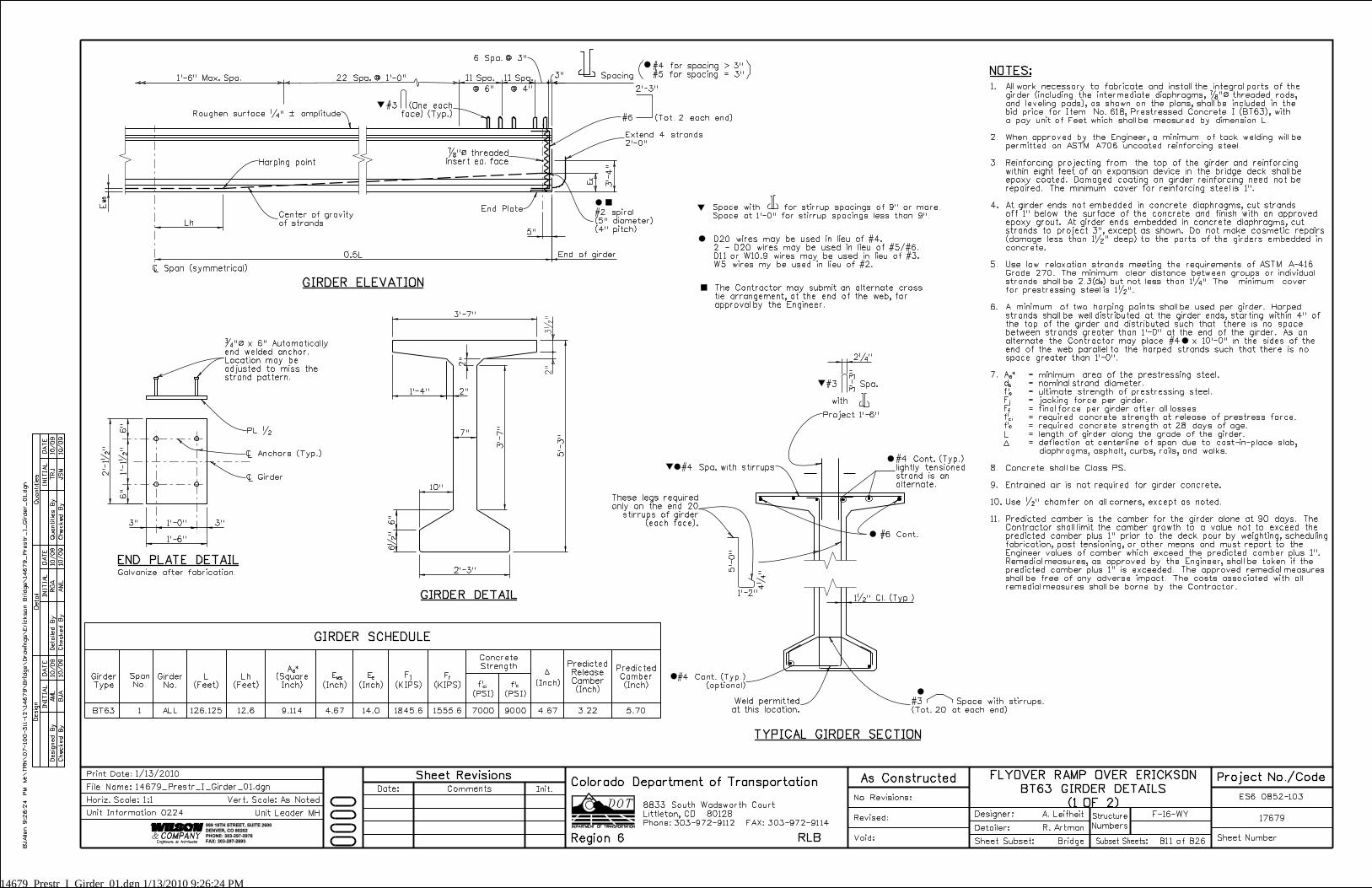
GIRDER ELEVATION
END PLATE DETAIL
TYPICAL GIRDER SECTION
GIRDER SCHEDULE
NOTES:1’-6" Max. Spa.
@ 6" @ 4"
6 Spa. @ 3"
3"
Predicted
Camber
(Inch)
Predicted
Release
Camber
(Inch)
Center of gravity
of strands
Harping point
#2 spiral
(5" diameter)
(4" pitch)
#6 (Tot. 2 each end)
�"ß threaded
insert ea. face
Ò Girder
Ò Anchors (Typ.)
PL �
Project 1’-6"
#3 Space with stirrups.
(Tot. 20 at each end)
Weld permitted
at this location.
#4 Cont. (Typ.)
(optional)
#3 (One each
face) (Typ.)
EE
3’-
4"
Extend 4 strands
2’-0"
5’-
0"
1’-2"
sAjF fF
cif’ cf’
EEMSE
12.6ALLBT63 4.67 14.0 7000 9000 4.67 3.22 5.701 9.114 1845.6 1555.6
22 Spa. @ 1’-0"
All work necessary to fabricate and install the integral parts of the
girder (including the intermediate diaphragms, �"ß threaded rods,
and leveling pads), as shown on the plans, shall be included in the
bid price for Item No. 618, Prestressed Concrete I (BT63), with
a pay unit of Feet which shall be measured by dimension L.
When approved by the Engineer, a minimum of tack welding will be
permitted on ASTM A706 uncoated reinforcing steel.
Reinforcing projecting from the top of the girder and reinforcing
within eight feet of an expansion device in the bridge deck shall be
epoxy coated. Damaged coating on girder reinforcing need not be
repaired. The minimum cover for reinforcing steel is 1".
At girder ends not embedded in concrete diaphragms, cut strands
off 1" below the surface of the concrete and finish with an approved
epoxy grout. At girder ends embedded in concrete diaphragms, cut
strands to project 3", except as shown. Do not make cosmetic repairs
(damage less than 1�" deep) to the parts of the girders embedded in
concrete.
Use low relaxation strands meeting the requirements of ASTM A-416
Grade 270. The minimum clear distance between groups or individual
strands shall be 2.3( ) but not less than 1�". The minimum cover
for prestressing steel is 1�".
A minimum of two harping points shall be used per girder. Harped
strands shall be well distributed at the girder ends, starting within 4" of
the top of the girder and distributed such that there is no space
between strands greater than 1’-0" at the end of the girder. As an
alternate the Contractor may place #4 x 10’-0" in the sides of the
end of the web parallel to the harped strands such that there is no
space greater than 1’-0".
= minimum area of the prestressing steel.
= nominal strand diameter.
= ultimate strength of prestressing steel.
= jacking force per girder.
= final force per girder after all losses.
= required concrete strength at release of prestress force.
= required concrete strength at 28 days of age.
= length of girder along the grade of the girder.
= deflection at centerline of span due to cast-in-place slab,
diaphragms, asphalt, curbs, rails, and walks.
Concrete shall be Class PS.
Entrained air is not required for girder concrete.
Use �" chamfer on all corners, except as noted.
Predicted camber is the camber for the girder alone at 90 days. The
Contractor shall limit the camber growth to a value not to exceed the
predicted camber plus 1" prior to the deck pour by weighting, scheduling
fabrication, post tensioning, or other means and must report to the
Engineer values of camber which exceed the predicted camber plus 1".
Remedial measures, as approved by the Engineer, shall be taken if the
predicted camber plus 1" is exceeded. The approved remedial measures
shall be free of any adverse impact. The costs associated with all
remedial measures shall be borne by the Contractor.
1.
2.
3.
4.
5.
6.
7.
8.
9.
10.
11.
3�
"2"
�"ß x 6" Automatically
end welded anchor.
Location may be
adjusted to miss the
strand pattern.
These legs required
only on the end 20
stirrups of girder
(each face).
GIRDER DETAIL
Spacing
Space with for stirrup spacings of 9" or more.
Space at 1’-0" for stirrup spacings less than 9".
D20 wires may be used in lieu of #4.
2 - D20 wires may be used in lieu of #5/#6.
D11 or W10.9 wires may be used in lieu of #3.
W5 wires my be used in lieu of #2.
#4 for spacing > 3"
#5 for spacing = 3"( )
#3 Spa.
with
126.125
MS
E
Roughen surface �" ˛ amplitude
End Plate
#4 Spa. with stirrups
#4 Cont. (Typ.)
lightly tensioned
strand is an
alternate.
4�
"
BJ
Allen 9:2
6:2
4
PM
M:\
TR
N\
07-100-3
11-12\
14
67
9\
Brid
ge\
Dra
win
gs\
Eric
kson
Brid
ge\
14
67
9_
Prestr_I_
Gir
der_
01.d
gn
F-16-WY
Numbers
Structure
No Revisions:
Revised:
Void: Sheet Subset:
Detailer:
Designer:
Bridge
R. Artman
A. Leifheit17679
ES6 0852-103
Sheet NumberSubset Sheets: B11 of B26
Init.CommentsDate:
Sheet Revisions As Constructed
1/13/2010Print Date:
Horiz. Scale:1:1
14679_Prestr_I_Girder_01.dgn
Vert. Scale: As Noted
Unit Leader MH
Project No./CodeFLYOVER RAMP OVER ERICKSON
BT63 GIRDER DETAILS
(1 OF 2)
File Name:
Unit Information 0224
14679_Prestr_I_Girder_02.dgn 1/13/2010 9:27:17 PM
C
3�"
1’-
3�
"
2�
"
1�" 1�"
1�
"7�
"1�
"
3�"
3�
"3�
"3�
"
Match flangeoverhang (Typ.)
INITIA
L
Desig
n
Desig
ned
By
Checked
By
DA
TE
DA
TE
DA
TE
INITIA
LINITIA
L
Detail
Quantities
Detailed
By
Checked
By
Checked
By
Quantities
By
JS
M
TRJ
BJ
A
RG
A
BJ
A
AM
L10/09
10/09
10/09
10/09
10/09
10/09
999 18TH STREET, SUITE 2600
DENVER, CO 80202
PHONE: 303-297-2976
FAX: 303-297-2693
Phone:303-972-9112 FAX:303-972-9114
Colorado Department of Transportation
Region 6 RLB
8833 South Wadsworth Court
Littleton, CO 80128
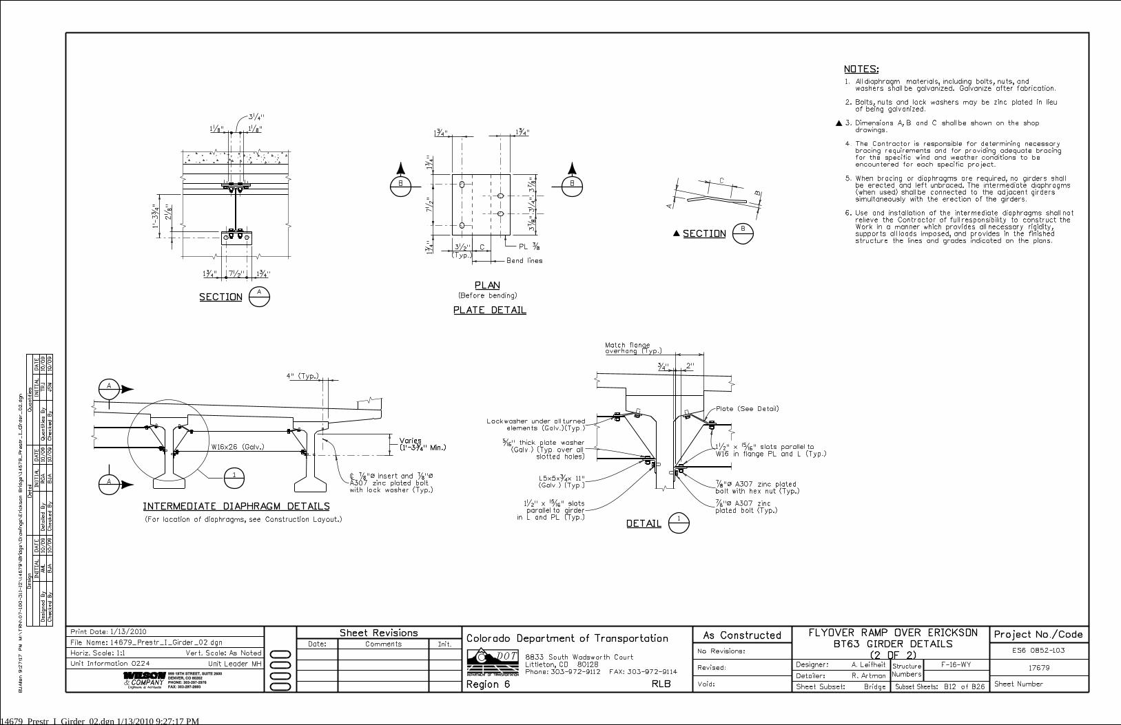
SECTION
1�" 7�" 1�"
1�"
3�"
1�"
A
A
B
p SECTIONB
PLAN
PLATE DETAIL
INTERMEDIATE DIAPHRAGM DETAILS
DETAIL1
�"
NOTES:
p
(Typ.)
PL �C
Bend lines
(Before bending)
Varies
(1’-3�" Min.)
Varies
(1’-3�" Min.)
4" (Typ.)
2"
Ò �"ß insert and �"ß
A307 zinc plated bolt
with lock washer (Typ.)
�" thick plate washer
(Galv.) (Typ. over all
slotted holes)
�"ß A307 zinc
plated bolt (Typ.)
�"ß A307 zinc plated
bolt with hex nut (Typ.)
1�" x �" slots parallel to
W16 in flange PL and L (Typ.)
1�" x �" slots
parallel to girder
in L and PL (Typ.)
B
B
1
A
A
All diaphragm materials, including bolts, nuts, and
washers shall be galvanized. Galvanize after fabrication.
Bolts, nuts and lock washers may be zinc plated in lieu
of being galvanized.
Dimensions A, B and C shall be shown on the shop
drawings.
The Contractor is responsible for determining necessary
bracing requirements and for providing adequate bracing
for the specific wind and weather conditions to be
encountered for each specific project.
When bracing or diaphragms are required, no girders shall
be erected and left unbraced. The intermediate diaphragms
(when used) shall be connected to the adjacent girders
simultaneously with the erection of the girders.
Use and installation of the intermediate diaphragms shall not
relieve the Contractor of full responsibility to construct the
Work in a manner which provides all necessary rigidity,
supports all loads imposed, and provides in the finished
structure the lines and grades indicated on the plans.
1.
2.
3.
4.
5.
6.
W16x26 (Galv.)
(For location of diaphragms, see Construction Layout.)
Lockwasher under all turned
elements (Galv.)(Typ.)
L5x5x�x 11"
(Galv.) (Typ.)
Plate (See Detail)
BJ
Allen 9:2
7:1
7
PM
M:\
TR
N\
07-100-3
11-12\
14
67
9\
Brid
ge\
Dra
win
gs\
Eric
kson
Brid
ge\
14
67
9_
Prestr_I_
Gir
der_
02.d
gn
F-16-WY
Numbers
Structure
No Revisions:
Revised:
Void: Sheet Subset:
Detailer:
Designer:
Bridge
R. Artman
A. Leifheit17679
ES6 0852-103
Sheet NumberSubset Sheets: B12 of B26
Init.CommentsDate:
Sheet Revisions As Constructed
1/13/2010Print Date:
Horiz. Scale:1:1
14679_Prestr_I_Girder_02.dgn
Vert. Scale: As Noted
Unit Leader MH
Project No./CodeFLYOVER RAMP OVER ERICKSON
BT63 GIRDER DETAILS
(2 OF 2)
File Name:
Unit Information 0224
14679_PrecastPanel_01.dgn 1/13/2010 9:27:46 PM
4" Min.
�
"ß strands
6"
Max.
1�
"
Min.
8’-
0"
Max.
1’-
6"
1’-
6"
3’-
0"
Min.
1�
"
�"
Min.
�
"ß strands
@
4�
"
1’-
6"
1’-
6"
�"
Min.
Length = 3’-
0"
Min., 8
’-0"
Max.
1" Min.Equal Spa. (2" Min., 1’-0" Max.)1" Min.
Panel Width (varies with girder spa.)
1.3
"
Panel Width
1’-0"
2"
6" 6"
1’-4"
1 �"R
Panel Width
Vent trapped air
4" Min.
INITIA
L
Desig
n
Desig
ned
By
Checked
By
DA
TE
DA
TE
DA
TE
INITIA
LINITIA
L
Detail
Quantities
Detailed
By
Checked
By
Checked
By
Quantities
By
JS
M
TRJ
BJ
A
RG
A
BJ
A
AM
L10/09
10/09
10/09
10/09
10/09
10/09
999 18TH STREET, SUITE 2600
DENVER, CO 80202
PHONE: 303-297-2976
FAX: 303-297-2693
Phone:303-972-9112 FAX:303-972-9114
Colorado Department of Transportation
Region 6 RLB
8833 South Wadsworth Court
Littleton, CO 80128
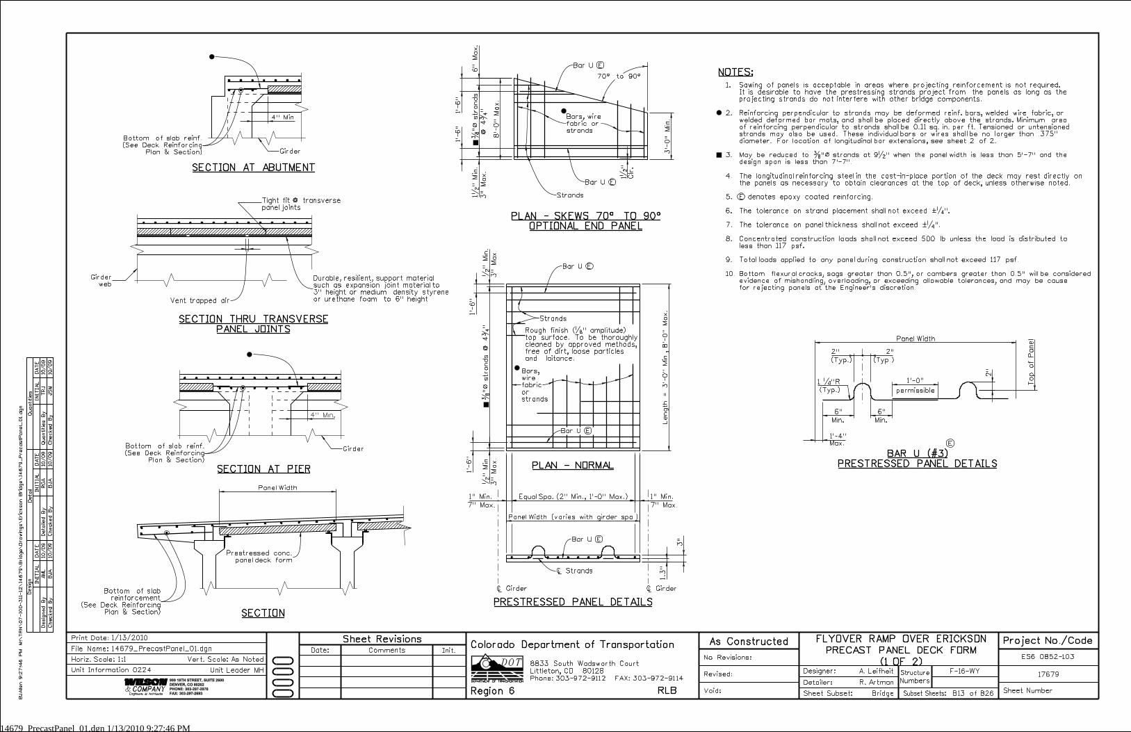
PLAN - SKEWS 70^ TO 90^
OPTIONAL END PANEL
3"
Max.
@
4�
"
Clr.
SECTION THRU TRANSVERSE
PANEL JOINTS
3"
Max.
3"
Max.
Rough finish (�" amplitude)
top surface. To be thoroughly
cleaned by approved methods,
free of dirt, loose particles
and laitance.
7" Max. 7" Max.
Ò Girder Ò Girder
PRESTRESSED PANEL DETAILS
SECTION AT PIER
SECTION
(Typ.)
Min. Min.
permissible
Max.
BAR U (#3)
PRESTRESSED PANEL DETAILS
E
Top of Panel
NOTES:70^ to 90^
(Typ.) (Typ.)
2" 2"
PLAN - NORMAL
Bar U E
Bar U E
Bar U E
Bar U E
Girder
Prestressed conc.
panel deck form
Ò Strands
Bars,
wire
fabric
or
strands
Strands
Bar U E
Girder
Durable, resilient, support material
such as expansion joint material to
3" height or medium density styrene
or urethane foam to 6" height
Bars, wire
fabric or
strands
Strands
Girder
web
3"
1.
2.
3.
4.
5.
6.
7.
8.
9.
10.
Sawing of panels is acceptable in areas where projecting reinforcement is not required.
It is desirable to have the prestressing strands project from the panels as long as the
projecting strands do not interfere with other bridge components.
Reinforcing perpendicular to strands may be deformed reinf. bars, welded wire fabric, or
welded deformed bar mats, and shall be placed directly above the strands. Minimum area
of reinforcing perpendicular to strands shall be 0.11 sq. in. per ft. Tensioned or untensioned
strands may also be used. These individual bars or wires shall be no larger than .375"
diameter. For location of longitudinal bar extensions, see sheet 2 of 2.
May be reduced to �"ß strands at 9�" when the panel width is less than 5’-7" and the
design span is less than 7’-7".
The longitudinal reinforcing steel in the cast-in-place portion of the deck may rest directly on
the panels as necessary to obtain clearances at the top of deck, unless otherwise noted.
E denotes epoxy coated reinforcing.
The tolerance on strand placement shall not exceed ˛�".
The tolerance on panel thickness shall not exceed ˛�".
Concentrated construction loads shall not exceed 500 lb unless the load is distributed to
less than 117 psf.
Total loads applied to any panel during construction shall not exceed 117 psf.
Bottom flexural cracks, sags greater than 0.5", or cambers greater than 0.5" will be considered
evidence of mishandling, overloading, or exceeding allowable tolerances, and may be cause
for rejecting panels at the Engineer’s discretion.
SECTION AT ABUTMENT
Bottom of slab reinf.
(See Deck Reinforcing
Plan & Section)
Tight fit @ transverse
panel joints
Bottom of slab reinf.
(See Deck Reinforcing
Plan & Section)
Bottom of slab
reinforcement
(See Deck Reinforcing
Plan & Section)
BJ
Allen 9:2
7:4
6
PM
M:\
TR
N\
07-100-3
11-12\
14
67
9\
Brid
ge\
Dra
win
gs\
Eric
kson
Brid
ge\
14
67
9_
PrecastPanel_
01.d
gn
F-16-WY
Numbers
Structure
No Revisions:
Revised:
Void: Sheet Subset:
Detailer:
Designer:
Bridge
R. Artman
A. Leifheit17679
ES6 0852-103
Sheet NumberSubset Sheets: B13 of B26
Init.CommentsDate:
Sheet Revisions As Constructed
1/13/2010Print Date:
Horiz. Scale:1:1
14679_PrecastPanel_01.dgn
Vert. Scale: As Noted
Unit Leader MH
Project No./CodeFLYOVER RAMP OVER ERICKSON
PRECAST PANEL DECK FORM
(1 OF 2)
File Name:
Unit Information 0224
14679_PrecastPanel_02.dgn 1/13/2010 9:28:14 PM
2" min. concrete bearingin-place field dimension.
2�" (Typ.)
2" (Typ.)
1"
Min.
in-pla
ce field
dim
ensio
n
2" Min. concrete bearingin-place field dimension.
1"
Min.
in-pla
ce field
dim
ensio
n
INITIA
L
Desig
n
Desig
ned
By
Checked
By
DA
TE
DA
TE
DA
TE
INITIA
LINITIA
L
Detail
Quantities
Detailed
By
Checked
By
Checked
By
Quantities
By
JS
M
TRJ
BJ
A
RG
A
BJ
A
AM
L10/09
10/09
10/09
10/09
10/09
10/09
999 18TH STREET, SUITE 2600
DENVER, CO 80202
PHONE: 303-297-2976
FAX: 303-297-2693
Phone:303-972-9112 FAX:303-972-9114
Colorado Department of Transportation
Region 6 RLB
8833 South Wadsworth Court
Littleton, CO 80128
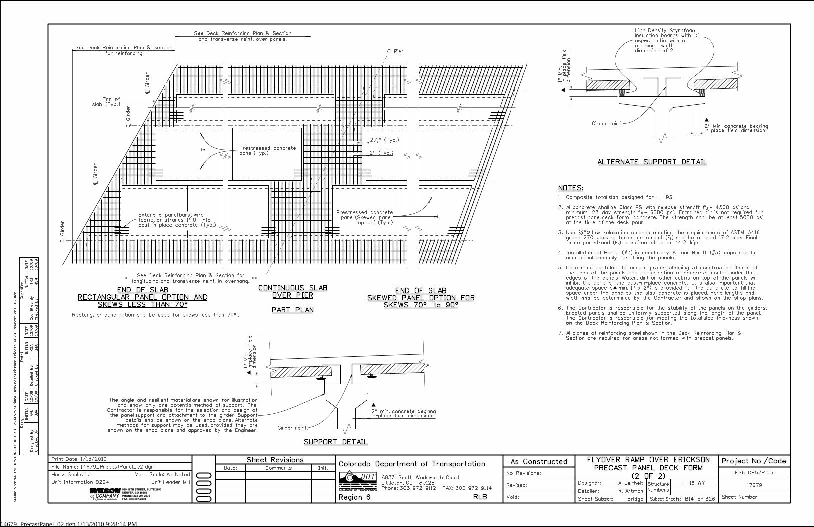
PART PLAN
END OF SLAB
SKEWED PANEL OPTION FOR
SKEWS 70^ to 90^
CONTINUOUS SLAB
OVER PIEREND OF SLAB
RECTANGULAR PANEL OPTION AND
Ò Pier
~
~
Ò
Gir
der
Ò
Gir
der
Ò
Gir
der
Ò
Gir
der
Rectangular panel option shall be used for skews less than 70^.
NOTES:
SUPPORT DETAIL
ALTERNATE SUPPORT DETAIL
Prestressed concrete
panel (Skewed panel
option) (Typ.)
Prestressed concrete
panel (Typ.)
Girder reinf.
The angle and resilient material are shown for illustration
and show only one potential method of support. The
Contractor is responsible for the selection and design of
the panel support and attachment to the girder. Support
details shall be shown on the shop plans. Alternate
methods for support may be used, provided they are
shown on the shop plans and approved by the Engineer.
End of
slab (Typ.)
Extend all panel bars, wire
fabric, or strands 1’-0" into
cast-in-place concrete (Typ.)
High Density Styrofoam
insulation boards with 1:1
aspect ratio with a
minimum width
dimension of 2"
Girder reinf.
cf’cif’
fFiF
1.
2.
3.
4.
5.
6.
7.
See Deck Reinforcing Plan & Section
for reinforcing
See Deck Reinforcing Plan & Section
and transverse reinf. over panels.
See Deck Reinforcing Plan & Section for
longitudinal and transverse reinf. in overhang.
Composite total slab designed for HL 93.
All concrete shall be Class PS with release strength = 4500 psi and
minimum 28 day strength = 6000 psi. Entrained air is not required for
precast panel deck form concrete. The strength shall be at least 5000 psi
at the time of the deck pour.
Use �"ß low relaxation strands meeting the requirements of ASTM A416
grade 270. Jacking force per strand ( ) shall be at least 17.2 kips. Final
force per strand ( ) is estimated to be 14.2 kips.
Installation of Bar U (#3) is mandatory. All four Bar U (#3) loops shall be
used simultaneously for lifting the panels.
Care must be taken to ensure proper cleaning of construction debris off
the tops of the panels and consolidation of concrete mortar under the
edges of the panels. Water, dirt or other debris on top of the panels will
inhibit the bond of the cast-in-place concrete. It is also important that
adequate space ( min. 1" x 2") is provided for the concrete to fill the
space under the panel as the slab concrete is placed. Panel lengths and
width shall be determined by the Contractor and shown on the shop plans.
The Contractor is responsible for the stability of the panels on the girders.
Erected panels shall be uniformly supported along the length of the panel.
The Contractor is responsible for meeting the total slab thickness shown
on the Deck Reinforcing Plan & Section.
All planes of reinforcing steel shown in the Deck Reinforcing Plan &
Section are required for areas not formed with precast panels.
BJ
Allen 9:2
8:1
4
PM
M:\
TR
N\
07-100-3
11-12\
14
67
9\
Brid
ge\
Dra
win
gs\
Eric
kson
Brid
ge\
14
67
9_
PrecastPanel_
02.d
gn
F-16-WY
Numbers
Structure
No Revisions:
Revised:
Void: Sheet Subset:
Detailer:
Designer:
Bridge
R. Artman
A. Leifheit17679
ES6 0852-103
Sheet NumberSubset Sheets: B14 of B26
Init.CommentsDate:
Sheet Revisions As Constructed
1/13/2010Print Date:
Horiz. Scale:1:1
14679_PrecastPanel_02.dgn
Vert. Scale: As Noted
Unit Leader MH
Project No./CodeFLYOVER RAMP OVER ERICKSON
PRECAST PANEL DECK FORM
(2 OF 2)
File Name:
Unit Information 0224
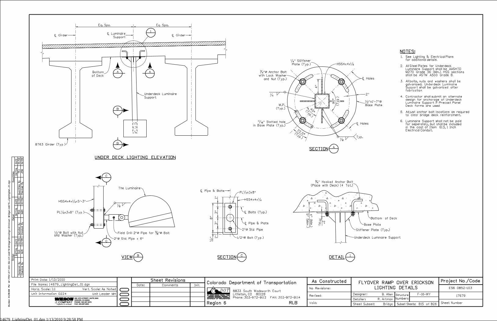
14679_LightingDet_01.dgn 1/13/2010 9:28:58 PM4"
8"
�" 1"
3"
3"
1"
Proj.
2"
Eq. Spa. Eq. Spa.
5" (
Max.)
4" (
Min.)
INITIA
L
Desig
n
Desig
ned
By
Checked
By
DA
TE
DA
TE
DA
TE
INITIA
LINITIA
L
Detail
Quantities
Detailed
By
Checked
By
Checked
By
Quantities
By
JS
M
TRJ
MJ
N
RG
A
MJ
N
BJ
A10/09
10/09
10/09
10/09
10/09
10/09
Phone:303-972-9112 FAX:303-972-9114
Colorado Department of Transportation
Region 6 RLB
8833 South Wadsworth Court
Littleton, CO 80128
999 18TH STREET, SUITE 2600
DENVER, CO 80202
PHONE: 303-297-2976
FAX: 303-297-2693
(Typ.)
W.P.
(Typ.)
�
Ò Holes
Ò Holes
2"
A
A
B
B
C
C
CSECTION
ASECTION
2"ß Std. Pipe
DETAIL
1
Bottom of Deck
1
Ò Girder Ò Girder
NOTES:
The Luminaire
�Typ.
�" Slotted hole
in Base Plate (Typ.)
Ò Luminaire
Support
�" Stiffener
Plate (Typ.)
(Typ.)
(Typ.)
�"ß Anchor Bolt
with Lock Washer
and Nut (Typ.)
HSS4x4x�
�
Field Drill 2"ß Pipe for �"ß Bolt
PL�x3x8"
PL�x3x8" (Typ.)
HSS4x4x�x5’-3"
2"ß Std. Pipe x 6"
�" Hooked Anchor Bolt
(Place with Deck) (4 Tot.)
Underdeck Luminaire Support
Base Plate
Stiffener Plate (Typ.)
Ò Pipe & Plate
Ò Pipe & Bolts
Ò Bolts (Typ.)
1/2"ß Bolt (Typ.)
BT63 Girder (Typ.)
UNDER DECK LIGHTING ELEVATION
HSS4x4x�
BVIEW
Bottom
of Deck
�"x1’-7"ß
Base Plate
�"ß Bolt with Nutand Washer (Typ.)
See Lighting & Electrical Plans
for additional details.
All Steel Plates for Underdeck
Luminaire Support shall be AASHTO
M270 Grade 36 (Min.). HSS sections
shall be ASTM A500 Grade B.
All bolts, nuts and washers shall be
galvanized. Underdeck Luminaire
Support shall be galvanized after
fabrication.
Contractor shall submit an alternate
design for anchorage of Underdeck
Luminaire Support if Precast Panel
Deck forms are used.
Adjust anchor bolt locations as required
to clear bridge deck reinforcment.
Luminaire Support shall not be paid
for seperately, but shall be included
in the cost of Item 613, 1 Inch
Electrical Conduit.
1.
2.
3.
4.
5.
6.
Underdeck Luminaire
Support
BJ
Allen 9:2
8:5
8
PM
M:\
TR
N\
07-100-311-12\
14
67
9\
Brid
ge\
Dra
win
gs\
Eric
kson
Brid
ge\
14
67
9_
Lig
htin
gDet_
01.d
gn
F-16-WY
Numbers
Structure
No Revisions:
Revised:
Void: Sheet Subset:
Detailer:
Designer:
Bridge
R. Artman
B. Allen17679
ES6 0852-103
Sheet NumberSubset Sheets: B15 of B26
Init.CommentsDate:
Sheet Revisions As Constructed
1/13/2010Print Date:
Horiz. Scale:1:1
14679_LightingDet_01.dgn
Vert. Scale: As Noted
Unit Leader MH
Project No./CodeFLYOVER RAMP OVER ERICKSON
LIGHTING DETAILSFile Name:
Unit Information 0224
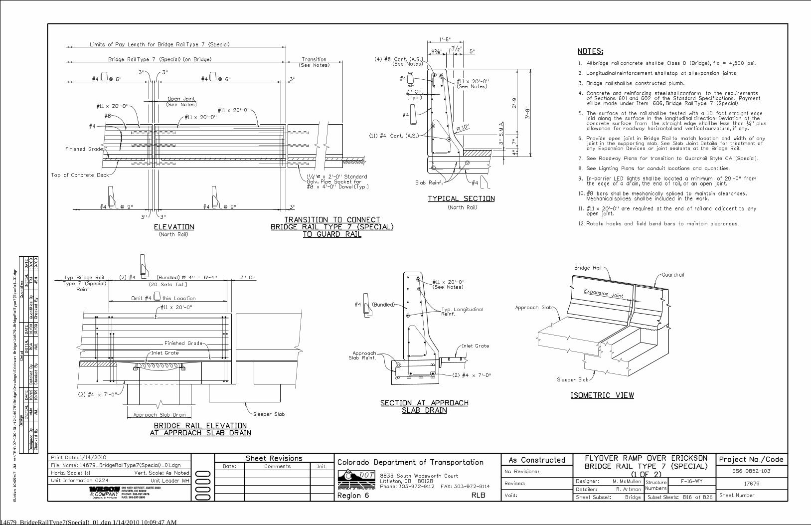
14679_BridgeRailType7(Special)_01.dgn 1/14/2010 10:09:47 AM
3"
3"
Expansion Joint
(See Notes)
Open Joint
Approach Slab Drain
(2) #4 (Bundled) @ 4" = 6’-4" 2" Clr.
#4 @ 9"
2’-
9"
3’-
8"
9�" 5"
1’-6"
3�"
7"
4"
10"R
3" S.M.A.
(Typ.)
2" Clr.
Type 7 (Special)
Typ. Bridge Rail
INITIA
L
Desig
n
Desig
ned
By
Checked
By
DA
TE
DA
TE
DA
TE
INITIA
LINITIA
L
Detail
Quantities
Detailed
By
Checked
By
Checked
By
Quantities
By
JS
M
TRJ
AM
L
RG
A
AM
L
MM
M10/09
10/09
10/09
10/09
10/09
10/09
999 18TH STREET, SUITE 2600
DENVER, CO 80202
PHONE: 303-297-2976
FAX: 303-297-2693
Phone:303-972-9112 FAX:303-972-9114
Colorado Department of Transportation
Region 6 RLB
8833 South Wadsworth Court
Littleton, CO 80128
#4 @ 9"
3" 3"
3"3"
ISOMETRIC VIEW
ELEVATION
#4
Approach Slab
Sleeper Slab
Guardrail
Bridge Rail
TYPICAL SECTION
Finished Grade
Top of Concrete Deck 1�"ß x 2’-0" Standard
Galv. Pipe Socket for
#8 x 4’-0" Dowel (Typ.)
SECTION AT APPROACH
SLAB DRAIN
BRIDGE RAIL ELEVATION
AT APPROACH SLAB DRAIN
Sleeper Slab
Finished Grade
Inlet Grate
(2) #4 x 7’-0"
(20 Sets Tot.)
Limits of Pay Length for Bridge Rail Type 7 (Special)
(North Rail)
TRANSITION TO CONNECT
BRIDGE RAIL TYPE 7 (SPECIAL)
TO GUARD RAIL
(North Rail)
#8
Slab Reinf.
ApproachSlab Reinf.
Inlet Grate
(2) #4 x 7’-0"
BJ
Allen 10:0
9:4
7
AM
M:\
TR
N\
07-100-311-12\
14
67
9\
Brid
ge\
Dra
win
gs\
Eric
kson
Brid
ge\
14
67
9_
Brid
ge
RailT
ype7(S
pecial)_
01.d
gn
F-16-WY
Numbers
Structure
No Revisions:
Revised:
Void: Sheet Subset:
Detailer:
Designer:
Bridge
R. Artman
M. McMullen17679
ES6 0852-103
Sheet NumberSubset Sheets: B16 of B26
Init.CommentsDate:
Sheet Revisions As Constructed
1/14/2010Print Date:
Horiz. Scale:1:1
14679_BridgeRailType7(Special)_01.dgn
Vert. Scale: As Noted
Unit Leader MH
Project No./CodeFLYOVER RAMP OVER ERICKSON
BRIDGE RAIL TYPE 7 (SPECIAL)
(1 OF 2)
File Name:
Unit Information 0224
Bridge Rail Type 7 (Special) (on Bridge) (4) #8 Cont. (A.S.)(See Notes)
(11) #4 Cont. (A.S.)
#4
#4
#4 #4 @ 6" #4 @ 6"
#11 x 20’-0"
#11 x 20’-0"
#11 x 20’-0"
#11 x 20’-0"Typ. LongitudinalReinf.
#4 (Bundled)
6�"
5�"
Omit #4 this Loaction
Reinf.
NOTES:
1.
2.
3.
4.
5.
6.
7.
8.
9.
10.
11.
12.
All bridge rail concrete shall be Class D (Bridge), f’c = 4,500 psi.
Longitudinal reinforcement shall stop at all expansion joints.
Bridge rail shall be constructed plumb.
Concrete and reinforcing steel shall conform to the requirements
of Sections 601 and 602 of the Standard Specifications. Payment
will be made under Item 606, Bridge Rail Type 7 (Special).
The surface of the rail shall be tested with a 10 foot straight edge
laid along the surface in the longitudinal direction. Deviation of the
concrete surface from the straight edge shall be less than � " plus
allowance for roadway horizontal and vertical curvature, if any.
Provide open joint in Bridge Rail to match location and width of any
joint in the supporting slab. See Slab Joint Details for treatment of
any Expansion Devices or joint sealants at the Bridge Rail.
See Roadway Plans for transition to Guardrail Style CA (Special).
See Lignting Plans for conduit locations and quantities.
In-barrier LED lights shall be located a minimum of 20’-0" from
the edge of a drain, the end of rail, or an open joint.
#8 bars shall be mechanically spliced to maintain clearances.
Mechanical splices shall be included in the work.
#11 x 20’-0" are required at the end of rail and adjacent to any
open joint.
Rotate hooks and field bend bars to maintain clearances.
#11 x 20’-0"
(See Notes)
Transition
(See Notes)
#11 x 20’-0"
(See Notes)

14679_BridgeRailType7(Special)_02.dgn 1/14/2010 10:11:31 AM
3"
#4 @ 9"
11"
1’-
2"
1’-
7"
1’-6"
9�"3�"
5"
2’-
9"
3’-
8"
7"
4"
3" S.M.A.
10"R
5" Max.
Varies
1�" Clr.
(Typ.)
2" Clr.
(20) #4 @ 6" (N.F.)
3"
@ 1’-6" Max. (F.F.)
(7) #4
9"
3"
9"
(Typ.)
2" Clr.
3’-0"
3’-0"
3’-0"
10’-0" 5"
2’-0"
1’-0"
5"
10’-0" Blockout
10’-0" Tapered Blockout
21’-0" Min. (See Notes)
INITIA
L
Desig
n
Desig
ned
By
Checked
By
DA
TE
DA
TE
DA
TE
INITIA
LINITIA
L
Detail
Quantities
Detailed
By
Checked
By
Checked
By
Quantities
By
JS
M
TRJ
AM
L
RG
A
AM
L
MM
M10/09
10/09
10/09
10/09
10/09
10/09
999 18TH STREET, SUITE 2600
DENVER, CO 80202
PHONE: 303-297-2976
FAX: 303-297-2693
Phone:303-972-9112 FAX:303-972-9114
Colorado Department of Transportation
Region 6 RLB
8833 South Wadsworth Court
Littleton, CO 80128
ELEVATION
TYPICAL SECTION
Top of Concrete Deck1�"ß x 2’-0" Standard
Galv. Pipe Socket for
#8 x 4’-0" Dowel (Typ.)
Limits of Pay Length for Bridge Rail Type 7 (Special)
#4 @ 6"
TRANSITION TO CONNECT
BRIDGE RAIL TYPE 7 (Special)
TO GUARD RAIL
#8
Slab Reinf.
BJ
Allen 10:1
1:3
1 A
M
M:\
TR
N\
07-100-3
11-12\
14
67
9\
Brid
ge\
Dra
win
gs\
Eric
kson
Brid
ge\
14
67
9_
Brid
ge
RailT
ype7(S
pecial)_
02.d
gn
F-16-WY
Numbers
Structure
No Revisions:
Revised:
Void: Sheet Subset:
Detailer:
Designer:
Bridge
R. Artman
M. McMullen17679
ES6 0852-103
Sheet NumberSubset Sheets: B17 of B26
Init.CommentsDate:
Sheet Revisions As Constructed
1/14/2010Print Date:
Horiz. Scale:1:1
14679_BridgeRailType7(Special)_02.dgn
Vert. Scale: As Noted
Unit Leader MH
Project No./CodeFLYOVER RAMP OVER ERICKSON
BRIDGE RAIL TYPE 7 (SPECIAL)
(2 OF 2)
File Name:
Unit Information 0224
(South Rail at Blockout and Taper)
TYPICAL SECTION
#4 @ 9"
Finished
Grade
LED Light
Junction
Box
Grind Corner to
a 10" Radius
(South Rail)
PLAN
Outside Edge of Deck
(South Rail at Blockout)
Bridge Rail Type 7 (Special) (on Bridge)
#4
(4) #8 Cont. (A.S.)(See Notes)
#4
(11) #4 Cont. (A.S.)
#4
Slab Reinf.
#4
#4
(4) #8 Cont. (A.S.)(See Notes)
#4
(2) #4*
#4*
(9) #4 Cont.(A.S.)
(South Rail)
LED Light (See
Lighting Plans)
(13) #4 @ 9" Max.
#4 #11 x 20’-0"
6�"
5�"
4�"
4�"
Traffic Side of Rail
6�"
5�"
NOTES:
1.
2.
3.
4.
5.
6.
7.
8.
9.
10.
11.
12.
All bridge rail concrete shall be Class D (Bridge), f’c = 4,500 psi.
Longitudinal reinforcement shall stop at all expansion joints.
Bridge rail shall be constructed plumb.
Concrete and reinforcing steel shall conform to the requirements
of Sections 601 and 602 of the Standard Specifications. Payment
will be made under Item 606, Bridge Rail Type 7 (Special).
The surface of the rail shall be tested with a 10 foot straight edge
laid along the surface in the longitudinal direction. Deviation of the
concrete surface from the straight edge shall be less than � " plus
allowance for roadway horizontal and vertical curvature, if any.
Provide open joint in Bridge Rail to match location and width of any
joint in the supporting slab. See Slab Joint Details for treatment of
any Expansion Devices or joint sealants at the Bridge Rail.
See Roadway Plans for transition to Guardrail Style CA (Special).
See Lignting Plans for conduit locations and quantities.
In-barrier LED lights shall be located a minimum of 21’-0" from
the edge of a drain, the end of rail, or an open joint.
#8 bars shall be mechanically spliced to maintain clearances.
Mechanical splices shall be included in the work.
#11 x 20’-0" are required at the end of rail and adjacent to any
open joint.
Rotate hooks and field bend bars to maintain clearances.
#11 x 20’-0"
(See Notes)#4 (See Notes)
Transition
(See Notes)
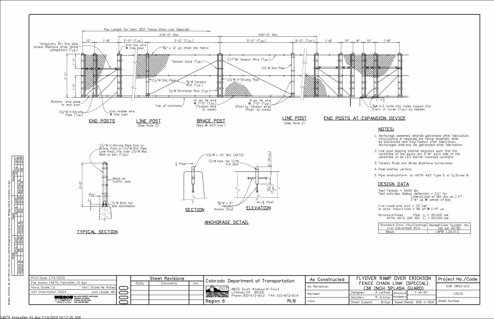
14679_FenceDet_01.dgn 1/14/2010 10:12:26 AM
1’-
0"
1’-
6"
3’-
0"
Pay Length for Item 607 Fence Chain Link (Special)
400’-0" Max.
5’-0" (Typ.)5’-0" (Typ.)1’-8"10" 5’-0" (Typ.)
400’-0" Max.
5’-0" (Typ.) 1’-8" 10" 8" 10" 1’-8"
4" (Proj.)
2"
4�"
1�
"
INITIA
L
Desig
n
Desig
ned
By
Checked
By
DA
TE
DA
TE
DA
TE
INITIA
LINITIA
L
Detail
Quantities
Detailed
By
Checked
By
Checked
By
Quantities
By
JS
M
TRJ
BJ
A
RG
A
BJ
A
AM
L10/09
10/09
10/09
10/09
10/09
10/09
999 18TH STREET, SUITE 2600
DENVER, CO 80202
PHONE: 303-297-2976
FAX: 303-297-2693
Phone:303-972-9112 FAX:303-972-9114
Colorado Department of Transportation
Region 6 RLB
8833 South Wadsworth Court
Littleton, CO 80128
END POSTSLINE POST
(Spa. @ 400’ max.)
END POSTS AT EXPANSION DEVICE
TYPICAL SECTION
ELEVATION
LINE POST BRACE POST
ANCHORAGE DETAIL
SECTION
Black 1.8PB 1.26/0.5
DESIGN DATA
2
fy
fy
Standard Color Vinyl Coatings
over Galvanized Wire
Munsell Color System No.
(as per ASTM)
3’-
0"
�" x 12 ga. chain link fabric
Tension band (Typ.)
1�"ß Std. Pipe
0.177ß Tension Wire (Typ.)
1�"ß Std. Pipe
�"ß Bolt, nut
and lockwasher
1�"ß x 10" Bar (A572)
�"ß hole for �"ß
H.S. bolt
�"ß x 4"
Headed
Anchor Stud
Bottom wire goes
to end post
1�"ß X-Strong
Pipe (Typ.)
Temporary �" Std. pipe
brace (Remove after fence
completion) (Typ.)
Mesh on
traffic side
9 ga. tie wire
@ 1’-0" (Typ.)
(Post to Tension wire)
(Post to mesh)
�"ß Stretcher Rod (Typ.)
�"ß Tension
Rod (Typ.)
14 ga. tie wire
@ 1’-0" (Typ.)
(Tension wire
to mesh)
Top of concrete
1�"ß X-Strong Pipe End or
Brace Post or 1�"ß Std. Pipe
Line Post, fits over 1�"ß Bar.
Bolt to bar. (Typ.)
Test Tension = 5400 lbs
Test with: Max Midbay deflection = 1�" for
Lateral Load of 160 lbs. on 1 ft .
1’-6" up @ center of bay.
Live Load: wind load = 32 psf
or snow impact load = 96 plf @ 1’-6" up
Structural Steel: Pipe = 35,000 psi
ASTM A572 (GR 50) = 50,000 psi
1�"ß X-Strong Pipe
End top wire
@ this post
End middle wire
@ this post
�ß H.S. bolts into holes tapped into
Exp’n. Jt. cover (Typ.) as needed
Ò Post
Ò Post
NOTES:
BJ
Allen 10:1
2:2
6
AM
M:\
TR
N\
07-100-311-12\
14
67
9\
Brid
ge\
Dra
win
gs\
Eric
kson
Brid
ge\
14
67
9_
Fence
Det_
01.d
gn
F-16-WY
Numbers
Structure
No Revisions:
Revised:
Void: Sheet Subset:
Detailer:
Designer:
Bridge
R. Artman
A. Leifheit17679
ES6 0852-103
Sheet NumberSubset Sheets: B18 of B26
Init.CommentsDate:
Sheet Revisions As Constructed
1/14/2010Print Date:
Horiz. Scale:1:1
14679_FenceDet_01.dgn
Vert. Scale: As Noted
Unit Leader MH
Project No./CodeFLYOVER RAMP OVER ERICKSON
FENCE CHAIN LINK (SPECIAL)
(36 INCH SPLASH GUARD)
File Name:
Unit Information 0224
1.
2.
3.
4.
5.
(See Note 2)(See Note 2)
Anchorage assembly shall be galvanized after fabrication.
Vinyl Coating is required, the fence assembly shall
be Galvanized and Vinyl Coated after fabrication.
Anchorages shall only be galvanized after fabrication.
Line post spacing shall be adjusted such that the
centerline of line posts are 2’-6" each side of the
centerline of an LED barrier mounted luminaire.
Tension Rods and Wires shall have turnbuckles.
Post shall be vertical.
Pipe shall conform to ASTM A53 Type E or S, Grade B.
(T
yp.)
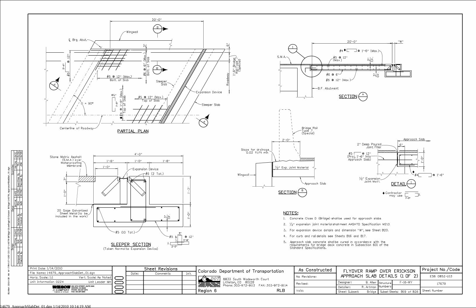
14679_ApproachSlabDet_01.dgn 1/14/2010 10:14:19 AM
1’-
3"
3"
"W"
1’-
0"
1’-0"
1’-6" 1’-6"1’-0"
4’-0"
3"
1’-
0"
1’-
0"
2’-0"
6"
Clr.
2"
Clr.
3"
Clr.
3"
6"
20’-0"
20’-0"
1’-
6"
Brid
ge
Rail T
ype 7
(S
pecial)
INITIA
L
Desig
n
Desig
ned
By
Checked
By
DA
TE
DA
TE
DA
TE
INITIA
LINITIA
L
Detail
Quantities
Detailed
By
Checked
By
Checked
By
Quantities
By
JS
M
TRJ
MJ
N
RG
A
MJ
N
BJ
A10/09
10/09
10/09
10/09
10/09
10/09
999 18TH STREET, SUITE 2600
DENVER, CO 80202
PHONE: 303-297-2976
FAX: 303-297-2693
Phone:303-972-9112 FAX:303-972-9114
Colorado Department of Transportation
Region 6 RLB
8833 South Wadsworth Court
Littleton, CO 80128
B
SECTION
�" Exp. Joint Material
1’-
0"
2’-
4"
Road
way
SECTIONA
Approach Slab
1’-0"
7"
SLEEPER SECTION
8"
2’-2"
2’-8"
7"
1’-
9"
NOTES:
1.
2.
3.
4.
5.
A
A
#5 @ 12" (Max.)
Bott. of Slab
#4
@ 1’-
6" (
Max.)
Top of Sla
b
#5 @ 12" (Max.)
Top of Slab
#5
@ 12"
Slope for drainage
0.02 ft/ft min.
20 Gage Galvanized
Sheet Metal (to be
included in the work)
Wingwall
Sleeper
Slab
Centerline of Roadway
�" Expansion
Joint Mat’l.
#4 @ 1’-6"
#6 @ 6"
Ò Brg. Abut.
S.M.A.
Expansion Device
Sleeper Slab
#5 @ 12" (Max.)
#5 @ 12"(Max.)
B.F. Abutment
Wingwall
(Taken Normal to Expansion Device)
#5 @ 12"
#5 (10 Tot.)
Approach Slab
PARTIAL PLAN
Contractor may use
#5 @ 12"
(Proj. 1’-6" into
Approach Slab)
#5 (2 Tot.)
1
B
B
DETAIL
1
Expansion Device
Concrete Class D (Bridge) shall be used for approach slabs.
�" expansion joint material shall meet AASHTO Specification M213.
For expansion device details and dimension "W", see Sheet B20.
For curb and rail details see Sheets B16 and B17.
Approach slab concrete shall be cured in accordance with the
requirements for bridge deck concrete in Subsection 601 of the
Standard Specifications.
#6
@ 6" (
Max.)
Bott.
of Sla
b
6�"
Stone Matrix Asphalt
(S.M.A.) over
Waterproofing
Membrane
2" Deep Poured
Joint Filler
= 90^
#4 @ 1’-6" (Max.)
BJ
Allen 10:1
4:1
9
AM
M:\
TR
N\
07-100-3
11-12\
14
67
9\
Brid
ge\
Dra
win
gs\
Eric
kson
Brid
ge\
14
67
9_
ApproachSla
bDet_
01.d
gn
F-16-WY
Numbers
Structure
No Revisions:
Revised:
Void: Sheet Subset:
Detailer:
Designer:
Bridge
R. Artman
B. Allen17679
ES6 0852-103
Sheet NumberSubset Sheets: B19 of B26
Init.CommentsDate:
Sheet Revisions As Constructed
1/14/2010Print Date:
Horiz. Scale:1:1
14679_ApproachSlabDet_01.dgn
Vert. Scale: As Noted
Unit Leader MH
Project No./CodeFLYOVER RAMP OVER ERICKSON
APPROACH SLAB DETAILS (1 OF 2)File Name:
Unit Information 0224
Bridge RailType 7(Special)
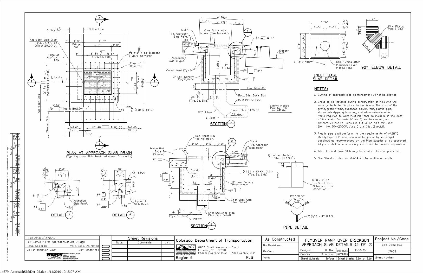
14679_ApproachSlabDet_02.dgn 1/14/2010 10:15:07 AM
(Typ.)
2"
Clr.
1’-1�
"
(Min.)
11"
(Min.)
11"
1’-3"
1"
Clr.
2"
Approach Sla
b
3"
4’-
8�
"
3"
4’-0"6" 1’-6"
1’-0"3’-0"Sle
eper Sla
b
4’-
1"
2’-5"
2’-5"
4’-10"
9"6"
8"
8"
@
6"
#4
4"
9"9"
(Typ.)
8"
(Typ.)
8"
(Typ. Ea. Side)
(8) #4 @ 6"
(Top)
2�
"
Clr.
(Top)
2�
"
Clr.
1’-6"1’-6"
(Typ. Ea. Side)
(4) #6 x 10’-0" (A.S.)
2’-
0"
4"
Varies
1’-3"2’-2�"
1’-3"
4’-8�"
(Bott.)
(4) #6 6"
(Bott.)
(4) #6
1’-
3" 1’-
3"
1’-6"
1’-0"
(Eq.
Spa.)
(5) #4
Proj.
1’-0"
Proj.
10"
(Typ.)
(4) #4 (E.W.)
(Centered on Inlet)
(6) #
5
@ 12"
(8) #6 @ 6"
2’-
0�
"2’-
0�
"
1"
INITIA
L
Desig
n
Desig
ned
By
Checked
By
DA
TE
DA
TE
DA
TE
INITIA
LINITIA
L
Detail
Quantities
Detailed
By
Checked
By
Checked
By
Quantities
By
JS
M
TRJ
MJ
N
RG
A
MJ
N
BJ
A10/09
10/09
10/09
10/09
10/09
10/09
999 18TH STREET, SUITE
2600
DENVER, CO 80202
PHONE: 303-297-2976
FAX: 303-297-2693
Phone:303-972-9112 FAX:303-972-9114
Colorado Department of Transportation
Region 6 RLB
8833 South Wadsworth Court
Littleton, CO 80128
A
A
B
B
90^ ELBOW DETAIL
#4
SECTIONSECTIONA
SECTIONSECTIONB
3’-
2"
#4
Approach
Slab (Typ.)
3" Low DensityPolystyrene
Ò Inlet
Ò Inlet
Edge ofApproach
Slab
B.F. ofBridge Rail
Ò Inlet
Gutter Line
BridgeRail
#5 (Top & Bott.)
(Typ. @ Corners)
#5 (Top & Bott.)
PLAN AT APPROACH SLAB DRAIN
Edge of
Concrete
Const. Joint (Typ.)
#4
3’-
2�
"
(Typ. Ea. Side)
Elev. 5478.99
15"ß Plastic Pipe
2% Min.
1
3" Low DensityPolystyrene
#4 (Typ.)
#4
2.0%
4’-
0"
2’-6"
2’-6"
Vane Grate with
Frame (See Notes)
SleeperSlab
INLET BASE
SLAB DETAIL
DETAIL1
2
DETAIL2
Invert Elev. 5475.50
(Typ. Ea. Side)
Inlet Base Slab(See Detail)
NOTES:
(Typ.) (Typ.)
Approach
Slab Reinf.
#4
#5#5
Approach
Slab Reinf.
#4
PIPE DETAIL
Typ. Approach
Slab Reinf.
(Typ.)
Typ. Approach
Slab Reinf.
(3) �"ß x 4" H.A.S.
2’-8"
5’-
0"
#5 (Top & Bott.)
4’-3�"
4’-
6"
2’-6"
2’-
6"
#5
5%Approach Slab Drain
Sta. 741+77.34
Offset 28.00’ Lt.
Ò Inlet
#4
#4
(Typ. Approach Slab Reinf. not shown for clarity)
3" S.M.A.
S.M.A.
#6 @ 6"
Bott. Inlet Base Slab
90^ Elbow
See Sheet B16
for Rail Reinf.
4% 4%
S.M.A.
Ò Headed Anchor
Stud (H.A.S.)
12"ß x 2’-0"
Std. Steel Pipe
(Galvanize after
Fabrication)
Ò 18"ß Hole
15"ß PlasticPipe (Typ.)
12"ß Std. Steel Pipe(See Pipe Detail)
(T
yp.)
Const.
Joint
(Typ.)
Grout Voids after
Placement over
Plastic Pipe
1.
2.
3.
4.
5.
2’-6"
2’-6"
2’-6"
2’-6"
Extend PlasticPipe to IntletNo. 741.64L
Cutting of approach slab reinforcement will not be allowed.
Grate to be installed during construction of inlet with the
vane grate bolted in place to the frame. The cost of the
grate, grate frame, expanded polystyrene, plastic pipe,
elbows, steel pipe, galvanizing, and other miscellaneous
items required to construct inlet shall be included in the cost
of the work. Concrete (Class D), reinforcement, and
anchors will not be measured but will be paid for under
Item No. 604-25000, Vane Grate Inlet (Special).
Plastic pipe shall conform to the requirements of AASHTO
M294, Type S. Plastic pipe shall be joined by watertight
couplings as recommended by the Pipe Supplier or as approved.
All joints shall be mechanically restrained to prevent separation.
Inlet Box and Base Slab may be cast-in-place or pre-cast.
See Standard Plan No. M-604-25 for additional details.
BJ
Allen 10:1
5:0
7
AM
M:\
TR
N\
07-100-311-12\
14
67
9\
Brid
ge\
Dra
win
gs\
Eric
kson
Brid
ge\
14
67
9_
ApproachSla
bDet_
02.d
gn
F-16-WY
Numbers
Structure
No Revisions:
Revised:
Void: Sheet Subset:
Detailer:
Designer:
Bridge
R. Artman
B. Allen17679
ES6 0852-103
Sheet NumberSubset Sheets: B20 of B26
Init.CommentsDate:
Sheet Revisions As Constructed
1/14/2010Print Date:
Horiz. Scale:1:1
14679_ApproachSlabDet_02.dgn
Vert. Scale: As Noted
Unit Leader MH
Project No./CodeFLYOVER RAMP OVER ERICKSON
APPROACH SLAB DETAILS (2 OF 2)File Name:
Unit Information 0224
Bridge Rail
Type 7
(Special)
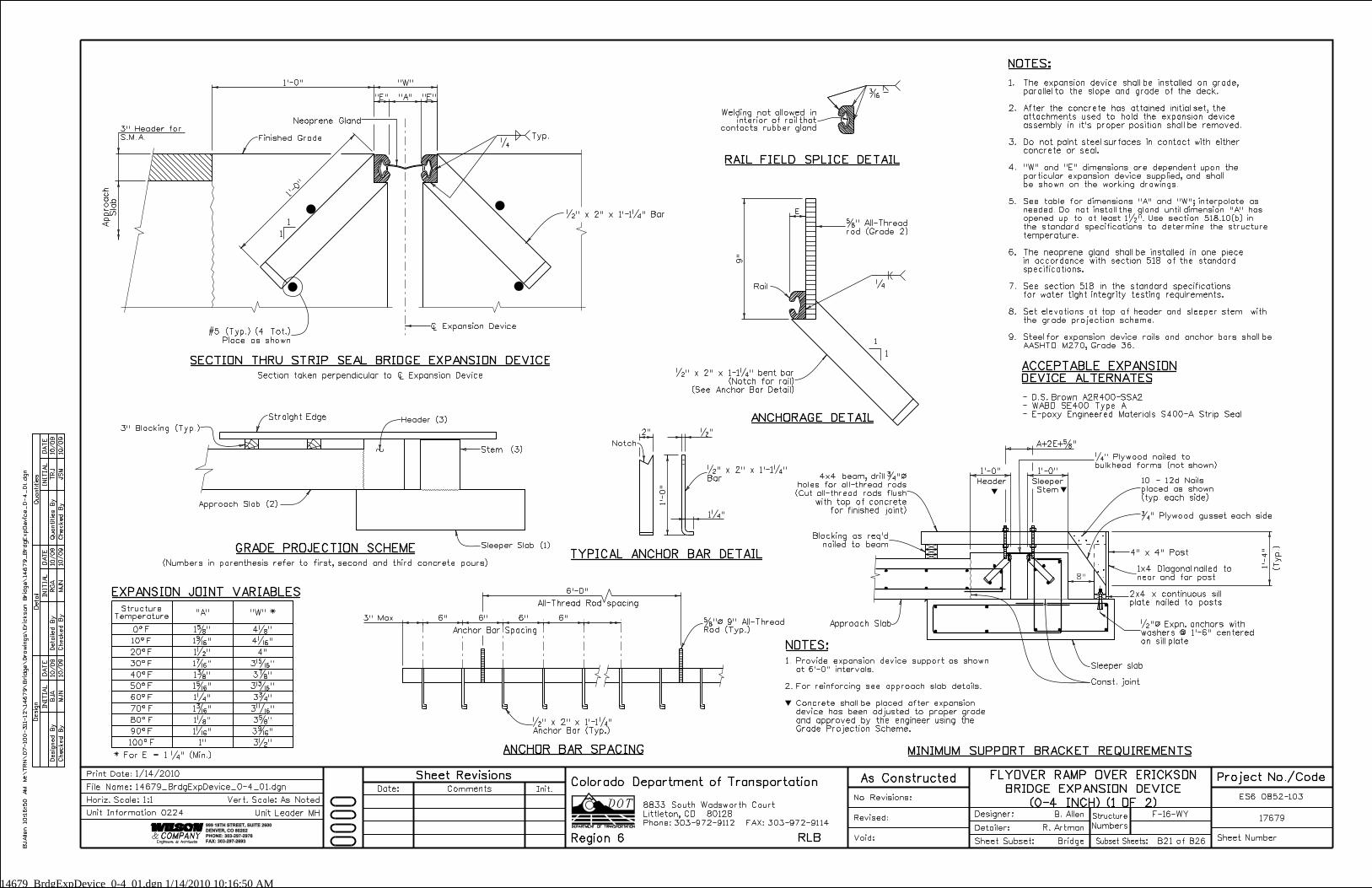
14679_BrdgExpDevice_0-4_01.dgn 1/14/2010 10:16:50 AM
8"
1’-0" "W"
3" Max.
1’-
0"
�"2"
1�"
9"
E
1’-0" 1’-0"
1’-
4"
1’-0"
"E" "E""A"
INITIA
L
Desig
n
Desig
ned
By
Checked
By
DA
TE
DA
TE
DA
TE
INITIA
LINITIA
L
Detail
Quantities
Detailed
By
Checked
By
Checked
By
Quantities
By
JS
M
TRJ
MJ
N
RG
A
MJ
N
BJ
A10/09
10/09
10/09
10/09
10/09
10/09
999 18TH STREET, SUITE 2600
DENVER, CO 80202
PHONE: 303-297-2976
FAX: 303-297-2693
Phone:303-972-9112 FAX:303-972-9114
Colorado Department of Transportation
Region 6 RLB
8833 South Wadsworth Court
Littleton, CO 80128
Typ.
1
1
SECTION THRU STRIP SEAL BRIDGE EXPANSION DEVICE
RAIL FIELD SPLICE DETAIL
�
1
1
�
ANCHORAGE DETAIL
NOTES:
ACCEPTABLE EXPANSION
DEVICE ALTERNATES
GRADE PROJECTION SCHEME
(Numbers in parenthesis refer to first, second and third concrete pours)TYPICAL ANCHOR BAR DETAIL
20^F
30^F
40^F
50^F
"A"
All-Thread Rod spacing
ANCHOR BAR SPACING
Header
(T
yp.)
MINIMUM SUPPORT BRACKET REQUIREMENTS
1.
2.
Provide expansion device support as shown
at 6’-0" intervals.
For reinforcing see approach slab details.
Concrete shall be placed after expansion
device has been adjusted to proper grade
and approved by the engineer using the
Grade Projection Scheme.
NOTES:
�
Sleeper
Stem
A+2E+�"
6’-0"
Anchor Bar Spacing
6" 6" 6" 6"
�" x 2" x 1’-1�" Bar
Neoprene Gland
Finished Grade
Welding not allowed ininterior of rail that
contacts rubber gland
Header (3)Straight Edge
3" Blocking (Typ.)
Approach Slab (2)
Sleeper Slab (1)
Stem (3)
�" x 2" x 1’-1�"
Bar
Approach Slab
10 - 12d Nails
placed as shown
(typ. each side)
Sleeper slab
Const. joint
�" Plywood nailed to
bulkhead forms (not shown)
�" Plywood gusset each side
�"ß 9" All-ThreadRod (Typ.)
Blocking as req’d
nailed to beam
4x4 beam, drill �"ß
holes for all-thread rods
(Cut all-thread rods flush
with top of concrete
for finished joint)
�"ß Expn. anchors with
washers @ 1’-6" centered
on sill plate
2x4 x continuous sill
plate nailed to posts
3" Header for
S.M.A.
Rail
#5 (Typ.) (4 Tot.)
Place as shown
Ò Expansion Device
Approach
Sla
b
StructureTemperature
�" x 2" x 1-1�" bent bar
(Notch for rail)
(See Anchor Bar Detail)
�" x 2" x 1’-1�"
Anchor Bar (Typ.)
Section taken perpendicular to Ò Expansion Device
Notch
1x4 Diagonal nailed to
near and far post
4" x 4" Post
The expansion device shall be installed on grade,
parallel to the slope and grade of the deck.
After the concrete has attained initial set, the
attachments used to hold the expansion device
assembly in it’s proper position shall be removed.
Do not paint steel surfaces in contact with either
concrete or seal.
"W" and "E" dimensions are dependent upon the
particular expansion device supplied, and shall
be shown on the working drawings.
See table for dimensions "A" and "W"; interpolate as
needed. Do not install the gland until dimension "A" has
opened up to at least 1�". Use section 518.10(b) in
the standard specifications to determine the structure
temperature.
The neoprene gland shall be installed in one piece
in accordance with section 518 of the standard
specifications.
See section 518 in the standard specifications
for water tight integrity testing requirements.
Set elevations at top of header and sleeper stem with
the grade projection scheme.
Steel for expansion device rails and anchor bars shall be
AASHTO M270, Grade 36.
1.
2.
3.
4.
5.
6.
7.
8.
9.
- D.S. Brown A2R400-SSA2
- WABO SE400 Type A
- E-poxy Engineered Materials S400-A Strip Seal
10^F
60^F
70^F
80^F
90^F
100^F
EXPANSION JOINT VARIABLES
4"
"W" *
* For E = 1 �" (Min.)
1�"
1�"
1�"
1�"
0^F
1�"
1�"
1�"
1�"
1�"
1�"
1"
4�"
4�"
3�"
3�"
3�"
3�"
3�"
3�"
3�"
3�"
�" All-Thread
rod (Grade 2)
BJ
Allen 10:1
6:5
0
AM
M:\
TR
N\
07-100-3
11-12\
14
67
9\
Brid
ge\
Dra
win
gs\
Eric
kson
Brid
ge\
14
67
9_
Brdg
Exp
Devic
e_
0-4
_01.d
gn
F-16-WY
Numbers
Structure
No Revisions:
Revised:
Void: Sheet Subset:
Detailer:
Designer:
Bridge
R. Artman
B. Allen17679
ES6 0852-103
Sheet NumberSubset Sheets: B21 of B26
Init.CommentsDate:
Sheet Revisions As Constructed
1/14/2010Print Date:
Horiz. Scale:1:1
14679_BrdgExpDevice_0-4_01.dgn
Vert. Scale: As Noted
Unit Leader MH
Project No./CodeFLYOVER RAMP OVER ERICKSON
BRIDGE EXPANSION DEVICE
(0-4 INCH) (1 OF 2)
File Name:
Unit Information 0224
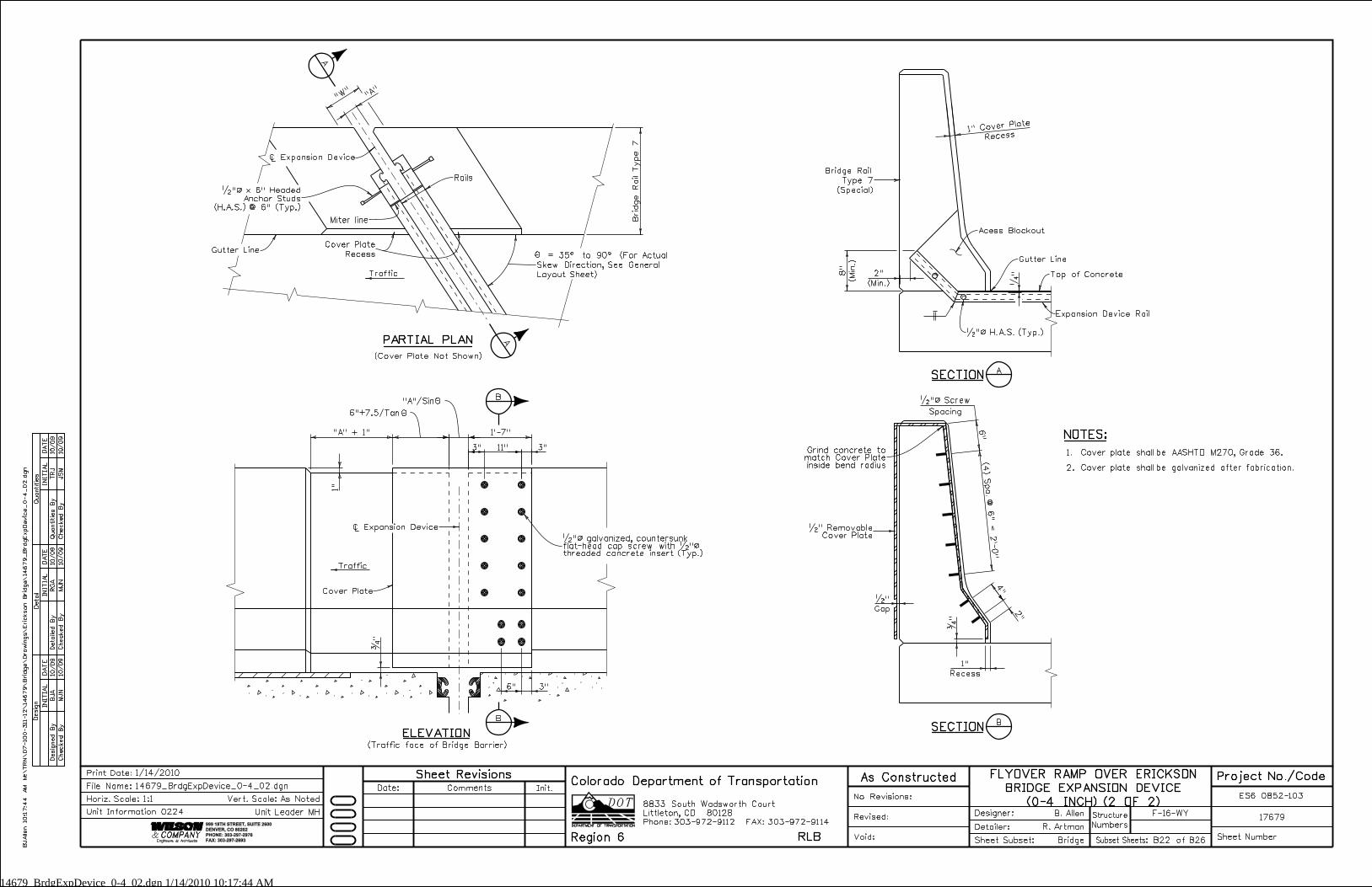
14679_BrdgExpDevice_0-4_02.dgn 1/14/2010 10:17:44 AM
Brid
ge
Rail T
ype 7
1’-7"
6" 3"
"A" + 1"
6"+7.5/Tan
�"
"A"/Sin
1"
Recess1" Cover Pl
ate
(Min.)
8"
(Min.)
2"
�"
(4) Spa. @ 6" = 2’-
0"
6"
4"
2"
Recess
1"
�"
Gap
�"
3"
11"
3"
INITIA
L
Desig
n
Desig
ned
By
Checked
By
DA
TE
DA
TE
DA
TE
INITIA
LINITIA
L
Detail
Quantities
Detailed
By
Checked
By
Checked
By
Quantities
By
JS
M
TRJ
MJ
N
RG
A
MJ
N
BJ
A10/09
10/09
10/09
10/09
10/09
10/09
999 18TH STREET, SUITE 2600
DENVER, CO 80202
PHONE: 303-297-2976
FAX: 303-297-2693
Phone:303-972-9112 FAX:303-972-9114
Colorado Department of Transportation
Region 6 RLB
8833 South Wadsworth Court
Littleton, CO 80128
Traffic
"W"
"A"
Miter line
Rails
B
B
A
A
Ò Expansion Device
PARTIAL PLAN
NOTES:
= 35^ to 90^ (For Actual
Skew Direction, See General
Layout Sheet)
Gutter Line
(Cover Plate Not Shown)
ELEVATION(Traffic face of Bridge Barrier)
Traffic
Cover plate shall be AASHTO M270, Grade 36.
Cover plate shall be galvanized after fabrication.
1.
2.
Ò Expansion Device
�"ß galvanized, countersunkflat-head cap screw with �"ßthreaded concrete insert (Typ.)
Acess Blockout
Top of Concrete
Gutter Line
Expansion Device Rail
�"ß H.A.S. (Typ.)
Bridge Rail
Type 7
(Special)
�"ß Screw
Spacing
�" RemovableCover Plate
Grind concrete tomatch Cover Plateinside bend radius
BSECTION
ASECTION
Cover Plate
Recess
�"ß x 6" Headed
Anchor Studs
(H.A.S.) @ 6" (Typ.)
Cover Plate
BJ
Allen 10:1
7:4
4
AM
M:\
TR
N\
07-100-3
11-12\
14
67
9\
Brid
ge\
Dra
win
gs\
Eric
kson
Brid
ge\
14
67
9_
Brdg
Exp
Devic
e_
0-4
_02.d
gn
F-16-WY
Numbers
Structure
No Revisions:
Revised:
Void: Sheet Subset:
Detailer:
Designer:
Bridge
R. Artman
B. Allen17679
ES6 0852-103
Sheet NumberSubset Sheets: B22 of B26
Init.CommentsDate:
Sheet Revisions As Constructed
1/14/2010Print Date:
Horiz. Scale:1:1
14679_BrdgExpDevice_0-4_02.dgn
Vert. Scale: As Noted
Unit Leader MH
Project No./CodeFLYOVER RAMP OVER ERICKSON
BRIDGE EXPANSION DEVICE
(0-4 INCH) (2 OF 2)
File Name:
Unit Information 0224
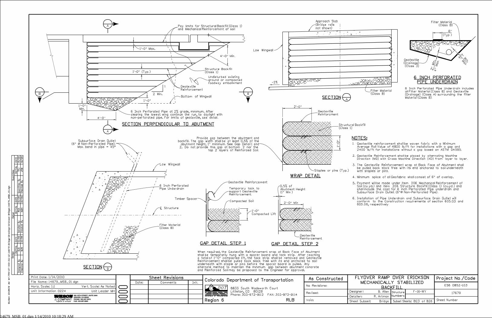
14679_MSB_01.dgn 1/14/2010 10:18:29 AM
6"
2" M
in.
2"
Min.
1’-
0"
2’-0"
2’-0" Min.
0.5% of
4’-0"
INITIA
L
Desig
n
Desig
ned
By
Checked
By
DA
TE
DA
TE
DA
TE
INITIA
LINITIA
L
Detail
Quantities
Detailed
By
Checked
By
Checked
By
Quantities
By
JS
M
TRJ
MJ
N
RG
A
MJ
N
BJ
A10/09
10/09
10/09
10/09
10/09
10/09
999 18TH STREET, SUITE 2600
DENVER, CO 80202
PHONE: 303-297-2976
FAX: 303-297-2693
Phone:303-972-9112 FAX:303-972-9114
Colorado Department of Transportation
Region 6 RLB
8833 South Wadsworth Court
Littleton, CO 80128
Min.
1
SECTION PERPENDICULAR TO ABUTMENT
A
-2%
SECTION
WRAP DETAIL
4"
Max.
(Typ.)
6 INCH PERFORATED
PIPE UNDERDRAIN
B
SECTION
When required, the Geotextile Reinforcement wrap at Back Face of Abutment
shall be temporarily hung with a spacer board and tack strip. After reaching
a total of 1’-0" compacted lift, the tack strip shall be removed and Geotextile
Reinforcement shall be pulled back slack free with its end anchored to soil
underneath with staple or pins before the spacer board is pulled. Any
alternate method to maintain the minimum gap between abutment concrete
and Reinforced Soil may be proposed to the Engineer for approval.
GAP DETAIL STEP 2GAP DETAIL STEP 1
6 Inch Perforated Pipe Underdrain includes
all Filter Material (Class B) and Geotextile
(Drainage) (Class A) surrounding the filter
Material (Class B).
Compacted Lift
Abutment Height
(1" Min.)
NOTES:
~
2 Min.
Filter Material
(Class B)
Staples or pins (Typ.)
6 Inch Perforated
Pipe Underdrain
Filter Material
(Class B)
Subsurface Drain Outlet
(6" ß Non-Perforated Pipe).
Max. bend in pipe = 45^
Compacted Soil
Geotextile Reinforcement
Timber Spacer
Structural Backfill
(Class 1)
6 Inch Perforated Pipe at 2% grade, minimum. After
clearing the lowest wing continue the run, to daylight with
non-perforated pipe. For limits of geotextile, see detail.
Structure Backfill
(Class 1)
Geotextile
Reinforcment
Filter Material
(Class B)
Geotextile
(Drainage)
(Class 3)
Approach Slab
(Bridge rails
not shown)
Low Wingwall
Bottom of Wingwall
Low Wingwall
B
B
1.
2.
3.
4.
5.
6.
Undisturbed existing
ground or compacted
roadway embankment
A
A
1’-0"
1’-0"
1’-0" (Typ.)
1’-0"
1’-0" Max.
4’-0" Min. 4" M
ax.
Pay limits for Structural Backfill (Class 1)
and Mechanical Reinforcement of soil
Geotextile
Reinforcement
Geotextile
Reinforcement
Temporary tack to
support Geotextile
Reinforcement.
Provide gap between the abutment and
backfill. The gap width shall be at least 0.5% of the
abutment height, 1" minimum. See Gap Detail 1 and
2. Do not provide this gap at bottom 2 nor the
top 2 layers of Reinforced Soil.
BJ
Allen 10:1
8:2
9
AM
M:\
TR
N\
07-100-311-12\
14
67
9\
Brid
ge\
Dra
win
gs\
Eric
kson
Brid
ge\
14
67
9_
MS
B_
01.d
gn
F-16-WY
Numbers
Structure
No Revisions:
Revised:
Void: Sheet Subset:
Detailer:
Designer:
Bridge
R. Artman
B. Allen17679
ES6 0852-103
Sheet NumberSubset Sheets: B23 of B26
Init.CommentsDate:
Sheet Revisions As Constructed
1/14/2010Print Date:
Horiz. Scale:1:1
14679_MSB_01.dgn
Vert. Scale: As Noted
Unit Leader MH
Project No./CodeFLYOVER RAMP OVER ERICKSON
MECHANICALLY STABILIZED
BACKFILL
File Name:
Unit Information 0224
Geotextile reinforcement shall be woven fabric with a Minimum
Average Roll Value of 4800 lb/ft for installations with a gap and
2400 lb/ft for installations without a gap based on ASTM D4595.
Geotextile Reinforcement shall be placed by alternating Machine
Direction (MD) with Cross Machine Direction (XD) from layer to layer.
The Geotextile Reinforcement wrap at Back Face of Abutment shall
be pulled back slack free with its end anchored to soil underneath
with staples or pins.
Minimum splice of all Geofabric shall consist of 6" of overlap.
Payment will be made under item 206 Mechanical Reinforcement of
Soil (cu.yd.) and item 206 Structure Backfill (Class 1) (cu.yd.) and
shall include the cost for 6 inch Perforated Pipe underdrain and
Subsurface Drain Outlet (6"ß Non-Perforated Pipe).
Installation of Pipe Underdrain and Subsurface Drain Outlet will
conform to the Construction requirements of section 605.03 and
605.06, respectively.
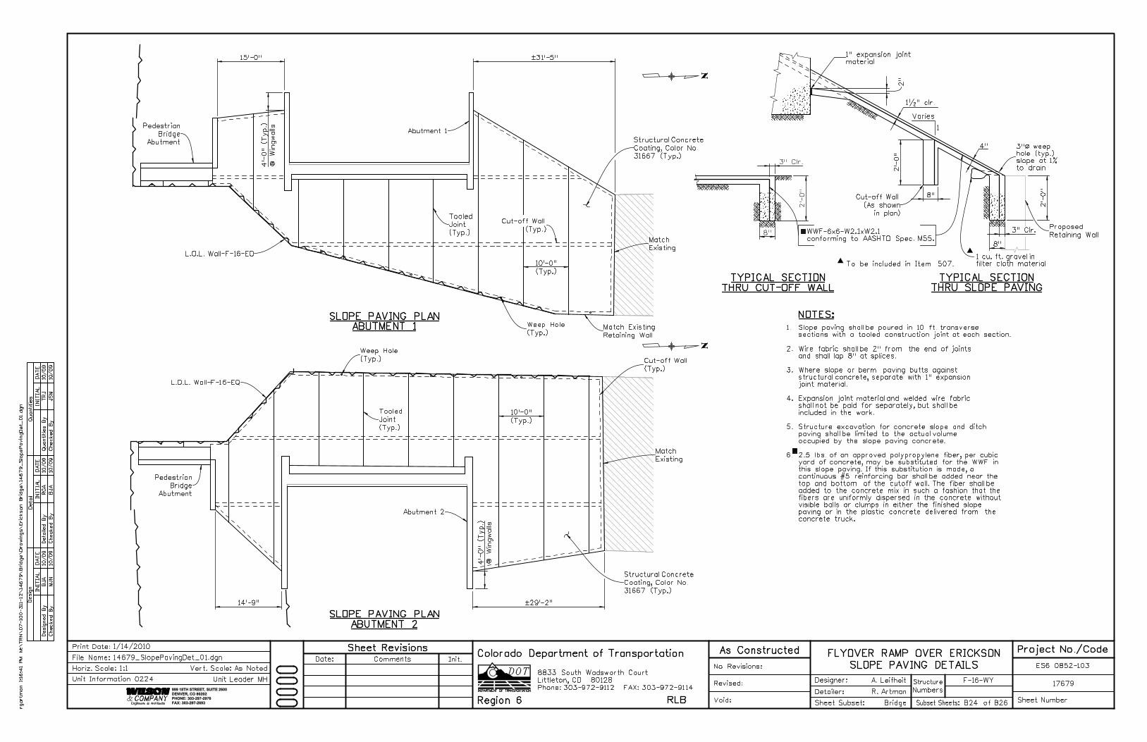
2"
2’-
0"
8"
2’-
0"
8"
15’-0"
14’-9"
@
Win
gwalls
4’-
0" (T
yp.)
@
Win
gwalls
4’-
0" (T
yp.)
2’-
0"
˛31’-5"
˛29’-2"
(Typ.)
10’-0"
(Typ.)
10’-0"
8"
3" Clr.
3" Clr.
INITIA
L
Desig
n
Desig
ned
By
Checked
By
DA
TE
DA
TE
DA
TE
INITIA
LINITIA
L
Detail
Quantities
Detailed
By
Checked
By
Checked
By
Quantities
By
JS
M
TRJ
BJ
A
RG
A
MJ
N
BJ
A10/09
10/09
10/09
10/09
10/09
10/09
Phone:303-972-9112 FAX:303-972-9114
Colorado Department of Transportation
Region 6 RLB
8833 South Wadsworth Court
Littleton, CO 80128
999 18TH STREET, SUITE 2600
DENVER, CO 80202
PHONE: 303-297-2976
FAX: 303-297-2693
TYPICAL SECTION
THRU CUT-OFF WALL
TYPICAL SECTION
THRU SLOPE PAVING
To be included in Item 507.
1 cu. ft. gravel in
filter cloth material
4"
1
1�" clr.
NOTES:
WWF-6x6-W2.1xW2.1
conforming to AASHTO Spec. M55.
1.
2.
3.
4.
5.
6.
Slope paving shall be poured in 10 ft. transverse
sections with a tooled construction joint at each section.
Wire fabric shall be 2" from the end of joints
and shall lap 8" at splices.
Where slope or berm paving butts against
structural concrete, separate with 1" expansion
joint material.
Expansion joint material and welded wire fabric
shall not be paid for separately, but shall be
included in the work.
Structure excavation for concrete slope and ditch
paving shall be limited to the actual volume
occupied by the slope paving concrete.
2.5 lbs. of an approved polypropylene fiber, per cubic
yard of concrete, may be substituted for the WWF in
this slope paving. If this substitution is made, a
continuous #5 reinforcing bar shall be added near the
top and bottom of the cutoff wall. The fiber shall be
added to the concrete mix in such a fashion that the
fibers are uniformly dispersed in the concrete without
visible balls or clumps in either the finished slope
paving or in the plastic concrete delivered from the
concrete truck.
SLOPE PAVING PLAN
ABUTMENT 1
SLOPE PAVING PLAN
ABUTMENT 2
Varies
rgart
man 1:1
6:4
1 P
M
M:\
TR
N\
07-100-3
11-12\
14
67
9\
Brid
ge\
Dra
win
gs\
Eric
kson
Brid
ge\
14
67
9_
Slo
pePavin
gDet_
01.d
gn
F-16-WY
Numbers
Structure
No Revisions:
Revised:
Void: Sheet Subset:
Detailer:
Designer:
Bridge
R. Artman
A. Leifheit17679
ES6 0852-103
Sheet NumberSubset Sheets: B24 of B26
Init.CommentsDate:
Sheet Revisions As Constructed
1/14/2010Print Date:
Horiz. Scale:1:1
14679_SlopePavingDet_01.dgn
Vert. Scale: As Noted
Unit Leader MH
Project No./CodeFLYOVER RAMP OVER ERICKSON
SLOPE PAVING DETAILSFile Name:
Unit Information 0224
3"ß weep
hole (typ.)
slope at 1%
to drain
1" expansion joint
material
Proposed
Retaining Wall
Tooled
Joint
(Typ.)
Tooled
Joint
(Typ.)
L.O.L. Wall-F-16-EO
L.O.L. Wall-F-16-EQ
Match
Existing
Match
Existing
Weep Hole
(Typ.)
Weep Hole
(Typ.)
Pedestrian
Bridge
Abutment
Pedestrian
Bridge
Abutment
Abutment 1
Abutment 2
Cut-off Wall
(Typ.)
Cut-off Wall
(Typ.)
Structural Concrete
Coating, Color No.
31667 (Typ.)
Structural Concrete
Coating, Color No.
31667 (Typ.)
Cut-off Wall
(As shown
in plan)
Match Existing
Retaining Wall
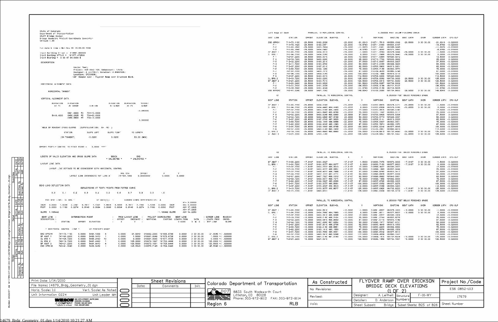
14679_Brdg_Geometry_01.dgn 1/14/2010 10:21:27 AM
MJ
N
TRJ
BJ
A
DR
A
BJ
A
AM
L10/09
10/09
10/09
10/09
10/09
10/09
INITIA
L
Desig
n
Desig
ned
By
Checked
By
DA
TE
DA
TE
DA
TE
INITIA
LINITIA
L
Detail
Quantities
Detailed
By
Checked
By
Checked
By
Quantities
By
999 18TH STREET, SUITE 2600
DENVER, CO 80202
PHONE: 303-297-2976
FAX: 303-297-2693
Phone:303-972-9112 FAX:303-972-9114
Colorado Department of Transportation
Region 6 RLB
8833 South Wadsworth Court
Littleton, CO 80128
BJ
Allen 10:2
1:2
7
AM
M:\
TR
N\
07-100-3
11-12\
14
67
9\
Brid
ge\
Dra
win
gs\
Eric
kson
Brid
ge\
14
67
9_
Brdg_
Geo
metry_
01.d
gn
F-16-WY
Numbers
Structure
No Revisions:
Revised:
Void: Sheet Subset:
Detailer:
Designer:
Bridge
D. Anderson
A. Leifheit17679
ES6 0852-103
Sheet NumberSubset Sheets: B25 of B26
Init.CommentsDate:
Sheet Revisions As Constructed
1/14/2010Print Date:
Horiz. Scale:1:1
14679_Brdg_Geometry_01.dgn
Vert. Scale: As Noted
Unit Leader MH
Project No./CodeFLYOVER RAMP OVER ERICKSON
BRIDGE DECK ELEVATIONS
(1 OF 2)
File Name:
Unit Information 0224
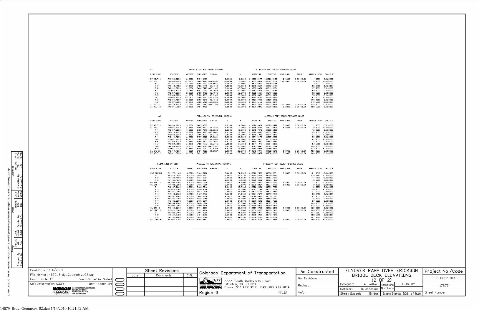
14679_Brdg_Geometry_02.dgn 1/14/2010 10:21:42 AM
JS
M
TRJ
BJ
A
RG
A
BJ
A
AM
L10/09
10/09
10/09
10/09
10/09
10/09
INITIA
L
Desig
n
Desig
ned
By
Checked
By
DA
TE
DA
TE
DA
TE
INITIA
LINITIA
L
Detail
Quantities
Detailed
By
Checked
By
Checked
By
Quantities
By
999 18TH STREET, SUITE 2600
DENVER, CO 80202
PHONE: 303-297-2976
FAX: 303-297-2693
Phone:303-972-9112 FAX:303-972-9114
Colorado Department of Transportation
Region 6 RLB
8833 South Wadsworth Court
Littleton, CO 80128
BJ
Allen 10:2
1:4
2
AM
M:\
TR
N\
07-100-3
11-12\
14
67
9\
Brid
ge\
Dra
win
gs\
Eric
kson
Brid
ge\
14
67
9_
Brdg_
Geo
metry_
02.d
gn
F-16-WY
Numbers
Structure
No Revisions:
Revised:
Void: Sheet Subset:
Detailer:
Designer:
Bridge
D. Anderson
A. Leifheit17679
ES6 0852-103
Sheet NumberSubset Sheets: B26 of B26
Init.CommentsDate:
Sheet Revisions As Constructed
1/14/2010Print Date:
Horiz. Scale:1:1
14679_Brdg_Geometry_02.dgn
Vert. Scale: As Noted
Unit Leader MH
Project No./CodeFLYOVER RAMP OVER ERICKSON
BRIDGE DECK ELEVATIONS
(2 OF 2)
File Name:
Unit Information 0224